/


Tags: weapons
Year: 1944

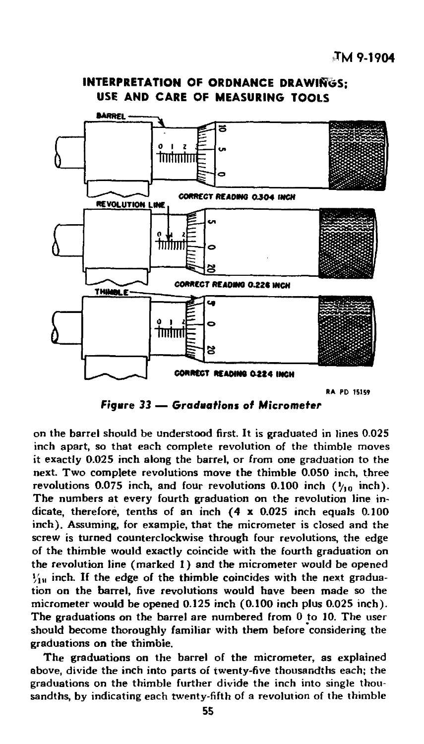
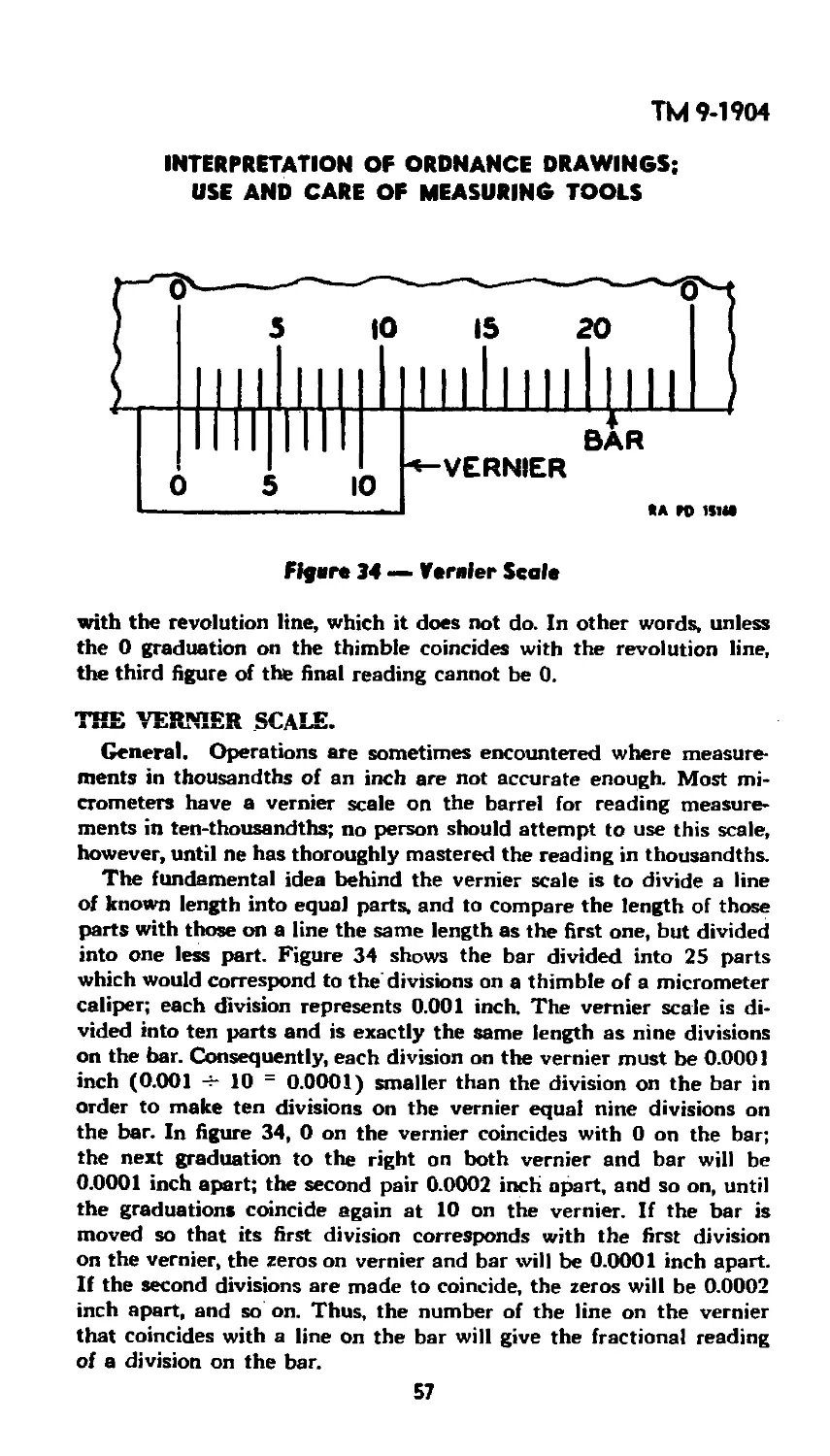
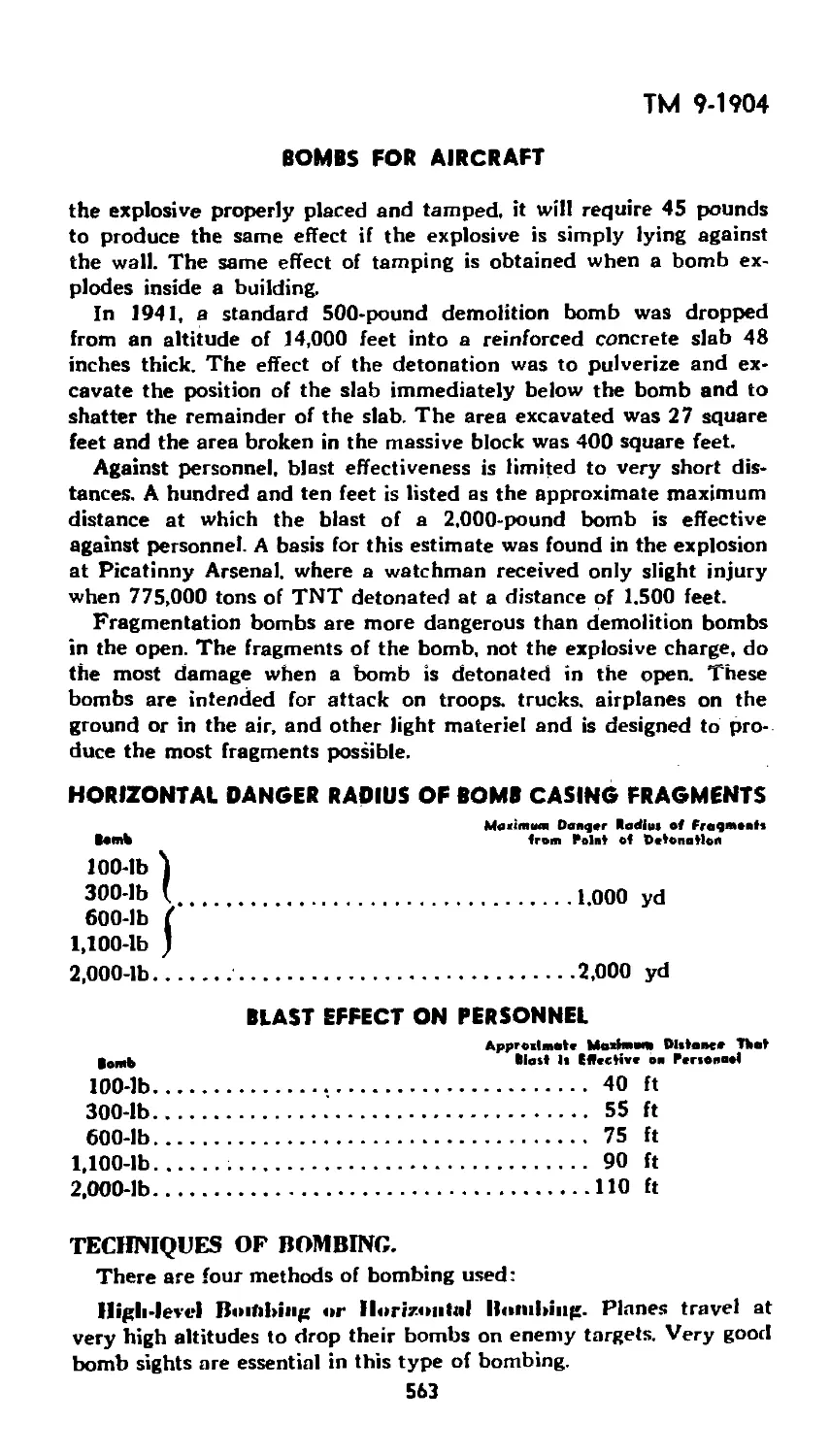
Text
IP AR DEPARTMENT TECHNICAL MANUAL
TM 9-1904
PRINT OR HANDWRITING
NOT CONDUCIVE FOR
LEGIBLE CD IMAGING ON
VARIOUS PAGES IN
DOCUMENT.
Ammunition Inspection Guide
WAR DEPARTMENT
* 2 MARCH 1944
RESTRICTED DISSEMINATION OF RESTRICTED MATTER—
The information contained in restricted documents and the essential char-
acteristics of restricted material may be given to any person known to be in
the service of the United States and to persons of undoubted loyalty and
discretion who are cooperating in Government work, but will not be com-
municated to the public or to the press except by authorised military public
relations agencies. (See also paragraph 1g b, AR 340-5, 2g September 1942.)
WAR DEPARTMENT
Washington 25, D. C„ 2 March 1944
TM 9-1904, Ammunition Inspection Guide, is published for the
information and guidance of all concerned.
[A.G. 300.7 (2 Feb 44)1
O.O. 300.7/ 1365 J
By order of the Secretary of War:
G. C. MARSHALL,
Chief of Staff.
Official:
J. A. ULIO,
Major General,
The Adjutant General.
Distribution: IBn 9 (2); IC 9 (2), (10).
(For explanation of symbols, see FM 21-6.)
ТМ 9-1904
CONTENTS
PAGE
SECTION I. Introduction
Chapter 1. Ammunition in General..................... 5
2. Safety................................... 21
SECTION II. Interpretation of Ordnance Drawings,-
Use and Care of Measuring Tools
Chapter 1. Information Topics...................... 23
2. Regulations Covering Ordnance Drawings for
Ammunition Division Materiel............... 33
3. Use and Care of Measuring Tools......... 37
SECTION HI. Explosives
Chapter'1. Introduction, Military Explosives.. 66
2. Low Explosives.......................... 68
'3. High Explosives......................... 96
4. Explosive Trains....................... 117
5. Exudation .............................. 132
6. High-explosive Loading................. 135
SECTION IV. Chemical Warfare Agents
Chapter 1. Chemical Agents.................... 158
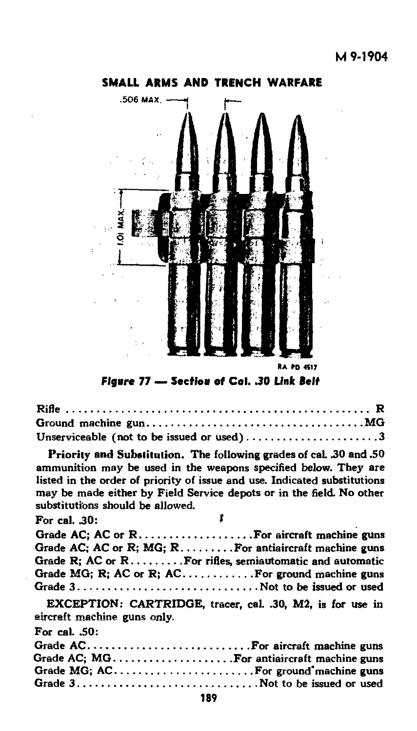
SECTION V. Small Arms and Trench Warfare
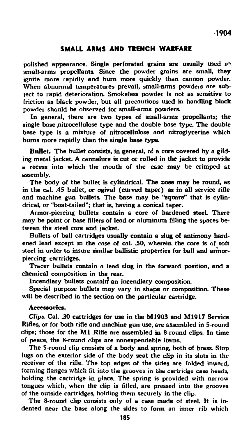
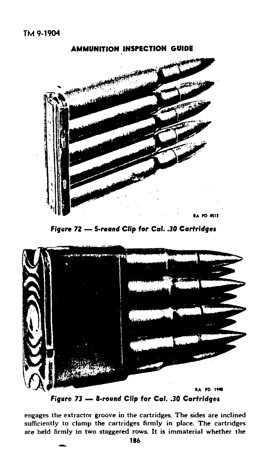
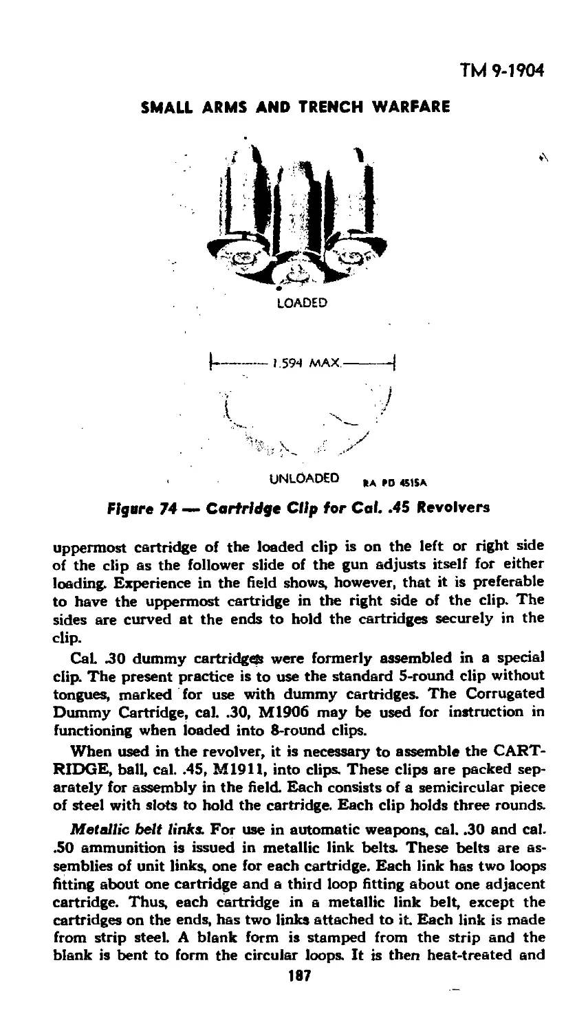
Chapter 1. Small-arms Ammunition.............. 179
2. Hand Grenades.......................... 234
3. Antipersonnel Mines and Booby Traps..... 240
4. Rifle Grenades and Rockets............. 253
5. Antitank Mines........................ 263
6. Bangalore Torpedo...................... 270
7. Trench Mortar Ammunition............... 272
SECTION VI. Artillery Ammunition
Chapter 1. Introduction to Artillery Fuzes.... 319
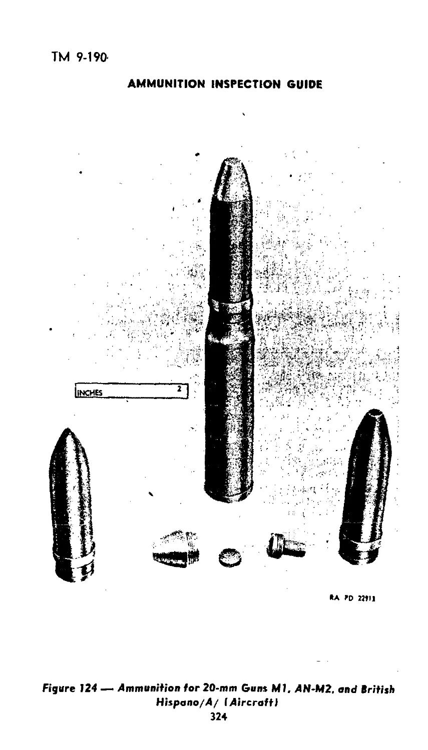
2. 20-mm Ammunition ...................... 323
3. 37-mm Ammunition ...................... 331
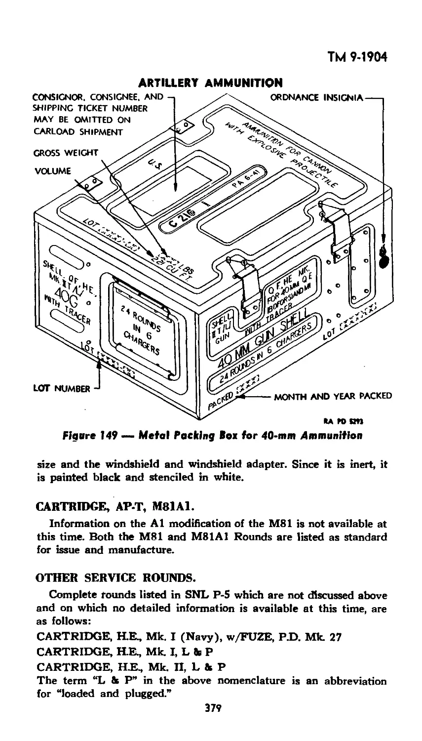
4. Ammunition for 40-mm Gun Ml........... 363
5. Ammunition for 57-mm Guns.............. 380
6. 75-mm Gun Ammunition.................. 382
7. 75-mm Howitzer Ammunition ............. 425
8. 3-inch Ammunition...................... 437
9. Ammunition for 90-mm Guns ........... . 462
10. Ammunition for 105-mm Guns and •
Howitzers................................... 469
3
ТМ 9-1904
AMMUNITION INSPECTION GUIDE
PAGE
Chapter 11. Ammunition for 4.7-inch AA Guns......... 484
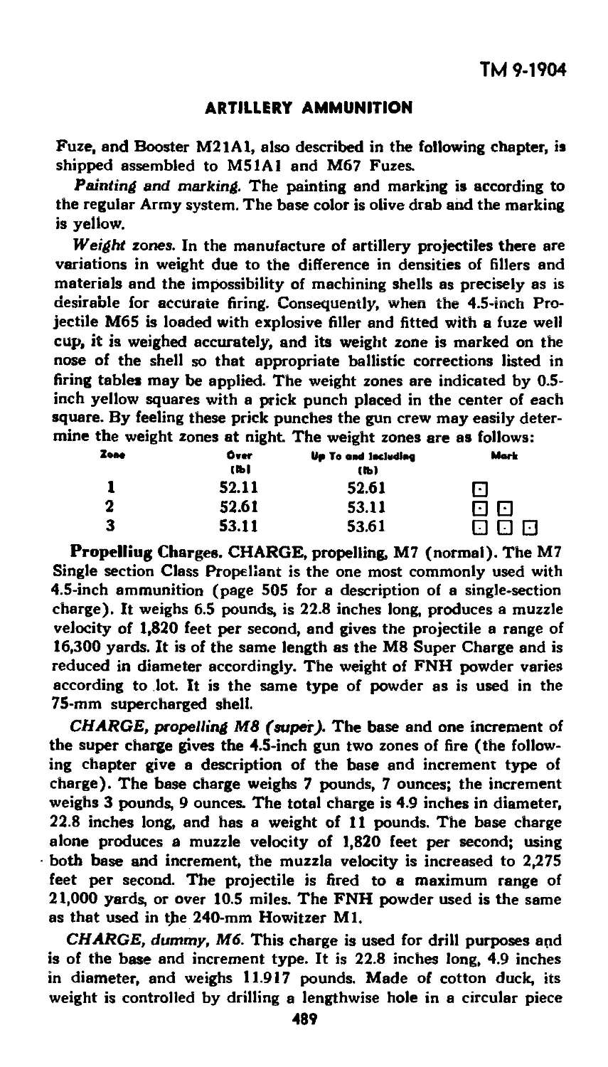
12. Ammunition for 4.5-inch Guns .......... 486
13. Ammunition for 155-mm Guns and
Howitzers.......................... 490
14. Ammunition for 240-mm Howitzers........ 522
15. Ammunition for 14-inch Guns ........... 529
SECTION VII. Bombs for Aircraft
Chapter^!. Introduction.......................... 548
2. G.P. (General Purpose) Bombs........... 564
3. Semi-armor-piercing and Armor-piercing
Bombs ................................605
4. Depth Bombs . ...:..................... 623
5. Fragmentation Bombs ................... 641
6. Chemical Bombs......................... 667
7. Incendiary Bombs....................... 677
~~ 8. Practice and Drill Bombs.............. 697
SECTION VIII. Military Pyrotechnics
Chapter T Pyrotechnics . L ......—л;.--.;:-.....- 7-09-
SECTION IX. Destruction of Unusable Ammunition
and Explosives
Chapter 1. Introduction........................... 748
2. Destruction by Detonation ............. 752
3. Destruction by Burning................. 772
4. Dumping at Sea......................... 777
SECTION X. Magazine Area
Chapter 1. Magazine Construction and Inspection.....779
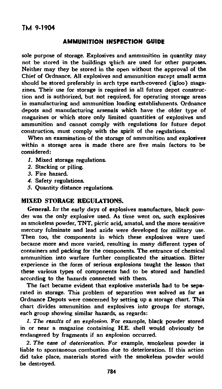
2. Storage of Ammunition and Explosives..... 783
3. Storage of Chemical Ammunition ........ 812
SECTION XI. Transportation
Chapter 1. Inspection of Incoming and Outgoing
Shipments ........................... 827
2. I.C.C. Regulations Pertaining to Blocking and
Staying.............................. 831
3. I.C.C. Regulations Pertaining to Shipper. 856
4. Duties of an Ammunition Inspector at a Port
of Embarkation............................ 883
SECTION XII. Renovation
Chapter 1. General ............................... 892
SECTION XIII. Surveillance— General
Chapter 1. Introduction........................... 898
2. Surveillance............................901
3. Surveillance Records and Reports........909
INDEX...................................................921
4
TM 9-1904
RESTRICTED
SECTION I.
INTRODUCTION
Chapter I
Ammunition in General
GENERAL.
When venturing into any new field, one finds himself confronted
with many new terms and materials to such an extent that he often
becomes lost in a maze of confusion. It is, therefore, necessary to lay
a foundation of information that will aid in interpreting the material
which will follow.*
It is necessary for the ammunition inspector to have a wide and
complete knowledge of all the types of ammunition that he will come
in contact with in the line of duty, for he will be called on to pass
judgment as to the safe conduct of various operations. To do this,
he must know all the facts about the material in question. It might
be well to point out that all ammunition is inherently dangerous, for
its whole purpose of existence is to destroy or kill, but, if handled
correctly and-earefuilv, one need-not-ba afraid tn work-with_it. At all
times, however, it must be given the fullest respect. A great portion
of the accidents which do occur can be traced to some form of care-
lessness when the full measure of safety was not applied.
Nomenclature. In his daily dutiesZthe ammunition inspector will
be called upon to discuss ammunition. Whether this discussion be
written or oral, the proper use of terms or proper nomenclature is
constantly required. All articles have specific names and designations
which must be used at all times. The purpose of this is to insure that
there will be no error in understanding, for some types of ammunition
are so nearly alike that only by the use of proper terminology can
they be distinguished. The habit of using proper nomenclature is one
that should be formed from the beginning.
Model Designations. To distinguish a particular design, a model
designation is assigned at the time the model is classified as an
adopted type. This model designation becomes an essential part of
the standard nomenclature and is included in tiie marking on
the item.
Prior to World War I, tbe number of the year in which the design
was adopted preceded by an "M” was used as the model designation;
for example, M1906. From the World War until July 1, 1925, it was
the practice to assign mark numbers. The word “Mark,” abbreviated
“Mk.,” was followed by a roman numeral; for example, Shell, H.E.,
Mk. III. The first modification of a model was indicated by the addi-
tion of MI to the mark number, the second by МП, etc. The present
* This Technical Manual has been published in advance of comp/efe technicnl review in
order to provide a background for inspection of all types of ammunition.
5
ТМ 9-1904
AMMUNITION INSPECTION GUIDE
system of model designation consists of the letter “M” followed by
an arabic numeral. Modifications are indicated by adding the letter
“A” and appropriate arabic numerals. Thus, M2A1 indicates the first
modification of an item for which the original model designation was
М2. In addition to the “A” modifications there are also “B” modifica-
tions. These may be either a change in the method of manufacture
of an item, or a change in the material used. Examples of this are the
M18B1 steel cartridge case and the M1B1A1 primer. Certain items
standardized for use by both Army and Navy are designated by the
letters “AN” preceding the model designation; for example, AN-
M100A1, AN-Mk. 19, AN-Mk. IV. The two designations above, AN-
M100A1 and AN-Mk. IV, indicate that the item is of Army design,
while the designation AN-Mk. 19, indicates that the item is of Navy
design. In recent years the Navy designations have been arabic
numerals, previously they were roman numerals and some of these
may still be found.
Classification by Standards.
Standard articles are those which are the most advanced and satis-
factory, and have been adopted by the Secretary of War. They are
preferred for procurement to meet supply demands.
Substitute standard articles are those which do not have com-
pletely satisfactory military characteristics, but are usable substitutes
for standard articles. They are not normally in use, nor are they avail-
able for issue to meet supply demands. They may, however, be pro-
cured to supplement the supply of standard articles.
Limited standard articles are those which do not have as satis-
factory military characteristics as standard articles, but are usable
substitutes for standard articles. They are either in use or available
for issue to meet supply demands.
Classification by Issue and Manufacture. In making use of the
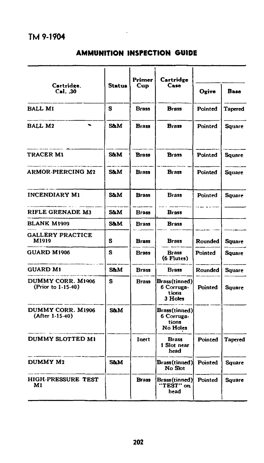
Standard Nomenclature Lists and Complete Round Charts, the status
of the ammunition may be found marked as “S” or "S&M.” In this
instance, the “S” indicates that the item is standard for issue only
and is no longer being manufactured. The "S&M” indicates that the
item is standard for issue and is being manufactured.
Ammunition Lot Number. When ammunition is manufactured,
a lot number, which becomes an essential part of the marking, is as-
signed in accordance with pertinent specifications. This lot number is
stamped or marked on every item of ammunition unless the item is
too small. A group of these lots which for both engineering and sta-
tistical reasons can be considered to be of the same standard of
quality is called a grand lot. In addition to this lot number, there is
assigned to each complete round of fixed and semifixed ammunition
an ammunition tot number which serves to identify the conditions
6
ТМ 9-1904
INTRODUCTION
under which the round was assembled and the components used in
the assembly. This ammunition lot number is marked on every com-
plete round of fixed and semifixed ammunition (except where the
item is too small as in the case of small-arms ammunition) and on
all packing containers. It is required for all purposes of record includ-
ing reports on condition, functioning, and accidents in which the am-
munition is involved. To provide for the most uniform functioning, all
of the components in any one lot are manufactured under as nearly
identical conditions as practicable. For example, in the case of fixed
ammunition, all of the rounds in any one lot consist of:
1. Projectiles of one lot or grand lot (one type and one weight
zone).
2. Fuzes of one lot or grand Jot
3. Primers of one lot or grand lot
4. Propellent powder of one lot.
DEFINITIONS.
A few basic definitions are essential if one is to attain complete
understanding of the material which is to follow.
Ammunition. Ammunition is defined as any. or all materials used
to charge weapons of war, including pyrotechnics in all of its forms.
There is one point in this definition that might not be clear.
“Weapons of War” refers to not only guns, howitzers, mortars, and the
like, but to airplanes and soldiers as well.
Caliber. Caliber is a term whi^l has widespread use in the field of
an ammunition inspector. Nearly all of the ammunition is measured
in calibers. A caliber is the diameter of the bore of the weapon be-
tween opposite lands. While it is used as a unit of measure and is
expressed in inches or millimeters, it has no unit in itself. Thus, if
it is said that the barrel of a particular weapon is 30 calibers in length
it does not mean that it is 30 inches or 30 millimeters long, but that
its length is 30 times the diameter of its bore between opposite lands.
To be of any use, caliber must refer to a specific weapon.
Lande. The lands in a weapon are the raised portions of the rifling
of the weapon, and the spaces between the lands are called grooves.
Complete Round. A complete round of ammunition is made up
of all the necessary components to a chain of events which will per-
form a desired function under the proper circumstances and at the
proper time. For example, a complete round of a high-explosive shell
would be made up of a projectile, an explosive filler, a fuze, a booster,
a propelling charge, a cartridge case, and a primer. Here, all of these
components are.necessary to bring about the desired function of the
shell and thus make up a complete round.
Small-arme and Artillery Ammunition. A most important divi -
ding line in ammunition is that between small-arms and artillery am-
7
ТМ 9-1904
AMMUNITION INSPECTION GUIDE
munition. This dividing line is based on 0.60 inch. Small-arms ammu-
nition is defined as ammunition fired in weapons whose bores are
0.60 inch or less in diameter, while artillery ammunition is defined as
ammunition fired in weapons whose bore is over 0.60 inch in dia-
meter. It is well to note that small-arms ammunition includes ammu-
nition which is 0.60 inch in diameter, and that anything over 0.60
inch must be considered as artillery ammunition.
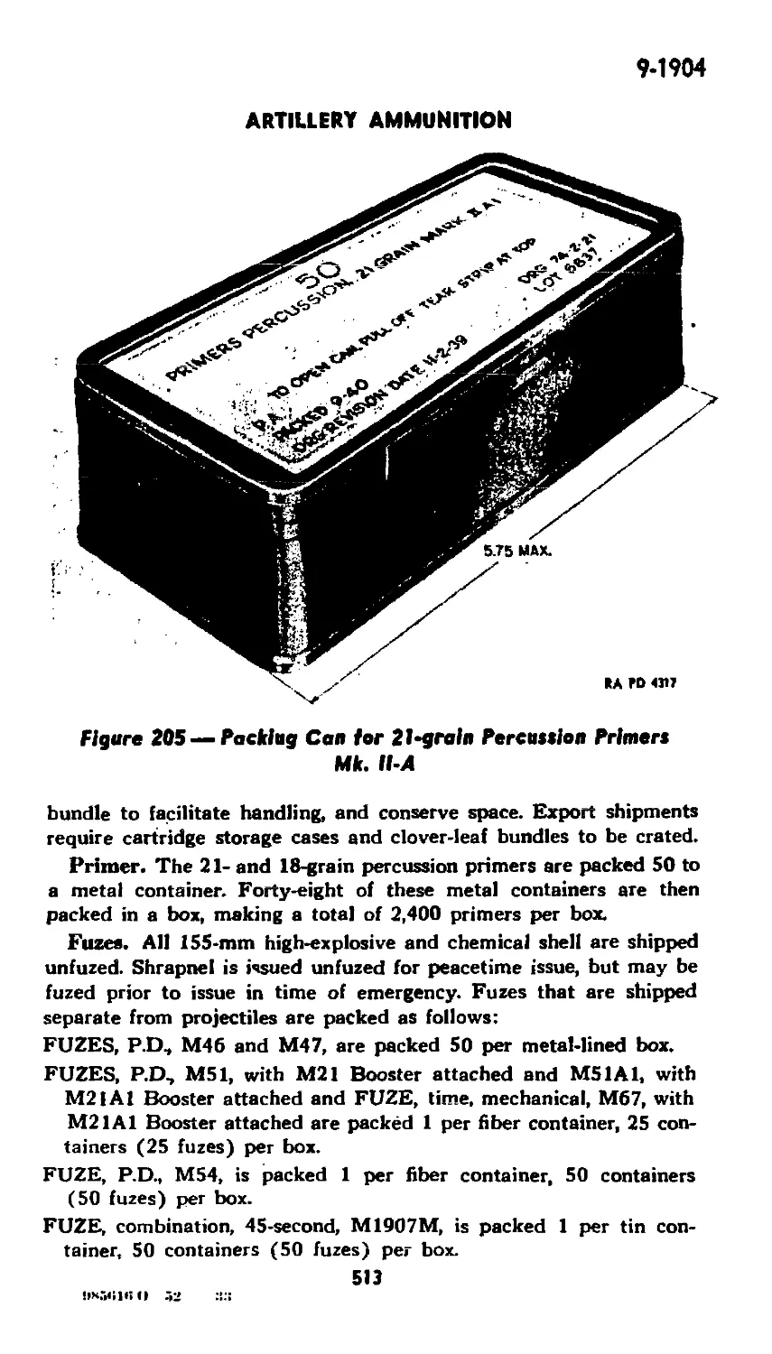
ARTILLERY AMMUNITION.
Tactics and Ammunition. Artillery was first used mainly against
fortifications for the purpose of breaking down walls to allow the pass-
age of foot troops in an attack. Because the hand weapons of the
defending forces were crude and of short range, the cannon, of the
attacking force could be emplaced at close range. There was, there-
fore, no need for long-range fire, and artillery was put into position
in front of the foot troops. With the development of shoulder weapons
of increased range and accuracy, it became necessary for artillery to
seek positions at greater distances from the opposing forces and in
the rear of friendly troops who served to protect the artillery division.
These conditions called for greater range and power, which in turn
necessitated improved projectiles and propellent powders. The as-
signment of special missions to artillery brought about the develop-
ment of special ammunition with which to accomplish these missions.
Projectiles. A projectile is a missile, either solid or with an explo-
sive, chemical, or inert filler, propelled from a weapon by the force
of gases produced by a propelling charge.
Early projectiles fired from cannon were iron darts, wrapped with
leather, of a size to fit the bore. These continued in use up to the
sixteenth century, when they were replaced by spherical shot. One
example of this shot was roughly rounded stone balls chosen because
of their cheapness. Forged iron, bronze, and lead balls were tried, but
expense prevented their general adoption.
Also, since heavy metal shot necessitated the use of a correspond-
ingly large propelling charge, too great a strain was exerted on the
feeble artillery pieces of the period. This frequently caused rupture
of the cannon. Stone shot being about one-third the weight of iron,
the powder charge was reduced in proportion, effecting an additional
economy.
Both iron and stone shot occasionally were covered with lead to
preserve the interior of the bore by reducing the friction, and to
afford a closer fit between the shot and the bore, thereby improving
the obturation, preventing the escape of gases, and increasing the
muzzle velocity and range. Hollow projectiles filled with explosives
or combustibles, and variations of canister appeared during the six-
teenth century.
8
BASE FRM6ING
Пди
INTRODUCTION
ТМ 9-1904
AMMUNITION INSPECTION GUIDE
Shape. Since its inception, the demand for greater and greater
range has influenced the shape of the projectile. Toward the end of
the sixteenth century, cannon shot was made of cast iron and was
spherical in form. The spherical projectile was inefficient ballistically.
it was erratic in flight. Because of the crude methods of manufacture,
a tight fit could not be obtained between the projectile and the bore
of the cannon. Its rough surface increased air resistance and, by virtue
of its shape, a maximum surface in proportion to its weight was
effected by resistance. Nevertheless, the spherical form continued in
use up to the advent of rifled cannon (about I860), when projectiles
were elongated to a cylindrical form with a pointed nose.
Factors affecting desired shape. The amount of air resistance de-
pends upon the size, shape, and “presentation” of the projectile. Size
is significant because of the greater number of air molecules to be
displaced by movement of the larger projectile. Shape of the pro-
jectile has an important effect on the manner in which the mole-
cules are shouldered aside. “Presentation” affects both the number of
air molecules displaced and the manner in which they are pushed
aside. A projectile of 2 feet in diameter displaces four times as many
molecules as does a projectile of 1-foot diameter, since the area of
the cross section of a projectile varies as the square of the diameter.
A cone with a base diameter of 2 feet, since its greatest cross section
is the same as a cylinder of the same diameter, displaces just as many
molecules as does the cylinder, but because of its pointed shape, it
effects the displacement more smoothly and consequently encounters
less resistance.
Weight exercises a great effect on the power to overcome resistance.
Thus, two cylinders of equal diameter and length composed of dif-
ferent materials, one twice as heavy as the other, would experience
the same resistance to travel through the air. However, the heavier
would possess double the ability of the lighter to overcome resistance.
Again, since length has little effect on resistance, a cylinder twice
the length of the original one and composed of the same material, if
solid, would be twice as heavy and would possess double the energy.
In order that a cone may possess the same energy as a cylinder of
equal diameter, it must be longer, since it otherwise would be of less
weight. As the length of a projectile is limited by certain other con-
siderations, the modern projectile represents a compromise, combin-
ing energy-producing effect by means of increased weight, and re-
sistance-reducing effect by means of the pointed nose.
The air resistance is affected in a marked degree by the shape of
the nose. It is found that in a shell in the usual form, the shape of
the shoulders is more important than that of the actual point. This
is explained by the fact that as air streams outward from the point
to pass over the shoulders of the shell, it leaves a partial vacuum
10
ТМ 9-1904
INTRODUCTION
near the point while the main air pressure comes near the shoulders.
When a projectile with a radius of ogive of 5 or 6 calibers is used,
the shape of the point becomes important in determining the direction
of the air currents which flow over the shoulders.
The ideal shape for a projectile intended to travel through the air
with the minimum, resistance would be one of streamline profile and
having a nose with an ogive curved for pushing aside the air mole-
cules with the least disturbance. It would also have a tapered or
conical (“boat-tailed”) tail to eliminate vacuum-forming eddies in its
wake. The flat, sawed-off bottom of the type of projectile in use prior
to World War I is inefficient, because the partial vacuum formed be-
hind the projectile during flight greatly retards it and causes un-
steadiness in flight For this reason modern projectiles are of the
“boat-tailed" type.
Exterior of Modern Projectiles. Modern projectiles combine
weight and form in the most practical way to secure a maximum of
stability and a minimum of air resistance in flight.
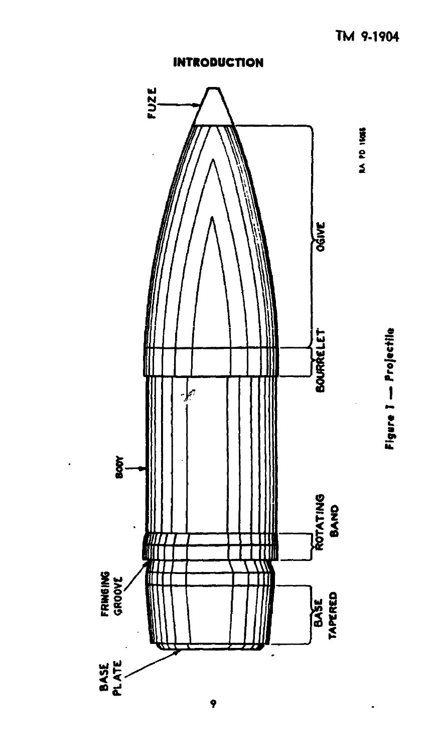
Ogive. Starting with the point of the projectile and working to-
ward the rear, the first portion encountered is the curved portion of
the nose of the projectile. This is known as the ogive. The ogive
describes an arc whose center lies on a plane perpendicular to the
axis of the projectile, with a radius usually expressed in terms of
caliber. This radius formerly was two calibers for all projectiles, but
experiments have proved that a marked reduction in air resistance,
resulting in greater range, can be obtained by increasing the radius of
the ogive to as much as 10 or 11 calibers.
Bourrelet. Directly behind the ogive is a very carefully and ac-
curately machined portion of the projectile, known as the bourrelet.
It is this portion of the propectile which most nearly conforms to the
bore of the weapon. In action, it £cts as a forward bearing surface,
and also helps to center the projectile in the bore of the weapon. The
average bourrelet is about 1/6 of a caliber in width. By having only
a small band such as the bourrelet for a bearing surface, the amount
of resistance due to friction in the bore is greatly reduced as com-
pared to the friction which would be produced if the whole body of
the projectile were to contact the lands.
Body. The cylindrical portion of the projectile directly behind the
bourrelet and extending to the rotating band is commonly called
the body. This is slightly smaller in diameter than the bourrelet
and is usually 1 to 2 calibers in length.
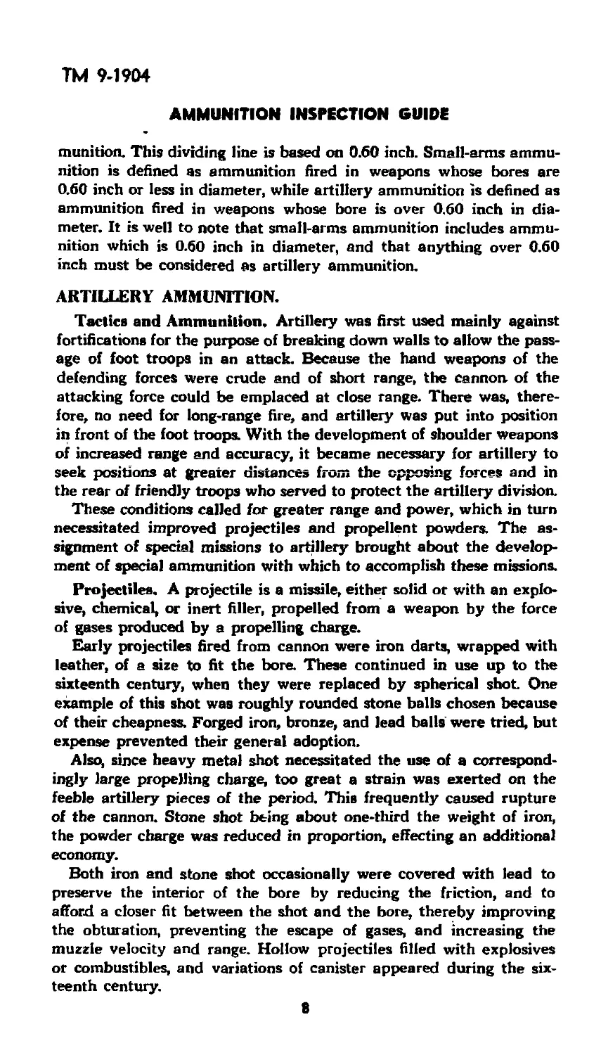
Rotating band. The purpose of the rotating band is tcf cause rota-
tion of the projectile about its axis, in order to give it stability in
flight. If the projectile did not rotate in flight, it would fly end over
end or tumble; its flight would be irregular and inaccurate, and the
range would be reduced. The rotating band, by engaging the lands
11
ТМ 9-1904
AMMUNITION INSPECTION GUIDE
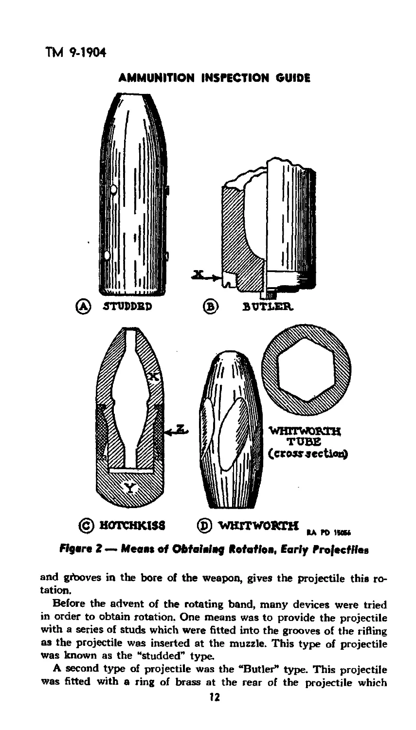
(c) HOTCHKISS © WHITWORTH
Flgtn 2 — Mean* of Obtaining Rotation, Early Projectiles
and giboves in the bore of the weapon, gives the projectile this ro-
tation.
Before the advent of the rotating band, many devices were tried
in order to obtain rotation, One means was to provide the projectile
with a series of studs which were fitted into the grooves of the rifling
as the projectile was inserted at the muzzle. This type of projectile
was known as the “studded” type.
A second type of projectile was the “Butler” type. This projectile
was fitted with a ring of brass at the rear of the projectile which
12
ТМ 9-1904
INTRODUCTION
would expand when acted upon by the pressure of the gases from
the propelling charge. This expansion caused the brass to fit into the
grooves of the rifling and thus gave rotation to the projectile.
Another early type of projectile was the “Hotchkiss” type. This
projectile was manufactured in three parts; the forward portion of
steel, a rear portion also of steel, and the two held apart by a lead
ring. When the round was fired, the rear portion forced against the
lead ring which expanded into the grooves and thus gave rotation
to the projectile.
A different method entirely was found in the “Whitworth” gun and
projectile. In this model, the weapon was fitted with a hexagonal bore,
twisted in the same manner as the rifling in the other types. The pro-
jectile was fashioned to fit the bore, its sides being provided with
flattened surfaces of a similar pattern.
With the introduction of breech-loading cannon, the problem of
giving rotation to the projectile was simplified. As previously ex-
plained, the raised portions between the grooves are known as the
IsncJs. The bourrelet of the projectile has the approximate diameter
of the lands. At the rear of the projectile is a smooth band of soft
metal which has the diameter of the grooves. The projectile is in-
serted into the smooth-surfaced chamber in the rear of the rifled
portion of the bore, and then is rammed forward. The grooves engage
the soft metal of the rotating band and hold the projectile in place
while the tube is elevated. On the explosion of the propelling charge,
the projectile moves forward and the lands cut into the rotating
band, causing it to conform to the rifling. This gives the projectile
a rotary motion about its long axis.
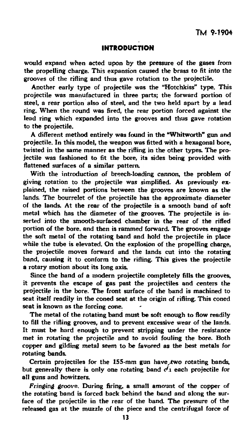
Since the hand of a modern projectile completely fills the grooves,
it prevents the escape of gas past the projectiles and centers the
projectile in the bore. The front surface of the band is machined to
seat itself readily in the coned seat at the origin of rifling. This coned
seat is known as the forcing cone.
The metal of the rotating band must be soft enough to flow readily
to fill the rifling grooves, and to prevent excessive wear of the lands.
It must be hard enough to prevent stripping under the resistance
met in rotating the projectile and to avoid fouling the bore. Both
copper and gilding metal seem to be favored as the best metals for
rotating bands.
Certain projectiles for the 155-mm gun have,-two rotating bands,
but generally there is only one rotating band each projectile for
all guns and howitzers.
Fringing groove. During firing, a small amount of the copper of
the rotating band is forced back behind the band and along the sur-
face of the projectile in the rear of the band. The pressure of the
released gas at the muzzle of the piece and the centrifugal force of
13
ТМ 9-1904
AMMUNITION INSPECTION GUIDE
rotation combine to throw out this excess metal in a radial direc-
tion, so that it becomes a fringe around the rear part of the band.
When this fringe is excessive and irregular, it builds up air resistance,
lessens the stability in flight, and causes decreased range and de-
creased accuracy. This fringing is eliminated to a great extent by
cutting a fringing groove around and in the rear of the band.
Boat-tail. In order to reduce the vacuum forming eddies at the
base of the projectile in flight, the base is tapered to an angle of
from 6 to 8 degrees. These vacuum eddies, if present, tend to hold
back the projectile and thus reduce the range.
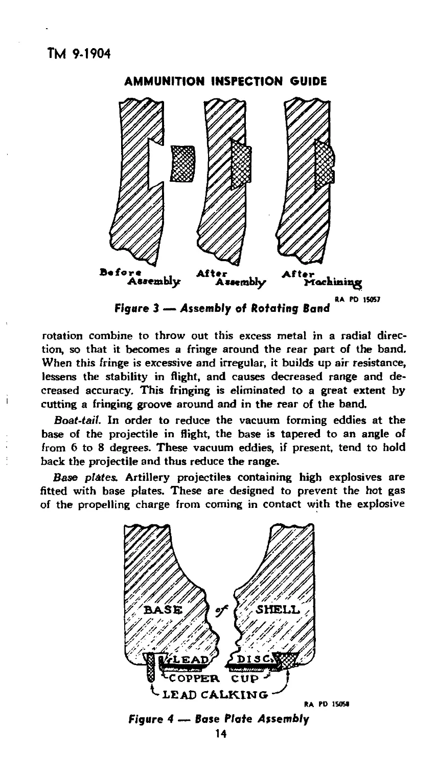
Base plates. Artillery projectiles containing high explosives are
fitted with base plates. These are designed to prevent the hot gas
of the propelling charge from coming in contact with the explosive
Figure 4 — Base Plate Assembly
14
ТМ 9-190*
INTRODUCTION
filler of the shell through possible defects in the base. Three types
of base plates are in use.
The older type, common to all calibers, consists of a slightly dished
brass plate covering a lead disc, the brass plate being crimped to
the base of the projectile.
The new type, for small and medium calibers, has a disc of sheet
brass or steel sweated to the base of the projectile with solder, or
a steel disc welded to the base of the projectile.
For the larger calibers, the base plate assembly consists of a
copper cup covering a lead disc. The copper cup is held in a dove-
tailed groove in the base of the projectile by means of a strip of
lead calking wire, which is hammered down to fill the groove com-
pletely and to bend the flange of the copper cup. However, in large
caliber projectiles that are not fitted with base fuzes, the steel disc
is welded to the base.
Painting. All projectiles are painted primarily for the prevention
of rust. The color of the paint, however, is varied for the different
types of projectiles and thereby becomes a basic means for identifi-
cation. The explanation of the color scheme is as follows:
1. Projectiles filled with high explosive, such as amatol, explosive
D, TNT, etc., are painted olive drab and stenciled in yellow.
2. Shrapnel and low-explosive shells are painted red. This indi-
cates that they contain a charge of low explosive.
3. Projectiles that are solid or filled with an inert filler are painted
black.
4. Ammunition to be used for practice is painted blue. This paint-
ing holds even though the projectile may be solid or filled with a
black powder (low-explosive) spotting charge.
5. Chemical shell are painted with a blue-gray base color, stenciled
with a color which corresponds to its chemical classification, and have
circumferential painted bands of the jame color.
Projectile Fillers.
Solid shot. The earliest projectiles were spheres of solid metal and
depended for their effect upon their weight and velocity, no attempt
being made to produce effect by explosion at the target
Case shot. The first departure from the solid type of projectile
came with the advent of case shot. Case shot can be traced back to
the early part of the fifteenth century; it retained, its original form
throughout the entire period of its use. It was intended for use at
close quarters when a volley of small shot was required.
Case shot consisted of a cylindrical container of tin with a cast
or sheet iron bottom and top plate. The container was filled with
small round shot and the voids were packed with sawdust to prevent
undue movement of the balls due to the shock of discharge. The
15
ТМ 9-1904
AMMUNITION INSPECTION GUIDE
shock of discharge disrupted the case, and the balls were scattered
shortly after leaving the muzzle of the cannon. Case shot was very
effective against troops at short range owing to the wide pattern
made by the spreading shot, but when the range exceeded 500 or 600
yards, there was practically no effect
Grapeshot. A variation of case shot, known as grapeshot, consisted
generally of three tiers of cast iron balls separated by iron plates and
held in place by an iron bolt which passed through the center of the
plates. The effect of grapeshot was similar to that produced by case
shot.
Explosive shell. Explosive shell do not appear to have been in gen-
eral use before the middle of the sixteenth century. About that time,
hollow balls of cast iron were fired from mortars. The balls were al-
most completely filled with gun powder; a small space was filled with
a slow-burning composition. The slow-burning composition was
ignited by the flash of discharge, and burned until the flame reached
the bursting charge. As there was no way of accurately regulating th'e
time of burning, some of the projectiles burst during flight, but many
of them did not explode until a considerable time after they had
struck the ground. With the development of more accurate fuzes,
these projectiles became formidable missiles against fortifications, and
were used with some effect against personnel in the open.
Modern shell, made of forged steel, are filled with high explosive,
and upon burning a predetermined time, or upon impact, explode
with terrific energy, breaking up the shell walls into several hundred
fragments. Depending upon the fuze employed, they are designed
either to burst in the air or promptly on impact, for effect against per-
sonnel, or to penetrate a short distance before explosion for the pur-
pose of destruction.
Armor-piercing. Armor-piercing projectiles consist essentially of a
steel shell to which is attached, usually by crimping, a steel armor-
piercing cap, and to this cap is attached, by screw threads or crimp-
ing, a windshield for ballistic purposes. The projectile may be either
filled with explosive D or may be inert A very important part of the
modern armor-piercing projectile is the cap. Against face-hardened
armor, projectiles which would be useless without the cap are, with
its assistance, able to penetrate in bursting condition. The cap is
made of high-carbon chrome steel and heat treated so that the por-
tion directly in front of the point of the projectile is very hard while
the skirt is very tough. The period during which the cap performs its
functions is so very short and the forces which act on it are so great
that it is impossible to say exactly what takes place, but certain
theories have been advanced and seem to be borne out by experi-
ment. It is now generally accepted that the principal function of the
cap is to place the armor under great stress, flaking the hardened
16
ТМ 9-1904
INTRODUCTION
surface and destroying it, permitting the projectile body to reach the
inner layers at an instant when they are already stressed in a favor-
able direction. The cap also lends lateral support to the point at the
'instant of impact, preventing a deformation which would result in
disintegration of the projectile before perforation could be accom-
plished.
The cap also performs the valuable function of increasing the angle
of obliquity at which penetration or perforation will take place, thus
tending to avoid ricochet
The function of the windshield is to increase the ballistic efficiency
of the projectile by enabling it to overcome more readily the retard-
ing effect of the atmosphere with a consequent increase in range. The
windshield is mf-de of brittle material and shatters on impact with
the target.
The steel shell, or body, finally does the actual penetrating of
the armour plate, and if loaded with an explosive filler, will explode
after penetrating.
THs shrs^ne! r'ro*sctil“ was сЗигзп** the tatter
part of the eighteenth century as a result of the lack of an effective
projectile for use against troops in the open beyond the range of case
shot
The original shrapnel was a spherical shell filled with lead musket
balls mixed with the bursting charge. With the advent of rifled guns,
the form of the shrapnel projectile has changed, but its character has
remained. Modern shrapnel cases are made of forged steel. The lead
balls are contained in a matrix of smoke-producing compound and
are separated from the base charge by a steel diaphragm. They are
provided with a time fuze designed to cause the projectile to burst
either during flight or on impact. Shrapnel is designed to carry the
balls to a point ov^r the heads of troops and, by the functioning of the
fuze and base charge, to scatter the balls with increased velocity
over a considerable area.
Chemical shell. Chemical shell are a development of World War I,
resulting from the desire to transfer quantities of chemicals into
enemy territory. Chemical projectiles are filled with chemical com-
pounds designed to produce casualties, or with smoke-producing
compositions for use in screening certain areas from view. Very little
effect is produced by fragmentation, since the bursting charge is just
sufficient to crack the projectile and scatter the chemical filler. In
firing chemical shell, it is important that the shell burst before enter-
ing the ground, in order that the chemical be spread instead of being
concentrated in and near the shell crater.
Fuzes.
Early luxes. A fuze is a mechanical device to function the projectile
ТМ 9-1904
AMMUNITION INSPECTION GUIDE
at the time or place desired. Proper functioning of projectiles depends
upon accurate and efficient fuzes.
It may be said that fuzes, from the start, have had more influence
on the effectiveness of artillery than any other single item. Early ex-
plosive shell and shrapnel, more often than not, were wholly ineffec-
tive because of uncertain fuzes.
Early fuzes not only were inaccurate and uncertain of action, but
also were dangerpus to use. Many accidents resulted from prematures
caused by defective fuzes. Even with the most modern fuzes in use
today, a certain percentage of duds may be expected, and the safety
devices are not infallible.
The first fuzes used were short iron or copper tubes filled with
slow-burning composition and screwed into the fuze hole of the shell.
The slow-burning composition was ignited by the flash of discharge
and, when consumed, transmitted the flame to the bursting charge of
the shell. There was, at first, no means of regulating the time of burn-
ing. Later, about the end of the seventeenth century, the fuze case
was made of wood, so that by boring a hole through the outer casing
into the composition, the fuze could be made to burn approximately
for a given time before exploding the shell; or the fuze could be cut
to the correct length for the same purpose.
Early attempts to produce percussion fuzes were unsuccessful, but
the discovery of mercury fulminate in 1799 finally afforded the means
of attaining this object. Some 50 years elapsed, however, before a
satisfactory fuze was made. This was the Pettman fuze, in which a
roughened ball covered with a detonating composition was released
by the discharge of the piece. When the shell struck any object, the
ball was thrown against the interior walls of the fuze, thereby explod-
ing the composition and, consequently, the bursting charge of the
shell.
World War I types. Much ingenuity and labor have been expended
in the effort to produce safe and accurate fuzes for all purposes.
World War I types were satisfactory, in general, for their purpose of
detonating or exploding the bursting charge at the time and under
the circumstances desired. However, safety devices were not suffi-
ciently refined to insure complete safety against premature action in
transportation and loading, and during travel through the bore of the
piece.
Another serious disadvantage of World War I types of detonating
fuzes was the fact that they could not be set at will for sunerquick
or delay action. This necessitated a supply of all three types in the
field.
Later types. Most of the disadvantages enumerated above have
been overcome in the recently developed fuzes. These are explained
in the chapters dealing with fuzes.
18
ТМ 9-1904
INTRODUCTION
Adapters and Boosters. Since the small detonator contained in
the fuze is not powerful enough to insure complete detonation of the
shell filler, it is necessary to have a slightly larger quantity of high
explosive, more sensitive than the shell filler, to amplify the detonat-
ing wave and insure the detonation of the filler. This intermediary
filler is the booster. In recent years, boosters have been designed to
be assembled directly to the projectile, the old “adapter-boosters”
being discarded. The fuze is customarily screwed into the booster.
Boosters are used in all high explosive and chemical shell for all guns
and howitzers.
The old “adapter-boosters” consisted of an adapter and a booster
which were held together as one piece. The adapter was designed
to decrease the diameter of the nose of the shell so that the fuze
could be screwed into place. The booster was simply a casing of
high explosive.
The term “bolster,” when applied to chemical shell, is converted
to “burster,” as the function of this component is to break up the,shell
and disperse the chemical filler. The burster charge is therefore
greater than in the high-explosive booster.
Propellants. A propellant is an explosive which, upon burning,
propels the projectile from the tube of the gun. It is the final link
in the low-explosive train.
Early propellants. The earliest propelling powder was black pow-
der, of about the same composition as we know it today. In the six-
teenth century, it was used in the form of a fine powder or dust, but
owing to the difficulty of loading this fine dust into the muzzle of
small arms, a granular form was developed about the year 1600, and
continiXd in use for more than 200 years.
Smokeless powder. Smokeless powder came into use about 1890,
and quickly replaced black powder as the universal propellant for
artillery projectiles.
The first Army Ordnance experiments with smokeless powder were
with nitrocellulose-nitroglycerine, or “double-base” powder, which
type was used in small-arms ammunition until 1906.
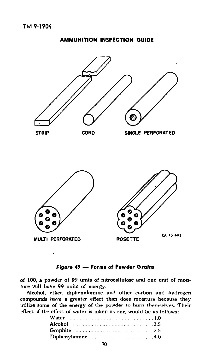
The smokeless powder now used consists essentially of a gelati-
nized nitrocellulose in the form of short multiperforated grains. The
United States and other countries have developed powders in the
form of long tubes or flat ribbons and cords which usually contain a
certain percentage of nitroglycerine.
Because of their hotter gases of combustion, nitroglycerine powders
produce more erosion in the bore of the piece than nitrocellulose.
For this reason, the latter are generally used as propellants.
A full discussion of smokeless powder will be found in the chapter
covering low explosives.
19
ТМ 9-1904
AMMUNITION INSPECTION GUIDE
Propellent Containers. According to the method of assembly for
transportation and for loading into the piece, ammunition is classified
as “fixed,” “semifixed” or “separate-loading” (unfixed).
Fixed Ammunition. This type comprises a cartridge case (which
contains the propellant) whose base contains the primer, and whose
forward opening is crimped to the projectile so that the entire round
is integral and all components are loaded into the weapon in one
operation.
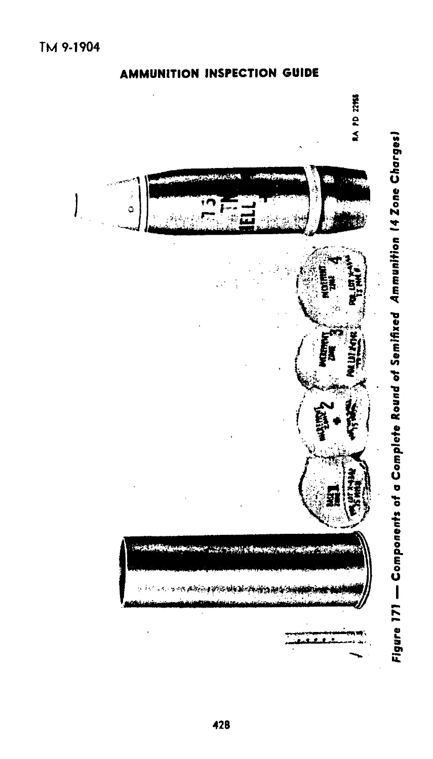
Semifixed Ammunition. This type differs from fixed ammunition
in that, while the projectile and cartridge case are issued assembled
and are loaded into the gun as a unit, the cartridge case is not per-
manently attached to the projectile, but may be removed at the fir-
ing point for the purpose of varying the amount of propelling charge
as desired.
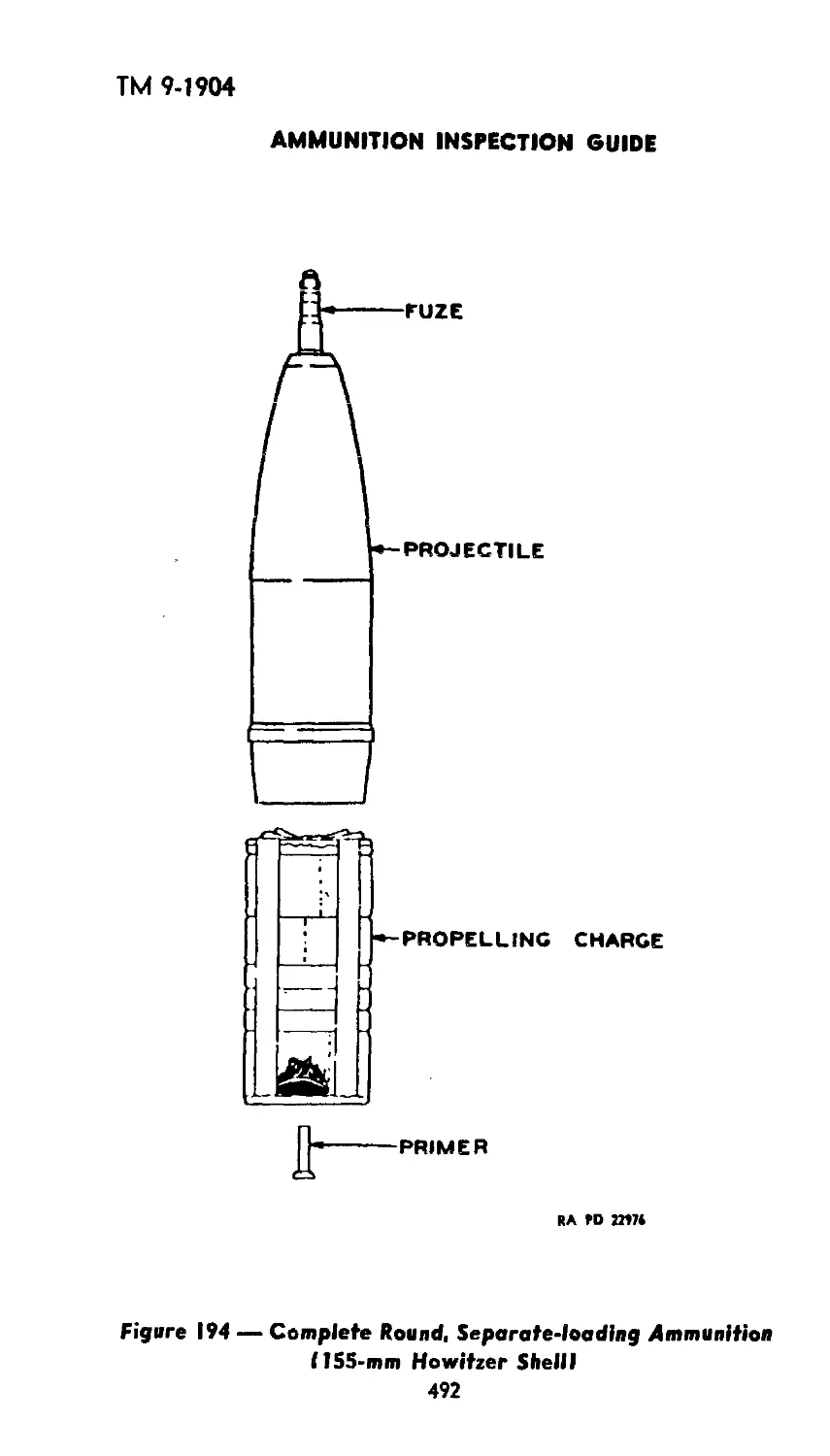
Separate-loading Ammunition. The distinguishing characteristic
of separate-loading ammunition is that it requires two or more opera-
tions to be loaded into the breech of the gun. The propellant and
primer are loaded separate from the projectile. The propellant is con-
tained in either cartridge bags in definite quantities, or loosely in an
uncrimped cartridge case. In the former instance, the amount of pro-
pelling charge may be varied as desired. The primer is generally
inserted after the breechblock has been closed.
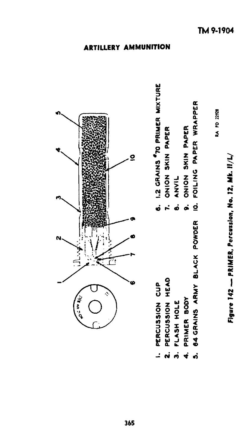
Primers. A primer is used to ignite the propelling charge of
smokeless powder. The primer is loaded with a charge of black pow-
der which, in ammunition for small calibers, is sufficient to ignite
the propelling charge. In the larger calibers, additional ignition pow-
der is required.
With fixed and semifixed ammunition, the primer is forced into the
base of the cartridge case before loading the propelling charge.
With bag-loaded (separate-loading) charges the primer is inserted
in the firing mechanism in the breech of the cannon. Primers for
separate-loading ammunition are of the obturating type, in that the
body of the primer is thin, so that, when the primer charge explodes,
the primer will be expanded and pressed tightly against the inner
surface of the primer cavity, thus preventing the escape of propelling
charge gases to the rear.
Classification The general classification of primers is based on the
method of firing or initiating the ignition, as follows; percussion, fric-
tion, electric, combination percussion-electric, and igniting. The de-
tailed description and functioning of these types will be taken up in
the chapters covering the complete rounds.
20
ТМ 9-1904
INTRODUCTION
Chapter 2
Safety
GENERAL.
In the line of duty as an ammunition inspector, the full meaning
of safety must he kept in mind at all times. This is indicated by the
fact that the “Ordnance Safety Manual” is the inspector’s “Bible."
No matter what the operation or procedure may be, the inspector’s
thought should always be, “Is it safe?”
There are several references where general safety regulations may
be found, such as. The Ordnance Safety Manual, Safety Bulletins,
TM 9-1900, and other manuals. However, while the regulations cover
a wide field, there are times when it becomes necessary for an inspec-
tor to rely on his own judgment and common sense in arriving at
a decision. For this reason, one should always keep an eye open for
safety features and precautions while studying this text. Without some
basic knowledge of the article being handled, common sense soon
becomes little more than pure guess work. A study of accidents which
have occurred in the handling, shipping, and storage of explosives and
ammunition shows that in practically every instance where the cause
could be determined, the accident has been due to circumstances
which may be classed as avoidable.
There are two prime requisites which must be considered when
determining a safe practice; safety for personnel, and safety for the
ammunition. With respect to personnel, the inspector should be con-
stantly on the alert to forestall any practice which might cause injury
or death to any worker. With respect to ammunition, the inspector
should see that it is handled, stored, and shipped in such a manner
that no deterioration, damage, or destruction may result.
SAFETY REGULATIONS.
Personnel. All personnel handling ammunition should be im-
pressed with the fact that their safety as well as that of others de-
pends upon the intelligence and care exercised by themselves and
their fellow workers.
The number of persons engaged in or around an operation should
be kept at a minimum, but never should one person be allowed to
carry on an operation of a hazardous nature.
Unauthorized persons should not be permitted to tamper with or
disassemble any components. Serious accidents may result.
Safety shoes should be worn at any operation where explosive dust
is present; particularly in the case of black powder or high-explosive
operations. Safety shoes of the noninsulating type are mandatory
for black powder operations.
21
ТМ 9-19
AMMUNITION INSPECTION GUIDE
Smoking must be absolutely prohibited in any magazine or maga-
zine area, or around freight cars, motor trucks, or boats in which
there are explosives or ammunition.
No portable lights other than approved electric lanterns and flash-
lights are to be used in magazines or around explosives and ammuni-
tion in freight cars, motor trucks, or boats.
Ammunition. Explosives and ammunition should be handled care-
fully. Containers should not be tumbled, dragged, thrown, or dropped
on each other or on the floor.
All tools used when repairing, opening, or closing containers filled
with explosives should be of nonferrous or nonsparking materials.
Explosives and ammunition should not be exposed to moisture or
dampness or to the direct rays of the sun for any long period. If it
is necessary to leave boxes temporarily outside of magazines or cars,
they should be covered with a tarpaulin which is so placed that air
can circulate freely through the pile.
If explosives spill or sift from a leaky container, all work must be
stopped until the explosives have been swept up and removed and
any remaining particles or dust have been neutralized with water.
When ammunition is to be stored, it must be stored in accord-
ance with the current ordnance drawings in such a way that the
piles are stable and cannot tip.
CONCLUSION.
The general precautions mer.tioned above are but an indication of
the many rules and regulations to be followed. As additional mate-
rial is discussed, safety regulations will be brought out and empha-
sized. In addition, every ammunition inspector should become fa-
miliar with the safety regulations as set forth in section II, page 5,
of the Ordnance Safety Manual (O.O. Form No. 7224), and should
govern his actions in the field accordingly. If all safety measures are
applied and strictly observed, the number of accidents which occur
can be reduced to a very small percentage of the present total.
22
ТМ 9-1904
SECTION II.
INTERPRETATION OF ORDNANCE DRAWINGS;
USE AND CARE OF MEASURING TOOLS
Chapter 1
Information Topics
GENERAL.
Engineering Drawings. Engineering drawings were developed to
portray an object of the inventor’s mind in such a way as to enable
someone other than himself to construct the item. Word descriptions
proved entirely inadequate. Chinese, the language of Confucius, who
said, “One picture is worth a thousand words” still uses line drawings
of objects as letters of its alphabet.
Photographs were considered, but dismissed at once, for the simple
reason that one cannot photograph what is in a person’s mind. Thus,
the only alternative was found to be line drawings. Through constant
use they underwent considerable development until in the present
day, carefully made line^lrawings, laid out according to certain sim-
ple, 'universally understood rules, act as our basis for transmitting
precise information between various phases of production. It is a
decided advantage, therefore, to anyone interested in almost any
phase of production to understand these simple rules that he might
be able to read the language of engineering drawings. Persons inter-
ested in the inspection and maintenance of manufactured items are
certainly not an exception.
Reproduction of Engineering Drawings. There are many means
of reproducing the original drawing. One of the most common is the
blueprint, so called because of its blue background which results from
a chemical action on exposure to light. It is made by exposing a
piece of sensitized paper in contact with the tracing of the drawing
to sunlight or electric light.
Other types of reproduction are blufe line prints (blue lines on a
white background), black line prints (black lines on a white back-
ground), and photostat prints. Photostats are commonly used in the
Ordnance Department and consist of white lines on a dark back-
ground when taken directly from the tracing; brown lines on a white
background when taken from the original photostat. They are made
by taking a picture of the draftman’s tracing with a large, specially
designed camera.
Why Ammunition Inspectors Should Understand the Language
of Mechanical Drawing. Some of the instances in which prints are
of value to the ammunition inspector are as follows:
1. The construction of the buildings in which ammunition com-
ponents are stored will show such factors as ventilation, floor load
limits, floor finishing, and lightning rod equipment. The lay-out of the
23
ТМ 9-1904
AMMUNITION INSPECTION GUIDE
F H
*A ГО is»»
Figere 6 — Wedge
24
ТМ 9-1904
INTERPRETATION OF ORDNANCE DRAWINGS;
USE AND CARE OF MEASURING TOOLS
area, described as a general map, is used to determine what explo-
sives and ammunition may be stored in a given magazine or building.
2. The approved methods of piling and stacking and the proper
use of dunnage in storing ammunition and explosives are shown on
ordnance drawings.
3. The loading and staying of explosives and ammunition for
various means of transportation is described on ordnance drawings.
Bureau of Explosives Pamphlets Nos. 6 and 6A are evidence of the
wide use of drawings since they show the loading and staying in
railroad cars.
4. Proper packing, stenciling, painting, and marking of ammuni-
tion components are illustrated with ordnance prints.
5. Ammunition components may be identified by looking through
drawings of that particular class of ammunition.
6. Prints may be used to determine items for inspection by ob-
serving how the component is assembled, the importance of each
part in the assembly, wha< explosive materials are contained, where
they are located, under what circumstances the explosive train might
be initiated and what parts are liable to damage due to rough han-
dling or deterioration.
7. Drawings are used as guides in breaking down assembled com-
ponents, such as fuzes, and in renovating and reconditioning ammuni-
tion and containers of ammunition components and explosives.
8. The ordnance drawings covering a particular component of
ammunition are statements of authority as to how that component
should be made, loaded, assembled, packed, marked, shipped, and
stored.
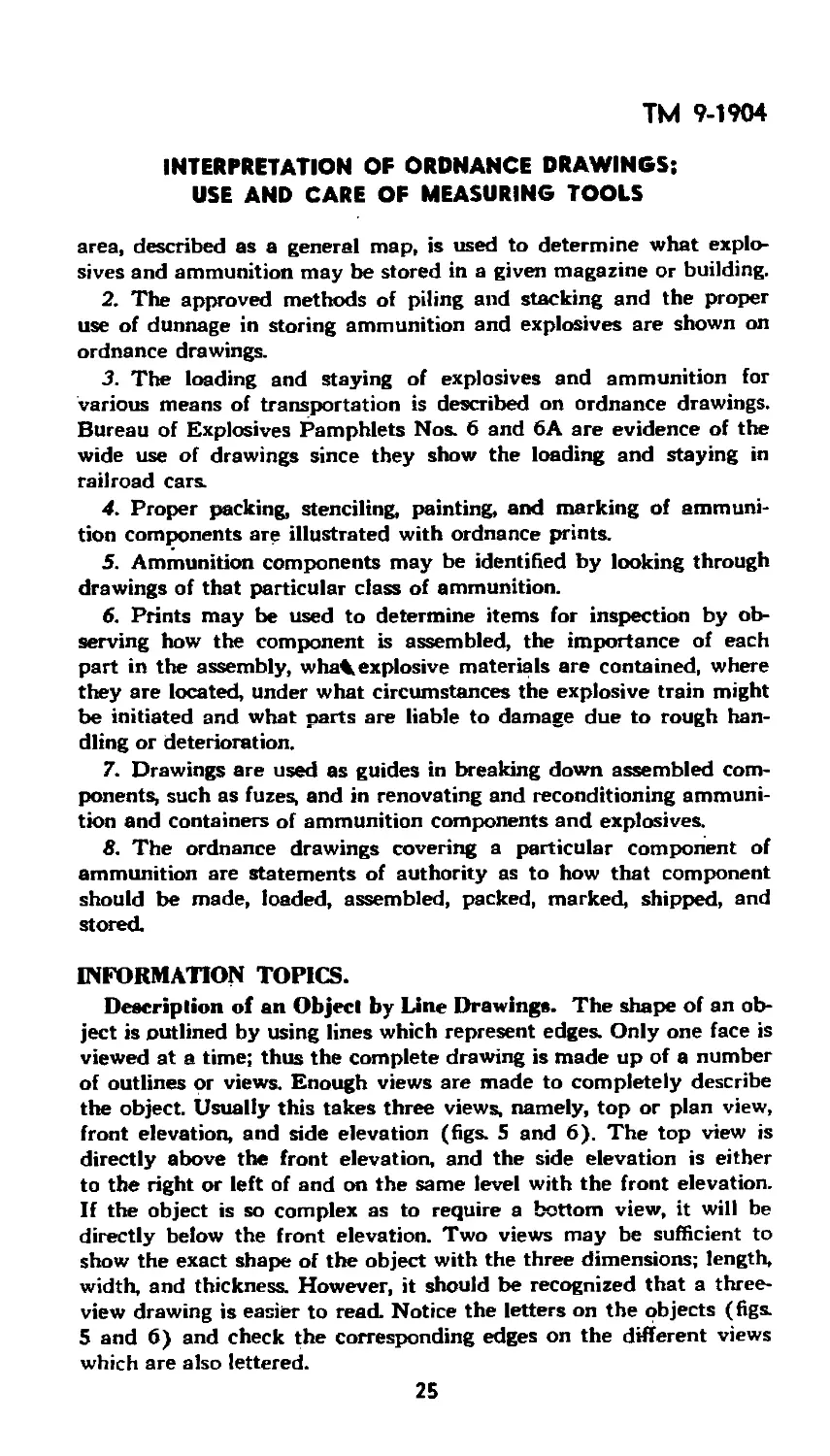
INFORMATION TOPICS.
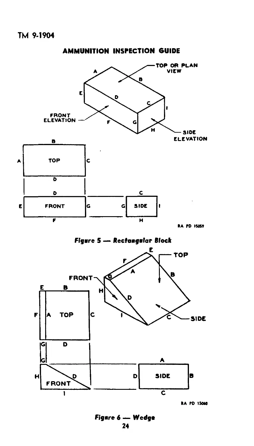
Description of an Object by Line Drawings. The shape of an ob-
ject is outlined by using lines which represent edges. Only one face is
viewed at a time; thus the complete drawing is made up of a number
of outlines or views. Enough views are made to completely describe
the object. Usually this takes three views, namely, top or plan view,
front elevation, and side elevation (figs. 5 and 6). The top view is
directly above the front elevation, and the side elevation is either
to the right or left of and on the same level with the front elevation.
If the object is so complex as to require a bottom view, it will be
directly below the front elevation. Two views may be sufficient to
show the exact shape of the object with the three dimensions; length,
width, and thickness. However, it should be recognized that a three-
view drawing is easier to read. Notice the letters on the objects (figs.
5 and 6) and check the corresponding edges on the different views
which are also lettered.
25
ТМ 9-19?
AMMUNITION INSPECTION GUIDE
Figure 1 — Tube
*A PO 1Ш1
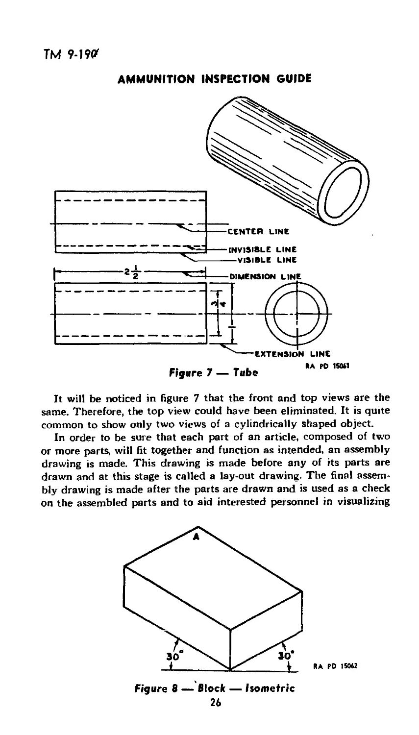
It will be noticed in figure 7 that the front and top views are the
same. Therefore, the top view could have been eliminated. It is quite
common to show only two views of a cylindrically shaped object.
In order to be sure that each part of an article, composed of two
or more parts, will fit together and function as intended, an assembly
drawing is made. This drawing is made before any of its parts are
drawn and at this stage is called a lay-out drawing. The final assem-
bly drawing is made after the parts are drawn and is used as a check
on the assembled parts and to aid interested personnel in visualizing
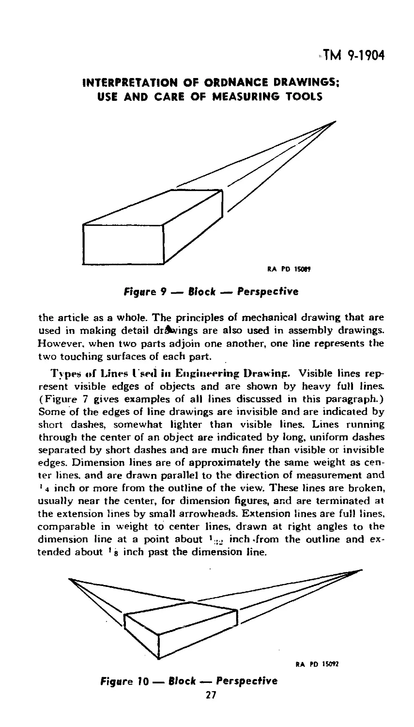
Figure 8 — Block — Isometric
26
ТМ 9-1904
INTERPRETATION OF ORDNANCE DRAWINGS;
USE AND CARE OF MEASURING TOOLS
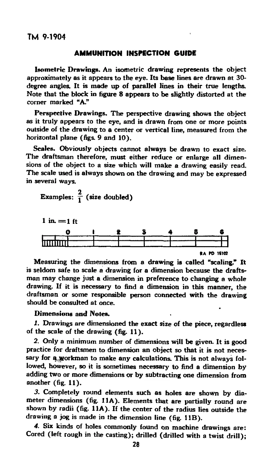
Figure 9 — Block — Perspective
the article as a whole. The principles of mechanical drawing that are
used in making detail drawings are also used in assembly drawings.
However, when two parts adjoin one another, one line represents the
two touching surfaces of each part.
Types of Lines I sed in Engineering Drawing. Visible lines rep-
resent visible edges of objects and are shown by heavy full lines.
(Figure 7 gives examples of all lines discussed in this paragraph.)
Some of the edges of line drawings are invisible and are indicated by
short dashes, somewhat lighter than visible lines. Lines running
through the center of an object are indicated by long, uniform dashes
separated by short dashes and are much finer than visible or invisible
edges. Dimension lines are of approximately the same weight as cen-
ter lines, and are drawn parallel to the direction of measurement and
1 4 inch or more from the outline of the view. These lines are broken,
usually near the center, for dimension figures, and are terminated at
the extension lines by small arrowheads. Extension lines are full lines,
comparable in weight to center lines, drawn at right angles to the
dimension line at a point about ’ inch .from the outline and ex-
tended about 1 g inch past the dimension line.
27
ТМ 9-1904
AMMUNITION INSPECTION GUIDE
Isometric Drawings. An isometric drawing represents the object
approximately as it appears to the eye. Its base lines are drawn at 30-
degree angles. It is made up of parallel lines in their true lengths.
Note that the block in figure 8 appears to be slightly distorted at the
corner marked “A.”
Perspective Drawings. The perspective drawing shows the object
as it truly appears to the eye, and is drawn from one or more points
outside of the drawing to a center or vertical line, measured from the
horizontal plane (figs. 9 and 10).
Scales. Obviously objects cannot always be drawn to exact size.
The draftsman therefore, must either reduce or enlarge all dimen-
sions of the object to a size which will make a drawing easily read.
The scale used is always shown on the drawing and may be expressed
in several ways.
2
Examples: у (size doubled)
1 in. =1 ft
0 i t 3 4 8 6
III " Г ............I— — I---------------------n
llllllllll
*a ro isim
Measuring the dimensions from a drawing is called “scaling.” It
is seldom safe to scale a drawing for a dimension because the drafts-
man may change just a dimension in preference to changing a whole
drawing. If it is necessary to find a dimension in this manner, the
draftsman or some responsible person connected with the drawing
should be consulted at once.
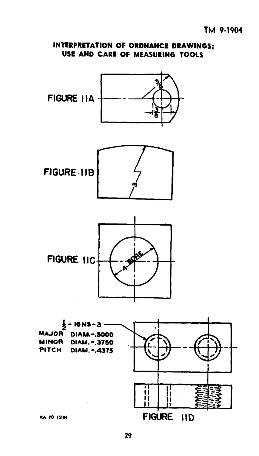
Dimensions and Noles.
1. Drawings are dimensioned the exact size of the piece, regardless
of the scale of the drawing (fig. 11).
2. Only a minimum number of dimensions will be given. It is good
practice for draftsmen to dimension an object so that it is not neces-
sary for алкогктап to make any calculations. This is not always fol-
lowed, however, so it is sometimes necessary to find a dimension by
adding two or more dimensions or by subtracting one dimension from
another (fig. 11).
3. Completely round elements such as holes are shown by dia-
meter dimensions (fig. 11 A). Elements that are partially round are
shown by radii (fig. 11 A). If the center of the radius lies outside the
drawing a jog is made in the dimension line (fig. 11B).
4. Six kinds of holes commonly found on machine drawings are:
Cored (left rough in the casting); drilled (drilled with a twist drill);
28
ТМ 9-1904
INTERPRETATION OF ORDNANCE DRAWINGS;
USE AND CARE OF MEASURING TOOLS
FIGURE IIA
FIGURE IIC
major
MINOR
PITCH
FIGURE I ID
ГО 1S104
29
ТМ 9-1904
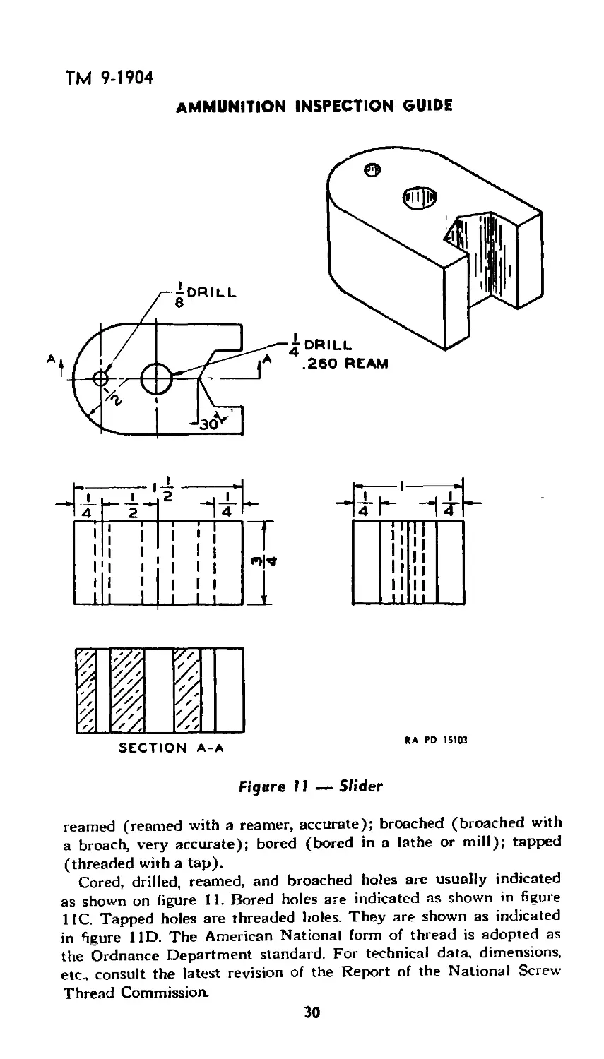
ammunition inspection guide
Figure 11 — Slider
reamed (reamed with a reamer, accurate); broached (broached with
a broach, very accurate); bored (bored in a lathe or mill); tapped
(threaded with a tap).
Cored, drilled, reamed, and broached holes are usually indicated
as shown on figure 11. Bored holes are indicated as shown in figure
11C. Tapped holes are threaded holes. They are shown as indicated
in figure 11D. The American National form of thread is adopted as
the Ordnance Department standard. For technical data, dimensions,
etc., consult the latest revision of the Report of the National Screw
Thread Commission.
30
ТМ 9-1904
INTERPRETATION OF ORDNANCE DRAWINGS*;
USE AND CARE OF MEASURING TOOLS
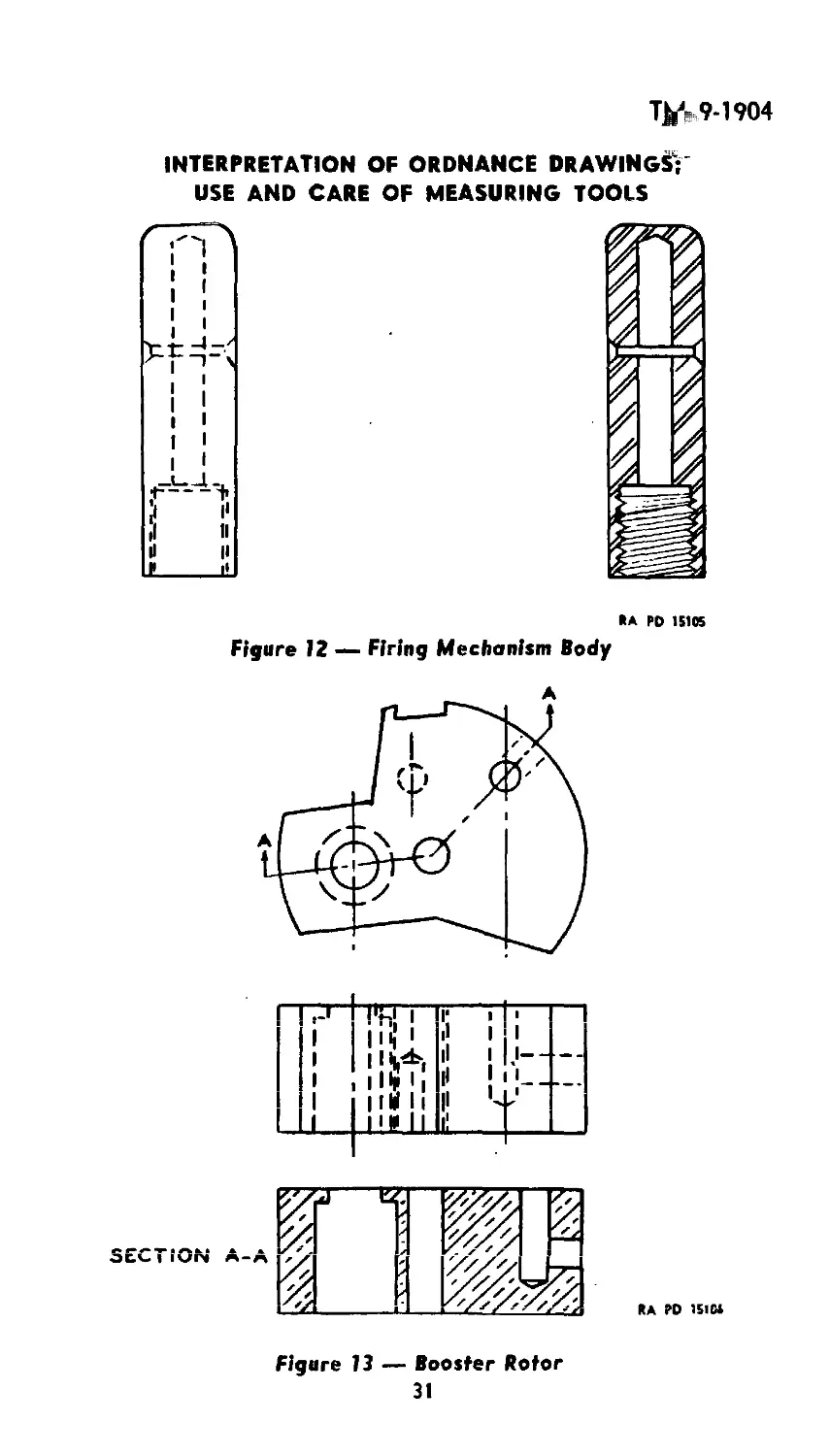
*A PO 15105
Figure 12 — Firing Mechanism Body
Figure 13 — Booster Rotor
31
IM 9-1904
AMMUNITION INSPECTION GUIDE
iron он area.,cast жяхнеоитяекяувтоа. гяягн сглгме^т.теп.
ALUMINvM.eTC. СОЛКЯСТГ INSULATION CLASS
сояк amatol. so^so /мсягглсея а саз
£со1мтяме Амятси.,аа-го кмт(яеиетселов9 black яоиоея
ргяояесилвссакразгпам нелсмущиямклте схяюз/ув'о тетягс.
еии сетта.ч
ти т (CAST)
^MOK-CL£.S3 яаыжи
тяните:
НВЕЯ
RA ГО 1S10
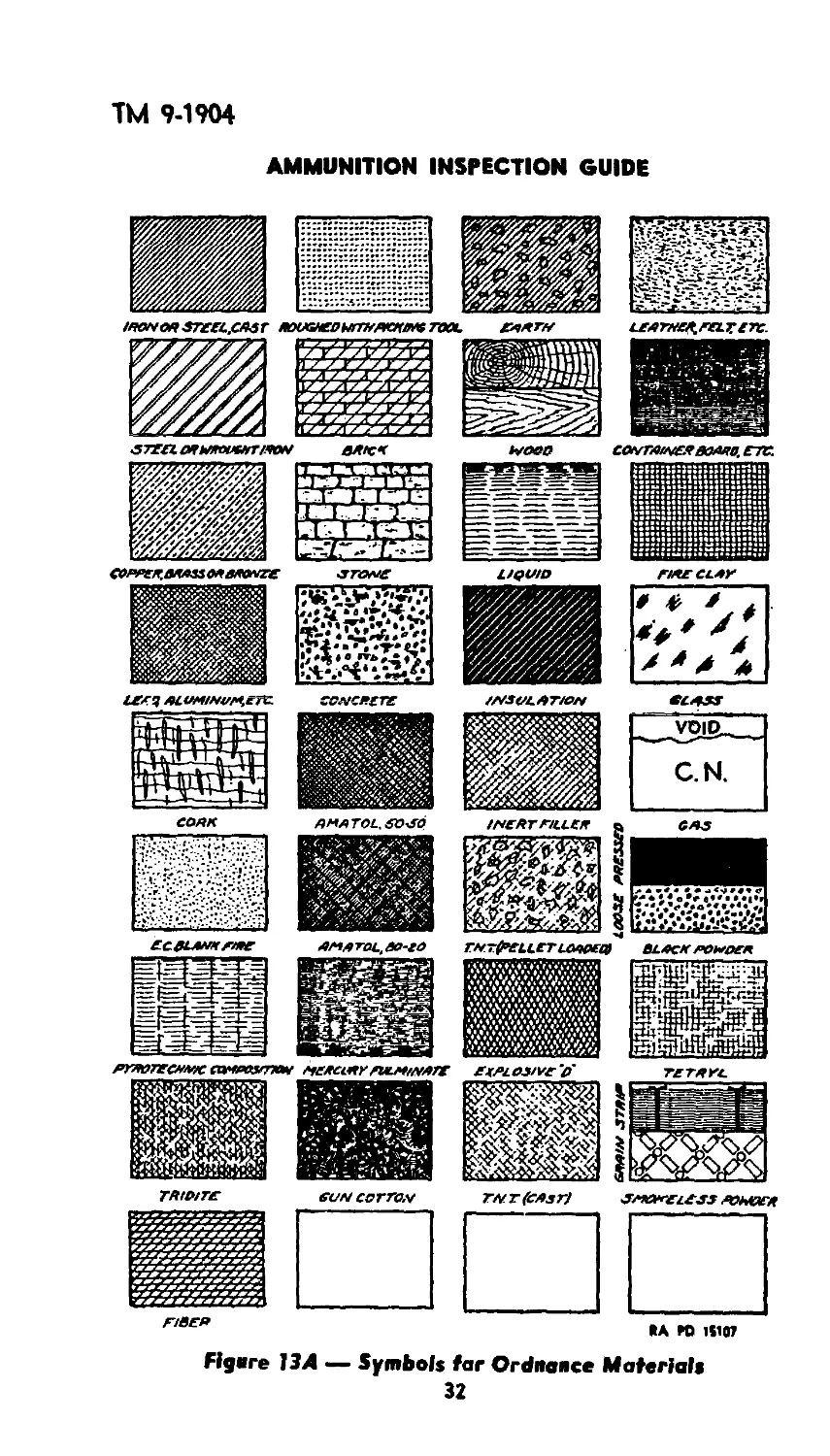
Figvre 13А — Symbols far Ordnaoce Materials
32
ТМ 9-1904
INTERPRETATION OF ORDNANCE DRAWINGS:
USE AND CARE OF MEASURING TOOLS
5. Where accuracy is required, decimal dimensions are used.
Sections. The purpose'of sectioning is to show the shape of cores,
thickness of stock, interior mechanisms, and assembly. When a com-
plex object is drawn, the number of invisible lines required may be-
come confusing (figs. 11, 12, and 13). The object may be considered
sawed in two on the plane indicated hy the section lines A-A (figs.
11 and 13), and only the parts cut by the saw are sectioned. The
sectioned parts are filled in with cross-hatching shown on “Symbols
for Ordnance Materials.” The section line may be passed through the
important parts of the Object it is desired to show, regardless of their
position (section A-A, fig. 13). Invisible lines, back of the cutting
plane, are not ordinarily shown in sectioning because their presence
might make the section confusing and thus defeat its purpose. Sections
taken through the width or diameter of objects are called cross sec-
tions, and those taken through the length are longitudinal sections.
Chapter 2
Reqelatioes Covering Ordnance Drawings
for Ammunition Division Materiel
GENERAL.
Classification, and Numbering.
Classification of drawings and model designations will be assigned
by the keeper of the standard nomenclature record. Serial numbers
of drawings will be assigned by the prints section.
All ammunition division tracings will be classified by giving each
article a class and division number, as C12, Div. 107; C122, Div. 47;
etc., and will be placed on “D” size sheets. The “D” size sheet is 40
by 24 inches.
Piece Marks. Each detail on every ordnance drawing will be given
a piece mark. On ammunition division tracings, piece marks shall
consist of the entire drawing number followed by a letter, viz., 73-3-
116A, and these piece marks shall be placed immediately following
and ordinarily on the same line with the name of the part. Piece
marks should be lettered beginning at the upper-left-hand comer of
the sheet across the top half, then the bottom half, from left to right.
In any quarter of the drawing, the same process shall be followed.
In case of one piece mark in the left half of the sheet, it shall be “A,”
then “B” upper right quarter, and “C” lower right quarter. In case
of one piece mark in the right half of the sheet it shall be “B,” and the
left quarter “A,” and the lower left quarter “C.” Liquid parts and
IR.inil) <> 52 3 33
ТМ 9-190-
AMMUNITION INSPECTION GUIDE
such articles as glue, shellac, solder, putty, wax, etc., shall not be
given piece marks.
Titles. On detail tracings, the title will consist of the name of the
component and under it the word “Details.” On tracings of assembled
views, the title of the article will be given followed by the word
“Assembly.”
Revision of Tracings. The revision number and date of revision
will be indicated in the revision block The piece mark of the part
will be followed by the same number as indicated in the revision
block; if part 115E is revised for the first time under the fourth re-
vision of drawing 73-3-115, the new piece mark would be 115E4.
KINDS OF DRAWINGS.
General. Drawings of ammunition division material show either
the details of the item or the assembly of items into more complete
articles.
A set of drawings for an item may consist of one or more of the
following series, including therein a list of parts, list of drawings,
list of specifications, and list of components, etc.: detail drawings;
component-assembly drawings; loading assembly drawings; complete-
round assembly drawings; marking drawings, or packing, and mark-
ing drawings; and illustration drawings.
The title of each tracing will indicate the information included
thereon, or as much thereof as is considered necessary.
The information to be placed on any one tracing and the arrange-
ment thereon will depend on the item under consideration. Some
tracings will contain only details; while others will contain details,
an assembly or assemblies, list of parts, etc.
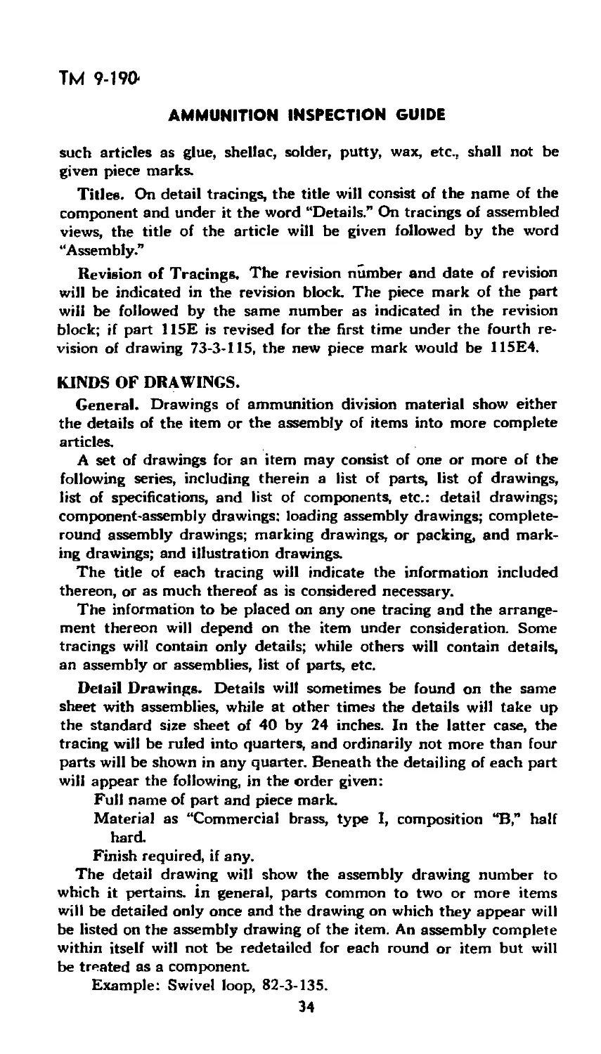
Detail Drawings. Details will sometimes be found on the same
sheet with assemblies, while at other times the details will take up
the standard size sheet of 40 by 24 inches. In the latter case, the
tracing will be ruled into quarters, and ordinarily not more than four
parts will be shown in any quarter. Beneath the detailing of each part
will appear the following, in the order given:
Full name of part and piece mark
Material as “Commercial brass, type I, composition “B,” half
hard.
Finish required, if any.
The detail drawing will show the assembly drawing number to
which it pertains, in general, parts common to two or more items
will be detailed only once and the drawing on which they appear will
be listed on the assembly drawing of the item. An assembly complete
within itself will not be redetailcd for each round or item but will
be treated as a component.
Example: Swivel loop, 82-3-135.
34
9-1904
INTERPRETATION OF ORDNANCE DRAWINGS;
USE AND CARE OF MEASURING TOOLS
All artillery ammunition should be drawn pointing to the right.
All bombs should be drawn pointing to the left.
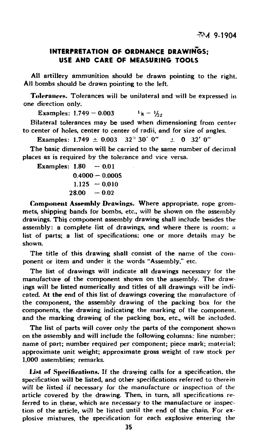
Tolerances. Tolerances will be unilateral and will be expressed in
one direction only.
Examples: 1.749 — 0.003 *'я —
Bilateral tolerances may be used when dimensioning from center
to center of holes, center to center of radii, and for size of angles.
Examples: 1.749 ± 0.003 32° 30' 0" ± 0 32' 0"
The basic dimension will be carried to the same number of decimal
places as is required by the tolerance and vice versa.
Examples: 1.80 — 0.01
0.4000 - 0.0005
1.125 -0.010
28.00 - 0.02
Component Assembly Drawings. Where appropriate, rope grom-
mets, shipping bands for bombs, etc., will be shown on the assembly
drawings. This component assembly drawing shall include besides the
assembly: a complete list of drawings, and where there is room; a
list of parts; a list of specifications; one or more details may be
shown.
The title of this drawing shall consist of the name of the com-
ponent or item and under it the words “Assembly," etc.
The list of drawings will indicate all drawings necessary for the
manufacture of the component shown on the assembly. The draw-
ings will be listed numerically and titles of all drawings will be indi-
cated. At the end of this list of drawings covering the manufacture of
the component, the assembly drawing of the packing box for the
components, the drawing indicating the marking of the component,
and the marking drawing of the packing box, etc., will be included.
The list of parts will cover only the parts of the component shown
on the assembly and will include the following columns: line number:
name of part; number required per component; piece mark; material;
approximate unit weight; approximate gross weight of raw stock per
1,000 assemblies; remarks.
List of Specifications. If the drawing calls for a specification, the
specification will be listed, and other specifications referred to therein
wili be listed if necessary for the manufacture or inspection of the
article covered by the drawing. Then, in turn, all specifications re-
ferred to in these, which are necessary to the manufacture or inspec-
tion of the article, will be listed until the end of the chain. For ex-
plosive mixtures, the specification for each explosive entering the
35
ТМ 9-1904
AMMUNITION INSPECTION GUIDE
mixture will be listed. The following statement will appear with each
list of specifications. “Specifications referred to in these specifications
and not listed hereon, shall not apply.”
Where space does not permit, the “List of parts” and “List of
specifications” should be placed on supplementary drawings bearing
the same number as the assembly drawing but followed by the letter
“A” on the drawing showing “List of specifications,” and by the letter
“B" on the drawing showing the “List of parts.” The “List of parts”
and “List of specifications” may be placed on one drawing bearing
the same number as the assembly drawing but followed by the letter
“A.” The title of the supplementary drawing shall consist of the com-
ponent and under it “Assembly,” “List of specifications,” etc.
Loading-assembly Drawings. Loading drawings will show the
loaded and assembled item ready for shipment by the loading plant.
In addition to an assembled view of the item loaded, a “List of parts,”
“List of specifications,” and a “List of drawings” will be included.
Complele-ronnd Assembly Drawing. Assembly drawings for all
fixed and semifixed ammunition (both fuzed and unfuzed complete
rounds), hand and rifle grenades shipped fuzed or unfuzed, and
pyrotechnics, should show the particular round or grenade in the
“as-issued” state before packing. This complete round drawing should
include, besides the assembly drawing, a list of components, etc. The
title should consist of its name and under it the words “Assembly,
etc.” Drawings showing bombs in the “as-shipped” condition will be
treated as loading drawings.
The “List of components, etc.” will include not only the main com-
ponent parts but such other materials as NRC compound, shell grease,
etc., used in assembling the round, as well as the packing box and
marking instructions. This list will have the following columns: line
number; name of component; drawing number or piece mark; specifi-
cation; approximate weight per unit assembly; approximate gross
weight per 1,000 assemblies; remarks.
Marking Drawings or Packing and Marking Drawings. Pack-
ing and marking drawings are made for all packing boxes, containers,
and crates. In addition to the proper marking for the box, container,
or crate, there will be placed on this drawing a “List of parts,” “List
of specifications," and a ‘“Table of weights” of the box plus the
contents.
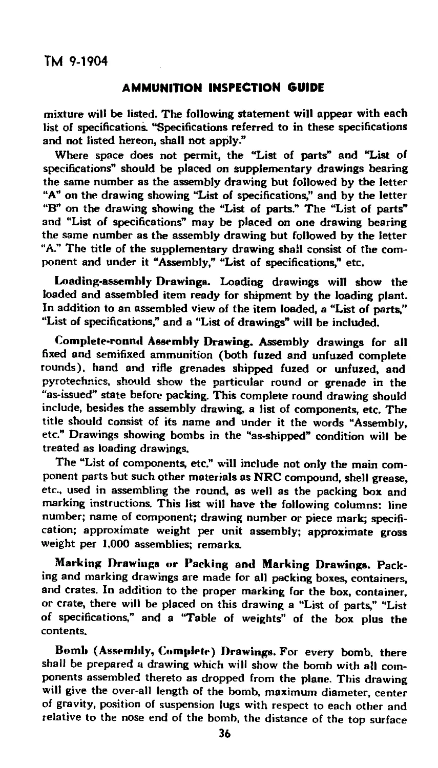
Bomb (Assembly, Complete) Drawings. For every bomb, there
shall be prepared a drawing which will show the bomb with all com-
ponents assembled thereto as dropped from the plane. This drawing
will give the over-all length of the bomb, maximum diameter, center
of gravity, position of suspension lugs with respect to each other and
relative to the nose end of the bomb, the distance of the top surface
36
ТМ 9-1904
INTERPRETATION OF ORDNANCE DRAWINGS:
USE AND CARE OF MEASURING TOOLS
of the suspension lugs from the outside of the bomb body, and the
maximum and minimum projected width of the fins. In the case of
small fragmentation, and chemical bombs, the distance of the leading
edge of the fin from the suspension lug will be given. A table listing
the components with approximate weights and assembly drawings
therefor will be shown. The drawings will bear the title “Bomb—
assembly, complete” and will be placed in class 82, division 0.
Illustration Drawings. For each caliber of separate-loading ammu-
nition an illustration drawing should show the complete round in the
gun chamber. For each round of fixed and semifixed ammunition
(except where covered by a complete round drawing) an illustration
drawing should show the complete round including fuze. These draw-
ings will indicate all important dimensions.
Other Drawings. There are other drawings used by renovation and
surveillance not included in the above such as for small-arms am-
munition and drawings for piling and stacking ammunition and ex-
plosives in magazines. However, if the inspector learns how to use
the drawings described herein, he should have little trouble in inter-
preting others because practically the same principles are involved.
Chapter 3
Use and Care of Measuring Tools
GENERAL.
The lives of troops and the accomplishment of their missions in
bringing a war to a successful close are dependent on the quality of
workmanship in their ammunition. For example, an imperfectly ma-
chined bourrelet on an artillery projectile will cause faulty ballistics
which will result in the loss of the shell’s effectiveness, and may en-
danger the lives of friendly troops.
Measuring tools are the inspector’s means of checking ammunition
components to insure that they are manufactured in such a way as to
fulfill their purpose. The ability of the ammunition inspector to per-
form his duties in seeing that ammunition is furnished in a condition
that will meet the requirements of the using arms is dependent, to a
great extent, upon his knowledge of the use and care of measuring
tools.
RULES.
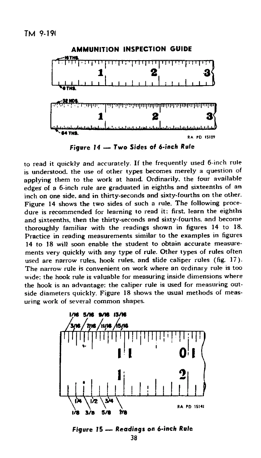
The simplest measuring device is the rule. The mechanic's 6-inch
flexible rule is most commonly used and the inspector should be able
37
ТМ 9-191
AMMUNITION INSPECTION GUIDE
RA RD 15109
Figure 14 — Two Sides of 6-inch Rule
to read it quickly and accurately. If the frequently used б-inch rule
is understood, the use of other types becomes merely a question of
applying them to the work at hand. Ordinarily, the four available
edges of a 6-inch rule are graduated in eighths and sixteenths of an
inch on one side, and in thirty-seconds and sixty-fourths on the other.
Figure 14 shows the two sides of such a rule. The following proce-
dure is recommended for learning to read it: first, learn the eighths
and sixteenths, then the thirty-seconds and sixty-fourths, and become
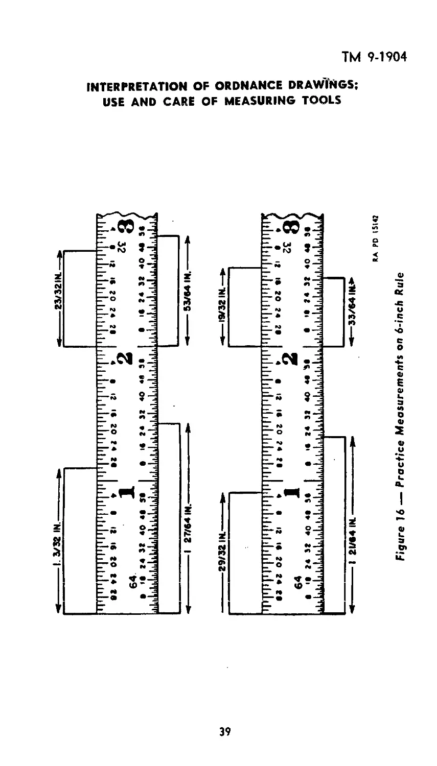
thoroughly familiar with the readings shown in figures 14 to 18.
Practice in reading measurements similar to the examples in figures
14 to 18 will soon enable the student to obtain accurate measure-
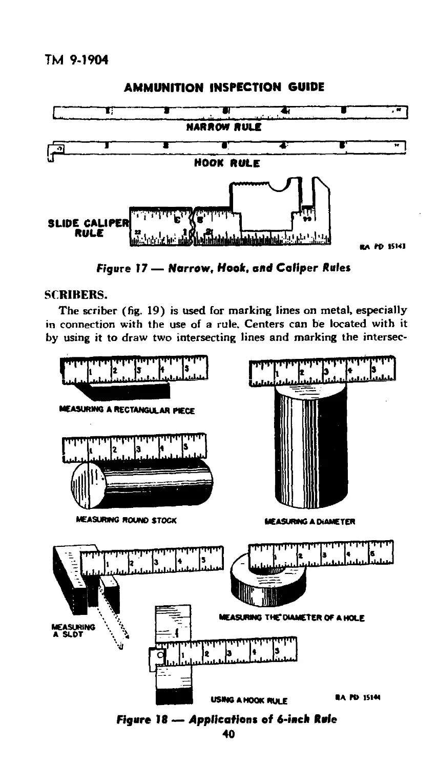
ments very quickly with any type of rule. Other types of rules often
used are narrow rules, hook rules, and slide caliper rules (fig. 17).
The narrow rule is convenient on work where an ordinary rule is too
wide: the hook rule is valuable for measuring inside dimensions where
the hook is an advantage: the caliper rule is used for measuring out-
side diameters quickly. Figure 18 shows the usual methods of meas-
uring work of several common shapes.
1/18 5/18 8Л6 13/18
1/8 3/B 5/8 fr8
Figure 15 — Readings on 6-inch Rule
38
о
O'
ajny ipui-9 uo sjueiuajnsoa^ 931430JJ — 91 ajnStj
j»isi ad va
INTERPRETATION OF ORDNANCE DRAWINGS;
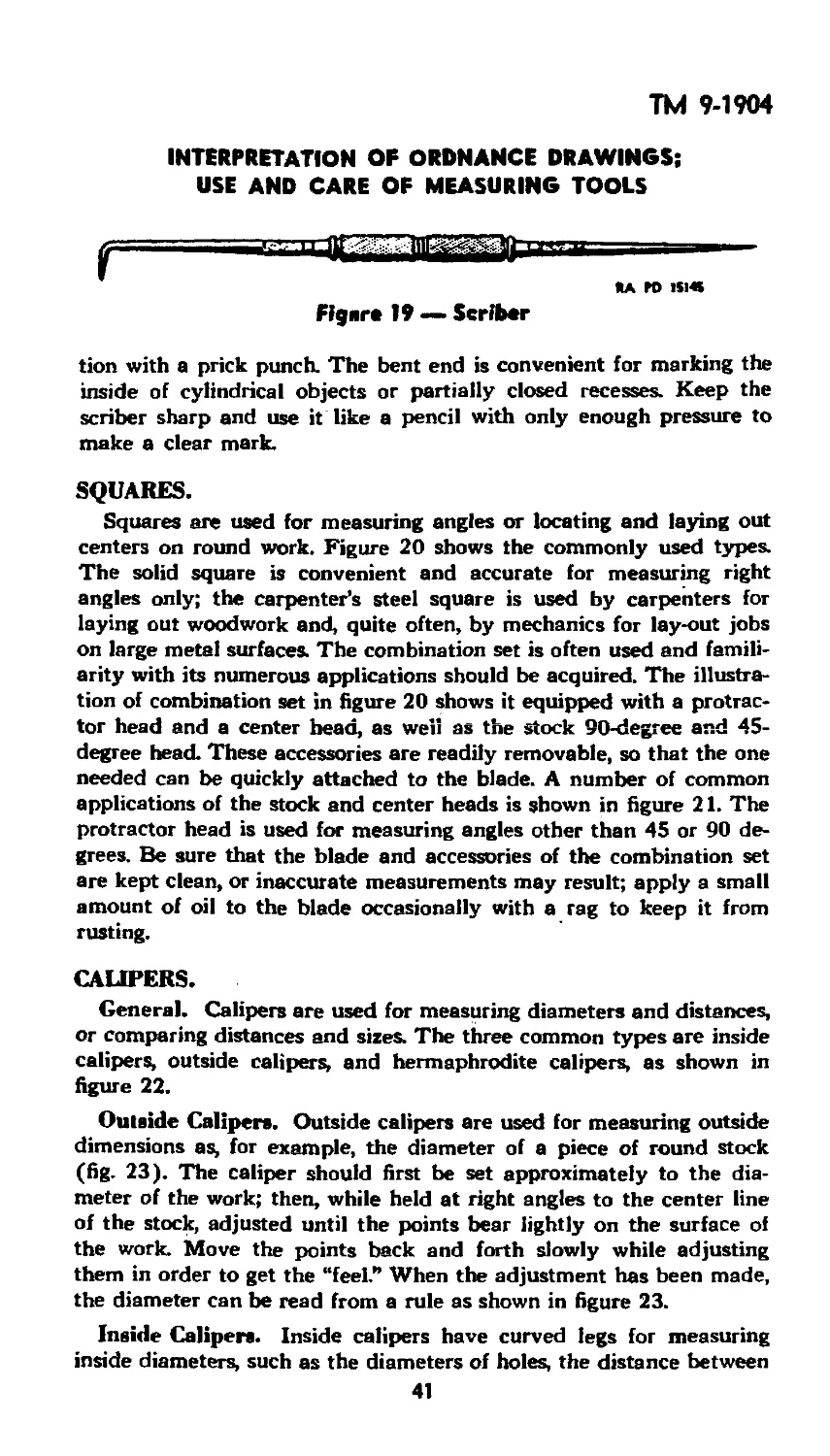
USE AND CARE OF MEASURING TOOLS
ц|>»лг i
rri'iTi’I'iTi'I'i'I'iyiTiYii'q'iT^i
*t •» о» к »г ti •
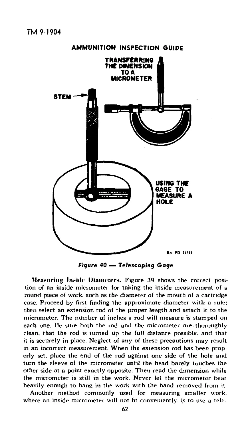
e 32 г т
4 ( it I* 20 24 22 4 • 12 I* 20 24 22 I 4 2 it l« 20 24 20
ll 11111 h 11111 tfl 1111 ll 1111 ll 11 1111111111 ll 111111 ll 111111111111 ill 1111111 ll 11 ll 1111 ll 11 i I ll 111
ТГ|’1Ц]|Г|'|'|Ч'Г1'|ЧЧЧЧМ'|1'|Т|Т|Ч,|'' ч11рт1|1^фЧ,|рГ|Г|т|уИ,||,|Т1|
'Ml 99/M
•ni гс/бг
Ml >9/2 г I
rrrfiTi'p’fi'p'n'p’i'i'p'ii'i'iTi'pTi' ^lTl|lTl^|T|'l'|T|^lpччYИЧI|,THl|1'T1п,ГI'T11l,TlT,VVTПЧlll|V,^
r »s •» o> гс >г <i 2 «с в» о» гс »г г в | и •» о» гс >г •• •
е м г
4 • 12 )* 20 24 22 4 • it I* 20 24 20 4 t 12 1в 20 24 2в
। lilil t li h li h lili li 11 h 11 li 11 ihLh lili li hill i 111 i lih lihlih lih lih li hlil 11 ill lili 111 i
99
*—’NIZE/EZ
NI 3£/E I
ТМ 9-1904
AMMUNITION INSPECTION GUIDE
Figure J7 — Narrow, Hook, and Caliper Rule»
SCRIBERS.
The scriber (fig. 19) is used for marking lines on metal, especially
in connection with the use of a rule. Centers can be located with it
by using it to draw two intersecting lines and marking the intersec-
MEASURING A RECTANGULAR PIECE
ММИИШИШМИЦ
MEASURMG A DIAMETER
MEASURING POUND STOCK
Figure 18 — Applications of 6-inch Rale
40
ТМ 9-1904
INTERPRETATION OF ORDNANCE DRAWINGS;
USE AND CARE OF MEASURING TOOLS
SA ГО 1S1«
Fij»r» 19 — Scriber
tion with a prick punch. The bent end is convenient for marking the
inside of cylindrical objects or partially closed recesses. Keep the
scriber sharp and use it like a pencil with only enough pressure to
make a clear mark.
SQUARES.
Squares are used for measuring angles or locating and laying out
centers on round work. Figure 20 shows the commonly used types.
The solid square is convenient and accurate for measuring right
angles only; the carpenter’s steel square is used by carpenters for
laying out woodwork and, quite often, by mechanics for lay-out jobs
on large metal surfaces. The combination set is often used and famili-
arity with its numerous applications should be acquired. The illustra-
tion of combination set in figure 20 shows it equipped with a protrac-
tor head and a center head, as well as the stock 90-degree and 45-
degree head. These accessories are readily removable, so that the one
needed can be quickly attached to the blade. A number of common
applications of the stock and center heads is shown in figure 21. The
protractor head is used for measuring angles other than 45 or 90 de-
grees. Be sure that the blade and accessories of the combination set
are kept clean, or inaccurate measurements may result; apply a small
amount of oil to the blade occasionally with a rag to keep it from
rusting.
CALIPERS.
General. Calipers are used for measuring diameters and distances,
or comparing distances and sizes. The three common types are inside
calipers, outside calipers, and hermaphrodite calipers, as shown in
figure 22.
Outside Calipers. Outside calipers are used for measuring outside
dimensions as, for example, the diameter of a piece of round stock
(fig. 23). The caliper should first be set approximately to the dia-
meter of the work; then, while held at right angles to the center line
of the stock, adjusted until the points bear lightly on the surface of
the work. Move the points back and forth slowly while adjusting
them in order to get the “feel.” When the adjustment has been made,
the diameter can be read from a rule as shown in figure 23.
Inside Calipers. Inside calipers have curved legs for measuring
inside diameters, such as the diameters of holes, the distance between
41
RA РО 15146
Figure 20 — Types of Squares
AMMUNITION INSPECTION GUIDE
г
4 9-1904
INTERPRETATION OF ORDNANCE DRAWINGS:
USE AND CARE OF MEASURING TOOLS
43
ТМ 9-1904
AMMUNITION INSPECTION GUIDE
FIRM JOINT SCREW ADJUSTING SPRING .OUTSIDE
FIRM JOINT SCREW SPRING INSIDE HERMAPHRODITE
ADJUSTING INSIDE CALIPERS CALIPERS
CALIPERS
RA РО 151M
Figure 22 — Calipers
44
ТМ 9-1904
INTERPRETATION OF ORDNANCE DRAWINGS;
USE AND CARE OF MEASURING TOOLS
Figure 23 — Measvrlvg Roeed Stock w/Oaf side Calipers
45
ТМ 9-19С
AMMUNITION INSPECTION GUIDE
Figure 24 — Measuring a Diameter w/Inside Calipers
46
ТМ 9-1904
INTERPRETATION OF ORDNANCE DRAWINGS;
USE AND CARE OF MEASURING TOOLS
sememe arcs settrm calikrs
RA PO 151 SI
Figure 25 — Three Uses of Hermaphrodite Colipers
two surfaces, the width of slots, and other similar jobs. To measure
the inside diameter of a hole with inside calipers, first set them
approximately to the size of the hole: then, holding one leg against
the wall of the hole, adjust the other leg until it just touches the
point exactly opposite, as shown in figure 24. The dimension can then
be determined with a rule or a micrometer as shown. With practice,
one can caliper a hole to an accuracy of one half-thousandth of an
RA PD 15151
Figure 26 — Dividers
47
ТМ 9-1904
AMMUNITION INSPECTION GUIDE
Figure 27 — Plug Gage and Ring Gage
Hermaphrodite Calipers. Hermaphrodite calipers are ^generally
used to scribe arcs, or as a marking gage in lay-out work, as shown in
figure 25. To adjust them to a rule, set the scriber leg slightly shorter
than the curved leg; then with the curved leg against the end of the
rule, adjust the scriber leg to the desired graduation on the rule.
Hermaphrodite calipers should not be used for precision measure-
ments.
DIVIDERS.
Dividers are tools for measuring distances between points, for
transferring distances directly from a rule, or for scribing circles or
parts of circles. Figure 26 shows a pair of dividers of a type com-
monly used. They are convenient for dividing spaces into equal parts
or determining the dimensions of irregularly shaped work. Keep the
*A ГО 151M
Figure 26 — Oafside Caliper I snap I Gage
48
ТМ 9-1904
INTERPRETATION OF ORDNANCE DRAWINGS;
USE AND CARE OF MEASURING TOOLS
points of dividers sharp, and use only enough pressure on them to
make a clear scribed mark on the work.
FIXED GAGES.
General. Gages are tools for measuring or transferring distances
or dimensions, usually within one one-thousandth of an inch or less.
They are made both adjustable and nonadjustable; this section deals
only with gages which are nonadjustable or fixed. A fixed gage is
made with extreme accuracy to some fixed standard of measurement
or shape, so that when it is applied to a piece of work, the standard
is transferred to the work. For example, if a mechanic wants to fix
two surfaces, say six-thousandths of an inch apart, he will adjust
them until a piece of metal tyown to be six-thousandths of an inch
thick will just fit between them. Such a piece of metal would be a
fixed gage. Fixed gages are generally made, either individually or in
sets of two or more, for some specific operation, or for transferring
some particular, measurement, such as gaging thickness, threads, diam-
eters, depths, and so on.
Types of Fixed Gages. A fixed gage can be obtained for prac-
tically any close measurement; thickness gages and screw thread
gages are examples of fixed or nonadjustable gages. Plug gages and
ring gages (fig. 27) are used in production work to check inside and
outside dimensions for size and to see that finished parts are within
the manufacturing tolerance. (Tolerance is the allowable variation in a
dimension that is permissible without rejection of the finished part
when inspected.) Fixed gages are usually made in pairs, either in one
piece or two units. For instance, a plug gage generally has a “go”
end, and a “no go” end. If the “go" end of such a gage will enter a
finished hole and the “no go” will not, the hole is within the tolerance
for which the gage was designed. If the “go” end of the gage will
not enter the hole, the hole is too small. If the “no go” end of the
gage, being slightly larger than the “go” end, does enter the hole,
the hole is too large. Plug gages are used by the ammunition inspec-
tor for such purposes as checking the mouths of cartridge cases, size
of primer holes, and so on. Plug thread gages and ring thread gages,
are similar, except that they are threaded to check the accuracy of
inside or outside threads. Outside caliper or snap gages (fig. 28), also
used almost exclusively in production work, are for checking the
dimensions of round or fiat surfaced pieces; inside caliper gages (not
illustrated) are used much as a plug gage for checking inside dimen-
sions. The profile and alinement gage simulates the chamber of an
artillery weapon and is used for gaging assembled artillery rounds
to insure their fitting properly into the weapon. Flush pin gages are
often used for measuring depths of booster cavities, etc.
49
‘IH5II I IS 11
4
ТМ 9-190'
The flush pin gage consists of a pin which runs through a body
as illustrated in figure 30. The upper surface of the body is divided
into two parts, A and B. The opposite surface of the body rests on
the top of the cavity whose depth is to be measured. When the top
of the pin is flush with surface A, the other end of the pin is 3.61
inches from the lower part of the body or the top of the cavity.
When the top of the pin is flush with surface B, this distance is 3.58
inches. Thus, if the depth of the cavity is to fall within the tolerance
of 0.03 inch (3.61 — 3.58 --- 0.03 inch), the pin must either be flush
with surfaces A or B, or be between the two surfaces. In using the tool,
*a ro IMS*
Figure 30 — Flush Piu Gage
50
’М 9-1904
INTERPRETATION OF ORDNANCE DRAWINGS;
USE AND CARE OF MEASURING TOOLS
Figure 31 — Outside Micrometer — Sectional View
51
ТМ 9-1904
AMMUNITION INSPECTION GUIDE
Common Types of Micrometers
I
52
ТМ 9-1904
INTERPRETATION OF ORDNANCE DRAWINGS;
USE AND CARE OF MEASURING TOOLS
insert it into the cavity and check with the thumbnail for the proper
position of the top of the pin.
Using Fixed Gages. All fixed gages are made for measuring some
specific dimension. Handle them carefully; any strain imposed on
them by forcing them over or into a piece of work or by dropping
them can distort them enough to spoil their accuracy. See that their
measuring surfaces, as well as the surfaces of the work, are clean
and smooth; do not, under any circumstances, force a gage on any
job. They are instrqments of extreme precision; check them peri-
odically with some standard to make sure that they have not changed
in size because of wear or damage.
MICROMETER CALIPERS.
General. The micrometer is the most commonly used adjustable
gage, and it is important that the inspector understand its mechanical
principles, construction, use, and care. Figure 31 shows a 1-inch out-
side micrometer caliper with the various parts clearly indicated. Be-
fore making any attempt to use the tool, the user should become
familiar with its nomenclature, especially the frame, anvil, spindle;
barrel (or sleeve), screw, and thimble. Micrometers are generally in-
tended to measure distances to one ten-thousandth of an inch; the
measurement is usually expressed or written as a decimal, so the
user should also know the method of writing and reading decimals.
Decimals. The decimal system is a method of expressing fractions
and mixed numbers. For example, 2.000 inches written decimally in-
dicates exactly 2 inches, accurate to within one-thousandth of an
inch.
All figures to the left of the decimal point are whole numbers; all
figures to the right of it indicate parts of whole numbers. Starting
from the decimal point and moving to the right, the first digit indi-
cates tenths; second, hundredths; third, thousandths; fourth, ten-
thousandths; and so on. Thus, 2.3 is read two and three-tenths; 1.85
is read one and eighty-five hundredths; 4.071 is read four and seventy-
one thousandths; 0.2318 is read twenty-three hundred eighteen ten-
thousandths. (When there is no number to the left of the decimal
point, the quantity indicated is less than one.)
Types of Micrometers. Three types of micrometers are com-
monly used: the outside micrometer, the inside micrometer, and the
depth micrometer (fig. 32). The outside micrometer is used for
measuring outside dimensions, such as the diameter of a piece of
round stock. The screw thread micrometer is used to determine the
pitch diameter of screws (fig. 32). The inside micrometer is used for
measuring inside dimensions, as, for example, the inside diameter of
53
ТМ 9-1904
AMMUNITION INSPECTION GUIDE
a tube or hole, or the width of a recess. The depth micrometer is used
for measuring the depth of holes or recesses.
Selecting Micrometers. All three types of micrometers are usually
made so that the longest movement possible between the spindle and
the anvil is 1 inch. This movement is called the “range.” The frames
of micrometers, however, are available in a wide variety of sizes, froip
1 inch up to as large as 24 inches for special work. The range of the
1-inch micrometer is from 0 to 1 inch; in other words, it can be
used on work where the part to be measured (between the spindle
and the anvil) is 1 inch or less. The 2-inch micrometer has a range
from 1 inch to 2 inches, and will measure only work between 1 and 2
inches thick; a б-inch micrometer has a range from 5 to 6 inches, and
will measure only work between 5 and 6 inches thick. It is necessary,
therefore, that a person, in selecting a micrometer, first find the ap-
proximate size of the work to the nearest inch, and then select a
micrometer that will fit it. For example, to find the exact diameter
of a piece of round stock; if it is found, by using a rule, that the dia-
meter is approximately 5 % inches, a micrometer with a 5- to 6-inch
range would be required to measure the exact diameter. Similarly,
with inside and depth micrometers, rods of suitable lengths must be
fitted into the tool to reach the desired dimension within an inch,
after which the exact measurement is read by turning the thimble.
The size of a micrometer is sometimes given as the size of the largest
work it will measure and sometimes as its range.
Mechanics of Micrometer. The micrometer actually records the
endwise travel of a screw during a whole turn or any part of a turn.
The micrometer screw.has a pitch of 40 threads to the inch; in other
words, if the screw is turned 40 times, it will move the spindle ex-
actly 1 inch either toward or away from the anvil. A clockwise turn
moves the spindle toward the anvil: a counterclockwise turn moves
the spindle away from the anvil. Therefore, by simple arithmetic, it
is plain that a single turn of the screw moves the thimble %0 or
0.025 of an inch (1.000 inch divided by 40 equals 0.025 inch).
READING MICROMETERS.
Thimble and Barrel Graduations. Remember that, if the sleeve
of the micrometer is turned through one complete revolution, the
micrometer opens or closes 0.025 inch. Hence, to change the opening
0.001 inch, the thimble should be turned to only one'twenty-fifth of
a revolution. To divide the inch into 1,000 parts by using the micro-
meter, therefore, the problem involved is to. count the number of
complete revolutions, plus any part of a revolution in twenty-fifths,
that the sleeve makes to set the spindle and anvil exactly against the
work being measured. For this purpose, the barrel and thimble of all
micrometers are marked as shown in figure 33. The revolution line
54
ТМ 9-1904
INTERPRETATION OF ORDNANCE DRAWINGS;
USE AND CARE OF MEASURING TOOLS
RA RD 1515»
Figure 33 — Graduations of Micrometer
on the barrel should be understood first. It is graduated in lines 0.025
inch apart, so that each complete revolution of the thimble moves
it exactly 0.025 inch along the barrel, or from one graduation to the
next. Two complete revolutions move the thimble 0.050 inch, three
revolutions 0.075 inch, and four revolutions 0.100 inch (’/,0 inch).
The numbers at every fourth graduation on the revolution line in-
dicate, therefore, tenths of an inch (4 x 0.025 inch equals 0.100
inch). Assuming, for exampie, that the micrometer is closed and the
screw is turned counterclockwise through four revolutions, the edge
of the thimble would exactly coincide with the fourth graduation on
the revolution line (marked 1) and the micrometer would be opened
inch. If the edge of the thimble coincides with the next gradua-
tion on the barrel, five revolutions would have been made so the
micrometer would be opened 0.125 inch (0.100 inch plus 0.025 inch).
The graduations on the barrel are numbered from 0 to 10. The user
should become thoroughly familiar with them before considering the
graduations on the thimble.
The graduations on the barrel of the micrometer, as explained
above, divide the inch into parts of twenty-five thousandths each; the
graduations on the thimble further divide the inch into single thou-
sandths, by indicating each twenty-fifth of a revolution of the thimble
55
ТМ 9-1904
AMMUNITION INSPECTION GUIDE
(complete revolution moves the thimble 0.025 inch which, when
divided by 25, gives 0.001 inch). When the micrometer is closed,
the edge of the thimble will coincide with 0 on the barrel, and 0 on
the thimble will also coincide with the revolution line. As the thimble
is turned, each time a graduation on the thimble passes the revolution
line on the barrel, the micrometer opens 0.001 inch.
Procedure in Reading. With practice the inspector can read a
micrometer correctly at a glance; however, in learning to do so, the
following procedure is recommended; using pencil and paper, find
the largest number on the revolution line between 0 and the edge of
the thimble. Use the middle reading in figure 33 as an example; this
figure is 2. Write it as 0.200 inch. Then add it to the number of un-
marked graduations between this figure and the edge of the thimble,
which in the example being used is 1, or 0.025 inch. Write this down
under 0.200 inch, already written. At this point, if the 0 graduation
on the thimble coincided with the revolution line, the reading would
be complete, as follows:
0.200
0.025
0.225 inch, final reading
However, the 0 graduation on the thimble and the revolution line do
not coincide, so it is necessary that the number of graduations be-
tween the 0 on the thimble and the revolution line be added to the
0.225-inch reading. In this example, there is one such graduation.
Write this as 0.001 inch, and the complete addition is as follows:
0.200
0.025
0.001
0.226 inch, final reading
Therefore, in the example being used, the micrometer is open 0.226
inch. Using a similar procedure with the top reading in figure 33
the result works out as follows:
0300 (largest number on revolution line between 0 and edge of
thimble)
0.000 (number of unmarked graduations between this and edge
of thimble)
0.004 (number of graduations on the thimble between 0 and the
revolution line)
0304 inch, final reading
Use the same procedure again with the bottom reading in figure 33.
If the reading is taken correctly, the final answer will be 0.224. It
should be noticed particularly in this last example, that the edge of
the thimble appears to coincide with the 0.025 graduation on the bar-
rel; but if this weie true, the 0 line on the thimble would coincide
56
ТМ 9-1904
INTERPRETATION OF ORDNANCE DRAWINGS;
USE AND CARE OF MEASURING TOOLS
*A ГО 1ЯМ
Flfen 34 — Varaler Scale
with the revolution line, which it does not do. In other words, unless
the 0 graduation on the thimble coincides with the revolution line,
the third figure of the final reading cannot be 0.
THE VERNIER SCALE.
General. Operations are sometimes encountered where measure-
ments in thousandths of an inch are not accurate enough. Most mi-
crometers have a vernier scale on the barrel for reading measure-
ments in ten-thousandths; no person should attempt to use this scale,
however, until ne has thoroughly mastered the reading in thousandths.
The fundamental idea behind the vernier scale is to divide a line
of known length into equal parts, and to compare the length of those
parts with those on a line the same length as the first one, but divided
into one less part. Figure 34 shows the bar divided into 25 parts
which would correspond to the divisions on a thimble of a micrometer
caliper; each division represents 0.001 inch. The vernier scale is di-
vided into ten parts and is exactly the same length as nine divisions
on the bar. Consequently, each division on the vernier must be 0.0001
inch (0.001 -r- 10 = 0.0001) smaller than the division on the bar in
order to make ten divisions on the vernier equal nine divisions on
the bar. In figure 34, 0 on the vernier coincides with 0 on the bar;
the next graduation to the right on both vernier and bar will be
0.0001 inch apart; the second pair 0.0002 inch apart, and so on, until
the graduations coincide again at 10 on the vernier. If the bar is
moved so that its first division corresponds with the first division
on the vernier, the zeros on vernier and bar will be 0.0001 inch apart.
If the second divisions are made to coincide, the zeros will be 0.0002
inch apart, and so on. Thus, the number of the line on the vernier
that coincides with a line on the bar will give the fractional reading
of a division on the bar.
57
ТМ 9-1904
Figure 35 — Vernier Scale Applied to Micrometer
Vernier Scale Applied Io Micrometer. Figure 35 shows how this
principle is applied to the micrometer. The vernier consists of ten
divisions marked on the barrel which equal in over-all dimension,
nine divisions on the thimble. To obtain a correct reading in ten-
thousandths in the example in figure 35. first find the reading in
thousandths by the method described above, which in this case would
give:
0.300 (largest number on revolution line between 0 and edge
of thimble)
0.050 (number of unmarked graduations on the barrel between
3 and edge of thimble)
0.019 (number of graduations on the thimble between 0 and the
revolution line)
0.369 inch, final reading
Now to read the vernier, find the vernier scale graduation that coin-
cides with a graduation on the thimble. In this example, the figure is
5. Write this as 0.0005 inch, and add this to the reading in thou-
sandths already obtained, and the result is:
0.369 (reading in thousandths)
0.0005 (vernier reading)
0.3695 inch, final reading in ten-thousandths
Figure 36 shows two further examples of the vernier scale applied
to the micrometer. Following the procedure previously outlined, the
example on the left is read thus:
58
ТМ 9-1904
INTERPRETATION OF ORDNANCE DRAWINGS;
USE AND CARE OF MEASURING TOOLS
CORRECT READING 0.4690 INCH. CORRECT READING 0.469T INCH.
RA RD 151*2
Figure 36 — Practice Readings of Vernier Micrometer
0.4000 (largest number on revolution line between 0 and edge
of thimble)
0.0500 (number of unmarked graduations on barrel between 4 and
edge of thimble)
0.0190 (number of graduations on thimble between 0 and revolu-
tion line)
0.0000 (number on vernier scale which coincides with a gradua-
tion on thimble)
0.4690 inch, final reading in ten-thousandths
Use the same method on the example on the right in figure 36. If
the reading is taken correctly, the answer is 0.4697 inch.
Alternative Method for Reading Micrometer. A method of read-
ing the micrometer may be defined in a few simple steps as follows:
1. Count the number of divisions on the revolution line between 0
and the edge of the thimble.
2. Multiply the above number by 0.025 inch.
3. Count the number of graduations on the thimble between 0
and the revolution line.
4, Multiply the above number by 0.025 inch.
5. Find the number of the line on the vernier scale that coincides
with a division on the thimble.
6. Multiply the coinciding vernier scale line number by 0.0001
inch.
7. Add results of steps 2, 4. and 6. This sum is final correct reading.
59
ТМ 9-1904
Figure 37 — MeaSvrleg Flbt Surfaces With Micrometers
USING MICROMETERS.
Measuring Flat Surfaces. Figure 37 shows two uses of the out-
side micrometer in measuring the distance between two flat surfaces.
The inspector should first of all select the right size micrometer for
the work (in the first case a 0 to 1-inch size, as the work is less than
1 inch across). The micrometer should be opened far enough to slip
RA го IS1M
Figure 38 — Measuring Kouud Stock With Micrometers
60
ТМ 9-1904
INTERPRETATION OF ORDNANCE DRAWINGS;
USE AND CARE OF MEASURING TOOLS
over the work freely; then, the micrometer being held in the left
hand, the thimble is turned clockwise until the spindle and the anvil
lightly touch the work. A very light pressure only is required; if the
tool is turned up too tight on the work, the frame will almost surely
be sprung out of shape and the reading will be inaccurate. Most
micrometers are equipped with a ratchet stop (fig. 32) on the end
of the thimble which prevents the operator from closing the tool too
tightly. This ratchet stop is so made that it will slip and click when
a certain amount of pressure is applied to it, and so prevent the
spindle from moving farther. If the micrometer being used is fitted
with a ratchet stop, it is recommended that the operator make use
of it to avoid damaging the micrometer. Take the reading of the
micrometer while it is still on the work. Finally, open the micrometer
and remove it from the work. The readings in figures 37 and 38 may
be interpreted for further practice in reading the micrometer.
Measuring Round Surface. Figure 38 shows two operations in
measuring the diameter of round stock. When the correct size micro-
meter is selected, the procedure is the same as in measuring across
the flat surface. Care must be used to see that the work is measured
at points exactly opposite each other; this can be done by sliding the
micrometer back and forth across the piece until the right “feel” is
obtained.
CORRECT READWG>4.»S (4 l/S) INCHES
Figure 39 — Measuring Inside Diameters With Micrometers
61
ТМ 9-1904
AMMUNITION INSPECTION GUIDE
Figure 40 — Telescoping Gage
Measuring Inside Diameters. Figure 39 shows the correct posi-
tion of an inside micrometer for taking the inside measurement of a
round piece of work, such as the diameter of the mouth of a cartridge
case. Proceed by first finding the approximate diameter with a rule:
then select an extension rod of the proper length and attach it to the
micrometer. The number of inches a rod will measure is stamped on
each one. Be sure both the rod and the micrometer are thoroughly
clean, that the rod is turned up the full distance possible, and that
it is securely in place. Neglect of any of these precautions may result
in an incorrect measurement. When the extension rod has been prop-
erly set, place the end of the rod against one side of the hole and
turn the sleeve of the micrometer until the head barely touches the
other side at a point exactly opposite. Then read the dimension while
the micrometer is still in the work. Never let the micrometer bear
heavily enough to hang in the work with the hand removed from it.
Another method commonly used for measuring smaller work,
where an inside micrometer will not fit conveniently, is to use a tele-
62
ТМ 9-1904
INTERPRETATION OF ORDNANCE DRAWINGS;
USE AND CARE OF MEASURING TOOLS
scoping gage (fig. 40). The telescoping gage should be adjusted until
it exactly touches points directly across from each other; it is then
locked by turning the stem; then it is removed, and the dimension is
measured with an outside micrometer. For very small holes, the type
of inside micrometer shown in figure 41 is convenient; the illustration
shows clearly its use and the correct method of reading the measure-
ment obtained with it
Measuring Depth of Recesses. Figure 42 shows the depth micro-
meter used to measure the depth of a hole. The inspector should first
be sure that the surface of the work around the top of the hole is
clean and smooth; any burs should be removed with a fine, smooth,
flat file. With the base of the micrometer set firmly against the flat
surface, as shown, turn the sleeve clockwise until the pin just touches
the bottom of the hole. If the micrometer is equipped with a ratchet
stop, it should be used. The measurement can then be read in the
usual manner.
ADJUSTMENT OF MICROMETERS.
General. Micrometers often get out of adjustment, and should
not be used until set back to their proper position. If the frame has
been badly bent, it must be straightened before any adjustment is at-
tempted; if it is sprung only 0.002 or 0.003 inch, the error can be
compensated by the adjusting arrangements. The two adjustments
possible on any micrometer are adjustment for wear of the screw and
adjustment for position of the spindle.
Adjustment for Wear of Screw. Constant use of a micrometer
will slightly wear the threads of the screw. In order to adjust the too!
to compensate for this wear, proceed as follows:
1. Turn the thimble counterclockwise until the compression nut
at the top of the hub can be reached with a spanner wrench provided
with the tool.
2. Turn the compression nut a slight amount to the right and try
the screw to see if it is tight.
3. If it is not tight, continue to turn the compression nut until the
screw has a firm, easy “feel.”
Adjustment for Position of Spindle. To compensate for wear on
the end of the spindle of a micrometer, proceed as follows:
1. Loosen the cap with the wrench: this will make it possible to
turn the thimble and the spindle independently of each other. Hold
the spindle stationary and turn the thimble counterclockwise about
one-fourth of a turn. Then let go of the spindle and turn the thimble
to the correct 0 reading. Test this reading as follows:
63
ТМ 9-1904
AMMUNITION INSPECTION GUIDE
2. Let go of the thimble, and back the spindle away from the anvil
with the fingers, then, again turning the thimble and letting go of
the spindle, close the micrometer; if 0 on the edge of the thimble
coincides with the revolution line, and the edge of the thimble coin-
cides with the 0 graduation on the barrel, the micrometer is properly
set. If not, continue adjusting until they do coincide, and tighten the
cap.
3. To adjust a micrometer larger than a 1-inch size, the gage block
must be used between the anvil and spindle to test for the correct 0
reading.
PRECAUTIONS IN THE USE OF A MICROMETER.
Normal use of the micrometer does not involve danger to the
operator, but certain precautions should always be taken to prevent
damage to the tool itself, since it is a delicate instrument. Most
micrometers are ruined by being closed too tightly on the work. Only
a very light pressure is needed to obtain an accurate measurement.
If the micrometer has a ratchet stop, it should be used. It should
never be dragged from the work; it should first be opened and then
64
ТМ 9-1904
INTERPRETATION OF ORDNANCE DRAWINGS;
USE AND CARE OF MEASURING TOOLS
CORRECT READING-LENGTH OF EXTENSION ROD
PLUS 0.625 INCH.
IA № 151M
Figure 42 — Depth Micrometer
removed. The tool should never be swung back and forth by the
thimble to secure tbe correct adjustment; always hold the frame sta-
tionary and adjust the micrometer by turning the thimble. Both the
micrometer and the surfaces being measured must be clean to give
accurate readings. In using large micrometers (24 to 36 inches), care
is needed to see that the frames are not handled roughly, or sprung
out of shape. When using the larger micrometers in cold weather, it
is good practice to use a piece of cloth or waste between the hand and
the frame, as the heat of the hand may expand the frame enough to
cause a variation in the reading. The tool should not be laid where
it will be dropped to the floor, or where it will pick up abrasive
particles.
985616 0 52
5
65
ТМ 9-19С
AMMUNITION INSPECTION GUIDE
SECTION III.
EXPLOSIVES
Chapter 1
Introduction, Military Explosives
GENERAL.
When discussing any subject, it is necessary to build up a back-
ground and most particularly a vocabulary. This is especially true
of the explosives used by the Ordnance Department, since people in
widely scattered establishments must communicate with each other
and use commonly understood terms in their communications. It is,
therefore, necessary to know some fundamental definitions:
Explosive. A gaseous, liquid, or solid substance, or mixture of sub-
stances, which upon application of a blow to a small portion of its
mass, or by a rise in temperature, is converted in a small space of
time into other substances more stable, which are mainly gases or
vapors, but may include solids. The chemical changes thus produced
result in a sudden rise in temperature and pressure in the surround-
ing medium.
Upon analyzing this definition, it will be found that three essential
characteristics are required in an explosive. These are namely:
1. Method of initiation; flame, spark, shock, or blow.
2. Rapidity of reaction; extremely rapid.
3. Results of reaction; rise in temperature and pressure in the sur-
rounding medium.
Any substance to be properly termed an explosive must conform
to all of the above points. For example, if a small amount of sodium
chloride solution were poured from one test tube into silver nitrate
solution in another test tube, a white precipitate would form with
great rapidity. Even though one of the conditions (rapid reaction)
was fulfilled, the others were not, and thus the mixture of substances
would not be considered an explosive. Also, if a small amount of
hydrochloric or nitric acid were poured into a small amount of sodium
carbonate solution an effervescence would be noted. Even though
two of the conditions were fulfilled (a formation of gases and thus
pressure if confined, and a rapid reaction), the third was not, and
thus the mixture of substances would not be considered an explosive.
If, finally, a small amount of black powder is ignited, all of the re-
quired characteristics of an explosive as listed above will readily
be observed.
AH explosives, however, are not used by the military. A military
explosive may be defined as “An explosive both suitable for and
used for military purposes.” As an example, let us consider dynamite
66
ГМ 9-1904
EXPLOSIVES
or even its mother substance, nitroglycerin. Both are commonly used
in industrial fields, yet neither is suitable or used for military pur-
poses, particularly not in ammunition.
HIGH EXPLOSIVES AND LOW EXPLOSIVES.
Military explosives are divided into a class of low explosives or
high explosives. These two groups differ generally in three major
characteristics; namely, method of initiation, rapidity of reaction, and
results of reaction. A brief chart will best serve to visualize these
differences.
Low Exptoshro» High Eiplmlvos
Method of initiation Rapidity of reaction Results of reaction Flame or spark Slower, deflagration Displacement, power Blow or shock Faster, detonation Shattering, brisance
It must be remembered that the comparison above is general in
nature. Exceptions to any one of the generalities may be found. For
example, lead azide and mercury fulminate, both commonly classed
as high explosives, may be, and many times in their military uses,
are initiated by flame or spark. Black powder, on the other hand, is a
low explosive but may be caused to detonate if ignited while con-
fined. Normally however, high explosives and low explosives will each
exhibit characteristics in line with the above chart. Variations in
normal conditions, however, can be used to cause practically any de-
sired change in the characteristics of any one substance.
Upon being ignited, low explosives will burn rapidly, but yet slower
than the reaction of a high explosive. Rapid burning of this nature,
rapid combustion, the same as the burning of paper or wood although
much faster, is termed deflagration.
Deflagration is a comparatively slow transformation consisting of
a rapid combustion.
Low explosives as a result of their deflagration exhibit a char-
acteristic known as power.
Power may be defined as the ability of an explosive to displace
its surrounding medium.
As an example, smokeless powder in the chamber of a gun, when
ignited, does not burst the gun, but displaces its surrounding medium,
the only movable portion of which is the projectile. A charge of TNT
in the chamber of a gun however would burst the gun. TNT is a high
explosive, smokeless powder a low. This gives an insight into the
probable uses of low and high explosives. Low explosives are most
commonly used as propellants, while high explosives are most com-
monly used as bursting charges in various components of am-
munition.
High explosives are normally initiated by blow or shock, either
produced by mechanical means or by the explosion of a preceding
67
ТМ 9-1904
AMMUNITION INSPECTION GUIDE
high explosive in the explosive train. The high-explosive filler of a
projectile, for example, is initiated by the detonation of a booster
which precedes it. The booster is functioned by the shock of a de-
tonator in the fuze which precedes it. The detonator in the fuze is
initiated, perhaps, by a blow front a firing pin. Upon being so initiated,
the high explosive undergoes a very rapid reaction termed detonation.
Detonation is a very rapid transformation, not instantaneous, but
starting at a given point and traveling in all directions away from that
point with a high but measurable velocity.
The travel of the detonation is termed the wave of detonation or
the detonating wave. Its rate may be so high as to exceed even 7,000
meters per second (approx. 23,000 ft per sec). It is this extreme
rapidity that causes the results of the reaction of a high explosive
to differ so greatly from the results of the reaction of a low explosive.
The high explosive is so rapid in its transformation that the sur-
rounding medium is shattered. This shattering is directly related to
the rapidity of the reaction. It is termed brisance.
Brisance may be defined as the capacity of an explosive upon
detonation to shatter its surrounding medium.
FURTHER REFERENCES:
TM 9-2900; FM 5-25; OS 9-18, Vol. I.
Chapter 2
Low Explosives
BLACK POWDER.
Historical. The origin of black powder has been attributed by
various authorities to the Chinese, the Arabs, or the Hindus. It has
been proven that alchemists of medieval days were familiar, to a
certain extent, with the properties of mixtures of saltpeter, sulfur,
and charcoal. References to black powder may be found in history
as early as 1250 A.D. Progress and development led to use of black
powder as a propellant until 1870 when it replaced all other devices
in use for this purpose. Today, however, its use as a propellant has
been discontinued, but it retains its utility in the form of spotting
charges, delay elements, and safety fuse.
Manufacture. The manufacture of black powder is not technically
complicated, since black powder is nothing more than a very intimate
mechanical mixture of saltpeter, sulfur, and charcoal. However, be-
cause of the great sensitivity of black powder to initiation by prac-
tically any means, unusual precautions must be observed in its
68
ТМ 9-1904
EXPLOSIVES
НА ГО 151И
Flgun 43 — Grtison Powder Mill
69
ТМ 9-190
AMMUNITION INSPECTION GUIDE
•*>
manufacture. A summary of the main steps in the manufacture, of
black powder follows:
Standard composition; 75 percent potassium or sodium nitrate,
15 percent charcoal, 10 percent sulfur.
Black powder made with potassium nitrate is known as Army
black powder while black powder made with sodium nitrate is known
as commercial or as sodium nitrate black powder. Sodium nitrate is
commonly referred to as Chile saltpeter.
1. Pulverization and mixing. In the “wet” method of mixing, which
is the most used method, the charcoal and sulfur, in the specified
proportions, are pulverized in a ball mill. The ball mill is a device
consisting of a revolving steel cylinder in which iron or steel balls
do the crushing. The pulverized charcoal and sulfur are then stirred
into a saturated solution of saltpeter at a temperature of about 130
C (265 F). The mass is then spread on a floor to cool, after which
it is ready for incorporation. The lumps formed in the cooling are
easily broken.
2. The edge-runner or wheel mills. After being mixed by the above
method, the material is spread on the bed plate of a wheel mill. The
wheel mill consists of two cast iron wheels, with nonsparking plows
of phosphor-bronze. These wheels revolve on an axle, which in turn
rotates about a central axis, the wheels rolling on the bed plate of the
wheel mill. The wheels are in contact with the bed plate if it is
wooden, but are suspended slightly above it if the bed plate is of
cast iron. A safety device is included which consists of independent
suspension of the wheels permitting an upward movement to prevent
violent crushing of any possible lumps. The wheels weigh from 5 to 8
tons each. The plows are set in opposite directions, the plows on the
inner wheel throwing the material to the outside, the plows on the
outer wheel throwing the material to the inside. The process is car-
ried on for about 3 hours at 10 rotations per minute. Water is added
to maintain 3 to 4 percent water content (safety precaution). A
wheel cake or clinker which forms must be broken before the next
operation. The wheel mills thoroughly mix the ingredients, insuring
a close mechanical contact between the ingredients.
3. Pressing. In order that the powder exhibit uniformity of bal-
listics, it is necessary that it be of uniform density. To achieve this
uniform density, the mix from the edge-runner mills, is placed on
aluminum press plates which are then stacked on a small trolley.
The trolley is then run over the bed plate of a vertical hydraulic
press. A pressure of 1,200 pounds per square inch is applied and held
for varying lengths of time. Cakes about inch thick by 24 inches
square are the result. These cakes are broken with wooden tools and
transported to the corning mills.
70
PLATE. AND
RACK
Figure 44 — Pressing Operation
EXPLOSIVES
ТМ 9-1904
AMMUNITION INSPECTION GUIDE
4. The corning mills. The press cake is cracked or granulated in
the corning mill by feeding the cake between crusher rolls. Mechan-
ically-operated shaking screens separate the dust and coarse grains
from the finished grains; the coarser lumps pass through successive-
crushing rolls, four sets of crushing rolls being the usual number per
mill. The dust is generally passed back to the edge-runner mills but
may also be used as meal black powder. The corning operation is
considered the most hazardous of the various operations in the manu-
facture of black powder. Many devices, of which the following are
typical, have been employed to reduce the loss of property and life
in the corning mill to a minimum:
One of each set of crusher rolls is held by springs so that the
roil may give, rather than violently crush extraordinarily hard lumps?
The broken press cake is fed to the corning mill by a conveyor
which passes over the top of a steel barricade.
All personnel are excluded from the building during the operation.
5. Finishing. Rounding or polishing the grain is accomplished by
tumbling in a revolving wooden cylinder. Drying is generally accom-
plished by forcing a current of warm air through the cylinder while
the powder is being polished, or the powder may be removed from
the cylinder and dried in stationary wooden trays. To glaze the
grains, a small quantity of pulverized graphite is added to the powder
while the powder is warm from the tumbling process and the process
is continued for about a half hour. The drying and glazing process,
when carried out on the single operation plan, requires approximately
8 hours.
Grades and Uses. Army black powder.
Composition: potassium nitrate, 75 percent; charcoal, IS percent;
sulfur, 10 percent.
Grade A.
Glazed.
No. 1. Igniting charges, certain primers, saluting charges.
No. 2. Unassigned.
No. 3. Special uses.
No. 4. Base charges for shrapnel, base charges for fuzes, primers,
smoke-puff charges, bursting charges for practice projectiles, burst-
ing charges for certain subcaliber shell, and spotting charges for prac-
tice bombs.
Unglazed.
No. 5. Pellets for primers and fuzes.
No. 6. Pellets for primers and fuzes.
Meal or fuze powder. Loading time train rings.
72
Figure 45 — The Corning Mills
-I
2
ТМ 9-19С
AMMUNITION INSPECTION GUIDE
Claeses and Uses. Sodium nitrate black powder.
Composition: sodium nitrate, 75 percent; charcoal, 15 percent; sul-
fur, 10 percent.
Class A; saluting charges.
Ciass B; spotting charges for practice bombs.
Both the above grades are based on granulation, for Army black
powder grade A, No. 1 is the coarsest granulation and meal or fuze
powder the finest. For sodium nitrate powders, Class A is the coarser
and Class В the finer.
The sodium nitrate black powder is more hygroscopic than the
potassium nitrate black powder, and therefore is used where absolute
dependability is not required.
Control of the Burning Rate of Black Powder.
To slow the rate.
1. Compress the powder into pellets, time train rings, or other
devices.
2. Increase the charcoal content at the expense of the nitrate con-
tent.
3. Increase the sulfur content at the expense of the charcoal con-
tent. (Note—lessens the uniformity of the burning rate.)
4. Incorporate adulterants such as red or white clay. (Note—ab-
sorption of moisture acts as an adulterant.)
5. Substitute other nitrates for potassium nitrate. Barium nitrate
is sometimes used for this purpose.
6. Substitute hardwood (oak) charcoal for softwood (willow or
alder) charcoal.
7. Substitute coal (powdered) for charcoal.
To speed the rate.
1. Confinement of burning black powder speeds the rate of burn-
ing. In some cases detonation may result. (Note—speed is not desired
but must be considered.)
Comparison of effect of confinement and compression. By virtue
of its method of manufacture black powder has a porqrs structure.
Therefore, if the powder is compressed into pellet form, the porosity
is lessened and the penetration of hot gases into the interior of the
pellet is hampered, thus reducing the burning rate. On the other hand,
if the powder is burned in confinement (or as a result of greater than
atmospheric pressure), the penetration of hot gases into the interior
74
ТМ 9-1904
EXPLOSIVES
of the grain will be enhanced. This will result in a faster rate of
burning and a quicker consumption of the grain.
OR
COMPRESSION
PRESSURE INTRODUCED
BY CONFINEMENT OF THE
BURNING POWDER
НА ГО 15172
Reasons for Discontinuance of Use of Black Powder as a Pro-
pelling Charge.
1. Flash and smoke of discharge too great, revealing gun positions
day and night.
2. Intense heat and violent pressure developed during discharge
caused excessive erosion of the gun barrels.
3. Solid residue or ash left in the chamber after combustion proved
dangerous to loading of succeeding charges, particularly in the case
of separate loading ammunition.
4. Rate of burning difficult to control. Control of burning rate is
essential for uniform ballistics.
5. Unstable in storage; it is hygroscopic. Absorbed water acts as
an adulterant and slows the burning rate.
6. Dangerous to handle. Black powder is easily initiated by spark,
flame, friction, and other means.
Products of Combustion of Black Powder.
Gaseous—44 percent
Gaseous Products percent by volume
CO2—carbon dioxide..49.0
CO—carbon monoxide...12.5
N2—nitrogen ........33.0
H2—hydrogen ........ 2.0
CH4—methane......... 0.4
H2S—hydrogen sulfide. 2.5
H2O—water vapor...... 0.6
Solid—S6 percent
SoKd Products percent by weight
K2COg—potassium
carbonate ...........61.0
K2SO4—potassium sulfate. . 15.0
K2S—potassium sulfide. .. . 14.5
S—sulfur ............ 9.0
KCNS—potassium
sulfocyanide .........0.2
KNO3—potassium nitrate. . 0.3
Uses of Black Powder.
1. Miners safety fuse which is composed of a core of compressed
black powder enclosed in an insulated wrapping. It burns at a rate
75
ТМ 9-1904
AMMUNITION INSPECTION GUIDE
of 3% to 40 seconds per foot. It is recognizable by its smooth, white,
outer wrapping.
2. Instantaneous blasting fuse which is a core of loose black pow-
der enclosed in an insulated wrapping. No delay is imposed on the
rate of burning. It is recognizable by its welted or braided red outer
wrapping.
It is necessary, in order tcf achieve maximum safety, to burn an
experimental length of about 1 foot of the fuse being used to deter-
mine its burning rate. One can easily see the danger or hazard coin-
cident with mistaking instantaneous fuse for safety fuse.
It will also be noted that there are two spellings for the word
fuse (fuze). By common practice in this country, the word “fuze” is
applied to a mechanical device for producing explosion or detonation
in artillery projectiles, bombs, or grenades, while the word “fuse” re-
fers to the cord or casing filled with black powder or high explosive
such as is used in blasting and mining work for setting off charges of
explosive.
At the present time, any stocks of instantaneous fuse, not the prop-
erty of the engineers, on hand in depot storage should be destroyed.
Stocks which are engineer property should be marked with a red tag
for issue only as directed by the Chief of Ordnance. Such issue will
be for experimental purposes or to meet special situations.
Black Powder Chargee. The assembly of blank ammunition for
cannon and assembly of saluting charges will be conducted in ac-
cordance with special instructions furnished by the Chief of Ordnance.
Blank ammunition may be loaded with either:
1. Army black powder in bags.
2. Sodium nitrate black powder in bags.
3. Sodium nitrate black powder in pellet form.
Sodium nitrate black powder is available commercially and at a
cost somewhat less than Army black powder, which contains potas-
sium nitrate. Commercial sodium nitrate black powder pellets
wrapped in cellophane are being used extensively. The pellet form
of this powder greatly facilitates loading and reduces assembly
hazards. Pellets are supplied in single and double units for reduced
and full charges, respectively. Because sodium nitrate black powder
is more hygroscopic than Army black powder, additional care is nec-
essary in storing and handling, to prevent exposure to moisture.
Precautions similar to those applying to the assembly of other
ammunition will be- followed in assembling blank ammunition and
saluting charges. Particular caution must be exercised because of the
treacherous nature of black powder. The following general safety
regulations will be complied with in the assembly of blank ammuni-
tion and saluting charges:
76
ТМ 9-1904
EXPLOSIVES
1. Black powder operations should be conducted in special build-
ings which will not be used for other purposes at the same time.
2. The floor of the building in which black powder is handled will
be surfaced with suitable material.
3. Intraplant quantity-distance requirements for high explosives
as given in the Ordnance Safety Manual will be followed.
4. Absolute cleanliness will be maintained at all times in and
around each operation.
5. Noninsulating safety shoes will be worn by personnel in all
assembly operations.
6. All equipment will be electrically grounded, and it should be
determined by test that all parts of the equipment are effectively
grounded.
7. Empty metal containers which have held black powder will be
thoroughly washed inside with water before they are disposed of.
Serious explosions have occurred with supposedly empty cans.
Wooden containers will be destroyed by burning.
8. Safety tools only will be used in opening or closing containers
or in handling black powder.
9. Processes should be so laid out as to bring about frequent
grounding of operators.
Packing and Marking. The standard container for Army black
powder is a metal keg of 25-pound capacity built in accordance with
ordnance specifications, or a commercial drum of equal quality and
capacity complying with Interstate Commerce Commission regula-
tions.
Black powder in the form of igniting charges may be packed in
airtight, metal-lined containers, complying with Interstate Commerce
Commission regulations; but the amount of black powder packed in
one container is limited to 50 pounds.
In addition to the marking prescribed by Interstate Commerce
Commission regulations, the following identifying data should appear
on Army black powder containers: ordnance contract number; manu-
facturer’s name; plant symbols or key letter; name and grade of
material; army lot number; net weight and gross weight.
Storage and Shipping. Ordnance drawings show the recom-
mended method of piling black powder in metal containers. This
method will be followed when new stocks are received or existing
stocks are repiled.
Present ordnance drawings recommend storage of black powder
metal containers with longitudinal seams on the side, with lip down
so that moisture will drop off rather than run into the seam. This
is in a pyramided stack. It is'suggested, that since rusting occurs at
points where the metal cans contact each other, that a pile built up
77
ТМ 9-190
AMMUNITION INSPECTION GUIDE
with battens between each layer will afford better protection against
moisture. The use of separators on the battens to prevent even a side
contact of the cans may be found effective. It should be noted that
this is a suggestion. There is no present authority for storage in this
manner.
When black powder is shipped or received, each container will be
inspected for holes, such as those made by nails, which are visible
only upon close examination. Damaged containers will not be re-
paired; the contents will be transferred to new or serviceable con-
tainers.
Metal containers for export shipment will be crated. Usually two
containers are packed in each crate.
Surveillance. Since black powder deteriorates with the absorp-
tion of moisture, and the cans in which it is stored are subject to
rust, a thorough inspection of this material in storage will be made at
least once each year. One or more containers from each lot will be
opened at the time of the annual inspection, and if there is any doubt
as to the serviceability of the powder, the Chief of Ordnance will
be notified of the existing conditions.
Maintenance. Repainting of containers and repacking of black
powder contained in damaged or unserviceable containers constitute
the principal maintenance activities. Black powder containers are
subject to condensation of moisture, which rusts metal drums or kegs,
so repainting is necessary to keep containers serviceable. Repainting
will not be done in a magazine in which explosives or ammunition
are stored. It may be done in a nearby empty magazine, or in clear
weather in the open at least 100 feet from the nearest magazine. The
quantity of black powder at or near such operations will be limited
to 100 pounds. The marking on repainted containers will be checked
carefully to see that it is a facsimile of the old.
The metal caps on certain types of black powder containers deteri-
orate in storage. Replacement of these caps is allowed, but the same
safety precautions as outlined above for repainting containers will
be followed.
Operations such as the removal of black powder from containers
and its transfer from unserviceable to serviceable drums will be con-
ducted in strict compliance with applicable portions of the safety
regulations for black powder charges, as described in the following
paragraph.
Д?*_ A if —4. w «• 4. 4. £ 1 - ’ -'i.' -
* ««vo. irtvot, wiavn pjwuci нГсэ SiSTi >ГОП1 SpafiCS, clliu iglliliuil
results in an explosion so quickly that no attempt can be made to
fight the fire. Every effort will be made to prevent fire from reaching
stores of black powder, but if this fails, fire-fighting forces will be
withdrawn at least 800 feet from the fire, and will protect themselves
78
ТМ 9-1904
EXPLOSIVES
against an explosion by seeking any cover available, or by lying flat
on the ground.
If an explosion should occur, every effort will be made to prevent
flames from spreading to adjacent mazagines. Fire-fighting forces
must be cautious in approaching a fire which may involve black
powder to avoid being trapped or injured by an explosion.
Safety Precautions. Black powder is regarded as one of the worst
known explosive hazards. When ignited unconfined, it burns with ex-
plosive violence, and will explode if ignited under even slight con-
finement. It can be ignited easily by very small sparks, heat, or
friction.
Most explosions of black powder originate from sparks, and the
safety rules contained in the following paragraphs will be strictly
enforced and obeyed.
A container will not be opened in a magazine in which explosives
or ammunition are stored. This will be done only in a room or build-
ing free from all other explosives or ammunition, or in suitable
weather in the open at least 100 feet from the nearest magazine.
The quantity, at or near such an operation will be limited to 100
pounds.
Safety tools only will be used in opening or closing containers, or
in other operations involving black powder.
Safety shoes will be worn in all rooms in which black powder is
handled, and by all persons engaged in handling black powder; the
wearing of nonconductive shoes such as rubber is prohibited.
If the handling of black powder is carried on over a concrete
floor, the floor will be covered with a tarpaulin, or other suitable
material.
Loose black powder is extremely dangerous. Whenever it is neces-
sary to handle loose black powder, not over 50 pounds of powder
in open containers and 50 pounds in closed containers (100 pounds,
total) will be permitted at or near such operations.
If black powder is spilled on benches or floors, all work will be
stopped until the powder has been removed and the explosive hazard
of any remaining dust or fine particles has been neutralized with
water.
Rooms or buildings in which black powder is handled will be in-
spected frequently for the presence of black powder dust; and all
such dust will be immediately removed with water.
SMOKELESS POWDER.
General. Smokeless Powder is considered in this chapter because
of its succeeding black powder as a propellant. There are so many
variations in the rate of burning of the various granulations and
formulas of smokeless powder that it should be considered as a
79
ТМ 9-1904
AMMUNITION INSPECTION GUIDE
нгпмпм
WltlNQ№
Figure 46 — Flow Sheet — Manufacture of Smokeless Powder
80
ТМ 9-1904
EXPLOSIVES
class 2 explosive, except as noted under “Fires," below, with hazards
largely limited to combustion with intense heat, rather than as a true
low explosive.
In the latter part of the nineteenth century, smokeless powder of
various forms was considered for use as a propellant. Its rapid devel-
opment toward this end soon led to its replacing black powder for
this use. At present, smokeless powder is the only propellant used.
Its many advantages over black powder as a propellant include:
accurately controlled burning rate; it is nonhygroscopic; it produces
much less flash and smoke when fired; and it is much less hazardous
in handling and storage..
Manufacture. The manufacture of smokeless powder may be con-
sidered as the result of eight major steps. These steps are best ex-
plained by the following outline:
I. PURIFICATION OF THE RAW COTTON.
A. Digestion. The purpose of this step is to remove the vegetable
oils, resins, and other extraneous material in the cotton.
1. Cook. 6 hours, 2 percent caustic soda solution at 72 pounds per
square inch pressure and 152 C temperature.
2. Wash. With water.
3. Bleach. A 2 Уг percent solution of. commercial bleach for as
short a time as is necessary to decolorize. 36 C.
4. Excess bleach is destroyed with sulfuric acid.
5. Wash and dry.
B. Picking. If uniform nitration is to be obtained, it is essential
that the cotton be of uniform low moisture content, or uniform
physical condition, and free from lumps or other extraneous mate-
rials. The picking process and the drying process, which follows it,
together achieve this uniformity of condition.
1. Picking machine. Cotton torn apart and fluffed by toothed
rollers revolving at 1,000 revolutions per minute.
2. Air-blast. Cotton blown through flues and past baffles to the dry
house. The baffles separate the fibers from the dust which settles into
elbows or traps in the flues.
C. Dry House. Entering cotton contains about 8 percent of mois-
ture. Treatment reduces this to about 0.5 percent.
1. Continuous drier. Cotton carried by conveyor through a long
chamber heated to about 100 C. Weighted directly from belt into
containers for transportation to dry house.
2. Chamber drier. An alternative method, more costly and less
economical of time. The cotton is placed in long chambers which are
tightly closed and heated to 105 C by a hot air blast. The time for
81
985616 0 52 6
ТМ 9-1904
AMMUNITION INSPECTION GUIDE
a 2,500-pound charge is 24 hours. The end of the process is indi-
cated by a laboratory test of the cotton showing a moisture content
of less than 1 percent. Cotton transferred in fiber containers, carry-
ing 32 pounds each, to the nitrating house.
П. NITRATION OF THE PURIFIED CELLULOSE.
A. Systems Used. DuPont mechanical dipper. Centrifugal. Thomp-
son displacement. Pot.
1. The DuPont mechanical dipper process is the most frequently
used because it is more economical of time, and also because the
fumes are negligible.
The nitration. Four iron or stainless steel nitrators arranged for
handling from a central point. Charge per nitrator is 1,500 pounds
of mixed nitric and sulfuric acid and 32 pounds of cotton. The tem-
perature of the acid is about 30 C. The cotton is drawn beneath the
acid charge by vertically revolving paddles revolving at 60 revolu-
tions per minute. Nitration continues for 24 minutes after which dis-
charge valves in the bottom of each nitrator are opened dropping the
nitro cotton and acid into centrifugal wringers below each nitrator.
The centrifugal wringer is a device, similar to a centrifuge, which
rotates at first slowly at 300 revolutions per minute and later as fast
as 1,100 revolutions per minute. This latter rate is held for З'/а
minutes. The cotton is forked from the wringer into an immersion
vessel below, from whence it is pumped or transferred by gravity to
the boiling tub house. The heavier acid has been whirled off into
catch basins where small residual amounts of nitrocotton are allowed
to settle out. ,
HI. PURIFICATION OF THE NITRATED CELLULOSE.
A. The Preliminary Boiling. The purpose of this step is to re-
move lower nitrated bodies and other impurities. The first boil lasts
16 hours, and is done in a solution of 0.1 to 0.3 percent sulfuric acid.
Three neutral water changes are then made, the second and third
coming at 8-hour intervals. The entire process consumes 40 hours.
B. Pulping. The purpose of this operation is to macerate the
fibers of the nitro cotton in order to liberate free acid absorbed
within the fiber. Also a finer state of division is obtained. The Jordan
engine used in this process is a conical rotor in which are set broad
bladed knives. These knives macerate the fibers as they are pushed
through by a large volume of water. The desired degree of fineness
is indicated by a clean break of a squeezed dry handful of material.
Actual fineness is shown by laboratory test.
C. Poaching. The purpose of this process is to neutralize the acid
liberated during the pulping process. It is similar to the preliminary
82
4 9-1904
EXPLOSIVES
boiling except that it is carried out in a first water which is alkaline
rather than acidic. The solution of first water is made up by dis-
solving 1 pound of SODA ASH (sodium carbonate) to a gallon of
water. Seven and a half gallons of this solution are used to every
3,000 pounds of dry nitrocellulose. The other waters used are neu-
tral and there are four rather than three changes. Ten cold water
washes conclude the process.
D. Teels. At this stage of the process, various tests are per-
formed on the nitrocellulose to indicate various properties which
are of importance to later steps in the process. It is tested for:
1. Stability of the pyrocotton by KI test (potassium iodide and
heat test at 134.5 C).
2. Percentage of nitrogen in the pyrocotton.
3. Solubility of the pyrocotton in the ether-alcohol mixture.
4. Degree of fineness.
5. Ash.
E. Screening. The purpose of this process is to remove any lumps .
or foreign materials. It is carried out in a Packer screen which is a
brass plate having slits 0.025 inch wide. The pyrocotton is drawn
through the slits by suction. Lumps are returned to the pulping
process.
F. Wringing. The purpose of this process is to remove me-
chanically the larger amount of water present in the pyrocotton so
that the dehydration with alcohol is accomplished with the minimum
amount of water present. The wringer is a perforated brass basket
lined with 24-mesh screen. This is revolved at 950 revolutions per
minute for about 7 minutes. The moisture content will average 26 to
28 percent after this process.
IV. FORMATION OF THE COLLOID.
The purpose of this step is to put the nitrocellulose in a form in
which its ballistics can be controlled.
A. Dehydration. The nitrocellulose as it leaves the previous step
contains about 28 percent of moisture. The dehydration process re-
moves this moisture and leaves in its place the required amount of
alcohol solvent. The nitrocellulose is placed in a hydraulic press, and
a pressure of 250 pounds per square inch is applied to squeeze out a
portion of the excess moisture. One and a quarter pounds of alcohol
per dry weight pound of nitrocellulose is then added under pressure
and the pressure in the press is raised to 3,500 pounds per square
inch. The first portion of alcohol combines with residual moisture
and is forced out leaving a block practically free of moisture. The
remaining portion is that amount of alcohol necessary as a solvent
83
ТМ 9-1904
AMMUNITION INSPECTION GUIDE
В. Breaking. The dehydrated block of nitrocellulose from the
press is broken up to enhance the next process. The block is broken
by being thrown against prongs and wire screens in a rotating drum.
This produces small lumps which readily lend themselves to the
mixing process.
C. Mixing. At this point, the ether necessary as a solvent for
formation of the colloid is' added. In solution with the ether is the
diphenylamine necessary as the stabilize. The finished powder will
contain 0.9 to 1.10 percent diphenylamine. The mixing is accom-
plished in a water-cooled tank in which agitators rotate in opposite
directions, thus kneading the material in the mixer. The ether is
poured in rapidly to minimize evaporation, and the material is kept
in closed containers from this point onward, for the same purpose.
D. Pressing. The mechanical action of three pressing operations
completes the formation of the colloid.
1. The preliminary blocking press. Hydraulic press similar to the
dehydrating press. The material is formed into a cylindrical block at
3,500-pound per square inch pressure.
2. The macaroni press. The block from the previous process is run
through one 12-mesh-per-inch steel plate, two 24-mesh-per-inch steel
screens, and one 36-mesh-per-inch steel screen at a pressure of
3,500 pounds per square inch.
3. The final blocking press. The material is again formed into a
cylindrical block at a pressure of 3,500 pounds per square inch in a
press similar to the preliminary blocking press. The colloid has now
changed its appearance from a mass resembling light brown sugar
to a dense, elastic, translucent brown or amber substance.
V. GRAINING AND CUTTING.
The granulation of the powder is one of the major factors in con-
trol of the burning rate. The block of colloid from the previous proc-
ess is forced in horizontal or vertical hydraulic presses through steel
dies. The press head may be equipped with 1 (16-in. gun powder)
to 36 (small-arms powder) dies. The material issues from the press
in strands which are led over, pulleys to the cutters. The cutters are
finely adjusted and control the length of the grain very closely.
VI. SOLVENT RECOVERY.
An excess of solvent is used to enhance formation of the colloid.
The solvent recovery process removes the greater portion of this
excess. The equipment used for this process varies but the cycle of
operations is the same in all cases. Warm air is circulated through
the powder in a closed chamber, and then passed over cold condenser
coils where it loses the solvent it has picked up. The cycle is re-
84
RA PD 151M
Figure 47 — Powder Ole Assembly for Cylindrical Groins
ТМ 9-1W
AMMUNITION INSPECTION GUIDE.
I
a
i
Figure 48 — Typical Powder Grains
86
ТМ 9-1904
EXPLOSIVES
peated as long as necessary; large calibers requiring a greater length
of time than smaller calibers. The rate of recovery is carefully con-
trolled in order that an even removal of solvent will be obtained,
and in order that shrinkage may be controlled.
VII. DRYING.
A certain amount of solvent is retained in the powder by specifica-
tion as an additional factor in control of the burning rate. The dry-
ing process removes residual solvent to this point. It is more finely
controlled than the solvent recovery process. Three processes are in
use.
A. Air-dry. The most satisfactory from standpoint of stability.
The powder is placed in bulk in narrow bins and subjected to heat.
The time necessary to drive off the required amount of solvent, and
the necessary temperature increases with larger calibers of powder.
Laboratory test of samples indicates the end of the process. Control
is essential since increase in percentage of retained volatiles reduces
the rate of burning and the energy content of the powder. Thirty to
90 days are usually necessary.
B. Waler-dry. The most satisfactory from the standpoint of time
consumed. Warm water is circulated through the powder at a tem-
perature of 25 C to 55 C. The powder after a few days of this treat-
ment is air dried for another few days.-The moisture content will, of
course, be higher than that of air dried powders.
C. Continuous-dry. The powder is slowly run through a chute
as warm air is passed through it. Baffles in the chute retard its prog-
ress. A shaking device controls the rate of progress. This process is
most economical of time, and is also satisfactory from the standpoint
of stability and fineness of control. 100,000 pounds of 75-mm pow-
der may be dried by this system in 24 hours.
VIII. BLENDING.
In order to obtain uniformity of ballistics, lots of powder are thor-
oughly mixed or blended. This blending insures that all charges man-
ufactured from a lot of powder will have similar ballistics. Lots range
in size from 15,000 to 50,000 pounds for small arms and minor
calibers to 100,000 pounds for larger calibers. The operation consists
of transferring the powder by gravity from an upper to a lower bin. A
baffle fans out the powder and insures proper mixing. A continuous
cycle is the most recent development. Two buildings are placed 100
feet apart, each with upper and lower bins. Powder is transferred by
conveyor belt from lower bins of one to upper bins of the other.
Four complete cycles complete the blending. The powder is weighed
into storage containers from the blending operation.
87
ТМ 9-1904
AMMUNITION INSPECTION GUIDE
Disadvantage of Early Nitrocellulose Powders. The straight ni-
trocellulose or NC powders, if exposed to the atmosphere, were sub-
ject to change. Exposure to a humid atmosphere will cause absorp-
tion of water and a resultant reduction in the rate of burning and
in energy. It will also cause deterioration of the powder by hydroly-
sis. As previously stated, the ether-alcohol solvent is npt entirely re-
moved, but is allowed to remain in percentages ranging from 3 to 7.5
percent for purpose of controlling ballistics. If the powder is exposed
to a warm dry atmosphere, this residual solvent will escape with a
resultant increase in the burning rate and energy of the powder. Bal-
listics will thus be affected.
Another objection to the NC powder was the large, brilliant muzzle
flash produced upon bring. This flash aided the enemy in locating
gun positions during night firing. The flash was caused by unburned
propelling charge gases meeting the outside air at kindling tempera-
ture. Ignition and muzzle flash resulted.
Materials Added to FNH and NH Powders.
Diphenylamine (D.P.A.). This substance stabilizes the smokeless
powder by combining with nitrous fumes given off as a result of de-
terioration. When nitrocellulose reacts with water, it hydrolyzes and
reverts back to cellulose and free acid. The free acid is given off in the
form of acidic gaseous oxides of nitrogen. The presence of these
acidic fumes causes acceleration of the deterioration. The reaction
builds up heat as it progresses until finally the kindling temperature
of the nitrocellulose is reached and spontaneous ignition results.
Diphenylamine by chemically combining with the acidic fumes pre-
vents this acceleration of reaction as long as any of it remains present
and uncombined. It thus prolongs the stable life of the powder.
Dibutylpthalate (D.B.T.). This substance is used as a cooling agent
and as an inhibitor of hygroscopicity. It is an oily viscous liquid and
is inert in the explosive sense. Since it is inert explosively, it cools the
gases from the propelling charges below their kindling point and thus
prevents muzzle flash when they reach the outside air. Since it is
oily and viscous, it acts to sheer off water and thus overcomes the
hygroscopic tendencies of the nitrocellulose. It is added during the
mixing process of the formation of the colloid and replaces a portion
of the volatile solvent necessary to the old NC powder. In this way,
it reduces the percentage of volatile constituents present and thus
the possibility of loss of volatile ingredients.
Dinitrotoluene (D.N.T.). This is used as a coat on certain small-
arms powders to control the burning rate. Used as dinitrotoluene oil
in larger calibers, it aids in reducing hygroscopicity. In reducing per-
centage of volatiles present, and being explosive in nature to a certain
extent, it compensates, to a degree, for the loss in potential caused
by incorporation of the explosively inert dibutylpthalate.
88
ТМ 9-1904
EXPLOSIVES
The terms FNH and NH are related to the caliber of weapons in
which the powder is used. As weapons increase in caliber, the powder
charge also increases, and at a rate in excess of the increase in length
of gun barrel. In larger weapons, therefore, not enough D.B.T. can be
added to cool unburned gases before they reach the muzzle of a com-
paratively shorter barrel, as related to the increase in weight of the
charge. Generally speaking, FNH and NH powders have the same
composition, the flashlessness depending upon the weapon in which
the powder is used.
The potential of FNH and NH powders is somewhat lower than
that of NC powders due to the addition of the inert cooling agent.
However, it is not so much lower that the FNH and NH powders can-
not be used in the same weapons as the NC powders without modifica-
tion of the weapons.
Control of Burning Rale of Smokeless Powder. Three funda-
mental factors influence the burning rate of smokeless powder. These
will best be considered individually:
I. Size and shape of grain. The rate of burning of a grain of pow-
der is said to be degressive when the burning surface of the grain
is reduced as the grain consumes itself. This results in the intensity
of burning, and thus the amount of gases produced, lessening con-
tinually as the grain is consumed. Grains which exhibit a degressive
rate of burning include strip, cord, and monoperforate types (fig. 49).
Conversely, the rate of burning is said to be progressive when the
burning surface of the grain increases as the grain consumes itself.
This results in the burning rate, and thus the amount of gases pro-
duced, increasing continually as the grain is consumed. Progressive
burning is exhibited by multiperforate rosette or multiperforate cylin-
drical grains (fig. 49). It will be noted that perforated grains have
either one or seven perforations. There are no intermediates.
When the multiperforate cylindrical grain burns, slivers which burn
degressively are formed as the perforations enlarge through burning
and meet the decreasing outer surface. In such weapons as the 12-
inch seacoast mortars the barrel is not sufficiently long to allow com-
plete burning of these slivers, and they are thus expelled from the
muzzle in the unburned state. To reduce the amount of powder thus
wasted, the sliverless grain was developed. This is commonly known
as rosette (fig. 50).
2. The percentage of volatile and inert ingredients and retained
moisture. The moisture retained in smokeless powder acts as an adul-
terant in the same way as it would in black powder. That is, it slows
the burning rate and reduces the energy of the powder. The moisture
reduces the energy of the powder and its rate of burning directly.
For example, if a powder of 100 units of nitrocellulose has an energy
89
ТМ 9-1904
AMMUNITION INSPECTION GUIDE
MULTI PERFORATED
Figure 49 — Forms of Powder Groins
of 100, a powder of 99 units of nitrocellulose and one unit of mois-
ture will have 99 units of energy.
Alcohol, ether, diphenylamine and other carbon and hydrogen
compounds have a greater effect than does moisture because they
utilize some of the energy of the powder to burn themselves. Their
effect, if the effect of water is taken as one, would be as follows:
Water ............................ 1.0
Alcohol ............................2.5
Graphite ...........................2.5
Diphenylamine ......................4.0
90
М 9-1904
RA RD 411*
Figure 50 — Burning Grains
Other substances of like nature would influence the energy of powder
in ratios corresponding to their carbon content and the readiness with
which they will take part in the reaction.
3. The web average. The web of a powder grain is defined as
the leakt burning thickness between parallel surfaces on a diameter.
This factor is used as a control of the burning rate of multiperforate
grains. As shown by the diagram (fig. 50), these grains will have two
webs, an inner and an outer web. The web average is an average
of these webs as shown. Powders having a thicker web are slower
burning, and powders having a thinner web are faster burning.
Generally speaking, web thickness increases with caliber. How-
ever, shorter barreled weapons such as the howitzer and mortar will
require thinner webs to achieve complete burning. Also, the larger
the capacity of the powder chamber, the thicker the web of the
grains.
Final Dimensions Factors in Design of Powder. Generally speak-
ing, the weight of the projectile effects the design of powder since
the heavier the projectile the thinner is the web required, consistent
with the maximum chamber pressure.
Also, the greater the velocity desired the thicker is the web re-
quired, consistent with the maximum chamber pressure.
The maximum chamber pressure of any weapon is a constant.
Therefore, an increase in weight of the projectile or an increase in
velocity will require a slower burning powder, or in other words one
of thicker web.
Causes of Deterioration in Smokeless Powder. Moisture causes
hydrolysis of nitrocellulose with the evolution of nitrous fumes. Pres-
ence of fumes will cause acceleration of the deterioration, a building
up of heat, and finally spontaneous ignition of the powder.
91
ТМ 9-1904
AMMUNITION INSPECTION GUIDE -
A specified percentage of volatile solvents and moisture is allowed
to remain in the finished powder as a control of burning rate. Any
change in this content will result in a change in ballistics, thereby
making the powder useless from a ballistic standpoint.
Heat will accelerate any chemical reaction. Moisture and heat will,
therefore, cause the powder to deteriorate more quickly than moisture
alone.
Smokeless powder is kept in airtight containers. Fluctuating tem-
peratures to extremes set up expansions and contractions which may
cause leaks in the containers, and thus allow moisture to enter and
volatiles to escape.
Packing and Marking. Smokeless powder is packed in accord-
ance with the following general rules. Specific requirements for pack-
ing are covered in ordnance drawings, specifications, and directives.
The standard container for multiperforated nitrocellulose powders
with web thickness of 0.019 inch and above is an all steel box of
110-pound capacity, constructed in accordance with ordnance draw-
ings.
Standard containers for most double base powders, single perfor-
ated powders, and all powders with web thickness less than. 0.019
inch are metal-lined wooden boxes, constructed in accordance with
ordnance drawings.
For temporary storage, or transportation to loading plants, most
powders may be packed in fiber containers in accordance with in-
sti actions issued by the Chief of Ordnance.
In addition to the marking required by Interstate Commerce Com-
mission regulations, the following data should appear on smokeless
powder containers: initials of the manufacturer whose formula is
used; type of powder; manufacturer’s initials; lot number; year of
manufacture; caliber of gun for which intended; net weight.
Storage. The methods of piling bulk smokeless powder in boxes
are shown on ordnance drawings. These drawings will be followed
when new stock is piled, or existing stock rearranged.
Smokeless powder containers (bulk) are piled in double ranks,
tops toward the aisles, and inclined at a 20-degree upward angle.
This angle is to allow for insertion of methyl violet paper in con-
tainer of powder undergoing inspection, without spilling of powder
from the containers. Powder not as yet requiring inspection need not
be stored at this angle. When restoring bulk powder containers which
require inspection, a point should be made of keeping the methyl
violet paper inserts uppermost.
The stability and useful life of smokeless powder are adversely
affected if it is stored in a damp atmosphere or subjected to high
temperatures. A combination of the two is particularly bad. Maga-
zines for smokeless powder should be dry, and the ground around
92
ТМ 9-1904
EXPLOSIVES
them should be well drained. They should have a minimum varia-
tion in temperature and a free circulation of cool, dry air, except that
a ftee circulation of air is not ordinarily required for smokeless pow-
der stored in igloo magazines. Small-arms powders in bulk are stored
in the same manner as cannon powders. As they may deteriorate
more rapidly than cannon powders, the selection of proper storage
magazines and the maintenance of good storage conditions are most
important
Smokeless powder in containers will not be exposed to the direct
rays of the sun for any long period of time. Containers which cannot
be placed promptly under cover will be covered with a tarpaulin
placed so that air can circulate through the pile.
Rough handling of smokeless powder containers is prohibited, as
seams may be opened in the containers or liners thus allowing air
and moisture to enter the container, creating conditions which may
seriously affect the life of the powder.
Surveillance. All bulk smokeless powder, except those lots man-
ufactured within 15 years of date of inspection, will be inspected in
accordance with the following procedure (see also, OFSB 3-13).
Each box will be opened. If the powder smells of nitrous fumes,
or if the N/10 methyl violet paper has turned white, that box will
immediately be segregated and subsequently be disposed of in ac-
cordance with regulations in OFSB 3-13. If neither of the above de-
fects are found, a new dated N/10 methyl violet paper will be placed
in the box, and the box returned to storage. If the amount of defec-
tive powder in any one lot equals 10 percent of the lot, the balance
of the lot will be inspected thereafter at б-month intervals.
Separate-loading propelling charges follow the same scheme ex-
cept that inspection is not started until the powder has reached an
age of 20 years from date of manufacture. Also the bags shall be
removed from the cartridge-storage case for charges for 155-mm
gun, 6-inch gun, 8-inch gun, 10-inch gun; 155-mm and 240-mm
howitzers; and 12-inch mortars, and inspected for brown spots, odor
of nitrous fumes, and general deterioration of the bag.
With charges for 12-inch, 14-inch, and 16-inch guns, the bags will
not be removed unless* the N/10 methyl violet paper shows signs
of discoloration.
Segregated charges will be disposed of in accordance with regula-
tions in OFSB 3-13. Satisfactory charges will be returned to storage
with a new dated methyl violet insert.
Where the number of defective charges in any one lot reaches
10 percent, the balance of the lot will thereafter be inspected at
б-month intervals.
Maintenance. The principal maintenance activities are the repair
of damaged containers and the replacement of defective covers and
93
ТМ 9-1V
AMMUNITION INSPECTION GUIDE
gaskets. Containers for bulk powder are not ordinarily air-tested in
storage. They are substantially made and should not develop leaks
after they have been filled and air-tested, unless they have been sub-
jected to extremely rough handling.
Powder will not be stored or shipped in damaged containers. The
outer or wood container usually can be repaired or replaced without
removing the contents of the inner container. This work will be done
in a suitable room or building, free from all other explosives or am-
munition, or in clear weather, in the open, shaded from the sunlight
at sufficient distance to comply with quantity-distance requirements,
but in no case closer than 100 feet from any building containing ex-
plosives or ammunition. Safety tools will be used.
When the inner metal container is damaged, or when powder is
to be repacked in new or serviceable containers, all repacking will
be done in a suitable room or building, free from all other explosives
or ammunition, where the powder will not be exposed to a damp
atmosphere or the direct rays of the sun. Each container, in which
powder is to be repacked, will be air-tested both before and after it
is filled. This will be done with the air-testing apparatus used for
testing the containers for separate-loading propelling charges, and
using a special cover fitted with an air-test hole. The amount of
powder at or near repacking operations will be limited to that in one
open container and nine closed containers. The distance from nearby
buildings containing explosives will be in accordance with the intra-
plant quantity-distance table, and in no case less than 100 feet. The
inner metal container will not be repaired or soldered until precau-
tions have been taken to insure that it contains no loose grains of
powder or powder dust. Safety tools only will be used.
Fires. Careful study of the reports of several smokeless powder
fires, which have occurred at ordnance establishments, shows that
bulk powder in storage constitutes an unusual and severe fire hazard
which in most cases can be confined to the building in which it origi-
nates. If a fire is discovered in a magazine, there is little chance that
the building can be saved, and the efforts of the fire-fighting forces
will be confined to protecting adjacent magazines. Because of the
intense heat generated by burning smokeless powder, all fire-fighting
equipment must be halted at least 200 yards from the fire, and all
available cover utilized by the fire-fighting forces. A rareful watch
will be maintained for burning embers and grass fires in order to
prevent the fire from spreading. If a fire occurs in a magazine or
repacking room where employees are working, and involves only a
small amount of loose powder (not more than 150 pounds), an effort
should be made to control and prevent the spread of the fire.
NOTE: All types of smokeless powders, are class 2, except for the
extremely fine flake powder of high nitroglycerine content used in
94
ТМ 9-1904
EXPLOSIVES
trench mortar ignition cartridges, which are class 9. In the case of the
latter type, the powder will be stored as class 9 explosives as regards
quantity-distance tables. Personnel engaged in combating fires involv-
ing this type powder will use the same precautions as for bulk high
explosives.
EXPLOSION HAZARDS OF SMOKELESS POWDER.
When smokeless powder, other than the extremely fine flake pow-
der, in bulk, of high nitroglycerine content as used in trench mortar
ignition cartridges, is stored in magazines in containers or propelling
charges, there is no evidence to indicate that fires will rise to any
unusual hazards. Cases have been reported in which pressures suffi-
ciently great to result in structural damage have occurred but which
involved the burning or explosion of smokeless powder under cir-
cumstances not ordinarily encountered in the storage of the material
in standard containers. It is known that pressures may develop when
extremely fine bulk flake powder of high nitroglycerine content is
burned under normal storage conditions; for this reason, powders of
this type are considered class 9 explosives and are to be stored and
handled as such. Normally, when other types of smokeless powders
are burned under conditions encountered in storage, dangerous pres-
sures do not develop. There is, however, evidence that explosions
of nitrocellulose powders up to large grain sizes are capable of being
propagated from box to box when initiated by the detonation of a
high-explosive charge.
Safety Precanlions. Smokeless powder exposed to extremely ad-
verse conditions of moisture and temperature for a long period of
time may ignite spontaneously. Care will be taken to protect powder
from excessive temperature and moisture, as such conditions hasten
decomposition. It always must be protected from the direct rays of
the sun. If powder becomes wet or damp, or if there is any reason
to suspect that it has been exposed to moisture, it will be segregated
from other powder until it has been found satisfactory by stability
tests. When leaking containers are discovered, an examination of the
contents will be made for the odor of decomposing powder and the
evolution of reddish fumes. If any sucii condition is observed, the
powder will be segregated or disposed of in accordance with perti-
nent Ordnance Field Service Bulletins.
Powder will always be stored in containers, but should powder be
spilled or powder dust accumulate, it will be removed immediately,
as loose powder and powder dust are dangerous fire hazards. Drag-
ging powder boxes over smokeless powder grains has been the cause
of serious fires. Extreme care will be taken to guard against powder
dropping into cracks and crevices or lodging in places where it may
95
ТМ 9-1904
AMMUNITION INSPECTION GUIDE
remain over a long period of time without being detected. It is be-
lieved that many fires have occurred from this cause.
In opening containers or repairing damaged boxes containing
smokeless powder, safety tools will be used, and if powder is being
repacked, the floor will be covered with tarpaulins, and safety shoes
will be worn.
COMPOUND PROPELLANTS.
Ballistite. A double base compound propellant is a powder com-
posed of nitrocellulose and nitroglycerine.
A single base compound propellant is a powder composed of nitro-
cellulose and other explosive factors.
Ballistite is our best example of a double-base powder. It is com-
posed of: 60 percent nitrocellulose; 39 percent nitroglycerine; 0.75
percent diphenylamine; coating graphite.
It may be found in use as a propellant for trench-mortar ammuni-
tion and as a propellant for shotgun shells.
It is of satisfactory stability, the oily nitroglycerine content over-
coming hygroscopic tendencies of the nitrocellulose.
E. C. Blank Powder. E. C. Blank powder is our best known
single-based compound powder. It is composed of: 80.4 percent, nitro-
cellulose; 8.0 percent potassium nitrate; £.0 percent barium nitrate;
3.0 percent starch; 0.6 percent diphenylamine.
It is used as a bursting charge for fragmentation hand grenades
and as a filler for small-arms blank ammunition.
Storage. Compound propellants require similar precautions in
storage and handling to those discussed for smokeless powder earlier
in this chapter. They are not identical, however, and further study
should be made before extensive handling of these powders.
FURTHER REFERENCES:
TM 9-2900; O.O. 7224, Ordnance Safety Manual.
Chapter 3
High Explosives
GENERAL.
When the entire field of high explosives is considered, the term
"military high explosives” has a restricted application to a small num-
ber of substances. Those substances whose rate of decomposition is
so rapid as to preclude their use as propellants, but which on the
other hand bring about a very disruptive action are known as deto-
nating substances, or more commonly as high explosives. The selec-
96
ТМ 9-1904
EXPLOSIVES
tion of various substances for use as a military high explosive are
dependent on various factors.
Requirements for a Military High Explosive. The following fac-
tors must be considered in the selection of a substance for military
use as a high explosive:
1. Availability of raw material. There are many high explosives
which are excellent for use, but cannot be used for military purposes
because the materials for their manufacture are not available in this
country or from friendly neighbors. It is needless to mention that high
explosives whose basic materials are available only in enemy territory
are unsuitable for use as a military high explosive.
2. Cost of manufacture. Another factor to consider is the cost of
manufacturing processes. The baric material may be available, but
the machinery, the technical skill required in manufacture, and the
danger involved may be so restrictive as to make the cost of its»
manufacture too expensive. An important point to note is the quantity
of explosive desired for military use. That explosive which is used in
great quantity must cost less than the explosive used in smaller
quantities. For example, the TNT which is used in the greatest quan-
tity as a military high explosive costs $0.14 to $0.25 a pound; tetryl
which is used in smaller quantities as a military high explosive costs
$0.60 to $1.00 a pound while mercury fulminate which is used in the
least amount as a military high explosive costs $3.25 a pound.
3. Stability in storage. Military high explosives must not undergo
decomposition in storage. Military high explosives manufactured to-
day may be used years later, and therefore must be stored. High ex-
plosives which would deteriorate and be subject to change over a
period of time not only under favorable conditions, but even under
adverse conditions of storage, such as high temperature and humidity
are not desirable for military use.
4. Hygroscopicity. A substance is defined as hygroscopic when it
shows a tendency to absorb moisture. Such a characteristic, evidenced
in a high explosive, indicates the possibility of this explosive to deteri-
orate in storage, or to corrode the casing in which it is inclosed.
5. Reaction with metals. High explosives for military use are usu-
ally loaded in metal shells, projectiles, and casings. A high explosive
which reacts with metals will not only corrode its container, but in
many instances will produce new, very sensitive explosive compounds;
picric acid, for example, produces metallic picrates. These new com-
pounds or high-explosive gaits which are produced are much too dan-
gerous to handle for military use.
6. Sensitivity to shock incident to loading, handling, and shipping.
A high explosive used for military purposes must be loaded into the
shell, handled, and shipped in large quantities. Many times it under-
97
985816 0 52
ТМ 9-191
v я ч
AMMUNITION INSPECTION GUIDE
goes rough treatment during this procedure, treatment which will
occur even with reasonable care in handling the explosive. A high
explosive which will detonate under shocks which are unavoidable
in its transit from the coarse high explosive to the firing point is de-
cidedly not suitable for military purposes.
7. Sensitivity to setback action in the weapon. The force of set-
back that takes place in the barrel of the weapon illustrates a basic
principal of physics. From Newton’s law, it is known that objects at
rest tend to stay at rest and that objects in motion tend to stay in
motion. Setback is the force due to this fundamental principal of
inertia. The shell with high-explosive filler and all its components
are at rest when the shell is placed into the weapon. Suddenly the
shell is propelled forward at a very high velocity. All components
in that shell tend to fall back toward the base of the shell, and do
so with terrific impact. Many high explosives under such conditions
may explode. A high explosive for military use which is reasonably
well loaded must not detonate in a weapon under such conditions.
8. Brisance or shattering effect. A very obvious requirement for a
military high explosive is its ability to shatter its surrounding medium
when properly initiated. A substance must have brisance or shatter-
ing effect to be considered suitable for a military high explosive.
9. Suitability for its purpose. Not all high explosives have the same
brisance nor the same ability to be initiated by various external
forces. A military high explosive on the basis of its characteristics is
assigned to a certain use or purpose which is determined mainly by
its brisance and sensitivity. It must be suitable for the requirements
set forth for that purpose to be considered as suitable for military
use. A further study of this point will be made in the chapter deal-
ing with explosive trains.
It must be kept in mind that not all high explosives employed to-
day for military use fulfil all the requirements desired, but several
of the requirements are absolutely essential. Therefore, some disad-
vantages may be overcome in such a way that the military high
explosive will meet the requirements deemed necessary for its use.
For example, picric acid reacts with metals. This disadvantage can be
overcome by painting the inside of the shell with a nonmetallic and
acidproof paint. The requirements as listed, therefore, can be con-
sidered as those which depict the ideal military high explosive.
TRINITROTOLUENE (TNT).
General. Although trinitrotoluene was known as early as 1863,
it was not suggested as an explosive until about 1890, and its impor-
tance from a military standpoint dates from 1904. Since that time,
it has appeared as the principal constituent of many explosives, and
has been used by itself under such various names as triton, trotyl,
98
ТМ 9-1904
EXPLOSIVES
tolite, trilite, trinol, tritolo, etc. It is commonly known in this country
by the abbreviation TNT. The term trinitrotoluol, which is more
generally used than trinitrotoluene, is less correct from the chemical
point of view than the latter.
The importance of this explosive is based upon its relative safety
in manufacture, loading, transportation, and storage, on the fact that
it is not hygroscopic, on the lack of any tendency to form unstable
compounds with metals, and upon its powerful, brisant, explosive
properties.*
Properties. Color and solubility. TNT usually resembles in ap-
pearance, light brown sugar, although in different grades of refinement
or purity its color and appearance vary. When pure, it is a crystalline
powder of very pale straw color. It dissolves readily in ether, acetone,
alcohol, and various other solvents, but it is practically insoluble in
water.
Classification. TNT is classified in U. S. Army Specifications into
two grades designated as grade I, with a setting point of 80.2 C
minimum, and grade II, with a setting point of 76.0 C minimum.
Grade II is obtained directly by the nitrating process, while grade I
must be prepared by recrystallization or by special chemical treat-
ment of grade II material.
Safety precaution. Both grades of TNT are slightly toxic, and it
is necessary that proper precaution be taken by those engaged in its
manufacture or handling to avoid inhaling the vapors or dust from
the molten or crystalline material. Good ventilation in manufactur-
ing or shell loading plants is highly essential, and personal cleanliness
should be enforced. All clothing should be changed upon the begin-
ning and completion of work.
Stability. TNT is one of the most stable of high explosives, and
when properly, purified may be stored over long periods of time with-
out alteration. 'It is quite insensitive to blows or friction, but can be
detonated by severe impact between metal surfaces. When ignited
by flame, it burns rapidly without explosion. Burning or rapid heat-
ing of large quantities especially in closed vessels may, however, cause
violent detonation. It should therefore be melted in equipment so
arranged that the maximum temperature of the melting unit cannot
exceed 105 C.
Chemical action. While TNT has no tendency to form compounds
with metals, thereby producing sensitive salts, it will react with
alkalies such as sodium hydroxide or sodium carbonate to form un-
stable sodium salts which are quite sensitive. For this reason, the
use of alkalies in purification of TNT is not permissible.
Detonation. TNT in crystalline form detonates readily under the
influence of a No. 6 detonator (containing 1 gram of mercury ful-
minate). When compressed to a high density, it requires a No. 8
99
ТМ 9-1904
AMMUNITION INSPECTION GUIDE
detonator (containing 2 grams of mercury fulminate), and when cast,
it is necessary to employ a booster charge of pressed tetryl, or an
explosive of similar high brisance, to insute complete detonation.
TNT may be classed as a “quick acting” explosive. It detonates at
a rate varying from about 5,200 meters per second for loosely com-
pressed material to nearly 7,000 meters per second for material cast
or compressed to its maximum density.
Decomposition. The decomposition of TNT on explosion may be
regarded as occurring according to one or both of the following re-
actions:
2CeH2(CH3) (NO2)3 = 12 CO + 2CH4 + H, + 3N2
ОГ 2C6H2(CH3) (NO2)3 =12 CO + SH2 + 3N2 + 2C.
The deficiency in oxygen as indicated by both of these reactions is
always apparent from the black smoke produced by the explosion
of TNT. This deficiency of oxygen may be compensated for by addi-
tion of such substances as ammonium nitrate or sodium nitrate in
various proportions, the resulting mixtures being designated as amatol
and sodatol, respectively.
Manufacture. Manufacture of TNT involves the following proc-
esses:
J. Nitration of: toluene to mononitrotoluene; mononitrotoluene to
dinitrotoluene; dinitrotoluene to trinitrotoluene.
2. Washing the finished product until free of acid.
3. Purification by remelting and chemical treatment or recrystal-
lization.
4. Granulation, screening, and drying
The detailed procedure involved in each of these steps will not
be discussed here. It may be found in TM 9-2900, and other refer-
ences indicated at the close of this chapter.
Usee. Bursting charge. Grade I TNT is slightly more expensive
than grade II because it requires the additional purification. Grade I
is used as the bursting charge for high-explosive shell, either alone
or mixed with an equal weight of ammonium nitrate to form 50/50
amatol. (The TNT, in either case, being melted so that the shell
is filled by a casting or pouring process.) Grade II is used only
in 80/20 amatol, where it is mixed in the molten state with four
times its weight of ammonium nitrate and filled into high-explosive
shell by hand stemming or by means of a screw filling machine.
A charge of about 1% pounds of cast TNT in a 75-mm high-
explosive shell weighing about 10 pounds breaks up the shell into
approximately 400 fragments retained on a 4-mesh screen.
Other military uses for TNT are as a bursting charge for rifle
grenades, airplane drop bombs, naval submarine mines, depth bombs,
and as a constituent of propellent powder. In airplane bombs, it has
100
ТМ 9-1904
EXPLOSIVES
the disadvantage that penetration of the bomb by a rifle bullet may
cause an explosion of the charge. This is also true of amatol, which
is used extensively in drop bombs.
Demolitions. TNT is also used for military purposes in demolition
work on bridges, railroads, eta, and for land mines placed under
enemy trenches or fortifications. For demolition work carried on by
the Corps of Engineers, the TNT is made up in the form of small,
highly compressed blocks inclosed in a fiber container which protects
them from crumbling in handling and renders them waterproof.
Airtight seal. TNT is used in conjunction with other explosives,
such as amatol, to seal the amatol from moisture and to act as an
efficient explosive to receive the detonating wave from the booster.
Blasting work. TNT has been demonstrated to be suitable for all
kinds of blasting work where 40 or 60 percent dynamite is used and
to give practically equal effects. It is well adapted for “adobe” shoot-
ing or “mud capping,” terms applied to breaking up large rocks or
boulders by means of a charge of high explosive placed on the rock
and confined only by means of a shovelful of mud or wet earth
thrown over it Only quick-acting explosives can be successfully used
for such work. Even in drill holes containing water, TNT gives excel-
lent results because of the fact that it is insoluble in water. How-
ever, its use for blasting has been negligible because of the fact that
it is expensive as compared with commercial dynamites.
Detonating fuse. “Cordeau Bickford,” a trade designation for deto-
nating fuse, consists of a flexible lead tube, smaller in diameter than
a lead pencil, filled with TNT. It is quite extensively used in certain
blasting operations, especially for insuring complete detonation of
large charges of dynamite. The detonating fuse, being passed through
the entire length of the charge and detonated at its external end by
means of an ordinary blasting cap, transmits its high rate of detona-
tion to the entire charge of dynamite.
AMMONIUM PICRATE (EXPLOSIVE D).
General. The use of ammonium picrate as an explosive was pat-
ented by Nobel in 1888 (Mosenthal, Jour. Soc. Chem. Ind., Vol. 18,
p. 447, May, 1899), although even prior to that time Brugere made
use of a mixture of ammonium picrate and sodium nitrate as a
propellent explosive.
The importance of ammonium picrate as a military explosive is
due entirely to its marked insensitiveness to shock and friction, which
makes it well suited for use as a bursting charge in armor-piercing
projectiles. From the standpoint of brisance, however, this explosive
is inferior to TNT.
Properties.
Color and solubility. Ammonium picrate is soluble in water, crys-
101
ТМ 9-1904
AMMUNITION INSPECTION GUIDE
tallizing from its solution in orange-yellow needles darker in color
than picric acid. It resembles picric acid in its bitter taste and prop-
erty of dyeing the skin, clothing, etc., of those engaged in its manufac-
ture or handling.
Hygroscopicity. It has a much greater tendency to absorb moisture
than has picric acid, samples having been found to absorb over 5
percent by weight of water during storage for 1 month in an atmos-
phere saturated with moisture.
Chemical action. Like picric acid, ammonium picrate can react
with metals to form metallic picrates, but it reacts with much less
readiness than picric acid; in fact, when dry its action is almost neg-
ligible. Wet ammonium picrate reacts slowly, especially with copper
or lead, to form picrates which are particularly sensitive and dan-
gerous.
Heat action. Ammonium picrate does not melt on heating, but ex-
plodes when heated to a temperature of about 300 C. Small traces
of metallic picrates may however lower this ignition temperature
appreciably.
Sensitivity. Ammonium picrate is the least sensitive of all military
explosives used as the bursting charge for shell. Its insensitiveness to
shock accounts for it being given preference over TNT or amatol as
the bursting charge for armor-piercing, base-fuzed shell. It is also
more insensitive to detonation by means of mercury fulminate than is
TNT. At a pressure of about 12,000 pounds per square inch the two
explosives have the same densities, about 1.48.
Toxicity. Like TNT and picric acid, ammonium picrate liberates
free carbon on explosion, giving a black smoke. The products of explo-
sion, although more disagreeable in odor, are less poisonous than
those from TNT and picric acid in that they contain less carbon
monoxide.
Manufacliire.
Process. The manufacture of ammonium picrate consists in the
main of a simple neutralization of picric acid by means of ammonia
either alone or in combination with ammonium carbonate. This proc-
ess is not attended with any serious manufacturing difficulties or dan-
gers, provided one excludes the possibility of leaking ammonia pipes.
Detailed presentation of the manufacturing methods may be found
in references listed at the close of this chapter.
Use. As has been mentioned, ammonium picrate is used as the
bursting charge for armor-piercing shell on account of its insensitive-
ness to shock which permits the shell to pass through the armor
without exploding. Owing to the fact that it cannot be melted with-
out decomposing, it must be loaded into the shell by pressing. The
interior of the shell is covered with a suitable nonmetallic paint or
102
ТМ 9-1904
EXPLOSIVES
varnish. It has no commercial use as an explosive, although it enters
into the composition of numerous patented blasting explosives which
have not been used to any great extent.
Storage.
Regulations. Storage of ammonium picrate is governed by the same
regulations as are applicable for the storage of TNT both as to type
of magazine and rules for handling, and special regulations governing
this particular explosive are not necessary.
Special precautions. Ammonium picrate which has been pressed at
a shell-loading plant and removed from a shell is very much more
sensitive to shock or blow than new material, and there are cases on
record where serious accidents have happened in the loading of shell
with ammonium picrate so treated. If it becomes necessary to store
this material, special precautions should be observed to protect it
against shock or fire, and it preferably should be stored in a building
by itself.
Although less sensitive than TNT, ammonium picrate can be ex-
ploded by severe shock or friction, is highly inflammable, and when
heated to a high temperature may detonate. It is therefore necessary
that it be treated with proper care as a high explosive.
Magazines. Since it absorbs moisture, it should be stored in dry
magazines and protected from dampness. Moisture, however, has no
effect on ammonium picrate except to reduce its explosive strength
and its sensitiveness to detonation.
Containers. Ammonium picrate is always stored in wooden con-
tainers because of the possibility of its forming metallic picrates in
contact with metals, especially when moist.
PICRIC ACID.
General. Picric acid or trinitrophenol was first adopted as a mili-
tary high-explosive by the French Government in 1886 under the
name of melinite, and has since been used to a greater or less ex-
tent by almost all countries with or without addition of various mate-
rials intended to reduce its melting point. The British explosive desig-
nated as lyddite and the Japanese explosive schimose are both cast
picric acid, and various names are given to other shell explosives
the chief component of which is picric acid.
Properties.
Color and solubility. Picric acid is a lemon-yellow, crystalline solid,
only slightly soluble in cold water but soluble in alcohol, benzene, and
other organic solvents. A very small amount is, however, sufficient to
color a large volume of water a distinct yellow color. It likewise stains
the skin of workmen, colors clothing, hair, and everything else with
which it comes in contact, and has an exceedingly persistent, dis-
103
ТМ 9-1904
AMMUNITION INSPECTION GUIDE
agreeable, bitter taste. Its property of coloring is utilized in the dye
industry, and in fact, picric acid was long known as a dyestuff before
its explosive nature was discovered. It has no tendency to absorb
moisture from the air.
Heat action. Picric acid melts at a temperature of about 122 C
when pure, and is usually required for .explosive use to have a melt-
ing (or solidifying) point of at least 120 C.
Chemical action. Being an acid, it has the property of combining
with ammonia and alkalies and with many of the metals, forming
salts which are called picrates. Some of the picrates are much more
sensitive than picric acid itself, and it is therefore necessary that
formation of these picrates be avoided by keeping picric acid from
direct contact with those metals with which it readily reacts.
Precautions. Picric acid is not as toxic as TNT and the chief dan-
ger in connection with its use is probably the fumes given off from
the molten explosive in loading shell. While practically no trouble
from poisoning results in manufacture or handling of picric acid, care
must be taken, however, to avoid breathing the large amounts of
picric acid dust that may arise in screening or packing the dry
material.
Stability. Picric acid is entirely stable. It has no tendency to de-
compose at any temperatures which it might meet in storage. On
sudden heating at temperatures much above its melting point
(122 C) it may explode, although many cases are noted where con-
siderable quantities of picric acid have burned without explosion.
Presence of any trace of explosive that will detonate more readily
such as metallic picrates may cause sudden detonation of burning
picric acid.
Detonation. It has about the same sensitivity to shock or friction
as TNT and is somewhat more readily detonated by means of a
detonator. Picric acid is one of the most powerful of military explo-
sives. Its high strength or concussive effect is due to its high rate of
detonation which, for the cast or highly compressed explosive, is about
7,000 meters per second, slightly greater than that of TNT under
the most favorable conditions. By both the Trauzl lead block test and
the ballistic pendulum test, picric acid shows appreciably greater
strength than TNT, being exceeded only by tetryl and TNA. The
results of these methods of testing are confirmed by actual fragmen-
tation tests of high-explosive shell where it is found that a larger
number of shell fragments are produced from picric acid than from
TNT at equal loading densities.
Use. The fact already noted that picric acid combines readily
with some metals to form picrates which are unduly sensitive to fric-
tion, shock, or heat has been detrimental to the use of picric acid for
military purposes in spite of the fact that it is a stronger explosive
104
ТМ 9-1904
EXPLOSIVES
than TNT. When a nonmetallic lining is used for the shell cavity as
for instance, certain lacquers, varnishes, or paints, danger of formation
of these salts is obviated to a great degree. Introduction of TNT as
a military explosive has resulted in gradual abandonment of picric
acid by practically every country except France where it was largely
used during World War I. In the United States, it is used for con--
version into “Explosive D” or ammonium picrate which is used in
base-fuzed shell for seacoast cannon. Picric acid has also found use
as a booster explosive and even as a substitute for part of the mer-
cury fulminate charge in detonators.
Picric acid has been used extensively in the form of mixtures with
other nitro compounds. Such mixtures, having a lower melting point
than picric acid, can be melted and cast at temperatures below 100 C.
The mixtures are more generally practicable because of the hazard
involved in melting picric acid at the relatively high temperature re-
quired. Some of the compounds which have been used with picric
acid are trinitrotoluene, trinitrocresol, trinitrobenzene, and the dinitro
and mononitro derivatives of phenol, cresol, and naphthalene. Little,
if any, change in brisance results from the addition of the trinitro
compounds, but the addition of the mono and dinitro compounds
causes a reduction in brisance in proportion to the amount added.
Storage. Rules governing storage of dry picric acid are the same
as for TNT. Dimension of magazines should not exceed 42 by 26
feet It is necessary that all dust accumulating from dry picric acid
should be carefully removed from any point in or around the build-
ings, conveyors, or cars. Although dust originating from this source
is not as dangerous as that from black powder, it is nevertheless a
matter of record that serious explosions have been caused from this
source. Safety shoes must be worn in every instance where picric acid
is being handled.
NITROSTARCH EXPLOSIVES.
General. During World War I, certain explosives having nitro-
starch as a base were used under the designations “Trojan grenade
explosive,” “Trojan trench-mortar shell explosive,” and “G renite.”
These explosives were frequently referred to as “nitrostarch,” but
it should be noted that pure nitrostarch was not used alone as a
military explosive, the nearest approach to it for military purposes
being grenite, which was about 95 percent nitrostarch, the balance
being a binding material added for the purpose of granulating. The
two Trojan explosives which were practically identical in composition
contained approximately 25 percent nitrostarch with ammonium ni-
trate, sodium nitrate, and small amounts of materials added for the
purpose of stabilizing, reducing sensitiveness and hygroscopicity, and
neutralizing any possible acidity of other ingredients.
105
ТМ 9-1
AMMUNITION INSPECTION GUIDE
f
These nitrostarch explosives were used for the reason that at the
time the United States entered the war a decided shortage of TNT
was indicated and investigation showed nitrostarch explosives to be
entirely suitable for trench warfare purposes and to offer the advan-
tages of low cost and ample supply of raw materials, etc.
Properties.
Color and solubility. Nitrostarch is a white, finely divided
material similar in appearance to ordinary powdered starch. When
observed under the microscope, there is no appreciable difference
between nitrated and unnitrated starch until the granules a recreated
with iodine, which colors the unnitrated starch blue but does not
affect the nitrated product. Nitrostarch is insoluble in water and does
not gelatinize or form a paste when heated with water, thereby differ-
ing from starch. The grade of nitrostarch ordinarily employed con-
tains from 12.50 to 12.75 percent nitrogen; that prescribed for
military purposes contains at least 12.80 percent. All nitrostarch is
readily soluble in acetone, solubility in ether-alcohol in general in-
creasing as the nitrogen content decreases. It has no great tendency
to absorb moisture from the atmosphere beyond the amount of 1
to 2 percent
Trojan grenade or trench-mortar shell explosive differed greatly in
appearance and in certain of its properties from straight nitrostarch,
being of grayish-black color and of about the consistency of ordinary
brown sugar, having a slightly damp feel and tendency to pack under
compression due to the small amount of mineral oil contained as an
ingredient. This oil, besides decreasing the sensitiveness of the ex-
plosive to ignition and to shock or friction, helped to reduce its
attraction for moisture, the mixture of ammonium nitrate and sodium
nitrate which it contained being very hygroscopic. In spite of this
coating of oil, the Trojan explosive when spread out in a thin layer
in a damp atmosphere rapidly absorbed moisture to such extent that
it became decidedly wet. Under ordinary working conditions, there-
fore, great care was taken in loading this explosive to avoid absorp-
tion of an undesirable amount of moisture.
Grenite, which was almost entirely pure nitrostarch with addition
of a small amount of oil and a binding material, differed greatly in
appearance from Trojan explosive, being in the form of small, white,
hard granules which flowed freely without sticking together. Since
it contained no ammonium nitrate or other hygroscopic materials,
Grenite had no particular tendency to absorb moisture even in damp
atmospheres.
Sensitivity. Pure dry nitrostarch is more sensitive to impact than
TNT but less sensitive than dry guncotton or nitroglycerin. As
mentioned above, it is highly inflammable and readily ignited by the
slightest spark such as may result from friction, and like black
106
ТМ 9-1904
EXPLOSIVES
powder, burns with explosive violence. It is readily detonated by a
mercury fulminate detonator.
Trojan explosive and Grenite were both much less sensitive than
straight nitrostarch, being required to pass the pendulum friction test
of the United States Bureau of Mines and the rifle bullet test when
packed in pasteboard containers. In heavy metal containers, these
explosives frequently ignited and burned when penetrated by a rifle
bullet, and in rare instances exploded under this test. Trojan explo-
sive was especially insensitive to ignition, being rather difficult to
ignite with the flame of a match when spread out unconfined. When
once ignited, however, especially in any quantity, it burned freely
with a light-colored smoke.
Detonation. Nitrostarch explosives were readily detonated by mer-
cury fulminate detonators, a Na 6 detonator containing 1 gram of
fulminate composition, producing complete detonation unless the
explosive had been rendered unduly insensitive by absorption of
excessive moisture or by other cause.
Stability. Early attempts to manufacture nitrostarch resulted in
production of material which was unstable, and numerous statements
found in literature of explosives refer to nitrostarch as being un-
satisfactory for use as an explosive because of sensitivity and in-
stability. However, manufacturers in this country succeeded in
placing on the market nitrostarch explosives which proved highly
satisfactory in these respects and found considerable application as
blasting explosives. Developments led to a product which met re-
quirements prescribed for military explosives. However, the Trojan
explosive if allowed to absorb undue quantities of moisture, especially
in a warm atmosphere, tended to deteriorate, being quite similar to
nitrocellulose in this respect.
Use.
Trojan explosive. The Trojan nitrostarch explosive was used
as the bursting charge for hand grenades, rifle grenades, and trench-
mortar shell. It was well adapted to such purposes, but was not
considered for use as a bursting charge for high-explosive gun shell.
Its physical consistency was such that it was loaded into grenades
through the small filling hole by means of vibrating machines, the
explosive being “jarred” into the grenade through small funnel open-
ings. Trench-mortar shell were loaded by hand-stemming.
Grenite. Grenite was used only for grenades and was considered
too sensitive for use as a trench-mortar shell explosive. Being granular
and “free-running,” it was readily loaded into the grenades through
funnel openings, no attempt being made to pack it to a high density.
Nitrostarch. Nitrostarch has been considered for the manufacture
of smokeless propellent powder and numerous attempts have been
107
ТМ 9-1904
AMMUNITION INSPECTION GUIDE
made to develop a satisfactory powder of this type, but the problem
cannot as yet be considered solved.
Nitrostarch explosives, similar to Trojan grenade explosive, have
been used for a considerable number of years as blasting explosives
for use in mining, quarrying, and other engineering operations, and
have met with considerable success as substitutes for the more expen-
sive nitroglycerin explosives.
There has recently been adopted, after thorough investigation, a
nitrostarch demolition explosive as a substitute for TNT. This explo-
sive is somewhat similar to that used during the World War, but the
formula has been modified by raising the nitrostarch content and the
replacement of the ammonium nitrate with barium nitrate. It can be
consolidated into blocks in the same manner as TNT, and in compari-
son tests it has been found that the TNT formula for computing small
charges are directly applicable to the nitrostarch demolition explosive.
Storage. Storage of nitrostarch explosives, in general, is mainly a
fire risk, that is, the danger accompanying storage is more one of fire
than of explosion. However, burning may proceed at such a rate as to
be almost explosive in nature, and the fact that nitrostarch can be
exploded by impact should not be overlooked.
Magazines. Magazines should be kept at as low temperatures as
possible in order to avoid as much as possible the tendency of nitro-
starch to undergo decomposition on heating. A reasonably dry atmos-
phere in magazines is also essential for the Trojan explosive. This
explosive was not suitable for storage in bulk in wooden containers
because of its hygroscopicity. Even when loaded into grenades it
tended to absorb moisture. Long contact of the explosive with the
metal parts of the grenade, either iron, brass, or copper, resulted in
corrosion.
Handling. There is no danger of poisoning of any kind connected
with the handling of nitrostarch explosives.
TETRYL. V
General. The high explosive commonly known as tetryl is trinitro-
phenylmethylnitramine. It is a derivative of benzene and is therefore
in the same class of aromatic nitro compounds as TNT. Tetryl was
first synthesized by Mertens in 1877. It did not acquire prominence
as a military explosive until World War I when it was used as a
booster explosive.
Properties.
Chemical and physical. Tetryl is a fine crystalline powder of a
yellow color, practically insoluble in water but soluble in acetone,
benzene, and other solvents. It is readily recrystallized and can
therefore be obtained in very pure condition if desired. It melts
when pure between 129 C and 130 C. Tetryl is poisonous when
108
ТМ 9-1904
EXPLOSIVES
taken internally, and precaution is necessary in its manufacture, espe-
cially regarding the dust encountered in handling and packing the dry
material. It has a higher nitrogen content (24.4 percent) than any
other military explosive. Tetryl is practically nonhygroscopic, absorb-
ing less than 0.1 percent moisture when stored for several days in a
saturated atmosphere.
Stability and sensitivity. Tetryl is stable at all temperatures which
may be encountered in storage. When heated above its melting point,
it undergoes gradual decomposition and explodes when exposed to a
temperature of 260 C for S seconds. It is more sensitive to shock or
friction than TNT, being of about the same order of sensitivity as
picric acid. It is slightly more sensitive to detonation by means of
mercury fulminate than TNT, and is readily exploded by penetration
of a rifle bullet
Detonation. Tetryl has been found to have a rate of detonation
somewhat higher than the maximum rate obtained with TNT (7,000
meters per second). Strength tests such as the Trauzl lead block test
shew tetryl to be stronger than any other military high explosive,
the average expansion produced in the lead block for the more
common military high explosives being as follows: tetryl, 320 cubic
centimeters; picric acid, 300 cubic centimeters; TNT, 260 cubic
centimeters.
Use. Charges. The high-explosive strength and brisance of tetryl
would seem to adapt it for use as a bursting charge, but its sensitivity
to mechanical shock is such that if used as a shell filler it would not
withstand shock of discharge of the gun. It is, however, sufficiently
insensitive that when compressed into a booster it is perfectly safe.
In this condition, it is readily detonated by the detonator in the fuze
of the shell, and the violence of its detonation insures a high order of
detonation of the bursting charge.
Tetryl has been adopted as a booster explosive. Formerly it was
combined with TNT (grade I), the two explosives being usually
loaded separately into the booster casing in the form of highly com-
pressed pellets.
Detonator. It is also used in detonators for both military and com-
mercial purposes as a base charge, the tetryl being pressed into the
bottom of the detonator shell and then covered with a small priming
charge of mercury fulminate, lead azide, or other initiator.
Storage and Handling. The same precautions should be observed
in storage and handling of tetryl as in the case of other sensitive high
explosives. It should be kept dry because moisture interferes with its
effectiveness. It must be properly protected from bullet fire in brick
or hollow tile magazines with iron doors and window shutters.
Detonators, blasting caps, fuzes, dynamite, etc., must not be stored
10?
ТМ 9-1904
AMMUNITION INSPECTION GUIDE
with tetryl. Rubber soled shoes should be worn in magazines and
every precaution taken to prevent ignition or explosion from friction
or blows due to rough handling.
MERCURY FULMINATE.
General. Mercury fulminate is one of the explosives used for bring-
ing about detonation of high explosives. It detonates completely and
with great violence on ignition by means of a flame such as the spit
from a fuze or by means of an electrically heated wire. This fact,
together with its property of initiating detonation of other explosives,
makes it a most suitable detonator material.
Properties.
Color and solubility. Mercury fulminate is a heavy, crystalline
solid, white when pure, but ordinarily of a faint brownish yellow
or grayish tint. It has practically no tendency to absorb moisture
from the atmosphere. It is only slightly soluble in water, 100 parts
of water at 15.S C (60 F) dissolving less than 0.01 part of fulminate,
and may be kept in contact with water for long periods of time with-
out undergoing change.
Size ot crystals. Size of the crystals of mercury fulminate is an
important factor, since it has been determined that very finely divided
fulminate consisting mostly of fragments of crystals and usually con-
taining an excessive amount of impurities is less efficient in detonating
value and strength than larger crystals. In specifying the size of crys-
tals desired, however, consideration has been given to the possibilities
of controlling this feature in manufacture and also to the fact that
there is some reason to believe that very large crystals of fulminate
are more sensitive to friction or shock than smaller ones. As indicated
below, U. S. Ai*hy specifications for mercury fulminate prescribe
definite limits for the size of the crystals.
Impurities. Mercury fulminate is required by U. S. Ari«iy specifica-
tions to be at least 98 percent pure and the amounts of impurities
which it may contain are strictly limited. The most objectionable
impurities are:
Free metallic mercury, for the reason that it readily attacks copper
or brass with which it may be in contact when loaded into fuzes,
detonators, or primers, causing the metal to become brittle.
Acidity, which would cause deterioration of the explosive composi-
tion and corrosion of metal parts.
Insoluble material such as sand and grit, which might cause explo-
sion of the dry fulminate in loading operations.
If improperly manufactured or incompletely washed, the fulminate
may also contain various compounds of mercury which might produce
decomposition and would certainly diminish explosive efficiency.
110
ТМ 9-1904
EXPLOSIVES
Stability. Mercury fulminate has been kept for long periods both
dry and wet, and is believed to undergo practically no change when
properly manufactured and stored. However, when stored either wet
or dry at tropical temperature gradual deterioration takes place. It
has been found that when stored at 35 C (95 F), mercury fulminate
deteriorated to the point of malfunctioning in about 3 years and at
50 C (122 F) it deteriorated to practically the same degree in 10
months. It is never stored in quantity in dry condition except when
loaded into detonators, fuzes, or primers for the reason that when
dry it is readily detonated by friction or shock. Whereas, the great
majority of high explosives will burn without detonating when ignited
by a flame especially if a relatively small amount of the explosive
is ignited, mercury fulminate is one of the so-called “primary" or
“initiating” explosives which detonate completely on being heated to
their ignition point by means of a flame or hot wire.
The presence of even small amounts of moisture in mercury ful-
minate greatly reduces its efficiency, and as little as 1 percent is said
to cause failure to detonate. However, fulminate completely saturated
with water may be detonated by detonation of dry fulminate in con-
tact with it
Sensitivity. By usual methods of determining ignition temperature,
mercury fulminate detonates at a temperature of about 180 C (about
356 F), but under varying conditions detonation may result at much
lower temperatures. Sensivitity to shock is much greater at elevated
temperatures than under storage conditions.
When loaded into commercial detonators, mercury fulminate is
usually compressed at pressures of about 3,000 pounds per square
inch. In this condition, its explosive properties are not appreciably
different from those of loosely compressed material. At greater densi-
ties obtained by higher pressures, there is a gradual reduction in
sensitivity, until at such extreme pressures as 25,000 to 30,000 pounds
per square inch fulminate entirely loses its property of detonating
when ignited and will only burn. In this condition, it is referred to as
“dead pressed.” If, however, such highly pressed fulminate is initiated
by loose fulminate or other initial detonating agent, it will detonate
at even higher rates than are obtainable at low densities.
Although fulminate can be pressed under very high pressures with-
out explosion, the presence of any particles of sand or grit is very
dangerous in any pressing operation. Presses for loading are always
carefully protected by heavy barricades, and no one is permitted
to be near the press during operation.
The readiness with which dry mercury fulminate detonates from
the effect of blows or frictiop is the chief reason for the fact that its
transportation and storage in the dry state is not permitted. Tests
with a special type of impact machine showed that mercury fulminate
111
ТМ 9-1904
AMMUNITION INSPECTION GUIDE
detonated from the blow of the falling weight dropped from a height
of only 2 centimeters (about 0.8 inch), while TNT in the same
apparatus required a drop of about 120 centimers (48 inches).
Detonation. For a number of years, mercury fulminate was consid-
ered to have special properties which made it an especially favorable
initiating agent and numerous theories were advanced to account for
its so-called “unique” properties. As a matter of fact, mercury ful-
minate has been used only because of its extreme sensitivity to flame
or impact In all other respects, mercury fulminate is inferior to other
high-explosives such as TNT, tetryl, and picric acid as a detonating
agent For example, mercury fulminate has a rate of detonation of
about 4,000 meters per second as compared with 6,800 meters per
second for TNT under the same conditions. In the Trauzl lead block
test, mercury fulminate produces an expansion of 213 cubic centi-
meters and TNT 260 cubic centimeters. The trend in military and
commercial detonators for the past several years has been gradual
replacement of the major portion of the fulminate charge with some
high explosive to increase efficiency of the detonator, the fulminate
being used only as a cover charge to initiate detonation of the high
explosive forming the base charge in the detonator.
Use. Mercury fulminate is used only for the purpose of bringing
about the detonation of other high explosives or the ignition of
propellent explosives. In detonators for commercial or military use
it may be used alone or mixed with from 10 to 20 percent of potas-
sium chlorate. The usual grades of detonators contain from IS to 30
grains of fulminate or its equivalent.
The ignition of propellent explosives, for example, smokeless or
black powder in small arms cartridges, is effected by the flame from
a primer or cap, the charge of which is usually a composition contain-
ing mercury fulminate mixed with other flame-producing materials
such as potassium chlorate and antimony sulfide. The primer is
initiated by impact of the firing pin.
Storage. Mercury fulminate is always stored thoroughly saturated
with water.
When left in the barrels during storage, regular inspection must be
made to insure that the barrels are kept always full of water and
are not leaking.
Fulminate must not be stored with any other explosives for the
reason that explosion of even a relatively small amount of dry
fulminate may cause detonation of the wet material, effect of which
might be to detonate any other high explosives stored in the same
building.
In case of breakage, or other cause by which wet fulminate may
be spilled on the floor, it must not be allowed to dry out before
cleaning up. Dry fulminate is very sensitive to friction and must be
112
ТМ 9-1904
EXPLOSIVES
handled with extreme care. Spilled fulminate may be destroyed by
washing floors, benches, etc., with a saturated solution of sodium
thiosulfate (photographer’s “hypo”).
AMATOL.
General. Amatol is a mixture of ammonium nitrate and TNT. Due
to the shortage of toluene during the early stages of World War I,
the British Government developed this explosive and adopted it after
exhaustive tests as a bursting charge for high-explosive shell. The
United States Government shortly after its entrance into World
War I and for similar reasons authorized its use as follows: 50/50 for
shell from 75-mm up to and including 4.7 inches; 80/20 for shell
from 4.7 inches up to and including 9.2 inches. The ingredients are
mixed by weight The first figure refers to ammonium nitrate, the
second to TNT.
Properties. Amatol is hygroscopic, insensitive to friction, but can
be detonated by severe impact. It has no tendency to form dangerous
compounds with metals other than copper. It is more insensitive to
explosion by initiators than TNT. 50/50 amatol has approximately
the same rate of detonation and strength as TNT, but 80/20 amatol
is slightly lower in rate of detonation and brisance. On detonation
the ammonium nitrate oxidizes the excess carbon of the TNT with
the result that 80/20 amatol produces a white smoke on detonation
and 50/50 amatol produces a black smoke which is not as dark
as that produced by straight TNT.
Mannfacture. 50/50 amatol.
Ammonium nitrate as received may contain some moisture and
must be dried to a moisture content of not more than 0.25 percent.
Caking may have occurred in barrels or drums in which it was
shipped. To break up the lumps, it is often necessary to first run the
material through a crusher, after which it is dried to the proper mois-
ture content. After drying, the material is screened to remove any
foreign material with which it may have become contaminated. It is
now ready for addition to molten TNT. The speed of adding ammo-
nium nitrate to TNT can be increased greatly if the ammonium
nitrate can be added while it is still hot. It must be added at a rate so
that no solidification of the molten TNT takes place in the melting
kettle. Proportions for use in mixing 50/50 amatol range from 45
percent to 55 percent ammonium nitrate. This variation is permitted
to take care of the various granulations, fine material requiring more
TNT than coarse material. Temperature of the mixture when it is
ready for pouring into the shell is 80 C to 85 C.
80/20 amatol. 80/20 amatol is a plastic mass resembling wet brown
sugar and cannot be loaded by the casting method. The principal
113
985616 0 52
8
ТМ 9-19С
AMMUNITION INSPECTION GUIDE
difficulty experienced with 80z20 amatol is to obtain ammonium
nitrate which has proper granulation. With very fine material, plas-
ticity of the mass is such that when loaded the density falls below
the point desired, namely, not less than 1.38. With coarse material
molten TNT is not completely absorbed, and a relatively large
amount leaks out in the extruding operation which results in a charge
of low density. It is, therefore, essential that granulation be such as
to give a mixture which will not permit leaking of TNT and which
will be sufficiently plastic to consolidate well from the extruder. It
has been found that a mixture of coarse and fine material is the most
suitable for this operation. Granulation requirements are through a
No. 10 U. S. standard sieve not less than 99.0 percent; through a
No. 10 on No. 35, 32 to 48 percent; through a No. 100, 15 to 30
percent.
Preparation of 80/20 amatol is conducted in a mixing kettle having
a capacity of about 500 pounds of amatol. The correct amount of
ammonium nitrate is added to the kettle and heated to the point
where solidification of TNT will not occur. When the ammonium
nitrate has been raised to at least 90 C, molten TNT is added, and
the charge thoroughly mixed for 15 minutes. At the end of this time,
it is transferred to the extruding machine from which it is forced
into the shell by means of a screw working inside of a steel tube.
This machine is counterweighted so that the material is forced into
the shell under a definite pressure.
LEAD AZIDE.
General. Lead azide was first prepared and identified by Curtius
in 1891, and in 1893 Will and Lenze began an investigation of lead
azide as a military explosive. About 1910, commercial manufacture
of lead azide was started abroad and has continued up to the present
time. Since 1931 it has been produced commercially in this country.
This commercial lead azide is free from needle crystals having a
maximum dimension greater than 0.1 mm.
Properties. Lead azide (PbNl;) is an initiating compound used
for bringing about detonation of high explosives. It is sensitive to
flame but is too insensitive to be used alone where initiation is by
impact of a firing pin. Lead azide is practically insoluble in water
and its hygroscopicity at 30 C and 90 percent relative humidity is
only 0.03 percent. It is not easily decomposed by heat as shown by
surveillance tests where it has been stored for 15 months at 80 C
without any noted impairment in sensitivity or brisance.
Storage. Lead azide is always stored thoroughly saturated with
water. It is stored and handled in the same manner as mercury ful-
minate. Spilled lead azide may be destroyed by washing floors,
benches, etc., with a solution of ammonium acetate.
114
vl 9-1904
EXPLOSIVES
PENTAERYTHRITE TETRANITRATE (PETN).
General. Pentaerythrite tetranitrate, commonly known as PETN,
is derived from the nitration of pentaerythritol. PETN is considered
by the Interstate Commerce Commission as an initiating agent. It
must be packed wet with not less than 40 percent by weight of water
in metal barrels, or wooden kegs, in which the material is packed in
cloth or rubber bags.
Sensitivity. PETN is more sensitive than tetryl, but not as sensi-
tive as mercury fulminate.
Uses. PETN is used in detonating cord, commercially 'known as
Primacord. Primacord is a flexible, waterproof fabric tube 1inch
(0.203 inch) in diameter with an explosive core of PETN; which
has the velocity of detonation of about 20,300 feet per second. In
this form, PETN is quite insensitive to shock, flame, or friction, and
requires a cap to detonate it It is now issued in 100-foot spools, is
greenish yellow in color, and has a relatively rough waxy surface.
These characteristics are not definitely dependable, however, for
positive identification of present or future issues.
The extreme violence of a primacord explosion is sufficient to
detonate high explosives in intimate contact with it Hence, it is
valuable for safe priming of charges in drill holes and for the simul-
taneous firing of a number of charges at some distance apart.
PETN has a second use in that it is used in conjunction with TNT
to form pentolite, a bursting charge for certain types of ammunition.
TRIMONITE.
Trimonite, like amatol is specified as a substitute explosive for
shell and bomb loading.
It is composed of 88 percent picric acid and 12 percent alpha-
mononitronaphthalene. The reason for using 12 percent alphamononi-
tronaphthalene is to obtain a mixture which can be melted in melting
kettles using not more than 10-pound steam pressure. Picric acid
melts at 120 C which prohibits its use as a casting explosive if low--
pressure steam equipment is the only type available. However, by
mixing 12 percent alphamononitronaphthalene with picric acid, the
material becomes fluid at about 100 C and can be cast without
any trouble.
Trimonite resembles SO/SO amatol in all its characteristics, with
the single exception that it is likely to form sensitive compounds with
metals. Provision must be made, therefore, that it will not come in
contact with metal, such as zinc or lead. It has one advantage over
TNT in that there is no danger of exudation.
In all tests conducted to date, no results have been obtained which
would prohibit its use, and in case cf an emergency it could be loaded
with equipment available for the loading of TNT or 50/50 amatol
115
ТМ 9-1904
AMMUNITION INSPECTION GUIDE
TRIDITE.
Tridite consists of approximately 90 percent picric acid and 10
percent dinitrophenol. It was formerly specified as a substitute
explosive for shell and bomb loading, but has been replaced as a
substitute by trimonite. It has similar advantages to those of trimo-
nite, and adaptability of these two explosives is almost identical,
however, is more dangerous to load because of the toxicity of its
fumes which accompany its melting.
TETRYTOL.
Tetrytol is a mixture of tetryl and molten TNT. As some of the
tetryl goes into the solution, the mixture can be successfully cast
with as high as 70 percent tetryl and 30 percent TNT by weight.
The principal use and advantage of tetrytol is in loading boosters
and bursters by the cast method. These items were previously loaded
with dry tetryl which was pressed into pellets and then reconsolidated
by pressing into the burster or booster casing. The mixture is agitated
until ready for casting to prevent separation or precipitation. The
use of tetrytol loaded into boosters and bursters has been approved
except where the loaded item :s plunged into or surrounded by a hot
bursting charge, such as in the case of auxiliary boosters in general
purpose bombs, where a remelt of the tetrytol might occur. The
advantages of casting over the pellet reconsolidation, especially in
long burster tubes, is tremendous from a standpoint of simplicity of
operations, safety, and cost of equipment.
PENTOLITE.
Pentolite is a mixture of PETN and TNT. The 50/50 mixture
results in a considerable increase in the brisance of TNT as measured
by the rate of detonation. It is more sensitive to shock and friction
than TNT, and where booster cavities have to be drilled, a mixture of
10 percent PETN and 90 percent TNT is used for the booster
surround.
50/50 pentolite in the dry state is packed in the same manner as
TNT. It is loaded by the casting method, 5 pounds of steam pressure
on a steam jacketed open kettle being sufficient to melt the dry
material. As the dry material melts, it must be constantly agitated
to keep the PETN in suspension, as only a small portion of it goes
into solution with the TNT. This agitation, usually by air-driven
propellers or hand paddles, must be continued until the material is
cast into the ammunition being loaded.
The stability of pentolite is' not as favorable as that of straight
TNT. Long periods of storage under high temperature may result in
a separation of the material and the loss of its greatest effectiveness
116
ТМ 9-1904
EXPLOSIVES
as an explosive of high brisance. Every effort must be made to store
it in a cool, dry place.
GENERAL SAFETY PRECAUTIONS PERTINENT TO HIGH
EXPLOSIVES.
Safety shoes will be worn in repacking rooms or buildings, and
whenever loose high explosives are handled. The wearing of safety
shoes by personnel handling high explosives in boxes or other con-
tainers is at the discretion of the commanding officer, who should
be guided in his decision by existing conditions. Boxes containing
high explosives will be opened and repaired with safety tools. Con-
tainers will not be opened in a magazine in which explosives or
ammunition are stored.
TABLE OF USES AND LOADING METHODS OF HIGH EXPLOSIVES
Кхр1мН« Malw Us» MltM of lwdl«L If Any
TNT Bursting charge Casting or pouring
Amatol 50/50 Bursting charge Casting or pouring
Amatol 80/20 Bursting charge Extrusion
Picric Acid Basis for making other explosives
Explosive D Bursting charge for A.P. shells Tamped in increments
Trimonite Bursting charge Cast
Tridite Bursting charge Cast
Nitrostarch Demolition work Pressed
Tetryl Booster Pressed in pellets
Lead Azide Detonator or initiator Pressed
Mercury Fulminate Detonator or initiator Pressed
Tetrytol Burster charge Cast
Pentolite Bursting charge Cast
PETN Detonating cord Pressed
(Primacord)
FURTHER REFERENCES: TM 9-2900; FM 5-25; Ordnance
Safety Manual; Picatinny Test, Vol. II.
Chapter 4
Explosive Trains
GENERAL.
During the study of ammunition, there is usually much discussion,
and confusion, over the subject of explosive trains. In reality, those
117
ТМ 9-1904
AMMUNITION INSPECTION GUIDE
Figure 51 —Explosive Train Fragmentation Hand Grenade
explosive trains contained in ammunition are very simple; most of
the confusion is a result of the numerous components which may be
interposed in the basic train to gain the functioning desired from a
particular train. An explosive train is nothing more than a series of
explosions, the arrangement being such that control is gained over the
explosions and the desired effect is accomplished.
Classes. There are numerous explosive trains found in ammuni-
tion, some of which are closely related and others which differ in many
ways. Any of the explosive trains may, however, be roughly divided
into one of the two general classes below:
1. PROPELLENT CHARGE EXPLOSIVE TRAINS.
A. Low-explosive Trains.
IL BURSTING CHARGE EXPLOSIVE TRAINS.
A. IxiwH-xplosive Trains.
B. High-explosive Trains.
In all explosive ammunition, one or both of the above trains will
be found.
PROPELLENT CHARGE EXPLOSIVE TRAINS.
Small Anns. Propelling charge explosions are utilized to force
the projectile from the weapon toward its target. A simple example
118
PRIMER PROPELLING CHARGE
RA RD I SI 74
EXPLOSIVES
Figure 52 — Explosive Train Small-arms Cartridge
ТМ 9-1904
AMMUNITION INSPECTION GUIDE
PRIMER
AUXILIARY
CHARGE
PROPELLING
CHARGE
RA RD 15177
Flgnre 53 — Component» Used In the Propelling Charge
Explosive Train — Artillery Ammunition
120
ТМ 9-1904
EXPLOSIVES
PROPELLING CHARGE
Figure 54 — Primer Showing Auxiliary Charge Contained
in Primer Body
of this train is found in a round of small-arms ammunition (fig. 52).
The components used in this train are a percussion primer and a pro-
pelling charge. The primer converts the mechanical energy received
from the firing pin of the weapon into a flame. The flame passes
AUXILIARY
PROPELLING CHARGE
KA PD 1517*
Figure 55 — Primer Showing Auxiliary Charge Divided Between
Primer and Igniting Charge
121
ТМ 9-1904
AMMUNITION INSPECTION GUIDE
through the vent leading to the powder chamber and ignites the pro-
pelling charge. The gases from the propelling charge explosion push
the bullet out through the bore of the weapon. The train of explosions
present in this series are the explosion of th? primer and the explosion
of the propelling charge.
Artillery. The propellent charge explosion of a round of artillery
ammunition will show a slightly diRerent train from the one in small-
arms ammunition. In this train we have a primer and a propelling
charge as illustrated (fig. 52), but in addition to these components, it
is necessary to place an auxiliary charge of black powder between the
primer and the propelling charge (fig. 53). The addition of the
auxiliary charge is necessary because the small flame produced by the
primer is not of sufficient intensity to properly initiate the large
amount of propelling charge powder which is normally contained
in a round of artillery ammunition.
The auxiliary charge may be contained in the body of the cannon
primer, making an assembly of the primer and auxiliary charge
(fig. 54), or it may be divided between the primer body and the
igniter pad (fig. 55). In either case, its function is the same, the
arrangement being such as to give the best ignition to the propelling
charge. The series of explosions in this train are the explosion of the
primer, auxiliary charge, and propellent charge.
BURSTING CHARGE EXPLOSIVE TRAINS.
General. Bursting charge explosive trains may be classified as
high-explosive trains or as low-explosive trains. Shrapnel projectiles
and fragmentation hand grenades are examples of those containing
low-explosive trains. Rifle grenades, bombs, and artillery shell are
examples of those containing high-explosive trains.
Low Explosive. In the case of shrapnel the components contained
in the explosive train are a percussion primer, a powder time train of
black powder, a magazine charge of black powder, and a base charge
of black powder (fig. 56). The action is initiated by the firing pin
within the fuze striking the primer, the flame thus set up is trans-
mitted through the components named to the base charge. The explo-
sion of the base charge forces the lead balls out of the body of the
projectile.
The low-explosive train contained in the fragmentation hand
grenade may be easily traced by reference to figure 51. The action of
this train is started by a spring-driven firing pin striking the primer
in the fuze. The flame from the primer is transmitted through a length
of safety fuses to the black powder igniting charge at the end of the
fuses. The explosion of the igniting charge initiates the action of the
bursting charge of E. C. Blank Powder.
122
RA ГО 151W
EXPLOSIVES
Figure 56 — Explosive Train — Shrapnel Projectile
-o
о
u
ТМ 9-1904
AMMUNITION INSPECTION GUIDE
DETONATOR
BOOSTER
BURSTING
CHARGE
RA RO 1S1I1
Figure 57 — Batic Chain of Components — High-explosive Train
124
ТМ 9-1904
EXPLOSIVES
High Explosive. High-explosive trains are very simple basically,
but as the need for various actions arise the train becomes compli-
cated. If we remember the basic chain of components which must
be present in all high explosive trains, the picture will be clearer
(fig. 57). The basic chain of components which must be present in
all high-explosive trains used in ammunition are:
1. A detonator.
2. A booster.
3. A bursting charge.
The detonator sets up a high-explosive wave when initiated by the
stab action of a firing pin or a flame. This detonation is so small and
weak that it will not initiate a high order detonation in the bursting
charge unless a booster is placed between the two. The booster picks
up the small explosive wave from the detonator and amplifies it to
such an extent that the bursting charge is properly initiated (fig. 58).
To gain the action necessary to control the time and place at
which an explosive projectile will function, it is necessary to incorpo-
rate other components in the high-explosive train. The action desired
may be a burst in the air, a burst instantly upon impact with the
target, or a burst shortly after the projectile has penetrated the target.
The components which may be used to give these various actions are
a primer, a black powder delay pellet or train, an upper detonator,
or any combination of these components arranged in such an order
that the desired effect is gained. Regardless of the arrangement of the
components the basic chain will remain the same, other components
being placed in front of the basic chain.
TH! HIGH-EXPLOSIVE TRAIN. COMPARISON OF TH! BASIC STEPS
»Hp Explosive Cm* Par Uatt Wal«b* AmooH UsW Soasltivlty BrisoMi
Detonator Lead Azide or Mercury Fulminate Mort Least Moat Leaat
Booster Tetryl Intermediate Inter- mediate Inter- mediate Most
Buntinc Charco TNT, Amatol, etc Lea it Mort Leaat Inter- mediate
The action for causing a projectile to burst in the air may be ob-
tained by placing a primer, which is fired when the projectile leaves
the weapon, and a black powder time train in front of the basic
chain (fig. 59).
The primer is fired upon discharge from the weapon, thus igniting
the time train rings. The time train rings burn for the length of time
125
DETONATOR
Figure 58 — Detonator Wave Amplified by Use ot booster
RA PD ISW
AMMUNITION INSPECTION GUIDE
ТМ 9-1904
EXPLOSIVES
PRIMER
BOOSTER
BURSTING
CHARGE
RA RD 1S1B1
Figure 59 — Arrangement of Components for Time Action
127
ТМ 9-1904
AMMUNITION INSPECTION GUIDE
for which they were set previous to firing and then initiate the action
of the detonator, booster, and bursting charge.
For bursting the projectile promptly upon impact with the target,
a superquick or instantaneous action is necessary. This action is usu-
ally obtained by placing an upper detonator in the extreme front of
the fuze and a lower detonator in the body near the booster charge
(fig. 60). Upon impact with the target, the upper detonator is fired
by the stab action of the firing pin which is set directly above it The
explosive wave thus started passes through the flash tube of the fuze
to the lower detonator, to the booster, and in turn to the bursting
charge. By placing an upper detonator in the extreme front of the
fuze, the wave is started instantly upon impact and the mechanical
problem of fuze design is greatly reduced.
To allow penetration of the target by the projectile, a delay action
is necessary. This is obtained by placing a primer and a delay ele-
ment ahead of the detonator (fig. 61). In some instances, this com-
bination of primer and delay are inserted between an upper and a
lower detonator. In such cases, the action starts off as a detonation,
is converted into a flame by the primer, and into a detonation again
by the lower detonator. In most cases, however, the action is started
by the action of a firing pin on the primer without the use of an
upper detonator.
It may be noticed that no mention has been made of mechanical
actions utilized to effect bursting in the air. Action produced by
mechanical means is not a part of the explosive train, hence only
time action derived from explosive action is given.
Chemical Shell. A variation of the high-explosive train is found
in chemical shell. In this train, there is no large bursting charge such'
as is found in high-explosive shell as it is only necessary to rupture
the shell case and allow the chemical contents to escape. The actual
bursting or rupturing of the shell is accomplished by the booster or
an auxiliary booster charge. The boosters contained in chemical shells
are usually larger than those contained in high-explosive shell of
corresponding size. In chemical shell of more recent design, the shell
body is ruptured by an added component called the burster. The com-
ponents contained in the explosive train of the older type chemical
shell are the detonator, usually upper and lower as superquick action
is needed, and a booster.
The components used in the newer type chemical shell are the
detonator, usually upper and lower, a booster, and a burster. The
burster is a charge of tetryl which is contained in a thin aluminum
case. This charge extends through the chemical filler to the base of
the shell body. Upon functioning, a better rupturing effect is obtained
than with the older type in which all of the explosive charge was
concentrated in the nose of the shell.
128
ТМ 9-1904
EXPLOSIVES
UPPER
DETONATOR
FLASH TUBE
LOWER
DETONATOR
BURSTING
CHARGE
RA RO I5IM
Figure 60 — Arrangement of Components for Saperqalck Action
985616 0 52 9
129
ТМ 9-19С
AMMUNITION INSPECTION GUIDE
BOOSTER
BURSTING
CHARGE
RA RD IS1K
Figure 61 — Arrangement of Component* for Delay Action
130
rM 9-1904
EXPLOSIVES
DUDS AND LOW ORDER DETONATIONS.
General. In considering the high-explosive bursting charge trains,
it is taken for granted that the explosives would function properly.
Occasionally, however, a dud or low order detonation may occur.
Dnds. A dud is said to occur when a shell fails to explode. This
condition is the result of a component which fails to function, or fails
to completely function.
A dud can result from many causes which are often inherent in the
high-explosive bursting train. Some of these can be listed as follows:
1. Improper initiation.
2. Deterioration of one component.
3. Poor contact between the steps of the train.
4. Omission of a component.
5. Foreign materials obstructing the function of a mechanical com-
ponent which takes part in the action of the explosive train.
Low Order Delonalion. A low order detonation is said to occur
when the shell explodes incompletely. The detonation is in the nature
of a burning instead of a shattering wave. It is well to note, in contra-
distinction to a dud, a low order detonation is the result of a com-
ponent functioning completely but improperly. The detonating wave
is slowed down.
A low order detonation in the high-explosive bursting train will
result from the following causes:
1. Improper initiation.
2. Deterioration of one component.
3. Poor contact between the steps of the explosive train.
4. Low density of the shell filler.
5. Exudation.
A low order detonation can be detected in the following manner:
1. By the low report produced after the shell has exploded.
2. By the color of the smoke produced; for example:
Explosive Color of Smoke for High Order Detonation Color of Smoke for Low Order Detonotion
TNT Black White
SO/SO Amatol Black White
Explosive D Black Yellow
80/20 Amatol White White
3. Examination of shell body; unexploded fragments of explosive.
The shell body may be split instead of properly shattered into effi-
cient fragments.
CONCLUSION.
In conclusion, it may be well to reiterate that each and every ele-
ment must function properly or the entire round of ammunition is
131
ТМ 9-1904
AMMUNITION INSPECTION GUIDE
lost. If a 5 cent primer fails to function, not only may a shell costing
hundreds of dollars be wasted, but a life may be lost, or perhaps
even the results of battle may be determined.
Chapter 5
Exudation
GENERAL.
Shortly after World War I, when large amounts of TNT and
amatol loaded shell were stored, it was noticed that the TNT and
50/50 amatol loaded shell seemed to be undergoing some sort of
deterioration evidenced by the emission of an oily, tarry material and,
in some cases, a gas. Because of the large number of shells showing
this deterioration, it was considered a serious problem and imme-
diately an investigation was begun. As a result of that investigation, it
was possible to arrive at conclusions as to the various causes for exuda-
tion, the remedies, and also the effect of exudation upon serviceability
of the shell.
CAUSES.
The principal causes of exudation were found to be of two types,
physical and chemical. These causes are:
1. The presence of impurities in the TNT as a result of manufac-
ture.
2. The use of alcohol shellac in the booster cavity, and alcohol for
cleaning threads in the nose of shell. Also, the occasional use of
alcohol for recrystallizing TNT in the “purification” process.
3. The introduction of impurities by the ammotnium nitrate used
for amatols whose compositions are:
(50/50)—NH4NO3, 50 percent; TNT 50 percent by weight
(80/20)—NH,NO:I, 80 percent; TNT 20 percent by weight
Imparities in TNT as a Result of Manufacture. The first cause, of
manufacturing impurities, is a physical cause. The manufacture of
TNT involves the reaction of toluene with nitric and sulfuric acids,
to form trinitrotoluene. This reaction is controlled by the close control
of temperatures and concentration of the acids.
However, even with the best possible control of conditions, it is
still impossible to completely control side reactions, which are dem-
onstrated below.
If A and В are the raw materials and C is the product desired,
A + В = C should be the reaction.
However, in organic reactions, C is very often only one of several
132
ТМ 9-1904
EXPLOSIVES
possible products, so that while C may be the product preponderantly
formed, another or several other products may be formed in small
amounts, as indicated by
A + В = C (99 percent)
D, E, (1 percent)
Furthermore, it can be seen that if the materials A and В do not
react completely, the final product will also have them in it, as an
impurity, so that where we originally started to prepare pure C, we
have ended up with a mixture of А, В, C, D, E, etc. down the alphabet.
Although these impurities are present in only small quantities, they
still exert an appreciable influence on the properties of the final
product
In the case of TNT, the manufacturing impurities usually consist
of incompletely reacted material such -as dinitrotoluene, and the
isomers of TNT, that is; those materials which have the same compo-
sitions, but in which the molecules are arranged in a different fashion.
Close control of conditions cuts those down to a minimum. How-
ever, during World War I, the grades of TNT used were of a low
degree of purity as determined by melting point (or setting point)
indicating sizable amounts of impurities.
To indicate the effect of these impurities, one can recall sprinkling
salt on ice to lower the melting point, thus causing it to liquefy where
ordinary water would be frozen. The DNT and isomers have the
same affect on the TNT, that is, they lower the melting point.
Chemically pure TNT melts at 80.75 C. Impure TNT may melt at
as low a temperature as 76 C. In the center portion of the cast is the
part that solidifies last, because the metal walls of the shell cool the
outside rapidly.
For the reason indicated above, any impurities would tend to con-
centrate in the center core because they solidify at a lower tempera-
ture. In these areas, the impurities and TNT form low melting point
mixtures, and if the shell should be exposed to elevated temperatures,
even such as are reached in the southern parts of the United States,
these low-melting point areas will liquefy and, due to expansion, will
force their way out through the booster cavity. Note that this is a
purely physical process; no gas is liberated and no reaction occurs. The
remedy obviously is to use only high purity TNT. It has been found
that TNT with setting point of 80.2 C or higher gave no exudation
trouble.
Introduction of Alcohol Into the TNT. It will be noted that the
cause of exudation discussed above creates no gas. Since gas is present
in some cases, further investigation was made to determine its source.
The gas liberated was found to be ethyl nitrite, which caused the
investigators to suspect ethyl alcohol which was used for cleaning,
and sometimes for “purification” of the TNT. By actual laboratory
133
TM 9-v
AMMUNITION INSPECTION GUIDE
experiments, they were able to prove that TNT and alcohol react,
and they prepared in this manner the same material that exuded
from the shell. It will be noted that this is a chemical reaction.
To overcome this, the use of alcohol shellac for strengthening the
booster cavity and alcohol for washing the threads on the nose, was
discontinued, and acetone was substituted. Furthermore, the Army
Specifications were revised to prohibit use of alcohol in recrystalliza-
tion of TNT.
Introduction of Impurities liy Ammonium Nitrate in Amatol.
The third cause of exudation has been found in the case of the ama-
tols. Ammonium nitrate as commonly prepared, is made from the
ammonia that is liberated in the destructive'distillation of coat It
is a byproduct, and contains as impurities many of the organic break-
down products such as pyridine. These had been found to act in a
fashion similar to alcohol The remedy is purification of the am-
monium nitrate or the use of ammonium nitrate which is prepared
in a different way, from pure products. The latter is a good deal more
expensive, and purification of the byproduct NH4NO;| is usually
practiced.
It was noted by the investigators, that 50/50 amatol exuded while
80/20 amatol showed only rare cases of exudation. This was because
of the small amount of TNT and because the ammonium nitrate
itself absorbed most of the exudate.
One final problem arose which was baffling for some time. Some
samples of exudate showed red particles of an explosive compound
which was found to contain iron. It was shown that when alcohol
and TNT reacted in the presence of iron, this red material was
formed. The iron came from corrosion of the shell case by the exu-
date in the case of TNT shell, or by moisture in the ammonium
nitrate.
Several methods have been introduced to avoid this. One method
is coating the shell inside with an acidproof paint. The other is
controlling the moisture of the NH4NO3. Another is a TNT pour
on top of the amatol, called a booster-surround. The purpose of this
is to seal the hygroscopic ammonium nitrate from moisture.
EFFECTS OF EXUDATION.
Fire Hazard. Since the exudate from TNT shell carries TNT, and
in some cases the explosive red iron compound with it, it is inad-
visable to have it on the floor of a magazine. It is washed away
with hot water as soon as it is found. Regulations require a monthly
inspection of magazines containing shell and bombs, and one of the
purposes of this inspection is to find exudation and have it cleaned
up. Bulk TNT will not exude.
134
ТМ 9-1904
EXPLOSIVES
Corrosion of Shell. Since exudate is often acid in reaction, it
corrodes the unprotected shell case and booster. When exudation
is found, the booster is removed and the cavity is cleaned. It may
be necessary to have this done regularly. Fortunately, however, this
condition is unlikely to be found in modern ammunition so that it
is only in war reserve ammunition that it may prevail.
Cavitation. Cavities in the filler are often another result of exuda-
tion. They may cause trouble in two ways. First, by desensitizing
the booster or the surrounding charge; and, second, by lowering the
density of loading, thereby decreasing the efficiency of the shell,
somewhat. The exudate contains some TNT, but is very much less
sensitive to detonation, so that the booster has a smaller chance
of causing a high order detonation when initiated by a Mark III
fuze, for example. However, it has been found that the M46 fuze
which has what is called a “Horse Detonator” compensates both for
desensitization of the booster and of the bursting charge, and gives
consistently high order detonations with the worst exuding shell
that can be found.
It was assumed at one time that cavitation was dangerous, since
during setback a premature might occur because of the crushing of
one piece of TNT against another, or against the shell wall, or
pinching of TNT exudate in booster threads. This was tested in
75-mm and 155-mm shell in a very bad state of deterioration from
exudation. They were fired at 12 percent excess pressure to make
the worst possible combination of conditions. No prematures resulted
either in the gun or along the trajectory. It was, therefore, concluded
that for these two types of shell it was safe to use the exuding shell.
The restriction on their use was therefore removed and they are
cleaned with acetone and painted, when necessary, for morale. The
issue of exuding shell is given priority for training purposes with
a view to expending them.
Chapter 6
High-explosive Loading
GENERAL.
In the consideration of high-explosive loading, it is well to note
that once a suitable bursting charge has been developed, the next
important step is to load it into the projectile or bomb cavity at the
proper density. Uniform density of loading is desired for the fol-
lowing reasons:
Low or nonuniform density of the charge in a shell will cause it
to “set back” on being fired, and “set forward” on impact. This might
135
ТМ 9-1904
AMMUNITION INSPECTION GUIDE
possibly leave a void around the fuze or booster at the instant of
functioning and result in a “dud” or “low order” detonation.
Voids or areas of low density within the explosive charge may
cause a “dying out” of the detonating wave, resulting in the explosion
of only a portion of the charge. This is also generally referred to as
a “low order” detonation.
Internal stresses combined with frictional heat from “set back” on
firing a high-explosive shell of low or nonuniform density is the
cause of premature explosions of shells while still in the gun barrel
(with resultant loss of life and materiel).
It may be said that practically all loading operations are made
with a definite aim in view; to completely fill the shell and bomb
cavities with high explosive to a predetermined satisfactory density
in a safe and uniform manner.
TRINITROTOLUENE (TNT).
Melting. TNT is supplied to loading plants packed in paper-
lined wooden boxes in the form of finely divided flakes or crystals.
It varies in color from light yellow to buff. Grade I TNT has a
minimum setting point of 80.2 C and Grade II has a minimum
setting point of 76.0 C. NOTE: At the present time, Grade I TNT
is being used exclusively in loading operations. It has been definitely
determined that the exudation of oily liquids from shells and bombs
loaded in the past was due principally to the residual impurities in
Grade II TNT. The fact that TNT melts at a temperature less than
the boiling point of water gives it a great advantage over most other
high explosives since it facilitates its manipulation for shell filling
permitting it to be melted in steam jacketed kettles or on low-pressure
steam coils. The melt unit employs steam pressure not to exceed
5 pounds. To insure this, an 11 foot water column or “leg” (open at
the top) is connected to the incoming steam line feeding the melt
unit Should the pressure at any time exceed 5 pounds, this water
column will be blown out, releasing the incoming steam to the at-
mosphere. Prior to melting, flake or crystalline TNT is run through
a ’/g-inch mesh sieve to remove all splinters, nails, lumps and extrane-
ous material The screen for flake TNT has oblong openings ap-
proximately Va inch by Vi inch.
Another great advantage of TNT, is that it does not corrode the
metal parts of ammunition or form sensitive compounds with metals
over long periods of storage. Each shell or bomb, however, is carefully
inspected for condition before loading. Interiors must be clean and
free of rust, scale, chips, grease, etc. A coating of black acidproof paint
is customary for all interiors, and this must be thoroughly dry before
loading. NOTE: In some instances where shell are loaded with TNT
immediately after shot blasting the interiors, this paint is omitted.
136
ТМ 9-1904
EXPLOSIVES
Precooling. TNT is loaded by means of the casting method; that
is, it is poured directly into the shell or bomb cavity and allowed to
solidify. The principal difficulty encountered in loading this material
is to obtain a solid cast of uniform density. TNT when passing from
the molten to the solid state contracts approximately 8 percent in
volume, and it is necessary to take care of this contraction in some
manner in order to overcome the cavities which will be produced by
normal shrinkage of the charge. The first step to overcome this cavi-
tation is to cool the molten TNT to between 79 C and 80.S C, or to
the point where fine crystals appear in the molten mass. This cooling
process is done in large metal tubs provided for the purpose. As an
additional precaution to remove foreign materials, the molten TNT
is drawn off from the melt unit into the cooling tubs through a suit-
able 18-mesh brass or aluminum screen. Cooling is accelerated by
mechanical agitation; by hand, with a wooden or aluminum paddle;
or both. The molten TNT is stirred continuously during the cooling
period. Mechanical agitation is recommended for preliminary cooling
point as tubs can be set under hoods and fumes exhausted. (TNT
fumes become very toxic over long periods of exposure.) As the
molten mass approaches the proper temperature, it should be care-
fully observed in a good light to note the formation of the fine
crystals which reflect the light much like tiny flakes of gold leaf.
The trained eye of an experienced operator will be found entirely
adequate to determine when the molten mass is ready for casting.
In this manner, the amount of contraction which occurs in the shell
is reduced nearly 50 percent. While this cooling reduces the amount
of cavitation, it also reduces the cooling time required in the shell
itself.
Ponring. Shells are filled either in one pour, or more than one
pour, depending on their size and shape. The one-pour operation
will be considered first and is described as follows:
Inspect the shell cavity to insure it is clean, evenly coated with
black acidproof paint, and thoroughly dry.
Insert a suitable funnel and pour in the molten TNT, filling the
funnel approximately three-quarters full.
The TNT first solidifies on the shell bottom and sides (fig. 62),
and then forms a trust over the top surface of the liquid in the funnel.
As the charge solidifies, contraction occurs causing the liquid in the
funnel to recede into the shell, forming a cavity under the top crust
in the funnel (fig. 63). No cavities will be formed in the shell charge,
provided there is enough liquid TNT in the funnel to take care of all
shrinkage in the shell charge, and provided the liquid TNT in the
funnel is allowed to flow to all parts of the shell charge where
shrinkage is taking place. A good example of this is shown in figure
137
ТМ 9-1*
AMMUNITION INSPECTION GUIDE
LIGHT CRUST-
SPACE FORMING UNDER
CRUST CAUSED BY
SHRINKAGE OF CHARGE
AS IT SOLIDIFIES
-FUNNEL
A BEVEL INSIDE BOTTOM
EDGE OF FUNNEL MAY
PREVENT TRAPPING AIR.
OR BUBBLES TRAPPED
HERE MAY BE REMOVED
BY L SHAPED ROD IMME-
DIATELY AFTER FILLING
SHELL
MOLTEN CHARGE
THIS LAYER OF SOLID-
IFIED TNT FORMS WITH-
IN THE FIRST FEW MIN-
UTES AFTER FILLING
SHELL
SHELL BODY
AS HEAT RISES,CHARGE
MAY BE EXPECTED TO
COOL FASTER AT THE
BOTTOM THAN AT THE
TOP
RA PD 151P6
Figure 62____Shell Immediately After Loading (One Pour I
138
ТМ 9-1904
EXPLOSIVES
RA RD 1S1»T
Figure 63 — TNT Solidifying In Shell I One Pour I
139
ТМ 9-1904
AMMUNITION INSPECTION GUIDE
64. All cavities due to shrinkage have been formed in the funnel
which is now loosened by a light tap and lifted out of the shell.
The principal cause of cavitation in the shell charge is illustrated
by figures 65 and 66. In this case, cooling takes place more rapidly
in the neck of the funnel than in the shell below and the TNT finally
"freezes” solid at this point. The liquid TNT in the funnel can no
longer flow into the shell and all further shrinkage that takes place
below this point results in a central cavity or “pipe” in the shell
charge. Three possible causes of this are:
The inside diameter of the funnel may be too small at the neck.
The funnel may be made of material that radiates heat too rapidly.
The outside circulation of cold air may be causing rapid cooling
at this point.
This condition may be corrected by:
Redesigning the funnel to enlarge the inside diameter of the neck.
The use of approved plastic funnels which are relatively poor
conductors of heat.
The insulation of shells and funnels by hoods, baffles, or other
protection from drafts to prevent rapid cooling of the top portion
of shell.
The size and shape of some of the larger shell is such that it is
impracticable to obtain a suitable cast in one pour. When the opening
in the nose is of considerably smaller diameter than the shell cavity,
the TNT will freeze solid at this point long before the rest of the
charge has had time to cool. This difficulty is overcome by partially
filling the shell and allowing it to cool sufficiently before adding a
second or final pour. The casting of a 155-mm H. E. shell is described
as follows:
The shell is filled approximately two-thirds full and allowed to
cool until a thin crust has formed. The crust is then cut into small
pieces with a chisel pointed half-inch brass rod approximately 18
inches long. The crust is carefully cut away from the sides leaving
a round hole with no projecting ledges. Trained operators continue
cutting back the crust as it forms, carefully noting the condition of
the molten mass. As the molten core in the center of the shell grows
smaller in diameter, care must be exercised not to allow heavy or
large pieces of crust to fall in and choke it up, as a cavity will form
in the molten core below the choke point. When the center hole in
the cast has reduced to about 1 inch in diameter, and the molten TNT
has reached a consistency of thin mush, the second pour should be
added by filling the shell to within approximately 2 inches from the
top. As the second pour is added, care must be exercised to be sure
there is no crust over the molten core of the first pour. An operator
should precede the bucket man and cut the crust in each shell with
a brass rod a few seconds before the second pour is added.
140
ТМ 9-1904
EXPLOSIVES
-ORIGINAL CRUST
FUNNEL
SHELL BODY
RA RD 151M
SOLIDIFIED TNT
ALL VOIDS FROM
SHRINKAGE ARE
IN THE FUNNEL
fWHEN FUNNEL IS
REMOVED BREAK
OCCURS HERE
VOIDS LEFT BY
SHRINKAGE OF
CHARGE
Figure 64 — Shell Properly Loaded — Cavity In Funnel
141
ТМ 9-1904
AMMUNITION INSPECTION GUIDE
-ORIGINAL CRUST
I VOID LEFT BY
SHRINKAGE OF CHARGE
-MOLTEN TNT
-FUNNEL
SOLIDIFIED TNT
SHELL BODY
RA PD 15IM
Fignre 65 — Cavlfy Forming in Shell
142
ТМ 9-1904
EXPLOSIVES
ORIGINAL CRUST
VOIDS LEFT BY
SHRINKAGE OF
CHARGE
FUNNEL
SOLIDIFIED TNT
[BREAK OCCURS HERE
WHEN FUNNEL IS
REMOVED
CAVITY REMAINING
IN SHELL CHARGE
SOLIDIFIED TNT
SHELL BODY
Fignre 66 — Shell Improperly Loaded — Cavity or Pipe
Formed Near Neck of Shell
143
НА Ю IS1M
ТМ 9-19b
AMMUNITION INSPECTION GUIDE
RA RD SUM
Fignre 67 — Stenciling 155-mm Shells
144
ТМ 9-1904
EXPLOSIVES
Continue cutting the crust on the second pour in the same manner
as described for the first. More care must be used as the molten
core in the center is smaller now and can be more easily choked with
dry chips falling into it. Keep it cut back and open in exactly the
same manner .as described for the first pour. Carefully watch the
consistency of the molten mass as it will probably cool much faster
than the first pour. When the central core has reduced to about 1
inch in diameter, and the molten TNT is the consistency of thin
mush, the shells are ready to be topped off. This is done by inserting
a large funnel to protect the threads and with enough volume to act
as a riser. (If no other means of protecting the threads is used, this
funnel remains in the shell during all previous operations.) The same
care must be exercised in adding the top off pour as was used in
adding the second pour to break up any crust on top of the molten
core in the shell. An operator should precede the bucket man and cut
the crust in each shell with a brass rod a few seconds before the top-
off pour is added.
Fill the funnel approximately three-quarters full and allow to cool.
If previous instructions have been followed, all shrinkage that takes
place from now on in the shell will be filled from the reservoir of
molten TNT in the riser and solid cast shell of uniform density will
result Common practice is to break the crust that forms on top of
the funnel during the cooling period, but this is not necessary, and
may even be harmful because if a a solid chip falls into and chokes
the narrow molten central core, a cavity will form in the shell below
the choked point.
Housekeeping. To assist in keeping the exterior of the shells
and pouring room floor free of TNT, spilled during operations, a
paper mat may be spread over the shells cutting openings for the
insertion of each funnel. As an alternate, brass mats may be used
with suitable openings for the nose of each shell. If a brass mat is
used, it should be wiped very lightly with a half mixture of kerosene
and paraffin oil to prevent the TNT from adhering to it. This liquid
mixture is also excellent for treating pouring from floors and any
metal or cement surface likely to become splashed with molten TNT,
as it prevents the TNT from sticking. Rubber pouring buckets of
soft latex have been found excellent for pouring TNT into shell as
the bucket can be quickly collapsed by the operator as soon as it is
empty (while still hot), causing the film of TNT adhering to the
inside to flake off for reuse. Pouring funnels made of approved molded
plastic material have also been found highly satisfactory. These are
made to extend well into the shell nose protecting the threads during
the casting period.
Drilling. Booster cavities are drilled, using a horizontal drill or
other suitable means to produce a booster cavity which will conform
145
88561fl O 52
ТМ 9-1904
AMMUNITION INSPECTION GUIDE
to that shown on the loading drawing. A twist drill of high-speed
steel has been found to be very satisfactory for this operation. Recom-
mended maximum speed for horizontal drilling machines is 120 revo-
lutions per minute. All explosive must be remoyed from the threads
of shells, using a bronze pick while the shell is rotated on a rotating
device. All loose particles of explosive must be removed from the
booster cavity. This is usually accomplished by a vacuum unit ap-
proved for use in hazardous operations. All explosive must be re-
moved from the exterior of the shell using a bronze scraper. Shells
which have been carelessly loaded will usually have a cavity or pipe
extending into the charge below the bottom of the booster cavity.
This condition should be carefully watched for at this point in the
operations, and such shell set aside pending decision of the inspector.
Determination of Specific Gravity. For the determination of spe-
cific gravity (density) of the charge, there shall be selected one
empty bomb or shell from each 100 to be loaded. Each sample select-
ed shall be marked so that it can be identified after loading. The
test shall be accomplished as follows: Weigh each sample bomb or
shell empty and then fill with water, making allowance for space
occupied by fuze, booster, and weight cf auxiliary boosters (if any).
Weigh each water-filled sample, then empty, and throughly dry for
loading. At the rate of 1 per 100, these samples will be loaded under
conditions identical in all respects with those employed in loading
other bombs or shells. After loading weigh'each sample and calculate
the specific gravity of the charge as follows:
Specific Gravity — Wt - We
= Ww-We
We = weight of empty shell in pounds
Ww — weight of water-filled shell in pounds
Wt = weight of loaded shell in pounds
If the *specifiic gravity complies with the requirements, the identi-
fication markings may be removed and the samples included in the
lot. The specific gravity of the TNT charge shall not be less than
1.54. If the specific gravity falls below this requirement the 100
shells or bombs represented by the sample will be held pending final
decision of the inspector as to the cause of the low density.
Splits. A visual examination of the charge is made as follows:
The United States shall provide one or more empty shells or bombs
of the type being loaded which shall be made into molds by halving
longitudinally. These halves shall be held together with bands or
other means and a gasket to prevent leaks while loading. From time
to time at the discretion of the inspector, and especially at the begin-
ning of loading operations, these split bombs or shells shall be filled
under conditions identical in all respects employed during regular
operations. After the charge has cooled, it is removed and examined
146
ТМ 9-1904
EXPLOSIVES
by the inspector to enable him to judge whether there is any objec-
tionable cavitation or other defects. The molded charge is usually
split longitudinally by sawing with an ordinary hand saw. If the
conditions exhibited by the sectional charges are not satisfactory,
steps shall be taken immediately to remedy the faults that have
been disclosed. Additional valuable data may also be gained if water
weight determination of density is taken on all splits as described
above.
AMATOL.
General. Amatol is a mixture of TNT and ammonium nitrate.
The percentage of each is determined by weight and may be mixed
in proportions varying from SO/SO to 80/20, the latter figure in each
case representing the percentage of TNT. Ammonium nitrate is a
white crystalline material which when finely ground, resembles table
salt in appearance. When pure and dry it melts at 170C. (Compare
this with TNT.) Its chief drawback is that it is very hygroscopic,
quickly taking up moisture from the air. For this reason, amatol must
be carefully sealed from the atmosphere. Unlike TNT, amatol has
quite a corrosive effect on metals especially if moisture is present.
The great value of ammonium nitrate is that it opens an enormous
supply of an easily procurable and cheap material, practically non-
explosive by itself, which when mixed with as little as 20 percent
of TNT provides an explosive practically of the same brisance as
TNT alone. The available supplies of TNT can therefore provide a
far larger quantity of high-explosive ammunition than would be
possible without the use of ammonium nitrate. When mixed with
various percentages of TNT, it will flow in the molten state and can
be loaded by casting. When only 20 percent TNT is mixed with 80
percent nitrate (80/20), the mass is too stiff to pour and must be
extruded or tamped while hot into the shell or bomb cavities.
Casting Method of Loading Amatol. When ammonium nitrate is
received in hermetically sealed containers, it is fed directly into a sifter
to screen it to the proper size. Lumps which fail to pass the screen
are shoveled into a rotary nitrate cutter and thence back into the
screen. The screened nitrate is placed in 50-pound covered buckets
and taken to the mixing house and elevated to the third floor level.
After carefully weighing, a charge of nitrate (approx. 800 lb) is placed
in a steam jacketed rotary mixer known as a preheater where its
temperature is raised to 82.1 C (180F). This requires approximately
45 minutes.
In the meantime, a charge of TNT is being melted in a melt unit
on the second floor (same as that used in TNT loading). The weight
of this charge is such that when mixed with the charge of nitrate, the
desired percentage of each will result. When all the TNT has melted,
147
ТМ 9-
AMMUNITION INSPECTION GUIDE
it is drawn off into a steam jacketed mixing kettle equipped with
a mechanical agitator and kept at a temperautre of 85 C (184F).
The agitator is started and the operator opens a valve which allows
the hot nitrate from the preheater on the third floor above to feed
slowly into the molten kettle of TNT where it is thoroughly mixed
and blended by the agitators. The dryness of the nitrate is essential,
as with moist nitrate the amatol does not flow well or mix well, the
moist nitrate crystals collecting together as lumps. Specifications
require that ammonium nitrate contain not more than 0.25 percent
moisture. After the entire charge of nitrate has been added, the blend-
ing and mixing in the kettle is allowed to continue until the entire
charge appears to be fluid and no lumps of nitrate appear. For bombs
which are to be loaded with approximately 60/40 amatol, it is desired
that the amatol contain as high a percentage of ammonium nitrate
as possible and still flow from the mixing kettle. This percentage
depends on the fineness of the ammonium nitrate and may vary from
55 to 65 percent The amount of ammonium nitrate used may vary
from batch to batch and no attempt should be made to hold a uni-
form percentage. The amount used in each batch will be determined
by the fluidity of the mix. The addition of ammonium nitrate to the
molten TNT should stop at the point where the mixture will flow
from the mixing kettle and at the point where the addition of more
ammonium nitrate would prevent the mixture flowing from the mix-
ing kettle.
From this point, the molten amatol is cast in the same manner as
described for TNT, except for the fact that amatol is usually loaded
with one pour, cooled -until the central core is about ready to set
up or has become ‘‘mushy,” and topped off with TNT, using a riser
as in the case of other TNT loading. This provides a TNT surround
for the booster, seals the charge of amatol against moisture, and
prevents corrosion of the booster case which would otherwise occur
if it were in direct contact with the amatol. The interiors of all shells
and bombs are given a coating of black acidproof paint prior to load-
ing with amatol.
In the case of bombs which have both nose and tail fuzes, it is
necessary to provide a TNT surround in both nose and tail to protect
the fuze cavities from corrosion and seal the amatol charge against
.moisture. In loading a bomb through the tail opening, it is apparent
that the TNT surround for the nose fuze must be poured in first A
separate melt unit is provided on the ground floor of the amatol
mixing house to supply molten TNT for the purpose of casting TNT
surrounds. The following operations are performed incident to load-
ing a bomb with amatol by the casting method:
1. Remove nose plug and tail cap.
2. Inspect bomb interior and repaint if necessary.
148
ТМ 9-1904
EXPLOSIVES
3. Remove all grease from bomb and threads.
4. Insert fuze seat liner in nose of bomb sealing threads with ani-
mal glue.
5. Gauge fuze seat liner and insert nose plug.
6. Place bomb in loading rack. Insert auxiliary booster with special
tool
The bomb is now ready for TNT bottom pour to surround the nose
fuze seat liner; the depth of this pour is shown on the loading draw-
ings. TNT prepared in accordance with specifications is poured into
the bomb to a depth somewhat above the joint between the fuze
seat liner and auxiliary booster in accordance with the loading draw-
ing, and allowed to cooL After the crust is formed, it is cut down
with a brass rod every half hour, taking care not to disturb the core
that forms around the auxiliary booster. When the molten charge
becomes almost stiff, smooth off the surface with a rod by submerg-
ing any crust or chips and allow to set
Amatol prepared in accordance with preceding paragraphs is drawn
into a cooling tub and agitated with a paddle to cool it to a tem-
perature of between 80 C and 85 C. (82 C or 179.6 F is recom-
mended.) The molten amatol is then transferred into pouring buck-
ets and poured into the bomb cavity to a depth as shown on the
loading drawing. In loading smaller bombs, a funnel is used to avoid
splashing. After the required charge is placed in the bombs, they
are transferred, to a cooling room where the crust is broken down
and cut back in the manner described for TNT. When the amatol
charge has become quite stiff and the molten central core has re-
duced to approximately 4Уг inches in diameter, the TNT surround
is poured as shown on the loading drawing.
If a tail auxiliary booster is required, it is inserted just prior to
this pour and held in place with a special tool In this case, the
breaking down of the TNT crusts is done around this tool, taking
care not to disturb the auxiliary booster until the charge around it
has cooled. The booster cavity may be formed or drilled at the dis-
cretion of the contractor. In either case, a riser must be used for the
last pour to eliminate cavitation due to shrinkage. The forming opera-
tions usually require the addition of two or three increments of
molten TNT and several special tools are required. Complete in-
structions for forming of drilling operations may be obtained from
the Chief of Ordnance.
After drilling or forming the booster cavity, threads should be
thoroughly cleaned and freed from all explosive and foreign mater-
ial. If chemical cleaner is used, no material other than acetone should
be used. Care must be taken to prevent the acetone from soaking
into the charge. Final assembly of the bomb should be completed
as specified by the respective drawings.
149
ТМ 9-1904
AMMUNITION INSPECTION GUIDE
Steps should be taken to reduce the waste of amatol 'scrap to the
absolute minimum. Such scrap as is obtained from the cooling tubs
and pouring pails can be utilized by puddling it into hot molten
bomb castings while thin and friable scrap may be placed into the
amatol mixing kettle after the TNT has been introduced and before
the charge of ammonium nitrate is added so that remelt is obtained.
In this latter instance, the granulation of the scrap should not ex-
ceed in size the clearance between the moving and stationary paddles
of the amatol mixing kettle.
Density determination, selection of samples, and examination of
the explosive charge by means of a split bomb will be carried out in
the manner prescribed for TNT. The specific gravity of 50/50
amatol should not be less than 1.50.
Extrusion Method of Loading 80/20 Amatol. 80/20 amatol is a
mixture of 80 percent ammonium nitrate and 20 perecent TNT. This
material is not fluid enough to use the casting method and has to be
handled by the extrusion method. The ammonium nitrate used for
this work is prepared in the same manner as that for 50/50 amatol.
From this point, the procedure changes for the 80/20 mixture. The
ammoniun nitrate is first placed in the amatol mixing kettle and
heated to approximately 95 C. The proper proportion of TNT is then
added in the liquid state and the mixing continued for at least 15
minutes or until the entire mass has become plastic and of uniform
composition. The. mixed 80/20 is then transferred to the hopper of
the extrusion machine. The hopper of this machine will hold approx-
imately 250 pounds which is sufficient to load 16 155-mm shells.
The hopper is steam heated so that the material is maintained in
the plastic condition throughout the process. From the hopper, the
material is fed into the shell by means of a steel screw operated
inside of a steel tube. The shell is first placed on the carriage
of the extrusion machine and allowed to run forward so that the end
of the screw is within 2 to 4 inches of the base of the shell. At this
point, a second trip action disengages the screw so that the shell
can be removed from the carriage. A counter weight placed on the
carriage of 200 pounds to 300 pounds maintains a steady pressure
against the extruding amatol and thus solidifies the charge within
the shell.
A number of difficulties arose during World War I in connection
with the loading of 80/20 amatol These difficulties were due to
the type of ammonium nitrate which was furnished. If the ammonium
nitrate is of fine granulation, low densities will be obtained due to
insufficiency of the TNT to fill in the spaces between the crystals.
If the crystals are too large, liquid TNT leaks from the extruder
and also causes low density. For 2 years, Picatinny Arsenal investi-
gated the loading of 80/20 amatol for the purpose of determining
150
ТМ 9-1904
EXPLOSIVES
the type of ammonium nitrate which should be used. The work on
granulation has been completed and with a proper control of granu-
lation, no difficulty is encountered with obtaining satisfactory density
of the charge. The ammonium nitrate intended for use in the man-
ufacture of 80/20 amatol is listed under specification 50-11-59 as
“Class B.” The granulations specified are those of commercial grade
of ammonium nitrate used in the manufacture of dynamite and no
increase in cost should arise.
Shells and bombs loaded with 80/20 amatol are topped off with
TNT surround. Density determination, selection of samples, and
examination of the explosive by means of a split will be carried out
in the manner prescribed for TNT. The specific gravity of 80/20
amatol will be not less than 138.
TRIMONITE.
Trimonite is a mixture of 88 percent picric acid and 12 percent
alphanitronaphthalene. This material is loaded by the casting method
and is handled in the same manner as TNT. At the time of casting,
the charge resembles 50/50 amatol more than it does TNT, due to
the fact that all of the picric acid has not melted and is in suspension
in the liquid. The casting temperature of trimonite is from 95 C to
105 C. Trimonite has practically the same explosive properties as
50/50 amatol. The cast charge has a density of not less than 1.60.
Work at Pi'catinny Arsenal has shown it to be an excellent explosive
for shell and bombs and the numerous tests at Aberdeen Proving
Ground have failed to indicate a single item which would militate
against its use as a shell and bomb filler. To date, however, it has
not come into general use for loading high-explosive ammunition.
EXPLOSIVE D.
General. Explosive D (ammonium picrate) is supplied to loading
plants in the form of finely divided crystals packed in paper lined
wooden boxes. It varies in color from canary yellow to reddish brown.
It does not melt on heating, but explodes when heated to a tempera-
ture of about 300 C. The only method of loading is to press it into the
projectile cavity until the proper density is obtained. Ammonium
picrate can react with metals to form metallic picrates but when dry,
this action is almost negligible. Wet ammonium picrate reacts slowly,
especially with copper or lead, to form picrates which are particularly
sensitive and dangerous. Each projectile is carefully inspected before
loading and interiors must be clean and well coated with black acid-
proof paint, which has thoroughly dried, before loading. Explosive
D is used as a bursting charge for armor-piercing projectiles on ac-
count of its insensitiveness to shock, which permits the projectile to
penetrate the armor without exploding. It will absorb moisture from
damp atmosphere and should be stored in dry magazines.
151
ТМ 9-1904
AMMUNITION INSPECTION GUIDE
The Pressing Process. Projectiles are loaded with explosive D
behind barricades with hydraulic equipment The shell must be placed
centrally under the ram of the press in order to make certain that the
ram does not strike the side walls of the shell. The weight of the
shell must not rest on the false ogive, armor-piercing cap, or wind-
shield while pressing the charge, but must be supported at a point
on the shell wall immediately forward of the bourrelet. This support-
ing ring must be machined of special steel to very close tolerance in
order to prevent the projectiles from sticking in the support.
Explosive D is pressed into shell in increments of various sizes.
Starting in the nose of the shell a small amount of explosive D is
pressed with a ram of small diameter. The ram is then removed and
a larger amount of explosive D added and pressed with a ram of
larger diameter. As the height of the pressed charge rises, the diam-
eter of the shell cavity (which is usually cone shaped) increases,
and this allows an increase in the diameter of the ram used as well
as an increase in each successive increment of explosive. When the
cylindrical portion of the shell cavity is reached, the rammer diameter
and explosive increment have reached their maximum size and remain
constant until the shell is filled to the required height. Pressures re-
quired to obtain the desired density may vary from 7,000 to 20,000
pounds per square inch of pressing area of the ram, depending on
numerous factors described in the following paragraphs. Pressure per
square inch under the ram will be computed as follows:
p x A
------= Pounds per square inch under ram
Ai
P = Pounds pressure per square inch in press
cylinder (dial pressure)
A =Area of press cylinder in square inches
A! = Area of ram pressing surface in square inches
Experiments with all shapes of rams show that a flat ram is best.
The diameter of the rammer face must be carefully determined. A
properly designed ram reduces the danger of the operation by allow-
ing excess explosive D not pressed by the ram to have free escape
around the sides. This also produces more uniform densities; a larger
ram gives high densities on the sides, a smaller ram gives high den-
sities in the center. When loading is properly carried out, the major
portion of the explosive is held firmly under the ram while the excess
is given free escape around the sides without undergoing any com-
pression. Relative motion of the particles of explosive D which are
held firmly is negligible and the explosive D which escapes is still
in proper condition for incorporation in the next increment. If, how-
ever, the clearance is too small (clearance area less than 16 percent
of the cross section of the cavity, or ram not centrally located in the
cavity), the escaping material will be compressed before it gets clear;
152
М 9-1904
EXPLOSIVES
and will not be in satisfactory condition for repressing. It will also
be noted that unless rams of small diameter are not made long
enough, some explosive D may be compressed by the enlarged upper
portion of the rammer shaft.
The amount of explosive for each increment and the size of ram
and estimated pressure for each have been recorded from actual load-
ing records and may be obtained from Picatinny Arsenal for a large
number of projectiles of various sizes. Where records are not avail-
-able, the rule for determining the size of the increment is that the
height of the increment after pressing should not exceed the diameter
of the ram by more than 25 percent The diameter of the ram should
be approximately 88 percent of the diameter of the favity at the in-
crement level after pressing. The pressure required to obtain the
specified density varies with the granulation of the explosive and
must be determined by actual test. Coarser grained explosive D is
relatively easy to press to the required density while a fine, light,
fluffy material is very hard to press. Granulation of the explosive is
now controlled by current specifications that allow not more than 20
percent to pass a No. 100 U. S. standard sieve.
Setting Up the Loading Procedure. In preparation for the loading
of shell, it is necessary to load the point increment into a projectile
in strict accordance with the procedure so far outlined, and carefully
note the following:
1. Weight of explosive.
2. Diameter of ram.
3. Maximum pressure applied and length of time the maximum
pressure was held before releasing. It may be necessary to vary this
time from 3 to 30 seconds.
4. Diameter of shell cavity at top of pressed increment
5. Total length of pressed increment
6. Condition of explosive remaining unpressed.
7. Centering of ram with respect to shell cavity.
CAUTION: Care must be exercised during experimental work to
prevent the ram striking the shell cavity walls, especially on the first
increment where the cavity diameter is small and tapers to a point
The shell is removed from the press and the increment is carefully
dug out by cutting it away from the side walls of the shell with a
chisel-jointed brass rod. A!! large piecss are saved for determination
of specific gravity by the mercury method. If uncompressed explosive
is found in the bottom of the shell cavity, one or more of the following
may be the cause and must be corrected: increment too large; ram
too large in diameter; not enough pressure applied; or a combination
of several causes. A properly pressed first increment will hold its shape
153
ТМ 9-1904
AMMUNITION INSPECTION GUIDE
to the point of the cavity and when care is used in cutting, a sample
for density calculation can be obtained from the cavity point.
Corrections are made, and the above is repeated on several shells
until a satisfactory increment of uniform density is obtained. The
specific gravity of all samples is carefully recorded and charts to show
a cross section of the cavity for each sample shell. Like procedure is
followed for all increments. When satisfactory results are obtained,
this procedure then becomes standard practice for loading the par-
ticular increment involved.
After samples are removed for density determination of the incre-
ment under development, samples are further cut out until the shell
is entirely unloaded and the density of all previously loaded incre-
ments is checked. All results are checked against the points noted
above, and a chart is prepared for each experimental shell. If the
specific gravity runs higher than required, the possibility of increas-
ing the size of the increment should be investigated with a view of
reducing operating costs and increasing production. The use of more
pressure than is required to obtain specified density should also be
avoided. The foregoing procedure is continued until a standard
practice has been developed for each increment. The height to which
the last increment is pressed will be determined by a study of the
drawing of the shell being loaded. Excess explosive to be cut away to
allow seating of the base plug should be kept to a minimum.
The first projectile is loaded in accordance with the procedure
so far outlined. Samples are taken for specific gravity in accordance
with U. S. Army Specifications 50-15-1A. If the procedure has been
correctly developed, the specific gravity throughout the charge should
be satisfactory. If not, such corrections to the loading procedure as
may be necessary are made. A good plan is to select several shells at
intervals from the first day’s production and remove samples for spe-
cific gravity to check operations. These results should definitely prove
the quality of loading and if satisfactory, production should proceed.
The shells used for all previous tests should be thoroughly cleaned,
and the interiors should be recoated as required by the drawing.
Specific Gravity. The selection of sample shells for determination
of specific gravity of the explosive charge should be made by the in-
spector in accordance with U. S. Army Specification 50-15-1 A. The
number selected varies from 1 for each 50 to 1 for each 1,000 shells
loaded, depending upon the type and caliber of the shell. Samples
for the determination of the specific gravity of the charge should be
taken from each increment of loading and should be sufficient in
number to represent all parts of the charge. The samples may be
taken with a core drill or by using a metal bar of nonsparking material
with a chisel point. Each of the samples of explosive should be cut
to approximately a 3/4-inch cube, and the specific gravity should be
154
ТМ 9-1904
EXPLOSIVES
determined on each sample by the mercury displacement method,
as follows:
Clean the samples so as to leave no sharp corners, and weigh ac-
curately on a laboratory balance. For determining the displacement,
use an apparatus consisting of a glass beaker with ground top, a piece
of glass of sufficient size to completely cover the top of the beaker,
and a semihard rubber perforated plate, pierced at each comer with
sharp pointed pins so that about V2 inch of pin protrudes from each
side. Fill the beaker with clean mercury. Insert the rubber plate, and
level off the mercury by pressing down with a flat glass until it is even
with the top of the beaker. Place the sample beneath the prongs of
the rubber plate, and level the mercury as before. Catch the excess
mercury in a clean bowl. Weigh the mercury displaced, and calculate
the specific gravity of the sample as follows:
13.54 W
Specific gravity = ——
W = weight of sample in grams
Wj = weight of mercury displaced in grams.
For armor-piercing projectiles the specific gravity should not be less
than 1.45 in all parts of the charge. For projectiles other thar^prmor-
piercing, the specific gravity should not be less than 1.35 in all parts
of the charge.
After the last increment has been passed, the shell is removed to a
convenient location for assembly of the base plug, fuze, and base
cover. Excess explosive is removed from the projectile by means of a
cutter having a contour the same as the inner face of the base plug.
The amount of explosive removed should be such that the void be-
tween the inner face of the base plug and the explosive charge would
not exceed 0.125 inch. Loose explosive left by the cutter should be
removed by an approved vacuum unit and the threads thoroughly
cleaned of all explosive dust. Waste explosives from drilling and
thread cleaning operations must not be reclaimed but should be de-
stroyed in accordance with safety regulations.
Base plugs are not interchangeable and both shell and plug must
be cold stamped with a serial number before removing the plug to
insure reassembly in the shell to which it belongs. NOTE: All base
plugs and base fuzes are equipped with left-hand threads. The inner
face of the plug must be coated with black acidproof paint and dusted
lightly with flake graphite when thoroughly dry. A small quantity of
the specified lubricant is applied to the threads of the base plug and
the base plug is screwed into the projectile until it is properly seated
flush with the base of the projectile. The plug is unscrewed one or two
turns, and paraffin is poured through the fuze hole until it completely
fills the void between the explosive charge and inner face of the plug.
155
ТМ 9-1904
AMMUNITION INSPECTION GUIDE
The base plug is immediately tightened in the projectile and the
paraffin is allowed to solidify.
A cutter having a contour which conforms to the contour of the fuze
body is inserted through the fuze hole and the fuze cavity is drilled
in the explosive charge. NOTE: Where a fuze seat liner is required,
it must be inserted prior to final assembly of the base plug. The
depth of this cavity should be such that when the fuze is assembled
any void existing between the fuze and face of the explosive charge
will not exceed 0.02S inch. All surfaces of the fuze coming in contact
with the explosive must be coated with black acidproof paint. All
loose explosives are removed from fuze cavity and fuze hole threads.
A small quantity of approved lubricant is applied to the fuze threads
before assembly. The fuze is screwed firmly in place until it seats flush
with the base plug. In most cases the fuze comes to a positive stop
against a shoulder in the fuze hole. Where a positive stop is not pro-
vided, the fuze is held in place with a locking pin. Wrench hole filling
plugs are inserted as required. The calking groove is thoroughly
cleaned and the base cover is assembled complete with lead disc. The
projectiles are painted and marked as required by specifications and
drawings.
In view of the fact that proper loading of projectiles depends abso-
lutely on the size of the increment, the size of the ram, the pressure
applied, and the granulation of the explosive, it can readily be seen
that the explosive operators must follow instructions to the letter. The
rate of application of the pressure and the time of holding the pres-
sure on the explosive must be uniform, as disr4*ard of these points
alone can give a variation in density greater than allowed by spe-
cifications.
The foregoing information is to be used only as a guide where ap-
plicable to the various loading activities. Specific operations will be
governed by the drawings, specifications, operation studies, standard
practice sheets, and other instructions issued by the Chief of Ordnance.
TETRYL.
Tetryl has been recently adopted as a standard filler for small high-
explosive shells. It is first blended with a small percentage of graphite
or stearic acid and then pressed into pellet form (dry). These pellets
are made to fit the inside diameter of the cavity to be filled. The
correct number of these pellets are placed in the shell cavity and
reconsolidated by a final pressing operation. Operators are always pro-
tected by a shield or barricade when pressing tetryl. To date, tetryl
has been used principally as a filler for 20-mm and 37-mm high-
explosive shells.
TETRYTOL.
This is a mixture of tetryl and molten TNT. As some of the tetryl
goes into solution, the mixture can be successfully cast with as high
156
4 9-1904
EXPLOSIVES
as 70 percent tetryl and 30 percent TNT by weight. The principal use
and advantage of tetrytol is in loading boosters and bursters by the
casting method. These items were previously loaded with dry tetryl
which was pressed into pellets and then reconsolidated by pressing
into the burster or booster casing. The mixture is agitated until ready
for casting to prevent separation or settling. The use of tetrytol loaded
boosters and bursters has been approved except where the loaded
item is plunged into or surrounded by a hot bursting charge, such as
(auxiliary boosters in demolition bombs) where a remelt of the
tetrytol might occur. The advantages of casting over pellet recon-
solidation, especially in long burster tubes, is tremendous from a
standpoint of simplicity of operations, safety, and cost of equipment.
PENTOLITE.
This is a mixture of PETN and TNT. The 50/50 mixture results in
a considerable increase in the brisance of TNT as measured by the
rate of detonation. It is more sensitive to friction and shock than TNT
and where booster cavities have to be drilled, a mixture of 10 percent
PETN and 90 percent TNT is used for the booster surround.
50/50 pentolite is supplied in the dry state packed in the same
manner as TNT, It is loaded by the casting method, 5-pound steam
pressure on a steam jacketed open kettle being sufficient to melt the
dry material. As the dry material melts, it must be constantly agitated
to keep the PETN in suspension, since only a small portion of it goes
into solution with the TNT. This agitation, usually by air driven pro-
pellers or hand paddles, must be continued until the material is cast
into the ammunition being loaded.
The stability of pentolite is not as good as straight TNT. Long
periods of storage under high temperature may result in a separation
of the material and the loss of its greatest effectiveness as an explosive
of high brisance. Every effort must be made to store it in a cool,
dry place.
157
ТМ 9-1904
AMMUNITION INSPECTION GUIDE
SECTION IV.
CHEMICAL WARFARE AGENTS
Chapter 1
Chemical Agents
INTRODUCTION.
General. Chemical agents are many times referred to as the
weapons which can “shoot around corners,” due to their ability to filter
through small crevices and to settle in all recesses, thus seeking out
their victims. A great many people feel that, because of this, chemical
agents are too brutal and too inhuman to be used by a civilized nation.
The facts from World War I prove otherwise. Of the 275,000 Ameri-
can casualties, more than one-fourth were caused by gas. Of the gas
casualties, only about 2 percent died. Of those caused by other
weapons nearly 25 percent died. In other words, the man wounded
by gas had about twelve times the chance to live, in comparison with
his fellow soldier suffering from the effects of the traditional weapon.
Those who have opposed gas weapons on the basis of inhumanity
have long since been halted by the facts.
No form of warfare is humane, for war is the negation of humanity.
Before one concludes that gas warfare is too horrible for a civilized
people to tolerate, he should compare gas casualties with the injuries
resulting from high explosives, bullets, and bayonets. He should think
of the torture that comes to the man who has been bayonetted, before
death releases him, or to the man whose face has been shattered by
a bullet which destroys eyes, nose, and jaw, yet fails to bring the re-
lease of death. He should also remember that most gas casualties can
be avoided. Proper gas discipline and use of protective equipment can
reduce to a very small percentage the number of men put out of
action by chemical agents. A man in the open is helpless against the
missile weapons, there is nothing he can do to avoid injury by bullets,
flying pieces of metal, or shock of explosion. He can and should avoid
injury by gas.
Hielory. The idea of using chemical agents in warfare was not con-
ceived as many believe in the days of World War I. History shows
that the seed of chemical warfare has always been present in military
thought. Only a proper combination of conditions was required to
bring it to a vigorous life. The required conditions did not exist until
the latter part of the nineteenth century, and the proper combination
was not reached until the First World War.
The earliest recorded use of chemicals in military operations was
at the siege of Plataea, 428 В. C., where the Spartans used gas as an
offensive weapon against the Athenians. Wood, saturated with pitch
158
ТМ 9-1904
CHEMICAL WARFARE AGENTS
and sulfur, was burned under the walls of the city in order to create
choking and poisonous fumes to assist the assault in subduing the de-
fenders. This operation would have been most successful if a sudden
rainstorm had not put out the fire. A similar operation at the siege of
Delium, 5 years later, was a complete success.
Ancient chronicles report that about the year 360 B.C., the Greeks
used suffocating and incendiary mixtures formed of various chemical
substances easily ignited and hard to extinguish. They consisted of
pitch, sulfur, tow, and resinous wood chips. This compound was put
into pots which were thrown burning from besieged towns upon the
“tortoise,” the shelter under which the besiegers attempted to approach
the walls. Later, incendiary arrows and other incendiary devices shot
from catapaults came into use.
Greek fire was perhaps the most famous of all of the early means
of chemical warfare. This compound was a powerful incendiary which
produced suffocating fumes. Early writers state that it would ignite
when brought in contact with the water and float and burn on the
surface of the sea. The exact composition of Greek fire is not known.
The process for its manufacture was kept a close secret for several
hundred years. It must, however, have contained rosin, pitch, sulfur,
naphtha or petroleum, quicklime, and perhaps also saltpeter. It was
discharged from tubes in the bows of the ships.
At the siege of Petra, in the days .of the Roman Empire, the Per-
sians used vases filled with a fire compound of sulfur, asphalt, and
naphtha. These were thrown into the city by mangonels, a military
engine for hurling rocks and javelins. When they broke, the com-
pound burst into flames which could not be extinguished and which
gave off choking gases.
Smoke was successfully used in a river crossing by Charles XII
of Sweden in 1701. Under cover of a thick cloud produced by burn-
ing damp straw, Charles was able to cross the Dvina and take position
in the face of superior forces before the enemy learned what was
happening.
During the siege of Sebastopol, 1855, Admiral Lord Dundonald
submitted a plan for the use of sulfur gas for the reduction of the
Russian forts. The English government admitted the plan was feasible,
but would not permit putting it into execution. The use of sulfur
was suggested at the siege of Charleston in the Civil War.
As a matter of fact, modern chemical warfare might just as well
have started during the War Between the States in 1862 as during
the World War in 1915. Only the failure of the War Department to
grasp the golden opportunity offered prevented this. Not only was
a practical scheme for using gas recommended, but the suggestion
incorporated the use of the very gas that the Germans used so
successfully at Ypres over 50 years later.
159
ТМ 9-190
AMMUNITION INSPECTION GUIDE
During World War I, the first gas attack of any consequence was
the famous gas cloud attack at Ypres in April 1915. The chemical
agent used in this attack was chlorine and the casualties numbered
about 5,000 men. Although the element of surprise was perfect, the
Germans failed to make the gains that were possible because they
failed to realize the effect the attack had on the Allied morale.
Chlorine was followed by phosgene, also developed by the Ger-
mans, in an attack which took place on December 11, 1915. This
attack was not successful because the Allies were ready for it.
Mustard followed next in line, being introduced by the Germans
near Ypres on July 12 1917. This marked the first use of a chemical
agent which would linger in one place for a great length of time
and thus render that area unfit for use.
From this period in the First World War, chemical agents were
developed in rapid succession by all nations, and new agents are
still being experimented with and adopted for use today.
GENERAL.
Most people, when the words “chemical warfare” are mentioned,
immediately think "poison gas.” As a matter of fact, in the Chemical
Warfare Service the agents are often referred to as "gases.” The term
“poison gas,” however, is a misnomer. Most of the chemical combat
substances are liquids and solids which are disseminated in the air
by various methods. Some are contained in shells, or bombs, which
explode and throw the liquid or solid agent into the air in drops or in
fine particles. Some solids, are vaporized by heat within a container
and pass into the air as a smoke. Others, generally liquids, are carried
in tanks upon airplanes and released into the air to fall to the ground
as droplets or as a fine mist. A few, those which enter readily into
the gaseous state, can be released directly from cylinders, merely by
opening a valve, and form a dense cloud which is carried by the wind.
Definition. Whether these materials are called chemical agents,
combat chemicals, or poison gases, the terms all refer to any sub-
stance, useful in warfare, which by its ordinary and direct chemical
action, produces either a powerful physiological effect, a screening
smoke, or an incendiary action. Note the words "by direct chemical
action.” The active agent itself creates casualties directly. TNT, picric
acid, smokeless powder, are all chemicals but they are useful in war
because they propel shell fragments or bullets by their explosion.
They exert their chemical effect indirectly and so are not spoken of
as chemical agents.
Requirements. Of the many thousands of poisonous substances
known to the chemist, the number that are important as agents of
chemical warfare may almost be counted on the fingers. One may
160
М904
CHEMICAL WARFARE AGENTS
point out very good reasons why there are so few effective combat
chemicals. Not only must the warfare agent have irritant or toxic pro-
perties sufficient to irritate or cause casualties in extremely low con-
centrations, but it must also possess suitable physical characteristics
and chemical properties, and meet rigid economic standards.
To find a material that will combine all requirements is practically
impossible. There are 10 requirements which the ideal war gas must
possess. To meet the ideal specifications, a chemical agent for our
armed services must be:
1. Effective in small concentrations.
2. Unreactive, and not so easily neutralized or destroyed.
3. Easily manufactured in large quantities.
4. Composed of raw materials easily procurable on the North
American continent or in the Western Hemisphere.
5. Cheap.
6. Easy to transport, compressible to a liquid.
7. Stable in storage and stable against shock of explosion.
8. Heavier than air.
9. Effective against all parts of the body; combination of lung, eye,
skin, and nose irritant.
10. Odorless, tasteless, colorless; not easily detected.
All of these requirements obviously cannot be found in one chemi-
cal, they represent the ideal. Certain of them are essential. Every
agent must combine at least the first five.
It is because of the necessity of meeting these requirements, especi-
ally the first three, that we have so few agents from which to choose.
Obviously, any agent to be useful must be effective in extremely
small concentrations. It is necessary to understand how extremely
smell the concentrations of the really powerful chemical agents can
be and still be effective. For example, one of the tear gases has a
pronounced irritant effect at a concentration of eight ten-thousandths
of an ounce (0.0008 ounces) in a thousand cubic feet of air. More
than an ounce of this material can be held in the hand. Suppose an
ounce of it is divided into 10,000 small parts. Then eight of these
parts are put into a box 10 feet high, 10 feet long, 10 feet wide. This
almost infinitely small quantity of tear gas inside the large box
would cause much discomfort if one were in it for 3 minutes. It can
thus he understood thst sirssl! conceutrstiuns of chenucs! agents
almost infinitesimal quantities are referred to quantities which can
be disseminated in the air with little difficulty.
The most poisonous chemical that exists is valueless in warfare
unless it can be manufactured quickly and in sufficient quantity. The
chemical that is effective, cheap, and .easily manufactured, is of little
985616 0 52- 11
ТМ 9-1904
AMMUNITION INSPECTION GUIDE
use if protection against it is easily obtained. Consequently, one
quality of the ideal chemical agent is that it must not combine readily
with other substances, so that it cannot be easily destroyed or re-
moved. An unreactive chemical is sought, sinrt the unreactive chemi-
cals are more likely to pass through a gas mask without being
filtered out
Stability is important The ideal agent should be stable in storage
and also stable against the shock of explosion. Even if the agent
were otherwise effective, it would not be used if it had a tendency
to break down into its elements after storage for several weeks or
several months, or if it would break down when fired in a shell. Lack
of stability was one of the reasons why the very poisonous hydrogen
cyanide, or hydrocyanic acid, proved to be a poor war gas. It was
unstable in storage and also unstable to shock. Since the last war,
suitable means have been found of stabilizing this poisonous material.
The chemical selected must not be too corrosive or it will destroy
the container and itself. Several agents, which might otherwise be de-
sirable, have to be used in glass-lined shells or containers because
of their corrosive nature. The use of special linings or special con-
tainers complicates manufacture, is expensive, slows down production.
To be used on the battlefield, a gas must be heavier than air. Gases
lighter than air rise and may have no effect on the man on the ground.
They dissipate too rapidly. The fact that hydrogen cyanide is just a
trifle lighter than air is another reason for its previous failure as a
war gas.
An agent that will affect all parts of the body is far more useful
than one which will affect only the lungs or the eyes or the skin. That
is one reason why mustard gas is such an extremely valuable war
material. If a man breathes it, he will become a dangerous casualty
through the effects of the gas on his lungs. A very small amount in
the surrounding atmosphere causes a powerful irritation on the eyes
over a period of time. If a gas mask is worn, a man’s lungs and eyes
are protected. However, mustard gas is still effective even against a
man wearing the gas mask, since it also affects the skin and causes
serious burns.
Finally, the ideal war gas should be odorless, tasteless, and color-
less. It would thus get in its deadly effect without the victim know-
ing it and making an effort to protect himself. No such toxic gas
exists, with the possible exception of carbon monoxide which has
neither color, odor, nor taste. However, although carbon monoxide
is extremely poisonous, cheap, easily available, and stable; it is lighter
than air and can not be compressed to liquid form. No method has
ever been found that would permit its use in large quantities on the
battlefield as a poison gas. Carbon monoxide, nevertheless, does cause
deaths in battle because some of it is formed in every explosion. When
162
ТМ 9-1904
CHEMICAL WARFARE AGENTS
a high-explosive bomb or shell bursts in an inclosed space, men who
escape the effects of the blast sometimes die from the .effects of the
carbon monoxide produced. This, however, is an incidental effect and
carbon monoxide is not considered as an agent of chemical warfare.
Classification. Chemical agents are classified in various ways, de-
pending upon who is doing the classifying, and in what phase of the
subject the classifier is interested.
To obtain the color marking used on chemical ammunition, the
classification according to tactical use is taken as the basis. The
painting of chemical ammunition is as follows:
The round is painted a blue-grey base color to denote a chemi-
cal filler.
Then the round is marked with a band or bands and stencil, the
color of which is based on the type of agent used as the filler.
Casualty agents............................................. Green
Irritating or harassing agents .................................Red
Screening smoke agents.......................................Yellow
Incendiary agents............................................Purple
The number of bands on a round depends upon the persistency of
the agent used as a filler. By persistency is meant the time after
dispersal of the agent that it will be effective in the area in which
it was released. Agents which remain effective for over 10 minutes
are termed persistent, while those which remain effective for less
than 10 minutes are termed nonpersistent. Persistent agents are
marked with two bands and nonpersistent agents are marked with
one band.
According to their physiological effects, chemical agents are classi-
fied as lung irritants, vesicants, lacrimators, irritant smokes (sternu-
tators), screening smokes, and incendiaries.
The lung irritants are those agents which when breathed cause
irritation and inflammation of the bronchial tubes and lungs.
The vesicants are those agents readily absorbed through both the
exterior and the interior parts of the human body, resulting in the
production of inflammation, blisters, and general destruction of tissue.
Lacrimators are those agents which cause a copious flow of tears,
and intense, although temporary, eye pain.
Irritant smokes, also called sternutators, are those agents which
cause sneezing, coughing, lacrimation, headache, followed by nausea
and temporary physical disability.
Screening smokes are those agents which when burned, hydrolyzed,
or atomized, produce a dense obscuring smoke in air.
Incendiaries are those agents which are used primarily for setting
fire to materiel.
163
ТМ 9-1904
AMMUNITION INSPECTION GUIDE
SYMBOL NAME CLASS BANDS COLON LOADING ODOR TACTICAL CLASS PHYSIOLOG- ICAL EFFECT
H MUSTARD n i—i imr~ r— G« = Un* Garlic НопвгаЛЛ M&tad Abiiw ahi* ar
L LEWISITE Gee 2 Стам nib Cwmi—, Нм aaW mem. IWfJW
ED ETHYL» CHLORARSINE Gee fCrmt , ill* СишИй*!, mrm
PS CHLORPICR1N Gee i- l iJ1 ГЪРЧМГ
DP DIPHOSGENE IBOUMKfm П1МПЯ—11Г Gee iC^at i.lil Мм(у Mgr Green Com E/utoft iimMw. forflb Мум mWar, tame
CG PHOSGENE GMBWl OMSK Gee l&mi UH Ми(у Hey Огня Com
CL CHLORINE Gee 1 &mi Лм««яГ ImSt'
,CN 4CNS) CHLORACETO- PHENONE <! ] /AW (2 AW) :||ih Mahm Ч* **< AjW *y, MM
рве BROMBENZYL CYANIDE JAW Soar farit -45^ <mi —dh*. Mva tarn C*M iMamta
DM ADAMSITE Gee < 1 Н-СН» C—l ХжЛг -45^ • e. Ыч
PD DIPHENYL- CHLORARSINE Gee 1 TAW Am MM •4s$»s Im, afeh^amW JtaKxff
HC HC MIXTURE f ГаМт» f Sbarp-aerid Mermfaii
FS SULFUR TRIOXIDE * асоамломс *® f ГЛ* 1П1». ill ilia Doming мамй
FM TITANIUM TETRACHLORIDE t rww» уJlil Acrid Mermfaii
WP WHITE PHOSPHORUS t TJfa» Bmint OMteAc* 49^$^ •JhmateaMit dWMw
та THERMIT [THEMffTT) шм cu* jum щтма Pawnee facca- Лагу 1 ftspfo 11 OMtee MN dbfrw F. AaerifiWm
# CNS. A SOLUTION Of СЯ OOOitOFORM ANO CHLORPVCMN. FREQUENTLT USED FOG WtU 1ШЛС
+ ТИГ FBJJNr. QF A MiQffJBJM BOW WHCH 93tV£9 TO iGMTt THE WTAt. magmsnjm сдана
MA ГО 271Ы
Explanatory Chart —Chemical Ammunition
IM
CHEMICAL WARFARE AGENTS
тИ iw
pro- 1ECD0N FIRST AID COLOR 4 ЯАП PERSIS- TENCE TACTICAL ВЯЗ
LOADED RELEASED
J Ламма ctafAtoff. Wathaffnetod O«rfR af MtA Map? o*r. Jrnrete pyea *M iWaodaam Ы- oorAeMfe aehciaa HEAVY DARK. GAY UQUW Liquid dowfy яскфогоВм Орая • Иву УДа- I яма! to oB Гр uwlietiai1 oiay CaeMai hnNaij АамеА м Лмаяям/
J АД?-* l**1.1 h*WM рммА|еаЬ*аД Д ааар ай аммг. Ата*» мм мА hl^ HEAVY СМЯК. OR.Y UQUD Liquid My ttapontu (>•*• WmA- 1Д SMfar to Майм/
J Aap»l«atonhtii. Мцч. nii iai'A Aiiify чЛнйб—iр Йем- toQMa «ум Д аайсйГ CUAR ОЯ.Т UQUD Eeaponttt Mt пмвмт rote. 1 tear СапяГМ fcaffwy ^YwerPtaM fire
i Ней «ра* W «ем* вяЛ магм /ЬайДуаа YtUDW OR.Y UQUD foRporotca Hkt water. ОраяВАааяа У«Д- fRtow Ммоаамя oW саамМу fire
H5 КиДм/ига Gaae anftw aa a ataaanfato COLORUS UQUD Evaporate» «Mter. Mmtoatoe MenaaeMRmWcaaoaRy fire
КиД^мге Gho enftw oa * ataaanfato соияияа UQUD CnferlMR f" tetoJO Sorpaaae aNaehw ргчЙ<йЗм Gaadaadaafaaae FotroM p^amafafiMX
H5 К^рЙаЙамм Cafil» м atamaiato TULOW UQUD KfloW-fTORII fOR Mtotoatoe Swpraat MtocAa (r/aarf)
Wath «re* wart мает or lone acid. D» Mf nA er Оам^Ьга. IF«h ahm art 4% М^ЗДм МъЛЫШШм WMIt CRYYTALLM TOWDOI CMcf tat^Kf »oSd partidtt JOtoippto» TaainaiR АЫ оаОаЫ СЮ oaW ia «oaator4aNery to fi»ca aaaah мям
г УааА yea *M baric acid fibaafhaadh«e DAMCMUWN OR.Y UQUD Skarfy uaponta Seowof Any» («МЙМ MMtw) ТамаатаЕмагерс Caatoa» haffarj
и* Aareaat to pm air aadAaap pet. OtoatfoemeR aaiiaati uf rhbrmi TULOW- QtEEN GRANULAR 30U) УгВош MRO&R tepMMtoe GaaaaWAtoreAr JMab сайте/-
H5 Лаями to pa» •*> heap paiM SaalF cMaraw Ама WHTi OtYSTAURC 30U) Vapor or Am mro&r 3мм* Ю там№а MarwaainR ftp
NOFC МЕМО AaAacae м affiatf GREY 90UD Wbitato MROOR Tpceraai aaapf «рагНмаамаам
H5 №a«b «М Sudh aeteriea O£AR TO BROWN UQUD Duue aAtte MRO&R <«!0 MiM№ Aarplaae totar Лг мгеаа M Breed fieaf *
not* MDO Aadheoe м efilact yulowsh TO MOWN UQUD White •moAo Мамай ScraMwif eparatieae
<кмг WALMUE ИД яйА Сарраг У„Н— PALI. YELLOW SOU» Вот» to white mroAr m air *Мянмш Ге аггем Meanciaf freapa Ceaae i-iu. ndTiaj afifaeto. Ъааш Негам аяаяу еВаагееге •
covawnw umwe Treaf tor here METALLIC FOWMR Whito-kot mrtaf Ояайома thorn Niaa «ZMatonal-
ra го тл>
Explanatory Chart —Chemical Ammnnition
165
ТМ 9-1904
AMMUNITION INSPECTION GUIDE
VESICANTS.
Muslard, H, Dichlorethylsulfide, S(CH2CH2)2C12.
Properties. When pure, mustard is a transparent, amber, oily liquid
of 1,27 specific gravity, which boils with slight decomposition at 433.6
F, yielding a vapor S.S times as heavy as air.
Odor. It is almost odorless in ordinary field concentrations and in
strong concentrations resembles horseradish or mustard.
Persistency. Because of its low volatility, mustard gas is very per-
sistent in the field, varying from 1 day in the open and 1 week in the
woods in summer, to several weeks both in the open and in the woods
in winter. Its great persistency is the principal limitation on its use, as
it cannot be used on the tactical offensive where friendly troops have
to traverse or occupy the infected ground. However, by the same
token, mustard is particularly adapted for use in the tactical defen-
sive, to prevent the occupation by hostile troops of ground evacuated
on withdrawal.
Physiological effect. Mustard is classified as a vesicant gas. At first
it acts as a cell irritant, and finally as a cell poison. The first symptoms
of mustard-gas poisoning appear in from 4 to 6 hours, but a latent
period up to 24 hours may occur. The length of the latent period
depends upon the concentration of the gas. The higher the concen-
tration the shorter the interval of time between the exposure to the
gas and the first symptoms arising as a result of mustard-gas poisoning.
The physiological action of mustard gas may be classified as local
and general. The local action results in conjunctivitis or inflammation
of the eyes; erythema of the skin, which may be followed by blistering
or ulceration and inflammatory reaction of the nose, throat, trachea,
and bronchii.
It is of interest that racial susceptibility to toxic action of mustard
gas exists; the Caucasian is more susceptible than the Negro. There is
also an individual susceptibility > to the toxic action of mustard gas,
particularly of the skin, and also of the respiratory tract.
Protection. Complete protective clothing plus the gas mask are
required for protection against mustard gas. A discussion of the pro-
tective equipment follows at the end of the discussion of chemical
agents.
First aid. To be effective, treatment must begin within a few
minutes after exposure. Immediate prophylaxis is effective only up
to 5 minutes after liquid contamination. It is of little value after ex-
posure to vapor because, in this form, most of the agent has pene-
trated the skin before the person reports for treatment.
Contaminated clothing must be removed quickly, using proper pre-
cautions (mask, gas proof gloves, apron, protective ointment) to
protect the attendant. Clothes must be placed in a covered metal con-
tainer until decontaminated.
166
ТМ 9-1904
CHEMICAL WARFARE AGENTS
Great care must be taken in the removal of mustard from the skin;
otherwise the agent will merely be spread. The steps are as follows:
1. Gently apply dry pads to absorb any mustard remaining on
the skin.
2. Swab the area repeatedly with Protective Ointment M4, wip-
ing the ointment off thoroughly after each application.
3. Scrub the contaminated area with soap and water.
4. Pat the area dry with a towel. Do not rub.
5. Burn or bury the materials contaminated during the procedure.
In the event that Protective Ointment M4 is not available, step 2,
above, may be done with the application of sponges dampened with
kerosene, CARBON TETRACHLORIDE, or alcohol. When follow-
ing this procedure, the sponges should be damp with the solvent; if
dripping wet, they may dissolve the agent and spread it as they run
over the skin.
The eyes should be irrigated with a 2 percent solution of sodium
bicarbonate. The solution should be run directly into the eyes with
a rubber tube from an enema can or similar container. Petrolatum on
the edges of the eyelids will prevent their sticking together.
If it is likely that mustard has entered the mouth or nose, the
mouth and nasal passages should be rinsed and the throat gargled
repeatedly with 2 percent solution of sodium bicarbonate. The patient
should be kept quiet and warm to guard against bronchitis and
bronchopnedmonia.
If nausea and vomiting indicate that contaminated materials have
been swallowed, the stomach should be washed out by repeated drink-
ing of warm 2 percent solution of sodium bicarbonate. This will induce
vomiting and wash out the irritant.
After decontamination, all persons with eye, nose, and throat burns,
and with extensive skin burns should be hospitalized. Skin burns must
be treated surgically as any severe extensive burn.
Lewisite, Chlorvinyldichlorarsine, CHClCH-AeCL.
Properties. Lewisite is an oily, colorless to light amber liquid, of
1.88 specific gravity, which boils at 374 F, yielding a dense vapor 7.1
times heavier than air. The freezing point of lewisite is 0 F.
Odor. Its odor faintly resembles that of geraniums.
Persistency. Lewisite is slightly less persistent than mustard. Under
average conditions, in summer, it persists for 24 hours in the open,
and from 2 to 3 days in woods. In winter it may last for a week
or more.
Physiological effect. Physiologically, lewisite acts similarly to mus-
tard gas and in addition is a systemic poison when absorbed into the
body through the skin or lungs. It may, therefore, be classed as
167
ТМ 9-1904
AMMUNITION INSPECTION GUIDE
primarily a vesicant, secondarily a toxic lung injurant, and tertiarily
a systemic poison when absorbed in the tissues. Lewisite is then both
a general and local toxic of great strength. The effects of lewisite are
visible much more quickly than those of mustard.
Protection. Complete protective clothing plus the gas mask are re-
quired for protection against lewisite. A discussion of the protective
equipment follows the discussion of chemical agents.
First aid. Treatment must begin within 1 minute after exposure
to liquid lewisite to be really effective. Contaminated clothing must
be quickly removed with precautions to protect the attendant, and
treatment should be started while the clothing is being removed.
The contaminated areas should be swabbed immediately and re-
peatedly with hydrogen peroxide. Solutions with 10 or even 20 per-
cent available oxygen are best, but are somewhat unstable. The or-
dinary 2 percent solution available in drug stores will suffice. If
hydrogen peroxide is not available, a solution of 10 percent sodium
hydroxide ip a 30 percent solution of glycerin in water, alternating
with 70 percent alcohol, is the second choice. The glycerin protects
the skin from the hydroxide. If no glycerin is available, S percent
sodium hydroxide in water may be used. Lacking all of these, the
solvents and technique described for liquid mustard must be used.
Following treatment, the skin should be washed with soap and water
and patted dry. All contaminated cloths or sponges must be burned
or buried.
It is important that patients contaminated with lewisite come im-
mediately under medical treatment The doctor must open the blisters
as soon as possible to prevent further absorption of arsenic. In open-
ing the blisters, he must be careful to prevent infection and must
remember that the blister fluid itself is capable of producing bums.
Liquid lewisite in the eyes is an emergency. The eyes must be
rinsed immediately with 2 percent hydrogen peroxide. If that is not
available, they must be irrigated with 2 percent solution of sodium
bicarbonate. Delay may result in blindness.
Ethyldichlorarsine, ED, Ethyldichlorarsine, C2H5-AbC12.
Properties. Ethyldichlorarsine is a clear, somewhat oily liquid of
1.7 specific gravity, which boils at 312 F, yielding a vapor 6.5 times!
denser than air. /
Odor. It has a stinging odor similar to that of pepper in the nose'.
Persistency. Ethyldichlorarsine has a persistency of about 1 hour.
Physiological effect. Although ethyldichlorarsine is a fairly power-
ful stemutator and vesicant agent, its primary action on the body is
is a lung injurant. Its first effect in low concentrations is a respiratory
irritant. The effect upon the' eyes and upper respiratory tract is
evanescent, while that upon the lower respiratory tract leads to mem-
168
1904
CHEMICAL WARFARE AGENTS
brqnous tracheitis and pulmonary congestion, edema, and pneumonia.
Arsenic is absorbed rapidly and leads to systemic poisoning, char-
acterized by lowered temperature, toxic symptoms, anesthesia, and
depression.
On short exposure (less than 5 minutes), ethyldichlorarsine is not
a particularly efficient irritant for the human skin. On exposure
greater than S minutes, however, positive burns appear which increase
in severity with length of exposure. On the basis of rapidity of action,
extent of rubefaction, swelling and edema, and time of healing,
ethyldichlorarsine is about two-thirds as effective as mustard gas, but
for vesication it is only about one-sixth as effective.
Protection. Complete protective clothing plus the gas mask are
required for protection against ethyldichlorarsine. A discussion of the
protective equipment follows at the end of the discussion of chemical
agents.
First Aid. Immediate measures are the same as for lewisite. Nose
irritation may be relieved by inhaling dilute chlorine from a small
amount of bleaching powder in a wide-mouthed bottle or can. Re-
peated drinking of warm 2 percent sodium bicarbonate solution
should be used for vomiting.
LUNG IRRITANTS.
Chlorpicrin, PS, Nitrochloroform, CCI3NO2.
Properties. Chlorpicrin is a colorless, oily liquid of 1.66 specific
gravity, which boils at 231.5 F, giving off a vapor 5.6 times heavier
than air.
Odor. Its odor is rather sweetish in nature resembling that of
fly-paper or anise.
Persistency. Chlorpicrin has a persistency of about 6 hours in the
open and 12 hours in the woods.
Physiological effect. It is a lethal compound which acts primarily
as a lung injurant. In toxicity, it is intermediate between chlorine and
phosgene.
In addition to its lung injurant effects, chlorpicrin is also a strong
lacrimator, and has the additional advantage of being capable of
penetrating gas mask canisters that are resistant to ordinary acid
gases, such as chlorine and phosgene. The injurious effects of chlor-
picrin also extend to the stomach and intestines, causing nausea,
vomiting, colic, and diarrhea. These conditions are difficult to combat
in the field and often persist for weeks so that even slight cases of
chlorpicrin gassing frequently involves large casualty losses.
Protection. The service gas mask will provide adequate protection
against this type of chemical agent.
169
ТМ 9-1904
AMMUNITION INSPECTION GUIDE
First aid. Absolute rest and warmth are essential. The patient
should be removed immediately to a pure atmosphere and made to
lie down, kept at absolute rest, and kept warm with blanket#. A
person affected by lung irritants should always be moved on a litter
or stretcher. He must never be allowed to walk. A light stimulant
or hot coffee may be given. A glass of milk or cream, if available,
will give marked relief from pharyngeal irritation, and the patient
should be hospitalized. In cases of splashes of liquid on the skin,
it should be washed off at once with alcoholic sodium sulphite, in
order to prevent ulcerations. Skin scratches and abrasions exposed to
chlorpicrin fumes or liquid develop a high degree of inflammation
and easily become infected.
Diphosgene, DP, Trichlormethyl-chloroformale, C1COOC-C13.
Properties. Diphosgene is an oily liquid of specific gravity 1.6S. It
boils at 260.6 F, giving a dense whitish vapor 6.9 times heavier than
air.
Odor. It has an acrid odor which strongly resembles that of musty
hay, green corn, or ensilage.
Persistency. Dtphosgene has a relatively short persistency of about
30 minutes on open ground.
Physiological effect. The toxicity of diphosgene is about the same
as that of phosgene. In fact, it is probable that the toxicity of diphos-
gene is not a specific property of that compound, but is derived from
the phosgene molecules into which it decomposes in the tissues of
the body.
Diphosgene is somewhat lacrimatory and thus causes watering of
the eyes, as well as coughing, and occasional vomiting.
Protection. The service gas mask will provide adequate protection
against this type of chemical agent.
First aid. The first aid for this type of chemical agent is the same
as that given for chlorpicrin above.
Phosgene, CG, Carbonyl Chloride, COC12.
Properties. At ordinary temperatures and pressure, phosgene is a
colorless gas which condenses at 46.7 F, to a colorless liquid of 1.38
specific gravity. Above 46.7 F, phosgene immediately evaporates, al-
though at a slower rate than chlorine, and gives off a transparent
vapor, 3.5 times heavier than air.
Odor. It has an odor which strongly resembles that of musty hay,
green corn, or ensilage.
Persistency. Because phosgene is a gas it is nonpersistent, remaining
in the open for up to 10 minutes. It will, however, remain in low
protected areas for as long as 30 minutes.
170
ТМ 9-1904
CHEMICAL WARFARE AGENTS
Physiological effect. The toxicity of phosgene is over 10 times that
of chlorine. In high concentrations, which are often met in battle,
one or two breaths may be fatal in a few hours. Phosgene appears
to exert its physiological and toxic effects chiefly through the medium
of its hydrolysis products, hydrochloric acid, and carbon dioxide. Its
effects upon the upper air passages of the body, where moisture is
relatively small, is therefore comparatively slight. With prolonged
breathing, however, sufficient phosgene is decomposed in the bronchi
and trachea to produce marked inflammation and corrosion. These
effects reach their maximum in the alveoli where the air is saturated
with water.
Unlike chlorine, phosgene produces but slight irritation of the
sensory nerves in the upper air passages, so the men exposed to this
gas are likely to inhale it more deeply than they would to equivalent
concentrations of chlorine or other directly irritant vapors. For this
reason, phosgene is very insidious in its action and men gassed with it
often have little or no warning symptoms until too late to avoid
serious poisoning.
Protection. The service gas mask will provide adequate protection
against this type of chemical agent.
First aid. The first aid for this type of chemical agent is the same
as that given for chlorpicrin above.
Chlorine, Cl, Chlorine, CL>.
Properties. At ordinary temperatures and pressures, chlorine is a
greenish-yellow volatile gas. It is readily liquefied by moderate pres-
sure at ordinary temperatures. When liquid, it has a specific gravity
of 1.46 and when a gas it is 2.S times heavier than air.
Odor. Chlorine has a highly pungent odor.
Persistency. Chlorine is a gas, and as such is nonpersistent It re-
mains at the point of dispersal for a short length of time, up to
10 minutes.
Physiological effect. Chlorine has a very irritating effect upon the
membranes of the upper air passages. It causes violent coughing
immediately if small amounts are breathed. It can also be lethal on
continued exposure to the agent.
Protection. The service gas mask will provide adequate protection
against this type of chemical agent.
First aid. The first aid for this type of chemical agent is the same
as that given for chlorpicrin above.
LACRIMATORS.
Chloracetophenone, CN, Chloracetophenone, СуН5СО-СНчС1.
Properties. When pure, chloracetophenone consists of colorless crys-
171
TM 9-1904i
AMMUNITION INSPECTION GUIDE
tals, of 1.3 specific gravity, which melt at 138 F, and boil at 476 F,
yielding a vapor which is S.2 times as heavy as air.
Odor. The odor of apple blossoms is characteristic of both the solid
and the vapor.
Persistency. In the solid form, chloracetophenone is very persis-
tent However, in the vapor form, as usually released, it has a per-
sistency of about 10 minutes. For this reason, it is classed as non-
persistent
Physiological effect. Chloracetophenone, being a lacrimator, has the
effect of producing a copious flow of tears when breathed. In addition
to its lacrimatory effect chloracetophenone is a decided irritant to
the upper respiratory passages. In higher concentrations, it is irritating
to the skin, producing a burning and itching sensation especially on
the moist parts of the body.
Protection. The service gas mask will provide adequate protection
against this type of chemical agent.
First aid. The individual should be removed from the contaminated
air and face the wind with the eyes open. If irritation is marked,
the eyes may be irrigated with boric acid or a 2 percent solution of
sodium bicarbonate. The eyes must not be rubbed or bandaged.
Skin irritation may be treated by sponging with a solution of
4 percent sodium sulfite in 50 percent alcohol. All symptoms usually
disappear within 1 hour.
Brombenzylcyanide, BBC, Brombenzylcyanide, C6H5CH-BrCN.
Properties. Brombenzylcyanide is a yellow-white crystalline solid
which melts at 77 F into a brownish oily liquid of 1.47 specific
gravity, and boils at 437 F, giving off a vapor which is 6.6 times
as heavy as air.
Odor. This substance has an odor similar to that of soured fruit.
Persistency. Its persistency in the open is 3 days; in woods, 7 days;
and in the ground, from 15 to 30 days.
Physiological effect. Brombenzylcyanide produces a burning sen-
sation of the mucous membranes and severe irritation and lacrima-
tion of the eyes with acute pain ir. the forehead.
Protection. The service gas mask is adequate protection against
this type of chemical agent.
First aid. The first aid for this agent is the same as that given for
chloracetophenone above.
STERNUTATORS (IRRITANT SMOKES).
Adamsite, DM, Diphenylaminechlorarsine, (CeH4)2-NH-AeCl.
Properties. The impure commercial product used in chemical war-
fare is a dark brownish-green crystalline mass which partially liquefies
172
19-1904
CHEMICAL WARFARE AGENTS
at 320 F, but the major portion does not melt until a temperature
Of 374 F is reached. It has practically no vapor pressure or vapor
density, as it distills into the air in the form of minute solid particles.
Odor. Adamsite has an odor which closely resembles that of coal
smoke.
Persistency. The persistency of adamsite averages about 5 minutes
in the open both in summer and in winter.
Physiological effect. It strongly irritates the eyes and mucous mem-
branes of the nose and throat and causes violent sneezing and cough-
ing. It then produces severe headaches, acute pains and tightness in
the chest, and finally nausea and vomiting. The effects last for about
3 hours.
Protection. The service gas mask will provide adequate protection
against this type of chemical agent
First aid. Remove to pure air. Let the patient inhale dilute chlorine
from a small amount of bleaching powder in a wide-mouthed bottle
or can. Headache may be controlled with 10 to 15 grains of aspirin.
There are no after effects and the person recovers within a few hours.
Severely exposed persons must be watched for suicidal tendencies.
Continue to reassure them that their symptoms will be of brief
duration and are not dangerous.
Diphenylchlorarsine, PD, Diphenyichlorarsine, (C6H5)2-AbC1.
Properties. Diphenyichlorarsine is a white crystalline solid, of 1.4
specific gravity, which melts at 113 F. It boils with decomposition at
720 F. It has practically no vapor pressure or vapor density as it dis-
tills into the air in the form of minute solid particles.
Odor. The characteristic odor of diphenyichlorarsine is comparable
to that of shoe polish.
Persistency. The persistency of diphenyichlorarsine is about 5
minutes in either summer or winter.
Physiological effect. The irritation begins in the nose, as a tickling
sensation, followed by sneezing, with a flow of viscous mucus, similar
to that which accompanies a bad cold. The irritation then spreads down
into the throat and coughing and choking set in until finally the air
passages and the lungs are also affected. Headache, especially in the
forehead, increases in intensity until it becomes almost unbearable,
and there is a feeling of pressure in the ears and pains in the jaws
and teeth. These symptoms are accompanied by an oppressive pain
in the chest, shortness of breath, and nausea which soon causes retch-
ing and vomiting. The. victim has an unsteady gait, a feeling of
vertigo, weakness in the legs, and a trembling all over the body.
Protection. The service gas mask will provide adequate protection
against this type of chemical agent.
173
ТМ 9-1904
AMMUNITION INSPECTION GUIDE
First aid. The first aid for diphenylchlorarsine is the same as that
for adamsite given above.
SCREENING SMOKES.
HC Mixlnre, HC, Hexachlorelliane-zinc, Zn + C2Cli;.
Properties. HC mixture is a combination of zinc dust, hexachlore-
thane, ammonium perchlorate, and ammonium chloride. When this
material is burned, it yields zinc chloride which passes into the air
in the form of a grayish-white smoke.
Odor. The odor of the smoke is rather acrid in nature.
Persistency. As the smoke is formed only as long as the particular
round is burning, the persistency of the smoke will continue only as
long as the burning continues.
Physiological effect. The zinc chloride smoke which is formed is
harmless to personnel. Its use being to screen off operatidhs from
the enemy.
Protection. As the smoke has no harmful effects there is no pro-
tection required against this agent.
First aid. No first aid is needed as far as the smoke is concerned.
If burns are produced from the burning agent, they should Jbe treated
as for any other burn.
Sulfur Trioxide in Chlorsulfonic Acid, FS, SO;!-SO3HC1.
Properties. This mixture is a liquid of 1.91 specific gravity, which
freeezes at —22 F. On contact with the air, it fumes vigorously and
throws off dense white clouds composed of minute droplets of sul-
furous, sulfuric, and. hydrochloric acids.
Odor. The odor of this mixture is similar to that of burning matches.
Persistency. The persistency of this agent varies from 5 to 10
minutes.
Physiological effect. Although the smoke is harmless, it irritates the
skin and throat. Spray in the eyes may cause serious burns.
Protection. Because of the irritation to the nose and throat, and the
burns to the eyes, a gas mask is needed to prevent such action.
First aid. This consists of washing with large quantities of water.
In the eyes, this should be followed by irrigation with a 2 percent
solution of sodium bicarbonate.
Tilanium Tetrachloride, FM, Titanium Tetrachloride, TiCI4.
Properties. Titanium tetrachloride is a colorless, highly refractive
liquid, of 1.7 specific gravity, which boils at 277 F and solidifies into
white crystals at — 9 F. It reacts vigorously with the moisture in the
air, forming titanic acid hydrate and hydrochloric acid, with the
evolution of dense white clouds of acrid smoke.
174
ТМ 9-1904
CHEMICAL WARFARE AGENTS
Odor. The smoke has an acrid odor.
Persistency. The persistency of this agent is approximately 10
minutes.
Physiological effect.' On account of its hydrochloric acid content,
titanium tetrachloride is acrid, but in ordinary field conditions it is
not sufficiently irritating to the respiratory system as to cause cough-
ing or other unpleasant physiological effects. The liquid may cause
slight irritation to the skin due to its acidic nature.
Protection. No protection is needed against this agent.
First aid. The first aid for this agent is the same as that given for
FS above.
While Phosphorus, WP, Yellow Phosphorus, P.
Properties. White phosphorus is a' waxy solid, of 1.8 specific gravity,
which melts at 111 F, and boils at 549 F. It is chemically very active
and combines readily with oxygen in the air. Upon oxidation, the
phosphorus becomes luminous and in a few minutes bursts into vigor-
ous flames that can only be quenched by complete submersion in
water.
Odor. The odor of phosphorus is similar to that of burning matches.
Persistency. The persistency of white phosphorus is about 10
minutes.
Physiological effect. While the vapors of white phosphorus are ex-
ceedingly toxic, thele vapors are so quickly oxidized to phosphorus
pentoxide and phosphoric acid as to be harmless to men and animals
in ordinary field conditions.
In addition to its smoke value, phosphorus is of tactical importance
because of its burning effect upon both personnel and material. In
contact with the body, phosphorus produces burns that are slow and
difficult to heal; the firing of phosphorus against personnel has a
physiological value that greatly increases its tactical effectiveness.
Against material, however, the incendiary effect of phosphorus is
limited, as it only ignites readily combustible materials, so that here
it is inferior to thermite and other primarily incendiary materials.
Protection. No protection is required against the smoke derived
from white phosphorus. No satisfactory material has been found which
will give protection against the burning particles of the material and
still afford freedom of movement and comfort to the wearer under
working conditions.
First aid. Keep the burn wet with water or wet cloths. This will
stop the phosphorus from burning. Then apply large amounts of
copper sulphate solution. Continue this treatment for three minutes.
Remove the phosphorus particles (copper plated) by washing, or
with forceps and treat the injury like an ordinary burn.
175
ТМ 9-1904
AMMUNITION INSPECTION GUIDE
INCENDIARIES
Thermile, TH, Thermite, 2Al-3FeO.
Properties. Thermite is an intimate mixture of iron oxide and finely
powdered aluminum. It is in the form of a dark-gray granular mass.
When ignited, it burns with great rapidity and the evolution of
extreme heat, the iron oxide being reduced to boiling molten iron.
Odor. This material is odorless.
Persistency. The average thermite has a persistency of about
S minutes.
Physiological effect. There is no physiological effect derived from
thermite other than that of burns from the hot metal. If any of this
material gets on skin or clothing, it will cause severe burns.
Protection. No protection is needed for personnel other than that
of cover from the burning particles.
First aid. Burns received from the hot metal may be treated the
same as ordinary burns.
PROTECTIVE EQUIPMENT.
Protective Clothing. Protective clothing is designed to protect the
body against vesicant agents. There are two requirements which
govern the kind of protective clothing needed. One requirement is to
provide protection for certain personnel engaged in filling operations
who might encounter large pools of the liquid or be subjected to
sprays of the agent from broken pipes and vessels in case of accidents.
The other is to provide protection for personnel required to handle
contaminated equipment, engage in decontamination operations, or be
protected from vapor or from airplane spray attacks. In the first
consideration, a complete impermeable suit is required. It is not
recommended for any use except in potentially dangerous situations
where liquid mustard gas or lewisite in large quantities may likely
be encountered. In the second situation, permeable protective cloth-
ing provides ample protection for all cases where vapor, absorbed
mustard gas, or light spray of liquid gas is encountered.
Impermeable clothing. Impermeable suits are made of coated mate-
rials which will not allow liquid vesicants or vapors to pass through
them. Since there is no circulation of air, the wearer perspires exces-
sively and can wear this covering for only a relatively short time
because of exhaustion. There is no satisfactory method of neutralizing
liquid mustard gas on the garment, and accordingly it must be de-
stroyed when excessively contaminated. A suit of impermeable cloth-
ing consists of a 1-piece working garment made of impermeable
material with an attached hood of the same material. Under this suit,
protective permeable underclothing and socks are worn. The foot
covering consists of treated shoes over which the legs of the imperme-
176
9-1904
CHEMICAL WARFARE AGENTS
able suit are buckled tightly. Boots of a type of rubber highly resistant
to mustard gas or lewisite penetration can be substituted for the
shoes, provided the trousers are pulled on over the boot leg. Highly
resistant rubber gloves and a gas mask are likewise worn.
Permeable clothing. The permeable type of clothing consists of
garments treated in such a manner that they afford reasonably safe
protection against vesicant chemical agents in the form of vapor and
small drops. The ordinary field uniform can be treated to provide
considerable protection, yet permit much comfort and serviceability.
However, specially designed garments add greater protection because
of the necessity of covering completely all parts of the skin. Each suit
includes one pair of socks, one pair of gloves, one pair of drawers,
one undershirt, one hood and one 1-piece protective suit (coveralls).
For protection of the feet, the wearer treats his footgear with im-
pregnite issued for that purpose. It is sometimes advisable to include
a nontreated set of underwear with the above treated outfit because
of the allergy of some skins to the treated clothing. Protection of the
hands is afforded by the chemically treated cotton gloves which may
be supplemented by outer chemically resistant rubber gloves. For
protection of the face, eyes, and lungs, a mask must also be worn.
Gas mask. The gas mask protects the wearer’s eyes and respiratory
tract from the chemical agents.
The principle of operation of the gas mask is based on air filtration.
Air is drawn into the mask when the individual inhales, the mask
being so constructed that the air must pass first through a canister
containing a filtration system. This comprises a mechanical filter to.
prevent the entrance of smoke or dust, and a filter of charcoal and,,
soda lime to absorb and neutralize toxic and irritating gases and
vapors. After being purified, the air is drawn into the face piece, and
after being inhaled and exhaled is expelled from the mask through
an outlet valve. Gas masks, as issued, will give full protection against
lung irritants, irritant smokes, and lacrimators in concentrations likely
to be encountered. They will not protect against gases encountered
in industry such as carbon monoxide and ammonia gas.
The service gas mask is the one that is commonly issued for the
use of inspectors in the field. This type of mask will afford protection
against all agents likely to be encountered under field conditions.
A tube of antidim compound is included in the carrier, and if applied
in a very thm film to both sides of the eyepiece, will assist in prevent-
ing fogging of moisture in the mask and from rain. The canister is
carried in a carrier under the left arm and is connected to the face
piece by a noncollapsible rubber hose. It must be remembered that,
to be of any use, the gas mask must be correctly adjusted to the
wearer. Any leaks around the face piece will prevent the mask from
9SS6IBO 52 12 ^7
ТМ 9-1904
AMMUNITION INSPECTION GUIDE
performing i*s proper function of preventing the entrance of the
agent into ttA nasal passages.
FURTHER REFERENCES: O.O. 7224, Ordnance Safety Manual;
FM 21-40, Defense Against Chemical Attack; Pamphlet No. 2, Chemi-
cal Warfare School, Edgewood Arsenal, Md.; Protection Against Gas,
U.S. O.C.D., Washington, D. C.; Chemicals in War, Prentiss; Gas
Warfare, Waitt.
178
ТМ 9-1904
SECTION V.
SMALL ARMS AND TRENCH WARFARE
Chapter 1
Small-arms Ammunition
GENERAL.
Small arms refers to those weapons normally accompanying foot
troops (infantry). They include rifles, automatic rifles, pistols, and
machine guns up to cal. .60 (0.60 inches diameter of bore) and also
shotguns. Small-arms ammunition is defined as “amunition fired in
weapons whose bore is 0.60 inches or less in diameter.” In ordnance,
small-arms ammunition is restricted to mean ammunition for those
small arms used in military service. These are:
1. Cal. .50 machine guns.
2. Cal. .30 carbines, rifles, semiautomatic rifles, automatic rifles,
and machine guns.
3. Cal. .22 pistols, rifles, and machine guns (for gallery practice).
4. Shotguns of 12-gage.
5. Cal. .45 automatic pistols, revolvers, and submachine guns.
6. Subcaliber tubes and adapters for artillery weapons which use
ammunition of similar size and type.
Caliber and Gage. The caliber of a weapon is the diameter of
the bore of the weapon between opposite lands, and in the instance
of small arms, is expressed in inches unless millimeters are specifically
mentioned. For example, cal. 30, means that the diameter of the
bore of the weapoR-is 0.30 inches.
The gage of a shotgun refers to the number of lead balls of the
diameter of the bore required to weigh 1 pound. For example, the
diameter of the bore of a 12-gage shotgun is 0.785 inches, and it
takes 12 lead balls of this diameter to weigh 1 pound.
Classification. Dependent on its purpose, small-arms ammunition
is classified as follows:
Ball. This type is effective against personnel or light materiel
targets.
Armor-piercing. This type has a bullet containing a hardened steel
core. It is intended for use against armored aircraft and vehicles, con-
crete shelters, and other bullet resisting targets.
Tracer. This type has a bullet containing a chemical composition
which burns in flight. It is used for observation of fire, for incendiary
purposes, and for signaling.
Incendiary. This type has a bullet containing a chemical composi-
tion. It is used to start fires.
Blank. This type contains no bullet. It is used for simulated fire,
for signaling, and for salutes.
179
ТМ 9-19С
AMMUNITION INSPECTION GUIDE
A-CARTRlDGE. CARBINE. CAL..30. Ml
В-CARTRIDGE, BALL, CAL..45, MI9II.
C-CARTRIDGE, BALL, CAL..22, LONG RIFLE
D-SHELL, SHOTGUN, I2>GAGE
E-CARTRIDGE, BALL, CAL..30, М2
F-CARTRIDGE, BALL, CAL..50, М2
RA ГО 4507
Figure 68 — Types of Small-arms Ammunition
180
. 9-1904
SMALL ARMS AND TRENCH WARFARE
Dummy. This type has no propelling charge or primer. It is used
for training.
Gallery practice. This type has a reduced charge. It was formerly
used for gallery practice, but is now standard for guard ammunition.
Guard. This type has a reduced propelling charge It is used for
guard purposes.
High-pressure test. This type has an augmented propelling charge.
It is used only in proof-firing.
Rifle grenade. This type has no bullet It is used with the rifle
grenade.
Subcaliber. This type has a rimmed cartridge case. It is used in
subcaliber tubes and mounts of cannon.
Shotgun shells. These are used for guard purposes, target practice,
and hunting.
Complete Round. A complete round of small-arms ammunition
is known as a cartridge, and is made up of the following components:
1. Cartridge case.
2. Primer.
3. Propelling charge.
4. Bullet.
Cartridge Case. The cartridge case is the means whereby the
other components are assembled into a unit. It also provides a water-
proof container for the propelling charge. When the cartridge is fired,
the thin brass is forced against the walls of the chamber by the pres-
sure, thus preventing the escape of gases to the rear. This sealing
process is known as obturation. The extraction groove on the case
provides a means for extracting the fired cartridge case from the
weapon.
Manufacture. The cartridge case is made from a circular disc of
cartridge brass which is punched into the form of a cup and drawn
through successive dies into shape. The closed end is pressed into
shape to form the head which contains the primer pocket and vent.
An extractor groove is machined in the side of the head to provide a
grip for the mechanical extractor of the weapon. The case for pistol
ammunition is cylindrical; that for carbine ammunition tapers
slightly; that for rifle and machine gun ammunition tapers slightly
from the head to the shoulder (approx, three-quarters of its length),
then sharply at the shoulder to the cylindrical neck. After each
punching or drawing operation, the case is annealed to remove strains.
Primer. The primer which is crimped into the primer pocket in
the head of the cartridge case, consists of a soft metal cup, a priming
or percussion composition, a disc of shellacked manila paper, and an
anvil. A blow from the firing pin on the primer cup compresses the
181
ТМ 9-1904
AMMUNITION INSPECTION GUIDE
DEF
A CARTRIDGE, CARBINE, CAL. .30, Ml.
В CARTRIDGE, BALL, CAL. .45, MI9II-
C CARTRIDGE, BALL, CAL. .22, LONG RIFLE
D SHELL, SHOTGUN, 12 GAGE.
E CARTRIDGE, BALL, CAL. .30, М2
F CARTRIDGE, BALL, CAL. .50, М2
RA RD 4S08
Figure 69 — Cartridges in Section
182
ТМ 9-1904
SMALL ARMS AND TRENCH WARFARE
. Д-CANNELURE
В-EXTRACTING GROOVE
C-HEAO
D-MOUTH
E-NECK
F-PRIMER POCKET
G-SHOULDER
H—VENT
RA RD 4509
Figure 70 — Cartridge Cases in Section
183
ТМ 9-1904
AMMUNITION INSPECTION GUIDE
I-8RASS ANVIL
2-BRASS CUP
3-GILDING METAL CUP
4-PAPER DISK
5-PELLET
.225
CAL..30
CAL..45 CAL .50
ra ro «10
Figure 71 — Primers lu Section
priming composition between the cup and the anvil, thereby produc-
ing a flame which passes through the vents in the anvil and cartridge
case, and ignites the propelling charge of smokeless powder. The
cup of the cal. 30 or cal .50 primer is made of brass, whereas the
cup of the cal. .45 is made of gilding metal because the lighter blow
of the firing pins of pistols and revolvers necessitates a softer mate-
rial The priming composition is inserted into the cup and is held in
place and protected from moisture and electrolytic action by the
paper disc. The brass anvil is inserted last
Recent primers of the noncorrosive, nonmercuric type are used in
some cal .45 cartridges and in the cal 30 carbine cartridge. To func-
tion properly, primers must be free from such surface defects as folds,
wrinkles, scratches, scales, or dents. Other primer defects are cocked,
broken, or inverted anvils; scratched, torn, or dirty cups; and miss-
ing anvils, discs, or pellets.
Propelling Charge. The propelling charge consists of a quantity
of smokeless powder. The weight of the charge is not a constant It
is adjusted for each powder lot to give the required velocity with
pressure within the limits prescribed for the weapon in which it is
fired. The powder charge is assembled loosely in the cartridge case.
Smokeless powder for small-arms ammunition is usually glazed
with graphite to facilitate machine loading, and thus presents a black
184
-1904
SMALL ARMS AND TRENCH WARFARE
polished appearance. Single perforated grains are usually used
small-arms propellants. Since the powder grains are small, they
ignite more rapidly and burn more quickly than cannon powder.
When abnormal temperatures prevail, small-arms powders are sub-
ject to rapid deterioration. Smokeless powder is not as sensitive to
friction as black powder, but all precautions used in handling black
powder should be observed for small-arms powders.
In general, there are two types of small-arms propellants; the
single base .nitrocellulose type and the double base type. The double
base type is a mixture of nitrocellulose and nitroglycerine which
burns more rapidly than the single base type.
Bnllet. The bullet consists, in general, of a core covered by a gild-
ing metal jacket. A cannelure is cut or rolled in the jacket to provide
a recess into which the mouth of the case may be crimped at
assembly.
The body of the bullet is cylindrical The nose may be round, as
in the cal. .45 bullet, or ogival (curved taper) as in all service rifle
and machine gun bullets. The base may be “square” that is cylin-
drical, or “boat-tailed"; that is, having a conical taper.
Armor-piercing bullets contain a core of hardened steel There
may be point or base fillers of lead or aluminum filling the spaces be-
tween the steel core and jacket.
Bullets of ball cartridges usually contain a slug of antimony hard-
ened lead except in the case of cal. .50, wherein the core is of soft
steel in order to insure similar ballistic properties for ball and armor-
piercing cartridges.
Tracer bullets contain a lead slug in the forward position, and a
chemical composition in the rear.
Incendiary bullets contaiij an incendiary composition.
Special purpose bullets may vary in shape or composition. These
will be described in the section on the particular cartridge.
Accessories.
Clips. Cal. .30 cartridges for use in the M1903 and M1917 Service
Rifles, or for both rifle and machine gun use, are assembled in 5-round
clips; those for the Ml Rifle are assembled in 8-round clips. In time
of peace, the 8-round clips are nonexpendable items.
The 5-round clip consists of a body and spring, both of brass. Stop
lugs on the exterior side of the body seat the clip in its slots in the
receiver of the rifle. The top edges of the sides are folded inward,
c. __________ _____________________i_
nausea wiui.il in aiiiu inc giuvvca an inc laiiuugc vaac ucauS,
holding the cartridge in place. The spring is provided with narrow
tongues which, when the clip is filled, are pressed into the grooves
of the outside cartridges, holding them securely in the clip.
The 8-round clip consists only of a case made of steel. It is in-
dented near the base along the sides to form an inner rib which
185
ТМ 9-1904
AMMUNITION INSPECTION GUIDE
Figure 72 — 5-round Clip for Cal. .30 Cartridges
engages the extractor groove in the cartridges. The sides are inclined
sufficiently to clamp the cartridges firmly in place. The cartridges
are held firmly in two staggered rows. It is immaterial whether the
186
ТМ 9-1904
SMALL ARMS AND TRENCH WARFARE
LOADED
»\
I-------1.594 MAX-------
I
unloaded 1a 45)SA
Figure 74 — Cartridge Clip tor Cal. .45 Revolvers
uppermost cartridge of the loaded clip is on the left or right side
of the clip as the follower slide of the gun adjusts itself for either
loading. Experience in the field shows, however, that it is preferable
to have the uppermost cartridge in the right side of the clip. The
sides are curved at the ends to hold the cartridges securely in the
clip.
CaL 30 dummy cartridges were formerly assembled in a special
clip. The present practice is to use the standard 5-round clip without
tongues, marked for use with dummy cartridges. The Corrugated
Dummy Cartridge, cal. .30, M1906 may be used for instruction in
functioning when loaded into 8-round clips.
When used in the revolver, it is necessary to assemble the CART-
RIDGE, ball, cal. .45, M1911, into dips. These clips are packed sep-
arately for assembly in the field. Each consists of a semicircular piece
of steel with slots to hold the cartridge. Each clip holds three rounds.
Metallic belt links. For use in automatic weapons, cal. .30 and cal.
.50 ammunition is issued in metallic link belts. These belts are as-
semblies of unit links, one for each cartridge. Each link has two loops
fitting about one cartridge and a third loop fitting about one adjacent
cartridge. Thus, each cartridge in a metallic link belt, except the
cartridges on the ends, has two links attached to it. Each link is made
from strip steel. A blank form is stamped from the strip and the
blank is bent to form the circular loops. It is then heat-treated and
187
ТМ 9-1904
AMMUNITION INSPECTION GUIDE
Flgnre 75—LINK, Metallic Belt, Figure 76—LINK, Metallic Belt.
Col. .30, Ml Cal. .50, М2
processed to prevent rusting. The links are manufactured to meet
specified extraction tests from prescribed steel plugs made in the
shape of cartridges. LINK, metallic belt, cal. .30, Ml, must with*
stand an extraction pull of 5 to 10 pounds and LINK, metallic belt,
cal. .50, Ml, or М2, must withstand an extraction puli of 10 to 25
pounds.
GRADES OF SMALL-ARMS AMMUNITION.
Ammunition is manufactured to rigorous specifications and is in;
spected and tested thoroughly before acceptance. Since the various
types of weapons; rifles, ground machine guns, aircraft machine guns,
etc., have different requirements, production orders and specifications
call for the classification of lots for use in specific weapons. Varia-
tions in manufacture may occur because of problems of mass pro-
duction of ammunition. Considering variations from lot to lot and
the different requirements for each type of weapon, grades are as-
signed to each lot of ammunition, in accordance with acceptance
tests, to designate their use in the different types of weapons.
Current grades of all existing lots of small-arms ammunition are
established by the Chief of Ordnance as a result of inspection and
are published in OFSB 3-5. Grades are not marked on packing boxes
or on slips inside the box. No lot other than that of grade appropriate
for the weapon, as specified in the current publication of OFSB 3-5,
will be fired.
The following grades have been established for cal. .30 and .50
ammunition as most appropriate for use in a specific type of weapon:
Aircraft machine gun..................................................AC
Aircraft machine gun or rifle....................................AC or R
188
М 9-1904
SMALL ARMS AND TRENCH WARFARE
.506 MAX. ------4
I
RA RO «17
Flg«re 77 — Section of Col. JO Link Self
Rifle.........................................................R
Ground machine gun............................................MG
Unserviceable (not to be issued or used).......................3
Priority and Substitution. The following grades of caL JO and .50
ammunition may be used in the weapons specified below. They are
listed in the order of priority of issue and use. Indicated substitutions
may be made either by Field Service depots or in the field. No other
substitutions should be allowed.
For cal. JO: F
Grade AC; AC or R............................For aircraft machine guns
Grade AC; AC or R; MG; R...............For antiaircraft machine guns
Grade R; AC or R..............For rifles, semiautomatic and automatic
Grade MG; R; AC or R; AC.....................For ground machine guns
Grade 3......................................Not to be issued or used
EXCEPTION: CARTRIDGE, tracer, cal. .30, М2, is for use in
aircraft machine guns only.
For cal. .50:
Grade AC....................................For aircraft machine guns
Grade AC; MG.............................For antiaircraft machine guns
Grade MG; AC................................For ground*machine guns
Grade 3.....................................Not to be issued or used
189
ТМ 9-1904
AMMUNITION INSPECTION GUIDE
EXCEPTION-- CARTRIDGE, tracer, cal. 30, М2, is for use in
aircraft machine guns only.
The following grades have been established for cal. .45 ammuni-
tion:
Grade 1. For cal. .45 revolvers, pistols, and submachine guns.
Grade 2. For cal. .45 pistols and submachine guns only. When
available, this grade should be issued for these weapons in prefer-
ence to grade 1.
Grade 3. Not to be issued or used.
For other calibers, the ammunition is considered serviceable unless
specifically designated grade 3 (not to be issued or used).
Linked, Clipped, and Belted Ammunition. The grades of indi-
vidual repacked lots of linked, belted, or clipped ammunition, caL .30
and cal. .50, will not be listed in OFSB 3-5.
For the purpose of issuing and reporting repacked lots, their grades
will be considered as follows:
All cal. 30 ammunition in 5- or 8-round clips will be grade R.
All cal. .30 ammunition in web belts will be grade MG.
All cal. 30 ammunition in linked belts will be grade AC.
All cal. .50 ammunition in linked belts will be grade AG
All cal. .50 ammunition in linked belts with marking "Ground Ma-
chine Guns” on box will be grade MG.
All cal. .50 ammunition in linked belts in box, ammunition, cal. .50,
М2 (steel) will be grade MG.
All cal. .50 ammunition in web belts will be grade MG.
Examples of Grading Considerations.
Grade 3. When ammunition becomes unserviceable due to some
defects such as season crack, corrosion, or other defects, it is desig-
nated as grade 3.
Ammunition which has lost its identity is also considered as grade
3. However, unidentified ammunition will not be classified as unserv-
iceable for this reason, until every effort has been made to establish
its identity.
Grade 3 ammunition ordinarily will not be issued or used except
in the instance of ammunition which is grade 3 because of loss of
identity only. This ammunition may be issued for practice purposes
in the ground machine gun only.
It should be kept in mind that in order to positively identify
small-arms ammunition, the type, caliber, manufacturer, and lot
number must always be known, and that every precaution should be
made to maintain this information with a lot of ammunition in any
and all operations where the ammunition may become separated
from its original packing.
190
ТМ 9-1904
SMALL ARMS AND TRENCH WARFARE
Some of the considerations taken in grading of ammunition are
illustrated by the following examples:
Ammunition to be used in the bolt-action rifle requires that the
average net extraction effort shall not exceed IS pounds. This is
essential for uniform and reliable action in a manually-operated
weapon but is of lesser importance in automatic and semiautomatic
weapons.
Ammunition for use in synchronized and remote controlled air-
craft machine guns must be of selected uniformity and have a mini-
mum variation in rate of ignition. These requirements are essential
to insure continuous feeding during combat use of aircraft guns,
where malfunctioning might result in destruction of propellers or
might create other hazards.
Due to the rugged construction of the ground type of machine
guns, the continuous control exercised by the operator, and the lower
rate of fire, less stringent test limits are required. Ammunition that
meets the general specifications for accuracy, pressure, dimensions,
etc., is satisfactory.
Regrading. Ammunition in storage is periodically retested to in-
sure that its characteristics have not changed. If changes have oc-
curred, as shown by surveillance tests, the ammunition is regraded
and the new grades published in OFSB 3-5.
Priority of Isene, Use and Sale. In order to provide a sequence
for the issuance of small-arms ammunition, the following priorities
of issue have been established:
1. Those lots marked with an asterisk in OFSB 3-5.
2. Lots containing less than 20,000 rounds.
3. Lots marked “Repacked-Liners Not Sealed.”
4. Lowest or oldest numbered lots.
Following this rule, ammunition which has had the longest or least
favorable storage will be issued first whenever practicable.
AMMUNITION, CAL. 30.
General. The ammunition described is designed for use in all
standard rifles and machine guns of cal. .30. It includes cartridges
of the following types: armor-piercing, ball, tracer, incendiary, blank,
dummy, guard, rifle grenade, and high-pressure test.
Cartridges which differ in the type of cartridge case, such as sub-
caliber, cal. .30, and carbine, cal. .30, will be described separately.
CARTRIDGE, Ball, Cal. .30, M1906.
General. While the cal. .30, Ml, and cal. 30, М2, Ball Ammunition
have superseded the Ml906 as standard items, the description of the
191
ТМ 9-1904
AMMUNITION INSPECTION GUIDE
latter is of value, in view of the stock of M1906 Ammunition that
remains on hand.
i
Visual identification. This cartridge may be distinguished from the
Ml and М2 Ball Rounds by the color of the jacket of the bullet,
which is cupronickel and has a silvery appearance. Also, the numerals
on the head of the cartridge case run from “21” downward.
Components. The cartridge consists of a cartridge case, primer,
propelling charge, and bullet The complete assembly weighs approxi-
mately 395 grains.
The bullet is pointed, having a square or cylindrical base, and
the length of the bullet is approximately 1.085 inches. It has a jacket
of cupronickel with a lead core hardened with antimony (97 Уз
percent lead and 2Уз percent antimony). The bullet is secured in the
neck of the cartridge case by crimping the mouth into a cannelure
on the bullet. The pull required to extract the bullet from the case
is 75 pounds (minimum bullet pull).
External ballistics, maximum range (approx.).................3,450 yd
Average maximum pressure.........................52,000 lb per sq in.
Velocity:
At 78 ft.... ......................................2,640 ft per sec
At 53 ft..............................................2,660 ft per sec
At muzzle..............................................2,700 ft per sec
Muzzle energy..............................................2,429 ft-lb
CARTRIDGE, Bail, Cal. .30, Ml.
General. This cartridge is a limited standard item of issue and is
used in the same weapons and for the same purposes as the CAR-
TRIDGE, ball, cal. .30, М2.
Visual identification. This cartridge cannot be readily distinguished
from the М2 Ball Cartridge of late manufacture except by weight
and date.
Components. The cartridge consists of a cartridge case, primer,
propelling charge, and bullet. The complete assembly weighs approxi-
mately 420 grains.
The bullet consists of two parts, a lead alloy core, composed of 90
percent lead and 10 percent antimony, and a gilding metal jacket
An alternative bullet having a gilding metal jacket and a core com-
posed of 97 Уз percent lead and 2 Уз percent antimony may also be
used. The base of either bullet has a 9-degree taper, called a boat-
tail The over-all length of the Ml Bullet is 132 inches, and that of
4 Alternative Bullet, 1.265 inches. The mouth of the cartridge
\rimped into the knurled cannelure at assembly and a mini-
'l of 45 pounds is required to remove the bullet from the
\
192
SMALL ARMS AND TRENCH WARFARE
Т^-1904
External ballistics, maximum range (approx.)................5,500 yd
Average maximum pressure..........................48,000 lb per sq in.
Velocity:
At 78 ft............................................2,600 ft per sec
At 53 ft............................................2,620 ft per sec
At muzzle...........................................2,647 ft per sec
Muzzle energy.............................................2,675 ft-lb
Accuracy. Average of mean radii of all targets at 500 yards, not
greater than 4.5 inches; at 600 yards, 5.5 inches, when fired from a
Mann accuracy weapon. Dispersions obtained from firings under
service conditions at all ranges are published in firing tables for the
weapons in which this ammunition is used.
CARTRIDGE, Ball, Cal. .30, М2.
General. This cartridge is a current standard item of issue and is
used in machine guns and rifles against personnel and light materiel
targets.
Visual identification. Cartridges of recent manufacture cannot be
readily distinguished from the Ml Cartridges by visual inspection,
although this can be done by weight and date. Cartridges manufac-
tured prior to September 20, 1940, could be readily distinguished
from the Ml Cartridges by their tin-coated, gilding metal bullet
jackets.
Components. The cartridge consists of a cartridge case, primer,
propelling charge, and bullet The complete assembly weighs approxi-
mately 396 grains.
The'bullet consists of two parts, a lead alloy core, composed of
90 percent lead and 10 percent antimony, and a gilding metal jacket.
An alternative bullet having a gilding metal jacket, and a core com-
posed of 9 7 Vi percent lead and 2 Vi percent antimony may also be
used. The base ot the bullet retains its cylindrical shape to the base
line. The over-all length of the М2 Bullet is 1.125 inches, and that
of the М2 Alternative Bullet is 1.103 inches. A minimum pull of 45
pounds is required to remove the bullet from the case.
External ballistics, maximum range (approx.) ..................3,500 yd
Average maximum pressure...........................50,000 lb per sq in.
Velocity:
At 78 ft.................................................2,740 ft per sec
At 53 ft.............................................2,755 ft per sec
At muzzle ............................................2,805 ft per sec
Accuracy (from accuracy rifle). Average of mean radii of all tar-
gets of 500 yards not greater than 6.5 inches; at 600 yards not
greater than 7.5 inches.
es&eieo 52 is
193
ТМ 9-1904
AMMUNITION INSPECTION GUIDE
CARTRIDGE,^Armor-piercing, Cal. .30, М2.
General. This cartridge is a current standard item of issue and is
fired from machine guns and rifles. It is designed for use against
armored aircraft, armored vehicles, concrete shelters, and similar
bullet-resisting targets.
Visual identification. This cartridge may be identified by the addi-
tional cannelure and the blackened tip of the bullet.
Components. The cartridge consists of a cartridge case, primer,
propelling charge, and bullet. The complete assembly weighs approxi-
mately 414 grains.
The bullet consists of four parts: a gilding metal jacket, a tungsten
chrome steel core, a lead “T”-shot point filler, and a gilding metal
base filler. The over-all length of this bullet is 1.370 inches and its
point is blackened for a distance of approximately inch. The
bas'e of the bullet is cylindrical down to the base line where it has
a slightly beveled edge. The mouth of the case is crimped into the
cut cannelure at assembly, and a minimum pull of 45 pounds is re-
quired to remove the bullet from the case.
External ballistics, maximum range (approx.)...................3,500 yd
Average maximum pressure............................50,000 lb per sq in.
Velocity:
At 78 ft.............................................2,715 ft per sec
At 53 ft.............................................2,730 ft per sec
At muzzle............................................2,775 ft per sec
Accuracy. Average of mean radii of all targets at 500 yards, not
greater than 9.0 inches; at 600 yards not greater than 10.0 inches.
CARTRIDGE, Tracer, Cal. .30, MI.
Genera/. This cartridge is a standard item of issue and is used in
both machine guns and rifles. It is intended for use with either type
of ammunition to show the gunner, by its trace, the path of the bul-
lets. While tracer cartridges were primarily intended for machine gun
use, there are C-ises wherein they can be advantageously used in
rifles; for example, for signal and incendiary purposes, target designa-
tion, and range estimation.
Visual identification. The cartridge is readily identified by its char-
acteristic red bullet point, red indicating the color of the trace.
Components. The cartridge consists of a cartridge case, primer,
propelling charge, and bullet. The complete assembly weighs ap-
proximately 396 grains.
The bullet consists of four parts: a gilding metal jacket, a lead
alloy slug, a tracer composition, and an igniter composition. The
over-all length of this bullet is 1.45 inches and the point is painted
red for a distance of approximately inch. It has a square base
which contains the igniter composition which is ignited by the propel-
194
ТМ 9-1904
SMALL ARMS AND TRENCH WARFARE
r
1145
BULLET, BALL, CAL. .30, М2
BULLET, ARMOR-PIERCING, CAL. .30, М2
BULLET, TRACER, CAL. .30, Ml
RA PD «31
Figure 78a — auiiers. Cai. .30
ling charge when the cartridge is fired. The tracer composition burns
with a bright red flame which enables the course of the bullet to be
followed by the gunner. The mouth of the cartridge case is crimped
into the knurled cannelure at assembly, and a minimum pull of 45
pounds is required to remove the bullet from the case.
Exterior ballistics, maximum range (approx.,)................3,450 yd
Range of trace...........trace begins at a distance not greater than
125 yd from the weapon, and bullets con-
tinue tracing to 750 yd from the weapon
Average maximum pressure.......................50,000 lb per sq in.
Velocity:
At 78 ft...........................................2,650 ft per sec
At muzzle .......................................2,715 ft per sec
Accuracy. Average of mean radii of all targets at 600 yards less
than 15 inches.
Trajectory. This ammunition is designed so that the bullet’s trajec-
tory will cross the trajectory of Ball М2, and АР, М2 Ammunition of
the same caliber at approximately 600 yards.
CARTRIDGE, Incendiary, Cal. .30, Ml.
General. This cartridge is a standard item of issue for machine
guns.
195
ТМ 9-1904
AMMUNITION INSPECTION GUIDE
Д-BASE FILLER-GILDING METAL
B^OMPOSITION. IGNITER
C-COMPOSITION. TRACER
D-CORE-TUNGSTEN CHROME STEEL
E-JACKET-GILDING METAL
F-POINT FILLER-LEAD TSHOT.
G- SLUG-LEAD WITH ANTIMONY
1.145
BULLET. BALL. CAL. .30, М2
BL ACK-APPROX
E
A
D
BULLET. ARMOR-PIERCING. CAL..30. М2
BULLET. TRACER. CAL 30. Ml. IA ro «ha
Figure 78b — Ballets, Cal. .30 — Sectioned
Visual identification. The cartridge resembles the CARTRIDGE,
ball, cal. .30, М2, in outward appearance, but it may be identified by
the light blue paint on the tip of the bullet.
Components. The cartridge consists of a cartridge case, primer,
propelling charge, and bullet.
The bullet consists of four parts: a gilding metal jacket, a hollow
steel cylindrical core, an incendiary composition, and a lead base
filler. The mouth of the cartridge case is crimped into the knurled
cannelure at assembly and a minimum pull of 45 pounds is required
to remove the bullet from the case.
CARTRIDGE, Rifle Grenade, Cal. .30, М3.
Genera/. This cartridge is used in cal. .30 Rifles, Ml, M1903,
M1903A1, and M1917, for discharging antitank rifle grenades. This
196
'9-1904
SMALL ARMS AND TRENCH WARFARE
3.34 MAX.
A- CARTRIDGE, ARMOR-PIERCING, CAL..30, М2
B- CARTRIDGE, BALL, CAL..30, М2
C-CARTRIDGE,TRACER, CAL..30, Mi
D-CARTRIOGE, BALL,CAL. 30, Ml
E-CARTRIDGE, BALL, CAL .30, М2, NATIONAL MATCH
ra RD «11
Figure 79a — Cartridges, Cal. .30
197
ТМ 9-1904
AMMUNITION INSPECTION GUIDE
A- CARTRIDGE, BLANK, CAL..3O, MI909
B-CARTRIDGE,DUMMY,CAL..3O, М2
C-CARTRIDGE, DUMMY, CAL.. 30, MI906
0-CARTRIDGE, GUARD, CAL..30, Ml
E-CARTRIDGE, GUARD, CAL..30, MI906
F-CARTRIDGE. HIGH PRESSURE TEST. CAL..3O. Ml
RA H> «23
Figure 79b — Cartridges, Cal. .30 — Continued
198
ТМ 9-1904
SMALL ARMS AND TRENCH WARFARE
cartridge must not be used in lieu of the cal. .30, M19O9 Blank Cart-
ridge in automatic weapons, nor should it be fired in the direction of
personnel.
Visual identification. This cartridge may be identified, by the ab-
sence of a bullet and by the 5-petai rose crimp in the mouth of the
case.
Components. The cartridge consists of a cartridge case, primer, and
propelling charge, having no bullet. The complete assembly weighs
approximately 246 grains.
The case is the same as the standard cal. .30 case except for a
cannelure located about lA inch from the mouth. A wad is seated
immediately above the cannelure after the propelling charge has
been inserted. A drop of red lacquer is applied to the wad, and the
mouth of the case is closed by crimping in the shape of a 5-leaf
rosette. The cartridge is first loaded with a charge of 5 grains of
black rifle powder, then with a progressive-burning small-arms pow-
der.
Exterior ballistics. The cartridge, grenade, cal. .30, М3, is loaded
to obtain a grenade velocity of 165 feet per second at 5.5 feet.
CARTRIDGE, Blank, Cal. .30, M1909.
Genera/. This cartridge is a current standard item of issue and is
used in the U: S. Rifles, M1903 and M1917, for simulated fire dur-
ing maneuvers, for signaling purposes, and for firing salutes. It is also
used in the machine guns and automatic rifles equipped with blank
firing attachments, in order to operate these weapons for instructional
purposes.
Visual identification. It is readily identified since it has no bullet,
and furthermore, a cannelure is present in the neck of the cartridge
case.
Components. The cartridge consists of a cartridge case, primer,
propelling charge, and a paper cup or wad of thin paper. Prior to
January, 1925, a felt wad was used but was discontinued due to
accidents caused by the clogging of gas escape holes in the blank
firing attachment of machine guns and automatic rifles. The complete
assembly weighs approximately 207 grains.
The cartridge case differs from the standard cal. .30 cartridge case
described previously, only in that the neck has a cannelure and that
the mouth is slightly rounded. Second class cartridge cases having
small dents, scratches, or other minor defects may be used in the
assembly of this ammunition.
The propelling charge for this cartridge differs from the standard
cal. .30 propelling charge in that E. C. Blank Fire Powder is used in
place of the standard smokeless powder.
199
ТМ 9-1904
AMMUNITION INSPECTION GUIDE
----PAPER DISK
Figure 80 — Blank Cartridges —- Necks In Section Showing Wads
The paper wad or cup is inserted in the neck against the cannelure
and sealed in place with a few drops of shellac. The mouth of the
case is rollcrimped to keep the wad in place.
CARTRIDGE, Gallery Practice, Cal. .30, M1919.
General. This cartridge is now superseded by the cal. .22 ball
cartridge long rifle for gallery practice. Stocks on hand, however, are
retained for guard purposes, for use when the supply of CAR-
TRIDGE, guard, cal. .30, M1906, is exhausted. Cartridges of older
manufacture are labeled cartridge, gallery practice, but new manufac-
ture will be designated CARTRIDGE, guard, cal .30, Ml. This car-
tridge is described under that heading.
CARTRIDGE, Guard, Cal. .30, Ml.
General. This cartridge was formerly the CARTRIDGE, gallery
practice, cal. .30, M1919. It is now standard for guard purposes, and
is used only in the cal. .30 rifle.
Visual identification. It is easily identified by its short, round nose,
lead bullet.
Components. The cartridge consists of a cartridge case, primer,
propelling charge and bullet The complete assembly weighs ap-
proximately 346 grains. '*
The bullet is composed of a lead alloy and has a round nose and
a cylindrical base. Its over-all length is approximately 0.815 inch
and it has two knurled cannelures. A pull of not less than 45 pounds
is required to remove the bullet from the case.
Exterior ballistics, maximum range (approx.)..........................2,500 yd
Average maximum pressure..................................15,000 lb per sq in.
200
1 9-1904
SMALL ARMS AND TRENCH WARFARE
Velocity:
At 53 ft........................................1,100 ft per sec
At muzzle.......................................1,200 ft per sec
Muzzle energy ...........................................376 ft-lb
Accuracy. At 100 yards, the group diameter will be not greater
than 6 inches;
CARTRIDGE, Guard, Cal. .30, M1906.
General. This cartridge is a limited standard item of issue and is
used in the cal. .30 rifle for guard purposes. Second class bullets and
cartridge cases may be used in the assembly of this cartridge.
Visual identification. This cartridge is readily identified by its six
short corrugations, called flutes, just below the neck of the cartridge
case.
Components. The cartridge consists of a cartridge case, primer,
propelling charge, and bullet. The complete assembly weighs 355
grains.
The cartridge case is essentially the same as the cal. .30 case pre-
viously described, except that it has six short flutes or corrugations
just below the neck.
The bullet consists of a cupronickel jacket encasing a lead alloy
slug. It has a cylindrical base.
Exterior ballistics, maximum range (approx.)..................2,000 yd
Average maximum pressure............................15,000 lb per sq in.
Muzzle velocity........................................1,200 ft per sec
Muzzle energy.................................................479 ft-lb
CARTRIDGE, Dummy, Cal. .30, Ml906.
Genera/. This cartridge is a current standard item of issue and is
used for training .personnel in the operation of loading and unloading
rifles, and simulating rifle fire. Prior to January 15, 1940, this car-
tridge was assembled only with the M1906 Bullet Since then, how-
ever, it has been permissible to also use either the М2 or Ml Ball
Bullet
Visual identification. There are six longitudinal corrugations on
the tinned cartridge case. Before January 15, 1940, the cartridge
case contained an inert primer and three holes, 0.125 inch in diam-
eter, drilled through the case in alternate corrugations; Since that
date, the cartridge has been assembled without a primer and the
holes are omitted.
Components. The cartridge consists of a cartridge case and a bullet.
The complete assembly weighs 339 grains when assembled with
either the М2 or M1906 Bullet, and 363 grains when assembled with
the Ml Ball Bullet Second class components are used in the car-
201
ТМ 9-1904
AMMUNITION INSPECTION GUIDE
Cartridge. Cal. .30 Statu* Primer Cup Cartridge Cate
Ogive Bate
BALL MI S Brass Brass Pointed Tapered
BALL М2 S&M Brass Brass Pointed Square
TRACER Ml S&M Brass Brass Pointed Square
ARMOR-PIERCING М2 S&M Brass Brass Pointed Square
INCENDIARY Ml S&M Brass Brass Pointed Square
RIFLE GRENADE М3 S&M Brass Brass
BLANK M1909 S&M Brass Brass
GALLERY PRACTICE MI919 s Brass Brass Rounded Square
GUARD Ml906 s Brass Brass (6 Flutes) Pointed Square
GUARD Ml S&M Brass Brass Rounded Square
DUMMY CORR. M1906 (Prior to 1-15-40) s Brass Brass(tinned) 6 Corruga- tions 3 Holes Pointed Square
DUMMY CORR. MI906 (After 1-15-40) S&M Brass(tinned) 6 Corruga- tions No Holes
DUMMY SLOTTED Ml Inert Brass 1 Slot near head Pointed Tapered
DUMMY М2 S&M Brass (tinned) No Slot Pointed Square
HIGH-PRESSURE TEST MI Brass Brass(tinned) "TEST”on head Pointed Square
202
ТМ 9-1904
SMALL ARMS AND TRENCH WARFARE
BULLET
Jacket Point Filler Core Base Filler REMARKS
Gilding Metal Lead Antimony Cartridge case has numerals "25" and above on head
Gilding Metal Lead Antimony Cartridge case has numerals ' "38” and above on head (38- 40 jacket tinned, 40-up not tinned)
Gilding Metal Lead Antimony Tracer Mixture Igniter Mixture Tip of bullet painted red
Gilding Metal Lead (T Shot) Tungsten Chrome Steel Gilding Metal Tip of bullet painted black
Gilding Incendiary Mixture Tip of bullet painted blue
Mouth rose crimped
Mouth roll crimped
Lead
Cupronickel Lead Antimony
Lead
Cupronickel Lead Antimony
f May use M1906, Ml, or М2 Bullets
Gilding Metal Lead Antimony Range dummy
Gilding Metal Lead Antimony Used in inspection of weapons Not issued to troops
Gilding Metal Lead Used to test for breech pressure Not issued to troops
203
ТМ 9-1904
AMMUNITION INSPECTION GUIDE
tridge assembly. The cartridge case is essentially the cal. .30 case de-
scribed previously, but is corrugated and tinned for identification
purposes.
CARTRIDGE, Dummy, Cal. .30, Ml.
Genera/. This cartridge is a standard item of issue for use when
assembled in clips with live ammunition on the range for detecting
and correcting flinching and faulty trigger squeeze. The use of these
cartridges in rifle practice requires that they be mixed with service
cartridges without visual detection by personnel. They must there-
fore closely resemble the service cartridges with which they are
mixed. The primers are inert and the cartridge cases do not contain
a powder charge.
Visual identification. These cartridges are identified by a longitudi-
nal slot, 0.06 inch wide, cut in the body of the case beginning at
the extractor groove and continuing to a point approximately 0.687
inch from the head. The depth of this slot tapers from 0.03 inch
at the extractor groove to 0.0 inch at the end farthest from the head of
the case. When this ammunition is assembled in clips with service
ammunition, the slot is hidden from view by turning it toward the
adjoining cartridge.
Components. The cartridge consists of a cartridge case, inert
primer, and bullet. The bullet may be either the М2 or Ml Ball
Bullet depending on the type which is to be simulated. When using
the М2 Ball Bullet, the complete assembly weighs approximately 340
grains. When using the M1 Ball Bullet, the complete assembly weighs
approximately 364 grains. Second class components are generally used
in the assembly of these cartridges;
CARTRIDGE, Dummy, Cal. .30, М2.
General. This cartridge is used only in the inspection of weapons
and will not be issued to the service.
Visual identification. This cartridge is easily identified by its tinned
brass cartridge case and the absence of a primer. It differs from the
Dummy M1906 in not having corrugations in the case.
Components. The cartridge consists of a cartridge case, and bullet.
Second class components may be used in the assembly of this car-
tridge. The complete assembly weighs approximately 341 grains.
The cartridge case is the same as the standard cal. .30 case except
that it is tinned for identification purposes.
The bullet consists of a gilding metal jacket encasing a lead alloy
core. It is a ball М2 Bullet, and prior to September 20, 1940, was
tin-coated for further identification.
204
9-1904
SMALL ARMS AND TRENCH WARFARE
CARTRIDGE, High-pressure, Test, Cal. .30, Ml. This cartridge
is used for proof-firing rifles, automatic rifles, and machine guns; It
is loaded with a powder charge sufficient to give a breech pressure
of approximately 68,000 pounds per square inch. Due to this exces-
sive pressure, and the consequent danger involved in firing, the guns
under test are fired from a fixed rest under a hood by means of a
mechanical firing device. This cartridge may be fired only by au-
thorized personnel.
Visual identification. This cartridge is identified by its tinned car-
tridge case. Some models have the word “Test” stamped on the head.
Components. The cartridge consists of a cartridge case, primer,
propelling charge, and bullet The complete assembly weighs approxi-
mately 433 grains;
The cartridge case is the same as those used in the service car-
tridges and is further identified by being tinned.
The bullet consists of a gilding metal jacket encasing a hardened
lead core, and has a cylindrical base. Its over-all length is 1.235
inches. The mouth of the case is crimped into the knurled cannelure
at assembly and a pull of not less than 40 pounds is required to re-
move the bullet from the case.
AMMUNITION, CAL. .45.
General. The ammunition described in this discussion is designed
for use in all standard revolvers, pistols, and submachine guns of
cal. .45. It includes cartridges of the following types: ball, tracer,
blank, dummy, and high-pressure test.
CARTRIDGE, Ball, Cal. .45, M1911.
General. This cartridge is a current standard item of issue and is
used in the Automatic Pistol M1911 and M1911A1, the Colt Revol-
ver M1917, the Smith and Wesson Revolver M1917, and the Thomp-
son Submachine Gun M1928 and M1928A1 against personnel. To
adapt it for use in the revolvers, it must be assembled in clips designed
for this purpose.
Components. The cartridge consists of the cartridge case, primer,
propelling charge, and the bullet. The complete assembly weighs
approximately 327 grains.
The bullet has a round nose and a flat base. It consists of two
parts, a gilding metal jacket and a slug of lead hardened with anti-
mony. In early designs, bullet jackets were made of cupronickel and
these have a silvery appearance. This was later changed to gilding
metal which was given a thin tin wash whidyhas a close resemblance
to the cupronickel jacket. The practice of tinning the jackets has
since been discontinued and the bullets of current design have the
natural copper color of gilding metal. The over-all length of the
205
ТМ 9-1904
AMMUNITION INSPECTION GUIDE
bullet is 0.68 inch. The mouth of the case may be crimped to the
bullet and a pull of approximately 40 pounds is required to remove
the bullet from the case.
Exterior ballistics, maximum range:
In piSlOl......................................... .... 1,600 yd
In submachine gun.....................................1,700 yd
Pressure......................................14,000 lb per sq in.
Velocity:
Pistol:
At 25.5 ft......................................820 ft per sec
At muzzle...................................... .825 ft per sec
Submachine gun:
At 25.5 ft.................'....................885 ft per sec
At muzzle.......................................990 ft per sec
Muzzle energy:
In pistol ............................................329 ft-lb
In submachine gun.....................................383 ft-lb
CARTRIDGE, Tracer, Cal. .45, Ml.
General. This cartridge was a standard item of issue for use in the
Thompson Submachine Gun M1928A1 for observation of fire and
incendiary purposes. It was also used for signal purposes in the auto-
matic pistol. The Ml Cartridges have now been declared grade 3
and are not to be issued.
Visual identification. The cartridge is readily identified by its red
tipped bullet, and the fact that the cartridge case has no cannelure.
Components. The cartridge consists of the cartridge case, primer,
propelling charge, and bullet. The complete assembly weighs approxi-
mately 303 grains:
The bullet has a round nose and a cylindrical base. It consists of
four parts: a gilding metal jacket, which is painted red for approxi-
mately 3/1(i inch from the tip; a slug of lead hardened with antimony
in the forward portion of the jacket; a tracer mixture in the central
portion; and an igniter mixture in the rear portion. The over-all
length of the bullet is 0.857 inch. The case may be crimped to the
bullet and a pull of approximately 40 pounds is required to extract
the bullet from the case.
Exterior ballistics, average maximum pressure... . 18,000 lb per sq in.
Velocity, from submachine gun, at 25.5 ft...............975 ft per sec
Range of trace.................................................200 yd
Accuracy. Fires within a mean radius of 8 inches at 100 yards.
CARTRIDGE, Blank, Revolver, Cal. .45, Ml.
General. This cartridge is a current standard item of issue for use
in the Colt, and Smith and Wesson, cal. .45 Revolvers M1917. It is
206
ТМ 9-1904
SMALL ARMS AND TRENCH WARFARE
used for signaling purposes, firing salutes, training cavalry horses, and
in maneuvers where simulated fire is desired. It is fired from the
revolver without the use of clips, as the cartridge case has a rim for
extracting purposes.
Visual identification. This cartridge is identified by the absence of
a bullet.
Components. The cartridge consists of the cartridge case, primer
propelling charge, and a paper wad. The complete assembly weighs
approximately 123 grains; r
The cartridge case differs from the standard cal. .45 cartridge case
in that it is heavier and has a rim for extracting purposes.
The paper wad, inserted over the powder charge, is sealed in with
a coat of varnish, and the mouth of the case is roll crimped to a
diameter of %(1 inch.
CARTRIDGE, Dummy, Cal. .45, M1921.
General. This cartridge is a current standard item of issue and is
used for training personnel in the operation of loading and unloading
revolvers and to simulate firing. It is also used as a range dummy
cartridge in the automatic pistol. In this latter case, it is mixed with
live ammunition in pistol magazines, the purpose being to detect
and correct flinching and faulty trigger squeeze.
Visual identification. This cartridge is identified by its tinned case
which either has no primer or has holes drilled in the side of the case.
Components. The cartridge consists of a cartridge case, and a
bullet. The complete assembly weighs approximately 313 grains.
The case of the earlier design contained three */e-inch holes drilled
in the body of the case, equally distant from each other, and an inert
primer. In later design, the holes and the inert primer are omitted.
Both cases are tinned for further identification.
The bullet is the same as that in the CARTRIDGE, ball,.M1911.
CARTRIDGE, High-preesnre Test, Cal. .45, Ml.
Genera/. This cartridge is used for proof-firing cal. .45 weapons at
the place of their manufacture. It contains a powder charge that will
develop a breech pressure of approximately 20,000 pounds per square
inch, this pressure being 4,000 pounds in excess of that required in
cal. .45 service ammunition. Due to the danger involved in firing this
cartridge, it should only be fired from a fixed rest under a hood, by
means of a mechanical firing device, and only by authorized personnel.
Visual identification. It is readily identified by its tinned cartridge
case.
207
ТМ 9-1904
AMMUNITION INSPECTION GUIDE
A —CARTRIDGE. BALL. CAL. .45. MI9II
B —CARTRIDGE. BLANK, REVOLVER, CAL. .45. Ml
C —CARTRIDGE. DUMMY, CAL. .45, MI92I
o —cartridge, high pressure test, cal 45 mi
E— CARTRIDGE, TRACER. CAL 45. Ml
Figure 81 — Cartridges, Cal. .45
208
RA PO 4525
М 9-1904
SMALL ARMS AND TRENCH WARFARE
Components. The cartridge consists of the cartridge case, primer,
propelling charge, and bullet The complete assembly weighs approxi-
mately 327 grains;
The bullet is the same as that in the CARTRIDGE, ball, M1911.
AMMUNITION, CAL. .50.
General. The ammunition described in this discussion is designed
for use in all cal. .50 machine guns. It includes cartridges of the follow-
ing types: ball, armor-piercing, tracer, incendiary, blank, dummy, and
high-pressure test
CARTRIDGE, Ball, Cal. .50, М2.
General. This cartridge is a standard cartridge for all cal. .50
machine guns.
Visual identification. This cartridge does not have any identifica-
tion markings and the tip of the bullet is not painted.
Components. The cartridge consists of a cartridge case, primer,
propelling charge, and bullet. The complete assembly weighs 1,800
grains;
The bullet consists of three parts; a gilding metal jacket a soft
steel core, and a point filler of lead hardened with antimony. The
over-all length of the bullet is 2.29 inches. The base has a 9-degree
taper, beginning at a point 0386 inch from the base. The mouth of
the case is crimped into the cannelure at assembly and a minimum
pull of 100 pounds is required to extract the bullet from the case.
Exterior ballistics, maximum range (approx.)...................7,200 yd
Velocity:
At 78 ft..............................................2,900 ft per sec
At muzzle ...........................................2,935 ft per sec
Maximum pressure...................................52,000 lb per sq in.
Accuracy. At the time of acceptance, this ammunition will group
within mean radii not greater than 8.0 inches at 500 yards, or 9.0
inches at 600 yards, when fired from an accuracy rifle held in a
V-block.
CARTRIDGE, Armor-piercing, Cal. .50, М2.
General. This cartridge is a current standard item of issue for all
cal. .50 machine guns. It is designed for use against armored aircraft,
armored vehicles, concrete shelters, and similar bullet-resisting targets.
Visual identification. This cartridge may be identified by the
blackened tip of the bullet.
Components. The cartridge consists of a cartridge case, primer,
propelling charge, and bullet. The complete assembly weighs approxi-
mately 1,800 grains.
209
9
985616 0 52
14
ТМ 9-1904
AMMUNITION INSPECTION GUIDE
BULLET. BALL, CAL .50, М2
BULLET, ARMOR-PIERCING, CAL. .50, М2
BULLET, TRACER, CAL. .50. Ml
Figure 82a — Bullets, Cal. .50
The ballet consists of three parts: a gilding metal jacket; a
tungsten-chrome steel core; and a point filler of lead hardened with
antimony. The over-all length of the bullet is 2.29 inches and the
point is blackened for approximately %(i inch. The base has a 9-degree
taper beginning 0.386 inch from the base. The mouth of the case is
crimped into the cannelure at assembly, and a minimum pull of
100 pounds is required to extract the bullet from the case.
Exterior ballistics, maximum range (approx.).........................7,200 yd
Maximum pressure..........................................52,000 lb per sq in.
Velocity:
At 78 ft...........................................
At muzzle .......................................
2,900 ft per sec
2,935 ft per sec
210
ТМ 9-1904
SMALL АГЗД AND TRENCH WARFARE
A-COMPOSITION, IGNITER
B-COMPOSmON, SUB-IGNITER
C-COMPOSITION, TRACER
D-.CORE-STEEL
E-CORE-TUNGSTEN CHROME STEEL
F-JACKET-GILDING METAL
G-POINT FILLER-LEAD WITH ANTIMONY
H-SLUG-LEAD WITH ANTIMONY
BULLET..ARMOR-PIERCING, CAL..50, М2
BULLET, TRACER, CAL. .50, Ml
RA ГО «11
Figure 82b — Bullets, Cal. .50 — Sectioned
211
ТМ 9-1904
AMMUNITION INSPECTION GUIDE
A —CARTRIDGE, ARMOR-PIERCING CAL. .50, М2
В - CARTRIDGE. BALL. CAL. .50. М2
C—CARTRIDGE, TRACER, CAL. .50, Ml
RA PO 2117
Figure 83 — Cartridges, Cal. J50
212
I 9-1904
SMALL ARMS AND TRENCH WARFARE
A — Cartridge, blank, cal. .50, mi
B — CARTRIDGE, DUMMY, CAL. .50, М2
C —CARTRIDGE, HIGH PRESSURE TEST, CAL. .50. Ml
*a f>0
Figure 84 — Cartridges, Cal. .50 — Continued *
ТМ 9-1904
AMMUNITION INSPECTION GUIDE
Accuracy. At the time of acceptance, this ammunition will group
within a mean radius not greater than 8.0 inches at 500 yards, or
9.0 inches at 600 yards.
CARTRIDGE, Tracer, Cal, .50, Ml.
General. The cartridge is standard for observation of fire in all
cal. .50 machine guns. It may also serve as an incendiary against
balloons and other readily inflammable targets. Care must be exer-
cised in the use of this cartridge to guard against its igniting dry
vegetation on the range.
Visual identification. This cartridge may be distinguished by the
point of the bullet, which is painted red to indicate the color of
the trace.
Components. The cartridge consists of cartridge case, primer, pro-
pelling charge, and bullet The complete assembly weighs approxi-
mately 1,760 grains;
The bullet consists of five parts: a gilding metal jacket; a hard-
ened lead slug which fills the forward end of the jacket; a tracer
composition which fills the central portion; an igniter; and subigniter
composition, which fills the rear portion. Unlike the bullets for
armor-piercing and ball cartridges, this bullet is cylindrical to the
base. The base is open to permit the propelling charge to ignite the
tracer composition. The over-all length of the bullet is 2.4 inches.
The mouth of the case is crimped into the cannelure at assembly,
and a minimum pull of 100 pounds is required to extract the bullet
from the case.
Exterior ballistics, maximum range:
Bullet.................................................3,500 yd
Trace......The trace begins at a distance not greater than 250 feet
from the weapon; the range of the trace is about
1,600 yards.
Maximum pressure ................................52,000 lb persq in.
Velocity:
At 78 ft.........................................2,830 ft per sec
At muzzle........................................2,865 ft per sec
Accuracy. At the time of acceptance, this ammunition will group
within a mean radii not greater than 20 inches at 600 yards.
CARTRIDGE, Incendiary, Cal. .50, Ml.
General. This cartridge is a standard item of issue for use in cal. .50
machine guns.
Visual identification. The cartridge resembles the CARTRIDGE,
ball, cal. .50, М2, in outward appearance, but it may be identified by
the light-blue paint on the tip of the bullet
214
ТМ 9-1904
SMALL ARMS AND TRENCH WARFARE
Components. The cartridge consists of a cartridge case, primer,
propelling charge, and bullet.
The bullet consists of four parts: a gilding metal jacket; a hollow
steel cylindrical core; an incendiary composition; and a lead base
filler. The mouth of the cartridge case is crimped into the knurled
cannelure at assembly, and a minimum pull of 100 pounds is required
to remove the bullet from the case.
Exterior ballistics—This information is not available at this time.
CARTRIDGE, Blank, Cai. .50, Ml.
General. The CARTRIDGE, blank, cal. .50, Ml, is a standard item
of issue designed for use in cal. .50 machine guns with a blank firing
attachment in order to operate the weapon for training purposes.
Visual identification. This cartridge is identified by the absence of
a bullet
Components. This cartridge consists of a cartridge case, primer,
propelling charge, and wad.
The case has a slight annular groove about Vi inch from the mouth,
which serves as a seat for the wad.
The wad is a disc punched out of strawboard sheet Vie inch thick,
and is lacquered on both sides before the blanking operation.
The powder charge consists of 43 grains of E. C. Blank Fire
Powder. After loading, a heavy coat of lacquer is applied to the wad
and the mouth is crimped.
CARTRIDGE, Dummy, Cal. .50, М2.
General. This cartridge is standard for use in all caL .50 machine
guns for training purposes; It may also be used for testing the
mechanism of the gun.
Visual identification. This cartridge is distinguished from live am-
munition by the cartridge case, "which is tin-coated, has three holes
drilled in the side and an empty primer pocket It is distinguished
from the CARTRIDGE, dummy, cal. .50, Ml, by the bullet which
is tin-coated.
Components. This cartridge consists of a cartridge case, and a
bullet.
The cartridge case is identical with service cases except, as noted
above, it is tin-coated and has three holes drilled about the midpoint.
The bullet consists of three parts: a tin-coated gilding metal
jacket, a soft steel core, and a point filler of hardened lead. The
mouth of the case is crimped into the cannelure at assembly, and a
minimum pull of 100 pounds is required to extract the bullet from
the case.
215
ТМ 9-1904
AMMUNITION INSPECTION GUIDE
Cartridge Cal. .50 Status Primer Cup Cartridge Case
Ogive Base
BALL М2 S&M Brass Brass Pointed Tapered
TRACER Ml S&M Brass Brass Pointed Square
ARMOR-PIERCING М2 S&M Brass Brass Pointed Tapered
INCENDIARY Ml S&M Brass Brass Pointed Tapered
DUMMY М2 S&M Brass(tinned) 3 Holes Pointed Tapered
BLANK Ml S Brass Brass
HIGH-PRESSURE TEST Ml Brass Brass (tinned) "TEST” on head Pointed Square
Cartridge Cal. .45 Statu* Primer Cup Gilding -Metal Cartridge Case
Ogive Base Square
BALL M1911 TRACER Ml S&M Brass Rounded
S&M Qtlding Metal Brass Rounded Square
DUMMY M1921 S&M Inert None 3 Holes* No Holes* Brass Has extract- ing flange Brass(tinned) "TEST”on head Rounded Square
BLANK Ml HIGH PRESSURE TEST Ml S&M Gilding Metal Gilding Metal Rounded Square
216
*19-1904
SMALL ARMS AND TRENCH WARFARE
BULLET REMARKS
Jacket Point Filler Core Base Filler
Gilding Metal Lead Antimony Soft Steel
Gilding Metal Lead Antimony Tracer Mixture Igniter Subigniter Tip of bullet painted red
Gilding Metal Lead Antimony Tungsten Chrome Steel Tip of bullet painted black
Gilding Metal Incendiary Mixture Tip of bullet painted blue
Gilding Metal (tinned) Lead Antimony Soft Steel
Gilding Metal Lead Slug in two parts Used to test for breech pressure Not issued to troops
BULLET REMARKS
Jacket Point Filler Core Base Filler
Gilding Metal Lead Antimony Old jackets—cupronickel Next jackets—gilding metal— tinned Present jackets—gilding metal
Gifding Metal Lead Antimony Tracer Mixture igniter Tip of bullet painted red Used in submachine gun
Gilding Metal Lead Antimony 'Cartridge case is brass (tinned)
Fired in revolvers only
Gilding Metal ! Lead Antimony i Used to test for breech pressure Not issued to troops
217
ТМ 9-1904
AMMUNITION INSPECTION GUIDE
CARTRIDGE, High-pressure Teel, Cal. .50, Ml.
General. The CARTRIDGE, high-pressure test, cal. .50, Ml, is used
for proof-firing cal. .50 machine guns at the place of manufacture.
The cartridge is loaded with a powder charge sufficient to develop a
breech pressure averaging 62,500 pounds per square inch for any
10 consecutive shots. Due to this excessive pressure and the danger
involved in firing, the guns under test are fired from a fixed rest under
a hood by means of a mechanical firing device. This cartridge should
be fired only by authorized personnel.
Visual identification. This cartridge is distinguished from other
cal. .50 cartridges by the tinned cartridge case. Dummy cartridges,
which also have tinned cartridge cases, have holes drilled through
the case.
Components. The cartridge consists of a cartridge case, primer,
propelling charge, and bullet. The entire assembly weighs 1,980
grains.
The case is made of tinned cartridge brass; in other respects it is
the same as the cases of other cartridges of this caliber.
The bullet consists of a gilding metal jacket and a core made up
of two slugs, a front slug and a rear slug. The mouth of the case is
crimped into the cannelure at assembly and a minimum pull of
100 pounds is required to extract the bullet from the case.
AMMUNITION, MISCELLANEOUS.
CARTRIDGE, Ball, Cal. .22, Long Rifle.
General. This cartridge has superseded the CARTRIDGE, cal. .30
gallery practice, M1919, and is used in the cal. .22 U. S. Rifles M1922,
M1922MI, and М2, and in cal. .22 machine guns, machine-gun
trainers, and pistols for gallery practice and training purposes.
Visual identification. Containers of this ammunition are marked by
the manufacturer with the caliber, type, and such trade names as
“Kleanbore,” “Lubaloy,” “Rustless,” “Tackhole,” “Copperhead,” etc.
Cal. .22 ammunition has the manufacturer’s lot number stamped on
the wooden packing box. This provides a means of identifying and
reporting any ammunition of this type which may become defective.
Components. These cartridges are purchased by the Ordnance
Department from several commercial manufacturers. They are all of
the same general appearance, but differ slightly in the shape of bullet,
powder used, and ballistic qualities. The cartridge, cofhplete, weighs
approximately 53 grains. It consists of cartridge case, priming com-
position, propelling charge, and bullet. The cartridge case is made
of brass or gilding metal, and is of the rim-fire type; that is, the
priming composition is spun into a circular recess inside the rim
instead of being seated in the center of the case'head as a separate
component. A blow from the firing pin at any position on the rim
218
ТМ 9-1904
SMALL ARMS AND TRENCK^WARFARE
compresses the priming composition causing it to explode and ignite
the powder charge. The priming composition and charge of smokeless
powder may differ for each manufacturer. Cal. .22 long rifle ammuni-
tion contains a noncorrosive, nonmercuric primer composition. The
type of powder used is usually marked on the containers, and the
charge weighs approximately 1.7 grains. The bullet is made of lead.
Bullets of different manufacture differ slightly in shape, but all weigh
approximately 40 grains.
Exterior ballistics. Cal. .22 long rifle cartridges of different manu-
facture vary somewhat in velocity and pressure. The following data
are approximate:
Maximum range, with the piece elevated at an angle
in order of 30 degrees...................................1,500 yd
Average muzzle velocity...........................1,100 ft per sec
Average pressure...............................16,000 lb per sq in.
CARTRIDGE, Subcaliber, Cal. .30.
General. The cal. .30 cartridge, subcaliber is designed for firing
from the subcaliber tube of the 3-inch (15 pdr.) seacoast gun. Its use
for subcaliber practice with other types of cannon has been discon-
tinued. There are two types of cal. .30 subcaliber cartridges: the
CARTRIDGE, subcaliber, cal. 30, M1925; and the caL .30, sub-
caliber, cartridge old stock. Both types of cal. .30 subcaliber cartridges
are limited standard; the old stock on hand is given priority of issue.
Under no circumstances may the cal. .30, subcaliber, cartridge be
used in other than “Krag” type rifle barrel chambers.
Visual identification. Subcaliber cartridges are distinguished from
other cal. .30 types by the presence of an extracting rim on the car-
tridge case.
Components. This cartridge consists of cartridge case, primer, pro-
pelling charge, and bullet
The cartridge case differs from that of other cal. .30 types, in
that it has an extracting rim instead of a groove.
The primer is assembled in a monel metal primer cup in order that
it may function without being punctured on the heavy blow of a gun
firing pin, and still function properly on the light blow of a rifle firing
pin.
The propelling charge consists of approximately 35 grains of pyro
D. G. powder.
The bullet of the old style cartridge is cylindrical, with a round
nose; the jacket is cupronickel; the filler, hardened lead*. The bullet
of the M1925 is boat-tailed and pointed; the jacket is gilding metal.
Exterior ballistics, maximum range.................................4,300 yd
Muzzle velocity............................................2,025 ft per sec
Average maximum pressure................................40,000 lb per sq in.
219
ТМ 9-1 <
AMMUNITION INSPECTION GUIDE
CARTRIDGE, Carbine, Cal. .30, Ml.
General. This cartridge is a current standard item of issue for use
in the CARBINE, cal. .30, Ml.
Visual identification. This cartridge can be readily identified by its
characteristic shape.
Components. The cartridge consists of a cartridge case, primer,
propelling charge, and bullet. The complete assembly weighs 195
grains. The cartridge case has a slight taper throughout its length. The
bullet consists of two parts; a lead alloy core, and the jacket. The
bullet weighs 110 grains.
Exterior ballistics, maximum pressure................31,000 lb per sq in.
Velocity:
At 53 ft............................................1,900 ft per sec
At muzzle...........................................2,000 ft per sec
Accuracy. When test fired, it will group within a mean radius of
4 inches at 300 feet
SHELL, Shotgun, 12-gage.
General. Shotgun shells are procured by the Ordnance Department
from several manufacturers for use in 12-gage sporting and riot-type
shotguns. They are intended for guard or combat use and for hunting
or trap shooting.
Visual identification. Shells for guard and combat use have a brass
head extending at least 1 inch along the case. Shells for sporting use
have a head extending only */2 inch along the case.
Components. The shell consists of a case, a primer, several wads,
a propelling charge, and a load of lead shot.
The case consists of a brass head and a paper case or shell body.
In guard or combat shells, the head extends a distance of 1 inch along
the case. (In some shells, the entire case is of brass.) In sporting
shells, the head extends */2 inch. The head is reinforced by a base of
compressed paper in which the primer pocket is formed. Some paper
shells have a steel reinforcement, called the lining, under the brass
head. The shell body is made of paper and waterproofed. The head
is attached to the shell body by crimping.
The primer is a commercial type suitable for ignition of the smoke-
less powder used.
The size of the leadshot for each type is as follows:
Guard or combat......................................No. 00 buckshot
No. 4 chilled shot
Sporting ........................................No. 7,/г chilled shot
No. 9 chilled shot
The arrangement of the wads (paper and felt) is shown in the
illustration.
220
ТМ 9-1904
SMALL ARMS AND TRENCH WARTARE
Ф JdmJ
CARTRIDGE, BLANK, CAL. .22, FIELD ARTILLERY TRAINER,
М2 AND М2 AI
S=ED-—LEAD BULLET
(—.984 MAX.—4
CARTRIDGE, BALL, CAL. .22, LONG RIFLE |A p0 4SJ1
Figure 85a — Cartridges, Cal. .22
Figure 85b — SHELL, Skofguu, 12-gage
CARTRIDGE, CARBINE. CAL .30, Ml
CARTRIDGE SUBCALIBER CAL 30. MI925
Figure 85c — Miscellaneous Cartridges
PACKING.
Packing Boxes. Standard wooden packing boxes are illustrated in
figure 86. The outer wooderrcover of the box is held in place by
six wing nuts. Some boxes have watertight, metal liners. The cover of
these liners is closed by soldering but can readily be torn or ripped
off by use of a wire handle provided for this pqrpose.
Due to the current shortage of metal, other forms of liners are
being used in place of the metal liners in some packing boxes. A liner
made of paraffin-coated cardboard is used ip some instances. This
liner is but one-half the length of the metal liner, and two are
required to a wooden packing box.
Another substitute for the metal liner is the use Of packing en-
velopes. These are used for cal. .30 rounds, vfhen linked in the 100-
221
ТМ 9-1904
AMMUNITION INSPECTION GUIDE
round link belts. The envelope is made of paper with a metal foil
liner. Twelve of these envelopes are used to a wooden packing box.
An all metal packing box is also used for some packings. This metal
box holds one machine gun belt (250 rounds) and four of these
boxes are packed in wire-bound crate.
Within Boxes—Cal. .30. For cal. .30, the following packings are
found within the wooden packing box:
1. Cartons (20* rounds per carton).
2. Clips in cartons (5 rounds per clip, 4 clips per carton).
3. Clips in bandoleers (5 rounds per clip, 2 clips per pocket, 6
pockets per bandoleer; or 8 rounds per clip, 1 clip per pocket, 6
pockets per bandoleer).
4. Machine gun (web) belts (250-round belt).
5. Metallic link belts (100-round belt).
Within Boxes—Cal. .50. For cal. .50, the following packings are
found within the wooden packing box:
1. Cartons (10 rounds per carton).
2. Metallic link belts (265 rounds per link belt).
Within Boxes—Cal. .45. For cal. .45, the following packings are
found within the wooden packing box:
1. Cartons (20 rounds per carton).
2. Cartons (50 rounds per carton).
Within Boxes—Cal. .22. For cal. .22, the following packings are
found within the wooden packing box:
1. Boxes within cartons (50 rounds per cardboard box, 10 boxes
per carton, 20 cartons per wooden box).
MAKKING.
General. The marking of small-arms packing boxes is divided into
two groups: the older method; which covered cal. .30, cal. .45, and
cal. .50 cartridges in all packings; and the modified method; which
covers cal. .30 and cal. .50 cartridges when packed in clips, link belts,
and web belts. In both methods, the boxes are painted chocolate
brown and the stencil is in yellow.
Older Method. To provide a means of identification as to type
and caliber, small-arms packing boxes were marked with color bands.
On boxes for cal. .30 and cal. .45 cartridges, the band is painted
vertically on the sides and horizontally on the ends. On boxes for
cal. .50 cartridges, the bands are painted diagonally on ends and sides.
Prior to 1933, the band was also painted across the top. Cal. .45 may
be distinguished from cal. .30 by the size of the box (cal. .45 is
222
(/I
z
>
RA PD 4014 3Z
«О
I
Figure 86 — Color Band Marking for Small-arms Packing Boxes
ТМ 9-19С
AMMUNITION INSPECTION GUIDE
CAL ,30 BELTED
CAL. 30 LINKED CAL .50 LINKED
Figure 87 — Symbol Marking for Small-arms Packing Boxes
224
М 9-1904
SMALL ARMS AND TRENCH WARFARE
smaller) and by the band which is one-half the width, for cal. .45 of
that used for cal. .30.
The following color bands were used for each type:
Type Band
Ball ..........................................................Red
Blank.........................................................Blue
Dummy ......................................................'Green
Gallery practice .......................................... Brown
Guard .........•............................................Orange
High-pressure test .........................................Yellow
Armor-piercing..............................................Blue on yellow
Tracer.....................................................Green on yellow
Incendiary...................................................Red on yellow
Rifle grenade.........................................2 Blue bands
While this method has been superseded by the modified method
for certain packings (dips, link belts, and web belts), those boxes
already marked with the bands will not be changed, and rounds which
do not come under the provisions of the modified method continue
to use the appropriate bands.
In addition to color bands, each box of ammunition is marked
with complete information necessary for shipping, care, handling,
and use.
Modified Melhod. In this method, symbols representing the meth-
od of packing within the box (clips, link belts, web belts) are stenciled
on the box. These symbols are vertical, on the side and end, for
cal. .30 ammunition, and diagonal, on the side and end, for cal. .50
ammunition. Color bands, formerly used to indicate the type of car-
tridges in the box, are replaced by markings stenciled on the box
indicating the type, or types and ratio, of ammunition within the
box, for example:
“4 BALL М2. 1 TR Ml”
Aside from the changes noted above, the packing boxes are marked
in the same manner as previously.
In view of the fact that both methods are now in service, it is to the
ammunition inspector’s advantage to be familiar with both methods.
SURVEILLANCE,
General. Surveillance includes, in part, the observation, inspection,
investigation, and test of explosives and ammunition both in storage
and in use. The Chief of Ordnance exercises general supervision over
the surveillance of explosives and ammunition, prescribes the tests,
and maintains the records of the condition of all lots in service and
in storage.
Description of Teels. Tests to which small-arms ammunition is
subjected for acceptance and, subsequently, for surveillance and grad-
225
985816 0 52
15
ТМ 9-1904
AMMUNITION INSPECTION GUIDE
ing are visual examination; velocity test; pressure test; functioning
and casualty tests in specified weapons; hang-fire test; bolt-lift test;
accuracy test; tracer test; loading and unloading test. Some of these
tests are described below.
Visual inspection. Examination of sample for season cracks, corro-
sion, or other visual defects.
Velocity test. Standard methods are used for conducting velocity
tests. Screens are placed a definite distance apart and the velocity of
the bullet is calculated from the time of flight in traveling from the
first screen to the second. In the Boulenge test, the first screen is
placed 3 feet from the gun muzzle and the second screen is placed
150 feet from the first. The velocity determined from the time of
flight between the two screens is the velocity at 78 feet from the
muzzle. A modification of the above test, where distance is not avail-
able, requires the screens to be spaced 100 feet apart, and the calcu-
lated velocity is the velocity at 53 feet from the muzzle of the gun.
Other modifications of the test are to ascertain the velocities at the
same average distance from the muzzle of the gun.
Pressure test. This test is conducted in a pressure barrel. The
barrel has a small hole drilled in the side of the chamber into which
is inserted a small piston. On firing the cartridge, the pressure of the
gases forces the piston against a copper cylinder and compresses it.
The amount of compression of the cylinder is the index of the pres-
sure developed.
Hang-fire test. In this test, the cartridges are fired in a machine gun
at a disc revolving at a prescribed speed. By means of a mechanical
device the gun is synchronized with the disc; that is, the gun is
mechanically timed to fire at a given point on the disc each time it
makes a complete revolution. A small group of holes is produced on
the disc, which must not exceed 15 degrees for grade AC ammunition,
nor 28 degrees for other grades, when the disc speed is 1,800 revolu-
tions per minute.
Machine gun functioning test. A number of cartridges are fired in
a machine gun to determine the number of jams, ruptures, or other
mechanical defects.
Rifle functioning tests. A number of rounds are fired in a rifle
whose head space is specified.
Tracer test. Tracer ammunition is given a tracer test in which the
ammunition is fired in a machine gun. The number of shots failing
to trace the required distance and the number of muzzle bursts,
blinds, or other erratics are recorded.
Defects found on visual examination. The following defects may
be found in cartridges during examination:
226
ТМ 9-1904
SMALL ARMS AND TRENCH WARFARE
Season crack. A split in the neck of the cartridge case. Working
the metal in the drawing and tapering operations in the manufacture
of the cartridge case produces internal stresses or strains due to distor-
tion of the normal crystalline structure. This condition is further
aggravated by the insertion of the bullet. Rearrangement of the crys-
talline structure leads to failure of the metal along definite longi-
tudinal lines of least resistance. This is known as season cracking.
Exposure to severe weathering conditions or certain reagents hastens
the time of cracking. In order to prevent or decrease the tendency
to season crack, a final anneal is applied to the neck of the cartridge
case. This annealing allows the crystals to rearrange themselves in
their natural state without the metal cracking. In reporting season
crack in ammunition, care should be taken not to confuse this defect
with that known as “split necks” which occur when the ammunition
is fired.
Corrosion. There are varied stages of corrosion. The minor stages
do not necessarily raise the surface of the metal, but are more in the
nature of a harmless discoloration of the cartridge case. An examina-
tion of the case should indicate whether the corrosion has eaten into
and weakened the metal to such an extent that it may cause rupture
when the cartridge- is fired.-True discoloration is the blackening of
the cartridge case, whereas corrosion adds other colors such as green,
red, yellow, blue, and white. Corrosion in the advance stages, through
some chemical action, appears to deposit a substance on the case
which will interfere with chambering the cartridge. In reporting corro-
sion, the degree of corrosion should be described. Discoloration is
really of minor importance since ammunition that is only discolored
will function as well as good ammunition. Advanced corrosion, how-
ever, is a serious defect and ammunition thus affected should not be
fired. The use of steel wool or .other abrasives to remove corrosion
from cartridge cases is prohibited.
Mouth pulled down. This defect would be attributed to the fact
that the mouth of the cartridge case was not concentric, and when
the bullet was seated it struck one side of the mouth of the cartridge
case and shoved the metal down. This defect occurs much more fre-
quently with a cartridge case whose mouth is annealed very soft, than
with a cartridge case whose mouth has no, or a very slight, anneal.
It is also possible that this defect may be caused by improper aline-
ment of the bullet loading machine.
Shoulder bulge. A pucker in the metal of the cartridge case at the
junction of the shoulder and body. This defect is generally caused
by the metal at that point being either too thin or too soft. It is also
caused by a maximum diameter bullet being seated in a cartridge
case having a neck of minimum diameter.
Oil dent. A smooth-surfaced indent in the cartridge case generally
227
ТМ 9-1904
AMMUNITION INSPECTION GUIDE
in or near the shoulder or neck. This defect is caused by an excess
of oil used in the tapering operation. Unless extremely large, so as to
greatly increase the density of loading, thereby, increasing the pres-
sure, this defect is negligible.
Draw scratch. A longitudinal scratch, varying in degree, on the
cartridge case. This defect is caused by grit or some other foreign
material in the final draw die and is due to the improper washing
of the material before reaching that operation. A cartridge having a
deep draw scratch will probably open up on firing with a consequent
loss in velocity. Also cartridge cases containing this defect will prob-
ably split in storage sooner than normal cartridge cases.
Split mouth. A split in the edge of the cartridge case. This defect
is caused by the plugging operation.
Folded neck. Overlapping of metal in the neck of a cartridge case
indi< ted by a longitudinal protuberance on the outside. This defect
is caused by the metal in the neck of the cartridge case being thinner
on one side than on the other and by insufficient annealing.
Scale. Inclusions of impurities in the metal which are sometimes
hidden. If hidden, and not discovered by the inspectors, it often causes
an irregular break in the cartridge case and loss of velocity due to
the escape of gas when fired. This defect is inherent in the metal
and is not caused by faulty manufacture. Scaly metal shortens the
life of the cartr'dge-making tools considerably.
Indent and bur. These defects generally arise from rough handling
of the cartridge cases during the process of manufacture. If cartridges
with these defects chamber in the rifle, there is no danger in using
them, unless the dent is so large that the density of loading is
increased to such an extent that a dangerous pressure would result.
Crease. This is very similar to a fold, and generally occurs in the
neck or shoulder of the cartridge case. It is caused by thin metal.
Thick head. The head of the cartridge case has a thickness of
metal greater than the maximum allowed. This defect generally
occurs during the adjustment of the head-trimming machine. It is
also sometimes caused by a chip of metal getting on the push-in feed
rod, thereby causing a cartridge case to be improperly chucked. Such
a defect will probably give trouble in extraction, as the extractor
is not able to function with an extremely large head.
Thin head. The head of the cartridge case has a thickness of
metal less than the minimum allowed. This defect happens during the
adjustment of the head-trimming machine. It will be the probable
cause of the extractor failing to function because it pulls through
the thin metal of the head and does not extract the case.
Round head. The head of the cartridge case which is beveled on
the outer edge so that it is practically round. This defect is generally
228
И 9-1904
SMALL ARMS AND TRENCH WARFARE
LOCATION OF SPLITS
A - MOUTH
В-BETWEEN MOUTH AND BUL-
LET SEAT CANNELURE
C-IN SIDEWALL NEAR HEAD
О-IN SIDEWALL EXTENDING IN-
TO EXTRACTION GROOVE
E-IN SIDEWALL EXTENDING
INTO PRIMER POCKET
F-1N SIDEWALL OF SHOULDER
CAL. .30 В CAL. .50
RA FO «20
CAL. .45, MI9II
Figure 88 — Location of Splits in Cartridge Cases
found in a case which has been pocketed but not headed. It some-
times happens with a thin case which contains too little metal
in the head to properly form it. This defect causes trouble in extrac-
tion. At times a thick-headed cartridge, on account of the bevel given
it, has an appearance of a round head.
Split buffets (tracer ammunition). Longitudinal cracks in the bullet
which often rupture the neck of the cartridge case. In most cases, this
is due to impure tracer mixture which either has absorbed too much
moisture or liberated free mercury which amalgamates with the
229
ТМ 9-1904
AMMUNITION INSPECTION GUIDE
metal of the bullet causing the split. This defect is very serious and
when found should be immediately reported.
Defects Found After Firing.
Misfire (heavy blow). The primer shows an impression of the firing
pin which indicates that a blow sufficiently hard to ignite a perfect
primer has been delivered. Such a misfire as described indicates that
the primer is defective. The defect may be from:
1. Thick metal in the base of the primer cup.
2. Thick primer pellet which cushions the blow.
3. No priming pellet in the primer.
4. No primer pellet mixture between the primer cup and anvil.
5. No anvil.
6. No vent hole.
7. Various combinations of these defects.
Misfire (light blow). The primer is so lightly marked by the im-
pression of the firing pin that it indicates that the force of the blow
struck was not sufficient to ignite the primer. This may be caused by:
1. A mecIiaiaiCal dsfsct in 'А'?°ПОП
2. A short or broken firing pin.
3. A weak firing pin spring.
4. The bolt of the weapon not completely locked.
5. Grease in the firing pin hole which cushions the blow of the
firing pin.
6. Primer seated too deep in the primer pocket.
7. Improper angle of the shoulder of the cartridge case which
allows the cartridge case to go forward.
Hangfire. Delayed ignition of the powder in the cartridge may
be caused by a small or decomposed primer pellet, damp powder,
or a light blow of the firing pin caused by dirt or a defect in the
weapon. While a hangfire is a serious defect if the delay is long
enough to permit the bolt to be opened before the powder burns
completely, such a delay is rarely found in practice. Should a hang-
fire of several seconds delay occur, and the bolt be opened before
the powder explodes, injury to the firer or damage to the weapon,
or both, may result.
Pierced primer. Perforation of the primer cup by the firing pin.
This may be caused by an imperfect pin or very thin metal in the
base of the primer cup. There are various degrees of this perforation.
A very small perforation will show, by means of a discoloration around
the indent made by the firing pin, the escape of gas. The disc from a
large perforation may be blown into the action of the gun with such
an escape of gas as to lower the velocity of the bullet.
230
ТМ 9-1904
SMALL ARMS AND TRENCH WARFARE
Primer leak. Gas generated by the explosion of the powder charge
escapes between the walls of the primer cup and the primer pocket,
causing discoloration around the primer and the head of the cartridge
case. The discoloration may be slight, indicating a small primer leak;
or heavy, indicating a large primer leak. The primer leak may be
because of too small a primer, too large a primer hole, or excessive
pressure generated by the propelling charge.
Blown primer. On firing the cartridge, the primer is blown com-
pletely from the pocket of the cartridge case. Although this is a
serious defect, it is seldom encountered.
Primer set-back. Pressure developed by the explosion of the pro-
pellant charge forces the primer back against the face of the bolt.
On examination, it will be seen that the primer protrudes above the
head of the cartridge case. The set-back of the primer may be slight
or heavy and is due to a defective bolt, cartridge, or excessive
pressure.
Leak at back of case. The gas escapes into the action of the weapon.
The discoloration due to this escape of gas is along the body of the
cartridge case.
Failure of case to extract. This may be due to a poorly formed
or weak extractor, or a defective cartridge.
Blowback. An escape of gas under pressure to the rear is commonly
referred to as a blowback. Pierced primer, primer leak, blown primer,
primer set-back, and ruptured cartridge, are known as blowbacks.
Split neck. The neck of the cartridge case splits in firing and is
accompanied by an escape of gas. This should not be confused with
a split neck due to season cracking which can be observed before
firing.
Split body. A more or less regular longitudinal split in the body
of the case which allows gas to escape, thereby reducing the velocity
of the bullet. This defect is generally found in cartridge cases which
have a deep draw scratch or in those which are made from defective
brass.
CAKE, HANDLING, AND PRESERVATION.
General. The provisions contained in this section are of a specific
nature for small-arms ammunition only.
Care and Precautions in Handling.
Boxes. Small-arms ammunition, as compared with other types of
ammunition, is not dangerous to handle. Care, however, must be
observed to keep the boxes from becoming broken or damaged. All
broken boxes must be repaired immediately. All markings should
be transferred to the new parts of the box. The metal liner should be
air-tested and sealed if equipment for this work is available.
231
ТМ 9-19
AMMUNITION INSPECTION GUIDE
Boxes should always be opened by breaking the seals and un-
screwing the wing nuts. They should be opened carefully, as the
wooden boxes are used as long as they are serviceable. If the cover
of the metal liner sticks, it may be loosened by placing a piece of wood
inside the handle so as to get a better grip. The metal liner is expend-
able but should be turned in for salvage.
Ammunition boxes should not be opened nor the metal liner broken
until the ammunition is required for issue o^ use. Ammunition re-
moved from the airtight container, particularly in damp climates may
corrode, thereby causing the ammunition to become unserviceable.
Handling cartridges. After a box of ammunition has been opened
and the cartridges removed, the primer should be protected from
blows by sharp instruments as such a blow might explode the car-
tridges;
Ammunition should be protected from mud, sand, dirt, and water.
If it gets wet or dirty, it should be wiped off at once. Verdigris or
light corrosion should be wiped off. However, cartridges should not
be polished to make them look better or brighter. The use of abra-
sives is forbidden. If a cartridge case becomes so corroded that a
perceptible amount of metal is eaten away, it is dangerous to fire
and should not be used.
The use of oil on cartridge cases is prohibited. Greasing or oiling
cartridges used in machine guns and automatic arms cause the collec-
tion of dust and other abrasives which are injurious. Grease or oil on
cartridge cases or on the walls of the chamber in nonautomatic rifles
creates excessive and hazardous pressure on the rifle bolt. When
there is oil on the cartridge case, there is no adhesion of the case
to the chamber. When the case expands upon firing, the case slips
back, and the bolt receives a greater rearward thrust. An apparent
exception exists in the case of lead bullets. However, only the bullet
is waxed or greased as issued.
Ammunition should not be exposed to the direct rays of the sun
for any length of time. If the powder is heated, it is likely to cause
excessive pressure when fired and will affect the performance of the
ammunition.
Whenever cartridges are taken from cartons and loaded into belts
or clips, the latter should be tagged or otherwise marked so that the
ammunition may be identified as to lot number and manufacturer.
Such identification is necessary to prevent otherwise serviceable
ammunition from being placed in grade 3, because of loss of lot
number.
Defective cartridges. Dented cartridges, cartridges with loose bul-
lets, or otherwise defective rounds should not be issued. Lots having
more than 5 percent of defective cartridges will be subjected to
100 percent inspection. Defective rounds will be culled out, the
232
ГМ 9-1904
SMALL ARMS AND TRENCH WARFARE
serviceable rounds repacked, and a report made to the Chief of
Ordnance. If 20 percent or more are defective, the lot is withdrawn
from issue and held for disposition. Particular attention should be
paid to incipient cracks which are not easily detected unless the
thumb is pressed against the bullet, thus exposing the crack in the
cartridge case. Defective cartridges will be considered as grade 3
ammunition.
No small-arms ammunition may be issued until it has been posi-
tively identified by ammunition lot number and grade, as published
in the latest revision of OFSB 3-5.
Storage.
Piling by lot. Small-arms ammunition should be stored and piled
according to type and ammunition lot number. Extreme care must
be exercised to prevent the mixing of ammunition lots in one pile.
When small-arms ammunition is received, issued, checked, stacked, or
restacked, reliable personnel should be in charge and a check made
of the ammunition lot number on each box.
Grade 3 ammunition. Whenever grade 3 ammunition is to be stored
it should, if possible, be segregated and plainly marked with some
sort of “issues prohibited” tags.
Protection. Whenever practicable, small-arms ammunition should
be stored under cover. This applies particularly to tracer and shotgun
ammunition. Tracer ammunition is subject to rapid deterioration if
it becomes damp, and may even ignite spontaneously. Shotgun shells
are not packed in waterproof metal-lined boxes except for overseas
shipment.
Although small-arms ammunition is packed in boxes with metal
liners, actual tests have shown that leaks in liners are developed in
handling and shipping to the extent of 8 percent in newly packed
ammunition, while in the older lots leaks have been found in as high
as 70 percent of the liners. . The leaks, though small, will admit
moisture if the ammunition is exposed to the weather or extreme
variations in temperature.
Should it become necessary to leave small-arms ammunition in the
open, it should be raised on dunnage at least 6 inches from the
ground and the pile should be covered with a double thickness of
serviceable tarpaulin. Care must be exercised in using a tarpaulin to
give the pile sufficient ventilation and to avoid the building-up of
extreme temperature, especially in warm weather. Suitable trenches
should be dug to prevent water flowing under the pile.
Tracer ammunition storage. If practicable, tracer ammunition
should be stored separately from other ammunition.
High temperatures. Small-arms ammunition in storage should be
protected from extreme heat to avoid decomposition of the propellent
233
ТМ 9-1904
AMMUNITION INSPECTION GUIDE
powder. The combination of high temperature and a damp atmosphere
is particularly detrimental to the powder.
Opened boxes. When only a part of a box is used, the remaining
ammunition should be protected against unauthorized handling and
use by fastening the cover firmly in place. Such boxes should also be
marked with a “light box” tag and be placed in a conspicuous place.
Fire hazard. If placed in a fire, small-arms ammunition does not
explode violently. There are small individual explosions of each car-
tridge, the case flying in one direction and the bullet in another.
In case of fire, it is advisable to keep personnel not engaged in fight-
ing the fire at least 200 yards distant, and have them lie on the
ground. It is unlikely that bullets and cases will fly over 200 yards.
FURTHER REFERENCES: OS 9-18, Vol. I, Ammunition General
(Small Arms); O.O. 7224, Ordnance Safety Manual; TM 9-1990,
Small-arms Ammunition; OFSB 3-5, Grades and Lot Numbers; SNL’s,
T-series ТВ 1990-1, Marking of Cartridge Packing Boxes.
Chapter 2
Hand Grenades
GENERAL.
Hand grenades form an important class of ammunition, especially
for trench warfare. They are a convenient type of ammunition which,
within certain limitations, enables the infantry to augment its primary
weapons with a missile somewhat similar in action to a shell or
bomb. Chemical hand grenades that produce clouds of irritant gases
are also effective in dispersing mobs, quelling riots, etc.
Types. Hand grenades are divided into three general types,
namely: explosive grenades containing a heavy charge of explosive,
chemical grenades which contain a chemical filler, and training
grenades developed for training in the use of grenades. At the present
time, the Chemical Warfare Service handles all chemical hand
grenades and there will be no discussion of this type.
GRENADE, HAND, FRAGMENTATION, MK. II, WITH HAND
GRENADE IGNITING FUZE M10A2.
General. The Fragmentation Hand Grenade Mk. II, loaded with
E. C. Blank smokeless powder and assembled with the Hand Grenade
Igniting Fuze M10A2 is the standard for manufacture and issue. Its
function is to cause casualties due to fragments of the grenade body.
The grenade complete weighs approximately 20 ounces. This grenade,
as issued, is shown in figure 90.
234
ТМ 9-1904
SMALL ARMS AND TRENCH WARFARE
YELLOW BAND
grenade'hand;
SMOKE, HC, MB
RA RD 411»
Figure 89 — Hand Grenades
GRENADE,HAND. FRAG
MENTATION, MK2 —-
Z GRENADE, HAND,
TRAINING, MKlAi
Body. The Fragmentation Hand Grenade Body Mk. II, is made of
cast iron. It is about the size and shape of a large lemon and is
designed to fit comfortably in the hand. The outside surface is deeply
serrated, horizontally and vertically, to assist in forming uniform
fragments of effective size when the grenade explodes. The opening
in the top is threaded for assembly of the fuze. The body weighs ap-
proximately 1 pound, empty.
Bursting Charge. The explosive filler or bursting charge consists
of 0.74 ounce of E. C. Blank smokeless powder. This is a commercial
type of semicolloided nitrocellulose, granulated into small shot-like
grains. It is generally pink or yellow in color and is associated with
the words “blank fire” in that its principal use has been for loading
blank ammunition for small arms.
FUZE, Igniting, Hand Grenade, MIO. This is a mechanical de-
vice assembled to the grenade body which functions the grenade at
the time and under the circumstances desired. (For details, see
figure 90.) The fuze body (16, fig. 90) is threaded and screwed into
the opening in the top of the grenade body. A lever (10, fig. 90)
covers the top of the ftize body, one end being bent over to hook
under a protruding lip. The other end of lever extends downward
and is curved to follow the contour of the grenade body. A cotter pin
(11, fig. 90) with a ring (20, fig. 90) in the eye* extends through
235
ТМ 9-1904
AMMUNITION INSPECTION GUIDE
1. FILLING HOLE SCREW Ю1Е CASTI.
2. DURST ING CHARGE lE'.C. CLANK PONDER I.
3. IGNITING CHARGE Ю1АСК POWOERI.
Ч. CASE ICOPPER*.
5. COATED WITH N.R.C. COMPOUND.
6. TIRE FUSE (COMMERCIAL!.
7. STRIKER.
8. FUZE SEALER.
9. striker point.
10. LEVER.
11. COTTER PIN.
12. HINGE PIN.
1J. SPRING.
IN. DISK 1TIN FOILI.
19. PRIMER ASSEMBLY, MK. V.
16. FUZE BODY.
11. PRIMING CAP.
ID. WASHER ICOVPOSIYIONI.
19. GRENADE BODY.
20. RING.
21. MDOEL DF FUZE* MFG.’S INITIALS*
ANO FUZE IDT NUMBER STAMPED ON LEVER.
22. INSPECTOR'S STAMP.
2). GRENADE BODY MFG.’S INITIALS.
ORO 9417
Figure 90 — GRENADE, Hand, Fragmentation, Mk. II. w Hand
Grenade Igniting Fuze MIO
holes in the lever and fuze body, holding the lever and striker
assembly (7, fig. 90) in place against the action of the spring (13,
fig. 90). The primer (15, fig, 90) is of the center fire type and is
known as the Mk. V. It contains a 0.4-grain charge of primer mixture
in a cup inverted over an anvil. When the cotter pin (11, fig. 90)
is removed and the lever (10, fig. 90) released, pressure from the
spring (13, fig. 90) rotates the striker (7, fig. 90) around the hinge
pin (12, fig. 90). The point of the striker impacts against the primer
cup and explodes the primer charge by crushing it on the anvil. The
flame from the primer charge flashes through the primer body and
ignites a 2-inch piece of commercial time fuse (6, fig. 90). This burns
for approximately 5 seconds while conducting the flame to the igniting
charge (3, fig. 90') which then explodes and functions the grenade.
236
Эй 9-1904
SMALL ARMS AND TRENCH WARFARE
Figure 91 — GRENADE. Hand, Fragmentation, Mk. II
The igniting charge consists of 7 grains of loose black powder con-
tained in a copper case (4, fig? 90). The open end of the case extends
inside the stem of the fuze body and is crimped in place, the joint
being waterproofed by an application of green colored N.R.C. com-
pound. The primer end of the fuze is protected against the entrance
of moisture by a tin foil disc (14, fig. 90) which is sealed in place
with shellac varnish. Other components of the fuze are the fuze sealer
Figure 92 — Grenade — Section View
237
ТМ 9-1904
AMMUNITION INSPECTION GUIDE
(Я, fig. 90) and the composition washer (18, fig. 90). The fuze sealer
is a piece of sheet metal which fits around the fuze body just above
the threaded portion. Two projecting sides fit the triangular space
between the fuze body and lever, thus preventing the entrance of
mud, sand, or other foreign material into the firing mechanism. The
composition washer serves as a gasket between the fuze and grenade
body when the fuze is seated in place. Should the spring (13, fig. 90)
lose its strength or become “set." failure of the fuze will result. It has
been found necessary to replace old springs with new ones after long
periods of storage. The complete fuze weighs approximately 3.22
ounces.
FUZE, Igniting, Hand Grenade, М10Л1. The Al modificiation of
the FUZE, igniting, hand grenade, MIO, consists of a redesign of the
head of the fuze so that the fuze sealer washer is dispensed with
and yet the striking mechanism is completely enclosed as before.
FUZE, Igniting, Hand Grenade, M10A2. The A2 modification of
the FUZE, igniting, hand grenade, MIO, consists of a change in the
explosive train. The length of the Bickford fuse is shortened from
2 inches to lr>'H( inches, and between it and the primer are two delay
pellets of compressed black powder. The delay time remains 5
seconds, 2 seconds being obtained from the black powder pellet and
3 seconds from the shortened length of Bickford fuse. This modifica-
tion was found necessary in order to prevent the primer flame from
completely bypassing the Bickford fuse and igniting the igniting
charge directly when small diameters of Bickford fuse were coinci-
dentally associated with large inner diameters of the fuze stem.
Operation. The grenade is grasped in the throwing hand with the
lever held firmly against the grenade body. The first finger of the
free hand is inserted in the ring, gripping it firmly between the second
and third joints of the finger. The cotter pin is withdrawn by pulling
the ring. The grenade is then ready to be thrown. The thrower must
take every precaution after the cotter pin has been withdrawn, not
to release his grip on the lever until the grenade is thrown. The
grenade is thrown with a full swing of the cocked arm as one would
throw a ball. The instant the grenade is released, the striker forces
the lever away and fires the primer as shown in figure 91. Five seconds
later the action of the fuze causes the grenade to explode. The body
bursts, forming many small fragments, some of which may fly over
200 yards. Personnel should be thoroughly familiar with the safety
precautions in the following paragraphs before attempting to fire live
fragmentation hand grenades.
Safely Precautions.
1. A live fragmentation hand grenade should never be thrown un-
238
ТМ 9-1904
SMALL ARMS AND TRENCH WARFARE
less cover is at hand behind which the operator and friendly troops
may secure shelter. Fragments may fly over 200 yards.
2. The grenade should not be armed by withdrawing the cotter pin
unless the grenade is to be thrown at once. If the lever is accidentally
released after the cotter pin is withdrawn, the striker will function
immediately and the grenade will explode in approximately 5 seconds.
3. If the striker is accidentally allowed to function, the grenade
should be thrown as far as possible and the thrower should seek
shelter, but if none is near he should drop flat on the ground and
lie prone.
4. If the grenade is accidentally dropped after the cotter pin has
been removed, it should be picked up and thrown immediately; there
is plenty of time if one does not hesitate. It will function in 4 or 5
seconds, but it can be thrown farther than one can run in that length
of time. The operator should throw himself flat on the ground, as
above, and warn others near him to do likewise.
5. It should never be assumed that one can guess when 5 seconds
have elapsed, and allow the striker to function a moment or so before
throwing the grenade. The material on the A2 modification of the
fuze should bear out the wisdom of this precaution.
6. Live grenades that fail to fire (duds) should be handled very
carefully in the manner prescribed in FM 23-30.
7. It should be kept in mind that the hand grenade is always
loaded and cocked. It is always pointed at you. It is safe and effective
when properly handled, but it is very dangerous when handled other-
wise.
Painting and Marking. Loaded Fragmentation Hand Grenades
Mk. II, are painted lustreless olive drab The levers of the igniting
fuzes are stamped with the fuze model, lot number of loaded fuze,
and the fuze loader’s initials.
Packing. Loaded and fuzed fragmentation hand grenades are
packed in individual fiber containers, 25 grenades in containers per
wooden packing box.
GRENADE, HAND, OFFENSIVE, MK. IIIA1, UNFUZED
(ADAPTED FOR HAND GRENADE DETONATING FUZE,
M6A2).
General. Because of its structure, which is such that there is no
marked fragmentation, this grenade can be used more safely in the
open than can fragmentation hand grenades. It is used for demolition.
'Body. The body of this grenade is formed of laminated cartridge
paper and is fitted with light sheet metal plates crimped to the ends
of the body. In the center of the top, a threaded brass collar is
239
ТМ 9-1
AMMUNITION INSPECTION GUIDE
crimped in place as an adapter for the FUZE, detonating, hand
grenade, M6A2. The grenade is cylindrical in shape.
Filler. The filler of this grenade is a pressed charge of flake TNT.
FUZE, Detonating, Hand Grenade, M6A2. This fuze is similar in
mechanical action to the FUZE, igniting, hand grenade, M10A2. It is
provided with a 5-second delay.
Painting and Marking. The loaded grenade body is black in color.
A yellow gummed paper sealer runs about the center of the body
and is printed with the type, the model, the lot number, the date of
loading, and the loader’s initials.
Packing. The loaded offensive hand grenade and the FUZE, deto-
nating, hand grenade, M6A2, are packed and shipped separately. The
loaded grenade bodies are packed 24 per box or 50 per box. The
fuzes are packed 25 per carton, 8 cartons (200 fuzes) and 1 wrench
(for field assembly of fuze to grenade) per box.
GRENADE, HAND, TRAINING, MK. IA1.
General. The training hand grenade is made of cast iron and is
approximately the same shape, size, and weight as a loaded Fragmen-
tation Hand Grenade Mk. II. A projection is cast on the top and
side to represent the fuze assembly. The Al modification consists of
the addition of a cotter pin and pull ring to a hole drilled in appro-
priate position through this projection. This more closely simulates
the operations involved in the throwing of a fragmentation hand
grenade. The training hand grenade is used for preliminary practice
in grenade throwing.
Painting and Marking. This grenade is painted black; that being
its only distinctive marking.
Packing. This grenade is packed 24 per box.
FURTHER REFERENCES: SNL S-4; OFSB 3-10; TM 9-1900,
TM 9-1985; FM 23-30; O.O. 7224.
Chapter 3
Antipersonnel Mines and Booby Traps
GENERAL.
Antipersonnel mines аге designed for effect against personnel and
are laid to perform a definite tactical mission. Antipersonnel mine
fields are used in antitank mine fields to give warning of enemy
mine removal parties as well as for effect against such parties. They
240
ТМ 9-1904
SMALL ARMS AND TRENCH WARFARE
surrt.
selves a.
enemy, the
In many ca&
personnel mine oi
the purpose for which
Psychology of Use. Ti.
more important for their effe. /
than for the number of casualtie. <er
unexpectedly, and often when he . .s or
busying himself with some routine tasa. aid be
planned by ingenious individuals who hav. ading of
enemy psychology. The enemy should be for». es of con-
fusing and frightful experiences to live in uncertb J dread. He
should be given good cause to fear to advance into i. / localities, to
undertake new tasks, or to enter buildings or dugouts for shelter or
rest. To this end, mines and traps should have infinite variety in
their distribution and use, and should be particularly dangerous to
those who attempt to locate or remove them.
Types. Two standard antipersonnel mines are provided; namely,
the MINE, antipersonnel, М2, which in action is similar to a small
trench mortar, projecting a shell about 6 feet into the air where it
explodes, and the MINE, antipersonnel, М3, which is a fragmenta-
tion type. The complete round of either type consists of the mine
itself, the firing device, and accessories such as trip wires which are
necessary to the proper functioning of the mine.
In addition to the above types, fragmentation hand grenade, dem-
olition blocks, and other adaptable ammunition items may be used
as either antipersonnel mines or booby traps by their being fitted
with standard firing devices.
FIRING DEVICES.
General. The following firing devices are manufactured especially
for use with antipersonnel mines or booby traps: Pull Firing Device
Ml; Pressure Firing Device Ml; Combination Firing Device Ml;
Release Firing Device Ml.
These standard firing devices afford the following advantages over
improvisations: established supply; speed of installation; dependabil-
ity of mechanical functioning; resistance to weather; safety.
241
985616 0 52
16
ТМ 9-1904
AMMUNITION INSPECTION GUIDE
A few of the many ways in which the above listed devices may be
used are as follows:
J. To fire antipersonnel mines.
2. To protect antitank mine fields from enemy attempts to clear
them.
3. To impede the advance of enemy troops.
4. To activate road mines.
5. To protect tactical barb wire from enemy attempts to cut the
wire.
6. To set off booby traps in dwellings or other buildings which the
enemy is likely to use.
7. To set off explosive charges instantaneously when electrical
means are not available.
8. To prevent removal by the enemy of prepared demolition
charges or delay action mines.
9. To prevent removal of railway equipment or other facilities
abandoned to the enemy.
JO. To cause demolition of bridges by vehicles crossing them.
J J. -To set off hand grenade antipersonnel mines.
12. To make the removal of other antipersonnel mines or vehicle
mines in the vicinity more difficult.
These are only a few of the many and various ways in which these
devices may be used. The actual number of uses is limited only by
the ingenuity of the user. It is important to remember, however,
that the entire installation must be well camouflaged or it will be
discovered by the enemy. Standardization of location must be avoided
so that the enemy will be forced to suspect everything and will fear
to touch or move even the least suspicious object.
Pull Firing Device Ml.
Description., The Pull Firing Device Ml, is a nonelectrical
mechanism, designed primarily for use with a trip wire, for firing
mines or other explosive charges. A direct pull of from.3 to 5 pounds
applied to the trip wire releases the firing pin, which is driven by the
compression spring into a percussion cap fitted in the base. The per-
cussion cap fires a nonelectric blasting cap, attached to the base,
which in turn detonates the explosive charge. The device (fig. 93)
measures approximately 4% inches long by s/s inch in diameter.
It consists of a head, a housing tube, and a base. The head contains
a release pin, a safety pin, and a loading spring.The housing tube con-
tains the firing pin and the firing pin compression spring. The base
contains a recess into which the percussion cap is placed, and a
projection to which a-nonelectric blasting cap is crimped when the
device is loaded. The firing mechanism consists of a firing pin. a
242
TM 9-1904
SMALL ARMS AND TRENCH WARFARE
RA PD
Figure 93 — Pull Firing Device Ml
243
ТМ 9-1904
AMMUNITION INSPECTION GUIDE
compression spring, a release pin assembly, and a loading spring. The
split head of the firing pin is forced against pressure of the compres-
sion spring through a small opening or well, in the housing tube. The
release pin enters into and expands the split head of the firing pin
spindle against the sides of the well, thus preventing its return, al-
though the striker is under pressure from the compression spring.
The release pin is held in position by the loading spring. Holes in
the main head and in the release pin allow insertion of a safety pin,
thus preventing accidental movement of the release pin from firing
the cap. A soldered joint is made between the main head and the
housing tube, so that this part of the device cannot be taken apart
A short piece of flexible wire terminating in a loop is attached to the
housing tube at this joint This is to be used as an anchorage for
the firing device. The ring on the release pin facilitates fastening the
trip wire to the device.
Function. When the safety pin is removed, a pull of from 3 to 5
pounds applied through a distance of about %._> of an inch is sufficient
to overcome the resistance of the loading spring and cause the
tapered end of the release pin to be withdrawn from within the split
head of the firing pin. The split head of the spindle being no longer
forced against the well, slips through under the influence of the
compression spring. This forward movement of the firing pin con-
tinues until it strikes the head of the percussion cap contained in the
base of the device. The percussion cap is thus fired and detonates
the nonelectric cap crimped onto the base.
Packing. Pull firing devices are packed in boxes, each box con-
taining five devices complete with percussion caps and two 80-foot
spools of light trip wire. The box measures 4% by 4% by 1% inches.
Each box weighs 1 pound 3 ounces.
Pressure Firing Device Ml.
Description. The Pressure Firing Device Ml is a nonelectrical
device designed to cause the detonation of antipersonnel mines or
other explosive charges when the device is subjected to a pressure
of 30 pounds or more. The device (fig. 94) is mounted on a rectan-
gular base plate, measuring 2 Vi by 1 Уз inches and is composed of a
barrel, head, and base. The barrel contains the firing mechanism. The
head, permanently joined to the barrel, contains the trigger assembly.
The base, which screws into the barrel, contains a recess into which
a percussion cap fits and a projection over which a nonelectric blast-
ing cap is crimped. (The base and percussion cap are identical with
those used on the Pull Firing Device Ml.) The firing mechanism
consists of a striker assembly, a striker spring, a trigger assembly, and
a trigger spring. The striker assembly consists of a round spintjle with
a turned down section of reduced diameter 3/s of an inch from the
244
I 9-1904
SMALL ARMS AND TRENCH WARFARE
Figure 94 — Pressure Firing Device MI
end opposite the striker, the striker head, and a firing pin mounted
on the striker head. The trigger unit consists of a large, flat head
mounted on a trigger pin extending through the side and down into
the barrel. The trigger pin has a pear-shaped hole in it. The small
section of the spindle fits in the small end of the pear-shaped hole
so that the striker spring is unable to cause a movement of the
striker and firing pin. A safety clip extends around the trigger pin,
between the barrel and the trigger head. No appreciable movement
of the trigger pin against the action of the trigger spring is possible
until the safety clip is removed.
Function. When the safety clip is removed, a force of from 25 to
35 pounds applied to the trigger head through a distance of :,/ц; of
an inch is sufficient to overcome the resistance of the trigger spring
and cause the trigger pin to move into the barrel, permitting the
245
TM 9-1904
AMMUNITION INSPECTION GUIDE
striker and firing pin to be driven forward and strike the percussion
cap. The percussion cap detonates the nonelectric cap attached to
the projection on the base.
Packing. These firing devices are packed in boxes containing five
devices each, complete with percussion caps. A full box weighs 1
pound 14 ounces. It measures 43/ч by 5% by l5/s inches.
Combination Firing Device Ml.
Description. This firing device combines the principles of the
Pull Firing Device Ml and those of the Pressure Firing Device Ml
to give a firing device which may be set for either or both of the
actions. This device is standard for use on the Antipersonnel Mines
М2 and М3. It is a simple type firing mechanism containing a spring-
loaded firing pin, and a percussion cap. It may be fired by means of a
cord connected to the release pin ring, or by pressure applied to the
pressure cap (fig. 97). A pressure of 20 to 40 pounds on the pressure
cap or tension of 3 to 6 pounds on the release pin will cause release
of the firing pin and detonation of the mine. It is packed with the
mines with which it is used, along with the necessary accessories
to proper function.
Release Firing Device Ml.
Description. The Release Firing Device Ml is a nonelectrical fir-
ing device designed to operate when a restraining load is lifted from
it. The device (fig. 95) measures 2% by l7/e by 1% inches, and
consists of a cube-shaped body containing the lever, spring and firing
pin, mounted on a nailing bracket. The end of the body is provided
with a female connection to take the standard firing device base used
on the Pull Firing Device Ml and on the Pressure Firing Device Ml.
The firing mechanism consists of the latch, spring lever, spring, and
firing pin. When cocked, the device is restrained from firing as long
as there is at least a 2-pound load on the top face of the latch.
When the load is removed, the latch releases the spring lever which
springs down and strikes the firing pin, firing the percussion cap. The
latch normally is held in position by the safety pin which is so de-
signed that it cannot be removed easily except when there is at least
a 2-pound load on the top face of the latch. A nailing bracket is
provided by a thin plate of an inch wide by 4 inches long, spot-
welded to the bottom of the body. Two Ц-inch holes are provided
on opposite sides of the device to permit the insertion of a nail or
stiff wire to act as an auxiliary safety device by blocking the spring
lever and preventing it from striking the firing pin.
Function. In order to remove the safety pin, a weight of at least
2 pounds must be applied to the exposed surface of the latch. After
the safety pin in removed, the removal of the load on the latch auto-
matically frees the spring lever which, propelled by the spring, swings
246
OBJECT REMOVED
MECHANISM SET
MECHANISM - RELEASED
RA PO 48321
SMALL ARMS AND TRENCH WARFARE
—I
£
Figure 95 — Release Firing Device
ТМ 9-
AMMUNITION INSPECTION GUIDE
through and strikes the firing pin at the end of its flight, firing the
percussion cap which detonates the blasting cap crimped to the base.
Use. The principal uses of this device are to activate antitank
mines, and to construct various types of booby traps.
Packing. Packed four per cardboard carton, with bases complete
with percussion cap, unassembled but in the same carton.
ANTIPERSONNEL MINES.
General. An antipersonnel mine may consist of any of the fol-
lowing:
1. Standard Antipersonnel Mine М2 (bounding type).
2. Standard cast iron encased Antipersonnel Mine М3.
3. Improvised antipersonnel mine.
Principles of employment. The following principles should be ob-
served in installing antipersonnel mines:
1. Concealment. They should be concealed carefully and camou-
flaged in order to make detection and removal difficult.
2. Terrain. They should be installed in likely avenues of enemy
approach.
3. Tactical purpose. Antipersonnel mines are laid to reinforce anti-
tank mine fields, barbed wire entanglements or other obstacles, and
to establish antipersonnel mine fields to block hostile avenues of ap-
proach. Their purpose is not only to secure'effect against personnel but
also to give warning of their approach.
4. Change in methods. The utmost ingenuity should be exercised
in varying the method of installing and camouflaging antipersonnel
mines so as to keep the enemy in doubt as to what he may encounter.
5. Variety. Several different types of antipersonnel mines should
be employed in any one locality.
MINE, Antipersonnel, М2.
General. MINE, antipersonnel, М2, (fig. 96) is similar to a small
mortar, and projects a shell about 6 feet in the air, where it explodes.
Designed for use against personnel, it has an effective radius of about
30 feet. The shell weighs approximately 3 pounds, of which 12 per-
cent is high explosive. The shell fuze, which is ignited by the propel-
ling charge, contains a delay element that delays detonation of the
shell until it has attained the most effective height This mine is
fired by the action of a pull wire or a pressure cap.
Description. The mine (fig. 96) consists of a base plate to which
a short length of thin-walled tubing is welded, and to which a '/«-inch
pipe nipple is threaded. The cavity in the base plate contains the
propelling charge, which consists of 20 grains of black powder assem-
bled in a small bag. The mortar tube, containing the fuzed shell, is
248
TM 9-1904
SMALL ARMS AND TRENCH WARFARE
!N BLACK
Figure 96 — MINE, Antipersonnel, М2, w/FUZE. Mine,
Antipersonnel, М2, Complete
249
ТМ 9-1904
AMMUNITION INSPECTION GUIDE
RA FD 4KMA
Figure 97 — MINE. Antipersonnel, М2 Al, w/FUZE, Mine.
Antipersonnel, М2, Complete
250
TM 9-1904
SMALL ARMS AND TRENCH WARFARE
sealed with a metal cap. Attached to the pipe nipple is a coupling
into which is fitted the primer and igniter assembly (the standard
firing device base with a black powder igniter crimped in place).
The primer is protected during handling and shipment by a metal
cap. The firing pin assembly of the firing device is shipped separately
in a tube, in the same box with the mine.
The firing device used with this mine is Combination Firing De-
vice Ml. (See previous description and figures;)
Function. When either by a 3- to б-pound pull on the trip wire,
or by a 20- to 40-pound pressure on the pressure cap the firing
pin is released, it is driven by its compression spring into the percus-
sion cap. This in turn ignites the igniter, the flame passing through
the pipe nipple to the propelling charge of black powder in the base.
The burning of the propelling charge ignites the fuze of the shell and
propels the shell into the air. The delay in the fuze delays detonation
of the shell until it has reached its most effective height (about 6
feet).
Painting and marking. The mine and the firing device are painted
olive drab, lustreless, except for the flange of the mine base, which
is painted yellow and embossed with the type and model of mine, the
lot number, manufacturer’s symbol, and date of loading.
Packing. The mine is packed one per corrugated paper carton. The
carton contains the firing pin assembly in a fiber tube and 104 feet
of wire. The wire is used for making tripping devices and is either
olive drab or sand color. Ten such containers are packed in a wooden
packing case, 32 by 13У1Й by 9’%.> inches in over-all dimension, and
93.4 pounds in weight.
MINE, Antipersonnel, М3.
General. The MINE, antipersonnel, М3, is a fragmentation type
of land mine intended primarily for use against personnel. It con-
sists of a cast iron block containing TNT and a firing device. It has
an effective radius against personnel of 10 yards when fired at the
surface of the ground. The effective radius is slightly increased when
the mine is used several feet above ground level, and is decreased
when the mine is buried in the ground. Fragments of the mine may
be thrown more than 100 yards and suitable protection should be
provided for friendly personnel within this radius.
Description. The MINE, antipersonnel, М3, is shown with prin-
cipal dimensions in figure 98. It is a cast iron casing 3!/г by 3*/г by
53/s inches in over-all dimension. This casing is filled with a charge of
9/10 of a pound of flaked TNT. In two opposite sides and one end,
there are holes below which are fuze wells. Any one of these holes
may be used. As shipped, the holes are closed with plastic plugs. In
the end opposite the well is a filling hole which is closed with a disc.
The firing device used with this mine is the Combination Firing
251
8 68 APPROX.
OLIVE DRAB
FUZE WELL CLOSING PLUG
SJ75
Figure 98 — MINE, Antipersonnel. М3
2
1°
с=
RA ₽0 415W
AMMUNITION INSPECTION GUIDE
ТМ 9-1904
SMALL ARMS AND TRENCH WARFARE
Device Ml. (See previous description and figures.) In this instance,
the firing device is provided with a special blasting cap (U. S. Army
blasting cap, type A), which is crimped to the projection on the base
of the firing device. The firing device complete with blasting cap is
issued unassembled to the mine.
Function. When either by a 3- to б-pound pull on the trip wire,
or by a 20- to 40-pound pressure on the pressure cap the firing pin
is released, it is then driven‘by its compression spring into the per-
cussion cap. This in turn causes detonation of the blasting cap
crimped to the base of the firing device and of the bursting charge
of the mine. Fragments of the mine body will cover a 30-foot radius
effectively.
Painfin^ and marking. The mine body and the firing device are
painted olive drab with the exception of the closing disc, which is
yellow. The mine body is stenciled in black with type and model, lot
number, and date of loading.
Packing. Six mines are packed in a wooden packing case, which
also contains six firing devices. The firing devices are packed in sealed
cylindrical fiber containers which, in turn, are packed in compart-
ments in one end of the packing box. The dimensions of the packing
box are 17% by 84/ie by 9%2 inches. As packed, the packing box
weighs 72 pounds. Packed in the box is a small wrench which fits
the square holes in the plastic plugs in the mine, and is used for un-
screwing them prior to assembling the firing devices; Six coils of
wire, for making tripping devices, are also packed in the box. Each
of these coils is 104 feet in length. Some of the wires are olive drab
and some are sand colored.
Improvised Devices.
General. The use of improvised devices as antipersonnel mines is
limited only by the material at hand and by the ingenuity of the
maker. Generally, these devices are not as effective as standard
devices for reasons stated previously.
FURTHER REFERENCES: TM 9-1940; The Ordnance Sergeant,
February 1943; SNL R-7.
Chapter 4
Rifle Grenades and Rockers
RIFLE GRENADES.
General. Rifle grenades fall into three general types: antitank
grenades, practice antitank grenades, and fragmentation grenades.
These types are designed to be fired from the cal. .30 rifle and the
253
TM 9-1904
AMMUNITION INSPECTION GUIDE
cal. 30 carbine. The various weapons used to project the rifle gre-
nades require certain accessories.
The U. S. RIFLE, cal 30, M1903, requires a launcher which is
attached to the muzzle of the rifle, and the CARTRIDGE, rifle gre-
nade, cal. 30, М3.
The U. S. RIFLE, cat 30, M1903Al and M1917, may also be
used to project rifle grenades. In such cases, each of the above rifles
requires a special sight and the M1917 Rifle also requires a special
launcher, desighed to fit this weapon in particular.
The cal. 30 carbine requires a special launcher and the CAR-
TRIDGE, grenade, carbine, cal. 30, Мб. No further information is
available at the present time with regard to these accessories for the
firing of rifle grenades from the carbine.
The original issue of antitank grenades to an individual soldier is
made by means of a kit which contains, in addition to a supply of
grenades and cartridge, the necessary .auxiliary equipment for the
rifle with which he is provided. Subsequent issues consist of only rifle
grenades and cartridges until such time as replacement of the acces-
sories becomes necessary.
GRENADE, Rifle, H.E.,* M9. This is the originally developed
antitank grenade, and is now standard for issue only since an im-
proved type has been developed. It has a sheet metal body and
weighs 1.5 pounds. It will detonate upon impact, provided the sur-
face struck and the angle of impact are such as to exert pressure on
the projection on the nose of the grenade (fig. 99).
GRENADE, AT, M9A1. This grenade also has a sheet metal body,
but weighs only 131 pounds. It is more sensitive than the M9 and
may detonate upon impact with soft earth. However, for certainty of
detonation, it should strike the target head-on, or nearly so. The
grenade consists of two principal parts: the high explosive head, and
the stabilizer tube and fin assembly (fig. 99). The head of the
grenade is composed of the ogive, or forward rounded portion; and
the body, or rear portion to which the ogive is crimped. The charge
of the grenade is 50/50 cast pentolite with the exception of a 10/90
cast pentolite booster surround.
This type of charge is known by the name “shaped charged.” The
effect of such a shaped charge on armor plate is very unusual. It
appears to focus the detonating wave against a small area of the plate.
This focused and concentrated wave hits the plate with such terrific
force that a roughly cylindrical hole is driven through it. The metal
of the plate is raised to an incandescent heat and issues from the
rear of the hole in the armor in the form of a cone-shaped spray whose
angle of opening is approximately 90 degrees. This effect of the
shaped charge is alsq known as the “Munroe effect,” receiving this
254
SMALL ARMS AND TRENCH WARFARE
ТМ 9-1904
CARTRIDGE,
AT, GRENADE, М3
GRENADE, AT, M 9.
’GRENADE, AT, M9AI
LAUNCHER, GRENADE.MI.
Я
1
RA PO IS1M
Figure 99 — Rifle Grenades and Launcher
255
►4
$
Figure 100 — Launcher, Rocket, AT, MT
AMMUNITION INSPECTION GUIDE
TM 9-1904
SMALL ARMS AND TRENCH WARFARE
name from that of the discoverer of the effect of shaping charges.
Some figures substantiating the effect on armor plate will be pre-
sented in the sections dealing with antitank rockets.
The stabilizer assembly consists of these major parts: the fuze
body, which contains the fuze parts and which threads into the union;
the stabilizer tube, which attaches to the rear of the fuze body with
four rivet-like pins; and the fin, which is spot-welded to the rear
of the stabilizer tube.
The fuze is a simple impact firing device consisting of a spring
restrained striker, which on impact strikes a detonator of priming
mixture, lead azide, and tetryl, which in turn causes detonation of
a booster of tetryl. The wave from the booster in turn detonates the
bursting charge in the grenade body. The striker is held safe in
storage by a safety pin which clips to the stabilizer tube and passes
through the fuze body, at the same time engaging an annual groove
in the striker. This safety pin must be removed prior to firing the
grenade.
The stabilizer tube serves two purposes, an attachment for the
fin, and a support for the grenade on the launcher. The tube is slipped
over the end of the launcher. The fin, of course, stabilises the flight of
the grenade.
It should be noted that the penetration of the grenade is not
achieved by its velocity, the initial velocity being in the vicinity of
ISO feet per second, but entirely by the effect of the shaped charge.
GRENADES, AT, Practice, Mil and M11A1. These grenades are
dummy (inert) grenades, similar in size, shape, and weight to the
GRENADE, rifle, HE, M9, and the GRENADE, AT, M9A1, respec-
tively. Each of these grenades consists of two parts, a head and a fin
assembly. When damaged by repeated use, the fin assembly may be
replaced. These grenades are used for target practice only.
CARTRIDGE, Rifle Grenade, Cal. .30, М3. This cartridge, used
in discharging rifle grenades, is a special type of blank cartridge, rec-
ognizable by the rose crimp at its mouth. Only this cartridge must be
used for this purpose. Neither ordinary blank ammunition nor ball
ammunition may be used.
LAUNCHER, Grenade, Ml. The launcher, on which the grenade
is placed for firing, is an extension to the barrel of the rifle. A clamp
with a wing nut is provided for attaching the launcher securely to
the muzzle of the rifle. When the launcher is attached, the rifle may
be employed for firing ball ammunition; however, the bayonet can-
not be fixed. The rings and grooves on the launcher (ng. 99) act as
gas checks, slowing down the escape of the propellent gases from the
rifle grenade cartridge.
Recoil Pad. A rubber recoil pad is provided for protecting the
rifle stock when the rifle is fired with butt resting against a hard sur-
257
9S56I6O 52
ТМ 9-1904
AMMUNITION INSPECTION GUIDE
face. The pad also lessens the shock of recoil when the rifle is fired
from the shoulder.
Painting and Marking. High explosive grenades are painted a
lustreless olive drab and stenciled in yellow with the model and lot
number. Practice grenades are painted black and stenciled in white
with the mode! and lot numbers.
Packing. GRENADES, rifle, HE, M9, and AT, M9A1, are packed
1 per fiber container, 10 containers and 11 cartridges per box.
GRENADE, AT, practice, Mil, is packed 1 grenade and 1 car-
tridge per fiber container, 50 containers per box.
GRENADE, AT, practice, M11A1, is packed 1 per fiber container, 4
50 containers per box.
CARTRIDGE, rifle grenade, cal. .30, М3, is packed 20 per carton,
100 cartons (2,000 rounds) per metal lined box.
GRENADE, Rifle, Fragmentation, Impact, M17.
General. The Ml7 Impact Fragmentation Rifle Grenade is an
antipersonnel grenade for use in conjunction with standard grenade
launchers, grenade cartridges, and cal. .30 rifles. The grenade is fired
in a manner similar to the firing of the Antitank Grenade M9A1, ex-
cept for the range determination. An impact type of' fuze fires the
grenade upon impact. The .maximum range when fired from a gre-
nade launcher on the M1917 or M1903 Rifles is about 220 yards.
Description. The grenade consists of a serrated cast iron body to
which is fitted a tail assembly made up of a stabilizer tube and a
fin assembly. An impact fuze is located in the forward end of the
stabilizer tube. The firing pin is held in the unarmed position by a
safety pin, which fits in an annular groove around it, through a hole
in the fuze body, and clamps about the stabilizer tube. The safety
pin and fuze is identical to that of the Antitank Grenade M9A1.
Function. The grenade is fired from a grenade launcher fitted to
a cal. .30 rifle by using a standard rifle grenade cartridge (CAR-
TRIDGE, rifle, grenade, cal. 30, М3). The safety pin must be re-
moved before the grenade is fired. Upon impact, the fuze functions
and detonates the grenade, provided the surface struck and the angle
of impact are such as to exert pressure on the forward end of the
grenade.
Packing and marking. The grenades are painted lustreless olive
drab. Ten grenades in individual fiber containers and a carton of 11
rifle grenade cartridges are packed in a wooden packing box. Also
included in the box are 3 launcher positioning clips for use in range
determination.
ROCKETS.
ROCKETS, AT, 2.36-inch. The 2.36-inch AT rockets are
launched from the LAUNCHER, rocket, AT, Ml. The launcher is
258
TM 9-1904
SMALL ARMS AND TRENCH WARFARE
КА ГО 240»
Figure 101 — ROCKET, AT, 2.36-lnch, M6
an open tube approximately 54 inches long and 2.365 inches internal
diameter, equipped with hand grips, stock, firing mechanism, and
sights. The firing mechanism is electrical in nature, the ignition of
the rocket propelling charge being accomplished by the current from
a 2 dry-cell battery in the stock. The launcher may be fired from the
shoulder. There is no recoil, since propulsion of the rocket is by jet
action of the propelling gases. The range of the rockets ranges from
200 to 300 yards as an optimum, although longer ranges can be ob-
tained. The muzzle velocity is about 300 feet per second. Two types
of rocket are provided; namely, high-explosive and practice.
ROCKET, AT, 2.36-inch, M6 (fig. 101). This rocket is a high-
explosive projectile for use against tanks. It is 21 V2 long and
weighs ЗУ2 pounds. The rocket consists of three principal parts: the
high-explosive head, the stabilizer tube, and the fin assembly.
The head consists of metal parts which are similar in function to
the parts of the AT grenade head. These parts are the ogive and the
body. The bursting charge is similar, both ip that it is a “hollow" or
a "shaped charge,” and also in its composition which is mainly 50/50
pentolite with a 10/90 pentolite booster surround. It is, however, a
heavier charge, weighing approximately */2 pound.
The stabilizer tube consists of two principal parts: the fuze body,
which threads into the union and contains the fuze mechanism, and
the powder tube to which the fuze body is permanently joined, and
which contains the propellent charge.
The fuze is similar in all its components to that of the AT
grenade. It is, however, of heavier construction, as is the entire rocket,
and contains heavier booster and detonator charges. The parts of the
fuze are a spring restrained striker; a detonator of priming mixture,
lead azide, and tetryl; and a booster of tetryl. The striker is held in
the unarmed position prior to loading into the launcher, by a safety
pin which engages an annular groove in the striker as it passes
through opposed holes in the fuze body. The safety pin clips to the
stabilizer tube and must be removed prior to firing of the rocket.
The powder tube or remainder of the stabilizer tube in this case
serves as a housing for the propellent powder and an electric safety
match or squib. The propellent powder is a monoperforated ballistite
type formed into rather long grains. The electric safety match with
259
ТМ 9-19ф'
AMMUNITION INSPECTION GUIDE
an igniting charge of black powder is located at the upper end of
the powder tube. Two contact wires pass down through the powder
tube and out through the nozzle portion of the fin assembly.
The fin assembly consists of three parts: the nozzle, which is a
venturi tube; the trap, which is a spider ring closing the nozzle open-
ing above the venturi and holding the propellent powder in place;
and finally, the fins themselves. The fins are six metal blades, each
spot-welded to the outer surface of the nozzle at two points. Each
blade is notched at a point opposite the lower extremity of the noz-
zle. These notches are unpainted and one of them serves as a con-
tact for the electric safety match, one ignition wire being soldered to
it. The other contact is made by means of an insulated (with a fiber
strip) brass contact ring encircling the ogive. A brass connector strip
runs from the end of the body to this ring. To the end of the connec-
tor strip is soldered the other ignition wire from the electric safety
match. This ignition wire is taped to the stabilizer tube midway be-
tween fins and body.
Function. The safety pin is removed and the rocket inserted into
the rear opening of the launcher. It is held in place by a safety catch.
Firing is accomplished by establishing an electric circuit between
rocket and launcher. This causes ignition of the electric safety match,
the black powder ignites, and the propellent powder gases issue
through the nozzle, the venturi serving to increase their velocity. This
back blast served to propel the rocket forward. There is no recoil and
the back blast should not affect the firer since the powder is designed
to be completely burned within the launcher. On impact with the
target the striker, due to inertia, drives forward overcoming its re-
straining spring. It strikes and causes detonation of a detonator of
priming mixture, lead azide, and tetryl, which in turn carries detona-
tion of a tetryl booster, a 10/90 pentolite booster surround, and a
50/50 pentolite bursting charge.
Effect. The rocket has effect against various targets as follows:
I. Armor plate. Penetration slightly in excess of 3 inches of
homogeneous steel armour plate at all ranges and at angles of impact
as low as 60 degrees from normal. A hole, roughly cylindrical and
about 1 inch in diameter, is blown through the plate, the force ex-
erted by the detonation being of such high order that the metal of
the armor plate is raised to a state of incandescence, and exits from
the back of the plate in a spray of several hundred particles. Such a
spray is cone-shaped with its angle of opening about 90 degrees. This
spray exerts antipersonnel effect to a distance of 30 yards and usually
causes explosion of ammunition it strikes.
2. Masonry. Penetration of brick walls and rock masonry not over
8 inches in thickness is accomplished with a burst having a powerful
blast effect.
260
V ТМ 9-1904
SMALL ARMS AND TRENCH WARFARE
3. Structural steel. Shattering effect against cast steels and such
materials as girders and railroad rails. Effect against a motor block
causes extensive damage, in most cases irreparable.
4. Wood. Penetration of up to 9 inches of pine timber, caused by
its blast action. Less than 1 inch of wood ordinarily will not cause
detonation.
5. Water. Water will not cause detonation of the rocket bursting
charge.
6. Soil. Impact with the ground will not ordinarily cause detona-
tion except at ranges in excess of 300 yards. The trajectory is suffi-
ciently flat to cause the rocket to ricochet at shorter ranges without
detonating. At ranges from 300 yards to 650 yards, the extreme range,
impact usually does cause detonation except in very soft soil such as
mud. Bursts against the ground have much of the blast effect and all
of the appearance of 75-mm H.E. shell. However, it will be under the
most exceptional circumstances that this type of rocket will ever be
employed against personnel in the open.
Uses. The primary use of the rocket is of course against tanks, it
being highly effective against all known types of medium tanks. It,
however, has secondary uses as follows:
1. Antitank mine. The rocket is placed, nose up, in a hole in the
ground about 2 feet deep, properly placed to achieve the desired
effect. It is fired electrically by attaching the ends of two wires to
the rocket ignition wires, one to the brass contact ring on the ogive,
the other to the fins. Ordinary twisted field telephone wire and the
dry-cell battery from the launcher suffice for this purpose. The rocket
may be placed in a road bed or set horizontally into the side of a
cut or bank.
2. Demolition. The rocket may be used for destruction of rail-
road rails, structural steel, disabled armored vehicles, and various
types of material. It may be placed in or near the object to be
destroyed, allowance being made for about a foot of travel before
impact. Ignition is accomplished as in the antitank mine use.
3. Booby traps. When used for this purpose, the rocket should be
sited to strike a hard surface such as masonry or heavy timbers to
obtain maximum effect of the blast. The ignition would be accom-
plished as above with a trip wire or similar device to make contact.
ROCKET, Practice, 2.36-inch, M7. This rocket is similar in
shape, size, and weight to the high-explosive type. However, it is
provided with only a propellent charge, the head being inert. No
fuze is provided. The end of the stabilizer tube is extended to coun-
ter-weight the head and make the ballistics of this rocket similar to
that of the H.E. type. A safety pin passes through the stabilizer tube
261
ТМ 9-1904
AMMUNITION INSPECTION GUIDE
Figure 102 — Packing of ROCKET, AT, M6
at the upper end and in order to make the detail of firing this rocket
similar to that necessary in the above H.E. type. Since there is no
fuze, it naturally serves no useful function. In all other respects the
rocket is similar to the H.E. type. It is used for target practice only.
Painting and Marking. The M6 Rockets (H.E. type) are
painted a lustreless olive drab and stenciled in yellow, while the prac-
tice type (the M7) is painted black and stenciled in white. The
stencil in each case includes the type, model, and lot number.
262
TM 9-1904
SMALL ARMS AND TRENCH WARFARE
Packing. Each of the above types is packed 1 per fiber container,
20 containers (20 rockets) per box.
FURTHER REFERENCES: TM 9-294, TM 9-1900; FM 23-30;
TC 104; SNL S-4, SNL S-9.
Chapter 5
Antitank Mines
GENERAL.
The antitank mine is an explosive device designed to be laid on
the ground or planted flush with the surface for defense against
armored cars and tanks. During the present war, with its great em-
phasis on humored vehicles, the antitank mine has become a very
important device, being planted literally by the millions. Our mines
are rather light and their effect is to severely damage or break the
tread of a tank, stopping it, and leaving it open to the fire of other
antitank weapons.
Foreign mines are in some cases heavy enough to breach the belly
of a tank, as will our mines in isolated instances. Two types of mines
are provided, high-explosive and practice.
MINE, ANTITANK, H.E., Ml.
General. This complete round (fig. 103) consists of three parts:
the loaded mine body, the fuze, and a spider which fits over the fuze
to increase the effective size of its head.
The steel body is cylindrical, approximately 23A inches high and
7*Л inches in diameter. The flanged rim around the top is notched
in two places for assembling the spider.- In the center of the top
is the fuze cavity, approximately 2 inches in diameter and 2yin inches
deep. A carrying ring is attached to the side of the mine. A filling
hole, closed by a light, press-fit, metal cap is located near the outer
edge of the top of the body. The complete body and fuze, with the
spider, weighs approximately 10.4 pounds. The high-explosive filler
weighs 6 pounds.
The spider consists of a ring and two cross members, each with
a hook on either end, spot-welded together as shown in the illustra-
tion. The hooks engage the flange .on the mine body and the center
of the spider rests on the striker head of the fuze.
FUZE, Mine, Antitank, H.E., Ml. This fuze which is used only
in the H.E. mine contains its own booster. It consists (fig. 103) of a
striker assembly and a body which houses the detonator and booster.
263
ТМ 9-19С
AMMUNITION INSPECTION GUIDE
Figure 103 — MINE. Antitank, H.E., Ml
264
ГМ 9-1904
SMALL ARMS AND TRENCH WARFARE
The striker assembly, on the outer end of which is a 2-inch diameter
head, protrudes approximately % inch beyond the body of the fuze.
The firing mechanism, consisting of a firing pin and a compressed
spring, is contained within the striker assembly. A collar, attached to
the striker by shear pins, supports the firing pin in a cocked position
by means of two steel locking balls. Each of these rests in a recess
in the collar and is held in position by the shoulder of a similarly
located recess in the striker. A detonator of priming mixture, lead
azide, and tetryl is located in the fuze body directly beneath the fir-
ing pin. The lower part of the body contains the booster charge, which
consists of a ring pellet and a full pellet of tetryl. The ring pellet
encircles the lower end of the detonator. The striker head during
shipping and handling is supported by a safety fork attached to it
with a cord. On the outer surface of the fuze body are found two
steel locking balls, each spring actuated, and each protruding slightly
from the sides of the fuze body. These lock the fuze in the fuze
cavity.
Assembly. The following steps are required to assemble the com-
plete found:
1. Remove the spider from the bottom of the body.
2. Insert the fuze in the fuze cavity, pushing it down until it
latches. When thus assembled, the upper surface of the fuze body
is flush with the upper surface of the mine. Always be sure that the
fuze cavity is clear of foreign material before inserting the fuze.
3. Assemble the spider by alining, but not engaging, two of its
hooks with the two notches in the flange on the mine body. Engage
the other twq hooks beneath the flange. Next, press the first two
hooks through the notches, then rotate the spider approximately one-
eighth turn in either direction to secure the spider to the body.
4. Plant the mine, recording its location.
5. Withdraw the safety fork, thereby arming the fuze. The safety
fork should be left beside the mine, attached to its cord, never be-
tween body and spider.
Function. A force of 500 pounds directly on the striker head or
of 250 pounds on the rim of the spider is sufficient to force the
striker inward, breaking the shear pins. The striker recesses become
alined with the collar recesses and the locking balls are ejected from
the collar by the force of the compressed spring of the firing pin. The
firing pin spring also forces the firing pin down through the collar to
strike a detonator of priming mixture, lead azide, and tetryl. The
detonation of this detonator causes, in turn, detonation of a tetryl
booster charge contained within the fuze, and of a TNT bursting
charge contained in the mine body.
265
TM 9-1904
AMMUNITION INSPECTION GUIDE
------OLIVE DRAB (MARKING IN BLACK)
------------------8.03 MAX.-----------
OLIVE DRAB—
RA ГО МЭН
Figure 104 — MINE. Antitank. H.E.. Ml Al
266
ТМ 9-1904
SMALL ARMS AND TRENCH WARFARE
MINE, ANTITANK, H.E., M1A1.
General. Because of disadvantages which appeared in the strik-
ing mechanism of the FUZE, mine, antitank, H.E., Ml, a modification
of this fuze was developed to derive the Fuze Ml Al. This modifica-
tion consisted of separating the striking mechanism and detonator
from the booster, the booster being shipped assembled to the mine
body. The fuze (striking mechanism and detonator) is shipped in a
separate compartment of the same box in which the mine bodies are
packed. The booster is held in a light steel cup which has five slightly
outwardly flared steel fingers; These lock the booster in place beneath
the flange at the top of the fuze cavity. The striking mechanism is
similar to that of the Ml Fuze. The same detonator, within a detona-
tor housing, protrudes from the base of it. The booster charge is of
tetryl and consists of a ring pellet and solid pellet; the ring pellet
once again accommodating the detonator.
The M1A1 Mine Body is similar to the Ml Mine Body except
that the spider is formed from one piece of sheet steel rather than
being composed of three members as formerly.
FUZE, Mine, Antitank, H.E., M1A2. The above described M1A1
Fuze has been modified further by the changing of its detonator to
one more powerful All other details are similar.
MINE, ANTITANK, H.E., M4.
In this round, the mine body differs only in that it is provided
with an activator well which is capable of taking an engineer firing
device with blasting cap. This enables planting of the mine in such
a way that any attempt at removal will result in detonation.
FUZE and BOOSTER, Mine, Antitank, H.E., M4. The fuze dif-
fers in that a cricket spring which both supports the firing pin and
propels it into the detonator, is substituted for the compressed spring
and steel locking balls; This overcomes the obvious disadvantage of
the cocked firing pin assembly formerly used. Also the detonator is
housed within the fuze body, not protruding as formerly.
The booster differs from the M1A1 Booster only in that there is
no ring pellet of tetryl, there being no necessity for it since the
detonator does not protrude.
MINE, ANTITANK, NONMETALLIC, M5, WITH FUZE, CHEMI-
CAL, MINE, ANTITANK, NONMETALLIC, MS.
The body of this mine is an inverted ceramic bowl, whose top is
threaded for assembly of the chemical fuze. A masonite disc forms a
container for the TNT bursting charge. Between this disc and a plate-
like ceramic base a shock absorber ring of neoprene rubber is assem-
bled. The entire assembly is contained within a hard paper shell
267
ТМ 9-190^
AMMUNITION inspection guide
BLUE (MARKING IN WHITE!
ANTI! TANK
MIN
Ml
I
FRAC
LOT 1234
V1
ШJ110
BLUE
RA FD S)M4A
Figure 105 — MINE, Antitank, Practice, Ml
268
A 9-1904
SMALL ARMS AND TRENCH WARFARE
which is separated from the ceramic parts by perforated asphalt
cushions. This protective outer covering is held in place by nonstretch
adhesive tape which allows compression action only. An activator
well, in the base of the mine, accommodates engineer firing devices.
The fuze, as well as the body, has no metal parts other than a
metal safety key which must be removed in order that the fuze can
be inserted in the mine, and a metal safety ring which must be re-
moved to arm the mine. The plastic fuze body contains a plastic
firing pin which, under pressure, breaks an acid ampule. The acid sets
off a priming mixture, which in turn causes detonation of a detonator,
a tetryl booster, and the bursting charge of TNT.
This mine has two advantages over previous types:
1. It is nonmetallic and therefore not detectable by the detectors
in use at the present time.
2. Due to its shock absorber ring, it is very insensitive to sym-
pathetic detonation and therefore is resistant to attempts to clear
paths through the mine fields with devices such as bangalore tor-
pedoes;
MINE, ANTITANK, PRACTICE, Ml, WITH FUZE, MINE ANTI-
TANK, PRACTICE, Ml.
The body of this mine is similar to that of the H.E. mine, differing
only in that it is empty (no bursting charge). Also, it is provided with
a cast iron former as a support to prevent crushing of the body. It
has no filling hole. Five, equally spaced, 1-inch diameter holes may
be found in the side of the mine body.
The FUZE, mine, antitank, practice, Ml, is similar to the Ml
H.E. Fuze except that a cal. .32 blank cartridge replaces the deto-
nator and a smoke-puff charge of black powder and red phosphorus
replaces the booster.
A FUZE, dummy (antitank mine), Ml, is also provided. It is a
plastic simulation of the service fuze and is provided with a remov-
able safety fork. As its name indicates it is completely inert.
This mine can be used more than once by the provision of new
fuzes and, when necessary, the replacement of bent or broken spiders.
MINE, ANTITANK, PRACTICE, M1B1.
This mine body differs from the previous mine body in that it may
be sand-loaded to weight. A filling hole and filling hole cap are pro-
vided. Also, the body is without holes in the side. The cast iron former
is of smaller diameter and is located centrally within the body. Four
slotted openings are formed between it and the fuze cavity in the top
of the mine body. The same fuzes as in the previous round are used
with this practice mine.
269
ТМ 9-1904
AMMUNITION INSPECTION GUIDE
PAINTING AND MARKING.
H.E. types are painted a lustreless olive drab with yellow base and
black stencil. The H.E. fuze has a yellow striker head.
Practice types are painted blue and stenciled in white. The prac-
tice fuze has a red striker head.
PACKING.
Both types are packed in wooden boxes separated into six com-
partments by means of plywood separators; Five of these compart-
ments contain mine bodies to the bottom of which are nested the
spiders. In the case of the later (M1A1, etc.) H.E. types, the booster
is assembled in the mine body. The sixth compartment contains five
fuzes in a wooden separator.
The M5 Mines are packed four per box complete, no further data
being available at the present time.
Chapter 6
Bangalore Torpedo
TORPEDO, BANGALORE, Ml.
General. The bangalore torpedo is a tube or pipe filled with high
explosive, primarily used for blasting an opening through wire en-
tanglements or for clearing mine fields. In addition to these uses, it
may also be used as an antitank mine, or antipersonnel mine. Be-
cause of its high percentage of explosive charge, it may also be used
for demolition purposes.
Description. The TORPEDO, bangalore, Ml, consists of a steel
tube 5 feet in length and 2*Л inches in diameter which is grooved
and capped at each end. The tube is filled with amatol, with about
4 inches of TNT at each end. The weight of explosive charge is
about 9 pounds. Each end of the tube is capped and contains a
recess or well to accommodate a detonator or blasting cap. Nose
sleeves which fit on the ends of the torpedo, and connecting sleeves
for assembling the torpedoes in multiple lengths, are provided. The
torpedoes and accessories are painted lusterless olive drab.
Detonator. Electric or nonelectric blasting caps may be used to
detonate the torpedo. If commercial blasting caps are used, a No. 8,
or stronger, blasting cap should be used.
A pull type detonator consisting of a blasting cap with an arrange-
ment for detonating it by means of a pull wire loop may be used.
A force of 15 pounds on the pull wire loop will cause detonation.
270
TM 9-1904
SMALL ARMS AND TRENCH WARFARE
5- . ..
® 4=—................ .1 - ~ III
RA ГО 4ИЮ
Figure 106a — TORPEDO, Bangalore, Ml
CONNECTING SLEEVE
RA ГО 4HM
Figure 106c — TORPEDO, Bangalore, Ml — Accessories
Nose Sleeve. This is a rounded point which fits over the end of
a torpedo (fig. 106). It contains a single spring clip which holds it
in place. It is used when multiple sections are assembled and pushed
along the ground. The nose sleeve is provided for ease in installation
and is not necessary for the proper functioning of the’torpedo.
Connecting Sleeve. The connecting sleeve (fig. 106) is a short
tube into which the ends of two torpedo tubes will fit and be held by
three spring clips. It is used when assembling the torpedoes in mul-
tiple lengths.
Torpedo Cap. The torpedo cap (fig. 106) fits on the end of the
torpedo and is locked in place by a spring clip. It is used to hold
271
ТМ 9-1904
AMMUNITION INSPECTION GUIDE
the detonator in place in the recess in the torpedo. When the pull
wire detonator is used, the pull wire passes through the slot in the
cap and a cotter pin is passed through the ears of the cap and the
loop in the pull wire. The cotter pin then serves as a safety pin.
Detonator Wires. Hairpin wires are furnished to connect the loop
of the pull wire detonator to a fixed object or pull cord.
Packing. TORPEDO, bangalore, Ml, is packed 10 in a plywood
box, which also contains 10 connecting sleeves, 20 torpedo caps, 20
detonator wires, 1 nose sleeve, and 20 detonators. The dimensions of
the box in inches are 63% by 15% by 5%. As packed, the box
weighs approximately 168 pounds.
Packed with each box of torpedoes is an instruction sheet which
shows how the components are assembled and how the torpedo may
be used as an antitank mine.
FURTHER REFERENCES: TM 9-1940; SNL R-7.
Chapter 7
Trench Mortar Ammunition
HISTORY.
Experience in World War I emphasized the need of more exten-
sive and efficient artillery for the support of the land army. The in-
fantry needed a weapon which would support it when it outdistanced
its artillery forces. The artillery was merely able to give initial sup-
port. This resulted in terrific massacres of the infantry with the loss
of what had been gained. Some attempts were made to increase the
offensive power of the infantry by attaching field artillery batteries
and guns. However, flat trajectory weapons did not supply the
answer to the problem. The enemy dug in and the shells passed over
the trenches or hills where they were located. In addition, a 550-yard
minimum range of the artillery weapon and a 50-yard maximum
range of the hand grenade produced a definite void.
The earliest form of the trench mortar weapon was a crude affair.
It consisted of an arrangement of pipes and supports. Crude missiles
were hurled at the enemy by propelling charges. At the time of entry
into World War I, the United States did not number the trench
mortar as one of its standard weapons. Britain, however, had adopted
a standard 3-inch trench mortar weapon known as the Stokes Mortar.
This weapon had a high angle of fire, short range, and short oarrel.
It was muzzle loaded and had a smooth bore. It fired a projectile
weighing 11.7 pounds a maximum distance of 750 yards. This weapon
at the time was the answer to a great need. It gave a decent range
272
9S&616O 52
75 MM GUN
81 MM MORTAR 75 MM HOWITZER
SMALL ARMS AND TRENCH WARFARE
RA PD 15W7
Figurg 707
Weapons and Trajectories
2
ТМ 9-1904
AMMUNITION INSPECTION GUIDE
and much better accuracy than the crude affair of pipes. The weapon
served its purpose in that it supplied the needed support for the in-
fantry that the artillery fire lacked, and it served'to blast out machine
gun nests, barbed wire entanglements and other obstructions. It also
proved its efficiency by being a light weapon, firing a fairly heavy
shell, being simple to manufacture and easy to carry.
Brief Comparison of Weapons. The classification of gun, how-
itzer, and mortar no longer conveys the precise meaning it once did.
As formerly defined, a gun was a long, high-velocity weapon fired at
elevations not exceeding 20 degrees; a howitzer of equal caliber was a
shorter, lighter weapon, firing at higher elevations than the gun with
less velocity, and at targets that could not be reached by direct
force; the mortar was still a shorter weapon designed to fire at ele-
vations up to 65 degrees and to give plunging fire on the targets. The
distinction between gun and howitzer is less marked. The modern
gun carriage permits firing at high elevations; For example, the 16-
inch seacoast gun can be fired at elevations up to 65 degrees, and
antiaircraft guns can fire up to 85 degrees; On the other hand, the
increased ranges, demanded of howitzers have necessitated longer,
heavier weapons to produce the velocities required. The factors of
weight and mobility, however, still justify provision of distinctive
gun, howitzer, and mortar types of mobile artillery. Considering
equal calibers, the gun will have the highest velocity, longest range,
and least mobility.
Purpose of the Trench Mortar Weapon.
1. To tear down barbed wire entanglements.
2. To blast troops out of trenches.
3. To destroy obstructions.
4. To reach dead space behind hills.
3-INCH TRENCH MORTAR AMMUNITION.
General. The 3-inch trench mortar shell consists of a cylindrical
steel casing, having a steel base and steel head screwed on at each
end of the casing. The steel head serves to close the nose of the shell,
and also seats the booster jacket and fuze. The steel base serves to
close the tail end, and seats the cartridge container. Depending on
the type of shell, the filler will either be TNT, WP, or inert filler
with black powder to act as a spotting charge.
The booster jacket which is seated in the steel head consists of
a 1-piece drawn steel cup with a supporting flange formed on one
end. It serves to seat the booster charge consisting of mercury ful-
minate, tetryl, and TNT; or, in case of the practice shell, black
powder. The fuze which screws into the head is known as the Mk. VI,
all-ways percussion fuze. “All-ways,” because this fuze is designed to
274
TM 9-1904
SMALL ARMS AND TRENCH WARFARE
Figure 108 — 81-mm Mortar
function regardless of what position the shell may land, on nose,
tail, or side. “Percussion,” because this fuze has no detonating element
in it and functions on impact action. This fuze must be used on 3-
inch trench mortar shell because the shell is unstable in flight and
may land in any position.
The cartridge container consists of a short, steel tube threaded
at one end so as to screw on the steel base. The interior of the car-
tridge container is hollow, and into this cartridge container fits an
275
ТМ 9-1904
AMMUNITION INSPECTION GUIDE
ignition cartridge. Sixteen holes are drilled through the walls of the
cartridge container to permit the escape of gases after the ignition
cartridge is fired, and also to allow the ignition of powder rings which
are placed around the outside of the cartridge container.
The propelling charge consists of two main units:
1. The ignition cartridge.
2. Powder rings.
The ignition cartridge. This is known as the Mk. I green cartridge
and is similar in appearance to a blank shotgun shell. It consists of
a cardboard cylinder, which has a brass base containing a primer.
The rest of the ignition cartridge consists of 120 grains of loose
ballistite sporting powder. The ignition cartridge fits into the cartridge
container so that the primer fits flush with the end of the container,
and when the shell is dropped into the weapon the primer strikes
the firing pin of the trench mortar weapon. The flame produced from
the primer ignites the ballistite powder which propels the shell a
distance of 150 yards.
Powder rings. The powder rings consist of ring-shaped, silk cloth
bags, each loaded with 100 grains of ballistite or 110 grains of MR
No. 31 powder. The rings fit around the outside of the cartridge
container and are ignited by the flame from the ignition cartridge.
The shell may be fired by using the ignition cartridge alone, which
permits a range of 150 yards, or may be fired by using the cartridge,
and one, two, or three powder rings, depending upon the range de-
sired. This permits four zones of fire, giving ranges of approximately
150 yards to approximately 750 yards. Zone 1 firing is conducted by
using the cartridge only; zone 2, by using the cartridge and one
powder ring; jlone 3, by using the cartridge and two powder rings;
and zone 4, by using the cartridge and three powder rings. The
number of powder rings to be used is determined by the range de-
sired. More than three powder rings are never used, as excessive
pressure would be developed which might burst the mortar. Zone 4
is within the working pressure of the mortar, but use of this charge
is recommended only in case of necessity.
Types of Ammunition: H.E. shell, chemical shell, and practice
shell.
Class of Ammunition. Semifixed. Although all the ammunition is
designed to be loaded into the weapon in one operation, provisions
are made for adjusting the propelling charge at the point of fire.
Packing. The 3-inch trench mortar shell is sent to the field as un-
assembled, complete rounds. Three unassembled complete rounds are
packed per wooden box, with one extra propelling charge (a total of
12 powder rings and 4 ignition cartridges).
276
М 9-1904
SMALL ARMS AND TRENCH WARFARE
I—CASING
г — base
3 — HEAD
4 —CARTRIDGE
CONTAINER
5 —BOOSTER JACKET
« —FUZE HOLE PLUG
7 —EXPLOSIVE FILLER mm
COMPLETE ROUND
1 — FUZE 4 — POWDER RINGS
2 — BOOSTER 5 — CAR TRIDCE
3 — SHELL
KA PD 1S1W
Figure J09 — 3-inch and 81-mm Trench Mortar Ammunition Mk. I
277
ТМ 9-1904
AMMUNITION INSPECTION GUIDE
81-MM TRENCH MORTAR.
General. The first attempt to obtain more efficient trench mortar
ammunition was with the development of the 75-mm smooth bore
mortar in which the old 75-mm French type shell was modified by
tapering the shell from the bourrelet back to the base, and fitting an
aluminum fin in the base of the shell. The round was propelled by
means of an ignition cartridge inserted in a short cartridge case, and
with propelling increments inserted between the blades of the fin.
The stability of the round was not satisfactory, and the development
was abandoned. A streamlined projectile with fin assembly was then
designed for the 3-inch trench mortar with poor results. Several at-
tempts were made with shell of different contours, but proved un-
satisfactory because proper stability was not obtained^
After World War I, there was an early trend away from the low
powered, muzzle-loading Stokes mortar to breech and rifled mortars
which were mounted on wheels. The muzzle velocity, the range, and
the weight increased, but in so doing, the effectiveness of the trench
mortar was decreased in that it lost its simplicity. The weapon be-
came too cumbersome and unwieldly.
Meanwhile the Edgar Brandt Company worked on the 81-mm
trench mortar which turned out to be simple in design, utilizing
ammunition which was stable in flight and had a long range. In 1931
and 1932, tests conducted by the War Department proved that this
mortar and ainmunition were highly satisfactory. In 1932, manu-
facturing rights were purchased from Brandt Company. The weapon
itself was a refinement of the 3-inch trench mortar, consisting mainly
of a cross leveling mechanism, a better sight, and a heavier baseplate.
For simplicity and effectiveness, this mortar proved a remarkable
weapon.
Advantages of 81-mm over 3-inch Trench Mortar Ammunition.
1. The 81-mm ammunition is more stable in flight
2. The 81-mm ammunition has a longer range.
3. The 81-mm ammunition comes to the firing line assembled,
ready for use.
4. The 81-mm ammunition utilizes a point detonating fuze.
Types of 81-mm Ammunition: High-explosive shell, chemical
shell, practice shell, and training shell.
Class of Ammunition. 81-mm ammunition is classified as semi-
fixed; although the ammunition is designed to be loaded into the
weapon in one operation, provisions are made for adjusting the pro-
pelling charge at the point of fire.
Description. The ammunition itself is streamline in design. It has
a stabilizer assembly in the rear of the shell to produce stability in
flight and to seat the propelling charge. The stability adds to the
278
ТМ 9-1904
SMALL ARMS AND TRENCH WARFARE
range, velocity, and accuracy of the projectile, and causes the pro-
jectile to strike point first, allowing the use of a point detonating
fuze. It comes assembled with fuze, propelling charge, and ignition
cartridge in place. The only operation necessary before loading the
shell into the weapon is to remove the round from its fiber container
and then pull the cotter pin or safety wire from the fuze and drop
shell into the weapon.
SHELL, H.E., M43. The shell was originally adapted as the light
shell for the 81-mm mortar. It is designed for use against light tar-
gets such as machine gun nests, barbed wire entanglements and
personnel in the open.
Shell body. The body of this shell is constructed of forged steel.
It is tear-dropped in shape; that is, blunt nose and tapered tail. It
has a bourrelet machined near the nose of the shell consisting of
several annular grooves which serves to act as a forward bearing
surface and a gas check. The action of the propelling charge gases
expanding in the grooves and contracting to pass the raised portions
tends to slow the gases and prevent their passing the bourrelet The
nose is machined and threaded to receive an adapter. The adapter
is threaded and acts as a bushing for a bakelite fuze well cup and
the fuze. The bakelite fuze well cup is fitted to the adapter before
it is assembled to the shell body and prevents the entrance of foreign
material into the fuze cavity prior to the assembly of the fuze to the
round. The fuze used is the Point-detonating Fuze M45. This fuze
has a selective element and can be set for either superquick or delay
action. (For details, see pages 295 to 298.) To the rear of the bourre-
let is a curved taper reducing the base of the shell to approximately
l*/2 inches. The base is closed and machined so as to receive a
stabilizer assembly. The shell filler is 1.22 pounds of TNT. The total
weight of completely assembled round is 7.05 pounds. Entire length
of the fuzed shell is 13% inches.
Fin assembly. The fin assembly consists of a machined cartridge
container to which are attached six stationary fins. One end is closed
and threaded so as to be screwed on to the body of the shell. The
other end is machined and hollow inside so as to receive the ignition
cartridge. Several holes leading from the interior to the exterior
periphery of the cartridge container serve to conduct the flames
from the ignition cartridge to the propellent increments which are
seated in the fins.
The ignition cartridge. The Ignition Cartridge М3, red. is similar
in appearance to a shotgun shell; the head is of brass and contains
the percussion primer; the body is of cardboard, red in color, and
contains 120 grains of finely granulate double base powder. It is de-
signed to fit into the hollow portion of the stabilizer assembly.
279
TM 9-'
AMMUNITION INSPECTION GUIDE
The propellent increments. The propellent increments are in the
form of small half-round celluloid increments. These increments are
often referred to as “chocolate drops” due to their similar shape. Each
of these increments contains 100 grains of finely granulated double
base powder.
A total of one ignition cartridge and a set of increments comprise
the full propelling charge (720 grains of ballistite). The increments
are held in the stabilizer assembly by small flanges on the fins and
may be removed to adjust the propelling charge.
Zones of fire and range. This shell has seven zones of fire. The
first zone of fire consists of the ignition cartridge. Zone seven consists
of the ignition cartridge and six increments.
Zone one has a range of approximately 100 yards.
Zone seven has a range of approximately 3,300 yards.
Marking and packing. The shell body is painted olive drab lustre-
less with yellow stencil to indicate H.E. filler. The stenciling includes
the following information: caliber of weapon, kind of filler, model
number of shell, and ammunition lot number.
For storage, shipment, and issue this shell is packed as a complete
assembled round with the fuze and propelling charge in place.
It is packed one round per individual fiber container, six containers
per bundle. Weight of a full bundle is 59 pounds. It may also be
packed one per individual fiber container, eight containers per wooden
box. Weight of a full box is 91 pounds.
Individual fiber containers are sealed with adhesive tape. The
color of the tape and stenciling indicate the type of the shell inside.
Metal plates are placed on the ends of each packing bundle. One
plate gives the number of rounds contained in the bundle, the nomen-
clature of the rounds, the lot number, and initials of the loading plant
The plate at the opposite end gives the proper shipping name as listed
in SNL R-4, the total weight of the loaded bundle, and cubic dis-
n l&ccment.
Packing bundles are held together by a rod passing through the
center of the bundle with a wing nut at the end. After assembling,
each bundle is sealed with a wire and lead seal. If this seal has not
been broken, the bundle may be considered as the original package,
positively identified by the metal plates at the ends of the bundle and
by the marking of the fiber container.
SHELL, H.E., M43A1. This shell was designed to replace SHELL,
HE. M43. It is standard for issue and manufacture (S & where-
as the SHELL, H.E., M43, is standard for issue (S).
Shell body. The body, filler, adapter, and bakelite fuze well cup
are exactly the same as in the M43. The fuze used is the Point-deto-
nating Fuze M52, which has a superquick action. Due to the light
280
ТМ 9-1904
SMALL ARMS AND TRENCH WARFARE
MODEL OF SHELL KIND OF FILLER
OLIVE DRAB (MARKING IN YELLOW)
13.27 MAX. --------------------------------
RA PO 72328
Figure 110a — SHELL, H.E., М43Д1, 81-mm Mortar
KIND OF FILLER- - MODEL OF SHELL
-----------BLUE (MARKING IN WHITE) -----------------'
---------------------------------------------------- - 13 27 MAX. • -
RA PD 7235A
Figure 110b — SHELL, Practice, M43A1, 81-mm Mortar
weight and blunt nose of this shell, very little penetration can be
obtained. This shell, as the M43, is designed, therefore, to produce
fragments as its primary function against personnel in the open and
against barbed wire entanglements. Fragments to be effective must
be above ground. The use of a superquick fuze to burst the shell
above ground is therefore mandatory. For details in the functioning
of the M52 P.D. Fuze, see page 298 to 300.
Fin assembly. The fin assembly is similar to that previously de-
scribed. It differs in that the flanges on the fins for holding the pro-
pellent increments are omitted, as they are not necessary with the
newer type increments. Later models, without any change in designa-
tion, have the hollow end threaded in the inside so as to receive the
new percussion primer.
281
AMMUNITION INSPECTION GUIDE
ТМ 9-1904
PRIMER, PERCUSSION, M33
AND
CARTRIDGE, IGNITION, M6
SHELL. TRAINING. M68. 81-MM MORTAR.
W/O FIN. IGNITION CARTRIDGE. AND PRlMER
A —COMPONENTS
й--------------— BLACK (MARKING IN WHITE)
В-ASSEMBLED
' KA PO «ОПТ»
Figure HOc — SHELL, Training, M68, 81-mm Mortar
282
TM 9-1904
SMALL ARMS AND TRENCH WARFARE
Ignition cartridge. The Ignition Cartridge Мб, red, consists of a
cardboard container having approximately 120 grains of double base
powder. It supersedes the М3 red and differs from it in that the per-
cussion primer is no longer part of the ignition cartridge but a sepa-
rate component.
The percussion primer. The Percussion Primer M33 is a relatively
new component. The percussion primer is contained in an aluminum
head and is threaded so as to screw into the end of the cartridge
container after the ignition cartridge has been inserted. The advan-
tage of this type of percussion primer and ignition cartridge is that
the whole assembly will leave the mortar with the shell whereas the
older type ignition cartridge would, due to the force of setback, at
times leave its brass head in the trench mortar weapon, fouling the
firing pin and possibly causing a misfire in subsequent rounds.
Propenent increments. The Propellent Increment Ml consists of
square strips of double base powder sewn together to form incre-
ments; Passing thru these increments will be found holes to increase
the burning surface. These sheets are thin and flexible and will not
crumple or break as did the old celluloid containers of double base
powder used with the M43 Shell. Each increment has 117 grains
of double base powder. Occasionally one comer edge of an incre-
ment will be cut away (notched) so as to bring the charge to the
desired weight and specification. The increments are held in the
stabilizer assembly by being placed diagonally in the holes of
the fins.
The percussion primer, ignition cartridge and six increments make
up the full propelling charge of a total of 822 grains of powder. The
increments may be removed to adjust the propelling charge.
Zone of fire and range. This shell has the same number of zones
of fire and approximately the same range as described for SHELL,
H.E., M43.
Marking and packing. The shell body is painted olive drab with
yellow stencil. It is packed one per individual fiber container, six
fiber containers per bundle, one bundle per wooden chocolate-stained
crate for overseas shipme'nt. The rounds are completely assembled,
ready to fire.
SHELL, Practice, М43Л1. SHELL, practice, M43A1, is similar to
SHELL, H.E., M43A1. The shell body, components used, and pack-
ing are identical to the shell previously described. It differs in that
the filler consists of 0.16 pound of black powder to act as a spotting
charge, and 1.06 pounds of inert filler such as wax, talcum, or rosin
which will not crack up in handling. The body is painted blue with
white stencil to indicate a practice shell.
283
ТМ 9-191
AMMUNITION INSPECTION GUIDE
AMM
SHELL BODY
BOURRELET
FUZE. P D„ M45
— ADAPTER —
BAKELITE FUZE WELL CUP
TNT FILLER
FIN ASSEMBLY
(PROPELLANT
(INCREMENT
CARTRIDGE. IGNITION. М3
COLLAPSIBLE FIN ASSEMBLY
PROPELLANT INCREMENT
isiMi sfnnict.1 ceuuiorp
CARTRIDGE, IGNITION, М3
RA RD 77W
Figure 1П — SHELL. H.F., M45, 81-mm Mortar
284
ТМ 9-1904
SMALL ARMS AND TRENCH WARFARE
SHEIX, Practice, M44. This shell is used for practice firing in
the 81-mm trench mortar weapon.
The body of the shell is made of cast iron and contains an inert
filler. A small amount of black powder (0.20 pound) is placed be-
low the fuze to give a spotting effect when the fuze functions. The
body shape, size, and weight are identical to the M43 Shell. It has
no adapter, however. The fuze screws directly into the nose of the
shell.
The shell body is painted blue with white stencil and is packed in
the same manner as SHELL, H.E. M43.
SHELL, H.E., M45. This shell is one of the early types adopted
for use in the 81-mm mortar. At the present time, this shell is standard
for issue but not standard for manufacture. The principal use of this
shell is against dugouts, heavy barricades, and underground structures
where a mining action is most effective.
Shell body. The body of this shell is constructed of forged steel.
It is cylindrical in shape, having a tapered nose and tail. It has a bour-
relet machined on the body near the tail which serves as a rear
bearing surface and a gas check. There is no bourrelet at the front
of the shell. The nose is threaded to receive an adapter.
The adapter is threaded to receive the fuze well cup and fuze.
The use of an adapter bushing allows the shell to be loaded with less
difficulty and also permits the use of the same fuze for the 81-mm
and 60-mm shells; The fuze used is the P.D. M45 having a selective
setting for either superquick or delay action. For details as to func-
tioning of the M45 Fuze see pages 295 to 298. The base of the shell
is closed and threaded so as to receive a stabilizer assembly. The
shell filler is 4.48 pounds of TNT. The total weight of the completely
assembled round is 15.10 pounds The entire length of the shell is
23,/z inches.
Fin assembly. The fin assembly consists of a machined cartridge
container to which are attached collapsible fins. One end of the car-
tridge container is closed and threaded to be screwed on the body
of the shell. The other end is machined and hollow inside to receive
the ignition cartridge. Holes in the cartridge container act to lead
the flame from the ignition cartridge to the propellent increments.
The propellent increments are held in place by the collapsible fins.
The fins are always being forced into their open position by com-
pressed springs. The fins are kept in position before firing by a small
copper wire tied around them. The blast of the propelling charge
shears the copper wire and permits the fins to open to a greater
diameter than the shell body after it has cleared the muzzle of the
weapon. This was designed to increase the stability of the shell by
increasing the fin surface.
285
TM 9-1904
AMMUNITION INSPECTION GUIDE
This type of fin assembly has not proved successful for several
reasons: <
During storage the springs which are always compressed will lose
their tension or become set
The fins, due to their size, are delicate and the blast of the propel-
ling charge explosion will in many cases cause distortion.
Both of the above reasons tend to result in unstable flight and the
purpose for which this stabilizer assembly was designed is defeated.
The ignition cartridge. The ignition cartridge is the М3 red previ-
ously described.
The propellent increments. The propellant is in the form of half-
round celluloid increments previously described.
A total of one ignition cartridge and four increments comprise the
full propelling charge of 520 grains of double base powder.
The propelling charge may be adjusted to vary the range.
Zones of fire and range. This shell has five zones of fire. The first
zone of fire consists of the ignition cartridge itself. Zone five consists
of ignition cartridge and four increments.
Zone one has a range of approximately 100 yards.
Zone five has a range of approximately 1,275 yards.
Marking and packing. The shell body is painted olive drab lustre-
less with yellow stencil to indicate H.E. filler.
The shell is packed as complete and assembled rounds for storage,
shipment, and issue in the following manner:
One per individual fiber container, three rounds per bundle, or one
per individual fiber container, four rounds per wooden box.
SHELL, H.E., M56. This shell was developed to replace the H.E.
Shell M45 and is standard for issue and manufacture (S & M). It
is used against dugouts, barricades, and underground structures
where a mining action is desired. This shell is a much more effective
one than the M45 due to the fact that it contains approximately 40
percent explosive filler as compared to 30 percent explosive filler of
the M45. The greater the percentage of explosive filler, without sacri-
ficing the penetrating ability of the shell body, the more effective is
the shell when used for mining effect.
The shell body. The shell body is constructed of forged steel. It
is long and cylindrical in shape with a tapered nose and tail. It has
a bourrelet machined on the body near the base of the shell which
acts as a rear bearing surface and a gas check. There are three raised
portions around the shell near the nose to act as a forward bearing
surface. The nose is machined and threaded to receive an adapter.
The adapter is threaded to receive a fuze well cup and fuze. The fuze
used is the M53 P.D. which has a delay in action on impact. For
mining effect, penetration of the target produces the most effective
286
Г KIND OF FILLER
"CALIBER OF MORTAR
rKIND OF FILLER
MODEL OF SHELL-
AMMUNITION LOT NUMBER
RA PO 7JMA
RA RD 7731A
SMALL ARMS AND TRENCH WARFARE
OLIVE DRAB (MARKING IN YELLOW)
— 22.89 MAX. .................
Figure J12 “ SHELL, H,E,, M56, 81-mm Mortor
* CALIBER OF MORTAR
MODEL OF SHELL-
AMMUNITION LOT NUMBER-)
./GREEN BANDS
-GRAY (MARKING IN GREENI—
----22.89 MAX.----------------
Figure 113 — SHELL, Gas, Persistent, H, M57, 81-mm Mortar
ТМ 9-1
AMMUNITION INSPECTION GUIDE
results. The use of a delay action fuze, therefore, to allow penetration
is mandatory. For details of functioning of the M53 P.D. Fuze, see
page 300 to 303. The base of the shell is closed, machined, and
threaded to receive the stabilizer assembly. The shell filler consists of
4.31 pounds TNT. The weight of the completely assembled round
is 10.77 pounds. The entire length of the shell with fuze assembled
is 22.89 inches.
The fin assembly. The fin assembly consists of a long stem and
cartridge container made of aluminum alloy. Having stationary fins
formed at the open end of the cartridge container, the stem is closed
and threaded so as to be screwed to the shell body. The cartridge
container which is part of the same unit is hollow, machined, and
threaded at the open end to receive the percussion primer. There
are holes in the cartridge container near the fins so as to conduct the
flames from the ignition cartridge to the propellent increments which
fit around the cartridge container.
The ignition cartridge. The earlier shell of this model used the М3
Ignition Cartridge red. The later shell of the same model had the
fin assembly threaded so as to receive the Мб Ignition Cartridge and
percussion primer.
The percussion primer. The Percussion Primer M34 is of the same
construction and shape as the M33 previously described except that
it has a greater diameter.
The propellent increments. The Propellent Increment М2 is made
up of thin square sheets of double base powder sewn together. A
hole of the same diameter as the stem of the fin assembly is cut in
the center of the increment and a slit runs to the outer edge so
that the increments can be easily attached to the stem or removed
to adjust the propelling charge. In the latest manufacture, however,
the increments are held in place by a star shaped spring wire clip
known as a propellent holder. Each increment has 205 grains of
double base powder.
The percussion primer, ignition cartridge, and four increments com-
prise the field propelling charge; a total of 940 grains of powder.
Zone of fire and range. The shell has five zones of fire. The first
zone of fire consists of the ignition cartridge and percussion primer;
zone five consists of the ignition cartridge, percussion primer, and four
propellent increments.
Zone one has a range of approximately 300 yards.
Zone five has a range of approximately 2,655 yards.
Marking and packing. The shell body is painted olive drab with
yellow stencil. It is packed one per fiber container, three fiber con-
tainers per bundle, and one bundle per wooden crate for overseas
shipment. The rounds are completely assembled ready for fire.
288
TM 9-1904
SMALL ARMS AND TRENCH WARFARE
RA PD им?
Figure 114 — SHELL, Chemical, M57, 81-mm Mortar
935616 0 52 19
289
ТМ 9-1904
AMMUNITION INSPECTION GUIDE
SHELL, Chemical, M57. This shell is used for the placing of
smoke screens and gas clouds with a secondary incendiary effect
when WP is used as its chemical filler.
Shell body. In general construction, this shell body has the same
outer characteristics as the High-explosive Shell M56. The nose of
the shell is threaded to receive the type of adapter peculiar to
chemical shell. The adapter is threaded internally to receive the
Point-detonating Fuze M52 which has a superquick action. All
chemical shelf to produce efficient dispersion of filler must burst
above ground. A superquick action fuze is therefore used to produce
such action. For details, in function of the M52 P.D., see pages 298
to 300.
The chemical filler is loaded into the shell body, and then the
burster casing is pressed in place. The head of the Burster Casing
М2 is wider than the body of the burster casing and has a slight
taper; when pressed into place in the adapter sleeve it forms a gas-
tight seal and acts as a seat for the burster charge. A recess is ma-
chined in the base of the shell body internally so as to receive the
end of the casing, preventing it from becoming loose due to the shock
and jars incident to shipment. During the loading of the chemical
filler and the pressing of the burster casing in place, there is no ex-
plosive charge present in the casing.
The Burster Charge Ml consists of tetryl pellets or tetrytol in a
thin aluminum or cardboard cylinder. It is placed in the burster cas-
ing prior to the assembly of the fuze to the shell. This construction
burster as compared to the old booster found in the 3-inch smoke
shell is much more efficient. The explosive charge runs through the
entire length of the shell and splits the shell from nose to tail upon
function of the fuze, allowing for the dispersion of all the chemical
filler in the shell. The old booster charge found in 3-inch smoke shell
split the shell near the nose where the booster charge was located,
and allowed a good deal of the chemical filler to remain in the base
of the shell.
The fin assembly, ignition cartridge, propellent increments, and
percussion primer are identical to those used with the High-explosive
Shell M56.
Three chemical fillers are loaded at the present time; WP smoke,
FS smoke, and H gas. The weight of the completely assembled round
varies with the filler used. The weights of the various rounds are:
Weight of Completely
Weight of Filler Auembled Roend
Filler (lb) (lb)
WP 4.04 11.50
FS 4.59 12.00
H 3.15 10.45
290
TM 9-1904
SMALL ARMS AND TRENCH WARFARE
The total length of the shell with the fuze assembled is 22.89
inches.
Marking arid packing. Shell loaded with WP and FS are painted
a blue-gray base color with yellow stencil and one yellow band to
indicate a nonpersistant screening smoke filler. Shell loaded with H
are painted a blue-gray base color with green stencil and two green
bands indicate a persistant'toxic filler.
Packing is the same as for M56 High-explosive Shell.
SHELL, Training, M68. The shell is designed to give the mortar
crew training in loading the weapons and practice in firing under
conditions which will not permit firing in more than the first zone.
Shell body. The body of the shell is cast iron. It is similar in shape
to the light H.E. 81-mm shell which is tear-drop with a blunt nose
and tapered tail. It has a bourrelet on the body near the nose to act
as a forward bearing surface and gas check. At the tail end is a
recess which is threaded to receive a stabilizer assembly. The nose
end is closed and rounded with no provisions made to receive a fuze.
Its weight varies depending on its weight zone. Nine weight zones
are used with a minimum of 9,50 pounds for weight zone one, and
a maximum of 10.10 pounds for weight zone nine, weighed without
fin assembly and ignition cartridge.
The fin assembly and propelling charge. The fin assembly is of
the same construction and shape as previously described. It receives
the Ignition Cartridge М3. Several ignition cartridges are provided
with each round so that the shell can be fired more than one time.
There are no propellent increments used because the shell is designed
to be fired in the first zone only. The maximum range is 350 yards.
Marking and packing. The shell is painted black with white sten-
cil. On the shell body may be found a number of white squares (one
to nine) with a prick punch mark in the center of each to indicate
the zone weight
Information as to the packing of the shell is not available at the
present time. However the complete round comes in separate units
consisting of shell body, ignition cartridge, and fin assembly.
TRENCH MORTAR FUZES.
General. The fuzes used with the 81-mm and the 60-mm mortar
ammunition are, except for the 60-mm illuminating shell, of the point-
detonating type. The stability of the shell in flight allows the use of
this type of fuze. The M45 Fuze, first used on the M43, M44 and
M45 Shells, is a point-detonating fuze having a selective feature
which allows the fuze to be set for either superquick or delay action
as desired. The superquick action is used for effect against light
291
£
Figure П5 — Trench Mortar Propellants
RA PD 1ЭТ01
AMMUNITION INSPECTION GUIDE
TM 9-1904
SMALL ARMS AND TRENCH WARFARE
targets above the ground where no penetration is necessary, and
a fragmentation effect is desired such as against personnel and barbed
wire entanglements. The delay action is used against heavy targets
and underground structures where penetration is desired to produce
the most effective mining and concussion results.
Recently it was decided that each shell could be classified as for
use against light targets or as for use against heavy targets. Thus,
a single action fuze could be definitely assigned to each shell accord-
ing to its tactical use. All of the light shell (7 pounds or less) were
classified for use against light targets, as very little penetration could
be obtained due to their light weight and blunt construction. It is also
to be noted that the percentage of explosive filler as compared to the
percentage of metal components (approx. 17 percent) was designed
to destroy the light shell so as to produce efficient fragments which
can be effective only if distributed above ground. The M52 P.D.
Superquick Fuze was also assigned to the Chemical Shell M57, as
it is necessary to function the chemical shell above the ground to
obtain the proper effects and dispersion to its chemical filler. All the
heavy shell of the H.E. type were classified for use against heavy
targets and for use where a mining effect was necessary. It is also
to be noted here that the percentage of explosive filler as compared
to the percentage of metal components (approx. 40 percent) was
designed to produce an efficient mining or concussion result with
heavy shell which would be most effective if allowed to penetrate
its target and then explode. The M53 P.D. Delay Action Fuze was
assigned to these shell.
The M45 P.D. Selective Fuze was declared limited standard (S).
It was a waste of one element to use a selective fuze on trench mortar
shell, because it was known before the shell ever reached the firing
point what action fuze was desired. The M52 P.D. superquick > .a nd
the M53 P.D. delay are standard for issue and manufacture (SkM).
It is interesting to note that the subdivision of a selective fuze into
two separate fuzes is in definite opposition to the trend in artillery
fuze design where the tendency is to combine two fuzes into one
selective or combination fuze. This is true because in artillery fuzes
the action desired varies with the condition at the field of battle.
Rounds used with these fuzes may be considered boresafe. The
detonating elements are positively separated from the booster until
the projectile has left the bore of the mortar. The fuzes are assembled
to their respective shell and stacked in place. They are, therefore,
being stored, shipped, and issued as a permanent part of the com-
plete round. Each fuze is stamped with its model number, manufac-
turer’s initials, and lot number for positive identification. The M45
can be obtained in a practice type. It has a black powder charge in
place of a tetryl booster charge, and is designated as a point practice
293
S Q FIRING
PIN
STRIKER
PRIMER
RELAY-
SLIDER
SAFETY
PIN-
DETONATOR
LEAD AZIDE
TETRYL
DELAY FIRING
PIN
BODY MARK LINE
SQ.
PRIMER
DELAY B.P. 0.1 SEC.
RELAY LEAD AZIDE
TETRYL
LEAD CHARGE
-HEAD IDENTIFICATION
PIN
BODY IDENTIFICATION
PIN
Figure 116 — FUZE, P.O., M45
ЯА ГО
AMMUNITION INSPECTION GUIDE
-a
i
ТМ 9-1904
SMALL ARMS AND TRENCH WARFARE
fuze. The head is painted blue, and “Fuze, Point, M45, Practice” is
stamped on the body.
Point-delonaiing Fuze M45.
Description. The M45 Point-detonating Fuze is a selective, super-
quick, and delay action fuze, used to effect functioning of SHELL,
H.E. M45, fired from the 81-mm trench mortar. This shell and fuze
are now limited standard. The superquick setting is used when it is
desired to obtain fragmentation of the shell above the ground, whereas
the delay setting is used for underground action. The fuze weighs
approximately 0.52 pounds.
The fuze housing is made of aluminum. The head of the fuze fits
into the body so as to be able to turn on the body housing. The head
houses a comparatively short, but wide, striker which is flush with
the nose. The striker has two firing pins and is held in place by a
shear wire. Underneath the firing pins is a superquick element and a
delay element. One element is directly in line with a flash hole to
the body explosive charges, and the other element is in line with
a dead flash hole depending on the setting. Located in the head are
setting pins and setting pin springs which when in proper position
for either delay or superquick setting will engage recesses in the
body. On the external surface of the head are stamped “S.Q,” or “D,"
to indicate the setting. The body houses the slider, slider lock, safety
pin, and set-back pin, with their respective springs. In the center and
at the base of the body is an inverted brass cup known as a lead cup.
It is held in place by crimping, and contains a tetryl lead pellet. The
base of the body is internally threaded to receive a booster cup, which
in turn houses a tetryl booster pellet On the external surface of the
body is a marked line and an identification pin which indicates the
setting,
Setting. When set for superquick action the head is set so that
the “S.Q.” stamped thereon is in line with the line on the body. Identi-
fication pins are provided for setting at night. These pins are so
located that for superquick setting the heads of the pins are directly
ip line and for delay setting, they are 180 degrees removed. Pressure
applied on the setting pin by the setting pin springs forces them to
engage in recesses in the body at the exact position of “S.Q,” and
“D” so as to restrain the head in proper position.
Safety features. The M45 Fuze is boresafe. This is accomplished
by assembling the detonator into a slider which in the armed position
holds the detonator out of alinement with the explosive train. Arming
of the slider in the bore of the mortar is prevented by a safety pin,
the head of which bears against the bore, thereby retaining the slider
in the safe position. To preVent arming of the set-back pin, which
holds the safety pin in position, a cotter pin is utilized, preventing
295
TM 9-191
AMMUNITION INSPECTION GUIDE
the set-back pin from moving rearward against its spring during
handling.
Function when set for superquick action. The cotter pin is removed,
freeing the set-back pin. The shell is dropped down the bore of the
weapon. The force of set-back resulting from ignition of the propelling
charge causes the set-back pin to move down against the set-back pin
spring, freeing the safety pin. The safety pin, due to the action of
the safety pin spring, is forced out of the fuze until its head comes in
contact with the bore of the mortar. After emerging from the mortar
the safety pin is completely ejected by its spring from the fuze. The
slider is now free, and due to the action of the slider spring is forced
into the armed position, thereby bringing its detonator in direct aline-
ment with the explosive train. The slidep^lso serves to close the
hole left by the safety pin, so as to prevent the entrance of mud dr
dirt into the slider cavity which might interfere with the fuze func-
tioning. The slider is locked in the armed position by a slider lock
which is forced up into a recess in the slider by a slider lock spring.
Upon impact with the target the striker is forced inward, breaking
the shear wire and carrying both firing pins into their respective
elements. The superquick firing pin ignites a primer which in turn
ignites a lead azide relay charge. The lead azide relay detonates, and
sends a wave to the detonator charge of lead azide and tetryl in the
slider. The wave from the detonator functions the lead charge of
tetryl. The wave from the lead charge of tetryl detonates the booster
of tetryl which amplifies the wave and sends it to the shell filler.
Simultaneously with the above action, the delay firing pin functions
its primer. If the superquick action functions properly, the delay
action will proceed no farther. If the superquick fails to function, the
primer will ignite a black powder pellet which will burn for 0.1
second. The flame from the black powder delay pellet in turn will
set off a relay of lead azide which will detonate and carry a wave into
a blank flash hole where it will be stopped and will proceed no
farther.
Function on delay. The head must be turned so that the “D”
stamped thereon is in line with the mark line on the body. By means
of setting the head as described, the delay element is brought into
alinement with the flash hole and the superquick primer is 180
degrees removed. The fuze function is exactly the same until action
on impact.
Upon impact the striker is forced inward, breaking the shear wire,
carrying both firing pins into their respective elements. The super-
quick firing pin ignites its primer which in turn sets off a relay
of lead azide. The wave produced passes into a blank flash hole and
proceeds no farther. Simultaneously with the above action, the delay
firing pin functions its primer. The flash from the primer ignites a
296
К)
о
SAFETY PIN
SLIDER
RECESS FOR
SLIDER LOCK
SLIDER LOCK
SLIDER LOCK SPRING
HEAD
STRIKER
SAFETY WIRE
slider lock screw
FIRING
PIN
- STRIKER CAP-
STRIKER SPRING
RECESS TO
PROTECT
FIRING PIN
DETONATOR'
PPIMNG AVXTUM
uao Azioe
term
KEEPER
SAFETY PIN SPRING
SAFETY PIN
set BACK PIN
SET BACK SPRING
BODY
SET BACK)
WIRE
Figure 117 — FUZE, P.D., M52
SAFETY
SLIDER
SCREW
Slider
LEAD CHARGE)
BOOSTER CASING
TETRYL BOOSTER CHARGE
------FELT PAD
RA PD 22WS
SMALL ARMS AND TRENCH WARFARE
ТМ 9-1904
AMMUNITION INSPECTION GUIDE
black powder delay pellet which bums for 0.1 second. The delay
pellet ignites a relay of lead azide which detonates, and in turn sets
off the detonator charge of lead azide and tetryl located in the slider.
The wave from the detonator functions the lead charge of tetryl
which detonates, and functions the booster of tetryl. The booster
charge amplifies the wave and sends it to the shell filler.
Point-detonating Fuze M52.
Description. The M52 Fuze is a superquick fuze used to effect the
functioning of rounds fired from the 81-mm and 60-mm mortars. It is
normally used with light shell when fragmentation above the ground
is desired. This fuze will fit any of the present “M” series of shell;
however, it is only assembled in the following shell at present:
M43A1 H.E. for
81-mm T.M.
M43A1 Practice for
81-mm T.M.
M44 Practice for
81-mm T.M.
MS7 Chemical for
81-mm T.M.
M49A2 H.E. for
60-mm T.M.
M50A2 Practice for
60-mm T.M.
The weight of the fuze is 0.45 pound.
The fuze housing is made of aluminum. The head of the fuze
screws into the body. The head houses a long protruding striker and
a compressed restraining spring. The striker and restraining spring
are held in place by a keeper. The body houses the slider, slider lock,
safety pin, and set-back pin, with their respective springs. In the^enter
and at the base of the body is an inverted cup known as a lead cup.
It is held in place by crimping and contains a tetryl lead pellet The
base of the body is internally threaded to receive a booster cup
which in turn houses a tetryl booster pellet The slider carries a
detonator and a blank flash hole to receive and protect the firing pin
from shocks due to handling and set-back action.
Safety features. The safety features correspond to the M45. The
M52 Fuze is boresafe. This is accomplished by the assembling of the
detonator into a slider which in the unarmed position holds the
detonator out of alinement with the firing pin and the tetryl lead
chdrge. Arming of the slider within the bore of the weapon is pre-
vented by the safety pin, the head of which bears against the bore
and retains the slider in the unarmed position. To prevent arming of
the set-back pin, which holds the safety pin in position, a cotter pin
(safety wire in later manufacture) is utilized.
Function. This fuze is armed in the same manner as the M45. The
cotter pin or safety wire is removed to free the set-back pin. The
shell is dropped down the bore of the weapon. The force of set-back
resulting from ignition of the propelling charge causes the set-back
pin to move rearward against its spring. This frees the safety pin.
298
TM 9-1904
SMALL ARMS AND TRENCH WARFARE
TETRYL LEAD CHARGE
*A KJ &Ш
Figure J18 — Working Parts for FUZE, P.D., M52
The safety pin, due to the action of its spring, is forced out of the
fuze until its head comes in contact with the bore of* the mortar.
After emerging from the mortar, the safety pin is completely ejected
by its spring from the fuze. The slider is now free, and due to the
action of the slider spring, is forced into the armed position, thereby
bringing the detonator in direct alinement with the explosive train.
The slider also serves to close the hole left by the safety pin, so as
to prevent the entrance of mud or dirt into the slider cavity which
might interfere with the fuze functioning, The slider is locked in the
299
TM 9-19^
AMMUNITION INSPECTION GUIDE
armed position by a slider lock which is forced into a recess in the
slider by a slider lock spring.
Upon impact with the target, the striker is forced inward against
its spring bringing the firing pin into the detonator charge of priming
mixture, lead azide, and tetryl. The wave produced functions the lead
charge of tetryl which in turn detonates the booster of tetryl. The
booster charge amplifies the wave and sends it to the shell filler.
Point-detonating Fuze M52B1. This fuze differs from the M52 in
that the body and head housing are made of bakelite instead of
aluminum as the M52. In all other respects, it is identical to the
M52 Fuze.
Point-detonating Fuze M52B2- This fuze differs from the M52 in
that the body housing is made of bakelite, but the head housing is
made of aluminum alloy. In all other respects, it is identical to the
M52 Fuze.
Point-detonating Fuze M53.
Description. The M53 Fuze is a delay fuze used to effect the
functioning of rounds fired from the 81-mm trench mortar. It is norm-
ally used with heavy shell where penetration is desired. This fuze will
fit any of the “M” series of shell; however, it is only authorized to be
assembled in the H.E. Shell MS6 for 81-mm mortars. The weight
of the fuze is 0.45 pound.
The fuze housing is made of aluminum. The head of the fuze
screws into the fuze body. The head houses a comparatively short
striker which is flush with the nose of the fuze. The striker is held
in place by a shear wire. The head is internally threaded at the base
to receive a delay assembly. The delay assembly houses a primer,
delay pellet of black powder and a relay of lead azide. The body
houses the slider, slider lock, safety pin, and set-back pin, with their
respective springs. In the center and at the base of the body is an
inverted brass cup known as a lead cup. It is held in place by crimp-
ing and contains a tetryl lead pellet. The base of the body is internally
threaded to receive a booster cup which in turn houses a tetryl
booster pellet.
Safety features. The safety features correspond to the M45 and
M52 P.D. Fuzes previously described. The M53 is boresafe. This is
accomplished by the assembling of the detonator, into a slider which
in the unarmed position holds the detonator out of alinement with
the relay charge of lead azide and the lead charge of tetryl. Arming
of the slider within the bore of the weapon is prevented by the safety
pin, the head of which bears against the bore, thereby retaining the
slider in the unarmed position. A set-back pin is used to hold the
safety pin in position until set-back action occurs. To prevent arming
of the set-back pin, a cotter pin (safety wire in later manufacture)
300
PRIMER
HEAD
DELAY HOUSING
FELT PAD
STRIKER HEAD-
--- STRIKER----
SHEAR WIRE
SAFETY
SLIDER
ЯА
l,SAFETY PIN
I SPRING
Figure 119 — FUZE, P.D.. M53
SAFETY WIRE
SLIDER
SLIDER LOCK?
SPRINGS
SLIDER?
LOCK SCREW I'
RECESS FOR?
SI IDER LOCK'
DELAY 0.1 SEC. BLACK POWDER
RELAY LEAD AZIDE
SAFETY WIRE-
\ DETONATOR
/LEAD AZIDE TETRYL
SLIDER SPRING
SET BACK PIN
SET BACK SPRING
BODY
SET BACK PIN SCREW
TETRYL LEAD CHARGE
BOOSTER CASING
m
О
PD 22707
PIN
</>
$
m
TETRYL BOOSTER CHARGE
COMPLETE ROUND CHART FOR 81-MM TRENCH MORTAR WEAPONS
Complete Round Designation Filler Fuze Propellent Increment Percussion Primer Ignition Cartridge Packing Status
SHELL. H.E., M43 TNT P.D. M45 or MS2 400 grains (4 incr) , М3 Fuzed S
SHELL. H.E., M43A1 TNT P.D. MS2 700 grains (6 incr—Ml) M33 Мб Fuzed S&M
SHELL, practice. M43A1 Inert Mat*] B.P. Pellet P.D. MS2 700 grain* (6 incr—Ml) M33 Мб Fuzed S 6* M
SHELL, practice, M44 Inert Mat'l B.P. Pellet P.D. M52 700 grains (6 incr—Ml) M33 Мб Fuzed S&M
SHELL, H.E., M45 TNT P.D. M4S or MS3 400 grains (4 incr) М3 Fuzed S
SHELL, H.E., MS6 TNT P.D. MS3 820 grains (4 incr—М2) M34 Мб Fuzed S 8* M
SHELL, chemical, MS7 WP, FS, H P.D. M52 820 grains (4 incr—М2) M34 Мб Fuzed S&M
SHELL, training, M68 М3 S&M
AMMUNITION INSPECTION GUIDE
TM 9-1904
SMALL ARMS AND TRENCH WARFARE
is utilized, preventing the set-back pin from moving rearward against
its spring during handling.
Function. This fuze is armed in the same manner as the M45 and
M52 P.D. Fuzes previously described. The cotter pin or safety wire
is removed, freeing the set-back pin. The shell is dropped down the
bore of the weapon. The force of set-back resulting from ignition of
the propelling charge causes the set-back pin to move rearward against
its spring, freeing the safety pin. The safety pin, due to the action
of its spring, is forced out of the fuze until its head comes in contact
with the bore of the mortar. After emerging from the mortar, the
safety pin is completely ejected by its spring from the fuze. The slider
is now free, and due to the action of the slider spring is forced into
the armed position, thereby bringing the detonator in direct aline-
ment with the explosive train. The slider also serves to close the hole
left by the safety pin so as to prevent the entrance of mud or dirt
into the slider cavity which might interfere with the fuze function.
The slider is locked in the armed position by a slider lock which is
forced up into a recess in the slider by a spring.
Upon impact with the target, the striker is forced inward against
its shear wire, breaking it and bringing the firing pin of the striker
into a primer. The flame from the primer ignites a black powder delay
pellet which bums for 0.1 second. The pellet in turn ignites a relay of
lead azide which detonates and in so doing sends a wave to the deto-
nator of lead azide and tetryl. The detonator in turn functions the
lead charge of tetryl which detonates the booster of tetryl. The
booster charge amplifies the wave and sends it to the shell filler of
TNT.
General Information. 81-mm ammunition can be used in 3-inch
trench mortar weapons by making the following modifications:
1. The firing pin in the 3-inch trench mortar weapon must be
lengthened. This modification will be found in the 3-inch Trench
Mortar Mk. IA2. Therefore, the 81-mm mortar ammunition may be
used only in the 3-inch Mk. IA2, and never in the 3-inch Trench
Mortar Mk. I or Mk. IA1.
2. Maximum number of increments must be changed in the fol-
lowing manner:
Outer zone propelling charge must be reduced from six to four
increments, for the M43A1 and M44 Shells.
Outer zone propelling cHer^e must be reduced from four to three
increments, for the M5£ and M57 Shells.
The full charge of four increments may be used with the M45 shell.
The 3-inch trench mortar shell can be fired in an 81-mm weapon
without any modifications being made.
303
ТМ 9-1904
AMMUNITION INSPECTION GUIDE
Ra rd 22ЖИ
Figure 120 — SHELL, H.E., М49Д2
304
TM 9-1904
SMALL ARMS AND TRENCH WARFARE
Figure 121 — SHELL H.E., M49A2
COLLAR
935616 0 52
20
305
ТМ 9-1904
AMMUNITION INSPECTION GUIDE
60-MM TRENCH MORTAR.
General. For missions between ranges of usefulness of hand gren-
ade and 81-mni trench mortar, the Ordnance Department initiated
the development of a light 42-mm trench mortar.
Before a 42-mm trench mortar could be made, the Brandt Com-
pany furnished a 47-mm trench mortar which was suitable for in-
fantry. The cavalry wanted something that had a greater maximum
range than the 47-mm weapon. Consequently, a 60-mm trench mortar
and ammunition for it was developed by the Brandt Company.
In 1938, the 60-mm trench mortar was adopted and the 47-mm
trench mortar was rejected. The mobility of the weapon, due to its
light weight, and the quantities of ammunition that can be carried, in-
creased the fire power of the using arms in movement
The general design of the 60-mm trench mortar shell is similar
to the light shell for the 81-mm trench mortar. The method of firing
is exactly the same. The color, marking, and stenciling are the same
as for the 81-mm mortar ammunition of the same types. The class
of ammunition used for the 60-mm mortar is once again semifixed.
Four types of ammunition are at present provided for use in the
60-mm mortar: high-explosive shell, practice shell, training shell, and
illuminating shell.
SHELL, H.E., M49A2. This is the present standard high-explosive
shell for use in 60-mm trench mortar. It is used against light targets
and personnel in the open.
Shell body. In shape, the body of this shell closely resembles the
light shell for the 81-mm trench mortar; however, it is much, smaller
in size. Several methods of manufacturing the shell body are in prac-
tice at the present time, depending on the method best adapted to
the individual manufacturer. The body may be of forged steel,
cupped-rolled, plate-welded longitudinally, or a machined casting.
It is tear-dropped in shape, having a blunt nose and tapered tail.
Near the nose end of the shell is a machined bourrelet which acts as
a forward bearing surface and as a gas check. The nose is threaded
to receive the fuze directly. The fuze used is the P.D. Fuze M52
which has a superquick action. Due to the light weight and blunt
nose, very little penetration can be obtained. The shell is designed
to produce fragments as the other light shells previously described.
•Ти„ A 1—* It.. i-J *-
«.an спи аэ tiuocu «яиц unci папу uiicducu ш icixjyc UiC Siaui-
lizer assembly. Earlier models of this shell had the stabilizer and
body made from one piece with the fins attached. The shell filter is
0.34 pound of flake TNT. The weight of the round completely as-
sembled is 2.94 pounds; the entire length of the shell with fuze at-
tached is 9Уг inches.
306
TM 9-1904
SMALL ARMS AND TRENCH WARFARE
The fin assembly. The fin assembly consists of a machined cart-
ridge container closed at one end with a threaded protrusion to
screw into the shell body. It is hollow, with the Other end threaded
to receive an ignition cartridge and a percussion primer. A series
of holes in the cartridge container serves to allow for the escape of
gas, and to conduct the flame from the ignition cartridge to the pro-
pellent increments. Attached to the cartridge container are eight
stationary fins in which may be seated the increments, or as recently
changed, the increments are placed between the fins and held there
by an increment holder.
The ignition cartridge. The ignition cartridge is the M5A1. It con-
sists of a cardboard container having approximately 40 grains of
double base powder. It supersedes the M5, and differs from it in
that the number of grains of powder has been reduced from 47 to 40
grains. A hollow celluloid tube three-fourths inch long was also intro-
duced at ignition end of cartridge. The M5 Ignition Cartridge pro-
duced erratic flight. Short ranges made it necessary for all members of
the crew to be protected. With the M5A1, muzzle velocities have been
reduced, but the maximum range obtained with all propellent incre-
ments and cartridges have not been reduced. ,
Previous to the M5 Ignition Cartridge, the M4 had been used. The
M4 was a cardboard container having 47 grains of double base pow-
der with a primer located in a brass base. It fitted snugly into the
cartridge container and was disadvantageous in that set-back would
cause residue of the M4 Ignition Cartridge to remain in the weapon.
The percussion primer. The Percussion Primer M32 is of the same
construction and shape as the M33 previously described. It differs
in that it has a narrow body diameter.
The propellent increments. The Propellent Increments М3 are
made up of thin square sheets of double base powder sewn together.
Each increment weighs approximately ЗГ grains. In the center of
each increment is a hole which serves to increase the burning surface,
and allows the increment to be held by the Propellent Increment
Holder Ml, by fitting into the wire loop of the increment holder. The
corners, the sides, or edges may be notched to adjust the increment
to the desired weight. The increments are held in place by seating
in the fins diagonally, or recently by use of the Propellent Incre-
ment Holder Ml. The Propellent Increment Holder Ml consists of a
wire band seated around the stabilizer assembly near the body of the
shell. Two thin wires bent in a V-shape, their ends in a circular loop,
extend from the band down between the fins. On these loops are
placed the increments by means of the holes in their center.
The percussion primer, ignition cartridge, and four increments
comprise the full propelling charge; a total of 180 grains of powder.
307
TM 9-1904
AMMUNITION INSPECTION GUIDE
Zones of fire and range. The shell has five zones of fire. The first
zone of fire consists of the ignition cartridge and percussion primer.
Zone five consists of the ignition cartridge, percussion primer, and
four propellent increments.
Zone one hgs a range of approximately 100 yards.
Zone five has a range of approximately 1,935 yards.
Marking and packing. The shell body is painted olive drab with
yellow stencil. The shell is shipped as a complete assembled round.
One round is packed per individual fiber container, six individual
fiber containers per large outer fiber container, three large outer con-
tainers (18 rounds) per bundle. One bundle per chocolate-stained
wooden crate for overseas shipment.
SHELL, Practice, M50A2. SHELL; practice, M50A2, is similar to
SHELL, H-E-.M49A2. The shell body, components used, and packing
are identical to the shell previously described. It differs in that its
filler consists of 0.29 pound of inert material and 0.05 pound of a
smoke producing pellet of black powder to act as a spotting charge.
The body is painted blue with white stencil to indicate a practice shell.
SHELL, Training, M69. This shell is designed to give the mortar
crew training in loading the weapon, and practice in firing under
conditions which will not permit firing in more than the first zone.
Shell body. The body of the shell is cast iron. It is similar in shape
to the 60-mm trench mortar shell and the M68 Training Shell for
81-mm mortar previously described. It is tear-dropped with a blunt
nose and tapered tail. It has a bourrelet on the body near the nose
to act as a forward bearing surface and gas check. At the tail end is
a recess which is threaded to receive a stabilizer assembly. The nose
end is closed and rounded with no provisions made to receive a fuze.
Its weight varies depending on its weight zone. Seven weight zones
are possible with a minimum of 3.83 pounds for weight zone one and
a maximum of 4.07 pounds for weight zone seven without fin assem-
bly and ignition cartridge.
The fin assembly and propelling charge. The fin assembly is of
the same construction and shape as previously described. It receives
the Ignition Cartridge M4. Several ignition cartridges are provided
with each round so that the shell can be fired more than one time.
There are no propellent increments used, for the shell is designed
to be fired in the first zone only.
Marking and packing. The shell is painted black with white sten-
cil. On the shell body will be found a number of white squares (one
to seven) with a prick punch mark in the center of each to indicate
the zone weight.
308
.4 9-1904
SMALL ARMS AND TRENCH WARFARE
Figure 122a — SHELL, Illuminating, M83 — Parachate Assembly
Information as to the exact packing of the shell is not available
at the present time. However, the complete round comes in separate
units consisting of the shell body, ignition cartridge, and fin assembly.
SHELL, Illuminating, 60-mm, M83. The SHELL, illuminating,
M83, was designed to provide a night light of relatively high, candle
power that could be fired from a standard infantry weapon. The
SHELL, illuminating, M83, adequately fills the need, having 110,000
candle power, minimum, and burning for 25 seconds while drifting'
earthward on its parachute. The shell consists of the following compo-
nents: fuze, body assembly, parachute assembly, illuminant assembly,
fin assembly, propellant, and ignition cartridge.
Shell body. The body is constructed of a machined steel tube. It
is cylindrical in shape with a tapered tail assembly and a nose as-
sembly having its taper produced by the contour of the fuze. At the
nose is a steel adapter spot welded and internally threaded so as
to receive the Time Fuze M65. At the base of the cylindrical.body is
a coupling which serves to join the body to the tail assembly. The
body is held to the coupling by means of four shear pins and Pett-
man cement. The tail assembly is held to the coupling by means of
spot welding and Pettman cement,
The tail assembly consists of a cone to which is attached a fin
adapter. The fin adapter is internally threaded to receive the fin
assembly. The total weight of the shell completely assembled is
approximately 3.8 pounds. Entire length of the fuzed shell is approxi-
mately 14.2 inches.
Parachute assembly. The parachute assembled in the illuminating
shell is of sufficient size to permit the illuminant to burn 25 seconds
while falling to the ground from a height of approximately 400 feet.
The parachute assembly consists of a parachute canopy, tying cord,
eight eyelets, eight shroud lines, reinforcing tape, and tying thread.
309
ТМ 9-1904
AMMUNITION INSPECTION GUIDE
The parachute canopy is cut from Fortisian cloth, in the form of
an octagon, having a width of 36 inches and pinked on the periphery.
The canopy has a porosity of 225 cubic feet air per minute per
square foot
At each corner of the octagonal canopy, an eyelet is crimped into
the cloth, the latter being first reinforced by sewing on a strip of cot-
ton tape with nylon thread.
One end of each of the shroud lines is tied to an eyelet. The cords
in each assembly are the same length, usually 31 inches. The lines
are tied together with tying cord, at a point 27 inches distant from
the eyelets.
The shrouds are run through the flare assembly loop and tied firmly
back upon themselves with tying thread. The canopy is then folded
according to specified directions and inserted in the parachute case.
After the illuminant assembly is inserted in the body tube, the
suspension wire (to which the shroud lines are attached) is coiled
in the bottom of the parachute case. The two hetnicylindrical steel
parachute spacers are fitted into the rear end of the body tube. They
fit snugly against the inner wall of the tube and rest on the steel
disc of the flare assembly. The two spacers form the cylindrical para-
chute case into which the chute is placed. The chute and the suspen-
sion wire are separated in the case by an onionskin paper separator.
Two chipboard parachute discs are forced into place against the
walls of the spacers. A coupling disc is placed on the runs of the
parachute spacers and the tail assembly is pressed into position, and
the shear pins are inserted.
Illuminant assembly. The illuminant assembly is the functional
part, the “heart” of the shell, and is carefully designed to insure its
effectiveness. The assembly fits into the shell body, and its front face
is in contact with the fuze. Its rear face is attached to the parachute
assembly by means of a suspension wire. The illuminant assembly
consists of a case, first fire charge, illuminant charge, priming charge,
suspension wire, steel disc, quick match disc, top disc, plywood plug,
quick match, top seal, spacer, quick match spacer, tying string, rein-
forcing band, and binding tape.
The quick match is in contact with the expelling charge of the
fuze. The quick match leads through four alined holes in the steel
quick match disc, hair felt quick match spacer, and* top disc. The
ends of the quick match, which is in two lengths, are exposed to
the fuze; the middles, after passing through the four holes pass thru
the priming charge.
The priming charge consists of a 0.055-ounce pellet of Army black
powder that is located just above and in contact with the' first fire
charge. The first fire charge is 0.74-ounce pellet consisting of a mix-
ture of 25 percent black powder and 75 percent illuminant com-
310
г
s
10
14
CASE
r«ST FIRE CHARGE
R.LUMNANT CHARGE
PRIMING CHARGE
SUSPENS0N WRt
DISK
QUICKMATCH DISK
TOR DISK
PLUG
QUICK MATCH
TOR SEAL
SPACER
QUICK MATCH SPACER
TYING STRING
REINFORCING BA NOT
BINDING TAPE
BOOT ASSEMBUf
RELET
Ш10
M& ЮМТЮН CAATRCCC
МЭ2 PRIMER
LEAD *0
FIN ASSCMBU
M4 PROPELLENT
NCRCMCNT
ei—1991»_______ CMFI I Н1иш1>>л21ив UM Sadv and
fLLUMfNANT AWuaUf
ОДЕ. Mt»
I BODY. TUBE ASSEMBLY
2 LLUMMANT ASSEMBLY
3. PARACHUTE ASSEMBLY
TAR. ASSEMBLY
ADAPTER
ГМ ADAPTER
parachute spacer
CONE
COUPLING
COUPLING DISK
PARACHUTE 0>SK
SWAP PM
BOOT TUBE
SMALL ARMS AND TRENCH WARFARE
p
ТМ 9-19
AMMUNITION INSPECTION GUIDE
position. Since the illuminant is difficult to ignite, the straight black
powder priming charge and the partially black powder first fire
charge are set up in series to insure ignition of the illuminant. The
illuminant charge is just below the first fire charge and in contact
with it
The illuminant charge, which is pressed in two equal increments,
weighs approximately 8.8 ounces, and has the following compositions:
Percent
Barium nitrate................................................52.1
Sodium nitrate ...............................................10.4
Aluminum .....................................................26.0
Sodium oxalate.................................................5.2
Sulfur.........................................................4.1
Castor oil.....................................................1.1
Linseed oil....................................................1.1
The illuminant is ignited by the first fire composition and burns with
a clear white light of 110,000 candle power, minimum, for 25 seconds
minimum time. The illuminant (when the shell is in firing position)
rests on a %-inch thick top seal of fire clay. Just below the fire clay
is a %-inch thick plug of plywood, with a hole through its center.
All the components of the illuminant assembly mentioned prev-
iously with the exception of the quick match disc and a quick match
spacer are within the illuminant case. The case is constructed of
sheet box board 3/s inch thick in the shape of a tube which will fit
freely into the shell body. The quick match passes through four holes
in the top disc. The disc serves as a cover for the case, after being
glued and nailed into place. The fire clay top seal, illuminant, prim-
ing charge, and first fire charge are all shaped into discs to fit into the
case. The quick match in passing through holes in the top disc and
the quick match disc and spacer, anchors the latter two parts in
place.
The suspension wire passes through the hole in the plywood plug,
with the knotted end fitting flush in the pocket The wire passes
through alined holes in the hair felt spacer and steel disc. The steel
disc forms the rest for the parachute spacer in the parachute case.
The suspension wire from the surface of this disc to the end of the
loop is approximately 11 Vz inches long. The loop is formed by
wrapping the wire about itself and then binding with tape. The com-
plete illuminant assembly slips freely into the shell case coming to
rest against the fuze.
The top disc closing one end of the case is further sealed by the
addition of a strip of crinoline that is pasted over the sides of the
case and top disc.
The hair felt spacers serve to protect the illuminant charge against
the sudden shocks of set back and expulsion from the body tube. They
312
ТМ 9-1904
SMALL ARMS AND TRENCH WARFARE
also assist in preventing the escape of expelling charge gases around
the illuminant case.
Fin assembly. The fin assembly is the same as that assembled with
the SHELL, H.E., M49A2.
ignition cartridge. The ignition cartridge is the M5A1 previously
described.
Primer. The primer is the M32 Percussion Primer previously
described.
Propellent increments. The Propellent Increment M4 assembled
with the illuminating shell are essentially the same as the Propellent
Increment М3. The M4 Increments are composed of flake propellent
powder, and each increment weighs 28 grains, which is less than the
weight of the М3. Four increments are assembled with the illuminat-
ing shell, comers of the increments being wedged into the fin blade
slots to hold them in place. An increment holder may be used with
the illuminating shell to hold the propellent increments in place.
The percussion primer, ignition cartridge, and four increments com-
prise the full propelling charge; a total of 152 grains of powder.
Zone of fire and range. The shell is normally fired with the full
complement of propellent increments. This fact and the fixed burn-
ing time of the fuze cause the shell to shear and the flare to commence
to burn at a point at 800 yards range and 400 feet elevation. The
parachute canopy controls the speed of descent so that the flare burns
completely during its descent and no effect is lost by the flare burning
on the ground.
Action. The cotter pin is removed from the fuze and the round
is dropped down the bore of the mortar. The round is propelled from
the mortar in the same manner as the H.E. shell, the propellent gases
being confined by the bourrelet. Set-back causes the fuze to function
in the manner described in pages 314 to 318. Ignition of the expelling
charge in the fuze has two functions. First, to ignite the quick match;
and second, to expel the flare assembly. The latter is accomplished
by the expelling charge gases acting forcibly against the steel quick
match disc. The shock caused by these gases is transmitted to the
shear pins that hold the body tube to the tail assembling coupling.
These pins are sheared and the flare assembly is expelled from the
body tube. The tail assembly, the fuze, and the body tube fall free.
As the flare assembly (designation of the parachute assembly and
the illuminant assembly together) is forced out of the case, the two
parachute spacers fall free as do the coupling and parachute oiscs.
The parachute spacers guide the ejection of the chute from the core,
and when they fall free the parachute unfolds and checks the descent
of the illuminant case. The flame from the expelling charge ignites
the quick match, which in turn ignites the primer charge. As the quick
313
ТМ 9-1904
AMMUNITION INSPECTION GUIDE
14.28 MAX
RA ГР 2152
Figure 122c — SHELL, lllvminofing, M83 — Marking Diagram
match burns through the holes in the quick match disc, and the quick
match spacer disintegrates, the two components fall free.
The primer charge ignites the first fire charge, and the latter ig-
nites the illuminant charge. The burning of the illuminant ignites the
illuminant case, but the case being in several thicknesses, burns at
the same rate as the illuminant and is able to support the charge
for its period of burning. The fire clay prevents the flame of the
burning illuminant from igniting the shroud lines, during the period
of descent.
Marking and packing. The shell body is painted gray with black
stencil. The shell is shipped as a complete assembled round. One
round is packed per individual fiber container, six individual fiber
containers per large outer fiber container, three large outer containers
(18 rounds) per bundle. One bundle per chocolate-stained wooden
crate for overseas shipment.
FUZE, Time, (Fixed) M65. The Time Fuze (Fixed) M65 is as-
sembled to the SHELL, illuminating, M83. It is a simple powder
time-train fuze whose burning time is fixed. The fuze consists of a
body assembly, a time train ring assembly, a head assembly, and a
primer assembly.
Body assembly. The body is alumimum alloy die cast to the shape
illustrated in figure 123. The upper projection is threaded to receive
the head, and a recess is drilled to seat the primer. This recess nar-
rows, and is met at right angles by a hole drilled through the walls
of the time-train recess. The continuation of the primer recess and the
hole which meets it, form the flash vent for the primer flame. The sur-
face of the base on which the time-train may rest is cut with eight
annular grooves. Glued to this grooved surface is a cloth washer. In
the rear face of the body, a recess is formed for the expelling charge.
The lower edge of this recess is threaded to receive the steel ex-
314
u>
Ul
Figure 723 — FUZE, Time I Fixed I, M65
RA PO №1
2
s
ТМ 9-190
AMMUNITION INSPECTION GUIDE
pelling charge retainer-ring that holds the steel expelling charge re-
tainer-disc and crinoline against the expelling charge. Leading from
the surface of the time-train ring recess base to the expelling charge
recess is a hole. It is drilled at a 45-degree angle to the surface of the
time-train ring recess base. The upper or larger section houses the
body pellet; the lower section is empty, and is the flash hole proper.
A final hole is drilled normal to the surface of the time-train ring
base. In this hole is seated a brass locating pin that fits into a hole
in the' time-train ring, thus properly locating the ring in the final
assembly.
Time-train ring assembly. The time-train is essentially a large thick
washer that fits over the upper projection of the body and rests on
the fuze cloth-covered surface of the time-train ring recess base. The
time ring is made of brass. In the lower surface of the ring is an an-
nular groove interrupted by a brass plug. The black powder time-
train ring (groove charge) is housed in this groove. Leading into the
groove from the inner wall of the ring is a hole. This hole is a con-
tinuation of the primer flash vent in the head and houses a length
of quick match. Drilled from the outer wall of the ring and meeting
the annular groove at the ignition of the quick match hole and similar
groove hole is another hole. This hole is closed by a lead vent clos-
ing disc and vent crimping support washer. The disc melts on ignition
of time-train charge and permits the combustion gases to escape. An
onionskin paper groove cover is shellacked to the lower surface of the
ring.
Head assembly. The head made of aluminum alloy has two func-
tions: first, to house the striker; second, to hold the time-train ring
securely in place. The striker is housed in a recess in the top of the
head. Passing through the head and striker, is a removable cotter pin
and pull ring. Also passing through the striker and head is a shear
wire. The inner recess of the head is threaded to receive the projection
on the body. An outer flange rests on top of the time-train ring, and,
when the head is tightened, holds the ring firmly in place.
Explosive components. A primer which is the standard Mk. V
Primer is used in this fuze. In the flash vent of the time-train ring is
housed a Winch length of quick match that transmits the primer
flame to the groove charge. The groove charge is approximately
60 grains of fuze powder, black powder of a very fine texture. It
provides a time delay of approximately 14 seconds. The body pellet
which leads from the ring to the expelling charge consists of approxi-
mately 5.2 grains of black pellet powder. The body pellet has a core,
the pellet charge, which consists of approximately 0.02 grains of
nitrocellulose. The expelling charge consists of 40 grains of black
powder.
316
COMPLETE ROUND CHART FOR 60-MM TRENCH MORTAR WEAPONS
Complete Round Designation Filler Fuze Propellent Increment Percussion Primer Ignition Cartridge Packing Statu*
SHELL, H.E., M49A2 TNT P.D. MS2 140 grains (4 incr—М3) M32 M5A1 Fuzed S 8s M
SHELL, practice, M50A2 Inert Mat*! B.P. Pellet P.D. MS2 140 grains (4 incr—М3) M32 MSA1 Fuzed S&M
SHELL, training, M69 M4 S&M
SHELL, illuminating, M83 Flare Composition Time M65. 112 grains (4 incr—M4) M32 M5A1 Fuzed S&M
SMALL ARMS AND TRENCH WARFARE
<0
о
TM 9-1904
AMMUNITION INSPECTION GUIDE
Function. The cotter pin is removed prior to dropping the round
down the bore of the mortar. The shear wire retains the striker in
its normal position. The sudden forward motion of the round being
fired causes the striker, through set-back, to shear the wire and move
to the rear. The bring pin of the striker functions the primer. The
flame from the primer ignites the quick match in the time-train ring
flash hole. The quick match in turn ignites the time-train ring groove
charge. The groove charge has a burning time of about 14 seconds.
When the flame from the groove charge has completed its circle
about the time-train ring, it ignites the body pellet of black powder
and the pellet charge of nitrocellulose. This, in turn, ignites the
expelling charge. The flame from the expelling charge passes to the
rear through apertures in the expelling charge retainer disc. The
fixed burning time of the fuze permits the round, fired with full
increment charge, to be nearly at its optimum range and height
when the fuze has completed its function.
Marking. On the circumferential flange just above the body threads
of the fuze is stamped in small characters: "Time fuze, M65.”
Packing. The fuze is packed assembled to the round.
Safety precautions. The cotter pin must only be removed immedi-
ately before; the round is placed in the mortar.
FURTHER REFERENCES: TM 9-1900, Ammunition in General; OS
9-18, Ammunition in General; The Ordnance Sergeant; TR 1350-3A,
3-inch Trench Mortar Ammunition; FM 23-90 Basic Field Manual,
81-mm Mortar Ml; SNL R-4 Parts 1 and 2; Complete Round Chart
No. 5981; O.O. 7224, Ordnance Safety Manual Elements of Ordnance,
Hayes; Ordnance Drawings; Picatinny Text, Vol. Ill; Ammunition
for 60-mm and 81-mm Mortars, Savanna Section, Ordnance School.
318
ТМ 9-1904
SECTION VI.
ARTILLERY AMMUNITION
Chapter 1
Introduction to Artillery Funes
GENERAL.
An artillery fuze is a mechanism or device by which the explosion
of a projectile is governed to cause the explosion at a certain time,
or only under certain conditions.
Historical. Fuzes as originally used in spherical projectiles were
“time” or “concussion” fuzes. The oldest form of time fuze was a piece
of “fuze" or “slow match.” This was followed by a wooden fuze forced
into the opening in the shot containing a compressed black powder
charge which was ignited by the blast of the gun. When burned down
to the end it spit through an opening into the burster charge, and
exploded the projectile. The wooden fuze was cut off or pierced along
its length to fix the time of burning. In later developments, metal
cases were substituted, but the principles involved were the same.
In a concussion fuze, an inflammable composition was ignited on
discharge of the gun, and on impact the flame was admitted to the
burster charge. The contrivances used were glass tubes, plaster of
Paris tubes, or zinc tubes which when heated by the burning powder
inside would break off on impact. Due to the fact that a spherical
projectile wotild strike at any point on its surface, percussion (im-
pact)fuzes did not operate satisfactorily, though tried in many forms.
The discovery of mercury fulminate in 1799 afforded a means of
attaining a percussion fuze. Even so, early attempts to produce this
type of fuze were unsuccessful. In one type developed during this
period, three distinct double-ended plungers were used with their
axes perpendicular to each other. The plunger whose axis was in line
on impact, was arranged to strike a fulminate composition. The
plungers were held in place during flight by copper shear wires. Some
50 years after the discovery of mercury fulminate, a fairly satisfactory
percussion fuze was developed; this was the Pettman fuze. In this type,
a roughened ball covered with a detonating composition was released
by the discharge of the piece. When the shell struck any object, the
ball was thrown against the interior walls of the fuze, thereby ex-
ploding the composition and, consequently, the bursting charge of the
shell.
The introduction of rifled guns and elongated projectiles elim-
inated a great deal of the trouble with percussion fuzes. As the projec-
tile then struck point foremost, the use of a plunger striking a cap on
impact was made possible.
A further development of projectiles, the use of high-explosive
bursting charges, made necessary the development of detonating fuzes
319
TM 9-19(
AMMUNITION INSPECTION GUIDE
and of delay action features. World War I fuzes of these types were
satisfactory, in general, for the purpose of detonating or exploding
the bursting charge at the time and under the circumstances desired;
however, safety devices were not sufficiently refined to insure com-
plete safety against premature action in transportation and loading,
and during travel through the bore of the piece.
Another serious disadvantage of World War I types of detonating
fuzes was the fact that they could not be set at will for super-quick
or delay action. This necessitated carrying a supply of all types in
the field.
Also, experiences during World War I indicated that science and
engineering, as applied to the art of warfare, had advanced to such a
degree that the system employed in fuzing our projectiles was in-
adequate to meet the requirements imposed on those same compo-
nents. The changes made since the time of World War I have been
mostly in the nature of improvement in safety features and of pro-
viding selectivity of action so that supply disadvantages have become
eased.
CLASSIFICATION.
Fuzes are grouped according to the:
1. Assembled position in the projectile.
2. Action of functioning.
Following is a classification of those fuzes in use in present day
artillery ammunition:
Assembled in Point.
Time Fuzes.
Powder
Mechanical
Combination Fuzes.
Time and impact
Impact Fuzes.
Superquick
Supersensitive
Instantaneous
Delay
Selective
Assembled in Base.
Impact.
Nondelay
Delay
DEFINITIONS.
The following is the definition of terms as applied to artillery fuzes:
320
Ч 9-1904
ARTILLERY AMMUNITION
Superquick, Instantaneous, and Nondelay. These fuze actions
are designed to burst the shell promptly on impact and before it
has penetrated. Very little crater effect will be obtained from these
types. They are used where the target to be demolished is above the
ground, such as wire and personnel.
NOTE: These actions differ from each other as follows:
1. Superquick is the fastest of the three actions.
2. Instantaneous is slightly slower in action than superquick, prin-
cipally because of the several metal impedances which must be
blown through by the elements of the explosive train.
3. Nondelay is the slowest of the three actions because the firing
pin or striker is not acted upon directly on impact but is driven
forward by its own inertia usually overcoming spring tension in its
forward movement.
Supersensitive. This fuze action is designed to burst the shell
promptly on impact against a light target, such as an airplane wing.
Delay. This fuze action is designed to burst the shell shortly after
impact. It is used where it is desired to obtain penetration, and also
against personnel. When used against personnel, the round is fired
so that ricochet action is obtained. NOTE: In point delay actions,
we generally find the delay present as a short delay of 0.05 seconds
or as a long delay of 0.15 seconds. In base delay actions, we find the
delay as both short and long delays, and also in other lengths. The
length of the delay used is determined by the requirement imposed
upon the fuze.
Time. This fuze action is designed to burst the shell at some pre-
determined time after the projectile leaves the cannon. It is used
against personnel and aircraft, and in barrages. The time action may
be obtained through a mechanical clock work mechanism as in mod-
ern fuzes, or through the burning of a black powder train.
Combiuation. This action as its name implies combines both a time
action and an impact action (such as “time and superquick”) in one
and the same fuze.
Selective. This action as contrasted with the above, combines two
or more impact actions (such as “superquick and short delay”) in one
and the same fuze.
—n * ir a ww a г4» д ЯЮГ? * жж*ж‘*жж ж ir’rawr r’li'ir1 mrmrr’
rUilVISS AVA1LADLL 1VF ЛП I ILAULIl I Г U£«E< FUllb-
TION.
These following forces, their causes, and their effects are funda-
mental to the firing of any artillery weapon and the full trajectory
of its projectiles.
321
985616 0 52
21
ТМ 9-1904
AMMUNITION INSPECTION GUIDE
Chamber Pressure. This force results from the burning of the
propelling charge and the confinement of the resultant gases in the
chamber of the weapon. This force, of course, is responsible for the
others which follow in that it causes movement of the projectile.
(The fuzes discussed in this text do not use this force to directly
cause some part of this action even though it is used directly by
other countries.)
Sei-back Force. This force results from the linear acceleration
imparted to the projectile when the weapon is fired. It has the effect
of causing objects within a fuze, which are free to move, to move
toward the rear or base of the fuze. It persists throughout the travel
of the projectile in the bore of the weapon.
Centrifugal Force. This force results from the rotation of the pro-
jectile during flight. It has the effect of causing objects within the
fuze, which are free *to move, to move away from the central axis of
the fuze toward its periphery. This force, however, is not felt until
the projectile has left the bore of the weapon, since frictional forces
resulting from set-back force overcome it until that time.
Creep Force. This force results from the gradual retardation of
the projectile due to air resistance encountered during flight. It has
the effect of causing objects within the fuze, which are free to move,
to move slowly (to creep) forward toward the nose or head of
the fuze.
Impact Force. This force results from the sudden retardation of
the projectile upon striking the target. It has the effect of causing
objects within the fuze, which are free to move, to move violently
forward toward the nose or head of the fuze. It may also act directly
on one or more elements of the fuze.
SAFETY.
As previously stated, a major factor in the development of fuzes
since World War I has been the addition and improvement of safety
features. An important consideration in regard to safety in artillery
fuzes is known as boresafety (detonator safety). Boresafety cannot
be considered in regard to the fuze alone. All elements of the high-
explosive train of a round must be considered.
Definilioii of Boreeafely. A projectile may be said to be boresafe
when all of its detonating elements are positively separated from the
booster by some form of interruption while in the bore of the weapon.
SUMMARY.
Proper functioning of projectiles depends upon accurate and effi-
cient fuzes. A fuze is but a small part of a complete round, yet the
322
TM 9-1904
ARTILLERY AMMUNITION
value of the round is lost unless the projectile can be made to function
at the time and place desired. It may be said that fuzes, more than
any other one item, have been responsible for the ever increasing
effectiveness of artillery.
FURTHER REFERENCES: Picatinny Text, Vol. II; OS 9-18, Vol.
II; OS 9-20, Vol I.
Chapter 2
20-mm Ammunition
GENERAL.
The use of 20-mm ammunition against aircraft has been very signi-
ficant in World War II. The Mk. II and Mk. IV Guns, commonly
referred to as “Oerlikon guns,” used for antiaircraft firing by the
Navy have given outstanding performance and may be adopted by
the Army. The present use of 20-mm ammunition by the Army is in
Guns Ml and М2 which are mounted in aircraft Ml and М2 Gun
ammunition is also fired in the British Hispano gun mounted in air-
craft. All 20-mm ammunition is of the fixed class, the cartridge case
containing the propellant and primer is crimped rigidly to the pro-
jectile. The complete round is loaded into the weapon as a unit
Weapons. The 20-mm Ml, AN-M2, and Hispano guns are mounted
for firing through the propeller hubs, or from fixed mounts in the
wings of aircraft. They are capable of delivering fire at the rate of
600-700 rounds per minute. The guns are fed from either a 60-round
drum-type magazine, or from disintegrating link belts similar to those
used for machine gun ammunition.
Types of Ammunition. Types of ammunition authorized for use
in the Ml, AN-M2, and Hispano guns are:
H.E.-I (High-explosive-incendiary)
Ball AP-T (armor-piercing with tracer)
All types are standard for issue, and manufacture.
CARTRIDGE, H.E.-I, MK. I.
Complete Round. The CARTRIDGE, H.E.-I, Mk. I, w/FUZE, per-
cussion, DA, No. 253 Mk. I /А/, was adopted from the British in
1941. Little modification has followed except in the redesign of the
cartridge case and primer. The fuzed projectile remains the same as
may be sensed from the adopted British nomenclature. (/А/ is the
British symbol for shell used in aircraft mounted guns.) The car-
323
ТМ 9-190
AMMUNITION INSPECTION GUIDE
»a ro m>i
Figure 124 — Ammunition for 20-mm Guns Ml. AN-M2, and British
Hispano/А/ (Aircraft!
324
.И 9-1904
ARTILLERY AMMUNITION
tridge is fired from aircraft guns against aircraft, primarily, although
it may be directed against light ground targets and personnel. The
complete round consists of the cartridge case, primer, propellant, and
the projectile with its fuze and high-explosive-incendiary charge. It
is 7.19 inches long, and weighs 0.57 pound.
Cartridge Cases. There are three cases used with this round:
Cartridge case M21A1. This is the standard cartridge case. It is
made of cartridge brass and is very similar in appearance to cal. .50
small-arms cases.
Cartridge case M21A1B1. This case is “Substitute Standard.” It is
identical to the M21A1 except that it is made of steel and has a
deeper extracting groove machined in the head. The “Bl” designa-
tion on cartridge cases refers to steel as a substitute for cartridge
brass.
Cartridge case M21. This case is “Limited Standard” and its manu-
facture has ceased. It differs from the M21A1 Case in that its primer
recess is machined to receive the M37 (Berdan) Primer. In this type
of primer, the anvil is not a component of the primer, but is a part of
the cartridge case. The case also has two flash vents instead of the
single vent found in the M21A1.
Primers. The PRIMER, percussion, M36, is standard for assem-
bly in Cartridge Cases M21A1 and M21A1B1. It is the American
type of primer with the anvil included. The primer consists of a brass
primer cup, a strip brass anvil, a foiling paper cover, and a primer
mixture of 2.1 grains. The primer is press fit into the cartridge case
and is either staked with five equally spaced stab crimps, or is roll
crimped in place.
The PRIMER, Berdan type, M37, is used with the M21 Cartridge
Case. It differs from the American type primer in that it has no anvil.
(The anvil is machined from the cartridge case.)
Propelling Charge. The standard propellant for the H.E.-I round
is FNH (flashless and nonhygroscopic) powder, type II. Approxi-
mately 0.07 pound is poured loosely into the cartridge case.
Projectile. The projectile is made of cold-drawn steel and two
recesses are machined into the body; one to receive a copper or
gilding metal rotating band, the other is the cannelure into which the
cartridge case is crimped. The cartridge case is crimped to the
projectile with a minimum of four stab crimps or a continuous crimp.
The thickness of the body at the base is only 0.15 inch, and to prevent
a premature explosion a base cover is added. This cover is secured
by a continuous resistance weld entirely around the edge. If the
base cover were not used, there is a possibility that the propelling
charge would initiate the explosive filler through flaws or cracks
325
—I
Г
RA ГО 4500
2
AMMUNITION INSPECTION GUIDE
Flgt^ 125 — 20-mm Cartrldjit, HJE.-I, Mk. I
PRIMER, М37
L1WTC0 STANOARO
ARTIU.IRY AMMUNITION
PRIMER, МЗв
STANOARO
Figure 726 — 20-mn Primers
•a
I
TM 9-19
AMMUNITION INSPECTION GUIDE
in the base of the shell. The projectile has a radius of ogive of
2.56 inches.
The filler for the projectile is high-explosive incendiary in nature,
and weighs 175.2 grains. Details on the filler are classed as confi-
dential at this time.
Fuze. The FUZE, percussion, D.A, No. 253 Mk. I /А/, is made
of brass, and is streamlined to continue the ogive of the projectile.
It is designed to function after the projectile has entered the plane,
but before it penetrates the opposite wall. The projectile will thus
burst inside of the cockpit of the plane, for example, where the frag-
ments and incendiary bursting charge will be most effective. The fuze
is not boresafe since there is no positive separation between the
detonator and the booster. It is threaded into the projectile and
secured with either three equally-spaced stab crimps ог Pettman
cement Further details of the construction and function of the fuze
are not available for publication at this time.
Identification. From the rearmost portion of the bourrelet forward,
the surface of the projectile is painted yellow, with the letters “HEI,”
indicating the type of filler, stencilled in black. The remainder of the
projectile, as far as the rotating band, is painted red.
CARTRIDGE, AP T, M75.
Complete Round. This cartridge is used primarily from aircraft
against the armored parts of other aircraft, and may also be used
against lightly armored ground and sea-borne targets. The complete
round is 7.22 inches long, and weighs 0.639 pound.
Cartridge Cases and Primers. M21A1, “Standard,** M21A1B1,
“Substitute Standard,” or M21, “Limited Standard” cartridge cases
with the appropriate primers may be used with this round (cartridge
cases, page 325, and primers, page 325).
Propelling Charge. 0.066 pound of FNH powder, type II is poured
loosely into the cartridge case.
Projectile. The projectile is machined from cold-drawn bar steel.
A recess for seating the rotating band and a cannelure to receive the
cartridge case crimps are cut into the projectile. The radius of ogive
is 1.875 inches except for the very tip which is rounded giving it a
blunted appearance. There is a cavity machined into the base to
receive a tracer.
Tracer. The “T” in the nomenclature of this round stands for
tracer mixture which is charged into the cavity in the base of the
projectile. After the tracer charge is loaded, it is sealed by the assem-
bly of a celluloid closing cup held in place by an adhesive compound.
328
ТМ 9-1904
ARTILLERY AMMUNITION
8>
A.
<?
\Ав<?
,AoA
Ww
A <?
AeA
Ч А/
A A
г A <?
о о
& ъ
%Ао<?
& %
329
TM 9-1904
AMMUNITION INSPECTION GUIDE
The heat from the propellant ignites the closing disc which in turn
starts the tracer mixture burning.
The purpose of the tracer is to make a portion of the flight of the
projectile visible so that the gunner may correct the line of Are and
'find the target.
Identification. The projectile is solid except for the tracer cavity,
and the nose is slightly rounded. It is painted with black lacquer
enamel excepting the rotating band which must remain clean.
CARTRIDGE, BALL.
Complete Round. The CARTRIDGE, ball, was designed to simu-
late the H.E.-I Mk. I for practice firing purposes. Since the projectile
is cheap and easy to manufacture, its use for practice firing is economi-
cal. As indicated by the nomenclature, the round has lately been
adopted for actual combat fire. The ballistics and effectiveness of the
round in the field have warranted its manufacture and issue for
combat. The complete round is 7.23 inches long and weighs 0.56
pound.
Cartridge Cases nnd Primers. M21A1, M21A1B1, or M21 Car-
tridge Cases with appropriate primers, are used (cartridge cases, page
325, and primers, page 325).
Propelling Charge. 0.07 pound of FNH powder is held loosely in
the cartridge case.
Projectile. The projectile is machined from bar steel with a recess
for a copper rotating band and a cannelure for securing the cartridge
case. A cavity extending from the rear to about seven-eighths the
length of the projectile brings it to the desired weight A steel closing
disc is fitted into the base. The nose of the projectile has an ogive
radius of 2.56 inches. The nose appears to have been cut off squarely
about % inch from the tip. No tracer is incorporated.
Identification. The entire projectile except for the rotating band
is painted black. The cut-off nose and the lack of any identifying
marking on the projectile body serves to differentiate between the
ball and the AP round.
PACKING.
The three complete rounds for the 20-mm Automatic Guns, Ml,
AN-M2, and British Hispano /А/, are packed similarly. Ten rounds
are packed in a heavy chipboard carton. The carton is in two parts,
the cartridges are placed nose down in two vertical rows of five in
the bottom part, and covered with the upper part, which is labeled
and glued in place. Twelve of these cartons, making a total of 120
rounds, are placed in a metal-lined wooden box.
330
ТМ 9-1904
ARTILLERY AMMUNITION
Detailed packing data may be obtained from ordnance drawings.
The numbers of these drawings may be found under packing data
for 20-mm ammunition in SNL R-l, Part 2.
FURTHER REFERENCES: OS 9-20, Vol. II; SNL R-l; Ordnance
Drawings; Complete Round Chart No. 5981.
Chapter 3
37-mm Ammunition
GENERAL.
Types of 37-mm Gans. There are six different 37-mm guns in
standard use, each one serves a specific purpose.
The 37-mm Gun M1916, while formerly used for infantry support
as a field weapon, is now used primarily as subcaliber equipment for
larger guns. Its only combat use is when firing the H.E. round, Mk.II,
which is used as a substitute for armor-piercing shot.
The 37-mm Gun M1A2 is used for antiaircraft defense.
The 37-mm Guns М3 and М3 Al are mobile weapons for antitank
use.
The 37-mm Automatic Gun M4 is mounted in aircraft
The 37-mm Guns M5 and Мб are usually mounted in tanks.
Types of Ammunition. Each gun, except the M1916, is furnished
a variety of types of ammunition so that the weapon may be fired
against personnel, general targets, armor plate, or in target practice.
Accordingly, there is a high-explosive, an armor-piercing and a target-
practice round for each weapon except the M1916. The tank and
antitank guns ate also provided with canister ammunition.
Primers. The PRIMER, percussion, 20 grain, M23A2, is stand-
ard for all 37-mm rounds being manufactured at present Primer
M23A1 may be found in some rounds on hand for all guns, and some
cartridge cases for the M1916 Field Gun ammunition may be primed
with Primer Mk. IIA1.
PRIMER, percussion, 20-grain, Mk. UA1. The Mk. IIA1 consists of
a cartridge brass body machined with a slight taper for press-fitting
into the cartridge case, a brass primer cup, a brass anvil, primer mix-
ture, a foiling paper cover, and a charge of 20 grains of black powder
sealed with a cardboard disc. The use of this primer was discontinued
in 37-mm ammunition because the blow from the firing pin of the
weapon was sufficient to puncture the primer cup. A part of the flame
and gases from the priming mixture and primer charge were thus
permitted to blow back through the primer cup instead of into the
propelling charge.
331
TM 9-1904
AMMUNITION INSPECTION GUIDE
----------------CARDBOARD DISK
---BLACK POWDER
---BODY
VENT HOLE
ANVIL
PRIMER CUP
PAPER DISC
PRIMER COMPOSITION
*A № 22П7
Figure 129 — 20-grain Percussion Primer Mk. IIA1
PRIMER, percussion, 20-grain, M23. This primer replaced the
Mk. IIAl for 37-mm weapons. The body is of entirely different design,
being of greater diameter and of different shape. It is press-fit into
the cartridge case as are al! American made primers for fixed and
semifixed ammunition. A soft metal auxiliary firing pin or firing plug
was added to eliminate direct contact of the weapon firing pin with
the primer cup. This assures that obturation (prevention of loss of
gases) at the base will not be destroyed by piercing of the primer
cup. A long rear sleeve extending from the bevel at the primer head
332
Л 9-1904
ARTILLERY AMMUNITION
M23
M23AI
Figure 130 — Modifications of PRIMER, Percussion, 20-graln, M23
333
PRIKRCUP
FOILING PAPER COVER
PERCUSSION ELEMENT CHARGE
Figure 131 — PRIMER. Pe reunion, М23Д2
RA RD 22f1f
AMMUNITION INSPECTION GUIDE
ТМ 9-1904
ARTILLERY AMMUNITION
to the bottom of the cup cavity, and a shorter sleeve between this
long sleeve and the primer cup were added to further aid obturation.
PRIMER, percussion, 20-grain, M23A1. The modification of the
M23 to the M23A1 Primer consisted of shortening of the long rear
sleeve and elimination of the primer cup sleeve. A rounded shoulder
was also machined into the body between the rear sleeve and the
primer cup cavity. These changes result in better obturation and
insure the transmission of the force of the blow from the firing pin
to the primer cup at a point just over the apex of the anvil, even if
the primer is not in direct line with the firing pin.
PRIMER, percussion, 20-grain, M23A2. The A2 modification con-
sists of a boss added to the firing plug which increases its thickness
and reduces the number of misfires resulting from short firing pins.
This primer is now standard for 37-mm ammunition.
When the firing pin of the gun strikes the firing plug of the primer,
the blow is transmitted to the primer cup, indenting it and crushing
the priming mixture against the anvil, causing the mixture to ignite.
The flame from the explosion passes through the flash vent and
ignites the black powder charge which in turn ignites the propellant
Identification.
Cartridge cases. The best means of positively separating rounds for
the various 37-mm guns is to compare their cartridge cases. The
cartridge case for the M1916 Gun is the shortest of the lot with a
length of 3.64 inches. The Aircraft Gun M4 requires a cartridge case
5.69 inches long. The Antiaircraft Weapon M1A2 and the Tank and
Antitank Guns М3, М3 Al, M5, and M6 all require cartridge cases
8.75 inches in length. The cartridge cases for the antiaircraft gun
may be distinguished from those for the tank and antitank weapons
by an extraction groove around the case just above the head. The
antiaircraft gun has an automatic extractor device while the tank
and antitank weapons are operated manually.
Projectiles. Differences in weapons also require variations in
projectiles. For example, since the M4 (Aircraft) Gun is lighter than
the M1A2 (Antiaircraft) Gun, the projectile of SHOT, АР, M80, is
the same as the projectile of SHOT, АР, M74, only shorter and lighter
in weight Another instance is in the case of SHOT, AJ’.C. (Armor-
piercing-capped), M59, which is similar to SHOT, AP.C. M51,
except that the chambering mechanism of the M1A2 Gun requires
that the windshield of the M51, for the М3, М3 Al, M5 and M6
Guns, be omitted in the projectile for the antiaircraft gun.
Painting. In addition to being painted to prevent rust, all projec-
tiles are colored to provide a ready means of identification as to type.
The following color scheme applies to 37-mm projectiles as well as
to artillery shell, in general, for the types included:
335
ТМ 9-19(f
AMMUNITION INSPECTION GUIDE
1. Black with white stencil. Armor-piercing, canister and drill (all
inert).
2. Olive drab with yellow stencil. High-explosive.
3. Blue with white stencil. Practice.
4. Red with black stencil. Low-explosive.
Packing and Marking. Details of packing and marking will be
most accurate if obtained from Standard Nomenclature Lists (SNL)
R-l, Parts 1 and 2, and ordnance drawings. The numbers of complete
round drawings will be found in SNL R-l, Part 2. Numbers of pack-
ing drawings will be found in SNL R-l, Part 2. Only very general
details of packing and marking will be given in this text.
AMMUNITION FOR 37-MM GUN M1916.
General.
Weapon. With the introduction of armored vehicles during World
War I, and the need for light supporting weapons for the infantry, it
became necessary to develop a light field gun. As a result, the 37-mm
Gun M1916, often referred to as the famous "one pounder,** was
adopted. Because of its low power, the gun is incapable of penetrat-
ing anything except very light агщог plate (it will not penetrate
0.375 inch of good armor plate at 500 yards with the high-explosive
shell), so today its use is limited. The weapon is used primarily as
subcaliber equipment for larger guns, being standard for 75-mm,
155-mm guns and howitzers, and 105-mm howitzers. An oddity of this
gun is that it is the only artillery piece in the service to have a left-
hand twist of the lands and grooves.
Since the M1916 Gun is low powered as compared to other 37-mm
guns, a smaller cartridge case and less propelling charge is used. A
muzzle velocity of 1,276 feet per second is achieved with the high-
explosive shell. The gun has no automatic feeding and extractor mech-
anism, but instead must be hand operated. The cartridge case,
therefore, has only a flange for extraction and no groove as do most
rounds for automatic weapons.
Types of ammunition. The age and success of the M1916 Gun
resulted in the development of many types of rounds, as follows:
Type Filter
Low-explosive.........................................Black powder
Practice ...................................................... Sand
High-explosive...................................................TNT
Practice ............................................Black powder
Canister ..................................................Lead balls
Blank..........................Black powder (old type) 10 Ga blank
shotgun shell containing EC Blank
powder (new type)
Drill ..........................................................None
336
ТМ 9-1904
ARTILLERY AMMUNITION
Only two rounds, H.E. Mk. II, and Practice Round Mk. IIA1 which
stimulates the high-explosive round, are the standard for issue and
manufacture. All other rounds are standard for issue only.
Cartridge cases. The Cartridge Case Mk. I, was the first used in
the M1916 Field Gun. It is short as compared to other 37-mm cases,
measuring 3.64 inches in length. The length of the neck and amount
of shoulder is very slight, giving the case the appearance of a cylin-
der having almost straight sides and a flange at the base. The primer
seat hole is of a size to receive only the Mk. IIA1, 20-grain, Percus-
sion Primer.
To derive Cartridge Case Mk. I Al, the Al modification of the
Mk.1 Cartridge Case consisted of reboring the primer seat hole of
cartridge cases in the Held to a larger diameter to receive the M23-
series Primers.
The Mk. IA2 Cartridge Case is identical to the Mk.IAl except
that it is manufactured with a primer seat hole large enough to take
the M23-series Primers.
SHELL, Fixed, L.E., Mk. I.
Complete round. The low-explosive round was the first ammunition
adopted for the M19I6 Gun. It was designed for use against per-
sonnel and light targets. It is now standard for issue only and is used
for practice firing only.
Cartridge case and primer. This round will probably be found with
the old Mk.1 Cartridge Case primed with the Mk. IIA1 Primer, since
its manufacture has been discontinued for some time (cartridge cases,
page 337 and primers, page 331).
Propelling charge. Approximately 550 grains of FNH powder is
poured loosely into the cartridge case. This is sufficient to give the
projectile a muzzle velocity of 1,312 feet per second, a maximum
range of 4,500 yards, and an effective range of 1,200 yards.
Projectile. The projectile is made of bar steel and is filled with
.034 pound of black powder. It weighs approximately 1 pound. Since
it is adapted for a baSe fuze, its nose is continued to a rounded point.
The projectile is about 3.56 inches long and has a radius of ogive
of approximately 2.25 calibers.
FUZE, base percussion, Mk. I. The construction of the Mk. I Fuze
differs from the M38A1 Base-detonating Fuze (page 340) in that
it has a shear pin rather than the plunger and resistance-ring arrange-
ment Also, as indicated by "percussion” in the nomenclature, it is an
igniting fuze and its explosive train consists of pntning mixture and
black powder which ignites the black powder bursting charge. The
M38A1 is a detonating fuze in which the explosive train consists of a
detonator of priming mixture, lead azide and tetryl, and a booster of
tetryl.
337
985616 0 52
22
ТМ 9-1904
AMMUNITION INSPECTION GUIDE
Identification. The shell is painted red and stenciled in black (red
indicates a low-explosive filler). Aside from the painting and mark-
ing,, it can be positively identified as a round for the M1916 Gun by
the length of its cartridge case (3.64 inches) which is more than 2
inches shorter than those for other 37-mm guns. The Low-explosive
Round Mk. I may also be distinguished from the High-explosive
Mk. II by its length. The Mk. II is .549 inch longer than the Mk. I.
The Mk.1 is 6.371 inches in length and weighs about 149 pounds.
SHELL, Fixed, Sand-loaded, Mk. I. The purpose of this round
was to simulate the Low-explosive Mk. I, just discussed, for practice
Are. The complete rounds are exactly the same except for the fact
that the black powder and the live fuze of the low-explosive shell
were replaced by sand and an inert fuze for practice work. The
manufacturing and loading of the Sand-filled Projectile Mk. I have
been discontinued, but, since a considerable number has been assem-
bled for training purposes, they will be issued until the present supply
is exhausted.
CANISTER, Fixed, Ml.
Complete round. The Canister Ml, was developed for the M1916
Gun. Its purpose was to spray personnel with lead balls at close
range.
Cartridge cases and primers. Canister Ml will probably be found
in the field assembled to MlcIAl Cartridge Case primed with M23A1
Primer. Some rounds may be found, however, with Mk.1 Cartridge
Cases and Mk. IIA1 Primers (cartridge cases, page 337, and primers,
page 331).
Propelling charge. FNH powder contained loosely in the cartridge
case.
Projectile. The canister is nothing more or less than a can filled
with 38 lead balls. The case is provided with 3 longitudinal slots. A
raised bead around the lower portion of the case stops the projectile
from seating too far into the cartridge case. It should be noted that
the projectile consists entirely of inert materials and does not re-
quire a fuze.
Function. When the gun is fired, the shock of discharge ruptures
the case at the longitudinal slots, freeing the lead balls. The case
bursts within 100 feet of the gun and the balls fan out into a cone-
shaped pattern with a velocity almost equal to the muzzle velocity
of the projectile which is about 1,276 feet per second. The penetration
of wood, earth, or brick by the balls is very slight. The maximum
effective range of canister against personnel is 75 yards.
Identification. The Canister Ml can be identified as a 37-mm
M1916 Gun round by the length of the cartridge case. It may be
338
TM 9-1904
ARTILLERY AMMUNITION
ra ro nm
Figure 132 — SHELL, H.E., Mk. II, for 37-mm Gun M1916
339
ТМ 9-1904
AMMUNITION INSPECTION GUIDE
distinguished from other rounds by the can-like appearance of the
projectile which is painted black (black painting indicates inert ma-
teriel).
, SHELL, Fixed, H.E., Mk. II.
Complete round. The Mk. II High-explosive Shell is standard for
issue and manufacture although it is not widely used for infantry
support. It is only reasonably satisfactory as a substitute for armor-
piercing shot against lightly armored targets since it will not pene-
trate .375 inch of good armor plate at 500 yards.
Cartridge cases and primers. The Mk. IA2 Cartridge Case with
M23A2 Primer is standard for the high-explosive shell. However,
older rounds may be found with the Mk. IA2 or Mk. IA1 Cartridge
Case and M23A1 Primers, or possibly with Mk. I Cartridge Cases
and Mk. IIA1 Primers (cartridge cases, page 337, and primers, page
331).
Propelling charge. Approximately 550 grains of FNH powder is
poured loosely into the cartridge case.
Projectile. This shell is made of bar steel and has an explosive
charge of 0.06 pounds of TNT. It is 4.45 inches long arid has an ogive
radius of 2.25 calibers. Sinqe it is adapted for a base-detonating fuze,
the nose is continued to a rounded point. The projectile is longer
and has thinner walls than the low-explosive shell. The total weight
of the projectile with fuze and bursting charge is about 1 pound.
FUZE, base-detonating, M38A1. The M38A1 Fuze is standard
for the Mk.II Round. It is a typical nondelay fuze, being located in
the base of the projectile and having no delay between the firing pin
and the detonator. There is no positive separation between the deto-
nating elements and the booster, so the fuze is not boresafe.
The fuze body is made of brass and forms a sleeve which contains
the plunger assembly, restraining spring, and detonator assembly. A
flange at the base prevents the fuze from being assembled flush with
the base of the shell and provides enough thickness so that no base
plate is required. The body has outside threads at the base for
screwing into the projectile, outside threads at the top over which
the closing cap is assembled, and inside threads at the top into which
the detonator assembly holder is screwed. The plunger assembly con-
sists of a firing pin, a resistance ring, and a sleeve. The sleeve is as-
sembled over the resistance ring in such a manner that it will force
the resistance ring over a shoulder and down into a groove at the
base of the firing pin on set-back action. A restraining spring is inter-
posed between the plunger assembly and detonator holder to restrain
the firing pin during flight. The detonator holder containing the deto-
nator assembly of priming mixture, lead azide, and tetryl is screwed
into the fuze body directly over the firing pin. The closing cap con-
340
9-1904
ARTILLERY AMMUNITION
Figure 133 — FUZE, Bate-detonating, M58
341
TM 9-1904
AMMUNITION INSPECTION GUIDE
taining the booster pellet of tetryl then assembles over the outside
threads at the top of the body. The booster pellet is separated from
the detonator by a thin aluminum disc.
The function of the fuze begins when the projectile is propelled
down the bore of the weapon. The set-back force caused by linear
acceleration causes the plunger sleeve to force the resistance ring
back over the shoulder into the groove at the base of the firing pin.
This locks the plunger sleeve and firing pin together and leaves the
point of the firing pin protruding far enough past the plunger sleeve
head to penetrate the recess in the detonator holder and strike the
priming mixture on impact The plunger assembly is restrained from
carrying the firing pin into the detonator during flight by a restrain-
ing spring. On impact, the firing pin is carried forward by inertia and
initiates the explosive train of detonator consisting of priming mixture,
lead azide and tetryl; booster of tetryl; and bursting charge of TNT.
FUZE, base detonating, M38. The M38 Fuze is limited standard
for the High-explosive Mk.II Shell, having been replaced by its
modification М38А1. The Al modification was a change in the deto-
nator assembly. The M38A1 contains priming mixture, lead azide,
and tetryl in the detonator whereas the M38 Detonator is made up
entirely of mercury fulminate. The M38 was designed, primarily, to
replace the old Mk. IV Base-detonating Fuze which, when fired in
conjunction with chamber pressures greater than 18,000 pounds per
square inch, frequently prematured.
Identification. The complete round of SHELL, fixed, H.E.,Mk.II,
may be identified for the M1916 Gun by the length of the cartridge
case (3.64 inches). The projectile is painted olive drab and is sten-
ciled in yellow. (This painting and stenciling is common to ammuni-
tion loaded with high explosives.) Aside from painting and marking,
the High-explosive Round Mk. II may be distinguished from the Low-
explosive Round Mk. I by its length. The Mk. II is .549 inch longer
than the Mk. I. The Complete Round Mk. II, is 6.92 inches long and
weighs approximately 1.61 pounds.
SHELL, Fixed, Practice, Mk. II.
Complete round. This round was constructed to simulate the high-
explosive shell for practice work. It is identical with the high-explosive
round except that the bursting charge consists of 0.05 pound of black
powder instead of 0.053 pound of TNT; and that FUZE, base-prac-
tice, M38 (a percussion type of fuze), is used instead of FUZE, base-
detonating, M38A2. A percussion fuze is necessary to ignite the black
powder charge. The Mk. II Practice Shell is standard for issue only,
having been modified to Mk. IIA1.
The M38 Practice Fuze is similar to the M38A1. However, no
booster is used so that the closing cap consists only of a threaded
cup with a hole in the center which is closed with a paper disc. The
342
ТМ 9-1904
ARTILLERY AMMUNITION
detonator assembly becomes an igniter assembly containing priming
mixture and black powder.
The function of the two fuzes are the same until the force of im-
pact when, in the practice M38, the firing pin strikes the priming mix-
ture which ignites the black powder igniting charge. The flame from
the igniting charge flashes through the paper covered hole in the
closing cap and ignites the black powder filler of the practice shell.
Identification. The Mk. II Practice Shell can be identified as an
M1916 Gun round by the length of the cartridge case (3.64 inches).
It is painted blue with white stencil as is most practice ammunition.
Aside from its painting and marking, it cannot be distingushed from
the High-explosive Mk. II Round on visual inspection. The round
would have to be broken down for complete identification if the
painting and marking were obliterated.
SHELL, Fixed, Practice, Mk. ПА1. The Al modification of the
Mk. II Practice Shell was the addition of 15 percent colloidal graphite
to the black powder charge. The Mk. II Practice Round could not be
fired over personnel due to the possibility of premature explosion.
The adding of colloidal graphite was for the purpose of eliminating
this possibility of premature explosion of the bursting charge. The
Mk.IIAl is standard for issue and manufacture since it is widely
used with subcaliber mounts.
CARTRIDGE, Drill, M5. Drill cartridges are used to train troops
in handling ammunition and in loading and unloading weapons. The
drill cartridge is entirely inert being assembled from inert components
of 37-mm Gun M1916 ammunition. The drill round may be identified
by holes drilled through the cartridge case and through the projectile
to show that both are empty. The projectile is also painted black to
show that it is inert.
Blank Ammunition.
Old type. Typical blank ammunition of the old type is made up
of 37-mm Cartridge Case Mk. I, Mk. IA1 or Mk. IA2 with appropriate
primer; a cylindrically-shaped charge of black powder inclosed in a
silk bag or moistureproof cellophane bag with a hole in the center
for fitting over the primer; a cardboard wad for holding the black
powder charge in place; and a paper closing cup sealed with Pettman
cement.
New type. The new type of blank ammunition for 37-mm guns
consists of the appropriate cartridge case adapted at either end for a
central tube which is of a size to seat a 10-gage blank shotgun shell.
This 10-gage blank shell (correct nomenclature is Cartridge, blank,
10-gage) is fired when the firing pin of the weapon strikes its primer.
The blank round for the M1916 Gun consists of the Adapter Ml
343
AMMUNITION INSPECTION GUIDE
/ ТМ 9-190'
RA PD «29
Figure 134 — Blunk Ammunition (Typical)
(Mk. I, Mk. IA1 or Mk. IA2 Cartridge Case with tube for adaptation
to 10-gage shotgun shell) and 10-gage blank cartridge.
Packing. Ammunition for the 37-mm Field Gun 1916 is packed
as follows:
J. The Low-explosive Round Mk. I, the Sand-loaded Round Mk. I,
and the drill cartridge are packed 60 rounds per wooden- box without
metal liner.
2. The Canister Ml is packed in two ways:
60 rounds per wooden box without metal liner
60 rounds per metal-lined wooden box
Ammunition for shipment to the tropics must be packed in boxes with
metal liners.
3. The High-explosive Mk. II Shell and the Practice Shell Mk. II
are packed in three ways:
60 rounds per wooden box without metal liner
60 rounds per wooden box with metal liner
1 round per fiber container, 40 containers (40 rounds)
per wooden box
Ammunition for shipment to the tropics must be packed in boxes
with metal liners.
4. The Practice Shell Mk.IIAl is packed 1 round per fiber con-
tainer, 40 containers (40 rounds) per wooden box.
5. The old type blank ammunition for 37-mm Gun M1916 is
packed 100 rounds per wooden box.
6. The new type blank ammunition for 37-mm Gun M1916 is
packed in a chest which contains 100 blank 10-gage cartridges, 10
Ml Adapters, and 1 ramrod, Subsequent shipments of blank cart-
344
19-1904
ARTILLERY AMMUNITION
ridges are packed 25 per carton, 20 cartons (500 rounds) per wooden
box.
AMMUNITION FOR 37-MM GUNS М3 AND M3A1 (ANTITANK)
AND M5 AND M6 (TANK).
General.
Weapons. The slowly moving lightly armored vehicles of World
War I were successfully combated by the 37-mm Gun M1916, but
the high speed and improved armor plate of modern vehicles have
made the M1916 Gun practically useless as a combat weapon. This
situation resulted in the development of the much more powerful
mobile 37-mm Antitank Guns М3 and М3 Al, and the Tank Guns
M5 and M6. The chambers of these new weapons are all the same
size, and so they all use the same ammunition. Since the guns are
more powerful than the M1916, a larger propelling charge is used.
The cartridge case is, therefore, larger in diameter and longer (8.75
inches). These guns are manually operated; the ammunition is loaded
and extracted by hand so no extracting groove is needed on the car-
tridge case. Present light tanks mount 37-mm guns, while certain
medium tanks carry 37-mm weapons with 75-mm guns.
Types of ammunition. The following types of ammunition are used
in the 37-mm tank and antitank guns:
Type Filler
Canister.............................Steel balls in resinous material
High-explosive.................................................. TNT
Armor-piercing ................................................ None
Target-practice ............................................... None
Drill...........................................................None
Blank...................................................Black powder
All ammunition discussed herein for the 37-mm tank and antitank
guns is standard for issue and manufacture.
Cartridge Cases. The M16 Cartridge Case is “Standard” for all
rounds of ammunition used in the 37-mm tank and antitank guns. It
is made of cartridge brass and is 8.75 inches long. It has a flange at
the base for extraction; no groove is needed since the guns are hand
operated.
Cartridge Case M16B1 is “Substitute Standard.” The only differ-
ences between it and the M16 are that the M16B1 is made of steel
instead of cartridge brass, and has a slightly thinner primer seat. The
length (8.75 inches) and the fact that these cartridge cases have an
extracting flange only, positively identifies any 37-mm projectile to
which they are attached for use in the tank and antitank guns.
Primers. The M23A2, 20-grain, Percussion Primer is standard.
Some rounds may be on hand primed with the M23A1 (primers,
page 331.
345
TM 9-1904
AMMUNITION INSPECTION GUIDE
RESINOUS MAIN*
Figure 135 —Canister М2, and SHELL, H E., M63. for 37-mm Guns М3, M3A1, M5, and M6
346
ТМ 9-1904
ARTILLERY AMMUNITION
CANISTER, Fixed, М2.
Complete round, The canister is used in tank weapons to discour-
age personnel from approaching the tank.
Cartridge cases. M16 is “Standard,” M16B1 is "Substitute Stand-
ard” (see cartridge cases, page 345).
Primer. M23A2, 20-grain, Percussion Primer, is “Standard.” Some
rounds may be on hand, primed with M23A1 (primers, page 331).
Propelling charge. .44 pound of FNH powder is poured loosely
into the cartridge case. This imparts a muzzle velocity of 2,500 feet
per second to the canister (slightly slower in the M5 Gun).
Projectile. The canister case is made of ordinary roofing tin, or
template. The filling consists of 122 steel balls, each approximately
.375 inch in diameter, imbedded in a resinous material forming a
matrix. A raised bead around the lower part of the case serves to
seat it properly in the cartridge case. The function of the Canister
М2 is the same as that for the Canister Ml for the M1916 Field
Gun. Canister М2 is 6.50 inches long and weighs 1.94 pounds.
Identification. The length (8.75 inches) and extracting flange of
the cartridge case identify the round for use in the М3 and М3 Al
(antitank) and M5 and Мб (tank) Guns. The can-like appearance
and black painting of the projectile identify it as canister. The com-
plete round is 14.53 inches in length and weighs 3.31 pounds.
SHELL, Fixed, H.E., M63.
Complete round. The high-explosive shell for tank and antitank
weapons is used against targets where the explosive feature of the
shell will prove more destructive than armor-piercing shot. The round
is shipped complete with fuze, as are all fixed artillery shell.
Cartridge cases. M16 Cartridge Case is “Standard,” M16B1 is "Sub-
stitute Standard” (see cartridge cases, page 345).
Primer. The M23A2, 20-grain Percussion Primer is “Standard.”
Some rounds may be found primed with M23A1 (primers, page 331).
Propelling charge. Approximately 0.44 pound of FNH powder
poured loosely into the cartridge case imparts a muzzle velocity of
about 2,650 feet per second to the projectile.
Projectile. The High-explosive Shell M63 weighs 1.61 pounds
loaded and fuzed, and measures 5.92 inches in length. The nose of
the projectile has a long taper and extends to a rounded point since
a base-detonating fuze is used. The ogive radius is 13 inches. The
bursting charge consists of 0.085 pound of flaked TNT packed so as
to completely surround the booster cavity.
Fuze, base-detonating, M58. The internal mechanisms and explo-
sive contents of this fuze are identical to those of the M38A1 (page
347
JM 9-1904
AMMUNITION INSPECTION GUIDE
SHOIKPC>I51
SHOT, APC,M59i
KA KO 22’23
Figure 136 — SHOT, APC, M5I /ММ2 Gvnsl, end SHOT, ДРС,
M59 I М3, M3AI, M5, end M6 Gur»j)
348
И 9-1904
ARTILLERY AMMUNITION
340) therefore, its operation is the same. The differences in these
fuzes lie in the fuze body. The explosive cavity of the M63 H.E.
Shell, in which the M58 is used, is larger in diameter than the explo-
sive cavity of the Mk. II H.E. Shell in which the M38AlFuze is used.
Therefore, the body of the M58 is correspondingly greater in diameter
than the body of the M38A1.
Identification. The M63 H.E. Round can be identified by the
length of the cartridge case (8.75 inches) and the extracting flange.
It is painted olive drab with yellow stencilling. Aside from the paint-
ing and marking, it may be distinguished from other tank and antitank
rounds by its long, tapered nose. The AP and target-practice shot have
smaller radii of ogive giving the appearance of a much blunter nose.
If the shot is capped, the shape of the cap is peculiar. If the armor-
piercing round is capped and has a windshield, the windshield may
be distinguished because of the material used and because of the
fact that it is screwed to the cap. The complete round of H.E. Shell
M63 is 14.09 inches long, and weighs approximately 3.03 pounds.
SHOT, Fixed, A.P.C., M51 w/TRACER.
Complete round. This round has all of the features of an ideal
armor-piercing shot, and is effective against all types of armor plate.
The model number marked on the projectile may be either M51,
M51B1 or M51B2; rounds so marked are identical in functioning, the
Bl or B2 designations signifying only that the projectiles are manu-
facturing alternatives of the M51.
Cartridge cases. The Cartridge Case M16 is “Standard," M16B1 is
“Substitute Standard” (cartridge cases, page 345).
Primers. M32A2, 20-grain, Percussion Primer is “Standard.” Some
rounds may be found primed with the M23A1 (primers, page 331).
Propelling charge. 8.1 ounces of FNH powder contained loosely in
the cartridge case provides the projectile with a muzzle velocity of
2,900 feet per second.
Projectile. The projectile is made up of four parts:
1. The body is made of very hard steel and does the actual pene-
trating. It is solid except for a cavity in the base to contain the tracer.
2. The cap is made of soft steel and is sweated on the nose of the
body. Its purpose is to reduce the possibility of ricochet and to serve
as a cushion or guide for the body when it strikes the armor plate.
3. The windshield is a false ogive, made of an aluminum alloy,
which is assembled to the cap with threads, and continues the nose of
the projectile to a point. Its purpose is to streamline the projectile
in flight, thus improving its ballistics.
4. The tracer is made up of red tracer composition, and igniting
composition, and a celluloid cup which fits over the tracer charge
349
^М 9-1904
AMMUNITION INSPECTION GUIDE
and is sealed with adhesive compound. The tracer bums for about
2,000 yards pf the flight of the projectile.
The term AP.C. in the nomenclature of armor-piercing projectiles
stands for armor-piercing, capped. The projectile weighs 1.92 pounds
and is 6.36 inches long with the windshield and 4.63 inches long
without the windshield.
Identification. The complete round may be identified for the М3
and M3A1 (antitank) and M5 and M6 (tank) Guns by the length
(8.75 inches) and extracting flange of the cartridge case. It can be
distinguished as the А.Р.С. M51 Round by the aluminum windshield
or, if the windshield is not assembled, by the threads on the armor-
piercing cap. The complete round is 14.53 inches long and weighs
3.41 pounds. Since the projectile is inert, it is painted black and
stenciled in white.
SHOT, T.P., M51 w/TRACER.
Target practice shot is for use in target practice and general field
practice. The M51, T.P, Shot is listed as standard for issue and
manufacture in SNL R-l. A T.P. Shot M51A1 is also listed in SNL
R-l and is standard for issue only. The Al modification does not have
a windshield.
Cartridge cases. Cartridge Case M16 is “Standard,” M16B1 is
“Substitute Standard” (cartridge cases, page 345).
Primer. M23A2, 20-grain, Percussion Primer is standard. Some
primers designated M23A1 are on hand (primers, page 331).
Propelling charge. 6.6 ounces of FNH powder are poured loosely
into the cartridge case.
Projectile. The projectile is the same as that for the APC, M51,
Service Round except that the body and cap of the shot are made in
one piece of steel that is not heat-treated. The Complete Round
Chart carries the notation “Approximately 50,000 of unheat-treated
shot in accordance with Drawing 75-1-73 have been manufactured for
target practice purposes. Future requirements will be met by supply-
ing the standard AP round in accordance with Drawing 75-1-70.”
However, SNL R-l, which is of a later date than the Complete Round
Chart, lists T.P. M51A2 (Drawing 75-1-73) as standard for issue
and manufacture. The T.P. M51A2 is similar to the T.P. M51 and
also has a windshield.
Identification. Except for blue painting and white stencil, the T.P.
M51 Round has the same appearance as the Service Round APC
M51.
SHOT, Fixed, A.P., M74 w/TRACER.
Complete round. As indicated by the nomenclature, this round does
not have an armor-piercing cap. It was designed because the manu-
350
ТМ 9-1904
ARTILLERY AMMUNITION
facture requires fewer operations and less material and can be accom-
plished with greater speed. It is effective against homogeneous armor
plate, but is likely to ricochet or be deflected on impact with face-
hardened armor plate.
Cartridge cases. M16 is “Standard,” M16A1 is “Substitute Stand-
ard” (cartridge cases, page 345).
Primer. The M23A2 Primer is “Standard” with this round. Some
rounds may be on hand, primed with M23A1.
Propellant. Approximately 8.1 ounces of FNH powder, poured
loosely into the cartridge case provides the projectile with a muzzle
velocity of 2,600 feet per second.
Projectile. The Shot M74, is in the form of a solid steel slug,
measuring 4.84 inches in length and weighing 1.92 pounds. It has
a comparatively blunt nose, for the radius of ogive is 2.205 inches.
A cavity is machined into the base for a tracer. This built-in tracer
helps artillery crews to observe the Are of the weapon. The tracer
assembly is the same as that described for the APC M51 Round
(tracer, page 349). This M74 Shot is similar to the АР M80 Shot
used in the 37-mm Antiaircraft Gun M1A2. The complete rounds
differ in respect to cartridge cases and propelling charges.
Identification. The complete round may be identified for the tank
and antitank guns by the length of the cartridge case (8.75 inches)
and the extracting flange. It is distinguished as AP Shot M74 by the
absence of an armor-piercing cap and the stubby appearance of the
nose (ogive radius of'2.205 inches). The projectile is painted black
and stenciled in white. The complete round is 13.01 inches long and
weighs 3.34 pounds.
Blank ammunition. The old type blank ammunition for 37-mm
Guns М3, M3A1, M5, and Мб is of the same type construction as
that described for the M1916 Gun (blank ammunition, page 343).
Of course, a M16 or M16B1 Cartridge Case would be used.
The new type blank round for the tank and antitank guns consists
of an Adapter М2 and a 10-gage blank cartridge. The adapter is made
up of an M16 Cartridge Case adapted for a central tube of a size
to seat the 10-gage cartridge.
CARTRIDGE, Drill, M13. The drill round is made up of inert
used components from service rounds. It is used to train personnel
in the handling of ammunition and in loading and unloading weapons.
It may be identified by a hole drilled through the cartridge case to
show that it contains no propelling charge. If an inert H.E. projectile
is used, it will also have a hole drilled completely through it.
Packing of Ammunition for Guns М3 and M3A1 (Antitank)
and M5 and Мб (Tank). Ammunition for these weapons is packed
as follows:
351
CARTRIDGE. BLANK. 10-GAGE, 37MMGUNS. MI916, М2. М3. M3At, M5. AND'm6
ADAPTER. М2, 37MM GUNS, М3. M3AI. M5 AND Мб
AMMUNITION INSPECTION GUIDE
Flgare 137 — Adapter and Blank Cartridge for 37-mm Gan
ТМ 9-1904
ARTILLERY AMMUNITION
The canister, high-explosive, and drill rounds are packed 1 round
per fiber container, 20 containers (20 rounds) per unlined wooden
box.
The armor-piercing, armor-piercing capped, and target-practice
rounds are.packed in two ways:
1. 1 round per fiber container, 20 containers (20 rounds) per un-
lined wooden box.
2. 20 rounds per metal-lined wooden box.
Packing information on the old type blank ammunition for tank
and antitank guns is not available at this time. The new type is
packed in a chest containing 10 Adapters М2; 100, 10-gage blank
cartridges; and 1 ramrod. Subsequent shipments of 25 to a carton,
20 cartons (500 cartridges) to a wooden box.
AMMUNITION FOR 37-MM AUTOMATIC GUN MIA2 (ANTIAIR-
CRAFT).
General.
Weapon With the advent of aviation as a major factor in combat,
it became necessary to develop a light, mobile, automatic antiaircraft
weapon that would fire an explosive* projectile. First, the 37-mm Auto-
matic Gun M1A1, and later, the M1A2 were adopted to serve this
purpose. The M1A2 is a fully automatic weapon. It is loaded auto-
matically from a clip carrying 10 rounds. A cartridge case with an
extracting groove in the base is required for ejection by the automatic
extractor mechanism of the gun. The gun is mounted on a 4-wheeled
trailer carriage capable of being towed 50 miles per hour on good
roads. Antitank as well as antiaircraft firing is possible with this
weapon.
Types of ammunition. There arc three types of rounds used in the
M1A2 antiaircraft gun:
Types Hfler
High-explosive ...............................................Tetryl
Armor-piercing .................................................None
Practice .......................................................None
Cartridge cases. The Cartridge Case Ml7 is made of cartridge
brass, and is the same size and shape as the M16 used in the 37-mm
tank and antitank guns (page 345). The only difference in the two
cases is that the M16 has an extracting flange while the M17 has
an extracting groove located just above the head of the cartridge case.
The Cartridge Case M17B1 is “Substitute Standard.” Except for
being made of steel and having a slightly thinner head and primer
seat, it is exactly the same as the M17 Cartridge Case.
Primer. The M23A2, 20-grain, Percussion Primer is “Standard”
for all 37-mm antiaircraft ammunition. Some rounds may be found
primed with M23A1 Primer (primers, page 331).
353
985616 0 52 23
ТМ 9-1904
AMMUNITION INSPECTION GUIDE
FOR AUTOMATIC GUN MIA2 FOR AUTOMATIC GUN M4
Ч II МАГ
tn MAE
(a ro am
Figure 139 — SHELL. HJ., M54, for 37-mm Gnns ММ2 and M4
354
ТМ 9-1904
ARTILLERY AMMUNITION
SHELL, Fixed, H.E., M54 w/S.D. TRACER.
Complete round. The burst of the M54 High-explosive Shell is one
of the best means known by the Army to discourage attack by enemy
aircraft The combination of a tetryl loaded shell and supersensitive
fuze spells destruction for light material targets such as planes. The
same projectile is used in the M4 (Aircraft) Gun against planes.
Cartridge Cases. The M17 Case is “Standard,” the M17B1 is “Sub-
stitute Standard” (cartridge cases, page 3S3).
Primer. The M23A2 is “Standard.” Some rounds on hand may be
primed with the M23A1 (primers, page 331).
Propelling charge. A muzzle velocity of 2,600 feet per second is
imparted to the projectile by 6 ounces of FNH powder.
Projectile. The Projectile MS4, as bred, weighs 1.34 pounds and
is about 5.9 inches long. It is the same projectile as the M54 fired
from the M4 Aircraft Gun. The projectile consists of three compo-
nents: the body with its bursting charge; the Point-detonating Fuze
M56; and the shell-destroying tracer.
The body is machined from bar steel and is 4.13 inches long. Only
2.32 inches of the body itself protrudes from the cartridge case. The
base of the projectile is very thick (over IVi inches) and is tapered
for streamlining purposes. The cavity for the shell-destroying tracer
is machined into this heavy base. The bursting charge of 0.10 pound
of tetryl is pressed into the body in two increments: a base pellet
and a main charge.
The shell-destroying tracer assembly consists of a quantity of
tracer composition, an ignited charge, a celluloid closing cup, a relay
igniting charge and a relay pellet. The tracer charge is held in place
by a celluloid cup sealed with adhesive compound. The celluloid cup
transfers the- flame from the propellant to the igniter charge of 20
grains of igniter composition. The igniter fires the red tracer composi-
tion which weighs 90 grains. When the tracer composition is almost
completely burned, it initiates the relay igniting charge of 1.68 grains
of black powder contained in a steel housing which screws into the
tracer cavity just below the tetryl base pellet This relay igniter
carries the flame to the relay pellet of 23 grains of black powder
which covers the entire base of the bursting charge cavity. The relay
pellet is sufficient to effectively detonate the tetryl base pellet of the
bursting charge, and finally the main bursting charge itself.
The maximum vertical range of the high-explosive shell is 6,200
yards and the maximum horizontal range is 8,875 yards. The tracer
compound, however, burns out and ignites the black powder relay
pellet after approximately 3,500 yards of vertical travel or 4,000
yards of horizontal travel, so the shell is destroyed before it reaches
its maximum limit. This eliminates the possibility of the shell’s
355
TM 9-190^
AMMUNITION INSPECTION GUIDE
Figure 139 — FUZE, P.O., M56
falling to the ground, detonating, and causing casualties among
friendly troops.
FUZE, point-detonating, M56. Since the High-explosive Round
M54 is required to function on impact with light materials such as
those used in planes, a supersensitive fuze is needed. A supersensitive
fuze is one which will detonate on very slight impact such as with
a double thickness of airplane fabric. The M56 is both supersensitive
and superouick because the firing pin is protected only by a very
thin aluminum closing cup and rests, at the time of impact, right
on the detonator which initiates an almost uninterrupted train of
detonating explosives.
The body of the fuze is divided into three parts; the body loading
assembly, the head assembly, and cap. The booster of tetryl is
356
М 9-1904
ARTILLERY AMMUNITION
pressed into a cavity in the lower part of the body, and is held in
place by an aluminum closing cup which screws into the base of the
fuze. The body loading assembly also contains an eccentrically
weighted slider. The slider incorporates a charge of tetryl and is held
in place, with its charge out of line with the rest of the explosive
train, by a spring backed up by a cup-shaped brass retaining screw
which assembles into the side of the fuze body. The detonator assem-
bly consists of a brass detonator holder, which screws into the body
loading assembly; a detonator of priming mixture, lead azide and
tetryl, and a lead charge of tetryl. Semicircular, .brass half blocks
held together by a flat steel spring sit loosely in a cavity in the head
assembly which screws over the detonator holder and into the body
loading assembly. These half blocks have beveled notches which seat
a rim on the firing pin. The firing pin fits into a cap closed with a
very light aluminum cup. The cap containing the firing pin screws
into the head assembly. All of the parts just described except the
slider, the detonator holder, and the half blocks and their spring, are
made of aluminum alloy.
The function of the fuze begins when the projectile has cleared
the muzzle of the weapon and centrifugal force comes into play. The
velocity with which the projectile rotates as it leaves the gun causes
the eccentrically weighted slider to compress its spring and bring
its tetryl charge into line with the explosive train. At the same time,
the half blocks spread outward against their spring and the firing pin
rides up the beveled notches. As the half blocks spread a sufficient
distance apart, the firing pin comes gradually down between them
and rests on the light aluminum closing disc of the detonator. When
the projectile contacts the material of the target, the light aluminum
closing cup in the cap is pushed in, and forces the firing pin into the
priming mixture. The priming mixture initiates the explosive train
of detonator, lead azide and tetryl, lead charge of tetryl, slider charge
of tetryl, tetryl booster, and bursting charge of tetryi. These explo-
sives are arranged in a practically uninterrupted train which gives
the fuze superquick action.
Identification. The complete round of M54, H.E. Shell can be
identified for the Antiaircraft Gun M1A2 by the extracting groove in
the cartridge case. The presence of the M56 Fuze identifies the round
as H.E. M54. The only other 37-mm round for the M1A2 Gun that
has a fuze is the practice round. The fuze for the practice shell is a
dummy made of cast aluminum. The M54 is painted olive drab and
stenciled in yellow. The complete round is 12.81 inches long and
weighs 2.62 pounds.
SHELL, Fixed, Practice, M55A1 w/TRACER.
Complete round. This round was designed to simulate the M54,
H.E. Shell for practice firing.
357
TM 9-1904
AMMUNITION INSPECTION GUIDE
FOR M4 GUN
FOR MIA2 AA GUN
*A Г0 mt
Figure 140 — SHELL, Practice, M5SAT, for 37-mm Gans
M4 and ММ2
358
ТМ 9-1904
ARTILLERY AMMUNITION
Cartridge cases. M17 is “Standard,” M17B1 is “Substitute Stand-
ard” (cartridge cases, page 353).
Primer. M23A2, 20-grain, Percussion Primer is “Standard.” Some
rounds may be found primed with M23A1 Primer (primers, page
331).
Propelling charge. The propelling charge consists of 6 ounces of
FNH powder.
Projectile. The projectile is of the same length, weight, and contour
as the H.E. Shell M54 (page 355). It is made up of three parts.
The body has no filler, but is made to the same size and weight
as the high-explosive M54. A tracer cavity is machined into the base.
Of course, since no filler is used, the tracer does not have shell-
destroying qualities.
The tracer consists of red tracer composition and igniting com-
pound closed into the tracer cavity with a celluloid cup which is
sealed with adhesive compound.
The FUZE, dummy, M50, is entirely inert and is made in one
piece of cast aluminum. It is of the same size, shape, and weight
as the M56 Fuze.
Identification. The complete round can be identified for the M1A2,
37-mm Antiaircraft Gun by its size and the extracting groove in the
cartridge case. Aside from the blue painting and white stenciling on
the projectile, it may be distinguished as the Practice Round M55A1
by the Dummy Fuze M50. The complete round measures 12.8.1 inches
in length and weighs 2.62 pounds.
SHOT, Fixed, A.P.C., M59 w/TRACER.
Complete round. This round is “Standard” for use against any type
of armor plate. It is very similar to the SHOT, APC, M51, used in the
37-mm Antitank and Tank Guns М3, M3A1, M5, and Мб. The main
differences are in the cartridge cases and in the fact that the M59
Shot does not have a windshield to extend the ogive.
Cartridge cases. M17 is “Standard,” M17B1 is “Substitute Stand-
ard” (cartridge cases, page 353).
Primer. M23A2, 20-grain, Percussion Primer is “Standard.” Some
rounds on hand may incorporate the M23A1 Primer (primers, page
331).
Propelling charge. A propelling, charge of 0.31 pounds of FNH
powder gives the projectile a muzzle velocity of 2,050 feet per second.
Projectile. Aside from the following differences, the projectile is
the same as the SHOT, APC, M51, used in the Tank and Antitank
Guns М3, М3 Al, M5, and M6 (page 349).
The chambering of the Antiaircraft Gun M1A2 does not permit the
use of a windshield.
359
TM 9-190^
AMMUNITION INSPECTION GUIDE
The MS9 Antiaircraft Round contains more tracer composition in
the base (enough to burn 3,500 yards) than does the* MSI Antitank
Round.
The M59-Projectile is a trifle lighter than the M51.
Identification. The complete round may be identified for the anti-
aircraft group by the size and extracting groove of the cartridge case.
The black painting with white stencil and the armor-piercing cap
distinguishes it as SHOT, APC, M59. The complete round is 12.76
inches long and weighs 3.12 pounds.
SHOT, Fixed, A.P., M74 w/TRACER.
Complete round. As indicated by the nomenclature, this round does
not include an armor-piercing cap. It was designed as “Substitute
Standard” for SHOT, APC, M59. It does satisfactory work against
homogeneous armor plate, but not against face hardened armor plate.
Cartridge cases. Ml7 and M17B1 are “Standard” and “Substitute
Standard” respectively (cartridge cases, page 353).
Primer. M23A2, 20-grain, Percussion Primer is “Standard.” Some
rounds may still contain M23A1 Primer (primers, page 331).
Propelling charge. 4 ounces of FNH powder impact a muzzle ve-
locity of 2,050 feet per second to the shot.
Projectile. The projectile is exactly the same as the M74 used for
37-mm Tank and Antitank Guns M5, Мб, М3, and M3A1 (page
350).
Identification. The extracting groove on the cartridge case, and size
of the round identify it as belonging to 37-mm antiaircraft group.
The black painting with white stencil and the stubby nose (ogive
radius of 2.205 inches) distinguish it as SHOT, АР, M74. The com-
plete round is 13.01 inches long and weighs 3.07 pounds.
Packing of Ammunition for 37-mm Antiaircraft Gnn M1A2.
37-mm antiaircraft ammunition is packed as follows:
The high-explosive and practice rounds are packed in two ways:
I. 1 round per fiber container, 25 containers (25 rounds) per
wooden box.
2. 20 rounds per metal-lined wooden box.
The armor-piercing, and armor-piercing capped rounds are shipped
1 per fiber container, 25 containers (25 rounds) per wooden box.
AMMUNITION FOR 37-MM AUTOMATIC GUN M4 (AIRCRAFT).
Weapon. With the rapid advancement of aviation, the develop-
ment of new techniques and purposes for aircraft, and the improve-
ment of aviation armor, it was found necessary to design an aircraft
weapon with a high-explosive round. The 37-mm Automatic Gun M4
360
ТМ 9-1904
ARTILLERY AMMUNITION
was the answer to this necessity. It has a standard muzzle velocity
of 2,000 feet per second. The ammunition is fed into the gun by
a 5-round feeder, by a 15-round articulated-link belt housed in a
magazine, or by a 37-mm Endless Belt Мб containing 30 rounds.
A peculiarity of the weapon is that while it is automatic, the cartridge
cases used with the ammunition have extracting flanges and no
grooves.
Types of Ammunition. Types of ammunition used in the aircraft
weapon are as follows:
Type* Mbr
High-explosive ..............................................Tetryl
Armor-piercing .................................................None
Practice .......................................................None
Cartridge Cases. The Mk. IIIA2 Cartridge Case is “Standard” for
all ammunition used in the Aircraft Gun M4. It is made of cartridge
brass and can be distinguished from all other 37-mm cartridge cases
by its length (5.69 inches). The extracting mechanism of the weapon
requires a cartridge case with a flange.
The Mk. IIIA2B1 Cartridge Case is “Substitute Standard.” It differs
from the Mk. IIIA2 only in that it is made of steel and has a slightly
thinner head and primer seat
Primer. The M23A2, 20-grain, Percussion Primer is “Standard”
for all aircraft rounds. Some rounds may be on hand, primed with the
M23A1 Primer.
Propelling Chargee. The high-explosive and practice rounds re-
quire a propellant of 2.5 ounces of FNH powder. The armor-piercing
round requires 2.3 ounces of FNH powder.
SHELL, Fixed, H.E., M54, w/TRACER. The projectile of this
round is exactly the same as the M54, H.E., Shell for the Antiaircraft
Gun M1A2 (page 355). The only differences in the complete rounds
are in the cartridge case and propelling charge. The aircraft shell
may be distinguished as such by its shorter cartridge case (5.69
inches) with its extracting flange. The complete round is 9.75 inches
long and weighs 1,94 pounds,
SHELL, Fixed, Practice, M55A1, w/TRACER. This round is the
same as the M55A1 Practice Shell for the Antiaircraft Gun M1A2
except for differences in the cartridge case and propelling charge
(page 359). The aircraft round may be distinguished by the length
(5.69 inches) and extracting flange of its cartridge case. The com-
plete round is 9.75 inches iong and weighs 1.94 pounds.
SHELL, Fixed, Armor-piercing, M80, w/TRACER. The M80 is
very similar to the M74 Armor-piercing Shot which is fired from the
361
ТМ 9-1904
AMMUNITION INSPECTION GUIDE
Flgun 141 — SHOT, AP, MfiO, for 37-mm Gen M4
362
TM 9-1904
ARTILLERY AMMUNITION
M1A2 antiaircraft gun (page 360). The main differences are in the
cartridge case and propelling charge. The two projectiles are of
similar construction, but the M80 is lighter in weight This is accom-
plished by shortening the projectile. The M80 is 4.23 inches long
and weighs 1.66 pounds, while the M74 is 4.84 inches long and
weighs 1.92 pounds. The aircraft round also has a slightly greater
radius of ogive (2.3S inches as compared to 2.205 inches). The Air-
craft Round M80 may be distinguished as 37-mm ammunition by
its size, and for the aircraft group by the length (5.69 inches) and
flange of its cartridge case. The complete round is 934 inches long
and weighs 2.25 pounds. The projectile is painted black with white
stencil
Packing of Ammunition for the 37-mm Aircraft Gun M4.
This ammunition is packed as follows:
The high-explosive and practice rounds are packed in two ways:
1. 1 round per fiber container, 40 containers (40 rounds) per
wooden box.
2. 20 rounds per metal-lined wooden box.
The armor-piercing shot is packed 1 round per fiber container,
40 containers (40 rounds) per wooden box.
FURTHER REFERENCES: SNL R-l, Parts 1 and 2; SNL R-5,
Parts 1 and 2; Ordnance Drawings; OS 9-20.
Chapter 4
Ammanltion for 40-mm Gan Ml
GENERAL.
Weapon. The GUN, automatic, 40-mm, Ml, is intended for duties
intermediate between those of the high-altitude guns of the 3-inch
and 90-mm class and the 37-mm antiaircraft weapon. It is very effec-
tive against dive bombers and low-flying aerial targets. With the
armor-piercing ammunition it may also be effectively used against
armored ground targets. Its rate of fire is 120 rounds per minute
which is accomplished by feeding the ammunition into the weapon
by means of a 4-round changer clip. These rounds may be fired con-
tinuously in rapid fire or a single shot at a time.
This weapon is sometimes called the Bofors gun, since it was devel-
oped by the Bofors Company of Sweden. It was adopted by the
British and then by the United States Ordnance in 1941. The 40-mm
Ml or “Bofors” gun is easily recognized by the funnel-shaped flash
hider screwed on the forward end of the tube, which protects the
gun operators from temporary blinding by the flash.
363
ТМ 9-190#
AMMUNITION INSPECTION GUIDE
Class and Types. The 40-mm ammunition is of the fixed class
and includes three types: high-explosive, practice, and armor-piercing.
Cartridge Cases.
CASE, cartridge, M25. The M25 Cartridge Case is “Standard” for
ammunition of American design. This case is drawn from cartridge
brass. It is 12.24 inches long and has a maximum weight of 1.94
pounds. An extracting groove is machined into the head of the case.
Tfie feeder mechanism of <...e Ml Gun requires that an annular
groove be cut into the base. A tapered hole is machined through the
head for press fitting the M23A2 Primer.
CASE, cartridge, M25B1. This case is "Substitute Standard” for
40-mm, American designed ammunition. Except for a few, differences
in the propelling charge cavity near the head, a thinner head, and
being made of steel, it is the same as the M25 Brass Case. The
differences in the head and material make the steel case approxi-
mately 0.25 pound lighter than the brass case.
CASE, cartridge, M22A1. The M22A1 is “Standard” for 40-mm
ammunition of British design. It was developed from the Mk. I/L
Cartridge Case which was redesigned to become the M22. The M22
Case was machined in the head to receive the British Percussion
Primer, Mk. II/L/ which was assembled with threads into the car-
tridge case. The Al modification of the M22 consisted of changing
the head to seat the M23A2 American Primer. The M22A1 Car-
tridge Case differs only in very minor details from the M25.
CASE, cartridge, M22A1B1. This case is “Substitute Standard” for
40-mm ammunition of British design. It differs from the M22A1
Brass Case in that the material is steel and the head is thinner. It
weighs about .0.25 pound less than the brass case.
Primers.
PRIMER, percussion, 20-grain, M23A2. This primer is “Standard”
for use in both American and British designed 40-mm ammunition.
The primer and its development are described in the chapter dealing
with 37-mm ammunition.
PRIMER, percussion, No. 12, Mk. Il/I./. This primer may be found
in some old rounds of British design. It is screwed and staked into
the head of the old M22 or Mk. I/L/ Cartridge Case. The “L” in
British nomenclature stands for land use. The Mk, II Primer consists
of two parts, the head and the body.
The brass body contains the primer charge of 64 grains of black
powder. It is in the shape of a tube closed at one end and tapped at
the open end to receive the threads of the primer head. Several holes
are drilled into the .body to allow the flame from the primer charge
to ignite the propellant. The primer charge is contained in a foiling-
paper wrapping which lines the tube and prevents the powder from
364
«л
I. PERCUSSION CUP
2. PERCUSSION HEAD
3. FLASH HOLE
4. PRIMER BODY
S. 64 GRAINS ARMY BLACK POWDER
6. 1.2 GRAINS *70 PRIMER MIXTURE
7. ONION SKIN PAPER
B. ANVIL
9. ONION SKIN PAPER
10. FOILING PAPER WRAPPER
RA PD 22929
Figure 142 — PRIMER. Percussion, No. 12, Mk. Il/L/
5
•p
О
2
TM 9-1904
AMMUNITION INSPECTION GUIDE
spilling out through the holes. The charge is sealed at the open end
with a disc of onionskin paper.
The primer head has outside threads at the top for screwing into
the cartridge case and at the bottom for threading into the body.
The primer cup is press-fit into the head from the forward end so
as to leave a portion of the cup exposed to the firing pin of the
weapon. The primer cup contains a priming mixture weighing 1.2
grains sealed with a paper disc. The anvil is threaded into the head
behind the primer cup. A beveled gas-check plug fits loosely into a
cavity in the anvil. A plug with a flash vent machined into it, threads
into the head behind the anviL
The function is the same as for the American type of percussion
primer. The bring pin of the weapon indents the primer cup which
crushes the primer composition against the anvil. The flame from
the resulting explosion flashes through the vents and ignites the
primer charge. The gas-check plug is pushed down by the gases
from the primer composition and pushed up, closing the vent in the
anvil, when the primer charge explodes.
CARTRIDGE, H.E.-T(SD),-Mk. II.
General. This round was designed for use against aircraft but may
also be used against other targets of opportunity. The nomenclature
tells much of the story of the projectile since the “HE-T” indicates
high-explosive filler with tracer and the “SD” refers to the tracer as
shell-destroying. The complete round consists of a fuzed projectile
complete with filler and tracer, a propelling charge, and a primed
cartridge case.
Cartridge Cases. The M25 Brass Case is “Standard” for rounds
of American design; the M25A1 Steel Case is “Substitute Standard.”
The M22A1 Brass Case is “Standard” with British rounds, the
M22A1B1 Steel Case is “Substitute Standard.”
Propelling Charge. A muzzle velocity of 2,960 feet per second
is imparted to the projectile by 10.4 ounces of FNH smokeless powder
poured loosely into the cartridge Case.
Primer. The M23A2, 20-grain, Percussion Primer is “Standard”
for all 40-mm rounds. PRIMER, percussion, No. 12, Mk. II/L/, may
be found in some old rounds of British design.
Projeclile. The Mk. II High-explosive Projectile is made up of
a metal parts assembly, a filler, a shell-destroying tracer, and a point-
detonating fuze. The projectile, loaded and fuzed, is a little over 7
inches long, the length varying slightly for different fuzes.
Metal parts assembly. This assembly consists of the shell body and
the rotating band. The body is completely hollow. The cavity at the
366
ТМ 9-1904
ARTILLERY ammunition
«а го пт
Figure 143 — Alternate Assemblies of Cartridge, H.E.-T (SDI
40-mm, Mk. II, T/L/
rear of the body is shaped and threaded to take the Tracer Igniter
No. 12, Mk. I/L/. The nose end of the filler cavity is threaded to take
Point-detonating Fuzes No. 251, Mk. 27 or M64A1. A knurled or
ribbed recess 0.642 inch wide is machined into the body 1.745 inches
above the base to receive a copper rotating band. A cannelure is cut
into the shell about 0.5 inch behind the rotating band to receive the
cartridge case crimps. The ogive of the projectile is tapered rather
than curved. The taper is 7 degrees 15 minutes. The base is also
cylindrically tapered to an angle of 7 degrees 45 minutes.
367
ТМ 9-1904
AMMUNITION INSPECTION GUIDE
«А PD П»3в
Figure 144 — Tracer and Igniter, Shell No. 12, Mh. I/L/
Filler. The filler consists of 0.1S pound of TNT and 0.005 pound
of black powder in the form of a pellet with a hole in the center. The
filler of the American projectile is drilled out at the top to ac-
commodate the booster of the fuze. This drilling leaves the fuze
booster surrounded by TNT. The British filler is drilled deeper at
the nose to.accommodate an auxiliary booster pellet of tetryl. A cavity
is also drilled into the TNT at the bottom leaving a surrounH. A felt
disc fits into the top of this cavity. The black powder pellet is in-
serted behind this disc and is held in place by the tracer igniter
assembly.
Tracer assembly. The proper nomenclature for the tracer assembly
is “Tracer and Igniter, Shell, No. 12, Mk. I/L/ Internal,” the British
designation. The assembly is contained in a steel shell which threads
into the base of the projectile so that only a paper disc separates the
T-shaped relay igniter charge of loose black powder from the black
powder pellet in the bursting charge. This relay igniter is surrounded
by tracer composition which extends rearward to a layer of priming
composition. Between the priming composition and the cap holder
368
'-1904
ARTILLERY AMMUNITION
which fits inside a stirrup spring is loose black powder. The cap
holder assembly includes a cap anvil which fits over a vent leading
to the loose black powder and igniter composition placed between the
anvil and the stirrup spring. The stirrup spring rests on the shoulders
of a cylindrically shaped anvil which is closed at the bottom. A pro-
trusion in the bottom of the anvil acts much the same as a firing pin.
The tracer and igniter assembly is sealed at the base with a lead
sealing disc.
The function of the tracer and igniter assembly begins when the
projectile starts down the bore of the weapon. Set back action causes
the cap holder to move rearward and straighten out the stirrup spring
which has retained it. The action carries the cap and stirrup spring
onto the firing pin-like projection in the center of the anvil and
crushes the igniting composition against the cap anvil. The flame
from the resulting explosion fires the loose black powder which in
turn ignites the priming composition. The back pressure from this
loose black powder forces the mechanisms behind it out of the
igniter body. The priming composition ignites the tracer composition.
When the tracer composition has burned for approximately 7 seconds,
it ignites the black powder relay igniter which carries the flame to
the black powder pellet in the bursting charge and results in the
destruction of the projectile.
There are three fuzes listed as standard for issue and manufacture
for use with the Mk. II Projectile: the British FUZE, percussion,
D.A., No. 251, Mk. I/L/, the Navy FUZE, P.D., Mk. 27, and the Army
FUZE, P.D., M64A1.
FUZE, Percussion, D.A., No. 251, Mk. I/L/.
Description. The "DA.” in the nomenclature of this fuze is British
for “direct action” which means about the same as the Army
Ordnance term “superquick.” The body of the fuze is made in three
parts. The lower part is threaded on the outside for screwing into
the nose of the Mk. II Projectile and is threaded on the inside to
receive a relay assembly containing a charge of 2.3 grains of tetryl
and a booster cup containing a tetryl pellet weighing 109.69 grains.
A lead washer fits around the bottom of the protrusion on the relay
holder. A thin brass cylinder fits over the upper end of the relav
holder. Four tiny lugs at the top of this cylinder are bent over the
rounded shoulder on the relay holder. Four tiny lugs at the bottom
of the cylinder are bent out and up to retain a heavier brass arming
sleeve. The arming sleeve is of sufficient length to protrude above
the relay holder and retain two centrifugal blocks. These blocks form
a positive separation between the relay charge and the detonating
elements of the fuze making it boresafe. The detonator assembly fits
in through the top of the lower part of the body and rests on the
centrifugal blocks. The detonator charge consists of 0.93 grain of
369
985616 0 52
24
CAP--
FLANGED SLEEVE
PIN-----------
STEEL BALL-----
SPRING
FIRING PIN HOLDER
RETAINING SCREW
CLOSING DISK
STRIKER
ARMING SLEEVE
LEAD WASHER
LEAD AZIDE
TETRYL----
ARMING SLEEVE
-FIRING PIN
— PRIMER
— HEAD
Figure 145 — FUZE, Percuuion, D.A., Ho. 251, Mk. I/L/
THIN BRASS CYLINDER
--SPRING
--BRASS LOCKING WASHER
---CENTRIFUGAL BLOCKS
THIN BRASS CYLINDER
RELAY (TETRYL)
AMMUNITION INSPECTION GUIDE
RA f>0 2241
ТМ 9-1904
ARTILLERY AMMUNITION
lead azide over 0.15 grain of tetryl. A brass washer in two parts fits
around the detonator holder just above the shoulder. This washer
is backed up by a spring which is compressed and held in place by a
retaining screw. The lower portion of the body is threaded on the
outside at the top so that the second body part, the head, may be
screwed over it
The head is threaded on the inside at the rear to receive the firing
pin sleeve and the primer assembly. The primer holder screws into
the head behind the firing pin sleeve. The primer charge, of priming
mixtrre weighs 1.9 grains and should be inserted into the primer
holder so that the colored side is visible. A small hole in the firing
pin holder seats a steel ball which engages the shoulder of the firing
pin and keeps it from contacting the primer during shipment and
handling. A sleeve, flanged at the top, fits around the firing pin holder
and keeps the steel ball in place. A compressed spring fits around this
sleeve and is held in place by the flange. A thin brass cylinder similar
to that in the lower portion of the fuze has its upper lugs bent over
the shoulder of the flange on the firing pin holder sleeve and keeps
the spring from forcing it outward. The brass cylinder is in turn held
down by an arming sleeve fitting into the lower lugs which ere bent
outward and upward. A small pin fitting into a slot in the arming
sleeve insures proper movement. The arming sleeve cannot move
outward because it engages a shoulder in the third portion of the
body, the cap.
The cap is threaded on the inside at the bottom and screws over
the head. It retains a nail-shaped, plastic firing pin striker. The lower
end of the striker fits into the firing pin holder just over the firing
pin. The cap is closed at the top with a thin metal disc.
Function. When the weapon is fired and the projectile starts down
the bore of the weapon, set-back causes two actions to occur simul-
taneously. The arming sleeve around the centrifugal blocks and the
relay assembly is forced rearward dragging the lugs of the thin brass
cylinder off the shoulder of the relay assembly. The shock of this
action is taken up by the lead washer which acts as a cushion. At the
same time, the arming sleeve in the head of the fuze moves rearward
and drags the lugs of the thin brass cylinder off the shoulders of the
flange on the arming pin holder sleeve. As this flange is released, the
spring forces the firing pin holder sleeve outward into the fuze cap.
The steel ball then falls out of the firing pin holder and the firing
pin moves inward and rests on the primer. Set-back action also causes
the centrifugal blocks to be held more firmly in place.
As the projectile leaves the bore of the gun it has acquired a high
rotational velocity. The resulting centrifugal force causes the centrif-
ugal blocks, which are between the relay holder and the detonator
holder, to move out into the recess in the lower body. When this
371
TM 9-190
AMMUNITION INSPECTION GUIDE
BODY
STRIKER
FIRING PIN
MAGAZINE
CLOSING DISK
BOOSTER LEAD
(TETRYL)
BOOSTER CHARGE
(TETRYL)
CENTRIFUGAL PIN
-FLAT, SPRING BRASS
ROTOR HOUSING
-ROTOR
DETONATOR CHARGE
CENTRIFUGAL PIN
ALUMINUM CUP
ROLL CRIMP
RA PD П1П
Figure 146 — FUZE. P.D.. Mk. 27 (Navy)
372
19-1904
ARTILLERY AMMUNITION
occurs, the spring behind the detonator holder forces it rearward to
close the space formerly occupied by the centrifugal blocks and bring
the detonator charge immediately over the relay charge. The 2-
sectioned washer around the detonator holder spreads into a recess
in the lower body when the holder has moved sufficiently rearward.
This locks the detonator firmly in place.
Impact with the target forces the thin metal disc and the nail-
shaped firing pin striker inward. As the force is transmitted to the
firing pin, it penetrates the primer. The resulting explosion functions
the remainder of the explosive train consisting of the detonator charge
of lead azide and tetryl, the relay of tetryl, the booster of tetryl, and
finally the TNT bursting charge of the projectile.
FUZE, P.D., Mk. 27 (Navy).
Description. The body of the Mk. 27 Fuze is die-cast in one piece
from aluminum-base alloy. It is threaded on the outside at the base
to screw into the Mk. II or Mk. I High-explosive Projectiles and on
the inside to receive a magazine or booster cup. The nose of the body
is closed by leaving a thickness of 0.04 inch of the metal as a cover
during casting.
A small cavity in the nose of the fuze seats a nail-shaped plastic
firing pin striker. The lower part of the striker fits into the head
of the firing pin which is cup-shaped. The firing pin holder is made
in three diameters. The upper part with the smaller diameter fits into
the striker cavity. The part of intermediate diameter is drilled trans-
versely to seat two centrifugal pins which, in the unarmed position,
prevent the firing pin from contacting the rotor detonator. A strip of
spring brass is wrapped around this intermediate part and must be
spread by the centrifugal pins before the firing pin is released. The
part of largest diameter fits the larger cavity in the fuze and provides
room for the centrifugal pins to spread.
The firing pin assembly is held in place by the rotor assembly
which is fitted in behind it. The rotor housing is a solid cylinder of
aluminum-base alloy. A rectangular cavity is cut into the center and
goes completely through the length of the housing. The purpose of
this cavity is to house the rotor. A hole is drilled completely through
the housing at right angles to the rotor cavity. Centrifugal pins are
inserted into this hole on either side of the rotor and are backed up by
small springs. Small nipples on the end of the pins engage recesses
in the rotor. The pins and springs are held in place by a thin aluminum
cup which fits over the lower half of the housing. The aluminum cup
has a flash hole in the center of the bottom.
The rotor is a flat circular disc with a hole drilled through its
diameter to seat the detonator consisting of 0.03 gram of priming
mixture over two pellets of lead azide, each weighing 0.054 gram.
373
ТМ 9-1904
AMMUNITION INSPECTION GUIDE
Two lead weights are pressed into the rotor at opposite ends of a
diameter which is at right angles with the detonator cavity. Recesses
are machined into the rotor on each side to receive the nipples of the
centrifugal arming pins.
The magazine is cup-shaped with heavy walls and bottom. It
screws into the fuze body behind the rotor assembly so that only a
small part is left protruding at the rear. A hole is drilled through the
bottom of the cup to seat a booster lead charge of 0.020 gram of
tetryl The booster charge is made up of S.40 grams of tetryl divided
into two equal pellets. The open end of the magazine is closed with
a disc held in place by a 360-degree crimp.
Function. The function of the Mk. 27 Fuze begins as it leaves the
bore of the weapon. Centrifugal force causes both sets of centrifugal
pins to move against their springs. The firing pin, thus released,
moves inward and rests on the rotor. The rotor, which is then also
free to move, alines its detonator with the firing pin because of the
effect of centrifugal force upon the lead weights.
Impact with the target forces the firing pin into the priming com-
position. The resulting explosion initiates the remainder of the explo-
sive train consisting of lead azide detonator, tetryl lead, booster of
tetryl and the bursting charge of the Mk. II or Mk. I High-explosive
Projectile.
FUZE, P.D. M64A1.
Description. The M64A1 Fuze body is a single piece, die-cast from
an aluminum-base alloy. The body is threaded externally and in-
ternally at the base; the external threads screw into the nose of the
Mk. II Projectile and the booster cup screws into the internal threads.
A pellet of 112 grains of tetryl is contained in the booster.
The rotor assembly fits into a cavity ahead of the booster. The
rotor housing, which is also a die-cast aluminum-base alloy is en-
closed by a brass sleeve which fits snugly into the body cavity. The
housing is in the shape of a solid cylindrical block with a rectangular
cavity cut across its diameter to house the rotor. This cavity does
not extend the full length of the block. Two holes are bored com-
pletely through the housing at right angles to the rectangular cavity.
The upper hole is to seat two pins upon which the rotor pivots. These
pins fit into circular recesses in the side of the rotor and are staked
into place. The lower hole seats centrifugal pins on either side which
also fits into circular recesses in the side of the rotor and hold it in
position with the detonator out of line with the firing pin. A groove
is cut around the circumference of the housing so that it passes through
the centrifugal pinholes. A length of spring wire is wound around
this groove and retains the centrifugal pins. Between 10,000 and
20,000 revc utions per minute are required for the centrifugal pins to
374
TM 9-1904
ARTILLERY AMMUNITION
RA № 22711
Figure 147 — FUZE, P.D., M64A1
375
ТМ 9-191
AMMUNITION INSPECTION GUIDE
spread this wire sufficiently to free the rotor. A hole is drilled through
the bottom of the housing to the rotor cavity. A copper cup containing
a booster lead charge of 1.67 grains of tetryl fits into this hole.
The brass rotor is centrifugally weighted and in the unarmed
nosition holds its detonator of 0-72 grain of priming mixture. 2.39
grains of lead azide, and 1.08 grains of tetryl out of line with the
firing pin. Since the detonator is thus physically separated from the
booster charge, the fuze is regarded as boresafe. A notch is cut into
the top of the rotor from the detonator cavity outward. The point of
the firing pin rides this notch while the rotor is in the unarmed
position.
The firing pin is made of aluminum alloy and fits into a small
cavity in the nose of the fuze. A solid cylindrically shaped firing pin
striker made of molded plastic fits into the cavity above the firing
pin. The fuze body may be closed at the nose by leaving a thin
thickness of the metal as a cover during casting, or by a closing disc.
a! modifications. The M64A1 Fuze differs from the M64 in the
following respects:
The firing pin striker in the M64 is nail-shaped. The M64A1 is a
solid cylinder.
The firing pin of the M64 is hollowed out at the head to receive
the end of the striker. The firing pin of the M64A1 has a head that
contacts the full diameter of the striker.
In the M64 Fuzes, the rotor housing is contained directly in the
fuze body. The base is threaded for screwing into the fuze body. The
rotor housing for the M64A1 Fuze is contained in a brass sleeve
which fits into the fuze body and the base is not threaded. It is held
in place by the booster which is screwed in behind it.
There are other details of manufacture which differ in the two
fuzes, but the fundamental differences are those outlined above.
Function. The function of the fuze begins as rotational velocity is
imparted to it. Centrifugal force causes the centrifugal pins to move
outward, spread the spring wire and free the rotor. The rotor, being
eccentrically weighted, rights itself and brings the detonator into
position so that the firing pin rests on the detonator just above the
priming mixture.
Impact with the target crushes the nose of the fuze and forces
the firing pin striker and firing pin inward. When the firing pin
penetrates the detonator, the priming mixture explodes and initiates
the remainder of the explosive train consisting of the detonator of
lead azide and tetryl, the booster lead charge of tetryl, the tetryl
booster, and finally the TNT bursting charge of the Mk. II Projectile.
Idenlificalion. The complete round is approximately 17.64 inches
long and weighs about 4.64 pounds. The length and weight vary
376
W 9-1904
ARTILLERY AMMUNITION
Figure 148 — Cartridge, ЛР-Т, 40-mm, Mill
377
TM 9-1904
AMMUNITION INSPECTION GUIDE
slightly with the assembly of different fuzes. The No. 251, D.A, fuze
may be recognized by the fact that its body is made up of three
par|£ fitted together with threads. The M64A1 and Mk. 27 are similar
in outward appearance but the nomenclature “Mk. 27” is stamped
into the body of the Navy fuze. The Mk. 27 also has two notches
cut into the body 180 degrees apart to fit a wrench. The Army projec-
tile is painted olive drab and stenciled in yellow. The Navy system
of painting is different
CARTRIDGE, TP-T, Tl.
This round was designed to simulate the 40-mm H.E. rounds for
target practice. All components except the projectile and fuze are the
same as those used in the service round. The projectile is inert except
for a tracer in the base and is painted blue with white stencil to indi-
cate practice use. The fuze used is the Dummy M69. This round is
standard for issue only.
CARTRIDGE, AP-T, M81.
This complete round was designed for use against armored targets.
It is peculiar as an armor-piercing projectile in that it has a wind-
shield but no armor-piercing cap. The M81 is of American design
and is standard for issue and manufacture.
Cartridge Cases. The M25 Case is “Standard”; the M25B1 Case
is “Substitute Standard.”
^propelling Chsrge. The propelling chsrge consists of 10.4 ounces
of FNH powder held loosely in the cartridge case.
Primer. The M23A2, 20-grain, Percussion Primer is a standard
component of the M81 Round. This primer is described in the chapter
on 37-mm ammunition.
Projectile. The body of the projectile is machined from bar steel
and is hardened to produce armor-piercing qualities. The ogive has
a small radius and is continued to a point. A recess for a copper
rotating band and a cannelure to receive the cartridge case crimps
are machined into the body. The projectile is streamlined by the ad-
dition of a windshield which has a rounded nose. The windshield is
soldered to a sheet metal adapter which is soldered and crimped to
the nose of the body. A cavity is machined into the base of the body
to receive the tracer assembly.
The tracer assembly is made up of tracer composition, igniting
composition, and a clear celluloid cup. The cup is cemented and
press-fit into the base of the projectile.
Identification. The complete round of the M81 Cartridge is 17.62
inches long and weighs 4.535 pounds. It is easily recognized by its
378
ТМ 9-1904
ARTILLERY AMMUNITION
Figure 149 —- Metal Packing Box for 40-mm Ammunition
size and the windshield and windshield adapter. Since it is inert, it
is painted black and stenciled in white.
CARTRIDGE, AP-T, M81A1.
Information on the Al modification of the M81 is not available at
this time. Both the M81 and M81A1 Rounds are listed as standard
for issue and manufacture.
OTHER SERVICE ROUNDS.
Complete rounds listed in SNL P-S which are not discussed above
and on which no detailed information is available at this time, are
as follows:
CARTRIDGE, H.E., Mk. I (Navy), w/FUZE, P.D. Mk. 27
CARTRIDGE, H.E., Mk. I, Ыв P
CARTRIDGE, H.E, Mk. II, L к P
The term “L Us P” in the above nomenclature is an abbreviation
for “loaded and plugged.”
379
ТМ 9-1904
AMMUNITION INSPECTION GUIDE
PACKING.
CARTRIDGES, H.E.-T (SD), Mk. II; TP-T, Tl; AP-T, M81 and
AP-T, M81A1 may be packed either 1 round per fiber container, 24
containerj/24 rounds) per box or 4 rounds per charger clip, 6 clips
(24 rounds) per metal box. When CARTRIDGE, H.E.-T (SD),
Mk. II, is fuzed with the Mk. 27 Navy Fuze, it may also be packed 4
rounds per charger clip, 4 clips (16 rounds) per metal box.
CARTRIDGES, H.E., Mk. I, L fc P, and H.E, Mk. II, L fc P, are
packed 1 round per fiber container, 24 containers (24 rounds)
per box.
CARTRIDGE, H.E, Mk. I (Navy), is packed 4 rounds per charger
clip, 4 clips (16 rounds) per metal box.
FURTHER REFERENCES. OS 9-20; SNL P-5; SNL R-l; Ordnance
Drawings.
Chapter 5
Ammnnition for 57-mm Guns
GENERAL.
Weapons. The 57-mm Gun Ml is adapted from the British 2.24-
inch (6-pounder)Gun Mk. Ill which has been 'successfully employed
as an antitank weapon. The American gun differs in several respects
from the British gun, but the same ammunition may be fired from
either weapon. The gun is mounted on a split-trail carriage with
rubber-tired wheels for high-speed transport, and is provided with
armor-plate shields. The carriage is designed for 1-man control of
elevating, traversing, and firing. The Ml Gun was known as the T2
Gun before standardization.
Class and Types. The 57-mm ammunition is of the fixed class.
There are only two types of ammunition provided: the armor-pierc-
ing and the practice.
Carlridge Cases.
Case, cartridge, M23A2. This case, made of cartridge brass, is
“Standard” for all rounds of 57-mm ammunition. The case is very
long (17.40 in.), being approximately three-quarters the length of
the complete round. It is provided with an extraction flange 0.20 inch
thick. A primer seat to receive the M1B1A2 primer is machined into
the head. The weight of the M23A2 Cartridge case is 3.9 pounds.
Case, cartridge, M23A2B1. As indicated by the Bl designation
in the nomenclature, this case is made of steel. It is “Substitute
Standard” for 57-mm ammunition. It differs from the M23A2 in that
380
1 9-1904
ARTILLERY AMMUNITION
it is lighter (weighs 3.6 pounds), has a thicker extracting flange, and
a thinner primer seat.
COMPLETE ROUNDS.
General. All 57-mm rounds consist of a cartridge case with its
propelling charge and primer, and a projectile firmly attached by
crimps. These rounds and the 57-mm gun are very popular due to the
terrific “punch” resulting from a large propelling charge and compar-
atively light projectile. All 57-mm rounds are standard for issue and
manufacture.
CARTRIDGE, AP-T, M70.
Cartridge cases. The M23A2 Brass Case is “Standard”; M23A2B1
Steel Case is "Substitute Standard.”
Primer. The M1B1A2, 100-grain percussion primer is standard for
use in 57-mm ammunition (see Primer Ml, and diagram in a later
section).
Propelling charge. 2.25 pounds of FNH powder poured loosely into
the cartridge case propels the projectile from the gun at a muzzle
velocity of 2,800 feet per second.
Projectile. The M70 AP Projectile is a solid shot of hardened steel
with a cavity machined into the base to receive a tracer. The ogive
is continued to a point, and has a radius of 3.14 inches. A waved or
knurled recess 0.79 inch wide is machined into the shot 1.01 inches
above the base to receive a copper rotating band. A cannelure for
receiving the crimps from the cartridge case is located 0.51 inch be-
hind the rotating band.
The tracer charge consists of approximately 73 grains of red tracer
composition in the form of 3 solid pellets and 20 grains of igniter
charge in one pellet. The tracer charge is sealed into the tracer cavity
with a clear celluloid cup cemented into place. The tracer burns for
about 3 seconds. The projectile with tracer assembled weighs 6.37
pounds and is 6.81 inches long.
Identification. The complete round is 23.20 inches long and weighs
about 12.64 pounds with the brass cartridge case. The size, length
of cartridge case, stubby projectile, and black painting with white
stencil identify the round as CARTRIDGE, AP-T, M70. On visual
inspection the only difference between this round and the target prac-
tice round is the blue painting and white stenciling of the practice
projectile, however, by examining the manufacturer’s information just
above the rotating band, it may be possible to distinguish between
the two if the painting arid stenciling is obliterated.
Cartridge, TP-T, M76. This round is used for practice firing. The
only difference between it and the АР, M70 is that the projectile
381
ТМ 9-1904
AMMUNITION INSPECTION GUIDE
is made of mild steel which does not have the armor-piercing qualities
of the steel in the AP projectile. All other characteristics of the two
rounds, excepting the painting and marking, are the same. The target
practice projectile is used because of ease of manufacture and
economy.
CARTRIDGE, APC-T, M86. This is a new round. As indicated by
the nomenclature it has an armor-piercing cap. A windshield is also
added to decrease its wind resistance. Their features will distinguish
it from the other 57-mm rounds.
PACKING.
Ammunition for 57-mm guns is packed as follows:
CARTRIDGE, AP-T, M70, is packed in three ways:
I. 1 round per fiber container, 3 containers (3 rounds) per bundle.
2. 1 round per fiber container, 4 containers (4 rounds) per box.
3. 6 rounds per metal box.
CARTRIDGE, TP-T, M76, and CARTRIDGE, APC-T, M86, are
packed in two ways:
1. 1 round per fiber container, 3 containers (3 rounds) per bundle.
2. 1 round per fiber container, 4 containers (4 rounds) per box.
The bundled ammunition is put together in groups of three bundles
(9 rounds), and crated for export shipment. This crate weighs ap-
proximately 171 pounds and displaces 3.5 cubic feet.
FURTHER REFERENCES: OS 9-20; SNL R-l; Ordnance
Drawings.
Chapter 6
75-mm Gun Ammunition
GENERAL.
The 75-mm field guns are an adoption from the French. Previous
to the present war, the field gun was the only 75-mm weapon. At
the present time, due to war time development, we have three addi-
tional types. The four types of 75-mm guns are:
Field Guns M1897-16-17
Tank Guns М2, М3, T7
Antiaircraft Gun T6
• Aircraft Gun M4
All of the 75-mm guns are provided with the fixed class of ammuni-
tion. Fixed ammunition is loaded into the weapon in one operation,
the cartridge case being firmly crimped to the projectile so that
there is no opportunity to adjust the propelling charge at the point
382
ТМ 9-1904
ARTILLERY AMMUNITION
of fire. Three types of ammunition: H.E., chemical and AP, are pro-
vided for 75-mm guns.
The painting and marking of 75-mm gun ammunition corresponds
to the standard color scheme which has already been presented. A
possible additional marking, which may be found in the field, is a
latter “S” stenciled just above the bourrelet. This indicates the pres-
ence of a smoke produced in the shell. These shell are dangerous and
should be reported for destruction on ACR.
FUZES.
P.D. Fuze M46, Instantaneous. This fuze is an instantaneous fuze
manufactured by modifying the Mk.Ill Fuze (World War I type).
Originally designed to overcome the disadvantages of the Mk. Ill
when used with the reduced charge, or in the low zones of howitzers,
the M46 has very satisfactory results with all calibers of guns and
howitzers. This fuze is not boresafe since the lower detonator is not
positively separated from the booster.
Description. The conversion from Mk. Ill to M46 consists of cut-
ting on the forward end of the Mk. Ill body and installing a new
head assembly. The lower detonator housings are rebuilt, and more
powerful detonators are installed at the time of conversion. The im-
pact mechanism in the head of the fuze is identical to that found
in the M48 and M54 Fuzes. A cavity in the forward end contains an
aluminum firing pin which is shaped like a large-headed tack, and
a gilding metal cup which acts as a support for the firing pin. In
a socket below the point of the firing pin is the upper detonator of
lead azide priming composition over lead azide. A washer holds the
firing pin in place, and a tinfoil disc closes the open end of the cavity
to exclude foreign matter. The head of this fuze is painted white to
distinguish it from the similarly contoured M47 Fuze.
In the body of the fuze is contained the interrupter assembly con-
sisting of an interrupter, an interrupter spring, and a cap which re-
tains the mechanism within the fuze.
The lower end of the body is threaded to receive the lower deto-
nator which is composed of lead azide over tetryl.
Safety features. The firing pin support is so designed that it will
not collapse under the force of set-back but will collapse under the
force of impact^ and supports the firing pin at a safe distance from
the upper detonator.
The interrupter, while in the unarmed position, closes the passage
leading to the lower detonator preventing its function in the event
the upper detonator functions prematurely.
Function. The fuze is ready to function when it is screwed home
in the fuze socket of the projectile and seated with a fuze wrench.
Its action is such that during flight the interrupter is acted on by
centrifugal force as linear acceleration ceases, and is thrown out-
383
TM 9-1Ш*
AMMUNITION INSPECTION GUIDE
BLACK HEAD
BODY
FELT WASHER
J LOWER DETONATOR
{CASING •
INTERRUPTER;
LOWER DETONATOR-
FIRING PIN
FIRING PIN SUPPORT
UPPER DETONATOR
PRIMER
DELAY PELLET-
RELAY PELLET
M46 (swe*QUicK)
RA RD 22735
Figure 150 — FUZES, P.O., M46 and M47
384
ТМ 9-1904
ARTILLERY AMMUNITION
ward against the resistance of its spring, thus clearing the central
flash channel. No other parts are acted upon until impact. On im-
pact, earth, water, or sand enters the cavity in the head and drives
the firing pin inward. This action crushes the supporting cup and
permits the point of the firing pin to strike the upper detonator,
thus initiating a detonating wave. This detonating wave passes
through the open channel to the lower detonator, which in turn de-
tonates the booster and shell filler. Should the projectile strike a
rock or other hard substance, the entire front portion of the head
is crushed permitting the same functioning as described above.
P.D. Fuze M47, Short Delay. This fuze is a 0.05-second delay
fuze manufactured by modifying the Mk. Ill Fuze. This fuze is de-
signed to serve as a companion fuze to the M46, the ballistic char-
acteristics of the two fuzes being similar.
Description. Externally, this fuze is identical with the P.D. Fuze
M46 except for the marking. The stamping in the body of the fuze
naturally differ with types and lots. In addition, the head of the M47
Fuze is painted black. The mechanisms of the two fuzes are alike
except that, for the M47 Fuze, a delay element is inserted in the
central channel at the rear of the body. This delay element con-
sists of a primer striker, a primer, a delay pellet of compressed black
powder designed to burn for 0.05 second, and a relay pellet of lead
azide.
Saiety features. The safety features are identical with those of the
P.D. Fuze M46.
Function. The action of the fuze through impact with the target
is similar to that of the M46 Fuze. The upper detonator of lead
azide priming composition over lead azide upon being stabled by the
firing pin initiates a detonating wave which passes down the central
channel to the delay element located in the lower portion of the
central channel. The force of the detonating wave crushes the primer
which emits a nondisruptive flame, which in turn ignites the delay
pellet of compressed black powder. This in turn burns for 0.05 sec-
ond, at the end of that time igniting the relay pellet of lead azide
which transforms the combustion into a detonation. This causes deto-
nation of the lower detonator of lead azide and tetryl and of the
booster to which the fuze is assembled.
Development of the Selective Fuze. It has been noted previously
in relation to ammunition for the 81-mm trench mortar that, in that
particular instance, a selective action was unnecessary and, in fact,
uneconomical. The reason for the trend away from selectivity in the
trench mortar fuzes is that the use to which each projectile is going
to be put is known. Artillery ammunition presents a situation exactly
opposed to that found in trench mortar ammunition. The artillery
FIRING PIN (SQ.)
FIRING PIN SUPPORT
.GROUND
(FIRING PIN
(ASSEMBLY (DELAY)
PRIMER ASSEMBLY
. (DELAY HOLDER
{ASSEMBLY
RELAY ASSEMBLY
Figure 151 — FUZE, P.D., M48 — Superquick Functioning
SPRING CUP
SPRING
SETTING)
SLEEVEJ
-DETONATOR ASSEMBLY
INTERRUPTER
A » PLUNGER SUPPORT
IN FLIGHT
PLUNGER i
_ , RESTRAINING I
SPRING J
PLUNGER HEAD
PLUNGER BODY
CENTRIFUGAL ?
PLUNGER PIN .
’CENTRIFUGAL PIN SPRING'
- < ON IMPACT.
RA PO 22,34
AMMUNITION INSPECTION GUIDE
SPRING CUP
SPRING
SETTING)-
SLEEVEJ
-FIRING PIN (S.Q.I-7
FIRING PIN SUPPORT-
DETONATOR ASSEMBLY
INTERRUPTER
^PLUNGER SUPPORT
PLUNGER
RESTRAINING
SPRING
PLUNGER HEAD
PLUNGER BODY
'CENTRIFUGAL
PLUNGER PIN
ENTRIFUGAL PIN SPRING
ON IMPACT
IN FLIGHT
GROUND
(FIRING PIN
J {ASSEMBLY (DELAY!
PRIMER ASSEMBLY
(DELAY HOLDER
{ASSEMBLY
RELAY ASSEMBLY
ARTILLERY AMMUNITION
RA PO 22PJ7
Figure 152 — FUZE. P.D., M48 — Delay Functioning
TM 9-19|
AMMUNITION INSPECTION GUIDE
high-explosive shell jjua multipurpose projectile, being capable with
the proper fuzes of j«ang above ground bursts, or bursts after pene-
tration has occurred. :Ti is, therefore, desirable to have a selectivity
of action in the fuzes for artillery H.E. shells.
The M46 and M47 P.D. Fuzes together gave this selectivity of
action but presented a supply problem in that both had to be sup-
plied for the one projectile, one of them, of course, being unused. For
these reasons, it has been deemed advisable to develop a fuze with
selective action for artillery high-explosive rounds.
P.D. Fuze M48, Selective, Superquick or Short Delay. This fuze
may be se{ at will to give superquick functioning on impact, or to
function with a 0.05-second delay after impact. It is of the new
type with standard weight of 1.41 pounds, standard streamlined con-
tour, and standard location of the center of gravity. Bore safety is
obtained in conjunction with the M20 or M20A1 Boosters.
Description. The fuze consists of a head which carries the super-
quick element; a body which carries the delay element; setting
device and threads assembling the fuze to the booster; a flash tube
which forms a channel for the superquick detonation and holds the
head in its proper position; an aluminium ogive which continues the
contour of the projectile ogive; and a delay plunger assembly.
Setting. As issued by the Ordnance Department, this fuze is set for
superquick action. It is readily set and reset for either superquick or
delay action by a setting sleeve which for superquick action permits
the interrupter to move to its armed position, or which for delay ac-
tion retains the interrupter in its unarmed position during flight.
The setting sleeve is a cylindrical piece of brass with a slotted head
and a central hole slightly larger than the diameter of the spring.
The cylindrical piece contains a wide slot into which is fitted the
spring and cup. Both the superquick and delay elements function on
impact but, with a superquick setting, the faster action operates be-
fore the delay action, while with a delay setting, the superquick action
is stopped at the interrupter. Where superquick action is desired, the
setting sleeve is turned so that the screwdriver slot is in line with
“S. Q.” stamped on the ogive (slot parallel to longitudinal axis of
fuze). When the slot is in this position, the setting sleeve is turned
so that only the spring cup is in contact with the interrupter, thus
permitting centrifugal force to move the interrupter and spring cup
outward against the action of the interrupter spring. For delay action,
the screwdriver slot in the setting sleeve is turned so as to be in line
with the word “DELAY” stamped on the ogive (slot parallel to
transverse axis of fuze). In this position, one of the legs at either
side of the slotted portion of the setting sleeve overlaps the eccen-
trically located interrupter. The interrupter is thus retained in its
unarmed or safe position during firing or flight.
388
TM 9-1904
ARTILLERY AMMUNITION
Superquick element. Three major parts within the head comprise
the superquick impact mechanism of the fuze. A cavity in the forward
end contains a firing pin, shaped like a large-headed tack, and a
gilding metal cup which acts as a support for the firing pin. In a
cavity below the point of the firing pin is the detonator assembly.
A washer holds the firing pin in place and a tinfoil closing disc
seals the open end of the cavity to exclude foreign matter.
Delay Element. The delay element is contained in the rear of the
fuze body. During transportation and firing, a plunger support and
centrifugal pins prevent the plunger body, which carries the delay
element, from contacting the plunger head, which carries the delay
firing pin. The centrifugal pins and their springs are placed in the
body, below the plunger support, in order to limit the possible move-
ment of the plunger body until after the projectile has cleared the
muzzle of the weapon. A plunger restraining spring coiled about the
plunger support between the plunger head and the plunger body
prevents these elements from contacting each other due to creep
force during flight.
The delay-explosive train consists of a percussion primer which is
actuated by the delay firing pin, a delay pellet of compressed black
powder which is adjusted so as to burn for 0.05 second, and a relay
pellet of lead azide which transforms the combustion of the delay
pellet into a detonation.
Safety features. The firing pin support is so designed that it will
not collapse under the force of set-back, but will collapse under the
force of impact, and supports the firing pin at a safe distance from
the detonator assembly.
The. interrupter, while in its unarmed position, closes the passage
leading to the booster, preventing superquick action in the event the
superquick detonator functions prematurely.
The centrifugal pins in conjunction with the plunger support pre-
vent the delay firing pin from contacting the delay primer until after
the projectile has cleared the muzzle of the weapon.
The plunger restraining spring prevents the delay primer from con-
tacting the delay firing pin as a result of creep force during flight.
Superquick actiort. When set for superquick action, the interrupter
is permitted to move outward as soon as it may overcome the fric-
tion due to acceleration (the component of the set-back force resulting
from the inclined axis) and the force of the restraining spring. This
occurs after the projectile has emerged from the muzzle. On impact,
earth, water, or sand ruptures the closing disc and forces the firing pin
to the bottom of the cavity in the head. This action crushes the sup-
porting cup and permits the point of the firing pin to penetrate the
superquick detonator of lead azide priming mixture over lead azide.
389
ТМ 9-1904
AMMUNITION INSPECTION GUIDE
NOTE: Impact with a resistant target such as concrete or stone will
crush the head of the fuze with the same final effect. This action
initiates a detonating wave which is free to pass directly through the
open flash channel of the fuze to the detonator of the booster, the
latter being in the armed position. It should be remembered that the
delay firing pin also functions the delawJMement but, since the fuze
is set for superquick action, the detonlqgr of the booster functions
prior to the completion of burning of thuQelay pellet.
Delay action. This setting restrains the interrupter against outward
movement in flight and, consequently, prevents the explosive wave-
of the superquick detonator from passing down the flash channel
On set-back, the plunger support contacts the shoulders of the centrif-
ugal pins, thus preventing the plunger head and delay firing pin
from contacting the plunger body and delay primer. Centrifugal force
moves the two centrifugal pins to their outermost position, compress-
ing the springs behind them as soon, as linear acceleration has been
overcome. The delay element is fully armed about 3 to 5 feet beyond
the muzzle of the weapon. During flight, the plunger body and delay
primer are prevented from contacting the plunger head and delay fir-
ing pin by means of the plunger restraining spring which surrounds
the plunger support. On impact or retardation (ricochet), the plunger
body is forced by inertia to move forward in the cavity of the fuze
body, thus carrying the delay primer into contact with the delay firing
pin. Flame from the primer ignites the delay pellet of compressed
black powder which burns for 0.05 second and ignites a relay pellet of
lead azide which transforms the combustion into a detonation which
passes through an auxiliary flash channel into the main flash channel
and thence to the detonator of the booster.
P.D. Fuze, M48A1, Selective, Superquick or Long Delay. The
P.D. Fuze M48 has been found through combat experience to have
two faults in its design. Firstly, the delay was not of sufficient length
to allow for a high burst on ricochet Shells fuzed with the M48
Fuze burst on ricochet at a height of about 3 feet, whereas a burst
at a height of 8 to 10 feet is most desirable. Secondly the centrifugal
pins in the delay plunger have been found in certain weapons with
which the fuze is used to return to their unarmed position. This caused
a shell fired for delay action to become a dud.
To overcome these disadvantages, a new design, the FUZE, PB,
M48A1, selective, superquick, or long delay, has been developed. This
fuze differs from the M48 Fuze in that it contains the delay plunger
assembly of the M51 Fuze and a 0.15-second delay pellet The 0.15-
second delay pellet is of sufficient length to delay detonation until
the shell reaches a height of 8 to 10 feet on ricochet
Point-detonating Fuze M57. This fuze is a superquick point-
detonating fuze( with no delay element, designed primarily for use
ТМ 9-1904
ARTILLERY AMMUNITION
I. BODY
2. BODY TUBE
3. INTERRUPTER
4. SPRING
5. INTERRUPTER CLOSING DISK
6. OGIVE
7. TUBE
8. DETONATOR RETAINER SCREW
9. RETAINER WASHER
IO. DETONATOR ASSEMBLY
11. HEAD
12. FIRING PIN ASSEMBLY
13. FIRING PIN SUPPORT
14. CLOSING DISK
RA RD 229ЭВ
Figure 153 — FUZE. M57
•
on chemical shell. This fuze is similar to the M48, except that it con-
tains no delay element and has no setting sleeve on the centrifugal
interrupter. In Bring chemical shell, it is important that the shell
burst before entering the ground in order that the chemical be spread
instead of concentrating in and near the shell crater. Due to the fact
that the delay assembly of the M48 Fuze was not needed when firing
chemical shell, it was decided to effect an economy by redesigning
the M48 Fuze leaving out this assembly. This fuze as changed, is
designated M57.
391
TM 9-1904
AMMUNITION INSPECTION GUIDE
1. CONCUSSION PLUNGER.
2. CONCUSSION RESISTANCE RING, BRASS.
). VENTS IN CLOSING CAP.
1. BOOT, BRONZE.
5. UPPER TIME TRAIN, COMPRESSED POWOER.
6. LOWER TIME Train, compressed ponder.
z. percussion primer.
b. vents leading from percussion primer to magazine.
9. POWDER MAGAZINE.
10. PERCUSSION Plunger.
11. FIRING PIN, BRASS.
12. VENT LEADING TO UPPER TIME TRAIN.
13. COMPRESSED POWOER PELLET.
14. UPPER TIME-TRAIN RING, TDBIN BRONZE.
1;. WASHER FOR GRADUATED TIME-TRAIN RING, FELT CLOTH.
16. GRADUATED TIME-TRAIN RING, TOBIN BRONZE.
17. WASHER FOR BOOT, FELT CLOTH.
IB. COMPRESSED POWDER PELLET IN VENT LEADING TO LOWER TRAIN.
19. COMPRESSED POWDER PELLET IN LOWER TIME-TRAIN VENT.
20. BRASS DISC. CRIMPED IN PLACE.
21. COMPRESSED POWDER PELLET IN VENT LEADING TO MAGAZINE.
22. VENT LEADING TO MAGAZINE.
23. BOTTOM CLOSING SCREW, BRASS.
2». WASHER FOR CLOSING SCREW, BRASS.
23. WASHER FOR CLOSING SCREW, MUSLIN.
RA PD 2ПЗЧ
Figure 154 — FUZE, Combination, H-second, MI907M
392
9-1904
ARTILLERY AMMUNITION
Function. As linear acceleration ceases (this is after the projectile
has cleared the muzzle of the weapon), centrifugal force acts upon the
interrupter causing it to move outward clearing the central flash
channel. On impact, earth, water, or sand ruptures the closing disc
and forces the firing pin to the bottom of the cavity in the head. This
action crushes the supporting cup and permits the point of the firing
pin to penetrate the superquick detonator of lead azide priming mix-
ture over lead azide. This initiates a detonating wave which is free to
pass directly through the open flash channel of the fuze to the
booster or burster of the chemical sheii..
21-second Combination Fuze M1907M. This fuze is used with
shrapnel. Both shrapnel ammunition and this type of fuze are fast
becoming obsolete. The discussion, therefore, will be limited to a gen-
eral description. If further detail is desired, the time action of the
fuze may be compared generally to that of the 25-second combination
Fuze M54; and the impact action may be compared to that of the
Mk.V or Mk. X Base-detonating Fuzes in so far as plunger and
primer action are concerned.
This fuze can be set and reset at any time from 0, for canister
effect (point blank burst approximately 75 feet from the muzzle),
to 21.2 seconds, the longest time that the fuze will bum after leav-
ing the weapon. It is made of brass and bronze, and weighs 1.25
pounds.
The fuze is issued set at safe and assembled to the shrapnel pro-
jectile. It is protected by a waterproof cover which is removed and
thrown away when the fuze is set for time of flight
The fuze has no detonating element, as it is designed to ignite
the base charge of black powder in the shrapnel. If the time element
of the fuze fails to function, or the setting is too long, the percussion
element will cause the shrapnel to function upon impact. The term
“combination” is derived from this double-action (time and impact)
feature. Either burning of the time element or firing of the percus-
sion element on impact will ignite a black powder magazine charge
of the fuze. The flame from this charge will cause ignition of the
black powder base charge of the shrapnel.
Further discussion of this fuze will be found in applicable refer-
ences or by comparison of actions as outlined above.
Development of the Combination Fuze for the H.E. Round.
Since shrapnel is fast becoming obsolete it might be thought that
there would be no use for the combination fuze. The combination
fuze, although somewhat modified (a detonator in place of the per-
cussion element for impact action), is still, however, being used on
H.E. rounds. The various uses which are possible for the combination
fuze on H.E. round may be summarized as follows:
393
TIN FOIL SEALING DISC
FIRING PIN
FIRING PIN SUPPORT
SUPERQUICK DETONATOR ASSEMBLY)
PRIMING MIXTURE LEAD AZIDE J
SET SCREW
INTERRUPTER
on
TENSION)
WASHER)
SAFETY WIRE
HEAR PIN
SET SCREW
INTERRUPTERS
spring)
INTERRUPTER *
RETAINING SCREW
COLLAR
SAFETY WIRE
CONCUSSION PLUNGEP
PRIMER STRIKER
PRIMER
UPPER TIME TRAIN RING
UPPER RING PELLET
SAFETY DISC
LOWER RING PELLET
VENT CLOSING DISC
SAFETY DISC
BODY PELLET
BODY LEAD CHARGE
MAGAZINE CHARGE
CLOSING CUP
KA PD 22M0
Flgm 155 —- FUZF, Combination, 25-second, T&SQ, M54
2
AMMUNITION INSPECTION GUIDE
ТМ 9-1904
ARTILLERY AMMUNITION
High burst ranging
Time fire for H.E. shell.
P.D. Fuze M54, 25-eecon<l, Time and Superquick. This fuze is
a combination fuze which is used in conjunction with the M20 booster
to effect the functioning of a shell after a predetermined lapse of
time, or upon impact. It is of the new type, having a standard weight,
contour, and center of gravity, so that its trajectory is the same as
that of a similar round fuzed with the M48 Point-detonating Fuze.
Boresafety is obtained in conjunction with the M20 Booster.
Description. The fuze consists of a closing cap assembly, which
carries the superquick element; and a concussion (acting upon set-
back) plunger for initiating the burning of the time train; a body
which carries two brass time-train rings; an interrupter; and a black
powder magazine charge. The rear portion of the body is threaded
for assembly to the mating threads of the booster.
Superquick element. The superquick element is identical to that
of the Point-detonating Fuze M48, previously described.
Time element. The time element consists of an upper time-train
ring which is locked to the body of the fuze by a set screw which
engages a slot in the inner surfaces of the ring, a movable graduated
time-train ring, a pellet and body charge which connects the gradu-
ated ring time-train' to the magazine charge, and the initiating device
consisting of a concussion plunger, primer striker, and a primer.
The rings are held under compression by a cupped tension washer
which is installed between the closing cap and the upper ring. Felt
washers are glued to the upper surfaces of the graduated time-train
ring and body. These washers serve to confine the flame and gases
produced by the combustion of the time rings, and also to permit
the graduated ring to be turned with uniform resistance and without
mutilating the onion skin paper washers which are shellacked to
the lower' surfaces of the rings. On the lower face of each ring, a
horseshoe-shaped slot is milled, and this slot is filled with compressed
black powder. A graduated ring pellet connects one end of the train
on the graduated ring to the upper time-train ring. An upper ring
pellet connects one end of the upper ring to the initiating primer.
On the exterior surface of each ring, there is a hole or vent which
is closed by a tinfoil disc. The graduated time-train ring is gradu-
ated from 0 to 25 seconds, the graduation from 1 to 25 being in divi-
sions of 0.2 second. Directly above the primer there is an anvil-shaped
striker. A concussion plunger is held in place above the striker and
within a collar by means of a safety wire and two shear pins. The
collar has an alinement pin by which its position is maintained so
that the safety wire, which terminates in a spiral about the closing
cap nose, can extend through it, the plunger, and the closing cap.
395
TM 9-1904
AMMUNITION INSPECTION GUIDE
The shear pins maintain the alinement of the plunger within the col-
lar and support the plunger after the safety wire is withdrawn. The
magazine charge is contained within the bottom closing disc which
threads into the base of the body.
Safety features. The firing pin support maintains the firing pin at
a safe distance from the superquick detonator until impact It is
identical to that of the P.D. Fuze M48.
The interrupter, while in the unarmed position, closes the passage
leading from superquick detonator to booster preventing superquick
action of the round in the event that the superquick detonator func-
tions prematurely.
The safety wire supports the concussion plunger during trans-
portation, storage, and handling, thereby preventing accidental shear-
ing of the shear pins and firing of the concussion primer. It must be
removed prior to firing.
When the fuze is set at safe, the metal between the ends of the
time train in the upper ring covers the graduated ring pellet, and
the metal between the ends of the time train in the graduated ring
covers the body pellet. Under these conditions it is possible for one
pr both rings to burn completely without igniting the base charge
in the fuze.
The vent closing discs prevent premature ignition of the powder
trains by chamber gases. The pressure created by combustion gases,
upon ignition of the powder trains, ruptures these discs, thereby pro-
viding vents (termed “exterior vents”) for the gases generated as the
burning of the time train progresses. These discs also serve to seal
the powder trains against moisture.
Safety discs are located at the ignition end of both the upper and
graduated ring time-train. When the fuze is set at less than 0.4 sec-
ond, the safety disc of the upper ring covers the graduated ring pel-
let, and the safety disc of the graduated ring covers the body pellet,
thereby preventing ignition of these pellets by the burning of the
time-train rings. These features are necessary in order that a time
burst of a H.E. projectile shall not occur too close to the gun position.
The shear pins perform the same function as the safety wire in
that they support the concussion plunger during loading of the round
into the weapon, and thereby prevent accidental firing of the con-
cussion primer.
Setting. There is no selective setting provided for superquick action
but, when desired, it is obtained by firing with the time-train set at
safe (“S” on graduated ring opposite index line on body) or with
a time of burning which is surely in excess of the time of flight. The
manufacturer sets the time at safe, so that, if fired without any change
of setting, a superquick impact burst results. Time settings from 0.4
second (for close-in defense) to 25 seconds are obtained by rotating
396
гм 9-1904
ARTILLERY AMMUNITION
Figure 156 — FUZE. B.D., M66A1
the graduated time-train ring so that the desired reading in seconds
or fraction of seconds coincide with the fixed setting line on the body.
A shoulder is milled in the graduated time train* ring between the
ends of the scale, and another shoulder is milled in the body for turn-
ing the graduated ring in the fuze setter.
Superquick action. The nonsetting interrupter used with this fuze
moves to its outward or armed position as soon as linear acceleration
is overcome by centrifugal force. Provided the fuze is set on safe
or with a time of burning in excess of time of flight, the fuze will
function on impact in exactly the same manner as P.D. Fuze M57.
Time action. When the gun is fired, set-back force causes the con-
cussion plunger to shear its shear pins and bend the primer striker
397
TM 9-1904
AMMUNITION INSPECTION GUIDE
against the primer. The primer, upon firing, ignites the upper ring
pellet which ignites the powder of the upper time-train ring. The
compressed powder in the upper time train ring burns at a relatively
uniform rate, and the burning progresses to the point where the
flame contacts and ignites the graduated ring pellet. The position of
the graduated ring pellet is controlled by setting the graduated time-
train ring before flring. The pellet of the graduated time train ring
transmits the flame to the powder train of this ring. This powder
train burns in a manner similar to that of the upper ring and com-
municates the flame to the body pellet. The body pellet ignites the
body charge, which flres the magazine charge. As viewed from the
forward end of the fuze, the upper ring burns in a counterclockwise
direction and the graduated ring in a clockwise direction, so that in-
creasing the setting of the graduated ring causes an approximately
proportionate increase in the burning time of both rings.
FUZE, B.D. M66. This fuze is standard for use on APC pro-
jectiles for 75-mm guns, 76-mm guns, and 3-inch guns. The base Of
the fuze extends beyond the rear of the projectile, in the form of a
boat tail, the rearmost portion of the fuze containing the tracer as-
sembly.
The composition of the entire fuze may be broken down into five
subassemblies: the body assembly, the booster assembly, the primer
assembly, the delay charge assembly, and detonator assembly. Each
of these is described below.
Description. The body of the fuze consists of a steel part which
is threaded on the outside to fit into the base of the projectile body,
and on the inside to receive the booster holder. It has a tapered head
indented to house the tracer assembly and is hollowed out in the in-
side so that the firing pin and safety washer will be held in place
when the booster holder is screwed into the body.
Tracer assembly. The tracer assembly in the rear of the fuze body
consists of two pellets of tracer composition, one pellet of igniter
composition, and a celluloid closing cup.
The tracer mixture is loaded into the cavity and pressed into
place. The igniter composition is then pressed into place and the
clear celluloid closing cup is inserted and secured by application of
N.R.C. compound which has adhesive qualities.
Firing pin. The firing pin is a cylindrical brass plug with a small
nipple on one face. It is a free fit in the hollow of the fuze body and
is held in place by the safety washer until the fuze has been fired
and the projectile impacted. The safety washer is a brass disc 1 inch
in diameter, with a Vi-inch hole in the center and eight 1/16-inch
slots extending approximately */8 inch deep. These slots leave eight
lips of brass to support the firing pin, but these lips are designed to
___ 398
ТМ 9-1904
ARTILLERY AMMUNITION
collapse upon impact. The inertia of the firing pin, when the travel
of the projectile is abruptly halted, will carry the firing pin into con-
tact with the primer assembly.
Booster holder assembly. The booster holder comprises the steel
part which holds the primer, delay charge, detonator, and booster as-
semblies, and secures them to the body of the fuze. In short, it holds
the explosive elements of the fuze in their proper relative positions.
Primer assembly. The primer is contained in a cavity in the rear
face of the primer holder, a commercial brass cylinder which screws
into the booster holder and which houses the delay charge holder
assembly on its opposite face. The primer is of the same type as the
one generally used in cal. .30 ammunition.
Delay charge assembly. The delay charge assembly is held on the
other side of the primer holder and is connected to the primer by
means of a flash channel. The flame from the primer passes down
the flash channel, through a brass retaining washer, and into con-
tact with the delay pellet of compressed black powder. When the
delay charge has burned through, the flame again passes down a
flash channel and into the detonator assembly.
Detonator assembly. The detonator holder is a steel cylinder which
is designed to fit snugly into the booster holder and to be held in
place when the primer holder is screwed down tightly. It is bored
through the center with a hole that provides a snug fit for the deto-
nator cup, which contains a charge of lead azide over tetryl.
Booster assembly. The last component of the explosive train is the
booster charge. The detonating wave from the detonator passes
through a flash channel and detonates the booster charge of tetryl.
Action. The M66 B.D. Fuze must be considered nonboresafe since
there is no separation between detonator and booster. The restraining
washer holds the firing pin from the primer until the projectile in
which the fuze is being fired strikes a solid object so that its travel
is abruptly halted. When the solid target is struck, the inertia of the
firing pin causes it to continue in its course of flight. Thus it forces
itself through the lips of the washer and into contact with the primer.
The flame from the primer ignites the delay pellet of compressed
black powder which burns for 0.1 second. The flame from the delay
ignites the lead azide of the detonator which detonates; the wave
causes detonation of the tetryl in the detonator, the tetryl of the
booster, and the explosive D of the bursting charge.
Modification. The Al modification of the M66 Fuze consists of a
strengthening of the body and an enlargement of the booster charge.
ADAPTER BOOSTERS AND BOOSTERS.
General. In general, an adapter is a bushing that fits into the
nose of a shell and into which a fuze may be inserted. In general,
399
TM 9-1904
AMMUNITION INSPECTION GUIDE
Figure 157 — Adapter Booster Mk. IVB
a booster is a casing containing a charge of high explosive which
serves to amplify the detonating wave from the fuze so as to insure
detonation of the bursting charge in the shell. These assembled
components are known as the adapter and booster.
I—BOOSTER CHARGE iTETRYLl
2 —BOOSTER CASING
3 — FUZE SOCKET
4 —FELT WASHERS
5 —NOSE OF SHELL
6 _ ADAPTER
7 —CLOSING PLUG
Figure 158 — Adapter Booster Mk. Ill
400
9-1904
ARTILLERY AMMUNITION
The booster as used in projectiles of modern design and with fuzes
of modern design requires no adapter, it being so designed that it
takes the place of the adapter used with older types of projectiles
and fuzes. These boosters also usually have a boresafe feature in-
corporated in their design which enables the handling and shipping
of assembled complete rounds.
Adapter Booster Mk. III. The Adapter Booster Mk. Ill is used
in the Mk. I, H.E. Shell for 75-mm guns. The illustration shows this
adapter booster and gives the names of the principal parts. A fuze
socket protects the booster charge from moisture. As fuzes are never
assembled in these shell until the round is to be used, an adapter
plug is supplied which acts as a protection against the entrance of
foreign substances and prevents injury to the threads of the adapter.
This adapter plug consists of a piece of felt thoroughly oiled and
held in position between two metal plates by wire cleats. A ring is
provided by which the plug may be removed. The booster charge
consists of approximately 1 ounce of tetryl. Some boosters are loaded
with half tetryl and half TNT, the tetryl being placed around the
fuze socket.
Adapter Booster Mk. IVB. The Adapter Booster Mk. IVB is
used in the 75-mm Chemical Shell Mk.,11 for 75-mm guns. In com-
mon with adapter boosters for chemical shell, its function is to break
up the shell sb that the contents may be released and scattered. The
booster charge is therefore larger than that of the Mk. Ill Adapter
Booster. The adapter is provided with a pipe thread in order that
the projectile may be made gastight. The figure shows this adapter
booster together with the names of its principal parts. It will be
noted that the construction of the adapter booster casing is in one
piece, which, with the pipe threading of the adapter, forms a gastight
seal at the nose of the projectile. The joint made by the pipe threads
is the only place where gas can escape from the shell due to defective
assembly. The booster charge consists of approximately Ш ounces
of tetryl. Some boosters are loaded with half tetryl and half TNT,
the tetryl being placed around the fuze socket.
Adapter Booster Mk. IVM1. The Adapter Booster Mk. IVM1 is
a later form of the Mk. IV Adapter Booster. It differs from the
Mk. IVB only in the configuration of adapter head which is hexagonal
rather than octagonal as is that of the Mk. IVB. It is also used in the
SHELL, chemical, Mk. II, for 75-mm guns.
Booster M20. The combination of this booster and the Fuzes M48,
M48A1, or M54 is boresafe, since the rotor of the booster restrains
its detonator out of line with the flash hole connecting the detonator
of the fuzes with the closing cup charge of the booster, and positively
interrupts the channel until the projectile has cleared the muzzle of
.............. 401
AMMUNITION INSPECTION GUIDE
ТМ 9-1904
SAFETY
RA PD 22944
Figure 759 — Booster M20
402
TM 9-1904
ARTILLERY AMMUNITION
the weapon. This booster is used in conjunction with standard con-
tour fuzes in the SHELL, H.E., M48, for 75-mm guns.
Safety features. The safety features of the M20 Booster (see illus-
tration) consist of a rotor blocking the flash hole, held by centrif-
ugal pin and this pin being locked by the centrifugal pin lock pin.
Action. On set-back, the centrifugal pin lock pin moves rearward
against the pressure of its spring, and it is then locked in its rear-
ward position by centrifugal force which causes the end of the pin to
engage the projection on the centrifugal pin screw. When centrifugal
force is great enough to overcome the frictional forces resulting from
acceleration, the centrifugal pin is thrown outward releasing the rotor
which carries a detonator of lead azide over tetryl. The rotor, upon
being released, moves by centrifugal force about its pivot until it
strikes the rotor stop pin, this being the armed position. This action
is completed when the projectile has cleared the muzzle by from 3
to 5 feet In the armed position, the booster detonator (in the rotor)
is in the center of the booster and thus in line with the flash channel
of the fuze. To insure that the rotor will remain armed, it is locked
in the armed position during the remainder of its night by the rotor
lock pin which is thrown outward by centrifugal'force into the hole
closed by the body plug. During flight the rotor lock pin lock moves
by creep force behind the rotor lock pin and thereby restrains the
latter from possibly moving inward. Both these locking devices are
contained within the rotor, the lock pin in a recess drilled into the
side of the rotor, and the lock pin lock in a recess which communi-
cates with the recess for the lock pin drilled into the bottom of the
rotor. Action of the fuze will now successively explode the rotor
detonator of lead azide and tetryl, the closing cup charge of tetryl,
and the booster pellet of tetryl.
Modification. The M20 Booster has been modified by enlarging of
the flash hole in the rotor cover. The modified design is known as
the Booster M20A1.
CARTRIDGE CASES.
Cartridge Case M18. This cartridge case is drawn brass, and is
about 13.8 inches long. Assembled with a loaded primer, it weighs
about 2.75 pounds. A projecting rim or flange is formed on the head
of the cartridge case, and the extractor of the piece engages this rim
to eject the case from the piece after firing. This rim or flange acts
also as a stop for the round when it is loaded into the piece. The
primer is fitted in the center of the base of the case and is forced
into its seat by a press. The propelling charge is contained loosely
in the case which is crimped to the projectile. The ammunition lot
number of the complete round is stenciled across the base of the
cartridge case.
403
ТМ 9-1
AMMUNITION INSPECTION GUIDE
Cartridge Case M18B1. This cartridge case is similar in all re-
spects except the material from which it is made, to the Cartridge
Case M18. It is made from drawn steel which is then copper plated.
PRIMERS.
Primer M22. This primer is one of the primers used with the
reduced and normal charges for the 75-mm guns. It was originally de-
signed to accommodate over 200 grains of black powder, but it was
found that better performance could be obtained in some rounds with
a primer of the same length, but with reduced charge. The reduced
charge (fig. 161) is held in the end of the primer tube adjacent to
the primer head by means of a cardboard cup. The empty portion of
the tube is lined on the inside with a paper liner. The paper liner
serves a dual purpose: first, to prevent the grains of propellent powder
from entering the upper end of the primer tube; and second, it also
serves to support the black powder charge retaining cup.
The head assembly of this primer is similar to that of the Primer
M23, discussed in the chapter on 37-mm ammunition. To it is
threaded a brass tubing body, closed at the outer end by a threaded
brass plug. A 75-grain charge of black powder is contained in the
lower end of this flash tube as described above.
Modification* This primer has been redesigned on three different
occasions. The Al modification is similar to that of the M23A1
Primer, consisting of a redesign of the primer head. (See chapter on
37-mm ammunition, page 331).
The A2 modification consists of a taper being introduced into the
head of the primer beyond the flash hole and a resultant reduction
404
1. BODY, PRIMER HEAD S. ANVIL 10. PAPER CUP
2. PLUG 7. PRIMER CUP II. PAPER LINER
3. SLEEVE 3. FLASH HOLE 12. VENTS
4. PRIMER COMPOSITION 9. BLACK POWDER (75-GRAINS) 13. TUBE, BRASS
5. PAPER DISK 14. PLUG, BRASS
ARTILLERY AMMUNITION
RA I’D UW
Figure 161 — PRIMER, Percussion, 75-grain, M22A1
~o
о
4A
TM 9-1904
AMMUNITION INSPECTION GUIDE
I. BODY, PRIMER HEAD
2. PLUG
3. SLEEVE
4. SLEEVE, PRIMER CUP
5. PRIMER CUP
6. PRIMER COMPOSITION
7. PAPER DISK
8. ANVIL
9. FLASH HOLE
10. BLACK POWDER (lOO-GRAINS)
II. CASE, BRASS
12. PAPER LINER
13. PLUG, CLOSING
RA RD ПЮ
Figure 162 — 100-grain Percussion Primers
406
ТМ 9-1904
ARTILLERY AMMUNITION
of the auxiliary charge of black powder from 75 grains to 65 grains.
This was done to eliminate wastage of the black powder in the
auxiliary charge. Previous to this modification the powder in the
periphery of the primer head immediately behind the flash hole
was not ignited directly by the flame of the primer mixture (which
could not reach it), but indirectly by flame from that part of the
auxiliary charge ignited by the primer mixture.
The A3 modification of the primer is similar to that of the M23A2
Primer, consisting of a lengthening of the firing plug. (See chapter
on 37-mm ammunition.) This Primer M22A3 is the present standard
design.
Primer Ml. This primer is used with the normal charge in the
75-mm gun shrapnel round. It is a 100-grain primer. The head is
similar to that of the M22 (see above) Primer and the brass flash
tube is a drawn brass case open at one end, the other end being
slotted to receive a screwdriver (fig. 162).
Modification. This primer also has been modified on three different
occasions. The Bl modification consists of г change in the flash tube.
The redesigned tube is made of brass tubing closed at the one end
by a threaded brass plug, roll-crimped in place. This change was
made to aid procurement, some manufacturers being equipped for
drawing operations and others for tubing operations.
The Al modification is similar to that of the M22A1 Primer.
(See above.)
The A2 modification is similar to that of the M22A3 Primer.
(See above.)
The present standard 100-grain primer is designated the M1B1A2.
Primer M31. This 150-grain primer is used with supercharged
rounds for 75-mm guns, its higher capacity being necessary for effi-
cient ignition of the larger amount of smokeless powder in the super-
charge. The primer is entirely similar to the M22A1 Primer, except
that the flash tube is without vents to such a distance from the head
as is necessary to accommodate 150 grains of black powder. It is of
later design than the M22 Primer which accounts for its having the
later design of priming head, although it is unmodified.
PROPELLING CHARGES.
The propelling charges for 75-mm guns consist of FNH powder
accurately weighed and poured loosely into the case. In order to
afford a flexibility of fire, even though gun ammunition is fixed, three
different weights of propelling charge are issued; a supercharge, a
normal charge, and a reduced charge. The exact weight of charge in
each case is determined by proving ground test of the powder lot to
determine the weight required to give the desired muzzle velocity
407
ТМ 9-1
AMMUNITION INSPECTION GUIDE
consistent with the allowable chamber pressure. The following table
indicates the mean or average characteristics of these charges:
Cbarg* Weight of Charge
(lb)
Super........... ... 2.00
Normal................ 1.13
Reduced............... 0.56
Menlo Velocity Chamber Prestore
(ft per see) Ob per sq Io.)
1,950 33,800
1,500 26,000
950 8,500
The presence of these charges is indicated by the marking found
on the cartridge case in the complete round. The reduced charge is
indicated by two broad black bands on the side of the cartridge case,
between which is stenciled the word “reduced” and by a black cross
and the word “reduced" in black stencil on the base of the case.
The normal charge is denoted by a black stencil consisting of a band,
beneath which is the word “normal,” on the side of the case, and a
stripe and the word “normal” on the base of the case. The supercharge
is evidenced by the word “super” stenciled in black on the side and
base of the cartridge case. The marking for none of the charges indi-
cates the weight, velocity, and pressure obtained from the charge.
The data can be found on the ammunition data card for each lot. As
previously stated, the ammunition lot number will be found stenciled
in black on the base of the cartridge case in the complete round.
408
3
ARTILLERY AMMUNITION
ТМ 9-1904
AMMUNITION INSPECTION GUIDE
SHELL, H.E., M48.
General. This complete round as issued may be used against per-
sonnel, for demolition of above-ground targets such as barbed wire,
for penetration effects against heavier targets, and in barrages. The
mean or average weights of the complete round are: for the super-
charge, 193 pounds; for the normal charge, 18.5 pounds; and for the
reduced charge 18.0 pounds.
Projectile M48. This projectile is of the streamlined type with
a 9-degree tapered or boat-tailed base and a 7.5-caliber radius of
ogive. The streamlining of the projectile is completed by a continua-
tion of the projectile’s radius of ogive over the exterior surface of
the standard contour fuzes with which it is used. The projectile is
made of forged steel; it has a rotating band of gilding metal, a fring-
ing groove, and a steel base cover spot welded to its base. It is also
provided with a single groove, between the fringing groove and the
boat-tail, for stab crimping of the cartridge case. The booster and
fuze assemble directly to the nose of the shell, the booster being
tightened in place by a set screw which passes through one side of
the nose, and the fuze by staking into notches cut in the rim of the
nose. The standard bursting charge consists of 1.49 pounds of TNT
and is sufficient to break the shell into approximately 400 effective
fragments. The mean weight of the loaded and fuzed projectile is
14.6 pounds. The actual weights, for uniformity of ballistics, are
classified into weight zones which are indicated by yellow crosses
stenciled below the bourrelet of the shell (fig. 165). The zones and
their limiting weights in pounds are shown below.
Light I + ) Normal 14-41 H.avy (+ 4 +)
Minimum ............ 14.22 14.52 14.82
Maximum.............. 14.52 14.82 15.12
The projectile is painted a lusterless olive drab and is stenciled
in yellow with the designation of weapon (75G), the designation of
filler (TNT), and the complete round designation (Shell M48). In
the complete round, the following listed components may be asso-
ciated with this projectile:
Fuzes M48, M48A1 and M54.
Boosters M20 anti M20A1.
Cartridge Cases M18 ami MI8B1.
Propelling Charges. Reduced, normal, super.
Primers M22A3 (or others of M22-series) and M31.
Guns. This round is provided with all charges for the field guns;
with the normal and the supercharges and only the M48 and M48A1
410
FREUD
MANUFACTURER'S INITIALS
AND YEAR OF MANUFACTURE
A —2 DIAMETRAL STRIPES AT RIGHT ANGLES AND
“REDUCED" INDICATE REDUCED CHARGE
B — 2 BANDSAND "REDUCED" INDICATE REDUCED
CHARGE /
C — 1 DIAMETRAL STRIPE AND "NORMAL" INDICATE
NORMAL CHARGE
ARTILLERY AMMUNITION
Г- AMMUNITION LOT NUMBER AND LOADER'S INITIALS . - °— ™?Rr₽AND "N0RMAl-’' INDICATE NORMAL
/-CALIBER AND MODEL OF CARTRIDGE CASE u
RA RD 49S89B
Figure J 65 — SHELL, H.E., M48, tor 75-mm Gun*
TM 9-1904
AMMUNITION INSPECTION GUIDE
Fuzes, for the tank guns; and with the supercharge and only the
M54 Fuze for the antiaircraft guns.
NOTES: This round is standard for issue and for manufacture,
and is issued fuzed.
PROJECTILE, APC, M61, W/B.D. FUZE, M66A1 AND TRACER.
General. This projectile, as its name indicates, is an armor-pierc-
ing round. The fact that it has a high-explosive filler is indicated by
the inclusion of the fuze in the nomenclature.
Projectile M61. This projectile has a 7.5-caliber radius of ogive,
a gilding metal rotating band, a fringing groove, a single groove for
stab crimping, and a square base. The body of the projectile is of
hardened forged steel. A cavity machined in the base contains the
explosive hller which consists of 0.15 pound of explosive D. To the
nose of the body is crimped and soldered an armor-piercing cap,
which is centrally hardened and peripherally toughened. This armor-
piercing cap is designed to take up the initial shock of impact, there-
by protecting the body, and to set up favorable stresses in the plate,
so as to enhance penetration by the body itself. It also reduces greatly
the possibilities of ricochet on highly angled impacts. To the armor-
piercing cap is threaded a die-cast aluminum windshield or ballistic
cap. It is this cap which is responsible for the streamlining of the
otherwise blunt-nosed projectile (fig. 166). The base of the projec-
tile is closed by the M66A.1 Base-detonating Fuze which contains its
own booster. The fuze projects about 0.6 inch beyond the base of the
projectile, the projecting end containing a red tracer. (See descrip-
tion of fuze.) A notch in the fuze body is so shaped that a dove-
tailed groove is left between the fuze body and the base of the pro-
jectile. Lead calking wire is hammered into this groove so as to seal
the joint between fuze and projectile against seepage of propelling
charge gases, thus protecting against prematuring of the explosive D
filler. This projectile is not weight-zoned since the machining opera-
tions enable it to be brought to a close weight tolerance. The projec-
tile is painted a lusterless olive drab, and stenciled in yellow with the
designation of weapon, explosive filler, and complete round. The com-
ponents associated with the projectile in the complete round are:
Fuzes and М^вА1=
Cartridge Cases MI8 and MI8B1.
Propelling Charge. The supercharge only, since the greater -muzzle
velocity afforded by this charge' is a necessary factor in effective
penetration of armor plate.
412
4 9-1904
ARTILLERY AMMUNITION
WINDSHIELD
BODY
CAVITY (EMPTY)
ROTATING BAND-
ARMOR PIERCING CAP -
TRACER COMPOSITION
RA RD гтко
Figure 166 — PROJECTILE. APC. M6J
413
TM 9-1904
AMMUNITION INSPECTION GUIDE
Primer 1И32.
Guns. This round is provided as described above for all 75-mm
guns.
NOTE: This round is standard for issue and for manufacture and
is issued fuzed, even though it is not boresafe.
PROJECTILE, APC, M61.
General. This round, which is of an earlier design than the above
round, is explosively inert It will be noted that absence of mention
of the fuze in the nomenclature discloses this fact.
Projectile, APC, M6I, w/Tracer. This projectile is similar to
that of the previous complete round except that it does not contain
an explosive filler, and that the cavity in the base is closed by a steel
base plug containing a tracer element similar to that of the M66A1
B.D. Fuze. The projectile is painted black and stenciled in white
with the designation of the gun and of the complete round. The com-
ponents associated with the projectile in the complete round are:
Cartridge Cases M18 and M18B1.
Propelling Charge, supercharge.
Primer M32.
Guns. This round is provided as described above for the 75-mm
field, tank, and antiaircraft guns.
NOTE: This round is standard for issue only and is issued
complete.
SHOT, АР, M72.
General. This round has been developed as a substitute for the
two preceding rounds. Since it has no armor-piercing cap, it is not as
efficient as the two preceding rounds as regards penetration. It does,
however, fulfill the requirement of the using arms for armor-piercing
ammunition. Manufacture of the more complex M61 Projectiles
could not meet this requirement fully; therefore, the simpler round
was developed.
Projectile M72. This projectile is a solid hardened steel shot with
a small cavity in the base in which is incorporated a tracer element
similar to that of the M66A1 B.D. Fuze and that of the M61 APC
Projectile. It has a 1.5-caliber radius of ogive, a rotating band of
gilding metal, a fringing groove, a single groove for stab crimping of
the cartridge case to the projectile, and a boat-tail base with a 9-
degree taper. The absence of the armor-piercing cap as stated above
causes it to be of a lesser efficiency than the M61 APC Projectile, it
414
ТМ 9-1904
ARTILLERY AMMUNITION
RA RD 2MS1
Figure 167 — SHOT. АР, M72, 75-mm
415
ТМ 9-191
AMMUNITION INSPECTION GUIDE
having a greater tendency to ricochet on angled impacts and no pro-
tection against breaking of the nose on impact.
The projectile is painted black and stenciled in white with desig-
nations of the weapon and the complete round. No weight zoning is
necessary. The components of the complete round are:
Cartridge Cases M18 and MI8BI.
Propelling Charge. A super charge of average weight of 1.90
pounds of FNH powder. This charge has similar characteristics to the
previous supercharge of 2.00 pounds with this round.
Primer M32.
Guns. This round is provided, as described above, for all types
of 75-mm guns.
NOTE: This round is standard for issue and for manufacture as
long as a demand for it exists. If the armor-piercing requirements of
the using arms can be satisfied with the more efficient M61 Projec-
tile, this round will be standard for issue only. Its status at the pres-
ent time can be described as substitute standard. It is issued com-
plete.
SHELL, SMOKE, HC, Bl, M89.
General. The complete round of SHELL, smoke, M89, differs in
appearance from any round of ammunition previously described in
this text. The complete round has the shape of a candle, for there is
no ogive to improve ballistic properties, but only a blunt, perpendic-
ular, slug-like stub (fig. 168). The complete round weighs 9.83
pounds and is approximately 20.25 inches in length. Because of its
method of emitting smoke, the shell is termed a “base-emission” or
“base-ignition” shell. This is abbreviated to “B.I.” in the nomenclature.
Projectile M89. The Smoke Shell M89. with its squared off nose,
resembles an ordinary tin can more than an artillery projectile. It
is in the shape of a cylinder 7.49 inches long, and weighing 6.61
pounds, loaded. The shell consists of a tube and base which together
constitute the body, and a charge of HC smoke.
Body. The body is made of cold drawn steel and consists of a num-
ber of components. First, there is the body itself, which forms the
base of the shell, attached to which is the steel tube as an extension.
The tube consists of welded steel tubing 0.065 inch thick and is
approximately 5.25 inches long. This is closed at the end away from
the base of the shell by a spacing disc of binder board and a steel
closing disc, around which there is a 360-degree crimp of the end
of the tube. This tube provides a light weight thin-wall structure to
give maximum smoke capacity. Other standard high-velocity smoke
shell weigh more, contain a lower percentage of smoke mixture, and
416
ГМ 9-1904
ARTILLERY AMMUNITION
HCSMOKE
7SG
SELL И89
= = .. -i,
COMPLETE ROUNO
SHELL.CHEMtCAL.Mee
RA RD 2MM
Figure 168 — SHELL, Smoke, M89, 75-mm i Base-emission Type!
417
MS.HllIi О 52—
TM 9-1904
AMMUNITION INSPECTION GUIDE
occupy more storage space in a tank than the base-emission type of
shell.
Base. The base of the shell is in the shape of a cup. A large hole per-
forates the end, this hole being filled by a screwed-in, lead antimony
alloy plug which contains a flash hole measuring 0.10 inch in diam-
eter. The flash hole is covered by a thin flash hole disc of gilding
metal, the disc being held in place by a steel cap which screws onto
the lead alloy plug.
Charge. The HC charge is loaded into the shell in three steps. At
the closed end of the tube the smoke charge of approximately 1.68
pounds of HC (hexachloroethane zinc mixture) is pressed into place.
Behind that, the priming smoke charge of approximately 133 pounds
of HC is loaded under pressure. Finally, a charge pellet of 0.017
pound of HC is inserted, followed by the plug and cap assembly.
Action. When the round is fired from the tank gun, the propelling
charge bursts the gilding metal disc of the shell and ignites the charge
pellet. This pellet burns slowly and almost imperceptibly until the
sneii has cleared the muzzle by a good distance. When the pellet is
burned through, the priming smoke charge is ignited and smoke be-
gins to billow from the tail of the shell. The increased pressure tends
to blow the plug and cap assembly clear from the base and thus to
allow more oxygen to enter to aid the burning of the chemical smoke.
The charge is designed to bum freely for approximately 2 minutes.
Since the shell is not streamlined for best ballistic properties, it is apt
to tumble and wobble once the original rotation imparted by the rifling
of the gun on the rotating band of the projectile is lost. Modifications
are being considered to increase the stability of the shell in flight
The components associated with this shell in the complete round
are:
Cartridge Case M18 or M18A1.
Primer M31A2 (ISO-grain).
Propelling Charge. The propelling charge of this round consists
of 0.219 pound of FNH powder. This charge is poured loosely into
the cartridge case. The small amount of powder used in this round
is sufficient to give the smoke shell a velocity of approximately 850
feet per second and a range of between 1,500 and 2,000 yards when
the gun is fired with an elevation of 12 degrees.
NOTE: This round is standard for issue and for manufacture
(S 8c M) and is issued to the 75-mm Tank Guns М2, М3, and T7
only.
SHELL, H.E., Mk. I.
General. This complete round, which is not boresafe, weighs 16.5
pounds. It is no longer being manufactured, its present status being
418
ТМ 9-1904
ARTILLERY AMMUNITION
as a limited standard substitute for the SHELL, H.E., M48, in 75-mm
field guns.
Projectile Mk. I. This design of shell is an adaptation of the
French, M1900, and represents the older type of shell in use before
the streamlined shape was developed. It has a radius of ogive of
1.5 calibers, a copper rotating band, no fringing groove, two grooves
behind the rotating band for stab crimping of the cartridge case to
the projectile, a square base, and a base plate of brass covering a
lead plate. The base plate is crimped to the base of the projectile.
The nose does not take the fuzes directly but requires an adapter,
to which is also fitted the booster. The bursting charge is 1.64 pounds
of TNT. The weight zones and weight zone markings of this projec-
tile are shown in the following table: From To
Poands Омск Poaodt Oooeo» Marking
10 11 11 0 L
11 0 11 5 +
11 5 11 « -a 4- 4-
11 11 12 0 + + +
12 0 12. 5 + + + +
In common with the color scheme for marking of H.E. ammunition,
the projectile is painted olive drab and stenciled in yellow with the
designation of weapon, filler, complete round, and weight zone. The
other components of this complete round are:
Fuzes M46 and M47.
Adapter Booster Mk. III.
Cartridge Case M18.
Propelling Charges. Normal, reduced.
Total Weight of Manio VolocHy Chamber Frenaro
Charge Charge (ft>) |H per sec) (lb per »q lo.l
Normal 1.35 1,805 26,225
Reduced .56 1,130 8,500
Primer. M22 series.
Guns. This round is provided for the 75-mm field gun only.
NOTE: This round is standard for issue only, and since it is
not boresafe it is issued unfuzed.
SHELL, CHEMICAL, Mk. II.
General. This round also represents the older type of round in
use before the streamlined type were developed. At the present time
it is the only standard chemical shell for the 75-mm gun. It may be
expected that a chemical round of the newer streamlined type (sim-
419
TM 9-190-
AMMUNITION INSPECTION GUIDE
Figure 169 — SHELL, Chemical, Mk. II
420
VI 9-1904
ARTILLERY AMMUNITION
ilar to the M64 Chemical Round for 75-mm howitzers) will be de-
veloped in the near future. The loading of this round being carried
out at the present time is from empty shell taken from World War I
reserves.
Projectile Mk. II. This projectile varies from the H.E. Projectile
.Mk. I, only in that it is pipe-threaded in the nose and has no base
plate. (Absence of the base plate is common to chemical shell of all
calibers.) The purpose of .the pipe threads in the nose of the shell
is the insuring of a gastight seal in the joint between adapter booster
and the nose of the projectile. The adapter booster in this projectile
performs the function of bursting the shell. It is not entirely efficient
in this respect, sometimes fragmenting only the upper half of the
shell and leaving the lower half in the form of a cup which would
carry a portion of the chemical filler into the ground undispersed.
This projectile will be found provided with five different fillers:
H—mustard, FS—chlorsulfonic acid and sulfur trioxide, WP—white
phosphorus, FM—titanium tetrachloride, and NC—chlorpicrin. Pres-
ent loadings are being made with the first three of these fillers while
the latter two remain in storage from previous loadings. The pro-
jectile is weight-zoned in the same way as is the Mk. I H.E. Pro-
jectile. The marking of the projectile for the various fillers is shown
in the following table. The base color of the chemical projectile,
regardless of agent contained, is gray.
Chemical Fillar Marking on SkeM
Fretowt Color Schama OM Color Schema
H—persistent gas H—GAS and 2 bands (all in green) 3 red bands
NC—persistent gas NC—GAS and 2 bands (all in green) 1 white, 1 red and 1 yellow band
FM—smoke FM—SMOKE and 1 band (all in yellow) 2 yellow bands
FS—smoke FS—SMOKE and 1 band (all in yellow) None
WP—smoke WP—SMOKE and 1 band (all in yellow) 1 yellow band
The above marking is in addition to the designations of weapon,
complete round, and weight zones. The components used with this
projectile in the complete round are as follows:
irv ._» л jC
ruze niw.
Adapter Boosters Mk. IVB and Mk. IV Ml.
Cartridge Cases M18 and M18B1.
Propelling Charge. Normal (similar to normal charge in SHELL,
H.E. Mk. I.)
421
TM 9-1904
AMMUNITION INSPECTION GUIDE
Primers. M22 series.
Guns. This round is provided for the 75-mm field guns only.
NOTE: This round is standard for issue and for manufacture
(loading with the chemical fillers) with the H, WP, and FS fillers.
With the NC and FM fillers it is standard for issue only. Since it is
not boresafe it is issued unfuzed.
SHRAPNEL, Mk. I.
General. This round, an example of a very early type of artillery
ammunition, having been developed in 1784 by Lieutenant Shrapnel,
a British officer, is now fast becoming obsolete. Its use against troops
in the open is being fulfilled at present by high-explosive shell which
have been found to serve this same purpose more efficiently by
reason of the large number of jagged steel fragments which they
scatter in all directions at a high velocity. Shrapnel is now being,
used for training in the following rates of issue: 90 percent grade
HR for impact fire only; 10 percent grade I for high-burst ranging.
Boxes of grade HR shrapnel must be marked “FOR IMPACT FIRE
ONLY” and, if the box is opened, the data card also must be marked
in this manner. This must be done prior to issue of the ammunition.
PROJECTILE, Shrapnel, Mk. I. This projectile consists of a steel
case, near the base of which a shoulder is formed on the interior
surface. A base charge of 3 ounces of black powder is packed in the
base of the projectile beneath a diaphragm of steel which rests on
the shoulder. This diaphragm also supports a flash tube, the upper
end of which is flared out into a smaller thin diaphragm. Between
the two diaphragms is held a charge of melted resin which holds
270 lead balls suspended within it These balls average 42 to the
pound, the 270 totaling 6 pounds, 7 ounces. Above the lower dia-
phragm, the interior of the shrapnel case is gradually enlarged in
diameter so that it tapers outward from base to head. The top of
the case is closed by a steel head which fastens to the case with a fine
thread, and which is adapted to the fuze with a coarse thread. The
shrapnel is issued fuzed with the ,21-second Combination Fuze
M1907M, which is set at safe, and covered with a metallic moisture-
proof cap.
Function (fig. 170). The shrapnel projectile is actually a gun
within a gun. The flame from the magazine charge (2) of the fuze
(1) flashes down the central tube (3) and ignites the black
powder base charge (6). In some shrapnel may be found a fiber cup
(4) and cloth disc (5). The flash burns through these if they are
present. Explosion of this charge forces the lower diaphragm (7),
matrix and balls, and flash tube (3) upward, blowing off the fuze (8)
ТМ 9-1904
ARTILLERY AMMUNITION
ACTION OF FLAME THROUGH CENTRAL TUBE ANO
IGNITION OF BASE CHARGE
ACTION OF BASE CHARGE AND FORMATION OF
SMOKE BALL FROM MATRIX
ACTION OF BASE CHARGE COMPLETED.
SMOKE BALL AUGMENTED BY BASE CHARGE.
SHRAPNEL BALLS SPREADING TO FORM CONE.
RA ГО 2ИМ
Figure 170 — Action of Shrapnel of Time of Bunt
423
COMPLETE ROUNDS FOR 75-MM GUNS
Complete Round Projectile Fillar Fuze Booster j Cartridge Свое Propelling Charge Primer Statue
Shell, H.E., M48 M48 TNT M48 M48A1 M54 M20 M20A1 M18 M18B1 FNH Super Normal Reduced M31 M22A1. A2, A3 SbM
Projectile, APC, M61, W1 B.D. fuze, M66A1 M61 Explosive D M66A1 MIS M18B1 FNH Super M31 S&M
Projectile, APC, M61 M61 M18 M18B1 FNH Super M31 s
Shot. АР. M72 ft M72 M18 M1SB1 FNH Super M31 S&M
*" Shell, smoke, НС, B.I., M89 M89 HC M18 M18B1 FNH 0.219 lb. M31A2 S&M
Shell, H.E., Mk. I Mk. I TNT M46 M47 Mk. Ill M18 FNH Normal Reduced M22A1, A2, A3 s
Shell, chemical, Mk. II Mk. II HS, WP, FS M46 Mk. IV MI M18 M18B1 FNH Norma! M22A1, A2, A3 S&M
NC, FM M46 Mk. IV В M18 Normal M22A1, A2, A3 s
Shrapnel. Mk. I Mk. I Shrapnel case Lead balls В .P. base charge M1907M M18 FNH Normal M1B1A1 s
AMMUNITION INSPECTION GUIDE
М 9-1904
ARTILLERY AMMUNITION
and head (9) as a unit, the rupture occurring at the fine threads
between the head and the case (10). The resin matrix is melted and
ignited and the lead balls are ejected from the case in a whirling
cone-shaped pattern due to the rotation of the projectile. They have
a velocity of 350 feet per second in addition to the velocity of the
projectile at the time of bursting. The shrapnel case recoils to the
rear. The projectile is not weight-zoned, since it is possible to bring
it exactly to weight by varying the number of lead balls added at the
time of loading. It is painted red and stenciled in black with the
designations of weapon, and complete round. The components asso-
ciated with it in the complete round are:
Fuze M1907M.
Cartridge Case M18.
Propelling Charge. A normal charge of 1.69 pounds of powder
which imparts a muzzle velocity of about 1,755 feet per second.
Primer M1B1A1.
Guns. This round is issued for the 75-mm field guns only.
NOTES: This round is standard for issue only and is issued fuzed.
PACKING.
The present standard packing for 75-mm gun rounds is one round
per fiber container, three rounds in containers per bundle. Other
packings which may be found in storage are:
One round per tin container, 9 rounds per box
One round per fiber container, 9 rounds per box
One round per tin container, 4 rounds per box
One round per fiber container, 4 rounds per box
Overseas Shipihenl. Bundle packing must be crated in 1-bundle
crates which are stained chocolate brown and stenciled in the appro-
priate color marking for this type of round.
FURTHER REFERENCES: OS—9-20; OS —9-18; TM—9-1900;
O.O. 7224, Ordnance Safety Manual; Complete Round Chart No.
5981; SNL R-l; SNL R-3.
7
75-mm Howitzer Ammunition
GENERAL.
The 75-mm pack and field howitzers all take the same types of
ammunition, namely, at the present time, H.E., A.T. shell, H.E. shell,
425
ТМ 9-1904
AMMUNITION INSPECTION GUIDE
and chemical shell. The tubes themselves of the 75-mm pack and
field howitzers do not differ. The difference is in the carriages, the
pack howitzer carriage breaking down into mule loads for operation
over difficult terrains, and the field howitzer carriage being adapted
to high-speed transportation. Other characteristics of the two weapons,
such as elevation, traverse, etc- are also similar.
The ammunition provided for the 75-mm howitzer may with one
exception, the H.E, AT shell which is fixed, be classified as semifixed.
Semifixed ammunition is ammunition loaded in the weapon in one
operation, but with the cartridge case loosely fitted to the projectile,
permitting the adjustment of the propelling charge at the point of
fire. The marking of the projectiles of 75-mm howitzer rounds con-
forms to the standard color scheme for identification of types of
ammunition and will be discussed with the complete rounds.
Many of the components used in rounds for the 75-mm howitzer
have been discussed in the section dealing with ammunition for the
75-mm guns. Only the components that vary will be discussed.
BURSTERS.
Burster M8. The M8 Burster is an aluminum tube filled with a
cast charge of 70/30 tetrytol and covered at each end with a disc
of onionskin paper glued in place.
Burster Casing M6. The Burster Casing Мб is a seamless steel
tube closed at one end and fitted with a heavy flanged sleeve at the
other. It is tested at 200 pounds per square inch pressure to insure
its being gastight.
CARTRIDGE CASES.
Cartridge Case M5A1, Type I. This cartridge case, which is made
of drawn brass, is about 10.70 inches in length. The Al modification
coosisted of lengthening the case inch in order to keep complete
round lengths proportional when the gun rotating band was adopted
for howitzer shells. This case weighs approximately 2.45 pounds and
is of the flange type for extraction.
Cartridge Case M5A1B, Type I. This cartridge case is similar in
all respects to the M5A1 except that it is made from drawn steel and
weighs approximately 2.18 pounds.
Cartridge Case M5A1, Type II. This cartridge case was necessi-
tated by the adoption of the SHELL, H.E, AT, Мбб. The cartridge
case is similar in all respects to the type 1 case with the exception
of mouth diameter. The mouth of the type I case has a diameter of
2.938 inches whereas, for crimping to the projectiles, the mouth of
the type II case is 2.913 inches in diameter. The Bl modification of
the type II case, similarly to that of the type I case, consists of manu-
facture of the case from steel.
426
ТМ 9-1904
ARTILLERY AMMUNITION
PROPELLING CHARGE.
The FNH propelling charge has a base section to which a small
retainer assembly is attached. The retainer fits over the primer and
locks the base charge to it. Three increments ara each connected in
sequence by means of a string to the base charge. The base and the
first increment encircle the primer. The mean weight of the total
charge is about a pound, the exact weight being determined by
proving-ground test to secure a muzzle velocity of 1,250 feet per
second at a pressure not exceeding the maximum allowable. The exact
weight and velocity of each charge for a particular powder lot is found
on the ammunition data card. The following table shows the charac-
teristics of the charge:
Ze im Chart* Сааврмм*, Total Weiabt of Chart* fo2l Menlo Voloetty (ft per see) Pressor* (lb per sq Io.)
1 Base 6.7 700 4,500
2 Base and 1 increment 8.48 810 6,400
3 Base and 2 increments 10.75 950 9,300
4 Base and 3 increments 15.55 1250 21,500
SHELL, H.E., M48.
General. This complete round with the exception of cartridge case,
primer, propelling charge, and marking is similar to the Gun Round
M48.
Projectile M48. Similar to that discussed for 75-mm guns with
the exception of the designation of weapon which will he “75 H.”
The components associated with the projectile are:
Fuzes M48, M48A1, and M54. Discussed in chapter on 75-mm
ammunition.
Boosters M20 and M20A1. Discussed in chapter on 75-mm am-
munition.
Cartridge Cases M5A1 and MSA1B1.
Propelling Charge. 4 zone, base and increment.
Primer M1B1A2. Discussed in chapter on 75-mm ammunition.
NOTE: This round is standard for issue and manufacture and is
issued fuzed.
SHELL, H;E., M41A1.
General. This round is a substitute for the M48 H.E. Shell in the
75-mm howitzer. The projectile is made by cutting off the nose of
427
ю
QO
Figure 171 — Components of a Complete Round of Semifixed Ammunition 14 Zone Charges)
AMMUNITION INSPECTION GUIDE
£
о
~o
о
•A
TM 9-1904
ARTILLERY AMMUNITION
BHEU.M41
BOOSTER M20AI
EXPLOSIVE CHARGE
•OOY
РЯОРЕШНО CHARGE
4 ZOO
CARTRCGE CASE
MSA1
ОДЕ RD. MAR
OR MM
MMER ReWOJSlOH
МИМАХ
RA PO 2H5*
Figure 172 — SHELL. Semifixed. H.E.. M4B
429
ТМ 9-1904
AMMUNITION INSPECTION GUIDE
RA RO 22«2
Figure 173 — SHELL. Semifixed. H.E., M41A1
430
ТМ 9-1904
ARTILLERY AMMUNITION
the Mk. IV, H.E. Shell for 75-mm guns and rethreading it to take
the new type standard contour fuzes and the M20 Booster. It is
standard for manufacture and issue insofar as this modification pro-
cedure is concerned.
Projectile M41A1. This projectile is of the new type having an
11-caliber radius of ogive and a boat-tail base with a 9-degree
taper. The rotating band is of copper and a steel base plate is soldered
to the base. It is a low-capacity shell, one reason for its discontinuance
as a gun round, having a bursting charge in the howitzer of 1.11
pounds of TNT. There are only two weight zones in this projectile.
The markings of the projectile will be in yellow on an olive-drab
base coat, and will include the designation of weapon, filler, complete
round, and weight zone. The components associated with this pro-
jectile in the complete round are:
Fuzes M48, M48A1, and M54. Discussed in chapter on 75-mm
gun ammunition.
Boosters M2G and M20A1. Discussed in chapter on 75-mm gun
ammunition.
Cartridge Cases M5A1 and M5A1B1.
Propelling Charge. FNH 4 zone, base and increment.
Primer M1B1A2. Discussed in chapter on 75-mm gun ammunition.
SHELL, CHEMICAL, M64.
General. This round is a new type chemical round, the projectile
being equipped with a full length burster. It disperses the chemical
agents more efficiently than does the older type chemical round (see
SHELL, chemical, Mk. II, in section on 75-mm guns) since the
entire projectile is split open. It may be expected that a chemical
shell of this type will also be standardized for the 75-mm guns in the
near future.
Projectile M64. This projectile is similar to the H.E. Projectile
M48 with the exception of an adapter for the burster casing in the
nose, and the absence of a base plate. The burster casing is a press-fit
in the adapter provided for it. The burster assembles within the
burster casing. The standard fillers (chemical agents) for this shell
are H, WP, and FS. The marking for these fillers will be similar to
that for the same fillers in the SHELL, chemical, Mk. II. There are
five weight zones in this projectile. The components associated with
it in the complete round are:
Fuze M57. Discussed in chapter on 75-mm gun ammunition.
Burster M8.
Burster Lasing M6.
431
ТМ 9-19
AMMUNITION INSPECTION GUIDE
Cartridge Casings M5A1 and M5A1B1.
Propelling Charge. FNH, 4 zone, base and increment.
Primer M1B1A2. Discussed in chapter on 75-mm gun ammunition.
NOTE: This "round is standard for manufacture and issue and
is issued fuzed. It is a boresafe round.
SHELL, FIXED, H.E., A.T., M66.
General. This round employs the “hollow charge effect” discussed
in previous sections on rockets and rifle grenades. It is effective against
either face-hardened or homogeneous armor plate and is designed for
use against tanks.
Projectile M66. The M66 Projectile is composed of three major
parts: namely, the ogive, the cone, and the body. The ogive has two
purposes in this instance: first, to set up an effective distance between
hollow charge and plate to be penetrated, and second, to streamline
the round. It is a straight sided hollow cone which threads into the
body and is maintained in position by three set screws which pass
through the body.
The cone is held in position between the ogive and the shell body
and is designed to form a hollow in the charge (the apex of the
cone is to the rear, whereas the apex of the conical ogive is the front
or nose of the projectile) which will provide the “hollow charge”
or “Munroe effect.”
The body or the rear position of the projectile is made of forged
steel. It contains a cast charge of approximately 0.75 pound of 50/50
pentolite as a bursting charge. The base of the body is boat-tailed
with an approximate 9-degree taper and is provided with a threaded
opening to take the M62 RD. Fuze.
The entire projectile is 15 inches long and weighs 13.1 pounds.
The components associated with this projectile in the complete
round are:
Cartridge Саве M5A1, Type II, or M5A1BI, Type II. The type II
cases were especially designed for this round as it is the first fixed
round in the howitzers. The only difference between type II and
type I cartridge cases is in the mouth diameter; the mouth of the
type II case tapers to a diameter of 2.913 inches, while the mouth
of the type I case tapers to a mouth diameter of 2.938 inches. The
type II case with its smaller diameter mouth is designed for crimp-
ing to the projectile.
Primer. 100-grain, M1B1A2.
Propelling Charge. 1.04 pounds of FNH powder poured loosely
into the cartridge case. This charge '.jives the M66 Projectile a muzzle
velocity of approximately 1,000 feet per second without exceeding
432
ARTILLERY AMMUNITION
ТМ 9-190'
RA RO IMS»
Figure 174 — SHELL, Semifixed, Smoke. WP. M64
11> < * 52 2N
433
я* яо пт
Figure 175 — FUZE. B.D.. М62
AMMUNITION INSPECTION GUIDE
ТМ 9-1904
ARTILLERY AMMUNITION
the maximum allowable chamber pressure of 21,500 pounds per
square inch. It must be remembered that in this round, velocity is not
a factor in penetration, the penetration being accomplished by the
hollow charge effect
Fuze, Base-detonating, M62.
Genera/. The M62 Fuze is a comparatively small device, measur-
ing approximately 1.75 inches in diameter, and 3.5 inches in length.
It is designed for use in the H.E., AT shell only.
Description (fig. 175). This fuze consists of two major parts, the
head and the body. A recess within the head seats the percussion
plunger. The body contains the explosive train which consists of a
detonator of priming mixture, lead azide, and tetryl; a slider charge
of tetryl; a booster lead charge of tetryl; and a booster charge of
tetryl The booster charge is held within the cavity in the upper end
of the body by the booster cup. The body also houses a slider, slider
spring, and retaining cap. This device causes the fuze to be boresafe
by positively interrupting the explosive train and also by carrying
a charge of tetryl out of alinement with the remainder of the explo-
sive train in the unarmed or safe position.
Percussion Plunger Assembly. This assembly consists of a body,
in a slotted portion of which is housed an eccentrically pivoted firing
pin which is rotary in nature. The pin is held in a safe position by
two centrifugal pins and springs. Two recesses, one on either side of
the slot on the top of the body, house restraining springs and their
caps.
Slider assembly. This assembly consists of an eccentric charge-
carrying slider very similar in its shape to that of the M56 P.D. Fuze
mentioned as a component of 37-mm ammunition, a slider spring,
and a retaining cap. The slider is seated in the fuze body at an
approximate 15-degree angle.
Function. The frictional forces resulting from linear acceleration
prevent movement of centrifugally actuated parts while the pro-
jectile is in the bore of the weapon. When the projectile emerges
from the weapon, however, centrifugal force cause arming of the
percussion plunger and slider assemblies. The centrifugal pins which
hold the rotary firing pin of the plunger assembly in an unarmed
position are forced put into the plunger against their springs, thereby
releasing the firing pin. The firing pin is rotated outward and upward
into its armed position beneath the detonator by centrifugal force.
Also, centrifugal force moves the slider outward to its armed position,
alining the slider charge of tetryl with the remainder of the explosive
train.
435
AMMUNITION FOR 75-MM PACK AND FIELD HOWITZERS
Complete Round Projectile Filler Fuza Booster Cartridge Case Propellant Primer Class Issued Standard
Shell. H.E., AT, M66 Мбб 50/50 Pentolite M62 B.D. M5AI M5A1B1 Type II FNH loose 1.04 lb. M1BIA2 Fixed Fuzed S 8s M
Shell, H.E., M48 M48 TNT M48 M4SA1 M54 M20 M20A1 M5A1 M5A1B1 Type I FNH 4 zones Base and increment M1B1A2 Semifixed Fuzed S&M
Shell, H.E., M41AI M41A1 TNT M48 M48A1 M54 M20 M20A1 M5A1 M5A1B1 Type I FNH 4 zones Base and increment M1BIA2 Semifixed Fuzed S&M
Shell, chemical, M64 M64 H. FS, WP M57 M8 Burster M5A1 M5A1B1 Type I FNH 4 zones Base and increment M1B1A2 Semifixed Fuzed S&M
AMMUNITION INSPECTION GUIDE
9-1904
ARTILLERY AMMUNITION
During flight, the plunger restraining springs overcome the ten-
dency of the plunger to move forward due to creep force. They are,
however, overcome by the weight of the plunger during its forward
movement due to its own inertia at the moment of impact. The point
of the firing pin stabs into the priming mixture which causes detona-
tion of the lead azide and tetryl detonator charge, the slider charge
of tetryl, the tetryl booster lead charge, and the booster charge of
tetryl. The action is a nondelay action.
Safety features. The centrifugal pins hold the rotary firing pin in
an unarmed or safe position during storage, handling, loading, and
travel of the projectile through the bore of the weapon. They prevent
chance shocks to the fuze during these times when driving the firing
pin into the priming mixture.
The slider, prior to emergence of the projectile from the weapon,
positively interrupts the flash channel between detonator and booster
lead. It also carries a slider charge out of alinement with the re-
mainder of the explosive train. It prevents prematures of the detonator
prior to emergence of the projectile from the weapon from effecting
the booster. It causes the fuze to be boresafe.
The plunger restraining springs prevent forward movement of the
plunger due to creep force during flight They prevent prematuring
of the detonator by the firing pin during flight.
NOTE; This round is standard for issue and manufacture (S&M)
and is issued to all 75-mm howitzers.
PACKING.
The present standard packing for 75-mm howitzer rounds is one
round per fiber container, three rounds per bundle. They may also
be found one round per fiber container, four rounds per box.
Oversew Shipment. Bundle packing must be crated in 1-bundle
crates, which are stained chocolate brown and stenciled in the appro-
priate color marking for this type of round.
FURTHER REFERENCES! OS 9-20; OS 9-18; TM 9-1900; O.O.
7224, Ordnance Safety Manual; Complete Round Chart No. 5981;
SNL R-l; SNL R-3.
Chapter 8
3-inch Ammunition
AMMUNITION FOR 3-INCH ANTIAIRCRAFT GUNS.
General. With the rapid development, since World War I, in the
437
ТМ 9-1904
AMMUNITION INSPECTION GUIDE
1. CLOSING CAP.
2. concussion plunger.
3. resistance ring.
N. CONCUSSION PRIMER.
5. CONCUSSION FIRING PIN.
6. UPPER TIME-TRAIN ring.
7. POWDER TRAIN.
e. LOWER OR GRADUATED TIME-TRAIN RING.
9. BOOT. '
10. MAGAZINE CHARCrt I8LACK
POWDER!.
11. VENTS.
12. POWDER PELLET.
IJ. POWDER PELLET.
in. powder pellet.
]}. WATERPROOF COVER.
ORO M51A
Figure 176 — FUZE, Antiaircraft, 21-second, Mk. Ill
use of the airplane as a weapon of modern warfare it has become im-
portant that guns be developed to counteract this menace. The 3-inch
antiaircraft guns were some of the first weapons designed to meet
this need. The 3-inch AA guns are fired from two mounts: “fixed”
and “mobile.” The essential difference in the guns lies in the size of
the powder chamber. The fixed mount guns have powder chambers
that are longer and diametrically larger than the mobile mount guns;
therefore, although the projectiles are interchangeable, the complete
rounds are not because of the fact that the cartridge cases must be
of different size and shape. The gun models that are fired from fixed
mounts are the M1917 (all models), M1925MI, M1925MIA1, and
the newer М2 and M4. Those fired from mobile mounts are the
M1918 (all models) and the new Ml and М3.
All ammunition for 3-inch AA weapons is of the fixed class: that
is, a cartridge case with its primer, propelling charge, and distance
wad is firmly attached to a loaded and fuzed projectile.
438
ТМ 9-1904
ARTILLERY AMMUNITION
Types of ammunition provided for 3-inch AA weapons are:
Shrapnel Shot, A.P. (armor-piercing)
High-explosive Shot, TP. (target practice)
Projectile, A.P.C, Drill
(armor-piercing capped) Practice
FUZE, 21-second, AA, Mk. III. This fuze, a powder time-train
type, with the Al modifications, is standard for use in all 3-inch AA
shrapnel ammunition. It is limited standard, with the A2 modifica-
tion, for use with all 3-inch AA high-explosive shell The Mk.HI
fuze is patterned after the M1907M Combination 21-second Fuze dis-
cussed in the chapter dealing with 75-mm ammunition components.
Its only difference lies in the omission of the percussion plunger
assembly in the base of the M1907M Fuze.
Description. This fuze is constructed of brass and consists of a con-
cussion plunger assembly (with its resistance ring, primer, and
plunger), a stationary firing pin in the head of the fuze body, two
black powder time-train rings (the upper stationary and the lower
movable and graduated in one-fifth seconds) and a magazine charge
of loose black powder. Ignition pellets of black powder connect the
primer to the upper time-train ring, the upper time-train ring to the
lower time-train ring, and the lower time-train ring to the magazine
charge. The time-train rings are separated from one another, and
from the lower portibn of the body by wax paper and felt washers.
The fuze can be set and reset for any time from 0 to 21.2 seconds.
Function. When the setting is at zero, the action is as follows:
When the gun is fired, the concussion plunger slides through the re-
sistance ring due to inertia or set-back action in the projectile. The
concussion primer which is held in the concussion plunger is thus
fired by striking the firing pin. The flame from this primer passes
through a hole in the fuze body and ignites the black powder pellet
which is in the upper time-train ring. The flame from this primer is
transmitted to the ignition pellet which is located in the lower or
graduated time-train ring. The flame from this pellet ignites the igni-
tion pellet in the fuze body which in turn ignites the magazine charge.
The flame from the magazine charge ignites the booster detonator in
the H.E. shell or, in the case of the shrapnel flashes through the cen-
tral tube and ignites the base charge. In the above action it is readily
seen that, when the fuze is set at zero, the action is merely a transmis-
sion of flame from the concussion primer to the magazine charge by
means of powder pellets. The powder train rings, which are respon-
sible for the time feature, do not enter into this action even though
they are ignited and completely burned.
When a time setting is desired, 15 seconds, for instance, the action
is somewhat different. The lower time-train ring is turned counter-
439
w
TM 9-1904
AMMUNITION INSPECTION GUIDE
clockwise until the 15 is in line with the lines on the body and the
upper time-train ring. The action of the concussion plunger is the
same, and the flame reaches the powder pellet as previously de-
scribed. This powder pellet ignites the powder train. The powder
train is placed in the upper and lower time-train rings in the shape
of a horseshoe: that is, there is a solid section of metal at the begin-
ning and end of the powder train. The ignition pellet in the lower
time-train ring is moved in setting the fuze, and it is necessary that
the powder train of the upper ring burns until this pellet is reached
by the flame. Then with the ignition of the pellet, the powder train
in the lower ring will begin to burn. When the flame reaches the igni-
tion pellet in the body, the action is as previously described for zero
setting. The gases from the burning of the powder train escape to
the atmosphere by means of the vents in the closing cap.
When the lower ring is set so the mark “S” is in line with the lines
on the body and the upper ring, the fuze is said to be “safe.” At this
setting, the solid metal section of the upper ring is completely cover-
ing the ignition pellet of the lower ring, and the solid section of the
lower ring is completely covering the ignition pellet in the fuze body
which leads to the magazine charge.
Moisture should be kept away from this fuze. The waxed paper,
felt cloth discs, and the waterproof metal covers are all designed to
prevent moisture from getting to the powder.
Modifications. Mk.HI to Mk. Ill Al consisted of strengthening the
nose end of the fuze so the accidental striking of the point against
the breech of the gun would not function the fuze.
Mk. ША1 to Mk. IIIA2 consisted of reducing the weight of the
magazine charge from 95 to 15 grains, which is enough to function
the Mk. X or the M20 Boosters which are used on H.E. antiaircraft
rounds.
FUZE, Mechanical Time, M43.
Genera/. This fuze is designed to initiate the functioning of the
explosive charge of a projectile at a predetermined time after firing,
It is standard for use on 3-inch, 90-mm, and 105-mm AA high-explo-
sive shell ammunition. The time element of the fuze resembles a
watch mechanism in general principles, differing from it in the fol-
lowing respects: Instead of being driven by a main spring, it is driven
by a pair of weighted gear segments which are actuated by centrif-
ugal force created by the rotation of the projectile in flight; its
escapement differs from that of a watch, in that it beats at a very
much higher frequency and makes use of a straight spring instead
of the conventional spiral spring; also, the gears and pinions are
much more rugged than those in a watch. The advantages of the
440
ТМ 9-1904
ARTILLERY AMMUNITION
I. LOWER CAP, BRASS
2. SETTING PIN
3- HAMMERS
4. SETTING LUG
5. MAIN DRIVING PINION
Figure 177 —
6. FIRING PIN spring
7. FIRING PIN
a. PRIMER
9. MAGAZINE CHARGE
ra ГО 2Ж0
FUZE, Mechanical Time, M43
441
TM 9-1904
AMMUNITION INSPECTION GUIDE
mechanical time fuze as compared with the powder train type of
time fuze are:
1. Greater accuracy.
2. Calibration and accuracy are not affected by varying atmos-
pheric conditions which result from firing at various gun elevations.
3. Ability to withstand long time storage without deterioration or
loss in accuracy.
4. Possible production advantages, since manufacture does not re-
quire usual facilities necessary for explosive powder time-train fuzes.
Construction. The. shape of this fuze is designed for good ballistics,
the contour being streamlined as that of other modern point fuzes.
The base is marked in Ц-second graduations and may be adjusted
from Ц to 30 seconds. Each full second graduation is numbered. The
lower cap and base are provided with slots for the purpose of locking
the fuze in the fuze setter and preventing its withdrawal until the.
fuze has received the proper setting.
Safety. The fuze contains three main safety devices which are
armed by the action of firing the projectile from the gun. Two of them
are under the force of set-back or linear acceleration, and one arms
under the action of centrifugal force. These safety devices act respec-
tively on the timing disc, the firing device, and the escapement move-
ment. An inherent safety in the fuze is that no energy is available for
running the movement and releasing the firing device until centrifugal
force due to the rotation of the projectile in flight is created.
Timing. The timing of the fuze is regulated by the angular distance
through which the firing notch in the timing-disc must move to reach
the finger of the firing arm. In setting the fuze, this angular distance
is increased or decreased as the fuze setting is increased or decreased.
Setting of the fuze is accomplished by turning the brass lower cap
with respect to the body. The lower cap can be turned in either
direction and through the zero and safety graduations. Turning this
cap in a counterclockwise direction, as viewed from the point of the
fuze, increases the fuze setting. When the fuze is being set, the timing
disc rotates with the lower cap by means of the setting pin; however,
the main driving pinion to which the timing disc is attached cannot
move, because the gear train and escapement are locked by the cen-
trifugal safety device. The friction washer which attaches the timing
disc to the main driving pinion permits slippage to occur during the
setting of the fuze, but the friction is sufficient for the main pinion
to rotate timing disc after it has been released from the setting pin.
Function. When fired, the acceleration force or set-back developed
in the bore of the gun causes the hammer on the cantilever spring to
strike the protruding lug on the timing disc, flattening it and releasing
it from the setting pin. The cantilever spring returns to its original
position as soon as set-back ceases. Simultaneously, the set-back pin
that locks the firing device is released. This is accomplished by the
442
ТМ 9-1904
Figure 178 — Timing Mechanism of Mechanical Time Fuse
set-back pin moving rearward against the tension of a wishbone-
shaped spring which in turn holds the set-back pellet in the rearmost
portion of its recess. The firing arm is then free to rotate. Centrifugal
force created by the rotation of the projectile in flight causes the
safety lever plate or safety lock to rotate and release the escapement
The safety lever plate is held in the locked position by a relatively
soft flat spring. The movement is then free to run. The weighted gear
segments mesh with the main driving pinion and drive the movement.
The main driving pinion is connected by a train of gears to the
escapement mechanism. Since the escapement lever is free to move,
it is forced outward by each cog of the escapement gear, and then
is thrown back by the escapement spring. The escapement mechanism
thus controls the rate of rotation of the gears and, consequently, of
the timing disc. As the action continues, the timing disc carrying the
443
ТМ 9-1904
AMMUNITION INSPECTION GUIDE
firing notch moves in a clockwise direction toward the firing arm
finger. When the notch comes in line with the finger, centrifugal
force causes the eccentrically weighted firing arm to move the finger
into the firing notch. In so doing, it revolves the firing arm shaft and
turns the notch in it into line with the firing pin safety plate. The
firing pin safety plate being eccentrically weighted is now free to
swing away from the firing pin shoulder. As it swings away it releases
the firing pin which is driven by its compressed spring into a primer.
The flame from the primer ignites the black powder magazine charge
in the base of the fuze, completing the function.
Modifications. The M43 Fuze was modified to the M43A1 by the
addition of a copper retaining ring designed to protect the timing
disc against bulging or bending. Later, without changing the desig-
nation number, the groove just above the lower cap was eliminated,
making the surface of the fuze smooth. The M43A1 was modified to
the M43A2 by the addition of a metal leaf beneath the timing disc
which prevents the functioning of the fuze until 1.67 seconds have
elapsed. The A3 modification embodied several changes: Where the
fuze parts had been cast, they were now machined; the frequency
of the escapement was increased; and the manufacturer was changed
from Bendix Aviation Corporation to Frankford Arsenal.
The M43A3B1 Fuze is the same as the M43A3, differing only in
that it has laminated body parts. At the present time, there are fuzes
of the M43-series being made with A4 and A5 modifications, but
there is no information as to the nature of these changes available
for publication.
Booster M20. Boosters M20 and M20A1 are used in the High-
explosive Rounds M42 and M42A1 and are completely described in
the chapter dealing with 75-mm ammunition.
Booster M23. Booster M23 is similar to the M20-series, and is
used in the H.E. Mk.IX Round; however, there is no detailed infor-
mation available at this time with regard to this booster.
Booster Mk. X. The Booster Mk. X will be found assembled in
3-inch AA High-explosive Shell Mk. I and Mk.IX. Practically all
metal parts of this booster are made of brass. The split slider, which
is similar to the split slider of the Mk, V B.D. Fuze, constitutes a bore-
safe device and is armed by centrifugal force. When the fuze has
burned its predetermined time, the magazine charge explodes, and
functions the detonator of the booster which contains about 12 grains
of mercury fulminate. This detonates the booster charge. The booster
charge in turn serves to detonate the explosive charge of the shell.
The standard booster charge is 3/a ounce of pressed tetryl. Lead
charges and slider charges are TNT.
Cartridge Cases for 3-inch AA Guns on Fixed Mounts.
Cartridge Case Mk. I and Mk. I Al. These cases have an over-all
length of 27.15 inches, and are identical, except for the size of primer
444
rM 9-1904
ARTILLERY AMMUNITION
seat. The Mk. I takes the older 110-grain percussion primer, while
the Mk.IA1 takes the 100-grain, Ml; the 330-grain, M21; or the
300-grain, M28A1. These two cases are used only on Mk. I Shrapnel
to be fired in guns provided on fixed mounts.
Cartridge Cases Mk. IM1 and Mk. IM2. These cases have an over-
all length of 26.7 inches, and are identical except for size of primer
seat. The primers used are the same as those rnentioned above for
the Mk. I and Mk. IA1, respectively. The Mk. IM2 Case is the present
standard .for ammunition to be used in guns on fixed mounts, except
for shrapnel which (due to its narrow rotating band) is provided
with the longer Mk. IA1 Case.
Cartridge Cases for 3-inch AA Gnus on Mobile Mounts.
Cartridge Cases Mk.II and Mk.IIAl. These cases have an over-all
length of 23.65 inches, and are identical, except for the size of the
primer seat The primers used are the same as those used in the pre-
viously mentioned Mk.1 and Mk.IAl, respectively. These two cases
are used only with the Mk. I Shrapnel when fired from mobile
mounted guns.
Cartridge Cases Mk.IIMl and Mk.IlM2, These cases have an
over-all length of 23.08 inches, and are identical except for the size
of the primer seat. The primers are the same as those mentioned for
the Mk. I and Mk. IA1 Cases, respectively. The Mk. ПМ2 Case is the
present standard for ammunition to be fired in mobile mounted guns,
except for shrapnel which (due to its narrow rotating band) is pro-
vided with the longer Mk. IIA1 Case.
Propelling Charges and Distance Wads. The propelling charge
used with 3-inch AA ammunition is, in all rounds, approximately 5
pounds of nonhygroscopic (NH) or flashless nonhygroscopic (FNH)
smokeless powder held loosely in the cartridge case. In this connec-
tion, a cardboard distance wad is used to serve two purposes; It
keeps the powder at a uniform density, thus insuring proper burning;
and it also holds the powder firmly in intimate contact with the
primer to insure efficient ignition. The distance wad consists of a
wax-coated cardboard tube and two cardboard discs. This distance
wad fills the space between the top of the powder in the cartridge
case and the base of the projectile.
Primers. The primer which is standard for future manufacture
of 3-inch AA ammunition is the 300-grain M28A2 which is identical
in construction to the М1В1Д2 described in the chapter dealing with
75-mm ammunition. The only difference lies in the fact that the M28
has 300 grains of powder while the Ml-series has 100 grains.
SHRAPNEL, Fixed, Mk. I.
General. This round was developed during World War I and was
used against aircraft at that time. At the present time, however, due
+45
ТМ 9-1904
AMMUNITION INSPECTION GUIDE
to added armament on aircraft, shrapnel serves no effective service
use, and has therefore been classified limited standard. The existing
stocks are being used for target practice.
Projectile. The projectile for the Mk.1 Round is of steel con-
struction, with a radius of ogive of 7 calibers. The rotating band is
of copper and is 0.55 inch wide. It retains its cylindrical shape from
the rotating band to the base, and the projectile has no base plate.
The base or expelling charge consists of 3 ounces of black powder
which is separated from the lead balls in a matrix by means of a
steel diaphragm that acts also as a support for the filling. The filling
consists of 253 lead balls (hardened with antimony) held in a resin
matrix. Each ball is approximately 0.5 inch in diameter and average
weight is 42 balls to the pound. The shell also has a central flash
tube that leads from the fuze to the base charge.
Components. The complete round consists of the Mk. I Projectile,
fuzed with the 21-second MlcIIIAl Powder Time-train Fuze, and
using the Mk. IA1 or the Mk. IIAl Cartridge Case with a propelling
charge of N, H. smokeless powder, distance wad, and M28A2 Primer.
Guns- The Mk. I Shrapnel Round can be used in all models of fixed
or mobile mounted guns providing the cartridge case corresponds
with the proper weapon.
SHELL, Fixed, H.E., Mk. IX.
General. In order to increase the life of the 3-inch AA gun, the
twist of the rifling in all late models and relined or retubed guns was
reduced to one turn in forty calibers. This change in rifling, however,
caused the Mk.1 High-explosive Shell to become unstable in flight,
and it was therefore necessary to design a new H.E. shell. The shell
designed to supersede the Mk. I is known as the Mk. IX.
Projectile. The Projectile, Mk. IX is of steel construction, and is
shorter and lighter in weight than the Mk. I. It has a radius of ogive
of 7 calibers, and it continues its cylindrical shape from the rotating
band to the base. The rotating band is 1 inch wide. The filler is 0.91
pound of TNT. This shell has a steel base plate and an adapter.
Varying projectile weights give rise to three zone weights; they vary
from a minimum in zone 1 of 12 pounds, 7.75 ounces to a maximum
in zone 3 of 12 pounds, 14.25 ounces.
Components. The complete round consists of the Mk. IX Projectile
with its adapter, fuzed with the Mechanical Time Fuze M43A2, and
using the Booster M23 or Mk. X. This loaded, boostered, and fuzed
projectile is assembled to the Mk. IM2 or the Mk. IIM2 Cartridge
Case with its propelling charge of NH smokeless powder, distance
wad, and M28A2 Primer.
446
ТМ 9-1904
ARTILLERY AMMUNITION
ruZC.M4D.M4 X
ON. MK ЗГА 2
SET ICRCW
BOOSTER.M20AI
ClPlOSlVC Г«лС*
SMELL too*
base plate
distance wad
CAATIUOOC CASE.
MKB М2
PDOPELLMD СИАЖН------
PRIME* .PERCUSSION.
M2DA2"
A AgANTITANK;A»® TANK SUMS
RA RD ПН2
Ftgnre 179 — SHELL, H.E.. 3*lncb, M42A1
447
ТМ 9-1
AMMUNITION INSPECTION GUIDE
Guns. The Mk. IX H.E. Round can be used in all models of fixed
or mobile mounted guns providing the cartridge case corresponds
with the proper weapon.
SHELL, Fixed, H.E., M42.
General. This shell is essentially designed to replace the SHELL,
H.E., MlcIX, to take the M20 Booster directly without use of an
adapter.
Projectile. The projectile is of 1-piece steel construction and has
the same length and contour as the Mk. IX combined with its adapter.
The nose is threaded to receive the M20 Booster. The radius of ogive,
rotating band, and base plate are also identical to that of the Mk. IX
H.E. Shell. The filler is 0.86 pound of TNT. The variation in shell
weights gives three zone weights, similar to the MlcIX. The M42
Projectile has been modified to the M42A1, and will be manufactured
as such in the future. The modification consists of changing the inside
cavity at tha base of the projectile from a flat to a hemispherical
contour.
Components. The complete round consists of the 42 Projectile
loaded with TNT, having a bakelite cup in the nose to receive the
M20-series Booster, and fuzed with the M.T. M43 Fuza (all models)
or the 21-second Powder Time-train Fuze Mk. ША2. The above
projectile is ctimped to the Mk. IM2 or Mk. IIM2 Cartridge Case with
its propelling charge of NH smokeless powder, distance wad, and the
M28A2 Primer.
Guns. The M42 H.E. Round can be used in all models of fixed or
mobile mounted guns, providing the cartridge case corresponds with
the proper weapon.
SHOT, Fixed, A.P., M79, With Tracer.
General. As a direct outcome of World War II, some of the weapons
designed originally for AA work entirely have been converted into
dual-purpose weapons simply by adding rounds that serve an entirely
different purpose. This is the case with regard to this armor-piercing
round. The AA weapon can, with this type of ammunition, be used
against tanks and armored vehicles as well as against aircraft It
should be noted at this point however, that these new A.P. rounds
are provided only for weapons on the mobile mount
Projectile. The projectile consists of a heat-treated, hardened steel,
solid shot which has a cavity in its base to hold the tracer element
which is ignited by the propellent charge. The rotating band is of
gilding metal, and is approximately 1 inch wide.
Components. The complete round consists of the Shot M79, with
its tracer composition in the base, crimped firmly to the Mk.IIM2
448
TM 9-1904
ARTILLERY AMMUNITION
OISTANCC WAD -«-------
SPLIT DIM
CARTRIDGE CASE*
MAS М2
? v%-
% Ж <2
o_ ° -°
RA ro mu
Figure 180 — SHOT, A.P., 3-inch, M79
IIH.’illUI <> 52 2!l
449
ТМ 9-1904
AMMUNITION INSPECTION GUIDE
Cartridge Case containing 438 pounds of flashless nonhygroscopic
(FNH) smokeless powder, a distance wad, and the Primer M28A2.
Gans. The SHOT, A.P., M79, can be used only in models of guns
of the mobile mount.
SHOT, Fixed, T,P. (Target Practice) M85, With Tracer.
General. Simultaneously with the adoption of A.P. ammunition for
AA weapons came the need for a practice round. The SHOT, T.P.,
M85, was designed to satisfy that need. To date, this projectile has
not been manufactured.
Projectile. The projectile is the same as the one used on the A.P.
M79 Round, but is probably of cast iron construction.
Composition. The complete round of SHOT, T.P., M85, has the
same components as the SHOT, fixed, A.P, M79.
Guns. This round is used for target practice work in all guns on
mobile mounts.
PROJECTILE, Fixed, A.P.C., M62, With FUZE, B.D., M66 or
M66A1 and Tracer.
General. The Projectile A.P.C. M62 Round is the preferable service
A.P. round. The Shot M79 is being made, however, since it can be
manufactured much easier and faster than the PROJECTILE, A.P.C.,
M62. The need for AP. ammunition has been immediate, and in
order to satisfy this need the shot AP. is being made on a larger
scale than the projectile AP.C. The SHOT, АР., M79, is substitute
standard, in that it will be manufactured only so long as the supply
of PROJECTILE, AP.C, M62, is not sufficient to the need for AP.
ammunition for the 3-inch weapon.
Projectile. The projectile consists of a heat-treated, hardened steel
body which has a softer steel AP. cap sweated on its forward end.
The AP. cap in turn is threaded to receive a cast aluminum wind-
shield or false ogive. The body has a cavity for the high-explosive
filler, and the base is threaded to receive a base-detonating fuze if a
filler is used, or a base plug with tracer composition if no filler is
used. Standard nomenclature informs whether or not a filler is used
by specifying “With fuze and with tracer’ if filler is present or sim-
ply “With tracer’' if no filler is present
Components. The complete round consists of the projectile AP.C.
with 0.17 pound of explosive D filler, and the Base-detonating Fuze
Мбб or МббAl. The above fuze is discussed fully in connection with
75-mm ammunition components. It has a boat-tail shaped base that
protrudes from the rear of the projectile and contains the tracer com-
position. The projectile is crimped firmly to the Mk. IIM2 Cartridge
450
ТМ 9-1904
ARTILLERY AMMUNITION
Figure 181 — Drill Cartridge MIO
451
TM 9-1904
AMMUNITION INSPECTION GUIDE
Case which contains 4.62 pounds of FNH smokeless powder, a dis-
tance wad, and the M28A2 Primer.
Gans. This round is fired only from guns on mobile mounts.
CARTRIDGE, Drill, M9 and MIO.
General. It has always been standard, logical training procedure to
train gun crews in loading weapons and setting of the fuze on some-
thing other than service ammunition. The drill round is an outgrowth
of this procedure.
Complete round. This round consists of a 1-piece hollow bronze
casting (cartridge case and projectile) simulating service ammunition.
The nose is threaded to receive 21-second M42 Dummy Fuze. The
round has a base that is threaded and screwed in rear of the drill
cartridge; this base receives the inert dummy primer. Both the
fuze and base are held in place by means of set screws.
Guns. The M9 Drill Round is used in all models of guns on fixed
mounts, while the MIO is used on mobile mounts.
AMMUNITION, Blank, M12 and M13.
General. Blank ammunition was designed to serve three purposes:
firing salutes; firing the morning and evening guns; and firing in
maneuvers. This ammunition is identical in construction to that pro-
vided for 75-mm guns.
Complete round. A complete round of blank ammunition utilizes
a cut-down service cartridge case. This is accomplished by cutting the
case down to proper length, and then reaming out the open end of
the case and reducing the metal thickness. This cut-down case uses
the M1B1A1, 100-grain, percussion primer and contains 1 pound of
black powder in a fitted cloth bag. The charge is held in place by
the insertion of a chipboard closing cup in the mouth of the case.
On the bottom of the closing cup is cemented a 0.5-inch felt wad. This
cup with its felt wad is sealed in the mouth of the case with Pettman
cement and confines the charge of powder to produce loud report.
Ordinarily, a sodium nitrate type powder is used; however, if potas-
sium nitrate type is used, the felt wad is omitted as the report from
the powder is loud enough without the use of the wad.
SHELL, Fixed, Practice, M42B2, With FUZE, T.M., M43 (All
Modifications).
General. This round was designed for practice in AA fire, setting
of the fuze, etc.
Projectile. The M42B2 Shell Body has an open base which is
closed when a large steel base plug is screwed into place, In all
other respects except for painting it is the same as the M42 Shell
Body. It is painted blue with white stencil.
452
М 9-1904
ARTILLERY AMMUNITION
BURSTING CHARGE
BLACK POWER
kA fd ma
Figure 182 — SHELL, Practice, 3-inch, M42B2
453
ТМ 9-1904
AMMUNITION INSPECTION GUIDE
Components. This complete round is sand-loaded with a black
powder spotting charge, and has the M20-series of booster, the M.T.
Fuze M43 (all modifications). The projectile is firmly attached to
the Mk. IM2 or Mk. IIM2 Cartridge Case with its propelling charge
of NH powder, distance wad, and the M28A2 Primer.
Guns. The M42B2 Practice Round can be used in all models of
fixed and mobile mounted guns, providing the cartridge case corre-
sponds with the proper weapon. The round for the fixed mount guns
is the only one standard for future manufacture.
SHELL, Fixed, Smoke, НС, B.I., M88. This round is similar to
the SHELL, smoke, HC, B.I, M89, discussed in the chapter dealing
with ammunition for 75-mm weapons. Components required to make
up a complete round are: Mk. IIM2 Cartridge Case, M28A2 Primer,
and a reduced propelling charge of FNH poyjder. Use of this round
is confined to mobile mount guns, as indicated by the fact that the
complete round is provided with the Mk. ПМ2 Cartridge Case.
Packing. Following is a list of the present standard packings or
ammunition for 3-inch AA guns, fixed and mobile mounts:
SHOT, T.P, M85; SHRAPNEL, Mk.I; SHELL, H.E;, Mk.IX;
SHELL PRACTICE, M42B2; SHELL, H.E., M42; PROJECTILE,
A.P.C., M62; SHOT, A.P, M79: 1 round per fiber container, 4 con-
tainers (4 rounds) per wooden nacking box.
CARTRIDGE, drill, M9 and MIO: packed as required.
AMMUNITION, blank, M12 and M13: 1 round per fiber con-
tainer, 20 containers (20 rounds) per wooden box.
AMMUNITION FOR 3-INCH SEACOAST GUNS.
General. 3-inch seacoast guns were designed to serve the general
purpose of protecting important areas on sea frontiers. Naturally,
these guns are fired from permanent emplacements in a fixed position;
however, like 3-inch AA guns, they have two different sizes of powder
chambers. The gun models that use 3-inch seacoast ammunition are
the M1902MI which has a powder chamber of the same size as the
mobile mounted 3-inch AA, and the M1903 whose powder chamber
is the same as that of the fixed mount 3-inch AA guns. The projec-
tiles in the 3-inch seacoast guns are interchangeable, but the cartridge
cases are different.
Types of ammunition provided for the 3-inch seacoast weapons arr:
High-explosive
Practice
Drill
Subcaliber
454
TM 9-1904
ARTILLERY AMMUNITION
PRIMER
PLUNGER
SPLIT SLIDER
LOCKING BALL
FIRING PIN
DETONATOR —
TETRYL----
LEAD AZIDE
BOOSTER CHARGE
(TETRYL)
LEAD CHARGE
(TETRYL)
LEAD CHARGE
(TETRYL)
SLIDER CHARGE
(TETRYL)
-RESTRAINING
SPRING
---DELAY
(BLACK POWDER)
-CENTRIFUGAL
PIN
RA RD 22Ш
Figure 183 — FUZE, B.D.. Mk. V
455
ТМ 9-1904
AMMUNITION INSPECTION GUIDE
FUZE, Baee-detonaling, Mk. V (Medium Caliber). This fuze is
used in the SHELL, H.E., M1915, in which nondelay action is re-
quired. The fuze, however, can be manufactured with a short delay
•of 0.05 second or a long delay of 0.15 second by merely adding a
black powder pellet. It is a boresafe fuze, and loaded projectiles are
issued with the fuze assembled in place.
Description. Illustration of the Mk. V Fuze presents a study of the
fuze and its principal parts.
Action. When the gun is fired, no action takes place in the fuze
while the projectile is in the weapon. After the projectile has left the
muzzle of the gun, the centrifugal pins in the percussion plunger re-
cede and the eccentrically weighted firing pin is swung into armed
position by centrifugal force. Simultaneously with this arming of the
percussion plunger by centrifugal force, the movable half of the split
slider is forced outward against jts spring, lining up the explosive
train. A metal ball located ip the stationary part of the slider drops
into the space vacated by the movable part of the slider and prevents
the fuze from disarming. On impact, the armed percussion plunger is
driven forward, overcoming the resistance of the restraining spring.
The firing pin strikes the percussion primer, creating a tiny flame
which causes explosion of the detonator of lead azide and tetryl in
the nondelay fuze, or ignites a delay train of black powder which
burns for 0.05 second for the short delay, or 0.15 seconds for the long
delay fuze. This in turn sets off a tetryl lead charge leading to the
slider, and tetryl charges in the slider, which in turn function a tetryi
lead charge leading from the slider. This, in turn, detonates the boos-
ter charge of tetryl. The explosive charge of the projectile is then
detonated.
Safety. Bore safety is achieved by use of the split slider which
prevents any action of the primer or detonator from being trans-
mitted to the booster charge until the projectile has left the muzzle
of the gun. The percussion plunger, also a safety feature, arms at a
predetermined number of revolutions per minute. The restraining
spring holds the firing pin off the primer and counteracts creep force.
FUZE, Poinbdelonating, M48 and M48AL This fuze has been
completely discussed in the chapter dealing with 75-mm gun ammuni-
tion.
Boosters M20 and M20A1. This booster, used in 3-inch seacoast
H.E. shell, has been completely discussed in connection with 75-mm
gun ammunition components.
Cartridge Cures. The cartridge cases used in conjunction with
3-inch seacoast ammunition are identical in every respect to those
used on 3-inch AA rounds. They consist of the Mk. IA1, Mk. IIA1,
Mk. IM2, and the Mk.IIM2.
456
ТМ 9-1904
ARTILLERY AMMUNITION
Propelling Chargee. 3-inch seacoast ammunition uses propelling
charges of approximately 5 pounds of NH smokeless powder, and
distance wads. Used in connection with the ROUND, shell, H.E.,
Ml915, there is a black powder igniter pad placed on top of the
propelling charge.
Primera. The primers used in complete rounds of 3-inch seacoast
ammunition are identically the same as the primers used in 3-inch
AA ammunition, namely, the M28A1, M28A2, and the M1B1A1.
SHELL, Fixed, H.E., M1915.
General. This round of ammunition is a based-fuzed high-explosive
round used for armor-piercing work. The round is standard for issue
only at the present time, due to the fact that it is ineffective as an
A.P. round.
Projectile. The shell used in the M1915 H.E. Round is of forged
steel construction. It has a rather blunt nose (radius of ogive of 2
calibers) and a square base. The filler is 'Л pound of explosive D.
A steel base plate is assembled by means of lead calking wire. The
shell has a rotating band of approximately 0.55 inch.
Components. The completed round consists of the M1915 Shell
with an explosive D fillet: and a Mk. V Base-detonating Fuze, the
shell being firmly assembled to the Mk. IA1 or Mk. IIAl Cartridge
Case with its propelling charge Of NH powder, igniter pad of black
powder, a distance wad, and an M28A1 300-grain Percussion Primer.
Gans. This round is fired from the M1902MI (same chamber as
mobile mount, 3-inch AA) and the M1903 (same chamber as fixed
mount, 3-inch AA) Guns
SHELL, Fixed, H.E., M42.
General. This round replaces the M1915 H.E. Round. It is identical
to the SHELL, fixed, H.E., for 3-inch AA guns, except for the fact
that it is fuzed with the P.D. M48 Fuze rather than the M43
Mechanical Time Fuze. The complete round consists of the M42
Shell, M20 Booster, explosive filler of TNT, Mk. IM2 or Mk. IIM2
Cartridge Case, propelling charge of NH powder, distance wad, and
the M28A1 Primer.
PROJECTILE, Fixed, Target Practice, Mk. VHA1.
General. This round has been designed as the practice round for
training gun crews operating 3-inch seacoast °uns.
Projectile. The Mk. VIIAl Projectile is of cast iron construction
with no fUze, booster, or H.E. filler.
Components. The complete round consists of the MlcIIAl Projec-
tile, attached to a Mk. IM2 or Mk. IIM2 Cartridge Case with NH
propelling charge, distance wad, and M28A1 Primer.
457
TM 9-1904
AMMUNITION INSPECTION GUIDE
Guns. This round is fired from the 3-inch Seacoast Guns M1902MI
and M1903.
CARTRIDGE, Drill, М3 and M4.
Complete round. This round is essentially the same as the Drill
Rounds M9 and MIO, discussed in connection with 3-inch A A am-
munition. They are standard for future issue and manufacture for
3-inch seacoast weapons. They consist of a 1-piece hollow bronze cast-
ing (cartridge case and projectile) simulating service ammunition.
The nose has the M42A1 Dummy Fuze. A replaceable base is also
provided to receive an inert primer.
AMMUNITION, Blank, M12 and M13.
General. These two rounds of blank ammunition are identical to
the rounds provided for 3-inch AA, discussed previously in this
chapter.
CARTRIDGE, Snbcaliher.
General. The subcaliber cartridge consists of a cal. *30 rifle barrel
mounted in a 1-piece bronze replica of a service round of 3-inch
seacoast ammunition. The> weight and dimensions of this round are
similar to a service round. The base is grooved to receive two flat
steel springs that eject the fired cal. .30 cartridge case. The 3-inch
subcaliber cartridge is inserted and pushed home in the gun. The sub-
caliber cartridge, cal. .30, is then inserted in the chamber of the sub-
caliber barrel until its rim comes in contact with the extractor springs.
The breech of the gun is then closed, the face of the breechblock com-
ing in contact with the subcaliber cartridge, cal. .30, and forcing it
to its proper sedt. Ordinary cal. .30 cartridges cannot be used in
subcaliber cartridges because their primer cups cannot withstand
the heavy blow of the cannon firing pin. A special cal. .30 cartridge
with a primer cup of monel metal has been adapted for this purpose,
and requisitions for subcaliber ammunition should call for “subcaliber
cartridge, caliber .30.”
Packing. Following is a list of the present standard packings of
ammunition for 3-inch seacoast guns:
SHELL, fixed, H.E., M42, and SHELL, fixed, target practice,
Mk. VHA1 are packed in individual fiber containers, four rounds per
wooden box.
SHELL, H.E., M1915, is packed four rounds per wooden box.
CARTRIDGE, drill, М3 and M4 are packed as required.
AMMUNITION, blank, M12 and M13, one round per fiber con-
tainer, 20 rounds per wooden box.
ТМ 9-1904
ARTILLERY AMMUNITION
AMMUNITION FOR 3-INCH TANK AND ANTITANK GUNS.
General. The development of 3-inch tank and antitank guns is a
result of the pronounced trend to armored tanks and vehicles in
modern warfare. The MS and Мб Guns are mounted on tank destroy-
ers while the M7 is mounted in tanks. The fact that these weapons
are all designed to be fired from mobile mounts indicates the use of
ammunition with the Mk. ПМ2 Cartridge Case used in other 3-inch
mobile mounts.
Types of ammunition provided for the 3-inch Guns M5, Мб, and
M7 are:
Projectile, A.P.C. (armor-piercing, capped)
Shot, AP. (armor-piercing)
High-explosive
Chemical, smoke (base ignition or base emission)
Components. Fuzes M66A1, M48, and M48A1 are used in this
ammunition. They have been previously discussed in the chapter
dealing with 75-mm gun ammunition. The Booster M20 was also
described with 75-mm gun ammnuition. The Cartridge Case
Mk. IIM2 and Primer M28A2 described earlier in this chapter are
used in all rounds fired in 3-inch tank and antitank guns. The pro-
pelling charge is approximately 5 pounds of NH smokeless powder.
Complete Rounds. The following rounds are issued for use in
3-inch tank and antitank guns:
PROJECTILE, fixed, AP.C, M62, with FUZE, B.D, Мбб or
МббAl, and tracer
PROJECTILE, fixed, AP.C, M62, with tracer
SHOT, fixed, A.P, M79, with tracer
SHELL, fixed, H.E, M42 or M42A1, with FUZE, P.D, M48
SHELL, fixed, smoke, HC, B.I, M88
The first four rounds listed are identical to rounds of the same
nomenclature provided for use in 3-inch AA guns on fixed mounts.
The M42 H.E. Round is identical to the same round provided for use
in the 3-inch Seacoast Gun M1902ML
Packing. All rounds for 3-inch tank and antitank guns are packed
in individual fiber containers, four rounds per wooden box.
AMMUNITION FOR 3-INCH FIELD GUNS.
General. Since the first World War, the 3-inch Field Guns M1902,
M1904, and M1905 have been used only as saluting guns. Conse-
quently, the only type of ammunition provided for these guns, is
blank or saluting ammunition.
These blank rounds, of which there are four types, are practically
the same. All four types use the Cartridge Case MIO which is made
459
COMPLETE ROUNDS FOR 3-INCH SEACOAST GUNS
Complete Round Status Projectile Filler Fuzes Booster Cartridge Case Primer
Shell, H.E., M1913 S M1915 Explosive “D” Mk.V Mk.IAl Mk.IIAl M28A1
Shell, H.E., M42A1 S&M M42A1 TNT M48 M20 Mk.IM2 Mk.IIM2 M28A1
Shell Practice, Mk.VIIAl S&M Mk.VIIAl Cast Iron Inert Mk.IM2 Mk.IIM2 M28A1
Cartridge, Drill, М3 and M4 S&M Cast Bronze M42A1 Dummy Cast Bronze Inert
Ammunition, Blank M12 and M13 S&M Cut-down Mk.IM2 Mk.IIM2 M1B1A1
AMMUNITION INSPECTION GUIDE
COMPLETE ROUNDS FOR THE 3-INCH AA GUNS (FIXED AND MOBILE)
Complete Round Status Projectile Filler Fuze Booster Cartridge Case Primer Gun Mounts
Shrapnel, Mk.I S Mk.I Lead balls, Bl. P. Base charge Mk.IIIAl Mk.IAl, Mk.IIAl M28A1 Fixed mobile
Shell, H.E., Mk.IX S Mk.IX TNT M43 (all mod.) M23 Mk.IMl, Mk.IIMl M28A1 Fixed mobile Я
Shell, H.E.. M42A1 S&M M42A1 TNT Mk.I 11A2 M43 (all mod.) M20 Mk.IM2, Mk.IIM2 M28A1 Fixed mobile f—
Proj., A.P.C., M62, w/fuze, BX)., M6(iAl S&M M62 Explosive D M66A1 Mk.IIM2 M28A2 Я Mobile *<
2 Proj., A.P.C., M62 S&M M62 Mk.IIM2 M28A2 Mobile 2
Shot, AJ>.. M79 S&M M79 . Mk.IIM2 M28A2 Mobile
Shot. T M85 S&M M85 Mk.IIM2 M28A2 Mobile “J
Shell, prac., M42B2 S&M M42B2 Sand M43 (all mod.) M20A1 Mk.IM2 M28A2 Fixed О
Shell, prac., M42B2 s M42B2 Sand M43 (all mod.) M20A1 Mk.IIM2 M28A2 Mobile
Cart., drill, M9 and MIO S&M Cast bronze M42A1 dummy Cast bronze Inert Fixed mobile
Ammunition, blank, M12 and M13 S&M Cut-down Mk.IM2 Mk.IIM2 M1B1A1 £ Fixed mobile
904
ТМ 9-1904
AMMUNITION INSPECTION GUIDE
by cutting down a regular service cartridge case. The charge in each
type is black powder, but each type uses a different weight charge.
The standard for all purposes except firing salutes of international
courtesy is a 6-ounce charge. A charge of 6.9 ounces, called a single
pellet charge, is provided for use in lieu of the 6-ounce charge. A
charge of 1 pound is provided for firing salutes of international
courtesy, with a 13.8-ounce double pellet for use as an alternate/
Each round of blank ammunition is packed in an individual fiber
container, and 10 rounds are packed in a wooden packing box.
In general, Blank Ammunition MIO for the 3-inch field gun is
similar to the blank rounds discussed in connection with the 3-inch
AA ammunition.
FURTHER REFERENCES: Complete Round Chart No. 5981; OS
9-20; OS 9-18; TR 1360-3A, 1370-A; OS 9-48.
Chapter 9
Ammunitiou for 90-mm Guns
GENERAL.
One of the most effective AA weapons used by the various arms
today, is the 90-mm Gun Ml. It is fired from a self-propelled mount
as well as from the more common mobile mount The self-propelled
mount is used as a tank destroyer, and is moved about on half or
full tracks by its own power. The mobile mount which can be used
against tanks and aircraft is a towed carriage.
Types of ammunition provided for the 90-mm Gun Ml are:
High-explosive
Projectile, A.P.C.
Shot, A.P.
Practice
Drill
Fuses. All fuzes used with complete rounds of 90-mm ammunition
have been previously discussed.
P.D., M48, and M48A1, selective, time and super quick—Fully
discussed with 75-mm gun ammunition.
B.D., M68—Identical in all respects to the FUZE, B.D, M66A1,
discussed with 75-mm gun ammunition, except for the fact that the
body of the M68 is larger.
Mechanical Time M43 (all modifications)—Fully discussed in tha
chapter dealing with 3-inch AA ammunition.
Boosters. All boosters are of the M20-series (M20, M20A1, etc.).
462
ТМ 9-1904
ARTILLERY AMMUNITION
Cartridge Case. The case used on all 90-mm ammunition is the
M19 or M19B1 (steel). This case is usually of drawn brass, and is
about 23s/s inches long. The case has an extracting flange on the head
which acts to stop the round when it is loaded into the weapon, and
also to eject the case after firing. The metal near the mouth of the
case is comparatively thin and soft, so that the pressure of the pro-
pelling charge gases expands it tightly against the walls of the cham-
ber, thus preventing the leakage of any gases past the cartridge case.
Propelling Charge. The propellent charge for 90-mm ammunition
consists of approximately 7 pounds of NH smokeless powder poured
loosely in the cartridge case.
Primer. The primer used in all complete rounds is the M28-series
of 300-grain percussion type of cannon primer.
SHELL, FIXED, PRACTICE, M58.
General. This complete round was originally developed as the
High-explosive Round M58. Due to the thin body walls, prematures
resulted. As a result, the filler was washed out and a substitute filler
of sand and a black powder spotting charge was substituted. The
round, thus, has been designated a. practice round.
Projectile. The projectile is of steel construction. It is stream-
lined, with a boat-tail base. The ftize continues the exterior streamline
of the projectile. The shell has a steel base plate welded to its base.
Components. A complete round of M58 Practice Ammunition con-
sists of the following: An M58 Projectile with 2.11 pounds of inert
filler and 0.56 pound black powder spotting charge in pellet form; an
M20 Booster and an M43A2 Fuze; and an M19 Cartridge Case with
a propellent charge of NH smokeless powder.
Gnns. This complete round is fired from all models of the Ml Guns.
SHELL, FIXED, H.E., M71.
General. The M71 Shell was developed to replace the M58. The
walls are made thicker to overcome the prematuring factor. In all
other respects (outwardly) the shell is identical to the M58.
Projectile. The M71 Shell is streamlined, with a boat-tail base
and a steel base plate. The fuze continues the streamline of the
projectile. It is of forged steel construction.
Components. The filler for this round is 2.04 pounds of cast TNT,
which is detonated by the M20A1 Booster used in conjunction with
the M43-series mechanical time fuze for AA work, and the P.D. M48
or M48A1 for firing against ground targets. The loaded and fuzed
projectile is assembled to an M19 Cartridge Case containing approxi-
463
ТМ 9-190
AMMUNITION INSPECTION GUIDE
RA RD 229*2
Figure 184 — SHELL. H.E.,$0-mm, M71
464
ТМ 9-1904
ARTILLERY AMMUNITION
- FUZE.M43AI
— BOOSTER, M2O
-BOURRELET
-90 MM SHELL, M58
-EXPLOSIVE FILLER (TNT)
-ROTATING BAND
-CRIMP
-BASE COVER
CARTRIDGE CASE, MI9
PRIMER, M28AI
PROPELLING CHARGE
RA P0 229И
465
Figure 185 — SHELL, H.E., 90-mm. M58
<|-
TM 9-1904
AMMUNITION INSPECTION GUIDE
Figure 186 — SHOT, Д.Р., 90-mm, M77
466
ТМ 9-1904
ARTILLERY AMMUNITION
mately 7 pounds of loose NH smokeless powder and an M28A1 or
A2 Primer.
Gun. This round is fired from the 90-mm AA or AT Gun Ml.
SHELL, FIXED, H.E., MS8 (AMMANOL).
General. This round of ammunition was developed largely for
testing purposes. It is identical in every way to the SHELL, H.E,
M71, except for filler which consists of TNT, ammonium nitrate,
and flaked aluminum. The aluminum gives a brilliant flash when the
shell functions, and produces an incendiary effect against inflam-
mable targets.
SHOT, FIXED, A.P., M77.
General. As the 90-mm Gun Ml can be used either again st air-
craft or tanks, the ammunition is adapted to both targets. The Shot
M77 is provided for antitank use.
Projectile. The projectile consists of a heat-treated solid steel shot
with no provision made for booster or fuze.
Components. The complete round consists of a SHOT, A.P, M77,
firmly attached to an M19 Cartridge Case containing NH smokeless
powder (approx. 7 lb) and an M28A1 or A2 Primer.
Gun. The 90-mm Gun Ml fires this round against tanks.
PROJECTILE, FIXED, A.P.C., M82.
General. This round is the more effective of the two armor-
piercing rounds provided for the 90-mm gun when used against
tanks.
Projectile. This round is the same as other A.P.C. rounds previ-
ously discussed, in that it has the heat-treated solid steel shot with
an A.P. cap sweated on, and a fake ogive or windshield screwed to
this cap. Provisions are made for an explosive filler and base-
detonating fuze.
Components. The complete round consists of the A.P.C. Projectile
M82, with an explosive D filler and a B.D. Fuze M68. The M68
is similar to the B.D. M66, the only difference being in size. The
M68 is larger than the M66. The fuze has a tracer composition in a
boat-tail shaped portion that protrudes from the base of the pro-
jectile. The loaded and fuzed projectile is firmly crimped to the M19
Cartridge Case with its NH smokeless powder propellant and the
M28A1 or A2 Primer.
Gun. This round is issued for firing in the Ml Gun when used
against tanks.
467
COMPLETE ROUNDS FOR 90-MM GUNS
Complete Round Status Projectile Filler Fuze Booster Cartridge Case Primer
Shell, Prac., M58 S M58 Sand Inert M43A2 Inert M20 MI9 M28A1
Shell, H.E., M71 S&M M71 TNT M43A2 M48 M48A1 M20A1 M19 M28AI
Shell, H.E., M58 s M71 Ammonal M43 M20A1 M19 M28A1
Shot. A.P., M77 S&M M77 M19 .M28A1
Projectile. A.P.C., M82 S&M M82 Exp. "D” M68 M19* M28A1
Cartridge, Drill, M12 S&M Cact Bronze M44A2 Dummy Cast Bronze Inert
AMMUNITION INSPECTION GUIDE
^4 9-1904
ARTILLERY AMMUNITION
CARTRIDGE, DRILL, M12.
General. This round serves the same purpose and is of the same
construction as other drill rounds already discussed. It is used to train
troops in loading, and fuzing of ammunition. It is of 1-piece cast
bronze construction that simulates a service round. The fuze used is
the M44A2 Dummy Fuze, and an inert primer is also provided.
PACKING.
Ail rounds except the drill cartridge are packed one round per
individual fiber container, and two or four rounds in containers per
wooden box. The drill cartridge is packed as required. All rounds
are shipped fuzed and boostered.
FURTHER REFERENCES! OS 9-20; Complete Round Chart
Chapter 10
Ammuuition for 105-mm Guns and Howitzers
AMMUNITION FOR 105-MM AA GUN М3.
General. The 105-mm A A Gun М3 is being replaced by other
caliber AA guns that have proven to be more effective. It has been
used for AA protection to harbor installations.
The types of ammunition provided for the 105-mm AA Gun М3,
Pedestal Mount, are:
High-explosive
Practice
Drill
FUZE, M.T., M43 (All Modifications). This fuze has been dis-
cussed in conjunction with 3-inch AA ammunition components.
FUZE, M.T., М2. This fuze is similar to the M43, the only differ-
ence being the fact that it is a much larger fuze, and that it has a
booster as an integral part of its make-up. Its function and parts are
for all practical purposes the same.
Booster M20 (All Modifications). This booster is used on all
105-mm A A ammunition. It has been previously discussed in connec-
tion with 75-mm ammunition components.
Cartridge Case. The cartridge case used on 105-mm ammunition
is the Brass Case M6. The M6 is 30.37 inches long, weighs 19.0
pounds, and is designed to seat the M28A2 Percussion Primer. It is
469
ТМ 9-1904
AMMUNITION INSPECTION GUIDE
fitted with a flange to contact the extractor lugs and to provide for
ejecting the empty cartridge case after firing.
Propelling Charge. The powder used with rounds of 105-mm
AA ammunition is 11 pounds of either FNH or NH smokeless pow-
der. With this charge, there is a distance wad and an igniter of 5
ounces of Army black powder used.
Primers. The 300-grain Percussion Primer M28A2 is used on all
rounds of ammunition for the 105-mm gun. This primer is the same
as that introduced in the chapter dealing with 3-inch AA ammunition.
SHELL, Fixed, H.E., M38.
General. The M38 Round is at this time standard for issue only.
This is due to the fact that it uses the older М2 Mechanical Time
Fuze and an adapter rather than the M43 Fuze series. The М2 Fuze
requires a nose opening of 2.2 inches, and has a booster embodied
in its make-up.
Projectile. The M38 Projectile is streamlined in shape and is of
forged steel construction. It is adapted to take a fuze that continues
this streamline effect. The rotating band on the shell is 1.42 inches
wide. A base plate of steel is found welded on the base. A cavity
large enough to hold 4 pounds of TNT as a bursting charge is also
provided.
Components. A complete round of H.E. M38 consists of a loaded
and fuzed (M.T. М2 Fuze) projectile firmly attached to the M6
Cartridge Case with its propellant of NH or FNH powder, a distance
wad, an igniter, and an M28A2 Percussion Primer.
Guns. The 105-mm AA Gun М3 on the Mount M1, fires this round
of ammunition.
SHELL, Fixed; H.E., M38A1.
General. This high-explosive round is the same in every respect
as the H.E. Round M38 discussed above, with one exception: The
nose of the Projectile M38A1 is modified to receive an M43-series
Mechanical Time Fuze in conjunction with the M20 Booster, while
the M38 used the М2 M.T. Fuze.
The M38A1 Round may be fodnd with an ammanol filler.
SHELL, Fixed, Practice, M38 and M38A1.
General. These two practice rounds differ from the high-explosive
rounds in regard to filler only. The filler consists of 3.09 pounds of an
inert filler made of lead oxide, paraffin, and barium carbonate accom-
panied by a black powder charge. This black powder charge is
8 ounces in the M38A1 Round, while it is only 5 ounces in the M38
470
TM 9-1904
ARTILLERY AMMUNITION
Round. The components are the same as those in the high-explosive
rounds.
CARTRIDGE, Drill, M8 (S) and Mil (S&M).
General. These drill rounds are similar in make-up to other drill
rounds previously discussed, and they serve the same purpose. The
T23 Dummy Fuze is used on the Mil Round while the M44A2 is
used on the M8.
Packing. 105-mm AA gun ammunition is packed 1 round per fiber
container, 2 rounds per box.
AMMUNITION FOR 105-MM HOWITZERS.
General. Three different types of howitzers are provided in the
105-mm caliber. Their difference lies in the function they are designed
to perform, and in the carriage mount which equips them to fulfill
that function. The light field howitzer, mounted on a split-trail type
of carriage and towed behind a prime mover, is designed to meet the
traditional demand of the artillery. It is designed to provide the
infantry with necessary cover and support The same weapon mounted
on a full track chassis similar to that of the medium tank, will perform
essentially the same job as the tank itself and, because of its lighter
weight, it will have important advantages over the tank. These
105-mm howitzers are provided in two models: the “Limited Stand-
ard,” М2, and the “Standard,” M2A1, which are interchangeable and
differ only slightly.
The third type is the recently developed, М3 Airborne Howitzer.
It is naturally lighter, and complete rounds are not interchangeable
between the М3 and the other howitzers.
All ammunition provided for the 105-mm howitzer is of the semi-
fixed class.
Types of ammunition provided for the 105-mm howitzer are:
High-explosive
High-explosive, antitank (H.E, A.T.)
Chemical
Drill
Blank
Fuzes. Fuzes used may be listed as follows:
M48, P.D, selective, S.Q. and short delay
M54, combination, time and superquick
M57, P.D, superquick
M62, base-detonating
All of the above fuzes have been completely discussed with 75-mm
gun ammunition components.
471
ESEJ
Figure 187 — Components of a Complete Round of Semifixed Ammunition (7 Zone Charges)
AMMUNITION INSPECTION GUIDE
I ТМ 9-1904
ARTILLERY AMMUNITION
Hoosiers. The M20 (or M20A1) Booster is used in the H.E.
rounds with the M48 or M54 Fuzes. The M22 is used in conjunction
with the M5 Burster for the 105*mm Chemical Shell M60. The M22
is similar in size and outward shape. It differs in that a detonator
of lead azide and tetryl is located in the body of the booster in line
with the central flash channel of the fuze. As rounds assembled with
this booster are not boresafe, the use of this booster will be restricted
to chemical shell. The Burster M5 is similar to that in 75-mm chemi-
cal ammunition, except, naturally, for the fact that it is much larger.
The burster charge is 1,331 grains of tetryl or tetrytol.
Cartridge Case. The standard case used with 105-mm howitzer
ammunition is the M14, type I. This case is 14.64 inches long and
weighs 5.9 pounds. It is made of brass. The type II case has a slightly
smaller mouth, and was used in the ROUND HE., AT, M67. M14
Cartridge Cases are designed to seat the M1B1A2 100-grain, Percus-
sion Primer, and are found with and without screw eyes in the head
to fasten the propelling charge. A retainer disc is used on cases that
do not have screw eyes.
Propelling Charge. The smokeless powder used is FNH. It is
inserted in seven increments, each in a cloth bag. Seven zones of fire
result from the base and increment type of charge. The increments
are of unequal weight and are, therefore, not interchangeable.
The propelling charge for rounds to be fired from the М3 Airborne
Howitzer consists of a reduced charge which includes only a base
and four increments, allowing five zones of fire. This difference makes
the complete rounds for this weapon not interchangeable with those
provided for other 105-mm howitzers.
The base charge (No. 1) and increment(No. 2) have a doughnut
shape which enables the primer to fit up into the charge. When the
retainer disc is used, it is sewn to the base charge and is then forced
over the primer, holding the propelling charge firmly in the case.
Primer. 105-mm howitzer ammunition is provided with the
M1B1A2 100-grain Percussion Primer exclusively. This primer is
discussed in detail with 75-mm ammunition.
SHELL, Semifixed, H.E., Ml.
Genera/. The HE. Shell Ml is issued to the using arms as a fuzed
complete round, weighing 42.07 pounds.
Projectile. The Ml Projectile is of forged steel construction,
streamlined in shape with a boat-tail base, and is adapted for a fuze
that continues the contour. It has a steel base plate and a 0.81-inch
rotating band of gilding metaL Provision is made for a 4.8-pound
HE. filler.
Components. A complete round of Ml H.E. Ammunition consists
of a loaded and fuzed (M48 or M54 Fuze) projectile loosely attached
’ 473
TM 9-1904
AMMUNITION INSPECTION GUIDE
/ 105 H
TNT
SHELL Ml
НА Ю П»71
Figure 188 — SHELL, H.E., 105-mm, Ml
474
ТМ 9-1904
ARTILLERY AMMUNITION
to the M14 Cartridge Case with its 3-pound bag of propelling charge
(7 zones) of FNH powder and an M1B1A2 Primer. If fired in the
М3 Airborne Weapon, the reduced propelling charge will consist of a
base and four increments.
SHELL, Semifixed, Chemical, M60.
Genera/. There are three types of fillers for the Chemical Shell
M60. These fillers аге H (mustard), FS (smoke), and WP (smoke).
Of the three fillers, only shell filled with H are classed as “Standard,”
the FS and WP filled shell being made “Substitute Standard” because
of the standardization of the base - ejection type Smoke Shell M84.
Projectile. The M60 Projectile is of forged steel construction with
the same general shape and size as the Ml H.E. Projectile. The body
is actually 1 inch shorter, but the adapter that is necessary to hold
the burster brings the length up to 19.33 inches, the same length as
the Ml. This projectile has no base plate. The rotating band, radius
of ogive, and boat-tail base are the same in both rounds. The loaded
weight of rounds varies with the filler: 37.77 pounds with H, 34.7
with WP, and 35.21 pounds with FS. The projectile has provisions
for the M5 Burster which consists of the Burster Casing M5, and
the Burster Charge M5.
Components. A complete round of M60 Chemical Ammunition
consists of a loaded and fuzed (P.D. M57 Fuze with M22 Booster)
projectile loosely attached to an M14 Cartridge Case with its pro-
pelling charge of seven increments of FNH powder and an M1B1A2
Primer. The Burster M5 consists of 1,331 grains of tetryl pressed in
pellets. The fillers are found in the following quantities: H—3.17
pounds; WP—4.06 pounds; FS—4.61 pounds.
SHELL, Semifixed, Smoke, B.E., M84.
General. Two factors contributed to the adoption of the M84 base-
ejection type of smoke shell in place of the M60 Smoke Shell. The
first was the failure of the M60 to satisfy the requirements of the
using arms for a screening smoke producer, and the second was the
successful development and use of the base-ejection type by the
British in their 25-pounder gun.
The general effect of the M60 Smoke Shell, with its superquick
type of impact fuze and a burster charge of high explosive to disperse
the chemical agent, is to create a large cloud of dense white smoke,
most of which, due to the heat evolved, rises rapidly so that only a
small percentage of the total remains to produce screening effect.
This tendency to form a mushroom-shaped pillar of smoke is obvi-
ously unsatisfactory.
The British developed a base-ejection type of smoke shell similar
to the ordinary star shell (illuminating projectile). It is fitted with
475
£
о
I
SHCL1. BODY
AMMUNITION INSPECTION GUIDE
15.72 —------------------------------------
RA PD 22,72
Figure 189 — SHELL, Chemical, 105-mm. MAO
ТМ 9-1904
ARTILLERY AMMUNITION
ADAPTER
BURSTING CHARGE
(IN BAG)
IGNITER CHARGE
SMOKE CHARGE
SHELL BODY
SMOKE CHARGE
ASSEMBLY
BASE PLUG
RA RD iHTi
Figure 190—>SHELL, Smoke, B.E.. 105-mm, M84
a time fuze and with a small black powder charge in the nose of the
shell. The smoke elements are burning candles which are ejected
from the base of the shell during its flighty through action of the time
fuze. These candles continue burning for a period of over 1 minute
after reaching the ground.
It is found that there is only negligible loss of accuracy in laying
down a smoke screen when the time fuze is used, as in the M84,
compared to when the superquick point-detonating fuze is used, as in
the M60. When the candle units are ejected from the base of the
shell, there is only a small loss in velocity and the units continue
substantially along the trajectory, and fall only slightly short of the
477
ТМ 9-1904
AMMUNITION INSPECTION GUIDE
shell body. Thus, whether the burst is high in the air or close to the
ground, the points of impact of the candles are not greatly affected.
Projectile. The B84 body is approximately 18.75 inches long and
is of cold-drawn steel tubing. Its external contour is like that of the
M60 and Ml Projectiles. The inside walls are left cylindrical. The
base is closed by a steel base plug. This plug is screwed handtight and
is held by three threads. A copper gasket of the same diameter fits
in front of the plug to provide a moistureproof seal. The nose of the
shell is extended 2 inches by an adapter which screws in handtight
and is then staked. The adapter is made of cold-drawn steel and is
threaded on the inside to receive the fuze. Just below the fuze, and
connected to it by a short flash channel, is a charge of black powder
(0.14 lb) in a bag of cotton cartridge cloth.
Below the burster charge is a steel baffle plate approximately 0.12
inch thick with a 0.10 inch hole in the center. This plate is designed
to allow the flash from the burster charge to pass down the flash
tube, and at the same time to be forced rearward by the burster
charge detonation, thus expelling the smoke charge from the base
of the shell. Behind the baffle plate is a spacer made of commercial
binders board and measuring 0.09 inch in thickness. This spacer has a
1.1-inch hole in the center so that the flash tube will be clear.
Three smoke assemblies, separated from each other and from the
base plug by spacers identical with the one described above, comprise
the main charge of the shell Each of these smoke assemblies is
doughnut-shaped in that their containers have a hole down the center
to allow clearance for the flash tube. The bottom and sides of the
canister are made of a continuous sheet of steel. The top consists
of a steel disc which is inserted after the canister is loaded and is held
in place when the sides of the assembly are crimped over.
Each smoke assembly weighs approximately 2.50 pounds. The steel
container holds the smoke charge which may be either HC mixture or
a British composition. The British agent is considered “Standard”
while the HC mixture (hexachlorethane-zinc mixture) is "Substitute
Standard.” Inside the smoke mixture, and surrounding the flash tube,
is an igniting charge of igniting powder. The ignition charge is sepa-
rated from the smoke charge by a layer of paper. The steel flash
tube, extending from the baffle plate to the base plug, is perforated
with vents in order to insure deflagration of the igniting charges in
each of the smoke assemblies.
Functioning. When the round of ammunition is loaded into the
gun, the Time-and-superquick Fuze M54 may be set to detonate for
any time up to 25 seconds. When the desired time has elapsed and
the fuze functions, the flash is picked up by the black-powder charge.
The flame passes through the small vent in the baffle plate and sets
off the igniter charge in each of the three smoke assemblies. Simul-
478
TM 9-1904
ARTILLERY AMMUNITION
taneously the force of the explosion of the black powder charge forces
the baffle plate toward the rear, and with it the three smoke assem-
blies and the base plug. Thus the entire charge is ejected from the
base of the shell, and the three assemblies are left to land by them-
selves, like smoke candles.
Components. A complete round of 105-mm M84 Ammunition
consists of a loaded and fuzed (FUZE, P.D., M54) projectile loosely
attached to the M14 Type I Cartridge Case with its base and incre-
ment propelling charge of FNH powder and an M1B1A2 100-grain
Primer.
SHELL, Semifixed. H.E., A.T., M67.
General. The H.E., AT Shell M67 is the exact counterpart of the
75-mm Shell M66. It is identical to the M66 in all respects except
size and resembles other 105-mm howitzer ammunition in length and
weight. This round of ammunition is designed for use against either
face-hardened or homogeneous armor plate.
Projectile. The M67 Shell body is made of a steel forging and
the base is fitted with a Base-detonating Fuze M62. The body is fitted
with the same width and type of rotating band as other projectiles
for these weapons. For details, note SHELL, H.E., A.T, M66, in, the
chapter dealing with 75-mm howitzer ammunition.
Components. A complete round of M67. H.E, A.T. Ammunition
consists of a loaded and fuzed projectile assembled loosely to an
M14 Cartridge Case with its propelling charge of approximately 3
pounds in one bag, and an M1B1A2 Primer. Originally, the round
was designed as a fixed round, with a loose propelling charge of
smokeless powder in an M14, Type II, Cartridge Case. The change
back to semifixed class is to facilitate packing and shipping in
accordance with existing standards. This round is adapted for firing
from the М3 Airborne Howitzer.
CARTRIDGE, Drill, M14.
General. The Drill Cartridge M14 is a dummy round of ammuni-
tion for the use of gun crews in simulating the handling of service
ammunition. The round is completely inert, but is so constructed that
all of the functions normally required of a'gun crew to prepare a
round of service ammunition for firing may be practiced on it.
The over-all length of the Drill Cartridge M14, when the round
is assembled, is 31.07 inches, and the weight is 41.35 pounds. The
dummy shell and dummy cartridge case are designed to fit freely
together, similar to semifixed service ammunition.
The Cartridge Case M14, usually used in 105-mm howitzer ammu-
nition, is simulated by a dummy assembly 14.64 inches long. The
479
AMMUNITION INSPECTION GUIDE
TM9|
Figure 191 — CARTRIDGE, Drill, 105-mm, M14
S
О
480
ТМ 9-1904
ARTILLERY AMMUNITION
assembly consists of a base which screws onto a tubular body, and a
bronze collar to fit around the dummy shell when the round is
assembled. The base is made of manganese bronze and has two steel
eyebolts screwed into its face. The body is made from seamless steel
tubing and is then given a cadmium plating. The body and the base
are assembled by threads, and then held in place by two screws.
At the other end of the tubular body a collar is welded to the
inside to provide form of sleeve for the projectile. The bronze collar
is approximately 2 inches long, and extends a trifle beyond the end
of the steel body. It is held in place by either 12 spot welds or by
soldering with silver solder.
A sash chain made of coppered steel and 16 inches long is secured
to the eye bolts in the base of the “cartridge case.” After the chain is
assembled, the eyes of the eye bolts are closed to prevent its slipping
off. The other end of the chain bears a half-inch brass ring, which is
later used to hold the zone 2 charge of the propellant
The DUMMY PRIMER, percussion, 100-grain, M1B1A1, is used
in this inert round.
The propelling charge for the Dummy Round M14 is an inert
assembly broken down into a base charge and six increments. Each
of the increments corresponds in size and weight to its counterpart
in service ammunition, the total weight of the propellant being
approximately 3.10 pounds.
The base zone charge is assembled to the eye bolts in the base
of the cartridge case by means of snaps which are first looped through
rings on the flaps of the cartridge bag. Tha zone 2 charge is assembled
to the brass ring on the end of the sash chain by means of a snap,
which is connected to the cartridge bag by being looped through
the same kind of ring. The zone 3 charge is snapped onto the ring on
the flap of the zone 2 charge, and the other four increments are simi-
larly attached to the next lower zone.
This arrangement of the sash chain and the snaps enables the gun
crew to simulate the adjustment of the propelling charge for firing
inner zones without necessitating the breaking and retying of twine
for each drill problem. The 16-inch chain allows the six top powder
bags to be removed from the case, the extra charges to be removed,
and the required bags to be replaced without the expenditure of twine.
A cast bronze dummy shell is used to resemble the 105-mm service
projectiles. This dummy has the same radius of ogive and the same
boat-tail base as service missiles, and is cast with a flange to cor-
respond to the rotating band generally seated on service projectiles.
The dummy shell body is hollow and has an open base.
The nose of the shell body is threaded to fit either the M59 Dummy
Fuze or an inert M54 Time-and-superquick Fuze. The M59 Fuze has
the same contour as the M48 point-detonating, and is fitted with a
11; < i 52
TM 9-1904
AMMUNITION INSPECTION GUIDE
setting pin so that the gun crew may practice fuze setting. The body
of the dummy fuze is stamped with the letters “SQ” and “DELAY,”
and thus resembles the markings on the M48 Fuze. The setting pin
is held under spring tension. If an inert M54 Fuze is used, it is made
up of burned-out fuze parts, parts that have been condemned, or parts
rejected by inspectors, of the regular service fuze. The time trains
and concussion and percussion elements are omitted from the inert
fuze. Both of these fuzes screw into the nose of the shell body and
are held by lock screws which press against a brass shoe and are
lightly staked in place. The shoe between the fuze threads and the
screw preserves the threads of the fuze, so that it may be replaced
if damaged.
Blank Ammunition. Genera/. There is one standard round of
blank ammunition for the 105-mm howitzer, a 2-pound charge. This
cartridge is used for firing salutes and for simulating battle conditions.
The blank cartridge consists of an M15 Cartridge Case, a charge
of black powder contained in a cotton bag, a percussion primer, and a
closing cap assembly. Its over-all length is approximately 6 inches,
and its weight is 6.23 pounds.
The Cartridge Case Ml5, can be made either by cutting down the
M14 Case, or by original manufacture. It is made of brass and is
approximately 6 inches long. It seats the PRIMER, percussion, 49-
grain, Mk. II. The 2-pound charge of Army black powder is held in a
12-inch bag of cotton sheeting, the charge assembly being wrapped
around the primer and held in place by the closing cup assembly.
Next to the charge is a wad of hard hair felt % inch thick, which is
secured to the under side of the pulpboard closing сиц by cementing.
The wad and the closing cup are then firmly cemented in place near
the mouth of the cartridge case. An alternative charge of 1.5 pounds
of a better grade of black powder is sometimes used, in which case
the felt wad is omitted and the closing cup is brought into direct
contact with the charge assembly.
Guns. All 105-mm howitzer ammunition with the 7-zone charge is
fired from the М2 or М2 Al Weapon. The 5-zone charge for use in
the М3 Howitzer has a quick-burning powder, and the rounds for the
М2 and М2 Al Howitzers are not interchangeable with those for
the М3 Howitzer.
Packing. SHELL, Semifixed, H.EM AT., M67, is packed one round
per fiber container, three rounds per bundle.
SHELL, semifixed, gas, persistent, H, M60, is packed one round
per fiber container, two rounds per box; or one round per fiber con-
tainer, three rounds per bundle.
SHELL, semifixed, smoke, НС, В.ЕЧ M84, is packed one round per
fiber container, three rounds per bundle.
482
105-MM AA GUN AND HOWITZER COMPLETE ROUNDS
483
Complete Round Statua Projectile Filler Fuze Booster Cartridge Caw Primer Weapon Claw
Shell, H.E., M38 S M38 TNT M.T. М2 Мб M1B1A2 Gun Fixed
Shell, H.E., M38A1 S&M M38A1 TNT M43 (all mod.) M20 Мб M1B1A2 Gun Fixed
Shell, Prae., M3S S M38 -Inert М2 Мб M1B1A2 Gun Fixed
Shell, Prae., M38A1 S&M M38A1 Inert M43 (all mod.) M20 Мб M1B1A2 Gun Fixed
Cart., Drill, M8 S Cast Bronze M44A2 Cast Bronze Inert Gun
Cart., Drill, Mil S&M Cast Bronze T23 Cast Bronze Inert Gun
Shell, H.E., Ml Ml TNT M48 M54 M20 M14 M1B1A2 How. Semifixed
Shell, Chem. B.E., M84 S&M M84 H.C. Mixture M54 M14 M1B1A2 How. Semifixed
Shell, Chem., M60 s s S&M M60 F.S. W.P. H.S. M57 M22 M14 M1B1A2 How. Semifixed
Shell, H.E., AT, M67 S&M M67 50/50 Pentolite M62 M14 M1B1A2 How. Semifixed
Cart., Drill, M14 S&M Cast Bronze M59 Dummy M54 Inert M14 Dummy M1B1A1 How. Semifixed
Blank Ammunition S&M Black Powder M15 Mk. II How.
TM 9-19
AMMUNITION INSPECTION GUIDE
All other rounds are packed in fiber containers, two rounds per
box, or three rounds per bundle.
The 105-mm howitzer container has been changed recently, due to
damage done to cartridge cases in shipment when loosely assembled
to the projectile. A container is now being used that opens at both
ends, having a stop in the center. The projectile is placed in one end,
fuze first, and the cartridge case with propelling charge and closing
plug of cardboard is placed in the other end.
FURTHER REFERENCES: Complete Round Chart No. 5981;
OS 9-20.
Chapter 11
Ammunition for 4.7-luch AA Guns
GENERAL.
The 4.7-inch AA Gun Ml on the 4.7-inch Gun Mount Ml is a new
weapon designed for protection of large rear areas against fast-flying
bombers at altitudes of approximately 30,000 feet. The maximum
range varies from 50,000 to 60,000 feet. The mount is a trailer type,
one load, two bogie portable unit designed for transport at low speeds
over good roads. When emplacing the gun, the two bogies are removed
and the four outriggers, which are connected to a heavy chassis, are
lowered by hydraulic jacks to support the weight of the weapon. The
breechblock is of the vertical sliding type which may be operated
semiautomatically or manually. Ammunition is rammed home in the
chamber by a power rammer which facilitates loading of the heavy
round of ammunition. This ammunition is unique since it is the only
existing round of separate loading ammunition that is provided with
a cartridge case and is loaded into the gun in one operation.
Types of ammunition provided for the 4.7-inch AA gun include
only high explosive.
Fuze. The FUZE, time, mechanical, M61, is “Standard” with this
round of ammunition. It has a watch-like mechanism that can be set
for any length of time up to 30 seconds. The M61 has a long ogive
which continues the streamlining of the shell body and extends out
6.867 inches from the nose of the body. The fuze is shipped assembled
to the M73 Shel*. The function of the fuze is similar to that of the
M43 Fuze used in 3-inch AA shell.
Booster. The M20A1 Booster is used on the M73 Round, and
has been discussed with 75-mm gun ammunition.
Cartridge Case. The Brass Cartridge Case M24, weighs 24.70
pounds, and has an over-all length of 32.80 inches. It is fitted with a
484
RA RD 5ЭтА
Figure 192 — SHELL. H.E., 4.7. M73
ARTILLERY AMMUNITION
TM 9-1904
AMMUNITION INSPECTION GUIDE
base rim to assist in extracting of the case after firing, and to trip the
extractors in the breach so that the breechblock closes as the round is
seated in the gun chamber. The diameter of the base is 7.55 inches.
Propelling Charge. This charge consists of loose NH powder con-
tained in a brass cartridge case which is closed by a cork plug. An
igniter of 8 ounces of Army black powder is placed around the primer
to insure proper ignition.
Primer. The primer is the M1B1A2 100-grain percussion type of
primer, discussed with 75-mm gun ammunition components.
SHELL, H.E., M73.
General. In this round the shell has a distinctive conical, long,
graceful ogive beginning just ahead of the bourrelet and extending
the length of the elongated fuze. The shell alone weighs approximately
50 pounds and is 24.06 inches long.
Projectile. The shell body is of forged steel construction with an
ogival radius of 27.1 inches. It has a boat-tail base and a base plate
of steel. The rotating band is 2.2S inches wide, and is made of gilding
metal. The shell cavity is designed to hold 5.26 pounds of TNT, 4.8
pounds of 50/50 amatol and TNT surrounds, or 5,42 pounds of tri-
monite as a bursting charge.
Components. This round consists of a loaded projectile with the
M20A1 Booster and the M61 Mechanical Time Fuze, and a separate
Cartridge Case M24, with its cork closing plug, NH powder, igniter,
and M1B1A2 Primer.
Packing. The propelling charge assembly is packed in an indi-
vidual fiber container, two containers per wooden box. The fuzed shell
is packed in an individual fiber container, two containers per wooden
box
Chapter 12
Ammunitlou for 4.5-lnch Gaos
GENERAL.
Weapon. The 4.5-inch Gun Ml on the 4.5-inch Gun Carriage Ml
is a standard field weapon used for shelling targets within the ranges
of 16,000 to 21,000 yards. Original American design called for a 4.7-
inch gun, but the 4.5-inch caliber(approx 114-mm)was standardized so
that British and American guns could fire the same rounds of ammuni-
tion. The Ml Gun Carriage is of the split-trail type with pneumatic
tires for high-speed transport
486
ТМ 9-1904
ARTILLERY AMMUNITION
Паев. Since the 4.5-inch complete round is loaded into the gun in
more than one operation, it is classed as separate loading ammunition.
NOTE: It should be understood that this text does not deal with all
separate loading ammunition. Only 4.5-inch; 155-mm, which is the
most widely used; 240-mm; and 14-inch ammunition are discussed.
The 14-inch ammunition is representative of the larger calibers.
Type. Only the high-explosive type of ammunition is provided for
use in 4.5-inch guns. The projectile is filled with TNT or substitutes,
amatol or trimonite.
COMPLETE ROUND, SHELL, H.E., M65.
General. The complete round of 4.5-inch ammunition, as fired, con-
sists of the fuzed projectile, a propelling charge, and a primer.
Projectile M65. The projectile is made up of a body or metal
parts assembly, a bursting charge or filler, and a fuze with booster
attached.
Metal parts assembly. The body has a streamlined shape that is
characteristic of most modern artillery shell. The radius of ogive is
45.0 inches and the base is cylindrically tapered (7 deg 30 min). The
length of the body is 18.90 inches excluding a 0.14-inch protrusion on
the back and surrounding the base plate cavity. The purpose of this
protrusion is to provide metal for a 360-degree crimp which secures
a mild steel base plate 0.34 inch in thickness in a cavity in the base
of the shell. This plate prevents the hot gases of the propelling charges
from coming into contact with the bursting charge through possible
defects in the base of the shell body. A knurled or grooved recess seats
a 1.72-inches copper or gilding metal rotating band. The projectile
is threaded at the nose to receive the fuze directly. When the body is
made of cast steel it is designated as M65; when it is made of forged
steel it is designated M65B1.
Bursting charges. As is the case with all filled projectiles, the in-
terior of the shell is coated with acidproof black paint. The filler may
be one of three high explosives. The most common and most desirable
is 4.49 pounds of cast TNT. If TNT is not obtainable, 4.08 pounds of
50/50 amatol or 4.64 pounds of trimonite may be used. When the
bursting charge is amatol, a 0.2 pound TNT booster surround is in-
serted between the booster and the filler to act as an auxiliary booster.
Regardless of the bursting charge, a molded bakelite fuze well cup is
screwed into the nose of the shell ahead of the booster to protect the
booster from corrosive action by explosives.
Fazes and boosters. P.D. Fuze M51 or M51A1, or FUZE, time,
mechanical, M67, may be used with this round. See the following
chapter for the description and function of these fuzes. The Booster
М21, described in the following chapter, is shipped assembled to M51
487
TM 9-19
AMMUNITION INSPECTION GUIDE
488
ТМ 9-1904
ARTILLERY AMMUNITION
Fuze, and Booster M21A1, also described in the following chapter, is
shipped assembled to M51A1 and M67 Fuzes.
Painting and marking. The painting and marking is according to
the regular Army system. The base color is olive drab and the marking
is yellow.
Weight zones. In the manufacture of artillery projectiles there are
variations in weight due to the difference in densities of fillers and
materials and the impossibility of machining shells as precisely as is
desirable for accurate firing. Consequently, when the 4.5-inch Pro-
jectile M65 is loaded with explosive filler and fitted with a fuze well
cup, it is weighed accurately, and its weight zone is marked on the
nose of the shell so that appropriate ballistic corrections listed in
firing tables may be applied. The weight zones are indicated by 0.5-
inch yellow squares with a prick punch placed in the center of each
square. By feeling these prick punches the gun crew may easily deter-
mine the weight zones at night The weight zones are as follows:
Z»m Over (№1 Up To end leclvdleg (№) Mark
1 52.11 52.61 □
2 52.61 53.11 □ □
3 53.11 53.61 □ □ □
Propelling Chargee. CHARGE, propelling, M7 (normal). The M7
Single section Class Propellant is the one most commonly used with
4.5-inch ammunition (page 505 for a description of a single-section
charge). It weighs 6.5 pounds, is 22.8 inches long, produces a muzzle
velocity of 1,820 feet per second, and gives the projectile a range of
16,300 yards. It is of the same length as the M8 Super Charge and is
reduced in diameter accordingly. The weight of FNH powder varies
according to lot. It is the same type of powder as is used in the
75-mm supercharged shell.
CHARGE, propelling M8 (super). The base and one increment of
the super charge gives the 4.5-inch gun two zones of fire (the follow-
ing chapter give a description of the base and increment type of
charge). The base charge weighs 7 pounds, 7 ounces; the increment
weighs 3 pounds, 9 ounces. The total charge is 4.9 inches in diameter,
22.8 inches long, and has a weight of 11 pounds. The base charge
alone produces a muzzle velocity of 1,820 feet per second; using
both base and increment, the muzzla velocity is increased to 2,275
feet per second. The projectile is fired to a maximum range of
21,000 yards, or over 10.5 miles. The FNH powder used is the same
as that used in tjie 240-mm Howitzer Ml.
CHARGE, dummy, M6. This charge is used for drill purposes and
is of the base and increment type. It is 22.8 inches long, 4.9 inches
in diameter, and weighs 11.917 pounds. Made of cotton duck, its
weight is controlled by drilling a lengthwise hole in a circular piece
489
ТМ 9-1904
AMMUNITION INSPECTION GUIDE
of wood, filling the hole with lead, and inserting it in the base of
the cartridge bag. The dummy igniter is also made of cotton duck,
is filled with gravel, and dyed red. The igniter, base charge, and in-
crement are each appropriately stenciled with the word “Dummy.”
Igniter pad and protector. The igniter pad attached to the M7
Charge and the base of the M8 Charge is filled with approximate!/
5 ounces of Grade A-l Army black powder. It can be distinguished
from the rest of the charge by its red color and stenciling. To pro-
tect the igniter cap during handling and shipment, a protector cap
made either of cloth or of paper and containing a felt pad in its base
is used. It is secured to the base of the propelling charge by a draw
string.
Primer. Mk. II or Mk. IIA 21-grain Percussion Primer is used to
ignite the propelling charge (see page 509 for description). Mk. IIA1
Primer is restricted to use in 155-mm howitzers. AU of these primers
are standard for issue only. A new Primer, Mk. ПАЗ, 18-grain Per-
cussion, is listed in SNL R-3; however, no information on this primer
is available at this time.
Packing for Shipment and Storage. The components of a com-
plete round of SHELL, H.E, M65, are prepared for shipment and
storage as follows:
The projectile is shipped with eyebolt lifting plug to protect the
fuze cavity and facilitate handling, and rope grommet protecting the
rotating band from damage. The grommets are removed and the shell
are stacked on their sides in storage.
The propelling charges are packed one per fiber container, three
containers (three charges) per bundle. These bundles are crated for
export shipment. The charges remain crated during storage, in emer-
gency, to facilitate immediate shipment. In peacetime, the crates
are removed when the charges are stored.
Fuzes and boosters are assembled together for shipment and
storage. They are packed 1 fuze and booster per fiber container,
25 containers (25 fuzes and boosters) per box.
The primers are packed 50 primers per metal container, 48 con-
tainers (2,400 primers) per box.
FURTHER REFERENCES: SNL R-2 and R-3; Qrdnance Draw-
ings; OS 9-20; Complete Round Chart No. 5981.
Chapter 13
Ammunition for 155-mm Gnns and Howitzers
GENERAL.
Weapons. The 155-mm weapons were developed during World
War I. They are classed as mobile field artillery and their function is
490
TM 9-1904
ARTILLERY AMMUNITION
to provide the fire power necessary to support other ground forces in
combat. The 155-mm gun has been the standard heavy mobile artil-
lery weapon of the United States Army since the first World War. It
is a much more powerful weapon than the howitzer, having a greater
muzzle velocity and range. The M1917-17A-18MI Guns fire the
M101 H.E. Shell at a muzzle velocity of 2,410 feet per second to a
maximum range of 20,100 yards, or approximately 11.5 miles. The
new Guns Ml and Ml Al are still more powerful, firing the same
projectile at a muzzle velocity of 2,800 feet per second to a maximum
range of 25,400 yards, or about 14.5 miles. The 155-mm gun has been
of great service in World War II, mounted on a tank chassis and
being used as a tank destroyer.
The howitzers have shorter barrels and smaller powder chambers
than the guns. Their purpose is to fire at intermediate ranges be-
tween the 155-mm gun and lighter artillery. The old M1917-17A1-18
Howitzer weapons fire the Ml02 H.E. Shell at a muzzle velocity of
1,476 feet per second to a maximum range of 12,775 yards with a
full propelling charge. The new Ml Howitzer, fully charged, fires the
M107 H.E. Shell at a muzzle velocity of 1,850 feet per second to a
maximum range of 16,000 yards. The 155-mm howitzer was originally
a French weapon, and most of the ammunition for the old 155-mm
weapons was patterned from French designs.
Class. All 155-mm ammunition is of the separate loading class,
meaning that it is loaded into the gun or howitzer in more than one
operation. The general procedure for loading weapons with such
ammunition is as follows:
The projectile is inserted into a weapon in such a manner that the
rotating band fits tightly into the forcing cone of the bore of the
weapon.
The propelling charge is placed in the powder chamber so that the
igniter pad will take the flame from the primer. In larger guns, such
as 14-inch, the propelling charge is divided into separate sections of
a size that requires loading into the weapon one at a time. In this
case, the placing of the propelling charge requires several operations.
The primer is finally inserted into the breech mechanism.
Types of Ammunition.
For 155-mm guns. The following types of ammunition are used in
the guns:
Тура Hilar
Low-explosive (shrapnel)....... .Black powder and lead balls in
resinous material
High-explosive.............................TNT or substitutes
Practice .............................................. Sand
Chemical..............'............................H, FS, WP
Armor-piercing...................................Explosive D
Dummy.................................................. None
491
AMMUNITION INSPECTION GUIDE
ТМ 9-1904
RA RD 2И7*
Figure 194 — Complete Round, Separate-loading Ammunition
П55-тт Howitzer Shelll
492
ТМ 9-1904
ARTILLERY AMMUNITION
For 155-mm howitzers. The same types of ammunition as those
provided for guns are used in the howitzers, with the exceptions that
HC end FM are added to the chemical Ollers and that the armor-
piercing round is omitted. The lower muzzle velocity of the howitzer
as compared to the gun makes it unsatisfactory for armor-piercing
work.
PROJECTILES.
Body. The bodies of all 155-mm projectiles except the dummy,
armor-piercing, and base ejection are very similar in construction.
They all have a radius of ogive of approximately 65 inches or 10
calibers, range from 22.84 inches to 23.80 inches in length, have
tapered bases, are manufactured from forged steel, and are hollowed
out to nearly their entire length to receive a filler of some type. The
AP dummy and base ejection projectiles will be discussed under
complete rounds since their construction is peculiar to the type.
Rotating Bands. The recesses for rotating bands machined into
ths bodies of the 155-mm projectiles vary in size depending on the
weapon in which the projectile is used. The width of the rotating
band varies directly as the power of the weapon. As the propelling
charge gets larger, the rotating band must be wider to act as a gas
check at the increased pressures. The Mk. and modified Mk. series
gun shell have two rotating bands, each 0.602 inch in width and
separated by a space of 0.5625 inch. These rotating bands are suffi-
cient for the old M1917-17A1-18MI Guns, but do not suffice for the
new Ml and M1A1 Guns. Therefore, Mk. and modified Mk. series
gun shell cannot be used in the Ml and M1A1 weapons. The M-series
gun projectiles are provided with a single rotating band 2.02 inches
wide. The 2.02-inch rotating band is sufficient to withstand the pres-
sure in both old and new guns so the M-series projectiles are inter-
changeable. Rotating bands for both gun and howitzer are made of
gilding metal.
Mk., modified Mk, and M-series projectiles for the M1917-17A1-18
Howitzers have single rotating bands 0.602 inch in width. It is in the
same position on the shell as the back rotating band on the Mk. and
modified Mk. series gun shell which is of the same width. For this
reason, Mk. and modified Mk. series shell for the old guns may be
modified to old howitzers by simply trimming the front rotating band
down even with the shell body. The new Ml Howitzer is much more
powerful than the old howitzer, so a wider rotating band (1.02
inches) is required. The 0.602-inch band is not sufficient to withstand
the pressures developed in the Ml weapon. On the other hand, the
1.02-inch band does not produce the desired ballistics in the M1917-
17A1-18 Howitzer. Consequently, rounds for the old and new howit-
zers are not interchangeable.
493
ТМ 9-1904
AMMUNITION INSPECTION GUIDE
I. ADAPTER BOOSTER
2. WEIGHT ZONE MARKS
3. CALIBER AND TYPE OF CANNON
4. FILLER
S. LOT NUMBER OF FILLED SHELL
6. MK OR M NUMBER
7. MANUFACTURERS MARKINGS
(STAMPED UNDER PAINT)
8. MEAN OR NORMAL WEIGHT OF SHELL
(unfuzed)
9. ADAPTER- TAKES NEW BOOSTERS
10. WIDER ROTATING BAND
«А FD W1
Figure 195 — Marking and Comparison of Old and New I55-mm
Explosive Shell
494
TM 9-1904
ARTILLERY AMMUNITION
It should be understood that 155-mm shell are not to be inter-
changed except in the cases specified. Such interchange is certain to
result in faulty ballistics, and may even be dangerous. For example,
if an attempt is made to use a Mk. series gun shell in the howitzer,
the front rotating band on the gun shell, being positioned farther for-
ward' than the rotating band of the howitzer, will engage the forcing
cone so as to leave the base of the projectile protruding too far. into
the powder chamber. The space in the powder chamber will conse-
quently be reduced, and when the howitzer is fired, the pressures
built up in the decreased space may be sufficient to burst the weapon.
Vice versa, if the howitzer shell were substituted for the gun, the
rotating band, being positioned nearer the base would result in in-
creased chamber space, reduce the pressure from the propellant and
decrease the range.
Nose Fittings. The old Mk. series high-explosive and chemical
shell are threaded in the nose to take adapter boosters. However, the
nose of the Mk. series chemical shell is fitted with tapered pipe
threads instead of standard threads in order to form a gastight seal
when the adapter booster is screwed into place. These adapter
boosters take the old M46 and M47 Fuzes. The modified Mk. and
M-series H.E. shell are threaded in tha nose to take the new M21
and M21A1 Boosters directly. The modified Mk. and М-series chem-
ical shell are fitted with an adapter which is screwed into the nose
threads and brazed with silver to form a gastight seal. An opening in
the bottom of the adapter provides for press-fitting the burster casing.
This adapter will receive the M21 or M21A1 Booster. In addition to
the fittings just described for the modified Mk. and M-series chemical
and H.E. shell, there is provided a bakelite fuze well cup which
screws into the nose or adapter threads, as the case may be, and
is cemented in place with N.R.C. compound.
Filler Cavities. A variation in the method of manufacture of the
new M-series H.E. and chemical shell leaves filler cavities of some
with flat bottoms and others with hemispherical bottoms. The shell
with flat cavity bottoms are designated with just plain model num-
bers; for example, M101, while those with hemispherical cavity bot-
toms are given a Bl designation, example M101B1. In addition, both
the modified Mk. and M-series chemical shell have a recess machined
into the base to receive the burster well and hold it in place.
ADAPTER BOOSTERS AND BOOSTERS.
Adapter Booster Mk. IIIA. The Mk. IIIA is used in the Mk.
series H.E. shell for both 155-mm gun and howitzer. It is made up of
an adapter, a booster casing, and a fuze socket The booster casing is
threaded into the lower part of the adapter and contains a charge
of either 1 ounce of tetryl or 0.50 ounce of tetryl and 0.50 ounce of
495
AMMUNITION INSPECTION GUIDE
IM Y-IYU4
1—ADAPTER PLUG
2 —ADAPTER
3 — FELT WASHER
4 —BOOSTER CASING
5 —FELT WASHER
6 —FUZE SOCKET
7 —BOOSTER CHARGE, («nm,
RA RD mn
Figure 196 Adapter Booster Mk. IIIA
TNT, the tetryl being placed around the fuze socket The fuze socket
is press-fit into the. booster casing and is of a shape to receive the M46
Fuze. The adapter is threaded internally at the top to take the exter-
nal threads of the M46 Fuze.
Adapter Booster Mk. I1IAMI. The Ml modification of the
Mk.IIIA consisted of beveling the inside shoulder at the top of the
adapter so that the Mk.III Fuze would screw in entirely. (The
Mk.HI Fuze was replaced by the M46.) The interrupter of the
Мк.Ш Fuze was situated so as to contact the shoulder of the
.Mk. IIIA Adapter before the fuze was screwed all the way in.
Adapter Booster Mk. ШАМ2. The only difference between
Adapter Boosters Mk. IIIAMI and Mk. П1АМ2 is that the shoulder
of the Mk. IIIA Adapter was beveled in the field to become
Mk. IIIAMI while the manufacture of the Mk. IIIAM2 included the
beveled shoulder.
Booster M21. This booster is used in modified Mk. and M-series
H.E. and chemical projectiles for 155-mm guns and howitzers. It is
identical with Booster M20 used in 75-mm ammunition, except that
the centrifugal pin lock pin is omitted, and a spring is placed behind
the centrifugal pin. This change was necessary because the set-back
action of the larger caliber weapons when fired in the lower zones
of fire was not sufficient to cause the lock pin to release.the centrifugal
pin.
Booster M21A1. The Al modification of the M21 Booster was
the enlargement of the diameter of the flash hole from 0.125 to 0.25
496
ТМ 9-1904
ARTILLERY AMMUNITION
inch. It was found that, with the smaller flash hole, the М21 Booster
and the fuze assembled to it did not aline themselves perfectly.
Adapter Booster Mk. VIB. This booster is used with the old
Mk. series chemical shell for 155-mm guns and howitzers. It is com-
monly called an adapter burster because its function is to burst the
shell body and release the chemical filler. The Mk.VIB consists of
an adapter and exterior booster casing made in one piece, an interior
booster casing and a fuze socket The exterior booster casing is
threaded externally with tapered pipe threads to form a gastight seal
when screwed into the nose of the projectile. This outside booster
contains the main booster charge of 9 ounces of TNT. The main
charge is detonated by the interior booster which fits inside the main
charge and contains 1 ounce of tetryl. The fuze socket fits into the
adapter and extends into the inner booster. It seats the M46 Fuze.
The adapter booster is protected against injury to the threads and the
entrance of foreign substances by an adapter plug.
Burster M6. The Burster Мб is used in conjunction with the
Burster Casing Ml. It is used in all modified Mk. and M-series
chemical shell for 155-mm weapons. The Casing Ml is press-fit into
the nose adapter and extends the full length of the chemical shell.
It fits into a recess in the bottom of the filler cavity which prevents
any movement of the burster. The Burster Мб is made up of 2,550
grains of tetryl in the form of 45 pellets contained in an aluminum
alloy tube. The tube is 20.45 inches long, 0.745 inch in diameter,
and 0.061 inch thick.
FUZES.
FUZE, P.D., M46. This fuze is used on Mk. series 155-mm H.E.
and chemical shell. The M46 with explosives removed is also used in
sand-loaded shell for practice firing. Its instantaneous action is re-
quired in the case of the chemical shell for above-ground bursting.
The description and function of the M46 Fuze were previously dis-
cussed in the chapter on 75-mm ammunition.
FUZE, P.D., M47. This fuze is of the old type and has a delay
of 0.05 second; therefore, it is used on high-explosive, Mk. series,
155-mm shell where the 0.05-second delay is desired. The inert M47
Fuze is also used on sand-loaded practice Shell. The description and
function of the M47 may be found in the chapter on 75-mm ammuni-
tion.
FUZE, P.D., M54. The M54 Combination Time and Superquick
Fuze is used without a booster to ignite the black powder charge in
base-ejection shell. Such shell are issued for both old and new 155-mm
howitzers. The M54 Fuze is discussed in the chapter on 75-mm
ammunition.
!IS.*>li Ii> 11
497
1—EXTERIOR BOOSTER CASING
2—INTERIOR BOOSTER CASING
3 — FUZE SOCKET
4 — ADAPTER PLUG
5 —BOOSTER CHARGE (TNTI
6— AUXILIARY OR INTERIOR BOOSTER CHARGE (TETRYL!
RA PD nm
AMMUNITION INSPECTION GUIDE
£
2
Figure 197 — Adapter Booster Mk. VIB
ТМ 9-1904
ARTILLERY AMMUNITION
5.W MAX.-
RA ГО 1OTIA
Figure 198 — FUZE. P.D.. M51AI, w/BOOSTER M21A1
FUZE, P.D., M51. FUZE, M51, with BOOSTER, M21, is “Lim-
ited Standard” since it is superseded by the M51A1. It is used with
all modified Mk. series and M-series, 155-mm, high-explosive and
chemical shell except base ejection. It is identical with FUZE, P.D.,
M48, as discussed with 75-mm ammunition, except for the addition
of an arming fork in the -plunger assembly. The rotational velocity
of major caliber projectiles is not sufficient, throughout their flight,
to keep the plunger arming -pins of the M48 Fuze in the receded
position. As rotational velocity decreases the arming pins are forced,
by their springs, back into the unarmed position sustaining the
plunger support and thus prevent the primer from being driven onto
the firing pin. To prevent this action a light, centrifugally weighted
arming fork is pivoted in such a position as to swing its prongs be-
tween the arming pins when centrifugal force comes into play. The
springs of the arming pins tend to push them back into place so
that, as centrifugal force decreases, the pins contact the prongs of
the fork and, while being held apart themselves, help to keep the
fork in the armed position. There is enough room between the
prongs of the fork for the plunger support to pass. The addition of
the arming fork and use with the M21 instead of the M20 Booster
resulted in changing the fuze nomenclature from M48 to M51.
FUZE, P.D., M51A1. When the M21 was changed to the M21A1
Booster, the Al designation was also added to the fuze since the fuze
and booster are shipped assembled to each other.
FUZES, Time and.Snperquick, M55 and M55A1. FUZE, time
and superquick, M54, when assembled to the M21 Booster is desig-
nated M55. When the same fuze is assembled to the M21A1 it is
designated M55A1. Fuzes M55 and M55A1 are used on modified
499
ТМ 9-190
AMMUNITION INSPECTION GUIDE
Mk. and M-series high-explosive shell for M1917-17A1-18 Howitzers.
For description and function, see FUZE, time and superquick, M54,
in the chapter on 75-mm gun ammunition.
FUZE, B.D., M60. This fuze is used in the armor-piercing round
for 155-mm guns. The function and explosive train of the M60 are
the same as those of the Mk. X, B.D. Fuze used in 14-inch ammuni-
tion (see description and illustration of Mk. X in chapter on 14-inch
ammunition); the only difference in the two fuzes is in the body.
The M60 has fewer threads for screwing into the projectile, and the
diameter of the threads is greater than those of the Mk. X. The M60
body also has a flange for fitting over the base of the projectile which
is omitted on the Mk. X.
Description. The M60 Fuze has a heavy steel body with a zinc
plate as a rust-preventive. There is a cavity in the base into which
is inserted the rotor assembly, the primer and delay assembly, the
restraining spring the plunger assembly, and a base plug, in the order
given. The rotor assembly includes a brass rotor, a rotor charge of
mercury fulminate and tetryl, a rotor lock pin, and a rotor lock pin
lock. The primer and delay assembly fits in behind the rotor and
contains a variable delay or no delay, and a percussion primer. The
delay and primer holder is brass and has a sleeve extending rear-
ward into which the restraining spring and plunger assembly fits.
The plunger assembly consists of a sleeve, a plunger body, a firing
pin, a pivot pin. and centrifugal pins backed up by springs. The firing
pin is eccentrically weighted. Its point, in the unarmed position, is
inside the plunger assembly. Two centrifugal pins, the heads of which
engage recesses in the firing pin, hold it in the unarmed position. The
sleeve fits around the plunger body and holds th ecentrifugal pins
and their springs in place. The sleeve is held in position by a small
pin. A heavy base plug screws into the fuze body behind the plunger
assembly.
A cavity in the upper part of the fuze body is connected with a
small hole to the rotor cavity. A lead charge of tetryl is pressed into
this hole. A booster pellet of 278 grains of tetryl is pressed in over
the lead charge. The upper cavity is closed with a hollow closing screw
containing another booster pellet of 170 grains of tetryl. Centrifugal
pins backed up by springs are inserted through diametrically opposed
holes in the fuze body and are held in place by retaining screws.
These pins are for the purpose of holding the rotor in the unarmed
position. One of the rotor centrifugal pins is at an angle of 30 degrees.
A small hole in the side of the slider cavity is backed up by a pin
inserted through the side of the body and soldered in place. A rotor
stop pin is also inserted through the fuze body and soldered in place.
Function. The function of the M60 Fuze begins with centrifugal
force when the projectile leaves the bore of the weapon. The
500
EYEBOLT LIFTING PLUG
О)
TNT
GROMMET
H.E. SHELL
BAKELITE FUZE WELL CUP
ALUMINUM ALLOY TUBE-
STEEL BASF. COVER
HS. FS.OR W.P.
-FORGED STEEL BODY
ROTATING BAND
TETRYL BURSTER
CHARGE, M6---
NOSE ADAPTER
PRESS FIT
CHEMICAL SHELL
STEEL BURSTER
CASING, Ml
i
i
FALSE OGIVE
STEEL BODY
EXPLOSIVE D
B.D.MBO FUZE
SOFT STEEL
CAP-------
HARD _____
(FORGED OR CAST)
GROMMET
ROTATING BAND
ARTILLERY AMMUNITION
COPPER BASE COVER
A.P. PROJECTILE
RA PD J2W0
Figure J99 — Section of Modern 755-mm Projectiles
•O
О
TM 9-1904
AMMUNITION INSPECTION GUIDE
centrifugal pins holding the firing pin in place move outward against
their springs. The eccentrically weighted firing pin, now being free,
swings on its pivot to an upright position with the point protruding
from the plunger assembly and in line with the primer. While these
actions are talcing place, the centrifugal pins in the upper part of the
fuze spread against their springs and leave the rotor free to move.
The rotor, being weighted off center, swings around its pivot until it
contacts the rotor stop. At this instant the rotor lock pin, also acted
upon by centrifugal force, moves partially outward into the recess
in the fuze body and thus locks the rotor securely in place. The rotor
lock pin lock, due to air retardation or “creep” in the projectile, moves
in behind the rotor lock pin providing additional insurance that the
rotor will remain armed. In this armed position the rotor detonator is
in line with the rest of the explosive train.
On impact, the plunger compresses the restraining spring and car-
ries the firing pin into the primer. The flash from the primer either
ignites a variable delay of black powder or flashes through the hole
to the detonator if no delay is present. The explosion of the mercury
fulminate in the detonator, which is detonated by the primer flash
or the burning delay, initiates the remainder of the explosive train of
tetryl detonator pellet, tetryl lead'charge; booster pf tetryl, and shell
bursting charge of explosive D.
FUZE, Time, Mechanical, M67.' This time fuze is Used on modi-
fied Mk. and M-series 155-mm projectiles when a time setting rather
than impact with the target is desired. The action of the fuze is sim-
ilar to the M43 with its modifications (see M43 Fuze, in chapter on
3-inch AA ammunition). The fundamental differences are as follows:
The centrifugal gears in the M67 are spring-driven and will, there-
fore, complete their part of the function without the aid of centrifugal
force.
The escapement is so controlled that the time setting is from
0 to 75 seconds.
The escapement lever is released by a centrifugal plate which is
backed up by the set-back pin. This is an added safety precaution
against the accidental functioning of the fuze before it is fired from
the weapon.
A safety pin is added under the set-back pin to insure its staying
in position during handling, shipment, and storage.
BASE COVERS.
Two types of base covers may be found on 155-mm, H.E. shell.
The old type of cover consists of a lead disc, a copper cover, and lead
calking wire. The copper cover, with lead disc inside, fits into a groove
machined into the base of the projectile and is secured by calking the
lead wire into the remaining space in the groove. The new type con-
502
ТМ 9-1904
ARTILLERY AMMUNITION
(before assembly)
(after assembly)
I. LEAD calking WIRE 3. COPPER CUP
2. LEAD DISK
4. BASE OF SHELL
KA ГО 1ПП
Figure 200 —• Base Cover
503
ТМ 9-1904
AMMUNITION INSPECTION GUIDE
sists of a thin steel cover, 0.031 inch (22 U.S.Ga.) in thickness, se-
cured to the base with either a continuous overlapping spot weld or
a seam weld around the entire edge of the cover.
The Mk. and modified Mk.-series H.E. projectiles in the field will
be found with old type copper base covers. The Armor-piercing Pro-
jectile M112 also uses this cover after the M60 B.D. Fuze is inserted.
M-series H.E. projectiles will usually be found with the new steel
cover; however, the copper cover is an alternative in manufacture.
PAINTING AND MARKING.
The regular Army system of painting and marking is followed with
155-mm projectiles. The listing below shows painting and marking as
to type:
Гур* РЫяНад
Low-explosive.................................Red with black stencil
High-explosive......................Olive drab with yellow stencil
Practice.................................. Blue with white stencil
Chemical...............Blue gray with appropriate stencil and bands
Armor-piercing......................Olive drab with yellow stencil
Dummy.........................................Unpainted or black
WEIGHT ZONING.
All 155-mm H.E and chemical projectiles are weight-zoned. The
weights of the chemical projectiles, loaded and unfuzed, vary from
90.1 pounds to 100 pounds. High-explosive shell, loaded and un-
fuzed, vary in weight from 89 pounds to 95.6 pounds. Obviously, so
much variation in weight would result in considerable variation in
range. In order that the service may conveniently note these differ-
ences in weight, the shell are divided into 10 weight zones. Each par-
ticular lot number of ammunition contains only shell of one weight
zone. The ballistic results are more uniform when firing shell from
the same weight zone. The weight zone marks are yellow, 0.5-inch
squares with a prick punch in the center for identification at night.
These marks are in a straight line running at right angles to the axis
and just below the nose of the shell. If more than five zone marks
are required, the excess marks will be placed in another line immedi-
ately below the first five.
Variance in weight of projectiles may be caused by differences in
manufacture, densities of metals, and densities of fillers. The first
weight zone was between weights of 89 and 90.1 pounds. Projectiles
within these weights were found to be too light to produce the
desired results and were therefore rejected. This fact accounts for
not finding projectiles with only one zone mark. High-explosive
projectiles have a maximum weight of 95.6 pounds, which is in the
sixth zone; therefore, high-explosive shell never bear more than 6
504
fM 9-1904
ARTILLERY AMMUNITION
zone marks while chemical shell, with a maximum weight of 100
pounds, may have as many as 10 zone marks.
PROPELLING CHARGES.
General. Propelling charges for projectiles of all sizes-are divided
into two classes: the single section and the multisection.
Single section class. The single section is made up of the propellent
powder in a single cartridge bag with an igniter pad sewn to the
base. The cartridge bag cloth is made of raw silk or a substitute, such
as wool, that will burn completely and leave very little ash. The
igniter is made up of black powder contained in a pad of raw silk
which is dyed red and stenciled in black. Old charges may have a
white igniter pad stenciled in black. Its purpose is to ignite the base
of the propellent uniformly and thus insure uniform and complete
burning. The charge may or may not be putteed or wrapped with
strips of raw silk to facilitate handling. Since black powder is very
sensitive, a felt padded cloth or paper bag, called an igniter protec-
tor cap, is placed over the igniter and pulled tight with a draw
string.
Multisection class. The multisection class consists of propelling
charges divided into more than one cartridge bag. This class is
divided into three types: the equally related type (sometimes re-
ferred to as aliquot parts type), the unequally related type, and the
base and increment type. The equally related type consists of a
propelling charge divided into separate cartridge bags of two or
more equal parts. The igniter pad of all types is attached to one
part known as the base charge and is covered with a protector cap.
The- unequally related charge is divided into equal sections, one of
which is further divided into two half sections. Each section is con-
tained in an individual cartridge bag. The name of this type is derived
from the fact that while the two half sections are not equal to the
other sections, they are directly related. The advantage of such a
propelling charge is in the additional zones of fire that may be ob-
tained. For example, the Mk. I, unequally related charge, for 240-mm
howitzers consists of four one-fifth and two one-tenth sections. The
zones of fire that may be obtained are as follows:
Zone 1.............................................Base section (%)
Zone 2.......................................Base and one Цо section
Zone 3..................................... Base and one Ц section
Zone 4................................Base, one Ц and one Цо section
Zone 5........................................Base and two Ц sections
Zone 6......................Base, two Ц sections, and one Цо section
Zone 7.....................................Base and three Ц sections
Zone 8....................Base, three Ц sections, and one Ц6 section
Zone 9.............Full charge—four Ц sections and two Цо sections.
505
ТМ 9-1904
AMMUNITION INSPECTION GUIDE
Such arrangement gives four more zones of fire than could have been
obtained with five equally related sections.
The base and increment type of charge is made up just as the name
implies. Any desired number of increments, parts of the full charge
in individual cartridge bags, may be attached to the base charge.
Each increment is stenciled with the zone of fire for which it is in-
tended; for example, the old M1917-17A1-18, white bag, charge for
155-mm howitzers has seven zones of fire. The top increment is sten-
ciled with “Zone 7” and, used with the previous five increments and
base charge, gives the greatest range for that particular charge. The
projectile may be fired into zone 6 by discarding the bag marked
“Zone 7" and using the remainder of the charge. All multisection
charges are assembled together with straps sewn to the base and tied
above the last section.
The variation in ranges required makes the base and increment
type of charges best suited to 155-mm weapons. The guns, having
longest range, require two zones of fire. The howitzers fire to many
varied ranges between the 155-mm gun and lighter artillery weapons.
This wide variation of ranges requires a propelling charge that will
fire into seven zones. It should be noted, also that the difference be-
tween old and new howitzers and guns necessitates changes in propel-
ling charges. The new weapons have larger chambers that can stand
greater pressures than those of the old.
Propelling Charge for 155-mm Guns M1917-17A1-18MI. The
full charge of base and increment for the old 155-mm guns measures
from 35 to 37 inches in length, has a maximum diameter of 5.8 inches,
and weighs approximately 26.17 pounds. The base is filled with
19.125 pounds of NH smokeless powder. The increment contains
5.875 pounds of NH smokeless powder, making a total charge of 25
pounds. Both base and increment are putteed.
Propelling Charge for 155-mm Guns Ml and M1A1. The new
Ml and M1A1 Guns have larger and stronger powder chambers
than the old M1917-17A1-18MI models and therefore take a larger
propelling charge. The charge for the new gun is made up in the
same manner as the old M1917-17A1-18M1. The chief differences
are in the diameters and weights of the charges; the charge for Ml
and Ml Al Guns having a maximum diameter of 6.5 inches and
weighing 32.24 pounds, whereas the old charge has a maximum dia-
meter of 5.8 inches and weighs 26.17 pounds. The base of the Ml
and M1A1 Charge contains 20.35 pounds of NH smokeless powder.
The increment contains the balance of 10.35 pounds of powder, mak-
ing a total of 30.70 pounds. Both the old and new charges are con-
tained in white cartridge bagsmade of silk, wool, or mohair and are
putteed.
506
TM 9-1904
ARTILLERY AMMUNITION
INCREMENT SECTION
it
TYING STRAPS
BASE SECTION
IGNITER (сгдск rowoftj
s
Br*
SPIRAL WRAPPING tnintti
SMOKELESS POWDER
НА ГО 22M1
Figure 201 — 155-mm Gun Propelling Charge
507
ТМ 9-1904
AMMUNITION INSPECTION GUIDE
RA RO 12MA
Figure 202a — Propelling Charges for 155*mm Howitzer
М1917-17АЫ8, White Bag
RA RD 122SA
Figure 202b — Propelling Charges for 155-mm Howitzer
MJ9I7-17AM8, Green Bog M1A1
NUMBER OF CHARGE MARKED ON TOP OF INCREMENT"]
CHARGES------ 5 —----— 6 — 7
----10. MIN. II МАХ,— ЯА,О11Я
Figure 202c — Propelling Charges for 155-mm Howitzer
MI9I7-17A1-I8, White Bog М2
Propelling Charges for 155-mm Howitzers M1917-17A1-18.
First charge developed (white bag). As previously stated, all
155-mm howitzers fire in seven zones, and take base and increment
propelling charges of seven sections (a base and six increments) or
508
ТМ 9-1904
ARTILLERY AMMUNITION
the equivalent Since howitzer charges are much smaller than those
for the gun it is not necessary to puttee them for handling purposes.
The first charge developed for the M1917-17A1-18 Howitzers is
packed into white cartridge bags of base and six increments. The full
charge is between 10 and 11 inches long, has a maximum diameter of
6 inches and weighs 8.64 pounds. The propellent is FNH smokeless
powder as is true of all propellants used in 155-mm howitzers.
Ml (green bag). It was found that when using the base and 6-in-
crement charge for firing in the lower zones, a large amount of pow-
der was wasted, therefore, two new charges for the M1917-17A1-18
Howitzers were developed. One is designated as the Ml Charge and
consists of the base charge and four increments, or the first five zones.
It has a maximum diameter of 6 inches, is about 6 inches in length,
and weighs approximately 3.93 pounds. The Ml Charge is contained
in cartridge bags dyed green, and is designated as a “Green Bag”
charge to distinguish it as the one used for the first 5 zones of fire
in the howitzer.
М2 (white bag). Another charge was developed for firing in zones
5, 6, and 7, and is designated М2 (white bag) to distinguish it for
firing in the outer zones. The М2 has powder ballistically equal to
the first five zones of fire incorporated into one bag or base. Zones
6 and 7 in separate bags are strapped to this base charge. The М2
Charge being for the same weapons is about the same size and weight
as the old propelling charge including all seven zones. With this
arrangement, by using the Ml (green bag) Charge for firing in the
inner zones, the zone 6 and 7 increments are not wasted.
Ml Al (green bag). The Ml (green bag) Charge did not prove
satisfactory because of its length. Since it was only as long (6 in.)
as its diameter, it would topple over in the chamber of the weapon
exposing the side instead of the igniter pad to the flash from the
primer. The result was poor ignition and irregular burning of the
propelling charge. To remedy this disadvantage, the M1 was modified
to Ml Al by changing the length to 10 inches and the diameter to
about 4.5 inches. The weight remains the same; decreased diameter
compensates for increased length.
Propelling Charges for 155-mm Howitzer Ml. Propelling Charges
М3 (green bag) and M4 (white bag) for the Ml Howitzer are made
up in the same way as the M1A1 (green bag) and М2 (white bag)
for the old M1917-17A1-18 Howitzers. The М3 is used for the five
inner zones of fire and the M4 incorporates five zones in the base
charge and has zones 6 and 7 detachable. Since the Ml Howitzer is
more powerful than the old weapons, it requires more propellant. The
М3 (green bag) Charge is between 14 and 15 inches in length, has a
maximum diameter of 5 inches, and weighs 5.94 pounds. The M4
509
TM 9-1904
AMMUNITION INSPECTION GUIDE
(white bag) Charge is between 19 and 21 inches in length, has a
maximum diameter of 5.8 inches, and weighs 13.87 pounds.
PRIMERS.
General. The Mk. IIAl 21-grain Percussion Primer is standard
for issue for 155-mm howitzers. PRIMERS, percussion, Mk. II and
Mk. IIA, may be used in all 155-mm weapons, but should be reserved,
where practicable, for issue for weapons other than 155-mm howit-
zers. Information on the primer that is standard for issue and manu-
facture for 155-mm weapons is not available at this time; however, a
new, 18-grain percussion primer is listed in SNL R-3, part 1 which
may be the one in question.
PRIMER, Percussion 21-grain Mk. IIA1. The Mk. IIA1 was
derived through modification of the Mk. II and Mk. IIA 21-grain Per-
cussion Primers. Information on the exact nature of these modifica-
tions is not available. The Mk.IIAl, while used for 155-mm and
larger weapons up to 10 inches in caliber, is much smaller than
primers used in fixed and semifixed ammunition larger than 37-mm.
Separate loading ammunition requires a primer for the purpose of
igniting only the igniter pad attached to the base of the propelling
charge, while fixed and semifixed ammunition primers must ignite
the propelling charge directly.
The body of the Mk.IIAl 21-grain Percussion Primer is 1.595
inches long and the diameter, except for the flange at the head,
tapers from 0.356 inch at the head to 0.348 inch at the open end
for press-fitting into the cartridge case. The primer body is made
of cartridge brass. The percussion assembly consisting of anvil, paper
disc, percussion compound, and percussion cup is inserted into the
flanged head of the primer in the order given. The primer charge of
21 grains of Army black powder. Grade A4, glazed, is put in
through the forward end of the primer and consolidated into a
definite space by sealing it with onionskin paper, beeswax, and shellac.
The beeswax must be a minimum of 0.11 inch in thickness.
Function. The primer is functioned by the firing pin in the breech
mechanism. The firing pin indents the percussion cup and crushes the
percussion composition against the anvil, causing the composition to
explode. The flame from the percussion composition passes through
vents in the anvil and a flash hole in the body to the primer charge.
The heat and gasses from the primer charge melt the beeswax and
consume the onionskin paper, allowing the flame from the primer
charge to ignite the igniter pad attached to the base of the propelling
charge.
PACKING FOR STORAGE AND SHIPMENT.
Projectiles. All 155-mm projectiles, except armor-piercing and
shrapnel, are shipped uncrated. The Armor-piercing Round Ml 12 is
510
ТМ 9-1904
ARTILLERY AMMUNITION
<\\X\XX\\\44XXVKVX\\S>i
HA PO HNl
Figure 203 —• Rope orommef
shipped one per box. The shrapnel is shipped two per box. All other
projectiles are shipped fitted with grommets protecting the rotating
bands and with eyebolt lifting plugs.
Eyebolt lifting plug. Plug screwed into fuze cavity for the following
purposes: to keep foreign materials out of fuze cavity; to- protect
threads to which the fuze assembles; and to facilitate handling.
Grommets. The grommet may be one of three types: rope, rubber,
or metal. The rope grommet is made of a length of rope splice-looped
at either end and joined with heavy hemp twine. It is used on all
Mk. and modified Mk. series 155-mm shell, and is fitted between the
rotating bands on gun shell, and just above the rotating bands on
howitzer shell The rubber type grommet consists of a rubber strip
backed by canvas. An eyelet is placed in either end through which
heavy cord is threaded and tied. This grommet replaced rope on the
M102 Shell but, due to the strategic value of rubber in World War II,
it was not provided for other M-series shell The rope on all M-series
155-mm shell except the H.E. M102 Howitzer Shell was replaced
by metal type grommets. The metal grommet has the same construc-
tion as the rubber grommet except that the rubber strip was replaced
by steel. These grommets are placed on the rotating bands on the
M-series shell. It is very important that all rotating bands be pro-
tected, because a damaged band may result in improper seating of
the projectile in the bore of the weapon, and in poor obturation.
Propelling Charges. Propelling charges may be packed in metal
cartridge storage cases or in new type fiber containers for shipment.
If fiber containers are used, three are assembled into a clover-leaf
511
ТМ 9-1904
AMMUNITION INSPECTION GUIDE
Figure 204 — Cartridge Storage Case
512
9-1904
ARTILLERY AMMUNITION
Figure 205 —Packing Can far 21-grain Percussion Primers
Mk. ii-A
bundle to facilitate handling, and conserve space. Export shipments
require cartridge storage cases and clover-leaf bundles to be crated.
Primer. The 21- and 18-grain percussion primers are packed 50 to
a metal container. Forty-eight of these metal containers are then
packed in a box, making a total of 2,400 primers per box
Fuzes. All 155-mm high-explosive and chemical shell are shipped
unfuzed. Shrapnel is issued unfuzed for peacetime issue, but may be
fuzed prior to issue in time of emergency. Fuzes that are shipped
separate from projectiles are packed as follows:
FUZES, P.D, M46 and M47, are packed 50 per metal-lined box.
FUZES, P.D, M51, with M21 Booster attached and M51A1, with
М21 Al Booster attached and FUZE, time, mechanical, M67, with
M21A1 Booster attached are packed 1 per fiber container, 25 con-
tainers (25 fuzes) per box.
FUZE, P.D, M54, is packed 1 per fiber container, 50 containers
(50 fuzes) per box.
FUZE combination, 45-second, M1907M, is packed 1 per tin con-
tainer, 50 containers (50 fuzes) per box.
513
ТМ 9-1904
AMMUNITION INSPECTION GUIDE
Storage. Boxed armor-piercing and shrapnel rounds remain in their
boxes for storage and are stacked in block style. All other projectiles
have their grommets removed for storage, and are stacked on their
sides. In peacetime, export crates on propelling charge containers
are removed before the charges are stored. In wartime, however, the
crates are left on to facilitate immediate shipment. Primers and
fuzes are stored in block form in their regular shipping containers.
COMPLETE ROUNDS FOR 155-MM GUNS M1917-17A1-18MI,
AND M1A1.
General. The Mk. and modified Mk.-series 155-mm gun shell are
used with the old models, M1917-17A1-18MI Guns, only. M-series
gun shell may be used in both the old models, M1917-17A1-18MI
Guns, and new models, Ml and Ml Al Guns. All of the M-series
rounds are standard for both issue and manufacture, while the Mk.
and modified Mk. series are standard for issue only.
SHELL, H.E., Mk. III. This was the first high-explosive round to
be developed for 155-mm guns. The complete round, as fired, consists
of the projectile fuzed either with P.D. M46 or M47 Fuze, the
propelling charge for 155-mm Guns M1917-17A1-18MI, and either
a Mk. II or Mk. ПА 21-grain Percussion Primer.
SHELL, H.E., Mk. 1IIA1. The Mk. Ill Round was modified by
adapting the nose of the projectile to take new fuzes and boosters.
Complete round of Mk. IIIA1, as fired, consists of the following:
Projectile. The projectile fuzed with either the Selective Fuze M51
with Booster M21, or Fuze M51A1 with Booster M21A1: or FUZE,
time, mechanical, M67, with Bootser M21A1.
Propelling charge. The propelling charge for 155-mm Guns M1917-
17A1-18MI.
Primer. Mk. II or Mk. IIA 21-grain Percussion Primer.
SHELL, H.E., Ml01. This is the new high-explosive round for use
in either old or new 155-mm guns. The complete round consists of
the following:
Projectile. The projectile fuzed with either the Selective Fuze M51
with Booster M21, or M51A1 with Booster M21A1; or FUZE, time,
mechanical, M67, with Booster M21A1.
Propelling charge. The propelling charge for M1917-17A1-18MI
Guns or Ml and Ml Al Guns, depending on the weapon the round
is to be fired in.
Primer. Mk. II or Mk. IlA 21-grain Percussion Primer.
SHELL, Chemical, Mk. VII. This shell was the original chemical
shell developed for the American 155-mm guns. It may be filled with
either f WP. Complete round, aS fired, consists of the projectile
514
ТМ 9-1904
ARTILLERY AMMUNITION
with M46 PD Fuze, the propelling charge for M1917-17A1-18MI
Guns, and either a Mk. II or Mk. IIA 21-grain Percussion Primer.
SHELL, Chemical, Mk. VHA1. The Projectile Mk. VII was modi-
fied to take new fuzes, adapters, and bursters. It may be filled with
H. FS, or WP. The complete round consists of the following:
Projectile. The projectile fuzed with the Selective Fuze M51 with
M21 Booster, or M51A1 with M21A1 Booster.
Propelling charge- The propelling charge for M1917-17A1-18MI
155-mm Guns.
Primer. Mk. II or Mk. HA 21-grain Percussion Primer.
SHELL, Chemical, M104. The new chemical shell for old and new
155-mm guns may be filled with H, FS, or WP. The complete round
consists of the following:
Projectile. The projectile fuzed with the Selective Fuze M51
with M21 Booster, or M51A1 with M21A1 Booster.
Propelling charge. The propelling charge for M1917-17A1-18MI or
Ml and M1A1 Guns, depending on the weapon the round is to be
fired in.
Primer. Mk. II or Mk. HA 21-grain Percussion Primer.
SHELL, Empty, for Sand-loading, 95-lb, Mk. III. This round is
used to simulate high-explosive and chemical shell for practice firing.
The complete round consists of the following:
Projectile. An empty Mk. Ill High-explosive Projectile. The pro-
jectile is sand-loaded to service weight at the point of use. It is fuzed
with an inert M46 or M47 Fuze.
Propelling charge. The propelling charge for M1917-17A1-18MI
155-mm Guns is furnished.
Primer. Mk. II or Mk. HA 21-grain Percussion Primer is used.
PROJECTILE, AP, 100-lb, Ml 12. This round was designed for
armor-piercing work with old and new 155-mm guns. The complete
round consists of the following:
Projectile. The projectile is filled with 1.44 pounds of explosive D,
and fuzed with the B.D. Fuze M60. The projectile consists of a heavy
steel body hollowed out to receive the filler and fuze, a steel adapter
soldered and crimped to the nose of body and a steel windshield
threaded to the adapter. The addition of the windshield continues
the ogive which has a radius of approximately 65 inches. The base
of the projectile is not tapered, and has a groove cut in it to receive
a copper base cover after the M60 Fuze has been inserted. The fuze
515
TM 9-1904
AMMUNITION INSPECTION GUIDE
designation and lot number are stamped on the rotating band, and
the appropriate delay is stenciled on the base cover. The projectile
loaded and fuzed weighs 100 pounds. Since it contains a high explo-
sive, the projectile is painted olive drab and stenciled in yellow.
Propelling charge. The propelling charge for M1917-17A1-18MI
or Ml and M1A1 Guns, depending on the weapon the round is to be
used in.
Primer. Mk. II or Mk. ПА 21-grain Percussion Primer.
Shrapnel Mk. I. The shrapnel is the only projectile that may be
fired from either 155-mm guns or howitzers, however, its use is
limited to the old M1917-17A1-18MI Guns and M1917-17A1-18
Howitzers for impact practice fire. Only in cases of extreme emer-
gency would shrapnel be used for combat. The complete round, as
fired, consists of the following:
Projectile. The projectile with the Combination 45-sec Fuze
M1907M. Except for size, the 155-mm shrapnel projectile is the
same as that described in 75-mm ammunition.
Propelling charge. The propelling charge for 155-mm Guns M1917-
17A1-18MI.
Primer. Mk. II or Mk. IIA 21-grain Percussion Primer.
PROJECTILE, Dummy, 954b, Mk. I. In the larger caliber weap-
ons, drill rounds are used to give personnel practice in loading and
unloading weapons, and handling ammunition without the expense
of actually firing the weapon. The components of such a round are
entirely inert. The drill or dummy round for 155-mm guns consists
of the following:
Projectile. The dummy projectile has approximately the same
size, shape, and weight as the service rounds it simulates. The pro-
jectile is made up of a steel body, an inert fuze, a removable bronze
band forming the bourrelet, a cast steel base on which is mounted
a forged steel sliding ring, and a removable bronze band which is
attached to the sliding ring and simulates the rotating band. Both
the bronze bourrelet and rotating bands are secured with set screws
so that they may be replaced when they become unserviceable.
Bronze is used because it is soft as compared to steel, and protects
the weapon. The cast steel base screws into the body and, with its
handle and sliding ring, provides a means of extracting the projectile.
There is always starting space between the sliding ring with its
bronze rotating band and the base of the projectile for removal from
the weapon.
Propelling charge. A dummy propelling charge is used to simu-
late the propelling charge used with the weapon concerned.
516
9-1904
ARTILLERY AMMUNITION
BODY
BASE
INERT FUZE
BRONZE BOURRELET
SLIDING RING
BRONZE ROTATING
BAND
RA ГО 2ЛК
Figure 206 — PROJECTILE, Dummy, 95-pound, Mk. I
517
TM 9-1904
AMMUNITION INSPECTION GUIDE
Primer. An inert Mk. II, Mk. IIA, or Mk. ПА1 21-grain Percussion
Primer is used.
COMPLETE ROUNDS FOR 155-MM HOWITZERS
M1917-17A1-18.
General. The width of the rotating band prevents interchange-
ability between old and new howitzer projectiles. All M-series pro-
jectiles for M1917-17A1-18 Howitzers are standard for issue and
manufacture.
SHELL, H.E., Mk. I. This is the original shell designed for high-
explosive work with the M1917-17A1-18 Howitzers. The complete
round is made up of the following:
Projectile. The projectile with P.D. M46 or M47 Fuze. An unsuc-
cessful attempt was made to make this projectile interchangeable
between old guns and howitzers by increasing the width of the rotat-
ing band. The difference in position of the rotating band made the
shell unsatisfactory for gun use, and the increased width made it
unsatisfactory for howitzer use. The bands were therefore cut down
to their original width. If Mk. I Rounds are found in the field with
rotating bands exceeding a width of 0.602 inch, they should not
be issued.
Propelling charges.
CHARGE, propelling, for 155-mm Howitzers M1917-17A1-18
(7 zones, adjustable).
CHARGE; propelling, Ml Al (green bag) (5 zones adjustable).
CHARGE, propelling, М2 (white bag) (zones 6 and 7 adjustable).
Primer. Mk. II, Mk. IIA, or Mk. ПА1 21-grain Percussion Primer.
SHELL, H.E., Mk. IA1. The Mk. I Projectile was modified in the
nose to take new fuzes and boosters. The resulting Mk. IA1 Complete
Round, as fired, consists of the following:
Projectile. The projectile with P.D. MSI or M5S Fuze with
Booster M21, Fuze M51A1 or M55A1 with Booster M21A1.
Propelling charges.
CHARGE, propelling, for 155-mm Howitzers M1917-17A1-18
(7 zones, adjustable).
CHARGE, propelling, M1A1 (green bag) ^5 zones adjustable).
CHARGE, propelling, М2 (white bag) (zones 6 and 7 adjustable).
Primer. Mk. II, Mk. IIA, or Mk. IIA1 21-grain Percussion Primer.
SHELL, H.E., Mk. TV. The complete round, as fired, is made up
as follows:
518
ТМ 9-1904
ARTILLERY AMMUNITION
Projectile. The projectile with P.D. M46 or M47 Fuze.
Propelling charges.
CHARGE, propelling, for 155-mm Howitzers M1917-17A1-18
(7 zones, adjustable).
CHARGE, propelling, M1A1 (green bag) (5 zones adjustable).
CHARGE, propelling, М2 (white bag) (zones 6 and 7 adjustable).
Primer. Mk. II, Mk. IIA, or Mk. IIAl 21-grain Percussion Primer.
SHELL, H.E., Ml02. This is the new shell manufactured to re-
ceive new fuzes and boosters. The complete round, as fired, consists
of the following:
Projectile. The projectile with P.D. M51 or M55 Fuze with M21
Booster or M51A1 or M55A1 with M21A1 Booster.
Propelling charges.
CHARGE, propelling, for 155-mm Howitzers M1917-17A1-18
(7 zones, adjustable).
CHARGE, propelling, M1A1 (green bag) (5 zones adjustable).
CHARGE, propelling, М2 (white bag) (zones 6 and 7 adjustable).
Primer. Mk. II, Mk. IIA, or Mk. IIA1, 21-grain Percussion Primer.
SHELL, Chemical, Mk. II. This is the original chemical shell
for use with M1917-17A1-18 Howitzers. It may be filled with H, FM,
FS, or WP. The complete round, as fired, is made up as follows:
Projectile. The projectile with PJ)., M46 Fuze.
Propelling charges.
CHARGE, propelling, for 155-mm Howitzers M1917-17A1-18
(7 zones, adjustable).
CHARGE, propelling, M1A1 (green bag) (5 zones, adjustable).
CHARGE, propelling, М2 (white bag) (zones 6 and 7, adjustable).
SHELL, Chemical, Mk. I1A1. The Al modification of the Mk. II
Chemical Shell was the change of the nose to take new adapters,
fuzes, and boosters and the machining of a recess in the base to re-
ceive the shell-length burster. The Mk. IIA1 Shell may be filled
with H, FS, or WP. There is also a Mk. IIA1 Mod. 1 Chemical Shell
which is filled with H only. The “Mod. 1” change information is not
available at this time. The complete round of Mk. IIA1, as fired,
is made up as follows:
Projectile. The projectile with P.D. M51 Fuze with M21 Booster
or M51A1 with Booster M21A1.
Propelling charges.
CHARGE, propelling, for 155-mm Howitzers M1917-17A1-18
(7 zones, adjustable).
519
ТМ 9-1904
AMMUNITION INSPECTION GUIDE
CHARGE, propelling, M1A1 (green bag) (5 zones, adjustable).
CHARGE, propelling, М2 (white bag) (zones 6 and 7 adjustable).
Primer. Mk. II, Mk. IIA, or Mk. ПА1 21-grain Percussion Primer.
SHELL, Chemical, Ml OS. This is a modern chemical shell for use
with M1917-17A1-18 Howitzers. The components of a complete
round are as follows:
Projectile. The projectile with P.D. M51 Fuze with M21 Booster
or M51A1 Fuze with M21A1 Booster.
Propelling charges.
CHARGE, propelling, for M1917-17A1-18 Howitzers (7 zones,
adjustable).
CHARGE, propelling M1A1 (green bag) (5 zones, adjustable).
CHARGE, propelling, М2 (white bag) (zones 6 and 7 adjustable).
Primer. Mk. II, Mk. ПА, or Mk. IIAl 21-grain Percussion Primer.
SHELL, empty, for Sand-loading, 95-lb, Mk. I. This round is
used to simulate high-explosive and chemical rounds for M1917-
I7A1-18 Howitzers for practice firing. The complete round, as fired,
is made up as follows:
Projectile. The projectile with inert P.D. M46 or M47 Fuzes.-The
projectile is loaded with sand to service weight at the point of use.
Propelling charges.
CHARGE, propelling for 155-mm Howitzers M1917-17A1-18
(7 zones, adjustable).
CHARGE, propelling M1A1 (green bag) (5 zones, adjustable).
CHARGE, propelling М2 (white bag) (zones 6 and 7 adjustable).
Primer. Mk. II, Mk. HA, Mk. IIA1 21-grain Percussion Primer;
SHELL, Smoke, НС, B.E., Ml IS. This shell, while in flight,
ejects burning candles which fall only slightly short of the shell body,
and produce an effective screening smoke. This is accomplished with
the M54 Fuze which furnishes the time element and also will function
on impact if the target is struck before the predetermined time has
expired. The complete round, as fired, consists of the following:
Projectile. The projectile with M54 Combination Time and Super-
quick Fuze. The construction and function of this projectile are the
same as for the M84 105-mm Howitzer Projectile (see discussion
in chapter on 105-mm howitzer ammunition).
Propelling charge.
CHARGE, propelling, for 155-mm Howitzers M1917-17A1-18
(7 zones, adjustable).
520
<1904
ARTILLERY AMMUNITION
CHARGE, propelling, M1A1 (green bag) (5 zones adjustable).
CHARGE, propelling, М2 (white bag) (zones 6 and 7 adjustable).
Primer. Mk. П, Mk. IIA, or Mk. IIA 1 21-grain Percussion Primer.
SHRAPNEL, Mk. I. This round is used only for practice impact
firing. The complete round is made up as follows:
Projectile. The projectile with M1907M 45-sec Combination Fuze.
The projectile has the same construction and function as the shrapnel
described in the chapter on 75-mm ammunition.
Propelling charges.
CHARGE, propelling, for 155-mm Howitzers M1917-17A1-18
(7 zones, adjustable).
CHARGE, propelling, M1A1 (green bag) (5 zones, adjustable).
CHARGE, propelling, М2 (white hag) (zones 6 and 7 adjustable).
Primer. Mk. II, Mk. IIA, or Mk. IIA1 21-grain Percussion Primer.
PROJECTILE, Dummy, 95-lb, Mk. I. The dummy or drill round
is used to train troops in loading and unloading weapons and in
handling ammunition. The complete round is made up as follows:
Projectile. The projectile with an inert fuze. The projectile is of the
same type as that used for training with 155-mm guns except that the
bronze band simulating the rotating band has a different over-all
width.
Propelling charge. Dummy propelling charges to simulate service
charges.
Primer. Inert Mk. II, Mk. IIA, or Mk. IIA1 21-grain Percussion
Primer.
COMPLETE ROUNDS FOR 155-MM HOWITZER Ml.
General.The Ml Howitzer is a new weapon, and all rounds used
with it are standard for issue and manufacture. The rounds tired in
the Ml Howitzer are not interchangeable with those fired in any
other weapon.
SHELL, H.E., Ml07. The M107 is a new-type projectile designed
for high-explosive work with the Ml Howitzer. The make-up of the
complete round, as fired, is as follows:
Projectile. The projectile with P.D. M51 Fuze with M21 Booster,
M51A1 Fuze with M21A1 Booster.
Propelling charges. Propelling Charges М3 (green bag) (5 zones
of fire, adjustable) and M4 (white bag) (zones 6 and 7 adjustable).
Primer. Mk. II, Mk. IIA, or Mk. ПА1 21-grain Percussion Primer.
521
ТМ 9-1904
AMMUNITION INSPECTION GUIDE
SHELL, Chemical, Ml 10. The MHO Projectile may be filled
with H, FS, or WP. The components of a complete round, as fired,
are as follows:
Projectile. The projectile with P.D. Fuze M51 with M21 Booster
or MSI Al with M21A1 Booster.
Propelling charges. Propelling Charges М3 (green bag) (5 zones
of fire, adjustable) and M4 (white bag) (zones 6 and 7 adjustable).
Primer. Mk. II, Mk. IIA, or Mk. ПА1 21-grain Percussion Primer.
SHELL, Smoke, НС, B.E., Ml 16. The purpose of this round is
to screen enemy positions with smoke. Burning smoke candles are
ejected from the projectile during flight which fall only slightly short
of the shell. Components of a complete round, as fired, are as follows:
Projectile. The projectile with M54 Combination Time and Super-
quick Fuze. The construction and function are the same as for. the
M84 Projectile used with 105-mm howitzers.
Propelling charges. Propelling Charges М3 (green bag) (5 zones
of fire, adjustable) and M4 (white bag) (zones 6 and 7 adjustable).
Primer. Mk. II, Mk. IIA, or Mk. IIA1 21-grain Percussion Primer.
FURTHER REFERENCES: SNL P-1, P-2, P-7, P-8, R-2, R-3,
R-6; Complete Round Chart No. 5981; OS 9-20; Ordnance Drawings.
Chapter 14
Ammunition for 240-mm Howitzers
GENERAL.
Weapons. The 240-mm howitzers are mobile field weapons classed
as heavy artillery. The old M1918-18A1-18MI-18MAI Howitzers
are difficult to move and set up. Each breaks down into four 10-ton
tractor loads. A pit 6 feet deep and 8 feet square must be dug to bury
the base plate. The weapon fires the high-explosive projectile with a
muzzle velocity of 1,700 feet per second to a maximum range of
16,400 yards, or over 9.5 miles.
The new Ml Howitzer was developed very recently, so that very
little information about it is available. It is mounted on a mobile
mount with pneumatic tires, and can be moved by one prime mover
and set up in a much shorter space of time than the old howitzer.
Class. The complete rounds for 240-mm howitzers are classed as
separate loading, since they are loaded into the weapon in more than
one operation.
522
ТМ 9-1904
ARTILLERY AMMUNITION
ADAPTER BOOSTER, MK.II-A
— NOSE BUSHING
BODY(forged steel)
— FILLER
OR substitutes)
ROTATING BAND
BASE COVER
*A ГО 2»M
Figure 207 — 240-mm Projectile
523
TM 9-1904
AMMUNITION INSPECTION GUIDE
Types. The three types of ammunition, classified as to filler, pro-
vided for 240-mm howitzers are as follows:
Type ЯИег
High-explosive.............................TNT or substitutes
Practice....... ....................................... Sand
Dummy or drill.................................... None
Painting and Marking. 240-mm projectiles follow the Army
scheme of painting and marking as outlined below:
Types Paietin^ «nd Marking
High-explosive...................Olive drab with yellow stencil
Practice...............................Blue with white stencil
Drill...._................................Black or unpainted
COMPLETE ROUNDS FOR 240-MM HOWITZERS
M1918-18A1-18MI-18MIA1.
Complete rounds of separate loading ammunition, as fired, consist
of a fuzed projectile or shell, a propelling charge, and a primer. All
rounds for 240-mm weapons are standard for issue and manufacture.
SHELL, H.E., Mk. III. This original shell was designed for use
against personnel and structures. Despite the fact that it takes the
old Fuzes M46,and M47, it is still listed for issue and manufacture in
SNL P-1. The SHELL, H.E., Mk. Ill, consists of a metal parts
assembly, a filler, an adapter booster, and a fuze.
Metal parts assembly. The Shell Body Mk. Ill is forged from
forging steel. It has an ogive radius of 42.98 inches and the base has
a cylindrical taper of 7 degrees. There is a circumferential groove
machined into the base to receive a copper base plate. A recess 1.98
inches wide and with waved ribs on the bottom is machined into the
shell to receive a copper or gilding metal rotating band. The filler
cavity is threaded at the nose to take a bushing which continues the
ogive, and reduces the size of the nose opening to take Adapter
Booster Mk. IIA. The complete assembly is 32.64 inches long.
Filler. The filler or bursting charge is approximately 49 pounds of
TNT or substitutes. The TNT is poured in liquid form into the nose
and solidifies on cooling to a temperature below 80.2 C.
Adapter Booster Mk. IIA. The Mk. IIA has a wide use in major
caliber shell. It is standard for the following: SHELL, H.E., Mk.II,
for 6-inch guns; SHELL, H.E., Mk. I, for 8-inch guns and howitzers;
SHELL, HE.; Mk. Ill, for 240-mm howitzers; SHELL, HE, Mk. IV,
for 10-inch guns; SHELL, H.E., Mk. X, for 12-inch guns; and SHELL,
H.E., Mk. VIA, and Mk. XI, for 12-inch mortars.
The booster charge of about 4.4 ounces of tetryl is contained in a
booster casing which is assembled with threads into the lower part of
524
М 9-1904
ARTILLERY AMMUNITION
5 S
• _ ^BOOSTER CHARGE
jpwitox. 4 OZ nr»rll
J —BOOSTER CASING
3—FUZE SOCKET
4 —ADAPTER PLUG
5 — INITIALS OR SYMBOL
e_ (INITIALS OR SYMBOL OF
(METAL PARTS MANUFACTURER
7_|LOT NUMBER OF LOADED
(ADAPTER AND BOOSTER
« — MARK NUMBER
OF LOADER _______
Figure 208 — Adapter Booster Mk. IIA
the adapter. A fuze socket of a shape to receive the lower part of the.
M46 or M47 Fuze is press-fit into the adapter and extends into the
booster charge. Some boosters are charged with half tetryl and half
TNT. In such case, the tetryl surrounds the fuze socket. The adapter
has outside threads at the bottom for threading into the nose bushing
of the shell. Inside threads at the top receive the exterior threads of
the M46 or M47 Fuze.
Fuzes. P.D. M46 or M47 Fuzes are used with the Mk. Ill Round
depending on whether instantaneous or short delay action is desired.
SHELL, H.E., Mk. 1IIA1. The Mk. IIIA1 Shell is the same as the
Mk. Ill except that the Mk. IIA Adapter Booster is eliminated and
new fuzes and boosters are used. P.D. Fuze M51 with M21 Booster,
or Fuze M5IA1 with M21A1 Booster, or FUZE, time, mechanical,
M67, with Booster M21A1 are assembled into the nose bushing. The
outside threads of the M21 or M21A1 Booster are of a size to screw
directly into the bushing threads. Fuzes M51, M51A1, and M67 are
discussed in the chapter on 155-mm ammunition.
Shell, Empty, for Sand-loading, 345-pound, Mk. Ш. This shell
consists of the metal parts assembly of the Mk. Ill High-explosive
Shell, an inert Adapter Booster Л|к. IIA, and an inert M46 or M47
Fuze. It is loaded to service weight with sand at the point of use.
525
ТМ 9-1904
AMMUNITION INSPECTION GUIDE
Projectile, Dummy, 356-pound, Mk. I. This projectile, designed
for training in loading and unloading weapons, is of the sliding ring
type. Except for size, it is exactly the same as the dummy projectile
used in 155-mm weapons.
Weight Zones. Due to differences in densities of fillers, high-
explosive and chemical shell of medium and major calibers vary so
much in weight that wide variations in range occur. To decrease in-
accuracies in range, such shell are divided into weight zones, and
marked so that these variations may be conveniently noted by the
service. The Mk. Ill, High-explosive, 240-mm Shell vary in weight
from 337 to 352 pounds. To obtain more uniform ballistic results
these weights are divided into three zones as follows:
From Tg eed iBcludfam Zhd Merks
lib) fib)
1 337 342 □
2 342 347 □ □
3 347 352 □ □ □
The zone marks consist of Vi-inch yellow squares with a prick
punch in the center for identification at night. By feeling the pricks,
the gun crew can determine the weight zone without seeing the
squares. The squares are placed in a straight line running around and
just below the nose of the shell. Each particular lot of ammunition
contains shell of only 1-weight zone.
Propelling Chargee. The multisection class of propelling charges
is provided for 240-mm howitzers. (See chapter on 155-mm ammuni-
tion for general discussion on classes and types of propelling charges.)
Two types of multisection charges are provided for M1918-18A1-
18MI-I8MIA1 240-mm Howitzers; the equally related and the un-
equally related types. Only the unequally related type filled with NH
powder is standard for issue and manufacture. Some charges of both
types are made up of the old pyro powder and must be inspected
annually. The new NH powders, in propelling charges, need not be
inspected until 20 years after the date of manufacture.
CHARGE, propelling, 4 one-fifth and 2 one-tenth section, Mk. I.
The discussion of this charge and its zones of fire may be found in the
general discussion of propelling charges in the chapter on 155-mm
ammunition. The total charge assembled varies from 18.875 to 20.75
inches in length, has a maximum diameter of 9.025 inches, and
weighs approximately 37.3 pounds. The total charge consists of an
igniter pad sewn to the bottom one-fifth section; 3 additional one-fifth
sections, and 2 one-tenth sections tied with straps to the bottom sec-
tion; and an igniter protector cap fitted over the igniter pad and
secured to the charge with a draw string.
CHARGES, propelling. 5 equal sections, Mk. I. The only difference
between thi-iMfaarge and the 4 one-fifth and 2 one-tenth section charge
Ш 526
TM 9-1904
I. PRIMER РАО 2. TYING STRAPS
3. INCREMENTS
ra ro nm
Figure 209 — Multisection Propelling Charge for
240-mm Howitzer M19I8
is that the top section is not divided in half; in other words, it is
made up of 5 one-fifth sections. The manufacture of this charge has
been discontinued in favor of the unequally related charge because
of its advantage of furnishing additional zones of fire.
CHARGE, propelling, dummy, 5 section pounds each). This
charge is used to simulate charges used in both old and new 240-mm
howitzers for practice in loading and unloading weapons The charge
consists of dummy powder grains of wood and lead in bags made of
527
ТМ 9-190^
AMMUNITION INSPECTION GUIDE
heavy canvas in order to withstand repeated handlings. An inert
igniter pad is attached to the bottom bag. Igniter pads and bags are
stenciled with the word “Dummy.”
Primers. Mk. II or Mk. IIA 21-grain Percussion Primers are
used in 240-mm rounds. (These are discussed in the chapter on
155-mm ammunition.) The Mk. IIA1 Primer is restricted for use in
155-mm howitzers. All of these primers are listed as standard for
issue only in SNL R-3. A new, 18-grain Percussion Primer Mk. IIA3
is listed as standard for issue and manufacture, however, no informa-
tion as to its use and construction is available at this time.
Packing for Shipment and Storage. The components of complete
rounds for 240-mm Howitzers M1918-18A1-18MI-18MIA1 are
packed as follows:
Projectile. The projectiles, except the dummy, are prepared for
shipment with eyebolt lifting plugs protecting the fuze cavity, and
grommets protecting the rotating band. (Lifting plugs and grommets
are discussed in the chapter on 155-mm ammunition.) The dummy
projectile is packed one per crate. In storage, the grommets are re-
moved and the shell are stacked on their sides.
Fuzes and boosters. The new fuzes and boosters are shipped and
stored assembled together. They are packed 1 per fiber container,
25 containers (25 fuzes and boosters) per box. The old M46 and M47
Fuzes are packed 50 per metal-lined box.
Propelling charges. The propelling charges are packed in two ways:
2 charges per cartridge storage case; 1 charge per fiber container,
3 containers (3 charges) per bundle.
The storage cases and bundles, often referred to as cloverleafs, are
crated for export shipment In emergency, these crates are not re-
moved in storage to facilitate immediate shipment. In peacetime, the
crates are removed to conserve space and reduce the fire hazard.
Primers. The Mk. II and Mk. IIA Primers are packed 50 per metal
container, 48 containers (2,400 primers) per box.
COMPLETE ROUNDS FOR 240-MM HOWITZER Ml.
General. Only two types of projectiles, high-explosive and dummy
are used in the new Ml Howitzer to date. The dummy projectile is
the same as that used in the old 240-mm howitzers.
SHELL, H.E., Ml 14. This projectile is longer (approx. 38 in. as
compared to 32.68 in.) and has a larger radius of ogive than the
Mk. Ill for the old howitzers. A wider rotating band (about 2,/z in.)
is required to withstand the power of the new weapon. The base
cover, usually steel, is secured with an overlapping spot, or continuous
resistance weld entirely around its circumference. No bushing is used
in the nose, since the nose is of a size to take new boosters.
528
ТМ 9-1904
ARTILLERY AMMUNITION
Fuzes and boosters. FUZE, P.D., M51, with Booster M21 or Fuze
M51A1 with Booster M21A1, or FUZE, time, mechanical, M67, with
Booster M21A1 is assembled to the Ml 14 Projectile at the time of
use. These fuzes and boosters are discussed in the chapter on 155-mm
ammunition.
CHARGE, propelling, base and 3 increments, NH powder. See the
chapter on 155-mm ammunition for a general discussion on this type
of multisection charge. This charge, with the exception of the dummy
charge which was described under old 240-mm howitzer ammunition,
is the only charge provided for the new Ml Howitzer. Information as
to weight, size, etc., is not available at this time. However, the charge
is more powerful than those used in the old howitzer and is therefore
heavier.
Primers. The Mk. II or Mk. IIA 21-grain Percussion Primers
initiate the propelling charge for 240-mm Howitzers Ml. These
primers together with the Mk. IIA1 are discussed with primers for
155-mm guns. A new, 18-grain Percussion Primer Mk. ПАЗ is listed
in SNL R-3, but information as to its use and construction is not
available at this time.
Packing for shipment and storage. The packing of the components
of a complete round is the same as for complete rounds of old 240-mm
howitzers, except that old Fuzes M46 and M47 are eliminated, and
that the base and increment propelling charge is packed only in cart-
ridge storage cases.
FURTHER REFERENCES: SNL P-1, P-2, P-6, P-8; Complete
Round Chart No. 5981; Ordnance Drawings; OS 9-20.
chapter 15
Ammunition for 14-inch Guns
GENERAL.
The purpose of this chapter is to present 14-inch ammunition as a
representative sample of ammunition used in the large guns. There
are several different models of 14-inch guns in the service. These
include M1907, M1907MI, M1909, M1910MI, and M1920MI-MII.
They are used cainly on railroad mounts for coastal defense but
may, in some cases, be used for land defense purposes with fixed
mounts. With the rise of aviation as a major factor in warfare, a
large portion of coastal defense has been taken over by aircraft.
In 14-inch, as well as in other separate loading ammunition, the
complete round consists of a projectile, a propelling charge, and a
primer.
529
1<111 52 :;|
— BASE COVER
r-BASE PLUG
[—ROTATING BAND
— BURSTING CHARGE
i—STEEL SHELL
WINDSHIELD —
r- ARMOR-PIERCING CAP
‘-FUZE
‘—BOURRELET
Figure 210 —* Projectile, Armor-piercing
ЯА PO «14
AMMUNITION INSPECTION GUIDE
ТМ 9-1904
ARTILLERY AMMUNITION
(PROJECTILES PAINTED OLIVE DRAB, STENCILED IN YELLOWl
A — BASE COVER IS STENCILED WITH THE AMOUNT OF DELAY OF FUZE.
B —FOUR YELLOW STRIPES. 2 INCHES WIDE. INDICATE THAT THE
FUZE HAS NOT BEEN ASSEMBLED IN THE PROJECTILE THESE
STRIPES ARE PAINTED-OUT WITH OLIVE DRAB PAINT AFTER FUZE
HAS BEEN ASSEMBLED.
C — THE AMMUNITION LOT NUMBER IGI. IN ADDITION TO BEING
PAINTED ON THE PROJECTILE IS ALSO STAMPED ON THE ROTAT-
ING BAND ON THE OPPOSITE SIDE FROM FUZE STAMPING
D — TYPE OF FUZE TO BE ASSEMBLED IN PROJECTILE AFTER PROJEC-
TILE HAS BEEN FUZED THE LOT NUMBER OF FUZE IS STAMPED
ON IMMEDIATELY FOLLOWING THIS.
E — CALIBER AND TYPE OF CANNON. MARK NUMBER OF PROJECTILE.
LOT NUMBER OF UNFILLED PROJECTILE INITIALS OR SYMBOL OF
MACHINING PLANT, AND INSPECTOR'S STAMP (STAMPED ON PRO-
JECTILE. UNDER PAINT).
F —TYPE OF PROJECTILE AND MARK NUMBER ILOCATION OF THIS
STENCILING INDICATES CENTER OF GRAVITY OF LOADED AND
FUZED PROJECTILE).
C — AMMUNITION LOT NUMBER OF FILLED PROJECTILE.
H —EXPLOSIVE FILLER.
J — CALIBER AND TYPE OF CANNON.
К — WEIGHT OF LOADED AND FUZED PROJECTILE (IN POUNDS).
KA PO IX»)
Figure 211 — Meriting for Armor-piercing end Deck-piercing
Pro/ecfiies
PROJECTILES.
There are four types of projectiles used in 14-inch guns. Classified
as to filler, they are as follows:
Typ« rm»r
Armor-piercing ......................................Explosive D
High-explosive ......................................Explosive D
Target-practice...................................None, or sand
Dummy ......................................................None
Armor-piercing Projectiles.
General. Since the primary function of 14-inch guns, in so far as
the Army is concerned, is to protect coast lines, armor-piercing pro-
jectiles for the purpose of penetrating the armor plate of ships are
most used. At one time armor-piercing projectiles were subclassified
as “armor-piercing shot” and "armor-piercing shell.” “Armor-piercing
shot” applied to a projectile with relatively thick walls, and a corre-
spondingly small-explosive charge. “Armor-piercing shell” applied to
a projectile with thinner walls, and a correspondingly greater amount
531
ТМ 9-1904
AMMUNITION INSPECTION GUIDE
of filler. For example, M1909, 1,660-pound, “armor-piercing shot”
contains a filler of 31.30 pounds of explosive D, while the M1909,
1,660-pound “armor-piercing shell” contains 883 pounds of the same
filler. These terms have been discontinued in favor of the term “armor-
piercing projectile." This accounts for the differences in nomenclature
in 14-inch armor-piercing rounds. The modern design of armor-
piercing projectile follows more closely the design of the old armor-
piercing shot.
The armor-piercing projectiles in the service consist of a number
of different models, varying in minor details, as manufactured by
different contractors. For convenience, these are grouped into three
divisions based on the three weights of projectiles in the service;
namely, 1,400 pounds, 1,560 pounds and 1,660 pounds.
Metal parts assembly. The metal parts assembly consists mainly
of a hard steel body, a soft steel cap crimped to the body, and a false
ogive or windshield threaded to the cap. The body has a cavity
machined into the base to receive the filler. This cavity is closed off
with a heavy base plug which seats the fuze and screws into the
body behind the filler. A recess approximately 4.66 inches wide and
either knurled, waved, or scored at the bottom is machined into the
body a few inches above the base to receive a copper rotating band.
A circular groove is machined into the base to receive a copper base
cover. The bases of the armor-piercing projectiles are not tapered.
The assembly of the windshields give the projectiles a large radius
of ogive (varies from approx. 98 to 126 in.). If fuzes are not
assembled, a l^e hole plug threads into the base plug. The lengths
of projectiles vaSfL from a little over 4 feet to approximately 5 feet.
Filler. All 14-inch armor-piercing projectiles are filled with ex-
plosive D.
FUZE, B.D., Mk. X. The Base-detonating Fuze Mk. X, is used
in all 14-inch armor-piercing projectiles. However, some A.P. shot
and shell issued prior to January 1, 1943, may be fitted with earlier
models of fuzes. The interior mechanism and function of the Mk. X
is identical to that of the M60 Base-detonating Fuze used in 155-mm
A.P. shell. The only difference in the two fuzes is the size of the
outside body threads and the fact that the M60 body has a large
flange at the base.
Fourteen-inch projectiles may be shipped and stored with or with-
out fuzes. In order that the service may note whether or not the
projectile is fuzed, four 2-inch black stripes, equally spaced and
running parallel to the axis of the projectile, are painted from the
base to the rotating band when the projectile is unfuzed. When the
projectiles are fuzed, these black stripes are painted out with olive-
drab paint. The nomenclature of the fuze is stamped on the rotating
band. The time of the delay of the fuze is stenciled on the base cover.
532
TM 9-1904
ARTILLERY AMMUNITION
PLUNGER
Figure 212 — FUZE. B.D.. Mk. X
533
ra ro mtn
rBASE COVER
l-BASE PLUG
t— BURSTING CHARGE
— STEEL SHELL
Figure 213 — Projectile, High-explosive
AMMUNITION INSPECTION GUIDE
RA PO 5300
£
~O
I
s
ТМ 9-1904
ARTILLERY AMMUNITION
Service projectiles. The armor-piercing projectiles in use in the
service are as follows:
PROJECTILE, A.P, 1,400-lb, Mk. VII, Mod. 6A1
PROJECTILE, A.P., 1,400-lb, Mk. VIII, Mod. 9A1
PROJECTILE, A.P, 1,560-lb, Mk. VI
PROJECTILE, A.P, 1,560-lb, Mk. VII
PROJECTILE, A.P, 1,560-lb, Mk. IX
PROJECTILE, A.P, 1,560-lb, Mk. X
SHELL, A.P, 1,660-lb, M1909
SHOT, A.P, 1,660-lb, M1909
Only one of these projectiles, the 1,560-pound Mk. VI is standard
for both issue and manufacture. With the exception of the 1,660-
pound Shot M1909, which is not used in the M1920MI-2QMII Guns,
any of the armor-piercing projectiles may be used in all models of
14-inch guns.
High-explosive Projectiles.
General. There is only one high-explosive projectile designed for
use in 14-inch guns. It is used in the Ml920 Guns only for demolition
of targets which do not require an armor-piercing projectile. High-
explosive projectiles have comparatively thin walls and a greater
quantity of explosive filler than armor-piercing projectiles, and there-
fore cannot be used effectively against armor plate.
PROJECTILE, H.E., 1,200-lb Mk. XI. This projectile is standard
for issue and manufacture, and is designated for use in M1920 Guns
only.
The metal parts assembly consists of a forged steel body, a heavy
forged steel base plug which screws into the rear of the filler cavity,
a copper rotating band, and a copper base cover. The filler cavity
extends from the base to within about 11 inches of the blunted nose
of the body. The radius of ogive of 127.26 inches, and short cylindri-
cal taper of 6 degrees at the base, streamline the projectile in flight.
A recess, 4.65 inches wide and ribbed at the bottom, is machined into
the body 2.25 inches above the base to receive the rotating band.
The base plug seats the Mk. V Fuze and has a circular groove cut
into its circumference to receive a copper base cover. The base
cover is assembled after the base plug is screwed into the base of
the shell. When the fuze is not shipped assembled to the projectile,
a die cast shipping plug screws into its place.
The filler is approximately 167 pounds of explosive D. Even
though the projectile is for demolition of targets other than armor
plate, for best effect it must, on some occasions, do some penetrating
before exploding. This fact accounts for the comparatively insensitive
explosive D being used in place of TNT.
The B.D, Mk. V, Major Calibef Fuze is exactly the same as the
B.D. Mk. V Medium Caliber Fuze (described and illustrated with
535
ТМ 9-19(
AMMUNITION INSPECTION GUIDE
IFOR 10", 1Г. 1Г, ANO 16" CANNON, PROJECTILE FAINTED OLIVE DEAR;
STENCILED IN YELLOW)
A — BASE COVER IS STENCILED WITH THE AMOUNT OF DELAY OF FUZE
В — FOUR YELLOW STRIPES. 2 INCHES WIDE. INDICATE THAT THE FUZE HAS
BEEN ASSEMBLED IN THE PROJECTILE. THESE STRIPES ARE PAINTED OUT
WITH OLIVE DRAB PAINT AFTER THE FUZE HAS BEEN ASSEMBLED.
C — THE AMMUNITION LOT NUMBER (HI. IN ADDITION TO BEING PAINTED ON
THE PROJECTILE. IS ALSO STAMPED ON THE ROTATING BAND ON THE
OPPOSITE SIDE FROM THE FUZE STAMPING.
D — TYPE OF FUZE TO BE ASSEMBLED IN PROJECTILE. AFTER PROJECTILE HAS
BEEN FUZED. LOT NUMBER OF FUZE IS STAMPED IMMEDIATELY FOLLOW-
ING THIS.
E — CALIBER AND TYPE OF CANNON. MARK NUMBER OF PROJECTILE. LOT NUM-
BER OF UNFILLED PROJECTILE. INITIALS OR SYMBOL OF MACHINING PLANT
AND INSPECTOR S STAMP (STAMPED ON PROJECTILE UNDER PAINTI.
F — LOCATION OF CENTER OF GRAVITY OF LOADED AND FUZED PROJECTILE.
C — MARK NUMBER OF PROJECTILE.
н — AMMUNITION LOT NUMBER OF FILLED PROJECTILE.
J — EXPLOSIVE FILLER.
К — CALIBER AND TYPE OF CANNON.
L — WEIGHT OF LOADED AND FUZED PROJECTILE UN POUNDS!.
NOTE:—HIGH EXPLOSIVE PROJECTILES FOR 10“ AND 12" CANNON ADAPTED FOR
POINT DENOTING FUZES ARE MARKED AS SHOWN ABOVE EXCEPT THAT
lAl. IBI. ICl AND IDI ARE OMITTED AND IJI MAY BE "TNT". "AM
50-50 , OR "AM 80-20 цд pg
Figure 214 — Meriting for High-explosive Projectiles—
Base Fused
3-in. seacoast ammunition), except for the size of the head or base
that assemble^ to the lower part of the fuze body. A larger head is
required for screwing into the base plug of the 14-inch high-explosive
shell.
Target-practice Projectiles.
General. Fourteen-inch projectiles for target practice are provided
in two types; cast iron and sand-loaded. They are used to give per-
sonnel practice in loading and unloading weapons and in firing at
a target.
Cast iron projectiles. The cast iron projectiles have the outside
dimensions and features of a service round excepting, of course, the
base covers which are not needed. The projectile is made in two
parts: a solid, cast iron body with a cavity left in the nose to bring
it to service weight, and a nose plug which threads into the cavity.
These cast iron shell have the same center of gravity as the service
rounds which together with like dimensions and weights, give practice
and service projectiles practically the same flight characteristics.
536
1Я
u>
ARTILLERY AMMUNITION
Figure 215 — Projectile, Target-practice
г
-о
~о
о
00
-Ч
£
~о
I
о
о
4*.
1. Weight of projectile (in pounds).
2. Caliber and type of cannon.
3. Type of projectile andosrk number. (Location of this stenciling indicates
center of gravity of projectile.)
AMMUNITION INSPECTION GUIDE
ORO IOS ASA
Figure 216 — Marking for Target-practice Projectile
TM 9-1904
ARTILLERY AMMUNITION
Sand-loaded projectiles. There are only two sand-loaded, target-
practice, projectiles used in 14-inch guns; the 1,500-pound, Mk. IX,
Mod. 2 and the 1,200-pound, Mk. XI, Mod. 2Al. The 1,200-pound
target-practice projectiles are provided by loading empty High-explo-
sive Projectiles, Mk. XI, Mod. 2A1, to the required weight with sand
at the point of use. The fuze cavity is closed with a steel plug or
dummy fuze. The 1,200-pound practice shell is used to simulate the
1,200-pound, high-explosive shell for practice purposes. The 1,400-
pound, Mk. IX, Mod. 2, Empty Shell is made up in the same manner
as the 1,200-pound projectile.
Service projectiles. The target practice projectiles used in the
service are as follows:
SHELL, СЛ, l,400-!b, Mk. XIV
SHELL, C.I, 1,560-lb, Mk. XI
SHELL, C.I, 1,660-lb, M1909
SHELL, empty for sand-loading, 1,200-lb, Mk. XI, Mod. 2Al
SHELL, empty for sand-loading, 1,400-lb, Mk. IX, Mod. 2
The cast iron, Mk. XIV, and the sand-loaded, Mk. XI, Mod. 2Al, are
standard for both issue and manufacture. The 1,400-pound, Mk. IX,
Mod. 2, is to be substituted for cast iron, Mk. XIV, until the present
supply is exhausted.
Dummy Projcetilea. Dummy projectiles are designed to train
troops in loading and unloading weapons without the expense'And
danger of actually firing the projectile from the gun. The 14-inch
dummy projectiles are of the sliding ring type and, except for size,
are very similar to the dummy projectile described in the chapter
on 155-mm ammunition. Dummy projectiles for 14-inch guns are
provided in two weights, as follows:
PROJECTILE, dummy, 1,560-lb, M4
PROJECTILE, dummy, 1,660-lb, Mk. I
Mk. I is standard for issue only; M4 is standard for both issue and
manufacture.
Painting and marking. Fourteen-inch projectiles are painted and
marked according to the regular Army system.
PROPELLING CHARGES.
General. Two classes of propelling charges were furnished for the
14-inch guns: the single section class, and the multisection class. The
single section class is no longer standard for issue or manufacture.
However, there may still be some in the field to destroy. The equally
related type of multisection charge is used in 14-inch guns. (See
chapter on 155-mm ammunition for a general discussion on classes
and types of propelling charges.) Some equal section charges are
“stacked” and some are not. The term “stacked” refers to charges
539
TM 9-1901
AMMUNITION INSPECTION GUIDE
PYRO POWDER ,BLACK POWDER CORE
540
ТМ 9-1904
ARTILLERY AMMUNITION
in which the powder grains are piled in orderly fashion, end to end,
throughout the charge. In charges that are not stacked, the powder
is just poured into the cartridge bags. Only propelling charges in
which new NH smokeless powder is “stacked” are standard for issue
and manufacture. The old charges filled with pyro powder must be
inspected annually. The new NH powders in propelling charges
must be inspected after 20 years have elapsed from the date of
manufacture.
Single Section Charge. The single section charge is made up of
one bag, having a central tube which passes longitudinally through
the center of the bag. This tube is filled with approximately 72
ounces of black igniting powder. Approximately 14 ounces of black
igniting powder is also quilted to each end of the bag. The bag is
laced along both sides to make it more rigid.
Equally Related or Aliquot Parts Chargee. The M1909 14-inch
Gun takes a charge of two equal sections; all other 14-inch guns
use charges made up of four equal sections. The size and weight
of these charges varies with the guns they are to be used in. The
weights vary from 320 pounds for M1907 Guns to 480 pounds for
M1920 Guns. The sections are all made up in the same way, however.
NH powder is stacked into a cartridge bag made of wool, silk, or
mohair. The stacking of the grains of powder is accomplished with
a form made especially for that purpose. The cartridge bags are laced
along either side to make them more rigid. An igniter pad containing
approximately 3 pounds is attached to one section of the charge with
commercial brass safety pins during shipment and storage. When the
charge is to be loaded into the gun, these safety pins are removed,
and the igniter pad is attached to the base section by stitching in at
least three places. An igniter protector cap is placed over the igniter
pad and is secured to the charge with a draw string.
PRIMERS.
General. Electric primers are used to ignite the propelling charges
for all 14-inch guns except the M1920MI and М1920МП. A friction
primer is used as a substitute for the electric primer in case of
emergency. M1920MI and М1920МП Guns use a combination
electric and percussion primer for ignition of the propelling charge.
PRIMER, Electric, M30.
Description. This primer is initiated by heat resulting from the
resistance offered by a platinum ignition wire to an electric current
(fig. 219). A current of 1.1 amperes is required to fire the primer.
It is usually supplied by a special hand-operated magneto which is
considered safest for the work. The primer explosive train consists
S41
S
BLACK POWDER PELLETS
WIRE
BODY
GAS CHECK
BUTTON
FRICTION COMPOSITION
BLACK POWDER
REINFORCING CHARGE
CLOSING CUP
RA FD 22W
Figure 218 — PRIMER. Friction, M1914
GUN COTTON—т
IGNITION WIRE-т / Г-----BLACK POWDER
CONTACT PLUG mSK / / \ REINFORCING CHARGE
D • / / \ CLOSING CUP
£
S
CONTACT WIRE
BOOT
BUTTON
COATED W/
INSULATING ENAMEL
feT.w^w^-^.isssassa iX
INSULATOR WASHER
PLASTIC INSULATOR TUBE—J
CLOSING SCREW
ОТ
YjOWX
BLACK POWDER PELLETS
RA FD inn
AMMUNITION INSPECTION GUIDE
Figure 219 — PRIMER, Electric, M30
ТМ 9-1904
ARTILLERY AMMUNITION
of guncotton wrapped around the platinum ignition wire; 3 grains
of loose black powder over the guncotton and extending into a
hollow black powder pellet weighing 13.39 grains; and a solid pellet
of black powder weighing 22.80 grains. The primer is sealed at the
forward end with shellac and a chipboard closing cup.
Function. One electrical contact is made with the button (fig. 219)
and the other is made with the body, which, in contact with the firing
mechanism of the gun, forms the ground. The electrical current
therefore, flows through the system as follows:
1. From the magneto to the button.
2. From the button through the contact wire to the contact plug,
which is insulated from the body by a plastic insulator tube and an
insulator washer of fiber. The contact wire is insulated with insulat-
ing enamel.
3. From the contact plug, through the brass disc, to the rear gild-
ing metal cap which is in contact with the platinum ignition wire.
The gilding metal cap is insulated from the body by the outer
insulator tube, and from the forward gilding metal cap by the inner
plastic insulator tube.
4. Through the ignition wire to the forward gilding metal cap
which contacts the closing screw.
5. Through the closing screw to the primer body and breech
mechanism. The remaining connection on.the magneto is attached
to the firing mechanism.
At the point of the ignition wire in the circuit, the resistance
offered to the flow of electricity results in enough heat to ignite the
guncotton which initiates the primer explosive train.
PRIMER, Friction, Ml 914.
Description. The construction and explosive train of the friction
primer is similar to that of the electric except that the explosives are
initiated by a serrated gas check which is drawn through friction
composition (fig. 218).
Function. The firing leaf of the gun engages the button, which is
threaded and riveted to the wire. When the lanyard which is attached
to the firing leaf is pulled, the wire draws the serrated gas check
through the friction compound, causing it to explode. The resulting
flame ignites the black powder reinforcing charge and pellets. The
primer is a close fit in its seat in the spindle of the breechblock, and
the walls of the primer body are made thin so that they are expanded
by the gas pressure against the primer seat, thus making a gastight
seal. After the gas check is pulled through the friction composition, it
seats itself in the cone-shaped recess in the head of the primer body,
thus preventing escape of the powder gases through the primer.
543
ТМ 9-19(Х
AMMUNITION INSPECTION GUIDE
RA ГО 2НП
Flgun 220 — PRIMER, Combination, Electric and Percussion,
Mk. XV. Mod. 1
544
9-1904
ARTILLERY AMMUNITION
PRIMER, Combination, Electric and Percussion, Mk. XV,
Mod. 1. The explosive train of this primer consists of priming mix-
ture, a loose black powder reinforcing charge, and a main charge of
approximately 30 grains of loose black powder. The explosive train
may be initiated either by a blow on the Bring plug or by heat gen-
erated by the resistance offered to an electric current by the ignition
wire (fig. 220).
Function when initiated by a blow. When firing by percussion
action, the striker, or firing pin in the breech mechanism of the gun
drives the plunger or firing plug against the percussion cup. The
percussion cup is dented inward, crushing the primer composition
against the anvil, and exploding it. The resulting flame flashes
through vents in the anvil and ignites the loose black powder reinforc-
ing charge and main charge.
Function when initiated by electricity. One electrical connection is
made to the firing plug and the other to the body. The current flows
through the brass firing plug and sleeve and through the ignition wire
to the body (fig. 220). The firing plug and sleeve are insulated from
the body, thus preventing short circuiting. The ignition wire is
wrapped with guncotton. The heat caused by the resistance of the
ignition wire to the flow of electricity is sufficient to ignite the gun-
cotton. The guncotton in turn ignites the loose black powder rein-
forcing and main charges.
PACKING.
The components of a complete round of 14-inch ammunition are
packed as follows:
Projeelilee. Armor-piercing, high-explosive, and dummy projec-
tiles are packed one per crate. These crates are made of heavy
lumber, and furnish protection to the rotating band, windshield, and
cap. Target-practice projectiles may be shipped uncrated. Whether
crated or uncrated, the rotating band is always protected by a rope
grommet.
Fuzes. Ordinarily fuzes will be shipped assembled in the loaded
projectiles, however, for replacement purposes, shipment of fuzes is
made as follows: FUZES, B.D., Mk. V, are packed 1 per metal con-
tainer, 25 containers (25 fiizes) per box.
FUZES, B.D, Mk. X, are packed 1 per metal container, 20 containers
(20 fuzes) per box.
Propelling Chargee. The 14-inch gun propelling charges are
packed in cartridge storage cases, one half charge per case. An
igniter pad is included in each case. Some of the older charges may
be packed one full charge per cartridge storage case. These cases
545
ТМ 9-1904
AMMUNITION INSPECTION GUIDE
Figure 221 — Crate for Shipping 14-inch Projectiles
546
RA Ю ТЯГА
ТМ 9-1904
ARTILLERY AMMUNITION
are crated for export. Peacetime storage requires removal of export
crates.
Primers. Primers used in 14-inch guns are packed as follows:
Electric and friction primers are packed 20 primers per metal
container, 25 containers (500 primers) per box. Combination electric
and percussion primers are packed 24 primers per metal container,
42 containers (1,008 primers) per box.
FURTHER REFERENCES: SNL P-3, P-4, P-7, and P-8; Complete
Round Chart No. 5981; OS 9-20; Ordnance Drawings.
547
TM 9-lfl
AMMUNITION INSPECTION GUIDE
SECTION VII.
BOMBS FOR AIRCRAFT
Chapter 1
Introduction
DEVELOPMENT.
Improvised Bombs. The development of bombs depends on the
previous development of aircraft. In the early part of the eighteenth
century, long before man thought of using bombs, he perceived the
playful idea of sending gaily colored bags of paper, buoyed up by hot
air, into the sky. The military significance of this idea was not realized
until 1794 in the battle of Maubeuge. The Austrians were surprised
to see, hovering above the French lines, huge paper bags having two
baskets. One basket contained hotcoal or charcoal to emit hot gases
so as to keep the balloon aloft. In the other basket sat an observer to
keep watch on all of the Austrian movements far beyond the range
of vision of the average man.
In 1849 in a battle between the Austrians and Venetians, the Aus-
trians found that the range of their batteries was too short to reach
the city of Venice. When the wind was in the proper direction, blow-
ing toward the city of Venice, the Austrians attached small bombs
with time fuzes to paper balloons. The balloons were capable of lift-
ing the bombs to altitudes of 30 feet, and drifted into the city. When
well inside the city, the time fuzes exploded the bombs. Some bombs
exploded in the canals of Venice. The material and physical damage
which resulted was slight; however, the psychological effects were
great
In 1899, at the Hague Conference, an agreement was reached to
prohibit the throwing of projectiles from balloons. In 1903, the Wright
brothers invented the airplane. In 1907, the restrictions of the Hague
Conference were removed.
By 1910, military authorities of all the major powers had begun
experimenting with airplanes. The plane was regarded, however, as a
more efficient means for gaining information in the field, and not so
important for dropping explosives in enemy territory. The earliest
recorded use of bombs dropped from planes was made in 1911 by
the Italians in Tripoli. The Italians desired to drive the Arabs and
Berbers from the strategic harbor of Tripoli. These early bombs were
makeshift equipment dropped by hand over the side of a plane.
During the first few weeks of World War I, planes were used for
observation purposes only. These planes had no guns nor bomb sights.
It was customary during these few weeks for hostile aviators meeting
over the lines to salute each other and then proceed to their respec-
tive missions. At the end of the first 3 months, however, all belliger-
548
ТМ 9-1904
BOMBS FOR AIRCRAFT
ents had organized squadrons to drop bombs. These bombs were
crude artillery shells, such as 3-inch and 75-mm, equipped with fins
and fuze. The planes had no sighting apparatus and no bomb racks.
Bombers operated as free lancers, and accuracy depended on luck
and judgment. A bomb which struck about % mile from its target
was considered fair aim.
By the end of World War I, bomb squadrons were of great im-
portance, due to the vast improvement in planes, including speed, load
capacity, bomb sights, and bomb racks. Also, there was a great im-
provement in bombs. Special purpose bombs such as incendiary,
demolition, and fragmentation appeared. The size of the demolition
bomb increased. During the war, the United States government man-
ufactured large quantities of bombs. However, the United States
forces in France were limited to bombs of British and French design.
No bombs of American manufacture reached the front in time.
Demolition bombs used at that time were 45-pound, 122-pound, and
230-pound. The fragmentation bombs used was the 25-pound British
Cooper bomb.
Demolition Bom he. The demolition bomb as known today was
developed during World War I. The demolition bomb as its
name signifies was designed to produce a demolishing effect by pro-
ducing a blast and mining result It, therefore, carried the greatest
percentage of filler possible.
The first demolition bombs made by the United States were the
Mk. I series. These followed the streamlined tear-drop design of the
French demolition bombs, and were manufactured in 25-, 50- and
100-pound sizes. None of these bombs saw service in World War I.
The construction consisted of welding separate steel sections to-
gether by means of circumferential and longitudinal welds. The
bombs contained approximately 50-percent explosive filler. The fins
were known as conical type fins. The fins were four in number, and
extended over the rear one-third of the case. They were made from
light sheet steel. The rear tip was welded to a cone which covered the
fuze and completed the streamline contour of the case. The front tips
were held to the bomb case by screws threaded into lugs which were
welded on the case. A tail fuze of the arming pin type was employed.
These bombs had many disadvantages, several of which can be listed
as follows:
The body welds provided weak spots where the case might split
open upon impact before proper penetration and detonation could
be obtained.
The fins were not stable enough to produce satisfactory flight.
The fins had to be removed to fuze the bomb.
The fuze was armed immediately after withdrawal of the arming
wire, and therefore could function while still in the bomb bay of
the plane.
549
TM 9-1904
AMMUNITION INSPECTION GUIDE
The small nose opening did not lend itself well to rapid and eco-
nomical filling with explosive filler.
The method of manufacture of the bomb cases was long and costly.
In an attempt to remedy the faults of the Mk. I Bombs, a series
of modifications and new bombs were developed. Some of the modi-
fications included the elimination of the 25- and 50-pound bombs be-
cause they were too small for effective blast. Larger size bombs such
as the 300-, 600-, 1,100-, and 2,000-pound demolition bombs were in-
troduced. Nose and tail fuzes were included to decrease the chance
of duds, and the fin assembly although still conical was made much
more stable and permitted the tail fuze to be assembled without be-
ing removed. These modifications took place over a period of years,
and later, some of the smaller weight demolition bombs had the tail
assembly changed from conical to box type. All had a new nose fuze
and tail fuze with appropriate adapter boosters included where nec-
essary in a modern.'zPtion program so as to incorporate some of the
advantages in these bombs which the new M-series bombs at that
time included. These bombs were known as the Mk. IMI. Mk. 1MII,
Mk.IMIII, Mk.IMIV, Mk.IMV, Mk.HI, and Mk.IIIMl. The modi-
fication depended on the weight of the bombs. For example, the MI
modification in the 100-pound bomb did not correspond to the
MI modification in the 2,000-pound bomb.
A Mk. II series of bombs was later designed and tested at Aberdeen
Proving Ground. This was known as a thick case bomb. These bombs
were similar in construction to the 100-pound Mk. IMI Bomb in
every respect, except that the cases were made of extremely heavy
material, very much like our semiarmor-piercing bombs of today.
The case was designed heavy enough to withstand proper penetra-
tion of any target so as to determine whether the use of flying frag-
ments or blast had the greater effect. As a result of the tert, this series
was never standardized, for it was found that extremely heavy cases
were not needed to withstand impact Blast effect was found to be
the significant factor in demolition bombs.
Later still, a Mk. Ш-series of bombs known as a thin case bomb
was developed. Again the shape and construction was similar to the
100-pound Mk. IMI Bombs. The filler percentage was increased, how-
ever, to 55 percent. This series of bombs was found to be satis-
factory and was included in the modernization program previously
mentioned.
The forerunner of the M-series was the 2,000-pound Mk. I Bomb.
About 1921, when the demolition bombs were undergoing develop-
ment, it was decided that experiments with larger bombs were neces-
sary. The result was the design and manufacture of test bombs 2,000-,
3,000-, and 4,000-pound bombs. The tests, as conducted, showed that
the effects of 2,000- and 3,000-pound bombs were not sufficiently
different to warrant the additional weight. As for the 4,000-pound
550
ТМ 9-1904
BOMBS FOR AIRCRAFT
bomb, it was decided at that time that the destructive forces of the
4,000-pound bomb were too great for any man-made target, and a
plane carrying two 2,000-pound bombs had twice as great a chance
of hitting the target. The 4,000-pound bomb was, therefore, discarded.
The final result was the 2,000-pound Mk. I Demolition Bomb.
The design of this bomb was revolutionary in so far as the shape
of body and fin assembly were concerned. The 2,000-pound bomb
was cylindrical in shape and allowed in later manufacture a 1-piece
construction with no welding, casting, or other difficult procedure of
manufacture. The fin was box shape in construction. This shape of
bomb case and fin assembly, and the construction of bomb body
was the forerunner of the M-series of demolition bombs and AN-M
series of GP bombs.
TYPES OF BOMBS AND FILLERS.
Demolition. This group is composed of the following:
G.P. (general purpose). .Filled with Amatol, TNT, or composition В
L.C, (light case bombs)........................Filled with amatol
S.A.P. (semiarmor-piercing) ...................Filled with amatol
A.P. (armor-piercing).....................Filled with explosive D
D.B. (depth bomb)......................Filled with torpex or TNT
Fragmentation. Filled with TNT.
Chemical (Including Incendiary). Filled with HS, WP, or incen-
diary composition.
Practice.
Demolition. Filled with sand and black powder spotting charge.
Fragmentation. Filled with black powder spotting charge or
pyrotechnic composition.
Drill and Gage. Inert or no filler.
PAINTING AND STENCILING.
General. Bombs are painted for prevention of rust, as a means
for identification, and for camouflage. All bombs, except chemical, are
painted olive drab, lusterless, base color, with black stencil for
camouflage purposes.
Demolition. For identification purposes, GP, LC, AP, and depth
bombs have three yellow bands to indicate high-explosive filler. One
band, 1 inch wide, is located at each end of the bomb body, and one,
one-fourth inch wide, is at the center of gravity.
Fragmentation. Fragmentation bombs have nose and tail caps
painted yellow to indicate high-explosive filler.
Practice. Practice bombs, simulating GP bombs, have three blue
bands instead of the yellow bands, whereas practice bombs, simulat-
551
ТМ 9-19
AMMUNITION INSPECTION GUIDE
ing fragmentation bombs, have the ends painted blue instead of yel-
low to indicate practice bomb filler. All practice bombs except the
100-pound M38A2 have “EMPTY" stenciled longitudinally in at
least four places. When the spotting charge is added “EMPTY” is
painted out. The 100-pound M38A2 is shipped separately from the
spotting charge which is always added in the field. When practice
bombs, which contain no spotting charge, are intended to be dropped
in training, the fins and rear portions will be painted black.
Drill, Drill bombs have three black bands in place of yellow to
indicate inert filler.
Chemical. Chemical bombs are painted with the same color
scheme as other chemical ammunition. The base color of chemical
bombs is blue gray with bands and stencil color to indicate type of
filler and persistency of filler.
Marking. The following information is stenciled on the bomb
body:
1. Type. “G.P,” “A.P,” “SAP,” “DEPTH," “FRAG.,” “CHEM,” or
“PRACTICE” whichever applies.
2. Weight and mark or model of bomb. For example, 100-pound,
AN-M30.
3. Kind of filler (if filled). Example, “TNT,” “AM 50-50,” “CN
GAS,” “WP SMOKE,” etc.
4. The word “EMPTY” is stenciled on unloaded bombs containing
no explosive. At the time of loading, “EMPTY” is painted out with
paint of the same color as that on the bomb body. The exception to
this statement is the 100-pound M38A2, as previously explained.
5. Lot number of loaded bomb.
6. Initials of loading plant, and date loaded.
PACKING AND SHIPPING.
For the purpose of packing and shipping in general, bombs cgn be
divided into three weights: under 100 pounds, 100 pounds, and over
100 pounds.
Bombs under 100 pounds in weight including fragmentation, chem-
ical (incendiary) and practice fragmentation bombs are usually
packed and shipped in clusters completely assembled, one cluster per
metal-lined wooden box. The number of bombs in the cluster depends
on the shape and size of the bombs and the size of cluster.
GP bombs weighing 100 pounds are packed and shipped in metal
crates with fin attached and nose and tail shipping plugs threaded
into the bomb body so as to close the nose and tail openings. Chem-
ical bombs weighing 100 pounds are packed unfuzed, without burster,
in wooden boxes.
552
BOMBS FOR AIRCRAFT
S- ' RA FSD 411Д
Figure 222 — Packing Crate for TOO-pottnd G.P. Bomb
TM 9-1904
AMMUNITION INSPECTION GUIDE
RA
Figure 223 —• Paper Shipping Band
Bombs weighing over 100 pounds such as GP, AP, SAP, LC, and
depth bombs are packed in two parts. One part consists of the bomb
body with shipping plugs to protect the nose and tail openings, if
- such are present. Shipping bands are channeled to fit over the suspen-
sion lugs around the circumference of the bomb. These bombs are
provided with slots to attach slings, hooks, or any other means of
handling. The shipping band protects the suspension lugs from dam-
age and provides tracks for rolling the bomb on hard surfaces. Ship-
ping bands are made of metal or, more recently, of layers of paper
glued together.
554
ТМ 9-1904
BOMBS FOR AIRCRAFT
к* го тн
Figure 224 — Paper Shipping Band Showing Lug Cavity
555
ТМ 9-19f
AMMUNITION INSPECTION GUIDE
STENCILED ON
OPPOSITE SIDE
OF BOMB------
NOTE. CONSIGNOR,
CONSIGNEE, AND
SHIPPING TICKET
NUMBER MAY BE
OMITTED ON CAR-
LOAD SHIPMENTS
RA ГО «SA
Figure 225 — BOMS, Detnellfha, 1,000-povnd—as Shipped
556
TM 9-1904
BOMBS FOR AIRCRAFT
The second unit of the pecking of bombs over 100 pounds is the
fin assembly which is packed in a metal crate. Metal is used for all
AN bombs because Navy regulations will not permit wood aboard
ships. The nose and tail fuze assembly and arming wire assembly
will be shipped separately in bulk.
Components of unassembled rounds are never assembled until
ready for use and when assembled, fuzes are threaded in handtight,
never with the use of tools.
ARMING WIRE.
An arming wire is usually used with each complete round of bomb
to provide a means whereby the fuzes are restrained from arming
until such time as the bomb is released. At release, retention of the
arming wire in the release mechanism of the plane arms the fuzes,
while release of the arming wire with the bomb permits it to be
dropped safe in friendly territory if the necessity arises.
Standard arming wire is of hard-drawn brass wire provided in
either of two diameters, 0.036 and 0.064 inch, dependent upon the
model of the bomb. To facilitate use, a swivel loop is attached at one
end, or near the middle of the arming wire, dependent upon whether
the bomb is fitted with one or two fuzes. A safety clip (phosphor
bronze Fahnestock connector No. 3) is required for each type of arm-
ing vane type fuze. To aid in installing the smaller bombs in vertical
bomb racks, if used, a serrated wire paper clip is furnished. At present,
the tendency is to issue the arming wire, swivel loops, safety clips,
and serrated wire paper clips unassembled in bulk. Standard arming
wire assemblies have been found to be too short in some cases when
alternate fuzes are used in bombs. Components in bulk consist of a
40-pound coil (approx. 3,300 ft) of 0.064-inch arming wire, 100
swivel loops, 100 Fahnestock connectors, and arming wire ferrules as
required. The ferrules are included to aid in attaching swivel loops.
When assembled to the fuze, the protruding end of the arming
wire should be adjusted to a length of approximately 2*A inches be-
yond the fuze; not less than 2 inches, nor more than 3 inches.
Arming wire assemblies are classified as type A and type B. Type
A has the swivel loop at the end of the arming wire, whereas type В
has the swivel loop situated near the middle. Type A will usually be
found with bombs equipped with one fuze (an exception is the trans-
verse hydrostatic fuze). Type В will usually be used with bombs
equipped with two fuzes. Type A is supplied in sufficient length to
provide for any method of suspension and therefore it may be neces-
sary to cut off the excess length when certain methods of suspension
are used.
FUZES.
General. Current designs of cylindrical GP and demolition bombs
of the “AN” and M-series are equipped with both nose and tail fuzes.
557
ТМ 9-1904
AMMUNITION INSPECTION GUIDE
CLIP. SAFETY
Figure 226a — Arming Wire Component*
FERRULE
RA PO 4N10
ra po mu
Figure 226b — Arming Wire Components—Continued
TYPE "В"
RA PO 4HI2
Figure 226c — Arming Wire Assemblies
Two fuzes are used, because it was found that 3 to 5 percent of
fuzes fail to function and therefore 3 to 5 percent of the bombs would
fall as duds. Two fuzes reduced the duds to 0.2 percent. Therefore,
although two fuzes are not necessary for complete detonation of the
558
TM 9-1904
BOMBS FOR AIRCRAFT
bomb, the extra fuze is an insurance that the bomb will function if
one fuze fails.
The nose fuze is so designed that the primer, detonator, and boos-
ter are integral parts of the fuze. In the tail fuze, the primer detona-
tor is a separable comportent, while the booster is assembled to the
bomb at the time of manufacture in the form of an adapter booster.
Most of the fuzes of earlier design were mechanical firing mechanisms
containing no explosives.
An arming wire threaded through an eyelet in the arming pin, the
vane strap, or the arming vane prevents initiation of the fuze action
until such time as the arming wire is withdrawn.
Fragmentation and chemical bombs (excluding incendiary) are
equipped with a nose fuze only. Practice bombs are equipped with a
nose or tail fuze depending on the bomb.
SAP and AP bombs are designed for tail fuzes only, although SAP
may also receive a nose fuze if so desired.
Depth bombs are provided with fuzes that run diametrically
through the body or with nose or tail fuzes, depending on the target
against which the bomb is used and on the size of the bomb.
Method of Arming. Fuzes are classified according to the method
of arming in the following manner:
Arming vane type. This type is armed by means of two or more
bladed vanes or propellers which begin revolving when the bomb
is released from the plane. The vane is threaded directly to a striker.
When the vane has revolved the same number of times as there are
threads on the striker, the vane assembly falls free, arming the
striker. This type of fuze arms immediately when it is dropped from
the plane. It may be used for low-altitude demolition bombing. If it
is used, a long delay in action is incorporated in the fuze, allowing
the plane to escape after bomb impact, and also protecting the plane
and pilot in case the bomb fuze should accidently strike another bomb
or the plane fuselage after it has armed.
Arming vane type with mechanical delay. In this type, the vane
is not directly threaded to the striker, but is meshed with reduction
gears which control the freedom of the striker. The vane must make
several hundred revolutions before the fuze is armed. This type of
fuze provides a delay in arming and is used with bombs carrying
high-explosive fillers, to prevent the fuze from accidently functioning
near the plane if it should strike another bomb or the plane fuselage.
Arming pin type. This type is armed when the arming wire is with-
drawn from the arming pin which holds the striker in place. This type
of fuze arms immediately, and if used on bombs containing a high-
explosive filler, it will be found to have a long delay on impact as
previously explained.
559
ТМ 9-190
AMMUNITION INSPECTION GUIDE
Arming pin type with time delay. In this type, the fuze is armed
by a black powder train. The arming wire, when withdrawn, allows
the arming pin to be ejected by its spring. The arming pin frees a
firing pin which starts a black powder train burning for a set time
after which time the fuze is armed. This type fuze is used in bombs
with high-explosive fillers for reasons previously explained.
Time. In this type, the fuze is armed either by the rotation of a
vane assembly or ejection of an arming pin. This type is designed
to function a predetermined number of seconds after release and is
designed to be used against moving aircraft and for several types of
pyrotechnics.
Any one of the above types may be designed for use in the nose
or tail of the bomb. Nose fuzes, except time, function on impact by
direct action; that is, the firing pin is driven into a primer at the
instant the nose of the bomb strikes the target, whereas tail fuzes
function by inertia. In tail fuzes, the plunger which carries the firing
pin continues its forward motion as the bomb is retarded by the re-
sistance of the target. Hence, the action of the nose fuze is slightly
the faster.
Action on Impact. Fuzes can be classified according to the
action on impact into three general classes:
Instantaneous and nondelay fuzes. Instantaneous and nondelay
fuzes are used in demolition bombs to attain surface effect against
targets which may be destroyed by the violence of the explosion.
Nose fuzes which function immediately on impact are considered in-
stantaneous acting fuzes, while tail fuzes which function immediately
on impact are considered nondelay. The action of the tail fuze is
slightly slower due to indirect action of impact causing inertia to act
on the fuze as compared to the direct action on impact on the nose
fuze. Instantaneous fuze action is also used for fragmentation and
chemical bombs for above ground distribution of fragments and dis-
persion of chemical fillers.
Short delay fuzes. The greatest effect of any explosive is obtained
when the charge is tamped. Similarly, the best effect of the demoli-
tion bomb against a resistant target is achieved if the bomb pene-
trates and then detonates within the target. For this reason, a great
majority of targets against which demolition bombs are used will
suffer maximum damage if the bombs are fuzed for delay action.
The optimum delay is that which is long enough to allow the bomb
to come to rest within the target. At present, the short delay fuzes
vary from 0.01 of a second to 0.1 of a second delay in functioning
after impact. The extent of the penetration will depend on the type
of target, the bomb used, and the height from which it is dropped.
In considering ship bombing, it is found that a short delay fuze is
in most cases the optimum desired. Such fuzes would permit the
560
ТМ 9-1904
BOMBS FOR AIRCRAFT
bomb to sink under the water a sufficient depth before exploding to
exert maximum force against the armor plate near the bottom of the
hull. Against submarines, a fuze which operates on water pressure
is used. A short delay fuze would have slight effect if the submarine
dived.
Long delay action- fuzes. According to earlier regulations, planes
could not drop bombs except from safe altitudes if these bombs were
fuzed with instantaneous or short delay action fuzes for land bomb-
ing. Safe altitudes vary from a minimum of 1,500 feet for the drop-
ping of a 100-pound bomb to the minimum of 4,000 feet for the drop-
ping of a 4,000-pound bomb. For a plane to go below these safe alti-
tudes is dangerous because the effects of concussion and fragments
will be felt below such altitudes. It was found that in many cases such
altitudes did not enable effective or any bombing. Particularly are
such high altitudes not advisable or possible in such cases as the
following:
1. Bad weather conditions where the target cannot be seen from
high altitudes.
2. Where the climate is too cold to permit high-altitude bombing
as in Alaska and Russia.
3. Where a good percentage of effective antiaircraft fire can be
avoided by flying at low altitudes.
Long delay action fuzes from 4 seconds to 45 seconds have solved
this problem by allowing the pilot to drop his bomb from low alti-
tudes and move out of the effective danger area before the bomb
explodes. As the tail fuze is usually the fuze designed for long delay,
when such bombing is to be done and the type of bombing is not
known until the target is reached, the nose fuze is made inoperative.
The nose fuze can be made inoperative by removing the vane or by
cutting the arming wire and wrapping it around the vane. If it is
understood before the planes take off that the bombing is to be low
altitude, both nose and tail fuze may be assembled to the bomb
which provide for long delay.
Long delay fuzes of 4 to 5 seconds are found utilized for low-
altitude sea bombing (masthead bombing). Such bombs are dropped
near the side of a ship to allow for effective action below the water
surface while long delay fuzes of 8 to 15 seconds are used for low-
altitude land bombing (hedge hopping).
For special use, such as preventing immediate reuse of bombed
dress arid for moral effect, long delay fuzes which vsrv from one hour
to several days may be found in use.
Fuze Nomenclature. Army fuzes will either be found with “Mk.”
and the appropriate mark number in Roman numerals or “M” with
the appropriate M number in Arabic numerals. The Mk. series are the
old fuzes and are obsolete. The M series of bomb fuzes will start at
561
TM 9-1904
AMMUNITION INSPECTION GUIDE
100 and at the present time can be found with numbers 100 to 126
inclusively. These fuzes may or may not be SbM. When these fuzes
are interchangeable for Navy or Army use, the letters “AN—M” will
precede the number to indicate the interchangeability and also that
the fuze is Army design.
Navy fuzes were formerly found with the letters “Mk.” and the
appropriate mark number in Roman numerals. Later the letters “Mk.”
were followed by the appropriate mark number in Arabic numerals.
For example, Fuze Mk. XXIV became Fuze Mk.24. When these
fuzes are interchangeable for Navy or Army use, the letter “AN—Mk.”
will precede the number to indicate the interchangeability, and also
that the fuzes are Navy design. Recently, in order to avoid confusion
in Navy fuzes, it was decided by the Navy to use the following sys-
tem of numbering. All artillery fuzes were to be numbered from
1 to 99. All miscellaneous fuzes, such as used in torpedoes would be
numbered from 100 to 199, whereas all bomb fuzes woyld be num-
bered from 200 to 299. For example Fuze Mk. XXIV which became
Fuze Mk.24, today should be changed to Mk.224, and if it is also
for Army use the fuze nomenclature should read AN-Mk. 224.
POWER AND EFFECT OF BOMBS.
Action and Effect of Explosives. The destructive effect of a
bomb is in most cases due to the detonation of the high-explosive
charge, and consequently it will be of interest to consider briefly
some of the ways in which a high explosive acts.
In general, a high explosive consists of an unstable compound in-
cluding nitrogen. The results of an explosion are to' convert the whole
of the explosive into gas. This may result in a volume of gas 10,000
times that of the explosive in solid or liquid form.
Thus, a bomb containing 10 pounds of explosive occupying v]((
cubic foot tends to produce 1,000 cubic feet of gas. At the bomb, the
instantaneous pressure is momentarily of the same order as would
be required to compress the gas back to solidity; about 10,000 atmos-
pheres or 147,000 pounds per square inch. Fragments of a bomb may
acquire velocities comparable to those of rifle bullets (nearly 3,000 ft
per sec) and cause great impact effects.
There are two ways in which an explosive may act. If the bomb is
exploded in the open, there is a blast effect accompanied by the dis-
persion of missiles which are fragments of the bomb case. If, on the
other hand, the bomb is exploded deep in the earth or water, there is
a lifting and heaving of the surrounding substance which is sometimes
described as a mining effect.
A high explosive which is well tamped has about four and one half
times the shattering effect that the same amount of explosive would
have if it were exploded in contact with the same object, but in the
open. Thus, if it required 10 pounds of TNT to breach a wall with
562
ТМ 9-1904
BOMBS FOR AIRCRAFT
the explosive properly placed and tamped, it will require 45 pounds
to produce the same effect if the explosive is simply lying against
the wall. The same effect of tamping is obtained when a bomb ex-
plodes inside a building.
In 1941, a standard 500-pound demolition bomb was dropped
from an altitude of 14,000 feet into a reinforced concrete slab 48
inches thick. The effect of the detonation was to pulverize and ex-
cavate the position of the slab immediately below the bomb and to
shatter the remainder of the slab. The area excavated was 27 square
feet and the area broken in the massive block was 400 square feet.
Against personnel, blast effectiveness is limited to very short dis-
tances. A hundred and ten feet is listed as the approximate maximum
distance at which the blast of a 2,000-pound bomb is effective
against personnel. A basis for this estimate was found in the explosion
at Picatinny Arsenal, where a watchman received only slight injury
when 775,000 tons of TNT detonated at a distance of 1.500 feet.
Fragmentation bombs are more dangerous than demolition bombs
in the open. The fragments of the bomb, not the explosive charge, do
the most damage when a bomb is detonated in the open. These
bombs are intended for attack on troops, trucks, airplanes on the
ground or in the air, and other light materiel and is designed to pro-
duce the most fragments possible.
HORIZONTAL DANGER RADIUS OF BOMB CASING FRAGMENTS
Maximum Danger Radius af FragmaaH
lamb from Point of Detonation
100-lb 1
300-lb (........................................1,000 yd
600-lb (
1,100-lb )
2,000-lb........................................... 2,000 yd
BLAST EFFECT ON PERSONNEL
Approximate Montmam Distance That
gemb Blast It Effective on Personnel
100-lb........................................ 40 ft
300-lb............................................ 55 ft
600-lb............................................ 75 ft
1,100-lb........................................ 90 ft
2,000-lb..............................................110 ft
TECHNIQUES OF BOMBING.
There are four methods of bombing used:
High-level Bombing or Horizontal Bombing. Planes travel at
very high altitudes to drop their bombs on enemy targets. Very good
bomb sights are essential in this type of bombing.
563
ТМ 9-1
AMMUNITION INSPECTION GUIDE
Dive Bombing. This is done at an angle of 70 to 75 degrees. It
was developed by the United States government, but put into exten-
sive use by the Germans.
Glide Bombing. Shallow dive bombing at an angle of 45 degrees
or less for planes which cannot withstand the stress and strain in-
volved in dive bombing techniques.
Low-level Skip or Hedge Hop Bombing. Bombs dropped from
levels of 50 to 200 feet. Such bombs will ricochet; this is very effec-
tive against merchant shipping.
FURTHER REFERENCES: All references may be found at the
close of this section.
Chapter 2
G.P. (General Purpose) Bombs
GENERAL.
With the design of the 2,000-pound Mk. I Bomb as cylindrical, a
new innovation in American bomb development was initiated. A new
series of bombs was developed and later standardized in 1939. This
series of bombs was known as the M series.
The M series demolition bombs were cylindrical in shape with a
box type tail assembly. The bomb body was made in one piece. This
provided for four advantages over the Mk. series, namely:
The bomb case was stronger due to the absence of welds.
The bomb case was easier to manufacture and cheaper in cost.
The bomb itself was easier to load with explosive.
The shape of the bomb facilitated handling in the field. The
M series of demolition bombs had the following nomenclature: 100-
pound M30; 300-pound M31; 600-pound M32; 1,100-pound M33;
2,000-pound M34.
Shortly thereafter, the above series of demolition bombs were modi-
fied and several sizes of bombs were replaced by others. To make
Army and Navy bombs interchangeable, a 500- and 1,000-pound
demolition bomb were standardized and the 600- and 1,100-pound
bombs were declared standard for issue only. To allow for Army,
Navy, and British interchangeability of bombs, the 250-pound bomb
was standardized and the 300-pound bomb which would not con-
veniently fit into British bomb racks was declared standard for issue
only. In accordance with the above, all new bombs being manufac-
tured had welded on their bomb bodies a single suspension lug at
the center of gravity to allow for use in British single suspension racks
and several of the Navy planes which carried single suspension racks.
564
TM 9-1904
BOMBS FOR AIRCRAFT
Also the new bomb was improved by the substitution of the tail base
plug instead of a rear closing cap to close the tail of the bomb. The
lip of the rear closing cap would snag as the bomb penetrated the
target pulling oft the cap, fuze, and booster. This resulted in a low
order detonation or dud. The tailbase plug screws into an internally
threaded bomb body, overcoming this disadvantage.
To indicate these changes, a new nomenclature was utilized. All
these new bombs were designed as AN to indicate Army and Navy
use with the appropriate Arabic numerals preceded by a model or
mark number to designate Army or Navy design respectively. The
letters GP (general purpose) were added in place of demolition to
conform with British nomenclature. The word “demolition” which
had previously been restricted to what today is known as GP bombs
received a new meaning to include all of the new bombs, which
arose because of the complexities of modern warfare, such as general
purpose, light case, semiarmor-piercing, armor-piercing, and depth
bombs having a demolition effect. Because of their similarities, light
case and the old demolition bombs are considered with general pur-
pose bombs.
In considering a particular type of bomb, it is advisable to analyze
one example of that type, for with slight variations the other bombs
in that group are exactly the same. A typical example of GP bombs
is the AN-M 500-pound bomb.
The early method of manufacture for GP bombs or their predeces-
sor, the M-series, was made by swaging the end of a piece of seam-
less steel pipe to form the nose. The tail end was tapered down, using
the same method. The shape of the bomb body was, therefore, cylin-
drical with tapered nose and tapered tail. Later, forging was also used;
that is, a solid ingot of metal was forged into a cylinder with one
end closed. The open end was tapered and trimmed, and the closed
end was machined down to proper dimensions for the nose. As the
demand for bombs increased, any case that could meet the require-
ments was accepted. This allowed for the use of welding, since tech-
niques in welding have improved tremendously in recent years.
Today, bomb cases will be found made of cast steel noses welded to
seamless steel pipe, for example.
Dimensions of the Bomb Case. Regardless of the method of
manufacture, a cross section of a bomb case will be essentially the
same. The nose is relatively thick at the point where the fuze is
attached, and it will taper gradually back through the ogive until the
cylindrical side walls are reached. The cylindrical side walls are of
uniform thickness and will continue through the tapering tail. That
portion of the tail which is threaded internally for the tail base plug
is thickened to make up for the loss of material through threading.
565 -
ТМ 9-1904
AMMUNITION INSPECTION GUIDE
SERIES DEMOLITION BOMB
FAHNESTOCK CONNECTOR
NOSE FUZE Ml 03
HEAVY ROUNDED NOSE
FUZE SEAT LINER
BAKELITE SLEEVE
AUXILIARY BOOSTER MI04
BOMB CASE
SINGLE!
SUSPENSION LUGj
ARMING WIRE
SUSPENSION LUG
iff "Лг
?/* J-^Л ».\r.
ST
»MIW
AUXILIARY BOOSTER Ml04
TAPERED TAIL
ADAPTER BOOSTER Ml02
TAIL BASE PLUG
FIN LOCK NUT
FIN ASSEMBLY
SWIVEL LOOP
TAIL FUZE AN-MIOIAI
SUSPENSION LUC
a room
Figure 227 — BOMB, G.P., 500-pound, AN-M43
566
ТМ 9-1904
BOMBS FOR AIRCRAFT
To illustrate, the minimum dimensions of the AN-M 500-pound GP
bomb are as follows:
anb Cau $«сЯая ThlcUwi la laclwa
Nose ........................................................1.25
3 inches in back of nose.....................................1.10
6 inches in back of nose.....................................0.56
9 inches in back of nose.....................................0.49
12.2 inches in back of nose...................................0.30
Side walls...................................................0.30
Taper on tai!................................................0.30
Portion of tail threaded for tail base plug.................0.318
These figures can be considered typical, provided that they are, in
any given case, proportioned to the size of the bomb.
Body Fittings. The nose of the bomb case is drilled and tapped
for the fuze seat liner and nose fuze. The tail opening is threaded
internally to receive an externally threaded base plug. This is a
much more efficient construction than that employed in the past
with rear closing cap. The rear closing cap is internally threaded so
as to screw into an externally threaded bomb body. The lip produced
in this type of construction has been found to catch as the bomb pene-
trates targets, pulling off the cap and tail fuze, and resulting in a low
order detonation or a dud. The tail base plug is drilled and tapped
in its center for the adapter booster. A collar is machined and
threaded on the back side of the base plug for the fin locking ring
which holds the fin in place and is internally threaded to receive an
adapter booster. The adapter booster is internally threaded to receive
the tail fuze. Welded to the bomb body are two Army suspension
lugs, 14 inches apart, each 7 inches away from the center of gravity.
A single suspension lug is welded to the opposite side of the bomb
body at the center of gravity.
Construction of the Fin. The fins used on GP bombs are box
type, and because of their structure they are very stable. The founda-
tion of the fin assembly is a square metal box with top and botton
open. One end of each side of the box ends in a vane, and is fas-
tened to the end of another side of the box. These stabilizing vanes
ere at an angle of 135 degrees from the sides of the box. The ends
of the vane extend beyond the end of the box, and are so cut that the
extensions will bisect the angles of the box and meet in a common
center. Fastened to these extensions is a shallow drawn cup or sleeve
made to fit over the rear end of the bomb case. The sleeve conforms
to the bomb case and fits snugly over the collar on the tail base plug.
The fin locking ring or fin lock nut is threaded to the collar, jamming
the base of the sleeve against the rear of the base plug and locking
the fin assembly to the bomb case.
567
TM 9-1 <
AMMUNITION INSPECTION GUIDE
Painting. Until March 1942, all GP bombs were externally
painted yellow with black stencil. Since March 1942, all bombs have
been painted olive drab with black stencil. For identification, the
bomb bodies have a 1-inch yellow band around the tail and nose and
a %-inch yellow band around the center of gravity. Internally, all
GP bombs are painted with acidproof black paint to prevent reaction
of high-explosive filler with the metal bomb case.
Explosive Filler. The standard filler for the GP bomb is amatol
in any of its percentages. Alternate fillers are TNT and composition
B. When amatol is used, a TNT seal may or may not be used at the
nose and tail openings. The TNT seal is advisable if the bomb is
to be stored for long periods of time, because of the airtight seal it
would form, preventing the ammonium nitrate in the amatol from
reacting with the moisture in the air. The weight of 50/50 amatol
in a 500-pound bomb is about 265 pounds, while for TNT loaded
bombs the weight of TNT is about 280 pounds. In general, the ex-
plosive content is about 50 to 55 percent of the total weight of the
GP bomb.
Fuse Seal Uner. The fuze seat liner is a steel cup which may
be cadmium plated. It has a flange which is externally threaded so
as to screw into the nose of the bomb body. The fuze seat liner
serves to form a seat for the fuze when the latter is to be inserted
into the bomb body, and also with the aid of a bakelite sleeve, it
holds the nose auxiliary booster in line with the fuze while the bomb
is being loaded. Recently, the construction of the fuze seat liner was
changed from a 2-piece affair to a 1-piece design. It was found, in
many cases, that the base of the fuze seat liner, which was a separate
part, would allow the amatol filler to seep or run into the liner it-
self. The 1-piece construction helps to eliminate this condition. The
outside of the fuze seat liner is painted acidproof black as in any
meta! component which comes into contact with explosive filler such
as amatol.
Bakelite Sleeve. The bakelite sleeve is an open hollow bakelite
cylinder with an internal shoulder so designed as to hold the auxiliary
booster. The other end fits around the fuze seat liner. The position
of the bomb in pouring, nose down, allows the bakelite sleeve in con-
junction with the fuze seat liner to hold the auxiliary booster at the
nose in place.
Boosters. An adapter booster is found in the tail of the bomb
body only and is used to seat the tail fuze and amplify the detonat-
ing wave of the tail fuze detonator. All nose fuzes for GP bombs have
the boosters incorporated in the fuze, for there is no adapter booster
located at the nose of the bomb body. Correspondingly, all tail fuzes
for bombs do not have boosters incorporated in the fuze because the
bomb body has its own adapter booster.
568
ТМ 9-1904
BOMBS FOR AIRCRAFT
Auxiliary Booster M104. The Ml04 Auxiliary Booster consists of
a booster charge of tetryl (0.5 pound) in a bakelite casing 1 foot
long. It is closed at the top with a felt disc, under a threaded bake-
lite cap. The cap of the booster casing rests on the shoulder of the
bakelite sleeve as described previously. The M104 Auxiliary Booster
is also found in the tail end of the bomb body. This is true of all GP
bombs except the 100-pound GP bomb and the 4,000-pound LC
bomb, each of which has one auxiliary booster only. The 100-pound
GP bomb is too small to use two auxiliary boosters, so that the Ml04
is only found in the nose of the 100-pound bomb. The 4,000-pound
bomb uses one large auxiliary booster which extends the entire length
of the bomb. This auxiliary booster is the Mill. It has approximately
3.4 pounds of tetryl and is 7 feet long. It is held in position at the
nose in the same manner as described for the M104 Auxiliary Boos-
ter. For all other GP bombs, the M104 Auxiliary Booster is held in
the tail by the amatol solidfying around the casing. Special equip-
ment is utilized to form a cavity for the auxiliary booster and to hold
it in place while the amatol solidifies. Such equipment is removed
when the tail auxiliary booster is properly in place.
The use of auxiliary boosters is necessary to insure the high order
detonation of the large quantity of comparatively insensitive bursting
charge which is found in the GP bomb.
Adapter Booster M102. The M102 is threaded at the top with
outside threads for screwing into the tail base plug. It is internally
threaded to receive an Army tail fuze. At the bottom, the adapter is
threaded to receive the booster casing which contains a charge of
tetryl. A small closing cup located in the housing between the fuze
cavity and booster charge is filled with tetryl and acts as a lead
charge. The adapter booster is made of steel, and may be cadmium
or zinc plated.
Adapter Booster Ml 15. This recently adopted booster is similar
to the M102 except that the diameter of the Ml 15 is larger, making
it possible to use the AN-Mk. 230 Navy Hydrostatic Tail Fuze. To
reduce the diemeter of the adapter to receive Army fuzes, a threaded
sleeve is screwed into the Ml 15 Adapter Booster. To make use of
Navy fuzes, the sleeve must be removed with a special stud wrench
having two studs which fit into two holes in the face of the sleeve.
All GP bombs except the 500-pound AN-M64, the 1,000-pound
AN-M65, and the 2,000-pound AN-M66 use the M102 Adapter Boos-
ter. The AN-M64, AN-M65, and AN-M66 use the Ml 15 Adapter
Booster, and are replacing GP bombs of like size.
Shipping Plugs. To close the nose and tail fuze cavities, shipping
plugs are screwed into the nose threads and adapter booster threads.
These plugs protect the threads and prevent entrance of dirt into the
569
TM 9-1904
AMMUNITION INSPECTION GUIDE
Figure 228 — Suspension Band
ra ro mn
Figure 229 — Truuulon Bond
570
TM 9-1904
BOMBS FOR AIRCRAFT
fuze cavities. This is particularly necessary because bombs are never
shipped with fuzes assembled.
Arming Wire. Type В arming wire is generally used for all GP
bombs. This type has a diameter of 0.64 inch. The swivel loop is at-
tached somewhat off center of the length of the wire with the longer
end of the wire designed to be inserted in the tail fuze. As the stand-
ard bomb fuzes for GP bombs are of the arming vane type both at
the nose and tail positions, two safety clips (phosphor-bronze
Fahnestock connector No. 3) are required for the complete round.
Trunnion Band. Previously it had been mentioned that to adapt
Army bombs for Navy use, a single suspension lug and a means of at-
taching bombs to special racks used in dive bombing had to be pro-
vided. To accomplish these necessities, the bombs were provided with
trunnion bands. A trunnion band is merely a steel ring which can be
placed around the circumference of the bomb and bolted together at
the ends to secure it in place. Opposite the point where the band is
bolted together, a single suspension lug is riveted and welded to the
band. This single lug is for use in single suspension. Two pivot points
or trunnions are provided on the same band for dive bombing racks.
Each trunnion is 90 degrees from the suspension lug and the ends of'
the band. Thus, the trunnions are on the same plane and 180 degrees
from each other on the band. They are riveted and welded in place.
The trunnion band is bolted around the center of gravity of the bomb
with the bolt on the same side of the bomb as the double suspension
lugs. The trunnions fit into a yoke arrangement that lowers the bomb
out of the propeller arc when it is released from the bomb shackle.
Trunnion bands can be considered used for one or two of three pur-
poses: to provide trunnions for dive bombing; to provide a third lug
for single suspension; to provide a hoisting lug.
All trunnion bonds serve to provide trunnions for dive bombing,
and some trunnion bands serve for this purpose only. Others act to
provide trunnions for dive bombing and also provide a third lug. The
final group of trunnion bands acts to provide trunnions for dive
bombing and a lug for hoisting. The Ml and М2 Trunnion Bands
previously described act to provide trunnions for dive bombing and
also furnish a single suspension lug, since the bomb for which they
are provided has no lug for single suspension. The M1A1 acts to
provide trunnions for dive bombing and a lug for hoisting.
Trunnion bands and the bombs they are used with are listed
below:
Ml; 500-pound M43 Demolition Bomb
Ml Al; 500-pound AN-M43 and AN-M64 GP Bombs; also the 1,400-
pound M63 AP Bombs
М2; 1,000-pound M44 Demolition Bomb
M2A1; 1,000-pound AN-M44 and AN-M65 GP Bombs
571
ТМ 9-19С
AMMUNITION INSPECTION GUIDE
M3A1; 1,000-pound M52 and M52A1 AP Bombs; also the 900-pound
M60 AP Bomb and 800-pound M61 Bomb
M4; 500-pound AN-M58 and AN-M58A1 SAP Bombs
M5; 1,000-pound AN-M59 SAP Bomb
M6; 600-pound M62, M62A1 and M62A2 AP Bombs
Suspension Bands. The 100-pound M30 Demolition Bomb uses
a suspension band which is a steel band that fits around the bomb
body. It provides the third lug which is attached to the band. The
band is known as the Ml, and adapts the bomb for single lug sus-
pension racks for dive bombing purposes.
Suspension bands have one main purpose, and that is to provide
an additional lug where desired. Some suspension bands provide be-
sides the single lug, trunnions for dive bombing.
Hoisting Bands. These are bands which have one or two lugs for
hoisting purposes only. They are used primarily by the Navy. Army
hoisting bands are in the form of trunnion bands or suspension bands.
FUZE, Nose, M103 and AN-M103.
General. This is an arming vane type with mechanical delay in
arming. It is used in all GP bombs, the M-series demolition bombs
which preceded the GP series, the 4,000-pound LC bomb, and in the
650-pound depth bomb. It is used for high-altitude land bombard-
ment, and also against water targets. Its action on impact is selective,
instantaneous or 0.1 second delay. The length of this fuze is about 7
inches, and it weighs about 3.7 pounds. It is packed 1 per container,
25 containers per box. The vanes are packed separately in the same
container.
Description. The selective action of this fuze is obtained by use
of two firing systems, one for instantaneous action, the other for
delay; both are contained in the upper part of the body. The detona-
tor is mounted in a slider located below the firing pins, and is nor-
mally held out of firing position by the arming stem. In this “out
of firing** position, the detonator communicates with a cavity into
which the force of the explosion of the detonator could expand
should the detonator function prematurely. In the arming of the fuze,
the arming stem serves as a stop to limit the movement of the slider
to the position appropriate for the required action, instantaneous or
short delay, depending on the position of the setting pin. Delay
arming is accomplished by interposing a reduction gear train between
the arming vane and the arming screw to reduce the movement of
the arming screw to 1 turn for approximately 65 revolutions of the
arming vane. Arming discs between the striker and the body of the
fuze prevent movement of the firing pin prior to arming. The detach-
able arming vane is held in position by a spring vane-holder ring.
572
ГМ 9-1904
BOMBS FOR AIRCRAFT
«А PO 23000
Figure 230 — FUZE. Bomb. M103 < Notel
573
ТМ 9-1904
AMMUNITION INSPECTION GUIDE
Eyelets in the vane strap which aline with corresponding eyelets at-
tached to the vane cup are provided for the arming wire. The fuze
may be set at will to instantaneous or 0.1 second short delay.
The reduction gear train consists of a drive gear which is directly
connected to the arming vane. The drive gear rotates with the arm-
ing vane. The drive gear is in mesh with two eccentric gears. Upon
the hubs of the eccentric gears rides an external gear. The external
gear executes pure revolution about the axis of the drive gear and
meshes with an internal gear, to which the arming screw is directly
attached, at only one point on its circumference. The reduction
achieved is 65 revolutions of the vane to 1 revolution of the arming
screw.
Function when set for delay action. The bomb is dropped and the
arming wire is retained in the plane. The arming vane is now free to
be rotated by the air stream. The rotating arming vane, acting
through the reduction gear train, slowly unscrews the arming screw
which carries the vane cup with it. This movement of the vane cup
uncovers the arming discs and permits them to be ejected by the
flat U-spring. The striker is now held in place by a shear pin and the
setting pin which acts as a secondary shear pin.
Simultaneously, this movement of the vane cup permits the arm-
ing stem, due to the action of the arming stem spring, to move par-
tially out of the slider cavity until the shoulder of the arming stem
comes into contact with the setting pin. When set for delay action,
the setting pin is in the deep slot of the body and therefore protrudes
into the arming stem cavity. The slider is now free, and due to the
action of its spring it is forced to move toward the end of the slider
cavity until its shoulder comes into contact with that part of the
arming stem which still protrudes into the slider cavity. It is pre-
vented from moving rearward by a slider lock which consists of a
cupped spring which slips into a step-like cavity in the slider. It allows
the slider to move forward but not backward. The slider is prevented,
however, from moving forward by the arming stem. In this locked
position, the detonator which is carried by the slider is directly in
line with the delay explosive train. The instantaneous firing pin is
now directly over a blank hole in the slider while the arming stem
is over a second blank hole in the slider. This is to prevent these
elements from interfering with action on impact, and also serves as
additional locking elements after impact.
On impact, the striker is forced inward, breaking the shear pin
and setting pin. The instantaneous firing pin and arming stem move
into the blank holes in the slider. The delay firing pin strikes a
primer. The flame from the primer ignites a black powder delay
pellet which burns for 0.1 second. A relay of lead azide is initiated
by the black powder flame. The detonating wave produced functions
the detonator of priming mixture, lead azide, and tetryl. The detona-
574
ТМ 9-1904
BOMBS FOR AIRCRAFT
tor functions the lead charge of tetryl which detonates the booster of
tetryl in the base of the fuze. The wave from the fuze detonates the
auxiliary booster of tetryl in the bomb body and the explosive burst-
ing charge.
Function set for instantaneous action. The bomb is dropped and
the arming wire is retained in the plane. The arming vane is now
free to be rotated by the air stream. The rotating arming vane, acting
through the reduction gear train, slowly unscrews the arming screw
which carries the vane cup with it. The movement of the vane cup
uncovers the arming discs and permits them to be ejected by the
flat U-spring. The striker is now held in place by a shear pin and
the setting pin which acts as a secondary shear pin.
Simultaneously, this movement of the vane cup permits the arm-
ing stem, due to the action of its spring, to move up until its shoulder
strikes the top of the striker body. The setting pin engaged in the
shallow slot does not interfere with the movement of the arming
stem. The slider cavity is now entirely free of the arming stem. The
slider, due to the action of its spring, moves until it strikes the fuze
housing. It is prevented from moving rearward by the slider lock.
In this locked position, the detonator which is carried by the slider
is directly underneath the instantaneous firing pin and over a second
lead charge of tetryl. The arming stem is directly.over the innermost
blank hole in the slider and therefore does not interfere with action
on impact but serves as an additional locking element after impact.
On impact, the striker is forced inward breaking the shear pin
and setting pin. The arming stem moves into the blank hole in the
slider. The instantaneous firing pin strikes the detonator of priming
mixture, lead azide, and tetryl. The detonating wave produced func-
tions the lead charge of tetryl which in turn detonates the booster
of tetryl located in the base of the fuze.
Comparison between M103 and AN-M103. Normal arming of the
M103 Bomb Fuze requires from 1,000 to 3,500 feet of air travel or
525 revolutions for delay action, 820 revolutions for instantaneous.
Dive bombing and low-altitude bombing over water have produced
bomb failures because the Ml03 Fuze was not completely armed at
the time of impact. This fuze, when used for low-altitude water im-
pact bombing, must be partially armed before dropping. Fuzes par-
tially armed and set for instantaneous or delayed action will become
completely armed at the time of impact when dropped from mini-
mum combat altitudes.
The M103 Bomb Fuze may be partially armed by backing off the
arming vane until */e inch of the safety discs is exposed by the vane
cup. This requires approximately 250 turns. Tolerance variations in
manufacture and assembly of M103 Fuze may cause exposure of
one-eighth inch of safety discs before making 250 turns of arming
575
TM 9-
AMMUNITION INSPECTION GUIDE
vane. Such a fuze is partially armed when one-eighth inch of safety
discs is exposed. The arming vane must not be backed off more than
250 turns.
The Fuze AN-M103 arms within the minimum combat altitudes
or within 435 to 935 feet of air travel or 220 revolutions for delay and
330 for instantaneous are required. An additional change was the
modification of the arming vane to one somewhat smaller in diameter
to make it more stable.
FUZE, Tail, AN-M101A1.
General. This is an arming vane type of fuze with mechanical
delay. It is used in 500- and 600-pound GP bombs and M-series
demolition bombs which preceded the GP series. 500-pound SAP
bombs also utilize this fuze. It is used for high-altitude land bombard-
ment and also against water targets. Its action on impact depends on
the primer detonator used. It can vary from nondelay to 0.1 second
delay. The arming time is approximately 720 revolutions of the arm-
ing vane. It is about 12 inches long, weighs about 2.9 pounds, and
is packed 1 per container, 25 per box. The vanes are packed separately
on spindles in the same box.
Description. This fuze is designed so that the delay time may be
varied by changing the primer detonator. As shipped, the Primer
Detonator M14 with 0.025-second delay is assembled to the fuze. This
may be replaced in the field by use of the M14 Primer Detonator
having a nondelay, a 0.01-second delay, or a 0.1-second delay by un-
screwing the primer detonator, which appears as a knurled ring at
the base of the fuze, and by screwing in the primer detonator assem-
bly of the desired delay. The work is done by hand since the use of
tools is neither necessary nor permitted. The length of the firing stem
tube is 6.6 inches. Housed in the fuze body are the firing pin, primer,
delay element, and detonator. The plunger is held in place by means
of an arming stem which passes through the arming stem tube to the
upper portion of the fuze. A cotter pin passes through the fuze
housing and plunger at the point where the external threads are
located for screwing the fuze into the adapter booster. This cotter
pin must be removed therefore before the fuze can be assembled to
the bomb.
Attached to the upper end of the arming stem is a cup in which
is housed the delay arming mechanism. Delayed arming is obtained
by a reduction gear train. Essentially, the reduction gear train con-
sists of 3 gears. The idler gear is fixed to the bearing cup by means of
a pinion called the idler pinion. The bearing cup is directly attached
to the arming vane. The idler gear is in mesh with a stationary gear
and a movable gear. The stationary gear has 29 teeth and is on a
stationary gear carrier which is held to the stem cup by means of a
576
RA ГО ЗИМ
BOMBS FOR AIRCRAFT
ж >
Figure 231 — FUZE, Bomb, AN-M100A1
~O
о
Л.
ТМ 9-1904
AMMUNITION INSPECTION GUIDE
ARMING STEM
KEY
PIN
PLUNGER
COTTER PIN
PRIMER
DETONATOR
LEAD AZIDE
TETRYL
RESTRAINING SPRING
IGNITER BLACK POWDER
DELAY BLACK POWDER
RELAY LEAD AZIDE
-HOUSING OF MI4
PRIMER DETONATOR
RA ГО 2ХКП
Figure 232 — FUZE, Bomb. AN-MI0M2 (Tail!
578
TM 9-1904
BOMBS FOR AIRCRAFT
carrier stop. This carrier stop will prevent any rotation of the sta-
tionary gear assembly. The movable gear has 30 teeth. Because of
the differential number of teeth in the stationary and movable gears,
the movable gear is caused to rotate 1 tooth for each turn of the idler
gear about the 2 gears. This is 1 complete turn for 30 turns of the
vane since the vane rotates the idler gear directly. The movable gear
is attached to the arming stem. Consequently, as the movable gear
rotates so does the arming stem. The stem turns l'i;l of a thread for
each turn of the vane or 1 complete thread for 30 turns of the vane.
Function. The bomh is dropped and the arming wire is retained
in the plane, thereby permitting the arming vane to be rotated by
the air stream. The rotating arming vane acting through the reduc-
tion gear train unscrews the stem from the plunger (approx. 720
revolutions), thereby arming the fuze. The plunger is now held away
from the primer of the M14 Primer Detonator by a light coil re-
straining spring. After a total of approximately 1,260 revolutions,
the entire arming vane, reduction gear train, and arming stem assem-
bly is carried clear of the fuze by the air currents passing through the
tail fin assembly. During this entire process of arming, a key pin
prevents the rotation of the plunger as the arming stem unscrews.
Upon impact, the motion of the bomb is arrested and the plunger
compresses the restraining spring causing the firing pin, which is
milled into the end of the plunger, to strike the primer of the M14
Primer Detonator. The flame produced ignites a black powder
igniter charge which in turn ignites the delay of black powder. This
bums for the prescribed time and ignites a relay of lead azide. The
detonating wave from the relay functions the detonator of lead azide
and tetryl.
Primer Detonator M14 and M14A1. The Primer Detonator M14
or M14A1 screws into the base of the Tail Fuze AN-M100A1,
AN-M101A1, AN-M102A1, AN-M100A2, AN-M101A2, or AN-
RI 102 A2. The primer detonator consists of a housing so threaded
and machined as to receive a primer, delay, and detonator assembly.
Around the outside of the housing will be found threads which are
designed to screw into the base of any of the fuzes previously named.
The base of the primer detonator is stamped with the appropriate
delay and is painted to indicate the various delays as follows:
0.1-second delay......................Entire base is painted black
0.025-second delay.........................% base is painted black
0.01-second delay..........................’Л base is painted black
Nondelay............................ Entire base is painted white
The primer detonator delay which comes assembled with the fuze
579
ТМ 9-1904
AMMUNITION INSPECTION GUIDE
Figure 233 — Marking of M14 Primer Detonators
is at present the 0.025-second delay. The explosive train consists of
the following elements in position as listed:
Delay Halder Assembly Drtoaatar Halder
Primer Upper detonator lead azide
Igniter black powder Lower detonator tetry
Delay black powder 0.025 sec
Relay lead azide
All other delays for the MI4 or M14A1 Primer Detonator have the
same explosive train elements with a difference, of course, in the
delay pellet burning time, if any is present. The nondelay and
0.1-second delay primer detonator does not have an igniter charge
of blacl wder.
FUZE, tail, AN-Ml 00Al and AN-M102A1. These fuzes are en-
tirely the same as the AN-M101A1 described above in so far as func-
tion and description are concerned, diHering only in the length of the
arming stem tube in order that the arming vane will be properly
positioned in the air stream. The arming stems are: 3.6 inches on
Hie AN-M100A1: 6.6 inches on the AN-M101A1; and 10.6 inches
on the AN-M102A1. Longer stems are necessary in larger bombs.
FUZES, Tail, M100, M101, and Ml02. These fuzes diHer from
the AN-M100A1, AN-M101A1, and AN-M102A1 only in that they
580
1 9-1904
BOMBS FOR AIRCRAFT
have a primer detonator ot 0,1-second delay firmly attached. Delay
cannot be changed.
FUZE, Tail, AN-M100A2, AN-M101A2, ami AN-MI02A2. Arming
of fuzes listed above, having but the Al modification, requires from
1,000 to 3,500 feet of air travel. Dive bombing and low-altitude
bombing over water have produced bomb failures because the bomb
fuzes were not completely armed at the time of impact. These fuzes,
when used for low altitude water impact bombing, must be partially
armed before using. Fuzes partially armed as described below will
become completely armed at the time of impact when dropped from
minimum combat altitudes.
To partially arm the AN-M101A1 or M101, or any others in
the same series, one must measure the length of the :t-jl(-inch diameter
rod (stationary gear carrier stop) extending beyond the cup. This
length should be approximately 1.5 inches before partial arming.
The vane is rotated clockwise approximately 350 turns. The rod is
again measured. Its length should now be 0.4 inch less or approxi-
mately 1.1 inches. If the difference in measurement is greater or less
than 0.4 inch, the vane may be rotated either clockwise or counter-
clockwise until the required difference of 0.4 inch is obtained.
Bomb Fuzes AN-M101A2, AN-M100A2, and AN-M102A2 are ex-
actly the same as the Al modification of the corresponding size, but
do not require being partially armed. These fuzes arm within mini-
mum combat altitudes. An additional change was the modification of
the arming vane assembly from eight blades to four blades in order
to make the assembly more stable.
FUZE, Tail, M113.
General. This is an arming vane type of fuze which is used in the
500- and 600-pound GP bombs and M-series demolition bombs. 500-
pound SAP bombs also utilize this fuze. It is used for low-altitude land
and sea bombing. Its action on impact depends on the action of the
primer detonator used. The M16 Primer Detonator has two possible
actions, a 4- to 5-second delay for low-altitude sea bombing, and an
8- to 11-second delay for low-altitude land bombing.
The arming time is about 18 turns of the arming vane or 100
feet of air travel; At speeds of 68 miles an hour, the fuze arms ap-
proximately 16 feet below the plane. At speeds of 136 miles per hour,
the fuze. It has 4 blades, 0.5 inch wide and 5 inches long.
Description. This fuze is similar in outward appearance to Bomb
Fuze AN-M101A2, except that it does not have the reduction gear
assembly in the head and the cotter pin through the body. As shipped,
the Primer Detonator Ml6, 8- to 11-second delay, is assembled to
the fuze. This may be replaced in the field with Primer Detonator
581
TM 9-1904
AMMUNITION INSPECTION GUIDE
DETONATOR
LEAD AZIDE
TETRYL
RA RO 23001
Figure 234 — FUZE, Bomb, МПЗ (Tail!
582
ТМ 9-1904
BOMBS FOR AIRCRAFT
M16, 4- to 5-second delay, by unscrewing the primer detonator
(which appears as a knurled and grooved member at the forward
end of the fuze), and by screwing in the primer detonator assembly
with the desired delay. The delay time is marked on the end of the
detonator assembly. This replacement is done by hand. The use of
tools is neither necessary nor permitted.
Housed in the fuze body, in addition to the detonator assembly, is
the firing pin assembly. The firing pin assembly is of the cocked firing
pin type. After arming, only a very light impact is necessary to cause
detonation of the fuze; therefore, it is extremely sensitive to shock
after the fuze is armed. The firing pin assembly is held in place
(unarmed) by the threaded arming stem, which passes through the
arming stem tube to the upper portion of the fuze. There is no gear
reduction mechanism; the arming vane is directly connected to the
arming stem which releases the firing pin assembly after approxi-
mately 18 turns of the vane. The vane is shipped unassembled to
the fuze. It has 4 blades, 0.5 inch wide and 5 inches long.
This fuze is used for low-altitude demolition bombing as its special
purpose. For that reason, it is instantaneous in arming and has a long
delay action on impact. This long delay allows the plane to escape
after the bomb strikes its target, or if it should accidentally strike
another bomb while in flight after it has armed. For sea bombing,
a 4- to 5-second delay primer detonator is used to allow the bomb
to sink a sufficient depth underneath the water and then function
near the side of the ship below the water line so as to produce effec-
tive damage.
With a direct arming vane type of fuze such as this, a special pre-
caution must be taken to insure that a safety pin or arming wire is
in place at all times to prevent any rotation of the vane and arming
stem. If the arming stem has been rotated and unscrewed from the
firing pin assembly (indicated by a gap between the eyelets in the
stem cup and vane holder assembly of Vi inch or more), the fuze
should be destroyed. One must not attempt to reengage the threads
in the firing pin assembly. If the arming vane and arming stem have
rotated, and the gap between eyelets is less than */г inch, the primer
detonator should be removed and the arming stem turned counter-
clockwise until tight and then turned clockwise three-quarters of a
turn. The primer detonator may then be replaced. The arming stem
should not be turned while the fuze is in a bomb.
Function. The bomb is dropped and the arming wire is retained
in the plane. The arming vane is rotated by the air stream. The
rotating arming vane directly connected to the arming stem, unscrews
the arming stem from an inertia sleeve, arming the fuze. On impact,
the force of inertia causes the inertia sleeve to move inward against
a restraining spring. A pair of locking balls housed in the inertia
sleeve, and supporting the firing pin, move with the sleeve until they
583
TM 9-1904
AMMUNITION INSPECTION GUIDE
fall ipto a recess in the fuze housing. The movement of the locking
balls into the recess frees the firing pin which is forced into the
primer of the M16 Primer Detonator by a compressed spring. The
flame produced ignites a black powder igniter charge which in turn
ignites a delay of black powder. This burns for 8 to 11 seconds or
4 to 5 seconds, and ignites a relay of lead azide. The wave from the
relay functions the detonator of lead azide and tetryl.
Primer Detonator M16. The Primer Detonator M16 screws into
the bases of the following Tail Fuzes M112, M113, Ml 14, M115,
Ml 16, Ml 17, and'Ml22. The primer detonator consists of a housing
so threaded and machined as to receive primer, delay, and detonator
assemblies. Around the outside of the housing will be found threads
which are designed to screw into the base of an} of the fuzes pre-
viously mentioned. The M16 Primer Detonator in outward appear-
ance resembles the M14 Primer Detonator. It can be distinguished
from the M14 by an annular groove in the knurled part, the base
of the M14 being completely knurled for facility in handling. The
base is painted yellow with black stencil either 4 to 5 or 8 to 11
seconds, to indicate the time of delay. However, as an added safe-
guard, the two are so threaded and constructed that it is impossible
to interchange the M14 and M16 Primer Detonators. The explosive
train consists of the following elements in position as listed:*
Primer
Igniter, black powder
Delay, black powder, 4 to 5 or 8 to 11 second
Delay, lead azide
Upper detonator, lead azide
Lower detonator, tetryl
FUZES, Tail, M112 and M114. These fuzes are entirely the same
as the Ml 13 described above as far as the description and function
are concerned, except for the length of the arming stem fuze. The
length of the stems varies so that the arming vane will be properly
positioned in the air streams. The arming stems are: 9.6 inches on
the M112; 12.6 inches on the M113; and 16.6 inches on the M114.
Longer stems are necessary oi. larger bombs.
FUZES, Tail, M115, MI 16, and M117. The M115, Ml 16, and
Ml 17 are Army fuzes designed for Navy use only. Navy planes leav-
ing from aircraft carriers have found it extremely dangerous to carry
bombs fuzed with the M112, M113, or Ml 14 Fuzes because of land-
ing hazards due to their almost instantaneous arming. The Ml 15,
Mi 16, and Ml 17 incorporate the reduction gear assembly and arming
tern found in the A2 modifications of the AN-M100, AN-M101, and
AN-M102 Fuzes. (These fuzes do not have to be partially armed
for low-altitude water bombing.) Because oi the low altitudes from
584
9-1904
BOMBS FOR AIRCRAFT
which the M115, Ml 16, and M117 Fuzes are dropped, the base in-
corporates the firing mechanism of the M112, M113, and M114 Fuzes
respectively, including the use of the M16 Primer Detonator, 4- to 5-
or 8- to 11-second delay. These fuzes can therefore be classified as
the arming vane type with mechanical delay with 4- to 5- or 8- to 11-
second delay action on impact. The Ml 15 corresponds to the Ml 12
or AN-M100A2 Fuzes in size; the M116 corresponds to the М113 or
AN-101A2 in size; the M117 corresponds to the M114 or AN-102A2
in size. The Ml 15, Ml 16, and Ml 17 Fuzes are used in the same
size bombs as the respective bomb fuzes to which they correspond.
FUZES, Nose, MI 18 and MI 19. These fuzes are of the arming
vane type and are used in GP bombs and M-series demolition bombs
from 100 to 2,000 pounds, inclusive. 500-pound and 1,000-pound
SAP bombs also utilize these fuzes. They are used for low-altitude
land and sea bombing. Their action on impact is as follows: Ml 18,
4- to 5-second delay; Ml 19, 8- to 11-second delay. The arming time
is approximately 16 turns of the arming vane. This is normally accom-
plished in 80 to 100 feet of air travel.
Description. The Ml 18 and Ml 19 Bomb Fuzes are quick arming
fuzes which may be used for extremely low-altitude bombing against
unarmored or lightly armored targets. They contain delay elements
which give a time delay of 4 to 5 seconds for the Ml 18 Fuze and
8 to 11 seconds for the Ml 19 Fuze to provide time for the plane
to leave the effective area of the bomb blast. The delay element
provides the only difference between the two models. The fuzes
are intended for special tactical missions as auxiliary fuzes in bombs
in which Ml 12, Ml 13, and Ml 14 Tail Fuzes are used. They are
similar in appearance to the M103 and AN-M103 Nose Bomb
Fuzes, differing in that they do not have the reduction gear assembly
in the head, nor do they have instantaneous elements. They are not
detonator safe, for the explosive train is always in line whether the
fuze is in the armed or unarmed position.
Rotation of the arming vane unscrews the arming screw from the
striker, causing the vane cup to move forward and permitting the
fuze to arm in a manner similar to the arming of the AN-M103 Fuze.
Arming discs between the striker and body of the fuze prevent move-
ment of the striker and firing pin prior to arming. The arming vane
is held in position by a spring vane-holder ring. It is shipped un-
assembled to the fuze. Eyelets in the vane strap which aline with
corresponding eyelets attached to the vane cup are provided for
the arming wire.
Incorporated in each fuze is the explosive element consisting of
primer, igniter, delay, relay, upper and lower detonator, lead charge,
and booster charge. The tail fuzes used in conjunction with these
nose fuzes may have primer detonators of either 4- to 5-second or
585
ТМ 9-1904
AMMUNITION INSPECTION GUIDE
8- to 11-secorid delay. It is important to use the nose fuze of which
the time delay corresponds with the time delay of the primer
detonator used in the tail fuze.
Function. The bomb is released and the arming wire is retained
in the plane. The arming vane is rotated by the air stream and since
it is directly connected to the arming screw it turns the screw up
and out of the striker. As the arming screw turns in the striker, it
moves the vane cup forward and uncovers the arming discs which
are then ejected by a spring. The fuze is now armed, the striker
which carries the firing pin being prevented by a shear wire from
moving inward.
Upon impact, the striker is forced inward causing the shear wire
to be broken and the firing pin to strike the primer. The flame from
the primer ignites an igniter of red lead and silicon which in turn
functions the delay of lead chromate and silicon of either 4 to 5
seconds (Ml 18 Fuze) of 8 to 11 seconds (M119 Fuze). The flame
from the delay ignites a relay charge of lead azide which detonates
and sends a wave to the detonator (upper and lower) of lead azide
and tetryl. The wave is then carried to a lead charge of tetryl which in
turn functions the booster of tetryl, which is a part of the fuze.
FUZE, Tail, M106. This fuze is of the arming pin type and is
used in GP bombs and M-series demolition bombs from 100 to 2,000
pounds, inclusive. This fuze is standard for issue only, and was used
for low-altitude land demolition bombing. On impact, it has a mini-
mum delay of 45 seconds, and it arms instantaneously. It is 9.4 inches
long and weighs 2.38 pounds. It is packed one per fiber container,
50 per box.
Description. The primer, delay element, and detonator are located
in the body of the fuze. The delay of 45 seconds in this fuze is ob-
tained by means of a coiled length of safety fuse incorporated in the
explosive train between the primer and detonator. The striker is
located in the tail end of the fuze and is restrained from moving by
the arming pin. A restraining spring between the firing pin and primer
prevents the striker, which incorporates the firing pin, from moving
forward and resting on the primer after the arming pin has been
ejected. The arming pin has two holes, the outer one for a cotter pin
for shipment, the inner one, which is visible only when a slight
pressure is exerted on the head of the arming pin, for the arming
wire. The entire fuze is unpainled.
Function. The bomb is dropped and the arming wire is retained
in the plane. The arming pin is ejected by the arming pin spring,
arming the fuze. The striker which was held in place by the arming
pin is now free and is prevented from resting upon the primer by a
restraining spring.
586
TM 9-1904
BOMBS FOR AIRCRAFT
STRIKER
DETONATOR—
LEAD AZIDE
TETRYL
ARMING PIN
FIRING PIN
PRIMER
SAFETY FUSE
BLACK POWDER
PELLET
BLACK POWOER
PELLET
--RESTRAINING
SPRING
*a м> гххм
Figure 235 — FUZE, Bomb, M106AI IToill
587
ТМ 9-1904
AMMUNITION INSPECTION GUIDE
Upon impact, the force of inertia causes the striker to move inward
against the spring driving the firing pin into the primer. The flame
from the primer ignites a black powder pellet which insures ignition
of the safety fuse. The safety fuse burns from; 45 to 60 seconds, at
the end of which time, it ignites a second black powder pellet which
insures functioning of the detonator of lead azide and tetryl. Upon
detonating, the detonator starts a shattering wave which functions
the bomb.
Special features of the M106. The M106, besides insuring function
of the bomb in the event that the nose fuze fails, is also a special
purpose fuze. It is used for low-altitude land demolition bombing.
When used for this purpose, the nose fuze is made inoperative by
removal of the arming vane or by wrapping the arming wire around
the vane, or by removing the nose fuze entirely. Because it is dropped
from low altitudes, it arms instantaneously and has a long delay in
action on impact to allow the pilot and plane to escape. From low
altitudes, the force of inertia is not great. To insure the fuze’s func-
tioning, the M106 has a very heavy striker or plunger, a light restrain-
ing spring, and a very sensitive primer.
It was found in low-altitude bombing that the angle of impact of
the bomb body was almost flat on its side. This tended to break the
tail fuze at the point of entrance into the bomb case or rip it entirely
out of the bomb body. This led to failure of the bomb to function.
An improvement was made to overcome this difficulty. The M106
Fuze body was weakened by machining a groove somewhat above
the external threads designed to screw into the bomb body. When
the fuze does snap off, having this groove it will break at that point
where the complete function will not be hindered.
M106 Al. The Al modification consists of reducing the action of
impact from a minimum of 45 seconds to 8 to 11 seconds. In all other
features, the fuze is entirely the same. The time of delay and the
fuze model is indicated by black stencil on the side of the fuze
housing, and the outer end of the body is painted white with the
top painted green.
M106A2. For sea bombing, 8- to 11-second delay is too long. The
A2 modification consists of reducing the action of impact from 8 to
11 seconds to 4 to 5 seconds. In all other features, the fuze is entirely
the same as the M106 and M106A1. The time of delay and fuze
model is indicated by black stencil on the side of the fuze housing
and the outer end of the body is painted white with the top painted
yellow.
The M106 with the Al and A2 modifications is Standard for issue
only. The Ml 12, Ml 13, and Ml 14 Fuzes as previously described
were designed to replace the M106. MI06A1, and M106A2 and were
found much more satisfactory.
588
9-1904
BOMBS FOR AIRCRAFT
FUZE, Tail, M122.
General. This fuze is of the arming vane type with mechanical
delay. In outward appearance and size, it resembles the M102
Bomb Fuze, having the same reduction gear train. It has, however,
the cocked firing pin assembly of the Ml 14 Bomb Fuze. It is a
combination, therefore, of two fuzes previously discussed. The primer
detonator is the M16 which has been previously described. It is
used on a modified 2.000-pound GP bomb in conjunction with the
M121 and M4 Destructor which destroys the control units of the
bomb. No further information is available at the present time.
FUZE, Tail, M124.
General. This fuze is a very long delay fuze. It functions from
1 hour to 6 days after impact. It has an ampoule of acetone which
is crushed by the arming stem. The acetone dissolves a celluloid
collar which supports a firing pin. In size, it resembles the M101.
It has incorporated in the fuze an antihandling device which will
function the fuze if an attempt is made to unscrew it from the
bomb body.
This fuze is used on the 500-pound GP bomb, all models; the
500-pound SAP bomb, and the 600-pound demolition bomb which
preceded the GP bombs. It is designed to make immediate repara-
tion of enemy targets that have been bombed extremely hazardous.
It is further designed to provide a demoralizing effect since it will
function if any attempt is made to remove it.
NOTES: Changes in fuze temperature will cause the average
delay time to vary approximately as follows:
Temperatar* Averag* Time IHw Delay 1
(Degrees F) (Hoars)
110 ................................................................... 1
75 .................................................................... 2
45 .................................................................... 4
40 .................................................................... 6
25 ....................................................................12
The firing pin in the fuze is supported by a celluloid collar which
may be damaged by exposure to high temperature. If the temperature
exceeds 150 F (as indicated by solidification of powder in a green
stoppered vial in the packing box), the fuze must not be used for
low-altitude bombing. If the temperature exceeds 170 F (as indi-
cated by solidification of powder in a red stoppered vial), the fuze
must be destroyed.
Since the glass ampoule in this fuze may break on impact, with
subsequent functioning, the fuze must be treated as though it cannot
be dropped “safe.”
589
TM 9-1904
AMMUNITION INSPECTION GUIDE
Assembling the fuze to a bomb.
1. Remove adhesive tape and shipping plug from detonator end of
fuze. In so doing the fuze should be held by body extension and not
by body.
2. Insert holder closing disc (aluminum or copper); holder sealing
washer (lead); and detonator holder assembly in lower end of fuze.
These parts are packed in the wooden block inclosed with each fuze.
Tighten detonator holder assembly with wrench. Since the purpose
of the holder closing disc and sealing washer is to seal the detonator
against the liquid contents of the fuze, considerable torque should
be used to assure proper sealing of the detonator holder assembly.
When properly assembled, the holder sealing washer will be flat-
tened and deformed to a considerable extent. In making this assem-
bly, special care should be taken that the crimp holding the extension
ball in place is not damaged.
3. Remove thumb screw and ball clip. Ball should move freely in
groove. After thumb screw has been removed, every effort should be
made to handle fuze carefully since this fuze will fire if body extension
is backed off approximately inch from the body.
4. After making sure ball will move freely in groove, screw fuze
in bomb as far as possible. Fuze must not be unscrewed during or
after assembly to bomb since unscrewing will cause ball to seize in
adapter and will cause fuze to fire.
5. Arming wire should be inserted in place of arming block cotter
pin before safety pin is removed. Fuze is to be inserted in bomb
immediately before aircraft takes off. Fuzed bombs must never be
stored.
FUZES, Tail, M123 and M125. These fuzes are exactly the same
as the M124, differing only in the size of the arming stem tube and
bombs for which they are adapted in the same manner as the M100,
M101, and M102.
FUZE, Tail, Hydrostatic, AN-Mk. 230.
General. This is an arming vane type of fuze with a mechanical
delay. Upon arming, detents (spring actuated pins) fly out so as to
allow a bellows-like affair to expand under water pressure. It can
function in various prechosen depths, and settings are made by a dial
located on the exterior of the fuze body which operates a spindle
inside the bomb fuze. The spindle varies the compression on the
depth spring. By turning the dial, one of five settings can be ob-
tained; namely, 25-, 50-, 75-, 125-, and 175-foot depths.
In operation, it is somewhat similar to the AN-Mk. 224 discussed
later in the text except that water pressure forces the initiating
explosive into a stationary firing pin. Only one system of bellows
is used.
590
ТМ 9-1904
BOMBS FOR AIRCRAFT
The fuze is used on 500-pound AN-M64 GP, 1,000-pound AN-M65
GP, and 2,000-pound AN-Мбб GP Bombs in conjunction with the
Ml 15 Adapter Booster. When using this fuze, the sleeve in the
Ml 15 Adapter Booster must be removed so that the fuze can be
screwed directly into the adapter booster.
Bombs fuzed with the AN-Mk. 230 Fuze are designed to be used
against submarines.
Inspection of Bomb Components.
Bomb body. The bomb body should be inspected for proper paint-
ing and stenciling, rust spots, and for bent or broken areas. The
shipping plugs should be removed from the fuze cavities and the
cavities should be inspected for cleanliness and for worn or battered
threads. The threads may be gaged for the purpose of insuring free
entrance of the fuzes. The fin lock nut should be present and should
be held in place securely, when the fin is unassembled, by cotter pins
or wires.
Metal shipping bands, when present, should be inspected to insure
that they are firmly attached and that the cotter pin which holds
one of the main bolts in place has its ends spread apart wide enough
so that it will not fall out. The nut holding the second bolt should,
be screwed on securely. Paper shipping bands, when present, should
be inspected to make sure that they are firmly attached. The cotter
pin which holds the retainer pin in position should be spread wide
apart. The steel strip which holds the shoe around the paper band
should be so tightened as to allow the shoe to fit securely over
the paper band.
Suspension lugs should be checked for strength of welds to the
bomb body and for any damage which might result in weakened
lugs. They should be gaged by use of a bomb shackle to insure that
they are the correct distance apart and in alinement with each other.
Fuzes. The container should be examined to insure that it is not
damaged and is properly stenciled. The fuze should be free from any
deterioration such as heavy rust or corrosion which might interfere
with the proper function of the fuze and it should be free from any
damage due to rough handling. Cotter pins should be checked for
sufficient spread and for rust or corrosion which would make with-
drawal difficult. All springs should be examined to make sure that
rust, corrosion, or brittleness does not interfere with their proper
function. In so far as possible, it should be ascertained that all visible
safety components such as arming pins, safety blocks, cotter pins,
and set screws are present. Fuze threads, external and internal, if
present, should be examined to insure that they are not battered,
rusted, worn or burred. Vanes should not be damaged nor distorted.
Arming wire assembly. This should be examined to insure that
the wire is free from kinks, burs, or rough spots. The swivel loop
591
in
a
K>
VANE
FUZE. BOMB, AN-MI03 OslOSE)
Wl RE, ARMING, ASSEMBLY
BOMB. GENERAL PURPOSE. 100-LB.. AN-M3O, UNFUZED
Figure 236 — BOMB, G.P., 100-pound Components, Complete Round
FUZE.BOMB. AN-MIOOAI (TAIL)
AMMUNITION INSPECTION GUIDE
RA FSO41IA
Л 9-1904
BOMBS FOR AIRCRAFT
should be properly assembled and should be securely fastened. The
arming wire must be checked for brittleness by gripping the ends
and bending in a gentle loop, taking care not to produce kinks. The
wire must be the proper type, thickness, length, and all additional
components to make the assembly complete must be present. When
assembled to the bomb, the arming wire should protrude from the
fuze housing approximately 2*/г inches.
Fin assembly. The fin assembly must be inspected for any distor-
tion or damage. It should be properly welded and painted. If the
fin assembly is attached to the bomb, it should be assembled securely
and should be so alined that one blade will be in exact line with the
suspension lugs, or at an angle of 45 degrees with the lugs. If the
fin assembly is not attached to the bomb body, it should be in its
proper metal crate. In the crate should be all the necessary compo-
nents that travel with the fin for that particular assembly. The
crate should be properly painted and stenciled.
Inspection Areas. An inspection such as the above in which the
components are broken out of the packing should be carried on
at a safe distance taking into consideration various factors in accord-
ance with Ordnance Safety Manual regulations.
BOMB, GENERAL PURPOSE, 100-POUND, AN-M30.
General. The GP and M-series bombs of 100-pound weight have
the same dimensions. The GP is distinguishable from the M-series by
the fact that it has a base plug in the tail and a single suspension
lug in addition to two Army lugs. The two Army lugs are 14 inches
apart, each 7 inches away from the center of gravity. The single
suspension fug is on the center of gravity 14 inches behind the nose.
Use. The 100-pound bomb is used bn such targets as ammuni-
tion dumps, railway rolling stock, ordinary buildings, supply depots,
grounded planes, and aircraft installations.
Description. The total length of this bomb is 38.5 inches, and the
diameter is 8.2 inches. The weight of the case is 42.1 pounds and the
fins weigh 3.5 pounds. The filler is either 53.3 pounds of 50/50
amatol or 56.6 pounds of TNT. The total weight of the bomb filled
with amatol is 98 pounds, and if filled with TNT it weighs 100
pounds. Percentage of filler is approximately 49 percent.
Fnzes. The AN-M30 Bomb is fuzed in the nose with the AN-M103
Fuze and in the tail with the AN-M100A2 Fuze. Alternate fuzes that
may be used as substitutes or for special purposes are the M103,
Ml 18, or Ml 19 Nose Fuzes, and the Ml 12, M100, M106, or its
modifications, or the AN-M100A1 Tail Fuzes.
iis.'iiili; li
593
ТМ 9-1904
AMMUNITION INSPECTION GUIDE
Complete Round Components. A complete round consists of the
following components or an alternate if permissible:
Loaded AN-M30, GP, 100-pound Case (1)
Nose Fuze AN-M103 (1)
Tail Fuze AN-M100A2 (1)
Fin assembly (1)
Arming wire, type В (1)
Fahnestock clips (2)
BOMB, GENERAL PURPOSE, 250-POUND, AN-M57.
General. The 250-pound bomb replaced the 300 pound, and is
preferred when available. The AN-M57 has a base plug in the tail,
the single suspension lug, and the two Army suspension lugs. The
Army lugs are 14 inches apart, each 7 inches from the center of
gravity. The single suspension lug is on the center of gravity 17.7
inches behind the nose.
Use. Targets suitable for the 250-pound bomb are concentrations
of railway rolling stock, rail terminals and buildings of similar con-
struction, ammunition dumps, aircraft installations, seacraft such as
submarines, transports, destroyers, etc.
Description. The total length of this bomb is 47.8 inches and the
diameter is 10.9 inches. The weight of the case is 116. 6 pounds and
the fins weigh 6.0 pounds. The filler is either 123.7 pounds of 50/50
amatol or 129 pounds of TNT. The total weight of the bomb filled
with amatol is 240.9 pounds and if filled with TNT it weighs 262.3
pounds. Percentage of filler is approximately 49 percent.
Fnzes. The 250-pound Bomb AN-M57 is fuzed in the nose with
the AN-M103 Fuze and in the tail with the AN-M100A2. Alternates
or substitutes are exactly as those provided for the 100-pound
AN-M30 Bomb described previously.
Complete Round Components. A complete round consists of the
following listed components or permissible alternates:
Loaded AN-M57, GP, Bomb Case (1)
Nose Fuze AN-M103 (1)
Tail Fuze AN-M100A2 (1)
Fin assembly (1)
Arming wire, type В (1)
Fahnestock clips (2)
BOMB, GENERAL PURPOSE, 500-POUND, AN-M43 AND
AN-M64.
General. The 500-pound bomb is made in three models: the M43,
the AN-M43, and the AN-M64. The case and the fin can be consid-
ered the same for the three models; therefore, these bombs are con-
594
ТМ 9-1904
BOMBS FOR AIRCRAFT
sidered under one heading because of their similarity in construction
and use.
The identifying features of the M43 are the tail-base cap and
two Army suspension lugs. This bomb is converted for Navy use
by the Ml Trunnion Band which is shipped as an accessory. The
AN-M43 has the same case as the M43, but is readily identifiable
by the tail-base plug and the addition of the single suspension lug.
The AN-M64 is practically the same bomb as the AN-M43 having
a tail-base plug. The internal threads are somewhat wider in diam-
eter to receive the Ml 15 Adapter Booster, which results in a slight
change in the fin assembly. It also has two Army suspension lugs
and the single lug. One distinguishing feature is the presence of a
sleeve in the tail adapter booster for Army tail fuzes. The AN-M64,
by utilizing the Ml 15 Adapter Booster, makes it possible to use both
Army and Navy tail fuzes. The diameter of the Navy fuze is greater
than that of the Army fuze and therefore requires an adapter of
larger dimensions. To reduce the diameter of the adapter to take
the Army fuzes, a threaded sleeve is screwed into the Ml 15 Adapter
Booster. Bombs using the Ml 15 Adapter Booster are shipped with
the sleeve in place. To make use of the Navy fuze, the sleeve must
be removed with a special stud wrench having two studs which fit
into the two holes in the face of the sleeve.
Use. These bombs are intended for destructive effect against such
targets as steel railway bridges, underground railways, seacraft such
as light cruisers, concrete docks, medium size buildings, etc.
Description. The total length of these bombs is 59.2 inches, and
the diameter is 14.2 inches. The case is 0.3 inch thick and weighs
210 pounds. The explosive filler is either 264.5 pounds of 50/50
amatol or 280 pounds of TNT. The total weight when filled with
amatol is 494 pounds, and if filled with TNT the weight is 508
pounds.
Fuzes. The standard nose fuze used in these bombs is the
AN-M103 and the tail fuze is the AN-M101A2. Alternates or substi-
tutes are the M103, Ml 18, or М119 Nose Fuzes and the M113,
AN-M101A1, M101, M106 (all modifications), or the AN-Mk. 230
Hydrostatic Tail Fuzes.
Complete Round Components. A complete round consists of the
following components or their substitutes:
Loaded M43, AN-M43, or AN-M64 Bomb Case (1)
Nose Fuze AN-M103 (1)
Tail Fuze AN-M101A2 (1)
Fin assembly (1)
Arming wire, type В (1)
Fahnestock clips (2)
595
TM 9-1904
AMMUNITION INSPECTION GUIDE
BOMB, GENERAL PURPOSE, ],(MM>-POliND, AN-M44 AND
AN-M65.
General. The 1,000-pound bomb is made in three models, the
M44, the AN-M44, and the AN-M65. The bomb case and the fin
can be considered the same for the three models; therefore, these
bombs are considered under one heading because of their similarity
in construction and use.
The M44 is identified by the tail-base cap and the two Army sus-
pension lugs. It is converted to Navy use by the М2 Trunnion Band.
The AN-M44 makes use of the same case as the M43 but is readily
identifiable by the tail-base plug and the addition of the single
suspension lug. The AN-M65 is distinguished from the AN-M44
by the sleeve in the Ml 15 Adapter Booster. The Ml 15 Adapter
Booster is used to adapt both Army and Navy tail fuzes. The sleeve
mus,t be removed when Navy fuze is used. Detailed explanation of
the Ml 15 Adapter Booster is given under the AN-M64 500-pound
Bomb.
Use. These bombs are intended for destructive effort aganst such
targets as reinforced concrete bridges, steel railway bridges, piers,
approach spans, etc.
Description. The total length of these bombs is 69.5 inches and
the diameter is 18.8 inches. The case is 0.35 inch thick and weighs
399 pounds. The fins weigh 21.5 pounds. The filler is 536.6 pounds
of 50/50 amatol or 566 pounds of TNT. The total weight is 939
pounds when loaded with amatol, and 967 pounds when loaded with
TNT. Percentage of filler is 56 percent.
Fuzes. These bombs are fuzed with the AN-M103 Nose Fuze
and the AN-M102A2 Tail Fuze. Alternate or substitute fuzes are
the Nose Fuzes M103, Ml 18, or Ml 19, and Tail Fuzes AN-M102A1,
Ml 14, M106 (all modifications), M102, or the AN-Mk. 230 Hydro-
static Fuze.
Complete Round Components. A complete round includes the
following components or any permissible alternates:
Loaded M44, AN-M44, AN-M65 Bomb Case (1)
Nose Fuze AN-M103 (1)
Tail Fuze AN-M102A2 (1)
Fin assembly (1)
Arming wire, type В (1)
Fahnestock clips (2)
BOMB, GENERAL PURPOSE, 2,000-POUND, AN-M34 AND
AN-M66.
General. The 2.000-pound bomb is made in three models: the
M34, the AN-M34, and the AN-M66. The bomb case and the fin
596
4 9-1904
BOMBS FOR AIRCRAFT
assembly can be considered the same for the three models; there-
fore, these bombs are considered under one heading because of their
similarity in construction and use.
The M34 is identified by the tail-base cap and two Army sus-
pension lugs. The suspension lugs are 30 inches apart. The AN-M34
has the additional single suspension lug and the tail-base plug. The
single lug is on the center of gravity 33.5 inches behind the nose. The
AN-M66 can be distinguished by the Ml 15 Adapter Booster, used
to adapt Navy fuzes to Army bombs.
Use. These bombs are intended for destructive effect against such
massive structures as reinforced concrete bridges, dams, battleships,
large skyscrapers, etc.
Description. These bombs are 92.9 inches long with a diameter of
23.3 inches. The case is 0.52 inch thick and weighs 942.5 pounds.
The explosive filler is 1,014 pounds of 50/50 amatol or 1,117 pounds
of TNT. The total weight is 2,045 pounds if filled with amatol, and
2,101 pounds if filled with TNT. Percentage of explosive filler is
54 percent.
Fuzes. These 2,000-pound bombs are fuzed in the nose with the
AN-M103 Fuze, and in the tail with the AN-M102A2 Fuze. Alter-
nates or substitutes for the nose are the M103, Ml 18, or Ml 19 Fuze.
Alternate fuzes for the tail are the AN-M102A1, M106 (all modifica-
tions), M102, Ml 14, or the AN-Mk. 230 hydrostatic.
Complete Round Components. A complete round consists of the
following components or their alternates:
Loaded M34, AN-M34, AN-M66 Bomb Case (1)
Nose Fuze AN-M103 (1)
Tail Fuze AN-M102A2 (1)
Fin assembly (1)
Arming wire, type В (1)
Fahnestock clips (2)
BOMB, LIGHT CASE, 4,000-POUND, AN-M56.
General. This bomb is designated as a light case because it has
an exceptionally thin metal case in order to allow for a high per-
centage of explosive filler. Because of the equipment required to
carry and release this bomb, it has only two Army suspension lugs
30 inches apart. Contrary to the other modern bombs previously
described, the tail end is closed with a rear closing cap instead of
a tail-base plug. This is due to the fact that penetration is not
597
Figure 237 — BOMB, Light Case, 4,000-paund, AN-M56
И* >0 2100$
AMMUNITION INSPECTION GUIDE
TM 9-1904
BOMBS FOR AIRCRAFT
desired. This is the largest bomb used by the U. S. forces today,
although larger bombs may be forthcoming as the need arises.
Use. This bomb is intended for use against targets of large area
such as villages, towns, and cities to produce a tremendous blast
effect. It is familiarly termed a block buster.
Description. The total length of this bomb is 117.2 inches, and
the diameter is 34.2 inches. The case is 0.38 inch thick and weighs
840.3 pounds. It is filled with either 3,240.6 pounds of 50/50 amatol,
or 3,362 pounds of TNT. The total loaded weight is 4,087 pounds
if filled with amatol, or 4.204 pounds if filled with TNT. Percentage
of filler is 77.4 percent.
Fnzcs. The L.C. 4,000-pound bomb is fuzed with the AN-M103 in
the nose and the AN-M102A2 nondelay in the tail. Alternates are
the M103 Nose Fuze and the AN-M102A1 Tail Fuze.
Complete Round Components. A complete round is made up of
the foilowing components:
Bomb Case AN-M56, loaded (1)
Nose Fuze AN-M103 (1)
Tail Fuze AN-M102A2, nondelay (1)
Fin assembly (1)
Arming wire, type В (1)
Fahnestock clips (2)
BOMB, DEMOLITION, 300-POUND, M31.
General. The 300-pound M31 Bomb has been replaced by the
250-pound bomb, but it is still found in service. It is identified by
the rear closing cap and it has only two Army suspension lugs
14 inches apart.
Use. It is used on the same targets as the 250-pound GP bomb
previously described. These targets are concentrations of railway
rolling stock, brick and concrete buildings, aircraft installations, sup-
ply depots, and unarmored seacraft.
Description. The length of the 300-pound demolition bomb is
51 inches and its diameter is 10.9 inches. The case is 0.2 inch thick
and it weighs 124 pounds. The explosive filler consists of 135 pounds
of 50/50 amatol, or 144 pounds of TNT. Total weight of the bomb
is 263 pounds when loaded with 50/50 amatol, and 270 pounds when
loaded with TNT. The percentage of explosive filler is 50 percent.
Fuzes. The 300-pound Bomb M31 is fuzed with the Nose Fuze
AN-M103 and the Tail Fuze AN-M100A2. Alternate fuzes are the
M103, Ml 18, or Ml 19 Nose Fuzes and the Ml 12, M100, AN-
M100A1, or M106 (all modifications) Tail Fuzes.
599
ТМ 9-190
AMMUNITION INSPECTION GUIDE
Complete Round Components. A complete round consists of the
following components or their alternates:
Loaded М31 Bomb Case (1)
Nose Fuze AN-M103 (1)
Tail Fuze AN-M100A2 (1)
Fin assembly (1)
Arming wire, type В (1)
Fahnestock clips (2)
BOMB, DEMOLITION, 600-POUND, M32.
General. The 600-pound bomb has been superseded by the 500-
pound GP bomb. It is identified by the presence of two Army lugs
and a rear closing cap.
Use. It is used on the same targets as the 500-pound GP bombs
previously described. These targets are light steel bridges, concrete
docks, underground railways, medium sized buildings, light cruisers,
seacraft, and railway terminals.
Description. This bomb has a total length of 61.9 inches and has
a diameter of 15.2 inches. The case is 0.35 inch thick and weighs
265.5 pounds. It has an explosive filler of 3193 pounds of 50/50
amatol, or 336 pounds of TNT. Total weight of the bomb filled with
amatol is 586 pounds, and if filled with TNT, it weighs 603.5 pounds.
The percentage of explosive filler is approximately 56 percent.
Fnzes. The nose fuze used in the 600-pound bomb is the AN-M103
and the tail fuze is the AN-M101A2. Permissible alternates are the
M103, M118, and M119 Nose Fuzes as well as the МПЗ, M101,
AN-M101A1, and M106 (all modifications) Tail Fuzes.
Complete Round Components. A complete round consists of the
following components or their permissible components:
Loaded M32 Bomb Case (1)
Nose Fuze AN-M103 (1)
Tail Fuze AN-M101A2 (1)
Fin assembly (1)
Arming wire, type В (1)
Fahnestock clips (2)
BOMB, DEMOLITION, 1,100-POUND, M33.
General. The 1,100-pound bomb has been replaced by the 1,000-
pound GP bomb, but it may still be found in service. It is identified
by the rear closing cap and it has only two Army suspension lugs
14 inches apart.
Use. It is used on the same targets as the 1,000-pound GP bombs.
These targets are reinforced concrete and heavy steel bridges, large
reinforced buildings, light armored seacraft, reinforced docks, and
warehouses.
600
COMPLETE ROUND CHART—GP BOMBS
Weight, Designation, and Status Weight of Filler (Amatol) Tail Auxiliary Booster Tail Adapter Booster Tail Fuze Nose Fuze Nose Auxiliary Booster
100 lb AN-M30 (S&M) 54.2 lb None M102 AN-M100A2<<> AN-M103rt M104
250 lb AN-MS7 (S&M) 123 lb M104 Ml 02 AN-M100A2O) AN-MIOS^ M104 Ш - Q
500 lb AN-M43 (S) 266 lb M104 M102 AN-M101A2<’> AN-M103<’> M104 J
500 lb AN-M64 (S&M) 264.5 lb M104 М115 AN-M101A2W ANM103<*> M104 ®
1.000 lb AN-M44 (S) 538 lb M104 M102 AN-M102A2<‘> AN-M103<’> M104 О
2 1,000 lb AN-M65 (S&M) 536.6 lb M104 M115 AN-M102A2O AN-M103<’> M104
2.000 lb AN-M34 (S) 1.077 lb M104 M102 AN-M102A2<‘> AN-M103<!> M104 Я о
2,000 lb AN-M66 (S&M) 1,014 lb M104 М115 AN-M102A2<*> AN-M103m M104 J
4.000 lb AN-M56 L.C. (S&M) 3,245 lb M102 AN-M102A2<’> AN-M103<’> МНШ 5
(П Fuse AN-M100A1, M1OO, M106 or modifications, MH2, M115. or M123 may bs substituted.
(П Fuse M103, М118. М119, may be substituted.
Cl Fuse AN-M101A1. M101. M106 or modifications. Ml 13» МШ or M124 may be substituted.
Cl Fuse AN-M101A1, M101, M106 or modifications, Ml 13, МПб. M124 or AN-Mk. 230 may be substituted.
(*l Fuse AN-M102A1, M102, M106 or modifications, M114, M117. or M125 may be substituted.
(') Fuse AN-M102A1, M102. M106 or modifications. МП4, M117, M125 or AN-Mk. 230 may be substituted. .J
Cl Fuse AN-M102A1 may be substituted.
(*> Fuse M103 may be substituted.
О Passes through entire length of bomb body from nose to tail. ^0
•
s
FUZES USED IN GP BOMBS
Fuze Designation Position in Bomb Booster in Fuze Bomb for Which It Is Adapted Method of Arming Primer Detonator Action on Impact
If mioo Tail No 100 to 300 lb Arming Vane w/mech. del. None 0.1 sec del.
AN-M101A1 Tail No 500 and 600 lb Arming Vane w/mech. del. M14 or M14A1 Nondelay to 0.1 sec del.
AN-M102A2 Tail No 1.000 to 4,000 lb Arming Vine w/mech. del. M14 or M14A1 Nondelay to 0.1 sec del.
AN-M103 Nose Yes All GP Ind. 4,000 lb L.C. Arming Vane w/mech. del. None Selective Inst., or 0.1
_ M106 Tail No All GP Arming Pin None 45 sec del.
M106A1 Tail No All GP Arming Pin None 8 to 11 sec del.
M106A2 Tail No All GP Arming Pin None 4 to 5 sec del.
М112 Tail No 100 to 3001b Arming Vane M16 4 to 5 sec or 8 to 11 sec del.
M113 Tail No 500 and 600 lb Arming Vane M16 4 to 5 sec or 8 to 11 sec del.
Ml 14 Tail No 1,000 to 2,000 lb Arming Vane M16 4 to 5 sec or 8 to 11 sec del.
M115 Tail No 100 to 300 lb Arming Vane w/mech. del. MI6 4 to 5 sec or 8 to 11 sec del.
Ml 16 Tail No 500 and 600 lb Arming Vane w/mech. del. M16 4 to 5 sec or 8 to 11 sec del.
AMMUNITION INSPECTION GUIDE
M117 Tail No 1,000 to 2,000 lb Arming Vane w/mech. del. M16 4 to 5 tec or 8 to 11 sec del.
M118 Note Yea All GP Arming Vane None 4 to S sec del.
M119 Nose Ye» All GP Arming Vane None 8 to 11 sec del.
Ml 21 Tall No Destructor Arming Vane w/mech. del. M27 Nondelay
M122 Tail No 2,0001b Arming Vane w/mech. del. M16 4 to 5 sec or 8 to 11 sec. del.
Ml 23 Tail No 100 to 300 lb 1 to 144 hr del.
M124 Tail No SOO and 600 lb 1 to 144 hr del.
g M125 Tail No 1,000 to 2,0001b • • 1 to 144 hr del.
AN-Mk. 230 Tail No 500, 1,000, 2,000 lb Arming Vane w/mech. del. None Water pressure
BOMBS FOR AIRCRAFT
ТМ 9-190\.
AMMUNITION INSPECTION GUIDE
Description. This bomb has a total length of 71.1 inches and a
diameter of 19.8 inches. The case is 0.43 inch thick and weighs
493.7 pounds. The filler is 588 pounds of 50/50 amatol, or 613
pounds of TNT. The total weight when filled with amatol is 1,083.4
pounds, and when filled with TNT, it weighs 1,113.4 pounds. The
percentage of filler is approximately 54 percent
Fuzes. Fuzes provided for this bomb are the AN-M103 Nose Fuze
and the AN-M102A2 Tail Fuze. Alternate fuzes are the M103, Ml 18,
or Ml 19 Nose Fuze with the Ml 14, M102, AN-M102A1 or M106
(all modifications) Tail Fuzes.
Complete Round Components. A complete round consists of the
following components or permissible alternates:
Loaded M33 Case (1)
Nose Fuze AN-M103 (1)
Tail Fuze AN-M1O2A2 (1)
Fin assembly (1)
Arming wire, type В (1)
Fahnestock clips (2)
DESTRUCTOR M4.
General. The Destructor M4 is a detonating device for use in con-
trol unit boxes of certain planes to destroy their contents completely.
It consists primarily of an explosive block of 2.5 pounds of tetrytol,
an impact type of bomb tail fuze, and accessories for its assembly
and mounting in the control unit.
Descriplion. The main destructor assembly consists of an adapter
into which the fuze fits, and of the explosive block mounted on a
sheet metal support which is bent into the shape of an L. The adapter
is welded in place on the short leg of the L. The explosive block is
strapped in place on the other leg. The adapter and explosive block
are connected by a length of detonating cord, which is crimped to
the base of the adapter and extends to and through the center of the
explosive block. A wood block having a channel to accommodate the
detonator cord is fastened to the support and protects the detonator
cord.
Complete Round Components. The Destructor M4 consists of the
following components:
Main destructor assembly
Fuze Bomb M121 (tail) with vane assembly
Arming wire assembly
Fuze locking nut
FUZE, Tail, M121 for Destructor. This fuze is of the arming
vane type with mechanical delay. It resembles in outward appearance
and size, the M100 Bomb Fuze having the same reduction gear
train as the M100. It has, however, the cocked firing pin assembly
604
М 9-1904
BOMBS FOR AIRCRAFT
of the Ml 12 Bomb Fuze. It is a combination, therefore, of two fuzes
previously discussed. The primer detonator it has incorporated in it,
however,, is the M27 Nondelay Primer Detonator which functions
immediately on impact. It is used to function the M4 Destructor
detonating device. On impact, the detonator in the fuze fires the de-
tonator cord which detonates the explosive block of 2.5 pounds of
tetrytol.
FURTHER,REFERENCES: All references may be found at the
close of this section.
Chapter 3
Semi-armor-piercing and Armor-piercing Bombs
GENERAL.
Semi-armor-piercing Bombs. Semi-armor-piercing (SAP) and ar-
mor-piercing (AP) bombs are designed to pierce the deck armor of
battleships, heavy concrete structures, and similar highly resistant
targets. SAP bombs have a heavy case of special steel and contain
approximately 30 percent explosive. They are effective against all
but the heaviest deck armor of modern battleships. SAP bombs are
conventional in outline, resembling cylindrical GP bombs but being
somewhat smaller in diameter and longer. The nose fuze seat liner
is generally filled by a steel plug.
Armor-piercing Bombs. Armor-piercing bombs are designed to
penetrate the heaviest deck armor, such as that used on the deck
of a modern battleship. Unlike the rest of our modern demolition
bombs; the armor-piercing bombs are filled with explosive D. This
explosive is used because armor-piercing bombs are subject to great
shock, and explosive D is very insensitive to shock. Armor-piercing
bombs are designed to penetrate the target before function, and
premature function due to a sensitive explosive is therefore unde-
sirable.
Both the Navy and Army have a series of armor-piercing bombs.
The Army bombs are converted 10-inch, 12-inch and 14-inch sea-
coast mortar deck-piercing or armor-piercing projectiles. The suspen-
sion lugs are attached to the body by means of suspension bands that
surround the circumference of the shell and are bolted in place. A
tail-base plug has been added to adapt the shell for tail adapter
booster, fuze, and fin assembly. These bombs are standard for issue
only.
The Navy bombs are made to be interchangeable for Army or
Navy use. These bombs are standard for issue and manufacture.
605
TM 9-1904
AMMUNITION INSPECTION GUIDE
Penetration and Terminal Velocity. GP bombs will penetrate
three to four stories of ordinary buildings. SAP bombs will pene-
trate five to six stories of heavy construction or 2 Vi to 3 inches of
armor plate. AP bombs are made to pierce 6 to 7 inches of armor
plate.
The semiarmor-piercing bombs are capable of penetrating mod-
erately armored decks from 12,000-foot altitude in horizontal bomb-
ing, or light armored decks in dive bombing from about 2,500-foot
altitude. There is a small degree of underwater effect from near
misses with the 1,000-pound size, but the effect is negligible with the
500-pound size.
The large armor-piercing bombs are capable of piercing the heavi-
est armor deck from about 12,000 feet in horizontal bombing, or
moderate decks in dive bombing from about 2,500 feet.
In considering the terminal velocity of the above types of bombs,
it was found that at 14,000 feet, planes traveling at 200 miles per
hour dropped bombs producing the following maximum terminal
velocities:
GP SAP AP
600-700 ft per sec 750-800 ft per sec 900-950 ft per sec
Armor-piercing Bomb Fuze, Nose AN-Mk. 228.
General. This fuze is designed to be used on armor-piercing bombs
of Navy design such as the 1,600-pound AN-Mk. 1 and the 1,000-
pound AN-Mk. 33. It is of the arming vane type with mechanical
delay having a series of reduction gears to produce the desired delay
in arming. It arms in 900 feet of air travel, and is designed to func-
tion on impact with a delay time of 0.08 second. One auxiliary
booster of 180 grams is required to be used with this fuze. The
auxiliary booster is found in the adapter booster fuze seat located in
the bomb body. The fuze is packed one per can, four cans per crate.
BOMB, SEMI-ARMOR-PIERCING, 500-POUND, AN-M58.
General. This bomb is of the cylindrical type and has a box type
fin. It contains approximately 154 pounds of high explosive and is
adapted for both nose and tail fuzes, although the nose fuze seat
liner contains a steel plug instead of a fuze. The tail-fuze cavity is
kept free of foreign matter by means of an adapter plug. This bomb
can be identified by the sharply pointed nose and pointed nose plug.
It has two Army suspension lugs 14 inches apart and a single suspen-
sion lug at the center of gravity. It utilizes a tail-base plug as the
GP bombs da
Use. The 500-pound AN-M58 SAP Bomb is designed to pierce
armor plate, reinforced concrete construction, and similar resistant
targets.
606
ТМ 9-1904
BOMBS FOR AIRCRAFT
Figure 23* — FUZE, Bomb, AN-Mk. 28, Mod. 1—-Packing
607
TM 9-1904
AMMUNITION INSPECTION GUIDE
Description. The total length of the 500-pound SAP bomb is
57.9 inches and the diameter is 11.9 inches. The case is 0.75 inch
thick and weighs 310 pounds. It is filled with 154 pounds of 50/50
amatol, or 159 pounds of TNT. Total fined weight is 466.5 pounds
if amatol is used, or 471.5 if TNT is used. The percentage of ex-
plosive filler is approximately 32 percent.
Fuzes. Standard fuzes used are, none in the nose and the AN-
M101A2 in the tail. For special purposes or as substitutes, Alternate
Fuzes M103, AN-M103, Ml 18, and Ml 19 are used in the nose while
the AN-M101A1, M101, Ml 13, and M106 (all modifications) are
supplied for the tail.
Complete Round Components. The following components are
provided to make up a complete round:
Bomb Case AN-M58, loaded (1)
Tail fuze AN-M101A2 (1)
Fin assembly (1) *
Arming wire type A (1)
Fahnestock clip (1)
BOMB, SEMI-ARMOR-PIERCING, AN-M58A1.
General. This bomb was designed to replace the AN-M58 which
was found to lack necessary penetrating power to be effective.
The AN-M58A1 is the same as the AN-M58 except for a heavier
nose. Added to the nose was 27.5 pounds of steel. This replaced 5.5
pounds of amatol in order to give the bomb more penetrating power.
This bomb is S fc M. The AN-M58 is S.
Comparison With the 500-ponnd GP Bomb.
Use. The SAP bomb is used against more resistant targets than the
GP bomb.
Shape. Both bombs are cylindrical; however, the diameter of the
SAP bomb is much narrower (11.9 inches as compared to 14.2
inches) and the nose portion is more pointed.
Percentage of filler. Although the filler is the same, the percentage
varies. The SAP carries approximately 30 to 33 percent of explosive
filler, whereas the GP carries approximately 50 to 55 percent of
explosive filler.
Bomb case. The SAP bomb case is made of special steel and is
much heavier and thicker (0.75 in. as compared to 0.3 in.) than the
corresponding GP bomb.
Fuzes. The SAP bomb, although it has the conventional fuze seat
liner in the nose, is usually provided with no nose fuze but has a
steel nose plug to aid in penetration. It can utilize a nose fuze in
place of the steel plug. If it were to employ a nose fuze, this bomb
could be effectively used as a large fragmentation bomb.
608
Г-ЛД£, ДК-ШОШ
TM 9-1904
AMMUNITION INSPECTION GUIDE
Arming wire. As it usually employs only a tail fuze type A, arming
wire 0.064 inch in diameter is shipped as a component of the com-
plete round whereas the GP bomb utilizes a type В arming wire.
Auxiliary booster. The SAP bomb employs merely a tail auxiliary
booster, whereas at the present time (although a change may be
forthcoming) the GP bomb employs both a nose and tail auxiliary
booster.
Other features. In all other features except size, the two bombs are
alike. Both utilize a tail-base plug instead of a rear closing cap and
a box type fin held firmly in place by a fin lock nut. The adapter
booster in the SAP bomb is always the Ml02 whereas in the GP
bombs either the M102 or the Ml 15 Adapter Booster is employed,
depending on the model of the bomb.
BOMB, SEMI-ARMOR-PIERCING, 1,000-POUND, AN-M59.
General. This bomb is similar except in size to the 500-pound
SAP bomb previously described. It is cylindrical in shape and has a
box type fin. It has approximately 307 pounds of high explosive and
is adapted for both nose and tail fuze, although the nose fuze adapter
(fuze seat liner) contains a steel plug instead of a fuze. The tail fuze
cavity is kept free of foreign matter by an adapter plug or shipping
plug. This is the largest bomb of the semiarmor-piercing type. It has
the Army lugs 14 inches apart, one single suspension lug at the
center of gravity, and a tail-base plug in the same manner as the
GP bombs.
Use. This bomb is used against heavily reinforced buildings, docks,
bridges, and seacraft
Deacriplion. The total length of this bomb is 70.4 inches and the
diameter is 15.1 inches. The case is 0.75 inch thick and weights 661
pounds. It is filled with 307 pounds of 50/50 amatol, or 318 pounds
of TNT. The total loaded weight is 971 pounds with amatol, or 990
pounds with TNT filler. Percentage of filler is approximately 31
percent.
Fuzes. Fuzes provided for the 1,000-pound SAP bomb are the
standard AN-M1O2A2 Tail Fuze with no nose fuze; however, alter-
nates are the Nose Fuzes M103, AN-M103, Ml 18, and M119, with
Tail Fuzes AN-M102A1, M102, Ml 14, and M106 (all modifica-
tions).
Complete Round Components. A complete round consists of the
following components or their alternates:
Bomb Case AN-M59, loaded (1)
Tail Fuze AN-M102 A2 (1)
Fin assembly (1)
Arming wire, type A (1)
Fahnestock clip (1)
610
ТМ 9-1904
BOMBS FOR AIRCRAFT
Figure 240 — BOMB, A.P.. 1,000-pouud, M52
611
ТМ 9-1904
AMMUNITION INSPECTION GUIDE
BOMB, ARMOR-PIERCING, 1,000-POUND, M52.
General. The 1,000-pound armor-piercing bomb is a converted 12-
inch mortar shell. The modifications included the removal of the base
fuze and the incorporation of a tail-base plug which adapted the
shell to receive a tail adapter booster, the Ml 10, and a box type fin
assembly by means of a coupling extension and fin lock nut. The fin
lock nut holds the fin assembly around the bomb body in the same
manner as described for the GP bombs, except that the threads to
seat the fin lock nut are provided by the coupling extension.
Attached to the bomb body are two suspension bands which pro-
vide the lugs for double suspension. These bands fit around the cir-
cumference of the shell and are bolted in place. For dive bombing
purposes, the Trunnion Band М3 Al was included in the complete
round. The final addition was a type A arming wire assembly .064
inch in diameter for use in the tail fuze. This bomb can be identified
by the blunt mild steel pellet on the nose.
Description. Total length of this bomb is 70.88 inches and the
diameter is 12 inches. The case is 2.3 inches thick and weighs 983
pounds. It is filled with 58.35 pounds of explosive D, bringing the
total weight to 1,077 pounds. Percentage of explosive filler in this
bomb is 5.4 percent.
Fnzee. The bomb is fuzed with the Tail Fuze AN-M102A2. There
is no nose fuze. Substitute fuzes are the AN-M102A1 and M102 Tail
Fuzes.
Complete Round Components. A complete round consists of the
following components or permissible substitutes:
Covered Mortar Shell M52, 1,000-pound, loaded (1)
Suspension bands (2)
Tail Fuze, AN-M102A2 (1)
Fin assembly (1)
Arming wire, type A (1)
Fahnestock clip (1)
The Al Modification. The 1,000-pound AP Bomb M52A1 differs
from the M52 only in that it has a new adapter booster which has a
greater tetryl booster charge.
BOMB, ARMOR-PIERCING, 900-POUND, M60.
General. This bomb is a converted 12-inch mortar shell Its mod-
ifications in general are the same as that previously’ described for the
AP, 1,000-pound, M52 Bomb.
Description. Complete length of this bomb is 61.72 inches and the
diameter is 12 inches. The case weighs 807.74 pounds and is filled
with 43.34 pounds of explosive D to bring the total weight of the
bomb to 899 pounds. Percentage of filler is approximately 5.5 percent.
612
’М 9-1904
BOMBS FOR AIRCRAFT
Fuzes. The standard for this bomb is the AN-M102A2 Tail Fuze.
Alternates are the AN-M102A1 and M102 Tail Fuzes.
Complete Round Components. A complete round consists of the
following components or alternates:
Converted Mortar Shell M61, loaded (1)
Suspension bands (2)
Tail Fuze AN-M1O2A2 (1)
Fin assembly (1)
Arming wire, type A (1)
Fahnestock clip (1)
BOMB, ARMOR-PIERCING, 800-POUND, M61.
General. The M61 Bomb is a converted 12-inch mortar shell. In
general, the modifications involved are the same as those in the AP,
1,000-pound, M52 Bomb. It can be identified by its extremely blunt
nose and threads for a windshield.
Description. Total length of this bomb is 58.72 inches and the
diameter is 12 inches. Weight of the empty case is 787.28 pounds.
The filler is 32.68 pounds of explosive D, bringing the weight of the
complete round to 853 pounds. Percentage of filler is approximately
3.8 percent.
Fnzes. The standard fuze for this bomb is the Tail Fuze AN-
M102A2 with the AN-M102A1 and M102 as alternates.
Complete Round Components. A complete round consists of the
following components or permissible alternates:
Converted Mortar Shell M61, loaded (1)
Suspension bands (2)
Tail Fuze AN-M102A2 (1)
Fin assembly (1)
Arming wire, type A (1)
Fahnestock clip (1)
BOMB, ARMOR-PIERCING, 600-POUND, M62.
General. This bomb is я converted 10-inch shell Its modifications
in general are the same as those previously described for the AP,
1,000-pound, M52 Bomb. It can be identified by the sharply tapering
nose windshield.
totsl of tHis is 62.06 incH^s snd its
diameter is 10 inches. Weight of the empty case is 575 pounds. Filled
with 33.61 pounds of explosive D, the complete round weighs 634
pounds. The percentage of filler is approximately 5.2 percent.
Fuzes. This bomb is fuzed with the AN-M102A2 Tail Fuze, and
the AN-M102A1 and M102 are provided as alternates.
613
ТМ 9-1904
AMMUNITION INSPECTION GUIDE
Complete Round Components. A complete round consists of the
following components:
Converted AP Shell M62, loaded (1)
Suspension bands (2)
Tail Fuse AN-M102A2 (1)
Fin assembly (1)
Arming wire, type A (1)
Fahnestock clip (1)
Al and A2 Modifications. The 600-pound AP Bomb M62 used the
Ml 10 Adapter Booster. The M62A1 utilizes the Ml 13 Adapter
Booster, whereas the M62A2 incorporates the Ml 14 Adapter Booster.
In general, the bombs are the same in all other respects.
BOMB, ARMOR-PIERCING, 1,400-POUND, M63.
General. This bomb is a converted AP shell which weighs approx-
imately 1,400 pounds. Its modifications in general correspond to those
described for the AP, 1,000-pound, M52 Bomb.
Description. The total length of this bomb is 69.1 inches and the
diameter is 14.0 inches. It is filled with 35 pounds of explosive D and
weighs, 1,412 pounds. Percentage of explosive filler is approximately
2.5 percent.
Fuzes. The standard for this round is the Tail Fuze AN-M102A2.
Alternates are the AN-M102A1 and the M102 Tail Fuzes.
Complete Ronnd Components. The complete round consists of
the following components:
Converted AP Shell M63, loaded (1)
Suspension bands (2)
Tail Fuze AN-M102A2 (1)
Fin assembly (1)
Arming wire, type A (1)
Fahnestock clip (1)
BOMB, ARMOR-PIERCING, 1,600-POUND, AN-MK. 1.
General. This bomb was designed by the Navy and is inter-
changeable between the Army and Navy. It is standard for issue and
manufacture. It is cylindrical in shape and has a pointed nose,
tapered tail, and box type fin assembly.
Uses. It is designed to penetrate the heaviest horizontal armor
of combatant ships and detonate below deck. It should not be em-
ployed against unarmored or lightly armored craft, as the fuze delay
may permit the bomb to pass completely through the ship before
detonating. Due to the thickness of the walls of this bomb, the ex-
plosive cavity is small compared to that of GP bombs and it has
614
ТМ 9-1904
BOMBS FOR AIRCRAFT
Figure 241 — BOMB, A.P., 7,600-pound, ML 1, Complete Round
615
ЛА FD MH
AMMUNITION INSPECTION GUIDE
Figure 242 — BOMB, Д.Р., 1,600-pound, AN-Mk. 1, Complete Round
N 9-1904
BOMBS FOR AIRCRAFT
RA ГО П»
Figure 243 — Modifications of 1,600-potind A.P. Bomb
617
TM 9-1904
AMMUNITION INSPECTION GUIDE
not as great an underwater effect for a near miss. It is adapted for
tail fuze only.
Models. There are three modifications of this bomb which differ
principally in the method of attachment of suspension accessories.
The Mark I has two suspension bands and one hoisting band, each
of which is located by a stud on the inner surface of the band engag-
ing a recess in the bomb body.
The Mark I or AN-Mk. I (early lot) has two suspension bands
and one hoisting band, each of which is located by a shallow groove
machined in the bomb case. (Five grooves are provided, the outer
pair for locating the bands for 30-inch racks and the next pair to
locate the bands for the 14-inch racks, the center groove for locating
the hoisting band.)
The AN-Mk. I of current design has blind holes drilled and tapped
in the bomb case. Suspension lugs, hoisting lugs and bolts, therefore,
as well as trunnions, are packed in the fin crate for attachment as
required. A guide key is also furnished for use when using torpedo
sling suspension. The vane stop fork is not fitted to the tail of the
AN-Mk. I Bomb; instead, an Arming Bracket Mk. I is attached to
the fuze.
Suspension for dive bombing is provided by a combination hoist-
ing and trunnion band for the Mk. I and Mk. I-Mod. 1. For the AN-
Mk. I, the trunnions screw into the holes in the bomb case.
Description. The length of this bomb is 83.5 inches and the di-
ameter is 14 inches. The total weight of this bomb when loaded with
228 pounds of explosive D is 1,613 pounds. Percentage of filler is
14.1 percent.
Fuzes. Fuzes provided for this bomb are the standard AN-Mk.228
Tail Fuze or its substitute, the AN-Mk.28 Mod. 1.
Complete Ronnd Components. A complete round consists of the
following components:
Bomb body, including:
Filler
Auxiliary booster
Adapter
Fin lock nut
Suspension bands (or suspension lugs and bolts)
Hoisting band (or hoisting lugs and bolts)
Arming Bracket, Mk. I (packed with fin assembly)
BOMB, Fuze, AN-Mk.228, Mod. 1 (tail)
Fin assembly
Trunnion band (or threaded trunnions, for dive bombing)
Arming, wire, assembly
«Ж.
618
ТМ 9-1904
BOMBS FOR AIRCRAFT
Figure 244 —- BOMB, Д.Р., 1,600-pound, Mk. I, os Shipped
619
ТМ 9-19 0L
AMMUNITION INSPECTION GUIDE
BOMB, ARMOR-PIERCING, 1,000-POUND, AN-Mk. 33.
General. This bomb is at the present time the latest armor-piercing
bomb designed by the Navy for joint Army and Navy use. It is
standard for issue and manufacture. It.is cylindrical in shape and
has a pointed nose, tapered tail, and box type fin assembly.
Uses. Similar to the 1,600-pound armor-piercing bomb, it is de-
signed to penetrate heavy horizontal armor plate of combatant ships
and to detonate below deck. It should not be employed against un-
armored or iightly armored craft as the fuze delay may permit the
bomb to pass completely through the ship before detonating. Due
to the thickness of the walls of this bomb, the explosive cavity is
small compared to that of the GP bombs and it has not as great
an underwater effect in case of a near miss. It is adapted for a tail
fuze only.
Bomb Body Description. The bomb body is of the same design
as the 1,600-pound AN-Mk. I AP Bomb.
It is cylindrical in shape with a slightly tapered tail and a round
nose ending in a sharp point. The nose portion of the bomb is solid,
bringing the total weight of the empty bomb to between 800 and 825
pounds. The rear portion is threaded to receive a tail-base plug in
the same manner and for the same purpose as that found in the GP
bombs. Drilled and tapped in the bomb body are blind holes pro-
tected by shipping plugs threaded into these holes. Approximately 29
inches from the nose will be found four blind holes for the-first of
the double suspension lugs. When assembled, the shipping plugs are
removed by means of a screwdriver and the suspension lug is then
securely attached by means of four screws which are safety-wired
in place. Fourteen inches from the first set of holes will be found a
second set of four blind holes for the second suspension lug. Between
these two sets of holes are two more blind holes for attachment of
a hoisting lug. The body will also have two blind holes on opposite
sides into which trunnions are threaded. Opposite the hoisting lug
will be found the final series of holes to receive the single suspension
lug or guide key. Guide keys are provided for longitudinal bracing
of the bomb when suspended by slings in the torpedo position, for
example in Navy TBD and TBF planes.
A box type fin assembly is provided which seats around a ma-
chined-down portion at the tail end of the body. It is held in place
by a fin lock nut which screws around the tail-base plug. The fuze
used is the AN-Mk.228. It utilizes an arming bracket over the fuze
which alines with suspension lugs in the same manner as described
for the 1,600-pound AP AN-Mk. I.
DcHcriplion. Total length Of this bomb is 73.0 inches and the di-
ameter is 12.0 inches. Weight of the bomb complete with a filler of
620
COMPLETE ROUND CHART—SAP AND AP BOMBS
Type, Weight, Designation, and Statue Filler Tail Auxiliary Booster Tail Adapter Booster Fuze (Tail) Fuze (Nose)
Bomb, SAP. 500 lb, AN-M58 (S) 155 lb Amatol M104 M102 AN-M101A2(>> Steel Plug« Fuze Seat Liner
Bomb, SAP, 500 lb, AN-M58A1 (S&M) 150.4 lb Amatol M104 M102 AN-M101A2<‘> Steel Plugffl Fuze Seat Liner
Bomb, SAP, 1,000 lb, AN-M59 (S&M) 308 lb Amatol M104 M102 AN-M102A2<’> Steel Plug'1» Fuze Seat Liner
Bomb, AP, 1,000 lb, M52 (S) 58.35 lb Exp. D. None MHO AN-M102A2<4> None
N Bomb, AP. 900 lb, M60 (S) 43.34 lb Exp. D. None MHO AN-M102A2W None
Bomb, AP, 800 lb. M61 (S) 32.68 lb Ezp. D. None MHO AN-M102A2W None
Bomb, AP, 600 lb, M6A2 (S)<*> 33.61 lb Ezp. D. None M1I4 AN-M102A2<«> None
Bomb, AP, 1,400 lb. M63 (S) 35 lb Exp. D. None Mlio AN-M102A2C9 None
Bomb, AP, 1,600 lb. AN-Mk. 1 (S&M) 228 lb Exp. D. Navy 180 g AN-Mk. 228 None
Bomb. AP, 1,000 lb, AN-Mk. 33 (S&M) 146 lb Exp. D. Navy 180 g AN-Mk. 228 None
(0 Fuze AN-MlOlAt, M101. M113 may be zubstituted.
(>) Fuit AN-МЮЗ. M103, Mils or M119 may be uacd.
(•) Fuze AN-M102A1, M102. M114 may be »ul>Jtituted.
(•) Fuze AN-M102A1 or M102 may be ueed.
(*> M62 usee Adapter Booster МИО; M62A1 uuea Adapter Booster M113.
FUZES USED IN AP AND SAP BOMBS
Fuze Designation Position in Bomb Booster in Fuzo? Bomb for Which It It Adapted Method of Arming Primer Detonator Action on Impact
AN-M101A1 Tail No 500 lb SAP Arming Vane w/mech. del. M14 or M14A1 Nondelay to 0.1 sec
AN-M102A2 Tail No 600 to 1.400 lb AP Arming Vane w/mech. del. M14 or M14A1 Nondeley to 0.1 sec
AN-M103 Note Yes All SAP Arming Vane w/mech. del. None Selective, Inst, or 0.1 sec
Ml 13 Tail No 500 lb SAP Arming Vane M16 4 to 5 tec or 8 to 11 sec del.
Ml 14 Tail No 1.000 lb SAP Arming Vane M16 4 to 5 tec or 8 to 11 sec del.
M116 Tail No 500 lb SAP Arming Vane w/mech. del. M16 4 to 5 sec or 8 to 11 sec del.
M117 Tail No 1.000 lb SAP Arming Vane w/mech. del. M16 4 to 5 sec or 8 to 11 sec del.
M118 Note Yet All SAP Arming Vane None 4 to 5 sec del.
Ml 19 Note Yet All SAP Arming Vane None 8 to 11 sec del.
Ml 24 Tail No 500 lb SAP 1 to 12 hr del.
M125 Tail No 1.000 lb SAP 1 to 12 hr del.
AN-Mk. 228 Tail * 1,000 and 1,600 lb AP Arming Vane w/mech. del. None 0.08 sec del.
AMMUNITION INSPECTION GUIDE
ТМ 9-1904
BOMBS FOR AIRCRAFT
146 pounds of explosive D is 1,004 pounds. Percentage of filler is
approximately 14.5 percent.
Fuzes. The standard fuze for this bomb is the AN-Mk. 228 Tail
Fuze. Alternate or substitute fuzes are the AN-Mk.28, Mod. 1 or the
Mk. 28 Tail Fuze.
Complete Round Components. A complete round consists of the
following components:
Bomb Case AN-Mk.33, 1,000-pound, loaded (1)
Tail Fuze, AN-Mk.228 (1)
Fin assembly (with lugs, keys, trunnions, and screws) (1)
Arming wire, type A (1)
Fahnestock clip (1)
FURTHER REFERENCES: A complete list of references dealing
with bombs may be found at the close of the final chapter of this
section.
Chapter 4
Depth Bombs
GENERAL.
Depth bombs were used by the Navy for a considerable length
of time before their adoption by the Army. This is very natural, of
course, since depth bombs are designed for use entirely against
watercraft. After the introduction of the policy to make bombs
interchangeable between the Army and Navy, the Army became
concerned about depth bombs. Those designated as AN are very
similar in operation and construction to one another.
Depth Bomb, FUZE, Transverse, Hydrostatic, AN-Mk. 224.
Genera/. This fuze is designed to function in response to hydro-
static pressure at a predetermined depth. As issued, the fuze is set
for a depth of *50 feet, but this setting may be changed for 25, 75,
100, or 125 feet. The fuze is installed in a transverse fuze cavity just
forward of the bomb center.
Description. The fuze is issued in three subassemblies: pistol,
booster, and booster extender. When assembled to the bomb, the fuze
protrudes slightly on both sides and requires a section of arming
wire for each end. Both sections of arming wire must be withdrawn
in order to permit the fuze to operate.
623
ТМ 9-1904
AMMUNITION INSPECTION GUIDE
RA PD 213S
Figure 245 — FUZE. Bomb, AN-Mk. 219
The fuze is approximately 3.6 inches in diameter and 16.6 inches
in length when completely assembled. When inserted into the bomb
body, the pistol assembly is bolted to one side of the bomb and the
extender is bolted to the opposite side.
The explosive train for this fuze is interrupted by the primer as-
sembly being held out of alinement with the detonator assembly and
both of these assemblies being out of line with the firing pin and
subbooster. The primer assembly is located in a sliding wedge which
is under a spring load, with a similar sliding wedge containing the
detonator assembly under a spring load in the opposite direction.
The booster extender assembly contains a bellow-shaped hydro-
static piston, an extender base, and extender pin. The extender pin,
having a small groove milled in it, is held, by means of three locking
RA ГО 2IM
Figure 246 — FUZE, Bomb, Hydrostatic, AN-Mk. 224
624
Л 9-1904
BOMBS FOR AIRCRAFT
:< 1
EXTENDER
ASSEMBLY
BOOSTER
ASSEMBLY
HYDROSTATIC PISTON BUSHING
FIRING PIN SPRING
LOCATING DOWEL PIN
PISTOL CARRYING FLANGE
AUXILIARY DEPTH SPRING
DETONATOR
Ц
DETONATOR
HOLDER
LOCATING DOWEL PL.
locking^all'//
EXTENDER SPRING /
EXTENDER PIN GUIDE PIECE
PISTOL
ASSEMBLY
ISTOL PIN
•HOLDING SCREW
RminG
WIRE
JUMP OUT
SPRING AND PIN
TRANSVERSE
TUBE
PRIMER
DETONATOR.
HOLDER)
BOMB BODY
imiistfl
HOLDING SCREW
PRIMER
(PRIMER
"(HOLDER
‘PH. SPRING
‘D.H. SPRING
JSUB
/BOOSTER
(MECHANICS
/CASING
PISTOL BASE
(FIRING PIN
(GUIDE PIECE
LOCKING BALLS
BOOSTER
SiH:^UB00STER
HOUSING
WATER PRESSURE
EQUALIZING TUBE
•J EXTENDER
Г/BASE
KA KD BOOS
Figure 247 — FUZE, Bomb, Hydrostatic, AN-Mk. 224—Transverse
625
:>s5lllllll 52 JO
ТМ 9-1904
AMMUNITION INSPECTION GUIDE
balls which are 120 degrees apart, to an extender pin guide piece
which has three corresponding holes to receive the locking balls and
keeps the locking balls in position by means of a sleeve. Movement
of the guide piece is counteracted by an extender spring which fits
around the guide piece. An arming pin or jump-out pin prevents
movement of the extender pin and, therefore, prevents movement of
the booster extender assembly when the fuze is in the unarmed
position.
The pistol assembly contains a hydrostatic piston which is also
bellow shaped, a pistol base, and firing pin. The firing pin at its upper
end has a small groove milled in it and is held, by means of two
locking balls 180 degrees removed, to a firing pin guide piece which
has two corresponding holes to receive the locking balls. The firing
pin guide piece is covered by a sleeve which is part of the pistol base.
Between the pistol base and the firing pin will be found a main
spring and, if the depth setting so requires, an auxiliary spring, tend-
ing to counteract water pressure.
The pistol base at the top portion ends in a protrusion known as
the pistol pin. Inserted into the pistol pin is an arming pin or jump-
out pin which prevents the entire pistol assembly from operating
when the fuze is in the unarmed position. The entire pistol assembly
is encased in a mechanism casing which can be removed to change or
add depth springs so as to vary the depth setting.
Function. The bomb is dropped and the arming wire is retained in
the plane. The arming pins are ejected by their springs freeing the
pistol pin and extender pin, and arming the fuze.
As the bomb sinks, water enters the inlets in the fuze and flows
into the hydrostatic pistons and water pressure equalizing tube thus
putting uniform pressure at opposite ends of the fuze. This pressure
tends to force the pistol base and extender base toward the center
of the fuze.
Considering the booster extender assembly, water pressure acts on
a hydrostatic piston and extender base forcing the two, which are di-
rectly attached and therefore act as a unit, to move toward the center
of the fuze (the piston merely expanding and acting as the water
carrier). The extender pin, being directly attached to the extender
base, carries with it the extender pin guide piece by means of three
locking balls. The guide piece compresses the extender spring. The
extender spring therefore counteracts the pressure created by the
water and in so doing slows down the movement of the extender
base. As this movement continues, the locking balls reach a recess
in the sleeve, which is found between the guide piece and spring. The
locking balls fall into this recess and free the extender pin from
the guide piece and, therefore, from the extender spring. The water
626
TM 9-1904
BOMBS FOR AIRCRAFT
pressure no longer being counteracted by the extender spring quickly
drives the extender base and pin toward the center of the fuze. This
occurs before a depth of 25 feet is reached.
The movement of the extender base serves to move the booster
assembly to which the base is attached by threads toward the center
of the fuze. The booster assembly at its lower end has a funnel-
shaped opening which, as it moves toward the center of the fuze,
forces the primer detonator holders to act against their springs bring-
ing the primer and detonator into the armed position or in line with
the firing pin. The booster assembly also carries the subbooster and
booster charge into close position with the detonator so as to effec-
tively receive the detonating wave.
Considering the pistol assembly, water pressure acting through a
hydrostatic piston causes the pistol base with its sleeve to move
toward the center of the fuze. In so doing, the pressure of the water
is counteracted by a main firing pin depth spring and an auxiliary
depth spring, if present. The greater the tension of the depth spring
or springs, the more is the water pressure required to move the pistol
base, with the sleeve, inward. As the sleeve moves inward, the two'
locking bajls which hold the firing pin to the guide piece are almost
uncovered. It is prevented from moving any farther by the mech-
anism casing. The firing pin guide piece due to the pressure pro-
duced by the water at the extender is forced toward the pistol end
of the fuze. The locking balls are uncovered and fall into the recess
of the pistol base and release the firing pin.
The firing pin is now driven by its compressed main spring into a
primer which ignites. The flame from the primer ignites the deto-
nator which starts a wave to function the subbooster. The subbooster
of tetryl functions the booster.
Depth settings. There are five possible depth settings which may
be obtained with this fuze, namely: 25, 50, 75, 100, and 125 feet.
Unless otherwise marked, the fuze as issued will function at 50 feet.
This may be changed by the insertions of the appropriate springs
which are supplied in the can in which the fuze is packed. There are
four springs supplied in all. Two of these are main springs, one being
a 25-foot depth spring and the other a 50-foot depth spring. One or
the other must be used, never both, in all depth settings because the
width of these springs (Vz inch) allows either one to fit over and
around the firing pin. The two auxiliary springs give additional depth
settings of 25 and 75 feet and must be used for depth settings over 50
feet. The diameter of these springs is 3A inch so as to allow them
to fit around the main springs. These auxiliary springs are too wide
in diameter to fit over and around the firing pin, and must be used in
conjunction with a main spring. The springs are painted different
627
ТМ 9-190-
AMMUNITION INSPECTION GUIDE
colors to differentiate between them. The depth settings and how
each is obtained may be summarized in the following table:
Dopth Sotting Mala Spring AnKary Spring Color of Sprlag Dlomotor of Spring
25 ft 25 ft None Yellow Vs in.
50 ft 50 ft None Black Vi in.
75 ft 50 ft 25 ft Black (main) Green (aux.) Vs in. % in.
100 ft 25 ft 75 ft Yellow (main) Red (aux) ’/2 in. % in.
125 ft 50 ft 75 ft Black (main) Red (aux) ’/a in. 3A in.
Change of depth setting. To change depth settings of this fuze pro-
ceed as follows:
Unscrew primer detonator holder after forcing counterclockwise
by hand to break staking.
Remove set screw in mechanism casing and unscrew casing from
pistol carrying flange.
Remove guide piece, firing pin, and locking balls as a unit from
hydrostatic piston bushing exposing the spring cavity.
For function at 25-foot depth, remove the black spring and sub-
stitute the yellow spring.
To function at 75-foot depth, leave the black spring in place and
insert the larger green spring over it.
For function at 100-foot depth, remove the black spring and in-
sert the small yellow spring, and over it, the larger red spring.
For 125-foot depth, use the black spring and the red spring.
Assemble firing pin and locking balls in guide piece and insert as
a unit into the hydrostatic piston bushing, resting the firing pin on
the 0.5-inch spring.
Assemble the mechanism casing to the pistol carrying flange, tak-
ing care that the guide pin enters the hole in the guide piece. Screw
mechanism casing home and replace the set screw.
Reassemble primer and detonator holder to guide piece, taking
care that end of firing pin is centered. Screw tightly home and stake
uy iiiEano ui a ouuauit iGui.
Mark pistol head to indicate depth setting. If the fuze is repacked,
mark tbe packing can and data card as well.
Modifications. The late modification 1 fuze and the newer modifi-
cation 2 fuze have certain differences as described below:
In an effort to make the fuzes watertight and to adapt them to
628
TM 9-1904
BOMBS FOR AIRCRAFT
r-PRIMER AND DETONATOR HOLDER
SET SCRE
PISTOL DISASSEMBLY. PRIMER AND
DETONATOR HOLDER REMOVED
MECHANISM CASING
PISTOL CARRYING FLANGE
MECHANISM CASING REMOVED
GUIDE PIECE AND FIRING PIN ASSEMBLY REMOVED "a ro 2117
Figure 248 — Disassembly of Pistol for Insertion of
Auxiliary Depth Spring, FUZE, AN-Mk. 224
629
TM 9-1904
AMMUNITION INSPECTION GUIDE
a new type packing container, the design of the jump-out pin was
altered so as to fit into the fuze body proper without the pin protrud-
ing from the circumference of the fuze.
All of the water ports leading into the fuze were eliminated except
the jump-out pinhole which acts as the water port after the emission
of the jump-out pin. This jump-out pin is designed with a rubberized
extender washer-like affair near the outer end, which fits up against
the surface of a shoulder in the jump-out pinhole making the fuze
watertight.
Instead of two holes through the jump-out pin, there is now but
one. This makes it only possible to insert either a cotter pin or an
arming wire at one time. It is therefore necessary to apply pressure
to the end of the jump-out pin in order to prevent it from flying out
during the interval between the time the cottar pin is removed and
the arming wire is inserted.
As an aid to accomplishing the withdrawal of the cotter pin and
the insertion of the arming wire, a special tool is used which has been
designed to hold the jump-out pin in place.
Packing. This fuze is packed as three subassemblies: pistol, booster,
and booster extender аге in a sealed metal container which contains
auxiliary springs and 12 screws for attaching the fuze to the bomb.
Four such containers are packed per metal crate or box.
Deplh Bomb, FUZE, Transverse, Hydrostatic, AN-Mk. 234. The
AN-Mk. 234 recently designed will replace the AN-Mk.224. This new
fuze is designed to allow for depth settings which can be varied from
the outside of the fuze without the necessity for disassembling the
fuze and changing springs. This fuze will also utilize the special tool
which is a modification of a screwdriver to hold the jump-out pin
in place when the cotter pin is removed and the arming wire is in-
serted.
Depih Bomb, FUZE, Nose, AN-Mk. 219.
General. This fuze is an arming vane type with mechanical delay.
It arms in 600 to 850 feet of air travel or about 6 seconds, and func-
tions on impact with water or any denser medium with instantaneous
action.
The fuze is shipped with an adapter so that when fuze and adapter
are assembled, they will fit in the fuze cavity in the nose of the depth
bomb.
Two booster pellets each containing 180 grams of TNT are
shipped in place in the bomb in the booster cavity.
The fuze is packed one per meta! container which is sealed by a
soldered metal tear strip.
Use. This fuze is standard for Navy demolition bombs and in a spe-
cial purpose fuze for the depth bomb when surface demolition or
blast effect is desired with this bomb.
630
Figure 249 — FUZE, AN-Mk. 224, Reassembly of Ph fol, Wrfh Auxiliary Depth Spring S
TM 9-1904
AMMUNITION INSPECTION GUIDE
Depth Bomb, FUZE, Nose, AN-Mk. 221.
General. This fuze is an arming vane type with mechanical delay.
It arms in 800 to 1,100 feet of air travel and functions on impact
with water or any denser medium with a delay of 0.01 second.
This fuze diHers from the AN-Mk. 219 in the following main fea-
tures:
A delay of 0.01 second is incorporated in the explosive train of
the fuze.
The fuze body itself is threaded to be screwed into the fuze cavity
of the depth bomb, consequently no adapter is used.
When this fuze is used, only one 180 gram TNT booster pellet is
used in the fuze cavity, another must be removed before assembling
of the fuze to the bomb.
Use. This fuze is standard for Navy domolition bombs and is a
special purpose fuze for the depth bomb where blast effect is de-
sired. For all normal usage, a hydrostatic fuze will function the depth
bomb. Due to the fact that depth bombs are light case construction,
the use of this fuze with its incorporated delay of 0.01 second is not
recommended as the case may break before the fuze will function.
Models AN-Mk. 221 not antisubmarine. This includes AN-Mk. 221
and AN-Mk.221M1 except lots 21, 22, 23 and AN-Mk.221M3 and
M4. These models are all the same being only slightly changed from
the AN-Mk. 221 Fuze and are manufactured by different concerns.
The AN-Mk. 221 will arm in approximately 850 feet air travel. All
these fuzes will function, if dropped from 2,000 feet or higher, on
impact with water.
Models AN-Mk. 221 antisubmarine. This includes AN-Mk. 221M1
lots 21, 22 and 23 and AN-Mk. 221M2. These fuzes were modified to
be inoperative on water impact when released from less than 7,000
feet altitude. The AN-Mk. 22M1 are marked “A.S.” fuzes if they are
of the antisubmarine lots. Aii of the AN-Mk. 221M2 are built the
same way, and therefore there is no need to mark these ‘‘A.S.’’
Depth Bomb, FUZE, Tail, Hydrostatic, AN-Mk. 229M1.
General. This is an arming vane type of fuze with mechanical de-
lay. Upon arming, detents (spring actuated pins) fly out so as to
allow the bellows to operate. It is a tail fuze and when armed it
functions on water pressure. Depth setting is made by a dial located
on the exterior of the fuze body which operates a long spindle in the
interior of the bomb fuze. This varies the compression on the depth
spring. By turning the dial, one of five settings can be obtained,
namely: 25-, 50-, 75-, 125-, and 175-foot depths.
In operation, it is somewhat similar to the AN-Mk. 224 except that
water pressure forces the initiating explosive into a stationary firing
pin with only one system of bellows. The AN-Mk. 230 used on the
632
OLIVE DRAB I MARKING IN BLACK!
Figure 250 — BOMB, Depth, 325-pound, AN-Mk. 17
BOMBS FOR AIRCRAFT
ЯА Pt! 2134
ТМ 9-1904
AMMUNITION INSPECTION GUIDE
new GP bombs resembles this fuze; however, it is smaller in diameter
and has different threads to fit the GP bombs.
Actually there are no AN-Mk. 229 (no mod.) Fuzes in service. Only
the AN-Mk. 229 Mod. 1 Fuzes have been issued for service use.
BOMB, DEPTH, 325-POUND, AN-MK. 17M1.
General. This bomb is a light case bomb which is intended for use
primarily "against submarines but with special fuzing may be used
for demolition effect on surface craft. It weighs 325 pounds of which
243 pounds or 75 percent is high-explosive filler.
Description of the Bomb Body. The body of the bomb is con-
structed from */16-inch sheet metal with a well rounded nose and a flat
recessed base. The nose end of the bomb is adapted to receive the
adapter for the AN-Mk.219 Fuze or the AN-Mk.221 Fuze directly.
These fuzes are used only when blast effect is desired.
Approximately 1 foot behind the nose of the bomb, a cavity passes
through the bomb body from one side to the opposite side. This
cavity is known as the transverse tube and serves as the housing for
the AN-Mk. 224 Hydrostatic Fuze. The bomb is shipped unfuzed
with suitable plugs and plates protecting the fuze cavities. These cavi-
ties are swabbed with gun slushing or rust-preventive compound and
must be cleaned of this and other foreign matter before a fuze is
assembled.
Welded to the top of the bomb body with the first lug approxi-
mately */г inch behind the end of the ogive of the bomb and the
second lug 14 inches further to the rear, are dual suspension lugs
which permit the suspension of this depth bomb in the standard
Army B-7 shackle.
A hoisting lug is approximately 6 inches behind the first lug and
in line with both lugs. This hoisting lug is simply an L-shaped piece
of metal with its base welded to the bomb body and along the long
axis of the bomb. This lug protrudes from the body approximately 1
inch and it is designed to accommodate the hoisting hook of the Navy
portable bomb hoist
If the bomb is to be used in an Army bomber requiring the use
of the B-7 shackle, then this L-shaped Navy hoisting lug must be
gently pried to one side or it will interfere with the operation of the
B-7 shackle. The lug may be bent to one side and out of alinement
with the B-7 shackle by the insertion of a piece of drill rod into the
hoisting hole and applying a bending force to the lug. Under no con-
dition may a hammer or similar instrument be used to pound the
lug to one side.
If this bomb is to be suspended from the belly of certaip planes,
the single suspension lug will be used. This lug is located 180 degrees
away from the hoisting lug and at the approximate center of gravity
634
ТМ 9-1904
BOMBS FOR AIRCRAFT
of the bomb. This lug is 4 inches wide and protrudes from the bomb
body approximately 1.6 inches.
Approximately eight inches to the rear of the suspension lug is lo-
cated a small metal protrusion which serves as a seat for the steady-
ing forks of the Mk. XLI Bomb Rack. This metal protrusion is 3
inches wide and protrudes from the bomb body 0.7 of an inch.
Description of Tail Fin Assembly. Assembled to the rear of the
bomb body by eight bolts is the tail fin assembly. The tail fin assem-
bly consists of a frustum (bottom half) of a cone, 15 inches in diam-
eter at the base, 435 inches in diameter at the top, and approximately
22 inches long. The base of the frustum has been drilled and tapped
to receive eight bolts which pass through the body of the bomb and
anchor the tail fin assembly to the bomb body.
Welded to the frustum are four U-shaped blades having the open
ends of the U attached to and starting approximately five inches from
the base of the frustum. The four fins are located 90 degrees from
each other.
A band of metal, 5 inches wide and 15 inches in diameter, is welded
to the rear end of the fin assembly. This band serves to protect the
fin blades against warpage caused by impact with the water and
also protects the blades against damage in handling and assembly.
Arming Wire. The arming wire assembly for use with the AN-
Mk.. 224 Hydrostatic Bomb Fuze is type В which consists of a swivel
loop or arming plate to which are attached two lengths of wire each
approximately 20 inches long.
The arming wire assembly for use with the AN-Mk. 219 or AN-
Mk. 221 Nose Bomb Fuzes is type A which consists of a swivel loop
or arming plate and a single wire approximately 22 inches long.
Altitude and Speed of Release. Tests show that this bomb will
function if released from altitudes up to 5,000 feet However, when
dropped from high altitudes, the hydrostatic fuze will function at a
greater depth than that for which it is set. The minimum altitude to
provide safety from blast in horizontal bombing is 100 feet
If speed and altitude at release are such as to produce an angle
of impact flatter than 20 degrees from horizontal, a ricochet is prob-
able and if flatter than 15 degrees a ricochet may be expected.
Flat Nose Attachments. As stated above, ricochets may be ex-
pected with the round nose 325-pound AN-Mk. 17M1 Depth Bomb.
Also, it has been found that deflection to the right or left from the
course intended may result. To remedy this situation, flat nose at-
tachments are issued so as to enable the bombs to be modified sn
the field. The attachments will greatly reduce the tendency of the
bombs to ricochet at low altitudes and high speed. The 325-pound
bomb, when equipped with flat nose attachments, may be dropped
635
Figure 251 — Antiricochet Cap for 325-pound Depth Bomb AN-Mk. 17
AMMUNITION INSPECTION GUIDE
ТМ 9-1904
BOMBS FOR AIRCRAFT
at an altitude of 50 feet without appreciable danger or ricochet, pro-
vided the airspeed at release does not exceed 200 knots.
In general, the average horizontal component of the underwater
travel to a depth of 25 feet will be between 30 and 40 feet, and the
time of underwater travel to a depth of 25 feet will be between 2
and 4 seconds for the 325-pound depth bomb.
Tests have also shown that the depth bombs equipped with flat
noses have considerably less tendency to deflect to the right or left
of a normal course in underwater travel. Average deflections from
the normal point of detonation (25-foot setting) are approximately
7 feet for the 325-pound depth bomb with a maximum of 15 feet oc-
curring in some cases.
The air trajectories of the depth bomb will be slightly affected by
the addition of the flat nose attachments. When aircraft bombs
equipped with flat nose attachments are carried on external racks,
some reduction in air speed due to increased drag of the flat
noses will occur.
The flat nose attachment consists of a metal nose attachment
which fits around the adapter of the Nose Fuze AN-Mk. 219 or the
nose of the bomb itself. The metal attachment has openings in it to
allow for the addition of a plaster filling which fills the space between
it and the round nose of the bomb body. The entire bomb weight is
increased by approximately 44 pounds, of which 34 pounds consist
of the plaster filling and the other 10 pounds consist of the flat nose
attachment.
Complete Round Description. The total length of this bomb is
52.48 inches and the diameter is 15 inches. The case is only 0.062
inch thick. The weight of the metal parts is 85 pounds while the
TNT filler weighs 243 pounds. Total weight of this bomb is 325
pounds. Percentage of filler is approximately 75.8 percent.
Fuzes. This bomb is fuzed with the Transverse Fuze AN-Mk. 234.
Substitute or alternate fuzes are the transverse AN-Mk. 224 or its
modifications, or the Nose Fuze AN-Mk. 219 or AN-Mk. 221.
Complete Round Components. A complete round is made up of
the following components:
BOMB, AN-Mk. 17M1, 325 lb (1)
Fin assembly (1)
Fuze, nose, or transverse (1)
Arming wire (1)
NEW 325- TO 350-POUND DEPTH BOMBS.
Following the development of 325-pound AN-Mk.l7Ml Depth
Bombs, a new series was issued. These new bombs differ only in the
shape of the nose or in the kind of filler, or may differ in both of
637
ТМ 9-1904
AMMUNITION INSPECTION GUIDE
these ways. The difference in filler has caused an increased weight
so that the bombs are described as 350-pound depth bombs. The flat
nose as previously described was added to prevent ricochet. A sum-
mary of the bombs and the main differences are indicated in the
following table.
Bomb Nomaaclotora Shop* of Noto Bomb locks ЯИм*
325 lb AN-Mk. 17M1 Round External or Internal TNT
325 lb AN-Mk. 17M1 Flat (special attachment) Internal TNT
325 lb AN-Mk. 41 Flat Internal TNT
350 lb AN-Mk. 44 Round External or Internal Torpex *
350 lb AN-Mk. 47 Flat Internal Torpex *
*44% cyclonite, 37% TNT, 1B% powdered aluminum aud 1% beeswax. Much more brisant lhan TNT.
BOMB, DEPTH, 650-POUND, AN-MK. 29.
General. The 650-pound depth bomb is used for undersea craft or
surface vessels. It can be identified by the blunt nose, sheet metal
case, and trunnion mounts, in addition to the double and single sus-
pension lugs. The trunnion mounts are at the center of gravity and
on opposite sides of the case 90 degrees from the double and single
suspension lugs. The mounts are closed by a threaded plug. The trun-
nions are used to mount the depth charge on dive bomb suspension
racks. When used with the AN-Mk. 224 Fuze, an extender is provided
to make the fuze fit the longer transverse tube.
Description. Complete length of this bomb is 74.1 inches and the
diameter is 17.07 inches. The bomb case is 0.125 inch thick. The
metal parts of this bomb weigh 193 pounds while the explosive filler
weighs 464 pounds. Total weight of this bomb is 657 pounds, 70.6
percent being explosive filler.
Fnzes. The standard fuzes provided for this bomb are the Tail
Fuze AN-Mk. 229M1 and the Transverse Fuze AN-Mk. 234. Alter-
nate fuzes are either nose or transverse. Those provided for the nose
are the AN-Mk. 219, AN-Mk. 221, AN-M103, or M103. The alternate
transverse fuze is the AN-Mk. 224 with its modifications. The M103
or AN-M103 must be equipped with special vane when used on flat-
nose bombs. The standard vane will not cause the fuze to arm.
638
COMPLETE ROUNDS—DEPTH BOMBS
Weight and Designation Filler Fuze (Nose) Fuze (Tail) Fuze (Transverse)
325 lb AN-Mk. 17M1 243 lb TNT AN-Mk. 219<>) None AN-Mk. 234П) О
325 lb AN-Mk. 41 TNT AN-Mk. 219<‘> None AN-Mk. 234i-> S
350 lb AN-Mk. 44 TORPEX AN-Mk. 219<>> None AN-Mk. 234<!> g
El 350 lb AN-Mk. 47 TORPEX AN-Mk. 219i‘> None. AN-Mk. 234<:> »
650 lb AN-Mk. 29 464 lb TNT AN-Mk. 219<’> AN-Mk. 229 AN-Mk. 234>’> — Я
650 lb AN-Mk. 37 TNT AN-Mk. 219(4 AN-Mk. 229 AN-Mk. 234«> 2 Я
650 lb AN-Mk. 38 TNT AN-Mk. 219<’> AN-Mk. 229 AN-Mk. 234<’>
(0 Fuse AN-Mk. 221 may be substituted. The adapter and one booster charge must be removed.
(’I Fuse AN-Mk. 224 or modifications may be substituted.
(’I Fuse AN-MIt. 221 or modifications or AN-MI03 with special vane, may be substituted.
(9 Fuse AN-Mk. 224 or modifications may be substituted. An eatender supplied with the bomb muse be used when using the AN-Mk. 234 or AN-Mk. 224 in
6 50-pound depth bombs,
FUZES USED IN DEPTH BOMBS
Fuze Designation Poaition In Bomb Booster In Fuze Bomb for Which It Is Adapted Method of Arming Primer Detonator Action on Impact
AN-M103<‘> Nose Yes 650 lb Arming Vane w/mech. del. None Selective, Nondelay or 0.1
AN-Mk.219 Note No All depth bombs Arming Vane w/mech. del. None Instantaneous
AN-MK221 Nose No All depth bombs Arming Vane w/mech. del. None 0.01 sec del.
AN-Mk.224 Transverse Yes 325, 350, 650 lb Arming Pin None Acta on water pressure
AN-Mk.229 Tail ? 650 lb Arming Vene w/mech del. None Acts on water pressure
AN-Mk.234 Transverse Yes 325, 350, 650 lb Acts on water pressure None Acts on water pressure
O Special vaas mum be uaad «rhea AN-M103 1» uaed with flat note bombs. The standard vane will net ana the fuse on tuch bomba.
AMMUNITION INSPECTION GUIDE
М 9-1904
BOMBS FOR AIRCRAFT
Complete Round Components. Components necessary to make a
complete round of ammunition are the following:
BOMB, Mk. 29 650 lb, loaded (1)
Fin assembly (1)
Fuze, nose, transverse or tail (1)
Arming wire (1)
Comparison of 650-pound Depth Bombs.
ВывЬ NOHitBclatare Shop* of Now Shop* of Вам Ixplotlvo HSor
650 lb AN-Mk. 29 Round Round TNT
650 lb AN-Mk. 37 Round Flat TNT
650 lb AN-Mk. 38 Flat Flat TNT
700 lb. AN-Mk. 49 Flat Flat Torpex
FURTHER REFERENCES: A complete list of references regard-
ing bombs may be found at the close of this section.
Chapter 5
Fragmentation Bombs
GENERAL.
Early Types. At the close of World War I the U. S. government
had two fragmentation bombs which were designated the 17-pound
Mk.II and the 25-pound Mk.III.
The 17-pound Mk.II was a modification of rejected 3-inch and
75-mm shells. Attached to the shell to convert it to a bomb was a
fin assembly, a lug for horizontal suspension, and an adapter to pro-
vide for fitting a suitable fuze to the body. The fuze used was the
Mk.XI arming pin type with the Mk.HI Primer Detonator.
The 25-pound Mk.III Bomb was a pear-shaped bomb known as
the British Cooper bomb. The body was manufactured from mal-
leable iron or semisteel. It was stabilized in flight by use of a fin
assembly» It utilized the Mk.XII Time Fuze, which could be set
from 0 to 30 seconds in intervals of 5 seconds, in conjunction with
the Mk.II Primer and the Mk.IV Detonator.
Both bombs were intended for high-altitude bombing. Both bombs
are now obsolete.
Modern Design. Fragmentation bombs are used for the purpose
of producing destructive effect against personnel and light material
targets. To accomplish this, the bombs are so designed as to break
641
HM.'ililliO 11
TM 9-1904
AMMUNITION INSPECTION GUIDE
into a large number of effective fragments of uniform size. Although
the blast will do damage at the point of impact, most of the effect
is achieved by the bomb fragments. To facilitate fragments of uni-
form size, the bomb body is constructed of a series of rings as-
sembled over a tubular sleeve. Recently, a spiral spring of square
cross section has replaced the rings. The width and thickness of the
ring or spring determines the width and the thickness of the frag-
ments. Attempts to predetermine a third dimension, the length of
the fragment, by notching each spring has not been successful. The
design entailed too much machining to make large scale production
feasible. Since the bombs depend entirely upon fragmentation to pro-
duce desired effects, the case or body is comparatively heavy while
the explosive charge is just enough to rupture the case. The weight
of the high explosive in these bombs is about 12 to 15 percent of
the total weight of the bomb.
Fragmentation bombs are considerably smaller than demolition
bombs, making it possible for a greater number to be carried by a
plane. Some foreign countries have fragmentation bombs of even
smaller size.
Testa.
The pit test. In determining the fragmentation efficiency of bombs
at the proving ground, three types of tests are conducted. The pit
test, the low panel test, and the silhouette test. In the pit test, the
bomb is placed in a wooden box and buried in a sand pit of suitable
size, and detonated statically. The sand is then screened and the
fragments recovered on four sizes of mesh, the openings varying from
0.165 to 0.838 inch. These fragments are carefully weighed, screened,
and classified, and a decision as to the effectiveness of the bomb is
obtained. Any of these sizes is considered an effective fragment.
However, the more fragments, the better the bomb is considered
to be.
The low panel test. The low panels consist of four quadrants of
panels, 12 inches wide, 5.75 feet high and 0.82 inch thick, of spruce
lumber. Each panel represents the height and width of a man. Quad-
rants of panels are placed 10, 20, 30, and 40 meters from the center
at which the bomb is fragmented statically. By substituting either the
total number of perforations counted or the number of panels per-
forated at the several distances in a formula, a figure is obtained
which represents relative fragmentation effectiveness in terms of
casualties over a definite area and with a definite and uniform dis-
tribution of personnel over this area.
Silhouette test. The silhouette test consists in dropping a bomb
on a field of silhouettes spaced 15 to 45 feet apart The silhouettes
are of the same dimensions as the low panels and represent the height
642
ТМ 9-1904
BOMBS FOR AIRCRAFT
and width of a man. The bombs are dropped from altitudes between
2,000 and 4,000 feet. The perforations of silhouettes within radii of
10, 20, 30, and 40 meters from the point of impact are counted and
used in a formula to obtain a figure of effectiveness. This fest is
identical with the low panel test except that the bombs are actually
dropped and fragment on impact rather than being set off statically.
This brings in the effect of the forward motion of the bomb, angle
from vertical at which impact occurs, and any delay in functioning,
thus giving д measure of the actual performance of the bomb.
Results of tests. The results of various tests seem to indicate that
the ring or spring 0.44-inch square is the best The number of frag-
ments from the entire bomb will vary between 1,000 and 1,500, al-
though'many of these are relatively ineffective. To obtain the most
effect, the bomb must be exploded while its axis is as nearly vertical
as possible. This is because the side spray may be directed into the
ground or harmlessly dissipated in the air if the bomb detonates while
at any appreciable angle from the vertical.
If a stabilized bomb is released from minimum altitudes, it will
not strike the ground in an upright position which is desirable.
As a result of tests, a means of assuring the escape of the plane
from bomb fragments and a tneans of having the bomb nearly verti-
cal at impact has been devised by replacing the fin assembly with a
parachute assembly. A specially designed fuze is used to initiate func-
tion of fragmentation bombs with this parachute attachment
Effect of Fragments. The fragments from a fragmentation bomb
are projected with a velocity of over 4,000 feet per second. Frag-
ments weighing approximately 03 ounce have been projected to a
distance of 600 yards. The average fragment has about the same
bulk as a cal. 30 bullet The side spray of a fragmentation bomb (if
detonated in a vertical position) is much more effective than that
of a shell of equal weight
FUZE, Bomb, Nose, M104.
General. This fuze is of the arming pin type with time delay. It
arms approximately 2.5 seconds after the arming wire is withdrawn.
Its action on impact is instantaneous because this action is necessary
for effective dispersion of fragments. The Ml04 is used in the
23-pound M40 or the 23-pound M72 Fragmentation Bomb. It is
packed 1 per container, 50 per box.
Description, A mushroom-shaped striker assembly extends approx-
imately 0.5 inch beyond the nose of the fuze body. The firing pin,
supported by a spring which keeps it in contact with the striker
assembly, is housed within the body of the fuze. The booster encased
in an aluminum cup protrudes from the base of the fuze. A time
643
AMMUNITION INSPECTION GUIDE
TM 9-1904
FLASH)
channel)
RESTRAINING
DISC
BLACK) ,
POWDER/
pellet'
DELAYED ARMING PIN
LEAD AZIDE LEAD
BLACK)
powder;
RING)
ARMING)
PINJ
FIRING PIN NO/2
BLANK HOLE
SLIDER
TETRYL
V Ач
(PRIMING
/MIXTURE
»-ft 1.^4 55,
•I BLACK
. {POWDER
* (RING
:W':
-LEAD AZIDE
i £
Figure 252 — FU2E, Bomb, M104 I Nose I
644
'М 9-1904
WIRE
SEAL
ARMING PIN SPRING
INITIAL FIRING PIN
BOMBS FOR AIRCRAFT
ARMING PIN
SLIDER LOCK SPRING
SLIDER LOCK
SLIDER
DETONATOR
(GROOVE IN SLIDER
/FOR SLIDER LOCK
SLIDER SPRING
kA FD IMtt
.•fc-, ‘..'A
Тб htMOVED aftJr
ARMING WIRE HAS BEEN
INSERTED IN ARMING PIN
| IF BOMB IS NOT DROPPED.
REPLACE PIN BEFORE RE-
\ MOVING ARMING WIRE
Figure 253 — FUZE, Bomb, M104 f Nose J—Cross Section
delay train located near the midpoint of the fuze provides for time
delay in arming. The detonator is mounted in a slider located below
the firing pin and is normally held out of the firing position by the
arming pin which extends through the body of the fuze. Located in
the slider is a blank hole for the protection of the firing pin when
the fuze is in the unarmed position. In addition to the arming pin, a
delayed arming plunger prevents the slider from moving to its firing
position until the time delay train has burned through. When the
time delay train has burned through, the delayed arming plunger
is ejected and the slider moves to its armed position due to its
spring. The time delay* is initiated by an auxiliary firing pin which
is driven forward by a compressed spring after the arming pin is
ejected.
If armed, the fuze will function at any angle up to 13 degrees
from the horizontal on striking the ground. If the fuze impacts the
ground while the time train is still burning, it will not function on
645
ТМ 9-1904
AMMUNITION INSPECTION GUIDE
impact If armed, the fuze will function on jarring and is exceedingly
dangerous to handle.
Time delay is necessary because the parachute fragmentation
bomb falls too slowly and from too low an altitude to use an arming
vane with mechanical delay type of arming.
Function. The arming cord is withdrawn by the parachute, and the
arming wire, which is tied to the arming cord, is withdrawn from the
arming pin. The arming pin is ejected by its spring. Ejection of the
initial arming pin leaves the slider held in the unarmed position only
by the delayed arming pin. At the same time, the arming pin frees
the cocked firing pin which is forced by its spring to strike the
primer.
The flame from the primer ignites a loose charge of black powder
which ignites the delay train. The gas from the burning black powder
escapes from the fuze through vents in the upper part of the fuze
body. The delay train bums for approximately 2.5 seconds and
terminates in a small charge pellet of nitrocellulose. This ignites the
body pellet which causes the explosion of a black powder charge
around the delayed arming assembly.
The delayed arming assembly, consisting of a washer restraining
disc and a plug, is forced out of the fuze body by the pressure cre-
ated by the black powder. The slider, due to the action of its spring,
is now free to move the delayed arming pin to the end of the fuze
housing. In so doing, the slider brings the detonator directly under-
neath the firing pin, or into the armed position. The slider is locked
in this position by a slider lock pin which rides in a groove in the
side of the slider and fits into a cavity in the groove when the slider
moves into the armed position.
Upon impact, the striker is forced inward causing the firing pin
to move against its spring and strike the detonator. The detonator
consisting of priming mixture, lead azide, and tetryl starts a shatter-
ing wave which functions a lead charge of lead azide. The lead charge
in turn functions the booster charge of tetryl which is part of the
fuze.
FUZE, Bomb, Nose, Ml 09. There are but few differences be-
tween the M109 and the M104 described above.
The Ml04 is used on the parachute fragmentation bombs for low-
altitude bombing. The M109 is used on the fin fragmentation bomb
(20-lb M41) for medium low-altitude bombing (below 800 feet).
The M104 has a larger diameter striker head than the M109.
The M104 has the striker resting on the firing pin. The M109 has
a striker spring cover and striker resistance spring underneath the
cover to hold the striker in position. This is because the M109 has
more wind pressure to counteract as it falls because of the height
646
ТМ 9-1904
BOMBS FOR AIRCRAFT
Striker head
FIRING PIN SPRING
GAS VENT HOLE
PAPER
ARMING PIN
PRIMER
ARMING PIN
INITIAL!
FIRING PlN|
BLACK
POWDER
TRAIN
SECONDARY!
FIRING
I BLACK
I POWDER TRAIN
SPRING COVER
STRIKER SPRING
STRIKER
FELT WASHER
SLIDER
LEAD
AZIDE CHARGE
---- TETRYL
BOOSTER
ARMING
PIN SPRING
BLACK POWDER
IGNITING CHARGE
COCKED'FIRING
PIN SPRING
ГО 2JO12
Figure 254 — FUZE. Bomb, M109 IMosel
647
ТМ 9-19С
AMMUNITION INSPECTION GUIDE
of fall and the speed of fall due to the absence of a parachute The
M109 might function before it struck if it did not incorporate this
additional safety feature.
The M109 in all other features is similar to the M104. It is not
generally used because the parachute fragmentation bomb is used
for low-altitude bombing whereas the fin fragmentation bomb is
usually used for high-altitude fragmentation bombing.
FUZE, Bomb, Noee, Ml 20. Recently the M104 Fuze described
above was replaced by the M120. The M120 is fundamentally the
same fuze as the M104 except that its delay of 2.5 seconds in arm-
ing is produced by a mechanical time mechanism. It is more economi-
cal and easier to manufacture than the M104.
FUZE, Bomb, Nose, AN-M110A1.
General. This is an arming vane type of fuze with mechanical
delay in arming. Its action on* impact is instantaneous. The fuze is
armed after approximately 340 revolutions of the vane. It is used in
the 20-pound AN-M41 Fragmentation Bomb, the 20-pound M48
Practice Bomb, and the 115-pound M70 Chemical Bomb. It is
packed 1 per container, 50 per box.
Description. The fuze is about 3.59 inches long and 230 inches of
this length projects from the bomb when assembled. The vane is as-
sembled to the fuze and has two tabs leading from it. These tabs
have two holes which correspond to holes in a vane lock on the side
of the body. These holes are to allow the fuze to be kept in the un-
armed position until otherwise desired. The booster is encased in a
metal cup which protrudes from the base of the fuze. On top of the
booster cup & a metal disc with a small hole in the center to hold
the detonator cup.
Above the detonator is the striker which is held away from the
explosive element by a restraining spring and metal safety block.
This unit is held in place by a small keeper.
The safety block is in the form of a ring with a section removed.
This opening in the ring allows it to slip over the striker, but not
over an arming sleeve which fits inside the safety block. When the
vane revolves, the arming sleeve moves into the fuze housing by
means of reduction gears, thereby freeing the safety block.
The reduction gears consist of a movable lower gear which is at-
the base of the srniin0 sleeve. *I*he urniin0 sleeve is
threaded into a ball race by means of 10 threads and so rotates with
the arming vane. A stationary upper gear is attached to the ball race
and, therefore, directly to the arming vane. Both gears are in mesh
with an idler gear which is fixed loosely to a pin so that it can re-
volve around the axis of the pin.
648
STRIKER ASSEMBLY
Figure 255 — FUZE, Bomb, Ml 10 (Noiel
IM 9-1904
AMMUNITION INSPECTION GUIDE
The movable gear has 34 teeth and the stationary gear has 33
teeth. Both gears turn with the arming vane. Both gears are in mesh
with the idler gear and because of the differential in teeth, for every
rotation of the arming vane the movable gear gains one tooth and the
arming sleeve turns */м of a thread. For every 34 revolutions of
the vane, the movable gear gains 1 complete turn and the arming
sleeve turns 1 thread. As there are 10 threads to be turned before
the arming sleeve moves completely into the fuze housing, 340 turns
of the arming vane are required to arm the fuze.
Function. The cluster is dropped and the arming wire is retained
in the plane. The cluster opens and the bombs fall free. The arming
vane begins to rotate and, through a set of reduction gears, slowly
moves the arming sleeve into the fuze housing. After approximately
340 revolutions of the arming vane, the sleeve moves completely
into the fuze housing allowing the safety block to fall free, arming
the fuze. The striker is now held away from the detonator only by
a restraining spring.
Upon impact, tbe striker is forced inward against its spring causing
the firing pin to strike the detonator of priming mixture, lead azide,
and tetryl. The wave produced functions the booster of tetryl which
is part of the fuze,
FUZE, Bomb, Nose, MHO.
General. There are several differences between the Ml 10 and the
AN-M110A1 Fuzes, although the latter is the result of modifications
made on the Ml 10.
The AN-M110A1 is of much heavier construction, is larger in
body shape although it has & smaller striker head. The vanes are
smaller but wider and the entire body is treated with chromate solu-
tion to permit greater resistance to rust and corrosion. In general, it
can be stated that the construction is much sturdier.
The AN-M110A1 has one safety block, split-ring shaped, and an
arming sleeve which fits inside the safety block. The Ml 10 had three
safety blocks with inner recesses which slipped around an arming
sleeve. If, as in certain cases, the arming sleeve was partially in the
armed position, the safety blocks of some of the fuzes examined were
found missing or almost off the arming sleeve. Such situations could
and did result in serious accidents. All of the Ml 10 fuzes were re-
moved and were returned to the manufacturing plant for modifica-
tion.
The AN-M110A1 has a reduction gear ratio which will allow the
fuze to arm in 340 rotations of the arming vane, whereas the Ml 10
has a ratio which allows the fuze to arm in 570 rotations of the arm-
ing vane.
650
ТМ 9-1904
BOMBS FOR AIRCRAFT
Figure 256 — 30-роип<1 Fragmentation Bomb M5, With Mk. XIV Nose Fuse
651
TM 9-1904 (
AMMUNITION INSPECTION GUIDE
BOMB, FRAGMENTATION, 30-POUND, M5.
General. This bomb was designed to have uniform effective frag-
ments. It is standard for issue only, supplanted by a smaller bomb
which is as effective and more economical. It is intended for high-
altitude fragmentation bombing against such targets as personnel,
motor convoys, planes on the ground, etc.
Bomb Body Description. The body consists of an inner steel
sleeve which is threaded on both ends. Assembled over the sleeve is
a series of steel rings which was cut from seamless steel tubing. The
width and thickness of the individual rings determines the size of the
fragments. A very even distribution of fragments of uniform size
can be obtained. As an alternate to the rings, a closely wound helix
bar of steel which is cheaper and just as effective is sometimes used.
The steel rings or helix bar of steel are held in place by two end
adapter forgings which are screwed into the threads of the inner
steel tube. The nose adapter is threaded to receive the M26 Adapter
Booster. The M26 Adapter Booster in turn receives the Mk.IIB
Primer Detonator and the Mk XIV Fuze. The tail adapter is closed
and has a threaded protrusion to receive the fin assembly.
Two suspension lugs are provided, one welded to the bomb body
for horizontal suspension and the other threaded to the fin assembly
for vertical suspension. t
The filler consists of 4.5 pounds of TNT, about 15 percent of the
total weight of the bomb.
Fnze Mk. XIV. Brief mention can be made of this fuze as it is of
relative unimportance today. It is the arming vane type, arming after
several revolutions of the vane. The vane cup which moves up with
the vane on arming frees a series of metal balls which permit the
striker to be held off the fuze housing only by a shear wire.
The instantaneous primer detonator, the MkJIB, is a separate
component consisting of primer, black powder, mercury fulminate,
and tetryl. It is quite sensitive and dangerous to handle. On impact,
the firing pin functions the primer detonator which in turn functions
the M26 Tetryl Booster which functions the TNT charge in the
bomb body.
The use of this fuze was dangerous because it armed so quickly
and functions instantaneously on impact. If dropped singly, the fuze’s
arming so quickly may function the bomb directly beneath the plane
due to accidental impact
BOMB, FRAGMENTATION, 20-POUND, AN-M41.
General. This bomb is designed to replace the 30-pound M5
Fragmentation Bomb complete with stabilizing fins and fuze. It
weighs 20 pounds and yields fragments equal to those of the 30-
652
9-1904
BOMBS FOR AIRCRAFT
STRIKER HEAD
FUSE, BOMB Ml09 (NOSE)
ARMING PIN
NOSE ADAPTER
TNT FILLER'
TAIL ADAPTER
HELIX SHAPED)
STEEL BODY}-*»
SET SCREW
>♦('4'4
HORIZONTAL
SUSPENSION LUG
ARMING WIRE FOR
HORIZONTAL SUSPENSION
TAIL ADAPTER BUSHING-*-
FIN ASSEMBLY THREA
to
(ARMING WIRE FOR
{VERTICAL SUSPENSION
FIN ASSEMBLY"
VERTICAL SUSPENSION LUG
PAPER CLIP
SWIVEL LOOP
Figure 257 — BOMB. Fragmentation. 20-pounrf, M41
653
RA ГО 2MIS
ГМ 9-1904
AMMUNITION INSPECTION GUIDE
pound bomb in both size and destructive effectiveness. It is intended
mainly for high-altitude and occasionally for medium low-altitude
bombing, depending on the fuze, against such targets as personnel,
motor convoys, planes on the ground, etc.
Bomb Body Description. The body consists of an inner tubular
steel sleeve which is threaded on both ends. Assembled over the
sleeve is a closely wound helix bar of steel whose width and thick-
ness will determine the size of the fragments. A very even distribu-
tion of fragments of uniform effective size can be obtained.
The helix bar is held securely in plpce by two end adapter forgings
screwed into the threads of the inner sleeve. The nose adapter is
internally threaded to receive the Nose Fuze AN-M110A1 or Ml09
and a fuze well cup. The tail adapter is closed and has a threaded
protrusion to receive the fin assembly.
Suspension lugs, one for horizontal suspension is welded on the
bomb body, the other for vertical suspension is attached to the tail
end of the assembly. The filler consists of 2.7 pounds of TNT or
approximately 13 ’/i percent of the total weight of the bomb.
Fin Assembly. The fin assembly consists of steel pipe threaded at
one end to screw into the bushing of the rear adapter. It is held in
place by a set screw when assembled. Attached to the pipe are four
blades, and at the rear end a suspension lug is attached for vertical
suspension.
When assembled to the bomb body, the fin is so assembled that
one fin blade will be in line or at an angle of 45 degrees to the hori-
zontal lug on the bomb body.
BOMB, FRAGMENTATION, 20-POUND, M42.
General. This bomb in construction is exactly the same as the
20-pound AN-M41 previously described. However, it is used against
invading bombardment formations. For this purpose, the only change
in the complete round is a change in the fuze from AN-M110A1 to
the T7E1 which is a mechanical time and impact fuze.
This bomb is still in the experimental stage not in so far as tbe
bomb body or fin assembly is concerned, for it has the standard body
and fin assembly, but in so far as the fuze is concerned. The diffi-
culty arises in timing the fuze so as to function the bomb near the
proper place to produce effective fragments. At the present time,
this model bomb is not included in the Standard Nomenclature
Lists (January 1, 1943).
BOMB, FRAGMENTATION, 23-POUND, M40.
General. The Air Forces introduced a new tactical use for frag-
mentation bombs in which the bombing was to be done from very
654
TM 9-1904
BOMBS FOR AIRCRAFT
low altitudes in order that the screening effect of trees and low hills
might be used to hide the approach of attacking planes. Extensive
tests were conducted; it was found that usually the pl&ne was not far
enough away to be out of the danger zone when the bomb exploded
and also that the bomb would usually function in a horizontal posi-
tion so that a loss of efficiency would occur. At times, the bomb failed
to function at all.
It was evident, therefore, that two factors bad to be considered.
The bomb must be retarded so that the plane would have time to
leave .the danger zone of the fragments before the detonation oc-
curred. Also, it must function while its long axis was perpendicular
to the ground.
The most practical way to accomplish this was to equip the bomb
with a small parachute housed within a case occupying little more
space than the stabilizing fins of the high altitude bomb. The 23-
pound M40 Bomb was thus developed. The parachute serves to re-
tard the descent of the bomb for the required time and causes it to
strike with its axis nearly vertical.
The use of a fuze with a semi-all ways percussion head and in-
stantaneous action on impact insures function before the bomb loses
its vertical position and even though it strikes the target at an angle
while swinging, pendulum-like, from its parachute. A delay in arming
incorporated in the fuze prevents premature detonation of the bomb
due to malfunction of the parachute or collision during flight
Bomb Body Description. This bomb uses the same body as the
20-pound AN-M41 and M42 Fragmentation Bombs. It is equipped
with a parachute, however, in place of a fin assembly. The fin as-
sembly is removed and the same bushing that receives the fin as-
sembly now receives the parachute assembly. It is kept securely
attached to the bomb body by a set screw in the same manner as is
the fin assembly. It uses the Ml04 or M120 Nose Fuze. The addi-
tional weight of the bomb is produced by the parachute assembly.
Parachute Assembly Description. The parachute case is cylin-
drical in shape. It is made of sheet metal. Inside the parachute case
are two cardboard pilot discs which are attached by means of silk
cord to the top of the parachute. The parachute is made of mercer-
ized cotton and airplane fabric and is 8 feet in diameter. It is at-
tached to the parachute case by 12 silk shrouds which are tied to an
eye in the base of the parachute case. Tied to the lower ends of the
shroud lines is a silk cord known as the arming cord. It extends
through an opening in the base of the parachute case and terminates
in a short length of arming wire which is inserted in the arming pin
of the fuze.
Earlier models of this bomb were designed to be dropped singly.
Later without changing the model number of the bomb, the bomb
655
ТМ 9-1 9о4
AMMUNITION INSPECTION GUIDE
STRIKER HEAD—-
ARMING PIN
NOSE ADAPTER
TNT FILLER
TAIL ADAPTER
SHROUD LINES
FLEXIBLE STEEL CABLE
PILOT DISK
HELIX SHAPED)
STEEL BODY}
TAIL ADAPTER)
BUSHING}
PARACHUTE)
CASE THREADS}
INNER SLEEVE
-♦—ARMING WIRE
1f
ARMING CORD
SET SCREW
PARACHUTE EYE
GUIDE DISK
PARACHUTE
PARACHUTE CASE
HANGWIRE L
(HORIZONTAL
(SUSPENSION LUC
FUZE. BOMB. Ml04 ,nosj(
VERTICAL SUSPENSION LUC
INNER COVE
HANGWIRE
* n •
kA PD 13011
Figure 258 — BOMB, Fragmentation, 23-pound, M72
656
Л 9-1904
BOMBS FOR AIRCRAFT
was modified to be dropped from clusters. The description of the
above bomb is that of the later models.
Function of Parachnle Assembly. The cluster is dropped and
the arming wire is retained in the plane. The cluster opens and the
outer cover is carried off the parachute case by the wind stream.
The pilot discs are lifted out of the case by the air stream and in so
doing withdraw the parachute from the case. As the parachute is
filled with air, it retards the forward motion of the bomb and the
arming cord is drawn into the parachute case and the arming wire
is withdrawn from -the arming pin of the fuze.
BOMB, FRAGMENTATION, 23-POUND, M72.
General. This bomb is the old 23-pound M40 Bomb used for
single suspension only. The 23-pound M40 at one time was used for
single suspension racks to be dropped unclustered. It was decided
to change the 23-pound M40 in order to be able to drop these bombs
from clusters. Without changing the model number, all of these
bombs were modified to function from clusters. Included in the modi-
fication was the elimination of the outer cover and replacing it with
the outer cover of the cluster, and the elimination of the .inner cover,
hangwire, and tear wire.
It was found that certain planes could not be adapted to receive
the clustered parachute fragmentation bombs and could make effec-
tive use of parachute fragmentation bombs singly suspended. It was
therefore decided to manufacture the old 23-pound M40 Parachute
Fragmentation Bombs once again. However, to avoid confusion be-
tween the old and the new, the singly suspended parachute frag-
mentation bombs received the nomenclature “Bomb, Fragmentation,
23 pound M72.”
Description. The body is the same as described for the 23-pound
M40. The fuze used is the same, either the M104 or the M120 Nose
Fuze. The parachute assembly in outward appearance is the same.
It has attached to two points on the side, a flexible steel cable ending
in a suspension loop above the case for vertical suspension.
The parachute assembly differs in the inside. After removing the
outer cover, a flexible steel cable (hangwire) having a loop at one
end and attached to an inner metal cover at the other end will be
found. The loop on the cable is assembled to the bomb shackle in
the same position as the arming wire. The inner cover which is held
snugly in the parachute case has on its inner side a tear wire which
is attached to the top pilot disc. From this point, both parachute as-
semblies are the same.
Funetion of Parachute Assembly. The bomb is dropped and
the hangwire is retained in the plane. This pulls the inner cover from
657
I'i <1 32
42
ТМ 9-1904
AMMUNITION INSPECTION GUIDE
the parachute case. The inner cover, by means of the tear wire, pulls
with it the top pilot disc. By means of a connecting cord, the top pilot
disc withdraws the lower pilot disc and parachute. As the parachute
is filled with air, it retards the forward motion of the bomb. The tear
wire is torn, freeing the top pilot disc from the inner cover and thus
severing any connection between the bomb and the plane. At the
same time, the arming cord is.sharply withdrawn from the arming
pin of the fuze.
CLUSTER, FRAGMENTATION BOMB, Ml (100-POUND SIZE).
General. In order to provide for flexibility, fragmentation bombs
are assembled into dusters. This serves for two definite advantages:
the cluster may be installed in aircraft equipped with racks for large
bombs: and clusters cover a large area more adequately than does
the same number of bombs released singly.
The complete assembly consists of the following components:
Adapter Cluster Ml
BOMB, fragmentation, 20-pound, M41 (6)
FUZE, bomb, MHO or AN-M110A1 (nose) (6)
Steel wires (4)
Cartridge MS
Firing mechanism Ml
Wire, arming, type A
Adapter Cluster Ml. The adapter cluster serves as the framework
for holding the bombs together. It consists of two longitudinal steel
tubes, a barrel, and separator. Welded to the separator and barrel
are two nose and two fin supports for six bombs. Welded to the sepa-
rator are two vane stops to prevent motion of the fuze vanes.
The barrel is hollow and is pierced with four holes through which
four steel tie wires are threaded. The steel tie wires encircle the six
bombs and hold them securely in place. One end of the barrel is
closed with a steel plug. The other end seats a Cartridge M6 fmd is
externally threaded to receive the Ml Firing Mechanism. Welded to
the barrel are two loops 14 inches apart which act as double suspen-
sion lugs to fit into bomb racks that receive 100-pound bombs.
Firing Mechanism Ml. The firing mechanism consists of a hous-
ing which contains a cocked firing pin. The lower portion is internally
threaded to screw onto the barrel of the adapter cluster. The firing
pin has two holes, one for a cotter pin and the lower one for the car
seal wire which is replaced by the arming wire -on assembly in the
plane.
Cartridge M6. This consists of a primed cartridge case carrying
a small propelling charge of 6 grains of black powder. The mouth of
the cartridge case fits around a steel slug and the cartridge case is
658
TM 9-1904
BOMBS FOR AIRCRAFT
Figure 259 — Fragmentation Bomb Cluster
659
BLACK POWDER PROPELLING CHARGE
8
STEEL SLUG^" ^PRIMED CARTRIDGE
CASE
CARTRIDGE. MS
FIRING MECHANISM.Ml
AMMUNITION INSPECTION GUIDE
RA PD «017
Figure 260 — Firing Mechanism and Cartridge for Fragmentation Bomb Cluster Ml
'М 9-1904
BOMBS FOR AIRCRAFT
held to the slug by crimping. The steel slug has sharp corners for
severing the tie wires.
BOMB, Fragmentation, 20-pound, M41. In this fragmentation,
cluster six 20-pound Fragmentation Bombs M41 are used. These
bombs are fuzed with Ml 10 Nose Fuze or AN-M110A1 Nose Fuze.
The bombs are held in place by the four steel tie wires, resting on
the adapter cluster by means of the nose and fin supports which al-
low for a snug fit.
Fnnction. The fragmentation cluster is dropped and the arming
wire is retained in the plane. This allows the firing pin due to the
action of its compressed spring to strike the primer of the cartridge.
The primer ignites the black powder propelling charge which propels
the steel slug down the barrel of the adapter cluster. The slug, as it
passes through the barrel, severs the four steel tie wires allowing the
bombs to fall free and the vanes to begin to rotate. The steel slug
terminates in a steel plug at the end of the barrel. Also at the end
of the barrel is a large hole pierced in one side to allow for the
escape of gas at that point.
If dropped safe, the arming wire is dropped with the cluster. The
cartridge is not fired nor are the bombs released from the cluster. The
vane stops restrain the fuzes from arming and the bombs do not
function on impact.
CLUSTER, FRAGMENTATION, BOMB, М3 (100-POUND SIZE).
General. This cluster is similar to the Ml previously described.
The components differ, but in function it is similar except in the
incorporation of a delay cartridge of 5 seconds. This cartridge permits
the cluster to drop for 5 seconds before opening. This delay is essen-
tial because the fuzes used with the fragmentation bombs in this
cluster arm after several rotations of the arming vane. This delay
permits the bombs to be well out of the range of the bomb frag-
ments in the event that the bombs accidentally function in the air
upon arming of the fuze.
The complete assembly consists of the following components:
Adapter Cluster М2
BOMB, fragmentation 30-pound, M5 (6)
FUZE, bomb, Mk.XIV (nose) (6)
Primer Detonators, MkJIB or Mk.IIC, instantaneous (6)
Steel wire (4)
Cartridge M7
Firing mechanism Ml
Wire, arming, type A
Adapter Clnsler М2. This adapter cluster is the same as the Ml
previously described. Fundamentally, it differs only in size. It is
661
TM 9-1904
AMMUNITION INSPECTION GUIDE
larger for it receives the larger 30-pound fragmentation bomb instead
of the smaller 20-pound fragmentation bomb. It is designed for 100-
pound bomb racks.
Firing Mechanism Ml. This is the same mechanism as previously
described.
Cartridge M7. This consists of a primed cartridge case contain-
ing an igniter of black powder, a 5-second delay of black powder, a
relay of black powder and a propelling charge of black powder. The
mouth of the cartridge case fits around a steel slug and is held in
place by crimping.
BOMB, Fragmentation, 30-pound, M5. In this fragmentation
cluster, six 30-pound Fragmentation Bombs M5 are used. These
bombs are fuzed with Mk.XIV Nose Fuzes using the Mk.IIB or
Mk.IIC Instantaneous Primer Detonator. The bombs are held in
place by four steel tie wires, resting on the adapter cluster by means
of the nose and fin supports which allow for a snug fit.
Function. The fragmentation cluster is dropped and the arming
wire is retained in the plane. This allows the firing pin due to the
action of its compressed spring to strike the primer of the cartridge.
The primer ignites a black powder igniter charge which ignites the
delay of black powder that burns for 5 seconds. The delay of black
powder ignites a relay charge of black powder and that initiates the
propelling charge of black powder. The propellant sends the steel slug
down the barrel of the cluster causing the slug to sever the four tie
wires and to set the bombs free. The bombs fall free of the cluster
and the vanes begin to rotate. The steel slug terminates in a steel
plug at the end of the barrel. Also at the end of the barrel is a large
hole pierced in one side to allow for the escape of gas at that point.
CLUSTER, FRAGMENTATION, BOMB, AN-M1A1 (100-POUND
SIZE).
This cluster has been designed to replace Ml Fragmentation Bomb
Cluster. It is simpler in construction and operation and utilizes a
mechanical releasing device in place of a firing mechanism and car-
tridge to release the bombs from the .cluster.
Components necessary to make a complete round:
Adapter Cluster AN-M1A1
BOMB, fragmentation, 20-pound AN-M41 (6)
FUZE, bomb, AN-M110A1 (nose), (6)
Steel, band (2)
Wire, arming, type В
Adapter Cluster AN-M1A1. This cluster consists of two longitudi-
nal hollow steel tubes which can be described as a barrel and separa-
tor, the barrel being wider in diameter than the separator. Welded to
662
ТМ 9-1904
BOMBS FOR AIRCRAFT
the barrel and separator are two nose supports and fin supports for
six bombs. Welded to the separator are two vane stops to prevent
motion of the fuze vanes. Passing through slits in the nose and fin
supports near the separator are two flat pieces of spring steel formed
in such a manner that when the bombs are pressed against them the
resulting tension will force the bombs out of the cluster when the
cluster opens.
Around the barrel will be found three suspension l.'gs, the outer
two being 14 inches apart for double suspension, the inner one being
exactly between the outer two at the center of gravity for single
suspension. Any of these lugs can be removed from its extended posi-
tion by withdrawing a cotter pin and bolt which holds them extended.
The lugs will now be in such position that the bolt which formed
the point for suspension will be in contact with the barrel.
Welded to the barrel approximately 5 inches from the outermost
lugs are two clasp holders. Each clasp holder consists of two metal
pieces, each piece having a hole at one end for a screw bolt of a
steel band to fit through. The steel band has a clasp at its other end
and will encircle the bombs, thereby holding them in place, so that
the clasp will - fit into the clasp holder. Four small holes pierced
through the clasp holder at a point somewhat above the two main
holes allow for the insertion of a common safety wire and arming
wire.
As there are two clasp holders and two steel bands, the arming
wire and safety wire pass through the two holders and when removed,
the pressure of the bombs against the steel bands and the spring
tension of the steel bands forces the bands with their clasps to spring
open and free the bombs. The adapter cluster is designed for 100-
pound bomb racks.
BOMB, Fragmentation, 20-ponnd AN-M41. This bomb is the
same as the 20-pound M41, the AN merely being used to indicate
that both services can utilize the bomb and cluster. The bombs, six
in all, are held in place by the two steel bands which encircle the
cluster. They rest on the adapter cluster by means of nose and fin
supports which allow for a snug fit and are always being forced out-
ward away from the cluster by the two flat spring steel pieces. The
fuze used is the AN-M110A1.
Function. The cluster is dropped and the arming wire is re-
tained in the plane. The clasps, which are now free, are sprung out
of their holders by the pressure of the bombs against the steel bands
and by the spring tension of the bands, freeing the bombs. The bombs
are aided in their release from the adapter cluster by means of two
flat spring steel pieces which eject them from the adapter. When the
663
ТМ 9-1904
AMMUNITION INSPECTION GUIDE
bombs are free from the cluster, the vanes begin to rotate and the
fuze begins to arm.
CLUSTER, FRAGMENTATION BOMB, M4.
General. This cluster was designed to enable the dropping of
parachute bombs from a cluster. The 23-pound Fragmentation Bombs
M40 were all rpodified without change in nomenclature to enable
them to be dropped from a cluster. Tests conducted at Aberdeen in
October of 1942 proved that the cluster would function satisfactorily.
However, a difference in position of cluster was noticeable in function.
When the clusters were dropped with the nose end forward in the
rack, 4 out of 36 bombs failed to function. When the clusters were
dropped with the parachute end forward in the bomb rack, none of
the 24 bombs tested failed to function.
Components necessary to make a complete assembly for this
cluster are the following:
Adapter Cluster М3
BOMB, fragmentation, 23-pound M40 (3)
FUZE, bomb, M104 or M120 (nose) (3)
Steel, band (2)
Wire, arming, type В
Adapter Cluster М3. This adapter cluster is similar in construc-
tion to the AN-M1A1, although smaller. It consists of two longitudinal
hollow tubes which can be described as a barrel and separator, the
separator being smaller in diameter but about */z foot longer than
the barrel. Welded to both tubes is a rear end plate support for the
parachute assembly, two parachute assembly supports, a support for
the point of attachment of the parachute assembly and bomb body,
and finally a bomb body support.
The barrel is the same in general construction and components as
the adapter cluster barrel for the AN-M1A1. It has three lugs and
two clasp holders attached in the same manner as previously de-
scribed.
Attached to the parachute supports below the separator .are two
bolts. Around these bolts are coiled spring wires. Also attached to
the bolts are partially cylindrical metal plates in which the three
parachute assemblies are partially encased. The pressure of the para-
chute assemblies forces these plates against the coiled spring wire
onto the parachute assembly supports. This causes the compressed
springs to eject the parachute assemblies and, therefore, the bomb,
when the cluster opens.
Two bolts are found protruding near the separator attached to
the body supports. Around these bolts are spring coil wires against
which the bomb body will press in order to rest on its support. These
compressed springs will also aid in the ejection of the bomb body
when the cluster opens.
664
COMPLETE ROUND CHART FOR FRAGMENTATION BOMBS
&
сл
Weight, Designation and Status Filler Fuze (Nose) Primer Detonator Nose Adapter Booster Tail Assembly
30 lb MS (S) 4.SI lb TNT Mk. XIV Mk. IIC<>> M26 Fin
20 lb ANM41 (S&M) 2.7 lb TNT AN-M11OA1<5> None None Fin
20 lb M42 2.7 lb TNT T7EI None None Fin
23 lb M40 (S&M) 2.7 lb TNT M120<’> None None Parachute
23 lb M72 (S&M) 2.7 lb TNT М1201Ч- None None Parachute
(4 Primer Detonator Mk. IIB may be found used.
(:) Fuse M109 or M110 may be found used.
I*? Fuse M104 may be substituted.
BOMBS FOR AIRCRAFT
FUZES USED IN FRAGMENTATION BOMBS
£
Fuze Designation Position In Bomb Booster In Fuze Bomb for Which It la Adapted Method of Arming Primer Detonator Action on Impact
M104 Nose Yes 23 lb Parachute Arming Pin w/time del. None Instantaneous
M109 Nose Yes 20 lb Fin Arming Pin w/time del. None Instantaneous
AN-M110A1 Nose Yes 20 lb Fin Arming Vane w/mech. del. None Instantaneous
Ml 20 Nose Yes 23 lb Parachute Arming Pin w/mech. time del. В None Instantaneous
AMMUNITION INSPECTION GUIDE
ТМ 9-1904
BOMBS FOR AIRCRAFT
Around the tail end of the parachute assembly and in contact
with the rear end plate support will be found three covers in place
of the outer covers of the parachute assemblies. These covers are
the same in diameter, but differ in length. The longest is 4 inches;
the next is 2 inches, and the smallest is Уг inch in length. These
covers fall off the parachute assembly at different points in the bomb
drop, the smallest freeing its parachute first, the longest freeing its
parachute last, preventing the parachutes and bomb from interfering
with each other.
The parachute fragmentation bombs are held in the adapter cluster
by means of two steel bands and clasps in the same manner with
the use of the same type arming wire and common safety wire as
previously described.
BOMB, Fragmentation, 23-pound, M40. In this fragmentation
cluster, three 23-pounfl Fragmentation Bombs M40 are used, the
parachute fragmentation being much longer and heavier than the
fin fragmentation borribs. These bombs are fuzed with the M104
Nose Fuze or the Ml20 and are held in place by two steel bands,
resting on the adapter cluster by means of supports.
Function. The cluster is dropped and the arming wire is re-
tained in the plane. The clasps, which are now free, are sprung out
of their holders by the pressure of the bombs against the steel bands
and the spring tension of the bands, freeing the bombs. The bombs
are aided in their release from the adapter cluster by means of com-
pressed springs which eject them from the adapter. When the bombs
are free from the cluster, the outer covers fall off at different points
in the bomb fall allowing the parachute discs to be exposed and the
parachutes to open. The parachutes, as they open, pull the arming
cord into the parachute case. The arming cord carries with it the
arming wire which frees the arming pin allowing the fuze to arm.
FURTHER REFERENCES: A complete list of bomb references
can be found at the close of the final chapter in this section.
Chapter 6
Chemical Bombs
GENERAL.
Development. For several years after World War I, no atten-
tion was directed toward the development of chemical bombs except
for demonstration purposes. For this use, a 50-pound Mk.I with a
smoke filler of FM was used. The bomb was made from the 40-
667
ГМ 9-1904
AMMUNITION INSPECTION GUIDE
LEAD AZIDE
TETRYL
RA RD 2301»
Figure 261 — FUZE. Bomb, MI08 (Nosel
668
904
BOMBS FOR AIRCRAFT
pound Mk.I incendiary which was streamlined in shape. A full
length black powder burster with the Mk.XIV Fuze was provided.
With the trend toward the development of a chemical bomb being
initiated, a general requirement that the bomb case must be strong
enough to withstand “safe dropping” on normal soil from a height of
7,000 feet was decided upon.
This led to the development and standardization of the 30-pound
Ml Chemical Bomb. This bomb was made by swaging a length of
seamless steel tubing to a streamlined shape, fully closed at the tail
end. A full length burster well was assembled to the nose end of the
body by means of pipe threads which seal the bomb against leakage
of the filler. The two authorized chemical loadings for the bomb were
HS and WP. A full length burster of tetryl was used with both fillers.
The bomb was functioned by the Mk.XIV Fuze, using the Mk.IIB
Instantaneous Primer Detonator.
In 1934, the requirement that the chemical bomb must withstand
safe dropping was eliminated. After much experimentation on thin
case bombs, fuzed and unfuzed, the 30-pound M46 Chemical Bomb
was standardized in 1940. This bomb was cylindrical in shape and
was made of sheet metal. It was a great improvement over the old
30-pound Ml Chemical Bomb carrying much more filler (75 percent
as compared to 30 percent) and gave a much more efficient distribu-
tion of the chemical filler. It incorporated the M108 Nose Fuze with
a full length charge of tetryl known as the Burster М3. It was loaded
with HS and WP.
Recent Developments. A 100-pound thin case bomb was stand-
ardized after the development of the 30-pound M46. This was des-
ignated as the 100-pound M47 Chemical Bomb. It had a filler of
WP or incendiary oil. It utilized the M108 Nose Fuze with the M4
Burster of tetryl.
The 30-pound M46 in the meantime had undergone changes in
its fin assembly to make it more stable in flight and body construc-
tion. It was modified so that its latest designation was 30-pound
M46A2. However, because of the change in Air Force tactics, the
tactical use of this bomb became quite limited. Fighter planes no
longer had racks to fit this type of bomb: Experimental clusters of
six bombs required as much room as a 500-pound demolition bomb
and were deemed a great waste of space. Consequently, in 1942, all
the 30-pound M46 Bombs with their modifications were declared
obsolete and the 280,000 of these bombs found in the field were
withdrawn and returned to Chemical Warfare Service for use as
components in chemical land mines.
Chemical Bomb Nose Fnze Ml08.
General. This is an arming pin type of fuze with instantaneous
arming action and instantaneous action on impact. It is possible to
669
ТМ 9-1904
AMMUNITION INSPECTION GUIDE
use this type of fuze on chemical bombs because this would cause no
damage to a plane, were they to function immediately upon clearing
the bomb bay. This, of course, is not the case with H.E. bombs. The
M108 Fuze is used on the 100-pound Chemical Bomb M47 or its
modifications. The fuze is packed 1 per container, 200 per box.
Description. This fuze has an over-all length of 2.66 inches. A
striker assembly protrudes approximately 3A inch beyond the nose
of the fuze body. At the rear of the body are two spring-actuated
steel balls diametrically opposed, which engage in the groove of the
burster well adapter when the fuze is inserted in the nose of the
bomb. This operation, performed solely by hand and without the
use of force or tools requires no screwing. An arming pin with two
transverse eyelets and positioned on a compressed spring, extends
through both fuze body and striker shaft, thereby preventing move-
ment of the striker. Also extending through both fuze body and
striker is a shear wire. Incorporated as an integral part of the fuze
is a detonator assembly.
As an added safety device for this fuze, a steel spring-loaded safety
block is mounted between the striker head and fuze body. It is re-
tained in place by a safety-block holder which is a thin metal plate
fitting under the arming wire in the arming pin. It bears against the
safety block and holds it in place. Upon fuzing, the arming wire is
threaded through the inner eyelet and the cotter pin is removed.
The original Ml08 Fuze did not have the safety-block assembly.
When used with the 100-pound chemical bomb, it was found to be
quite dangerous because a drop of about 6 inches on a hard surface
was sufficient to function the fuze despite the safety features. M108
Fuzes in the held without safety-block assemblies should be modified
by inserting properly sized wooden blocks between the striker and
fuze body and taping them securely in place. These blocks are re-
moved only when the bomb is placed in the bomb rack.
Function. The bomb is dropped and the arming wire is retained
in the plane. The arming pin is ejected from the fuze by its spring.
At the same time, the safety-block holder, being free, is ejected by
the safety-block spring. The striker is now held away from the de-
tonator by a shear wire.
On impact, the striker is forced inward, shearing the shear wire
and bringing the firing pin into the detonator. The detonator consist-
ing of priming mixture, lead azide, and tetryl detonates and sends
a wave to the burster charge of tetryl or black powder in the burster
casing.
Chemical Bomb, FUZE, Nose, M126.
Genera!. This is an arming vdne type of fuze with mechanical de-
lay in arming. It has instantaneous action on impact which is in all
670
ТМ 9-1904
BOMBS FOR AIRCRAFT
cases necessary to provide for dispersion of chemical filler before any
penetration can occur. It is used in the 100-pound Bombs M47A1
and M47A2 when dropped in clusters, and also in the 115-pound
M70 Bomb.
Description. This fuze is similar to the AN-M110A1 with the
elimination of the booster housing and booster charge, and with the
incorporation of a detonator housing instead of a cup for the de-
tonator charge. In all other respects, it is similar to the AN-M110A1
described in the chapter dealing with fragmentation bombs. It was
designed to prevent the bomb from functioning too close to the plane.
Especially is there a possibility of this if the bombs are to be dropped
in clusters.
Function. In function it is similar to the AN-M110A1. Upon im-
pact. however, the firing pin functions a detonator. The function in
so far as the fuze is concerned ends at this point. In the AN-M110A1
a booster of tetryl which is part of the fuze is detonated by the
detonator.
BOMB, CHEMICAL, 100-POUND, M47.
General. This bomb was developed to meet the requirements of
the Air Forces for a chemical bomb for “bombardment” purposes. It
is a thin case bomb whose design and construction is such as to pro-
vide maximum efficiency after release from the bomb bay of the
plane.
Bomb Descriplion. The body of this bomb is made of 1/32-inch
sheet metal rolled and lap welded into a cylindrical shape 8 inches
in diameter. The nose is hemispherical and welded to the body as is
the box type tail fin assembly which forms the tail taper of the bomb
body.
The over-all length is 45 inches excluding fuze, and the weight,
after insertion of the burster well, is 20 pounds. The burster well is
screwed into the bomb body by means of pipe threads to make a
gastight seal at nose. It is held in place at the tail of the bomb body
by an attached cone in the inner side of the fin assembly. It is in-
ternally threaded to receive a sleeve which has a groove in its lower
portion to seat the fuze which is pressed in place. The pipe threads
аге coated with either white lead-in-oil, red lead-in-oil or varnish
shellac before the burster is inserted to make a leaktight joint. The
center of gravity is about 18.5 inches from the nose. Around the bomb
body are two suspension bands 14 inches apart which provide suspen-
sion lugs for horizontal suspension. One blade of the fixed box type
tail assembly is in. line with the suspension lug.
It utilizes the Bomb Fuze^ M108 (Nose) in conjunction with the
M4 Burster which has a charge of tetryl when used with a WP or
671
КЗ
Figure 262 — Assembly of 100-pound Incendiary Bomb M47
AMMUNITION INSPECTION GUIDE
BOMBS FOR AIRCRAFT
г
ТМ 9-1904
AMMUNITION INSPECTION GUIDE
H filler. The H filler has been found to leak when loaded into
this bomb and the M47A1, and is not to be loaded into the M47
or M47A1 Bombs at the present time. When loaded with H, the
entire weight of the bomb is 93 pounds of which 73 pounds is H.
The bomb may be loaded with an incendiary filler of rubber and
gasoline in the field. The base filling is gasoline supplemented by
one of four different incendiary ingredients as follows:
1. LA-60. Consists of crude latex or sap in combination with
caustic soda, cocoanut oil, and water.
2. Crepe rubber (CR). This is crude latex but is reduced to a solid
by precipitation and kneading.
3. LA-100. This is crude latex dried until it is approximately 100
percent solid.
4. Smoked rubber sheets (SR). This is crude latex which has been
dried over a smoky fire until it is approximately 100 percent solid.
When loaded with the incendiary filler the Fuze Bomb M108
(Nose) with a 1-pound black powder Burster Charge M7 is used.
This burster charge bursts the bomb and scatters and ignites the
filler. When filled, the body weighs 85 pounds of which 65 pounds is
incendiary filler. This is a typical example of the scatter type of in-
cendiary filler.
Painiing. The bomb is painted as other chemical ammunition
with a blue-gray base color. If loaded with H, it will have two green
bands and will be stenciled in green. If loaded with WP, it will have
one yellow band and will be stenciled in yellow. If loaded with in-
cendiary filler, it will have one purple band and will be stenciled in
purple. The stenciling for the incendiary bomb will indicate the type
of rubber filling such as “incendiary oil, LA-60” or “incendiary oil
SR."
Packing. This bomb is packed in a wooden box, one per box
without fuze, arming wire or burster charge. Incendiary oils are
loaded in the field into the empty bombs.
BOMB, CHEMICAL, 100-POUND, M47A1.
General. This bomb was designed to replace the 100-pound M47.
The 100-pound M47 was found to have too thin a wall section, and in
handling and storage, it developed leaks due to corrosion and rough
treatment. Consequently, the wall thickness was increased from 1/32
inch to 1/16 inch, and the case was protected by coating inside with
acidproof black.
Comparison. In design, it is similar to the 100-pound M47. It is,
however, approximately 9 pounds heavier and weighs, when loaded
with H, 102 pounds, of which 73 pounds is H. When loaded with
674
TM 9-1904
BOMBS FOR AIRCRAFT
Figure 264 — Bomb. Chemical, iOO-pound, M47A1
675
ТМ 9-1904
AMMUNITION INSPECTION GUIDE
incendiary oil, it weighs 94 pounds, of which 65 pounds is incendiary
oil.
In fillers, fuze, painting and packing, it is exactly the same as
the 100-pound M47. It has a special inside coat of paint which pro-
vides a resistance of 100-pound pressure. However, H was still
found to leak from the bomb case as with the previous bomb and is
not to be loaded in empty 100-pound M47A1 Bomb Cases. The only
standard fillers are WP or incendiary oils.
An additional fuze which may be found used with this chemical
bomb is Fuze Bomb M126 (Nose).
BOMB, CHEMICAL, 100-POUND, M47A2.
General. This bomb was designed to be able to receive the chemi-
cal filler mustard (H) without leaking. It was coated on the inside
with a special oil which proved in theoretical tests to be resistant to
filler pressure having a resistance of 400-pound pressure.
Comparison. It does not differ from the 100-pound M47A1 in any
appreciable way. It has the inside wall painted, however, with the
special oil to make it resistant to H. It was found, however, that this
bomb was also subject to leaking, but not to such an extent as its
predecessors. H is still to be loaded into this bomb as a temporary
emergency filler. Other fillers are WP and incendiary oils. The fuze
is the Nose Bomb Fuze M108 or Fuze Bomb M126 (Nose). When
the Ml26 Fuze is used, the special adapter for the Ml08 Fuze is
removed, as the M126 Fuze can screw directly in the burster well.
In all other components, the bomb is exactly the same.
BOMB, CHEMICAL, 115-POUND, M70.
General. This bomb was designed to receive a chemical filler of
mustard (H ) without any possibility of leaking. It is a thick case
bomb as compared to the bombs which preceded it.
Comparison. In shape, construction, and weight, the bomb re-
sembles the 100-pound general purpose bomb. It is somewhat longer,
however. It is cylindrical, having a rounded nose and tapered tail.
The body is constructed in one piece without any welds. At the base,
however, a closed base plug which has a threaded protrusion is
welded to the bomb body. The threaded protrusion receives a fin
lock nut which seats the fin assembly snugly on the bomb. The nose
of the bomb is unthreaded but receives a long burster which is press-
fit into the nose to form a gastight seal.
Welded to the bomb body are three lugs. Two lugs 14 inches apart
are provided for horizontal suspension, and a third lug on the oppo-
site side at the center of gravity is provided for single suspension.
676
-1904
BOMBS FOR AIRCRAFT
The burster casing receives a Burster Charge MIO and is threaded
to receive Fuze Bomb M126 (Nose). The filler is at the present
time H only.
FURTHER REFERENCES: A complete list of references may be
found at the close of this section.
Chapter 7
Incendiary Bombs
GENERAL.
Definition. Incendiaries are combustible materials which are
burned with intent to cause destruction of buildings, crops, food, am-
munition, or materials of military importance.
Incendiaries dependent on their construction and manner of use
are classified as intensive or scatter. The intensive type remains as a
unit until consumed, thus confining its heat to a restricted area. The
scatter type dispenses small fragments of its burning material usually
by an explosive charge, thus starting simultaneously as many fires in
as many different places as possible. Examples of the scatter type
are the 100-pound gasoline rubber filled bomb and the 6-pound oil
incendiary filled bomb. Some of the chemical bombs discussed in the
preceding chapter are called a scatter type incendiary if the filler is
of an incendiary nature. The M47 series of chemical bombs are an
example.
Theory. For every incendiary bomb dropped, a fire is no^tarted.
The practice is to scatter the bombs over the heart of an entire city.
The average city has- 85 percent of its area devoted to parks, roads,
valleys, back yards, and front yards, leaving 15 percent of the average
city composed of some incendiary composition.
If a bomber carrying 2,000 of the small 2-pound incendiaries were
to travel at a speed of 200 miles per hour dropping 20 bombs per
second, the plane would travel 6 miles before it expended its cargo
of incendiaries. Of 2,000 dropped, only 300 bombs will strike possible
targets. One half of these will harmlessly ricochet off roofs or fail
to find combustible roofs.
Thus it is obvious that for every 2,000 bombs dropped over the
modern city, only 150 bombs will ignite targets; thus, only 7 Vi per-
cent of those dropped will be effective.
Chemical Bomh, FUZE, Transverse, MI.
General. This fuze is used in the 6-pound Oil Incendiary AN-M69
and in the 10-pound WP incendiary AN-M67. It is threaded at one
677
ТМ 9-1904
AMMUNITION INSPECTION GUIDE
end so as to seat itself in threads located in the side of the bomb
body near its nose portion.
Description. This fuze contains a safety plunger which is posi-
tioned on a spring so as to be partially ejected from the fuze housing
when it is free or in the armed position. The ends of the safety
plunger protrude from the fuze housing at the point where the
threads are located. Passing through the fuze housing is a striker
in the form of an E. The upper portion of the E-shaped striker is
held in place by the end of the safety plunger in the unarmed posi-
tion. The middle portion of the E-shaped striker is in the form of a
firing pin and is directly over a primer. The lower portion of the E-
shaped striker is resting against a spring which prevents the striker
from moving down on the primer in the armed position before im-
pact occurs.
Underneath the primer is a black powder spitter fuze which leads
to a black powder booster charge located at the end of the fuze op-
posite the threads. The fuze should be inserted in the side of the
bomb with the arrows which are located on the external surface of
the fuze body pointing to the rear.
Function. The cluster is dropped and the arming wire is retained
in the plane. The cluster opens and the bombs fall free. The safety
plunger which had been imprisoned by intimate contact with the
bomb next to it, is now free and is partially ejected by its spring from
the fuze housing. The striker is now free but is restrained from strik-
ing the primer by a restraining spring.
On impact, the force of inertia causes the striker to move against
its spring bringing the firing pin into the primer. The flame from the
primer ignites a black powder spitter fuze which in turn sets off a
black powder booster charge. The booster charge functions a charge
of black powder and magnesium mixture which ruptures the bomb
case, spreads the filler, and ignites it.
BOMB, INCENDIARY, OIL, 6-POUND, AN-M56.
General. This bomb is a relatively new bomb designed to be
dropped from clusters to produce an incendiary effect. It is of the
scatter type and is filled with an incendiary oil, the composition of
which at the present time is unknown.
Bomb Descriplion. The incendiary bomb is contained within a
hexagonal light steel case 19.5 inches long and 2.9 inches wide. This
outer case is divided into three compartments. The tail compartment
contains 9.5 feet of 3-inch gauze which occupies 1.5 inches. In the
main body of the bomb is loaded the oil emulsion filler. The FUZE,
bomb, Ml, occupies about 1.5 inches in the nose end and is separated
from the filler by an impact diaphragm. The fuze should be inserted
678
ТМ 9-1904
BOMBS FOR AIRCRAFT
in the side of the bomb with the arrows pointing to the rear. The
bomb is designed to be packed in dusters.
Function. Upon release from the plane, the cluster breaks apart
and the safety plunger of each bomb which was imprisoned by inti-
mate contact with the bomb next to it, is free to move partially out
under spring action. This arms the fuze. At the same time, the gauze
streamer is forced out by air pressure and serves to stabilize the
bomb in flight.
Upon impact, the striker moves down against its spring and strikes
the primer. The flame ignites the spitter fuse which functions a black
powder and magnesium mixture. The combined action of these
charges ruptures the impact diaphragm and ignites the oil filler. The
mixture is spread over an area of 100 yards. The oil emulsion which
is known as IM or NP burns at a temperature of 700 C.
BOMB, INCENDIARY, WP, 10-POUND, AN-M67.
This bomb is identical to the AN-M69 described above in descrip-
tion and operation, but the filler is white phosphorus rather than in-
cendiary oil.
BOMB, INCENDIARY, 4-POUND, AN-M50A1.
General. This magnesium type of incendiary bomb is patterned
after the original German “Elektron” bomb but incorporates several
distinct improvements including a blunt steel nose and a bigger
stabilizing fin assembly. It is of the intensive type.
Description. This bomb measures 21.69 inches in length and 1.69
inches in width at the hexagonal cross section, with the center of
gravity located 6.5 inches from the tip of the nose. The bomb con-
sists essentially of a hexagonal blunt steel nose, a cored magnesium
alloy body containing a first fire charge, and a thermate igniting com-
position, a striker unit with a safety plunger, and a hollow, hexagonal
sheet steel tail approximately 8 inches long. The total weight of the
AN-M50A1 Bomb is approximately 4 pounds, apportioned approxi-
mately as follows:
Magnesium alloy....................................1 lb 4 oz
Steel nose.........................................1 lb 8 oz
Thermate igniting mixture.............................10 oz
The firing mechanism and tail assembly make up the balance of
the weight
Description. The striker is held away from a primer by the safety
plunger which is actuated by a spring tending to eject the plunger
partially out of the bomb body. It is prevented from doing so by
being imprisoned in intimate contact with the bomb adjacent to it
In the armed position, the striker is held off the primer by a thin
brass cross which rests on a firing pin holder.
679
Figure 265 — BOMB, Incendiary, 4-pound, AN-MS0A1
.Л 9-1904
BOMBS FOR AIRCRAFT
The design of the bomb is such as to set in motion the first of its
functions immediately upon impact when released from a height of
50 feet or more above a target Greater heights of release are always
used, however, so that a maximum velocity consistent with a pre-
determined accuracy may be obtained, thus assuring to the bomb
a maximum penetration upon impact.
Function. The cluster, is dropped and the arming wire is retained
in the plane. The cluster opens and the bombs fall free. The safety
pin or plunger is now free and is partially ejected by its spring from
the body of the bomb. The striker is now held in position by only the
brass T-cross. The bomb is now armed. The hollow tail assembly and
the heavy steel nose plug assure a vertical flight of the bomb in the
air.
Upon impact, the force of inertia exerted upon the striker is suffi-
cient to send it downward through the firing pin holder, pulling after
it the thin brass cross. The consequent impact of the firing pin on
the primer ignites the first fire charge. The fire charge ignites the
thermate mixture and this ignites the magnesium alloy body. For a
period of about 10 minutes, the body burns at an intense heat of
2300 F to 2,500 F.
Painting and Stenciling. The bomb is painted a blue-gray base
color with one purple band and purple stencil to indicate a nonper-
sistent incendiary. The lettering is in panel form surmounted by the
band on the body of the bomb and gives the following information in
two size letters as follows:
Purple band..................................................
Thermate...................................................TH
Model number....................................... AN-M50A1
Loader’s initials or symbol................................EA
Date of filling.........................................10-41
Loader’s lot number ...................................Lot 123
Packing. These bombs are packed 34 to a cluster in a metal-lined
wooden box. Larger cluster may be found having 62 and 128 bombs
to the cluster.
BOMB, INCENDIARY, 4-POUND, AN-M50XA1.
This bomb is approximately equal in weight and is identical in
measurement to the AN-M50A1 described above, and differs only in
composition in that it contains a burster charge of 170 grains of
black powder. The black powder burster charge is contained in a
metal case near the nose of the bomb. The presence of the burster
charge decreases the weight of the thermate igniting mixture by a
slight amount
The burster charge is incorporated to make hazardous an immedi-
ate approach to a burning bomb, thus discouraging attempts at ex-
681
ТМ 9-1904
AMMUNITION INSPECTION GUIDE
tinguishing all 4-pound incendiaries. In this way, it increases the life
span and burning efficiency of the standard Nonexplosive Incendiary
AN-M50A1. The burster charged bomb may be said to “run inter-
ference” for the nonexplosive bomb. It explodes about Р/г minutes
after the bomb is functioned. Approximately 20 percent of 4-pound
magnesium alloy bombs in a cluster are of the AN-M50XA1 type.
BOMB, INCENDIARY, 2-POUND, AN-M52.
This bomb is similar to the AN-M50A1. It is shorter, 14.25 inches
long, although it is the same width. It has no steel nose, nor does it
have a long hollow tail assembly, although it has a short sheet metal
tail approximately 5 inches long. In all other respects, except for
the weight of the components, it is the same as the AN-M50A1. It
is of the intensive type. The firing mechanism, the first fire charge, the
thermate igniting composition, and the hexagonal magnesium case is
the same. It is designed to be loaded so that 51 bombs may fit into
100-pound adapter clusters, 93 bombs into 250-pound adapter clus-
ters and 192 bombs into 500-pound clusters. Upon function, the bomb
burns at an approximate temperature of 2,400 F for a period of
approximately 6 minutes.
BOMB, INCENDIARY, 4-POUND, AN-M54.
General. This bomb is similar to the 4-pound AN-M50A1 but it is
designed to be used against much more resistant targets such as
inflammables encased in metal as oil tanks. It burns at a much higher
temperature and for a much shorter period of time. It is of the inten-
sive type.
Description. Although within a fraction of an ounce of the same
weight and of almost identical appearance, the AN-M54 differs con-
siderably from the AN-M50A1 in its construction. The major differ-
ence is in its body, which is of tubular steel, and in the amount of
thermate igniting mixtures. This allows for a much higher burning
temperature although a much shorter time of burning.
There are also other differences in the weight and shape of the
steel nose, in the design and operation of the firing mechanism, and
in the weight and design of the tail. The striker, instead of being
checked by a thin brass cross, is restrained by a 1%-inch thin, wire
spring attached to its nose. The spring has a pressure resistance equal
to 25 ounces in weight.
The lengths of the two bombs are almost identical, and the diam-
eter of the hexagonal noses and tails is almost the same. The center
of gravity of this steel body bomb, however, is 6 inches from the tip
of the nose, or Уг inch nearer the nose than in the magnesium type.
Similar to the 4-pound magnesium bomb, the weight of this incendi-
682
Figure 266 — BOMB, Incendiary, 4-pound, AN-M54
BOMBS FOR AIRCRAFT
i
TM 9-1904
AMMUNITION INSPECTION GUIDE
ary is approximately 4 pounds apportioned approximately as follows:
Steel body..............................................1 lb 6 oz
Steel nose..................................................10 oz
Thermate igniting mixture...............................1 lb 10 oz
The balance of the weight is distributed in the tail assembly
and firing mechanism.
Function. The cluster is dropped and the arming wire is retained
in the plane. The cluster opens and the bombs fall free. The safety
pin or plunger is now free and is partially ejected by its spring from
the body of the bomb. The striker is held in position by a restraining
spring. The bomb is armed. The hollow tail assembly and the heavy
steel nose plug assure a vertical flight of the bomb in the air.
Upon impact, the force of inertia exerted on the striker is sufficient
to send it down against its spring. The firing pin functions the primer
charge which ignites the first fire charge. The first fire charge ignites
the thermate igniting mixture in the bomb core. For approximately
1 minute, the thermate bums fiercely at a temperature between
4,300 F and 4,400 F. This intense heat melts the tubular steel body,
releasing molten metal to run in many directions, searing and igniting
combustible material with which it may come into contact.
Marking and Packing. The marking and packing for this bomb
is exactly the same as that described for the AN-M50A1, except for
the fact that where the number 50 appears in the nomenclature
the number 54 will replace it.
BOMB, INCENDIARY, 4-POUND, AN-M54X.
This bomb is identical to the AN-M54 described above except
for the fact that a burster charge of 170 grains of black powder is
incorporated in the core near the nose. 'This is similar to that in the
AN-M50XA1. The purpose of the burster charge is the same as
that previously described with the Bomb AN-M50XA1. The M54X
Bombs are packed in clusters with the M54, the M54X making up
about 20 percent of each cluster.
BOMBS, INCENDIARY, INSTRUCTIONAL, GENERAL.
Instructional incendiaries have no relation to aircraft and should
not be confused with the incendiary bombs previously discussed.
Their design, construction, ignition, and purpose differ from the stand-
ard types. Only in the materials of their composition and in the nature
of their final function do they approximate incendiary bombs in the
true sense of that term.
Purpose. Instructional incendiary bombs are designed for the
purpose of demonstrating to troops and qualified civilians the func-
tional time element and incendiary action of certain types of incen-
684
9-1904
BOMBS FOR AIRCRAFT
Figure 267 — Instructional Incendiary Bomb Ml
diaries. When burning, they and the materials ignited by them pro-
vide opportunities for instruction in methods of control of burning
magnesium and thermate bombs and the extinction of fires initiated
by them.
Use. Since they are employed for training and educational pur-
poses, instructional incendiary bombs are used at military and naval
training centers and before civilian protective groups and agencies.
Rather than being released from aircraft, dropped from stationary
heights, propelled by mechanisms or discharged from weapons, they
are hand-ignited and positioned by hand upon or near the material
to be set а Яге. Their control is thus completely vested at all times in
the hands of the instructor or demonstrator. For this reason, they may
not properly be termed “practice” bombs as such classification is
sometimes accorded to various other types of aircraft instructional
bombs.
BOMB, INCENDIARY, INSTRUCTIONAL» Ml.
General. This bomb simulates the magnesium type of incendiary
bomb and is designed to give instructional methods in the handling of
bombs whose basic composition is the magnesium body.
Description. This bomb, 2 inches in diameter and 9 inches in
length, is cylindrical in appearance and is constructed of an extruded
length of magnesium alloy tubing. One end is closed by a tin cap
held in place by an 8-inch length of waterproof adhesive tape
inch wide. The 1-inch diameter core is packed with the thermate
igniting mixture to within s/b inch of its fuzing head. This remaining
space is filled with the first fire charge to within Vt inch of the end of
the bomb, at which point a metal closing disc is inserted and secured
685
TM 9-1904
AMMUNITION INSPECTION GUIDE
by a second 8-inch strip of waterproof adhesive tape. All fillings are
subjected to a pressure of 5,500 pounds per square inch.
Three holes perforate the closing disc, one in the center, and two
% inch off the center. An 8-inch length of safety fuse, one end of
which has been treated with a mixture of collodion and black powder
and rests within a depression of the first fire charge, passes through
the center hole, carries up and back and is taped to the bomb. After
the installation of the fuse, the rim of the center hole is sealed with
cement and coated with quick drying shellac. The off-center holes
of %-inch diameter, serving as gas vents are covered with %-inch
squares of waterproof adhesive tape and coated with varnish shellac.
A pull wire fuse lighter is taped to the bomb but not assembled to
the fuse.
Ignition. After *4 inch has been cut cleanly from its end, the fuse
is inserted in the fuse lighter with moderate pressure. The bomb is
then held firmly in one hand with the thumb pressing the fuse lighter
flat against the bomb body. With the other hand, the handle of the
fuse lighter is pulled sharply away from the fuse which will burn
for 30 seconds before igniting the first fire charge. The bomb will
then burn for 5 minutes.
Safety Precantions. The following safety precautions should be
observed when igniting instructional incendiary bombs:
Protect the hand holding the bomb with a heat-resisting glove or
pad.
Point the fuze end of the bomb away from the face and body when
pulling the fuze lighter.
Place the bomb in its predetermined incendiary position immedi-
ately after pulling the fuze lighter.
Stand at least 10 feet from the bomb after it has been placed in
its incendiary position.
Remain in such position for at least 30 seconds after the bomb
has ignited.
Marking and Packing. The instructional incendiary is marked
with one band and lettering in purple lacquer enamel to indicate its
type, the initial or symbol and lot number of the loader, and the date
of filling.
Bombs are packed in cartons designed to contain four bombs each,
and thence packed in wooden boxes designed to contain from six to
eight such cartons. Packing cartons and shipping boxes are both
marked in the same manner as the bomb body.
V >IB, INCENDIARY, INSTRUCTIONAL, М2.
\ral. This bomb simulates the thermate type of incendiary
\1 is designed to give instructional methods in the handling
\ 686
ТМ 9-1904
BOMBS FOR AIRCRAFT
FUZE LIGHTER
FIRST FIRE CHARGE
Ra го 1Ш1
Figure 268 — Instructional Incendiary Bomb М2
of bombs whose basic composition is the thermate igniting mixture
and steel body.
Description. Only in structional substances and in minor details
does this thermate bomb differ especially from the foregoing mag-
nesium type. It is 9 inches in length, but its body has a diameter of
only I’/z inches and is constituted of steel tubing 0.04jnch thick. One
end is closed by a tin plate, friction fitted and soldered, the other
by a similarly soldered plate containing a center fuze hole and three
vent holes equally spaced around the center. The body filling con-
sists of thermate capped by a first fire charge. A 6-inch powder time-
train fuse tipped with a collodion and black powder mixture is assem-
bled in the same manner as in the Ml Bomb. The vent holes are
taped; both they and the run of the fuze holes are treated with com-
mercial liquid solder to insure waterproofing. A pull wire fuse lighter
is taped to the bomb but not assembled to the fuse.
Ignition. This bomb is ignited in the same manner as the Ml pre-
viously described. The burning time for this bomb is 75 seconds,
however.
Safely Precanlions, Marking and Packing. The safety precau-
tions, marking and packing described for the Ml Instructional In-
cendiary Bomb apply in the same manner to the М2 Instructional
Incendiary Bomb.
CLUSTER ADAPTER T2.
General. All intensive incendiary bombs (except instructional)
are designed to be released from clusters. The use of adapter clusters
permits the bombs to be dropped effectively over a given area and
also permits the use of the same bomb racks for demolition bombs.
The Cluster Adapter T2 is described as a 100-pound adapter and is
designed to be suspended in bomb racks which receive 100-pound
687
9-1904
BOMBS FOR AIRCRAFT
demolition bombs. It resembles the Ml Adapter Cluster used for
fragmentation bombs.
Description. This adapter is composed of two thin steel end plates
attached at right angles to two steel rods. The end plates are approxi-
mately 9 inches in diameter resembling a rounded shield or fat letter
“U” closed at the top. One of the rods is %(i-inch in diameter and
is solid (separator), while the other is hollow with a 3/«-inch outside
diameter (barrel). The hollow rod, open at one end, is attached to
the top centers of the end plates; the solid rod is attached to the
bottom. A series of four small transverse holes in the hollow rod are
at equal distances between the ends. At about one third the distance
from each end is welded a steel suspension lug.
Long wires pass through the four series of holes in the hollow rod
or barrel. These encircle a total of 34 bombs separated into two equal
lots, and each bomb is positioned so that its safety pin or plunger
is imprisoned against the adjacent bomb. A cluster adapter metal
support plate of three angled sides, each side of which is the equival-
ent width of one of the hexagonal sides of the bomb nose and tail, is
on each side of the cluster in such manner, that the adapter plate
grips the sides of three bombs. There are four such plates for a full
adapter load each plate being notched at its top and bottom. The wire
through the barrel passes through the notches of the cluster plates
and the ends are twisted together under -the solid rod, thus insuring
two fast, compact, and immobile clusters of 17 bombs each within
the adapter.
Assembly. A special ball type cartridge similar to that used in
fragmentation bomb clusters described previously is inserted into
the open end of the hollow rod and the assembled firing mechanism
is screwed on the barrel. The completed and loaded cluster adapter
is then attached to the bomb shackle by means of the two suspension
lugs welded around and to the hollow rod, and the arming wire is
substituted for the safety pin in the firing mechanism. The plane is
now serviced for incendiary flight
Fnnetion. The cluster is dropped and the arming wire is retained
in the plane. The compressed spring forces the firing pin into the
primer of the cartridge. The propelling charge is ignited and propels
the bullet through the barrel, cutting the four wires holding the two
clusters to the adapter. The bombs tumble out The bullet spends
itself against the plug in the sealed end of the hollow rod. In a few
seconds, the bombs right themselves and speed earthward nose first,
the slip stream of the airplane and the backwash of the propeller
having dispersed them. The cluster must open before the bomb can
be armed, and the bombs must be dispersed for proper incendiary
effect. In all operations, the adapter falls as a unit to the earth, empty
or filled, as the case may be.
ii
689
ТМ 9-1904
AMMUNITION INSPECTION GUIDE
Should it be necessary or desirable to rid the plane of its loaded
cluster adapter unarmed, the arming wire is dropped with the incen-
diary cluster. This allows the cluster adapter with all of its bombs
to fall as an intact unit.
Cluster Adapter Markings. It should be noted that the 4-pound
incendiary bombs are not only manufactured as complete units in
munitions plants, but are grouped in clusters as well, each cluster
being “spotted” with its approximate 20 percent ratio of explosive or
“X” bombs, and the finished cluster being properly loaded into the
cluster adapter and secured as described.
The complete cluster is then packed in its metal-lined shipping
box together with the arming wire. For this reason, it is necessary
that proper information be shown upon each cluster adapter. Depend-
ing on the type of bomb, the following facts are stenciled in black
upon the outside of one of the adapter end plates:
CLUSTER ADAPTER 100 LB. T2
FOR
34 INCENDIARY BOMBS
4 LB. AN-M50A1
CLUSTER ADAPTER AN-M3.
General. This cluster is designed to replace the Cluster Adapter
T2. It is of the mechanical releasing type similar to the AN-M1A1
Adapter Cluster for fragmentation bombs.
Description. This cluster adapter is fundamentally similar to
Cluster Adapter T2 described above, but is of noticeably different
design and appearance. In place of the two parallel rods in the T2
Adapter, two parallel channelized bars of approximately */16-inch
sheet steel and 47.87 inches in length have been substituted. In addi-
tion, four %-inch thin sheet steel bands are substituted for the four
cluster circumscribing wires, and three manipulative suspension lugs
are set in a special affixed plate atop the upper bar to supersede the
two welded lugs of the T2 Adapter in the same manner as the
AN-M1A1 Cluster for fragmentation bombs.
The cartridge, and the four side support angle plates are not
present. Four steel bands circumscribe the clusters, with band ends
meeting above the top bar of the adapter, thus holding the bombs
within the adapter frame. Each such function of ends is made fast
by a common adapter length locking pin, which is assembled to the
cluster adapter at the point of bomb manufacture. In the case of this
cluster adapter, a 4-pronged arming wire is likewise assembled to
the adapter at the point of bomb manufacture. The full adapter is
attached to the bomb shackle by means of its suspension lugs. The
last operation is the withdrawal of the common locking pin.
690
BOMBS FOR AIRCRAFT
ТМ 9-1904
Figure 270 — ADAPTER, Cluster, 100-pound (Incendiary Bombs f, М3
691
дН*МЗ
4>
«
figure 2’1
adapter.
1OO'p<»uBd
.,arV водаЬ*1'
(incei»dierY
I 9-1904
BOMBS FOR AIRCRAFT
Fnnction. The cluster is dropped and the arming wire is retained
in the plane. The four prongs of arming wire release the steel bands
which spring open and release the bombs. In a few seconds, the
bombs right themselves and speed earthward, nose first, the slip
stream of the plane and the backwash of the propeller having dis-
persed them. The bombs are now said to be armed. In this cluster
adapter, the rods and end plates likewise fall apart and drop earth-
ward.
CInster Adapter Markings. In addition to the information de-
scribed as stenciled upon one of the end plates of Cluster Adapter
T2, the opposite end plate of Cluster Adapter AN-M3 will also bear
the word “FRONT” for instruction in loading.
EXTINCTION OF AND CARE IN HANDLING INCENDIARY
BOMBS.
General. Incendiary bombs should be handled carefully. How-
ever, should on^ of the incendiaries described function when unde-
sired, care, knowledge, and preparation is required to extinguish the
bomb. It should be noted that the subsequent discussion applies only
to the incendiaries discussed. Procedures to extinguish foreign incen-
diaries have recently changed to combat the new types found. These
newer procedures are in sharp contrast to the procedure to be treated
herein which is effective only for the incendiaries described previously.
In dealing with these incendiaries, efforts are aimed at control
rather than extinguishment. Methods of control are described below,
but in all instances one fundamental rule of conduct should be
observed: Do not approach the bomb after its ignition until the
expiration of 2 minutes. Both the spattering effect of the thermate
igniting mixture and the burster charge explosion of the explosive
bomb types are dangerous to personnel.
Control of AN-M50A1, AN-M50XA1, and AN-M52.
Water. In the use of water for control, care must be taken that no
large amount such as a solid stream or a bucketful comes quickly
into contact with the burning bomb. Should such occur, the resulting
explosion will scatter burning fragments of magnesium over a consid-
erable area. A fine water spray applied to the bomb will accelerate its
burning rate and thus decrease the burning time.
Solids. Almost any powdered solid that is not of itself combustible
is, to varying degrees, effective in controlling a burning magnesium
bomb. Such substances, when thrown upon the bomb, decreases the
amount of oxygen, thus causing the bomb to burn less violently. It
may then be approached more closely and, if possible, moved to a
less vulnerable place. This removal should be effected by means of
a long-handled shovel, or some similar implement, and the bomb
693
Figure 272 — Bomb Release Assembly and Loaded Cluster Adapter М3, Attached
AMMUNITION INSPECTION GUIDE
к
>о
2
ТМ 9-1904
BOMBS FOR AIRCRAFT
should be deposited in some receptacle, the bottom of which is lined
with some noncombustible solid, preferably of a powdery nature.
This Яге resistant false bottom is more important, for without it the
bomb might quickly burn through the vessel. Suggested solids include
sand, commercial fire resistant powders, talc, ashes, and earth.
Chemicals. Chemical fire extinguishers are no more effective than
water, and should be used with caution because of possible harmful
physiological effects resulting from the reaction of burning mag-
nesium and ingredients of certain extinguishers. Carbon tetrachloride,
the filling of one type of extinguisher, gives off a vapor with anaes-
thetic properties similar to chloroform and is, therefore, dangerous
in confined spaces. Accompanying this vapor may also be the toxic
gas phosgene. Carbon dioxide, in contact with burning magnesium is
broken down into carbon and deadly monoxide gas.
Control of AN-M54 and AN-M54X. These thermate and steel
bombs burn at temperatures between 4.300 F and 4,400 F and cannot
be smothered by water, sand, or other materials. This is true because
the thermate mixture contains its own adequate supply of oxygen.
The bomb simply must burn itself out, which it will do in not more
than 2 minutes. Personnel should take pains to dispose of the molten
iron produced during the thermate reaction.
Treatment of Burns From Incendiary Bombs. Particles of burn-
ing metal in contact with the skin should be removed at once. Should
injury result- from imbedded particles of magnesium bomb, relief
may be obtained by application of petroleum jelly or some equivalent
substance. But in no case should water be applied, as this will stimu-
late the burning rate of magnesium. For injury due to the thermate
and steel bombs, flooding the affected surface with water will cool
the molten iron and afford relief. Further treatment, once the metal
has ceased burning, will be the same as that for any bum of like
degree. Injury to eyes will require immediate medical or hospital
treatment
Carc and Preservation. Extreme care should be exercised to in-
sure that these bombs are stored in a dry place well removed from
heat and fire. Rough handling is prohibited. If the airtight Seal of the
shipping containers is broken, the first fire charge of the bomb will
absorb moisture which will radically interfere with ignition of the
bomb. This is especially true of moisture-laden bombs loaded into a
plane and carried aloft. The extreme low temperature of high altitude
causes the first fire charge to freeze, thereby rendering the bombs
completely useless for incendiary purposes.
FURTHER REFERENCES: A complete list of references dealing
with bombs can be found at the close of this section.
695
ТМ 9-190'
AMMUNITION INSPECTION GUIDE
Figure 273 — Loaded ADAPTER, Cluster, М3, Suspended in Airplane
696
Л 9-1904
BOMBS FOR AIRCRAFT
Chapter 8
Practice and Drill Bombs
GENERAL»
Practice Bombs. Practice bombs are used during both peacetime
and wartime. Their chief function is to enable Air Corps bombardiers
to practice their marksmanship with bombs which resemble real
bombs closely enough to assure that a hit with a practice bomb would
be a hit with a real bomb. A secondary function is to give ordnance
personnel practice in assembling, fuzing, and handling bombs.
Development. Practice bombs in contrast to other practice am-
munition are not made by using the same case as the H.E. round
and filling it with a spotting charge. Obviously it would be too ex-
pensive to drop large GP bombs, sand filled with a spotting charge
and fuze added for practice. Therefore, the search for a cheap bomb
was initiated.
The first real practice bomb used by the Army was water filled.
This bomb had no spotting charge but depended entirely upon the
resultant splash to inform the bombardier of his accuracy. This type
was unsatisfactory for the following reasons:
The water froze at high altitudes.
The water moved and caused the bomb to waver in flight.
The splash could not be seen from high altitudes.
Another bomb was developed using sand and water as the filler.
This gave the bomb added weight and prevented the water from
swishing around during flight To increase its visibility at the point of
impact, a spotting charge was added in the tail end of the bomb.
This was in the form of a smoke compound confined in a glass bottle.
This compound on exposure to air immediately formed a cloud of
smoke. However, it was found unsatisfactory because of the following:
The glass bottle burst at high altitudes.
The cap loosened under high pressure or temperatures.
The contents froze and broke the bottle at high altitudes.
In any of these cases, the plane became filled with smoke.
At this point, it was decided to use the empty bomb bodies of the
Mark series from the first World War as practice bombs and at the
same time to continue the search for a satisfactory cheap bomb. The
Mark series used, consisted of bombs 17, 25, 40, 50, 100, and 300
pounds in weight. Sand, a spotting charge, a fuze (either nose or
tail) and a primer detonator wherever necessary were added to the
bomb body to make for a practice bomb.
Finally the 100-pound M38, later modified in several respects so
as to become the M38A2, was developed as the standard practice
bomb for demolition bombing. In the subsequent pages, the bombs
697
OLIVE OR Ав (MARKING IN BLACK)
4?.SMAXr
AMMUNITION INSPECTION GUIDE
Figure 274 — BOMB, Practice, 700-pound, M38A2
ТМ 9-1904
BOMBS FOR AIRCRAFT
discussed are those which are in use at the present time and were
developed for practice in the use of specific types of service bombs.
Drill Bombs anti Gage Bombs. Drill bombs are provided for
training and practice in assembling, fuzing, handling, and loading
on planes, and for the study of logistics. They are fitted with adapters
to receive inert fuzes of standard models. Drill bombs are of the
same size, shape, and weight as the corresponding service bombs.
These bombs contain no explosive and are painted black or olive
drab with black bands and are appropriately marked to distinguish
them from explosive bombs.
Manufacturers of the various types of bombers and manufacturers
of bomb racks are chiefly interested in gage bombs. These are either
empty standard bombs or wooden forms used in the. testing of planes
for clearances, or in testing racks for capacity or proper function.
BOMB, PRACTICE, 100-POUND, M38A2.
General. This bomb is used to give practice in demolition bomb-
ing. It is a thin case bomb, easy to manufacture, cheap in cost, and
accurate in use. The bomb case cannot be reused after it has once
been dropped in practice.
Body Description. It is constructed of light sheet metal, approxi-
mately 22 gage. The body is formed by rolling a rectangular sheet
of metal into the form of a cylinder 8 inches in diameter, and spot-
welding the seam at 2-inch intervals. The rounded nose is pressed
from the same metal, as is the tail which is formed in the shape of
a cone. Inside of the smaller end of the conical tail section is welded
the spotting charge receiver. It extends about 7 inches into the cone
and projects about 2 inches out of the tail end. The inner end of
this receiver is fitted with a shoulder which supports a thin metal
cover which is inserted after sand loading to protect the spotting
charge from the sand in the bomb. At the outer end of the receiver
are two projecting ears which serve to lock the spotting charge in
place.
The receiver may be equipped with a cover cap. This is sometimes
removed because it tends to stick tightly and make insertion of the
spotting charge difficult in the field. Since the bombs are protected
from the elements by at least a tarpaulin, this procedure does not
appreciably harm the bombs.
Two suspension lugs are bolted to the bomb body during fabrica-
tion. The tail portion ends in a box type tail fin which has one blade
in line with the suspension lugs. The over-all length of the bomb body
is 47% inches. When empty, the bomb body weighs approximately 14
pounds. When completely loaded with sand (approx. 80 lb) and
spotting charge, the weight of the bomb is approximately 100 pounds.
The cost of the empty bomb body is approximately $1.50. When
699
ТМ 9-1904
AMMUNITION INSPECTION GUIDE
Figure 275 — BOMB, Practice, 100-pound, M38A2—Sectioned
700
J 9-1904
BOMBS FOR AIRCRAFT
completely loaded, the cost of the complete round is approximately
$3.00. It receives the M1A1 Spotting Charge which houses both the
spotting charge and firing mechanism. The Suspension Band Ml is
provided for single suspension. The band is a separate component.
CHARGE,Spotting, MlAl.TheMlAl Spotting Charge is used to
provide a charge and a firing mechanism. It is made from a large
size tin can which has 3 pounds of black powder assembled loosely
within. At the top of the can is a cover which has a hole in it for
the insertion of a 28-gage blank shotgun shell and firing mechanism.
The blank shotgun shell serves as a primer and igniting charge.
The firing mechanism consists of a fuze housing which has within
it a striker held in position by an arming pin. Below the striker is
a separate firing pin. The arming pin is always being forced outward
by its spring but it is held in position by a cotter pin or arming wire
located in one of the two eyelets in the small end of the arming pin.
A small freely fitting sleeve is assembled over the end of the arming
pin which is held in place by a cotter pin in the outer of the two holes.
This sleeve makes the cotter pin more accessible and provides for
proper arming wire resistance. It is important that this sleeve is al-
ways in place and that it is a loose fit on the arming pin. An inner
hole through which the arming wire is threaded is exposed by a slight
pressure on the head of the arming pin. The complete assembly is
moisturepropHind must not be disassembled under any circumstances.
It is painted red with black stencil.
To assemble the spotting charge, about 80 pounds of sand is first
added to the bomb. This requires filling to within *4 inch of the
receiver with sand. No water is ever to be added to the sand. The
receiver cover disc is then inserted and the spotting charge is placed
in the receiver sc that the cotter pin is alined with the two suspension
lugs. The two holes in the spotting charge cap are alined with the
two ears projecting from the receiver sleeve. A slight force will cause
the spotting charge cap holes and receiver ears to engage. A wooden
tool is used to facilitate this action. This prevents longitudinal or
rotational motion of the spotting charge in the receiver. The arming
wire is placed through the inner hole of the arming pin after being
threaded through the rear suspension lug. The arming wire is ad-
justed so as to protrude 2 to 3 inches beyond the arming pin. No
safety clip is to be used.
Function. The bomb is dropped and the arming wire is retained
in the plane. The arming pin ejected by its spring allows the striker
to move down and come to rest on the firing pin.
On impact, the force of inertia causes the striker to move down
against the firing pin. The firing pin strikes the primer of the 28-gage
blank shotgun shell, igniting it. The flame produced ignites the ignit-
ing charge in the blank shotgun shell which in turn ignites the black
701
ТМ 9-1904
AMMUN!T!ON INSPECTiON GU!DE
'иге 276 — BOMB, Practice, 20-pound, M4B
707
ТМ 9-1904
BOMBS FOR AIRCRAFT
powder spotting charge. The black powder produces a puff of white
smoke at the point of impact to indicate where the bomb has struck.
The bomb body is not reusable after dropping.
Packing. The bombs are packed 1 per cardboard container,
empty. The spotting charges are packed 20 to the box. They are
shipped separately.
Complete Round Components. Components necessary for a com-
plete round consist of the following:
BOMB, practice, 100-pound. M38A2. less spotting charge
CHARGE, spotting, assembly M1A1, Practice Bomb, 100-pound,
M38A2
Wire, arming, type A
BOMB, PRACTICE, 20-POUND, M48.
General. This bomb is designed to give practice in high-altitude
fragmentation bombing. The bomb body may be reused after it has
been dropped in practice unless it is badly damaged.
Description. The bomb body is cylindrical in shape and is made
of heavy cast iron. To the rear of the bomb body, a hole in the side
of the bomb, covered by a sheet metal disc is provided to allow for
the escape of smoke. Opposite the hole on the other side of the bomb
body is a lug for horizontal suspension. The nose is threaded to re-
ceive the MHO or the AN-M110A1 Bomb Nose Fuze. The body is
hollow and receives a spotting charge of 0.13 pound of black powder.
The rear of the bomb body is closed by means of a threaded cap.
The cap is also threaded to receive the fin assembly. The fin assembly
is bladed and the same as that of the 20-pound AN-M41 Fragmenta-
tion Bomb. Attached to Йе fin assembly is a lug for vertical suspen-
sion of the bomb. The Tin is held securely to the threaded cap by
means of a set screw. The over-all length is 21.7 inches. The total
weight with spotting charge (no inert filler is used) is 20.5 pounds.
Fnnelion. In function, it acts exactly as the 20-pound AN-M41
High-altitude Fragmentation Bomb using the same fuze. The cluster
is dropped and the arming wire is retained in the plane. The cluster
opens and the bombs drop out. After several hundred revolutions of
the vane, the fuze will arm. Upon impact, the fuze will function the
black powder spotting charge. The smoke produced will blow out the
metal disc and will show a white puff at the point of impact. The
bomb body may be reused although the other components, fuze and
spotting charge, must be replaced.
Packing. The bombs are packed in clusters, six bombs per cluster.
Cluster Practice Bomb М2 is similar to the Fragmentation Bomb
Cluster Ml except that six practice bombs replace the six fragmenta-
ТМ 9-1904
AMMUNITION INSPECTION GUIDE
tion bombs. Cluster Practice Bomb M2A1 is similar to the Frag-
mentation Bomb Cluster AN-M1A1 with the same difference as de-
scribed for the Ml and М2 Clusters.
Complete Round Components. A complete round consists of the
following components:
BOMB, practice, 20-pound, M48, unfuzed without spotting charge
assembly
CHARGE, spotting, assembly, PRACTICE BOMB, 20-pound, M48
FUZE, bomb, MHO or AN-M110A1 (nose)
Wire, arming, type A
BOMB, PRACTICE, I7-POUND, M37.
General. This bomb is designed to give practice in low-altitude
parachute fragmentation bombing with or without the use of a fuze.
The bomb is designed for reuse after it has been dropped.
Description. The bomb body is cylindrical in shape and is made
of cast iron. Near the nose of the bomb body are two diametrically
opposed holes leading into the bomb body. These holes allow for
the escape of smoke from the spotting charge. At the center of
gravity (6.13 inches from the nose) will be found a lug for horizon-
tal suspension. The nose is threaded to receive the Ml04 Practice
Bomb Nose Fuze or a closing plug. This fuze is similar to the M104
Fuze previously described except for the omission of the booster
cup and charge of tetryl. The body is hollow and receives a spotting
charge assembly weighing 0.75 pound. The rear of the bomb body
is closed by means of a threaded cap. The cap is threaded to receive
the same parachute assembly as the 20-pound M72 Fragmentation
Bomb. Attached to the parachute case are wires which end in a lug
for vertical suspension. The parachute case is held securely to the
threaded cup by means of a set screw. The over-all length is 29.4
inches. The total weight with spotting charge (no inert filler is used)
and fuze is 22.5 pounds.
Function. In function, it acts similarly to the 23-pound, M72,
Low-altitude Parachute Fragmentation Bomb dropped without clus-
ter. The bomb is dropped and the parachute opens arming the fuze.
Upon impact, the firing pin initiates the detonator charge in the fuze
(no booster) which in turn functions the spotting charge located at
the rear of the bomb body. The smoke produced will blow out from
the holes in the bomb body, producing a puff of smoke at the point
of impact The bomb body and parachute case may be reused al-
though the other components, fuze and spotting charge, must be re-
placed.
NOTE: Since the parachute is ample for spotting purposes, the
fuze and spotting charge are no longer used.
704
TMV 904
BOMBS FOR AIRCRAFT
Packing. The bomb bodies, parachute units, fuzes, and smoke
charges are shipped separately. The bomb bodies are packed four
to a wooden box, whereas the parachute assembly is packed eight
to a wooden box.
Complete Round Components. A complete round consists of the
following components:
BOMB, practice, 17-pound, М3 7
PARACHUTE and CASE assembly for 17-pound Practice Bomb М3 7
BOMB, PRACTICE, 23-POUND, M71.
General. This bomb is designed to give practice in low-altitude
parachute fragmentation bombing using an adapter cluster.
The bomb consists of the 23-pound M40 Bomb Case and parachute
assembly. The bomb case is empty, and in place of a nose fuze, a nose
plug is inserted. It is dropped from a cluster in the same manner as
the 23-pound M40 Bomb. The open parachute lying on the ground
after dropping provides a simple and efficient means of identifying
where the bomb struck. All parts of this bomb are reusable.
It is packed, in clusters, three bombs to the Adapter Cluster М3
previously described. The entire practice bomb cluster is designated
as the M5 and differs from the M4 Fragmentation Bomb Cluster in
that three practice parachute bombs replace the three fragmentation
parachute bombs and no fuzes are used.
BOMB, PRACTICE, 23-POUND, M73.
General. This bomb is designed to give practice in low-altitude
parachute fragmentation bombin&using bombs suspended singly.
This bomb consists of the 2f£pound M72 Fragmentation Bomb
Case and parachute assembly. The bomb case is empty, and in place
of a nose fuze, a nose plug is inserted. It is dropped in the same man-
ner as the 23-pound M72 or as the 17-pound M37 Practice Bomb.
The open parachute lying on the ground after dropping provides a
simple and efficient means of identifying where the bomb struck. All
parts of this bomb are reusable.
BOMB, PRACTICE, 3-POUND, AN-MK. 5 MOD. 1.
General. This bomb is designed to give practice in low-altitude
bombardment. It is particularly used for dive bombing practice on
water or land. The bomb is rugged enough to allow for reuse after
it has been dropped.
Body Description. The bomb body is streamlined or tear drop
in shape, having a blunt nose and a tapered tail. It is made in one
piece zinc alloy casting. An axial hole somewhat wider at the nose
portion, extends through the bomb and is approximately 0.9 inch in
705
985616 0 52 4S
ТМ 9-1904
AMMUNITION INSPECTION GUIDE
§
i
Figure 277 — Practice Bomb Mk. V (Miniature—Navy)
706
ТМ 9-1904
BOMBS FOR AIRCRAFT
diameter. A tail fin which consists of four blades .is part of the body.
There is no suspension lug on the bomb body. At the nose, a firing
mechanism and blank shotgun shell is assembled to provide for a
puff of white smoke. The entire length of the bomb body is about
8 inches. The total weight of the bomb body is approximately 2.7
pounds.
Firing Mechanism and Spotting Charge. The firing device con-
sists of two shallow cups separated by a spacer. The firing pin extends
through the bottom of one cup. The firing mechanism is held in
place at the nose by a cotter pin which passes through holes in the
bomb body above the firing pin and thereby prevents it from falling
out through the nose and by a shoulder produced by the axial hole
becoming smaller in diameter to prevent it from dropping out through
the tail of the bomb body.
The Signal Cartridge AN-Mk. 4 consists of a long 10-gage blank
shotgun shell 5.75 inches long containing an ejection charge and a
pyrotechnic charge which burns above water after impact, forming a
large puff of white smoke. To assemble the cartridge, it is only neces-
sary to remove the cotter pin and firing pin assembly. The cartridge
is then inserted. It is held by the flange on the brass base of the
cartridge coming in contact with the shoulder of the bomb body.
The firing pin assembly, having the firing pin directly above the
primer of the cartridge, is replaced. The cotter pin is next inserted
through holes in the nose of the bomb body to prevent the entire
assembly from dropping out. No arming wire is used.
Function. The bomb is uropped, and on impact, the firing pin
strikes the primer of the cartridge. The flame produced ignites the
black powder which in turn expels a puff of white smoke through
the tail of the bomb, body to indicate the point of impact. The bomb
body is reusable.
Packing. The bomb body and signal cartridge are shipped sepa-
rately. The bomb bodies are shipped with the firing mechanism assem-
bled to the bomb, 25 per crate. The signals are packed in a paper
carton, 20 per carton, 20 cartons are packed per wooden box.
Complete Round Components. A complete round consists of the
following components:
BOMB, practice, 3-pound, AN-Mk. 5 Mod. 1
BOMB, signal, practice, AN-Mk. 4
Comparison to Other Models. The AN-Mk. 5 Mod. 1 can be com-
pared to a number of other miniature practice bombs as follows:
AN-Mk. 5. This bomb has a firing mechanism which is less sensitive.
M36. This bomb is the same as the AN-Mk. 5. It is made of a one
piece die casting. It utilizes the M4 and M5 Blank 10-gage Shotgun
Shell. The M4 has more powder and is used for high altitudes.
707 г!Ж
TM 9-1904
AMMUNITION INSPECTION GUIDE
AN-Mk. 23. This bomb is 3 pounds in weight, made of cast iron.
AN-Mk. 43. This bomb is 4 pounds in weight, made of lead, and
suited for glide and dive bombing. It conserves zinc.
FURTHER REFERENCES: Ordnance Drawings; TM 9-1980,
Bombs for Aircraft; TM 3-330, Incendiary Bombs; OS 9-18, Ammuni-
tion, General; Ordnance Pamphlet No. 878; Ordnance Pamphlet No.
736; TM 9-1900, Ammunition in General; Pamphlet No. 2, Chemical
Warfare; The Ordnance Sergeant; Complete Round Chart No. 5981;
O.O. 7224, Ordnance Safety Manual; OS 9-49, Aircraft Depth Bomb
Mk. XVII.
708 •
9-1904
SECTION VIII.
MILITARY PYROTECHNICS
Chapter 1
Pyrotechnics
GENERAL.
Pyrotechnics are modifications of fireworks designed to produce a
brilliant light for illumination, or to produce colored lights or smoke
for signaling.
Some pyrotechnics were originally designed to be projected from
or used on the ground; others to be released from or fired from air-
craft. Accordingly they are classified as:
1. Ground types.
2. Aircraft types.
Further, pyrotechnics are classified according to the purpose for
which they are intended:
1. Illumination.
2. Signaling.
Illumination may be necessary for:
1. Reconnaissance.
2. Observation.
3. Bombardment.
4. Landings.
Signaling may involve sending messages from aircraft to other air-
craft, or to ground units. On the other hand, it may involve sending
messages from ground troops to other ground troops, or to aircraft.
Pyrotechnic Flare Composition. In general, pyrotechnic composi-
tions may be said to be meoHmical mixtures of chemical compounds
and elements. The action produced is an incandescence of the gases
and of the small particles of solids carried by the gases. These sub-
stances, by virtue of their chemical composition, radiate much more
light of the desired wave length than inert materials heated to the
same temperature.
Chemical Characteristics. Since the composition is pressed into
the form of candles, and burns progressively from one end to the
other, oxygen of the air is not sufficient to support rapid combustion.
Therefore, the mixture must contain an oxidizing agent for combus-
tion, as- well aS a I‘rel. When subjected to pressure, the mixture must
be sufficiently coherent to remain in compact form, so a binding
agent is necessary. If the composition is to yield a colored flame, it
may be necessary to include a color-intensifying compound. This
compound must not affect the thermochemical reaction as a whole,
but should influence the spectral distribution of the flame. In order
709
ТМ 9-1904
AMMUNITION INSPECTION GUIDE
to obtain the desired results, the burning rate must be kept within
controllable limits. A retarding agent is needed for this purpose.
Finally, as the composition must be protected against the absorption
of moisture, a waterproofing agent is required. As some materials
serve more than one purpose, each composition does not contain
single ingredients serving each of the purposes mentioned.
The ingredients used in pyrotechnic flare compositions may be
classified as fuels, oxidizing agents, color intensifiers, retardants, bind-
ing agents, and waterproofing agents. Typical ingredients in the clas-
sification are as follows:
1. Fuels. Provide combustible material: magnesium; aluminum;
sulphur; asphalt; resinates of calcium, barium strontium, copper.
2. Oxidixing agents. Provide oxygen for combustion: perchlorates
of potassium and ammonium; chlorates of potassium and barium;
nitrates of potassium, barium, strontium, sodium; chromates of stron-
tium and barium.
3. Color intensifiers, Add color to flame: chlorides of barium, stron-
tium, copper; nitrates of strontium, sodium.
4, Retarding agents. Control burning rate: asphalt, paraffin, sul-
phur, resinates of metals.
5. Binding agents. Hold composition together: asphalt, paraffin,
sulphur, resinates of metals.
From this tabulation, it is obvious that in some cases a single
material will serve more than one purpose.
Factors Inflnencing Candlepower and Burning Rale.
1. Percentage compositions.
The addition of an ingredient may increase or decrease the candle-
power and burning rare, depending on its chemical characteristics.
For example:
Color-intensifying agents which are also oxidizing agents can be
used to increase the candlepower and burning rate. Color intensifiers
which are neither fuels nor oxidizing aggsf* reduce the candlepower
and burning rate while improving the color value.
2. Granulation of ingredients.
If a given composition is prepared from ingredients having certain
granulations, and this is formed into a candle under a prescribed up-
loading pressure, combustion will take place at a controlled rate.
This will result in definite pyrotechnic characteristics. It has been
found that if the granulation of one or more ingredients is changed,
the chemical reactions involved in the burning are retarded or acceler-
ated, and the pyrotechnic values are affected. In general, decrease in
size of particles increases the candlepower and increases the burning
rate.
710
TM 9-1904
MILITARY PYROTECHNICS
3. Density of loading (pressure)
It has also been found that the pressure under which a composition
is formed into a candle affects the pyrotechnic characteristics. How-
ever, increased pressure brings about an increase in candlepower and
a reduction in burning rate.
4. Diameter of candle (burning area).
Taking the same quantity of composition and forming, at constant
pressure, candles of increasing diameters it has been found that an
increase in diameter will cause an increase in candlepower and an
increase in burning rate for the candle as a unit This is naturally due
to more exposed burning area.
Stability of Pyrotechnic Flare Compositions. The stability char-
actristics of pyrotechnic compositions as a class present a problem
of major magnitude. This is due to the fact that ingredients, which
in themselves may be quite stable, may prove extremely unstable
when mixed with certain other materials.
Magnesium and aluminum are excellent fuels because each burns
with a white light which is accompanied by the formation of a refrac-
tory oxide. Magnesium is superior to aluminum in these respects.
However, each undergoes oxidation on exposure to air or moisture,
magnesium being more easily oxidized than aluminum. In the case of
aluminum, it appears that the thin film of oxide formed in early
stages of oxidation acts as a protective coating. Magnesium, however,
must be protected by a thin film of chemically inert material, such
as paraffin.
Anhydrous strontium nitrate is hygroscopic, but normally stable.
However, it has been found that when composition containing 40
percent strontium nitrate, IS percent strontium chromate, 9 percent
strontium chloride, 10 percent strontium resinate, 26 percent mag-
nesium, coated, are subjected to storage at 50 C, there is no deteriora-
tion. However, at magazine temperatures there is a very definite
deterioration within 9 months. Deterioration is accompanied by the
formation of ammonia, indicating reduction of the nitrate by the mag-
nesium. The reaction has been ascribed to temperature fluctuations,
causing condensation of moisture or dehydration of the crystalline
strontium chloride resulting in reaction between the nitrate and mag-
nesium.
Slight volatility of a solid ingredient may cause the deterioration
of a pyrotechnic composition.
Peroxides such as those of barium and strontium are oxidizing
agents and color intensifiers. There is some evidence that, unless
compositions containing these are protected from atmospheric mois-
ture, this causes the reduction and hydration of the peroxide and
consequent deterioration of the composition.
711
ТМ 9-1904
AMMUNITION INSPECTION GUIDE
The stability of the newly developed pyrotechnic composition
must, therefore, be established by storage at different temperatures
with periodic tests. This is usually done by placing candles, in water-
proofed paper cases, into a magazine subjected to climatic tempera-
ture variations. In some cases, the composition is also stored in an
unpressed condition.
It is therefore important, in developing pyrotechnic compositions,
to utilize ingredients which are nonhygroscopic, nonvolatile, non-
oxidizing at ordinary temperatures, and nonreactive with other com-
pounds in the presence of moisture.
Also from the preceding discussion, it is possible to determine the
following factors which influence the deterioration of pyrotechnic
compositions:
1. Moisture.
2. Continued high temperature.
3. Sudden fluctuations in temperature.
Visibility of Pyrotechnic Signals. The range of visibility of pyro-
technic flame signals is determined by:
1. Candlepower.
2. Color.
3. Weather (including time of day).
It is an accepted fact that the greater the candlepower (amount of
light), the greater the range of visibility, all other factors being
equal.
The color of the flame also determines its range of visibility in
accordance with its color wave length. Colors with shorter wave
lengths (red) are absorbed by air more quickly than those with
longer wave lengths (green).
The presence of moisture in air has a notable^cSect in reducing
the visibility of signals. In clear weather, a light сагдое seen farther
than during rain, snow, fog, etc.
The amount of light present also influences the range of visibility.
Light can be seen farther at night than during the day.
FLARE, AIRCRAFT, PARACHUTE, M8A1.
Use. For emergency night landings or for landings on fields with
insufficient ground illumination.
Description. Burning time = 3 minutes; candlepower = 400,000;
weight — 17 pounds; and dimensions = 2514 inches long by 4V4
inches diameter.
Methods of Release. From,vertical flare launching tubes; horizon-
tal flare racks; internal bomb racks; and from external bomb racks.
712
if 7-1904
MILITARY PYROTECHNICS
Composition. r.r«.f
Barium nitrate..........................................33.7
Magnesium (linseed oil coat)............................30.3
Aluminum................................................15.2
Sodium oxalate .........................................18.8
Castor oil ............................................. 1.0
Linseed oil ............................................ 1.0
Construction.
Illuminant case. A convolute paper tube with 3/ie-inch walls en-
cased in a zinc sheath 0.14 inch thick. The composition is pressed into
this at a pressure of 3,600 pounds per square inch.
Nonglare effect. This is produced by use of sodium oxalate. This
gives flame a yellowish tinge which reduces glare and also reduces
contrast between light and shadow. It does not blind the pilot in the
plane.
Inner construction. A fire clay seal is pressed into the case through
the opening in the bottom; this prevents the friction igniters from
igniting the candle at the upper end. The flare composition is pressed
in increments against the fire clay seal. A first fire charge, Composed
of 75 percent flare composition and 25 percent black powder, is
pressed in against the flare composition. A primer disc follows in line.
This is a perforated disc with the perforations filled with black pow-
der priming paste. A closing cover closes the open end and is fas-
tened over a metal end reinforcing ring. This cover is merely pressed
on, but it must be tight enough so that it cannot work free in hand-
ling. It must, however, be loose enough so that it can be blown
off when the composition begins to burn. An aluminum base block
is secured to the upper end of the illuminant case above the fire clay
seal. This base block holds the illuminant case to the parachute case.
Within the base block are two friction igniters which contain:
1. A primer cup which holds the friction composition (potassium
chlorate, charcoal, and a dextrine binder).
2. A friction wire made in the form of a loop, coated with red
phosphorus and running through the friction composition.
3. A tear strip of aluminum which secures the friction wire to the
base block and insures that a good pull is necessary before tfle fric-
tion wire is drawn through the igniter.
The base block also serves as an anchorage for the suspension cable
—shock absorber assembly.
A paper tube (the quickmatch housing) runs through the illumi-
nant and carries a double length of quickmatch from the igniters to
the primer disc.
Parachute case. Zinc metal, made the same as the outside of the
illuminant case.
713
TM 9-1904
AMMUNITION INSPECTION GUIDE
1. Shipping cover. A metallic cover sealed with tear strip.
2. Hangwire cover. A dish-shaped metal container for the hang-
wire.
3, Hangwire. A means of initiating function of the flare on release
from the plane.
4. Coupling. Connects hangwire and tear wire. Also provides means
for the release of the hangwire cover from the hangwire, thus prevent-
ing its pounding against the plane after release of the flare.
5. Tear wire, A thin copper wire with a breaking test of 26 pounds.
It serves to pull out parachute and release flare from the hangwire.
6. Pull-out cord. A cord 15 feet long. It pulls parachute out of
parachute case.
7. Pilot disc. A cardboard disc which serves to aid in pulling the
parachute out of the case in the event of failure of the tear wire.
8. Parachute. Made of silk. Substitutes are being used in view of
the shortage of silk. IS feet in diameter.
9. Shrouds. Cotton cord 14 feet long with a breaking test of 100
pounds.
10. Metal spool. This spool provides a means of joining the shrouds
to the suspension cable.
11. Suspension cable. Composed of metal wire. It prevents the
flame of the flare from igniting the shroud lines.
12. Shock absorber. Made by running the suspension cable through
copper tubing and then winding the assembly into the form of a
spring. It lessens the load on the parachute at the instant it opens
by absorbing the sudden shock of retardation of the fall.
Operation of the Flare. Before installing the flare in the plane,
the tear strip is removed, thereby enabling removal of the shipping
cover. If the flare is placed in the vertical launching tube, it may rest
on the ignition end of the illuminant or may be supported by the
suspension hook, depending on the type of device used. If the flare
is installed on a horizontal rack, it is supported by the suspension
bands. * Ji
The swivel loop of the hangwire is attached to the anfSng pawl of
the releasing device. When the flare is released, the hangwire cover
is removed by the resulting jerk on the hangwire, and, by means of
the pull-out cord, the parachute is withdrawn from the parachute
case. As the flare continues its descent the load, or weight, of the flare
breaks the tear wire, the flare is free of the plane, and the parachute
opens. When the hangwire cover is pulled out of the parachute case,
a spring, which is U-shaped and which serves to hold the coupling
in the hangwire cover, is ejected. This releases the hangwire cover
from the coupling. When the tear wire breaks, this allows the hang-
714
ТМ 9-1904
MILITARY PYROTECHNICS
wire cover to drop free of the hangwire, and thus avoids the possibil-
ity of the cover battering against the plane in the air stream. The load
suddenly applied to the shock absorber by the opening of the para-
chute pulls the friction wires through the friction composition, creat-
ing a flame which starts the ignition train. This flame is picked up
by the double length of quickmatch and is carried down through the
quickmatch housing where it is transmitted to the primer disc. The
black powder* in the perforations of the primer disc is ignited, and
in turn carries the flame to the first fire charge. The first fire charge
amplifies the flame and ignites the flare composition. With the igni-
tion of the flare composition, a pressure is produced which blows off
the closing cover of the flare and the operation is complete.
The interval of time required for full ignition of the flare after
release is from 3 to 5 seconds.
FLARE, AIRCRAFT, PARACHUTE, M24.
Use. At present, for training in night bombing. Also substitute
standard for night observation and bombardment.
Description. Length = 37 inches; diameter — 8.1 inches; weight
= 44 pounds; burning time = 3-3 Vi minutes; and candlepower —
1,000,000 nominal.
Method of Release. From horizontal suspension.
Construction. The body of the flare consists of a cylindrical case
forward from terneplate, having one end permanently closed by a
pressed metal cap. The other end is provided with a removable
cover which consists of a steel disc yIG-inch thick. To this disc is
attached a light pressed metal cup which serves as a container for
the hangwire. The disc is seated in an internal annular bead by three
equally spaced indentations formed in the flare case. The hangwire
assembly, which consists of a flexible steel cable %2-inch in diameter
having a steel ring attached to the free end, is provided for the pur-
pose of removing the cover assembly when the flare is released from
a plane. The hangwire assembly is not permanently attached to the
cover assembly, but is anchored to it by means of a soldered stop
on the end of the steel cable. The stop is seated on the outer face
of the disc, in the channel formed by the hangwire container and the
wall of the flare case. The cable is then passed through a notch in the
disc, then underneath the cover, and out through a notch in the oppo-
site side. The channel between the hangwire container and the flare
case is filled with a sealing compound to waterproof the end of the
flare. A tubular stop, crimped to the hangwire, rests on the outer face
of the disc at the point where the hangwire projects outward from
the flare. A notched turned4>ver portion of the hangwire container
bears against the top of the tubular stop for the purpose of preventing
715
GRAY (MARKING IN SLACK)
Figure 278 — FLARE, Aircraft, Parachute, M24
AMMUNITION INSPECTION GUIDE
1904
MILITARY PYROTECHNICS
longitudinal movement of the hangwire. Movement of the hangwire
would tend to fracture the sealing compound. A copper sealing wire
is threaded through holes provided in opposite sides of the flare case,
over the cover assembly. The ends of the sealing wire are twisted
together over the center portion of the hangwire container. The
twisted ends are embedded in a lead seal, stamped with the letters
“P.A.” The purpose of the seal is to indicate whether or not the
flare has been tampered with. A tear wire whieh connects the hang-
wire to the parachute pull-out cord is attached to that portion of the
hangwire extending underneath the cover assembly. A shipping cover
is assembled to this end of the flare and is secured to the flare case
with adhesive tape.
The illuminant assembly is of the same design as that used in
the M8A1 Flare, with the exception that the illuminant case is 22 ¥2
inches in length, which is 63A inches longer than the illuminant for
the M8A1 Flare. The base block igniter assembly and the shock ab-
sorber assembly are the same types as those used in the M8A1 Flare.
The illuminant composition consists of the same ingredients as used
in the M8A1 Flare composition, the proportions of which have been
adjusted to give a candlepower of approximately 1,000,000.
A shade, 58 inches in diameter, made from asbestos cloth, is at-
tached to the illuminant assembly in order to screen the glare of the
burning composition from the bombardier sighting on a target illumi-
nated by the flare. The shade assembly consists of eight arms made
from %-inch seamless steel tubing to which the asbestos cloth shade
is attached. The arms are hinged to a spider, and each is actuated by
a rat trap type coiled spring. The shade assembly is secured to the
upper end of the illuminant assembly with the same screws which
hold the base block in the illuminant assembly. The M8A1 Flare'
type Parachute is attached to the illuminant assembly. A pull-out
cord, approximately 12 feet long and attached to the crown of the
parachute, is connected to the hangwire with a copper tear wire. Sus-
pension bands are furnished with the flare for suspension from stand-
ard horizontal bomb racks.
Operation. Before installing the flare in the plane, the adhesive
tape is removed, thereby enabling removal of the shipping cover.
The ring on the hangwire is attached to the arming pawl of the re-
leasing device. When the flare is released,- the cover assembly is re-
moved by the resulting jerk on the hangwire. The parachute is then
withdrawn from the flare case by the pull-out cord. As the flare con-
tinues its descent, the load, or weight, of the flare breaks the tear
wire, the flare is free of the plane, and the parachute opens. Due to
the retardation of the fall caused by the resistance of the parachute,
the flare case is stripped from the illuminant and shade assembly. At
the same time, the resultant jerk pulls the friction igniters through
717
50. МАХ,-
GRAY (MARKING IN BLACK)
*A H> 4SM
Figure 279 — FLAKE, Aircraft, Parachute, M26
FLARE. AIRCRAFT.
PARACHUTE.M
AMMUNITION INSPECTION GUIDE
TM 9-1904
MILITARY PYROTECHNICS
the friction composition, thus creating a flame which is picked up by
the double length of quickmatch. The flame passes down through
the quickmatch housing to the primer disc by means of the double
length of quickmatch. The black powder paste in the perforations
of the primer disc carries the flame to the first fire charge which in
turn ignites the flare composition. When the flare composition is
ignited, the pressure which builds up causes the end closing cover
of the illuminant assembly to blow out, releasing the rib retainer
which is attached to it, and thus allowing the springs to open the
shade.
The full time for the complete ignition of the flare after release
is approximately 2 seconds. Both the cover assembly and tbe flare
case drop to the ground. The cover assembly is released from the
hangwire assembly to avoid the possibility of the cover battering
against the plane in the air stream.
FLARE, AIRCRAFT, PARACHUTE, M26.
Use. To provide illumination for night bombardment
Description. Length = 50 inches; diameter =8 inches; weight —
53 pounds; burning time = 3-3 16 minutes; candlepower - - 800,000;
substitute composition = 575,000.
The flare is equipped with the Mill Mechanical Time Flare Fuze
which permits the function of the flare at 3,000 feet when released
from aircraft at any altitude between 5,500 and 25,000 feet The
flare may be released from a plane traveling at any speed up to 200
miles per hour.
Method of Release. From horizontal suspension.
Construction. The flare case is cylindrical with a rounded nose,
has tail fins, and the body has two suspension lugs attached for
horizontal suspension. A shipping cover with a handle closes the
tail end of the body, and is sealed by a strip of tape.
The inner construction is similar to the M24 Flare with the addi-
tion of the stabilizing sleeve, and the aluminum disk assembly which
is functioned by the pressure built up by the functioning of the fuze.
Installation. Unscrew the fuze hole plug, screw the fuze in by
hand, and seat it by hand force. Set the fuze to the desired time
by loosening the thumb screw, rotating the body of the fuze until
the desired number of seconds is indicated opposite the marker, then
tighten the thumbscrew.
The cover is removed from the base of the flare and the outer end
of the arming wire hangwire assembly is drawn from the hangwire
container, taking care not to pull out the attached end of the hang-
wire. The hangwire is brought around the vane stiffener to the sus-
pension side of the flare, and the arming wire is threaded through first
719
ТМ 9-1904
AMMUNITION INSPECTION GUIDE
STRIKER
ARMING VANE
SAFETY BLOCKS
SLEEVE
IDLER GEA
FIRING PIN/
SHOULDER!
ARMING VANE HUB
firing pin spring
cocking PIN
HOLDING PIN
FIRING LEVER
TIMING DISC
PRIMER
BASE CHARGE
FIRING NN RELEASED
FIRING PIN COCKED
(CLOCK WORKS
1тмпт>
(LOCKING
/SCREW
(STATIONARY GEAR
156 TEETH
(MOVABLE GEAR
>57 TEETH
firings
PIN)
timing
disc
LEVER
RA ГО 2М»
Figure 280 — FUZE, Flare, Mechanical Time, Mill
720
i 9-1904
MILITARY PYROTECHNICS
the forward suspension lug, then the inner holes in the arming pin
of the fuze, and finally through the inner holes in the vane stop. The
flare is then installed in the plane and the ring of the arming wire
hangwire assembly is attached to the arming pawl.
Operation. The flare may be released “safe” or “armed.” If re-
leased “safe,” it may function on impact. If released “armed,” the
following steps take place:
1. Movement downward withdraws the arming wire from the fuze
allowing the vane to rotate to arm the fuze and, at the same time,
allowing the arming pin to be ejected, thus starting the time mech-
anism.
2. When the flare has dropped the length of the hangwire, it breaks
the seal wire, and pulls out the hangwire container which drops free.
The tear wire, attached to the hangwire near its end, pulls out the
tear-wire cord which, in turn, pulls out the stabilizing sleeve and its
shrouds. A short length of cord attached to the shrouds removes the
lock of the cover releasing cup.
3. When the flare has dropped this far, its momentum breaks the
tear wire, allowing the flare to drop free. It is stabilized in flight by
the fins and the sleeve. The arming vane on the fuze rotates to arm
the fuze approximately 6 seconds after release.
4. At the time set, the fuze functions to push out the cover releas-
ing cup. This releases the detachable cover to which the sleeve
shrouds are attached, allowing the sleeve and cover assembly to
separate from the flare and, by means of the parachute pull-out cord,
to pull out the parachute.
5. The parachute opens and retards the fall of the flare with a jerk
which: :
Breaks the parachute pull-out cord, allowing the sleeve assembly
to drop free.
Pulls the friction igniters through the friction composition, thus
starting the ignition train of igniter, lead spitter fuze, quickmatch,
primer, first fire, and candle. This is the same as the function of the
M24, and reaches full ignition in approximately 9 seconds.
Pulls the flare assembly out of the case allowing the case to drop
free.
6. As the candle ignites, it expels the rib retainer, as in the M24,
allowing the rib springs to open the shade.
7. The flare burns for 3 to 3*/г minutes with a light of 800,000
candlepower while dropping at an average speed of ii.6 feet per
second.
FLARE, AIRCRAFT, PARACHUTE, M9.
Use. For reconnaissance. It is fired from Pyrotechnic Pistol М2
from a plane. It is not to be fired from a grounded plane.
721
9S56I6O —52 —16
ТМ 9-1904
AMMUNITION INSPECTION GUIDE
ALUMINUM (MARKING IN BLACK)
-------------------------13.8 MAX.--------------------------H
HA l>D «0*A
Figure 281 — FLARE, Aircraft, Parachute, M9
Descriplion. Length = 13.8 inches; diameter — 2 inches; weight
1.9 pounds; burning time --- 1 minute; candlepower = 60,000.
Construction. The body of the flare is an extruded aluminum
case, reduced at the base to fit into the detachable barrel, which is
also of aluminum but of a smaller diameter than the flare case.
An expelling charge cup, containing black powder for the expell-
ing charge, is attached to the inner wall at the base of the flare case.
The fuse train (2‘/2-sec del.) is housed in a metal flanged tube and
is secured to the base of the expelling charge cup. The inner end of
the fuse is in contact with the expelling charge, and the outward end
is exposed to the flame of the propelling charge. The propelling
charge is contained in the breech of the detachable barrel.
The illuminant charge is contained in the candle case. This case is
closed at the upper end by the candle case cap which provides a
means of attaching the parachute wire. A felt washer between the
candle and the parachute acts to keep the flame of the expelling
charge from igniting the parachute.
The upper end of the signal case is closed with a closing cap of
aluminum which is pressed over the signal case.
A percussion primer is inserted into the lower end of the detachable
barrel.
Operation. The flare is first locked in the pyrotechnic projector
and is then initiated by a continuous pull on the trigger which fires
the primer of the detachable barrel. This ignites the propelling charge,
and projects the flare from the plane through a distance»of approxi-
mately 80 feet, and at the same time ignites the delay train. After
2‘/2 seconds, the delay train burns through, igniting the expelling
charge. The gases of this charge expel the candle and the parachute.
At the same time, the expelling charge ignites the igniter charge of
the candle; thus, the first fire charge and finally the flare composition
is fully ignited.
The flare burns’ for approximately 1 minute with a candlepower of
60,000.
722
ТМ 9-1904
MILITARY PYROTECHNICS
fl»’- МП
ил rt> ЯМ
Figure 282 — FLARE. Airport, M13
723
TM 9-1904
AMMUNITION INSPECTION GUIDE
FLARE, AIRPORT, M13.
Use. To provide illumination for night landings at emergency
landing fields or in case of power failure at regular airports. It is
operated from the ground.
Description. Length = 23 inches; diameter = 13A inches; burn-
ing time = 3 minutes; candlepower — 40,000.
Handle (hollow"). Length =7 inches; diameter ~ IVi inches.
Construction. The body is composed of chip board with a chip
board closing plug at the lower end held in place by the hollow
handle.
The flare composition is pressed in on top of the plug, followed
by a first fire charge, and finally by a primer disc. Perforations in
the primer disc are filled with black powder priming paste.
The single friction igniter is held at the top of the primer disc in
a metal cap with a raised hollow ridge running through the center.
Operation. After removing the shipping cover, a lanyard is at-
tached to the ring on the end of the friction igniter. A quick jerk on
the lanyard causes the friction igniter to be pulled through the fric-
tion composition thereby starting a flame. The flame ignites the black
powder priming paste in the perforations of the primer disc, which
ignites the first fire charge. The first fire charge ignites the flare com-
position, and the flare is fully ignited.
The flare burns for approximately 3 minutes with a candlepower
of 40,000.
Before operating this flare, it must be fastened onto a support
which may, in turn, be fastened onto a post or planted firmly into the
ground.
When using a flare of this description, it must be borne in mind
that pyrotechnics will drip in operation; consequently, care must be
exercised that no inflammable material is present around the flare
that might become ignited by the drippings.
Substitute Flare. Overage M8A1 Flares may be substituted for
the M13. In so doing, al! the components above the metal spool are
removed and the lanyard is attached to the metal spool.
A sharp pull on the lanyard will cause the friction igniters to be
pulled through the friction composition and then the ignition train
runs its regular procedure of quickmatch, primer, first fire, and flare
composition.
BOMB, PHOTOFLASH, M23A1.
Use. Aerial night photography.
Description. Length — 25.4 inches; diameter = 4% inches;
weight — 10.5 pounds. Contents = 7% pounds flashlight powder;
724
9-1904
MIUTARY PYROTECHNiCS
'GILDING METAL CUP
BUILT-IN FUZE
SHIPPING COVER . .
HANGWIRE
HANGWIRE COVER
FIRING CORD
FRICTION WIRES
““FLASHLIGHT POWDER ;
b
J
- г
RA RD
Figure 283 — BOMB, Pkofoflash, M23A1
725
ТМ 9-1904
AMMUNITION INSPECTION GUIDE
maximum candlepower = 303,000,000; average candlepower —
84,840,000; total burning time = 0.16 second. „
Construction. The case of the photoflash bomb is of laminated
paper, sealed at the lower end with a metal closing cup. The flashlight
powder is placed inside the bomb body and kept in place by a metal
partition cup which is secured to the body by rivets. This cup ac-
commodates the adapter for the fuze, and is a seat for the hangwire
container. The hangwire container is provided with a flange which
is notched on opposite sides. The partition cup is also provided with
corresponding notches to accommodate the portions of the hangwire
which project through the notches in the hangwire container. The
hangwire is made from flexible steel aircraft cable */]0 inch in diam-
eter. The free end of the hangwire is provided with a swivel loop,
the other end with a soldered stop. In assembling the hangwire con-
tainer to the bomb, the end of the hangwire which is provided with
the soldered stop is placed in a notch in the flange of the hangwire
container. The hangwire then passes across the bottom of the hang-
wire container and projects outward through the other notch in the
flange of the container. A ring is secured to that portion of the hang-
wire which passes underneath the container. A firing cord, which fires
the fuze, is secured to this ring.
The design provides a delay of approximately 15 seconds from the
release of the bomb to the ignition of the flashlight powder charge.
The fuze consists of a body which houses an upper and lower time
train ring assembly and two friction igniter assemblies. The friction
wires are made from No. 1 braided picture wire. The ends of the
friction wires, which project through the igniter cups, are coated
with a red phosphorus paste. The igniter cups are loaded with a
friction composition. At the outer face of the igniter cups, the friction
wires are bent at right angles toward the center of the fuze, then
twisted together. A thin aluminum disc, having a central hole, is
pressed against the bent portions of the wire by the igniter retainer.
The twisted ends of the wires project through the hole in the alu-
minum disc. The aluminum disc is a safety feature and, in operation,
must tear or deform before the friction wires can fire the composi-
tion in the igniter cups. The coated ends of the igniter wires are
formed in the shape of a helix, and in operation the helix must
straighten out as the wires are drawn through the igniter cups, thus
adding more resistance to the movement of the igniter wires. The
twisted ends of the friction wires are run through a ring fastened
to the firing cord and are attached to a staple secured to the partition
cup.
Both time-train rings are loaded with compressed fuse powder,
sealed with fire clay loaded into the fuze rings under pressure. The
time trains of both rings burn both ways from the point of ignition
726
TM 9-1904
MILITARY PYROTECHNICS
to a flash hole which is opposite the point of ignition. Thus, in effect,
each time ring has two separate delay elements. A piece of quick-
match is used to ignite the upper time-train ring from the flame pro-
duced by the friction igniters. The flame from the upper ring is
relayed to the lower ring by another piece of quickmatch. The time-
train rings are separated by a spacer to facilitate venting. The lower
ring contains a base charge which consists of 50 grains of grade A4
black powder. The ignition of this charge ignites the flashlight powder
charge.
Operation. The outer cover is first removed; then the bomb is in-
stalled in the plane. The swivel loop on the end of the hangwire is
secured to the arming pawl of the releasing device. When the bomb
is released, the resulting jerk on the hangwire removes the hangwire
container. As the bomb continues to fall, the friction igniters are fired
by means of a jerk on the firing cord. The jerk removes the phos-
phorus coated ends of the friction wires from the igniter cups. The free
ends of the friction wires slip through the ring on the firing cord and
the bomb is free from the plane. The hangwire and firing cord re-
main attached to the releasing device. The hangwire container, which
is not permanently attached to the hangwire, falls to the ground. The
hangwire container is designed to automatically detach itself from
the hangwire to prevent the container from battering the plane due to
the force of the air stream. Because the twisted ends of the friction
wires are secured to the partition cup, the wires remain with the
bomb.
The flame from the friction igniters is picked up by the first length
of quickmatch, and transmitted to the upper time-train ring. This
ring burns in both directions around to the flash hole, where the
flame is picked up by the second strip of quickmatch and carried
to the lower time-train ring. This ring also burns in both directions
to its flash hole where the flame passes through to ignite the black
powder base charge. The blast from the base charge ruptures the
adapter cup and ignites the flashlight powder charge. The time of
delay of the fuze is 15 seconds.
The bomb bums for 0.16 second with a maximum candlepower
of 303,000,000, and an average candlepower of 84,840,000.
BOMB, PHOTOFLASH, M46.
Use. For high-altitude night photography.
Description. Length = 45 V2 inches; diameter = 8 inches; weight
= 51.9 pounds. Contents = 25 pounds flashlight powder; maximum
candlepower = 1,000,000,000.
Construction. This photoflash bomb is equipped with the Mill
Mechanical Time Flare Fuze which permits the function of the bomb
727
ТМ 9-1904
AMMUNITION INSPECTION GUIDE
PLATE
TRAIL ANGLE
Figure 284 — BOMB, Phofoflosh, M46
RA PD 230»
728
•1904
MILITARY PYROTECHNICS
at 3,000 feet when released from aircraft at any altitude up to 20,000
feet.
In appearance, the bomb resembles the 100-pound, M47 Chemical
Bomb. It consists of a thin sheet steel cylindrical body to which a
rounded nose and tail assembly are attached.
Into the nose section of the bomb is welded a steel nose adapter
having a fuze cavity for the Mill Pyrotechnic Fuze, and containing
in its base an explosive charge of 140 grains of black powder. Inside
the bomb body, and directly below the adapter charge, is the card-
board container with 25 pounds of photographic flashlight powder.
The top of this container is closed with a thin gilding metal disc, and
the bottom is closed with crimped, sheet metal terneplate. This
charge container is only 24 inches long and does not fill the entire
bomb body. It rests on a plywood supporting disc which is held by
a cardboard spacer in its proper place with respect to the strawboard
filler and the sheet metal body closing cup.
The tail assembly is spot-welded together, and to the sheet metal
cone section. The cone is attached to the rear end of the bomb body
by means of three slotted grooves which lock around corresponding
riveted lugs on the bomb body, and is held there hy the fastening
band. Attached across the back of the fin assembly is the flat trail
angle plate, held by two ’Л-inch carriage bolts running through the
fins.
Operation. After proper fuzing and the insertion of the arming
wire, the bomb is suspended in the bomb rack by use of a standard
B-7 type shackle attached to the suspension lugs.
On release from the plane, the fuze arms in several seconds, and
then functions at the predetermined time according to the altitude
of the plane. When the fuze functions, the 70-grain black powder
booster in the fuze sets off the 140-grain adapter charge in the bomb.
The pressure set up by the adapter charge ruptures the gilding metal
disc and ignites the flashlight powder charge.
TYPES OF SIGNALS.
General. Of the original class of aircraft signals, all except the
SIGNAL, aircraft, red star, parachute, MU have been reclassified as
standard for issue only, while the Mil is still standard for issue and
manufacture.
In January 1942, the Ordnance Department standardized a series
of signals now referred to as the “Interim” type. This series consisted
of six double star and three single star signals.
1. SIGNAL, aircraft, double star. Red-red, AN-M28.
2. SIGNAL, aircraft, double star, Yellow-yellow, AN-M29.
3. SIGNAL, aircraft, double star, Green-green, AN-M30.
4. SIGNAL, aircraft, double star, Red-yellow, AN-M31.
729
21
IDENTIFICATION TOP FOE; COLOR IDENTIFICATION TOP FOE; COLOR
A — SIGNAL, AIRCRAFT, PARACHUTE. RED STAR, Ml 1 RED F — SIGNAL. AIRCRAFT, DOUBLE STAR, AN-M29 YELLOW- YELLOW
В — SIGNAL. AIRCRAFT, SINGLE STAR. AN-M34 RED G — signal. AIRCRAFT, DOUBLE STAR, AN-M30 GREEN - GREEN
C — SIGNAL. 0 — SIGNAL. AIRCRAFT, SINGLE STAR. AIRCRAFT, SINGLE STAR. AN-M35 AN-M36 yellow GREEN H — 1 — J — SIGNAL, AIRCRAFT. DOUBLE STAR, AN-M3I SIGNAL. AIRCRAFT, DOUBLE STAR, AN-M32 SIGNAL. AIRCRAFT, DOUBLE STAR. AN-M33 RED-YELLOW RED-GREEN GREEN. YELLOW
E — SIGNAL. AIRCRAFT. DOUBLE STAR. AN-M28 RED-RED X — ALUMINUM (MARKING IN BLACK)
2
Figure 285 — Aircraft Signal»
TM 9-1904
MILITARY PYROTECHNICS
5. SIGNAL, dircraft double star, Red-green, AN-M32.
6. SIGNAL, aircraft double star, Green-yellcv, AN-M33.
7. SIGNAL, aircraft, single star, Red, AN-M34.
8. SIGNAL, aircraft, single star, Yellow, AN-M35.
9. SIGNAL, aircraft, single star, Green, AN-M36.
These signals consisted of a star composition loaded in an alu-
minum cup and contained within an aluminum barrel, with dimen-
sions of 3.02 by 1.56 inches. They were designed to be fired from the
М2 Pyrotechnic Pistol. Each star composition burned for 7 seconds,
with the candlepower depending upon the color of the star.
In April 1942, the “Interim” type signals were declared limited
standard, and the “Final” type series signals were standardized to
replace the “Interim” type.
The “Final” type signals closely resemble the British aircraft sig-
nals.
These signals are assembled in a shotgun type shell of cartridge
paper with a brass head. The signal cartridge is 3.85 inches in length
by 1.537 inches in diameter. They are designed for use in the breech
loading PISTOL, pyrotechnic, AN-M8. Upon firing, the propelling
charge ignites and projects either one or two freely falling stars,
which burn from 7 to 13 seconds. The candlepower depends upon
the color of the star.
Included in the “Final” type series are also six double star and
three single star signals.
1. SIGNAL, aircraft, double star, Red-red, AN-M37.
2. SIGNAL, aircraft, double star, Yellow-yellow, AN-M38.
3. SIGNAL, aircraft, double star, Green-green, AN-M39.
4. SIGNAL, aircraft, double star, Red-yellow, AN-M40.
5. SIGNAL, aircraft, double star, Red-green, AN-M41.
6. SIGNAL, aircraft, double star, Green-yellow, AN-M42.
7. SIGNAL, aircraft, single star, Red, AN-M43.
8. SIGNAL, aircraft, single star, Yellow, AN-M44.
9 SIGNAL, aircraft, single star, Green, AN-M45.
Color Identification.
Original type.,The color of the star is shown on the closing or
identification top of the outer case. In the one signal that is now
standard, the top is painted red to illustrate the color of the star,
and the top is also embossed with the letters "RP" to make identifica-
tion possible at night. “R” signifies red, and “P” signifies parachute.
Interim type. In the “Interim” type of signal, the closing top is
painted the same as in th₽ original type. For the single stars, the
top is a solid color of the same color as the star, and is embossed
with a letter also corresponding to the color. In the double stars, the
731
ТМ 9-1904
AMMUNITION INSPECTION GUIDE
КА ГО 2X31 .
Figure 286 — SIGNAL, Aircroft, Single Star, AN-M43
top is painted to represent the color of the stars with each half
taking the color of one of the stars; in addition, the letters which
correspond to the colors are embossed in their proper colors.
In addition to the marking of the closing top, the barrel itself is
marked with colored bands to represent the color of the star. In the
single star signals, one band is used and is */2 inch wide. In the double
star signals, two bands are used, each being Vt inch wide and % inch
apart. Each band is the color of the star it represents.
Final type. The “Final” type of signals is marked at the top in
the same manner as the “Interim" type except that the word of the
color is spelled out and is printed instead of being embossed. The
barrels are marked in the same manner as the “Interim” type signals.
By means of these identification features it is possible to determine
the type and color of the signal, even should the standard stenciling
and nomenclature be obliterated.
KA ГО 33032
Figure 287 — SIGNAL, Aircraft, Double Star, AN-M42
732
9-1904
MILITARY PYROTECHNICS
IDENTIFICATION TOP-^
SIGNAL CASE
CAS CHECK PAD
CAS CHECK PAD
candle case
FIRST FIRE
SET-BACK WAD
WOODEN SPACE
CAS CHECK WASHER
PRIMER
PARACHUTE
PROTECTOR
CLOSING WAD
PARACHUTE
SHROUD LINES
FIRE CLAY
IGNITION CHARGE
DELAY FUZE
ILLUMINANT
CHARGE
PROPELLING
CHAR&e.
EXPELLING CHARGE
*A FD 2ЭО13
Flgore 288 — SIGNAL, Aircraft, Fed Star, Parachato, Mil
733
TM 9-1904
AMMUNITION INSPECTION GUIDE
SIGNAL, AIRCRAFT, RED STAR, PARACHUTE, Mil.
Use. For signaling from aircraft to other aircraft, or from aircraft
to ground units. Also used as a distress signal when fired from a
grounded plane.
Description. Length = 8 inches; diameter = 1*4 inches; weight
— 914 ounces; burning time = 30 seconds; candlepower — 30,000.
Construction. This signal is constructed with an outer case of
aluminum, known as the barrel, which is closed at one end with a
metallic closing cap. At the other end, which is permanently closed
in manufacture, is a percussion primer. Also around the base is an
annular groove which serves to lock the signal in the projector. Inside
the barrel is a black powder propelling charge which is held in a
recess in the base and in contact with the primer.
Within the barrel is the signal case which is also constructed of
aluminum. At the base of the signal case is the exposed end of the
fuse train and a gas-check washer. Inside the signal case, at the base,
is a wood spacer enclosing the inner end of the fuse train and holding
an expelling charge of black powder. Above the wood spacer is a
set-back wad of black felt upon which the candle case rests. Directly
on top of the candle case are a pair of felt gas check pads, and a para-
chute of either cloth or paper. This parachute is held around a wood
spacer known as the parachute protector. The signal case is closed
with a cork closing wad.
The candle case is of paper with the lower end open in the center
to expose the ignition charge. Following the ignition charge is a first
fire charge, and finally the signal composition itself. Above the signal
composition is a fire clay seal which protects the shrouds from being
ignited.
Operation. The signal is locked in the projector and the trigger is
squeezed causing the firing pin to strike the percussion primer. The
flame from the f rimer ignites the propelling charge of black powder
which propels the signal case into the air and ignites the exposed end
of the delay fuse. This fuse burns for 2 Vi seconds and then ignites
the expelling charge. The gas-check washer at the base of the signal
case prevents the escape of the gases around the signal case and thus
insures the maximum efficiency of the propelling charge.
When the fuse ignites the expelling charge, the candle and para-
chute are expelled into the air, and the exposed ignition charge is
ignited. The set-back wad between the wood spacer and the candle
serves to prevent the candle from being crushed due to the force of
set-back. The gas-check pads between the candle case and the para-
chute serve to prevent the escape of gases past the candle, protect
the parachute from fire, and cushion the upward thrust on the para-
chute and the wooden parachute protector. The wooden parachute
734
«л
CORK CLOSING WAD
IGNITION CHARGE
RA PO 23035
Figure 289 — SIGNAL, Aircraft, Double Star ("Interim" Type!
MILITARY PYROTECHNICS
TM 9-1904
AMMUNITION INSPECTION GUIDE
protector pushes out the cork closing wad, and the parachute and
candle follow.
With the ignition of the ignition charge which in turn ignites the
first fire charge, the burning train is initiated. The first fire charge
insures the ignition of the signal composition which burns for approxi-
mately 30 seconds with a candlepower of 30,000.
SIGNAL, AIRCRAFT, DOUBLE STAR, AN-M28 to AN-M33
(“INTERIM” TYPE).
Use. For signaling from aircraft to other aircraft or to ground
units.
Description. Length — 3.02 inches; diameter — 1.56 inches;
weight — 5 ounces; burning time = 7 seconds.
Conslrnction. There are six of the signals, aircraft, double star, of
the so-called “Interim” type. They are similar to each other, varying
only in the color and candlepower of the stars. The assembly con-
sists of a pair of stars housed in an aluminum barrel, tied together
with a length of quickmatch, and separated from each other by a
cushioning wad. The aluminum barrel is grooved at the base to fit in
the М2 Pyrotechnic Pistol, and contains in its base a primer and
a propelling charge of black powder. This is held in place by an
onionskin retaining disc.
Each of the stars consists of an aluminum cup filled with illuminant
charge which is coated, top and bottom, with a layer of black powder
ignition charge. The top and bottoms of the star cups are perforated
with six holes, in addition to the large central hole running entirely
through the stars. Through these holes are threaded lengths of quick-
match which run from the ignition charge on the face of each star
to the top of the propelling charge. The stars are held in the barrel
by the cork closing wad and the identification top. This identification
top is made from thin sheet metal and has two letters embossed into
it which describe the color of the stars; it is painted correspondingly.
Operation. The signal is locked in the pyrotechnic pistol and the
trigger is squeezed, causing the firing pin to hit the primer. The
flame from the primer ignites the propelling charge, which ignites
the quickmatch and propels the stars from the barrel. The quick-
match, in turn, ignites the ignition charges on the tops and bottoms
of the stars, and these in turn cause the signal composition to become
fully ignited.
The flaming stars fly through the air, burning for about 7 seconds
each.
SIGNAL, AIRCRAFT, SINGLE STAR, AN-M34 TO AN-M36
(“INTERIM” TYPE).
Use. For signaling.
736
29 O9I9S86
CORK CLOSING WAD IGNITION CHARGE
Figure 290 — SIGNAL. Aircraft,'Single Star ("Interim” Type I
MILITARY PYROTECHNICS
KA t>0 UOM
ТМ 9-1904
AMMUNITION INSPECTION GUIDE
Description. Length = 3.02 inches; diameter = 156 inches;
weight = 5 ounces; burning time = 7 seconds.
Construction. There are three of the signals, aircraft, single
star of the so-called “Interim” type. They are similar to each other,
varying only in the color and candlepower of the star. The assembly
consists of a star housed in an aluminum barrel, protected by cushion-
ing wads, and held in place by the cork closing wad. The star con-
sists of an aluminum cup filled with illuminant charge which is
coated, top and bottom, with black powder ignition charge. The top
and bottom of the star cup are perforated with six holes in addition
to the large central hole running entirely through the star. Through
these holes are threaded lengths of quickmatch running from the
ignition charge on the face of the star to the top of the propelling
charge. The propelling charge consists of black powder and is housed
in the barrel underneath the onionskin retaining disc in contact with
the primer. The top of the barrel is closed with an identification top
which is painted the same color as the signal, and which has a cor-
responding letter embossed in it.
Operation. The signal is locked in the pyrotechnic pistol and
the trigger is squeezed, causing the firing pin to hit the primer. The
flame from the primer ignites the propelling charge, which ignites
the quickmatch and propels the star from the barrel. The quick-
match, in turn, ignites the ignition charges on the top and bottom of
the star, and these in turn cause the signal composition to become
fully ignited.
The flaming star flies through the air, burning for about 7 seconds
with the candlepower depending upon the color of the star.
SIGNAL, AIRCRAFT, DOUBLE STAR, AN-M37 TO AN-M42
(“FINAL” TYPE).
Use. For signaling.
Description. Length = 3.85 inches; diameter = 1537 inches;
weight — 6.4 ounces; burning time = 7-13 seconds.
Construction. There are six of the signals, aircraft, double star,
of the “Final” type. They are similar to each other, varying only in
the color and candlepower of the stars. The assembly consists of two
stars housed in a cardboard signal case, protected by cushioning
wads, and tied together with quickmatch. Each star consists of an
aluminum cup filled with illuminating charge which is coated, top
and bottom, with black powder ignition charge. The top and bottom
of each star cup are perforated with six holes, in addition to the
large hole running entirely through the center of the stars; through
these holes are threaded lengths of quickmatch running from the
ignition charge on the faces of the stars to the top of the propelling
738
UJ
RA PD 23037
Figure 291 — SIGNAL, Aircraft, Double Star Г'Р1паГ'Туре1
MILITARY PYROTECHNICS
ТМ 9-1904
AMMUNITION INSPECTION GUIDE
charge. The propelling charge consists of black powder and is housed
in a cardboard spacer inside the signal case underneath an onionskin
retaining disc, and is in contact with the primer. The bottom of the
signal case is reinforced by a thin brass base which provides a rim
for seating the signal in a projector.
The top of the signal case is closed by a 360-degree, crimp-fast-
ened, cardboard identification top which is colored correspondingly
to the color of the signal.
Operation. The signal is inserted into the breech of the pyro-
technic pistol, and the trigger is squeezed, causing the firing pin to
hit the primer. The flame from the primer ignites the propelling
charge, which ignites the quickmatch and propels the stars from the
signal case. The quickmatch, in turn, ignites the ignition charges on
the tops and bottoms of the stars, and these cause the signal compo-
sition to become fully ignited.
The flaming stars fly through the air, burning for 7 to 13 seconds
each, with the candlepower depending on the color of the star.
SIGNAL, AIRCRAFT, SINGLE STAR, AN-M43 TO AN-M45
(“FINAL” TYPE).
Hee. For signaling from aircraft to other aircraft, or to ground
units.
Description. Length = 3.85 inches; diameter = 1.537 inches;
weight = 6.4 ounces; burning time =. 7-13 seconds.
Construction. There are three of the signals, aircraft, single star
of the “Final" type. They are similar to each other, varying only in
the color and candlepower of the star. The assembly consists of a
star housed in a cardboard signal case protected by cushioning wads,
and held in place by a spacer and a spacer disc. The star consists of
an aluminum cup filled with illuminant charge which is coated, top
and bottom, with black powder ignition charge. The top and bottom
of the star cup are perforated with six holes, in addition to the large
central hole running entirely through the star; through these holes
are threaded lengths of quickmatch running from the ignition charge
on the face of the stsr to the top of the propelling charge. The pro-
pelling charge consists of black powder, and is housed in a cardboard
spacer inside the signal case underneath an onionskin retaining disc,
and is in contact with the primer. The bottom of the signal case is
reinforced by a thin brass base which provides a rim for seating the
signal in the projector. The top of the signal case is closed by a 360-
degree, crimp-fastened cardboard identification top which is colored
corresponding to the color of the signal.
Operation. The signal is inserted into the breech of the pyro-
technic pistol and the trigger is squeezed, causing the bring pin to
740
*А ГО 2»М
Figure 292 — SIGNAL, Aircraft, Single Star ("Final" Type)
MILITARY PYROTECHNICS
s
ТМ 9-1904
AMMUNITION INSPECTION GUIDE
strike the primer. The flame from the primer ignites the propelling
charge which ignites the quickmatch, and propels the star from the
signal case. The quickmatch, in turn, ignites the ignition charges on
the top and bottom of the star, and these cause the signal composition
to become fully ignited.
The flaming star flies through the air, burning for about 7 to 13
seconds, with the candlepower depending on the color of the star.
GROUND SIGNALS.
General. Ground signals are designed to be fired from the
PROJECTOR, pyrotechnic, Ml, М3, or M4. They are similar to the
aircraft signals in construction, except that the signal case closing
cap carries a tail and fin assembly to improve flight characteristics.
The fin is marked by painting and embossing for identification pur-
poses.
Operation is similar to that for the aircraft signals except that the
signal case is projected from the fixed barrel of the projector instead
of from an individual removable barrel as is the case with aircraft
signals. The signal is fired by the impact of the signal primer with
the firing pin of the projector. In the case of the PROJECTOR, pyro-
technic, Ml, the firing pin is operated by a pull on the lanyard. In
the case of the PROJECTOR, pyrotechnic, М3 or M4, the projector
is struck smartly on the ground, thus driving the signal primer against
a fixed firing pin.
SIGNAL, GROUND, WHITE STAR, PARACHUTE, M17.
Use. For signaling from ground units to other ground troops, or
to aircraft.
Description. Length =• 9 inches; diameter — 1У2 inches; candle-
power = 20,000; burning time — 20 to 30 seconds.
Construction. The signal case is a drawn aluminum body closed
at one end by a fuze housing which is attached by four crimps. This
fuze housing is chambered to hold the propelling charge of Herco
powder. A breech cap, which screws on the fuze housing, holds the
propelling charge in place, and also provides a seat for the percussion
primer.
The upper end of the fuze housing contains a circular time-train
groove filled with black powder and covered with a fire clay seal
except for the pellet of black powder which extends through the seal.
Inside the signal case, on the inner surface of the fuze housing,
is an expelling charge of black powder connected to the fuze train
by means of a flash hole in the fuze housing. This expelling charge
is held in place by means of an onionskin retaining disc. Above the
retaining disc is a set-back wad of black felt which is open in the
center to allow the passage of the flame. Resting on the set-back wad
742
ТМ 9-1904
MILITARY PYROTECHNICS
Figure 293 — Ground Signals and Projector
ТМ 9-1904
AMMUNITION INSPECTION GUIDE
is the candle case which is covered by the gas-check washer of black
felt. Over this may be found the parachute of cloth or paper; the
wooden parachute protector around which the parachute is wound;
the cardboard closing disc; and finally, the tail and fin assembly
which closes the signal case.
The candle case itself is of cardboard, with the end nearest the
expelling charge closed by means of an aluminum cap which is per-
forated. A strip of quickmatch is inserted into the cap. The ignition
charge follows the quickmatch and is itself followed by the first
fire charge and then the signal composition. Above the signal compo-
sition is a fire clay seal.
Operation. When the projector functions, the flame from the
primer ignites the propelling charge which is held in the breech cap.
The pressure of the propelling charge gases blows out the four re-
cesses in the breech cap, and causes the signa! case to move out of
the projector. At the same time, the flame from the propelling charge
ignites the black powder pellet of the time-train which ignites the
time-train itself. The time-train burns in both directions giving a
delay of 5’/2 seconds, then flashes the flame through the flash hole
to the expelling charge. This delay allows the signal to reach a height
of approximately 600 feet. When the expelling charge is ignited, the
pressure of the gases forces the candle and parachute assembly from
the signal case, and at the same time the flame ignites the strip of
quickmatch. This ignites the ignition charge, then the first fire charge,
and finally the signal composition.
The candle burns for approximately 20 to 30 seconds with a can-
dlepower of 20,000 while suspended from the parachute.
NOTE: At about 100 feet, the signal flips over so that the tail and
fin assembly act to stabilize the flight for the remaining 500 feet.
Other Ground Star Signals. In addition to the White Star Para-
chute Signal M17, the following are at present also standard tor issue
and manufacture:
SIGNAL, ground, white star, cluster, M18.
SIGNAL, ground, green star, parachute, M19.
SIGNAL, ground, green star, cluster, M20.
SIGNAL, ground, amber star, parachute, M21.
SIGNAL, ground, amber star, cluster, M22.
The cluster type signals function in the same manner as the single
star parachute type with the exception that there are five freely fall-
ing stars that make up the cluster. These are each held in an alumi-
num star cup similar to those studied in the aircraft signals, and tied
together with quickmatch.
The candlepower and burning rate for each of the above signals
varies with the color of the star.
744
•u
U1
MILITARY PYROTECHNICS
ЯА FD 2122
Figure 294 — SIGNAL, Ground, High Burst Banging
TM 9-1904
AMMUNITION INSPECTION GUIDE
MISCELLANEOUS PYROTECHNICS.
SIGNAL, Ground, High Bnrst Ranging, M27. This type of sig-
nal produces a smoke puff at the top of its rise and is used to simu-
late the high burst of artillery shell. It is fired from the Ml Al Pro-
jector and rises to an' altitude of approximately 550 feet.
Further information is not available for publication at this time.
SIGNAL, Drift, Day, AN-Mk. I. This signal consists of a stream-
lined clay shell containing a metallic powder. When the signal is
dropped in water the shell breaks, allowing the metallic powder to
form a slick on the surface, which may be used as a reference point
for air navigation.
The shell is a waterproof clay, ’/ю inch thick. The nose is of
hemispherical shape, 3*/a inches in diameter, and the body tapers
over its 10-inch length to a blunt point. The cone of the tail has four
clay fins formed integral with it, which tend to stabilize the flight of
the signal. Because the day shell is fragile, these signals should be
handled with care to prevent their destruction.
SIGNAL, Drift, Night, AN-Mk. IV. This signal is torpedo-
shaped and consists of a bronze hemispherical nose, a wood body
tapered at the rear, and an aluminum alloy tail fin assembly. It is de-
signed to float in water in a vertical position with the nose submerged.
The wooden body is hollow and comains the first fire composition
and the pyrotechnic pellet. The fuze functions when the signal strikes
the water surface and ignites the first fire composition, which in turn
ignites the pyrotechnic pellet. It burns out of the tail and projects a
flame which may be used as a reference point for air navigation at
night
GRENADE, Hand, Smoke, НС, M8. While this round is dis-
cussed under its proper heading of grenades, it should be kept in mind
that it has one use in the field of pyrotechnics in that it is issued to
the Air Corps for use as an emergency distress signal
HANDLING.
All pyrotechnics should be protected against moisture, continued
high temperatures, and sudden fluctuations in temperature. If ex-
posed to moisture they should be segregated until examination can
be made to show if the pyrotechnic is still serviceable or if any dan-
gerous conditions exist
All pyrotechnics should be handled with care to prevent the possi-
bility of functioning the friction igniters or of setting off the pyro-
technic compositions in cases such as the photoflash bomb. Care
should also be exercised to prevent damage to the cases, especially
in the instance of those fired from a projector, where a damaged
746
ТМ 9-1904
MILITARY PYROTECHNICS
case might cause a round to become lodged in the bore of the pro-
jector.
It should be kept in mind at all times that photoflash powder is
as hazardous as black powder.
STORAGE.
Pyrotechnics should be stored in a dry, well ventilated place, out
of the direct rays of the sun, and should be protected against ex-
cessive or variable temperatures. Pyrotechnics should not be stored
with other kinds of ammunition, except small-arms ammunition.
When storage space is limited, pyrotechnics, except photoflash bombs,
may be stored with burning type chemical ammunition (group D)
provided the total quantity of pyrotechnic, chemical, and explosive
material in the magazine does not exceed 1,000 pounds. Photoflash
bombs may not be stored with other types of ammunition except
under conditions of limited storage space when they may be stored
in one magazine with small-arms ammunition, provided the total
amount of explosives and flashlight powder does not exceed 1,000
pounds. Red and green light compositions may explode under cer-
tain conditions and hence should be stored separately if practical.
Certain pyrotechnics deteriorate in storage and have an expiration
date on the containers. Care should be taken to observe the directions
for disposal of this material at the time indicated as prescribed in
OFSB 3-9.
FIRE.
Pyrotechnics such as photoflash bombs and high burst ranging
signals explode when heated, but most types burn with an intense
heat and without serious explosions. Water should not be used to
combat fires involving material containing magnesium.
FURTHER REFERENCES: OS 9-18, Volume 3; TM 9-1981;
OFSB 3-9; SNL S-5; O.O. No. 7224; Ordnance Sergeant, September
1942 and December 1942.
747
ТМ 9-1904
AMMUNITION INSPECTION GUIDE
SECTION IX.
DESTRUCTION OF UNUSABLE AMMUNITION
AND EXPLOSIVES
Chapter 1
Infrodactioa
UNUSABLE AMMUNITION.
The term “unusable” has replaced the term “unserviceable” with
regard to destruction because it gives a better understanding of what
materials are destroyed. Unserviceable ammunition and explosives
are those that are in such a condition as to render them unfit for
their intended purposes. Unusable components include those that are
unfit for their intended purposes and cannot be used to advantage
for any other purpose. Unusable ammunition or explosives may in-
clude the following:
Items of faulty manufacture. Materials which have failed to pass
inspection.
Deteriorated materials. Deterioration has rendered them unsafe or
ineffective.
Damaged components. Ammunition damaged beyond repair during
manufacture, shipment or storage.
Obsolescent materials. Outdated ammunition or explosives which
have been replaced by newer materials and which are made ineffec-
tive or detrimental by changes in methods of warfare.
Captured materials. The conversion of some captured ammunition
for use by friendly troops is considered unfeasible.
Duds. Ammunition that has been properly initiated and has failed
to function, but may function at any time.
SALVAGE.
Only ammunition or explosives that cannot be economically sal-
vaged are destroyed. Salvage is a reclaiming rather than a destruc-
tion operation. For this reason, salvage operations will not be included
in this chapter. It should also be recognized that during times of war
certain materials, particularly metals, take on such strategic value
as to become priceless. Under wartime conditions, cost would not be
considered in the salvaging of such materials.
SAFETY.
The dangerous nature of explosives makes safety the major con-
sideration in their destruction. They are made immeasurably more
dangerous by deterioration because the sensitivity of such explosives
748
М 9-1904
DESTRUCTION OF UNUSABLE AMMUNITION AND EXPLOSIVES
is usually increased. Safety must not be sacrificed for cost reduction
and speed. There are cases on record of explosions which destroyed
property worth much more from the standpoint of dollars and cents
and the time necessary for replacement than could be saved through
several years of relaxation of certain fundamental safety rules. This
is to say nothing of lives that were lost and could not be replaced.
Investigations of such explosions almost invariably bring out evidence
indicating negligence or disregard of some safety precaution.
Every person engaged in an explosive operation should feel that
it is his or her duty to see that pertinent safety regulations are en-
forced. There is a tendency among personnel to become less respect-
ful of explosives upon observing that rough handling does not always
result in an explosion. It should be remembered that explosives are
fickle and when treated in certain disrespectful ways will respond
violently. This fact, along with safety rules applicable to the item
and operation, should always be pointed out to persons caught hand-
ling explosives carelessly.
The Ordnance Safety Manual and TM 9-1900 contain regulations
for the safe handling of the various classes and types of ammunition
and explosives. These rules, where applicable, will be observed in
addition to the specific safety regulations presented in this chapter.
RESPONSIBILITY AND PROCEDURE.
General. Usually the ammunition inspector is given the responsi-
ability for the disposition and actual destruction of unserviceable am-
munition and explosives at ordnance establishments. Whenever am-
munition or explosives are discovered to be unserviceable, the ammu-
nition inspector will prepare and submit an Ammunition Condition
Report (O.O. Form 7235) to the Office of Chief of Ordnance. »
The Ammunition Condition Report (A.C.R.). This will in-
clude the following in the order given:
1. The number of the station the report is sent from in the block
in upper left-hand corner.
2. The number assigned to the report for filing purposes in the
block in the upper right-hand corner.
3. Complete standard nomenclature of the item in question.
4. The lot number assigned to the item.
5.. The name of the station.
6. The date the report is written.
7. The quantity of components in the lot.
8. The number of components inspected.
9. The number of components found to be unserviceable.
10. A brief, concise, yet complete explanation of the reason or rea-
749
TM 9-1904
AMMUNITION INSPECTION GUIDE
46$
AMMUNITION CONDITION REPORT
O. O. No,
10460
Item ДЬ*11» seal-fixed, gaa, persistent, 11$, X64. w/ГОД, bot No E.A, 475-16______
P.D.* 457, 75-oa how.\ 414*1041 "
Station P*lgw*r» Ordnance Depot Date 5-16ЧД_______________Quantity in lot 5000
Number inspected.......5.999-.
_________ Number found unserviceable___________-3___________________
The unserviceabiliiy of the items covered by thle report was not due to fault or neglect.
Reasons for unserviceability;
Throe (J) rounds leaking slightly at пом from burster
well casing, ttecomnend ianediate local destruction.
Signature of Companding Officer
(Simtai)
FIRST ENDORSEMENT
Ordnance Office,.................................. Date
War Department, Ordnance Office.
Recommendation approved.
___Signature °f Crdnance Officer.
OrdMnw Departmewt, АиЫме.
THIRD XNDOKSBMKNT
Delaware Ordnance Depot _5r25=42__________________
1. It is advised that the above-authorized work has been completed* in accordance with
the second Indorsement.
___jUwtwni-at-^MiMiirtinc Ufflcur__________
LETbT" (SAMPLE)
KA PD 23039
Figure 295 — Couditlon Report—Obverse
750 ч
ТМ 9-1904
DESTRUCTION OF UNUSABLE AMMUNITION AND EXPLOSIVES
INSTRUCTIONS
1. Thia foe» *iD be need for Maervletable leBwition, componenta, aod exploeivaa. AMradfai. cmimmbU.
•nd exploalvea will be eonsidored Mearvleaablo when they eannot 1м eafely ana effectively seed for their intended
purpose.
2. When baannea шаегфмЫеЬу reaaan of/bait or Mgleet, tha statement to tbs eoatnury an mtm
•ide win be lined oof. end thia report win be atrrwapaa^j by • report of enrvey fixing responribffity.
8. Prepare a separate report for each lot Involved, end forward In quadrupbeate to tbs Chief of OHmmi,
except that where ths defects ere common to several tots, a aingto AmmwRioo Condition Report win be need, enumer-
ating by tot namber the quantities Involved. No totter of treftsmittal is required.
4. АП information nroot be definite and complete, hot as brief ae poaeible. Do not list rorteepondence («Темме
nombeve in lieu of fan information: bat make sure that thto report tella ths whole story. Do not state that as Item la
**вмап4еееЫе** witboot addtoff why and to whet extent. Quote tert results when available. Modify diacriptiona
of coadltioa by indications of degree, each as “slight rust,” “very heavy corrosion," “extreow exudation,** etc.
Б. Each report МП be signed by or for the Command^ Officer or the station Ordnance Officer, and forwarded
through tha eorpa ana or department Ordnance Овеет, where applicable, for his recommendation.
в. Renovation pleats will NOT пае this fem t& report unserviceable ammunition or eomponento reanHIng (rem
renovation operattoou.
7. Instructtoaa for dlmneitton will be ondomd on theerigbal report, whieh win be retamed for the permanent
files of the station. The diet of Ordnance МП be tafwuiid of completion of the authorised work by third endorse-
ment on one copy of the report, thus ctoaii^ tha ease.
, 8. When endorsement to thia report orden the transfer of ammunition or amaannHton cccnpowenta, two certified
copies wID be forwarded to the consignee with tha shipping ticket,
9. Sm Section П, Circular Na во, dated October 12, 19S9. for mo of thia form м a property voocher.
тпв масс гоп амптолпок or naicannow or mih.ii, дкп гоп омшансв omen йоте» on twomvcnoM
RA FO 230«
Figure 296 — Condition Report—Reverse
751
TM 9-190
AMMUNITION INSPECTION GUIDE
sons for unserviceability.
11. Disposition may or may not be recommended. Such recom-
mendation will facilitate the second indorsement, however. If recom-
mendation for disposal is not made, the Office of the Chief of Ord-
nance will state the disposition and method in the second indorse-
ment.
A sample of a completed Ammunition Condition Report is illus-
trated in figures 295 and 296. The person preparing the report should
be sure to read the instructions shown on reverse.
When the basic A.C.R. is prepared as outlined above, it is sent
to the Commanding Officer for his signature. It is then forwarded in
quadruplicate to the Renovation and Surveillance Section, Office
Chief of Ordnance. As -many more copies as are required at the estab-
lishment will be made. The representative of the Chief of Ordnance
will either state how the material is to be disposed of or will approve
the ammunition inspector’s recommendation for disposal by second
indorsement The first indorsement is used only in the case of Ports
of Embarkation or Service Commands. After the second indorsement
is made, the report is returned to the station and the material is dis-
posed of as directed. The case is then closed by third indorsement
stating that the work has been completed in accordance with the sec-
ond indorsement and the form is returned to the Chief of Ordnance.
The only exception to this procedure is in the case of ammunition
or explosives that are considered immediately dangerous to life and
property. When this is true, the destruction may be authorized by
the Commanding Officer of the establishment The A.C.R. is then
made out and the Office, Chief of Ordnance is advised in the basic
report that the destruction has been completed.
METHODS OF DESTRUCTION.
Three general methods are authorized for the destruction of am-
munition and explosives: detonation, also referred to as demolition
or static firing; burning; and dumping at sea, establishments located
near coasts may dump at sea. Burying or dumping into waste places,
pits, wells, marshes, shallow streams or inland water ways is pro-
hibited except as may be authorized under-provisions of paragraphs
66a and 259d of the Ordnance Safety Manual for the disposition of
black powder and chemical ammunition.
Chapter 2
Destruction by Detonation
GENERAL.
Ammunition components may be destroyed by initiating the ex-
plosive contained or by the force of explosion of explosive materials
752
Л 9-1904
DESTRUCTION OF UNUSABLE AMMUNITION AND EXPLOSIVES
placed in contact with the item. Components destroyed in such a
manner are as follows:
Artillery projectiles
Aircraft bombs
Trench mortar shell
Antitank mines
Rockets
Offensive hand grenades
Rifle grenades
Fuzes, primers, detonators, boosters, and bursters
Photoflash bombs
Duds
One of two firing systems may be used to detonate the above items:
the electric or the nonelectric systems.
THE NONELECTRIC FIRING SYSTEM.
The nonelectric firing system consists of a high explosive, a non-
electric blasting cap inserted into the explosive, and a length of
miners’ safety fuse inserted into the cap.
High Explosives. Detonation of ammunition components at ord-
nance establishments is accomplished with one of three explosives,
TNT, nitrostarch, or dynamite. A fourth explosive, composition C,
has been developed but information concerning it is not available at
this time. However, it is of a plastic nature and may be molded to
any shape.
Explosive, TNT, rectangular. TNT is issued in rectangular blocks,
sometimes called “Triton” blocks, for destruction work. The blocks,
as issued, weigh 14 pound and are 1 % inches square by 3 ’/< inches
long. Each block is incased in a cardboard container closed at both
ends with lacquered tin. At one end is a cylindrical hoie approxi-
mately 2 Vs inches deep to receive a blasting cap. This hole is cov-
ered with tissue paper. The blasting cap must not be forced through
this paper; the paper should first be broken with a sharp piece of
wood or similar instrument.
TNT blocks are “Standard” for destruction work because TNT
most nearly fulfills the requirements of an ideal explosive for the
task. It is comparatively insensitive in all forms. This characteristic
makes a powerful detonating agent necessary. Fulminate of mercury
will not positively detonate TNT so commercial blasting caps cannot
be depended upon for its detonation. It may be positively detonated
by special issue tetryl caps or detonating cord. TNT is insoluble in
water and may be used for demolition work under water. A disad-
vantage is that explosion of TNT produces poisonous gases. However,
these gases are so rapidly dissipated in open air that they are ren-
753
995616 0 62 48
AMMUNITION INSPECTION GUIDE
ТМ 9-1904
З-И/16"
Figure 297 — Tritoe Block
754
TM 9-1904
DESTRUCTION OF UNUSABLE AMMUNITION AND EXPLOSIVES
dered harmless. The production of poisonous gases does prohibit the
use of TNT in situations where the gases are confined.
Explosive, nitrostarch, rectangular. Nitrostarch is a substitute for
TNT for destruction work. It is issued either in ’/г-pound blocks,
1.906 inches square by 3.062 inches long with a cap hole as in the
TNT block; and in ’/«-pound blocks, 1% inches square by 2 */2 inches
long with a cap hole extending all the way through the length of the
block. These blocks are wrapped in paraffin-treated paper. For con-
venience of handling and use, ’/«-pound blocks are assembled into
pound packages.
For practical purposes, the same methods and computations as for
TNT are applicable. However, nitrostarch is somewhat more sensi-
tive to friction, impact and flame or spark than TNT and conse-
quently more care must be exercised in its use. The ’/«-pdund and
’/2-pound blocks must not be broken into smaller pieces.
Dynamite. Commercial straight dynamite consists of nitroglycerin
absorbed in some porous material such as sawdust. The percent of
the dynamite signifies the actual percent of nitroglycerin by weight.
It is issued for destruction work in two types: dynamite, 40 percent
(commercial) and dynamite, 50 to 60 percent (commercial). The
40 percent is issued on the basis of 1 ’A pounds for each pound of
TNT. The 50 to 60 percent is issued on an equal weight basis with
TNT. Dynamite is usually packed in approximately ’/г-pound
cartridges 1 Vt inches in diameter by 8 inches long, of water-resistant-
treated paper.
Dynamite is more sensitive than other high explosives and must
be handled accordingly. Cases of dynamite should be stored right side
up so that the cartridge will lie flat and will not stand on end. The
cases should be turned every 30 days. The nitroglycerin has a ten-
dency to shift to the under side and become concentrated and con-
sequently much more dangerous.
Nonelectric Blasting Caps. Detonation of explosives such as
TNT, nitrostarch, and dynamite is initiated by a small quantity of a
more sensitive explosive contained in a cap. A No. 8 commercial
blasting cap will detonate nitrostarch and dynamite. Special tetryl
nonelectric or tetryl electric caps are necessary to insure detonation
of TNT. Commercial blasting caps are numbered consecutively from
1 to 10, according to their strength, and contain, respectively, 0.3,
0.4, 0.54, 0:65, 0.80, 1.0, 1.5, 2.0, 2.5, and 3 grains of a mixture of 85
percent fulminate of mercury and 15 percent potassium chlorate.
The special tetryl cap differs from the commercial cap in that its
main charge is tetryl and is detonated by a small charge of fulminate
of mercury and potassium chlorate.
The explosive charge of the cap is contained in a thin copper shell
which is closed at the open end with a plug. The shell protrudes past
the plug for assembly to miners’ safety f6se by crimping.
755
TM 9-1904
AMMUNITION INSPECTION GUIDE
CAP CRIMPER
NON-ELECTRIC BLASTING CAP
SAFETY FUSE
*A Г0 HOW
Figure 298 — Nonelectric Blasting Equipment
756
9-1904
DESTRUCTION OF UNUSABLE AMMUNITION AND EXPLOSIVES
Safety precautions. The following safety precautions must be ob-
served in the use of nonelectric blasting caps:
1. One person should be designated for the responsibility of taking
care of the blasting caps during operations of destroying explosive
components.
2. Blasting caps must not be stored or transported with high ex-
plosives.
3. Caps should not be left exposed to the direct rays of the sun.
4. Caps should not be carried in the pocket; there are special boxes
made for the purpose.
5. Do not remove blasting caps from the box with a wire, a nail or
similar instrument; use the fingers.
6. Do not use a weak cap. Use the prescribed cap or a more power-
ful one.
7. The cap should be held with the fingers by the open end. Sub-
jecting the explosive to the heat of the hand should be avoided as
much as possible. Heat increases the sensitivity of explosives.
8. Do not tap caps or attempt to disassemble them.
9. Do not hold the blasting cap in the hand while crimping. Place
the cap on the fuse and holding the fuse in one hand crimp with the
other. Hold the cap to one side, away from in front of the body while
crimping. The crimp should be made at the extreme open end, oppo-
site the explosive.
10. Do not crimp a cap with the teeth or a knife. Use the cap
crimper.
11. Improvised methods of detonating blasting caps are prohibited.
Fuse, Blasting Time, This fuse is commonly called miners*
safety fuse. It consists of a thin train of black powder tightly com-
pressed and partially waterproofed in inner and outer wrappings.
Safety fuse is manufactured in lengths of 50 feet and made into rolls.
The exterior surface of the fuse is relatively smooth and'is white or
orange in color. These outward appearances cannot be depended upon
for positive identification, however. The purpose of the /use is to
provide heat through the burning of the black powderfto initiate
nonelectric blasting caps and to provide enough time between the
lighting of the fuse and the detonation of the cap to allow personnel
to take cover. It burns at the rate of about 32 to 40 seconds per foot.
Safety precautions. The following precautions must be observed
in the use and care of safety fuse:
1. The fuse should be stored in a cool, dry place free from oils,
paints, gasoline, kerosene, distillates, and similar solvents that have
a deteriorating effect on the fuse.
757
TM 9-1904
AMMUNITION INSPECTION GUIDE
2. Care should be taken in handling not to twist the fuse or pro-
duce kinks, especially in cold weather. Such treatment will loosen
the black powder and decrease the burning time.
3. Five or 6 inches should be cut from the end of the roll and dis-
carded before using. The powder in the end is likely to have become
damp or loose.
4. After 5 or 6 inches have been discarded, one foot must be cut
from the roll and tested for burning time.
5. A length of fuse must be used that will give the person lighting
it plenty of time to reach cover.
6. The fuse must square-cut. If an obliquely cut fuse is inserted
into a blasting cap, it may double over the powder core and cause
a misfire.
7. Do not twist the safety fuse into the cap and do not use force
or violence. If the end of the fuse is flattened or too large, roll it
between the thumb and finger.
Cord, Detonating (Primacord). The detonating cord, known
commercially as primacord, is a flexible, waterproof fabric tube 0.203
inch in diameter with an explosive core of pentaerythritetetranitrate
(PETN). It is used as a detonating agent for high explosives and
may be initiated by an electric or nonelectric blasting cap. It may be.
used to provide a link between the blasting cap and the demolition
block when safety fuse is used so that time need not be wasted by
burning more fuse than is required. It is also valuable for the firing
of a number of shots at some distance apart. PETN has a velocity
of detonation of about 19,700 feet per- second. It is comparatively
insensitive to shock, flame, or friction. It is furnished in 100-foot
lengths on wooden spools 7% inches long by 3% inches in diameter.
The cord is greenish-yellow in color, and has a relatively rough, waxy
surface.
Obsolete Fusee. There are two fuses formerly used for demoli-
tion work which are now obsolete. The first is called instantaneous
fuse and consists of a core of loose black powder in a rough braided
outer wrapping. Its burning time is* 120 feet per second. It was used
with miners’ safety fuse to increase the length without making an
appreciable increase in time. Issue of instantaneous fuse is prohibited,
and if any is found it should be reported for destruction.
The second obsolete fuse is called cordeau detonant and consists
of a core of TNT in a lead tube about the size of a lead pencil. This
fuse has been discontinued for issue and manufacture. It has been
replaced by primacord.
Miscellaneous Equipment.
Crimper, cap. The cap crimper resembles a pair of pliers in ap-
pearance. It is made of blued steel and is 7 inches long. A hole in
758
TM 9-1904
DESTRUCTION OF UNUSABLE AMMUNITION AND EXPLOSIVES
the nose of the crimper is of a diameter that will close the open end
of a blasting cap firmly on miners’ safety fuse and yet prohibit
squeezing the fuse so tightly as to interfere with the burning of the
powder train and cause a misfire.
Jackknife. A pocket knife with a sharp blade should be included in
demolition equipment for the purpose of slitting safety fuse and cut-
ting twine and tape.
Tape and twine. Tape and twine are included in the equipment
for such duties as assembling a number of explosive blocks together
to form a charge, securing the blasting cap to the primer block, for
wrapping splices and joints of time fuze, for securing a charge to a
component and for securing blasting caps to detonating cord.
Safety matches. Safety matches of the wooden stick variety are
used to ignite miners’ safety fuse. Their care should be entrusted to
one designated person as no other personnel is permitted to carry
matches on explosives operations, and smoking is prohibited. The
best method of lighting blasting time fuse with a match is to split
the end of the fuse for about 1 inch so that the black powder is
exposed, hold the match at right angles to the fuse with the head in
the slit and draw the friction surface of the match box across it.
Lighter, fuse. The fuse lighter consists of a thin metal tube con-
taining friction composition, a paper reinforcing tube, and a friction
wire attached to a handle. The metal tube has sharp prongs on the
inside pointing inward. When the fuse is inserted past these prongs,
it will not pull out Pulling the handle initiates a flame which is
transferred to the safety fuse. Fuse lighters are also used in the
construction of trap mines.
Preparation of Charges. When a number of demolition blocks
are required for the destruction of ammunition components, best re-
sults will be obtained by placing the blocks in intimate contact with
the item and placing one on top of the other. If three or four blocks
are used, two will be placed close together on the wall of the com-
ponent and the others will be placed on top of those two. If five or
six are needed, there will be two layers of two blocks each with the
fifth and sixth on top in a third tier. One of the top blocks, with
blasting cap and fuse attached, will be inserted into the charge to
a'bt as a primer after the other blocks are in place. The blocks may
be held in place by tamping moist earth lightly around them or by
taping or tying them together and to the component to be destroyed.
The fuse should be tied to the primer block about six inches above
the blasting cap to prevent it from being pulled out.
Demolition explosives may be detonated with detonating cord by
tying it tightly around the block. Further details on the assembly of
charges may be obtained from the Engineer Field Manual, No. 5-25.
759
TM 9-191
AMMUNITION INSPECTION GUIDE
A. COPPER SHELL
B. DETONATING CHARGE
C. INSULATED LEAD WIRES
D. ENDS OF LEAD WIRES PROJECTING INTO CHARGE
E. PLATINUM WIRE BRIDGE
F. PLUG (ASPHALT)
C. FILLING MATERIAL (SULFUR)
SECTION OF ELECTRIC CAP
IO CAP EXPLODER
RA ГО 2ЭМ1
Figure 299 — Electric Blasting Equipment
760
DESTRUCTION OF UNUSABLE AMMUNITION AND EXPLOSIVES
i 9-1904
THE ELECTRIC FIRING SYSTEM.
General. An electric firing system consists of a high explosive with
an electric blasting cap inserted, a firing wire, and a magneto exploder
or blasting machine.
High Explosives. The same explosives for destruction of ammu-
nition are used in the-electric system as are used in the nonelectric
system.
Cap, blasting, electric. Electric blasting caps for demolition work
may be either commercial or special tetryl caps. These caps contain
the same explosives as the nonelectric cap and the commercial caps
are numbered according to strength in the same way. Special tetryl
caps are required positively to detonate TNT.
The explosive charge is contained in the bottom of a copper shell.
An asphalt plhg is inserted over the explosive and the remainder of
the shell is filled with a sulphur filling material. Two 12-foot lead
wires are inserted through and kept separated in the filling material
and plug which are insulators. These wires extend into the explosive
charge and are joined at the ends with a platinum wire or bridge. The
lead wires are insulated from the cap outward. If the cap is of the
special electric type, the explosive around the platinum wire is a
mixture of mercury fulminate and potassium chlorate, and the bal-
ance is tetryl. When an electric current is induced through the lead
wires, the resistance offered by the platinum bridge produces enough
heat to initiate the mixture of mercury fulminate and potassium
chlorate.
Safety precautions. The same safety precautions that apply to
nonelectric caps also apply to electric caps with the exception of
those that deal with the crimping and the holding of the cap in the
hand. When using electric caps, the following should be added:
1. Hold the electric cap by the lead wires.
2. Do not pull on the wires of an electric cap.
3. The lead wires should be kept separated during connection to
the firing wire to prevent short circuiting.
4. The ends of the lead wires and the ends of the firing wire should
be scraped lightly with a knife blade before splicing to insure a good
electrical connection.
761
ТМ 9-1904
AMMUNITION INSPECTION GUIDE
5. If working on wet ground, the electrical splice between cap lead
wires and firing wire should be held in an above ground position by
bending the firing wire upward about a foot from the end and secur-
ing with mud. This will prevent short circuiting through the ground
and consequent misfires.
6. The bared ends of the firing wire should be touched together
before being spliced to the cap lead wires to get rid of any static
electricity that may have accumulated.
Reel, Firing IFire, The firing wire is issued on a metal reel car-
rying 500 feet, the total weight of the reel and wire being about 30
pounds. The firing wire is made up of two No. 18 gage (B 8c S) cop-
per wires, each insulated independently of the other, contained in a
rubber cover. The inner end of the firing wire is attached to the reel
and is always available for connection to the exploder. The other
end is free to be unwound for connection to the charge. If one reel
does not provide sufficient distance from the point of explosion for.
safe cover, two reels may be spliced together by connecting the free
end of the wire from one reel to the inner end of the other.
Blasting Machines or Magneto Exploders. The blasting machine
is used to generate the current for firing electric blasting caps. It con-
sists essentially of a small portable dynamo or magneto. Blasting
machines are issued in two sizes, the 10-cap and the 30-cap ex-
ploders.
The 10-cap exploder. This machine will initiate the detonation of
10 electric blasting caps with 12-foot copper wire leads connected in
series. It has a possible overload of 100 percent. It is operated by a
vigorous twist of the handle; the quicker the twist, the more current
is developed. The exploder weighs approximately 5 pounds. If the
voltage produced weakens through lack of use, the magneto may be
revitalized by connecting the two posts with a short piece of copper
wire or other conductor, and twisting the handle in a clockwise direc-
tion several times. The handle is easily removable, and for safety
should be inserted in the exploder only when ready to fire and
should be removed immediately after firing.
The 30-cap exploder. This exploder has a capacity of 30 electric
caps with copper wire leads. It weighs about 25 pounds. This machine
is operated by a hard downward thrust of the handle to the bottom of
its travel.
Safety precautions. The following precautions should be observed
in the use and care of the exploder:
1. The exploder should be assigned to the care of one responsible
person who should keep it in sight during the whole destruction op-
eration.
2. The firing wires should not be connected to the exploder until
all personnel is under cover and the area is seen to be clear.
762
TM 9-1904
DESTRUCTION OF UNUSABLE AMMUNITION AND EXPLOSIVES
3. The exploder should not be operated half-heartedly.
4. In case of misfires, the handle of the exploder should be twisted
several times to ascertain that enough current is being generated. If
the charge still does not detonate, the exploder should be discon-
nected, revitalized, reconnected and tried again.
Miscellaneous Equipment.
Galvanometer. The galvanometer is an instrument used in demoli-
tion work to determine whether a blasting circuit is open or closed;
that is, whether the circuit is in proper condition for the blast or,
because of defective wiring or other reasons, will fail to transmit the
electric current. The instrument is a magnetic device in which an
electric current from a small chloride of silver dry cell moves a
pointer across a scale. There are two posts conveniently located for
connections. When the posts are connected in a closed circuit, the
current flows through the galvanometer coil and causes the pointer
to be deflected. The amount of deflection depends on the amount
of resistance in the closed circuit and on the strength of the chloride
of silver dry cell.
The galvanometer should be handled carefully and kept dry. It
should be tested before using by placing a short piece of copper wire
momentarily across its binding posts. If the needle does not swing
freely across the scale, the battery cell is weak and should be re-
placed. A galvanometer circuit should never be closed over long
periods of time because the strength of the chloride of silver dry
cell would soon be exhausted.
To test a blasting circuit, touch the two ends of the inner reel firing
wire to the two posts of the galvanometer. If the circuit is closed
and has a low resistance, the needle will move freely across the scale.
If the needle does not move, there is a break in the circuit. If the
needle moves only slightly, there is a place of high resistance in the
circuit such as a splice or partially broken wire. If the caps are
placed in parallel, each cap must be tested individually. Each series
in a series parallel circuit must also be tested individually.
Precautions applicable to the use of the galvanometer are as fol-
lows:
1. The proper chloride of silver dry cell must always be used, as
other cells may have sufficient strength to detonate a cap.
2. All personnel should be under cover when the circuit is tested
because it is possible that the caps may be set off by the small
amount of galvanometer current
Preparation of Charges. The only differences between nonelec-
tric and electric charges is the use of an electric cap in the primer
block and the electric system for the initiation of the cap. The cap
may be secured in the block by looping the cap wires over the block
instead of tying with string. A mud pack may serve the same pur-
763
TM 9-1904
AMMUNITION INSPECTION GUIDE
1ЛШШ
RA RD 23043
Figure 301 — Two Series Connected in Porolfel
pose. A number of charges may be detonated simultaneously by con-
necting the lead wires of the blasting caps and the firing wire in
series. A parallel circuit is rarely 'used because it necessitates testing
each part of the circuit separately. A series parallel circuit is some-
times used, but the parallel connection must be made to the blasting
machine since the circuit must be tested from cover. Detailed infor-
mation of the assembly of charges is given in the Engineer Field
Manual No. 5-25.
DESTRUCTION OF ARTILLERY SHELL.
General. The method of destruction of artillery shell varies some-
what with the filler and the construction.
However, the fundamental characteristics of the operation are the
same and safety precautions vary only slightly. It should be under-
stood that shell destruction refers only to the projectile. If fixed am-
munition is to be destroyed, the cartridge case is removed from the
projectile, the propelling charge is burned, the primer is fired and
the primer body and cartridge case are salvaged. For better under-
standing of a destruction operation, it is best to take a specific case
and compare other operations to it. The case cited in the following
will be the destruction of 155-mm H.E. shell.
Dealiudion of SHELL. H.E., Ml07. Unfiised, for 155-MM
Howitzer Ml. In the discussion of a sample destruction, it is best
to assume that a number of shell are being destroyed and that, as
yet, a site has not been selected for destruction work.
764
DETONATING CORD MAIN
ELECTRIC CAP
TNT BLOCK
PRIMERS
TO EXPLODER
TAPED JOINT
FIRING WIRE
DETONATING CORO
RA PO 25044
Figure 302 — Use of Detonating Cord
DESTRUCTION OF UNUSABLE AMMUNITION AND EXPLOSIVES
ТМ 9-1904
AMMUNITION INSPECTION GUIDE
Selection of a demolition ground. The site used for the destruction
of ammunition or explosives must be at a minimum distance of 800
yards from inhabited buildings, public railways, public highways,
magazines, and operating buildings. (Definitions of these terms may
be found in the Ordnance Safety Manual, section V.) Distances from
l*/2 to 3 miles are desirable. The area around the point of destruc-
tion must be cleared of dry grass, leaves, and other inflammable ma-
terials for a radius of 200 feet. Shell awaiting destruction will not be
piled within 200 feet of the point of destruction and will be pro-
tected from grass fires, burning embers, and flying fragments. All dry
grass, leaves, and other inflammable materials will be removed within
a radius of 50 feet of the piles. Fire-fighting facilities for combatting
grass fires should be maintained readily available if practicable.
If an area containing ravines or deep gullies is available, time and
labor may be saved. In such case, the charge should be placed in a
sharp bend that will block the flying fragments.
Shelter. A bombproof or barricade of sufficient strength to provide
protection for personnel from flying fragments or missiles should be
erected.
Personnel. The destruction of explosive material requires great
care in every detail and should never be attempted by inexperienced
or untrained personnel. Trainees must not take part in operations
such as preparing charges and caring for blasting caps until they
have first observed and been fully instructed on pertinent safety pre-
cautions on handling of equipment and explosives. The number of
persons engaged in explosive operations should be consistent with
the amount of work to be done; under no circumstances will one
person be permitted to work alone. In addition to persons required
for the work, guards or warning signs will be posted on all roads
leading into the danger area to keep unauthorized personnel out
during demolition operations.
Every person taking part in the destruction should be instructed
as to his specific duties before the operations begin. If untrained per-
sonnel are present, pertinent safety precautions should be pointed
out
Transportation. The cargo portion of the truck carrying materials
to the demolition grounds for destruction should be lined with boards
or canvas. Signs should be displayed on each side and rear with the
word “EXPLOSIVES” or a red flag 24 inches square marked with
the word "DANGER” in white letters should be displayed. The ex-
plosive materials should be covered with a tarpaulin. The driver
should be instructed to drive slowly and carefully, especially over
rough roads. No more materials should be taken to the demolition
grounds than can be destroyed in one day. Upon arriving at the
grounds, the motor of the vehicle should be shut off while the ex-
766
TM 9-1904
DESTRUCTION OF UNUSABLE AMMUNITION AND EXPLOSIVES
plosive materials are being unloaded. The explosives should be cov-
ered with a tarpaulin before the motor is started and the truck is
driven away.
Preparation of shelf for destruction. If the number of shell that
may be safely detonated at one time has not been previously deter-
mined, it may be found by starting with one shell and building up to
a maximum number consistent with safety. This number will vary
with conditions at different establishments. The number of shell to
be detonated will be carried to the point of destruction and placed
in a pit large enough to contain them. They will be piled together in
intimate contact in pyramid fashion.
The charge of demolition blocks is placed on one of the top and
center shell of the pile and either tied, taped, or packed in place
with moist earth. The number of blocks required for the destruction
may be found in the following table:
N«mb«r d
СеПЬег ef Shed TNT feloeb*
20-mm, 37-mm, 40-mm ...................................... 1
75-mm, 76-mm, 3-inch ..................................... 2
90-mm, 105-mm, 4.5-inch I
4.7- inch, 155-mm, 6-inch f...............................
8-inch, 240-mm ........................................ 4
10-inch, 12-inch.......................................... 5
14-inch, 16-inch ......................................... 6
Never less than the number of blocks shown in the table should be
used; it is better to use one more in the case of the larger calibers.
A nonelectric or electric blasting cap is inserted into one of the top
blocks in the charge and is secured in place. If TNT blocks are used
a special tetryl cap is required; if nitrostarch or dynamite is used, a
No. 8 commercial cap or stronger is required. The cap lead wires or
miners’ safety fuse are laid so that the free ends will not be covered
with earth and the shell are covered with three to four feet of dirt
Care should be taken that the earth cover does not include materials
that will form dangerous missiles. Personnel should be instructed to
pile the earth on the shell carefully so that the blasting cap and ex-
plosives will not be jarred. The earth should be piled so that it pro-
vides a 3- to 4-foot cover in all directions.
Destruction. If a nonelectric firing system is used, one man is left
at the destruction point to light the fuse. The balance of personnel
retire to the barricade and one specifically designated person, after
making sure that the area is clear, gives the signal for lighting the
fuse. The fuse is lighted and the lighter retires to the barricade.
If an electric firing system is used, the lead wires are connected
to the firing wire and all personnel retire to the barricade where the
other end of the firing wire is located. After the person in charge has
made sure that the area is clear and that all personnel are inside of
767
TM 9-190
AMMUNITION INSPECTION GUIDE
the barricade, the circuit is tested with a galvanometer. If the cir-
cuit is closed and has a low resistance, the firing wire is attached to
the binding posts of the exploder and the charge is detonated.
The hole resulting from the explosion may be used for the destruc-
tion of the next shell, but care should be taken that it has cooled
sufficiently. After each detonation, the area should be searched for
unexploded materials and if any are found they should be included
in the next blast
Safety Precautions and Use of Equipment. The methods of use
and the safety precautions connected with electric and nonelectric
firing systems should be applied to any destruction operations in
which they are used. .
Misfires. If a charge is initiated and does not explode, personnel
should remain in shelter at least 30 minutes before investigating the
failure. The charge should be uncovered very carefully so as not to
disturb the blasting cap and another block should be primed with a
new cap. This new primer is then exploded as before. Slight move-
ment of the blasting cap that failed to function may result in an ex-
plosion. Heating caused by the electric current or flame from the
fuse increases the sensitivity of the initiating explosive.
Shell Loailed With Explosive D. Shell loaded with explosive D
must be destroyed one at a time. The filler is so insensitive that it
will not detonate sympathetically. For the same reason, more demo-
lition blocks are needed than for the destruction of shell loaded with
TNT or amatoL
Shell Filled With Adapter Boosters. Shell fitted with adapter
boosters can be detonated without the use of demolition blocks by
placing a special tetryl cap in the fuze cavity and sealing the open-
ing with mud.
Chemical Shell. Shell with chemical fillers may be detonated as
outlined in the destruction of 155-mm H.E. shell. The following pre-
cautions are added:
1. As chemical shell contain a comparatively small amount of ex-
stroyed, water should be poured on the ammunition until no smoke
should be double the number specified for high-explosive shell of
equal caliber.
2. The chemical shell to be destroyed, excepting those filled with
phosphorus, should be destroyed a single shell at a time, in a pit at
least 6 feet deep. Phosphorus shell should be destroyed on top of
the ground so that when the shell is split open, air will be available.
3. The point at which H shell are to be exploded should be chosen
so that personnel can be excluded for a period of approximately 48
hours from the area 1 mile down wind from where the shell is to be
768
I 9-1904
DESTRUCTION OF UNUSABLE AMMUNITION AND EXPLOSIVES
exploded. Also, personnel must be prevented from passing within a
distance of 150 yards from the [joint of destruction for a period of
about 2 weeks. When the charge has been set, the б-foot pit is back-
filled and the charge is exploded. The hole made by the blast should
be filled with a mixture of dry bleach powder and earth. Place a per-
manent sign on the fill prohibiting digging. When shell containing
persistent gases other than mustard are to be destroyed, specific in-
struction should be requested from the office of the Chief of Ord-
nance.
4. If leaking ammunition loaded with phosphorus is to be de-
stroyed, water should be poured on the ammunition until no smoke
is visible before the demolition blocks are placed for detonation.
5. Personnel engaged in the destruction of chemical ammunition
will wear adequate protective equipment and clothing and will have
necessary first aid supplies on hand.
Shrapnel.
Conventional method. The destruction of shrapnel cannot be ac-
complished by mass detonation as in the case of H.E. loaded shell.
A shrapnel projectile with the time fuze removed may be destroyed
by placing a blasting cap. in the flash tube. The cap should be pushed
down the tube carefully until it touches the bottom. The nose should
be closed around the safety fuse or cap lead wires, as the case may
be, with damp earth. If an electric system is used, the cap may be
further secured by folding the lead wires back and taping them to
the nose of the shell. When shrapnel is exploded in this manner, the
projectile case recoils with a tremendous velocity and will escape
from the pit unless backed up by a strong perpendicular surface.
Alternative method. The shrapnel is buried, base first, into the
side of a б-foot pit (large enough for operations described) for about
three-quarters of its length and with the nose pointing slightly down-
ward toward the bottom. A blasting cap is inserted into the flash
channel as described in the conventional method. When the cap is
initiated, the shrapnel case will be driven farther into the earth and
the balls will be propelled into the bottom and opposite side of the
pit. Several shrapnel may be detonated simultaneously by burying
them in the sides of the pit and detonating them with electric blast-
ing caps connected in series. Special tetryl caps are not required for
detonating shrapnel because their only purpose is to initiate the black
powder base charge.
DESTRUCTION OF AIRCRAFT BOMBS.
Compared With Destruction of Arlicllery Shell. Bombs may be
destroyed in accordance with the instructions for the detonation of
artillery shell However, the following should be noted:
769
52A I’’
TM 9-1904
AMMUNITION INSPECTION GUIDE
1. Bombs contain much larger quantities of explosives by percent
of total weight than artillery shell. The number detonated at one
time must be reduced accordingly.
2. Bombs have thin walls and detonate so readily that fewer demo-
lition blocks are required for their destruction.
3. Since bombs filled with high explosive are subject to mass de-
tonation, they should be segregated into small piles at least 100 feet
apart and at least 300 feet from the point of destruction. Protection
must be provided that will shield the piles against fragments or mis-
siles.
4. The destruction of bombs larger than 100 pounds will not be
undertaken without specific instructions from the Office, Chief of
Ordnance.
DESTRUCTION OF TRENCH MORTAR SHELL, ANTITANK
MINES, AND ROCKETS.
These components have greater amounts of finer as compared to
total weights than artillery shell so that fewer components should be
destroyed at one time. Otherwise the destruction procedures are the
same as for artillery shell. The part containing the propelling charge
is removed from the rocket before it is detonated. Since these com-
ponents have thinner walls than artillery shell, fewer demolition
blocks are required for their destruction.
DESTRUCTION OF OFFENSIVE HAND GRENADES AND RIFLE
GRENADES.
Grenades, up to a total of 40, should be packed in a box' in inti-
mate contact with each other and placed in a pit Approximately 1
block for each 6 grenades is placed on top of the grenades. One of
the top blocks in the pile should be fitted with a blasting cap. A lid
should be placed over the box and the box should be covered with 3
or 4 feet of earth. Care should be taken not to pinch the safety fuse
under the lid if safety fuze is used. All applicable safety precautions
set forth in the discussions of the detonation of artillery shell and
the nonelectric and electric firing systems will be observed.
DESTRUCTION OF FUZES, PRIMERS, DETONATORS,
BOOSTERS, AND BURSTERS.
A small quantity of these components should be placed in a box
of appropriate size in intimate contact. The box should be placed
in a pit large enough to contain the box. One demolition block is
fitted with a blasting cap and placed on top of the components. A
lid should be placed on the box, and 3 or 4 feet of earth should' be
770
TM 9-1904
DESTRUCTION OF UNUSABLE AMMUNITION AND EXPLOSIVES
provided as a cover. The charge should then be exploded in ac-
cordance with all applicable safety precautions set forth for destruc-
tion of artillery shell and use of electric and nonelectric equipment.
It should be particularly noted that the quantity of explosive in these
components, especially in the case of primers, is so large in proportion
to the total weight of the unit that small quantities only should be
exploded and then only with extreme caution.
DESTRUCTION OF PHOTOFLASH BOMBS.
Photoflash bombs may be treated as thin-walled artillery shell for
destruction. Personnel should be instructed not to look in their direc-
tion when they are detonated as the flash is blinding.
DESTRUCTION OF DUDS.
General. Ammunition inspectors may sometimes be called on to
destroy duds. Duds are marked where found with a red flag and
then are reported. Amateurs should leave duds strictly alone be-
cause components that have been initiated and have failed to func-
tion are extremely dangerous to handle. They should not be moved
but should be destroyed wherever found, if practicable. Should it be
necessary to move a dud, great care should be taken not to cause
movement of the internal parts. Such action may result in immediate
explosion.
Detonation. The detonation of duds is carried out in the same
manner as described for whichever type of component it happens to
be. Added caution must be exercised in not jarring the dud in any
way. If the dud is on a target range where shelter is not available, it
is usually detonated, using a nonelectric firing system. A length of
safety fuse that will give personnel time to get a safe distance away
will be used. If the explosive content is large and facilities are avail-
able, a conveyance may be used to carry personnel to a safe distance.
DESTRUCTION OF OTH^R COMPONENTS.
Components of the same nature of those discussed in this chapter
but not included must not be destroyed without specific instruction
from the Office, Chief of Ordnance. When exceptionally large quanti-
ties are to be destroyed, specific instructions will be requested from
the Office, Chief of Ordnance.
FURTHER REFERENCES: A complete list of references with
regard to disposal of unusable ammunition will be found at the end
of this section.
771
ТМ 9-1 <
AMMUNITION INSPECTION GUIDE
Chapter 3
Destraction by Burning
GENERAL.
Types of Explosives and Ammunition Destroyed by Burning.
The types of explosives and ammunition destroyed by burning are
as follows:
Black powder
Smokeless powder
High explosives (TNT, tetryl, explosive D)
Pyrotechnics
Small-arms ammunition
Primers, fuzes, detonators, and boosters
Fragmentation grenades
Chemical ammunition filled with H
Selection and Preparation of Grounds. In choosing a burning
ground, bad lands with gullies, etc., should be utilized. The burning
ground should not be closer than mile to the nearest inhabited
building, public railway, public highway, magazine, or operating
building. (Definitions of these terms may be found in section V of
the Ordnance Safety Manual.) Greater distances are desirable. All
dry grass, leaves, or other inflammable materials must be cleared from
around the [joint of destruction for a radius of 200 feet Material
awaiting destruction must be 200 feet from the point of destruction
and the area around this material should be cleared of dry grass,
leaves, and other inflammable materials for a radius of 50 feet.
Transportation. The cargo portion of the truck must be lined with
boards or canvas and the material being transported must be cov-
ered with a tarpaulin. Signs on each side and rear with the word
“EXPLOSIVES,” or a red flag 24 inches square marked with the
word “DANGER” in white letters must be displayed. The driver
should be instructed to drive carefully, especially over rough roads.
While the material is being unloaded at the burning grounds,, the
motor of the vehicle must be stopped. The explosive material must
be covered with a tarpaulin while the motor is started and the truck
drives away. No more than 1 day’s supply will be taken to the burn-
ing ground.
Personnel. The destruction should be accomplished by trained
personnel under the direction of a competent supervisor. Trainees
will be fully instructed and will observe operations before taking
part. Unauthorized personnel will not be permitted in the area while
burning of explosives or chemicals is being accomplished. There
should never be more than the'required number of persons on the
job, and never will there be less than two.
772
TM 9-1904
DESTRUCTION OF UNUSABLE AMMUNITION AND EXPLOSIVES
General Safely Regulations. The general safety regulations ap-
plicable to destruction by burning are as follows:
1. Facilities for fighting grass fires will be maintained readily
available. When exceptionally large quantities of explosives are being
burned, the fire department should be notified.
2. Unless otherwise specified, material to be burned will always be
removed from containers as attempts to burn certain explosives under
even slight confinement may result in detonation.
3. In repeated burning operations, care will be taken to guard
against material being ignited from burning residue or heat retained
in the ground. It is wise to select a new spot for each burning and not
to reuse ground until 24 hours have elapsed.
4. Matches will be of the wooden stick safety variety and will be
carried by one designated person only. Smoking will be strictly pro-
hibited during burning operations.
5. When explosives in a train, pit, or trench are being ignited with
inflammable material, all personnel except the person doing the light-
ing should retire to a safe distance. After lighting the material the
lighter must also take cover.
6. If practicable, the ground at the point of destruction should be'
wet down with water at the close of each day’s operation.
DESTRUCTION OF BLACK POWDER.
Containers. Black powder containers will be opened with tools
of wood or nonsparking metals. The contents of only one container
will be destroyed at a time. The emptied container will be thoroughly
rinsed with water since serious explosions have occurred with sup-
posedly empty black powder cans. The safest method of destroying
black powder is to dump it into a stream or body of water since
water dissolves the nitrates and.renders the powder ineffective. If
no suitable stream is available, it may be burned.
Burning. The powder must be removed from the container and
spread out in a. trail about, 2 inches wide, care being taken that no
part of the trail parallels another part within a distance of 10 feet.
The ground over which the trail is laid must be free from cracks
or other depressions in which the powder might be confined. A train
of'inflammable material, such as excelsior, st least 10 feet long and
laid so that when it is ignited it will burn with the wind is used to
ignite black powder. The ignition of black powder results in a flare
or explosion so quickly that there is no chance to withdraw after the
powder ignites.
There is some controversy over the position of the igniting train.
Some persons believe that the powder should be ignited against the
wind so that the train will burn more slowly and allow the person
igniting it more 4toe to get safely away. Others believe that if an
igniting train 10 feel long is used and the powder train is properly
773
TM 9-1904
AMMUNITION INSPECTION GUIDE
laid upward, the igniter will have plenty of time to get away and
in case of accidental ignition of the powder the wind will carry the
sudden intense heat away from the trapped person. The latter, while
recent, is very good reasoning.
BURNING OF SMOKELESS POWDER.
Bulk Smokelees Powder, Up To 500 Pounds. Quantities of less
than 500 pounds of bulk smokeless powder may be burned safely
if the powder is removed from the container and spread on the
ground in a thin layer or train not over 3 or 4 inches thick. If the
powder is transferred to a small-arms box, it will facilitate the spread-
ing of the train. A train of inflammable material, or a very thin train
of the powder itself, about 10 feet long and laid so that the lighter
has the wind blowing toward him should be used to ignite the
powder.
Bnlk Smokeless Powder, Up To 5,000 Ponnds. Quantities up to
5,000 pounds may be burned in a pit or trench if a train of inflam-
mable material, at least 25 feet long and on the down-wind side, is
used to ignite the powder. When such large quantities are burned, a
shield, at least 200 feet away from the point of destruction, should be
erected to protect personnel from the intense heat.
Propelling Charges. When separate loading propelling charges
are to be destroyed, the smokeless powder will be removed from the
bag at the burning ground by slitting the end opposite the igniter
pad with a safety knife. The slit is enlarged by tearing and the smoke-
less powder is (toured into a container which should be open only
while receiving powder. This powder will be burned in accordance
with the procedures for burning bulk smokeless powder.
The igniters and bags upon being emptied will be submerged im-
mediately into a container of water. The igniter pad will be slit with
a safety knife while being held under water and the black powder
emptied. The igniter pads and cartridge bags will remain under water
for a period of about 3 days, after which, they should be spread out
into the open until thoroughly dry. When the igniters and bags are
dry, they may be burned in a pit or trench taking care to limit the
amount destroyed at one time to a safe number and to ignite them
with an inflammable train. Bags and igniters awaiting destruction
must be protected against accidental ignition.
BURNING OF HIGH EXPLOSIVES (TNT, TETRYL AND EXPLO-
SIVE “D”).
High explosives such as TNT, tetryl, and explosive “D” will be
destroyed by burning. A bed of excelsior should be prepared and the
explosive should be spread on top of it in a thin layer, not over 3 or 4
inches thick. TNT box tops and wrapping paper may be substituted
for excelsior as a bed. If the boxes are to be destroyed, they may be
774
ТМ 9-1904
DESTRUCTION OF UNUSABLE AMMUNITION AND EXPLOSIVES
placed along the sides of the bed. A train of inflammable material
at least 10 feet long should be used to ignite the explosive from the
down wind side. Personnel will retire to a safe distance so that the
wind will blow the smoke and fumes away from them. The gases
formed in the burning are poisonous.
If it becomes necessary to burn other high explosives such as ful-
minate of mercury, dynamite, picric acid, etc., special instructions
will be requested from the office of the Chief of Ordnance.
BURNING OF PYROTECHNICS.
Pyrotechnics, Except Parachute Flares. Pyrotechnics, except para-
chute flares, will be destroyed in quantities consistent with safety in
a trench about 4 feet deep. A quantity of excelsior, wood, or similar
inflammable material sufficient to produce a good hot fire will be
placed in the bottom of the trench. The pyrotechnics to be burned
will be removed from their containers and placed on top of the in-
flammable material. A cover of heavy iron grating or wire mesh
should be placed over the pit end staked down. The fire is lighted
from the down-wind side with a train of inflammable material.
Parachute Flares. Parachute flares will be destroyed in the same
manner as other pyrotechnics except that they will be placed on their
ends atop the inflammable material with each flare separated by a
distance of at least 4 feet. No cover is placed over the pit. It is im-
perative that personnel have good protective cover or withdraw to a
safe distance since the flares are subject to detonation.
BURNING OF SMALL ARMS, PRIMERS, FUZES, DETONATORS,
AND BOOSTERS.
The Pit and Chute Method. A pit which is approximately 6 feet
square and 4 feet deep is dug. An inclined chute, such as a piece
of 4-inch pipe, should be provided and should be placed so that one
end is over the center of the pit and the other is behind a barricade.
The end of the chute behind the barricade should be baffled and
should be higher than ^^han's head. The chute may act as a rifle
barrel for fragments flying from the pit. The pipe must be securely
braced. A hot fire should be built in the pit and covered with sheet
iron or other material suitable to confine flying fragments. Openings
must be left for draft.
Components containing small amount of explosives such as small
arms and 21-grain percussion primers may be fed through the pipe
into the fire several at a time. This quantity may be properly limited
by using a dipper. Fuzes, detonators, boosters, and large primers must
be dropped into the pit one at a time and the explosion heard before
another is dropped. If the small-arms ammunition does not sound
like double machine guns when dropped into the pit, the operation
775
TM 9-19041
AMMUNITION INSPECTION GUIDE
should be discontinued. After 30 minutes, more fuel should be put
on the fire and the operation continued.
Other containers may be substituted for the pit if they are strong
enough to withstand the pressure of the explosions. An example is
a square container of approximately Vi-inch armor plate which is
welded together. The container is set up on hollow cement building
blocks and a good hot fire built under and around it. A heavy lid
is put over the top and has small holes drilled in it to prevent its
being blown off. The pipe runs through this lid. Holes may also be
drilled around the top of the container to reduce pressures. Small
holes about 2 inches apart may be drilled in the bottom. The con-
tainer must be given ample time to become heated before any com-
ponents are dropped in.
Burning in a Trench. Primers smaller than 100 grain may be
burned in a trench approximately 2 feet deep, 1 foot wide, and of
sufficient length to accommodate the number of primers to be burned
at one time. A quantity of excelsior or similar combustible material
sufficient to insure a good hot fire throughout its length should be
placed in the bottom of the trench. The primers must be removed
completely from their containers and placed on the combustible mate-
rial before the fire is lighted. A piece of sheet metal should be placed
over the trench to confine fragments. Sufficient space should remain
uncovered at the ends to allow a draft through the trench. The com-
bustible material is lighted with an inflammable train.
DESTRUCTION OF FRAGMENTATION GRENADES.
Grenades are destroyed by unscrewing the fuze from the body,
emptying the EC blank powder into a barrel of water, and destroying
the fuzes by the pit and chute method. The EC blank powder may
be later spread out on the ground, allowed to dry, and burned in
accordance with the procedures outlined for black powder. If the
fuzes do not disassemble easily, the grenades should be destroyed
with demolition blocks like offensive and rifle grenades.
DESTRUCTION OF CHEMICAL COMPONENTS FILLED WITH H.
General. When chemical ammunition containing mustard cannot
be dumped at sea and a sufficiently isolated area is not available for
static firing, it must be destroyed by one of the following methods.
The precautions discussed in the chapter on storage of chemical am-
munition will apply to the transporting and handling of the ammuni-
tion. Personnel will wear complete protective clothing and equipment
The appropriate first aid supplies must be on hand.
Burying. A small hole (about Vi in.) is drilled into the void space
of the component. A handful of waste or cloth wadding saturated
with 5 percent bleaching powder solution should be held around the
776
i 9-1904
DESTRUCTION OF UNUSABLE AMMUNITION AND EXPLOSIVES
[joint where the hole is being drilled to absorb any H vapor emitted
when the drill pierces the component. The hole is then reamed or
drilled to a diameter large enough to allow the mustard to be poured
out. The H is then poured over a pile of loose earth and bleaching
powder mixture in tf[e bottom of a hole about 5 feet deep, dug at
least 200 yards from well sites, streams, or bodies of water. Personnel
must have the wind blowing away from them during this operation.
The pile of loose earth and bleaching powder mixture in the bottom
of the hole should consist of an intimate mixture of about 1 bushel
of earth and 1 bushel of ordinary bleaching powder (35 percent
chlorine). The emptied shell should be placed on top of the bleaching
powder and the hole back filled to within a foot or so of the top.
Then, approximately a barrel of water should be [toured into the
hole and the back filling completed. If HTH (bleaching powder con-
taining 65 percent of available chlorine) is used instead of ordinary
bleaching powder, only about one half as much is needed. A perma-
nent sign should be placed on the fill prohibiting digging in the vici-
nity. The quantities given in this discussion are based on 155-mm
shell which contain approximately 11 pounds of mustard. In cases
where contents are greater or smaller, the amount of bleaching pow-
der and earth must be changed accordingly.
Burning. A mustard component opened by drilling may also be
destroyed by pouring the contents uniformly over a closely packed
pile of wood containing about % cord and laying the component on
the top. The wood is then set on fire and personnel excluded from
the down-wind area to a distance'of 200'yards while the wood is burn-
ing. If the shell is heated to a red heat in this method of disposal,
mustard adhering to the shell walls will be destroyed. If the shell
contains a burster charge, the change should be removed before the
shell is placed on the wood. In emptying the shell, personnel should
be placed so that the wind will blow the gas away from them. Drill-
ing tools contaminated with mustard should be cleaned thoroughly
by immersingtin a 5 percent solution of bleaching powder for 10 or
15 minutes and then washing ^|$th water.
FURTHER REFERENCES: References will be found at the end
of the last chapter in this section.
Chapter 4
Dumping st Sea
GENERAL.
The safest and easiest way to destroy unusable ammunition is to
dump it at sea. The items disposed of in this manner must be of
777
ТМ 9-1904
AMMUNITION INSPECTION GUIDE
sufficient weight to sink to the ocean floor. Only at establishments
located near a deep sea waterway is this method practicable. Port
authorities must be consulted prior to taking explosive materials out
to sea.
TRANSPORTATION.
Personnel supervising the loading of boats and barges should be
familiar with Army Regulation No. 55-470. Unless a definite location
for dumping is designated by the local port authorities, no explosive
material should be thrown overboard within a distance of 10 miles
from shore. An effort should be made to locate a deep place or a
ledge sloping seaward. Instances are on record of heavy items of
ammunition being washed ashore from almost incredible distances.
During daytime transit, the boat or barge will display a red flag
4 feet square at least 10 feet above the top deck. At night, a red
lantern is substituted for the flag. A competent man on board must
be on the alert to signal approaching vessels of the cargo.
DUMPING.
All precautions relative to the safe handling of the various types
of ammunition being destroyed will be carefully obeyed. All materials
must be carefully removed from their packing before being dumped
overboard. Great caution must be exercised to see that none of the
items strike together or strike any part of the boat or barge.
FURTHER REFERENCES : The following references apply to all
methods of destruction of unusable ammunition and explosives:
FM 5-25, Engineer Field Manual; TM 9-1900, Ammunition General;
O.O. 7224, Ordnance Safety Manual; SNL R-7; Training films; 5-270,
Explosives and Demolition, TNT; 5-271, Explosives and Demolition,
Nonelectric blasting equipment; 5-272, Explosives and Demolition,
Electric blasting equipment, 9-2007, Destruction of Unusable Am-
munition, Burning; 9-2008, Destruction of Unusable Ammunition,
Detonation; 9-2009, Destruction of Unusable Ammunition, Dumping
at sea; AR 55-470.
778
TM 9-1904
SECTION X.
MAGAZINE AREA
Chapter 1
Magazine Constrnction and Inspection
GENERAL. The end of World War I found this country with tre-
mendous stocks of ammunition, powder, and bulk explosives. Proper
storage facilities were not available for this quantity of material, and
makeshift arrangements were found necessary. Among the early types
of storage, wooden buildings, open sheds, and even outdoor storage
with tarpaulin protection were resorted to. As might be expected, this
type of storage proved unsatisfactory in many ways.
Exposute to excessive heat and moisture accelerated deterioration.
Nonfireproof construction permitted an exterior fire to destroy and
explode the ammunition and explosives.
Lack of lightning protection caused a considerable hazard during
thunderstorms:
Nonbulletproof, construction permitted accidental shooting into
magazine to set off some types of material so stored.
It is the purpose of this discussion to indicate the improvements
made as evidenced by modern construction of magazines.
There are at present two distinct types of magazines: the above
ground, and the underground or igloo. The tendency at new depots
under construction is to make all magazines of the standard under-
ground type.
ABOVE GROUND MAGAZINES.
Description. A typical modern pbove ground magazine has con-
crete foundation walls and piers. The walls are of hollow tile with or
without a sand filler. The filler is for the purpose of preventing
missiles from penetrating the hollow walls. The framework is of steel,
and the floor is of concrete which may be covered with a sparkproof
covering. A double pitched roof supported on steel trusses is used over
a ceiling of corrugated asbestos with fireproof rock-wool insulation.
The ceiling is attached to bottom chords of roof trusses.
It will be noted that the construction is fireproof. In addition, where
the type of storage warrants it. the hollow tile walls are filled with
sand to stop rifle bullets. This is especially important in storage of
items such as black powder.
The use of hollow tile walls comes as the result of observations
made at the scene of explosions in magazines. Often the radius and
extent of the damage was spread by missiles formed from the bricks
of which the magazines were constructed. The hollow tile construction
is expected to pulverize under the force of an explosion, thus prevent-
ing large missiles from being formed.
779
ТМ 9-19
AMMUNITION INSPECTION GUIDE
The roof is of fairly light construction, thus permitting dissipation
of part of the explosion force upward.
Adequate ventilation of the magazine is provided by roof, wall, and
subfloor ventilators. Ventilators are either screened or baffled to pre-
vent fire from entering the magazine from the outside. The air space
above the ceiling and the ceiling insulation both serve to prevent
heating up of the magazine from exposure to sun.
Water cannot readily enter the magazine (except through humidity
in the air), thus making the construction essentially waterproof.
The lightning protection system on the magazine has two primary
purposes. It provides a low resistance path for currents resulting
from lightning which strikes the building directly. It also serves to
prevent charging up of metal parts of the building as a result of
induction which may occur when the lightning strikes nearby.
To accomplish these ends, an overhead lightning rod system is set
up and, in addition,- all metal parts such as doors and ventilators are
connected to the grounding system."The grounding system enters the
ground at several different points. In addition to lowering the resist-
ance, this serves to prevent complete failure of the grounding system
if one ground connection should fail or break. The ground connection
itself, may consist of a metal pipe, copper plate or graphite rod ex-
tending down into the subsoil about 5 feet deep.
Sizes of magazines depend to a great extent upon what is being
stored in them because maximum permissible quantities for each type
are prescribed. Typical sizes are given in the following table to aid
in comparison of various types.
Trp« Storvf* sii.
Explosive magazine Bulk explosives 27 ft 6 in. x 43 ft 4 in.
Smokeless powder magazine Smokeless powder in boxes 37 ft 11 in. x 110 ft
Primer and fuze magazine Primers, boosters, and fuzes 27 ft 6 in. x 43 ft 4 in.
Ammunition magazine Fixed and separate loaded ammunition 51 ft 7 in. x 218 ft 8 in.
Warehouses Nonexplosive material, as, small arms Various sizes
The description given above is typical of recent construction. Devi-
ation from the indicated characteristics may be expected at ordnance
establishments having older types of magazines.
780
М 9-1904
MAGAZINE AREA
UNDERGROUND MAGAZINES.
General. The considerations of camouflage and still greater safety
in storage have been taken into account in the construction of “igloos"
or standard underground magazines.
The magazine is not really underground, but is built with the floor
at ground level. However, a covering of earth over the top and sides
constitutes the basis for the name.
Description. A typical igloo type magazine has reinforced concrete
foundations, rear and front walls, and arched roof. It is this arched
roof which is the basis for the name igloo. It has a built-in membrane
waterproofing over the arch and rear wall. A layer of sand covered
with a layer of soil is placed over the waterproofing. All metal parts
are grounded, and ventilators are provided on doors, and at the rear
of the magazine.
Gutters are provided beside each side wall which drain to the front
of the magazine. A flutter valve which allows exit but not entrance,
is provided at the drain end. The outermost extremity is closed by
heavy screen to prevent entry of rodents, snakes, etc.
It is interesting to note that the concrete used is of a special type
which will pulverize under the force of an explosion.
The entire arch roof as well as front and rear walls and floor are
reinforced with 4-inch x 4-inch mesh, 0.20-inch diameter iron, while
the sides of the arch contain %-inch reinforcing.
All reinforcing is grounded by means of heavy copper wire extend-
ing about 5 feet into the ground.
This type of magazine offers excellent protection against missiles
coming from outside the magazine and, for this reason, igloo maga-
zines are considered barricaded with respect to missiles.
The mound of earth and >£pd around and over the magazine also
serves to confine the missilesfresulting from explosions in the maga-
zine and tends to retard the missiles traveling through the side wail.
Typical sizes of these igloo magazines are 30 feet x 42 feet, 30 feet
x 62 feet, and 30 feet x 82 feet.
REPAIR OF MAGAZINES.
When a magazine must be repaired in any way, a decision must be
reached regarding disposition of the material in the magazine.
Common sense would indicate that there is no blanket rule which can
be used. The following regulations should determine the action taken:
Under normal conditions exterior repairs can be made to a maga-
zine without removing the contents.
Interior repairs to a magazine may require removal of some mate-
rials and not of others. For example, if black powder, TNT, tetryl,
or explosive “D” are in the magazine they should be removed for
any type of interior repair. On the other hand, assembled ammunition
781
TM 9-1904
AMMUN'T.-.........- 2CTION GUIDE
such as fixed rounds packed in boxes need not be removed except in
unusual cases.
All explosives and all ammunition must be removed from maga-
zines in which repairs require the use of a blowtorch or soldering
iron or the melting of asphalt
Repair work should always be done under competent supervision
and should be inspected after completion.
INSPECTION OF MAGAZINES.
Genera!. In inspecting a magazine, it is important that special
attention be given to the contents of the magazine, the magazine it-
self, the magazine and contents in relation to other magazines, to the
rest of the post, and to the surrounding area. The summary given
below is merely a rough outline of items which should be observed in
each phase of the inspection.
The Contents of the Magazine. Listed below are the points which
should be carefully checked in this inspection:
1. Are the mixed storage regulations being complied with?
2. Is the material separated by lots?
3. Is there sufficient aisle space?
4. Are there no blocked aisles?
5. Is the floor load too high?
6. Are all light boxes marked?
7. Are there any open boxes?
8. Is the material in stable piles?
9. Are piles separated by required safety distances where such
are specified?
10. Are quantities of explosives in each pile within required limits?
11. Are total quantities in the magazine within required limits?
12. If there are detonating fuzes, is the number limited?
13. Has wooden dunnage been reduced to a minimum where re-
quired?
14. Is there any evidence of leakage from containers, or exudation?
15. Is the “housekeeping”* inside the magazine satisfactory?
16. Are piles of ammunition properly grounded where this is
possible?
The Magazine Itself. A thorough inspection should be made of
the magazine itself to assure that all of the following points are satis-
factory.
1. Are lightning rod ground connections secure?
2. Are the doors and ventilators in satisfactory condition? If made
of metal are thev properly grounded?
782
ТМ 9-1904
MAGAZINE AREA
3. Is the lock in satisfactory condition?
4. Is the 50 foot fire break kept around the magazine?
5. Is there any loose wood or other inflammable material outside
near the magazine?
6. Are there any leaks in the roof or breaks in the floor or walls?
7. Is there excessive condensation?
8. Is the area around the magazine properly drained?
9. Is the jnagazine suitable for the type of material in storage?
10. Is the magazine properly marked as required for chemical
ammunition?
11. Is the auxiliary equipment required for a chemical magazine
available? (For example, rubber gloves and barrel of water for WP
ammunition.)
The Magazine in Relation to the Rest of the Post and Snrrouml-
ing Area. One should make certain that the quantity of explosives
in the magazine is within the quantity-distance limitations for the
nearest magazine, public railway, public highway, inhabited buildings,
or operating buildings. Any other unsafe conditions should be noted
and recommendations should be made for action to be taken.
Chapter 2
Storage of Ammunition and Explosives
GENERAL.
Many different kinds of ammunition and explosives are required
to meet the conditions of modern warfare. The diversity and the
urgent nature of problems in the field of operations makes imperative
the obtaining of any particular type of ammunition with the least
possible delay. Therefore, ammunition components and explosives
of all types are manufactured in excessive amounts and held in
storage until they are needed by the using arms. This reservoir of
ammunition must also be maintained in peacetime in the event of
any emergency. In order to solve the problem of storage, depots have
been established in various parts of the United States and outlying
possessions.
It is the duty of personnel, including ammunition inspectors, con-
nected with the handling, storage, and shipment of ammunition and
explosives on the depot to see that pertinent regulations are enforced.
It is also their duty to obtain maximum protection against fire and
explosions and to limit detei ioration to the minimum.
Buildings which, are of special construction and suited to the care
and maintenance of ammunition components are designed for the
783
TM 9-1904
AMMUNITION INSPECTION GUIDE
sole purpose of storage. Explosives and ammunition in quantity may
not be stored in the buildings ^hich are used for other purposes.
Neither may they be stored in the open without the approval of the
Chief of Ordnance. All explosives and ammunition except small arms
should be stored preferably in arch type earth-covered (igloo) maga-
zines. Their use for storage is required in all future depot construc-
tion and is authorized, but not required, for operating storage areas
in manufacturing and ammunition loading establishments. Ordnance
depots and manufacturing arsenals which have the older type of
magazines or which store only limited quantities of explosives and
ammunition and cannot comply with regulations for future depot
construction, must comply with the spirit of the regulations.
When an examination of the storage of ammunition and explosives
within a storage area is made there are five main factors to be
considered:
1. Mixed storage regulations.
2. Stacking or piling.
3. Fire hazard.
4. Safety regulations.
5. Quantity distance regulations.
MIXED STORAGE REGULATIONS.
General. In* the early days of explosives manufacture, black pow-
der was the only explosive used. As time went on, such explosives
as smokeless powder, TNT, picric acid, amatol, and the more sensitive
mercury fulminate and lead azide were developed for military use.
Then too, the components in which these explosives were used
became more and more varied, resulting in many different types of
containers and packing for the components. The entrance of chemical
ammunition into warfare further complicated the situation. Bitter
experience in the form of serious explosions taught the lesson that
these various types of components had to be stored and handled
according to the hazards connected with them.
The fact became evident that explosive materials had to be sepa-
rated in storage. This problem of separation was solved as far as
Ordnance Depots were concerned by setting up a storage chart. This
chart divides ammunition and explosives into groups for storage,
each group showing similar hazards, as regards:
1. The results of an explosion. For example, black powder stored
in or near a magazine containing H.E. shell would obviously be
endangered by fragments if an explosion occurred.
2. The ease of deterioration. For example, smokeless powder is
liable to spontaneous combustion due to deterioration. If this action
did take place, materials stored with the smokeless powder would
be destroyed.
784
9-1904
MAGAZINE AREA
3. The sensitivity of initiation. For example, mercury fulminate
may be initiated by a slight shock or jar. Demolition bombs stored
with mercury fulminate would be subjected to the same hazard.
4. The type of packing. For example, components packed in metal
crates stored with components packed in wood crates would also be
subjected to the additional fire hazard of wood crating.
5. Action in case of fire. Fire fighters would not attempt to put
out a fire in a magazine containing black powder because of the
extreme danger of explosion. Any materials stored in the same maga-
zine would be lost in case of fire.
6. The quantity of explosives in each unit. For example, demoli-
tion bombs are regarded as extremely dangerous because of the large
amount of explosives contained (30 to 75 percent of total weight).
H.E. shell contain approximately 15 percent of explosive filler. They
should not be subjected to additional hazard by storing them with
GP bombs.
Deviation From Storage Chart. The only deviation from mixed
storage regulations on the Ordnance Depot is in the case of temporary
storage in shipping and receiving buildings. Subject to certain limita-
tions, ammunition and explosives may be stored in accordance with
the Shipping and Storage Chart of Explosives and Other Dangerous
Articles. This chart is contained in the Interstate Commerce Com-
mission Regulations for the transportation of explosives and other
dangerous articles. Such storage will be in buildings specifically
designated and used as packing or shipping buildings. The limitations
under which storage according to ICC Regulations is permitted are
as follows:
1. Incoming shipments will not be allowed to accumulate but must
be distributed as soon as practicable after receipt
2. Items for outgoing shipment will not be accumulated prior to
receipt of orders covering each specific shipment.
3. Special rooms will be provided for the temporary storage of
ammunition and explosives awaiting shipment, and for their prepara-
tion for shipment by assembling, crating, marking, etc. These rooms
will be separated from each other and from offices and rooms in
which inert operations such as the preparation of stencils, packing,
and crating materials are performed by substantial dividing walls
so constructed that they will act as fire walls.
4. Not more than three cars of ammunition or explosives, includ-
ing both incoming and outgoing cars, will be permitted at a shipping
or receiving building or at a building used for both shipping and
receiving. In no case shall the total amount of explosives contained
in cars and buildings combined exceed that authorized by the intra-
785
all
*о
s
и. jtnwHK mines, practice
Antipersonnel mines
Ball and A.P. ammunition, 20-mm
Blank ammunition for cannon
Bombs, fragmentation
(in wood crateo)
Bombs; practice, packed with
spotting charge
Grenades, hand and AT—«accepting
training
H.E.I ammunition, 20-mm
Light mortar shell-
(81-mm and leas)
Rockets, AT, AA, and artillery
(including practice)
Separate loading shrapnel
Shell and shrapnel, fixed and
semifixed
Small-arms ammunition
H. Bernds, demolition
Bombs, fragmentation
(in metal crates)
Shell, H.E. Livens_________________
Torpedo, bangalore
t. Pyrotechnics
Antitank mines, H.E.
Black powder, bulk, saluting, spot-
ting and smoke puff charges
Bombs, photoflash
Chemical amm. gr. A (persistent
vesicants)
Chemical amm. gr. В (toxic
and smoke)
Chemical amm. gr. C (phosphorus)
Chemical amm. gr. D (burning)
Chlorates.-perchlorates, and
peroxides
Dynamite
Flashlight powder
Nitrocellulose
Separate loading shell
Smokeless powder, bulk or chargei
Tracer mixture
STORED SEPARATELY
STORAGE CHART FOR EXPLOSIVES AND AMMUNITION
MAGAZINE AREA
TM 9-1904
AMMUNITION INSPECTION GUIDE
plant quantity-distance table for the distance to the nearest magazine
or operating building.
5. These shipping and receiving buildings must also comply with
prescribed safety distances with respect to inhabited buildings, public
railways and public highways, based on the ammunition and explo-
sives in buildings and cars combined.
Use of Storage Chart for Ammunition and Explosives. The X in
the intersection of a horizontal row and a vertical column indicates
that these items may be stored together. As one example, small arms
may be stored with pyrotechnics. Where X appears in all of the
intersections within a group, any or all of the items in a group may
be stored together. For example, any or all of the items in group C
may be stored in one magazine. Where X does not appear at the
intersection of a row and a column, the two items may not be stored
together in one magazine.
All of the materials within a group may be stored together and
may not be stored with the materials in any other group. Such groups
are lettered A through I. The only exception is in the case of small-
arms ammunition (including 20-mm ball and armor-piercing ammu-
nition) which n>ay be stored with materials in groups F, G, and I.
Items which must be stored alone in a magazine are listed at the
bottom of the chart following the groups.
It should be noted that all components should be separated in
storage except where the possibility of losing an entire stock of one
item is decreased by dividing the stock into two or more magazines.
For example, fuzes are limited to 50,000 of any one type to a maga-
zine. The storage chart is to be used only in the case of such excep-
tions and where storage problems make it necessary to store more
than one type of ammunition or explosive within a magazine. This
is especially true at depots where small amounts of various types
of ammunition are stored.
The storage chart does not list all ammunition components and
explosives. Where items are not covered in the chart, it should be
used as an indicator. Semi-armor-piercing bombs, for example, are
not included. However, they are loaded with amatol as are general
purpose or demolition bombs and are shipped and stored similarly.
Therefore, presenting like hazards, the two types of bombs where the
situation warrants such action may be stored together. Armor-piercing
bombs are not included in the chart. They are loaded with explo-
sive D and present the same hazards as artillery shell loaded with
explosive D. Therefore, it may be assumed that the two items may
be stored together in one magazine. Inert materials are not listed in
the storage chart and should not be subjected to explosive hazards
by storing them with loaded components. Neither should explosive
materials be subjected to the additional fire hazards of inert compo-
788
9-1904
MAGAZINE AREA
nents packed in cardboard or wooden containers. These inert items
should be stored preferably in weatherproof warehouses. If ware-
houses are not available, inert items may be stored in magazines,
but not with explosive materials.
PILING AND STACKING.
General. Specific methods of piling or stacking of all types of
ammunition are described on ordnance drawings. Before making an
examination of any specific type of ammunition or explosives in
storage, the inspector should read the drawing carefully to determine
exactly how the item should be stored. There are certain rules to
remember in addition to the information obtained from the drawings
which apply to all types of storage. These are as follows:
1. Explosives or ammunition in piles will be separated by type
and by lot.
2. Adequate dunnage will be used on the floor to protect the mate-
rial in the pile from water and dampness.
3. Methods of piling or stacking will provide for good ventilation
to all parts of the pile. Dunnage will be used as required.
4. Unless otherwise specified on ordnance drawings, aisles will be
maintained so that units in the pile can be inspected, inventoried,
and removed for shipment or surveillance tests.
5. Lids or openihg ends of containers should face the aisles.
6. Partly filled boxes will be marked plainly and placed in con-
spicuous places on top of the piles containing the lots to which
they belong.
7. Nomenclature on containers should be in such a position as to
be easily read.
8. Inflammable material, such as dunnage and boxes, will be elimi-
nated or reduced to an absolute minimum in magazines containing
class 9 and class 10 materials (quantity-distance tables).
9. Quantity-distance requirements with regard to separation within
magazines or other buildings will be observed carefully.
10. The piles or stacks of ammunition or explosives will be stable.
Usually a level pile is a stable pile. Therefore, the stability of the
pile may be checked by observing how straight the rows are hori-
zontally and how straight the tiers a^e vertically.
Numbers of drawings of representative types of storage and infor-
mation pertinent to inspection that may be obtained from the drawing
will follow. This discussion will pertain mainly to storage in arch
type earth-covered (igloo) magazines because their use for storage
of all ammunition and explosives except small arms is required in
future depot construction. All of the drawings referred to are for
permanent storage. In wartime, when metal dunnage cannot be
obtained, wood will be substituted and methods of stacking suitable
to storage on wood will be used. Ways of stacking which deviate
789
ТМ 9-1904
AMMUNITION INSPECTION GUIDE
from those specified on ordnance drawings will conform in so far as
possible, to the regulations contained herein. Such deviations should
also provide for maximum storage and for maximum speed in getting
components ready for shipment.
Bulk Black Powder Storage. Drawing 19-48-179 shows storage of
black powder in metal containers (25 lb of explosive per container).
The containers are stacked in double rows, pyramid fashion on floor
dunnage only, running the length of the igloo. Aisles are maintained
on all sides of the double rows and the tops of all cans are toward
the aisles. Wooden floor dunnage is required because it is nonspark-
ing. The detail indicating the proper position of the container seam
in storage, shows it on the side, lip downward. This position is impor-
tant because water will run over rather than into the seam and will
drop off. The stops on the ends of the dunnage must be securely
fastened in order to bear the weight of the pile. The maximum amount
of explosive allowed is 250,000 pounds.
Bulk Smokeless Powder Storage. Storage for smokeless powder
contained in the steel box in igloo magazines is shown on drawing
19-48-92. The boxes are stacked in double rows across the magazine
and are held in place by steel dunnage made up of flat, angle, and
channel irons. The floor dunnage is elevated on the aisle sides so
that the containers lying on their sides are on a 20-degree angle
with the fids to the aisles. The lid, which is off center in the can,
should be uppermost so that methyl violet inspection may be made
without spilling the powder. The containers being slanted inward
make for a more stable pile and also permit any accumulated mois-
ture to run off. Aisles are maintained on all sides of the double stacks
except at the side walls of the magazine. A center aisle is left in
order to give access to all containers. The boxes on the center aisle
are stacked straight up in block form while those at the sides follow
the contour of the magazine. No containers should touch the walls
as condensation often occurs there and may result in rust and deterio-
rated powder.
Cloverleaf Bundle Storage. Many ammunition components and
explosives are packed in fiber drums which are in turn assembled
into a cloverleaf. Such items include fixed and semifixed artillery
ammunition, trench mortar ammunition, separate loading propelling
charges and rockets. Drawing 19-48-21 showing storage of 60-mm
mortar shell in igloo magazines is typical of bundle storage.
The bundles are stacked in double rows on metal dunnage consist-
ing of channels on the floor and angle iron supports on the center
aisle. The bundles are stacked so that the tiers form a straight line
perpendicular to the magazine at the center aisle and follow, the
contour of the magazine at theiside walls. There is a single row in
the extreme rear of the magazine, commonly called the back stack,
_ 790
TM 9-1904
MAGAZINE AREA
which is piled on floor dunnage only. The wing nuts on all packages
should face the aisles and should be secured with an ordnance seal.
Aisles are maintained between all double rows, at the center, in front,
and between the last double row and tiie back stack. The bundles
are nested together in the stack so that each bundle on the bottom
tier rests on the dunnage and every other bundle is inverted.
Bnndles Crated for Export. Due to conditions of war, it is
deemed advisable to have all types of ammunition crated for export.
Even propelling charges, which are stripped of wooden crating when
placed in the magazine during peacetime, are stored crated in order
to facilitate shipment to foreign theatres of operations. There is no
occasion for inspection of long time storage under these conditions
so the crates are stacked in intimate contact leaving only center and
front aisles. Drawing 19-48-185, illustrating storage of 105-mm shell
crated for export is typical of this type of storage. Every other crate
is inverted and dunnage is used between each tier to give the pile
stability. The crates are stacked solidly across the magazine from the
back stack to the front aisle leaving aisle space in the center.
Box Storage. Ammunition or explosives packed in boxes are piled
in block form follotyjng the contour of the igloo at the side walls.
There may or may not be aisles between rows of boxes, depending
upon the component. For instance, TNT is subject to sympathetic
detonation and consequently is stacked solid on either side of a
center aisle. If one box catches fire or explodes, all boxes in the
magazine will be lost. Inspectors should be certain that boxes con-
taining TNT or like explosives are stored with top side up so that
the explosives will not sift out. Dunnage necessary for proper ventila-
tion will depend upon the types of boxes. Storage of TNT is shown
on drawing 19-48-55.
Storage of Separate Loaded Shell. Drawing 19-48-22 shows stor-
age of separate loaded shell of 10 inches or less in caliber. There are
no provisions made for inspection within the magazine. The piles
consist of a back stack and double rows across the magazine leaving
center and front aisles. The shell are stacked nose to nose and base
to base leaving from 2 to 4 inches between noses. The shell in the
back stack are piled with their noses to the wall. The dunnage consists
of channels on the floor and bar steel between each tier with stops
at the end to keep the shell from rolling. Care must be taken to
keep the rotating bands from being injured by resting on the dun-
nage. Since the shell cannot be inspected during storage, a 100-percent
inspection of base plates and at least a sample inspection of fuze
cavities should be made before shipment. All unfuzed shell must
be fitted with fuze hole plugs adjusted to hand tightness. All piles of
separate loaded shell should be grounded for lightning protection.
791
TM 9-1904
AMMUNITION INSPECTION GUIDE
Quantity-distance regulations are not observed in the igloo maga-
zine, the shell are regarded as liable to mass detonation for quantity-
distance purposes. Chemical shell are separated by aisle spaces
however because they must be readily accessible to facilitate the
handling of leakers. Separate loaded shell in the standard magazine
are stacked in single rows, nose to nose, with aisle spaces which
conform to quantity-distance. When the number of shell to be stored
in a magazine is less than the quantity shown on ordnance drawings,
quantity-distance separation between piles will be observed in the
igloo and the number of shell in a pile in the standard magazine
will be reduced rather than making an increase in the distance
between piles.
Projectiles for fixed and semifixed ammunition, not assembled to
or packed with cartridge cases and propelling charges, will be treated
as separate loaded shell in regard to both piling or stacking and
mixed storage.
Shell of Over 10 Inches in Caliber. Shell larger than 10 inches
are stored on their bases on appropriate floor dunnage. Shell loaded
with TNT or amatol must be separated by caliber distance. For ex-
ample, shell of 12-inch caliber must be placed so that no shell will
be within 12 inches from it. Shell loaded with explosive D may be
stored in intimate contact
The principles discussed above for storing separate loaded shell
are based on the results of comprehensive tests at Aberdeen Proving
Grounds. The following conclusions were reached as a result of these
tests:
1. An explosion of shell loaded with TNT or amatol could be
confined to one pile if ample distances were maintained between
piles in a magazine.
2. Distance between piles at which an explosion would be trans-
mitted increases with the number of shell in the pile in which the
explosion originated.
3. All shell in the pile in which an explosion starts will explode.
Piles should be reduced to the smallest practicable size if the effects
of the explosion are to be limited.
4. Distances to be maintained between piles to prevent an explo-
sion from being transmitted must be greater for shell fitted with
die-cast white metal fuze hole plugs than for shell fitted with steel
or iron fuze hole plugs.
5. It is practically impossible to explode a pile of shell loaded
with explosive D. Explosions are usually of a very low order and
limited to one shell.
6. Shell should be arranged in single piles, nose to nose or base
to base. The lateral distance at which explosions are transmitted is
several times greater than the nose to nose or base to base distance.
792
1904
MAGAZINE AREA
7. If piles are knocked down or disarranged by the explosion of
one pile, or of an enemy bomb, or any similar occurrence, it is pos-
sible that a subsequent explosion will cause a mass detonation of
the disarranged piles.
Bomb Storage. Chemical bombs are packed in boxes and follow
the block form of storage with a back stack in the rear of the maga-
zine and aisles between double rows. Aisles are also left in the center
and in front. Armor-piercing bombs are stored similarly to separate
loaded artillery shell filled with explosive D.
Demolition bombs (general purpose, semi-armor-piercing and depth
bombs) and fragmentation bombs are subject to mass detonation
and because of the large amount of explosive in each unit are re-
garded as one of the most hazardous types of ammunition. Safety
can be obtained only by reducing the possibility of fire to an absolute
minimum since no feasible way has been found of separating bombs
or of barricading piles of bombs in a magazine to reduce the hazard
of mass detonation. If igloo magazines are available, they should be
used for storage of general purpose and semi-armor-piercing, depth,
and fragmentation bombs. Wood dunnage will be used only in cases
where metal dunnage cannot be obtained.
Drawing 19-48-1 is representative of storage of general purpose
and semi-armor-piercing bombs from 250 to 2,000 pounds in weight.
100-pound bombs are stored as complete unassembled rounds in
metal crates which are stored similar to boxed ammunition. Bombs
larger than 100 pounds are stacked crosswise of the magazine in
single rows leaving aisle space in the center and aisles between
stacks. None of the bombs will be fuzed but will be fitted with
shipping plugs screwed to hand tightness. These shipping plugs
should be unscrewed, the fuze cavities inspected, and the plugs reas-
sembled to hand tightness. The floor dunnage consists of channel
irons and the dunnage between tiers is made up of I-beams. The
shipping bands fit into the channel irons and I-beams. The above
drawing shows shipping bands interlocked. Due to a change in the
width of shipping bands, this practice is discontinued and the dun-
nage is made to fit the width of one band. The bombs are kept from
rolling by placing iron wedges under the shipping bands at either
end of the stack and backing them up with a piece of wood of
appropriate length between the wedge and flat steel welded across
the end of the channel or I-beam.
4,000-pound bombs are also stored on channels and I-beams, but
the stacks consist of single rows, 2 bombs high on either side of the
magazine (drawing 19-48-85). The noses of the bombs face the
center aisle. Seven bombs are stored in the center aisle on the floor
and 3 bombs are on the floor on each side of the center aisle in the
front of the igloo. This storage just fits -the 60-foot igloo with
793
ГМ 9-1904
AMMUNITION INSPECTION GUIDE
77 bombs containing approximately 250,000 pounds of explosive
which is the maximum permitted in the magazine.
FIRE HAZARDS.
Relative to Storage Within the Magazine. Magazines are con-
structed for the sole purpose of storing ammunition and explosives.
Materials that are unnecessary, such as excess dunnage, trash, etc,
are not to be permitted in the magazine. Materials crated for pro-
tection during shipment, such as propelling charges in wooden crates,
must have the crates removed before they are stored because the
wood is not necessary for protection during storage and constitutes
an additional fire hazard. Extremely hazardous materials, such as
general purpose and semi-armor-piercing bombs should be stored on
metal dunnage if it can possibly be obtained. Black powder will not
be stored on metal dunnage because of its sensitivity to sparks.
Any ci! stains or exudate will be eliminated immediately. Materials
subject to exudation, such as separate loaded artillery shell which
are liable to exude on the floors, will never be stored in magazines
floored with wood. Neither will chemical ammunition be stored on
wooden floors.
There should be signs placed at the approaches to the magazines
indicating the types of ammunition or explosives stored within, so
that depot firemen will know what action to take in case of fire.
In some cases, firemen will not attempt to extinguish the fire but will
limit their efforts to preventing it from spreading. In other cases,
depending оц. the components stored and the extent of the fire,
they will attempt to extinguish the fire at its origin. If evidence of
fire is detected by personnel in the area, they will turn in the fire
alarm before making any investigation. Fire extinguishers, water
barrels, buckets, and other auxiliary fire fighting equipment such as
gunny sacks and brooms, at or near magazines, will be arranged in a
neat and orderly manner and will be protected against undue deterio-
ration. They will be placed uniformly in position where they are in
plain sight and readily available. The inspector should make a
periodic inspection of such equipment to see that it is in good order.
Fire Hazards With Regard to Storage Aren Operations. Opera-
tions in the storage area will be accompanied by applicable fire-
fighting equipment. Inspectors should examine fire extinguishers care-
fully to see that they are properly filled and in good working order.
Any paints, oils, or solvents carried into a building in which explo-
sives are stored should be kept in safety containers. Rags soaked
with these liquids will not be allowed to accumulate. Safety tools
will be used as designated in the Ordnance Safety Manual. Wood
left from crating or loading must be removed at the close of the
day’s operatior-^г as soon as possible thereafter. If a portable light
794
TM 9-1904
MAGAZINE AREA
source is needed for the inspection of a magazine or other operations,
it should be an explosion proof type of electric light.
Fire Hazards Relative to the Repair of Magazines. The following
special regulations with regard to safety are particularly applicable
to the repair of magazines:
1. All work will be done by careful, experienced workmen under
competent supervision.
2. Safety tools will be used when indicated.
3. The floor in the immediate vicinity of the repair work will be
swept carefully.
4. No work requiring soldering, the melting of asphalt, or the use
of blowtorches will be done in a magazine containing explosives or
ammunition.
5. No repairs will be made to the interior of a magazine containing
bulk explosives such as black powder, TNT, tetryl or explosive D,
until all explosives have been removed.
6. Magazines in which repair work has been done will be inspected
by competent authority upon completion of the work.
7. When melting pots or any other heating apparatus, electrical
or otherwise, are authorized by the commanding officer in any maga-
zine or explosives area in connection with repair work on buildings,
all such equipment should be kept at least 100 feet from any maga-
zine or building containing explosives or ammunition and should be
baffled or screened as necessary to prevent danger from sparks or
flame.
The Fire Break. The area within a radius of 50 feet of the
magazine is designated as the fire break. The vegetation within this
area must be controlled to a height of not more than 10 inches.
This space must also be free of all dry grass, leaves, rubbish, lumber,
left-over dunnage, conveyors, etc.
SAFETY REGULATIONS.
Regulations for the safe manufacture, handling, shipment, and
storage of any particular type of ammunition or explosives are con-
tained in the Ordnance Safety Manual. The following are safety
regulations that apply generally to the storage of ammunition and
explosives:
1. Containers will be free from loose dirt and grit when stored.
Dirty containers will not make a stable pile. Cleanliness runs hand
in hand with safety.
2. Containers will not be opened or repaired in a magazine. This
will b^ifone in a building specifically set aside for this purpose or,
in clear weather, in the open at sufficient distance to comply with
intraplant quantity-distance tables (pages 802 to 806), but at least
100 feet from any building containing explosives.
795
ТМ 9-1904
AMMUNITION INSPECTION GUIDE
3. Explosives and ammunition in damaged containers will not be
stored in a magazine. Such containers will be repaired or the contents
transferred to new or serviceable containers.
4. Open containers and containers with covers not securely fast-
ened will not 'be allowed in magazines. Containers that have been
opened will be closed again as effectively as is required upon manu-
facture or ordnance drawings.
5. Loose rounds or loose components will not be stored in the
magazines.
6. The temperature in a magazine will be kept as even as possible.
Sudden changes in temperature may damage airtight containers, or
may result in excessive condensation of moisture in the air. If the
temperature in a magazine exceeds 100 F for a period of more than
24 hours, the magazine will be cooled by wetting the exterior of
the building with water or by opening the doors and ventilators after
sunset and closing them in the morning. If these methods do not
prove effective in lowering the temperature, the commanding officer
will decide if the stores are to be removed to some other magazine,
and will report such cases to the Chief of Ordnance. Maximum and
minimum or recording thermometers are placed in representative
magazines, and the records of the temperatures in those magazines
are included in the monthly report of the ammunition inspector.
When temperature is controlled by opening the doors after sunset,
effective measures will be taken to protect the stores against fires,
and provision will be made for closing the doors in case of rain.
7. Two or more doors, when available, must be unlocked when
personnel is working in a magazine in order that more than one
means of escape will be available.
QUANTITY-DISTANCE REGULATIONS.
General. Storage areas, manufacturing and loading areas, adminis-
tration buildings and other facilities at ordnance establishments, and
such public installations as railroads, highways, and inhabited build-
ings bordering the depots must be separated from any point of which
an explosion may occur by safe distances. These distances are de-
pendent upon the type and quantity of the ammunition or explosives
and upon the construction of the buildings in which they are stored.
The ammunition or explosives within an area must also be separated
by distances that will not permit explosions or fires to be propagated
from one point to another.
The distances and maximum quantities set forth in this section
are based on the following basic data:
1. Records of fires and explosions involving military explosives
and ammunition.
2. Reports covering a comprehensive series of tests at Aberdeen
Proving Ground.
796
.904
MAGAZINE AREA
3. The American Table of Distances, published by the Institute
of Makers of Explosives, United States of America.
4. Chapter 87, Laws of 1925, State of New Jersey. Where, under
quantity-distance, explosives and ammunition are grouped into classes,
it is not meant or implied that the articles in a particular class are
to be stored together, but merely that the hazards involved are
similar for all articles in each group. The materials that may be
stored together are designated in the storage chart on pages 786 and
787. The quantity-distance tables are based on three hazards:
namely, fire, missile, and concussion. The table for a particular class
of ammunition will be based on the hazard causing destruction at
the greatest distance.
EXPLOSIVES HAZARDS AND QUANTITY-DISTANCE REQUIRE-
MENTS.
Fire is the most common hazard incident to the manufacturing,
processing, handling, and storage of ammunition, propellent powders,
and other explosives. Except under unusual circumstances relating
to methods of packing and heights of column for certain types and
granulations (Ordnance Safety Manual, par. 94), smokeless powder
is considered a fire hazard only. Consequently, in the smokeless
powder tables (class 2) the quantities and distances shown are for
fire protection only. Pyrotechnics, excepting flashlight powder and
photoflash bombs, small-arms ammunition, and chemical ammunition
are also considered fire hazards only, as regards quantities and dis-
tances. Most other items of ammunition and explosives may, as a
result of fires, detonate and spread disaster to distances considerably
in excess of fire-protection distances.
Missile hazards are introduced by explosions involving high-explo-
sive shell or loaded ammunition components. Missiles may be pro-
jected either as pieces of broken shell cases or other components, or
as complete projectiles which may and often do explode on impact
or as a result of heating in burning explosives or other fires. Some
of the worst disasters have resulted from high-explosive shell spread-
ing explosions from building to building. Missile distances prescribed
in the quantity-distance tables for classes 3, 4, 5, 6, and 7 are based
upon tests made at Aberdeen Proving Ground. These distances do
not take into account occasional missiles which may be thrown a
mile or more. They are based upon the distance within which most
missiles will fall.
Concussion effect which is produced by the detonation of explo-
sives constitutes the commonest hazard associated with explosives.
The distances given in the tables 8, 9, and 10 are expected to give
protection against the concussion effect of explosions. They are
identical with the American Table of' Distances published by the
797
TM 9-1904
AMMUNITION INSPECTION GUIDE
Institute of Makers of Explosives. Concussion hazards have been
divided into three separate classes.
Structural damage to inhabited buildings. The distances shown in
tables 8, 9, and 10 for inhabited buildings represent the distances at
which buildings will be safe from substantial structural damage.
Minor damage such as the breaking of window glass or the shaking
down of plaster and possible damage from flying missiles is not con-
sidered as substantial structural damage. The term “substantial dam-
age” is defined as follows: In stone or brick buildings, the serious
weakening of or displacement of portions of supporting walls (i.e.,
foundations, side walls, or interior supports) and the breaking of
rafters or other important roof supports or floor joists; in frame
buildings, the serious weakening of or displacement of foundations,
the breaking of any of the main supports in the side walls or interior
supporting walls, and the breaking of any main supports of the roof
or floors.
Structural damage to railroad equipment. The distances at which
railroad cars are considered safe from the concussion effects of explo-
sions have been fixed in the American Table of Distances at 60
percent of the inhabited building distance. These distances have been
used in tables 8, 9, and 10. The use of the lesser distances was based
on the following considerations: The lesser height and smaller area
of railroad trains exposed to concussion, and the greater strength of
railroad cars to resist concussion, as compared to buildings; and the
fact that while a building is stationary and subject to any risk con-
stantly, the presence of a train is only temporary.
Injury to persons on public highways. The public highway distances
shown in tables 8, 9, and 10 were taken from the American Table
of Distances. They represent the distances at which persons in the
open are safe from the concussion effects of explosions. The cases
tabulated by the Institute of Makers of Explosives did not conform
to a fixed pattern, and in arriving at distances which would be safe
and well beyond the distances at which injuries have actually oc-
curred, public highway distances were fixed in the American Table
of Distances at one-half the railroad distance or 30 percent of the
inhabited building distances.
Explanation of terms used in quantity-distance.
Inhabited building. Any building customarily used as a habitation,
church, schoolhouse, hospital, railroad station, or for other purposes
of assembly; including general purpose buildings such as offices,
barracks, shops, and power plants. Buildings pertaining to an explo-
sives line or magazine area such as operating buildings, watchmen’s
shelters, field offices, and packing and shipping buildings are not
considered as inhabited buildings. Lands outside of and adjacent
to boundaries of military reservations will be considered as possible
798
ТМ 9-1904
MAGAZINE AREA
sites for inhabited buildings. Watchmen’s shelters, field offices, sur-
veillaqpe inspection buildings and bombproofs or shelters for per-
sonnel in the magazine area will not be located closer to magazines
than the magazine magazine distance for the quantity and classes
of ammunition or explosives involved.
Public railway. Any steam, electric, or other railroad which carries
passengers for hire.
Public highway. Any street, alley, road, or navigable stream. A
navigable, stream is one capable of extensive navigation by barges,
tugboats, and other large vessels.
Nearest magazine. The nearest magazine containing explosives
or ammunition. The amount of explosives or ammunition permitted
in a magazine can sometimes be increased if the nearest magazines
are filled with inert materials, thus greatly increasing the distance
to the nearest magazine containing explosives or ammunition.
Measurements. Measurements for determining quantities of explo-
sives will be made from the nearest point of the building containing
explosives to the nearest point of the magazine, inhabited building,
public railway, public highway, or channel of the navigable stream
under consideration.
Operating building. Any structure in which operations pertaining to
manufacture, processing, packing or shipping of explosives, or ammu-
nition are performed.
Maximum permitted. The maximum quantity of explosives or am-
munition permitted in any magazine. Maximum quantities are based
on limiting losses of military stores as well as on quantity-distance
considerations.
Sympathetic detonation. A sympathetic detonation is one which
immediately follows as a direct result of an initial explosion. It may
be the result of propagation, or it may be the result of missiles from
the initial explosion. In any case, it is an explosion that so closely
follows the initial explosion as to be indistinguishable from it. The
magazine to magazine distances and the intraplant distances shown in
this section for all classes of ammunition and high explosives are
expected to give protection against propagation from explosions in
adjoining buildingsror magazines. It will be noted that these distances
are in all cases substantially less than those required to protect
inhabited buildings, against structural damage, and it is not expected
that intraplant or magazine to magazine distances will give pro-
tection against structural damage.
Barricades. Whenever an explosives manufacturing building or
magazine is effectively screened from another explosive manufactur-
ing building or magazine, railroad or highway, either by natural
features of the ground or by efficient artificial barricades of such
799
TM 9-1904
AMMUNITION INSPECTION GUIDE
height that any straight line drawn from the top of any side wall of
the factory building or magazine to any part of the explosives plant
building or building to be protected will pass tHough such interven-
ing natural or artificial barricade, and any straight line drawn from
the top of any side wall of the factory building or magazine to any
point 12 feet above the center of the railroad or highway to be
protected will pass through such intervening natural or artificial
barricade, the applicable distance (except missile and smokeless pow-
der distances) as prescribed by the quantity-distance table, and the
intraplant quantity-distance table, and the distances separating maga-
zines, may be reduced one-half.
When protected by barricades at the door end, approved, rein-
forced-concrete, arch-type, earth-covered (igloo) magazines are con-
sidered barricaded in all directions, and “barricaded distances” may
be used as minimum safe distances in locating them with references
to inhabited buildings, public railways, public highways, operating
buildings, or other magazines. No other type of magazine is consid-
ered barricaded unless separate barricades are provided. Where con-
crete igloo magazines are not barricaded at the door end, “unbarri-
caded distances” will be used in locating them from structures and
facilities which lie in front of the magazines and within the area
bounded by lines drawn from the door and inclined by 30 degrees
from a line drawn perpendicular to the front of the magazine.
A barricade used for the purpose of reducing safety distances must
be constructed separate from the building it is to screen and must
be located at a minimum distance of 4 feet from such a building. It
may be either natural or artificial. If artificial, it should consist
of earth or sand-fill with a minimum width of 3 feet at the top. Either
one or both sides may be riveted, or supported by concrete, timber,
or masonry walls. Barricades are authorized for use in reducing both
intraplant distances and structural damage distances, but not for
reducing missile distances. Approved reinforced-concrete, arch-type,
earth-covered (igloo) magazines are considered barricaded with re-
spect to missiles. Other types of magazines are not considered barri-
caded in any respect unless separate barricades are provided.
Flash barricades which are authorized for the purpose of prevent-
ing the spread of fires will not be used for the purpose of reducing
safety distances.
Dividing walls. A definition of the words “within substantial divid-
ing walls" with reference to intraplant distances between factory
buildings is illustrated by the following example. If a building con-
tains 4.000 pounds of explosives and is provided with a “substantial
dividing wall,” dividing the building into two rooms, one containing
3.000 pounds of explosives and the other 1.000 pounds, the distance
between the room containing 3,000 pounds of explosives and the near-
800
-1904
MAGAZINE AREA
est operating factory building is based on the distance required for
3,000 pounds of explosives. To describe it otherwise, “a substantial
dividing wall” would, in the event of a detonation of the larger
quantity of explosives, prevent the sympathetic detonation of the
lesser quantity of explosives in the adjoining room. The distance to
the next building is governed by the 3,000 pound instead of the
total of 4,000 pounds.
Substantial dividing walls used to separate buildings into indi-
vidual rooms will not be added to existing buildings except by
authority of the Chief of Ordnance. It is not expected that substantial
dividing walls will materially limit structural damage. If all of the
explosives on both sides of a substantial dividing wall are prevented
from exploding en masse, the purpose for which the wall was provided
has been accomplished, even though the wall may be demolished
and structural damage in the plant may be severe. A substantial
dividing wall must extend to the roof and to the side walls of the
building or room which is divided into separate rooms. It must
consist of concrete at least 12 inches thick, reinforced on both sides
by rods at least Vi inch in diameter, located on maximum centers
of 12 inches both vertically and horizontally. This paragraph should
not be interpreted as discouraging the use of barricades of the bench
or wing-wall type to cut down operating hazards; but for the pur-
pose of establishing safety distances, such barricades should not be
considered as dividing the explosives contained within the building
or room into separate lots.
Classes and Quantity-distance Tables for Military Explosives
and Ammunition. The explosive contents of ammunition and com-
ponents are shown on ordnance drawings and in the complete round
chart; but if these are not available, the information desired should
be requested from the Chief of Ordnance. The quantities shown in
the tables herein were computed in the following manner:
For smokeless powder, the quantity in pounds in the net weight
of the powder in the boxes (bulk powder) or propelling charges.
For pyrotechnics, the quantity is the gross weight of the boxes
and contents.
For fixed ammunition, the pounds of explosives are computed as
follows:
If a magazine contains 200,000 pounds of 75-mm H.E. Shell M48,
the amount of explosives in the magazine is 200,000 x 1.47 — 294,000
pounds. (1.47 pounds is the approximate weight of the high explosive
in the shell.) The smokeless powder in the cartridge case is not
classed as an explosive in this case and is not included in the
computation.
Fbr separate loading shell and bombs, the pounds of explosives
are computed as follows: If a magazine contains 30,000 rounds of
ТМ 9-1904
AMMUNITION INSPECTION GUIDE
155-mm Howitzer Shell M102, the amount of explosives in the maga-
zine is as follows: 30,000 x 15.56 — 466,800 pounds.. (15.56 is the
approximate weight of the high explosives in the shell.)
When military explosives and ammunition are not packed in
accordance with the provisions of approved drawings and specifica-
tions, they will be stored in accordance with special instructions
issued by the Chief of Ordnance. When military explosives and
ammunition are packed in accordance with the requirements of
approved drawings and specifications, and are stored in accordance
with storage drawings, or as prescribed by the Ordnance Safety
Manual, they are classified as indicated below, and will be stored in
accordance with the quantity-distance tables shown.
Class 1. Small-arms ammunition, excepting 20-mm H.E.-I car-
tridge, fuzes without boosters, and antitank practice grenade. These
materials are principally fire hazards. No limit is placed on the
storage of small-arms ammunition, but the quantity limits imposed
on class 3 material mentioned below apply also to mechanical time
fuzes.
Class 2. Smokeless powder in containers1, pyrotechnics, and chemi-
cal ammunition filled with phosphorus. These materials may become
unsafe under extreme conditions of moisture and high temperature.
They bum with intense heat.
CLASS 2 QUANTITY-DISTANCI TABU
Quantity Unbarricaded Distance* la Feet From Nearest
Pnunds Over Pounds Not Over Inhabited Building Public Hallway Public Highway Magnslue1
100 1,000 75 75 75 50
1,000 5,000 115 115 115 75
5,000 10,000 150 150 150 100
10,000 20,000 190 190 190 125
20,000 30,000 215 215 215 145
30,000 40,000 235 235 235 155
40,000 50,000 250 250 250 165
50,000 60,000 260 260 260 175
60,000 70,000 270 270 270 185
70,000 80,000 280 280 280 190
80,000 90,000 295 295 295 195
90,000 100,000 300 300 300 200
100,000 200,000 375 375 375 250
200,000 300,000 450 450 450 300
300,000 400,000 525 525 525 350
400,000 500,000* 600 600 600 400
1 Smokeless powder in container* Is intended to mean any smokeless powder stored in boxes,
powder cans, cartridge storage cases, or any container used for the storage of smokeless
E^Jnbarrfcaded distances as shown always will be used when considering above-ground
magaxtnes in which smokeless powder is stored. One-half the above distances are authorised
for separation of Igloo type magazines containing smokeless powder.
3 Distances shown are applicable to operations succeeding the graining operation in smokeless
powder plants.
4 Maximum permitted In any one magasine. *
802
TM 9-1904
MAGAZINE AREA
Class 3. Point-detonating fuzes, minor caliber base-detonating fuzes,
powder train and antitank-mine fuzes, packed separately in boxes;
bomb fuzes, packed with fin assemblies; antitank mine, practice, with
smoke charge. The amount of explosives in articles of this class, in-
cluding the booster, varies from 30 to 500 grains, except in the case
of bomb fuzes packed with fin assemblies, which contain a charge of
approximately 1,000 grains. These fuzes usually explode progres-
sively, not more than a box or two at a time. Pressures which would
cause serious structural damage to adjacent magazines are not usually
generated, and missiles are small and of light weight, usually falling
within 300 feet. The quantity of fuzes stored in a single magazine
will be kept to the minimum, consistent with available storage, capac-
ity. The storage of more than 50,000 fuzes of any one model, or a
total of more than 150,000 fuzes of all models in a single magazine
will not be permitted except by specific authority of the Chief of
Ordnance.
CLASS 3 QUANTITY-DISTANCE TABLE
фивШу, Pounds of Cxplosives (Not Overt Uuharrieaded Distance! la Foot From Nearest
Inhabited BulMiegi РоЫк Rollway- Public Highway- Magaifaie
10,000» 400 400 400 300
1 These distance* wilt not be reduced by barricade*. One-half the above distance* are author-
ised for concrete igloo magazines. except at the door end.
* Missile distance.
s Maximum permitted In any one magazine.
Class 4. When packed in accordance with ordnance drawings and
specifications: Fixed and semifixed high-explosive shell (complete
rounds); light mortar ammunition; hand and antitank grenades;
shrapnel of all calibers (fuzed or unfuzed); blank ammunition for
cannon; 20-mm H.E.-I cartridge; AT, AA, target, and practice rockets.
Articles in this class usually explode progressively, only a few boxes
at a time, many explosions of individual rounds being of a very low
order. Pressures which would cause serious structural damage to
adjacent magazines are not usually generated, and most missiles
would fall within 600 feet
CLASS 4 QUANTITY-DISTANCE TABLE
QomiHty, Pound* of laptop*** (Not Over! DIsiaaMi la Feet Front Nearest
fuhoblfod tuttdlug* PabOc Railway: Public Highway- Mngozlae
500,0003 1,200 1,200 1,200 300
> These distance* will not be reduced by barricade*. One-half the dbove distances are author-
ized for concrete igloo magazines, except at the door end.
t Missile distance.
я Maximum permitted in any one magazine.
Class 5. Separate loading shell of all calibers, loaded with explosive
D, fuzed or unfuzed; and shell loaded with explosive D, fuzed or
803
TM 9-1904
AMMUNITION INSPECTION GUIDE
unfuzed, not assembled to or packed with cartridge cases. These
shell usually explode one at a time, and in practically all cases with
low order. As only one shell should be involved in an explosion, the
missiles are limited both as to number and range, and most missiles
will fall within 1,200 feet.
CLASS 5 QUANTITY-DISTANCE TABLE
QuaetHy, Poaeds of Exptoalvat (Not Overt (Mrteaes1 In Feet From Nearest
Inhabited Pnbffc RoRway^ Poblic Highway? Magazine
650,0003 1,200 1,200 1,200 300
’ These distance* will not bi reduced by barricades. One-half the above distances are author-
ised for concrete igloo magazines, except at the door end.
з Missile distance.
’ Maximum permitted in any one magazine.
Class 6. Major and medium caliber base-detonating fuzes, bomb
fuzes; and adapters and boosters for high-explosive shell, bursters for
chemical shell, and for bombs, packed separately in boxes. The
amount of explosives in single items of this class usually does not
exceed Уг pound. They usually explode progressively, by piles. The
number involved in any explosion is limited by making the piles
small and separating them by prescribed distances determined by
actual detonation tests. Structural damage caused by the pressure
generated usually is limited to adjacent magazines and the missiles
are light and usually fall within 600 feet. The quantity of fuzes stored
in a single magazine will be kept to the minimum consistent with
available storage capacity. The storage of more than 50,000 fuzes
of any one model, or a total of more than 150,000 fuzes of all models
in a single magazine will not be permitted except by specific author-
ity of the Chief of Ordnance.
CLASS b QUANTITY-DISTANCE TABLE
peaeflty, Poands of . Ezplotlves (Not Over! Uabarricoded Distance* la Feet From Nearest
Inhabited Hlldlaql Public Railway^ PiMIc Highway- Magazine
100,0003 1,500 900 450 300
> These distances will no! be reduced by barricades. For concrete igloo magazines (except
at the door end), one-half the above distances are authorized. When items o( this class
are stored in igloo magazines (except when segregated into piles in accordance with drawing
No. D-83*!), the Quantity and distance requirements prescribed lor classes P and 10 will
apply, except that no distances smaller than or.chal! th* distances quoted in the above
class 6 Quantity-distance Table are authorized.
2 Missile distance.
з Maximum permitted lc any one magazine.
Class 7. Separate-loading loaded shell pf all calibers, fuzed or un-
fuzed, except those loaded with explosive D; and loaded shell except
those loaded with explosive D, fuzed or unfuzed, not assembled to
or packed with cartridge cases. Shell in this class usually explode
804
М904
MAGAZINE AREA
progressively by piles. The number involved in any one explosion is
limited by making the piles small and separating them by prescribed
distances which have been determined by actual detonation tests.
Structural damage caused by the pressures generated is usually lim-
ited to adjacent buildings. Most missiles will fall within 1,500 feet.
CLASS 7 QUANTITY-DISTANCE TABLE
Quantify, Poaods of Explosive* (Not Over! Unborricaded Obfuuc»i fa Foot From Nearest
Inbobltvd Building- Public Railway? Public HtghwOyS Mogaxfae
500,0003 1,800 1,800 1,800 300
1 These distances will net be reduced by barricades. For concrete igloo megssines (except
at the door end), one-half the above distances are authorized. When items of this class
are stored in concrete igloo magazines (except when segregated into piles in accordance
with drawing No. 19-44'1?). the quantity and distance requirements prescribed for classes
9 and 10 will apply except that no distances less than one-hall the distances quoted in the
above class 7 Quantity'distance Table are authorized.
* Missile distance.
s Maximum permitted in any one magazine.
Class 8. Primers, detonators, primer-detonators for bombs, grenade
fuzes, and blasting caps, packed in accordance with ordnance drawings
and specifications. All in a magazine may explode at one time but
as the total amount of explosives is limited, structural damage usually
is limited to adjacent magazines. This class of ammunition forms light
missiles which have a very limited range.
CLASS a QUANTITY-DISTANCE TABLE
QuaMIty, Pounds of Explosives 1 Not Over) UubarHcoded Distance In Foot From Nearest
Inhabited taHdlngt РеЫк RoRway1* Public Highway1 Magazine
2,000 980 590 300 300
5,000 1,200 720 360 300
10,000 1,500 900 450 300
15,000 1,610 970 490 300
20,000» 1,740 1,040 520 300
lAmerieen Table ot Distances, requirements for explosives fa the form of blasting caps.
* Maximum permitted in any one magazine.
Class 9. Flashlight powder, demolition blocks, spotting charges,
black powder, bulk priming explosives; bulk initiating explosives such
as tetryl, and bulk high explosives such as TNT and explosive D.
Priming explosives such as mercury fulminate and lead azide will be
stored in accordance with special instructions to be issued by the
Chief of Ordnance. In a fire, black powder usually explodes and TNT
and explosive D usually burn, but may explode. Since these explo-
sives are similar to commercial explosives on which the American
Table of Distances was based, they are stored in accordance with
this table.
805
TM 9-1904
AMMUNITION INSPECTION GUIDE
CLASSES 9 AND 10 QUANTITY-DISTANCE TABLE
Quantity ef Expletive* Unborrieodod Dlstonee la Feet From Neorett
Fouad* Over Pound* Net Over Inbobttod BuHdlngt РиЫк Ra»way> Public Highway* МодоЛмЗ
500 720 430 220 140
500 1,000 1,020 610 310 180
1,000 1,500 1,060 640 320 210
1,500 2,000 1,200 720 360 230
2,000 3,000 1,300 780 390 260
3,000 4,000 1,420 850 420 280
4,000 5,000 1,500 900 450 300
5,000 6,000 1,560 940 470 300
6,000 7,000 1,610 970 490 300
7,000 8,000 1,660 1,000 500 300
8,000 9,000 1,700 1,020 510 300
9,000 10,000 1,740 1,040 520 300
10,000 15,000 1.780 1,070 530 300
15,000 20,000 1,950 1,170 580 300
20,000 25,000 2,110 1,270 630 300
25,000 30,000 2,260 1,360 680 300
30,000 35,000 2,410 1,450 720 3uu
35,000 40,000 2,550 1,530 760 300
40,000 45)000 2,680 1,610 800 300
45,000 50,000 2,800 1,680 840 300
50,000 55,000 2,920 1,750 880 400
55,000 60,000 3,030 1,820 910 400
60,000 65,000 3,130 1,880 940 400
65,000 70,000 3,220 1,940 970 400
70,000 75,000 ЗЗЮ 1,990 1,000 400
75,000 80,000 3390 2,040 1,020 400
80,000 85,000 3,460 2,080 1,040 400
85,000 90,000 3,520 2,120 1,060 400
90,000 95,000 3,580 2,150 1,080 400
95,000 100,000 3,630 2,180 1,090 400
100,000 125,000 3,670 2,200 1,100 800
125,000 150,000 3,800 2,280 1,140 800
150,000 175,000 3,930 4360 1,180 800
175,000 200,000 4,060 2,440 1,220 800
200,000 225,000 4,190 2,520 1,260 800
225,000 250,000* 4,310 2390 1,300 800
i American Table of Distances, requirements for bulk explosive».
! Magazine distances conforming with the requirements of basic magazine quantity-distance
rule page 8Ю tnay be authorized in special cases.
3 Maximum permitted in any one magazine.
a One-half the above distances are authorized for concrete igloo magazines, except at the
the door end.
b Distances applicable to fragmentation bombs will not be less than those stated in cleat 4
Quantity-distance Table.
Class 10. Demolition bombs; fragmentation bombs; photoflash
bombs; H.E. antitank mines; offensive hand grenade, bangalore tor-
pedo; Livins H.E. shell. AU in a magazine may explode. In this case,
structural damage will be limited to the distances specified for in-
habited buildings in the American Table of Distances for similar
quantities of commercial bulk explosives, and most missiles will also
fall within these distances. Quantities of class 10 explosives will be
stored in accordance with the table for class 9 and 10.
Th 80b
TM 9-1904
MAGAZINE AREA
Class 11. Chemical ammunition (except ammunition containing
phosphorus). This ammunition is not considered an explosive hazard,
and no limit has been placed on the storage of this material, except
that storage must comply with the requirements presented in the
chapter on storage of chemical ammunition.
Class 12. Explosives such as ammonium nitrate, DNT, and wet
nitrocellulose. These materials are insensitive and can be detonated
only by very strong initiation. When stored in an explosive area
where there is a possibility that explosives may be projected into
them, they will be stored in accordance with the regulations tor class
9 explosives. When stored in an area with fire hazards only, and sep-
arated by inhabited building distances - from areas containing explo-
sives or ammunition, these materials may be stored in accordance
with the regulations for smokeless powder.
Separation Within Magazines or Other Buildings. The quantity-
distance tables for ammunition and ammunition components of classes
3, 4, 5, 6, and 7 are based on the assumption that on initiation, mass
detonations will not occur, and that missile distances are the control-
ling consideration
On initiation, ammunition of classes 3, 4, and 5 may be expected
to explode progressively, a few boxes at a time, whether or not the
piles are separated within the magazine.
Ammunition of class 6 stored in above-ground magazines, will be
spaced in piles containing not over 5,000 pounds of explosives each,
with the piles spaced a minimum of 2 feet apart Otherwise, it must
be assumed that, on initiation, the ammunition in the magazine will
detonate en masse, and quantity-distance requirements including the
maximum permitted in each magazine, will be those prescribed for
classes 9 and 10. However, the limit per magazine will be 100,000
pounds, but not more than 50,000 fuzes of one model, nor a total
of over 150,000 fuzes of all models will be stored in a single magazine.
Ammunition of class 7, stored in above-ground magazines, will be
placed in piles cdntaining not over 15,000 pounds of explosives each,
and spaced in accordance with ordnance drawing 19-48-12. Other-
wise, it will be assumed that, on initiation, all ammunition in the
magazine will detonate en masse, and quantity-distance requirements
including the maximum permitted in each magazine, will be those
prescribed for classes 9 and 10.
When ammunition of classes 6 and 7 is stored in igloo magazines
in accordance with ordnance drawings, aisle spacing is not sufficient
to preclude mass detonation; therefore, quantity-distance require-
ments including the maximum permitted in each magazine will be
those prescribed for classes 9 and 10.
Special Area Distances. In the lay-out of explosives manufactur-
ing and ammunition loading plants, each operating line, storage area,
807
TM 9-19041
AMMUNITION INSPECTION GUIDE
and administrative area will constitute a separate group of buildings
and facilities, so located that any group is separated from all the
others by inhabited building distances. The distance to be used in
each case will be the greater of the following: Inhabited building dis-
tances based on the missile hazards for the particular type of ammu-
nition being loaded (tables for classes 3 to 8, inclusive); or inhabited
building distances based on structural damage for the total amount
of high explosives involved (table for classes 9 and 10).
Public railways which do not carry passengers will be permitted
to pass not closer than 400 feet from magazines. However, they must
be separated by railway distances from operating buildings.
In future construction, railroad classification yards designed to re-
ceive explosives or ammunition will be separated from inhabited
buildings, administration areas, magazines containing explosives or
ammunition, and operating buildings containing explosives or am-
munition, by a minimum distance of 1,800 feet. However, this dis-
tance may be decreased to a minimum of 1,400 feet in the case of
concrete igloo magazines.
New depot storage areas will be divided into blocks of not to ex-
ceed 100 igloo magazines each, the blocks to be separated by mini-
mum distances of 1,400 feet Each block will contain not more than
25,000,000 pounds of explosives. Storage areas will be separated
from administration and other inhabited building areas by inhabited
building distances based on the quantities and types of ammunition
and explosives contained in the magazine.
Renovation plants and reconditioning plants must be located at
inhabited building distances from magazine areas. However, the in-
habited building distance governing the location of such plants may
in some cases be based upon the amount of explosives in the renova-
tion or reconditioning plant rather than upon the amount of explo-
sives in magazines in the magazine area.
In arranging the storage of hazardous material in above-ground
(not concrete igloo-type) magazines, the following general principles
should be followed as guides for preventing the spread of damage
throughout an entire area in case of fire or explosion in one part of
the area:
1. Smokeless powder or other materials which may become haz-
ardous if the buildings in which they are stored are damaged or
demolished, or which may be ignited or exploded by burning or ex-
ploding missiles, should be stored at inhabited building distances
from high explosives and ammunition magazines.
2. Bulk high explosives, general purpose, or semi-armor-piercing
bombs, should be stored so they will be protected from missiles
which may be thrown from ammunition magazines as a result of
explosions. This principle requires a 'magazine in which bulk high
808
<9-1904
MAGAZINE AREA
explosive is stored to be at missile distance from a magazine in which
ammunition is stored.
Lbaded Railroad Cars. Cars of loaded ammunition such as shell,
complete rounds, smokeless powder in containers, or propelling
charges in containers, if alongside an operating building, are consid-
ered as separate rooms of that building. The space in the car opposite
the open doors will not be used for storage, except under the follow-
ing conditions:
1. Where it is possible to spot the car so that its doors are opposite
a blank wall with a minimum of 5 feet on either side of the car
door to the doors or windows of the building, such cars may be fully
loaded.
2. Where doors and windows in a building prevent the solution
suggested above, the car door adjacent to the building may be closed.
Thus a dividing wall is interposed and the car may be fully loaded
through the opposite car door.
If more than one car is located at an operating building, a separa-
tion of at least 10 feet between cars is required.
If nearer than magazine distance to an operating building, motor
trucks or railway cars containing classes 2, 9, or 10 ammunition and
explosives will be considered as part of the building and not within
separate substantial dividing walls unless such walls are interposed
between car and building. Cars containing these materials will not be
located beside buildings unless the amount in the car plus the amount
within all separate rooms or bays not protected by dividing walls
against propagation through influence by the car, is within the ex-
plosive limit bases on distances to adjacent buildings.
Cars or trucks containing ammunition or explosives will not be
spotted between magazines or other buildings where they reduce
effective safety distances apd may act to transmit fires or explosions
from building to building.
Railroad cars used for picking up or distributing shipments in a
magazine area must be loaded in accordance with the storage table,
pages 870 and 871. Except when the quantity involved is very small,
trucks so used will be loaded in accordance with the storage table
referred to. The use of the Interstate Commerce Commission loading
table is restricted to cars spotted at shipping or receiving buildings or
moving between the shipping and receiving buildings.
Inlraplanl Distances. All high explosives and black powder oper-
ating buildings must be located one from the other, and from other
buildings on explosives plants in which persons are regularly em-
ployed; all service magazines will be located from buildings on ex-
plosives plants in which persons are regularly employed in conformity
with the intraplant quantity-distance table.
If the hazards involved require dividing an operating line into
separate buildings, such hazards are great enough to require the use
809
TM 9-1904
AMMUNITION INSPECTION GUIDE
of full intraplant distances between buildings unless .effective separate
barricades are provided, in which case these distances may be halved.
In cases in which it is impracticable, or undesirable from a produc-
tion point of view, to separate operating buildings by prescribed
safety distances, their separation by lesser distances may be approved
by the commanding officer in special cases. Buildings so located will
be considered as separate rooms within a single building, and the total
INTRAMANT QUANTITY-DISTANCE TABLE1
QwafHy of (ч>1м|«м> Unbarrl««4«4 Dbtuca <• Fwt,
Separata tattdlaa, er WHMn * Substantial CNvIdlnf WaNa
Ponads Panada
Over He* Over
50 100 60
50 80
100 200 100
200 300 120
300 400 130
400 500 140
500 750 160
750 1,000 180
1.000 1,500 210
1,500 2,000 230
2,000 3,000 260
3,000 4,000 280
4,000 5,000 300
5,000 6,000 320
6.000 7,000 340
7,000 8,000 360
8,000 9,000 380
9,000 10,000 400
10,000 12,500 420
12,500 15,000 450
15,000 17,500 470
17,500 20,000 490
20,000 25,000 530
25.000 30,000 560
30,000 35,000 590
35.000 40,000 620
40,000 45,000 640
45,000 50,000 660
50,000 55,000 680
55,000 60,000 700
60,000 65,000 720
65,000 70,000 740
70,000 75,000 770
75,000 80,000 . 780
80,000 85,000 790
85,000 90,000 800
90,000 95,000 820
95,000 100,000 830
100,000 125,000 900
125,000 150,000 950
150,000 175,000 1,000
175,000 200,000 1,050
200,000 225,000 1,100
225,000 250,000 1,150
•1 New Jersey State law far intraplant quantities and distance*.
3 Applies to hi<h exploaivat or items loaded with high explosive*.
810
TM 9-1904
MAGAZINE AREA
amount of explosives contained in all buildings so located will not
exceed the maximum authorized for a single building.
In operating lines of explosives manufacturing or ammunition load-
ing plants, subbuildings in which persons are not regularly employed
or which are visited only intermittently by operators may be placed
adjacent to operating buildings without affecting the safety distances
determined by the main operating building, provided the maximum
amounts of explosives contained in each subbuilding are limited by
its distance from the nearest main operating building in accordance
with the intraplant quantity-distance table.
The maximum amount of explosives' permitted in operating build-
ings or between substantial dividing walls as prescribed by the intra-
plant quantity-distance table is the top limit for the distance specified,
and this limit must not be exceeded under any circumstances without
the specific approval of the Chief of Ordnance. In many cases, the
quantity specified will be excessive in view of conditions surrounding
individual operations; therefore, it. is mandatory that local limits be
established at amounts no greater than those consistent with con-
tinuous and efficient operation. Local limits must specify the maxi-
mum number of specific units or items in addition to-the quantity in
pounds. In cases where the weight of items is too small, or where
operations are changed too frequently to make it feasible to express
the limits in units, the limits may be specified in pounds only. These
limits must be posted in a conspicuous place in each room or building.
If the operation is changed to another item of ammunition, the unit
limits must be changed accordingly before operations may proceed.
Operations will be so arranged, and personnel will be utilized in
such a manner that the least number of men consistent with con-
tinuous and efficient operation will be exposed, to any one explosion
hazard. Local limits for personnel will be established for each room,
and will be posted in a conspicuous place in the room.
Basic Magazine Quantity-distance Rule. The laws of New Jersey
(latest revision, ch. 27, Laws of 1941, March 28 1941) require a dis-
tance of 200 feet separation for magazines containing 5,000 to 25,000
pounds of explosives, plus 2% feet additional distance for each 1,000
pounds iof explosives in excess of 25,000 pounds. This rule is the basis
for the table shown for quantity-distance classes 9 and 10, but for
reasons of policy:the latter table shows only three magazine distances
for quantities varying from 5,000 to 250,000 pounds. This basic rule
is restricted to intraplant use in locating service magazines from each
other and to such other uses as may be authorized by the Chief of
Ordnance in specific cases.
FURTHER REFERENCES: Ordnance storage drawings; Ordnance
Safety Manual: TM 9-1900, Ammunition General.
811
ТМ 9-190-
AMMUNITION INSPECTION GUIDE
Chapter 3
Storage of Chemical Ammaeltioa
GENERAL.
The term “chemical ammunition" is used to designate a variety of
forms of artillery shell, chemical mortar shell, Livens projector shell,
bombs, grenades, candles, and containers which contain chemical
agents.
Grouping of Fillings. For the purpose of storage, chemical ammu-
nition is divided into four groups according to the nature of the
fillings. These groups together with their fillings, are as follows:
c.w.s. Hm.
Symbol
Group A—Persistent Vesicants
H...................................................Mustard
L..................................................Lewisite
ED ..................................... Ethyldichlorarsine
Group В—Toxic and Smoke
PS................................................Chlorpicrin
DP.................................................Diphosgene
CG...................................................Phosgene
Cl ................................................. Chlorine
CN..........................................Chloracetophenone
CA ........................................ Brombenzylcyanide
DM ................................................. Adamsite
DA........................................Diphenylchlorarsine
FS.....................................Sulphur trioxide solution
FM.......... ............................Titanium tetrachloride
Group C—Spontaneously Inflammable
WP.........................................White phosphorus
Group D—Incendiary and Readily Inflammable
TH..................................................Thermite
HC..................................Hexachlorethane mixtures
CN........................................CN burning mixture
DM........................................DM burning mixture
CN-DM .... CN-DM burning mixture
CN and DM as listed in group В refers to these chemicals in bulk
or as chemical filling in shell. In group D, the chemicals are mixed
with small-grain smokeless powder as a filling for grenades.
General Rules. The general rules as to magazines and storage, as
set forth in the preceding chapters must be followed with the excep-
tions and additions which apply specially to chemical ammunition.
Whenever possible, each kind of material must be stored sepa-
rately. However, unless specifically prohibited, munitions of the same
group may be stored together. Munitions of two or more groups of
812
Л 9-1904
MAGAZINE AREA
fillings may not be stored together except upon the specific approval
of the Chief of Ordnance.
Chemical ammunition must be stored in accordance with current
ordnance drawings except for those lots for which special instructions
are issued by the Chief of Ordnance.
Ammunition must be handled carefully. It ijiust not be dropped or
unnecessarily jarred. The same mechanical equipment for handling
may be used as that used for high-explosive shell of the same size
aqd weight.
In any temporary emergency necessitating storage outdoors over-
night or for a longer period, chemical ammunition must be covered
with a tarpaulin to protect it from the direct rays of the sun and
from rainfall. Ammunition must be piled to permit free circulation
of air.
The 1-ton containers should be stored, preferably under a shed
or other o0en side protection, to allow handling with a crane. The
shed should be of sufficient size to protect containers from rain. If
stored in an open shelter, containers must be supported from the
ground.
Chemical ammunition must be inspected at regular intervals, at
least semiannually, to determine the condition of the paint or other
rust-preventing covering. If deterioration is found, immediate correc-
tive methods must be taken.
Report on Leaking Ammunition. Any chemical ammunition
found to be damaged or leaking, must be reported immediately to
the officer in charge of the magazines.
A report must be made to the Chief of Ordnance on all chemical
ammunition found in a damaged or leaking condition. This report
will include the following data:
1. Type and amount.
2. Lot number.
3. Date discovered. •
4. Detailed information covering the nature of the leak, and
whether it appeared to have been caused by defective material or
improper handling or packing.
t
5. Disposition, or in the event that immediate disposition is not
required, recommendations for such disposition.
A copy of this report must be forwarded direct to the Chief,
Chemical Warfare Service.
Report of Injuries. Injury reports in duplicate prepared in ac-
cordance with existing regulations are forwarded promptly to the
Chief of Ordnance, who will forward one copy to the Chief, Chemical
Warfare Service.
Special Equipment. The extreme danger involved in working
with chemical ammunition cannot be overemphasized. Because of this
813
ТМ 9-1904
AMMUNITION INSPECTION GUIDE
danger all personnel who work in magazines or buildings assigned to
chemical storage must be provided with appropriate protective equip-
ment.
Where special equipment is placed as called for under the special
rules for the storage of the various groups of chemical ammunition,
a list is posted showing the quantity of each item required. This spe-
cial equipment must be replenished as required to maintain the full
quantity in serviceable condition.
All required special equipment must be so marked as to preclude
possible misapplication.
Special equipment should be inspected to note condition and com-
pliance with rules at each regular inspection of the magazines for
which the equipment is provided.
Protection of Personnel. Protective and first aid equipment must
be provided for those employees handling defective or leaky chemical
ammunition.
Protective equipment which has become unserviceable will be
promptly replaced. The officer in charge of each establishment in
which protective equipment is on hand will have this equipment in-
spected as often as is necessary to insure serviceability.
Personnel must wash their hands thoroughly with soap and water
after handling chemical ammunition and particularly before eating.
Signs on Magazine Doors. There must be posted on the doors
of all magazines containing chemical ammunition appropriate signs
such as shown below:
Signs for group A chemical ammunition magazines. “This maga-
zine contains chemical ammunition of group A (blistering agents).
Complete protective equipment must be worn to avoid burns, if leak-
ing ammunition is present."
Signs for group В chemical ammunition magazine. “This magazine
contains chemical ammunition of group В (toxic and smoke agents).
Mask must be worn if odor is present.”
Signs for group C chemical ammunition magazines. “This maga-
zine contains group C chemical ammunition (spontaneously inflam-
mable). If fire breaks out, put on asbestos or heavy leather gloves
and place burning component in water."
Signs for group D chemical ammunition magazines. “This maga-
zine contains group D chemical ammunition (incendiary and readily
inflammable). Don’t use water on fires in this building."
GROUP A CHEMICAL AMMUNITION (PERSISTENT VESI-
CANTS).
Description of Group A Fillings. Mustard (H) as filled in muni-
tions is a liquid, dark brown to black in color, melting at 46 F to 50 F.
Its odor is rather faint and somewhat like horseradish or garlic. Its
814
TM 9-1904
MAGAZINE AREA
action is that of a vesicant or blistering agent. The liquid or vapor
causes intense inflammation which may proceed to blistering of any
skin or membrane with which it comes in contact. It causes redden-
ing of the eyes, burning of the nose and throat, inflammation of the
trachea and lungs, and burning or blistering of the skin. These symp-
toms develop 4 to 24 hours after exposure, thus giving no warning
that a oerson is being burned. An extremely slight concentration will
cause very severe hums. It can be detected by its odor in any concen-
tration likely to produce burns. However, one rapidly becomes accus-
tomed to the odor so that after a few minutes’ exposure the smell is
no longer noticed. When a dangerous concentration of mustard is
detected, it is absolutely essential that all unprotected personnel leave
the magazine at once. Any work done thereafter should be performed
by men completely protected, wearing gas masks, protective clothing,
protective globes or mittqns, and protective shoes or boots.
Lewisite (L) like mutitard has strong vesicant properties and is a
powerful lung irritantAIts vesicant action is not delayed, however,
and the blisters differ yi appearance from those produced by mustard.
Lewisite, being an arsenous compound, has the additional property of
entering and poisoning the blood stream. It is classed as a persistent
agent, but is readily hydrolized by water. However, the hydrolysis
product formed is itself a vesicant and very toxic, and contaminated
areas will repiain dangerous for a long time. Lewisite when pure is
a colorless or slightly yellow liquid, but the product as usually pre-
pared is a dark green oily liquid. It has a faint but unpleasant odor
which resembles geraniums. The vapor causes a very disagreeable
burning sensation in the nose and throat, and sometimes violent
sneezing. This material is practically insoluble in water, but is readily
soluble in absolute alcohol, benzene, kerosene, olive oil, liquid pet-
rolatum, and other' solvents. Woolen clothing gives some protection
against L vapor Wet wool absorbs more than dry wool, hydrolysing
the L. Most closely woven rubberized fabrics, as well as leather and
rubber, offer little resistance to penetration by liquid L. Lewisite is
destroyed by an alcoholic solution of caustic soda. Chloride of lime
may be used to destroy it in the field. L does not attack steel appre-
ciably, and no special lining is necessary for shells.
Storage. Ammunition and components with group A filling may
not be stored in magazines with wooden floors. They, preferably,
should be stored in magazines with concrete floors. The floor should
be treated with sodium silicate to render it nonabsorbent The use
of rubberoid or other such floor covering is prohibited. At all ordnance
depots and storage points, ammunition of class A must be stored in
fireproof magazines.
The slight odor of mustard or Lewisite in a magazine may not al-
ways indicate the pregpnce of leaking ammunition. However, ex-
cessive concentratior* of fumes do indicate leaking ammunition.
815
TM 9-1904^
AMMUNITION INSPECTION GUIDE
♦
Foremen, inspectors, or other authorized persons who are thoroughly
familiar with work in magazines containing these agents must be
present when a magazine is opened in order to determine whether or
not the magazine contains leaking ammunition.
If it is decided that a magazine contains leaking ammunition, all
personnel must put on protective clothing and equipment before
they enter the magazine. All windows and doors of the magazine
must be opened and a search conducted under the direct supervision
of some responsible officer or foreman until the leaking ammunition
is located.
Unboxed ammunition or containers filled with H (or L) must be
handled only by personnel wearing protective gloves or mittens.
The officer in charge of the storage of munitions in this group will
cause frequent inspections to be made to insure compliance with
regulations and to ascertain if leaking ammunition is present.
Some unboxed shell now in storage are covered with Cosmoline.
These should not Ъе set on readily combustible material such as
wood because, in warm weather, this coating impregnates the wood,
thereby increasing the fire hazard.
Special Equipment. The following protective equipment will be
made available when men are working in magazines where this
material is stored:
1. Service gas masks.
2. Protective clothing.
3. Protective footwear.
4. Protective gloves or mittens.
5. Commercial bleach or chloride of lime (calcium oxychloride
containing not less than 35 percent chlorine). 100 pounds for each
ton of H up to a total of 2 barrels of bleach should be supplied.
6. Iron tanks of such size os will readily contain the largest shell
or container in storage.
7. First aid equipment to include: 20 tubes Protective Ointment
Ml or M4; 3 dozen clean flannel, or cotton cloths, 1 square foot or
equivalent; 1 pint of a solution consisting of 10 percent sodium
hydroxide, 30 percent glycerin, and 60 percent water, to be labeled,
“For Removal of Lewisite—External Use Only. Do not Use In Eyes”;
one syringe, or douche cup; 1 nose cup; a supply of soap and water,
a 1 percent sodium bicarbonate solution, a saturated solution of boric
acid.
The sodium bicarbonate solution and the boric acid solution will
freeze during the winter months. In this case, the requisite amounts
of sodium bicarbonate or boric acid should be kept in a 1 pint bottle
or jar; labeled and corked. To use, fill with water and shake thor-
oughly, after which it may be applied as directed.
816
d 9-1904
MAGAZINE AREA
First Aid. In case of exposure to any of the agents in group A,
the proper first aid measures must be observed as set forth in the
section covering the agents themselves. First aid must be prompt,
however, for little can be done later than 20 to 30 minutes after
exposure.
Leaking Ammunition. When leaking ammunition or components
are located, they will be disposed of at the direction of the officer in
charge.
At all times during the handling or disposal of leaking ammunition,
adequate protective clothing and equipment will be worn by each
person so engaged.
A leaking shell or component will be immersed in freshly prepared
bleach solution and then removed down wind from the magazine
area. The bleach solution should be prepared in iron tanks large
enough to contain the shell in question. The solution is made up 3
pounds of chloride of lime to each gallon of water thoroughly mixed.
The methods for the final disposal of the leaking shell will be
found in the section covering demolition.
Leaking Containers. The officer in charge of the magazine, or
other responsible officer, will be notified whenever a shipping con-
tainer is found to be leaking. He will take direct personal charge of
removal.
In general, shipping containers are too large to immerse and
handle like a leaking shell. Therefore, an attempt should be made
to stop the leak by one of the methods set forth in the Ordnance
Safety Manual.
Leaking containers will be disposed of, in general, by transferring
the contents to a serviceable container. The transfer of contents will
be done only by specially trained depot personnel after authorization
from the Chief of Ordnance, or when in the opinion of the command-
ing officer of the depot immediate action is required. A leak which
cannot be stopped should be considered as requiring immediate trans-
fer of the contents of the container.
Removal of Spilled Material.
Mustard. If mustard from a leaking shell or container has contami-
nated the floor or other containers, it should be removed by washing
thoroughly with freshly prepared bleach solution. If woodwork is
stained, it should be removed and burned, as no simple treatment will
remove mustard from wood.
After washing metal containers, shell, or concrete floor with bleach
solution, dry bleach should be applied and allowed to remain for
several days, after which it should be swept up and daily applica-
tions of alcoholic caustic made over a period of 2 weeks. If it is im-
practicable to use alcoholic caustic, freshly prepared bleach solution
may be substituted.
EH
TM 9-1904
AMMUNITION INSPECTION GUIDE
Alcoholic caustic should not be used without consideration of pos-
sible later danger from the contact of loose high explosives with caus-
tic, which undoubtedly will remain in the floor.
The doors and windows of the magazine should remain open until
the odor of mustard has disappeared. Complete protective equipment
must be worn while conducting any of this work and at all times
thereafter until the mustard and its odor have been removed from
the magazine.
In the event that the above-described treatment does not remove
all mustard from the floor, the treatment must be repeated. If repeti-
tion does not suffice, the only course available is to remove the con-
taminated portion of the floor and replace with new material. Pro-
tective clothing must be worn during such removal.
Lewisite. Decontamination for lewisite essentially parallels that
for mustard. Like mustard gas, lewisite is almost immediately decom-
posed in the presence of alkalies such as caustic soda (5 percent solu-
tion) or ammonia, and by active oxydants, such as chloride of lime
and the hypochlorites. While lewisite is readily decomposed with
water, the reaction product is a vesicant solid-that will cause severe
burns upon contact with the body.
GROUP В CHEMICAL AMMUNITION (TOXICS, IRRITANTS,
AND SMOKE).
Description of Group В Fillings. Phosgene (CG) is normally a
colorless liquid. It boils at 47 F and has an odor resembling ensilage,
or fresh-cut hay. On inhalation, it causes pulmonary edema, or an ac-
cumulation of water in the lungs, as a result of the irritant action
of the chemical The first symptoms noted in a strong concentration
are a choking sensation and a feeling of constriction in the chest.
However, the danger lies in the fact that low concentrations that are
not particularly irritating may, after an interval of hours, produce
serious symptoms, and even death. Among these symptoms are diffi-
culty in breathing, rapid pulse, weakness, coughing with watery expec-
toration, and cyanosis (a blue color of the skin), caused by the inabil-
ity of the lungs to oxygenate the blood. \
The delayed action of phosgene makes it imperative that masks be
worn whenever the odor is present. Further, because of its extremely
rapid action in high concentrations, gas masks always must be readily
available while working with shell or containers filled with phosgene.
Chlorpicrin (PS) is a colorless liquid boiling at 234 F. It has a
sweet odor like sticky flypaper and causes irritation of the eyes with
lacrimation and some irritation of the nose and throat. Its action
is that of a lacrimator and suffocant. In a strong concentration, it
is nauseating. The first effects are followed by pains in the chest, ab-
dominal discomfort, and vomiting. The principal action, however, is
818
TM 9-1904
MAGAZINE AREA
on the lungs (pulmonary edema). Prolonged exposure to very low
concentrations may cause serious symptoms. Pulmonary edema does
not develop until several hours after exposure to the gas.
The delayed effect of this agent necessitates the same availability
of masks as prescribed for phosgene. A distinct odor and irritation
of the eyes is noticed readily in any concentration which would be
dangerous.
Brombenzylcyanide (CA) is a liquid, dark brown in color, which
causes intense irritation of the eyes, followed by a prompt flow of
tears. Lacrimation does not produce any permanent damage to the
eyes, and this chemical has apparently no other effect on the system.
Comfort of the worker will require wearing of the mask when in any
concentration of this material.
Adamsite (DM) is a greenish-yellow to black solid melting at
383 F. It causes irritation in the nose and throat even in minute con-
centrations. Longer exposure causes tightness of the chest, sneezing,
headache, coughing, intense nausea, and weakness. The symptoms
increase in severity some time after exposure. The irritation produced
by the smoke of this agent while burning is so intense that an intoler-
able concentration is reached long before it becomes dangerous to
life. The effects may last for several hours, but no permanent injury
is caused. (
Diphenylchlorarsme (DA) is a solid varying in color from white
to black which melts at 111 F. The crude material may be liquid in
some casesfr Its properties and action are the same as those of
Adamsite.
Titanium Tetrachloride (FM) is a heavy, colorless liquid with a
pungent odor. It can be readily detected by the large quantity of
smoke produced when it leaks. It is used solely as a smoke-producing
age^ and has practically no toxic effects. Large quantities of the
sr*oke produce a choking sensation and difficulty in breathing, re-
quiring a gas mask for the comfort of the worker.
Chloracetophenone (CN) is a white to gray or black solid, melting
at 138 F. It is a powerful lacrimator and has a somewhat fruity odor.
Usually it is put in candles with smokeless powder to cause it to bum,
or filled in liquid form in which CN is dissolved in suitable solvents.
In solution, the odor of the solvent is usually discernible in addition
to that of the chloracetophenone itself. In any case it is a strong
lacrimator but does not cause permanent damage to the eyes. Its
lacrimatory effects require the use of masks for the comfort of
workers.
Chlorine (Cl) is a greenish-yellow liquid or gas boiling at 30 F.
It has a pungent odor. The first effects produced by the inhalation of
small proportions of chlorine is an active irritation of the upper
respiratory passages, causing coughing and a sensation of suffocation
which is extremely disagreeable. The odor of chlorine is very strong
819
ТМ 9-1904
AMMUNITION INSPECTION GUIDE
in any concentration that would cause irritation or symptoms of
poisoning. When present in amount strong enough to cause irritation,
masks should be worn and all personnel not so equipped should leave
the vicinity.
Sulphur trioxide-chlorsulphonic acid mixture (FS) is a heavy mix-
ture which fumes strongly in air, and decomposes above 68 F. It has
an acid odor. It is used solely as a smoke-producing agent, and there
is no evidence that it is harmful to man in concentrations normally
attained in the field. Inhalation of concentrated fumes causes cough-
ing and strangulation; a feeling of constriction around the chest, burn-
ing of the nose and throat, and hoarseness. When the mixture comes
in contact with moisture, it forms hydrochloric acid and sulfuric acid,
thus making it very corrosive to metals and to fabrics of various
kinds. If applied directly to the skin, a burning sensation is felt at
once and an acid burn follows.
Chloracetophenone-chloroform-chlorpicrin (CNS) is a solution of
chloracetophenone, chlorpicrin, and chloroform. Its odor is somewhat
like that of sticky flypaper. In strong solution, it may cause nausea in
addition to severe lacrimation. An individual exposed to extremely
high concentrations for a relatively short time may suffer serious
effects such as pains in the chest, abdominal discomfort, vomiting,
and an action upon the upper air passages and bronchial tubes similar
to, but less than that of chlorine. Prolonged exposure, even to a very
low concentration, may cause these effects. CNS has only a slight
action on metals.
Chloracetophenone-benzol-carbon tetrachloride (CNB) is a solu-
tion of chloracetophenone in benzene and carbon tetrachloride. This
solution should not be permitted to come in contact with the skin
or eyes because of the considerable discomfort and possible injury
that may result It has no appreciable action on metals.
Storage. Ammunition and components with group В filling may
not be stored in magazines with wooden floors. Preferably, they
should be stored in magazines with concrete floors. The floor should
be treated with sodium silicate to render it nonabsorbent. The use
of rubberoid, or other such floor covering is prohibited. At all ord-
nance depots and storage points, munitions of group В must be stored
in fireproof magazines.
Whenever a magazine containing group В chemical ammunition is
opened, a foreman or other responsible person familiar with work in
magazines containing this material must be present to determine
whether munitions in the magazine are leaking. If it is decided that
munitions in the magazine are leaking, masks must be worn and the
doors and windows must be opened after which the leaking com-
ponent should be located.
Masks should be readily available to all men working in these
magazines. Unboxed shell and containers may be handled without
820
19-1904
MAGAZINE AREA
protective gloves unless contamination is noted. However, in some
cases, a small amount of filling may be left on the outside of a
shell during the filling of group В munitions. Protective gloves or
mittens should be worn when handling contaminated material.
Special Equipment. The following protective equipment will be
made available when men are working in magazines where this mate-
ria] is stored:
1. Service gas masks.
2. Protective gloves or mittens.
3. Stretchers or litters.
4. Woolen blankets.
5. Eight ounces of a mixture consisting of 4 ounces of pure grain
alcohol (95 percent), and 4 ounces of chloroform, U.S.P., to which is
added a few drops of ammonia.
6. One carboy of a saturated solution of sodium sulphite in pure
grain alcohol (95 percent). This carboy must be kept sealed to
prevent evaporation. This solution is for use in treating burns on the
skin from liquid chlorpicrin and chloracetophenone.
One carboy of a saturated solution of sodium hydroxide (caustic
soda) in pure grain alcohol (95 percent). This carboy must be kept
sealed to prevent evaporation. This solution is for use in' removing
brombenzylcyanide from magazine floors or munitions, but is not to
be used on personnel under any circumstances.
Leaking Ammunition. When leaking ammunition or components
are located, they must be disposed of at the direction of the officer
in charge.
A gas mask and protective gloves will be worn whenever handling
leaking ammunition filled with group В material. Care should be
observed that the leaking material does not come in contact with
skin or clothing.
Pending final disposition, leaking ammunition will be removed
from the magazine.
If the number of leaking shell or components is small, they should
be disposed of by one of the methods described in the chapter on
demolition. If a large number of shell is involved, the magazine should
be ventilated, placed under guard, and the Chief of Ordnance notified
by telephone or telegraph.
Leaking Containers. The officer in charge of the magazine will
be notified whenever a shipping container is discovered to be leaking.
He will inspect the container involved to determine proper disposi-
Xn-
As soon as possible after discovery of a leaking container, and
pending arrangements for its removal, attempt should be made to
place the container in a position to prevent the contents from spilling
821
TM 9-1904
AMMUNITION INSPECTION GUIDE
on the floor or on other containers. If possible, this should be done by
the man discovering the leak.
If the leak is stopped easily without allowing a large quantity of
the filler to escape, the container may remain in the magazine. If
the leak is not stopped promptly, the container must be transported
downwind from the magazine area.
Containers in which the leaks have been stopped in such manner
as, in the opinion of the magazine officer, renders them serviceable
for continued storage may remain in the magazine. Containers which
cannot be repaired satisfactorily with the facilities at hand will have
the contents transferred to serviceable containers under the direct
supervision of the magazine officer. The method of transferring con-
tents will vary with existing conditions and the nature of the material.
Removal of Spilled Material. Gas masks and protective gloves
must be worn when removing group В chemical fillings which have
spilled.
Phosgene if spilled will, if left alone, quickly and completely evap-
orate. The addition of water will cause the phosgene to break down
into other substances not harmful.
Chlorpicrin can be removed only with great difficulty, especially
from woodwork. The most effective treatment is by means of scrub-
bing with a liberal application of alcoholic sodium sulphite solution.
Brombenzylcyanide is extremely difficult to remove from any sur-
face which absorbs it. The liberal use of alcoholic caustic soda solu-
tion tends to reduce the nuisance caused by the presence of the
lacrimatory material in a magazine. It should be noted that under
many conditions the use of caustic soda in a magazine will be impos-
sible because of the possible effect of the caustic on high explosives
which might later be stored in this magazine, or on the bursting
charge of chemical munitions.
Adamsite, if spilled, may be removed by first wetting thoroughly
and then sweeping up with a broom. It should not be swept or
handled in any way to cause dust formation.
Titanium tetrachloride can be removed easily by the application
of large quantities of water.
Chloracetophenone can be removed best by scrubbing with soap
and water, followed by liberal applications of alcoholic sulphite solu-
tion, or by the use of sulphite solution alone.
Chlorine can be removed by ventilation.
Sulphur trioxide-chlorsulfonic acid mixture can be removed by the
application of large quantities of water.
GROUP C CHEMICAL AMMUNITION (SPONTANEOUSLY
INFLAMMABLE).
Description of Group C Fillings. White phosphorus (WP) is a
yellowish, translucent, wax-like substance, melting at 111 F. Its most
822
ТМ 9-1904
MAGAZINE AREA
characteristic property is that of spontaneously igniting upon expo-
sure to air, burning with an intensely hot flam?, and giving off large
volumes of white smoke. The fumes are not toxic except on exposure
for a period of several months. Phosphorus is intensely poisonous
when* taken internally. Precautions should be taken to insure that
none is taken into the body.
Storage. Chemical ammunition containing group C fillings must be
stored in fireproof magazines with concrete floors. The preferred stor-
age is in igloo magazines. It must be stored in accordance with cur-
rent ordnance drawings, where applicable, except for those lots for
which special instructions are issued by the Chief of Ordnance. In
any case, ammunition containing white phosphorus must be stored in
such a manner as to permit easy inspection.
The white phosphorus filling in ammunition or components be-
comes liquid at 111 F. At or above this temperature, defective ammu-
nition may leak, and may catch fire, and in some cases (where a
burster was in place) has been known to explode. Below 111 F the
filling is solid, and shell will not leak. It is highly important, especially
where this ammunition is stored on its side, that the temperature at
which it is stored be kept below 111 F.
Special Equipment. There must be maintained at all times adja-'
cent to each magazine in which group C chemical munitions are
stored the following special equipment:
1. Heavy rubber gloves (gauntlet type).
2. Rubber boots.
3. Rubber aprons (ankle length) or leather blacksmiths’ aprons.
4. A number of tubs, barrels, or tanks large enough to contain the
storage unit During the summer months, when fires are most likely
in this type of ammunition, these tanks must be kept, filled with water.
5. Two sponges and a pail or other vessel holding approximately
5 gallons.
6. A bathtub or similar container for first aid, and a means of
heating water for use therein, must be maintained in some heated
building as close as possible to the magazine of this group. Also a
small number of gauze sponges should be maintained.
7. One bottle containing at least 1 gallon of 3 percent copper sul-
phate solution.
Lacking Ammunition. With leaking shell of this group, the great
risk is that of fire. This can be combatted successfully only by prompt
action. In general, the time elapsing from the time the fire is reported
until the arrival of the fire department is sufficient to allow the fire
to get beyond bbntrol.
A leaking shell or container of any type should be immersed im-
mediately in one bf the tubs provided at the magazine. The person
discovering the leaking shell should put on rubber gloves and attempt
to immerse it at once. In the event that this action is impracticable,
823
TM 9-1904
AMMUNITION INSPECTION GUIDE
the hose, if available, should be used with hydrant pressure. This is
important, as a low-pressure stream of water will tend to smother the
fire, whereas high pressure tends to scatter the fire over a large area,
and thus greatly increases the difficulty of extinguishing it.
Rubber gloves will give protection against burns only, as they pre-
vent contact of the phosphorus with the skin. Gloves are not effective
when exposed to high temperatures, such as burning phosphorus.
When burning phosphorus adheres to gloves, it can be extinguished
by dipping the gloved hand in water.
When a single leaking shell has been discovered and immersed in
water, it should be destroyed at a place where fragmentation will not
be a hazard, smoke will not create a nuisance, and there is no dry
vegetation which may be ignited.
Where the ammunition is packed in a container, and is fitted with
either fuze or burster, the Яге will be fought with water from outside
the magazine. Defective shell must be removed if and when the fire
is extinguished. И the leaking shell is removed, subsequent action will
be taken to destroy it.
Removal of Spilled Phosphorus. Where phosphorus has leaked
on the floor or other parts of a magazine and has been extinguished,
a fire guard must be stationed within the building until it has been
completely removed, as the drying up of the water will permit .the
phosphorus to ignite again.
Small amounts of phosphorus can be removed best by first scrap-
ing off as much as possible with an implement such as a putty knife
and then removing the rest with a blowtorch or similar implement.
This removal of phosphorous must not be attempted until all loaded
ammunition has been removed.
After treatment the magazine should be kept under surveillance for
at least 2 weeks, as fire may break out again. Portions of the floor
containing deep cracks or crevices must be grouted with mortar be-
fore munitions are restored in the magazine.
GROUP D CHEMICAL AMMUNITION (INCENDIARY AND
READILY INFLAMMABLE).
Description of Group D Fillings, Thermit (TH) is a mixture of
iron, oxide, and aluminum. It is in the form of a dark-gray granular
mass. When ignited, it burns with great rapidity and the evolution of
extreme heat, the iron oxide being reduced to boiling molten iron.
Hexachlorethane mixture (HC) consists largely of hexachiorethane
and zinc. It is a gray solid with a camphor-like odor. It burns rather
slowly with the evolution of a dense cloud of smoke. The smoke pro-
duced is harmless and can be breathed without discomfort.
Incendiary bombs comprise a combustible body of magnesium
metal, inside of which is an igniter composition such as thermit. When
ignited, the body of the bomb burns with intense heat.
824
& М904
MAGAZINE AREA
Chloracetophenone burning mixture (CN) is a mixture of CN and
small grain smokeless powder. It is employed in hand grenades. It
is most effective when distilled into the air by the heat of a burning
composition.
Diphenylaminechlorarsine burning mixture (DM) is a mixture of
DM and smokeless powder. Like CN, diphenylaminechlorarsine is
most effective when disseminated as a smoke.
Burning mixture CN-DM is a mixture of chloracetophenone and
diphenylaminechlorarsine with smokeless powder.
Storage. Chemical munitions containing fillings of group D may
be stored in any dry, fireproof magazine.
Inspection and guard of ammunition of this type should be the
same as that maintained for high-explosive shell.
Special Equipment. Unboxed ammunition containing group D
material may be handled with special protective equipment. Some
suitable equipment for fighting oil fires should be maintained at all
times adjacent to magazines in which material of this class is stored.
Leaking Ammunition. In the event that containers of shell con-
taining group D materials are discovered in a leaking condition they
should be segregated. Instructions as to the disposition of such shell
will be requested from the Chief of Ordnance.
Leaking munitions of this group may be destroyed, if necessary,
by burning in the same manner as intended for service use, but in
the case of bombs, statically, in an area where fire risk is negligible.'
Removal of Spilled Material. In the event that components are
broken open or leaking, the material should be swept up, removed
from the building, and burned.
FIRES IN MAGAZINES CONTAINING CHEMICAL MUNITIONS.
Group A. If a fire breaks out in any building in which group A
fillings are stored, all personnel should be removed from the down-
wind side of the magazine, as the vapors will undoubtedly be carried
in the smoke as soon as the shell begins to open. If any large quantity
of the material is likely to be released by such a fire, all possible
means must be employed to notify inhabitants downwind from the
fire. If possible, they should be moved to some locality other than
downwind.
If it is impossible to move personnel, they should, as a last resort,
take shelter in rooms not having a flue connection, and should stuff
all openings to prevent ingress of the fumes. The danger zone for
unprotected personnel during a fire must be estimated at the time
by careful observation of smoke and presence of fumes.
Men fighting the fire should wear complete protective outfits. The
attack on the, fire should be made from the upwind side, if prac-
ticable; hut, in any event, the fire must be extinguished at all costs.
The immediate area in which any shell have opened during a fire
825
ТМ 9-1904
AMMUNITION INSPECTION GUIDE
will undoubtedly be contaminated, and should be treated м such.
Any shell which has been exposed to fire should be considered as
dangerous and made the subject of special inspection to ascertain
its condition.
Croup B. If a fire breaks out in any building in which group В
munitions are stored, all personnel should be removed from the
down-wind side of the magazine. All personnel fighting the fire should
wear gas masks.
The same precautions of notifying inhabitants down-wind from
the fire should be taken as in group A. The danger to personnel down-
wind is much less, however, than in the case of a fire involving group
A fillings.
Any shell or container which has been exposed to fire should be
considered dangerous and made the subject of special inspection to
ascertain its condition. A report should be made to the Chief of Ord-
nance and instructions should be requested.
Group C In the event of fire getting beyond control of the person
discovering it, the following precautions, not generally necessary dur-
ing ordinary fires, must be observed in order to attack the flames
successfully.
Phosphorous once extinguished must either be immersed under
water or must be continually sprayed to prevent the flames from
breaking out* anew.
Due to the great amount of smoke liberated, there is an extra
hazard of men becoming lost in the magazine while attempting to
fight the flames. Men with portable extinguishers should not be per-
mitted in the magazine after a fire gams headway unless they are
equipped with life lines, as they would have no hose line to follow
back in order to escape from the magazine.
The fact that components becoming highly heated in a fire will
explode with moderate violence, thus throwing the burning containers
for some distance, tends to spread the fire rapidly.
As a high velocity stream of water tends to spread the fire, the
lowest possible pressure stream consistent with possibility of ap-
proach should be used.
After a fire has been extinguished in a magazine, all adjacent shell
and components must be considered dangerous and a report of the
fire must be made immediately to the Chief of Ordnance.
Group D. The efforts of fire fighters should be confined to pre-
venting the spread of the fire. Fire in a magazine containing group D
material in any form should not be'fought with water.
Unburned material in a magazine which has been partially de-
stroyed by fire should be treated with the greatest caution, as HC
mixture may absorb sufficient moisture to cause ignition with conse-
quent recurrence of the fire.
826