/
Tags: weapons
Year: 1942


Text
ТМ 9-2210
WAR DEPARTMENT
TECHNICAL MANUAL
INSTRUCTION GUIDE
SMALL ARMS ACCIDENTS,
MALFUNCTIONS, AND
THEIR CAUSES
JULY 11, 1942
DOCUMENTS department
\ NOVI 91962
LWhARY
UNIVERSITY Qf CAKFORNH • j
О
ТМ 9-2210
TECHNICAL MANUAL
Ne. 9-22Ю
WAR DEPARTMENT,
Washington, Jvly 11,1942
INSTRUCTION GUIDE
SMALL ARMS ACCIDENTS, MALFUNCTIONS,
AND THEIR CAUSES
Prepared under the direction of the
Chief of Ordnance
CONTENTS
Paragraph Pages
Section I: Introduction
Purpose and scope................................ 1 2
II: Browning machine gun, cal. .30
Excessive headspace ................... 2 3
Defective ammunition ........... 3 3-6
Bore obstructions............... 4 6-14
Fractured firing pin............ 5 14
III: U. S. rifle, cal. .30, M1903A1
Examination of fired cartridge
cases .................................. 6 15-17
Defective ammunition.......... 7 17
Oversize ammunition............. 8 17-20
Bore obstructions............... 9 20
Premature explosion ........... 10 20-30
Defective metal................ 11 30
IV: Pistol, automatic, cal. .45, M1911
Defective ammunition .................. 12 31
Bore obstructions.............. 13 31
Defective metal................ 14 31-37
V: Colt and Smith & Wesson revolver,
cal. .45, M1917
Defective ammunition ................. 15 38
Bore obstructions.............. 16 38-40
VI: References
Explanatory publications .............. 17 41
Index................................................... 42-45
335
i
ТМ 9-2210
1
SMALL ARMS ACCIDENTS, MALFUNCTIONS, AND THEIR CAUSES
Section I
INTRODUCTION
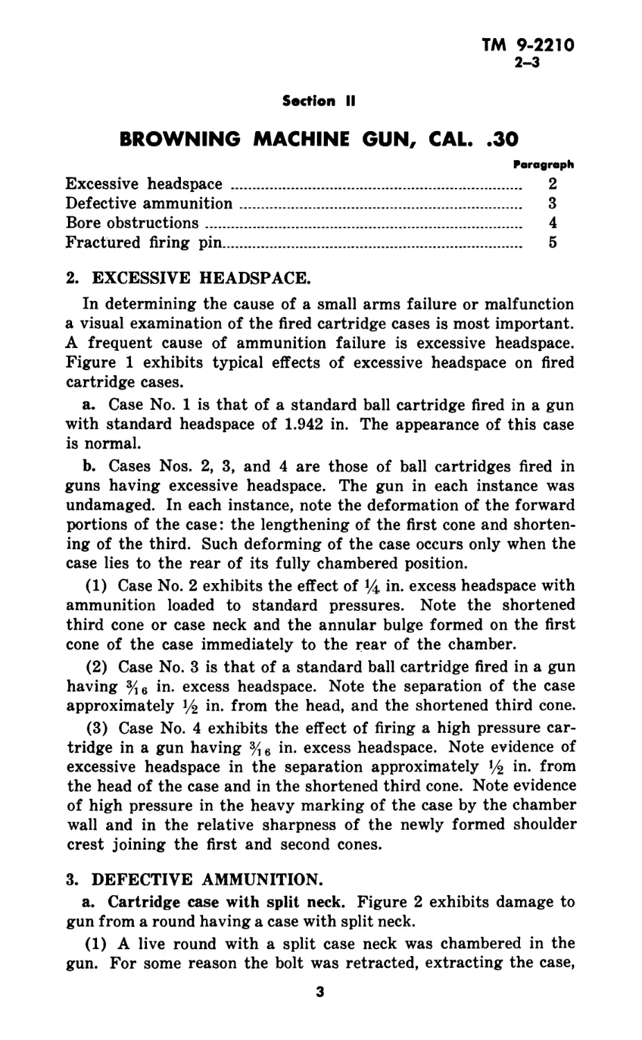
1. PURPOSE AND SCOPE.
This manual is published as an instruction guide for the informa-
tion of both using arms and ordnance maintenance personnel. It
contains detailed information on accidents and malfunctions occur-
ring in four commonly used small arms:
a. Browning machine gun, cal. .30.
b. U. S. rifle, cal. .30, M1903A1.
c. Automatic pistol, cal. .45, M1911.
d. Colt and Smith & Wesson revolver, cal. .45, M1917.
2
ТМ 9-2210
2-3
Section II
BROWNING MACHINE GUN, CAL. .30
Paragraph
Excessive headspace ..................................... 2
Defective ammunition..................................... 3
Bore obstructions........................................ 4
Fractured firing pin..................................... 5
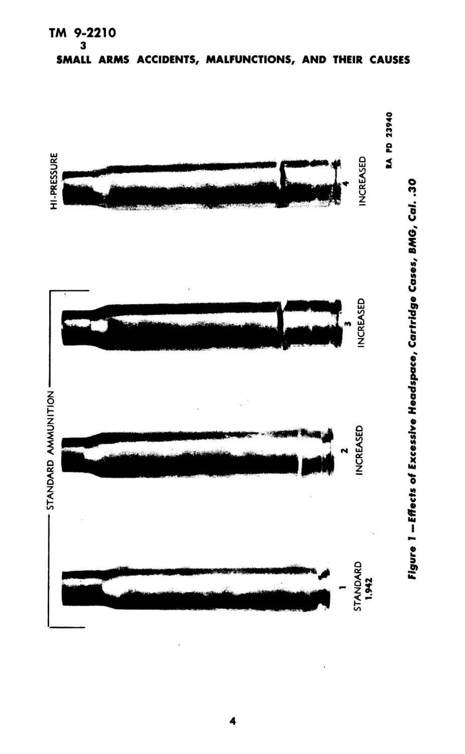
2. EXCESSIVE HEADSPACE.
In determining the cause of a small arms failure or malfunction
a visual examination of the fired cartridge cases is most important.
A frequent cause of ammunition failure is excessive headspace.
Figure 1 exhibits typical effects of excessive headspace on fired
cartridge cases.
a. Case No. 1 is that of a standard ball cartridge fired in a gun
with standard headspace of 1.942 in. The appearance of this case
is normal.
b. Cases Nos. 2, 3, and 4 are those of ball cartridges fired in
guns having excessive headspace. The gun in each instance was
undamaged. In each instance, note the deformation of the forward
portions of the case: the lengthening of the first cone and shorten-
ing of the third. Such deforming of the case occurs only when the
case lies to the rear of its fully chambered position.
(1) Case No. 2 exhibits the effect of %, in. excess headspace with
ammunition loaded to standard pressures. Note the shortened
third cone or case neck and the annular bulge formed on the first
cone of the case immediately to the rear of the chamber.
(2) Case No. 3 is that of a standard ball cartridge fired in a gun
having % 6 in. excess headspace. Note the separation of the case
approximately 14 in. from the head, and the shortened third cone.
(3) Case No. 4 exhibits the effect of firing a high pressure car-
tridge in a gun having in. excess headspace. Note evidence of
excessive headspace in the separation approximately 14 in. from
the head of the case and in the shortened third cone. Note evidence
of high pressure in the heavy marking of the case by the chamber
wall and in the relative sharpness of the newly formed shoulder
crest joining the first and second cones.
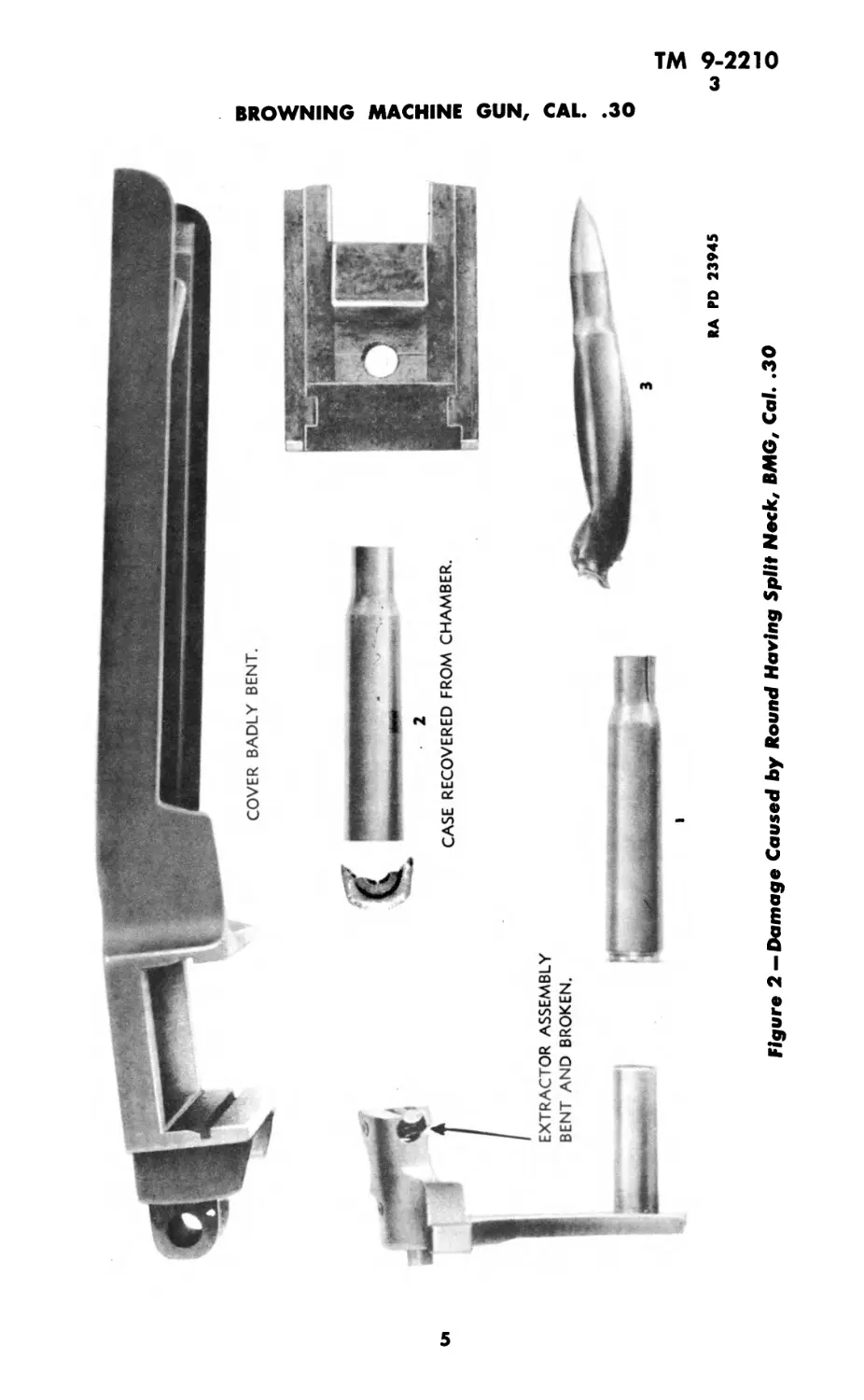
3. DEFECTIVE AMMUNITION.
a. Cartridge case with split neck. Figure 2 exhibits damage to
gun from a round having a case with split neck.
(1) A live round with a split case neck was chambered in the
gun. For some reason the bolt was retracted, extracting the case,
3
STANDARD AMMUNITION
1
STANDARD
1.942
INCREASED
HI-PRESSURE
INCREASED
RA PD 23940
Figure I —Effects of Excessive Headspace, Cartridge Cases, BMG, Cal. .30
RA PD 23945
Figure 2 — Damage Caused by Round Having Split Neck, BMG, Cal. .30
О
ТМ 9-2210
3-4
SMALL ARMS ACCIDENTS, MALFUNCTIONS, AND THEIR CAUSES
but leaving the bullet in the chamber. The extracted case was
ejected and a second live round chambered. When the chambered
cartridge was fired the case ruptured. This explosion ignited the
cartridge lying directly above in the feedway, rupturing the case
and releasing additional gases into the action.
(2) Damage to the gun is shown clearly in the photograph. Note
the bent cover and the bent breech lock cam. Observe the impres-
sions on the cartridge case from the walls of the chamber. The
extraction of a live case which left the bullet in the barrel is indi-
cated further by the presence of unburned powder grains in the
action.
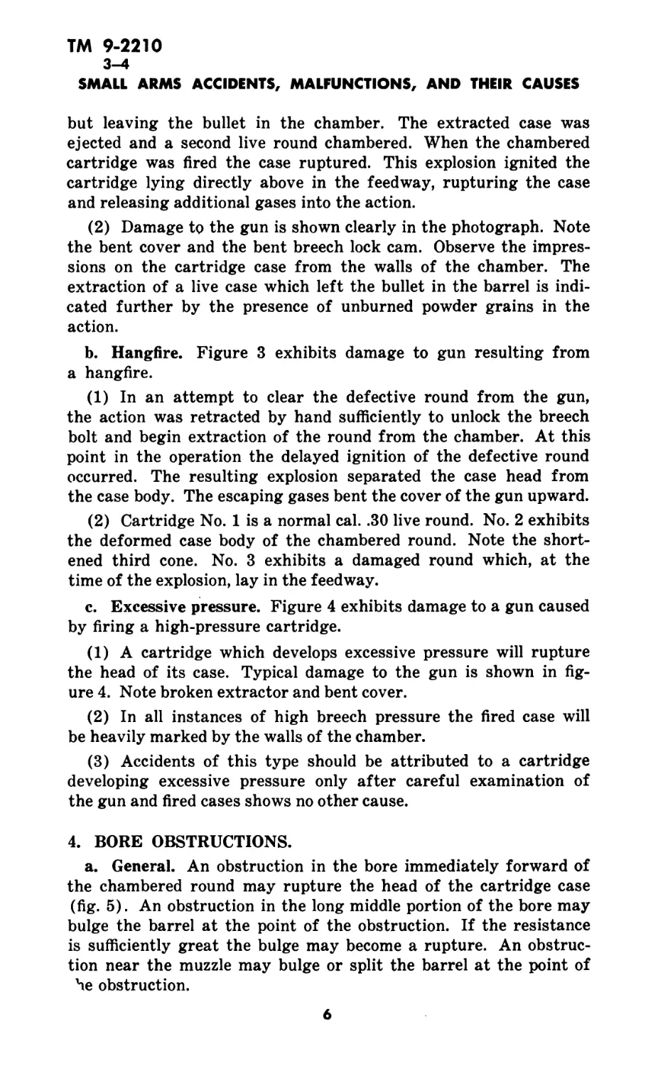
b. Hangfire. Figure 3 exhibits damage to gun resulting from
a hangfire.
(1) In an attempt to clear the defective round from the gun,
the action was retracted by hand sufficiently to unlock the breech
bolt and begin extraction of the round from the chamber. At this
point in the operation the delayed ignition of the defective round
occurred. The resulting explosion separated the case head from
the case body. The escaping gases bent the cover of the gun upward.
(2) Cartridge No. 1 is a normal cal. .30 live round. No. 2 exhibits
the deformed case body of the chambered round. Note the short-
ened third cone. No. 3 exhibits a damaged round which, at the
time of the explosion, lay in the feedway.
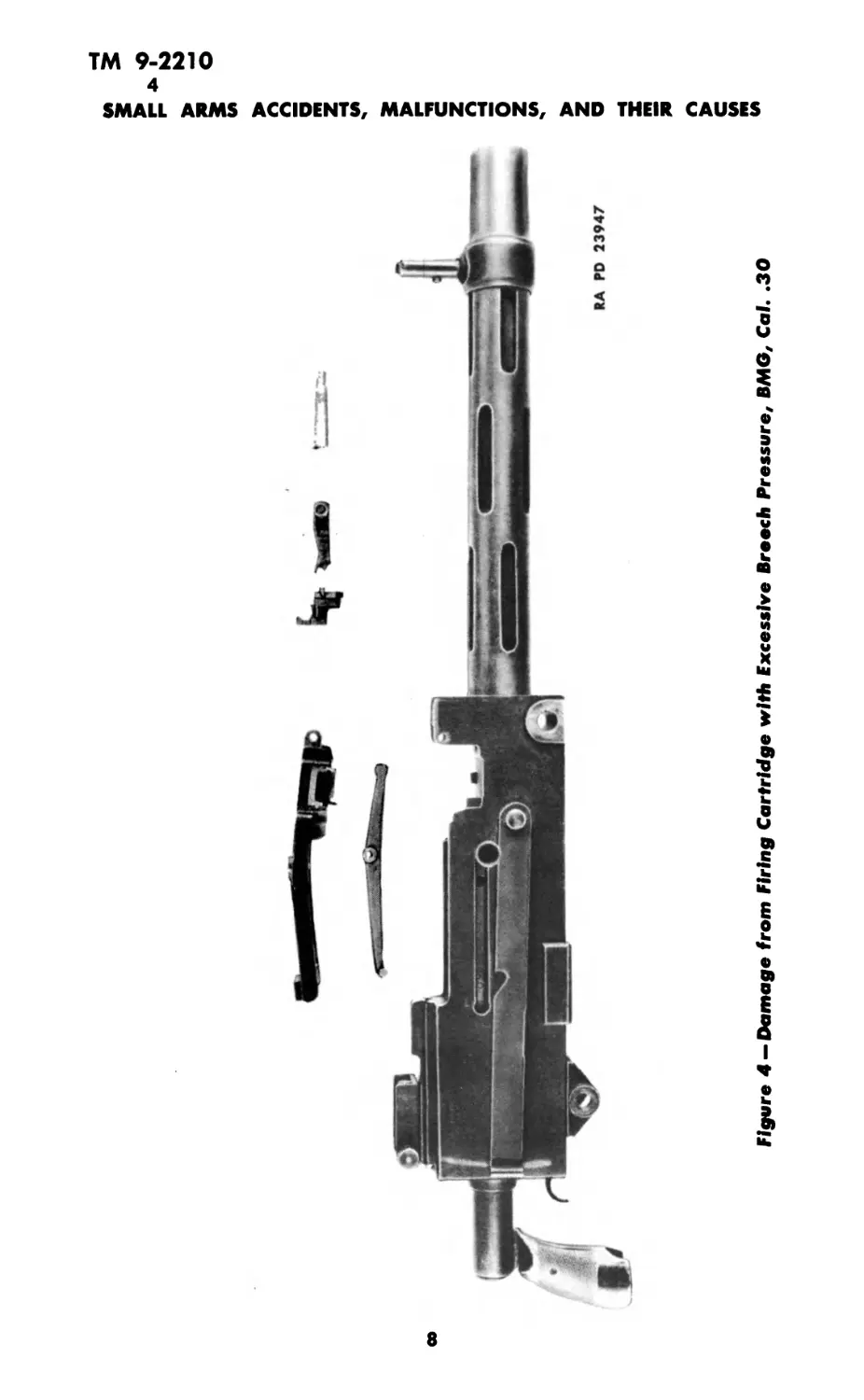
c. Excessive pressure. Figure 4 exhibits damage to a gun caused
by firing a high-pressure cartridge.
(1) A cartridge which develops excessive pressure will rupture
the head of its case. Typical damage to the gun is shown in fig-
ure 4. Note broken extractor and bent cover.
(2) In all instances of high breech pressure the fired case will
be heavily marked by the walls of the chamber.
(3) Accidents of this type should be attributed to a cartridge
developing excessive pressure only after careful examination of
the gun and fired cases shows no other cause.
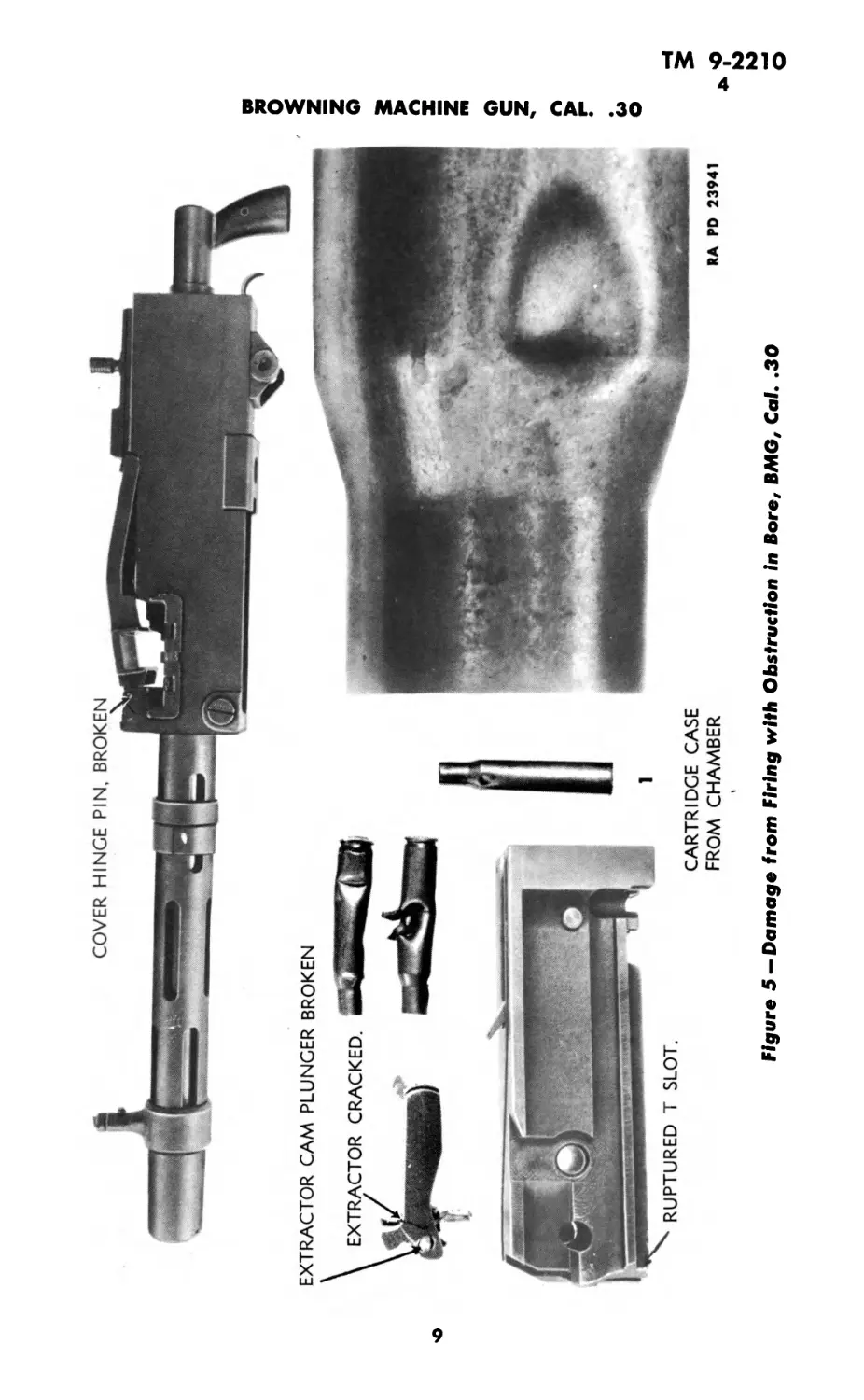
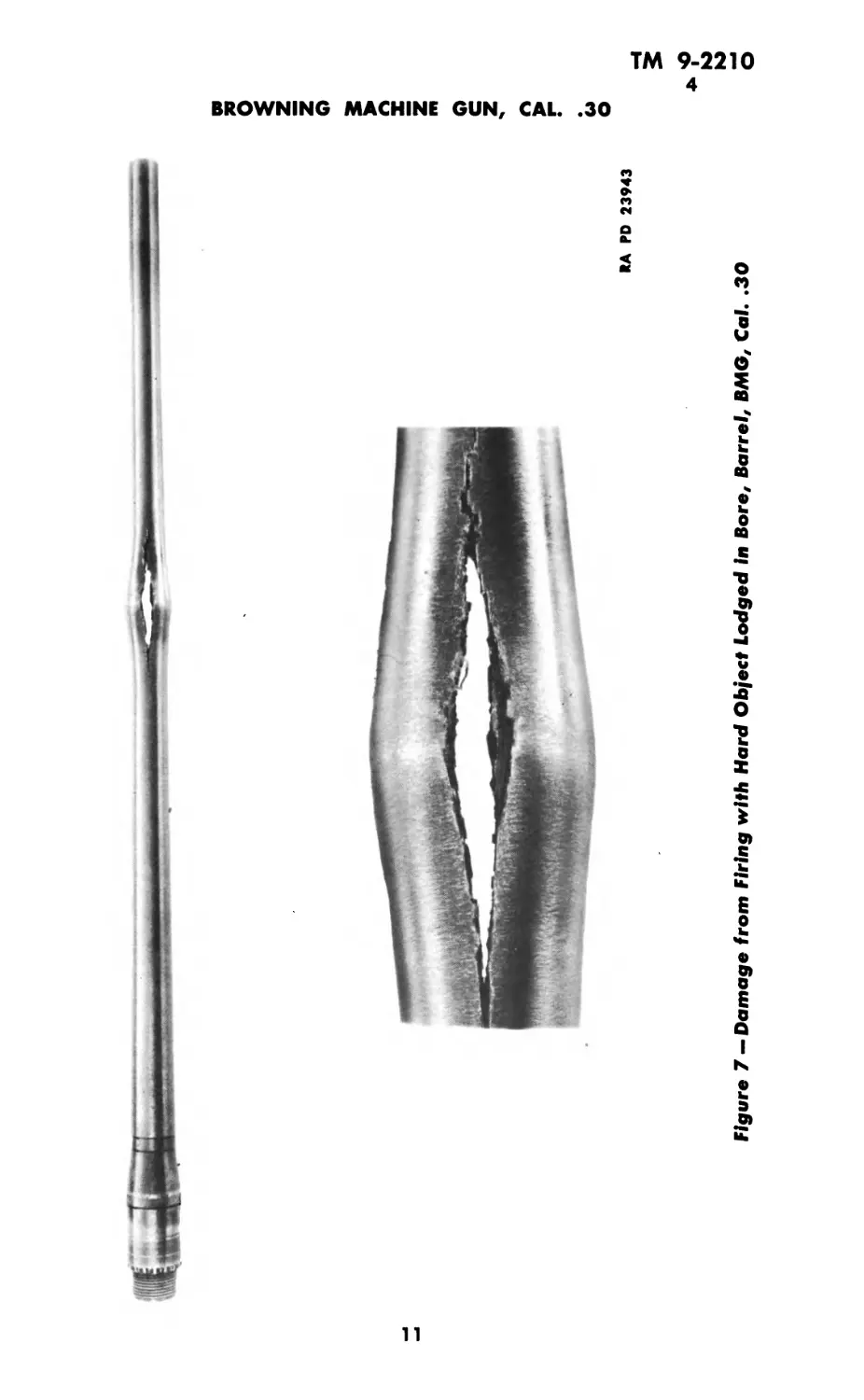
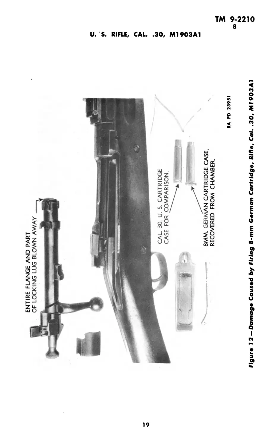
4. BORE OBSTRUCTIONS.
a. General. An obstruction in the bore immediately forward of
the chambered round may rupture the head of the cartridge case
(fig. 5). An obstruction in the long middle portion of the bore may
bulge the barrel at the point of the obstruction. If the resistance
is sufficiently great the bulge may become a rupture. An obstruc-
tion near the muzzle may bulge or split the barrel at the point of
he obstruction.
6
TM 9-2210
4
BROWNING MACHINE GUN, CAL. .30
Figure 3 —Damage from a Hangfire, В MG, Cal. .30
7
ТМ 9-2210
4
SMALL ARMS ACCIDENTS, MALFUNCTIONS, AND THEIR CAUSES
8
EXTRACTOR CAM PLUNGER BROKEN
CARTRIDGE CASE
FROM CHAMBER
RA PD 23941
Figure 5 —Damage from Firing with Obstruction in Bore, BMG, Cal. .30
О
Figure 6 — Damage from Firing with Bullet In Bore, BMG, Cal. .30
RA PD 23942
а,
RA PD 23943
Figure 7 — Damage from Firing with Hard Object Lodged in Bore, Barrel, BAIG, Cai. .30
О
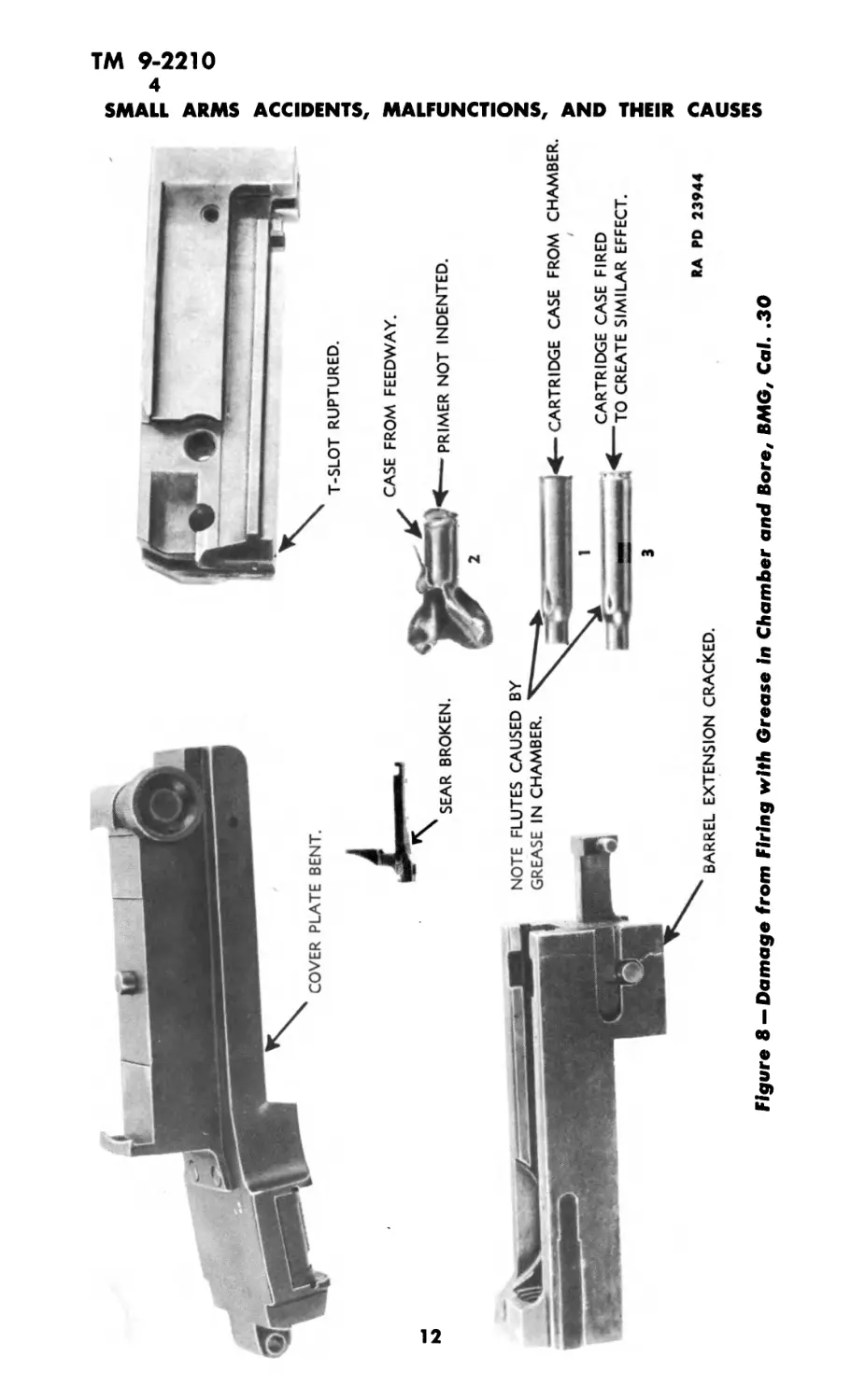
Figure 8 —Damage from Firing with Grease in Chamber and Bore, ВЛ46, Cal. .30
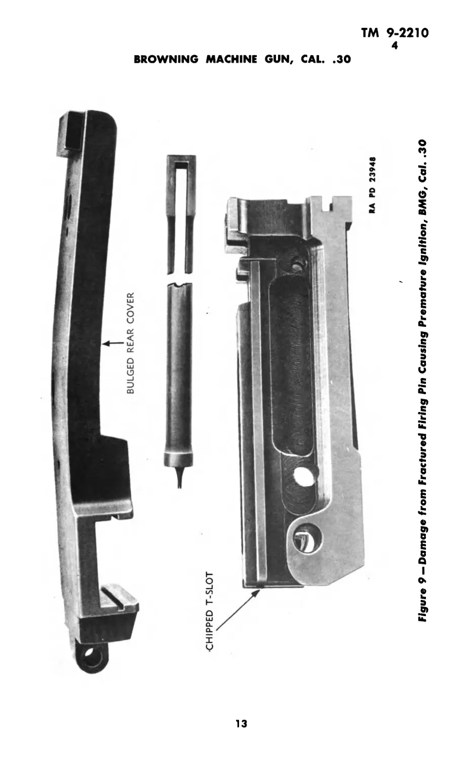
Figure 9— Damage from Fractured Firing Pin Causing Premature Ignition, BMG, Cal. .30
ТМ 9-2210
4—5
SMALL ARMS ACCIDENTS, MALFUNCTIONS, AND THEIR CAUSES
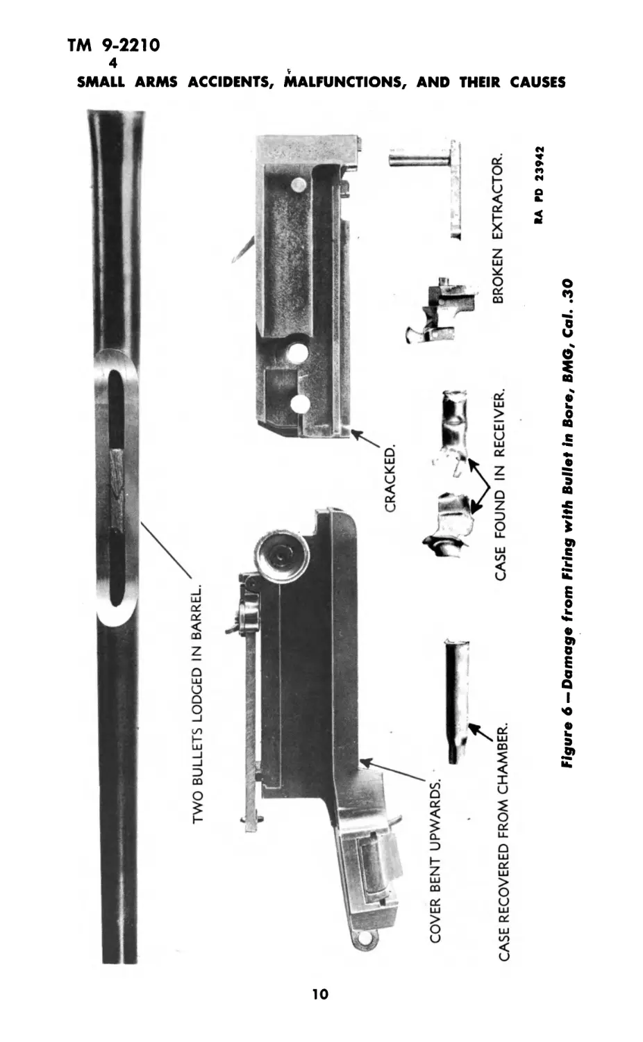
b. Bullet. A bullet lodged in the bore immediately forward of
the chambered cartridge will rupture the head of the cartridge
case (fig. 6). A bullet lodged in the middle portion of the bore
ordinarily does not rupture the fired case. The case may show
signs of high pressure. Ordinarily, the rupture of the case head
of the chambered round will ignite the cartridge lying directly
above in the feedway. Typical damage from these explosions con-
sists of a fractured T-slot, a cracked or broken extractor, and a
bent cover.
c. Grease.
(1 ) Grease or heavy oil in the chamber invariably produces a
flute in the fired case (fig. 8). Note the characteristically elongated
and radially contoured shape of these flutes. Case heads will show
some indications of high pressure.
(2 ) Damage to the gun which commonly results from firing with
grease in both chamber and breech end of bore is shown in figure 8.
The high pressure ruptures the case head, releasing the powder
gases into the action. Note fractured T-slot, cracked barrel exten-
sion, and bent cover.
5. FRACTURED FIRING PIN.
Figure 9 exhibits damage to gun caused by premature firing of
incoming round by fractured firing pin. This typical accident was
caused by fracture of the firing pin during counterrecoil. The firing
pin spring drove the firing pin point prematurely into the primer
of the incoming round. The explosion of the cartridge chipped the
T-slot and bent the cover upward.
14
ТМ 9-2210
6
Section III
U. S. RIFLE, CAL. .30, M1903A1
Paragraph
Examination of fired cartridge cases................... 6
Defective ammunition .................................. 7
Oversize ammunition.................................... 8
Bore obstructions...................................... 9
Premature explosion .................................. 10
Defective metal ...................................... 11
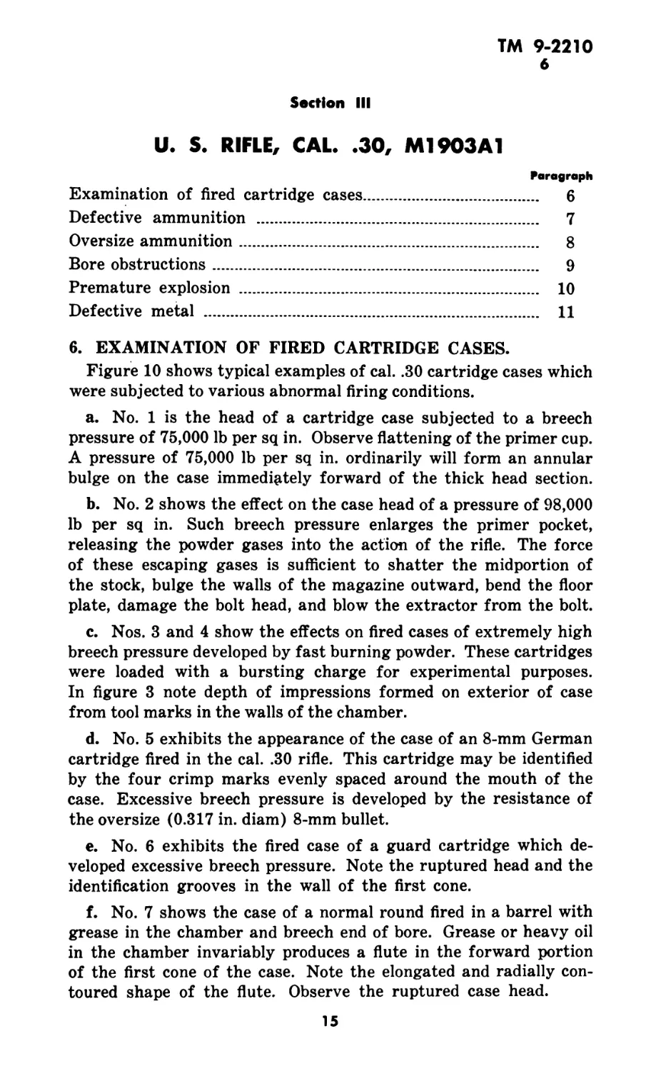
6. EXAMINATION OF FIRED CARTRIDGE CASES.
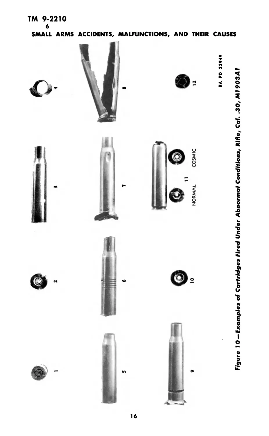
Figure 10 shows typical examples of cal. .30 cartridge cases which
were subjected to various abnormal firing conditions.
a. No. 1 is the head of a cartridge case subjected to a breech
pressure of 75,000 lb per sq in. Observe flattening of the primer cup.
A pressure of 75,000 lb per sq in. ordinarily will form an annular
bulge on the case immediately forward of the thick head section.
b. No. 2 shows the effect on the case head of a pressure of 98,000
lb per sq in. Such breech pressure enlarges the primer pocket,
releasing the powder gases into the action of the rifle. The force
of these escaping gases is sufficient to shatter the midportion of
the stock, bulge the walls of the magazine outward, bend the floor
plate, damage the bolt head, and blow the extractor from the bolt.
c. Nos. 3 and 4 show the effects on fired cases of extremely high
breech pressure developed by fast burning powder. These cartridges
were loaded with a bursting charge for experimental purposes.
In figure 3 note depth of impressions formed on exterior of case
from tool marks in the walls of the chamber.
d. No. 5 exhibits the appearance of the case of an 8-mm German
cartridge fired in the cal. .30 rifle. This cartridge may be identified
by the four crimp marks evenly spaced around the mouth of the
case. Excessive breech pressure is developed by the resistance of
the oversize (0.317 in. diam) 8-mm bullet.
e. No. 6 exhibits the fired case of a guard cartridge which de-
veloped excessive breech pressure. Note the ruptured head and the
identification grooves in the wall of the first cone.
f. No. 7 shows the case of a normal round fired in a barrel with
grease in the chamber and breech end of bore. Grease or heavy oil
in the chamber invariably produces a flute in the forward portion
of the first cone of the case. Note the elongated and radially con-
toured shape of the flute. Observe the ruptured case head.
15
Figure 10 — Examples of Cartridges Fired Under Abnormal Conditions, Rifle, Cal. .30, Ml 903Al
ТМ 9-2210
6-8
U. S. RIFLE, CAL. .30, М1903А1
g. No. 8 shows the case of a high pressure cartridge fired in a
barrel having a longitudinal seam in the walls. Note evidence of
excessive breech pressure in the ruptured case head. The longi-
tudinal separation of the case followed a similar separation of the
walls of the chamber.
h. No. 9 shows the effects on the case of extremely high breech
pressure and excessive headspace. Note evidence of excessive head-
space in the separation near head of the case. Evidence of excessive
pressure is found in the ruptured case head, and in the depth of
the impressions formed on the exterior of the case by tool marks
in the walls of the chamber.
i. No. 10 shows the effects of a normal breech pressure of 49,000
lb per sq in. on the head of a soft cartridge case. The first cone of
a soft case will be heavily marked from any tool marks in the wall
of the chamber. The enlargement of the primer pocket releases
the powder gases into the action, damaging the rifle as detailed
in paragraph 6 b above.
j. No. 11 exhibits the effect on the case of firing a cartridge
with an excessive bullet pull in a chamber coated with COMPOUND,
rust-preventive. Note the separation at the second cone and the
expanded case head.
k. No. 12 shows the head of a cartridge case with punctured
primer. This primer cup shows no indications of high pressure.
Compare the radius at the edge of this primer with that of the
primer shown in No. 1. When neither the primer nor the •fired case
show evidence of high pressure, a punctured primer usually indi-
cates a thin primer cup. Occasionally there is a small flash hole in
the case.
7. DEFECTIVE AMMUNITION.
Figure 11 shows typical damage to rifle from firing a high-
pressure cartridge. Note the fractured bridge of the receiver, the
bent ejector and magazine floor plate. Observe the ruptured head
of the fired case and the depth of the impressions formed on the
exterior of the case from tool marks in the walls of the chamber.
In an excessive pressure burst, brass from the ruptured case is
always plated along the exterior of the bolt.
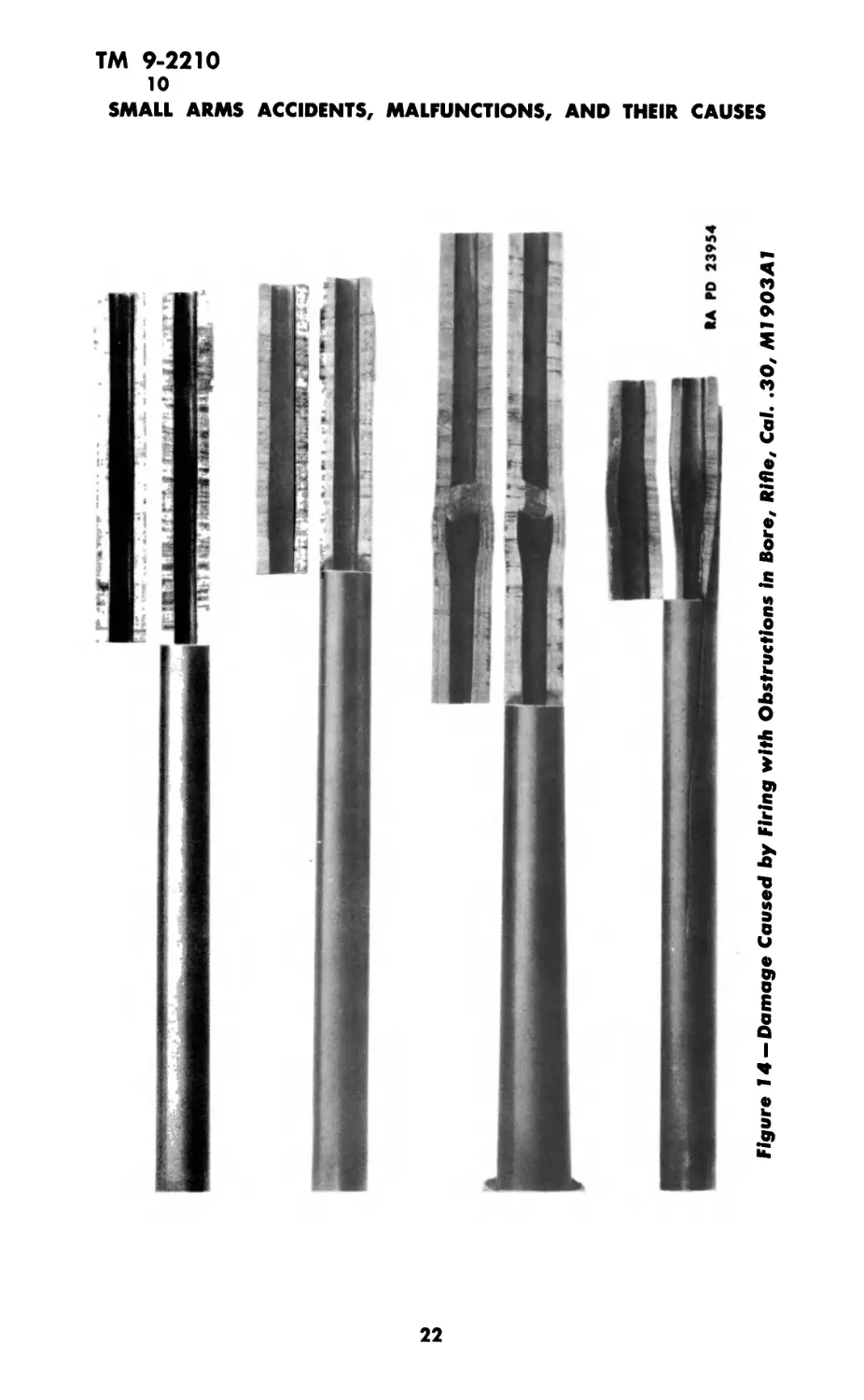
8. OVERSIZE AMMUNITION.
Figure 12 shows typical damage to rifle from firing an 8-mm
German cartridge. This cartridge may be identified by the four
crimp marks evenly spaced around the mouth of the case. Note
the fractured bridge of the receiver, the bent extractor and ex-
17
ТМ 9-2210
10
SMALL ARMS ACCIDENTS, MALFUNCTIONS, AND THEIR CAUSES
«•>
О
o>
d
<•>
о
h
Э
u.
22
8ММ. GERMAN CARTRIDGE CASE,
RECOVERED FROM CHAMBER.
RA PD 23951
Figure 12 — Damage Caused by Firing 8-mm German Cartridge, Rifle, Cal. .30, Ml 903AJ
О
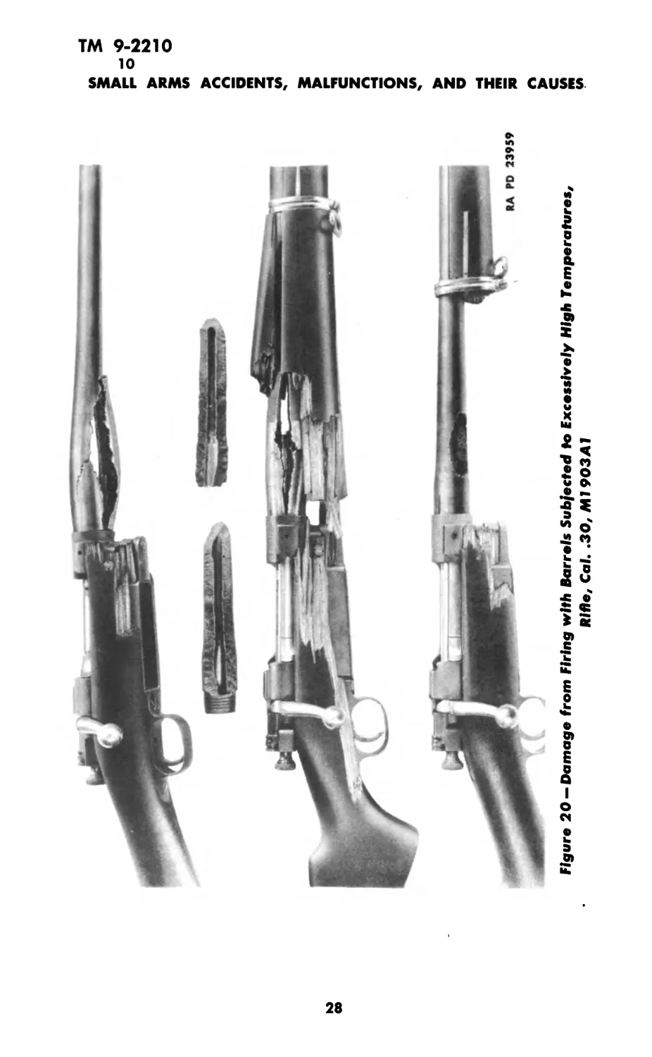
Figure 20 —Damage from Firing with Barrels Subjected to Excessively High Temperatures,
Rifle, Cal. .30, M1903Al
«А PD 23960
Ы
2
ю
о
сэ
>
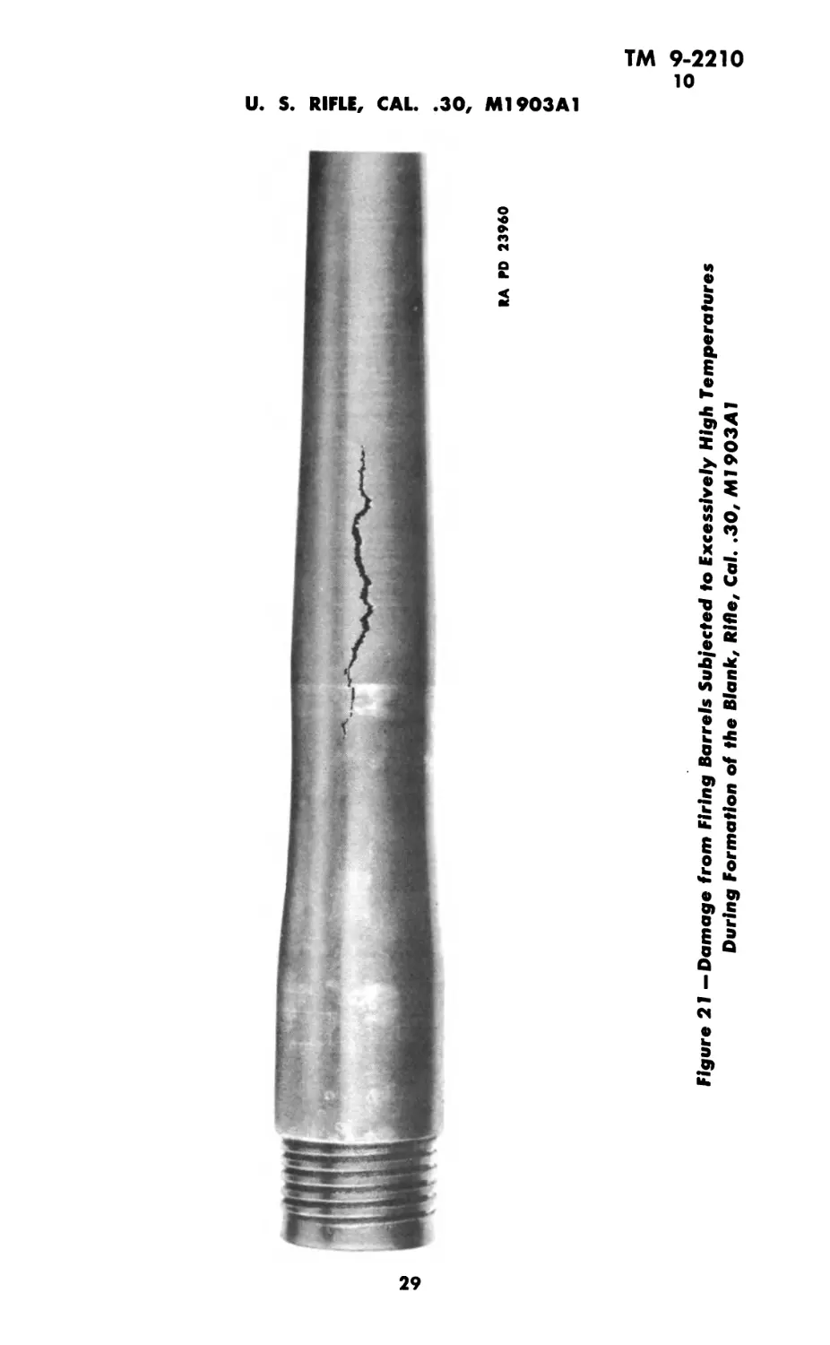
Figure 21 —Damage from Firing Barrels Subjected to Excessively High Temperatures
During Formation of the Blank, Rifle, Cal. .30, Ml 903Al
ТМ 9-2210
10-11
SMALL ARMS ACCIDENTS, MALFUNCTIONS, AND THEIR CAUSES
b. The resulting explosion ruptured the head of the cartridge
case, releasing the powder gases into the action of the rifle. Note
the fractured firing pin rod, the broken bolt handle, the bent ex-
tractor, extractor collar, and floor plate. Observe the ruptured
cartridge case with shortened third cone.
11. DEFECTIVE METAL.
Figures 19, 20, and 21 exhibit typical damage from firing normal
ammunition in a rifle with defective metal in receiver or barrel.
a. In figure 19 note that the head of the fired case shows no
expansion, indicating that the cartridge causing the rupture devel-
oped normal breech pressure. Observe the regularity of the edges
of the separated pieces of both receiver and barrel. Fractures with
this appearance indicate brittle steel.
b. In figures 20 and 21 observe the dark and coarse appearance
of the barrel structure. The steel in these barrels was damaged by
excessively high temperatures during the formation of the barrel
blank.
30
ТМ 9-2210
12-14
Section IV
PISTOL, AUTOMATIC, CAL. .45, Ml 911
Paragraph
Defective ammunition....................................... 12
Bore obstructions.......................................... 13
Defective metal ........................................... 14
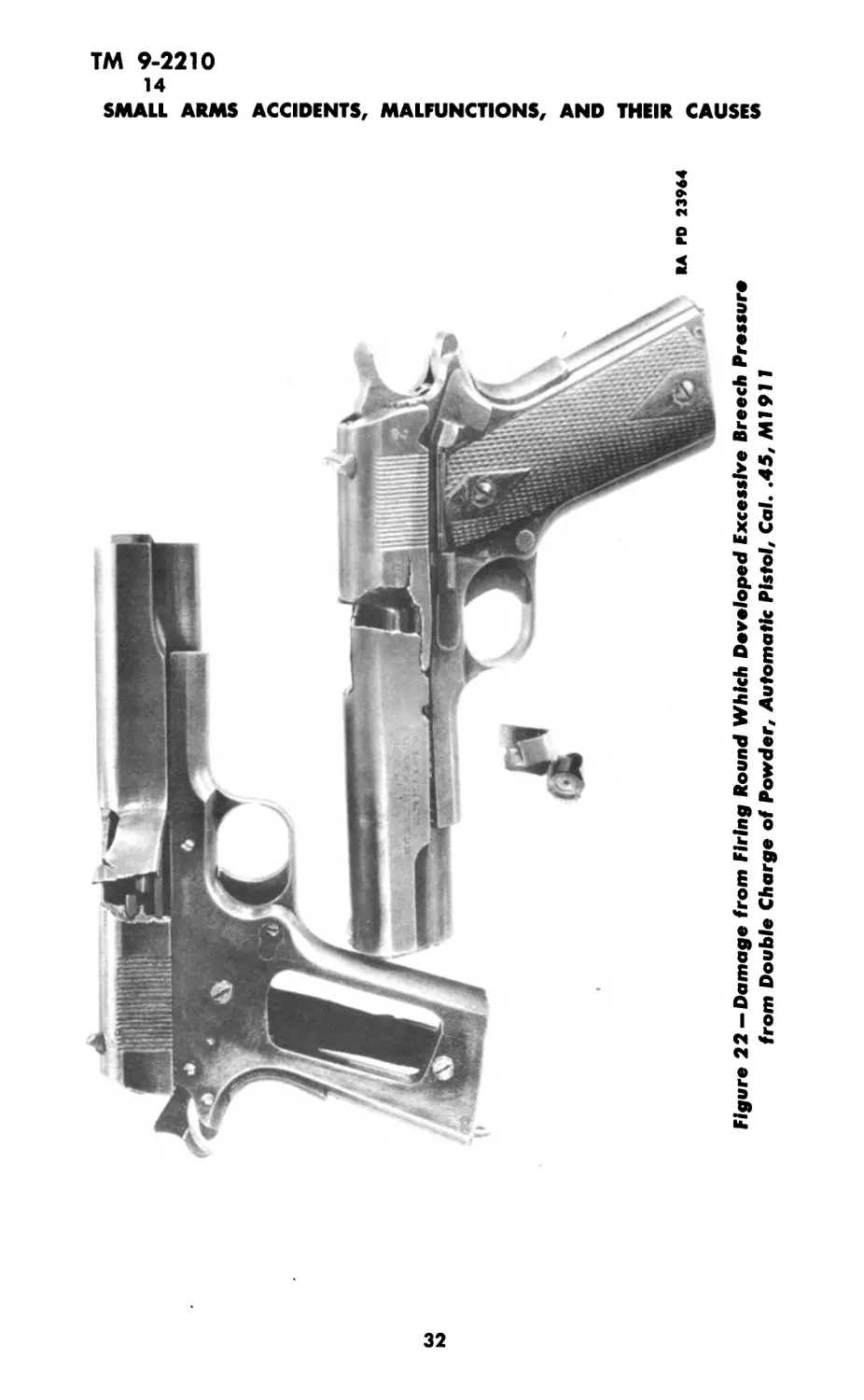
12. DEFECTIVE AMMUNITION.
Figure 22 shows typical damage to pistols caused by firing a
round which developed excessive pressure from a double charge
of powder.
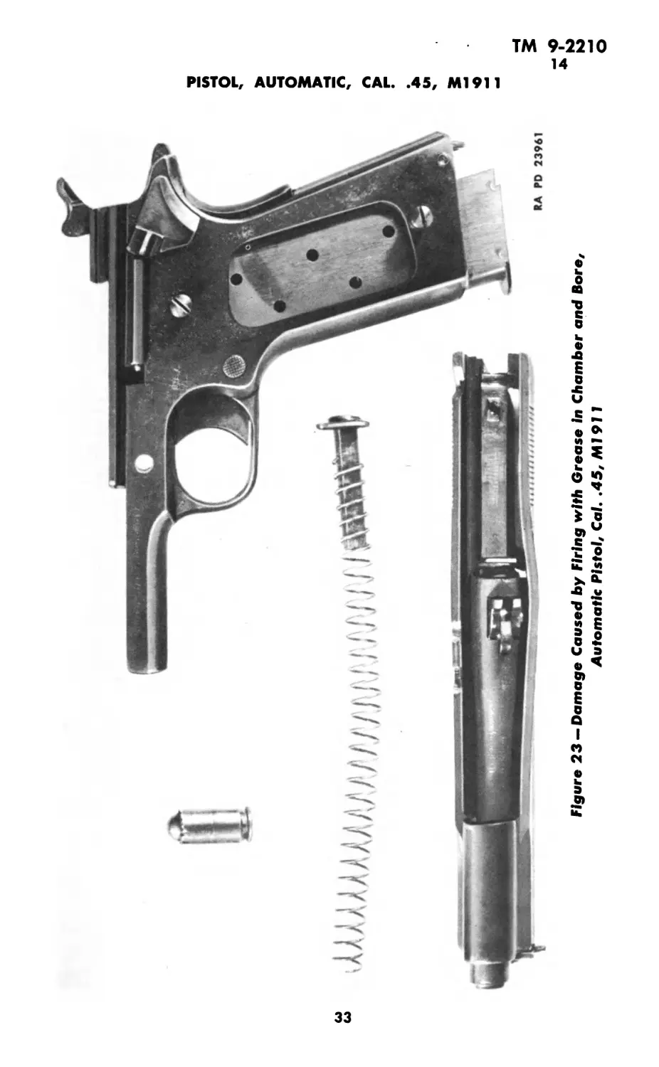
13. BORE OBSTRUCTIONS.
a. Figure 23 exhibits typical damage to pistol from firing a
normal round with grease in the chamber and breech end of the
bore. The breech pressure developed was sufficient to rupture the
head of the cartridge case, releasing the powder gases into the
action. Note the bulged housing and the damaged top round from
the magazine.
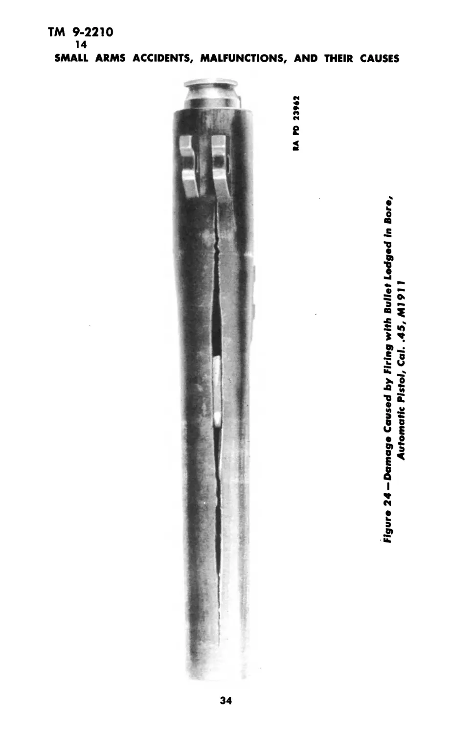
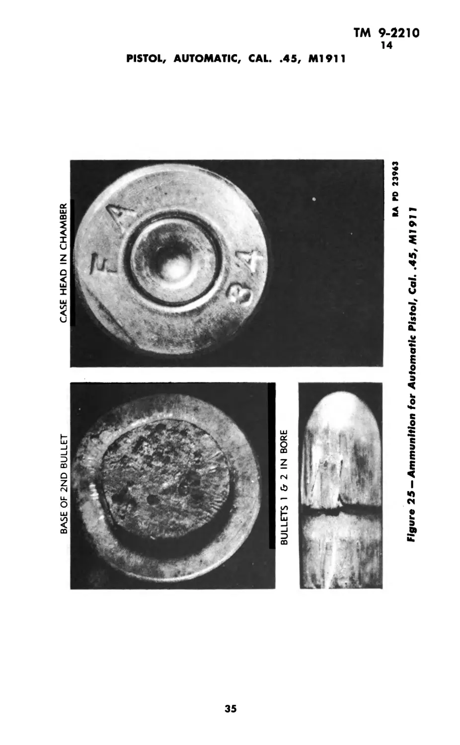
b. Figure 24 exhibits typical damage caused by firing a normal
round in a barrel with a bullet in the bore. Bullets may lodge in
the bore when fired from a cartridge containing damp powder. In
these instances some of the powder grains will be unburned. Figure
25 shows darkened, unburned powder grains adhering to the base
of the lodged bullet. Observe the long split in the barrel, and the
two bullets recovered from the bore.
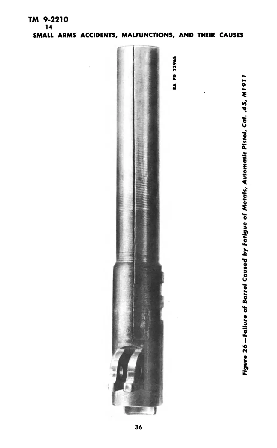
14. DEFECTIVE METAL.
a. Figure 26 shows typical failure of a barrel caused by fatigue
of the metal from long usage. Note the evidence of the wear on
the muzzle half of the barrel.
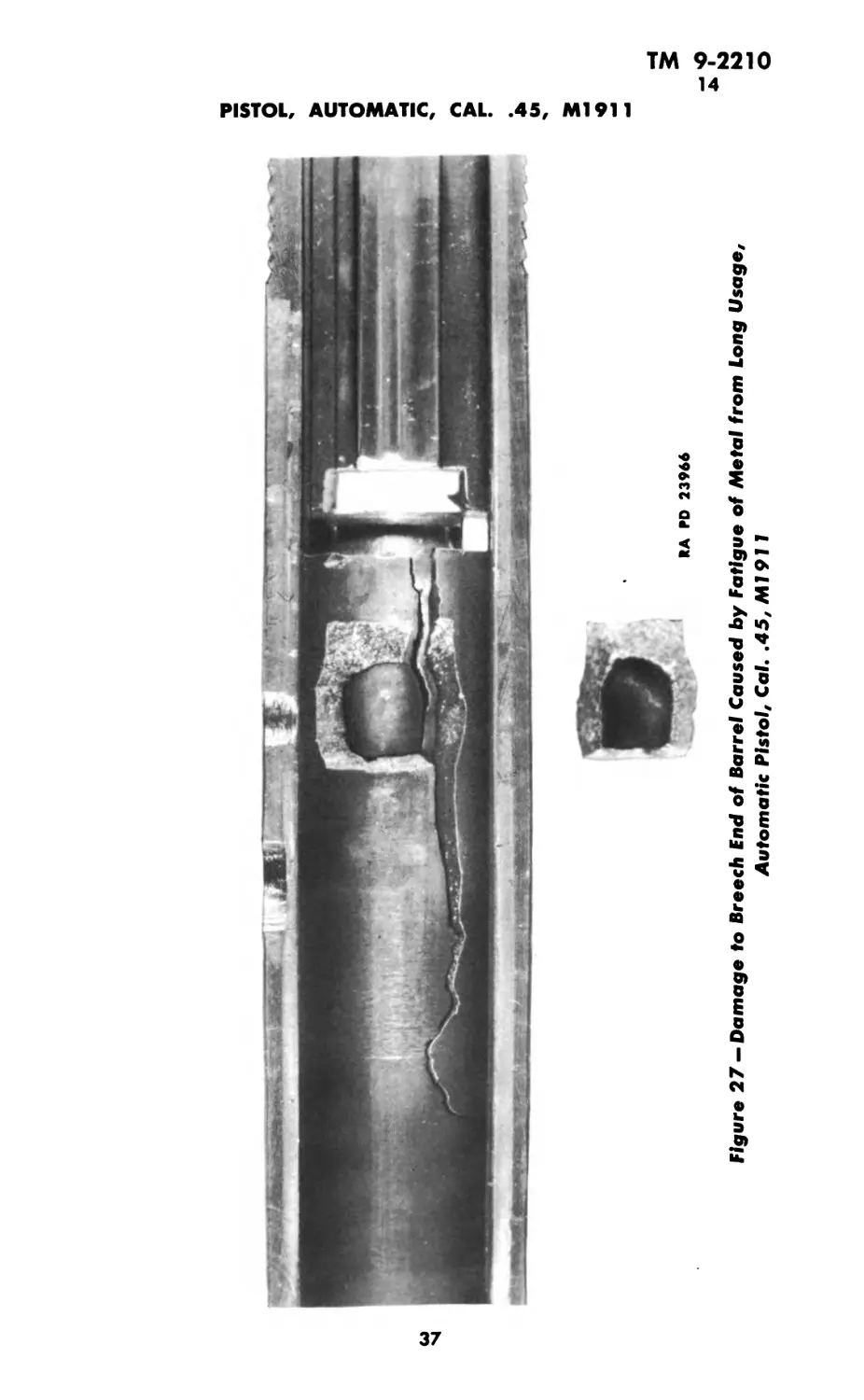
b. Figure 27 shows damage to the breech end of the barrel
when the metal has become fatigued from long usage. Note the
coarse structure of the metal at the break.
31
RA PD 23964
Figure 22 —Damage from Firing Round Which Developed Excessive Breech Pressure
from Double Charge of Powder, Automatic Pistol, Cal. .45, All911
сл
Hl
u>
Figure 23 —Damage Caused by Firing with Grease In Chamber and Bore,
Automatic Pistol, Cal. .45, Ml911
3
о
ТМ 9-2210
14
SMALL ARMS ACCIDENTS, MALFUNCTIONS, AND THEIR CAUSES
Figure 24—Damage Caused by Firing with Bullet Lodged In Bare,
Automatic Pistol, Cal. .45, Ml911
34
BASE OF 2ND BULLET
BULLETS 1 & 2 IN BORE
Figure 25 —Ammunition for Automatic Pistol, Cal. .45, Ml 911
CASE HEAD IN CHAMBER
RA PD 23963
2
<o
3
О
RA PD 23965
>
z
О
X
s
Я
Figure 26 — Failure of Barrel Caused by Fatigue of Metals, Automatic Pistol, Cal. .45, Ml 911
RA PD 23966
Figure 27 -* Damage to Breech End of Barrel Caused by Fatigue of Metal from Long Usage,
Automatic Pistol, Cal. .45, Ml 911
О
ТМ 9-2210
15-16
SMALL ARMS ACCIDENTS, MALFUNCTIONS, AND THEIR CAUSES
Section V
COLT AND SMITH & WESSON REVOLVER,
CAL. .45, M1917
Paragraph
Defective ammunition.................................... 15
Bore obstructions....................................... 16
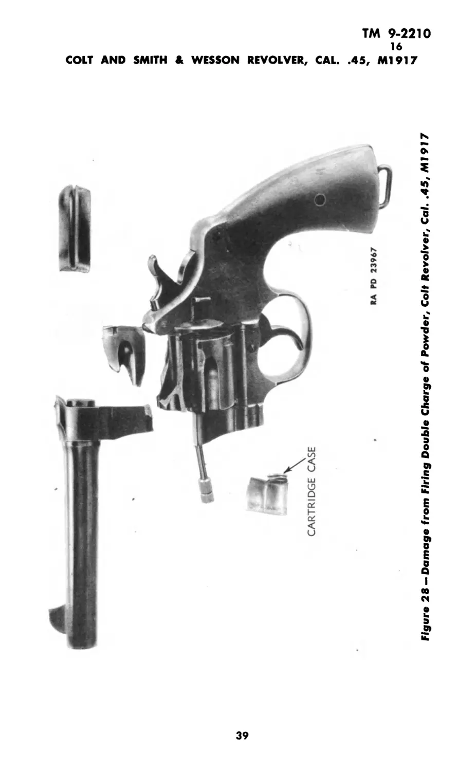
15. DEFECTIVE AMMUNITION.
Figure 28 exhibits typical damage from firing a round contain-
ing a double charge of powder.
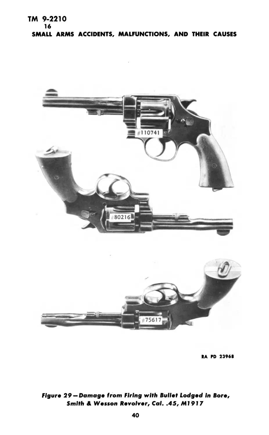
16. BORE OBSTRUCTIONS.
Figure 29 exhibits typical damage from firing a normal round
in a barrel with a bullet lodged in the bore. Bullets may remain
in the bore when fired from a cartridge containing damp powder.
Observe, in all three instances, the bulge produced at the point of
the obstruction, and the split in the barrel.
38
w
о
Figure 28 — Damage from Firing Double Charge of Powder, Colt Revolver, Cal. .45, Ml 917
О
ТМ 9-2210
16
SMALL ARMS ACCIDENTS, MALFUNCTIONS, AND THEIR CAUSES
RA PD 23968
Figure 29 —Damage from Firing with Bullet Lodged In Bore,
Smith & Wesson Revolver, Cal. .45, Ml 917
40
TM 9-2210
17
Section VI
REFERENCES
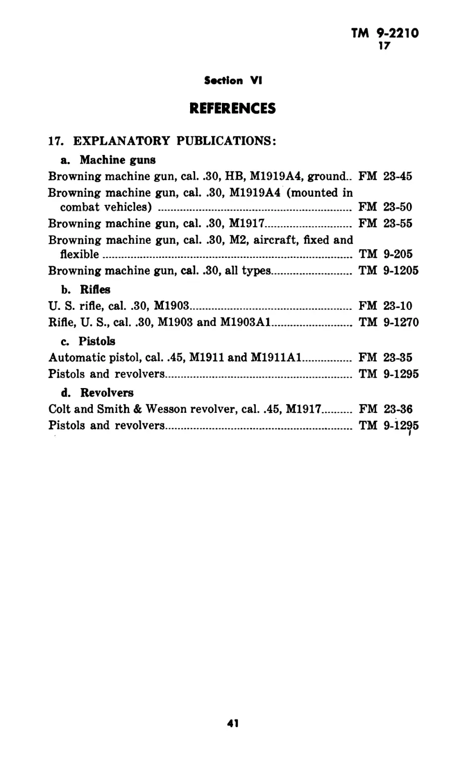
17. EXPLANATORY PUBLICATIONS:
a. Machine guns
Browning machine gun, cal. .30, НВ, M1919A4, ground.. FM 23-45
Browning machine gun, cal. .30, M1919A4 (mounted in
combat vehicles) ............................... FM 23-50
Browning machine gun, cal. .30, M1917............. FM 23-55
Browning machine gun, cal. .30, М2, aircraft, fixed and
flexible.......................................... TM 9-205
Browning machine gun, cal. .30, all types......... TM 9-1205
b. Rifles
U. S. rifle, cal. .30, M1903...................... FM 23-10
Rifle, U. S., cal. .30, M1903 and M1903A1......... TM 9-1270
c. Pistols
Automatic pistol, cal. .45, M1911 and M1911A1..... FM 23-35
Pistols and revolvers............................. TM 9-1295
d. Revolvers
Colt and Smith & Wesson revolver, cal. .45, M1917. FM 23-36
Pistols and revolvers............................. TM 9-1295
41
TM 9-2210
SMALL ARMS ACCIDENTS, MALFUNCTIONS, AND THEIR CAUSES
INDEX
Д Page No.
Ammunition, defective
Gun, machine, cal. .30, Brown-
ing
Cartridge case with split
neck ................... 3-6
Illustration ............... 5
Hangfire ...................... 6
Illustration ............... 7
Pressure, excessive ........... 6
Illustration ............... 8
Pistol, auto., cal. .45, M1911.. 31
Illustration ................. 32
Revolver, Colt, cal. .45, M1917 38
Illustration ................. 39
Rifle, U. S., cal. .30, M1903A1
Firing high pressure car-
tridge ......................... 17
Illustration .............. 18
Receiver or barrel, defective
metal in
Illustration ............27-29
Ammunition failure, cause of........ 3
Ammunition, oversize........17, 19-20
Illustration ................... 19
Automatic pistol, cal. .45, M1911
(See Pistol, auto., cal. .45,
M1911)
В
Barrel
Damaged
Gun, machine, cal. .30,
Browning ......................... 6
Defective metal in
Pistol, auto., cal. .45, M1911 31
Illustrations ............36-37
Rifle, U. S., cal. .30,
M1903A1 .................. 30
Illustrations ............27-29
Split in
Pistol, auto., cal. .45, M1911 31
Revolver, Smith & Wesson
cal. .45, M1917........... 38
Illustration ............... 40
Bore, grease in, result of....... 14
Bore obstructions
Gun, machine, cal. .30, Brown-
ing
Bullet ....................... 14
Illustration ............... 10
B—Cont’d Peg* No.
Bore obstructions—Cont’d
Gun, machine, cal. .30,
Browning—Cont’d
General explanation of........ 6
Illustration .............. 9
Grease in chamber and bore 14
Illustration ............... 12
Pistol, auto., cal. .45, M1911.... 31
Illustrations ..............33-35
Revolver, Colt, cal. .45, M1917 38
Revolver, Smith & Wesson, cal.
.45, M1917 ..........,.... 38
Illustration ................ 40
Rifle, U. S., cal. .30, M1903A1
Bullet in bore............ 20
Illustration ............. 21
Cloth patches ............... 20
Illustration ............. 22
Grease in chamber and bore 20
Illustration ............. 26
Muzzle obstructions......... 20
Illustrations ..........23-24
Breech pressure, excessive, dam-
age caused by, illustration..... 8
(See also Pressure)
Browning machine gun, cal. .30
(See Gun, machine, cal. .30,
Browning)
Bullet, 8-mm German, breech
pressure developed by............ 15
Bullet in bore, damage from
Gun, machine, cal. .30, Brown-
ing ............................. 14
Illustration ................ 10
Pistol, auto., cal. .45, M1911.. 31
Revolver, Colt, cal. .45, M1917
Illustration ................ 39
Rifle, U. S., cal. .30, M1903A1 20
Illustration ................ 21
Bullet pull, excessive, effect of.... 17
C
Cartridge
Bullet pull, excessive............... 17
8-mm German, damage from,
15, 17, 19-20
Illustration ................ 19
Firing high pressure........... 3
Explosion of ................ 6,14
Identification of ............ 15
42
ТМ 9-2210
INDEX
С—Conf d Peg» No.
Cartridge—Cont'd
Marking of ................... 17
Pressure, excessive, result of.. 6
Illustration ................. 8
Cartridge case(s)
Breech pressure, high
Pistol, auto., cal. .45, M1911 31
Rifle, U. S., cal. .30,
M1903A1 .................. 17
Bullet lodged in bore........ 14
Illustration ............... 12
Bullet pull, excessive, of car-
tridge ....................... 17
Explosion, premature ......... 30
Fired
Examination of ...........15-17
Illustration ............... 16
Flutes in .................... 14
Illustration ............... 12
Headspace, excessive
Gun, machine, cal. .30,
Browning....................... 3
Illustration .............. 4
Rifle, U. S., cal. .30,
M1903A1 .................... 17
Marking of .................... 6
Ruptured ...................... 6
Case (See Cartridge case(s))
Chamber, grease in, result of.. 14
Cloth patches in bore of rifle,
U. S., cal. .30, M1903A1... 20
Illustration ................. 22
Colt revolver, cal. .45, M1917
(See Revolver, Colt, cal. .45,
M1917)
Cone, marking of................ 17
Counterrecoil, fracture of firing
pin during ..................... 14
D
Defective ammunition (See Am-
munition, defective)
Defective metal (See Metal, de-
fective)
E
Examination of:
Fired cartridge cases.........15-17
Gun and fired cases............ 6
Explosion of:
Cartridge (case) ............. 6,14
E—Conf d
Page No.
Explosion of:—Cont’d
Round
Accidental firing of.......20, 30
Illustration ............. 26
Defective ................... 6
F
Failure of:
Ammunition, cause of............. 3
Barrel ......................... 31
Illustration ................. 36
Firing pin, fractured............. 14
Illustration ................... 13
Firing pin rod neck, fractured.. 20
Flute(s)
Cause of ......................... 15
In fired cases.................. 14
Illustration ................. 12
G
Gases, powder, escaping
Gun, machine, cal. .30, Brown-
ing ............................ 6,14
Pistol, auto., cal. .45, M1911.... 31
Rifle, U.S., cal. 30, M1903A1,
15,17, 30
German cartridge, 8-mm
Damage caused by.............17,19-20
Illustration ................. 19
Grease (and oil) in chamber
(and bore)
Gun, machine, cal. .30, Brown-
ing ...............’....... 14
Illustration ................. 12
Rifle, U. S., cal. .30, M1903A1..15, 20
Illustration ................. 25
Guard, cartridge, excessive pres-
sure of .......................... 15
Gun, machine, cal. .30, Browning
Ammunition, defective ........... 3-6
Cartridge case with split
neck ................... 3-6
Illustration ............... 5
Hangfire ...................... 6
Illustration ............... 7
Pressure, excessive ........... 6
Illustration ............... 8
Bore obstructions.............6, 9-14
Bullet ....................... 14
Illustration .............. 10
43
TM 9-2210
SMALL ARMS ACCIDENTS, MALFUNCTIONS, AND THEIR CAUSES
G—Cont’d No.
Gun, machine, cal. .30,
Browning—Cont’d
Bore obstructions—Cont’d
Cartridge case, ruptured... 6
Illustration ................. 9
Grease ........................ 14
Illustration ................ 12
Firing pin, fractured............ 14
Illustration .................. 13
Headspace
Excessive, effect of on fired
cartridge cases .......... 7
Illustration ................. 4
Normal ......................... 3
H
Hangfire ........................... 6
Illustration ..................... 7
Headspace, excessive, effect of
on cartridge cases
Gun, machine, cal. .30, Brown-
ing ........................ 3
Illustration ................... 4
Rifle, U. S., cal. .30, M1903A1.. 17
Headspace, standard, in car-
tridge case................... 3
Illustration ..................... 4
Housing, bulged ................... 31
I
Identification of 8-mm German
cartridge ....................... 15
L
Loam in muzzle of rifle, dam-
age from .................... 30
Illustration .................... 24
M
Marking of:
Cartridge case
Gun, machine, cal. .30,
Browning ..................... 3, 6
Rifle, U. S., cal. .30,
M1903Al ................... 17
Cartridge, 8-mm German....... 15
Metal, defective, in:
Pistol, auto., cal. .45, M1911... 31
Illustrations .............36-37
Rifle, U. S., cal. .30, M1903A1 30
Illustrations .............27-29
M—Cont’d P*e* No.
Muzzle (Rifle, U. S., cal. .30,
M1903A1)
Bulged and split............... 20
Illustration ................ 21
Obstructions .................. 20
Illustrations ................23-24
N
Neck, split, of cartridge case. 3-6
Illustration .................. 5
О
Obstructions in bore (See Bore
obstructions)
Oil (See Grease (and oil) in
chamber (and bore))
P
Patches, cloth, in bore of rifle,
U. S., cal. .30, M1903A1...... 20
Illustration ................... 22
Pistol, auto., cal. .45, M1911
Ammunition, defective .......... 31
Illustration ................. 32
Bore obstructions............... 31
Illustrations ..............33-35
Metal, defective ............... 31
Illustrations ..............36, 37
Powder, damage from double
charge of
Illustration ................... 39
Powder gases (See Gases, pow-
der, escaping)
Powder grains
Presence of ....................... 6
Unburned ........................ 31
Illustration .................. 35
Pressure, excessive, effect of on
cartridge case
Gun, machine, cal. .30, Brown-
ing ..................... 6,14
Illustration .................. 8
Rifle, U. S., cal. .30, M1903A1..15-17
Primer (cup), punctured......... 17
Primer pocket, enlargement of. .. 17
R
Receiver, defective metal in.... 30
Revolver, Colt, cal. .45, M1917
Ammunition, defective .......... 38
Illustration ................. 39
Bore obstructions............... 38
44
ТМ 9-2210
INDEX
R—Cont’d
Page No.
Revolver, Smith & Wesson, cal.
.45, M1917
Bore obstructions................. 38
Illustration .................. 40
Rifle, U. S., cal. .30, M1903A1....15-30
Ammunition
Defective .................... 17
Illustration ............... 18
Oversize ...................17-20
Illustration ............... 19
Bore obstructions................ 20
Illustrations:
Bullet ..................... 21
Cloth patches .............. 22
Grease ..................... 25
Muzzle obstructions ......23, 24
Cartridge cases, fired, exami-
nation of ...............15-17
Illustration ................. 16
Explosion, premature ..........20, 30
Illustration ................. 26
Metal, defective ................ 30
Illustrations ............27, 28, 29
Round (s)
Damaged, illustration of....... 7
Defective, explosion of........ 6
R—Cont’d Peg* No.
Firing with double charge of
powder, illustration of........ 39
Normal
Accidental firing of, illustra-
tion of ...................... 26
Illustration ................. 7
Premature firing of............. 14
Illustration ............... 13
With split case neck................... 3-6
S
Sand in bore of rifle......................... 20
Illustration ...................... 24
Smith & Wesson revolver, cal.
.45, M1917
Bore obstructions.............. 38
Illustration ................ 40
Split neck of cartridge case..... 3-6
Illustration ....................... 5
U
U. S. rifle, cal. .30, M1903A1
(See Rifle, U. S., cal. .30,
M1903A1)
Г A. G. 062.11 (7-7-42). 7
LO. O. 461/19223 О. O. (7-7-42) J
By order of the Secretary of War:
G. C. MARSHALL,
Chief of Staff.
Official :
J. A. ULIO,
Major General,
The Adjutant General.
Distribution :
Bn 9(2); C 9(4)
(For explanation of symbols see FM 21-6)
45
PUBLICATIONS DRPARTMINT—RARITAN ARIINAL