/


Text
Nov. 24, 1931.
1,833,862
H. SCHMEISSER
MAGAZINE FOR MACHINE PISTOLS
Filed Feb. 26, 1931 4 Sheets-Sheet 1
Nov. 24, 1931.
H. SCHMEISSER
1,833,862
MAGAZINE FOR MACHINE PISTOLS
Filed Feb. 26, 1Э31 4 Sheets-Sheet 2
Nov. 24, 1931.
1,833,862
H. SCHMEISSER
MAGAZINE FOR MACHINE PISTOLS
Filed Feb. 26, 1Э31 4 Sheets-Sheet 3
Nov. 24, 1931.
1,833,862
H. SCHMEISSER
MAGAZINE FOR MACHINE PISTOLS
Filed Feb. 26, 1931 4 Sheets-Sheet 4
7Z
Huqfo deb
At/tar7?e.y
Patented Nov. 24, 1931
1,833,862
UNITED STATES PATENT OFFICE
HUGO SCHMEISSER, OR SUHL, GERMANY
MAGAZINE FOR MACHINE PISTOLS
Application filed February 2fi, 1931, Serial No. 518,512, and in Germany February 27, 1930.
My invention relates to detachable mag-
azines for machine pistols and more partic-
ularly to an improved construction of the
- magazine body and the plunger-like follower
5 adapted to be actuated by the usual feeding
spring and upon which the cartridges rest.
According to the present invention the in-
ward bent upper edges or discharging lips
constituting the opening of the magazine for
’Э the egress and delivery of the cartridges into
the chamber in the breech are reinforced by
an U-shaped member or similar formation
mounted to laterally embrace the upper encl
of the magazine body and provided with a
15 recess or the like for securing purposes and
with lateral projections or noses forming
abutments for limiting the insertion of the
magazine body into the holder, while the
wall of the tubular magazine body itself is
20 entirely devoid of recesses, projections or
the like so that, on the one hand, the discharg-
ing lips or orifice of the magazine will be
snugly enclosed for protecting and stabiliz-
ing purposes, and, on the other hand, the
25 cartridges will readily move in. the contin-
uously smooth faced tubular magazine and
into the barrel, due to the action of the fol-
lower spring, without meeting any obstruc-
tions or impediments.
30 The magazine body, properly speaking,
thus is shaped to form a tube of preferably
quadrangular cross-section whereof the wall
is of uniform thickness and smooth-faced
throughout its length, the required projec-
35 tions, recesses or the like for the magazine
holder to co-operate therewith being provided
on or in the said reinforcing member instead
of in the magazine tube itself, as in the prior
art, so that the same may be given a greater
40 width or provided with larger cooperating
faces and a more reliable seat or cooperation
will be secured and loosening of the magazine
be prevented thereby even in the event of
most heavy shocks which firearms of this type
45 are liable to encounter, as contrasted with
the magazines hitherto constructed and de-
vised wherein shoulders, abutments or sim-
ilar projection for cooperation with the mag-
azine holder are provided immediately in
50 or on the magazine body and, therefore, are
of limited dimensions only in order to not
excessively reduce and weaken the wall there-
of. Moreover, another advantage- of my im-
proved magazine resides in the fact that the
reinforcing member or covering affords the 55
possibility of simplifying the construction
and manufacture of a magazine of large ca-
pacity adapted to receive'a plurality of stag-
gered rows of superposed cartridges. At any
rate the reinforcement of the discharging 60
lips of the magazine tube together with the
simultaneous improvement residing in the
continuously smooth faces of the magazine
tube devoid of interruptions is the principal
object feature and advantage of the present 65
invention.
In some cases I find it of particular ad-
vantage to construct and arrange the re-
inforcing member or covering in a manner
that the same will immediately form one of 70
the four wall surfaces of the magazine, tube.
To this end the two lateral flanges or shanks
of the twice bent covering are mounted to
overlie and embrace the two flanges or shanks
of the similarly U-shaped magazine tube ancb 75
the cooperating flanges are firmly united by
soldering or in any other suitable way. Obvi-
ously the manufacture of a magazine of the
described type will be greatly simplified and
a marked reduction of cost will be attained- 80
thereby.
In magazines of large capacity wherein
the cartridges are superposed to form two
parallel vertical rows in staggered relation-
ship and the uppermost cartridge only is- 85
pushed out at a time by the spring controlled
follower, it sometimes happens that, at the
pushing out operation, the upper-most car-
tridge engages into the circumferential bot-
tom groove of the shell of the next lower car-' 90
tridge and causes the latter to be at the same
time displaced towards the front side, thereby
entailing the danger of loading stoppage.
Another object of the present invention is
to remedy this defect. With this purpose in 95
view I provide in the magazine tube a means
for causing the uppermost cartridges of the
two vertical rows to occupy an inclined posi-
tion with relation to the cartridges tnere-
below so that the two uppermost cartridges 100
2
1,833,862
will revolve crosswise in their upwards
movement. The means employed to this end
preferably consists of two pairs of longi-
tudinal ribs of gradually increasing or taper-
B ing cross-section, provided on the two op-
posite side Avails of the top end of the maga-
zine tube, the upper ends of the ribs being
wider and projecting farther into the room
of the magazine tube than the lower ends
10 thereof due to the tapering shape of the ribs.
Further the front ribs of the two pairs, that
is to say, the two opposite ribs nearest the
barrel end of the firearm, are shaped to pro-
ject to a farther extent into the room of the
и magazine tube, in accordance with a pre-
• determined ratio, than the rear ribs of the
two pairs.
A still further object of the present inven-
tion resides in an improved construction of
>(j the follower employed in connection with the
improved magazine. In the firearms as
hitherto constructed or designed a particu-
lar element or member is employed for stop-
ping the follower or limiting the number of
25 cartridges to be inserted into the magazine.
According to the present invention the fol-
lower is provided with downwards extending
shanks adapted to guide both itself and the
controlling spring and to act at the same time
so as a stopping means for automatically limit-
ing the number of cartridges to be inserted
into the magazine, or in other words, to just
strike on the fixed bottom of the magazine
tube when in the loading operation the pre-
ss determined number of cartridges has been
inserted into the magazine. In this way I
combine and realize in a very simple, efficient
and inexpensive manner the two advantages
of automatically limiting the predetermined
40 load and reliably guiding both the follower
and the controlling spring during the up and
down movement thereof incident to the load-
ing and discharging proceedings.
To the accomplishment of the foregoing
45 and related ends, the invention then con-
sists of the means hereinafter fully described
and particularly pointed out in the claims.
The annexed drawing and the following de-
scription set forth in detail certain mecha-
50 nism embodying the invention, such disclosed
means constituting, however, but one of vari-
ous mechanical forms in which the principles
of the invention may be used.
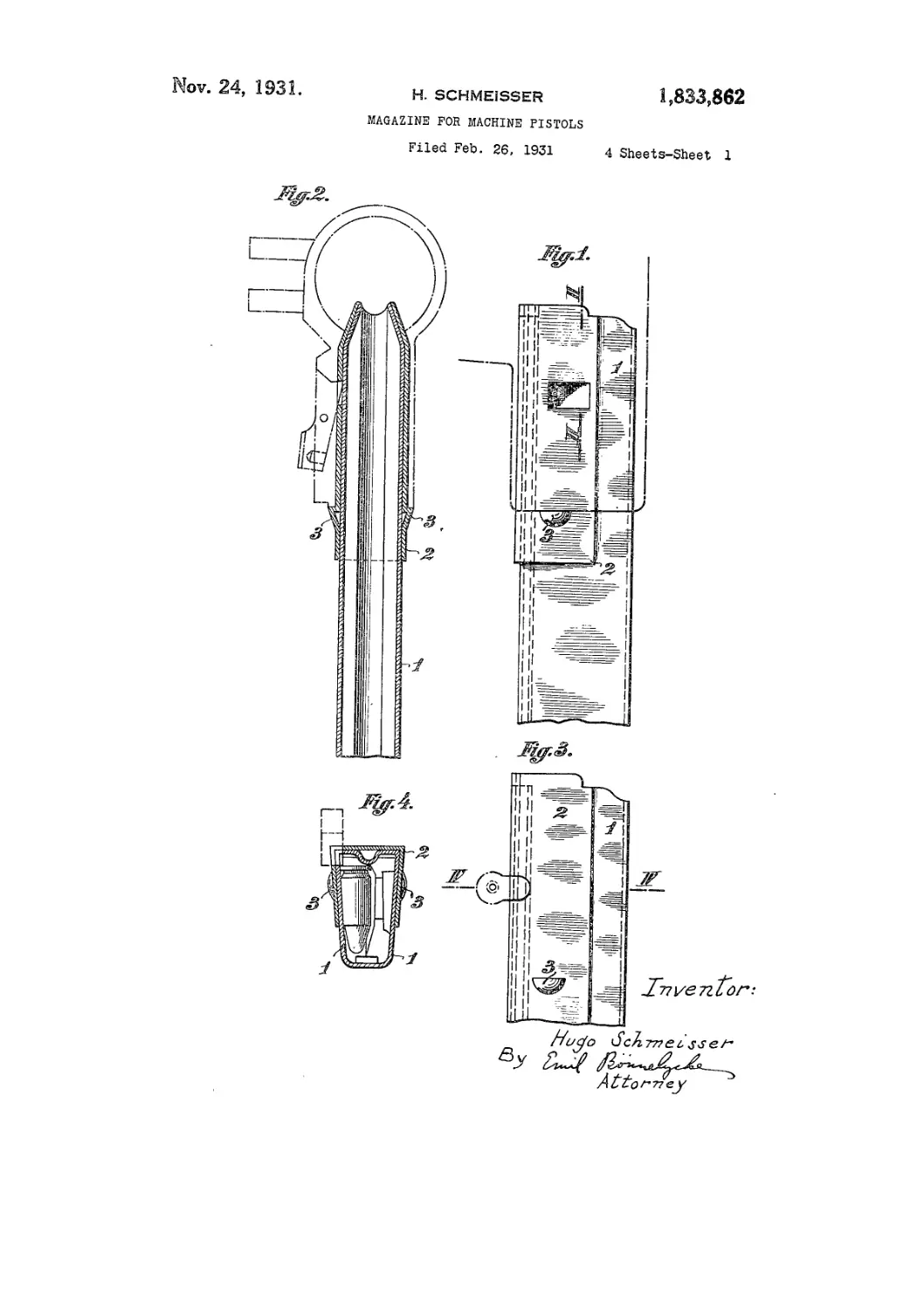
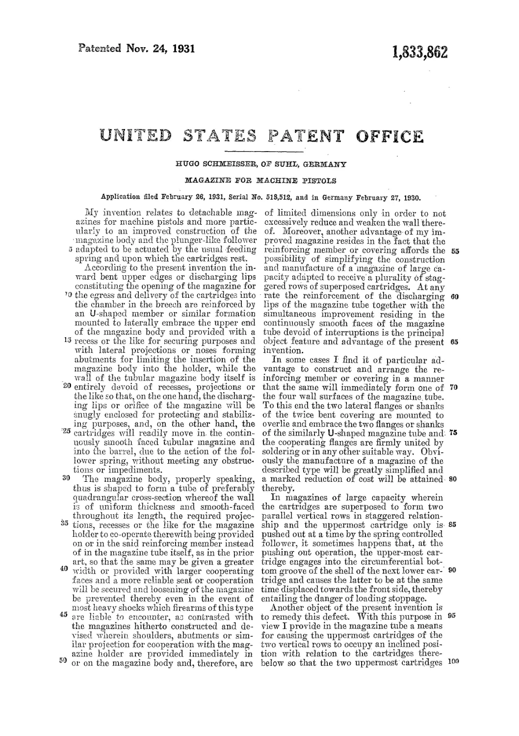
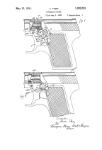
In said annexed drawings: Figure 1 shows
55 the magazine in side view with the lower end
broken away and with the magazine holder
indicated by broken or dot-and-dash lines;
Figure 2 is a view in vertical section on
the line II—II of Figure 1; Figure 3 is a
60 fragmentary side view of a modified form
of the magazine with the holder engaging
the rear side of the magazine; Figure 4 is
a view in horizontal section taken on the
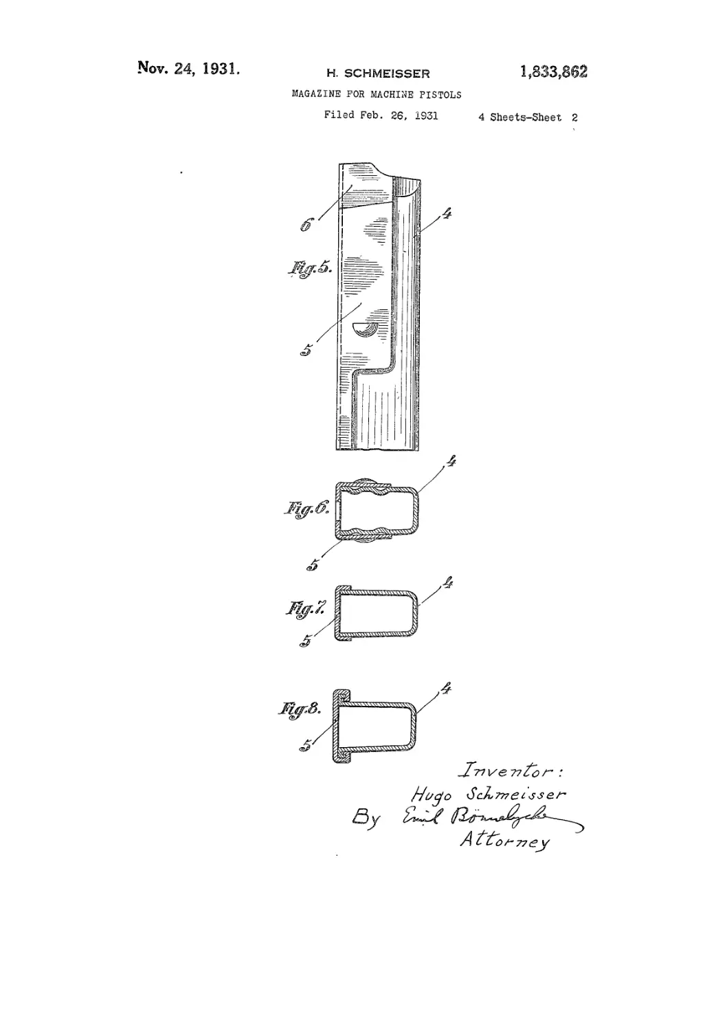
line IV—IV of Figure 3; Figure 5 is a
65 fragmentary view of a further modification
of the magazine Avith the reinforcing mem-
ber firmly attached thereto to form the rear
ivall thereof; Figure 6 is a sectional vieAV of
the upper part of the modification shoAvn
in Fig. 5; Figure 7 is a similar section of the 7o
loAver part thereof, while Figure 8 is a like
section of a modified construction of the
reinforcing member interconnected with the
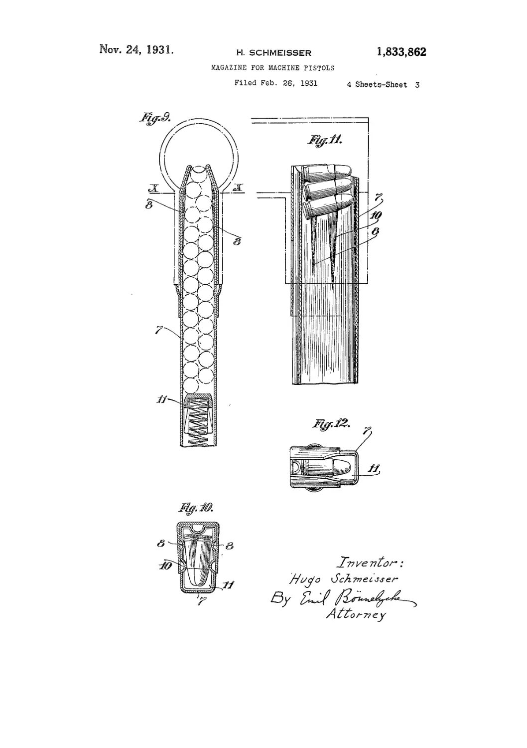
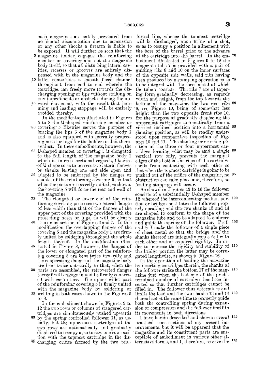
magazine; Figure 9 is a view in vertical
section of a further modification of the maga- 73
zine, partly broken off and with the holder
or casing carrying the magazine, and the
cartridges shoAvn in broken and dot-and-
dash lines; Figure 10 is a vieAv in section
taken on the line X—X of Figure 9; Figure go
11 is a view in longitudinal vertical section
of the upper end of the magazine shoAvn in
Figure 9 with a few cartridges therein and
Avith the folloAver removed; Figure 12 is a
vieAv in top plan of the parts illustrated in 85
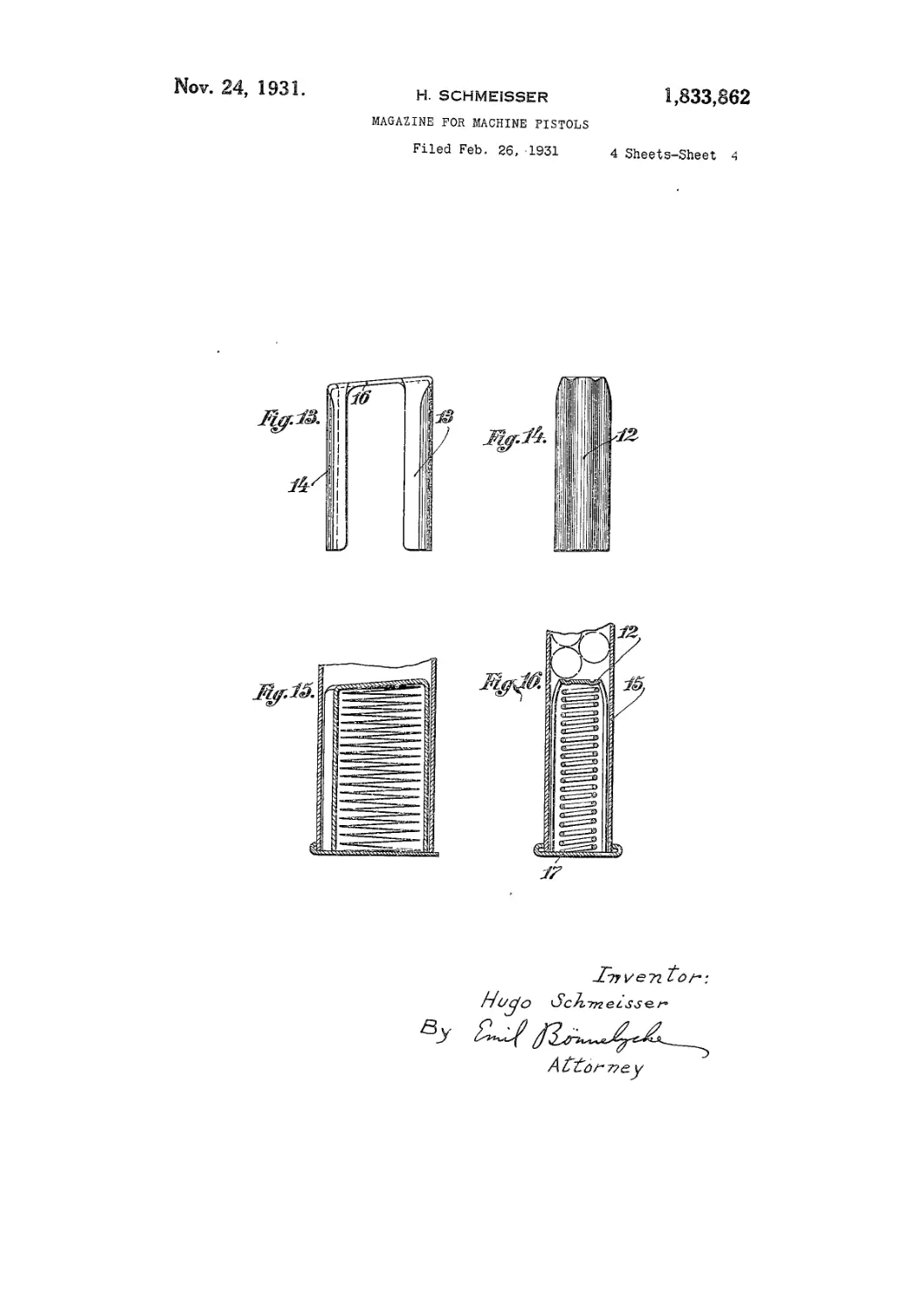
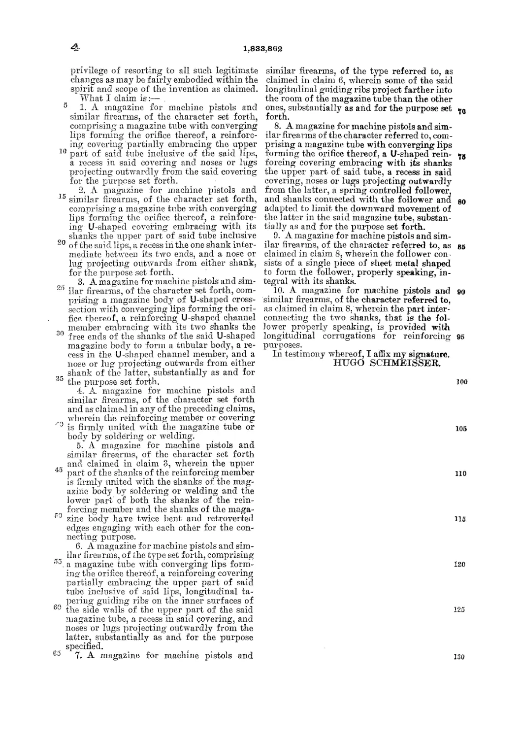
Figure 10; Figure 13 and Figure 14 are
front and side elevations, respectively, of
the folloAver constructed according to the
present iirvention; and Figures 15 and 16 are
corresponding sectional vieAvs of the folloAV- oo
er inserted in the bottom end of the maga-
zine.
Referring to the embodiment of the in-
vention shown in Figures 1 and 2 the U-
shaped reinforcing member 2 is firmly united as
Avith the upper end of the magazine body 1
by soldering or in any other suitable way.
The length of the member 2 corresponds to
the length of the holding sleeve taken from
the top forming the discharging orifice doivn 100
to the projections or noses 3 formed in the
members 2 to act as an abutment or stop for
the loAver end of the holding sleeve so that
the latter will rest thereon when the maga-
zine is fully pushed home, as shown in Fig- 105
ure 1. One Aving or shank of the U-shaped
member 2 is provided with a comparatively
Avide recess or aperture 4 for the magazine
holder to engage therein while at the same
time the txvo noses 3 act to limit the inser- 110
tion of the magazine into the holder. In the
modification shown in Figures 3 and 4 where-
in the holder engages the rear hind edge of
the magazine, the rear Avail of the magazine
tube is shapecl to form a longitudinal smooth 115
channelled rib or shoulder for the bottom end
of the cartridge shell to freely and smoothly
slide thereon. Also in this modification the
cartridges thus are prevented from coming
in contact with the magazine holder when 120
they are pushed upAvards in the magazine
by the spring controlled folloAver, although
the holder engages into recesses provided in
the one rear corner of both the reinforcing
member 2 and the magazine tube. 125
It Avill be seen that in both embodiments
shown in Figures 1 to 4 wide engaging sur-
faces may be offered to the magazine holder
so that even in case of abnormally long and
heavy magazines made of thin metallic sheets 139
1,833,862
3
such magazines are safely prevented from
accidental disconnection due to concussion
or any other shocks a firearm is liable to
be exposed. It will further be seen that the
- 5 magazine holder engages the reinforcing
member or covering’ and not the magazine
body itself, so that all disturbing lateral cav-
ities, recesses or grooves are entirely dis-
pensed with in the magazine body and the
.10 latter constitudes a smooth faced channel
throughout from end to end wherein the
cartridges can freely move towards the dis-
charging opening or lips without striking on
any impediments or obstacles during the up-
?lo ward movement, with the result that jam-
ming and loading stoppage will be entirely
avoided thereby.
In the modifications illustrated in Figures
5 to 8 the U-shaped reinforcing member or
•20 covering 5 likewise serves the purpose of
bracing the lips 6 of the magazine body 1
and is also equipped with laterally project-
ing noses or lugs for the holder to abut there-
a gainst. In these embodiments, however, the
25 U-shaped member or covering 5 is elongated
to the full length of the magazine body 1
which is, in cross-sectional regards, likewise
-of U-shape so as to possess two lateral flanges
or shanks leaving one end side open and
so adapted to be embraced by the flanges or
shanks of the reinforcing covering 5, so that
when the parts are correctly united, as shown,
the covering 5 will form-the rear end wall of
the magazine.
S5 The elongated or lower end of the rein-
forcing covering possesses two lateral flanges
of less width than that of the flanges of the
upper part of the covering provided with the
projecting noses or lugs, as will be clearly
d0 seen on inspection of Figures 6 and 7. In this
modification the overlapping flanges of the
covering 5 and the magazine body 1 are firm-
ly united by soldering throughout the whole
length thereof. In the modification illus-
15 trated in Figure 8, however, the flanges of
the lower or elongated part of the reinforc-
ing covering 5 are bent twice inwardly and
the cooperating flanges of the magazine body
are bent twice outwardly so that, when the
50 ’parts are assembled, the retroverted flanges
thereof will engage in and be firmly connect-
ed with each other. The upper wider part
of the reinforcing covering 5 is firmly united
with the magazine body by soldering or
55 welding in both cases shown in the Figures 5
to 8.
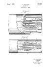
In the embodiment shown in Figures 9 to
12 the two row’s or columns of staggered car-
tridges are simultaneously pushed upwards
80 by the spring controlled follower 11, as us-
ually, but the uppermost cartridges of the
two rows are automatically and gradually
displaced to occupy a, so to say, one row posi-
tion with the topmost cartridge in the dis-
35 charging orifice formed by the two rein-
forced lips, whence the topmost cartridge
will be discharged, upon firing of a shot,
so as to occupy a position in alinement with
the bore of the barrel prior to the advance
of the cartridge into the barrel. In the em- 70
bodiment illustrated in Figures 9 to 12 the
magazine tube 7 is provided with a pair of
guiding ribs 8 and 10 on the inner surfaces
of the opposite side walls, said ribs having
been produced by a stamping operation so as 75
to be integral with the sheet metal of which
the tube 7 consists. The ribs 7 are of taper-
ing form gradually decreasing, as regards
width and height, from the top towards the
bottom of the magazine, the two rear ribs 80
' 8, see Figure 10, being of somewhat less
height than the two opposite front ribs 10,
for the purpose of gradually displacing the
uppermost cartridges automatically from a
vertical inclined position into a horizontal 85
slanting position, as will be readily under-
stood upon comparative inspection of Fig-
ures 10 and 11. The slanting or crossing po-
sition of the three or four uppermost car-
tridges forming what may be said a single 80
vertical row only, prevents the marginal
edges of the bottoms or rims of the cartridge
shells from contacting with each other so
that when the topmost cartridge is going to be
pushed out of the orifice of the magazine, no 05
obstruction can take place and, therefore, no
loading stoppage will occur.
As shown in Figures 13 to 16 the follower
consists of a substantially U-shaped member
12 whereof the interconnecting median por- too
tion or bridge constitutes the follower prop-
erly speaking and the two shanks 13 and 14
are shaped; to conform to the shape of the
magazine tube and to be adapted to embrace
and guide the spring of the follower. Pref- 105
erably I make the follower of a single piece
of sheet metal so that the bridge and the
shanks thereof are integrally connected with
each other and of required rigidity. In or-
der to increase the rigidity and stability of 110
the bridge portion the latter may be corru-
gated lengthwise, as shown in Figure 16.
In the operation of loading the magazine
by inserting cartridges therein, the shanks of
the follower strike the bottom 17 of the mag- г1!!
azine just when the last one of the prede-
termined number of cartridges has been in-
serted so that further cartridges cannot be
filled in. The follower thus determines and
limits the load and the two shanks 13 and 14 120
thereof act at the same time to properly guide
both the controlling spring during expan-
sion or compression and the follower itself in
its movements in both directions.
I have herein described and shown several 125
practical constructions of my present im-
provements, but it will be apparent that the
magazine and its constituent parts are sus-
ceptible of embodiment in various other al-
ternative forms, and I, therefore, reserve the 1ЗД
4-
1,833,862
privilege of resorting to all such legitimate
changes as may be fairly embodied within the
spirit and scope of the invention as claimed.
What I claim is:— ,
5 1. A magazine for machine pistols and
similar firearms, of the character set forth,
comprising a magazine tube with converging
lips forming the orifice thereof, a reinforc-
ing covering partially embracing the upper
10 part of said tube inclusive of the said lips,
a recess in said covering and noses or lugs
projecting outwardly from the said covering
for the purpose set forth.
2. A magazine for machine pistols and
15 similar firearms, of the character set forth,
comprising a magazine tube with converging
lips forming the orifice thereof, a reinforc-
ing U-shaped covering embracing with its
shanks the upper part of said tube inclusive
20 of the said lips, a recess in the one shank inter-
mediate between its two ends, and a nose or
lug projecting outwards from either shank,
for the purpose set forth.
8. A magazine for machine pistols and sim-
2:> ilar firearms, of the character set forth, com-
prising a magazine body of U-shaped cross-
section with converging lips forming the ori-
fice thereof, a reinforcing U-shaped channel
member embracing with its two shanks the
30 free ends of the shanks of the said U-shaped
magazine body to form a tubular body, a re-
cess in the. U-shaped channel member, and a
nose or lug projecting outwards from either
shank of the latter, substantially as and for
35 the purpose set forth.
4. A magazine for machine pistols and
similar firearms, of the character set forth
and as claimed in any of the preceding claims,
wherein the reinforcing member or covering
is firmly united with the magazine tube or
body by soldering or welding.
5. A magazine for machine pistols and
similar firearms, of the character set forth
and claimed in claim 3, wherein the upper
43 part of the shanks of the reinforcing member
is firmly united with the shanks of the mag-
azine body by soldering or welding and the
lower part of both the shanks of the rein-
forcing member and the shanks of the maga-
il0 zine body have twice bent and retroverted
edges engaging with each other for the con-
necting purpose.
6. A magazine for machine pistols and sim-
ilar firearms, of the type set forth, comprising
',3. a magazine tube with converging lips form-
ing the orifice thereof, a reinforcing covering
partially embracing the upper part of said
tube inclusive of said lips, longitudinal ta-
pering guiding ribs on the inner surfaces of
60 the side walls of the upper part of the said
magazine tube, a recess in said covering, and
noses or lugs projecting outwardly from the
latter, substantially as and for the purpose
specified.
Ga 7. A magazine for machine pistols and
similar firearms, of the type referred to, as
claimed in claim 6, wherein some of the said
longitudinal guiding ribs project farther into
the room of the magazine tube than the other
ones, substantially as and for the purpose set
forth.
8. A magazine for machine pistols and sim-
ilar firearms of the character referred to, com-
prising a magazine tube with converging lips
forming the orifice thereof, a U-shaped rein- <j8
forcing covering embracing with its shanks
the upper part of said tube, a recess in said
covering, noses or lugs projecting outwardly
from the latter, a spring controlled follower,
and shanks connected with the follower and go
adapted to limit the downward movement of
the latter in the said magazine tube, substan-
tially as and for the purpose set forth.
9. A magazine for machine pistols and sim-
ilar firearms, of the character referred to, as gs
claimed in claim 8, wherein the follower con-
sists of a single piece of sheet metal shaped
to form the follower, properly speaking, in-
tegral with its shanks.
10. A magazine for machine pistols and 90
similar firearms, of the character referred to,
as claimed in claim 8, wherein the part inter-
connecting the two shanks, that is the fol-
lower properly speaking, is provided with
longitudinal corrugations for reinforcing 95
purposes.
In testimony whereof, I affix my signature.
HUGO SCHMEISSER.
too
105
110
115
120
130