/

Tags: weapons military affairs patent mortar
Year: 1970

Text
J. J. DRISCOLL
SILENT MORTAR
3,505,924
April 14, 1970
Filed April 18, 1967
3 Sheets-Sheet 1
ATTORNEYS
ATTORNEYS
7///////7, 7///////////////////////////////7\
7//////7////777////777/////////////////////A
V
го
04
сл
СЛ
СЛ
U1 I f
Ч*/|
сл \'Ч
— \ I'
I Ь
СЛ
СЛ
" сл
U1
00
м
я
1-3
я
□
л
(Л
о
о
(Я
о
л
сл
2
<
hl
г
8
О)
0)
— ___J
—
СП \_—
ГО
О)
сл
00
00
7^^&ZSZgZZZg^ZZZZZZZZZZZZZZ2ZZZZZZZZZZZZZZ2Z^&Z^ZZZZZZZZZZZZZZZZZZZZZZZSi
а>
СЛ
00
СЛ
го
0)
го
м
W
tr
ф
ф
и
I
W
tr
ф
ф
м
сл
о
сл
ъ
№
April 14, 1970
J. J. DRISCOLL
SILENT MOBTAB
3,505,924
Filed April 18, 1967
3 Sheets-Sheet 3
FIG. 9
INVENTOR.
JOHN J. DRISCOLL
ATTORNEYS
3,505,924
Patented Apr. 14, 1970
United States Patent Office
1
3,505,924
SILENT MORTAR
John J. Driscoll, Paris, France, assignor to Allied
Research Associates, Inc., Concord, Mass., a cor-
poration of Delaware
Filed Apr. 18, 1967, Ser. No. 631,650
Int. Ci. F41f 1/06
U.S. CI. 89—1 8 Claims
5
ABSTRACT OF THE DISCLOSURE
A mortar with a projectile having a cylinder which
contains the propellant, and a piston within the cylinder
which pushes upon a rod within the mortar tube to ac-
celerate the projectile. The piston contains the expanded
propellant charge and silences the operation.
10
15
Mortars are widely used infantry weapons and pro-
vide supporting heavy fire power for light infantry and
other mobile units. The typical mortar has a heavy steel
tube to contain the explosive gases and guide the projectile
into the proper path. To keep unit weights down a sepa-
rate base plate is normally provided. Even the 60 milli-
meter mortar, the smallest in present use by American
forces, is normally broken down into a two-man load
for travel over difficult terrain or long distances. The
larger mortars must be broken down to be transported.
The fact that prior mortars have used the mortar tube
structure to withstand the propellant charge forces has re-
sulted in the above weight problems and made the mortars
more difficult to transport. In addition, the charge is free
to expand into the atmosphere once the projectile leaves
the tube. These expanding charges create a characteristic
noise which serves to inform the energy both as to the
type of weapon and its location. At night the flash is
visible as the projectile leaves the tube, giving a visible
indication of the location. Accordingly, both during the
day and during the night enemy fire power may be di-
rected rather accurately at the mortar crew.
Most existing mortars, even the small 60 millimeter
mortars, have a propellant system involving a basic charge
with supplemental charge increments. The mortar range
is a function of the angle of the tube and the number of
increments used with the basic charge. While this charge
system gives extended range capabilities, its adds unneces-
sary complications for a very portable mortar suited for
used by advanced elements. Specific and detailed per-
sonnel training is required. Furthermore, either extensive
data must be committed to memory, or the firing tables
must be available and readable at the time of firing.
Thus additional problems are created, particularly for a
small group which would prefer to remain undetected in
the nighttime.
My invention avoids the above problems and provides
a lightweight, silent mortar suited for use by unskilled
personnel. The mortar tube is fabricated from lightweight
material and an initiating rod is positioned at the center
of the base of the tube. The projectile contains a propel-
lant within a cylinder in its lower portion. A piston and
firing pin contained within this cylinder serve to initiate
propulson upon impact with the initiating rod. A safety
plug prevents inadvertent firing and allows the mortar
tube to be used as a carrier for the projectiles. The piston
serves to contain the expanded propellant charge so that
there is no noise, blast or flash due to expanding gases
from the charge. The projectile velocity is subsonic so
that the over all operation is silent. The base may be
formed at the angle for an average launch range, with
a bubble sight provided for more accurate range deter-
mination. Certain embodiments modify the ballistic trajec-
20
25
30
35
40
45
50
55
60
65
70
2
tory to deter even radar location of the silent, flashless
mortar operation.
The invention is more fully set forth in the following
description in conjunction with the drawings, wherein:
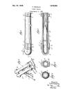
FIGURE 1 is an over-all elevation view in cross-sec-
tion of the mortar with a projectile in position for firing;
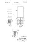
FIGURE 2 is an elevation view in cross-section of the
projectile at the moment of firing within the mortar tube;
FIGURE 3 is an elevation view in cross-section of the
projectile after leaving the initiating rod;
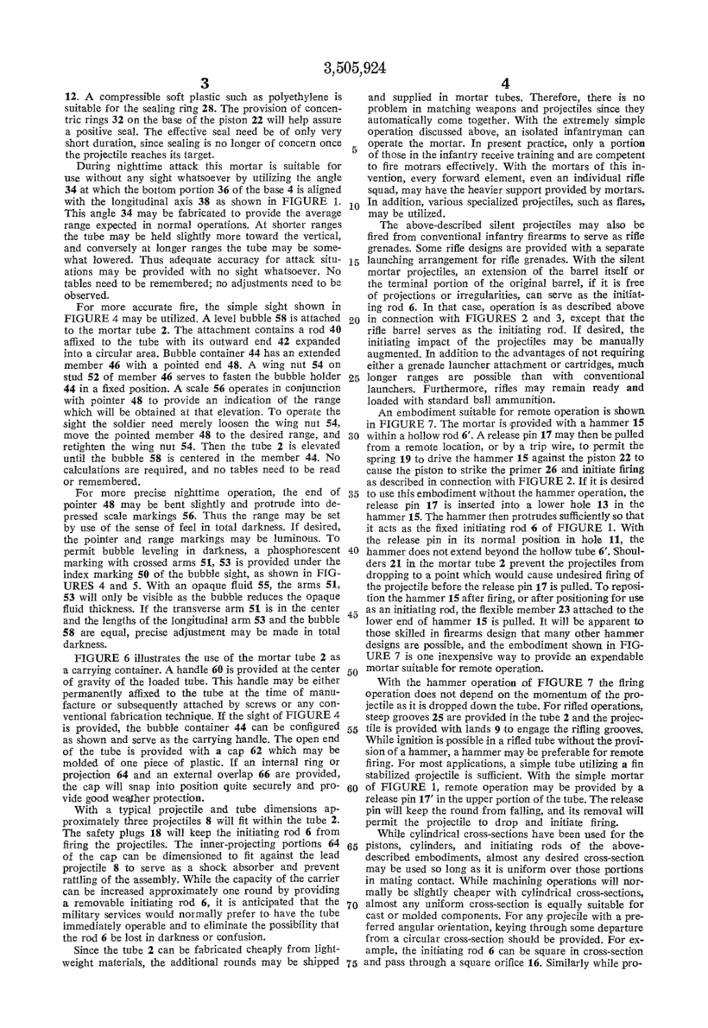
FIGURE 4 is a perspective view of the mortar sight;
FIGURE 5 is a plan view of bubble sight details;
FIGURE 6 is a view in cross-section of the over-all
mortar assembly utilized as a carrying container;
FIGURE 7 is an elevation view in cross-section of an
embodiment with a firing hammer;
FIGURE 8 is an elevation view in cross-section of a
cylinder assembly employing a consumable piston; and
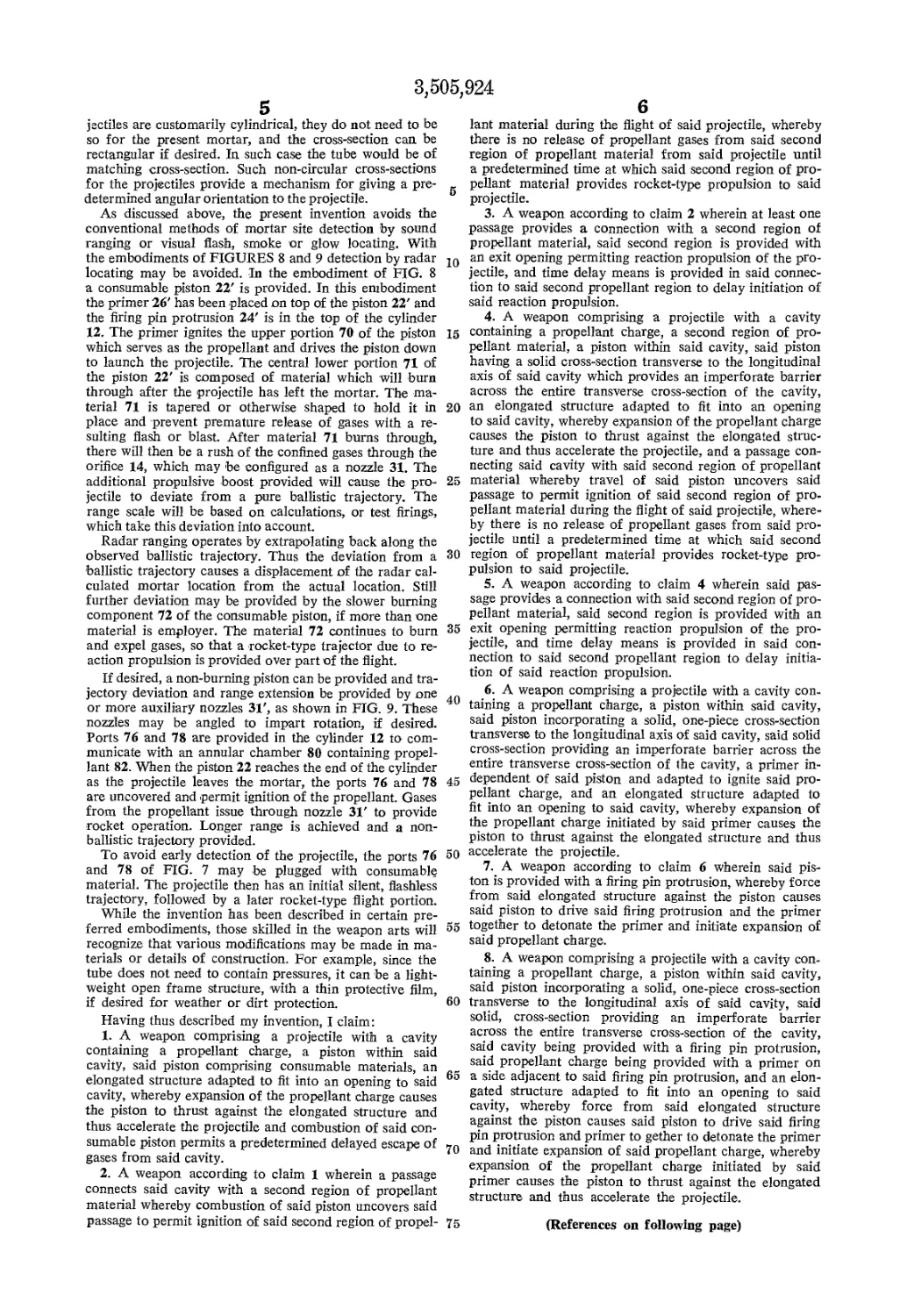
FIGURE 9 is an elevation view in cross section of an
embodiment providing reaction propulsion.
The over-all construction of the silent mortar is shown
in FIGURE 1. The mortar tube 2 is terminated in a base
portion 4. Since the mortar launching tube of this inven-
tion does not need to contain explosive pressure, the tube
and base may be molded as one unit from plastic mate-
rial. Fiber glass reinforcement gives adequate strength
to withstand the rough treatment of combat handling. If
desired, the tube 2 may be of metal, for example a light-
weight alloy, and the base either screwed or molded to
one end of the tube. The light tubes of my invention are
of sufficiently low cost to be considered expendable items.
The initiating rod 6 should be an elongated structure of
rigid material, such as metal.
The projectile 8 may be provided with any conventional
fuse 10. With the projectile 8 a cylinder 12 is provided
with an opening orifice 14 toward the rear. A safety plug
18 closes the orifice to prevent accidental firing. Threads
16 in the rear of piston 22 engage plug 18 to prevent
accidental firing through shock if the projectile is dropped.
The projectile is thus safe for normal handling. The body
of the projectile 8 will normally be fabricated of metal
to provide the necessary structure for desired high-ex-
plosive, fragmentation, shaped charge or other character-
istics. Fins 7 may be provided to furnish spin stabiliza-
tion or activate spin-actuated components. The safety plug
may be of metal but may be more cheaply provided as a
molded plastic product. While the plug 18 is shown
threaded into the piston 22, economies in manufacture
can be obtained by providing a plug with a molded de-
formable ring. The piston may then be threaded or sim-
ply have a mating ring or groove. If the plug 18 must be
unthreaded for removal, turning of the piston 22 may be
prevented by some deviation from a perfectly uniform
radius of cylindrical cross-section in cylinder 12 or by a
light staking or adhesive spot. If a deformable plug is
used, it may be simply pulled or pried out.
One possible sequence for the firing operation, and
the elements involved, are shown in FIGURE 2. The
projectile 16 with the safety plug 18 removed, has fallen
upon the initiating rod 6. The initiating rod 6 drives
the firing pin 24 attached to piston 22 against the primer
26. The flash from the primer 26 ignites the propellant
charge 20. As the propellant charge 20 expands, the piston
22 is forced toward the rear of the cylinder 12. Since
the initiating rod 6 is fixed within the base 4, the projectile
is forced upwards and towards the open end of the mor-
tar tube 2.
FIGURE 3 shows the shell in cross-section just after
it has left the initiating rod. The piston 22 is now forced
against the compressible sealing ring 28 which abuts
shoulder 29. Thus the expanded gases 30 formed by the
propellant charge 20 are contained within the cylinder
3;5
3
12. A compressible soft plastic such as polyethylene is
suitable for the sealing ring 28. The provision of concen-
tric rings 32 on the base of the piston 22 will help assure
a positive seal. The effective seal need be of only very
short duration, since sealing is no longer of concern once
the projectile reaches its target.
During nighttime attack this mortar is suitable for
use without any sight whatsoever by utilizing the angle
34 at which the bottom portion 36 of the base 4 is aligned
with the longitudinal axis 38 as shown in FIGURE 1.
This angle 34 may be fabricated to provide the average
range expected in normal operations. At shorter ranges
the tube may be held slightly more toward the vertical,
and conversely at longer ranges the tube may be some-
what lowered. Thus adequate accuracy for attack situ-
ations may be provided with no sight whatsoever. No
tables need to be remembered; no adjustments need to be
observed.
For more accurate fire, the simple sight shown in
FIGURE 4 may be utilized. A level bubble 58 is attached
to the mortar tube 2. The attachment contains a rod 40
affixed to the tube with its outward end 42 expanded
into a circular area. Bubble container 44 has an extended
member 46 with a pointed end 48. A wing nut 54 on
stud 52 of member 46 serves to fasten the bubble holder
44 in a fixed position. A scale 56 operates in conjunction
with pointer 48 to provide an indication of the range
which will be obtained at that elevation. To operate the
sight the soldier need merely loosen the wing nut 54,
move the pointed member 48 to the desired range, and
retighten the wing nut 54. Then the tube 2 is elevated
until the bubble 58 is centered in the member 44. No
calculations are required, and no tables need to be read
or remembered.
For more precise nighttime operation, the end of
pointer 48 may be bent slightly and protrude into de-
pressed scale markings 56. Thus the range may be set
by use of the sense of feel in total darkness. If desired,
the pointer and range markings may be luminous. To
permit bubble leveling in darkness, a phosphorescent
marking with crossed arms 51, 53 is provided under the
index marking 50 of the bubble sight, as shown in FIG-
URES 4 and 5. With an opaque fluid 55, the arms 51,
53 will only be visible as the bubble reduces the opaque
fluid thickness. If the transverse arm 51 is in the center
and the lengths of the longitudinal arm 53 and the bubble
58 are equal, precise adjustment may be made in total
darkness.
FIGURE 6 illustrates the use of the mortar tube 2 as
a carrying container. A handle 60 is provided at the center g0
of gravity of the loaded tube. This handle may be either
permanently affixed to the tube at the time of manu-
facture or subsequently attached by screws or any con-
ventional fabrication technique. If the sight of FIGURE 4
is provided, the bubble container 44 can be configured gg
as shown and serve as the carrying handle. The open end
of the tube is provided with a cap 62 which may be
molded of one piece of plastic. If an internal ring or
projection 64 and an external overlap 66 are provided,
the cap will snap into position quite securely and pro-
vide good weather protection.
With a typical projectile and tube dimensions ap-
proximately three projectiles 8 will fit within the tube 2.
The safety plugs 18 will keep the initiating rod 6 from
firing the projectiles. The inner-projecting portions 64
of the cap can be dimensioned to fit against the lead
projectile 8 to serve as a shock absorber and prevent
rattling of the assembly. While the capacity of the carrier
can be increased approximately one round by providing
a removable initiating rod 6, it is anticipated that the
military services would normally prefer to have the tube
immediately operable and to eliminate the possibility that
the rod 6 be lost in darkness or confusion.
Since the tube 2 can be fabricated cheaply from light-
weight materials, the additional rounds may be shipped
)5,924
4
and supplied in mortar tubes. Therefore, there is no
problem in matching weapons and projectiles since they
automatically come together. With the extremely simple
operation discussed above, an isolated infantryman can
operate the mortar. In present practice, only a portion
of those in the infantry receive training and are competent
to fire motrars effectively. With the mortars of this in-
vention, every forward element, even an individual rifle
squad, may have the heavier support provided by mortars.
20 In addition, various specialized projectiles, such as flares,
may be utilized.
The above-described silent projectiles may also be
fired from conventional infantry firearms to serve as rifle
grenades. Some rifle designs are provided with a separate
15 launching arrangement for rifle grenades. With the silent
mortar projectiles, an extension of the barrel itself or
the terminal portion of the original barrel, if it is free
of projections or irregularities, can serve as the initiat-
ing rod 6. In that case, operation is as described above
20 in connection with FIGURES 2 and 3, except that the
rifle barrel serves as the initiating rod. If desired, the
initiating impact of the projectiles may be manually
augmented. In addition to the advantages of not requiring
either a grenade launcher attachment or cartridges, much
25 longer ranges are possible than with conventional
launchers. Furthermore, rifles may remain ready and
loaded with standard ball ammunition.
An embodiment suitable for remote operation is shown
in FIGURE 7. The mortar is provided with a hammer 15
30 within a hollow rod 6'. A release pin 17 may then be pulled
from a remote location, or by a trip wire, to permit the
spring 19 to drive the hammer 15 against the piston 22 to
cause the piston to strike the primer 26 and initiate firing
as described in connection with FIGURE 2. If it is desired
35 to use this embodiment without the hammer operation, the
release pin 17 is inserted into a lower hole 13 in the
hammer 15. The hammer then protrudes sufficiently so that
it acts as the fixed initiating rod 6 of FIGURE 1. With
the release pin in its normal position in hole 11, the
40 hammer does not extend beyond the hollow tube 6'. Shoul-
ders 21 in the mortar tube 2 prevent the projectiles from
dropping to a point which would cause undesired firing of
the projectile before the release pin 17 is pulled. To reposi-
tion the hammer 15 after firing, or after positioning for use
as an initiating rod, the flexible member 23 attached to the
lower end of hammer 15 is pulled. It will be apparent to
those skilled in firearms design that many other hammer
designs are possible, and the embodiment shown in FIG-
URE 7 is one inexpensive way to provide an expendable
mortar suitable for remote operation.
With the hammer operation of FIGURE 7 the firing
operation does not depend on the momentum of the pro-
jectile as it is dropped down the tube. For rifled operations,
steep grooves 25 are provided in the tube 2 and the projec-
tile is provided with lands 9 to engage the rifling grooves.
While ignition is possible in a rifled tube without the provi-
sion of a hammer, a hammer may be preferable for remote
firing. For most applications, a simple tube utilizing a fin
stabilized projectile is sufficient. With the simple mortar
60 of FIGURE 1, remote operation may be provided by a
release pin 17' in the upper portion of the tube. The release
pin will keep the round from falling, and its removal will
permit the projectile to drop and initiate firing.
While cylindrical cross-sections have been used for the
65 pistons, cylinders, and initiating rods of the above-
described embodiments, almost any desired cross-section
may be used so long as it is uniform over those portions
in mating contact. While machining operations will nor-
mally be slightly cheaper with cylindrical cross-sections,
70 almost any uniform cross-section is equally suitable for
cast or molded components. For any projecile with a pre-
ferred angular orientation, keying through some departure
from a circular cross-section should be provided. For ex-
ample, the initiating rod 6 can be square in cross-section
75 and pass through a square orifice 16. Similarly while pro-
3,505,924
5
jectiles are customarily cylindrical, they do not need to be
so for the present mortar, and the cross-section can. be
rectangular if desired. In such case the tube would be of
matching cross-section. Such non-circular cross-sections
for the projectiles provide a mechanism for giving a pre-
determined angular orientation to the projectile.
As discussed above, the present invention avoids the
conventional methods of mortar site detection by sound
ranging or visual flash, smoke or glow locating. With
the embodiments of FIGURES 8 and 9 detection by radar
locating may be avoided. In the embodiment of FIG. 8
a consumable piston 22' is provided. In this embodiment
the primer 26' has been placed on top of the piston 22' and
the firing pin protrusion 24' is in the top of the cylinder
12. The primer ignites the upper portion 70 of the piston
which serves as the propellant and drives the piston down
to launch the projectile. The central lower portion 71 of
the piston 22' is composed of material which will burn
through after the projectile has left the mortar. The ma-
terial 71 is tapered or otherwise shaped to hold it in
place and prevent premature release of gases with a re-
sulting flash or blast. After material 71 burns through,
there will then be a rush of the confined gases through the
orifice 14, which may be configured as a nozzle 31. The
additional propulsive boost provided will cause the pro-
jectile to deviate from a pure ballistic trajectory. The
range scale will be based on calculations, or test firings,
which take this deviation into account.
Radar ranging operates by extrapolating back along the
observed ballistic trajectory. Thus the deviation from a
ballistic trajectory causes a displacement of the radar cal-
culated mortar location from the actual location. Still
further deviation may be provided by the slower burning
component 72 of the consumable piston, if more than one
material is employer. The material 72 continues to burn
and expel gases, so that a rocket-type trajector due to re-
action propulsion is provided over part of the flight.
If desired, a non-burning piston can be provided and tra-
jectory deviation and range extension be provided by one
or more auxiliary nozzles 31', as shown in FIG. 9. These
nozzles may be angled to impart rotation, if desired.
Ports 76 and 78 are provided in the cylinder 12 to com-
municate with an annular chamber 80 containing propel-
lant 82. When the piston 22 reaches the end of the cylinder
as the projectile leaves the mortar, the ports 76 and 78
are uncovered and permit ignition of the propellant. Gases
from the propellant issue through nozzle 31' to provide
rocket operation. Longer range is achieved and a non-
ballistic trajectory provided.
To avoid early detection of the projectile, the ports 76
and 78 of FIG. 7 may -be plugged with consumable
material. The projectile then has an initial silent, flashless
trajectory, followed by a later rocket-type flight portion.
While the invention has been described in certain pre-
ferred embodiments, those skilled in the weapon arts will
recognize that various modifications may be made in ma-
terials or details of construction. For example, since the
tube does not need to contain pressures, it can be a light-
weight open frame structure, with a thin protective film,
if desired for weather or dirt protection.
Having thus described my invention, I claim:
1. A weapon comprising a projectile with a cavity
containing a propellant charge, a piston within said
cavity, said piston comprising consumable materials, an
elongated structure adapted to fit into an opening to said
cavity, whereby expansion of the propellant charge causes
the piston to thrust against the elongated structure and
thus accelerate the projectile and combustion of said con-
sumable piston permits a predetermined delayed escape of
gases from said cavity.
2. A weapon according to claim 1 wherein a passage
connects said cavity with a second region of propellant
material whereby combustion of said piston uncovers said
passage to permit ignition of said second region of propel-
5
10
15
20
25
30
35
40
45
50
55
60
65
70
75
6
lant material during the flight of said projectile, whereby
there is no release of propellant gases from said second
region of propellant material from said projectile until
a predetermined time at which said second region of pro-
pellant material provides rocket-type propulsion to said
projectile.
3. A weapon according to claim 2 wherein at least one
passage provides a connection with a second region of
propellant material, said second region is provided with
an exit opening permitting reaction propulsion of the pro-
jectile, and time delay means is provided in said connec-
tion to said second propellant region to delay initiation of
said reaction propulsion.
4. A weapon comprising a projectile with a cavity
containing a propellant charge, a second region of pro-
pellant material, a piston within said cavity, said piston
having a solid cross-section transverse to the longitudinal
axis of said cavity which provides an imperforate barrier
across the entire transverse cross-section of the cavity,
an elongated structure adapted to fit into an opening
to said cavity, whereby expansion of the propellant charge
causes the piston to thrust against the elongated struc-
ture and thus accelerate the projectile, and a passage con-
necting said cavity with said second region of propellant
material whereby travel of said piston uncovers said
passage to permit ignition of said second region of pro-
pellant material during the flight of said projectile, where-
by there is no release of propellant gases from said pro-
jectile until a predetermined time at which said second
region of propellant material provides rocket-type pro-
pulsion to said projectile.
5. A weapon according to claim 4 wherein said pas-
sage provides a connection with said second region of pro-
pellant material, said second region is provided with an
exit opening permitting reaction propulsion of the pro-
jectile, and time delay means is provided in said con-
nection to said second propellant region to delay initia-
tion of said reaction propulsion.
6. A weapon comprising a projectile with a cavity con-
taining a propellant charge, a piston within said cavity,
said piston incorporating a solid, one-piece cross-section
transverse to the longitudinal axis of said cavity, said solid
cross-section providing an imperforate barrier across the
entire transverse cross-section of the cavity, a primer in-
dependent of said piston and adapted to ignite said pro-
pellant charge, and an elongated structure adapted to
fit into an opening to said cavity, whereby expansion of
the propellant charge initiated by said primer causes the
piston to thrust against the elongated structure and thus
accelerate the projectile.
7. A weapon according to claim 6 wherein said pis-
ton is provided with a firing pin protrusion, whereby force
from said elongated structure against the piston causes
said piston to drive said firing protrusion and the primer
together to detonate the primer and initiate expansion of
said propellant charge.
8. A weapon comprising a projectile with a cavity con-
taining a propellant charge, a piston within said cavity,
said piston incorporating a solid, one-piece cross-section
transverse to the longitudinal axis of said cavity, said
solid, cross-section providing an imperforate barrier
across the entire transverse cross-section of the cavity,
said cavity being provided with a firing pin protrusion,
said propellant charge being provided with a primer on
a side adjacent to said firing pin protrusion, and an elon-
gated structure adapted to fit into an opening to said
cavity, whereby force from said elongated structure
against the piston causes said piston to drive said firing
pin protrusion and primer to gether to detonate the primer
and initiate expansion of said propellant charge, whereby
expansion of the propellant charge initiated by said
primer causes the piston to thrust against the elongated
structure and thus accelerate the projectile.
(References on following page)
3,505,924 7 8 References Cited 3,104,523 9/1963 O’Donnell. UNITED STATES PATENTS Baton.
45,898 1,317,419 1,347,125 1,405,291 1,602,037 2,597,031 2,944,486 3,306,163 2/1967 Griessen. 1/1865 Berdan. 9/1919 Bergman. BENJAMIN A. BORCHELT, Primary Examiner 7/1920 Schneider. 6 „ „ bi-vtt rv л • . . r? 1/1922 Conill C. BENTLEY, Assistant Examiner 10/1926 Mixsell. S’. 102—49.1 IO2-38