/
Tags: weapons military affairs patent mortar
Year: 1923

Text
Oct. 16,1923. 1,471,063
F. ROGNLIE
TRENCH MORTAR
Filed March 19, 1923
Patented Oct. 16, 1923.
1,471,063
UNITED STATES PATENT OFFICE.
FRED ROGNLIE, OF CHURCHS FERRY, NORTH DAKOTA.
TRENCH MORTAR.
Application filed March 19, 1923 Serial No. 826,137.
To dll whom it may concern:
Be it known that' I, Fred Rognije, a
citizen of the United States, and a resident
of Churchs Ferry, in the county of Ramsey
б and State of North Dakota, have invented a
new and useful Improvement in Trench
Mortar, of which the following is a full,
clear, and exact description.
My invention relates to improvements in
io. portable guns used for artillery work in
warfare, especially for trench work, and it
. consists in the combinations, constructions,
and arrangements herein described and
claimed.
15 An object of my . invention is to provide
a gun' which can be used individually, or
which can be used in connection with other
guns of similar construction, means being
provided for interlocking the barrels of ad-
20 jacent guns, so that the batterv thus formed
will have the guns at the same inclination,
thus-enabling them to fire very closely to the
same location.
A further object of the invention is to pro-
25 vide a battery of interlocking guns of the
type described, in which the spinning or
rotating effect on the gun itself, caused by
the rifling of the guns, is diminished or
counteracted by providing adjacent guns
30 with rifling, running in the reverse direction;
that is to say,, by providing one gun, for in-
stance, with a right hand spiral rifling, and
the gun next to it with a left hand spiral
rifling. This causes the battery to remain
35 . steady while giving the full rotative effect to
the shells which are fired by the guns.
A further object is to provide a batterv
of trench mortars, in which the batteries of
the mortars or guns are interlocked, as
40 stated, but in which each individual gun has
freedom to recoil independently of other
guns, thereby reducing the liability of
damage to the guns of the battery.
A further object of my invention is to
45 provide a battery of the guns of the type
described, having means for quickly adjust-
ing the angle of elevation, and hence the
range of the guns, so as to give accurate
fire.
50 A further object of the invention is to pro-
vide a battery of breech loading guns in
which the breech block of each gun is locked
in position by its connection or attachment
with the adjacent gun, thus insuring the
55 locking of the. breech.
Other objects and advantages will appear
in the following specification, and the novel
features of the invention will be particu-
larly pointed out in the appended claims.
My invention is illustrated in the accom- 60
panying drawings, forming part of this ap-
plication, in which—
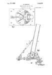
Figure 1 is a side elevation of a gun con-
structed according to my invention,
Figure 2 is a section along the line 2—2 65
of Figure 1, looking in the direction of the
arrows.
Figure 3 is a perspective view showing a
pair of guns in locked relation,
Figure 4 is a rear view of the gun, and 70
Figure 5 is a section along the line 5—5
of Figure 2.
In carrying out my invention, I make use
of a gun barrel, such as that shown at 1.
Toward the front of the barrel and on one 75
side thereof is a boss 2 which is provided
with a dovetail tongue 3 extending there-
from. The rear of the gun is provided with
a similar boss 4 with a dovetail-shaped
tongue 5. The breech block 6 is also pro- 80
vided with a boss 7,. having a tongue 8 of
similar shape. The bosses 4 and. 7, together
with their tongues 5 and 8, are adapted to
be brought into registration by means of the
engaging shoulders at 9 in Figure 1. 85
As will be seen from Figures 2 and 5, the
breech block 6 may be screwed into the
breech of the barrel 1. The screw thread
is so designed that the block 6 may be re-
moved from the barrel by a one-eighth turn so
of the block.
On the opposite side of the barrel is a boss
10 which is in alinement with the boss 2
and which is provided with a groove 11 of a
shape to receive the dovetail-shaped tongue, 85
of an adjacent gun, corresponding to the
tongue 3. A boss 12, having a similar
groove 13, is provided on the side opposite
from the boss 4.
Each gun is provided with rifling, such 100
as that shown at 14 in Figure 2, adapted
to give the shell 15 a rotary movement about
its axis to insure true flight.
In Figure 3,1 have shown a pair of these
mortars or guns mounted in battery form. 105
It is obvious that as many units may be
joined together as is necessary or desirable.
In this figure, the gun barrels A and В are
mounted on base plates A' and B', these base
plates resting on the ground and being con- HO
S3
1,471,063
б
10
15
20
25
30
35
40
45
50
55
tiguous to each other, but not being con-
nected together. The barrels of the guns A
and В are connected together by inserting
the tongues 3 and 4 of one gun into the
grooves 11 and 13 of the adjacent gun, and
bringing the two guns into position on their
base plates, so as to cause substantial regis-
tration of the bosses. Each gun is supported
by rods, such as those shown at (a) and (&)
respectively. Turn buckles or other means
of adjustment (t) are provided so that the
elevation of. the guns may be readily ef-
fected. The guns are preferably fired by det-
onators of any suitable type, and are de-
signed to be set off by electrical means. To
this end the wires (w) are provided.
From the foregoing description of the va-
rious parts of the device, the operation there-
of may be readily understood. The breech
block 6 is removed from the gun by turning
the block one-eighth of a turn, the shell 15
is inserted, and the block is then turned un-
til the shoulders 9 engage one another, there-
by bringing the tongues 5 and 8 into regis-
tration. The two guns are then secured to-
gether in the manner described, and this
locks the breech block through ths engage-
ment of the tongues 5 and 8 with the slot 13.
The guns may be elevated by placing the in-
clined supporting rods (a) and (&) at the
proper angle, and then a further adjustment
may be effected by means of the extension
members from the turn buckles (f).
The battery thus formed may be fired by
an electrical circuit through the wire (w).
The rifling of the adjacent barrels in oppo-
site directions tends to reduce the rotative
effect of the gun, while permitting the full
rotative effect to be imparted to the shell.
Should one of the guns have a greater recoil
than the other, this would be permitted
through the sliding engagement of the lock-
ing means, without damage to the guns.
While I have shown a battery of two
units, it is obvious that as many units may
be used as desired, and that the guns will be
kept in alinement.
I claim:
1. A trench mortar comprising a barrel, a
removable breech block, and means carried
by the breech block for connection with an
adjacent gun.
2. A trench mortar comprising a barrel
having a boss, a removable breech block
having a boss, the boss in the barrel and in
the breech block each having a groove ar-
ranged to register with the companion
groove, when the breech block is in firing po-
sition.
3. A trench mortar comprising a barrel 60
having laterally extending connecting means,
a removable breech block, means carried by
the barrel for connection with an adjacent
gun barrel, and means carried by the breech
block for connection with an adjacent gun. 65
4. A battery comprising a plurality of
trench mortars, each mortar having a barrel,
means carried by the barrel for interlocking
with the adjacent barrel, a removable breech
block and means carried by the breech block 1°
for interlocking' with an adjacent gun.
5. A battery comprising a plurality of
trench mortars, each mortar having a barrel,
means carried by the barrel for interlocking
with the adjacent barrel, a removable breech 75
block and means carried by the breech block
for interlocking with an adjacent gun, said
imerloeking means also locking the breech
block to its individual gun.
G. A battery comprising a plurality of 80
trench mortars, means for interlocking the
barrels of said mortars to prevent lateral
movement and to permit individual longi-
tudinal movement of each barrel.
7. A battery comprising a plurality of 85
trench mortars, the barrels of adjacent mor-
tars having interlocking means for prevent-
ing lateral movement, while permitting lon-
gitudinal movement, and a removable breech
block carried by each mortar, said breech 90
block being locked by the interlocking of
the barrels of adjacent mortars.
8. A battery comprising a plurality of
trench mortars, the barrels of said mortars
being disposed in parallel relation,:means. 95
carried by the barrels for interlocking them
to prevent lateral movement, and means for
supporting and for elevating said barrels to
the desired degree.
9. A battery comprising a, plurality of 100
trench mortars, the barrels of said mortars
being disposed in parallel relation, means
for interlocking the barrels to prevent lat-
eral movement, while permitting independ-
ent longitudinal. movement of each barrel, 105
the adjacent barrels being rifled.in opposite
directions, whereby the rotative effect on one
barrel is neutralized by the adjacent barrel.
FRED ROGNLIE.