/
Tags: weapons military affairs patent mortar
Year: 1921
Text
A. G. BERGMAN.
TRENCH MORTAR,
APPLICATION FILED' FEB. 24. 1919.
UNITED STATES PATENT OFFICE.
AXEL G. BERGMAN, OF NEW YORK, IT. Y., ASSIGNOR TO ORDNANCE ENGINEERING
CORPORATION, ОГ NEW YORK, N. Y., A CORPORATION OP NEW JERSEY.
TRENCH-MORTAR.
1,399,843. Specification of betters Patent. Patented Dec. 6,1981.
Application filed Pebrnary 24, 1919. Serial No. 278,869.
б
10
16
20
26
30
35
40
45
50
To dll whom it may concern:
Be it known that I, Axel G. Bergman, a
subject of the King of Sweden, residing in
the borough of Manhattan, city, county, and
State of New York, have invented certain
new and useful Improvements in Trench-
Mortars, of which the following is a speci-
fication.
My invention relates to that class of struc-
tures known as trench mortars or guns for
comparatively short ranges, to be used for
discharging illuminating shells and other
projectiles, and the purpose is to provide a
portable device that can be set up and
operated in any location and under most
adverse conditions.
One of the purposes of my improvement
is to enable positioning a mortar in soft
or muddy ground, entirely embedding the
rear end if it becomes necessary, and with-
out interfering with the proper control
and operation of the mechanism.
Another object of the improvement is
to provide means for insuring expulsion of
a projectile through the proper and accurate
positioning of the primer and propelling
charge, which governs the discharge of the
projectile, with reference to the firing pin
in the mortar.
The invention comprises, in general, a
barrel which is entirely closed at the rear
end, the latter serving to support a firing pin
which forms a part of a firing mechanism
that includes an actuating rod located out-
side the barrel and extending toward the
front thereof. The actuating rod referred
to is provided with a controlling member
located at a point remote from the rear end
of the barrel sufficiently to enable setting the
rear end on any kind of ground and hav-
ing it project beneath the surface of the
ground if necessary, while the firing mech-
anism can be adequately manipulated from
the front end of the barrel. The firing pin
is preferably arranged within a guide that
constitutes an extension at the center of
the rear end of the barrel, and this ex-
tension cooperates with guiding means in
the form of a cup-shaped member, or other
suitable device, mounted upon a holder for
the primer and propelling charge. This
holder may be permanently attached to the
projectile to be fired, or removably attached,
as the conditions may require; severally or
together, they may be dropped into the 55
barrel of the gun, convenience in practice
seeming to favor the utilization of the shell
and propelling charge holder with primer
as a unit. This insures proper contact be-
tween the firing pin and the primer, and 60
consequently, the discharge of the projectile
under most efficient conditions.
To these and other ends the invention
consists in certain details and combinations
of parts as will be hereinafter more fully 65
described, the essential features of the in-
vention being pointed out in the claims at
the end of the specification.
In the drawings,—
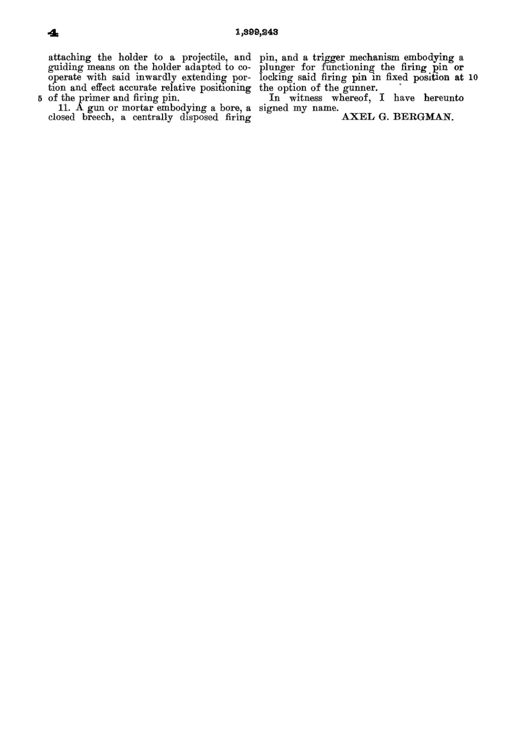
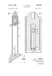
Figure 1 is a sectional view, illustrating 70
a mortar in operating position, showing the
application of a preferred embodiment of
the invention, with the firing pin withdrawn
and the firing mechanism ready for action;
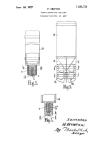
Fig. 2 is an enlarged sectional view, with 75
parts broken away, showing the details of
the construction;
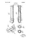
Fig. 3 is an enlarged sectional view of the
holder for the propelling charge and primer,
the latter being connected to a projectile, 80
a portion of which is broken away; and
Fig. 4 is an enlarged sectional view of a
slightly modified form of holder for the
propelling charge, intended for use where
it is permanently connected with the pro- 86
jectile.
The invention is susceptible of many dif-
ferent practical applications, and for pur-
poses or illustration, I have shown one em-
bodiment, consisting of a barrel A‘, pro- 90
vided with the usual form of leg В pivoted
thereto, and arranged for engagement with
the ground to support the barrel in an up-
wardly extending position. The rear end
of the barrel is formed by a wall C having 95
integral therewith an inwardly projecting
collar a, which threads into the barrel, as
shown clearly in Fig. 2. The wall C also
has an outwardly extending collar b which
receives a cap D that entirely closes the 100
SI
1,399,843
rear end of the barrel and permits the latter
to be partially or entirely embedded in the
ground, as shown in Fig. 1. The wall C and
cap D form a housing which defines a cham-
6 ber c for a purpose presently to appear.
The firing mechanism includes a firing
pin E which operates through the wall C,
the latter having an opening that receives
and constitutes a supporting guide for the
10 firingpin. The guide is formedby an inwardly
extending portion e formed upon the wall
C and located centrally of the end of the
barrel, as shown in Fig. 2.
The firing pin E is engaged by a lever F
16 pivoted at f in the chamber c, with its inner
end adapted to engage the outer end of the
firing pin. The outer end of the lever f lies
in the path of an actuating rod G, which is
located outside the barrel A and extends
20 lengthwise of the latter toward the front'
end. The rod G is housed within a tube g
which is supported at one end within an
opening of the wall C and is held at its op-
posite end by a suitable strap or support л.
25 The actuating rod G carries a controlling
member, preferably in the form of a bolt H,
which is movable within a housing I. The
actuating rod is operated by a spring J,
one end of which engages the contrdfling
30 member or bolt H, while the opposite end
engages a plate K. The housing 1 is slotted
longitudinally at i to permit longitudinal
travel of the bolt H from the cocked posi-
tion of Fig.-l to the released position of Fig.
36 2, and is slotted transversely at j and к to
permit the controlling member to be re-
tained in cocked position, as in Fig. 1; or to
retain the firing pin in its outermost posi-
tion, as in Fig. 2,-lhe latter position being
40 desirable when it is intended to bring about
the discharge of a projectile by merely drop-
ping it within the barrel of the gun. The
housing I is dosed at its outer end by a cap
I, and arranged between the plate К and
46 the cap I is a resilient buffer m of suitably
soft rubber, or other material, to take the
shock of the actuating rod G when it is
thrown backwardly upon the explosion of a
propelling charge.
50 It will be seen that two methods of opera-
tion are provided for. The firing mechanism
may be cocked, ready for action, as in Fig.
1, and a projectile inserted, after which the
latter will be discharged upon pulling the
56 bolt H until it is released from the slot j.
The spring J thereupon moves the actuating
rod G and forces the firing pin E against the
primer of the projectile. When the parts
are positioned, as in Fig. 2, the firing pin is
60 held fixedly in its outermost position, so that
when a projectile is dropped into the barrel,
its primer falls into engagement with the
point of the firing pin and the propelling
charge is immediately exploded.
It not infrequently happens that the pro- 55
pelling charge fails to explode because the
primer does not properly engage the firing
pin. To overcome this, I have provided
means for guiding the primer accurately to
the firing pin, and insuring, in every in- 70
stance, that the primer will be brought into
true and exact firing relationship with the
firing pin. This is best accomplished by
guiding means cooperating between the pro-
jectile and the firing pin, and to this end, I 75
have provided a holder for the propelling
charge and primer, adapted to be perma-
nently attached, or otherwise connected to
the projectile. A conventional form of pro-
jectile is shown partially by L, and the 80
holder, referred to above, consists of a base
Sortion M and an elongated hollow portion
’. The latter is provided at one end with a
socket n to receive the primer, and trans-
verse openings o. p designates the propel- 85
ling powder charge, which is held around the
hollow portion N preferably by a fabric bag
q, the ends of which are suitably secured to
the holder. In the structure shown in Fig.
3, one end of the fabric Jaag is held in en- 90
gagement with the plate r of the projectile,
the holder being secured to the projectile by
the screw з engaging a correspondingly
threaded opening in the holder. The other
end of the fabric bag q is retained by tying 96
it around the hollow portion N of the
holder. The powder will enter through the
transverse openings! о and fill the interior
of the holder, so that it is in immediate con-
tact with the primer in the socket n. In 100
the modified form of Fig. 4, providing a
holder which may not be permanently at-
tached to the projectile, the larger end of
the fabric bag is held in engagement with
the base, by providing a groove t in the 105
latter and a retaining wire и engaging the
bag.
The holder is provided with guiding
means which cooperates with the inwardly
extending portion e on the rear end of the no
barrel, already described, and thereby cen-
ters the holder and primer so that the latter
contacts accurately with the firing pin.
There are various ways in which this pur-
pose can be effected, and one method consists 116
in providing the holder with an integral,
substantially cup-shaped extension O, hav-
ing a beveled edge v. The inner diameter
of the guiding member О is such that, when
in final position, it engages closely with the 120
outer surface of the extension e, as shown
in Fig. 1. When the projectile, with the
holder attached, is dropped into the front
end of the barrel, if there is any inaccurate
alinement, the beveled edge v will engage 126
the innermost corners or edges of the pro-
jection portion e, thereby bringing the
holder into its proper relationship with the
1,S99,343
О
б
10
16
20
26
30
36
40
46
50
55
60
firing pin and surrounding guide. This in-
sures engagement of the firing pin with the
primer and the consequent explosion of thfe
propelling charge.
While the invention is here described with
reference to a particular structure, it is not
intended to be limited to the disclosure set
forth, but comprehends any modifications
or changes which do not depart from the
underlying purpose of the structure, and
any other such forms of mechanism which
are intended to come within the scope of
my invention.
When I speak in my claims of a barrel
being adapted to have its rear end embedded
in the ground, I mean that the barrel may
be embedded so that the ground level is
above the level of the firing pin without in-
terfering with the operation of the latter.
What I claim is:—
1. A mortar for projectiles and the like,
consisting of a barrel, the lower end of
which is adapted to be embedded in the
ground, a firing pin located at the lower
end and an actuating means located a con-
siderable distance above the lower end, and
leak-tight means for conveying movement
from the actuating means to the firing pin.
2. A mortar for projectiles and the like,
consisting of a barrel, the lower end of
which is adapted to be embedded in the
ground, a firing pin located at the lower end
and an actuating means located a consider-
able distance above the lower end, said actu-
ating means comprising a trigger mecha-
nism and leak-tight means for connecting
said trigger mechanism with said firing pin.
3. A mortar for projectiles and the like,
consisting of a barrel, the lower end of
which is adapted to be embedded in the
ground, a firing pin located at the lower
end and an actuating means located a con-
siderable distance above the lower end, a
tube having a leak-tight connection with the
barrel of the mortar, and trigger mechanism
contained in said tube.
4. The combination with a mortar hav-
ing a firing pin operating in its rear end,
of propelling means for a projectile com-
prising a holder, a propelling- charge and
primer mounted thereon, and means cooper-
ating between said holder and the end of
the barrel and acting to cause the primer to
be brought into accurate position with re-
spect to the firing pin, the means at the end
of the barrel guiding the firing pin.
5. The combination with a mortar having
a firing pin operating in its rear end, of
propelling means for a projectile compris-
ing a holder, a propelling charge and primer
mounted on the holder, and guiding means
cooperating between the holder and a por-
tion of the barrel, whereby/the primer is
brought into accurate relationship with the
firing pin, the means at the end of the barrel eg
guiding the firing pin.
6. The combination with a mortar hav-
ing a firing pin operating in its rear end,
of a supporting guide for the firing pin
including an inwardly extending portion у о
located centrally of the rear end, means for
propelling a projectile comprising a holder,
a propelling charge and primer mounted
thereon, and means on the holder adapted
to cooperate with said inwardly extending 75
portion, whereby to insure accurate posi-
tioning of the primer with reference to the
firingpin.
7. The combination with a mortar hav-
ing a firing pin operating in its rear end, of go
a supporting guide for the firing pin in-
cluding an inwardly extending portion lo-
cated centrally of the rear end, means for
propelling a projectile comprising a holder,
a propelling charge and primer mounted 85
thereon, and a substantially cup-shaped
guiding portion on the holder which co-
operates with said inwardly extending por-
tion on the barrel and effects accurate rela-
tive positioning of the primer and firing pin. 90
8. The combination with a mortar having
a firing pin operating in its rear end, of a
supporting guide including an inwardly ex-
tending portion located centrally of the rear
end, means for propelling a projectile com- 95
prising a holder which is hollow for a por-
tion of its length and has openings extend-
ing transversely of said hollow portion, a
powder charge surrounding and also within
said hollow portion and held in place by 100
retaining means, the holder having a primer
socket at one end, and guiding means sur-
rounding the primer socket and adapted to
cooperate with the aforesaid inwardly ex-
tending portion on the barrel to effect ac- 105
curate relative positioning of the primer
and firing pin.
9. The combination with a mortar having
a firing pin operating in its rear end, of a
supporting guide including an inwardly ex- 110
tending portion located centrally or the
rear end, and a projectile having propelling
means attached thereto and comprising a
holder, a propelling charge and primer
mounted on the holder, and means on the 115
holder adapted to cooperate with said in-
wardly extending portion to effect accurate
relative positioning of the primer and fir-
ing pin.
10. The combination with a mortar hav- 120
ing a firing pin operating in its rear end, of
a supporting guide for the firing pin includ-
ing an inwardly extending portion located
centrally of the rear end, and projectile-
propelling means comprising a holder, a 125
propelling charge ana primer mounted
thereon, a fabric retainer surrounding said
charge and secured to the holder, means for
4t 1,399,843
attaching the holder to a projectile, and
guiding means on the holder adapted to co-
operate with said inwardly extending por-
tion and effect accurate relative positioning
6 of the primer and firing pin.
11. A gun or mortar embodying a bore, a
closed breech, a centrally disposed firing
pin, and a trigger mechanism embodying a
plunger for functioning the firing pin or
locking said firing pin in fixed position at 10
the option of the gunner.
In witness whereof, I have hereunto
signed my name.
AXEL G. BERGMAN.