/


Tags: weapons military affairs patent
Year: 2011


Text
US 20110225862A1
(19) United States
(12) Patent Application Publication («» Pub. No.: US 2011/0225862 Al
Lowry (43) Pub. Date: Sep. 22,2011
(54) RECIPROCATING BARREL PISTOL
(76) Inventor: Charles Andrew Lowry, Riverton,
UT (US)
(21) Appl.No.: 12/928,031
(22) Filed: Dec. 2, 2010
Related U.S. Application Data
(60) Provisional application No. 61/284,383, filed on Dec.
16, 2009.
Publication Classification
(51) Int.Cl.
F41C 3/00 (2006.01)
(52) U.S. Cl............................... 42/6
(57) ABSTRACT
The present invention is a pistol incorporating a unique recip-
rocating barrel which is supported for reciprocal movement in
a pistol frame in a manner reminiscent of a common pistol
reciprocating slide with the barrel additionally incorporating
an integrated cartridge feed ramp and cartridge from maga-
zine extracting lug combination.
The present invention may also optionally employ a unique
gas operated barrel delay system which delays the forward
movement of the barrel.
Patent Application Publication Sep. 22, 2011 Sheet 1 of 12
US 2011/0225862 Al
20
Patent Application Publication Sep. 22, 2011 Sheet 2 of 12
US 2011/0225862 Al
Fig. 2
20
Patent Application Publication Sep. 22, 2011 Sheet 3 of 12
US 2011/0225862 Al
Fig. 3
A
Patent Application Publication Sep. 22, 2011 Sheet 4 of 12
US 2011/0225862 Al
20
Patent Application Publication Sep. 22, 2011 Sheet 5 of 12
US 2011/0225862 Al
14H
Patent Application Publication Sep. 22, 2011 Sheet 6 of 12
US 2011/0225862 Al
14F
Fig. 6
14
14D
14B
14A
14G
141
14H
14C
Pa,ea,^p«eatlo
n Publication
Sep’22,20ц
Sheet7Of12
VS2O1^SS62AI
Patent Application Publication Sep. 22, 2011 Sheet 8 of 12
US 2011/0225862 Al
16A
12
Patent Application Publication Sep. 22, 2011 Sheet 9 of 12
US 2011/0225862 Al
Fig. 9
28B
28A
птата
28C
28
28B
Patent Application Publication Sep. 22, 2011 Sheet 10 of 12 US 2011/0225862 Al
28C
28B
Patent Application Publication Sep. 22, 2011 Sheet 11 of 12 US 2011/0225862 Al
20Ay
20B“
20C
РРЙс’И<>ЯА.
^ер.2>
,2°Л S/.
’/л
ofl2
4S20,
US 2011/0225862 Al
Sep. 22, 2011
1
RECIPROCATING BARREL PISTOL
FIELD OF THE INVENTION
[0001] The present invention is a pistol incorporating a
unique reciprocating barrel which is supported for reciprocal
movement in a pistol frame in a manner reminiscent of a
common pistol reciprocating slide with the barrel addition-
ally incorporating an integrated cartridge feed ramp and car-
tridge from magazine extracting lug combination.
[0002] The present invention may also optionally employ a
unique gas operated barrel delay system which delays the
forward movement of the barrel, allowing pressures within
the barrel to subside before the extraction of the spent car-
tridge.
DESCRIPTION OF THE PRIOR ART
[0003] The only discovered relevant prior art to this inven-
tion is the inventors provisional patent application No.
61/284,383 received Dec. 16, 2009 and the disclosed patents
below. The disclosed patents below all relate to reciprocating
barrels which operate without the integrated cartridge feed
ramp and cartridge from magazine extracting lug as disclosed
in this patent application. Nor do any of the discovered rel-
evant prior art disclose the use of a gas operated barrel delay
system as disclosed in this patent.
[0004] European Patent number GB189402491 (Mannli-
char) discloses the use of a semi-automatic pistol which uti-
lizes a reciprocating barrel to facilitate the ejection and
reloading of a cartridge, but this design does not use a barrel
with an integrated cartridge feed ramp and cartridge from
magazine extracting lug as disclosed in this patent applica-
tion. Nor does this patent application disclose the use of a gas
operated barrel delay system as disclosed in this patent.
[0005] European Patent numbers GB224927 (Dibovsky),
and GB756769 (Fiorini/Bresciano) discloses the use of a
reciprocating barrel for use in firearms, but these designs also
do not use a barrel with an integrated cartridge feed ramp and
cartridge from magazine extracting lug as disclosed in this
patent application. Nor do these patent applications disclose
the use of a gas operated barrel delay system as disclosed in
this patent.
[0006] U.S. Pat. No. 932,183 (Schwarzlose) also discloses
the use of a semi-automatic pistol which utilizes a recipro-
cating barrel, but this design also does not use a barrel with an
integrated cartridge feed ramp and cartridge from magazine
extracting lug as disclosed in this patent application. Nor does
this patent application disclose the use of a gas operated barrel
delay system as disclosed in this patent.
[0007] U.S. Pat. No. 1,487,722 (Coenders) also discloses
the use of a semi-automatic pistol which utilizes a recipro-
cating barrel, but this design also does not use a barrel with an
integrated cartridge feed ramp and cartridge from magazine
extracting lug as disclosed in this patent application. Nor does
this patent application disclose the use of a gas operated barrel
delay system as disclosed in this patent.
[0008] U.S. Pat. Nos. 726,109 (Stow), 726,399 (Burgess),
839,911 (Wesson), 886,221 (Hino), 1,429,370 (Putnam)
2,397,572 (Weaver), 2,699,006 (Maerk), 2,835,171 (Lyon),
3,736,839 (Childers), 4,028,994 (Ferluga), 4,061,075
(Smith), 3,990,346 and 5,123,329 (Irwin) disclose the use of
a reciprocating barrel, but all of these patents do not disclose
an integrated cartridge feed ramp and cartridge from maga-
zine extracting lug as disclosed in this patent application. Nor
do these patent applications disclose the use of a gas operated
barrel delay system as disclosed in this patent.
[0009] All of the above mentioned prior art exhibited prob-
lems with the proper feeding of the cartridge into the barrel
due to the lack of an integrated cartridge feed ramp and
cartridge from magazine extracting lug.
[0010] U.S. Pat. Nos. 580,924 and 708,794 (Browning)
relates a cartridge feed ramp integral with the barrel and a
cartridge from magazine extracting lug integrated with the
slide, but not both integrated into the barrel.
[0011] None of the prior art utilizes an integrated cartridge
feed ramp and cartridge from magazine extracting lug, which
lug allows the reciprocating barrel to perform the operations
of properly loading the cartridge into the barrel such as is
performed in a manner reminiscent of a slide of a conven-
tional semi-automatic pistol. Nor do these patent applications
disclose the use of a gas operated barrel delay system as
disclosed in this patent.
[0012] There remains a need for an integrated cartridge
feed ramp and cartridge from magazine extracting lug which
allows a reciprocating barrel to perform the operations of
stripping the cartridge from the magazine and facilitates load-
ing the cartridge into the barrel such as is performed in similar
manner of a conventional semi-automatic pistol. Addition-
ally, there remains a need for the use of a gas operated barrel
delay system as disclosed in this patent to allow the pressures
within the barrel to subside before the extraction of the spent
cartridge when required. However, at the time the present
Reciprocating Barrel Pistol was made, it was not obvious to
those of ordinary skill in the art how these needs could be
fulfilled, in view of the prior art as a whole.
OBJECT OF THE INVENTION
[0013] It is therefore an object of the present invention to
provide a pistol which has the advantage of a reciprocating
barrel which combines the functions of a pistol barrel with the
cartridge stripping from magazine and feeding into the barrel
functions of a pistol slide. It is also an object of the present
invention to disclose the optional use of a unique gas operated
barrel delay system which delays the forward movement of
the barrel.
SUMMARY OF THE INVENTION
[0014] The heretofore unfulfilled need for a reciprocating
barrel which combines the functions of a pistol barrel with the
cartridge stripping from magazine function of a pistol slide is
now fulfilled by the invention disclosed in this patent appli-
cation.
[0015] All of the known disadvantages of prior art pistols
are believed to be overcome by the novel pistol of the present
invention.
[0016] The novel pistol of the present invention can be
thought of as comprising:
[0017] a frame unit having a front section and a rear section
terminating in fore and aft ends respectively, said front sec-
tion being trough shaped defining a pair of spaced apart side
walls and a bottom wall for forming the bottom of said trough
and interconnecting said spaced apart side walls, with said
spaced apart side walls optionally incorporating baffles
intended to work against the flow of gases emanating from the
barrel;
[0018] a barrel unit slidable on said frame unit in a manner
reminiscent of current state of the art pistol slide designs, said
US 2011/0225862 Al
Sep. 22, 2011
2
barrel comprising a bore for a bullet to pass therethrough, said
bore having a muzzle and breech ends wherein the breech end
incorporates an integrated cartridge feed ramp and cartridge
from magazine extracting lug combination, and wherein said
barrel may optionally incorporate a hole or holes which allow
the communication of gases from a location within the bore to
a location outside of the barrel, which location outside of the
barrel directly communicates with a baffle integral to the
spaced apart side walls which baffles are specifically
designed to oppose the force of these gases. Therefore when
the barrel moves forward due to the pressure of the expanding
gases within the bore, the gases traversing the aforemen-
tioned optional hole or holes abut against the optional baffles
in the frame imparting a restricting force to the movement of
the barrel, effectively delaying the forward movement of the
barrel, which delayed movement allows the gas pressures
within the bore to subside to a safe level before the extraction
and ejection of the spent cartridge.
[0019] The present invention also discloses the use of a
double action only trigger and hammer mechanism. The
operation of this type of double action trigger and hammer
mechanism is well known, and other types of trigger and
hammer mechanisms such as a single action or combination
single/double action trigger and hammer mechanisms are
well known, anticipated, and within the scope of the present
invention.
[0020] This patent application also discloses the use of a
cartridge extractor. Pistol cartridge extractors are understood
and well known in the trade and within the scope of this
invention.
[0021] The features of the invention are set forth with par-
ticularity in the appended claims. The invention will best be
understood from the following description when read in con-
junction with the accompanying drawings.
[0022] FIG. 1 is a side view of the present invention;
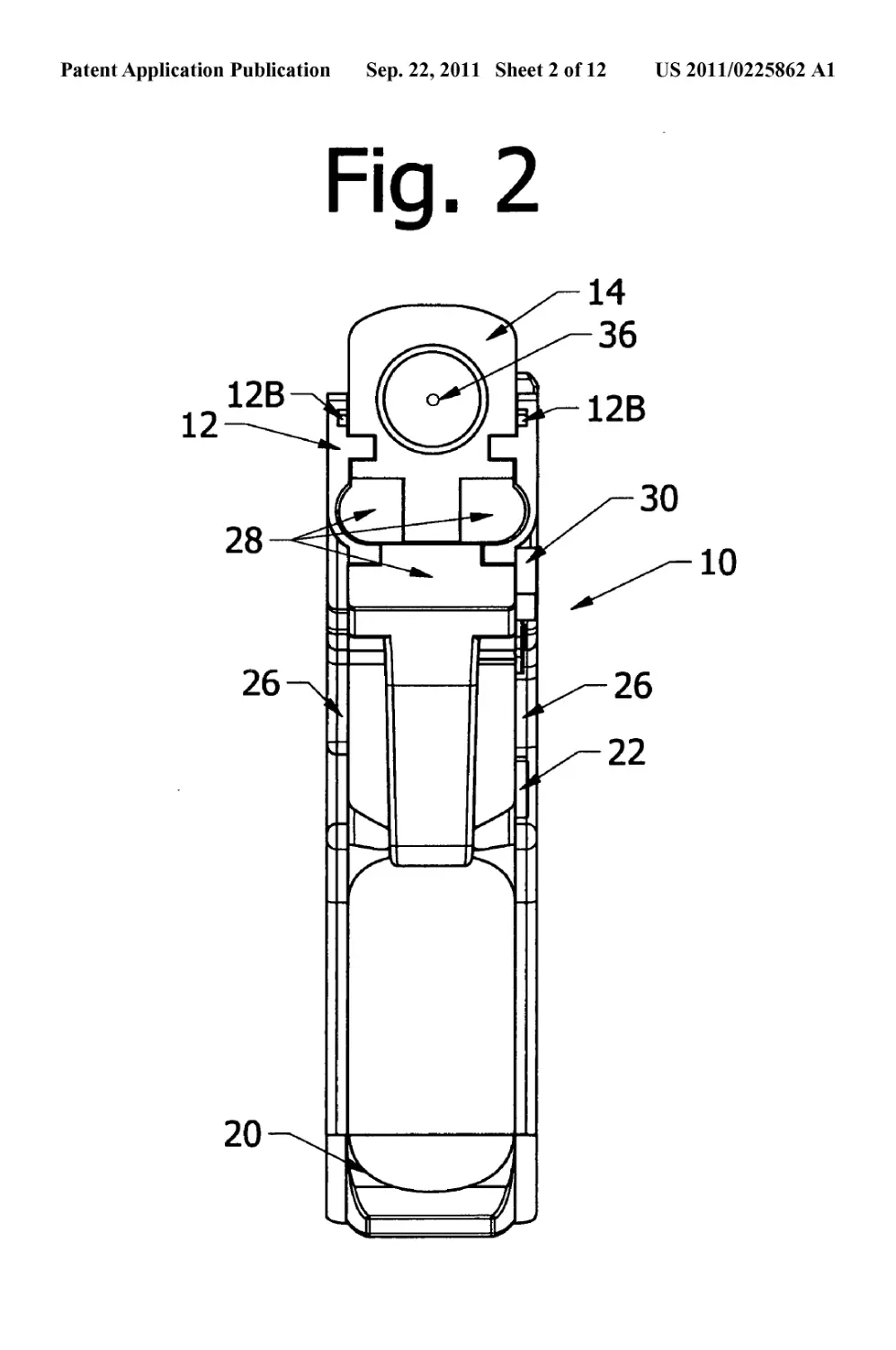
[0023] FIG. 2 is front view of the present invention;
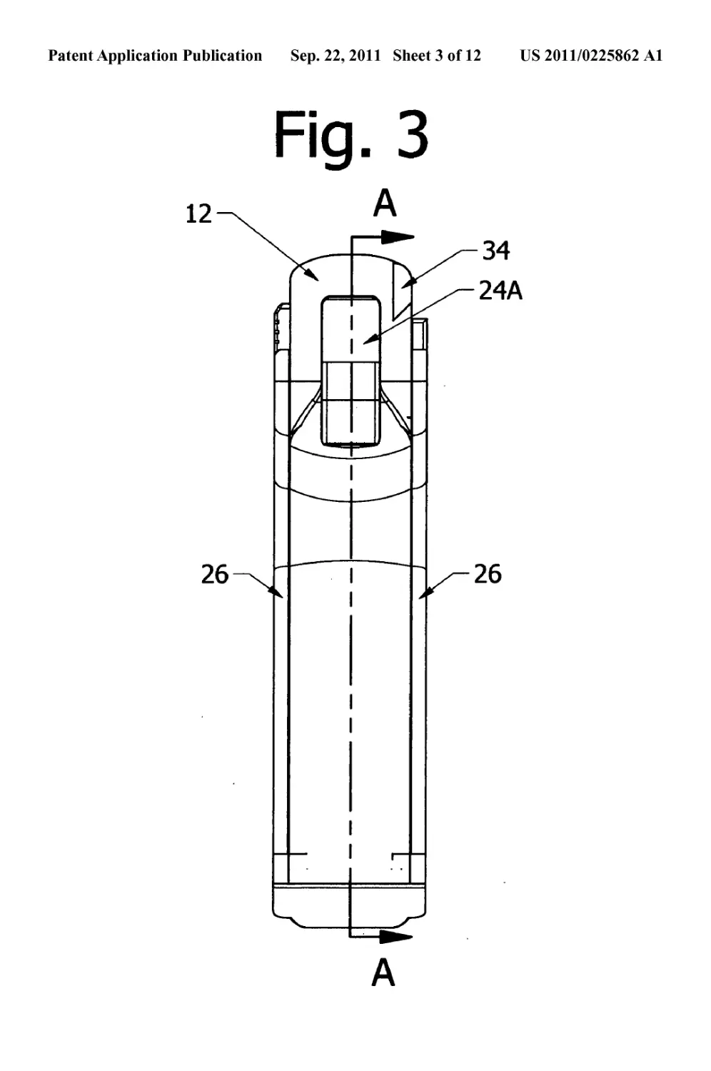
[0024] FIG. 3 is rear view of the present invention;
[0025] FIG. 4 is section view taken along line A-A of FIG.
3;
[0026] FIG. 5 is a front isometric view of the barrel;
[0027] FIG. 6 is a rear isometric view of the barrel;
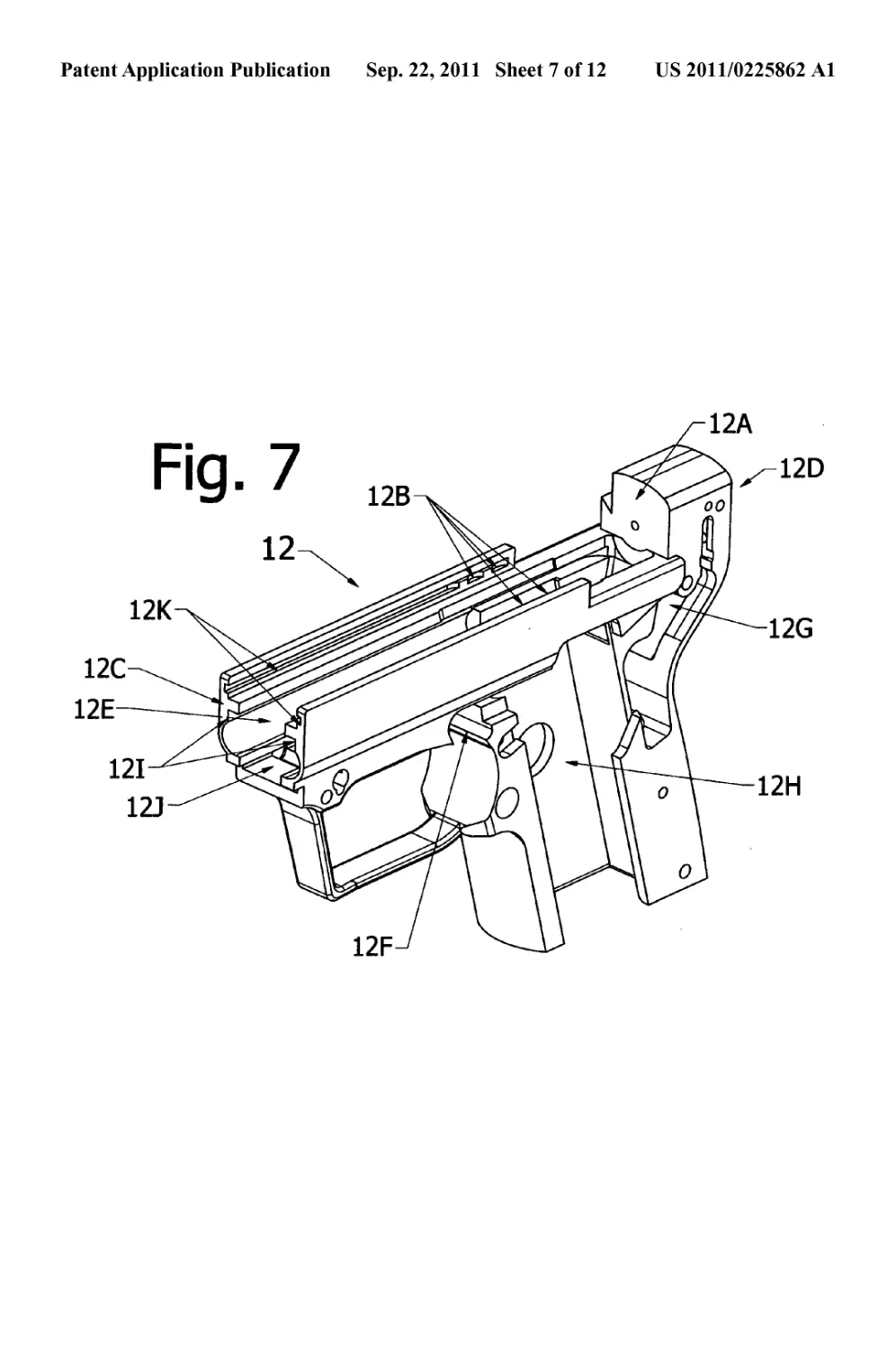
[0028] FIG. 7 is a front isometric view of the frame;
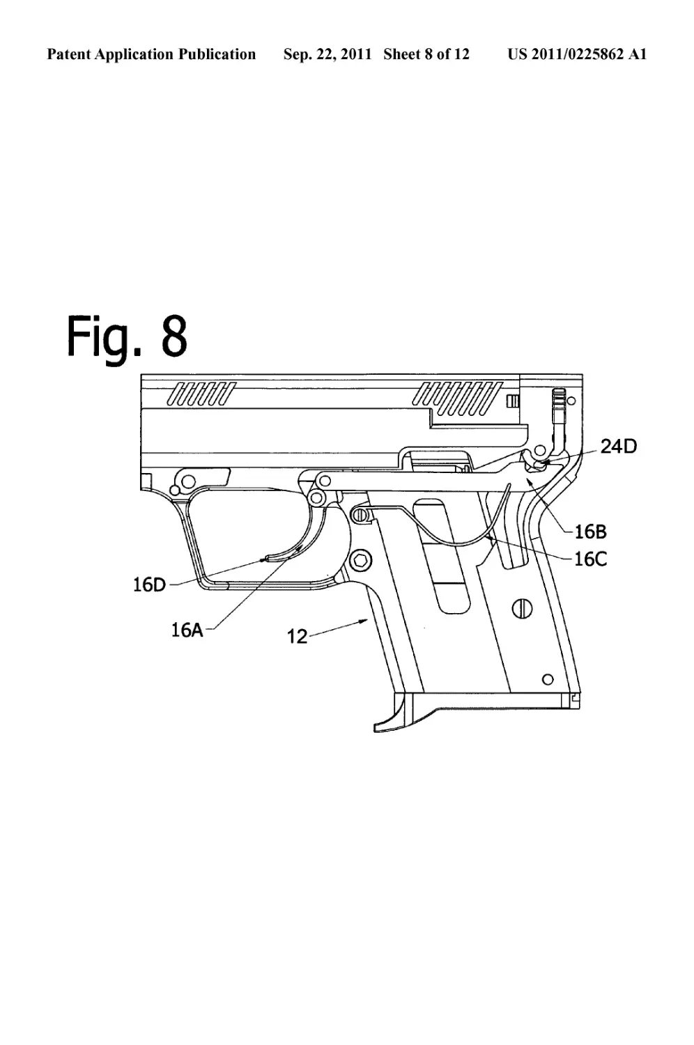
[0029] FIG. 8 is a side view of the present invention pistol
illustrating the trigger mechanism;
[0030] FIG. 9 is a side view of the barrel return spring
assembly;
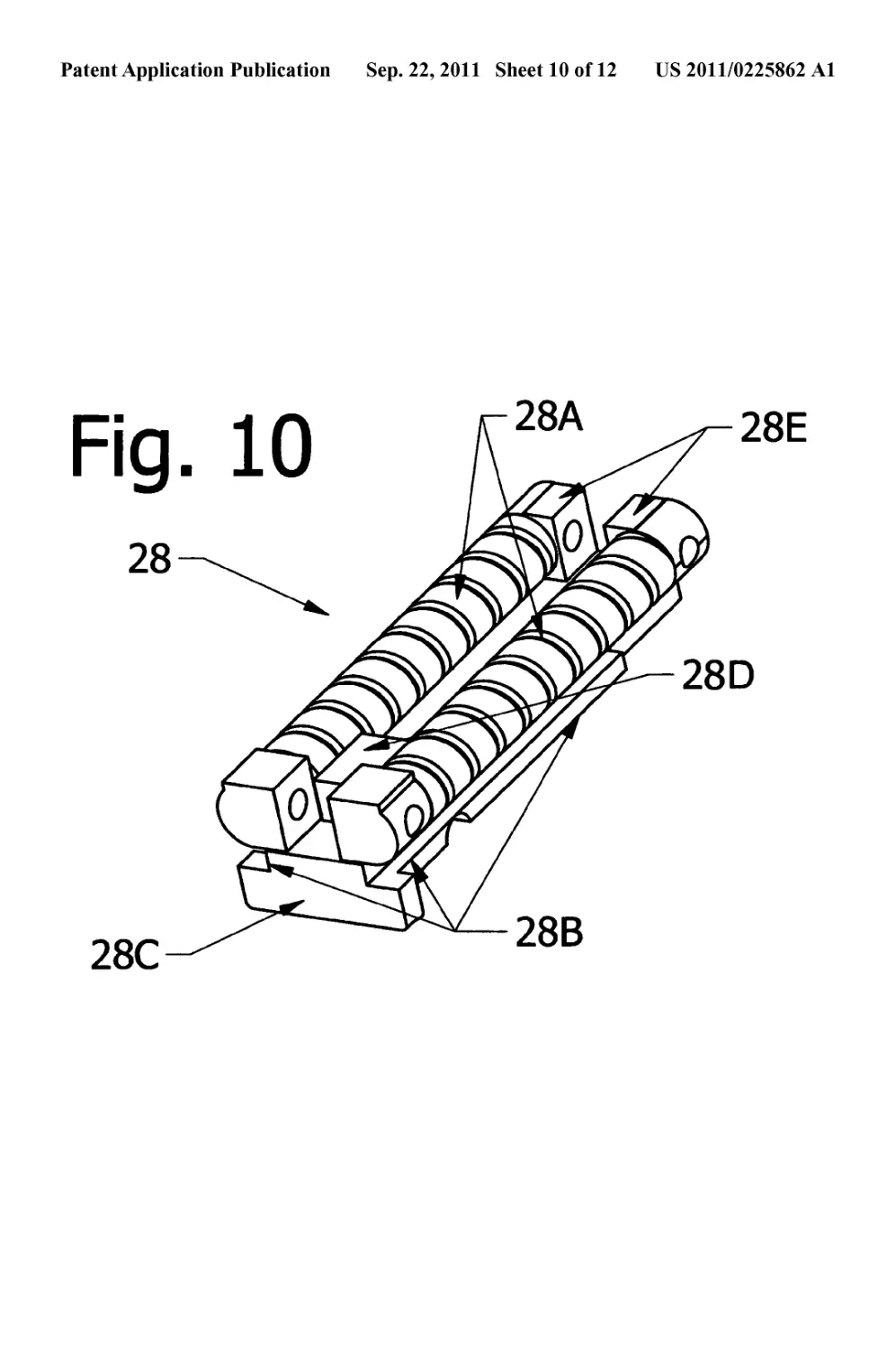
[0031] FIG. 10 is a front isometric view of the barrel return
spring assembly;
[0032] FIG. 11 is an exploded view ofthe present invention;
[0033] FIG. 12 is a side view of the cartridge magazine, and
in particular detail the direction of movement of the cartridge
required for extraction from the magazine.
[0034] With the following numeric designations.
[0035] Pistol 10
[0036] Pistol fore end 10A
[0037] Pistol aft end 10B
[0038] Frame 12
[0039] Frame breech face 12A
[0040] Frame gas baffles 12B
[0041] Frame fore end 12C
[0042] Frame aft end 12D
[0043] Frame barrel-accommodating section 12E
[0044] Frame trigger section accommodating section 12F
[0045] Frame hammer unit-accommodating section 12G
[0046] Frame magazine-accommodating section 12H
[0047] Frame barrel-accommodating section sidewalls 121
[0048] Frame barrel-accommodating section base 12J
[0049] Frame elongated grooves 12K
[0050] Frame barrel return spring assembly elongated
grooves 12L
[0051] Barrel 14
[0052] Barrel cartridge from magazine extraction lug 14A
[0053] Barrel cartridge feed ramp 14B
[0054] Barrel fore recoil spring attachment means 14C
[0055] Barrel bore 14D
[0056] Barrel fore end 14E
[0057] Barrel aft end 14F
[0058] Barrel gas ports 14G
[0059] Barrel elongated lugs 14H
[0060] Barrel fore movement limiter 141
[0061] Trigger 16A
[0062] Drawbar 16B
[0063] Trigger-Drawbar spring 16C
[0064] Trigger end 16D
[0065] Magazine 20
[0066] Magazine tangs 20A
[0067] Magazine cartridge feed notch 20B
[0068] Magazine cartridge release notch 20C
[0069] Magazine release notch 20D
[0070] Magazine cartridge extraction cutout 20E
[0071] Cartridge 20F
[0072] Cartridge from magazine extraction direction 20G
[0073] Magazine release assembly 22
[0074] Hammer 24A
[0075] Hammer spring assembly 24C
[0076] Hammer spur 24D
[0077] Pistol grips 26
[0078] Barrel return spring assembly 28
[0079] Barrel return springs 28A
[0080] Barrel return spring assembly elongated lugs 28B
[0081] Barrel return spring carrier 28C
[0082] Barrel fore movement limiter 28D
[0083] Barrel return spring attachment means 28E
[0084] Barrel return spring assembly retaining pin 30
[0085] Cartridge extractor 34
[0086] Firing pin assembly 36
[0087] Firing pin 36A
[0088] Attention is first directed to FIGS. 1, 7, and 11 in
connection with which the present invention and optional gas
operated system which delays the forward movement of the
barrel will first be described.
[0089] As will become apparent from the following
description of the pistol 10, with its major components con-
sisting of the frame 12, barrel and spring assembly 13, and
magazine 20, which are easily assembled and disassembled
for maintenance or repair. In FIG. 1 the pistol is shown fully
assembled. The figure represents a side view of the pistol with
its front or fore end designated by 10A and its rear or aft end
by 10B.
[0090] As shown in FIG. 7, the frame 12 is designated as
having a barrel-accommodating section 12E, a trigger section
accommodating section 12F, a hammer unit-accommodating
section 12G, a magazine-accommodating section 12H, and
optional frame gas baffles 12B.
[0091] Section 12E is a trough shaped cross-section and is
formed by the vertical spaced apart side walls 121 which are
joined together by a base 12J. Elongated grooves are formed
in the side walls 12K for engagement with mating barrel
US 2011/0225862 Al
Sep. 22, 2011
3
elongated lugs 14H for the purpose of facilitating the slidable
action of the barrel in the frame.
[0092] As shown in FIGS. 4, 5, and 6, the barrel 14 has a
bore 14D extending from the barrel’s fore end 14E, which
represents the barrel muzzle end, to aft end 14F, which rep-
resents the barrels breech end. Barrel 14 further includes the
barrel elongated lugs 14H for the purpose of facilitating the
slidable action of the barrel in the frame. Barrel 14 further
includes the barrel feed ramp 14B for the purpose of facili-
tating the feeding of the cartridge into the bore of the barrel
and the cartridge from magazine 225 extraction lug 14A for
the extraction of the cartridge from the magazine 20.
[0093] The shape and construction of a cartridge feedramp
and cartridge from magazine lug are known and well under-
stood by those versed in the art of pistol manufacture,
although at this time no known manufacturer has incorpo-
rated this combination of cartridge feed ramp and cartridge
from magazine lug into a pistol 230 barrel.
[0094] As shown in FIG. 4, the barrel 14 further incorpo-
rates optional gas ports 14G, which gas ports 14G cooperate
with optional frame gas baffles 12B which, upon firing of the
cartridge, the resulting gases imparts a restricting force to the
fore movement of the barrel, effectively delaying the forward
movement of the barrel. The barrel 14 further incorporates a
fore recoil spring attachment means 14C whereupon in the
preferred embodiment the barrel return springs 28A are fas-
tened.
[0095] As seen in FIGS. 9 and 10, the Barrel return spring
assembly 28 is a spring biasing assembly which consists of
the barrel return spring carrier 28C with two barrel return
springs 28A attached thereto.
[0096] In the preferred embodiment, the Barrel return
spring assembly 28 is contained within the trough 12E and
secured within by the meshing of the frame barrel return
spring assembly elongated grooves 12L and the barrel return
spring assembly elongated lugs 28B, with the barrel return
spring assembly retaining pin 30 preventing movement of the
barrel return spring assembly in the fore and aft direction.
[0097] In FIGS. 1, 2, and 4, it can be seen that the Barrel
return spring assembly 28 can be slidably removed to the fore
by removing the Barrel return spring assembly retaining pin
30. This system allows the quick and uncomplicated removal
of both the barrel 14 and the Barrel return spring assembly 28
as one unit thereby 250 facilitating easy cleaning and repairs.
[0098] The Barrel return spring assembly 28 also incorpo-
rates the barrel fore movement limiter 28D, which is an
obstruction which limits the movement of the barrel in the
fore direction by abutting against the barrel fore movement
surface 141 as the barrel travel forward.
[0099] FIG. 12 illustrates the unique cartridge extraction
direction 20G of cartridge 20/from magazine 20. This car-
tridge extraction direction is a requirement when a magazine
is employed for use in a pistol with a reciprocating barrel such
as is disclosed in this patent application.
[0100] Attention is now directed to FIG. 8 which is a side
view of the trigger and hammer units. Therein the trigger 16A
is shown pivotally held by a pin to frame 12 and pivotally
connected to drawbar 16B such that as trigger 16A rotates
about the pin, it moves drawbar 16B in a fore and aft direction.
[0101] In particular detail, as trigger 16A rotates such that
trigger end 16D moves aft, trigger 16A causes drawbar 16B to
move to the fore. As drawbar 16B moves to the fore, it
engages hammer spur 24D which causes hammer 24A to
rotate. As the hammer rotates, hammer spur 24D disengages
from drawbar 16B causing the hammer to quickly return to its
original position, whereupon the hammer strikes the firing pin
assembly 36 causing firing pin 36A to move forward, striking
and igniting the cartridge 20.
[0102] The method of operation of the firing pin assembly
36 is known and well understood by those versed in the art of
pistol manufacturing.
[0103] The expanding gases created by the ignition of the
cartridge 20 force the bullet axially through the barrel bore
14D from the Barrel aft end 14F through the Barrel fore end
14E. The bullet is of such size and construction as to exert a
friction on the barrel 14 from its contact to the barrel bore 14D
such that the barrel 14 is forced due to this friction and
expanding gases to move in a fore direction. As barrel 14
moves in the fore direction, Barrel return springs 28A which
are attached to the barrel by the Barrel fore recoil spring
attachment means 14C and to the carriage by the barrel recoil
spring attachment means 28E, exerts a biased force to the
barrel in an aft direction.
[0104] Referring to FIGS. 11,6,10, and 11, as the barrel 14
travels in the fore direction, the cartridge is extracted by the
Cartridge extractor 34 and ejected from the pistol 10. The
forward movement of the barrel 14 is arrested when Barrel
fore movement limiter 141 abuts against the Barrel fore move-
ment limiter 28D.
[0105] Once the bullet has travelled through the barrel bore
14D and exited Barrel fore end 14E, the gas pressures within
the barrel bore 14D immediately subsides, whereupon the
biased force exerted on the barrel to the aft by the Barrel
return springs 28 A causes an aftward movement of the barrel.
As the barrel travels aftward the Barrel cartridge from maga-
zine extraction lug 14A engages a cartridge in the magazine
20, pushing the cartridge in the aft direction. As the cartridge
moves in the aft direction, it is released from the magazine 20
and introduced to the Barrel cartridge feed ramp 14B. As the
barrel 14 continues to travel to the aft, the cartridge travels up
the Barrel cartridge feed ramp 14B until the cartridge is fully
inserted into the Barrel bore 14D.
[0106] As shown in FIG. 1, the rearward movement of the
barrel 14 is arrested when the Barrel aft end 14F abuts against
the Frame breech face 12A. In the preferred embodiment of
the present invention, the pistol 10 may also optionally
employ a unique gas operated barrel delay system which
delays the forward movement of the barrel wherein the barrel
may incorporate a hole or holes which allow the communi-
cation of gases from a location within the bore to a location
outside of the barrel, which location outside of the barrel
directly communicates with a baffle integral to the frame
which baffles are specifically designed to oppose the force of
these gases. Therefore when the barrel 14 moves forward due
to the pressure of the expanding gases within the barrel bore
14D, the gases traversing the optional Barrel gas ports 14G
abut against the optional Frame gas baffles 12B imparting a
barrel fore movement delaying force effectively delaying the
forward movement of the barrel, which delayed movement
allows the gas pressures within the bore to lower to a safe level
before the extraction and ejection of the cartridge case.
[0107] When the trigger is released, the trigger-drawbar
spring 16C returns the trigger to its initial state and simulta-
neously resets the position of the Drawbar 16B to a state ready
to reengage the hammer spur 24D, and therefore readying the
pistol for another cycle of operation.
US 2011/0225862 Al
Sep. 22, 2011
4
[0108] Triggers mechanisms of this type are known and
well understood by those versed in the art of pistol manufac-
turing.
[0109] Although particular embodiments of the invention
have been described and illustrated herein, it is recognized
that modifications and variations may readily occur to those
skilled in the art and consequently, it is intended that the
claims be interpreted to cover such modifications and equiva-
lents.
I claim:
1. In a fully operating pistol including:
a frame unit having a front section and a rear section
terminating in fore and aft ends thereof, respectively;
said front section being trough shaped defining a pair of
spaced apart side walls and a bottom wall for forming the
bottom of said trough and interconnecting said spaced
apart side walls, with said spaced apart side walls
optionally incorporating baffles intended to work
against a flow of gases;
a barrel unit slidable on said frame unit in a manner remi-
niscent of current pistol slide designs, said barrel defin-
ing an axial bore for a bullet to pass therethrough; said
bore having a muzzle and breech ends wherein the
breech end incorporates an integrated cartridge feed
ramp and cartridge from magazine extracting lug com-
bination;
said barrel may OPTIONALLY incorporate;
a hole or holes which allow the communication of gases
from a location within the bore to a location outside of
the barrel, which location outside of the barrel directly
communicates with said spaced apart side walls may
optionally incorporate baffles with the express purpose
of resisting the flow of these gases which have commu-
nicated from within the bore to a location outside of the
barrel.
2. A fully operated pistol as recited in claim 1 wherein;
a barrel return spring carrier unit slidably supported on said
frame unit within said front section between said spaced
apart side walls and located between said barrel unit and
the lower wall of the trough and including a barrel fore
movement limiter and a return spring attachment means.
3. A fully operated pistol as recited in claim 2 wherein;
a biasing means comprising one or more barrel return
springs disposed beneath said barrel unit and engaged to
the fore end of the barrel unit and the aft end of the barrel
return spring carrier.