/


Text
HANDBOOK
OK THE
LONDON.
PUBLISHED BY HIS MAJESTY’S STATIONERY OFFICE.
M.L. STOKES 3-INCH TRENCH
MORTAR EQUIPMENTS.
'i'.'
Xi
LAND SERVICE, 1919.
To be purchased through any Bookseller or directly from
H.M. STATIONERY OFFICE at the following addresses:
Imperial House, Kingsway, London, W.C. S, and 28, Abingdon Street, London, S.W. 1
37 Pbibi*. Street, Manchester; 1, St. Andrew’s Crescent, Cardiff;
23, Forth Street, Edinburgh ;
or from К PONSONBY, Ltd., 116, Srafton Street, Dublin .
1920.
Price Is. 6d. JVet.
40/W.Oy6966.
[Crown Copyright Reserved.
S.I.O
*
HANDBOOK
OF THE
M.L. STOKES 3-INCH TRENCH
MORTAR EQUIPMENTS.
LAND SERVICE, 1919.
LONDON:
PUBLISHED BY HIS MAJESTY’S STATIONERY OFFICE.
To be purchased through any Bookseller or directly from
H.M. STATIONERY OFFICE at the following addresses:
Impbrial Housb, Kingsway, London, W.C. 2, and 28, Abingdon Strbbt, London, S.W.
37, Pbtbr Stbbbt, Manchester; 1, St. Andrew’s Orbscbnt, Cardiff;
23, Forth Strbbt, Edinburgh ;
or from E. PONSONBY, Ltd., 116, Grafton Street, Dublin .
1920.
Pnce 15. 6c?. Net,
CONTENTS
Mortar:— page.
Particulars ...................................................... 3
Description ...................................................... 3
Base Plates, Marks П and III....................................... 4
Stand, Mark II...................................................... 4
Shield ............................................................ 5
Mounting, A. A...................................................... 5
Base plate, A.A. Equipment.......................................... 6
Strap, transporting ... 6
Sights, mirror .................................................... 6
„ open .......................................................... 6
Nomenclature of Equipment ...............* ..................... 7
Care and Preservation............................................... 8
Dimensions and Weights ............................................. 9
Miscellaneous Stores ............................................... 9
Ammunition—
Table...............................................................13
Bombs.............................................................14
Cartridges .......................................................14
Augmenting Charges................................................14
Fuzes........................................................... 15
Plates.
Nos.
Diagrams illustrating method of varying elevation......................I
Stand, Mark II ........................................................II
Stokes Trench Mortar Fitted with Mark II Stand .........................Ill
Base Plate, Mark II .....................................................IV
Base Plate, Mark III ... ..................... .................. V
Shield, M.L., 3-in. Stokes Trench Mortars ............ ... '.......... VI
Mountings, A.A., 3-in. Stokes Trench Mortars ........................ VII-X
Strap, Transporting, M.L., 3-in. Stokes Trench Mortar ................... X
Sights, Mirror and Open..................................................XI
Bomb, M.L., H.E., 3-in. Stokes Trench Mortar ...........................XII
Bomb, M.L., H.E., 3-in. Stokes Trench Mortar, Light ...................XIII
Cartridge, M.L., 3-in. Stokes Trench Mortar ............................XIV
Cartridge, M.L., 3-in. Stokes Trench Mortar, Augmenting......... XV-XVI
Fuzes ..............................................................XVII-XX
Note.—This book is corrected up to December, 1919. Any alterations
which may be suggested should be forwarded direct to the Chief Inspector of
Armaments, Inspection Department, Royal Arsenal, Woolwich.
HANDBOOK OF THE M.L. STOKES 3-INCH
TRENCH MORTAR EQUIPMENTS.
LAND SERVICE.
PARTICULARS.
Material ....................................SteeL
Weight (approximate) ........................44-lbs.
Length, total ...............................48-mches.
Г length (from muzzle to front end of striker stud) 45-inches,
Bores (approximate).
L diameter ............................. 3-inches.
Firing ......................................Percussion.
MORTAR.
(Plates VII to X,)
The moitar consists principally of a steel barrel, breech piece with
washer and striker stud, stop bolt, elevating band with securing
band and stop collar.
The barrel is of steel tube slightly reduced in section from the
breech towards the muzzle and reduced in diameter at the breech
end for the reception of the breech piece.
The breech piece is screwed over the rear end of the barrel and
is furnished with a striker stud screwed into the breech piece and
projecting axially into the bore. The outer end of the breech piece
is formed semi-spherical to suit the socket of the base plate and is
provided with a hole in the lower end for use with a tommy when
assembling and dismantling.
A bomb stop is provided on the left side of the barrel near the
muzzle, and consists of a stop bolt, the inner end of the bolt projecting
through the barrel into the bore when in the loading position. The
bolt is held in a socket which is screwed into the barrel and secured
by a lock-nut. A loop for lanyard is hinged at the outer end of the
bolt.
The devoting band is clamped round the barrel near the muzzle
by means of a securing band with two nuts. The bands are pre-
vented from moving by stop screws. The underside of the elevating
band forms a nut for the traversing screw in the. crosshead of the
stand.
The stop collar is of steel and is intended to be clamped round the
barrel in front of the elevating band, so as to prevent longitudinal
movement of the latter before firing.
It consists of a split steel ring and clamping collar, the former
having serrations prepared on the exterior surface and the latter being
slightly tapered with screw thread for screwing over the split ring.
A hole is provided in the exterior of the clamping collar for the
reception of the stud on the stop collar wrench “ A.” The split ring
being held by a wrench ts В ” while the collar is rotated in assembling.
(B 14184) wt. 49813—PP2072/98 БМ 2/20 HAS GH34 A 2
4
Base Plates.
The Mark II base plate (Plate IV) consists of an octagonal steel
plate having a flanged socket for the reception of the rounded end
of, the breech piece riveted to the upper side. Two rope handles
for transporting purposes are attached by steel loops to the upper
side of the plate. Holes to admit of the use of spikes for securing
the base plate in position are provided at the comers.
The Mark III base plate (Plate 7) consists of a steel stamping
in the form of a shallow rectangular tray, 20-inches long by 13-
inches wide, the centre of which is reinforced by a stiffening plate.
Three cupped recesses are formed on its longitudinal axis for the
reception of the rounded end of tlj.e breech piece of the mortar, the
latter being prevented from rearward movement by an angle steel
stop. The base plate is provided with a rope handle for lifting
purposes.
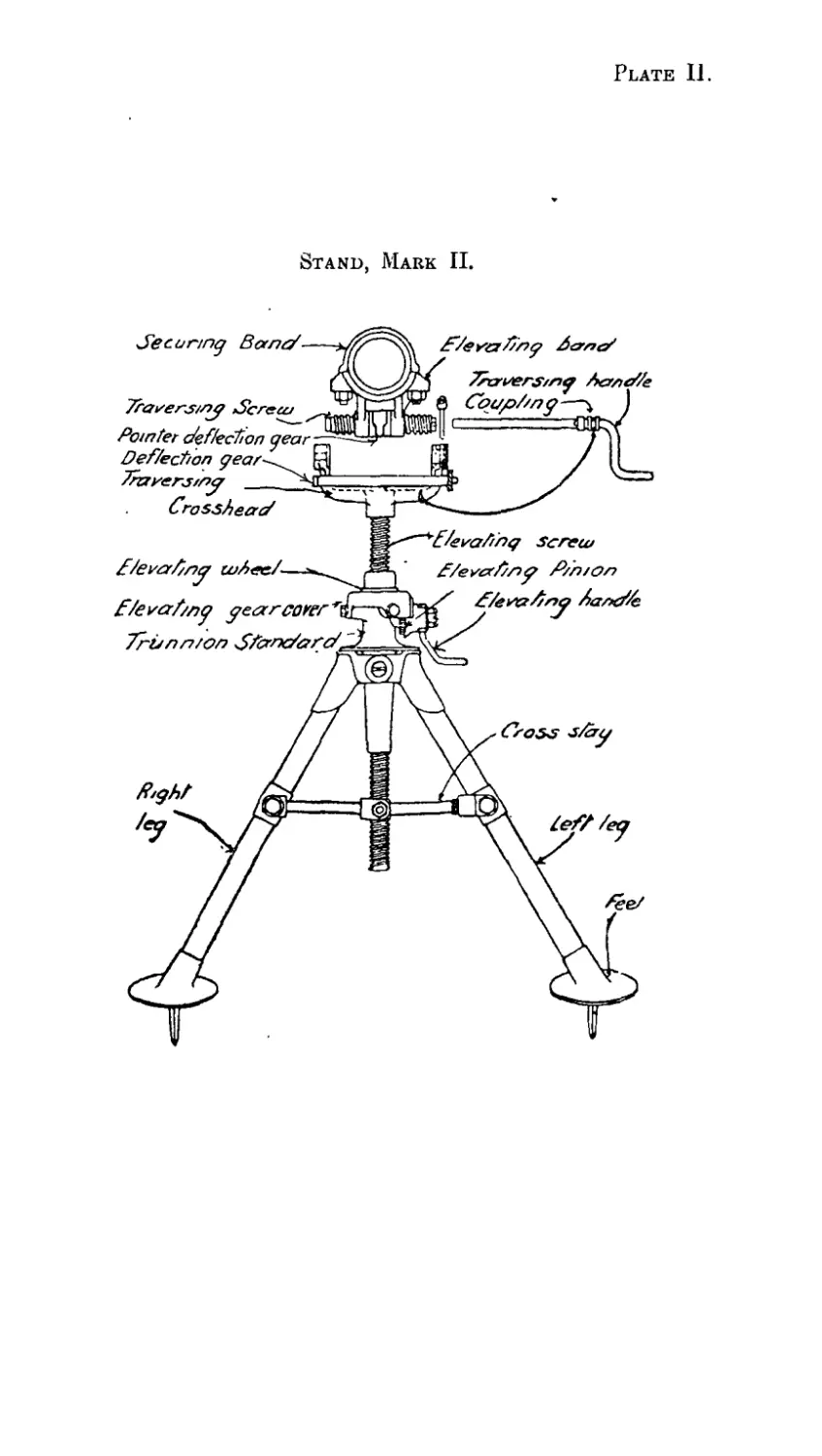
Stands.
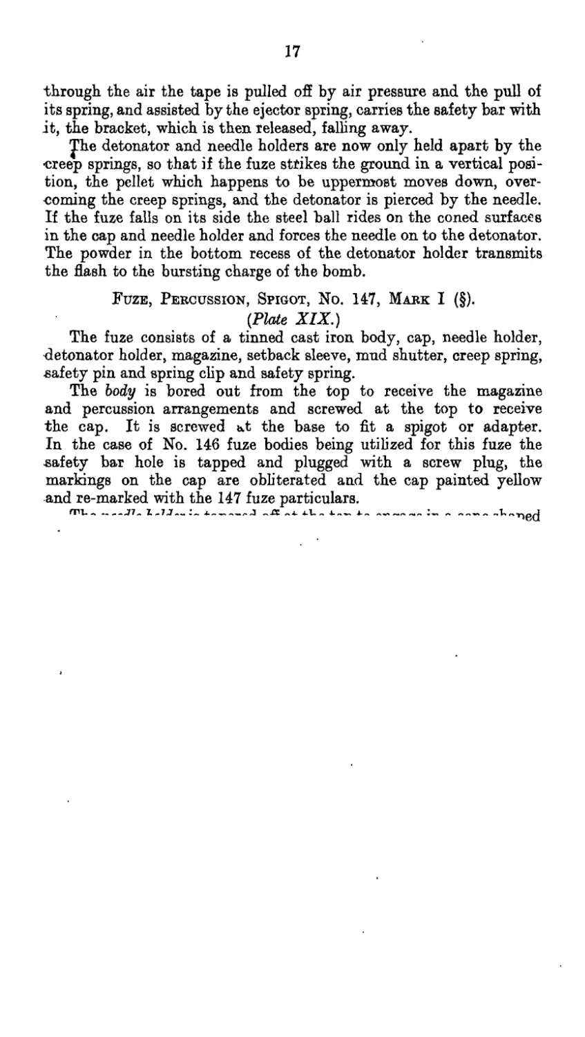
(Plates II and III.)
The Mark II stand consists principally of deflection, elevating
and traversing gears, supported on a tubular bipod stand with cross
stay.
The legs of the stand are left and right and are made of steel
tube, each with spiked foot, cross stay lug and fork end brazed on.
The legs are connected near the centre by means of a hinged cross stay
and at the upper ends by two trunnion studs to a trunnion standard
which carries the elevating wheel and pinion, elevating handle and
gear box. The elevating screw passes through the centre of the
elevating wheel, which forms a nut for the screw, and is prepared at
the upper end with a coned portion, with nut and washer, for connecting
to the traversing crosshead.
The traversing crosshead is attached to the upper end of the
elevating screw and carries the traversing handle and traversing
screw, which latter works in a nut formed in the underside of the
elevating band on the barrel.
The deflection gear consists principally of a supporting bracket,
spindle and pointer.
The supporting bracket is secured in a horizontal position in front
of the traversing crosshead by means of the nut on top of the
elevating screw and carries a brass tubular spindle.
The spindle has, inscribed longitudinally round its surface, eight
deflection scales which are graduated to suit angles of elevation (at
5° interval) between 45° and 80°, and are arranged to read “ right ”
and “left” from zero, the right graduations being in red and the
left in black. It is rotated by means of a knurled head until the
required scale is exposed to view through an opening formed in the
supporting bracket.
The pointer, by means of which, the scales are read, is attached
to the base portion of the traversing band by a spring clip.
5
The deflection, elevating and traversing gears are worked from
the left side of the mortar.
A bronze ring engraved with the nature and mark of the stand is
attached round one of the legs.
The Mark I stand differs from the Mark II tubular stand in being
made of lighter tubing and in having no bronze marking ring round
one of the legs.
These stands will be considered obsolete as they are replaced by
the Mark II tubular stands.
SHIELD, M.L. STOKES 3-INCH TRENCH MORTAR.
(Plate VI.)
The shield is made of steel plate, No. 5. S.W.G. (‘212-inch) thick,
and consists principally of one centre, one movable and three wing
portions, the third wing portion being used to extend the shield to
the left in order the better to protect the number operating the
elevating, traversing and deflection gears.
The centre portion is rectangular in shape and is provided with
two hinge bolt and catch plates for the attachment of the wing portions
The wing portions^ which are in all respects similar, are rectangular
in shape and have their upper edges scalloped for use in adjusting the
height of the movable portion to suit the angle of elevation of the
mortar. Each wing portion is provided with three hinge bolt and
catch plates, an eye supporting stay and stay for supporting the
shield when in use. The stay has, pivoted near its foot, a stop to
prevent undue sinking in the ground and is hinged about its centre
to facilitate transport, a steel loop being provided for locking the two
portions together when in use. When not in use the stay is folded
up and housed by a steel spring clip.
The movable portion is cut away on its upper edge in order to clear
the mortar and is hung in front of the shield over the centre portion
by means of two supporting hooks which engage the scallops in the
upper edges of the wing portions.
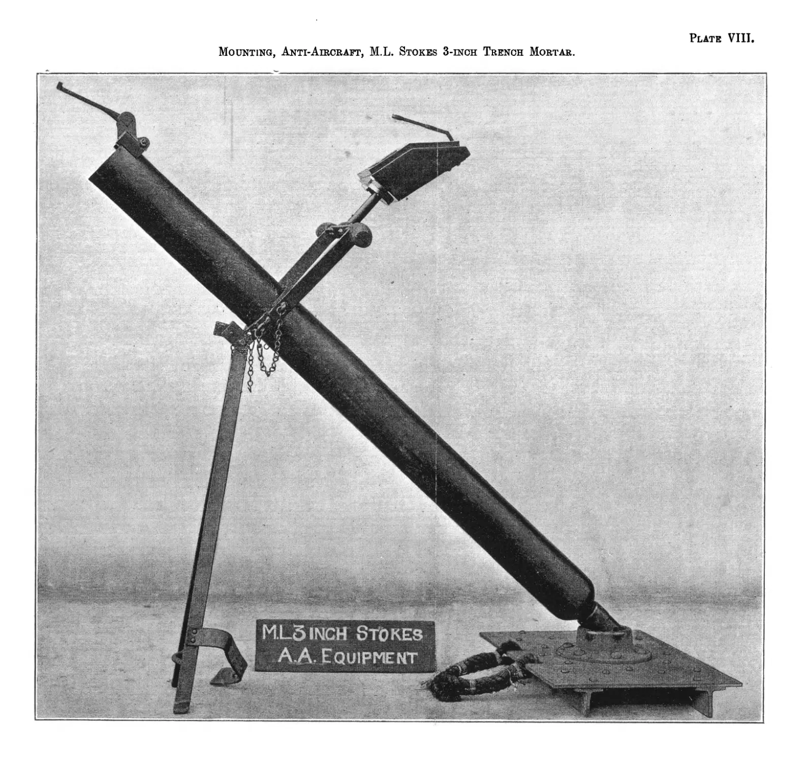
MOUNTING, ANTI-AIRCRAFT, M.L. STOKES 3-INCH
TRENCH MORTAR.
(Plates VII to A.)
The anti-aircraft mounting consists principally of a frame con-
structed of 1-inch by |-inch flat steel bar provided at the top with a
pair of hardwood handles, mounted on a pair of legs which being
connected near the bottom by a curved cross stay, forms a bipod
stand.
The central portion of the mounting is formed for the reception of
the barrel; the latter is held in position by a clamping band with two
clamping screws each of which is provided with a small securing chain
attached to an eye riveted in the side of the frame.
The stand is hinged to the frame portion to which it is held rigid,
when in use, by a locking pin with securing chain, when not in use
the stand is folded back against the barrel and secured by a leather
6
strap. A steel pillar for the reception of the mirror sight is provided*
centrally at the top of the mounting.
The approximate dimensions are as under:—
Height, overall (including pillar sup-
porting sight) .. .. .. 4 ГО-inches.
Width, maximum, over handles .. 2r0-inches.
Plate, Base.
(Plates VII to IX.)
The base plate for use with the Anti-Aircraft Mounting is of steel*
rectangular on plan ; it is provided centrally on its upper surface
with a raised cup for the reception of the breech end of the barrel,
re-inforced on its underside by steel angles, and furnished with a rope
handle for transporting purposes.
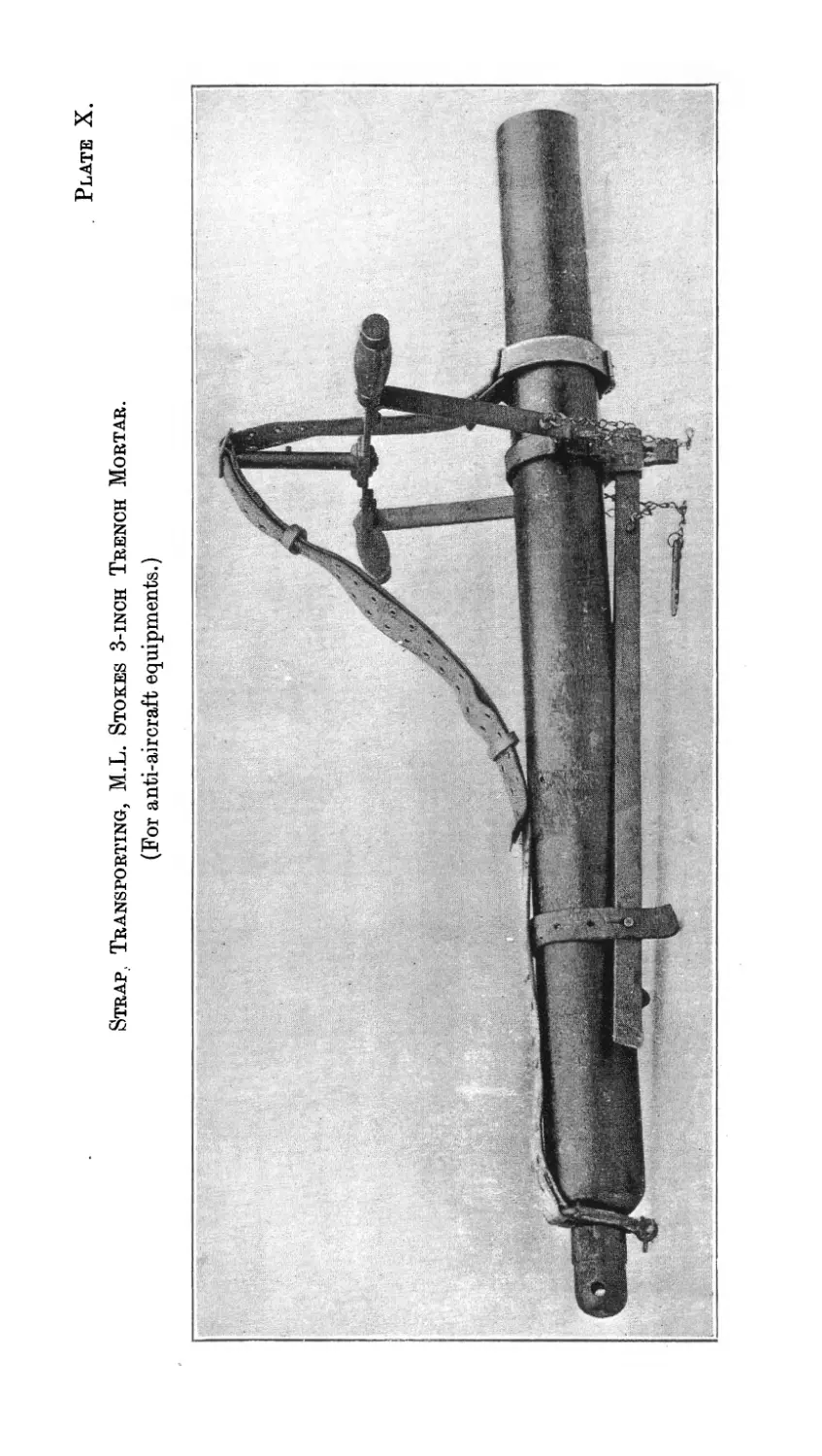
Strap, Transporting, M.L. Stokes 3-inch Trench Mortar.
(For Anti-Aircraft equipments.)
(Plate X.)
The transporting strap is made of 2-inch canvas webbing, in two-
parts, connected about the centre by a buckle with two running loops
of leather. The muzzle end portion of the strap is furnished with a
leather cross strap for attachment round the muzzle, the breech end
being provided with a steel spring loop, fitted with a clamping screw
with keep ring, for attachment to the breech end of the barrel.
SIGHTING.
(Plate XL)
Sight, Open, M.L. Stokes 3-inch Trench Mortar, Mark I.
The sight is so designed, that it can be rested on the muzzle of the-
mortar during the operation of laying, and the line of fire picked up
by the layer, by fixing the bar sight by hand in any position in the
vertical plane, so as to enable him to align the sights on any object
or auxiliary mark.
The body of the sight is shaped to rest on the muzzle of the mortar
and is provided with a fork to carry the bar sight. The bar sight is
provided with a fore and hind sight and is held in the fork by a clamping
bolt and nut, sufficiently tight to permit of the bar being moved up
or down by hand. The bar can be clamped in any position by means
of a milled head.
An adjustable spirit level, on the top side of the body, enables the
layer to cross-level the sight as required.
Sight, Mirror, A.A., M.L. Stokes 3-inch Trench
Mortar, Mark I.
The mirror sight which is for use against aircraft consists of a.
five-sided base block of hard wood, the underside of which is bored
and provided with a gun metal socket for the reception of the sight
supporting pillar on the clamping frame. A feather way is formed
in the socket for a feather on the supporting pillar, which prevents
7
the sight from turning, and the sight is locked by means of a locking'
piece secured to the socket.
The upper and lower forward faces of the base are provided with
mirrors, the latter are bedded in the base and secured by a frame and
wood screws. A clock dial is engraved on the mirrors, with the XII
point to the front and over the axis of the mortar. The figures on the
dial are engraved in the opposite direction to the ordinary clock,
г.е., the figure I is on the left of XII.
A sight bar, attached to the base is shaped to allow the layer to
look down into the mirrors. The bar is provided with two sighting
holes, one for use when engaging approaching machines, the other
for machines moving away.
NOMENCLATURE OF EQUIPMENT.
The nomenclature of the mortar, base plates, stand, shield^
mounting, A.A., and separate demandable stores is as follows :—
Ordnance, M.L. No.
Stokes 3-inch
trench mortar,
Mark I
Barrel .. Steel; with breech piece, washer and striker stud ;
elevating band with securing band and 2 nuts;
stop collar, consisting of split ring and clamp-
ing collar ; stop bolt socket; socket locking
nut; stop bolt; and stop bolt withdrawing
loop with axis rivet .. .. .. .. 1
Plate, base,
Mark II Steel, with socket with rivets, 4 loops and 21
or rope handles ............................... fl
Mark III Steel, with rope handle .. .. .. J
Stand,
Mark II Steel, tubular ; consisting of left and right legs,
each with spiked foot, cross stay lug, cross stay
bolt with nut, and fork end ; cross stay in 2
parts (I) and (II with connection), and hinge
bolt with nut; trunnion standard ‘ with
elevating pinion stud with keep pin and nut
and keep pin; 2 trunnion studs each with
keep pin, and gear cover with 3 securing
screws ; elevating wheel; elevating pinion ;
elevating handle; elevating screw with nut
and washer ; traversing crosshead ; travers-
ing screw ; traversing screw shaft with coupling
securing wire and traversing handle with pin ;
and locking pin for traversing screw shaft
with S-hook and spring ; pointer; bracket with
deflection tube, with knurled head with split
keep pin and spring washer .. .. .. 1
Shield, M.L. 3-inch
Stokes Trench
Mortars Steel; in five parts .. .. . .. 1
8
Mounting, anti- No.
aircraft M.L.
Stokes 3-inch
‘Trench Mor-
tar, Mark II Consisting of stand and clamp with mirror sight
pillar .. .. .. ..............1
Mounting, anti-
aircraft, M.L.
3-inch Stokes
trench mortar—
Plate, base
Mark I .. Steel, with rope handle .. ..............1
*Cover, muzzle,
M.L. 3-inch
Stokes Trench
Mortar,
Mark I .. Waterproof canvas ; with wire ring, chain and^l
or loop, and securing cord .. .. .. > 1
Mark II .. Leather ; with securing cord .. .. J
’Stiaps, trans-
porting, M.L.
3-inch Stokes
Trench Mor-
tar, Mark I.. Consisting of canvas shoulder strap, leather sling
strap with breech loop, and leather barrel strap 1
Tommy, M.L.
3-inch Stokes
Trench Mor-
tar, Mark I.. Steel ......................................... 1
Wrenches,
Stop Collar,
3-inch Stokes
Trench Mortar
“ A ” .. Steel; with riveted stud ..............1
. ,, ,, ,, ,, * • • • . . x
CARE AND PRESERVATION.
(These instructions apply also to the A. A. Equipment except where
reference is made to the elevating and traversing gears and shield.)
The mortar should be kept clean and free from rust and debris,
the bore slightly greased and the stop bolt and releasing trigger well
lubricated.
If the mortar is not to be used for some time, the bore should be
cleaned and oiled with paraffin or mineral oil. Thick lubricating oil
should not be used for this purpose as it chars and tends to clog the
bore. Should the bore become “ sticky ” the surface should be
cleaned with paraffin or petrol.
The striker stud should be examined from time to time, the breech
piece being removed from the barrel for this purpose by means of the
tommy provided. If found to be worn so as to be likely to cause
9
miss-fires it should be replaced by a new striker stud, care being taken
that the striker stud and the breech piece are tightly screwed home
on replacement.
The muzzle cover should be kept in position on the muzzle when
the mortar is not being used. In wet weather this is ofispecial import-
ance, as water in the bore seriously affects the range.
The recess for rear end of breech piece in the base plate should
be kept free from earth.
The stand should be kept clean and all working parts, the
elevating and traversing gears, well lubricated. It is important that
the nuts on the securing band of the elevating band should be tightened
up from time to time, as they tend to work loose after continuous
firing.
Before firing, care should be taken- to see that all oil is removed
from the bore. If the bore is oily, smoke will be given off and disclose
the position.
Under no circumstances should anyone be permitted to pass in
front of, or near to the muzzle, whilst firing is in progress.
All working parts should be cleaned and oiled, the striker stud
examined and, if necessary, tightened up. The mortar should be
cleaned, all residue removed from the chamber and the bore slightly
oiled.
After firing, the various nuts and screws on the mortar and stand
should be examined to see that they have not shaken loose by the
vibration due to firing.
Care should be taken that the hinge bolts and catch plates of the
shield are kept free from dirt and rust.
DIMENSIONS AND WEIGHTS.
Description. Dimensions (Approximate.) 1 Weight J (Approximate).
Mortar (with traversing band)... 48-ins. x 3f-ins. J 48-lbs.
Stand (tubular) Mark II 34-ins. x 8|-in. x 4j-in. .! 34-lbs.
Base plate (Mark II) 15-ins. x 15-ins. J 60-lbs.
(Mark III) | 20-ins. x 13-ins. .! 40-lbs.
Shield, assembled • 48-ins. x 72-ins. 270-lbs.
Box, Store, filled 57-ins. x 16|-ins. x llj-ins. 1 196-lbs. I
A Mortar ... ... ... .... nti-Aircraft Equipment. , 48-ins. x 3f -ins. I ' 44-lbs.
Mounting, Mark II 41-ins. x 21-ins. J 10-lbs.
Base plate, Mark I 20-ins. x 13^-ins. x 4-ins. .. J 46-lbs.
Straps, transporting ‘ Box, ammunition, B. 131 .... 21-ins X 12-ins. X 4-ins. 1-lb, . 46-lbs. 13j-ozs.
MISCELLANEOUS STORES.
Brushs Wire, M.L. 3-inch Stokes Trench Mortars.—The brush con-
sists principally of a square steel spindle with cast iron front and rear
flanges, a tubular rod with handle, and four wire-covered hard wood
segments, which are curved at the front end to suit the interior of
(14134) A3
10
the breech and are provided on. their underside with retaining plates
and flat steel springs. The free ends of the springs, operating on
the spindle, permit of the contraction and expansion of the brush
when in use.
The flanges are provided with perforations to receive the ends of
the retaining plates and with sockets which engage shoulders on
the ends of the spindle. The front and rear flanges are secured on
the spindle by a locking screw and a hexagon nut with spring washer,
respectively.
The rod is of tubular steel with a T-handle at one end and is
attached to the spindle by a screwed socket with keep pin.
Dimensions.
Length, overall .. .. .. . . 52-inches.
Diameter of brush (expanded) .. 3’45-inches.
Box, Ammunition, M.L. 3-inch Smokes Trench Mortar, B. 131.
The box is made of wood and is fitted internally with a wood
partition which is recessed to take the spigots of three bombs, and
forms a recess for an inner box in which is carried the necessary fuzes,
cartridges, &c., packed in tin boxes. The approximate dimensions
of the inner box are 10-inches by 3-inches by 3|-inches. Four splayed
pieces are attached to the bottom of the box to steady the bombs
during transit.
A certain number of boxes may be met with which differ from the
above in having two cross pieces, shaped to take the bombs, instead of
the wood partition.
Length overall .. .. .. .. 22-inches.
Breadth „....................... ... 12 „
Depth ,, .............. 6 ,,
The weights of the box, empty and filled, and also the contents
are as follows:— lbs. ozs>
Box, ammunition (empty) .. .. .. 13 0
Bombs, H?E. (3) .. .. .. .. 29 14
Box, inner (empty) .. .. .. . . — 91
Fuzes, No. 146 (3) (each in tin box) 2 10
Detonators, No. 1 (3) (in cardboard box) — 4 .
Cartridges (3) and aug- "1 r .. , . Q
? + 'j г (m tm box) — 8
menting cartridges (12) Jv ’
Total (box filled) .. ..46 13|
Box, Ammunition, M.L. 3-inch Stokes Trench Mortar, B. 153.
The box, which is made of wood, is furnished with rope handles
and is divided into two compartments, one to receive the bombs and
the other the cartridges, exploders and fuzes. The bombs are held in
position in the bottom of the box by means of wood guides and a rack
and are secured by means of a wood packing piece nailed to the
underside of the lid.
Length overall .. .. .. 21*5-inches.
Breadth ,, .. .. .. 11 *125-inches.
Depth „ .. .. .. 5'5-inches.
11
Contents.
Bombs, H.E., light .. .. .. .. 3
Fuzes, No. 136, in tinned plate box .. .. 3
Exploders ,, ,, .... 3
Cartridges ,, ,, .. .. 3 v
The approximate weight of the box, filled, is 31J-lbs.
Box, Store, M.L. 3-inch Stokes Trench Mortars.—The Mar к I box is
made of wood and is provided with rope handles secured by wood
cleats. It is provided internally with wood fittings and a leather
strap to -carry the equipment (except shield) and various stores,
also a small “Box, spare springs,” as shown in Appendix I to
A.F. G. 1098-243.
The lid is secured to the body by four screwed dowels which pass
through holes in the lid and are then nutted up by hexagon nuts.
The Mark II differs from the Mark 1 in being fitted with wing
nuts for securing the lid.
Box, tool, M.L. 34nch Stokes Trench Mortar.—This is of wood and
is fitted with a hinged lid provided with a hasp fastening. It is
carried in the Box, Store, and is designed to hold the various tools
for use with the equipment. For contents of this box see Appendix
I to A.F. G. 1098-243.
Carrier, bomb, M.L. 3-inch Stokes Trench Mortar.—The carrier is
of khaki canvas and is made up in the form of a sleeveless jacket
with open sides and a circular hole in the centre through which
the head of the ammunition number is passed. The back and front
•are sewn down the centre to form pockets to carry four bombs (one
in each pocket) and four small pockets are provided at the bottom
of the carrier to hold the cartridges.
Clinometer, M.L. 3-7-inch and 4-inch and Stokes 3-inch Trench
Mortars.—The clinometer consists of a cast-iron body having a long
flat bearing surface and a revolving circular disc, to which is attached
a spirit bubble, which is sensitive to about 2-minutes.
The disc is graduated in single degrees and can be clamped to the
body at any required reading.
In future, bubbles will be painted on the upper surface with black
streaks outside the ordinary graduations and with radium compound
on the underside to make them self-luminous for use at night. Instru-
ments fitted with radium-painted bubbles will be marked with a
red “ R ” for purposes of identification.
Clinometer, A.A. M.L. Stokes 3-inch T.M. Mark I (Plate XI).—•
The clinometer is of the pendulum type. The body is formed in a
four-sided skeleton plate, which is practically square. A slide is
secured to the underside of the body plate, which fits in a groove
formed in a supporting band. A stop at the front end of the slide
prevents the clinometer from slipping out of the groove when in use
and a clamping screw on the supporting band is also provided for
securing the clinometer. The supporting band which is shaped to
fit over the barrel is secured to the elevating band of the mortar by
two nuts.
12
An index plate and scale plate are attached to the body plate by
securing screws. Four-yard scales are graduated on the scale plate
to suit the various charges used with the mortar and the nature of
charge to be used with each scale is marked against it.
A pendulum reader and pendulum stop with a stop stud and
milled nut are hinged to the upper corner of the body plate and an
index pointer, with a radius line throughout its length, works in a groove-
cut in the index plate, a guide screw with milled nut is provided for
clamping the index pointer as required.
Cover, Muzzle, M.L. 3-inch Stokes Trench Mortar.—The Mark II
muzzle cover is of leather, shaped to fit over the muzzle and is pro-
vided with a securing cord.
The Mark I muzzle covers are similar to the Mark II, but are
made of canvas with wire ring and securing cord. No more Mark I
covers will, however, be made and existing covers will be considered
obsolete as they become unserviceable.
Implements, Ammunition—Extractor, Cartridge, M.L. 3-inch Stokes
Trench Mortar.—The Mark I extractor consists of a steel rod,,
blackened in oil, 4-52-inches long and l*22-inches in diameter; a.
semicircular hole with bevelled edges is provided at one end and a
morticed slot at the other for removing cartridges from the container.
A hole is drilled in the centre to receive a lanyard.
The Mark II differs from the Mark I in the semi-circular hole
being prepared for use with cartridges fitted with a guard.
Implements Ammunition—Key No. 74, Mark I.—The key consists-
of a flat bar of steel, 6-inuhes long, with a semi-circular jaw at one end
with two studs at right angles to the jaw to engage in the slots in
the No. 136 fuze for fixing purposes. The handle is fitted with a-
lanyard.
Rod, cleaning, M.L. 3-inch Stokes Trench Mortars.—The rod is
made of tubular steel, 49-inches long and about J-inch in diameter.
It is cut longitudinally at one end for about 6-inches to form four
portions, which are splayed out and have their ends turned in so as
to retain the cotton waste or rag when used for cleaning the mortar.
Spanner, combination, M.L. 3-inch Stokes Trench Mortar Equipment.
—The spanner is of steel. It is provided with two pairs of jaws at
one end, the other end being turned up to form a screwdriver; it has.
four hexagonal holes of various sizes formed in the body.
The spanner fits all the nuts and bolts of the stand and also fits-
the striker stud. The screwdriver end is for use with the trunnion
studs.
Tommy, M.L. 3-inch Stokes Trench Mortar.—The tommy is of
bar steel and is reduced at one end to suit the hole in existing breech
pieces, the other end being arranged to suit the larger hole in the
strengthened breech piece of future manufacture.
Wrenches, Stop Collar, M.L. 3-inch Stokes Trench Mortar “A3>
and “ В.”—The wrenches are of flat bar steel, one end being semi-
circular in shape and fitted with a stud to engage a hole provided
in the clamping collar of the stop collar and the opening of the split
ring respectively. The wrenches differ from each other in the diameter
of the clutch portion.
AMMUNITION.
Bombs. Nature of Fuze. Cartridge. Means of Firing.
Description. Mark. Weight.
Empty. Filled and Fuzed. Nature. Weight.
Bomb, M.L., H.E., 3-inch Stokes Trench Mortar Bomb, M.L., H.E., with vanes, 3-inch Stokes Trench Mortar, light (e) IV (a) II lbs. ozs. drs. 7 12 0 -p 2 ozs. — 4 ozs. 4 12 0 + 3 ozs. lbs. ozs. drs. 10 11 8 (b) 6 13 0(6) + 3 ozs. Fuze, percussion, Spigot, No. 146, 147 or 148 Fuze, percussion, No. 136 f Ballistite ... 5 Cordite flake I E.C. 3 powder 95 grains 110 grains (c) (d) 125 grains (c) Percussion cap.
(a) Other marks may be met with.
(b) Excluding cartridge.
(c) Alternative augmenting charges.
(d) Consisting of four rings, each of 110 grains.
(e) The cartridge for use with this bomb is not yet approved.
14
Bomb, M.L., H.E., 3-inch Stokes Trench Mortar (§).
(Plate XII.)
Typical.
The bomb consists of a steel or iron cylinder screwed at both ends,
one end to receive a head formed with a projecting spigot in the
centre, which is screwed to receive the fuze and the other end to
receive a base fitted with a “ Container, tubular, propelling charge.”
The container consists of a steel tube perforated with 16 holes.
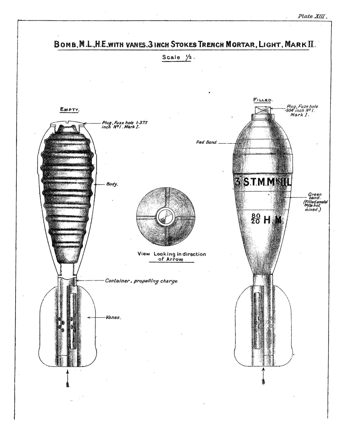
Bomb, M.L., H.E., with Vanes, 3-inch Stokes Trench Mortar,
Light, Mark II.
(Plate XIII.)
The Mark II bomb consists of a cast iron body, stream line
in shape, which is threaded at the head to receive the “ Plug, Fuze
Hole, 1 • 375-inch ” or a(! Container, Exploder,” No. 4, and at the base to
receive the “ Container, Propelling charge.” The exterior of the body
is formed with a guide ring at the shoulder and the interior is corrugated
and varnished. The container, propelling charge is of tubular steel
perforated with 16 holes to distribute the gas from the charge equally
around the bomb; it is threaded at the front end to screw
into the base of the body against a copper washer. The space within
the container not occupied by the cartridge is filled by a wood plug
driven in and the exterior is fitted with two pieces of sheet steel bent
at right angles to form four vanes and brazed on to the rear end of
the container.
The bombs are issued fitted with a “Plug, fuze hole, *904-inch”
and when required for use the plug is removed, an exploder inserted
into the exploder container and a No. 136 fuze screwed into the head.
Cartridge, M.L., 3-inch Stokes Trench Mortar ;
95 Grains Ballistite (§).
(Plate XIV.)
Typical.
The cartridge consists of a cylindrical paper case with a brass base
fitted with a brass cap chamber and filled with a charge of ballistite.
The top of the case is closed by two cardboard discs and two felt wads.
The base is fitted with a striking arrangement outside the cap which
consists of a steel guard, striker disc and a steel striker. The steel
guard is cup-shaped and is sprung on to the edge of the base. The
striker disc is secured to the guard by four nicks and has riveted to
it the steel striker, which it holds in position below the cap.
Cartridge, M.L., 3-inch Stokes Trench Mortab, Augmenting,
110 Grains Cordite -3mm. Flake, Mark I (§).
(Plate XV.)
Augmenting charges, each consisting of 110 grains of cordite flake
contained in a blue cambric bag, are also issued, the full charge for the
mortar consisting of the cartridge and four of these augmenting
charges. In order to fit the charges on to the container at the base
of the bomb, each charge is bent round in the form of a ring, the ends
being secured by elastic._______________________________________
(§) For method of packing, see description of “ Box, ammunition,” on page 10.
15
Cartridge, M.L., 3-inch Stokes Trench Mortar, Augmenting,
125 Grains, E.C. 3 Powder, Mark I (§).
(Plate XVI.)
This augmenting charge, which is alternative to that described on
page 14, consists of 125 grains of E.C. 3 powder enclbsed in a ring-shaped
cover of celluloid reinforced with book muslin; to enable the ring to
grip the container, the ends of the cover are connected by an elastic
band secured with thread.
Fuze, Percussion, No. 136, Mark I.
(Plate XVII.)
The fuze consists of the following parts :—Body, detonator holder,
detent and locking collars, needle, striker spring, impact cap, closing
plug, bush, detent spring, arming spring, needle holder and detonator.
All parts are of brass except the detent spring, arming spring and
needle which are of phosphor bronze, and the striker spring which is
of steel.
The body is screw threaded at its lower end to the -9-inch gauge
below which it is reduced in diameter and turned plain ; its upper end
is formed with a conical flange terminating a cylindrical stem. Slots
are cut in the flange to take the Key No. 74 for fixing purposes. Inter-
nally the body is bored out in two different diameters to take the per-
cussion arrangements ; a diaphragm is formed near the centre which
serves as a bearing for the striker spring and the top of the detent
collar ; a small hole bored through the centre of the diaphragm serves
as a guide for the needle. The body is threaded internally at the top
to take the bush and at the bottom for the closing plug.
The detonator bolder consists of a brass tube formed with a flange
near the centre which acts as a seating for the detent spring and the
arming spring. Two grooves are turned around the upper portion
of the holder to receive the projections of the detent collar in the
normal or armed position respectively, and a recess is formed at the
bottom to take a 1 - 7 grain detonator spun in.
The detent collar is flanged at the top to form a bearing for the top
of the locking collar; the lower portion has six projections which
grip in the upper grooves of the detonator holder when in the normal
position.
The locking collar, which fits around the detonator holder, is formed
internally with a shoulder which acts as a bearing for the detent spring
and locks the projections on the detent collar in the upper or lower
gfboves of the detonator holder.
The bottom of the fuze is closed by the closing plug ; the plug,
forms a seating for the arming spring which is fully compressed until
after firing.
The needle holder is inserted in the top of the fuze and secured by
means of the bush ; it is supported by the striker spring and recessed
through the centre to take the needle which is riveted in.
The impact cap is sprung into the needle holder.
The fuze requires no preparation before loading.
(§) For method of packing, see description of “ Box, ammunition,” on page 10;
16
Action.— On the shock of discharge the detent collar and locking
collar set back, compressing the detent spring; the projections
on the former ride over the shoulder between the grooves on the
detonator holder and grip into the bottom groove ; the detent spring
then reasserts itself, and forces the locking collar upwards, thus holding
the projections in the bottom groove and locking together the detonator
holder, detent collar and locking collar. Owing to the change in posi-
tionjof the detent collar, the detonator holder is now free to be lifted
by the arming spring until it fouls the diaphragm in the body, thus
bringing the detonator nearer to the needle; the fuze is then armed.
On impact, the needle holder is driven in, carrying the needle on to the
detonator, the flash from which detonates the exploder and the bursting
charge of the bomb.
Fuze, Percussion, Spigot, No. 146, Mark V (§).
(Plate XVIII.)
The fuze consists of the following principal parts :—Body of cast '
iron or mild steel, brass detonator holder with steel creep springs,
aluminium needle holder, steel or lead and antimony ball, steel or
zinc alloy cap, steel bracket, brass mud shutter, releasing tape and
retaining pin, steel ejector spring and safety bar.
The body is bored out internally and screwed at the bottom to
suit the spigot of the bomb, the top portion of the cavity containing
the detonator and needle holders and the steel or alloy ball, the fuze
being closed with the cap.
The top of the detonator holder is recessed to receive a 1-7 grain
detonator, the bottom to form a magazine containing about 5 grains
of F.G. powder.
The detonator and needle holders are kept apart by two creep springs
fixed to the detonator holder so that the upper end of the detonator
holder, which has a coned recess formed in the top, engages with the
steel ball which in turn engages in a coned recess in the under surface
of the cap.
A cylindrical metal mud shutter and a bracket with catch hooks
are secured to the exterior of the fuze by the safety bar which passes
through holes in the bracket, shutter and body of the fuze, the bar
thus serves to keep the holders apart during transport and shock of
discharge.
An ejector spring is placed between the brackets and the mud
shutter. t
A double twill cloth tape is attached to the safety bar; its free end
is fitted with a tape spring and a retaining pin which engages in a hole
and catch hooks in the bracket.
A safety pin passes through the retaining pin and prevents it from
being jarred out of. the catch hooks during transport.
The Mfoipipin is rumuvud. Just prio’Ftu-loading.
Action.—On the shock of discharge the retaining pin sets back
out of the catch hooks, thus releasing the tape. As the bomb travels
(§) For method of packing, see description of " Box ammunition ” on page 10.
17
through the air the tape is pulled off by air pressure and the pull of
its spring, and assisted by the ejector spring, carries the safety bar with
it, the bracket, which is then released, falling away.
yhe detonator and needle holders are now only held apart by the
creep springs, so that if the fuze strikes the ground in a vertical posi-
tion, the pellet which happens to be uppermost moves down, over-
coming the creep springs, and the detonator is pierced by the needle.
If the fuze falls on its side the steel ball rides on the coned surfaces
in the cap and needle holder and forces the needle on to the detonator.
The powder in the bottom recess of the detonator holder transmits
the flash to the bursting charge of the bomb.
Fuze, Percussion, Spigot, No. 147, Mark I (§).
(Plate XIX.)
The fuze consists of a tinned cast iron body, cap, needle holder,
detonator holder, magazine, setback sleeve, mud shutter, creep spring,
safety pin and spring clip and safety spring.
The body is bored out from the top to receive the magazine
and percussion arrangements and screwed at the top to receive
the cap. It is screwed at the base to fit a spigot or adapter.
In the case of No. 146 fuze bodies being utilized for this fuze the
safety bar hole is tapped and plugged with a screw plug, the
markings on the cap are obliterated and the cap painted yellow
and re-marked with the 147 fuze particulars.
ггг. ~ j.----- j „re 4-v - 4._-------:--------
16
Action,—On the shock of discharge the detent collar and locking
collar set back, compressing the detent spring; the projections
on the former ride over the shoulder between the grooves on the
detonator holder and grip into the bottom groove ; the detent spring
then reasserts itself, and forces the locking collar upwards, thus holding
the projections in the bottom groove and locking together the detonator
holder, detent collar and locking collar. Owing to the change in posi-
tionjof the detent collar, the detonator holder is now free to be lifted
by the arming spring until it fouls the diaphragm in the body, thus
bringing the detonator nearer to the needle; the fuze is then armed.
On impact, the needle holder is driven in, carrying the needle on to the
detonator, the flash from which detonates the exploder and the bursting
charge of the bomb.
Fuze, Percussion, Spigot, No. 146, Mark V (§).
(Plate XVIII.)
The fuze consists of the following principal parts:—Body of cast
iron or mild steel, brass detonator holder with steel creep springs,
aluminium needle holder, steel or lead and antimony ball, steel or
zinc alloy cap, steel bracket, brass mud shutter, releasing tape and
retaining pin, steel ejector spring and safety bar.
The body is bored out internally and screwed at the bottom to
suit the spigot of the bomb, the top portion of the cavity containing
Issued with Army Orders, March, 1921.
__40_
W,O,~
'79447
Addendum (No. 1) to the Handbook
OF THE
M.L. Stokes 3-inch Trench Mortar Equipments.
LAND SERVICE, 1919.
Page 16 :—
Description of “ Fuze, percussion, Spigot, No. 146, Mark V”—
For 3rd line of text from bottom of page :
/?W“The safety pin is. removed just prior to loading, care being
taken that the direction of the pull is at right angles to the
axis of the bomb and never in a downward direction.”
(B 153592) Wt. 34274—4849 5м 3/21 H & S Ltd. G.H.67
17
through the air the tape is pulled off by air pressure and the pull of
its spring, and assisted by the ejector spring, carries the safety bar with
it, the bracket, which is then released, falling away.
The detonator and needle holders are now only held apart by the
•creep springs, so that if the fuze strikes the ground,in a vertical posi-
tion, the pellet which happens to be uppermost moves down, over-
coming the creep springs, and the detonator is pierced by the needle.
If the fuze falls on its side the steel ball rides on the coned surfaces
in the cap and needle holder and forces the needle on to the detonator.
The powder in the bottom recess of the detonator holder transmits
the flash to the bursting charge of the bomb.
Fuze, Percussion, Spigot, No. 147, Mark I (§).
(Plate XIX.)
The fuze consists of a tinned cast iron body, cap, needle holder,
detonator holder, magazine, setback sleeve, mud shutter, creep spring,
safety pin and spring clip and safety spring.
The body is bored out from the top to receive the magazine
and percussion arrangements and screwed at the top to receive
the cap. It is screwed at the base to fit a spigot or adapter.
In the case of No. 146 fuze bodies being utilized for this fuze the
safety bar hole is tapped and plugged with a screw plug, the
markings on the cap are obliterated and the cap painted yellow
and re-marked with the 147 fuze particulars.
The needle holder is tapered off at the top to engage in a cone shaped
recess formed in the underside of the cap and is turned below a flange
to fit into a deep annular recess in the top of the detonator holder.
The needle is screwed in from the underside and projects below the base
and into a hole bored through the centre of the detonator holder ; a
creep spring in the annular recess of the latter prevents the needle
pellet from moving on to the detonator during flight.
The bottom of the detonator holder contains a 1-7 grain detonator
and is rounded to engage in a corresponding recess in the top face of
the magazine; two vent holes are bored through the side and into
the central hole and annular recess to prevent air cushioning.
The magazine which is hollowed out on the underside to contain
about 5 grains of F.G. powder, has seven flash holes bored through
it to convey the flash from the detonator.
The safety arrangement consists of the following:—A steel band
safety spring, corrugated at one end, is wound (commencing with the
corrugated end) round the side of the needle holder and retained in
position between the top face of the detonator holder and the flange
of the needle holder, by a brass set back sleeve ; the sleeve is held
in position by two tongues which fit on top of the safety spring.
A safety pin, carrying a horse shoe shaped steel band spring which
.grips around the exterior of the fuze body, is passed through the side
of the fuze under the lower edge of the mud shutter and set back sleeve
and through the side of the detonator pellet.
The safety pin is removed at the moment of loading.
(§) For method of packing, see description of “ Box ammunition ” on page 10.
18
Action.-—The shock of discharge causes the mud shutter to move;
backwards and cover the safety pin hole in the fuze body to prevent
the ingress of mud. The set back sleeve also moves backwards and
releases the safety spring, the latter, however, is prevented from
opening out whilst the bomb is under acceleration in the bore due
to the grip of the needle holder which sets back slightly. On accelera-
tion decreasing after the bomb has left the bore, the creep spring
re-asserts itself and lifts the needle holder, thus releasing the safety
spring which opens out, leaving the detonator and needle holders held
apart only by the creep spring. On impact, the detonator holder or
needle holder, according to whether the bomb falls on the head or the
base, moves forward and fires the detonator. If the bomb falls on
its side the needle holder rides on the coned surface in the cap and
forces the needle on to the detonator, the flash of which ignites the
powder in the magazine.
Fuze, Percussion, Spigot, No. 148, Mark I (§).
(Plate XX.)
This fuze is generally similar to the fuze, percussion, No. 146,
differing only in having a shutter arrangement for releasing the safety
bar in flight in place of a tape and spring.
The shutter arrangement consists of a brass shutter frame, shutter,
and shutter cover. The shutter frame, which contains the shutter,
is riveted to the mud shutter; two holes are bored in the frame, the
one at the top to take a hinge pin for the shutter and shutter cover
and one at the bottom to take a safety pin.
The shutter is a flat strip of brass formed at its upper end with
two elongated projections; slots are formed in the projections to
take the hinge pin and to allow the shutter a slight vertical movement
in the frame ; two arms, formed at the bottom of the shutter, fit
into recesses in the frame and cover.
The shutter cover is hinged at the top to the hinge pin ; two recesses
are formed at its lower end to take the arms of the shutter, and a hole
is bored through to take the safety pin.
The safety pin is removed at the moment of loading.
Action of Shutter.—In the normal position, the ejector spring is
held fully compressed between the outer end of the safety bar, to which
it is fixed and the mud shutter. The safety bar is kept in position
by the shutter, which in turn is held by the arms fitting in the
recesses in the frame and cover and is secured by the safety pin.
On removing the safety pin, the shutter is kept up only by the friction-
caused through the pressure of the safety bar. On the shock of dis-
charge it sets back and is released through the arms being withdrawn
from their recesses ; the pressure of the ejector spring, acting through
the safety bar, causes the shutter and cover to revolve upwards and
the safety bar to be withdrawn from the body. The fuze is then
armed and on impact, the action is the same as that described for the
No. 146 fuze on page 16.
(§) For method of packing, see description of “ Box ammunition” on page 10.
Plate 1.
Fig, 3.
Plate 11.
Stand, Mark II.
Securing Band
SV'C/Eng /)^/7(Г
Tra’^rs/ng />€^n<//e
Tracers//?? Screaj
Pointer deflection gearz~
Deffect/on gea/''-^^ Й
iforerj/ry' _____ "w“
fross^eo'd
E/eva/iny cu/nee./
Efevcrf/ng yea rearer
Trbnn/on Sfomc/ard'-
Cro^s j/cry
foght
E/eva/ing Screcu
f/evcd/ny P/n/on
S/evsrAno fand/o
Plate III.
Stokes Trench Mortar Fitted with Mark II Sta^d.
A—Barrel.
C—Base Plate, Mark I.
E—Elevating Gear.
G—Stop Bolt.
В—Tubular Supporting Legs.
D—Traversing Gear.
F—Stop Collar.
Plate IV.
Base Plate, Stokes Trench xMortar, Mark II.
Section on A.B.
Plate V.
Plate, Base, M.L. Stokes 3-inch Trench Mortar, Mark III.
Plate VI.
Shield, M.L., 3-in. Trench Mortars.
A—Shield, wing portion.
C—Shield, movable portion.
E—Clip, supporting stay.
G—Catch plate, hinge bolt.
J —Loop, locking stay.
В—Shield, centre portion.
D—Hook, supporting,
F—Hinge plate, with bolt.
H—Stay, supporting shield.
Plate VII.
Mounting, Anti-Aircraft, M.L. Stokes 3-inch Trench Mortar.
Plate VIIL
Mounting, Anti-Aircraft, M.L, Stokes 3-inoh Trench Mortar.
Plate 1X.
Mounting, Anti-Aircraft, M.L. Stokes 3 inch Trench Mortars.
Plate X.
Strap, Transporting, M.L. Stokes 3-inch Trench Mortar.
(For anti-aircraft equipments.)
Plate XI.
Sighting, M.L. Stokes 3-inch Trench Mortar.
puuexn:
BOMB, M, L, H, E, 3-INCH STOKES TRENCH MORTAR,
FILLED
SCALE /2.
Typical.
empty
4-Fz/ze,A? !4S
Bed Band.
Container propelling
charge.
Pink band filled
ammonal or
sabvh'te.
Green band Filled
amatol.
Exterior oF body
painted dirty
white.
2092. Ю./8- П Т fr$93i
3 STH
H.frC. SRAHAH L.T? Litre” 1.0
Plate РШЕ,
Bomb,M.L.,H.E.,with vanes(3 inch Stokes Trench Mortar, Light, Mar к П.
Scale
F*IL.L£D.
CARTRIDGE. M.L.3-INCH STOKES TRENCH
MORTAR, 95-GRAINS BALLISTITE.
SCALE */\
Typical.
. rc-./в tvTw^9y.
H * ОБАМАМ 'ЛР I TH’» uOHPOH.
Plate 2У.
Cartri dge,M.L.,3 inch Stoke's Trench Mortar,
Augmenting, IIO-grains Cordite -3 %. Flake, Mark. I.
Scale */i.
Alternative Cartridges .
Rubber Rina to connect White ribbon elastic to
____ends and Form ring._________connec t ends and form ring._
Cartridge,M.L.,3 inch Stokes Trench Mortar^’
Augmenting, 125-grains,E.C.3. Powder, Mark!.
Scale */i-
White ribbon elastic --
secured to bag at both,
ends by thread wound
round four times.
3092.
M, * C. ORAHAM n? LITH’5 LONDON, S.C.
'PlnfeXVLl.
Fuze , Percussion , N? 136, Mark I .
Scale Full Size.
External View .
Normal.
Detonator.
-Arming Spring.
-Closing Plug
-Locking Collar.
-Detonator Holder.
-Detent Spring.
-Body.
Detent Collar.
Impact Cap.
-Bush.
eed Ie Holder.
-Needle.
StrikerSpring.
Fuze Armsd . On Impact.
2032.
И.» C. 6RAHAM Ш LI TH» Я LONDON.«X.
J?la±&JLVllL
Fuze, Percussion , Spigot, № 146 , Mark V.
Full Size.
2O&2..
M. & C. GRAHAM (Л? LITHM LONDON, 8.1.
Plate Ш.
Fuig, Percussion, Spigot, N? 147. Mark I .
Full Size.
В
JPtafje
Fuze, Percussion, Spigot, N? 148. Mark I.
Full Size-
Shutter.------
Shutter Frame.
Hinge P/n.---
Safety Pin. —г
Shutter Cover
и, Л С.СЯАНАМ 1Л? ЫТИМ LONDON S.l