/
Tags: weapons military affairs patent
Year: 1912

Text
A. A. ACKERMAN.
MEANS FOB PREVENTING THE EROSION OF GUNS.
APPLICATION FILED DEO. 21, 1911.
1,036,171. Patented Aug. 20,1912.
2 SHEETS-SHEET 1.
A. A. ACKERMAN.
MEANS FOB PREVENTING THE EROSION OF GUNS.
APPLICATION FILED DEO. 21, 1911.
1,036,171. Patented Aug. 20,1912.
2 SHEETS-SHEET 2.
UNITED STATES PATENT OFFICE.
ALBERT AMMERMAN ACKERMAN, OF THE UNITED STATES NAVY.
MEANS FOR PREVENTING THE EROSION OF GUNS.
1,036,171. Specification of Letters Patent. Patented Aug. 20,1912.
Application filed December 21, 1911. Serial No. 667,121.
To all whom it may concern:
Be -it known that I, Albert Ammerman
Ackerman, captain, United States Navy,
retired, and a citizen of the United States,
5 residing at San Diego, in the county of San
Diego and State of California, have in-
vented certain new and useful Improve-
ments in Means for Preventing the Erosion
of Guns; and I do hereby declare the fol-
10 lowing to be a full, clear, and exact descrip-
tion of the invention, such as will enable
others skilled in the art to which it apper-
tains to make and use the same.
My present invention relates to improve-
15 ments in means for preventing the erosion
of guns, and it is especially intended to sup-
ply means carried by the shell, which may
be used in guns of ordinary construction
without necessitating changes in the shape
20 of the bore of the gun, or any of the acces-
sories of the gun proper.
The purpose of this invention is to pre-
vent erosion; restore the efficiency of eroded
guns; lubricate the bore in advance of the
25 rotating band; and in general, reduce the
wear and tear of high powered guns.
The principle is accepted that erosion is
caused by the escape-of powder'gases past
the projectile before it has moved from its
30 loaded position. Once started, the rotating
baud is swaged into the rifling and prac-
tically stops the leaks. Before that moving
pressure is attained, however, and through-
out a large part of the elapsed time between
35 ignition and expulsion, there are lower pres-
sures which, though unable to overcome the
inertia of the projectile, give an intense
velocity to the light, nascent gases of early
combustion escaping through chamber leaks.
40 Obviously larger, hotter, and chemically
more active, volumes of gas escape,-—under
greater pressure,—in the case of large cali-
bers and high velocities, than with the re-
verse.
45 Corrosion by the hot, but overloaded and
almost inert gases following the projectile is
practically non-existent. Their velocity,
while pushing the shell, especially past the
parts of the bore, commonly showing ero-
50 sion, is infinitesimal compared with that of
the first , gases freely escaping under pres-
sure; the late and slow moving gases are re-
ducing rather than oxidizing. Abrasion by
them should lie greater with the higher
55 velocity attained part-way down the bore
than at the projectile’s seat. These follow-
ing gases too would naturally attack, if they
corrode or abrade at all, the salient lands of
the rifling rather than the grooves or erosion
gutters. Finally, erosion by following gases 60
and powder fragments, would be distributed
with fair uniformity around the bore at the
shell seat and beyond, rather than confined
to deepening and extending the erosion gut-
ters near the origin of rifling. 65
The rotating band, especially of heavy
projectiles, is easily deformed in transporta-
tion or handling; the clearance necessary to
load puts the shell out of axial alinement
with the bore: particles, as powder residu- 70
urn, are also swept along and jammed be-
tween shell and bore in loading. . Some or
all of these conditions are generally present
and produce crevices for lhe escape of gases,
even in new and uneroded guns. 75
The lost gases are those which affect com-
bination most readily,—they are in fact, the
moving agents of combustion; only through
their combination with the unconsumed
powder can they liberate fresh oxidizing 80
material. Should any of these gases escape
past the projectile in the early stage of
charge combustion, there is a double disas-
trous effect :—not only is their nascent avid-
ity exercised in corroding the avenues of 85
escape, instead of extending combustion, but
their leakage carries with it heat, pressure
and affinity, so that the combustion of the
remainder of the charge is retarded or even
rendered incomplete. After leakage of this 90
first formed gas, there is left in the cham-
ber an overweight of base as compared with
acid in the reaction of explosion. That is,—
of part to be dissolved and gasified as to the
means for accomplishing the solution. 95
Hence, when the breech is opened immedi-
ately after the discharge, and atmospheric
oxygen comes in contact with the heated,
combustible gases, smothered in the bore,
there is or may be a flare-back. 100
To summarize:—On ignition of the
charge, a volume of super-oxidized gas flows
through the crevices between projectile and
bore with a velocity increasing to many
times that of the projectile at the muzzle. 105
This leak continues for at least a large part
of the time interval between ignition and
movement of the projectile. In effect this
leak is like the oxidizing flame of a blow-
pipe, playing with great force on certain no
small areas of the bore. Similar but more
minute leaks, past the breech gas-check disks,
1,036,171
2
are sometimes shown, by a corroded surface
of oxid of iron. In the case of oxidation
at the projectile seat, the burned surfaces are
scoured, if not reduced, by the later flow of
5 gas and powder fragments.
Many inadequate appliances have been
designed, but hone so far as I am aware
have been successfully used to confine the
expansion of the powder gases to useful
10 work on the base of the projectile. There
have been greased patches, wads, sabots,
expanding rings, and so-called mechanical
fits. As a rule, the more efficient the device
was for low pressures, the less resistant it
15 was for high: the more resistant it was
for high pressures, the less readily it adapt-
ed itself to checking the low. Thus pack-
ing and devices initially insecure were
penetrated or blown away before the pro-
20 jectile started; while the energy required
to mold the stiffer types, as expanding
rings, so as to close minute crevices, approxi-
mates that necessary to start the projectile,
a,nd therefore acts only after the escape of
25 uncertain but large volumes of gas.
Later types of projectile gas-checks rely
more or less entirely Upon the pressure of
the powder gases for their operation; hence
their obstruction is delayed and incomplete
30 following as it does the arrival and passage
of gases which, in their initial condition,
they are unable to check. Other varieties
require some movement of the projectile
after discharge before they become effective.
35 These act later, of course, than those de-
pending upon gas pressure to overcome the
lesser inertia of movable parts of the de-
vice attached to the projectile.
Still other methods employ a series of
40 non-resilient flanges and interspersed pack-
ing to obtain a piston or plunger fit and
action intended to choke the crevices about
the projectile. All of these methods show
weakness in the description of their opera-
45 tion. Drawing a series of inelastic flanges
in over the gun slopes, while it unquestion-
ably decreases the area of possible leaks,
cannot be a positive closure of all of them.
There is a minute but certain lack of uni-
50 formity in the loaded position of shell;
loading dents, scratches, incipient and
actual erosions, particles of powder residu-
um, etc.,—all tend to form openings which
no inelastic material subject to casual
55 pressure along 1 the slopes instead of at
right angles to them, can be expected to
fill. In fact, all such methods correspond
closely in their initial action to the use of
unground and. ill-fitting automatic gas
60 valves; there is bound to be considerable
leakage before they can be crushed into
firm contact and made tight by an over-
whelming pressure. These designs are as
a rule complicated, add a prohibitive cost
65 to the projectile, and are ineffective, through
requiring the development of considerable
pressure and a certain time interval to over-
come the inertia of plungers, change the
shape of material, as expanding rings,
sleeves or capsules, or force the flow of a ma-
terial. zIt need hardly be pointed out that
a material so soft as to flow before the lower
gas pressures, is detrimental in a modern
high powered gun; it cannot resist the tor-
sional stress of the rifling, and is certain to 75
clog the grooves.
Before describing my invention, it is well
' to state that a positive shell gas-check must
withstand practically the same pressure as
the breech gas-check. The latter, although go
mobile when warmed, is subjected to great
pressure in closing the breech so as to be
forced into close contact with the cleaned
surface of the gas-check slopes. In this
condition, it can hardly be indented by a 35
hammer stroke. Nevertheless, the slightest
mal-adjustment of the device causes it to
leak, The packing is cut or torn away be-
fore the pressure, and the exposed metal
parts are oxidized in a manner never shown 90
in the chamber itself. This is explained by
the fact that the first formed gases are
super-oxidized and in escaping through in-
effectively closed or minute crevices, act
with a concentrated blow-pipe effect. The 95
damage is ordinarily confined to the period
of lower pressures,—before the inertia of the
mushroom is overcome and it is driven back
so as to readjust and enforce closure of the
check. No comparative, progressive, or 100
step-by-step device of shell gas-check thus
far proposed can be expected to withstand
such an attack so as to insure protection
against erosion. An efficient gas-check to'
prevent erosion must operate successively, 105
even when conditions are unfavorable.
However small the avenue of approach may
be, it is impossible for any easily compres-
sible material to check even the lower pres-
sures. Powder gas is capable of leakage 110
through all the convolutions of the screw
thread of a -base plug though covered by a
flange, before the projectile has left its seat.
Moreover, this gas retains sufficient heat.to
ignite the bursting charge. These state- 115
ments are believed necessary in order to in-,
dicate what is required of a positive and
complete projectile gas-check as compared
with all other partial or step-by-step de-
vices. 120
My invention consists of a positive act-
ing projectile gas-check; initially secure
'against high as well as low pressures;
unique in that its action, when the shell is
properly and vigorously seated in its loaded 12?
position, is independent of the pressure of
the powder gases or further movement of
the projectile. It is determinedly effective
before discharge. The nature and position
of the gas-check are such as to cause its 131
1,038,171
s
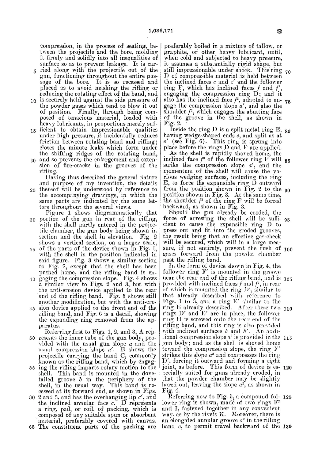
compression, in the process of seating, be-
tween the projectile and the bore, molding
it firmly and solidly into all inequalities of
surface so as to prevent leakage. It is car-
5 ried along with the projectile out of the
gun, functioning throughout the entire pas-
sage of the bore. It is so recessed and
placed as to avoid masking the rifling or
reducing the rotating effect of the band, and
10 is securely held against the side pressure of
the powder gases which tend to blow it out
of position. Finally, through being com-
posed of tenacious material, loaded -with
heavy lubricants, in proportions merely suf-
15 ficient to obtain impressionable qualities
under high pressure, it incidentally reduces
friction between rotating band and rifling;
closes the minute leaks which form under.
the shifting ridges of the rotating band,
20 and so prevents the enlargement and exten-
sion of fire-cracks in the grooves of the
rifling. I
Having thus described the general nature
and purpose of my invention, the details
25 thereof will be understood by reference to
the accompanying drawings, in which the
same parts are indicated by the same let-
ters throughout the several views.
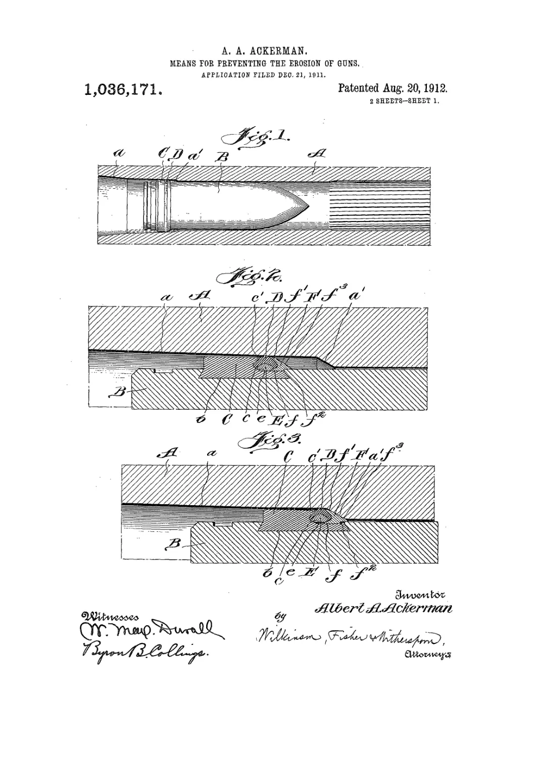
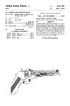
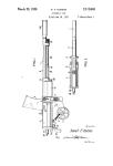
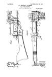
Figure 1 shows diagrammatically that
30 portion of the gun in rear of the rifling,
with the shell partly entered in the projec-
tile chamber, the gun body being shown in
section and the shell in elevation. Fig. 2
shows a vertical section, on a larger scale,
35 of the parts of the device shown in Fig. 1,
with the shell in the position indicated in
said figure. Fig. 3 shows a similar section
to Fig. 2, except that the shell has been
pushed home, and the rifling band is en-
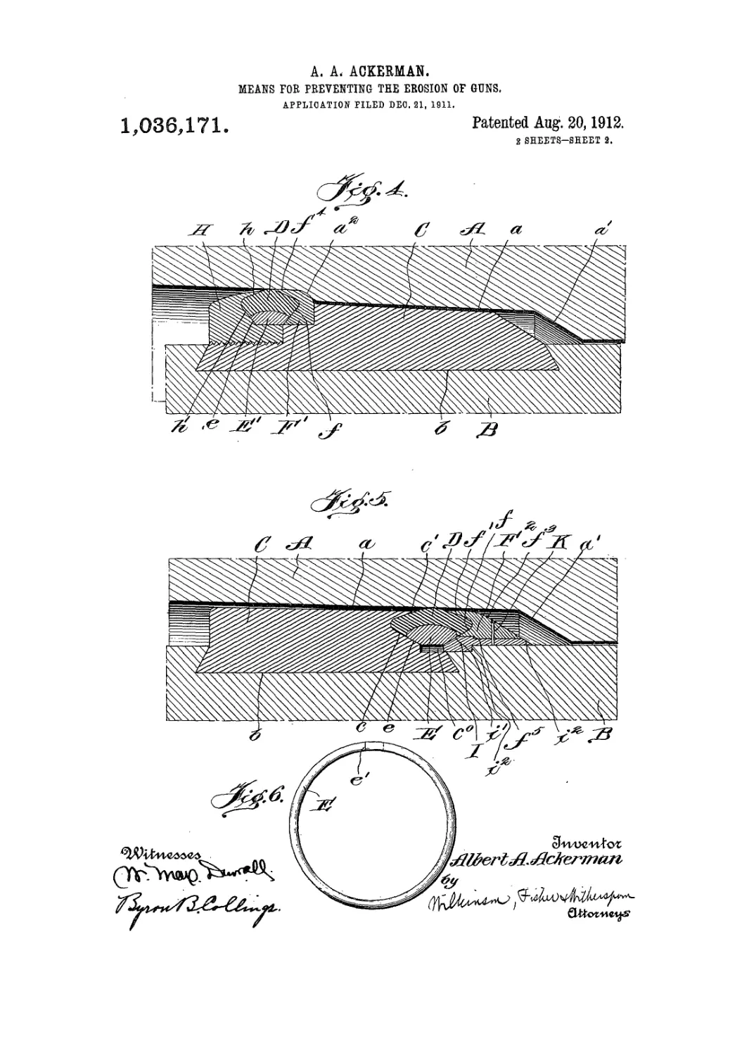
40 gaging the compression slope. Fig., 4 shows
a similar view to Figs. 2 and 3, but with
the anti-erosion device applied to the rear
end of the rifling band. Fig. 5 shows still
another modification, but with the anti-ero-
45 sion device applied to the front end of the
rifling band, and Fig. 6 is a detail, showing
the expanding ring removed from the ap-
paratus.
Referring first to Figs. 1, 2, and 3, A rep-
50 resents the inner tube of the gun body, pro-
vided with the usual gun slope a and the
usual compression slope a!. В shows the
projectile carrying the band C, commonly
known as the rifling band, which by e’ngag-
55 ing the rifling imparts- rotary motion to the
shell. This band is mounted in the dove-
tailed groove Ъ in the periphery of the
shell, in the usual way. This band is re-
cessed at its forward end, as shown in Figs.
60 2 and 3, and has the overhanging lip c", and
the inclined annular face c. D represents
a ring, pad, or coil, of packing, which is
composed Of any suitable spun or absorbent
material, preferably covered with canvas.
65 The constituent parts of the packing are
preferably boiled in a mixture of tallow, or
graphite, or other heavy lubricant, until,
when cold and subjected to heavy pressure,
| it assumes a substantially rigid shape, but
still impressionable under shock. This ring 70
D of compressible material is held between
the inclined faces c and c' and the follower
ring F, which has inclined faces f and
engaging the compression ring D; and it
also has the inclined face /3, adapted to en- 75
gage the compression slope a', and also the
shoulder /2, which engages the abutting face
of the groove in the shell, as shown in
FiS- 2-
Inside the ring D is a split metal ring E, 80
having wedge-shaped ends e, and split as at
e' (see Fig. 6). This ring is sprung into
place before the rings D and F are applied.
As the shell is rapidly shoved home, the
inclined face f2 of the follower ring F will 85
strike the compression slope a', and the
I momentum of the.shell will cause the va-
rious wedging surfaces, including the ring
E, to force the expansible ring D outward
from the position shown in Fig. 2 to the 90
position shown in Fig. 3. At the same time,
the shoulder f2 of the ring F will be forced
backward, as shown in Fig. 3.
Should the gun already be eroded, the
force of arresting the shell will be sufii- 95
cient to cause the expansible ring D to
press out and fit into the eroded grooves,
the result being that an effective gas-check
will be secured, which will in a large mea-
sure, if not entirely, prevent the rush of юо
gases forward from the powder chamber
past the rifling band.
In the form of device shown in Fig. 4, the
follower ring F' is mounted in the groove
near the rear end of the rifling band, and is Ю5
provided with inclined faces f and Д in rear
of which is mounted the ring I)', similar to
that already described with reference to
Figs. 1 to 3, and a ring E' similar to the
ring E already described. After these two no
rings 1)' and E' are in place, the follower
ring H is screwed onto the rear end of the
rifling band, and this ring is also provided
with inclined surfaces h and h'. An addi-
tional compression slope a2 is provided in the 115
gun body; and as the shell is shoved home
toward the compression slope, the ring F'
strikes this slope a2 and compresses the ring
I)', forcing it outward and forming a tight
joint, as before. This form of device is es- 120
pecially suited for guns already eroded, in
that the powder chamber may be slightly
bored out, leaving the slope a2, as shown in
Fig. 4.
Referring now to Fig. 5г a compound fol- 125
lower ring is shown, made of two rings Fz
and I, fastened together in any convenient
way, as by the rivets K. Moreover, there is
an elongated annular groove c° in the rifling
band c, to permit travel backward of the 130
1,036,171
5
10
15
20
25
30
35
40
45
50
55
60
65
•4е
compound follower ring. The ring F2 is
shown as provided with a shoulder /s to en-
gage a corresponding shoulder on the ring
I, and the latter ring is provided with a
shoulder r, normally engaging the shoulder
on the projectile. The rear outer face of the
ring I is tapered as at i', to form- a continu-
ous wedging face with the tapered surface f
of the ring F2. In Fig. 5, the shell is shown
as nearly home; but when it is driven home,
as in the ordinary process of ramming, the
inclined surfaces i2 and f3 of the compound
ring will engage the compression slope a',
wedging the split ring E outward, and at
the same time expanding the ring D. For
convenience of .assembly, the ring I may also
be split, as is well known in the ordnance
art.
In any of the forms of the device herein-
before described, it will be noted that the
more or less plastic ring D will be pressed
outward, due to the energy expended in
shoving the shell home, supplemented by the
inertia of the shell, and that the band or
ring D will be pressed outward, making a
snug fit, even though there be irregularities
in the abutting surface of the inner wall of
the bore.
It will be obvious that various modifica-
tions might be made in the herein described
apparatus, and in the construction, combina-
tion, and arrangement of parts, which could
be used without departing from the spirit of
my invention.
Having thus described my invention, what
I claim and desire to secure by Letters Pat-
ent of the United States is:—
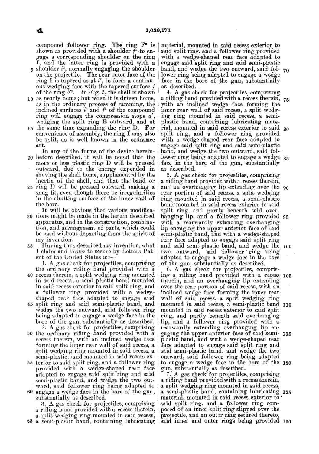
1. A gas check for projectiles, comprising
the ordinary rifling band provided with a
recess therein, a split wedging ring mounted
in said recess, a semi-plastic band mounted
in said recess exterior to said split ring, and
a follower ring provided with a wedge-
shaped rear face adapted to engage said
split ring and said semi-plastic band, and
wedge the two outward, said follower ring
being adapted to engage a wedge face in the
bore of the gun, substantially as described.
2. A gas check for projectiles, comprising
the ordinary rifling band provided with a
recess therein, with an inclined wedge face
forming the inner rear wall of said recess, a
split wedging ring mounted in said recess, a
semi-plastic.band mounted in said recess ex-
terior to said split ring, and a follower ring
provided with a wedge-shaped rear face
adapted to engage said split ring and said
semi-plastic band, and wedge the two out-
ward, said follower ring being adapted to
engage a wedge face in the bore of the gun,
substantially as described.
3. A gas check for projectiles, comprising
a rifling band provided with a recess therein,
a split wedging ring mounted in said recess,
a semi-plastic band, containing lubricating
material, mounted in said recess exterior to
said split ring, and a follower ring provided
with a wedge-shaped rear face adapted to
engage said split ring and said semi-plastic
band, and wedge the two outward, said fol- 70
lower ring being adapted to engage a wedge
face in the bore of the gun, substantially
as described.
4. A gas check for projectiles, comprising
a rifling band provided with a recess therein, 75
with an inclined wedge face forming the
inner rear wall of said recess, a split wedg-
ing ring mounted in said recess, a semi-
plastic band, containing lubricating mate-
rial, mounted in said recess exterior to said 8o
split ring, and a follower ring provided
with a wedge-shaped rear face adapted to
engage said split ring and said semi-plastic
band, and wedge the two outward, said fol-
lower ring being adapted to engage a wedge 35
face in the bore of the gun, substantially
as described.
5. A gas check for projectiles, comprising
a rifling band provided with a recess therein,
and an overhanging lip extending over the 90
rear portion of said recess, a split wedging
ring mounted in said recess, a semi-plastic
band" mounted in said recess exterior to said
split ring, and partly beneath said over-
hanging lip, and a follower ring provided gg
with a rearwardly extending overhanging
lip engaging the upper anterior face of said
semi-plastic band, and with a wedgeJshaped
rear face adapted to engage said split ring
and said semi-plastic band, and wedge the 10c
two outward, said follower' ring being
adapted to engage a wedge face in the bore
of the gun, substantially as described.
G. A gas check for projectiles, compris-
ing a rifling band provided with a recess 105
therein, and an overhanging lip extending
over the rear portion of said recess, with an
inclined wedge face forming the inner rear
wall of said recess, a split wedging ring
mounted in said reeess, a semi-plastic band no
mounted in said recess exterior to said split
ring, and partly beneath said overhanging
lip. and a follower ring provided with a
rearwardly extending overhanging lip en-
gaging the upper anterior face of said semi- 115
plastic band, and with a wedge-shaped rear
face adapted to engage said split ring and
said semi-plastic band, and wedge the two
outward, said follower ring being adapted
to engage a wedge face in the bore of the 120
gun, substantially, as described.
7. A gas check for projectiles, comprising
a rifling band provided with a recess therein,
a split wedging ring mounted in said recess,
a semi-plastic band, containing lubricating 125
materialj mounted in said reeess exterior to“
said split ring, and a follower ring com-
posed of an inner split ring slipped over the
projectile, and an outer ring secured thereto,
said inner and outer rings being provided 130
1,036,171
with a wedge-shaped rear face adapted to
engage said split ring and said semi-plastic
band, and wedge the two outward, and also
being adapted to engage a wedge face in
5 the bore of the gun, substantially as de-
scribed.
8. A gas check for projectiles, comprising
a rifling band provided with a recess therein,
with an inclined wedge face forming the
10 inner rear wall of said recess, a split wedg-
ing ring mounted in said recess, a semi-
plastic band, containing lubricating mate-
rial, mounted in said recess exterior to said
split ring, and a follower ring composed
15 of an inner split ring slipped over the pro-
jectile, and an outer ring secured thereto,
said inner and outer rings being provided
with a wedge-shaped rear face adapted to
engage said split ring and said semi-plastic
band, and wedge the two outward, and also 20
being adapted to engage a wedge face in
the bore of the gun, substantially as de-
scribed.
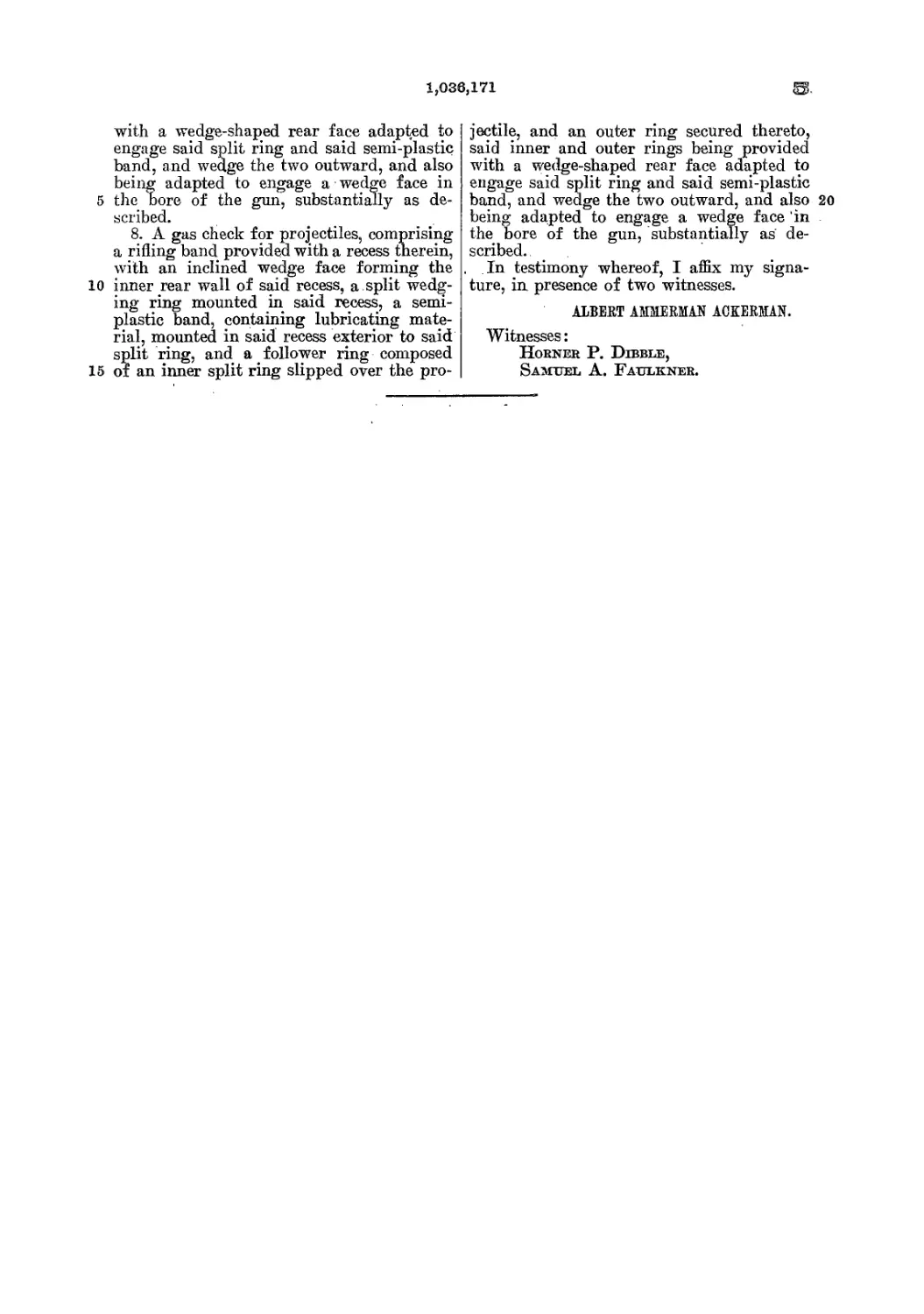
In testimony whereof, I affix my signa-
ture, in presence of two witnesses.
ALBERT AMMERMAN ACKERMAN.
Witnesses:
Horner P. Dibble,
Samuel A. Faulkner.