/


Tags: weapons military affairs

Text
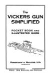
THE BREN GUN
POCKET BOOK
♦ AND
I ILLUSTRATED GUIDE
Price : One Shilling
i Robertson & Mullens
♦ MELBOURNE
THE BREN GUN
POCKET BOOK
ILLUSTRATED GUIDE
Robertson a Mullens ltd.
MELBOURNE
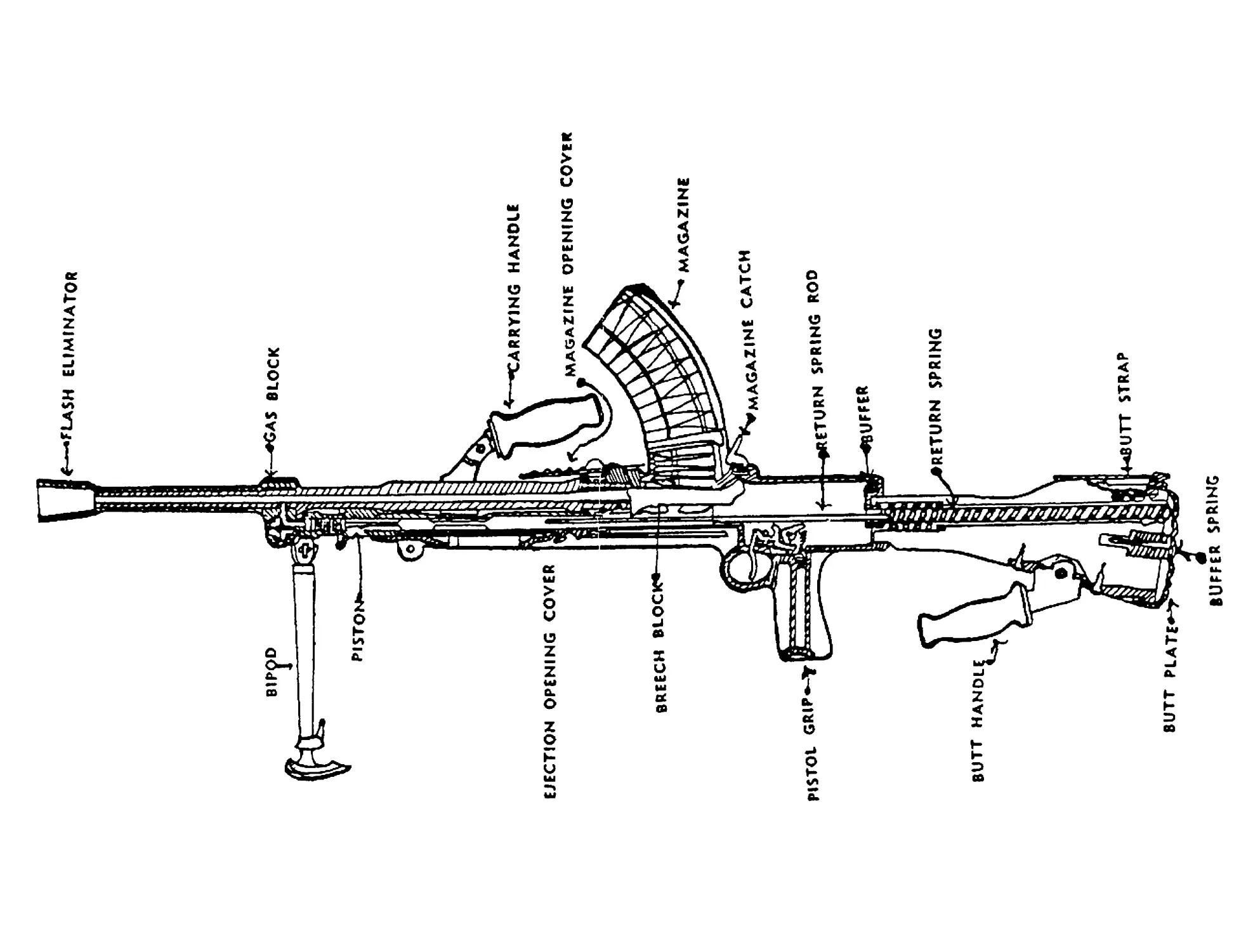
THE BREN GUN
Parts and their Functions
FLASH ELIMINATOR—a cone-shaped extension at the muzzle
of the barrel. Certain models of the Bren have a series
of holes bored around the eliminator.
FORESIGHT—"blade" pattern, fitted Into a stool formed "off-
set" to the left of the barrel axis. The stool includes two
"flared" foresight protectors.
GAS BLOCK—on assembly fitted to the barrel and enclosing
the Gas Vent. It contains the Gas Regulator and has a
Gas Passage projecting rearwards.
GAS REGULATOR—a shaped and drilled component which
seats in the Gas Block. Varying sized Gas Ports ore
drilled through the regulator. It is shaped to receive the
Cylinder Locking Bor or Combination Tool and carries 4
punch marks, the sizes of which are indicative of the Gas
Ports they represent. A Zero Mark Is also punched on the
Gas Block to which the Gas Ports marks register. On the
other face of the Gas Regulator Is an adjusting bar fitted
with a Retainer Pin, which secures the Gas Regulator in the
Gas Block,
CARRYING HANDLE—a rotateable metal arm fitted with a
wooden handle Is attached to the barrel. By pulling the
wooden handle to the rear, It con be moved to a fixed posi-
tion by a slight forward movement. This is done when using
the gun for anti-aircraft purposes, providing a forward
support for the gunner's left hand.
BARREL LOCKING THREADS—a series of interrupted square
threads ore formed around the barrel near the breech,
which lock the barrel to the Barrel Nut, when the barrel Is
rotated by means of the carrying handle. A reverse
movement by the same agency unlocks the barrel threads.
BARREL—each Bren gun barrel carries the above components
ready assembled. In addition, on the under side is shaped
a portion to engage on the top of the Body, and clearances
ore formed at the breech for the Feed Piece and the Ex-
tractor.
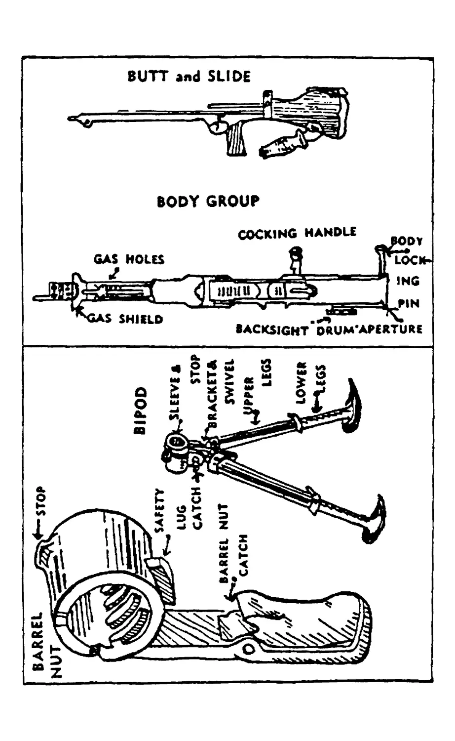
BARREL NUT—a circular component which links the barrel to
the body. It seats In a recess In the body, being. retained
in its position by a Retainer Plunger. The Nut Is fitted
with on external arm contain Ing the Barrel Nut Catch, by
means of which the rotation of the Nut is controlled.
The engagement of the Catch with the Body prevents the
Nut from moving. Internally, the Nut is formed with
squore threads to engage with those on the barrel. On Its
lower side the Nut has a Safety Lug which prevents incor-
rect assembly of other gun components. The Nut is re-
moved from the Body by depressing the Retainer Plunger
after the Barrel hos been removed from the gun. To
remove the Barrel, the Barrel Nut Catch is released ond the
Nut rotated to Its full extent. The Nut to be In the tame
position when replacing the Barrel.
MAGAZINE OPENING COVER—a ridged and shaped sliding
plate which covers the opening in the top of the body into
which the magazine is inserted to load the gun. The cover
prevents the entry of dirt, etc., into the body when the
magazine is off the gun. It is opened easily by a forward
pushing movement with the thumb of one hand on the
ridged portion.
MAGAZINE CATCH—a shaped up-right catch on the top of
the body in rear of the magazine opening. It engages
with the rear face of the magazine and retains It in posi-
tion on the gun. It is released by a slight forward push
with the palm of one hand, the fingers and thumb simul-
taneously removing the magazine.
BACKSIGHT—consisting of a Drum, fitted with a sight arm
on which is formed on Aperture Sight ond Stop. The Drum
is circular and grooved to facilitate handling. A window
is cut on Its rear face to enable range figures to be seen.
The range scale is graduated from 200 to 2,000. • The
Drum gives alterations of 50 yards, each being indicated
by a "dick.*' Movement of the Drum affects the sight
arm ond Aperture. When not in use the Stop must be in
contact with the top of the body.
BODY LOCKING PIN—fitted with shaped ends. Connects the
body and butt groups. To disconnect them, the pin Is
pushed to the right. It cannot be entirely removed from
the gun except by an armourer.
BUTT—normal wooden type. On its rear upper surface Is
attached a moveable Butt Strop which, when moved over
to the rear, assists the firer to control the gun whilst fir-
ing. A metol Butt Plate is attached which covers the Butt
and controls a Buffer Spring enclosed In the butt. A Catch
for the Butt Plate Is fitted to the top of the butt. A longi-
tudinal recess bored through the Butt houses a spiral Re-
turn Spring. This spring is attached to and operates a
steel Return Spring Rod, which projects through the for-
word foce of the butt. The Butt is fitted into о metal
holder at its forward end. This portion also contains a
buffering device. A housing is formed under the Butt to
receive the Butt Handle (for firing from the shoulder) or
the Rear Mounting (when the gun is fired from the tripod).
A Mounting Pin secures the connection In either case. The
Pin has a shaped handle and is not removeable from the
butt except for repair. A Butt Swivel is ottoched to the
right side of the butt to which a Sling is fitted.
BUTT SLIDE—о shaped metol extension ottoched to the forward
end of the Butt, forming the underside of the gun assembly.
At its forward end it has a housing for a Mounting Pin,
which is used to secure the gun to the Tripod (when used).
Guide Ribs ore formed on the Slide to engage with the Body.
An Ejection Opening Cover is fitted into the bottom of the
Slide and operated by a milled Catch. This Cover prevents
the entry of dirt, etc., into the body and is kept drawn to
the rear when the gun is not in use. The firing of the first
round automatically opens the Cover. A Trigger Guard and
Pistol Grip ore formed. The firing mechanism is contained
inside the Slide, consisting of a Trigger, Tripping Lever,
Sear Sear Spring and Pins. A Change Lever operates in
connection with the obove assembly. The finger piece of
the Change Lever projects through the left slide of the
Slide. The letters '* S," "A" ond "R" engraved on the
slide, indicate the positions for the Change Lever to produce
"Safety" "Automatic fire" or "Rounds (single shots)"
respectively.
BODY—slides on to the Butt Slide ond is secured to that as-
sembly by the Body Locking Pin. it is bored, etc., to ac-
commodate the Piston, Breech Block, etc. At its forward
end is a projection, the Gas Cylinder Locking Bor, which
seats in a recess formed In the Gas Regulator. In rear of
this projection Gas Fouling Holes are drilled in the Body.
A Gos Shield is formed in rear of these Holes to prevent the
"blown-off" hord fouling affecting the firer. A Gas Cy-
linder is formed inside the Body in rear of the Shield and
Gas escape Holes ore bored in the body. An Ejector is
housed in the magezine way. It consists of a steel finger
fixed under the Mogozine Catch. On the right side of the
Body is accommodated о folding Cocking Handle, working
in a Slide. The Cocking Handle connects with a projecting
Pin on the Piston. After cocking the gun the Handle is re-
turned to its forward position ond folded forward against
the Body side. It does not move during the firing of the
gun. The Body is supported ot Its forward end by the Sleeve
of the Bipod.
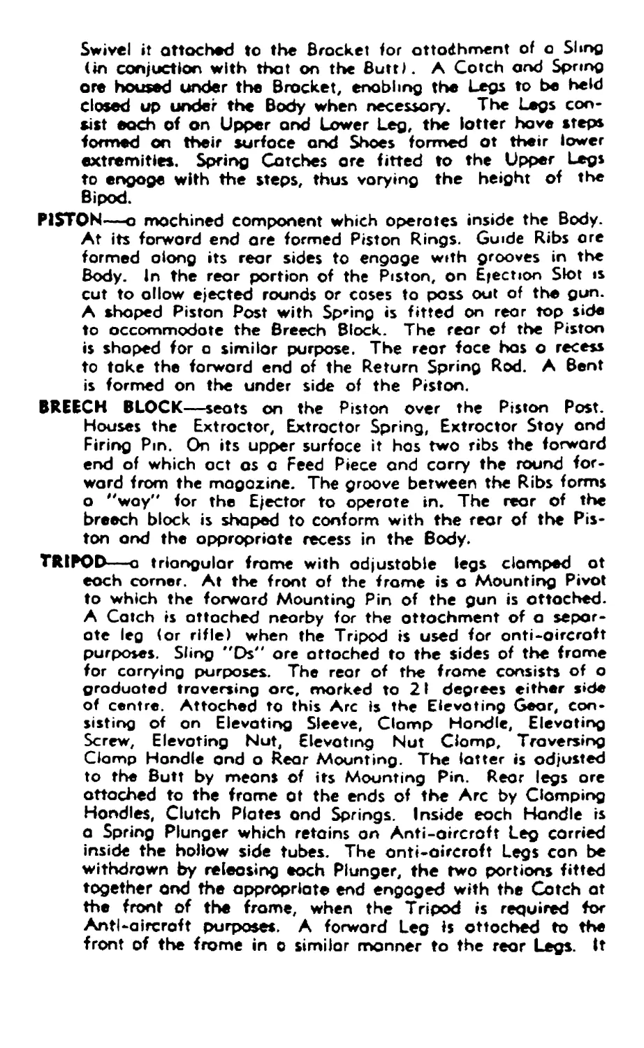
BIPOD—consists of a circular Sleeve to receive the forward por-
tion of the Body, a Brocket and two extending Legs. A
Swivel it attached to the Brocket lor ottodhment of о Shng
(in conduction with that on the Butt). A Cotch and Spring
ore housed under the Brocket, enabling the Legs to be held
closed up under the Body when necessary. The Legs con-
sist each of on Upper and Lower Leg, the latter have steps
formed on their surface and Shoes formed ot their lower
extremities. Spring Catches ore fitted to the Upper Legs
to engage with the steps, thus varying the height of the
Bipod.
PISTON—a machined component which operates inside the Body.
At its forward end are formed Piston Rings. Guide Ribs ore
formed along its rear sides to engage with grooves in the
Body. In the rear portion of the Piston, on Ejection Slot is
cut to allow ejected rounds or coses to pass out of the gun.
A shaped Piston Post with Spring is fitted on rear top side
to accommodate the Breech Block. The rear of the Piston
is shaped for c similar purpose. The rear face has a recess
to take the forward end of the Return Spring Rod. A Bent
is formed on the under side of the Piston.
BREECH BLOCK—seats on the Piston over the Piston Post.
Houses the Extractor, Extractor Spring, Extractor Stoy and
Firing Pm. On its upper surface it has two ribs the forward
end of which oct as a Feed Piece ond carry the round for-
ward from the magazine. The groove between the Ribs forms
о "way" for the Ejector to operate in. The rear of the
breech block is shaped to conform with the rear of the Pis-
ton ond the appropriate recess in the Body.
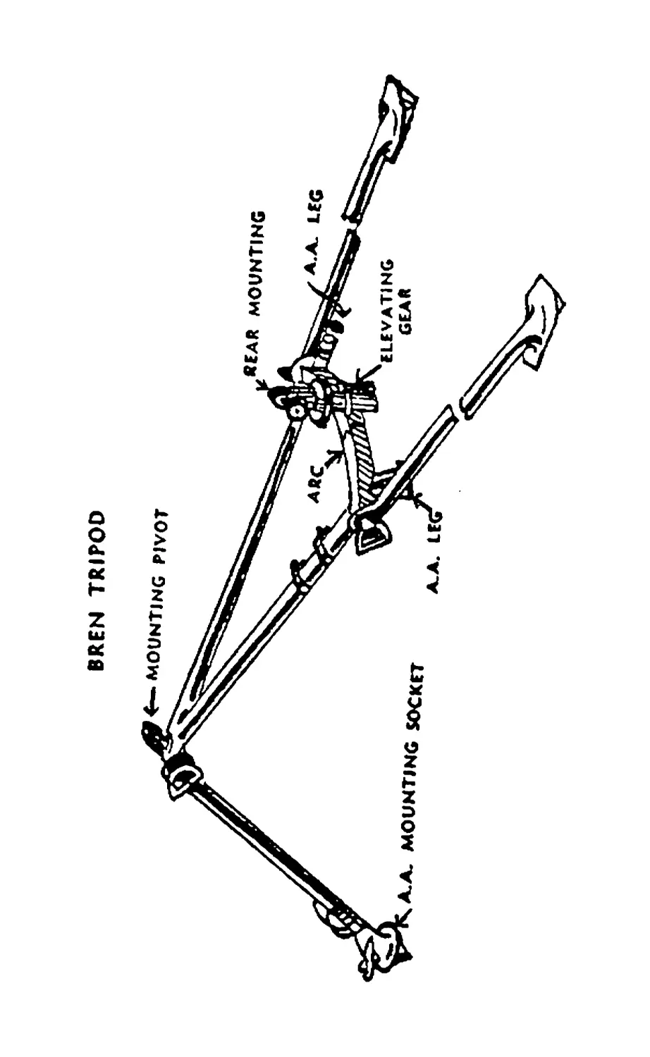
TRIPOD—□ triangular frame with adjustable legs clomped ot
eoch corner. At the front of the frame is a Mounting Pivot
to which the forward Mounting Pin of the gun is attached.
A Catch is attached neorby for the attachment of a separ-
ate leg (or rifle) when the Tripod is used for onti-oircroft
purposes. Sling "Ds" ore attached to the sides of the frame
for carrying purposes. The rear of the frame consists of о
graduated traversing orc, marked to 21 degrees either side
of centre. Attached to this Arc is the Elevating Gear, con-
sisting of on Elevating Sleeve, Clomp Handle, Elevating
Screw, Elevating Nut, Elevating Nut Clomp, Traversing
Clomp Handle and о Rear Mounting. The latter is adjusted
to the Butt by means of its Mounting Pin. Rear legs ore
attached to the frame ot the ends of the Arc by Clamping
Handles, Clutch Plates ond Springs. Inside eoch Handle is
a Spring Plunger which retains on Anti-aircraft Leg carried
inside the hollow side tubes. The onti-aircroft Legs con be
withdrawn by releasing each Plunger, the two portions fitted
together ond the appropriate end engaged with the Cotch at
the front of the frame, when the Tripod is required for
Anti-aircraft purposes. A forward Leg is attached to the
front of the frame in о similar manner to the rear Legs. It
is capable of extension, being positioned as required by a
Clamping Handle and Catch. The extension portion has
"steps" ond corries an Anti-aircroft Mounting Socket over
which the forward Mounting Pin of the gen fit*. Each tri-
pod leg is fitted with a Shoe. An infinite variation in height
is possible with the Tripod through the adjustment of the
legs. For Anti-aircraft purposes, the front leg is set in pro-
longation of the frame by means of its Clamping Handle.
Spring Clips ore attached to the inside of one leg of the
frame to hold the Butt Handle when the gun is used on the
Tripod.
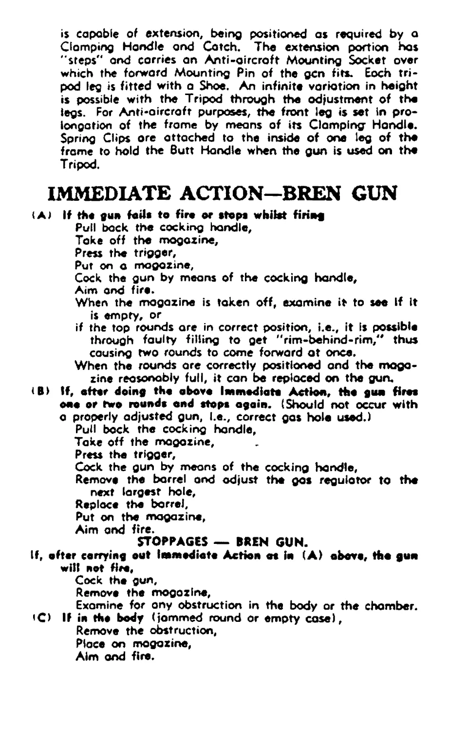
IMMEDIATE ACTION—BREN GUN
{A) If the gun fails to fire or stope whilst firing
Pull bock the cocking handle,
Токе off the magazine,
Press the trigger,
Put on a magazine,
Cock the gun by means of the cocking handle.
Aim and fire.
When the magazine is taken off, examine it to see if it
is empty, or
if the top rounds are in correct position, i.e., it Is possible
through faulty filling to get "rim-behind-rim," thus
causing two rounds to come forward at once.
When the rounds ore correctly positioned and the maga-
zine reasonably full, it can be replaced on the guru
<B> If, after doing the above Immediate Action, the gun ftres
one or two rounds and stops again. (Should not occur with
a properly adjusted gun, I.e., correct gas hole used.)
Pull bock the cocking handle,
Take off the magazine,
Press the trigger,
Cock the gun by means of the cocking handle,
Remove the barrel ond adjust the gas regulator to the
next largest hole,
Replace the barrel.
Put on the magazine,
Aim and fire.
STOPPAGES — BREN GUN.
If, after carrying out Immediate Action as In (A) above, the gun
wilt not Hre,
Cock the gun,
Remove the magazine,
Examine for any obstruction in the body or the chamber.
<C) If in the body (jammed round or empty cose),
Remove the obstruction,
Place on magazine,
Aim and fire.
(0) If no obstruction In body
Put the clearing plug into the chamber,
Press the trigger,
Cock the gun,
Remove the clearing plug ond obstruction (separated
case),
Place on the magazine,
Aim ond fire.
CAUSES.
Immediate Action-
(A) i. Empty magazine (no resistance will be felt when pulling
the cocking handle back).
ii. Badly filled magazine.
iii. Misfire.
iv. Faulty ejection.
v. Hord extraction.
Stoppage»—-
(B) Insufficient gas pressure. (No. 3 Hole normally to be used.)
(C) Mechanical irregularity or breakdown.
(D) Portion of empty case separated.
NOTE.—If the gun is properly adjusted and the gos pressure of
correct balance, stoppages other than those caused by an
empty magazine should be rare. Trouble will occur with
magazines unless they are properly cared for and correctly
filled.
BREN DETAILS.
Composite name from Bmo (Czeeho-Slovakia) and Enfield
(England).
Weight of gun, with bipod: 23 lbs.
Barrel: 6 lbs.
Magazine, filled (30 rounds) : 2$ lbs.
Tripod, complete: 30 lbs.
Rote of fire, automatic bursts: up to 120 rounds per mln.
Rote of fire, single rounds: up to 30 rounds per min.
flash eliminator
PISTON
BREN TRIPOD MOUNTING PIVOT MOUNTING SOCKET ивЕАК MOUNTING *-*- LEG X£L£VATING GEAR
MECHANISM OF THE BREN GUN.
(A) Looding.
The Mogozine Opening Cover Is pushed forward. A maga-
zine is placed on the gun by placing the front end in posi-
tion in the magazine opening, then drawing the rear end
of the magazine down to agree. The Cocking Handle is
grasped, turned back ond then pulled smartly to the rear.
It is then pushed forward again ond folded forward. When
the Cocking Handle is pulled to the rear a projection on
its inner surface engages with a projecting Cotter Pin ot
the rear right side of the Piston, thus withdrawing the Pis-
ton ond compressing the Return Spring, by forcing the Re-
turn Spring Rod rearwards into the Butt recess. The Piston
corries bock the Breech Block also. As the Piston rides over
the Sear it depresses It. The Sear rises again under the
influence of its spring ond engages ogoinst the bent of the
Piston, retaining it in its rearward position. The change
lever is set as required, normally ot "S" (safety). In this
cose the trigger Is disconnected from the Sear ond the gun
cannot fire.
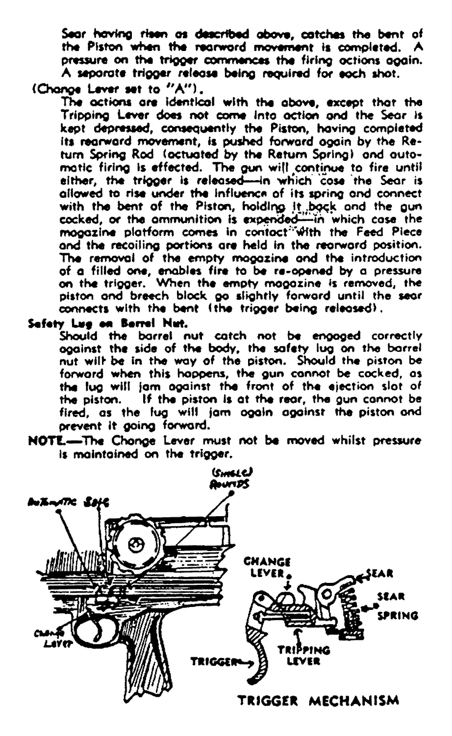
(B) Firing (Change Lever set to "R").
When the trigger is pressed the Sear is depressed, thus re*
leasing the bent of the Piston ond allowing the Return
Spring Rod (actuated by the Return Spring) to push the
Piston forward. Through the action of the Tripping Lever,
the Sear is released and rises again ready to connect with
bent of the Piston when it again comes to the rear.
During the forward movement of the Piston, the Ejection
Opening Cover (if closed) is caused to move forward, thus
clearing the ejection opening.
In moving forward, the Piston carries the Breech Block with
it and the Feed Piece on the lotter contacts with the first
round in the magazine, pushing it forward free of the maga-
zine ond into the chamber, the extractor engaging over
the rim of the cartridge. Through the action of the Piston
Post the Breech Block Is seated to take the shock of the ex-
plosion. The continued forward movement of the Piston
causes the Firing Pin to make contact with the cartridge
cop ond the round is fired.
As the bullet is passing from the gas vent to the muzzle,
a proportion of the explosive gases pass through the gas
vent, through the registering gas port in the gos regulator,
into the gos passage of the gos block and impinge on the
heod of the Piston, forcing It to the rear. The firing pin is
withdrawn by the action of Its spring. The Piston withdraws
the Breech Block ond compresses the Return Spring. The
Extractor withdraws the empty cose until It is brought Into
contact with the Ejector, when the cose Is deflected down-
words through the ejection opening clear of the gun. The
Sear having then os deacribed above, catches the bent of
the Piston when the rearword movement Is completed. A
pressure on the trigger commences the firing actions again.
A separate trigger release being required for each shot.
(Change Lever set to "A").
The actions are identical with the above, except that the
Tripping Lever does not come into oction ond the Sear is
kept depressed, consequently the Piston, having completed
its rearward movement, is pushed forward again by the Re-
turn Spring Rod (actuated by the Return Spring) ond auto-
matic firing Is effected. The gun wt(l continue to fire until
either, the trigger is released-—in wh'ich cose the Sear is
allowed to rise under the Influence of its spring ond connect
with the bent of the Piston, holding It^.bgck ond the gun
cocked, or the ammunition is expended^-m which cose the
magazine platform comes In contoct 'With the Feed Piece
and the recoiling portions are held in the rearward position.
The removal of the empty magazine ond the introduction
of a filled one, enables fire to be re-opened by a pressure
on the trigger. When the empty magazine is removed, the
piston ond breech block go slightly forward until the sear
connects with the bent (the trigger being released).
Safety Leg ea Barrel Het.
Should the barrel nut catch not be engaged correctly
ogainst the side of the body, the safety lug on the barrel
nut wilt be in the way of the piston. Should the piston be
forward when this happens, the gun cannot be cocked, os
the lug will jam ogainst the front of the ejection slot of
the piston. If the piston is at the rear, the gun cannot be
fired, as the fug wit! jam ogaln against the piston ond
prevent It going forward.
НОТЕ.—The Change Lever must not be moved whilst pressure
Is maintained on the trigger.
TRIGGER MECHANISM
NORMAL STRIPPING—BREN GUN
Magoxlne removed | Safetv
Cock the gun and press the trigger J 00
Push out Body Locking Pin to right and slide the butt back.
Draw the cocking handle bock and push it forward ogoin—
this will draw Piston, etc., to rear.
Hold Return Spring Rod gently to left—draw out the Piston
ond Breech Block, lift latter off.
Tum gun to right until it rests on the Stop on the Sleeve
of the Bipod.
Disengage Barrel Nut Catch and rotate the Nu^ fully to the
right.
Grasp the Carrying Handle, turn it upwards, push forward—
barrel will disengage from Nut.
Push Retainer Pin level with opening In Gas Regulator,
turn it and remove Regulator.
Hold the bocksight drum with one hand ond slide off the
Butt, etc.
Close the Magazine Opening Cover.
Press down the Barrel Nut Retainer Plunger and take out
the Barrel Nut.
Turn the Body upwards and remove it from the Bipod
Sleeve.
Replace in reverse order. Position Barrel Nut with Catch
downwords—top In position with hand. When replac-
ing the barrel, the Handle is vertically above the barrel,
the Barrel Nut rotated and the recesses in the Gas
Regulator ore in line with the projecting Cylinder
Locking Bar.
To Strip the Butt Plate, Etc.
Turn the Butt strap to the rear—it has to be pulled up-
wards slightly to unlock. Place the point of a round on the
Catch of the Butt Plate close to the Butt Wate and top the
base of the round. Токе off the Butt Plate.
Engage the cop of the Return Spring with the combination
tool, press it in, tum a quarter tum to the left ond gently
take out the Return Spring ond Rod.
To Assemble the Above.
Place In the Rod ond Return Spring. Place the combination
tool over the cop. Compress the Spring Ond guide It care-
fully into position. Press in cop and tum right to lock.
Fit the stud of the Butt Plate In the recess in the toe of the
Butt. Lift the Butt Strap upwards ond forwards firmly
pressing 4n the catch, using the other hand.
To Strip the Firing Pin.
Push out the Retainer Pin carefully so that the Firing Pin
does not fly out to the rear.