/


Tags: weapons machine gun carbine
Year: 1946


Text
TECHNICAL REPOET NO. J-«8
OK
й/М unknown
CARBINE.
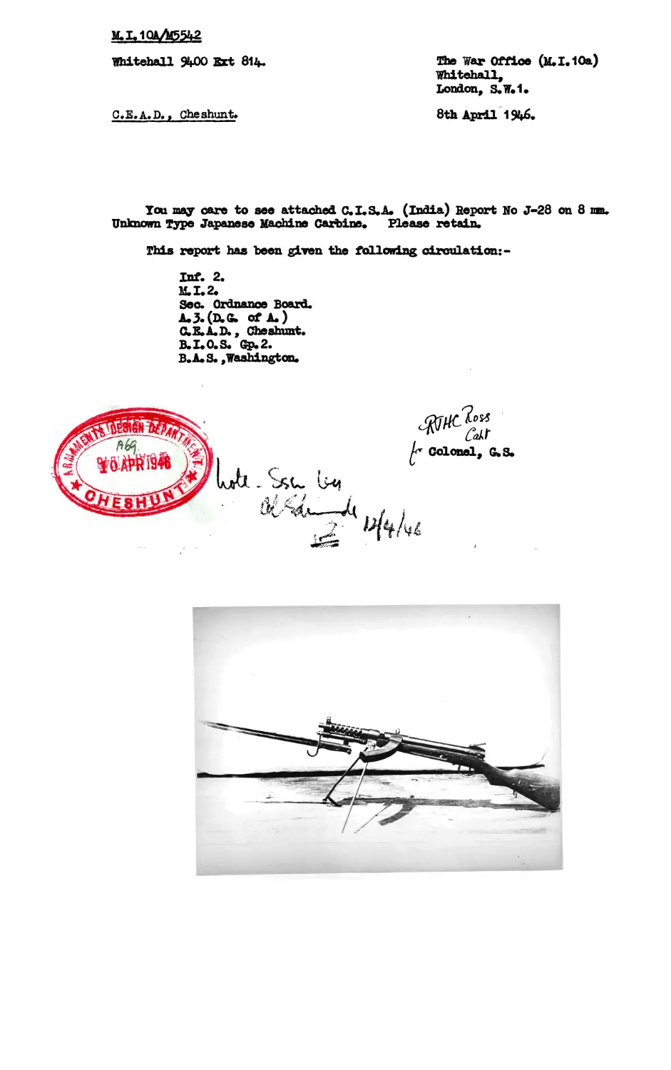
Whitehall %00 Ext 814.
C.E.A.D. > Che shunt.
The War Office (M.I.10a)
Whitehall,
London, S.W.1.
8th April 1946.
You may care to see attached C.I.S.A. (India) Report Ho J-28 on 8 шп.
Unknown Type Japanese Machine Carbine. Please retain.
This report has been given the following circulation: -
Inf. 2.
M.I.2.
Sec. Ordnance Board.
A.J.(D.& of A.)
C.E.A.D., Cheshunt.
B.I.O.S. Gp.2.
B.A.S. , Washington.
Colonel, G.S.
C.I.S.A. (INDIA)
TECHNICAL REPORT Jr£8
DATES FEBRUARY 1946.
E К E M ¥ EQ U I P M E N T
JA PAN E S E
8 Юк UNKNOWN TYPE
wMOarbine
CHIEF I^SPECTOR^OF SMALL ARMS.
ICHAPUR, B.A. RAILWAY.
BENGAL.
JAPANESE 8 MM. UNKNOWN TYPE
Machine carbine.
1. GENERAL FEATOfiES.
The carbine is operated by ease projection and is
fired from an open bolt. " *
A one piece wooden stock extends to the muzzle.
This stock is deep enough' to form the trigger guard and also
shroud tiie magazine opening (on the underside in front of the
trigger opening).
Neither bayonet or sling fixtures are provided.
Possibly the plate on the right side of the stock can be
used with some type of carrying harness.
It is reasonable to assume that the specimen
examined is either a «Pilot* or experimental model,possibly
the product of a private enterprise. The standard of
workmanship is above that normally found in Japanese, small
arms.
The positioning of the return spring around the
barrel, the addition of the weight of t he barrel casing
to the reciprocating parts, his been employed effectively
to reduce the length of the action, in rear of the chamber.
Hence a longer barrel and shorter overall length is obtained
than would be possible with a more .conventional arrangement.
The trigger mechanism with tubular sear is typically
Japanese. An unusual feature is the engagement of the sear
on t he face of the feed horn.
Fig.I.
CARBINE assembled with
Magazine Pouch.
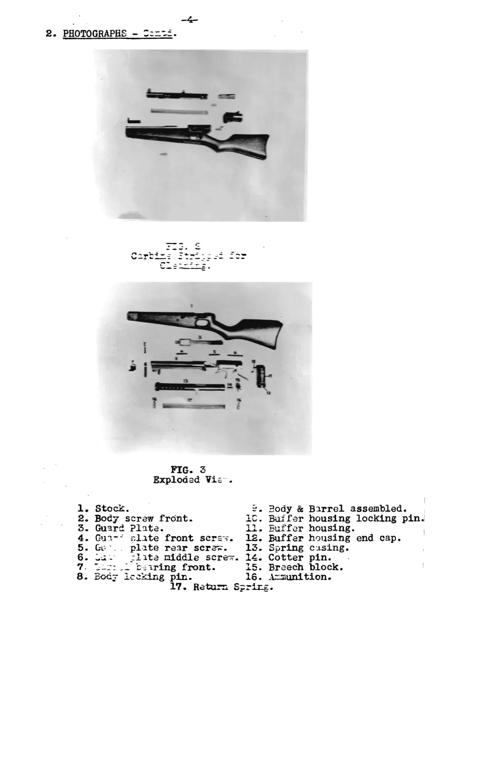
2. PHOTOGRAPHS - Ceric
FIG. 3
Exploded Vie .
1. Stock.
2. Body screw front.
3. Guard Plate.
4. Gua”-' plate front scrs*-.
5. Gv . plate rear sere*.
6. Ou- elate riddle scree*.
7- ’ —: -1 tearing front.
8. Body locking pin.
17. Return S
?. Body & Barrel assembled.
10. Buffer housing locking pin J
11. Buffer housing. ।
12. Buffer housing end cap.
13. Spring casing.
14. Cotter pin.
15. Breech block. 1 2 3 4 5 6 * 8
16. Ammunition.
-5-
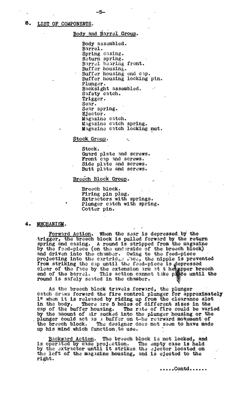
LIST OF COMPONENTS.
Body and Barrel Group.
Body assembled.
Barrel.
Spring casing.
Return spring.
Barrel bearing front.
Buffer housing.
Buffer housing end cap.
Buffer housing locking pin.
Plunger.
Backsight assembled.
Safety catch.
Trigger.
Sear.
Sear spring.
Ejector.
Magazine catch.
Magazine catch spring.
Magazine catch locking nut.
Stock Group. ч.
Stock.
Guard plate and screws.
Front cap and screws.
Side plate and screws.
Butt plate and screws.
Breech Block Group. z
Breech block.
Firing pin plug.
Extractors with springs.
Plunger catch with spring.
Cotter pin.
MECHANISM.
Forward Action. When the sear is depressed by the
trigger, the breech block is pulled forward by the return
spring and casing. A round is stripped from the magazine
by the feed-piece (on the underside of the breech block)
and driven into the- chamber. Owing to the feed-piece
projecting into the cartridge face, the nipple is prevented
from striking the cap until the feed-piece is depressed
clear of the face by the extension arm at t Ь^шррег breech
end of the barrel. This action cannot take рЖ^е until the
round is safely seated in the chamber. ж
/ *
As the breech block travels forward, the plunger
catch draws forward the fire control plunger for approximately
1» when it is released by riding up from the clearance slot
in the body. There are 5 holes of different sizes in the
cap of the buffer housing. The rate of fire could be varied
by the amount of air sucked into the plunger housing or the
plunger could act as a buffer on t-he rearward movement of
the breech block. The designer does not seem to have made
up his mind which function,to use.
Backward Action. The breech Ыос-к is not locked, and
is operate’d by case projection. The empty case is held
by the extractor until it strikes the ejector located on
the left of the magazine housing, and is ejected to the
right.
.*...Contd......
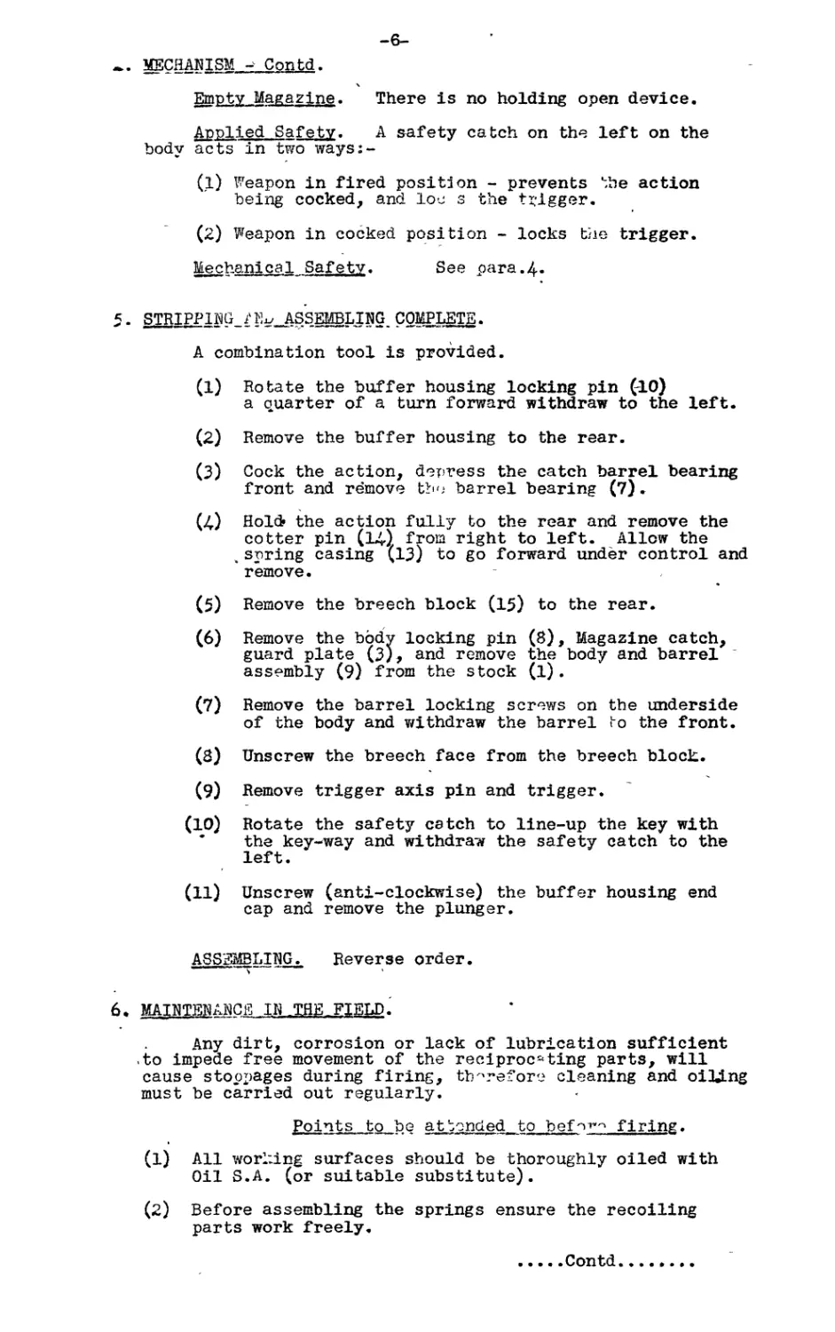
• MECHANISM - Contd.
Empty Magazine. There is no holding open device.
Applied Safety. A safety catch on the left on the
body acts in two ways:-
(1) Weapon in fired position - prevents the action
being cocked, and loc s the trigger.
(2) Weapon in cocked position - locks the trigger.
Mechanical Safety. See para.4-
5 - STRIPPING /Ev ASSEMBLING COMPLETE.
A combination tool is provided.
(1) Rotate the buffer housing locking pin (-10)
a quarter of a turn forward withdraw to the left.
(2) Remove the buffer housing to the rear.
(3) Cock the action, depress the catch barrel bearing
front and remove tbo barrel bearing (7).
(4) Hold» the action fully to the rear and remove the
cotter pin (14) from right to left. Allow the
шspring casing (13) to go forward under control and
remove.
(5) Remove the breech block (15) to the rear.
(6) Remove the body locking pin (8), Magazine catch,
guard plate (3), and remove the body and barrel '
assembly (9) from the stock (1).
(7) Remove the barrel locking screws on the underside
of the body and withdraw the barrel bo the front.
(8) Unscrew the breech face from the breech block.
(9) Remove trigger axis pin and trigger.
(10) Rotate the safety catch to line-up the key with
* the key-way and withdraw the safety catch to the
left.
(11) Unscrew (anti-clockwise) the buffer housing end
cap and remove the plunger.
ASSEMBLING.
———s ——
Reverse order.
6 . MAINTENANCE IN-THE FIELD.
Any dirt, corrosion or lack of lubrication sufficient
.to impede free movement of the reciprocating parts, will
cause stoppages during firing, therefore cleaning and oiling
must be carried out regularly.
Points to be attended to befer^ firing.
(1) All working surfaces should be thoroughly oiled with
Oil S.A. (or suitable substitute).
(2) Before assembling the springs ensure the recoiling
parts work freely.
....Contd.........
-7-
(3) Thoroughly dry the bore of the barrel.
(4) Examine the magazine for dirt or damage.
Points to be attended to- during firing.
(1) See that a sufficient- nticy o' a-munition is
always available.
(2) During a temporary cess-o I *, oil all the
working surfaces.
Points to be attended to after firing.
(1) See that the gun is unloaded.
(2) See that the bore and. bre.ch face are well oiled
immediately after firing.
(3) Ehsure that all unfired ammunition is collected.
Strinning for Cleaning.
(1) Rotate the buffer housing locking pin (10) a quarter
of a turn forward withdraw to the left.
(2) Remove the buffer housing to the rear.
(3) Cock the action, depress' the catch barrel bearing
front and remove the barrel bearing (7).
(4) Hold the action fully to the rear and remove the
cotter pin (14) from right to left. Allow the spring
casing (13) to go forward under control and remove.
(5) Remove the breech block (15) to the rear.
Cleaning and Lubricating.
(1) Thoroughly clean all the moving parts and the bore.
(2) Examine all the parts for burrs, remove with an
oil-stone.
(3) Lightly oil all the par^s with Oil S.A. or other
suitable substitute.
Assembly, Reverse order.
7. DETAIL.
1. Weapon
Type
Make
8 MM. Machine Carbine.
Unknown.
Date of manufacture
Markings
Due to lack of positive
identification, it is not
certain that this carbine
is of uv.panese manufacture
It was found in Japanese
HQ. Singapore.
Not known.
"37” on all components,
nothing else.
...Contd
-8-
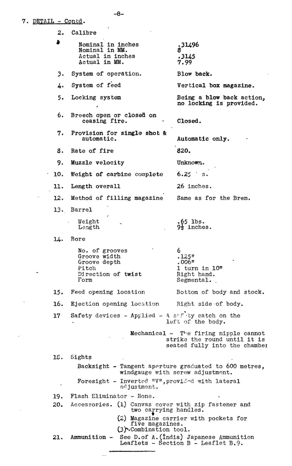
7. DETAIL - Contd.
2. Calibre
Nominal in inches Nominal in MM. Actual in inches Actual in MM. •31496 8 .3145 7.99
3. System of operation. Blow back.
4. System of feed Vertical box magazine.
5. Locking system f Being a blow back action, no locking is provided.
6. Breech open or closefl on
ceasing fire. • Closed.
7. Provision for single shot &
automatic.
8. Rate of fire
9. Muzzle velocity
10. Weight of carbine complete
11. Length overall
12. Method of filling magazine
13. Barrel
Weight
Length
14* Bore
No. of grooves
Groove width
Groove depth
Pitch
Direction of twist
Form
15. Feed opening location
16. Ejection opening location
17 Safety devices - Applied -
Automatic only.
820.
Unknown.
6.25 s.
26 inches.
Same as for the Bren.
.65 lbs.
9| inches.
6
.125”
. 006”
1 turn in 10”
Right hand.
Segmental.
Bottom of body and stock.
Right side of body.
A s-f>ty catch on the
left of the body.
Mechanical - Tve firing nipple cannot
strike the round until it is
seated fully into the chamber
18. Sights
Backsight - Tangent aperture graduated to 600 metres, windgauge with screw adjustment.
Foresight - Inverted ”V”,provided with lateral ad justment.
19.
20.
21.
Flash Eliminator - None.
Accessories. (1) Canvas cover with zip fastener and
two carrying handles.
(2) Magazine carrier with pockets for
five magazines.
(3^«Combination tool.
Ammunition - See D.of A.(India) Japanese Ammunition
Leaflets - Section В - Leaflet B.9.