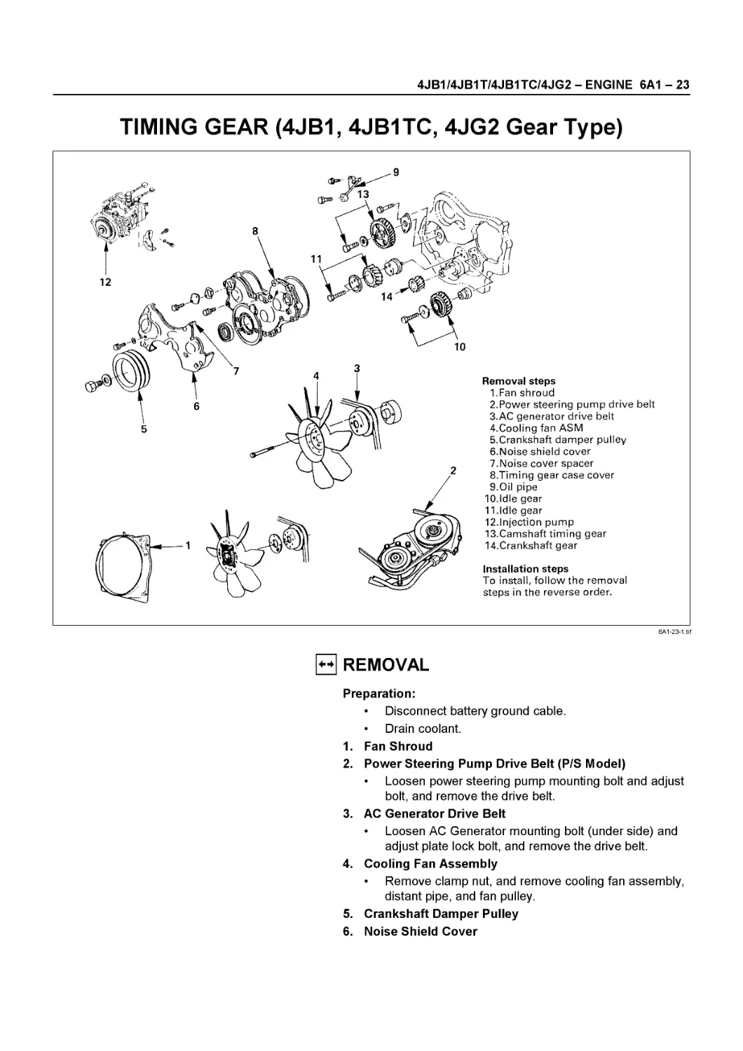
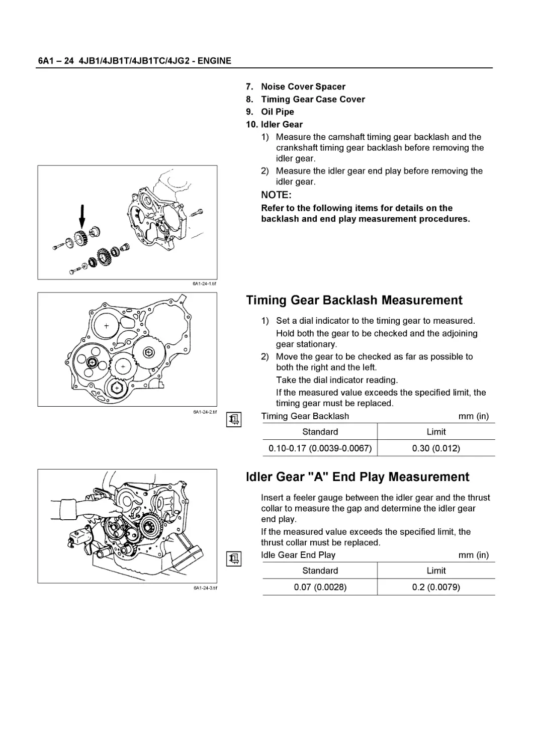
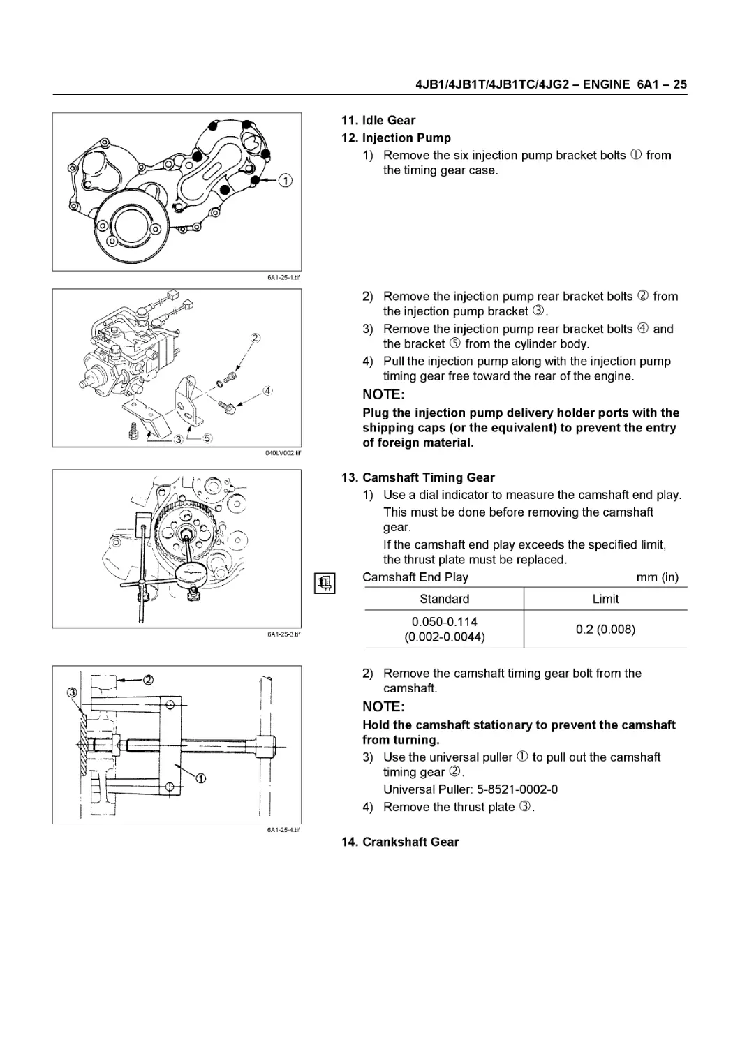
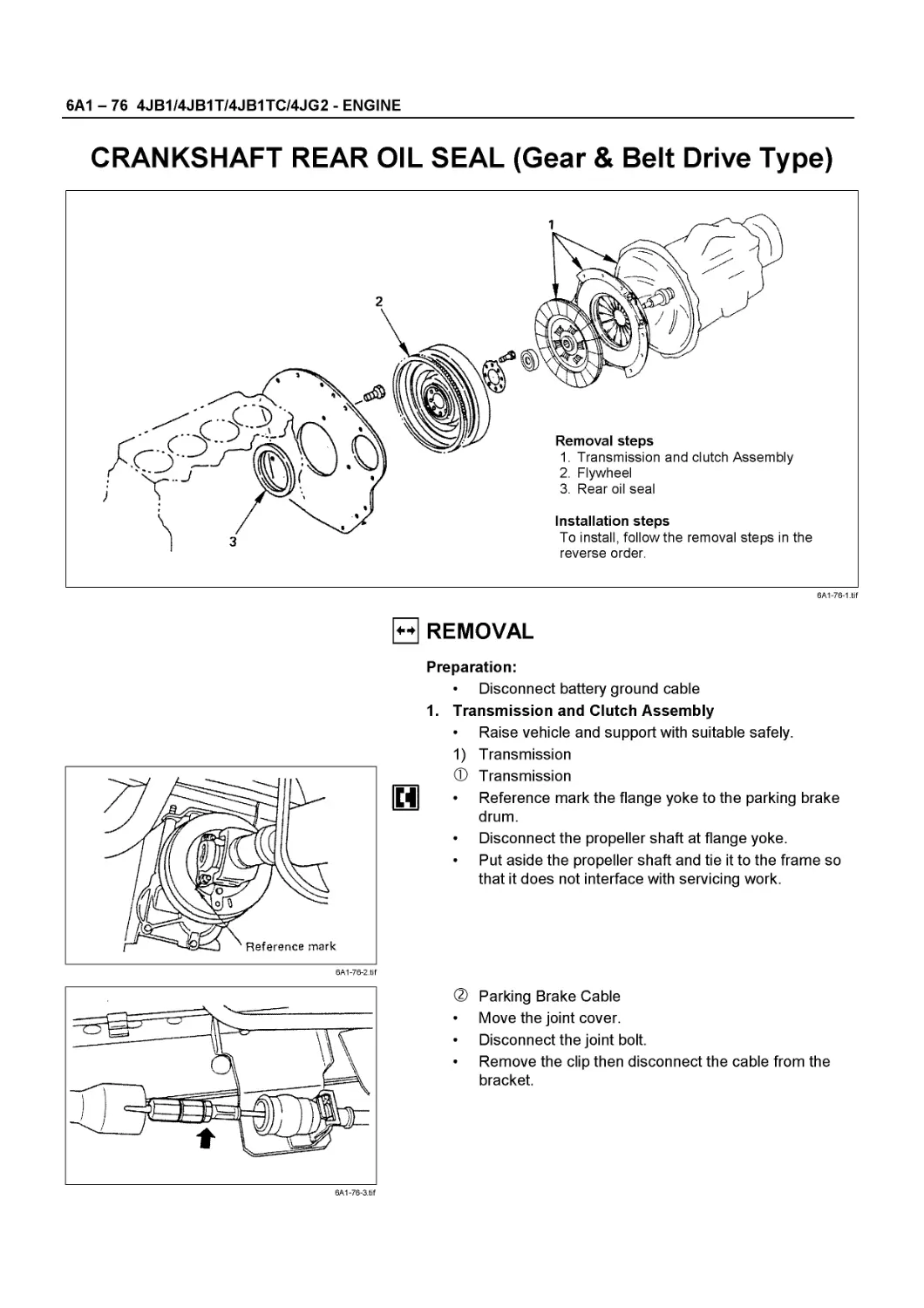
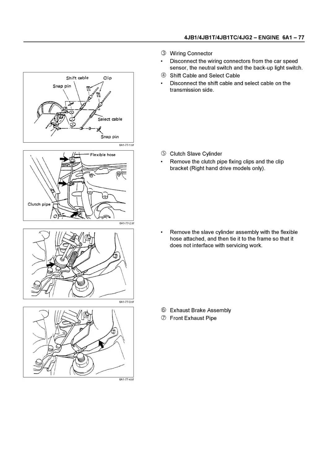
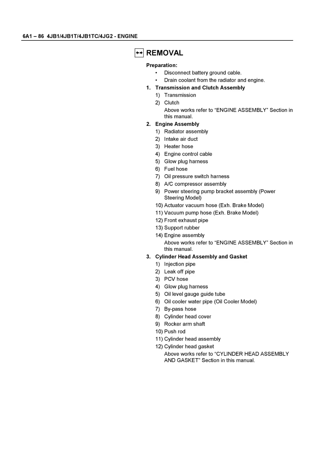
/


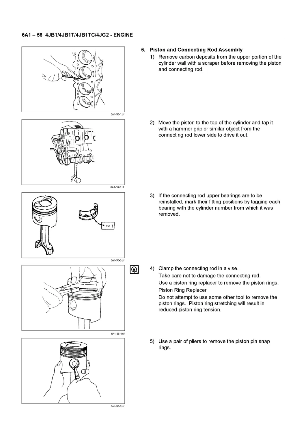
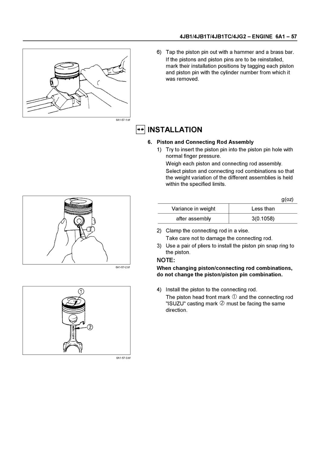
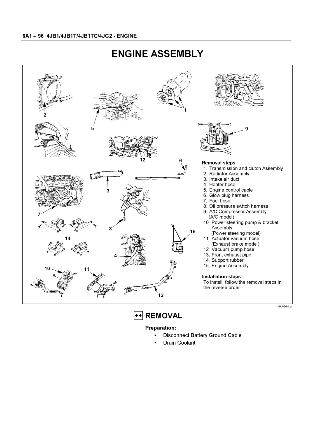
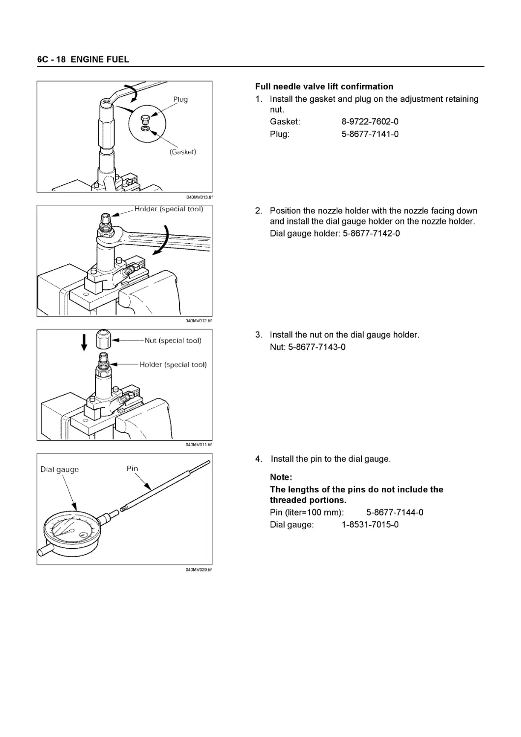
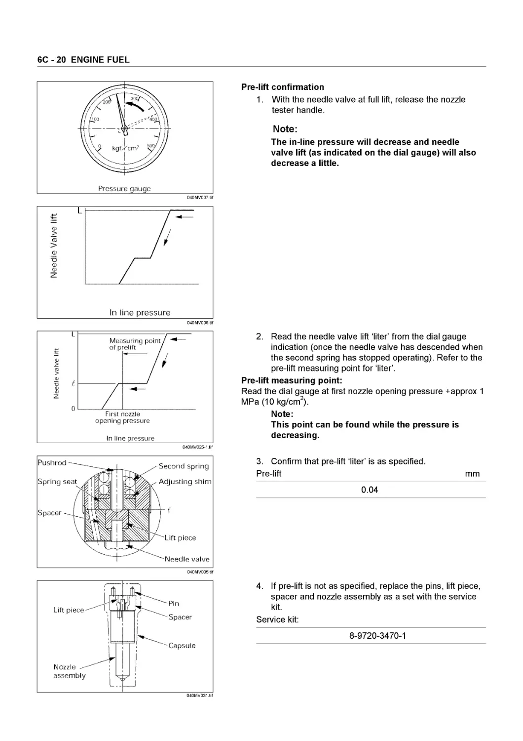
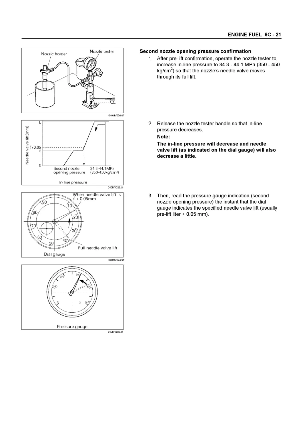


Tags: mechanics cars car engines
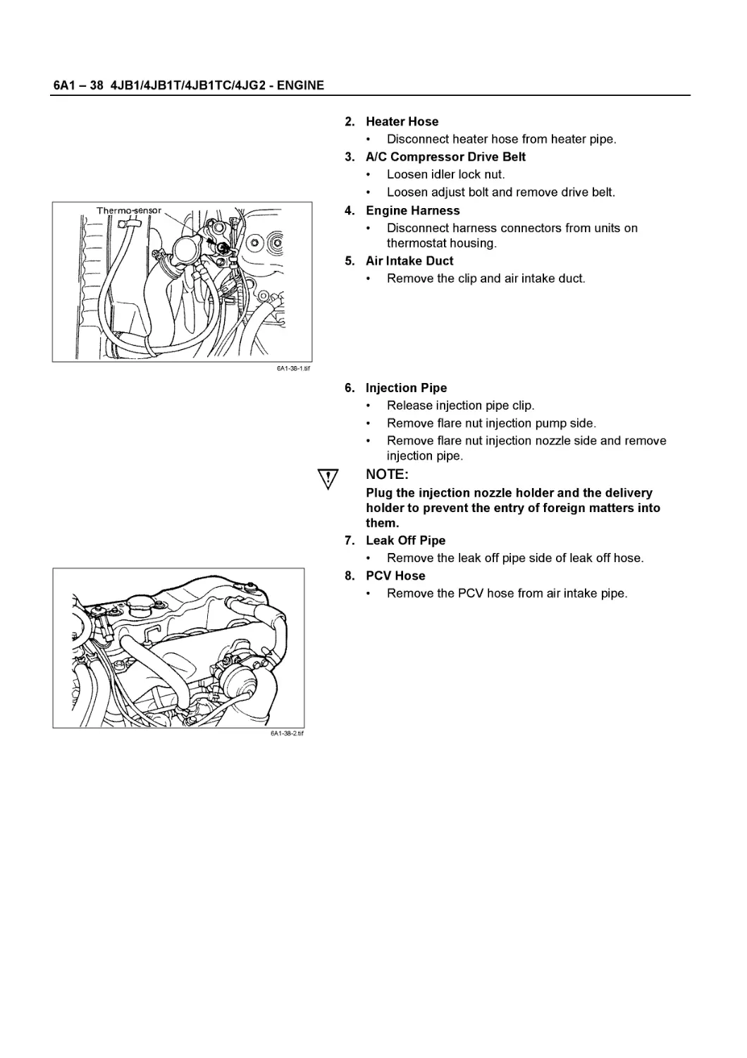
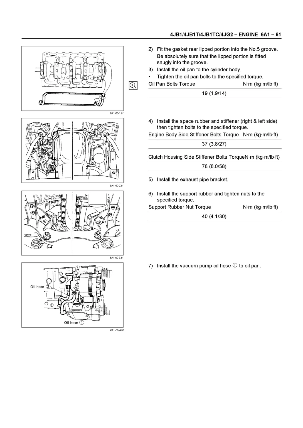
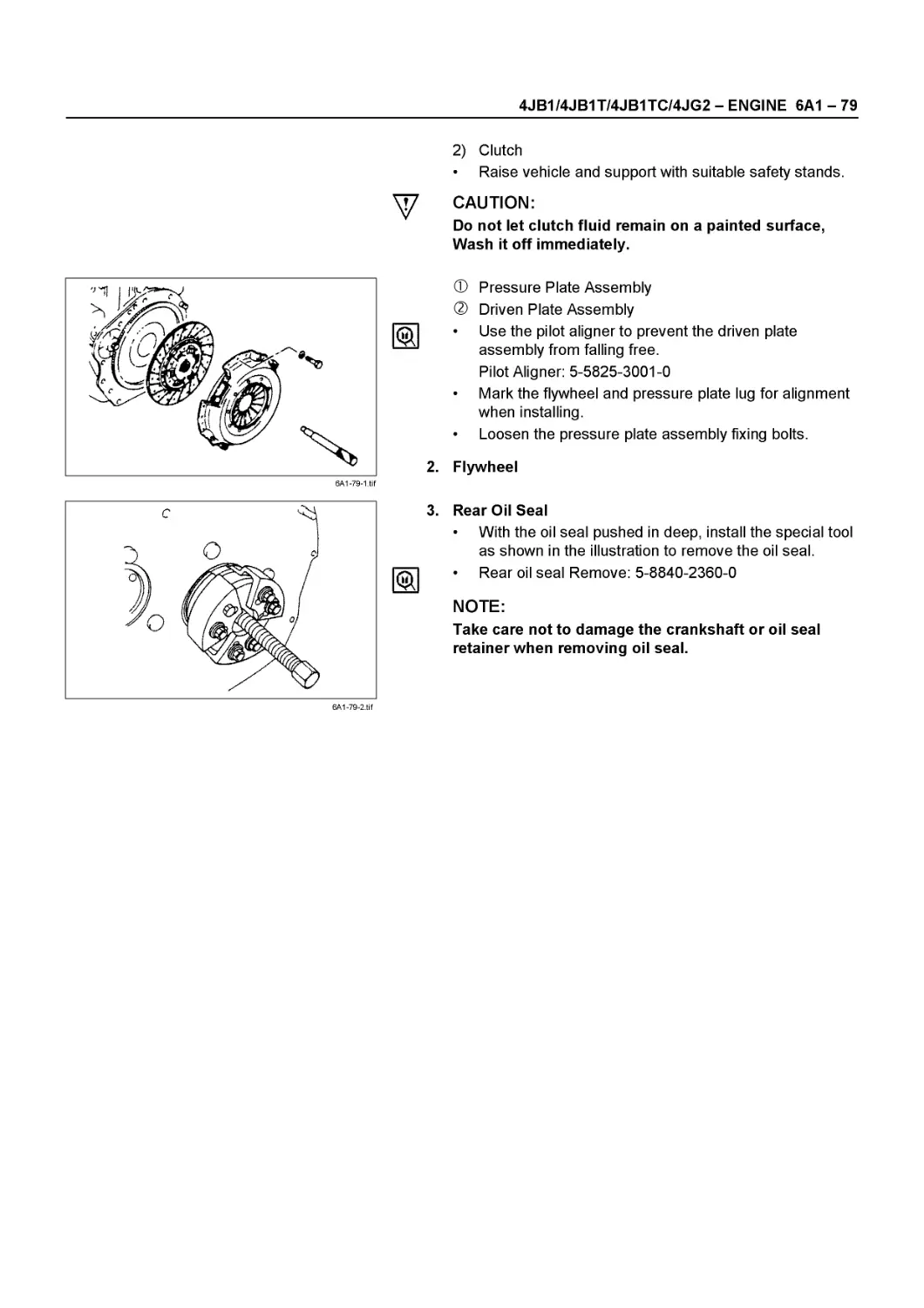
Year: 1999


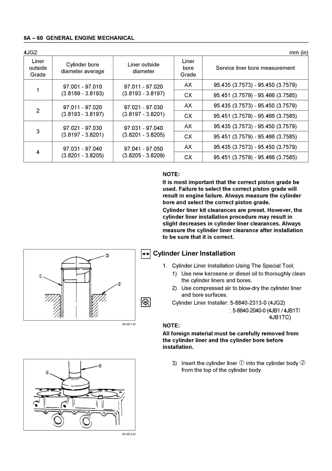
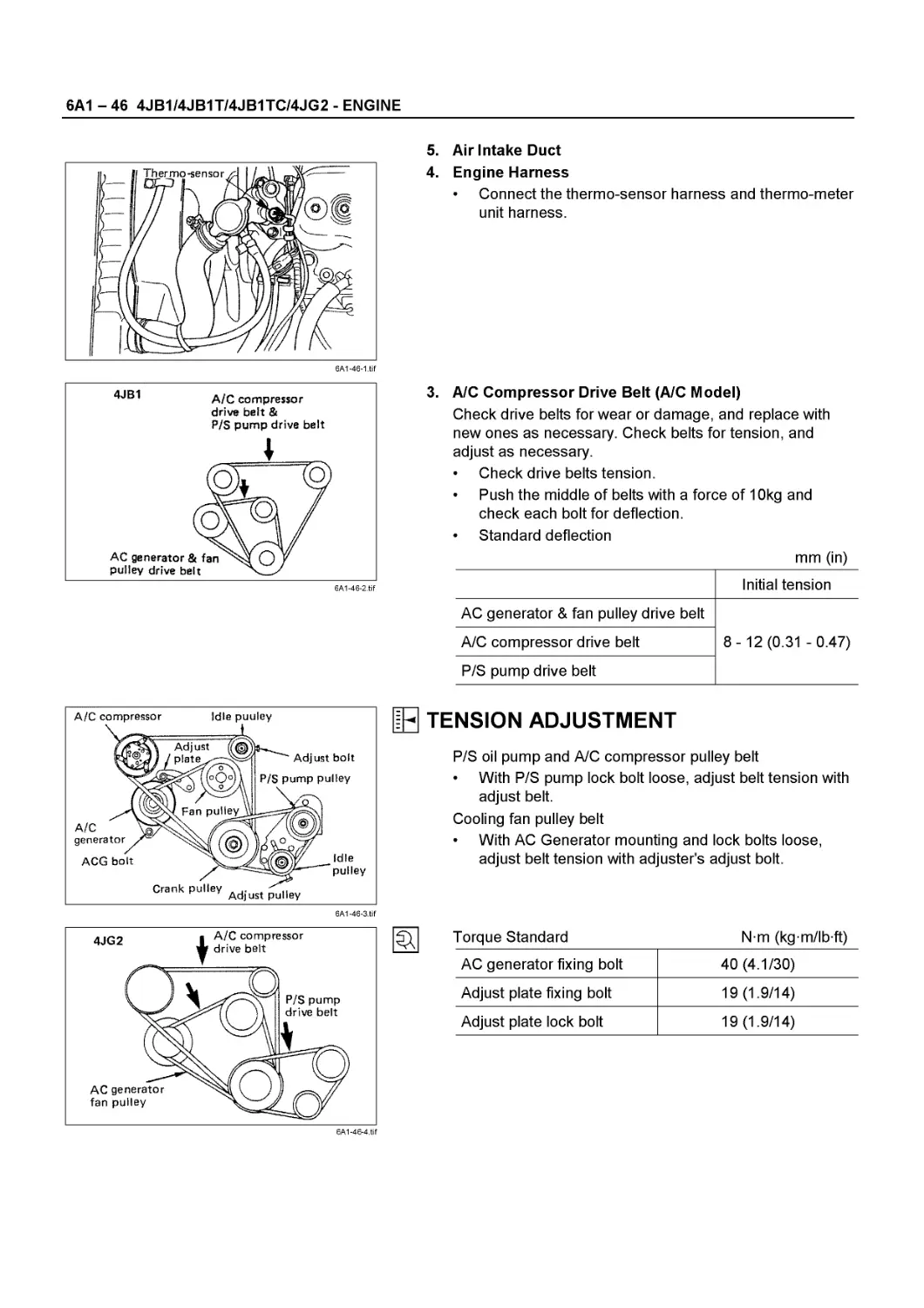
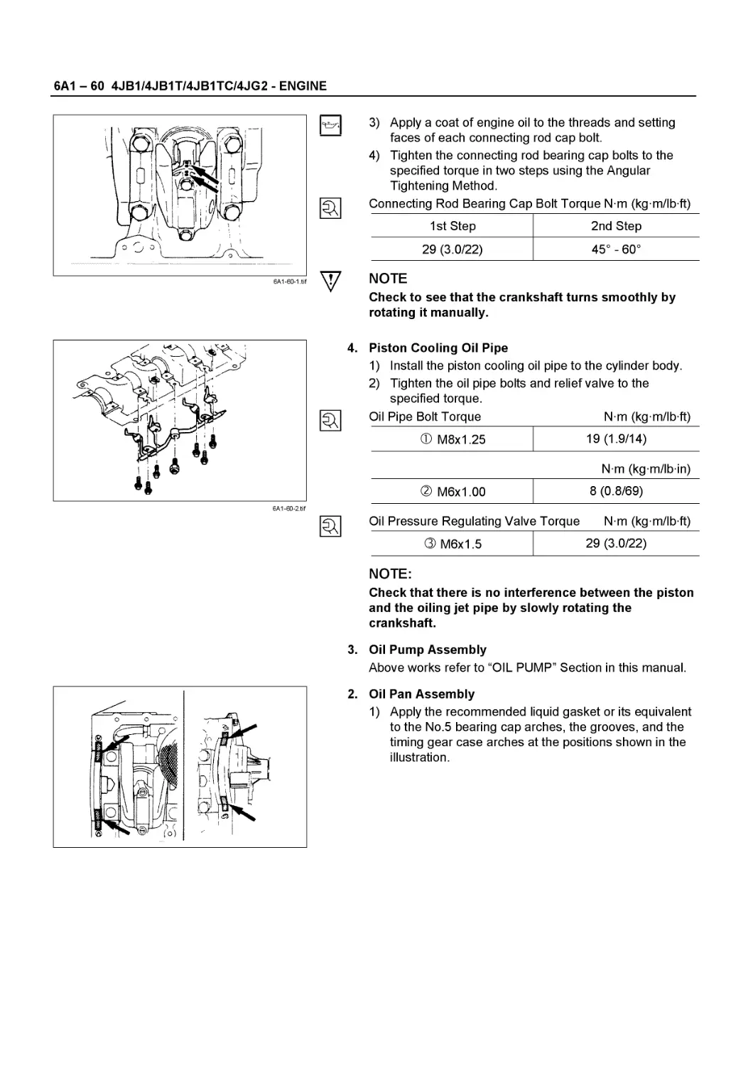
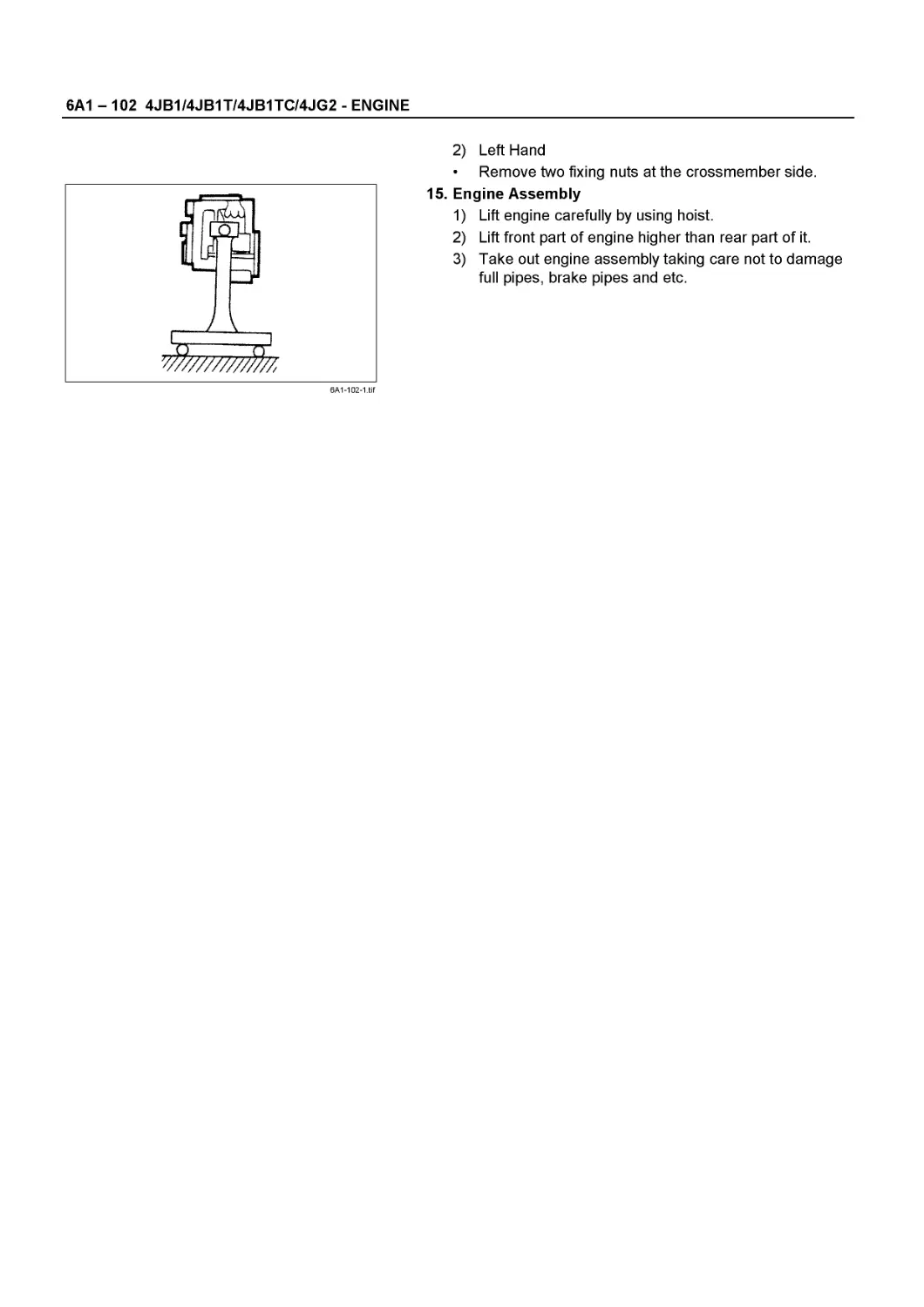
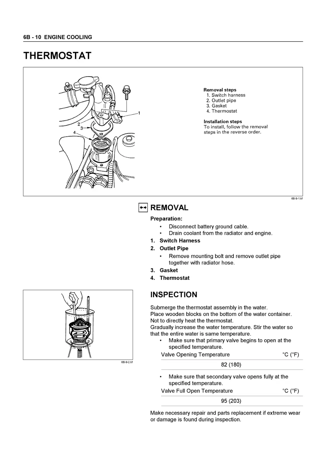
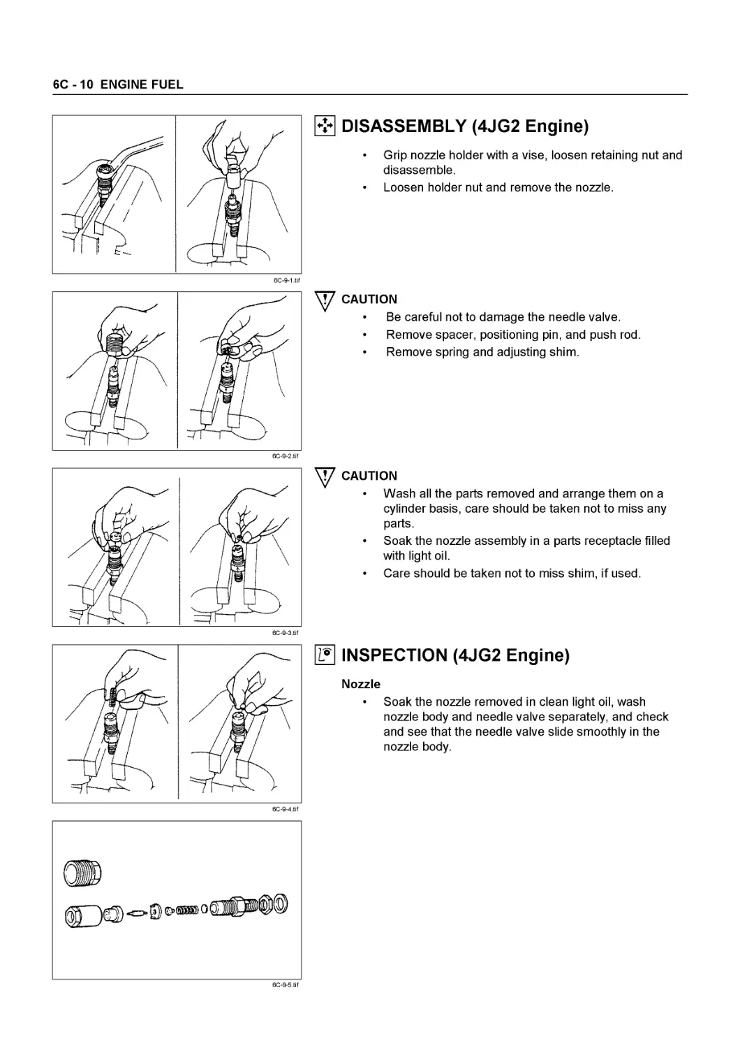
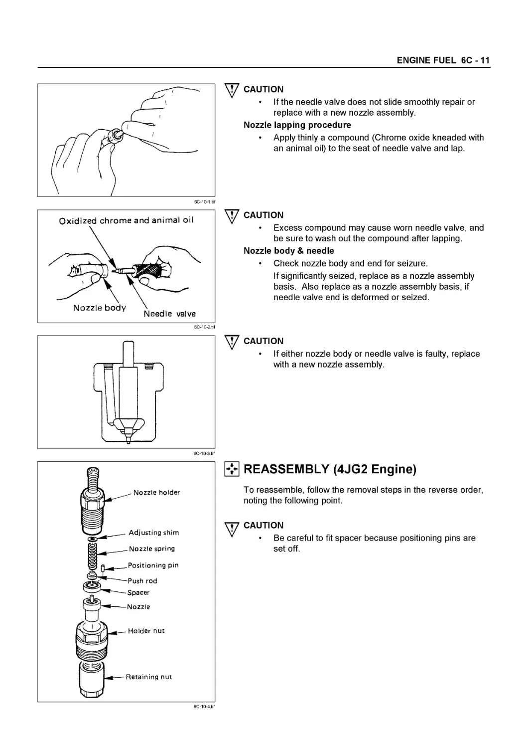
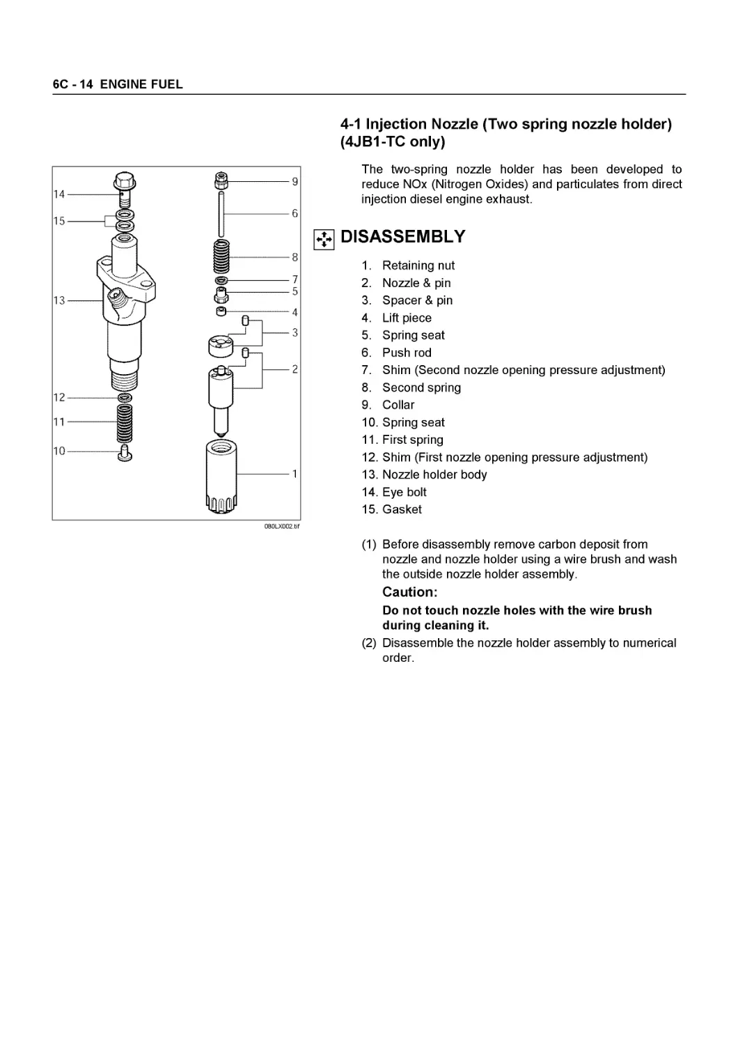
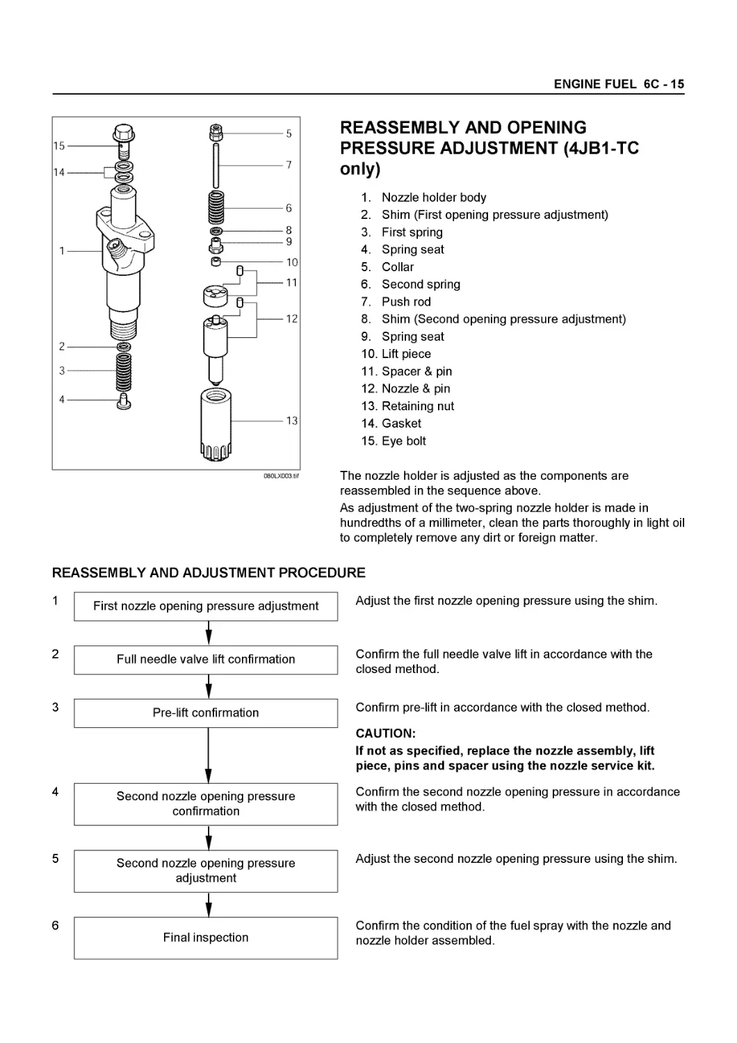
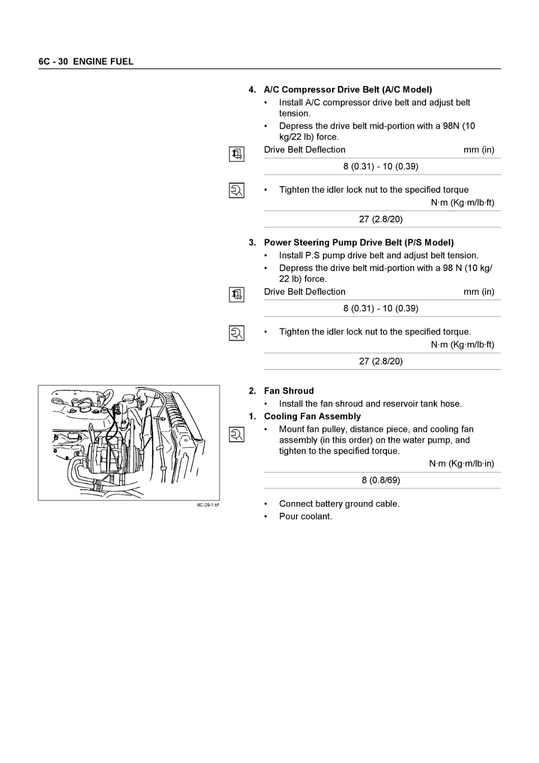
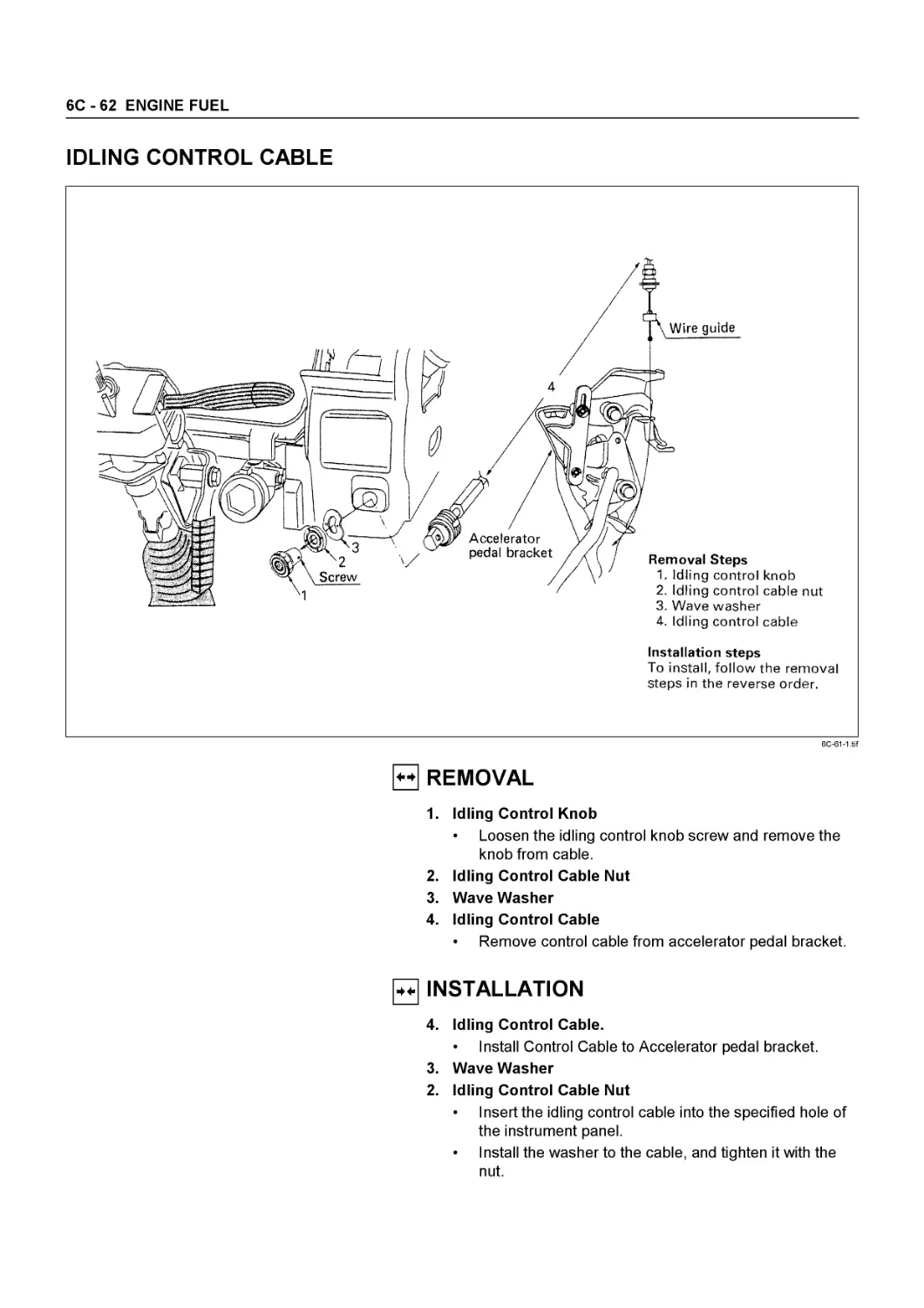
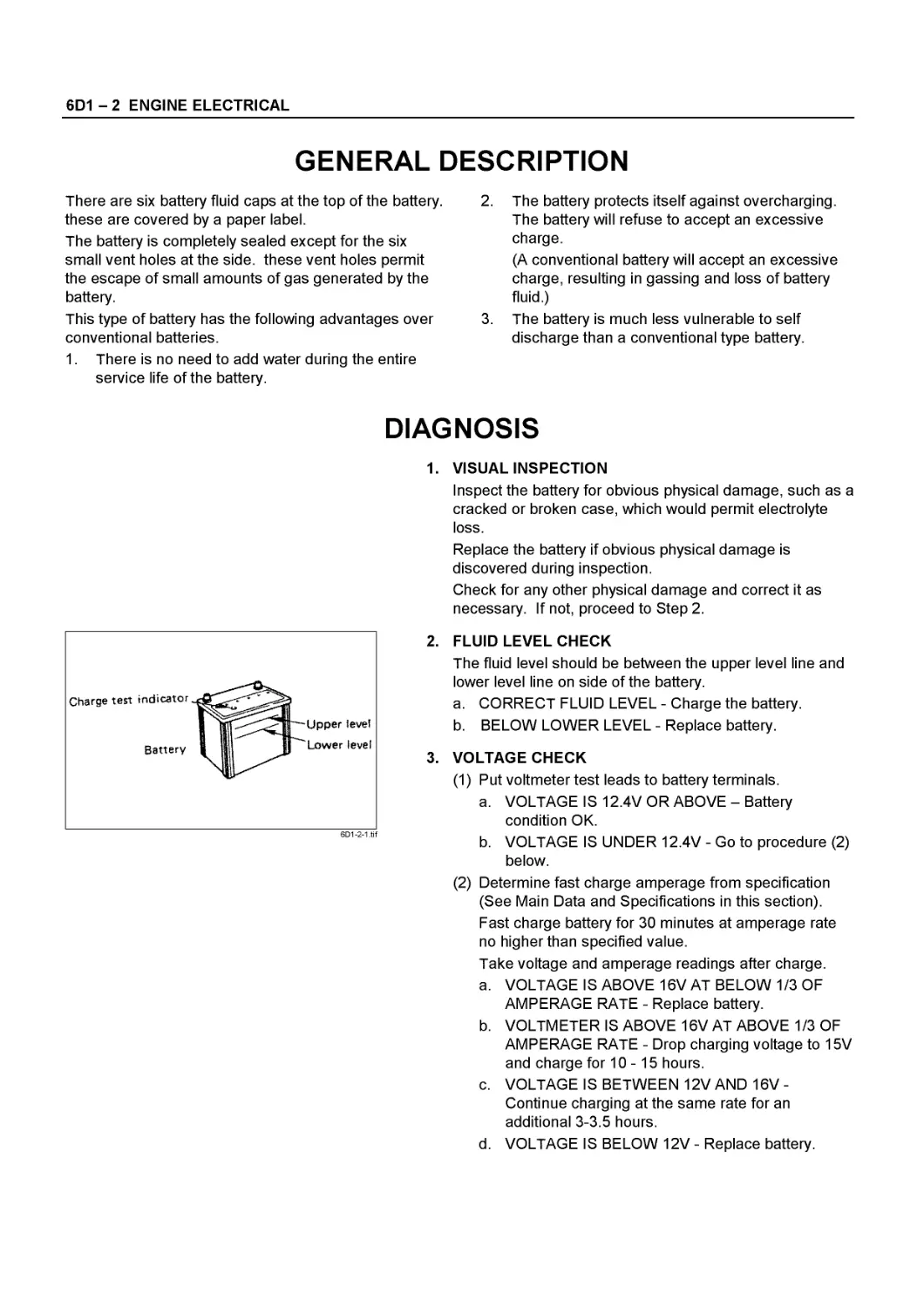
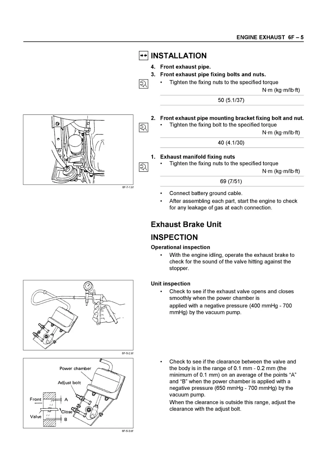
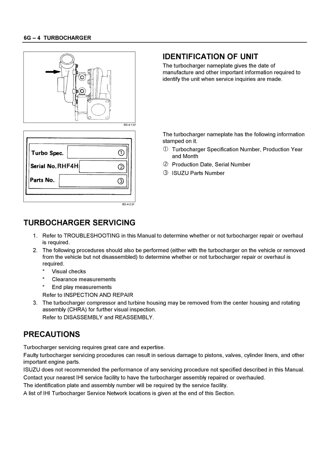
Text
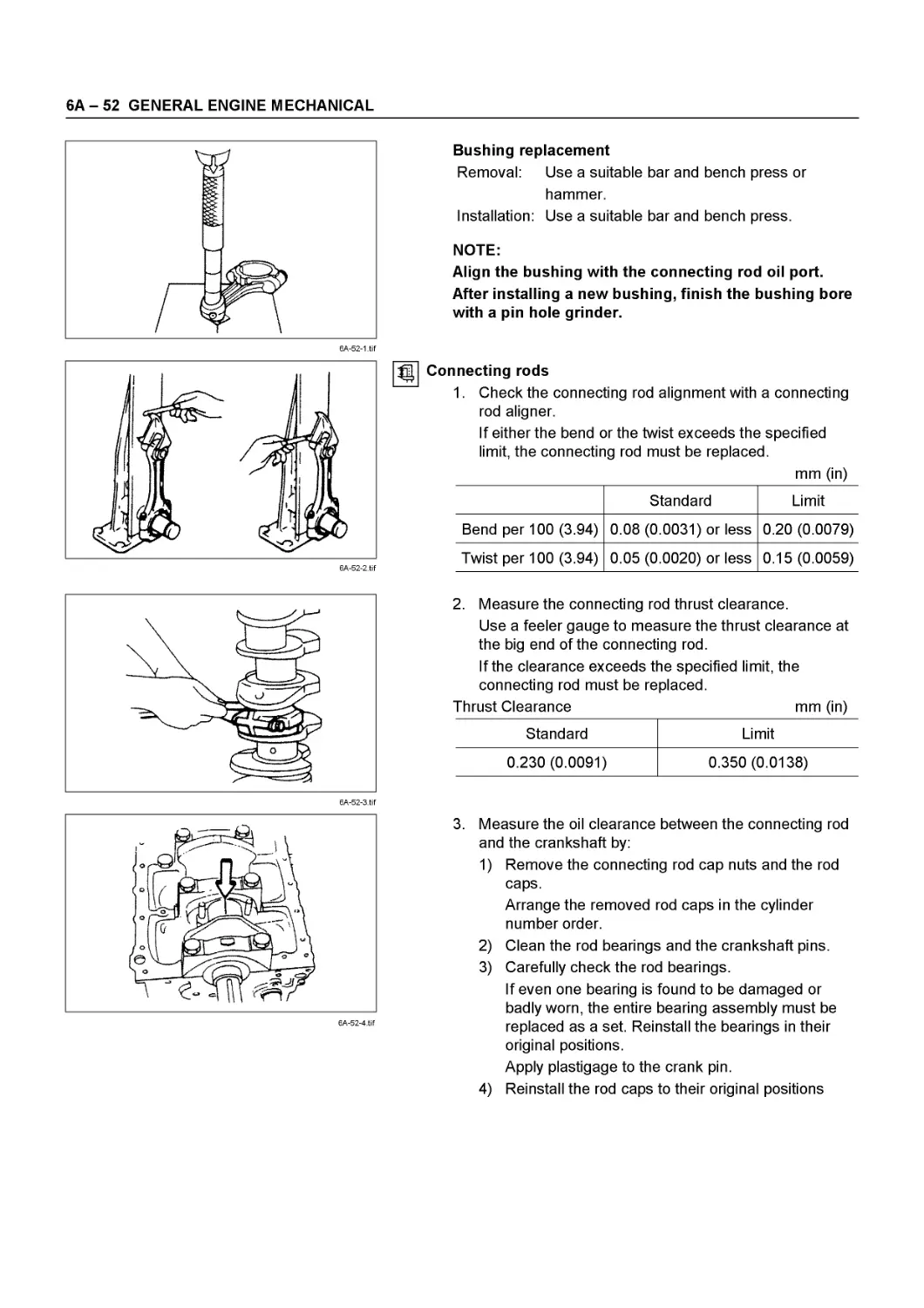
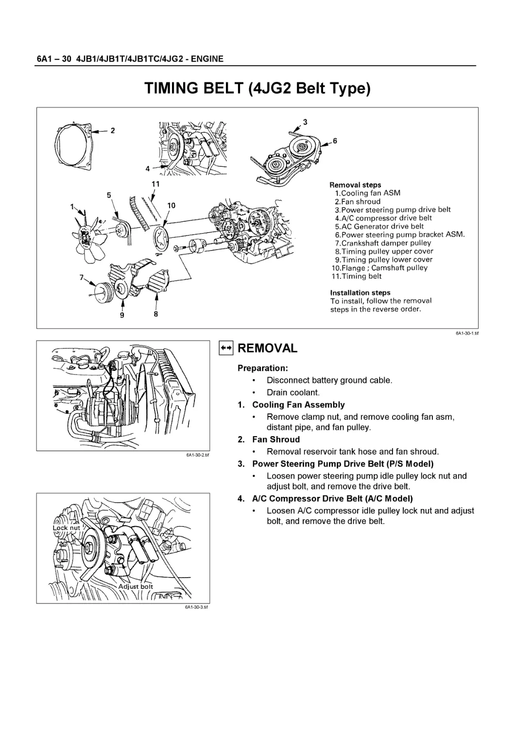
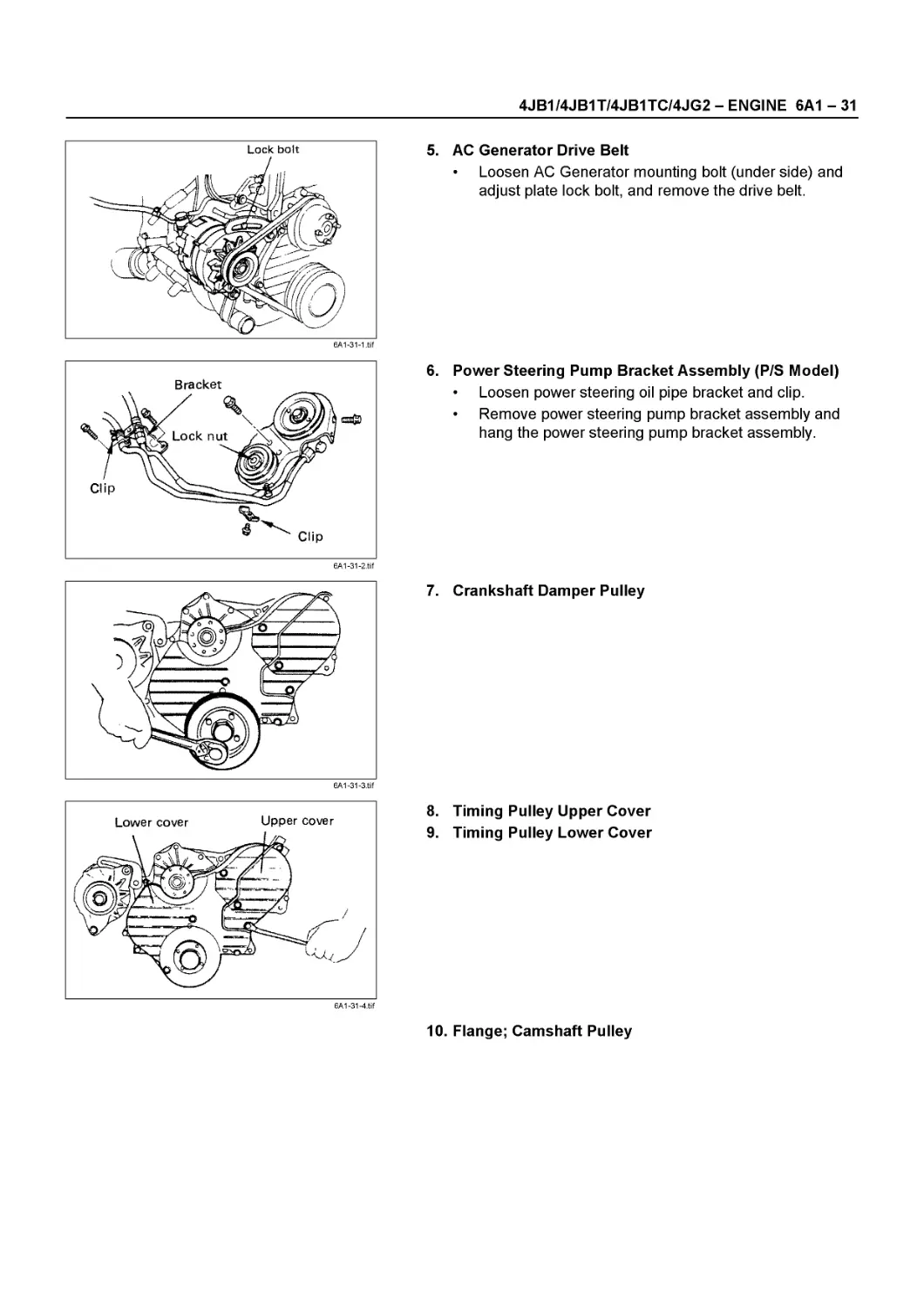
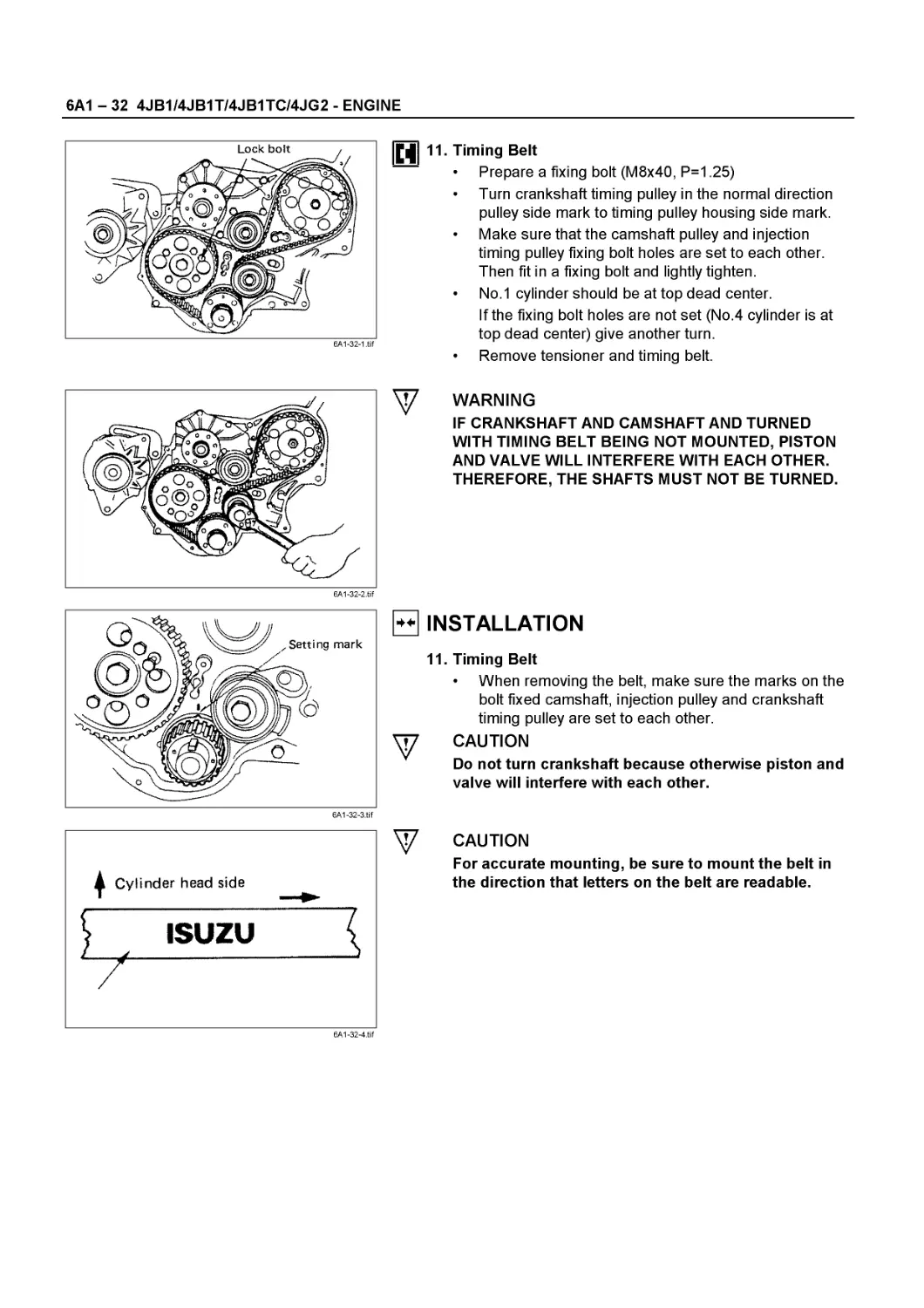
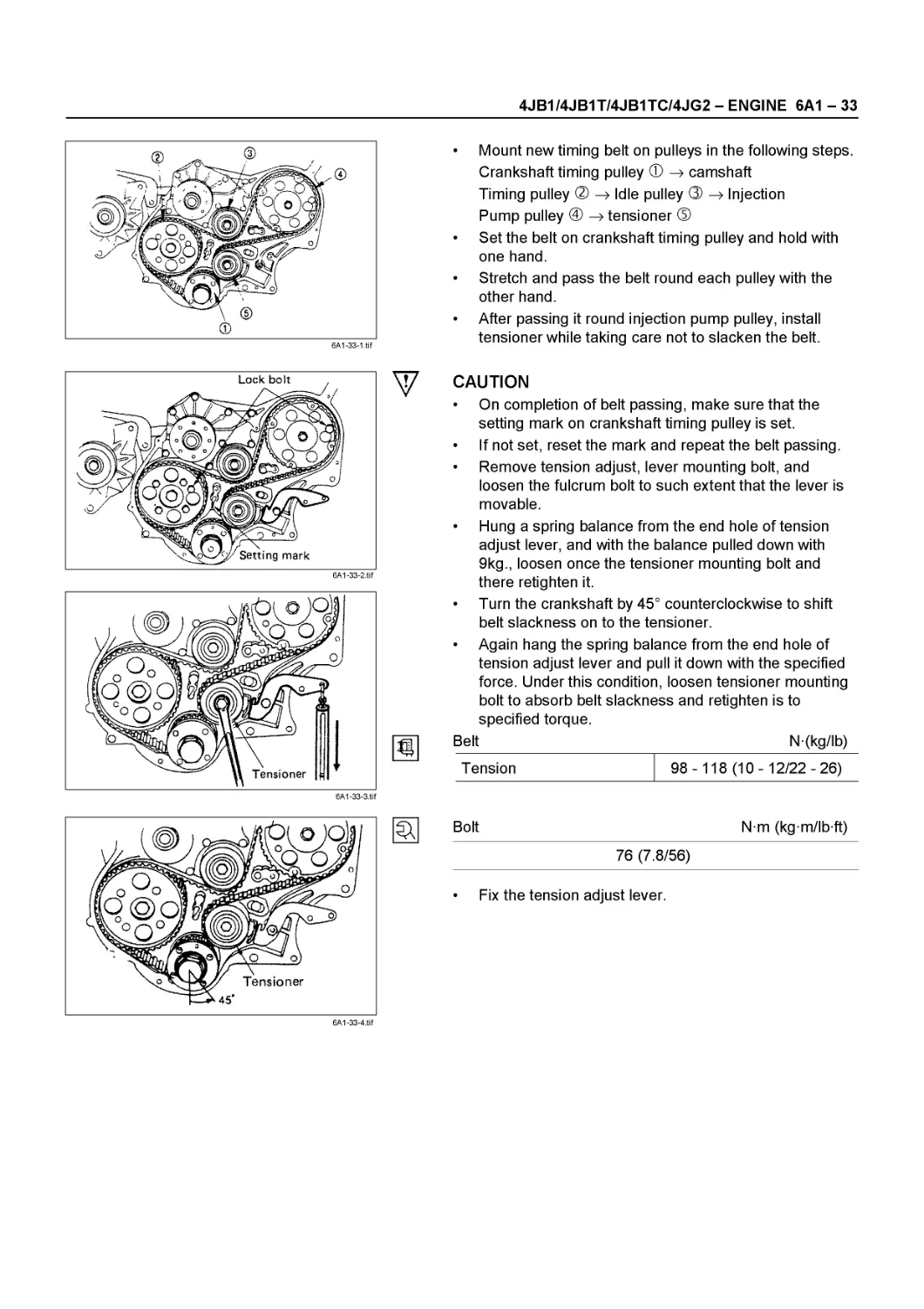
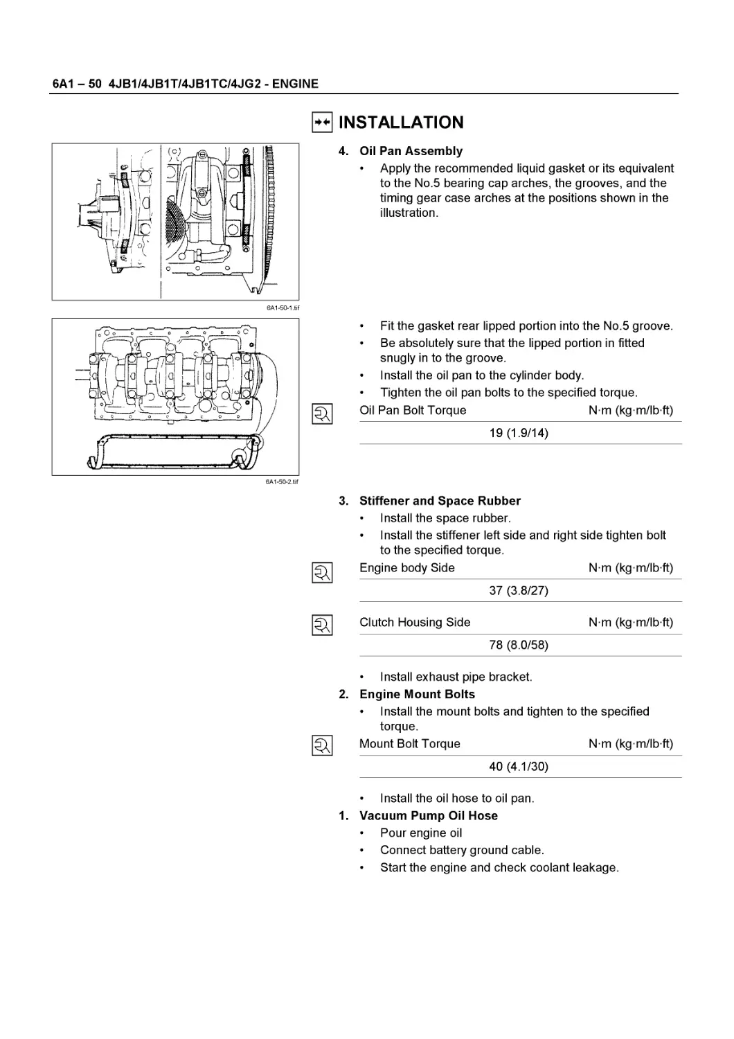
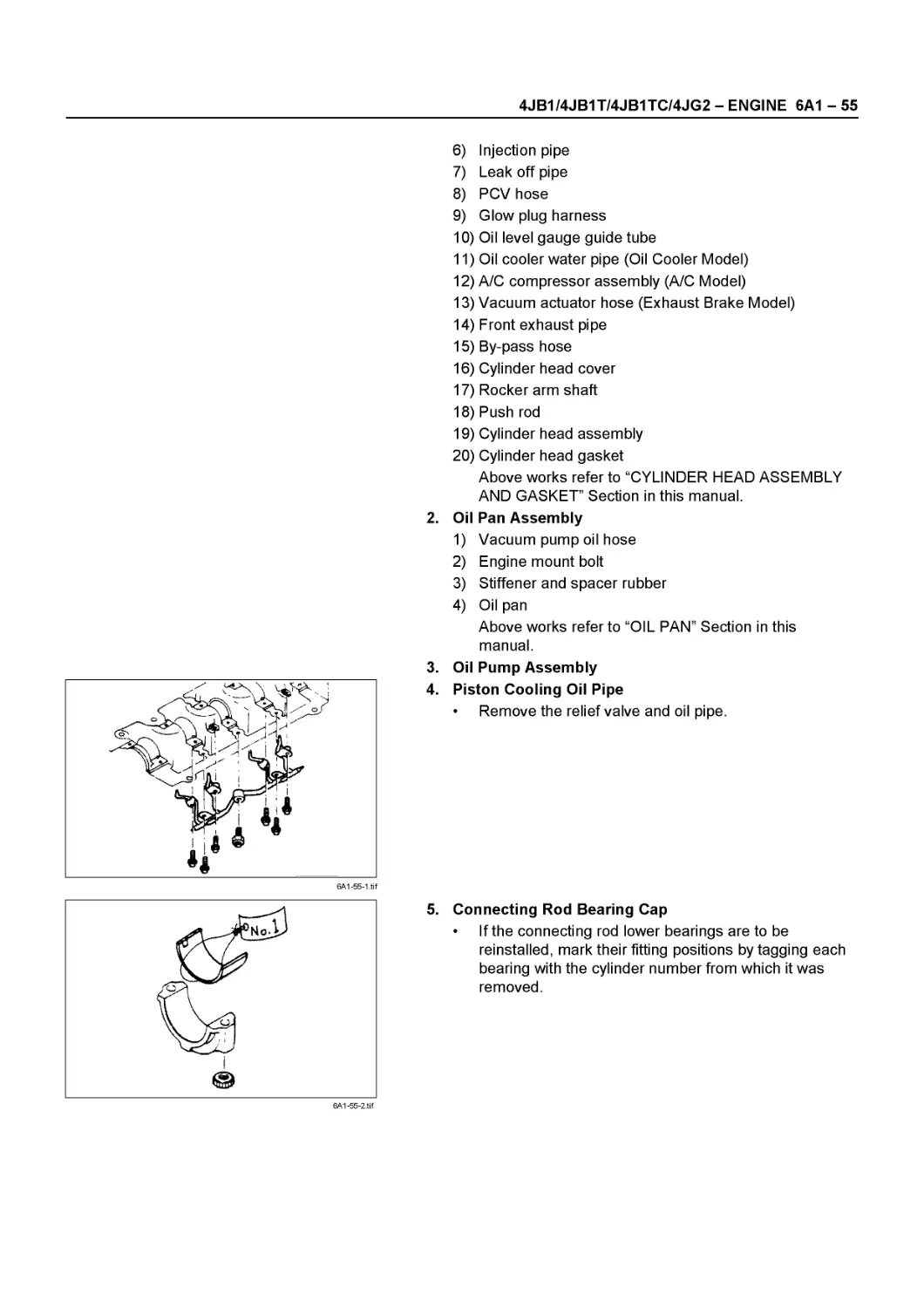
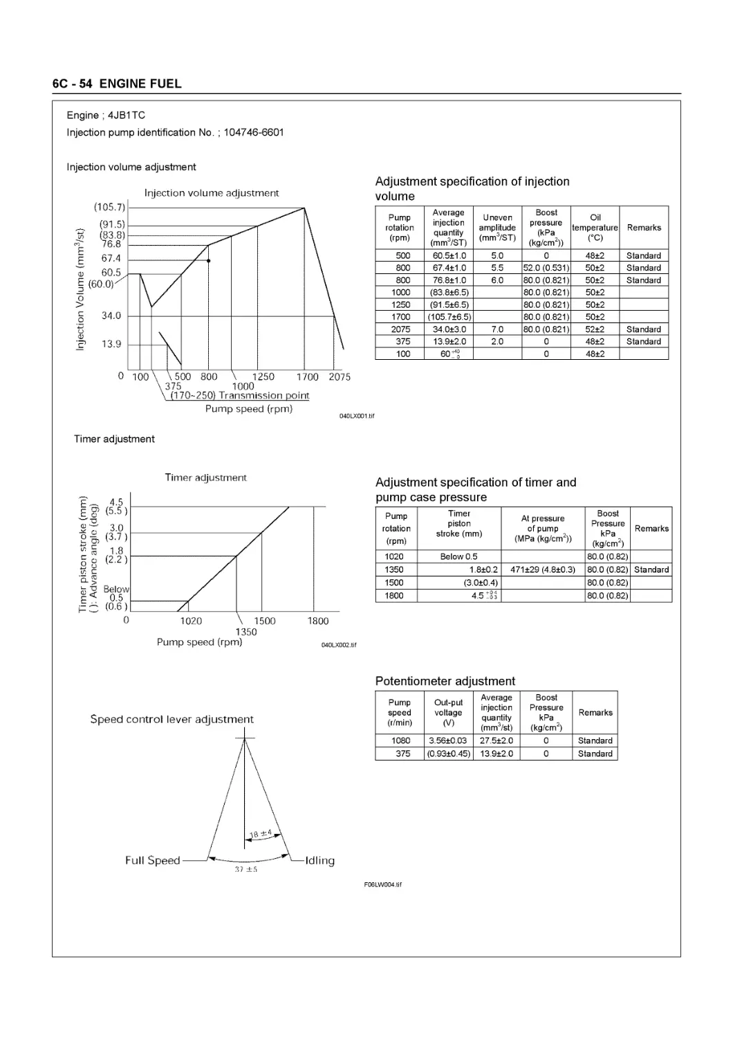
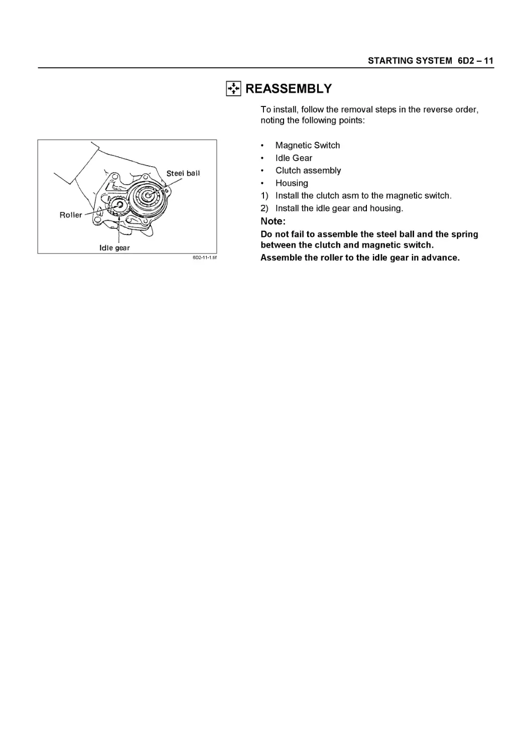
WORKSHOP MANUAL
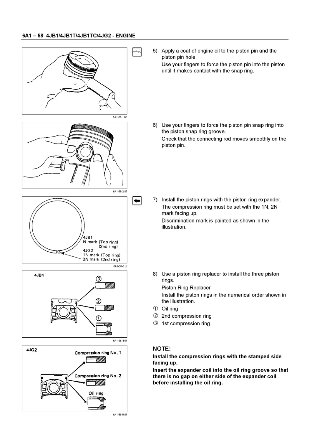
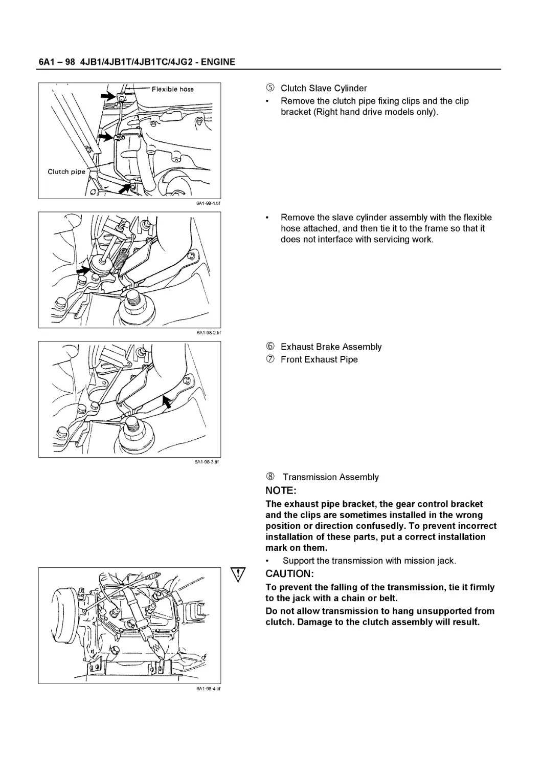
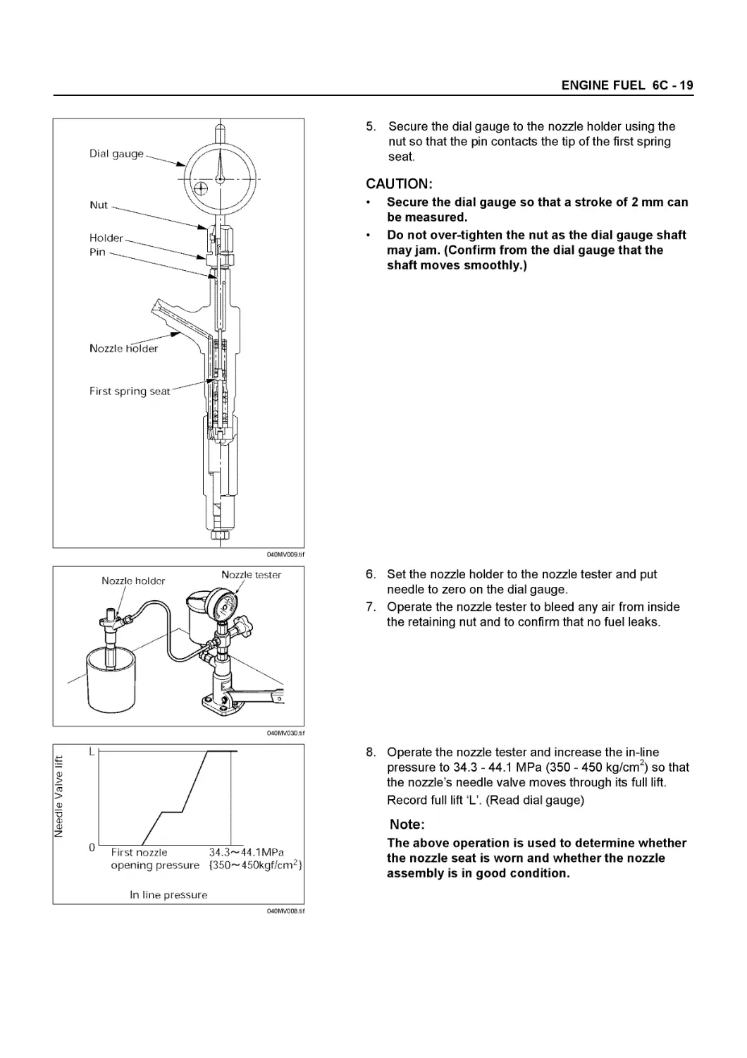
NHR • NKR • NPR
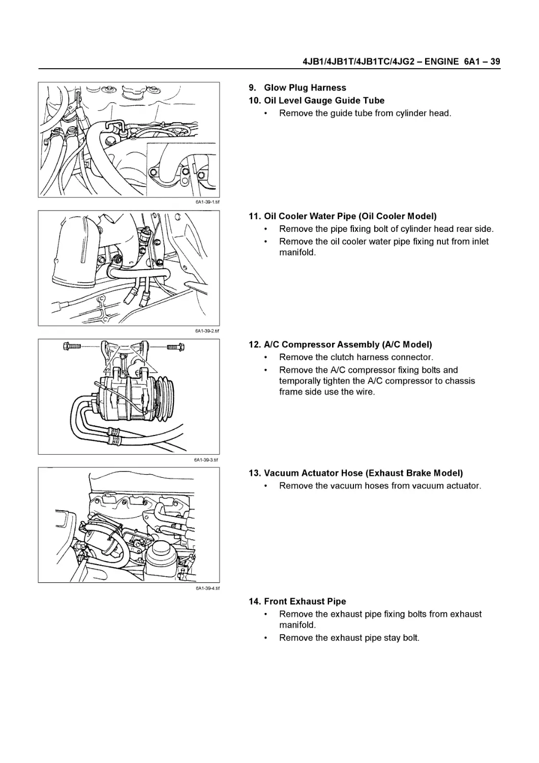
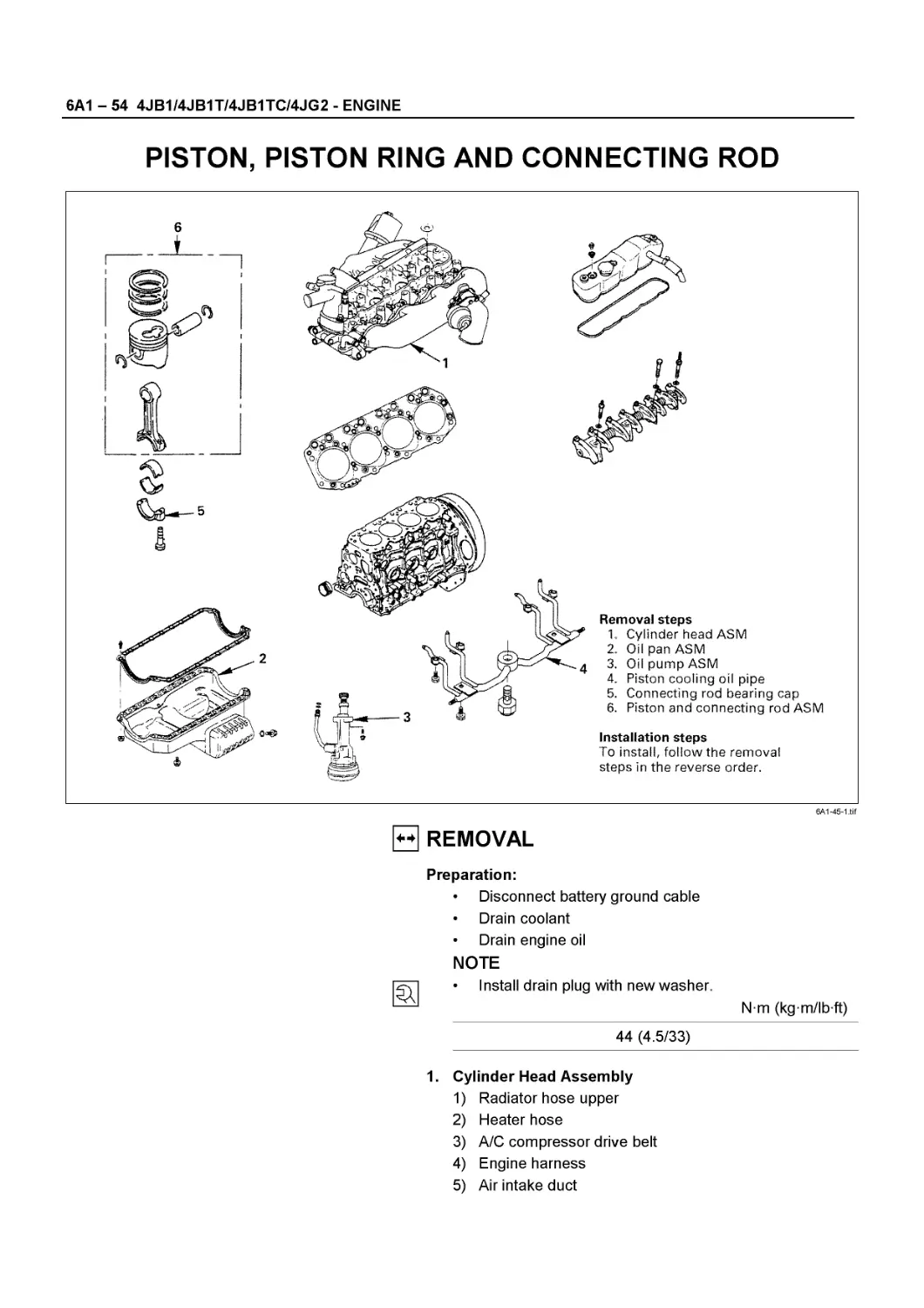
ENGINE
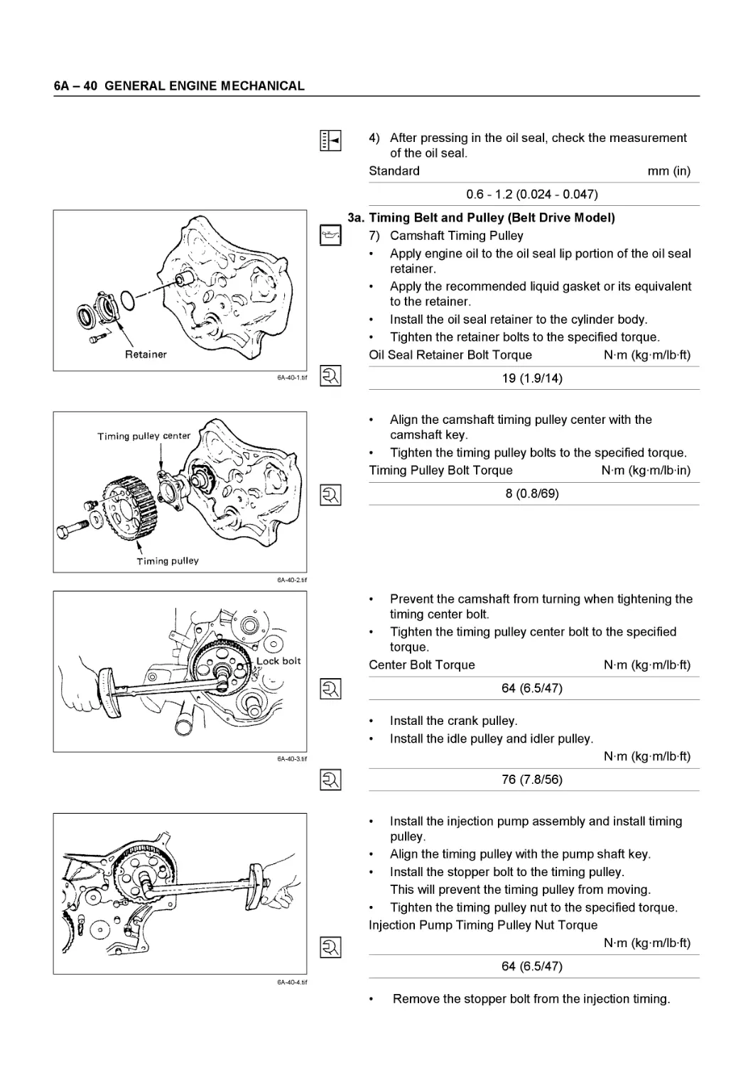
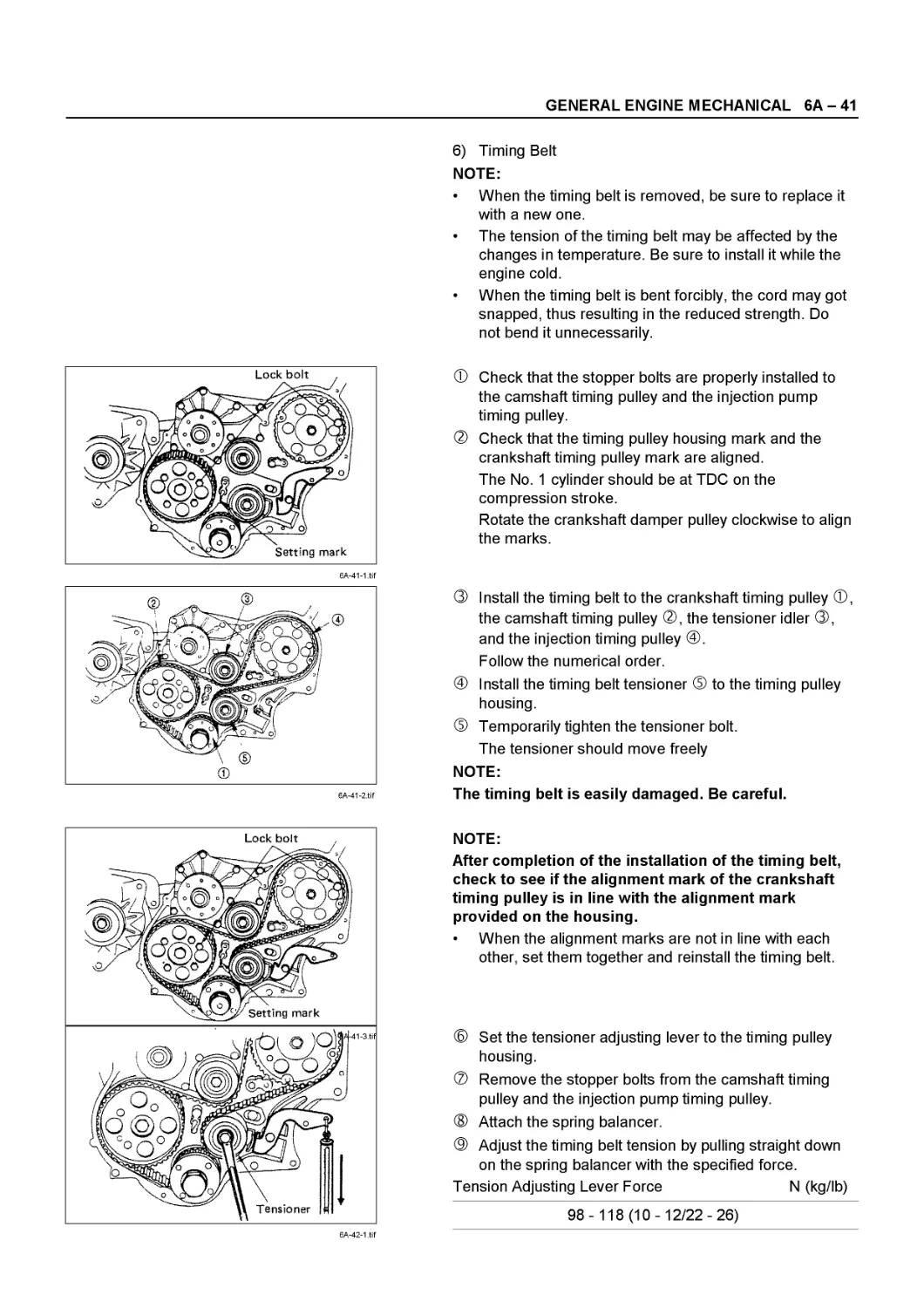
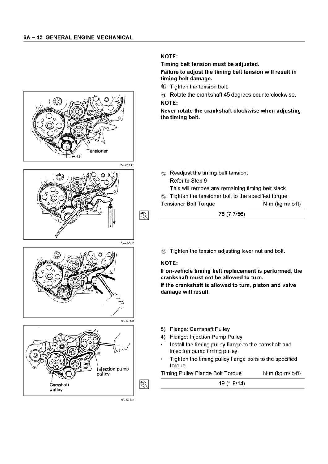
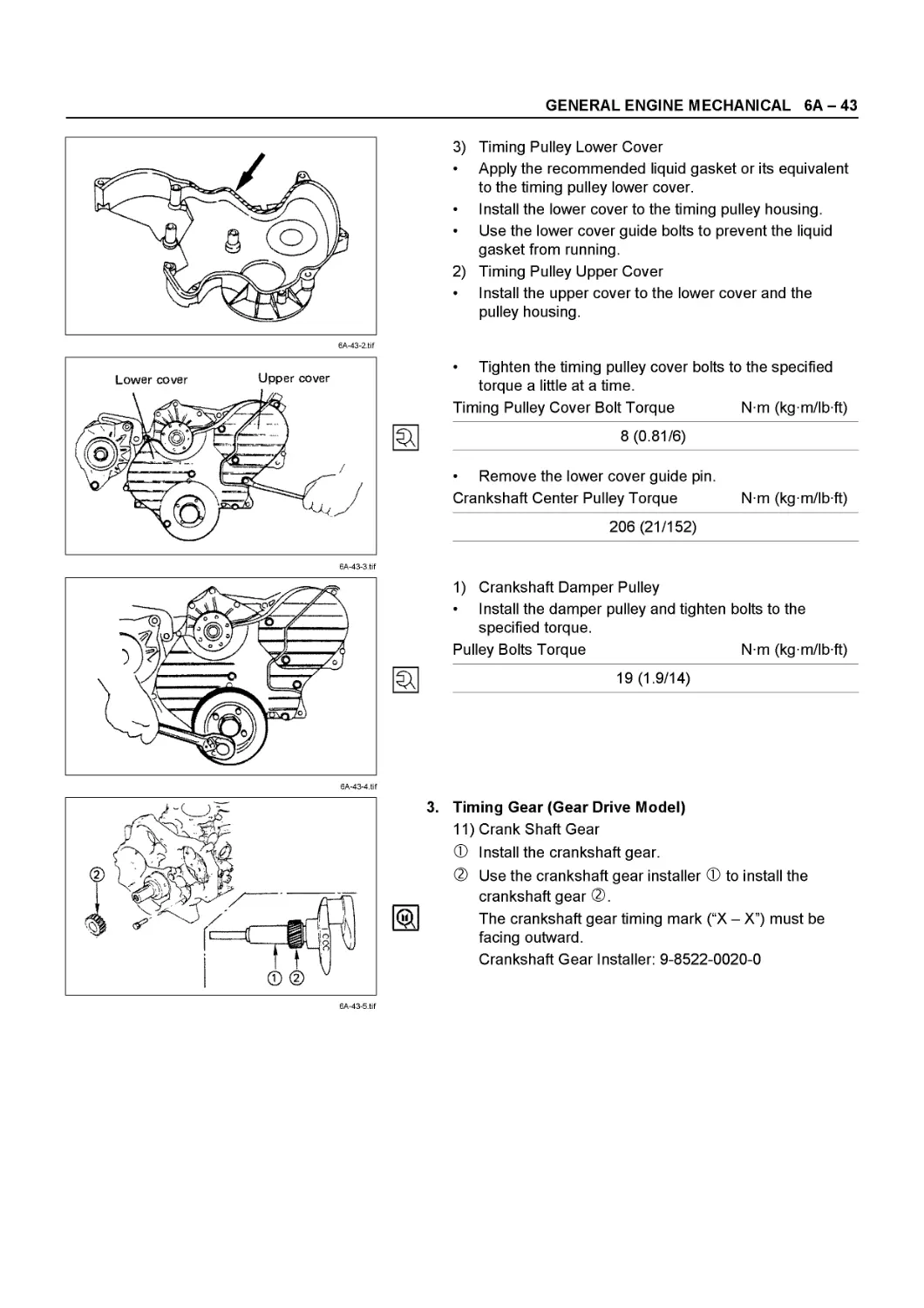
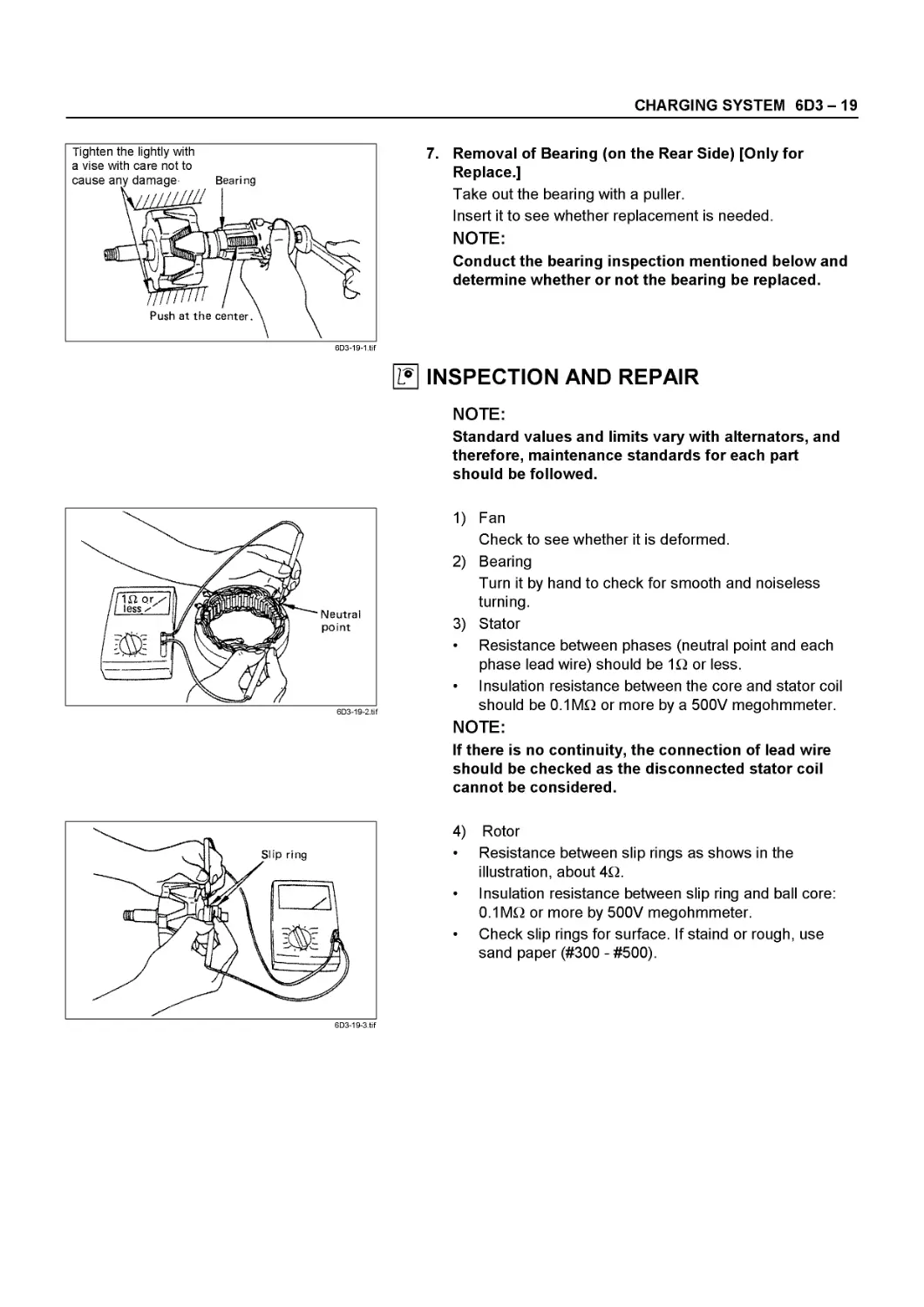
4J SERIES
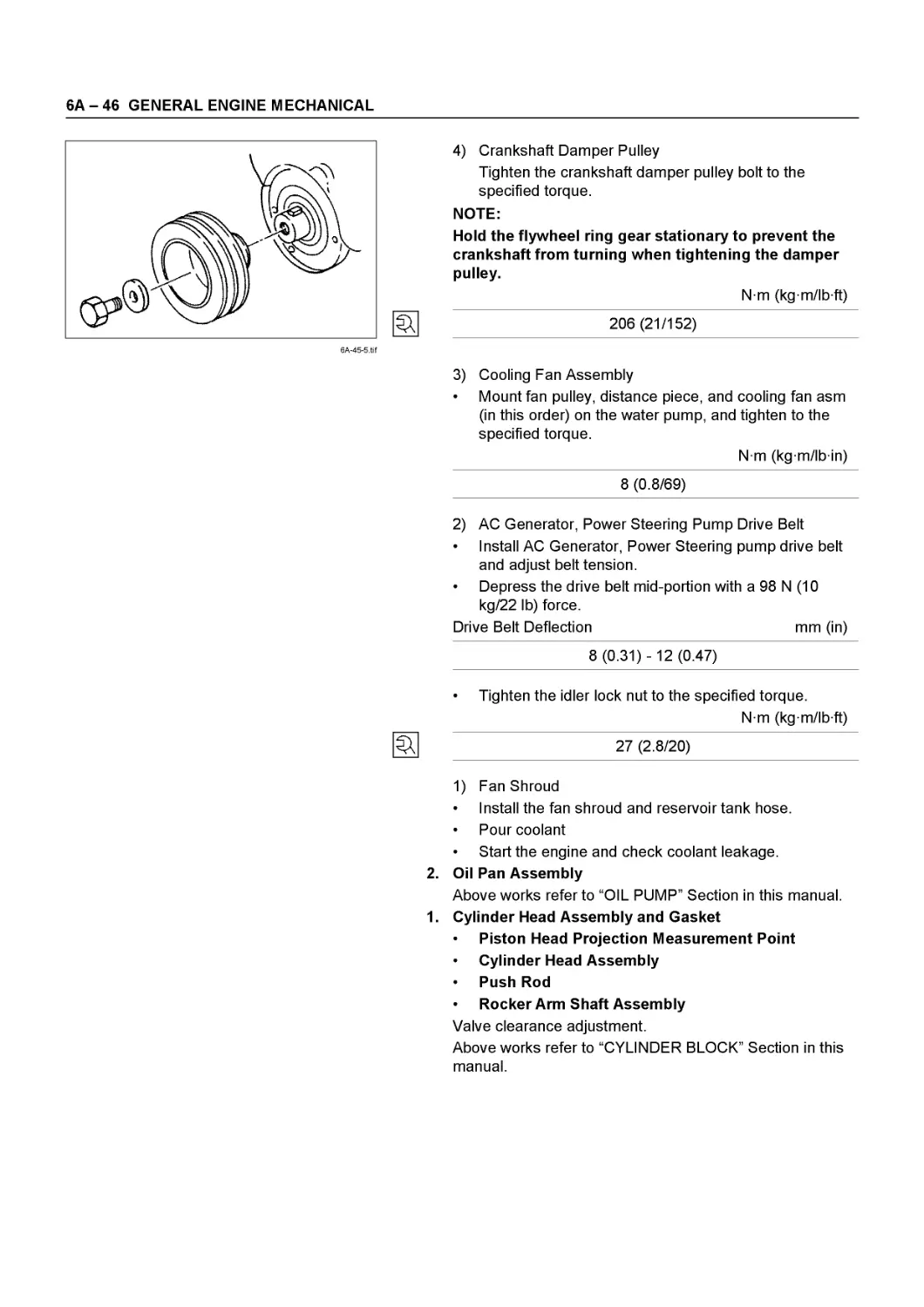
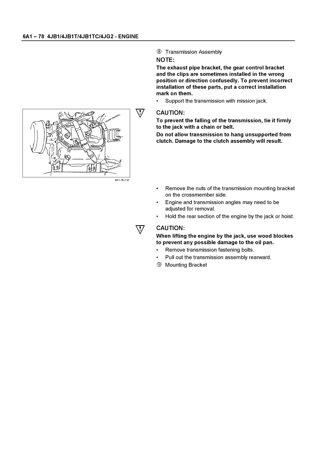
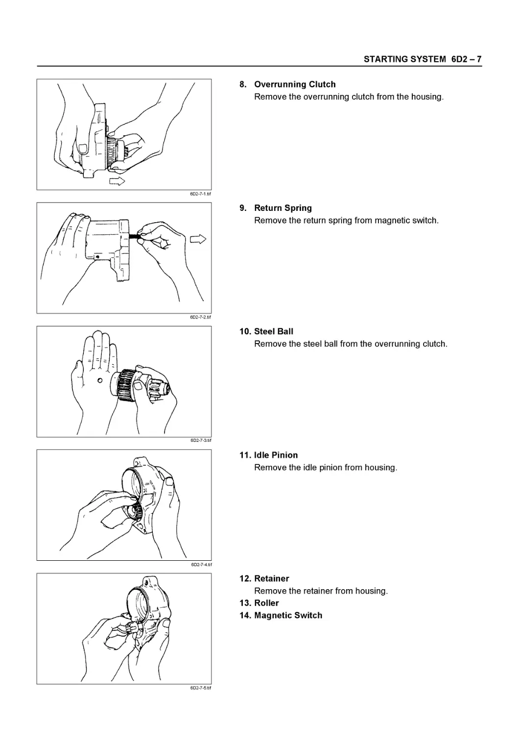
SECTION S
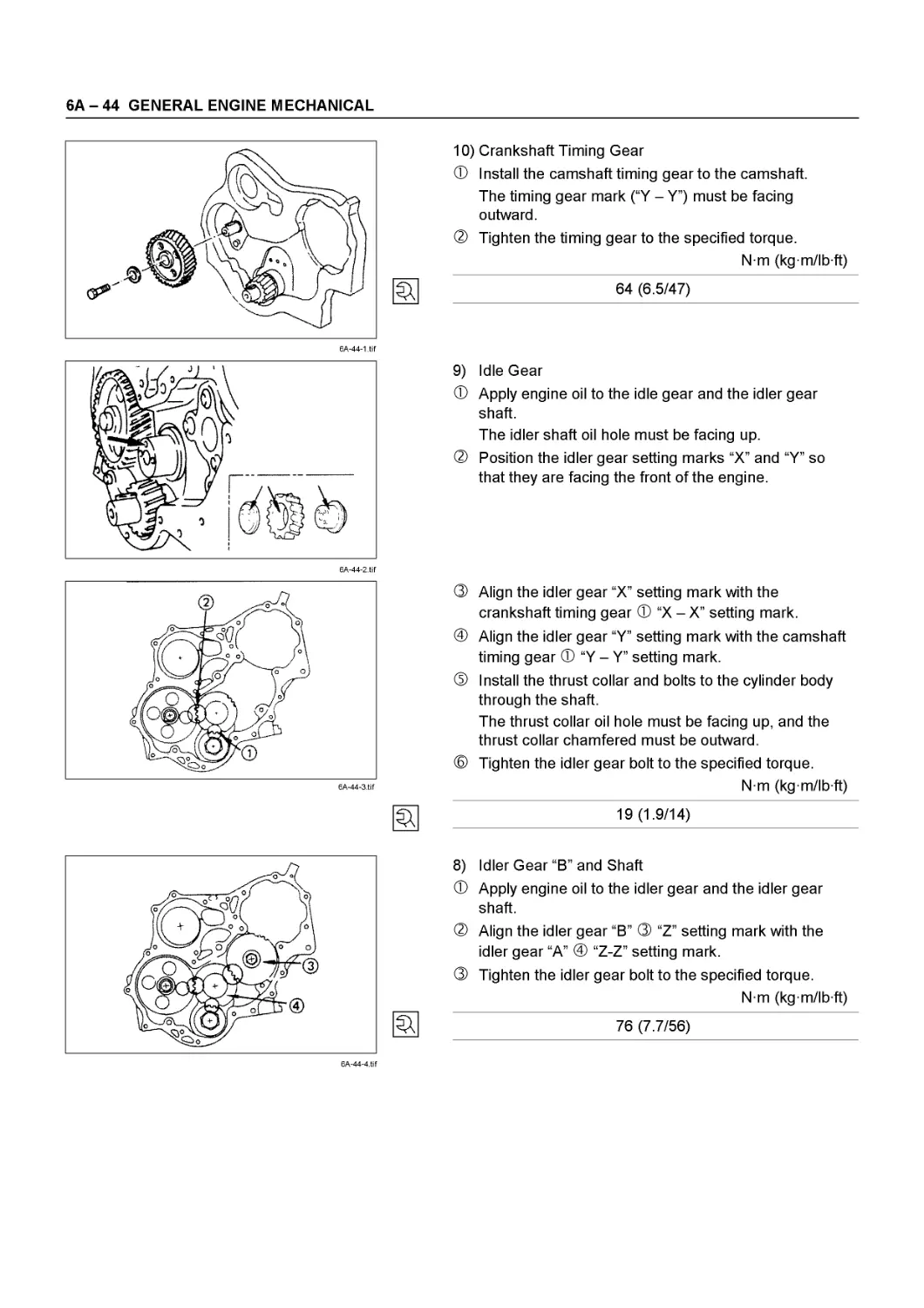
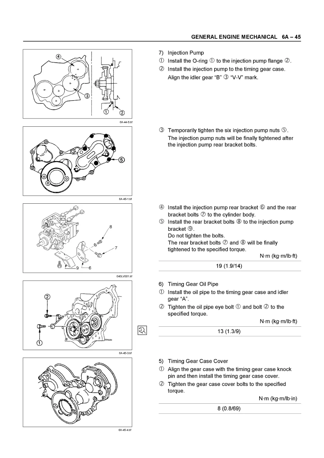
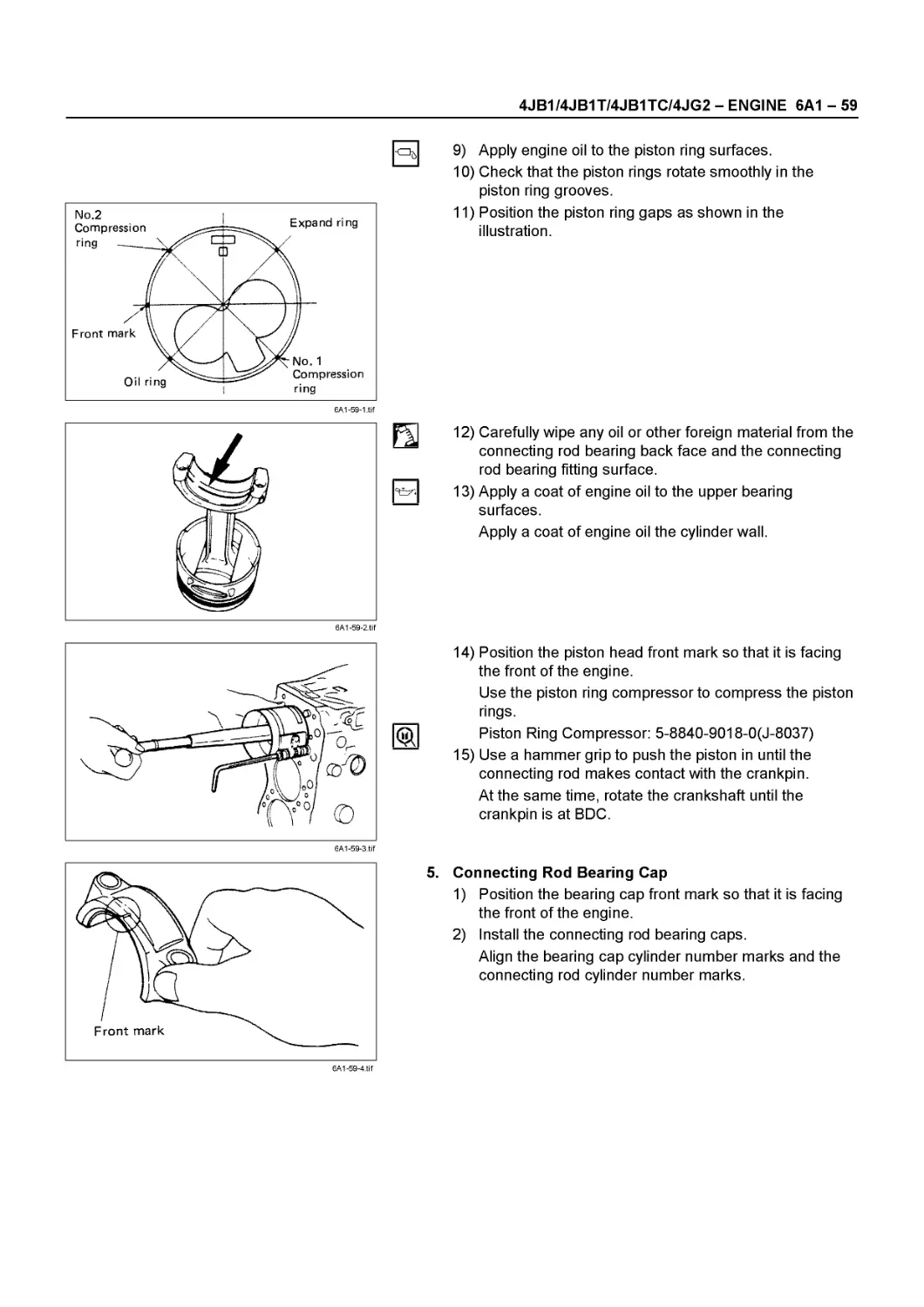
ISUZU
01Л131Л1
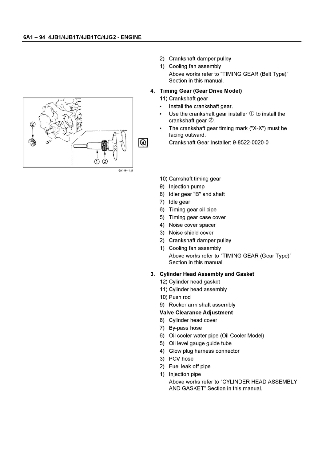
NOTICE
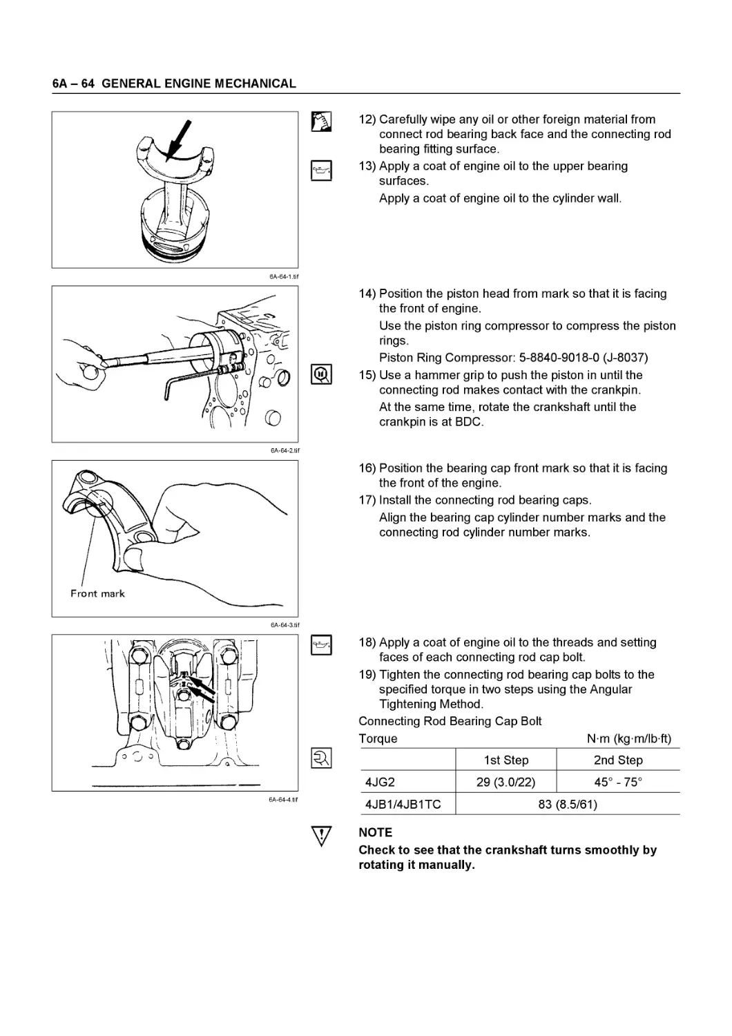
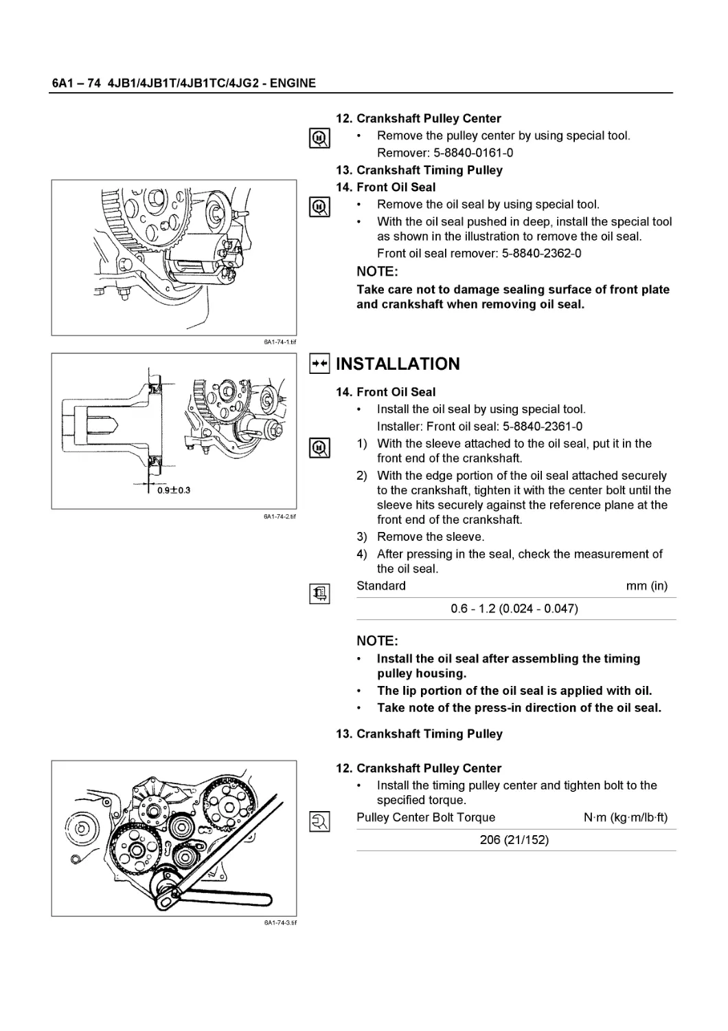
Before using this Workshop Manual to assist you in performing vehicle service and maintenance operations, it is recommended that you carefully read and thoroughly understand the information contained in Section OA under the headings “GENERAL REPAIR INSTRUCTIONS” and “HOW TO USE THIS
MANUAL”.
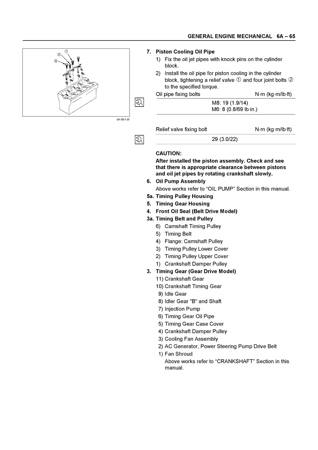
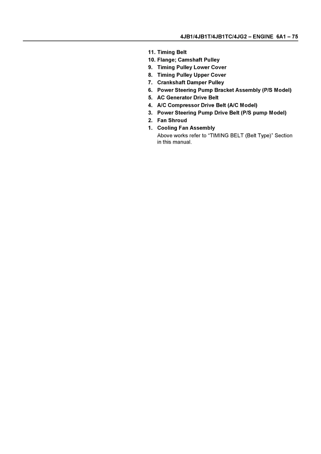
All material contained in this Manual is based on the latest product information available at the time of publication.
All rights are reserved to make changes at any time without prior notice.
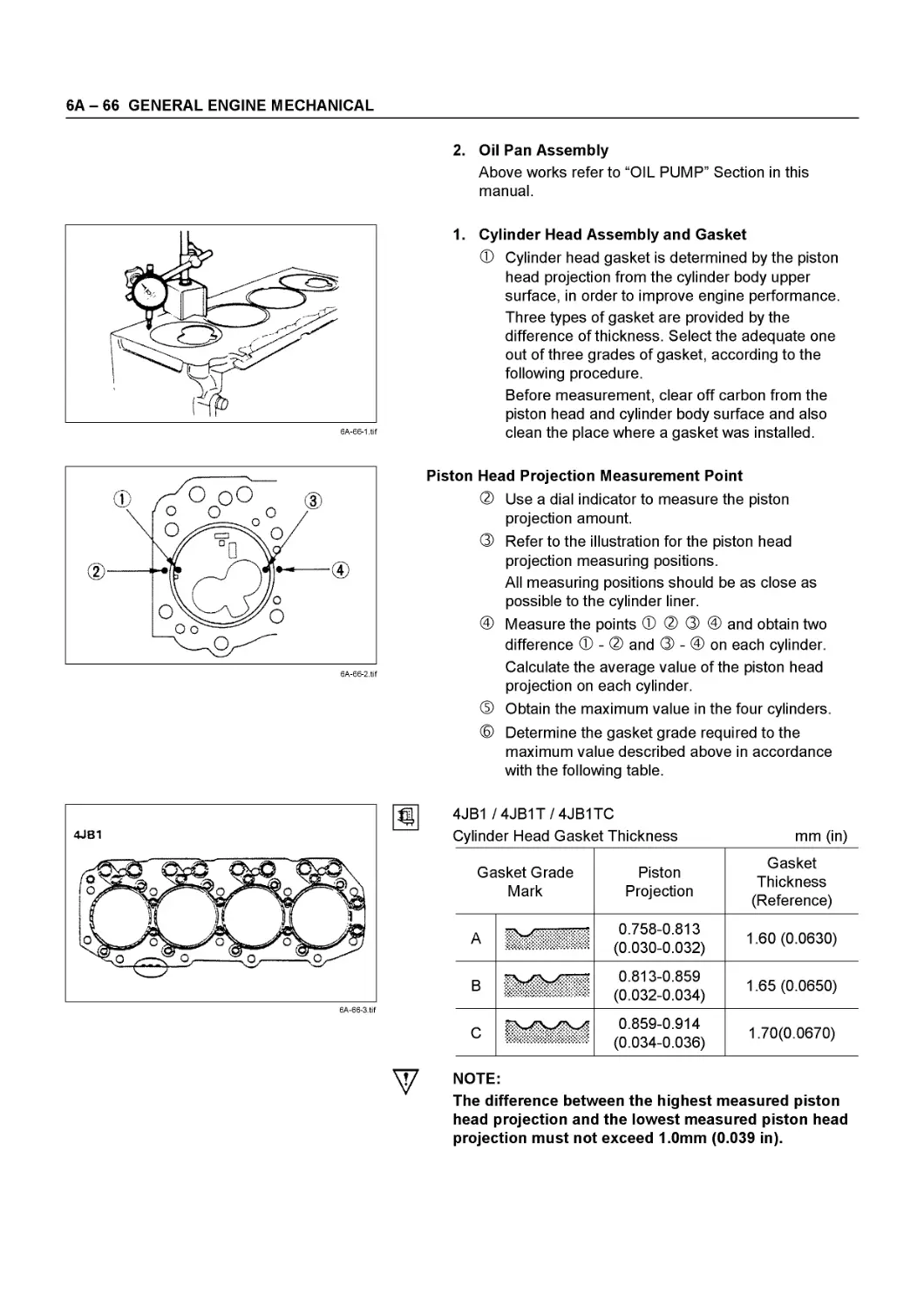
Applicable Model : NHR55. NKR55. NPR55. NPR69
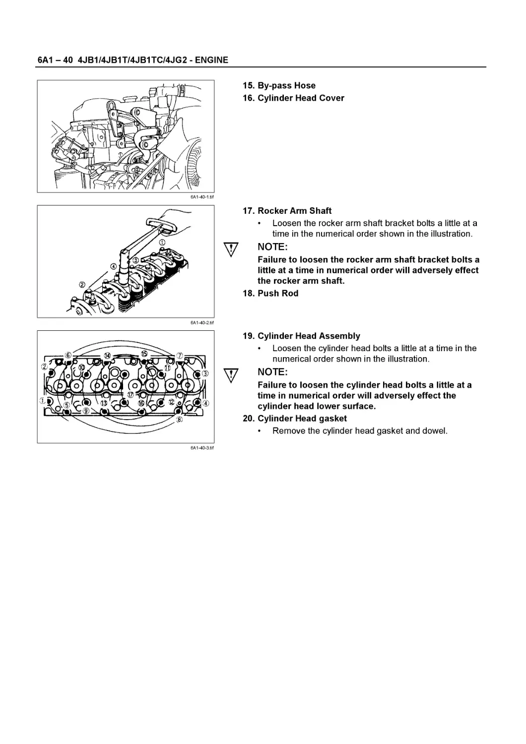
This manual is applicable to 1994 year model and later vehicles.
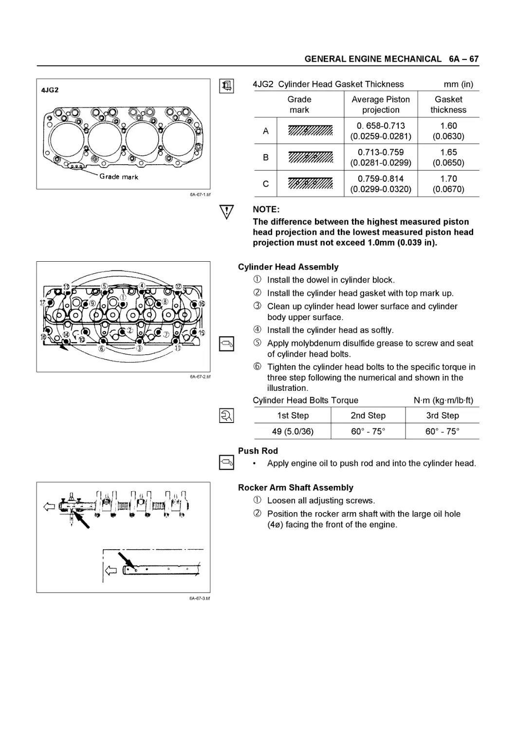
THIS MANUAL INCLUDES THE FOLLOWING SECTIONS:
SECTION NO. CONTENTS
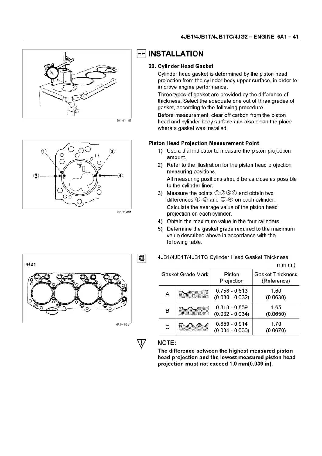
00 Service Information
6A Engine Mechanical
6A1 4JB1/4JB1T/4JB1-TC/4JG2 Engine
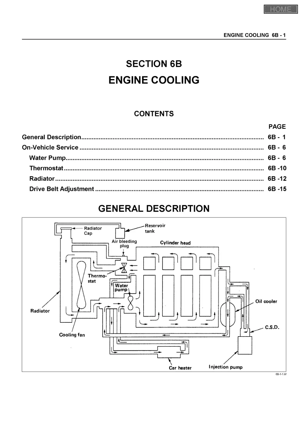
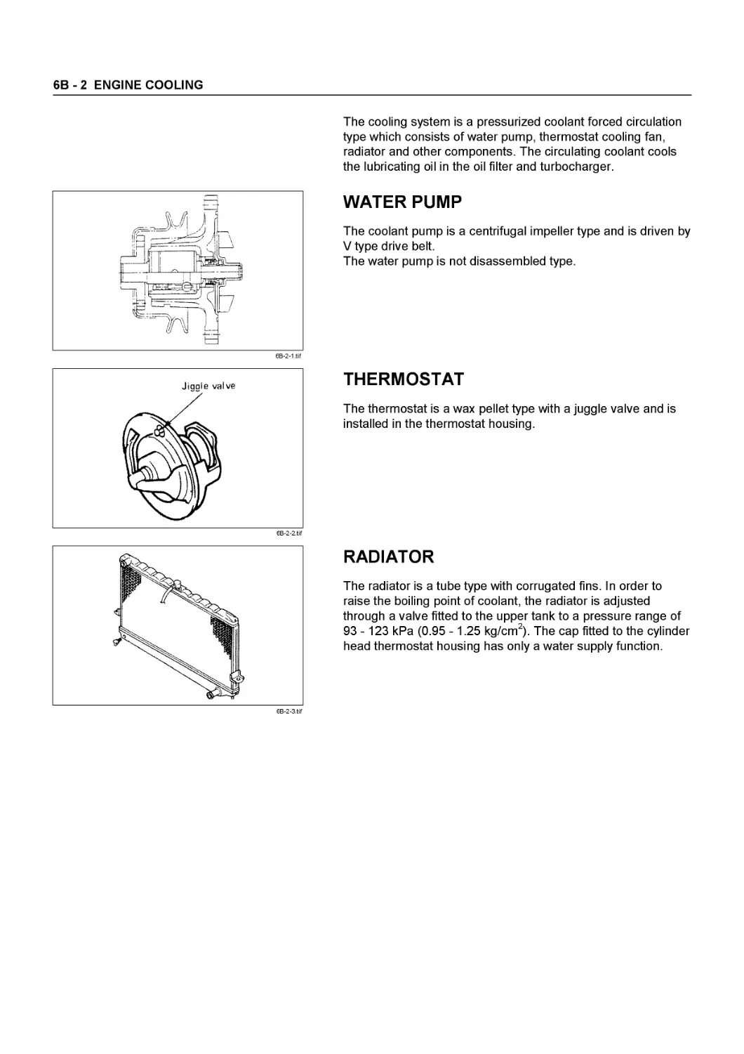
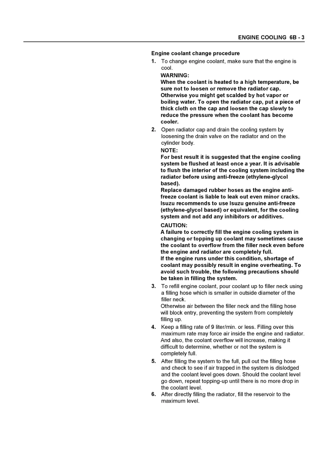
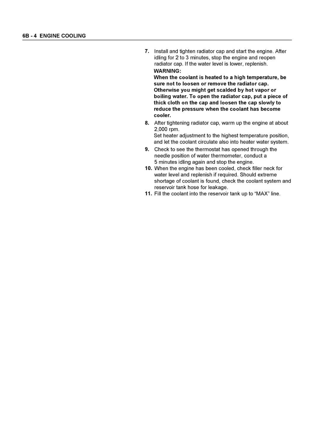
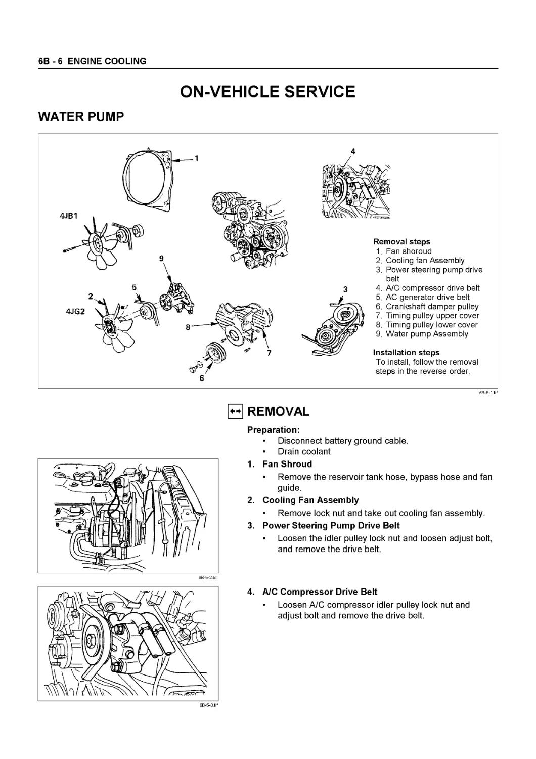
6B Engine Cooling
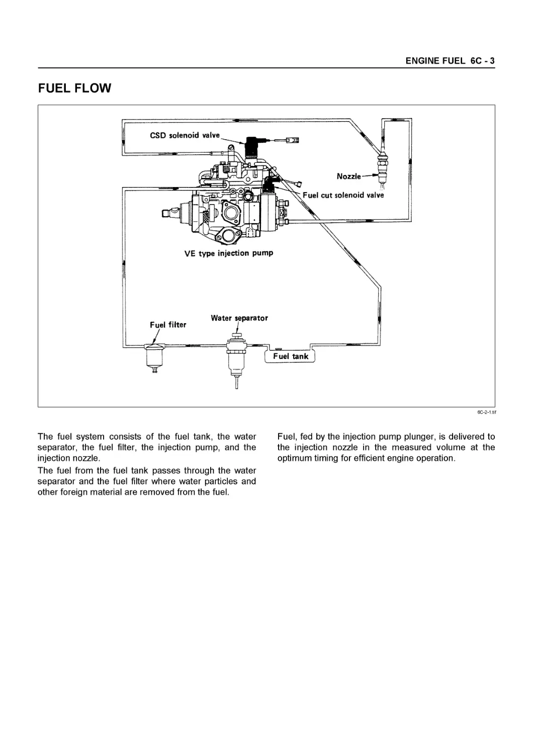
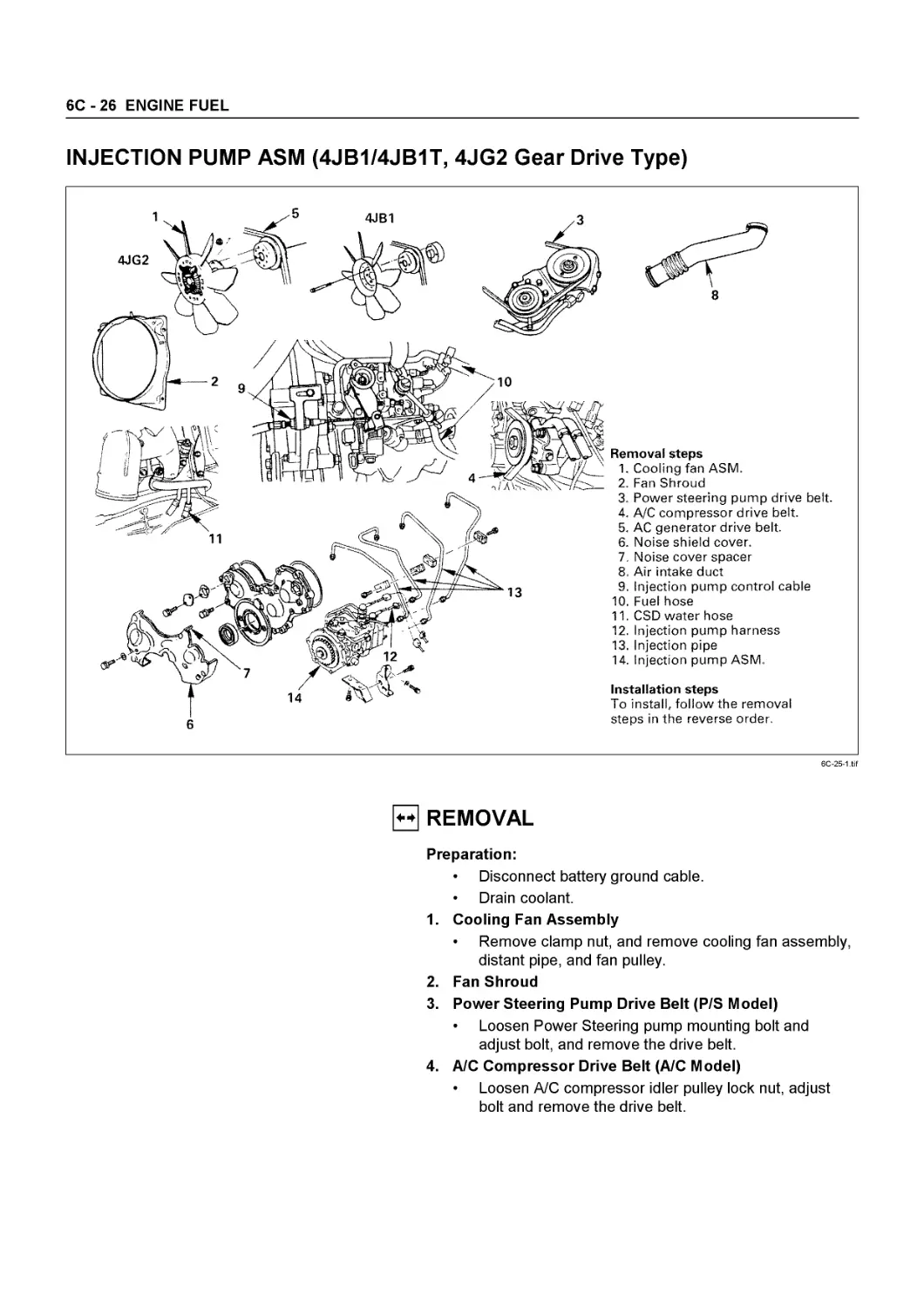
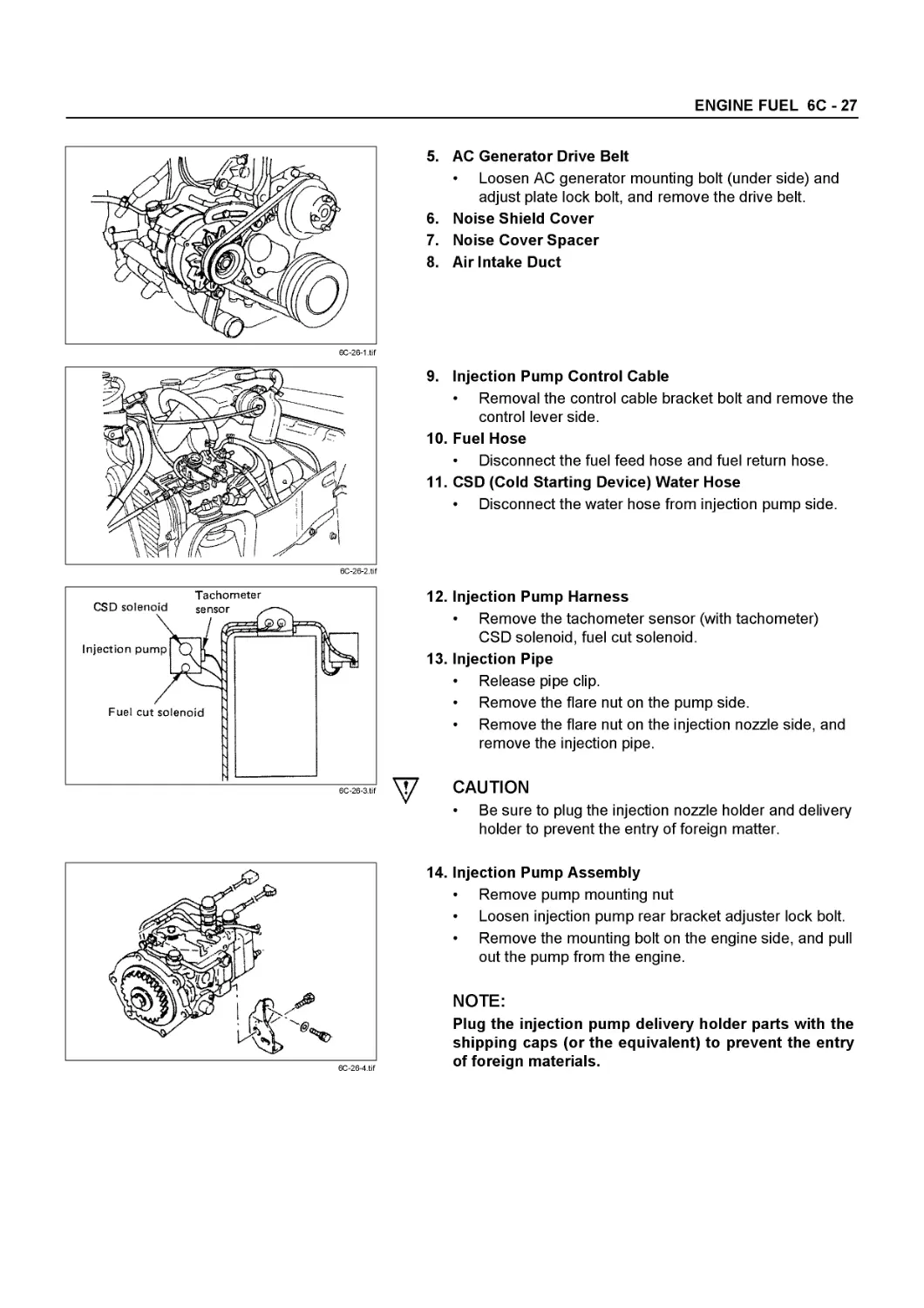
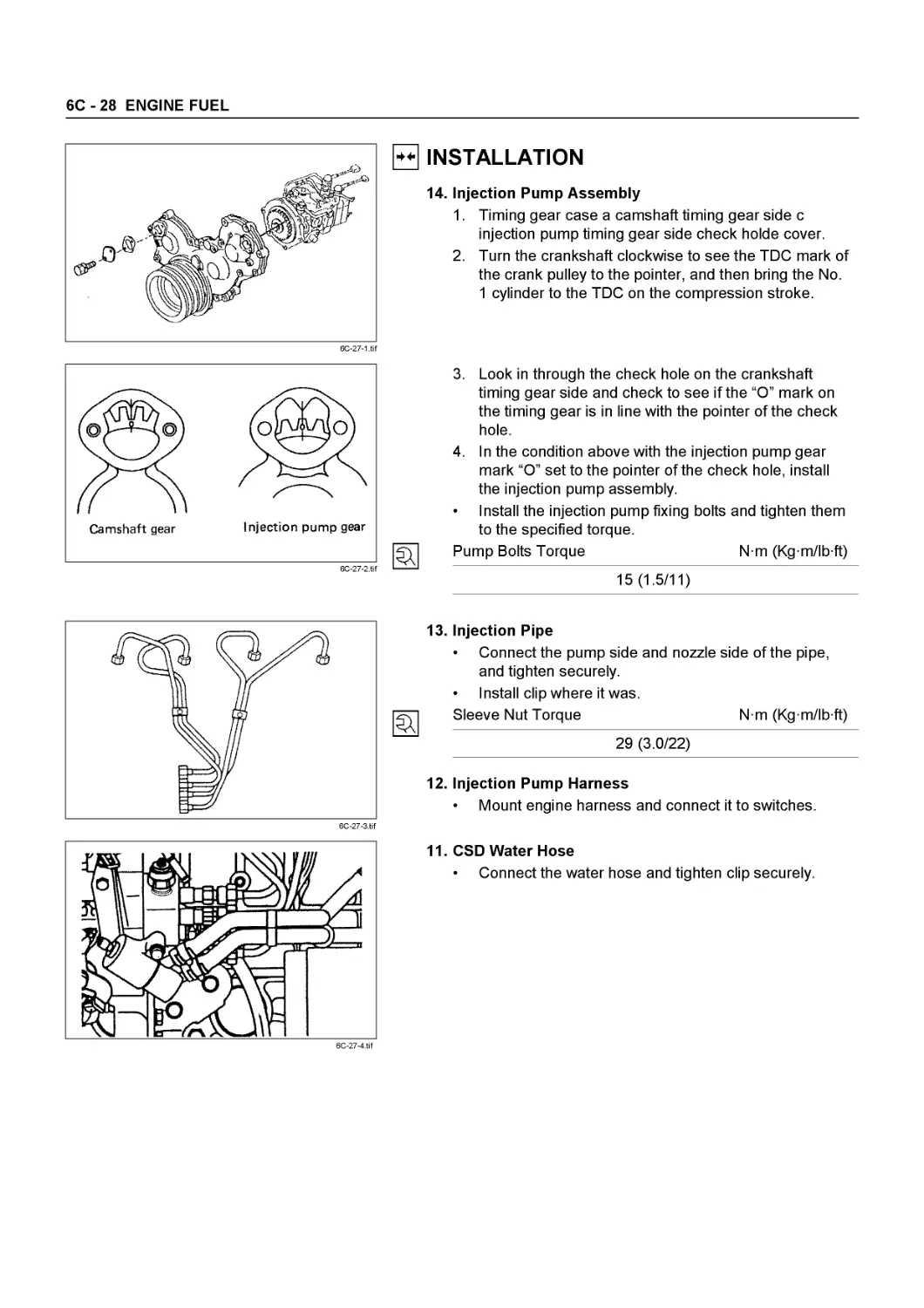
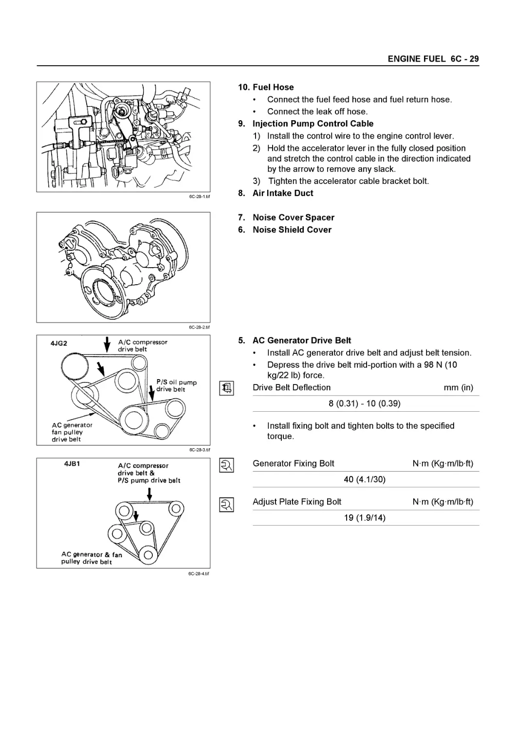
6C Fuel System
6D Engine Electrical
6E Exhaust Gas Recirculation (EGR) System
6F Exhaust
6G Turbocharger
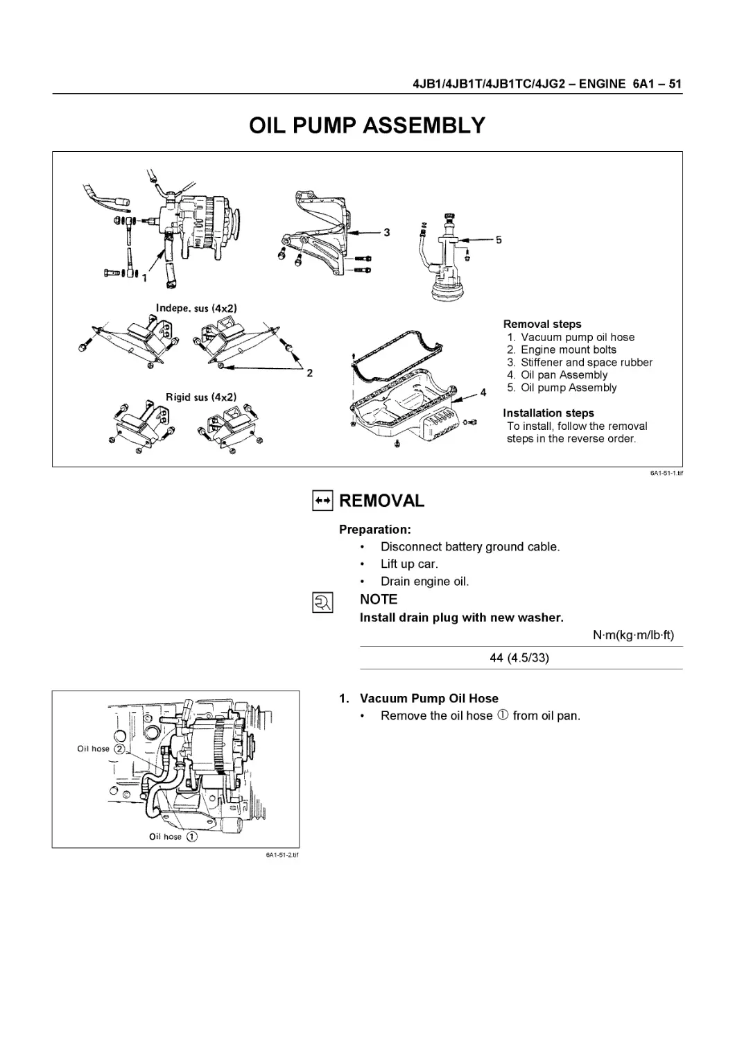
SERVICE INFORMATION 00 - 1
SECTION 00
SERVICE INFORMATION
CONTENTS
PAGE Troubleshooting............................................... 00 - 2
Main Data and Specifications.................................. 00 -30
Service Standard.............................................. 00 - 34
Servicing..................................................... 00-38
Fixing Torque................................................. 00-51
Special Tools................................................. 00 -60
00-2 SERVICE INFORMATION
TROUBLESHOOTING
CONTENTS
PAGE
Hard Starting............................................................ 00- 3
Starter Inoperative.................................................... 00- 3
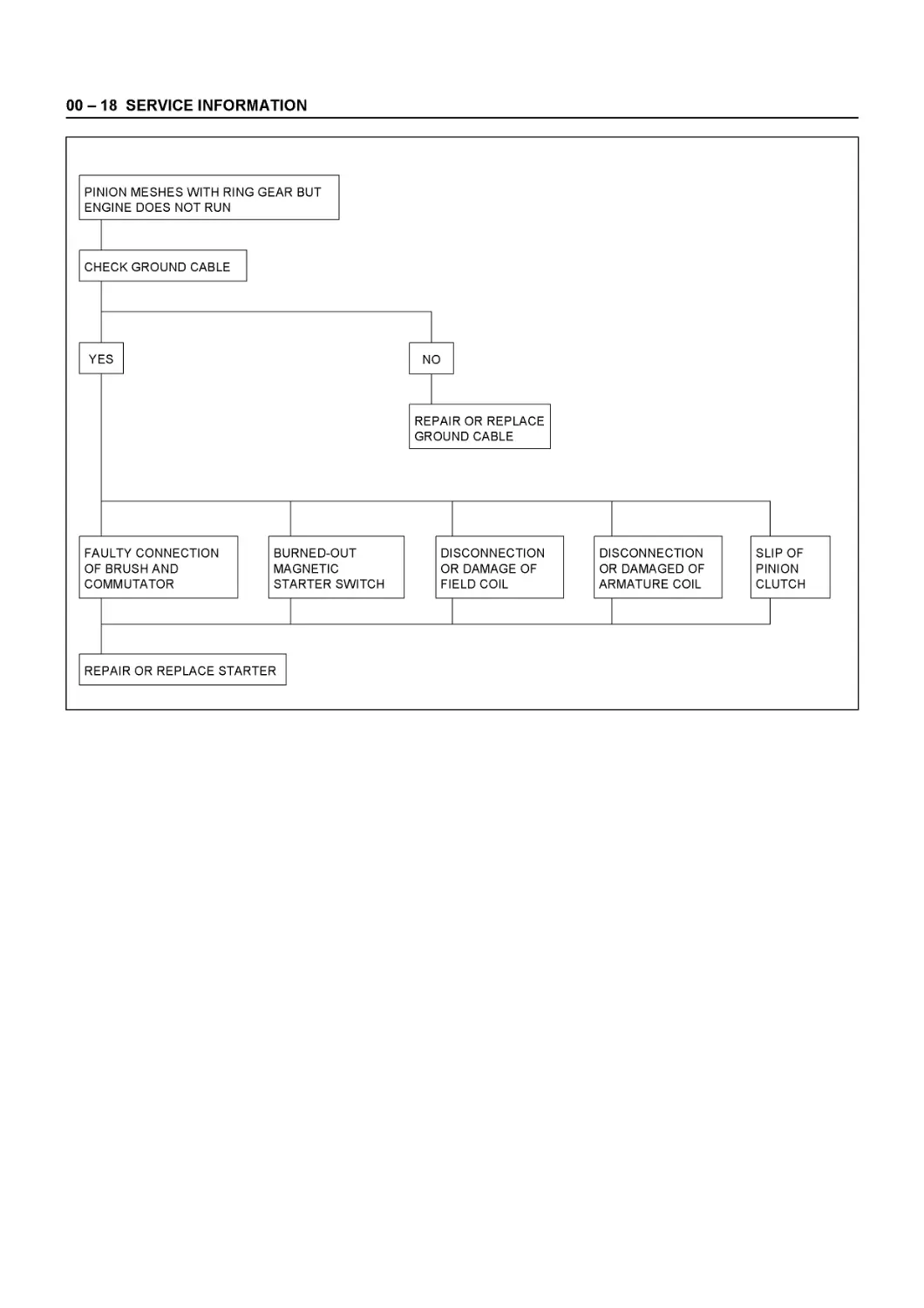
Starter Motor Operates but Engine Does Not Turn Over................... 00 - 3
Engine Turns Over but Does Not Start................................... 00- 4
Quick-on Start System.................................................. 00 - 5
Unstable Idling.......................................................... 00- 6
Insufficient Power....................................................... 00 - 7
Excessive Fuel Consumption............................................... 00- 9
Excessive Oil Consumption................................................ 00 - 9
Overheating............................................................... 00-10
White Exhaust Smoke...................................................... 00-10
Dark Exhaust Smoke....................................................... 00-11
Oil Pressure Does Not Rise............................................... 00-11
Abnormal Engine Noise.................................................... 00-12
Engine Knocking........................................................ 00-12
Gas Leakage Noise...................................................... 00-12
Continuous Noise....................................................... 00-12
Slapping Noise......................................................... 00 -13
Engine Cooling Trouble................................................... 00-14
Engine Electrical Part Trouble........................................... 00-15
Turbocharger.............................................................. 00-20
Lubrication Chart........................................................ 00-29
SERVICE INFORMATION 00-3
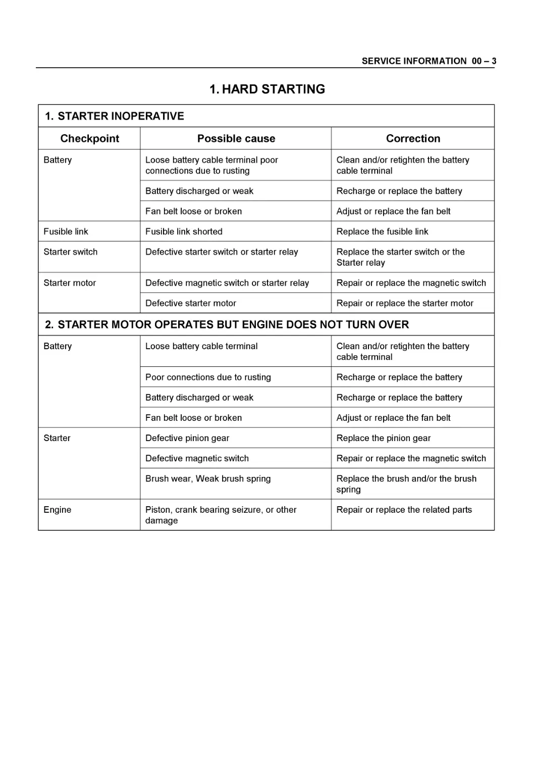
1.HARD STARTING
1. STARTER INOPERATIVE
Checkpoint Possible cause Correction
Battery Loose battery cable terminal poor connections due to rusting Clean and/or retighten the battery cable terminal
Battery discharged or weak Recharge or replace the battery
Fan belt loose or broken Adjust or replace the fan belt
Fusible link Fusible link shorted Replace the fusible link
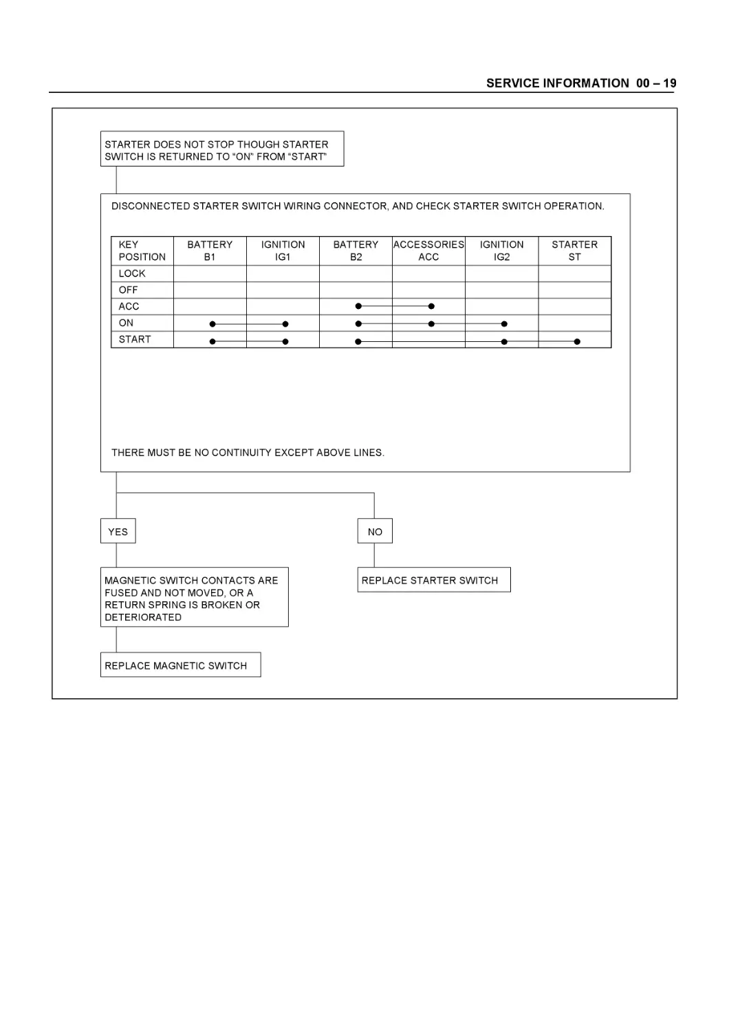
Starter switch Defective starter switch or starter relay Replace the starter switch or the Starter relay
Starter motor Defective magnetic switch or starter relay Repair or replace the magnetic switch
Defective starter motor Repair or replace the starter motor
2. STARTER MOTOR OPERATES BUT ENGINE DOES NOT TURN OVER
Battery Loose battery cable terminal Clean and/or retighten the battery cable terminal
Poor connections due to rusting Recharge or replace the battery
Battery discharged or weak Recharge or replace the battery
Fan belt loose or broken Adjust or replace the fan belt
Starter Defective pinion gear Replace the pinion gear
Defective magnetic switch Repair or replace the magnetic switch
Brush wear, Weak brush spring Replace the brush and/or the brush spring
Engine Piston, crank bearing seizure, or other damage Repair or replace the related parts
00-4 SERVICE INFORMATION
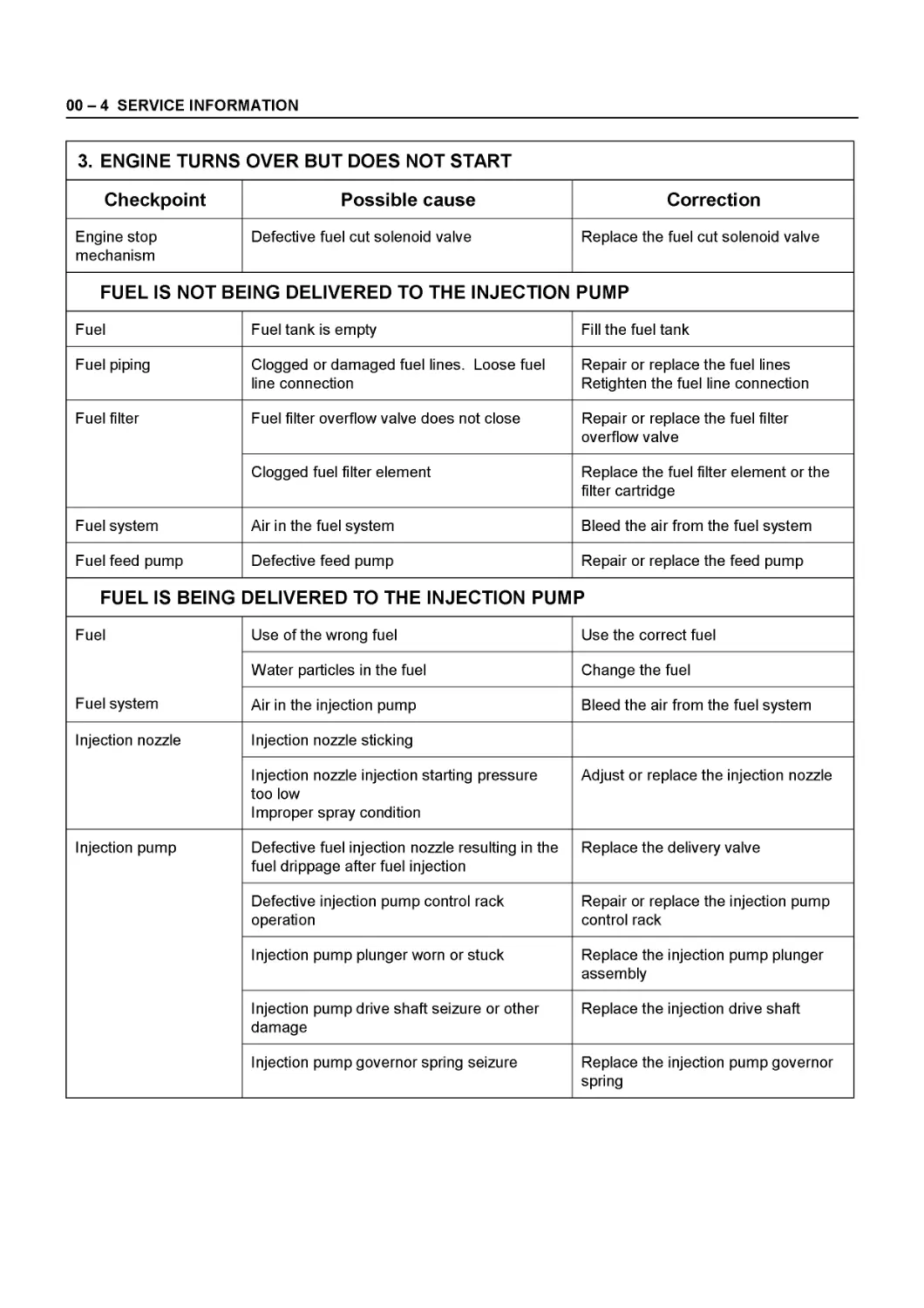
3. ENGINE TURNS OVER BUT DOES NOT START
Checkpoint Possible cause Correction
Engine stop mechanism Defective fuel cut solenoid valve Replace the fuel cut solenoid valve
FUEL IS NOT BEING DELIVERED TO THE INJECTION PUMP
Fuel Fuel tank is empty Fill the fuel tank
Fuel piping Clogged or damaged fuel lines. Loose fuel line connection Repair or replace the fuel lines Retighten the fuel line connection
Fuel filter Fuel filter overflow valve does not close Repair or replace the fuel filter overflow valve
Clogged fuel filter element Replace the fuel filter element or the filter cartridge
Fuel system Air in the fuel system Bleed the air from the fuel system
Fuel feed pump Defective feed pump Repair or replace the feed pump
FUEL IS BEING DELIVERED TO THE INJECTION PUMP
Fuel Fuel system Use of the wrong fuel Use the correct fuel
Water particles in the fuel Change the fuel
Air in the injection pump Bleed the air from the fuel system
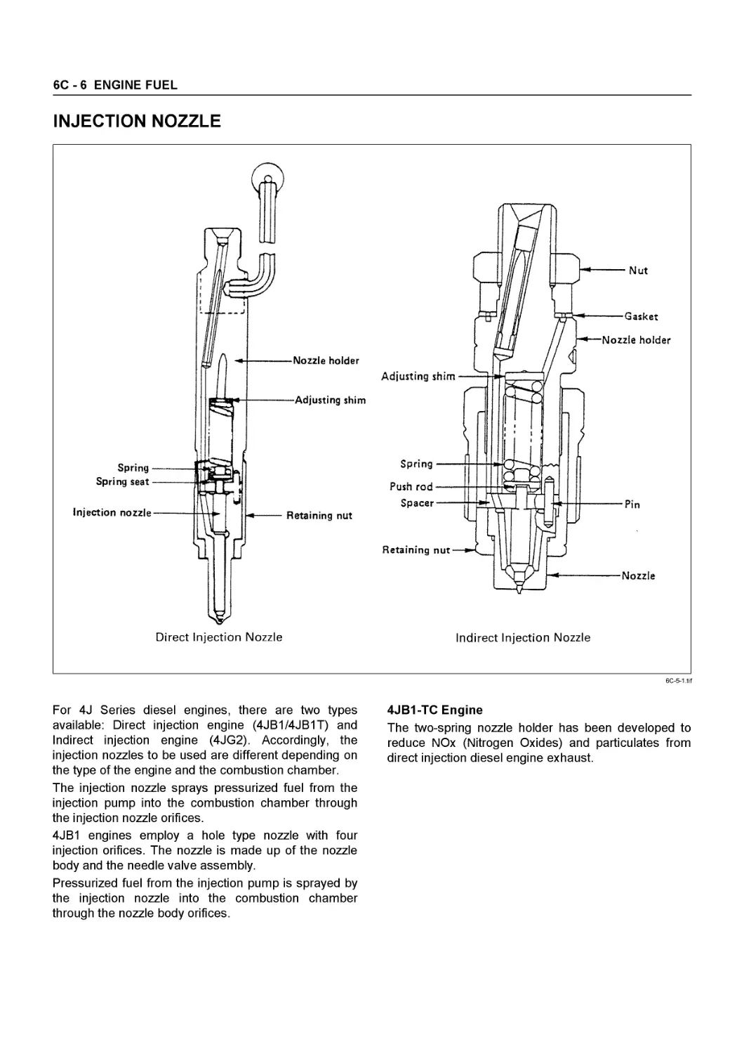
Injection nozzle Injection nozzle sticking
Injection nozzle injection starting pressure too low Improper spray condition Adjust or replace the injection nozzle
Injection pump Defective fuel injection nozzle resulting in the fuel drippage after fuel injection Replace the delivery valve
Defective injection pump control rack operation Repair or replace the injection pump control rack
Injection pump plunger worn or stuck Replace the injection pump plunger assembly
Injection pump drive shaft seizure or other damage Replace the injection drive shaft
Injection pump governor spring seizure Replace the injection pump governor spring
SERVICE INFORMATION 00-5
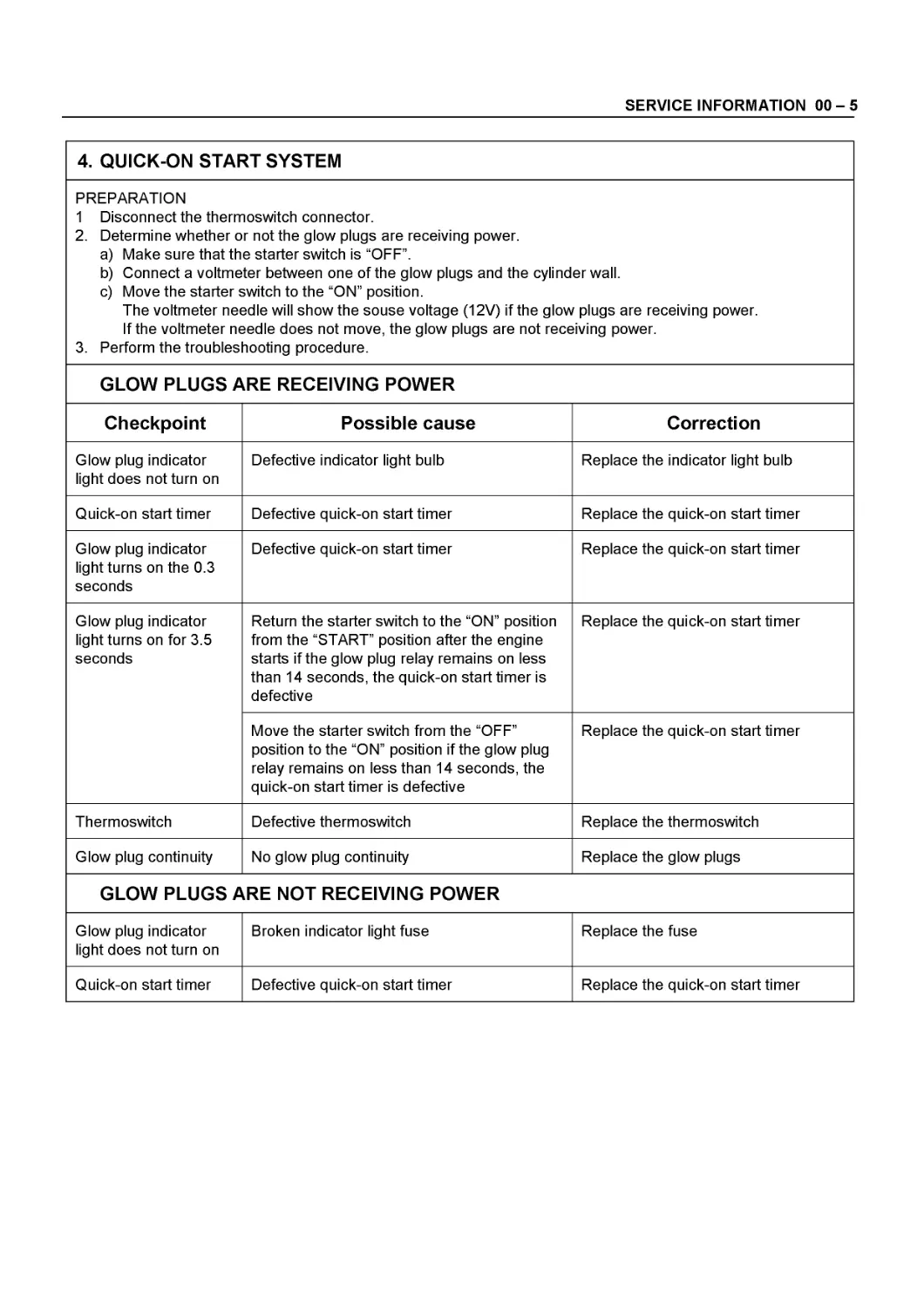
4. QUICK-ON START SYSTEM
PREPARATION 1 Disconnect the thermoswitch connector. 2. Determine whether or not the glow plugs are receiving power. a) Make sure that the starter switch is “OFF”. b) Connect a voltmeter between one of the glow plugs and the cylinder wall. c) Move the starter switch to the “ON” position. The voltmeter needle will show the souse voltage (12V) if the glow plugs are receiving power. If the voltmeter needle does not move, the glow plugs are not receiving power. 3. Perform the troubleshooting procedure.
GLOW PLUGS ARE RECEIVING POWER
Checkpoint Possible cause Correction
Glow plug indicator light does not turn on Defective indicator light bulb Replace the indicator light bulb
Quick-on start timer Defective quick-on start timer Replace the quick-on start timer
Glow plug indicator light turns on the 0.3 seconds Defective quick-on start timer Replace the quick-on start timer
Glow plug indicator light turns on for 3.5 seconds Return the starter switch to the “ON” position from the “START” position after the engine starts if the glow plug relay remains on less than 14 seconds, the quick-on start timer is defective Replace the quick-on start timer
Move the starter switch from the “OFF” position to the “ON” position if the glow plug relay remains on less than 14 seconds, the quick-on start timer is defective Replace the quick-on start timer
Thermoswitch Defective thermoswitch Replace the thermoswitch
Glow plug continuity No glow plug continuity Replace the glow plugs
GLOW PLUGS ARE NOT RECEIVING POWER
Glow plug indicator light does not turn on Broken indicator light fuse Replace the fuse
Quick-on start timer Defective quick-on start timer Replace the quick-on start timer
00-6 SERVICE INFORMATION
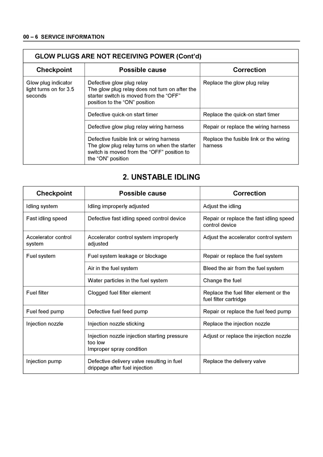
GLOW PLUGS ARE NOT RECEIVING POWER (Cont’d)
Checkpoint Possible cause Correction
Glow plug indicator light turns on for 3.5 seconds Defective glow plug relay The glow plug relay does not turn on after the starter switch is moved from the “OFF” position to the “ON” position Replace the glow plug relay
Defective quick-on start timer Replace the quick-on start timer
Defective glow plug relay wiring harness Repair or replace the wiring harness
Defective fusible link or wiring harness The glow plug relay turns on when the starter switch is moved from the “OFF” position to the “ON” position Replace the fusible link or the wiring harness
2. UNSTABLE IDLING
Checkpoint Possible cause Correction
Idling system Idling improperly adjusted Adjust the idling
Fast idling speed Defective fast idling speed control device Repair or replace the fast idling speed control device
Accelerator control system Accelerator control system improperly adjusted Adjust the accelerator control system
Fuel system Fuel system leakage or blockage Repair or replace the fuel system
Air in the fuel system Bleed the air from the fuel system
Water particles in the fuel system Change the fuel
Fuel filter Clogged fuel filter element Replace the fuel filter element or the fuel filter cartridge
Fuel feed pump Defective fuel feed pump Repair or replace the fuel feed pump
Injection nozzle Injection nozzle sticking Replace the injection nozzle
Injection nozzle injection starting pressure too low Improper spray condition Adjust or replace the injection nozzle
Injection pump Defective delivery valve resulting in fuel drippage after fuel injection Replace the delivery valve
SERVICE INFORMATION 00-7
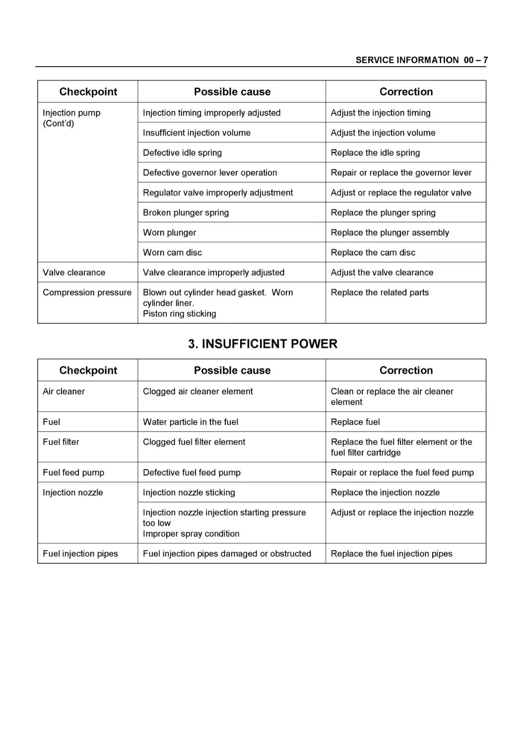
Checkpoint Possible cause Correction
Injection pump (Cont’d) Injection timing improperly adjusted Adjust the injection timing
Insufficient injection volume Adjust the injection volume
Defective idle spring Replace the idle spring
Defective governor lever operation Repair or replace the governor lever
Regulator valve improperly adjustment Adjust or replace the regulator valve
Broken plunger spring Replace the plunger spring
Worn plunger Replace the plunger assembly
Worn cam disc Replace the cam disc
Valve clearance Valve clearance improperly adjusted Adjust the valve clearance
Compression pressure Blown out cylinder head gasket. Worn cylinder liner. Piston ring sticking Replace the related parts
3. INSUFFICIENT POWER
Checkpoint Possible cause Correction
Air cleaner Clogged air cleaner element Clean or replace the air cleaner element
Fuel Water particle in the fuel Replace fuel
Fuel filter Clogged fuel filter element Replace the fuel filter element or the fuel filter cartridge
Fuel feed pump Defective fuel feed pump Repair or replace the fuel feed pump
Injection nozzle Injection nozzle sticking Replace the injection nozzle
Injection nozzle injection starting pressure too low Improper spray condition Adjust or replace the injection nozzle
Fuel injection pipes Fuel injection pipes damaged or obstructed Replace the fuel injection pipes
00-8 SERVICE INFORMATION
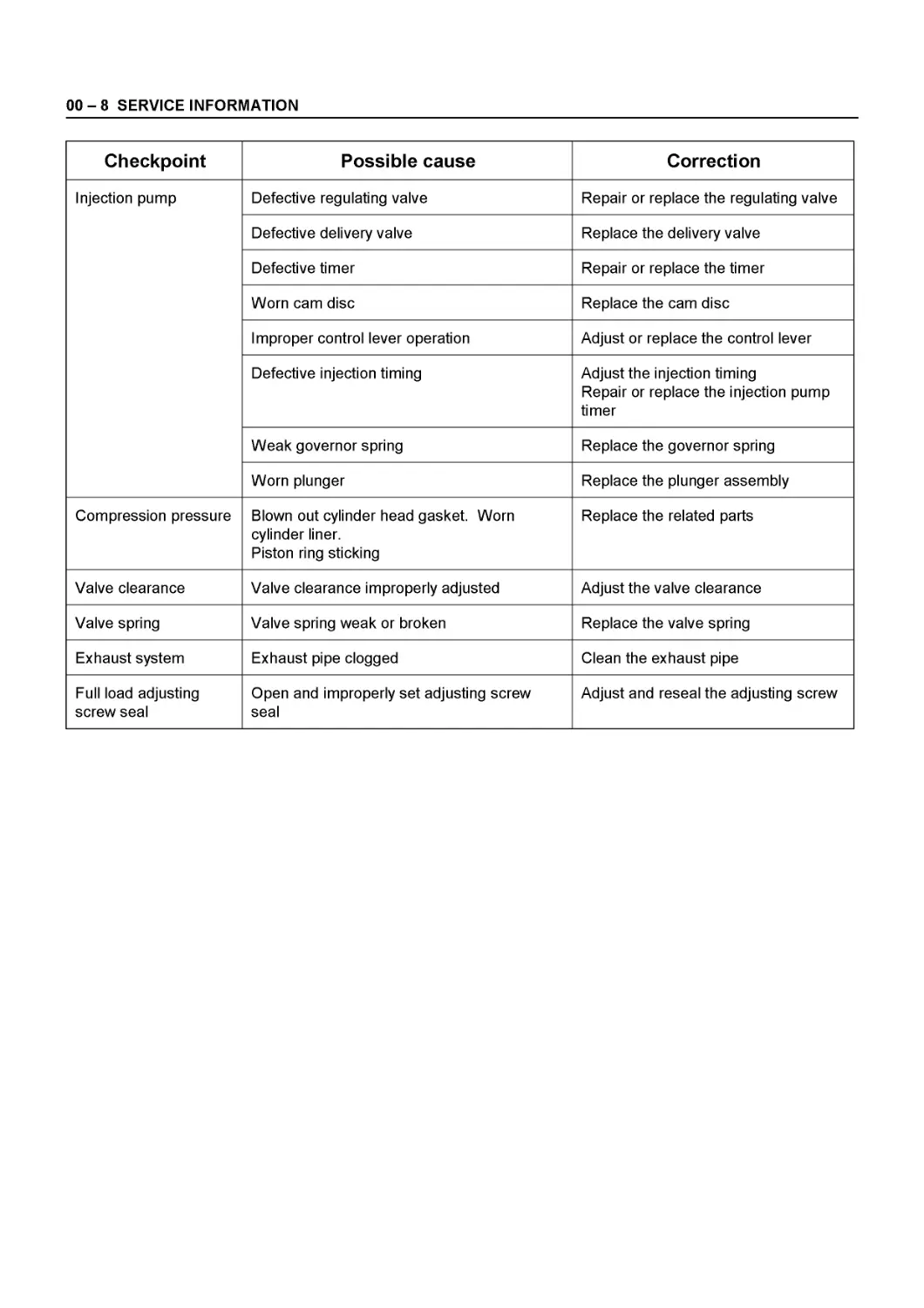
Checkpoint Possible cause Correction
Injection pump Defective regulating valve Repair or replace the regulating valve
Defective delivery valve Replace the delivery valve
Defective timer Repair or replace the timer
Worn cam disc Replace the cam disc
Improper control lever operation Adjust or replace the control lever
Defective injection timing Adjust the injection timing Repair or replace the injection pump timer
Weak governor spring Replace the governor spring
Worn plunger Replace the plunger assembly
Compression pressure Blown out cylinder head gasket. Worn cylinder liner. Piston ring sticking Replace the related parts
Valve clearance Valve clearance improperly adjusted Adjust the valve clearance
Valve spring Valve spring weak or broken Replace the valve spring
Exhaust system Exhaust pipe clogged Clean the exhaust pipe
Full load adjusting screw seal Open and improperly set adjusting screw seal Adjust and reseal the adjusting screw
SERVICE INFORMATION 00-9
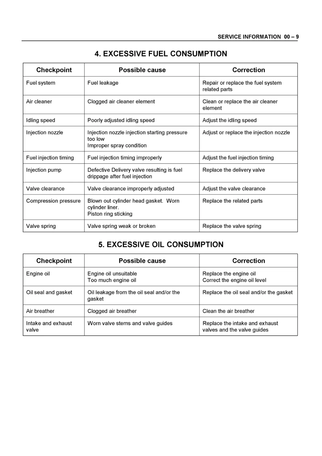
4. EXCESSIVE FUEL CONSUMPTION
Checkpoint Possible cause Correction
Fuel system Fuel leakage Repair or replace the fuel system related parts
Air cleaner Clogged air cleaner element Clean or replace the air cleaner element
Idling speed Poorly adjusted idling speed Adjust the idling speed
Injection nozzle Injection nozzle injection starting pressure too low Improper spray condition Adjust or replace the injection nozzle
Fuel injection timing Fuel injection timing improperly Adjust the fuel injection timing
Injection pump Defective Delivery valve resulting is fuel drippage after fuel injection Replace the delivery valve
Valve clearance Valve clearance improperly adjusted Adjust the valve clearance
Compression pressure Blown out cylinder head gasket. Worn cylinder liner. Piston ring sticking Replace the related parts
Valve spring Valve spring weak or broken Replace the valve spring
5. EXCESSIVE OIL CONSUMPTION
Checkpoint Possible cause Correction
Engine oil Engine oil unsuitable Too much engine oil Replace the engine oil Correct the engine oil level
Oil seal and gasket Oil leakage from the oil seal and/or the gasket Replace the oil seal and/or the gasket
Air breather Clogged air breather Clean the air breather
Intake and exhaust valve Worn valve stems and valve guides Replace the intake and exhaust valves and the valve guides
00-10 SERVICE INFORMATION
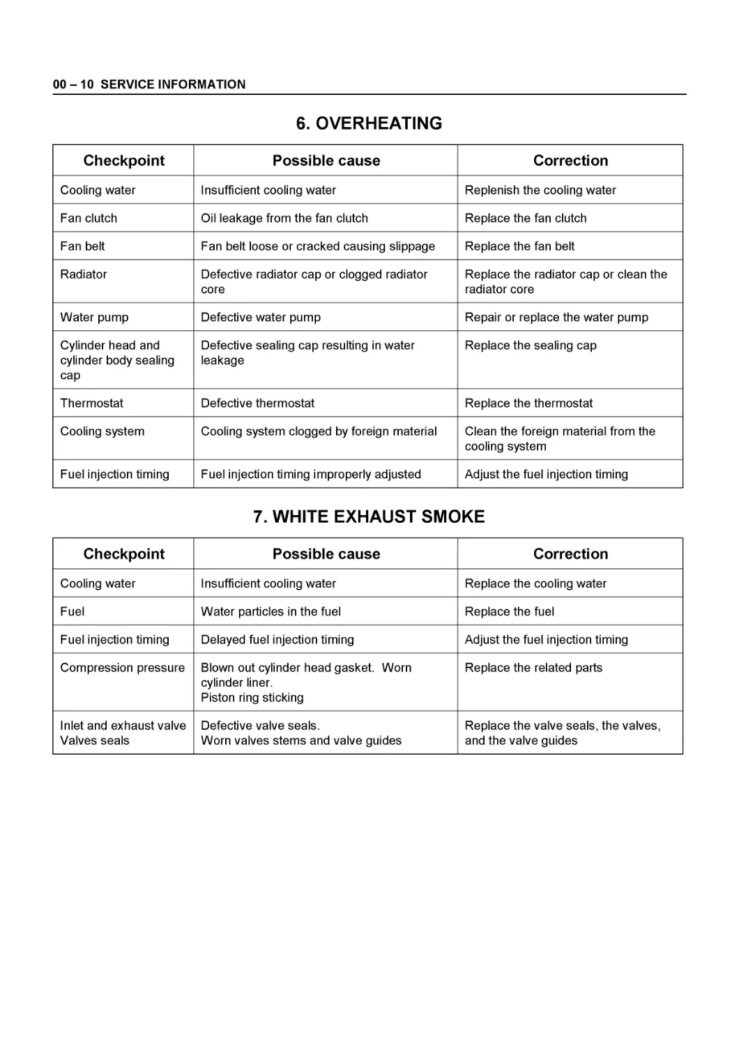
6. OVERHEATING
Checkpoint Possible cause Correction
Cooling water Insufficient cooling water Replenish the cooling water
Fan clutch Oil leakage from the fan clutch Replace the fan clutch
Fan belt Fan belt loose or cracked causing slippage Replace the fan belt
Radiator Defective radiator cap or clogged radiator core Replace the radiator cap or clean the radiator core
Water pump Defective water pump Repair or replace the water pump
Cylinder head and cylinder body sealing cap Defective sealing cap resulting in water leakage Replace the sealing cap
Thermostat Defective thermostat Replace the thermostat
Cooling system Cooling system clogged by foreign material Clean the foreign material from the cooling system
Fuel injection timing Fuel injection timing improperly adjusted Adjust the fuel injection timing
7. WHITE EXHAUST SMOKE
Checkpoint Possible cause Correction
Cooling water Insufficient cooling water Replace the cooling water
Fuel Water particles in the fuel Replace the fuel
Fuel injection timing Delayed fuel injection timing Adjust the fuel injection timing
Compression pressure Blown out cylinder head gasket. Worn cylinder liner. Piston ring sticking Replace the related parts
Inlet and exhaust valve Valves seals Defective valve seals. Worn valves stems and valve guides Replace the valve seals, the valves, and the valve guides
SERVICE INFORMATION 00-11
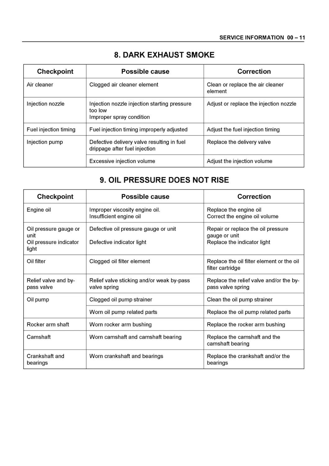
8. DARK EXHAUST SMOKE
Checkpoint Possible cause Correction
Air cleaner Clogged air cleaner element Clean or replace the air cleaner element
Injection nozzle Injection nozzle injection starting pressure too low Improper spray condition Adjust or replace the injection nozzle
Fuel injection timing Fuel injection timing improperly adjusted Adjust the fuel injection timing
Injection pump Defective delivery valve resulting in fuel drippage after fuel injection Replace the delivery valve
Excessive injection volume Adjust the injection volume
9. OIL PRESSURE DOES NOT RISE
Checkpoint Possible cause Correction
Engine oil Improper viscosity engine oil. Insufficient engine oil Replace the engine oil Correct the engine oil volume
Oil pressure gauge or unit Oil pressure indicator light Defective oil pressure gauge or unit Defective indicator light Repair or replace the oil pressure gauge or unit Replace the indicator light
Oil filter Clogged oil filter element Replace the oil filter element or the oil filter cartridge
Relief valve and bypass valve Relief valve sticking and/or weak by-pass valve spring Replace the relief valve and/or the bypass valve spring
Oil pump Clogged oil pump strainer Clean the oil pump strainer
Worn oil pump related parts Replace the oil pump related parts
Rocker arm shaft Worn rocker arm bushing Replace the rocker arm bushing
Camshaft Worn camshaft and camshaft bearing Replace the camshaft and the camshaft bearing
Crankshaft and bearings Worn crankshaft and bearings Replace the crankshaft and/or the bearings
00-12 SERVICE INFORMATION
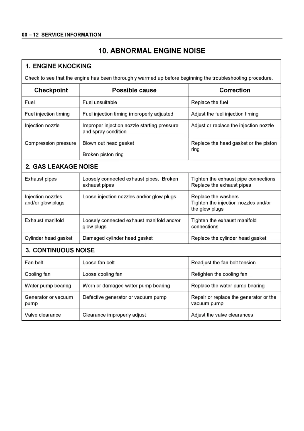
10. ABNORMAL ENGINE NOISE
1. ENGINE KNOCKING Check to see that the engine has been thoroughly warmed up before beginning the troubleshooting procedure.
Checkpoint Possible cause Correction
Fuel Fuel unsuitable Replace the fuel
Fuel injection timing Fuel injection timing improperly adjusted Adjust the fuel injection timing
Injection nozzle Improper injection nozzle starting pressure and spray condition Adjust or replace the injection nozzle
Compression pressure Blown out head gasket Broken piston ring Replace the head gasket or the piston ring
2. GAS LEAKAGE NOISE
Exhaust pipes Loosely connected exhaust pipes. Broken exhaust pipes Tighten the exhaust pipe connections Replace the exhaust pipes
Injection nozzles and/or glow plugs Loose injection nozzles and/or glow plugs Replace the washers Tighten the injection nozzles and/or the glow plugs
Exhaust manifold Loosely connected exhaust manifold and/or glow plugs Tighten the exhaust manifold connections
Cylinder head gasket Damaged cylinder head gasket Replace the cylinder head gasket
3. CONTINUOUS NOISE
Fan belt Loose fan belt Readjust the fan belt tension
Cooling fan Loose cooling fan Retighten the cooling fan
Water pump bearing Worn or damaged water pump bearing Replace the water pump bearing
Generator or vacuum pump Defective generator or vacuum pump Repair or replace the generator or the vacuum pump
Valve clearance Clearance improperly adjust Adjust the valve clearances
SERVICE INFORMATION 00-13
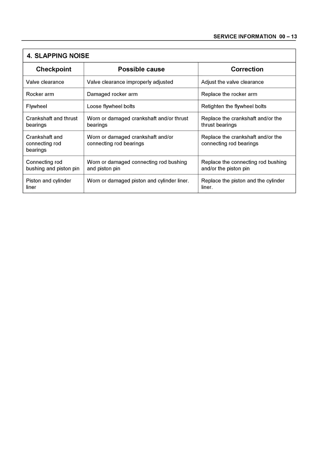
4. SLAPPING NOISE
Checkpoint Possible cause Correction
Valve clearance Valve clearance improperly adjusted Adjust the valve clearance
Rocker arm Damaged rocker arm Replace the rocker arm
Flywheel Loose flywheel bolts Retighten the flywheel bolts
Crankshaft and thrust bearings Worn or damaged crankshaft and/or thrust bearings Replace the crankshaft and/or the thrust bearings
Crankshaft and connecting rod bearings Worn or damaged crankshaft and/or connecting rod bearings Replace the crankshaft and/or the connecting rod bearings
Connecting rod bushing and piston pin Worn or damaged connecting rod bushing and piston pin Replace the connecting rod bushing and/or the piston pin
Piston and cylinder liner Worn or damaged piston and cylinder liner. Replace the piston and the cylinder liner.
00-14 SERVICE INFORMATION
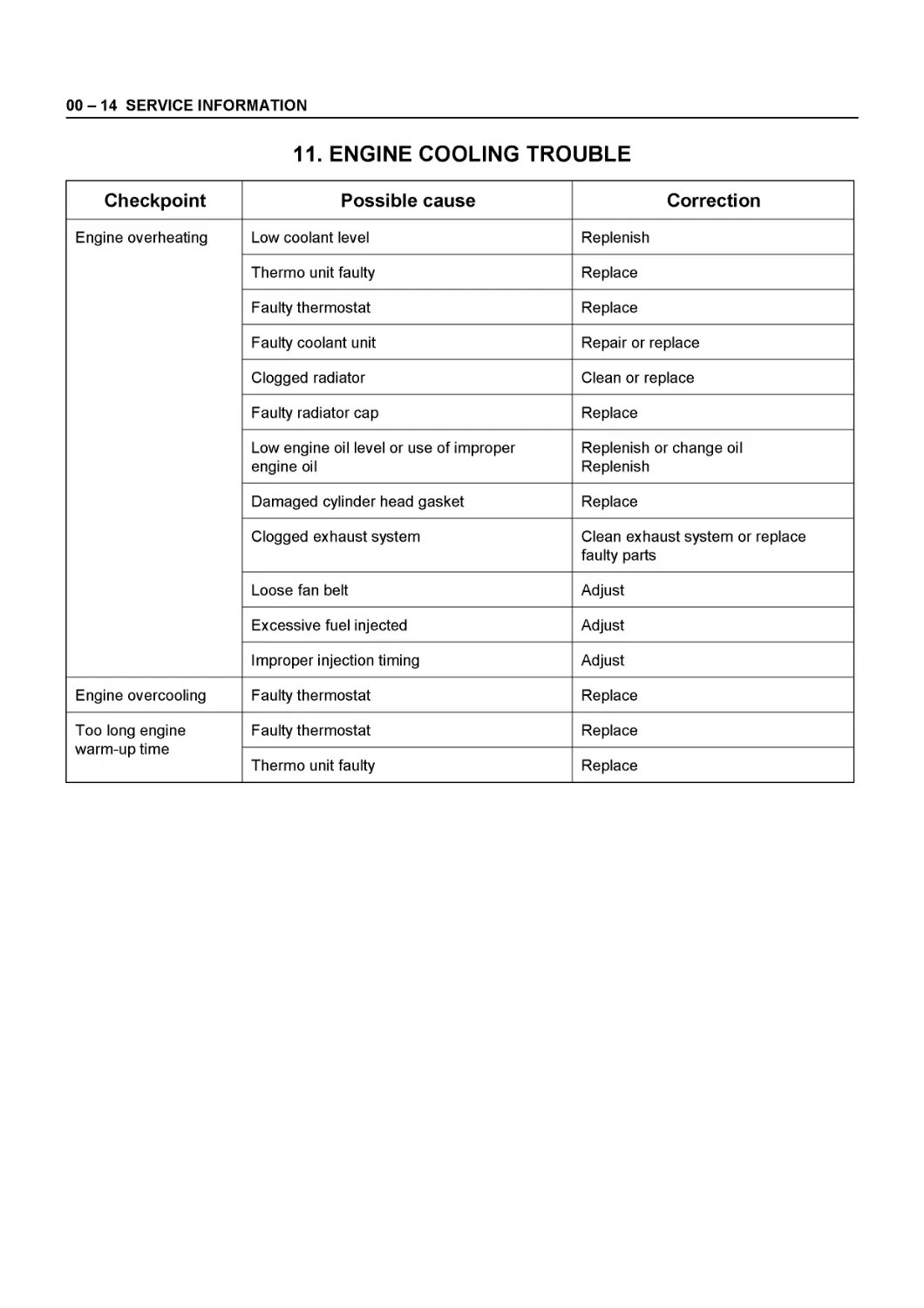
11. ENGINE COOLING TROUBLE
Checkpoint Possible cause Correction
Engine overheating Low coolant level Replenish
Thermo unit faulty Replace
Faulty thermostat Replace
Faulty coolant unit Repair or replace
Clogged radiator Clean or replace
Faulty radiator cap Replace
Low engine oil level or use of improper engine oil Replenish or change oil Replenish
Damaged cylinder head gasket Replace
Clogged exhaust system Clean exhaust system or replace faulty parts
Loose fan belt Adjust
Excessive fuel injected Adjust
Improper injection timing Adjust
Engine overcooling Faulty thermostat Replace
Too long engine warm-up time Faulty thermostat Replace
Thermo unit faulty Replace
SERVICE INFORMATION 00-15
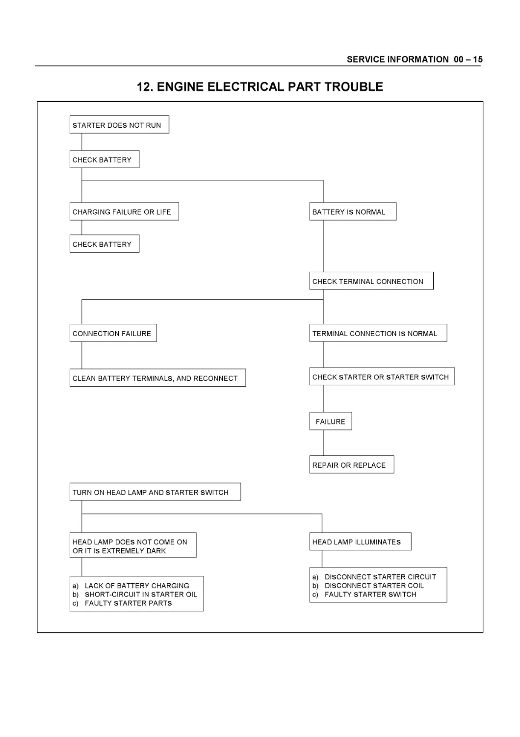
12. ENGINE ELECTRICAL PART TROUBLE
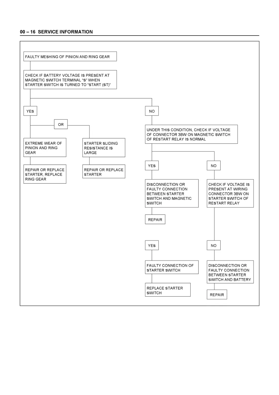
00-16 SERVICE INFORMATION
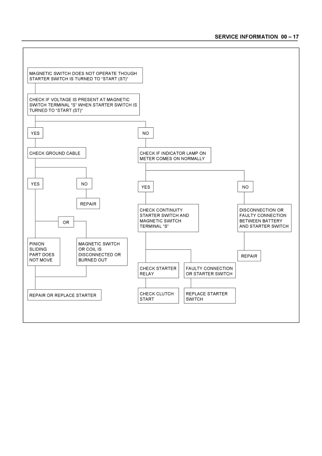
SERVICE INFORMATION 00-17
00-18 SERVICE INFORMATION
SERVICE INFORMATION 00-19
REPLACE MAGNETIC SWITCH
00 - 20 SERVICE INFORMATION
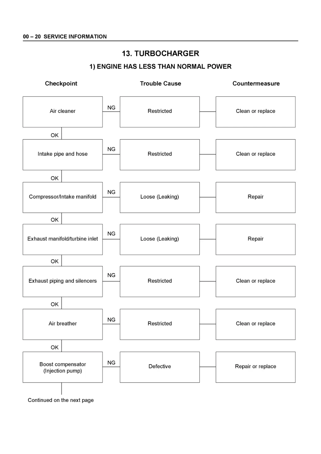
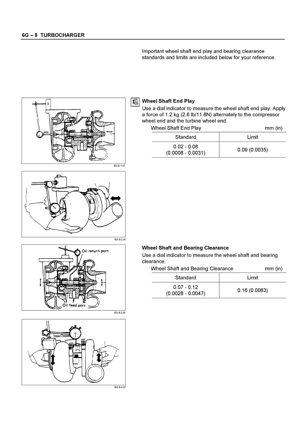
13. TURBOCHARGER
1) ENGINE HAS LESS THAN NORMAL POWER Checkpoint Trouble Cause Countermeasure
Air cleaner NG Restricted — Clean or replace
OK
Intake pipe and hose NG Restricted — Clean or replace
OK
Compressor/lntake manifold NG Loose (Leaking) — Repair
OK
Exhaust manifold/turbine inlet NG Loose (Leaking) — Repair
OK
Exhaust piping and silencers NG Restricted — Clean or replace
OK
Air breather NG Restricted — Clean or replace
OK
Boost compensator (Injection pump) NG Defective — Repair or replace
Continued on the next page
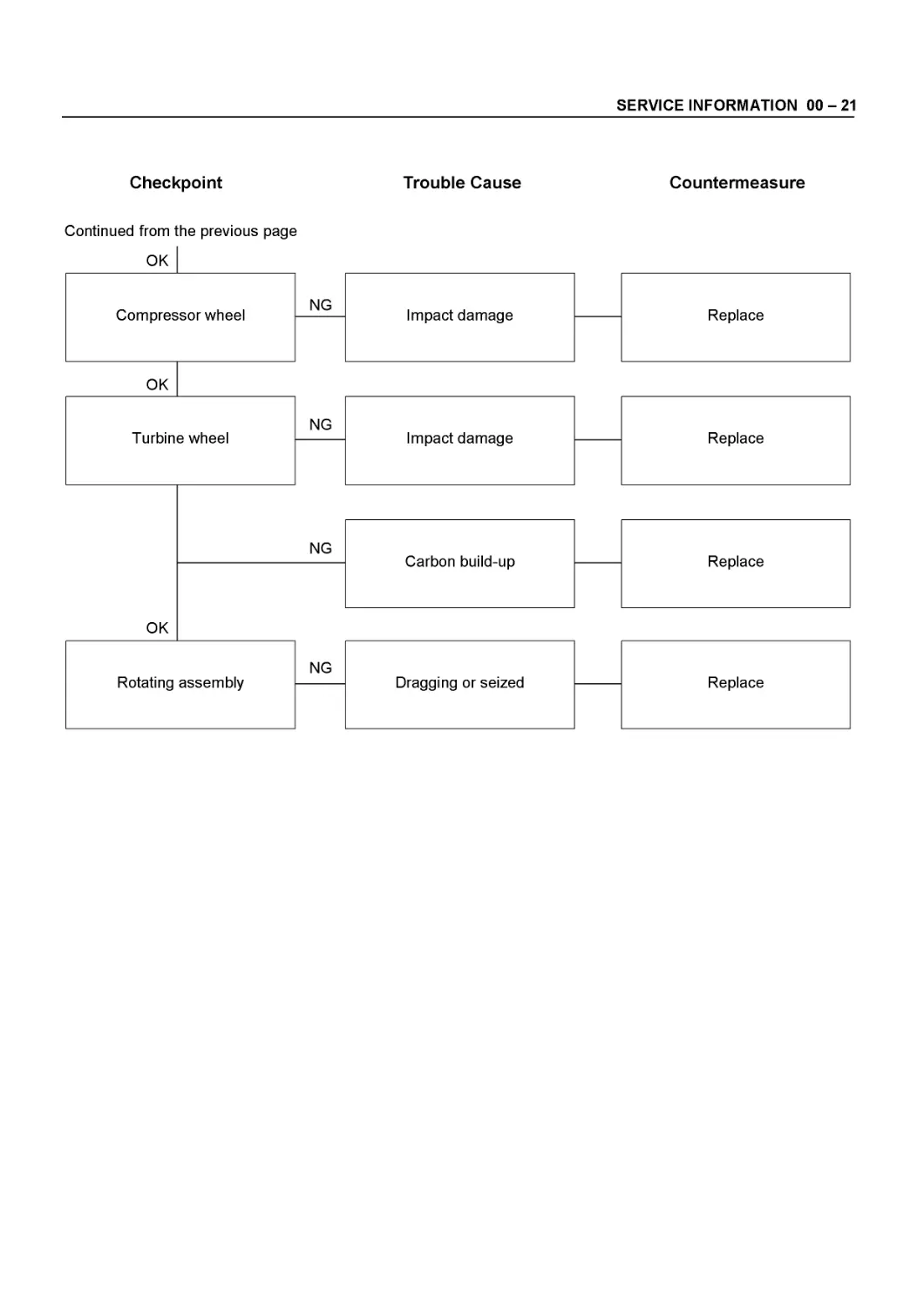
SERVICE INFORMATION 00 - 21
Checkpoint
Trouble Cause
Countermeasure
Continued from the previous page
00 - 22 SERVICE INFORMATION
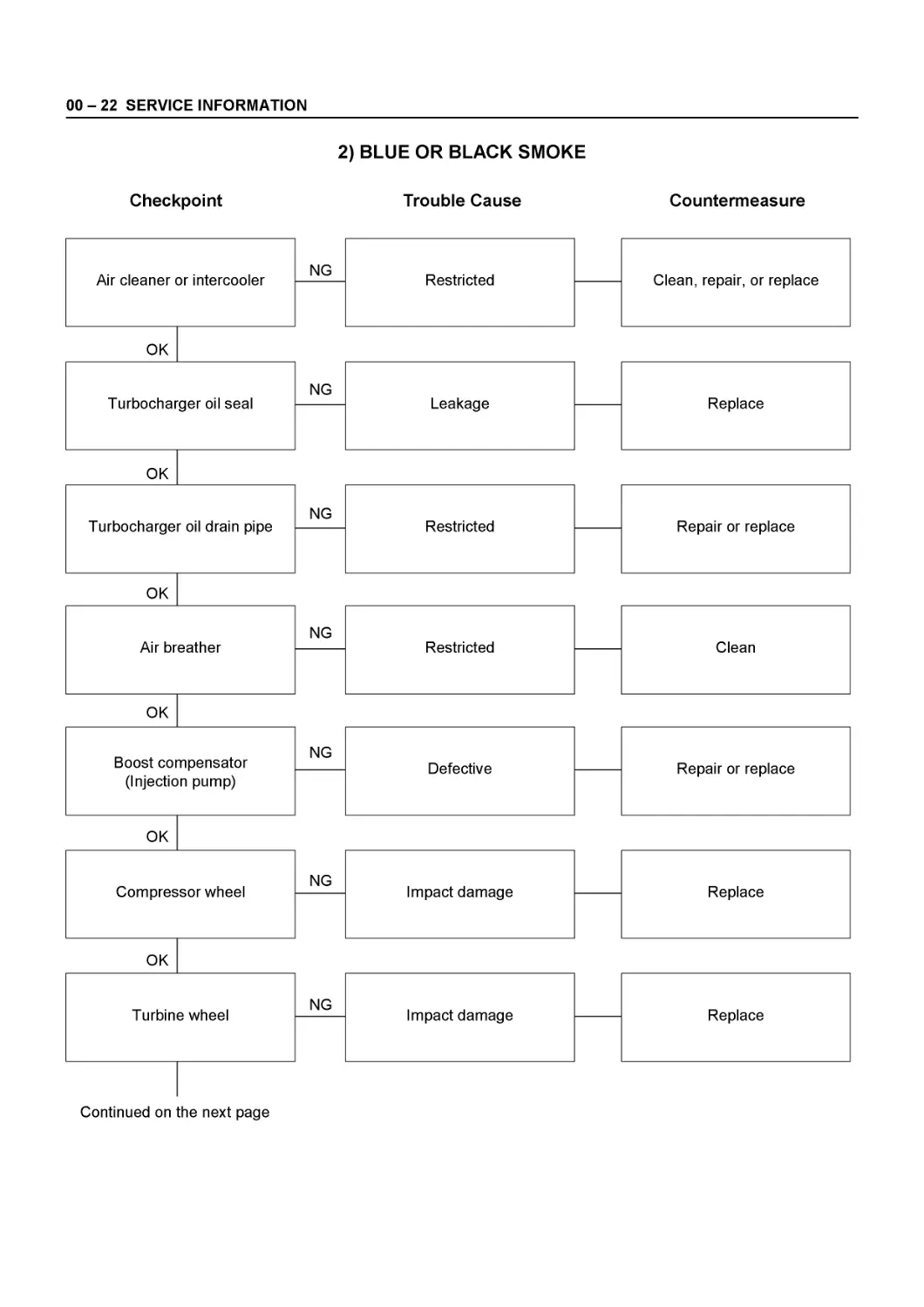
2) BLUE OR BLACK SMOKE
Checkpoint Trouble Cause Countermeasure
Air cleaner or intercooler NG Restricted — Clean, repair, or replace
OK
Turbocharger oil seal NG Leakage — Replace
OK
Turbocharger oil drain pipe NG Restricted — Repair or replace
OK
Air breather NG Restricted — Clean
OK
Boost compensator (Injection pump) NG Defective — Repair or replace
OK
Compressor wheel NG Impact damage — Replace
OK
Turbine wheel NG Impact damage — Replace
Continued on the next page
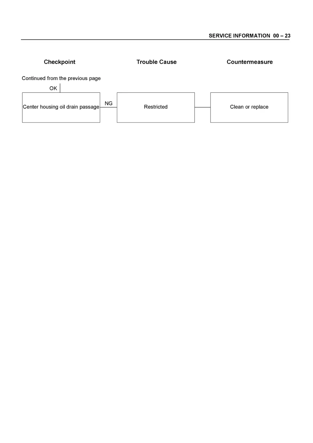
SERVICE INFORMATION 00 - 23
Checkpoint
Trouble Cause
Countermeasure
Continued from the previous page
00 - 24 SERVICE INFORMATION
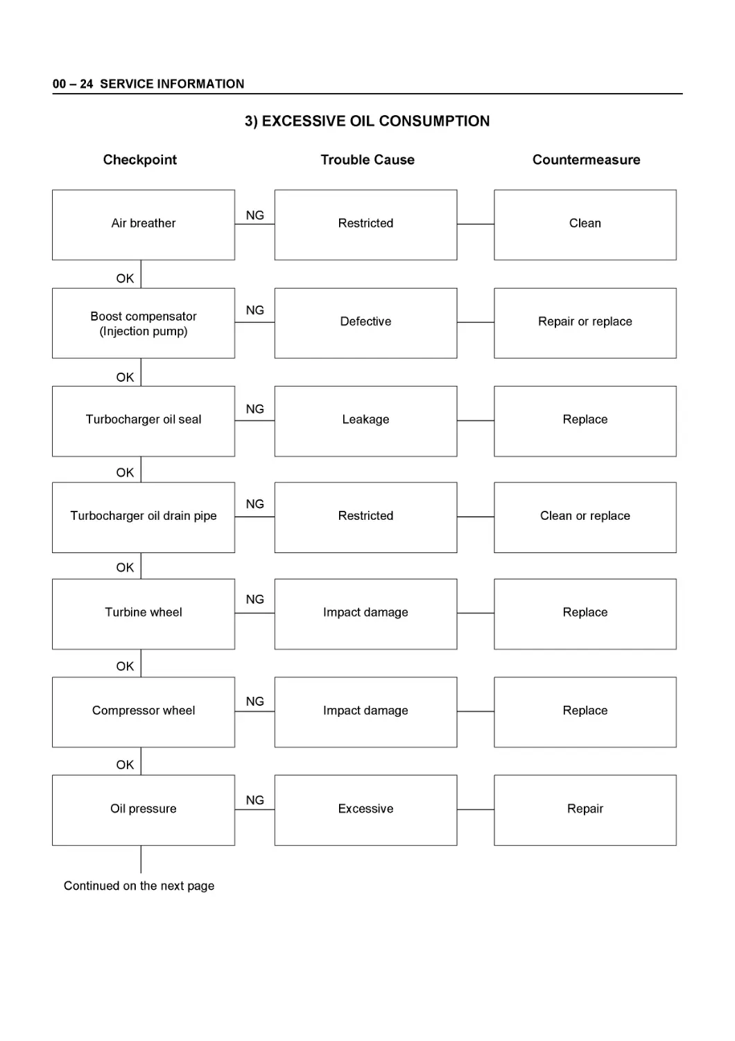
Checkpoint 3) EXCESSIVE OIL CONSUMPTION Trouble Cause Countermeasure
Air breather NG Restricted — Clean
OK
Boost compensator (Injection pump) NG Defective — Repair or replace
OK
Turbocharger oil seal NG Leakage — Replace
OK
Turbocharger oil drain pipe NG Restricted — Clean or replace
OK
Turbine wheel NG Impact damage — Replace
OK
Compressor wheel NG Impact damage — Replace
OK
Oil pressure NG Excessive — Repair
Continued on the next page
SERVICE INFORMATION 00 - 25
Checkpoint
Trouble Cause
Countermeasure
Continued from the previous page
00 - 26 SERVICE INFORMATION
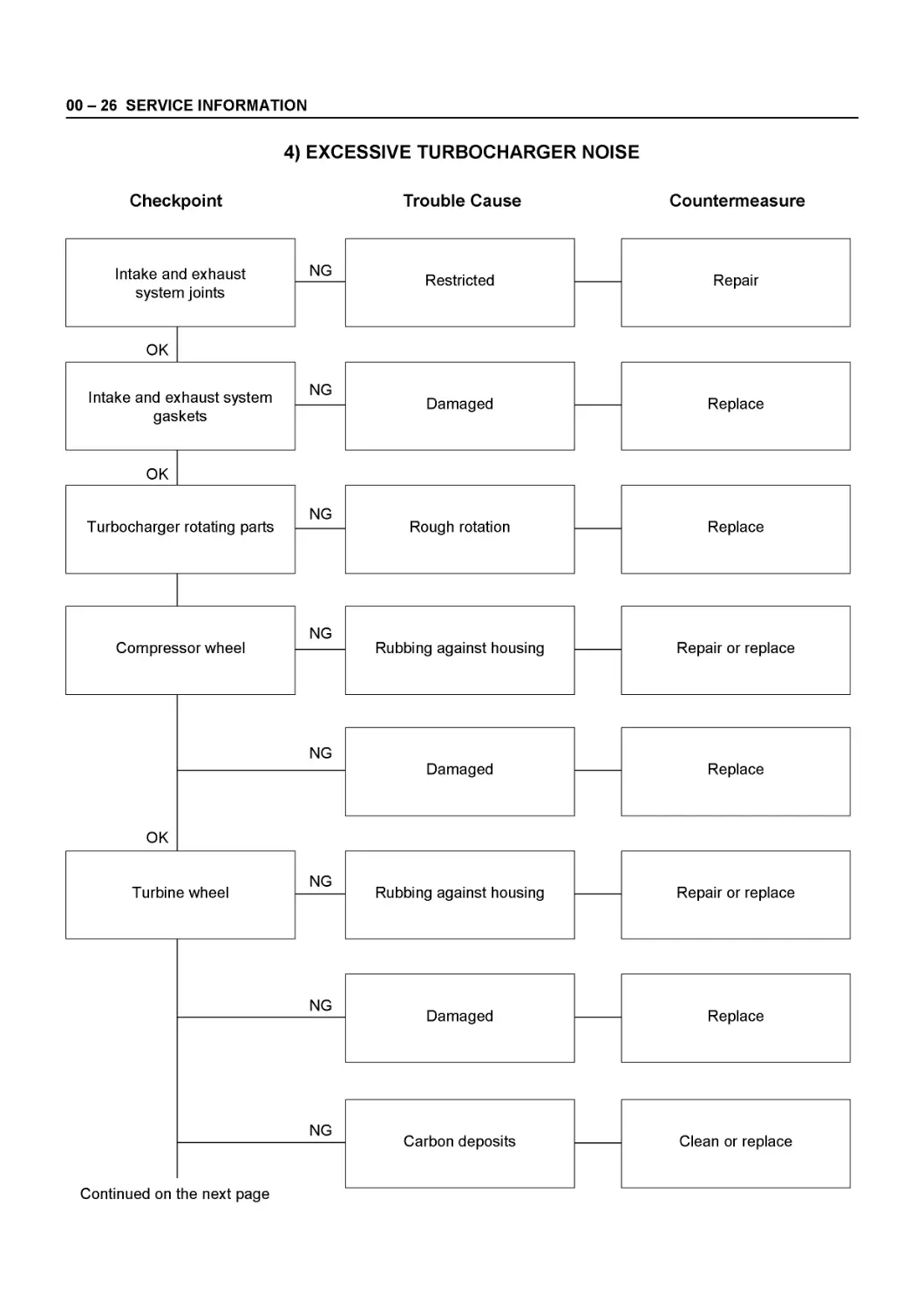
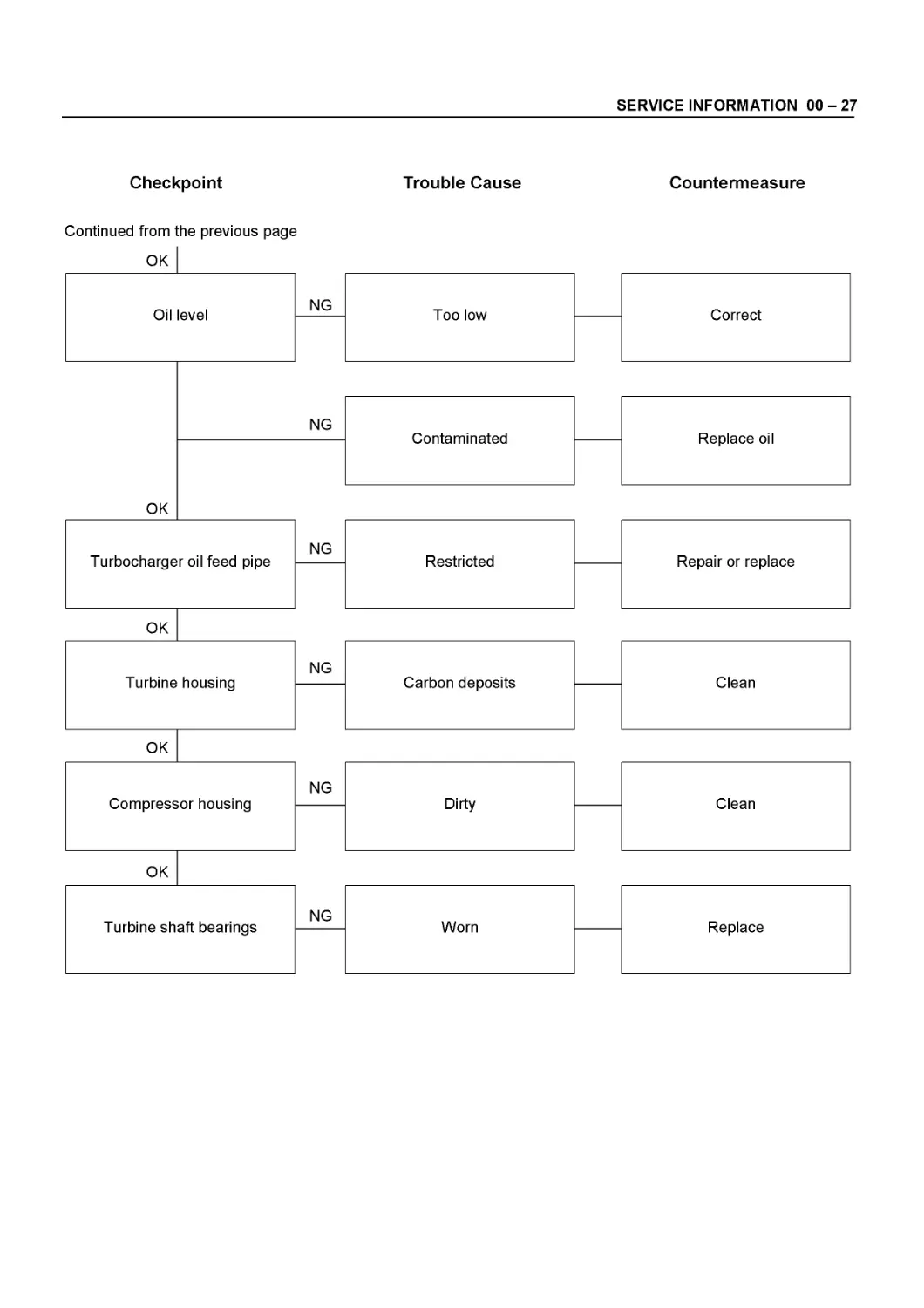
4) EXCESSIVE TURBOCHARGER NOISE
Checkpoint Trouble Cause Countermeasure
Intake and exhaust system joints NG Restricted — Repair
OK
Intake and exhaust system gaskets NG Damaged — Replace
OK
Turbocharger rotating parts NG Rough rotation — Replace
Compressor wheel NG Rubbing against housing — Repair or replace
OK
NG Damaged — Replace
Turbine wheel NG Rubbing against housing — Repair or replace
NG Damaged — Replace
NG Carbon deposits — Clean or replace
Continued on the next page
SERVICE INFORMATION 00 - 27
Checkpoint
Trouble Cause
Countermeasure
Continued from the previous page
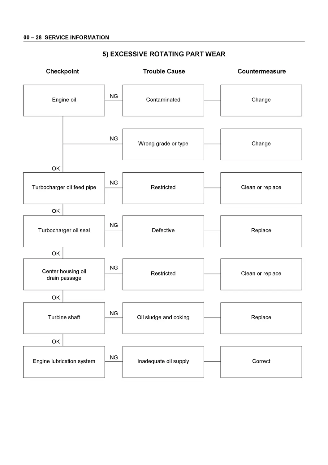
00 - 28 SERVICE INFORMATION
Checkpoint
5) EXCESSIVE ROTATING PART WEAR
Trouble Cause
Countermeasure
Engine oil
NG Contaminated
Change
OK
SERVICE INFORMATION 00 - 29
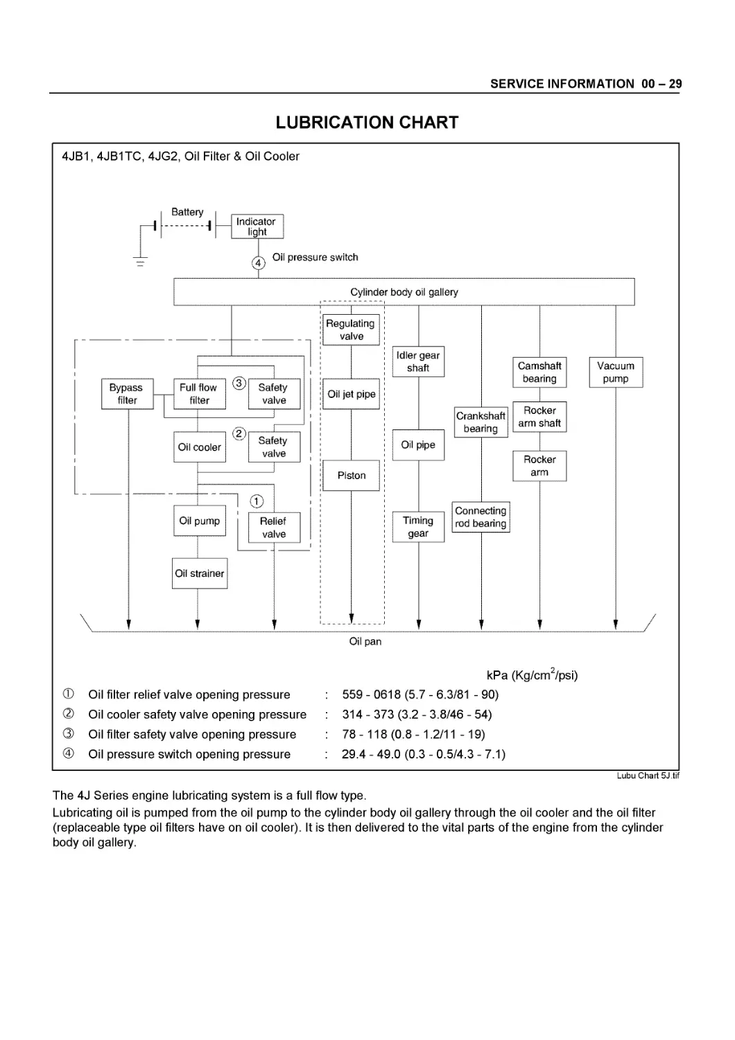
LUBRICATION CHART
4JB1,4JB1TC, 4JG2, Oil Filter & Oil Cooler
Oil pan
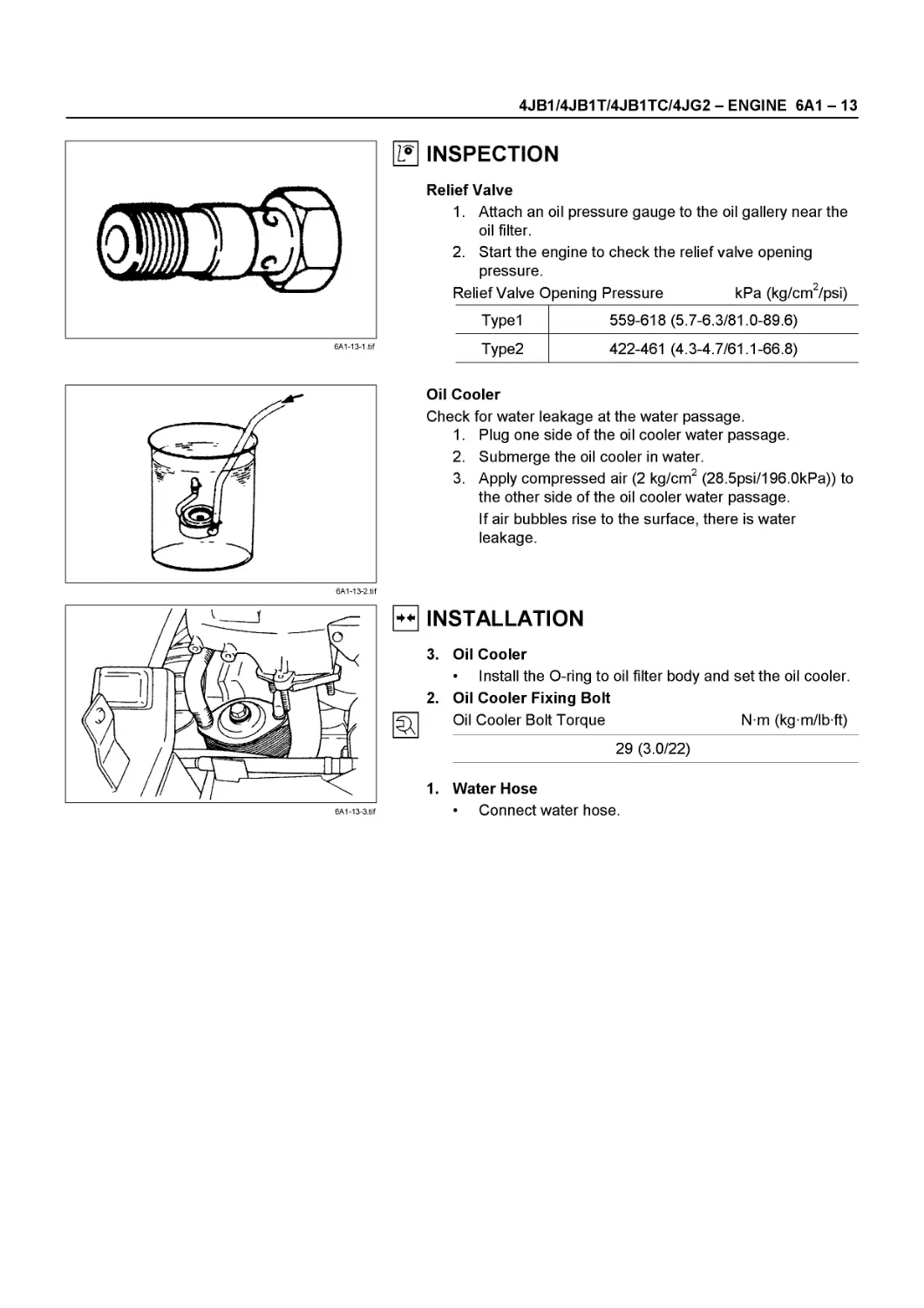
Ф Oil filter relief valve opening pressure ® Oil cooler safety valve opening pressure ® Oil filter safety valve opening pressure @ Oil pressure switch opening pressure
kPa (Kg/cm2/psi)
559-0618 (5.7-6.3/81 -90)
314-373 (3.2-3.8/46-54)
78-118 (0.8-1.2/11 -19)
29.4-49.0 (0.3-0.5/4.3-7.1)
Lubu Chart 5J.tif
The 4J Series engine lubricating system is a full flow type.
Lubricating oil is pumped from the oil pump to the cylinder body oil gallery through the oil cooler and the oil filter (replaceable type oil filters have on oil cooler). It is then delivered to the vital parts of the engine from the cylinder body oil gallery.
00 - 30 SERVICE INFORMATION
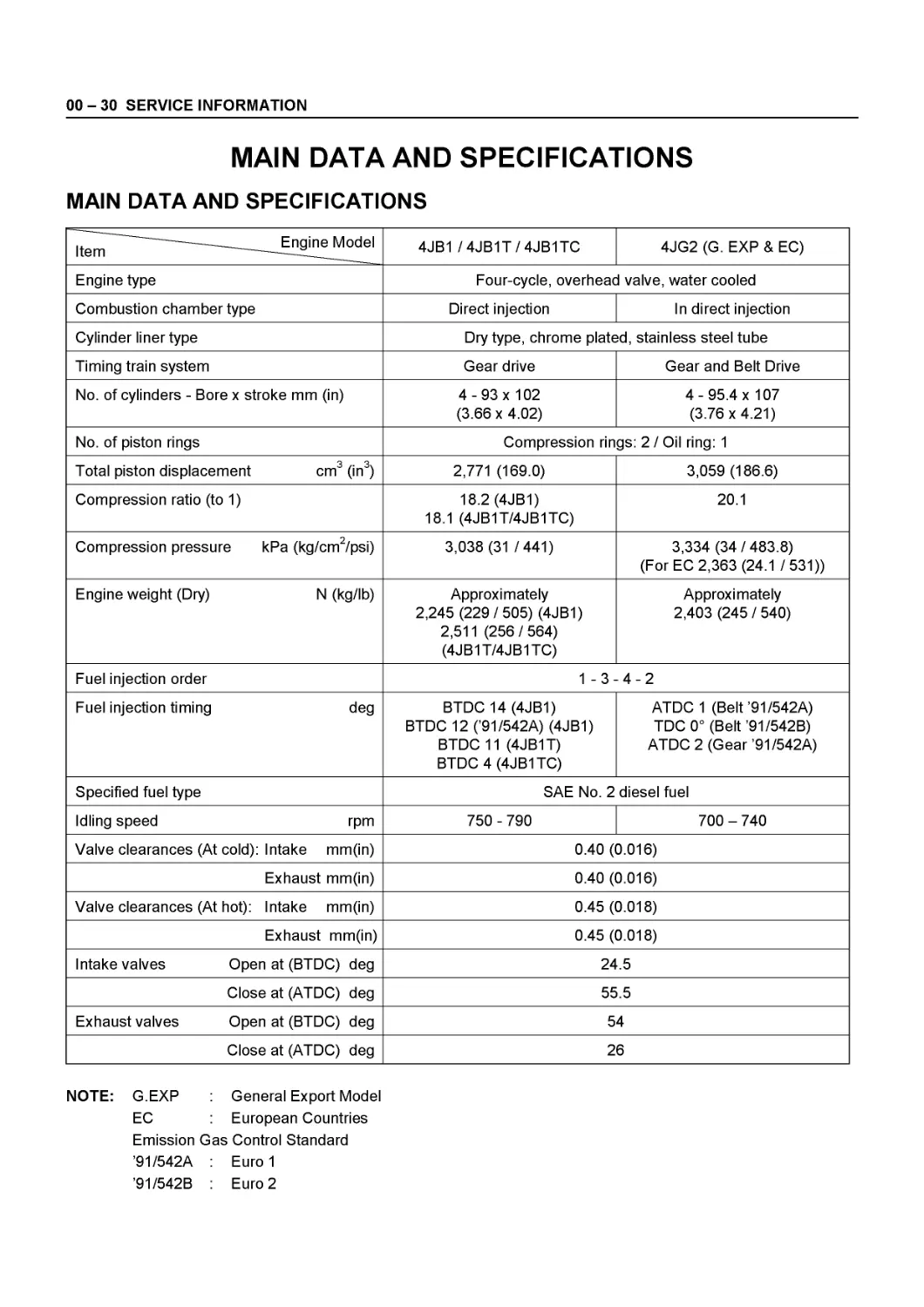
MAIN DATA AND SPECIFICATIONS
MAIN DATA AND SPECIFICATIONS
Item — Engine Model 4JB1 / 4JB1T / 4JB1TC 4JG2 (G. EXP & EC)
Engine type Four-cycle, overhead valve, water cooled
Combustion chamber type Direct injection In direct injection
Cylinder liner type Dry type, chrome plated, stainless steel tube
Timing train system Gear drive Gear and Belt Drive
No. of cylinders - Bore x stroke mm (in) 4 - 93x 102 (3.66 x 4.02) 4 - 95.4 x 10⁷ (3.76x4.21)
No. of piston rings Compression rings: 2 / Oil ring: 1
Total piston displacement cm3 (in3) 2,771 (169.0) 3,059 (186.6)
Compression ratio (to 1) 18.2 (4JB1) 18.1 (4JB1T/4JB1TC) 20.1
Compression pressure kPa (kg/cm2/psi) 3,038 (31 /441) 3,334 (34/483.8) (For EC 2,363 (24.1 /531))
Engine weight (Dry) N (kg/lb) Approximately 2,245 (229/505) (4JB1) 2,511 (256 / 564) (4JB1T/4JB1TC) Approximately 2,403 (245 / 540)
Fuel injection order 1-3- 4-2
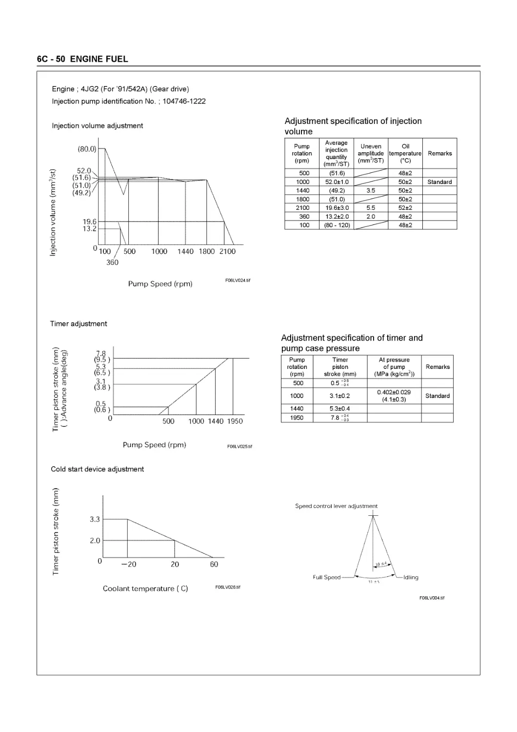
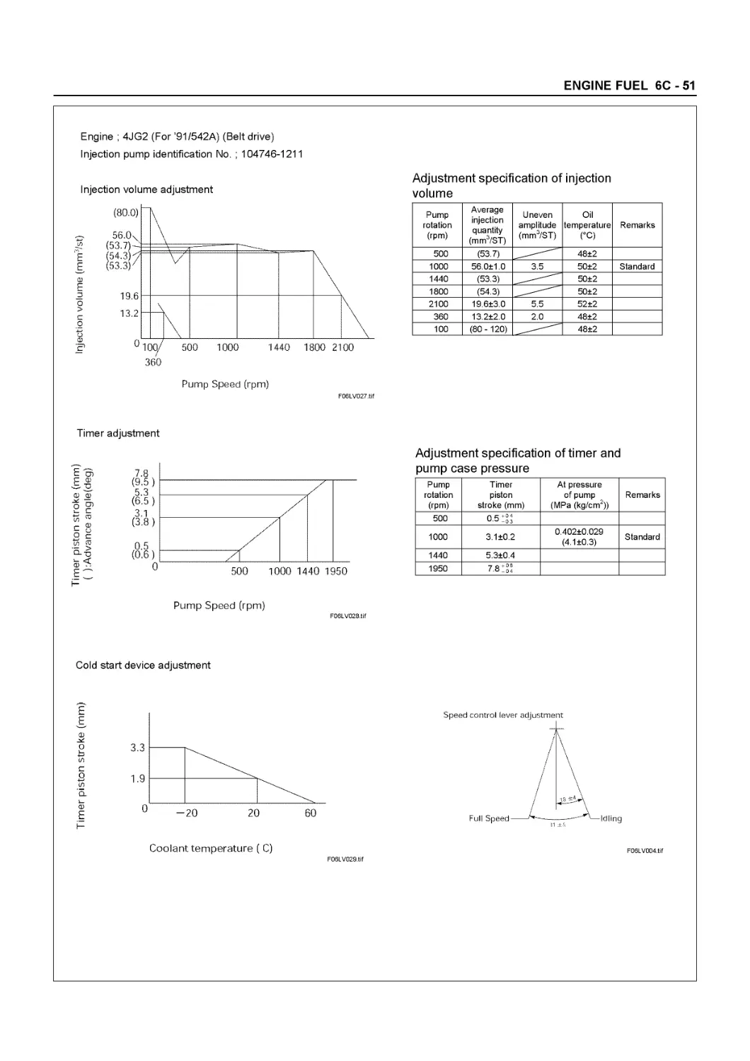
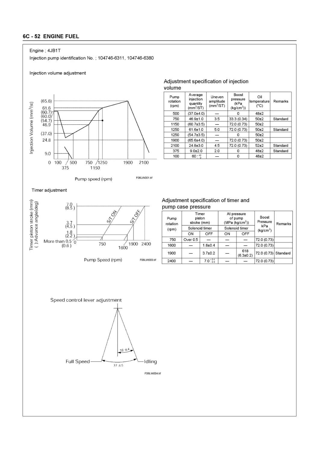
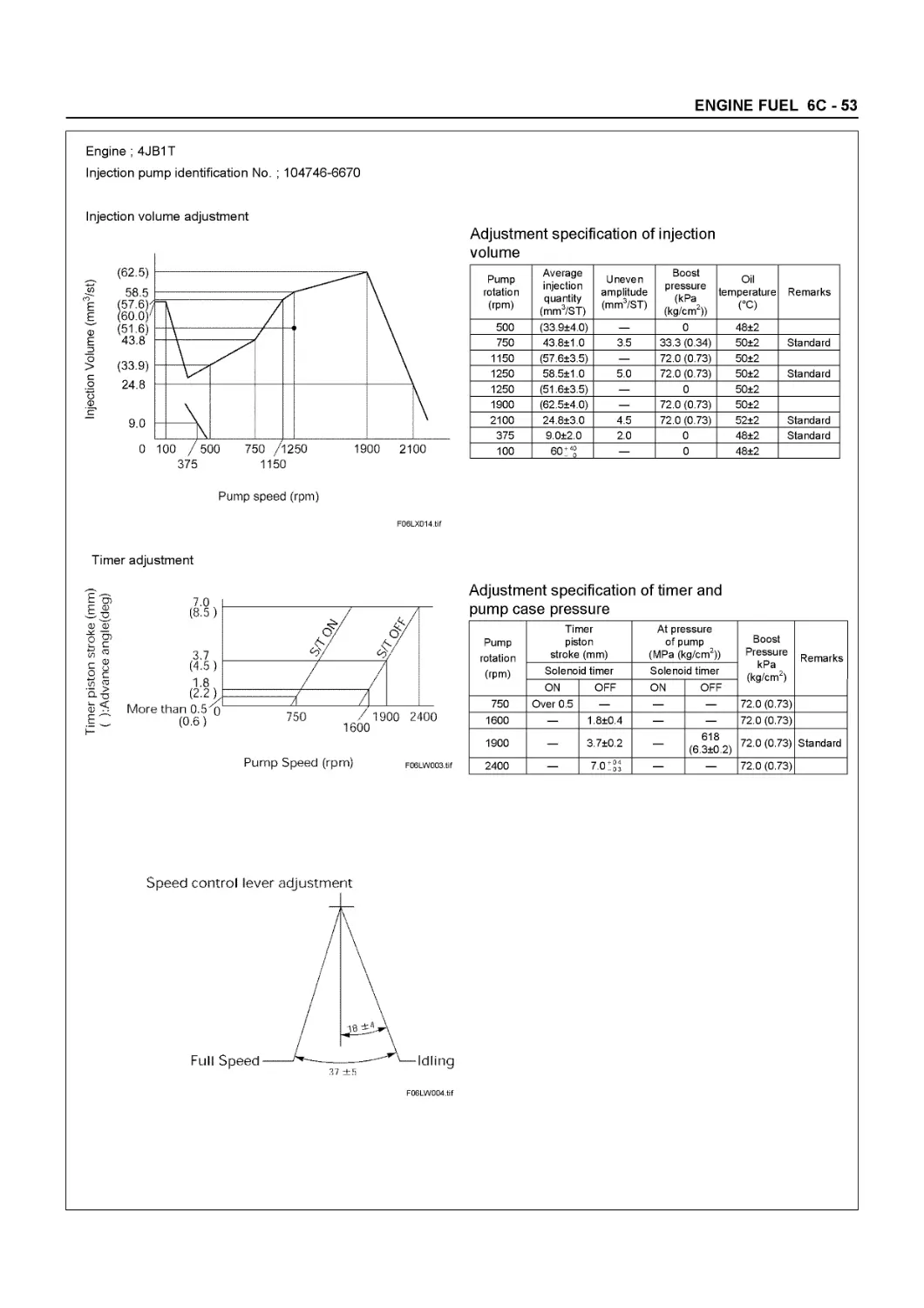
Fuel injection timing deg BTDC 14 (4JB1) BTDC 12 (’91/542A) (4JB1) BTDC 11 (4JB1T) BTDC 4 (4JB1TC) ATDC 1 (Belt’91/542A) TDC 0° (Belt ’91/542B) ATDC 2 (Gear’91/542A)
Specified fuel type SAE No. 2 diesel fuel
Idling speed rpm 750 - 790 700 - 740
Valve clearances (At cold): Intake mm(in) 0.40 (0.016)
Exhaust mm(in) 0.40 (0.016)
Valve clearances (At hot): Intake mm(in) 0.45 (0.018)
Exhaust mm(in) 0.45 (0.018)
Intake valves Open at (BTDC) deg 24.5
Close at (ATDC) deg 55.5
Exhaust valves Open at (BTDC) deg 54
Close at (ATDC) deg 26
NOTE: G.EXP General Export Model EC European Countries
Emission Gas Control Standard ’91/542A : Euro 1 ’91/542B : Euro 2
SERVICE INFORMATION 00 - 31
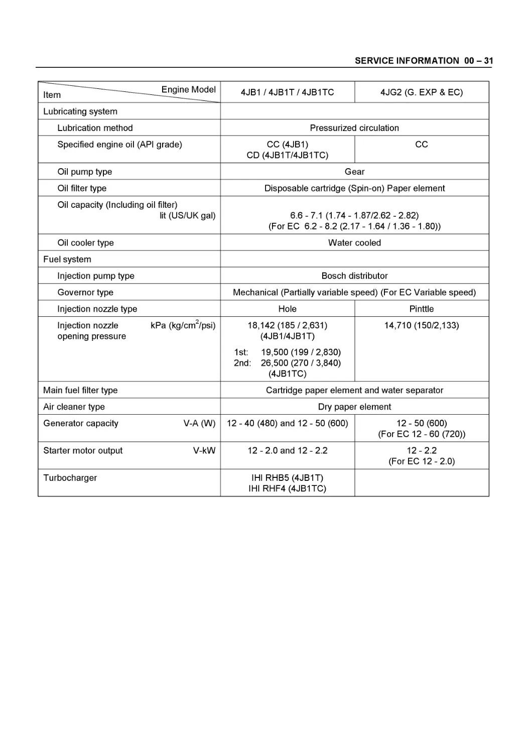
Item Engine Model 4JB1 / 4JB1T / 4JB1TC 4JG2 (G. EXP & EC)
Lubricating system
Lubrication method Pressurized circulation
Specified engine oil (API grade) CO (4JB1) CD (4JB1T/4JB1TC) CC
Oil pump type Gear
Oil filter type Disposable cartridge (Spin-on) Paper element
Oil capacity (Including oil filter) lit (US/UK gal) 6.6-7.1 (1.74- 1.87/2.62-2.82) (For EC 6.2 - 8.2 (2.17 - 1.64 /1.36 -1.80))
Oil cooler type Water cooled
Fuel system
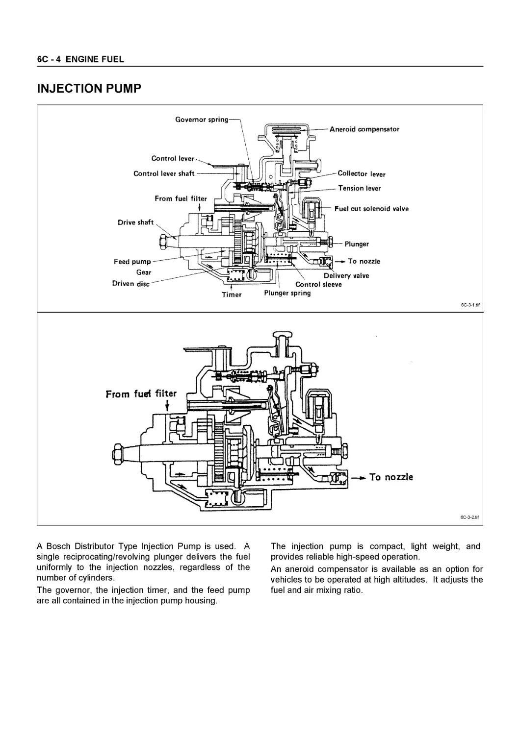
Injection pump type Bosch distributor
Governor type Mechanical (Partially variable speed) (For EC Variable speed)
Injection nozzle type Hole Pinttie
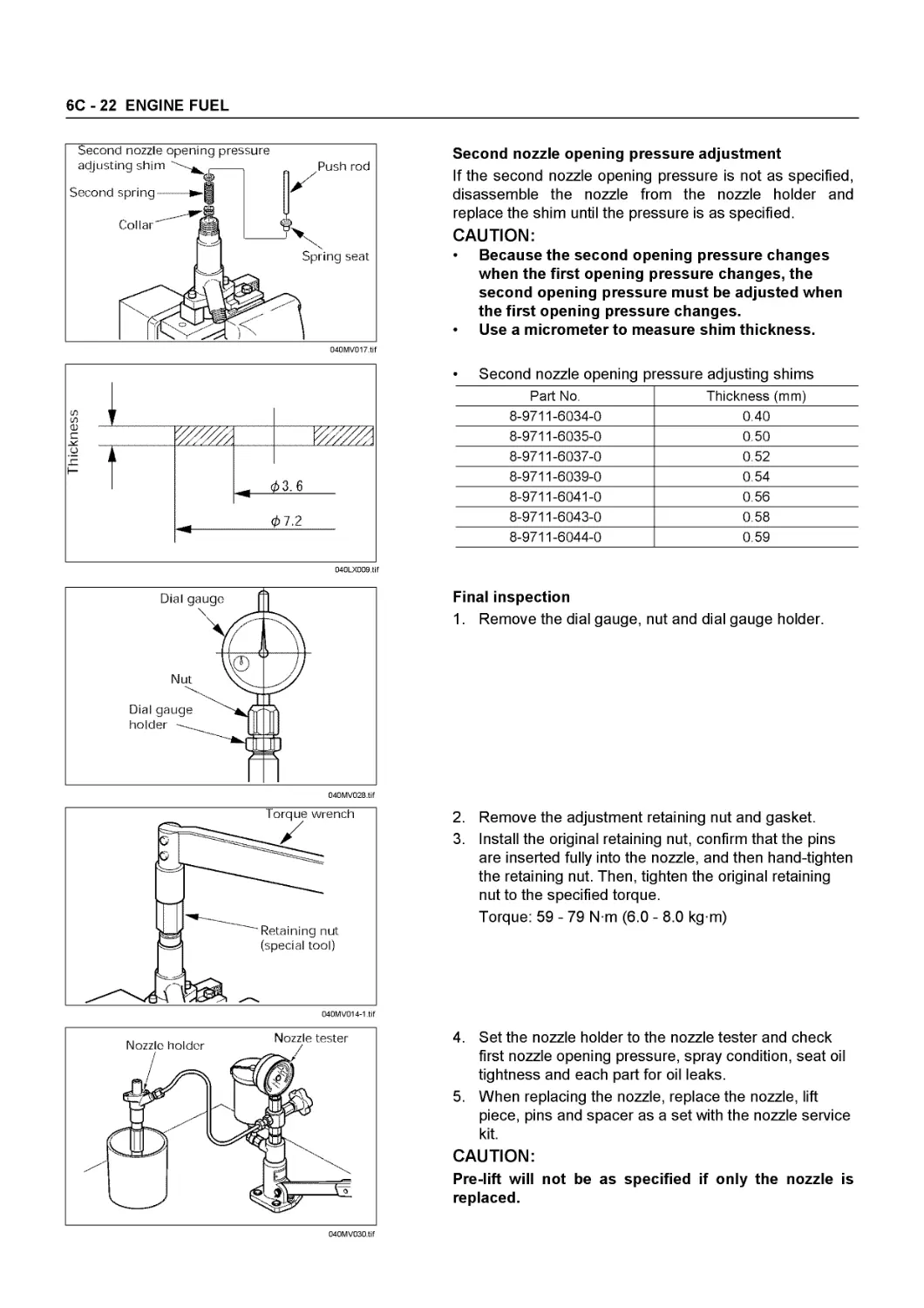
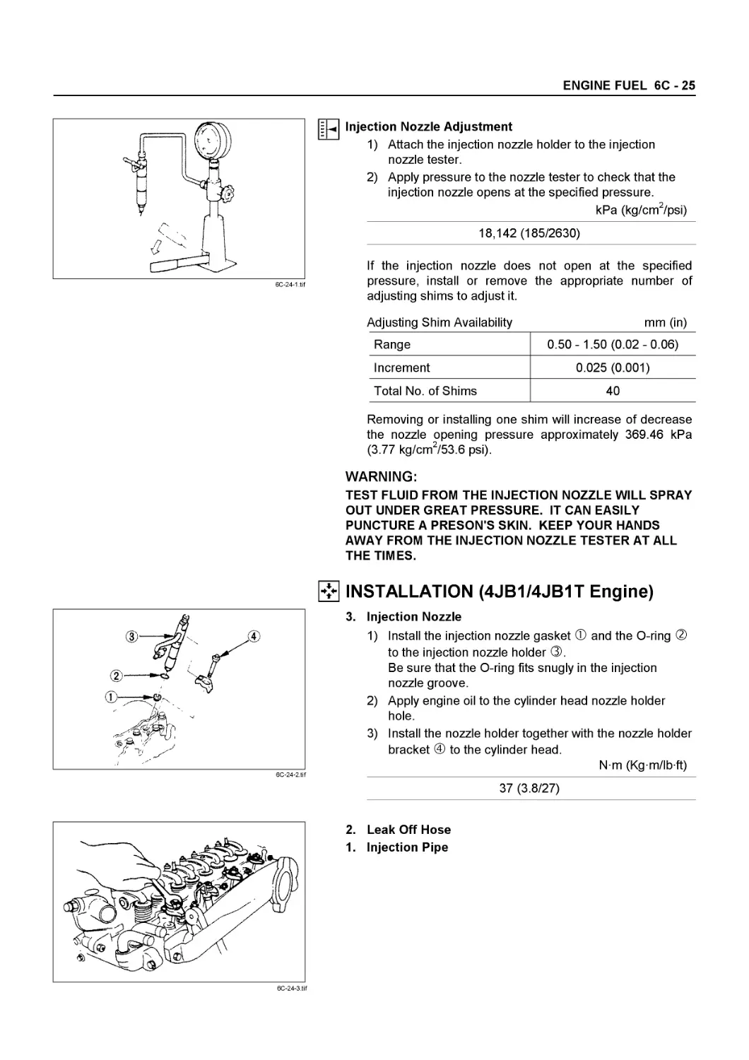
Injection nozzle opening pressure 2 kPa (kg/cm /psi) 18,142 (185/2,631) (4JB1/4JB1T) 1st: 19,500 (199/2,830) 2nd: 26,500 (270/3,840) (4JB1TC) 14,710 (150/2,133)
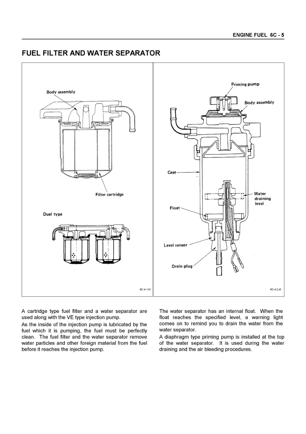
Main fuel filter type Cartridge paper element and water separator
Air cleaner type Dry paper element
Generator capacity V-A (W) 12-40 (480) and 12-50 (600) 12-50 (600) (For EC 12-60 (720))
Starter motor output V-kW 12-2.0 and 12-2.2 12-2.2 (For EC 12-2.0)
Turbocharger IHI RHB5 (4JB1T) IHI RHF4 (4JB1TC)
00 - 32 SERVICE INFORMATION
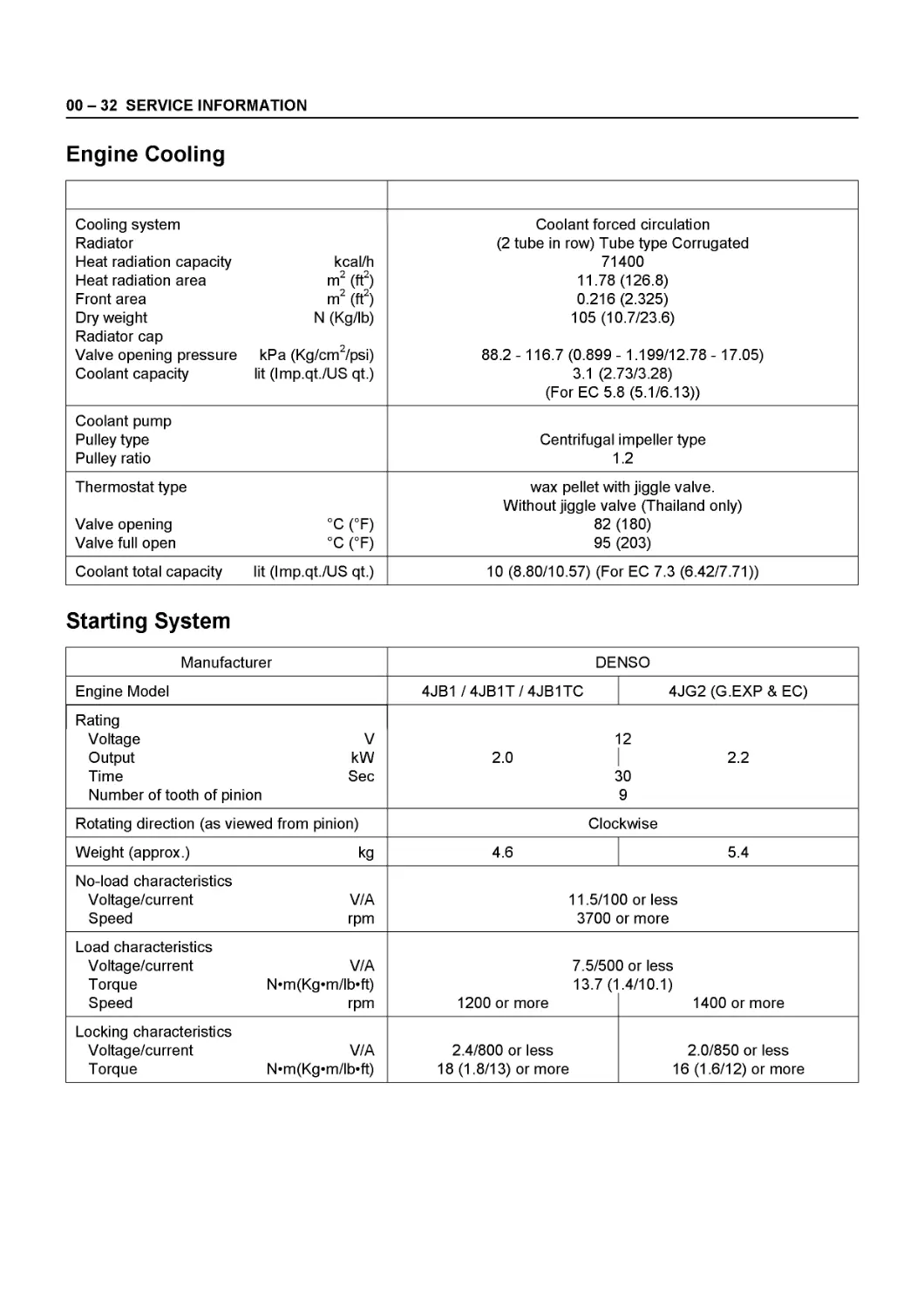
Engine Cooling
Cooling system Radiator Heat radiation capacity Heat radiation area Front area Dry weight Radiator cap Valve opening pressure Coolant capacity kcal/h m2 (ft2) m2 (ft2) N (Kg/lb) kPa (Kg/cm2/psi) lit (Imp.qt./US qt.) Coolant forced circulation (2 tube in row) Tube type Corrugated 71400 11.78 (126.8) 0.216 (2.325) 105 (10.7/23.6) 88.2- 116.7 (0.899- 1.199/12.78- 17.05) 3.1 (2.73/3.28) (For EC 5.8 (5.1/6.13))
Coolant pump Pulley type Pulley ratio Centrifugal impeller type 1.2
Thermostat type Valve opening Valve full open °C (°F) °C (°F) wax pellet with jiggle valve. Without jiggle valve (Thailand only) 82 (180) 95 (203)
Coolant total capacity lit (Imp.qt./US qt.) 10 (8.80/10.57) (For EC 7.3 (6.42/7.71))
Starting System
Manufacturer DENSO
Engine Model 4JB1 / 4JB1T / 4JB1TC 4JG2 (G.EXP & EC)
Rating Voltage V Output kW Time Sec Number of tooth of pinion 2.0 2 2.2 50 9
Rotating direction (as viewed from pinion) Clockwise
Weight (approx.) kg 4.6 5.4
No-load characteristics Voltage/current V/A Speed rpm 11.5/100 or less 3700 or more
Load characteristics Voltage/current V/A Torque N’m(Kg«m/lb’ft) Speed rpm 7.5/50( 13.7 (1 1200 or more 3 or less .4/10.1) 1400 or more
Locking characteristics Voltage/current V/A Torque N’m(Kg«m/lb’ft) 2.4/800 or less 18 (1.8/13) or more 2.0/850 or less 16(1.6/12) or more
SERVICE INFORMATION 00 - 33
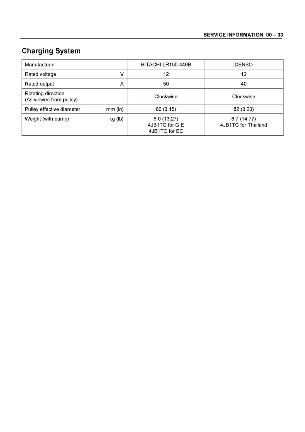
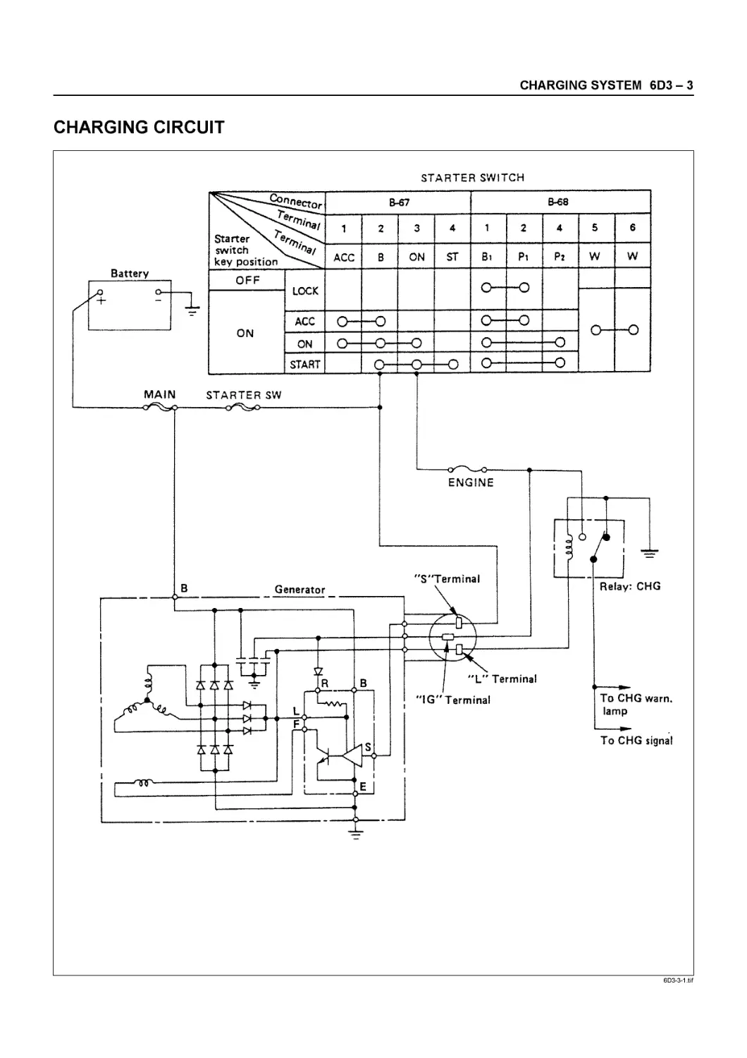
Charging System
Manufacturer HITACHI LR150-449B DENSO
Rated voltage V 12 12
Rated output A 50 40
Rotating direction (As viewed from pulley) Clockwise Clockwise
Pulley effective diameter mm (in) 80 (3.15) 82 (3.23)
Weight (with pump) kg (lb) 6.0 (13.27) 4JB1TCforG.E 4JB1TCforEC 6.7 (14.77) 4JB1TC for Thailand
00 - 34 SERVICE INFORMATION
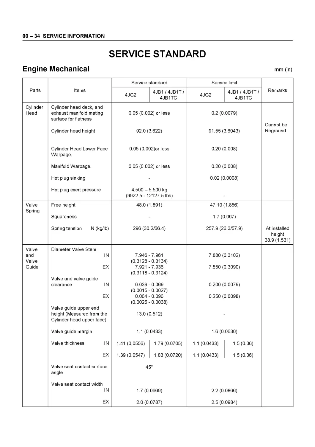
SERVICE STANDARD
Engine Mechanical
mm (in)
Service standard Service limit
Parts Items 4JG2 4JB1Z4JB1TZ 4JB1TC 4JG2 4JB1 /4JB1T/ 4JB1TC Remarks
Cylinder Head Cylinder head deck, and exhaust manifold mating surface for flatness Cylinder head height Cylinder Head Lower Face Warpage. Manifold Warpage. Hot plug sinking Hot plug exert pressure 0.05 (0.002) or less 92.0 (3.622) 0.05 (0.002)or less 0.05 (0.002) or less 4,500-5,500 kg (9922.5- 12127.5 lbs) 0.2 (0.0079) 91.55 (3.6043) 0.20 (0.008) 0.20 (0.008) 0.02 (0.0008) Cannot be Reground
Valve Spring Free height Squareness Spring tension N (kg/lb) 48.0 (1.891) 296 (30.2/66.4) 47.10 (1.856) 1.7 (0.067) 257.9 (26.3/57.9) At installed height 38.9 (1.531)
Valve and Valve Guide Diameter Valve Stem IN EX Valve and valve guide clearance IN EX Valve guide upper end height (Measured from the Cylinder head upper face) Valve guide margin Valve thickness IN EX Valve seat contact surface angle Valve seat contact width IN EX 7.946-(0.3128- 7.921 (0.3118- 0.039-(0.0015- 0.064- (0.0025- 13.0 ( 1.1 (0 1.41 (0.0556) 1.39 (0.0547) 4t 1.7 (0 2.0 (0 7.961 0.3134) 7.936 0.3124) 0.069 0.0027) 0.096 0.0038) 3.512) 0433) 1.79 (0.0705) 1.83 (0.0720) 5° 0669) 0787) 7.880 ( 7.850 ( 0.200 ( 0.250 ( 1.6 (0 1.1 (0.0433) 1.1 (0.0433) 2.2 (0 2.5 (0 3.3102) 3.3090) 3.0079) 3.0098) 0630) 1.5 (0.06) 1.5 (0.06) 0866) 0984)
SERVICE INFORMATION 00 - 35
mm (in)
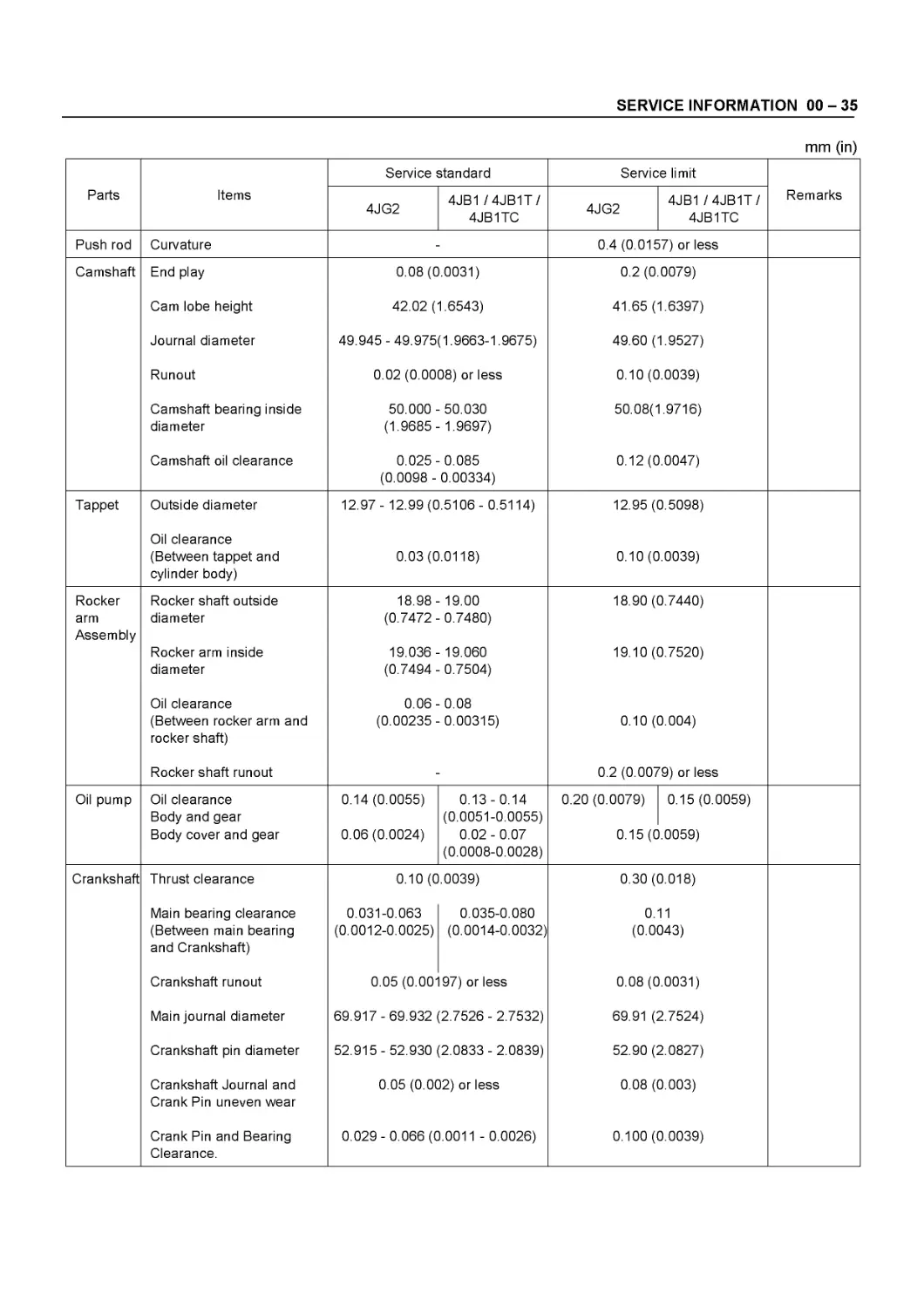
Parts Items Service standard Service limit Remarks
4JG2 4JB1/4JB1T/ 4JB1TC 4JG2 4JB1 /4JB1T/ 4JB1TC
Push rod Curvature 0.4 (0.0157) or less
Camshaft End play 0.08 (0.0031) 0.2 (0.0079)
Cam lobe height 42.02 (1.6543) 41.65 (1.6397)
Journal diameter 49.945 - 49.975(1.9663-1.9675) 49.60 (1.9527)
Runout 0.02 (0.0008) or less 0.10 (0.0039)
Camshaft bearing inside diameter 50.000 (1.9685- 50.030 1.9697) 50.08(1.9716)
Camshaft oil clearance 0.025- (0.0098 - 0.085 0.00334) 0.12 (0.0047)
Tappet Outside diameter 12.97- 12.99 (0.5106- 0.5114) 12.95 (0.5098)
Oil clearance (Between tappet and cylinder body) 0.03 (0.0118) 0.10 (0.0039)
Rocker arm Assembly Rocker shaft outside diameter Rocker arm inside diameter 18.98-(0.7472 19.036 (0.7494 19.00 0.7480) 19.060 0.7504) 18.90 (0.7440) 19.10 (0.7520)
Oil clearance (Between rocker arm and rocker shaft) 0.06-(0.00235- 0.08 0.00315) 0.10 (0.004)
Rocker shaft runout 0.2 (0.0079) or less
Oil pump Oil clearance Body and gear Body cover and gear 0.14 (0.0055) 0.06 (0.0024) 0.13 - 0.14 (0.0051-0.0055) 0.02 - 0.07 (0.0008-0.0028) 0.20 (0.0079) 0.15 (C 0.15 (0.0059) .0059)
Crankshaft Thrust clearance 0.10 (0.0039) 0.30 (0.018)
Main bearing clearance (Between main bearing and Crankshaft) 0.031-0.063 (0.0012-0.0025) 0.035-0.080 (0.0014-0.0032) 0.11 (0.0043)
Crankshaft runout 0.05 (0.00' 97) or less 0.08 (0.0031)
Main journal diameter 69.917 - 69.932 (2.7526 - 2.7532) 69.91 (2.7524)
Crankshaft pin diameter 52.915 - 52.930 (2.0833 - 2.0839) 52.90 (2.0827)
Crankshaft Journal and Crank Pin uneven wear 0.05 (0.002) or less 0.08 (0.003)
Crank Pin and Bearing Clearance. 0.029- 0.066 (0.0011 - 0.0026) 0.100 (0.0039)
00 - 36 SERVICE INFORMATION
mm (in)
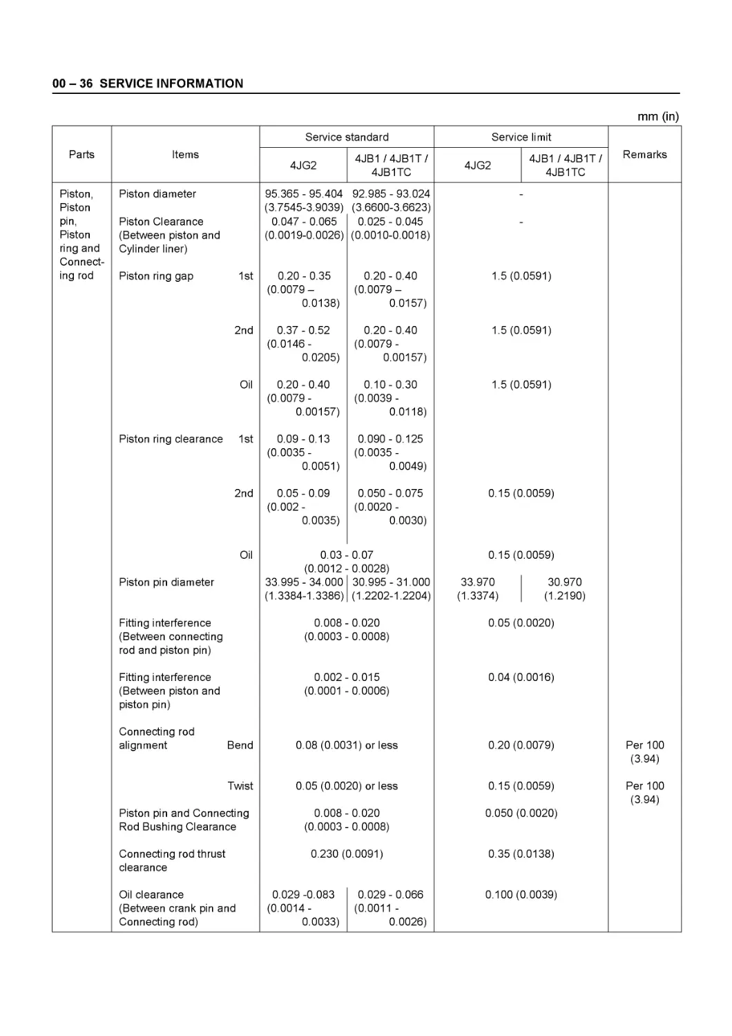
Parts Items Service standard Service limit Remarks
4JG2 4JB1/4JB1T/ 4JB1TC 4JG2 4JB1 /4JB1T/ 4JB1TC
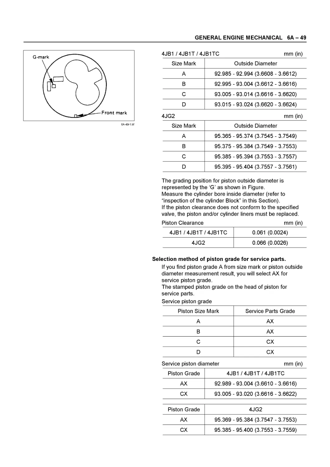
Piston, Piston pin, Piston ring and Connecting rod Piston diameter Piston Clearance (Between piston and Cylinder liner) Piston ring gap 1st 95.365 - 95.404 (3.7545-3.9039) 0.047- 0.065 (0.0019-0.0026) 0.20 - 0.35 (0.0079-0.0138) 92.985 - 93.024 (3.6600-3.6623) 0.025 - 0.045 (0.0010-0.0018) 0.20-0.40 (0.0079- 0.0157) 1.5 (0.0591)
2nd 0.37 - 0.52 (0.0146- 0.0205) 0.20-0.40 (0.0079 - 0.00157) 1.5 (0.0591)
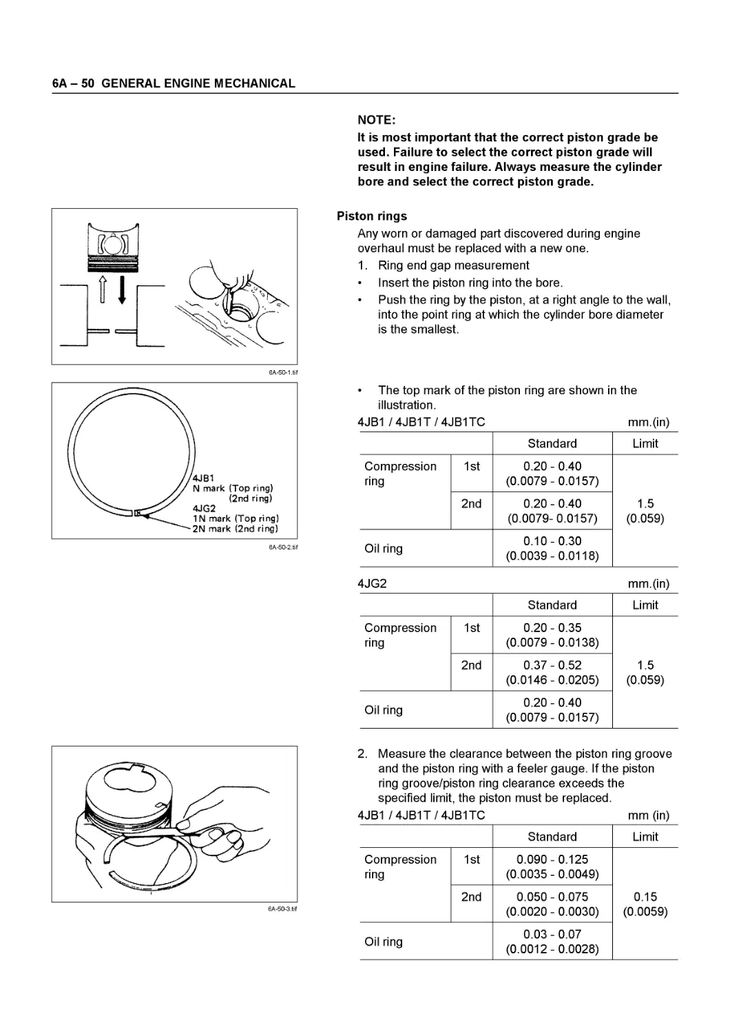
Oil 0.20 - 0.40 (0.0079- 0.00157) 0.10-0.30 (0.0039 - 0.0118) 1.5 (0.0591)
Piston ring clearance 1st 0.09 - 0.13 (0.0035- 0.0051) 0.090 - 0.125 (0.0035 - 0.0049)
2nd 0.05 - 0.09 (0.002- 0.0035) 0.050 - 0.075 (0.0020 - 0.0030) 0.15 (0.0059)
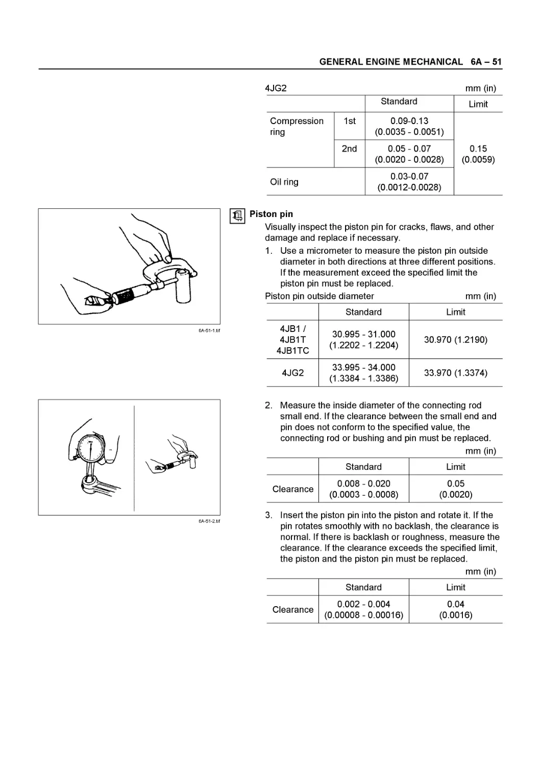
Piston pin diameter Oil 0.03-(0.0012- 33.995- 34.000 (1.3384-1.3386) 0.07 0.0028) 30.995 - 31.000 (1.2202-1.2204) 0.15 (C 33.970 (1.3374) .0059) 30.970 (1.2190)
Fitting interference (Between connecting rod and piston pin) 0.008- (0.0003- 0.020 0.0008) 0.05 (0.0020)
Fitting interference (Between piston and piston pin) 0.002-(0.0001 0.015 0.0006) 0.04 (0.0016)
Connecting rod alignment Bend 0.08 (0.0031) or less 0.20 (0.0079) Per 100 (3.94)
Twist Piston pin and Connecting Rod Bushing Clearance 0.05 (0.0020) or less 0.008- 0.020 (0.0003- 0.0008) 0.15 (0.0059) 0.050 (0.0020) Per 100 (3.94)
Connecting rod thrust clearance 0.230 (0.0091) 0.35 (0.0138)
Oil clearance (Between crank pin and Connecting rod) 0.029 -0.083 (0.0014- 0.0033) 0.029- 0.066 (0.0011 - 0.0026) 0.100 (0.0039)
SERVICE INFORMATION 00 - 37
mm (in)
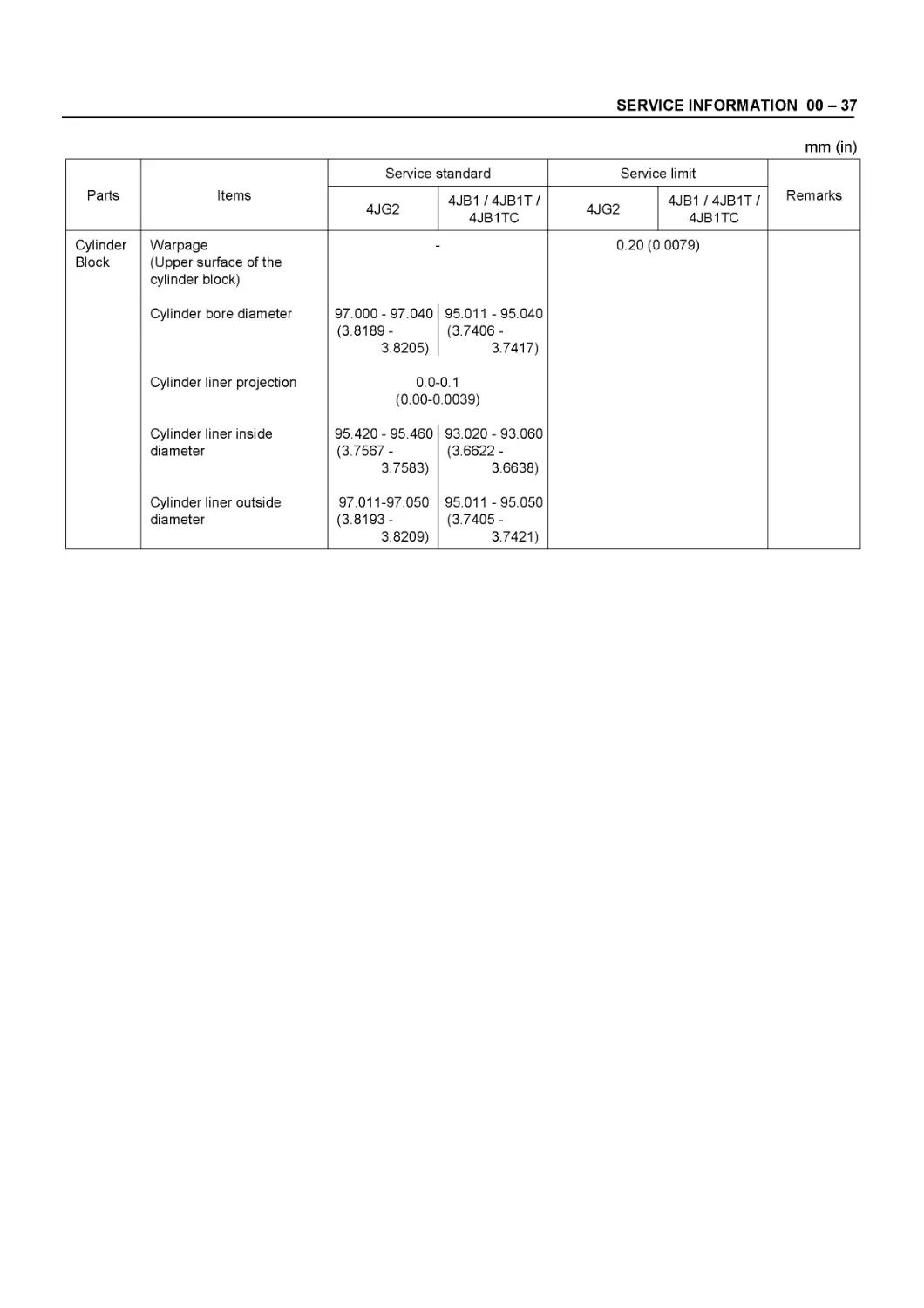
Parts Items Service standard Service limit Remarks
4JG2 4JB1/4JB1T/ 4JB1TC 4JG2 4JB1 /4JB1T/ 4JB1TC
Cylinder Block Warpage (Upper surface of the cylinder block) 0.20 (0.0079)
Cylinder bore diameter 97.000- 97.040 (3.8189- 3.8205) 95.011 - 95.040 (3.7406 - 3.7417)
Cylinder liner projection 0.0-0.1 (0.00-0.0039)
Cylinder liner inside diameter 95.420- 95.460 (3.7567 - 3.7583) 93.020 - 93.060 (3.6622 - 3.6638)
Cylinder liner outside diameter 97.011-97.050 (3.8193- 3.8209) 95.011 - 95.050 (3.7405 - 3.7421)
00 - 38 SERVICE INFORMATION
SERVICING
Servicing refers to general maintenance procedures to be performed by qualified service personnel.
0038-1 .tif
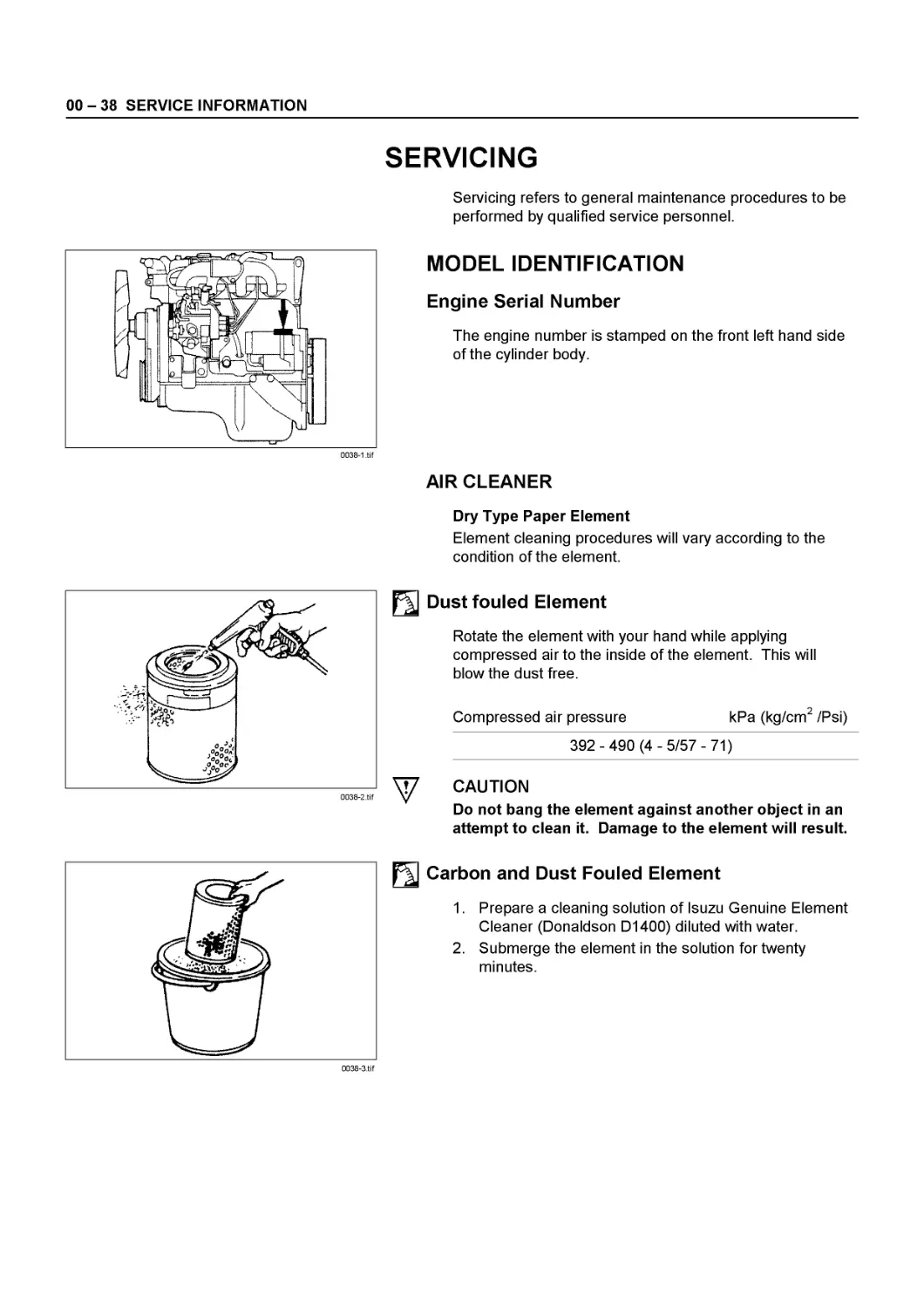
MODEL IDENTIFICATION
Engine Serial Number
The engine number is stamped on the front left hand side of the cylinder body.
AIR CLEANER
Dry Type Paper Element
Element cleaning procedures will vary according to the condition of the element.
0038-2.tif
Dust fouled Element
Rotate the element with your hand while applying compressed air to the inside of the element. This will blow the dust free.
Compressed air pressure kPa (kg/cm2 /Psi)
392-490 (4-5/57-71)
^7 CAUTION
Do not bang the element against another object in an attempt to clean it. Damage to the element will result
Carbon and Dust Fouled Element
1. Prepare a cleaning solution of Isuzu Genuine Element Cleaner (Donaldson D1400) diluted with water.
2. Submerge the element in the solution for twenty minutes.
0038-3.tif
SERVICE INFORMATION 00 - 39
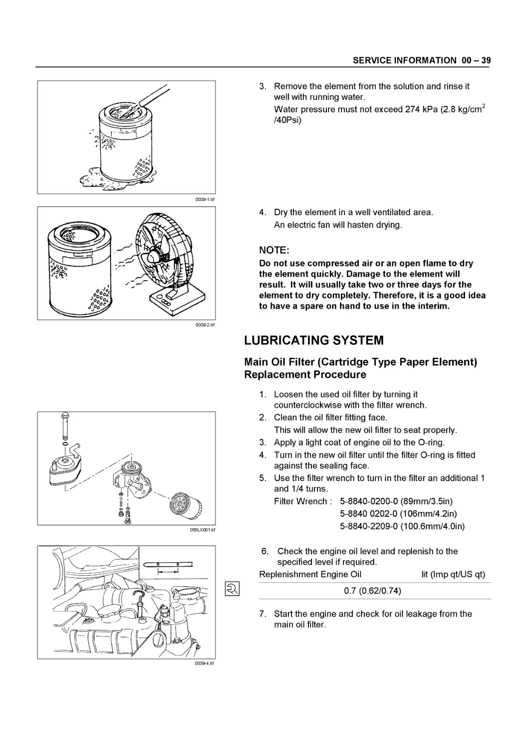
3. Remove the element from the solution and rinse it well with running water.
Water pressure must not exceed 274 kPa (2.8 kg/cm2 /40Psi)
0039-2.tif
050LX001.tif
0039-4.tif
4. Dry the element in a well ventilated area.
An electric fan will hasten drying.
NOTE:
Do not use compressed air or an open flame to dry the element quickly. Damage to the element will result. It will usually take two or three days for the element to dry completely. Therefore, it is a good idea to have a spare on hand to use in the interim.
LUBRICATING SYSTEM
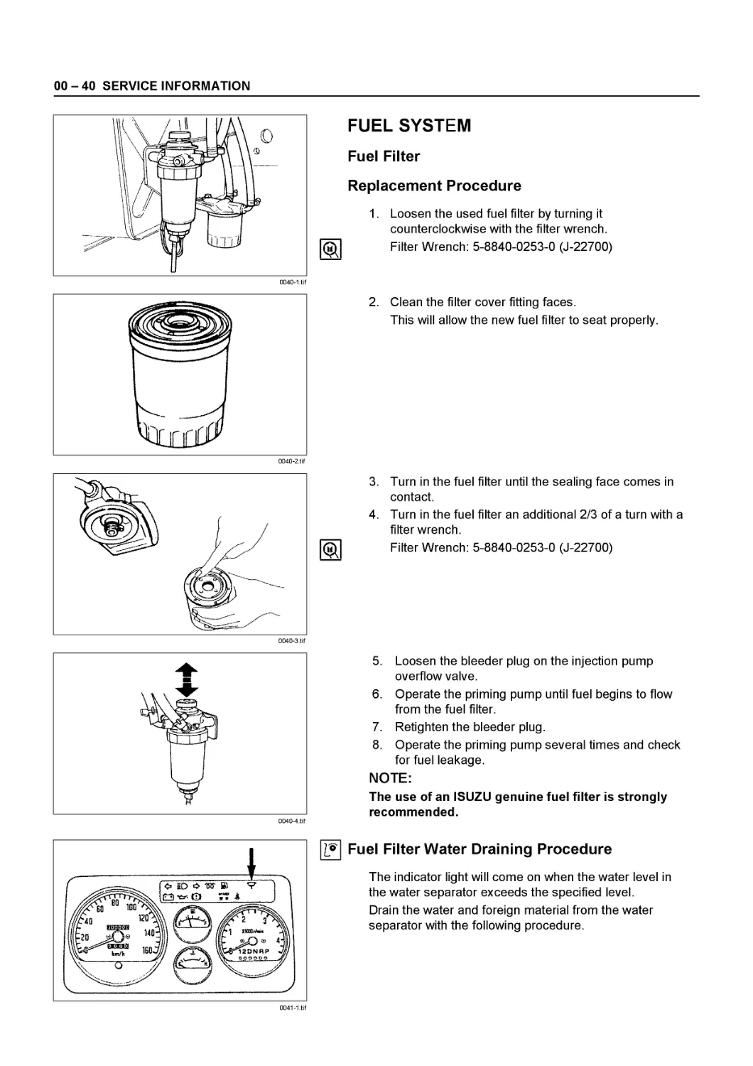
Main Oil Filter (Cartridge Type Paper Element) Replacement Procedure
1. Loosen the used oil filter by turning it counterclockwise with the filter wrench.
2. Clean the oil filter fitting face.
This will allow the new oil filter to seat properly.
3. Apply a light coat of engine oil to the O-ring.
4. Turn in the new oil filter until the filter О-ring is fitted against the sealing face.
5. Use the filter wrench to turn in the filter an additional 1 and 1/4 turns.
Filter Wrench : 5-8840-0200-0 (89mm/3.5in)
5-8840 0202-0 (106mm/4.2in)
5-8840-2209-0 (100.6mm/4.0in)
6. Check the engine oil level and replenish to the specified level if required.
Replenishment Engine Oil
lit (Imp qt/US qt)
0.7 (0.62/0.74)
7. Start the engine and check for oil leakage from the main oil filter.
00 - 40 SERVICE INFORMATION
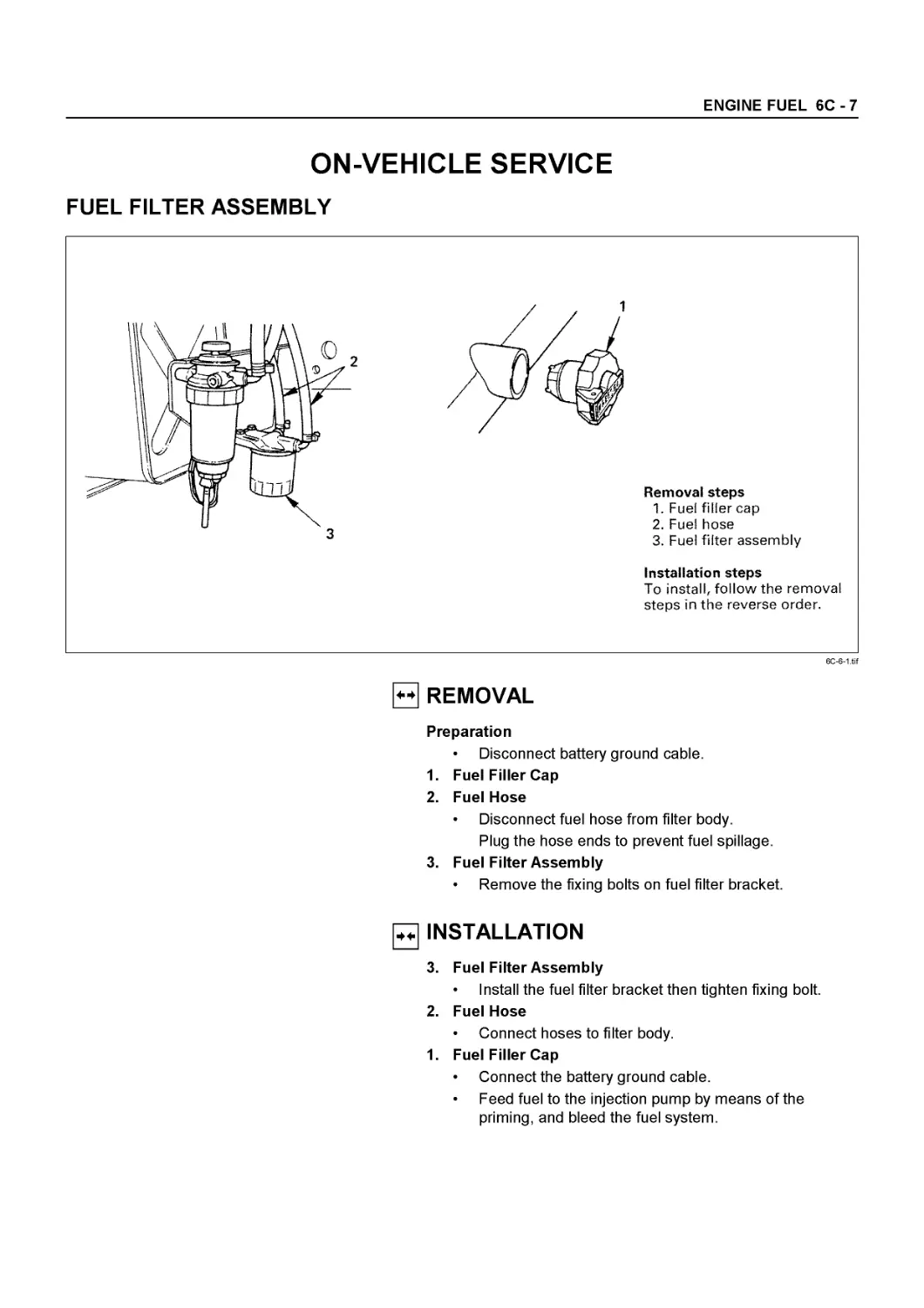
FUEL SYSTEM
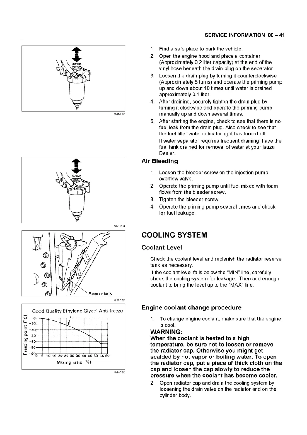
Fuel Filter
Replacement Procedure
1. Loosen the used fuel filter by turning it counterclockwise with the filter wrench.
(ЙЯ Filter Wrench: 5-8840-0253-0 (J-22700)
2. Clean the filter cover fitting faces.
This will allow the new fuel filter to seat properly.
0040-3.tif
3. Turn in the fuel filter until the sealing face comes in contact.
4. Turn in the fuel filter an additional 2/3 of a turn with a filter wrench.
(ЙЯ Filter Wrench: 5-8840-0253-0 (J-22700)
5. Loosen the bleeder plug on the injection pump overflow valve.
6. Operate the priming pump until fuel begins to flow from the fuel filter.
7. Retighten the bleeder plug.
8. Operate the priming pump several times and check for fuel leakage.
NOTE:
The use of an ISUZU genuine fuel filter is strongly recommended.
0041-1.tif
I? Fuel Filter Water Draining Procedure
The indicator light will come on when the water level in the water separator exceeds the specified level.
Drain the water and foreign material from the water separator with the following procedure.
SERVICE INFORMATION 00 - 41
0041-4.tif
1. Find a safe place to park the vehicle.
2. Open the engine hood and place a container (Approximately 0.2 liter capacity) at the end of the vinyl hose beneath the drain plug on the separator.
3. Loosen the drain plug by turning it counterclockwise (Approximately 5 turns) and operate the priming pump up and down about 10 times until water is drained approximately 0.1 liter.
4. After draining, securely tighten the drain plug by turning it clockwise and operate the priming pump manually up and down several times.
5. After starting the engine, check to see that there is no fuel leak from the drain plug. Also check to see that the fuel filter water indicator light has turned off.
If water separator requires frequent draining, have the fuel tank drained for removal of water at your Isuzu Dealer.
Air Bleeding
1. Loosen the bleeder screw on the injection pump overflow valve.
2. Operate the priming pump until fuel mixed with foam flows from the bleeder screw.
3. Tighten the bleeder screw.
4. Operate the priming pump several times and check for fuel leakage.
COOLING SYSTEM
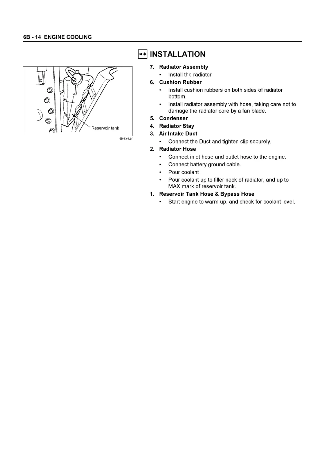
Coolant Level
Check the coolant level and replenish the radiator reserve tank as necessary.
If the coolant level falls below the “MIN” line, carefully check the cooling system for leakage. Then add enough coolant to bring the level up to the “MAX” line.
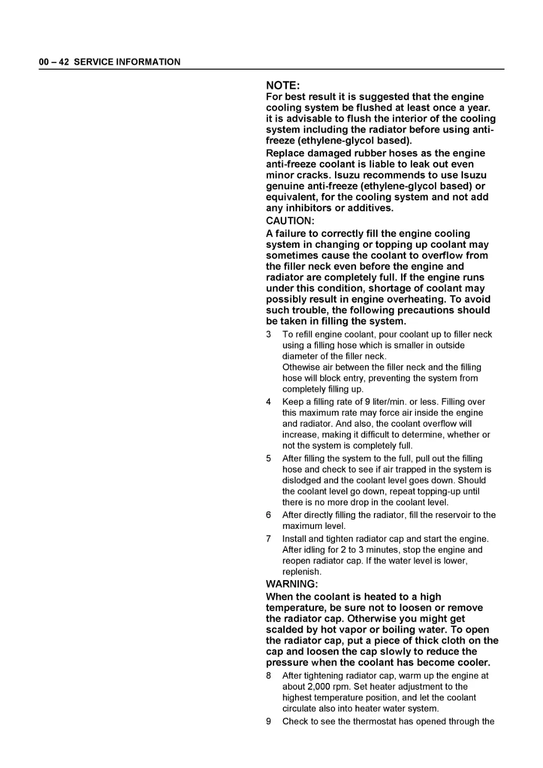
Good Quality Ethylene Glycol Anti-freeze
Engine coolant change procedure
1 . To change engine coolant, make sure that the engine is cool.
WARNING:
When the coolant is heated to a high temperature, be sure not to loosen or remove the radiator cap. Otherwise you might get scalded by hot vapor or boiling water. To open the radiator cap, put a piece of thick cloth on the cap and loosen the cap slowly to reduce the pressure when the coolant has become cooler.
2 Open radiator cap and drain the cooling system by loosening the drain valve on the radiator and on the cylinder body.
00 - 42 SERVICE INFORMATION
NOTE:
For best result it is suggested that the engine cooling system be flushed at least once a year, it is advisable to flush the interior of the cooling system including the radiator before using antifreeze (ethylene-glycol based).
Replace damaged rubber hoses as the engine anti-freeze coolant is liable to leak out even minor cracks. Isuzu recommends to use Isuzu genuine anti-freeze (ethylene-glycol based) or equivalent, for the cooling system and not add any inhibitors or additives.
CAUTION:
A failure to correctly fill the engine cooling system in changing or topping up coolant may sometimes cause the coolant to overflow from the filler neck even before the engine and radiator are completely full. If the engine runs under this condition, shortage of coolant may possibly result in engine overheating. To avoid such trouble, the following precautions should be taken in filling the system.
3 To refill engine coolant, pour coolant up to filler neck using a filling hose which is smaller in outside diameter of the filler neck.
Othewise air between the filler neck and the filling hose will block entry, preventing the system from completely filling up.
4 Keep a filling rate of 9 liter/min. or less. Filling over this maximum rate may force air inside the engine and radiator. And also, the coolant overflow will increase, making it difficult to determine, whether or not the system is completely full.
5 After filling the system to the full, pull out the filling hose and check to see if air trapped in the system is dislodged and the coolant level goes down. Should the coolant level go down, repeat topping-up until there is no more drop in the coolant level.
6 After directly filling the radiator, fill the reservoir to the maximum level.
7 Install and tighten radiator cap and start the engine. After idling for 2 to 3 minutes, stop the engine and reopen radiator cap. If the water level is lower, replenish.
WARNING:
When the coolant is heated to a high temperature, be sure not to loosen or remove the radiator cap. Otherwise you might get scalded by hot vapor or boiling water. To open the radiator cap, put a piece of thick cloth on the cap and loosen the cap slowly to reduce the pressure when the coolant has become cooler.
8 After tightening radiator cap, warm up the engine at about 2,000 rpm. Set heater adjustment to the highest temperature position, and let the coolant circulate also into heater water system.
9 Check to see the thermostat has opened through the
SERVICE INFORMATION 00 - 43
needle position of water thermomete, conduct a 5 minutes idling again and stop the engine.
10 When the engine has been cooled, check filler neck for water level and replenish if required. Should extreme shortage of coolant is found, Check the coolant system and reservoir tank hose for leakage.
11 Fill the coolant into the reservoir tank up to “MAX” line.
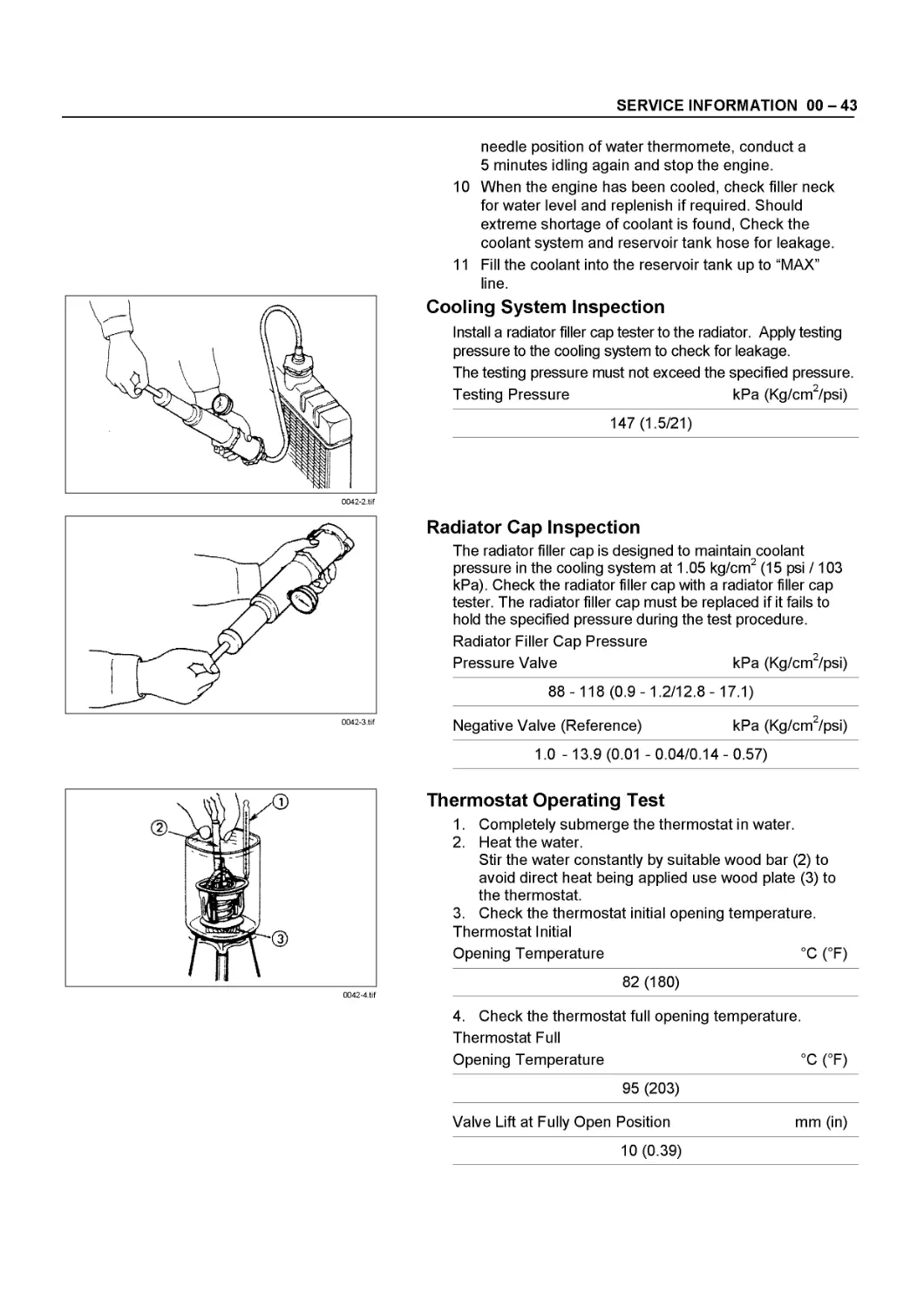
Cooling System Inspection
Install a radiator filler cap tester to the radiator. Apply testing pressure to the cooling system to check for leakage.
The testing pressure must not exceed the specified pressure.
Testing Pressure kPa (Kg/cm2/psi)
147 (1.5/21)
Radiator Cap Inspection
The radiator filler cap is designed to maintain coolant pressure in the cooling system at 1.05 kg/cm2 (15 psi /103 kPa). Check the radiator filler cap with a radiator filler cap tester. The radiator filler cap must be replaced if it fails to hold the specified pressure during the test procedure.
Radiator Filler Cap Pressure
Pressure Valve kPa (Kg/cm2/psi)
88-118(0.9-1.2/12.8-17.1)
Negative Valve (Reference) kPa (Kg/cm2/psi)
1.0 - 13.9 (0.01 -0.04/0.14-0.57)
0042-4.tif
Thermostat Operating Test
1. Completely submerge the thermostat in water.
2. Heat the water.
Stir the water constantly by suitable wood bar (2) to avoid direct heat being applied use wood plate (3) to the thermostat.
3. Check the thermostat initial opening temperature. Thermostat Initial
Opening Temperature °C (°F)
82 (180)
4. Check the thermostat full opening temperature.
Thermostat Full
Opening Temperature °C (°F)
95 (203)
Valve Lift at Fully Open Position mm (in)
10 (0.39)
00 - 44 SERVICE INFORMATION
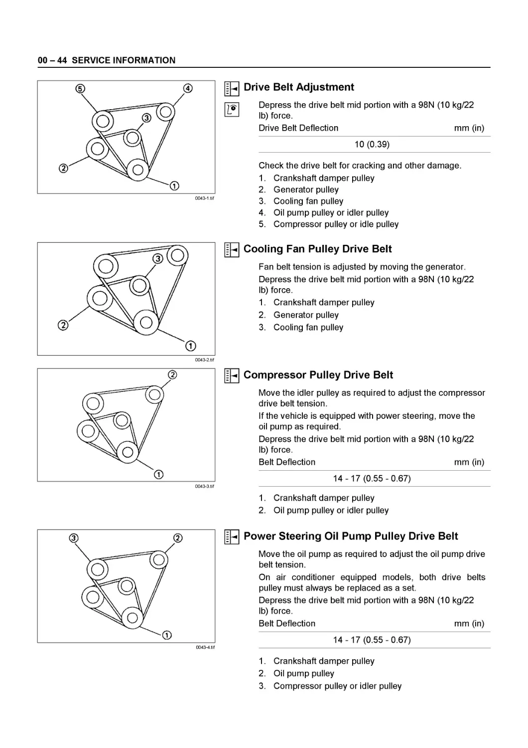
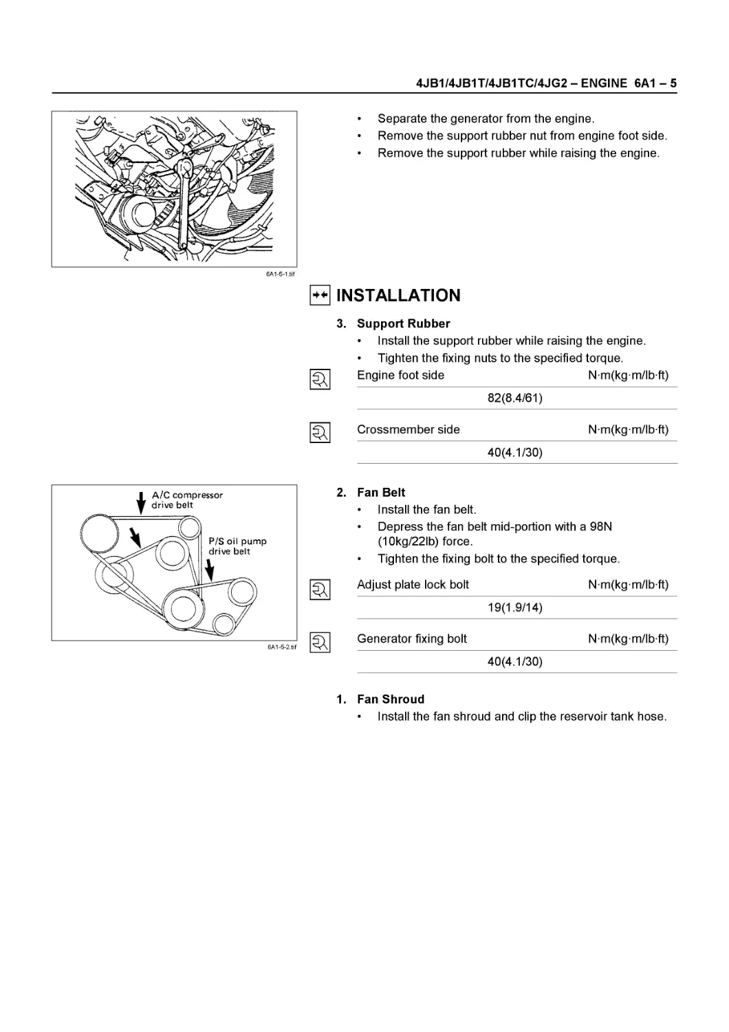
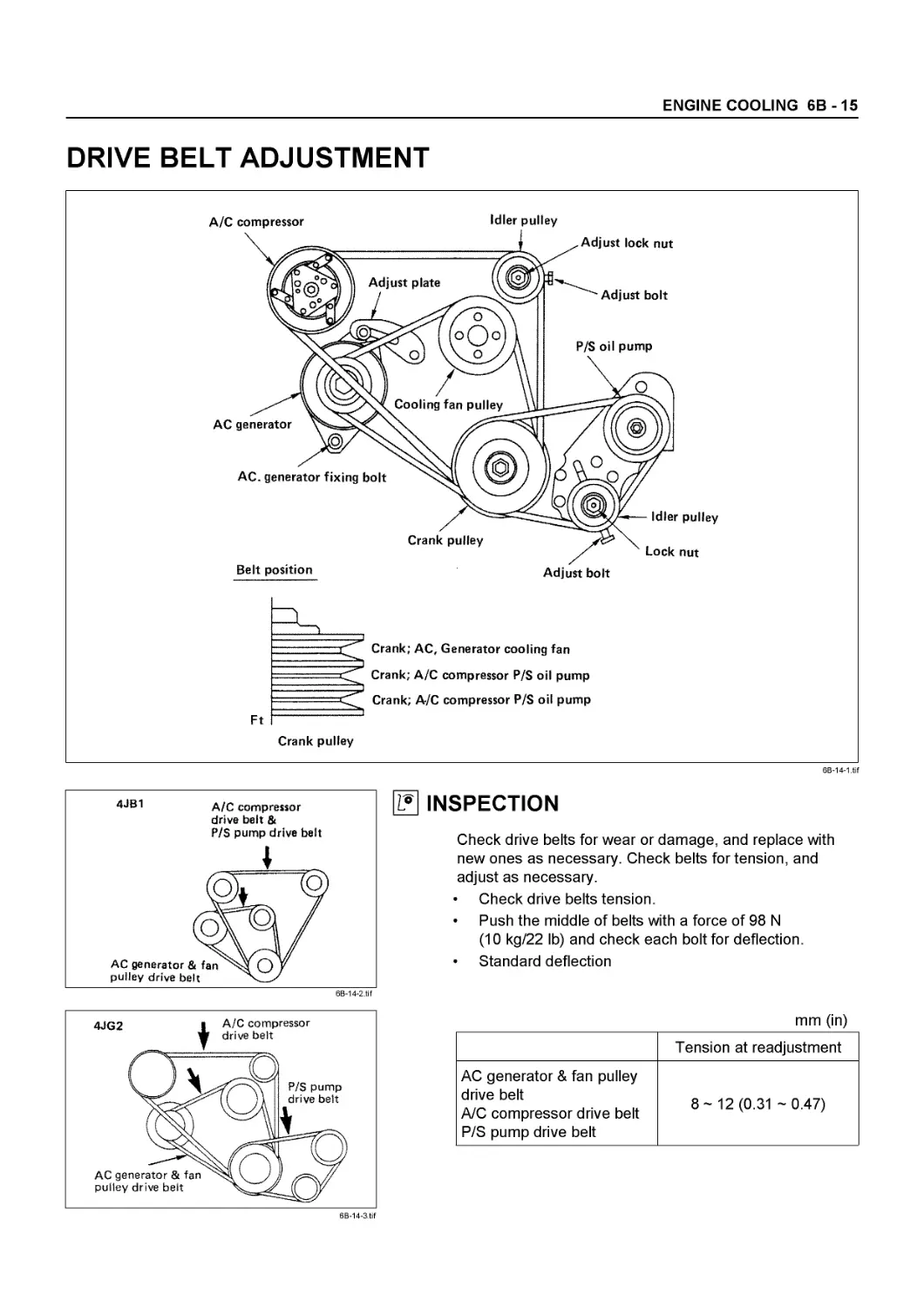
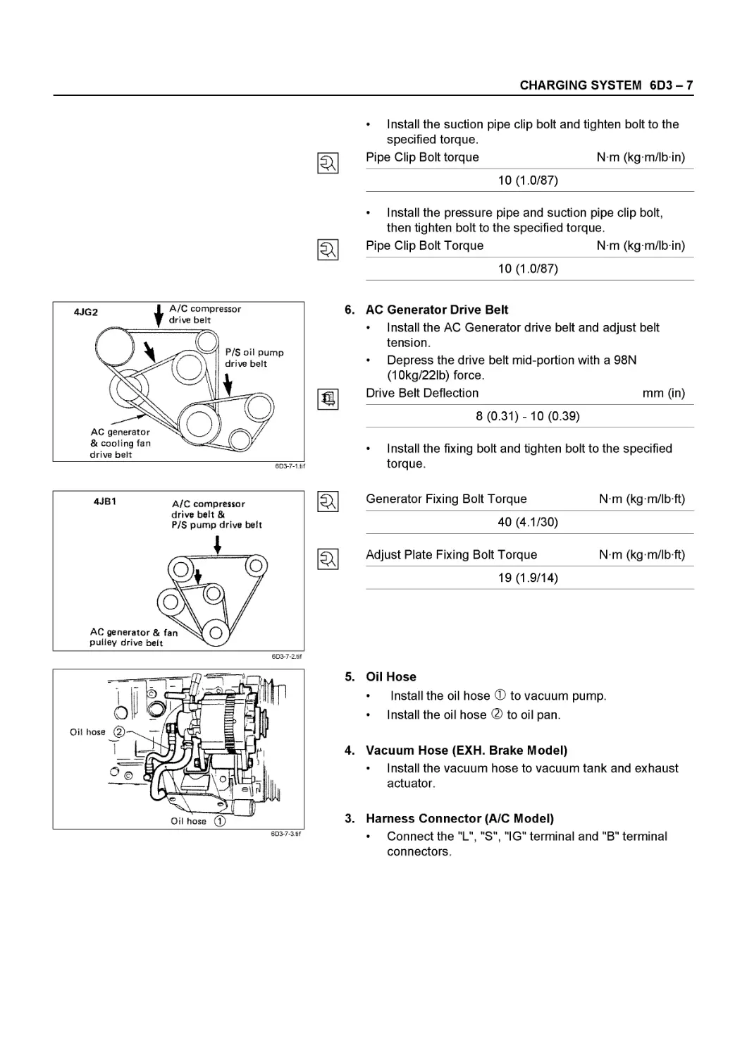
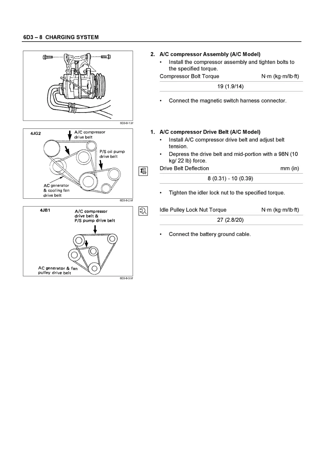
Drive Belt Adjustment
Depress the drive belt mid portion with a 98N (10 kg/22 lb) force.
Drive Belt Deflection mm (in)
10 (0.39)
Check the drive belt for cracking and other damage.
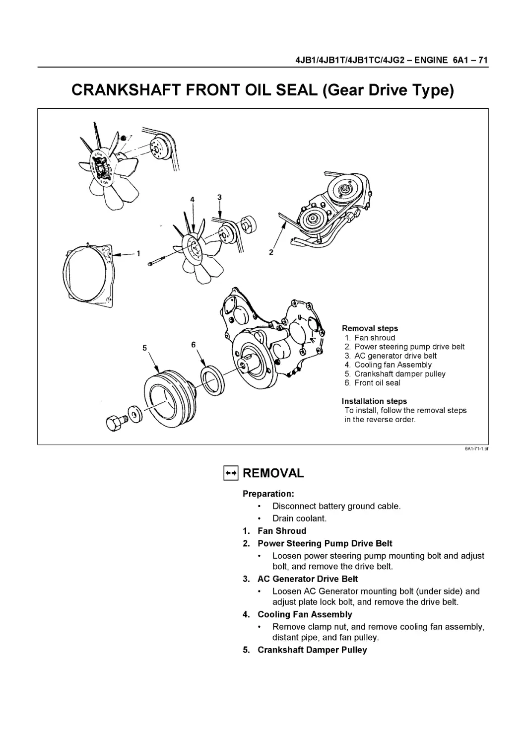
1. Crankshaft damper pulley
2. Generator pulley
3. Cooling fan pulley
4. Oil pump pulley or idler pulley
5. Compressor pulley or idle pulley
Cooling Fan Pulley Drive Belt
Fan belt tension is adjusted by moving the generator. Depress the drive belt mid portion with a 98N (10 kg/22 lb) force.
1. Crankshaft damper pulley
2. Generator pulley
3. Cooling fan pulley
Ip Compressor Pulley Drive Belt
Move the idler pulley as required to adjust the compressor drive belt tension.
If the vehicle is equipped with power steering, move the oil pump as required.
Depress the drive belt mid portion with a 98N (10 kg/22 lb) force.
Belt Deflection mm (in)
14- 17 (0.55-0.67)
1. Crankshaft damper pulley
2. Oil pump pulley or idler pulley
Ip Power Steering Oil Pump Pulley Drive Belt
Move the oil pump as required to adjust the oil pump drive belt tension.
On air conditioner equipped models, both drive belts pulley must always be replaced as a set.
Depress the drive belt mid portion with a 98N (10 kg/22 lb) force.
Belt Deflection mm (in)
14- 17 (0.55-0.67)
1. Crankshaft damper pulley
2. Oil pump pulley
3. Compressor pulley or idler pulley
SERVICE INFORMATION 00 - 45
ENGINE CONTROL
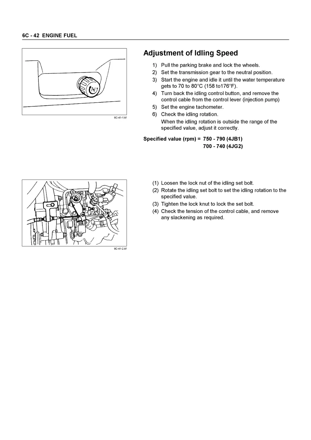
Idling Speed Inspection
1. Set the vehicle parking brake and choke the drive wheels.
2. Place the transmission in neutral.
3. Start the engine and allow it to warm up.
4. Disconnect the engine control cable from the control lever.
5. Set a tachometer to the engine.
6. Check the engine idling speed.
If the engine idling speed is outside the specified range, it must be adjusted.
Engine Idling Speed rpm
4JB1 / 4JB1T / 4JB1TC 750 - 790
4JG2 700 - 740
0044-1 .tif
0044-2.tif
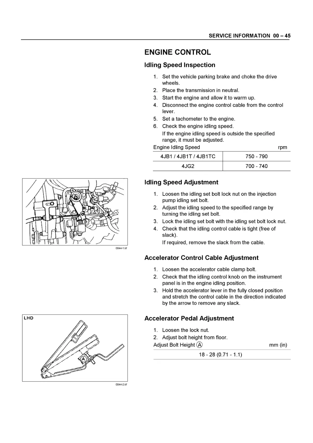
Idling Speed Adjustment
1. Loosen the idling set bolt lock nut on the injection pump idling set bolt.
2. Adjust the idling speed to the specified range by turning the idling set bolt.
3. Lock the idling set bolt with the idling set bolt lock nut.
4. Check that the idling control cable is tight (free of slack).
If required, remove the slack from the cable.
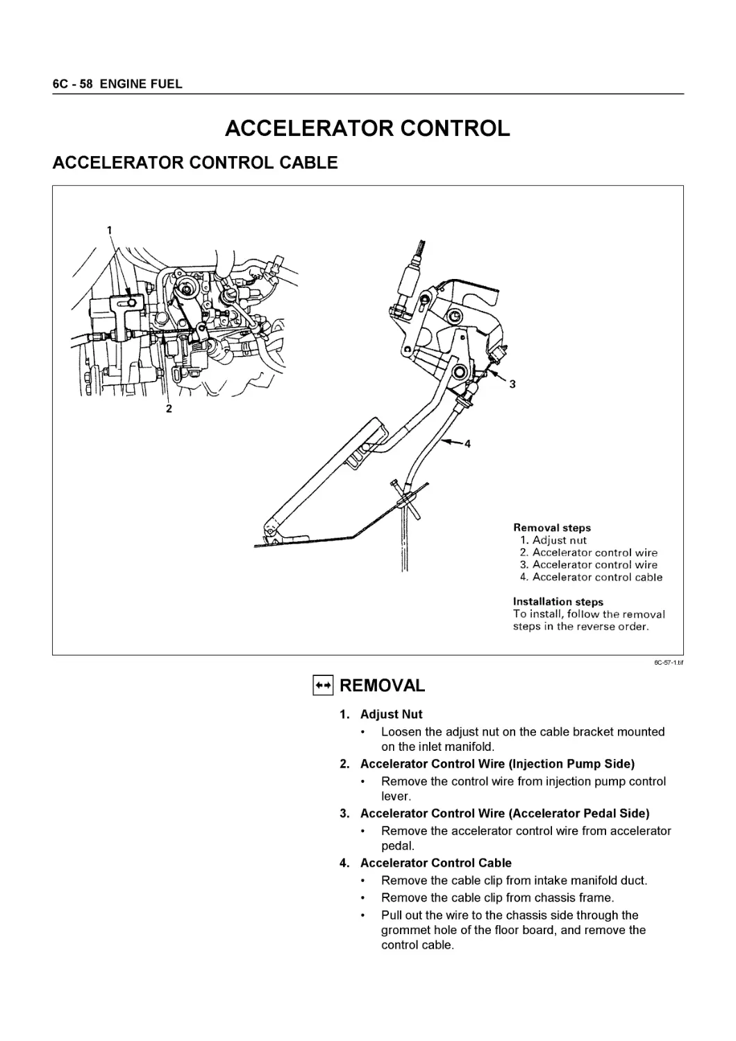
Accelerator Control Cable Adjustment
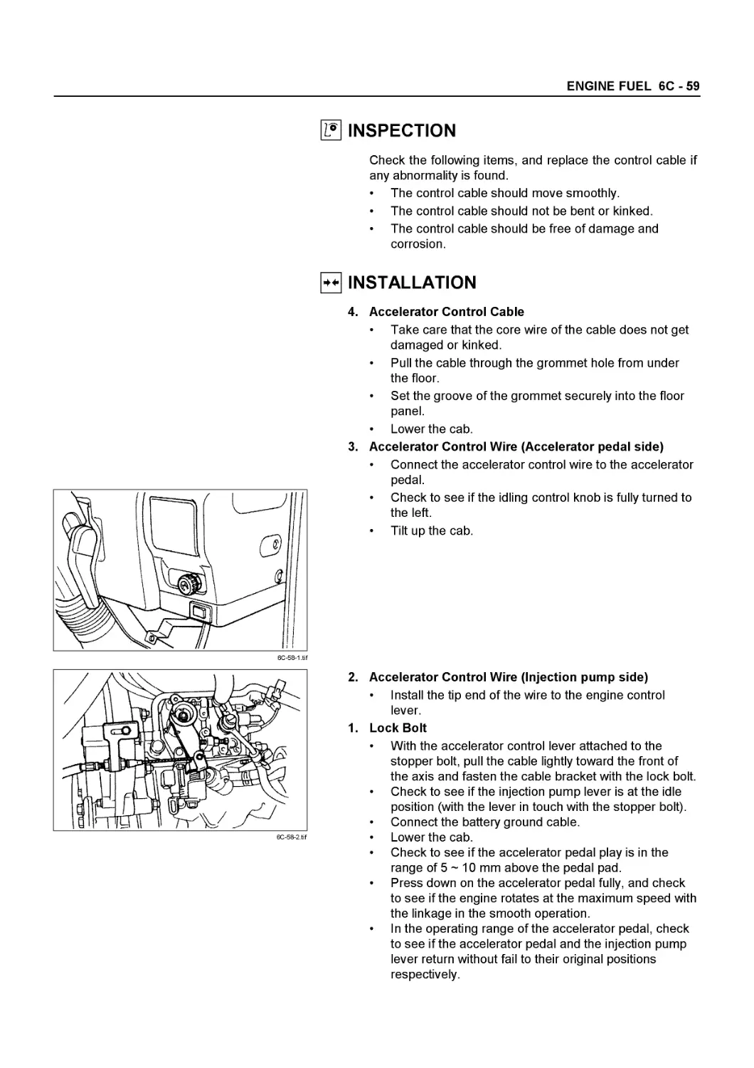
1. Loosen the accelerator cable clamp bolt.
2. Check that the idling control knob on the instrument panel is in the engine idling position.
3. Hold the accelerator lever in the fully closed position and stretch the control cable in the direction indicated by the arrow to remove any slack.
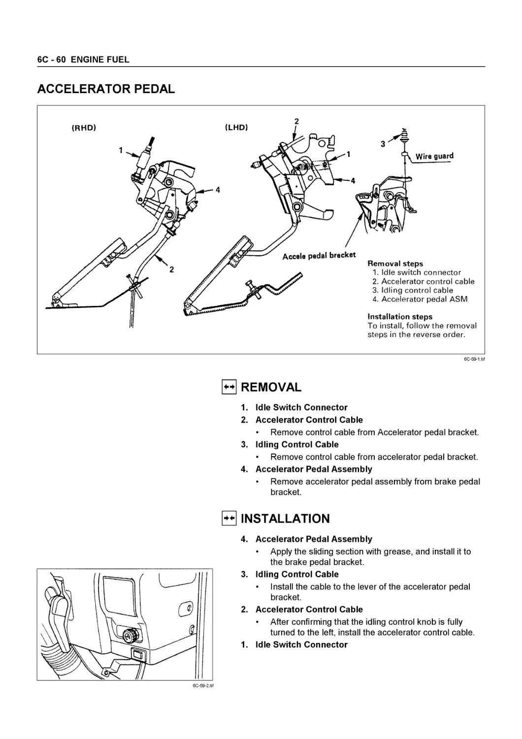
Accelerator Pedal Adjustment
1. Loosen the lock nut.
2. Adjust bolt height from floor.
Adjust Bolt Height (A) mm (in)
18-28 (0.71 -1.1)
00 - 46 SERVICE INFORMATION
0045-1 .tif
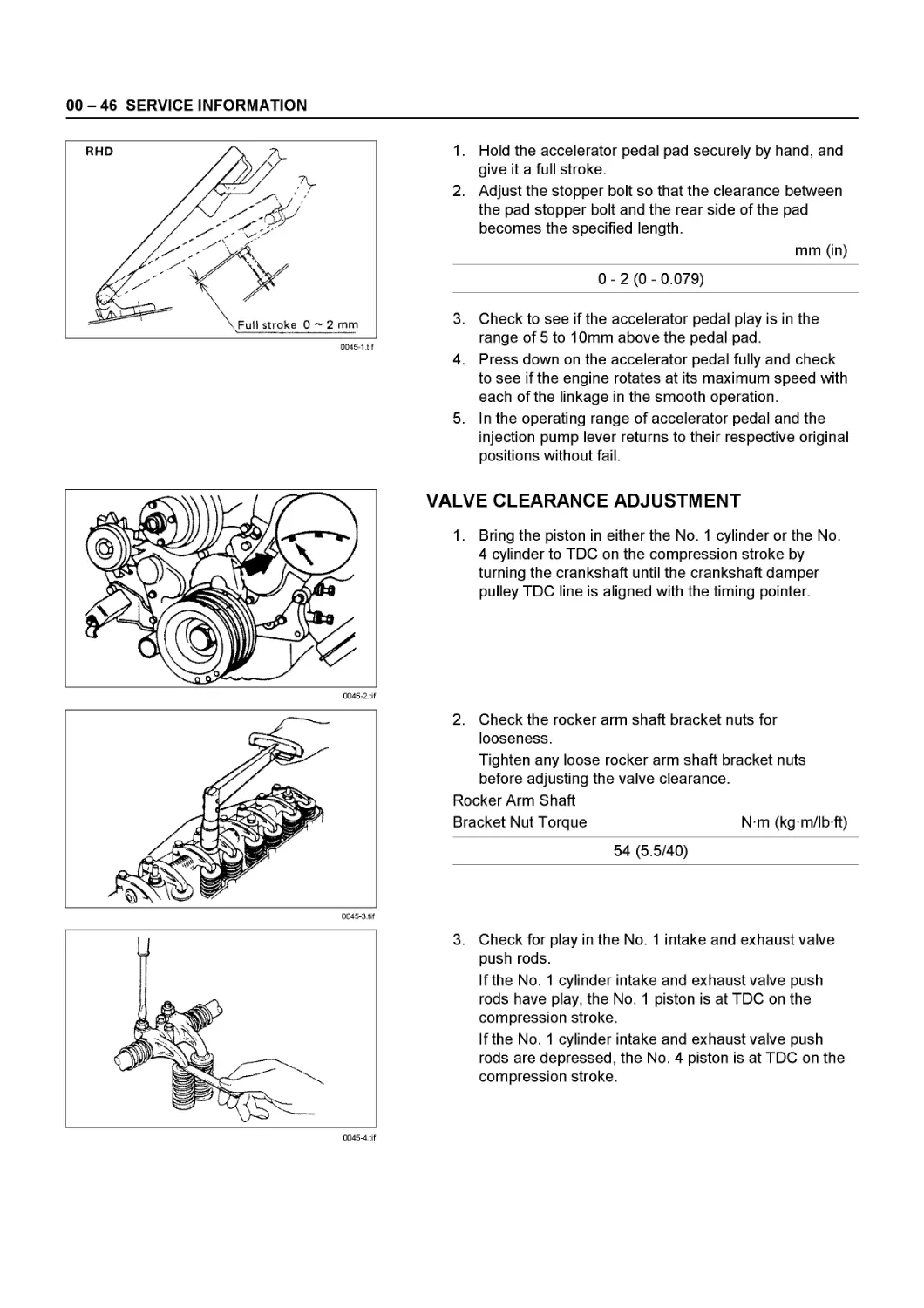
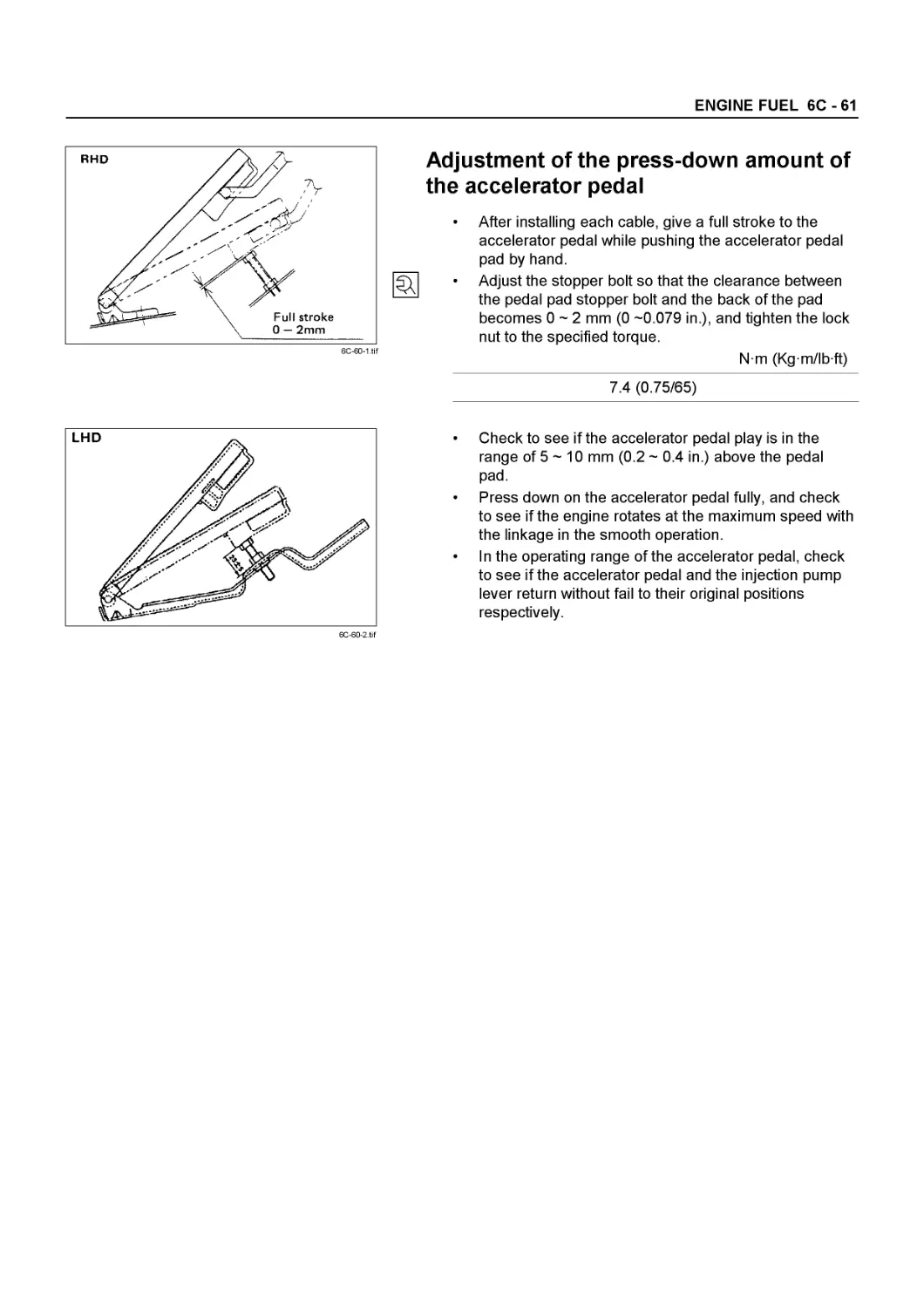
1. Hold the accelerator pedal pad securely by hand, and give it a full stroke.
2. Adjust the stopper bolt so that the clearance between the pad stopper bolt and the rear side of the pad becomes the specified length.
mm (in)
0 - 2 (0 - 0.079)
0045-2.tif
3. Check to see if the accelerator pedal play is in the range of 5 to 10mm above the pedal pad.
4. Press down on the accelerator pedal fully and check to see if the engine rotates at its maximum speed with each of the linkage in the smooth operation.
5. In the operating range of accelerator pedal and the injection pump lever returns to their respective original positions without fail.
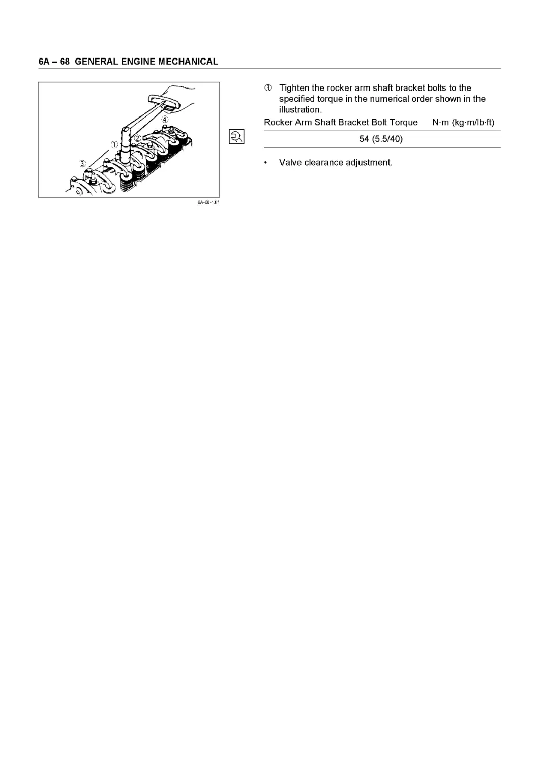
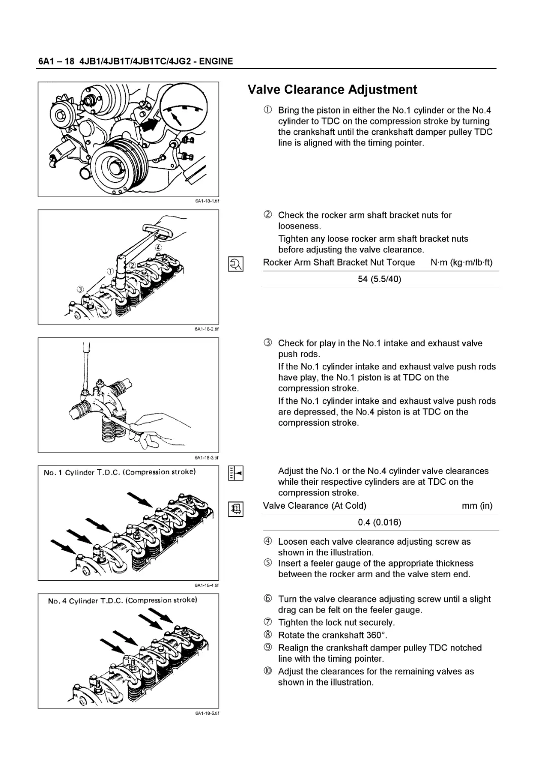
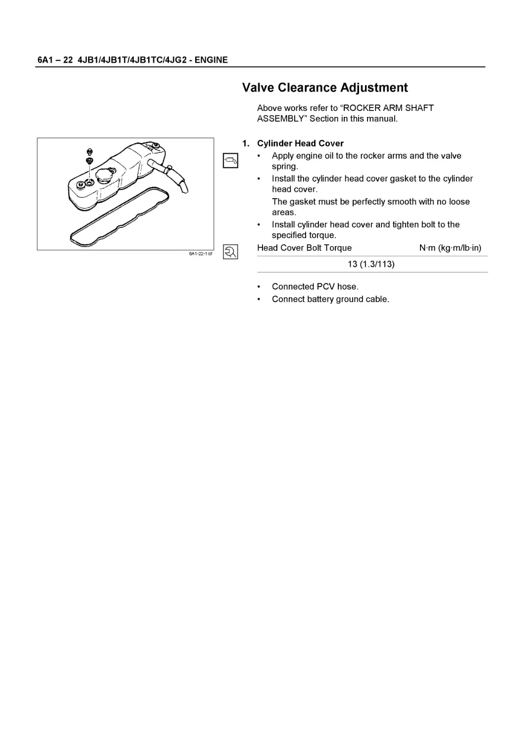
VALVE CLEARANCE ADJUSTMENT
1. Bring the piston in either the No. 1 cylinder or the No. 4 cylinder to TDC on the compression stroke by turning the crankshaft until the crankshaft damper pulley TDC line is aligned with the timing pointer.
2. Check the rocker arm shaft bracket nuts for looseness.
Tighten any loose rocker arm shaft bracket nuts before adjusting the valve clearance.
Rocker Arm Shaft
Bracket Nut Torque Nm (kgm/lbft)
54 (5.5/40)
0045-4.tif
3. Check for play in the No. 1 intake and exhaust valve push rods.
If the No. 1 cylinder intake and exhaust valve push rods have play, the No. 1 piston is at TDC on the compression stroke.
If the No. 1 cylinder intake and exhaust valve push rods are depressed, the No. 4 piston is at TDC on the compression stroke.
SERVICE INFORMATION 00 - 47
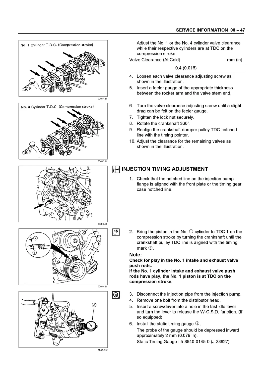
No. 1 Cylinder T.D.C. (Compression stroke)
0046-1 .tif
Adjust the No. 1 or the No. 4 cylinder valve clearance while their respective cylinders are at TDC on the compression stroke.
Valve Clearance (At Cold) mm (in)
0.4 (0.016)
4. Loosen each valve clearance adjusting screw as shown in the illustration.
5. Insert a feeler gauge of the appropriate thickness between the rocker arm and the valve stem end.
6. Turn the valve clearance adjusting screw until a slight drag can be felt on the feeler gauge.
7. Tighten the lock nut securely.
8. Rotate the crankshaft 360°.
9. Realign the crankshaft damper pulley TDC notched line with the timing pointer.
10. Adjust the clearance for the remaining valves as shown in the illustration.
0046-3.tif
Щ INJECTION TIMING ADJUSTMENT
1. Check that the notched line on the injection pump flange is aligned with the front plate or the timing gear case notched line.
0046-4.tif
2. Bring the piston in the No. Ф cylinder to TDC 1 on the compression stroke by turning the crankshaft until the crankshaft pulley TDC line is aligned with the timing mark ®.
Note:
Check for play in the No. 1 intake and exhaust valve push rods.
If the No. 1 cylinder intake and exhaust valve push rods have play, the No. 1 piston is at TDC on the compression stroke.
3. Disconnect the injection pipe from the injection pump.
4. Remove one bolt from the distributor head.
5. Insert a screwdriver into a hole in the fast idle lever and turn the lever to release the W-C.S.D. function. (If so equipped)
6. Install the static timing gauge ®.
The probe of the gauge should be depressed inward approximately 2 mm (0.079 in).
Static Timing Gauge : 5-8840-0145-0 (J-28827)
0046-5.tif
00 - 48 SERVICE INFORMATION
0047-1.tif
0047-2.tif
0047-3.tif
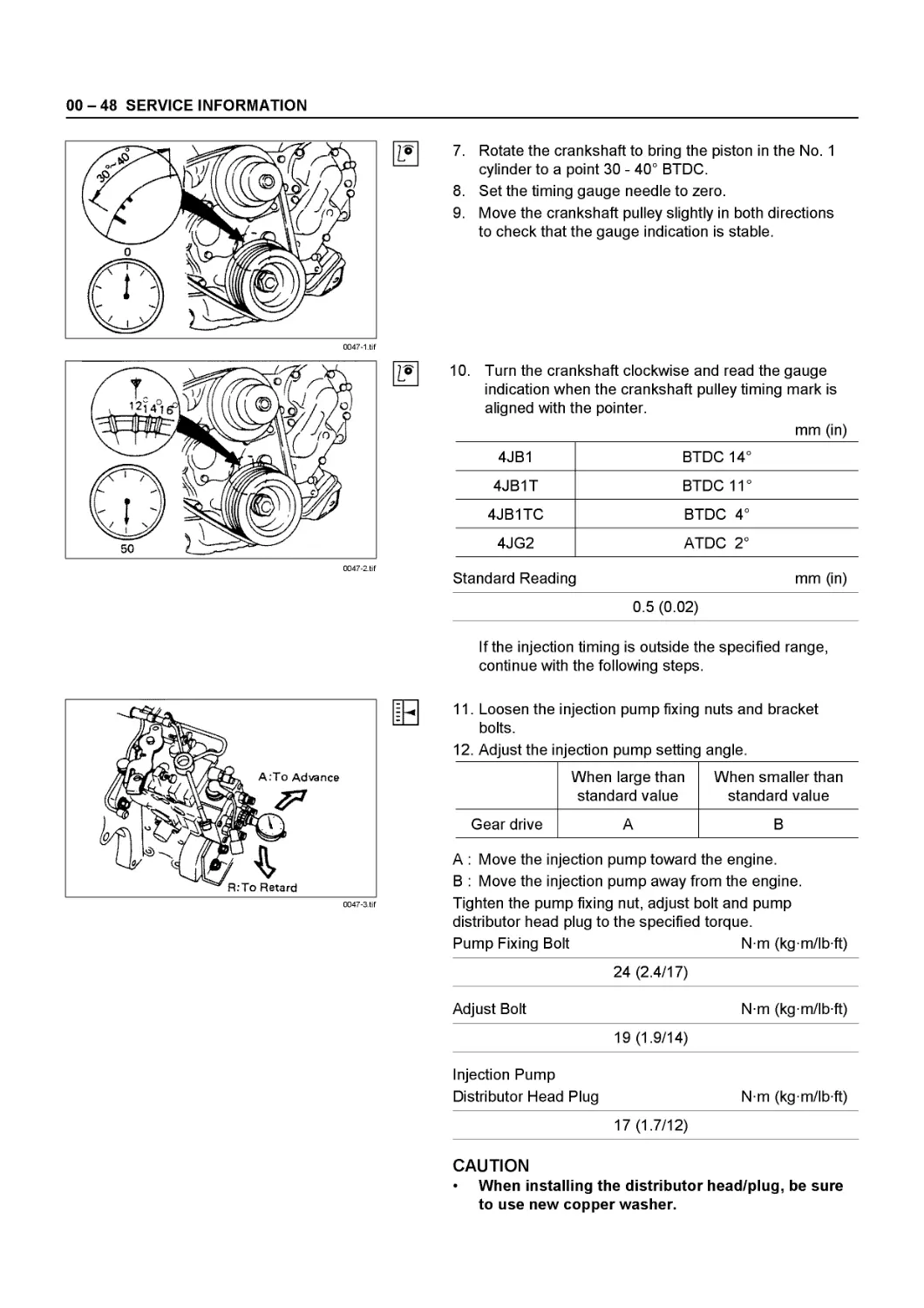
7. Rotate the crankshaft to bring the piston in the No. 1 cylinder to a point 30 - 40° BTDC.
8. Set the timing gauge needle to zero.
9. Move the crankshaft pulley slightly in both directions to check that the gauge indication is stable.
10. Turn the crankshaft clockwise and read the gauge indication when the crankshaft pulley timing mark is aligned with the pointer.
mm (in)
4JB1 BTDC 14°
4JB1T BTDC 11 °
4JB1TC BTDC 4°
4JG2 ATDC 2°
Standard Reading mm (in)
0.5 (0.02)
If the injection timing is outside the specified range, continue with the following steps.
11. Loosen the injection pump fixing nuts and bracket
bolts.
12. Adjust the injection pump setting angle.
When large than standard value When smaller than standard value
Gear drive A В
A : Move the injection pump toward the engine.
В : Move the injection pump away from the engine. Tighten the pump fixing nut, adjust bolt and pump distributor head plug to the specified torque.
Pump Fixing Bolt Nm (kgm/lbft)
24 (2.4/17)
Adjust Bolt Nm (kg m/lb ft)
19 (1.9/14)
Injection Pump Distributor Head Plug Nm (kg m/lb ft)
17 (1.7/12)
CAUTION
* When installing the distributor head/plug, be sure to use new copper washer.
SERVICE INFORMATION 00 - 49
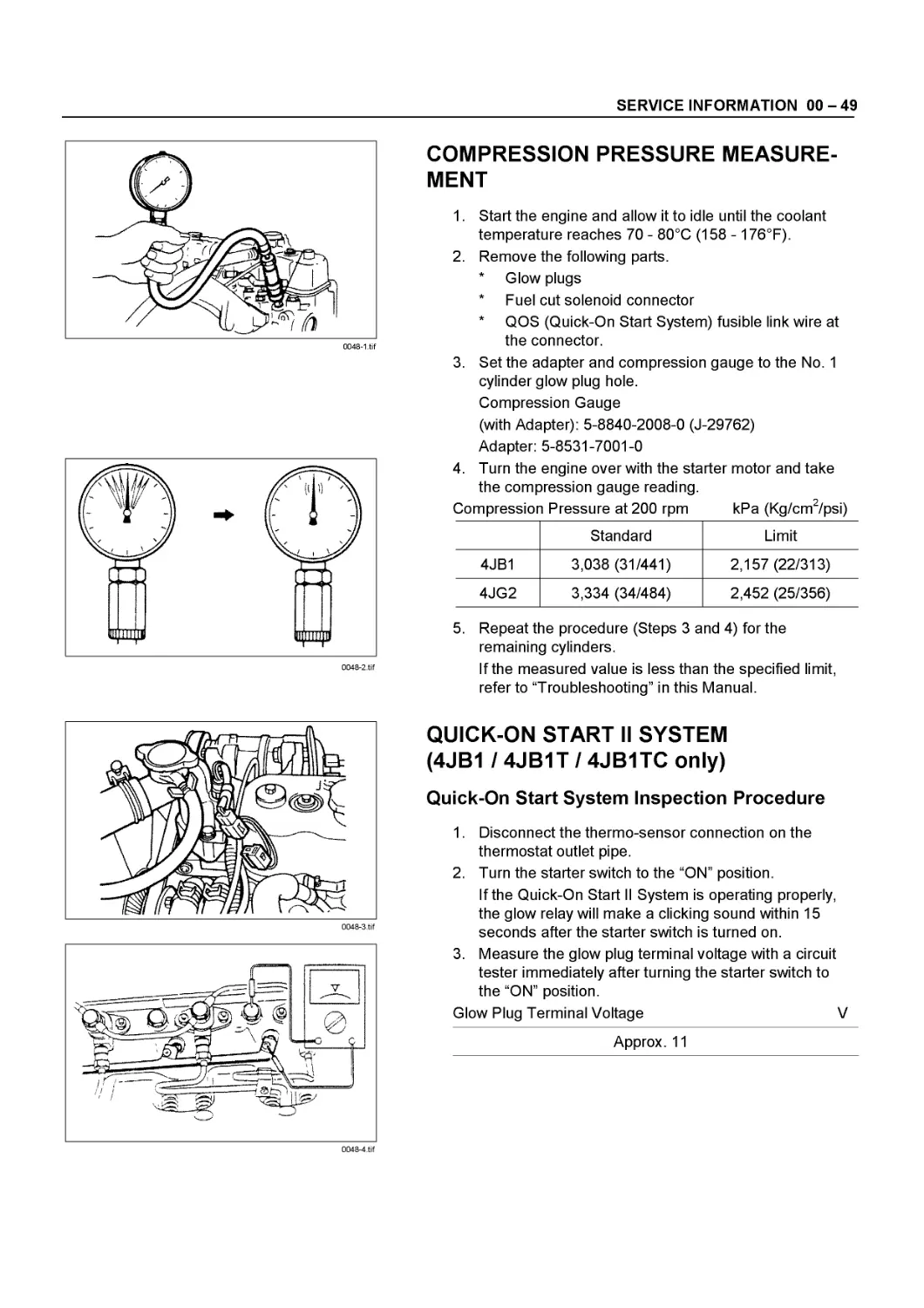
COMPRESSION PRESSURE MEASUREMENT
1. Start the engine and allow it to idle until the coolant temperature reaches 70 - 80°C (158 - 176°F).
2. Remove the following parts.
* Glow plugs
* Fuel cut solenoid connector
* QOS (Quick-On Start System) fusible link wire at the connector.
3. Set the adapter and compression gauge to the No. 1 cylinder glow plug hole. Compression Gauge (with Adapter): 5-8840-2008-0 (J-29762) Adapter: 5-8531-7001-0
0048-2.tif
4. Turn the engine over with the starter motor and take the compression gauge reading.
Compression Pressure at 200 rpm kPa (Kg/cm2/psi)
Standard Limit
4JB1 3,038 (31/441) 2,157 (22/313)
4JG2 3,334 (34/484) 2,452 (25/356)
0048-3.tif
0048-4.tif
5. Repeat the procedure (Steps 3 and 4) for the remaining cylinders.
If the measured value is less than the specified limit, refer to “Troubleshooting” in this Manual.
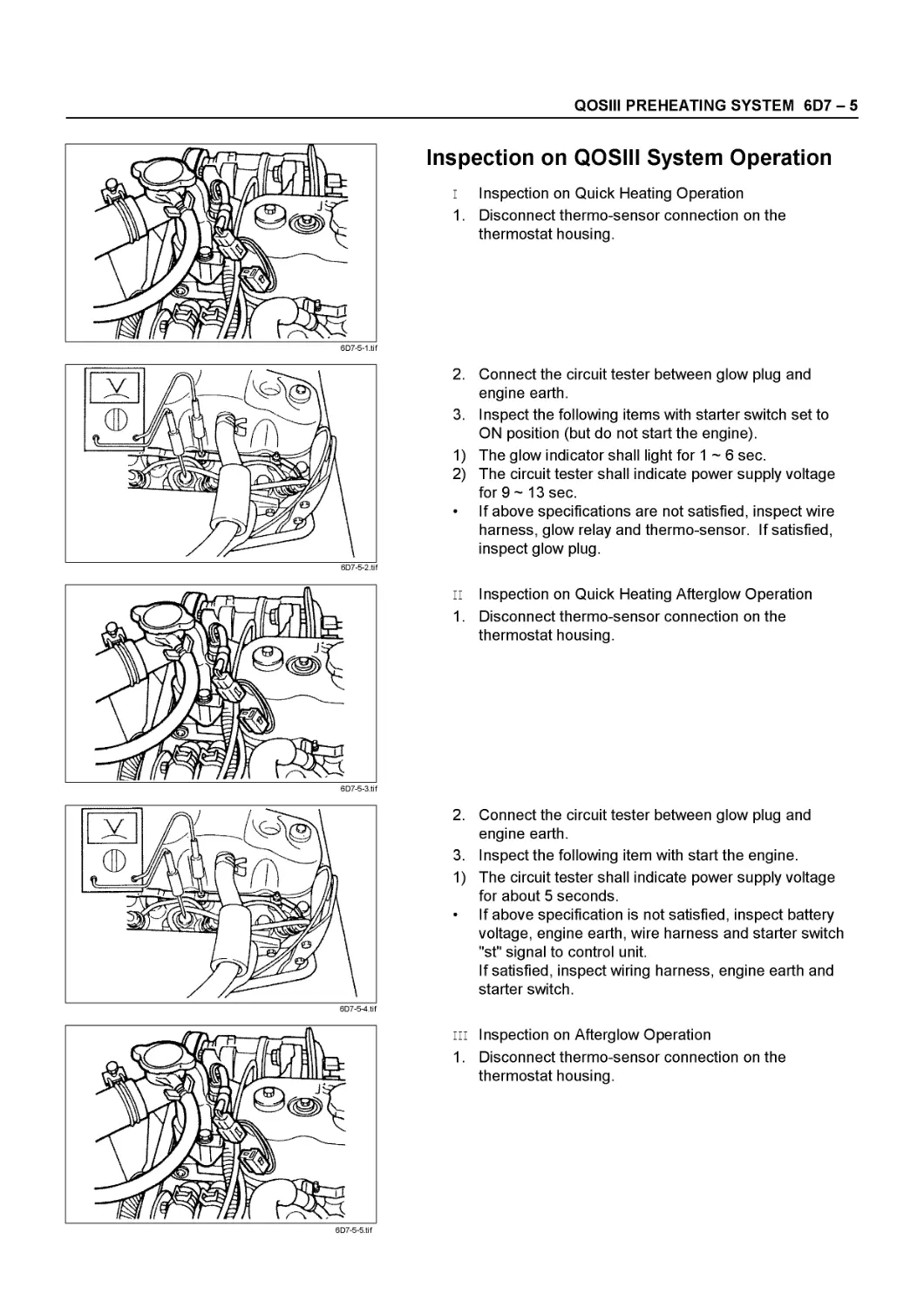
QUICK-ON START II SYSTEM (4JB1 / 4JB1T / 4JB1TC only)
Quick-On Start System Inspection Procedure
1. Disconnect the thermo-sensor connection on the thermostat outlet pipe.
2. Turn the starter switch to the “ON” position.
If the Quick-On Start II System is operating properly, the glow relay will make a clicking sound within 15 seconds after the starter switch is turned on.
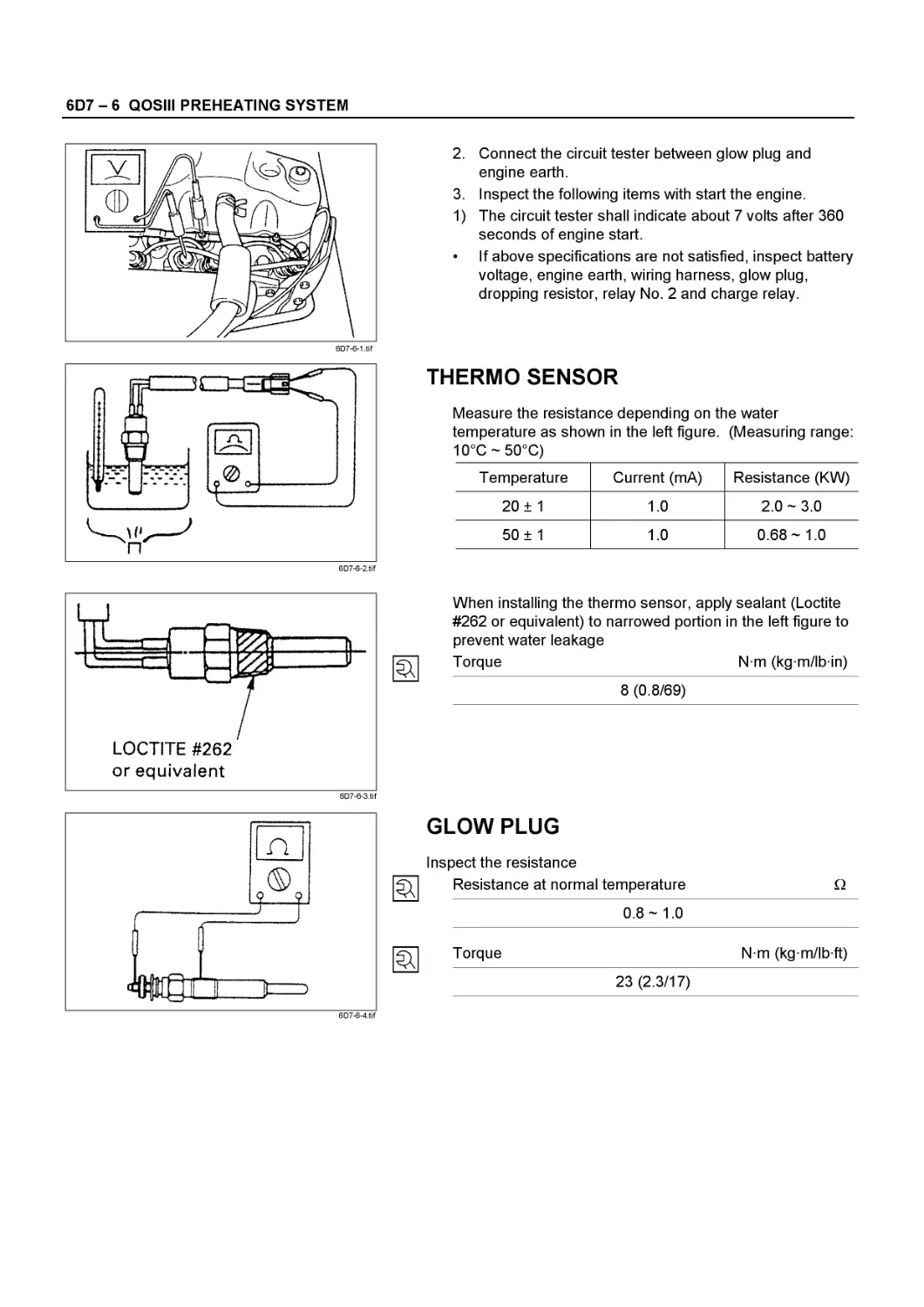
3. Measure the glow plug terminal voltage with a circuit tester immediately after turning the starter switch to the “ON” position.
Glow Plug Terminal Voltage V
Approx. 11
00 - 50 SERVICE INFORMATION
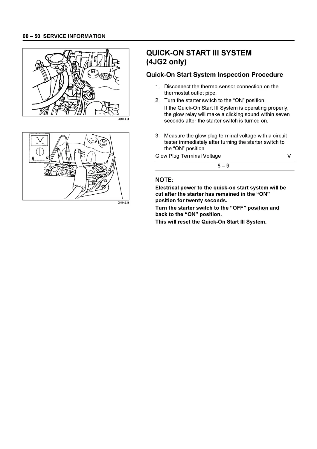
QUICK-ON START III SYSTEM (4JG2 only)
Quick-On Start System Inspection Procedure
1. Disconnect the thermo-sensor connection on the thermostat outlet pipe.
2. Turn the starter switch to the “ON” position.
If the Quick-On Start III System is operating properly, the glow relay will make a clicking sound within seven seconds after the starter switch is turned on.
3. Measure the glow plug terminal voltage with a circuit tester immediately after turning the starter switch to the “ON” position.
Glow Plug Terminal Voltage V
8-9
NOTE:
Electrical power to the quick-on start system will be cut after the starter has remained in the “ON” position for twenty seconds.
Turn the starter switch to the “OFF” position and back to the “ON” position.
This will reset the Quick-On Start III System.
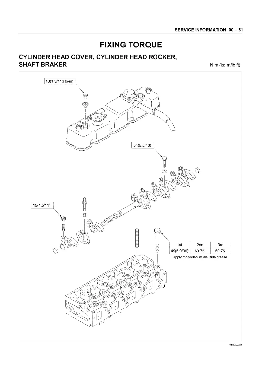
SERVICE INFORMATION 00 - 51
FIXING TORQUE
CYLINDER HEAD COVER, CYLINDER HEAD ROCKER,
SHAFT BRAKER
N m (kg m/lb ft)
011 LX002.tif
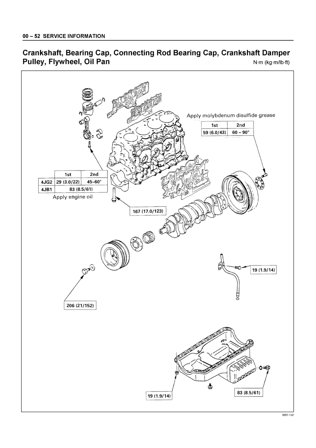
00 - 52 SERVICE INFORMATION
Crankshaft, Bearing Cap, Connecting Rod Bearing Cap, Crankshaft Damper
Pulley, Flywheel, Oil Pan N-m (kg-m/ib-ft)
0051-1.tif
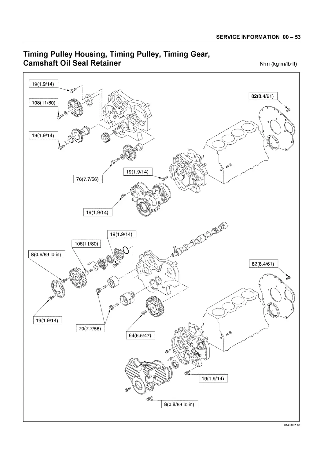
SERVICE INFORMATION 00 - 53
Timing Pulley Housing, Timing Pulley, Timing Gear, Camshaft Oil Seal Retainer
N m (kg m/lb ft)
014LX001.tif
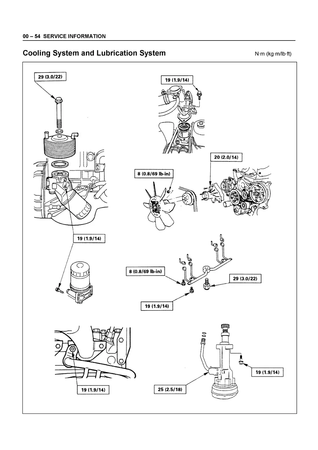
00 - 54 SERVICE INFORMATION
Cooling System and Lubrication System
N m (kg m/lb ft)
SERVICE INFORMATION 00 - 55
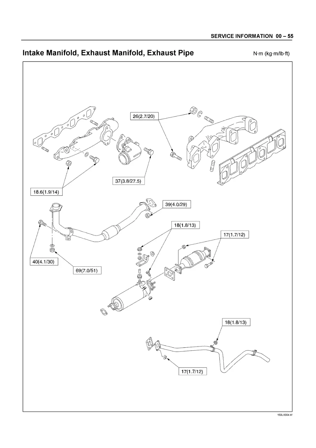
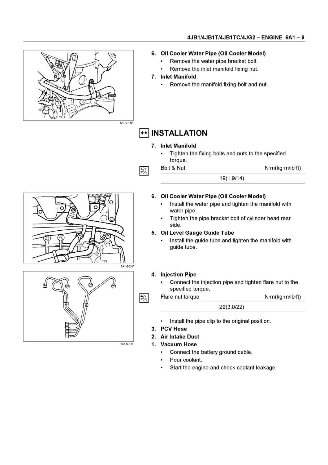
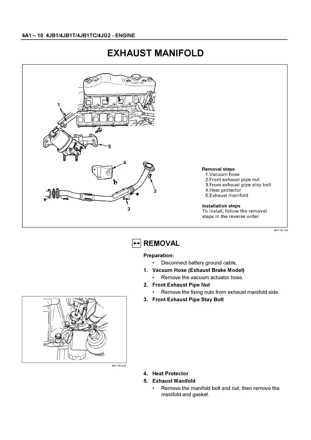
Intake Manifold, Exhaust Manifold, Exhaust Pipe n m (kgm/ibft)
18.6(1.9/14)
18(1.8/13)
150LX004.tif
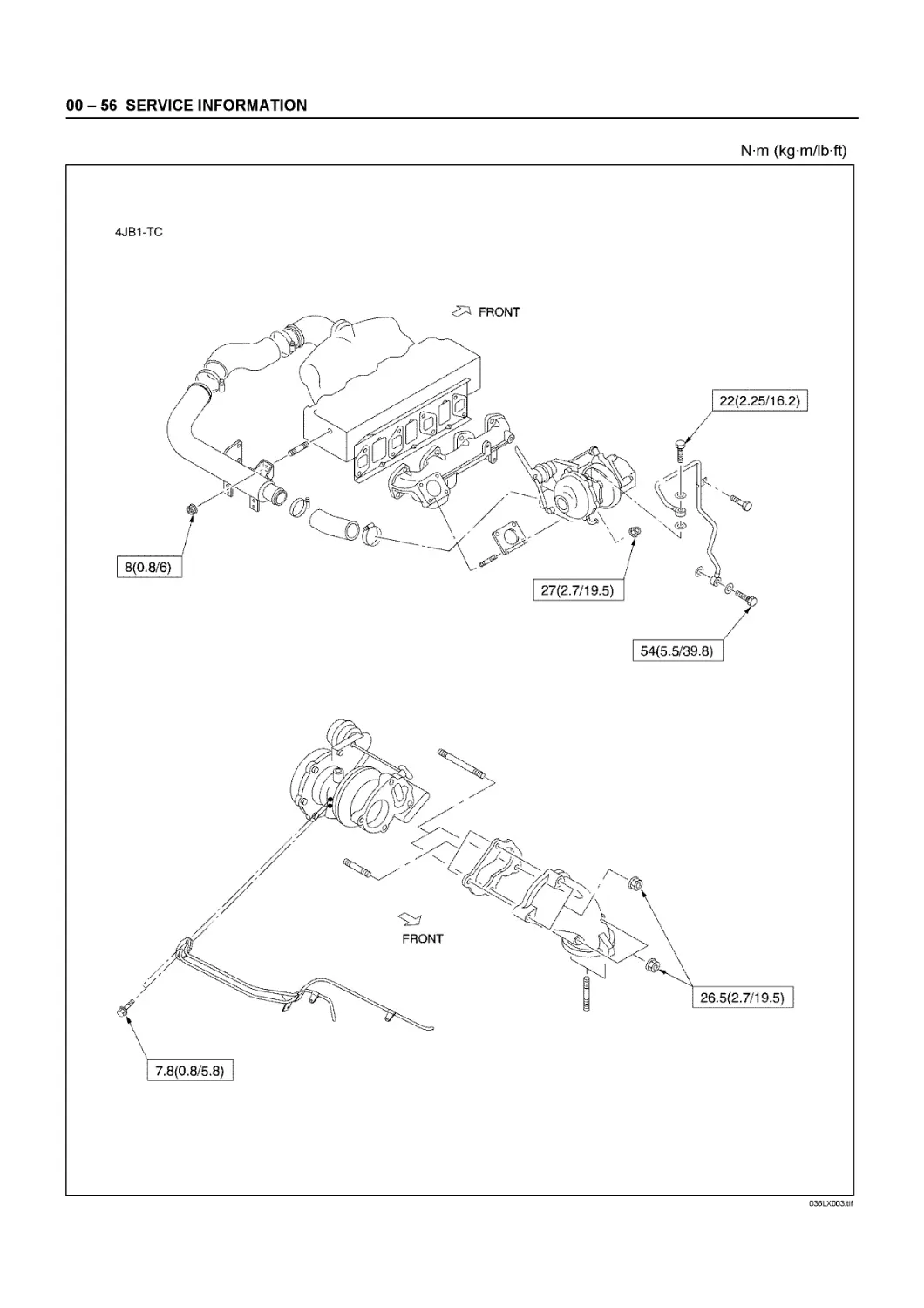
00 - 56 SERVICE INFORMATION
N m (kg m/lb ft)
036LX003.tif
SERVICE INFORMATION 00 - 57
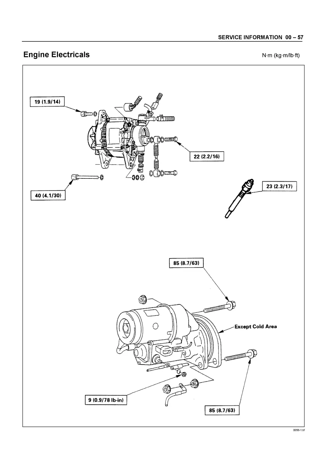
Engine Electricals
N m (kg m/lb ft)
0056-1.tif
00 - 58 SERVICE INFORMATION
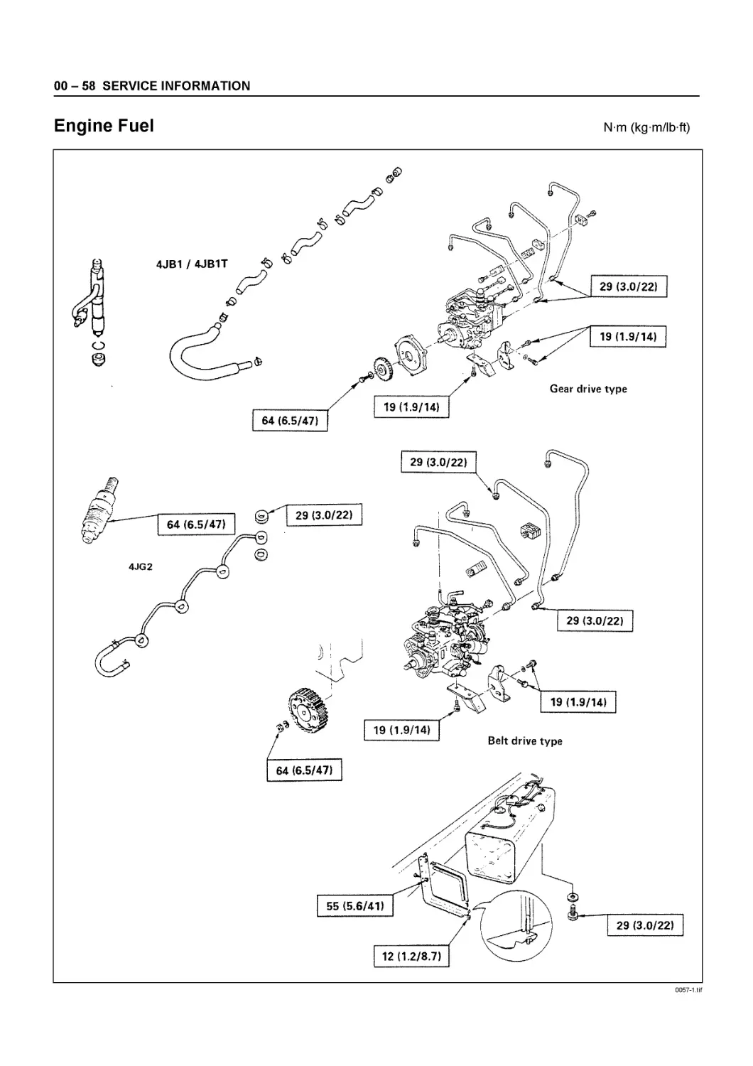
Engine Fuel
N m (kg m/lb ft)
0057-1.tif
SERVICE INFORMATION 00 - 59
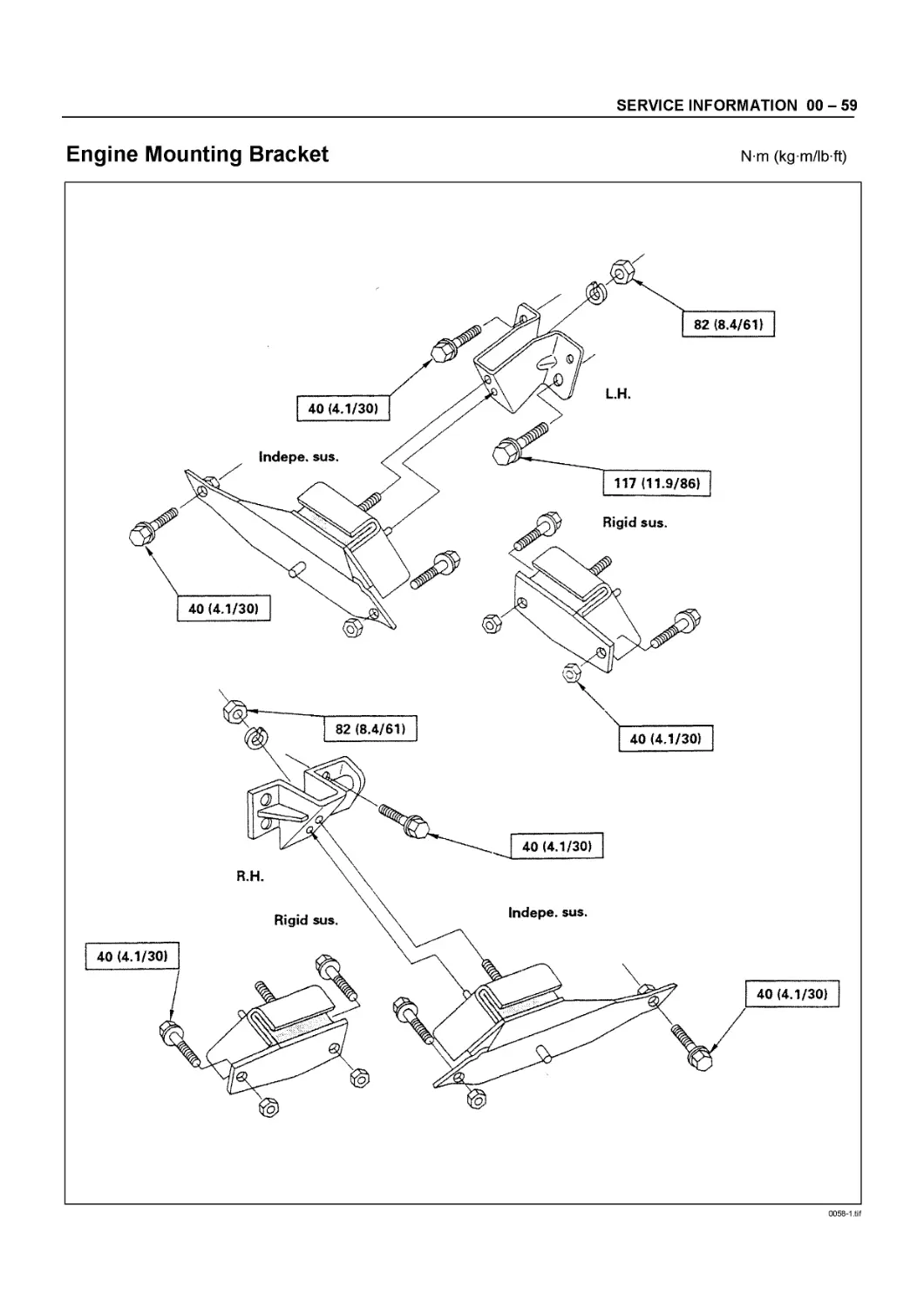
Engine Mounting Bracket
N m (kg m/lb ft)
0058-1.tif
00 - 60 SERVICE INFORMATION
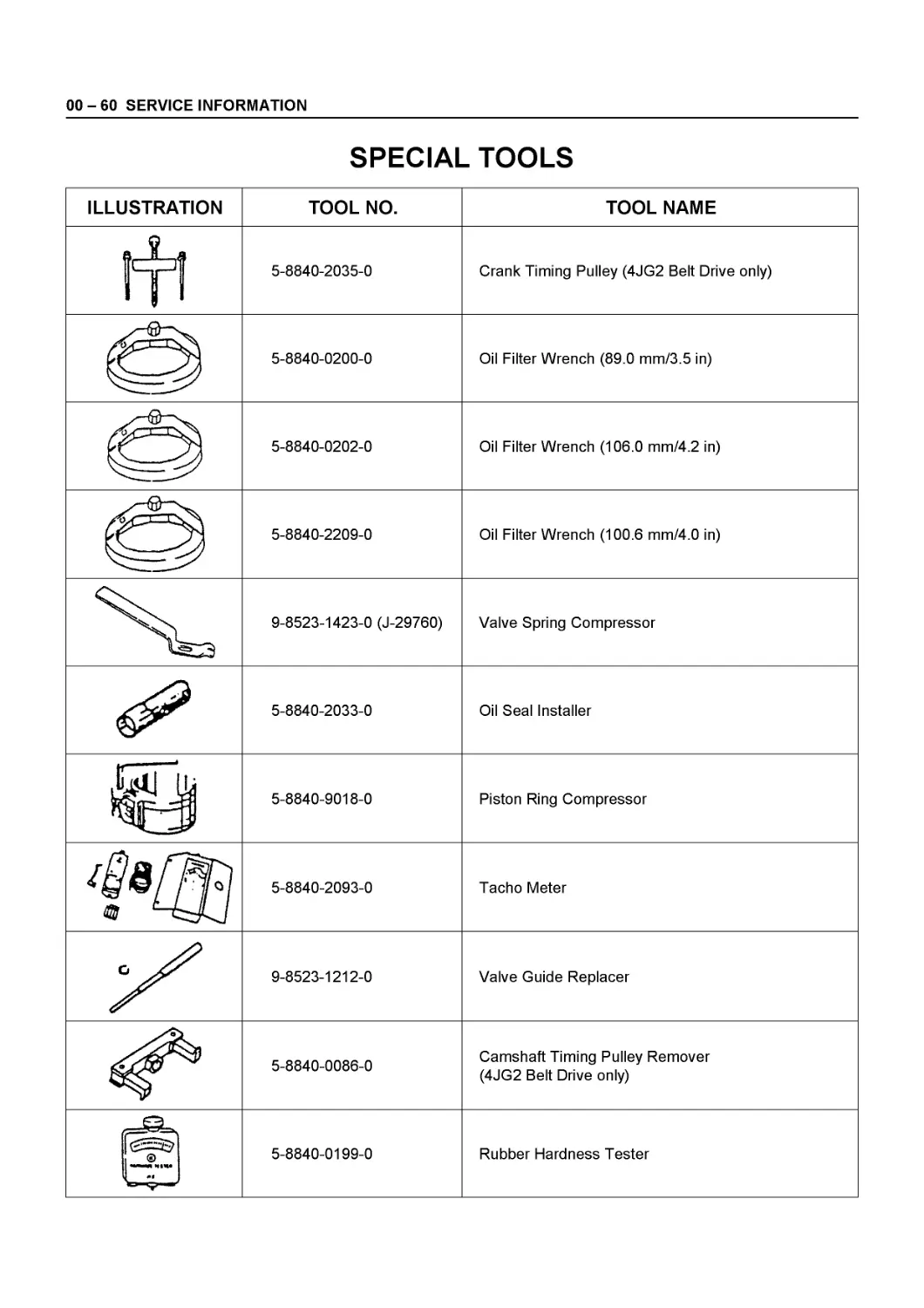
SPECIAL TOOLS
ILLUSTRATION TOOL NO. TOOL NAME
«1 TIT я® 5-8840-2035-0 Crank Timing Pulley (4JG2 Belt Drive only)
5-8840-0200-0 Oil Filter Wrench (89.0 mm/3.5 in)
5-8840-0202-0 Oil Filter Wrench (106.0 mm/4.2 in)
5-8840-2209-0 Oil Filter Wrench (100.6 mm/4.0 in)
9-8523-1423-0 (J-29760) Valve Spring Compressor
5-8840-2033-0 Oil Seal Installer
tau' |j 5-8840-9018-0 Piston Ring Compressor
^sf^i am 5-8840-2093-0 Tacho Meter
9-8523-1212-0 Valve Guide Replacer
5-8840-0086-0 Camshaft Timing Pulley Remover (4JG2 Belt Drive only)
c''®^ •** Mtwa 5-8840-0199-0 Rubber Hardness Tester
SERVICE INFORMATION 00 - 61
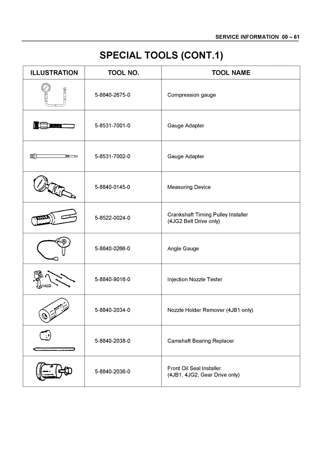
SPECIAL TOOLS (CONT.1)
ILLUSTRATION TOOL NO. TOOL NAME
® § 5-8840-2675-0 Compression gauge
5-8531-7001-0 Gauge Adapter
(ВД =!=> 5-8531-7002-0 Gauge Adapter
5-8840-0145-0 Measuring Device
5-8522-0024-0 Crankshaft Timing Pulley Installer (4JG2 Belt Drive only)
5-8840-0266-0 Angle Gauge
5-8840-9016-0 Injection Nozzle Tester
5-8840-2034-0 Nozzle Holder Remover (4JB1 only)
4 t 5-8840-2038-0 Camshaft Bearing Replacer
5-8840-2036-0 Front Oil Seal Installer (4JB1,4JG2, Gear Drive only)
00 - 62 SERVICE INFORMATION
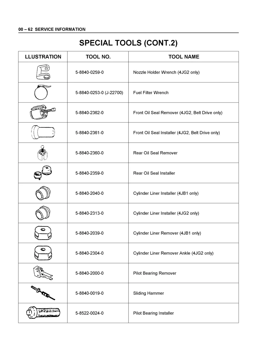
SPECIAL TOOLS (CONT.2)
LLUSTRATION TOOL NO. TOOL NAME
5-8840-0259-0 Nozzle Holder Wrench (4JG2 only)
5-8840-0253-0 (J-22700) Fuel Filter Wrench
5-8840-2362-0 Front Oil Seal Remover (4JG2, Belt Drive only)
CD 5-8840-2361-0 Front Oil Seal Installer (4JG2, Belt Drive only)
5-8840-2360-0 Rear Oil Seal Remover
a СЭ 5-8840-2359-0 Rear Oil Seal Installer
5-8840-2040-0 Cylinder Liner Installer (4JB1 only)
5-8840-2313-0 Cylinder Liner Installer (4JG2 only)
^ €> 5-8840-2039-0 Cylinder Liner Remover (4JB1 only)
<£> Lj IJ 5-8840-2304-0 Cylinder Liner Remover Ankle (4JG2 only)
5-8840-2000-0 Pilot Bearing Remover
5-8840-0019-0 Sliding Hammer
у., J. St» 5-8522-0024-0 Pilot Bearing Installer
SERVICE INFORMATION 00 - 63
MEMO
GENERAL ENGINE MECHANICAL 6A - 1
SECTION 6A
GENERAL ENGINE MECHANICAL
CONTENTS
PAGE
Cylinder Head............................................... 6A - 2
Valve Spring, Valve Guide Oil Seal, Valve Guide, Push Rod... 6A - 10
Camshaft, Tappet............................................ 6A- 17
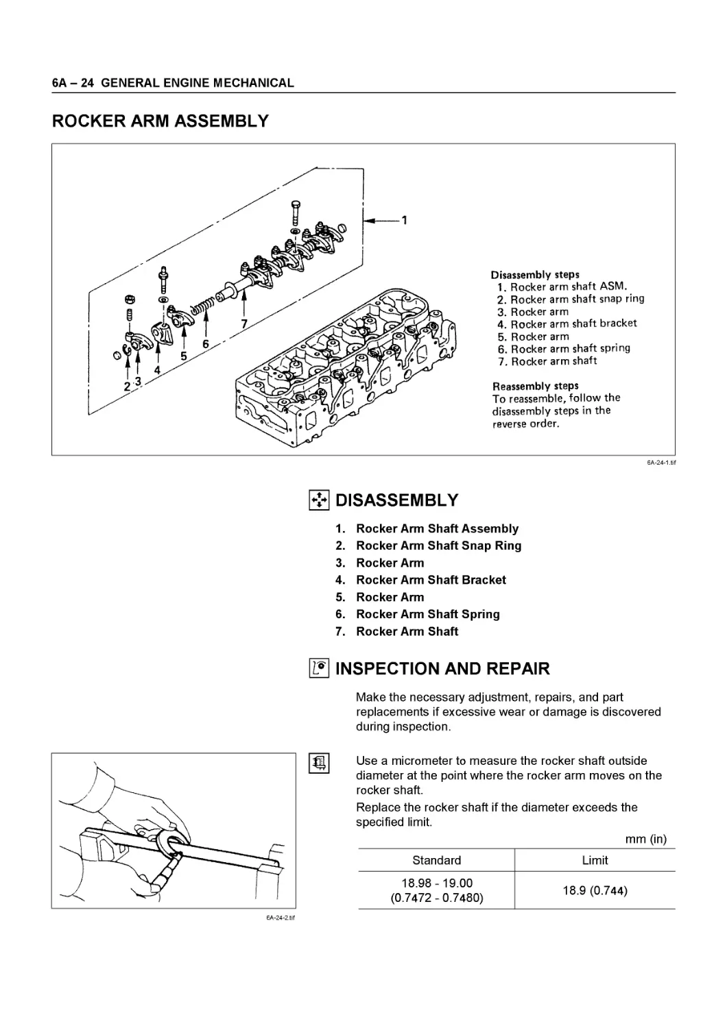
Rocker Arm Assembly......................................... 6A - 24
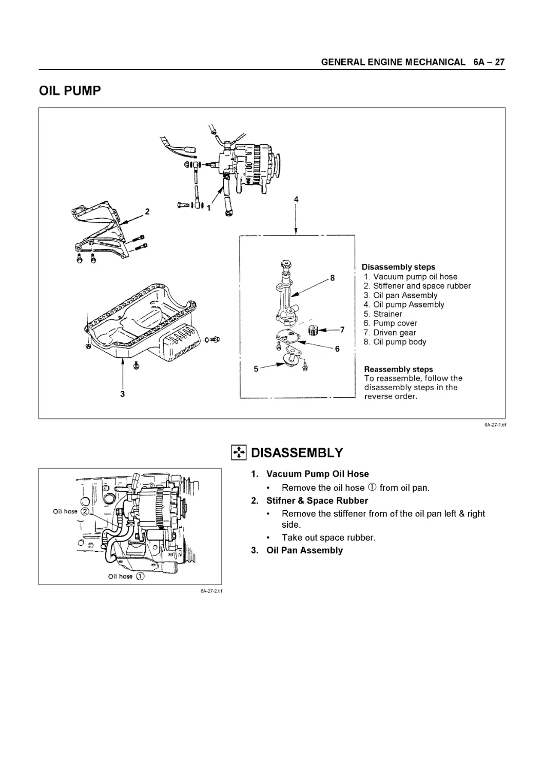
Oil Pump.................................................... 6A - 27
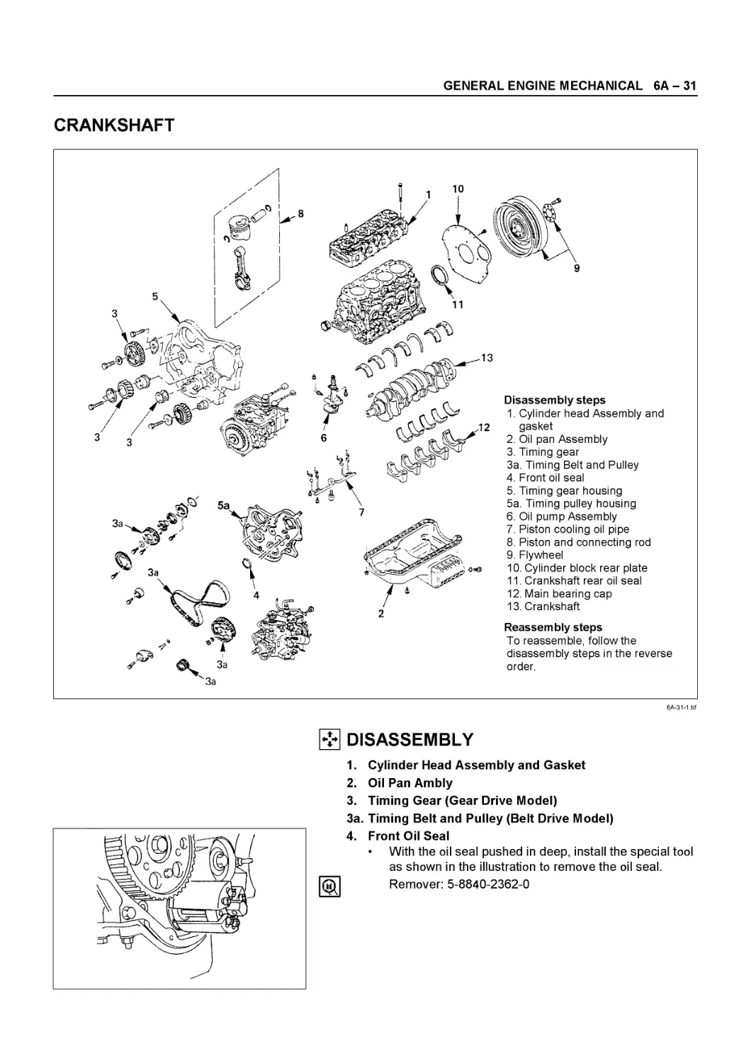
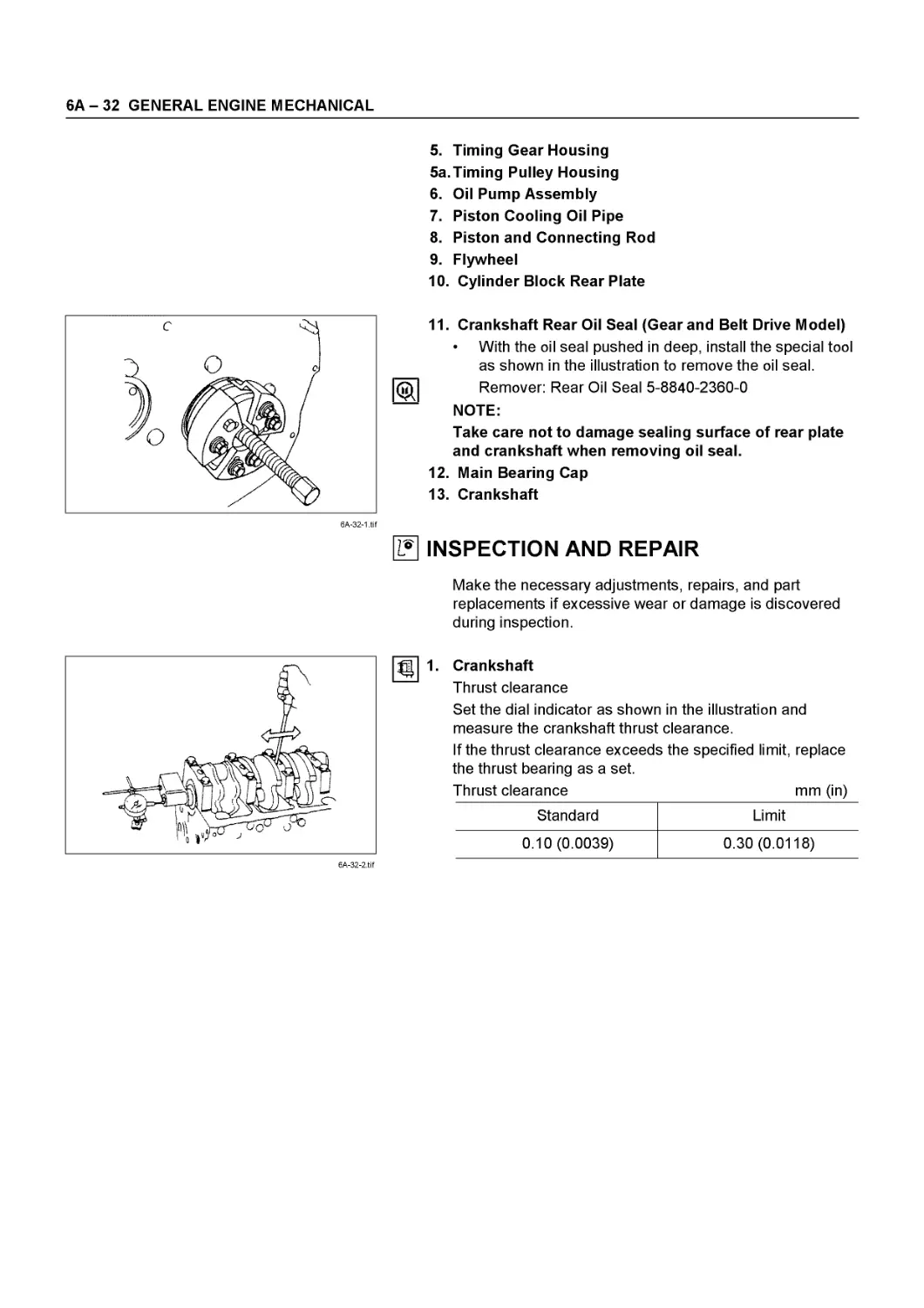
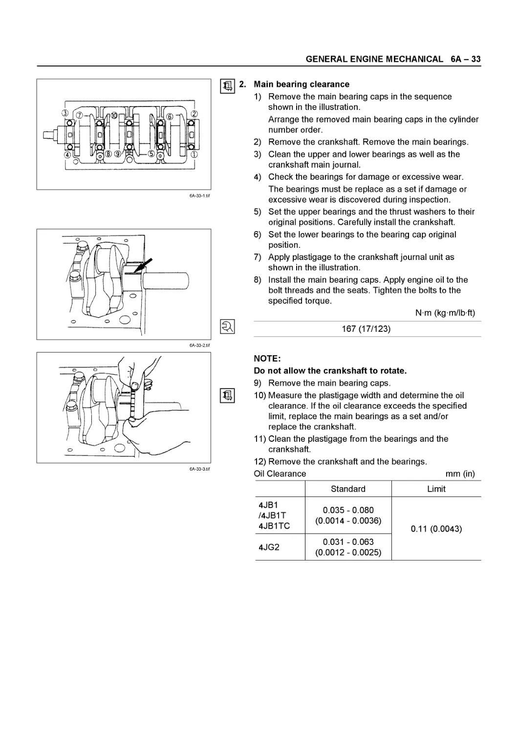
Crankshaft.................................................. 6A - 31
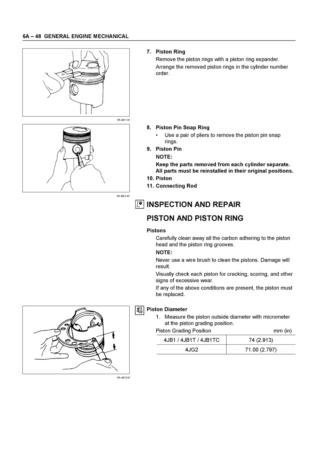
Piston and Connecting Rod................................... 6A - 47
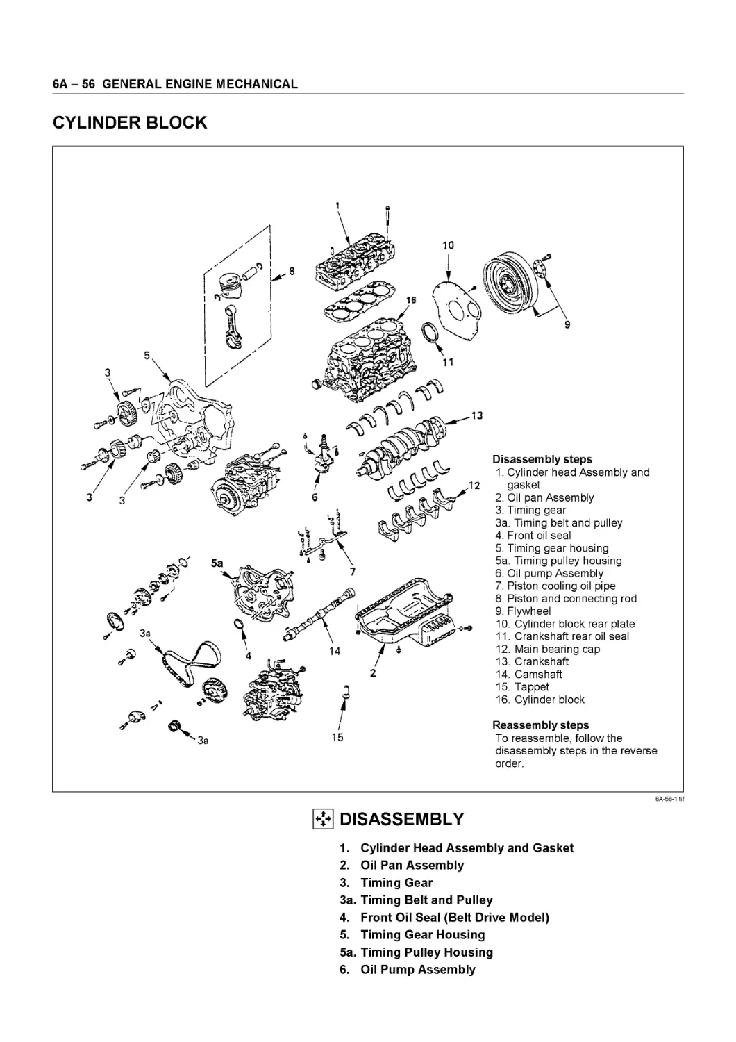
Cylinder Block.............................................. 6A - 56
6А - 2 GENERAL ENGINE MECHANICAL
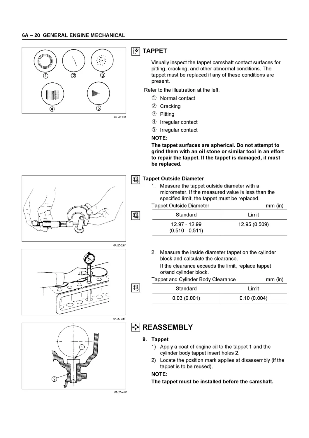
CYLINDER HEAD
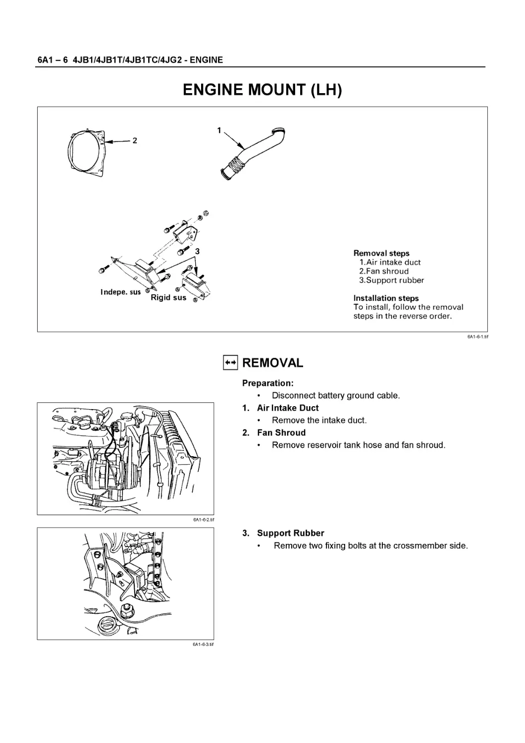
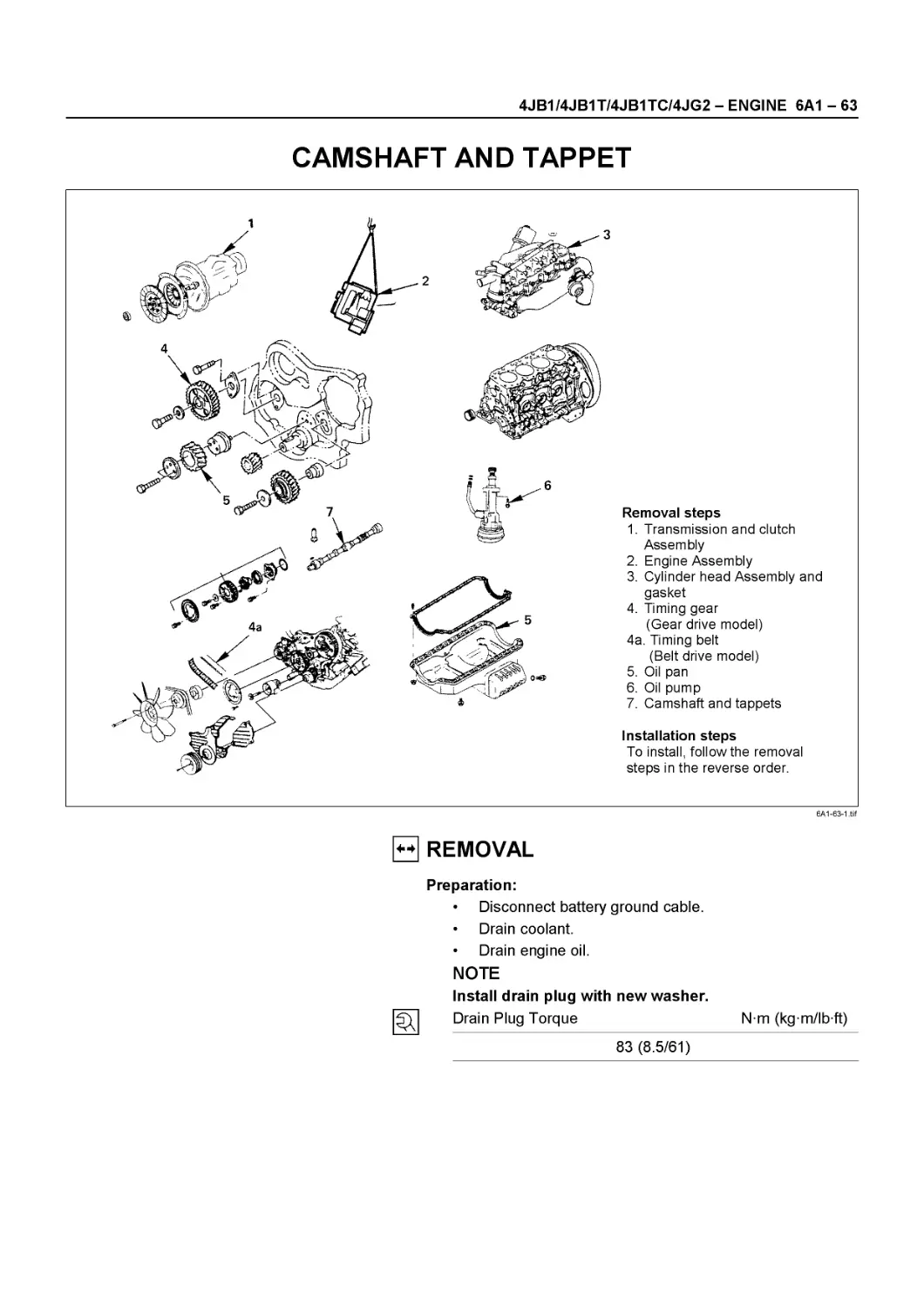
2a
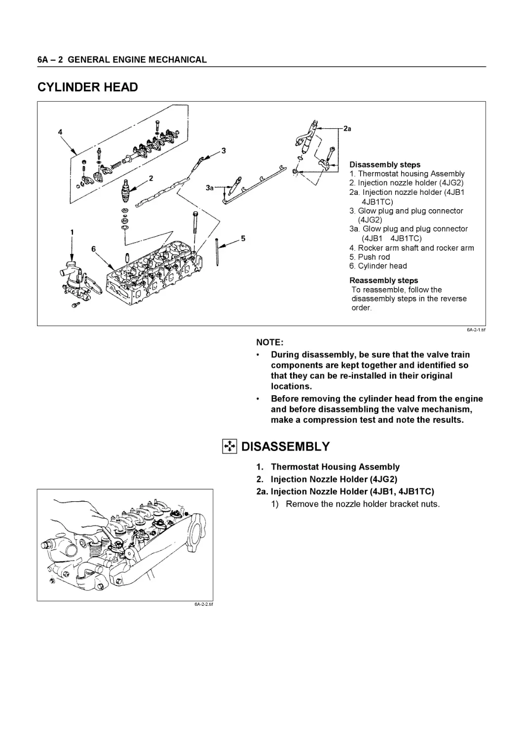
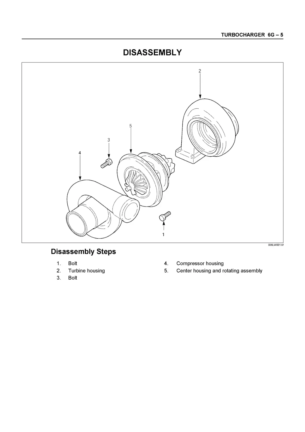
Disassembly steps
1. Thermostat housing Assembly
2. Injection nozzle holder (4JG2)
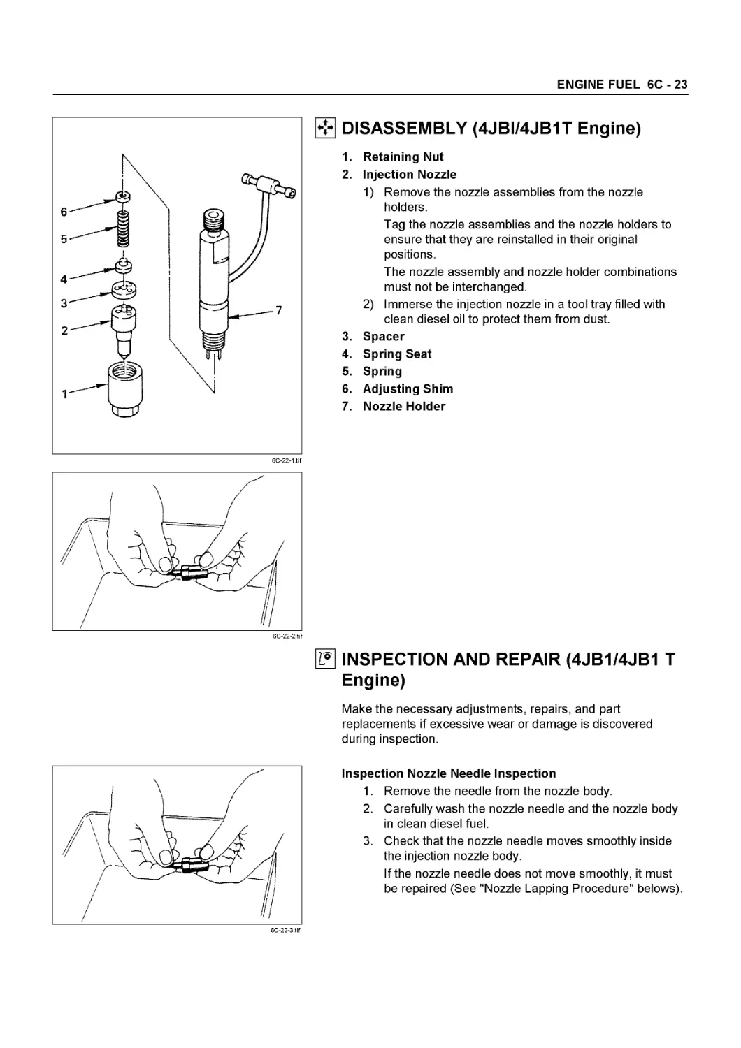
2a. Injection nozzle holder (4JB1 4JB1TC)
3. Glow plug and plug connector (4JG2)
3a. Glow plug and plug connector (4JB1 4JB1TC)
4. Rocker arm shaft and rocker arm
5. Push rod
6. Cylinder head
Reassembly steps
To reassemble, follow the disassembly steps in the reverse order.
6A-2-1 .tif
NOTE:
* During disassembly, be sure that the valve train components are kept together and identified so that they can be re-installed in their original locations.
* Before removing the cylinder head from the engine and before disassembling the valve mechanism, make a compression test and note the results.
DISASSEMBLY
6A-2-2.tif
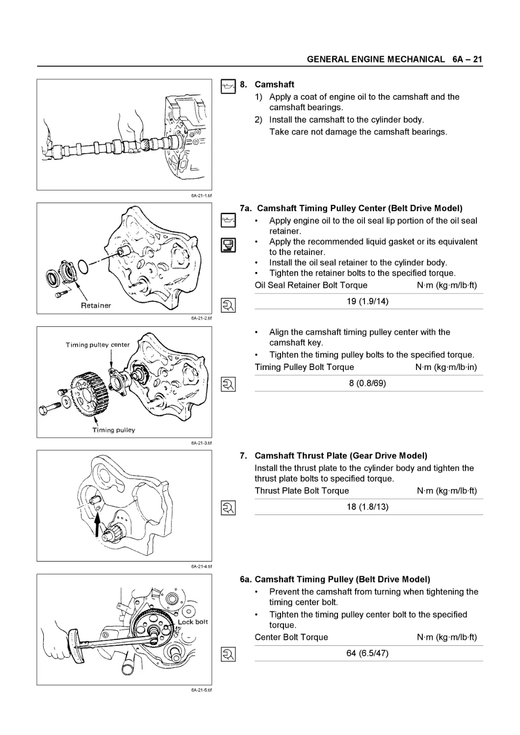
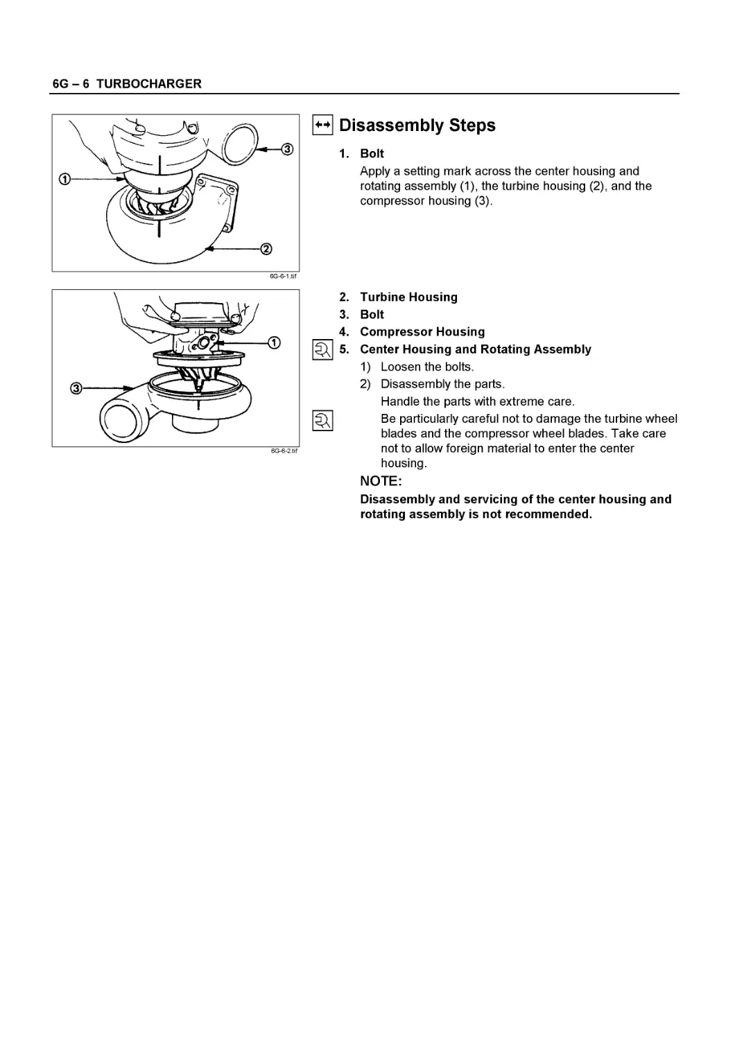
1. Thermostat Housing Assembly
2. Injection Nozzle Holder (4JG2)
2a. Injection Nozzle Holder (4JB1,4JB1TC)
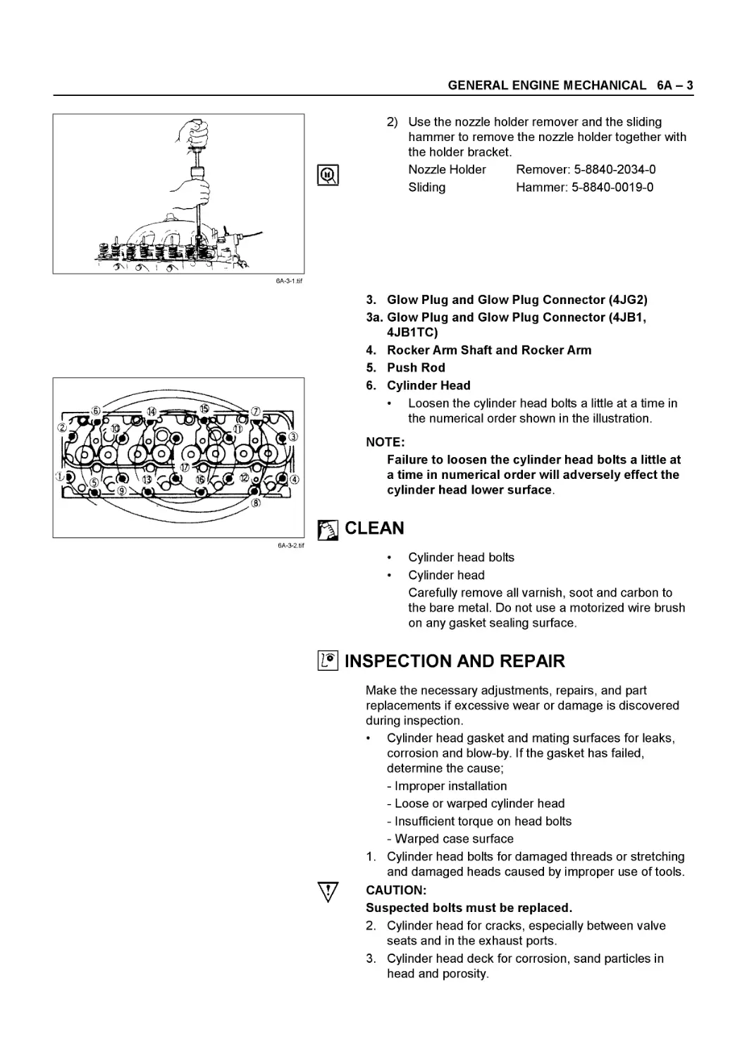
1) Remove the nozzle holder bracket nuts.
GENERAL ENGINE MECHANICAL 6A - 3
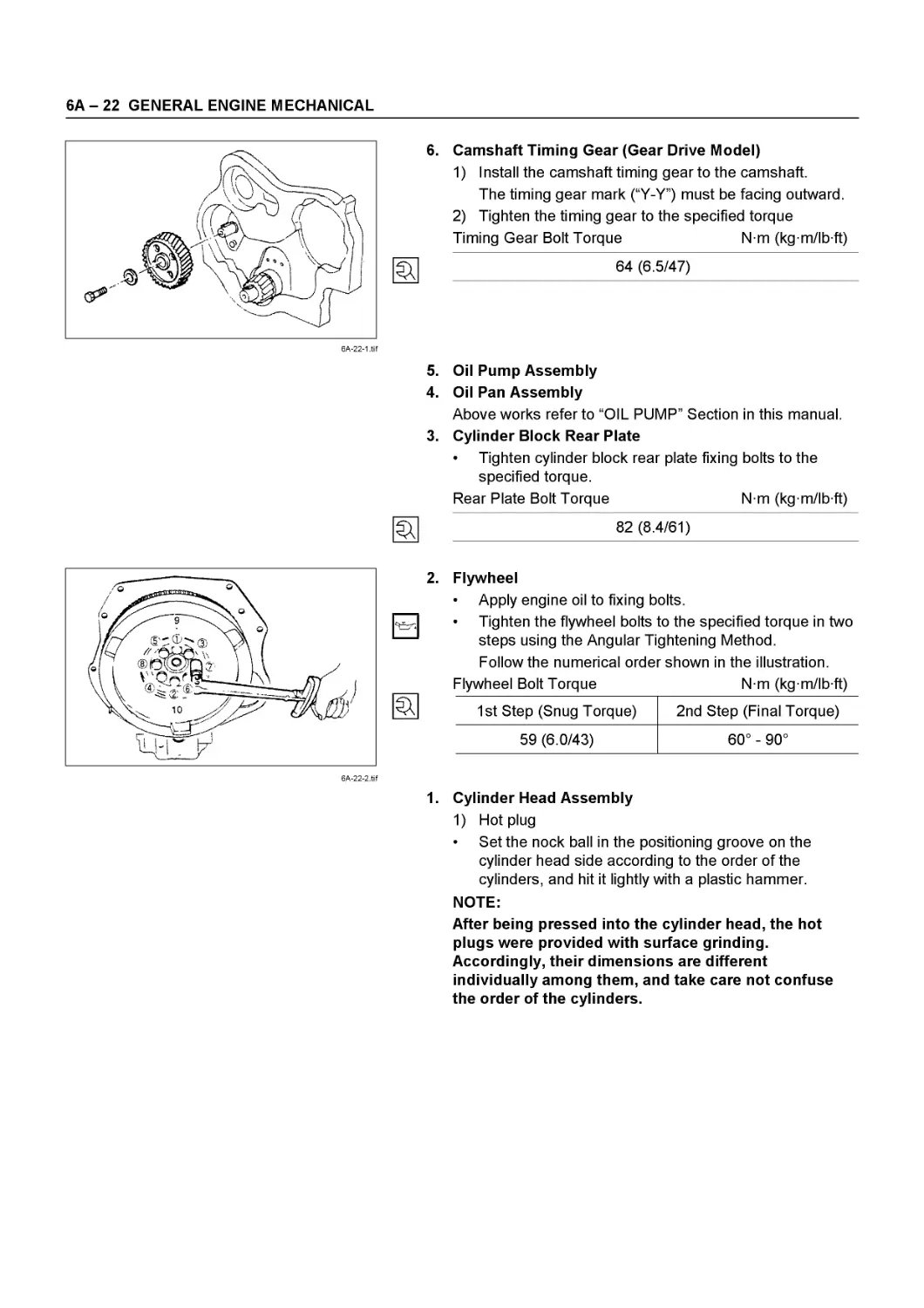
2) Use the nozzle holder remover and the sliding hammer to remove the nozzle holder together with the holder bracket.
Nozzle Holder Remover: 5-8840-2034-0
Sliding Hammer: 5-8840-0019-0
6A-3-1 .tif
6A-3-2.tif
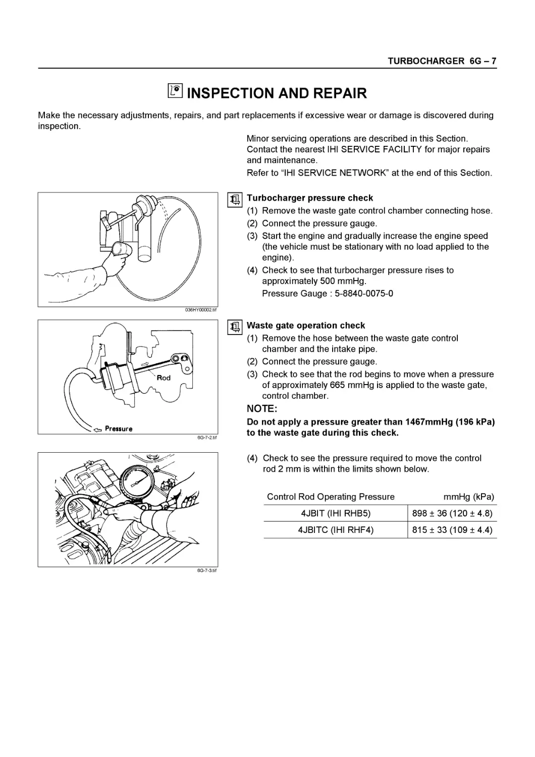
3. Glow Plug and Glow Plug Connector (4JG2)
3a. Glow Plug and Glow Plug Connector (4JB1, 4JB1TC)
4. Rocker Arm Shaft and Rocker Arm
5. Push Rod
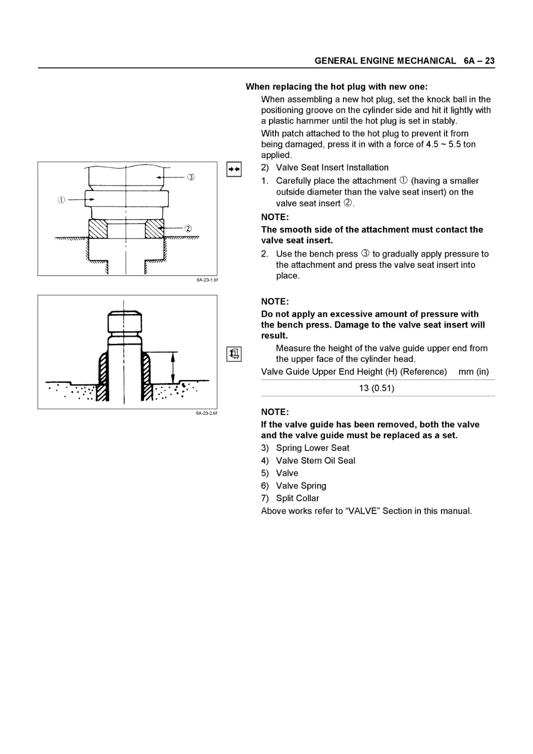
6. Cylinder Head
• Loosen the cylinder head bolts a little at a time in the numerical order shown in the illustration.
NOTE:
Failure to loosen the cylinder head bolts a little at a time in numerical order will adversely effect the cylinder head lower surface.
Щ CLEAN
• Cylinder head bolts
• Cylinder head
Carefully remove all varnish, soot and carbon to the bare metal. Do not use a motorized wire brush on any gasket sealing surface.
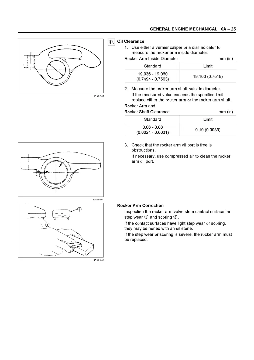
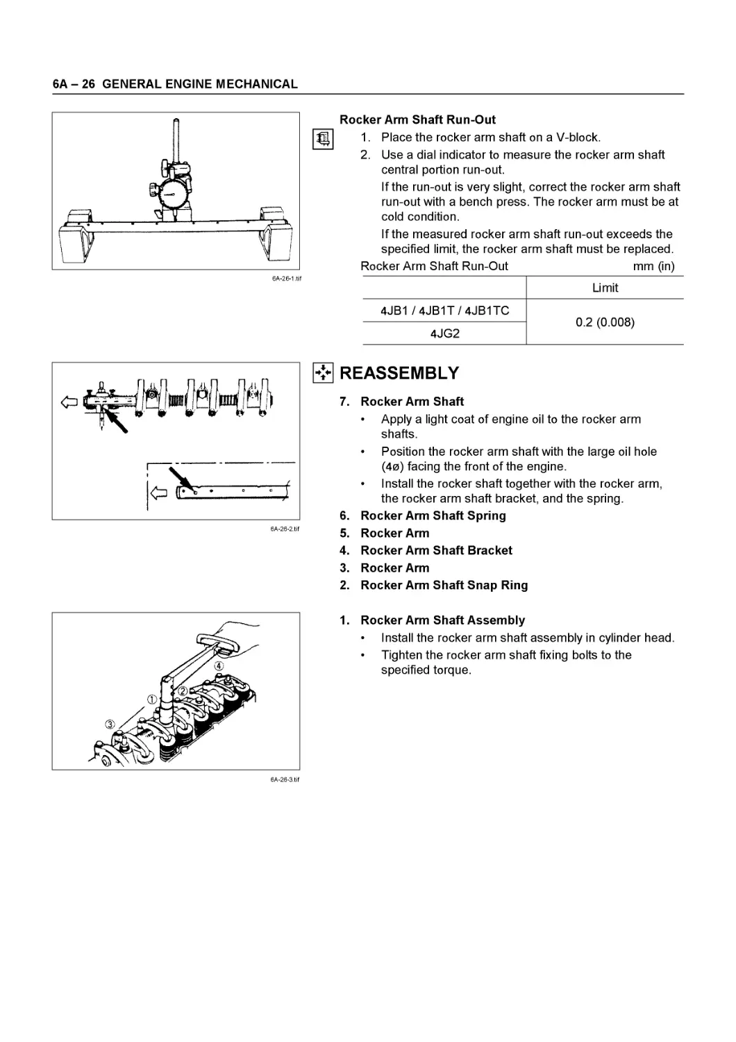
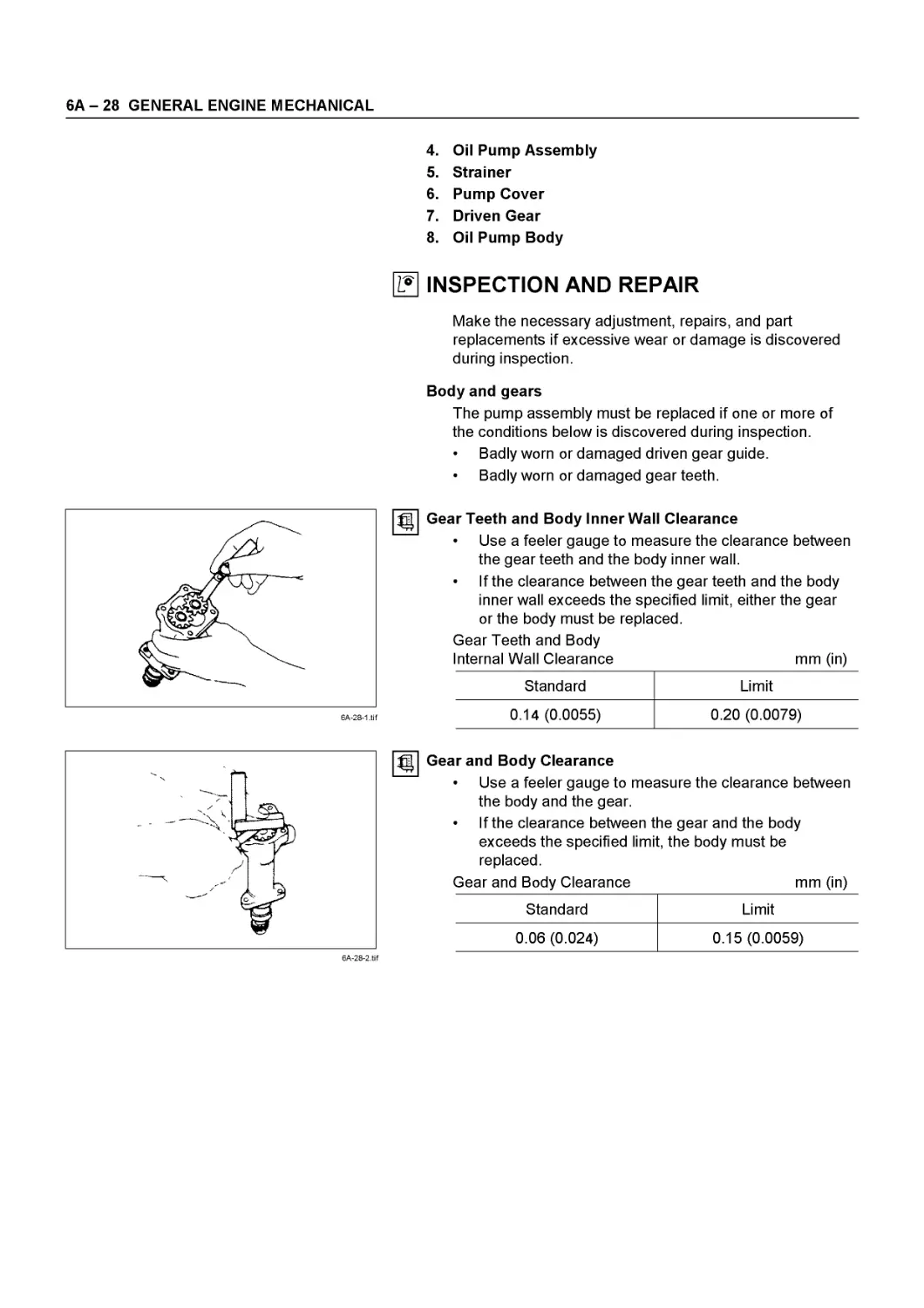
Ly| INSPECTION AND REPAIR
Make the necessary adjustments, repairs, and part replacements if excessive wear or damage is discovered during inspection.
• Cylinder head gasket and mating surfaces for leaks, corrosion and blow-by. If the gasket has failed, determine the cause;
- Improper installation
- Loose or warped cylinder head
- Insufficient torque on head bolts
- Warped case surface
1. Cylinder head bolts for damaged threads or stretching and damaged heads caused by improper use of tools.
CAUTION:
Suspected bolts must be replaced.
2. Cylinder head for cracks, especially between valve seats and in the exhaust ports.
3. Cylinder head deck for corrosion, sand particles in head and porosity.
6А - 4 GENERAL ENGINE MECHANICAL
6A-4-1 .tif
6A-4-2.tif
CAUTION:
Do not attempt to weld the cylinder head. Replace it.
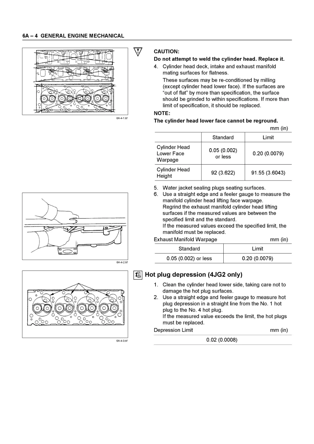
4. Cylinder head deck, intake and exhaust manifold mating surfaces for flatness.
These surfaces may be re-conditioned by milling (except cylinder head lower face). If the surfaces are “out of flat” by more than specification, the surface should be grinded to within specifications. If more than limit of specification, it should be replaced.
NOTE:
The cylinder head lower face cannot be reground.
mm (in)
Standard Limit
Cylinder Head Lower Face Warpage 0.05 (0.002) or less 0.20 (0.0079)
Cylinder Head Height 92 (3.622) 91.55 (3.6043)
5. Water jacket sealing plugs seating surfaces.
6. Use a straight edge and a feeler gauge to measure the manifold cylinder head lifting face warpage.
Regrind the exhaust manifold cylinder head lifting surfaces if the measured values are between the specified limit and the standard.
If the measured values exceed the specified limit, the manifold must be replaced.
Exhaust Manifold Warpage mm (in)
Standard Limit
0.05 (0.002) or less 0.20 (0.0079)
Hot plug depression (4JG2 only)
1. Clean the cylinder head lower side, taking care not to damage the hot plug surfaces.
2. Use a straight edge and feeler gauge to measure hot plug depression in a straight line from the No. 1 hot plug to the No. 4 hot plug.
If the measured value exceeds the limit, the hot plugs must be replaced.
Depression Limit mm (in)
0.02 (0.0008)
GENERAL ENGINE MECHANICAL 6A - 5
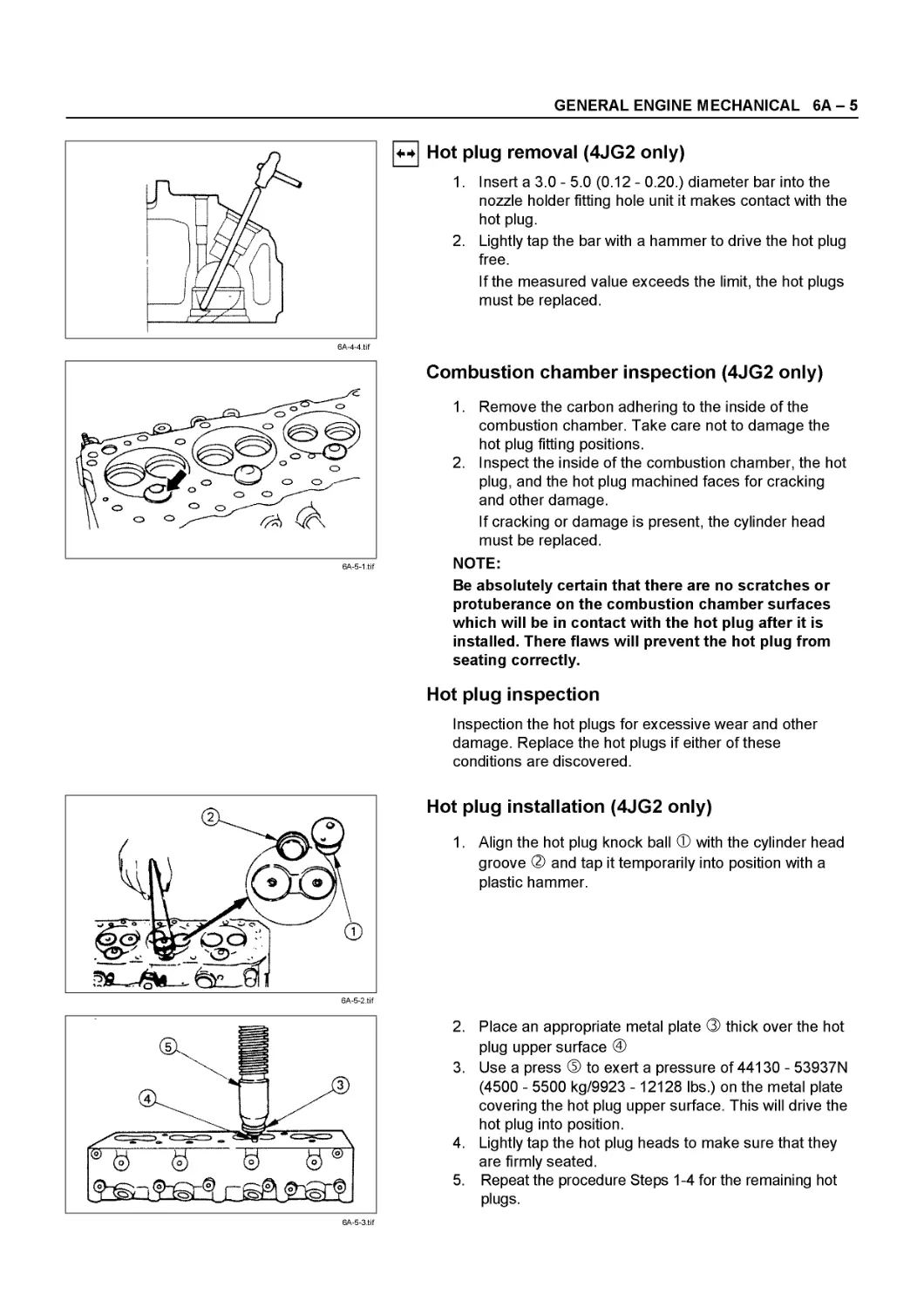
4-4 Hot plug removal (4JG2 only)
1. Insert a 3.0 - 5.0 (0.12 - 0.20.) diameter bar into the nozzle holder fitting hole unit it makes contact with the hot plug.
2. Lightly tap the bar with a hammer to drive the hot plug free.
If the measured value exceeds the limit, the hot plugs must be replaced.
6A-5-1.tif
Combustion chamber inspection (4JG2 only)
1. Remove the carbon adhering to the inside of the combustion chamber. Take care not to damage the hot plug fitting positions.
2. Inspect the inside of the combustion chamber, the hot plug, and the hot plug machined faces for cracking and other damage.
If cracking or damage is present, the cylinder head must be replaced.
NOTE:
Be absolutely certain that there are no scratches or protuberance on the combustion chamber surfaces which will be in contact with the hot plug after it is installed. There flaws will prevent the hot plug from seating correctly.
Hot plug inspection
Inspection the hot plugs for excessive wear and other damage. Replace the hot plugs if either of these conditions are discovered.
6A-5-2.tif
Hot plug installation (4JG2 only)
1. Align the hot plug knock ball Ф with the cylinder head groove ® and tap it temporarily into position with a plastic hammer.
6A-5-3.tif
2. Place an appropriate metal plate ® thick over the hot plug upper surface @
3. Use a press ® to exert a pressure of 44130 - 53937N (4500 - 5500 kg/9923 - 12128 lbs.) on the metal plate covering the hot plug upper surface. This will drive the hot plug into position.
4. Lightly tap the hot plug heads to make sure that they are firmly seated.
5. Repeat the procedure Steps 1-4 for the remaining hot plugs.
6А - 6 GENERAL ENGINE MECHANICAL
CAUTION:
Do not apply pressure greater than that specified.
Damage to the cylinder head will result.
6. Use a surface grinder to grind off any hot plug surface protuberances. The hot plug surfaces must be perfectly flush with the cylinder head.
7. After grinding, make sure that the hot plug surfaces are completely free of protuberances. The hot plug surfaces must also be free of depressions.
Once again, lightly tap the hot plug heads to make sure that they are firmly seated.
6A-6-2.tif
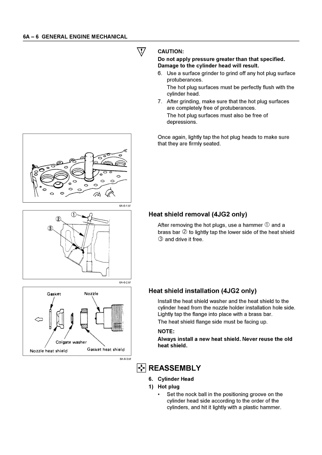
Heat shield removal (4JG2 only)
After removing the hot plugs, use a hammer Ф and a brass bar ® to lightly tap the lower side of the heat shield ® and drive it free.
Heat shield installation (4JG2 only)
Install the heat shield washer and the heat shield to the cylinder head from the nozzle holder installation hole side.
Lightly tap the flange into place with a brass bar.
The heat shield flange side must be facing up.
NOTE:
Always install a new heat shield. Never reuse the old heat shield.
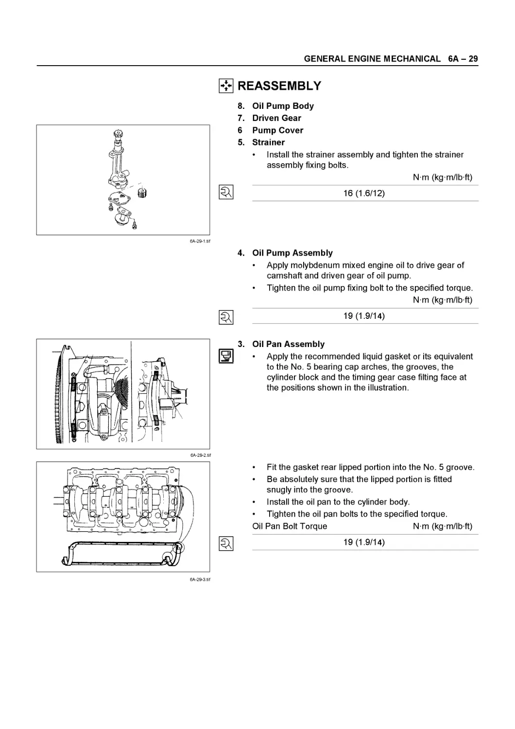
REASSEMBLY
6. Cylinder Head
1) Hot plug
• Set the nock ball in the positioning groove on the cylinder head side according to the order of the cylinders, and hit it lightly with a plastic hammer.
GENERAL ENGINE MECHANICAL 6A - 7
NOTE:
After being pressed into the cylinder head, the hot plugs were provided with surface grinding. Accordingly, their dimensions are different individually among them, and take care not confuse the order of the cylinders.
When replacing the hot plug with new one:
When assembling a new hot plug, set the knock ball in the positioning groove on the cylinder side and hit it lightly with a plastic hammer until the hot plug is set in stably.
With patch attached to the hot plug to prevent it from being damaged, press it in with a force of 4.5 to 5.5 ton applied.
After pressing the hot plug, grind its surface to the cylinder head.
And finally, hit the hot plug lightly with a plastic hammer and check it for any excessive sinking, protrusion or backlash.
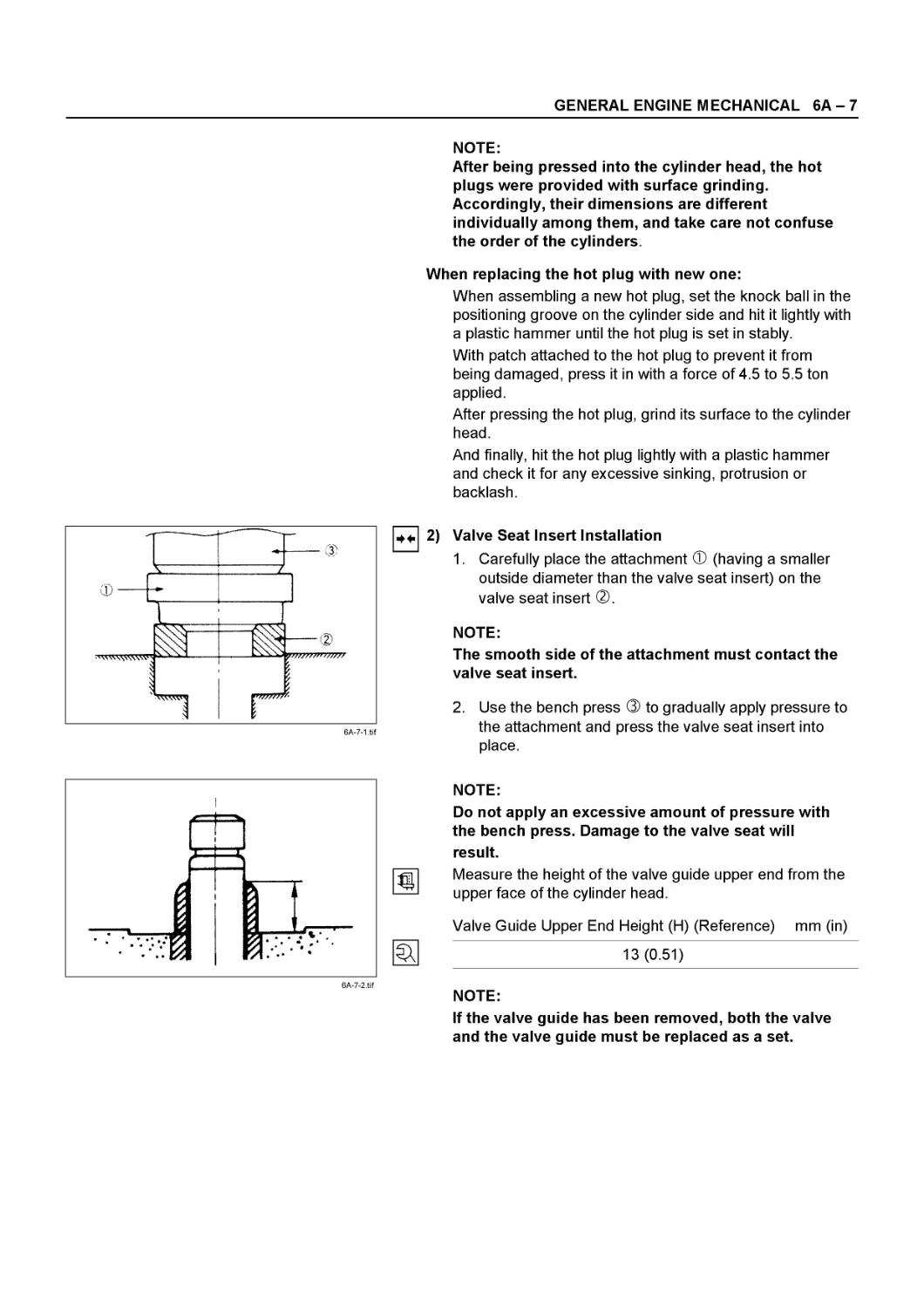
44. 2) Valve Seat Insert Installation
1. Carefully place the attachment Ф (having a smaller outside diameter than the valve seat insert) on the valve seat insert ®.
NOTE:
The smooth side of the attachment must contact the valve seat insert.
2. Use the bench press ® to gradually apply pressure to the attachment and press the valve seat insert into place.
NOTE:
Do not apply an excessive amount of pressure with the bench press. Damage to the valve seat will result.
Measure the height of the valve guide upper end from the upper face of the cylinder head.
Valve Guide Upper End Height (H) (Reference) mm (in)
13 (0.51)
NOTE:
If the valve guide has been removed, both the valve and the valve guide must be replaced as a set.
6А - 8 GENERAL ENGINE MECHANICAL
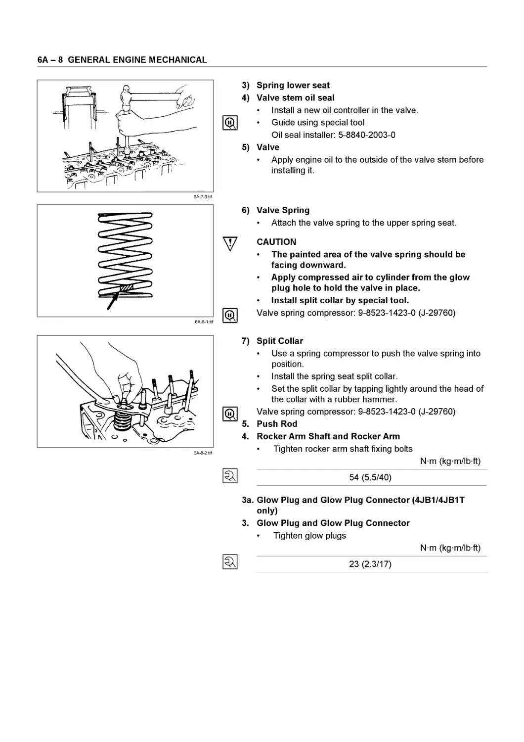
3) Spring lower seat
4) Valve stem oil seal
____ • Install a new oil controller in the valve.
ф • Guide using special tool
Oil seal installer: 5-8840-2003-0
5) Valve
• Apply engine oil to the outside of the valve stem before installing it.
6) Valve Spring
• Attach the valve spring to the upper spring seat.
у CAUTION
* The painted area of the valve spring should be facing downward.
* Apply compressed air to cylinder from the glow plug hole to hold the valve in place.
* Install split collar by special tool.
jhl Valve spring compressor: 9-8523-1423-0 (J-29760)
7) Split Collar
• Use a spring compressor to push the valve spring into position.
• Install the spring seat split collar.
• Set the split collar by tapping lightly around the head of the collar with a rubber hammer.
Valve spring compressor: 9-8523-1423-0 (J-29760)
5. Push Rod
4. Rocker Arm Shaft and Rocker Arm
• Tighten rocker arm shaft fixing bolts
Nm (kgm/lbft)
54 (5.5/40)
3a. Glow Plug and Glow Plug Connector (4JB1/4JB1T only)
3. Glow Plug and Glow Plug Connector
• Tighten glow plugs
Nm (kg m/lb ft)
23 (2.3/17)
GENERAL ENGINE MECHANICAL 6A - 9
6A-8-3.tif
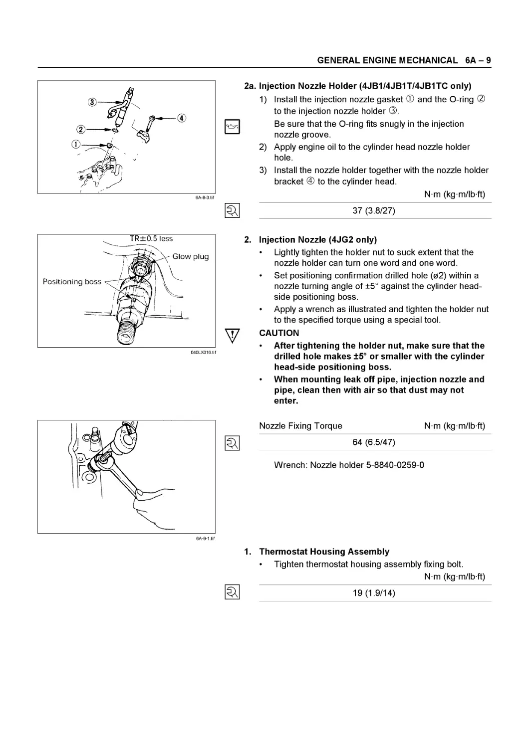
2a. Injection Nozzle Holder (4JB1/4JB1T/4JB1TC only)
1) Install the injection nozzle gasket Ф and the О-ring ® to the injection nozzle holder ®.
Be sure that the О-ring fits snugly in the injection nozzle groove.
2) Apply engine oil to the cylinder head nozzle holder hole.
3) Install the nozzle holder together with the nozzle holder bracket @ to the cylinder head.
Nm (kgm/lbft)
37 (3.8/27)
2. Injection Nozzle (4JG2 only)
• Lightly tighten the holder nut to suck extent that the nozzle holder can turn one word and one word.
• Set positioning confirmation drilled hole (02) within a nozzle turning angle of ±5° against the cylinder headside positioning boss.
• Apply a wrench as illustrated and tighten the holder nut to the specified torque using a special tool.
у CAUTION
* After tightening the holder nut, make sure that the drilled hole makes ±5° or smaller with the cylinder head-side positioning boss.
* When mounting leak off pipe, injection nozzle and pipe, clean then with air so that dust may not enter.
Nozzle Fixing Torque
64 (6.5/47)
Nm (kg m/lb ft)
Wrench: Nozzle holder 5-8840-0259-0
1.
Thermostat Housing Assembly
• Tighten thermostat housing assembly fixing bolt.
Nm (kg m/lb ft)
19 (1.9/14)
6А - 10 GENERAL ENGINE MECHANICAL
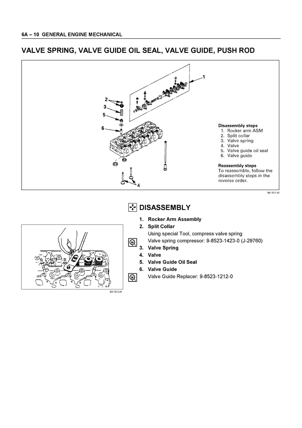
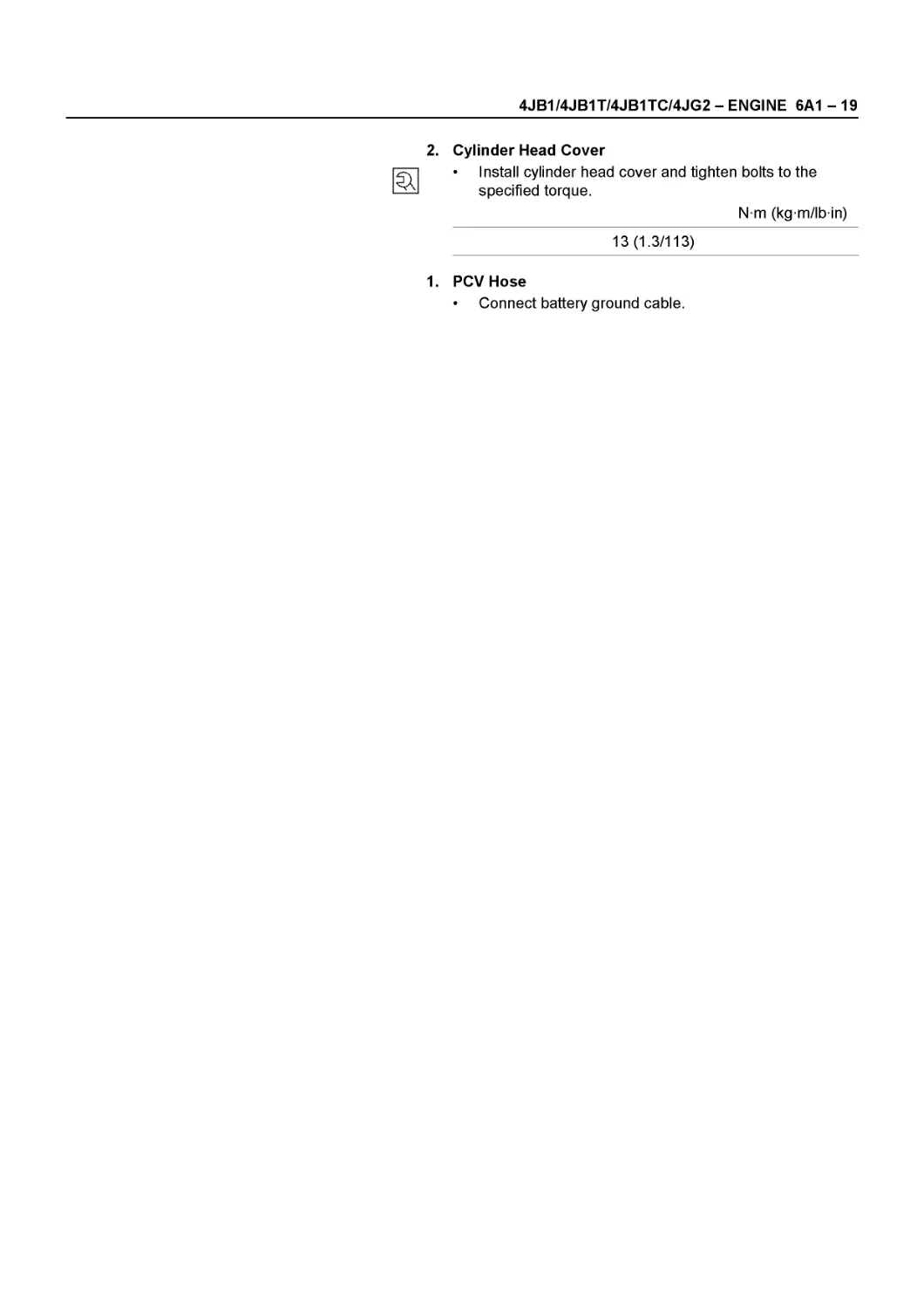
VALVE SPRING, VALVE GUIDE OIL SEAL, VALVE GUIDE, PUSH ROD
Disassembly steps
1. Rocker arm ASM
2. Split collar
3. Valve spring
4. Valve
5. Valve guide oil seal
6. Valve guide
Reassembly steps
To reassemble, follow the disassembly steps in the reverse order.
6A-10-1 .tif
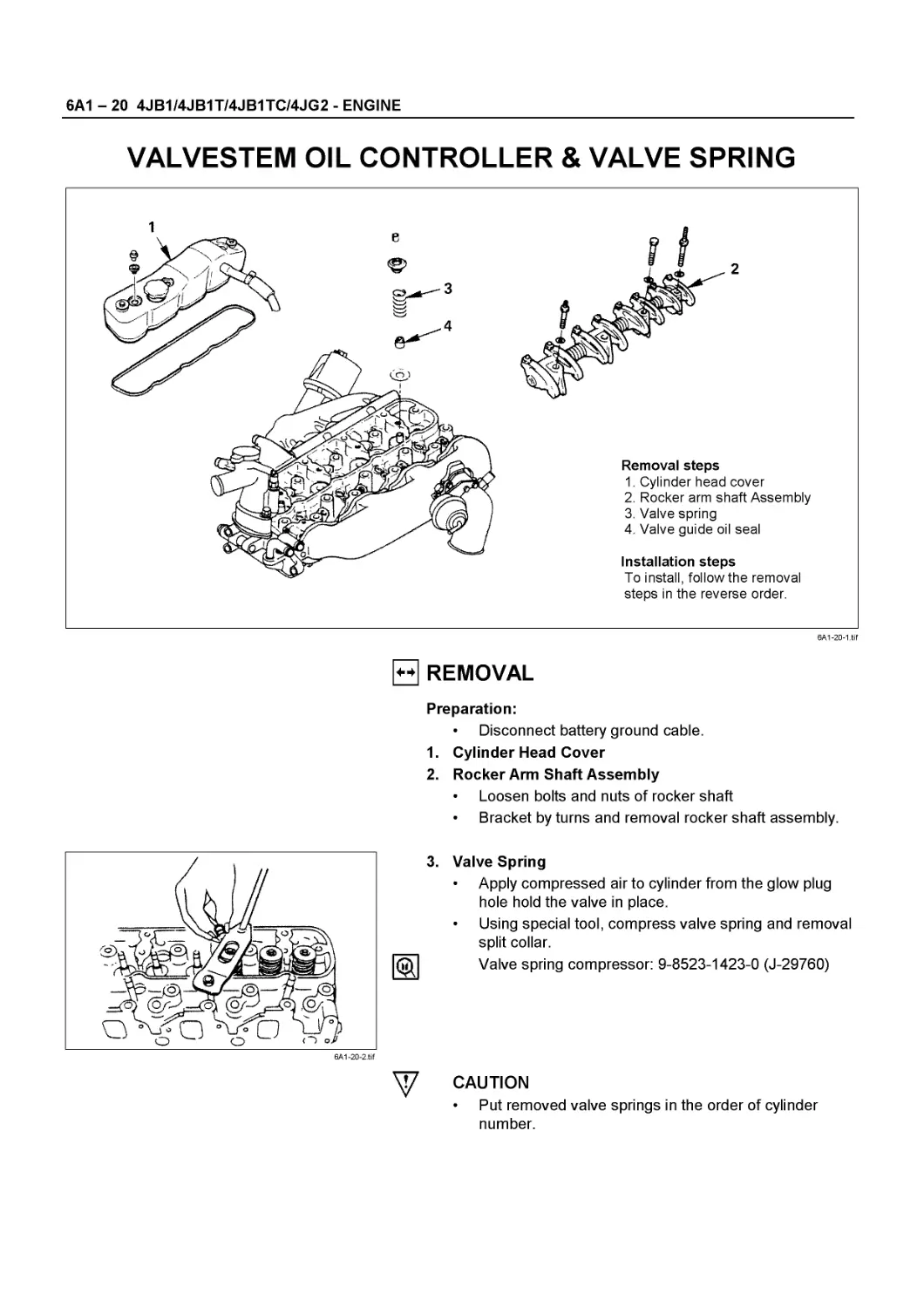
DISASSEMBLY
6A-10-2.tif
1. Rocker Arm Assembly
2. Split Collar
Using special Tool, compress valve spring
Valve spring compressor: 9-8523-1423-0 (J-29760)
3. Valve Spring
4. Valve
5. Valve Guide Oil Seal
6. Valve Guide
Valve Guide Replacer: 9-8523-1212-0
GENERAL ENGINE MECHANICAL 6A - 11
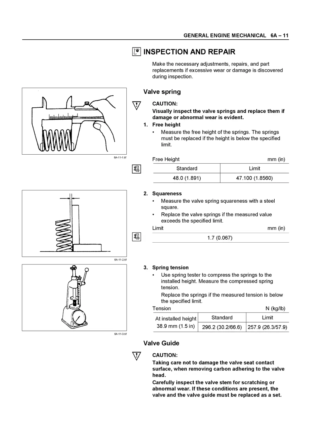
I? INSPECTION AND REPAIR
Make the necessary adjustments, repairs, and part replacements if excessive wear or damage is discovered during inspection.
Valve spring
у CAUTION:
Visually inspect the valve springs and replace them if damage or abnormal wear is evident.
1. Free height
• Measure the free height of the springs. The springs must be replaced if the height is below the specified limit.
Free Height
Standard
48.0 (1.891)
mm (in)
Limit
47.100 (1.8560)
Squareness
• Measure the valve spring squareness with a steel square.
• Replace the valve springs if the measured value exceeds the specified limit.
Limit mm (in)
1.7 (0.067)
3. Spring tension
• Use spring tester to compress the springs to the installed height. Measure the compressed spring tension.
Replace the springs if the measured tension is below the specified limit.
Tension N (kg/lb)
At installed height Standard Limit
38.9 mm (1.5 in) 296.2 (30.2/66.6) 257.9 (26.3/57.9)
Valve Guide
У CAUTION:
Taking care not to damage the valve seat contact surface, when removing carbon adhering to the valve head.
Carefully inspect the valve stem for scratching or abnormal wear. If these conditions are present, the valve and the valve guide must be replaced as a set.
6А - 12 GENERAL ENGINE MECHANICAL
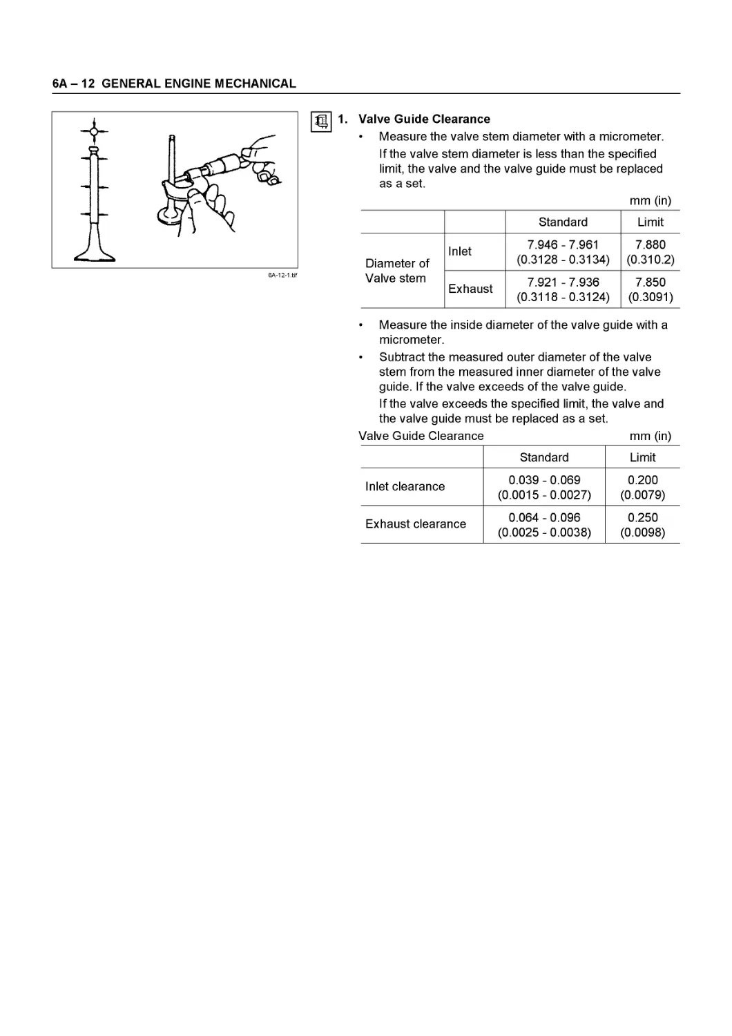
Ш 1-
Valve Guide Clearance
• Measure the valve stem diameter with a micrometer.
If the valve stem diameter is less than the specified limit, the valve and the valve guide must be replaced as a set.
mm (in)
Standard Limit
Diameter of Inlet 7.946-7.961 (0.3128-0.3134) 7.880 (0.310.2)
Valve stem Exhaust 7.921 -7.936 (0.3118-0.3124) 7.850 (0.3091)
• Measure the inside diameter of the valve guide with a micrometer.
• Subtract the measured outer diameter of the valve stem from the measured inner diameter of the valve guide. If the valve exceeds of the valve guide.
If the valve exceeds the specified limit, the valve and the valve guide must be replaced as a set.
Valve Guide Clearance mm (in)
Standard Limit
Inlet clearance 0.039-0.069 (0.0015-0.0027) 0.200 (0.0079)
Exhaust clearance 0.064 - 0.096 (0.0025 - 0.0038) 0.250 (0.0098)
GENERAL ENGINE MECHANICAL 6A - 13
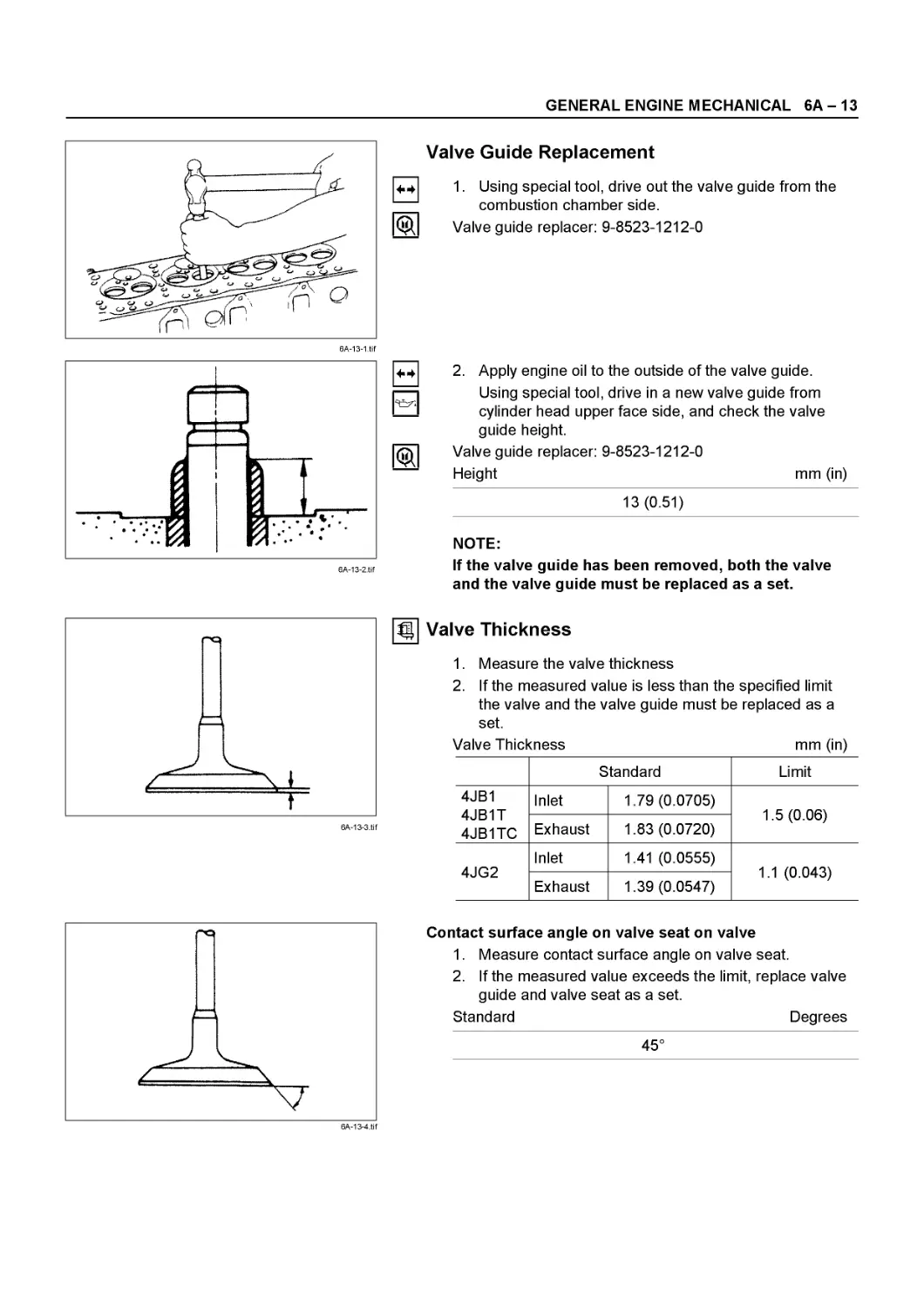
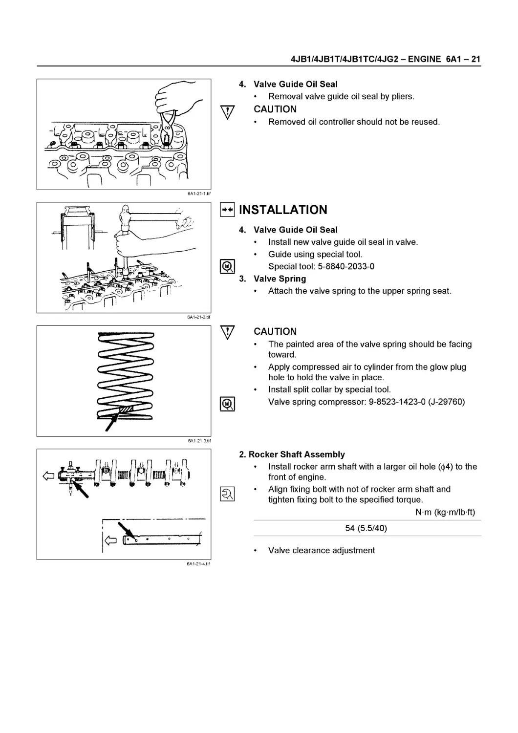
Valve Guide Replacement
1. Using special tool, drive out the valve guide from the combustion chamber side.
Valve guide replacer: 9-8523-1212-0
6A-13-2.tif
2. Apply engine oil to the outside of the valve guide. Using special tool, drive in a new valve guide from cylinder head upper face side, and check the valve guide height.
Valve guide replacer: 9-8523-1212-0
Height mm (in)
13 (0.51)
NOTE:
If the valve guide has been removed, both the valve and the valve guide must be replaced as a set.
Valve Thickness
1. Measure the valve thickness
2. If the measured value is less than the specified limit the valve and the valve guide must be replaced as a set.
Valve Thickness mm (in)
Standard Limit
4JB1 4JB1T 4JB1TC Inlet 1.79 (0.0705) 1.5 (0.06)
Exhaust 1.83 (0.0720)
4JG2 Inlet 1.41 (0.0555) 1.1 (0.043)
Exhaust 1.39 (0.0547)
Contact surface angle on valve seat on valve
1. Measure contact surface angle on valve seat.
2. If the measured value exceeds the limit, replace valve guide and valve seat as a set.
Standard Degrees
45°
6A-13-4.tif
6А - 14 GENERAL ENGINE MECHANICAL
6A-14-1 .tif
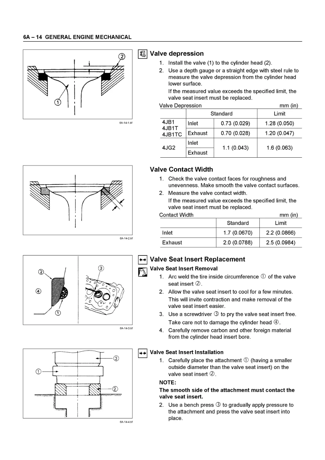
Valve depression
1. Install the valve (1) to the cylinder head (2).
2. Use a depth gauge or a straight edge with steel rule to measure the valve depression from the cylinder head lower surface.
If the measured value exceeds the specified limit, the valve seat insert must be replaced.
Valve Depression____________________________mm (in)
Standard Limit
4JB1 4JB1T 4JB1TC Inlet 0.73 (0.029) 1.28 (0.050)
Exhaust 0.70 (0.028) 1.20 (0.047)
4JG2 Inlet 1.1 (0.043) 1.6 (0.063)
Exhaust
6A-14-2.tif
Valve Contact Width
1. Check the valve contact faces for roughness and unevenness. Make smooth the valve contact surfaces.
2. Measure the valve contact width.
If the measured value exceeds the specified limit, the valve seat insert must be replaced.
Contact Width mm (in)
Standard Limit
Inlet 1.7 (0.0670) 2.2 (0.0866)
Exhaust 2.0 (0.0788) 2.5 (0.0984)
6A-14-3.tif
4-ф Valve Seat Insert Replacement
fth Valve Seat Insert Removal
—“ 1. Arc weld the tire inside circumference Ф of the valve
seat insert ®.
2. Allow the valve seat insert to cool for a few minutes. This will invite contraction and make removal of the valve seat insert easier.
3. Use a screwdriver ® to pry the valve seat insert free. Take care not to damage the cylinder head @.
4. Carefully remove carbon and other foreign material from the cylinder head insert bore.
Valve Seat Insert Installation
1. Carefully place the attachment Ф (having a smaller outside diameter than the valve seat insert) on the valve seat insert ®.
NOTE:
The smooth side of the attachment must contact the valve seat insert.
2. Use a bench press ® to gradually apply pressure to the attachment and press the valve seat insert into place.
GENERAL ENGINE MECHANICAL 6A - 15
NOTE:
Do not apply an excessive amount of pressure with the bench press. Damage to the valve seat insert will result.
6A-15-2.tif
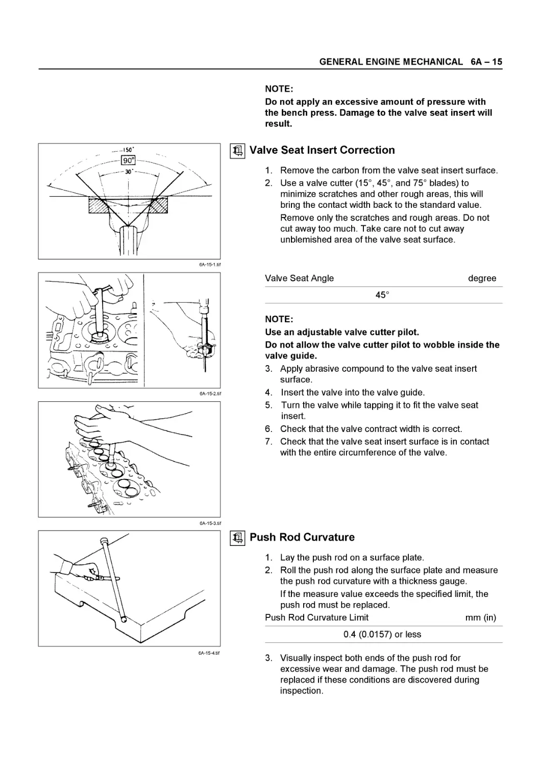
|| Valve Seat Insert Correction
1. Remove the carbon from the valve seat insert surface.
2. Use a valve cutter (15°, 45°, and 75° blades) to minimize scratches and other rough areas, this will bring the contact width back to the standard value. Remove only the scratches and rough areas. Do not cut away too much. Take care not to cut away unblemished area of the valve seat surface.
Valve Seat Angle
degree
45°
NOTE:
Use an adjustable valve cutter pilot.
Do not allow the valve cutter pilot to wobble inside the valve guide.
3. Apply abrasive compound to the valve seat insert surface.
4. Insert the valve into the valve guide.
5. Turn the valve while tapping it to fit the valve seat insert.
6. Check that the valve contract width is correct.
7. Check that the valve seat insert surface is in contact with the entire circumference of the valve.
Push Rod Curvature
1. Lay the push rod on a surface plate.
2. Roll the push rod along the surface plate and measure the push rod curvature with a thickness gauge.
If the measure value exceeds the specified limit, the push rod must be replaced.
Push Rod Curvature Limit mm (in)
0.4 (0.0157) or less
3. Visually inspect both ends of the push rod for excessive wear and damage. The push rod must be replaced if these conditions are discovered during inspection.
6А - 16 GENERAL ENGINE MECHANICAL
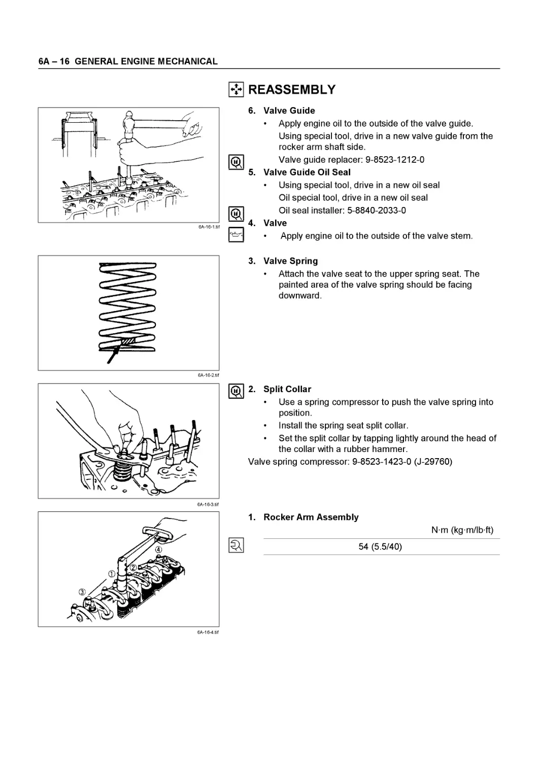
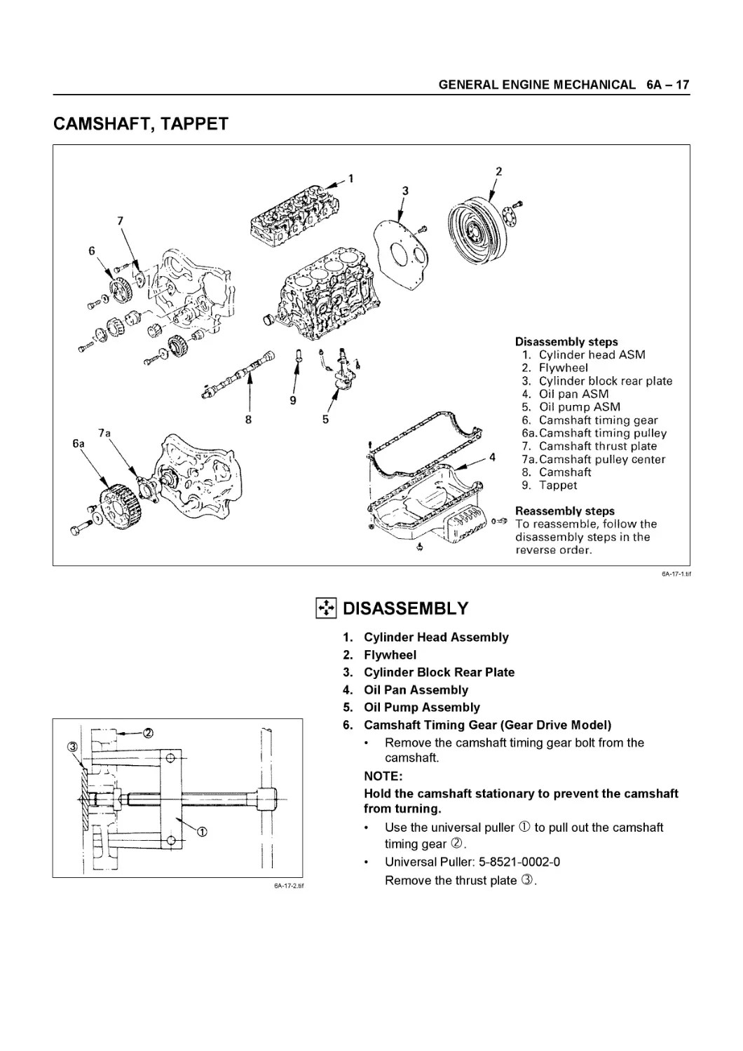
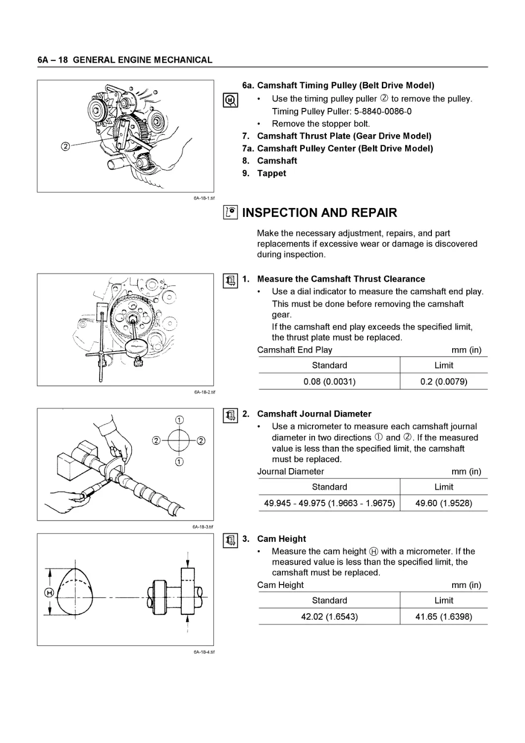
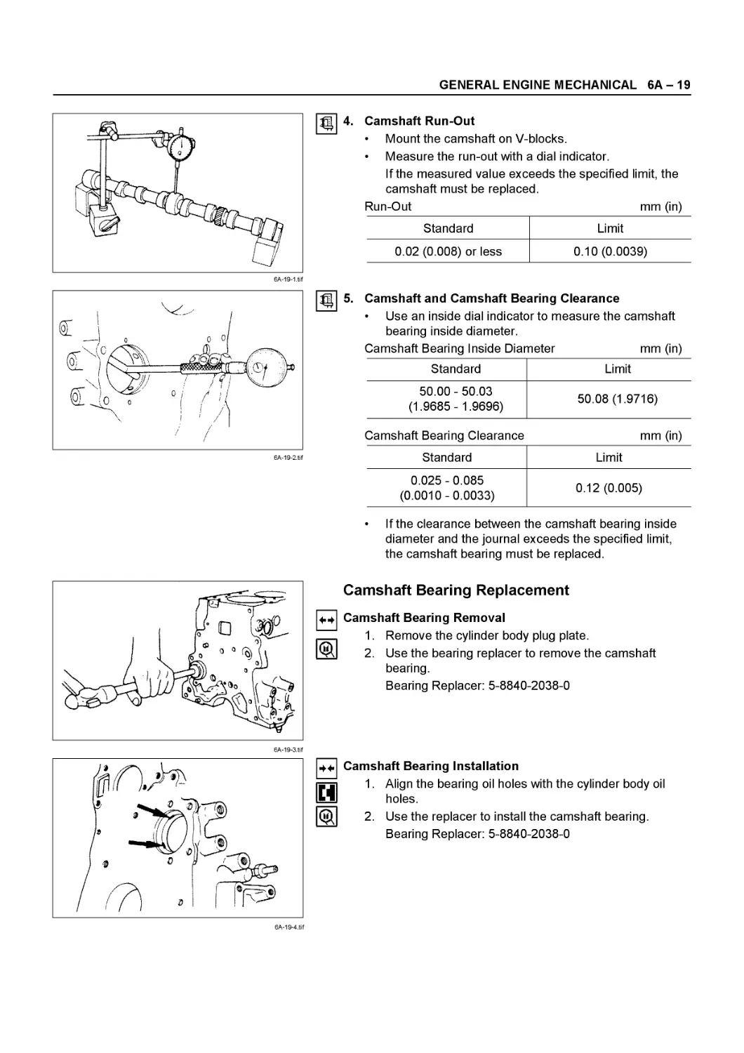
REASSEMBLY
6A-16-1.tif
6. Valve Guide
• Apply engine oil to the outside of the valve guide.
Using special tool, drive in a new valve guide from the rocker arm shaft side.
Valve guide replacer: 9-8523-1212-0
5. Valve Guide Oil Seal
• Using special tool, drive in a new oil seal
Oil special tool, drive in a new oil seal
gT Oil seal installer: 5-8840-2033-0
— 4. Valve
• Apply engine oil to the outside of the valve stem.
3. Valve Spring
• Attach the valve seat to the upper spring seat. The painted area of the valve spring should be facing downward.
2. Split Collar
• Use a spring compressor to push the valve spring into position.
• Install the spring seat split collar.
• Set the split collar by tapping lightly around the head of the collar with a rubber hammer.
Valve spring compressor: 9-8523-1423-0 (J-29760)
6A-16-4.tif
1. Rocker Arm Assembly
Nm (kg m/lb ft)
54 (5.5/40)
GENERAL ENGINE MECHANICAL 6A - 17
CAMSHAFT, TAPPET
6A-17-1.tif
DISASSEMBLY
6A-17-2.tif
1. Cylinder Head Assembly
2. Flywheel
3. Cylinder Block Rear Plate
4. Oil Pan Assembly
5. Oil Pump Assembly
6. Camshaft Timing Gear (Gear Drive Model)
• Remove the camshaft timing gear bolt from the camshaft.
NOTE:
Hold the camshaft stationary to prevent the camshaft from turning.
• Use the universal puller Ф to pull out the camshaft timing gear ®.
• Universal Puller: 5-8521-0002-0
Remove the thrust plate ®.
6А - 18 GENERAL ENGINE MECHANICAL
6a. Camshaft Timing Pulley (Belt Drive Model)
• Use the timing pulley puller ® to remove the pulley. Timing Pulley Puller: 5-8840-0086-0
• Remove the stopper bolt.
7. Camshaft Thrust Plate (Gear Drive Model)
7a. Camshaft Pulley Center (Belt Drive Model)
8. Camshaft
9. Tappet
INSPECTION AND REPAIR
Make the necessary adjustment, repairs, and part replacements if excessive wear or damage is discovered during inspection.
6A-18-2.tif
Measure the Camshaft Thrust Clearance
• Use a dial indicator to measure the camshaft end play. This must be done before removing the camshaft gear.
If the camshaft end play exceeds the specified limit, the thrust plate must be replaced.
Camshaft End Play mm (in)
Standard Limit
0.08 (0.0031) 0.2 (0.0079)
Camshaft Journal Diameter
• Use a micrometer to measure each camshaft journal diameter in two directions Ф and ®. If the measured value is less than the specified limit, the camshaft must be replaced.
Journal Diameter mm (in)
Standard Limit
49.945 - 49.975 (1.9663 - 1.9675) 49.60 (1.9528)
6A-18-4.tif
Cam Height
• Measure the cam height ® with a micrometer. If the measured value is less than the specified limit, the
camshaft must be replaced.
Cam Height mm (in)
Standard Limit
42.02 (1.6543) 41.65 (1.6398)
Ш 3‘
GENERAL ENGINE MECHANICAL 6A - 19
6A-19-1.tif
6A-19-2.tif
4. Camshaft Run-Out • Mount the camshaft on V-blocks. • Measure the run-out with a dial indicator. If the measured value exceeds the specified limit, the camshaft must be replaced. Run-Out mm (in)
Standard Limit
0.02 (0.008) or less 0.10 (0.0039)
5. Camshaft and Camshaft Bearing Clearance • Use an inside dial indicator to measure the camshaft bearing inside diameter. Camshaft Bearing Inside Diameter mm (in)
Standard Limit
50.00-50.03 (1.9685 - 1.9696) 50.08 (1.9716)
Camshaft Bearing Clearance mm (in)
Standard Limit
0.025-0.085 (0.0010-0.0033) 0.12 (0.005)
6A-19-3.tif
• If the clearance between the camshaft bearing inside diameter and the journal exceeds the specified limit, the camshaft bearing must be replaced.
Camshaft Bearing Replacement
4.4 Camshaft Bearing Removal
1. Remove the cylinder body plug plate.
2. Use the bearing replacer to remove the camshaft bearing.
Bearing Replacer: 5-8840-2038-0
6A-19-4.tif
H
Camshaft Bearing Installation
1. Align the bearing oil holes with the cylinder body oil holes.
2. Use the replacer to install the camshaft bearing. Bearing Replacer: 5-8840-2038-0
6А - 20 GENERAL ENGINE MECHANICAL
6A-20-1.tif
TAPPET
Visually inspect the tappet camshaft contact surfaces for pitting, cracking, and other abnormal conditions. The tappet must be replaced if any of these conditions are present.
Refer to the illustration at the left.
Ф Normal contact
® Cracking
® Pitting
@ Irregular contact
® Irregular contact
NOTE:
The tappet surfaces are spherical. Do not attempt to grind them with an oil stone or similar tool in an effort to repair the tappet. If the tappet is damaged, it must be replaced.
Tappet Outside Diameter
1. Measure the tappet outside diameter with a micrometer. If the measured value is less than the specified limit, the tappet must be replaced.
Tappet Outside Diameter mm (in)
Standard Limit
12.97-12.99 (0.510-0.511) 12.95 (0.509)
2. Measure the inside diameter tappet on the cylinder block and calculate the clearance.
If the clearance exceeds the limit, replace tappet or/and cylinder block.
Tappet and Cylinder Body Clearance mm (in)
Standard Limit
0.03 (0.001) 0.10 (0.004)
6A-20-4.tif
4* REASSEMBLY
9. Tappet
1) Apply a coat of engine oil to the tappet 1 and the cylinder body tappet insert holes 2.
2) Locate the position mark applies at disassembly (if the tappet is to be reused).
NOTE:
The tappet must be installed before the camshaft.
GENERAL ENGINE MECHANICAL 6A - 21
6A-21-1.tif
8. Camshaft
1) Apply a coat of engine oil to the camshaft and the camshaft bearings.
2) Install the camshaft to the cylinder body.
Take care not damage the camshaft bearings.
6A-21-2.tif
7a. Camshaft Timing Pulley Center (Belt Drive Model)
• Apply engine oil to the oil seal lip portion of the oil seal retainer.
□jl • Apply the recommended liquid gasket or its equivalent — to the retainer.
• Install the oil seal retainer to the cylinder body.
• Tighten the retainer bolts to the specified torque.
Oil Seal Retainer Bolt Torque Nm (kg m/lb ft)
19 (1.9/14)
Timing pulley
6A-21-3.tif
6A-21-4.tif
6A-21-5.tif
• Align the camshaft timing pulley center with the camshaft key.
• Tighten the timing pulley bolts to the specified torque.
Timing Pulley Bolt Torque Nm (kg m/lb in)
8 (0.8/69)
7. Camshaft Thrust Plate (Gear Drive Model)
Install the thrust plate to the cylinder body and tighten the thrust plate bolts to specified torque.
Thrust Plate Bolt Torque Nm (kg m/lb ft)
18 (1.8/13)
6a. Camshaft Timing Pulley (Belt Drive Model)
• Prevent the camshaft from turning when tightening the timing center bolt.
• Tighten the timing pulley center bolt to the specified torque.
Center Bolt Torque Nm (kg m/lb ft)
64 (6.5/47)
6А - 22 GENERAL ENGINE MECHANICAL
6A-22-1 .tif
5.
4.
6A-22-2.tif
Camshaft Timing Gear (Gear Drive Model)
1) Install the camshaft timing gear to the camshaft.
The timing gear mark (“Y-Y”) must be facing outward.
2) Tighten the timing gear to the specified torque Timing Gear Bolt Torque Nm (kg m/lb ft)
64 (6.5/47)
Oil Pump Assembly
Oil Pan Assembly
Above works refer to “OIL PUMP” Section in this manual.
Cylinder Block Rear Plate
• Tighten cylinder block rear plate fixing bolts to the specified torque.
Rear Plate Bolt Torque Nm (kg m/lb ft)
82 (8.4/61)
Flywheel
• Apply engine oil to fixing bolts.
• Tighten the flywheel bolts to the specified torque in two steps using the Angular Tightening Method.
Follow the numerical order shown in the illustration.
Flywheel Bolt Torque Nm (kg m/lb ft)
1st Step (Snug Torque) 2nd Step (Final Torque)
59 (6.0/43) 60°- 90°
Cylinder Head Assembly
1) Hot plug
• Set the nock ball in the positioning groove on the cylinder head side according to the order of the cylinders, and hit it lightly with a plastic hammer.
NOTE:
After being pressed into the cylinder head, the hot plugs were provided with surface grinding. Accordingly, their dimensions are different individually among them, and take care not confuse the order of the cylinders.
GENERAL ENGINE MECHANICAL 6A - 23
When replacing the hot plug with new one:
When assembling a new hot plug, set the knock ball in the
6A-23-2.tif
positioning groove on the cylinder side and hit it lightly with a plastic hammer until the hot plug is set in stably.
With patch attached to the hot plug to prevent it from being damaged, press it in with a force of 4.5 ~ 5.5 ton applied.
2) Valve Seat Insert Installation
1. Carefully place the attachment Ф (having a smaller outside diameter than the valve seat insert) on the valve seat insert ®.
NOTE:
The smooth side of the attachment must contact the valve seat insert.
2. Use the bench press ® to gradually apply pressure to the attachment and press the valve seat insert into place.
NOTE:
Do not apply an excessive amount of pressure with the bench press. Damage to the valve seat insert will result.
Measure the height of the valve guide upper end from the upper face of the cylinder head.
Valve Guide Upper End Height (H) (Reference) mm (in)
13 (0.51)
NOTE:
If the valve guide has been removed, both the valve and the valve guide must be replaced as a set.
3) Spring Lower Seat
4) Valve Stem Oil Seal
5) Valve
6) Valve Spring
7) Split Collar
Above works refer to “VALVE” Section in this manual.
6А - 24 GENERAL ENGINE MECHANICAL
ROCKER ARM ASSEMBLY
Disassembly steps
1. Rocker arm shaft ASM.
2. Rocker arm shaft snap ring
3. Rocker arm
4. Rocker arm shaft bracket
5. Rocker arm
6. Rocker arm shaft spring
7. Rocker arm shaft
Reassembly steps
To reassemble, follow the disassembly steps in the reverse order.
6A-24-1 .tif
DISASSEMBLY
1. Rocker Arm Shaft Assembly
2. Rocker Arm Shaft Snap Ring
3. Rocker Arm
4. Rocker Arm Shaft Bracket
5. Rocker Arm
6. Rocker Arm Shaft Spring
7. Rocker Arm Shaft
I? INSPECTION AND REPAIR
Make the necessary adjustment, repairs, and part replacements if excessive wear or damage is discovered during inspection.
6A-24-2.tif
Use a micrometer to measure the rocker shaft outside diameter at the point where the rocker arm moves on the rocker shaft.
Replace the rocker shaft if the diameter exceeds the specified limit.
mm (in)
Standard Limit
18.98-19.00 (0.7472 - 0.7480) 18.9 (0.744)
GENERAL ENGINE MECHANICAL 6A - 25
Oil Clearance
1. Use either a vernier caliper or a dial indicator to
measure the rocker arm inside diameter.
Rocker Arm Inside Diameter mm (in)
Standard Limit
19.036- 19.060 (0.7494 - 0.7503) 19.100 (0.7519)
2. Measure the rocker arm shaft outside diameter.
If the measured value exceeds the specified limit, replace either the rocker arm or the rocker arm shaft.
Rocker Arm and
Rocker Shaft Clearance
mm (in)
Standard Limit
0.06-0.08 (0.0024-0.0031) 0.10 (0.0039)
3. Check that the rocker arm oil port is free is obstructions.
If necessary, use compressed air to clean the rocker arm oil port.
6A-25-3.tif
Rocker Arm Correction
Inspection the rocker arm valve stem contact surface for step wear Ф and scoring ®.
If the contact surfaces have light step wear or scoring, they may be honed with an oil stone.
If the step wear or scoring is severe, the rocker arm must be replaced.
6А - 26 GENERAL ENGINE MECHANICAL
6A-26-1 .tif
Rocker Arm Shaft Run-Out
1. Place the rocker arm shaft on a V-block.
2. Use a dial indicator to measure the rocker arm shaft central portion run-out.
If the run-out is very slight, correct the rocker arm shaft run-out with a bench press. The rocker arm must be at cold condition.
If the measured rocker arm shaft run-out exceeds the specified limit, the rocker arm shaft must be replaced.
Rocker Arm Shaft Run-Out mm (in)
Limit
4JB1/4JB1T/4JB1TC 0.2 (0.008)
4JG2
❖ REASSEMBLY
6A-26-3.tif
7. Rocker Arm Shaft
• Apply a light coat of engine oil to the rocker arm shafts.
• Position the rocker arm shaft with the large oil hole (40) facing the front of the engine.
• Install the rocker shaft together with the rocker arm, the rocker arm shaft bracket, and the spring.
6. Rocker Arm Shaft Spring
5. Rocker Arm
4. Rocker Arm Shaft Bracket
3. Rocker Arm
2. Rocker Arm Shaft Snap Ring
1. Rocker Arm Shaft Assembly
• Install the rocker arm shaft assembly in cylinder head.
• Tighten the rocker arm shaft fixing bolts to the specified torque.
GENERAL ENGINE MECHANICAL 6A - 27
OIL PUMP
Disassembly steps
1. Vacuum pump oil hose
2. Stiffener and space rubber
3. Oil pan Assembly
4. Oil pump Assembly
5. Strainer
6. Pump cover
7. Driven gear
8. Oil pump body
Reassembly steps
To reassemble, follow the disassembly steps in the reverse order.
6A-27-1 .tif
2 DISASSEMBLY
1. Vacuum Pump Oil Hose
• Remove the oil hose Ф from oil pan.
2. Stifner & Space Rubber
• Remove the stiffener from of the oil pan left & right side.
• Take out space rubber.
3. Oil Pan Assembly
6A-27-2.tif
6А - 28 GENERAL ENGINE MECHANICAL
4. Oil Pump Assembly
5. Strainer
6. Pump Cover
7. Driven Gear
8. Oil Pump Body
1? INSPECTION AND REPAIR
Make the necessary adjustment, repairs, and part replacements if excessive wear or damage is discovered during inspection.
Body and gears
The pump assembly must be replaced if one or more of the conditions below is discovered during inspection.
• Badly worn or damaged driven gear guide.
• Badly worn or damaged gear teeth.
6A-28-2.tif
Gear Teeth and Body Inner Wall Clearance
• Use a feeler gauge to measure the clearance between the gear teeth and the body inner wall.
• If the clearance between the gear teeth and the body inner wall exceeds the specified limit, either the gear or the body must be replaced.
Gear Teeth and Body Internal Wall Clearance mm (in)
Standard Limit
0.14 (0.0055) 0.20 (0.0079)
Gear and Body Clearance
• Use a feeler gauge to measure the clearance between the body and the gear.
• If the clearance between the gear and the body exceeds the specified limit, the body must be replaced.
Gear and Body Clearance mm (in)
Standard Limit
0.06 (0.024) 0.15 (0.0059)
GENERAL ENGINE MECHANICAL 6A - 29
REASSEMBLY
6A-29-2.tif
6A-29-3.tif
8. Oil Pump Body
7. Driven Gear
6 Pump Cover
5. Strainer
• Install the strainer assembly and tighten the strainer assembly fixing bolts.
Nm (kg m/lb ft)
16 (1.6/12)
4.
Oil Pump Assembly
• Apply molybdenum mixed engine oil to drive gear of camshaft and driven gear of oil pump.
• Tighten the oil pump fixing bolt to the specified torque.
Nm (kg m/lb ft)
19 (1.9/14)
3. Oil Pan Assembly
• Apply the recommended liquid gasket or its equivalent to the No. 5 bearing cap arches, the grooves, the cylinder block and the timing gear case tilting face at the positions shown in the illustration.
• Fit the gasket rear lipped portion into the No. 5 groove.
• Be absolutely sure that the lipped portion is fitted
snugly into the groove.
• Install the oil pan to the cylinder body.
• Tighten the oil pan bolts to the specified torque.
Oil Pan Bolt Torque Nm (kg m/lb ft)
19 (1.9/14)
6А - 30 GENERAL ENGINE MECHANICAL
2. Stiffener & Space Rubber
• Install the space rubber.
• Install the stiffener tighten to the specified torque.
Engine Body Side N m (kg m/lb ft)
37 (3.8/27)
Clutch Housing Side
Nm (kg m/lb ft)
78 (8.0/58)
1. Vacuum Pump Oil Hose
• Install the oil hose to oil pan.
GENERAL ENGINE MECHANICAL 6A - 31
CRANKSHAFT
6A-31-1 .tif
2 DISASSEMBLY
1. Cylinder Head Assembly and Gasket
2. Oil Pan Ambly
3. Timing Gear (Gear Drive Model)
3a. Timing Belt and Pulley (Belt Drive Model)
4. Front Oil Seal
• With the oil seal pushed in deep, install the special tool as shown in the illustration to remove the oil seal.
®1 Remover: 5-8840-2362-0
6А - 32 GENERAL ENGINE MECHANICAL
5. Timing Gear Housing 5a.Timing Pulley Housing
6. Oil Pump Assembly
7. Piston Cooling Oil Pipe
8. Piston and Connecting Rod
9. Flywheel
10. Cylinder Block Rear Plate
6A-32-1 .tif
11. Crankshaft Rear Oil Seal (Gear and Belt Drive Model)
• With the oil seal pushed in deep, install the special tool as shown in the illustration to remove the oil seal.
Remover: Rear Oil Seal 5-8840-2360-0
NOTE:
Take care not to damage sealing surface of rear plate and crankshaft when removing oil seal.
12. Main Bearing Cap
13. Crankshaft
I? INSPECTION AND REPAIR
Make the necessary adjustments, repairs, and part replacements if excessive wear or damage is discovered during inspection.
6A-32-2.tif
1. Crankshaft
Thrust clearance
Set the dial indicator as shown in the illustration and measure the crankshaft thrust clearance.
If the thrust clearance exceeds the specified limit, replace the thrust bearing as a set.
Thrust clearance mm (in)
Standard Limit
0.10 (0.0039) 0.30 (0.0118)
GENERAL ENGINE MECHANICAL 6A - 33
6A-33-3.tif
2. Main bearing clearance
1) Remove the main bearing caps in the sequence shown in the illustration.
Arrange the removed main bearing caps in the cylinder number order.
2) Remove the crankshaft. Remove the main bearings.
3) Clean the upper and lower bearings as well as the crankshaft main journal.
4) Check the bearings for damage or excessive wear. The bearings must be replace as a set if damage or excessive wear is discovered during inspection.
5) Set the upper bearings and the thrust washers to their original positions. Carefully install the crankshaft.
6) Set the lower bearings to the bearing cap original position.
7) Apply plastigage to the crankshaft journal unit as shown in the illustration.
8) Install the main bearing caps. Apply engine oil to the bolt threads and the seats. Tighten the bolts to the specified torque.
Nm (kg m/lb ft)
167 (17/123)
NOTE:
Do not allow the crankshaft to rotate.
9) Remove the main bearing caps.
10) Measure the plastigage width and determine the oil clearance. If the oil clearance exceeds the specified limit, replace the main bearings as a set and/or replace the crankshaft.
11) Clean the plastigage from the bearings and the crankshaft.
12) Remove the crankshaft and the bearings.
Oil Clearance mm (in)
Standard Limit
4JB1 /4JB1T 4JB1TC 0.035-0.080 (0.0014-0.0036) 0.11 (0.0043)
4JG2 0.031 -0.063 (0.0012-0.0025)
6А - 34 GENERAL ENGINE MECHANICAL
Run-out
1) Carefully set the crankshaft on the V-blocks.
Slowly rotate the crankshaft and measure the runout.
If the crankshaft runout exceeds the specified limit, the
crankshaft must be replaced.
Run-Out mm (in)
Standard Limit
0.05 (0.0020) or less 0.08 (0.0031)
Measure the diameter and the uneven wear of main journal and crank pin.
If the crankshaft wear exceeds the specified limit, crankshaft must be replaced.
mm (in)
6A-34-2.tif
Standard Limit
Main journal diameter 69.917-69.932 (2.7526 - 2.7532) 69.91 (2.7524)
Crank pin diameter 52.915-52.930 (2.0833) 52.90 (2.0843)
Uneven wear limit 0.05 (0.0020) or less 0.08 (0.0031)
Crankshaft inspection
Inspect the surface of the crankshaft journals and crank pins for excessive wear and damage.
Inspect the oil seal fitting surfaces for excessive wear and damage.
Inspect the oil ports for obstructions.
The portion to be tested must be held horizontally the test Test liquid should not be applied to the area around the oil port.
so as not to let solution flow.
Approximately 10mm
The sliding surface of the pin or journal.
6A-34-3.tif
Crankshaft tufftriding inspection
The portion to be tested must be held horizontally so as not let the test solution flow.
Test liquid should not be applied to the area around the oil port.
The sliding surface of the pin or journal.
Approximately 10mm
NOTE:
To increase crankshaft strength, Tufftride Method (Soft nitriding) has been applied. Because of this, it is not possible to regrind the crankshaft surfaces.
1. Use an organic cleaner to thoroughly clean the crankshaft. There must be no traces of oil the surfaces to be inspected.
2. Prepare a 5-10% solution of ammonium cupric chloride (dissolved in distilled water).
GENERAL ENGINE MECHANICAL 6A - 35
Crankshaft Bearing Grade ф
3. Use a syringe to apply the solution to the surface to be inspected.
Hold the surface to be inspected perfectly horizontal to prevent the solution from running.
NOTE:
Do not allow the solution to come in contact with the oil ports and their surrounding area.
Testing
1. Wait for thirty to forty seconds.
If there is no discoloration after thirty or forty seconds, the crankshaft is usable.
If discoloration appears (the surface being tested will become the color copper), the crankshaft must be replaced.
2. Steam clean the crankshaft surface immediately after completing the test.
NOTE:
The ammonium cupric chloride solution is highly corrosive. Because of this, it is imperative that the surfaces being tested be cleaned immediately after completing the test.
CRANKSHAFT BEARING SELECTION
When installing new crankshaft bearings or replacing old bearings, refer to the selection table.
Crankshaft Journal Grade (2)
NOTE:
Please note that some Crankshaft No. 4 journals made during a limited production period have their number (No. 4) marked on either their front or rear side of webs as shown below.
6A-35-2.tif
NOTE:
Although all upper journal bearings (cylinder body side) have oil grooves and holes, all lower bearings (bearing cap side) have no groove and hole.
Play close attention to the distinction during the installation procedure.
6A-35-3.tif
6А - 36 GENERAL ENGINE MECHANICAL
Main Bearing Bore Diameter mm (in.) Crankshaft Main Journal Diameter mm (in.) Crankshaft Bearing Size Mark Oil Clearance mm (in.)
Size Mark Inside Diameter Size Mark Outside Diameter
1 73.987-74.000 (2.9129-2.9134) 1 or- 69.927-69.942 (2.7530-2.7536) Black 0.035-0.061 (0.0014-0.0024)
2 or- 69.922-69.927 (2.7528-2.7530) Blue 0.032-0.058 (0.0013-0.0023)
3 or - 69.917-69.922 (2.7526-2.7528) 0.037-0.063 (0.0015-0.0025)
2 73.975-73.987 (2.9124-2.9129) 1 or- 69.927-69.942 (2.7530-2.7536) Green 0.031-0.056 (0.0012-0.0022)
2 or- 69.922-69.927 (2.7528-2.7530) 0.036-0.048 (0.0014-0.0019)
3 or - 69.917-69.922 (2.7526-2.7528) Black 0.033-0.058 (0.0013-0.0023)
6A-36-2.tif
REASSEMBLY
13. Crankshaft
• Install the main bearings to the cylinder body and the main bearing caps.
• Be sure that they are positioned correctly.
• Apply new engine oil to the upper and lower main bearing faces.
• Carefully mount the crankshaft.
• Apply engine oil to the thrust washer.
Assemble the thrust washer to the No.3 bearing journal. The oil grooves must face the crankshaft.
GENERAL ENGINE MECHANICAL 6A - 37
6A-37-2.tif
6A-37-3.tif
12. Main Bearing Cap
• Apply the recommended liquid gasket or its equivalent to the No. 5 crankshaft bearing cap Ф as shown in the illustration.
• Install the arch gasket ® to the No. 5 bearing cap.
Use your fingers to push the arch gasket into the bearing cap groove.
NOTE:
Be sure that the bearing cap fitting surface is completely free of oil before applying the liquid gasket.
Do not allow the liquid gasket to obstruct the cylinder thread holes and bearings.
• Install the bearing caps with the bearing cap head arrow mark facing the front of the engine.
• Apply engine oil to the crankshaft bearing cap bolts.
• Tighten the crankshaft bearing cap bolts to the specified torque a little at a time in the sequence shown in the illustration.
Nm (kg m/lb ft)
167 (17.0/123)
NOTE:
Check to see that the crankshaft turns smoothly by rotating it manually.
6А - 38 GENERAL ENGINE MECHANICAL
6A-38-1 .tif
6A-38-2.tif
11. Crankshaft Rear Oil Seal (Gear and Belt Drive Model)
Use the oil seal installer to install the oil seal to the cylinder body.
(^ Installer: Rear Oil Seal 5-8840-2359-0
NOTES:
Wipe off rust and scraps clean from the press-in portion of the oil seal.
Take note of the press-in direction of the oil seal.
1) Install the adapter of the special tool to the rear end of the crankshaft with two bolts.
2) Install the oil seal to the outer circumference of the adapter.
3) Insert the slave into the adapter portion, and tighten it in with the bolt (M12 x 1.75L=70) until the adapter section hits the slave.
4) Remove the adapter and the slave.
5) After installing the oil seal, check the measurement of the oil seal.
Standard mm (in)
12.2- 12.8 (0.48-0.50)
10. Cylinder Block Rear Plate
Align the rear plate with the cylinder body knock pins.
Tighten the rear plate to the specified torque
Nm (kg m/lb ft)
82 (8.4/61)
9. Flywheel
1) Thoroughly clean the remove the oil from the threads of crankshaft.
2) Mount the flywheel on the crankshaft and then install the washer.
3) Apply a coat of engine oil to the threads of the flywheel bolts.
4) Align the flywheel with the crankshaft dowel pin.
5) Tighten the flywheel bolts to the specified torque in two steps using the Angular Tightening Method.
Follow the numerical order shown in the illustration.
Flywheel Bolt Torque Nm (kg m/lb ft)
1st Step 2nd Step
59 (6.0/43) 60°- 90°
8. Piston and Connecting Rod
7. Piston Cooling Oil Pipe
GENERAL ENGINE MECHANICAL 6A - 39
6A-39-1.tif
6A-39-2.tif
0.9±0.3
6A-39-3.tif
6. Oil Pump Assembly
Above works refer to “PISTON AND CONNECTING ROD” Section in this manual.
5a. Timing Pulley Housing
1) Install the timing pulley housing to the cylinder body.
NOTE:
Take care not to twist the front oil seal.
2) Tighten the timing pulley housing bolt together with the timing pulley housing gasket to the specified torque.
Nm (kg m/lb ft)
19 (1.9/14)
3) Cut away the gasket protruding above the fitting surfaces (as shown in the illustration)
5. Timing Gear Housing
1) Install the timing gear housing to the cylinder body.
2) Tighten the timing gear housing bolt together with the timing gear housing gasket to the specified torque.
Nm (kg m/lb ft)
19 (1.9/14)
3) Cut away the gasket protruding above the fitting surface (as shown in the illustration).
4. Front Oil Seal (Gear Drive Model)
• Install oil seal using special tool.
Installer: 5-8840-2061-0
4. Front Oil Seal (Belt Drive Model)
• Install oil seal using special tool.
Installer: 5-8840-2361-0
NOTE:
Wipe off rust and scraps clean from the press-in portion of the oil seal.
Take note of the press-in direction of the oil seal.
1) With the oil seal attached to the sleeve, put it in the front end of the crankshaft.
2) With the edge of the oil seal attached securely to the crankshaft, tighten it with the center bolt until the sleeve hits securely against the reference plane at the front end of the crankshaft.
3) Remove the sleeve.
6А - 40 GENERAL ENGINE MECHANICAL
4) After pressing in the oil seal, check the measurement of the oil seal.
Standard
mm (in)
0.6- 1.2 (0.024-0.047)
6A-40-1 .tif
Timing pulley
6A-40-2.tif
6A-40-4.tif
3a. Timing Belt and Pulley (Belt Drive Model)
7) Camshaft Timing Pulley
• Apply engine oil to the oil seal lip portion of the oil seal retainer.
• Apply the recommended liquid gasket or its equivalent to the retainer.
• Install the oil seal retainer to the cylinder body.
• Tighten the retainer bolts to the specified torque.
Oil Seal Retainer Bolt Torque Nm (kg m/lb ft)
19 (1.9/14)
• Align the camshaft timing pulley center with the camshaft key.
• Tighten the timing pulley bolts to the specified torque.
Timing Pulley Bolt Torque Nm (kg m/lb in)
8 (0.8/69)
• Prevent the camshaft from turning when tightening the timing center bolt.
• Tighten the timing pulley center bolt to the specified torque.
Center Bolt Torque Nm (kg m/lb ft)
64 (6.5/47)
• Install the crank pulley.
• Install the idle pulley and idler pulley.
Nm (kg m/lb ft)
76 (7.8/56)
• Install the injection pump assembly and install timing pulley.
• Align the timing pulley with the pump shaft key.
• Install the stopper bolt to the timing pulley.
This will prevent the timing pulley from moving.
• Tighten the timing pulley nut to the specified torque.
Injection Pump Timing Pulley Nut Torque
Nm (kg m/lb ft)
64 (6.5/47)
Remove the stopper bolt from the injection timing.
GENERAL ENGINE MECHANICAL 6A - 41
6A-41-2.tif
6A-42-1 .tif
6) Timing Belt
NOTE:
• When the timing belt is removed, be sure to replace it with a new one.
• The tension of the timing belt may be affected by the changes in temperature. Be sure to install it while the engine cold.
• When the timing belt is bent forcibly, the cord may got snapped, thus resulting in the reduced strength. Do not bend it unnecessarily.
Ф Check that the stopper bolts are properly installed to the camshaft timing pulley and the injection pump timing pulley.
® Check that the timing pulley housing mark and the crankshaft timing pulley mark are aligned.
The No. 1 cylinder should be at TDC on the compression stroke.
Rotate the crankshaft damper pulley clockwise to align the marks.
® Install the timing belt to the crankshaft timing pulley Ф, the camshaft timing pulley ®, the tensioner idler ®, and the injection timing pulley @.
Follow the numerical order.
@ Install the timing belt tensioner ® to the timing pulley housing.
® Temporarily tighten the tensioner bolt.
The tensioner should move freely
NOTE:
The timing belt is easily damaged. Be careful.
NOTE:
After completion of the installation of the timing belt, check to see if the alignment mark of the crankshaft timing pulley is in line with the alignment mark provided on the housing.
• When the alignment marks are not in line with each other, set them together and reinstall the timing belt.
© Set the tensioner adjusting lever to the timing pulley housing.
® Remove the stopper bolts from the camshaft timing pulley and the injection pump timing pulley.
® Attach the spring balancer.
® Adjust the timing belt tension by pulling straight down on the spring balancer with the specified force.
Tension Adjusting Lever Force N (kg/lb)
98- 118(10-12/22-26)
6А - 42 GENERAL ENGINE MECHANICAL
6A-42-2.tif
NOTE:
Timing belt tension must be adjusted.
Failure to adjust the timing belt tension will result in timing belt damage.
© Tighten the tension bolt.
@ Rotate the crankshaft 45 degrees counterclockwise.
NOTE:
Never rotate the crankshaft clockwise when adjusting the timing belt.
6A-42-3.tif
6A-42-4.tif
6A-43-1 .tif
© Readjust the timing belt tension.
Refer to Step 9
This will remove any remaining timing belt slack.
© Tighten the tensioner bolt to the specified torque.
Tensioner Bolt Torque Nm (kg m/lb ft)
76 (7.7/56)
© Tighten the tension adjusting lever nut and bolt.
NOTE:
If on-vehicle timing belt replacement is performed, the crankshaft must not be allowed to turn.
If the crankshaft is allowed to turn, piston and valve damage will result.
5) Flange: Camshaft Pulley
4) Flange: Injection Pump Pulley
• Install the timing pulley flange to the camshaft and injection pump timing pulley.
• Tighten the timing pulley flange bolts to the specified torque.
Timing Pulley Flange Bolt Torque Nm (kg m/lb ft)
19 (1.9/14)
GENERAL ENGINE MECHANICAL 6A - 43
Lower cover Upper cover
6A-43-3.tif
6A-43-4.tif
6A-43-5.tif
3) Timing Pulley Lower Cover
• Apply the recommended liquid gasket or its equivalent to the timing pulley lower cover.
• Install the lower cover to the timing pulley housing.
• Use the lower cover guide bolts to prevent the liquid gasket from running.
2) Timing Pulley Upper Cover
• Install the upper cover to the lower cover and the pulley housing.
• Tighten the timing pulley cover bolts to the specified torque a little at a time.
Timing Pulley Cover Bolt Torque Nm (kg m/lb ft)
8 (0.81/6)
• Remove the lower cover guide pin.
Crankshaft Center Pulley Torque Nm (kg m/lb ft)
206 (21/152)
1) Crankshaft Damper Pulley
• Install the damper pulley and tighten bolts to the specified torque.
Pulley Bolts Torque Nm (kg m/lb ft)
19 (1.9/14)
3. Timing Gear (Gear Drive Model)
11) Crank Shaft Gear
Ф Install the crankshaft gear.
® Use the crankshaft gear installer Ф to install the crankshaft gear ®.
The crankshaft gear timing mark (“X - X”) must be facing outward.
Crankshaft Gear Installer: 9-8522-0020-0
6А - 44 GENERAL ENGINE MECHANICAL
6A-44-1 .tif
6A-44-2.tif
6A-44-3.tif
10) Crankshaft Timing Gear
Ф Install the camshaft timing gear to the camshaft.
The timing gear mark (“Y - Y”) must be facing outward.
® Tighten the timing gear to the specified torque.
Nm (kg m/lb ft)
64 (6.5/47)
9) Idle Gear
Ф Apply engine oil to the idle gear and the idler gear shaft.
The idler shaft oil hole must be facing up.
® Position the idler gear setting marks “X” and “Y” so that they are facing the front of the engine.
® Align the idler gear “X” setting mark with the crankshaft timing gear Ф “X - X” setting mark.
@ Align the idler gear “Y” setting mark with the camshaft timing gear Ф “Y - Y” setting mark.
® Install the thrust collar and bolts to the cylinder body through the shaft.
The thrust collar oil hole must be facing up, and the thrust collar chamfered must be outward.
© Tighten the idler gear bolt to the specified torque.
Nm (kg m/lb ft)
19 (1.9/14)
6A-44-4.tif
8) Idler Gear “B” and Shaft
Ф Apply engine oil to the idler gear and the idler gear shaft.
® Align the idler gear “B” ® “Z” setting mark with the idler gear “A” @ “Z-Z” setting mark.
® Tighten the idler gear bolt to the specified torque.
Nm (kg m/lb ft)
76 (7.7/56)
GENERAL ENGINE MECHANICAL 6A - 45
6A-44-5.tif
6A-45-1 .tif
040LV001 .tif
7) Injection Pump
Ф Install the О-ring Ф to the injection pump flange ®.
® Install the injection pump to the timing gear case.
Align the idler gear “B” 0 “V-V” mark.
0 Temporarily tighten the six injection pump nuts ©.
The injection pump nuts will be finally tightened after the injection pump rear bracket bolts.
@ Install the injection pump rear bracket © and the rear bracket bolts ® to the cylinder body.
© Install the rear bracket bolts 0 to the injection pump bracket ®.
Do not tighten the bolts.
The rear bracket bolts ® and 0 will be finally tightened to the specified torque.
Nm (kg m/lb ft)
19 (1.9/14)
6A-45-3.tif
6A-45-4.tif
6) Timing Gear Oil Pipe
Ф Install the oil pipe to the timing gear case and idler gear A .
® Tighten the oil pipe eye bolt Ф and bolt ® to the specified torque.
Nm (kg m/lb ft)
13 (1.3/9)
5) Timing Gear Case Cover
Ф Align the gear case with the timing gear case knock pin and then install the timing gear case cover.
® Tighten the gear case cover bolts to the specified torque.
Nm (kg m/lb in)
8 (0.8/69)
6А - 46 GENERAL ENGINE MECHANICAL
6A-45-5.tif
2.
1.
4) Crankshaft Damper Pulley
Tighten the crankshaft damper pulley bolt to the specified torque.
NOTE:
Hold the flywheel ring gear stationary to prevent the crankshaft from turning when tightening the damper pulley.
Nm (kg m/lb ft)
206 (21/152)
3) Cooling Fan Assembly
• Mount fan pulley, distance piece, and cooling fan asm (in this order) on the water pump, and tighten to the specified torque.
Nm (kg m/lb in)
8 (0.8/69)
2) AC Generator, Power Steering Pump Drive Belt
• Install AC Generator, Power Steering pump drive belt and adjust belt tension.
• Depress the drive belt mid-portion with a 98 N (10 kg/22 lb) force.
Drive Belt Deflection mm (in)
8 (0.31) -12 (0.47)
• Tighten the idler lock nut to the specified torque.
Nm (kg m/lb ft)
27 (2.8/20)
1) Fan Shroud
• Install the fan shroud and reservoir tank hose.
• Pour coolant
• Start the engine and check coolant leakage.
Oil Pan Assembly
Above works refer to “OIL PUMP” Section in this manual.
Cylinder Head Assembly and Gasket
* Piston Head Projection Measurement Point
* Cylinder Head Assembly
• Push Rod
* Rocker Arm Shaft Assembly
Valve clearance adjustment.
Above works refer to “CYLINDER BLOCK” Section in this manual.
GENERAL ENGINE MECHANICAL 6A - 47
PISTON AND CONNECTING ROD
6A-47-1 .tif
*> DISASSEMBLY
1. Cylinder Head Assembly
2. Oil Pan Assembly
3. Oil Pump Assembly
4. Piston Cooling Oil Pipe
5. Connecting Rod Bearing Cap
6. Piston and Connecting Rod
• Remove carbon deposits from the upper portion of the cylinder wall with a scraper before removing the piston and connecting rod.
6А - 48 GENERAL ENGINE MECHANICAL
6A-48-3.tif
7. Piston Ring
Remove the piston rings with a piston ring expander.
Arrange the removed piston rings in the cylinder number order.
8. Piston Pin Snap Ring
• Use a pair of pliers to remove the piston pin snap rings.
9. Piston Pin
NOTE:
Keep the parts removed from each cylinder separate.
All parts must be reinstalled in their original positions.
10. Piston
11. Connecting Rod
I?| INSPECTION AND REPAIR
PISTON AND PISTON RING
Pistons
Carefully clean away all the carbon adhering to the piston head and the piston ring grooves.
NOTE:
Never use a wire brush to clean the pistons. Damage will result.
Visually check each piston for cracking, scoring, and other signs of excessive wear.
If any of the above conditions are present, the piston must be replaced.
Piston Diameter
1. Measure the piston outside diameter with micrometer
at the piston grading position.
Piston Grading Position mm (in)
4JB1 / 4JB1T / 4JB1TC 74 (2.913)
4JG2 71.00 (2.797)
GENERAL ENGINE MECHANICAL 6A - 49
4JB1 / 4JB1T / 4JB1TC mm (in)
Size Mark Outside Diameter
A 92.985 - 92.994 (3.6608 - 3.6612)
В 92.995 - 93.004 (3.6612 - 3.6616)
C 93.005 - 93.014 (3.6616 - 3.6620)
D 93.015 - 93.024 (3.6620 - 3.6624)
4JG2 mm (in)
Size Mark Outside Diameter
A 95.365 - 95.374 (3.7545 - 3.7549)
В 95.375 - 95.384 (3.7549 - 3.7553)
C 95.385 - 95.394 (3.7553 - 3.7557)
D 95.395 - 95.404 (3.7557 - 3.7561)
The grading position for piston outside diameter is represented by the ‘G’ as shown in Figure.
Measure the cylinder bore inside diameter (refer to “inspection of the cylinder Block” in this Section).
If the piston clearance does not conform to the specified valve, the piston and/or cylinder liners must be replaced.
Piston Clearance mm (in)
4JB1 / 4JB1T / 4JB1TC 0.061 (0.0024)
4JG2 0.066 (0.0026)
Selection method of piston grade for service parts.
If you find piston grade A from size mark or piston outside diameter measurement result, you will select AX for service piston grade.
The stamped piston grade on the head of piston for service parts.
Service piston grade
Piston Size Mark Service Parts Grade
A AX
В AX
C CX
D CX
Service piston diameter mm (in)
Piston Grade 4JB1 / 4JB1T / 4JB1TC
AX 92.989 - 93.004 (3.6610 - 3.6616)
CX 93.005 - 93.020 (3.6616 - 3.6622)
Piston Grade 4JG2
AX 95.369 - 95.384 (3.7547 - 3.7553)
CX 95.385 - 95.400 (3.7553 - 3.7559)
6А - 50 GENERAL ENGINE MECHANICAL
NOTE:
It is most important that the correct piston grade be used. Failure to select the correct piston grade will result in engine failure. Always measure the cylinder bore and select the correct piston grade.
Piston rings
Any worn or damaged part discovered during engine overhaul must be replaced with a new one.
1. Ring end gap measurement
• Insert the piston ring into the bore.
• Push the ring by the piston, at a right angle to the wall, into the point ring at which the cylinder bore diameter is the smallest.
• The top mark of the piston ring are shown in the illustration. 4JB1 / 4JB1T / 4JB1TC mm.(in)
Standard Limit
Compression ring 1st 0.20-0.40 (0.0079-0.0157) 1.5 (0.059)
2nd 0.20-0.40 (0.0079-0.0157)
Oil ring 0.10-0.30 (0.0039-0.0118)
4JG2 mm.(in)
Standard Limit
Compression ring 1st 0.20-0.35 (0.0079-0.0138) 1.5 (0.059)
2nd 0.37-0.52 (0.0146-0.0205)
Oil ring 0.20-0.40 (0.0079-0.0157)
6A-50-3.tif
2. Measure the clearance between the piston ring groove and the piston ring with a feeler gauge. If the piston ring groove/piston ring clearance exceeds the specified limit, the piston must be replaced.
4JB1 / 4JB1T / 4JB1TC mm (in)
Standard Limit
Compression ring 1st 0.090-0.125 (0.0035 - 0.0049) 0.15 (0.0059)
2nd 0.050-0.075 (0.0020 - 0.0030)
Oil ring 0.03-0.07 (0.0012-0.0028)
GENERAL ENGINE MECHANICAL 6A - 51
4JG2 mm (in)
Standard Limit
Compression ring 1st 0.09-0.13 (0.0035-0.0051) 0.15 (0.0059)
2nd 0.05-0.07 (0.0020 - 0.0028)
Oil ring 0.03-0.07 (0.0012-0.0028)
Piston pin
Visually inspect the piston pin for cracks, flaws, and other
damage and replace if necessary.
6A-51-2.tif
1. Use a micrometer to measure the piston pin outside diameter in both directions at three different positions. If the measurement exceed the specified limit the piston pin must be replaced.
Piston pin outside diameter mm (in)
Standard Limit
4JB1 / 4JB1T 4JB1TC 30.995-31.000 (1.2202 -1.2204) 30.970 (1.2190)
4JG2 33.995 - 34.000 (1.3384 - 1.3386) 33.970 (1.3374)
2. Measure the inside diameter of the connecting rod small end. If the clearance between the small end and pin does not conform to the specified value, the connecting rod or bushing and pin must be replaced.
mm (in)
Standard Limit
Clearance 0.008-0.020 (0.0003 - 0.0008) 0.05 (0.0020)
3. Insert the piston pin into the piston and rotate it. If the pin rotates smoothly with no backlash, the clearance is normal. If there is backlash or roughness, measure the clearance. If the clearance exceeds the specified limit, the piston and the piston pin must be replaced.
mm (in)
Standard Limit
Clearance 0.002 - 0.004 (0.00008-0.00016) 0.04 (0.0016)
6А - 52 GENERAL ENGINE MECHANICAL
Bushing replacement
Removal: Use a suitable bar and bench press or hammer.
Installation: Use a suitable bar and bench press.
NOTE:
Align the bushing with the connecting rod oil port.
After installing a new bushing, finish the bushing bore with a pin hole grinder.
Connecting rods
1. Check the connecting rod alignment with a connecting rod aligner.
If either the bend or the twist exceeds the specified limit, the connecting rod must be replaced.
mm (in)
Standard Limit
Bend per 100 (3.94) 0.08 (0.0031) or less 0.20 (0.0079)
Twist per 100 (3.94) 0.05 (0.0020) or less 0.15 (0.0059)
2. Measure the connecting rod thrust clearance.
Use a feeler gauge to measure the thrust clearance at the big end of the connecting rod.
If the clearance exceeds the specified limit, the connecting rod must be replaced.
Thrust Clearance mm (in)
Standard Limit
0.230 (0.0091) 0.350 (0.0138)
6A-52-4.tif
3. Measure the oil clearance between the connecting rod and the crankshaft by:
1) Remove the connecting rod cap nuts and the rod caps.
Arrange the removed rod caps in the cylinder number order.
2) Clean the rod bearings and the crankshaft pins.
3) Carefully check the rod bearings.
If even one bearing is found to be damaged or badly worn, the entire bearing assembly must be replaced as a set. Reinstall the bearings in their original positions.
Apply plastigage to the crank pin.
4) Reinstall the rod caps to their original positions
GENERAL ENGINE MECHANICAL 6A - 53
5) Tighten the cap nuts in 2 steps, using angular tightening method as shown in the following
specifications. (4JG2) 4JG2 Nm (kg m/lb ft)
1st Steps 2nd Step
29 (3.0/22) 45°- 75°
4JA1,4JB1,4JB1TC Nm (kg m/lb ft)
83 (8.5/61)
NOTE:
Do not allow the crankshaft to rotate.
6A-53-1.tif
6) Remove the rod caps.
7) Measure the width of the plastigage and determine the oil clearance. If the oil clearance exceeds the limit, replace the rod bearings as a set.
8) Clean the plastigage from the bearings and the crankshaft pins.
Crankshaft Journal and Bearing Clearance mm (in)
Standard Limit
4JB1 / 4JB1T/ 4JB1TC 0.029 - 0.066 (0.0011 -0.0026) 0.100 (0.0039)
4JG2 0.029-0.083 (0.0011 -0.0033)
J] REASSEMBLY
11. Connecting Rod
10. Piston
9. Piston Pin
Apply a cost of engine oil to the piston pin and the piston — pin hole.
8. Piston Pin Snap Ring
Apply a thin coat of engine oil to the piston pin.
Try to insert the piston pin into the piston pin hole with normal finger pressure.
Weigh each piston and connecting rod assembly.
Select piston and connecting rod combinations so that the weight variation of the different assemblies a held within the specified limits.
g (oz)
Variance in weight Less than 3
after assembly (0.1058)
NOTE:
When changing piston/connecting rod combinations, do not change the piston/piston pin combination
6А - 54 GENERAL ENGINE MECHANICAL
6A-54-3.tif
6A-54-4.tif
Attach the piston to the connecting rod with the piston front mark and the connecting rod ISUZU mark on the
same side.
7. Piston Ring
• Install the piston rings with the piston ring expander. The compression ring must be set with the 1N, 2N mark (4JG2) facing up.
• Discrimination mark is painted as shown in the illustration.
• Install piston rings in the following sequence.
1) Oil ring
Ф Expander ring
® Upper side rail
® Lower side rail
2) 2nd compression ring
3) 1st compression ring
• The compression ring must be set with the 1N or 2N mark (4JG2) facing up.
• 1st compression ring: 1N (4JG2), N (4JB1)
• 2nd compression ring: 2N (4JG2), N (4JB1)
• After installation, apply engine oil to the entire circumference of the piston rings.
Check to see that all the rings rotate smoothly.
• Insert the bearings into the connecting rods and caps. Apply new engine oil to the bearing faces.
Cap side bearings have no oil hole.
Conn rod side bearings oil hole should be aligned with oil hole on the conn rod.
GENERAL ENGINE MECHANICAL 6A - 55
6. Piston and Connecting Rod
• Apply engine oil to the cylinder bores, the connecting rod bearings and the crankshaft pins.
• Check to see that the piston ring end gaps are correctly positioned.
• Insert the piston/connecting rod assemblies into each cylinder with the piston ring compressor.
• The front marks must be facing the front of the engine.
5. Connecting Rod Bearing Cap • Tighten the cap nuts in 2 steps, using angular — tightening method as shown in the following specifications. 4JG2 Nm (kg m/lb ft)
1st Steps 2nd Step
29 (3.0/22) 45°- 75°
4JA1,4JB1,4JB1TC
Nm (kg m/lb ft)
83 (8.5/61)
After tightening the cap nuts, check to see that the crankshaft rotates smoothly.
6A-55-2.tif
Piston Cooling Oil Pipe
• Install the piston cooling oil pipe to the cylinder body.
• Tighten the oil pipe bolts and relief valve to the
specified torque.
Oil Pipe Bolt Torque Nm (kg m/lb ft)
(1) M8x 1.25 19 (1.9/14)
Nm (kg m/lb in)
(2) M6 x 1.00
8 (0.8/69)
Oil Pressure Regulating
Valve Torque
(3) M16x 1.5
Nm (kg m/lb ft)
29 (3.0/22)
NOTE:
Check that there is no interference between the piston and the oiling jet pipe by slowly rotating the crankshaft.
3. Oil Pump Assembly
2. Oil Pan Assembly
Above works refer to “OIL PUMP” Section in this manual.
1. Cylinder Head Assembly
* Piston Head Projection Measurement Point
* Cylinder Head ASM
• Push Rod
* Rocker Arm Shaft ASM
Valve clearance adjustment.
Above works refer to “CYLINDER BLOCK” Section in this manual.
6А - 56 GENERAL ENGINE MECHANICAL
CYLINDER BLOCK
Disassembly steps
1. Cylinder head Assembly and gasket
2. Oil pan Assembly
3. Timing gear
3a. Timing belt and pulley
4. Front oil seal
5. Timing gear housing
5a. Timing pulley housing
6. Oil pump Assembly
7. Piston cooling oil pipe
8. Piston and connecting rod
9. Flywheel
10. Cylinder block rear plate
11. Crankshaft rear oil seal
12. Main bearing cap
13. Crankshaft
14. Camshaft
15. Tappet
16. Cylinder block
Reassembly steps
To reassemble, follow the
disassembly steps in the reverse
order.
6A-56-1.tif
DISASSEMBLY
1. Cylinder Head Assembly and Gasket
2. Oil Pan Assembly
3. Timing Gear
3a. Timing Belt and Pulley
4. Front Oil Seal (Belt Drive Model)
5. Timing Gear Housing
5a. Timing Pulley Housing
6. Oil Pump Assembly
GENERAL ENGINE MECHANICAL 6A - 57
7. Piston Cooling Oil Pipe
8. Piston and Connecting Rod
9. Flywheel
10. Cylinder Block Rear Plate
11. Crankshaft Rear Oil Seal
12. Main Bearing Cap
13. Crankshaft
14. Camshaft
15. Tappet
16. Cylinder Block
I? INSPECTION AND REPAIR
Make the necessary adjustments, repairs, and part replacements if excessive wear or damage is discovered during inspection.
1. Remove the gasket and any other material adhering the upper surface of the cylinder block.
Be very careful not to allow any material to accidental drop into the cylinder block.
Be very careful not to scratch the cylinder block.
2. Carefully remove the oil pump, Rear Seal retainer and oil pan installation surface seal.
3. Wipe the cylinder block clean.
Cylinder Liner Projection Inspection
1. Hold a straight edge Ф along the top edge of the cylinder liner to be measured.
2. Use a feeler gauge ® to measure each cylinder line projection.
The difference in the cylinder liner projection height between any two adjacent cylinders must not exceed 0.03 mm (0.0012 in).
Standard mm (in)
0.0 -0.1 (0.0000-0.0039)
6A-57-2.tif
Flatness
1. Remove the cylinder body dowel.
2. Set the cylinder liner remover to the cylinder liner.
3. Check that the remover shaft ankle is firmly gripping the cylinder liner bottom edge.
4. Slowly turn the remover shaft handle counterclockwise to pull the cylinder liner free.
Cylinder Liner Remover Ankle: 5-8840-2304-0 (4JG2) 5-8840-2039-0 (4JB1/4JB1T/4JB1TC)
NOTE:
Take care not to damage the cylinder body upper during the cylinder liner removal procedure.
6А - 58 GENERAL ENGINE MECHANICAL
6A-58-2.tif
6A-58-4.tif
5. Use a straight edge Ф and a feeler gauge ® to measure the four sides and the two diagonals of the cylinder body upper face.
If the measured values exceeds the limit, the cylinder body must be replaced.
Cylinder Liner Bore Measurement
Use a cylinder indicator to measure the cylinder liner bore at measuring point Ф in the thrust ® - ® and axial ® direction of the crankshaft.
Measuring Point Ф 20mm (0.79 in)
If the measured value exceeds the specified limit, the cylinder liner must be replaced.
NOTE:
The inside of the dry type cylinder liner is chrome plated. It cannot be rebored or honed.
If the inside of the cylinder liner is scored or scorched, the cylinder liner must be replaced.
Cylinder Liner Grade Selection
Measure the cylinder body inside diameter and select the appropriate cylinder liner grade.
Standard Lifting Interference mm (in)
0.01 -0.019 (0.0004-0.0007)
If the cylinder liner fitting interference is too small, engine cooling efficiency will be adversely effected.
If the cylinder liner fitting interference is too large, it will be difficult to insert the cylinder liner into the cylinder body.
GENERAL ENGINE MECHANICAL 6A - 59
Cylinder Body Bore Measurement
1) Take measurements at measuring point (A) across positions Ф-Ф,®-®,®-®, and @
Measuring Point (A) 98mm (3.86 in).
2) Calculate the average value of the four measurements to determine the correct cylinder grade.
3) Consult the following table with the resultant diameter for the correct liner application.
Selection method of cylinder liner and piston grade for service parts.
The production line stamped cylinder liner grade on the top of cylinder body, the cylinder liner outside diameter grade 1,2, 3, 4.
If you find cylinder liner outside diameter grade 1 and piston outside diameter В on the cylinder body or result of measurement for each parts, you will select service parts grade for cylinder liner 1, AX grade and for piston AX grade.
The stamping grade code on the service parts are;
For cylinder liner grade stamped on the outside of cylinder liner.
For piston grade stamped on the head of piston.
4JB1 / 4JB1T / 4JB1TC mm (in)
Liner outside Grade Cylinder bore diameter average Liner outside diameter Liner bore Grade Service liner bore measurement
1 95.001 -95.010 (3.7402 - 3.7406) 95.011 -95.020 (3.7406 - 3.7409) AX 93.035 (3.6628) - 93.050 (3.6634)
CX 93.051 (3.6634) - 93.066 (3.6640)
2 95.011 -95.020 (3.7406 - 3.7409) 95.021 - 95.030 (3.7410-3.7413) AX 93.035 (3.6628) - 93.050 (3.6634)
CX 93.051 (3.6634) - 93.066 (3.6640)
3 95.021 - 95.030 (3.7410-3.7413) 95.031 - 95.040 (3.7414-3.7417) AX 93.035 (3.6628) - 93.050 (3.6634)
CX 93.051 (3.6634) - 93.066 (3.6640)
4 95.031 - 95.040 (3.7414-3.7417) 95.041 - 95.050 (3.7418-3.7421) AX 93.035 (3.6628) - 93.050 (3.6634)
CX 93.051 (3.6634) - 93.066 (3.6640)
6А - 60 GENERAL ENGINE MECHANICAL
4JG2 mm (in)
Liner outside Grade Cylinder bore diameter average Liner outside diameter Liner bore Grade Service liner bore measurement
1 97.001 -97.010 (3.8189-3.8193) 97.011 -97.020 (3.8193-3.8197) AX 95.435 (3.7573) - 95.450 (3.7579)
CX 95.451 (3.7579) - 95.466 (3.7585)
2 97.011 -97.020 (3.8193-3.8197) 97.021 - 97.030 (3.8197-3.8201) AX 95.435 (3.7573) - 95.450 (3.7579)
CX 95.451 (3.7579) - 95.466 (3.7585)
3 97.021 - 97.030 (3.8197-3.8201) 97.031 - 97.040 (3.8201 - 3.8205) AX 95.435 (3.7573) - 95.450 (3.7579)
CX 95.451 (3.7579) - 95.466 (3.7585)
4 97.031 - 97.040 (3.8201 - 3.8205) 97.041 - 97.050 (3.8205 - 3.8209) AX 95.435 (3.7573) - 95.450 (3.7579)
CX 95.451 (3.7579) - 95.466 (3.7585)
NOTE:
It is most important that the correct piston grade be used. Failure to select the correct piston grade will result in engine failure. Always measure the cylinder bore and select the correct piston grade.
Cylinder liner kit clearances are preset. However, the cylinder liner installation procedure may result in slight decreases in cylinder liner clearances. Always measure the cylinder liner clearance after installation to be sure that it is correct.
6A-60-2.tif
Cylinder Liner Installation
1. Cylinder Liner Installation Using The Special Tool.
1) Use new kerosene or diesel oil to thoroughly clean the cylinder liners and bores.
2) Use compressed air to blow-dry the cylinder liner and bore surfaces.
Cylinder Liner Installer: 5-8840-2313-0 (4JG2)
: 5-8840-2040-0 (4JB1 /4JB1T/
4JB1TC)
NOTE:
All foreign material must be carefully removed from the cylinder liner and the cylinder bore before installation.
3) Insert the cylinder liner Ф into the cylinder body ® from the top of the cylinder body.
GENERAL ENGINE MECHANICAL 6A - 61
4) Set the cylinder liner installer 3 to the top of the cylinder liner.
Position the cylinder body so that the installer center is directly beneath the bench press shaft center 4.
Cylinder Liner Installer: 5-8840-2313-0 (4JG2)
: 5-8840-2040-0 (4JB1/4JB1T/
4JB1TC)
NOTE:
Check that the cylinder liner is set perpendicular to the bench press and that there is no wobble.
5) Use the bench press to apply a seating force of 500 kg (1,102.5 lb/4,900 N) to the cylinder liner.
6) Apply a force 2,500 kg (5,512.5 lb/24,500 N) to fully seat the cylinder liner.
7) After installing the cylinder liner, measure the cylinder liner projection.
8) After installing the cylinder liner, measure the cylinder liner projection.
Refer to “Cylinder Liner Projection Inspection” in this Section.
Measure the cylinder liner bore inside diameter and select the appropriate piston grade.
REASSEMBLY
6A-61-1 .tif
16. Cylinder Block
15. Tappet
14. Camshaft
'&'• • Apply a coat of engine oil to the tappet and the cylinder
body tappet insert holes.
• Locate the position mark applied at disassembly (if the tappet is to be reused).
«Ы. • Apply a coat of engine oil to the camshaft and the
camshaft bearings.
• Install the camshaft to the cylinder body.
Take care not to damage the camshaft bearings.
13. Crankshaft
12. Main Bearing Cap
11. Crankshaft Rear Oil Seal
10. Cylinder Block Rear Plate
9. Flywheel
Above works refer to “CRANKSHAFT” Section in this manual.
6А - 62 GENERAL ENGINE MECHANICAL
6A-62-1 .tif
6A-62-4.tif
8. Piston and Connecting Rod
1) Try to insert the piston pin into the piston pin hole with normal finger pressure.
Weigh each piston and connecting rod assembly.
Select piston and connecting rod combinations so that the weight variation of the different assemblies is held within the specified limits.
g (oz)
Variance in weight Less than 3
after assembly (0.1058)
2) Clamp the connecting rod in a vise.
Take care not to damage the connecting rod.
3) Use a pair of pliers to install the piston pin snap ring to the piston.
NOTE:
When changing piston/connecting rod combinations, do not change the piston/piston pin combination.
4) Install the piston to the connecting rod.
The piston head front mark Ф and the connecting rod “ISUZU” casting mark ® must be facing the same direction.
5) Apply a coat of engine oil to the piston pin and the piston pin hole.
Use your fingers to force the piston pin into the piston until it makes contact with the snap ring.
6) Use your fingers to force the piston pin snap ring into the piston snap ring groove.
Check that the connecting rod moves smoothly on the piston pin.
GENERAL ENGINE MECHANICAL 6A - 63
6A-63-4.tif
7) Install the piston rings with the piston ring expander. The compression ring must be set with the 1N, 2N mark (4JG2) facing up.
Discrimination mark is painted as shown in the illustration.
8) Use a piston ring replacer to install the three piston rings.
Piston Ring Replacer:
Install the piston rings in the numerical order shown in the illustration.
Ф Oil ring
® 2nd compression ring
® 1st compression ring
NOTE:
Install the compression rings with the stamped side facing up.
Insert the expander coil into the oil ring groove so that there is no gap on either side of the expander coil before installing the oil ring.
9) Apply engine oil to the piston ring surfaces.
10) Check that the piston rings rotate smoothly in the piston ring grooves.
11) Position the piston ring gaps as shown in the illustration.
6А - 64 GENERAL ENGINE MECHANICAL
6A-64-1 .tif
12) Carefully wipe any oil or other foreign material from connect rod bearing back face and the connecting rod bearing fitting surface.
13) Apply a coat of engine oil to the upper bearing surfaces.
Apply a coat of engine oil to the cylinder wall.
14) Position the piston head from mark so that it is facing the front of engine.
Use the piston ring compressor to compress the piston rings.
Piston Ring Compressor: 5-8840-9018-0 (J-8037)
15) Use a hammer grip to push the piston in until the connecting rod makes contact with the crankpin. At the same time, rotate the crankshaft until the crankpin is at BDC.
16) Position the bearing cap front mark so that it is facing the front of the engine.
17) Install the connecting rod bearing caps.
Align the bearing cap cylinder number marks and the connecting rod cylinder number marks.
6A-64-4.tif
18) Apply a coat of engine oil to the threads and setting faces of each connecting rod cap bolt.
19) Tighten the connecting rod bearing cap bolts to the specified torque in two steps using the Angular
Tightening Method.
Connecting Rod Bearing Cap Bolt
Torque Nm (kg m/lb ft)
1st Step 2nd Step
4JG2 29 (3.0/22) 45°- 75°
4JB1/4JB1TC 83 (8.5/61)
NOTE
Check to see that the crankshaft turns smoothly by rotating it manually.
GENERAL ENGINE MECHANICAL 6A - 65
7. Piston Cooling Oil Pipe
1) Fix the oil jet pipes with knock pins on the cylinder block.
2) Install the oil pipe for piston cooling in the cylinder block, tightening a relief valve Ф and four joint bolts ® to the specified torque.
Oil pipe fixing bolts N m (kg m/lb ft)
M8: 19 (1.9/14)
M6: 8 (0.8/69 Ibin.)
Relief valve fixing bolt
Nm (kg m/lb ft)
29 (3.0/22)
CAUTION:
After installed the piston assembly. Check and see that there is appropriate clearance between pistons and oil jet pipes by rotating crankshaft slowly.
6. Oil Pump Assembly
Above works refer to “OIL PUMP” Section in this manual.
5a. Timing Pulley Housing
5. Timing Gear Housing
4. Front Oil Seal (Belt Drive Model)
3a. Timing Belt and Pulley
6) Camshaft Timing Pulley
5) Timing Belt
4) Flange: Camshaft Pulley
3) Timing Pulley Lower Cover
2) Timing Pulley Upper Cover
1) Crankshaft Damper Pulley
3. Timing Gear (Gear Drive Model)
11) Crankshaft Gear
10) Crankshaft Timing Gear
9) Idle Gear
8) Idler Gear "B" and Shaft
7) Injection Pump
6) Timing Gear Oil Pipe
5) Timing Gear Case Cover
4) Crankshaft Damper Pulley
3) Cooling Fan Assembly
2) AC Generator, Power Steering Pump Drive Belt
1) Fan Shroud
Above works refer to “CRANKSHAFT” Section in this manual.
6А - 66 GENERAL ENGINE MECHANICAL
2. Oil Pan Assembly
Above works refer to “OIL PUMP” Section in this manual.
1. Cylinder Head Assembly and Gasket
Ф Cylinder head gasket is determined by the piston head projection from the cylinder body upper surface, in order to improve engine performance. Three types of gasket are provided by the difference of thickness. Select the adequate one out of three grades of gasket, according to the following procedure.
Before measurement, clear off carbon from the piston head and cylinder body surface and also clean the place where a gasket was installed.
Piston Head Projection Measurement Point
® Use a dial indicator to measure the piston projection amount.
® Refer to the illustration for the piston head projection measuring positions.
All measuring positions should be as close as possible to the cylinder liner.
@ Measure the points Ф ® ® @ and obtain two difference Ф - ® and ® - @ on each cylinder. Calculate the average value of the piston head projection on each cylinder.
® Obtain the maximum value in the four cylinders.
© Determine the gasket grade required to the maximum value described above in accordance with the following table.
4JB1 / 4JB1T / 4JB1TC
Cylinder Head Gasket Thickness
mm (in)
Gasket Grade Mark Piston Projection Gasket Thickness (Reference)
A 0.758-0.813 (0.030-0.032) 1.60 (0.0630)
В 0.813-0.859 (0.032-0.034) 1.65 (0.0650)
C 0.859-0.914 (0.034-0.036) 1.70(0.0670)
NOTE:
The difference between the highest measured piston head projection and the lowest measured piston head projection must not exceed 1.0mm (0.039 in).
GENERAL ENGINE MECHANICAL 6A - 67
4JG2
6A-67-1 .tif
4JG2 Cylinder Head Gasket Thickness mm (in)
Grade mark Average Piston projection Gasket thickness
A ШЖ. 0. 658-0.713 (0.0259-0.0281) 1.60 (0.0630)
В 0.713-0.759 (0.0281-0.0299) 1.65 (0.0650)
C шв. 0.759-0.814 (0.0299-0.0320) 1.70 (0.0670)
6A-67-2.tif
NOTE:
The difference between the highest measured piston head projection and the lowest measured piston head projection must not exceed 1.0mm (0.039 in).
Cylinder Head Assembly
Ф Install the dowel in cylinder block.
® Install the cylinder head gasket with top mark up.
® Clean up cylinder head lower surface and cylinder body upper surface.
@ Install the cylinder head as softly.
® Apply molybdenum disulfide grease to screw and seat of cylinder head bolts.
© Tighten the cylinder head bolts to the specific torque in three step following the numerical and shown in the illustration.
Cylinder Head Bolts Torque Nm (kg m/lb ft)
1st Step 2nd Step 3rd Step
49 (5.0/36) 60°- 75° 60°- 75°
Push Rod
• Apply engine oil to push rod and into the cylinder head.
6A-67-3.tif
Rocker Arm Shaft Assembly
Ф Loosen all adjusting screws.
® Position the rocker arm shaft with the large oil hole (40) facing the front of the engine.
6А - 68 GENERAL ENGINE MECHANICAL
® Tighten the rocker arm shaft bracket bolts to the specified torque in the numerical order shown in the illustration.
Rocker Arm Shaft Bracket Bolt Torque Nm (kg m/lb ft)
54 (5.5/40)
• Valve clearance adjustment.
4JB1/4JB1T/4JB1TC/4JG2 - ENGINE 6A1 - 1
SECTION 6A1
4JB1/4JB1T/4JB1TC/4JG2-ENGINE
CONTENTS
PAGE General Description............................................ 6A1- 2
Engine Mount (RH).............................................. 6A1- 4
Engine Mount (LH).............................................. 6A1- 6
Inlet Manifold................................................. 6A1- 8
Exhaust Manifold............................................... 6A1- 10
Oil Cooler..................................................... 6A1- 12
Oil Filter Cartridge........................................... 6A1- 14
Cylinder Head Cover............................................ 6A1- 15
Rocker Arm Shaft Assembly...................................... 6A1- 17
Valvestem Oil Controller and Valve Spring...................... 6A1 - 20
Timing Gear.................................................... 6A1- 23
Timing Belt.................................................... 6A1- 30
Cylinder Head Assembly and Gasket.............................. 6A1- 37
Oil Pan........................................................ 6A1- 48
Oil Pump Assembly.............................................. 6A1- 51
Piston, Piston Ring and Connecting Rod......................... 6A1- 54
Camshaft and Tappet............................................ 6A1- 63
Crankshaft Front Oil Seal (Gear Drive Type).................... 6A1- 71
Crankshaft Front Oil Seal (Belt Drive Type).................... 6A1- 73
Crankshaft Rear Oil Seal (Gear & Belt Drive Type).............. 6A1- 76
Flywheel and Pilot Bearing..................................... 6A1- 83
Crankshaft and Main Bearings................................... 6A1- 85
Engine Assembly................................................ 6A1- 96
4JB1/4JB1T/4JB1TC/4JG2 - ENGINE 6A1 - 3
The 4JB1 Model engine employs a square troidal type combustion chamber provided with a fence around it. These designs employed allow a superior fuel economy over a wide range of driving conditions.
The 4JG2 Model engine employs, for its combustion chamber, the RECARD Comet V Type swirl combustion chamber which provides a superior driving performance, fuel economy and silent combustion over a wide range of driving conditions.
For the cylinder head gasket steel sheets, laminated steel sheets are employed.
Three grades of the gaskets according to the piston head projection measured from the cylinder block are employed to minimize the fluctuation of the engine compression ratio.
The Angular Tightening Method is employed to tighten the cylinder head fixing bolts, connecting rod fixing bolts and flywheel fixing bolts.
The chrome-plated steel dry type (Chromard) cylinder liners provide the highest durability.
Auto-thermic pistons with cast steel struts are used to reduce thermal expansion and resulting engine noise experienced while the engine is cold.
The tufftrided crankshaft has a long service life. Because it is tufftrided, it cannot be reground.
The crankshaft main bearings and the connecting rod bearings are of aluminum alloy. These bearings are especially vulnerable to foreign materials such as metal scraps. It is very important to keep the oil ports and other related surfaces clean and free of foreign materials.
The tufftriding treatment (nitriding treatment) of the crankshaft for the increased strength eliminates the regrinding of crankpins and journals.
An oiling jet device for piston cooling is provided in the lubricating oil circuit which runs through the check valve from the cylinder block oil gallery.
Take care not to damage the oiling jet when removing or installing the piston and the connecting assembly.
The 4JG2 engine use a single spring pintle type injection nozzle.
The 4JB1 Model employs a direct injection type engine provided with a nozzle with four holes, which makes it possible to obtain an excellent mixing ratio of intake air and fuel spray.
4JB1-TC engine has two springs injection nozzle system for efficient control.
The turbocharger increase air intake efficiency, the results in increased engine power, reduced fuel consumption and minimal engine noise.
Turbocharger rotating parts operate at very high speeds and temperatures. The parts materials have been carefully selected and machined to extremely high precision.
The 4JB1 Model engine employs the QOS II preheating system which features a quick-on glow to control the glow time and the afterglow time by the thermometer.
The 4JG2 engine employs the QOS III system which allows the most suitable starting conditions for the glow time to change according to the engine water temperature, and the optimum for the glow time to change according to the engine water temperature, and the optimum changes according to the water temperature immediately after the start of the engine.
The belt-driven type timing drive belt of the 4JG2 Model engine is a very important functional part, and requires the specified maintenance.
6А1 - 4 4JB1/4JB1T/4JB1TC/4JG2 - ENGINE
ENGINE MOUNT (RH)
6A1-4-1 .tif
<* REMOVAL
6A1-4-2.tif
6A1-4-3.tif
Preparation:
• Disconnect battery ground cable.
1. Fan Shroud
• Remove reservoir tank hose and fan shroud.
2. Fan Belt
• Remove adjust plate lock bolt.
• Loosen generator fixing bolt then remove fan belt.
3. Support Rubber
• Remove two fixing nuts at the crossmember side.
4JB1/4JB1T/4JB1TC/4JG2 - ENGINE 6A1 - 5
• Separate the generator from the engine.
• Remove the support rubber nut from engine foot side.
• Remove the support rubber while raising the engine.
** INSTALLATION
3. Support Rubber
• Install the support rubber while raising the engine.
• Tighten the fixing nuts to the specified torque.
Engine foot side Nm(kgm/lbft)
82(8.4/61)
Crossmember side
Nm(kgm/lbft)
40(4.1/30)
2. Fan Belt
• Install the fan belt.
• Depress the fan belt mid-portion with a 98N (10kg/22lb) force.
• Tighten the fixing bolt to the specified torque.
Adjust plate lock bolt
Generator fixing bolt
19(1.9/14)
Nm(kgm/lbft)
Nm(kgm/lbft)
1. Fan Shroud
40(4.1/30)
• Install the fan shroud and clip the reservoir tank hose.
6А1 - 6 4JB1/4JB1T/4JB1TC/4JG2 - ENGINE
ENGINE MOUNT (LH)
Removal steps
1 .Air intake duct
2 .Fan shroud
3 .Support rubber
Installation steps
To install, follow the removal steps in the reverse order.
6A1-6-1 .tif
<* REMOVAL
6A1-6-2.tif
Preparation:
• Disconnect battery ground cable.
1. Air Intake Duct
• Remove the intake duct.
2. Fan Shroud
• Remove reservoir tank hose and fan shroud.
6A1-6-3.tif
3. Support Rubber
• Remove two fixing bolts at the crossmember side.
4JB1/4JB1T/4JB1TC/4JG2 - ENGINE 6A1 - 7
• Remove the support rubber nut from engine foot side.
• Remove the support rubber while raising the engine.
6A1-7-2.tif
** INSTALLATION
3. Support Rubber
• Install the support rubber while raising the engine.
• Tighten the fixing nuts to the specified torque.
Engine foot side
Nm (kg m/lb ft)
82 (8.4/61)
Crossmember side
40 (4.1/30)
Nm (kg m/lb ft)
6A1-7-3.tif
2. Fan shroud
• Install the fan shroud and clip the reservoir tank hose.
1. Air Intake Duct
• Install the air intake duct.
• Connect battery ground cable.
6А1 - 8 4JB1/4JB1T/4JB1TC/4JG2 - ENGINE
INLET MANIFOLD
Removal steps
1. Vacuum hose
2. Air intake duct
3. PCV hose
4. Injection pipe
5. Oil level gauge guide tube
6. Oil cooler water pipe (Oil Cooler Model)
7. Inlet manifold
Installation steps
To install, follow the removal steps in the reverse order.
6A1-8-1 .tif
REMOVAL
Preparation:
• Disconnect battery ground cable.
• Drain coolant.
1. Vacuum Hose
2. Air Intake Duct
3. PCV Hose
4. Injection Pipe
• Release injection pipe clip.
• Loosen the flare nut on the injection pump side.
• Loosen the flare nut on the injection nozzle side,
disconnect and put a side the pipe.
5. Oil Level Gauge Guide Tube
• Remove the fixing bolt and remove level gauge guide tube.
4JB1/4JB1T/4JB1TC/4JG2 - ENGINE 6A1 - 9
6. Oil Cooler Water Pipe (Oil Cooler Model)
• Remove the water pipe bracket bolt.
• Remove the inlet manifold fixing nut.
7. Inlet Manifold
• Remove the manifold fixing bolt and nut.
INSTALLATION
7. Inlet Manifold
• Tighten the fixing bolts and nuts to the specified torque.
Bolt & Nut Nm(kgm/lbft)
19(1.9/14)
6A1-9-2.tif
6. Oil Cooler Water Pipe (Oil Cooler Model)
• Install the water pipe and tighten the manifold with water pipe.
• Tighten the pipe bracket bolt of cylinder head rear side.
5. Oil Level Gauge Guide Tube
• Install the guide tube and tighten the manifold with guide tube.
6A1-9-3.tif
Injection Pipe
• Connect the injection pipe and tighten flare nut to the specified torque.
Flare nut torque N m(kg mZlb ft)
29(3.0/22)
• Install the pipe clip to the original position.
3. PCVHose
2. Air Intake Duct
1. Vacuum Hose
• Connect the battery ground cable.
• Pour coolant.
• Start the engine and check coolant leakage.
6А1 - 10 4JB1/4JB1T/4JB1TC/4JG2 - ENGINE
EXHAUST MANIFOLD
3
Removal steps
1 .Vacuum hose
2 .Front exhaust pipe nut
3 .Front exhaust pipe stay bolt
4 .Heat protector
5 .Exhaust manifold
Installation steps
To install, follow the removal steps in the reverse order.
6A1-10-1.tif
REMOVAL
6A1-10-2.tif
Preparation:
• Disconnect battery ground cable.
1. Vacuum Hose (Exhaust Brake Model)
• Remove the vacuum actuator hose.
2. Front Exhaust Pipe Nut
• Remove the fixing nuts from exhaust manifold side.
3. Front Exhaust Pipe Stay Bolt
4. Heat Protector
5. Exhaust Manifold
• Remove the manifold bolt and nut, then remove the manifold and gasket.
4JB1/4JB1T/4JB1TC/4JG2 - ENGINE 6A1 - 11
** INSTALLATION
5. Exhaust Manifold
• Tighten the fixing nuts and bolts to the specified torque.
Manifold Bolt Torque
Nm(kgm/lbft)
26 (2.7/20)
4. Heat Protector
• Remove the heat protector and tighten to the specified
torque.
Heat Protector Bolt Torque
Nm(kgmZlbft)
19 (1.9/14)
3. Front Exhaust Pipe Stay Bolt
• Tighten the fixing bolts to the specified torque.
Stay Bolt Torque
Nm(kgm/lbft)
40 (4.1/30)
2. Front Exhaust Pipe Nut
• Tighten the fixing nuts to the specified torque.
Without Exhaust Brake
Nm(kgm/lbft)
69 (7/51)
With Exhaust Brake
Nm(kgm/lbft)
69 (7/51)
1. Vacuum Hose (Exhaust Brake Model)
• Install the two hose a vacuum actuator.
• Connect battery ground cable.
• Start the engine and check coolant leakage.
6А1 - 12 4JB1/4JB1T/4JB1TC/4JG2 - ENGINE
OIL COOLER (Oil Cooler Model)
(4JG2, 4JB1, 4JB1TC)
Removal steps
1.Water hose
2.Oil cooler fixing bolt
3.0il cooler
Installation steps
To install, follow the removal steps in the reverse order.
6A1-12-1.tif
REMOVAL
Preparation:
• Disconnect battery ground cable
• Drain coolant
• Put rag to beneath side of oil cooler to prevent oil leaking.
1. Water Hose
• Disconnect water inlet and outlet hose.
2. Oil Cooler Fixing Bolt
3. Oil Cooler
4JB1/4JB1T/4JB1TC/4JG2 - ENGINE 6A1 - 13
6A1-13-3.tif
I? INSPECTION
Relief Valve
1. Attach an oil pressure gauge to the oil gallery near the oil filter.
2. Start the engine to check the relief valve opening pressure.
2
Relief Valve Opening Pressure kPa (kg/cm /psi)
Typel 559-618 (5.7-6.3/81.0-89.6)
Type2 422-461 (4.3-4.7/61.1-66.8)
Oil Cooler
Check for water leakage at the water passage.
1. Plug one side of the oil cooler water passage.
2. Submerge the oil cooler in water.
3. Apply compressed air (2 kg/cm2 (28.5psi/196.0kPa)) to the other side of the oil cooler water passage.
If air bubbles rise to the surface, there is water leakage.
** INSTALLATION
3. Oil Cooler
• Install the О-ring to oil filter body and set the oil cooler.
2. Oil Cooler Fixing Bolt
Oil Cooler Bolt Torque Nm (kg m/lb ft)
29 (3.0/22)
1. Water Hose
Connect water hose.
6А1 - 14 4JB1/4JB1T/4JB1TC/4JG2 - ENGINE
OIL FILTER CARTRIDGE
(4JG2, 4JB1, 4JB1TC)
6A1-14-2.tif
REMOVAL
• Place a receptacle beneath the oil filter to contain the drained oil.
• Remove the oil filter cartridge using filter wrench.
Filter wrench: 5-8840-0200-0
** INSTALLATION
• Lightly oil the О-ring of oil filter cartridge.
• Turn in the new oil filter cartridge by hand until the sealing face is fiffted against the O-ring.
• Use the filter wrench to turn in the oil filter and additional one and 1.1/8 turns.
• Start the engine and check for oil leakage from oil filter.
4JB1/4JB1T/4JB1TC/4JG2 - ENGINE 6A1 - 15
CYLINDER HEAD COVER
2
Removal steps
1. PCV hose
2. Cylinder head cover
Installation steps
To install, follow the removal steps in the reverse order.
6A1-15-1 .tif
HREMOVAL
Preparation:
• Disconnect battery ground cable.
1. PCV Hose
• Disconnect the PCV hose from intake pipe side.
2. Cylinder Head Cover
** INSTALLATION
2. Cylinder Head Cover
• Apply engine oil to the rocker arms and the valve springs.
• Install the cylinder head cover gasket to the cylinder head cover.
• The gasket must be perfectly smooth with no loose areas.
• Tighten the cylinder head cover nuts to the specified torque.
Nm (kg m/lb ft)
13 (1.3/9)
6А1 - 16 4JB1/4JB1T/4JB1TC/4JG2 - ENGINE
1. PCVHose
• Connect the PCV hose to the intake pipe.
• Connect battery ground cable.
4JB1/4JB1T/4JB1TC/4JG2 - ENGINE 6A1 - 17
ROCKER ARM SHAFT ASSEMBLY
Removal steps
1. PCV hose
2. Cylinder head cover
3. Rocker arm shaft Assembly
Installation steps
To install, follow the removal steps in the reverse order.
6A1-17-1 .tif
** REMOVAL
Preparation:
• Disconnect battery ground cable.
1. PCV Hose
2. Cylinder Head Cover
3. Rocker Arm Shaft Assembly
• Loosen bolts and nuts of rocker shaft bracket by turns and remove rocker shaft assembly.
** INSTALLATION
6A1-17-3.tif
3. Rocker Arm Shaft Assembly
• Install rocker arm shaft with larger oil hole (ф4) to the front of engine.
• Align fixing bolt with nut of rocker arm shaft and tighten fixing bolts to the specified torque.
Nm (kg m/lb ft)
54 (5.5/40)
6А1 - 18 4JB1/4JB1T/4JB1TC/4JG2 - ENGINE
6A1-18-1.tif
No. 1 Cylinder T.D.C. (Compression stroke)
6A1-18-4.tif
Valve Clearance Adjustment
Ф Bring the piston in either the No.1 cylinder or the No.4 cylinder to TDC on the compression stroke by turning the crankshaft until the crankshaft damper pulley TDC line is aligned with the timing pointer.
® Check the rocker arm shaft bracket nuts for looseness.
Tighten any loose rocker arm shaft bracket nuts before adjusting the valve clearance.
Rocker Arm Shaft Bracket Nut Torque Nm (kg m/lb ft)
54 (5.5/40)
© Check for play in the No.1 intake and exhaust valve push rods.
If the No.1 cylinder intake and exhaust valve push rods have play, the No.1 piston is at TDC on the compression stroke.
If the No.1 cylinder intake and exhaust valve push rods are depressed, the No.4 piston is at TDC on the compression stroke.
Adjust the No.1 or the No.4 cylinder valve clearances while their respective cylinders are at TDC on the compression stroke.
Valve Clearance (At Cold) mm (in)
0.4 (0.016)
No. 4 Cylinder T.D.C. (Compression stroke)
@ Loosen each valve clearance adjusting screw as shown in the illustration.
® Insert a feeler gauge of the appropriate thickness between the rocker arm and the valve stem end.
© Turn the valve clearance adjusting screw until a slight drag can be felt on the feeler gauge.
® Tighten the lock nut securely.
® Rotate the crankshaft 360°.
® Realign the crankshaft damper pulley TDC notched line with the timing pointer.
© Adjust the clearances for the remaining valves as shown in the illustration.
6A1-18-5.tif
4JB1/4JB1T/4JB1TC/4JG2 - ENGINE 6A1 - 19
2. Cylinder Head Cover
• Install cylinder head cover and tighten bolts to the specified torque.
N m (kg m/lb in)
13 (1.3/113)
1. PCV Hose
• Connect battery ground cable.
6А1 - 20 4JB1/4JB1T/4JB1TC/4JG2 - ENGINE
VALVESTEM OIL CONTROLLER & VALVE SPRING
Removal steps
1. Cylinder head cover
2. Rocker arm shaft Assembly
3. Valve spring
4. Valve guide oil seal
Installation steps
To install, follow the removal steps in the reverse order.
6A1-20-1.tif
6A1-20-2.tif
HREMOVAL
Preparation:
• Disconnect battery ground cable.
1. Cylinder Head Cover
2. Rocker Arm Shaft Assembly
• Loosen bolts and nuts of rocker shaft
• Bracket by turns and removal rocker shaft assembly.
3. Valve Spring
• Apply compressed air to cylinder from the glow plug hole hold the valve in place.
• Using special tool, compress valve spring and removal split collar.
Valve spring compressor: 9-8523-1423-0 (J-29760)
CAUTION
• Put removed valve springs in the order of cylinder number.
4JB1/4JB1T/4JB1TC/4JG2 - ENGINE 6A1 - 21
6A1-21-1 .tif
4. Valve Guide Oil Seal
• Removal valve guide oil seal by pliers.
CAUTION
• Removed oil controller should not be reused.
6A1-21-2.tif
H INSTALLATION
4. Valve Guide Oil Seal
• Install new valve guide oil seal in valve.
Guide using special tool.
Special tool: 5-8840-2033-0
3. Valve Spring
• Attach the valve spring to the upper spring seat.
6A1-21-3.tif
CAUTION
• The painted area of the valve spring should be facing toward.
• Apply compressed air to cylinder from the glow plug hole to hold the valve in place.
• Install split collar by special tool.
@1 Valve spring compressor: 9-8523-1423-0 (J-29760)
6A1-21-4.tif
2. Rocker Shaft Assembly
• Install rocker arm shaft with a larger oil hole (ф4) to the front of engine.
• Align fixing bolt with not of rocker arm shaft and tighten fixing bolt to the specified torque.
Nm (kg m/lb ft)
54 (5.5/40)
• Valve clearance adjustment
6А1 - 22 4JB1/4JB1T/4JB1TC/4JG2 - ENGINE
Valve Clearance Adjustment
Above works refer to “ROCKER ARM SHAFT ASSEMBLY” Section in this manual.
6A1-22-1.tif
Cylinder Head Cover
• Apply engine oil to the rocker arms and the valve spring.
• Install the cylinder head cover gasket to the cylinder head cover.
The gasket must be perfectly smooth with no loose areas.
• Install cylinder head cover and tighten bolt to the specified torque.
Head Cover Bolt Torque Nm (kg m/lb in)
13 (1.3/113)
• Connected PCV hose.
• Connect battery ground cable.
4JB1/4JB1T/4JB1TC/4JG2 - ENGINE 6A1 - 23
TIMING GEAR (4JB1, 4JB1TC, 4JG2 Gear Type)
6A1-23-1.tif
HREMOVAL
Preparation:
• Disconnect battery ground cable.
• Drain coolant.
1. Fan Shroud
2. Power Steering Pump Drive Belt (P/S Model)
• Loosen power steering pump mounting bolt and adjust bolt, and remove the drive belt.
3. AC Generator Drive Belt
• Loosen AC Generator mounting bolt (under side) and adjust plate lock bolt, and remove the drive belt.
4. Cooling Fan Assembly
• Remove clamp nut, and remove cooling fan assembly, distant pipe, and fan pulley.
5. Crankshaft Damper Pulley
6. Noise Shield Cover
6А1 - 24 4JB1/4JB1T/4JB1TC/4JG2 - ENGINE
6A1-24-1.tif
6A1-24-2.tif
6A1-24-3.tif
7. NoiseCoverSpacer
8. Timing Gear Case Cover
9. Oil Pipe
10. Idler Gear
1) Measure the camshaft timing gear backlash and the crankshaft timing gear backlash before removing the idler gear.
2) Measure the idler gear end play before removing the idler gear.
NOTE:
Refer to the following items for details on the backlash and end play measurement procedures.
Timing Gear Backlash Measurement
1) Set a dial indicator to the timing gear to measured. Hold both the gear to be checked and the adjoining gear stationary.
2) Move the gear to be checked as far as possible to both the right and the left.
Take the dial indicator reading.
If the measured value exceeds the specified limit, the timing gear must be replaced.
Timing Gear Backlash mm (in)
Standard Limit
0.10-0.17 (0.0039-0.0067) 0.30 (0.012)
Idler Gear "A" End Play Measurement
Insert a feeler gauge between the idler gear and the thrust collar to measure the gap and determine the idler gear end play.
If the measured value exceeds the specified limit, the thrust collar must be replaced.
Idle Gear End Play mm (in)
Standard Limit
0.07 (0.0028) 0.2 (0.0079)
4JB1/4JB1T/4JB1TC/4JG2 - ENGINE 6A1 - 25
6A1-25-1.tif
11. Idle Gear
12. Injection Pump
1) Remove the six injection pump bracket bolts Ф from the timing gear case.
040LV002.tif
2) Remove the injection pump rear bracket bolts ® from the injection pump bracket ®.
3) Remove the injection pump rear bracket bolts @ and the bracket ® from the cylinder body.
4) Pull the injection pump along with the injection pump timing gear free toward the rear of the engine.
NOTE:
Plug the injection pump delivery holder ports with the shipping caps (or the equivalent) to prevent the entry of foreign material.
6A1-25-3.tif
13. Camshaft Timing Gear
1) Use a dial indicator to measure the camshaft end play. This must be done before removing the camshaft gear.
If the camshaft end play exceeds the specified limit, the thrust plate must be replaced.
Camshaft End Play mm (in)
Standard Limit
0.050-0.114 (0.002-0.0044) 0.2 (0.008)
6A1-25-4.tif
2) Remove the camshaft timing gear bolt from the camshaft.
NOTE:
Hold the camshaft stationary to prevent the camshaft from turning.
3) Use the universal puller Ф to pull out the camshaft timing gear ®.
Universal Puller: 5-8521-0002-0
4) Remove the thrust plate ®.
14. Crankshaft Gear
6А1 - 26 4JB1/4JB1T/4JB1TC/4JG2 - ENGINE
** INSTALLATION
14 Crankshaft Gear
1) Install the crankshaft gear.
2) Use the crankshaft gear installer Ф to install the crankshaft gear ®.
The crankshaft gear timing mark ("X-X") must be facing outward.
iftl Crankshaft Gear Installer: 9-8522-0020-0
6A1-26-2.tif
13. Camshaft Timing Gear
1) Install the thrust plate to the cylinder body.
2) Tighten the thrust plate bolts to the specified torque.
Nm (kg m/lb ft)
18 (1.8/13)
3) Install the camshaft timing gear to the camshaft.
The timing gear mark ("Y-Y") must be facing outward.
4) Tighten the timing gear to the specified torque.
Nm (kg m/lb ft)
64 (6.5/47)
6A1-27-2.tif
12. Injection Pump
1) Install the О-ring Ф to the injection pump flange ®.
2) Install the injection pump to the timing gear case.
Align the idler gear "B" ® "V-V" mark with the injection pump timing gear @ "V" mark.
6A1-27-3.tif
3) Temporarily tighten the six injection pump nuts ®.
The injection pump nuts will be finally tightened after the injection pump rear bracket bolts.
4JB1/4JB1T/4JB1TC/4JG2 - ENGINE 6A1 - 27
040LV001
4) Install the injection pump rear bracket © and the rear bracket bolts ® to the cylinder body.
5) Install the rear bracket bolts ® to the injection pump bracket ®.
Do not tighten the bolts.
The rear bracket bolts ® and ® will be finally tightened to the specified torque after tighten the injection pump nuts.
6) Tighten the injection pump nuts to the specified torque. Nm (kg m/lb ft)
19 (1.9/14)
7) Tighten the injection pump bracket bolts to the specified torque.
Nm (kg m/lb ft)
19 (1.9/14)
11. Idler Gear
1) Apply engine oil to the idler gear and the idler gear shaft.
The idler gear shaft oil hole must be facing up.
2) Position the idler gear setting marks "X" and "Y" so that they are facing the front of the engine.
3) Align the idler gear "X" setting mark with the crankshaft timing gear Ф "X-X" setting mark.
4) Align the idler gear "Y" setting mark with the camshaft timing gear ® "Y-Y" setting mark.
5) Install the thrust collar and bolts to the cylinder body through the shaft.
The thrust collar oil hole must be facing up, and the thrust collar chamfered must be outward.
6) Tighten the idler gear bolt to the specified torque.
Nm (kg m/lb ft)
19 (1.9/14)
6А1 - 28 4JB1/4JB1T/4JB1TC/4JG2 - ENGINE
6A1-27-1.tif
10. Idler Gear
1)
2)
3)
Apply engine oil to the idler gear and the idler gear shaft.
Align the idler gear "B" ® "Z" setting mark with the idler gear "A" @ "Z-Z" setting mark.
Tighten the idler gear bolt to the specified torque.
Nm (kg m/lb ft)
76 (7.7/56)
6A1-28-1.tif
9. Oil Pipe
1) Install the oil pipe to the timing gear case and idler gear "A".
2) Tighten the oil pipe eye bolt Ф and bolt ® to the specified torque.
Oil Pipe Eye Bolt Torque
Nm (kg m/lb ft)
13 (1.3/9)
6A1-28-2.tif
8. Timing Gear Case Cover
1) Align the gear case with the timing gear case knock pin and then install the timing gear case cover.
2) Tighten the gear case cover bolts to the specified torque.
7. NoiseCoverSpacer
6. Noise Shield Cover
6A1-28-3.tif
5. Crankshaft Damper Pulley
Tighten the crankshaft damper pulley bolt to the specified torque.
NOTE:
Hold the flywheel ring gear stationary to prevent the crankshaft from turning when tightening the damper pulley.
Pulley Boss Bolt Torque Nm (kg m/lb ft)
206 (21/152)
4. Cooling Fan Assembly
Mount fan pulley, distance piece, and cooling fan assembly (in this order) on the water pump, and tighten to the specified torque.
Nm (kg m/lb in)
8 (0.8/69)
4JB1/4JB1T/4JB1TC/4JG2 - ENGINE 6A1 - 29
3. AC Generator Drive Belt
• Install AC Generator drive belt and adjust belt tension.
• Depress the drive belt mid-portion with a 98N (10kg/22lb) force.
Drive Belt Deflection mm (in)
8 (0.31) -12 (0.47)
Tighten the idler lock nut to the specified torque.
Nm (kg m/lb ft)
27 (2.8/20)
2.
Power Steering Pump Drive Belt (P/S Model)
• Install Power Steering pump drive belt and adjust belt tension.
• Depress the drive belt mid-portion with a 98N (10kg/22lb) force.
Drive Belt Deflection mm (in)
8 (0.31 )-12(0.47)
• Tighten the idler lock nut to the specified torque.
Nm (kg m/lb ft)
27 (2.8/20)
1. Fan shroud
• Install the fan shroud and reservoir tank hose.
• Pour coolant
• Start the engine and check coolant leakage.
6А1 - 30 4JB1/4JB1T/4JB1TC/4JG2 - ENGINE
TIMING BELT (4JG2 Belt Type)
1 .Cooling fan ASM
2 .Fan shroud
3 .Power steering pump drive belt
4 .A/C compressor drive belt
5 .AC Generator drive belt
6 .Power steering pump bracket ASM.
7 .Crankshaft damper pulley
8 .Timing pulley upper cover
9 .Timing pulley lower cover W.FIange; Camshaft pulley 11.Timing belt
Installation steps
To install, follow the removal steps in the reverse order.
6A1-30-1 .tif
6A1-30-2.tif
6A1-30-3.tif
REMOVAL
Preparation:
• Disconnect battery ground cable.
• Drain coolant.
1. Cooling Fan Assembly
• Remove clamp nut, and remove cooling fan asm, distant pipe, and fan pulley.
2. Fan Shroud
• Removal reservoir tank hose and fan shroud.
3. Power Steering Pump Drive Belt (P/S Model)
• Loosen power steering pump idle pulley lock nut and adjust bolt, and remove the drive belt.
4. A/C Compressor Drive Belt (A/C Model)
• Loosen A/C compressor idle pulley lock nut and adjust bolt, and remove the drive belt.
4JB1/4JB1T/4JB1TC/4JG2 - ENGINE 6A1 - 31
Bracket
6A1-31-2.tif
6A1-31-3.tif
5. AC Generator Drive Belt
• Loosen AC Generator mounting bolt (under side) and adjust plate lock bolt, and remove the drive belt.
6. Power Steering Pump Bracket Assembly (P/S Model)
• Loosen power steering oil pipe bracket and clip.
• Remove power steering pump bracket assembly and hang the power steering pump bracket assembly.
7. Crankshaft Damper Pulley
8. Timing Pulley Upper Cover
9. Timing Pulley Lower Cover
10. Flange; Camshaft Pulley
6А1 - 32 4JB1/4JB1T/4JB1TC/4JG2 - ENGINE
6A1-32-1 .tif
11. Timing Belt
• Prepare a fixing bolt (M8x40, P=1.25)
• Turn crankshaft timing pulley in the normal direction pulley side mark to timing pulley housing side mark.
• Make sure that the camshaft pulley and injection timing pulley fixing bolt holes are set to each other. Then fit in a fixing bolt and lightly tighten.
• No.1 cylinder should be at top dead center.
If the fixing bolt holes are not set (No.4 cylinder is at top dead center) give another turn.
• Remove tensioner and timing belt.
6A1-32-2.tif
WARNING
IF CRANKSHAFT AND CAMSHAFT AND TURNED WITH TIMING BELT BEING NOT MOUNTED, PISTON AND VALVE WILL INTERFERE WITH EACH OTHER. THEREFORE, THE SHAFTS MUST NOT BE TURNED.
6A1-32-3.tif
** INSTALLATION
11. Timing Belt
• When removing the belt, make sure the marks on the bolt fixed camshaft, injection pulley and crankshaft timing pulley are set to each other.
у CAUTION
Do not turn crankshaft because otherwise piston and valve will interfere with each other.
6A1-32-4.tif
CAUTION
For accurate mounting, be sure to mount the belt in the direction that letters on the belt are readable.
4JB1/4JB1T/4JB1TC/4JG2 - ENGINE 6A1 - 33
6A1-33-1.tif
6A1-33-2.tif
6A1-33-3.tif
Mount new timing belt on pulleys in the following steps.
Crankshaft timing pulley Ф camshaft
Timing pulley ® Idle pulley ® Injection
Pump pulley @ tensioner ®
Set the belt on crankshaft timing pulley and hold with one hand.
Stretch and pass the belt round each pulley with the other hand.
After passing it round injection pump pulley, install tensioner while taking care not to slacken the belt.
CAUTION
• On completion of belt passing, make sure that the setting mark on crankshaft timing pulley is set.
• If not set, reset the mark and repeat the belt passing.
• Remove tension adjust, lever mounting bolt, and loosen the fulcrum bolt to such extent that the lever is movable.
• Hung a spring balance from the end hole of tension adjust lever, and with the balance pulled down with 9kg., loosen once the tensioner mounting bolt and there retighten it.
• Turn the crankshaft by 45° counterclockwise to shift belt slackness on to the tensioner.
• Again hang the spring balance from the end hole of tension adjust lever and pull it down with the specified force. Under this condition, loosen tensioner mounting bolt to absorb belt slackness and retighten is to specified torque.
Belt N(kg/lb)
Tension 98-118 (10- 12/22-26)
6A1-33-4.tif
Nm (kg m/lb ft)
76 (7.8/56)
• Fix the tension adjust lever.
6А1 - 34 4JB1/4JB1T/4JB1TC/4JG2 - ENGINE
6A1-34-1.tif
CAUTION
• In case where the timing belt has been replaced with the actuation of warning light, put off the light with change over switch on the reverse side of meter.
• Refer to Chassis Electrical in Section 8.
• Tighten the tension adjusting lever nut and bolt.
10. Flange; Camshaft Pulley
• Install the timing pulley flange Ф to the camshaft timing pulley ®.
Flange Bolts Torque Nm (kg m/lb ft)
19 (1.9/14)
Lower cover Upper cover
9.
Timing Pulley Lower Cover
• Install timing pulley lower cover and tighten bolt to the specified torque.
Cover Bolts Torque Nm (kgm/lbin)
8 (0.8/69)
6A1-34-4.tif
Timing Pulley Upper Cover
• Install timing pulley upper cover and tighten bolt to the specified torque.
Cover Bolts Torque Nm (kg m/lb in)
8 (0.8/69)
6A1-34-5.tif
7. Crankshaft Damper Pulley
Install crankshaft damper pulley and tighten bolt to the specified torque.
Nm (kg m/lb ft)
19 (1.9/14)
4JB1/4JB1T/4JB1TC/4JG2 - ENGINE 6A1 - 35
6.
N m (kg m/lb ft)
Power Steering Pump Bracket Assembly (P/S Model)
• Install the pipe bracket & clip and tighten bolts to the specified torque.
Pipe Bracket Bolts Torque
19 (1.9/14)
Pipe Clip Bolts Torque Nm (kg m/lb in)
10 (1.0/87)
• Install the P/S pump & bracket assembly.
10M bolts Nm (kg m/lb ft)
40 (4.1/30)
8M bolts Nm (kg m/lb ft)
19 (1.9/14)
Lock nut Nm (kg m/lb ft)
27 (2.8/20)
5. AC Generator Drive Belt
• Install AC Generator drive belt and adjust belt tension.
• Depress the drive belt mid-portion with a 98N (10kg/22lb) force.
Drive Belt Deflection mm (in)
8 (0.31) -12(0.47)
• Install fixing bolt and tighten bolts to the specified torque.
Generator Fixing Bolt Nm (kg m/lbvft)
40 (4.1/30)
Adjust Plate Fixing Bolt Nm (kg m/lb ft)
19 (1.9/14)
4. A/C Compressor Drive Belt (A/C type)
• Install A/C compressor drive belt and adjust belt tension.
• Depress the drive belt mid-portion with a 98N (10kg/22lb) force.
Drive Belt Deflection mm (in)
8 (0.31) -12 (0.47)
• Tighten the idler lock nut to the specified torque.
Nm (kg m/lb ft)
27 (2.8/20)
6А1 - 36 4JB1/4JB1T/4JB1TC/4JG2 - ENGINE
6A1-36-1.tif
2.
1.
Power Steering Pump Drive Belt (P/S pump model)
• Install PS pump drive belt and adjust belt tension.
• Depress the drive belt mid-portion with a 98N (10kg/22lb) force.
Drive Belt Deflection mm (in)
8 (0.31) -12 (0.47)
• Tighten the idler lock nut to the specified torque.
Nm (kg m/lb ft)
27 (2.8/20)
Fan Shroud
• Install the fan shroud and reservoir tank hose.
Cooling Fan Assembly
• Mount fan pulley, distance piece, and cooling fan asm (in this order) on the water pump, and tighten to the specified torque.
Nm (kg m/lb in)
8 (0.8/69)
• Connect battery ground cable.
• Pour coolant.
• Start the engine and check coolant leakage.
4JB1/4JB1T/4JB1TC/4JG2 - ENGINE 6A1 - 37
CYLINDER HEAD ASSEMBLY AND GASKET
Removal steps
1. Radiator hose upper
2. Heater hose
3. A/C Compressor drive belt
4. Engine harness
5. Air intake duct
6. Injection pipe
7. Leak off pipe
8. PCV hose
9. Glow plug harness
10. Oil level gauge guide tube
11. Oil cooler water pipe
12. A/C Compressor Assembly
13. Vacuum actuator hose
14. Front exhaust pipe
15. By-pass hose
16. Cylinder head cover
17. Rocker arm shaft
18. Push rod
19. Cylinder head Assembly
20. Cylinder head gasket
Installation steps
To install, follow the removal steps in the reverse order.
REMOVAL
Preparation:
• Disconnect battery ground cable.
• Drain coolant from the radiator and engine.
1. Radiator Hose Upper
• Disconnect upper radiator hose from engine side.
6A1-37-1.tif
6А1 - 38 4JB1/4JB1T/4JB1TC/4JG2 - ENGINE
2. Heater Hose
• Disconnect heater hose from heater pipe.
3. A/C Compressor Drive Belt
• Loosen idler lock nut.
• Loosen adjust bolt and remove drive belt.
Thermo-sensor
Engine Harness
• Disconnect harness connectors from units on
thermostat housing.
Air Intake Duct
• Remove the clip and air intake duct.
6A1-38-1.tif
6. Injection Pipe
• Release injection pipe clip.
• Remove flare nut injection pump side.
• Remove flare nut injection nozzle side and remove injection pipe.
NOTE:
6A1-38-2.tif
Plug the injection nozzle holder and the delivery holder to prevent the entry of foreign matters into them.
7. Leak Off Pipe
• Remove the leak off pipe side of leak off hose.
8. PCV Hose
• Remove the PCV hose from air intake pipe.
4JB1/4JB1T/4JB1TC/4JG2 - ENGINE 6A1 - 39
9. Glow Plug Harness
10. Oil Level Gauge Guide Tube
• Remove the guide tube from cylinder head.
11. Oil Cooler Water Pipe (Oil Cooler Model)
• Remove the pipe fixing bolt of cylinder head rear side.
• Remove the oil cooler water pipe fixing nut from inlet manifold.
12. A/C Compressor Assembly (A/C Model)
• Remove the clutch harness connector.
• Remove the A/C compressor fixing bolts and temporally tighten the A/C compressor to chassis frame side use the wire.
13. Vacuum Actuator Hose (Exhaust Brake Model)
• Remove the vacuum hoses from vacuum actuator.
14. Front Exhaust Pipe
• Remove the exhaust pipe fixing bolts from exhaust manifold.
• Remove the exhaust pipe stay bolt.
6А1 - 40 4JB1/4JB1T/4JB1TC/4JG2 - ENGINE
15. By-pass Hose
16. Cylinder Head Cover
17. Rocker Arm Shaft
• Loosen the rocker arm shaft bracket bolts a little at a time in the numerical order shown in the illustration.
NOTE:
Failure to loosen the rocker arm shaft bracket bolts a little at a time in numerical order will adversely effect the rocker arm shaft.
18. Push Rod
6A1-40-3.tif
19. Cylinder Head Assembly
• Loosen the cylinder head bolts a little at a time in the numerical order shown in the illustration.
XT7 NOTE:
Failure to loosen the cylinder head bolts a little at a time in numerical order will adversely effect the cylinder head lower surface.
20. Cylinder Head gasket
• Remove the cylinder head gasket and dowel.
4JB1/4JB1T/4JB1TC/4JG2 - ENGINE 6A1 - 41
6A1-41-1 .tif
** INSTALLATION
20. Cylinder Head Gasket
Cylinder head gasket is determined by the piston head projection from the cylinder body upper surface, in order to improve engine performance.
Three types of gasket are provided by the difference of thickness. Select the adequate one out of three grades of gasket, according to the following procedure.
Before measurement, clear off carbon from the piston head and cylinder body surface and also clean the place where a gasket was installed.
6A1-41-2.tif
Piston Head Projection Measurement Point
1) Use a dial indicator to measure the piston projection amount.
2) Refer to the illustration for the piston head projection measuring positions.
All measuring positions should be as close as possible to the cylinder liner.
3) Measure the points ®<2>® @ and obtain two differences Ф-® and ®-@ on each cylinder. Calculate the average value of the piston head projection on each cylinder.
4) Obtain the maximum value in the four cylinders.
5) Determine the gasket grade required to the maximum value described above in accordance with the following table.
4JB1
6A1-41-3.tif
4JB1/4JB1T/4JB1TC Cylinder Head Gasket Thickness mm (in)
Gasket Grade Mark Piston Projection Gasket Thickness (Reference)
A 0.758-0.813 (0.030 - 0.032) 1.60 (0.0630)
В 0.813-0.859 (0.032 - 0.034) 1.65 (0.0650)
C 0.859-0.914 (0.034 - 0.036) 1.70 (0.0670)
NOTE:
The difference between the highest measured piston head projection and the lowest measured piston head projection must not exceed 1.0 mm(0.039 in).
6А1 - 42 4JB1/4JB1T/4JB1TC/4JG2 - ENGINE
6A1-42-1 .tif
4JG2 Cylinder Head Gasket Thickness mm (in)
Gasket Grade Mark Piston Projection Gasket Thickness (Reference)
A 0.658-0.713 (0.026 - 0.028) 1.60 (0.0630)
В 0.713-0.759 (0.028 - 0.030) 1.65 (0.0650)
C 0.759-0.814 (0.030 - 0.032) 1.70 (0.0670)
NOTE:
The difference between the highest measured piston head projection and the lowest measured piston head projection must not exceed 1.0 mm (0.039 in).
4-
6A1-42-3.tif
19. Cylinder Head Assembly
1) Install the dowel in cylinder block.
2) Install the cylinder head gasket with top mark up.
3) Clean up cylinder head lower surface and cylinder body upper surface.
4) Install the cylinder head as softly.
5) Apply engine oil to screw and seat of cylinder head bolts.
6) Tighten the cylinder head bolts to the specified torque in three steps following the numerical order shown in the illustration.
Cylinder Head bolts Torque Nm (kg m/lb ft)
1st Step 2nd Step 3rd Step
49 (5.0/36) 60 - 75° 60 - 75°
18. Push Rod
• Apply engine oil to push rod and in to the cylinder head.
17. Rocker Arm shaft
1) Loosen all adjusting screws.
2) Position the rocker arm shaft with the large oil hole (40) facing the front of the engine.
4JB1/4JB1T/4JB1TC/4JG2 - ENGINE 6A1 - 43
3) Tighten the rocker arm shaft bracket bolts to the specified torque in the numerical order shown in the illustration.
Rocker Arm Shaft Bracket Bolt Torque Nm (kg m/lb ft)
54 (5.5/40)
• Valve clearance adjustment.
6А1 - 44 4JB1/4JB1T/4JB1TC/4JG2 - ENGINE
Valve Clearance Adjustment
6A1-44-1.tif
Above works refer to “ROCKER ARM SHAFT ASSEMBLY” Section in this manual.
16. Cylinder Head Cover
• Apply engine oil to the rocker arms and the valve spring.
• Install the cylinder head cover gasket to the cylinder head cover.
• The gasket must be perfectly smooth with no loose areas.
• Tighten the cylinder head cover nuts to the specified torque in the numerical order shown in the illustration.
Cylinder Head Cover Torque Nm (kg m/lb in)
13 (1.3/113)
6A1-44-2.tif
15. By-Pass Hose
14. Front Exhaust Pipe
• Install the pipe to manifold and tighten bolts and nuts to the specified torque.
W/Exhaust Brake Manifold Nut Torque Nm (kg m/lb ft)
37 (3.8/27)
WO/Exhaust Brake Manifold Nut Torque Nm (kg m/lb ft)
40 (4.1/30)
Pipe Stay Bolts Torque Nm (kg m/lb ft)
40 (4.1/30)
6A1-44-3.tif
13. Vacuum Actuator Hose (Exhaust Brake Model)
• Install the vacuum hose to the vacuum actuator.
6A1-44-4.tif
12. A/C Compressor Assembly (A/C Model)
• Install the A/C compressor fixing bolts and tighten bolts to the specified torque.
Compressor Bolts Torque Nm (kg m/lb ft)
37 (3.8/27)
4JB1/4JB1T/4JB1TC/4JG2 - ENGINE 6A1 - 45
6A1-45-1 .tif
11. Oil Cooler Water Pipe (Oil Cooler Model)
• Install the water pipe bolt and tighten bolt to the specified torque.
Water Pipe Nut Torque N m (kg m/lb ft)
19 (1.9/14)
Pipe Bracket Bolt Torque Nm (kg m/lb ft)
40 (4.1/30)
6A1-45-2.tif
10. Oil Level Gauge Guide Tube
• Install the guide tube bolt and tighten bolt to the specified torque.
Guide Tube Bolt Torque N m(kg mZlb ft)
9. Glow Plug Harness
19 (1.9/14)
8. PCV Hose
7. Leak Off Pipe
• Mount using a new copper washer.
6A1-45-4.tif
6. Injection Pipe
• Install the flare nut to injection pump side.
• Install the flare nut to injection nozzle side.
• Tighten the flare nut to the specified torque.
Flare Nut torque N m (kg m/lb ft)
29 (3.0/22)
Fit pipe clip in specified torque.
6А1 - 46 4JB1/4JB1T/4JB1TC/4JG2 - ENGINE
1, Il Th er mo-sensor л 1 L1 К 1 1 /7 ДиЛм ъЬЙу 0 r—
6A1-46-1.tif
5. Air Intake Duct
4. Engine Harness
• Connect the thermo-sensor harness and thermo-meter unit harness.
3. A/C Compressor Drive Belt (A/C Model)
Check drive belts for wear or damage, and replace with new ones as necessary. Check belts for tension, and adjust as necessary.
• Check drive belts tension.
• Push the middle of belts with a force of 10kg and check each bolt for deflection.
• Standard deflection
mm (in)
Initial tension
AC generator & fan pulley drive belt 8-12(0.31 -0.47)
A/C compressor drive belt
P/S pump drive belt
0 TENSION ADJUSTMENT
P/S oil pump and A/C compressor pulley belt
• With P/S pump lock bolt loose, adjust belt tension with adjust belt.
Cooling fan pulley belt
• With AC Generator mounting and lock bolts loose, adjust belt tension with adjuster's adjust bolt.
Torque Standard Nm (kg m/lb ft)
AC generator fixing bolt 40 (4.1/30)
Adjust plate fixing bolt 19 (1.9/14)
Adjust plate lock bolt 19 (1.9/14)
6A1-46-4.tif
4JB1/4JB1T/4JB1TC/4JG2 - ENGINE 6A1 - 47
2. Heater Hose • Connect the heater hose them tighten clip securely.
1. Radiator Hose Upper • Connect the radiator hose them tighten clip securely. • Pour coolant • Connect battery ground cable. • Start the engine and check coolant leakage.
6А1 - 48 4JB1/4JB1T/4JB1TC/4JG2 - ENGINE
OIL PAN
Indepe. sus (4x2)
Removal steps
1. Vacuum pump oil hose
2. Engine mount bolts
3. Stiffener and space rubber
4. Oil pan Assembly
Installation steps
To install, follow the removal steps in the reverse order.
6A1-48-1 .tif
<* * REMOVAL
Preparation:
• Disconnect battery ground cable.
• Lift up car.
• Drain engine oil.
NOTE
Install drain plug with new gasket.
Nm(kgmZlbft)
44 (4.5/33)
6A1-48-2.tif
1. Vacuum Pump Oil Hose
• Remove oil hose Ф from oil pan.
4JB1/4JB1T/4JB1TC/4JG2 - ENGINE 6A1 - 49
6A1-49-1.tif
2. Engine Mount Bolts
• Remove the engine mount bolts right & left side.
6A1-49-2.tif
3. Stiffener & Space Rubber
• Remove the exhaust pipe bracket.
• Remove the stiffener from of the oil pan left & right side.
• Take out space rubber.
4. Oil Pan Assembly
• Raising the engine about 50mm.
• Remove the oil pan from cylinder block.
6А1 - 50 4JB1/4JB1T/4JB1TC/4JG2 - ENGINE
** INSTALLATION
4. Oil Pan Assembly
• Apply the recommended liquid gasket or its equivalent to the No.5 bearing cap arches, the grooves, and the timing gear case arches at the positions shown in the illustration.
• Fit the gasket rear lipped portion into the No.5 groove.
• Be absolutely sure that the lipped portion in fitted snugly in to the groove.
• Install the oil pan to the cylinder body.
• Tighten the oil pan bolts to the specified torque.
Oil Pan Bolt Torque Nm (kg m/lb ft)
19 (1.9/14)
3. Stiffener and Space Rubber
• Install the space rubber.
• Install the stiffener left side and right side tighten bolt to the specified torque.
Engine body Side Nm (kg m/lb ft)
37 (3.8/27)
Clutch Housing Side Nm (kg m/lb ft)
78 (8.0/58)
2.
• Install exhaust pipe bracket.
Engine Mount Bolts
• Install the mount bolts and tighten to the specified torque.
Mount Bolt Torque Nm (kg m/lb ft)
40 (4.1/30)
• Install the oil hose to oil pan.
1. Vacuum Pump Oil Hose
• Pour engine oil
• Connect battery ground cable.
• Start the engine and check coolant leakage.
4JB1/4JB1T/4JB1TC/4JG2 - ENGINE 6A1 - 51
OIL PUMP ASSEMBLY
Removal steps
1. Vacuum pump oil hose
2. Engine mount bolts
3. Stiffener and space rubber
4. Oil pan Assembly
5. Oil pump Assembly
Installation steps
To install, follow the removal steps in the reverse order.
6A1-51-1 .tif
<* * REMOVAL
Preparation:
• Disconnect battery ground cable.
• Lift up car.
• Drain engine oil.
NOTE
Install drain plug with new washer.
Nm(kgmZlbft)
44 (4.5/33)
6A1-51-2.tif
1. Vacuum Pump Oil Hose
• Remove the oil hose Ф from oil pan.
6А1 - 52 4JB1/4JB1T/4JB1TC/4JG2 - ENGINE
2. Engine Mount Bolts
• Remove the engine mount bolts right & left side.
3. Stiffener & Space Rubber
• Remove the exhaust pipe bracket.
• Remove the stiffener from of the oil pan left & right side.
• Take out space rubber.
4. Oil Pan Assembly
• Raise the engine about 50mm.
• Remove the oil pan from cylinder block.
5. Oil Pump Assembly
• Remove the oil pump from cylinder block.
4JB1/4JB1T/4JB1TC/4JG2 - ENGINE 6A1 - 53
** INSTALLATION
• Prepare a solution of 80% engine oil and 20% molybdenum disulfide.
• Apply and ample coat of the solution to the teeth of the oil pump pinion.
Oil Pump Assembly
• Apply engine oil to oil pipe О-ring and insert the O-ring in О-ring hold on cylinder block.
• Install oil pump asm with oil pipe in cylinder block and tighten fixing bolts to the specified torque.
Nm (kg m/lb ft)
19 (1.9/14)
• Tighten sleeve nut to the specified torque.
Nm (kg m/lb ft)
25 (2.5/18)
4. Oil Pan Assembly
3. Stiffener & Space Rubber
2. Engine Mount Bolts
1. Vacuum Pump Oil Hose
Above works refer to “OIL PAN” Section in this manual.
6А1 - 54 4JB1/4JB1T/4JB1TC/4JG2 - ENGINE
PISTON, PISTON RING AND CONNECTING ROD
Removal steps
1. Cylinder head ASM
2. Oil pan ASM
3. Oil pump ASM
4. Piston cooling oil pipe
5. Connecting rod bearing cap
6. Piston and connecting rod ASM
Installation steps
To install, follow the removal steps in the reverse order.
6A1-45-1.tif
HREMOVAL
Preparation:
• Disconnect battery ground cable
• Drain coolant
• Drain engine oil
NOTE
T~T| • Install drain plug with new washer.
N m (kg m/lb ft)
44 (4.5/33)
1. Cylinder Head Assembly
1) Radiator hose upper
2) Heater hose
3) A/C compressor drive belt
4) Engine harness
5) Air intake duct
4JB1/4JB1T/4JB1TC/4JG2 - ENGINE 6A1 - 55
6A1-55-1.tif
6) Injection pipe
7) Leak off pipe
8) PCV hose
9) Glow plug harness
10) Oil level gauge guide tube
11) Oil cooler water pipe (Oil Cooler Model)
12) A/C compressor assembly (A/C Model)
13) Vacuum actuator hose (Exhaust Brake Model)
14) Front exhaust pipe
15) By-pass hose
16) Cylinder head cover
17) Rocker arm shaft
18) Push rod
19) Cylinder head assembly
20) Cylinder head gasket Above works refer to “CYLINDER HEAD ASSEMBLY AND GASKET” Section in this manual.
2. Oil Pan Assembly
1) Vacuum pump oil hose
2) Engine mount bolt
3) Stiffener and spacer rubber
4) Oil pan Above works refer to “OIL PAN” Section in this manual.
3. Oil Pump Assembly
4. Piston Cooling Oil Pipe
• Remove the relief valve and oil pipe.
6A1-55-2.tif
5. Connecting Rod Bearing Cap
• If the connecting rod lower bearings are to be reinstalled, mark their fitting positions by tagging each bearing with the cylinder number from which it was removed.
6А1 - 56 4JB1/4JB1T/4JB1TC/4JG2 - ENGINE
6A1-56-1.tif
6. Piston and Connecting Rod Assembly
1) Remove carbon deposits from the upper portion of the cylinder wall with a scraper before removing the piston and connecting rod.
6A1-56-2.tif
2) Move the piston to the top of the cylinder and tap it with a hammer grip or similar object from the connecting rod lower side to drive it out.
3) If the connecting rod upper bearings are to be reinstalled, mark their fitting positions by tagging each bearing with the cylinder number from which it was removed.
4) Clamp the connecting rod in a vise.
Take care not to damage the connecting rod.
Use a piston ring replacer to remove the piston rings.
Piston Ring Replacer
Do not attempt to use some other tool to remove the piston rings. Piston ring stretching will result in reduced piston ring tension.
6A1-56-5.tif
5) Use a pair of pliers to remove the piston pin snap rings.
4JB1/4JB1T/4JB1TC/4JG2 - ENGINE 6A1 - 57
6) Tap the piston pin out with a hammer and a brass bar. If the pistons and piston pins are to be reinstalled, mark their installation positions by tagging each piston and piston pin with the cylinder number from which it was removed.
** INSTALLATION
6. Piston and Connecting Rod Assembly
1) Try to insert the piston pin into the piston pin hole with normal finger pressure.
Weigh each piston and connecting rod assembly.
Select piston and connecting rod combinations so that the weight variation of the different assemblies is held within the specified limits.
g(oz)
Variance in weight Less than
after assembly 3(0.1058)
6A1-57-3.tif
2) Clamp the connecting rod in a vise.
Take care not to damage the connecting rod.
3) Use a pair of pliers to install the piston pin snap ring to the piston.
NOTE:
When changing piston/connecting rod combinations, do not change the piston/piston pin combination.
4) Install the piston to the connecting rod.
The piston head front mark Ф and the connecting rod "ISUZU" casting mark ® must be facing the same direction.
6А1 - 58 4JB1/4JB1T/4JB1TC/4JG2 - ENGINE
5) Apply a coat of engine oil to the piston pin and the piston pin hole.
Use your fingers to force the piston pin into the piston until it makes contact with the snap ring.
6A1-58-2.tif
6) Use your fingers to force the piston pin snap ring into the piston snap ring groove.
Check that the connecting rod moves smoothly on the piston pin.
7) Install the piston rings with the piston ring expander. The compression ring must be set with the 1N, 2N mark facing up.
Discrimination mark is painted as shown in the illustration.
6A1-58-4.tif
8) Use a piston ring replacer to install the three piston rings.
Piston Ring Replacer
Install the piston rings in the numerical order shown in the illustration.
Ф Oil ring
® 2nd compression ring
® 1st compression ring
6A1-58-5.tif
NOTE:
Install the compression rings with the stamped side facing up.
Insert the expander coil into the oil ring groove so that there is no gap on either side of the expander coil before installing the oil ring.
4JB1/4JB1T/4JB1TC/4JG2 - ENGINE 6A1 - 59
9) Apply engine oil to the piston ring surfaces.
10) Check that the piston rings rotate smoothly in the piston ring grooves.
11) Position the piston ring gaps as shown in the illustration.
12) Carefully wipe any oil or other foreign material from the connecting rod bearing back face and the connecting rod bearing fitting surface.
13) Apply a coat of engine oil to the upper bearing surfaces.
Apply a coat of engine oil the cylinder wall.
6A1-59-3.tif
14) Position the piston head front mark so that it is facing the front of the engine.
Use the piston ring compressor to compress the piston rings.
Piston Ring Compressor: 5-8840-9018-0(J-8037)
15) Use a hammer grip to push the piston in until the connecting rod makes contact with the crankpin. At the same time, rotate the crankshaft until the crankpin is at BDC.
6A1-59-4.tif
5. Connecting Rod Bearing Cap
1) Position the bearing cap front mark so that it is facing the front of the engine.
2) Install the connecting rod bearing caps.
Align the bearing cap cylinder number marks and the connecting rod cylinder number marks.
6А1 - 60 4JB1/4JB1T/4JB1TC/4JG2 - ENGINE
6A1-60-1 .tif
3) Apply a coat of engine oil to the threads and setting faces of each connecting rod cap bolt.
4) Tighten the connecting rod bearing cap bolts to the specified torque in two steps using the Angular Tightening Method.
Connecting Rod Bearing Cap Bolt Torque N m (kg m/lb ft)
1st Step 2nd Step
29 (3.0/22) 45° -60°
NOTE
Check to see that the crankshaft turns smoothly by rotating it manually.
6A1-60-2.tif
Piston Cooling Oil Pipe
1) Install the piston cooling oil pipe to the cylinder body.
2) Tighten the oil pipe bolts and relief valve to the
specified torque. Oil Pipe Bolt Torque Nm (kg m/lb ft)
Ф M8x1.25 19 (1.9/14)
Nm (kg m/lb in)
® M6x1.00 8 (0.8/69)
Oil Pressure Regulating Valve Torque Nm (kg m/lb ft)
® M6x1.5 29 (3.0/22)
NOTE:
Check that there is no interference between the piston and the oiling jet pipe by slowly rotating the crankshaft.
3. Oil Pump Assembly
Above works refer to “OIL PUMP” Section in this manual.
2. Oil Pan Assembly
1) Apply the recommended liquid gasket or its equivalent to the No.5 bearing cap arches, the grooves, and the timing gear case arches at the positions shown in the illustration.
4JB1/4JB1T/4JB1TC/4JG2 - ENGINE 6A1 - 61
6A1-60-1 .tif
2) Fit the gasket rear lipped portion into the No.5 groove. Be absolutely sure that the lipped portion is fitted snugly into the groove.
3) Install the oil pan to the cylinder body.
• Tighten the oil pan bolts to the specified torque.
Oil Pan Bolts Torque N m (kg m/lb ft)
19 (1.9/14)
6A1-60-2.tif
6A1-60-3.tif
4) Install the space rubber and stiffener (right & left side) then tighten bolts to the specified torque.
Engine Body Side Stiffener Bolts Torque Nm (kg m/lb ft)
37 (3.8/27)
Clutch Housing Side Stiffener Bolts TorqueN m (kg m/lb ft)
78 (8.0/58)
5) Install the exhaust pipe bracket.
6) Install the support rubber and tighten nuts to the specified torque.
Support Rubber Nut Torque Nm (kg m/lb ft)
40 (4.1/30)
6A1-60-4.tif
7) Install the vacuum pump oil hose Ф to oil pan.
6А1 - 62 4JB1/4JB1T/4JB1TC/4JG2 - ENGINE
1. Cylinder Head ASM
1) Cylinder head gasket
2) Cylinder head assembly
3) Push rod
4) Rocker arm shaft
5) Valve clearance adjustment
6) Cylinder head cover
7) By-pass hoses
8) Front exhaust pipe
9) Vacuum actuator hose (Exhaust Brake Model)
10) A/C compressor assembly (A/C Model)
11) Oil cooler water pipe (Oil Cooler Model)
12) Oil level gauge guide tube
13) Glow plug harness
14) PCV hose
15) Leak off pipe
16) Injection pipe
17) Air intake duct
18) Engine harness
19) A/C compressor drive belt (With A/C Model)
20) Heater hose
Above works refer to “CYLINDER HEAD ASSEMBLY AND GASKET” Section in this manual.
4JB1/4JB1T/4JB1TC/4JG2 - ENGINE 6A1 - 63
CAMSHAFT AND TAPPET
Removal steps
1. Transmission and clutch Assembly
2. Engine Assembly
3. Cylinder head Assembly and gasket
4. Timing gear (Gear drive model)
4a. Timing belt
(Belt drive model)
5. Oil pan
6. Oil pump
7. Camshaft and tappets
Installation steps
To install, follow the removal steps in the reverse order.
6A1-63-1 .tif
<* REMOVAL
Preparation:
• Disconnect battery ground cable.
• Drain coolant.
• Drain engine oil.
NOTE
Install drain plug with new washer.
Drain Plug Torque
N m (kg m/lb ft)
83 (8.5/61)
6А1 - 64 4JB1/4JB1T/4JB1TC/4JG2 - ENGINE
1. Transmission and Clutch Assembly
1) Transmission
2) Clutch
2. Engine Assembly
1) Radiator assembly
2) Intake air duct
3) Heater hose
4) Engine control cable
5) Glow plug harness
6) Fuel hose
7) Oil pressure switch harness
8) A/C compressor assembly (A/C Model)
9) Power steering pump & bracket assembly (Power steering Model)
10) Actuator vacuum hose (Exh. Brake Model)
11) Vacuum pump hose (Exh. Brake Model)
12) Front exhaust pipe
13) Support rubber
14) Engine assembly Above works refer to “ENGINE ASSEMBLY” Section in this manual.
3. Cylinder Head Assembly and Gasket
1) Injection pipe
2) Leak off pipe
3) PCV hose
4) Glow plug harness
5) Oil level gauge guide tube
6) Oil cooler water pipe (Oil Cooler Model)
7) By-pass hose
8) Cylinder head cover
9) Rocker arm shaft
10) Push rod
11) Cylinder head assembly
12) Cylinder head gasket Above works refer to “CYLINDER HEAD ASSEMBLY AND GASKET” Section in this manual.
4. Timing Gear (Gear Drive Model)
1) Cooling fan assembly
2) Crankshaft damper pulley
3) Noise shield cover
4) Noise cover spacer
5) Timing gear case cover
6) Camshaft timing gear Above works refer to “TIMING GEAR (Gear Type)” Section in this manual.
4JB1/4JB1T/4JB1TC/4JG2 - ENGINE 6A1 - 65
6A1-65-1 .tif
4a. Timing Belt (Belt Drive Model)
1) Cooling fan assembly
2) Crankshaft damper pulley
3) Timing pulley upper cover
4) Timing pulley lower cover
5) Flange: camshaft pulley
6) Flange: injection pump pulley
7) Timing belt
Above works refer to “TIMING BELT (Belt Type)” Section in this manual.
8) Camshaft timing pulley
• Use a dial indicator to measure the camshaft end play.
This must be done before removing the oil pump.
If the camshaft end play exceeds the specified limit, the camshaft and/or the driven gear must be replaced.
: Camshaft End Play mm(in)
Standard Limit
0.08 (0.003) 0.20 (0.008)
6A1-65-2.tif
• Install the stopper bolt Ф to the timing pulley to prevent the pulley from turning.
• Loosen the center bolt.
6A1-65-3.tif
Use the timing pulley puller ® to remove the pulley.
Timing Pulley Puller: 5-8840-0086-0
Remove the stopper bolt.
6А1 - 66 4JB1/4JB1T/4JB1TC/4JG2 - ENGINE
Timing pulley
• Remove the center bolt and remove the timing pulley with pulley center.
6A1-66-1.tif
• Remove the oil seal retainer.
6A1-66-2.tif
5. Oil Pan Assembly
• Disconnect vacuum pump oil hose Ф from oil pan.
6A1-66-3.tif
• Remove the stiffener and space rubber from oil pan both side.
• Remove the oil pan bolts and remove oil pan from cylinder body.
6A1-66-5.tif
6. Oil Pump Assembly
• Remove the oil pump assembly from cylinder body.
4JB1/4JB1T/4JB1TC/4JG2 - ENGINE 6A1 - 67
7. Camshaft and Tappets
• Remove the camshaft from cylinder body.
• Take care not to damage the camshaft bearings.
6A1-67-2.tif
• Take out the tappets from cylinder body.
6А1 - 68 4JB1/4JB1T/4JB1TC/4JG2 - ENGINE
** INSTALLATION
Camshaft and Tappets
• Apply a coat of engine oil to the tappet and the cylinder body tappet insert holes.
• Locate the position mark applied at disassembly (if the tappet is to be reused).
NOTE:
The tappet must be installed before the camshaft.
• Apply a coat of engine oil to the camshaft and the camshaft bearings.
• Install the camshaft to the cylinder body.
Take care not to damage the camshaft bearings.
Oil Pump Assembly
• Prepare a solution of 80% engine oil and 20% molybdenum disulfide.
• Apply and ample coat of the solution to the teeth of the oil pump pinion.
• Apply engine oil to oil pipe О-ring and insert the O-ring in О-ring hold on cylinder block.
• Install oil pump asm with oil pipe in cylinder block and tighten fixing bolts to the specified torque.
Oil Pump Bolt Torque Nm (kg m/lb ft)
19 (1.9/14)
• Tighten sleeve nut to the specified torque.
Sleeve Nut Torque Nm (kg m/lb ft)
25 (2.5/18)
Oil Pan Assembly
Above works refer to “OIL PAN” Section in this manual.
4a. Timing Belt
8) Camshaft timing pulley
7) Timing belt
6) Flange: injection pump pulley
5) Flange: camshaft pulley
4) Timing pulley lower cover
3) Timing pulley upper cover
2) Crankshaft damper pulley
1) Cooling fan assembly
Above works refer to “TIMING BELT (Belt Type)” Section in this manual.
4JB1/4JB1T/4JB1TC/4JG2 - ENGINE 6A1 - 69
4. Timing Gear (Gear Type)
6) Camshaft timing gear
5) Timing gear case cover
4) Noise cover spacer
3) Noise shield cover
2) Crankshaft damper pulley
1) Cooling fan assembly Above works refer to “TIMING GEAR (Gear Type)” Section in this manual.
3. Cylinder Head Assembly and Gasket
12) Cylinder head gasket
Piston Head Projection Measurement Point
11) Cylinder head assembly
10) Push rod
9) Rocker arm shaft
Valve Clearance Adjustment
8) Cylinder head cover
7) By-pass hose
6) Oil cooler water pipe (Oil cooler Model)
5) Oil level gauge guide tube
4) Glow plug harness
3) PCV hose
2) Fuel leak off pipe
1) Injection pipe Above works refer to “CYLINDER HEAD ASSEMBLY AND GASKET” Section in this manual.
2. Engine Assembly
14) Engine assembly
13) Support rubber
12) Front exhaust pipe
11) Vacuum pump hose
10) Actuator vacuum hose
9) Power steering pump & bracket assembly (With Power Steering Model)
8) A/C compressor assembly (A/C Model)
7) Oil pressure switch harness
6) Fuel hose
5) Glow plug harness
4) Engine control cable
3) Heater hose
2) Intake air duct
1) Radiator assembly
6А1 - 70 4JB1/4JB1T/4JB1TC/4JG2 - ENGINE
1. Transmission and Clutch Assembly
2) Clutch
1) Transmission
Above works refer to “ENGINE ASSEMBLY” Section in this manual.
• Connect the battery ground cable.
• Pour coolant
• Pour engine oil
• Start the engine and check coolant leakage.
4JB1/4JB1T/4JB1TC/4JG2 - ENGINE 6A1 - 71
CRANKSHAFT FRONT OIL SEAL (Gear Drive Type)
6A1-71-1 .tif
REMOVAL
Preparation:
• Disconnect battery ground cable.
• Drain coolant.
1. Fan Shroud
2. Power Steering Pump Drive Belt
• Loosen power steering pump mounting bolt and adjust bolt, and remove the drive belt.
3. AC Generator Drive Belt
• Loosen AC Generator mounting bolt (under side) and adjust plate lock bolt, and remove the drive belt.
4. Cooling Fan Assembly
• Remove clamp nut, and remove cooling fan assembly, distant pipe, and fan pulley.
5. Crankshaft Damper Pulley
6А1 - 72 4JB1/4JB1T/4JB1TC/4JG2 - ENGINE
6A1-72-1 .tif
6. Front Oil Seal
• Use a plastic hammer and a screwdriver to top around the oil seal to free it from the gear case cover.
Take care not to damage the oil seal fitting surfaces.
6A1-72-2.tif
INSTALLATION
6. Front Oil Seal
• Use the installer to install the front oil seal Ф to the gear case cover ®.
(ЙЯ Oil Seal Installer: 5-8840-2061-0
Note the oil seal installation depth ® shown in the illustration.
Depth ® = 1 mm (0.039 in.)
6A1-72-3.tif
5. Crankshaft Damper Pulley
Tighten the crankshaft damper pulley bolt to the specified torque.
NOTE:
Hold the flywheel ring gear stationary to prevent the crankshaft from turning when tightening the damper pulley.
Pulley Boss Bolt Torque Nm (kg m/lb ft)
206 (21/152)
4. Cooling Fan Assembly
• Mount fan pulley, distance piece, and cooling fan asm (in this order) on the water pump, and tighten to the specified torque.
Nm (kg m/lb in)
8 (0.8/69)
3. AC Generator Drive Belt
• Install AC Generator drive belt and adjust belt tension.
• Refer to Drive Belt Adjustment in this section.
2. Power Steering Pump Drive Belt
• Install power steering pump drive belt and adjust belt tension.
• Refer to “Drive Belt Adjustment” in this section.
1. Fan Shroud
• Install the fan shroud and reservoir tank hose.
• Pour coolant
• Start the engine and check coolant leakage.
4JB1/4JB1T/4JB1TC/4JG2 - ENGINE 6A1 - 73
CRANKSHAFT FRONT OIL SEAL (Belt Drive Type)
6A1-73-1 .tif
REMOVAL
Preparation:
• Disconnect battery ground cable.
• Drain coolant.
1. Cooling Fan Assembly
2. Fan Shroud
3. Power Steering Pump Drive Belt (P/S Model)
4. A/C Compressor Drive Belt (A/C Model)
5. AC Generator Drive Belt
6. Power Steering Pump Bracket Assembly (P/S Model)
7. Crankshaft Damper Pulley
8. Timing Pulley Upper Cover
9. Timing Pulley Lower Cover
10. Flange; Camshaft Pulley
11. Timing Belt
Above works refer to “TIMING BELT (Belt Type)” Section in this manual.
6А1 - 74 4JB1/4JB1T/4JB1TC/4JG2 - ENGINE
12. Crankshaft Pulley Center
• Remove the pulley center by using special tool.
Remover: 5-8840-0161-0
13. Crankshaft Timing Pulley
14. Front Oil Seal
• Remove the oil seal by using special tool.
• With the oil seal pushed in deep, install the special tool as shown in the illustration to remove the oil seal.
Front oil seal remover: 5-8840-2362-0
NOTE:
Take care not to damage sealing surface of front plate and crankshaft when removing oil seal.
6A1-74-2.tif
** INSTALLATION
14. Front Oil Seal
• Install the oil seal by using special tool.
Installer: Front oil seal: 5-8840-2361-0
1) With the sleeve attached to the oil seal, put it in the front end of the crankshaft.
2) With the edge portion of the oil seal attached securely to the crankshaft, tighten it with the center bolt until the sleeve hits securely against the reference plane at the front end of the crankshaft.
3) Remove the sleeve.
4) After pressing in the seal, check the measurement of the oil seal.
Standard mm (in)
0.6- 1.2 (0.024-0.047)
NOTE:
* Install the oil seal after assembling the timing pulley housing.
* The lip portion of the oil seal is applied with oil.
* Take note of the press-in direction of the oil seal.
13. Crankshaft Timing Pulley
6A1-74-3.tif
12. Crankshaft Pulley Center
• Install the timing pulley center and tighten bolt to the specified torque.
Pulley Center Bolt Torque Nm (kg m/lb ft)
206 (21/152)
4JB1/4JB1T/4JB1TC/4JG2 - ENGINE 6A1 - 75
11. Timing Belt
10. Flange; Camshaft Pulley
9. Timing Pulley Lower Cover
8. Timing Pulley Upper Cover
7. Crankshaft Damper Pulley
6. Power Steering Pump Bracket Assembly (P/S Model)
5. AC Generator Drive Belt
4. A/C Compressor Drive Belt (A/C Model)
3. Power Steering Pump Drive Belt (P/S pump Model)
2. Fan Shroud
1. Cooling Fan Assembly
Above works refer to “TIMING BELT (Belt Type)” Section in this manual.
6А1 - 76 4JB1/4JB1T/4JB1TC/4JG2 - ENGINE
CRANKSHAFT REAR OIL SEAL (Gear & Belt Drive Type)
6A1-76-1 .tif
<* REMOVAL
6A1-76-2.tif
6A1-76-3.tif
Preparation:
• Disconnect battery ground cable
1. Transmission and Clutch Assembly
• Raise vehicle and support with suitable safely.
1) Transmission
Ф Transmission
[J • Reference mark the flange yoke to the parking brake drum.
• Disconnect the propeller shaft at flange yoke.
• Put aside the propeller shaft and tie it to the frame so that it does not interface with servicing work.
® Parking Brake Cable
• Move the joint cover.
• Disconnect the joint bolt.
• Remove the clip then disconnect the cable from the bracket.
4JB1/4JB1T/4JB1TC/4JG2 - ENGINE 6A1 - 77
6A1-77-1 .tif
© Wiring Connector
• Disconnect the wiring connectors from the car speed sensor, the neutral switch and the back-up light switch.
@ Shift Cable and Select Cable
• Disconnect the shift cable and select cable on the transmission side.
® Clutch Slave Cylinder
• Remove the clutch pipe fixing clips and the clip bracket (Right hand drive models only).
6A1-77-3.tif
• Remove the slave cylinder assembly with the flexible hose attached, and then tie it to the frame so that it does not interface with servicing work.
6A1-77-4.tif
© Exhaust Brake Assembly
® Front Exhaust Pipe
6А1 - 78 4JB1/4JB1T/4JB1TC/4JG2 - ENGINE
® Transmission Assembly
NOTE:
The exhaust pipe bracket, the gear control bracket and the clips are sometimes installed in the wrong position or direction confusedly. To prevent incorrect installation of these parts, put a correct installation mark on them.
• Support the transmission with mission jack.
6A1-78-1.tif
CAUTION:
To prevent the falling of the transmission, tie it firmly to the jack with a chain or belt.
Do not allow transmission to hang unsupported from clutch. Damage to the clutch assembly will result.
• Remove the nuts of the transmission mounting bracket on the crossmember side.
• Engine and transmission angles may need to be adjusted for removal.
• Hold the rear section of the engine by the jack or hoist.
у CAUTION:
When lifting the engine by the jack, use wood blockes to prevent any possible damage to the oil pan.
• Remove transmission fastening bolts.
• Pull out the transmission assembly rearward.
® Mounting Bracket
4JB1/4JB1T/4JB1TC/4JG2 - ENGINE 6A1 - 79
2) Clutch
• Raise vehicle and support with suitable safety stands.
У CAUTION:
Do not let clutch fluid remain on a painted surface, Wash it off immediately.
6A1-79-1.tif
6A1-79-2.tif
Ф Pressure Plate Assembly
® Driven Plate Assembly
• Use the pilot aligner to prevent the driven plate — assembly from falling free.
Pilot Aligner: 5-5825-3001-0
• Mark the flywheel and pressure plate lug for alignment when installing.
• Loosen the pressure plate assembly fixing bolts.
2. Flywheel
3. Rear Oil Seal
• With the oil seal pushed in deep, install the special tool as shown in the illustration to remove the oil seal.
• Rear oil seal Remove: 5-8840-2360-0
NOTE:
Take care not to damage the crankshaft or oil seal retainer when removing oil seal.
6А1 - 80 4JB1/4JB1T/4JB1TC/4JG2 - ENGINE
H INSTALLATION
3. Rear Oil Seal
• Use the oil seal installer the oil seal to the cylinder body.
(»( Rear oil seal Install: 5-8840-2359-0
NOTE:
Wipe off rust and scraps clean from the press-in portion of the oil seal.
Take note of the press-in direction of the oil seal.
1) Install the adapter of the special tool to the rear end of the crankshaft with two bolts.
2) Install the oil seal to the outer circumference of the adapter.
3) Insert the sleeve into the adapter portion, and tighten it in with the bolt (M12x1.75L=70) until the adapter section hits the sleeve.
4) Remove the adapter and the sleeve.
5) After installing the oil seal, check the measurement of the oil seal.
Standard mm (in)
12.2- 12.8 (0.48-0.50)
2. Flywheel
• Apply engine oil to fixing bolts.
• Tighten the flywheel bolts to the specified torque in two steps using the Angular Tightening Method.
Follow the numerical order shown in the illustration.
Flywheel Bolt Torque Nm (kg m/lb ft)
1st Step 2nd Step
59 (6.0/43) 60°- 90°
1. Transmission and Clutch Assembly
2) Clutch
@ Driven Plate Assembly
• Apply multi-purpose with MOS2 type grease to the driven plate hub spline.
• Use the pilot aligner to install the driven plate assembly.
Pilot Aligner: 5-5825-3001-0
6A1-80-3.tif
4JB1/4JB1T/4JB1TC/4JG2 - ENGINE 6A1 - 81
6A1-81-1.tif
Ф Pressure Plate Assembly
• Tighten pressure plate assembly fixing bolts in numerical order.
Pressure Plate Fixing Bolt Torque Nm (kg m/lb ft)
18 (1.8/13)
• Remove the pilot aligner.
NOTE:
In case a new pressure plate assembly is mounted, after tightening a pressure plate at the specified torque, be sure to remove the wiring for protection of a diaphragm spring.
1) Transmission
® Mounting Bracket
Mounting Bracket Nuts Torque Nm (kg m/lb ft)
69 (7.0/51)
6A1-81-2.tif
35 (1.381
® Transmission Assembly
• Support the transmission with mission jack.
CAUTION:
To prevent the falling of the transmission, tie it securely to the jack with a chain or belt.
• Shift transmission into high gear.
• Align transmission with engine slope.
• Turn output parking brake drum to aid clutch spring engagement.
Clutch Housing to Flywheel
Hosing Bolts Torque Nm (kg m/lb ft)
M10 : 46 (4.7/34)
M12 : 91 (9.3/67)
• Raise engine and transmission up into rear transmission mount.
Engine Rear Mounting Nuts
and Bolts Torque Nm (kg m/lb ft)
M10 : 40 (4.1/30)
M12 : 69 (7.0/51)
6A1-81-3.tif
6А1 - 82 4JB1/4JB1T/4JB1TC/4JG2 - ENGINE
El
® Front Exhaust Pipe Front Exhaust Pipe Bolts Torque Nm (kg m/lb ft)
37 (3.8/27)
© Exhaust Brake Assembly Exhaust Brake Bolts Torque Nm (kg m/lb ft)
17 (1.8/12)
® Clutch Slave Cylinder Slave Cylinder Bolts Torque Nm (kg m/lb ft)
19 (1.9/14)
• Perform slave cylinder adjustment before installation of the return spring. a) Loosen the lock nut of the push rod. b) Turn the adjust nut until it reaches the shift fork. c) Back off the adjust nut 1.5 turns, (shift fork free play Approximately 2 mm/0.1 in). d) Tighten the lock nut. Push Rod Lock Nut Torque Nm (kg m/lb ft)
16 (1.6/12)
@ Shift Cable and Select Cable © Wiring Connector • Color of Connector Back-up Light Switch: Brown Neutral Switch: Gray @ Parking Brake Cable Ф Propeller Shaft • Line up reference mark. Propeller Shaft Nuts Torque Nm (kg m/lb ft)
66 (6.7/48)
Connect battery ground cable.
4JB1/4JB1T/4JB1TC/4JG2 - ENGINE 6A1 - 83
FLYWHEEL AND PILOT BEARING
6A1-83-1 .tif
REMOVAL
Preparation:
• Disconnect battery ground cable.
1. Transmission and Clutch Assembly
1) Transmission
2) Clutch
Above works refer to “ENGINE ASSEMBLY” Section in this manual.
6A1-83-2.tif
Pilot Bearing
• Remove pilot bearing using remover.
Pilot Bearing Puller: 5-8840-2000-0
Sliding hammer: 5-8840-0019-0
Flywheel
• Set the flywheel stopper.
• Loosen flywheel fixing bolts then remove the flywheel.
6А1 - 84 4JB1/4JB1T/4JB1TC/4JG2 - ENGINE
** INSTALLATION
3. Flywheel
• Apply engine oil to fixing bolts.
• Tighten the flywheel bolts to the specified torque in two steps using the Angular Tightening Method.
Follow the numerical order shown in the illustration.
Flywheel Bolt Torque Nm (kg m/lb ft)
1st Step 2nd Step
59 (6.0/43) 60°- 90°
2. Pilot Bearing
Install the pilot bearing using installer. Pilot bearing Installer: 5-8522-0024-0
1. Transmission and Clutch Assembly
2) Clutch
1) Transmission
Above works refer to “ENGINE ASSEMBLY” Section in this manual.
4JB1/4JB1T/4JB1TC/4JG2 - ENGINE 6A1 - 85
CRANKSHAFT AND MAIN BEARINGS
6A1-85-1 .tif
6А1 - 86 4JB1/4JB1T/4JB1TC/4JG2 - ENGINE
<>! REMOVAL
Preparation:
• Disconnect battery ground cable.
• Drain coolant from the radiator and engine.
1. Transmission and Clutch Assembly
1) Transmission
2) Clutch
Above works refer to “ENGINE ASSEMBLY” Section in this manual.
2. Engine Assembly
1) Radiator assembly
2) Intake air duct
3) Heater hose
4) Engine control cable
5) Glow plug harness
6) Fuel hose
7) Oil pressure switch harness
8) A/C compressor assembly
9) Power steering pump bracket assembly (Power Steering Model)
10) Actuator vacuum hose (Exh. Brake Model)
11) Vacuum pump hose (Exh. Brake Model)
12) Front exhaust pipe
13) Support rubber
14) Engine assembly
Above works refer to “ENGINE ASSEMBLY” Section in this manual.
3. Cylinder Head Assembly and Gasket
1) Injection pipe
2) Leak off pipe
3) PCV hose
4) Glow plug harness
5) Oil level gauge guide tube
6) Oil cooler water pipe (Oil Cooler Model)
7) By-pass hose
8) Cylinder head cover
9) Rocker arm shaft
10) Push rod
11) Cylinder head assembly
12) Cylinder head gasket
Above works refer to “CYLINDER HEAD ASSEMBLY AND GASKET” Section in this manual.
4JB1/4JB1T/4JB1TC/4JG2 - ENGINE 6A1 - 87
6A1-87-1 .tif
Timing Gear (Gear Drive Model)
1) Cooling fan assembly
2) Crankshaft damper pulley
3) Noise shield cover
4) Noise cover spacer
5) Timing gear case cover
6) Oil pipe
7) Idle gear
8) Idle gear “B" and shaft
9) Injection pump
10) Camshaft timing gear
Above works refer to “TIMING GEAR (Gear Type)” Section in this manual.
11) Crankshaft gear
• Use the crankshaft timing gear remover Ф to remove the crankshaft gear ®.
Crankshaft Timing Gear Remover: 5-8840-2057-0
6A1-87-2.tif
4a. Timing Belt (Belt Drive Model)
1) Cooling fan assembly
2) Crankshaft damper pulley
3) Timing pulley upper cover
4) Timing pulley lower cover
5) Flange: camshaft pulley
6) Flange: injection pump pulley
7) Timing belt
Above works refer to “TIMING BELT (Belt Type)” Section in this manual.
8) Crankshaft timing pulley center
• Use the fixing wrench to prevent the crankshaft from turning.
(^ Fixing Wrench: 5-8840-0161-0
• Remove the timing pulley center from the crankshaft.
6А1 - 88 4JB1/4JB1T/4JB1TC/4JG2 - ENGINE
6A1-88-1.tif
9) Crankshaft timing pulley
• Block the crankshaft with a piece of hard wood.
• Use the crankshaft timing pulley puller to remove the timing pulley.
Crankshaft Timing Pulley Puller: 5-8840-2035-0
6A1-88-2.tif
10) Injection pump timing pulley
11) Injection pump
Above works refer to “CYLINDER BLOCK ASSEMBLY” Section in this manual.
12) Camshaft timing pulley
5. Oil Pan Assembly
6. Oil Pump Assembly
Above works refer to “CAMSHAFT AND TAPPET” Section in this manual.
7. Piston Cooling Oil Pipe
• Remove the oil pipe from cylinder block.
6A1-88-3.tif
8. Piston and Connecting Rod Assembly
• If the connecting rod lower bearings are to be reinstalled, mark their fitting positions by tagging each bearing with the cylinder number from which it was removed.
6A1-88-4.tif
• Remove carbon deposits from the upper portion of the cylinder wall with a scraper before removing the piston and connecting rod.
Move the piston to the top of the cylinder and tap it with a hammer grip or similar object from the connecting rod lower side to drive it out.
4JB1/4JB1T/4JB1TC/4JG2 - ENGINE 6A1 - 89
6A1-89-2.tif
6A1-89-4.tif
• If the connecting rod upper bearings are to be reinstalled, mark their fitting positions by tagging each bearing with the cylinder number from which it was removed.
9. Front Oil Seal (Belt Drive Model)
• With the oil seal pushed in deep, install the special tool as shown in the illustration to remove the oil seal.
Front Oil Seal Remover: 5-8840-2362-0
10. Timing Gear Housing
10a. Timing Pulley Housing
11. Water Pump Assembly
12. Flywheel and Cylinder Body Rear Plate
• Set the flywheel stopper.
• Loosen the flywheel fixing bolts then remove the flywheel.
• Remove the cylinder block rear plate.
13. Rear Oil Seal (Gear and Belt Drive Model)
• With the oil seal pushed in deep, install the special tool as shown in the illustration to remove the oil seal.
Rear Oil Seal Remover: 5-8840-2360-0
NOTE:
Take care not to damage sealing surface of front plate and crankshaft when removing oil seal.
14. Crankshaft and Main Bearing
1) Remove the main bearing caps and thrust washer.
2) Remover the crankshaft with care.
3) Remove the crankshaft upper bearing.
6А1 - 90 4JB1/4JB1T/4JB1TC/4JG2 - ENGINE
H INSTALLATION
14. Crankshaft and Main Bearings
• The crankshaft upper bearings have an oil hole and an oil groove. The lower bearings do not...
• Install main bearings in the cylinder body and main bearing cap respectively.
• Apply new engine oil to upper and lower main bearings.
• Make sure that main bearing are in correct position.
• Carefully wipe any foreign material from the upper bearing.
• Install the main bearings to the cylinder body and the main bearing caps.
NOTE:
Do not apply engine oil to the bearing back faces and the cylinder body bearing fitting surfaces.
• Be sure that they are positioned correctly.
• Apply new engine oil to the upper and lower main bearing faces.
• Carefully mount the crankshaft.
• Apply engine oil to the thrust washer.
• Install thrust washer on No.3 journal.
Oil grooves in thrust washer must face the crankshaft.
6A1-90-4.tif
• Apply the recommended liquid gasket or its equivalent to the No.5 crankshaft bearing cap cylinder body fitting surfaces at points and shown in the illustration.
NOTE:
Be sure that the bearing cap fitting surface is completely free of oil before applying the liquid gasket.
Do not allow the liquid gasket to obstruct the cylinder thread holes and bearings.
4JB1/4JB1T/4JB1TC/4JG2 - ENGINE 6A1 - 91
6A1-91-1 .tif
• Install the bearing caps with the bearing cap head arrow mark facing the front of the engine.
• Apply engine oil to the front of the engine.
• Tighten the crankshaft bearing cap bolts to the specified torque a little at a time in the sequence shown in the illustration.
Nm (kg m/lb ft)
167 (17.0/123)
NOTE:
Check to see that the crankshaft turns smoothly by rotating it manually.
6A1-91-2.tif
13. Crankshaft Rear Oil Seal
Use the oil seal installer to install the oil seal to the cylinder body.
Rear Oil Seal Installer: 5-8840-2361-0
NOTE:
Wipe off rust and scraps clean from the press-in portion of the oil seal.
Take note of the press-in direction of the oil seal.
1) Install the adapter of the special tool to the rear end of the crankshaft with two bolts.
2) Install the oil seal to the outer circumference of the adapter.
3) Insert the slave into the adapter portion, and tighten it in with the bolt (M12x1.75L=70) until the adapter section hits the slave.
4) Remove the adapter and the slave.
5) After installing the oil seal, check the measurement of the oil seal.
Standard mm (in)
12.2- 12.8 (0.48-0.50)
6A1-92-3.tif
12. Flywheel and Cylinder Body Rear Plate
• Align the rear plate with the cylinder body knock pins.
• Tighten the rear plate to the specified torque.
Rear Plate Bolts Torque Nm (kg m/lb ft)
82 (8.4/61)
6А1 - 92 4JB1/4JB1T/4JB1TC/4JG2 - ENGINE
6A1-92-1.tif
• Block the crankshaft with a piece of hard wood to prevent the flywheel form turning.
• Apply a coat of engine oil to the threads of the flywheel bolts.
• Align the flywheel with the crankshaft dowel pin.
• Tighten the flywheel bolts to the specified torque in two steps using the Angular Tightening Method.
Follow the numerical order shown in the illustration.
Flywheel Bolt Torque Nm (kg m/lb ft)
1st Step 2nd Step
59 (6.0/43) 60°- 90°
6A1-92-2.tif
11. Water Pump Assembly
• Fit the О-ring to the water pump body.
• Remove the water pump assembly and tighten bolts to the specified torque.
Water Pump Bolt Torque Nm (kg m/lb in)
20 (2.0/14)
6A1-92-3.tif
10a. Timing Pulley Housing
• Install the timing pulley housing the cylinder body. Take care not to twist the front oil seal.
• Tighten the timing pulley housing together with the timing pulley housing gasket to the specified torque.
Timing Pulley Housing Bolt Torque Nm (kg m/lb ft)
19 (1.9/14)
• Cut away the flash from the gasket.
10. Timing Gear Housing
• Install the timing gear housing the cylinder body.
• Tighten the timing gear housing together with the timing gear housing gasket to the specified torque.
Timing Gear Housing Bolt Torque Nm (kg m/lb ft)
19 (1.9/14)
• Cut away the flash from the gasket.
6A1-92-4.tif
9. Front Oil Seal (Belt Drive Model)
• Install oil seal using special tool.
Front Oil Seal Installer: 5-8840-2361-0
Notes:
Wipe off rust and scraps clean from the press-in portion of the oil seal.
Take note of the press-in direction of the oil seal.
1) With the oil seal attached to the sleeve, put it in the front end of the crankshaft.
4JB1/4JB1T/4JB1TC/4JG2 - ENGINE 6A1 - 93
6A1-93-1.tif
2) With the edge of the oil seal attached securely to the crankshaft, tighten it with the center bolt until the sleeve hits securely against the reference plane at the front end of the crankshaft.
3) Remove the sleeve.
4) After pressing in the oil seal, check the measurement of the oil seal.
: Standard mm (in)
0.6- 1.2 (0.024-0.047)
8. Piston and Connecting Rod Assembly
7. Piston Cooling Oil Pipe
Above works refer to “PISTON” Section in this manual.
6. Oil Pump Assembly
5. Oil Pan Assembly
Above works refer to “OIL PUMP AND OIL PAN” Section in this manual.
4a. Timing Belt (Belt Drive Model)
12) Camshaft timing pulley
Above works refer to “CAMSHAFT AND TAPPET” Section in this manual.
11) Injection pump
10) Injection pump timing pulley
Above works refer to “CYLINDER BLOCK ASSEMBLY” Section in this manual.
9) Crankshaft timing pulley
• Use the crankshaft timing pulley installer to install the timing pulley.
• The timing pulley flange must be facing the cylinder body.
TjTI Crankshaft Timing Pulley Installer: 5-8522-0020-0
6A1-93-2.tif
8) Crankshaft timing pulley center
• Install the crankshaft pulley center.
• Use the fixing wrench to prevent the crankshaft from turning.
Fixing Wrench: 5-8840-0161-0
• Tighten the crankshaft pulley center bolt to the specified torque.
Crankshaft Pulley Center Bolt Torque Nm (kg m/lb ft)
206 (21/152)
7) Timing belt
6) Flange: camshaft pulley
5) Flange: injection pump pulley
4) Timing pulley lower cover
3) Timing pulley upper cover
6А1 - 94 4JB1/4JB1T/4JB1TC/4JG2 - ENGINE
2) Crankshaft damper pulley
1) Cooling fan assembly
Above works refer to “TIMING GEAR (Belt Type)” Section in this manual.
6A1-94-1 .tif
3.
Timing Gear (Gear Drive Model)
11) Crankshaft gear
• Install the crankshaft gear.
• Use the crankshaft gear installer Ф to install the crankshaft gear ®.
• The crankshaft gear timing mark ("X-X") must be facing outward.
Crankshaft Gear Installer: 9-8522-0020-0
10) Camshaft timing gear
9) Injection pump
8) Idler gear "B" and shaft
7) Idle gear
6) Timing gear oil pipe
5) Timing gear case cover
4) Noise cover spacer
3) Noise shield cover
2) Crankshaft damper pulley
1) Cooling fan assembly
Above works refer to “TIMING GEAR (Gear Type)” Section in this manual.
Cylinder Head Assembly and Gasket
12) Cylinder head gasket
11) Cylinder head assembly
10) Push rod
9) Rocker arm shaft assembly
Valve Clearance Adjustment
8) Cylinder head cover
7) By-pass hose
6) Oil cooler water pipe (Oil Cooler Model)
5) Oil level gauge guide tube
4) Glow plug harness connector
3) PCV hose
2) Fuel leak off pipe
1) Injection pipe
Above works refer to “CYLINDER HEAD ASSEMBLY AND GASKET” Section in this manual.
4JB1/4JB1T/4JB1TC/4JG2 - ENGINE 6A1 - 95
2. Engine Assembly
13) Support rubber
12) Front exhaust pipe
11) Vacuum pump hose
10) Actuator vacuum hose (Exhaust Brake Model)
9) Power steering pump & bracket assembly (Power Steering Model)
8) A/C compressor assembly (A/C Model)
7) Oil pressure switch harness
6) Fuel hose
5) Glow plug harness
4) Engine control cable
3) Heater hose
2) Intake air duct
1) Radiator assembly Above works refer to “ENGINE ASSEMBLY” Section in this manual.
1. Transmission and Clutch Assembly
2) Clutch
1) Transmission Above works refer to “ENGINE ASSEMBLY” Section in this manual.
6А1 - 96 4JB1/4JB1T/4JB1TC/4JG2 - ENGINE
ENGINE ASSEMBLY
Removal steps
1. Transmission and clutch Assembly
2. Radiator Assembly
3. Intake air duct
4. Heater hose
5. Engine control cable
6. Glow plug harness
7. Fuel hose
8. Oil pressure switch harness
9. A/C Compressor Assembly.
(A/C model)
10. Power steering pump & bracket
Assembly
(Power steering model)
11. Actuator vacuum hose
(Exhaust brake model)
12. Vacuum pump hose
13. Front exhaust pipe
14. Support rubber
15. Engine Assembly
Installation steps
To install, follow the removal steps in the reverse order.
** REMOVAL
Preparation:
• Disconnect Battery Ground Cable
• Drain Coolant
6A1-96-1.tif
4JB1/4JB1T/4JB1TC/4JG2 - ENGINE 6A1 - 97
1.
Transmission and Clutch Assembly
• Raise vehicle and support with suitable safely.
1) Transmission
Ф Propeller Shaft
• Reference mark the flange yoke to the parking brake drum.
• Disconnect the propeller shaft at flange yoke.
• Put aside the propeller shaft and tie it to the frame so that it does not interface with servicing work.
® Parking Brake Cable
• Move the joint cover.
• Disconnect the joint bolt.
• Remove the clip then disconnect the cable from the bracket.
® Wiring Connector
• Disconnect the wiring connectors from the car speed sensor, the neutral switch and the back-up light switch.
@ Shift Cable and Select Cable
• Disconnect the shift cable and select cable on the transmission side.
6A1-97-3.tif
6А1 - 98 4JB1/4JB1T/4JB1TC/4JG2 - ENGINE
® Clutch Slave Cylinder
• Remove the clutch pipe fixing clips and the clip bracket (Right hand drive models only).
6A1-98-2.tif
• Remove the slave cylinder assembly with the flexible hose attached, and then tie it to the frame so that it does not interface with servicing work.
6A1-98-3.tif
© Exhaust Brake Assembly
® Front Exhaust Pipe
6A1-98-4.tif
® Transmission Assembly
NOTE:
The exhaust pipe bracket, the gear control bracket and the clips are sometimes installed in the wrong position or direction confusedly. To prevent incorrect installation of these parts, put a correct installation mark on them.
• Support the transmission with mission jack.
CAUTION:
To prevent the falling of the transmission, tie it firmly to the jack with a chain or belt.
Do not allow transmission to hang unsupported from clutch. Damage to the clutch assembly will result.
4JB1/4JB1T/4JB1TC/4JG2 - ENGINE 6A1 - 99
V
6A1-99-1.tif
• Remove the nuts of the transmission mounting bracket on the crossmember side.
• Engine and transmission angles may need to be adjusted for removal.
• Hold the rear section of the engine by the jack or hoist.
CAUTION:
When lifting the engine by the jack, use wood blocks to prevent any possible damage to the oil pan.
• Remove transmission fastening bolts.
• Pull out the transmission assembly rearward.
® Mounting Bracket
2) Clutch
• Raise vehicle and support with suitable safety stands.
CAUTION:
Do not let clutch fluid remain on a painted surface, Wash it off immediately.
Ф Pressure Plate Assembly
® Driven Plate Assembly
• Use the pilot aligner to prevent the driven plate assembly from falling free.
Pilot Aligner: 5-5825-3001-0
• Mark the flywheel and pressure plate lug for alignment when installing.
• Loosen the pressure plate assembly fixing bolts.
6А1 - 100 4JB1/4JB1T/4JB1TC/4JG2 - ENGINE
6A1-100-1 .tif
2. Radiator Assembly
1) Remove the radiator hose upper and lower.
2) Remove the reservoir tank hose
3) Remove the cushion rubbers on both sides.
4) Remove the radiator stay.
6A1-100-2.tif
6A1-100-3.tif
3. Intake Air Duct
4. Heater Hose
5. Engine Control Cable
• Loosen the locking nut at the bracket and disconnect accelerator cable from injection pump control lever.
6. Glow Plug Harness
7. Fuel Hose
• Remove the fuel inlet hose and fuel return hose.
8. Oil Pressure Switch Harness
9. A/C Compressor Assembly
• Loosen the idler pulley lock nut.
• Loosen the adjust bolt then remove the drive belt.
6A1-100-4.tif
• Disconnect magnetic clutch harness connector.
• Remove the A/C compressor fixing bolts and temporally tighten the A/C compressor to chassis frame side use the wire.
4JB1/4JB1T/4JB1TC/4JG2 - ENGINE 6A1 - 101
10. Power Steering Pump & Bracket Assembly (Power Steering Model)
1) Loosen the idler pulley lock nut.
2) Loosen the adjust bolt then remove the drive belt.
3) Remove the pipe bracket fixing bolt and clip.
4) Remove the power steering pump fixing bolts pump to chassis frame side use the wire.
11. Actuator Vacuum Hose (Exh. Brake Model)
• Disconnect the vacuum hose from actuator side.
12. Vacuum Pump Hose (Exh. Brake Model)
• Disconnect the vacuum hose from vacuum tank side and magnetic valve side.
13. Front Exhaust Pipe
• Remove the exhaust pipe fixing bolts from exhaust manifold.
• Remove the exhaust pipe stay bolt.
• Remover the fixing nuts from front pipe.
J Г wwmfl \
6A1-101-5.tif
14. Support Rubber
1) Right Hand
• Remove two fixing nuts at the crossmember side.
6А1 - 102 4JB1/4JB1T/4JB1TC/4JG2 - ENGINE
6A1-102-1.tif
2) Left Hand
• Remove two fixing nuts at the crossmember side.
15. Engine Assembly
1) Lift engine carefully by using hoist.
2) Lift front part of engine higher than rear part of it.
3) Take out engine assembly taking care not to damage full pipes, brake pipes and etc.
4JB1/4JB1T/4JB1TC/4JG2 - ENGINE 6A1 - 103
** INSTALLATION
S I
6A1-103-1 .tif
15. Engine Assembly
• Position engine mountings by using hoist.
14. Support Rubber
• After all fixing bolts (left:two bolts, righttwo bolts) were inserted to every holes, and engine asm and tighten fixing bolts to the specified torque.
Nm (kg m/lb ft)
40 (4.1/30)
13. Front Exhaust Pipe
• Connect the exhaust pipe and tighten nut to the specified torque.
Exhaust Pipe Nut Torque Nm (kg m/lb ft)
69 (7.0/51)
• Install the exhaust pipe stay and tighten bolt nut to the specified torque.
Stay Bolt Nut Torque Nm (kg m/lb ft)
40 (4.1/30)
12. Vacuum Pump Hose (Exh. Brake Model)
• Connect the vacuum hose to vacuum tank side and magnetic valve side.
6A1-103-4.tif
11. Actuator Vacuum Hose (Exh. Brake Model)
• Connect the vacuum hose to actuator.
6А1 - 104 4JB1/4JB1T/4JB1TC/4JG2 - ENGINE
6A1-104-1 .tif
10. Power Steering Pump & Bracket Assembly (Power
Steering Model) • Install the power steering pump and tighten bolts to the specified torque. Pump Bolts Torque □ipe bracket then Nm (kg m/lb ft)
19 (1.9/14)
Pipe Bracket Bolts Torque Nm (kg m/lb ft)
19 (1.9/14)
Clip Bolt Torque Nm (kg m/lb in)
10 (1.0/87)
4JG2
6A1-104-2.tif
• Install Power Steering pump drive belt and adjust belt tension.
Check drive belts for wear or damage, and replace with new ones as necessary.
Check belts for tension, and adjust as necessary.
• Push the middle of belts with a force of 10kg and check each bolt for deflection.
• Standard deflection
mm (in)
Initial tension
P/S pump drive belt 8-12(0.31 -0.47)
• P/S pump lock bolt loose, adjust belt tension with adjust belt.
Idler Lock Nut Torque
Nm (kg m/lb ft)
27 (2.8/20)
6A1-104-4.tif
9.
A/C Compressor Assembly (A/C Model)
• Install the A/C compressor fixing bolts and tighten bolts to the specified torque.
Compressor Fixing Bolts Torque
Nm (kg m/lb ft)
37 (3.8/27)
Connect the magnetic clutch harness connector.
4JB1/4JB1T/4JB1TC/4JG2 - ENGINE 6A1 - 105
• Install A/C compressor drive belt and adjust belt tension.
Check drive belts for wear or damage, and replace with new ones as necessary. Check belts for tension, and adjust as necessary.
• Push the middle of belts with a force of 10kg and check each bolt for deflection.
• Standard deflection
mm (in)
6A1-105-2.tif
Initial tension
A/C compressor drive belt 8-12(0.31 -0.47)
• A/C compressor pulley lock bolt loose, adjust belt tension with adjuster's adjust bolt.
Idler Lock Nut Torque Nm (kg m/lb ft)
27 (2.8/20)
8. Oil Pressure Switch Harness
• Connect the oil pressure switch harness connector.
7. Fuel Hose
• Connect the fuel feed hose and return hose then tighten clip securely.
6. Glow Plug Harness
• Install the harness connector then tighten bolt securely.
5. Engine Control Cable
1) Install the control wire to the engine control lever.
2) Hold accelerator lever in the fully closed position and stretch the control cable in the direction indicated by the arrow to remove any slack.
3) Tighten the accelerator cable bracket bolt.
6А1 - 106 4JB1/4JB1T/4JB1TC/4JG2 - ENGINE
6A1-106-1 .tif
6A1-106-2.tif
1.
6A1-106-3.tif
6A1-106-4.tif
Heater Hose
• Connect the heater hose then tighten clip securely.
Intake Air Duct
• Connect the air duct then tighten clip securely.
Radiator Assembly
1) Install the cushion rubber on both sides.
2) Install the radiator stay
3) Connect the radiator hose upper and lower.
4) Connect the reservoir tank hose.
Transmission and Clutch Assembly
2) Clutch
® Driven Plate Assembly
• Apply multi-purpose with MOS2 type grease to the driven plate hub spline.
• Use the pilot aligner to install the driven plate assembly.
Pilot Aligner: 5-5825-3001-0
Ф Pressure Plate Assembly
• Tighten pressure plate assembly fixing bolts in numerical order.
Pressure Plate Fixing Bolt Torque Nm (kg m/lb ft)
18 (1.8/13)
• Remove the pilot aligner.
NOTE:
In case a new pressure plate assembly is mounted, after tightening a pressure plate at the specified torque, be sure to remove the wiring for protection of a diaphragm spring.
4JB1/4JB1T/4JB1TC/4JG2 - ENGINE 6A1 - 107
1) Transmission
® Mounting Bracket
Mounting Bracket Nuts Torque Nm (kg m/lb ft)
69 (7.0/51)
6A1-107-2.tif
® Transmission Assembly
• Support the transmission with mission jack.
CAUTION:
To prevent the falling of the transmission, tie it securely to the jack with a chain or belt.
• Shift transmission into high gear.
• Align transmission with engine slope.
• Turn output parking brake drum to aid clutch spring engagement.
Clutch Housing to Flywheel
Housing Bolts Torque Nm (kg m/lb ft)
M10 : 46(4.7/34)
M12 : 91(9.3/67)
• Raise engine and transmission up into rear transmission mount.
Engine Rear Mounting Nuts
and Bolts Torque Nm (kg m/lb ft)
M10 : 40(4.1/30)
M12 : 69(7.0/51)
6А1 - 108 4JB1/4JB1T/4JB1TC/4JG2 - ENGINE
® Front Exhaust Pipe
Front Exhaust Pipe Bolts Torque N m (kg m/lb ft)
37 (3.8/27)
© Exhaust Brake Assembly Exhaust Brake Bolts Torque Nm (kg m/lb ft)
1 7(1.8/12)
® Clutch Slave Cylinder
Slave Cylinder Bolts Torque Nm (kg m/lb ft)
19 (1.9/14)
• Perform slave cylinder adjustment before installation of the return spring.
a) Loosen the lock nut of the push rod.
b) Turn the adjust nut until it reaches the shift fork.
c) Back off the adjust nut 1.5 turns, (shift fork free play Approximately 2 mm/0.1 in).
d) Tighten the lock nut.
Push Rod Lock Nut Torque Nm (kg m/lb ft)
16 (1.6/12)
N
@ Shift Cable and Select Cable
® Wiring Connector
• Color of Connector
Back-up Light Switch: Brown
Neutral Switch: Gray
® Parking Brake Cable
Ф Propeller Shaft
• Line up reference mark.
Propeller Shaft Nuts Torque
Nm (kg m/lb ft)
66 (6.7/48)
• Connect the battery ground cable
• Pour coolant
• Start the engine and check coolant leakage
ENGINE COOLING 6B -1
SECTION 6B
ENGINE COOLING
CONTENTS
PAGE
General Description....................................................... 6B - 1
On-Vehicle Service........................................................ 6B - 6
Water Pump.............................................................. 6B - 6
Thermostat.............................................................. 6B-10
Radiator................................................................ 6B-12
Drive Belt Adjustment................................................... 6B -15
GENERAL DESCRIPTION
6B-1-1 .tif
6В-2 ENGINE COOLING
The cooling system is a pressurized coolant forced circulation type which consists of water pump, thermostat cooling fan, radiator and other components. The circulating coolant cools the lubricating oil in the oil filter and turbocharger.
6B-2-1.tif
Jiagle valve
WATER PUMP
The coolant pump is a centrifugal impeller type and is driven by V type drive belt.
The water pump is not disassembled type.
THERMOSTAT
The thermostat is a wax pellet type with a juggle valve and is installed in the thermostat housing.
6B-2-2.tif
RADIATOR
The radiator is a tube type with corrugated fins. In order to raise the boiling point of coolant, the radiator is adjusted through a valve fitted to the upper tank to a pressure range of 93- 123 kPa (0.95 - 1.25 kg/cm2). The cap fitted to the cylinder head thermostat housing has only a water supply function.
6B-2-3.tif
ENGINE COOLING 6B - 3
Engine coolant change procedure
1. To change engine coolant, make sure that the engine is cool.
WARNING:
When the coolant is heated to a high temperature, be sure not to loosen or remove the radiator cap. Otherwise you might get scalded by hot vapor or boiling water. To open the radiator cap, put a piece of thick cloth on the cap and loosen the cap slowly to reduce the pressure when the coolant has become cooler.
2. Open radiator cap and drain the cooling system by loosening the drain valve on the radiator and on the cylinder body.
NOTE:
For best result it is suggested that the engine cooling system be flushed at least once a year. It is advisable to flush the interior of the cooling system including the radiator before using anti-freeze (ethylene-glycol based).
Replace damaged rubber hoses as the engine antifreeze coolant is liable to leak out even minor cracks. Isuzu recommends to use Isuzu genuine anti-freeze (ethylene-glycol based) or equivalent, for the cooling system and not add any inhibitors or additives.
CAUTION:
A failure to correctly fill the engine cooling system in changing or topping up coolant may sometimes cause the coolant to overflow from the filler neck even before the engine and radiator are completely full.
If the engine runs under this condition, shortage of coolant may possibly result in engine overheating. To avoid such trouble, the following precautions should be taken in filling the system.
3. To refill engine coolant, pour coolant up to filler neck using a filling hose which is smaller in outside diameter of the filler neck.
Otherwise air between the filler neck and the filling hose will block entry, preventing the system from completely filling up.
4. Keep a filling rate of 9 liter/min. or less. Filling over this maximum rate may force air inside the engine and radiator. And also, the coolant overflow will increase, making it difficult to determine, whether or not the system is completely full.
5. After filling the system to the full, pull out the filling hose and check to see if air trapped in the system is dislodged and the coolant level goes down. Should the coolant level go down, repeat topping-up until there is no more drop in the coolant level.
6. After directly filling the radiator, fill the reservoir to the maximum level.
6В-4 ENGINE COOLING
7. Install and tighten radiator cap and start the engine. After idling for 2 to 3 minutes, stop the engine and reopen radiator cap. If the water level is lower, replenish.
WARNING:
When the coolant is heated to a high temperature, be sure not to loosen or remove the radiator cap. Otherwise you might get scalded by hot vapor or boiling water. To open the radiator cap, put a piece of thick cloth on the cap and loosen the cap slowly to reduce the pressure when the coolant has become cooler.
8. After tightening radiator cap, warm up the engine at about 2,000 rpm.
Set heater adjustment to the highest temperature position, and let the coolant circulate also into heater water system.
9. Check to see the thermostat has opened through the needle position of water thermometer, conduct a 5 minutes idling again and stop the engine.
10. When the engine has been cooled, check filler neck for water level and replenish if required. Should extreme shortage of coolant is found, check the coolant system and reservoir tank hose for leakage.
11. Fill the coolant into the reservoir tank up to “MAX” line.
ENGINE COOLING 6B - 5
6B-4-2.tif
ANTI-FREEZE SOLUTION
• Relation between Mixing ratio and Freezing point Freezing temperature of the engine coolant varies with the ratio of anti-freeze solution in water.
Proper mixing ratio can be determined by referring to the chart. Supplemental inhibitors or additives claiming to increase cooling capability that have not been specifically approved by Isuzu are not recommended for addition to the cooling system.
• Calculation of mixing ratio
Mixing ratio
Anti-freeze solution (Lit/qt.)
Anti-freeze solution (Lit/qt.) + Water (Lit/qt.)
Note: Anti-freeze solution + Water = 10 lit Total cooling system capacity.
In case of 6.8 lit total cooling system capacity
Mixing ratio (%) Anti-freeze solution: lit. (imp. qt./U.S. qt) Water: lit. (imp. qt/U.S. qt)
0 0 0 10 (8.80/10.57)
5 0.5 (0.44/0.53) 9.5 (8.36/10.04)
10 1.0 (0.88/1.06) 9.0 (7.92/9.51)
15 1.5 (1.32/1.59) 8.5 (7.48/8.98)
20 2.0 (1.76/2.11) 8.0 (7.04/8.45)
25 2.5 (2.20/2.64) 7.5 (6.60/7.93)
30 3.0 (2.64/3.17) 7.0 (6.16/7.40)
35 3.5 (3.08/3.70) 6.5 (5.72/6.87)
40 4.0 (3.52/4.23) 6.0 (5.28/6.34)
45 4.5 (3.96/4.76) 5.5 (4.84/5.81)
50 5.0 (4.40/5.28) 5.0 (4.40/5.28)
• Mixing ratio
Check the specific gravity of engine coolant in the cooling system in temperature ranges from 0° to 50°C using a suction type hydrometer, then determine the mixing ratio of the coolant by referring to the table at left.
6В-6 ENGINE COOLING
ON-VEHICLE SERVICE
WATER PUMP
Removal steps
1. Fan shoroud
2. Cooling fan Assembly
3. Power steering pump drive belt
4. A/C compressor drive belt
5. AC generator drive belt
6. Crankshaft damper pulley
7. Timing pulley upper cover
8. Timing pulley lower cover
9. Water pump Assembly
Installation steps
To install, follow the removal steps in the reverse order.
6B-5-1.tif
** REMOVAL
6B-5-2.tif
Preparation:
• Disconnect battery ground cable.
• Drain coolant
1. Fan Shroud
• Remove the reservoir tank hose, bypass hose and fan guide.
2. Cooling Fan Assembly
• Remove lock nut and take out cooling fan assembly.
3. Power Steering Pump Drive Belt
• Loosen the idler pulley lock nut and loosen adjust bolt, and remove the drive belt.
6B-5-3.tif
4. A/C Compressor Drive Belt
• Loosen A/C compressor idler pulley lock nut and adjust bolt and remove the drive belt.
ENGINE COOLING 6B - 7
5. AC Generator Drive Belt
• Loosen AC Generator mounting bolt (under side) and adjust plate lock bolt, and remove the drive belt.
6. Crankshaft Damper Pulley
7. Timing Pulley Upper Cover
8. Timing Pulley Lower Cover
9. Water Pump Assembly
• Remove the O-ring
INSPECTION
Make necessary parts replacement if extreme wear or damage is found during inspection. Should any of the following problems occur, the entire water pump assembly must be replaced.
• Cracks in the coolant pump body
• Coolant leakage from the seal unit
• Play or abnormal noise in the bearing
• Cracks or corrosion in the impeller
6В-8 ENGINE COOLING
H INSTALLATION
9. Water Pump Assembly
• Set О-ring in water pump body groove.
• Install water pump assembly, and tighten to specified torque.
Pump Fixing Bolt Torque N m (Kg m/lb ft)
20 (2.0/14)
8. Timing Pulley Lower Cover
• Install timing pulley lower cover, and tighten to specified torque.
Cover Fixing Bolts Torque Nm (Kgm/lbin)
8 (0.8/69)
7. Timing Pulley Upper Cover
• Install timing upper cover, and tighten to specified torque.
Cover Fixing Bolts Torque Nm (Kg m/lb in)
8 (0.8/69)
6. Crankshaft Damper Pulley
• Install crankshaft damper pulley, and tighten to specified torque.
Pulley Bolt Torque Nm (Kg m/lb in)
19 (1.9/14)
5. AC Generator Drive Belt
4. A/C Compressor Drive Belt
3. Power Steering Pump Drive Belt
• Install the drive belts and adjust belt
Check drive belts for wear or damage, and replace with new ones as necessary. Check belts for tension, and adjust as necessary.
• Push the middle of belts with a force of 98 N (10 kg/22 lb) and check each bolt for deflection.
• Standard deflection
mm (in)
Initial tension
AC Generator drive belt A/C compressor drive belt Power Steering drive belt 8-12 (0.31-0.47)
6B-7-3.tif
ENGINE COOLING 6B - 9
Generator Fixing Belt Torque Nm (Kg m/lb ft)
40 (4.1/30)
Adjust Plate Fixing Belt Torque Nm (Kg m/lb ft)
19 (1.9/14)
A/C Idler Pulley Lock Nut Torque Nm (Kg m/lb ft)
27 (2.8/20)
P/S Idler Pulley Lock Nut Torque Nm (Kg m/lb ft)
27 (2.8/20)
2.
Cooling Fan Assembly
• Mount fan pulley and cooling fan assembly on the water pump and tighten to the specified torque.
Fan Pulley Nut Torque Nm (Kg m/lb in)
8 (0.8/69)
6B-8-2.tif
1. Fan Shroud
• Install the fan shroud and reservoir tank hose and bypass hose.
• Connect the battery ground cable.
• Pour coolant.
• Start the engine and check coolant leakage.
6В-10 ENGINE COOLING
THERMOSTAT
6B-9-1.tif
<* REMOVAL
1.
2.
3.
4.
Preparation:
• Disconnect battery ground cable.
• Drain coolant from the radiator and engine.
Switch Harness
Outlet Pipe
• Remove mounting bolt and remove outlet pipe together with radiator hose.
Gasket
Thermostat
INSPECTION
Submerge the thermostat assembly in the water.
Place wooden blocks on the bottom of the water container.
Not to directly heat the thermostat.
Gradually increase the water temperature. Stir the water so that the entire water is same temperature.
• Make sure that primary valve begins to open at the specified temperature.
Valve Opening Temperature °C (°F)
82 (180)
• Make sure that secondary valve opens fully at the specified temperature.
Valve Full Open Temperature °C (°F)
95 (203)
Make necessary repair and parts replacement if extreme wear or damage is found during inspection.
ENGINE COOLING 6B-11
6B-10-1.tif
** INSTALLATION
4. Thermostat
3. Gasket
2. Outlet Pipe
• Connect outlet pipe and tighten bolts to the specified torque.
Nm (Kg m/lb ft)
19 (1.9/14)
1. Switch Harness
• Install switch harness.
• Install battery ground cable.
• Pour coolant.
• Start the engine and check coolant leakage.
6В-12 ENGINE COOLING
RADIATOR
Removal steps
1. Reservoir tank hose & Bypass hose
2. Radiator hose
3. Air intake duct
4. Radiator stay
5. Condenser
6. Cushion rubber
7. Radiator ASM.
Installation steps
To install, follow the removal steps in the reverse order.
6B-11-1.tif
<* REMOVAL
Preparation:
• Disconnect battery ground cable.
• Loosen drain plug to drain coolant.
1. Reservoir Tank Hose & Bypass Hose
• Disconnect the hose from radiator.
2. Radiator Hose
• Disconnect lower hose and upper hose from the engine.
3. Air Intake Duct
4. Radiator Stay
5. Condenser
• Remove the condenser from radiator and temporarily tighten the condenser to cab body front side, use the wire.
6. Cushion Rubber
Remove cushion rubbers on both sides of the bottom.
ENGINE COOLING 6B-13
7. Radiator Assembly
• Remove upward the radiator assembly with hose, taking care not to damage the radiator core by fan blade.
I? INSPECTION
Radiator Valve
• Apply air pressure from filler neck using radiator cap tester and check the opening pressure of radiator valve. If the valve opening pressure is out of the standard value range, replace with a new radiator valve.
Radiator valve opening pressure kPa (kg/cm2/psi)
93- 123 (0.95- 1.25/13.5- 17.8)
• Remove the radiator valve and check a negative pressure valve as the center of the valve seat side. If the negative pressure valve does not work smoothly, clean or replace the radiator valve.
Radiator valve fixing torque Nm (kg m/lb ft)
6 (0.6/4)
• Conduct cooling system leakage check after reinstalling the radiator valve.
Radiator Core
• Deformed radiator fins could reduce radiation effects, resulting in overheat. Straighten the fins. In such a case, take care not to damage the fin roots.
• Remove dust and other foreign materials.
Flushing the Radiator
• Wash the inside of radiator and the coolant passage with water and neutral detergent. Remove all scales and rust.
6B-12-1.tif
Checking for Coolant Leakage
• Clog up the reserver tank hose carefully and check the cooling system for leakage with a radiator cap tester by applying an air pressure of 147 kPa (1.5 kg/cm2/21 psi) from filler neck to inside the radiator.
• As the radiator upper tank is provided with a valve, the pressure fails to rise higher than the valve opening pressure unless the hose is clogged up.
6В-14 ENGINE COOLING
** INSTALLATION
6B-13-1 .tif
7. Radiator Assembly
• Install the radiator
6. Cushion Rubber
• Install cushion rubbers on both sides of radiator bottom.
• Install radiator assembly with hose, taking care not to damage the radiator core by a fan blade.
5. Condenser
4. Radiator Stay
3. Air Intake Duct
• Connect the Duct and tighten clip securely.
2. Radiator Hose
• Connect inlet hose and outlet hose to the engine.
• Connect battery ground cable.
• Pour coolant
• Pour coolant up to filler neck of radiator, and up to MAX mark of reservoir tank.
1. Reservoir Tank Hose & Bypass Hose
• Start engine to warm up, and check for coolant level.
ENGINE COOLING 6B-15
DRIVE BELT ADJUSTMENT
A/C compressor
Idler pulley
Crank; AC, Generator cooling fan Crank; A/C compressor P/S oil pump
Crank; A/C compressor P/S oil pump
6B-14-1 .tif
INSPECTION
Check drive belts for wear or damage, and replace with new ones as necessary. Check belts for tension, and adjust as necessary.
> Check drive belts tension.
> Push the middle of belts with a force of 98 N (10 kg/22 lb) and check each bolt for deflection.
> Standard deflection
6B-14-3.tif
mm (in)
Tension at readjustment
AC generator & fan pulley drive belt A/C compressor drive belt P/S pump drive belt 8~ 12 (0.31 ~ 0.47)
6В-16 ENGINE COOLING
J TENSION ADJUSTMENT
1. Cooling Fan Pulley Belt
• With AC Generator mounting and lock bolts loose, adjust belt tension with adjuster's adjust bolt.
Tighten bolt to the specified torque
Generator Fixing Bolt Torque Nm (Kg m/lb ft)
40 (4.1/30)
Adjust Plate Fixing Bolt Torque Nm (Kg m/lb ft)
19 (1.9/14)
2. P/S Oil Pump and A/C Compressor Pulley Belt
• With P/S pump lock bolt loose, adjust belt tension with adjust belt.
Tighten lock nut to the specified torque.
Lock Nut Torque Nm (Kg m/lb ft)
27 (2.8/20)
ENGINE FUEL 60 -1
SECTION 6C
ENGINE FUEL
CONTENTS
PAGE
General Description................................................... 6C - 2
On-Vehicle Service.................................................... 6C - 7
Fuel Filter Assembly................................................ 6C - 7
Fuel Filter Cartrige................................................ 6C - 8
Injection nozzle.................................................... 6C - 9
Injection Pump Assembly (Gear Drive Type)........................... 6C - 26
Injection Pump Assembly (Belt Drive Type)........................... 6C - 31
Injection Timing Adjustment......................................... 6C - 41
Adjustment of Idling Speed.......................................... 60 - 42
Injection Pump Data................................................. 6C - 43
Injection Volume and Governor Performance Diagram................... 6C - 45
Fuel Tank........................................................... 6C - 55
Fuel Gauge Unit..................................................... 6C - 57
Accelerator Control................................................... 6C - 58
Accelerator Control Cable........................................... 6C - 58
Accelerator Pedal................................................... 6C - 60
Idling Control Cable................................................ 6C - 62
Air Cleaner Element................................................. 6C - 64
6С -2 ENGINE FUEL
GENERAL DESCRIPTION
When working on the fuel system, there are several things to keep in mind:
• Any time the fuel system is being worked on, disconnect the negative battery cable except for those tests where battery voltage is required.
• Always keep a dry chemical (Class B) fire extinguisher near the work area.
• Replace all pipes with the same pipe and fittings that were removed.
Clean and inspect "O" rings. Replace where required.
• Always relieve the line pressure before servicing any fuel system components.
• Do not attempt repairs on the fuel system until you have read the instructions and checked the pictures relating to that repairs.
ENGINE FUEL 60 - 3
FUEL FLOW
6C-2-1.tif
The fuel system consists of the fuel tank, the water separator, the fuel filter, the injection pump, and the injection nozzle.
The fuel from the fuel tank passes through the water separator and the fuel filter where water particles and other foreign material are removed from the fuel.
Fuel, fed by the injection pump plunger, is delivered to the injection nozzle in the measured volume at the optimum timing for efficient engine operation.
6С -4 ENGINE FUEL
INJECTION PUMP
Governor spring
Control lever
Control lever shaft
Drive shaft
Feed pump Gear Driven disc
Aneroid compensator
Collector lever
Tension lever
Fuel cut solenoid valve
Plunger
—► To nozzle
Timer
From fuel filter
Delivery valve
Control sleeve
Plunger spring
6C-3-1 .tif
6C-3-2.tif
A Bosch Distributor Type Injection Pump is used. A single reciprocating/revolving plunger delivers the fuel uniformly to the injection nozzles, regardless of the number of cylinders.
The governor, the injection timer, and the feed pump are all contained in the injection pump housing.
The injection pump is compact, light weight, and provides reliable high-speed operation.
An aneroid compensator is available as an option for vehicles to be operated at high altitudes. It adjusts the fuel and air mixing ratio.
ENGINE FUEL 60 - 5
FUEL FILTER AND WATER SEPARATOR
A cartridge type fuel filter and a water separator are used along with the VE type injection pump.
As the inside of the injection pump is lubricated by the fuel which it is pumping, the fuel must be perfectly clean. The fuel filter and the water separator remove water particles and other foreign material from the fuel before it reaches the injection pump.
The water separator has an internal float. When the float reaches the specified level, a warning light comes on to remind you to drain the water from the water separator.
A diaphragm type priming pump is installed at the top of the water separator. It is used during the water draining and the air bleeding procedures.
6С -6 ENGINE FUEL
INJECTION NOZZLE
6C-5-1 .tif
For 4J Series diesel engines, there are two types available: Direct injection engine (4JB1/4JB1T) and Indirect injection engine (4JG2). Accordingly, the injection nozzles to be used are different depending on the type of the engine and the combustion chamber.
The injection nozzle sprays pressurized fuel from the injection pump into the combustion chamber through the injection nozzle orifices.
4JB1 engines employ a hole type nozzle with four injection orifices. The nozzle is made up of the nozzle body and the needle valve assembly.
Pressurized fuel from the injection pump is sprayed by the injection nozzle into the combustion chamber through the nozzle body orifices.
4JB1-TC Engine
The two-spring nozzle holder has been developed to reduce NOx (Nitrogen Oxides) and particulates from direct injection diesel engine exhaust.
ENGINE FUEL 60 - 7
ON-VEHICLE SERVICE
FUEL FILTER ASSEMBLY
Removal steps
1. Fuel filler cap
2. Fuel hose
3. Fuel filter assembly
Installation steps
To install, follow the removal steps in the reverse order.
6C-6-1.tif
<* REMOVAL
Preparation
• Disconnect battery ground cable.
1. Fuel Filler Cap
2. Fuel Hose
• Disconnect fuel hose from filter body.
Plug the hose ends to prevent fuel spillage.
3. Fuel Filter Assembly
• Remove the fixing bolts on fuel filter bracket.
INSTALLATION
3. Fuel Filter Assembly
• Install the fuel filter bracket then tighten fixing bolt.
2. Fuel Hose
• Connect hoses to filter body.
1. Fuel Filler Cap
• Connect the battery ground cable.
• Feed fuel to the injection pump by means of the priming, and bleed the fuel system.
6С -8 ENGINE FUEL
H FUEL FILTER CARTRIDGE
REMOVAL
• Remove the cartridge using a filter wrench. Filter wrench: 5-8840-0253-0 (J-22700)
*<• INSTALLATION
• Clean the cartridge mounting surface of filter body so that the cartridge can be securely.
Apply engine oil thinly to new cartridge O-ring.
• To facilitate bleeding, fill the new cartridge with light oil.
• Tighten the cartridge until О-ring comes in contact with
the sealing, taking care not to spill the light oil.
• Retighten 1/3— 2/3 using a filter wrench.
Filter wrench: 5-8840-0253-0 (J-22700)
Bleeding
• Operate priming pump to send the air in the fuel system to the injection pump.
• Loosen injection pump bleeding plug, and operate the priming pump until no bubble is made.
• Tighten the bleeding plug.
• Start the engine, and if it is not started in 10 seconds or less, repeat the bleeding steps.
• Make sure of no fuel leakage, and tighten the priming pump.
Draining
• When the water in the sedimentor reaches the specified volume, warning light is actuated. In this case, follow the draining steps below.
• Set a vinyl hose over the drain plug.
• Loosen the drain plug.
• To drain the water, operate the priming pump several times.
• After draining, tighten the drain plug.
• Operate the priming pump several times to check for fuel leakage.
• Check and see the warning light is off.
ENGINE FUEL 60 - 9
INJECTION NOZZLE
Removal steps
1. Injection pipe
2. Leak off pipe or hose
3. Injection nozzle
Installation steps
To install, follow the removal steps in the reverse order.
HREMOVAL
Preparation:
• Disconnect battery ground cable.
1. Injection Pipe
• Release injection pipe clip.
• Loosen the flare nut on the injection pump side.
• Loosen the flare nut on the injection nozzle side,
disconnect and put aside the pipe.
2. Leak off Pipe or Hose
3. Injection Nozzle
INSPECTION
• Set the nozzle in a nozzle tester.
Check there is no fuel leak in the nozzle seal when a fuel pressure of kg/cm2 is applied.
If there is leak, replace.
6С -10 ENGINE FUEL
6C-9-1 .tif
5 DISASSEMBLY (4JG2 Engine)
• Grip nozzle holder with a vise, loosen retaining nut and disassemble.
• Loosen holder nut and remove the nozzle.
6C-9-2.tif
у CAUTION
• Be careful not to damage the needle valve.
• Remove spacer, positioning pin, and push rod.
• Remove spring and adjusting shim.
6C-9-3.tif
у CAUTION
• Wash all the parts removed and arrange them on a cylinder basis, care should be taken not to miss any parts.
• Soak the nozzle assembly in a parts receptacle filled with light oil.
• Care should be taken not to miss shim, if used.
6C-9-4.tif
I? I INSPECTION (4JG2 Engine)
Nozzle
• Soak the nozzle removed in clean light oil, wash nozzle body and needle valve separately, and check and see that the needle valve slide smoothly in the nozzle body.
6C-9-5.tif
ENGINE FUEL 60-11
у CAUTION
• If the needle valve does not slide smoothly repair or replace with a new nozzle assembly.
Nozzle lapping procedure
• Apply thinly a compound (Chrome oxide kneaded with an animal oil) to the seat of needle valve and lap.
у CAUTION
• Excess compound may cause worn needle valve, and be sure to wash out the compound after lapping.
Nozzle body & needle
• Check nozzle body and end for seizure.
If significantly seized, replace as a nozzle assembly basis. Also replace as a nozzle assembly basis, if needle valve end is deformed or seized.
У CAUTION
• If either nozzle body or needle valve is faulty, replace with a new nozzle assembly.
6C-10-3.tif
6C-10-4.tif
5 REASSEMBLY (4JG2 Engine)
To reassemble, follow the removal steps in the reverse order, noting the following point.
T7 CAUTION
v • Be careful to fit spacer because positioning pins are set off.
6С -12 ENGINE FUEL
• Install retaining nut and tighten nut to the specified torque.
N m (Kg m/lb ft)
39 (4.0/32)
6C-11-2.tif
1У ADJUSTMENT OF INJECTION OPENING PRESSURE (4JG2 Engine)
• Set nozzle holder assembly on a nozzle tester.
• Apply hydraulic pressure by operating tester handle, and make sure fuel cam be injected under the following pressure.
Kpa (Kg/cm2/psi)
14,710 (150/2,133)
у CAUTION
• If not injected under the specified pressure, adjust with adjusting shim.
Ref. Types are available in the 1.0 mm - 1.75 mm thickness range (on a 0.01 mm basis).
• Unless extremely deformed spray in seen, there is no problem.
У CAUTION
• The spray condition, when judged with a nozzle tester, is deemed as normal so long as the spray form is not excessively deformed.
Oil tight test (4JG2 Engine)
1) After completion of the adjustment of injection pressure, wipe off light oil at the tip of the nozzle with waste.
2) With pressure 1,961 Kpa (20 kg/cm2/284 psi) less than the specified injection pressure applied, check to see if an oil drop trickles off the tip of the nozzle within 10 seconds after application of pressure. (There is no problem with the nozzle when oil gathers at the tip, but does not drop off.)
3) When an oil drop trickles, clean the nozzle thoroughly. Then reassemble it to check for any dropping of oil. When oil still drops, change it with a new one.
ENGINE FUEL 60-13
040LX016.tif
INSTALLATION (4JG2 Engine)
у CAUTION
v • Nozzle and assembling should be as illustrated.
• Use new heat shield and new corrugated washer.
6C-12-3.tif
3. Injection Nozzle (4JG2 only)
• Lightly tighten the holder nut to suck extent that the nozzle holder can turn one word and one word.
• Set positioning confirmation drilled hole (ф2) within a nozzle turning angle of ±5° against the cylinder headside positioning boss.
• Apply a wrench as illustrated and tighten the holder nut to the specified torque using a special tool.
CAUTION
* After tightening the holder nut, make sure that the drilled hole makes ±5° or smaller with the cylinder head-side positioning boss.
* When mounting leak off pipe, injection nozzle and pipe, clean then with air so that dust may not enter.
Nozzle Fixing Torque Nm (Kg m/lb ft)
64 (6.5/47)
Wrench: nozzle holder 5-8840-0259-0
2. Leak Off Pipe
• Mount using a new copper washer
• Tighten nut to the specified torque. Pipe Nut Torque
Nm (Kg m/lb ft)
29 (3.0/22)
1. Injection Pipe
• Connect injection pipe to nozzle holder.
• Tighten the injection pump side.
Sleeve Nut Torque Nm (Kg m/lb ft)
29 (3.0/22)
Fit pipe clip in specified position.
6С -14 ENGINE FUEL
080LX002.tif
4-1 Injection Nozzle (Two spring nozzle holder) (4JB1-TC only)
The two-spring nozzle holder has been developed to reduce NOx (Nitrogen Oxides) and particulates from direct injection diesel engine exhaust.
DISASSEMBLY
1. Retaining nut
2. Nozzle & pin
3. Spacer & pin
4. Lift piece
5. Spring seat
6. Push rod
7. Shim (Second nozzle opening pressure adjustment)
8. Second spring
9. Collar
10. Spring seat
11. First spring
12. Shim (First nozzle opening pressure adjustment)
13. Nozzle holder body
14. Eye bolt
15. Gasket
(1) Before disassembly remove carbon deposit from nozzle and nozzle holder using a wire brush and wash the outside nozzle holder assembly.
Caution:
Do not touch nozzle holes with the wire brush during cleaning it.
(2) Disassemble the nozzle holder assembly to numerical order.
ENGINE FUEL 60-15
080LX003.tif
REASSEMBLY AND OPENING PRESSURE ADJUSTMENT (4JB1-TC only)
1. Nozzle holder body
2. Shim (First opening pressure adjustment)
3. First spring
4. Spring seat
5. Collar
6. Second spring
7. Push rod
8. Shim (Second opening pressure adjustment)
9. Spring seat
10. Lift piece
11. Spacer & pin
12. Nozzle & pin
13. Retaining nut
14. Gasket
15. Eye bolt
The nozzle holder is adjusted as the components are reassembled in the sequence above.
As adjustment of the two-spring nozzle holder is made in hundredths of a millimeter, clean the parts thoroughly in light oil to completely remove any dirt or foreign matter.
REASSEMBLY AND ADJUSTMENT PROCEDURE
1 First nozzle opening pressure adjustment Adjust the first nozzle opening pressure using the shim.
i
2 Full needle valve lift confirmation Confirm the full needle valve lift in accordance with the closed method.
3 Pre-lift confirmation Confirm pre-lift in accordance with the closed method.
v CAUTION: If not as specified, replace the nozzle assembly, lift piece, pins and spacer using the nozzle service kit.
4 Second nozzle opening pressure confirmation Confirm the second nozzle opening pressure in accordance with the closed method.
5 Second nozzle opening pressure adjustment Adjust the second nozzle opening pressure using the shim.
6 Final inspection Confirm the condition of the fuel spray with the nozzle and nozzle holder assembled.
6С -16 ENGINE FUEL
040MV018.tif
First nozzle opening pressure adjustment
1. Claim the nozzle holder in a vise.
2. Install the shim, first spring and spring seat in the nozzle holder.
3. Install the collar, second spring, shim, spring seat and pushrod in the nozzle holder.
4. Install the pins, lift piece and spacer in the nozzle holder.
5. Install the pins in the spacer.
6. Install the nozzle on the spacer.
040MV019.tif
ENGINE FUEL 60-17
040MV010.tif
Torque wrench
040MV014-1 .tif
7. Hand-tighten the adjustment retaining nut together with the gasket to the nozzle holder.
Retaining nut: 5-8677-7140-0
Gasket: 5-8677-7139-0
8. Tighten the adjustment retaining nut to the specified torque.
Torque: 29 - 39 Nm (3.0 - 4.0 kg m)
9. Set the nozzle holder to the nozzle tester.
10. Operate the nozzle tester and measure the first nozzle opening pressure.
11. If the first nozzle opening pressure is not as specified, disassemble the nozzle holder and replace the shim until the pressure is as specified.
CAUTION:
Use a micrometer to measure shim thickness.
• First nozzle opening pressure adjusting shims
Parts No. Thickness (mm)
1-1534-9042-0 0.40
1-1534-9043-0 0.50
1-1534-9044-0 0.52
1-1534-9045-0 0.54
1-1534-9046-0 0.56
1-1534-9047-0 0.58
1-1534-9048-0 0.60
1-1534-9049-0 0.70
6С -18 ENGINE FUEL
040MV013.tif
Full needle valve lift confirmation
1. Install the gasket and plug on the adjustment retaining nut.
Gasket: 8-9722-7602-0
Plug: 5-8677-7141-0
040MV012.tif
2. Position the nozzle holder with the nozzle facing down and install the dial gauge holder on the nozzle holder. Dial gauge holder: 5-8677-7142-0
3. Install the nut on the dial gauge holder. Nut: 5-8677-7143-0
040MV029.tif
4. Install the pin to the dial gauge.
Note:
The lengths of the pins do not include the threaded portions.
Pin (liter=100 mm): 5-8677-7144-0
Dial gauge: 1-8531-7015-0
ENGINE FUEL 60 -19
040MV009.tif
5. Secure the dial gauge to the nozzle holder using the nut so that the pin contacts the tip of the first spring seat.
CAUTION:
* Secure the dial gauge so that a stroke of 2 mm can be measured.
* Do not over-tighten the nut as the dial gauge shaft may jam. (Confirm from the dial gauge that the shaft moves smoothly.)
040MV030.tif
6. Set the nozzle holder to the nozzle tester and put needle to zero on the dial gauge.
7. Operate the nozzle tester to bleed any air from inside the retaining nut and to confirm that no fuel leaks.
opening pressure {350~450kgf/cm2}
In line pressure
8. Operate the nozzle tester and increase the in-line pressure to 34.3 - 44.1 MPa (350 - 450 kg/cm2) so that the nozzle’s needle valve moves through its full lift.
Record full lift ‘L’. (Read dial gauge)
Note:
The above operation is used to determine whether the nozzle seat is worn and whether the nozzle assembly is in good condition.
040MV008.tif
6С -20 ENGINE FUEL
Pre-lift confirmation
1. With the needle valve at full lift, release the nozzle tester handle.
Note:
The in-line pressure will decrease and needle valve lift (as indicated on the dial gauge) will also decrease a little.
2. Read the needle valve lift ‘liter’ from the dial gauge indication (once the needle valve has descended when the second spring has stopped operating). Refer to the pre-lift measuring point for ‘liter’.
Pre-lift measuring point:
Read the dial gauge at first nozzle opening pressure +approx 1 MPa (10 kg/cm2).
Note:
This point can be found while the pressure is decreasing.
3. Confirm that pre-lift ‘liter’ is as specified.
Pre-lift mm
0.04
4. If pre-lift is not as specified, replace the pins, lift piece, spacer and nozzle assembly as a set with the service kit.
Service kit:
8-9720-3470-1
040MV031 .tif
ENGINE FUEL 60 - 21
040MV030.tif
Second nozzle opening pressure confirmation
1. After pre-lift confirmation, operate the nozzle tester to increase in-line pressure to 34.3 - 44.1 MPa (350 - 450 kg/cm2) so that the nozzle’s needle valve moves through its full lift.
2. Release the nozzle tester handle so that in-line pressure decreases.
Note:
The in-line pressure will decrease and needle valve lift (as indicated on the dial gauge) will also decrease a little.
Dial gauge
3. Then, read the pressure gauge indication (second nozzle opening pressure) the instant that the dial gauge indicates the specified needle valve lift (usually pre-lift liter + 0.05 mm).
040MV024.tif
040MV026.tif
6С -22 ENGINE FUEL
Second nozzle opening pressure adjustment
If the second nozzle opening pressure is not as specified, disassemble the nozzle from the nozzle holder and replace the shim until the pressure is as specified.
CAUTION:
* Because the second opening pressure changes when the first opening pressure changes, the second opening pressure must be adjusted when the first opening pressure changes.
* Use a micrometer to measure shim thickness.
• Second nozzle opening pressure adjusting shims
040MV028.tif
Part No. Thickness (mm)
8-9711-6034-0 0.40
8-9711-6035-0 0.50
8-9711-6037-0 0.52
8-9711-6039-0 0.54
8-9711-6041-0 0.56
8-9711-6043-0 0.58
8-9711-6044-0 0.59
Final inspection
1. Remove the dial gauge, nut and dial gauge holder.
2. Remove the adjustment retaining nut and gasket.
3. Install the original retaining nut, confirm that the pins are inserted fully into the nozzle, and then hand-tighten the retaining nut. Then, tighten the original retaining nut to the specified torque.
Torque: 59 - 79 Nm (6.0 - 8.0 kg m)
4. Set the nozzle holder to the nozzle tester and check first nozzle opening pressure, spray condition, seat oil tightness and each part for oil leaks.
5. When replacing the nozzle, replace the nozzle, lift piece, pins and spacer as a set with the nozzle service kit.
CAUTION:
Pre-lift will not be as specified if only the nozzle is replaced.
040MV030.tif
ENGINE FUEL 60 - 23
5 DISASSEMBLY (4JBI/4JB1T Engine)
1. Retaining Nut
2. Injection Nozzle
1) Remove the nozzle assemblies from the nozzle holders.
Tag the nozzle assemblies and the nozzle holders to ensure that they are reinstalled in their original positions.
The nozzle assembly and nozzle holder combinations must not be interchanged.
2) Immerse the injection nozzle in a tool tray filled with clean diesel oil to protect them from dust.
3. Spacer
4. Spring Seat
5. Spring
6. Adjusting Shim
7. Nozzle Holder
INSPECTION AND REPAIR (4JB1/4JB1 T
Engine)
Make the necessary adjustments, repairs, and part replacements if excessive wear or damage is discovered during inspection.
6C-22-3.tif
Inspection Nozzle Needle Inspection
1. Remove the needle from the nozzle body.
2. Carefully wash the nozzle needle and the nozzle body in clean diesel fuel.
3. Check that the nozzle needle moves smoothly inside the injection nozzle body.
If the nozzle needle does not move smoothly, it must be repaired (See "Nozzle Lapping Procedure" belows).
6С -24 ENGINE FUEL
6C-23-1 .tif
Nozzle Lapping Procedure
1. Lap the nozzle needle Ф and the nozzle body ® by applying a compound of oxidized chrome and animal oil ®.
NOTE:
Do not apply an excessive amount of the oxidized chrome and animal oil compound to the injection needle valve seat area. Applying too much compound will cause the injection nozzle needle and the injection nozzle body cavity to wear excessively.
2. Carefully wash the needle valve and the nozzle body in clean diesel fuel after lapping.
Nozzle Body and Needle Valve Inspection
Check the nozzle body and the needle valve for damage and deformation.
The nozzle and body assembly must be replaced if either of these two conditions are discovered during inspection.
6C-23-3.tif
Reassembly
7. Nozzle Holder
6. Adjusting Shim
5. Spring
4. Spring Seat
3. Spacer
2. Injection Nozzle
1. Retaining Nut
Tighten the retaining nut to the specified torque.
Nm (Kg m/lb ft)
34 (3.5/25)
ENGINE FUEL 60 - 25
Injection Nozzle Adjustment
1) Attach the injection nozzle holder to the injection nozzle tester.
2) Apply pressure to the nozzle tester to check that the injection nozzle opens at the specified pressure.
kPa (kg/cm2/psi)
18,142 (185/2630)
If the injection nozzle does not open at the specified pressure, install or remove the appropriate number of adjusting shims to adjust it.
Adjusting Shim Availability mm (in)
Range 0.50- 1.50 (0.02-0.06)
Increment 0.025 (0.001)
Total No. of Shims 40
Removing or installing one shim will increase of decrease the nozzle opening pressure approximately 369.46 kPa (3.77 kg/cm2/53.6 psi).
WARNING:
TEST FLUID FROM THE INJECTION NOZZLE WILL SPRAY OUT UNDER GREAT PRESSURE. IT CAN EASILY PUNCTURE A PRESON'S SKIN. KEEP YOUR HANDS AWAY FROM THE INJECTION NOZZLE TESTER AT ALL THE TIMES.
INSTALLATION (4JB1/4JB1T Engine)
3. Injection Nozzle
1) Install the injection nozzle gasket Ф and the О-ring ® to the injection nozzle holder ®.
Be sure that the О-ring fits snugly in the injection nozzle groove.
2) Apply engine oil to the cylinder head nozzle holder hole.
3) Install the nozzle holder together with the nozzle holder bracket @ to the cylinder head.
Nm (Kg m/lb ft)
37 (3.8/27)
2. Leak Off Hose
1. Injection Pipe
6C-24-3.tif
6С -26 ENGINE FUEL
INJECTION PUMP ASM (4JB1/4JB1T, 4JG2 Gear Drive Type)
Removal steps
1. Cooling fan ASM.
2. Fan Shroud
3. Power steering pump drive belt.
4. A/C compressor drive belt.
5. AC generator drive belt.
6. Noise shield cover.
7. Noise cover spacer
8. Air intake duct
9. Injection pump control cable
10. Fuel hose
11. CSD water hose
12. Injection pump harness
13. Injection pipe
14. Injection pump ASM.
Installation steps
To install, follow the removal steps in the reverse order.
6C-25-1 .tif
REMOVAL
Preparation:
• Disconnect battery ground cable.
• Drain coolant.
1. Cooling Fan Assembly
• Remove clamp nut, and remove cooling fan assembly, distant pipe, and fan pulley.
2. Fan Shroud
3. Power Steering Pump Drive Belt (P/S Model)
• Loosen Power Steering pump mounting bolt and adjust bolt, and remove the drive belt.
4. A/C Compressor Drive Belt (A/C Model)
• Loosen A/C compressor idler pulley lock nut, adjust bolt and remove the drive belt.
ENGINE FUEL 60-27
6C-26-1 .tif
6C-26-4.tif
5. AC Generator Drive Belt
• Loosen AC generator mounting bolt (under side) and adjust plate lock bolt, and remove the drive belt.
6. Noise Shield Cover
7. NoiseCoverSpacer
8. Air Intake Duct
9. Injection Pump Control Cable
• Removal the control cable bracket bolt and remove the control lever side.
10. Fuel Hose
• Disconnect the fuel feed hose and fuel return hose.
11. CSD (Cold Starting Device) Water Hose
• Disconnect the water hose from injection pump side.
12. Injection Pump Harness
• Remove the tachometer sensor (with tachometer) CSD solenoid, fuel cut solenoid.
13. Injection Pipe
• Release pipe clip.
• Remove the flare nut on the pump side.
• Remove the flare nut on the injection nozzle side, and remove the injection pipe.
CAUTION
• Be sure to plug the injection nozzle holder and delivery holder to prevent the entry of foreign matter.
14. Injection Pump Assembly
• Remove pump mounting nut
• Loosen injection pump rear bracket adjuster lock bolt.
• Remove the mounting bolt on the engine side, and pull out the pump from the engine.
NOTE:
Plug the injection pump delivery holder parts with the shipping caps (or the equivalent) to prevent the entry of foreign materials.
6С -28 ENGINE FUEL
Camshaft gear Injection pump gear
6C-27-4.tif
** INSTALLATION
14. Injection Pump Assembly
1. Timing gear case a camshaft timing gear side c injection pump timing gear side check holde cover.
2. Turn the crankshaft clockwise to see the TDC mark of the crank pulley to the pointer, and then bring the No.
1 cylinder to the TDC on the compression stroke.
3. Look in through the check hole on the crankshaft timing gear side and check to see if the “O” mark on the timing gear is in line with the pointer of the check hole.
4. In the condition above with the injection pump gear mark “O” set to the pointer of the check hole, install the injection pump assembly.
• Install the injection pump fixing bolts and tighten them to the specified torque.
Pump Bolts Torque Nm (Kg m/lb ft)
15 (1.5/11)
13. Injection Pipe
• Connect the pump side and nozzle side of the pipe, and tighten securely.
• Install clip where it was.
Sleeve Nut Torque Nm (Kg m/lb ft)
29 (3.0/22)
12. Injection Pump Harness
• Mount engine harness and connect it to switches.
11. CSD Water Hose
• Connect the water hose and tighten clip securely.
ENGINE FUEL 60 - 29
10. Fuel Hose
• Connect the fuel feed hose and fuel return hose.
• Connect the leak off hose.
9. Injection Pump Control Cable
1) Install the control wire to the engine control lever.
2) Hold the accelerator lever in the fully closed position and stretch the control cable in the direction indicated by the arrow to remove any slack.
3) Tighten the accelerator cable bracket bolt.
8. Air Intake Duct
7. NoiseCoverSpacer
6. Noise Shield Cover
5. AC Generator Drive Belt
• Install AC generator drive belt and adjust belt tension.
• Depress the drive belt mid-portion with a 98 N (10 kg/22 lb) force.
Drive Belt Deflection mm (in)
8 (0.31) -10 (0.39)
• Install fixing bolt and tighten bolts to the specified torque.
Generator Fixing Bolt
Nm (Kg m/lb ft)
40 (4.1/30)
4JB1 A/C compressor
drive belt & P/S pump drive belt
Adjust Plate Fixing Bolt
Nm (Kg m/lb ft)
6C-28-4.tif
19 (1.9/14)
6С -30 ENGINE FUEL
4. A/C Compressor Drive Belt (A/C Model)
• Install A/C compressor drive belt and adjust belt tension.
• Depress the drive belt mid-portion with a 98N (10 kg/22 lb) force.
Drive Belt Deflection mm (in)
8 (0.31) -10 (0.39)
Tighten the idler lock nut to the specified torque
Nm (Kg m/lb ft)
27 (2.8/20)
3.
Power Steering Pump Drive Belt (P/S Model)
• Install P.S pump drive belt and adjust belt tension.
• Depress the drive belt mid-portion with a 98 N (10 kg/ 22 lb) force.
Drive Belt Deflection
mm (in)
8 (0.31) -10 (0.39)
• Tighten the idler lock nut to the specified torque.
Nm (Kg m/lb ft)
27 (2.8/20)
6C-29-1 .tif
2. Fan Shroud
• Install the fan shroud and reservoir tank hose.
1. Cooling Fan Assembly
• Mount fan pulley, distance piece, and cooling fan assembly (in this order) on the water pump, and tighten to the specified torque.
Nm (Kg m/lb in)
8 (0.8/69)
Connect battery ground cable. Pour coolant.
ENGINE FUEL 60-31
INJECTION PUMP ASSEMBLY (4JG2 Belt Drive Type)
6C-30-1 .tif
6C-30-2.tif
HREMOVAL
Preparation:
• Disconnect battery ground cable.
• Drain coolant
1. Cooling Fan Assembly
• Remove clamp nut, and remove cooling fan assembly, distant pipe, and fan pulley.
2. Fan Shroud
• Removal reservoir tank hose and fan shroud.
3. Power Steering Pump Drive Belt (P/S Model)
• Loosen power steering pump idle pulley lock nut and adjust bolt, and remove the drive belt.
6С -32 ENGINE FUEL
4. A/C Compressor Drive Belt (A/C Model)
• Loosen A/C compressor idler pulley lock nut, adjust bolt, and remove the drive belt.
Bracket
5. AC Generator Drive Belt
• Loosen AC generator mounting bolt (under side) and adjust plate lock bolt, and remove the drive belt.
6C-31-3.tif
6. Power Steering Pump & Bracket Assembly (P/S Model)
• Loosen power steering oil pipe bracket and clip.
• Remove P/S pump bracket assembly and hang the P/S pump bracket assembly.
6C-31-4.tif
7. Crankshaft Dumper Pulley
ENGINE FUEL 60 - 33
8. Timing Pulley Upper Cover
9. Timing Pulley Lower Cover
6C-32-2.tif
10. Flange; Camshaft Pulley
6C-32-3.tif
[J 11. Timing Belt
6C-32-4.tif
Prepare a fixing bolt (M8 x 40, P=1.25)
Turn crankshaft timing pulley in the normal direct pulley side mark to timing pulley housing side mark. Make sure that the camshaft pulley and injection timing pulley fixing bolt holes are set to each other. Then Fit in a fixing bolt and lightly tighten.
No. 1 cylinder should be at top dead center.
If the fixing bolt holes are not set (No. 4 cylinder is at top dead center) give another turn.
Remove tensioner and timing belt.
TJ WARNING
* If crankshaft and camshaft and turned with timing belt being not mounted, piston and valve will interfere with each other. Therefore, the shafts must not be turned.
6С -34 ENGINE FUEL
6C-33-1.tif
12. Injection Pump Timing Pulley
• Install the stopper bolt Ф to the timing pulley to prevent it from turning.
6C-33-2.tif
• Use the timing pulley puller ® to remove the injection pump timing pulley.
Timing Pulley Puller: 5-8840-0086-0
• Remove the stopper bolt.
13. Air Intake Duct
14. Injection Pump Control Cable
• Remove the control cable bracket bolt and remove the control lever side.
15. Fuel Hose
• Disconnect the fuel feed hose and fuel return hose.
16. CSD Water Hose
17. Injection Pump Harness
18. Injection Pipe
19. Injection Pump Assembly
• Remove the pump bracket bolt engine side.
• Remove the adjust lock bolt.
• Remove the injection pump fixing bolt and take out injection pump.
ENGINE FUEL 60 - 35
6C-34-1 .tif
6C-34-2.tif
6C-34-3.tif
6C-34-4.tif
** INSTALLATION
19. Injection Pump Assembly
• Put the timing pulley housing side and injection pump side setting marks together, and temporarily tighten.
• After adjusting injection timing retighten.
• Mount rear bracket on cylinder block and tighten to the specified torque.
N m (Kg m/lb ft)
19 (1.9/14)
• Install adjust lock bolt and lightly tighten.
• After adjusting injection timing, retighten.
18. Injection Pipe
• Connect the pump side and nozzle side of the pipe, and tighten securely.
• Install clip where it was.
Sleeve Nut Torque Nm (Kg m/lb ft)
29 (3.0/22)
17. Injection Pump Harness
• Mount engine harness and connect it to switches.
16. CSD Water Hose
• Connect the water hose and tighten clip securely.
15. Fuel Hose
• Connect the fuel feed hose and fuel return hose.
• Connect the rear off hose.
14. Injection Pump Control Cable
1) Install the Control wire to the engine control lever.
2) Hold the accelerator lever Ф in the fully closed position and stretch the control cable ® in the direction indicated by the arrow to remove any slack.
3) Tighten the accelerator cable bracket bolt.
6С -36 ENGINE FUEL
13. Air Intake Duct
• Connect the air intake duct and tighten clip securely.
6C-35-1.tif
12. Injection Pump Timing Pulley
• Align the timing pulley with the pump shaft key.
• Install the stopper bolt to the timing pulley.
This will prevent the timing pulley from moving.
• Tighten the timing pulley nut to the specified torque.
Injection Pump Timing Pulley Nut Torque Nm (Kg m/lb ft)
64 (6.5/47)
• Remove the stopper bolt from the injection timing pulley.
6C-35-2.tif
11. Timing Belt
• When removing the belt, make sure the marks on the bolt fixed camshaft, injection pulley and crankshaft timing pulley are set to each other.
у CAUTION
• Do not turn crankshaft because otherwise piston and
valve will interfere with each other.
Cylinder head side
J/ CAUTION
• For accurate mounting, be sure to mount the belt in
the direction that letters on the belt are readable.
ISUZU
6C-35-3.tif
ENGINE FUEL 60-37
6C-36-1.tif
• Mount new timing belt on pulleys in the following steps. Crankshaft timing pulley Ф camshaft Timing pulley.® Idle pulley ® Injection Pump pulley @ tensioner ®
• Set the belt on crankshaft timing pulley and hold with one hand.
• Stretch and pass the belt round each pulley with the other hand.
• After passing it round injection pump pulley, install tensioner while taking care not to slacken the belt.
6C-36-2.tif
6C-36-3.tif
CAUTION
• On completion of belt passing, make sure that the setting mark on crankshaft timing pulley is set.
• If not set, reset the mark and repeat the belt passing.
• Remove tension adjust, lever mounting bolt, and loosen the fulcrum bolt to such extent that the lever is movable.
• Hung a spring balance from the end hole of tension adjust lever, and with the balance pulled down with 88 N (9Kg/20 lb)., loosen once the, tensioner mounting bolt and there retighten it.
• Turn the crankshaft by 45° counterclockwise to shift belt slackness on the tensioner.
• Again hand the spring balance from the end hole of tension adjust lever and pull it down with the specified force. Under this condition, loosen tensioner mounting bolt to absorb belt slackness and retighten is to specified torque.
Belt Tension
N (Kg/lb)
98- 118(10- 12/22-26)
6C-36-4.tif
Bolt Torque
Nm (Kg m/lb ft)
76 (7.8/56)
• Fix the tension adjust lever.
6С -38 ENGINE FUEL
6C-37-1.tif
У CAUTION
• In case where the timing belt has been replaced with the actuation of warning light, put off the light with change over switch on the reverse side of meter.
• Refer to Chassis Electrical in Seetion 8 .
• Tighten the tension adjusting lever nut and bolt.
6C-37-2.tif
10. Flange; Camshaft Pulley
• Install the timing pulley flange Ф to the camshaft ®.
• Tighten the timing pulley flange bolts to the specified torque.
Nm (Kgm/lb ft)
19 (1.9/14)
9. Timing Pulley Lower Cover
Install timing pulley lower cover and tighten bolt to the specified torque.
Nm (Kgm/lb in)
8 (0.8/69)
8. Timing Pulley Upper Cover
• Install timing pulley upper cover and tighten bolt to the specified torque.
Nm (Kgm/lb in)
8 (0.8/69)
Crankshaft Damper Pulley
• Install crankshaft damper pulley and tighten bolt to the specified torque.
Nm (Kg m/lb ft)
19 (1.9/14)
Pipe bracket
6C-37-3.tif
Power Steering Pump & Bracket Assembly (P/S Model)
• Install the pipe bracket, clip and tighten bolts to the specified torque.
Pipe bracket bolts Nm (Kg m/lb ft)
Pipe clip bolts
19 (1.9/14)
Nm (Kg m/lb ft)
10 (1.0/7)
ENGINE FUEL 60 - 39
• Install the Power Steering pump & bracket assembly.
10M bolts N m (Kg m/lbft)
40 (4.1/30)
8M bolts Nm (Kg m/lb ft)
19 (1.9/14)
Lock nut Nm (Kg m/lb ft)
27 (2.8/20)
6C-38-1 .tif
5. AC Generator Drive Belt
• Install AC generator drive belt and adjust belt tension.
• Depress the drive belt mid-portion with a 98N (10 kg/ 22 lb) force.
Drive Belt Deflection
8 (0.31) -10 (0.39)
mm (in)
• Install fixing bolt and tighten bolts to the specified torque.
Generator fixing Bolt
40 (4.1/30)
Adjust Plate Fixing Bolt
19 (1.9/14)
Nm (Kgm/lb ft)
Nm (Kg m/lb ft)
4. A/C Compressor Drive Belt (A/C Model)
• Install A/C compressor drive belt and adjust belt tension.
• Depress the drive belt mid-portion with a 98N (10 kg/22lb) force.
Drive Belt Deflection
8 (0.31) -10 (0.39)
mm (in)
Tighten the idler lock nut to the specified torque.
Nm (Kg m/lb ft)
27 (2.8/20)
6С -40 ENGINE FUEL
3. Power Steering Pump Drive Belt (P/S Model)
• Install power steering pump drive belt and adjust belt tension.
• Depress the drive belt mid-portion with a 98N (10 kg/22 lb) force.
Drive Belt Deflection mm (in)
8 (0.31) -10 (0.39)
• Tighten the idler lock nut to the specified torque.
Nm (Kgm/lb ft)
27 (2.8/20)
6C-39-1 .tif
2. Fan Shroud
• Install the fan shroud and reservoir tank hose.
1. Cooling Fan Assembly
• Mount fan pulley, distance piece, and cooling fan assembly (in this order) on the water pump, and tighten to the specified torque.
Nm (Kgm/lb in)
8 (0.8/69)
• Connect battery ground cable.
• Pour coolant.
• Start the engine and check coolant leakage.
ENGINE FUEL 60 -41
6C-40-1 .tif
6C-40-2.tif
iH| INJECTION TIMING ADJUSTMENT
• Set No. 1 cylinder to top dead center.
• Remove injection pump distributor head plug.
• Cancel wax CSD with the handle of a screw driver.
• Fit a dial gauge and set lift to 2 mm.
Measuring device: 5-8840-0145-0
• Set crankshaft damper pulley top dead center mark about 45° before top dead center from the pointer.
• Set dial gauge in the "0" position.
• Turn the crankshaft a little right wise and left wise and see if the pointer is stable in the "0" position.
• Turn the crankshaft in the normal direction and read
the measuring device's indication at as follows.
4JB1 BTDC 14°, BTDC 12° (’91/ 542A)
4JB1T BTDC11°
4JB1TC BTDC4°
4JG2 (Belt Drive Type) ATDC 1° (’91/542A) TDC 0° (’91/542B)
" (Gear Drive Type) ATDC 2° (’91/542A)
Measuring Device's Indication
mm (in)
4JB1 4JG2 4JG2
Gear Drive Type Belt Drive Type
Standard
0.5 (0.0197)
• If it reads abnormal, loosen injection pump fixing nut and pump bracket adjust bolt, make adjustment by changing the pump mounting angle, and tighten the nut and bolt to the specified torque where the dial indicates the specified valve.
Pump fixing nut N m (Kg m/lb ft)
24 (2.4/17)
6C-40-3.tif
6C-40-4.tif
Adjust bolt
Nm (Kg m/lb ft)
19 (1.9/14)
Remove the measuring device and tighten the distributor head plug to the specified torque.
Nm (Kg m/lb ft)
17 (1.7/12)
J/ CAUTION
• When installing the distributor head plug, be sure to use new copper washer.
• Connect injection pipe.
• Fit pipe clip where specified.
6С -42 ENGINE FUEL
6C-41-2.tif
Adjustment of Idling Speed
1) Pull the parking brake and lock the wheels.
2) Set the transmission gear to the neutral position.
3) Start the engine and idle it until the water temperature gets to 70 to 80°C (158 to176°F).
4) Turn back the idling control button, and remove the control cable from the control lever (injection pump)
5) Set the engine tachometer.
6) Check the idling rotation.
When the idling rotation is outside the range of the specified value, adjust it correctly.
Specified value (rpm) = 750 - 790 (4JB1)
700 - 740 (4JG2)
(1) Loosen the lock nut of the idling set bolt.
(2) Rotate the idling set bolt to set the idling rotation to the specified value.
(3) Tighten the lock knut to lock the set bolt.
(4) Check the tension of the control cable, and remove any slackening as required.
ENGINE FUEL 60 -43
INJECTION PUMP DATA
TEST CONDITIONS
Items Conditions
Engine Type 4JB1(Gear) 4JG2(Belt) 4JB1(Gear) 4JG2(Gear) 4JB1TC 4JB1T
(For ’91/542B) (For ’91/542A) (For ’91/542A)
Euro 2 Euro 1 Euro 1
Injection Nozzle
ZEXEL Part Number 105780-0000 105780-0000 105780-0060 105780-0060 105780-0060
Bosch Type Number DN12SD12T DN12SD12 DN00SD1510 —
Injection Nozzle holder
ZEXEL Part Number 105780-2080 105780-2080 105780-2150 105780-2150 105780-2150
Bosch Type Number EF8511/9 EF8511/9 — — —
Injection Nozzle MPa(kg/cm2/psi) 14.7 (150/2,133) 13.0(133/1,891)
Opening Pressure
Injection Line dimensions mm(in)
Inside Diameter 2 (0.079)
Outside Diameter 6 (0.236)
Length 840 (33.1) 450 (17.7)
Fuel delivery Pressure kPa(kg/cm2/psi) 20 (0.2 / 2.84)
Test Fuel SAE Standard Test Diesel Fuel (SAE967D)
ISO Standard Test Diesel Fuel (ISO4113)
Test Fuel Temperature °C (°F) 48-52(118-126)
Identification Numbers 104746-1230 196000-1042 104742-1451 104746-1222 104746-6601 104746-6311
104746-1240 104742-1461
104746-1250 104742-1471 104746-1211 104766-6620 104746-6380
104746-1260 104742-1480 4JG2 (Belt) 104746-6670
104746-1270 104742-1490 (For +91/542A)
104746-1280
104746-1290
104746-1370
Note:
'91/542A ; Euro 1
'91/542B ; Euro 2
6С -44 ENGINE FUEL
(Identification Number)
F06LV002.tif
IDENTIFICATION PLATE AND NUMBER
Use the data following the injection pump identification number to adjust the injection volume.
Isuzu Part Number
F06LV001 .tif
Production Number ZEXEL Part Number
PUMP NO. 1 04 6 4 6 - 6 3 1 0
NP-VE4/1 1 F1 900LNP1 781
(LICENCE BOSCH)
F06LW002.tif
ENGINE FUEL 60 -45
INJECTION VOLUME AND GOVERNOR PERFORMANCE DIAGRAM
Engine ; 4JB1
Injection pump assembly No. ; 8943616830 (104741-6410)
8943616850 (104741-6430)
Injection volume adjustment
Adjustment specification of injection volume
Pump rotation rpm Average injection quantity mm3/ST Uneven amplitude mm3/ST Oil temperature °C Remarks
500 (38.6) 48±2
700 34.9±2.5 50±2
1000 42.1±1.0 4.0 50±2 Standard
1450 44.5±2.5 50±2
1800 47.6±3.0 60±2
2100 12.9±3.0 4.0 52±2
390 6.7±3.0 2.0 48±2
100 60-100 48±2
Timer adjustment
Adjustment specification of timer and pump case pressure
Pump rotation rpm Timer piston stroke mm Air pressure of pump kPa (kg/cm2) Standard
Solenoid timer Solenoid timer
ON OFF ON OFF
700 Over 0.5 — — —
1300 — 1.4±0.4 — —
1600 — 3.9±2 — 490±20 (5.0±0.2) Standard
1950 — 7 0 +04 » AJ _03 — —
(mm)
Pump Speed (rpm)
6C-44-2.tif
Aneroid compensator adjustment
(rate)
Adjustment specification of aneroid compensator
Pump rotation rpm Altitude m Air pressure difference kPa (mmHg) Amount of reduction mm3/ST Rate of reduction %
1000 0 0 0 0
(500) -5.9±3.3 (-44±3) Inflation point Inflation point
2000 -21.9 (-164) -4.6±1 -11±3
(-44) (-164) (-298)
Altitude(m)
Negative Pressure kpa(mmHg)
6C-44-3.tif
6С -46 ENGINE FUEL
Engine ; 4JB1
Injection pump identification No. ; 104746-1230, 1240, 1250, 1260, 1280, 1290, 1370
Injection volume adjustment
Adjustment specification of injection volume
Pump rotation (rpm) Average injection quantity (mm3/ST) Uneven amplitude (mm3/ST) Oil temperature (°C) Remarks
500 (38.6) 48±2
700 34.9±2.5 50±2
1000 42.1±1.0 4.0 50±2 Standard
1450 44.5±2.5 50±2
1800 47.6±3.0 50±2
2100 12.9±3.0 4.0 52±2
390 6.7±2.0 2.0 48±2
100 60-100 48±2
Pump Speed (rpm)
F06LV019.tif
Timer adjustment
Adjustment specification of timer and pump case pressure
Pump Speed (rpm) FoeLvozo.w
Pump rotation (rpm) Timer piston stroke (mm) At pressure of pump (MPa (kg/cm2)) Standard
Solenoid timer Solenoid timer
ON OFF ON OFF
700 Over 0.5 — — —
1300 — 1.4±0.4 — —
1600 — 3.9±2 — 0.49±0.02 (5.0±0.2) Standard
1950 — 7 0 +04 ' 'U -03 — —
Adjustment specification of aneroid compensator (For 104746-1230,14746-1280)
Pump rotation (rpm) Altitude (m) Air pressure difference kPa (mmHg) Amount of reduction (mm3/ST) Rate of reduction (%)
1000 0 0 0 0
(500) -5.9±3.3 (-44±25) Inflation point Inflation point
2000 -21.9 (-164) -4.6±1 -11±3
Speed control lever adjustment
F06LV004.tif
ENGINE FUEL 60-47
Engine ; 4JG2 (For ’91/542B) (Belt drive)
Injection pump assembly No. ; 897138-8422 (196000-1042)
Injection Volume
Adjustment specification of injection volume
Pump rotation rpm Average injection quantity mm3/ST Uneven amplitude mm3/ST Remarks
100 78±12 —
350 64±6.0
500 52±3.0
720 55.9±3.4
1000 62.6±1.0 4.0
1250 60.9±3.5
1700 574±3.5 4.0
2100 13±5.0
2250 Below 5.0
360 15.9±3.0 2.5
550 Below 3.0
F06LV005.tif
F06LV006.tif
Indication timer stroke in parentheses.(mm) The timer stroke 1mm=1.22 on camshaft.
1mm=2.44 on crankshaft.
Cold start device adjustment
Speed control lever adjustment
F06LV004.tif
Temperature of wax element ( C) Indication timer stroke in parentheses.(mm) The timer stroke 1 mm=1.22 on camshaft. The timer stroke 1 mm=2.44 on crankshaft.
6С -48 ENGINE FUEL
Engine ; 4JB1 (For ’91/542A) (Gear drive)
Injection pump identification No. ; 104742-1451, 1461, 1471
Injection volume adjustment
Adjustment specification of injection volume
Pump rotation (rpm) Average injection quantity (mm3/ST) Uneven amplitude (mm3/ST) Oil temperature (°C) Remarks
500 (29.7±4.5) 48±2
1000 (46.4±3.5) 50±2
1150 47.6±1.0 3.5 50±2 Standard
1800 (55.51^) 50±2
2100 14.9±3.0 4.0 52±2 Standard
375 7.3±2.0 2.0 48±2 Standard
100 (60-100) 48±2
Timer adjustment
Adjustment specification of timer and pump case pressure
Pump Speed (rpm)
Pump rotation (rpm) Timer piston stroke (mm) At pressure of pump (MPa (kg/cm2)) Remarks
Solenoid timer Solenoid timer
ON OFF ON OFF
700 Over 0.5 — — —
1400 — 1.5±0.4 — —
1600 — 3.0±0.2 — 0.53±0.02 (5.4±0.2) Standard
2100 — c 7 + 04 ' -03 — —
Adjustment specification of aneroid compensator (For 104742-1471)
Pump rotation (rpm) Altitude (m) Air pressure difference kPa (mmHg) Amount of reduction (mm3/ST) Rate of reduction (%)
1150 0 0 0 0
(500) -5.9±3.3 (-44±25) Inflation point Inflation point
2000 -21.9 (-164) (-5.2±1.3) (-11±3)
Speed control lever adjustment
F06LV004.tif
ENGINE FUEL 60 -49
Engine ; 4JB1 (For ’91/542A) (Gear drive)
Injection pump identification No. ; 104742-1480, 1490
Injection volume adjustment
Adjustment specification of injection volume
Pump rotation (rpm) Average injection quantity (mm3/ST) Uneven amplitude (mm3/ST) Oil temperature (°C) Remarks
500 (29.7±4.5) 48±2
1000 (46.4±3.5) 50±2
1150 47.6±1.0 3.5 50±2 Standard
1800 (55.5t“j) 50±2
2100 14.9±3.0 4.0 52±2 Standard
375 7.3±2.0 2.0 48±2 Standard
100 (60- 100) 48±2
Pump Speed (rpm)
F06LV021 .tif
Timer adjustment
Adjustment specification of timer and pump case pressure
Pump rotation (rpm) Timer piston stroke (mm) At pressure of pump (MPa (kg/cm2)) Remarks
1400 (1.5±0.4) —
1600 3.0±0.2 0.53±0.02 (5.4±0.2) Standard
2100 5 7 + 04 ' -03
Pump Speed (rpm)
Speed control lever adjustment
F06LV004.tif
6С -50 ENGINE FUEL
Engine ; 4JG2 (For ’91/542A) (Gear drive) Injection pump identification No. ; 104746-1222
F06LV024.tif
Adjustment specification of injection volume
Pump rotation (rpm) Average injection quantity (mm3/ST) Uneven amplitude (mm3/ST) Oil temperature (°C) Remarks
500 (51.6) 48±2
1000 52.0±1.0 — 50±2 Standard
1440 (49.2) 3.5 50±2
1800 (51.0) 50±2
2100 19.6±3.0 5.5 52±2
360 13.2±2.0 2.0 48±2
100 (80- 120) 48±2
Pump Speed (rpm)
Timer adjustment
Adjustment specification of timer and pump case pressure
Pump rotation (rpm) Timer piston stroke (mm) At pressure of pump (MPa (kg/cm2)) Remarks
500 0.5 to!
1000 3.1±0.2 0.402±0.029 (4.1 ±0.3) Standard
1440 5.3±0.4
1950 7.81^
Pump Speed (rpm)
F06LV025.tif
Cold start device adjustment
Speed control lever adjustment
Coolant temperature (C)
F06LV004.tif
ENGINE FUEL 60-51
Engine ; 4JG2 (For ’91/542A) (Belt drive) Injection pump identification No. ; 104746-1211
Adjustment specification of injection volume
Pump rotation (rpm) Average injection quantity (mm3/ST) Uneven amplitude (mm3/ST) Oil temperature (°C) Remarks
500 (53.7) 48±2
1000 56.0±1.0 3.5 50±2 Standard
1440 (53.3) 50±2
1800 (54.3) 50±2
2100 19.6±3.0 5.5 52±2
360 13.2±2.0 2.0 48±2
100 (80- 120) 48±2
Adjustment specification of timer and pump case pressure
Pump rotation (rpm) Timer piston stroke (mm) At pressure of pump (MPa (kg/cm2)) Remarks
500 0 5 +04 U 'J -03
1000 3.1±0.2 0.402±0.029 (4.1 ±0.3) Standard
1440 5.3±0.4
1950 7.8ts:
Pump Speed (rpm)
F06Lv02e.tif
Cold start device adjustment
Speed control lever adjustment
Coolant temperature (C)
F06LV004.tif
6С -52 ENGINE FUEL
Engine ; 4JB1T
Injection pump identification No. ; 104746-6311, 104746-6380
Injection volume adjustment
Adjustment specification of injection volume
Pump rotation (rpm) Average injection quantity (mm3/ST) Uneven amplitude (mm3/ST) Boost pressure (kPa (kg/cm2)) Oil temperature (°C) Remarks
500 (37.0±4.0) — 0 48±2
750 46.9±1.0 3.5 33.3 (0.34) 50±2 Standard
1150 (60.7±3.5) — 72.0 (0.73) 50±2
1250 61.6±1.0 5.0 72.0 (0.73) 50±2 Standard
1250 (54.7±3.5) — 0 50±2
1900 (65.6±4.0) — 72.0 (0.73) 50±2
2100 24.8±3.0 4.5 72.0 (0.73) 52±2 Standard
375 9.0±2.0 2.0 0 48±2 Standard
100 60 + ® — 0 48±2
Pump speed (rpm)
Timer adjustment
Adjustment specification of timer and pump case pressure
Pump Speed (rpm) Foeiwoos.tir
Pump rotation (rpm) Timer piston stroke (mm) At pressure of pump (MPa (kg/cm2)) Boost Pressure kPa (kg/cm2) Remarks
Solenoid timer Solenoid timer
ON OFF ON OFF
750 Over 0.5 — — — 72.0 (0.73)
1600 — 1.8±0.4 — — 72.0 (0.73)
1900 — 3.7±0.2 — 618 (6.3±0.2) 72.0 (0.73) Standard
2400 — 7.0/Sj — — 72.0 (0.73)
Speed control lever adjustment
Full Speed
F06LW004.tif
ENGINE FUEL 60 - 53
Engine ; 4JB1T
Injection pump identification No. ; 104746-6670
Injection volume adjustment
Adjustment specification of injection volume
Pump rotation (rpm) Average injection quantity (mm3/ST) Uneven amplitude (mm3/ST) Boost pressure (kPa (kg/cm2)) Oil temperature (°C) Remarks
500 (33.9±4.0) — 0 48±2
750 43.8±1.0 3.5 33.3 (0.34) 50±2 Standard
1150 (57.6±3.5) — 72.0 (0.73) 50±2
1250 58.5±1.0 5.0 72.0 (0.73) 50±2 Standard
1250 (51.6±3.5) — 0 50±2
1900 (62.5±4.0) — 72.0 (0.73) 50±2
2100 24.8±3.0 4.5 72.0 (0.73) 52±2 Standard
375 9.0±2.0 2.0 0 48±2 Standard
100 60 7 — 0 48±2
Pump speed (rpm)
F06LX014.tif
Timer adjustment
Adjustment specification of timer and pump case pressure
Pump Speed (rpm) роеил/ооз.иг
Pump rotation (rpm) Timer piston stroke (mm) At pressure of pump (MPa (kg/cm2)) Boost Pressure kPa (kg/cm2) Remarks
Solenoid timer Solenoid timer
ON OFF ON OFF
750 Over 0.5 — — — 72.0 (0.73)
1600 — 1.8±0.4 — — 72.0 (0.73)
1900 — 3.7±0.2 — 618 (6.3±0.2) 72.0 (0.73) Standard
2400 — 7 O + 04 ' 'U-03 — — 72.0 (0.73)
Speed control lever adjustment
Full Speed
6С -54 ENGINE FUEL
Engine ; 4JB1TC
Injection pump identification No. ; 104746-6601
Injection volume adjustment
Adjustment specification of injection volume
Pump rotation (rpm) Average injection quantity (mm3/ST) Uneven amplitude (mm3/ST) Boost pressure (kPa (kg/cm2)) Oil temperature (°C) Remarks
500 60.5±1.0 5.0 0 48±2 Standard
800 67.4±1.0 5.5 52.0 (0.531) 50±2 Standard
800 76.8±1.0 6.0 80.0 (0.821) 50±2 Standard
1000 (83.8±6.5) 80.0 (0.821) 50±2
1250 (91.5±6.5) 80.0 (0.821) 50±2
1700 (105.7±6.5) 80.0 (0.821) 50±2
2075 34.0±3.0 7.0 80.0 (0.821) 52±2 Standard
375 13.9±2.0 2.0 0 48±2 Standard
100 60 7 0 48±2
Pump speed (rpm)
040LX001.tif
Timer adjustment
Timer adjustment
Adjustment specification of timer and pump case pressure
Pump rotation (rpm) Timer piston stroke (mm) At pressure of pump (MPa (kg/cm2)) Boost Pressure kPa (kg/cm2) Remarks
1020 Below 0.5 80.0 (0.82)
1350 1.8±0.2 471 ±29 (4.8±0.3) 80.0 (0.82) Standard
1500 (3.0±0.4) 80.0 (0.82)
1800 л С +04 4.5 -оз 80.0 (0.82)
Potentiometer adjustment
Speed control lever adjustment
Full Speed
Pump speed (r/min) Out-put voltage (V) Average injection quantity (mm3/st) Boost Pressure kPa (kg/cm2) Remarks
1080 3.56±0.03 27.5±2.0 0 Standard
375 (0.93±0.45) 13.9±2.0 0 Standard
F06LW004.tif
ENGINE FUEL 60 - 55
FUEL TANK
Removal steps
1. Evapo fuel hose
2. Fuel feed hose
3. Fuel return hose
4. Fuel gauge unit connector
5. Band
6. Fuel tank
Installation steps
To install, follow the removal steps in the reverse order.
6C-54-1 .tif
REMOVAL
Preparation:
• Disconnect battery ground cable.
• Loosen fuel filler cap.
• Drain fuel from drain plug.
• After the drain fuel, tighten the drain plug to the specified torque.
Nm (Kg m/lb ft)
29 (3/22)
1. Evapo Fuel Hose
2. Fuel Feed Hose
3. Fuel Return Hose
• Plug the hose to prevent fuel from getting spilt, and tie it to the frame with the plugged end up.
4. Fuel Gauge Unit Connector
• Remove the connector of the fuel gauge.
5. Band
• Remove the nut of the fuel tank fixing band, and then remove the band end on the frame side.
6С -56 ENGINE FUEL
6. Fuel Tank
• Pull out the fuel tank to the outside.
Note:
When it is not possible to pull out the fuel tank, remove the bracket and then draw out the fuel tank downward.
INSTALLATION
6. Fuel Tank
Note:
When the bracket was removed to take off the fuel tank, install the bracket to the frame and tighten it to the specified torque.
Nm (Kg m/lb ft)
55 (5.6/41)
When mounting the fuel tank on the bracket, be sure to place the packing section pasted on the fuel tank securely on the bracket.
5. Band
• Tighten the band to the specified torque
Nm (Kg m/lb ft)
12 (1.2/104)
4. Fuel Gauge Unit Connector
• Connect the fuel gauge unit connector.
3. Fuel Return Hose
2. Fuel Feed Hose
• Set the hose to the pipe more than 25 mm (0.98 in) deep.
1. Evapo Fuel Hose
• Fill the fuel to the fuel tank.
• Connect battery ground cable.
ENGINE FUEL 60-57
FUEL GAUGE UNIT
Removal steps
1. Fuel gauge unit connector
2. Fuel gauge unit
Installation steps
To install follow the removal steps in the reverse order.
6C-56-1 .tif
<* REMOVAL
Preparation: Disconnect Battery ground cable.
1. Fuel Gauge Unit Connector
• Disconnect fuel gauge unit connector from fuel gauge unit.
2. Fuel Gauge Unit
• Remove fuel gauge unit fixing screw and fuel gauge unit.
У NOTE:
• After removing fuel gauge unit, cover fuel tank with waste to prevent any dust entering.
INSTALLATION
2. Fuel Gauge Unit
1. Fuel Gauge Unit Connector
• Connect the wiring connector to the fuel gauge unit.
6С -58 ENGINE FUEL
ACCELERATOR CONTROL
ACCELERATOR CONTROL CABLE
Removal steps
1. Adjust nut
2. Accelerator control wire
3. Accelerator control wire
4. Accelerator control cable
з
Installation steps
To install, follow the removal steps in the reverse order.
6C-57-1.tif
** REMOVAL
1. Adjust Nut
• Loosen the adjust nut on the cable bracket mounted on the inlet manifold.
2. Accelerator Control Wire (Injection Pump Side)
• Remove the control wire from injection pump control lever.
3. Accelerator Control Wire (Accelerator Pedal Side)
• Remove the accelerator control wire from accelerator pedal.
4. Accelerator Control Cable
• Remove the cable clip from intake manifold duct.
• Remove the cable clip from chassis frame.
• Pull out the wire to the chassis side through the grommet hole of the floor board, and remove the control cable.
ENGINE FUEL 60 - 59
I? I INSPECTION
Check the following items, and replace the control cable if any abnormality is found.
• The control cable should move smoothly.
• The control cable should not be bent or kinked.
• The control cable should be free of damage and corrosion.
** INSTALLATION
6C-58-1 .tif
6C-58-2.tif
4. Accelerator Control Cable
• Take care that the core wire of the cable does not get damaged or kinked.
• Pull the cable through the grommet hole from under the floor.
• Set the groove of the grommet securely into the floor panel.
• Lower the cab.
3. Accelerator Control Wire (Accelerator pedal side)
• Connect the accelerator control wire to the accelerator pedal.
• Check to see if the idling control knob is fully turned to the left.
• Tilt up the cab.
2. Accelerator Control Wire (Injection pump side)
• Install the tip end of the wire to the engine control lever.
1. Lock Bolt
• With the accelerator control lever attached to the stopper bolt, pull the cable lightly toward the front of the axis and fasten the cable bracket with the lock bolt.
• Check to see if the injection pump lever is at the idle position (with the lever in touch with the stopper bolt).
• Connect the battery ground cable.
• Lower the cab.
• Check to see if the accelerator pedal play is in the range of 5 ~ 10 mm above the pedal pad.
• Press down on the accelerator pedal fully, and check to see if the engine rotates at the maximum speed with the linkage in the smooth operation.
• In the operating range of the accelerator pedal, check to see if the accelerator pedal and the injection pump lever return without fail to their original positions respectively.
6С -60 ENGINE FUEL
ACCELERATOR PEDAL
6C-59-1 .tif
REMOVAL
1. Idle Switch Connector
2. Accelerator Control Cable
• Remove control cable from Accelerator pedal bracket.
3. Idling Control Cable
• Remove control cable from accelerator pedal bracket.
4. Accelerator Pedal Assembly
• Remove accelerator pedal assembly from brake pedal bracket.
6C-59-2.tif
H INSTALLATION
4. Accelerator Pedal Assembly
• Apply the sliding section with grease, and install it to the brake pedal bracket.
3. Idling Control Cable
• Install the cable to the lever of the accelerator pedal bracket.
2. Accelerator Control Cable
• After confirming that the idling control knob is fully turned to the left, install the accelerator control cable.
1. Idle Switch Connector
ENGINE FUEL 60 - 61
6C-60-1.tif
6C-60-2.tif
Adjustment of the press-down amount of the accelerator pedal
• After installing each cable, give a full stroke to the accelerator pedal while pushing the accelerator pedal pad by hand.
• Adjust the stopper bolt so that the clearance between the pedal pad stopper bolt and the back of the pad becomes 0 ~ 2 mm (0 -0.079 in.), and tighten the lock nut to the specified torque.
Nm (Kg m/lb ft)
7.4 (0.75/65)
• Check to see if the accelerator pedal play is in the range of 5 - 10 mm (0.2 - 0.4 in.) above the pedal pad.
• Press down on the accelerator pedal fully, and check to see if the engine rotates at the maximum speed with the linkage in the smooth operation.
• In the operating range of the accelerator pedal, check to see if the accelerator pedal and the injection pump lever return without fail to their original positions respectively.
6С -62 ENGINE FUEL
IDLING CONTROL CABLE
6C-61-1 .tif
REMOVAL
1. Idling Control Knob
• Loosen the idling control knob screw and remove the knob from cable.
2. Idling Control Cable Nut
3. Wave Washer
4. Idling Control Cable
• Remove control cable from accelerator pedal bracket.
INSTALLATION
4. Idling Control Cable.
• Install Control Cable to Accelerator pedal bracket.
3. Wave Washer
2. Idling Control Cable Nut
• Insert the idling control cable into the specified hole of the instrument panel.
• Install the washer to the cable, and tighten it with the nut.
ENGINE FUEL 60 - 63
1. Idling Control Knob
• Insert the idling control knob into the cable, and tighten the screw.
Inspection:
• With the idling control knob not in use, check to see if the injection pump lever is at the idle position (with the lever in contact with the stopper bolt).
• With the idling control knob turned fully to the right, check to see if the engine idles up to 1,500 rpm or more.
6С -64 ENGINE FUEL
AIR CLEANER ELEMENT
6C-63-1 .tif
4-4
REMOVAL
1. Cover Wing Nut
2. End Cover
3. Filter Wing Nut
4. Air Cleaner Element
6C-63-2.tif
Clean
• Wipe out the inside of the Air Cleaner assembly.
• Wipe off the Cover
Inspection
• The air filter with a light for fears rears or holes.
6C-63-3.tif
Cleaning Method
Dust Fouled Element
Rotate the element with your hand while applying compressed air to the inside of the element. This will blow the dust free.
Compressed air pressure kPa (kg/cm2/psi)
392-490 (4-5/57-71)
CAUTION
Do not bang the element against another object in an attempt to clean it. Damage to the element will result.
ENGINE FUEL 60 - 65
Carbon and Dust Fouled Element
1. Prepare a cleaning solution of Isuzu Genuine Element Cleaner (Donaldson D1400) diluted with water.
2. Submerge the element in the solution for twenty minutes.
6C-64-2.tif
3. Remove the element from the solution and rinse it well with running water.
Water pressure must not exceed 274 Kpa (2.8 kg/cm2 /40 psi).
6C-64-3.tif
4. Dry the element in a well ventilated area.
An electric fan will hasten drying.
NOTE:
Do not use compressed air or an open flame to dry the element quickly. Damage to the element will result. It will usually take two or three days for the element to dry completely. Therefore, it is a good idea to have a spare on hand to use in the interim.
INSTALLATION
4. Air Cleaner Element
3. Filter Wing Nut
2. End Cover
1. Cover Wing Nut
6С -66 ENGINE FUEL
MEMO
ENGINE ELECTRICAL 6D1 - 1
SECTION 6D
ENGINE ELECTRICAL
CONTENTS
PAGE Battery........................................................... 6D1
Starting System................................................... 6D2
Charging System................................................... 6D3
QOS-II Preheating System.......................................... 6D6
QOS-III Preheating System......................................... 6D7
SECTION 6D1 BATTERY
CONTENTS
PAGE General Description............................................. 6D1-2
Diagnosis....................................................... 6D1-2
On-Vehicle Service.............................................. 6D1-4
Battery Charging.............................................. 6D1-4
Jump Starting................................................. 6D1-5
Removal and Installation of Battery........................... 6D1-7
Main Data and Specifications.................................... 6D1-7
6D1-2 ENGINE ELECTRICAL
GENERAL DESCRIPTION
There are six battery fluid caps at the top of the battery, these are covered by a paper label.
The battery is completely sealed except for the six small vent holes at the side, these vent holes permit the escape of small amounts of gas generated by the battery.
This type of battery has the following advantages over conventional batteries.
1. There is no need to add water during the entire service life of the battery.
2. The battery protects itself against overcharging. The battery will refuse to accept an excessive charge.
(A conventional battery will accept an excessive charge, resulting in gassing and loss of battery fluid.)
3. The battery is much less vulnerable to self discharge than a conventional type battery.
DIAGNOSIS
1. VISUAL INSPECTION
Inspect the battery for obvious physical damage, such as a cracked or broken case, which would permit electrolyte loss.
Replace the battery if obvious physical damage is discovered during inspection.
Check for any other physical damage and correct it as necessary. If not, proceed to Step 2.
2. FLUID LEVEL CHECK
The fluid level should be between the upper level line and lower level line on side of the battery.
a. CORRECT FLUID LEVEL - Charge the battery.
b. BELOW LOWER LEVEL - Replace battery.
3. VOLTAGE CHECK
(1) Put voltmeter test leads to battery terminals.
a. VOLTAGE IS 12.4V OR ABOVE - Battery condition OK.
b. VOLTAGE IS UNDER 12.4V - Go to procedure (2) below.
(2) Determine fast charge amperage from specification (See Main Data and Specifications in this section). Fast charge battery for 30 minutes at amperage rate no higher than specified value.
Take voltage and amperage readings after charge.
a. VOLTAGE IS ABOVE 16V AT BELOW 1/3 OF AMPERAGE RATE - Replace battery.
b. VOLTMETER IS ABOVE 16V AT ABOVE 1/3 OF AMPERAGE RATE - Drop charging voltage to 15V and charge for 10 -15 hours.
c. VOLTAGE IS BETWEEN 12V AND 16V-Continue charging at the same rate for an additional 3-3.5 hours.
d. VOLTAGE IS BELOW 12V - Replace battery.
ENGINE ELECTRICAL 6D1 - 3
4. LOAD TEST
(1) Connect a voltmeter and a battery load tester across the battery terminals.
(2) Apply 300 ampere load for 15 seconds to remove surface charge from the battery.
Remove load.
(3) Wait 15 seconds to let battery recover. Then apply specified load from specifications (See Main Data and Specifications in this section).
Read voltage after 15 seconds, then remove load.
a. VOLTAGE DOES NOT DROP BELOW THE MINIMUM LISTED IN FOLLOWING TABLE - The battery is good and should be returned to service.
b. VOLTAGE IS LESS THAN MINIMUM LISTED -Replace battery.
ESTIMATED TEMPERATURE MINIMUM VOLTAGE
°F °C
70 21 9.6
60 16 9.5
50 10 9.4
40 4 9.3
30 -1 9.1
20 -7 8.9
10 -12 8.7
0 -18 8.5
The battery temperature must be estimated by feel and by the temperature the battery has been exposed to for the preceding few hours.
6D1 -4 ENGINE ELECTRICAL
ON-VEHICLE SERVICE
BATTERY CHARGING
Observe the following safety precautions when charging the battery:
1. Never attempt to charge the battery when the fluid level is below the lower level line on the side of the battery. In this case, the battery must be replaced.
2. Pay close attention to the battery during the charging procedure.
Battery charging should be discontinued or the rate of charge reduced if the battery feels hot to the touch.
Battery charging should be discontinued or the rate of charge reduced if the battery begins to gas or spew electrolyte from the vent holes.
3. In order to more easily view the hydrometer blue dot or ring, it may be necessary to jiggle or tilt the battery.
4. Battery temperature can have a great effect on battery charging capacity.
5. The sealed battery used on this vehicle may be either quick-charged or slow-charged in the same manner as other batteries.
Whichever method you decide to use, be sure that you completely charge the battery. Never partially charge the battery.
ENGINE ELECTRICAL 6D1 - 5
JUMP STARTING
JUMP STARTING WITH AN AUXILIARY (BOOSTER) BATTERY
CAUTION:
Never push or tow the vehicle in an attempt to start it. Serious damage to the emission system as well as other vehicle parts will result.
Treat both the discharged battery and the booster battery with great care when using jumper cables. Carefully follow the jump starting procedure, being careful at all times to avoid sparking.
WARNING:
Failure to carefully follow the jump starting procedure could result in the following:
1. Serious personal injury, particularly to your eyes.
2. Property damage from a battery explosion, battery acid, or an electrical fire.
3. Damage to the electronic components of one or both vehicles particularly.
Never expose the battery to an open flame or electrical spark. Gas generated by the battery may catch fire or explode.
Remove any rings, watches, or other jewelry before working around the battery. Protect your eyes by wearing an approved set of goggles.
Never allow battery fluid to come in contact with your eyes or skin.
Never allow battery fluid to come in contact with fabrics or painted surfaces.
Battery fluid is a highly corrosive acid.
Should battery fluid come in contact with your eyes, skin, fabric, or a painted surface, immediately and thoroughly rinse the affected area with clean tap water.
Never allow metal tools or jumper cables to come in contact with the positive battery terminal, or any other metal surface of the vehicle. This will protect against a short circuit.
Always keep batteries out of the reach of young children.
6D1-6 ENGINE ELECTRICAL
JUMP STARTING PROCEDURE
1. Set the vehicle parking brake.
If the vehicle is equipped with an automatic transmission, place the selector lever in the "PARK" position.
If the vehicle is equipped with a manual transmission place the shift lever in the "NEUTRAL" position.
Turn "OFF" the ignition.
Turn "OFF" all lights and any other accessory requiring electrical power.
2. Look at the built-in hydrometer.
If the indication area of the built-in hydrometer is completely clear, do not try to jump start.
3. Attach the other end of the same cable to the positive terminal of the discharged battery.
Attach the end of one jumper cable to the positive terminal of the booster battery.
Do not allow the vehicles to touch each other.
This will cause a ground connection, effectively neutralizing the charging procedure.
Be sure that the booster battery has a 12 volt rating.
4. Attach one end of the remaining cable to the negative terminal of the booster battery.
Attach the other end of the same cable to a solid engine ground (such as the A/C compressor bracket or the generator mounting bracket) of the vehicle with the discharged battery.
This ground connection must be at least 450 mm (18 in) from the battery of the vehicle whose battery is being charged.
ENGINE ELECTRICAL 6D1 - 7
WARNING:
Never attach the end of the jumper cable directly to the negative terminal of the dead battery.
5. Start the engine of the vehicle with the good battery. Make sure that all unnecessary electrical accessories have been turned "OFF".
6. Start the engine of the vehicle with the dead battery.
7. To remove the jumper cables, follow the above directions in the reverse order.
Be sure to first disconnect the negative cable from the vehicle with the discharged battery.
REMOVAL AND INSTALLATION OF THE BATTERY
** REMOVAL
1. All switches should be in the "OFF" position.
2. Disconnect the battery ground cable.
3. Disconnect the battery positive cable.
4. Disconnect the battery cable.
у CAUTION:
It is important that the battery ground cable be disconnected first.
Disconnecting the battery positive cable first can result in a short circuit.
*<• INSTALLATION
To install the battery, follow the removal procedure in the reverse order, noting the following points:
1. Make sure that the rod is hooked on the body side.
MAIN DATA AND SPECIFICATIONS
Model (JIS) 115E41R-MF 130E41R-MF 95D31R-MF 80D26R-MF
Voltage (V) 12 12 12 12
Cold-Cranking Performance (Amp) 651 799 622 582
Reserve Capacity (Min) 212 229 159 133
Load Test (Amp) 325 400 310 290
Fast Charge Maximum Amperage (Amp) 20 20 20 20
BCI Group No. - - 27 24
Overall Dimension LxW*H (mm) 410x178x213 410x178x213 - -
6D1-8 ENGINE ELECTRICAL
MEMO
STARTING SYSTEM 6D2 - 1
SECTION 6D2
STARTING SYSTEM
CONTENTS
PAGE
General Description....................................................... 6D2 - 1
On-Vehicle Service...................................................... 6D2 - 3
Unit Repair............................................................... 6D2 - 5
GENERAL DESCRIPTION
STARTING CIRCUIT
The cranking system consists of a battery, starter, components are connected as shown in Figure. For
starter switch, starter relay, etc. and these main details of the starting circuit.
STARTER
The starting system employs a magnetic type reduction starter in which the motor shaft is also used as a pinion shaft. When the starter switch is turned on, the contacts of magnetic switch are closed, and the armature rotates. At the same time, the plunger is attracted, and the pinion is pushed forward by the shift lever to mesh with ring gear. Then, the ring gear runs to start the engine. When the engine starts and the starter switch is turned off, the plunger returns, the pinion is disengaged from ring gear, and the armature stops rotation. When the engine speed is higher than the pinion, the pinion idles, so that the armature is not driven.
6D2 - 2 STARTING SYSTEM
STARTING CIRCUIT
STARTING SYSTEM
Battery
Key Position Key Battery B1 Ignition IG1 Battery B2 Accessories ACC Ignition IG2 Starter ST
LOCK Removed
Inserted
OFF
ACC
к/ xj
ON - — Z~4
и 'kJ kJ kJ kJ
START z*\
и xJ kJ kJ kJ
80A 50A
MAIN KEY SW
-0*^0-------o*=^o-
3WB
15A ENGINE
GENERATOR IG
RELAY; STARTER
STARTER
6D2-2-1.tif
STARTING SYSTEM 6D2 - 3
ON-VEHICLE SERVICE
Removal steps
1.50 terminal
2. 30 terminal
3. Earth cable terminal
4. Starter ASM.
5. Spacer (4JB1, except cold area)
Installation steps
To install, follow the removal steps in the reverse order.
6D2-3-1 .tif
HREMOVAL
Preparation
• Disconnect Battery Ground Cable.
1. "50" Terminal
2. "30" Terminal
3. Earth Cable Terminal
4. Starter Assembly
5. Spacer (4JB1, Except cold area)
**] INSTALLATION
5. Spacer (4JB1, Except cold area)
4. Starter Assembly
• Tighten the fixing bolt and nut to the specified torque Starter Bolts and Nuts Torque Nm (Kg m/lb ft)
81 (8.3/60)
3. Earth Cable Terminal
• Connect the earth cable terminal.
6D2 - 4 STARTING SYSTEM
2. "30" Terminal
• Connect the harness connector.
1. "50" Terminal
• Connect the battery cable terminal with starter switch harness terminal, then tighten nut to the specified torque.
Fixing Nut Torque N m (Kg m/lb in)
9 (0.9/78)
• Connect the battery cable.
STARTING SYSTEM 6D2 - 5
UNIT REPAIR
DISASSEMBLY
Disassembly steps
1. Lead wire
2. Through bolt
3. Yoke assembly
4. Cover yoke
5. Brush and brush holder
6. Armature
7. Drive side housing
8. Overrunning clutch
9. Return spring
10. Steel ball
11. Idle pinion
12. Retainer
13. Roller
14. Magnetic switch
Reassembly steps
To reassembly, follow the disassembly steps in the reverse order.
6D2-5-1.tif
1. Lead Wire
Disconnect the lead wire from the magnetic switch.
6D2-5-3.tif
2. Through Bolt
Remove the through bolts from the yoke.
6D2 - 6 STARTING SYSTEM
6D2-6-1 .tif
3. Yoke Assembly
Separate the yoke from the solenoid switch.
4. Yoke Cover
6D2-6-2.tif
5. Brush and Brush Holder
Remove (pull out) the brushes and the brush holder from the armature with a pair of long-nose pliers.
6. Armature
7. Drive Side Housing
STARTING SYSTEM 6D2 - 7
8. Overrunning Clutch
Remove the overrunning clutch from the housing.
9. Return Spring
Remove the return spring from magnetic switch.
6D2-7-3.tif
10. Steel Ball
Remove the steel ball from the overrunning clutch.
11. Idle Pinion
Remove the idle pinion from housing.
6D2-7-5.tif
12. Retainer
Remove the retainer from housing.
13. Roller
14. MagneticSwitch
6D2 - 8 STARTING SYSTEM
I? INSPECTION AND REPAIR
Make necessary correction or parts replacement if wear, damage or any other abnormal condition are found through inspection.
ARMATURE
Check the commutator for run-out and replace if the amount of run-out exceeds the limit.
Run-out test mm (in.)
kw Standard Limit
2.2 0.02 (0.0008) 0.05 (0.0020)
2.0
Check the mica segment for wear.
Depth of mica segment mm (in.)
kw Standard Limit
2.2 0.7 - 0.9 (0.028 - 0.035) 0.20 (0.008)
2.0
Check the commutator outer diameter.
Commutator outer diameter mm (in.)
kw Standard Limit
2.2 35.00 (1.378) 34.00 (1.339)
2.0
6D2-8-4.tif
Armature short circuit test
Check the armature for short circuit by placing it on a growler tester. Hold a piece of hacksaw blade against the armature core while slowly rotating the armature. A short-circuited armature will cause the blade to vibrate and to be attracted by the core. If the hacksaw blade is attracted or vibrates, the armature, is short circuited, and must be replaced.
STARTING SYSTEM 6D2 - 9
6D2-9-1 .tif
Armature ground test
Touch one probe of a circuit tester to the commutator segment and the other to the armature core. There should be no continuity. If there is a continuity, the armature is grounded. Replace the armature if it is grounded.
6D2-9-2.tif
Armature continuity test
Connect the probes of a circuit tester across the 2 segments. There should be continuity at any test points. Replace if it is open-circuited.
YOKE
Field winding ground test
Using circuit tester, touch one probe to the field winding end or brush and the other to the bare surface of yoke body.
There should be no continuity. If the tester indicates a continuity, the field coil is grounded and yoke assembly should be replaced.
6D2-9-4.tif
Field winding continuity test
Using a circuit tester, touch one probe to the "C" terminal lead wire and the other to the brush. There should be continuity. Replace the yoke if it is open.
6D2 - 10 STARTING SYSTEM
6D2-10-1 .tif
Ш BRUSH AND BRUSH HOLDER
Measure the brush length and replace if it is worn beyond the service limit.
Brush length mm (in.)
kw Standard Limit
2.2 14.5 (0.57) 10 (0.39)
2.0 16 (0.63)
Brush holder insulation test
Using a circuit tester, check the brush holder insulation.
Touch one probe to the holder plate and the other to the positive brush holder. There should be no continuity.
6D2-10-3.tif
OVERRUNNING CLUTCH
Inspect the teeth of pinion for wear and damage.
Replace if it damaged.
Rotate the pinion in direction of rotation (clockwise).
It should rotate smoothly. But in opposite direction, it should be locked.
6D2-10-4.tif
If BEARING
Check the bearings for wear and damage. If the bearings are noisy during operation, they should be replaceds.
STARTING SYSTEM 6D2-11
4* REASSEMBLY
To install, follow the removal steps in the reverse order, noting the following points:
• Magnetic Switch
• Idle Gear
• Clutch assembly
• Housing
1) Install the clutch asm to the magnetic switch.
2) Install the idle gear and housing.
Note:
Do not fail to assemble the steel ball and the spring between the clutch and magnetic switch.
Assemble the roller to the idle gear in advance.
6D2 - 12 STARTING SYSTEM
6D2-12-4.tif
MAGNETIC SWITCH
Temporarily connect the solenoid switch between the clutch and the housing and run the following tests. Complete each test within three to five seconds.
1. Pull-in test
Connect the battery negative terminal with the solenoid switch body and the M terminal. When current is applied to the 50 terminal from the battery positive terminal, the pinion should flutter.
2. Hold-in test
Disconnect the lead at the M terminal. The pinion should continue to flutter.
3. Return test
Connect the battery negative terminal to the 50 terminal and the body. Connect the battery positive terminal to the M terminal. The pinion will flutter. When the lead to the 50 terminal is disconnected, the pinion should immediately return to its stationary positions.
4. Current value
• Make connections as shown in the illustration, and measure the current value.
Standard = 120 A or less
Note:
For a battery, be sure to use one fully charged.
For lead wires, use thick ones since a large amount of current flows through them.
CHARGING SYSTEM 6D3 - 1
SECTION 6D3
CHARGING SYSTEM
CONTENTS
PAGE
General Description....................................................... 6D3 -1
Diagnosis................................................................. 6D3 - 4
On-Vehicle Service........................................................ 6D3 - 5
Unit Repair............................................................... 6D3 - 9
GENERAL DESCRIPTION
The charging system is the IC integral regulator charging system and its main components are connected as shown in Figure.
The regulator is a solid state type and it is mounted along with the brush holder assembly inside the generator installed on the rear end cover.
The generator does not require particular maintenance such as voltage adjustment. The rectifier connected to the stators coil has nine diodes to transform A.C. voltage into D.C. voltage. This D.C. voltage is connected to the output terminal of generator.
6D3-2 CHARGING SYSTEM
Generator
12V—50 A
6D3-2-2.tif
CHARGING SYSTEM 6D3 - 3
CHARGING CIRCUIT
STARTER SWITCH
6D3-3-1 .tif
6D3 - 4 CHARGING SYSTEM
DIAGNOSIS
GENERAL ON-VEHICLE INSPECTION
The operating condition of charging system is indicated by the charge warning lamp. The warning lamp comes on when the starter switch is turned on "ON" position. The charging system operates normally if the lamp goes off when the engine starts. If the warning lamp shows abnormality or if undercharged or overcharged battery condition is suspected, perform diagnosis by checking the charging system as follows:
6D3-4-1 .tif
1. Check visually the belt and wiring connector.
2. With the engine in stop status, turn the starter switch to "ON" position and observe the warning lamp.
• If lamp does not come on:
Disconnect wiring connector from generator, and ground the terminal "L" on connector side.
• If lamp comes on:
Repair or replace the generator.
CHARGING SYSTEM 6D3 - 5
ON-VEHICLE SERVICE
GENERATOR
8
Removal Steps
1. A/C compressor drive belt
2. A/C compressor ASM.
3. Harness connector
4. Vacuum hose
5. Oil hose
6. AC generator drive belt
7. Power steering oil pipe bracket
8. AC generator fixing bolts
9. AC generator ASM.
Installation steps
To install, follow the removal steps in the reverse order.
6D3-5-1.tif
HREMOVAL
Preparation
• Disconnect battery ground cable.
1. A/C Compressor Drive Belt (A/C Model)
• Loosen the idler pulley lock nut
• Loosen the adjust bolt and remove the drive belt.
2. A/C Compressor Assembly (A/C Model)
• Disconnect the clutch harness connector.
• Remove the A/C compressor fixing bolts and temporarily tighten the A/C compressor to chassis frame side use the wire.
6D3-6 CHARGING SYSTEM
3. Harness Connector (A/C Model)
• Disconnect the "L", "S", "IG" terminal.
• Disconnect the "B" terminal.
4. Vacuum Hose (EXH. Brake Model)
• Remove the vacuum hose to vacuum tank and exhaust actuator.
Oil Hose
• Remove the oil hose from oil pan.
• Remove the oil hose of vacuum pump side.
6. AC Generator Drive Belt
• Loosen the adjust plate fixing bolt.
• Remove the adjust bolt.
Loosen the AC Generator fixing bolt then remove the
fan belt.
7. Power Steering Oil Pipe Bracket (P/S Model)
• Remove the oil pressure pipe bracket fixing bolt and pipe clip bolt.
• Remove the oil suction pipe clip bolt.
8. AC Generator Fixing Bolts
9. AC Generator Assembly
** INSTALLATION
9. AC Generator Assembly
• Set the AC generator.
8. AC Generator Fixing Bolts
• Temporary install the AC generator fixing bolt.
7. Power Steering Oil Pipe Bracket (P/S Model)
• Install the oil pipe bracket and tighten bolts to the
specified torque.
Pipe Bracket Bolt torque
6D3-6-3.tif
19 (1.9/14)
Nm (kg m/lb ft)
CHARGING SYSTEM 6D3 - 7
• Install the suction pipe clip bolt and tighten bolt to the specified torque.
Pipe Clip Bolt torque N m (kgm/lbin)
10 (1.0/87)
• Install the pressure pipe and suction pipe clip bolt, then tighten bolt to the specified torque.
Pipe Clip Bolt Torque Nm (kg m/lb in)
10 (1.0/87)
6D3-7-1.tif
AC Generator Drive Belt
• Install the AC Generator drive belt and adjust belt tension.
• Depress the drive belt mid-portion with a 98N (10kg/22lb) force.
Drive Belt Deflection mm (in)
8 (0.31) -10 (0.39)
• Install the fixing bolt and tighten bolt to the specified torque.
Generator Fixing Bolt Torque
Nm (kg m/lb ft)
40 (4.1/30)
Adjust Plate Fixing Bolt Torque
Nm (kg m/lb ft)
19 (1.9/14)
6D3-7-3.tif
5. Oil Hose
• Install the oil hose Ф to vacuum pump.
• Install the oil hose ® to oil pan.
4. Vacuum Hose (EXH. Brake Model)
• Install the vacuum hose to vacuum tank and exhaust actuator.
3. Harness Connector (A/C Model)
Connect the "L", "S", "IG" terminal and "B" terminal connectors.
6D3-8 CHARGING SYSTEM
6D3-8-2.tif
6D3-8-3.tif
A/C compressor Assembly (A/C Model)
• Install the compressor assembly and tighten bolts to the specified torque.
Compressor Bolt Torque Nm (kg m/lb ft)
19 (1.9/14)
• Connect the magnetic switch harness connector.
A/C compressor Drive Belt (A/C Model)
• Install A/C compressor drive belt and adjust belt tension.
• Depress the drive belt and mid-portion with a 98N (10 kg/ 22 lb) force.
Drive Belt Deflection mm (in)
8 (0.31) -10 (0.39)
• Tighten the idler lock nut to the specified torque.
Idle Pulley Lock Nut Torque Nm (kg m/lb ft)
27 (2.8/20)
• Connect the battery ground cable.
CHARGING SYSTEM 6D3 - 9
UNIT REPAIR
12V-50A
❖ DISASSEMBLY
Disassembly steps
1. Vacuum pump
2. Read wire
3. Through bolt
4. Rotor and front cover assembly
5. Stator and rear cover assembly
6. Rotor
7. Rear bearing
8. Terminal bolt and nut
9, Rear cover
10. Stator
11. Diode
12. IC Regulator assembly
13. Brush holder
Reassembly steps
To reassemble, follow the disassembly steps in the reverse order.
6D3-9-1.tif
6D3-9-2.tif
6D3-9-3.tif
1. Vacuum Pump
• Dram fluid from discharged port.
• Remove the vacuum pump fixing bolts. Hold the center plate and remove the vacuum pump horizontally in direction in line with the rotor shaft.
2. Read Wire
3. Through Bolts
4. Rotor and Front Cover Assembly
5. Stator and Rear Cover Assembly
• Insert a driver into the clearance between the front cover and the stator core, and remove the assembly.
NOTE:
Take care not to damage the stator coil with the driver. When the assembly will not come off, hold down the rear cover and hit the end face of the shaft gently with a plastic hammer to detach it
6D3-10 CHARGING SYSTEM
6D3-10-1 .tif
6. Rotor
• With the rotor gripped with a vise, remove the pulley nut Ф, and then take off the pulley ®, fan ®, front cover @ and the rotor ®.
6D3-10-2.tif
7. Rear Bearing
8. Terminal Bolt and Nut
9. Rear Cover
• Remove the nuts fixing the В terminal and diode holder.
Separate the stator and rear cover.
Note the position of insulation washers to ensure reassembly into original position.
10. Stator
11. Diode
• Separate the diodes from the stator by melting away solder on stator coil and diode.
When melting solder, hold the lead wire with long nose pliers to prevent heat from being transferred to the diodes.
12. IC Regulator Assembly
• Separate the IC regulator from the diode by melting away solder on IC regulator holder plate and removing the nut.
6D3-10-4.tif
13. Brush Holder
• Remove the serrated bolts and melt away solder on IC regulator.
• Do not remove the serrated bolts unless the replacement of brush or condenser.
To install, follow the removal steps in the reverse order.
INSPECTION AND REPAIR
Repair or replace necessary parts if extreme wear or damage is found during inspection.
CHARGING SYSTEM 6D3-11
ROTOR
1. Check the rotor slip ring surfaces for contamination and roughness. If rough, polish with #500-600 sandpaper.
2. Measure the slip ring diameter, and replace if it
exceeds the limit. mm (in)
Standard Limit
34.6 (1.36) 33.6 (1.32)
3. Check for continuity between slip rings, and replace if there is no continuity.
4. Check for continuity between slip ring and rotor core or slip ring and rotor shaft.
In case of continuity, replace the rotor assembly.
Stopper ring
Rear Ball Bearing
Check to see if the ball bearing rotates smoothly with no noises.
When it does not rotate smoothly or any noises are heard, replace it with a new one.
When installing the bearing, press it in with the stopper ring turned to the spline side, while pushing the bearing inner ring.
Bearing press-in measurement: L mm (in)
Standard 41.8-42.0(1.64-1.65)
STATOR COIL
1. Check for continuity between respective phases. In case of no continuity, replace the stator.
6D3-11-5.tif
6D3-12 CHARGING SYSTEM
2. Check for continuity across one of the stator coils and stator core. If a continuity exists, replace the coil.
DIODE
1. Check for continuity across the terminal (example: across BAT and U). If a continuity exists, the diode is in satisfactory condition. If no continuity exists the diode is defective.
2. Make a test with the polarities reversed. If no continuity exists, the diode is in satisfactory condition. If a continuity exists at any point, the diode is defective and should be replaced.
Auxiliary diodes are not provided with the terminal and continuity test should be made across the terminals of the conventional diodes.
0 side diode check
Across terminals BAT (Positive side (+) diodes)
Tester pin Positive side Negative side
u.v.w Positive side No continuity
Negative side Continuity
@ side diode check
Across terminals E (Negative side (+) diodes)
Tester pin Positive side Negative side
U.V.W Positive side Continuity
Negative side No continuity
6D3-12-4.tif
BRUSH
Measure length of brushes.
Brush length (L)
mm (in)
Standard Limit
20 (0.79) 6 (0.24)
Brushes are provided with a line which indicates the limit of usage.
CHARGING SYSTEM 6D3-13
IC REGULATOR
Measuring instruments is necessary.
Take the following measurements with the instruments connected as shown in the illustration.
V1 Voltage at BAT1 V
Standard 10-13
V2 Voltage across F-E V
Standard Limit
2 or less 2 or more
Take measurement with 'S'terminal disconnected.
V3 Measure the voltage at BAT1 - BAT2. V
Standard 20-26
• Measurement the voltage across the E-F while varying resistance gradually from zero using variable resistor. Then check that voltage increases from 2V to 10 -13. If increase in voltage is interrupted at any point, replace the regulator.
• V4 Measure the voltage across the intermediate tap on variable resistor and 'E' terminal without actuating the variable resistor.
V
Standard voltage at 20°C (68°F)
14.0-14.9
If measured value deviates from the standard, replace the regulator.
Check the following with the instrument connected as illustrated.
Measure the voltage across the terminals В and E by gradually increasing voltage with variable resistor RV. Check to see if voltage increases from lower than 2V to range from 10 to 13 volts.
If the voltage does not vary, the regulator is defective and should be replaced.
Check the voltage across the intermediate tap of the variable resistor and terminal E without actuating the variable resistor.
V
Standard voltage at 20°C (68°F) 14.5 -16.9
If measured voltage deviates from the standard value, replace the regulator.
6D3-14 CHARGING SYSTEM
VACUUM PUMP
Visual check
• Inspect the following parts for wear, damage or other abnormal conditions.
6D3-14-1 .tif
«Л» Disassembly of Vacuum pump
• For the center plate, rotor and vane in the mentioned.
6D3-14-2.tif
6D3-14-4.tif
Housing
• Measure the inside diameter of housing and place if it exceed the standard.
mm (in)
ci 57.0-57.1
Standard (2 244 _ 2 248)
Vane
Measure the length of vanes
Standard
Check Valve
mm (in)
12.5- 13.5 (0.492-0.531)
1. Apply a light pressure onto the "B" side of valve with a screw driver and check that valve operates smoothly.
2. Apply compressed air 1 - 5 kg/cm1 2 3 onto "A" side of valve and check if there is air leak.
Reassembly of vacuum pump
1. Position the rotor, with the serrated boss turned up, on the center plate and housing.
Align the holes in center plate and rotor.
2. Install vanes into slits in rotor.
The vanes should be installed with chamfered side turned outward.
3. Install the О-ring and center plate
CHARGING SYSTEM 6D3-15
6D3-15-1.tif
REASSEMBLY
13. Brush Holder
12. IC Regulator Assembly
• Hold the brush in the holder as shown in the illustration and solder the lead wire.
• Put the IC regulator on the brush holder and press the bolt.
Bushing and connecting plate must be installed when pressing the bolt.
Connecting plate
6D3-15-2.tif
11. Diode
• Connect the terminals by fixing the rivet at 1 and soldering the terminal at 2.
6D3-15-3.tif
10. Stator
• When connecting stator coil leads and diode leads using solder, use long-nose pliers and finish the work as quickly as possible to prevent the heat from being transferred to the diodes.
9. Rear Cover
8. Terminal Bolt and Nut
7. Rear Bearing
6D3-15-4.tif
6. Rotor
• Cover vice with copper plates, clamp the rotor with the vice, and tighten nut to the specified torque.
Pulley Nut Torque Nm (kg m/lb ft)
90 (9.2/67)
6D3-15-5.tif
6D3-16 CHARGING SYSTEM
5. Stator and Rear Cover Assembly
4. Rotor and Front Cover Assembly
3. Through Bolts
• Place guide bar through the holes in front cover and rear cover flange for alignment, then install the through bolts.
• Tighten the through bolts to the specified torque Through Bolts Torque Nm (kg m/lb in)
3.5 (0.36/31)
2. Read wire
1. Vacuum Pump
• Install and mount the housing to the generator using 3 bolts.
• Pour engine oil (5 cc or so) in through the filler port, then check that generator pulley can be turned smoothly with hand.
• Tighten the pump fixing bolts to the specified torque.
Pump Fixing Bolts Torque Nm (kg m/lb in)
3.5 (0.36/31)
• Pour engine oil (5 cc or so) throuh the filler port, and then check the pulley for smooth rotation.
CHARGING SYSTEM 6D3-17
UNIT REPAIR
12V-40A
Disassembly steps
1. Through bolts
2. Drive, rear end frame ASM.
3. Fan pulley and rotor ASM.
4. Front bearing
5. Rear end frame and stator ASM.
6. Rectifier and stator
7. Rear bearing
Reassembly steps
To reassemble, follow the disassembly steps in the reverse order.
6D3-17-1 .tif
*> DISASSEMBLY
1. Removal of Through Bolts
Remove the three through bolts.
6D3-17-3.tif
2. Separation of Drive End Frame and Rear End Frame & Stator
As illustrated, put a screw-driver into the notched part of the drive end frame and separate the rear end frame and stator from the drive end frame.
NOTE:
Be careful not to put in a screw-driver to excess so as to prevent the stator coil from being scratched.
6D3-18 CHARGING SYSTEM
3. Separation of Pulley, Fan, Drive End Frame, and Rotor
Fix the rotor in a lock vice, and after removing the lock nut separate the pulley, fan, drive end frame, and rotor.
NOTE:
Be sure to fix the rotor through cloth in a vice.
4. Removal of Bearing (on the Drive End Frame Side)
• Remove the ball bearing fixing screw.
• As shows in the illustration, make the drive end frame parallel to a block, and then push out the bearing with a press through a jig.
5. Separation of Rear End Frame and Rectifier & Stator
Remove the nuts M5 and M6, and separate the rectifier and stator from the rear end frame.
6. Separation of Rectifier and Stator
Disconnect the stator lead wire from the rectifier by means of a soldering copper to separate the rectifier and stator from each other.
NOTE:
Since the rectifier a low resistance to heat, the work should be done quickly using radio pliers to absorb heat.
6D3-18-5.tif
CHARGING SYSTEM 6D3-19
6D3-19-1.tif
7. Removal of Bearing (on the Rear Side) [Only for Replace.]
Take out the bearing with a puller.
Insert it to see whether replacement is needed.
NOTE:
Conduct the bearing inspection mentioned below and determine whether or not the bearing be replaced.
L* INSPECTION AND REPAIR
NOTE:
Standard values and limits vary with alternators, and therefore, maintenance standards for each part should be followed.
6D3-19-2.tif
6D3-19-3.tif
1) Fan
Check to see whether it is deformed.
2) Bearing
Turn it by hand to check for smooth and noiseless turning.
3) Stator
• Resistance between phases (neutral point and each phase lead wire) should be 1Q or less.
• Insulation resistance between the core and stator coil should be 0.1 MQ or more by a 500V megohmmeter.
NOTE:
If there is no continuity, the connection of lead wire should be checked as the disconnected stator coil cannot be considered.
4) Rotor
• Resistance between slip rings as shows in the illustration, about 4Q.
• Insulation resistance between slip ring and ball core: 0.1 MQ or more by 500V megohmmeter.
• Check slip rings for surface. If staind or rough, use sand paper (#300 - #500).
6D3-20 CHARGING SYSTEM
6D3-20-2.tif
6D3-20-3.tif
In this case, the slip ring can be used until its outer diameter becomes 0.4mm shorter than the initial size.
5) Rectifier
Conduct a rectifier continuity test using the KQ range of a circuit tester.
Specifically, change polarity between the rectifier and holder fin, making sure that there continuity in either one direction only. (There should not be continuity in the other direction.)
NOTE:
It is impossible to judge a rectifier by the resistance in the direction of easy flow. Because of diode’s characteristics, the current in the direction of easy flow changes greatly depending on the power source voltage.
Therefore, a tester’s indication varies depending on its type and resistance range variation.
Accordingly, it must be regarded as a criterion that there is a wide difference between the resistances easy flow and the other direction.
Never use a 500V megohmmeter for such a continuity test, since the rectifier may be damaged.
6) Brush
Measure the protruding length from the brush holder, mm (in)
Standard Limit
12.5 (0.492) 5.5 (0.217)
CHARGING SYSTEM 6D3 - 21
*> REASSEMBLY
Follow the same procedure as for disassembly in the opposite order, paying special attention to the following points:
• Brush
When fitting a new brush, be sure to see it so that the free end of it is projecting 12.5mm (0.49 in) from the holder.
• Rotor
Be sure to fit it after brush is supported by the brush holder.
Otherwise, the rotor cannot be fitted or the brush may be broken.
6D3-21-3.tif
Output Characteristic
As alternator speed increases, the output gradually increases as shows in the illustration.
In other words, when alternator speed exceeds a certain limit to cause to enlarge output current, supply capacity will further increase owing to the neutral point diodes.
6D3-22 CHARGING SYSTEM
MEMO
QOSII PREHEATING SYSTEM 6D6 - 1
SECTION 6D6
QOSII PREHEATING SYSTEM (4JB1/4JB1T/4JB1TC ONLY)
CONTENTS
PAGE
General Description............................................................. 6D6 - 1
System Diagram............................................................. 6D6 - 2
Inspection on QOS II system Operation...................................... 6D6 - 3
QOSII System Troubleshooting............................................... 6D6 - 4
GENERAL DESCRIPTION
QOS II preheating system features a quick-on glow plug with thermometer control of the glowing time and the afterglow time function.
The system consists of a controller, indicator lamp, thermoswitch, relay, and glow plug (4 pcs).
With the employment of the thermoswitch, the glow time changes according to the engine coolant temperature, thus allowing optimum starting conditions to be obtained.
6D6 - 2 QOSII PREHEATING SYSTEM
SYSTEM DIAGRAM
QOS II Timing Chart
Starter SW ST ON OFF ON Indicator Lamp QpF OFF Thermo SW. , ON Relav Meiay QFF Glow plug temperature Starter SW is turned to "ST’' after indicator light goes out. Starter SW is turned to “ST” before indicator light goes out. Starter SW is turned to “ST” water temp, above O°C.
1 1 1
1 I 1
, (15s) , (15s) (0.3s)
^4
1
О о о
6D6-2-2.tif
QOSII PREHEATING SYSTEM 6D6 - 3
Inspection on QOSII System Operation THERMO SWITCH
The thermo switch is located on the water outlet pipe.
Use a circuit tester to check the thermo switch for continuity.
OFF^ON : 7-13°C (44.6-55.4T)
ON^OFF : Below 3°C (37.4T)
io°c ON
OFF| f 3°C
GLOW PLUG
Use a circuit tester to test the glow plugs for continuity.
Glow Plug Resistance (Reference) Ohms
Conventional model Approximately 1.5
Quick on start model Approximately 0.9
6D6-3-3.tif
6D6 - 4 QOSII PREHEATING SYSTEM
QOSII SYSTEM TROUBLESHOOTING
Problems when the water temperature of the engine is 0°C below.
Condition Cause Circuit
Glow plug relay will Bad connection of FLW between battery and starter.
not be lit. Bad connection or disconnection of starter SW circuit
Bad connection or disconnection Malfunction of other of Fuse No . 8 circuits occurred
simultaneously. Bad starter awitch. Bad connection of glow plug relay terminal. m
Disconnection of glow plug relay excitation coil. Disconnection of circuit between glow plug relay and timer. Г~б~~|
Bad glow relay. (The main contact does not pass electricity.) Bad connection of timer. Bad timer. Bad earth circuit of timer. m
Bad thermoswitch. (It remains ON even in water temperature below 0°C.) Earth short-circuiting of thermo SW. m
QOSII PREHEATING SYSTEM 6D6 - 5
Condition Cause Circuit
Through glow plug relay turns ON, preheating is not done. Bad connection of FLW between battery and glow relay. Bad connection or disconnection in preheating circuit of glow relay main contact terminal connector. Bad connection between plug connector and preheating circuit 0 0
Glow plug relay turns ON, but does not go OFF. Bad timer. Bad timer. Short circuiting in circuit or earth between 5 terminal and glow relay. Bad glow relay.
Indication lamp is not lit. Bad timer. Burning-out of light bulb. Г~8~~|
Note: Circuit No. in rectangle is shown in the previous pre-heating chart.
2) Problems when the time water temperature of the engine is 0°C or above.
Condition Cause Circuit
Indicator lamp is not lit Bad timer Burning-out of bulb. Г~8~~|
Turn glow relay ON. Bad thermoswitch or disconnection of thermo SW circuit. (Indicator will light up for 3.5 seconds.) Bad timer. Bad timer. Short-circuiting in circuit or earth between terminals 5 and glow relay.
Note: Circuit No. in rectangle is shown in the previous pre-heating chart.
3) Burning-out of glow plug
When only one line is burned out, it has no effect on the start up of the engine. Even if one line is burned out, judging from the characteristics of the glow plug, the impressed voltage will change only slightly. Therefore, no judgment can be made by normal testing while the glow plug is installed. In order to check for disconnections and burn-outs, the glow plugs will have to be removed from the connectors and checked one by one for continuity.
6D6 - 6 QOSII PREHEATING SYSTEM
MEMO
QOSIII PREHEATING SYSTEM 6D7 - 1
SECTION 6D7
QOSIII PREHEATING SYSTEM (4JG2 ONLY)
CONTENTS
PAGE
General Description............................................................. 6D7 - 1
System Diagram........................................................ 6D7 - 2
Inspection on QOS III system Operation......................................... 6D7 - 5
GENERAL DESCRIPTION
QOS III preheating system features a quick-on glow plug with thermometer control of the glowing time and the afterglow time function.
The system consists of a controller, indicator lamp, thermosensor, vehicle speedsensor, dropping resistor, relay (2 pcs), and temperature self-control type glow plug (4 pcs)
With the employment of the thermoswitch, the glow time changes according to the engine coolant temperature, thus allowing optimum starting conditions to be obtained.
The afterglow time function is controlled by thermosensor, vehicle speed sensor, and the engine runstall sensor (charge relay).
6D7 - 2 QOSIII PREHEATING SYSTEM
SYSTEM DIAGRAM
6D7-2-1.tif
QOS II Timing Chart
6D7-2-2.tif
QOSIII PREHEATING SYSTEM 6D7 - 3
QOS III FLOW CHART
6D7-3-1 .tif
6D7 - 4 QOSIII PREHEATING SYSTEM
QOS III BLOCK CHART
6D7-4-1 .tif
QOSIII PREHEATING SYSTEM 6D7 - 5
Inspection on QOSIII System Operation
i Inspection on Quick Heating Operation
1. Disconnect thermo-sensor connection on the thermostat housing.
2. Connect the circuit tester between glow plug and engine earth.
3. Inspect the following items with starter switch set to ON position (but do not start the engine).
1) The glow indicator shall light for 1 ~ 6 sec.
2) The circuit tester shall indicate power supply voltage for 9 ~ 13 sec.
• If above specifications are not satisfied, inspect wire harness, glow relay and thermo-sensor. If satisfied, inspect glow plug.
n Inspection on Quick Heating Afterglow Operation
1. Disconnect thermo-sensor connection on the thermostat housing.
2. Connect the circuit tester between glow plug and engine earth.
3. Inspect the following item with start the engine.
1) The circuit tester shall indicate power supply voltage for about 5 seconds.
• If above specification is not satisfied, inspect battery voltage, engine earth, wire harness and starter switch "st" signal to control unit.
If satisfied, inspect wiring harness, engine earth and starter switch.
in Inspection on Afterglow Operation
1. Disconnect thermo-sensor connection on the thermostat housing.
6D7-5-5.tif
6D7 - 6 QOSIII PREHEATING SYSTEM
2. Connect the circuit tester between glow plug and engine earth.
3. Inspect the following items with start the engine.
1) The circuit tester shall indicate about 7 volts after 360 seconds of engine start.
• If above specifications are not satisfied, inspect battery voltage, engine earth, wiring harness, glow plug, dropping resistor, relay No. 2 and charge relay.
6D7-6-2.tif
THERMO SENSOR
Measure the resistance depending on the water temperature as shown in the left figure. (Measuring range: 10°C~50°C)
Temperature Current (mA) Resistance (KW)
20 ± 1 1.0 2.0~ 3.0
50 ± 1 1.0 0.68-1.0
LOCTITE #262 or equivalent
6D7-6-4.tif
When installing the thermo sensor, apply sealant (Loctite #262 or equivalent) to narrowed portion in the left figure to prevent water leakage
Torque Nm (kg m/lb in)
GLOW PLUG
Inspect the resistance
8 (0.8/69)
Resistance at normal temperature
0.8 ~ 1.0
Torque
23 (2.3/17)
Nm (kg m/lb ft)
QOSIII PREHEATING SYSTEM 6D7 - 7
DROPPING RESISTOR
Inspect the resistance Resistance of normal ambient temperature mil
225 ~ 255
GLOW PLUG RELAY
Inspect the continuity
®-0 No Continuity
If apply the battery voltage to terminal between @ - ®
®-0 Continuity
6D7-7-3.tif
CHARGE RELAY
Inspect the continuity
®-® Continuity
Ф-® No Continuity
If apply the battery voltage to terminal between ® - @
®-® No Continuity
Ф-® Continuity
6D7 - 8 QOSIII PREHEATING SYSTEM
MEMO
EXHAUST GAS RECIRCULATION (EGR) SYSTEM 6E- 1
SECTION 6E
EXHAUST GAS RECIRCULATION (EGR) SYSTEM
CONTENTS
PAGE
General Description......................................................... 6E -2
EGR System Wiring Diagram................................................... 6E -3
EGR System Operation........................................................ 6E -3
EGR System Check............................................................ 6E -4
Inspection.................................................................. 6E-5
6Е - 2 EXHAUST GAS RECIRCULATION (EGR) SYSTEM
GENERAL DESCRIPTION
D06LX001.tif
This system controls the formation of NOx emission by recirculating the exhaust gas into the combustion chamber through the intake manifold.
The EGR valve are controlled by VSV, also VSV are controlled by EGR controller according to signals from RPM sensor and Potentiometer.
The amount of EGR depends on the number of engine rotations and the opening of the accelerator.
EXHAUST GAS RECIRCULATION (EGR) SYSTEM 6E- 3
EGR SYSTEM WIRING DIAGRAM
BATTERY (12V) I
EGR SYSTEM WIRING DIAGRAM
RPM SENSOR POTENTIO METER
826LX007.tif
056LX016.tif
1. CONNECTOR PIN ASSIGNMENT
No. CONNECTOR NAME
1
2 Battery (-) c/u GND
3 Thermo Switch
4 Battery (+)
5
6
7 rpm Signal (+)
8 rpm Signal (-)
9 Potentio Meter (+)
10 Potentio Meter
11 Potentio Meter (-)
12
13 VSV
EGR SYSTEM OPERATION
1) On the input side of engine speed, there is provided a hysteresis of 50 rpm on the speed rising side.
2) It does not work until 70 sec, pass after engine start.
3) It does not work while the water temperature switch is on (30°C or lower).
4) While engine speed drops from 3,800 rpm or higher, it does not work for 25 sec.
6Е - 4 EXHAUST GAS RECIRCULATION (EGR) SYSTEM
Exhaust Gas Recirculation (EGR) System Check
Step Action Value (s) Yes No
1 Check the EGR valve for looseness. Is the EGR valve loose? - Go to Step 2 Go to Step 3
2 Tighten the EGR valve. Is the action complete? - Verify repair -
3 1. Engine "OFF." 2. Ignition "ON." 3. Using test light to ground, check the EGR harness between the EGR valve and ignition feed. Does the test light illuminate? Go to Step 5 Go to Step 4
4 Repair the EGR harness ignition feed. Was the problem corrected? - Verify repair Go to Step 5
5 1. Remove the EGR valve. 2. Visually and physically inspect the EGR valve pintle, valve passages and adapter for excessive deposits, obstructions or any restrictions. Does the EGR valve have excessive deposits, obstructions or any restrictions? Go to Step 6 Go to Step 7
6 Clean or replace EGR system components as necessary. Was the problem corrected? - Verify repair Go to Step 7
7 1. Remove the EGR inlet and outlet pipes from the intake and exhaust manifolds. 2. Visually and physically inspect manifold EGR ports and EGR inlet and outlet pipes for blockage or restriction caused by excessive deposits or other damage. Do the manifold EGR ports or inlet and outlet pipes have excessive deposits, obstructions, or any restrictions? Go to Step 8 EGR system working properly. No problem found.
8 Clean or replace EGR system components as necessary. Is the action complete? - Verify repair -
EXHAUST GAS RECIRCULATION (EGR) SYSTEM 6E- 5
INSPECTION
Vacuum Switch Valve (VSV)
Check the resistance between the VSV connector terminals using a circuit tester.
Cold Resistance: 37 - 44 (Q) (for 12 volt)
Connect battery voltage between VSV connector terminals and make sure of the continuity between the ports.
EGR Valve
With negative pressure applied to the diaphragm chamber, make sure that the valve is smoothly actuated to make the area between (1) and (2) ventilated.
Startup: About -18.66±2.67 Kpa (-140±20 mmHg)
Check to see if EGR valve is normally actuated under the following conditions:
QWS off (After warming up)
Engine coolant temp: 80°C or higher
ILLUSTRATION TOOL NO. TOOL NAME
6E-143-1.tif 5-8840-0366-0 High Impedance Multimeter (Digital Voltmeter-DVM)
** 6E-143-3.tif 5-8840-0279-0 Vacuum Pump with Gauge
6Е - 6 EXHAUST GAS RECIRCULATION (EGR) SYSTEM
MEMO
ENGINE EXHAUST 6F - 1
SECTION 6F
ENGINE EXHAUST
V CAUTION:
Exhaust system components must have enough of the floor pan and possible damage to the passenger
clearance from the underbody to prevent overheating compartment, insulation and trim materials.
CONTENTS
PAGE
General Description.......................................................... 6F -2
Three Way Catalytic Converter................................................ 6F - 3
On-Vehicle Service......................................................... 6F - 4
Front Exhaust Pipe........................................................... 6F - 4
Exhaust Brake Unit........................................................... 6F - 5
Inspection................................................................. 6F-5
6F-2 ENGINE EXHAUST
GENERAL DESCRIPTION
501l_X002.tif
501LX003.tif
When inspecting or replacing exhaust system components, make sure there is adequate clearance from all points on the underbody to prevent overheating of the floor pan and possible damage to the passenger compartment insulation and trim materials.
Check complete exhaust system and nearby body areas and rear compartment lid for broken, damaged, missing or mispositioned parts, open seams, holes, loose connections or other deterioration which could permit exhaust fumes to seep into the rear compartment or passenger compartment. Dust or water in the rear compartment may be an indication of a problem in one of these areas. Any faulty areas should be corrected immediately.
ENGINE EXHAUST 6F - 3
150LS001 .tif
THREE WAY CATALYTIC CONVERTER
The three way catalytic converter is an emission control device added to the exhaust system to reduce pollutants from the exhaust gas stream.
CAUTION:
• The catalytic converter requires the use of unleaded fuel only.
Periodic maintenance of the exhaust system is not required. If the vehicle is raised for other service, it is advisable to check the condition of the complete exhaust system.
A dual bed monolith catalytic converter is used in combination with three way catalytic converter.
Catalytic Types:
Three way (Reduction/Oxidation) catalyst
The catalyst coating on the three way (reduction) converter contains platinum and rhodium which lowers the levels of oxide of nitrogen (NOx) as well as hydrocarbons (HC) and carbon monoxide (Co).
6F - 4 ENGINE EXHAUST
ON-VEHICLE SERVICE
Rattles and noise vibrations in the exhaust system are usually caused by misalignment of parts. When aligning the system, leave all bolts or nuts loose until all parts are properly aligned; then tighten, working from front to rear.
1. Check connections for looseness or damage, especially for exhaust gas leakage.
2. Check clamps and rubbers for weakness, cracks or damage.
3. If any part of the converter heat shield is damaged or dented to the extent that it contacts the catalyst, repair or replace.
4. Check for dents or damage and for any holes or cracks caused by corrosion.
FRONT EXHAUST PIPE
Removal steps
1 Exhaust manifold fixing nut.
2. Front exhaust pipe mounting bracket fixing bolt and nut.
3. Front exhaust pipe fixing bolts and nuts.
4. Front Exhaust Pipe.
Installation steps
To install, follow the removal steps in the reverse order.
6F-6-2.tif
REMOVAL
Preparation:
• Battery ground cable
1. Exhaust manifold fixing nuts.
• Remove two fixing nuts from exhaust manifold and front pipe.
2. Front exhaust pipe mounting bracket fixing bolt and nut.
3. Front exhaust pipe fixing bolts and nuts.
• Remove two bolts fixed from front pipe and center Pipe.
4. Front exhaust pipe.
Take out the exhaust pipe to another side.
ENGINE EXHAUST 6F - 5
** INSTALLATION
4. Front exhaust pipe.
3. Front exhaust pipe fixing bolts and nuts.
• Tighten the fixing nuts to the specified torque
N m (kg m/lb ft)
50 (5.1/37)
2. Front exhaust pipe mounting bracket fixing bolt and nut.
Tighten the fixing bolt to the specified torque
Nm (kg m/lb ft)
40 (4.1/30)
1. Exhaust manifold fixing nuts
Tighten the fixing nuts to the specified torque
Nm (kg m/lb ft)
69 (7/51)
• Connect battery ground cable.
• After assembling each part, start the engine to check for any leakage of gas at each connection.
Exhaust Brake Unit
INSPECTION
Operational inspection
• With the engine idling, operate the exhaust brake to check for the sound of the valve hitting against the stopper.
Unit inspection
• Check to see if the exhaust valve opens and closes smoothly when the power chamber is applied with a negative pressure (400 mmHg - 700 mmHg) by the vacuum pump.
6F-5-3.tif
• Check to see if the clearance between the valve and the body is in the range of 0.1 mm - 0.2 mm (the minimum of 0.1 mm) on an average of the points “A” and “B” when the power chamber is applied with a negative pressure (650 mmHg - 700 mmHg) by the vacuum pump.
When the clearance is outside this range, adjust the clearance with the adjust bolt.
6F-6 ENGINE EXHAUST
MEMO
TURBOCHARGER 6G - 1
SECTION 6G
TURBOCHARGER
CONTENTS
PAGE
Turbocharger..................................................... 6G - 2
Main Data and Specifications................................... 6G - 2
General Description.............................................. 6G - 3
Identification of Unit......................................... 6G - 4
Turbocharger Servicing......................................... 6G - 4
Precautions.................................................... 6G - 4
Disassembly...................................................... 6G - 5
Inspection and Repair............................................ 6G - 7
Reassembly....................................................... 6G - 9
IHI Service Net work............................................. 6G -11
6G-2 TURBOCHARGER
TURBOCHARGER
MAIN DATA AND SPECIFICATIONS
Model IHI RHF 4H I IHIRHB5
Turbine type Mixed-flow Radial-inflow
Compressor type Centrifugal
Maximum permissible speed rpm 180,000
Wastegate opening pressure kPa (mmHg) 109 ±4.4 (815 ±33) I 120 ±4.8 (898 ±36)
Weight N (kg/lb) 41 (4.2/9.3) I 45(4.6/10.1)
IHI : Ishikawajima-Harima Heavy Industries., Ltd.
TURBOCHARGER 6G - 3
GENERAL DESCRIPTION
6G-3-1 .tif
The turbocharger internal mechanism consists of the turbine wheel, the compressor wheel, and the radial bearings. These parts are supported by the bearing housing.
The turbocharger external mechanism consists of the compressor housing air intake port and the turbine housing air exhaust port.
The turbocharger increases air intake efficiency. This results in increased engine power, reduced fuel consumption, and minimal engine noise.
The turbocharger operates at very high speeds and temperatures. Part materials have been carefully selected and machined to extremely high precision.
Turbocharger servicing requires great care and expertise.
If reduced performance is noted, check the engine for damage or wear. If there is no apparent engine damage or wear, trouble with the turbocharger is indicated.
6G-4 TURBOCHARGER
6G-4-1.tif
IDENTIFICATION OF UNIT
The turbocharger nameplate gives the date of manufacture and other important information required to identify the unit when service inquiries are made.
The turbocharger nameplate has the following information stamped on it.
Ф Turbocharger Specification Number, Production Year and Month
® Production Date, Serial Number
® ISUZU Parts Number
6G-4-2.tif
TURBOCHARGER SERVICING
1. Refer to TROUBLESHOOTING in this Manual to determine whether or not turbocharger repair or overhaul is required.
2. The following procedures should also be performed (either with the turbocharger on the vehicle or removed from the vehicle but not disassembled) to determine whether or not turbocharger repair or overhaul is required.
* Visual checks
* Clearance measurements
* End play measurements
Refer to INSPECTION AND REPAIR
3. The turbocharger compressor and turbine housing may be removed from the center housing and rotating assembly (CHRA) for further visual inspection.
Refer to DISASSEMBLY and REASSEMBLY.
PRECAUTIONS
Turbocharger servicing requires great care and expertise.
Faulty turbocharger servicing procedures can result in serious damage to pistons, valves, cylinder liners, and other important engine parts.
ISUZU does not recommended the performance of any servicing procedure not specified described in this Manual.
Contact your nearest IHI service facility to have the turbocharger assembly repaired or overhauled.
The identification plate and assembly number will be required by the service facility.
A list of IHI Turbocharger Service Network locations is given at the end of this Section.
TURBOCHARGER 6G - 5
DISASSEMBLY
2
Disassembly Steps
1. Bolt 4. Compressor housing
2. Turbine housing 5. Center housing and rotating assembly
3. Bolt
6G-6 TURBOCHARGER
6G-6-2.tif
Disassembly Steps
1. Bolt
Apply a setting mark across the center housing and rotating assembly (1), the turbine housing (2), and the compressor housing (3).
2.
3.
4.
Turbine Housing
Bolt
Compressor Housing
Center Housing and Rotating Assembly
1) Loosen the bolts.
2) Disassembly the parts.
Handle the parts with extreme care.
Be particularly careful not to damage the turbine wheel blades and the compressor wheel blades. Take care not to allow foreign material to enter the center housing.
NOTE:
Disassembly and servicing of the center housing and rotating assembly is not recommended.
TURBOCHARGER 6G - 7
S INSPECTION AND REPAIR
Make the necessary adjustments, repairs, and part replacements if excessive wear or damage is discovered during inspection.
Minor servicing operations are described in this Section.
Contact the nearest IHI SERVICE FACILITY for major repairs and maintenance.
Refer to “IHI SERVICE NETWORK” at the end of this Section.
6G-7-3.tif
Turbocharger pressure check
(1) Remove the waste gate control chamber connecting hose.
(2) Connect the pressure gauge.
(3) Start the engine and gradually increase the engine speed (the vehicle must be stationary with no load applied to the engine).
(4) Check to see that turbocharger pressure rises to approximately 500 mmHg.
Pressure Gauge : 5-8840-0075-0
Waste gate operation check
(1) Remove the hose between the waste gate control chamber and the intake pipe.
(2) Connect the pressure gauge.
(3) Check to see that the rod begins to move when a pressure of approximately 665 mmHg is applied to the waste gate, control chamber.
NOTE:
Do not apply a pressure greater than 1467mmHg (196 kPa) to the waste gate during this check.
(4) Check to see the pressure required to move the control rod 2 mm is within the limits shown below.
Control Rod Operating Pressure mmHg (kPa)
4JBIT (IHI RHB5) 898 ±36 (120 ±4.8)
4JBITC (IHI RHF4) 815 ± 33 (109 ±4.4)
6G-8 TURBOCHARGER
Important wheel shaft end play and bearing clearance standards and limits are included below for your reference.
Wheel Shaft End Play
Use a dial indicator to measure the wheel shaft end play. Apply a force of 1.2 kg (2.6 lb/11.8N) alternately to the compressor wheel end and the turbine wheel end.
Wheel Shaft End Play mm (in)
Standard Limit
0.02-0.08 (0.0008-0.0031) 0.09 (0.0035)
Wheel Shaft and Bearing Clearance
Use a dial indicator to measure the wheel shaft and bearing clearance.
Wheel Shaft and Bearing Clearance mm (in)
Standard Limit
0.07-0.12 (0.0028 - 0.0047) 0.16 (0.0063)
6G-8-4.tif
TURBOCHARGER 6G - 9
REASSEMBLY
4
5
Reassembly Steps
1. Center housing and rotating assembly 4. Turbine housing
2. Compressor housing 5. Bolt
3. Bolt
6G-10 TURBOCHARGER
Reassembly Steps
1. Center Housing and Rotating Assembly
2. Compressor Housing
3. Bolt
1) Apply Threebond 1215 or equivalent to flange surface of compressor housing shown in the illustration.
2) Align the setting marks (applied at disassembly) on the center housing and rotating assembly and the compressor housing.
Handle the parts with extreme care to avoid damaging the compressor wheel blades.
3) Apply and anti-seizing agent (LOCTITE ANTISEIZE LUBRICANT or the equivalent) to the new bolt threads.
4) Install the new bolts to the compressor housing.
5) Tighten the bolts to the specified torque.
Compressor Housing Bolt Torque Nm (kg m/lb ft)
4.7 (0.5/3.5)
4. Turbine Housing
5. Lock Plate and Bolt
1) Align the setting marks (applied at disassembly) on the center housing and rotating assembly and the turbine housing.
Handle the parts with extreme care to avoid damaging the trubine shaft wheel blade.
2) Apply and anti-seizing agent (LOCTITE ANTISEIZE LUBRICANT or the equivalent) to the bolt.
3) Tighten the bolt to the specified torque.
Turbine Housing Bolt Torque Nm (kg m/lb ft)
28.0 (2.85/20.6)
4) Check that the rotating assembly turns smoothly.
TURBOCHARGER 6G-11
IHI SERVICE NETWORK
For inquiries relating to turbochargers, please contact your ISUZU distributor or the nearest IHI Turbocharger Service Facility.
HEADQUARTERS
ISHIKAWAJIMA HARIMA HEAVY INDUSTRIES CO., LTD.(IHI)
General Machinery Division
Tokyo Chuo Building 1-6-2 Marunouchi Chiyoda-ku
Tokyo 100-0005 JAPAN
TEL: 81 -(3)-3286-2405 to 2407 (3 lines)
FAX: 81-(3)-3286-2430
CHINA
IHI BEIJING OFFICE
Room 705, China World Trade Center, No. 1 Jian Guo Men Wai Avenue
Beijing, People’s Republic of CHINA
Beijing, People’s Republic of CHINA
TEL: 86-(1)-505-4997, 0408
FAX: 86-(1)-505-4350
TLX: 210343 IHIPKCN
TAIWAN
IHI TAIPEI OFFICE
Room 1202, Chia Hsin Building, No. 96 Chung Shan
North Road, Section 2, Taipei, TAIWAN
TEL: 886-(2)-542-5520, 5521,5523
FAX: 886-(2)-542-4362
TLX: 11320 IHICO
THAILAND
IHI BANGKOK OFFICE
8th Floor, Thaniya Building, 62 Silom Road, Bangkok, THAILAND
TEL: 66-(2)-236-3490, 7356, 9099
FAX: 66-(2)-236-7340
TLX: 82375 IHICO TH
MALAYSIA
IHI KUALA LUMPUR OFFICE
Letter Box No. 52, 22nd Floor, UBN Tower,
10 Jin. P. Ramlee 50250 Kuala Lumpur, MALAYSIA
TEL: 60-(3)-232-1255, 1271
FAX: 60-(3)-232-1418
TLX: IHI KLMA 20257
INDONESIA
IHI JAKARTA OFFICE
9th Floor, Skyline Building JI. M. H. Thamrin, No. 9, Jakarta, INDONESIA
TEL: 62-(21)-32-2147, 390-2211
FAX: 62-(21)-32-3273
TLX: 44175 IHIJKT
LG4J-WE-9491
You are requested to order this manual using the manual number that is shown above.
This manual is applicable for vehicles in all countries except the USA and Canada.
All rights reserved. This manual may not be reproduced in whole or in part, without the permission in writing of ISUZU MOTORS LIMITED.
Issued by
ISUZU MOTORS LIMITED
INTERNATIONAL SERVICE DEPARTMENT
Tokyo, Japan
First edition Jan., 1999
9001-12N-1
No. HGSTG-WE-661
PRINTED IN JAPAN