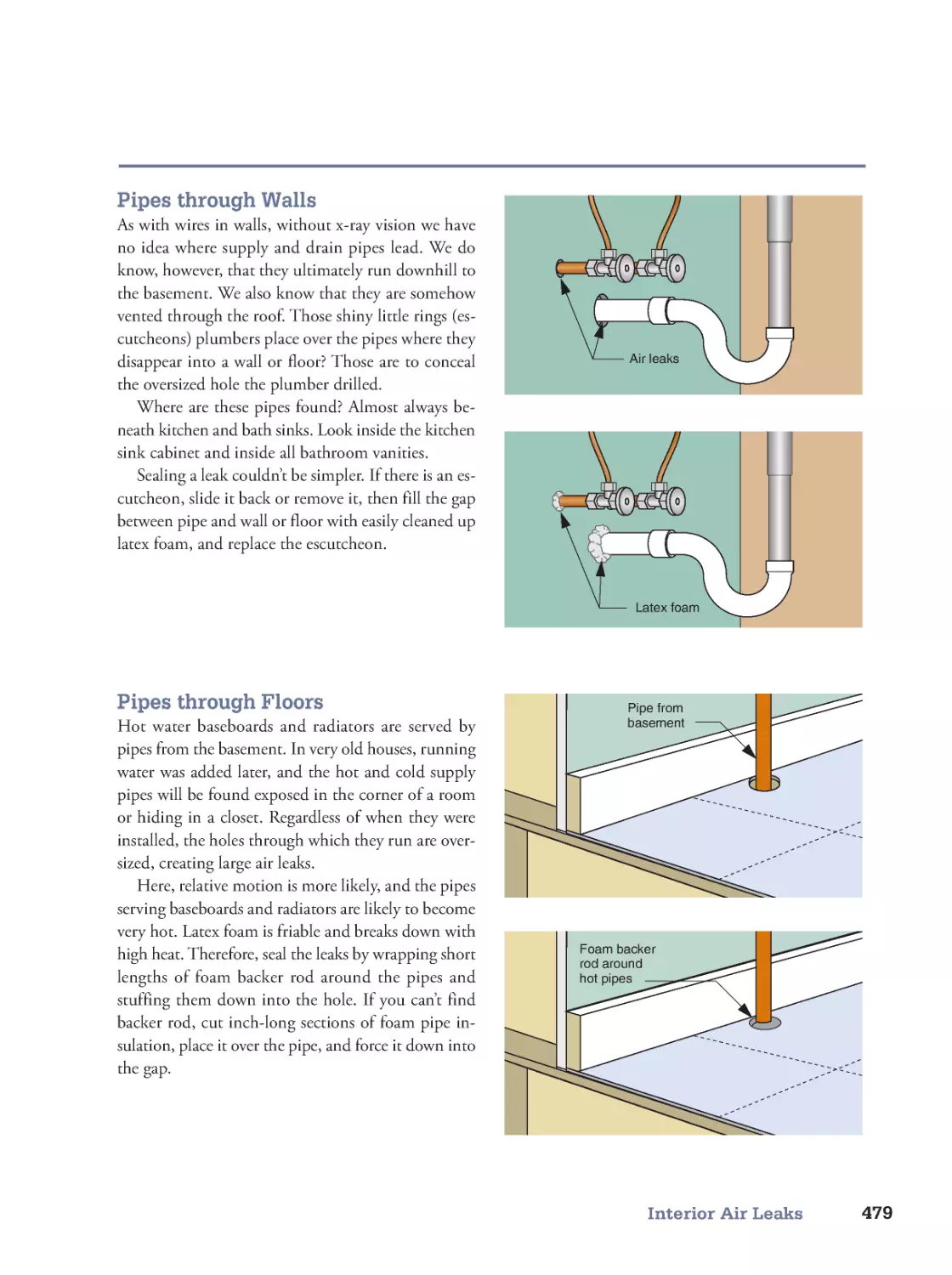
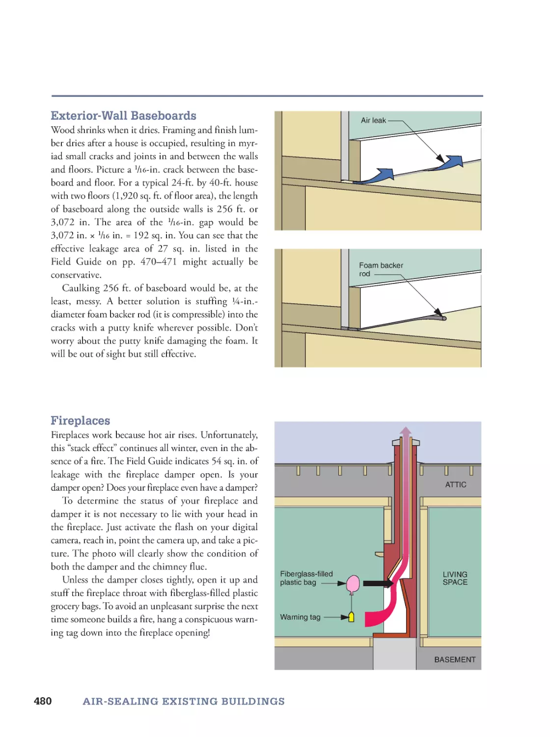
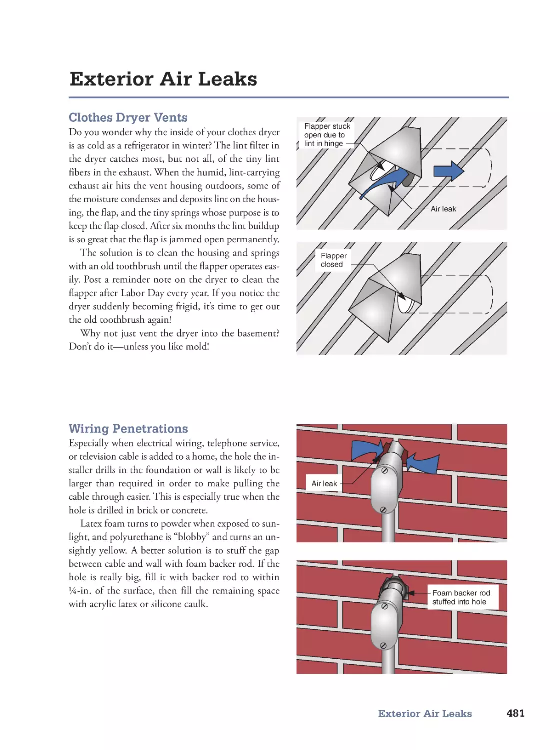
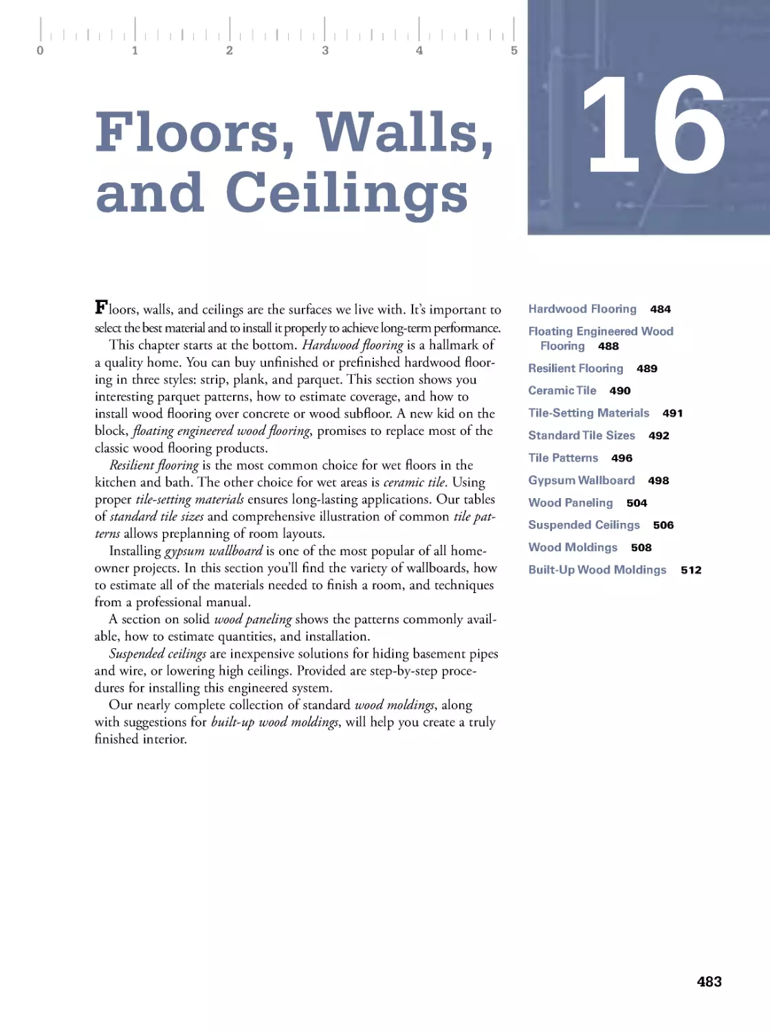
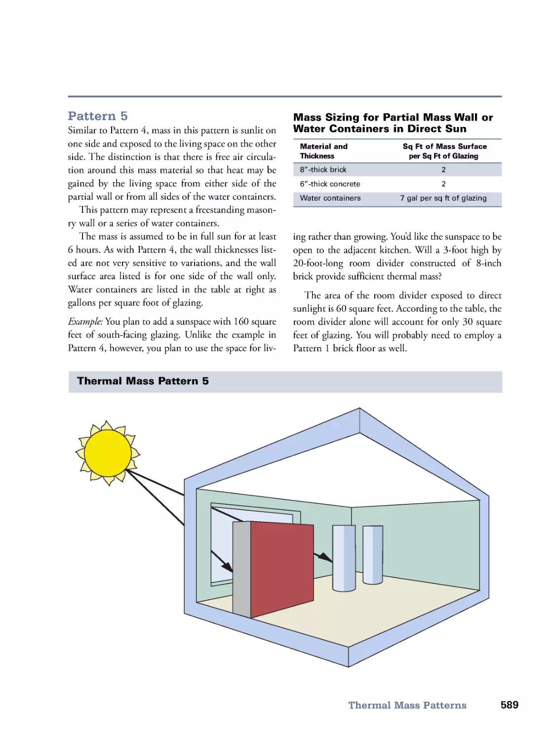
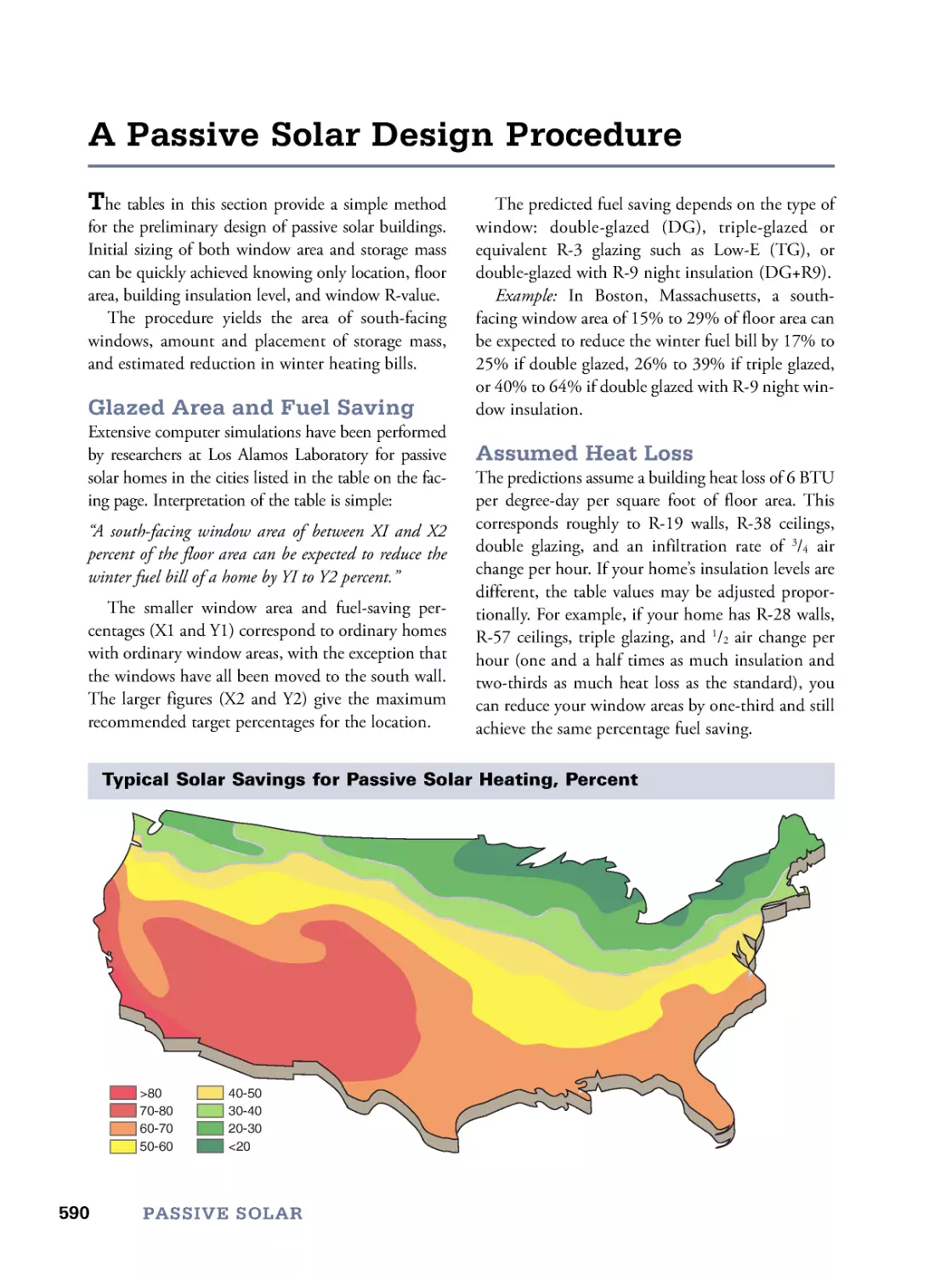
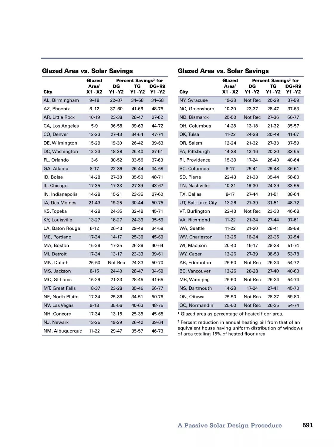
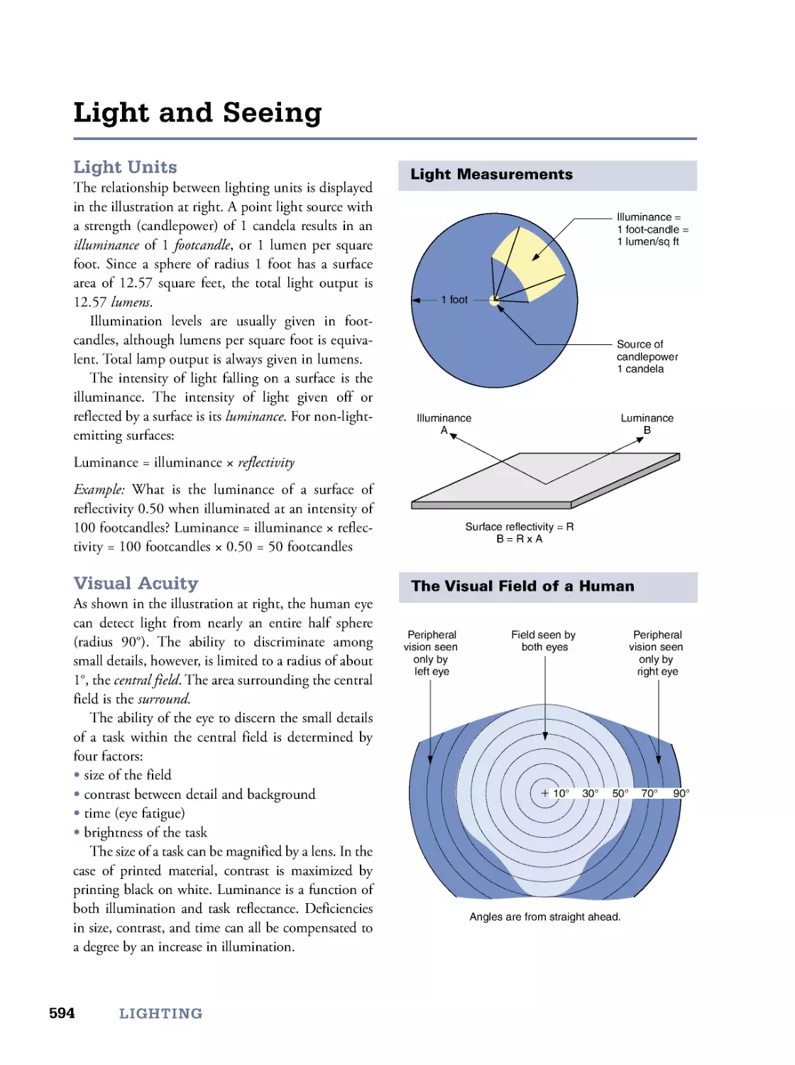
/


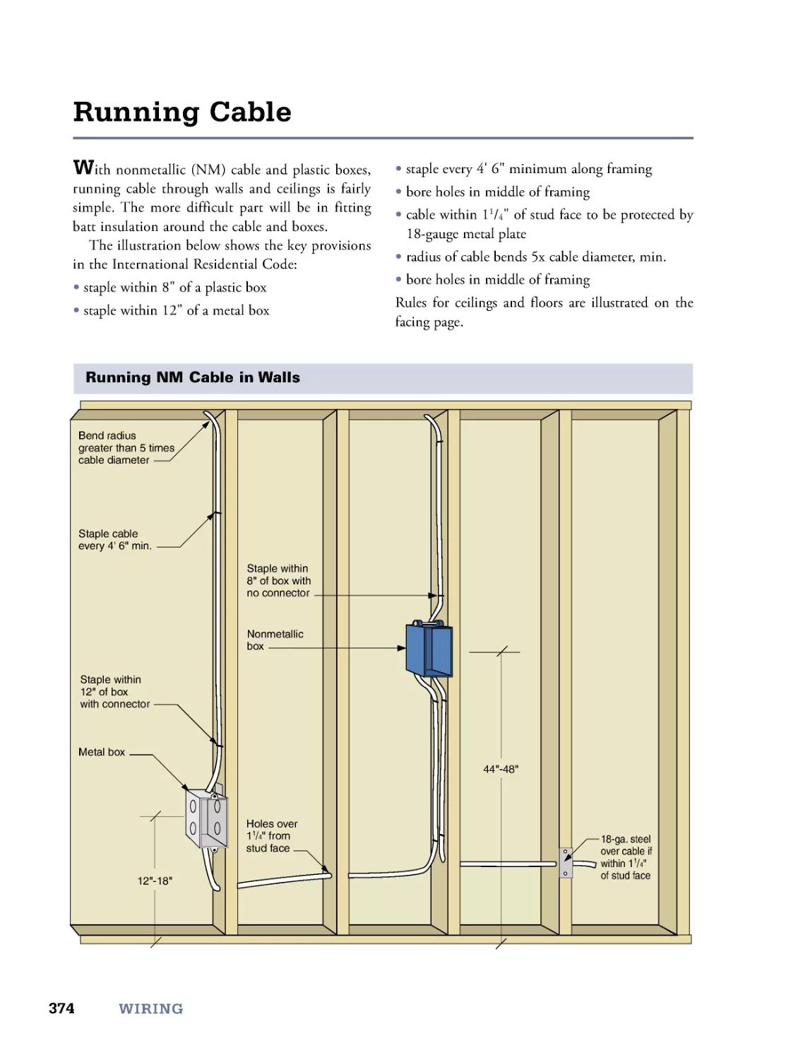


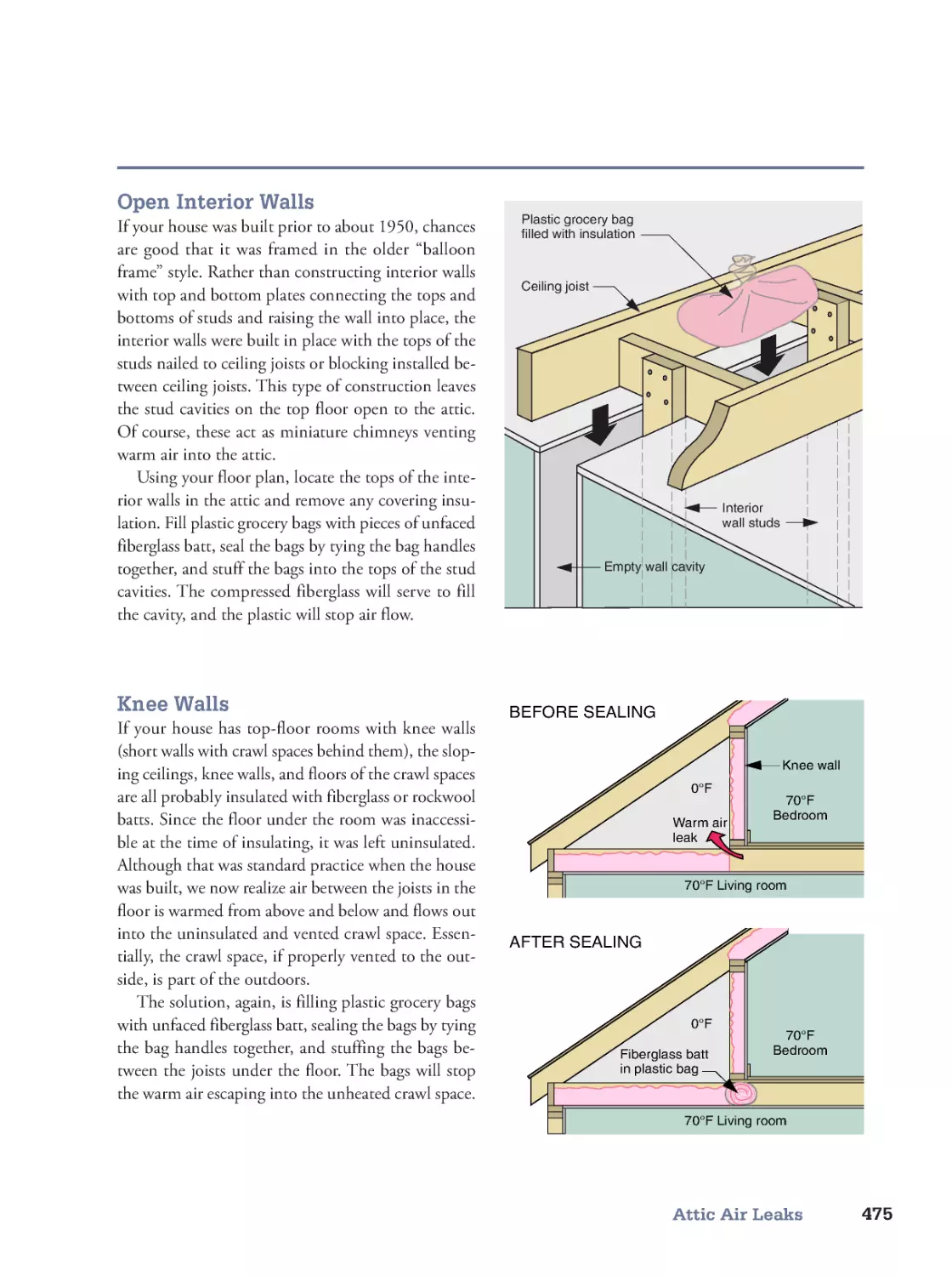

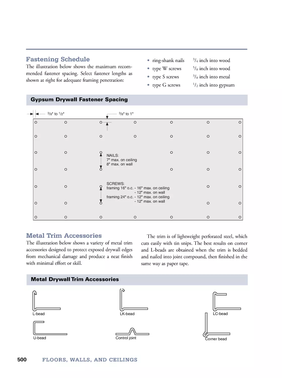
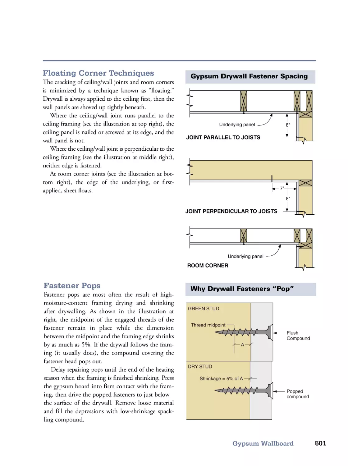
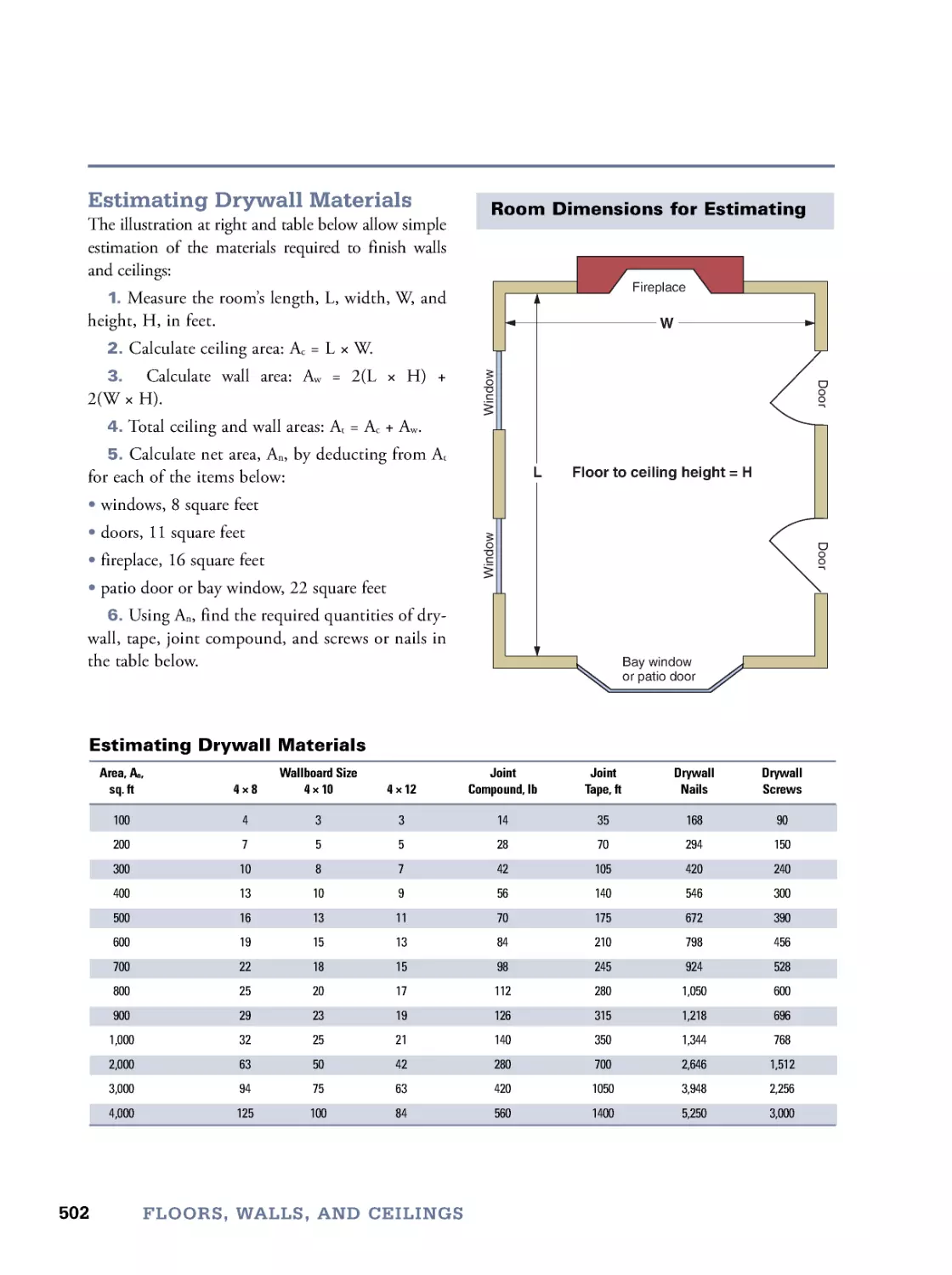
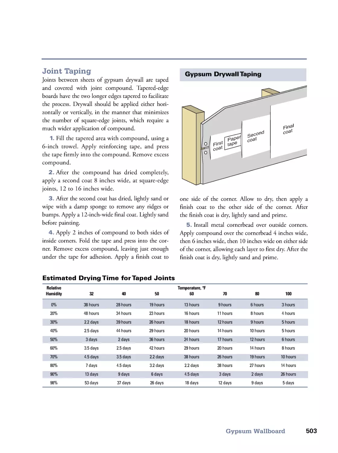


Text
TheVISUAL
HANDBOOKof
Building and Remodeling
A Comprehensive Guide to Choosing the Right
Materials and Systems for Every Part of Your Home
3RD
EDITION
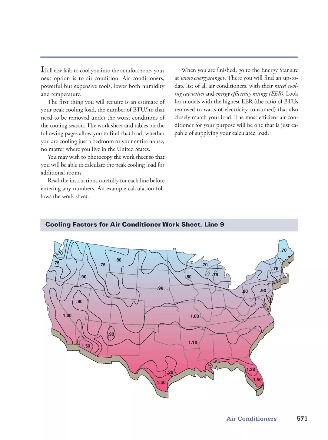
CHARLIE WING
Author of HOW YOUR HOUSE WORKS
TheVISUAL
HANDBOOKof
Building and Remodeling
A Comprehensive Guide to Choosing the Right
Materials and Systems for Every Part of Your Home
CHARLIE WING
Author of HOW YOUR HOUSE WORKS
4th
EDITION
The
VI-
SUAL
TheVISUAL
HANDBOOKof
Building and Remodeling
A
4th
EDITION
The
The
t
The
VI-
SUAL
TheVISUAL
HANDBOOKof
Building and Remodeling
A Comprehensive Guide to Choosing the Right
Materials and Systems for Every Part of Your Home
CHARLIE WING
4th
EDITION
© 2017 by Charlie Wing
All rights reserved.
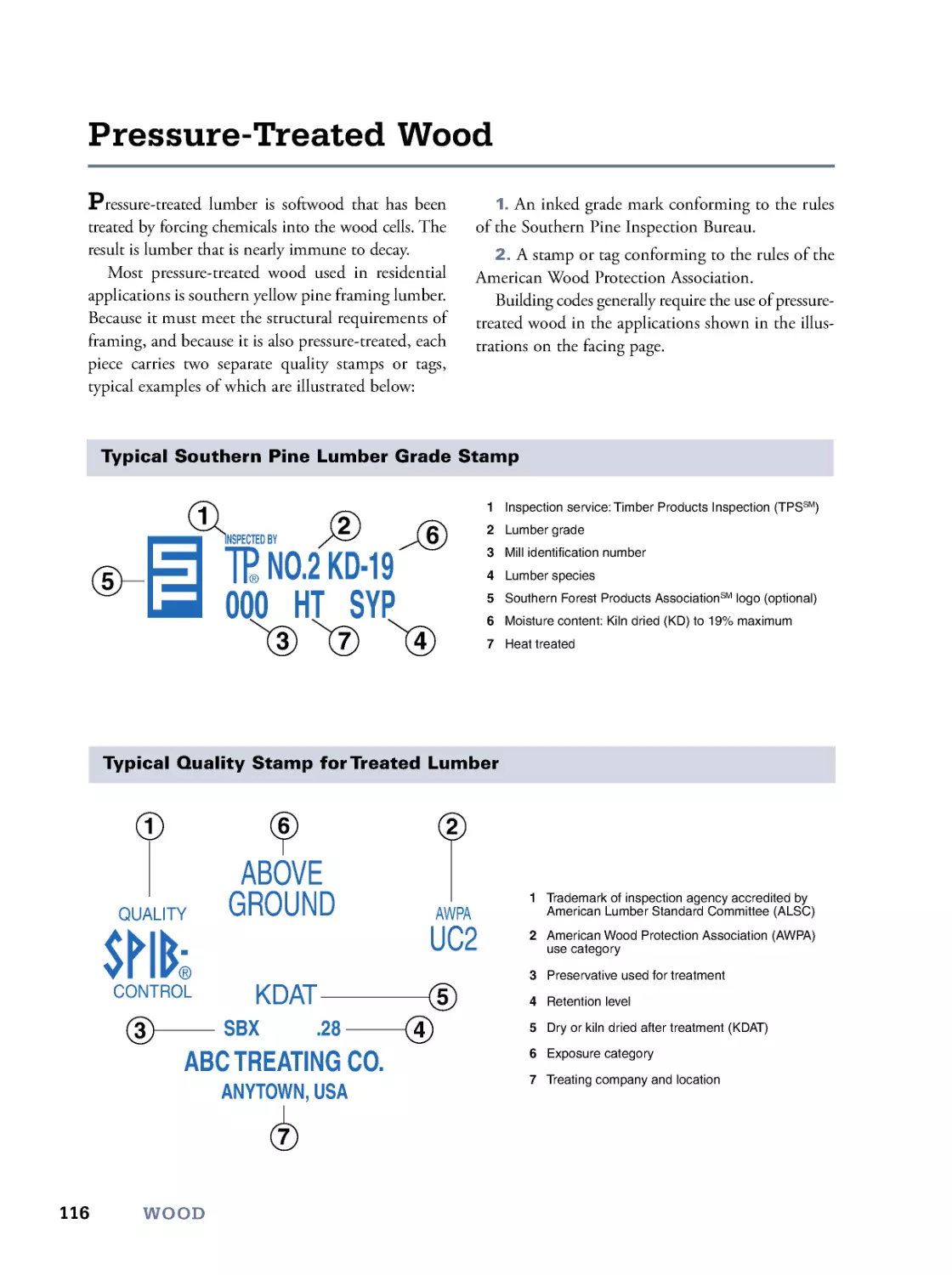
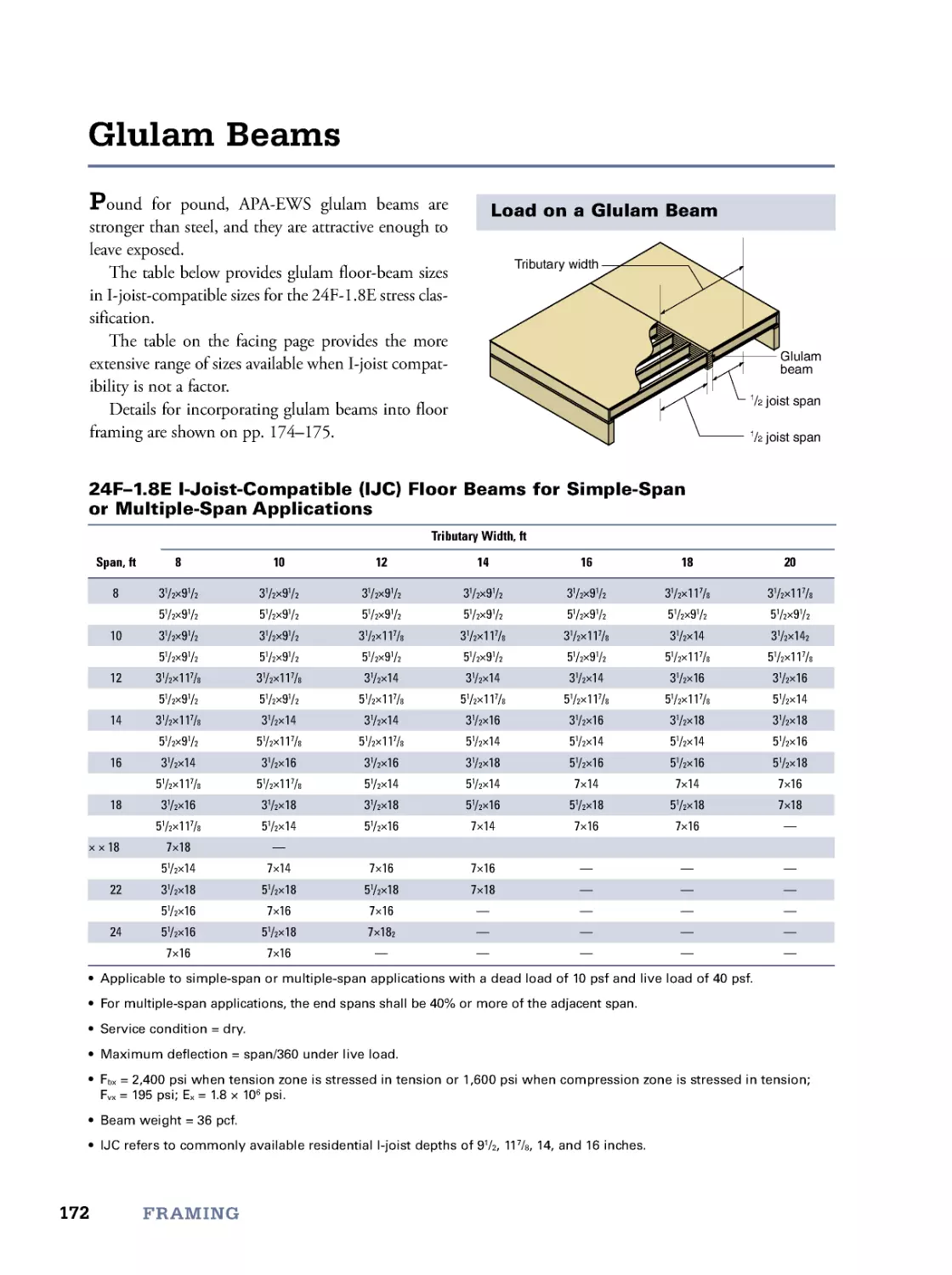
P
p
The Taunton Press, Inc., 63 South Main Street, PO Box 5506, Newtown, CT 06470-5506
email: tp@taunton.com
Editor: Peter Chapman
Indexer: Jim Curtis
Cover design: Jean-Marc Troadec
Cover illustration: Charlie Wing
Interior design: Nick Anderson
Layout: Charlie Wing
Illustrator: Charlie Wing
The following manufacturers/names appearing in The Visual Handbook of Building and Remodeling are trade-
marks: 3M Fastbond
®
30NF, Adobe Illustrator
®
, Amazon.com
SM
, American Forest & Paper Association
SM
,
APA Performance RatedTM I-Joist, Asphalt Roofing Manufacturers Association
SM
, Bilco
®
, BoilerMate
®
, Com-
Ply®
, Cornerstone
SM
, Dulux
®
EL, Duxseal®
, ENERGY STAR®
, Faststeel® Epoxy Putty, GE® Silicone II,
GoogleTM, Grace Ice and Water Shield®
, Hardiplank
®
, Heat Mirror
®
, Household Goop
®
, InDesign®
,
International Residential Code
®
, J-B Weld®
, Krazy Glue
®
, LePage
®
Metal Epoxy, Loctite
®
349, NAHB®
,
National Design Specification®
, NKBASM, Octron
®
, PVWatts®
, Quark
®
, Reader’s Digest®
, RhoplexTM,
Shelter Institute
SM
, Sobo
®
, Sturd-I -Floor
®
, Sturd-I -Wall
®
, Super GlueTM, Theodolite
®
, Uhu
®
Glue, Gorilla
Glue
®
, Velux
®
, Weldbond
®
, Zap
®
, Zip SystemTM
Library of Congress Cataloging-in-Publication Data
Names: Wing, Charles, 1939- author.
Title: The visual handbook of building and remodeling : a comprehensive guide
to choosing the right materials and systems for every part of your home /
Charlie Wing.
Description: 4th edition. | Newtown, CT : Taunton Press, Inc., 2017. |
Includes index.
Identifiers: LCCN 2017037031 | ISBN 9781631868795 (print) | ISBN 9781631869624 (pdf format) |
ISBN 9781631869648 (mobi format)
Subjects: LCSH: House construction--Handbooks, manuals, etc. |
Dwellings--Remodeling--Handbooks, manuals, etc. | Building
materials--Handbooks, manuals, etc. | House construction--Pictorial works.
| Dwellings--Remodeling--Pictorial works.
Classification: LCC TH4813 .W56 2017 | DDC 690/.8 --dc23
LC record available at https://lccn.loc.gov/2017037031
Homebuilding is inherently dangerous. Using hand or power tools improperly or ignoring safety practices
can lead to permanent injury or even death. Don’t try to perform operations you learn about here (or else-
where) unless you’re certain they are safe for you. If something about an operation doesn’t feel right, don’t do
it. Look for another way. We want you to enjoy working on your home, so please keep safety foremost in
your mind whenever you’re in the shop.
As the dedication indicates, without the experience, insight, and doggedness of my agent, Ray Wolf, this book
would have remained but a personal dream. Who would have thought, in 1990, The Visual Handbook of
Building and Remodeling would become a building classic with new editions every eight years?
As soon as I had committed to leading a Bowdoin College seminar titled “The Art of The House,” I started
gathering information, not only on how houses were constructed, but how they worked. The seminar, in real-
ity, should have been called, “ The Physics of the House.”
In addition to nearly 100 books, I soon had filing cabinets full of useful scraps of information gleaned
from every element of the building industry: architect and builder friends, lumberyards, hardware stores, con-
tractors, manufacturers and associations. When the usefulness of all of this seemingly disparate information
became apparent, I began dreaming of gathering it all into a single book. Architects have their Architectural
Graphic Standards; my book would be Graphic Standards for the Rest of Us.
For many years the dream remained just that. I could get no publisher to share my vision and enthusiasm.
Simply put, they didn’t get it. Then I met Ray Wolf. He had worked for many years at Rodale Press, publisher of
Organic Gardening and New Shelter Magazine. He knew how publishers worked, how they thought. He knew
how to present the project in terms they would understand. Better yet, he ran a set of numbers that prom-
ised profitability.
After signing the contract, the most trying task fell upon the shoulders of legendary editor Maggie
Balitas, who patiently tempered my vision with the realities of publishing. To her then-young associate,
David Schiff, Maggie assigned the duty of ensuring accuracy. I am sure that I am responsible for several years
of his accelerated aging. These are the three individuals who helped me turn my dream into reality. I can-
not thank them enough.
Of course, there would never have been a dream were it not for the legions of manufacturers and building
trades associations, listed on pp. 668–672, who first produced the information in my files. I thank them for their
efforts and their generosity in sharing their information.
Not least, thank you, Wid, for understanding that sitting in front of a computer eight hours a day, seven days
a week, for a whole year is how I make a living.
Acknowledgments
For Ray Wolf, agent, sailor and lifelong friend, without whom this book
would never have been born.
Contents
Introduction
viii
1. Design
1
Human Dimensions • Window, Closet, and Passage Dimensions • Kitchen Design Guidelines
• Bath Design Guidelines • Stair Design • Access • Meet the Code (IRC)
2. Site and Climate
35
Plot Plans • Soil Properties • Site Orientation • Determining Elevations • Driveways
• Climate Data • Shelterbelts • Trees • Lawns
3. Masonry
53
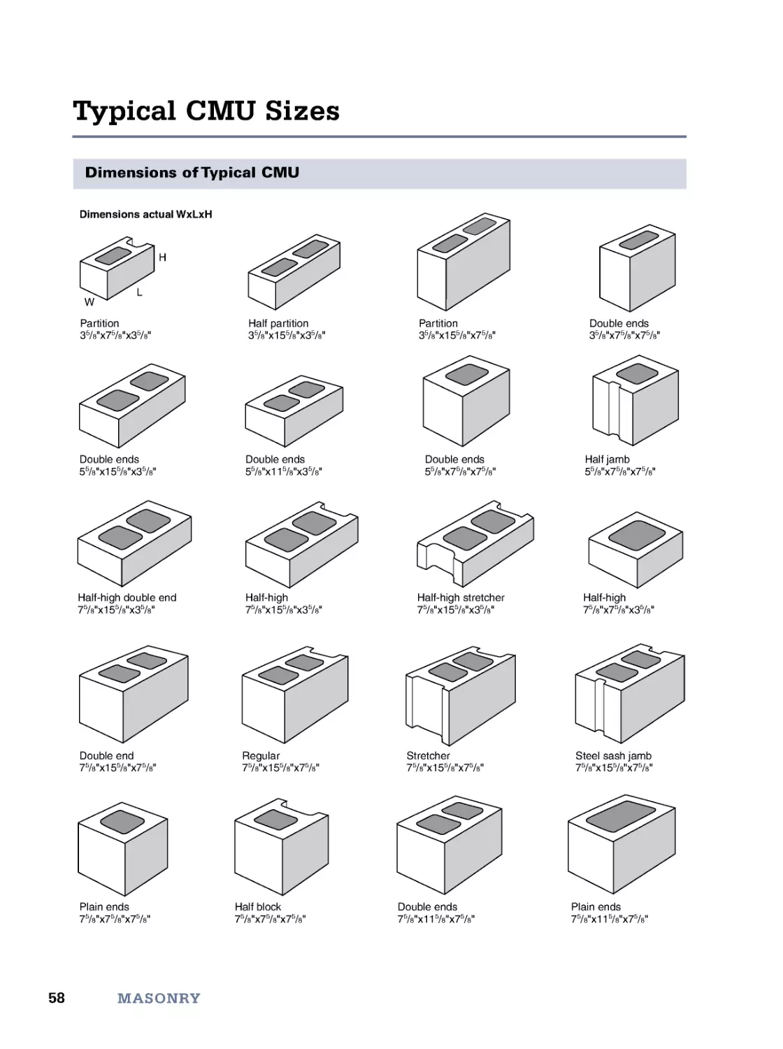
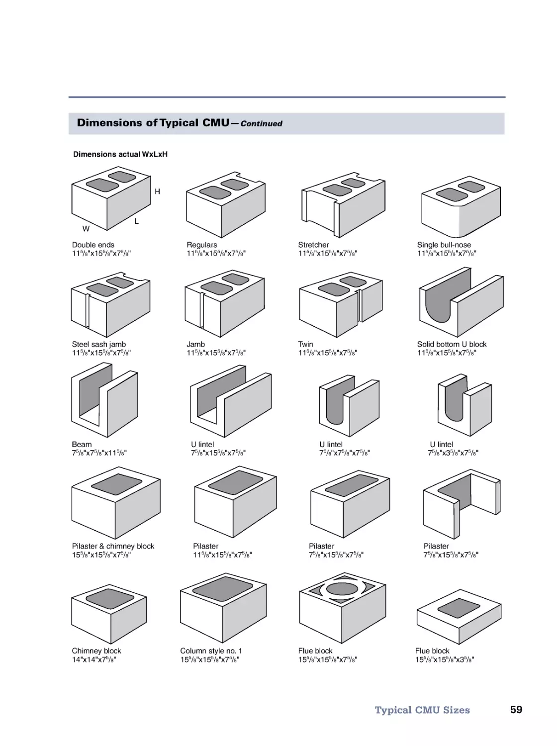
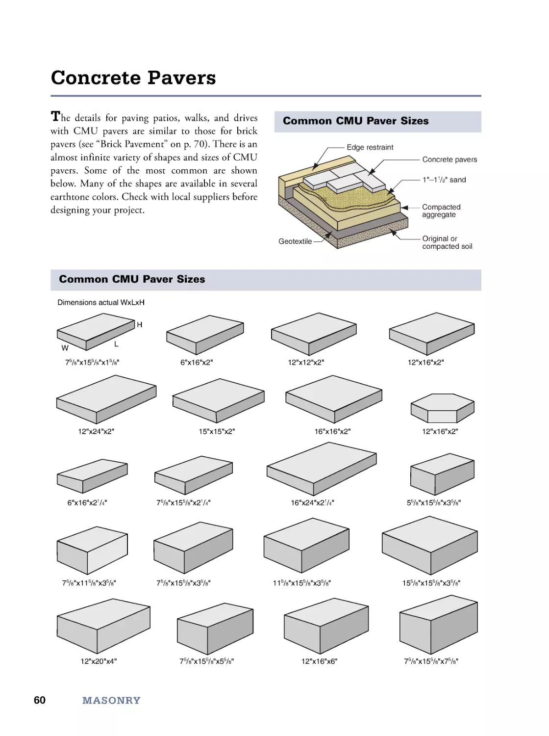
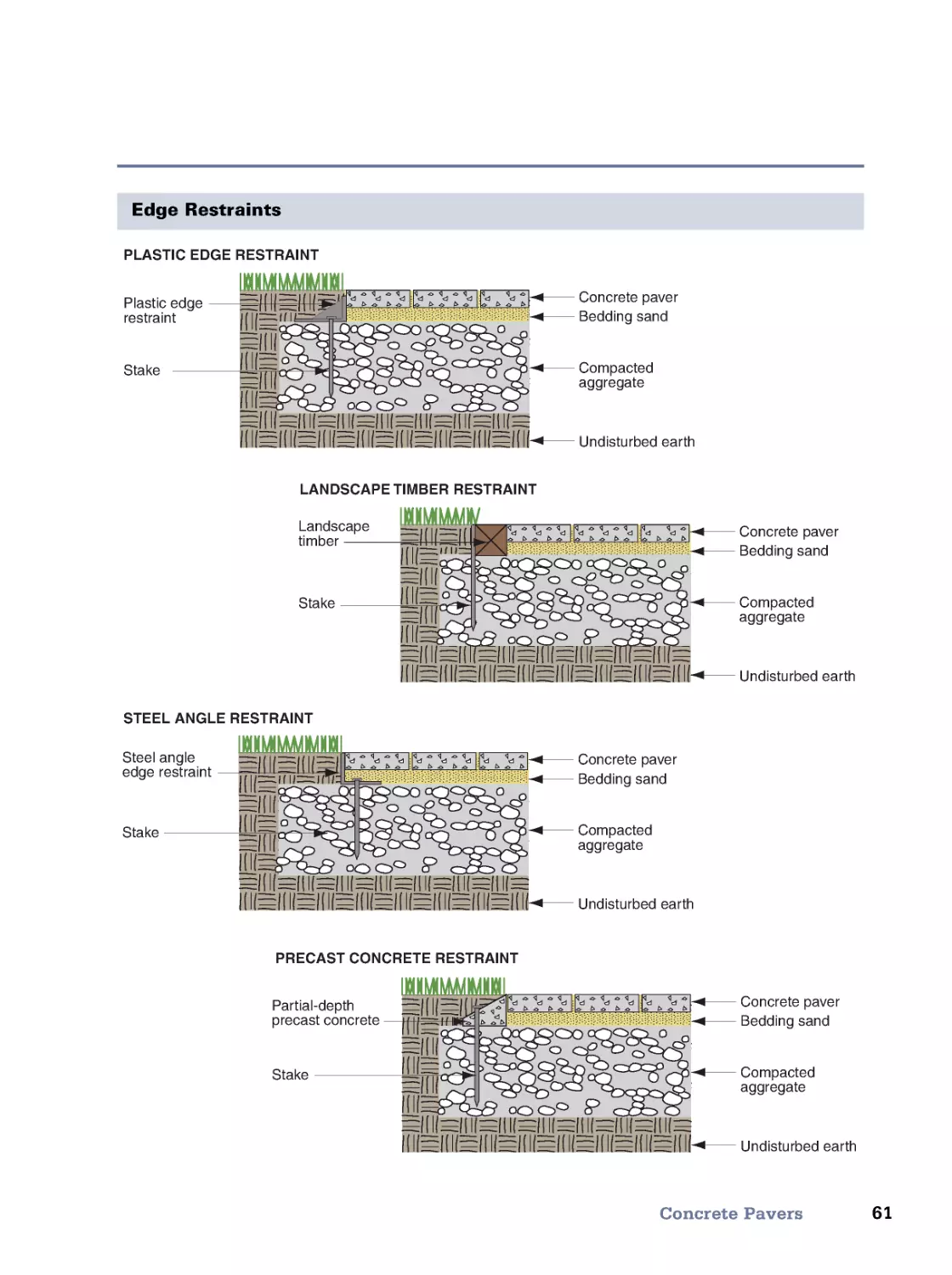
Concrete • Mortar • CMU Wall Construction • Typical CMU Sizes • Concrete Pavers • Brick Sizes
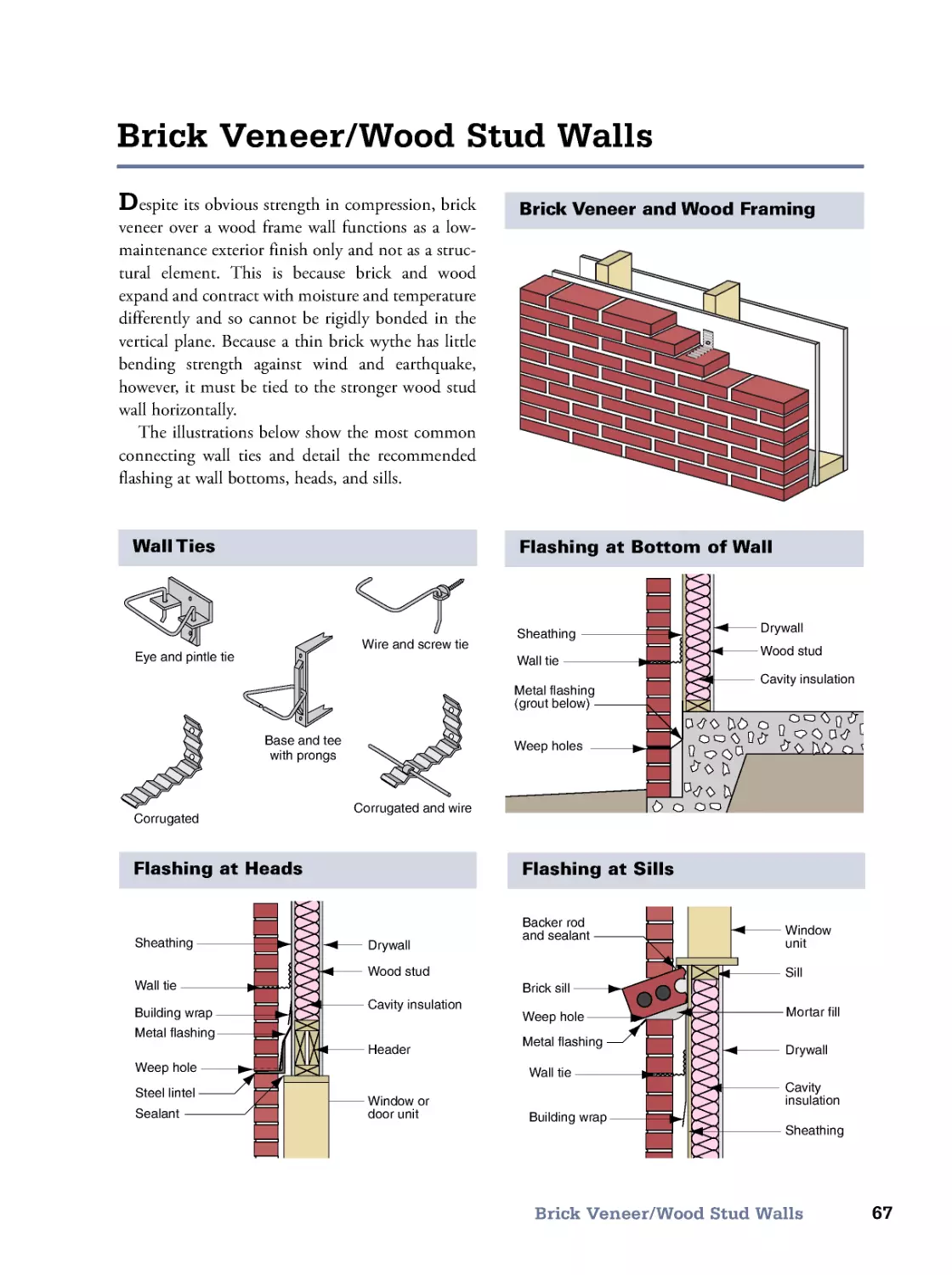
• Brick Wall Positions and Patterns • Brick Masonry Cavity Walls • Brick Veneer/Steel Stud Walls
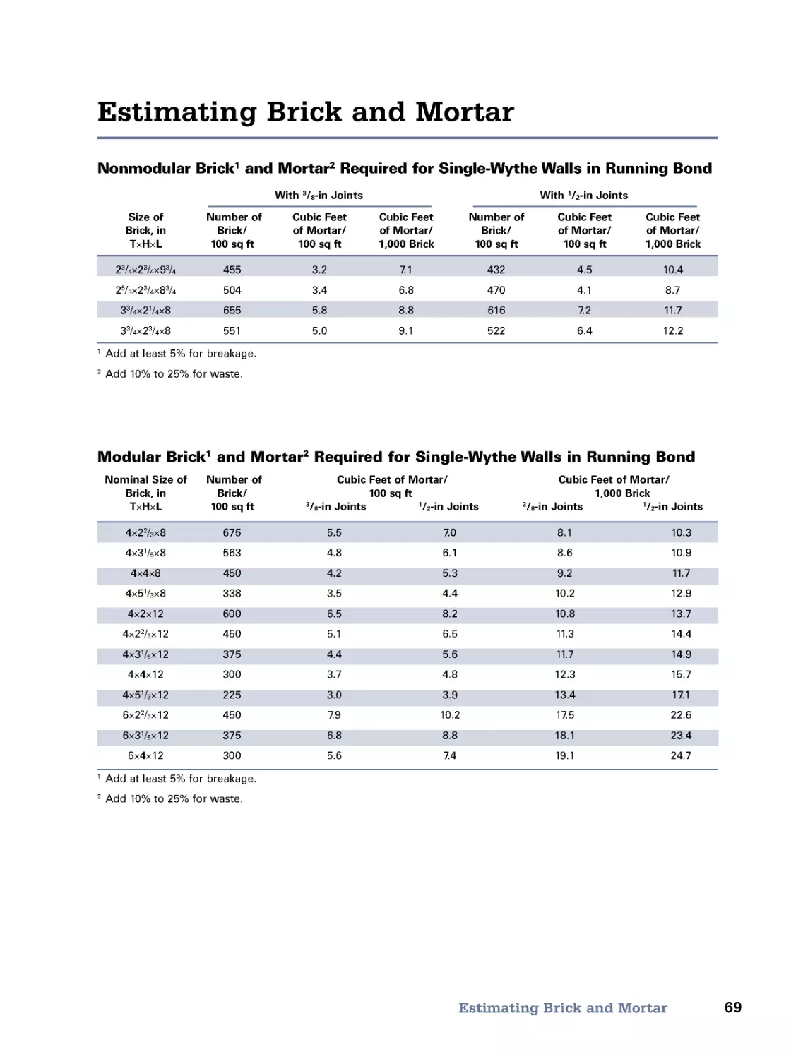
• Brick Veneer/Wood Stud Walls • Brick Wall Heights • Estimating Brick and Mortar • Brick Pavement
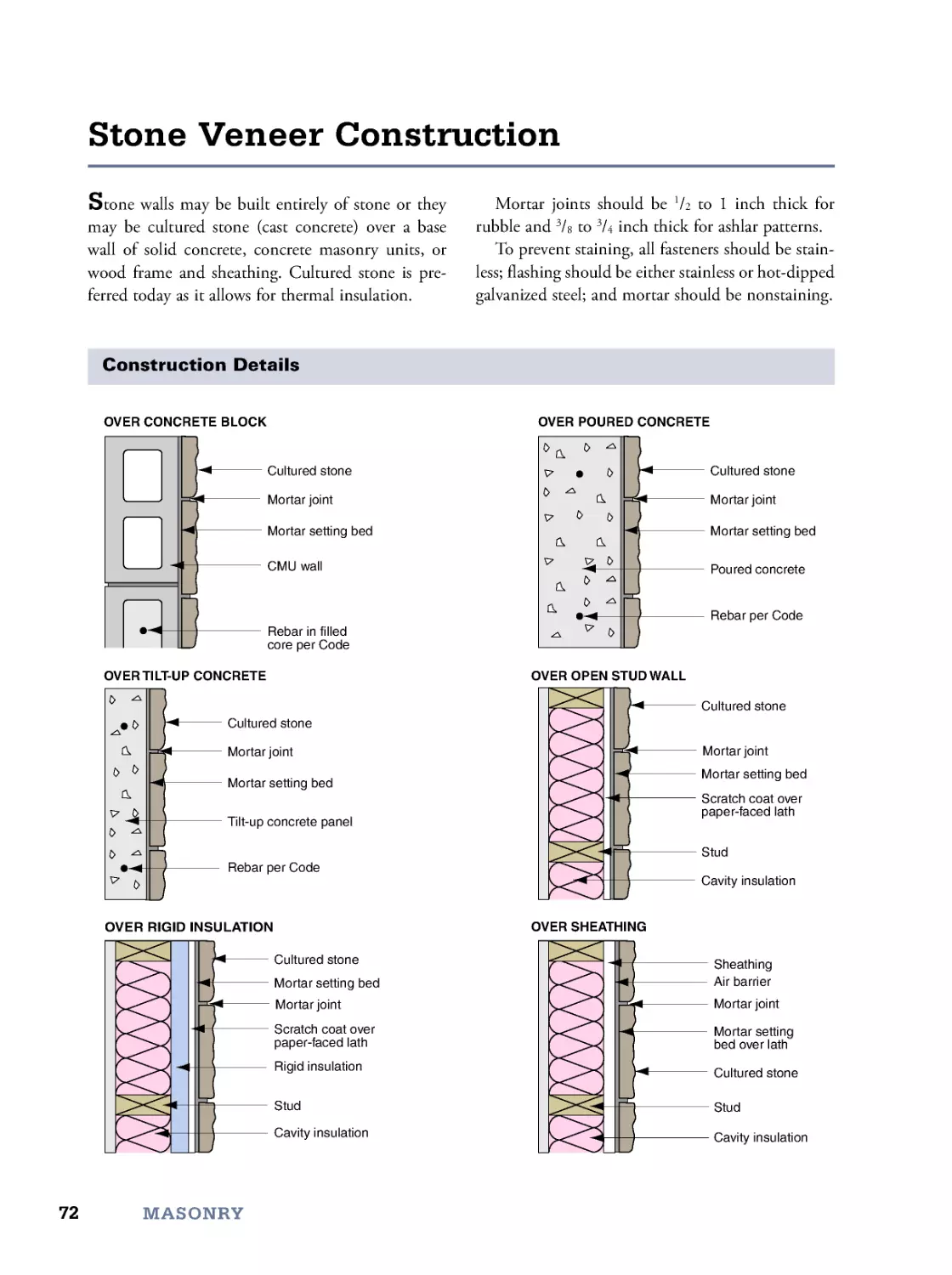
• Stone Veneer Construction • Meet the Code (IRC)
4. Foundations
77
Foundation Design • Full Basements • Crawl Spaces • Slabs on Grade • Ground Moisture Control
• Termite Control • Radon Mitigation • Meet the Code (IRC)
5. Wood
105
The Nature of Wood • Defects and Grading • Properties of North American Species
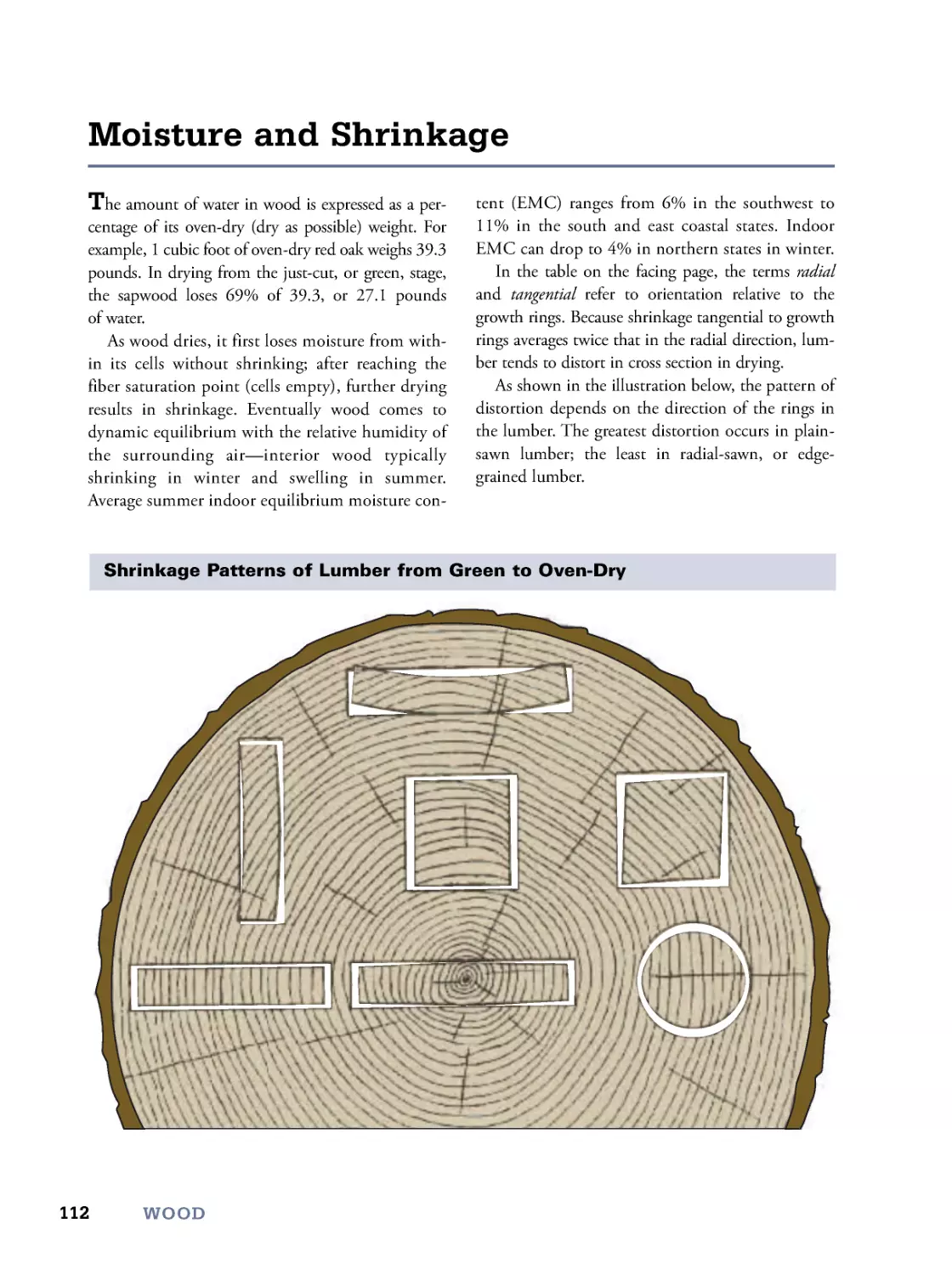
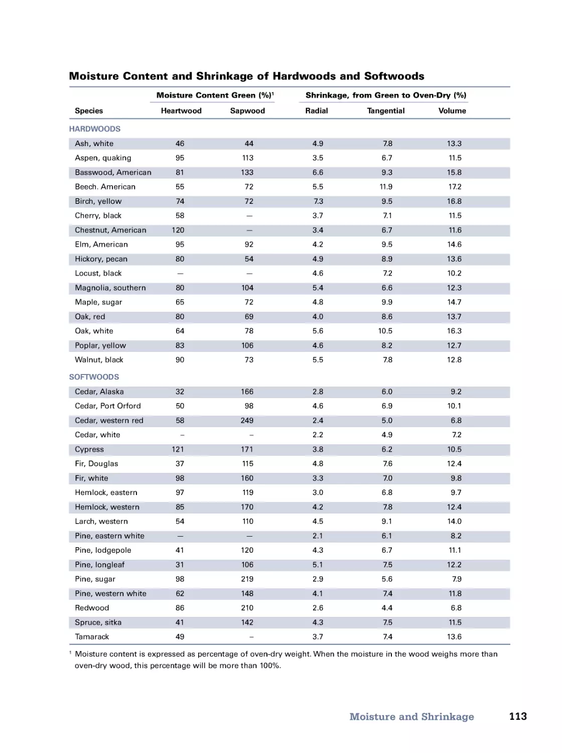
• Moisture and Shrinkage • Standard Finished Lumber Dimensions • Pressure-Treated Wood
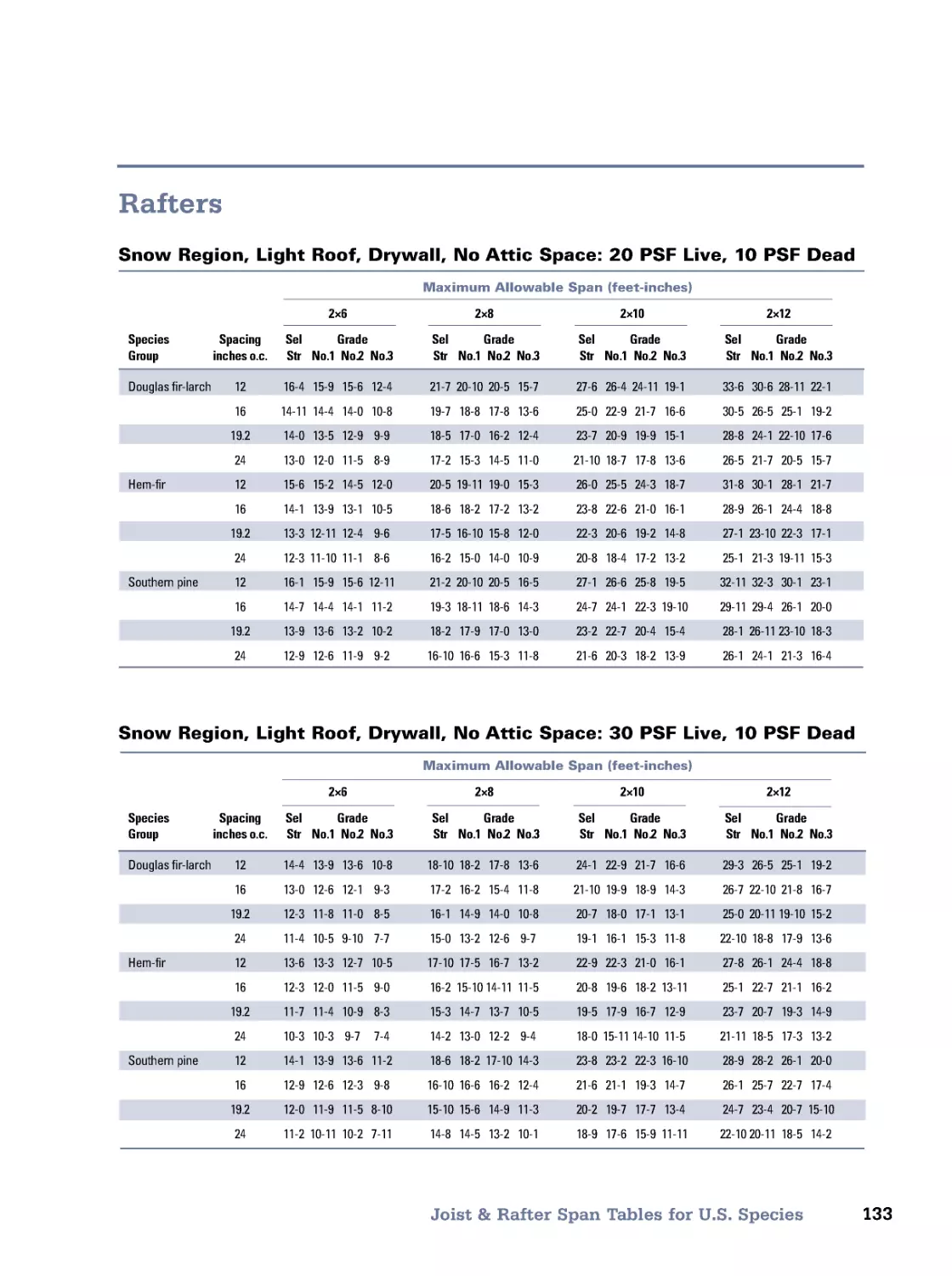
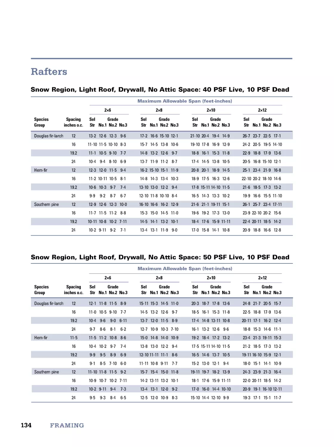
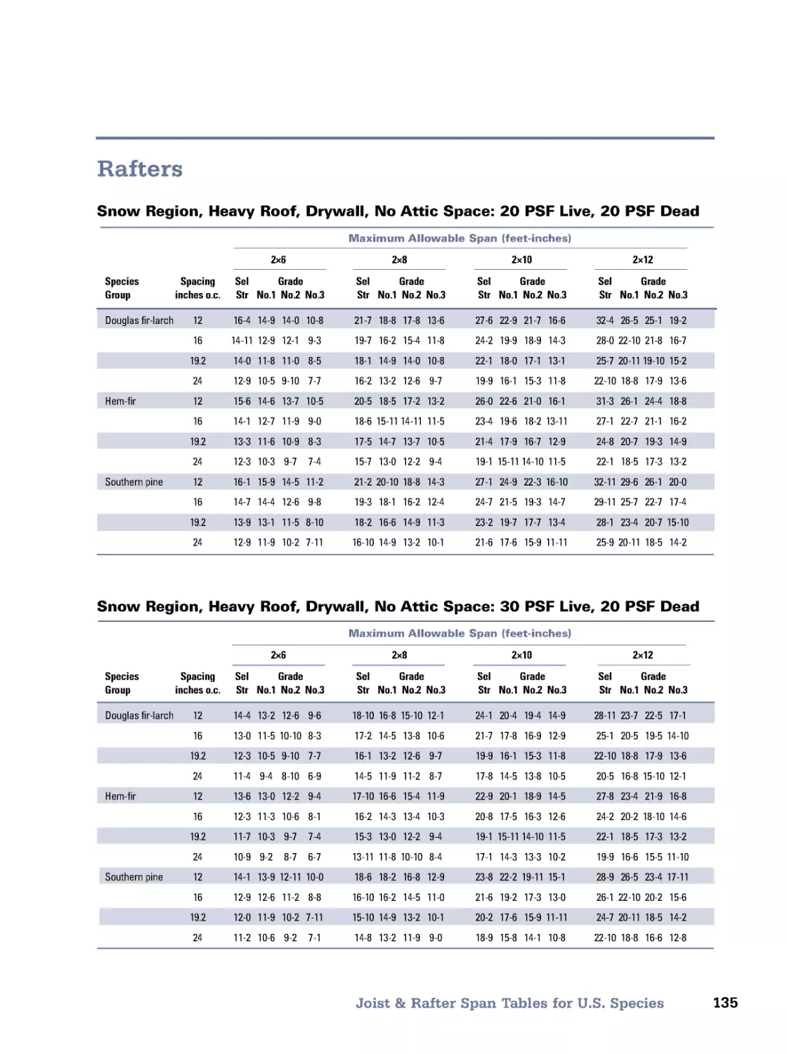
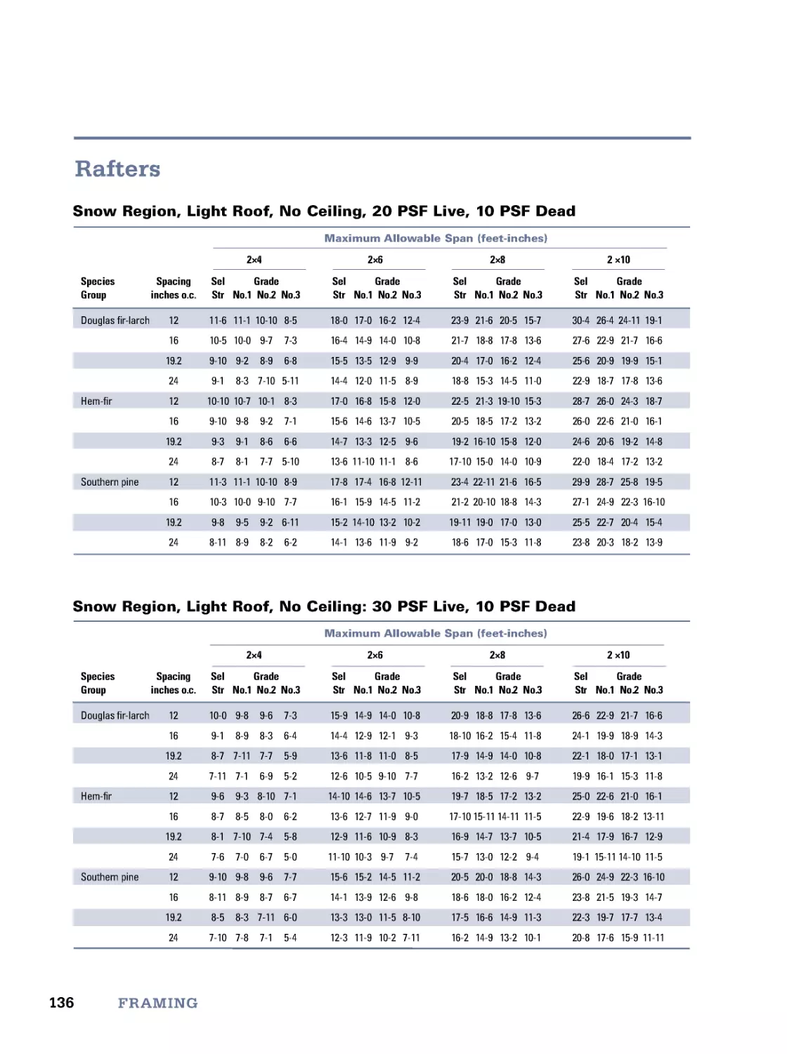
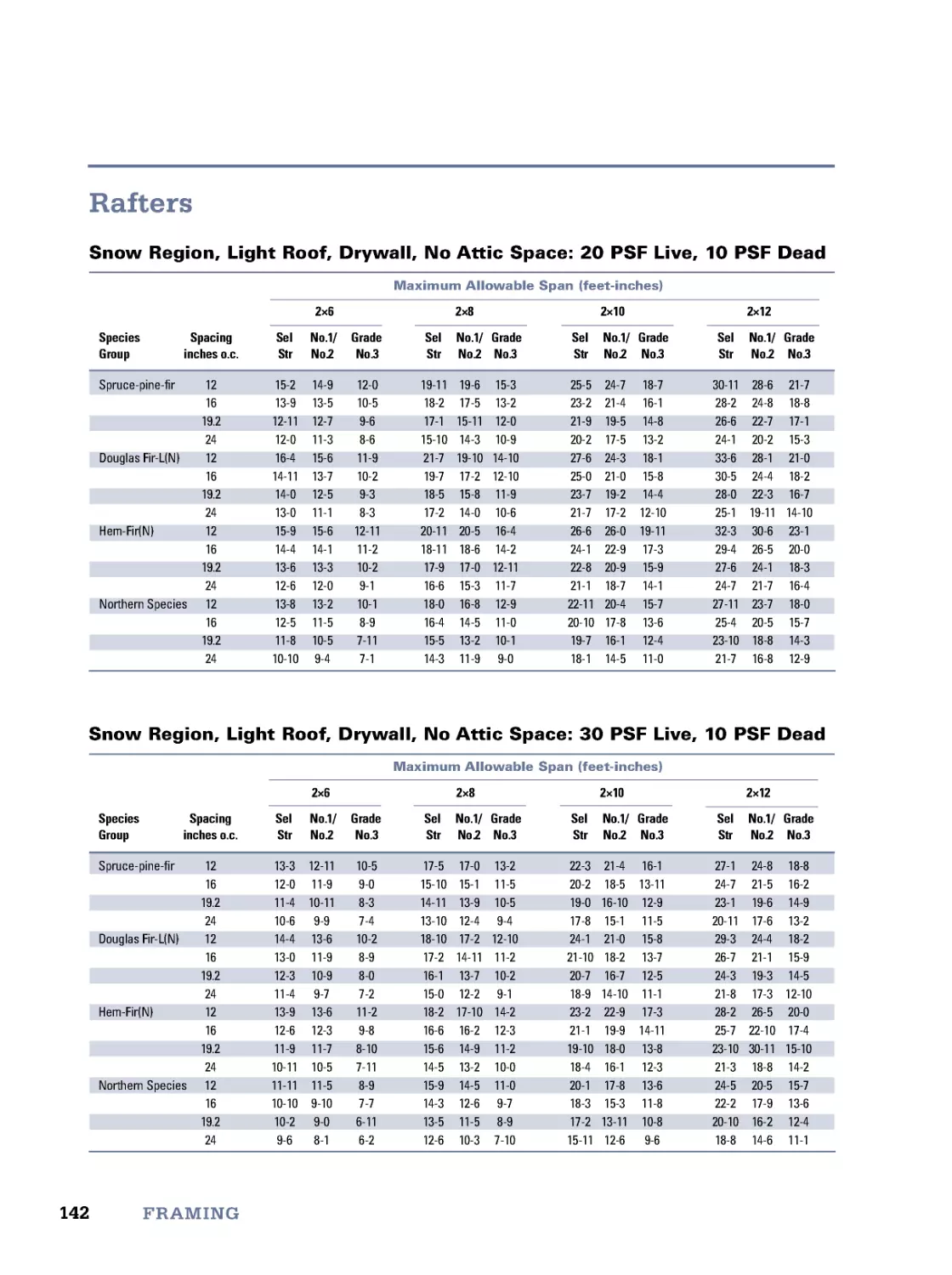
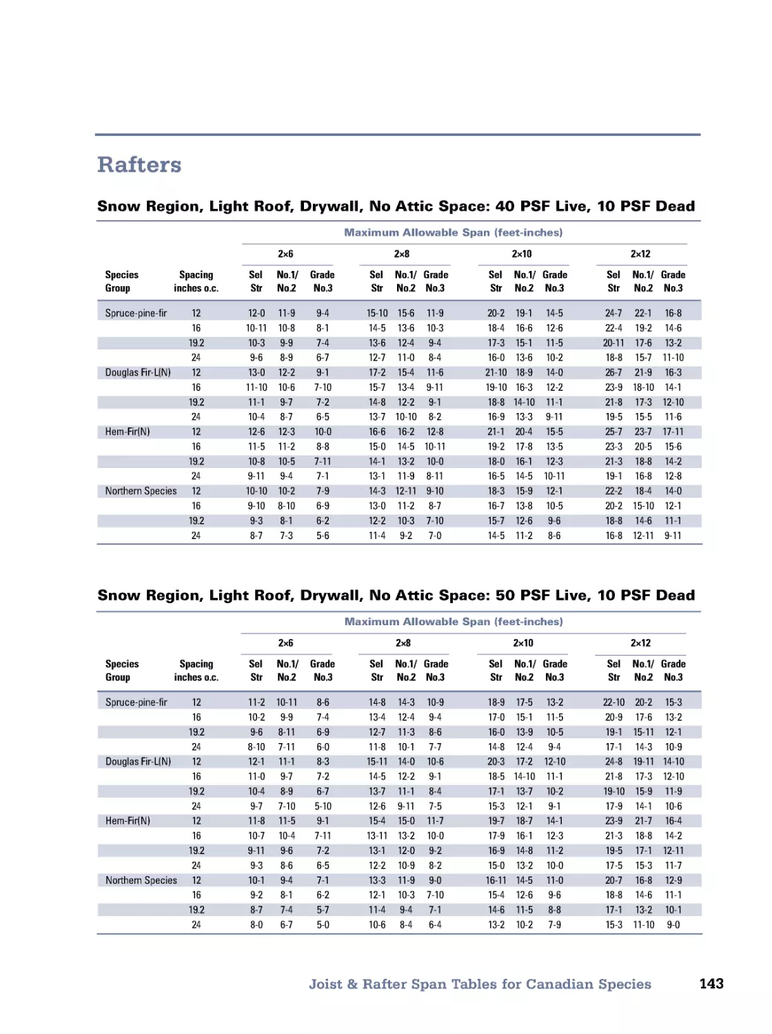
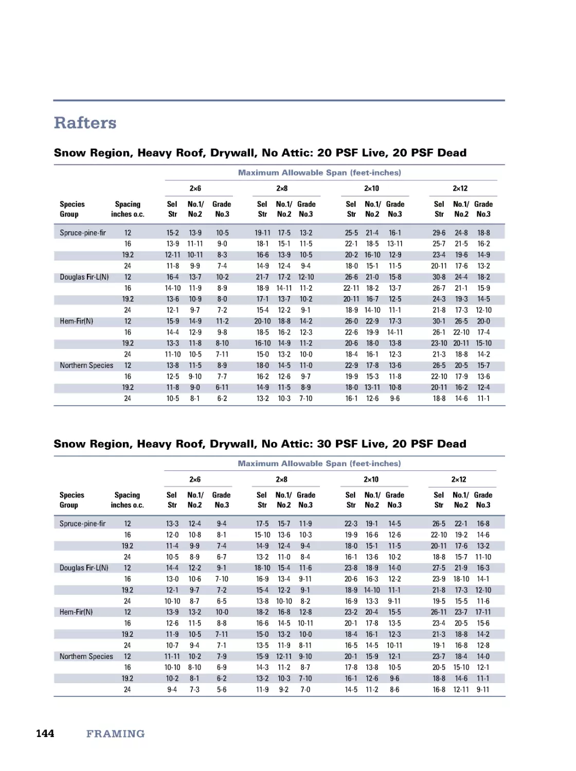
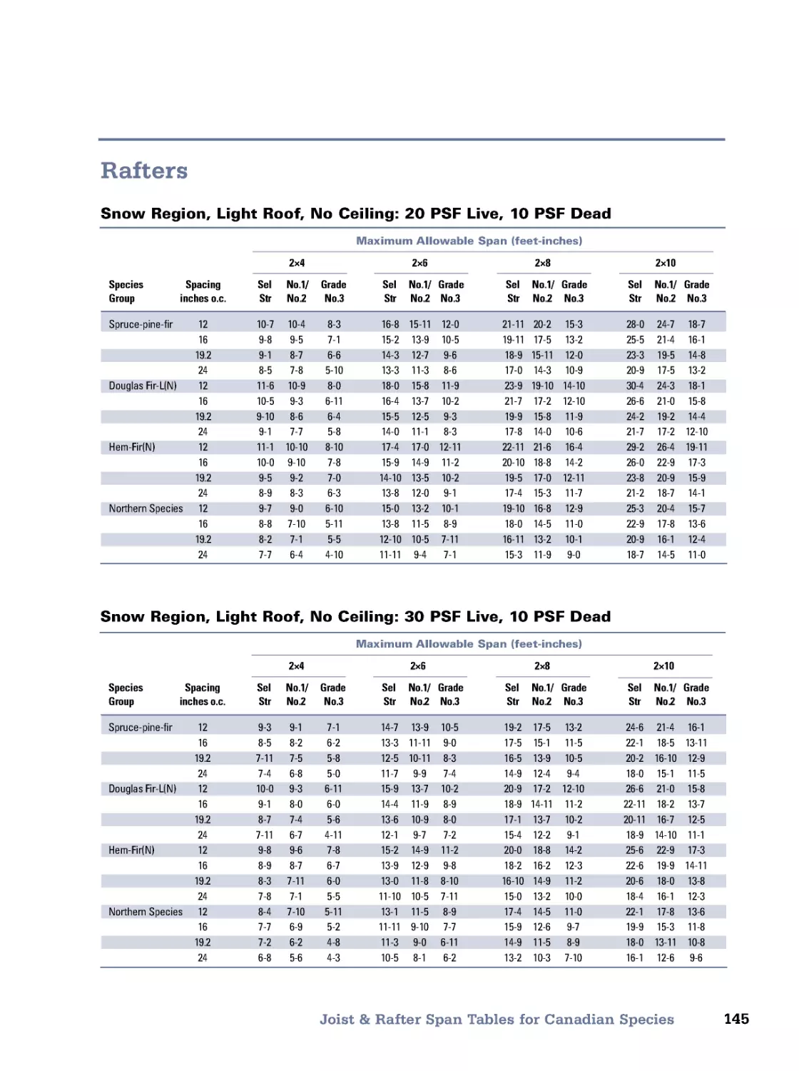
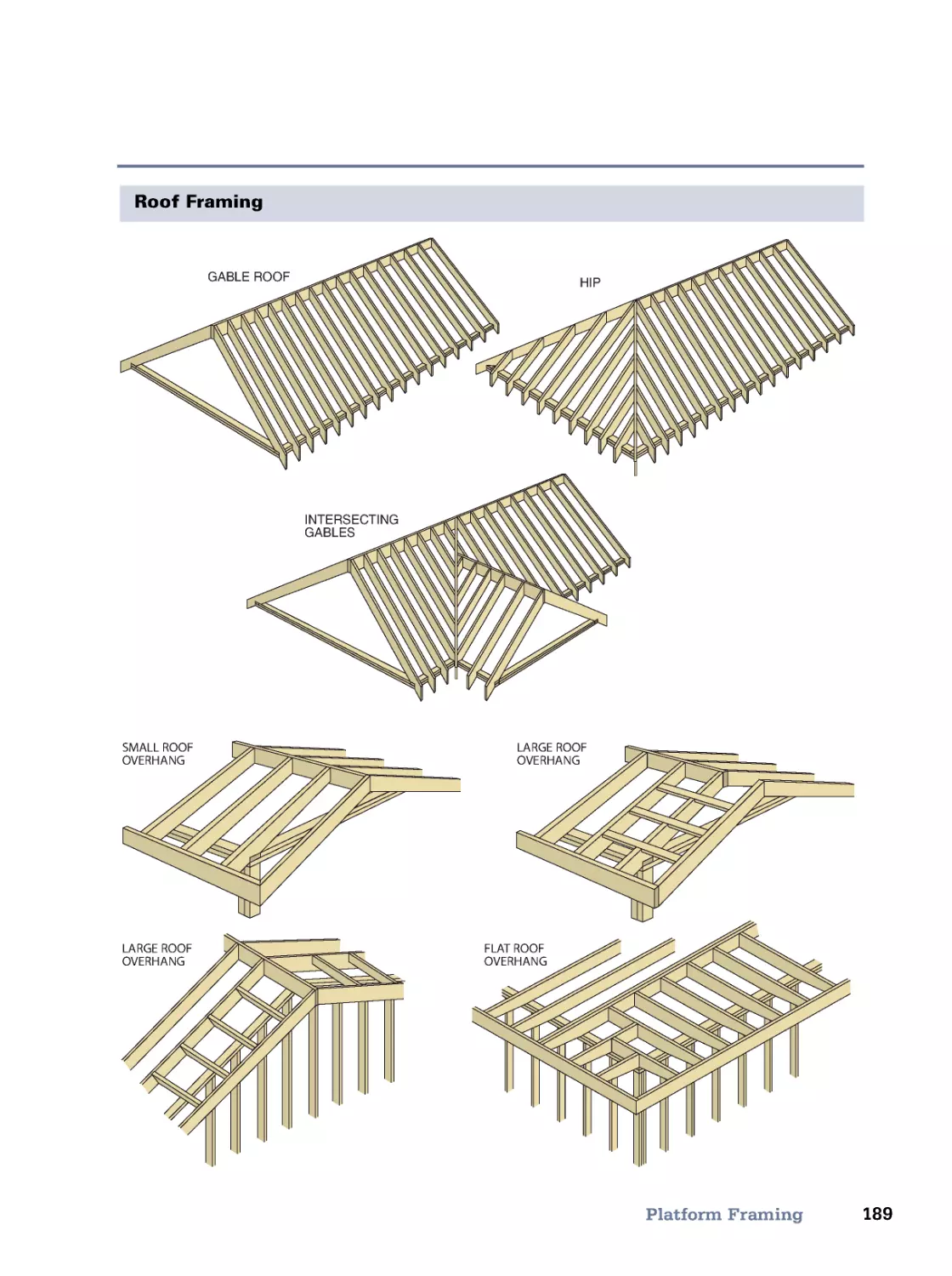
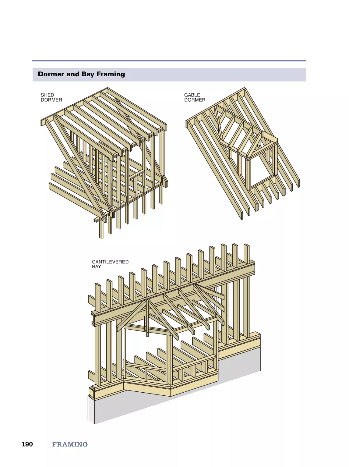
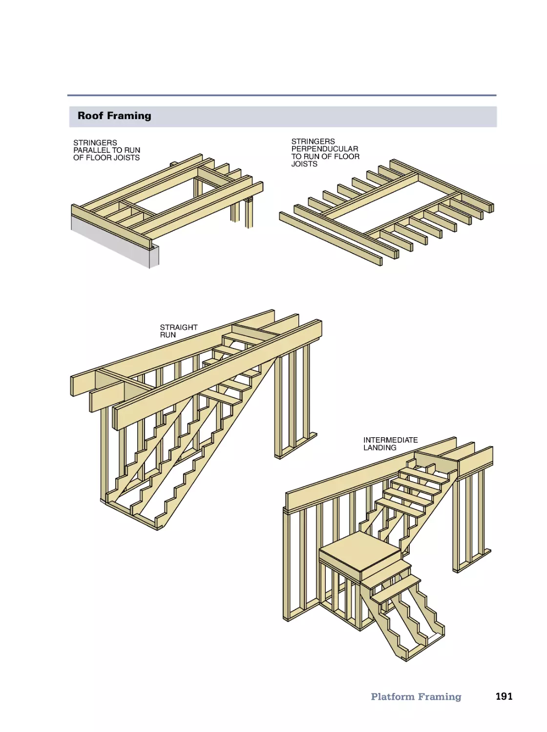
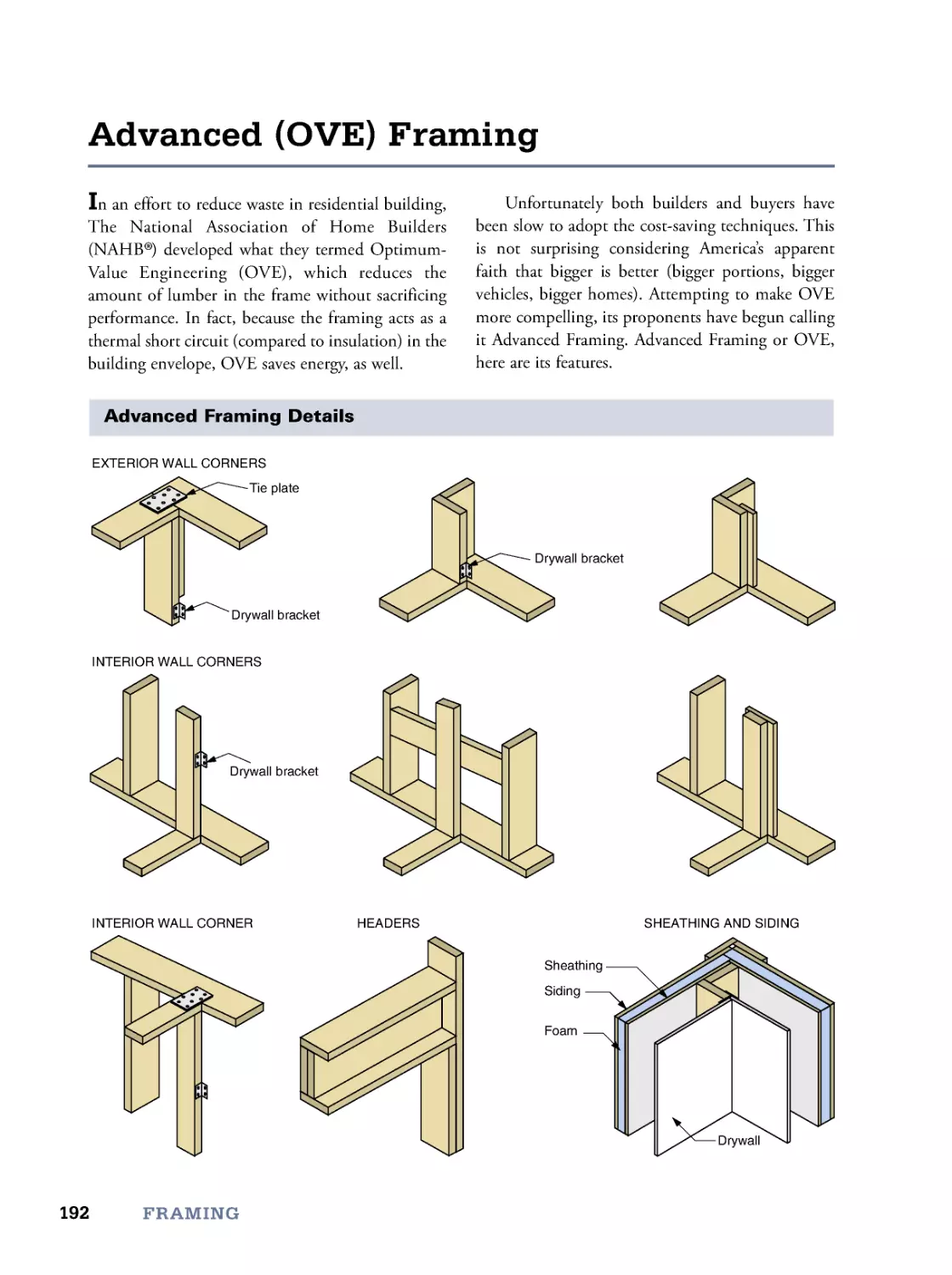
6. Framing
119
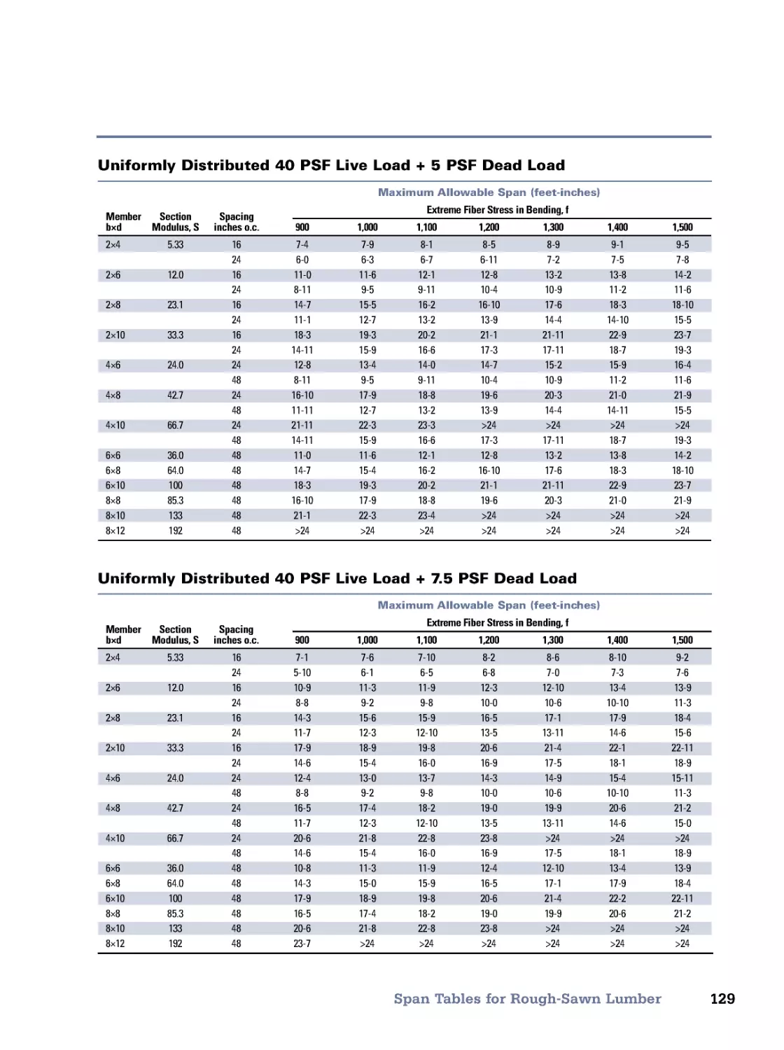
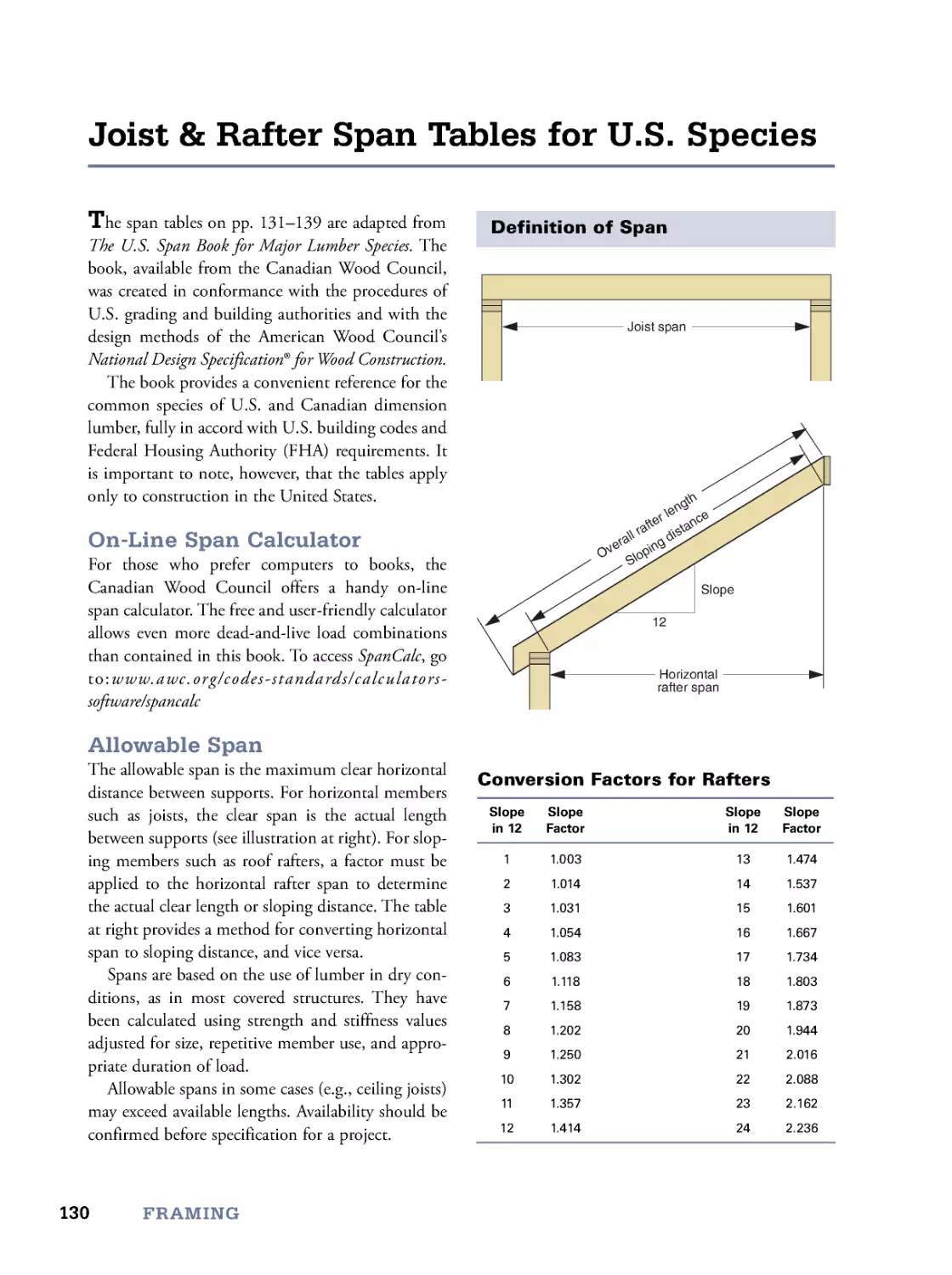
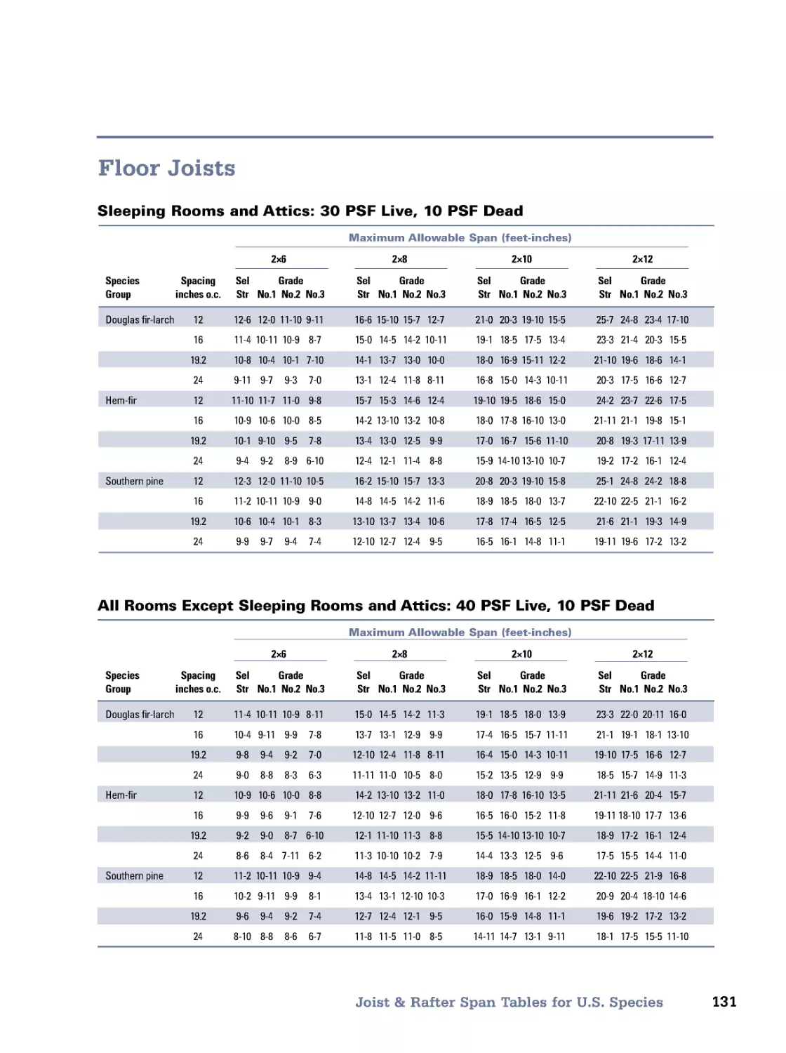
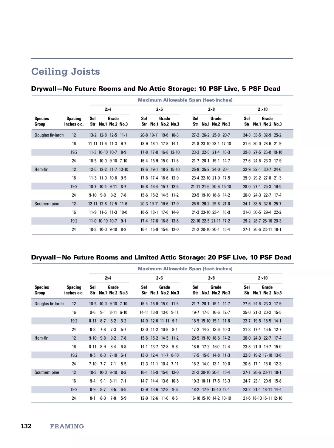
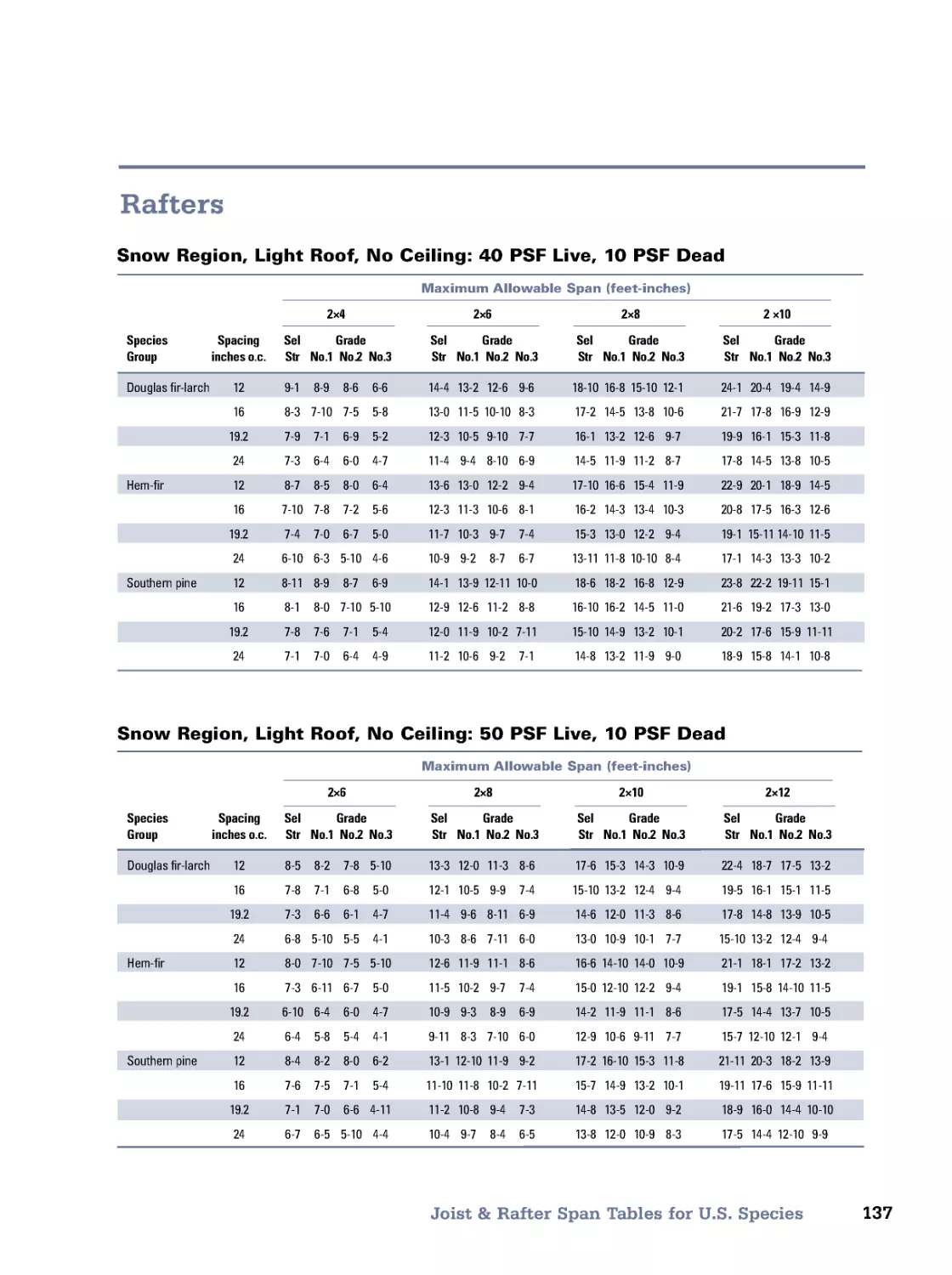
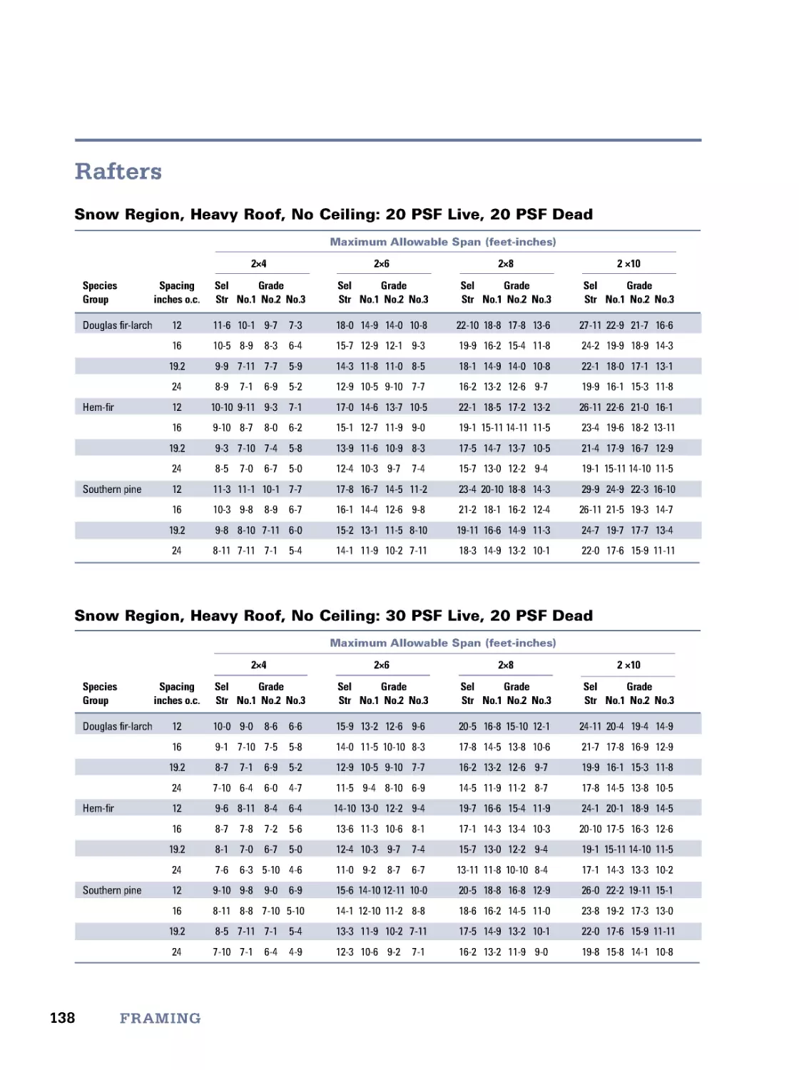
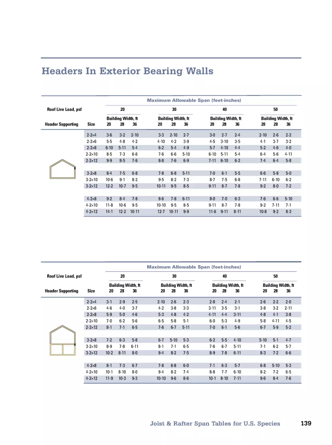
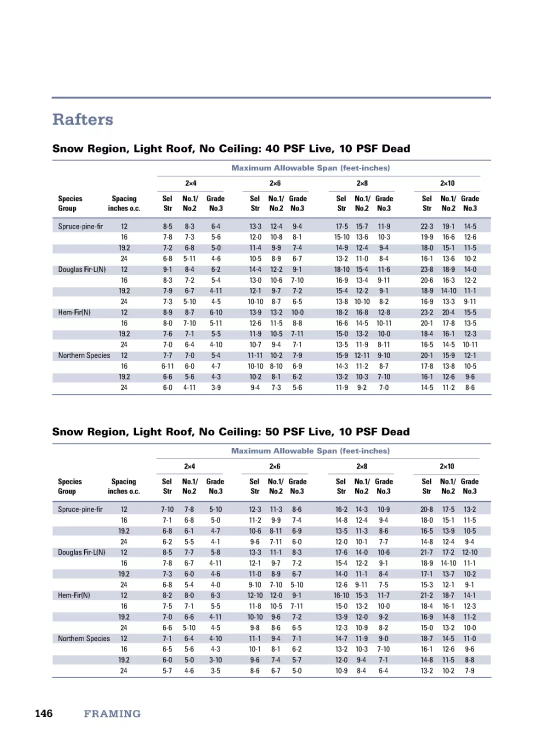
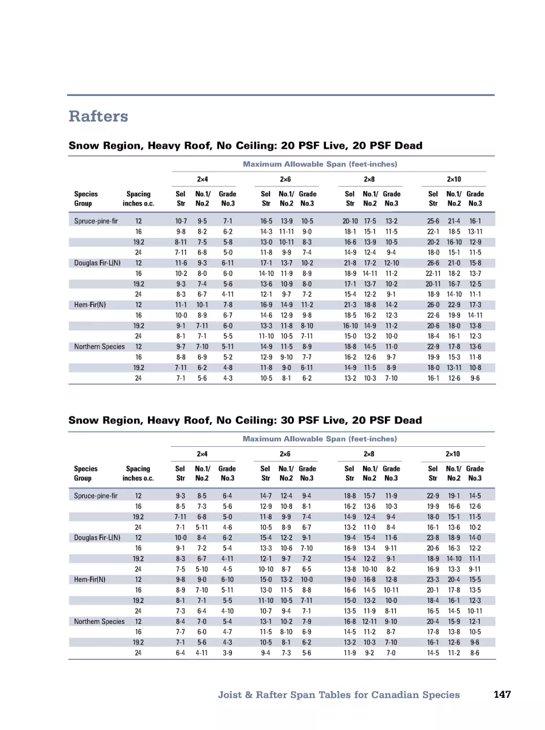
Building Loads • Wood Beam Design • Span Tables for Rough-Sawn Lumber • Joist & Rafter Span Tables
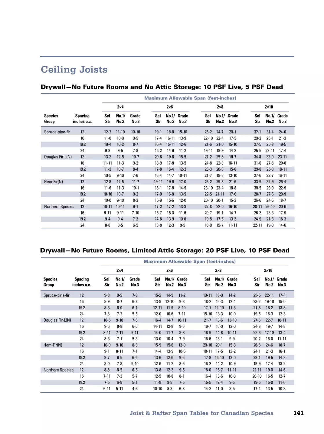
for U.S . Species • Joist & Rafter Span Tables for Canadian Species • I-Joists • Wood Trusses • Plank Floors and
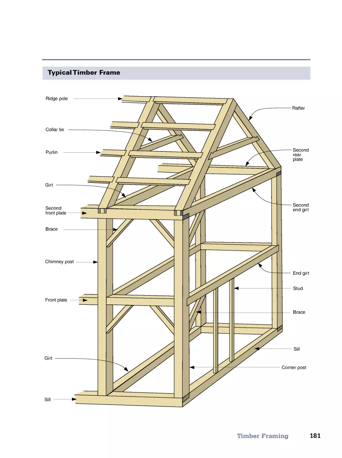
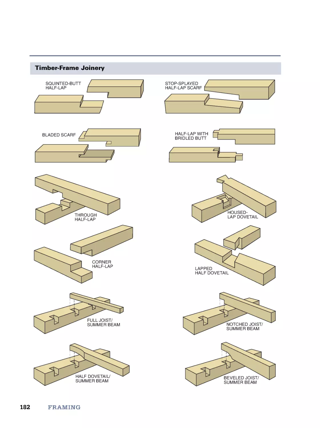
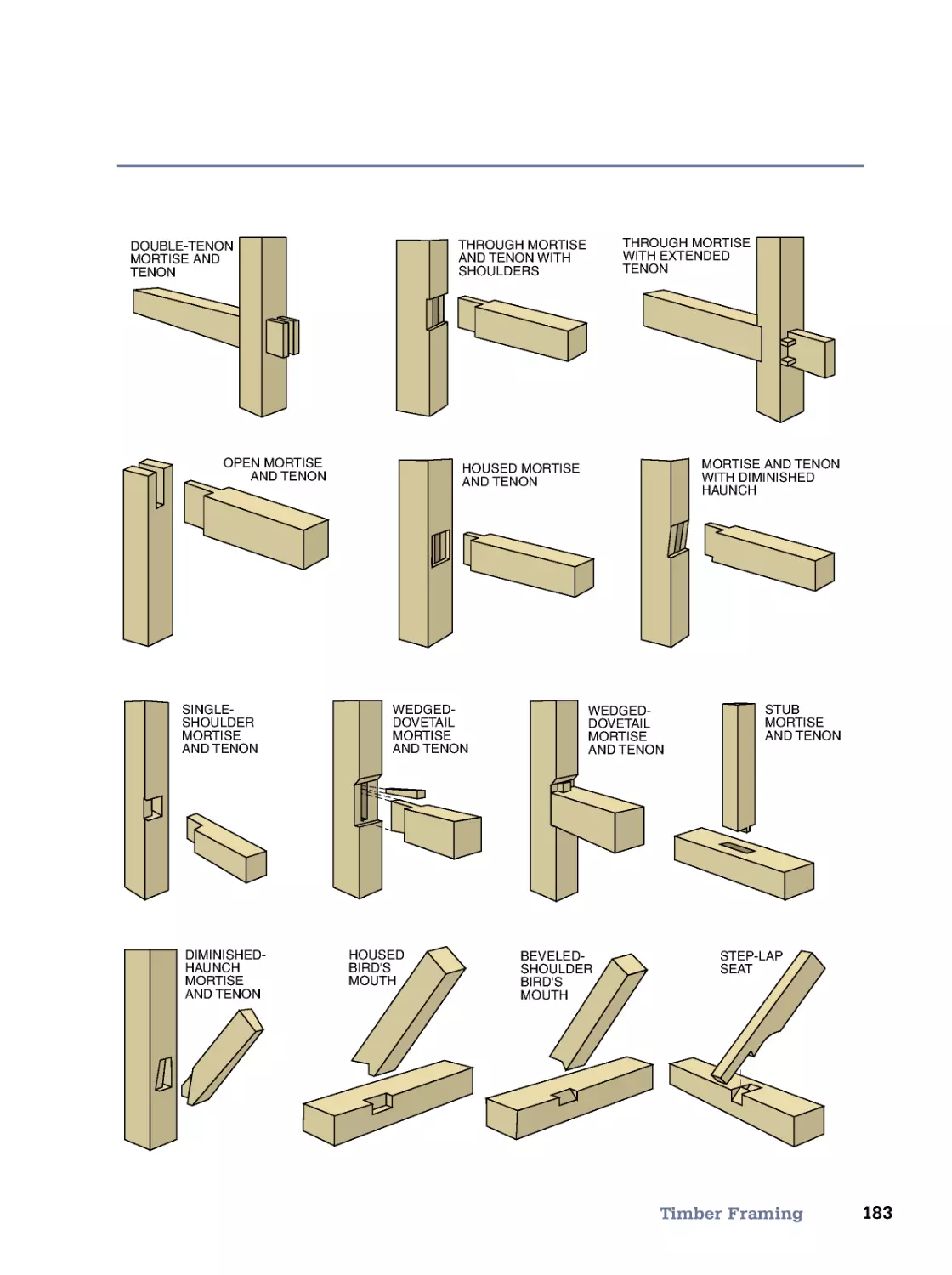
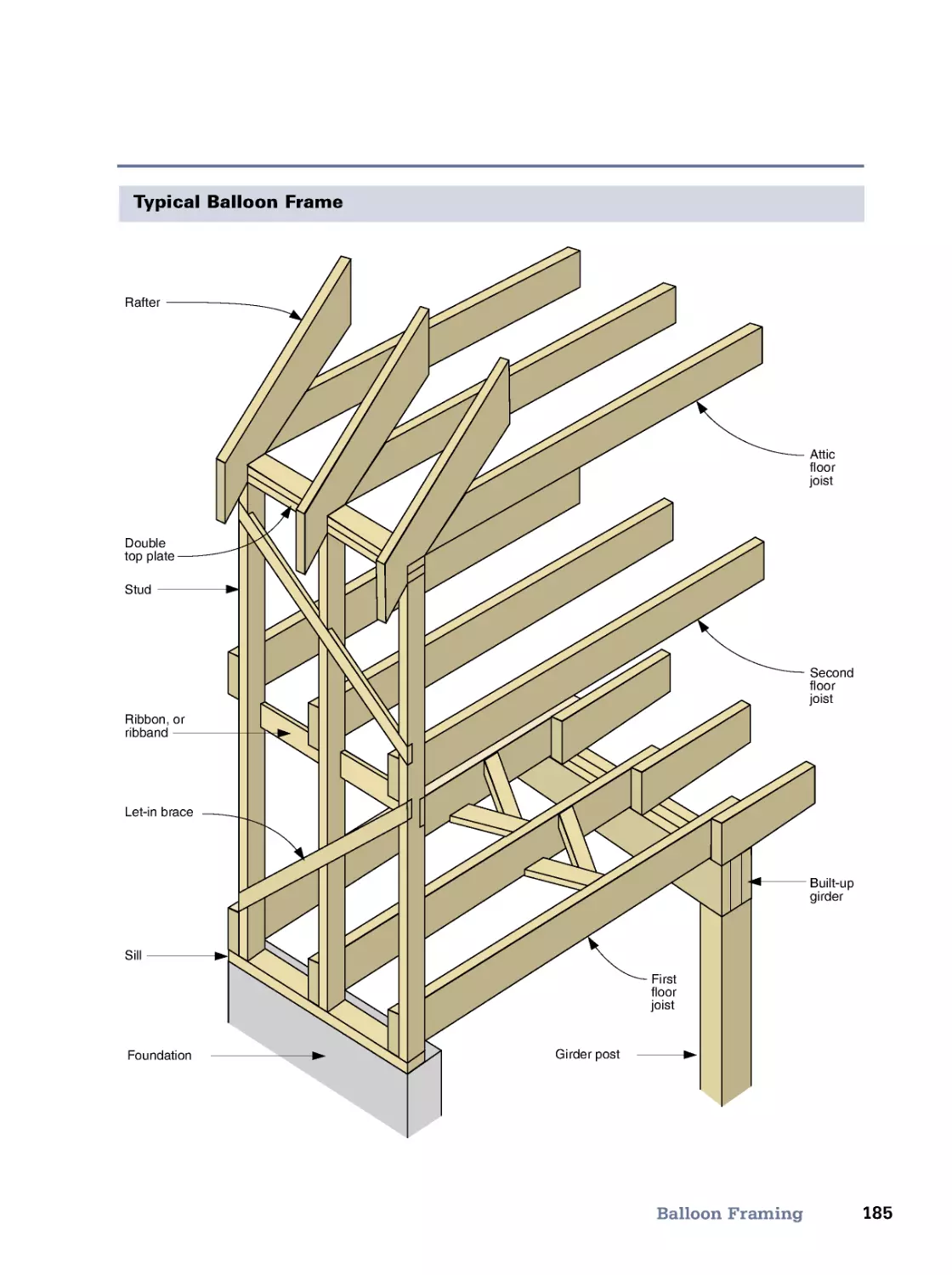
Roofs • Glulam Beams • Panel and Lumber Beams (Box Beams) • Steel Beams • Timber Framing • Balloon
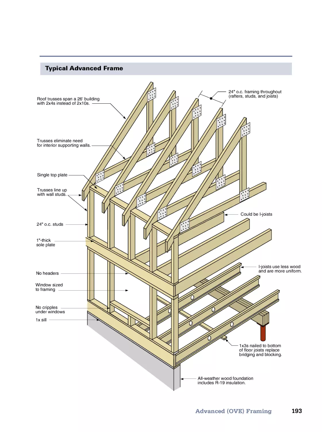
Framing • Platform Framing • Advanced (OVE) Framing • Stair Framing • Meet the Code (IRC)
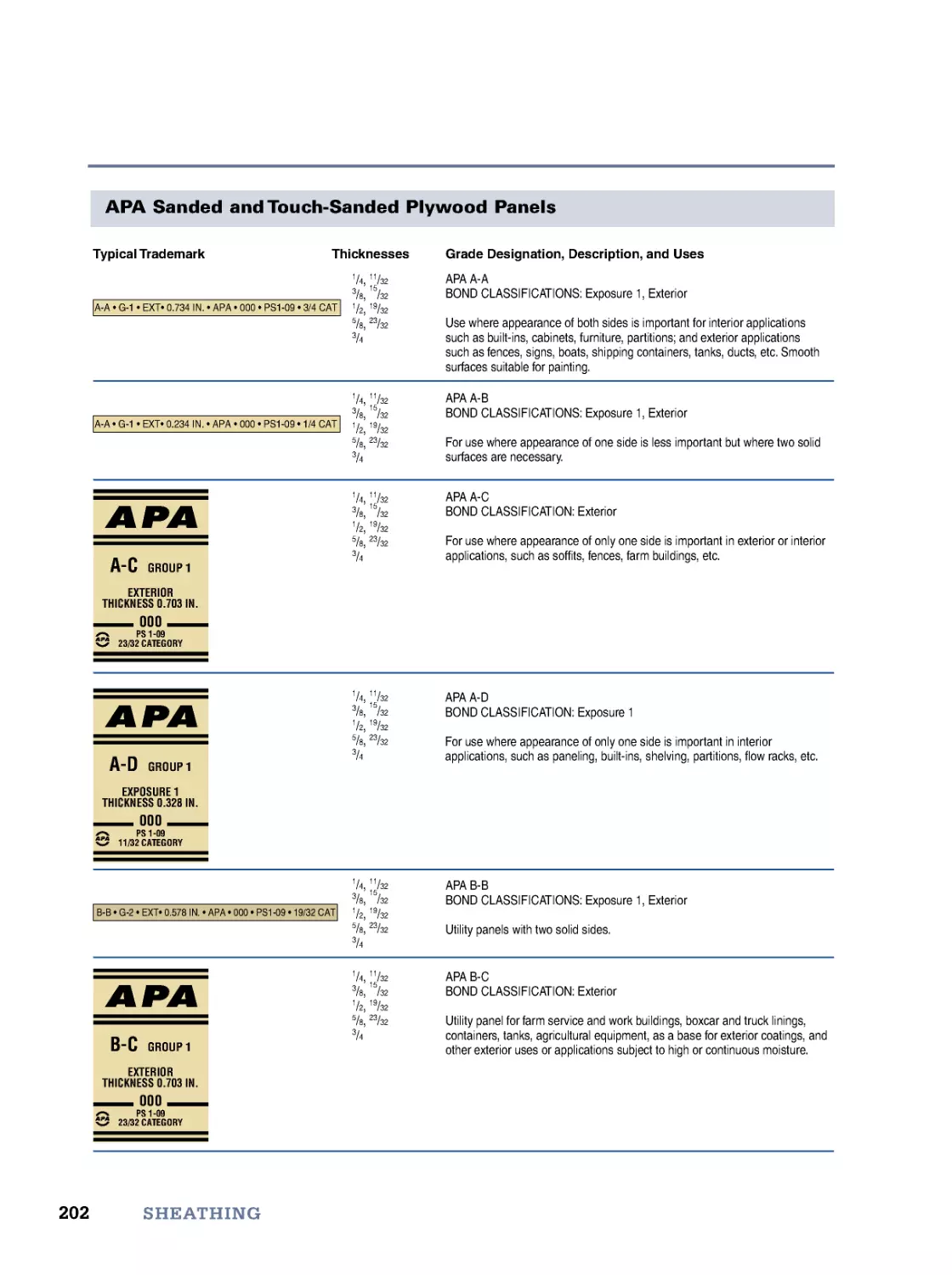
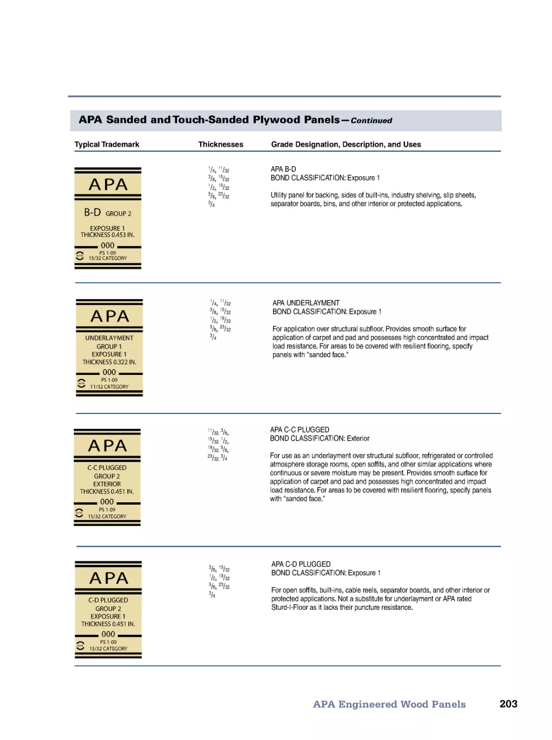
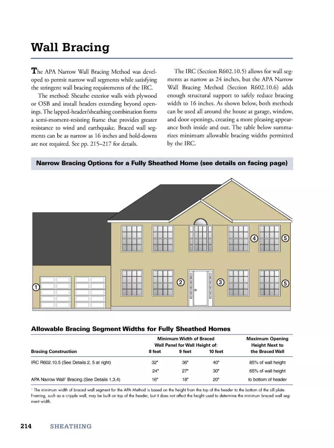
7. Sheathing
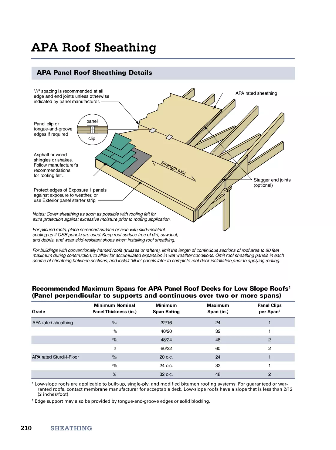
199
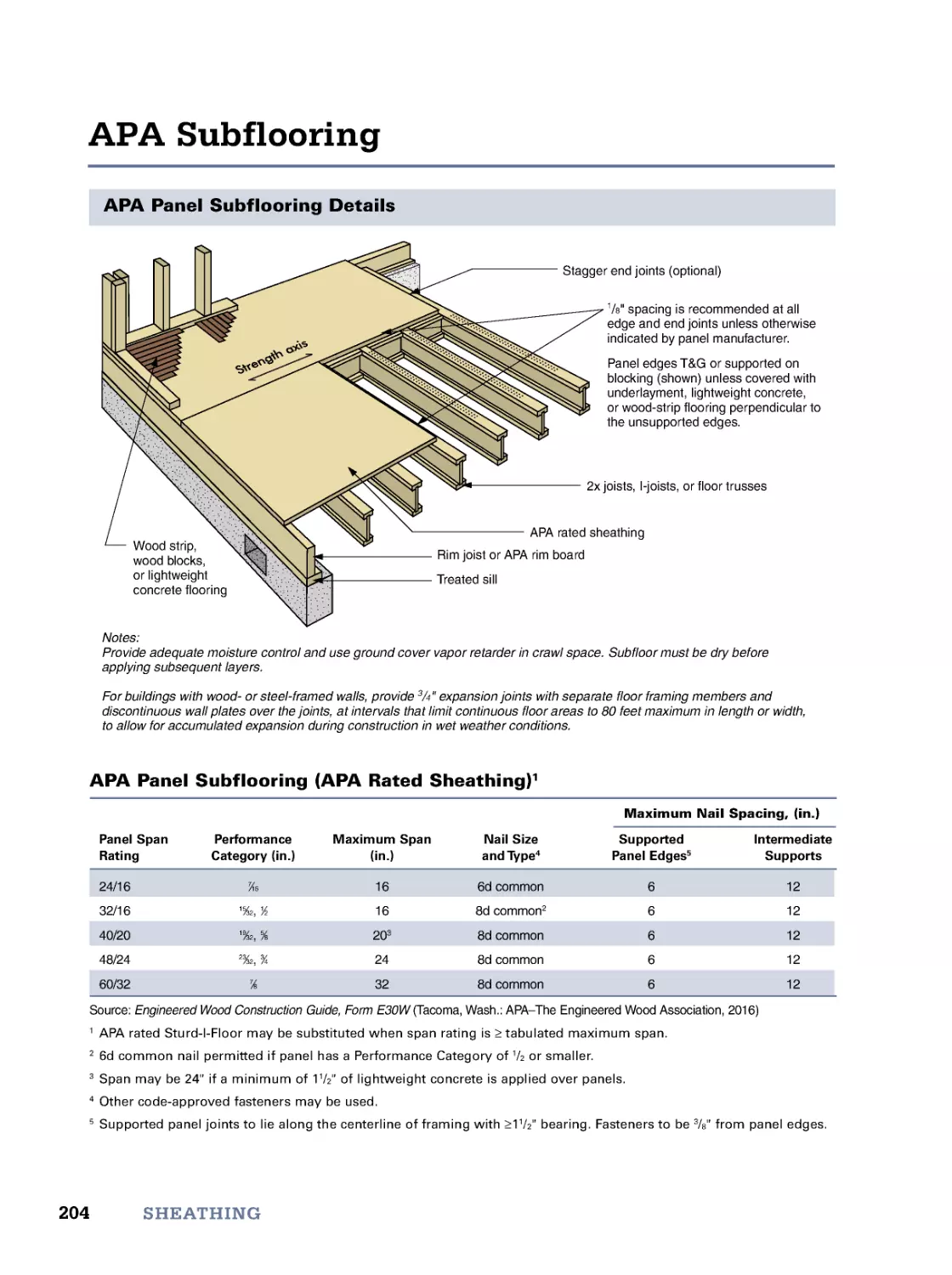
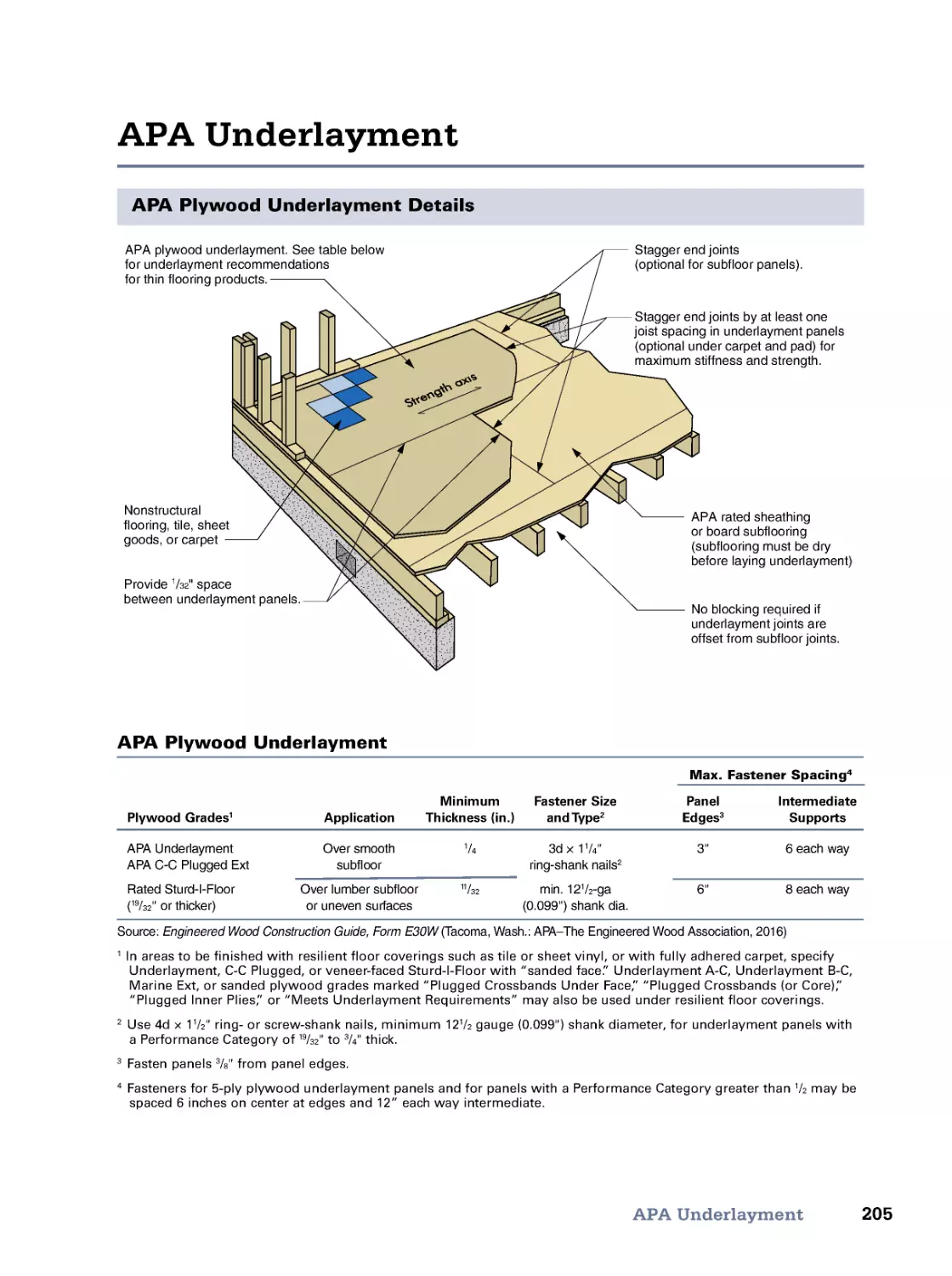
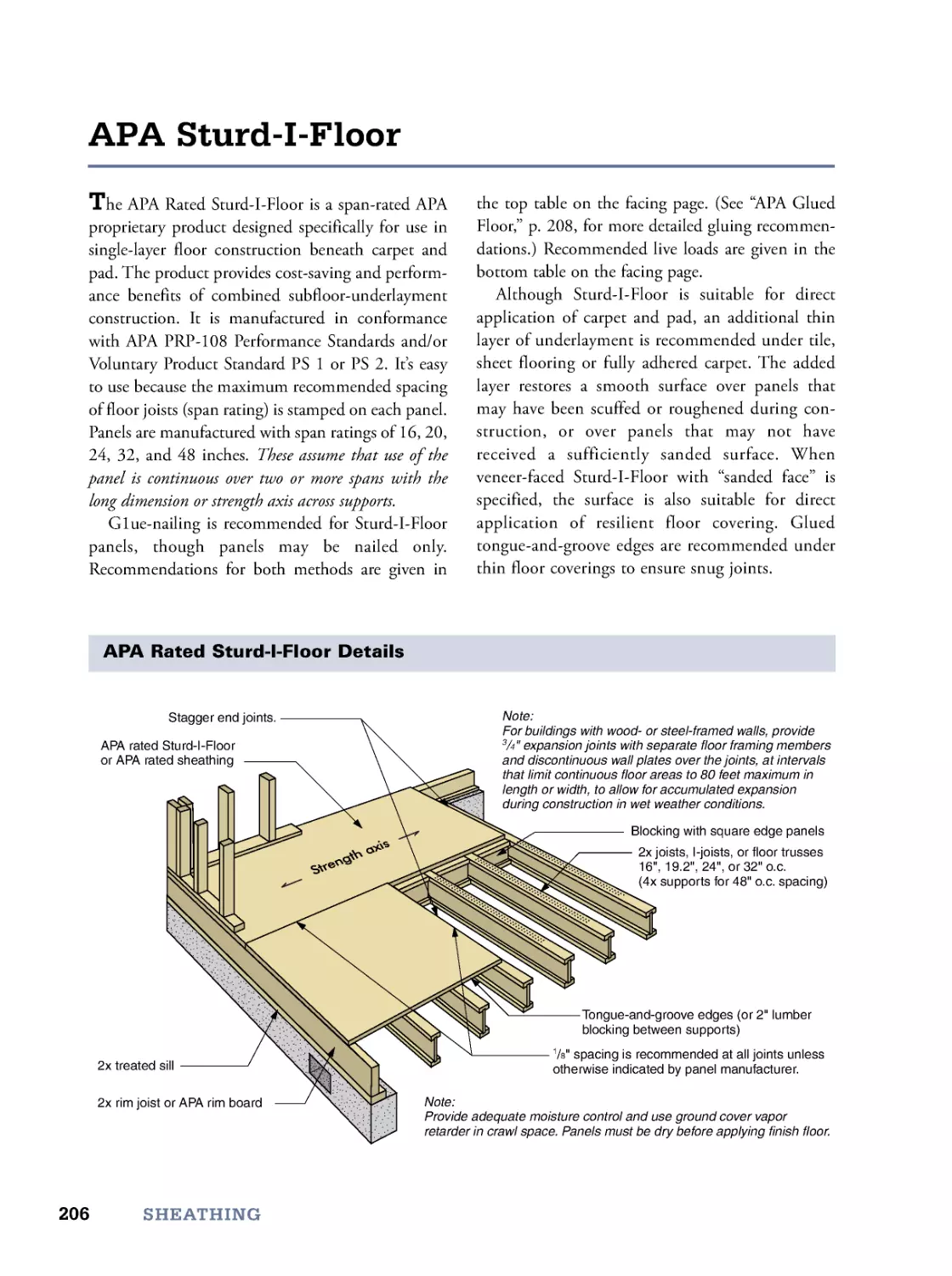
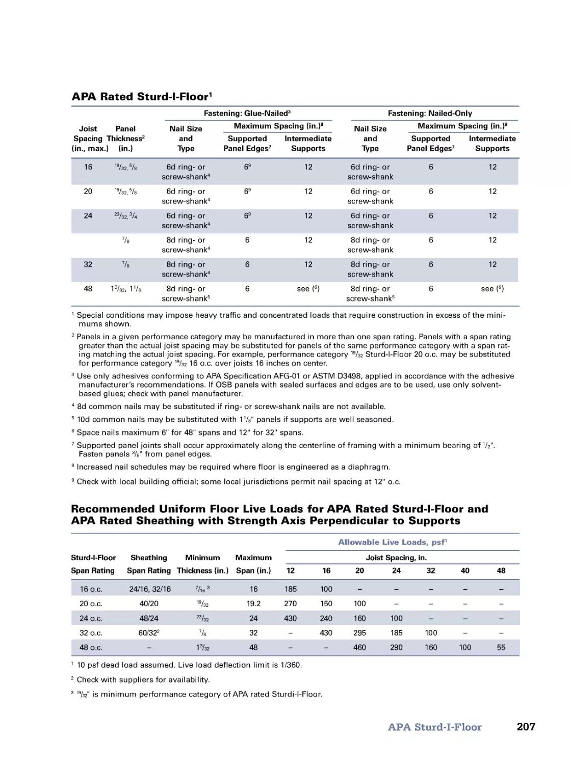
APA Engineered Wood Panels • APA Subflooring • APA Underlayment • APA Sturd-I-Floor
• APA Glued Floor • APA Wall Sheathing • Zip System Sheathing • Wall Bracing
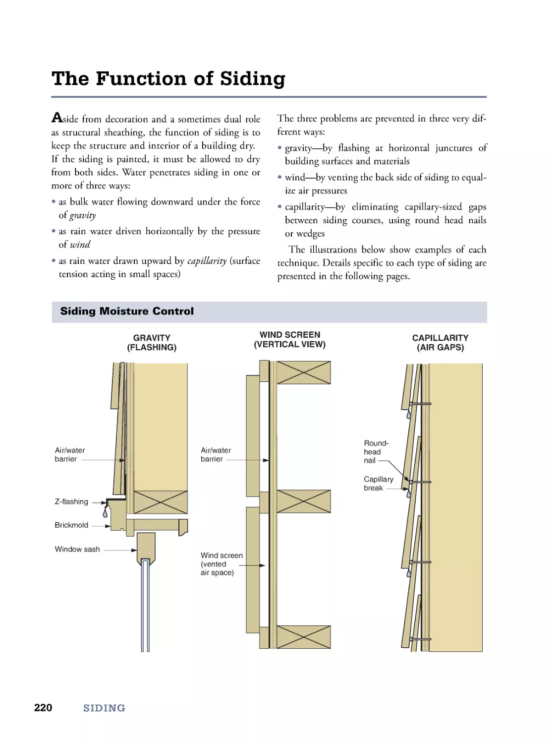
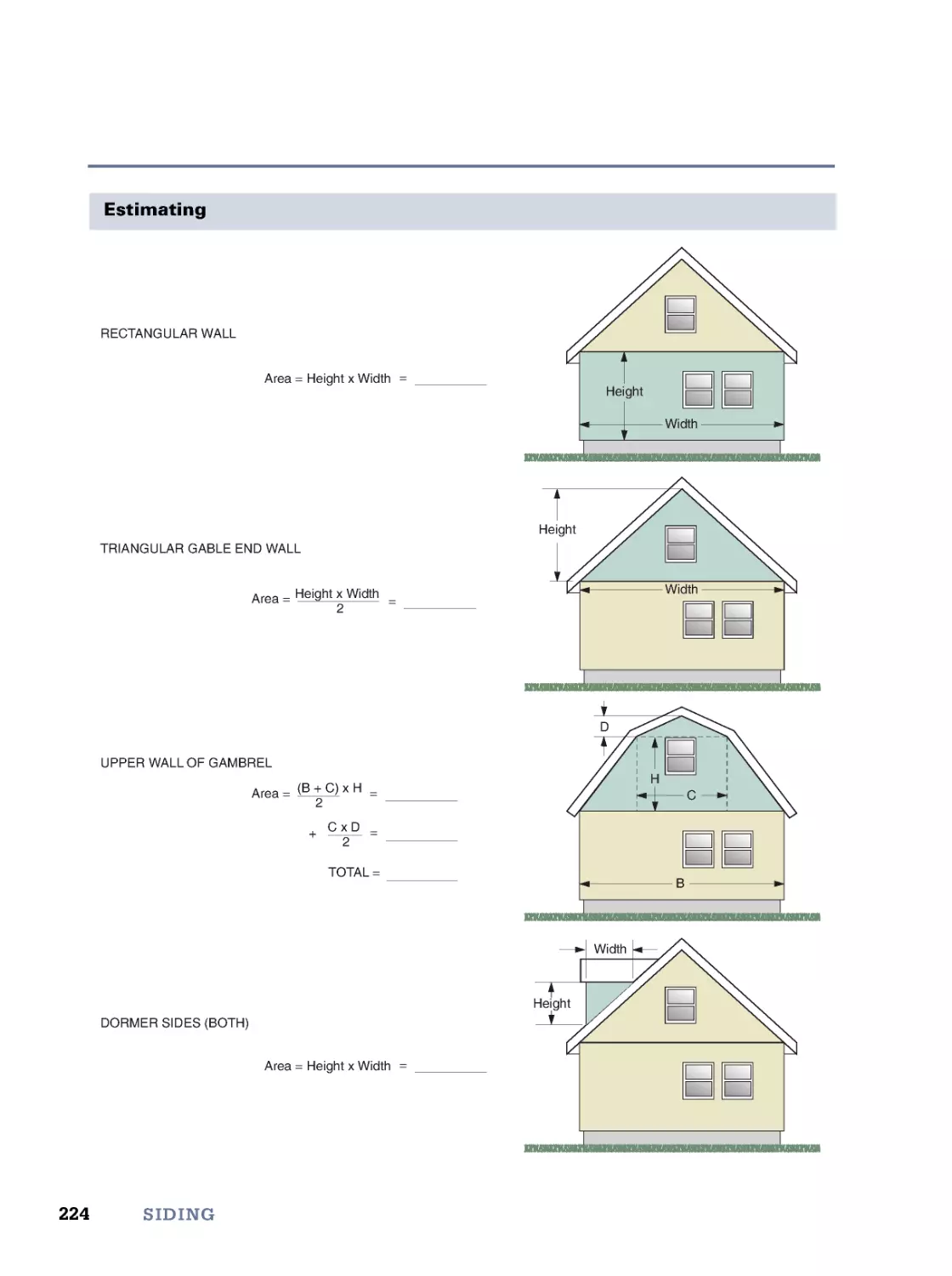
8. Siding
219
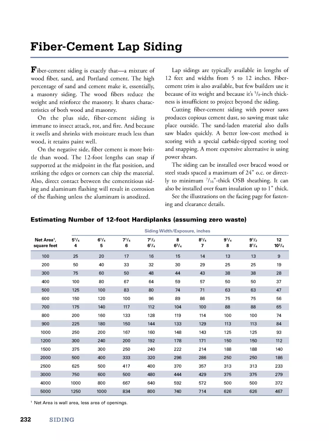
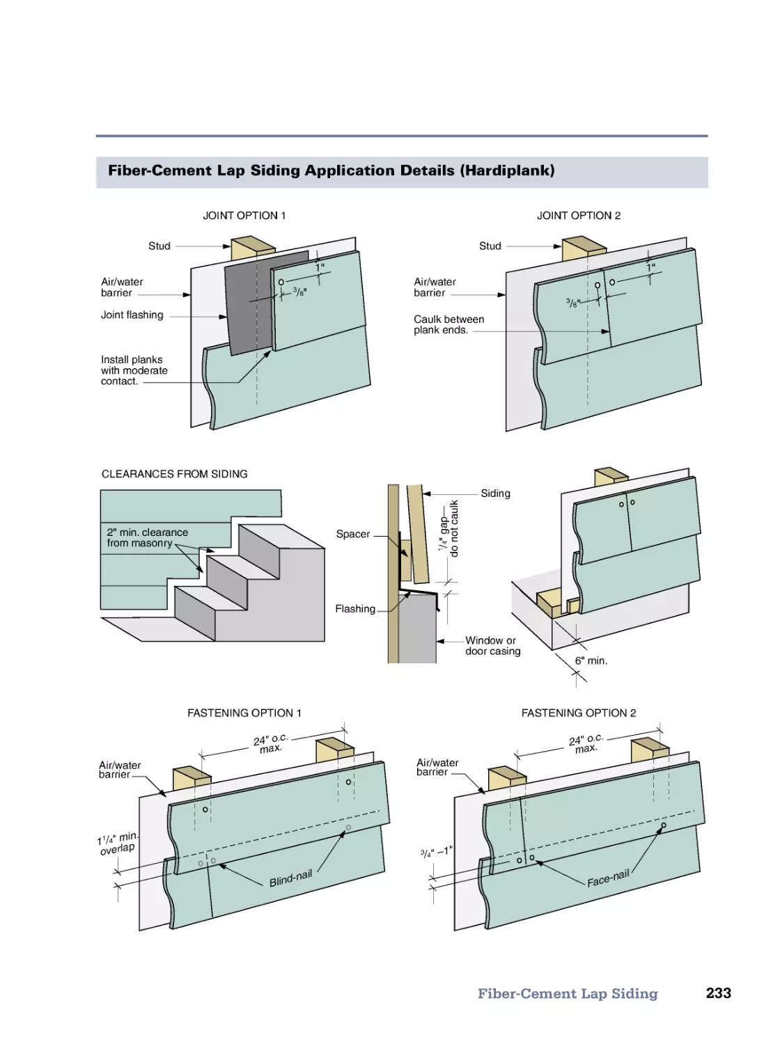
The Function of Siding • Siding Choices • Vinyl Siding • Fiber-Cement Lap Siding • Hardboard Lap
Siding • Cedar Shingles • Horizontal Wood Siding • Vertical Wood Siding • Plywood Siding • Stucco
• Asbestos Siding Solutions • Meet the Code (IRC)
9. Roofing
255
Roofing Terms • Roofing Materials • EPDM (Rubber Membrane) • Concealed-Nail Roll Roofing • Double-
Coverage Roofing • Asphalt Shingles • Cedar Shingles • Cedar Shakes • Slate • Tile • Metal Panel • Standing
Seam • Gutters • Meet the Code (IRC)
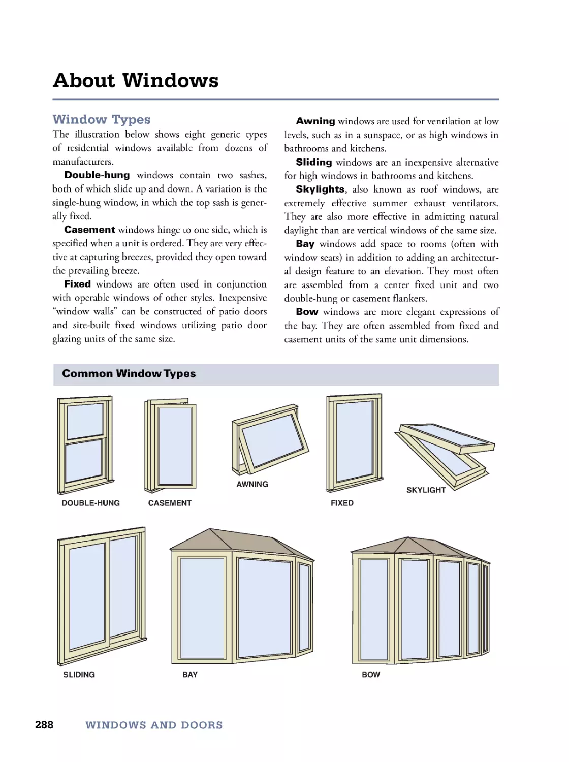
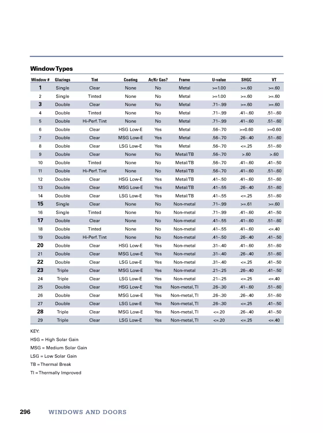
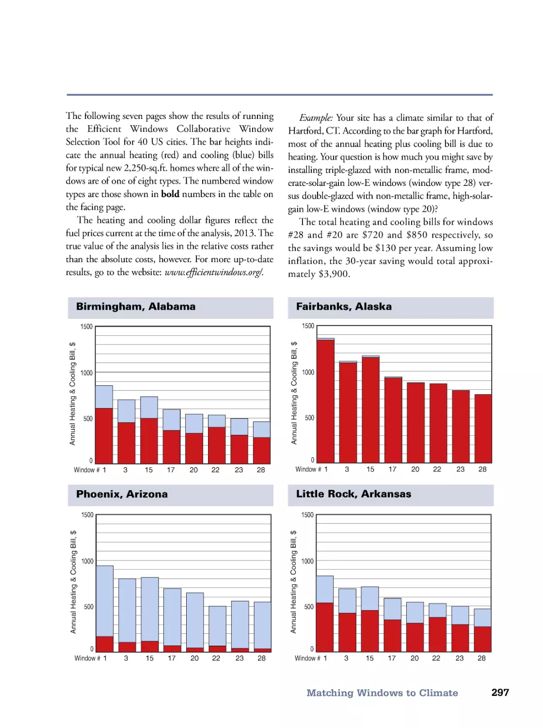
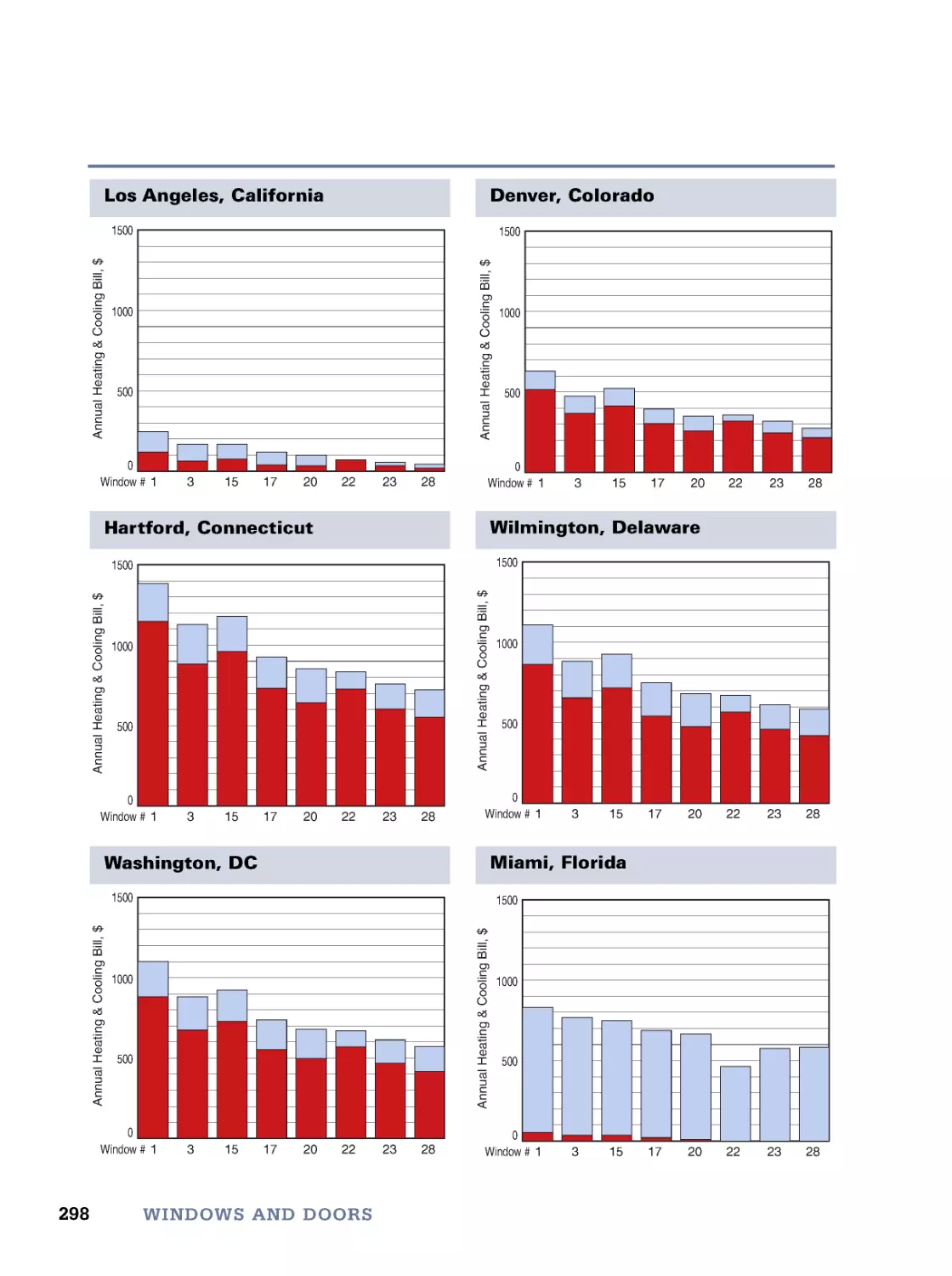
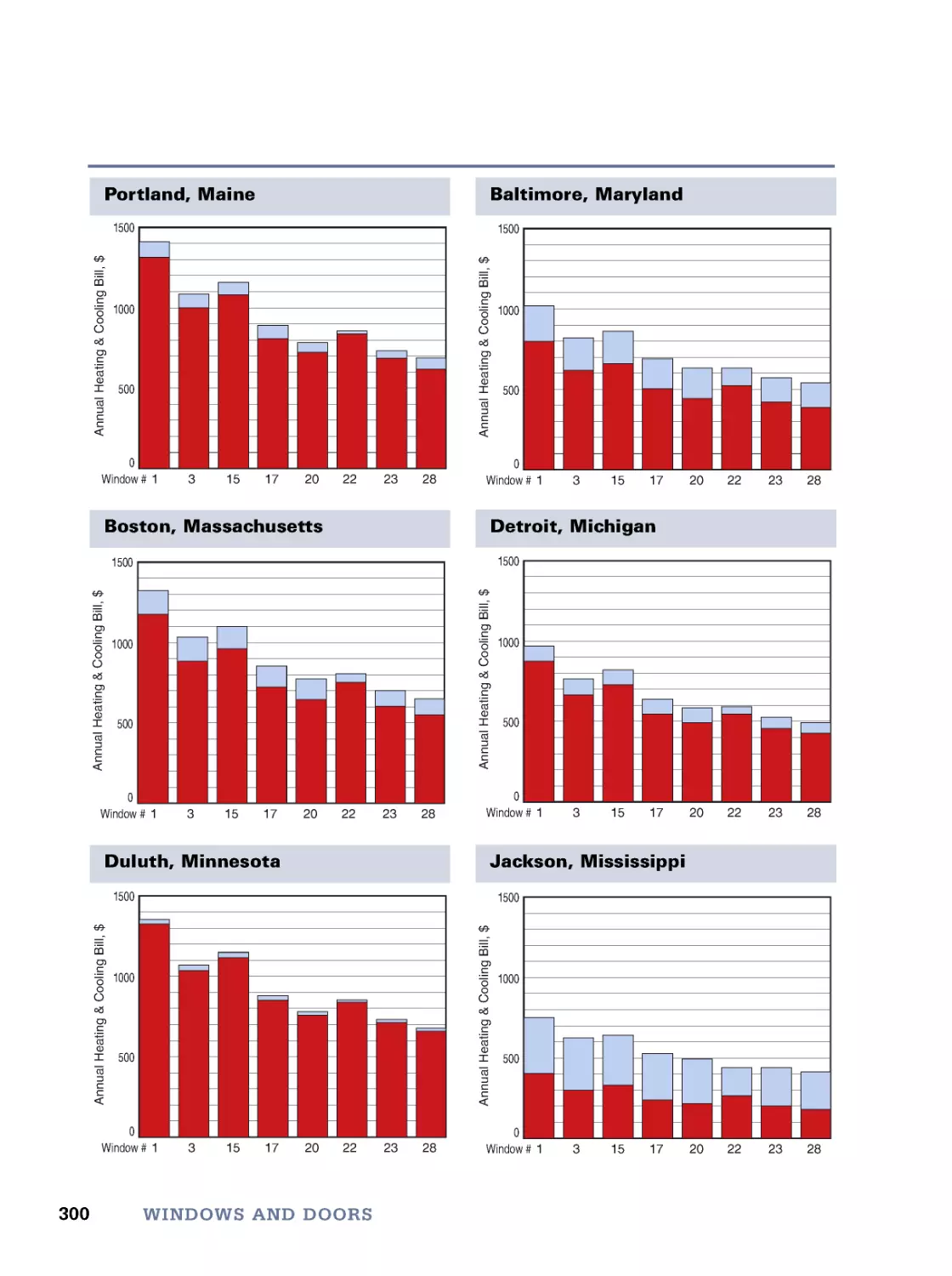
10. Windows and Doors
287
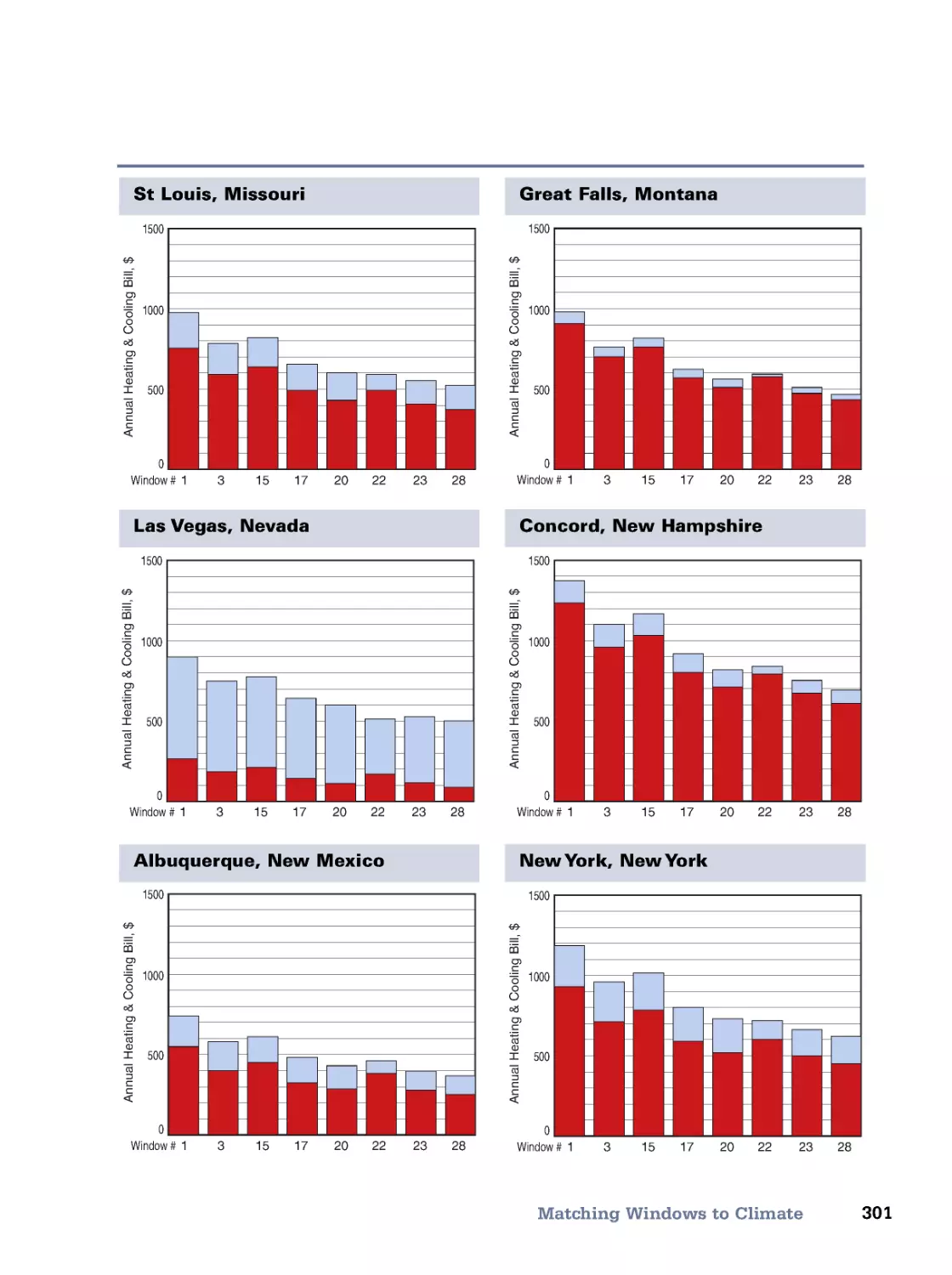
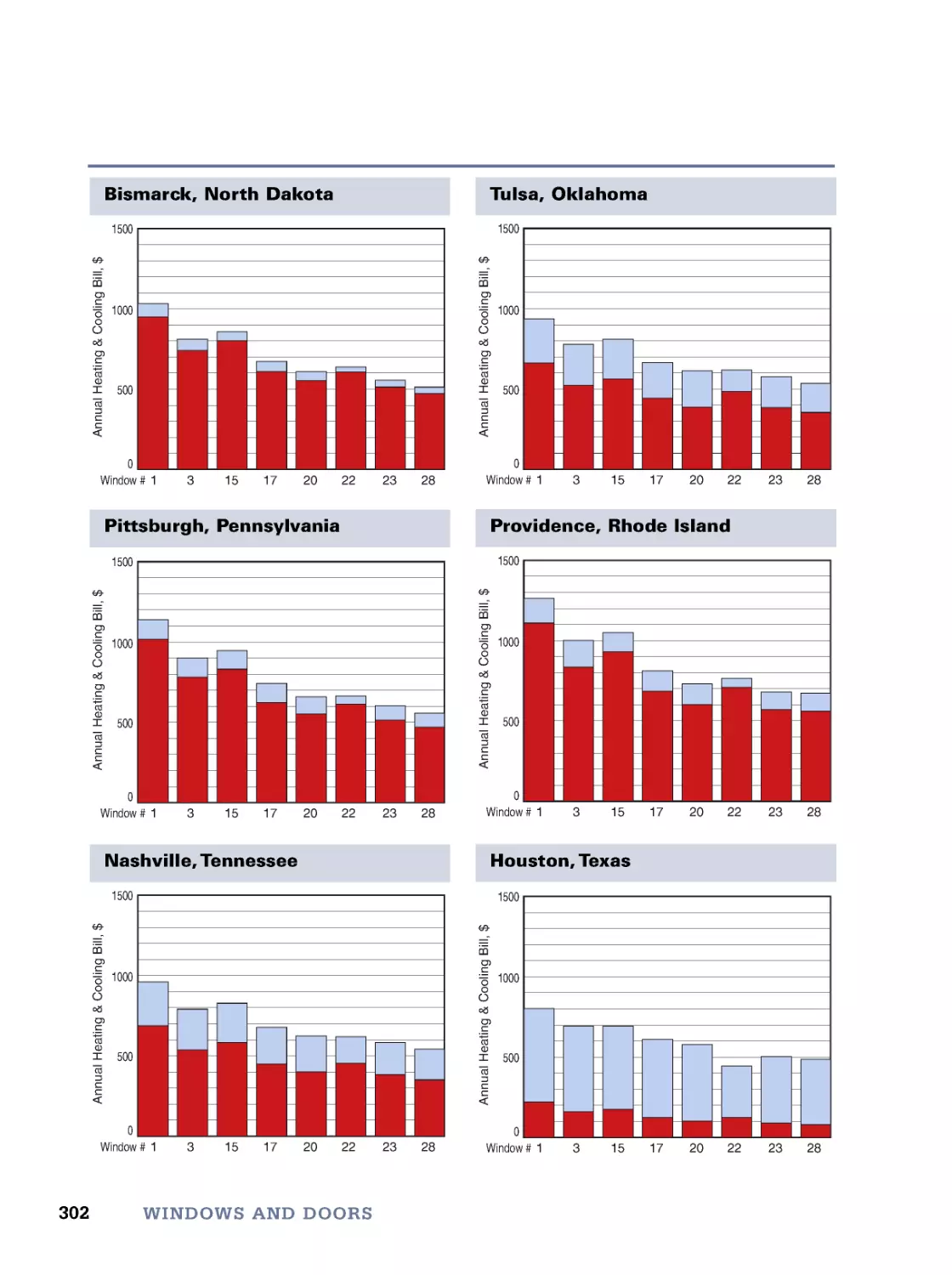
About Windows • Window Installation • Window Energy Performance • Matching Windows to Climate •
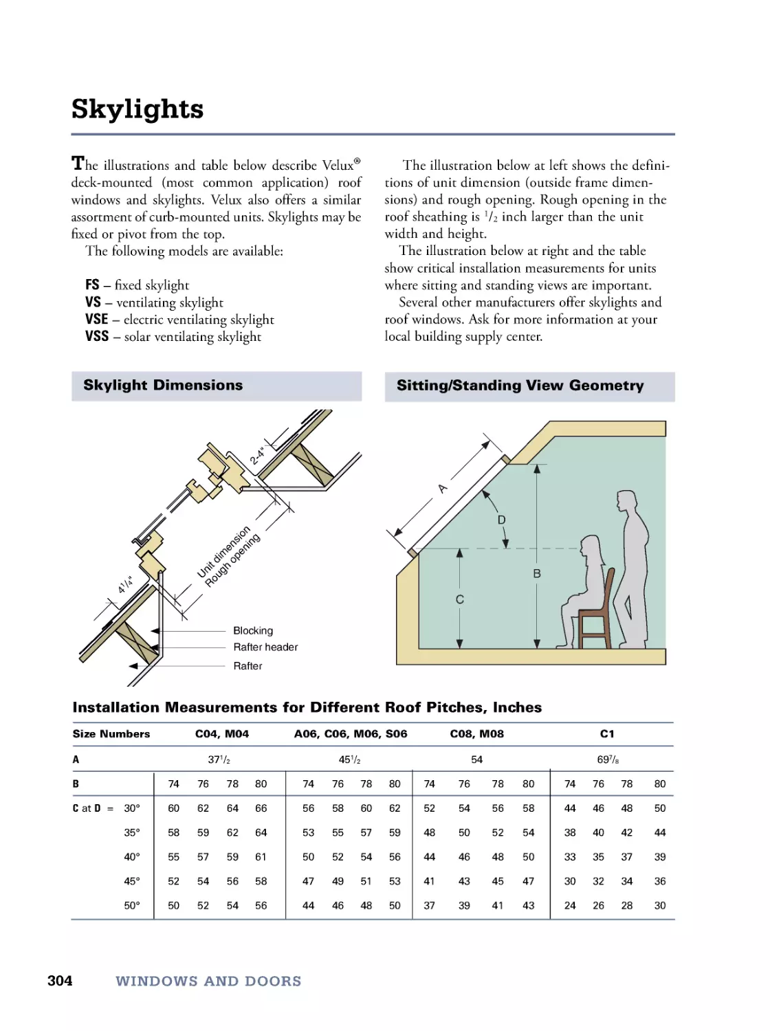
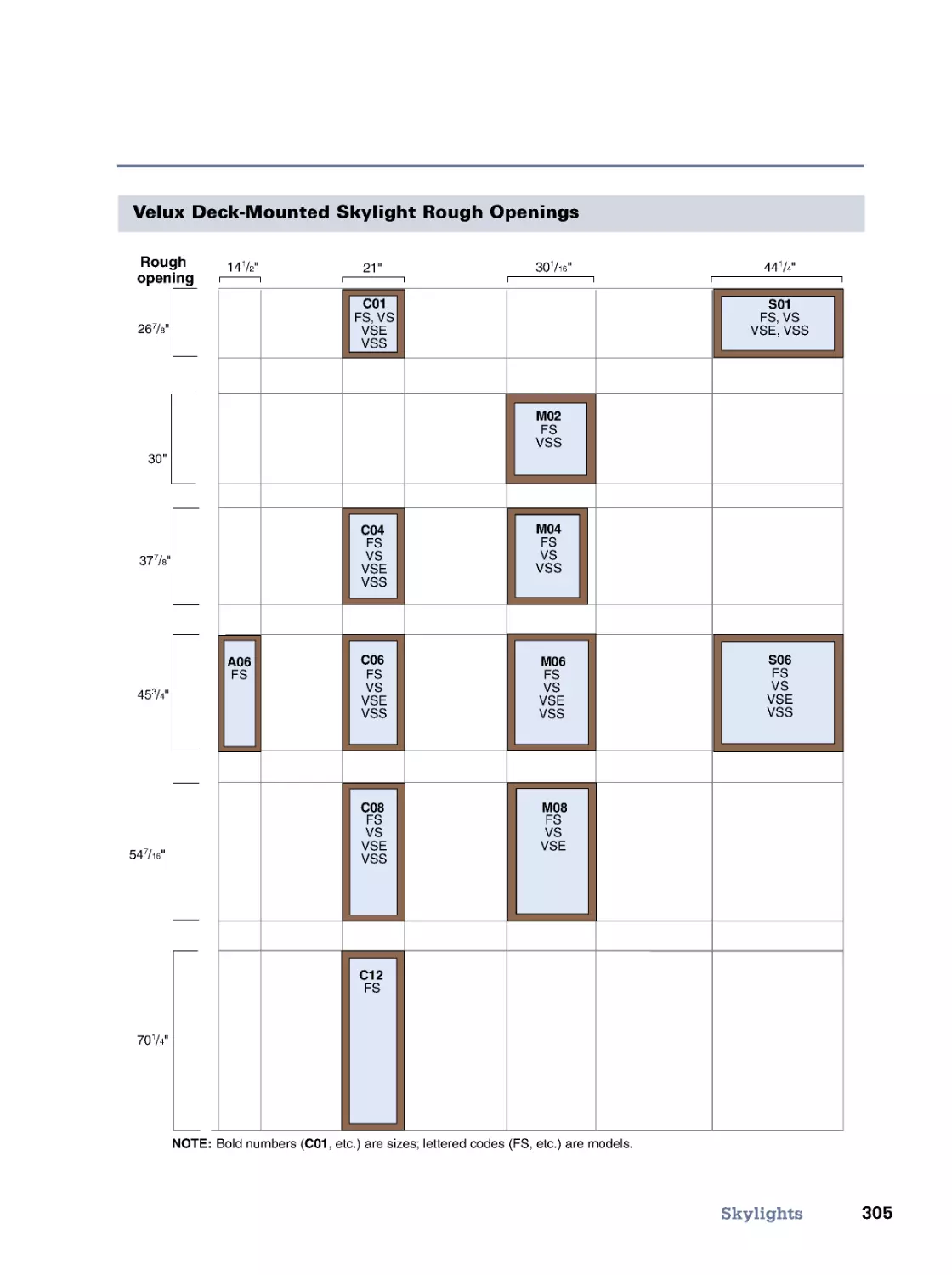
Skylights • Site-Built Windows • About Doors • Door Installation • Bulkhead Doors • Meet the Code (IRC)
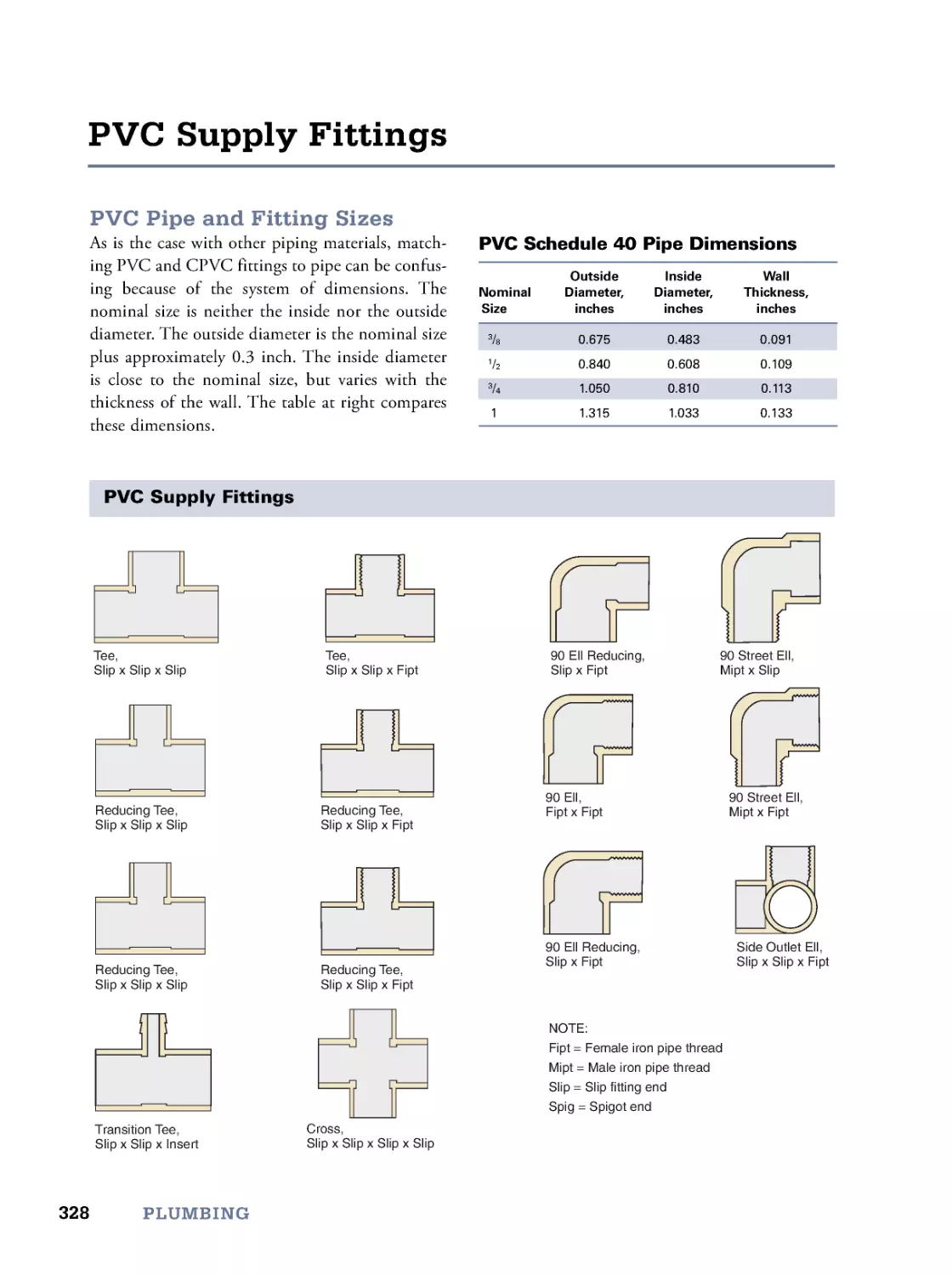
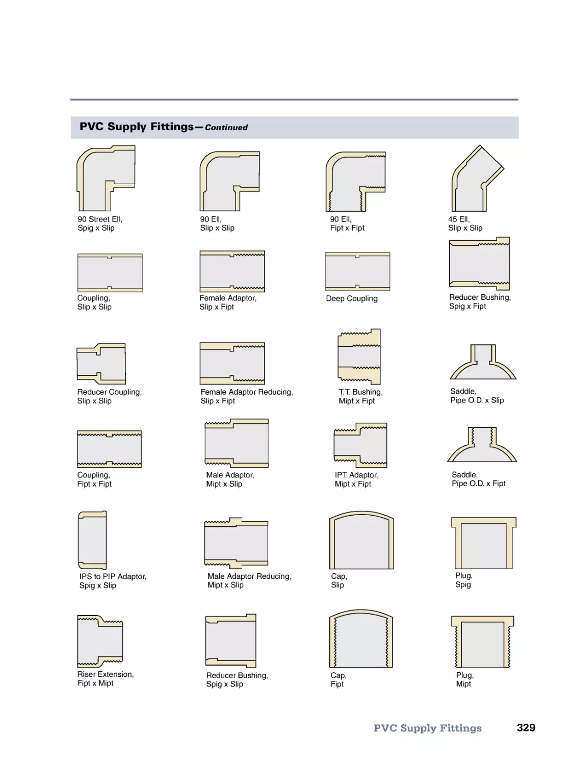
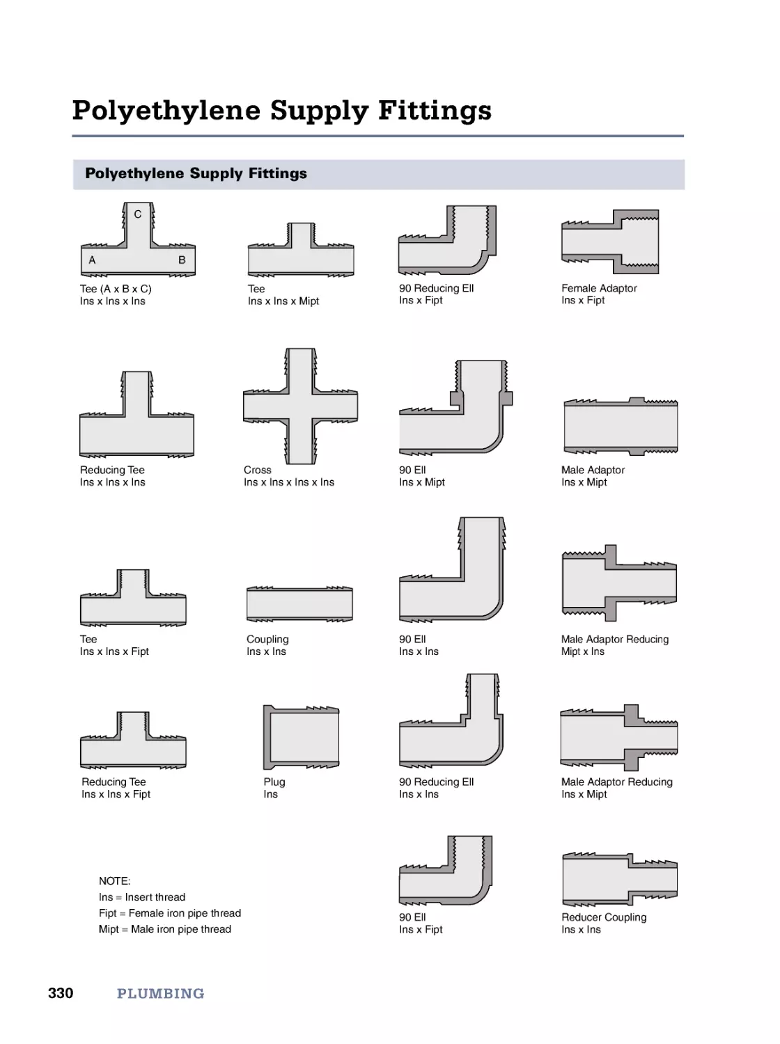
11. Plumbing
317
Water Wells and Pumps • Supply Piping • Supply Pipe Sizing • Freezeproofing Supply Pipes • Copper Supply
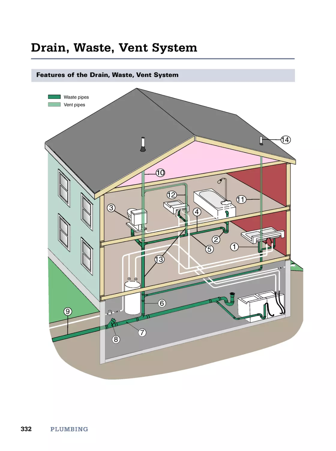
Fittings • PVC Supply Fittings • Polyethylene Supply Fittings • PEX Supply Fittings • Drain, Waste, Vent
System • Sizing Drainpipe • Running Drainpipe • Traps • Vents • Plastic DWV Fittings • Roughing-In
Dimensions • Private Well Water Standards & Treatments • Meet the Code (IRC)
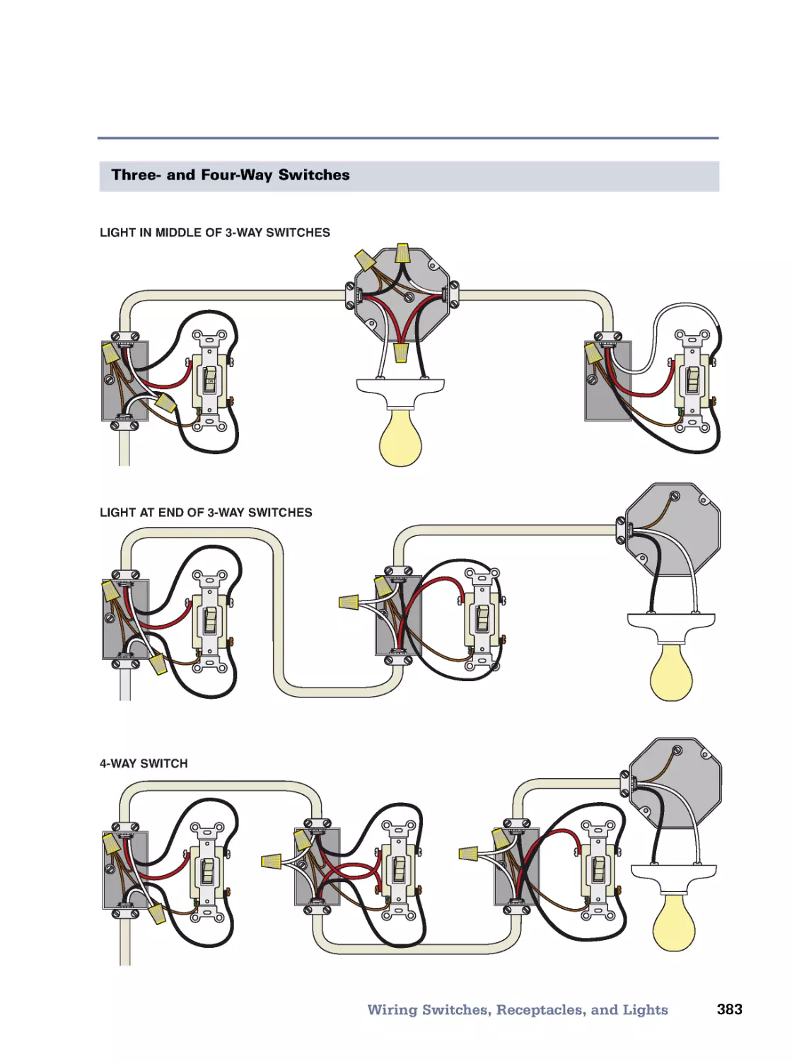
12. Wiring
351
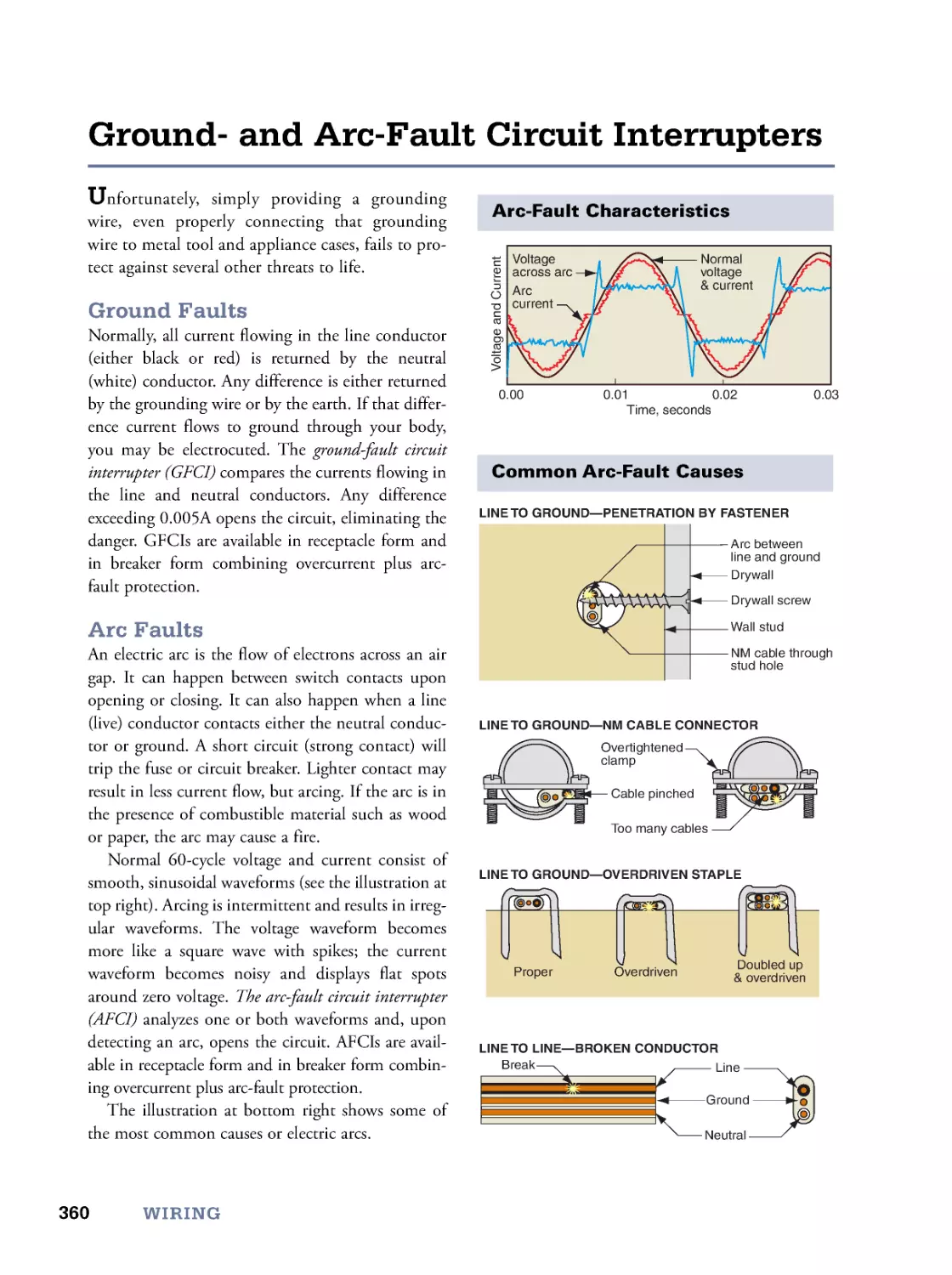
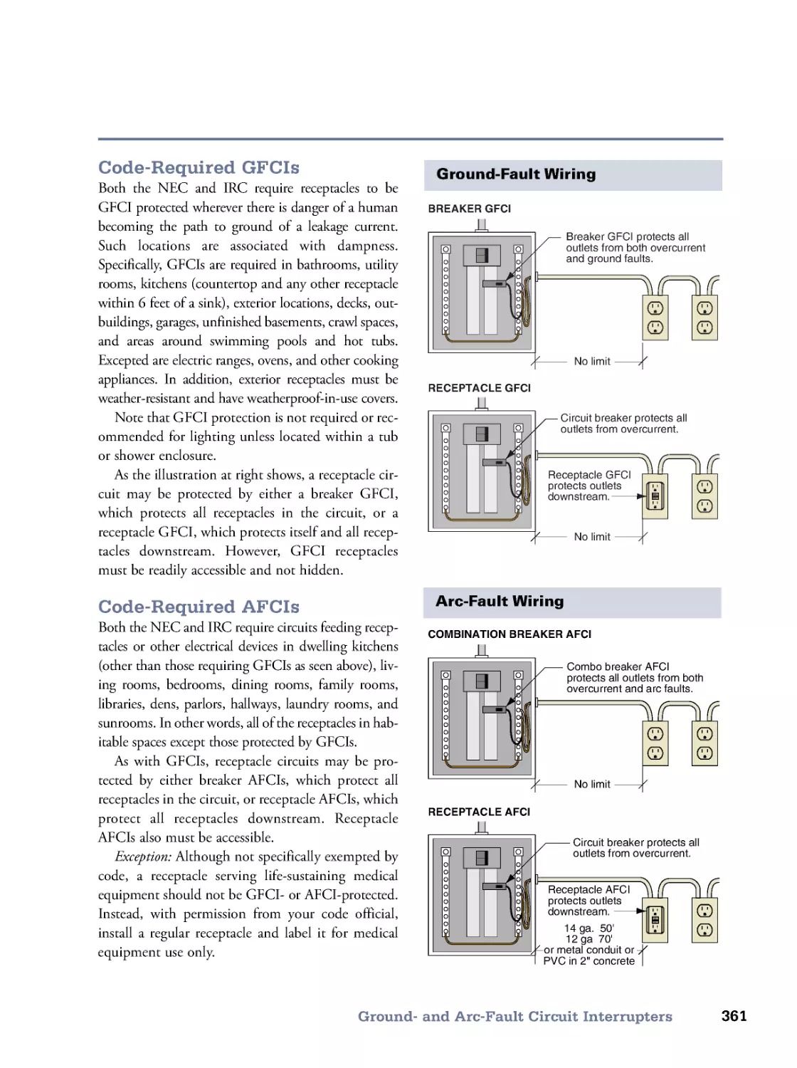
Electrical Circuit • Service Drops • Grounding • Ground- and Arc-Fault Circuit Interrupters • Panels and
Subpanels • Overview of Required Circuits • Kitchen Circuits • Bathroom Circuits • Load Calculations • Wire
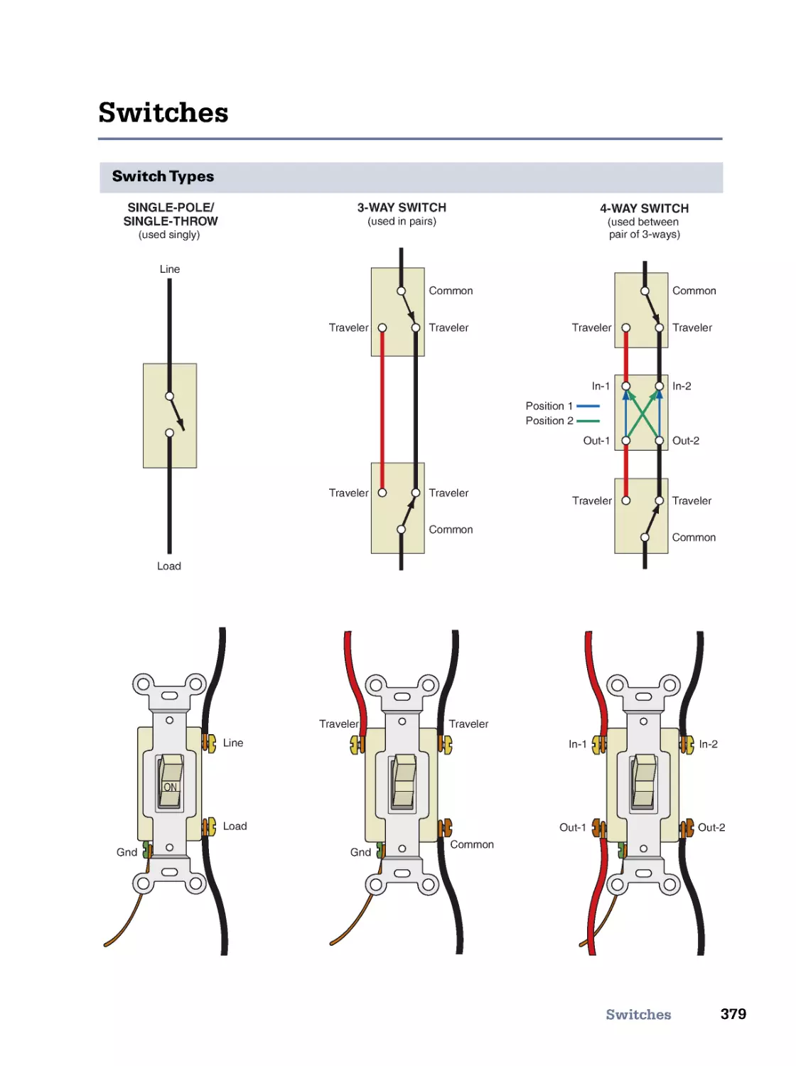
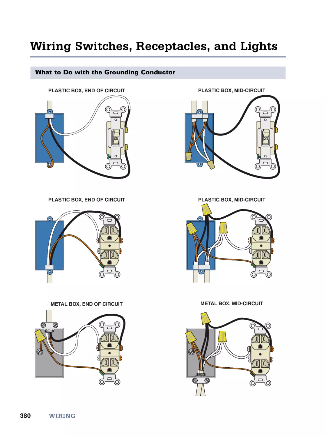
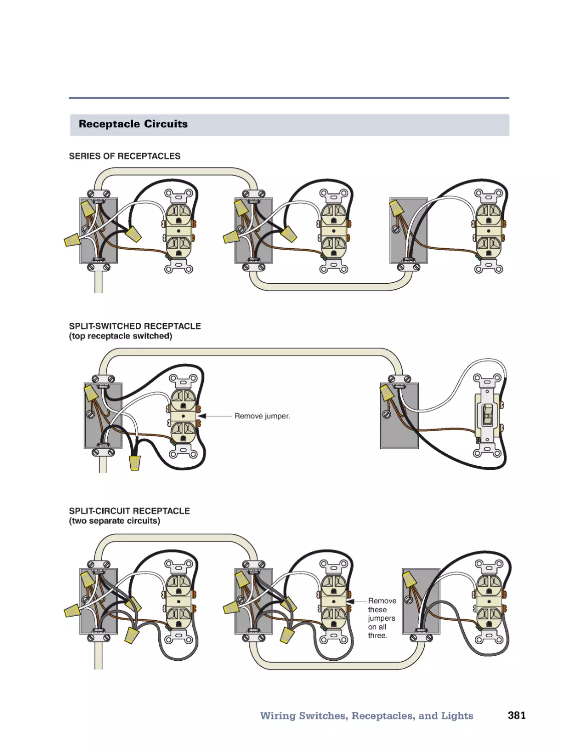
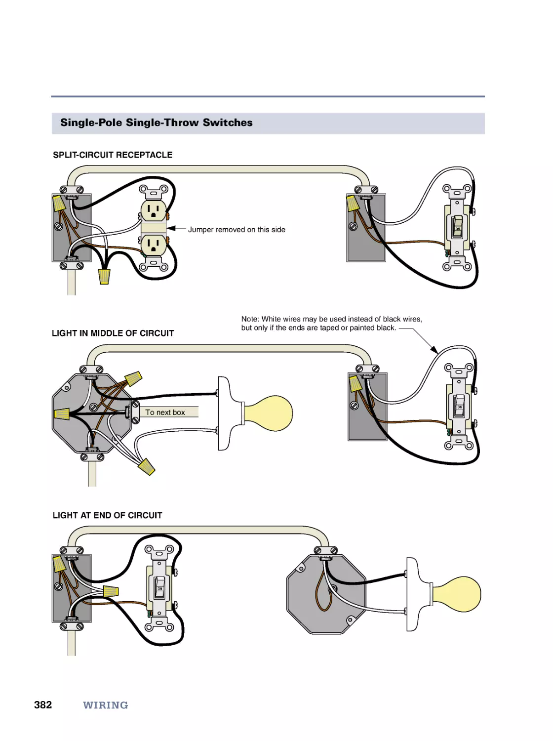
and Cable • Electrical Boxes • Running Cable • Running Conduit • Receptacles • Switches • Wiring Switches,
Receptacles, and Lights • Solar Electricity • Meet the Code (IRC)
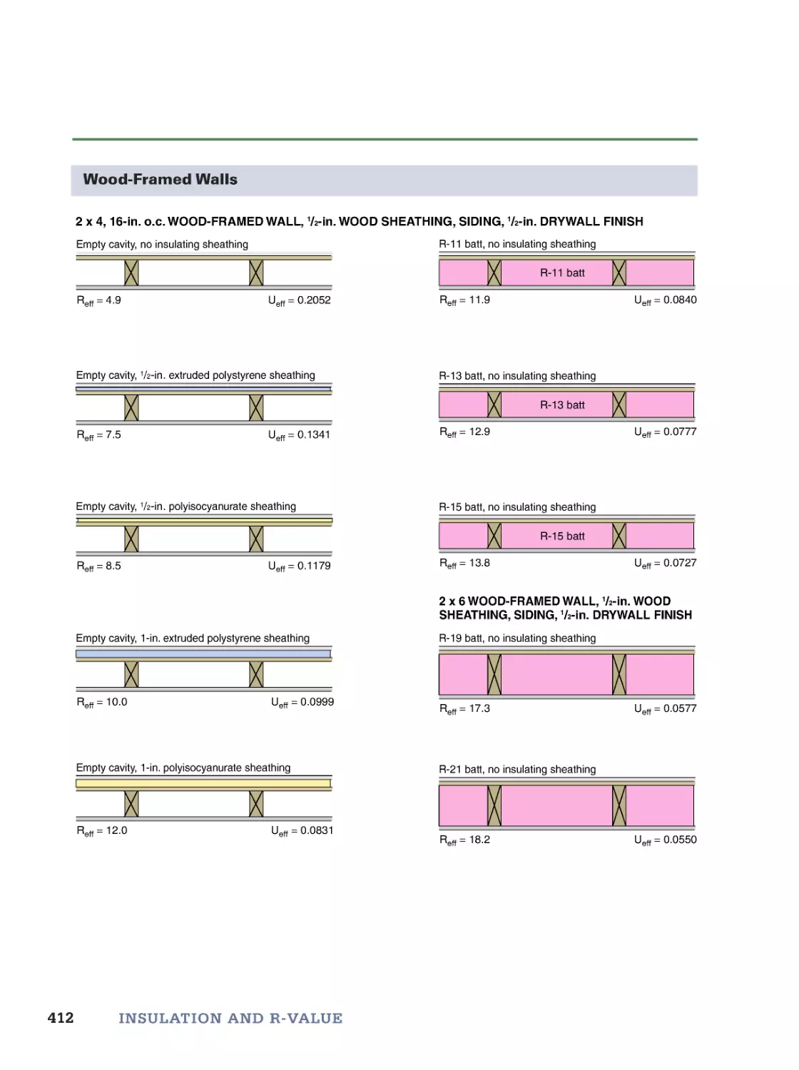
13. Insulation and R-Value
399
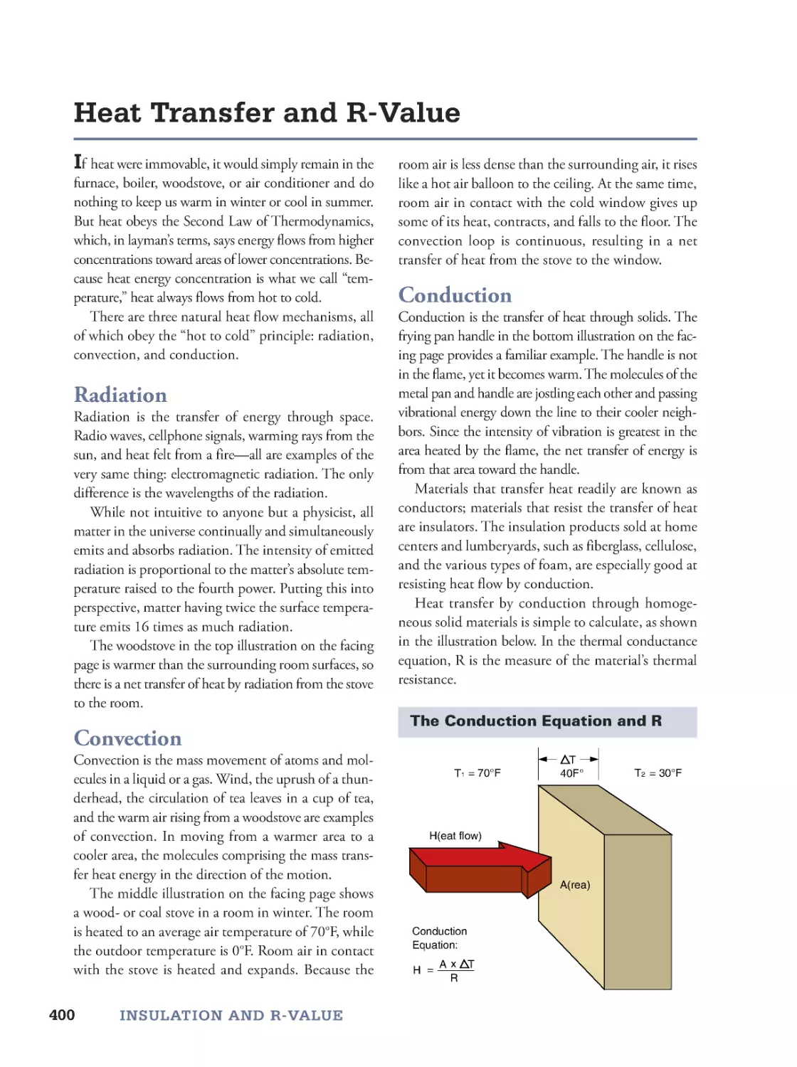
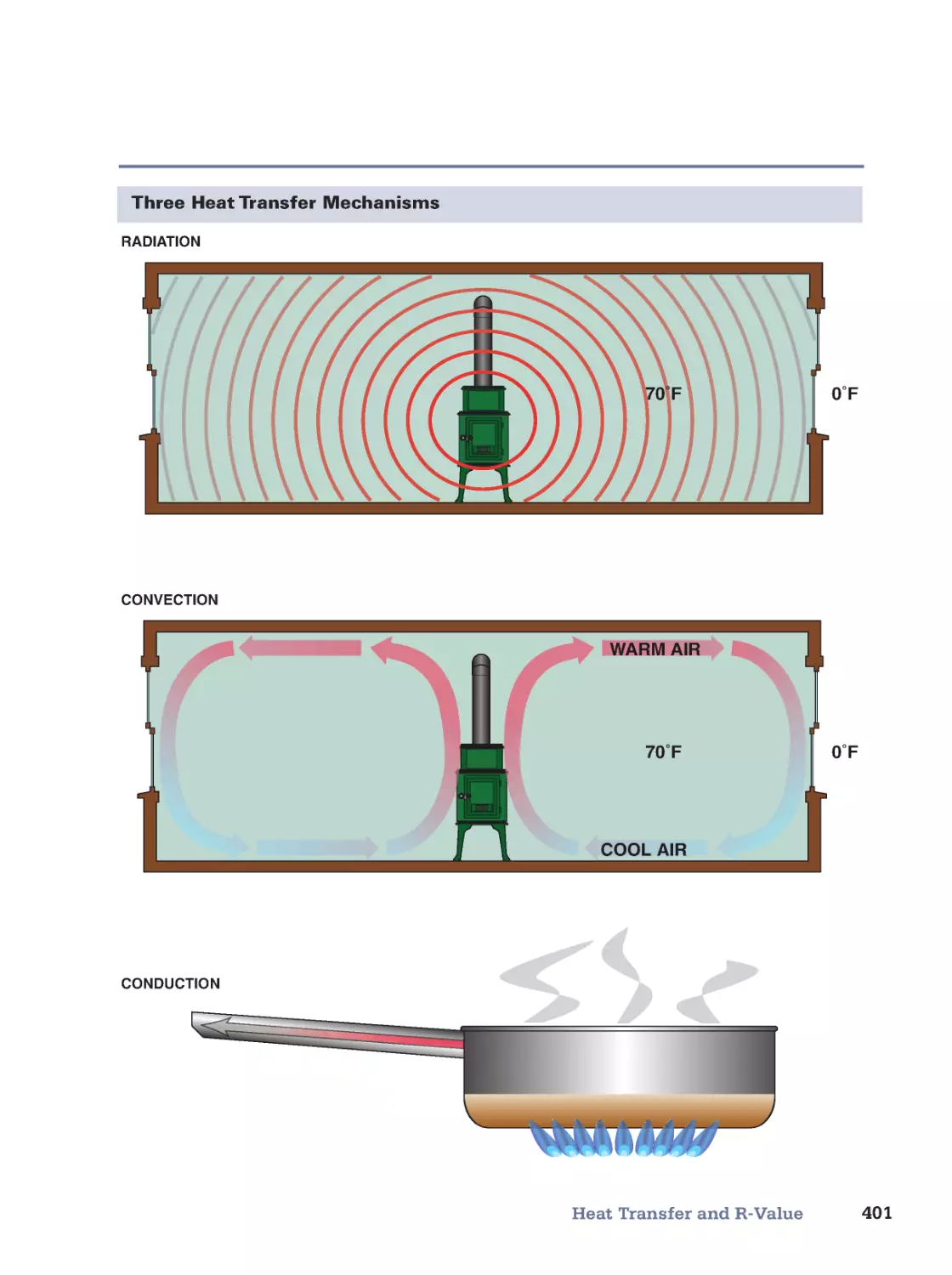
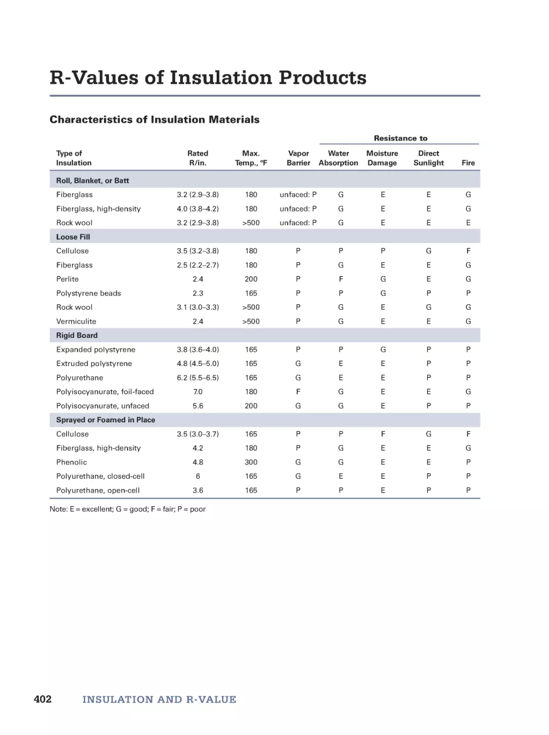
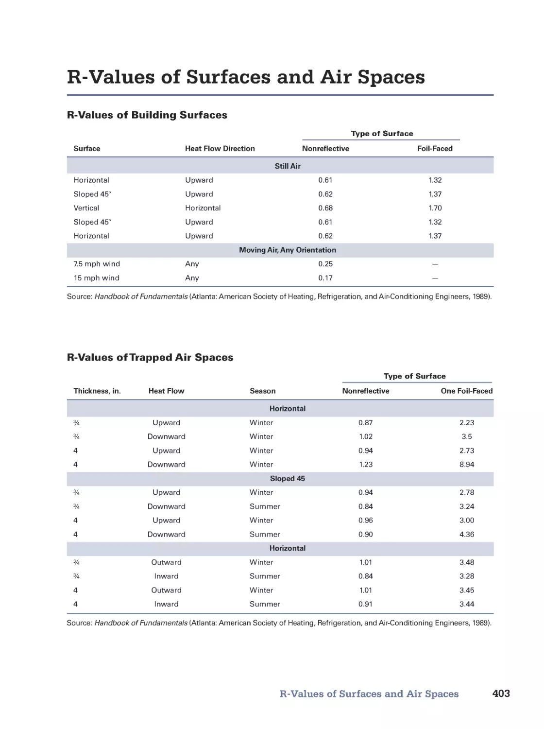
Heat Transfer and R-Value • R-Values of Insulation Products • R-Values of Surfaces and Air Spaces
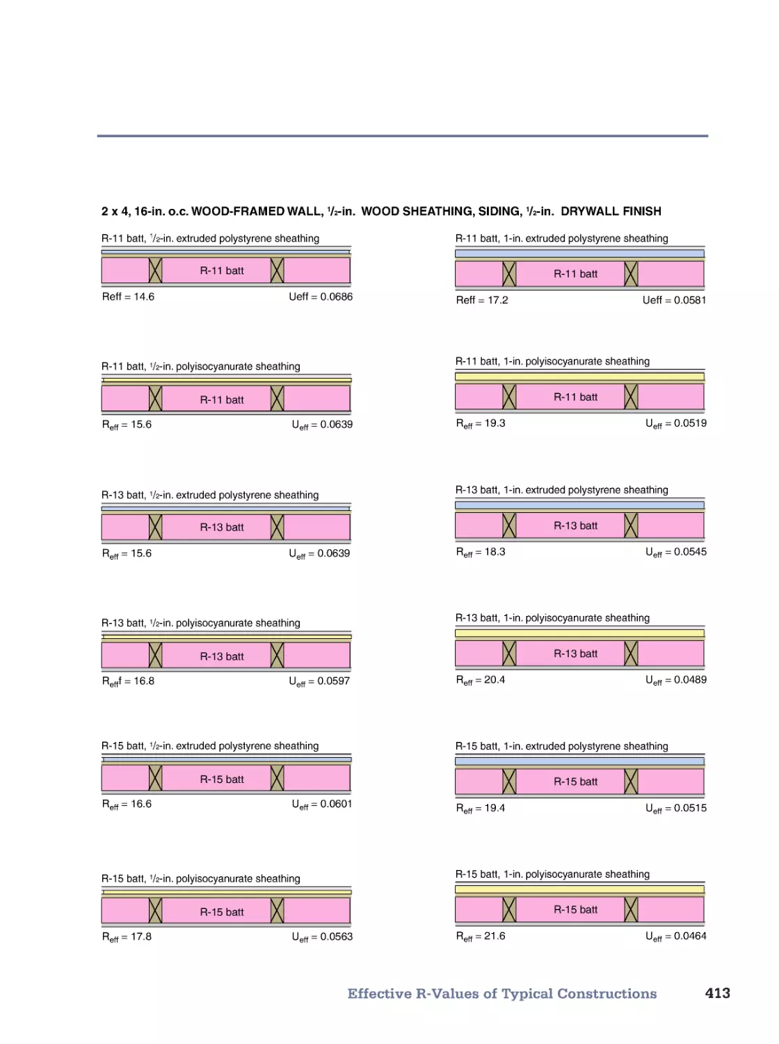
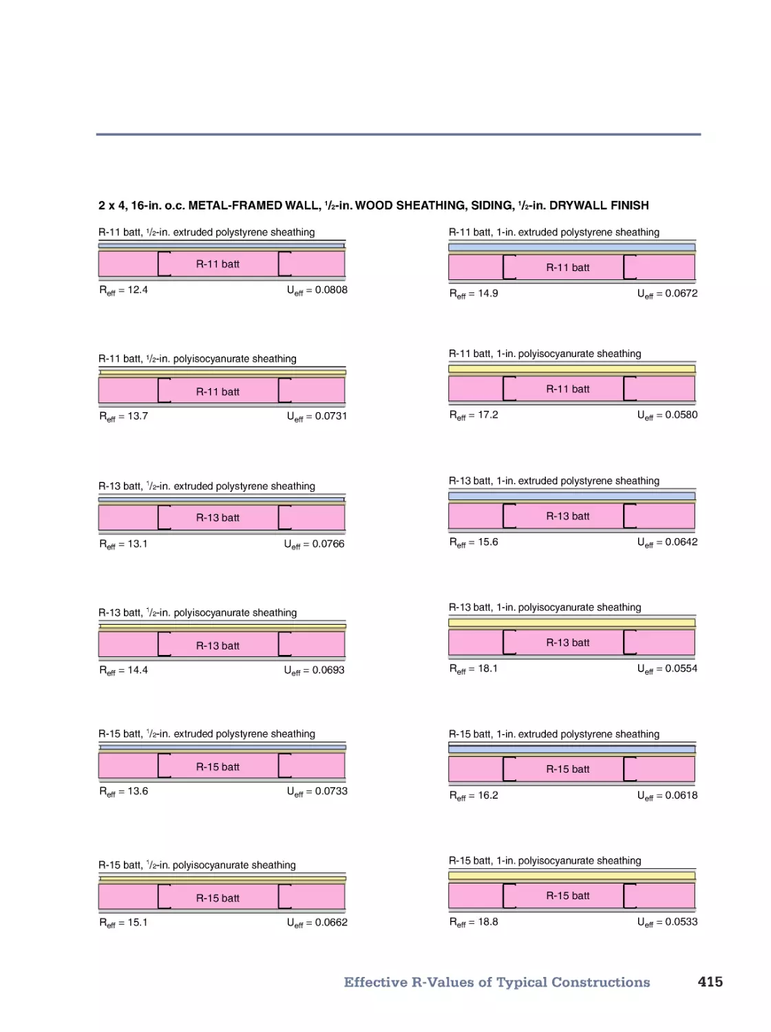
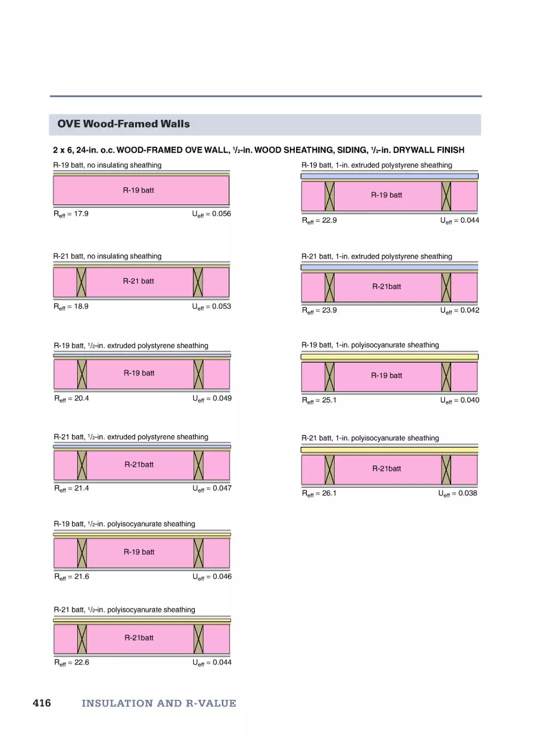
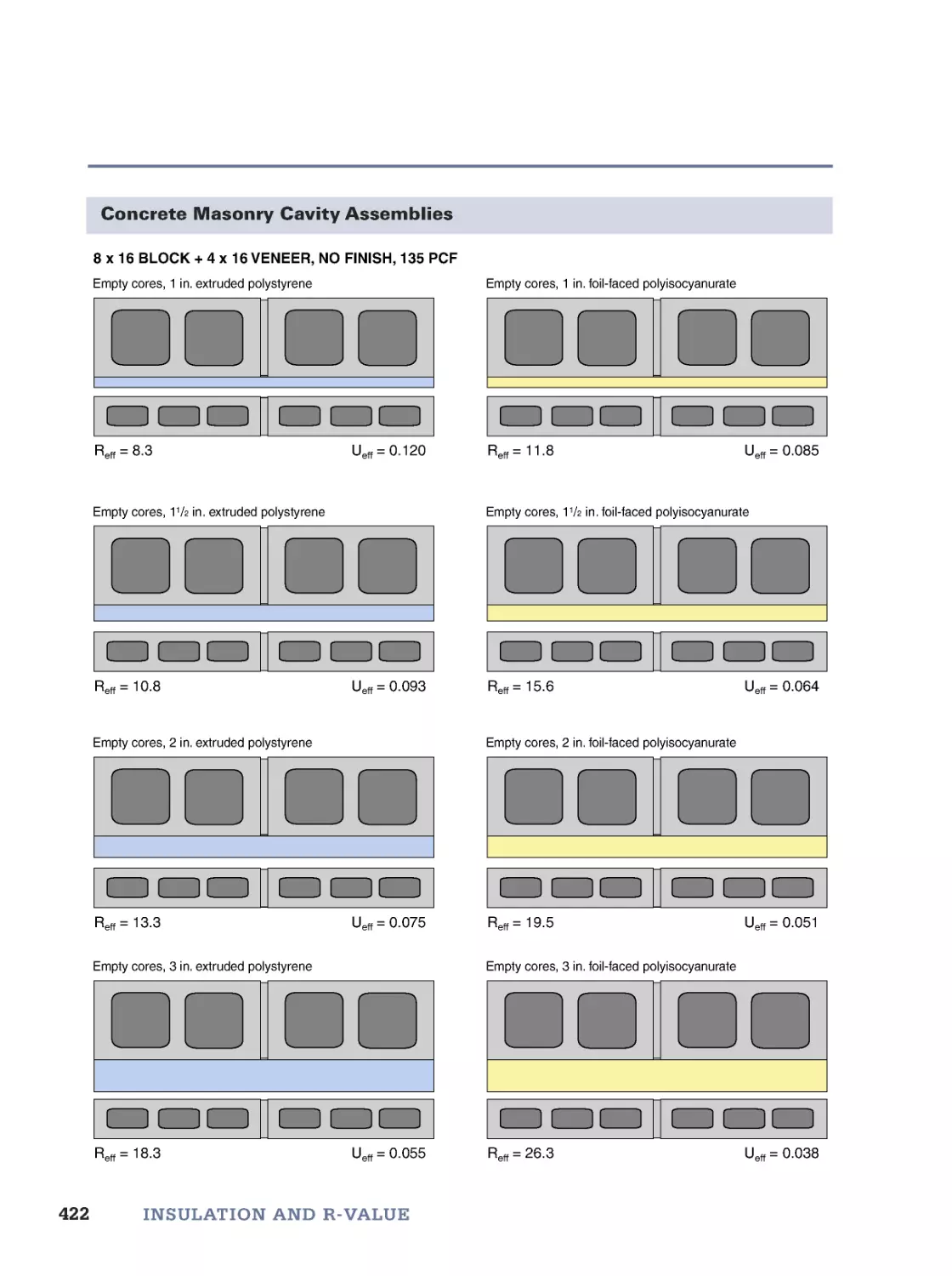
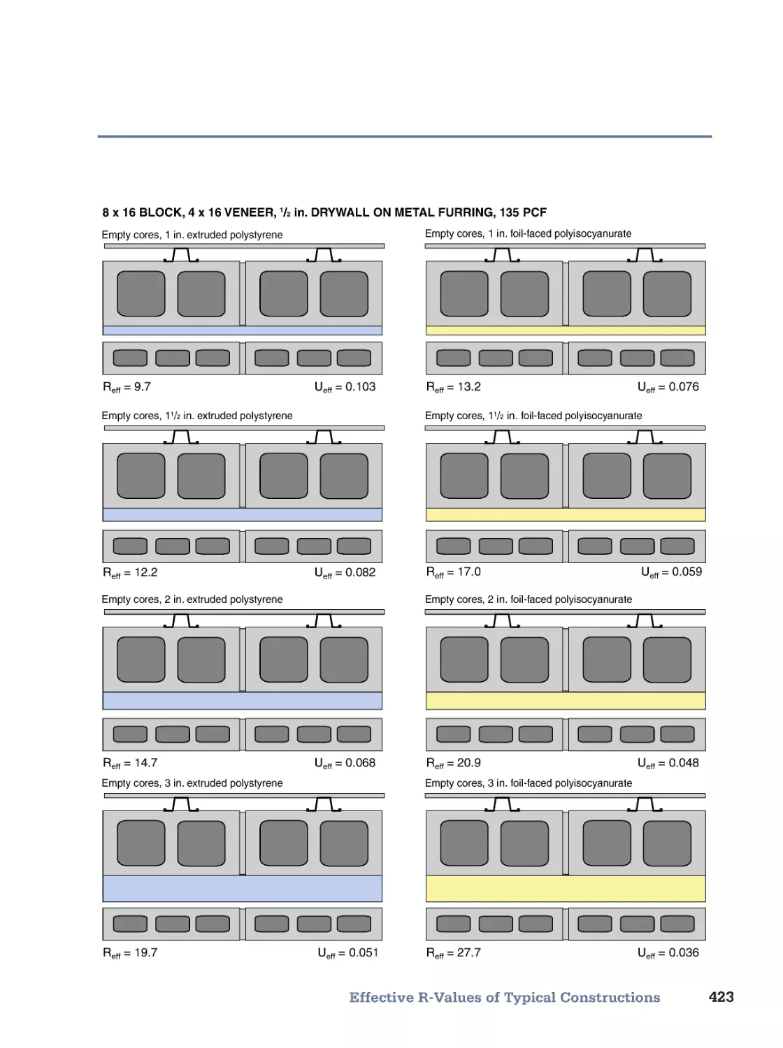
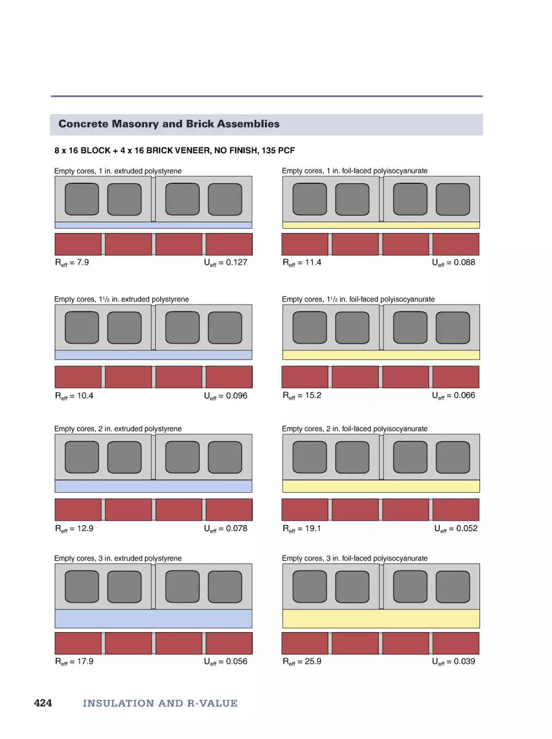
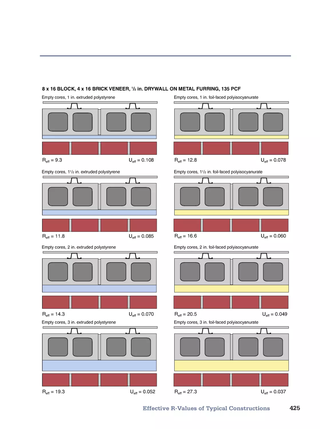
• R-Values of Building Materials • Calculating Effective R-Values • Effective R-Values of Typical Constructions
14. Best Practice Insulating
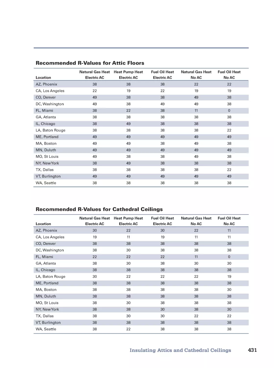
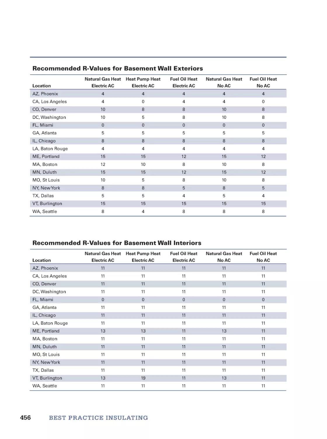
427
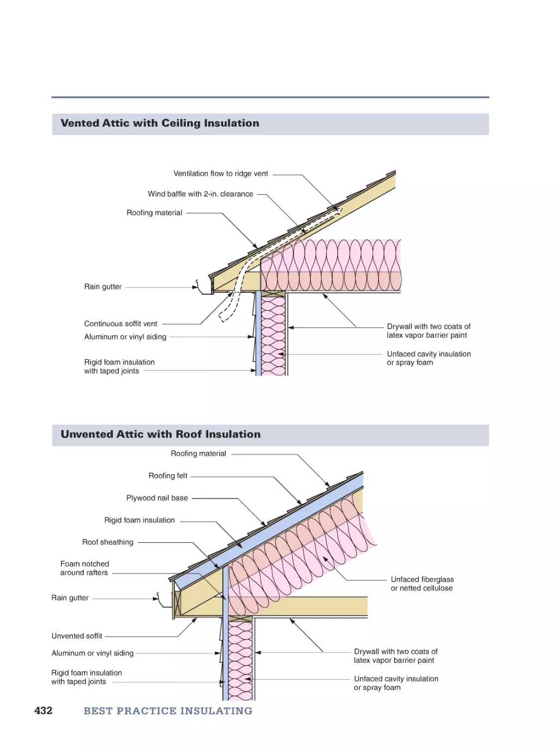
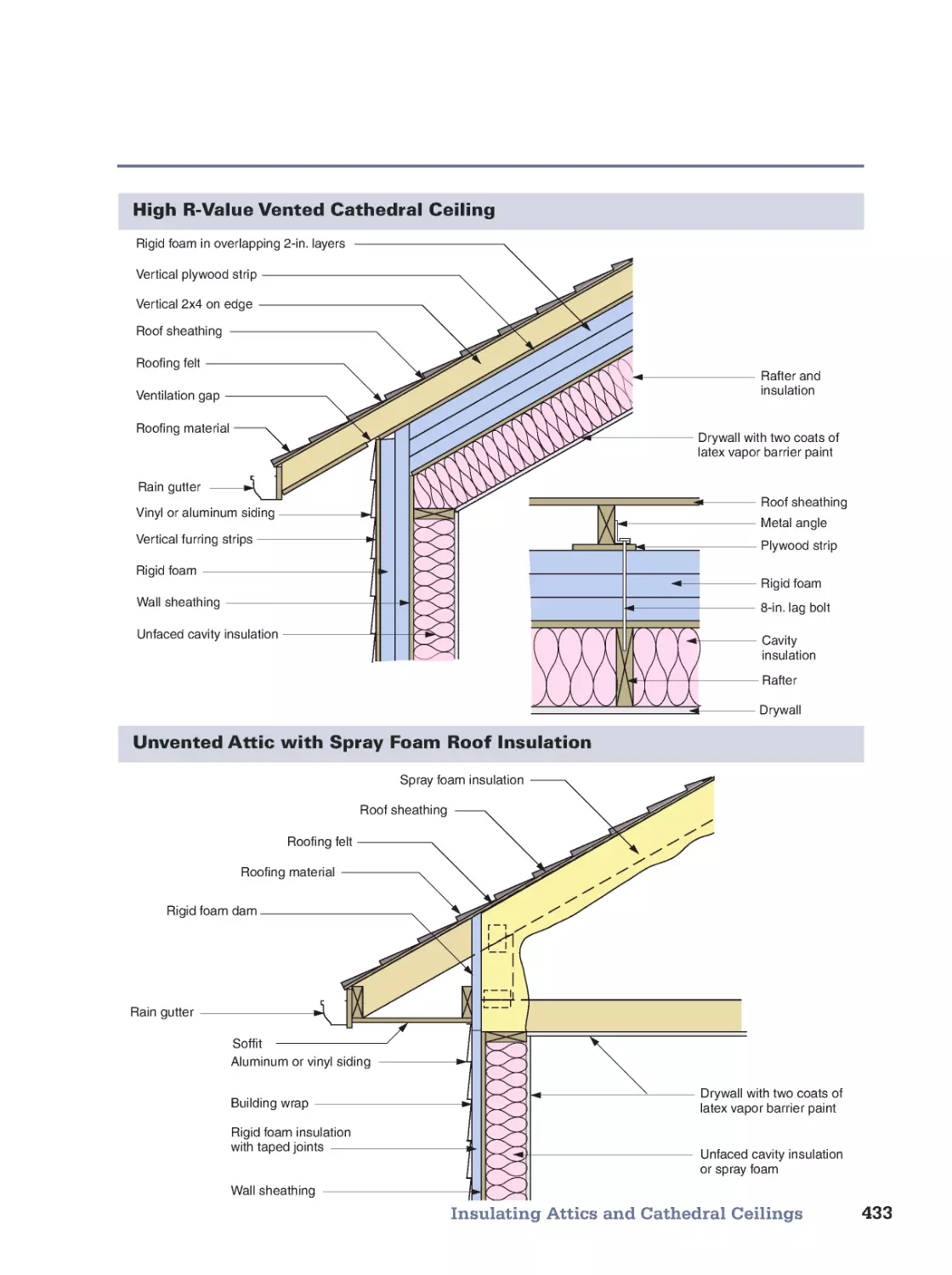
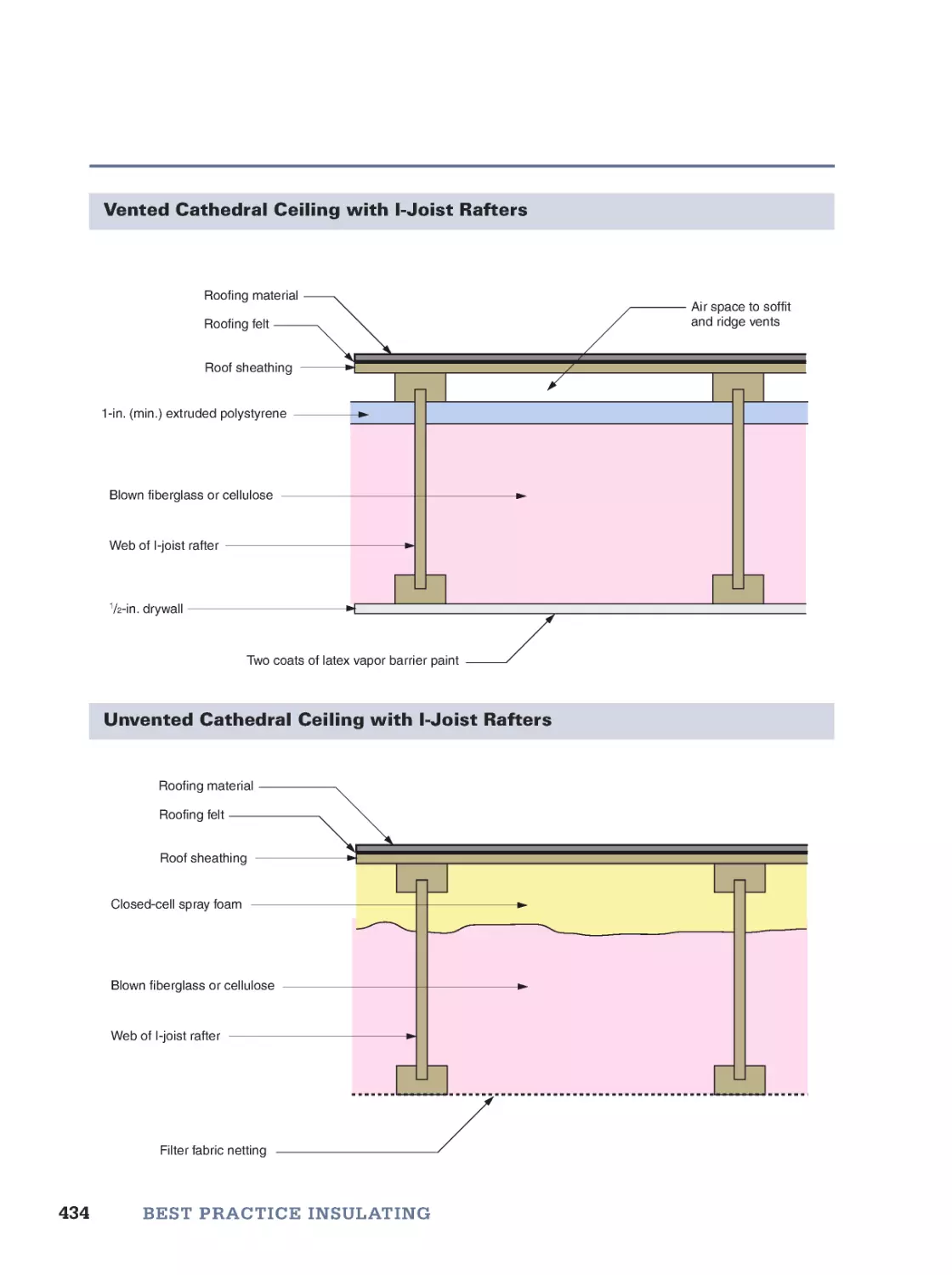
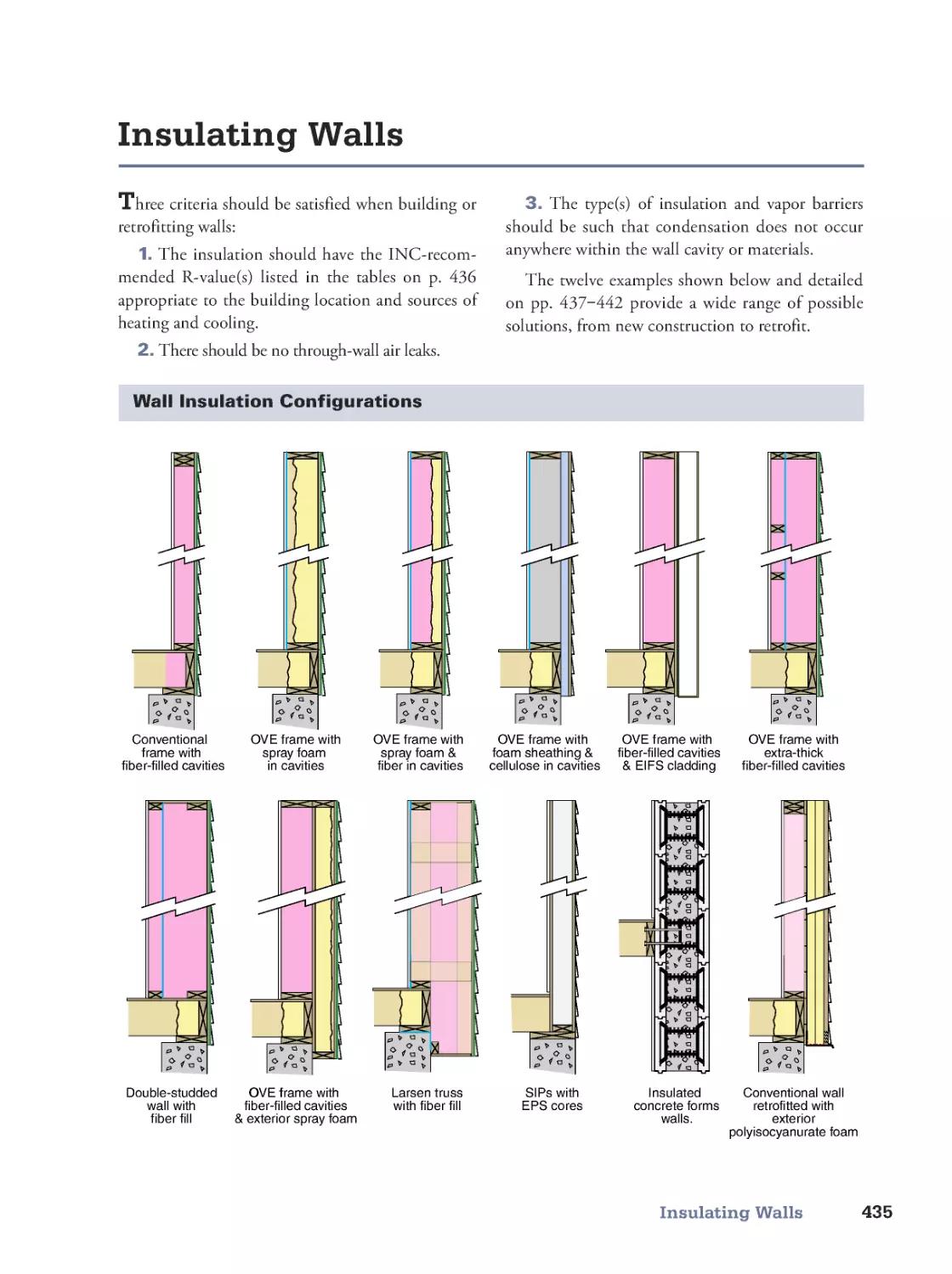
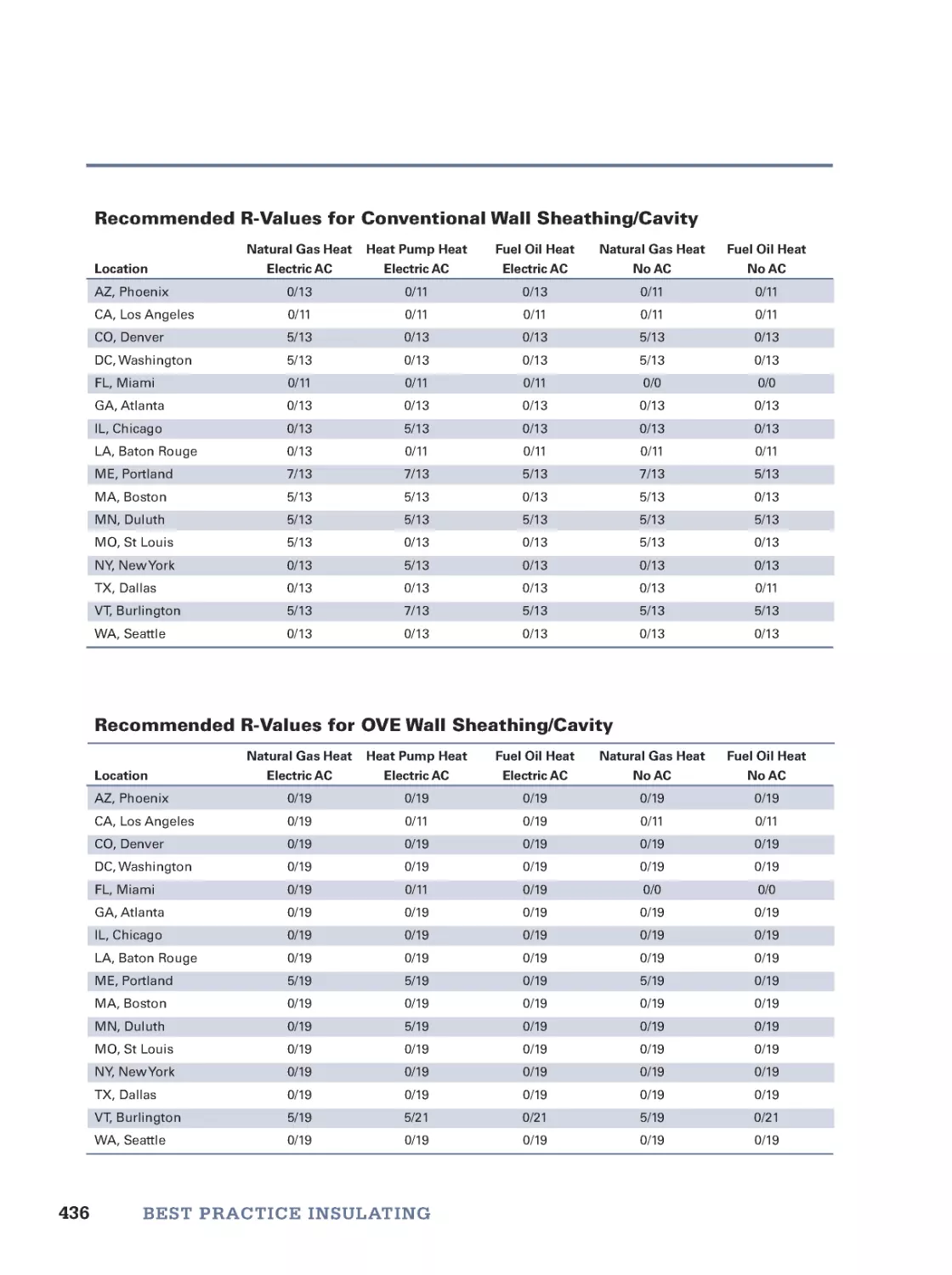
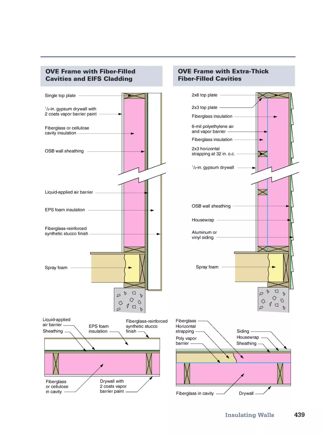
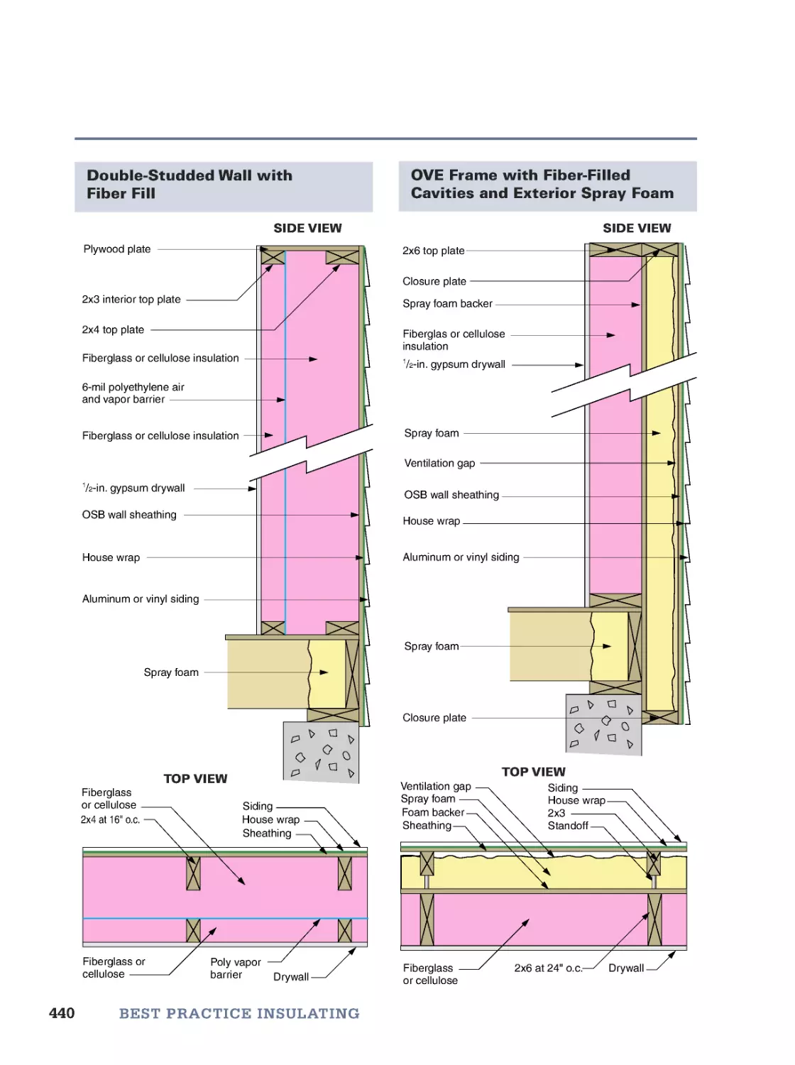
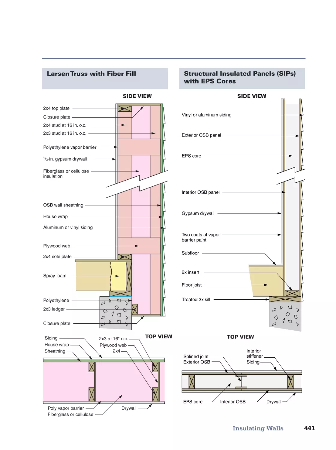
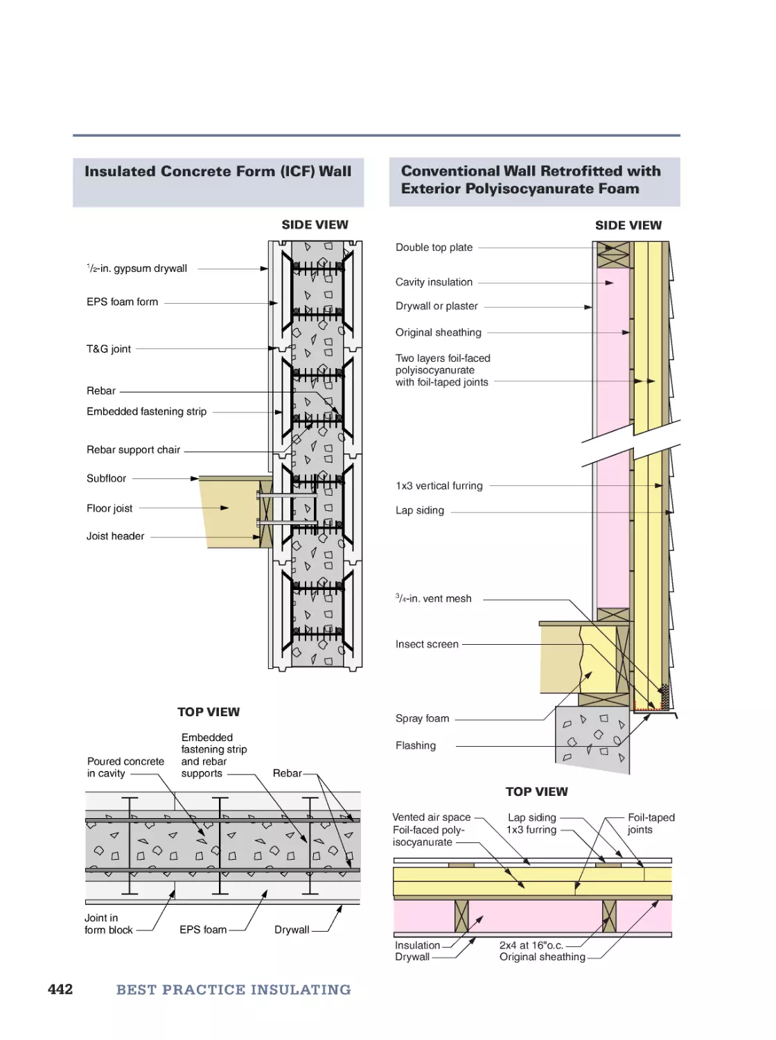
Where to Insulate: The Thermal Envelope • Insulating Attics and Cathedral Ceilings • Insulating Walls
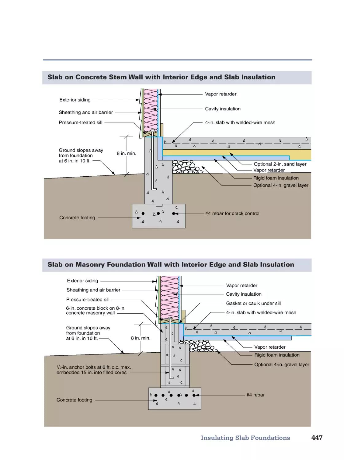
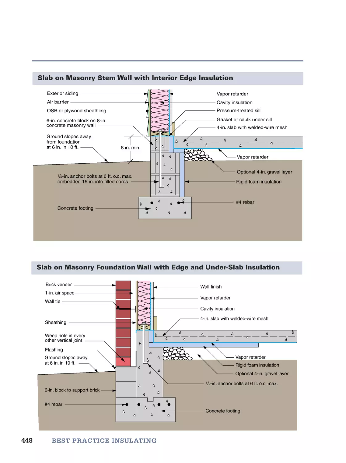
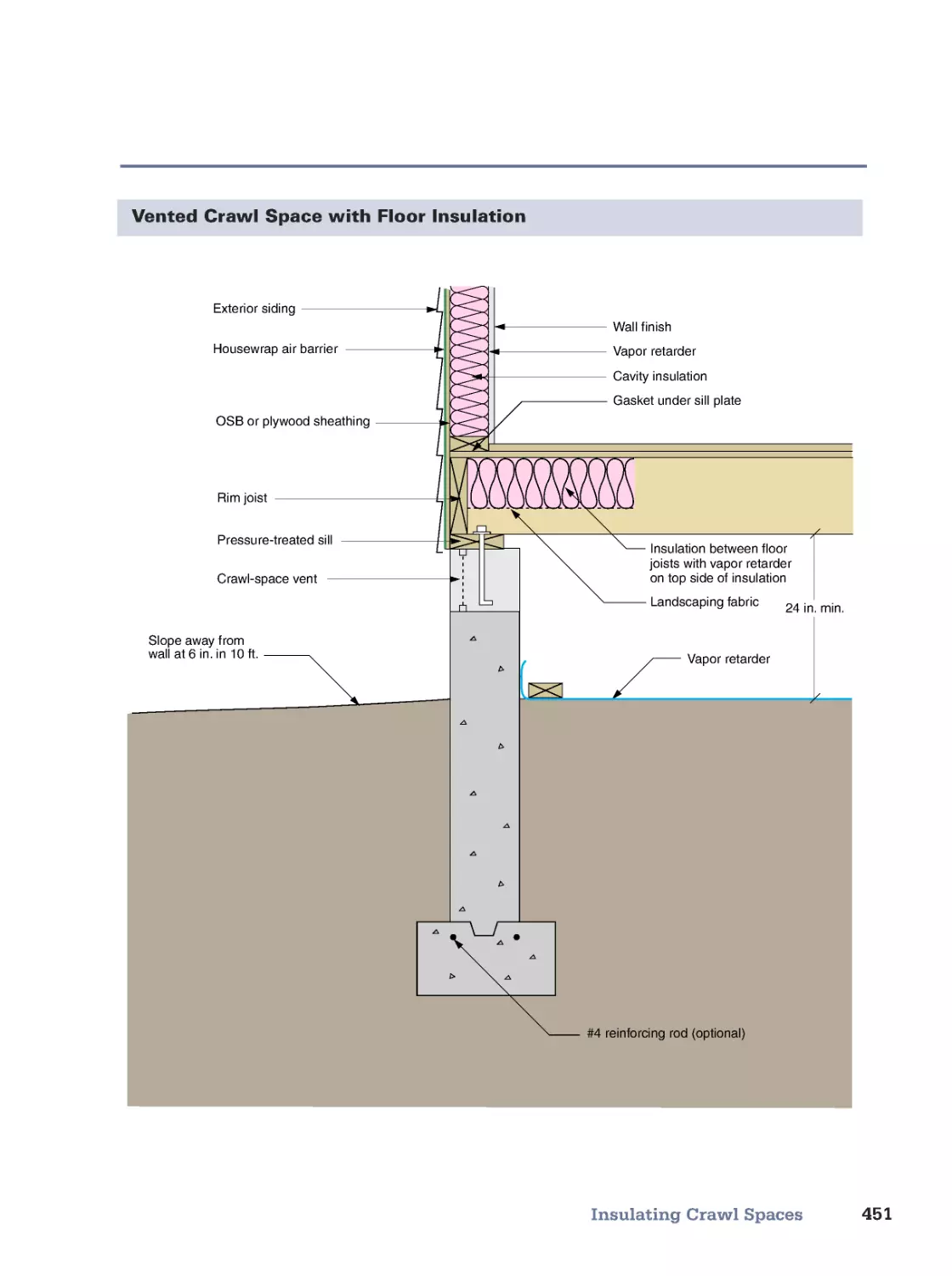
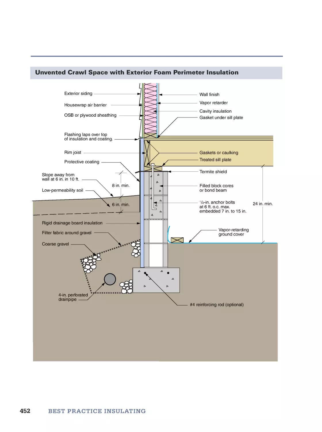
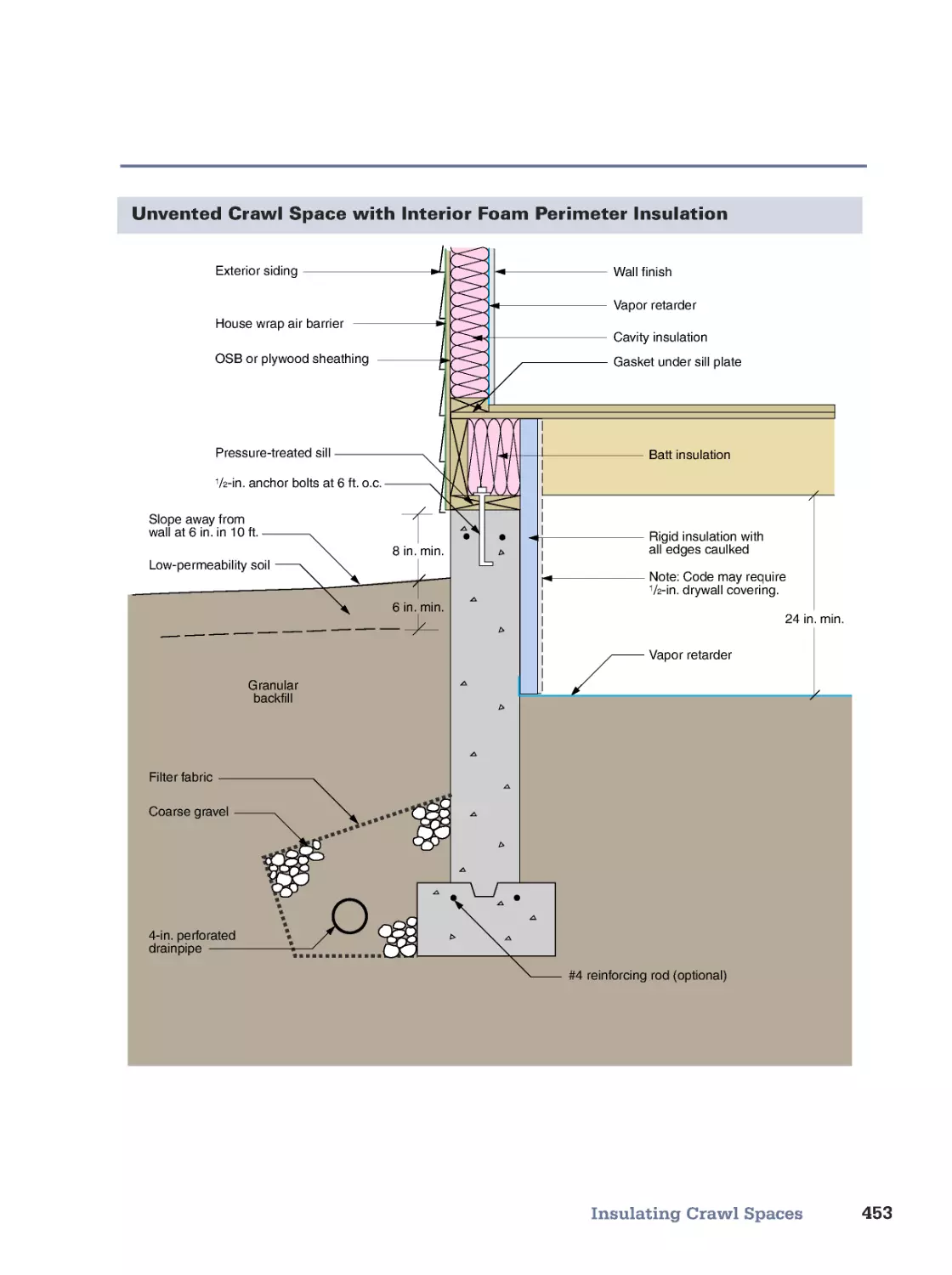
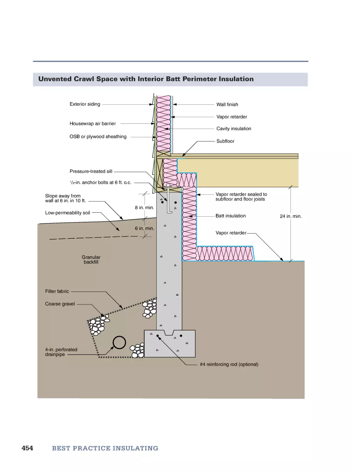
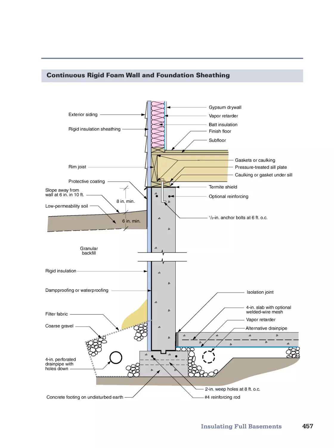
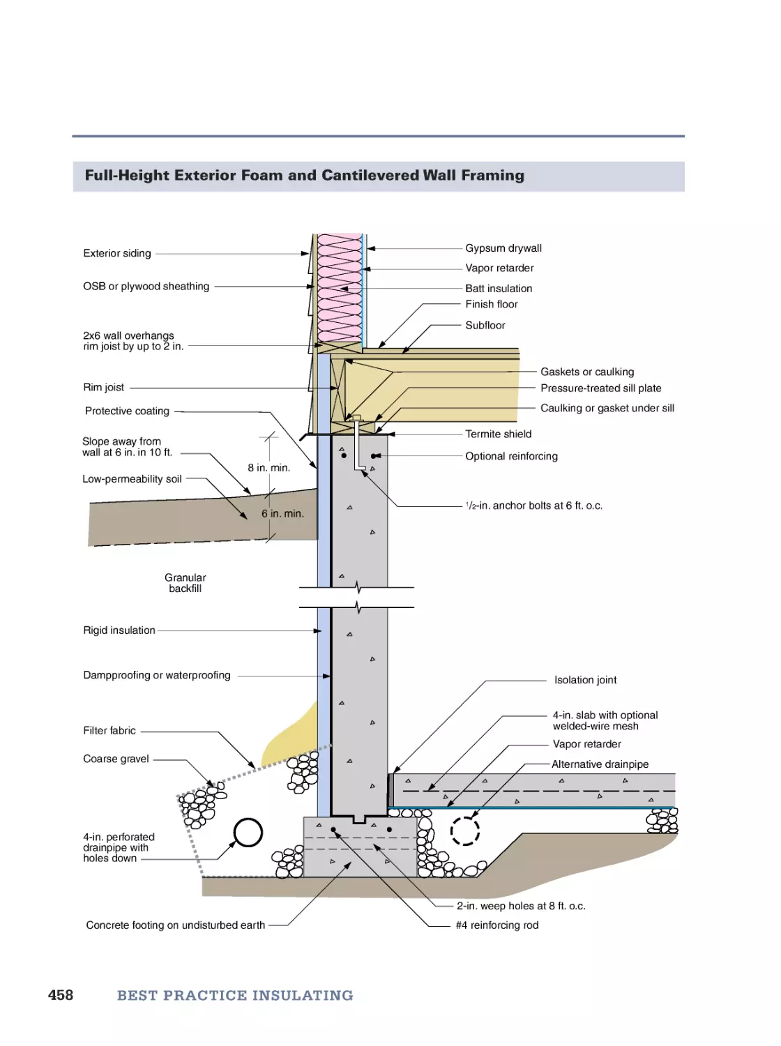
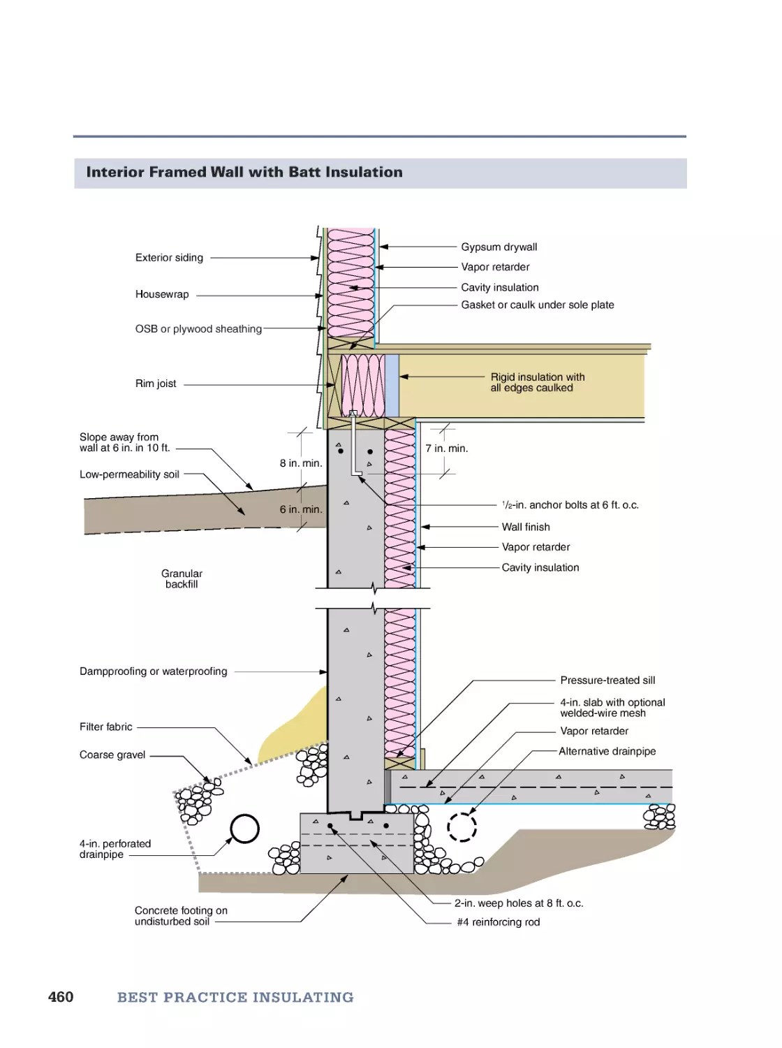
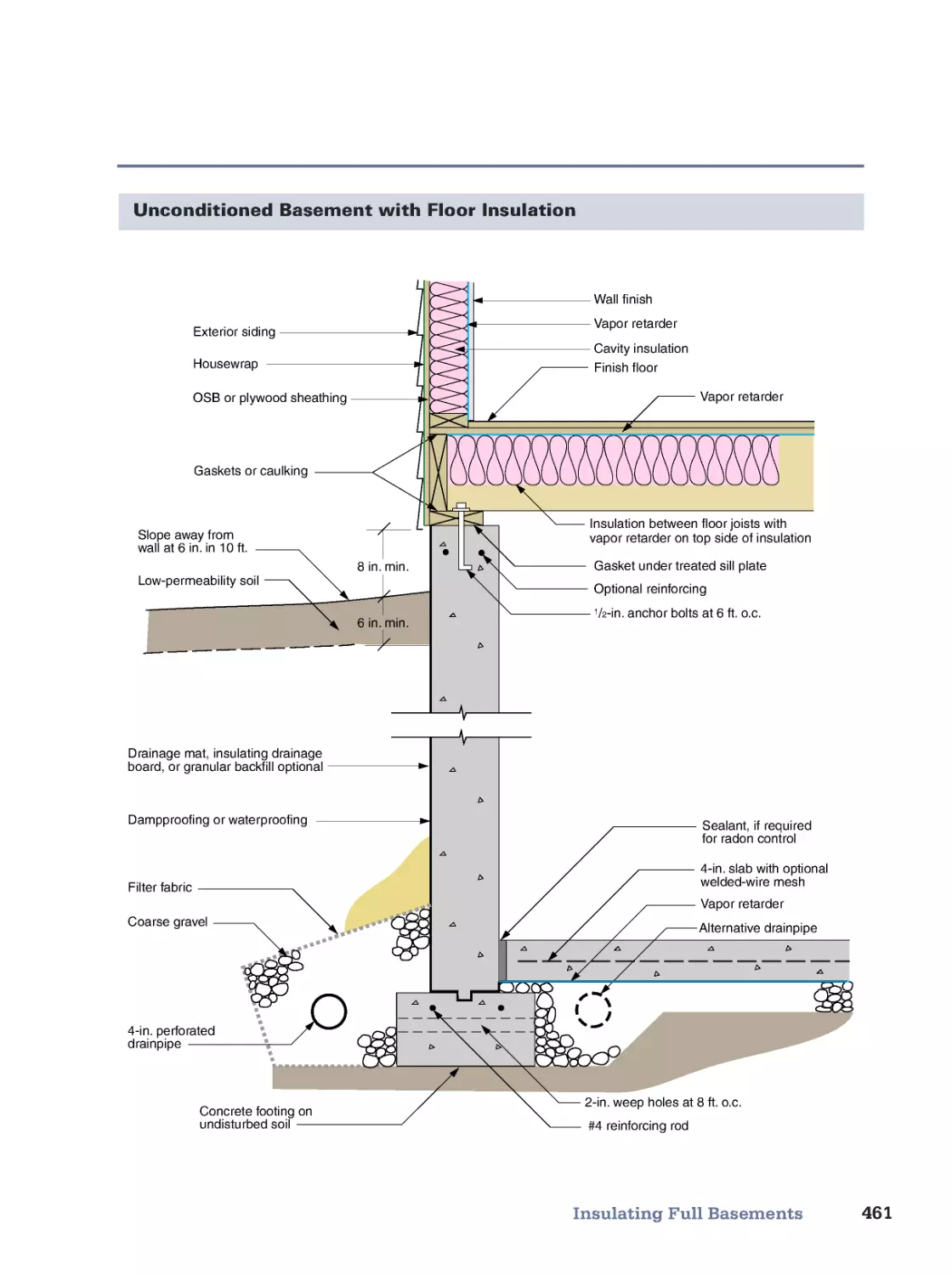
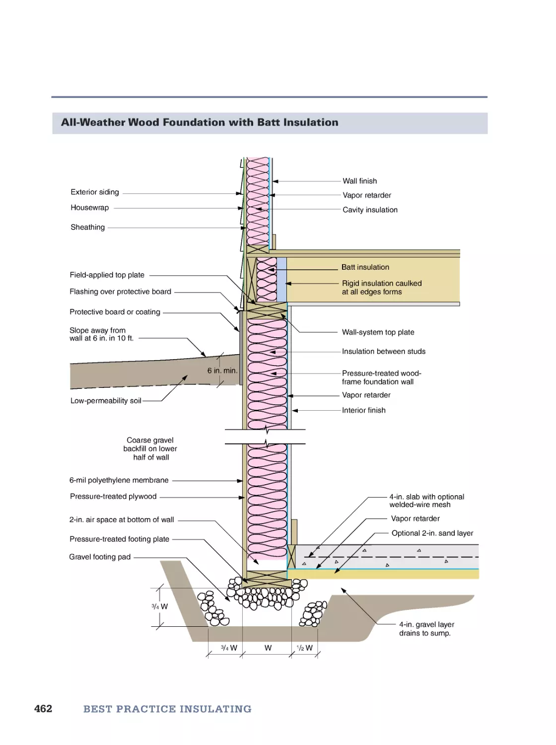
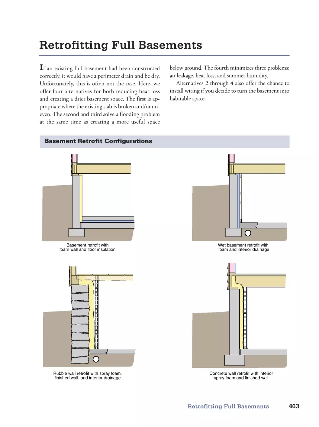
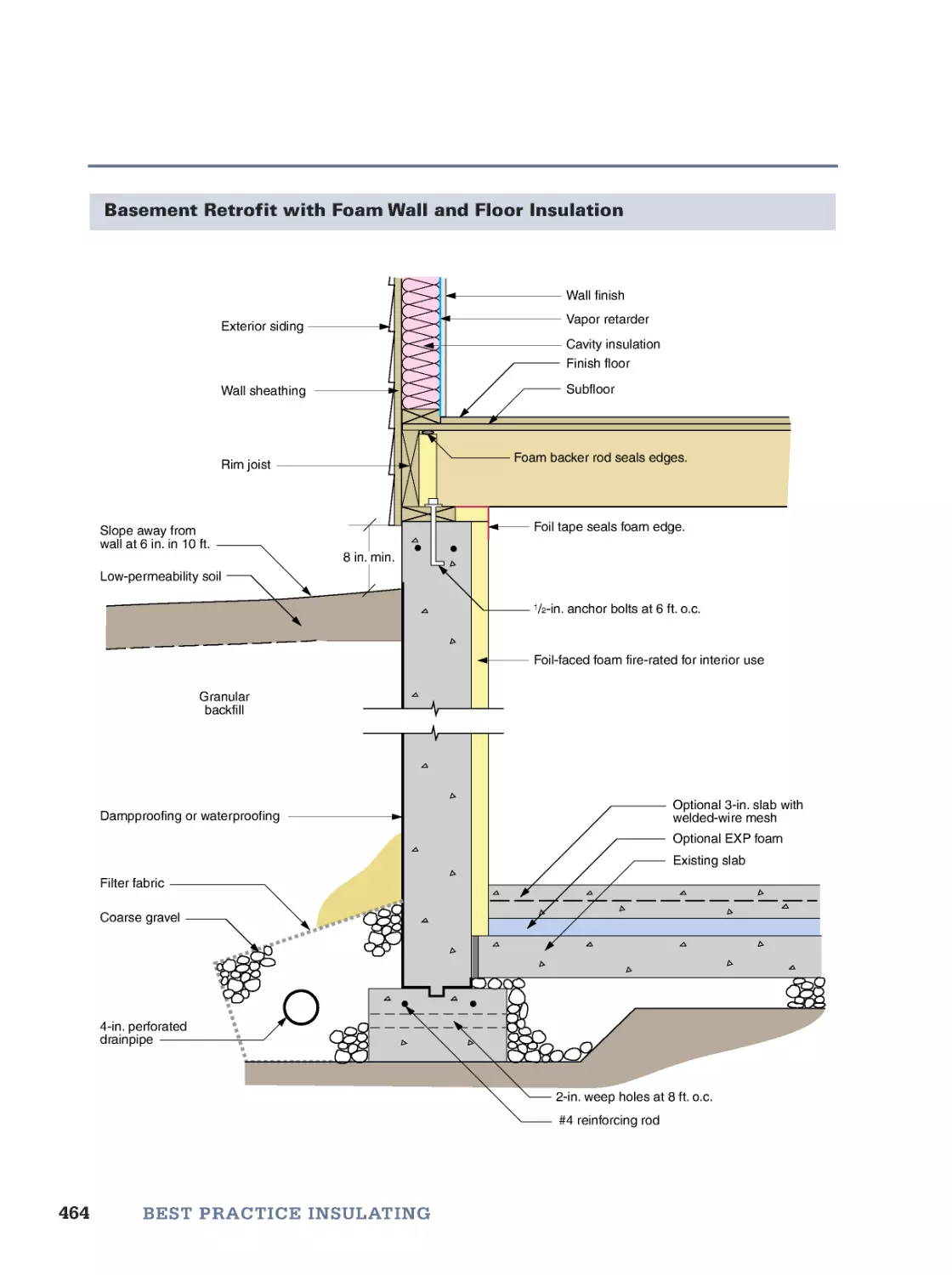
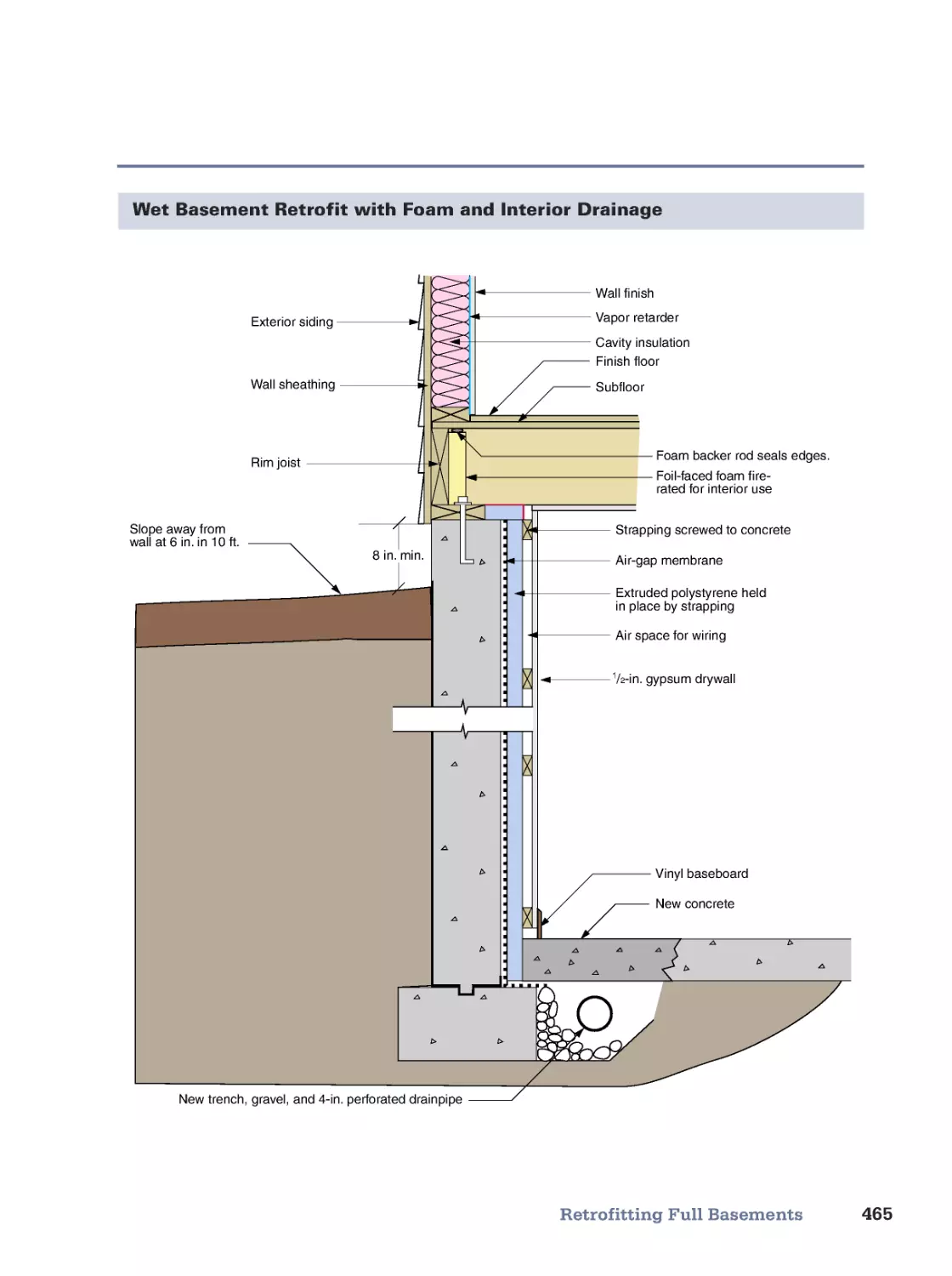
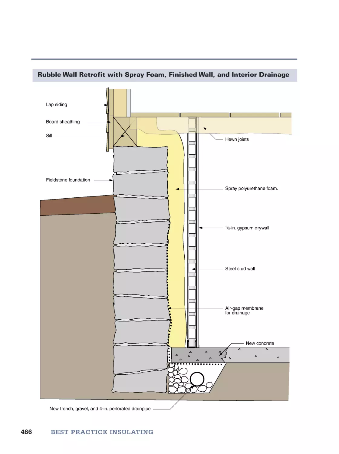
• Insulating Slab Foundations • Insulating Crawl Spaces • Insulating Full Basements • Retrofitting Full Basements
15. Air-Sealing Existing Buildings
469
A Field Guide to Air Leaks • Attic Air Leaks • Basement Air Leaks • Interior Air Leaks • Exterior Air Leaks
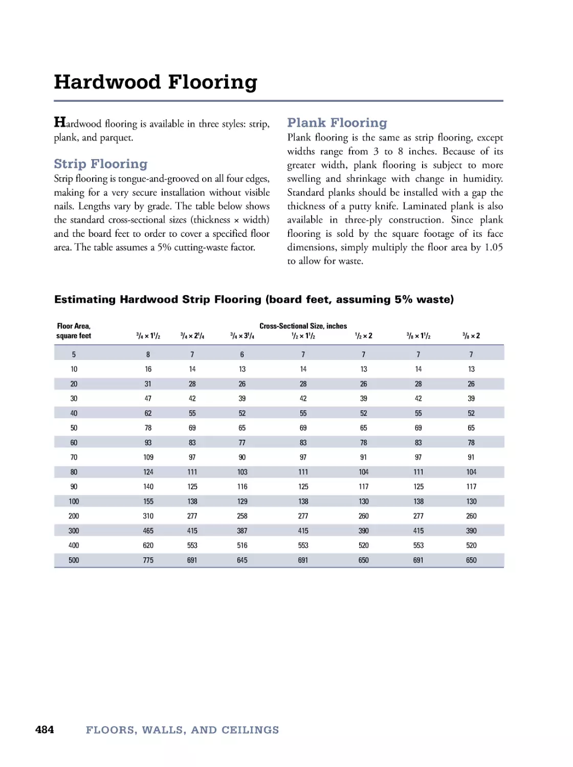
16. Floors, Walls, and Ceilings
483
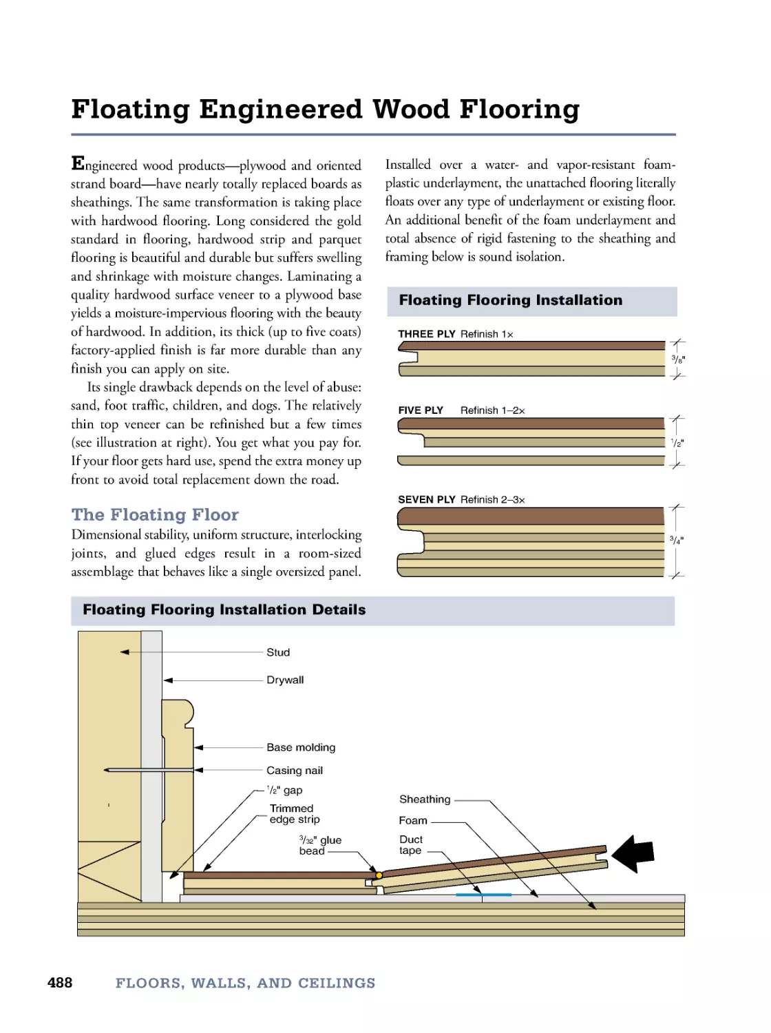
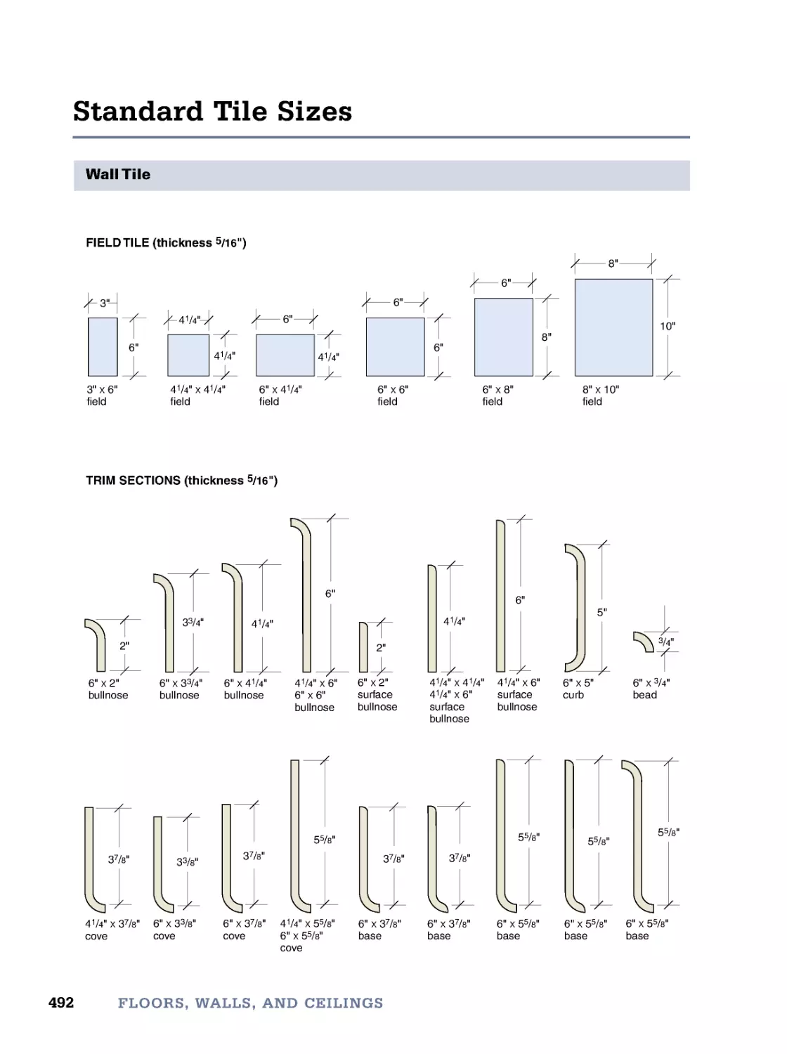
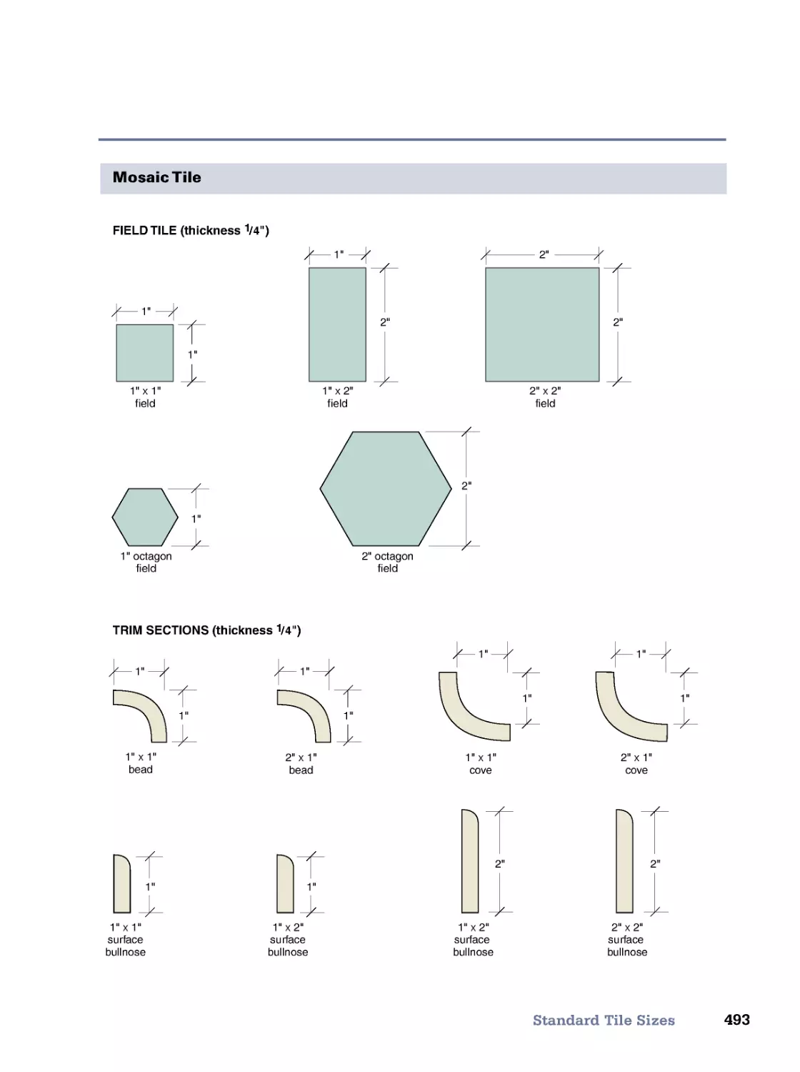
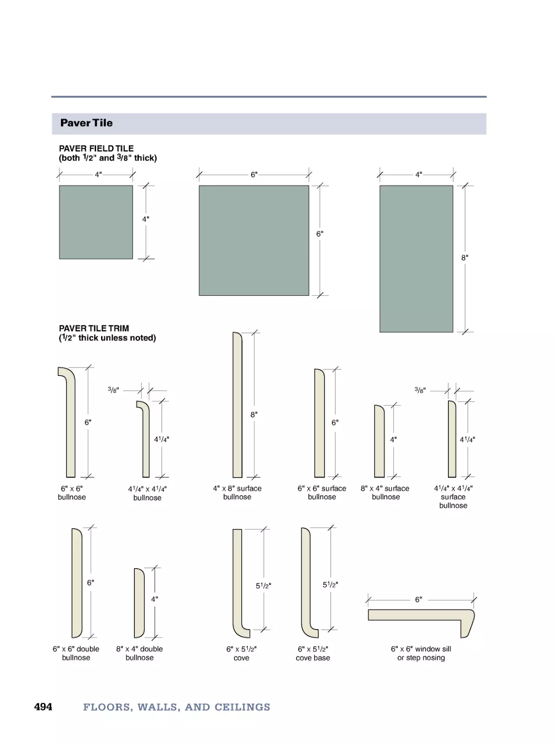
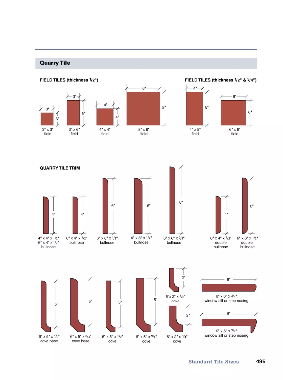
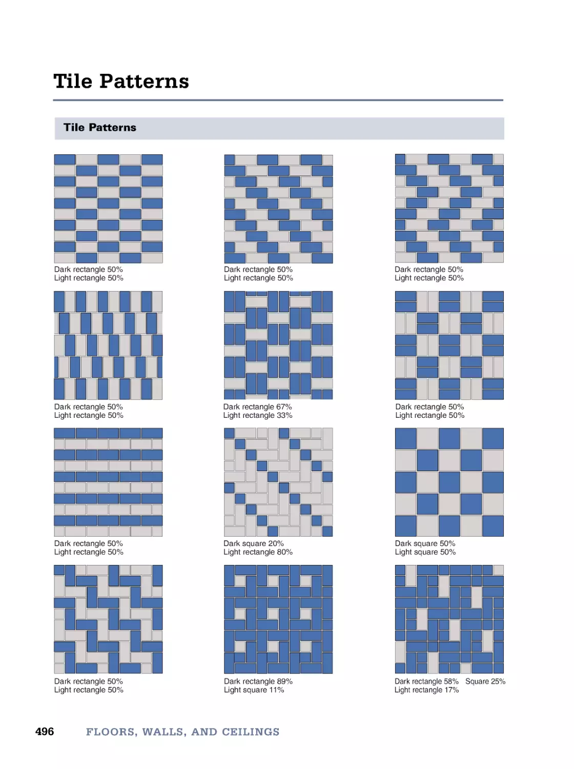
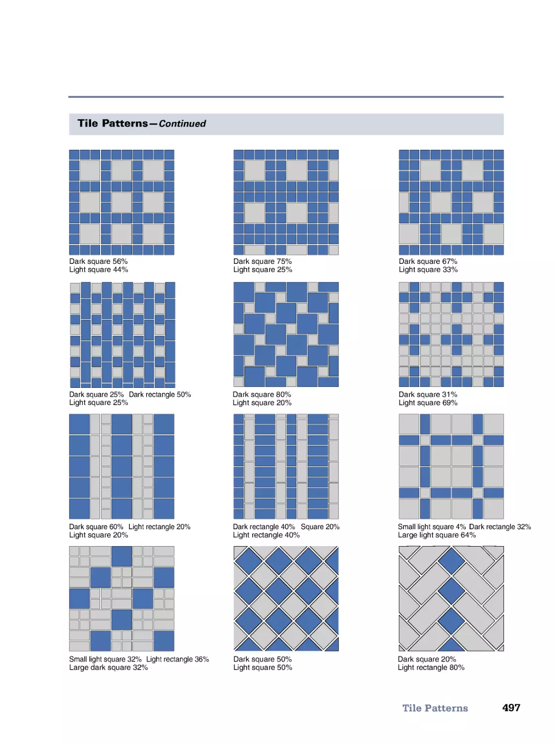
Hardwood Flooring • Floating Engineered Wood Flooring • Resilient Flooring • Ceramic Tile • Tile-Setting
Materials • Standard Tile Sizes • Tile Patterns • Gypsum Wallboard • Wood Paneling • Suspended Ceilings •
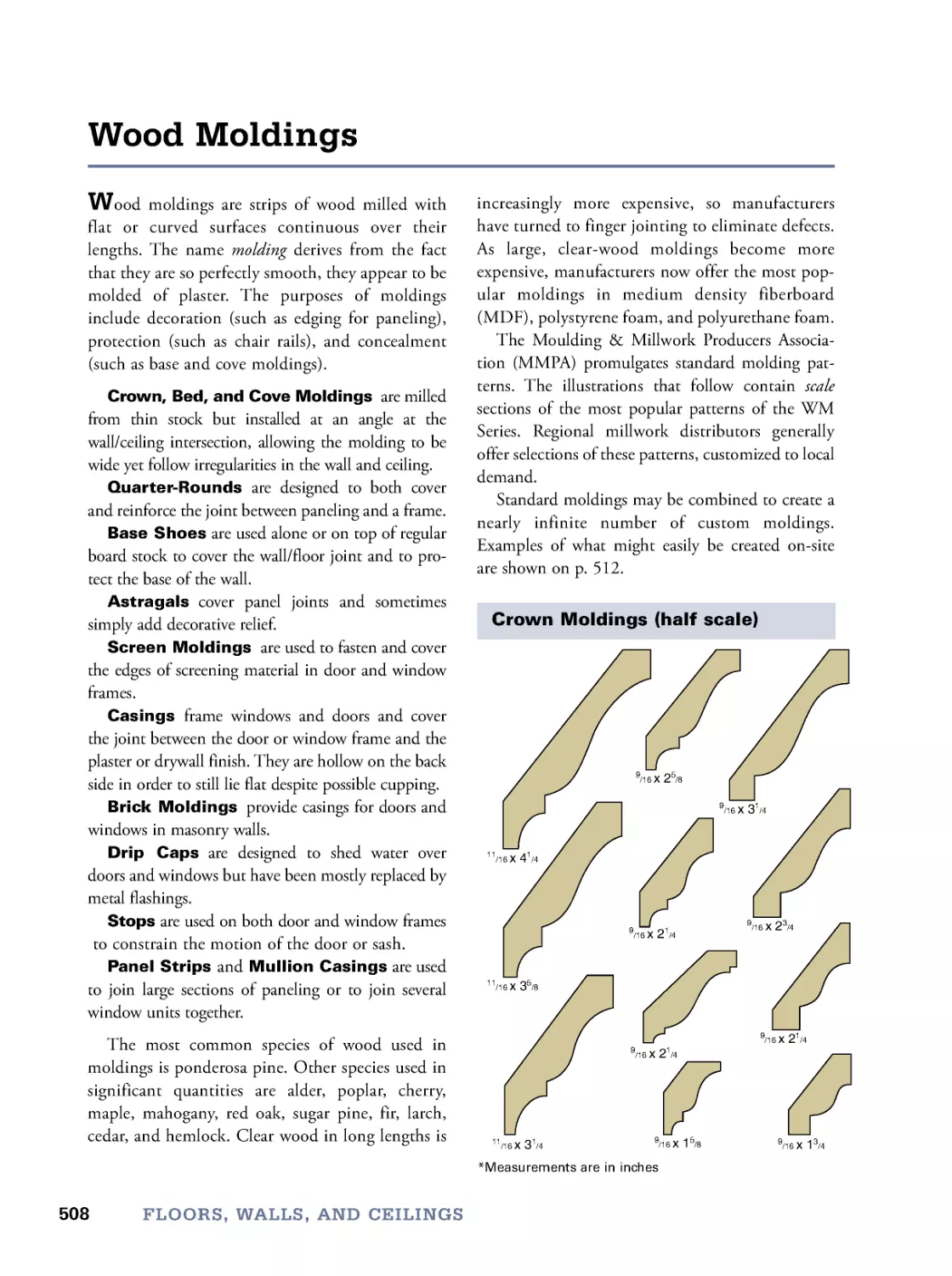
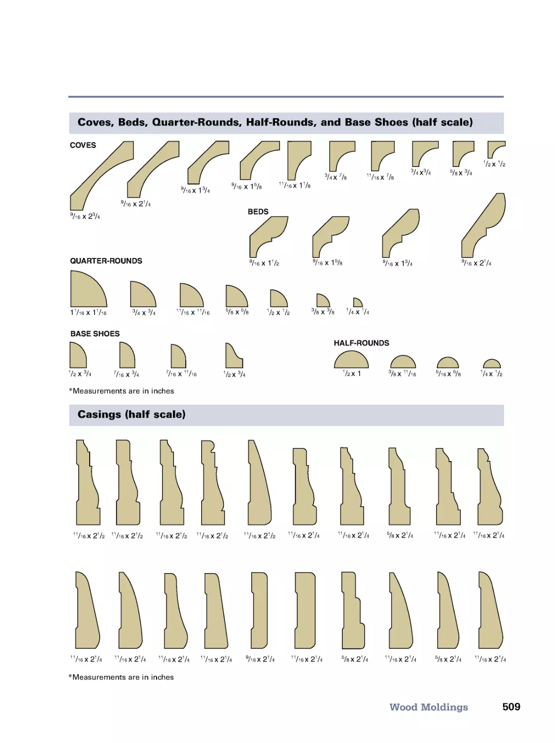
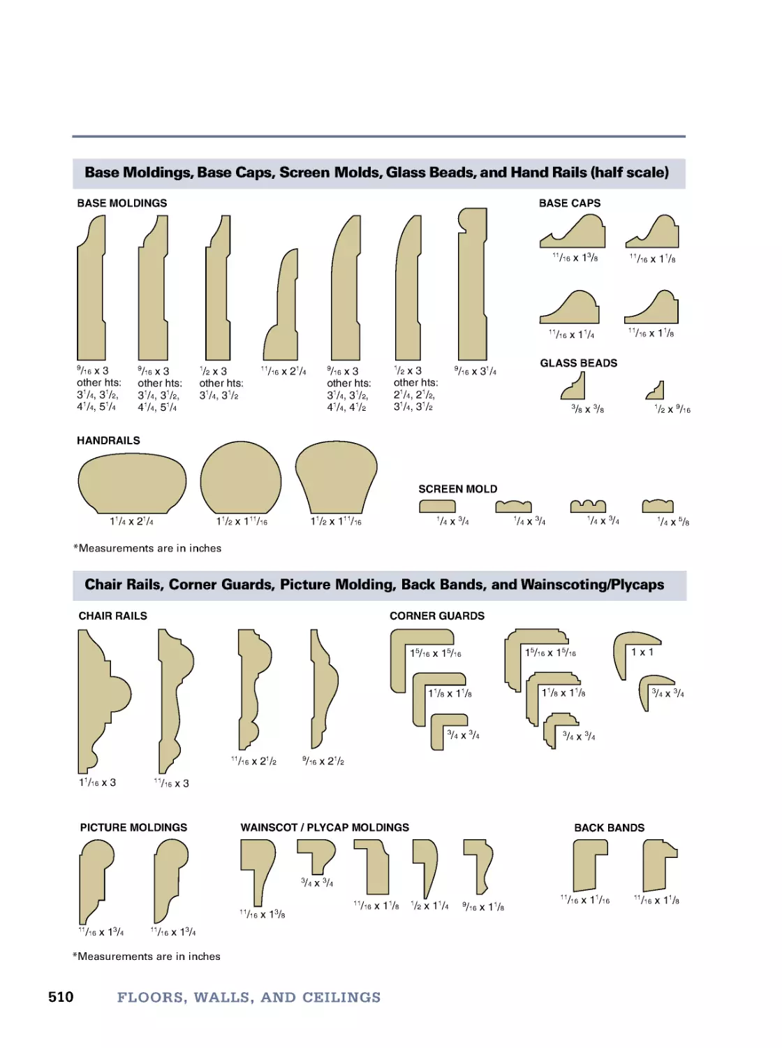
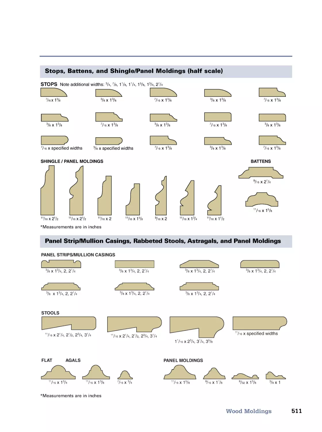
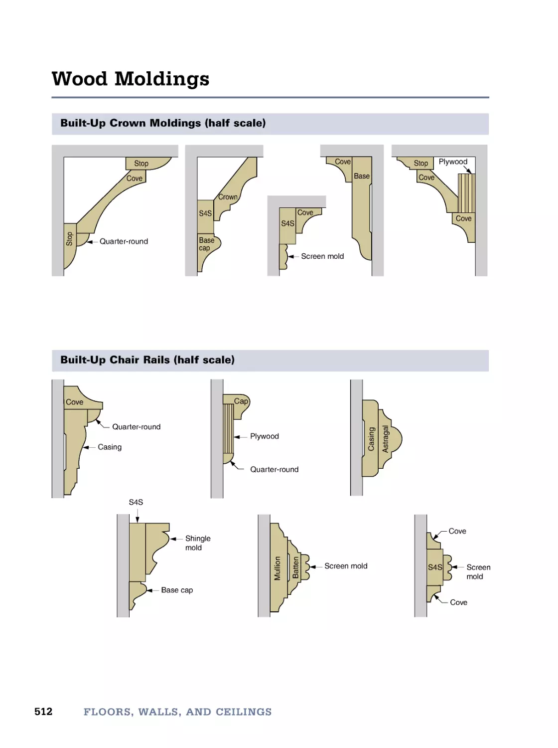
Wood Moldings • Built-Up Wood Moldings
17. Storage
513
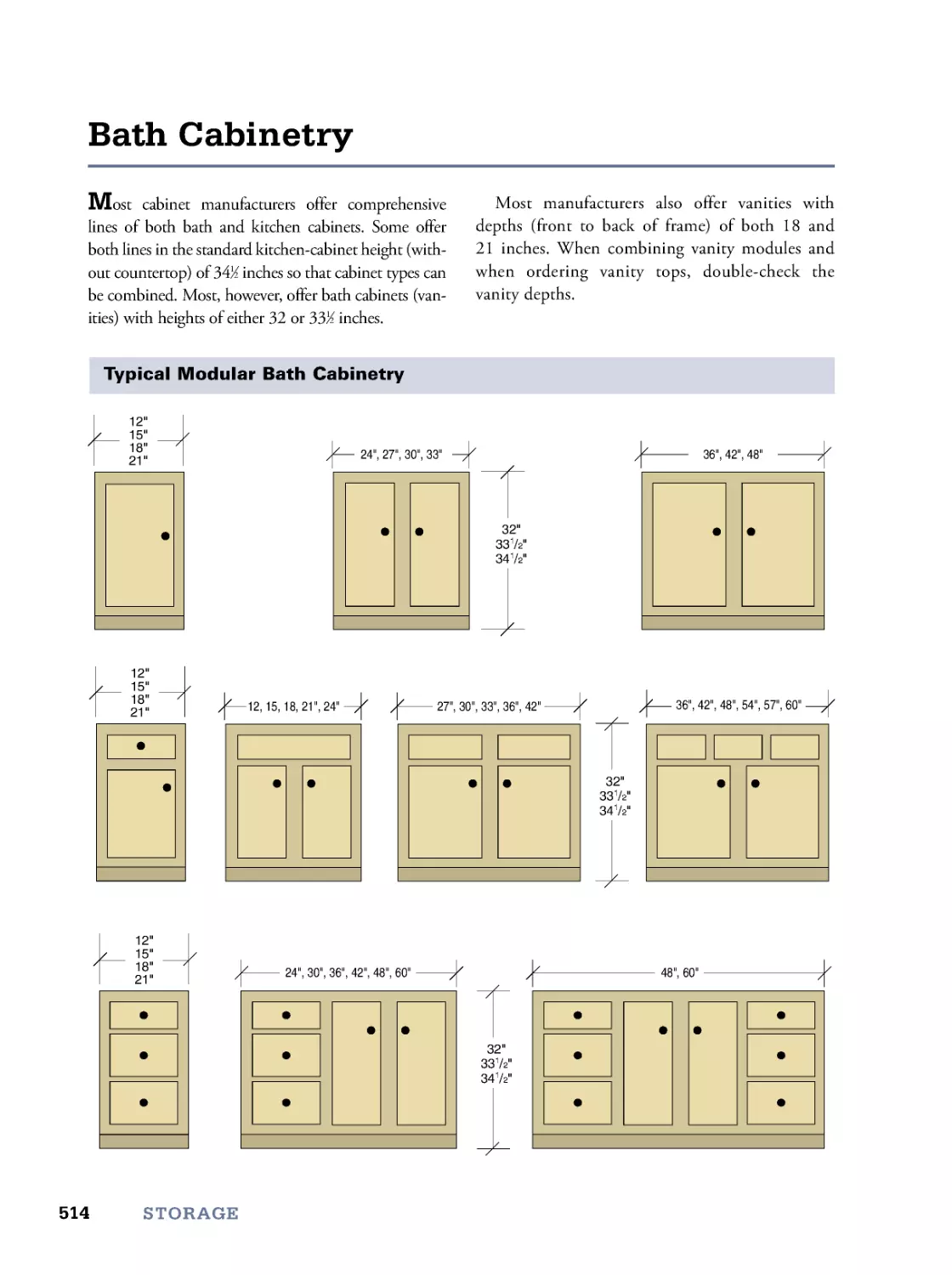
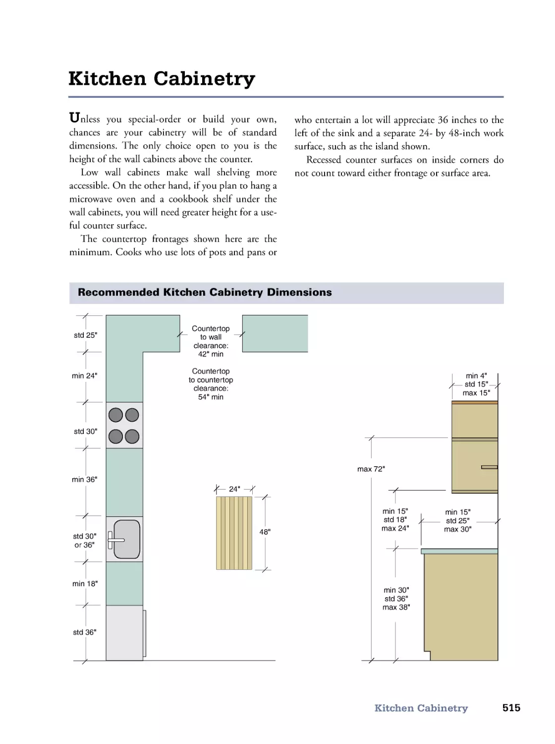
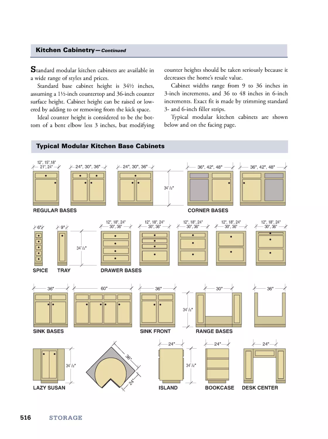
Bath Cabinetry • Kitchen Cabinetry • Finding More Storage • Shelving
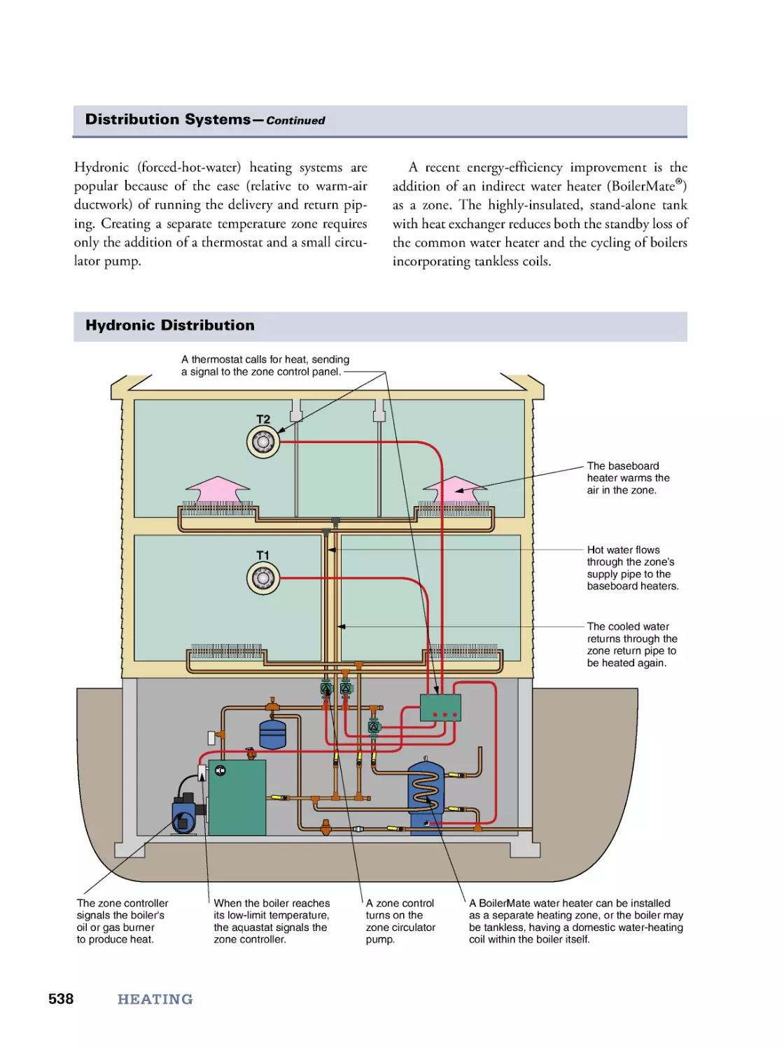
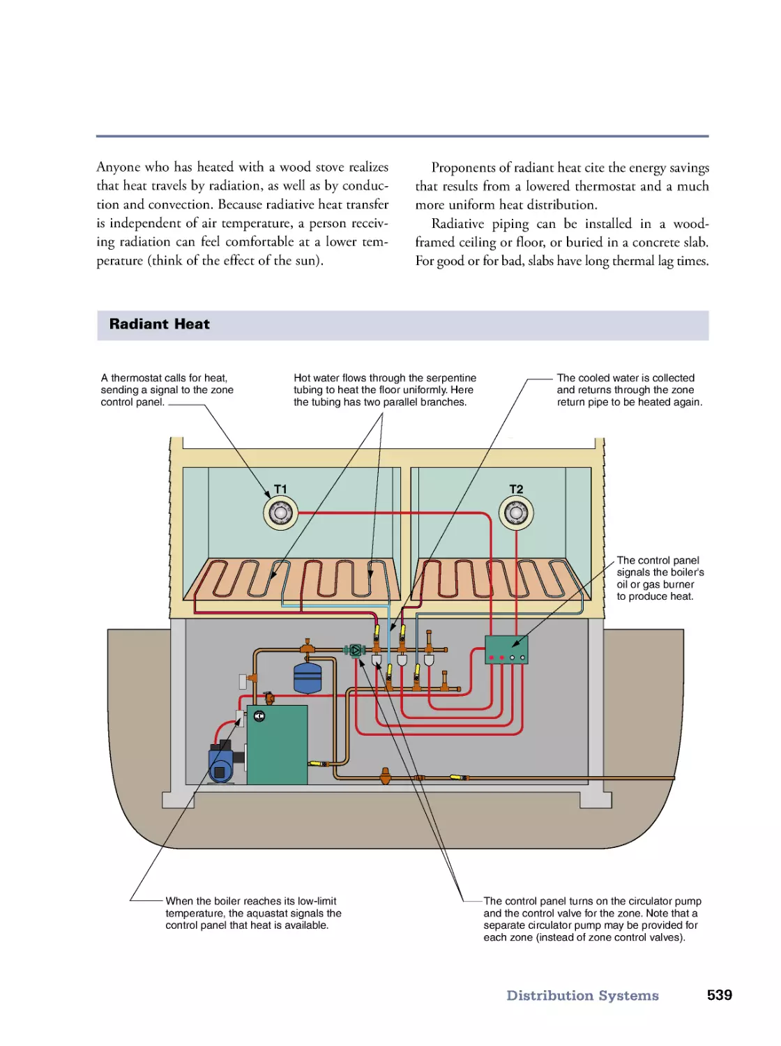
18. Heating
525
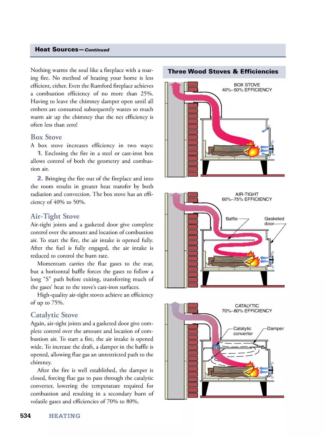
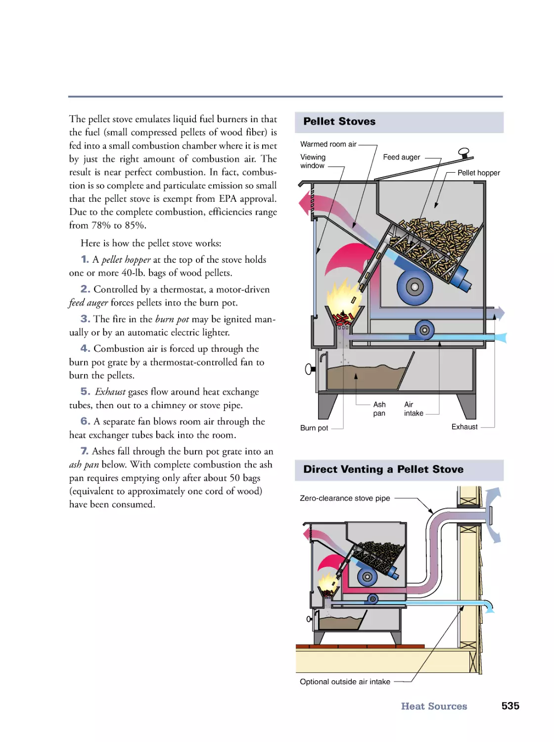
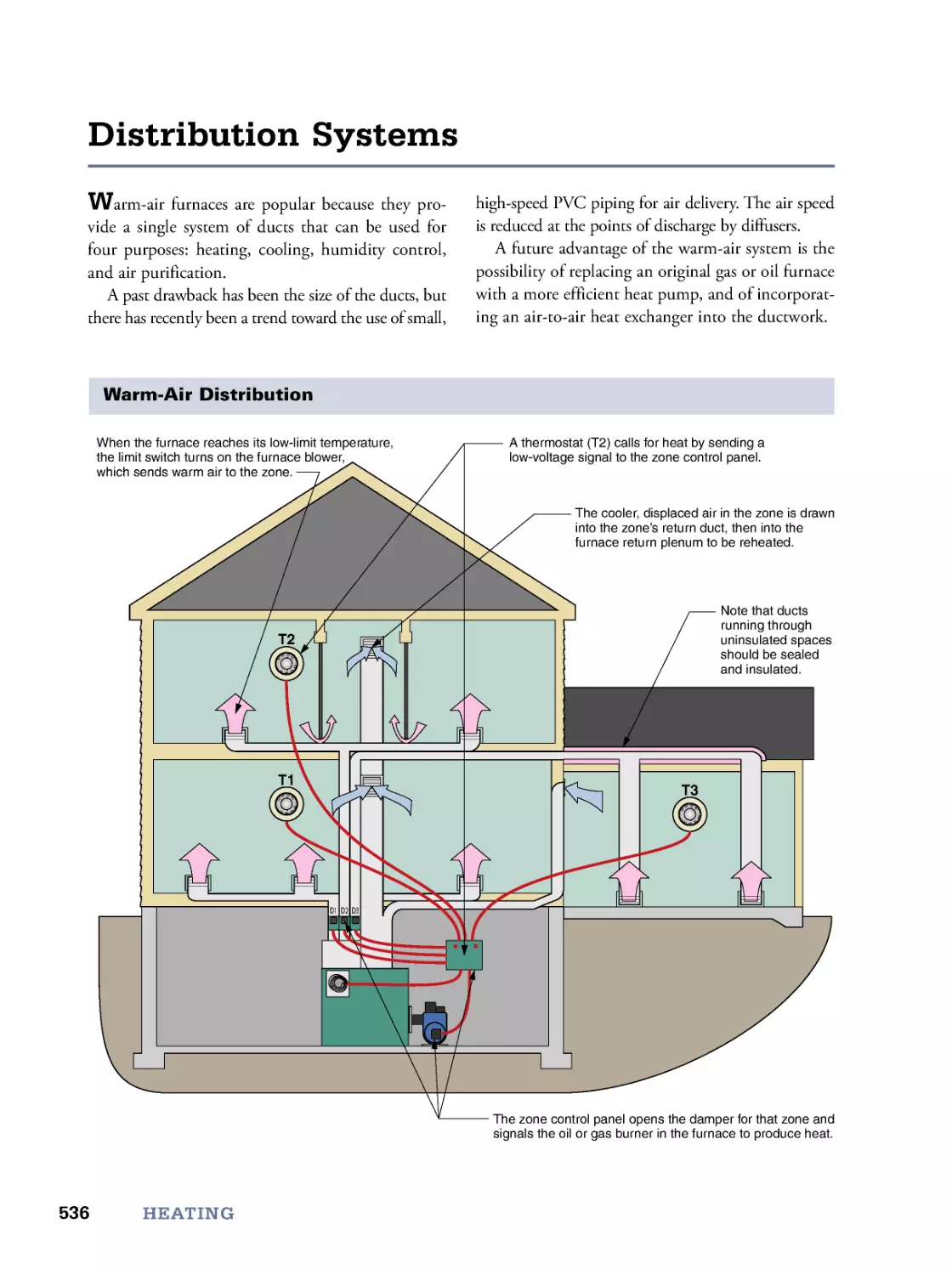
Building Heat Loads • Heat Sources • Distribution Systems • Fuels and Efficiencies • Fireplace Construction
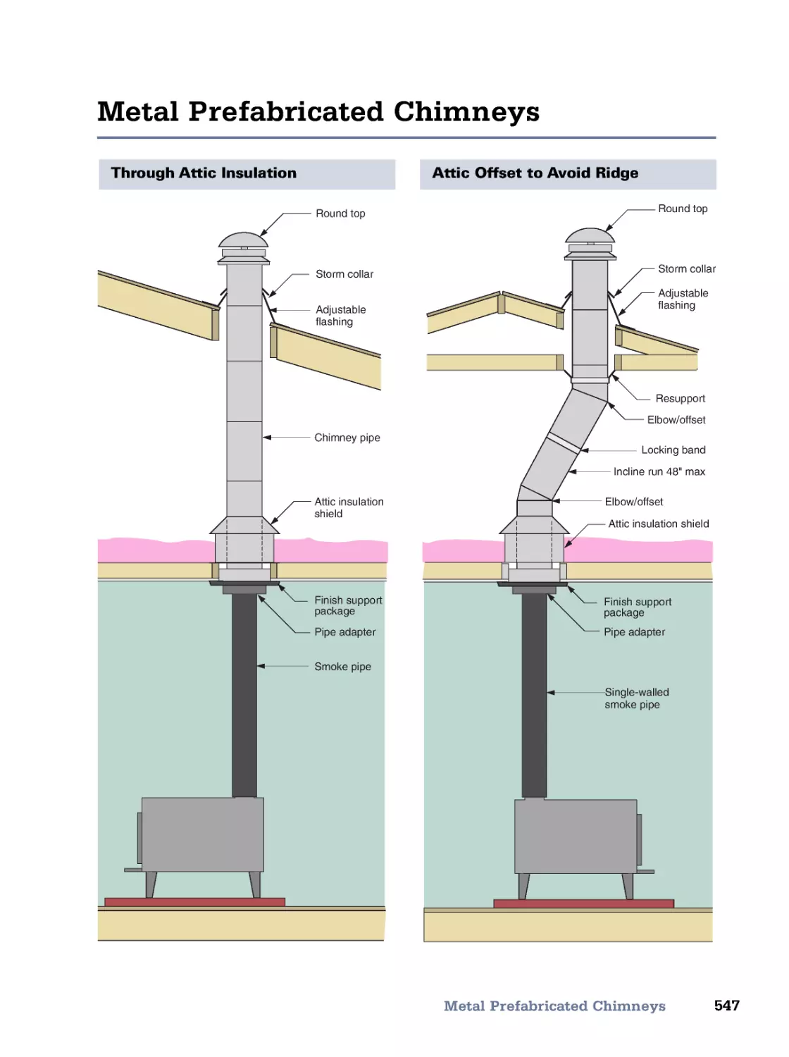
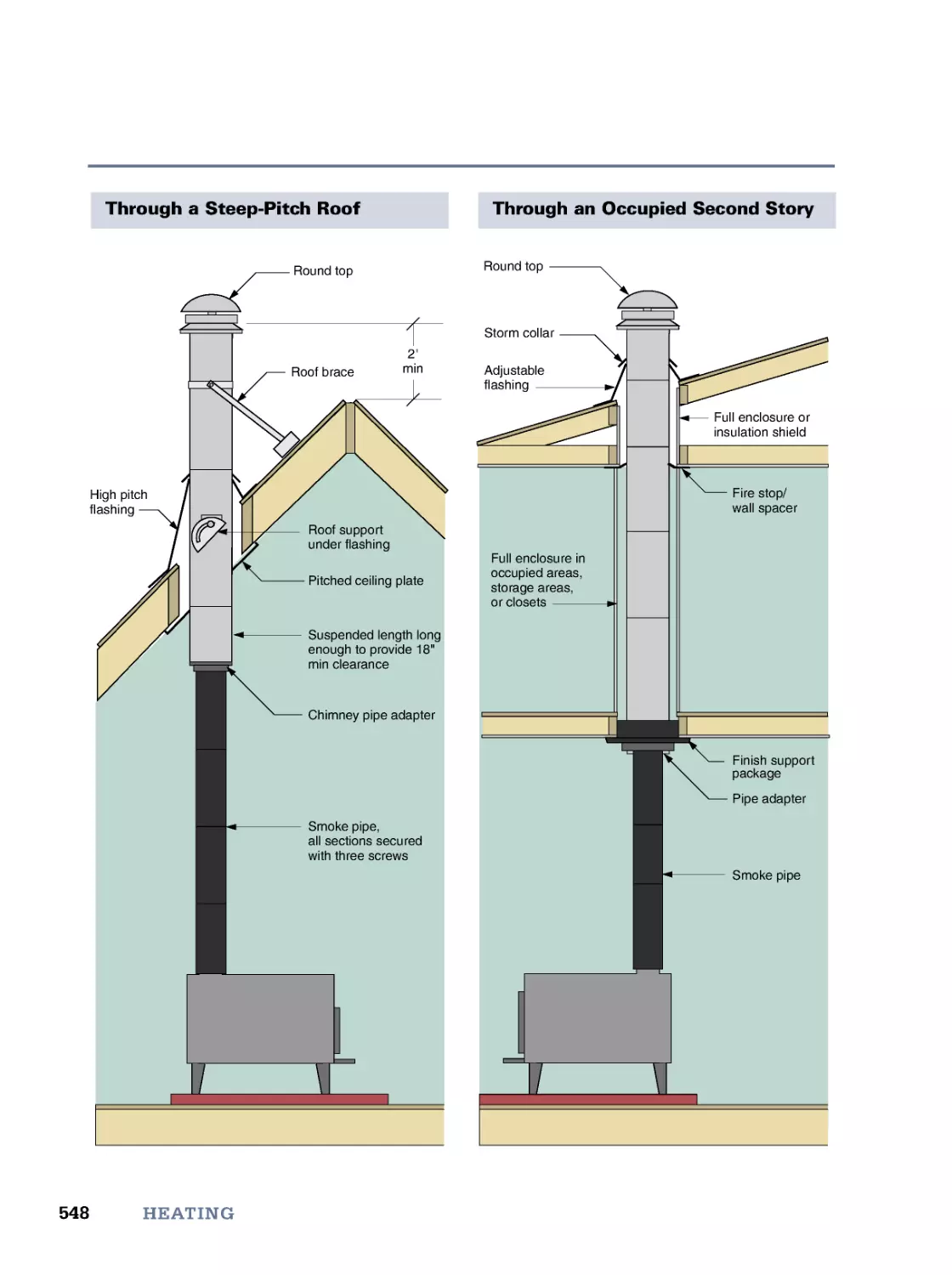
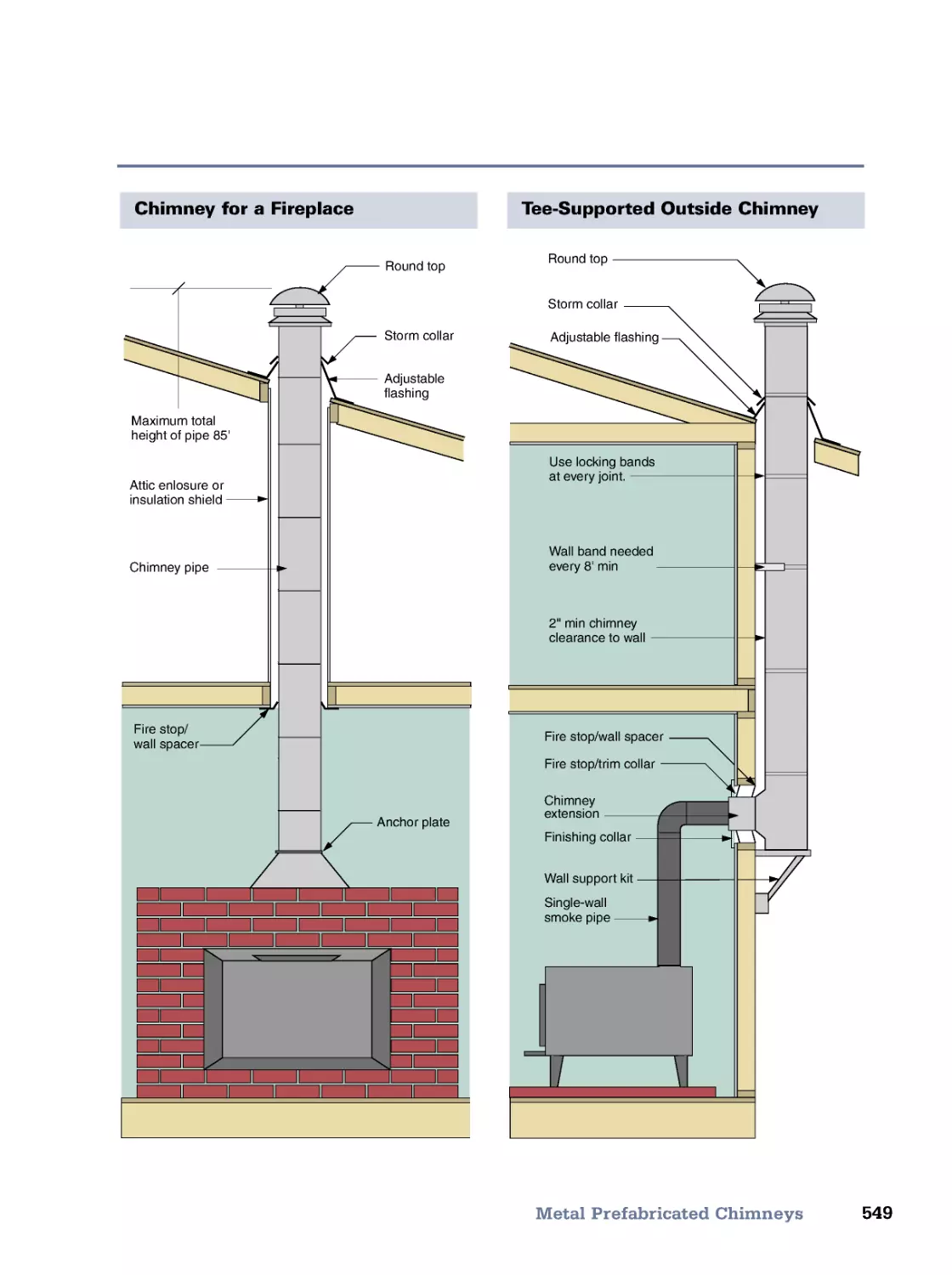
• Wood Stove Installation • Stovepipe Installation • Metal Prefabricated Chimneys • Meet the Code (IRC)
19. Cooling
553
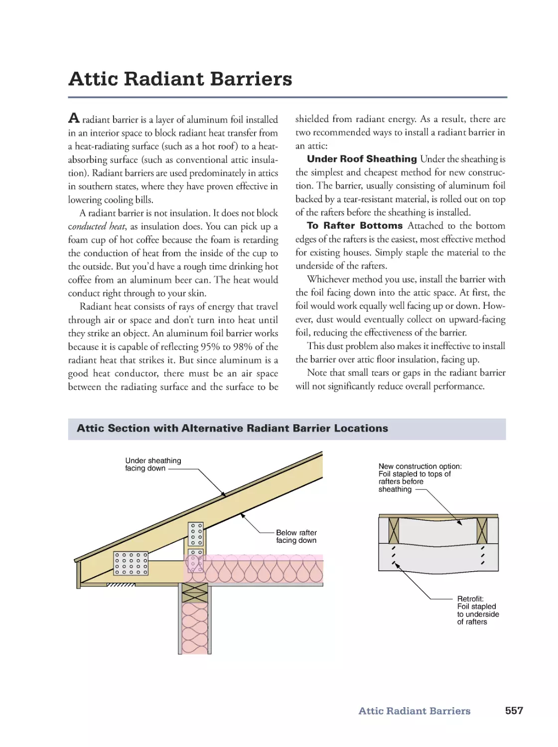
Human Comfort • Capturing Breezes • Attic Radiant Barriers • Shading Windows •
Utilizing Thermal Mass • Venting Heat with the Stack Effect • Creating Breezes with Box Fans •
Ceiling Fans • Evaporative Coolers • Air Conditioners
20. Passive Solar
577
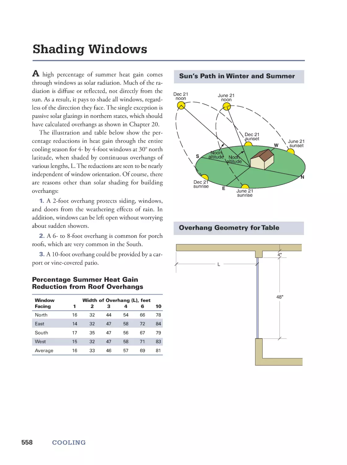
Passive Solar Possibilities • Glazing Orientation and Tilt • Summer Shading • Heat Storage
• Thermal Mass Patterns • A Passive Solar Design Procedure
21. Lighting
593
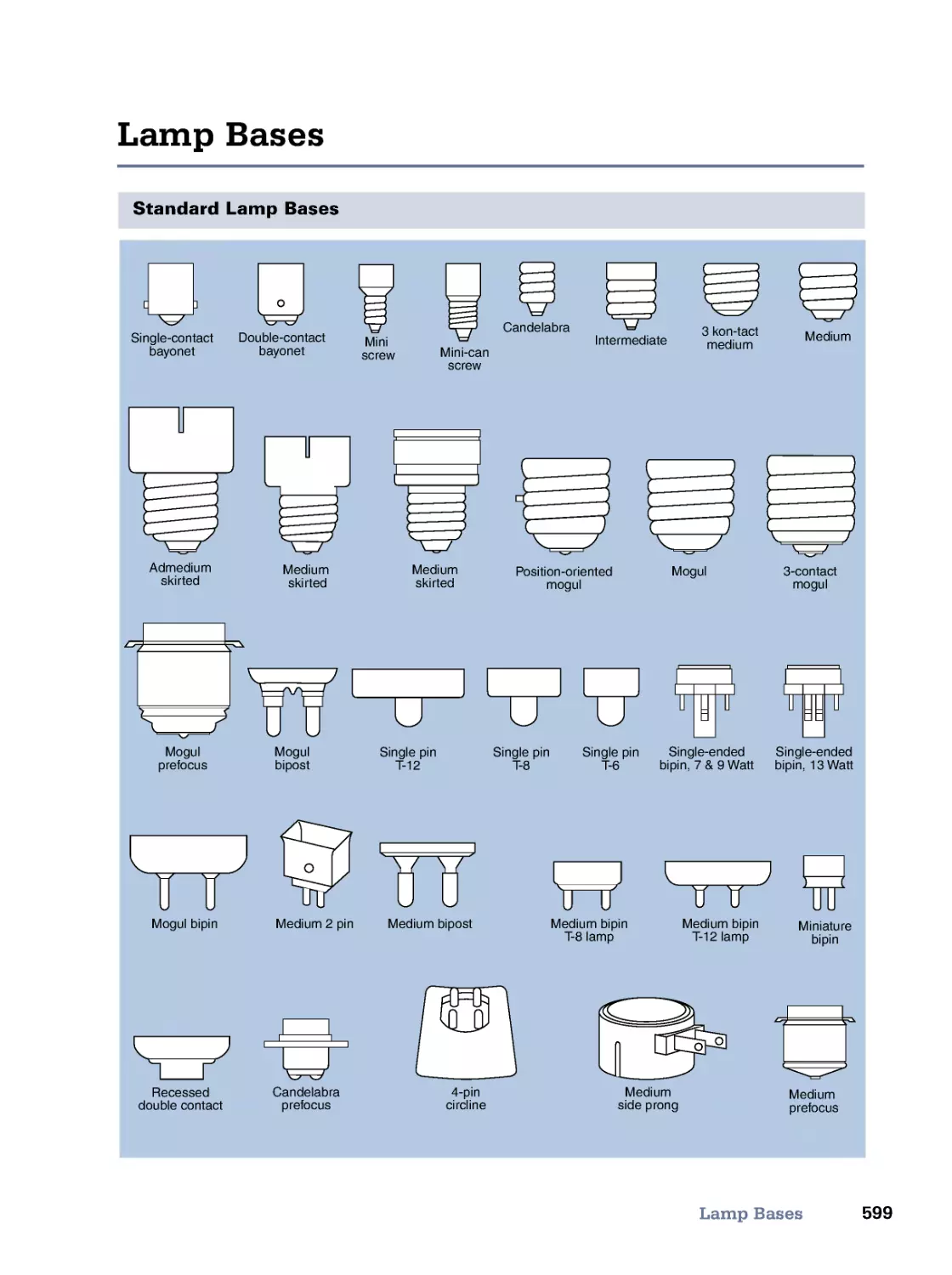
Light and Seeing • Light Sources • Lamp Shapes and Sizes • Lamp Bases • Residential Lighting
Guidelines • Meet the Code (IRC)
22. Sound
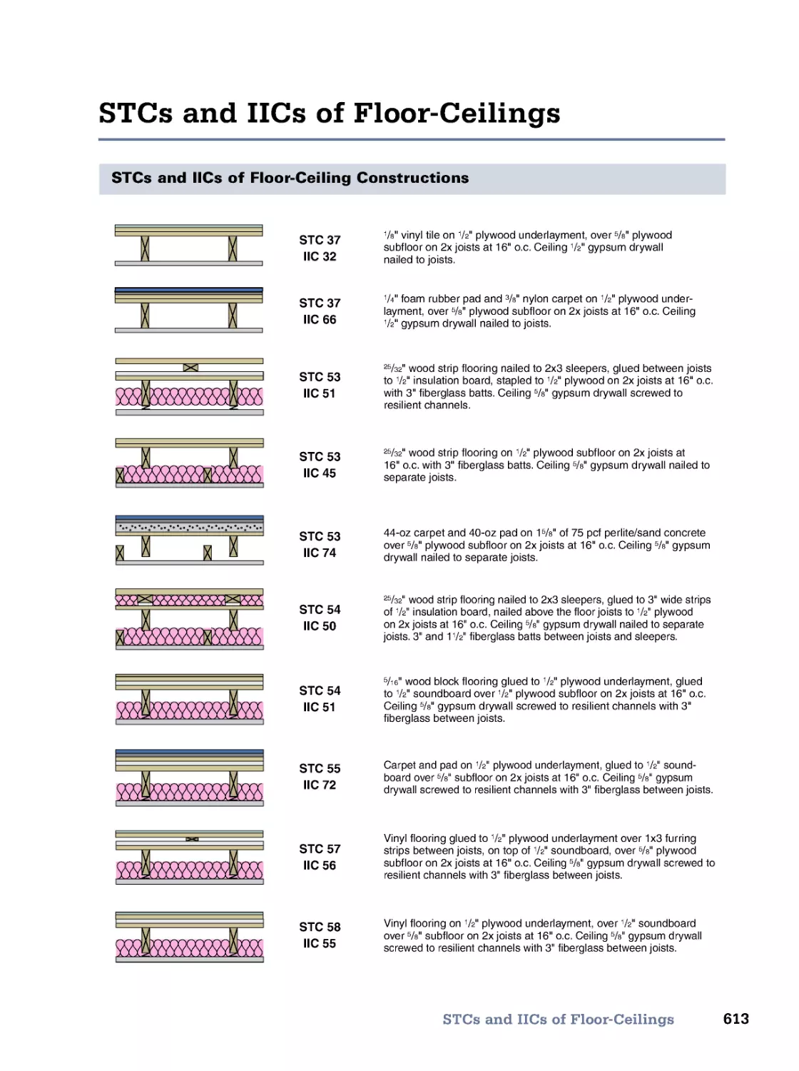
607
Quality of Sound • Noise-Reduction Coefficients • Absorption and Reverberation
• Sound Transmission • STCs of Walls • STCs and IICs of Floor-Ceilings
23. Fasteners
615
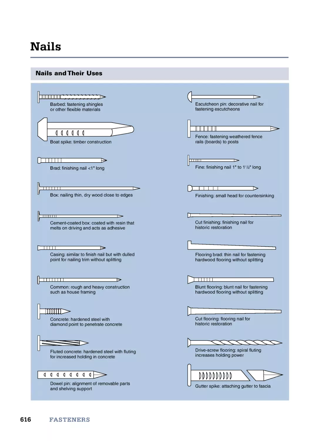
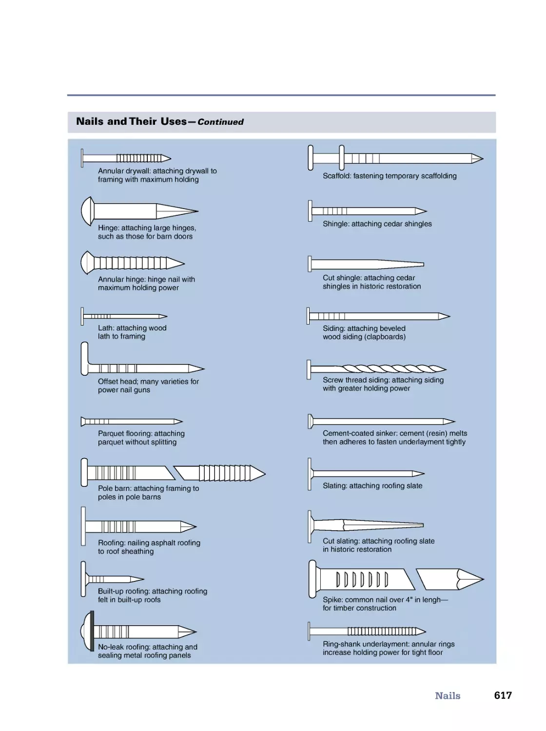
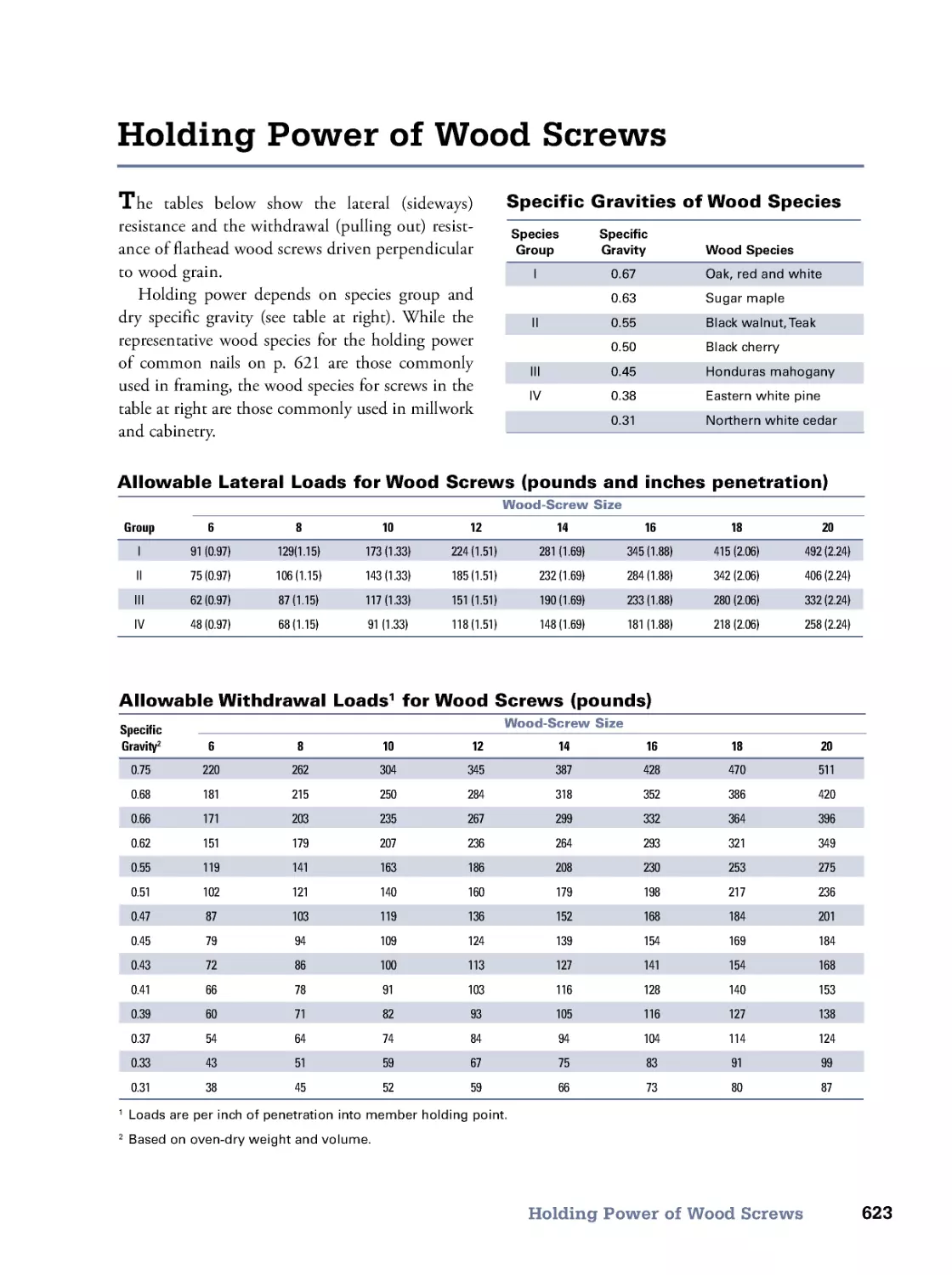
Nails • Fastening Schedule for Light Construction • Estimating Nail Requirements • Holding Power of
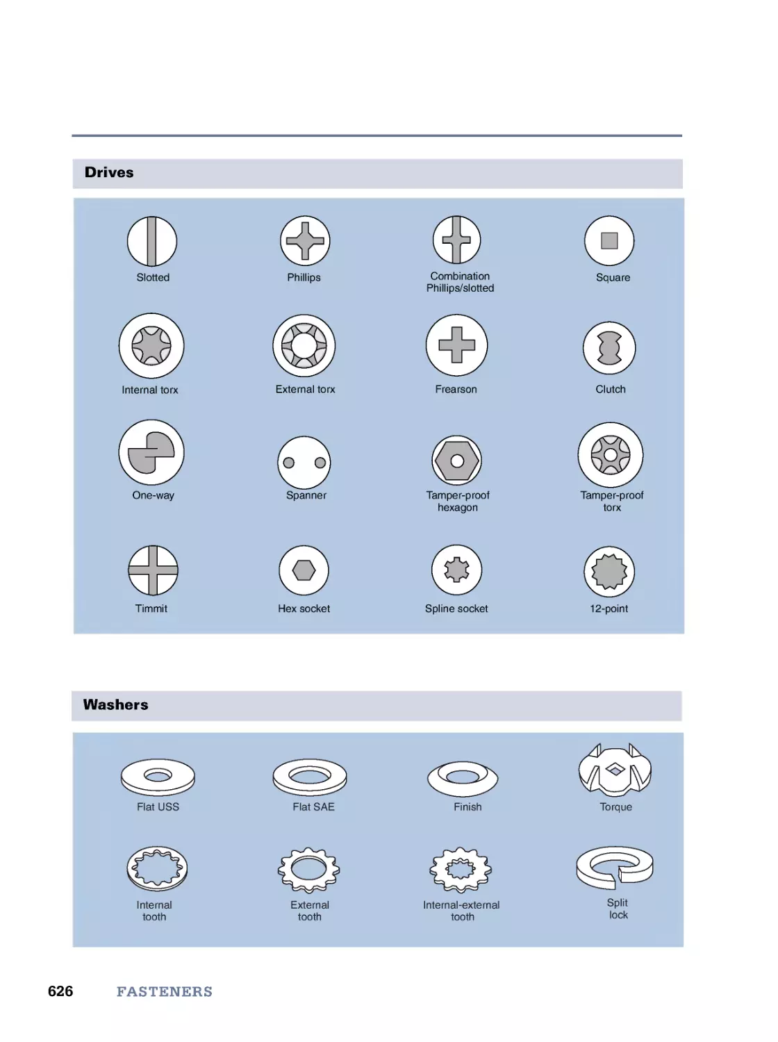
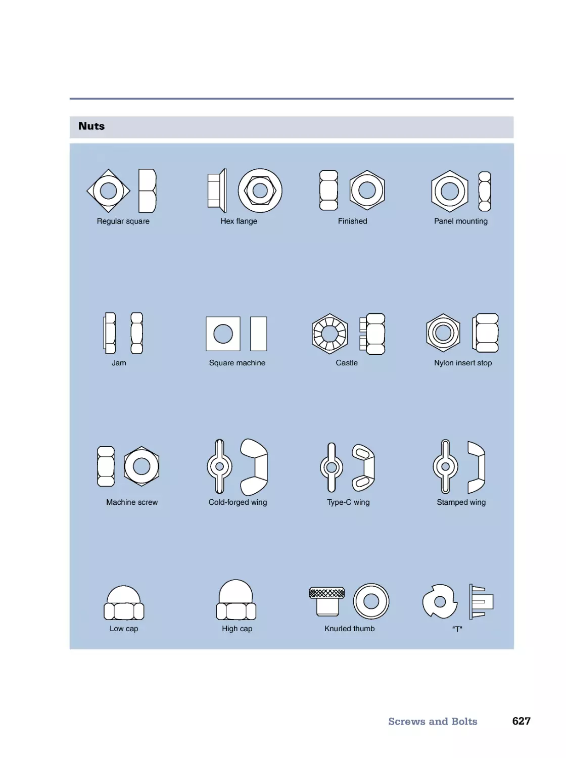
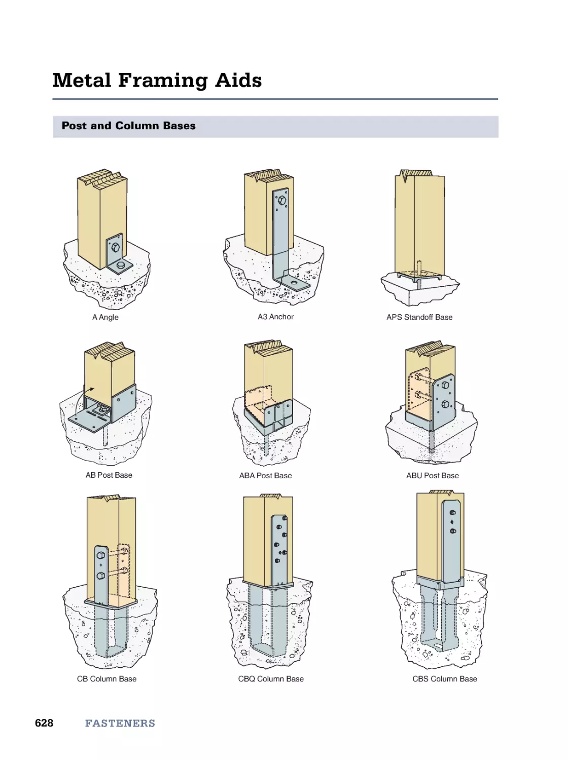
Common Nails • Wood Screws • Holding Power of Wood Screws • Screws and Bolts • Metal Framing Aids
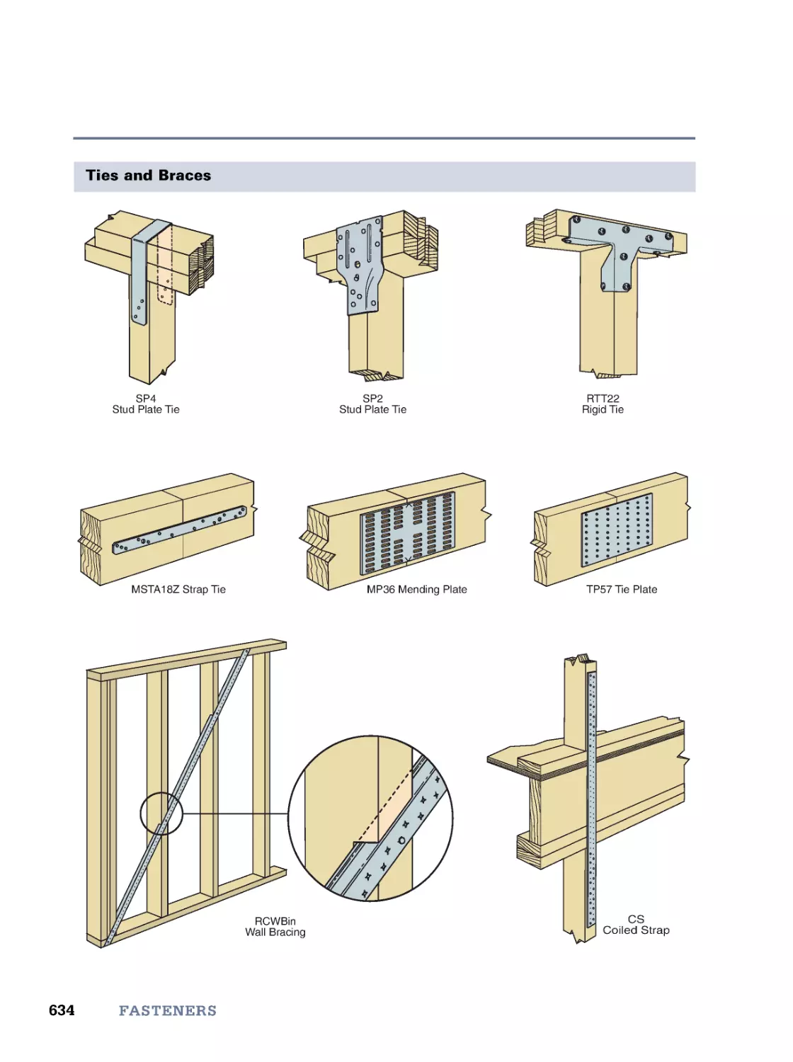
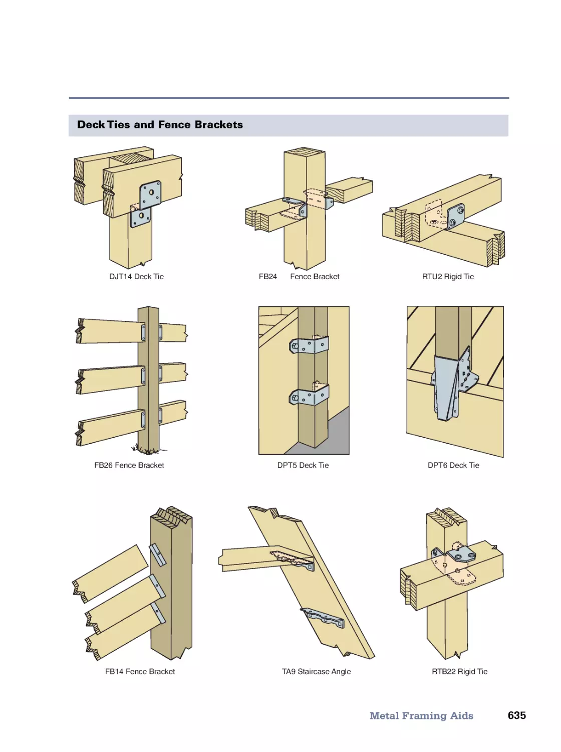
24. Decks and Railings
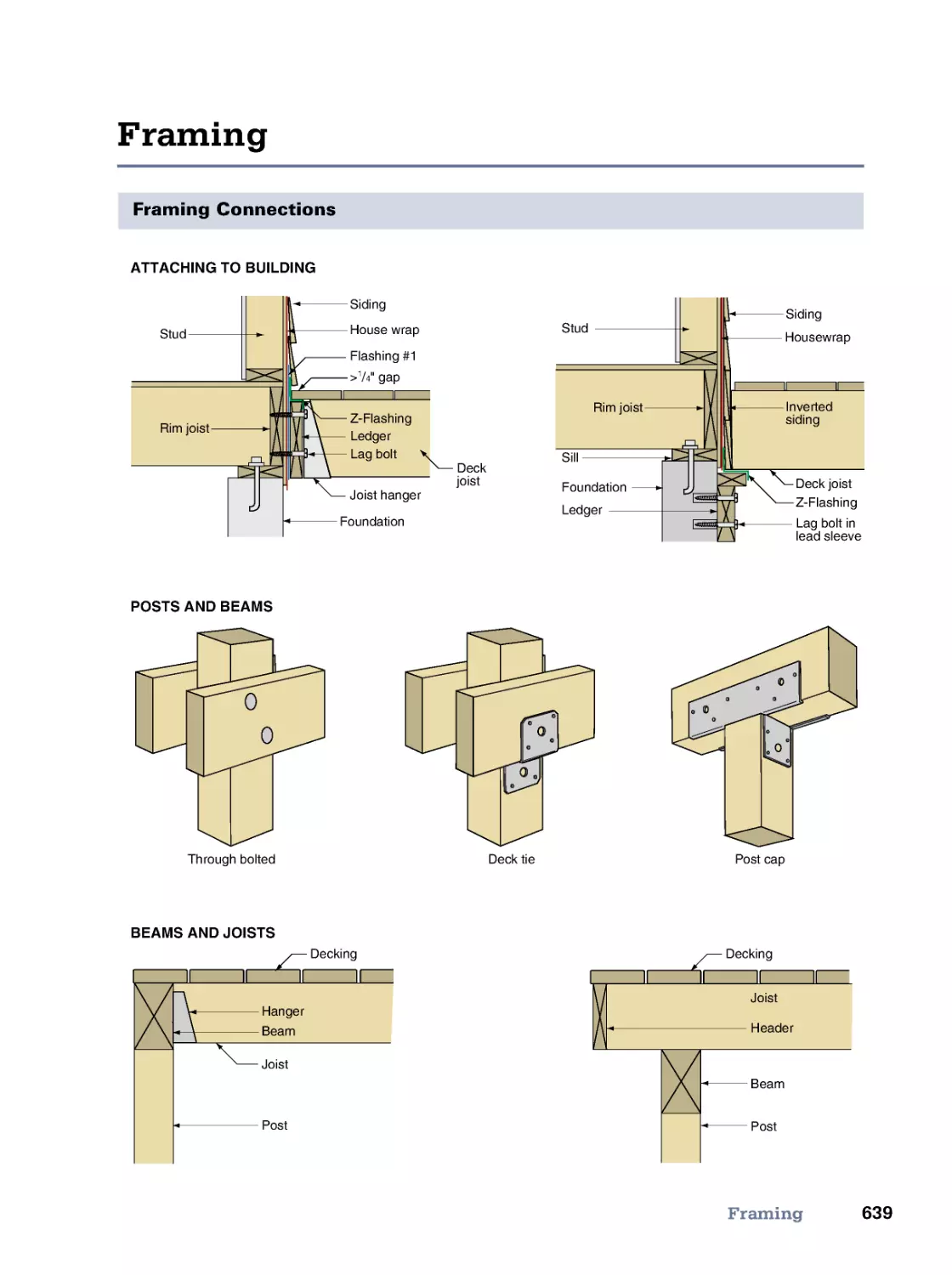
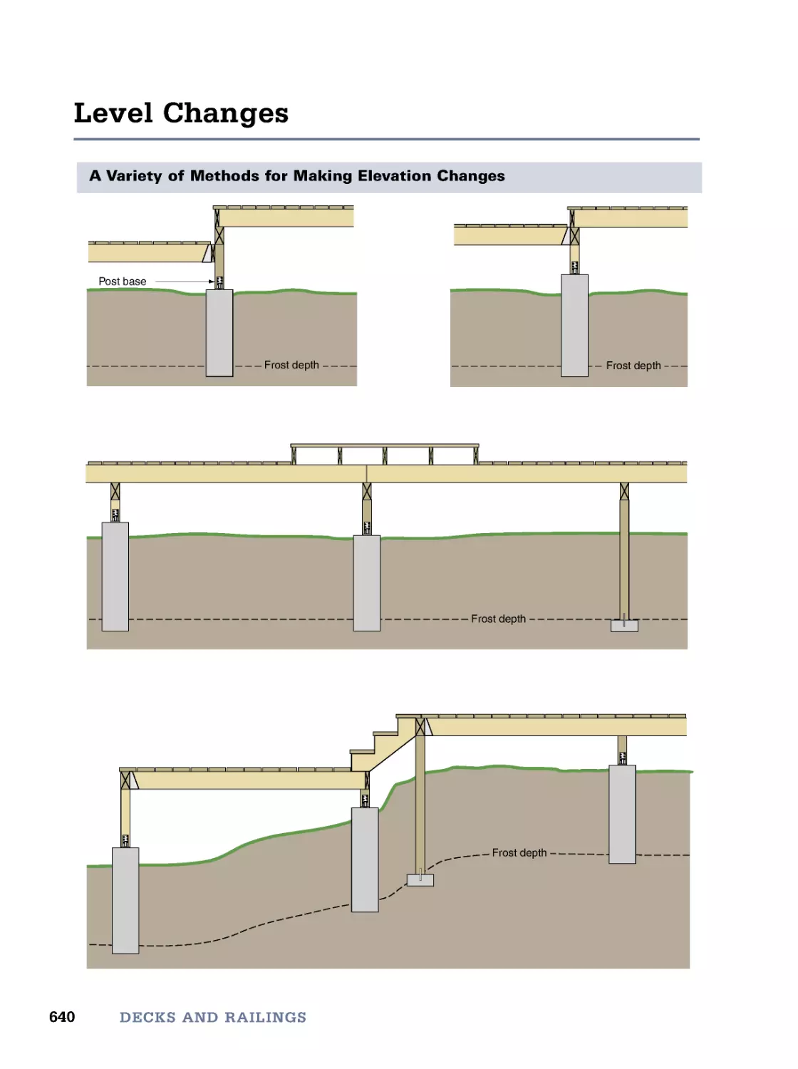
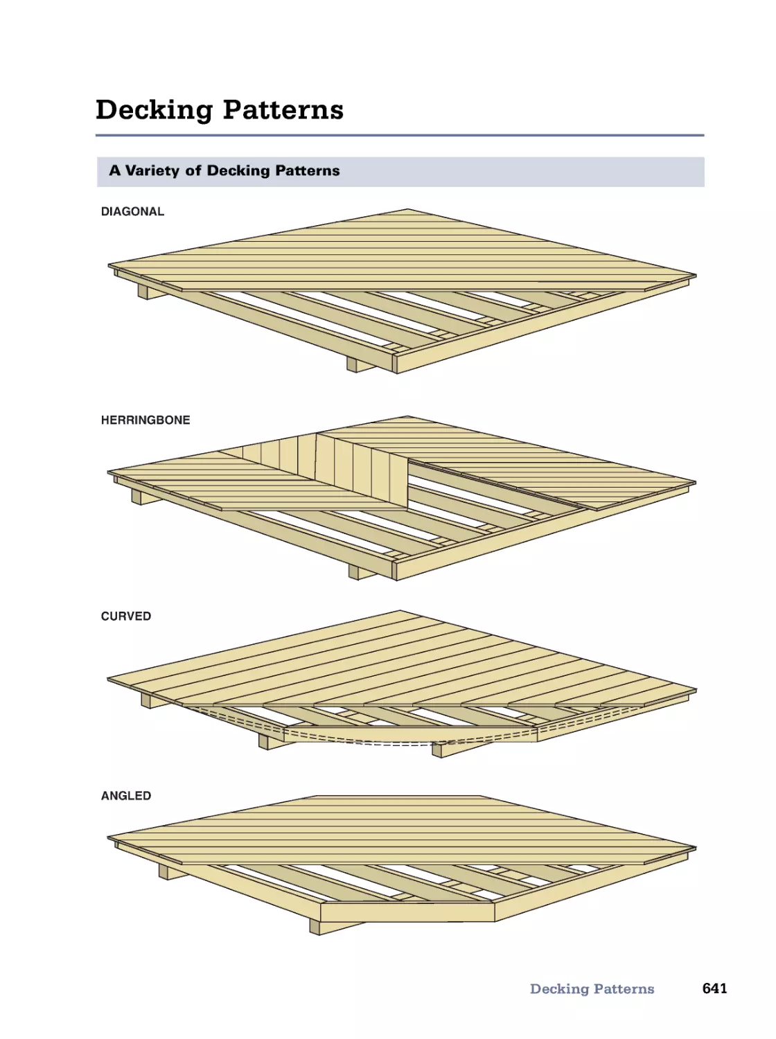
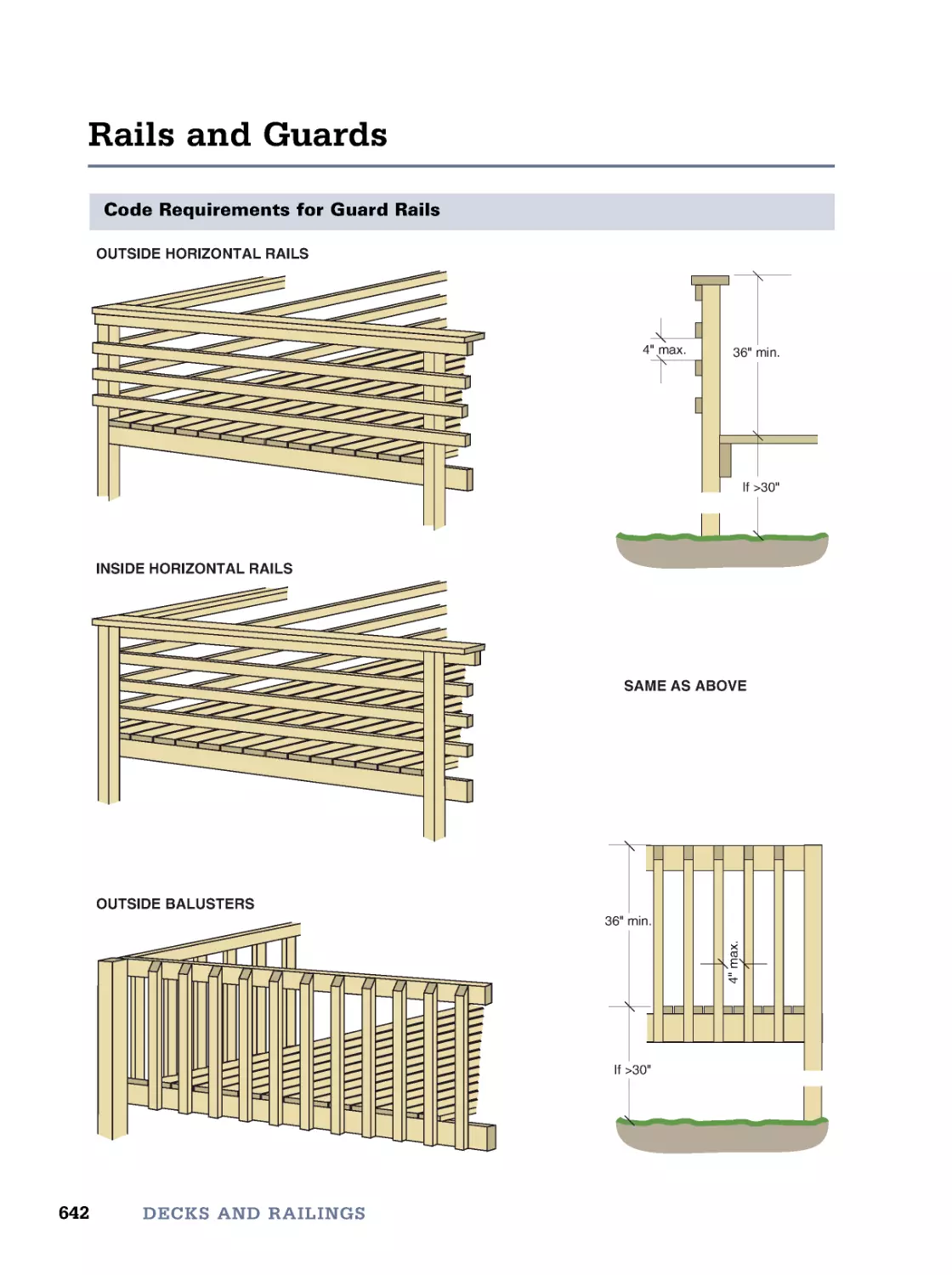
637
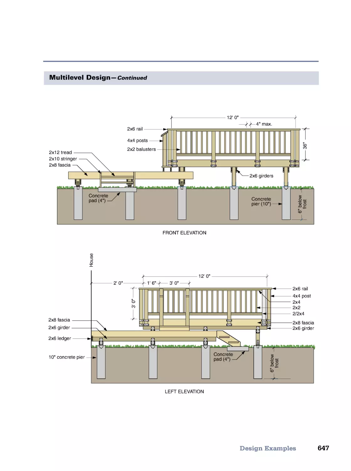
Layout and Foundation • Framing • Level Changes • Decking Patterns • Rails and Guards
• Stairs • Design Examples
25. Measuring and Finance
649
Home Mortgage Types • Interest on Loans • Geometric Figures • Trigonometry
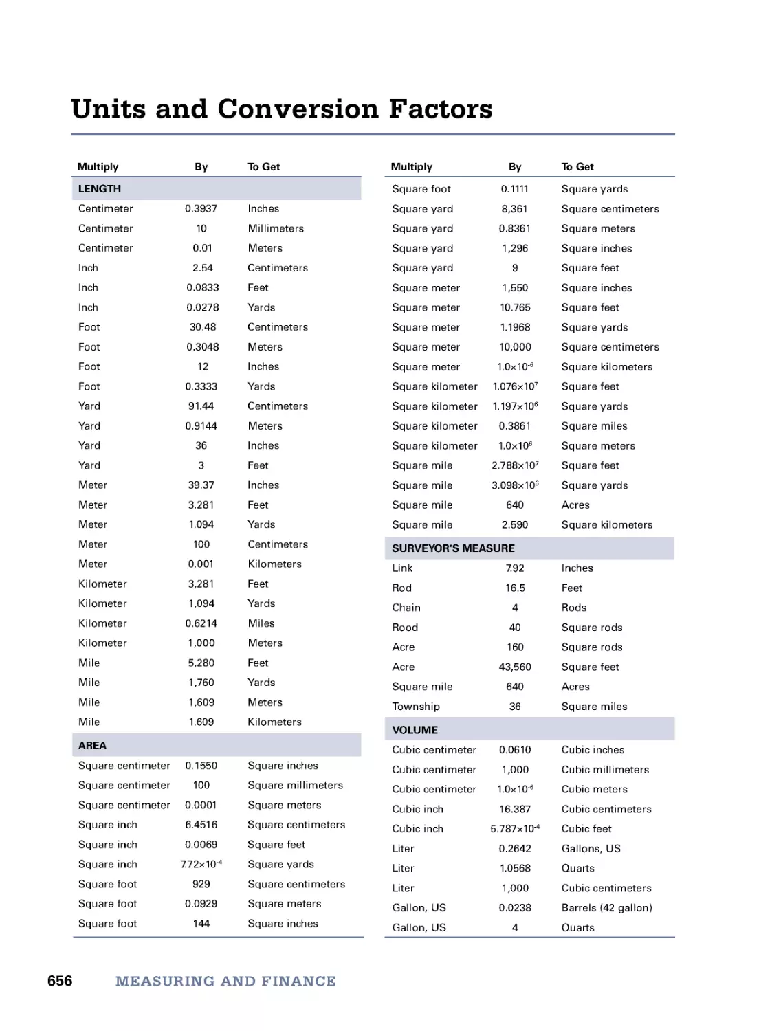
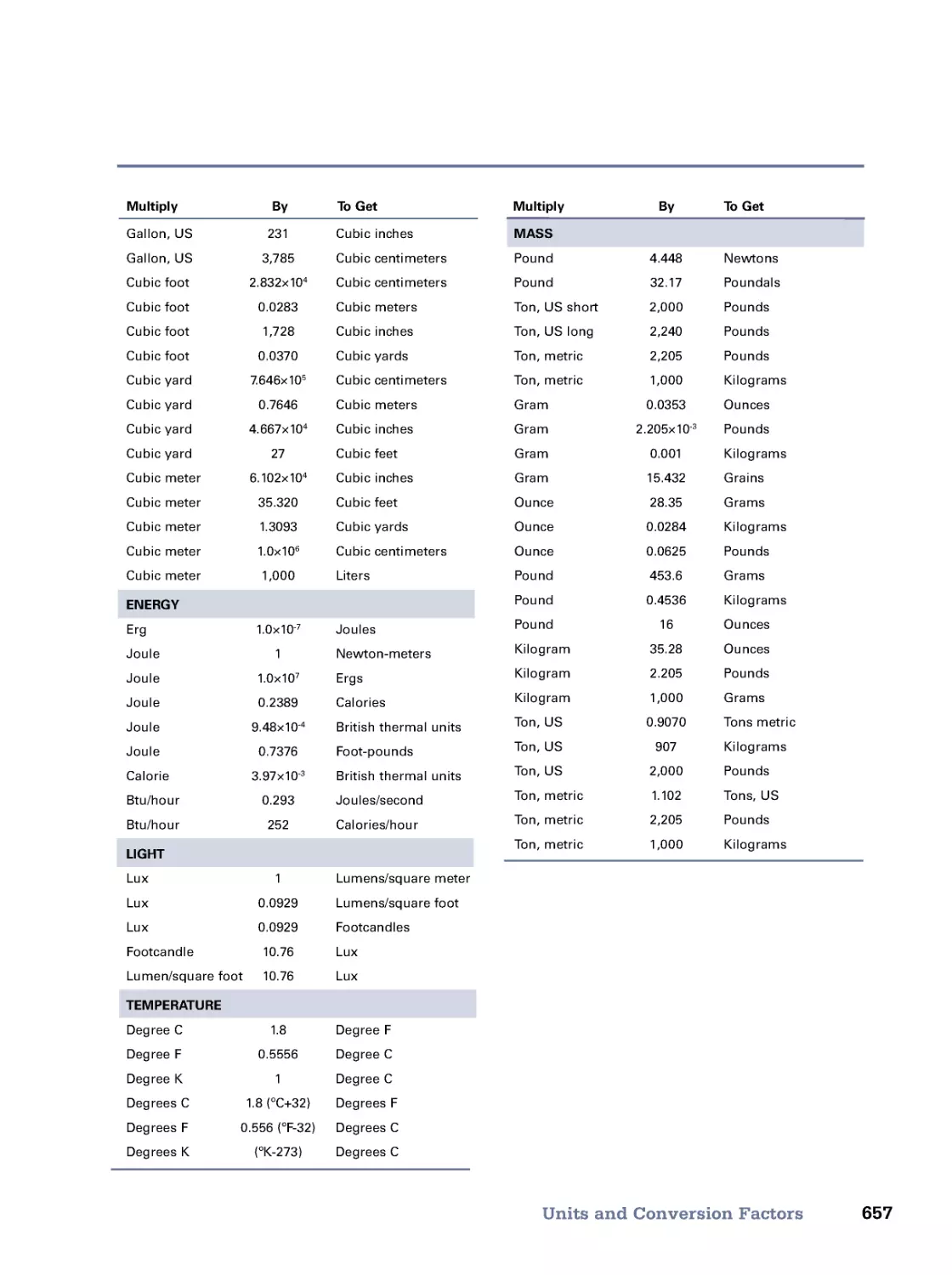
• Units and Conversion Factors
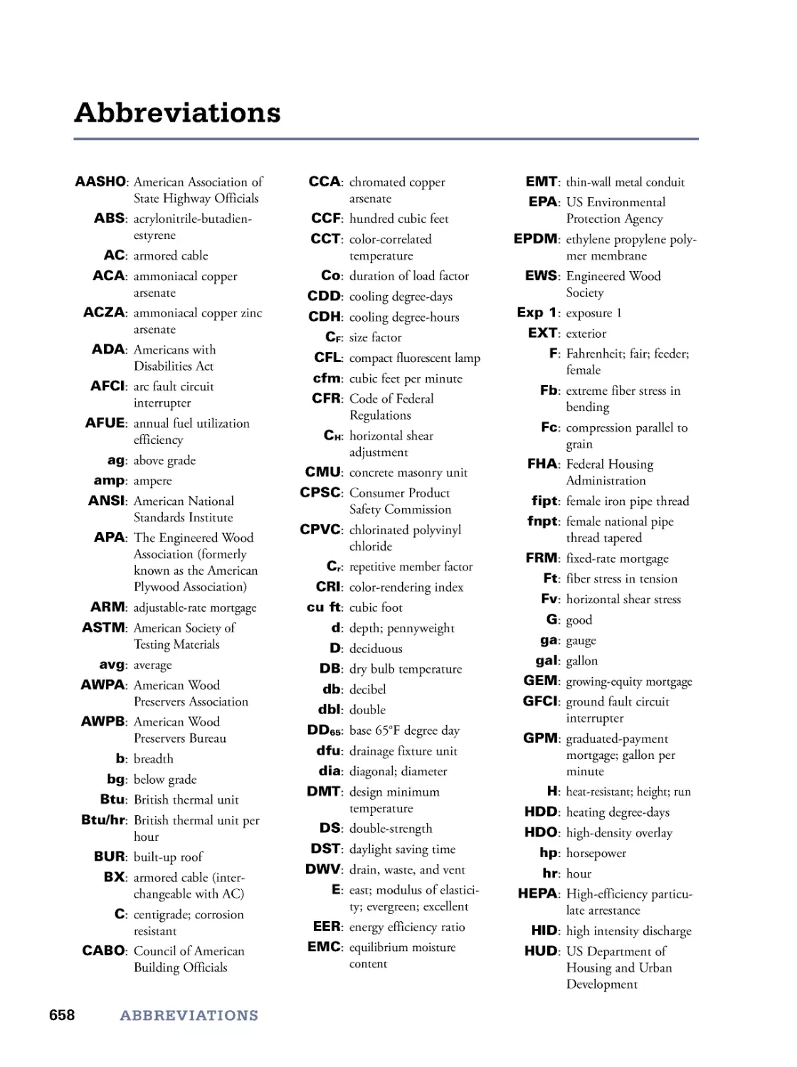
Abbreviations
658
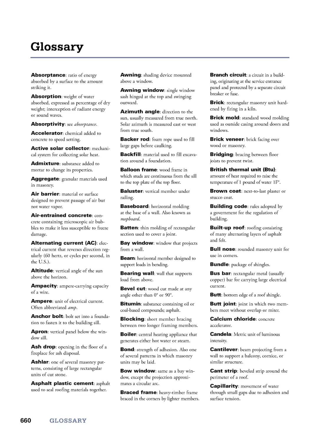
Glossary
660
Sources
668
Index
673
viii
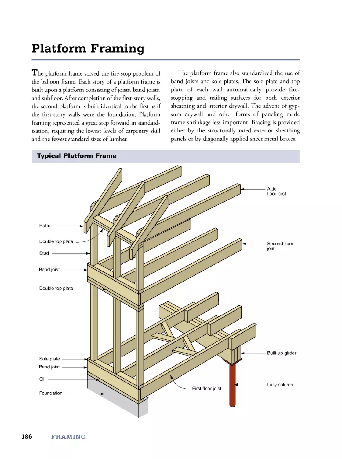
Twenty-eight years ago I proposed to Rodale
Press through my agent, Ray Wolf, a “visual hand-
book for small builders and do-it-yourselfers.” We
told them, in our opinion, such a book could sell
50,000 copies and might, with periodic revision
and addition, enjoy an indefinitely long life.
“Let’s just see how the first edition sells,” was
the dubious but predictable reply. (They later
confided they expected the book to sell only
5,000 to 10,000 copies.)
It turned out our gut instincts were right. In fact,
we were so right we were almost wrong! The first
edition sold not 50,000 but 200,000 copies and, at
age seven, was showing little sign of slowing.
Eight years later Reader’s Digest® purchased
the book and issued a second edition with an addi-
tional 100 pages containing:
• span tables for U.S . and Canadian lumber
• checklists of building code requirements
• a catalog of metal framing aids
• design standards for access
• three times as many framing details
The Reader’s Digest edition sold another
100,000 copies. In reading the Amazon.comSM
reviews, I discovered that, in addition to small
builders and do-it-yourselfers, the people finding
the book useful included home inspectors, energy
auditors, codes officials, and vocational instruc-
tors.
Ten years later I was thrilled when Taunton
Press—arguably the foremost publisher of build-
ing books—agreed to publish a third edition (and
now a fourth), in large format and full color.
But let me go back and tell you why I felt com-
pelled to create the handbook in the first place.
“Building a house requires thousands of deci-
sions based on a million bits of information.” This
was the opening line of my lectures to thousands
of potential owner/builders attending my three-
week courses at Shelter InstituteSM and
CornerstoneSM.
Teaching that course, and a precursor “physics
of the house” seminar at Bowdoin College, taught
me how to convey technical building information
to people who are not professional builders. I put
that training to work in five previous books, which
covered every aspect of building, from retrofitting
insulation to a drafty old house in House Warming,
to siting, planning, and constructing a house from
the ground up in Breaking New Ground.
But still, something was missing. I’d written all
I had to say about designing and constructing a
house, but I hadn’t thoroughly covered the topic of
what to construct a house of. What’s more, it didn’t
seem to me that anyone else had, either. There was,
and is, a plethora of technical literature for archi-
tects and structural engineers, but there was no
thorough guide for people without formal techni-
cal training. The fact is, the majority of people who
actually lay their hands on building materials—
tradesmen, owner/builders, and do-it-yourselfers—
are not trained architects or engineers. These people
needed a book as thorough as the ones the architects
use but that also offered explanations, formulas, and
charts that would make the information accessible.
The Visual Handbook of Building and Remodeling, I
believed, would be that book.
Naturally, in my previous books, I discussed
materials in the context of how to install them, as
do most other how-to writers. But the Visual
Handbook focuses on the materials themselves. Its
purpose is to enable one to decide how much of
which material of what size should be used for any
given house on any given site. Some how-to-install
information is included because the way materials
are used is often relevant in deciding which mate-
rial to use. However, the how-to is incidental to the
what-to, instead of the other way around. For
example, the chapter on siding discusses the pros
and cons of each type of siding, from clapboards to
vinyl, so you can make an informed decision about
which is best for your particular site and climate.
Introduction
ix
But it also illustrates construction details, to help
you decide which would work best on your partic-
ular house.
I could see right away that this had to be a high-
ly visual book. Nowhere is the saying, “A picture
(or drawing, in this case) is worth a thousand
words,” more true. Further, there is no way words
could describe, for example, every standard mold-
ing profile. It is possible, however, to show each in
scaled cross-section.
Three things have made it possible for me to cre-
ate this visual handbook. The first is software for
illustrating (Adobe Illustrator® ) and desktop publish-
ing (Quark
®
and InDesign
®
) that enabled me to cre-
ate illustrations without training and camera-ready
pages without being a printer. The second is that I
am an information pack rat, a looter of lists, a bur-
glar of booklets, a swiper of spec sheets. The third is
the willingness of manufacturers and trade associa-
tions to allow me to adapt their diverse materials to
a uniform format.
In the accretion of building information I am
insatiable. No builder, no hardware clerk, no sawyer
in the backwoods, not even architects are spared my
quest. I raid their files, their bookshelves, and their
minds. Over the years I have accumulated the best
of what they found useful in the actual building of
houses: tables, lists, government pamphlets, manu-
facturers’ literature, building-trade association pub-
lications, even instructions from a package of
asphalt shingles. And now there is the internet and
GoogleTM! Now I can sit at my computer and search
for and download information that used to require
road trips and photocopies.
The result is a book that should be useful to
anyone who puts his or her hands on building
materials or hires others who do so. If you hire a
builder, you won’t be limited to his or her prefer-
ences but will be able to take a more active role in
deciding what materials to use. If you are an
owner/builder, this book should complement the
how-to books containing step-by-step instructions.
And if you are a tradesman, I hope that you will
keep a copy behind the seat of your truck for easy
reference.
By the way, the opening line of my owner/
builder course proved to be a bit off the mark.
According to the computer, The Visual Handbook of
Building and Remodeling now contains 317 million
bytes of information.
Charlie Wing
South Portland, Maine
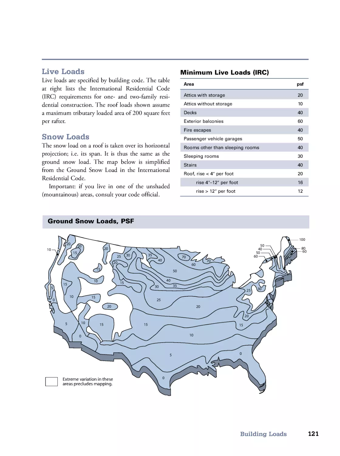
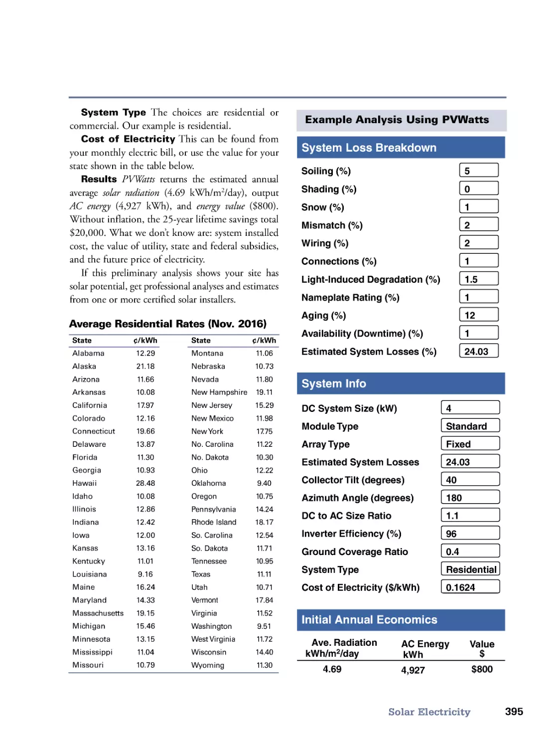
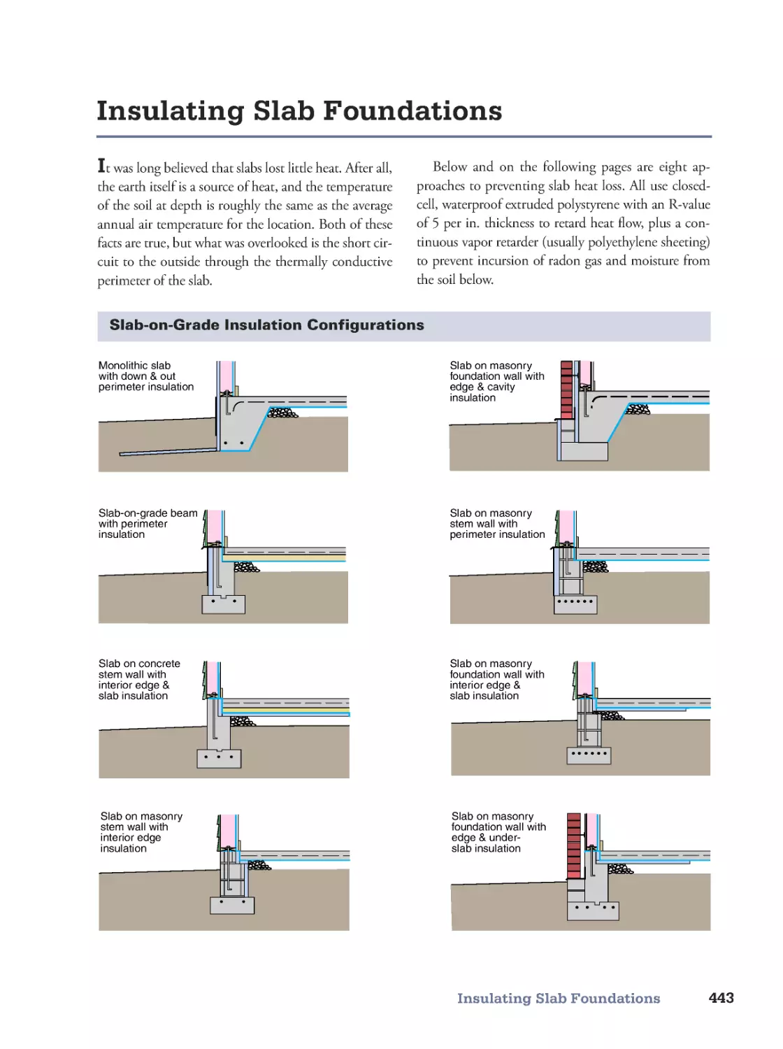
Houses are designed for the comfort and safety of human beings. House
dimensions must, therefore, be related to human dimensions.
Tied to human dimensions—but too often overlooked in our excite-
ment over cathedral-ceilinged great rooms, spectacular kitchens, and
commodious baths—are critical window, closet, and passage dimensions.
Central to the home, and tops in our list of priorities, are kitchens and
baths. We are fortunate in having permission to present most of the rec-
ommendations of the National Kitchen & Bath Association’s Kitchen
Design Guidelines and Bath Design Guidelines.
With more fatal in-the-home accidents occurring on stairs than in any
other area, building codes are becoming ever more specific and stringent
about stair design. We are again fortunate in having permission from the
Stairway Manufacturers’ Association to adapt the illustrations from their
excellent Visual Interpretation of the IRC 2006 Stair Building Code.
Although the 1990 Americans with Disabilities Act (ADA) was written
to guarantee physically handicapped citizens access to public buildings
and the workplace, many of its design requirements are equally applicable
to the home. Because homeowners generally prefer to remain in their
homes as long as physically practical, we have illustrated the applicable
ADA specifications in the section titled Access.
Finally, we provide you with a checklist of requirements so that your
foundation will meet the IRC Code.
Design
1
02
3
4
5
Human Dimensions 2
Window, Closet, and Passage
Dimensions 3
Kitchen Design Guidelines 4
Bath Design Guidelines 10
Stair Design 16
Access 22
Meet the Code (IRC) 32
1
1
2
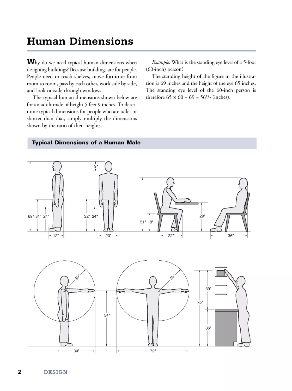
Why do we need typical human dimensions when
designing buildings? Because buildings are for people.
People need to reach shelves, move furniture from
room to room, pass by each other, work side by side,
and look outside through windows.
The typical human dimensions shown below are
for an adult male of height 5 feet 9 inches. To deter-
mine typical dimensions for people who are taller or
shorter than that, simply multiply the dimensions
shown by the ratio of their heights.
Example: What is the standing eye level of a 5-foot
(60-inch) person?
The standing height of the figure in the illustra-
tion is 69 inches and the height of the eye 65 inches.
The standing eye level of the 60-inch person is
therefore65×60÷69=56
1/2 (inches).
Human Dimensions
DESIGN
Typical Dimensions of a Human Male
54"
72"
34"
3
0
"
24"
32"
9"
24"
20"
36"
39"
75"
51" 18"
36"
22"
12"
29"
31"
69"
3
0
"
3
Window, Closet, and Passage Dimensions
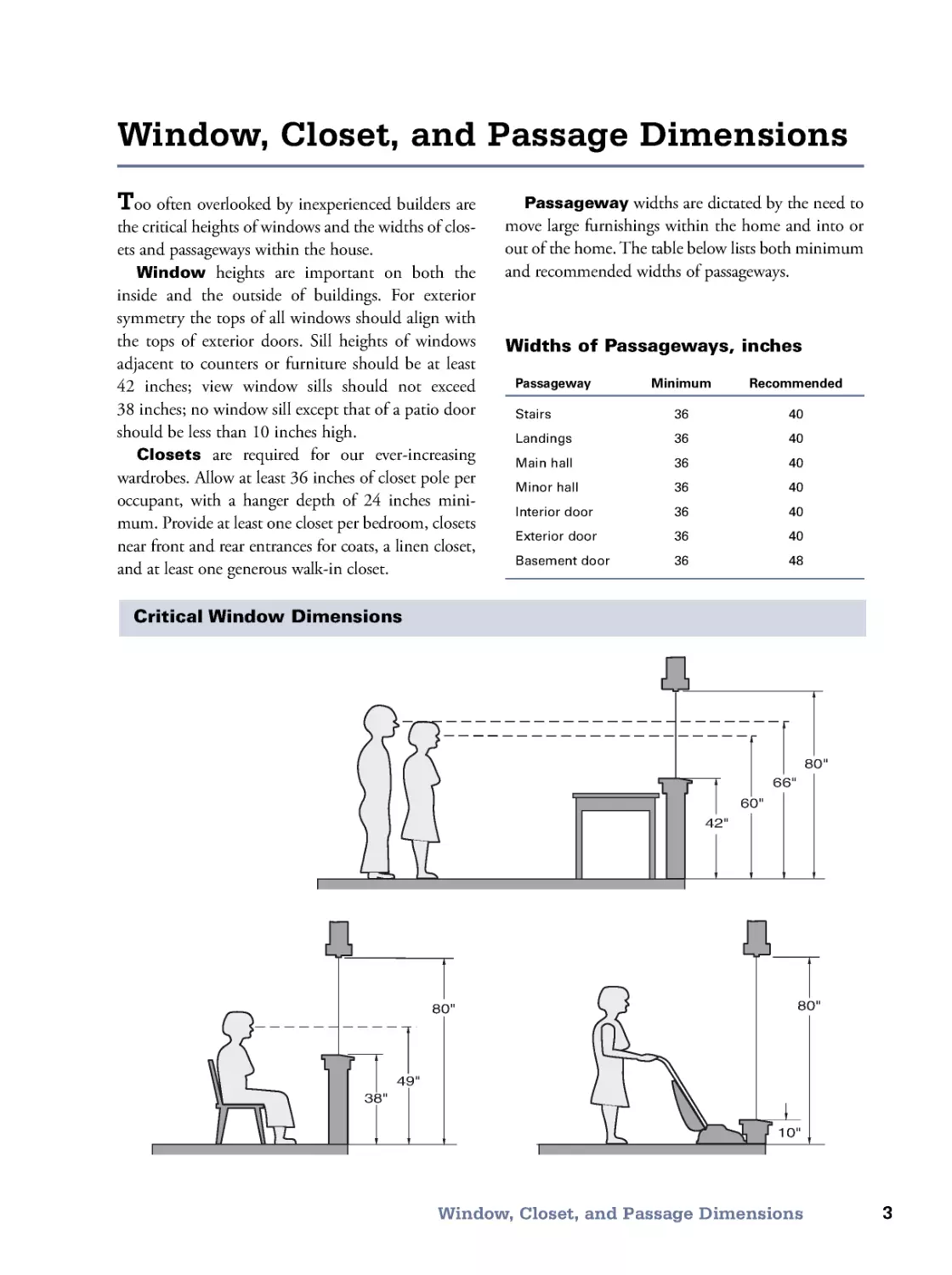
Too often overlooked by inexperienced builders are
the critical heights of windows and the widths of clos-
ets and passageways within the house.
Window heights are important on both the
inside and the outside of buildings. For exterior
symmetry the tops of all windows should align with
the tops of exterior doors. Sill heights of windows
adjacent to counters or furniture should be at least
42 inches; view window sills should not exceed
38 inches; no window sill except that of a patio door
should be less than 10 inches high.
Closets are required for our ever-increasing
wardrobes. Allow at least 36 inches of closet pole per
occupant, with a hanger depth of 24 inches mini-
mum. Provide at least one closet per bedroom, closets
near front and rear entrances for coats, a linen closet,
and at least one generous walk-in closet.
Window, Closet, and Passage Dimensions
80"
66"
60"
42"
38"
49"
80"
10"
80"
Critical Window Dimensions
Passageway widths are dictated by the need to
move large furnishings within the home and into or
out of the home. The table below lists both minimum
and recommended widths of passageways.
Widths of Passageways, inches
Passageway
Minimum
Recommended
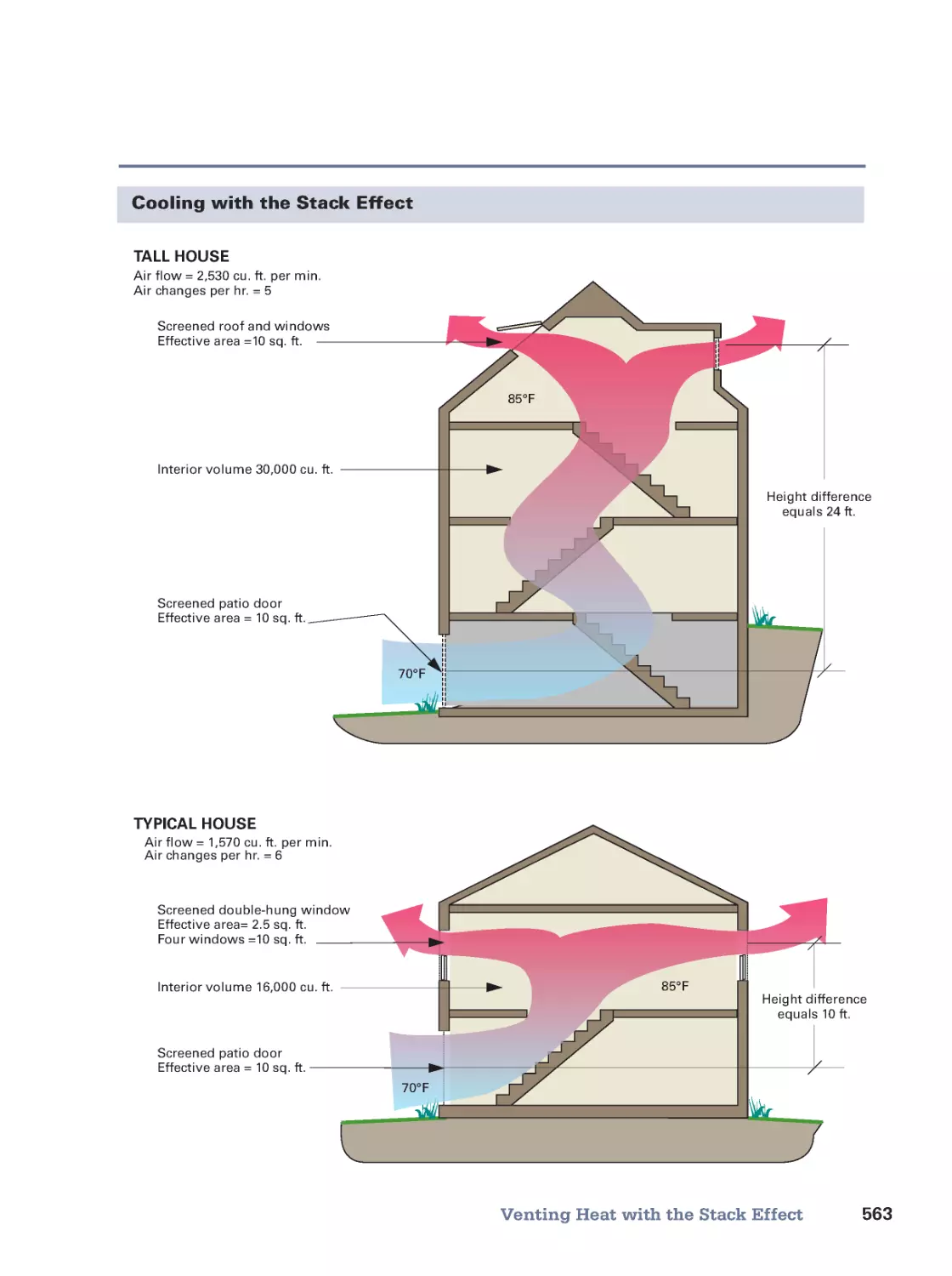
Stairs
36
40
Landings
36
40
Main hall
36
40
Minor hall
36
40
Interior door
36
40
Exterior door
36
40
Basement door
36
48
4
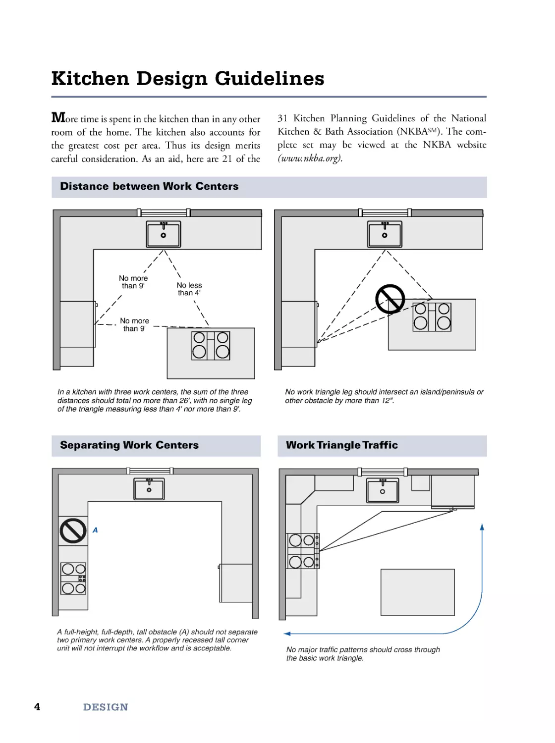
More time is spent in the kitchen than in any other
room of the home. The kitchen also accounts for
the greatest cost per area. Thus its design merits
careful consideration. As an aid, here are 21 of the
31 Kitchen Planning Guidelines of the National
Kitchen & Bath Association (NKBASM). The com-
plete set may be viewed at the NKBA website
(www.nkba.org).
Kitchen Design Guidelines
DESIGN
Distance between Work Centers
In a kitchen with three work centers, the sum of the three
distances should total no more than 26', with no single leg
of the triangle measuring less than 4' nor more than 9'.
No work triangle leg should intersect an island/peninsula or
other obstacle by more than 12".
No less
than 4'
No more
than 9'
No more
than 9'
Separating Work Centers
A full-height, full-depth, tall obstacle (A) should not separate
two primary work centers. A properly recessed tall corner
unit will not interrupt the wor kflow and is acceptable.
A
Work Triangle Traffic
No major traffic patterns should cross through
the basic work triangle.
5
Kitchen Design Guidelines
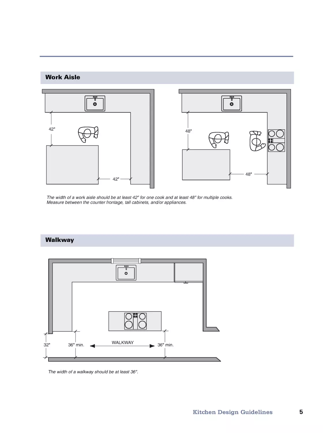
Work Aisle
The width of a work aisle should be at least 42" for one cook and at least 48" for multiple cooks.
Measure between the counter frontage, tall cabinets, and/or appliances.
48"
48"
42"
42"
Walkway
The width of a walkway should be at least 36".
32"
36" min.
36" min.
WALKWAY
6
DESIGN
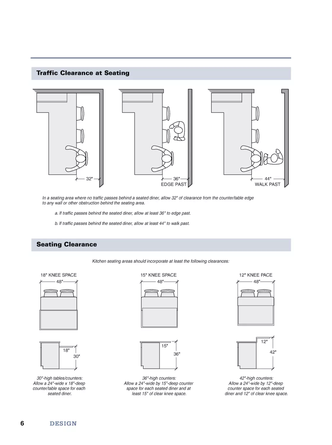
Traffic Clearance at Seating
Seating Clearance
Kitchen seating areas should incorporate at least the following clearances:
30"-high tables/counters:
Allow a 24"-wide x 18"-deep
counter/table space for each
seated diner.
36"-high counters:
Allow a 24"-wide by 15"-deep counter
space for each seated diner and at
least 15" of clear knee space.
42"-high counters:
Allow a 24"-wide by 12"-deep
counter space for each seated
diner and 12" of clear knee space.
18" KNEE SPACE
15" KNEE SPACE
12" KNEE PACE
48"
48"
48"
18"
15"
12"
30"
36"
42"
In a seating area where no traffic passes behind a seated diner, allow 32" of clearance from the counter/table edge
to any wall or other obstruction behind the seating area.
a
. If traffic passes behind the seated diner, allow at least 36" to edge past.
b
. If traffic passes behind the seated diner, allow at least 44" to walk past.
EDGE PAST
WALK PAST
32"
36"
44"
7
Kitchen Design Guidelines
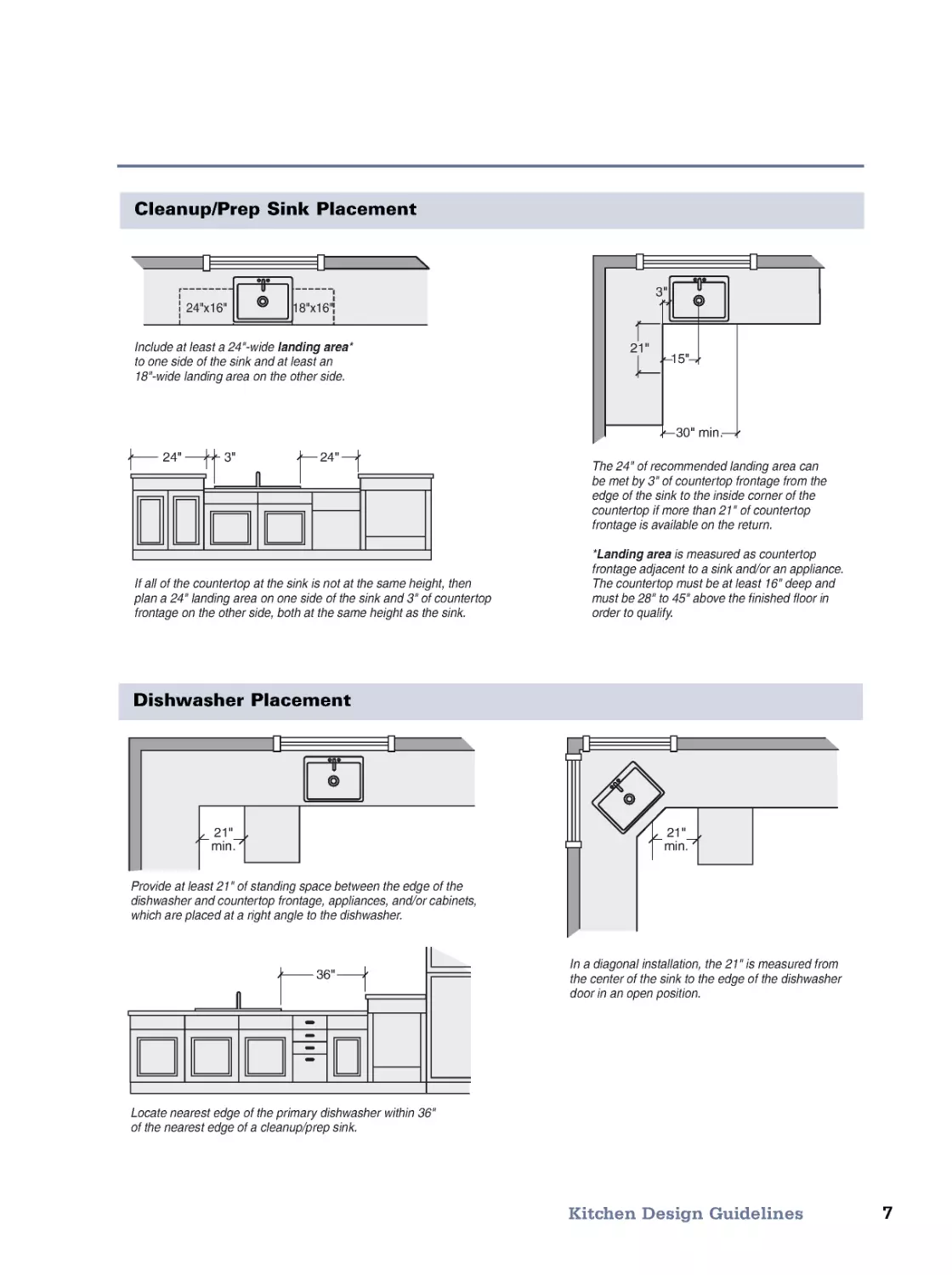
The 24" of recommended landing area can
be met by 3" of countertop frontage from the
edge of the sink to the inside corner of the
countertop if more than 21" of countertop
frontage is available on the return.
*Landing area is measured as countertop
frontage adjacent to a sink and/or an appliance.
The countertop must be at least 16" deep and
must be 28" to 45" above the finished floor in
order to qualify.
If all of the countertop at the sink is not at the same height, then
plan a 24" landing area on one side of the sink and 3" of countertop
frontage on the other side, both at the same height as the sink.
Include at least a 24"-wide landing area*
to one side of the sink and at least an
18"-wide landing area on the other side.
18"x16"
24"x16"
24"
3"
24"
3"
21"
15"
30" min.
Cleanup/Prep Sink Placement
Dishwasher Placement
Locate nearest edge of the primary dishwasher within 36"
of the nearest edge of a cleanup/prep sink.
Provide at least 21" of standing space between the edge of the
dishwasher and countertop frontage, appliances, and/or cabinets,
which are placed at a right angle to the dishwasher.
In a diagonal installation, the 21" is measured from
the center of the sink to the edge of the dishwasher
door in an open position.
36"
21"
min.
21"
min.
8
DESIGN
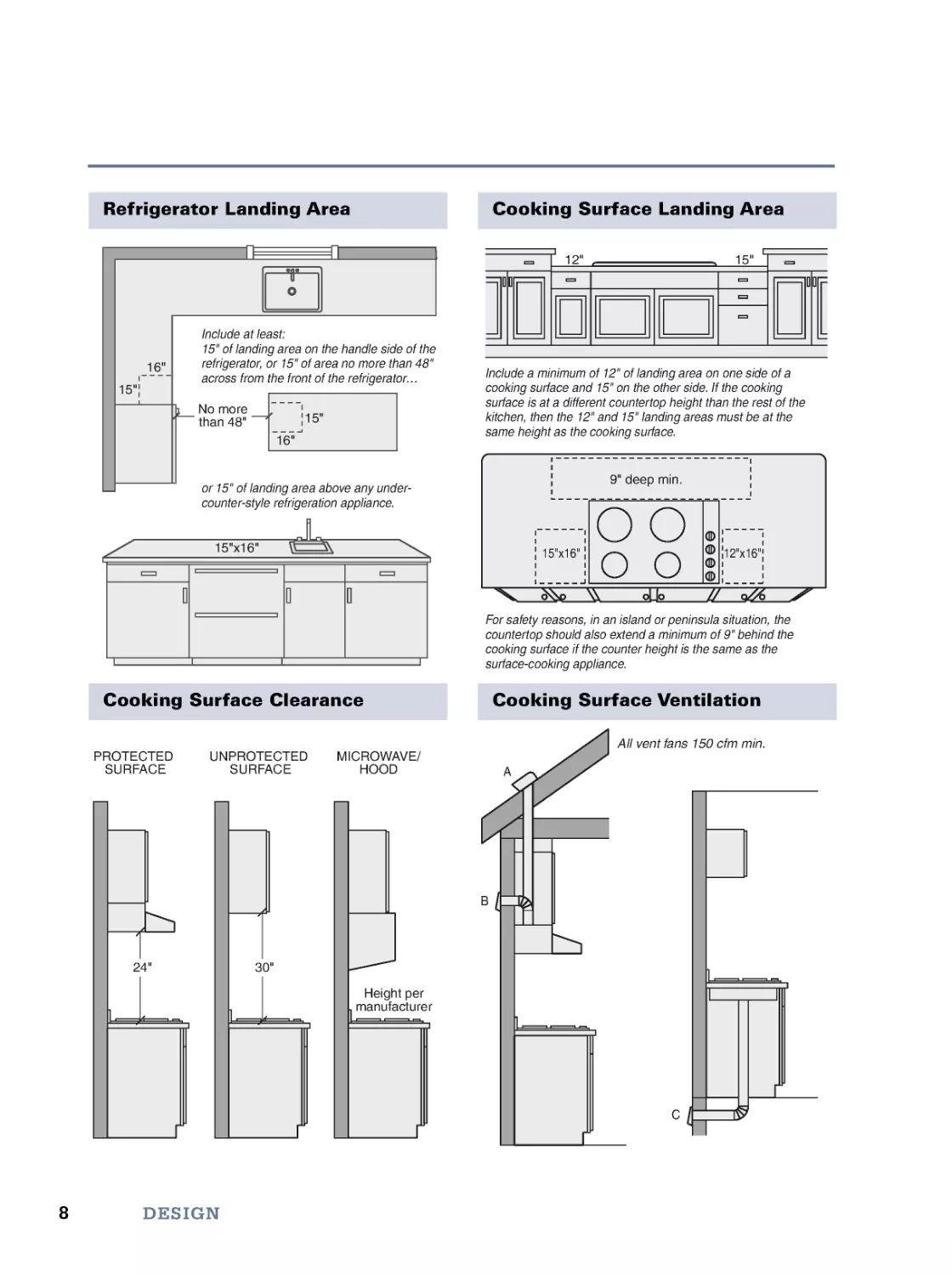
Refrigerator Landing Area
Include at least:
15" of landing area on the handle side of the
refrigerator, or 15" of area no more than 48"
across from the front of the refrigerator...
or 15" of landing area above any under-
counter-style refrigeration appliance.
16"
16"
15"
15"x16"
15"
No more
than 48"
Cooking Surface Landing Area
For safety reasons, in an island or peninsula situation, the
countertop should also extend a minimum of 9" behind the
cooking surface if the counter height is the same as the
surface-cooking appliance.
Include a minimum of 12" of landing area on one side of a
cooking surface and 15" on the other side. If the cooking
surface is at a different countertop height than the rest of the
kitchen, then the 12" and 15" landing areas must be at the
same height as the cooking surface.
12"
15"
9" deep min.
15"x16"
12"x16"
Cooking Surface Clearance
PROTECTED
SURFACE
UNPROTECTED
SURFACE
MICROWAVE/
HOOD
24"
30"
Height per
manufacturer
Cooking Surface Ventilation
A
B
C
All vent fans 150 cfm min.
9
Kitchen Design Guidelines
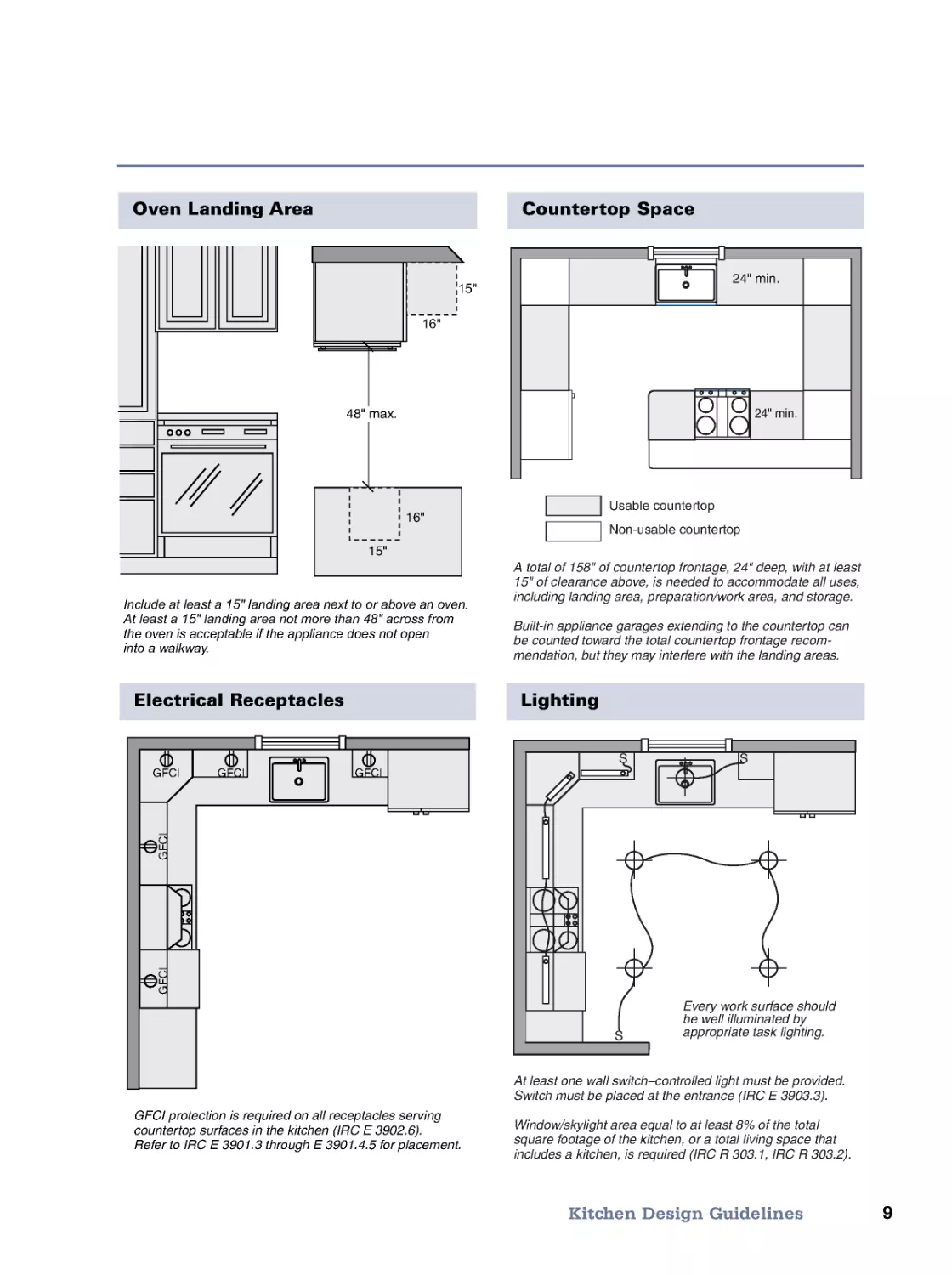
Countertop Space
24" min.
24" min.
Usable countertop
Non-usable countertop
A total of 158" of countertop frontage, 24" deep, with at least
15" of clearance above, is needed to accommodate all uses,
including landing area, preparation/work area, and storage.
Built-in appliance garages extending to the countertop can
be counted toward the total countertop frontage recom-
mendation, but they may interfere with the landing areas.
Oven Landing Area
Include at least a 15" landing area next to or above an oven.
At least a 15" landing area not more than 48" across from
the oven is acceptable if the appliance does not open
into a walkway.
16"
16"
15"
15"
48" max.
15"
16"
Electrical Receptacles
GFCI protection is required on all receptacles serving
countertop surfaces in the kitchen (IRC E 3902.6).
Refer to IRC E 3901.3 through E 3901.4.5 for placement.
GFCI
GFCI
GFCI
G
F
C
I
G
F
C
I
Lighting
At least one wall switch–controlled light must be provided.
Switch must be placed at the entrance (IRC E 3903.3).
Window/skylight area equal to at least 8% of the total
square footage of the kitchen, or a total living space that
includes a kitchen, is required (IRC R 303.1, IRC R 303.2).
S
S
S
Every work surface should
be well illuminated by
appropriate task lighting.
10
Bath Design Guidelines
DESIGN
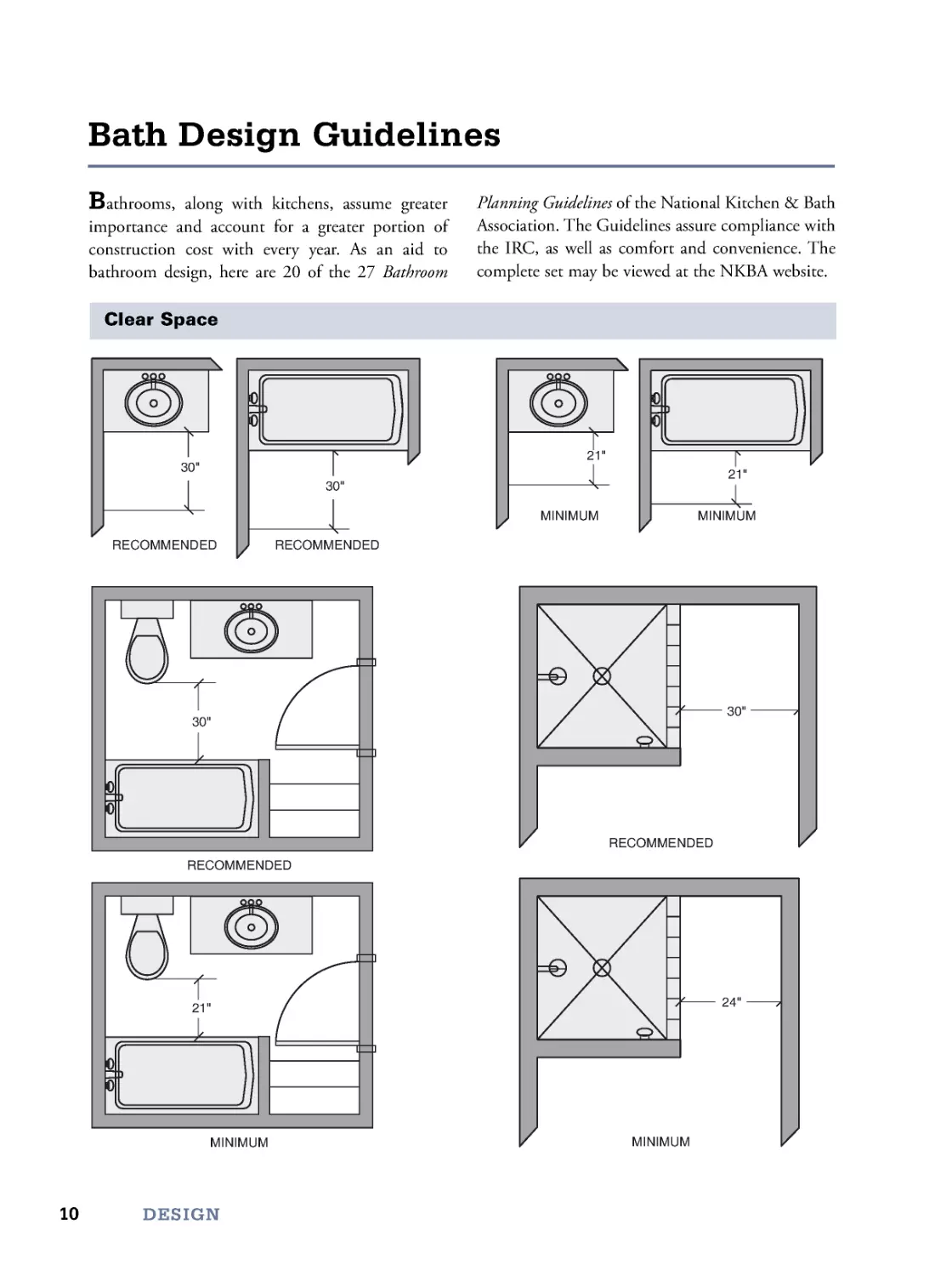
Bathrooms, along with kitchens, assume greater
importance and account for a greater portion of
construction cost with every year. As an aid to
bathroom design, here are 20 of the 27 Bathroom
Planning Guidelines of the National Kitchen & Bath
Association. The Guidelines assure compliance with
the IRC, as well as comfort and convenience. The
complete set may be viewed at the NKBA website.
Clear Space
30"
30"
RECOMMENDED
RECOMMENDED
RECOMMENDED
RECOMMENDED
21"
21"
30"
MINIMUM
MINIMUM
MINIMUM
21"
30"
MINIMUM
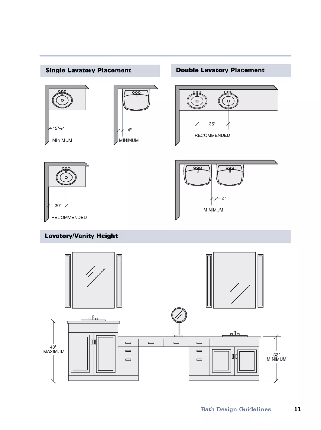
24"
43"
MAXIMUM
32"
MINIMUM
20"
RECOMMENDED
4"
15"
MINIMUM
MINIMUM
36"
RECOMMENDED
4"
MINIMUM
11
Bath Design Guidelines
Single Lavatory Placement
Double Lavatory Placement
Lavatory/Vanity Height
12
DESIGN
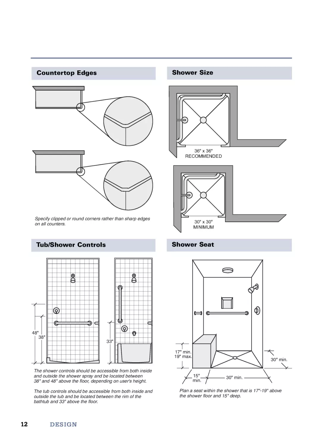
Specify clipped or round corners rather than sharp edges
on all counters.
36" x 36"
RECOMMENDED
30" x 30"
MINIMUM
Countertop Edges
Shower Size
The shower controls should be accessible from both inside
and outside the shower spray and be located between
38" and 48" above the floor, depending on user's height.
The tub controls should be accessible from both inside and
outside the tub and be located between the rim of the
bathtub and 33" above the floor.
33"
38"
48"
Plan a seat within the shower that is 17"-19" above
the shower floor and 15" deep.
17" min.
19" max.
15"
min.
30" min.
30" min.
Tub/Shower Controls
Shower Seat
13
Bath Design Guidelines
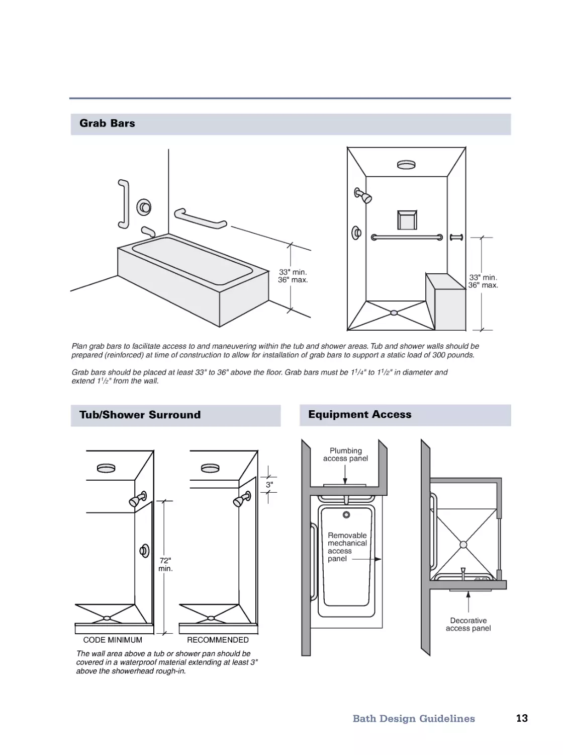
Grab Bars
Plan grab bars to facilitate access to and maneuvering within the tub and shower areas. Tub and shower walls should be
prepared (reinforced) at time of construction to allow for installation of grab bars to support a static load of 300 pounds.
Grab bars should be placed at least 33" to 36" above the floor. Grab bars must be 11/4" to 11/2" in diameter and
extend 11/2" from the wall.
33" min.
36" max.
33" min.
36" max.
The wall area above a tub or shower pan should be
covered in a waterproof material extending at least 3"
above the showerhead rough-in.
3"
72"
min.
RECOMMENDED
CODE MINIMUM
Plumbing
access panel
Removable
mechanical
access
panel
Decorative
access panel
Tub/Shower Surround
Equipment Access
14
DESIGN
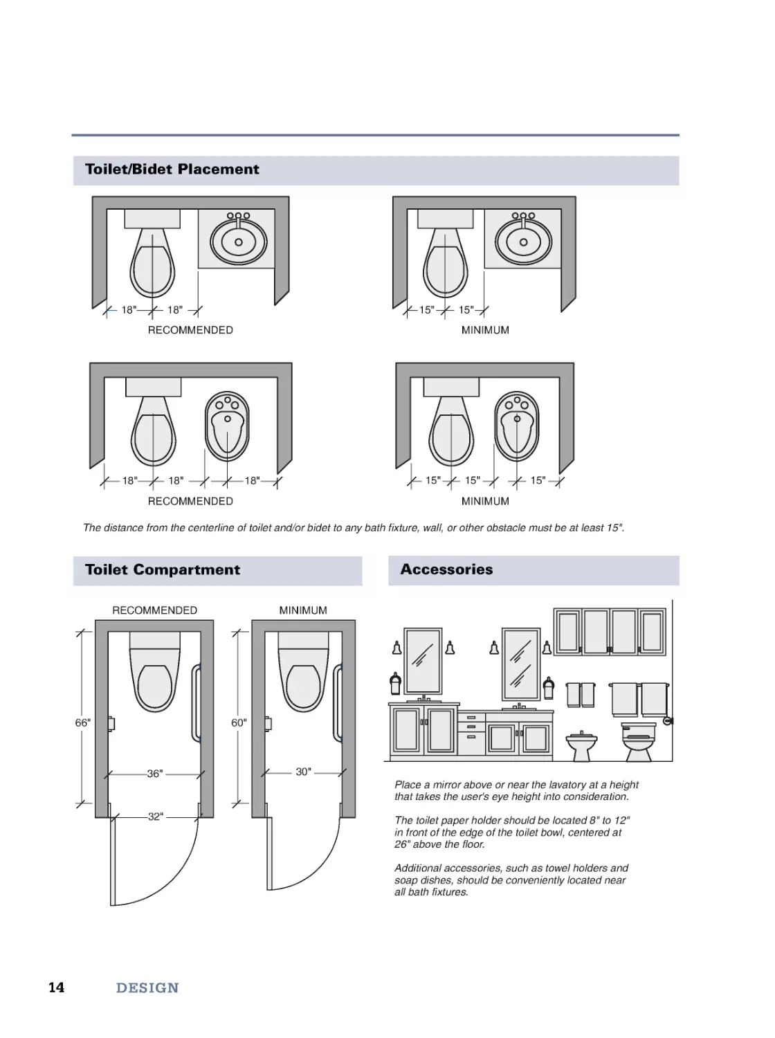
Toilet/Bidet Placement
The distance from the centerline of toilet and/or bidet to any bath fixture, wall, or other obstacle must be at least 15".
18"
18"
18"
18"
18"
15"
15"
15"
15"
15"
RECOMMENDED
MINIMUM
RECOMMENDED
MINIMUM
66"
36"
32"
RECOMMENDED
60"
30"
MINIMUM
Place a mirror above or near the lavatory at a height
that takes the user's eye height into consideration.
The toilet paper holder should be located 8" to 12"
in front of the edge of the toilet bowl, centered at
26" above the floor.
Additional accessories, such as towel holders and
soap dishes, should be conveniently located near
all bath fixtures.
Toilet Compartment
Accessories
15
Bath Design Guidelines
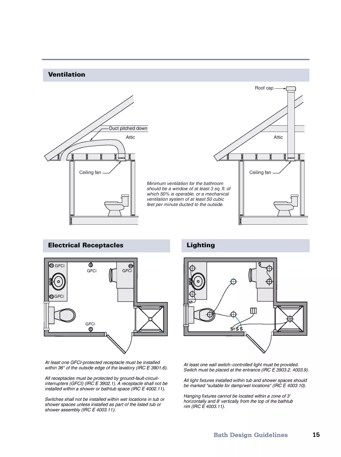
Ventilation
Minimum ventilation for the bathroom
should be a window of at least 3 sq. ft. of
which 50% is operable, or a mechanical
ventilation system of at least 50 cubic
feet per minute ducted to the outside.
Ceiling fan
Attic
Attic
Roof cap
Duct pitched down
Ceiling fan
At least one GFCI-protected receptacle must be installed
within 36" of the outside edge of the lavatory (IRC E 3901.6).
All receptacles must be protected by ground-fault-circuit-
interrupters (GFCI) (IRC E 3902.1). A receptacle shall not be
installed within a shower or bathtub space (IRC E 4002.11).
Switches shall not be installed within wet locations in tub or
shower spaces unless installed as part of the listed tub or
shower assembly (IRC E 4003.11).
GFCI
GFCI
GFCI
GFCI
GFCI
At least one wall switch–controlled light must be provided.
Switch must be placed at the entrance (IRC E 3903.2, 4003.9).
All light fixtures installed within tub and shower spaces should
be marked "suitable for damp/wet locations" (IRC E 4003.10).
Hanging fixtures cannot be located within a zone of 3'
horizontally and 8' ver tically from the top of the bathtub
rim (IRC E 4003.11).
S
S
S
ST
S
Electrical Receptacles
Lighting
16
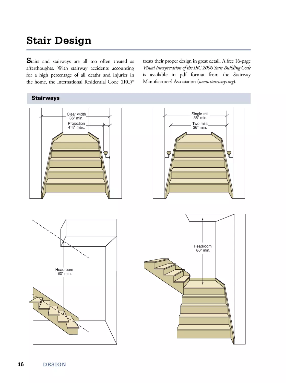
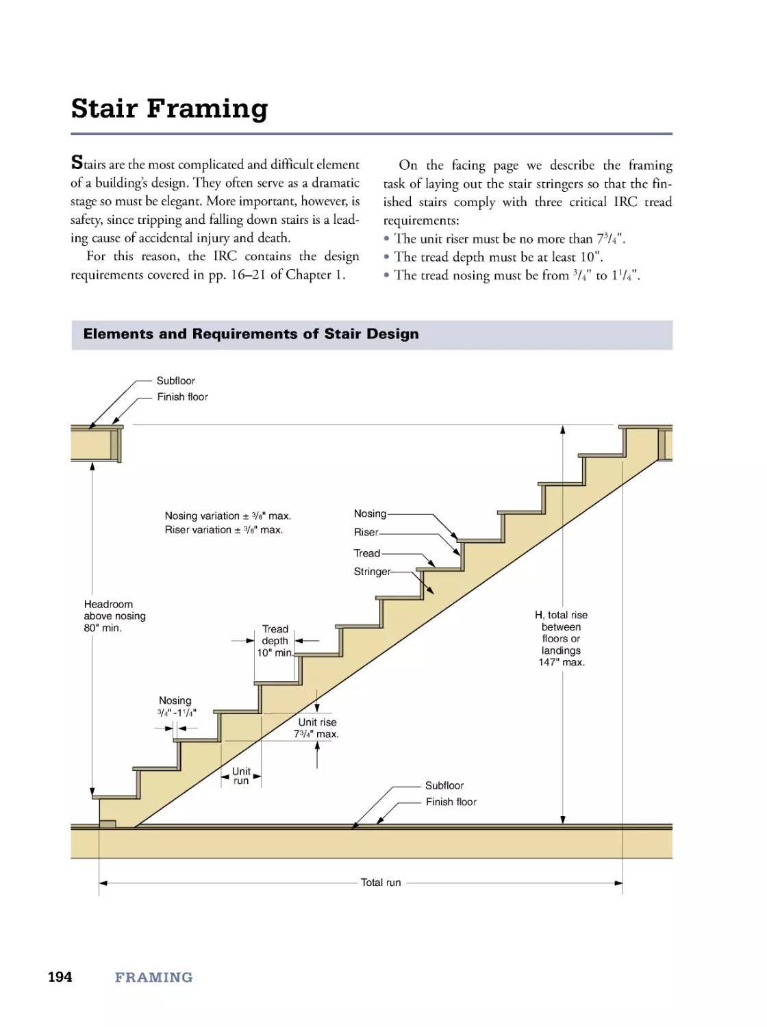
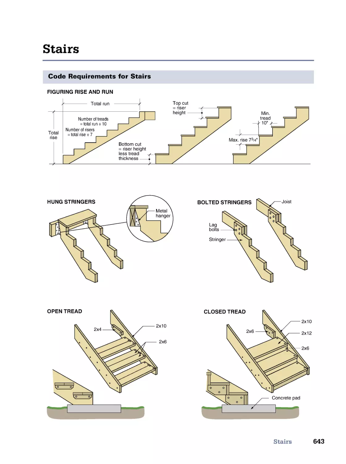
Stairs and stairways are all too often treated as
afterthoughts. With stairway accidents accounting
for a high percentage of all deaths and injuries in
the home, the International Residential Code (IRC)®
treats their proper design in great detail. A free 16-page
Visual Interpretation of the IRC 2006 Stair Building Code
is available in pdf format from the Stairway
Manufacturers’ Association (www.stairways.org).
Stair Design
DESIGN
Stairways
Clear width
36" min.
Projection
41/2" max.
Two rails
36" min.
Single rail
36" min.
Headroom
80" min.
Headroom
80" min.
17
Stair Design
A
B
L
a
n
d
i
n
g
w
i
d
t
h
≥
A
Landing
width
≥
B
3
6
"
m
i
n
.
3
6
"
m
i
n
.
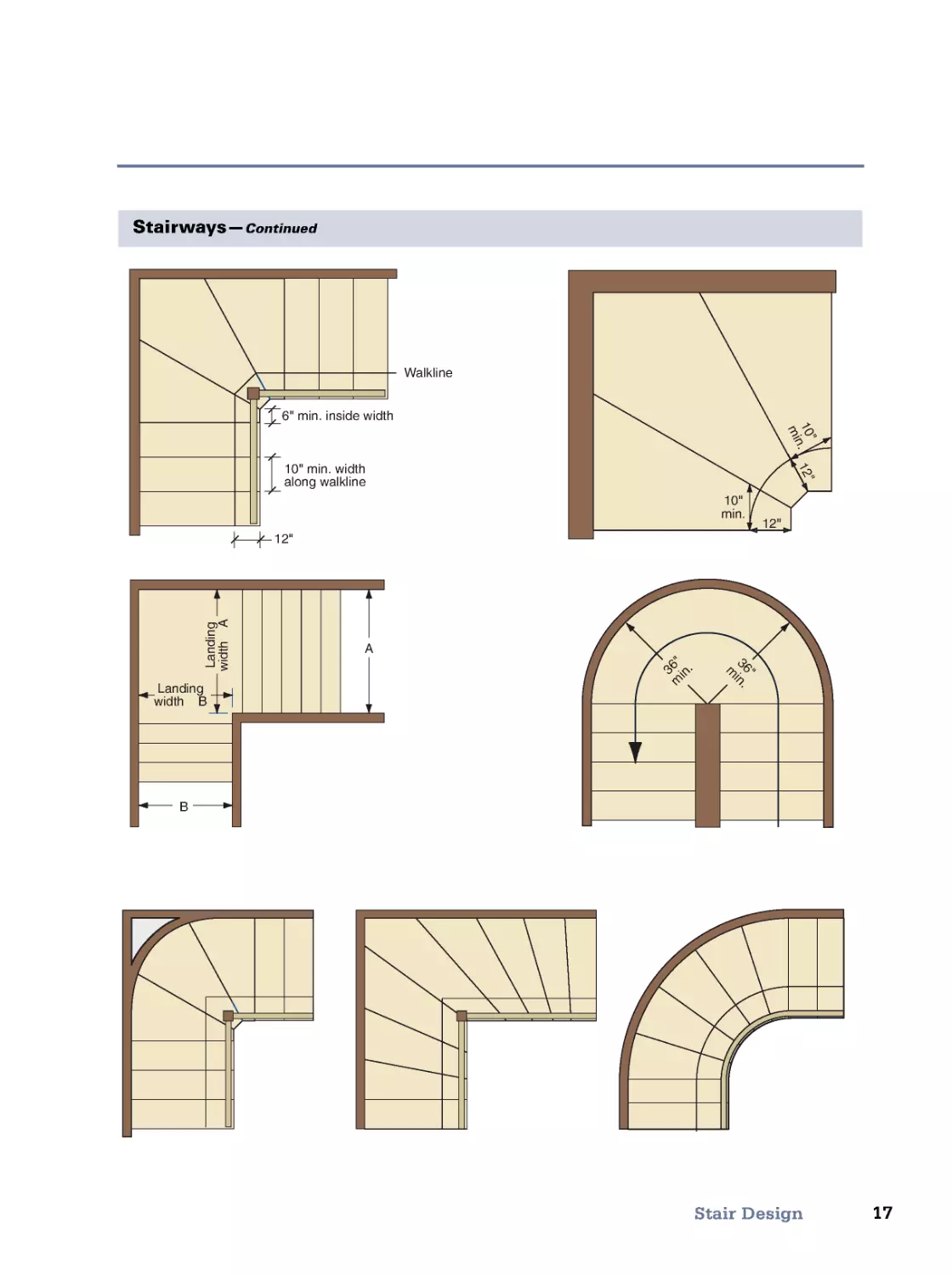
12"
10"
min.
1
2
"
1
0
"
m
i
n
.
12"
6" min. inside width
10" min. width
along walkline
Walkline
Stairways—Continued
18
DESIGN
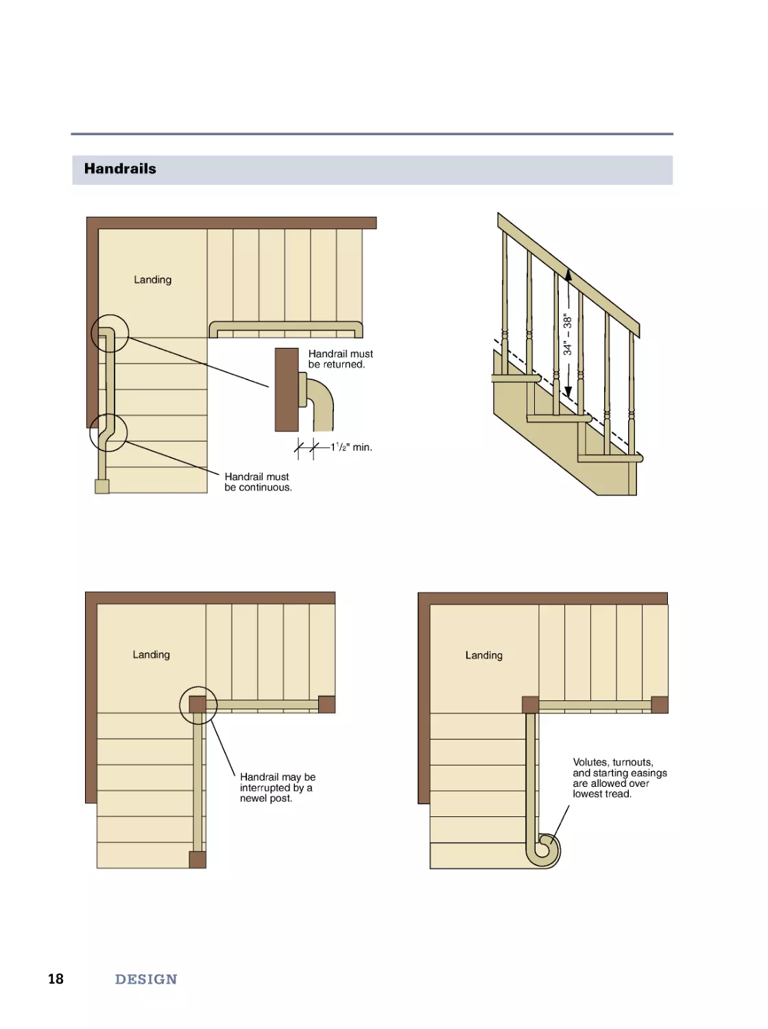
Handrails
Landing
Handrail may be
interrupted by a
newel post.
Volutes, turnouts,
and starting easings
are allowed over
lowest tread.
Landing
Handrail must
be continuous.
Handrail must
be returned.
11/2" min.
Landing
3
4
"
–
3
8
"
19
Stair Design
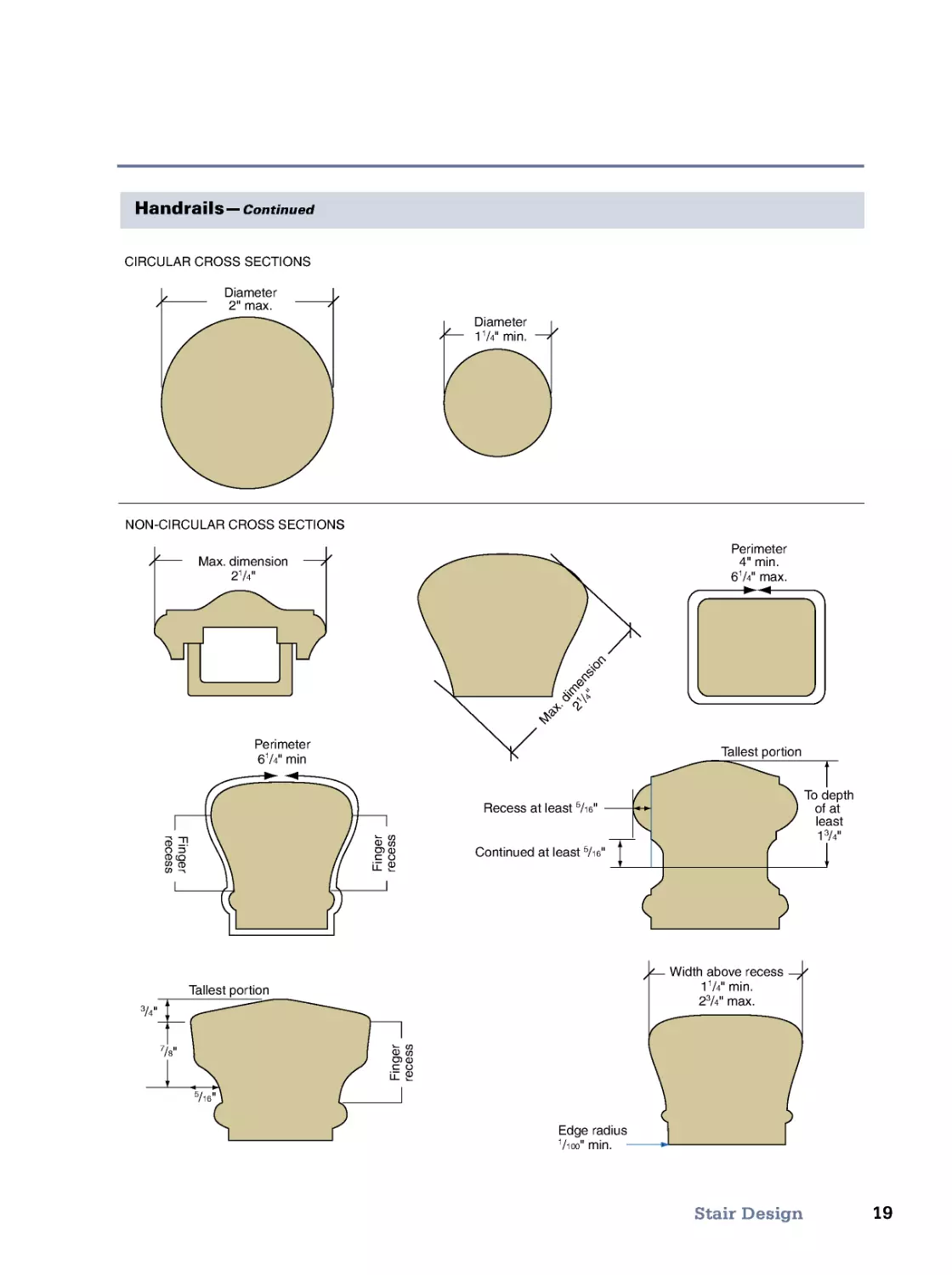
Handrails—Continued
CIRCULAR CROSS SECTIONS
NON-CIRCULAR CROSS SECTIONS
Diameter
2" max.
Diameter
11/4" min.
Perimeter
4" min.
61/4" max.
Perimeter
61/4" min
M
a
x
.
d
i
m
e
n
s
i
o
n
2
1
/
4
"
Max. dimension
21/4"
Width above recess
11/4" min.
23/4" max.
To depth
of at
least
13/4"
F
i
n
g
e
r
r
e
c
e
s
s
F
i
n
g
e
r
r
e
c
e
s
s
F
i
n
g
e
r
r
e
c
e
s
s
5
/16"
7
/8"
3/4"
Edge radius
1/100" min.
Tallest portion
Tallest portion
Recess at least 5/16"
Continued at least 5/16"
CIRCULAR CR
2" max.
Diameter
OSS SECTIONS
CIRCULAR CR
Diameter
NON-CIRCULAR CROSS SECTIONS
NON-CIRCULAR CR
min.
"
4/11
NON-CIRCULAR CROSS SECTIONS
NON-CIRCULAR CR
"
4/12
dimension
Max.
d
i
m
2
1
2
M
a
x
.
.
max.
"
4/
1
6
4" min.
imeter
er
P
m
e
n
s
i
o
n
/
"
2
4
/
4
2
1
2
/
max.
4" min.
imeter
r
e
c
e
s
s
F
i
n
g
e
r
min
"
4/
1
6
imeter
er
P
F
i
n
g
e
r
F
i
n
g
e
r
r
e
c
e
s
s
F
i
n
g
e
r
ued at least
Contin
5
Recess at least
"
16
/55/
ued at least
"
16
/5/
allest por
TTallest por
"
4/33/
1
least
of at
o depth
TTo depth
tion
allest por
"
4/3
"
8/
7
"
16
/5
tion
allest por
TTallest por
r
e
c
e
s
s
F
i
n
g
e
r
Edge r
max.
"
4/32
min.
"
4/
1
1
e recess
v
Width abo
adius
e recess
100
/1
Edge r
min.
"
100
adius
Edge r
20
DESIGN
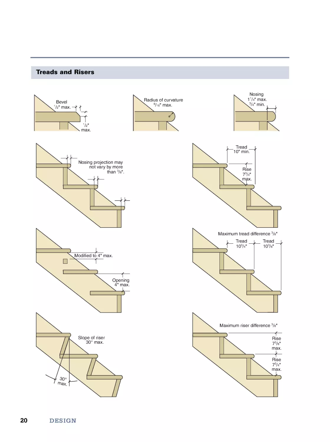
Treads and Risers
Bevel
1
/2" max.
1/2"
max.
Radius of curvature
9/16" max.
Nosing
11/4" max.
3/4" min.
Nosing projection may
not vary by more
than 3/8".
Maximum tread difference 3/8"
Maximum riser difference 3/8"
Slope of riser
30° max.
Opening
4" max.
Rise
73/4"
max.
Tread
10" min.
Tread
103/4"
Tread
103/8"
Rise
73/8"
max.
Rise
73/4"
max.
Modified to 4" max.
3
0
°
m
a
x
.
21
Stair Design
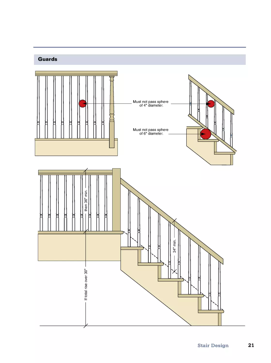
Guards
Must not pass sphere
of 4" diameter.
Must not pass sphere
of 6" diameter.
3
4
"
m
i
n
.
t
h
e
n
3
6
"
m
i
n
.
I
f
t
o
t
a
l
r
i
s
e
o
v
e
r
3
0
"
22
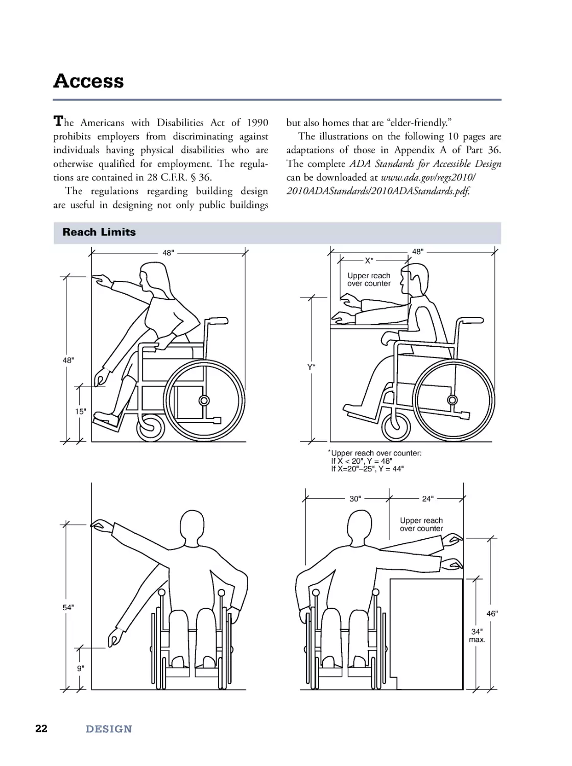
The Americans with Disabilities Act of 1990
prohibits employers from discriminating against
individuals having physical disabilities who are
otherwise qualified for employment. The regula-
tions are contained in 28 C.F.R . § 36.
The regulations regarding building design
are useful in designing not only public buildings
but also homes that are “elder-friendly.”
The illustrations on the following 10 pages are
adaptations of those in Appendix A of Part 36.
The complete ADA Standards for Accessible Design
can be downloaded at www.ada.gov/regs2010/
2010ADAStandards/2010ADAStandards.pdf.
Access
DESIGN
Reach Limits
48"
48"
X*
48"
54"
34"
max.
46"
24"
30"
15"
9"
Y*
Upper reach over counter:
IfX<20",Y =48"
If X=20"–25", Y = 44"
**
Upper reach
over counter
Upper reach
over counter
23
Access
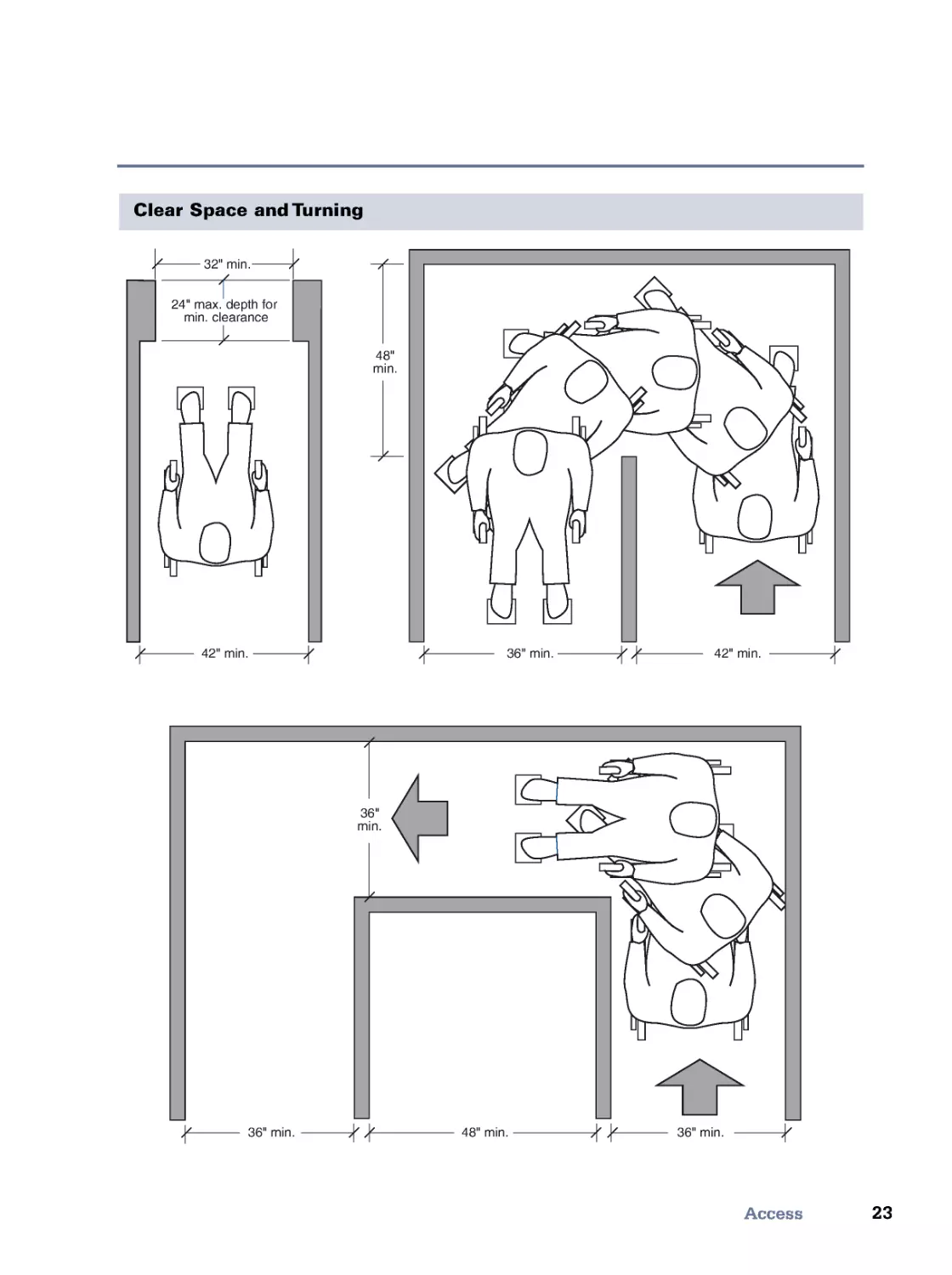
Clear Space and Turning
36" min.
24" max. depth for
min. clearance
36" min.
48" min.
36" min.
42" min.
32" min.
42" min.
36"
min.
48"
min.
24
DESIGN
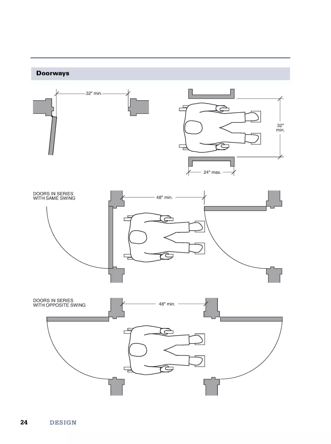
Doorways
32" min.
32"
min.
24" max.
48" min.
48" min.
DOORS IN SERIES
WITH SAME SWING
DOORS IN SERIES
WITH OPPOSITE SWING
25
Access
Doorways—Continued
54" min.
42" min.
(48" if both latch
and closer)
60"
min.
48"
min.
18" min.
24" preferred
X*
Y*
12" if door has both
closer and latch
X=36"min.ifY =60"
X=42"min.ifY =54"
**
48" min.
(54" if door
has closer)
42" min.
(48" if door
has closer)
24" min.
24" min.
FRONT APPROACHES
HINGE-SIDE APPROACHES
LATCH-SIDE APPROACHES
26
DESIGN
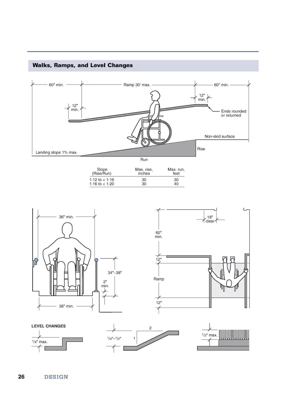
Walks, Ramps, and Level Changes
1/4" max.
2
1
18"
clear
60"
min.
2"
min.
12"
34"–38"
Ramp 30' max.
12"
min.
12"
min.
60" min.
Landing slope 1% max.
Non-skid surface
Run
Rise
60" min.
1/2" max.
1/4"–
1/2"
36" min.
36" min.
Ramp
12"
LEVEL CHANGES
Ends rounded
or returned
1:12 to < 1:16
1:16 to < 1:20
30
30
30
40
Slope
(Rise/Run)
Max. rise,
inches
Max. run,
feet
27
Access
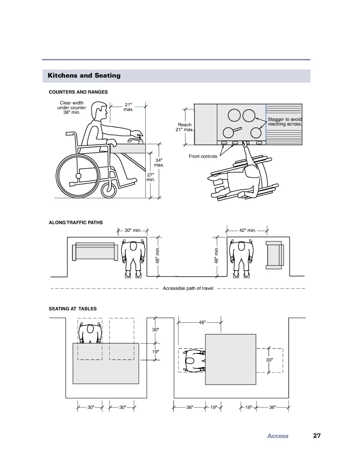
Kitchens and Seating
Reach
21" max.
Front controls
Stagger to avoid
reaching across.
27"
min.
34"
max.
30"
30"
30"
19"
21"
max.
Clear width
under counter
36" min.
30"
36"
48"
36"
19"
19"
SEATING AT TABLES
ALONG TRAFFIC PATHS
COUNTERS AND RANGES
42" min.
4
8
"
m
i
n
.
4
8
"
m
i
n
.
30" min.
Accessible path of travel
28
DESIGN
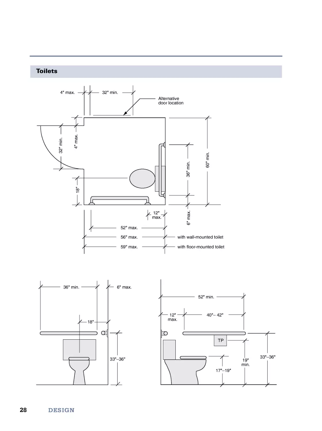
Toilets
36" min.
6" max.
19"
min.
17"–19"
33"–36"
33"–36"
18"
12"
max.
40"– 42"
52" min.
TP
4" max.
32" min.
3
2
"
m
i
n
.
1
8
"
4
"
m
a
x
.
6
"
m
a
x
.
3
6
"
m
i
n
.
6
0
"
m
i
n
.
Alternative
door location
12"
max.
52" max.
56" max.
59" max.
with wall-mounted toilet
with floor-mounted toilet
29
Access
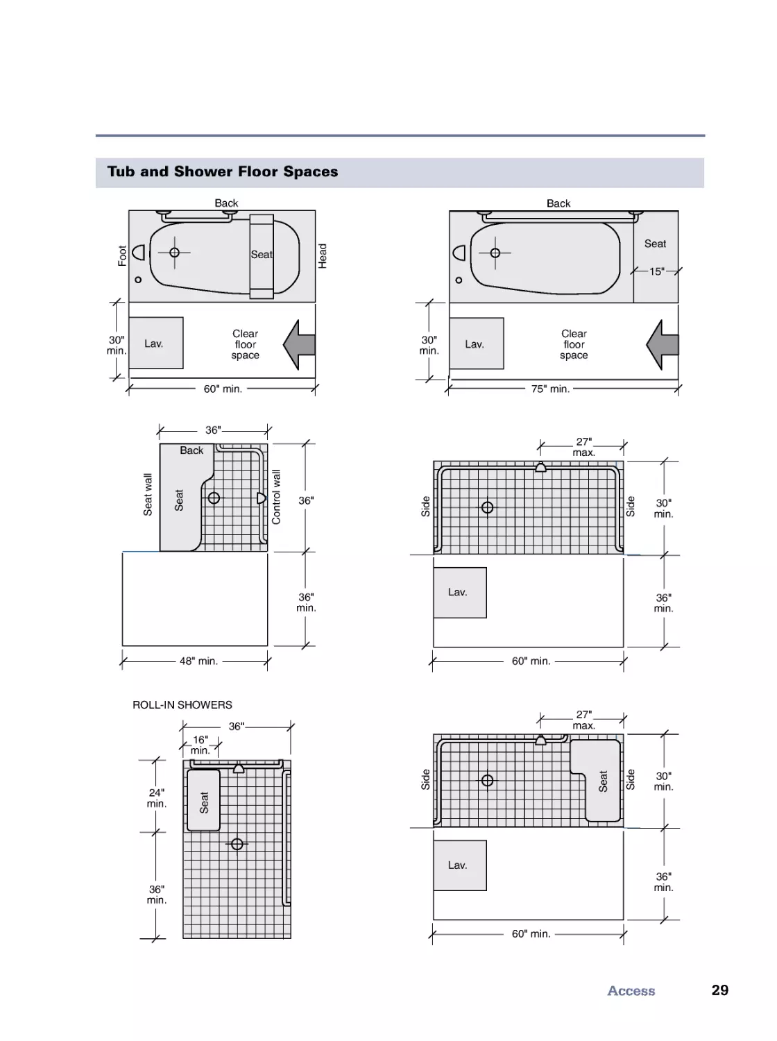
Tub and Shower Floor Spaces
Back
Lav.
Seat
F
o
o
t
H
e
a
d
Clear
floor
space
Back
Lav.
Seat
Clear
floor
space
S
e
a
t
w
a
l
l
C
o
n
t
r
o
l
w
a
l
l
S
i
d
e
S
i
d
e
36"
36"
36"
min.
30"
min.
30"
min.
15"
60" min.
75" min.
36"
min.
30"
min.
27"
max.
48" min.
60" min.
Lav.
S
i
d
e
S
i
d
e
36"
min.
30"
min.
27"
max.
60" min.
Lav.
36"
16"
min.
24"
min.
36"
min.
ROLL-IN SHOWERS
Back
Back
S
e
a
t
S
e
a
t
S
e
a
t
S
e
a
t
S
e
a
t
S
e
a
t
30
DESIGN
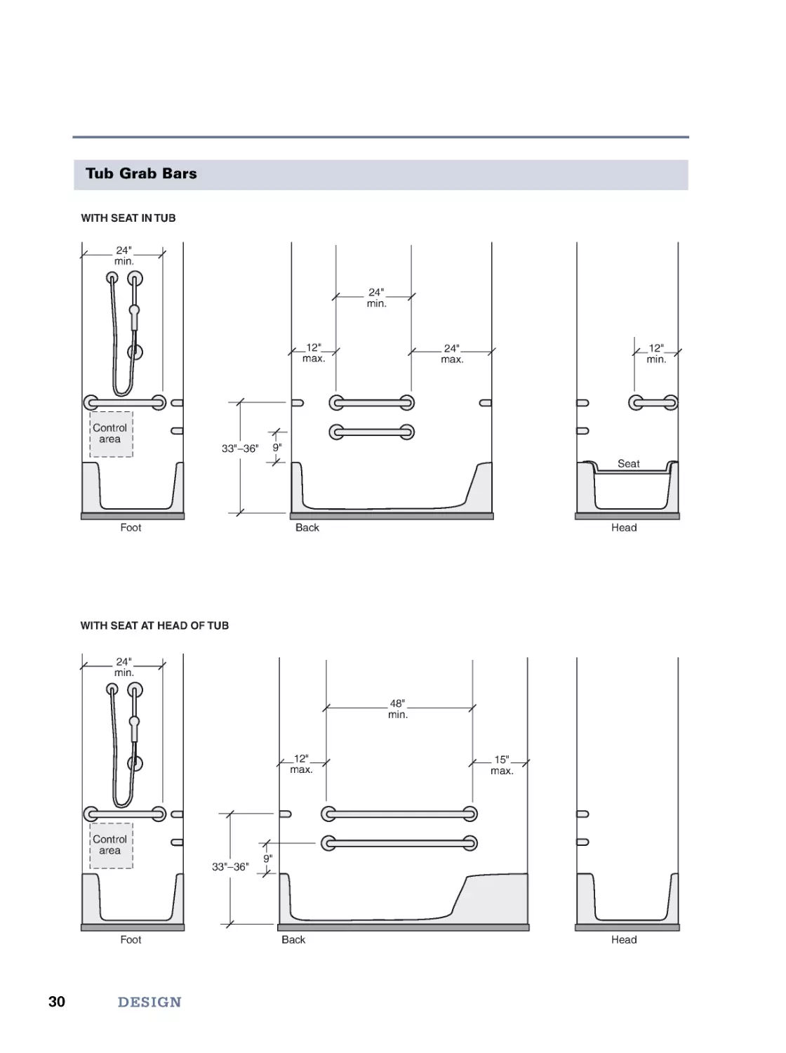
Tub Grab Bars
24"
min.
24"
min.
24"
max.
12"
max.
9"
33"–36"
Control
area
12"
min.
9"
Seat
48"
min.
15"
max.
12"
max.
33"–36"
WITH SEAT IN TUB
WITH SEAT AT HEAD OF TUB
Foot
Head
Back
Foot
Head
Back
24"
min.
Control
area
31
Access
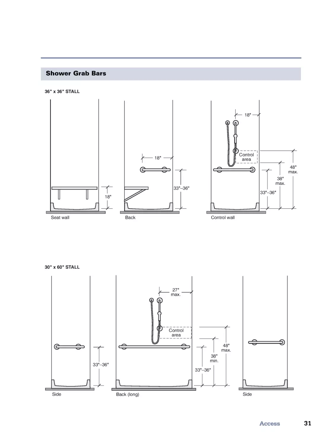
Shower Grab Bars
Seat wall
Side
Side
Back
Back (long)
Control wall
18"
18"
18"
38"
max.
27"
max.
48"
max.
33"–36"
33"–36"
38"
min.
48"
max.
33"–36"
33"–36"
Control
area
Control
area
36" x 36" STALL
30" x 60" STALL
32
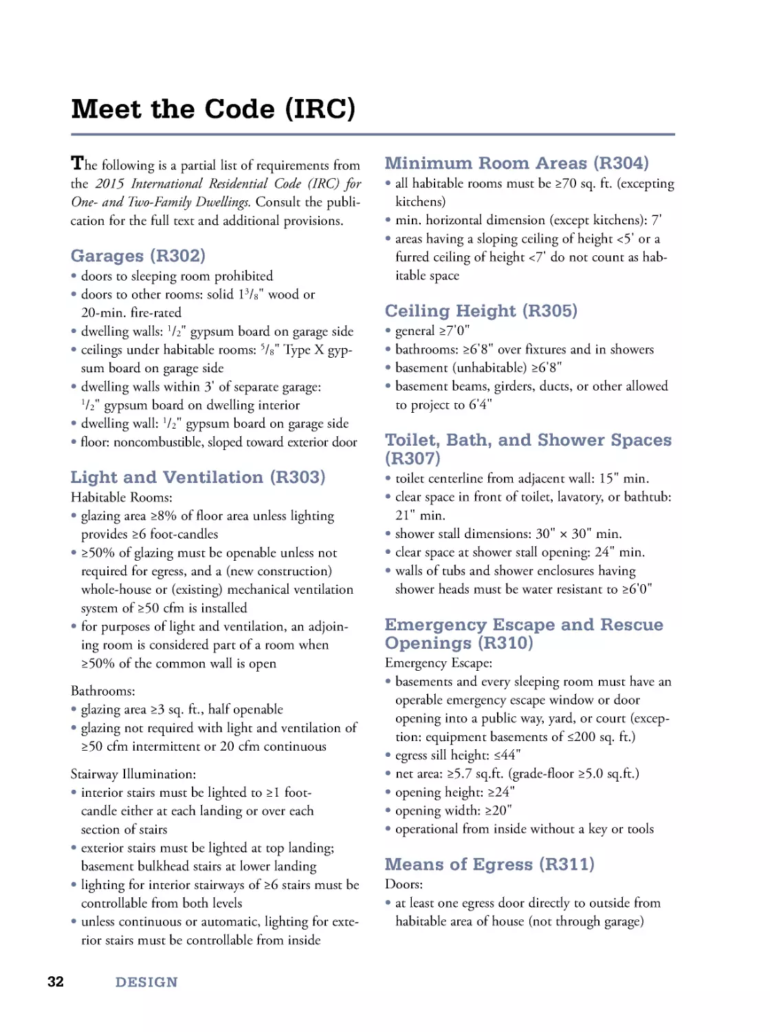
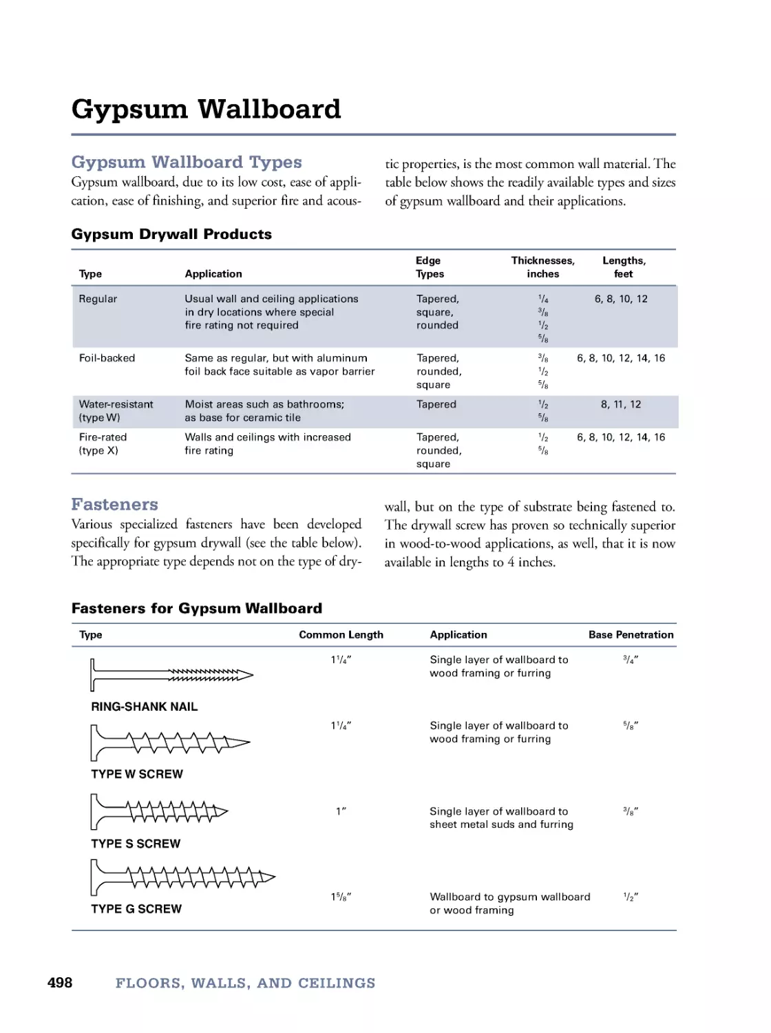
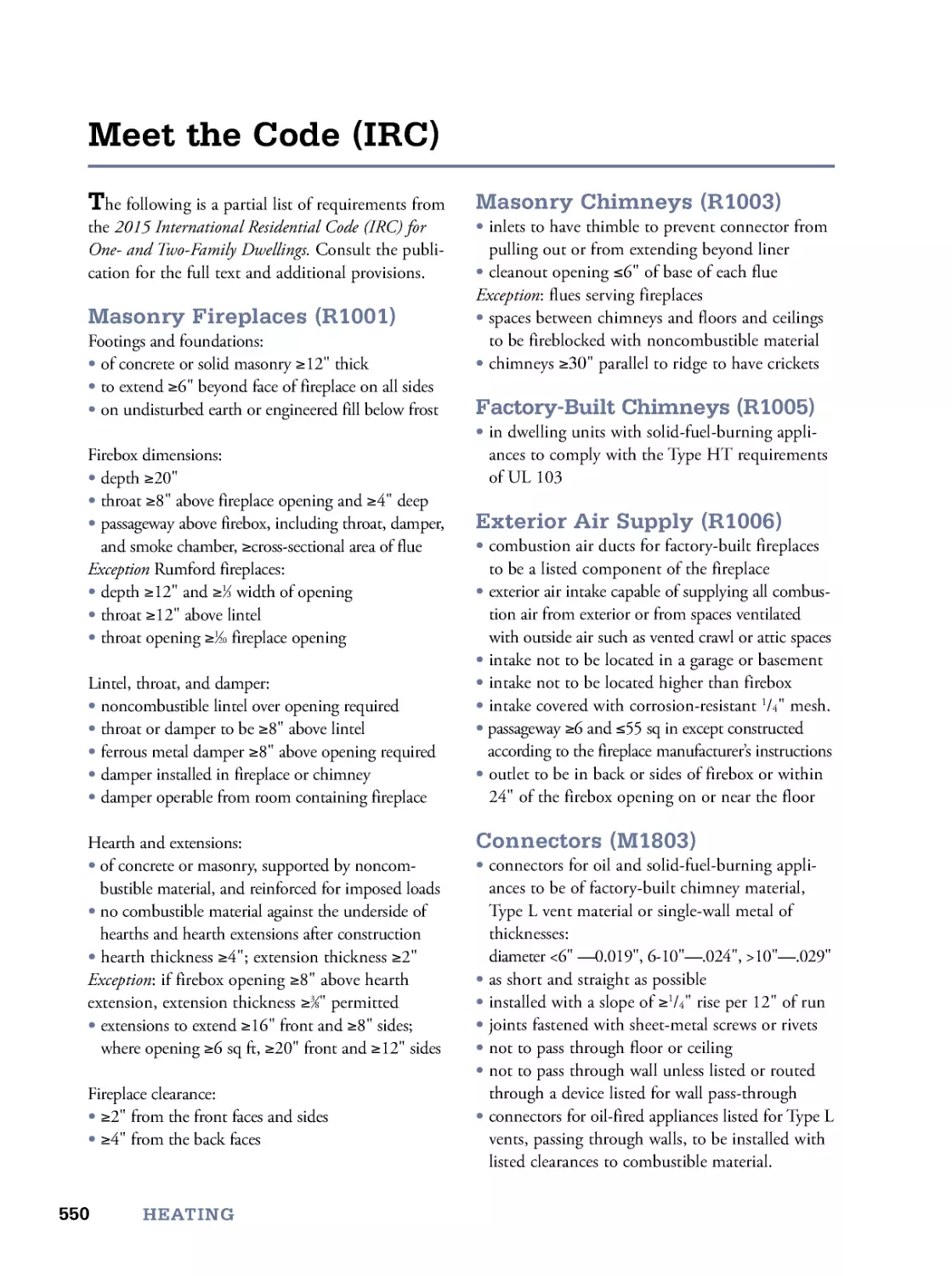
The following is a partial list of requirements from
the 2015 International Residential Code (IRC) for
One- and Two-Family Dwellings. Consult the publi-
cation for the full text and additional provisions.
Garages (R302)
• doors to sleeping room prohibited
• doors to other rooms: solid 13/8" wood or
20-min. fire-rated
• dwelling walls: 1/2" gypsum board on garage side
• ceilings under habitable rooms: 5/8" Type X gyp-
sum board on garage side
• dwelling walls within 3' of separate garage:
1/2" gypsum board on dwelling interior
• dwelling wall: 1/2" gypsum board on garage side
• floor: noncombustible, sloped toward exterior door
Light and Ventilation (R303)
Habitable Rooms:
• glazing area ≥8% of floor area unless lighting
provides ≥6 foot-candles
• ≥50% of glazing must be openable unless not
required for egress, and a (new construction)
whole-house or (existing) mechanical ventilation
system of ≥50 cfm is installed
• for purposes of light and ventilation, an adjoin-
ing room is considered part of a room when
≥50% of the common wall is open
Bathrooms:
• glazing area ≥3 sq. ft., half openable
• glazing not required with light and ventilation of
≥50 cfm intermittent or 20 cfm continuous
Stairway Illumination:
• interior stairs must be lighted to ≥1 foot-
candle either at each landing or over each
section of stairs
• exterior stairs must be lighted at top landing;
basement bulkhead stairs at lower landing
• lighting for interior stairways of ≥6 stairs must be
controllable from both levels
• unless continuous or automatic, lighting for exte-
rior stairs must be controllable from inside
Minimum Room Areas (R304)
• all habitable rooms must be ≥70 sq. ft. (excepting
kitchens)
• min. horizontal dimension (except kitchens): 7'
• areas having a sloping ceiling of height <5' or a
furred ceiling of height <7' do not count as hab-
itable space
Ceiling Height (R305)
• general ≥7'0"
• bathrooms: ≥6'8" over fixtures and in showers
• basement (unhabitable) ≥6'8"
• basement beams, girders, ducts, or other allowed
to project to 6'4"
Toilet, Bath, and Shower Spaces
(R307)
• toilet centerline from adjacent wall: 15" min.
• clear space in front of toilet, lavatory, or bathtub:
21" min.
• shower stall dimensions: 30" × 30" min.
• clear space at shower stall opening: 24" min.
• walls of tubs and shower enclosures having
shower heads must be water resistant to ≥6'0"
Emergency Escape and Rescue
Openings (R310)
Emergency Escape:
• basements and every sleeping room must have an
operable emergency escape window or door
opening into a public way, yard, or court (excep-
tion: equipment basements of ≤200 sq. ft.)
• egress sill height: ≤44"
• net area: ≥5.7 sq.ft. (grade-floor ≥5.0 sq.ft.)
• opening height: ≥24"
• opening width: ≥20"
• operational from inside without a key or tools
Means of Egress (R311)
Doors:
• at least one egress door directly to outside from
habitable area of house (not through garage)
Meet the Code (IRC)
DESIGN
33
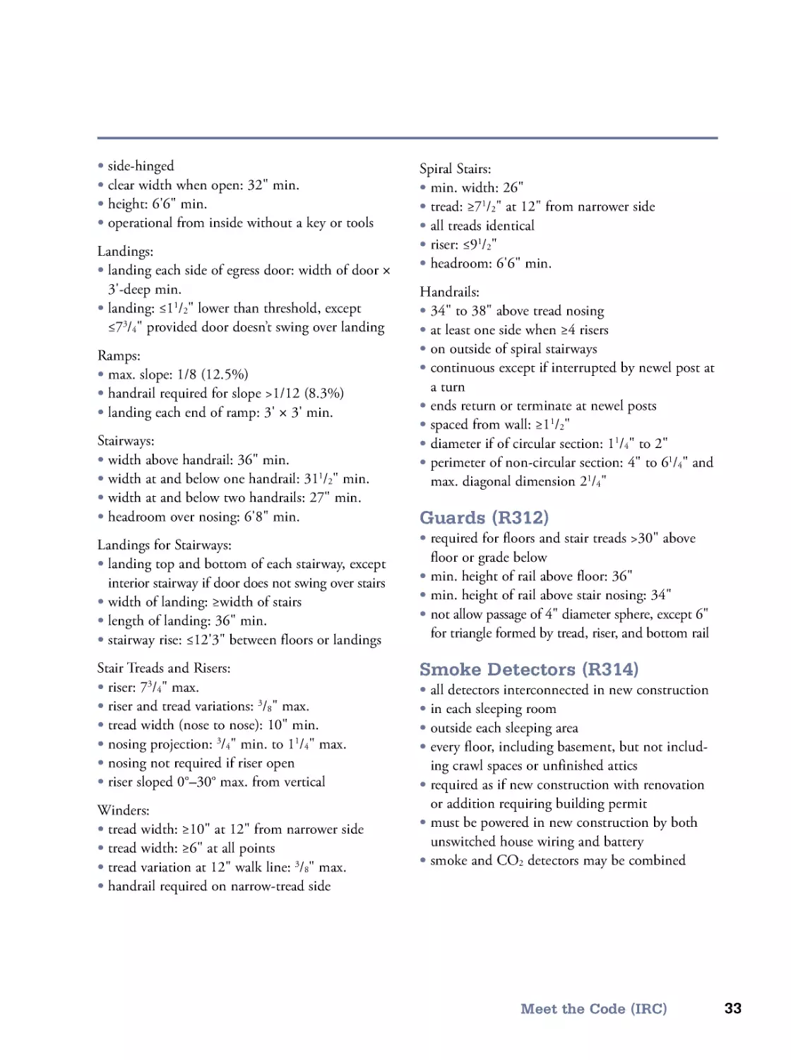
Meet the Code (IRC)
• side-hinged
• clear width when open: 32" min.
• height: 6'6" min.
• operational from inside without a key or tools
Landings:
• landing each side of egress door: width of door ×
3'-deep min.
• landing: ≤11/2" lower than threshold, except
≤73/4" provided door doesn’t swing over landing
Ramps:
• max. slope: 1/8 (12.5%)
• handrail required for slope >1/12 (8.3%)
• landing each end of ramp: 3' × 3' min.
Stairways:
• width above handrail: 36" min.
• width at and below one handrail: 311/2" min.
• width at and below two handrails: 27" min.
• headroom over nosing: 6'8" min.
Landings for Stairways:
• landing top and bottom of each stairway, except
interior stairway if door does not swing over stairs
• width of landing: ≥width of stairs
• length of landing: 36" min.
• stairway rise: ≤12'3" between floors or landings
Stair Treads and Risers:
• riser: 73/4" max.
• riser and tread variations: 3/8" max.
• tread width (nose to nose): 10" min.
• nosing projection: 3/4" min. to 11/4" max.
• nosing not required if riser open
• riser sloped 0°–30° max. from vertical
Winders:
• tread width: ≥10" at 12" from narrower side
• tread width: ≥6" at all points
• tread variation at 12" walk line: 3/8" max.
• handrail required on narrow-tread side
Spiral Stairs:
• min. width: 26"
• tread: ≥71/2" at 12" from narrower side
• all treads identical
• riser: ≤91/2"
• headroom: 6'6" min.
Handrails:
• 34" to 38" above tread nosing
• at least one side when ≥4 risers
• on outside of spiral stairways
• continuous except if interrupted by newel post at
a turn
• ends return or terminate at newel posts
• spaced from wall: ≥11/2"
• diameter if of circular section: 1
1
/4" to 2"
• perimeter of non-circular section: 4" to 61/4" and
max. diagonal dimension 21/4"
Guards (R312)
• required for floors and stair treads >30" above
floor or grade below
• min. height of rail above floor: 36"
• min. height of rail above stair nosing: 34"
• not allow passage of 4" diameter sphere, except 6"
for triangle formed by tread, riser, and bottom rail
Smoke Detectors (R314)
• all detectors interconnected in new construction
• in each sleeping room
• outside each sleeping area
• every floor, including basement, but not includ-
ing crawl spaces or unfinished attics
• required as if new construction with renovation
or addition requiring building permit
• must be powered in new construction by both
unswitched house wiring and battery
• smoke and CO2 detectors may be combined
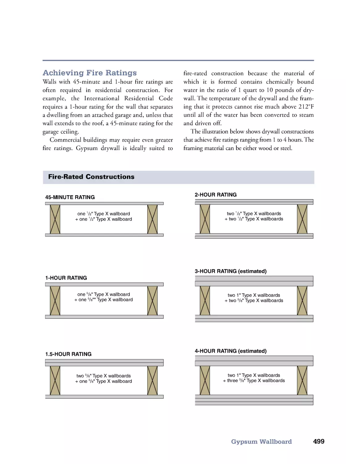
Architects often say, “You cannot build a good house on a bad site.” They
mean by this that the building site is, by far, the single most important ele-
ment in a house design. Of course, the qualities of a site involve a number
of variables, some quantifiable, some not. In this limited space we describe
the most important of those variables and how to deal with them.
We begin with plot plans, the drawings that describe the dimensions of
the site and the project, and that must be presented to the building codes
official in order to obtain a building permit.
Your site’s soil properties can have a great effect on the cost of develop-
ing the site, particularly the costs of foundation and driveway, so we include
the Unified Soil Classification System table of physical soil properties.
To take advantage of solar energy, whether photovoltaic or passive
heating, you must know the geographic site orientation. We show how to
determine true, or solar, south using times of sunrise and sunset.
The topographic relief, or variations in elevation, of your site influence
the costs of foundation, driveway, and grading, so we show a simple
method of determining elevations.
Automobiles (and trucks of various sizes) play important roles in mod-
ern life. We show how to design driveways that safely access public high-
ways and that provide adequate space in which to maneuver.
Throughout this book, whether predicting your heating bill or deter-
mining where to place windows for ventilation, you will have need for cli-
mate data, which we present in the form of simple maps.
In areas where too much winter wind results in high heating bills and
drifting snow, shelterbelts consisting of strategically placed trees and bushes
can provide significant relief.
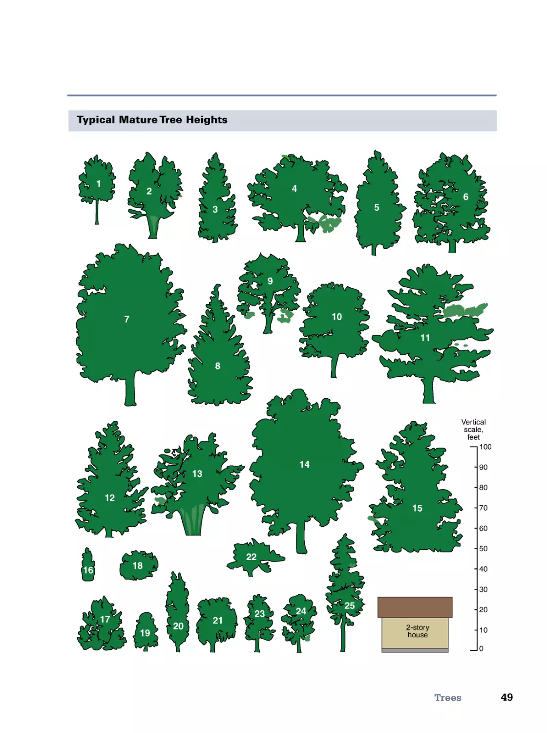
Important in selecting trees are the typical height and width at maturity.
We have included a table of tree dimensions and a chart of tree silhouettes
showing mature trees to scale and next to a typical house.
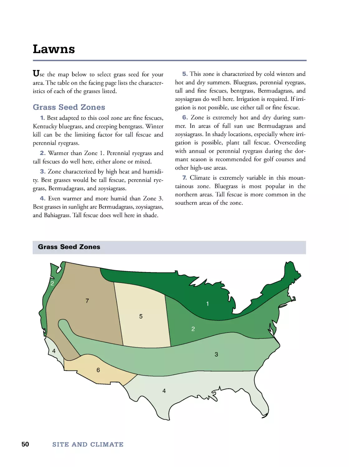
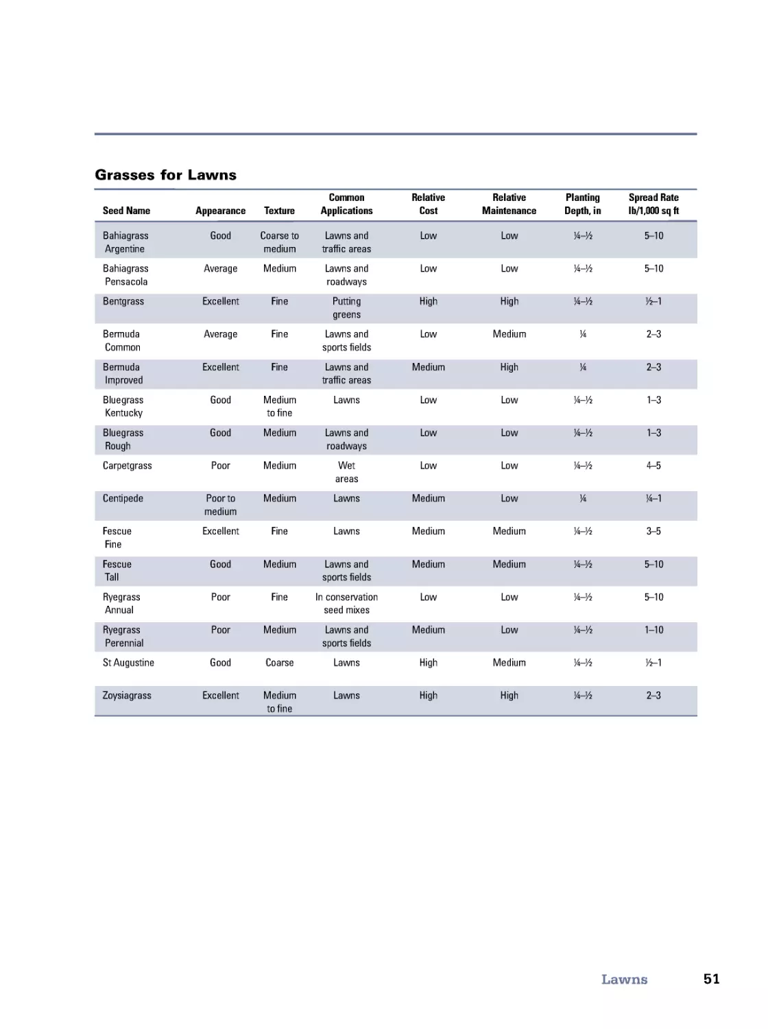
Last but not least, we have provided a table and map of grass seeds to
consider in establishing lawns.
Site and
Climate
1
02
3
4
5
Plot Plans 36
Soil Properties 37
Site Orientation 38
Determining Elevations 39
Driveways 40
Climate Data 42
Shelterbelts 46
Trees 48
Lawns 50
2
35
36
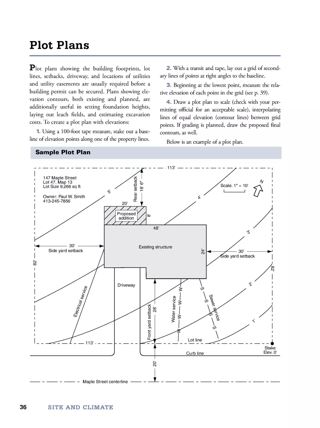
Plot plans showing the building footprints, lot
lines, setbacks, driveway, and locations of utilities
and utility easements are usually required before a
building permit can be secured. Plans showing ele-
vation contours, both existing and planned, are
additionally useful in setting foundation heights,
laying out leach fields, and estimating excavation
costs. To create a plot plan with elevations:
1. Using a 100-foot tape measure, stake out a base-
line of elevation points along one of the property lines.
2. With a transit and tape, lay out a grid of second-
ary lines of points at right angles to the baseline.
3. Beginning at the lowest point, measure the rela-
tive elevation of each point in the grid (see p. 39).
4. Draw a plot plan to scale (check with your per-
mitting official for an acceptable scale), interpolating
lines of equal elevation (contour lines) between grid
points. If grading is planned, draw the proposed final
contours, as well.
Below is an example of a plot plan.
Plot Plans
SITE AND CLIMATE
Driveway
S
e
w
e
r
s
e
r
v
i
c
e
S
S
S
S
Side yard setback
Side yard setback
F
r
o
n
t
y
a
r
d
s
e
t
b
a
c
k
R
e
a
r
s
e
t
b
a
c
k
W
a
t
e
r
s
e
r
v
i
c
e
E
l
e
c
t
r
i
c
a
l
s
e
r
v
i
c
e
W
W
W
W
Maple Street centerline
Curb line
Lot line
Scale: 1" = 10'
N
Proposed
addition
20'
30'
30'
8
'
1
8
'
6
"
113'
8
2
'
2
0
'
2
8
'
8
2
'
113'
147 Maple Street
Lot 47, Map 13
Lot Size 9,266 sq ft
Owner: Paul W. Smith
413-245-7856
Existing structure
48'
2
4
'
1
'
2
'
3
'
4
'
5
'
Stake
Elev. 0'
Sample Plot Plan
37
Soil Properties
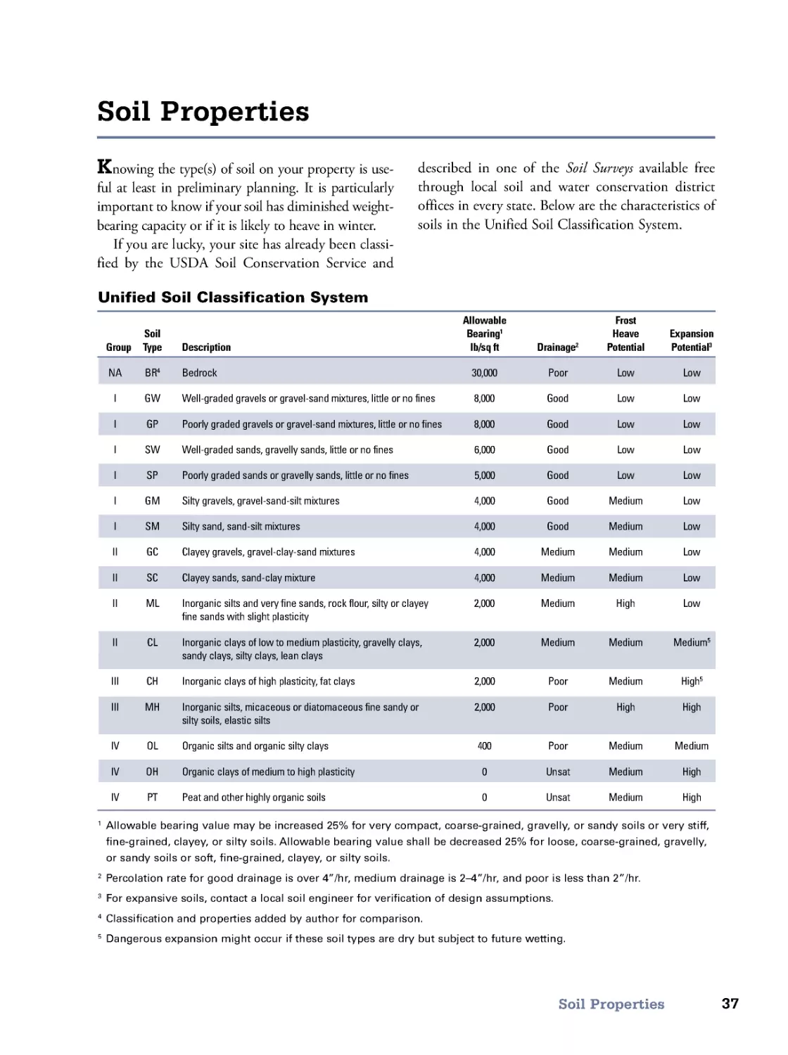
Knowing the type(s) of soil on your property is use-
ful at least in preliminary planning. It is particularly
important to know if your soil has diminished weight-
bearing capacity or if it is likely to heave in winter.
If you are lucky, your site has already been classi-
fied by the USDA Soil Conservation Service and
described in one of the Soil Surveys available free
through local soil and water conservation district
offices in every state. Below are the characteristics of
soils in the Unified Soil Classification System.
Soil Properties
Unified Soil Classification System
Allowable
Frost
Soil
Bearing1
Heave
Expansion
Group Type Description
lb/sq ft
Drainage2
Potential
Potential3
NA BR4 Bedrock
30,000
Poor
Low
Low
I
GW Well-graded gravels or gravel-sand mixtures, little or no fines
8,000
Good
Low
Low
I
GP Poorly graded gravels or gravel-sand mixtures, little or no fines
8,000
Good
Low
Low
I
SW Well-graded sands, gravelly sands, little or no fines
6,000
Good
Low
Low
I
SP Poorly graded sands or gravelly sands, little or no fines
5,000
Good
Low
Low
I
GM Silty gravels, gravel-sand-silt mixtures
4,000
Good
Medium
Low
I
SM Silty sand, sand-silt mixtures
4,000
Good
Medium
Low
II
GC Clayey gravels, gravel-clay-sand mixtures
4,000
Medium
Medium
Low
II
SC Clayey sands, sand-clay mixture
4,000
Medium
Medium
Low
II
ML Inorganic silts and very fine sands, rock flour, silty or clayey
2,000
Medium
High
Low
fine sands with slight plasticity
II
CL Inorganic clays of low to medium plasticity, gravelly clays,
2,000
Medium
Medium
Medium5
sandy clays, silty clays, lean clays
III
CH Inorganic clays of high plasticity, fat clays
2,000
Poor
Medium
High5
III
MH Inorganic silts, micaceous or diatomaceous fine sandy or
2,000
Poor
High
High
silty soils, elastic silts
IV
OL Organic silts and organic silty clays
400
Poor
Medium
Medium
IV
OH Organic clays of medium to high plasticity
0
Unsat
Medium
High
IV
PT
Peat and other highly organic soils
0
Unsat
Medium
High
1 Allowable bearing value may be increased 25% for very compact, coar se-grained, gravelly, or sandy soils or very stiff,
fine-grained, clayey, or silty soils. Allowable bearing value shall be decreased 25% for loose, coar se-grained, gravelly,
or sandy soils or soft, fine-grained, clayey, or silty soils.
2 Percolation rate for good drainage is over 4”/hr, medium drainage is 2–4 ”/hr, and poor is less than 2”/hr.
3 For expansive soils, contact a local soil engineer for verification of design assumptions.
4 Classification and properties added by author for comparison.
5 Dangerous expansion might occur if these soil types are dry but subject to future wetting.
38
The orientation of a building is important, not
only for obtaining a building permit but also for the
performance of any type of solar collector, including
passive solar buildings. Solar gain is maximum for
glazings facing true south, the direction to the sun
when at its greatest altitude.
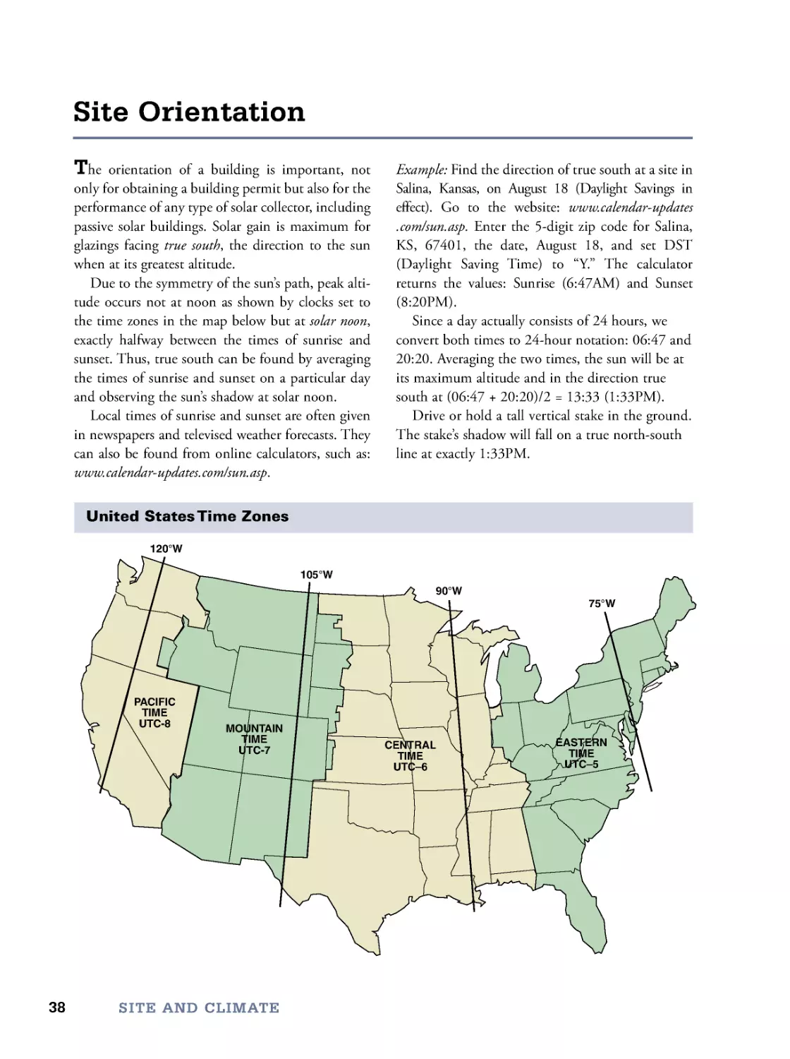
Due to the symmetry of the sun’s path, peak alti-
tude occurs not at noon as shown by clocks set to
the time zones in the map below but at solar noon,
exactly halfway between the times of sunrise and
sunset. Thus, true south can be found by averaging
the times of sunrise and sunset on a particular day
and observing the sun’s shadow at solar noon.
Local times of sunrise and sunset are often given
in newspapers and televised weather forecasts. They
can also be found from online calculators, such as:
www.calendar-updates.com/sun.asp.
Example: Find the direction of true south at a site in
Salina, Kansas, on August 18 (Daylight Savings in
effect). Go to the website: www.calendar-updates
. co m/sun.asp. Enter the 5-digit zip code for Salina,
KS, 67401, the date, August 18, and set DST
(Daylight Saving Time) to “Y.” The calculator
returns the values: Sunrise (6:47AM) and Sunset
(8:20PM).
Since a day actually consists of 24 hours, we
convert both times to 24-hour notation: 06:47 and
20:20. Averaging the two times, the sun will be at
its maximum altitude and in the direction true
south at (06:47 + 20:20)/2 = 13:33 (1:33PM).
Drive or hold a tall vertical stake in the ground.
The stake’s shadow will fall on a true north-south
line at exactly 1:33PM.
Site Orientation
SITE AND CLIMATE
United States Time Zones
90°W
105°W
120°W
75°W
EASTERN
TIME
UTC–5
CENTRAL
TIME
UTC–6
MOUNTAIN
TIME
UTC-7
PACIFIC
TIME
UTC-8
39
Determining Elevations
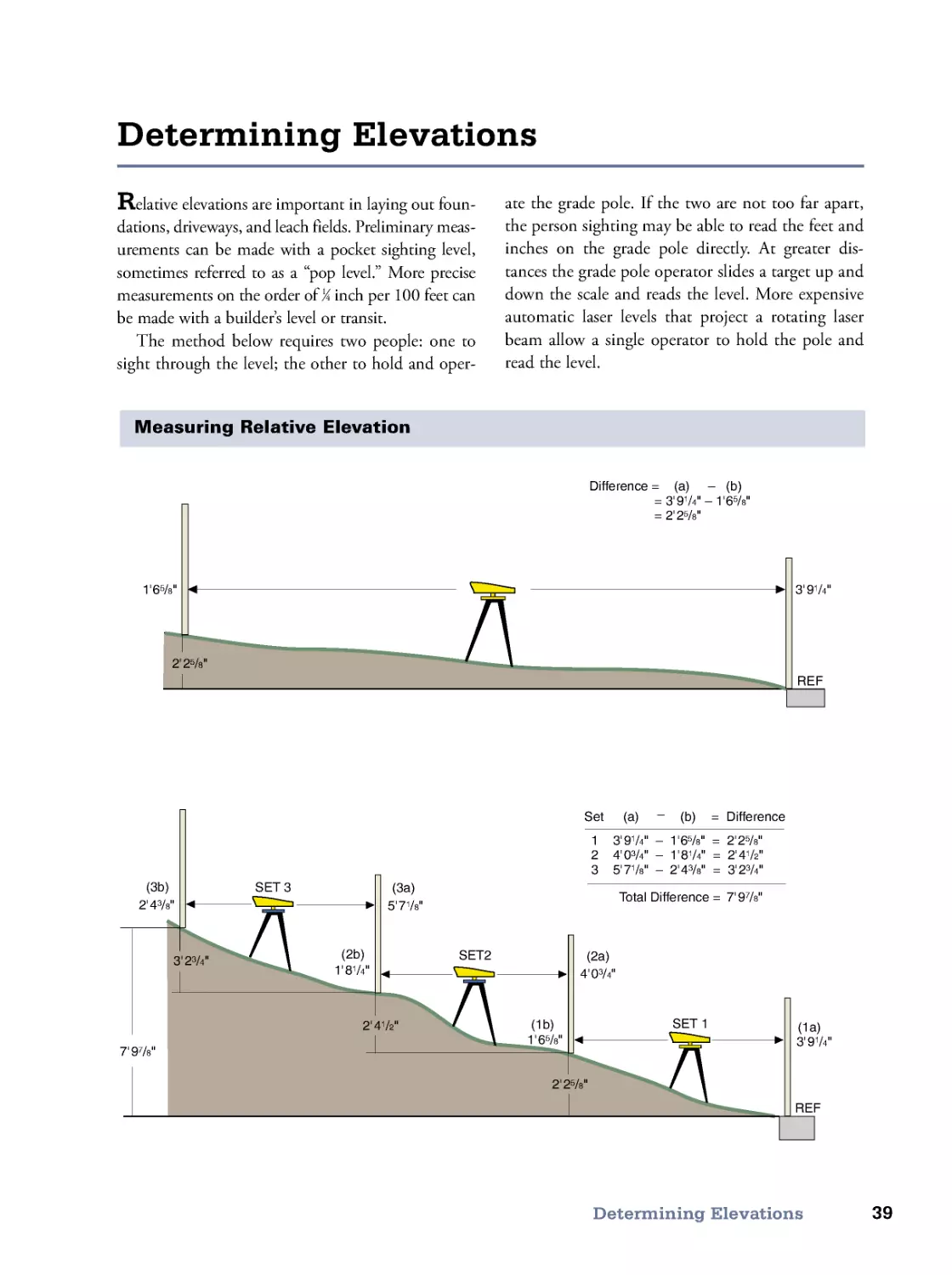
Relative elevations are important in laying out foun-
dations, driveways, and leach fields. Preliminary meas-
urements can be made with a pocket sighting level,
sometimes referred to as a “pop level.” More precise
measurements on the order of 1⁄4 inch per 100 feet can
be made with a builder’s level or transit.
The method below requires two people: one to
sight through the level; the other to hold and oper-
ate the grade pole. If the two are not too far apart,
the person sighting may be able to read the feet and
inches on the grade pole directly. At greater dis-
tances the grade pole operator slides a target up and
down the scale and reads the level. More expensive
automatic laser levels that project a rotating laser
beam allow a single operator to hold the pole and
read the level.
Determining Elevations
1'65/8"
2' 25/8"
3' 91/4"
2' 43/8"
7' 97/8"
5'71/8"
1' 81/4"
2' 41/2"
4'03/4"
1' 65/8"
2' 25/8"
3' 91/4"
REF
(1a)
(2a)
(3a)
(1b)
(2b)
(3b)
3' 23/4"
SET 3
SET2
SET 1
REF
Difference = (a) – (b)
= 3' 91/4" – 1'65/8"
= 2' 25/8"
1 3'91/4" – 1'65/8" = 2'25/8"
2 4'03/4" – 1'81/4" = 2'41/2"
3 5'71/8" – 2'43/8" = 3'23/4"
Set (a)
(b)
–
7' 97/8"
Total Difference =
= Difference
Measuring Relative Elevation
40
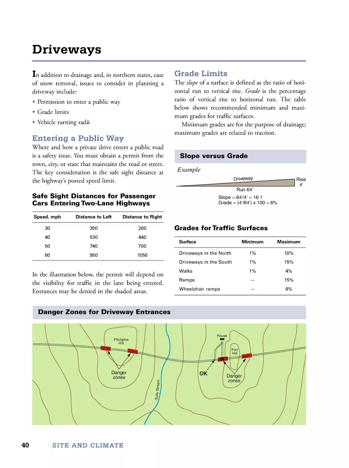
In addition to drainage and, in northern states, ease
of snow removal, issues to consider in planning a
driveway include:
• Permission to enter a public way
• Grade limits
• Vehicle turning radii
Entering a Public Way
Where and how a private drive enters a public road
is a safety issue. You must obtain a permit from the
town, city, or state that maintains the road or street.
The key consideration is the safe sight distance at
the highway’s posted speed limit.
Safe Sight Distances for Passenger
Cars Entering Two-Lane Highways
Speed, mph
Distance to Left
Distance to Right
30
350
260
40
530
440
50
740
700
60
950
1050
In the illustration below, the permit will depend on
the visibility for traffic in the lane being entered.
Entrances may be denied in the shaded areas.
Driveways
SITE AND CLIMATE
Grade Limits
The slope of a surface is defined as the ratio of hori-
zontal run to vertical rise. Grade is the percentage
ratio of vertical rise to horizonal run. The table
below shows recommended minimum and maxi-
mum grades for traffic surfaces.
Minimum grades are for the purpose of drainage;
maximum grades are related to traction.
Pitchpine
Hill
For t
Hill
House
S
u
l
l
y
S
t
r
e
a
m
Danger
zones
Danger
zones
OK
Danger Zones for Driveway Entrances
Slope versus Grade
Grades for Traffic Surfaces
Surface
Minimum
Maximum
Driveways in the North
1%
10%
Driveways in the South
1%
15%
Walks
1%
4%
Ramps
—
15%
Wheelchair ramps
—
8%
Run 64'
Driveway
Slope = 64'/4' = 16:1
Grade = (4'/64') x 100 = 6%
Example
Rise
4'
41
Driveways
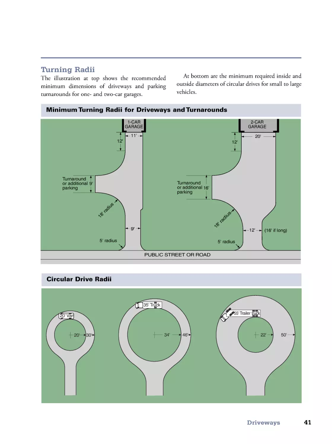
Turning Radii
The illustration at top shows the recommended
minimum dimensions of driveways and parking
turnarounds for one- and two-car garages.
12'
16'
1
8
'
r
a
d
i
u
s
5' radius
5' radius
(16' if long)
2-CAR
GARAGE
9'
12'
1
8
'
r
a
d
i
u
s
1-CAR
GARAGE
Turnaround
or additional
parking
Turnaround
or additional
parking
PUBLIC STREET OR ROAD
9'
12'
20'
11'
Minimum Turning Radii for Driveways and Turnarounds
Circular Drive Radii
34'
46'
35' Truck
22'
50'
55' Trailer truck
20' 30'
20' Van
At bottom are the minimum required inside and
outside diameters of circular drives for small to large
vehicles.
42
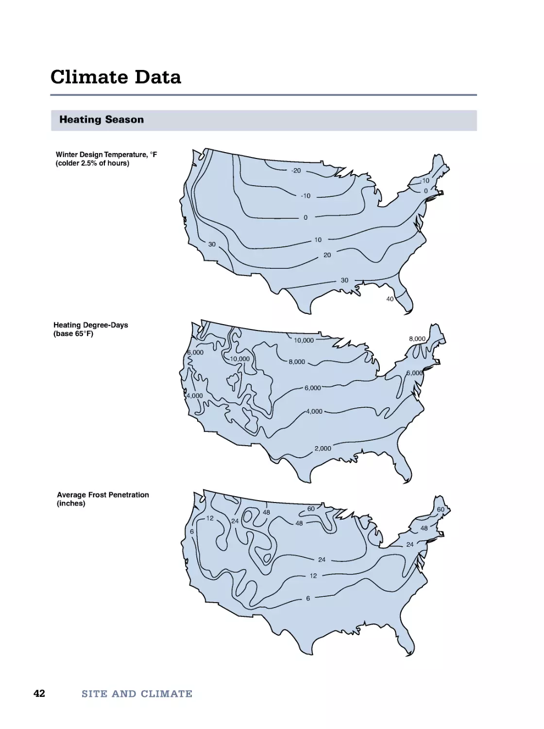
Climate Data
SITE AND CLIMATE
Heating Season
4,000
6,000
8,000
2,000
10,000
8,000
6,000
6,000
4,000
10,000
Heating Degree-Days
(base 65°F)
Average Frost Penetration
(inches)
60
48
24
6
12
24
48
60
48
24
12
6
-20
-10
0
-10
0
10
20
30
40
30
Winter Design Temperature, °F
(colder 2.5% of hours)
43
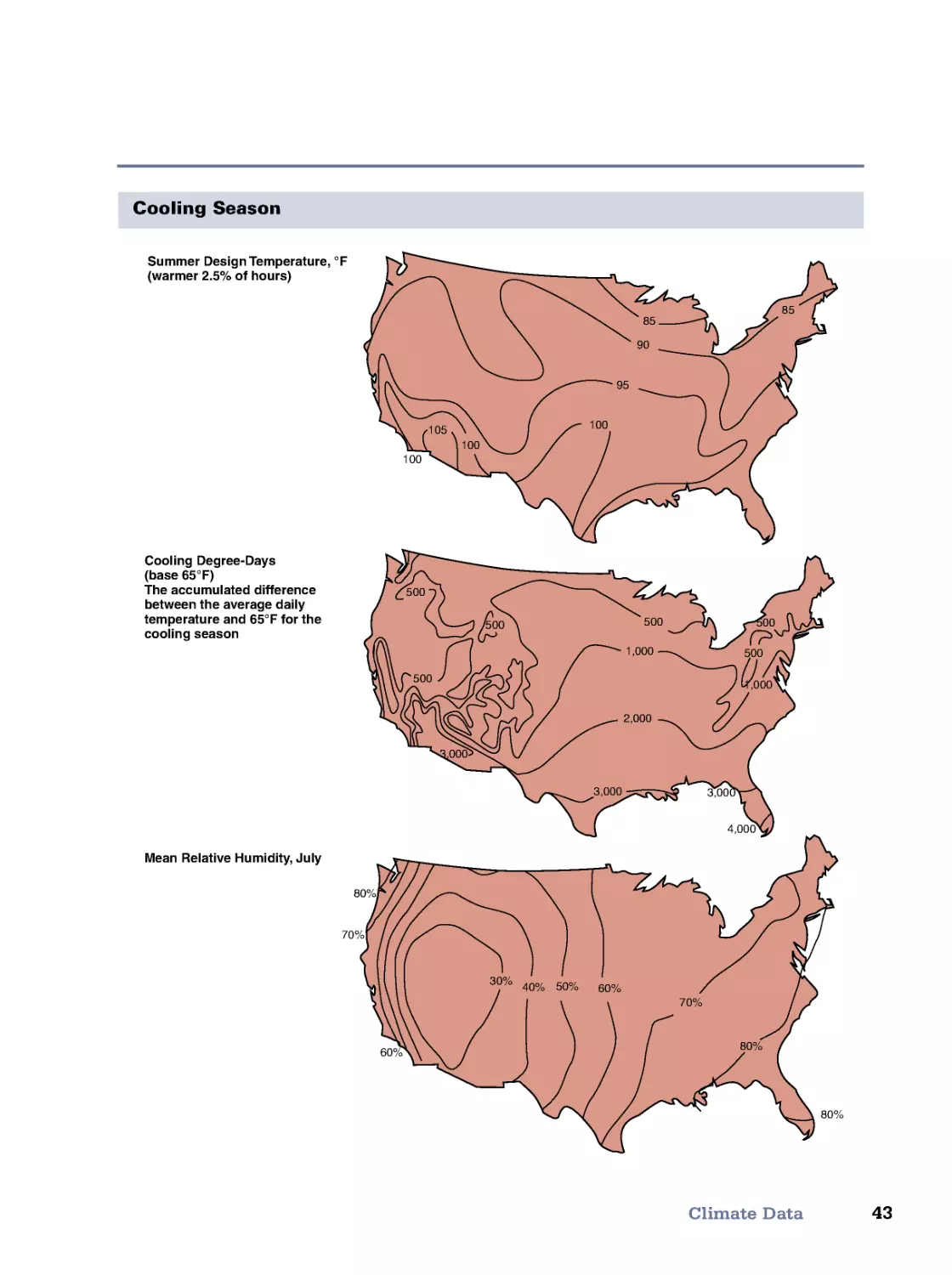
Climate Data
Cooling Season
85
85
90
95
100
105
100
100
Summer Design Temperature, °F
(warmer 2.5% of hours)
Cooling Degree-Days
(base 65°F)
The accumulated difference
between the average daily
temperature and 65°F for the
cooling season
500
500
500
500
1,000
2,000
3,000
3,000
3,000
4,000
1,000
500
500
Mean Relative Humidity, July
80%
80%
70%
60%
80%
70%
60%
50%
40%
30%
44
SITE AND CLIMATE
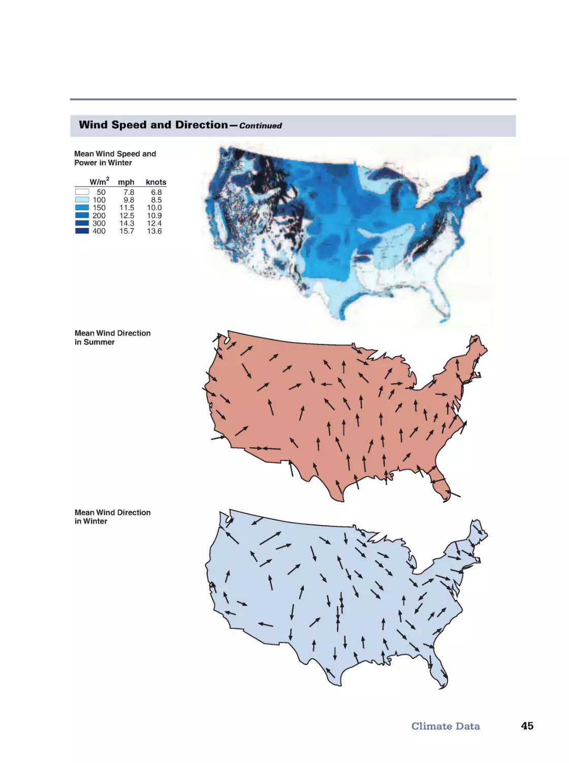
Wind Speed and Direction
W/m2 mph knots
50
100
150
200
300
400
7.8
9.8
11.5
12.5
14.3
15.7
6.8
8.5
10.0
10.9
12.4
13.6
W/m2 mph knots
50
100
150
200
300
400
7.8
9.8
11.5
12.5
14.3
15.7
6.8
8.5
10.0
10.9
12.4
13.6
W/m2 mph knots
50
100
150
200
300
400
7.8
9.8
11.5
12.5
14.3
15.7
6.8
8.5
10.0
10.9
12.4
13.6
Mean Wind Speed and
Power in Spring
Mean Wind Speed and
Power in Summer
Mean Wind Speed and
Power in Fall
45
Climate Data
Wind Speed and Direction—Continued
W/m2 mph knots
50
100
150
200
300
400
7.8
9.8
11.5
12.5
14.3
15.7
6.8
8.5
10.0
10.9
12.4
13.6
Mean Wind Speed and
Power in Winter
Mean Wind Direction
in Summer
Mean Wind Direction
in Winter
46
Shelterbelts
SITE AND CLIMATE
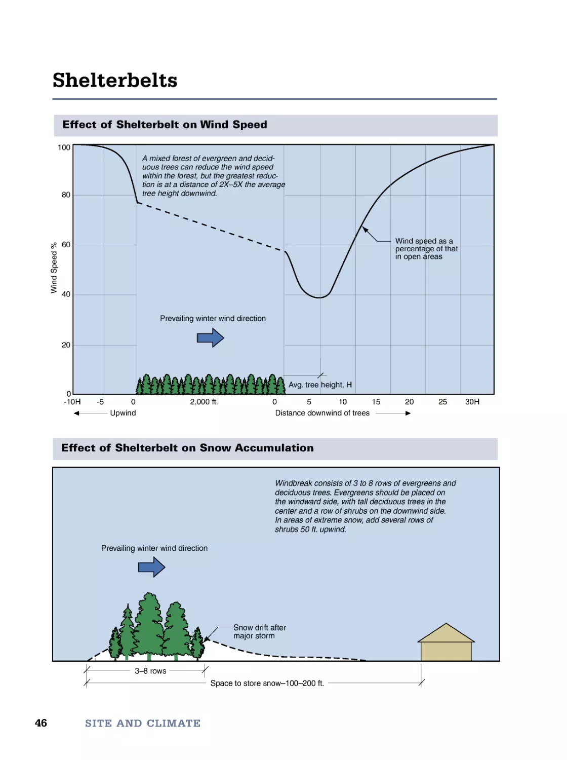
Effect of Shelterbelt on Wind Speed
Effect of Shelterbelt on Snow Accumulation
Space to store snow–100–200 ft.
3–8 rows
Prevailing winter wind direction
P
Snow drift after
major storm
Windbreak consists of 3 to 8 rows of evergreens and
deciduous trees. Evergreens should be placed on
the windward side, with tall deciduous trees in the
center and a row of shrubs on the downwind side.
In areas of extreme snow, add several rows of
shrubs 50 ft. upwind.
A
100
80
-10H -5
0
2,000 ft.
0
5
10
15
20
25
30H
60
40
20
0
W
i
n
d
S
p
e
e
d
%
Distance downwind of trees
Avg. tree height, H
Upwind
Prevailing winter wind direction
S
Wind speed as a
percentage of that
in open areas
A mixed forest of evergreen and decid-
uous trees can reduce the wind speed
within the forest, but the greatest reduc-
tion is at a distance of 2X–5X the average
tree height downwind.
47
Shelterbelts
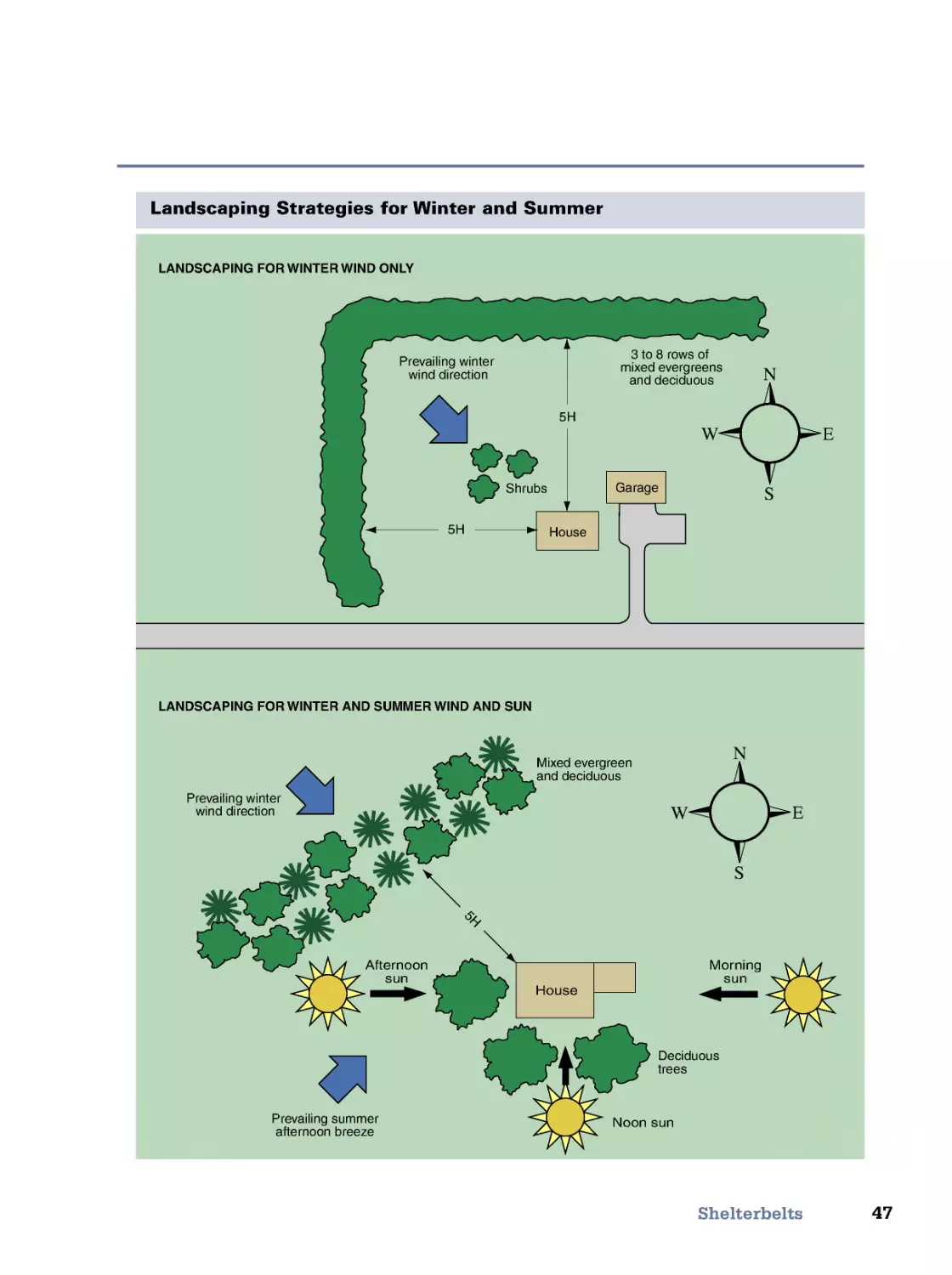
Landscaping Strategies for Winter and Summer
House
Morning
sun
Noon sun
Afternoon
sun
Prevailing summer
afternoon breeze
House
Garage
Shrubs
3to8rowsof
mixed evergreens
and deciduous
Prevailing winter
wind direction
Prevailing winter
wind direction
5H
5H
5
H
N
W
E
S
N
W
E
S
LANDSCAPING FOR WINTER WIND ONLY
LANDSCAPING FOR WINTER AND SUMMER WIND AND SUN
Deciduous
trees
Mixed evergreen
and deciduous
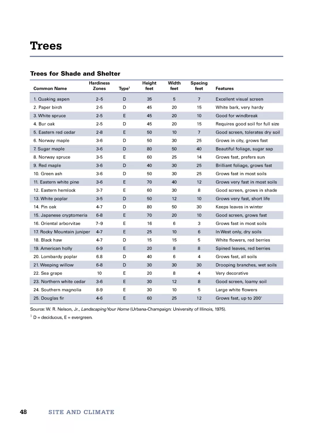
Trees for Shade and Shelter
Hardiness
Height
Width
Spacing
Common Name
Zones
Type1
feet
feet
feet
Features
1. Quaking aspen
2–5
D
35
57
Excellent visual screen
2. Paper birch
2-5
D
45
20
15
White bark, very hardy
3. White spruce
2-5
E
45
20
10
Good for windbreak
4. Bur oak
2-5
D
45
20
15
Requires good soil for full size
5. Eastern red cedar
2-8
E
50
10
7
Good screen, tolerates dry soil
6. Norway maple
3-6
D
50
30
25
Grows in city, grows fast
7. Sugar maple
3-6
D
80
50
40
Beautiful foliage, sugar sap
8. Norway spruce
3-5
E
60
25
14
Grows fast, prefers sun
9. Red maple
3-6
D
40
30
25
Brilliant foliage, grows fast
10. Green ash
3-6
D
50
30
25
Grows fast in most soils
11. Eastern white pine
3-6
E
70
40
12
Grows very fast in most soils
12. Eastern hemlock
3-7
E
60
30
8
Good screen, grows in shade
13. White poplar
3-5
D
50
12
10
Grows very fast, short life
14. Pin oak
4-7
D
80
50
30
Keeps leaves in winter
15. Japanese cryptomeria 6-8
E
70
20
10
Good screen, grows fast
16. Oriental arborvitae
7–9
E
16
6
3
Grows fast in most soils
17. Rocky Mountain juniper 4-7
E
25
10
6
In West only, dry soils
18. Black haw
4-7
D
15
15
5
White flower s, red berries
19. American holly
6-9
E
20
8
8
Spined leaves, red berries
20. Lombardy poplar
6.8
D
40
6
4
Grows fast, all soils
21. Weeping willow
6-8
D
30
30
30
Drooping branches, wet soils
22. Sea grape
10
E
20
8
4
Very decorative
23. Northern white cedar
3-6
E
30
12
8
Good screen, loamy soil
24. Southern magnolia
8-9
E
30
10
5
Large white flowers
25. Douglas fir
4-6
E
60
25
12
Grows fast, up to 200'
Source: W. R. Nelson, Jr., LandscapingYour Home (Urbana-Champaign: University of Illinois, 1975).
1 D = deciduous, E = evergreen.
48
Trees
SITE AND CLIMATE
49
Trees
Typical Mature Tree Heights
1
2
3
5
6
9
7
8
10
11
12
13
14
16
18
22
15
24
25
2-story
house
Vertical
scale,
feet
23
21
20
19
17
4
0
10
20
30
40
50
60
70
80
90
100
50
SITE AND CLIMATE
Use the map below to select grass seed for your
area. The table on the facing page lists the character-
istics of each of the grasses listed.
Grass Seed Zones
1. Best adapted to this cool zone are fine fescues,
Kentucky bluegrass, and creeping bentgrass. Winter
kill can be the limiting factor for tall fescue and
perennial ryegrass.
2. Warmer than Zone 1. Perennial ryegrass and
tall fescues do well here, either alone or mixed.
3. Zone characterized by high heat and humidi-
ty. Best grasses would be tall fescue, perennial rye-
grass, Bermudagrass, and zoysiagrass.
4. Even warmer and more humid than Zone 3.
Best grasses in sunlight are Bermudagrass, zoysiagrass,
and Bahiagrass. Tall fescue does well here in shade.
5. This zone is characterized by cold winters and
hot and dry summers. Bluegrass, perennial ryegrass,
tall and fine fescues, bentgrass, Bermudagrass, and
zoysiagrass do well here. Irrigation is required. If irri-
gation is not possible, use either tall or fine fescue.
6. Zone is extremely hot and dry during sum-
mer. In areas of full sun use Bermudagrass and
zoysiagrass. In shady locations, especially where irri-
gation is possible, plant tall fescue. Overseeding
with annual or perennial ryegrass during the dor-
mant season is recommended for golf courses and
other high-use areas.
7. Climate is extremely variable in this moun-
tainous zone. Bluegrass is most popular in the
northern areas. Tall fescue is more common in the
southern areas of the zone.
Lawns
1
2
3
4
4
5
6
2
7
Grass Seed Zones
Grasses for Lawns
Common
Relative
Relative
Planting
Spread Rate
Seed Name
Appearance Texture
Applications
Cost
Maintenance
Depth, in
lb/1,000 sq ft
Bahiagrass
Good
Coarse to
Lawns and
Low
Low
1⁄4–1⁄2
5–10
Argentine
medium
traffic areas
Bahiagrass
Average
Medium
Lawns and
Low
Low
1⁄4–1⁄2
5–10
Pensacola
roadways
Bentgrass
Excellent
Fine
Putting
High
High
1⁄4–1⁄2
1⁄2–1
greens
Bermuda
Average
Fine
Lawns and
Low
Medium
1⁄42
–
3
Common
sports fields
Bermuda
Excellent
Fine
Lawns and
Medium
High
1⁄42
–
3
Improved
traffic areas
Bluegrass
Good
Medium
Lawns
Low
Low
1⁄4–1⁄2
1–3
Kentucky
to fine
Bluegrass
Good
Medium
Lawns and
Low
Low
1⁄4–1⁄2
1–3
Rough
roadways
Carpetgrass
Poor
Medium
Wet
Low
Low
1⁄4–1⁄2
4–5
areas
Centipede
Poor to
Medium
Lawns
Medium
Low
1⁄41⁄4
–
1
medium
Fescue
Excellent
Fine
Lawns
Medium
Medium
1⁄4–1⁄2
3–5
Fine
Fescue
Good
Medium
Lawns and
Medium
Medium
1⁄4–1⁄2
5–10
Tall
sports fields
Ryegrass
Poor
Fine
In conservation
Low
Low
1⁄4–1⁄2
5–10
Annual
seed mixes
Ryegrass
Poor
Medium
Lawns and
Medium
Low
1⁄4–1⁄2
1–10
Perennial
sports fields
St Augustine
Good
Coarse
Lawns
High
Medium
1⁄4–1⁄2
1⁄2–1
Zoysiagrass
Excellent
Medium
Lawns
High
High
1⁄4–1⁄2
2–3
to fine
51
Lawns
Masonry constitutes man’s oldest building material. Remnants of
masonry structures more than 3,000 years old still exist, bearing witness
to the material’s resistance to the elements.
Chief among masonry materials are concrete, which can be poured
into forms, and mortar, which is the glue used to fasten solid masonry
units together.
Aside from floor slabs, most concrete in residential construction is used
in concrete masonry units (CMU). We begin with the details of typical
CMU wall construction. In addition to the ubiquitous 8×8×16 concrete
block, there is a wide variety of other typical CMU sizes. In addition to
walls, driveways, walks, and patios are often constructed of concrete pavers.
A second whole class of masonry consists of brick. As with concrete, there
is a wide range of standard brick sizes. More than with CMU, brick is used
in a variety of wall positions and patterns to achieve architectural designs.
Walls consisting entirely of brick are rare today. Instead, cost and prac-
tical considerations have led to the development of three hybrid systems:
brick masonry cavity walls, brick veneer/steel stud walls, and brick
veneer/wood stud walls.
In both design and construction, our tables for brick wall heights and
for estimating brick and mortar will prove time savers. And as with con-
crete, bricks are often used in walks and patios as brick pavement.
The last type of masonry is stone. Stone is a very difficult and expen-
sive material for residential construction. However, cultured stone—
concrete cast and colored to resemble a variety of natural stones—makes
possible stone veneer construction.
Finally, we provide another handy crib sheet to make sure your masonry
design will meet the code.
Masonry
1
02
3
4
5
Concrete 54
Mortar 55
CMU Wall Construction 56
Typical CMU Sizes 58
Concrete Pavers 60
Brick Sizes 62
Brick Wall Positions and
Patterns 63
Brick Masonry Cavity Walls 64
Brick Veneer/Steel Stud
Walls 66
Brick Veneer/Wood Stud
Walls 67
Brick Wall Heights 68
Estimating Brick and Mortar 69
Brick Pavement 70
Stone Veneer Construction 72
Meet the Code (IRC) 74
3
53
54
Concrete is reconstituted stone. Consisting of gravel
aggregate, sand, and portland cement, it is as strong
as most naturally occurring rock and will last as
long. Made improperly, it cracks and crumbles and
may have to be replaced within a few years.
Properly made concrete has four characteristics:
1. Correct ratio of clean and well-sized materials.
The proper ratios of materials ensure that all sand
grains are surrounded by cement and that all gravel
pebbles are surrounded by sand.
2. Correct amount of water. Portland cement
chemically combines with the water (the cement
hydrates). Too little water results in unhydrated
cement; too much water leaves voids when the water
eventually escapes.
3. Long curing time. Complete hydration requires
many days. To prevent evaporation of the water, the
surface of the concrete should be kept damp for up to
a week.
4. Air entrainment. When concrete is exposed to
freezing, water within the cured concrete can freeze
and expand and crack the concrete. Air-entraining
admixtures form billions of microscopic air bubbles,
which act as pressure relief valves for freezing water.
Concrete
MASONRY
Recommended Concrete Mixes
Cement
Sand
Gravel
Gal. Water Sand
Makes
Application
94-lb Sacks
cu ft
cu ft
if Dry
Wet
cu ft
Severe weather, heavy wear, slabs < 3” thick
1.0
2.0
2.2
5.0
4.0
3.5
Slabs > 3” thick, sidewalks, driveways, patios
1.0
2.2
3.0
6.0
5.0
4.1
Footings, foundation walls, retaining walls
1.0
3.0
4.0
7.0
5.5
5.0
Estimating Concrete for Slabs, Walks, and Drives (cubic yards)
Slab Area
Slab Thickness, inches
sq ft
234 56 810
12
10
0.1
0.1
0.1
0.2
0.2
0.3
0.3
0.4
50
0.3
0.5
0.6
0.7
0.9
1.2
1.4
1.9
100
0.6
0.9
1.2
1.5
1.9
2.5
3.0
3.7
300
1.9
2.8
3.7
4.7
5.6
7.4
9.4
11.1
500
3.1
4.7
6.2
7.2
9.3
12.4
14.4
18.6
Estimating Concrete for Footings and Walls (cubic yards per linear foot)
Depth/Height
Width or Thickness, inches
inches
68
12
18
24
8
0.012
0.017
0.025
0.037
0.049
12
0.019
0.025
0.037
0.056
0.074
24
0.037
0.049
0.074
0.111
0.148
72
0.111
0.148
0.222
0.333
0.444
96
0.148
0.198
0.296
0.444
0.593
55
Mortar
Mortar is a mixture of cement, lime, and sand for
the bonding together of unit masonry (bricks,
blocks, or stone). It differs from concrete in two
ways: 1) because it is used in thin layers, it contains
no gravel aggregate, and 2) because brick and block
laying is a slow process, it contains hydrated lime to
retain water and retard setup.
Availability
For small jobs requiring up to 1 cubic foot of mor-
tar (about thirty 8×8×16-inch blocks or seventy
2×4×8-inch bricks), purchase a bag of mortar mix
that requires only the addition of water. For larger
jobs, buy sacks of masonry cement. To each sack add
3 cubic feet of clean, sharp sand and enough water
to make the mix plastic. Precolored mortar mixes are
also available through masonry supply outlets.
Mixing
Unless you are a professional mason, or more than
one bricklayer is at work, mix small batches of mor-
tar by hand, because it must be used within approx-
imately 1 hour. Do not lay masonry when there is
any danger of freezing. Calcium chloride accelerator
is sometimes used to speed setup and lessen the
chances of freezing, but it can later cause efflores-
cence (a white, powdery deposit) on wall surfaces.
Use the bottom table below to estimate quantities of
mortar for various masonry wall constructions.
Mortar
Recommended Mortar Mixes
Mortar
Compressive
Portland
Masonry
Type
Strength @ 28 days
Cement
Cement
Sand
M
2,500 psi
1 Bag
1 Bag
6cuft
S
1,800 psi
1/2 Bag
1 Bag
4.5 cu ft
N,S,orM
750 psi
0
1 Bag
3cuft
Estimating Mortar (per 1,000 masonry units)
Mortar
Portland
Masonry
Masonry Unit Dimensions, inches
Type
Cement, lb
Cement, lb
35/8 × 21/4 × 8 standard brick
M
329
245
35/8 × 21/4 × 8 standard brick
S
219
327
35/8 × 21/4 × 8 standard brick
N,S,orM
0
490
35/8 × 35/8 × 8 utility brick
M
423
315
35/8 × 35/8 × 8 utility brick
S
260
420
35/8 × 35/8 × 8 utility brick
N,S,orM
0
700
35/8 × 21/4 × 8 Norman
M
329
245
35/8 × 21/4 ×8 Norman
S
235
350
35/8 × 2× 8 Norman
N,S,orM
0
560
8 ×8 ×16 block
M
1,034
770
8×8 ×16 block
S
705
1,050
8×8 ×16 block
N,S,orM
0
1,750
56
CMU Wall Construction
MASONRY
Typical CMU Wall Construction
Corners and Intersections
Exterior residential walls up to 35 feet in height
may be constructed of 8-inch-thick concrete mason-
ry units (blocks). Interior load-bearing walls may be
the same, or they may be 6-inch-thick up to 20 feet
in height.
Unless protected by shallow-foundation insula-
tion (see Chapter 4), footings must be poured
beneath the local frost depth. Mortar should be
applied only to the perimeter of the block, except on
all faces of blocks to be filled.
The top course of the wall should be made solid,
preferably by filling and reinforcing a continuous
bond beam. Vertical rebar should be placed 16 or
24 inches on-center.
Lap vertical rebar
30x bar diameter
at splices.
Fill with mortar and
vibrate in place.
Fill bond beams to
11/2" of top.
Footing (reinforcing
recommended)
OUTSIDE CORNER, INTERLOCKING
INTERSECTING WALLS, INTERLOCKING
INTERSECTING WALLS, STEEL CONNECTORS
Control joint
No mortar, caulk joint
Fill cores, embedding bars.
57
CMU Wall Construction
Rafter tie
Bond beam
Window unit
Solid backing
Wall finish
Strapping
Rebar
(per code)
Isolation joint
Vent
Drip edge
Lap siding
Insulation/
vertical
strapping
Footing
Rebar
Rafter tie
Bond beam
Window unit
Solid backing
Wall finish
Strapping
Rebar
(per code)
Isolation joint
Cast sill
Cast sill
Drip edge
Drainage
layer
Stucco
coating
Rigid foam
insulation
Footing
Rebar
Vent
WITH STUCCO FINISH
WITH HORIZONTAL LAP SIDING
Typical Walls with Exterior Insulation
58
Typical CMU Sizes
MASONRY
Half partition
35/8"x155/8"x35/8"
Partition
35/8"x75/8"x35/8"
Par tition
35/8"x155/8"x75/8"
Double ends
35/8"x75/8"x75/8"
Double ends
55/8"x155/8"x35/8"
Double ends
55/8"x115/8"x35/8"
Double ends
55/8"x75/8"x75/8"
Half jamb
55/8"x75/8"x75/8"
Half-high double end
75/8"x155/8"x35/8"
Half-high
75/8"x155/8"x35/8"
Half-high stretcher
75/8"x155/8"x35/8"
Half-high
75/8"x75/8"x35/8"
Double end
75/8"x155/8"x75/8"
Regular
75/8"x155/8"x75/8"
Stretcher
75/8"x155/8"x75/8"
Steel sash jamb
75/8"x155/8"x75/8"
Plain ends
75/8"x75/8"x75/8"
Half block
75/8"x75/8"x75/8"
Double ends
75/8"x115/8"x75/8"
Plain ends
75/8"x115/8"x75/8"
Dimensions actual WxLxH
W
L
H
Dimensions of Typical CMU
59
Typical CMU Sizes
Dimensions actual WxLxH
Steel sash jamb
115/8"x155/8"x75/8"
Jamb
115/8"x155/8"x75/8"
Twin
115/8"x155/8"x75/8"
Solid bottom U block
115/8"x155/8"x75/8"
Double ends
115/8"x155/8"x75/8"
Regulars
115/8"x155/8"x75/8"
Stretcher
115/8"x155/8"x75/8"
Single bull-nose
115/8"x155/8"x75/8"
Beam
75/8"x75/8"x115/8"
U lintel
75/8"x155/8"x75/8"
U lintel
75/8"x75/8"x75/8"
U lintel
75/8"x35/8"x75/8"
Pilaster & chimney block
155/8"x155/8"x75/8"
Pilaster
115/8"x155/8"x75/8"
Pilaster
75/8"x155/8"x75/8"
Pilaster
75/8"x155/8"x75/8"
Chimney block
14"x14"x75/8"
Column style no. 1
155/8"x155/8"x75/8"
Flue block
155/8"x155/8"x75/8"
Flue block
155/8"x155/8"x35/8"
W
L
H
Dimensions of Typical CMU—Continued
60
The details for paving patios, walks, and drives
with CMU pavers are similar to those for brick
pavers (see “Brick Pavement” on p. 70). There is an
almost infinite variety of shapes and sizes of CMU
pavers. Some of the most common are shown
below. Many of the shapes are available in several
earthtone colors. Check with local suppliers before
designing your project.
Concrete Pavers
MASONRY
Common CMU Paver Sizes
Common CMU Paver Sizes
75/8"x155/8"x15/8"6
"
x
1
6
"
x
2
"
1
2
"
x
1
2
"
x
2
"
1
2
"
x
1
6
"
x
2
"
12"x24"x2"
15"x15"x2"
16"x16"x2"
12"x16"x2"
6"x16"x21/4"7
5
/8"x155/8"x21/4"1
6
"
x
2
4
"
x
2
1/4"5
5
/8"x155/8"x35/8"
75/8"x115/8"x35/8"7
5
/8"x155/8"x35/8"1
1
5
/8"x155/8"x35/8"1
5
5
/8"x155/8"x35/8"
12"x20"x4"
75/8"x155/8"x55/8"1
2
"
x
1
6
"
x
6
"7
5
/8"x155/8"x75/8"
Dimensions actual WxLxH
W
L
H
Concrete pavers
1"–11/2" sand
Compacted
aggregate
Geotextile
Original or
compacted soil
Edge restraint
61
Concrete Pavers
Edge Restraints
LANDSCAPE TIMBER RESTRAINT
PRECAST CONCRETE RESTRAINT
PLASTIC EDGE RESTRAINT
Plastic edge
restraint
Stake
Bedding sand
Concrete paver
Compacted
aggregate
Undisturbed earth
STEEL ANGLE RESTRAINT
Landscape
timber
Stake
Bedding sand
Concrete paver
Compacted
aggregate
Undisturbed earth
Steel angle
edge restraint
Stake
Bedding sand
Concrete paver
Compacted
aggregate
Undisturbed earth
Partial-depth
precast concrete
Stake
Bedding sand
Concrete paver
Compacted
aggregate
Undisturbed earth
62
Brick Sizes
MASONRY
Standard
33/4"x8"x21/4"
Oversize
33/4"x8"x23/4"
Three inch
3"x93/4"x23/4"
Standard
4"x8"x22/3"
Engineer
4"x8"x31/5"
Jumbo closure
4"x8"x4"
Double
4"x8"x51/3"
Roman
4"x12"x2"
Norman
4"x12"x22/3"
Norwegian
4"x12"x31/5"
Jumbo utility
4"x12"x4"
Triple
4"x12"x51/3"
SCR brick
6"x12"x22/3"
6" Norwegian
6"x123"x31/5"
6" Jumbo
6"x12"x4"
8" Jumbo
8"x12"x4"
NON-MODULAR BRICK
(dimensions actual WxLxH)
MODULAR BRICK
(dimensions nominal WxLxH)
W
L
H
Dimensions of Common Bricks
63
Brick Wall Positions and Patterns
Brick Wall Positions and Patterns
Rowlock
stretcher
Header
Stretcher
Soldier
Rowlock
header
BRICK POSITIONS
BRICK PATTERNS
Stretcher
FLEMISH
FLEMISH CROSS
DUTCH
ENGLISH
GARDEN WALL
COMMON WITH
FLEMISH HEADERS
RUNNING
COMMON
Brick Position and Pattern Terminology
64
Brick and concrete masonry unit cavity wall con-
struction is common in commercial and southern res-
idential building. Best building practice requires the
use of durable brick (grade SW in ground contact
and freeze areas) and adherence to proper detailing.
Proper detailing requires the use of drips at sills,
flashing at wall top and bottom, flashing at win-
dow and door heads and sills, provision for weep
holes at all flashings, and caulking at the junctions
of masonry and nonmasonry materials.
Insulation is required in most locations, and a
draining cavity is recommended in areas of wind-
driven rain.
Brick Masonry Cavity Walls
MASONRY
Reinforced bond beam
Anchor bolt
Top plate
3-Wire
ladder
Tabbed
ladder
Ladder
tie
Rectangular
tie
Z-tie
Anchor
bolt
Reinforced
bond beam
Floor Load Bearing
Wall Ties
Brick/Masonry Cavity Construction
Roof Load Bearing
Wall Tie Spacing Requirements
Tie Wire Size
Wall Area per Tie Max. Tie Spacing
in. (mm)
No. per ft2 (m2) Horizontal × Vertical
W1.7 (MW11)
22/3 (0.25)
36×24
0.125 (3.06)
(914 × 610)
W2.8 (MW18)
41/2 (0.42)
36×24
0.188 (4.76)
(914 × 610)
Adjustable, with 2 1.77 (0.16)
16×16
W2.8 (MW18)
(406 × 406)
1.88 (4.76) legs
65
Brick Masonry Cavity Walls
Flashing
Tie
Drywall
CMU
Weep hole
Cavity seal
Backer rod
and sealant
Wall Tie
Insulation
Flashing
Weep hole
Air space
Fill below
flashing
Flashing at Bottom of Wall
Flashing
Tie
Drywall
CMU
Weep hole
Steel dowel
Cavity seal
Backer rod
and sealant
Through-wall
flashing
Lintel
Weep hole
Backer rod
and sealant
Steel lintel
Through-wall flashing
Brick
outer
wythe
CMU inner wythe
1" high, min.
Flashing
Prefab corners
Flashing at Heads
Flashing at Sills
66
Brick Veneer/Steel Stud Walls
MASONRY
The brick veneer/steel stud wall system has grown,
from its introduction in the 1960s, to one of the
most widely used in commercial, industrial, and
institutional building.
Because this style of building rarely has overhangs
or gutters, the wall is not as well protected from rain,
and the resulting incursion of water has required care-
ful detailing of windscreen and flashings. The illus-
trations below detail flashings at wall bottoms,
heads over doors and windows, and window sills.
As with all brick construction, best practice
requires the use of durable brick (grade SW) in
ground contact and freeze areas.
Adjustable tie
Weep hole
Brick sill
Backer rod
and sealant
Metal flashing
Drywall
Sheathing
Doubled
steel track
Window
unit
Cavity
insulation
Wire and screw tie
Eye and pintle tie
Base and tee tie
Base and tee
with prongs
Adjustable tie
Weep hole
Metal flashing
Drywall
Sheathing
Steel stud
Header
Cavity insulation
Building wrap
Steel lintel
Sealant
Window or
door unit
Flashing at Heads
Wall Ties
Flashing at Sills
Adjustable tie
Weep hole
Metal flashing
(grout below)
Drywall
Sheathing
Steel stud
Cavity insulation
Flashing at Bottom of Wall
Brick Veneer and Steel Framing
67
Brick Veneer/Wood Stud Walls
Brick Veneer/Wood Stud Walls
Despite its obvious strength in compression, brick
veneer over a wood frame wall functions as a low-
maintenance exterior finish only and not as a struc-
tural element. This is because brick and wood
expand and contract with moisture and temperature
differently and so cannot be rigidly bonded in the
vertical plane. Because a thin brick wythe has little
bending strength against wind and earthquake,
however, it must be tied to the stronger wood stud
wall horizontally.
The illustrations below show the most common
connecting wall ties and detail the recommended
flashing at wall bottoms, heads, and sills.
Weep hole
Brick sill
Backer rod
and sealant
Metal flashing
Drywall
Mortar fill
Sheathing
Window
unit
Sill
Cavity
insulation
Building wrap
Wall tie
Wire and screw tie
Corrugated
Corrugated and wire
Eye and pintle tie
Base and tee
with prongs
Steel lintel
Sealant
Weep hole
Metal flashing
Building wrap
Drywall
Sheathing
Wood stud
Header
Window or
door unit
Cavity insulation
Wall tie
Flashing at Heads
Wall Ties
Flashing at Sills
Wall tie
Weep holes
Metal flashing
(grout below)
Drywall
Sheathing
Wood stud
Cavity insulation
Flashing at Bottom of Wall
Brick Veneer and Wood Framing
68
Brick Wall Heights
MASONRY
Heights of Modular Brick Walls
Number of
Nominal Height (thickness) of Brick
Courses
2-in
22/3-in
31/5-in
4-in
51/3-in
10
'2"
0'211/16"0
'33/16"0
'4"
0'55/16"
2
0'4"
0'55/16"0
'63/8"
0'8"
0'1011/16"
3
0'6"
0'8"
0'95/8"
1'0"
1'4"
4
0'8"
0'1011/16"1
'013/16"
1'4"
1'95/16"
5
0'10"
1'15/16"1
'4"
1'8"
2'211/16"
6
1'0"
1'4"
1'73/16"
2'0"
2'8"
7
1'2"
1'611/16"1
'103/8"
2'4"
3'15/16"
8
1'4"
1'95/16"2
'15/8"
2'8"
3'611/16"
9
1'6"
2'0"
2'413/16"
3'0"
4'0"
10
1'8"
2'211/16"2
'8"
3'4"
4'55/16"
11
1'10"
2'55/16"2
'113/16"
3'8"
4'1011/16"
12
2'0"
2'8"
3'23/8"
4'0"
5'4"
13
2'2"
2'1011/16"3
'55/8"
4'4"
5'95/16"
14
2'4"
3'15/16"3
'813/16"
4'8"
6'211/16"
15
2'6"
3'4"
4'0"
5'0"
6'8"
Heights of Nonmodular Brick Walls
Number of
21/4-in-thick Bricks
25/8-in-thick Bricks
23/4-in-thick Bricks
Courses
3/8-in Joint
1/2-in Joint
3/8-in Joint
1/2-in Joint
3/8-in Joint
1/2-in Joint
10
'25/8"0
'23/4"0
'3"
0'31/8"0
'31/8"0
'31/4"
2
0'51/4"0
'51/2"0
'6"
0'61/4"
0'61/4"
0'61/2"
3
0'77/8"0
'81/4"0
'9"
0'93/8"
0'93/8"
0'93/4"
4
0'101/2"0
'11"
1'0"
1'01/2"
1'01/2"1
'1"
5
1'11/8"1
'13/4"1
'3"
1'35/8"
1'35/8"1
'41/4"
6
1'33/4"1
'41/2"1
'6"
1'63/4"
1'63/4"1
'71/2"
7
1'63/8"1
'71/4"1
'9"
1'97/8"
1'97/8"1
'103/4"
8
1'9"
1'10"
2'08"
2'1"
2'1"
2'2"
9
1'115/8"2
'03/4"2
'3"
2'41/8"
2'41/8"
2'51/4"
10
2'21/4"2
'31/2"2
'6"
2'71/4"
2'71/4"
2'81/2"
11
2'47/8"2
'61/4"2
'9"
2'103/8"
2'103/8"
2'113/4"
12
2'71/2"2
'9"
3'0"
3'11/2"
3'11/2"
3'3"
13
2'101/8"2
'113/4"3
'3"
3'45/8"
3'45/8"
3'61/4"
14
3'03/4"3
'21/2"3
'6"
3'73/4"
3'73/4"
3'91/2"
15
3'33/8"3
'51/4"3
'9"
3'107/8"
3'107/8"
4'03/4"
69
Estimating Brick and Mortar
Estimating Brick and Mortar
Modular Brick1 and Mortar2 Required for Single-Wythe Walls in Running Bond
Nominal Size of Number of
Cubic Feet of Mortar/
Cubic Feet of Mortar/
Brick, in
Brick/
100 sq ft
1,000 Brick
T×H×L
100 sq ft
3/8-in Joints
1/2-in Joints
3/8-in Joints
1/2-in Joints
4×22/3×8
675
5.5
7.0
8.1
10.3
4×31/5×8
563
4.8
6.1
8.6
10.9
4×4×8
450
4.2
5.3
9.2
11.7
4×51/3×8
338
3.5
4.4
10.2
12.9
4×2×12
600
6.5
8.2
10.8
13.7
4×22/3×12
450
5.1
6.5
11.3
14.4
4×31/5×12
375
4.4
5.6
11.7
14.9
4×4×12
300
3.7
4.8
12.3
15.7
4×51/3×12
225
3.0
3.9
13.4
17.1
6×22/3×12
450
7.9
10.2
17.5
22.6
6×31/5×12
375
6.8
8.8
18.1
23.4
6×4×12
300
5.6
7.4
19.1
24.7
1 Add at least 5% for breakage.
2 Add 10% to 25% for waste.
Nonmodular Brick1 and Mortar2 Required for Single-Wythe Walls in Running Bond
With 3/8-in Joints
With 1/2-in Joints
Size of
Number of
Cubic Feet
Cubic Feet
Number of
Cubic Feet
Cubic Feet
Brick, in
Brick/
of Mortar/
of Mortar/
Brick/
of Mortar/
of Mortar/
T×H×L
100 sq ft
100 sq ft
1,000 Brick
100 sq ft
100 sq ft
1,000 Brick
23/4×23/4×93/4
455
3.2
7.1
432
4.5
10.4
25/8×23/4×83/4
504
3.4
6.8
470
4.1
8.7
33/4×21/4×8
655
5.8
8.8
616
7.2
11.7
33/4×23/4×8
551
5.0
9.1
522
6.4
12.2
1 Add at least 5% for breakage.
2 Add 10% to 25% for waste.
70
Compared with asphalt and concrete paving, brick
paving is more attractive, will not crack (the cracks
are part of the design), and is easy to repair.
Below are designs for a walkway, a driveway, and
two patios. The use of Severe Weather (SW) grade
brick is recommended in all cases. All should incor-
porate a slope for drainage. Walks and drives should
slope at least 1/4 inch per foot (2% grade), but no
more than 13/4 inches per foot (15% grade).
Patios should slope from 1/8 to 1/4 inch per foot (1%
to 2% percent grade). The slopes can be from one
edge to the other or from the center to the edges.
Brick Pavement
MASONRY
WALKWAY–GRAVEL BASE
PATIO–SAND BASE
DRIVEWAY–BRICK ON EDGE
PATIO–GRAVEL BASE
15-lb roofing felt
2" screened stone
Compacted earth
3/8" expansion joint material
Compacted earth
2" sand base
15-lb roofing felt
Soldier course in concrete
Compacted earth
2" screened stone
Bricks on edge
Mortared brick curb set in concrete
4" washed gravel
1" screened stone
4" pipe drain tile
Soldier course in concrete
Sailor course in concrete
Bases for Brick Pavement
71
Brick Pavement
STACK BOND
BASKET WEAVE
HERRINGBONE
RUNNING BOND
HALF-BASKET
BASKET ON EDGE
OFFSET BOND
DOUBLE-BASKET
BASKET/WOOD GRID
Brick Pavement Patterns
72
Stone walls may be built entirely of stone or they
may be cultured stone (cast concrete) over a base
wall of solid concrete, concrete masonry units, or
wood frame and sheathing. Cultured stone is pre-
ferred today as it allows for thermal insulation.
Mortar joints should be 1/2 to 1 inch thick for
rubble and 3/8 to 3/4 inch thick for ashlar patterns.
To prevent staining, all fasteners should be stain-
less; flashing should be either stainless or hot-dipped
galvanized steel; and mortar should be nonstaining.
Stone Veneer Construction
MASONRY
Construction Details
Cultured stone
Cultured stone
Mortar joint
Mortar setting bed
CMU wall
Rebar in filled
core per Code
Cultured stone
Mortar joint
Mortar setting bed
Poured concrete
Rebar per Code
Cultured stone
Mortar joint
Mortar setting bed
Scratch coat over
paper-faced lath
Cavity insulation
Stud
Cultured stone
Mortar joint
Mortar setting bed
Scratch coat over
paper-faced lath
Rigid insulation
Cavity insulation
Stud
Cultured stone
Mortar joint
Mortar setting bed
Tilt-up concrete panel
Rebar per Code
OVER CONCRETE BLOCK
OVER POURED CONCRETE
OVER TILT-UP CONCRETE
OVER OPEN STUD WALL
OVER SHEATHING
Sheathing
Air barrier
Mortar setting
bed over lath
Mortar joint
Stud
Cavity insulation
OVER RIGID INSULATION
73
Stone Veneer Construction
COURSED ASHLAR
FIELDSTONE
RANDOM ASHLAR
MOSAIC
THREE-HEIGHT RANDOM ASHLAR
COURSED RUBBLE
Stone Patterns
74
Meet the Code (IRC)
MASONRY
The following is a partial list of requirements from
the 2015 International Residential Code (IRC) for
One- and Two-Family Dwellings. Consult the publi-
cation for the full text and additional provisions.
Concrete Floors on Ground (R506)
• slab thickness: ≥31/2 inches
• where provided, reinforcement should be supported
at center to upper third of slab during pour
Compressive strength:
• exposed to negligible or no weathering, 2,500 psi
• exposed to moderate weathering, 3,000 psi
• porches, steps, and garage floor slabs exposed to
severe weathering, 3,500 psi
Base preparation:
• vegetation, top soil, and foreign material removed
• fill free of vegetation and foreign material
• fill compacted to ensure uniform support
• fill depths ≤24 inches for clean sand and gravel
and ≤8 inches for earth
• 4-inch base course of clean sand, gravel, or
crushed stone when the slab is below grade
• base course not required if slab on well-drained or
sand-gravel mixture soils classified as Group I
• 6-mil vapor retarder with joints lapped ≥6 inches
between slab and base course or prepared subgrade
Exceptions—may be omitted from:
1. garages, carports, other unheated structures
2. driveways, walks, and patios
3. unheated storage rooms of ≤70 sq.ft.
Masonry Wall Construction (R606)
• minimum thickness of masonry bearing walls
more than one story high 8 inches
• minimum thickness of solid masonry walls ≤9 feet
high in 1-story dwellings and garages 6 inches, except
an additional 6 feet is permitted to a gable peak
• rubble stone masonry wall thickness ≥16 inches
• a course of solid masonry is required where hollow
unit walls decrease in thickness
Support considerations:
• beams/girders must have bearing of ≥3" on a solid
wall or column ≥4" thick or on a metal plate
• joists must have bearing of ≥11/2"
• interior nonload-bearing walls must be anchored
at intersections with ≥9-gauge or 1/4-inch galva-
nized mesh at vertical intervals of ≤16"
• other intersecting walls must be anchored at inter-
sections with ≥9-gauge galvanized mesh at vertical
intervals of ≤8" extending ≥30" in both directions
• masonry walls to be laterally supported at intervals
shown in Table R606.6 .4
Table R606.6.4
Max. Wall Length/Thickness
Construction
or Wall Height/Thickness
Bearing walls:
Solid or solid grouted
20
All other
18
Nonbearing walls:
Exterior
18
Interior
36
Mortar placement:
• unless otherwise required, head and bed joints
3/8 inch thick, except bed of starting course over
foundations shall be 1/4 – 3/4 inch
• mortar joint thickness shall be within the follow-
ing tolerances from the specified dimensions:
1. Bed joint: + 1/8 inch
2. Head joint: 1/4 inch + 3/8 inch
3. Collar joints: 1/4 inch + 3/8 inch
Exception: Nonload-bearing and masonry veneers
• mortar plasticity and pressure sufficient to extrude
mortar from the joint and produce a tight joint
• no furrowing of bed joints producing voids
• if bond broken after initial placement, unit must
be relaid in fresh mortar
• mortared surfaces clean and free of deleterious
materials
• solid masonry units laid with full head, bed, and
interior vertical joints filled
75
Meet the Code (IRC)
• hollow masonry unit head and bed mortar joints
not less than the thickness of the face shell
• wall tie ends embedded in mortar joints
• wall tie ends to engage outer face shells of hollow
units by at least 5/8 inch
• wire wall ties embedded at least 11/2 inches into
mortar bed of solid masonry units or solid grouted
hollow units
• wall ties must not be bent after embedment
Grouted masonry:
• grout to consist of cementitious material and
aggregate in accordance with ASTM C476
• Type M or Type S mortar with pouring consis-
tency can be used as grout
• if grout pour stopped for 1 hour, horizontal
joints shall be formed by stopping all tiers at
same elevation with grout 1 inch below top
• mortar projecting >
1
/2 inch into grout space to be
removed before inspection and grouting
• grout to be placed before any initial set and
<1
1
/2 hours after water added
• maximum pour heights and minimum spaces for
grout placement to conform to Table R606.3 .5 .1
• grout poured continuously in lifts ≤5 feet
• grout to be consolidated by puddling or vibration
during placement
• no grout pumping through aluminum pipes
• grout cleanouts may be required by official
• cleanouts to be sealed before pour
• cleanouts required at bottom course at each pour
of grout, where pour exceeds 4 feet in height
• fine grout required if vertical space ≤2 inches
• vertical grout barriers of solid masonry entire
height of wall to control horizontal flow of grout
• grout barriers to be >25 feet apart
• grouting between vertical barriers to be complet-
ed in one day with no interruptions >1 hour
Reinforcement of hollow unit masonry:
• horizontal grout or mortar between units and
reinforcement ≥1/4 inch
Exceptions:
1. 1/4-inch bar in horizontal mortar of thick-
ness ≥1/2 inch
2. steel wire reinforcement in mortar ≥2×
the wire diameter
• reinforced hollow-unit masonry must preserve
unobstructed vertical continuity of cells to be filled
• walls and cross webs forming filled cells to be
full-bedded in mortar to prevent leakage of grout
• head and end joints to be filled with mortar not less
than the thickness of the longitudinal face shells
• bond provided by lapping units in successive ver-
tical courses
• align filled cells to maintain an unobstructed vertical
cell of dimensions prescribed in Table R606.3.5.1.
• vertical rebar held in position at top and bottom
and at intervals of ≤200 reinforcement diameter
• cells containing rebar filled solidly with grout
• grout to be poured in lifts of ≤8 feet, except if
pour >8 feet, grout to be placed in lifts of ≤5 feet
and inspection during pour required
• horizontal steel to be fully embedded in grout in
an uninterrupted pour
Table R606.3 .5 .1
Grout
Max. Pour Min. Spacea,b
Min Spaceb,c
Type
Height, ft
Width, in
Hollow Units, in
Fine
1
0.75
1.5×2
52 2×3
12
2.5
2.5×3
24
3
3×3
Coarse
1
1.5
1.5×3
52 2.5×3
12
2.5
3×3
24
3
3×4
a
For grouting between masonry wythes.
b Grout space dimension is the clear dimension between
any masonry protrusion and shall be increased by the
horizontal projection of the diameters of the horizontal
bars within the cross section of the grout space.
c
Area of vertical reinforcement shall not exceed 6 percent
of the area of the grout space.
Many homeowners—even builders—think the words ”foundation” and
“basement” are synonymous. In northern states this is understandable,
since about 90 percent of homes there have basements. But as the foun-
dation design section shows, there are many other options for founda-
tions. Your choice should be determined by the functions you want the
foundation to perform.
After you choose the style (full basement, crawl space, or slab on
grade), you must choose the material (poured concrete, masonry, or all-
weather wood).
In this age of energy conservation, foundations must be insulated
against heat loss. Each of the 18 detailed foundation designs indicate the
placement of insulation, but recommended types and R-values are shown
in greater detail in Chapter 14, “Best Practice Insulating.”
Additional sections cover the details of ground moisture control, termite
control, and radon mitigation.
Finally, we provide you with a checklist of requirements so that your
foundation will meet the code (IRC).
Foundations
1
02
3
4
5
Foundation Design 78
Full Basements 80
Crawl Spaces 87
Slabs on Grade 93
Ground Moisture Control 97
Termite Control 99
Radon Mitigation 101
Meet the Code (IRC) 103
4
77
4
78
Vitruvius (80 BC to 25 BC), in his De architecture,
had it right, “Durability will be assured when foun-
dations are carried down to the solid ground and
materials wisely and liberally selected.”
Functions of Foundations
The longevity of many Roman public buildings is
testimony to Vitruvius having identified that most
important function of the foundation—transferring
the weight of the building to stable ground. Since
his day, however, we have added considerably to the
foundation’s list of duties. In selecting or designing
an appropriate building foundation, one must now
keep in mind all these possibilities:
• transfer building loads to the ground
• anchor the building against wind
• anchor the building against earthquakes
• isolate the building from frost heaving
• isolate the building from expansive soil
• support the building above ground moisture
• retard heat loss from the conditioned space
• provide dry storage space
• provide possible comfortable living space
• house the mechanical systems
Designing the Foundation
The design (decision-making) process should involve
these eight steps:
1. Select the basic foundation style.
2. Select the material of which the foundation
will be constructed (poured concrete, masonry
units, or pressure-treated wood).
3. Decide if it is to be unconditioned or condi-
tioned (heated to 65°F and cooled to 75°F).
4. Select the type and R-value of its insulation.
5. Detail its structure, insulation application, and
possible finish.
6. Detail its control of moisture (including sur-
face runoff, groundwater, and water vapor).
7. Detail its barriers against termites.
8. Detail its built-in radon mitigation.
The illustration below shows the three basic foun-
dation types (full basement, crawl space, and slab on
grade), each of which will be detailed in a number of
variations in the following pages. Regardless of foun-
dation type, however, all designs should conform,
where applicable, to the list of best practices described
on the facing page and the illustrations in Chapter 14.
Foundation Design
FOUNDATIONS
FULL BASEMENT
CRAWL SPACE
SLAB ON GRADE
The Three Basic Foundation Types
79
Foundation Design
Foundation Best Practices
Surface Drainage The surface next to the
foundation should slope downward at least 6 inches
in 10 feet to steer surface runoff away from the
building. If practical, gutters should be used to col-
lect roof runoff.
Backfill Foundation backfill should be topped
with low permeability soil to divert surface runoff.
Porous sand or gravel should be placed against the
walls to provide an easy path to the drain tile. In
place of porous backfill, a drainage mat or insulating
board with drainage channels may be placed against
the foundation wall.
Dampproofing A dampproof coating cov-
ered by a 4- or 6-mil layer of polyethylene is rec-
ommended to reduce water vapor transmission
from the soil to the basement. Parging is recom-
mended over masonry unit (CMU) walls before
dampproofing. Waterproofing applied directly to
the foundation surface from grade level to drain
tile is recommended for soils with poor drainage.
Filter Fabric A filter fabric over (and ideally
around) the gravel bed and drainpipe is recom-
mended to prevent clogging of the drain pipe.
Drainage System Where drainage problems
are possible, a 4-inch-diameter perforated drainpipe
should be installed in a gravel bed either outside or
inside the footing. The pipe should be placed with
holes facing downward and sloping 1 inch in 20 feet
to an outfall or sump. The pipe should be below the
level of the underside of the floor slab. Surface or roof
drainage systems should not be connected to the
foundation drainage system.
Exterior Insulation Acceptable materials
include: extruded polystyrene boards, molded poly-
styrene boards when porous backfill and adequate
drainage are provided, and fiberglass drainage
boards when drainage is provided at the footing.
Insulation materials should be protected to at least
6 inches below grade by a material such as fiber-
glass panel, latex-modified cementitious coating,
or other rigid weatherproof board—extending at
least 6 inches below grade.
Footings All footings must be beneath the max-
imum frost depth or insulated to prevent frost pen-
etration. They must be sized to distribute the load
uniformly and have a minimum compressive
strength of 2,500 psi.
Crack Control Two No. 4 bars running con-
tinuously 2 inches below the top of the wall and
above/below window openings are recommended to
minimize shrinkage cracking.
Anchor Bolts 1⁄2-inch anchor bolts embedded at
least 7 inches into concrete should be placed at a max-
imum spacing of 6 feet and no farther than 1 foot
from any corner.
Isolation Joint An isolation joint between slab
and foundation wall reduces cracking by allowing rel-
ative movement. In radon areas, a liquid sealant
should be poured into the joint over backing rod.
Concrete Slabs A slab of at least 4 inches
thickness compressive strength of 2,500 psi is rec-
ommended. Chopped fiberglass additive or welded
wire reinforcement held in place 2 inches below
the top of the slab is recommended in areas with
radon and termites. To avoid cracking due to soil
settlement, slabs should not rest on foundation
walls. To maximize strength and minimize crack-
ing, slabs poured directly over insulation board or
plastic vapor barrier should have a minimum
water/cement ratio. Alternatively, the slab may be
poured on a layer of sand over the foam insulation
or vapor barrier.
Sill The foundation sill should be at least
8 inches above grade and should be pressure-treated
to resist decay.
Caulking/Sealing Caulking against air leak-
age should include: foundation wall/sill plate, sill
plate/rim joist, rim joist/subfloor, and subfloor/
above-grade wall plate.
80
Full Basements
FOUNDATIONS
Masonry wall with full-height
interior insulation
Concrete wall with partial-height
exterior insulation
All-weather wood foundation
with blanket insulation
Masonry wall with full-height
exterior insulation
Concrete wall with
ceiling insulation
Concrete wall with full-height
interior insulation
Basement Insulation Configurations
Six full basement foundation options are shown
below. Details for placement of insulation, wall and
floor vapor control, and drainage are shown in
detailed drawings on the pages that follow.
Climate- and heating/cooling-specific insulation
R-value recommendations are further detailed in
Chapter 14, “Best Practice Insulating.”
81
Full Basements
Protective coating
Exterior siding
Rim joist
Rigid insulating sheathing
Slope away from
wall at 6" in 10'
Low-permeability soil
Granular
backfill
Rigid insulation
Dampproofing or waterproofing
Filter fabric
Coarse gravel
4" perforated
drainpipe
2" weep holes @ 8' o.c.
Gaskets or caulking
Sill plate
Polyethylene foam sill seal
Optional reinforcing
Wall finish
Cavity insulation
Finish floor
Floor sheathing
1/2" anchor bolts @ 6' o.c .
Sealant if required
for radon control
4" slab with optional
welded-wire mesh
Alternative drainpipe
Vapor retarder
8" min.
6" min.
Vapor retarder
#4 reinforcing rod
Concrete Basement Wall with Partial-Height Exterior Insulation
82
FOUNDATIONS
Protective coating
Exterior siding
Rim joist
Slope away from
wall at 6" in 10'
Low-permeability soil
Granular
backfill
Rigid drainage board insulation
Dampproofing or waterproofing
Filter fabric around gravel
Coarse gravel
4" perforated
drainpipe
2" weep holes @ 8' o.c.
Gaskets or caulking
Treated sill plate
Gasket under sill plate
Wall finish
Cavity insulation
Gasket under sill plate
Filled block cores
or bond beam
Isolation joint
4" slab with optional
welded-wire mesh
Vapor retarder
Rigid insulation
(optional)
8" min.
6" min.
Vapor retarder
#4 reinforcing rod
4" gravel drainage layer
(recommended for radon)
1/2" anchor bolts
@ 6' o.c . maximum
embedded 7" to 15"
Sheathing and air barrier
Flashing laps over top
of insulation and coating
Masonry Basement Wall with Full-Height Exterior Insulation
83
Full Basements
Slope away from
wall at 6" in 10'
Low-permeability soil
Granular
backfill
Dampproofing or waterproofing
Filter fabric
Coarse gravel
4" perforated
drainpipe
2" weepholes@8' o.c.
Rigid insulation with
all edges caulked
Wall finish
Cavity insulation
(R-value and type varies)
Gasket under sill plate
4" slab with optional
welded-wire mesh
Alternative drainpipe
Vapor retarder
Pressure-treated sill
8" min.
6" min.
Vapor retarder
Wall finish
Cavity insulation
(R-value and type varies)
Vapor retarder
7" min.
1/2" anchor bolts @ 6' o.c .
#4 reinforcing rod
Exterior siding
Sheathing and air barrier
Concrete Basement Wall with Full-Height Interior Insulation
84
FOUNDATIONS
Slope away from
wall at 6" in 10'
Low-permeability soil
Granular
backfill
Dampproofing or waterproofing
Filter fabric
Coarse gravel
4" perforated
drainpipe
2" weepholes@8' o.c.
Rigid insulation with
all edges caulked
Wall finish
Cavity insulation
Gasket under sill plate
4" slab with optional
welded-wire mesh
Alternative drainpipe
Vapor retarder
Pressure-treated sill
8" min.
6" min.
Vapor retarder
#4 reinforcing rod
Exterior siding
Sheathing and air barrier
Wall finish
Cavity insulation
(R-value and type varies)
Vapor retarder
Filled block cores
or bond beam
1/2" anchor bolts @ 6' o.c.
max. embedded 7" to 15"
Masonry Basement Wall with Full-Height Interior Insulation
85
Full Basements
Low-permeability soil
Batt insulation
Rigid insulation caulked at all
edges to form a vapor retarder
Field-applied top plate
Sheathing and air barrier
Exterior siding
Flashing over protective board
Protective board or coating
Coarse gravel
backfill on lower
half of wall
6-mil polyethylene membrane
Pressure-treated plywood
Pressure-treated footing plate
2" air space at bottom of wall
Insulation between studs
(R-value and type varies)
Wall system top plate
Pressure-treated wood
frame foundation wall
Vapor retarder
Interior finish
Optional 2" sand layer
Vapor retarder
6" min.
3/4 W
1/2 W
1/2 W
W
4" gravel layer
drains to sump
Gravel footing pad
Slope away from
wall at 6" in 10'
4" slab with optional
welded-wire mesh
Wall finish
Cavity insulation
(R-value and type varies)
Vapor retarder
All-Weather Wood Foundation
86
FOUNDATIONS
Insulation between floor joists with
vapor retarder on top side of insulation
Slope away from
wall at 6" in 10'
Low-permeability soil
Drainage mat, insulating drainage
board, or granular backfill optional
Dampproofing or waterproofing
Filter fabric
Coarse gravel
4" perforated
drainpipe
2" weep holes @ 8' o.c.
Gaskets or caulking
Gasket under treated sill plate
Optional reinforcing
Wall finish
Cavity insulation
Finish floor
Floor sheathing
1/2" anchor bolts @ 6' o.c .
Sealant if required
for radon control
4" slab with optional
welded-wire mesh
Alternative drainpipe
Vapor retarder
8" min.
6" min.
Vapor retarder
#4 reinforcing rod
Exterior siding
Sheathing and air barrier
Concrete Basement Wall with Ceiling Insulation
87
Crawl Spaces
Crawl Spaces
Vented concrete with
floor insulation
Open piers with
floor insulation
Unvented concrete with
rigid interior insulation
Unvented concrete with
blanket interior insulation
Unvented concrete with
rigid exterior insulation
Crawl-Space Insulation Configurations
Five crawl-space foundation options are shown
below. Details for placement of insulation, wall and
floor vapor control, and drainage are shown in
detailed drawings on the pages that follow.
Climate- and heating/cooling-specific insulation
recommendations are further detailed in Chapter
14, “Best Practice Insulating.”
88
FOUNDATIONS
1/2" anchor bolts @ 6' o.c.
Slope away from
wall at 6" in 10'
Low-permeability soil
Granular
backfill
Filter fabric
Coarse gravel
4" perforated
drainpipe
Rigid insulation with
all edges caulked
Note: code may require
1/2" drywall covering.
Wall finish
Cavity insulation
Gasket under sill plate
8" min.
6" min.
Pressure-treated sill
Vapor retarder
Vapor retarder
Exterior siding
Sheathing and air barrier
#4 reinforcing rod (optional)
Unvented Concrete Crawl Space with Rigid Interior Insulation
89
Crawl Spaces
1/2" anchor bolts @ 6' o.c.
Slope away from
wall at 6" in 10'
Low-permeability soil
Granular
backfill
Filter fabric
Coarse gravel
4" perforated
drainpipe
Wall finish
Cavity insulation
Caulk under sill
Fiberglass insulation with
vapor retarder on inside
Staple vapor retarder to bottom
of subfloor and flanges to flanges
of adjacent blankets
8" min.
6" min.
Pressure-treated sill
Vapor retarding
ground cover
Vapor retarder
Exterior siding
Sheathing and air barrier
#4 reinforcing rod (optional)
Unvented Concrete Crawl Space with Blanket Interior Insulation
90
FOUNDATIONS
Filter fabric around gravel
Coarse gravel
4" perforated
drainpipe
Protective coating
Exterior siding
Rim joist
Slope away from
wall at 6" in 10'
Low-permeability soil
Rigid drainage board insulation
(thickness and type vary)
Gaskets or caulking
Treated sill plate
Gasket under sill plate
Wall finish
Cavity insulation
Gasket under sill plate
Filled block cores
or bond beam
8" min.
6" min.
Vapor retarder
1/2" anchor bolts
@ 6' o.c . maximum
embedded 7" to 15"
Sheathing and air barrier
Flashing laps over top
of insulation and coating.
Vapor retarder
#4 reinforcing rod (optional)
Unvented Masonry Crawl Space with Exterior Insulation
91
Crawl Spaces
Insulation between floor
joists with vapor retarder
on top side of insulation
Crawl-space vent
Slope away from
wall at 6" in 10'
Wall finish
Cavity insulation
Gasket under sill plate
Vapor retarder
Vapor retarder
Exterior siding
Sheathing and air barrier
1/2" anchor bolts @ 6' o.c .
Pressure-treated sill
#4 reinforcing rod (optional)
Vented Concrete Crawl Space with Floor Insulation
92
FOUNDATIONS
Wall finish
Cavity insulation
Gasket under sill plate
Vapor retarder
Exterior siding
Sheathing and
air barrier
Shoulder cut into pole
Concrete necklace
Backfill with original soil
Footing below frost
Double 2x10 sill
Carriage bolts through
Ledger strip on joist
Molded polystyrene
Galvanized 60d spikes
Pressure-treated pole
Insulation between floor
joists with vapor retarder
on top side of insulation
CROSS SECTION
Open Piers with Floor Insulation
93
Slabs on Grade
Slabs on Grade
Shallow foundation with 2'
horizontal exterior insulation
Concrete foundation with
vertical exterior insulation
Concrete foundation with 4'
horizontal interior insulation
Masonry foundation with 4'
horizontal interior insulation
Masonry foundation with
interior vertical insulation
Concrete foundation with brick veneer
and 4' interior horizontal insulation
Slab-on-Grade Insulation Configurations
Six slab-on-grade foundation options are shown
below. Details for placement of insulation, wall and
floor vapor control, and drainage are shown in
detailed drawings on the pages that follow.
Climate- and heating/cooling-specific insulation
recommendations are further detailed in Chapter
14, “Best Practice Insulating.”
94
FOUNDATIONS
Ground slopes away from
foundation at 6" in 10'.
Rigid insulation sloping away from
slab edge to protect against frost
Protective coating
Pressure-treated sill plate
Siding
4" slab with welded-wire mesh
Vapor retarder
4" gravel layer
1/2" anchor bolts @ 6' o.c. max.
Vapor retarder
Concrete grade beam
#4 rebar for crack control
Rigid insulation
(type and thickness vary)
8" min.
6" min.
Interior finish
Cavity insulation (type and thickness vary)
Shallow Foundation with Exterior Insulation (Frost-Protected Slab)
Protective coating
Ground slopes away
from foundation
at 6" in 10'.
Rigid insulation
(type and thickness vary)
Isolation joint with sealant
for radon control if required
#4 rebar for crack control
4" slab with welded-wire mesh
8" min.
Exterior siding
Cavity insulation (type and thickness vary)
Gasket under sill plate
Vapor retarder
Vapor retarder
Optional 4" gravel
Sheathing and air barrier
Pressure-treated sill
Optional 2" sand
1/2" anchor bolts @ 6' o.c . max.
Slab-on-Grade and Concrete Foundation Wall with Exterior Edge Insulation
95
Slabs on Grade
Ground slopes away
from foundation
at 6" in 10'.
#4 rebar for crack control
4" slab with welded-wire mesh
8" min.
Exterior siding
Cavity insulation (type and thickness vary)
Gasket under sill plate
Vapor retarder
Sheathing and air barrier
Pressure-treated sill
Vapor retarder
Optional 4" gravel
Rigid foam insulation
(type and thickness vary)
Optional 2" sand
Slab-on-Grade and Concrete Foundation Wall with Interior Slab Insulation
Ground slopes away
from foundation
at 6" in 10'.
8" min.
#4 rebar for crack control
6" concrete block on 8"
concrete masonry wall
Vapor retarder
Cavity insulation (type and thickness vary)
Gasket or caulk under sill
Exterior siding
Sheathing and air barrier
Pressure-treated sill
4" slab with welded-wire mesh
Vapor retarder
Rigid foam insulation
Optional 4" gravel
1/2" anchor bolts @ 6' o.c . max.
embedded 15" into filled cores
Slab-on-Grade and Masonry Foundation Wall with Interior Slab Insulation
96
FOUNDATIONS
Ground slopes away
from foundation
at 6" in 10'.
8" min.
#4 rebar for crack control
6" concrete block on 8"
concrete masonry wall
Vapor retarder
Cavity insulation
(type and thickness vary)
Gasket or caulk under sill
Exterior siding
Sheathing and air barrier
Pressure-treated sill
4" slab with welded-wire mesh
Vapor retarder
Rigid foam insulation
(type and thickness vary)
Optional 4" gravel
1/2" anchor bolts @ 6' o.c . max.
embedded 15" into filled cores
Slab-on-Grade and Masonry Foundation Wall with Interior Edge Insulation
Ground slopes away
at 6" in 10'.
#4 rebar for crack control
4" slab with welded-wire mesh
Brick veneer
Cavity insulation (type and thickness vary)
Gasket under pressure-treated sill
Vapor retarder
1" air space
Wall tie
Sheathing
Flashing
Weep hole in every
other vertical joint
Vapor retarder
Optional 4" gravel
1/2" anchor bolts @ 6' o.c . max.
Rigid foam insulation
(type and thickness vary)
6" block to support brick
Slab-on-Grade and Concrete Foundation Wall with Interior Slab Insulation
97
Ground Moisture Control
Excessive moisture in a basement or crawl space
gives rise to two sorts of problems:
1. The wood structure—particularly the sills and
floor joists—can be infected by a fungus and, over
time, destroyed by “dry rot.”
2. Basement surfaces and wall stud cavities can
support the growth of various molds that can seri-
ously affect the health of occupants.
Prevention of excess moisture generally involves
at least several of the following tactics:
1. Choose a site with permeable soil and a water
table reliably below the foundation floor level.
2. Direct roof and ground-surface water away
from the building with gutters and downspouts and
by grading the surrounding ground surface away
from the foundation.
3. Install a system of perforated drainage pipes
around the foundation footing to lower the local
water table to below the foundation floor.
4. Diminish the amount of water vapor evaporat-
ing from the soil into the foundation space with
vapor-retarding ground covers.
5. Ventilate unconditioned foundation enclo-
sures to remove excess water vapor from the air.
Drainage Systems
Footing drains (illustration below) have two func-
tions. They draw down the groundwater level to
below the basement walls and floor, and they collect
and drain away water that seeps down through the
backfill from rain and melting snow. They may be
aided by vertical wall and underfloor drainage blan-
kets and, especially in the case of exterior footing
drains, by weep holes through the footing.
The drain must be placed so that the top of the
pipe is beneath the bottom of the floor slab and the
bottom of the pipe above the bottom of the footing.
Drains can be located outside the foundation or
inside next to the footing beneath the floor slab.
When the drain line is inside, a gravel fill should still
be provided at the outside, and weep holes should be
provided through the footing every 8 feet.
Exterior placement beside the footing is more
effective at drawing down the water table. Interior
drains are more effective for collecting soil gas in
radon-control systems.
The pipe is placed with the two rows of holes fac-
ing down. A fabric filter keeps coarse sediment from
washing into the drain line. The pipe should be
sloped at least 1 inch in 20 feet, although 1 inch in
10 feet compensates for settling after construction.
Ground Moisture Control
Waterproofing or dampproofing membrane
Sand
Poly vapor barrier
2" weep holes
@8' o.c. max.
Optional drain location
Pipe top below slab
Protected aggregate above floor
4" perforated pipe
sloped 1" in 20' min.
Fabric filter surrounding gravel
4" min.
2" min.
4" min.
6"
min.
Perimeter Drain System
98
FOUNDATIONS
Ventilation Requirements
The IRC requires unconditioned crawl spaces to be
ventilated to prevent moisture buildup. A rectangu-
lar crawl space requires a minimum of four vents,
one on each wall, located no farther than 3 feet from
each corner. The vents should be as high on the wall
as possible to capture breezes, and landscaping
should be planned to prevent obstruction. The free
(open) area of all vents must total no less than
1
⁄150 of
the floor area. The gross area of vents depends on
the type of vent cover. The gross area can be found
by multiplying the vent’s free area by one of the fac-
tors in the table at right.
Two exceptions to the passive ventilation require-
ment are as follows: 1) the ground surface is covered
by a qualified ground cover, and 2) forced ventila-
tion is provided.
Ground Covers
A ground cover (vapor retarder) that restricts evapora-
tion of soil moisture is the most effective way to pre-
vent condensation and wood decay problems in a
crawl space, as well as in an unheated full basement.
The vapor retarder should have a permeability
rating of 1.0 perm maximum and should be rugged
enough to withstand foot traffic. Recommended
materials include 6-mil polyethylene and 45-mil
ethylene polymer diene monomer membranes
(EPDM). Retarder sheet edges must overlap by 6
inches and be sealed or taped. The retarder must also
extend at least 6 inches up the foundation walls and
be fastened and sealed to the wall.
Forced Ventilation
It is not necessary to passively vent a crawl space if it
is continuous with an adjacent basement or if its
walls are insulated and a minimum of 1 cfm per
50 sq. ft. ventilating air is delivered by mechanical
ventilation. Venting is also incompatible with crawl
spaces that are used as heat distribution plenums (in
which the foundation walls are insulated and the
space acts as a giant warm-air duct).
Crawl-Space Vent Area Requirements
Vent Cover Material
Multiply Free Vent Area By
1
⁄4” mesh hardware cloth
1.0
1
⁄8” mesh screen
1.25
16-mesh insect screen
2.0
Louver s + 1⁄4” hardware cloth
2.0
Louver s + 1⁄8” mesh screen
2.25
Louver s + 16-mesh insect screen
3.0
99
Termite Control
Termites occur naturally in woodlands, where they
help break down dead plant material and play an
important role in the nutrient cycle. The problem
lies in the fact that termites don't distinguish
between the wood in dead trees and the dead wood
in structures. Subterranean termites, which account
for 95% of all termite damage, are found through-
out the United States wherever the average annual
air temperature is 50°F or above and the ground is
sufficiently moist (see map below).
Points of Entry
Since termites occur naturally in forests and brush-
lands, clearing wooded sites robs them of their food
supply. They adapt by feeding on the wood in struc-
tures. Termite control starts with blocking easy
routes of entry from the soil to the wood in the
structure. The most common points of entry are
shown on p. 100.
Termite Control
Control Measures
Termite control is simple in concept, but difficult in
practice, since termites. can pass through cracks as nar-
row as 1/32 inch. The major strategies of termite con-
trol include separating wood structures from the soil,
minimizing cracks in slabs and walls, creating barriers
to force termites into the open, treating soil with
chemicals, and keeping the soil and foundation dry.
Very heavy
Moderate to heavy
Slight to moderate
None to slight
Termite Hazard Distribution
Termite Identification
Straight antennae
Equal-sized wings
Unequal wings
Thick waist
Pinched waist
Elbowed antennae
TERMITE
WINGED ANT
100
FOUNDATIONS
Grade stakes
left in place
Buried site
debris
Construction
debris
Points of Termite Entry
Footing
Solid or filled cap
Wood girder
18" min.
24" desirable
12" min. with no access
18" min. with access
Pressure-treated sill
Minimum
clearances
• Treat soil.
• Remove all roots,
trunks and woody
debris from soil.
• Minimize soil
moisture.
Optional access trench
under girders and ducts
with drain at low point
4"
6"
8"
Preventive Steps
101
Radon Mitigation
Radon is a colorless, odorless, radioactive gas. It is
produced in the natural decay of radium and exists
at varying concentrations throughout the United
States (see map below). Radon is emitted from the
ground and diluted to an insignificant level in the
atmosphere. Being a gas, radon can travel through
the soil and into a building through cracks and other
openings in the foundation. Radon from well water
can also contribute to radon levels in indoor air.
Radon is drawn from the soil through the foun-
dation when indoor pressure is less than that in the
soil. Radon levels are generally higher in winter due
to the buoyancy of warm indoor air, furnace and
fireplace drafts, and power exhaust fans. There are
two effective approaches to radon management.
Neither cost much, so they should be standard prac-
tice in new construction.
The Barrier Approach
Like a boat in water, the barrier approach keeps
radon out by making it difficult for it to get in.
What works to keep a basement dry also works to
keep radon out. Because radon is a gas, the approach
relies on infiltration-control measures such as mini-
mizing cracks, joints, and other openings through
the foundation. Waterproofing and dampproofing
membranes outside the wall and under the slab are
excellent barriers.
The Suction Approach
Suction systems collect radon from under the foun-
dation and vent it to the outdoors. They do this by
creating a stronger suction than that of the building
itself. Suction systems are preferred where high
potential for radon exists.
The systems have two parts: collection and dis-
charge. A collection system adds little to construc-
tion cost, and the discharge system can be deferred
until proven necessary. The collection system may
utilize the existing moisture drainage system, or
individual suction taps may be installed at the rate
of one tap per 500 square feet of floor. A single tap,
however, is adequate for a slab poured over a 4-inch
layer of clean, coarse gravel.
Radon Mitigation
High, >4 pC/L
Moderate, 2 - 4 pC/L
Low, <2 pC/L
RADON POTENTIAL
Geologic Radon Potential
102
FOUNDATIONS
Passive Suction under Slabs
Basement
Living area
Attic
Polyethylene
Active Suction under Slabs
Basement
Living area
Attic
Polyethylene
Fan
Passive Suction in Crawl Space
Crawl space
Living area
Attic
Poly
Crawl-Space Groundcover Details
Crawl space
Living area
Poly
Poly
Sheet-metal
screw
Neoprene roof
flashing
103
Meet the Code (IRC)
The following is a partial list of requirements from
the 2015 International Residential Code (IRC) for
One- and Two-Family Dwellings. Consult the publi-
cation for the full text and additional provisions.
General (R401)
Drainage:
• diverted to a storm sewer or other collection point
• graded ≥6" within 10' of foundation
Exception: impervious surfaces within 10 feet of foun-
dation slope a ≥2% percent away from building.
Materials (R402)
Concrete:
• minimum compressive strength in Table R402.2
• subject to moderate or severe weathering to be
air-entrained
Table R402.2
Minimum Strength of Concrete, psi
Weathering Potential
Type or Location
Negligible Moderate Severe
Foundations & slabs (exc. garage) 2,500
2,500 2 ,500
Vertical walls exposed to weather 2,500
3,000 3,000
Porches, steps, garage & carport 2,500
3,000 3,500
slabs exposed to weather
Fasteners for wood foundations:
• for below-grade plywood or in knee walls, 304 or
316 stainless steel
• for above-grade plywood and lumber, 304 or 316
stainless steel, silicon bronze, copper, hot-dipped
galvanized steel or hot-tumbled galvanized steel
• electrogalvanized steel nails and galvanized steel
staples not permitted
Wood for wood foundations:
• lumber and plywood treated to AWPA Std. U1
• lumber or plywood cut after treatment, to be field-
treated with copper naphthenate until rejection
Footings R403
General:
• exterior walls supported on continuous concrete,
fully grouted masonry, crushed stone, or wood foot-
ings, or approved systems to accommodate loads
• supported on undisturbed soil or engineered fill
Minimum size:
• minimum sizes per Table R403.1
• footings spread ≥6" thick
• footing projections ≥2" and <thickness of footing
• pier and column footings based on tributary load
and allowable soil pressure
Table R403.1
Minimum Width of Footings, inches*
Load-Bearing Value of Soil, psf
1,500
2,000
3,000
4,000
Conventional light-frame construction
1-story
12
12
12
12
2-story
16
12
12
12
4“ brick veneer over light frame or 8“ hollow masonry
1-story
12
12
12
12
2-story
20
15
12
12
8“ solid or fully grouted masonry
1-story
19
14
12
12
2-story
29
22
14
12
* For 20 psf snow or live roof load and crawl-space foundations
Reinforcement:
• foundations with stemwalls, one No. 4 bar
within 12" of top of wall and one No. 4 bar
3"–4" from bottom of footing
• slabs on ground with turned-down footings, one
No. 4 bar at top and bottom of footing, except if
monolithic, 1 No. 5 bar or 2 No. 4 bars in mid-
dle third of footing depth
Meet the Code (IRC)
104
FOUNDATIONS
Frost protection:
• foundation walls, piers, and other supports to be
protected by one or more of the following methods:
1. extended below frost line
2. frost-protected shallow foundation (R403.3)
3. erected on solid rock
Exceptions:
1. freestanding light-framed structures of
≤600 sq. ft., with eave height ≤10'
2. other freestanding structures of ≤400 sq. ft.,
with eave height ≤10'
3. decks not supported by dwelling
Foundation/Retaining Walls (R404)
• height above finished grade ≥6"
Exception: ≥4" for masonry veneer walls
• no backfill until wall cured and anchored to floor
above or braced to prevent damage, except bracing
not required for <4' of unbalanced backfill
Anchor bolts:
• ≥1/2" bolts @ ≤6' o.c. and embedded ≥7"
• two bolts per plate section min.
• one bolt ≤12" from each end of plate section
Foundation Drainage (R405)
Concrete or masonry foundations:
• drains required around foundations enclosing
usable space below grade
• drain tiles, gravel or crushed stone, or perforated
pipe at or below area to be protected and dis-
charged into approved drainage system
• gravel or crushed stone drains must extend ≥12"
outside and ≥6" above footing and be covered
with filter membrane
• drain tiles or perforated pipe on ≥2" and covered
with ≥6" of washed gravel or crushed stone
Exception: drainage not required when foundation
on well-drained ground (USC, Group I soils)
Wood foundations enclosing usable space:
• ≥4" gravel, stone or sand under basement floor
• automatic draining of subslab and wall footings
• 6-mil poly vapor retarder under basement floor
• unless USC Group I (well-drained) soil, a sump
≥24" in diameter or 20" square, extending ≥24"
below bottom of basement floor, and discharging
into approved sewer system or to daylight
Dampproofing (R406)
• basement walls enclosing usable space must be
dampproofed from footing to grade
• masonry walls require ≥3/8" portland cement
parging plus dampproofing
Exception: parging not required for material
approved for direct application to masonry
• waterproofing required in areas of high water
table or other severe soil-water conditions
• membrane joints to be sealed with compatible
adhesive
Exception: organic-solvent-based waterproofing prod-
ucts such as hydrocarbons, chlorinated hydrocarbons,
ketones, and esters shall not be used for ICF walls
with expanded polystyrene (“beadboard”) forms
Crawlspace Ventilation (R408)
• net vent area with no vapor retarder covering
ground ≥1 sq ft per 150 sq ft of floor
• net vent area with Class I vapor retarder covering
ground ≥1 sq ft per 1,500 sq ft of floor
• 1 vent within 3' of each building corner
• ventilation not required where earth covered with
continuous vapor retarder having lapped and
sealed joints and edges, and there is continuous
mechanical ventilation of ≥1 cfm/50 sq ft
• access to under-floor areas: ≥18"×24" through
floor, or ≥16"×24" through perimeter wall
Wood is nature’s must wonderful building material. Its combination of
strength and beauty has never been surpassed in the laboratory. The first
section of this chapter explores the nature of wood.
The beauty of wood, however, is partly due to its imperfections. So next
the chapter looks at how lumber defects affect its grading and how lumber
grade stamps are interpreted.
Wood is categorized as being either softwood (from evergreens) or
hardwood (from deciduous trees). The Properties of North American Species
table lists the qualities of 56 species. A second table compares moisture
and shrinkage of 34 of the wood species.
And when is a 2×4 really a 2×4? Building projects often require that we
know the exact dimensions of the lumber. The table of standard finished
lumber dimensions lists both nominal and actual dimensions of all stan-
dard categories and sizes of lumber.
Wood will last a long time if kept dry. The building codes recognize
that many outdoor and underground applications lead to decay, however.
This chapter lists and illustrates the applications for which the codes call
for pressure-treated wood.
Wood
1
02
3
4
5
The Nature of Wood 106
Defects and Grading 108
Properties of North American
Species 110
Moisture and Shrinkage 112
Standard Finished Lumber
Dimensions 114
Pressure-Treated Wood 116
5
105
106
The fibrous nature of wood largely determines how
it is used. Wood is primarily composed of hollow,
elongate, spindle-shaped cells arranged parallel to
each other along the trunk of a tree. When lumber
and other products are cut from the tree, the charac-
teristics of these fibrous cells and their arrangement
affect such properties as strength and shrinkage as
well as the grain pattern of the wood.
Reading a Tree Trunk
Bark is a thick layer of dead cells, similar in function
to the outer layers of human skin, that protects the
living parts of the tree from insects and fire. A tree is
very resistant to insects as long as its bark forms a
complete barrier.
Phloem is the inner bark, consisting of live cells that
transmit nutrients, as do the cells of the sapwood.
The cambium is a single layer of cells where,
remarkably, all tree growth occurs. The cells of the
cambium continually divide, first adding a cell to
the phloem outside and then a cell to the sapwood
The Nature of Wood
WOOD
inside. As a result, a tree limb that first appears at a
height of 5 feet aboveground will remain 5 feet high,
even though the tree grows taller.
Sapwood consists of the most recently formed lay-
ers of wood, and, as its name implies, it carries sap
up and down the tree. When the rate of growth
varies throughout the year, or even ceases during
cold winters, the sapwood shows annual growth
rings. Wide rings are due to rapid growth in wet
summers; narrow rings indicate dry summers.
Heartwood is formed of dead sapwood cells.
Chemicals and minerals are deposited in and
between the heartwood cells, making the wood
more dense, strong, dark, and resistant to decay
than the sapwood.
The pith. at the very center of the tree, is the
overgrown remnant of the original shoot.
Rays are at right angles to the circular rings. Not
defects or cracks, as they appear, rays are bundles
of cells that transport and store food across the
annual rings.
B
a
r
k
C
a
m
b
i
u
m
S
a
p
w
o
o
d
H
e
a
r
t
w
o
o
d
P
i
t
h
D
r
y
y
e
a
r
s
W
e
t
y
e
a
r
s
D
a
m
a
g
e
P
h
l
o
e
m
R
a
y
Reading a Tree Trunk
107
The Nature of Wood
Growth Rings
In most species the difference between wood formed
early in the growing season and that formed later
produces well-marked annual growth rings. The age
of a tree can be determined by counting these annu-
al rings. However, if the growth is interrupted, by
drought or defoliation by insects for example, more
than one ring may be formed in the same season. In
this case the inner rings do not have sharply defined
boundaries and are called false rings.
The inner part of the growth ring formed early in
the growing season is called earlywood, and the outer
part formed later in the growing season, latewood.
The actual time of formation of these two parts of a
ring may vary with environmental and weather con-
ditions. Earlywood is characterized by cells with rela-
tively large cavities and thin walls. Latewood cells
have smaller cavities and thicker walls.
Growth rings are most readily seen in species with
sharp contrast between latewood formed in one year
and earlywood formed in the following year, such as
in the hardwoods ash and oak, and in softwoods like
southern pine. In some species, such as water tupelo,
aspen, and sweetgum, differentiation of earlywood
and latewood is slight and the annual growth rings
are difficult to recognize. In many tropical regions,
growth is continuous throughout the year, and no
well-defined growth rings are formed.
When growth rings are prominent, as in most
softwoods and ring-porous hardwoods, earlywood
differs markedly from latewood in physical proper-
ties. Earlywood is lighter in weight, softer, and
weaker than latewood. Because of the greater densi-
ty of latewood, the proportion of latewood is some-
times used to judge the strength of the wood. This
method is useful with such species as the southern
pines, Douglas fir, ash, hickory, and oak.
Wood Cells
Wood cells—the structural elements of wood tissue—
are of various sizes and shapes and are firmly
cemented together. Dry wood cells may be empty or
partly filled with deposits, such as gums and resins.
The majority of wood cells are considerably elongat-
ed and pointed at the ends; these cells are customar-
ily called fibers. The length of wood fibers is highly
variable within a tree and among species. Hardwood
fibers average about 1/25 inch in length; softwood
fibers range from 1/8 to 1/3 inch in length.
In addition to fibers, hardwoods have cells of rel-
atively large diameter known as vessels or pores.
These cells form the main conduits in the move-
ment of sap.
Both hardwoods and softwoods also have cells that
are oriented radially from pith toward bark. These
groups of cells conduct sap across the grain and are
called rays. The rays are most easily seen on edge-
grained or quartersawn surfaces, and they vary great-
ly in size in different species. In oaks the rays are very
conspicuous and add to the decorative features of the
wood. Rays also represent planes of weakness along
which seasoning (drying) checks develop.
Chemical Composition
Dry wood is primarily composed of cellulose, lignin,
hemicelluloses, and minor amounts (5% to 10%) of
extraneous materials. Cellulose, the major compo-
nent, constitutes approximately 50% of wood by
weight. It is a high-molecular-weight linear polymer.
During growth the cellulose molecules are arranged
into ordered strands called fibrils, which in turn are
organized into the larger structural elements that make
up the cell wall of wood fibers. Most of the cell wall
cellulose is crystalline. Delignified wood fibers, which
consist mostly of cellulose, are used in making paper.
Delignified fibers may also be chemically altered to
form textiles, films, lacquers, and explosives.
Lignin constitutes 23% to 33% of the wood sub-
stance in softwoods and 16% to 25% in hardwoods.
Although lignin occurs in wood throughout the cell
wall, it is concentrated toward the outside of the
cells and between cells. Lignin is the cementing
agent that binds the cells together. It is necessary to
remove lignin from wood to make high-grade paper.
108
Defects in Lumber
Lumber is sawn from trees, and trees grow in an ever
changing environment. As a result, the material
composition of trees and lumber varies. Some of the
variations are valued for their beauty, whereas others
reduce the strength or utility of the lumber. The
most common “defects” are illustrated on the facing
page and described below.
Bow is deviation from a flat plane of the wide
face, end to end. It is caused by a change in moisture
content after sawing and by fibers not being exactly
parallel to the surfaces. It has no effect on strength.
Therefore, feel free to use a piece wherever nailing
will constrain it to a flat plane.
Cup is deviation from a flat plane of the narrow
face, edge to edge. It is caused by a change in moisture
content after surfacing. It tends to loosen fasteners.
Crook is deviation from a flat plane of the narrow
face, end to end. It is caused by change of moisture
content after sawing and by fibers not parallel to the
surfaces. It makes wood unsuitable for framing.
Twist is deviation from a flat plane of all faces,
end-to-end. It results from spiral wood grain and
changes in moisture content. Twist also makes lum-
ber unsuitable for framing.
Knots are the high-density roots of the limbs.
Knots are very strong but not well connected to the
surrounding wood. The rules for use in joists and
rafters are 1) tight knots are allowed in the top third,
2) loose or missing knots are allowed in the middle
third, and 3) no knots at all over 1" are allowed in
the bottom third.
Check is the lumber version of a stretch mark, a
rift in the surface caused when the surface of a tim-
ber dries more rapidly than the interior. End checks
weaken a timber in shear; other checks are mostly
cosmetic. The development of check can be very
dramatic and unsightly in exposed beams that are
dried rapidly in a warm house the first winter.
Solutions include air drying for several years before
use, or treatment of timber surfaces with oil to
retard the drying process.
Split passes clear through the wood and is often
the result of rough handling. It constitutes a serious
structural weakness. Lumber with splits should not
be used in bending (joists and rafters) or in compres-
sion as a post.
Shake is a separation of growth rings. Lumber
with shake should not be used to support bending
loads (beams, joists, and rafters), because it must be
presumed that the zone of weakness extends the
entire length of the piece.
Wane is the presence of bark or lack of wood at an
edge. It results from a slight miscalculation on the
part of the sawyer. It has very little effect on
strength. The main drawback is the lack of a full-
width nailing surface.
Cross grain occurs when a board is sawn from a
crooked log. Since wood is ten times stronger in the
direction of grain than across the grain, a cross-grain
angle greater than one part in ten seriously weakens
the wood in bending (beams, joists, and rafters).
Decay is destruction of the wood structure by
fungi or insects. It prohibits structural use of the
wood but may enhance its decorative value, provid-
ed the decay process has been halted.
Pitch pockets are accumulations of natural resins.
They have little effect on strength but will bleed
through paint and should not be allowed in lumber
that will be painted.
Lumber Grade Stamps
A grade stamp assures the lumber customer that the
piece of lumber carrying the stamp meets the mini-
mum standard for the stated purpose. Some stamps
certify strength for use in framing, whereas others
certify appearance for use in millwork.
There is a bewildering array of grade stamps, but
all stamps from certified agencies conform to the
guidelines set by the American Lumber Standard
Committee Inc.SM Reading grade stamps is quite
simple, as demonstrated by the example on the fac-
ing page.
Defects and Grading
WOOD
109
Defects and Grading
BOW
CUP
CROOK
TWIST
CHECK
SPLIT
SHAKE
WANE
KNOT
CROSS
GRAIN
DECAY
PITCH
POCKET
Lumber Defects
®DOUG
FIR
S DRY
Mill number where
the lumber was
manufactured
Cer tified agency
under whose
rules the lumber
was graded
Species may be a
single species or a
group of species having
similar characteristics
Grade:
SEL.STR. = Select Structural
1=N0.1
2=No.2
3=No.3
CONST. = Construction
STAND. = Standard
UTIL. = Utility
STUD = Stud
Moisture content (MC) at the
time of surfacing (planing):
S-GRN = MC 20% or more
S-DRY = MC 19% or less
MC15=MC15%orless
Typical Lumber Grade Stamp
110
Properties of North American Species
WOOD
Physical Properties of Selected North American Hardwoods
Density Paint-
Resistance Resistance
R/inch R/inch
Color of
Species
lb/cu ft ability
to cupping to Checking
Oven-dry 12% MC
Heartwood
Alder, red
25.6
3– – ––Pale brown
Ash, white
37.4
––
–
1.0
0.84
Gray-brown
Aspen, quaking
24.3
3211.5
1.2
Pale brown
Basswood, American
23.1
3221.6
1.3
Cream
Beech. American
40.0
44 2 0.96
0.78
Pale brown
Birch, yellow
38.7
44 2 0.98
0.81
Light brown
Butternut
23.7
3–5
–
–
–
–
Light brown
Cherry, black
31.2
4––1.2
0.98
Brown
Chestnut, American
26.8
3–5
3
2
1.4
1.1
Light brown
Cottonwood, black
21.8
3421.7
1.4
White
Cottonwood, eastern
26.8
3421.4
1.2
White
Elm, American
31.2
4–5
4
2
1.2
0.96
Brown
Elm, rock
34.9
–4 20.97
0.80
Brown
Elm, slippery
41.8
––
–
1.1
0.93
Brown
Hickory, pecan
41.2
4–5
4
2
0.95
0.77
Light brown
Locust, black
43.1
––
–
–
–
Golden brown
Magnolia, southern
31.2
32–1.2
1.0
Pale brown
Maple, sugar
39.3
44 2 0.98
0.81
Light brown
Oak, red
39.3
4421.0
0.82
Light brown
Oak, white
42.4
4–5
4
2
0.91
0.75
Brown
Poplar, yellow
26.2
3211.3
1.1
Pale brown
Sycamore, American
30.6
4––1.2
0.96
Pale brown
Walnut, black
34.3
3–5
3
2
–
–
Dark brown
Below is a table of properties of North American
wood species. For all of the numerical ratings, 1 is
best and 5 is worst.
Density is an indirect measure of strength. Refer
to chapter 23 for tables of wood density versus the
holding power of nails and screws.
Paintability refers to the relative ease of maintain-
ing exterior painted surfaces such as clapboards,
decking, and trim.
Cupping, or deviation of the wide face of a board
from a flat plane, tends to loosen nails. Only species
with cupping ratings of 1 or 2 should be considered
for exterior siding and trim.
Checking is cracking of the exterior surface due to
drying too quickly. It does not usually affect
strength but is unsightly.
R/inch is the thermal resistance to heat flow, just
as with insulation.
111
Properties of North American Species
Physical Properties of Selected North American Softwoods
Density Paint-
Resistance Resistance
R/inch R/inch
Color of
Species
lb/cu ft ability
to cupping to Checking
Oven-dry 12% MC
Heartwood
Baldcypress
32.0
––
1 1.3
1.1
Brown
Cedar, Alaska
27.5
11 1 ––Golden brown
Cedar, Atlantic white
21.2
1111.7
1.4
–
Cedar, eastern red
30.0
1111.3
1.1
Pale red
Cedar, Incense
23.1
1– – ––Brown
Cedar, Port Orford
26.8
1–11.4
1.2
Cream
Cedar, western red
20.0
1111.7
1.5
Brown
Cedar, white
19.3
11–1.7
1.4
Light brown
Cypress
28.7
1111.3
1.1
Light brown
Fir, balsam
23.0
––
–
1.6
1.3
–
Fir, Douglas
30.0
4221.2
1.0
Pale red
Fir, white
24.3
3221.5
1.2
White
Hemlock, eastern
25.0
3221.4
1.2
Pale brown
Hemlock, western
28.1
3221.3
1.1
Pale brown
Larch
32.4
4221.1
0.93
Brown
Pine, eastern white
21.8
2221.6
1.3
Cream
Pine, loblolly
33.7
––
–
1.2
0.96
–
Pine, lodgepole
33.7
––
–
1.4
1.2
–
Pine, longleaf
38.7
––
–
1.0
0.87
–
Pine, Norway
–2
221.3
1.1
Light brown
Pine, pitch
33.1
––
–
1.2
0.98
–
Pine, ponderosa
25.0
3221.4
1.2
Cream
Pine, red
28.7
––
–
1.3
1.1
–
Pine, shortleaf
33.7
––
–
1.2
0.96
–
Pine, southern
34.3
4221.2
0.96
Light brown
Pine, sugar
22.5
2221.6
1.3
Cream
Pine, western white
23.7
22215
1.2
Cream
Redwood
22.5
1111.5
1.2
Dark brown
Spruce, black
26.8
3221.4
1.2
–
Spruce, Engelmann
23.1
3221.4
1.2
–
Spruce, sitka
26.2
3221.4
1.2
–
Spruce, white
21.8
3221.6
1.3
White
Tamarack
33.1
42 2 ––Brown
112
The amount of water in wood is expressed as a per-
centage of its oven-dry (dry as possible) weight. For
example, 1 cubic foot of oven-dry red oak weighs 39.3
pounds. In drying from the just-cut, or green, stage,
the sapwood loses 69% of 39.3, or 27.1 pounds
of water.
As wood dries, it first loses moisture from with-
in its cells without shrinking; after reaching the
fiber saturation point (cells empty), further drying
results in shrinkage. Eventually wood comes to
dynamic equilibrium with the relative humidity of
the surrounding air—interior wood typically
shrinking in winter and swelling in summer.
Average summer indoor equilibrium moisture con-
tent (EMC) ranges from 6% in the southwest to
11% in the south and east coastal states. Indoor
EMC can drop to 4% in northern states in winter.
In the table on the facing page, the terms radial
and tangential refer to orientation relative to the
growth rings. Because shrinkage tangential to growth
rings averages twice that in the radial direction, lum-
ber tends to distort in cross section in drying.
As shown in the illustration below, the pattern of
distortion depends on the direction of the rings in
the lumber. The greatest distortion occurs in plain-
sawn lumber; the least in radial-sawn, or edge-
grained lumber.
Moisture and Shrinkage
WOOD
Shrinkage Patterns of Lumber from Green to Oven-Dry
113
Moisture and Shrinkage
Moisture Content and Shrinkage of Hardwoods and Softwoods
Moisture Content Green (%)1
Shrinkage, from Green to Oven-Dry (%)
Species
Heartwood
Sapwood
Radial
Tangential
Volume
HARDWOODS
Ash, white
46
44
4.9
7.8
13.3
Aspen, quaking
95
113
3.5
6.7
11.5
Basswood, American
81
133
6.6
9.3
15.8
Beech. American
55
72
5.5
11.9
17.2
Birch, yellow
74
72
7.3
9.5
16.8
Cherry, black
58
—
3.7
7.1
11.5
Chestnut, American
120
—
3.4
6.7
11.6
Elm, American
95
92
4.2
9.5
14.6
Hickory, pecan
80
54
4.9
8.9
13.6
Locust, black
——
4.6
7.2
10.2
Magnolia, southern
80
104
5.4
6.6
12.3
Maple, sugar
65
72
4.8
9.9
14.7
Oak, red
80
69
4.0
8.6
13.7
Oak, white
64
78
5.6
10.5
16.3
Poplar, yellow
83
106
4.6
8.2
12.7
Walnut, black
90
73
5.5
7.8
12.8
SOFTWOODS
Cedar, Alaska
32
166
2.8
6.0
9.2
Cedar, Port Orford
50
98
4.6
6.9
10.1
Cedar, western red
58
249
2.4
5.0
6.8
Cedar, white
––
2.2
4.9
7.2
Cypress
121
171
3.8
6.2
10.5
Fir, Douglas
37
115
4.8
7.6
12.4
Fir, white
98
160
3.3
7.0
9.8
Hemlock, eastern
97
119
3.0
6.8
9.7
Hemlock, western
85
170
4.2
7.8
12.4
Larch, western
54
110
4.5
9.1
14.0
Pine, eastern white
——
2.1
6.1
8.2
Pine, lodgepole
41
120
4.3
6.7
11.1
Pine, longleaf
31
106
5.1
7.5
12.2
Pine, sugar
98
219
2.9
5.6
7.9
Pine, western white
62
148
4.1
7.4
11.8
Redwood
86
210
2.6
4.4
6.8
Spruce, sitka
41
142
4.3
7.5
11.5
Tamarack
49
–
3.7
7.4
13.6
1 Moisture content is expressed as percentage of oven-dry weight. When the moisture in the wood weighs more than
oven-dry wood, this percentage will be more than 100%.
114
Standard Finished Lumber Dimensions
WOOD
Standard Lumber Dimensions by Western Wood Products Association Rules
Nominal Dimensions, inches
Dressed Dimensions, inches
Product
Thickness
Width
Dry
Green
Dimension
2
2
11/2
19/16
3
3
21/2
29/16
4
4
31/2
39/16
5
41/2
45/8
6
51/2
55/8
8
71/4
71/2
10
91/4
91/2
12
111/4
111/2
Scaffold plank
11/4 and thicker
8 and wider
Same as for "dimension"
Timbers
5 and larger
5 and larger
Nominal less 1⁄2"
Thickness
Width
Decking
2
5
11/2
4
6
5
8
63/4
10
83/4
12
103/4
3
6
21/2
51/4
4
31/2
Flooring
3/8
2
5/16
11/8
1/2
3
7/16
21/8
5/8
4
9/16
31/8
1
5
3/4
41/8
11/4
6
1
51/8
11/2
11/4
Ceiling and partition
3/8
3
5/16
21/8
1/2
4
7/16
31/8
5/8
5
9/16
41/8
3/4
6
11/16
51/8
Factory and shop lumber
1 (4/4)
5 and wider
3/4
random width
11/4 (5/4)
15/32
11/2 (6/4)
113/32
13/4 (7/4)
119/32
2 (8/4)
113/16
21/2 (10/4)
23/8
3 (12/4)
23/4
4 (16/4)
33/4
115
Standard Finished Lumber Dimensions
Standard Lumber Dimensions by Western Wood Products Association Rules
Nominal Dimensions, inches
Dressed Dimensions, inches
Product
Thickness
Width
Thickness
Width
Selects and commons
1 (4/4)
2
3/4
11/2
11/4 (5/4)
3
15/32
21/2
11/2 (6/4)
4
113/32
31/2
13/4 (7/4)
5
119/32
41/2
2 (8/4)
6
113/16
51/2
21/4 (9/4)
7
23/32
61/2
21/2 (10/4)
8 and wider
23/8
nominal – 3/4
23/4 (11/4)
29/16
3 (12/4)
23/4
Finish and boards
3/8
2
5/16
11/2
1/2
3
7/16
21/2
5/8
4
9/16
31/2
3/4
5
5/8
41/2
1
6
3/4
51/2
11/4
7
1
61/2
11/2
8 and wider
11/4
nominal – 3/4
13/4
13/8
2
11/2
21/2
2
3
21/2
31/2
3
4
31/2
Rustic and drop siding
1
6
23/32
53/8
8
71/8
10
91/8
12
111/8
Paneling and siding
1
6
23/32
57/16
8
71/8
10
91/8
12
111/8
Ceiling and partition
5/8
4
9/16
33/8
1
6
23/32
53/8
Bevel siding
1/2
4
15/32 butt, 3/16 tip
31/2
5
41/2
6
51/2
3/4
8
3/4 butt, 3/16 tip
71/4
10
91/4
12
111/4
116
Pressure-treated lumber is softwood that has been
treated by forcing chemicals into the wood cells. The
result is lumber that is nearly immune to decay.
Most pressure-treated wood used in residential
applications is southern yellow pine framing lumber.
Because it must meet the structural requirements of
framing, and because it is also pressure-treated, each
piece carries two separate quality stamps or tags,
typical examples of which are illustrated below:
1. An inked grade mark conforming to the rules
of the Southern Pine Inspection Bureau.
2. A stamp or tag conforming to the rules of the
American Wood Protection Association.
Building codes generally require the use of pressure-
treated wood in the applications shown in the illus-
trations on the facing page.
Pressure-Treated Wood
WOOD
000 HT
NO.2 KD-19
SYP
INSPECTED BY
®
1
5
2
37
4
6
1 Inspection service: Timber Products Inspection (TPSSM)
2 Lumber grade
3 Mill identification number
4 Lumber species
5 Southern Forest Products AssociationSM logo (optional)
6 Moisture content: Kiln dried (KD) to 19% maximum
7 Heat treated
Typical Southern Pine Lumber Grade Stamp
QUALITY
CONTROL
®
ABOVE
GROUND
UC2
ABC TREATING CO.
KDAT
SBX
ANYTOWN, USA
.28
AWPA
2
4
3
1
7
6
5
1 Trademark of inspection agency accredited by
American Lumber Standard Committee (ALSC)
2 American Wood Protection Association (AWPA)
use category
3 Preservative used for treatment
4 Retention level
5 Dry or kiln dried after treatment (KDAT)
6 Exposure category
7 Treating company and location
Typical Quality Stamp for Treated Lumber
117
Pressure-Treated Wood
6
3
3
6
3
2
4
5
6
9
9
9
9
9
4
7
10
1
10
10
10
10
10
KEY:
1. Wood embedded in, or in direct contact with,
earth for support of permanent structures
2. Floor joists less than 18 inches and girders
less than 12 inches from the ground
3. Foundation plates, sills, or sleepers on a masonry
slab or foundation in earth contact
4. Posts or columns placed directly on masonry
exposed to weather, or in basements
5. Ends of girders entering concrete or masonry
walls without a 1/2-inch air space
6. Wood in permanent structures and located less
than 6 inches from earth
7. Wood structural members supporting moisture-
permeable floors or roofs exposed to the weather
unless separated by an impervious moisture barrier
8. Earth-retaining walls (not illustrated)
9. All-weather wood foundations
(see details in chapter 4)
10. In hot and humid areas, structural supports
of buildings, balconies, porches, etc., when
exposed to the weather without protection from
a roof, overhang, or other covering to prevent
moisture accumulation
Applications Where Code Requires Pressure-Treated Wood
To make a human analogy, the frame of a building is its skeleton. To
ensure that this skeleton is strong enough, we need to specify how much
weight it will support—the building loads. Using wood beam design for-
mulae, the loads, and the design values for structural lumber, we can cal-
culate span tables for rough-sawn lumber. Alternatively, we can consult joist
and rafter span tables for U.S . species and joist and rafter span tables for
Canadian species.
Builders are increasingly turning to engineered-wood I-joists and wood
trusses, so span tables for both are included here. Span tables are also given
for plank floors and roofs, which are often used with the greater-than-usual
joist and rafter spacing that results from timber framing. When loads
become too large for ordinary lumber, you can turn to glued laminated
(glulam) beams, panel and lumber beams, and even steel beams. This chap-
ter includes simple span tables for all three.
The section on timber framing traces the origins of this revitalized art
and illustrates the joinery that many find so beautiful. If you are remod-
eling an older home, you may be dealing with balloon framing. If your
home is less than 60 years old, you will probably recognize its platform
framing. If building a new home, you should take advantage of the energy-
and cost-efficiencies of advanced (OVE) framing.
Many of the code requirements for stairways are covered in Chapter 1,
“Design.” Stair framing, however, is covered in this chapter.
Finally, we provide you with a checklist so your framing will meet the
code (IRC).
Framing
1
02
3
4
5
Building Loads 120
Wood Beam Design 122
Span Tables for Rough-Sawn
Lumber 128
Joist & Rafter Span Tables for U.S.
Species 130
Joist & Rafter Span Tables for
Canadian Species 140
I-Joists 150
Wood Trusses 158
Plank Floors and Roofs 171
Glulam Beams 172
Panel and Lumber Beams (Box
Beams) 176
Steel Beams 178
Timber Framing 180
Balloon Framing 184
Platform Framing 186
Advanced (OVE) Framing 192
Stair Framing 194
Meet the Code (IRC) 196
6
119
120
In this chapter we will consider the variety of forces
acting on a building’s frame. Understanding these
forces (loads in building parlance), we can calculate
the total load on an individual framing member.
Being able to calculate loads is a powerful tool. It is
the key that allows us to use span tables.
Building loads are the forces a building frame
must support or resist. Building codes recognize five
types of load:
• Dead—the weight of the building materials
• Live—the weight due to occupancy; i.e., the
weight of people, furnishings, and stored materials
• Snow—the weight of snow on the roof
• Wind—the force of the wind against exterior
building surfaces, including the roof
• Seismic—the force of the reaction of the building
to the acceleration of the earth beneath
Dead Loads
For a floor or roof, the dead load in pounds per
square foot (psf ) is found by adding the weights of
the materials of which it is constructed using the
table at right.
Example 1: A first floor framed with 2×8 joists,
spaced 16 inches on-center, and covered with 5⁄8-inch
plywood and wall-to-wall carpet weighs 2.2 psf +
1.8psf+0.6psf=4.6psf.
Example 2: A second floor framed with 2×6 joists,
spaced 16 inches on-center, with 1⁄2-inch drywall ceil-
ing below and floored with 1⁄2-inch plywood and
3
⁄4-inch hardwood above, weighs 1.7 psf + 2.2 psf +
1.5psf+3.0psf=8.4psf.
Example 3: A roof with 2×8 joists 16 inches on-center,
6-inch fiberglass batts,
1
⁄2-inch plywood sheathing,
and asphalt shingles weighs 2.2 psf + 1.8 psf + 1.5 psf
+2.5psf=8.0psf.
Building Loads
FRAMING
Weights of Building Materials
Component
Material
psf
Framing
2×4 @ 16” o.c.
1.1
2×4 @ 24” o.c.
0.7
2×6@ 16” o.c.
1.7
2×6 @ 24” o.c.
1.1
2×8@ 16” o.c.
2.2
2×8 @ 24” o.c.
1.5
2×10 @ 16” o.c.
2.8
2×10 @ 24” o.c.
1.9
Flooring
Softwood, per inch
3.0
Hardwood, per inch
4.0
1
⁄2” Plywood
1.5
5
⁄8” Plywood
1.8
3
⁄4” Plywood
2.3
11⁄8” Plywood
3.4
Sheet vinyl
1.5
Carpet and pad
0.6
3
⁄4” Tile
10.0
3
⁄4” Gypcrete
6.5
Concrete, per inch
12.0
Stone, per inch
13.0
Ceiling
1
⁄2” Drywall
2.2
Plaster. per inch
8.0
Acoustic tile
1.0
Roofing
Asphalt shingles
2.5
Asphalt roll roofing
1.2
Asphalt, built-up
6.0
Wood shingles
3.0
Wood shakes
6.0
Roman tile
12.0
Spanish tile
19.0
Slate,
3
⁄8”
12.0
Steel
2.0
Insulation
Fiberglass wool, per inch
0.3
Fiberglass board, per inch
1.5
Foam. per inch
0.2
121
Building Loads
Live Loads
Live loads are specified by building code. The table
at right lists the International Residential Code
(IRC) requirements for one- and two-family resi-
dential construction. The roof loads shown assume
a maximum tributary loaded area of 200 square feet
per rafter.
Snow Loads
The snow load on a roof is taken over its horizontal
projection; i.e. its span. It is thus the same as the
ground snow load. The map below is simplified
from the Ground Snow Load in the International
Residential Code.
Important: if you live in one of the unshaded
(mountainous) areas, consult your code official.
Minimum Live Loads (IRC)
Area
psf
Attics with storage
20
Attics without storage
10
Decks
40
Exterior balconies
60
Fire escapes
40
Passenger vehicle garages
50
Rooms other than sleeping rooms
40
Sleeping rooms
30
Stairs
40
Roof, rise < 4" per foot
20
rise 4"– 12" per foot
16
rise > 12" per foot
12
0
0
0
0
0
5
5
5
10
10
10
10
15
15
15
15
15
15
20
20
20
20
20
20
20
25
25
25
30
35
35
40
40
50
60
70
70
30
30
100
80
60
10
60
50
40
50
15
Extreme variation in these
areas precludes mapping.
15
Ground Snow Loads, PSF
122
Wood has different strengths depending on
whether it is oak or pine; whether it has knots; how
big it is in cross section; how long it is, etc. We have
three choices in framing: 1) be supercautious and
overspecify (not overdesign, for no real design is
involved); 2) use graded dressed lumber and span
tables provided by grading associations; or 3) use
roughsawn ungraded lumber. Method #3 can save
50% of the cost of framing a house, but it also
requires calculating the sizes of beams. e follow-
ing six pages show how to size rough wood beams.
Forces in Wood
We are concerned with four types of forces in wood,
each with a different name according to what it tends
to do (see the illustration below).
Wood Beam Design
FRAMING
Forces in Wood Framing Members
Stress/Strain Experiment
TENSION
COMPRESSION
SHEAR
BENDING
1,000 lb.
1,000 lb.
1,000 lb.
1,000 lb.
Stress and Strain
Stress in a wood member is the measure of internal
force resulting from an external force. e larger the
member, the more external force it can resist. To be
able to compare wood members of varying size, unit
stress is defined:
f=F/A
where:
f = unit stress in psi
F = total force in lb.
A = area of cross section in sq.in.
According to atomic theory, all matter consists
almost entirely of empty space. Whenever a stress is
applied to a solid object, no matter how slight, there
is a resulting strain. What follows is true of any
material, be it wood, glass, steel, or stone. If we had
an extremely sensitive measuring device, we could
perform the following experiment:
We fashion a cube of material exactly 1 inch on
a side. Starting from zero, we slowly increase the
stress by adding weight and measure the correspon-
ding strain, or movement, of the pointer. e cross-
sectional area, A, of the cube is 1 sq.in.
1"x1"x1"cubeofwood
Unit strain, in.
Unit stress, psi
123
Wood Beam Design
Results of Stress/Strain Experiment
Force (unit stress, psi)
S
t
r
a
i
n
(
u
n
i
t
s
t
r
a
i
n
,
i
n
.
)
Allowable
stress
Elastic limit
Allowable stress
Force, Distance, and Bending
1,000 lb.
1
,
0
0
0
l
b
.
e results of our experiment plotted on a graph
would demonstrate Hooke’s Law: As stress increases
from zero, strain increases proportionately, giving
us a straight line. at is:
Change in stress/Change in strain = E
E is a measure of stiffness or rigidity and has the
engineering name modulus of elasticity, modulus
being a fancy term for ratio. In the straight-line
region where Hooke’s Law applies, removal of the
stress results in the return of strain to zero. at is
what elastic means. However, if we continue to
increase stress, we reach a point where not only does
the strain increase more rapidly, but removal of the
stress also results in a permanent strain, or set. We
have at this point exceeded the elastic limit.
Increasing the stress even further, we ultimately
reach a point where strain increases without limit
and without requiring further stress (the material
breaks). is point is the material’s ultimate strength.
Inhomogeneities and imperfections lower the
strength of wood. Visual grading of lumber for
framing purposes consists of specifying an allowable
stress due to visible defects. e ratio of ultimate
strength to allowable stress is called the safety factor.
e reason why flimsy carports sometimes with-
stand extreme winter snows in spite of violating the
building code is that the safety factor for graded
lumber is about eight!
Bending
Framing members subjected to forces that make
them bend are generally known as beams. Specific
examples of beams are joists and rafters. We are inter-
ested in two aspects of bending in beams: 1) Will the
beam break? 2) How much will the beam deflect
(bend) under a given load?
Experience tells us that beams supported at
both ends (top illustration below) are most likely
to break when the load is placed at the midpoint.
Similarly, cantilevered beams (bottom illustration
below) are most likely to break when the load is
placed at the unsupported end.
Obviously, force and distance are both impor-
tant in bending. A quantity that combines the
effects of both force and distance is the bending
moment, measured in inch-pounds. But what are the
properties of a beam that resists bending? Suppose
there are two identical 2×6 planks bridging a stream,
one of oak and one of pine. Which would you
124
FRAMING
choose to keep your feet dry? Which would be less
likely to break? Experience points to the oak plank.
In other words, there seems to be an inherent differ-
ence in strength in bending between wood species.
e quantity that expresses this difference is known
as the material’s (wood’s) extreme fiber stress in bend-
ing, f, measured in psi.
ere is also a geometric quality to strength.
Disregarding the question of balance, which way
would you lay the plank: on its edge or on its face?
Rafters and joists are used on edge because they are
stronger that way. e quantity that expresses geo-
metric strength is section modulus, S. Calculating S
for our example shows that the 2×6 is three times
stronger on edge than on its face.
section modulus, S =b ×d2/6
where b = breadth, d = depth in inches
Onface: S=6in.×2in.×2in./6=4in.3
Onedge:S=2in.×6in.×6in./6=12in.3
e way in which the three bending factors combine
is simple. Imagine a tug-of-war between the breaking
factor, M, and the strength factors, f and S.
M=f×S
bending
extreme
section
moment
fiber stress
modulus
in bending
e equality represents the point of breaking. e
beam is unsafe when the left-hand side, M, is larger
numerically.
Deflection
We are concerned with deflection less than with bend-
ing because deflection is not a safety issue. However,
the usual criterion for “bounciness” of a floor is that
the ratio of deflection to span of the beam be less than
1/360 for first floors, 1/240 for second and above
floors, and 1/180 for roofs under maximum live load.
Example: 1/360 translates into 1 inch of vertical
deflection at the center of a 30-foot (360-inch)
beam;
1
⁄2 inch over 15 feet, etc. e quantities deter-
mining deflection are the total load on the beam,
the span, the modulus of elasticity, E (stiffness), and
a quantity similar to section modulus but called
moment of inertia:
I=b×d3/12
Shear
When a beam bends under a vertical load, its
upper fibers shorten in compression, whereas the
lower fibers elongate in tension. These opposing
shearing stresses are maximum at the beam’s ends.
If the opposing forces exceed a certain limit, the
beam will attempt to relieve the shear by splitting
into two beams. Since the combined section mod-
uli of the two smaller beams are less that the sec-
tion modulus of the original intact beam, the beam
may subsequently fail (break) in bending.
There are two shear variables:
Vertical shear, V , is generally half of the total load
(W/2) on a beam supported at both ends and the
total load (W) on a cantilevered beam. Tables of
beam formule usually give the formula for com-
puting V.
Horizontal shear, H, is computed from vertical
shear and the beam’s cross-section dimensions,
bandd:
H=3/2V/(b×d)
H must not exceed the horizontal shear unit stress
value for the beam species.
Shear is rarely the cause of failure in a beam but
can occur when a beam carries a large load over a
short span. An example would be a cantilevered
floor joist supporting a wall post that, in turn, sup-
ports a second-floor load plus a roof load.
125
Wood Beam Design
Each joist carries one-half of the uniformly dis-
tributed weight of the floor area on each side (shad-
ed area in illustration). For interior joists, this is
equivalent to each joist carrying the weight of an
entire space. e weight carried by end joists is only
half as great, but because they also carry the end
walls they are usually doubled in practice. e sills
support the joists, and if there are more than two
uniformly spaced joists, the weight is assumed to be
uniformly distributed on the sill.
Example: e clear span, L, of the joists, is the length
unsupported from beneath. In the illustration, L =
15'0", and the clear span of the sills is 7'3". e uni-
Conventional Floor
Post-and-Beam Floor
16"
8'0"
6x10 sill
6x6 pier
7'3"
1
5
'
1
6
'
8'0"
16"
1
6
'
1
5
'
6x10 sill
6x6 pier
7'3"
6x6 pier
Center joist load
6x8 joist
6x10 sill
8'
4'
Example: In the post-and-beam floor illustrated
above we have substituted one 6×8 joist for every
three 2×8 joists. e o.c . spacing is now 48 inches
instead of 16 inches.
As before, the center joist carries the load of the
floor halfway to each of the adjacent joists:
W=45psi×16ft.×4ft. = 2,880lb.
Bending force is applied to each sill now at a single
point—the center joist. is is clearly a concentrat-
ed load. e point load on each sill is one-half of the
total load on the joist:
W=
1
/2 × 2,880 lb. = 1,440 lb.
formly distributed load on a floor is the dead load
of 5 psf plus the live load. e total load carried by a
first-floor joist is, therefore, (5 + 40) psf times the area
of the clear span times the o.c. spacing.
LoadW=45psi×15ft.×11/3ft. = 900lb.
e distributed load on a sill is 45 psf times the area
of the rectangle formed by the sill clear span and
one-half the joist length.
Load W = 45 psi ×71/4 ft. ×8ft. = 2,610 lb.
If the floor joists comprise an exposed design element
such as those carrying the second floor in a post-and-
beam building, they tend to be heavier and more
widely spaced. Because there are so few it is often
more accurate to treat each as a concentrated load.
Calculating the Load on a Beam
Loads are usually placed on beams in one of two
simple ways: distributed uniformly or concentrated
at one or more points. An example of a uniformly
distributed load is the live load of 40 psf on a resi-
dential floor. A single post bearing upon a sill is a
concentrated load. Before calculating the bending
strength of beams in various situations we must
learn to calculate the load(s) carried by each beam.
e illustration below shows a conventional floor with
joists spaced 16 inches o.c. resting on a pair of sills, in
turn supported by posts 8 feet o.c.
126
FRAMING
Beam Design Cases
e majority of cases are like the foregoing example.
e table below gives the formulae for six design cases
covering uniform loads, point loads, simple beams,
overhanging beams, and cantilevered beams.
When a design involves a combination of cases
loading a single beam, the solution is simple: solve
each case separately, and then add the reactions,
bending moments, deflections, and shears for the
total solution.
Case 1
Simple Beam
Uniform Load
Case 3
Cantilever
Uniform Load
Case 4
Cantilever
Point Load
Case 5
Overhanging
Uniform Load
Case 6
Overhanging
Point Loads
Case 2
Simple Beam
Point Load
w
w
w
L
L
L
aLa
L
L
W
W
R
W/2
W/2
D
a
a
R
R
R1
R
R=R1=W/2
Mmax = WL/8
Dmax = 5WL3/384EI
Vmax = W/2
R=Wb/L, R1=Wa/L
Mmax = Wab/L (at point of load)
Vmax = R or R1 (whichever greater)
Mat x = Wbx/L
R=W
Mmax = WL/2
D = WL3/8EI
Vmax = –W
R=W
Mmax = WL
D=WL
3
/3EI
Vmax=W
R=R1=W/2
Mmax = WL/8 – Wa/4 (within L)
M=Wa2/(2L+4a) (atR,R1)
Mat x = Wbx/L
R=R1=W/2
Mmax = Wa/2 (within L)
D = WaL2/16EI (at center)
Vmax = W/2
R1
RR
1
RR
1
b
a
x
M = bending moment, in.lb.
V = vertical shear, lb.
E = modulus of elasticity, psi
W = total weight, lb.
L
= clear span, in.
R, R1 = reactions, lb.
I
= moment of inertia, in.4
D = deflection, in.
D
Beam Formulae
127
Wood Beam Design
Average Strength Values of Ungraded North American Species
Clear Specimen
Allowable, 10 Year
1 Month
Fiber Stress Unit Shear Modulus of Fiber Stress Unit Shear Modulus of
in Bending
Stress
Elasticity in Bending
Stress
Elasticity
Species
f(psi)
S(psi)
E(106 psi)
f(psi)
S(psi)
E(106 psi)
f(psi)
Northern white pine
8,600
900
1.24
900
80
1.0
1,200
Eastern hemlock
8,900
1,060
1.20
1,200
80
1.2
1,400
Eastern spruce
9,800
1,080
1.34
1,200
100
1.2
1,400
Douglas fir
12,400
1,130
1.95
1,500
120
1.6
1,700
Red or white oak
15,200
2,000
1.78
1,800
190
1.5
2,100
Sugar maple
15,800
2,330
1.83
2,000
190
1.6
2,300
Eastern red cedar
8,800
–
0.88
1,200
60
0.8
1,400
American elm
11,800
1,510
1.34
1,400
150
1.2
1,600
Paper birch
12,300
1,210
1.59
1,600
190
1.6
1,800
Example: design a joist for the floor on page 125.
1. Eastern hemlock f = 1.200, E = 1,200,000 psi,
S=80psi.
2. Simple beam with uniform load, Case 1.
3.L =15', o.c.spacing=1
1
/3 ft.
4. W = 45 psf×15'×11/3' = 900 lb.
5. Mmax = 900 lb.×15'×12"/8 = 20,250 in.lb.
6. S = 20,250 in.lb./1,200 psi = 16.875 in3.
7.Letb=2". S =b×d2/6,ord=(6S/b)1⁄2=7.1".
ejoistneedstobea2×8.
8. I = b×d2/12 = 2×8×8×8/12 = 85.33 .
9. Dmax. = 5WL3/384EI
=5×900×153
×12
3
/(384×1,200,000×85.33)= 0.67".
L/360 = 15'×12"/360 = 0.5", so Dmax is too great.
10.V =W/2=450lb.
H = 3/2V/(b×d) = 1.5×450/(2×8) = 42.2
H (42.2) is less than S(80) so is ok.
Strengths of Wood Species
e table below lists values of f, extreme fiber stress
in bending, S, shear stress, and E, modulus of elas-
ticity, for nine common North American species.
Columns 2–4 are laboratory-measured values from
clear, perfect samples. Columns 5–7 are allowable
10-year values for ungraded joists, rafters, and
beams reflecting average real-world lumber imper-
fections. Recognizing the fact that lumber is
stronger over shorter periods, the last column lists
allowable values of f for durations of one month.
Ungraded Wood Beam Design
1. Pick a species and its values of f, E, and S.
2. Pick the beam design and write its formulae.
3. Define the clear span, L, and o.c. spacing.
4. Calculate the total load,W.
5. Calculate maximum bending moment, Mmax.
6. Calculate beam section modulus, S = Mmax/f.
7. Find the required breadth, b, and depth, d,
from the formula S = b×d2/6 or d2 = 6S/b.
8. Calculate moment of inertia, I = b×d2/12.
9. Calculate deflection, Dmax. If greater than 1/360
(or 1/240 or 1/180), recycle, increasing d or b.
10. Compute vertical shear, V, from beam formula,
then horizontal unit shear stress, H = 3/2V/(b×d).
If H exceeds the allowable 10-year unit shear stress
for the species, S, pick another species or increase
bord.
128
Span Tables for Rough-Sawn Lumber
Uniformly Distributed 20 PSF Live Load + 5 PSF Dead Load
Maximum Allowable Span (feet-inches)
Member Section
Spacing
Extreme Fiber Stress in Bending, f
b×d
Modulus, S inches o.c.
900
1,000
1,100
1,200
1,300
1,400
1,500
2×4
5.33
16
9-10
10-4
10-10
11-4
11-9
12-3
12-8
24
8-0
8-5
8-10
9-3
9-7
10-0
10-4
2×6
12.0
16
14-8
15-6
16-3
17-0
17-8
18-4
19-0
24
12-0
12-8
13-3
13-10
14-5
15-0
15-6
2×8
23.1
16
19-7
20-8
21-8
22-8
23-6
>24
>24
24
16-0
16-10
17-8
18-6
19-3
20-0
20-8
2×10
33.3
16
>24
>24
>24
>24
>24
>24
>24
24
20-0
21-1
22-1
23-1
24-0
>24
>24
4×6
24.0
24
17-0
17-11
18-9
19-7
20-5
21-2
21-11
48
12-0
12-8
13-3
13-10
14-5
15-0
15-6
4×8
42.7
24
22-8
23-10
>24
>24
>24
>24
>24
48
16-0
16-10
17-8
18-6
19-3
20-0
20-8
4×10
66.7
24
>24
>24
>24
>24
>24
>24
>24
48
20-0
21-1
22-1
23-1
24-0
>24
>24
6×6
36.0
48
14-9
15-6
16-3
17-0
17-8
18-4
19-0
6×8
64.0
48
19-7
20-8
21-8
22-8
23-6
>24
>24
6×10
100
48
>24
>24
>24
>24
>24
>24
>24
8×8
85.3
48
22-7
23-10
>24
>24
>24
>24
>24
8×10
133
48
>24
>24
>24
>24
>24
>24
>24
8×12
192
48
>24
>24
>24
>24
>24
>24
>24
Uniformly Distributed 30 PSF Live Load + 5 PSF Dead Load
Maximum Allowable Span (feet-inches)
Member Section
Spacing
Extreme Fiber Stress in Bending, f
b×d
Modulus, S inches o.c.
900
1,000
1,100
1,200
1,300
1,400
1,500
2×4
5.33
16
8-3
8-9
9-2
9-6
9-11
10-4
10-8
24
6-9
7-1
7-6
7-10
8-1
8-5
8-9
2×6
12.0
16
12-5
13-1
13-9
14-4
14-11
15-6
16-0
24
10-2
10-8
11-3
11-9
12-2
12-8
13-1
2×8
23.1
16
16-7
17-6
18-4
19-2
19-11
20-8
21-4
24
13-6
14-3
14-11
15-7
16-3
16-10
17-5
2×10
33.3
16
20-9
21-10
22-11
23-11
>24
>24
>24
24
16-11
17-10
18-8
19-6
20-4
21-1
21-10
4×6
24.0
24
14-4
15-1
15-10
16-7
17-3
17-11
18-6
48
10-2
10-8
11-3
11-9
12-2
12-8
13-1
4×8
42.7
24
19-1
20-2
21-2
22-1
23-0
23-10
>24
48
13-6
14-3
15-0
15-7
16-3
16-10
17-6
4×10
66.7
24
23-11
>24
>24
>24
>24
>24
>24
48
16-11
17-10
18-8
19-6
20-4
21-1
21-10
6×6
36.0
48
12-5
13-1
13-9
14-4
14-11
15-6
16-0
6×8
64.0
48
16-7
17-5
18-4
19-1
19-11
20-8
21-4
6×10
100
48
20-8
21-10
22-11
23-11
>24
>24
>24
8×8
85.3
48
19-1
20-2
21-2
22-1
23-0
23-10
>24
8×10
133
48
23-11
>24
>24
>24
>24
>24
>24
8×12
192
48
>24
>24
>24
>24
>24
>24
>24
FRAMING
129
Uniformly Distributed 40 PSF Live Load + 5 PSF Dead Load
Maximum Allowable Span (feet-inches)
Member Section
Spacing
Extreme Fiber Stress in Bending, f
b×d
Modulus, S inches o.c.
900
1,000
1,100
1,200
1,300
1,400
1,500
2×4
5.33
16
7-4
7-9
8-1
8-5
8-9
9-1
9-5
24
6-0
6-3
6-7
6-11
7-2
7-5
7-8
2×6
12.0
16
11-0
11-6
12-1
12-8
13-2
13-8
14-2
24
8-11
9-5
9-11
10-4
10-9
11-2
11-6
2×8
23.1
16
14-7
15-5
16-2
16-10
17-6
18-3
18-10
24
11-1
12-7
13-2
13-9
14-4
14-10
15-5
2×10
33.3
16
18-3
19-3
20-2
21-1
21-11
22-9
23-7
24
14-11
15-9
16-6
17-3
17-11
18-7
19-3
4×6
24.0
24
12-8
13-4
14-0
14-7
15-2
15-9
16-4
48
8-11
9-5
9-11
10-4
10-9
11-2
11-6
4×8
42.7
24
16-10
17-9
18-8
19-6
20-3
21-0
21-9
48
11-11
12-7
13-2
13-9
14-4
14-11
15-5
4×10
66.7
24
21-11
22-3
23-3
>24
>24
>24
>24
48
14-11
15-9
16-6
17-3
17-11
18-7
19-3
6×6
36.0
48
11-0
11-6
12-1
12-8
13-2
13-8
14-2
6×8
64.0
48
14-7
15-4
16-2
16-10
17-6
18-3
18-10
6×10
100
48
18-3
19-3
20-2
21-1
21-11
22-9
23-7
8×8
85.3
48
16-10
17-9
18-8
19-6
20-3
21-0
21-9
8×10
133
48
21-1
22-3
23-4
>24
>24
>24
>24
8×12
192
48
>24
>24
>24
>24
>24
>24
>24
Uniformly Distributed 40 PSF Live Load + 7.5 PSF Dead Load
Maximum Allowable Span (feet-inches)
Member Section
Spacing
Extreme Fiber Stress in Bending, f
b×d
Modulus, S inches o.c.
900
1,000
1,100
1,200
1,300
1,400
1,500
2×4
5.33
16
7-1
7-6
7-10
8-2
8-6
8-10
9-2
24
5-10
6-1
6-5
6-8
7-0
7-3
7-6
2×6
12.0
16
10-9
11-3
11-9
12-3
12-10
13-4
13-9
24
8-8
9-2
9-8
10-0
10-6
10-10
11-3
2×8
23.1
16
14-3
15-6
15-9
16-5
17-1
17-9
18-4
24
11-7
12-3
12-10
13-5
13-11
14-6
15-6
2×10
33.3
16
17-9
18-9
19-8
20-6
21-4
22-1
22-11
24
14-6
15-4
16-0
16-9
17-5
18-1
18-9
4×6
24.0
24
12-4
13-0
13-7
14-3
14-9
15-4
15-11
48
8-8
9-2
9-8
10-0
10-6
10-10
11-3
4×8
42.7
24
16-5
17-4
18-2
19-0
19-9
20-6
21-2
48
11-7
12-3
12-10
13-5
13-11
14-6
15-0
4×10
66.7
24
20-6
21-8
22-8
23-8
>24
>24
>24
48
14-6
15-4
16-0
16-9
17-5
18-1
18-9
6×6
36.0
48
10-8
11-3
11-9
12-4
12-10
13-4
13-9
6×8
64.0
48
14-3
15-0
15-9
16-5
17-1
17-9
18-4
6×10
100
48
17-9
18-9
19-8
20-6
21-4
22-2
22-11
8×8
85.3
48
16-5
17-4
18-2
19-0
19-9
20-6
21-2
8×10
133
48
20-6
21-8
22-8
23-8
>24
>24
>24
8×12
192
48
23-7
>24
>24
>24
>24
>24
>24
Span Tables for Rough-Sawn Lumber
130
Joist & Rafter Span Tables for U.S. Species
FRAMING
The span tables on pp. 131–139 are adapted from
The U.S . Span Book for Major Lumber Species. The
book, available from the Canadian Wood Council,
was created in conformance with the procedures of
U.S . grading and building authorities and with the
design methods of the American Wood Council’s
National Design Specification® for Wood Construction.
The book provides a convenient reference for the
common species of U.S. and Canadian dimension
lumber, fully in accord with U.S. building codes and
Federal Housing Authority (FHA) requirements. It
is important to note, however, that the tables apply
only to construction in the United States.
On-Line Span Calculator
For those who prefer computers to books, the
Canadian Wood Council offers a handy on-line
span calculator. The free and user-friendly calculator
allows even more dead-and-live load combinations
than contained in this book. To access SpanCalc, go
to:www.awc.org/codes-standards/calculators-
software/spancalc
Allowable Span
The allowable span is the maximum clear horizontal
distance between supports. For horizontal members
such as joists, the clear span is the actual length
between supports (see illustration at right). For slop-
ing members such as roof rafters, a factor must be
applied to the horizontal rafter span to determine
the actual clear length or sloping distance. The table
at right provides a method for converting horizontal
span to sloping distance, and vice versa.
Spans are based on the use of lumber in dry con-
ditions, as in most covered structures. They have
been calculated using strength and stiffness values
adjusted for size, repetitive member use, and appro-
priate duration of load.
Allowable spans in some cases (e.g ., ceiling joists)
may exceed available lengths. Availability should be
confirmed before specification for a project.
Conversion Factors for Rafters
Slope Slope
Slope Slope
in 12 Factor
in 12 Factor
1
1.003
13
1.474
2
1.014
14
1.537
3
1.031
15
1.601
4
1.054
16
1.667
5
1.083
17
1.734
6
1.118
18
1.803
7
1.158
19
1.873
8
1.202
20
1.944
9
1.250
21
2.016
10
1.302
22
2.088
11
1.357
23
2.162
12
1.414
24
2.236
Joist span
S
l
o
p
i
n
g
d
i
s
t
a
n
c
e
O
v
e
r
a
l
l
r
a
f
t
e
r
l
e
n
g
t
h
Horizontal
rafter span
Slope
12
Definition of Span
131
Joist & Rafter Span Tables for U.S. Species
Floor Joists
All Rooms Except Sleeping Rooms and Attics: 40 PSF Live, 10 PSF Dead
Maximum Allowable Span (feet-inches)
2×6
2×8
2×10
2×12
Species
Spacing Sel
Grade
Sel
Grade
Sel
Grade
Sel
Grade
Group
inches o.c. Str No.1 No.2 No.3
Str No.1 No.2 No.3
Str No.1 No.2 No.3
Str No.1 No.2 No.3
Douglas fir-larch 12
11-4 10-11 10-9 8 -11
15-0 14-5 14-2 11-3
19-1 18-5 18-0 13-9
23-3 22-0 20-11 16-0
16
10-4 9-11 9-9 7-8
13-7 13-1 12-9 9-9
17-4 16-5 15-7 11-11
21-1 19-1 18-1 13-10
19.2
9-8 9-4 9-2 7-0
12-10 12-4 11-8 8-11
16-4 15-0 14-3 10-11
19-10 17-5 16-6 12-7
24
9-0 8-8 8-3 6-3
11-11 11-0 10-5 8-0
15-2 13-5 12-9 9-9
18-5 15-7 14-9 11-3
Hem-fir
12
10-9 10-6 10-0 8-8
14-2 13-10 13-2 11-0
18-0 17-8 16-10 13-5
21-11 21-6 20-4 15-7
16
9-9 9-6 9-1 7-6
12-10 12-7 12-0 9-6
16-5 16-0 15-2 11-8
19-11 18-10 17-7 13-6
19.2
9-2 9-0 8-7 6-10
12-1 11-10 11-3 8-8
15-5 14-10 13-10 10-7
18-9 17-2 16-1 12-4
24
8-6 8-4 7 -11 6-2
11-3 10-10 10-2 7-9
14-4 13-3 12-5 9-6
17-5 15-5 14-4 11-0
Southern pine
12
11-2 10-11 10-9 9 -4
14-8 14-5 14-2 11-11
18-9 18-5 18-0 14-0
22-10 22-5 21-9 16-8
16
10-2 9-11 9-9 8-1
13-4 13-1 12-10 10-3
17-0 16-9 16-1 12-2
20-9 20-4 18-10 14-6
19.2
9-6 9-4 9-2 7-4
12-7 12-4 12-1 9-5
16-0 15-9 14-8 11-1
19-6 19-2 17-2 13-2
24
8-10 8-8 8-6 6-7
11-8 11-5 11-0 8-5
14-11 14-7 13-1 9-11
18-1 17-5 15-5 11-10
Sleeping Rooms and Attics: 30 PSF Live, 10 PSF Dead
Maximum Allowable Span (feet-inches)
2×6
2×8
2×10
2×12
Species
Spacing Sel
Grade
Sel
Grade
Sel
Grade
Sel
Grade
Group
inches o.c. Str No.1 No.2 No.3
Str No.1 No.2 No.3
Str No.1 No.2 No.3
Str No.1 No.2 No.3
Douglas fir-larch 12
12-6 12-0 11-10 9-11
16-6 15-10 15-7 12-7
21-0 20-3 19-10 15-5
25-7 24-8 23-4 17-10
16
11-4 10-11 10-9 8-7
15-0 14-5 14-2 10-11
19-1 18-5 17-5 13-4
23-3 21-4 20-3 15-5
19.2
10-8 10-4 10-1 7-10
14-1 13-7 13-0 10-0
18-0 16-9 15-11 12-2
21-10 19-6 18-6 14-1
24
9-11 9-7 9-3 7-0
13-1 12-4 11-8 8-11
16-8 15-0 14-3 10-11
20-3 17-5 16-6 12-7
Hem-fir
12
11-10 11-7 11-0 9-8
15-7 15-3 14-6 12-4
19-10 19-5 18-6 15-0
24-2 23-7 22-6 17-5
16
10-9 10-6 10-0 8-5
14-2 13-10 13-2 10-8
18-0 17-8 16-10 13-0
21-11 21-1 19-8 15-1
19.2
10-1 9-10 9-5 7-8
13-4 13-0 12-5 9-9
17-0 16-7 15-6 11-10
20-8 19-3 17-11 13-9
24
9-4 9-2 8-9 6-10
12-4 12-1 11-4 8-8
15-9 14-10 13-10 10-7
19-2 17-2 16-1 12-4
Southern pine
12
12-3 12-0 11-10 10-5
16-2 15-10 15-7 13-3
20-8 20-3 19-10 15-8
25-1 24-8 24-2 18-8
16
11-2 10-11 10-9 9-0
14-8 14-5 14-2 11-6
18-9 18-5 18-0 13-7
22-10 22-5 21-1 16-2
19.2
10-6 10-4 10-1 8-3
13-10 13-7 13-4 10-6
17-8 17-4 16-5 12-5
21-6 21-1 19-3 14-9
24
9-9 9-7 9-4 7-4
12-10 12-7 12-4 9-5
16-5 16-1 14-8 11-1
19-11 19-6 17-2 13-2
132
FRAMING
Ceiling Joists
Drywall—No Future Rooms and No Attic Storage: 10 PSF Live, 5 PSF Dead
Maximum Allowable Span (feet-inches)
2×4
2×6
2×8
2 ×10
Species
Spacing Sel
Grade
Sel
Grade
Sel
Grade
Sel
Grade
Group
inches o.c . Str No.1 No.2 No.3
Str No.1 No.2 No.3
Str No.1 No.2 No.3
Str No.1 No.2 No.3
Douglas fir-larch 12
13-2 12-8 12-5 11-1
20-8 19-11 19-6 16-3
27-2 26-2 25-8 20-7
34-8 33-5 32-9 25-2
16
11-11 11 -6 11-3 9-7
18-9 18-1 17 -8 14-1
24-8 23-10 23-4 17-10
31-6 30 -0 28-6 21-9
19.2
11-3 10-10 10-7 8-9
17-8 17-0 16-8 12-10
23-3 22-5 21-4 16-3
29-8 27-5 26-0 19-10
24
10-5 10-0 9-10 7-10
16-4 15-9 15-0 11-6
21-7 20-1 19-1 14 -7
27-6 24-6 23-3 17-9
Hem-fir
12
12-5 12-2 11-7 10-10
19-6 19-1 18-2 15-10
25-8 25-2 24-0 20-1
32-9 32-1 30-7 24-6
16
11-3 11-0 10-6 9-5
17-8 17-4 16-6 13-9
23-4 22-10 21-9 17-5
29-9 29-2 27-8 21-3
19.2
10-7 10-4 9-11 8-7
16-8 16-4 15-7 12-6
21-11 21-6 20-6 15-10
28-0 27-1 25-3 19-5
24
9-10 9-8 9-2 7-8
15-6 15-2 14-5 11-2
20-5 19-10 18-6 14-2
26-0 24-3 22-7 17 -4
Southern pine
12
12-11 12-8 12-5 11-6
20-3 19-11 19-6 17-0
26-9 26-2 25-8 21-8
34-1 33-5 32-9 25-7
16
11-9 11-6 11-3 10-0
18-5 18-1 17 -8 14-9
24-3 23-10 23-4 18-9
31-0 30 -5 29-4 22-2
19.2
11-0 10-10 10-7 9-1
17-4 17 -0 16-8 13-6
22-10 22-5 21-11 17 -2
29-2 28-7 26-10 20-3
24
10-3 10-0 9-10 8-2
16-1 15-9 15-6 12-0
21-2 20-10 20-1 15-4
27-1 26-6 23-11 18-1
Drywall—No Future Rooms and Limited Attic Storage: 20 PSF Live, 10 PSF Dead
Maximum Allowable Span (feet-inches)
2×4
2×6
2×8
2 ×10
Species
Spacing Sel
Grade
Sel
Grade
Sel
Grade
Sel
Grade
Group
inches o.c . Str No.1 No.2 No.3
Str No.1 No.2 No.3
Str No.1 No.2 No.3
Str No.1 No.2 No.3
Douglas fir-larch 12
10-5 10-0 9-10 7-10
16-4 15-9 15-0 11-6
21-7 20-1 19-1 14-7
27-6 24-6 23-3 17-9
16
9-6 9-1 8-11 6-10
14-11 13-9 13-0 9-11
19-7 17 -5 16-6 12-7
25-0 21-3 20-2 15-5
19.2
8-11 8-7 8-2 6-2
14-0 12-6 11-11 9-1
18-5 15-10 15-1 11 -6
23-7 19-5 18-5 14-1
24
8-3 7-8 7-3 5-7
13-0 11-2 10-8 8-1
17-2 14-2 13-6 10-3
21-3 17-4 16-5 12-7
Hem-fir
12
9-10 9-8 9-2 7-8
15-6 15-2 14-5 11-2
20-5 19-10 18-6 14-2
26-0 24-3 22-7 17 -4
16
8-11 8-9 8-4 6-8
14-1 13-7 12-8 9-8
18-6 17-2 16.0 12-4
23-8 21-0 19-7 15-0
19.2
8-5 8-3 7-10 6-1
13-3 12-4 11 -7 8-10
17-5 15-8 14-8 11-3
22-3 19-2 17-10 13-8
24
7-10 7-7 7-1 5-5
12-3 11-1 10-4 7-11
16-2 14-0 13-1 10-0
20-6 17-1 16-0 12-3
Southern pine
12
10-3 10-0 9-10 8-2
16-1 15-9 15-6 12-0
21-2 20-10 20-1 15-4
27-1 26-6 23-11 18-1
16
9-4 9-1 8-11 7-1
14-7 14 -4 13-6 10-5
19-3 18-11 17 -5 13-3
24-7 23-1 20-9 15-8
19.2
8-9 8-7 8-5 6-5
13-9 13-6 12-3 9-6
18-2 17-9 15-10 12-1
23-2 21-1 18-11 14 -4
24
8-1 8-0 7-8 5-9
12-9 12-6 11-0 8-6
16-10 15-10 14-2 10-10
21-6 18-10 16-11 12-10
Snow Region, Light Roof, Drywall, No Attic Space: 30 PSF Live, 10 PSF Dead
Maximum Allowable Span (feet-inches)
2×6
2×8
2×10
2×12
Species
Spacing Sel
Grade
Sel
Grade
Sel
Grade
Sel
Grade
Group
inches o.c. Str No.1 No.2 No.3
Str No.1 No.2 No.3
Str No.1 No.2 No.3
Str No.1 No.2 No.3
Douglas fir-larch 12
14-4 13-9 13-6 10-8
18-10 18-2 17-8 13-6
24-1 22-9 21-7 16-6
29-3 26-5 25-1 19-2
16
13-0 12-6 12-1 9-3
17-2 16-2 15-4 11-8
21-10 19-9 18-9 14-3
26-7 22-10 21-8 16-7
19.2
12-3 11-8 11-0 8-5
16-1 14-9 14-0 10-8
20-7 18-0 17-1 13-1
25-0 20-11 19-10 15-2
24
11-4 10-5 9-10 7-7
15-0 13-2 12-6 9-7
19-1 16-1 15-3 11-8
22-10 18-8 17-9 13-6
Hem-fir
12
13-6 13-3 12-7 10-5
17-10 17-5 16-7 13-2
22-9 22-3 21-0 16-1
27-8 26-1 24-4 18-8
16
12-3 12-0 11-5 9-0
16-2 15-10 14-11 11-5
20-8 19-6 18-2 13-11
25-1 22-7 21-1 16-2
19.2
11-7 11-4 10-9 8-3
15-3 14-7 13-7 10-5
19-5 17-9 16-7 12-9
23-7 20-7 19-3 14-9
24
10-3 10-3 9-7 7-4
14-2 13-0 12-2 9-4
18-0 15-11 14-10 11-5
21-11 18-5 17-3 13-2
Southern pine
12
14-1 13-9 13-6 11-2
18-6 18-2 17-10 14-3
23-8 23-2 22-3 16-10
28-9 28-2 26-1 20-0
16
12-9 12-6 12-3 9-8
16-10 16-6 16-2 12-4
21-6 21-1 19-3 14-7
26-1 25-7 22-7 17-4
19.2
12-0 11-9 11-5 8-10
15-10 15-6 14-9 11-3
20-2 19-7 17-7 13-4
24-7 23-4 20-7 15-10
24
11-2 10-11 10-2 7-11
14-8 14-5 13-2 10-1
18-9 17-6 15-9 11-11
22-10 20-11 18-5 14-2
133
Joist & Rafter Span Tables for U.S. Species
Rafters
Snow Region, Light Roof, Drywall, No Attic Space: 20 PSF Live, 10 PSF Dead
Maximum Allowable Span (feet-inches)
2×6
2×8
2×10
2×12
Species
Spacing Sel
Grade
Sel
Grade
Sel
Grade
Sel
Grade
Group
inches o.c. Str No.1 No.2 No.3
Str No.1 No.2 No.3
Str No.1 No.2 No.3
Str No.1 No.2 No.3
Douglas fir-larch 12
16-4 15-9 15-6 12-4
21-7 20-10 20-5 15-7
27-6 26-4 24-11 19-1
33-6 30-6 28-11 22-1
16
14-11 14-4 14-0 10-8
19-7 18-8 17-8 13-6
25-0 22-9 21-7 16-6
30-5 26-5 25-1 19-2
19.2
14-0 13-5 12-9 9-9
18-5 17-0 16-2 12-4
23-7 20-9 19-9 15-1
28-8 24-1 22-10 17-6
24
13-0 12-0 11-5 8-9
17-2 15-3 14-5 11-0
21-10 18-7 17-8 13-6
26-5 21-7 20-5 15-7
Hem-fir
12
15-6 15-2 14-5 12-0
20-5 19-11 19-0 15-3
26-0 25-5 24-3 18-7
31-8 30-1 28-1 21-7
16
14-1 13-9 13-1 10-5
18-6 18-2 17-2 13-2
23-8 22-6 21-0 16-1
28-9 26-1 24-4 18-8
19.2
13-3 12-11 12-4 9-6
17-5 16-10 15-8 12-0
22-3 20-6 19-2 14-8
27-1 23-10 22-3 17-1
24
12-3 11-10 11-1 8-6
16-2 15-0 14-0 10-9
20-8 18-4 17-2 13-2
25-1 21-3 19-11 15-3
Southern pine
12
16-1 15-9 15-6 12-11
21-2 20-10 20-5 16-5
27-1 26-6 25-8 19-5
32-11 32-3 30-1 23-1
16
14-7 14-4 14-1 11-2
19-3 18-11 18-6 14-3
24-7 24-1 22-3 19-10
29-11 29-4 26-1 20-0
19.2
13-9 13-6 13-2 10-2
18-2 17-9 17-0 13-0
23-2 22-7 20-4 15-4
28-1 26-11 23-10 18-3
24
12-9 12-6 11-9 9-2
16-10 16-6 15-3 11-8
21-6 20-3 18-2 13-9
26-1 24-1 21-3 16-4
134
FRAMING
Rafters
Snow Region, Light Roof, Drywall, No Attic Space: 40 PSF Live, 10 PSF Dead
Maximum Allowable Span (feet-inches)
2×6
2×8
2×10
2×12
Species
Spacing Sel
Grade
Sel
Grade
Sel
Grade
Sel
Grade
Group
inches o.c. Str No.1 No.2 No.3
Str No.1 No.2 No.3
Str No.1 No.2 No.3
Str No.1 No.2 No.3
Douglas fir-larch 12
13-2 12-6 12-3 9-6
17-2 16-6 15-10 12-1
21-10 20-4 19-4 14-9
26-7 23-7 22-5 17-1
16
11-10 11-5 10-10 8-3
15-7 14-5 13-8 10-6
19-10 17-8 16-9 12-9
24-2 20-5 19-5 14-10
19.2
11-1 10-5 9-10 7-7
14-8 13-2 12-6 9-7
18-8 16-1 15-3 11-8
22-9 18-8 17-9 13-6
24
10-4 9-4 8-10 6-9
13-7 11-9 11-2 8-7
17-4 14-5 13-8 10-5
20-5 16-8 15-10 12-1
Hem-fir
12
12-3 12-0 11-5 9-4
16-2 15-10 15-1 11-9
20-8 20-1 18-9 14-5
25-1 23-4 21-9 16-8
16
11-2 10-11 10-5 8-1
14-8 14-3 13-4 10-3
18-9 17-5 16-3 12-6
22-10 20-2 18-10 14-6
19.2
10-6 10-3 9-7 7-4
13-10 13-0 12-2 9-4
17-8 15-11 14-10 11-5
21-6 18-5 17-3 13-2
24
9-9 9-2 8-7 6-7
12-10 11-8 10-10 8-4
16-5 14-3 13-3 10-2
19-9 16-6 15-5 11-10
Southern pine
12
12-9 12-6 12-3 10-0
16-10 16-6 16-2 12-9
21-6 21-1 19-11 15-1
26-1 25-7 23-4 17-11
16
11-7 11-5 11-2 8-8
15-3 15-0 14-5 11-0
19-6 19-2 17-3 13-0
23-9 22-10 20-2 15-6
19.2
10-11 10-8 10-2 7-11
14-5 14-1 13-2 10-1
18-4 17-6 15-9 11-11
22-4 20-11 18-5 14-2
24
10-2 9-11 9-2 7-1
13-4 13-1 11-9 9-0
17-0 15-8 14-1 10-8
20-9 18-8 16-6 12-8
Snow Region, Light Roof, Drywall, No Attic Space: 50 PSF Live, 10 PSF Dead
Maximum Allowable Span (feet-inches)
2×6
2×8
2×10
2×12
Species
Spacing Sel
Grade
Sel
Grade
Sel
Grade
Sel
Grade
Group
inches o.c. Str No.1 No.2 No.3
Str No.1 No.2 No.3
Str No.1 No.2 No.3
Str No.1 No.2 No.3
Douglas fir-larch 12
12-1 11 -8 11-5 8-9
15-11 15-3 14-5 11-0
20-3 18-7 17 -8 13-6
24-8 21-7 20-5 15-7
16
11-0 10-5 9-10 7-7
14-5 13-2 12-6 9 -7
18-5 16-1 15-3 11-8
22-5 18-8 17-9 13-6
19.2
10-4 9-6 9 -0 6-11
13-7 12-0 11-5 8-9
17-4 14 -8 13-11 10-8
20-11 17 -1 16-2 12-4
24
9-7 8-6 8-1 6-2
12-7 10-9 10-3 7-10
16-1 13-2 12-6 9 -6
18-8 15-3 14-6 11-1
Hem-fir
11-5
11-5 11-2 10-8 8 -6
15-0 14-8 14-0 10-9
19-2 18-4 17 -2 13-2
23-4 21-3 19-11 15-3
16
10-4 10-2 9-7 7 -4
13-8 13-0 12-2 9-4
17-5 15-11 14 -10 11-5
21-2 18-5 17-3 13-2
19.2
9-9 9-5 8-9 6-9
12-10 11-11 11 -1 8-6
16-5 14-6 13-7 10-5
19-11 16-10 15-9 12-1
24
9-1 8-5 7-10 6-0
11-11 10-8 9-11 7-7
15-2 13-0 12-1 9-4
18-0 15-1 14 -1 10-9
Southern pine
12
11-10 11-8 11-5 9-2
15-7 15-4 15-0 11-8
19-11 19-7 18-2 13-9
24-3 23-9 21-3 16-4
16
10-9 10-7 10-2 7-11
14-2 13-11 13-2 10-1
18-1 17 -6 15-9 11-11
22-0 20-11 18-5 14-2
19.2
10-2 9-11 9-4 7-3
13-4 13-1 12-0 9-2
17-0 16-0 14-4 10-10
20-9 19-1 16-10 12-11
24
9-5 9-3 8-4 6-5
12-5 12-0 10-9 8-3
15-10 14-4 12-10 9-9
19-3 17-1 15-1 11 -7
135
Joist & Rafter Span Tables for U.S. Species
Rafters
Snow Region, Heavy Roof, Drywall, No Attic Space: 30 PSF Live, 20 PSF Dead
Maximum Allowable Span (feet-inches)
2×6
2×8
2×10
2×12
Species
Spacing Sel
Grade
Sel
Grade
Sel
Grade
Sel
Grade
Group
inches o.c. Str No.1 No.2 No.3
Str No.1 No.2 No.3
Str No.1 No.2 No.3
Str No.1 No.2 No.3
Douglas fir-larch 12
14-4 13-2 12-6 9 -6
18-10 16-8 15-10 12-1
24-1 20-4 19-4 14 -9
28-11 23-7 22-5 17-1
16
13-0 11-5 10-10 8-3
17-2 14-5 13-8 10-6
21-7 17-8 16-9 12-9
25-1 20-5 19-5 14-10
19.2
12-3 10-5 9-10 7-7
16-1 13-2 12-6 9 -7
19-9 16-1 15-3 11-8
22-10 18-8 17-9 13-6
24
11-4 9-4 8-10 6-9
14-5 11-9 11-2 8-7
17-8 14-5 13-8 10-5
20-5 16-8 15-10 12-1
Hem-fir
12
13-6 13-0 12-2 9-4
17-10 16-6 15-4 11-9
22-9 20-1 18-9 14-5
27-8 23-4 21-9 16-8
16
12-3 11-3 10-6 8 -1
16-2 14-3 13-4 10-3
20-8 17-5 16-3 12-6
24-2 20-2 18-10 14-6
19.2
11-7 10-3 9-7 7-4
15-3 13-0 12-2 9-4
19-1 15-11 14 -10 11-5
22-1 18-5 17-3 13-2
24
10-9 9 -2 8-7 6-7
13-11 11-8 10-10 8-4
17-1 14-3 13-3 10-2
19-9 16-6 15-5 11-10
Southern pine
12
14-1 13-9 12-11 10-0
18-6 18-2 16-8 12-9
23-8 22-2 19-11 15-1
28-9 26-5 23-4 17 -11
16
12-9 12-6 11-2 8-8
16-10 16-2 14-5 11-0
21-6 19-2 17-3 13-0
26-1 22-10 20-2 15-6
19.2
12-0 11-9 10-2 7-11
15-10 14-9 13-2 10-1
20-2 17-6 15-9 11-11
24-7 20-11 18-5 14-2
24
11-2 10-6 9 -2 7-1
14-8 13-2 11-9 9 -0
18-9 15-8 14-1 10-8
22-10 18-8 16-6 12-8
Snow Region, Heavy Roof, Drywall, No Attic Space: 20 PSF Live, 20 PSF Dead
Maximum Allowable Span (feet-inches)
2×6
2×8
2×10
2×12
Species
Spacing Sel
Grade
Sel
Grade
Sel
Grade
Sel
Grade
Group
inches o.c. Str No.1 No.2 No.3
Str No.1 No.2 No.3
Str No.1 No.2 No.3
Str No.1 No.2 No.3
Douglas fir-larch 12
16-4 14 -9 14-0 10-8
21-7 18-8 17-8 13-6
27-6 22-9 21-7 16-6
32-4 26-5 25 -1 19-2
16
14-11 12-9 12-1 9-3
19-7 16-2 15-4 11-8
24-2 19-9 18-9 14-3
28-0 22-10 21-8 16-7
19.2
14-0 11-8 11-0 8 -5
18-1 14-9 14-0 10-8
22-1 18-0 17-1 13-1
25-7 20-11 19-10 15-2
24
12-9 10-5 9-10 7-7
16-2 13-2 12-6 9 -7
19-9 16-1 15-3 11-8
22-10 18-8 17-9 13-6
Hem-fir
12
15-6 14-6 13-7 10-5
20-5 18-5 17-2 13-2
26-0 22-6 21-0 16-1
31-3 26-1 24-4 18-8
16
14-1 12-7 11-9 9 -0
18-6 15-11 14 -11 11-5
23-4 19-6 18-2 13-11
27-1 22-7 21-1 16-2
19.2
13-3 11-6 10-9 8 -3
17-5 14-7 13-7 10-5
21-4 17-9 16-7 12-9
24-8 20-7 19-3 14-9
24
12-3 10-3 9-7 7-4
15-7 13-0 12-2 9-4
19-1 15-11 14 -10 11-5
22-1 18-5 17-3 13-2
Southern pine
12
16-1 15-9 14-5 11-2
21-2 20-10 18-8 14-3
27-1 24-9 22-3 16-10
32-11 29-6 26-1 20-0
16
14-7 14-4 12-6 9 -8
19-3 18-1 16-2 12-4
24-7 21-5 19-3 14-7
29-11 25-7 22-7 17-4
19.2
13-9 13-1 11-5 8-10
18-2 16-6 14-9 11-3
23-2 19-7 17-7 13-4
28-1 23-4 20-7 15-10
24
12-9 11-9 10-2 7-11
16-10 14-9 13-2 10-1
21-6 17-6 15-9 11-11
25-9 20-11 18-5 14-2
136
FRAMING
Rafters
Snow Region, Light Roof, No Ceiling, 20 PSF Live, 10 PSF Dead
Maximum Allowable Span (feet-inches)
2×4
2×6
2×8
2 ×10
Species
Spacing Sel
Grade
Sel
Grade
Sel
Grade
Sel
Grade
Group
inches o.c. Str No.1 No.2 No.3
Str No.1 No.2 No.3
Str No.1 No.2 No.3
Str No.1 No.2 No.3
Douglas fir-larch 12
11-6 11-1 10-10 8-5
18-0 17-0 16-2 12-4
23-9 21-6 20-5 15-7
30-4 26-4 24-11 19-1
16
10-5 10-0 9-7 7-3
16-4 14-9 14-0 10-8
21-7 18-8 17-8 13-6
27-6 22-9 21-7 16-6
19.2
9-10 9-2 8-9 6-8
15-5 13-5 12-9 9-9
20-4 17-0 16-2 12-4
25-6 20-9 19-9 15-1
24
9-1 8-3 7-10 5-11
14-4 12-0 11-5 8-9
18-8 15-3 14-5 11-0
22-9 18-7 17-8 13-6
Hem-fir
12
10-10 10-7 10-1 8-3
17-0 16-8 15-8 12-0
22-5 21-3 19-10 15-3
28-7 26-0 24-3 18-7
16
9-10 9-8 9-2 7-1
15-6 14-6 13-7 10-5
20-5 18-5 17-2 13-2
26-0 22-6 21-0 16-1
19.2
9-3 9-1 8-6 6-6
14-7 13-3 12-5 9-6
19-2 16-10 15-8 12-0
24-6 20-6 19-2 14-8
24
8-7 8-1 7-7 5-10
13-6 11-10 11-1 8-6
17-10 15-0 14-0 10-9
22-0 18-4 17-2 13-2
Southern pine
12
11-3 11-1 10-10 8-9
17-8 17-4 16-8 12-11
23-4 22-11 21-6 16-5
29-9 28-7 25-8 19-5
16
10-3 10-0 9-10 7-7
16-1 15-9 14-5 11-2
21-2 20-10 18-8 14-3
27-1 24-9 22-3 16-10
19.2
9-8 9-5 9-2 6-11
15-2 14-10 13-2 10-2
19-11 19-0 17-0 13-0
25-5 22-7 20-4 15-4
24
8-11 8-9 8-2 6-2
14-1 13-6 11-9 9-2
18-6 17-0 15-3 11-8
23-8 20-3 18-2 13-9
Snow Region, Light Roof, No Ceiling: 30 PSF Live, 10 PSF Dead
Maximum Allowable Span (feet-inches)
2×4
2×6
2×8
2 ×10
Species
Spacing Sel
Grade
Sel
Grade
Sel
Grade
Sel
Grade
Group
inches o.c. Str No.1 No.2 No.3
Str No.1 No.2 No.3
Str No.1 No.2 No.3
Str No.1 No.2 No.3
Douglas fir-larch 12
10-0 9-8 9-6 7-3
15-9 14-9 14-0 10-8
20-9 18-8 17-8 13-6
26-6 22-9 21-7 16-6
16
9-1 8-9 8-3 6-4
14-4 12-9 12-1 9-3
18-10 16-2 15-4 11-8
24-1 19-9 18-9 14-3
19.2
8-7 7-11 7-7 5-9
13-6 11-8 11-0 8-5
17-9 14-9 14-0 10-8
22-1 18-0 17-1 13-1
24
7-11 7-1 6-9 5-2
12-6 10-5 9-10 7-7
16-2 13-2 12-6 9-7
19-9 16-1 15-3 11-8
Hem-fir
12
9-6 9-3 8-10 7-1
14-10 14-6 13-7 10-5
19-7 18-5 17-2 13-2
25-0 22-6 21-0 16-1
16
8-7 8-5 8-0 6-2
13-6 12-7 11-9 9-0
17-10 15-11 14-11 11-5
22-9 19-6 18-2 13-11
19.2
8-1 7-10 7-4 5-8
12-9 11-6 10-9 8-3
16-9 14-7 13-7 10-5
21-4 17-9 16-7 12-9
24
7-6 7-0 6-7 5-0
11-10 10-3 9-7 7-4
15-7 13-0 12-2 9-4
19-1 15-11 14-10 11-5
Southern pine
12
9-10 9-8 9-6 7-7
15-6 15-2 14-5 11-2
20-5 20-0 18-8 14-3
26-0 24-9 22-3 16-10
16
8-11 8-9 8-7 6-7
14-1 13-9 12-6 9-8
18-6 18-0 16-2 12-4
23-8 21-5 19-3 14-7
19.2
8-5 8-3 7-11 6-0
13-3 13-0 11-5 8-10
17-5 16-6 14-9 11-3
22-3 19-7 17-7 13-4
24
7-10 7-8 7-1 5-4
12-3 11-9 10-2 7-11
16-2 14-9 13-2 10-1
20-8 17-6 15-9 11-11
137
Joist & Rafter Span Tables for U.S. Species
Rafters
Snow Region, Light Roof, No Ceiling: 40 PSF Live, 10 PSF Dead
Maximum Allowable Span (feet-inches)
2×4
2×6
2×8
2 ×10
Species
Spacing Sel
Grade
Sel
Grade
Sel
Grade
Sel
Grade
Group
inches o.c. Str No.1 No.2 No.3
Str No.1 No.2 No.3
Str No.1 No.2 No.3
Str No.1 No.2 No.3
Douglas fir-larch 12
9-1 8-9 8-6 6-6
14-4 13-2 12-6 9-6
18-10 16-8 15-10 12-1
24-1 20-4 19-4 14-9
16
8-3 7-10 7-5 5-8
13-0 11-5 10-10 8-3
17-2 14-5 13-8 10-6
21-7 17-8 16-9 12-9
19.2
7-9 7-1 6-9 5-2
12-3 10-5 9-10 7-7
16-1 13-2 12-6 9-7
19-9 16-1 15-3 11-8
24
7-3 6-4 6-0 4-7
11-4 9-4 8-10 6-9
14-5 11-9 11-2 8-7
17-8 14-5 13-8 10-5
Hem-fir
12
8-7 8-5 8-0 6-4
13-6 13-0 12-2 9-4
17-10 16-6 15-4 11-9
22-9 20-1 18-9 14-5
16
7-10 7-8 7-2 5-6
12-3 11-3 10-6 8-1
16-2 14-3 13-4 10-3
20-8 17-5 16-3 12-6
19.2
7-4 7-0 6-7 5-0
11-7 10-3 9-7 7-4
15-3 13-0 12-2 9-4
19-1 15-11 14-10 11-5
24
6-10 6-3 5-10 4-6
10-9 9-2 8-7 6-7
13-11 11-8 10-10 8-4
17-1 14-3 13-3 10-2
Southern pine
12
8-11 8-9 8-7 6-9
14-1 13-9 12-11 10-0
18-6 18-2 16-8 12-9
23-8 22-2 19-11 15-1
16
8-1 8-0 7-10 5-10
12-9 12-6 11-2 8-8
16-10 16-2 14-5 11-0
21-6 19-2 17-3 13-0
19.2
7-8 7-6 7-1 5-4
12-0 11-9 10-2 7-11
15-10 14-9 13-2 10-1
20-2 17-6 15-9 11-11
24
7-1 7-0 6-4 4-9
11-2 10-6 9-2 7-1
14-8 13-2 11-9 9-0
18-9 15-8 14-1 10-8
Snow Region, Light Roof, No Ceiling: 50 PSF Live, 10 PSF Dead
Maximum Allowable Span (feet-inches)
2×6
2×8
2×10
2×12
Species
Spacing Sel
Grade
Sel
Grade
Sel
Grade
Sel
Grade
Group
inches o.c. Str No.1 No.2 No.3
Str No.1 No.2 No.3
Str No.1 No.2 No.3
Str No.1 No.2 No.3
Douglas fir-larch 12
8-5 8-2 7-8 5-10
13-3 12-0 11-3 8 -6
17-6 15-3 14-3 10-9
22-4 18-7 17 -5 13-2
16
7-8 7-1 6-8 5-0
12-1 10-5 9-9 7-4
15-10 13-2 12-4 9-4
19-5 16-1 15-1 11-5
19.2
7-3 6-6 6-1 4-7
11-4 9-6 8 -11 6-9
14-6 12-0 11-3 8 -6
17-8 14-8 13-9 10-5
24
6-8 5-10 5-5 4-1
10-3 8 -6 7-11 6-0
13-0 10-9 10-1 7 -7
15-10 13-2 12-4 9-4
Hem-fir
12
8-0 7-10 7-5 5 -10
12-6 11-9 11-1 8-6
16-6 14-10 14-0 10-9
21-1 18-1 17-2 13-2
16
7-3 6 -11 6-7 5-0
11-5 10-2 9-7 7 -4
15-0 12-10 12-2 9-4
19-1 15-8 14-10 11-5
19.2
6-10 6-4 6-0 4-7
10-9 9-3 8-9 6-9
14-2 11-9 11-1 8-6
17-5 14-4 13-7 10-5
24
6-4 5-8 5-4 4-1
9-11 8-3 7-10 6-0
12-9 10-6 9-11 7 -7
15-7 12-10 12-1 9-4
Southern pine
12
8-4 8-2 8-0 6-2
13-1 12-10 11-9 9-2
17-2 16-10 15-3 11-8
21-11 20-3 18-2 13-9
16
7-6 7-5 7-1 5-4
11-10 11-8 10-2 7-11
15-7 14 -9 13-2 10-1
19-11 17 -6 15-9 11-11
19.2
7-1 7-0 6-6 4-11
11-2 10-8 9-4 7-3
14-8 13-5 12-0 9 -2
18-9 16-0 14-4 10-10
24
6-7 6-5 5-10 4-4
10-4 9-7 8-4 6-5
13-8 12-0 10-9 8 -3
17-5 14-4 12-10 9-9
138
FRAMING
Rafters
Snow Region, Heavy Roof, No Ceiling: 20 PSF Live, 20 PSF Dead
Maximum Allowable Span (feet-inches)
2×4
2×6
2×8
2 ×10
Species
Spacing Sel
Grade
Sel
Grade
Sel
Grade
Sel
Grade
Group
inches o.c. Str No.1 No.2 No.3
Str No.1 No.2 No.3
Str No.1 No.2 No.3
Str No.1 No.2 No.3
Douglas fir-larch 12
11-6 10-1 9-7 7 -3
18-0 14-9 14-0 10-8
22-10 18-8 17-8 13-6
27-11 22-9 21-7 16-6
16
10-5 8-9 8-3 6-4
15-7 12-9 12-1 9-3
19-9 16-2 15-4 11-8
24-2 19-9 18-9 14-3
19.2
9-9 7-11 7 -7 5-9
14-3 11-8 11-0 8 -5
18-1 14-9 14-0 10-8
22-1 18-0 17-1 13-1
24
8-9 7-1 6-9 5-2
12-9 10-5 9-10 7-7
16-2 13-2 12-6 9 -7
19-9 16-1 15-3 11-8
Hem-fir
12
10-10 9-11 9-3 7-1
17-0 14-6 13-7 10-5
22-1 18-5 17-2 13-2
26-11 22-6 21-0 16-1
16
9-10 8-7 8-0 6 -2
15-1 12-7 11-9 9 -0
19-1 15-11 14 -11 11-5
23-4 19-6 18-2 13-11
19.2
9-3 7-10 7-4 5-8
13-9 11-6 10-9 8 -3
17-5 14-7 13-7 10-5
21-4 17-9 16-7 12-9
24
8-5 7-0 6-7 5-0
12-4 10-3 9-7 7-4
15-7 13-0 12-2 9-4
19-1 15-11 14 -10 11-5
Southern pine
12
11-3 11-1 10-1 7 -7
17-8 16-7 14 -5 11-2
23-4 20-10 18-8 14-3
29-9 24-9 22-3 16-10
16
10-3 9-8 8-9 6-7
16-1 14-4 12-6 9 -8
21-2 18-1 16-2 12-4
26-11 21-5 19-3 14-7
19.2
9-8 8 -10 7-11 6-0
15-2 13-1 11-5 8-10
19-11 16-6 14-9 11-3
24-7 19-7 17-7 13-4
24
8-11 7-11 7-1 5-4
14-1 11-9 10-2 7-11
18-3 14-9 13-2 10-1
22-0 17-6 15-9 11-11
Snow Region, Heavy Roof, No Ceiling: 30 PSF Live, 20 PSF Dead
Maximum Allowable Span (feet-inches)
2×4
2×6
2×8
2 ×10
Species
Spacing Sel
Grade
Sel
Grade
Sel
Grade
Sel
Grade
Group
inches o.c. Str No.1 No.2 No.3
Str No.1 No.2 No.3
Str No.1 No.2 No.3
Str No.1 No.2 No.3
Douglas fir-larch 12
10-0 9-0 8-6 6-6
15-9 13-2 12-6 9 -6
20-5 16-8 15-10 12-1
24-11 20-4 19-4 14 -9
16
9-1 7-10 7-5 5-8
14-0 11-5 10-10 8-3
17-8 14-5 13-8 10-6
21-7 17-8 16-9 12-9
19.2
8-7 7-1 6-9 5-2
12-9 10-5 9-10 7-7
16-2 13-2 12-6 9 -7
19-9 16-1 15-3 11-8
24
7-10 6-4 6-0 4-7
11-5 9-4 8-10 6-9
14-5 11-9 11-2 8-7
17-8 14-5 13-8 10-5
Hem-fir
12
9-6 8 -11 8-4 6-4
14-10 13-0 12-2 9-4
19-7 16-6 15-4 11-9
24-1 20-1 18-9 14-5
16
8-7 7-8 7-2 5-6
13-6 11-3 10-6 8 -1
17-1 14-3 13-4 10-3
20-10 17-5 16-3 12-6
19.2
8-1 7-0 6-7 5-0
12-4 10-3 9-7 7-4
15-7 13-0 12-2 9-4
19-1 15-11 14 -10 11-5
24
7-6 6 -3 5-10 4-6
11-0 9 -2 8-7 6-7
13-11 11-8 10-10 8-4
17-1 14-3 13-3 10-2
Southern pine
12
9-10 9-8 9-0 6-9
15-6 14-10 12-11 10-0
20-5 18-8 16-8 12-9
26-0 22-2 19-11 15-1
16
8-11 8-8 7-10 5-10
14-1 12-10 11-2 8-8
18-6 16-2 14-5 11-0
23-8 19-2 17-3 13-0
19.2
8-5 7-11 7 -1 5-4
13-3 11-9 10-2 7-11
17-5 14-9 13-2 10-1
22-0 17-6 15-9 11-11
24
7-10 7-1 6-4 4 -9
12-3 10-6 9 -2 7-1
16-2 13-2 11-9 9 -0
19-8 15-8 14-1 10-8
139
Joist & Rafter Span Tables for U.S. Species
Headers In Exterior Bearing Walls
Maximum Allowable Span (feet-inches)
Roof Live Load, psf
20
30
40
50
Building Width, ft
Building Width, ft
Building Width, ft
Building Width, ft
Header Supporting Size
202836
202836
202836
202836
2-2×4
3-6 3-2 2-10
3-3 2-10 2-7
3-0 2-7 2-4
2-10 2-6 2-2
2-2×6
5-5 4-8 4-2
4-10 4-2 3-9
4-5 3-10 3-5
4-1 3-7 3-2
2-2×8 6-10 5-11 5-4
6-2 5-4 4-9
5-7 4-10 4-4
5-2 4-6 4-0
2-2×10 8-5 7-3 6-6
7-6 6-6 5-10
6-10 5-11 5-4
6-4 5-6 4-11
2-2×12 9-9 8-5 7-6
8-8 7-6 6-9
7-11 6-10 6-2
7-4 6-4 5-8
3-2×8
8-4 7-5 6-8
7-8 6-8 5-11
7-0 6-1 5-5
6-6 5-8 5-0
3-2×10 10-6 9-1 8-2
9-5 8-2 7-3
8-7 7-5 6-8
7-11 6-10 6-2
3-2×12 12-2 10-7 9-5
10-11 9-5 8-5
9-11 8-7 7-8
9-2 8-0 7-2
4-2×8
9-2 8-4 7-8
8-6 7-8 6-11
8-0 7-0 6-3
7-6 6-6 5-10
4-2×10 11-8 10-6 9-5
10-10 9-5 8-5
9-11 8-7 7-8
9-2 7-11 7-1
4-2×12 14-1 12-2 10-11
12-7 10-11 9-9
11-6 9-11 8-11
10-8 9-2 8-3
Maximum Allowable Span (feet-inches)
Roof Live Load, psf
20
30
40
50
Building Width, ft
Building Width, ft
Building Width, ft
Building Width, ft
Header Supporting Size
202836
202836
202836
202836
2-2×4
3-1 2-9 2-5
2-10 2-6 2-3
2-8 2-4 2-1
2-6 2-2 2-0
2-2×6
4-6 4-0 3-7
4-2 3-8 3-3
3-11 3-5 3-1
3-8 3-2 2 -11
2-2×8
5-9 5-0 4-6
5-3 4-8 4-2
4-11 4 -4 3-11
4-8 4-1 3-8
2-2×10 7-0 6 -2 5-6
6-5 5-8 5-1
6-0 5-3 4-9
5-8 4-11 4 -5
2-2×12 8-1 7 -1 6-5
7-6 6-7 5-11
7-0 6-1 5-6
6-7 5-9 5-2
3-2×8
7-2 6-3 5-8
6-7 5-10 5-3
6-2 5 -5 4-10
5-10 5-1 4 -7
3-2×10 8-9 7-8 6-11
8-1 7-1 6-5
7-6 6 -7 5-11
7-1 6-2 5-7
3-2×12 10-2 8-11 8-0
9-4 8-2 7-5
8-9 7-8 6 -11
8-3 7-2 6-6
4-2×8
8-1 7-3 6-7
7-8 6-8 6-0
7-1 6-3 5-7
6-8 5-10 5-3
4-2×10 10-1 8-10 8-0
9-4 8-2 7-4
8-8 7-7 6-10
8-2 7-2 6-5
4-2×12 11-9 10-3 9-3
10-10 9-6 8 -6
10-1 8-10 7-11
9-6 8-4 7-6
140
Joist & Rafter Span Tables for Canadian Species
FRAMING
Floor Joists
Sleeping Rooms and Attics: 30 PSF Live, 10 PSF Dead
Maximum Allowable Span (feet-inches)
2×6
2×8
2×10
2×12
Species
Spacing
Sel No.1/ Grade
Sel No.1/ Grade
Sel No.1/ Grade
Sel No.1/ Grade
Group
inches o.c.
Str No.2
No.3
Str No.2 No.3
Str No.2 No.3
Str No.2 No.3
Spruce-pine-fir
12
11-7 11-3 9-8
15-3 14-11 12-4
19-5 19-0 15-0
23-7 23-0 17-5
16
10-6 10-3 8-5
13-10 13-6 10-8
17-8 17-2 13-0
21-6 19-11 15-1
19.2
9-10 9-8
7-8
13-0 12-9 9-9
16-7 15-8 11-10
20-2 18-3 13-9
24
9-2 8-11 6-10
12-1 11 -6 8-8
15-5 14-1 10-7
18-9 16-3 12-4
Douglas Fir-L(N) 12
12-6 11-10 9-6
16-6 15-7 12-0
21-0 19-7 14-8
25-7 22-8 17-0
16
11-4 10-9 8-2
15-0 13-11 10-5
19-1 16-11 12-8
23-3 19-8 14-8
19.2
10-8 10-0 7-6
14-1 12-8 9-6
18-0 15-6 11-7
21-10 17-11 13-5
24
9-11 8-11 6-8
13-1 11 -4 8-6
16-8 13-10 10-4
20-3 16-1 12-0
Hem-Fir(N)
12
12-0 11-10 10-5
15-10 15-7 13-2
20-3 19-10 16-1
24-8 24-2 18-8
16
10-11 10-9 9-0
14-5 14-2 11-5
18-5 18-0 13-11
22-5 21-4 16-2
19.2
10-4 10-1 8-3
13-7 13-4 10-5
17-4 16-9 12-9
21-1 19-6 14-9
24
9-7 9-4
7-4
12-7 12-4 9-4
16-1 15-0 11-5
19-7 17 -5 13-2
Northern Species 12
10-5 10-5 8-1
13-9 13-6 10-3
17-6 16-5 12-7
21-4 19-1 14-7
16
9-6 9-3
7-0
12-6 11-8 8-11
15-11 14-3 10-11
19-4 16-6 12-7
19.2
8-11 8-5
6-5
11-9 10-8 8-2
15-0 13-0 9-11
18-3 15-1 11-6
24
8-3 7-6
5-9
10-11 9-6 7-3
13-11 11-8 8-11
16-11 13-6 10-4
All Rooms Except Sleeping Rooms and Attics: 40 PSF Live, 10 PSF Dead
Maximum Allowable Span (feet-inches)
2×6
2×8
2×10
2×12
Species
Spacing
Sel No.1/ Grade
Sel No.1/ Grade
Sel No.1/ Grade
Sel No.1/ Grade
Group
inches o.c.
Str No.2
No.3
Str No.2 No.3
Str No.2 No.3
Str No.2 No.3
Spruce-pine-fir
12
10-6 10-3 8-8
13-10 13-6 11-0
17-8 17-3 13-5
21-6 20-7 15-7
16
9-6 9-4
7-6
12-7 12-3 9-6
16-0 15-5 11-8
19-6 17-10 13-6
19.2
9-0 8 -9 6-10
11-10 11-6 8 -8
15-1 14-1 10-7
18-4 16-3 12-4
24
8-4 8-1
6-2
11-0 10-3 7-9
14-0 12-7 9-6
17-0 14-7 11-0
Douglas Fir-L(N) 12
11-4 10-9 8-6
15-0 14-2 10-9
19-1 17 -6 13-1
23-3 20-4 15-2
16
10-4 9-9
7-4
13-7 12-5 9-3
17-4 15-2 11-4
21-1 17-7 13-2
19.2
9-8 8 -11 6-8
12-10 11-4 8-6
16-4 13-10 10-4
19-10 16-1 12-0
24
9-0 8-0 6-0
11-11 10-2 7-7
15-2 12-5 9-3
18-1 14-4 10-9
Hem-Fir(N)
12
10-11 10-9 9-4
14-5 14-2 11-9
18-5 18-0 14-5
22-5 21-11 16-8
16
9-11 9-9 8 -1
13-1 12-10 10-3
16-9 16-5 12-6
20-4 19-1 14-6
19.2
9-4 9-2
7-4
12-4 12-1 9-4
15-9 15-0 11-5
19-2 17-5 13-2
24
8-8 8-6 6-7
11-5 11-0 8 -4
14-7 13-5 10-2
17-9 15-7 11-10
Northern Species 12
9-6 9-6
7-3
12-6 12-1 9-2
15-11 14 -9 11-3
19-4 17-1 13-0
16
8-7 8-3 6-3
11-4 10-5 8-0
14-6 12-9 9-9
17-7 14-9 11-3
19.2
8-1 7-6
5-9
10-8 9-6 7-3
13-7 11-8 8-11
16-7 13-6 10-4
24
7-6 6-9
5-2
9-11 8-6 6 -6
12-8 10-5 7-11
15-4 12-1 9-3
141
Joist & Rafter Span Tables for Canadian Species
Drywall—No Future Rooms, Limited Attic Storage: 20 PSF Live, 10 PSF Dead
Maximum Allowable Span (feet-inches)
2×4
2×6
2×8
2×10
Species
Spacing
Sel No.1/ Grade
Sel No.1/ Grade
Sel No.1/ Grade
Sel No.1/ Grade
Group
inches o.c.
Str No.2
No.3
Str No.2 No.3
Str No.2 No.3
Str No.2 No.3
Spruce-pine-fir
12
9-8 9-5
7-8
15-2 14-9 11-2
19-11 18-9 14-2
25-5 22-11 17 -4
16
8-9 8-7
6-8
13-9 12-10 9-8
18-2 16-3 12-4
23-2 19-10 15-0
19.2
8-3 8-0 6-1
12-11 11-9 8-10
17-1 14-10 11-3
21-8 18-2 13-8
24
7-8 7-2
5-5
12-0 10-6 7-11
15-10 13-3 10-0
19-5 16-3 12-3
Douglas Fir-L(N) 12
10-5 9-10 7-6
16-4 14-7 10-11
21-7 18-6 13-10
27-6 22-7 16-11
16
9-6 8-8 6-6
14-11 12-8 9-6
19-7 16-0 12-0
24-8 19-7 14 -8
19.2
8-11 7-11 5-11
14-0 11-7 8-8
18-5 14-8 10-11
22-6 17-10 13-4
24
8-3 7-1
5-3
13-0 10-4 7-9
16-6 13-1 9-9
20-2 16-0 11-11
Hem-Fir(N)
12
10-0 9-10 8-3
15-9 15-6 12-0
20-10 20-1 15-3
26-6 24-6 18-7
16
9-1 8-11 7-1
14-4 13-9 10-5
18-11 17-5 13-2
24-1 21-3 16-1
19.2
8-7 8-5
6-6
13-6 12-6 9-6
17-9 15-10 12-0
22-1 19-5 14-8
24
8-0 7-8 5-10
12-6 11-2 8-6
16-2 14-2 10-9
19-9 17-4 13-2
Northern Species 12
8-8 8-5
6-5
13-8 12-3 9-5
18-0 15-7 11-11
22-11 19-0 14-6
16
7-11 7-3
5-7
12-5 10-8 8-1
16-4 13-6 10-3
20-10 16-5 12-7
19.2
7-5 6-8
5-1
11-8 9-8 7-5
15-5 12-4 9-5
19-5 15-0 11-6
24
6-11 5-11 4-6
10-10 8-8 6-8
14-2 11-0 8-5
17-4 13-5 10-3
Ceiling Joists
Drywall—No Future Rooms and No Attic Storage: 10 PSF Live, 5 PSF Dead
Maximum Allowable Span (feet-inches)
2×4
2×6
2×8
2×10
Species
Spacing
Sel No.1/ Grade
Sel No.1/ Grade
Sel No.1/ Grade
Sel No.1/ Grade
Group
inches o.c.
Str No.2
No.3
Str No.2 No.3
Str No.2 No.3
Str No.2 No.3
Spruce-pine-fir
12
12-2 11-10 10-10
19-1 18-8 15-10
25-2 24-7 20-1
32-1 31-4 24-6
16
11-0 10-9 9-5
17-4 16-11 13-9
22-10 22-4 17 -5
29-2 28-1 21-3
19.2
10-4 10-2 8-7
16-4 15-11 12-6
21-6 21-0 15-10
27-5 25-8 19-5
24
9-8 9-5
7-8
15-2 14-9 11-2
19-11 18-9 14-2
25-5 22 -11 17 -4
Douglas Fir-L(N) 12
13-2 12-5 10-7
20-8 19-6 15-5
27-2 25-8 19-7
34-8 32-0 23-11
16
11-11 11-3 9-2
18-9 17-8 13-5
24-8 22-8 16-11
31-6 27-8 20-8
19.2
11-3 10-7 8-4
17-8 16-4 12-3
23-3 20-8 15-6
29-8 25-3 18-11
24
10-5 9-10 7-6
16-4 14-7 10-11
21-7 18-6 13-10
27-6 22-7 16-11
Hem-Fir(N)
12
12-8 12-5 11-7
19-11 19-6 17-0
26-2 25-8 21-6
33-5 32-9 26-4
16
11-6 11-3 10-1
18-1 17-8 14-9
23-10 23-4 18-8
30-5 29-9 22-9
19.2
10-10 10-7 9-2
17-0 16-8 13-5
22-5 21-11 17 -0
28-7 27-5 20-9
24
10-0 9-10 8-3
15-9 15-6 12-0
20-10 20-1 15-3
26-6 24-6 18-7
Northern Species 12
10-11 10-11 9-1
17-2 17-2 13-3
22-8 22-0 16-10
28-11 26-10 20-6
16
9-11 9-11 7-10
15-7 15-0 11-6
20-7 19-1 14 -7
26-3 23-3 17-9
19.2
9-4 9-4
7-2
14-8 13-9 10-6
19-5 17-5 13-3
24-9 21-3 16-3
24
8-8 8-5
6-5
13-8 12-3 9-5
18-0 15-7 11-11
22-11 19-0 14-6
142
FRAMING
Rafters
Snow Region, Light Roof, Drywall, No Attic Space: 20 PSF Live, 10 PSF Dead
Maximum Allowable Span (feet-inches)
2×6
2×8
2×10
2×12
Species
Spacing
Sel No.1/ Grade
Sel No.1/ Grade
Sel No.1/ Grade
Sel No.1/ Grade
Group
inches o.c.
Str No.2
No.3
Str No.2 No.3
Str No.2 No.3
Str No.2 No.3
Spruce-pine-fir
12
15-2 14-9 12-0
19-11 19-6 15-3
25-5 24-7 18-7
30-11 28-6 21-7
16
13-9 13-5 10-5
18-2 17-5 13-2
23-2 21-4 16-1
28-2 24-8 18-8
19.2
12-11 12-7 9-6
17-1 15-11 12-0
21-9 19-5 14-8
26-6 22-7 17-1
24
12-0 11-3 8-6
15-10 14-3 10-9
20-2 17-5 13-2
24-1 20-2 15-3
Douglas Fir-L(N) 12
16-4 15-6 11-9
21-7 19-10 14-10
27-6 24-3 18-1
33-6 28-1 21-0
16
14-11 13-7 10-2
19-7 17 -2 12-10
25-0 21-0 15-8
30-5 24-4 18-2
19.2
14-0 12-5 9-3
18-5 15-8 11-9
23-7 19-2 14-4
28-0 22-3 16-7
24
13-0 11-1 8-3
17-2 14-0 10-6
21-7 17-2 12-10
25-1 19-11 14-10
Hem-Fir(N)
12
15-9 15-6 12-11
20-11 20-5 16-4
26-6 26-0 19-11
32-3 30 -6 23-1
16
14-4 14-1 11-2
18-11 18-6 14-2
24-1 22-9 17-3
29-4 26-5 20-0
19.2
13-6 13-3 10-2
17-9 17-0 12-11
22-8 20-9 15-9
27-6 24-1 18-3
24
12-6 12-0 9-1
16-6 15-3 11-7
21-1 18-7 14-1
24-7 21-7 16-4
Northern Species 12
13-8 13-2 10-1
18-0 16-8 12-9
22-11 20-4 15-7
27-11 23-7 18-0
16
12-5 11-5 8-9
16-4 14 -5 11-0
20-10 17-8 13-6
25-4 20-5 15-7
19.2
11-8 10-5 7-11
15-5 13-2 10-1
19-7 16-1 12-4
23-10 18-8 14-3
24
10-10 9-4
7-1
14-3 11-9 9-0
18-1 14-5 11-0
21-7 16-8 12-9
Snow Region, Light Roof, Drywall, No Attic Space: 30 PSF Live, 10 PSF Dead
Maximum Allowable Span (feet-inches)
2×6
2×8
2×10
2×12
Species
Spacing
Sel No.1/ Grade
Sel No.1/ Grade
Sel No.1/ Grade
Sel No.1/ Grade
Group
inches o.c.
Str No.2
No.3
Str No.2 No.3
Str No.2 No.3
Str No.2 No.3
Spruce-pine-fir
12
13-3 12-11 10-5
17-5 17-0 13-2
22-3 21-4 16-1
27-1 24-8 18-8
16
12-0 11-9 9 -0
15-10 15-1 11-5
20-2 18-5 13-11
24-7 21-5 16-2
19.2
11-4 10-11 8-3
14-11 13-9 10-5
19-0 16-10 12-9
23-1 19-6 14-9
24
10-6 9 -9
7-4
13-10 12-4 9-4
17-8 15-1 11-5
20-11 17-6 13-2
Douglas Fir-L(N) 12
14-4 13-6 10-2
18-10 17-2 12-10
24-1 21-0 15-8
29-3 24-4 18-2
16
13-0 11-9 8 -9
17-2 14-11 11-2
21-10 18-2 13-7
26-7 21-1 15-9
19.2
12-3 10-9 8 -0
16-1 13-7 10-2
20-7 16-7 12-5
24-3 19-3 14-5
24
11-4 9-7
7-2
15-0 12-2 9-1
18-9 14-10 11-1
21-8 17-3 12-10
Hem-Fir(N)
12
13-9 13-6 11-2
18-2 17-10 14-2
23-2 22 -9 17-3
28-2 26-5 20-0
16
12-6 12-3 9 -8
16-6 16-2 12-3
21-1 19-9 14-11
25-7 22-10 17-4
19.2
11-9 11-7 8-10
15-6 14-9 11-2
19-10 18-0 13-8
23-10 30-11 15-10
24
10-11 10-5 7-11
14-5 13-2 10-0
18-4 16-1 12-3
21-3 18-8 14-2
Northern Species 12
11-11 11 -5 8-9
15-9 14-5 11-0
20-1 17 -8 13-6
24-5 20-5 15-7
16
10-10 9-10 7-7
14-3 12-6 9 -7
18-3 15-3 11-8
22-2 17-9 13-6
19.2
10-2 9-0 6-11
13-5 11-5 8-9
17-2 13-11 10-8
20-10 16-2 12-4
24
9-6 8-1
6-2
12-6 10-3 7-10
15-11 12-6 9-6
18-8 14-6 11-1
143
Joist & Rafter Span Tables for Canadian Species
Rafters
Snow Region, Light Roof, Drywall, No Attic Space: 40 PSF Live, 10 PSF Dead
Maximum Allowable Span (feet-inches)
2×6
2×8
2×10
2×12
Species
Spacing
Sel No.1/ Grade
Sel No.1/ Grade
Sel No.1/ Grade
Sel No.1/ Grade
Group
inches o.c.
Str No.2
No.3
Str No.2 No.3
Str No.2 No.3
Str No.2 No.3
Spruce-pine-fir
12
12-0 11-9 9-4
15-10 15-6 11-9
20-2 19-1 14-5
24-7 22-1 16-8
16
10-11 10-8 8-1
14-5 13-6 10-3
18-4 16-6 12-6
22-4 19-2 14-6
19.2
10-3 9-9
7-4
13-6 12-4 9-4
17-3 15-1 11 -5
20-11 17-6 13-2
24
9-6 8-9 6-7
12-7 11-0 8-4
16-0 13-6 10-2
18-8 15-7 11-10
Douglas Fir-L(N) 12
13-0 12-2 9-1
17-2 15-4 11-6
21-10 18-9 14-0
26-7 21-9 16-3
16
11-10 10-6 7-10
15-7 13-4 9-11
19-10 16-3 12-2
23-9 18-10 14-1
19.2
11-1 9-7
7-2
14-8 12-2 9-1
18-8 14-10 11-1
21-8 17-3 12-10
24
10-4 8-7
6-5
13-7 10-10 8-2
16-9 13-3 9-11
19-5 15-5 11-6
Hem-Fir(N)
12
12-6 12-3 10-0
16-6 16-2 12-8
21-1 20-4 15-5
25-7 23-7 17-11
16
11-5 11-2 8-8
15-0 14-5 10-11
19-2 17-8 13-5
23-3 20-5 15-6
19.2
10-8 10-5 7-11
14-1 13-2 10-0
18-0 16-1 12-3
21-3 18-8 14-2
24
9-11 9-4
7-1
13-1 11-9 8-11
16-5 14-5 10-11
19-1 16-8 12-8
Northern Species 12
10-10 10-2 7-9
14-3 12-11 9-10
18-3 15-9 12-1
22-2 18-4 14-0
16
9-10 8-10 6-9
13-0 11-2 8-7
16-7 13-8 10-5
20-2 15-10 12-1
19.2
9-3 8-1
6-2
12-2 10-3 7-10
15-7 12-6 9-6
18-8 14-6 11-1
24
8-7 7-3
5-6
11-4 9-2 7-0
14-5 11-2 8-6
16-8 12-11 9-11
Snow Region, Light Roof, Drywall, No Attic Space: 50 PSF Live, 10 PSF Dead
Maximum Allowable Span (feet-inches)
2×6
2×8
2×10
2×12
Species
Spacing
Sel No.1/ Grade
Sel No.1/ Grade
Sel No.1/ Grade
Sel No.1/ Grade
Group
inches o.c.
Str No.2
No.3
Str No.2 No.3
Str No.2 No.3
Str No.2 No.3
Spruce-pine-fir
12
11-2 10-11 8-6
14-8 14-3 10-9
18-9 17-5 13-2
22-10 20-2 15-3
16
10-2 9-9
7-4
13-4 12-4 9-4
17-0 15-1 11-5
20-9 17-6 13-2
19.2
9-6 8-11 6-9
12-7 11-3 8-6
16-0 13-9 10-5
19-1 15-11 12-1
24
8-10 7-11 6-0
11-8 10-1 7-7
14-8 12-4 9-4
17-1 14-3 10-9
Douglas Fir-L(N) 12
12-1 11-1 8-3
15-11 14-0 10-6
20-3 17-2 12-10
24-8 19-11 14-10
16
11-0 9-7
7-2
14-5 12-2 9-1
18-5 14-10 11-1
21-8 17-3 12-10
19.2
10-4 8-9 6-7
13-7 11-1 8-4
17-1 13-7 10-2
19-10 15-9 11-9
24
9-7 7-10 5-10
12-6 9-11 7-5
15-3 12-1 9-1
17-9 14-1 10-6
Hem-Fir(N)
12
11-8 11-5 9-1
15-4 15-0 11-7
19-7 18-7 14-1
23-9 21-7 16-4
16
10-7 10-4 7-11
13-11 13-2 10-0
17-9 16-1 12-3
21-3 18-8 14-2
19.2
9-11 9-6
7-2
13-1 12-0 9-2
16-9 14-8 11-2
19-5 17-1 12-11
24
9-3 8-6 6-5
12-2 10-9 8-2
15-0 13-2 10-0
17-5 15-3 11-7
Northern Species 12
10-1 9-4
7-1
13-3 11-9 9-0
16-11 14-5 11-0
20-7 16-8 12-9
16
9-2 8-1
6-2
12-1 10-3 7-10
15-4 12-6 9-6
18-8 14-6 11-1
19.2
8-7 7-4
5-7
11-4 9-4 7-1
14-6 11-5 8-8
17-1 13-2 10-1
24
8-0 6-7
5-0
10-6 8-4 6-4
13-2 10-2 7-9
15-3 11-10 9-0
144
FRAMING
Rafters
Snow Region, Heavy Roof, Drywall, No Attic: 20 PSF Live, 20 PSF Dead
Maximum Allowable Span (feet-inches)
2×6
2×8
2×10
2×12
Species
Spacing
Sel No.1/ Grade
Sel No.1/ Grade
Sel No.1/ Grade
Sel No.1/ Grade
Group
inches o.c.
Str No.2
No.3
Str No.2 No.3
Str No.2 No.3
Str No.2 No.3
Spruce-pine-fir
12
15-2 13-9 10-5
19-11 17 -5 13-2
25-5 21-4 16-1
29-6 24-8 18-8
16
13-9 11-11 9-0
18-1 15-1 11-5
22-1 18-5 13-11
25-7 21-5 16-2
19.2
12-11 10-11 8-3
16-6 13-9 10-5
20-2 16-10 12-9
23-4 19-6 14-9
24
11-8 9-9
7-4
14-9 12-4 9-4
18-0 15-1 11-5
20-11 17 -6 13-2
Douglas Fir-L(N) 12
16-4 13-7 10-2
21-7 17 -2 12-10
26-6 21-0 15-8
30-8 24-4 18-2
16
14-10 11-9 8-9
18-9 14-11 11-2
22-11 18-2 13-7
26-7 21-1 15-9
19.2
13-6 10-9 8-0
17-1 13-7 10-2
20-11 16-7 12-5
24-3 19-3 14-5
24
12-1 9-7
7-2
15-4 12-2 9-1
18-9 14-10 11-1
21-8 17-3 12-10
Hem-Fir(N)
12
15-9 14-9 11-2
20-10 18-8 14-2
26-0 22-9 17-3
30-1 26-5 20-0
16
14-4 12-9 9-8
18-5 16-2 12-3
22-6 19-9 14-11
26-1 22-10 17-4
19.2
13-3 11-8 8-10
16-10 14-9 11-2
20-6 18-0 13-8
23-10 20-11 15-10
24
11-10 10-5 7-11
15-0 13-2 10-0
18-4 16-1 12-3
21-3 18-8 14-2
Northern Species 12
13-8 11-5 8-9
18-0 14-5 11-0
22-9 17-8 13-6
26-5 20-5 15-7
16
12-5 9-10 7-7
16-2 12-6 9-7
19-9 15-3 11-8
22-10 17-9 13-6
19.2
11-8 9-0 6-11
14-9 11-5 8-9
18-0 13-11 10-8
20-11 16-2 12-4
24
10-5 8-1
6-2
13-2 10-3 7-10
16-1 12-6 9-6
18-8 14-6 11-1
Snow Region, Heavy Roof, Drywall, No Attic: 30 PSF Live, 20 PSF Dead
Maximum Allowable Span (feet-inches)
2×6
2×8
2×10
2×12
Species
Spacing
Sel No.1/ Grade
Sel No.1/ Grade
Sel No.1/ Grade
Sel No.1/ Grade
Group
inches o.c.
Str No.2
No.3
Str No.2 No.3
Str No.2 No.3
Str No.2 No.3
Spruce-pine-fir
12
13-3 12-4 9-4
17-5 15-7 11-9
22-3 19-1 14-5
26-5 22-1 16-8
16
12-0 10-8 8 -1
15-10 13-6 10-3
19-9 16-6 12-6
22-10 19-2 14-6
19.2
11-4 9-9
7-4
14-9 12-4 9-4
18-0 15-1 11-5
20-11 17-6 13-2
24
10-5 8-9 6 -7
13-2 11-0 8 -4
16-1 13-6 10-2
18-8 15-7 11-10
Douglas Fir-L(N) 12
14-4 12-2 9-1
18-10 15-4 11 -6
23-8 18-9 14-0
27-5 21-9 16-3
16
13-0 10-6 7-10
16-9 13-4 9-11
20-6 16-3 12-2
23-9 18-10 14-1
19.2
12-1 9-7
7-2
15-4 12-2 9-1
18-9 14-10 11-1
21-8 17-3 12-10
24
10-10 8-7
6-5
13-8 10-10 8-2
16-9 13-3 9 -11
19-5 15-5 11-6
Hem-Fir(N)
12
13-9 13-2 10-0
18-2 16-8 12-8
23-2 20-4 15-5
26-11 23-7 17 -11
16
12-6 11-5 8-8
16-6 14-5 10-11
20-1 17-8 13-5
23-4 20-5 15-6
19.2
11-9 10-5 7-11
15-0 13-2 10-0
18-4 16-1 12-3
21-3 18-8 14-2
24
10-7 9-4
7-1
13-5 11-9 8 -11
16-5 14-5 10-11
19-1 16-8 12-8
Northern Species 12
11-11 10-2 7-9
15-9 12-11 9-10
20-1 15-9 12-1
23-7 18-4 14-0
16
10-10 8-10 6-9
14-3 11-2 8-7
17-8 13-8 10-5
20-5 15-10 12-1
19.2
10-2 8-1
6-2
13-2 10-3 7-10
16-1 12-6 9-6
18-8 14-6 11-1
24
9-4 7-3
5-6
11-9 9-2 7-0
14-5 11-2 8-6
16-8 12-11 9-11
145
Joist & Rafter Span Tables for Canadian Species
Rafters
Snow Region, Light Roof, No Ceiling: 20 PSF Live, 10 PSF Dead
Maximum Allowable Span (feet-inches)
2×4
2×6
2×8
2×10
Species
Spacing
Sel No.1/ Grade
Sel No.1/ Grade
Sel No.1/ Grade
Sel No.1/ Grade
Group
inches o.c.
Str No.2
No.3
Str No.2 No.3
Str No.2 No.3
Str No.2 No.3
Spruce-pine-fir
12
10-7 10-4 8-3
16-8 15-11 12-0
21-11 20-2 15-3
28-0 24-7 18-7
16
9-8 9-5
7-1
15-2 13-9 10-5
19-11 17-5 13-2
25-5 21-4 16-1
19.2
9-1 8-7
6-6
14-3 12-7 9-6
18-9 15-11 12-0
23-3 19-5 14-8
24
8-5 7-8 5-10
13-3 11-3 8-6
17-0 14-3 10-9
20-9 17-5 13-2
Douglas Fir-L(N) 12
11-6 10-9 8-0
18-0 15-8 11-9
23-9 19-10 14-10
30-4 24-3 18-1
16
10-5 9-3 6-11
16-4 13-7 10-2
21-7 17-2 12-10
26-6 21-0 15-8
19.2
9-10 8-6 6-4
15-5 12-5 9-3
19-9 15-8 11-9
24-2 19-2 14-4
24
9-1 7-7
5-8
14-0 11-1 8-3
17-8 14-0 10-6
21-7 17-2 12-10
Hem-Fir(N)
12
11-1 10-10 8-10
17-4 17-0 12-11
22-11 21-6 16-4
29-2 26-4 19-11
16
10-0 9-10 7-8
15-9 14-9 11-2
20-10 18-8 14-2
26-0 22-9 17-3
19.2
9-5 9-2
7-0
14-10 13-5 10-2
19-5 17-0 12-11
23-8 20-9 15-9
24
8-9 8-3 6-3
13-8 12-0 9-1
17-4 15-3 11-7
21-2 18-7 14 -1
Northern Species 12
9-7 9-0 6-10
15-0 13-2 10-1
19-10 16-8 12-9
25-3 20-4 15-7
16
8-8 7-10 5-11
13-8 11-5 8-9
18-0 14-5 11-0
22-9 17-8 13-6
19.2
8-2 7-1
5-5
12-10 10-5 7-11
16-11 13-2 10-1
20-9 16-1 12-4
24
7-7 6-4 4-10
11-11 9-4 7-1
15-3 11-9 9-0
18-7 14-5 11-0
Snow Region, Light Roof, No Ceiling: 30 PSF Live, 10 PSF Dead
Maximum Allowable Span (feet-inches)
2×4
2×6
2×8
2×10
Species
Spacing
Sel No.1/ Grade
Sel No.1/ Grade
Sel No.1/ Grade
Sel No.1/ Grade
Group
inches o.c.
Str No.2
No.3
Str No.2 No.3
Str No.2 No.3
Str No.2 No.3
Spruce-pine-fir
12
9-3 9-1
7-1
14-7 13-9 10-5
19-2 17-5 13-2
24-6 21-4 16-1
16
8-5 8-2
6-2
13-3 11-11 9-0
17-5 15-1 11-5
22-1 18-5 13-11
19.2
7-11 7-5
5-8
12-5 10-11 8-3
16-5 13-9 10-5
20-2 16-10 12-9
24
7-4 6-8
5-0
11-7 9-9 7-4
14-9 12-4 9-4
18-0 15-1 11-5
Douglas Fir-L(N) 12
10-0 9 -3 6-11
15-9 13-7 10-2
20-9 17-2 12-10
26-6 21-0 15-8
16
9-1 8-0 6-0
14-4 11-9 8-9
18-9 14-11 11-2
22-11 18-2 13-7
19.2
8-7 7-4
5-6
13-6 10-9 8-0
17-1 13-7 10-2
20-11 16-7 12-5
24
7-11 6-7 4 -11
12-1 9-7 7-2
15-4 12-2 9-1
18-9 14-10 11-1
Hem-Fir(N)
12
9-8 9-6
7-8
15-2 14-9 11-2
20-0 18-8 14-2
25-6 22-9 17-3
16
8-9 8-7
6-7
13-9 12-9 9-8
18-2 16-2 12-3
22-6 19-9 14-11
19.2
8-3 7-11 6-0
13-0 11-8 8 -10
16-10 14-9 11-2
20-6 18-0 13-8
24
7-8 7-1
5-5
11-10 10-5 7-11
15-0 13-2 10-0
18-4 16-1 12-3
Northern Species 12
8-4 7 -10 5-11
13-1 11-5 8-9
17-4 14-5 11-0
22-1 17-8 13-6
16
7-7 6-9
5-2
11-11 9-10 7-7
15-9 12-6 9-7
19-9 15-3 11-8
19.2
7-2 6-2
4-8
11-3 9-0 6 -11
14-9 11-5 8-9
18-0 13-11 10-8
24
6-8 5-6
4-3
10-5 8-1 6-2
13-2 10-3 7-10
16-1 12-6 9-6
146
FRAMING
Rafters
Snow Region, Light Roof, No Ceiling: 40 PSF Live, 10 PSF Dead
Maximum Allowable Span (feet-inches)
2×4
2×6
2×8
2×10
Species
Spacing
Sel No.1/ Grade
Sel No.1/ Grade
Sel No.1/ Grade
Sel No.1/ Grade
Group
inches o.c.
Str No.2
No.3
Str No.2 No.3
Str No.2 No.3
Str No.2 No.3
Spruce-pine-fir
12
8-5 8-3 6-4
13-3 12-4 9-4
17-5 15-7 11-9
22-3 19-1 14-5
16
7-8 7-3
5-6
12-0 10-8 8-1
15-10 13-6 10-3
19-9 16-6 12-6
19.2
7-2 6-8
5-0
11-4 9-9 7-4
14-9 12-4 9-4
18-0 15-1 11-5
24
6-8 5-11 4-6
10-5 8-9 6-7
13-2 11-0 8-4
16-1 13-6 10-2
Douglas Fir-L(N) 12
9-1 8-4
6-2
14-4 12-2 9-1
18-10 15-4 11-6
23-8 18-9 14-0
16
8-3 7-2
5-4
13-0 10-6 7-10
16-9 13-4 9-11
20-6 16-3 12-2
19.2
7-9 6-7 4-11
12-1 9-7 7-2
15-4 12-2 9-1
18-9 14-10 11-1
24
7-3 5-10 4-5
10-10 8-7 6-5
13-8 10-10 8-2
16-9 13-3 9-11
Hem-Fir(N)
12
8-9 8-7 6-10
13-9 13-2 10-0
18-2 16-8 12-8
23-2 20-4 15-5
16
8-0 7-10 5-11
12-6 11-5 8-8
16-6 14-5 10-11
20-1 17 -8 13-5
19.2
7-6 7-1
5-5
11-9 10-5 7-11
15-0 13-2 10-0
18-4 16-1 12-3
24
7-0 6-4 4-10
10-7 9-4 7-1
13-5 11-9 8-11
16-5 14-5 10-11
Northern Species 12
7-7 7-0
5-4
11-11 10-2 7-9
15-9 12-11 9-10
20-1 15-9 12-1
16
6-11 6-0
4-7
10-10 8-10 6-9
14-3 11-2 8-7
17-8 13-8 10-5
19.2
6-6 5-6
4-3
10-2 8-1 6-2
13-2 10-3 7-10
16-1 12-6 9-6
24
6-0 4-11 3-9
9-4 7-3 5-6
11-9 9-2 7-0
14-5 11-2 8-6
Snow Region, Light Roof, No Ceiling: 50 PSF Live, 10 PSF Dead
Maximum Allowable Span (feet-inches)
2×4
2×6
2×8
2×10
Species
Spacing
Sel No.1/ Grade
Sel No.1/ Grade
Sel No.1/ Grade
Sel No.1/ Grade
Group
inches o.c.
Str No.2
No.3
Str No.2 No.3
Str No.2 No.3
Str No.2 No.3
Spruce-pine-fir
12
7-10 7-8 5-10
12-3 11-3 8 -6
16-2 14-3 10-9
20-8 17-5 13-2
16
7-1 6-8
5-0
11-2 9-9 7-4
14-8 12-4 9-4
18-0 15-1 11-5
19.2
6-8 6-1
4-7
10-6 8-11 6-9
13-5 11-3 8-6
16-5 13-9 10-5
24
6-2 5-5
4-1
9-6 7-11 6-0
12-0 10-1 7-7
14-8 12-4 9-4
Douglas Fir-L(N) 12
8-5 7-7
5-8
13-3 11-1 8-3
17-6 14-0 10-6
21-7 17-2 12-10
16
7-8 6 -7 4-11
12-1 9-7 7 -2
15-4 12-2 9-1
18-9 14-10 11-1
19.2
7-3 6-0
4-6
11-0 8-9 6 -7
14-0 11-1 8-4
17-1 13-7 10-2
24
6-8 5-4
4-0
9-10 7-10 5-10
12-6 9-11 7 -5
15-3 12-1 9-1
Hem-Fir(N)
12
8-2 8-0 6-3
12-10 12-0 9 -1
16-10 15-3 11-7
21-2 18-7 14-1
16
7-5 7-1
5-5
11-8 10-5 7-11
15-0 13-2 10-0
18-4 16-1 12-3
19.2
7-0 6 -6 4-11
10-10 9-6 7-2
13-9 12-0 9 -2
16-9 14-8 11-2
24
6-6 5-10 4-5
9-8 8-6 6-5
12-3 10-9 8 -2
15-0 13-2 10-0
Northern Species 12
7-1 6-4 4-10
11-1 9-4 7 -1
14-7 11-9 9-0
18-7 14-5 11-0
16
6-5 5-6
4-3
10-1 8-1 6-2
13-2 10-3 7-10
16-1 12-6 9 -6
19.2
6-0 5-0 3-10
9-6 7-4 5-7
12-0 9-4 7-1
14-8 11-5 8-8
24
5-7 4-6
3-5
8-6 6-7 5-0
10-9 8 -4 6-4
13-2 10-2 7-9
147
Joist & Rafter Span Tables for Canadian Species
Rafters
Snow Region, Heavy Roof, No Ceiling: 20 PSF Live, 20 PSF Dead
Maximum Allowable Span (feet-inches)
2×4
2×6
2×8
2×10
Species
Spacing
Sel No.1/ Grade
Sel No.1/ Grade
Sel No.1/ Grade
Sel No.1/ Grade
Group
inches o.c.
Str No.2
No.3
Str No.2 No.3
Str No.2 No.3
Str No.2 No.3
Spruce-pine-fir
12
10-7 9-5
7-1
16-5 13-9 10-5
20-10 17-5 13-2
25-6 21-4 16-1
16
9-8 8-2
6-2
14-3 11-11 9-0
18-1 15-1 11 -5
22-1 18-5 13-11
19.2
8-11 7-5
5-8
13-0 10-11 8-3
16-6 13-9 10-5
20-2 16-10 12-9
24
7-11 6-8
5-0
11-8 9-9 7-4
14-9 12-4 9-4
18-0 15-1 11 -5
Douglas Fir-L(N) 12
11-6 9-3 6-11
17-1 13-7 10-2
21-8 17-2 12-10
26-6 21-0 15-8
16
10-2 8-0 6-0
14-10 11-9 8-9
18-9 14-11 11 -2
22-11 18-2 13-7
19.2
9-3 7-4
5-6
13-6 10-9 8-0
17-1 13-7 10-2
20-11 16-7 12-5
24
8-3 6-7 4-11
12-1 9-7 7-2
15-4 12-2 9-1
18-9 14-10 11-1
Hem-Fir(N)
12
11-1 10-1 7-8
16-9 14-9 11-2
21-3 18-8 14-2
26-0 22-9 17-3
16
10-0 8-9 6-7
14-6 12-9 9-8
18-5 16-2 12-3
22-6 19-9 14-11
19.2
9-1 7-11 6-0
13-3 11-8 8-10
16-10 14-9 11-2
20-6 18-0 13-8
24
8-1 7-1
5-5
11-10 10-5 7-11
15-0 13-2 10-0
18-4 16-1 12-3
Northern Species 12
9-7 7-10 5-11
14-9 11-5 8-9
18-8 14-5 11-0
22-9 17-8 13-6
16
8-8 6-9
5-2
12-9 9 -10 7-7
16-2 12-6 9-7
19-9 15-3 11-8
19.2
7-11 6-2
4-8
11-8 9-0 6-11
14-9 11-5 8-9
18-0 13-11 10-8
24
7-1 5-6
4-3
10-5 8-1 6-2
13-2 10-3 7-10
16-1 12-6 9-6
Snow Region, Heavy Roof, No Ceiling: 30 PSF Live, 20 PSF Dead
Maximum Allowable Span (feet-inches)
2×4
2×6
2×8
2×10
Species
Spacing
Sel No.1/ Grade
Sel No.1/ Grade
Sel No.1/ Grade
Sel No.1/ Grade
Group
inches o.c.
Str No.2
No.3
Str No.2 No.3
Str No.2 No.3
Str No.2 No.3
Spruce-pine-fir
12
9-3 8-5
6-4
14-7 12-4 9-4
18-8 15-7 11-9
22-9 19-1 14-5
16
8-5 7-3
5-6
12-9 10-8 8-1
16-2 13-6 10-3
19-9 16-6 12-6
19.2
7-11 6-8
5-0
11-8 9-9 7-4
14-9 12-4 9-4
18-0 15-1 11-5
24
7-1 5-11 4 -6
10-5 8-9 6-7
13-2 11-0 8-4
16-1 13-6 10-2
Douglas Fir-L(N) 12
10-0 8 -4
6-2
15-4 12-2 9-1
19-4 15-4 11-6
23-8 18-9 14-0
16
9-1 7-2
5-4
13-3 10-6 7-10
16-9 13-4 9-11
20-6 16-3 12-2
19.2
8-3 6-7 4 -11
12-1 9-7 7-2
15-4 12-2 9-1
18-9 14-10 11-1
24
7-5 5 -10 4-5
10-10 8-7 6-5
13-8 10-10 8-2
16-9 13-3 9-11
Hem-Fir(N)
12
9-8 9-0 6 -10
15-0 13-2 10-0
19-0 16-8 12-8
23-3 20-4 15-5
16
8-9 7-10 5-11
13-0 11-5 8-8
16-6 14-5 10-11
20-1 17-8 13-5
19.2
8-1 7-1
5-5
11-10 10-5 7-11
15-0 13-2 10-0
18-4 16-1 12-3
24
7-3 6-4 4 -10
10-7 9-4 7-1
13-5 11-9 8-11
16-5 14-5 10-11
Northern Species 12
8-4 7-0
5-4
13-1 10-2 7-9
16-8 12-11 9-10
20-4 15-9 12-1
16
7-7 6-0
4-7
11-5 8-10 6-9
14-5 11-2 8-7
17-8 13-8 10-5
19.2
7-1 5-6
4-3
10-5 8-1 6-2
13-2 10-3 7-10
16-1 12-6 9-6
24
6-4 4 -11 3-9
9-4 7-3 5-6
11-9 9-2 7-0
14-5 11-2 8-6
148
FRAMING
Maximum Allowable Span (feet-inches)
Roof Live Load, psf
20
30
40
50
Building Width, ft
Building Width, ft
Building Width, ft
Building Width, ft
Header Supporting Size
202836
202836
202836
202836
2-2×4
3-7 3-2 2-10
3-4 2-10 2-7
3-0 2-7 2-4
2-10 2-5 2-2
2-2×6
5-5 4-8 4-2
4-10 4-2 3-9
4-5 3-10 3-5
4-1 3-7 3-2
2-2×8 6-10 5-11 5-4
6-2 5-4 4-9
5-7 4-10 4-4
5-2 4-6 4-0
2-2×10 8-5 7-3 6-6
7-6 6-6 5-10
6-10 5-11 5-4
6-4 5-6 4-11
2-2×12 9-9 8-5 7-6
8-8 7-6 6-9
7-11 6-10 6-2
7-4 6-4 5-8
3-2×8
8-6 7-5 6-8
7-8 6-8 5-11
7-0 6-1 5-5
6-6 5-8 5-0
3-2×10 10-6 9-1 8-2
9-5 8-2 7-3
8-7 7-5 6-8
7-11 6-10 6-2
3-2×12 12-2 10-7 9-5
10-11 9-5 8-5
9-11 8-7 7-8
9-2 8-0 7-2
4-2×8
9-4 8-6 7-8
8-8 7-8 6-11
8-1 7-0 6-3
7-6 6-6 5-10
4-2×10 11-11 10-6 9-5
10-10 9-5 8-5
9-11 8-7 7-8
9-2 7-11 7-1
4-2×12 14-1 12-2 10-11
12-7 10-11 9-9
11-6 9-11 8-11
10-8 9-2 8-3
Headers In Exterior Bearing Walls
2-2×4
3-1 2-9 2-5
2-10 2-6 2-3
2-8 2-4 2-1
2-6 2-2 2-0
2-2×6
4-6 4-0 3-7
4-2 3-8 3-3
3-11 3-5 3-1
3-8 3-2 2-11
2-2×8
5-9 5-0 4-6
5-3 4-8 4-2
4-11 4-4 3-11
4-8 4-1 3-8
2-2×10 7-0 6-2 5-6
6-5 5-8 5-1
6-0 5-3 4-9
5-8 4-11 4 -5
2-2×12 8-1 7-1 6-5
7-6 6-7 5-11
7-0 6-1 5-6
6-7 5-9 5-2
3-2×8
7-2 6-3 5-8
6-7 5-10 5-3
6-2 5-5 4-10
5-10 5-1 4 -7
3-2×10 8-9 7-8 6-11
8-1 7-1 6-5
7-6 6-7 5-11
7-1 6-2 5-7
3-2×12 10-2 8-11 8-0
9-4 8-2 7-5
8-9 7-8 6-11
8-3 7-2 6-6
4-2×8
8-3 7-3 6-7
7-8 6-8 6-0
7-1 6-3 5-7
6-8 5-10 5-3
4-2×10 10-1 8-10 8-0
9-4 8-2 7-4
8-8 7-7 6-10
8-2 7-2 6-5
4-2×12 11-9 10-3 9-3
10-10 9-6 8-6
10-1 8-10 7-11
9-6 8-4 7-6
2-2×4
2-8 2-4 2-1
2-8 2-3 2-0
2-6 2-2 2-0
2-5 2-1 1-10
2-2×6 3-11 3-5 3-0
3-10 3-4 3-0
3-8 3-2 2-11
3-6 3-0 2-9
2-2×8
5-0 4-4 3-10
4-10 4-3 3-9
4-8 4-1 3-8
4-5 3-10 3-5
2-2×10 6-1 5-3 4-8
5-11 5-2 4-7
5-8 4-11 4 -5
5-5 4-8 4-3
2-2×12 7-1 6-1 5-5
6-11 6-0 5-4
6-7 5-9 5-2
6-3 5-5 4-11
3-2×8
6-3 5-5 4-10
6-1 5-3 4-9
5-10 5-1 4 -7
5-6 4-10 4-4
3-2×10 7-7 6-7 5-11
7-5 6-5 5-9
7-1 6-2 5-7
6-9 5-10 5-3
3-2×12 8-10 7-8 6-10
8-8 7-6 6-8
8-3 7-2 6-6
7-10 6-10 6-1
4-2×8
7-2 6-3 5-7
7-1 6-1 5-6
6-9 5-10 5-3
6-4 5-7 5-0
4-2×10 8-9 7-7 6-10
8-7 7-5 6-8
8-3 7-2 6-5
7-9 6-9 6-1
4-2×12 10-2 8-10 7-11
10-0 8-8 7-9
9-6 8-4 7-6
9-0 7-10 7-1
149
Joist & Rafter Span Tables for Canadian Species
Maximum Allowable Span (feet-inches)
Roof Live Load, psf
20
30
40
50
Building Width, ft
Building Width, ft
Building Width, ft
Building Width, ft
Header Supporting Size
202836
202836
202836
202836
2-2×4
2-7 2-3 2-0
2-6 2-2 2-0
2-5 2-1 1-11
2-3 2-0 1-10
2-2×6
3-9 3-3 2-11
3-8 3 -3 2-11
3-6 3-1 2-10
3-4 2-11 2-8
2-2×8
4-9 4-2 3-9
4-8 4-1 3-8
4-5 3-11 3-6
4-3 3-9 3-4
2-2×10 5-9 5-1 4 -7
5-8 5-0 4-6
5-5 4-9 4-4
5-2 4-7 4-1
2-2×12 6-8 5-10 5-3
6-7 5-9 5-2
6-4 5-7 5-0
6-0 5-3 4-9
3-2×8 5-11 5-2 4-8
5-10 5-1 4-7
5-7 4-11 4-5
5-4 4-8 4-2
3-2×10 7-3 6-4 5-9
7-1 6-3 5-7
6-10 6-0 5-5
6-6 5-8 5-2
3-2×12 8-5 7-4 6-7
8-3 7-3 6-6
7-11 6-11 6-3
7-6 6-7 6-0
4-2×8 6-10 6-0 5-5
6-8 5-11 5-4
6-5 5-8 5-1
6-1 5-5 4-10
4-2×10 8-4 7-4 6-7
8-2 7-2 6-6
7-10 6-11 6-3
7-6 6 -7 5-11
4-2×12 9-8 8-6 7-8
9-6 8-4 7-6
9-1 8-0 7-3
8-8 7-7 6-11
Headers In Interior Bearing Walls
2-2×4
3-5 2-10 2-6
2-2×6
4-11 4-2
3-8
2-2×8
6-3 5-4
4-8
2-2×10
7-8 6-6
5-9
2-2×12
8-11 7-6
6-7
3-2×8
7-10 6-8 5-10
3-2×10
9-7 8-1
7-2
3-2×12
11-1 9-5
8-3
4-2×8
9-1 7-8
6-9
4-2×10
11-1 9-4
8-3
4-2×12
12-10 10-10 9-7
Building Width, ft
Header Supporting
Size
20
28
36
2-2×4
2-3 1-11 1-9
2-2×6
3-4 2-10 2-6
2-2×8
4-3 3-7
3-3
2-2×10
5-2 4-5 3-11
2-2×12
6-0 5-2
4-7
3-2×8
5-4 4-6
4-0
3-2×10
6-6 5-5 4-11
3-2×12
7-6 6-5
5-8
4-2×8
6-1 5-3
4-8
4-2×10
7-6 6-5
5-8
4-2×12
8-8 7-5
6-7
Building Width, ft
Header Supporting
Size
20
28
36
Maximum Allowable Span (feet-inches)
Headers In Exterior Bearing Walls
150
The APA Performance RatedTM I-Joist (PRI) is an engi-
neered wood structural member, designed for residen-
tial floor framing, with the following characteristics:
• Flanges are either sawn lumber or structural com-
posite lumber. Top and bottom flanges are of the
same type and grade of material.
• Webs consist of wood structural panels, consist-
ing of Exposure I or Exterior plywood or OSB.
• The four depths are: 91/2 , 117/8 , 14, and
16 inches. Flange widths vary with strength.
• PRIs are manufactured in lengths to 60 feet, then
cut to standard lengths such as 16 to 36 feet.
I-Joists
FRAMING
SPACING
SIMPLE SPAN
12oc
18-0
16oc
16-5
19.2oc
15-6
24oc
14-1
SPACING
MULTIPLE SPAN
12oc
19-7
16oc
17-2
19.2oc
15-8
24oc
14-0
Performance Rated Wood I-Joist
PLANT 0000 • PRI 400
The I-joist alternative to 2x10 lumber with a net depth of 91/2". Also available in depths of 117/8", 14", and 16".
Identifies I-joists as being
manufactured in conformance with
APA Standard PRI-400, Performance
Standard or APA EWS I-Joists
The residential floor clear span that can be
achieved for a glued-nailed floor system at
the indicated spacing for a live load of 40 psf
and a dead load of 10 psf (optional)
Conforms with APA
Standard PRI-400
Joist designation
On-center spacing of
the I-joists (optional)
Plant number
See Allowed Holes, p.156
See Cantilevers, pp. 154–155
Glulam or
Structural Composite
Lumber (SCL)
headers
NOTE: Never cut or notch flanges.
Glulam or multiple
SCL headers
Some framing requirements
such as erection bracing and
blocking panels have been
omitted for clarity.
m
k
j
h
f
n
a
g
e
j
c
b
d
Typical Performance-Rated I-Joist Floor Framing (details on pp. 151–153)
Sample Trademark
151
I-Joists
Floor Framing Details (letters refer to illustration at bottom of p. 150)
A
Attach I-joist
to top plate
per B.
8d nails @ 6" o.c . to top plate (when used for lateral shear transfer, nail to
bearing plate with same nailing as required for decking)
PRI blocking
panel
Blocking Panel or Rim Joist Uniform Vertical Load Transfer Capacity* (plf)
PRI Joists
2000
*The uniform vertical load capacity is limited to a joist depth of 16 inches or
less and is based on the normal (10-yr) load duration. It shall not be used in the
design of a bending member, such as joist, header, or rafter. For concentrated
vertical load transfer capacity, see D.
B
APA Rim
Board
One 8d common or box nail at top and bottom flange
Attach APA rim board to top plate using 8d common or box toenails @ 6" o.c .
One 8d face
nail at each
side at bearing
To avoid splitting flange, start nails at least 11/2" from end of I-joist. Nails may
be driven at an angle to avoid splitting of bearing plate.
Blocking Panel or Rim Joist Uniform Vertical Load Transfer Capacity* (plf)
11/8" APA rim board plus
4850
11/8" APA rim board
4400
1" APA rim board
3300
*The uniform vertical load capacity is limited to a rim board depth of 16 inches
or less and is based on the normal (10-yr) load duration. It shall not be used in
the design of a bending member, such as joist, header, or rafter. For
concentrated vertical load transfer capacity, see D.
C
Attach rim joist to top plate per A.
PRI rim joist per A
Attach rim joist to floor joist with one nail at top and bottom. Nail
must provide 1" minimum penetration into floor joist. For
21/2" and 31/2" flange widths, toe nails may be used.
Minimum 13/4" bearing required
Attach I-joist per B.
D
Squash
block
Provide lateral bracing per A, B, or C.
PRI or APA rim
board blocking
panel per A
+ 1/16"
for squash
blocks
Vertical load transfer
capacity per pair of
squash blocks (lb)
Pair of Squash Blocks
31/2" wide 51/2" wide
2x lumber
4000
7000
1 1/8" APA rim board,
rim board plus, or
3000
3500
rated Sturd-I -Floor 48" o.c .
1" APA rim board or
rated Sturd-I-Floor 32" o.c .
2700
3500
152
FRAMING
E
Transfer load from above to bearing below.
Install squash blocks per D. Match bearing
area of blocks below to post above.
F
APA rim board may be used in lieu
of I-joists. Backer is not required
when APA rim board is used.
Provide backer for siding attachment
unless nailable sheathing is used.
Wall sheathing, as required
Use single I-joist for loads up
to 2000 plf, double I-joists for
loads up to 4000 plf (filler block
not required). Attach I-joist to
top plate using 8d nails at 6" o.c.
G
PRI blocking panel per A
Blocking required over all interior supports under load-bearing
walls or when floor joists are not continuous over support.
8d nails at 6" o.c . to top plate
Joist attachment per detail B
Load-bearing wall above shall align vertically with the wall below.
Other conditions, such as offset walls, are not covered by this detail.
H
F
l
a
n
g
eM
a
t
e
r
i
a
l
T
h
i
c
k
n
e
s
sM
i
n
i
m
u
m
W
i
d
t
hR
e
q
u
i
r
e
d
*
D
e
p
t
h
*
*
11/2"
19
/32"
51/2"
13/4"
23
/32"
51/2"
25/16" 1
"
7
1
/4"
21/2" 1
"
5
1/2"
31/2" 1
1/2"
71/4"
Backer block (use if hanger load exceeds 250 lb.)
Before installing a backer block to a double I-joist,
drive three additional 10d nails through the webs and
filler block where the backer block will fit. Clinch.
Install backer tight to top flange. Use twelve 10d nails,
clinched when possible. Maximum capacity for hanger
for this detail = 1,280 lb.
BACKER BLOCKS (Blocks must be long enough
to permit required nailing without splitting)
* Minimum grade for backer block material shall be utility grade SPF (south) or better for solid sawn lumber and rated
sheathing grade for wood structural panels.
** For face-mount hangers use net joist depth minus 31/4" for joists with 11/2" thick flanges. For 15/16" thick flanges use net
depth minus 27/8".
Backer block required
(both sides for face-
mounted hangers)
For hanger capacity see hanger manufacturer’s
recommendations. Verify double I-joist capacity to
support concentrated loads.
Filler block
Double I-joist
header
Top- or face-
mounted hanger
Note: Unless hanger
sides laterally support
the top flange, bearing
stiffeners shall be used.
153
I-Joists
J
Glulam or multiple structural composite lumber (SCL) beams
For nailing schedules for multiple SCL beams,
see the manufacturer‘s recommendations.
Note: Unless hanger sides laterally support the top flange,
bearing stiffeners shall be used.
Top- or face-mounted hanger installed per
manufacturer’s recommendations
K
2x plate flush with inside face of wall or beam
Top-mounted hanger installed per
manufacturer’s recommendations
Note: Unless hanger sides laterally support the top flange,
bearing stiffeners shall be used.
M
Filler block
Backer block attached per H. Nail with twelve
10d nails, clinch when possible.
Install hanger per manufacturer’s recommendations.
Multiple I-joist header with full-depth filler block shown.
Glulam and multiple SCL headers may also be used.
Verify double I-joist capacity to support concentrated loads.
N
Do not bevel-cut joist beyond inside face of wall.
Note: Blocking required at bearing for
lateral support not shown for clarity
Attach I-joist per B.
Maximum support capacity = 1,280 lb.
154
Cantilevers for Balconies
Balconies may be constructed using either contin-
uous APA PRIs (first figure below) or by adding
lumber extensions (second figure below) to the
I-joist. Continuous I-joist cantilevers are limited to
one-fourth the adjacent span when supporting uni-
form loads only. Applications supporting concen-
trated end loads, such as a wall, are shown on the
facing page.
Unless otherwise engineered, cantilevers are lim-
ited to a maximum of 4 feet when supporting only
uniform loads. Blocking is required at the cantilever
support as shown in both figures.
Uniform floor load shall not exceed 40 psf live
load and 10 psf dead load. The balcony load shall
not exceed 60 psf live load and 10 psf dead load.
FRAMING
2x8 min. Nail to backer block and joist with two rows of 10d nails
@ 6" o.c . and clinch. (Cantilever nails may be used to attach
backer block if length of nail is sufficient to allow clinching.)
Full-depth backer block with 1/8" gap between block and top flange of
I-joist. See H (p. 152). Nail with 2 rows of 10d nails @ 6" o.c. and clinch.
I-joist, or APA rim board
Lumber or wood
structural panel closure
31/2" min. bearing required
APA rim board, or wood structural panel
I-joist, or APA rim board
Cantilever extension supporting uniform floor loads only
Attach I-joists
to plate at all
supports per
B (p. 151).
CAUTION:
Cantilevers formed this way must be
carefully detailed to prevent moisture
intrusion into the structure and potential
decay of untreated I-joist extensions.
31/2" min.
bearing
required
Attach I-joists
to plate at all
supports per
B (p. 151).
Cantilever extension supporting
uniform floor loads only
L/4 4' maximum,
where L is joist span
L 4' max, where L
is length of cantilever
Cantilever Details for Balconies
155
I-Joists
Cantilevers for Building Offsets
I-joists may support a concentrated load applied to
the end of the cantilever, such as with a vertical
building offset. Whether an I-joist cantilever
requires reinforcement should be determined by
consulting Table 4 of the APA publication,
Performance Rated I-Joists. For cantilever-end concen-
trated load applications that require reinforcing, the
cantilever is limited to 2 feet maximum. In addition,
blocking is required along the cantilever support and
for 4 feet on each side of the cantilever area.
Depending on roof loads and layout, three methods
of reinforcing are allowed in load bearing cantilever
applications: reinforcing sheathing applied to one
side of the I-Joist (Method l), reinforcing sheathing
applied to both sides of the joist (Method 2), or double
I-joists (Alternate Method 2).
PRI blocking panel or APA rim board
blocking, attach per G (p. 152).
Block I-joists together with filler
blocks for the full length of the
reinforcement. For I-joist flange
widths greater than 3", place an
additional row of 10d nails along
the centerline of the reinforcing
panel from each side. Clinch
when possible.
APA rim board,
or wood structural
panel closure
(23/32" minimum
thickness), attach
per B (p. 151).
Attach I-joists to top plate
at all supports per B (p. 151),
31/2" min. bearing required.
Alternate Method 2:
DOUBLE I-JOIST
APA Rated Sheathing 48/24 (minimum thickness 23/32") required on sides of joist. Depth shall match the full height of the joist.
Nail with 8d nails at 6" o.c ., top and bottom flange. Install with face grain horizontal. Attach I-joist to plate at all supports per B (p. 151).
PRI blocking panel
or APA rim board
blocking, attach
per G (p. 152).
APA rim board or wood
structural panel closure
(23/32" minimum thickness),
attach per B (p. 151).
31/2" min. bearing
Use same installation as Method 1
but reinforce both sides of I-joist
with sheathing or APA rim board.
Use nailing pattern shown
for Method 1 with opposite
face nailing offset by 3".
6"
8d nails
Attach per B (p. 151).
Method 2:
SHEATHING REINFORCEMENT
TWO SIDES
Method 1:
SHEATHING REINFORCEMENT
ONE SIDE
S
t
r
e
n
g
t
h
a
x
i
s
S
t
r
e
n
g
t
h
a
x
i
s
Face-nail two rows 10d at
12" o.c. each side through one
I-joist web and the filler block to
other I-joist web. Offset nails
from opposite face by 6".
Clinch if possible (four nails per
foot required, except two nails
per foot required if clinched).
2'–0"
min
2'–0"
min
2'–0"
max
4'–0"
min
Cantilever Details for Vertical Building Offsets
156
FRAMING
The longest side of a rectangular hole
must not exceed 3/4 x the largest round
hole diameter permitted at the location.
Minimum distance from face of support
to the center of hole. See table below.
A group of closely spaced holes is
permitted if it meets the requirements of
a round hole circumscribed around them.
2x diameter
of larger hole
Knockouts are typically 13/8" to 13/4" prescored holes, spaced 12" to 24" o.c. along the I-joist.
Where possible, it is preferable to use knockouts instead of field-cutting holes.
3/4x
diameter
Allowed Holes in PRI Joists
Minimum Distance from Joist Supports to Center of Hole
Depth,
I-Joist
Round Hole Diameter, inches
inches Designation
23 45 67 8910
11
12
PRI-20
0-06 1-00
2-06 3-06
5-06
––
–
–
–
–
PRI-30
1-00
2-00
3-06 5-00
6-06
––
–
–
–
–
91/2
PRI-40
0-06 2-00
3-00 4-06
6-00
––
–
–
–
–
PRI-50
1-06
2-06
4-00 5-00
6-06
––
–
–
–
–
PRI-60
2-00 3-00
4-06 6-00
7-06
––
–
–
–
–
PRI-20
0-06 0-06
0-06 0-06
2-00 4-00
6-00
––––
PRI-30
0-06 0-06
0-06 2-00
3-06 5-00
7-00
––––
PRI-40
0-06 0-06
1-06 2-06
4-00 5 -06
7-00
––––
117/8
PRI-50
0-06 0-06
1-00 2-06
4-06 6-00
8-00
––––
PRI-60
1-00
2-00
3-06 4-06
6-00 7-06
9-00
––––
PRI-70
0-06 1-06
2-06 4-00
5-06 7-00
9-00
––––
PRI-80
2-00 3-06
4-06 6-00
7-06 9-00
10-06
––––
PRI-90
0-06 0-06
1-06 3-00
5-00 7-00
9-00
––––
PRI-40
0-06 0-06
0-06 1-00
2-00 3-06
5-00 6-00 8 -00
––
PRI-50
0-06 0-06
0-06 0-06
1-00 2 -06
4-06 7-00
9-00
––
14
PRI-60
0-06 0-06
0-06 2-00
3-06 5-00
6-06 8-06 10-06
––
PRI-70
0-06 0-06
0-06 1-00
2-06 4-06
6-00 8 -00 10-06
––
PRI-80
0-06 2-00
3-00 4-06
6-00 7-06
9-00 10-06 12-06
––
PRI-90
0-06 0-06
1-00 2-06
4-00 6-00
7-06 9-06 11-06
––
PRI-40
0-06 0-06
0-06 0-06
0-06 1-06
3-00 4-06
5-06 7-00
9-00
PRI-50
0-06 0-06
0-06 0-06
0-06 1-06
1-00 2-06
4-06 7-00 10-00
16
PRI-60
0-06 0-06
0-06 0-06
0-06 2-00
3-06 5-06
7-06 9-06 12-00
PRI-70
0-06 0-06
0-06 0-06
0-06 1-00
3-00 5 -00
7-00 9-06 11-06
PRI-80
0-06 0-06
0-06 2-00
3-06 5-00
6-06 8-06 10-06 12-06 14-06
PRI-90
0-06 0-06
0-06 1-00
2-06 4-00
5-06 7-06
9-00 11-00 13-06
• Table for I-joist spacing of 24 inches on center or less.
• Hole location distance is measured from the inside edge of supports to the center of the hole.
• Distances are based on uniformly loaded joists that meet the span requirements on the facing page.
• For continuous joists with more than one span, use the longest span to determine hole location in either span.
157
I-Joists
Residential Floor Spans
The allowable spans in the table below indicate the
allowable clear spans for various joist spacings under
typical residential uniform floor loads (40 psf live
load and 10 psf dead load) for glued-nailed systems.
The spans shown are based on repetitive member
usage that is typical for all wood products spaced
24 inches on center or less. In addition, floor sheath-
ing must be field glued to the I-joist flanges to achieve
the PRI allowable spans. APA PRIs can be used for
other applications such as roofs, to support line loads
or concentrated loads, etc. when properly engineered
using the appropriate design properties.
Allowable Spans for APA EWS Performance Rated I-Joists
Simple Spans
Multiple Spans
Depth,
I-Joist
On-Center Spacing, inches
On-Center Spacing, inches
inches Designation
12
16
19.2
24
12
16
19.2
24
PRI-20
16-07
15-02
14-04
13-05
18-01
16-06
15-07
13-05
PRI-30
17-01
15-08
14-10
13-10
18-07
17-00
16-01
15-00
91/2
PRI-40
18-00
16-05
15-06
14-06
19-07
17-11
16-04
14-07
PRI-50
17-10
16-04
15-05
14-05
19-05
17-09
16-09
15-07
PRI-60
18-11
17-04
16-04
15-03
20-08
18-10
17-09
16-06
PRI-20
19-10
18-02
17-02
16-00
21-08
19-07
16-09
13-05
PRI-30
20-06
18-09
17-08
16-06
22-04
20-05
18-10
15-00
PRI-40
21-05
19-07
18-06
16-08
23-05
20-05
18-07
16-07
117/8
PRI-50
21-04
19-06
18-05
17-02
23-03
21-02
20-00
16-01
PRI-60
22-07
20-08
19-06
18-02
24-08
22-06
21-02
19-07
PRI-70
23-00
21-00
19-10
18-06
25-01
22-10
21-07
18-06
PRI-80
24-11
22-08
21-04
19-10
27-01
24-08
23-03
21-07
PRI-90
25-08
23-04
22-00
20-05
27-11
25-05
23-11
22-02
PRI-40
24-04
22-03
20-06
18-04
25-11
22-05
20-05
18-03
PRI-50
24-04
22-02
21-0
19-07
26-06
24-02
20-02
16-01
14
PRI-60
25-09
23-06
22-02
20-08
28-00
25-07
24-01
19-09
PRI-70
26-01
23-10
22-06
20-11
28-05
25-11
23-02
18-06
PRI-80
28-03
25-09
24-03
22-07
30-10
28-00
26-05
23-11
PRI-90
29-01
26-05
24-11
23-02
31-08
28-10
27-01
25-02
PRI-40
26-11
24-03
22-01
19-09
27-11
24-02
22-00
19-08
PRI-50
27-00
24-08
23-04
20-02
29-06
24-03
20-02
16-01
16
PRI-60
28-06
26-00
24-07
22-10
31-01
28-04
24-09
19-09
PRI-70
29-00
26-05
24-11
23-01
31-07
27-10
23-02
18-06
PRI-80
31-04
28-06
26-10
25-00
34-02
31-01
29-03
23-11
PRI-90
32-02
29-03
27-07
25-07
35-01
31-10
30-00
26-07
• Allowable clear span applicable to residential floor construction with a design dead load of 10 psf and live load of
40 psf. The live load deflection is limited to span/480. The end spans shall be 40% or more of the adjacent span.
• Spans are based on a composite floor with glued-nailed sheathing meeting the requirements for APA rated sheathing or
APA rated Sturd-I-Floor ® conforming to PRP-108, PS 1, or PS 2 with a minimum thickness of 19/32 inch (40/20 or 20 oc) for
a joist spacing of 19.2 inches or less, or 23/32 inch (48/24 or 24 oc) for a joist spacing of 24 inches. Adhesive shall meet APA
Specification AFG-01 or ASTM D3498. Spans shall be reduced 1 foot when the floor sheathing is nailed only.
• Minimum bearing length shall be 13/4 inches for the end bearings, and 31/2 inches for the intermediate bearings.
• Bearing stiffeners are not required when I-joists are used with the spans and spacings given in this table, except as
required for hangers.
• This span chart is based on uniform loads.
158
With the decreasing availability of large structural
lumber, trusses offer cost savings in both roofs and
floors. The reason they can do so—in spite of an
added cost of fabrication—is that the lengths of
lumber subjected to bending stress are broken into
smaller sections.
The top left illustration on the facing page
shows how a simple triangle formed by two rafters,
a ceiling joist, and a vertical tie (a king post truss)
divides a building’s total clear span into two rafter
clear spans, each half as long. The vertical load of the
roof is transformed into forces of tension and com-
pression in the directions of the members.
The next illustration shows how, by simple
addition of two diagonal members, the queen post
truss further divides the rafter clear span.
The facing page shows a small sample (30) of the
variety of trusses available from truss manufacturers
nation-wide. Designed by computer and manufac-
tured of stress-rated lumber in precision jigs, trusses
offer precision, cost-effective solutions to any span
problem.
Pages 161–170 contain representative span
tables showing clear spans as limited by the species/
grades and sizes of the top and bottom chord
Wood Trusses
FRAMING
Anatomy of a Wood Truss
members. All of the roof-truss tables (pp. 161–169)
assume wood moisture content of less than 19% in
service, truss spacing of 24” on-center, and roof
live and dead loads of 30 psf and 7 psf, respectively.
The floor-truss tables (p. 170) assume moisture
content of less than 19% and the spacings, dead
loads, and live loads shown. Remember, these
tables are for preliminary design guidance only and
must be confirmed by the manufacturer.
Example: What is the maximum allowable clear
span of queen post trusses (p. 161) of #2 southern
pine with 24” on-center spacing, roof pitch of 4/12,
top-chord (rafter) dead and live loads of 7 psf and
30 psf, and bottom-chord (ceiling joist) dead load of
10 psf, if the top chord is a 2×6 and the bottom
chord a 2×4?
Turn to p. 161. Read horizontally across the
row labeled Species Group Southern Pine and
Grade #2 to the group of four spans under Pitch of
Top Chord 4/12. For a 2×6 top chord the maxi-
mum span is 28-2 . For a 2×4 bottom chord the
maximum span is 18-9 . The truss span is thus lim-
ited to 18-9 by the 2×4 bottom chord. If we
increase the bottom chord to a 2×6 the span will be
limited by the bottom chord to 26-3 .
Bottom chord
Splice
Web
Panel point
Bearing
Top chord
Peak
Truss plate
Heel
Continuous lateral brace
Slope
12
Panel length
Span (out-to-out of bearings)
Over-
hang
Bottom chord length
Canti-
lever
O
v
e
r
a
l
l
h
e
i
g
h
t
159
Wood Trusses
A Variety of Trusses (by No Means Complete)
King Post
Howe Scissors
Simple Fink
Vaulted
Queen Post (Fan)
Cambered
Howe Truss
Pratt
Modified Queen Post
Double Howe (KK)
Fink Truss (W)
Double Fink Truss (WW)
Scissors Mono
Triple Fink Truss (WWW)
Double Howe Scissors
Mono
Double Fan
Clear Story (Clerestory)
Modified Fan
Pitched Warren
Scissored Warren
Polynesian (Duo Pitch)
Room-in-Attic
Double Inverted
Umbrella
Gable End
Mansard
Hip
Dual Slope
Gambrel
160
FRAMING
Roof Truss Bearing and Eave Details
001
001
002
002
003
003
004
004
005
005
006
006
007
007
008
008
009
009
161
Wood Trusses
Queen Post Truss
Maximum Allowable (smallest of four figures) Span, feet-inches
Pitch of Top Chord
3/12
4/12
5/12
Top Chord
Bottom Chord
Top Chord
Bottom Chord
Top Chord
Bottom Chord
Species Group
Grade
2×4
2×6 2×4 2×6
2×4
2×6 2×4 2×6
2×4
2×6 2×4
2×6
Southern Pine
#1 Dense
21-6 28-2 21-6 28-2
21-6 28-2 21-6 28-2
21-6 28-2 21-6 28-2
#1
21-6 28-2 20-8 27-5
21-6 28-2 20-8 27-5
21-6 28-2 20-8 27-5
#2 Dense
21-6 28-2 20-1 27-3
21-6 28-2 20-1 27-3
21-6 28-2 20-1 27-3
#2
21-6 28-2 18-9 26-3
21-6 28-2 18-9 26-3
21-6 28-2 18-9 26-3
Douglas Fir-Larch Sel. Str.
22-4 29-0 22-4 29-0
22-4 29-0 22-4 29-0
22-4 29-0 22-4 29-0
#1 & Better
22-4 29-0 20-7 28-0
22-4 29-0 20-7 28-0
22-4 29-0 20-7 28-0
#1
22-4 29-0 19-0 27-0
22-4 29-0 19-0 27-0
22-4 29-0 19-0 27-0
#2
22-4 29-0 17-3 26-0
22-4 29-0 17-3 26-0
22-4 29-0 17-3 26-0
Spruce Pine-Fir
Sel. Str.
19-9 25-10 19-9 25-10
19-9 25-10 19-9 25-10
19-9 25-10 19-9 25-10
#1
19-9 25-10 16-10 24-6
19-9 25-10 16-10 24-6
19-9 25-10 16-10 24-6
#2
19-9 25-10 16-10 24-6
19-9 25-10 16-10 24-6
19-9 25-10 16-10 24-6
Hem-Fir
Sel. Str.
20-8 26-8 20-8 26-8
20-8 26-8 20-8 26-8
20-8 26-8 20-8 26-8
#1
20-8 26-8 18-1 25-5
20-8 26-8 18-1 25-5
20-8 26-8 18-1 25-5
#2
20-8 26-8 16-6 23-8
20-8 26-8 16-6 23-8
20-8 26-8 16-6 23-8
162
FRAMING
Fink Truss
Maximum Allowable (smallest of four figures) Span, feet-inches
Pitch of Top Chord
3/12
4/12
5/12
Top Chord
Bottom Chord
Top Chord
Bottom Chord
Top Chord
Bottom Chord
Species Group
Grade
2×4
2×6 2×4 2×6
2×4
2×6 2×4 2×6
2×4
2×6 2×4
2×6
Southern Pine
#1 Dense
27-7 40-11 30-10 40-11
30-7 42-0 31-11 42-0
31-11 42-0 31-11 42-0
#1
26-10 39-11 29-7 40-9
29-9 42-0 30 -8 40-9
31-1 42-0 30 -8 40-9
#2 Dense
26-6 39 -1 26-6 37-10
29-4 42-0 29-10 40-7
30-7 42-0 29-10 40-7
#2
25-5 37-5 25 -0 35-4
28-2 41-5 27-10 39-1
29-5 42-0 27-10 39-1
Douglas Fir-Larch Sel. Str.
28-2 41-10 33-2 41-10
31-4 43-2 33-2 43-2
32-8 43-2 33-2 43-2
#1 & Better
26-8 39 -7 30-2 41-9
29-7 43-2 30-6 41-9
30-10 43-2 30-6 41-9
#1
25-8 38 -1 27-5 39-1
28-6 42-2 28-3 40-3
29-8 43-2 28-3 40-3
#2
24-6 36 -4 24-10 35-1
27-3 40-3 25-7 38-8
28-5 41-10 25-7 38-8
Spruce Pine-Fir
Sel. Str.
26-0 38 -5 29-0 38 -5
29-0 38 -5 29-4 38-5
29-4 38-5 29-4 38-5
#1
23-8 34-11 21-4 29-8
26-5 38-5 24-7 34-5
27-7 38-5 25 -0 36-5
#2
23-8 34-11 21-4 29-8
26-5 38-5 24-7 34-5
27-7 38-5 25 -0 36-5
Hem-Fir
Sel. Str.
26-11 39-9 30 -9 39-9
30-0 39-9 30-9 39-9
30-0 39-9 30 -9 39-9
#1
24-9 36 -7 25-10 36-5
27-6 39 -9 26-10 37-11
28-9 39-9 26-10 37-11
#2
23-8 34-10 23-0 32-5
26-3 38 -7 24-5 35-2
27-5 39-9 24-5 35-2
163
Wood Trusses
Modified Queen Post Truss
Maximum Allowable (smallest of four figures) Span, feet-inches
Pitch of Top Chord
3/12
4/12
5/12
Top Chord
Bottom Chord
Top Chord
Bottom Chord
Top Chord
Bottom Chord
Species Group
Grade
2×4
2×6 2×4 2×6
2×4
2×6 2×4 2×6
2×4
2×6 2×4
2×6
Southern Pine
#1 Dense
33-2 46-5 33-2 46-5
38-4 54-6 38 -8 54-6
41-10 55-10 42-5 55 -10
#1
32-5 46-5 31-9 44-6
37-4 54-6 37-0 52-4
40-9 55-10 40-9 54-2
#2 Dense
32-1 46-5 27-11 39-7
36-10 54-6 33 -0 46-11
40-2 55 -10 36-11 52-7
#2
30-9 45-7 26-4 37-0
35-5 52 -5 31-1 43-10
38-8 55-10 34-9 49-1
Douglas Fir-Larch Sel. Str.
34-0 50-10 40-0 50-10
39-2 57-5 44-0 57-5
42-9 57-5 44-0 57-5
#1 & Better
32-2 48-1 33-0 46-6
37-1 55-4 37-11 53-10
40-6 57-5 40-6 55-5
#1
31-1 46-4 29-7 41 -10
35-10 53-4 34-4 48-9
39-1 57-5 37-5 53-6
#2
29-8 44-1 26-8 37-2
34-2 50-9 31-1 43-7
37-5 55-5 33-10 48-5
Spruce Pine-Fir
Sel. Str.
30-11 43-7 30-11 43-7
36-1 51-0 36 -3 51-0
38-11 51-0 38 -11 51-0
#1
28-3 41-10 21-11 30-1
32-9 48-6 26-4 36-5
36-0 51-0 29-10 41-5
#2
28-3 41-10 21-11 30-1
32-9 48-6 26-4 36-5
36-0 51-0 29-10 41-5
Hem-Fir
Sel. Str.
32-5 48-3 37-7 48-3
37-4 52-10 40-10 52-10
40-10 52-10 40-10 52-10
#1
29-10 44-3 27-7 38-6
34-5 51-0 32-3 45-3
37-8 52-10 35-6 50-4
#2
28-6 42-3 24-1 33-9
32-10 48-7 28-6 40-1
35-11 52-10 31-11 45-1
Maximum Allowable (smallest of four figures) Span, feet-inches
Pitch of Top Chord
3/12
4/12
5/12
Top Chord
Bottom Chord
Top Chord
Bottom Chord
Top Chord
Bottom Chord
Species Group
Grade
2×4
2×6 2×4 2×6
2×4
2×6 2×4 2×6
2×4
2×6 2×4
2×6
Southern Pine
#1 Dense
33-3 49-3 35-5 49-3
38-3 57-0 42-4 57-0
41-8 60 -0 47-9 60 -0
#1
32-4 48-4 33-11 47 -1
37-2 55-7 40-7 56-10
40-7 60-0 45-9 60 -0
#2 Dense 31-11 47 -6 29-5 41-7
36-9 54-6 35-9 50-7
40-1 59-4 40-9 57-10
#2
30-7 45-5 27-9 38-11
35-3 52-3 33 -8 47-3
38-6 56-11 38-5 54-0
Douglas Fir-Larch Sel. Str.
33-11 50-8 43-9 50-8
39-0 58-2 50-11 58-2
42-7 60-0 54-11 60-0
#1 & Better
32-1 47-11 35-7 49-11
36-11 55-1 42-0 58-2
40-4 60-0 46-11 60-0
#1
31-0 46-2 31-9 44-7
35-8 53-1 37-9 53-4
39-0 57-11 42-5 60-0
#2
29-6 43-11 28-4 39-3
34-1 50-7 34-0 47-4
37-3 55-3 38-4 53-8
Spruce Pine-Fir
Sel. Str.
31-1 46-1 32-10 46-1
35-11 53-6 39 -6 53-6
39-3 58-4 44-9 58-4
#1
28-1 41 -8 22-10 31-1
32-7 48-4 28-1 38-6
35-10 53-0 32-5 44-8
#2
28-1 41 -8 22-10 31-1
32-7 48-4 28-1 38-6
35-10 53-0 32-5 44-8
Hem-Fir
Sel. Str.
32-3 48-1 40-10 48-1
37-2 55-4 47-11 55-4
40-8 60 -0 50-10 60-0
#1
29-8 44-1 29-4 40-9
34-3 50-10 35-3 49-1
37-6 55-6 39-9 55-9
#2
28-4 42-1 25-5 35-4
32-9 48-5 30-10 43-0
35-10 52-11 35-2 49-4
164
FRAMING
Double Fink Truss
165
Wood Trusses
Mono Truss
Maximum Allowable (smallest of four figures) Span, feet-inches
Pitch of Top Chord
3/12
4/12
5/12
Top Chord
Bottom Chord
Top Chord
Bottom Chord
Top Chord
Bottom Chord
Species Group
Grade
2×4
2×6 2×4 2×6
2×4
2×6 2×4 2×6
2×4
2×6 2×4
2×6
Southern Pine
#1 Dense
16-0 23-5 21-6 23-5
16-6 24-1 21-6 24-1
16-10 24-6 21-6 24-6
#1
15-6 22-11 20-8 23-5
16-0 23-7 20-8 24-1
16-3 23-11 20-8 24-6
#2 Dense
15-2 22 -1 20-1 23-5
15-7 22-8 20-1 24-1
15-10 23-0 20-1 24-6
#2
14-6 21-0 18-9 23-5
14-11 21-6 18-9 24-1
15-1 21-9 18-9 24-6
Douglas Fir-Larch Sel. Str.
16-5 24-1 22-4 24-1
17-0 24-9 22-4 24-9
17-4 25-3 22-4 25-3
#1 & Better
15-3 22-5 20-7 24-1
15-9 23-0 20-7 24-9
16-0 23-4 20-7 25-3
#1
14-7 21-4 19-0 24-1
15-0 21-10 19-0 24-9
15-2 22-2 19-0 25-3
#2
13-10 20-3 17-3 24-1
14-2 20-8 17-3 24-9
14-5 20-11 17 -3 25-3
Spruce-Pine-Fir
Sel. Str.
15-4 22-4 19-9 22-4
15-10 23-1 19-9 23-1
16-1 23-6 19-9 23-6
#1
13-8 19-11 16-10 22-4
14-0 20-4 16-10 23-1
14-3 20-8 16-10 23-6
#2
13-8 19-11 16-10 22-4
14-0 20-4 16-10 23-1
14-3 20-8 16-10 23-6
Hem-Fir
Sel. Str.
15-11 23-3 20-8 23-3
16-6 24-0 20-8 24-0
16-10 24-6 20-8 24-6
#1
14-2 20-8 18-1 23-3
14-7 21-2 18-1 24-0
14-10 21-6 18-1 24-6
#2
13-6 19-8 16-6 23-3
13-10 20-1 16-6 23-8
14-1 20-5 16-6 23-8
166
FRAMING
Mono Truss
Maximum Allowable (smallest of four figures) Span, feet-inches
Pitch of Top Chord
3/12
4/12
5/12
Top Chord
Bottom Chord
Top Chord
Bottom Chord
Top Chord
Bottom Chord
Species Group
Grade
2×4
2×6 2×4 2×6
2×4
2×6 2×4 2×6
2×4
2×6 2×4
2×6
Southern Pine
#1 Dense
21-6 28-2 21-6 28-2
21-6 28-2 21-6 28-2
21-6 28-2 21-6 28-2
#1
21-6 28-2 20-8 27-5
21-6 28-2 20-8 27-5
21-6 28-2 20-8 27-5
#2 Dense
21-6 28-2 20-1 27-3
21-6 28-2 20-1 27-3
21-6 28-2 20-1 27-3
#2
21-3 28-2 18-9 26-3
21-6 28-2 18-9 26-3
21-6 28-2 18-9 26-3
Douglas Fir-Larch Sel. Str.
22-4 29-0 22-4 29-0
22-4 29-0 22-4 29-0
22-4 29-0 22-4 29-0
#1 & Better
22-4 29-0 20-7 28-0
22-4 29-0 20-7 28-0
22-4 29-0 20-7 28-0
#1
21-5 29-0 19-0 27-0
22-4 29-0 19-0 27-0
22-4 29-0 19-0 27-0
#2
20-6 29-0 17-3 26-0
22-4 29-0 17-3 26-0
22-4 29-0 17-3 26-0
Spruce-Pine-Fir
Sel. Str.
19-9 25-10 19-9 25-10
19-9 25-10 19-9 25-10
19-9 25-10 19-9 25-10
#1
19-9 25-10 16-10 24-6
19-9 25-10 16-10 24-6
19-9 25-10 16-10 24-6
#2
19-9 25-10 16-10 24-6
19-9 25-10 16-10 24-6
19-9 25-10 16-10 24-6
Hem-Fir
Sel. Str.
20-8 26-8 20-8 26-8
20-8 26-8 20-8 26-8
20-8 26-8 20-8 26-8
#1
20-8 26-8 18-1 25-5
20-8 26-8 18-1 25-5
20-8 26-8 18-1 25-5
#2
19-10 22-1 16-6 23-8
20-8 26-8 16-6 23-8
20-8 26-8 16-6 23-8
167
Wood Trusses
Howe Scissors Truss
Maximum Allowable (smallest of four figures) Span, feet-inches
Pitch of Top Chord
3/12
4/12
5/12
Top Chord
Bottom Chord
Top Chord
Bottom Chord
Top Chord
Bottom Chord
Species Group
Grade
2×4
2×6 2×4 2×6
2×4
2×6 2×4 2×6
2×4
2×6 2×4
2×6
Southern Pine
#1 Dense
20-2 30-0 21-8 30 -0
22-5 33-5 26-7 33-5
24-1 35-11 30-8 35-11
#1
19-7 29-4 20-8 28-7
21-10 32-7 25-5 33-5
23-6 35-0 29-4 35-11
#2 Dense
19-4 28-10 17-9 25-1
21-6 32-0 22-0 31-2
23-2 34-4 25-7 35-11
#2
18-6 27-7 16-9 23-6
20-8 30 -8 20-9 29-2
22-3 32-11 24-2 34-0
Douglas Fir-Larch Sel. Str.
20-6 30-8 27-8 30 -8
22-10 34-1 33-2 34-1
24-7 36-8 36 -6 36 -8
#1 & Better
19-5 29-0 22-1 30-8
21-8 32-4 26-10 34-1
23-4 34-9 30 -8 36 -8
#1
18-9 28-0 19-6 27-4
20-11 31-2 23-11 33-8
22-7 33-6 27-5 36-8
#2
17-10 26-8 17-4 23-11
20-0 29-9 21-4 29-6
21-7 32-0 24-7 34-3
Spruce-Pine-Fir
Sel. Str.
18-9 27-11 19-11 27-11
21-0 31-4 24-7 31-4
22-8 33 -9 28-6 33 -9
#1
16-11 25-3 13-7 18-8
19-1 28-4 17-0 23-2
20-8 30 -8 19-11 27-5
#2
16-11 25-3 13-7 18-8
19-1 28-4 17-0 23-2
20-8 30 -8 19-11 27-5
Hem-Fir
Sel. Str.
19-6 29-1 25-6 29-1
21-9 32-5 30-10 32-5
23-6 34-11 34-9 34-11
#1
17-11 26-9 17-11 24-9
20-1 29-10 22-1 30-7
21-8 32-2 25 -5 34-11
#2
17-2 25 -6 15-4 21-4
19-2 28-5 19-0 26-5
20-9 30 -7 22-1 30-11
168
FRAMING
Queen Scissors Truss
Maximum Allowable (smallest of four figures) Span, feet-inches
Pitch of Top Chord
3/12
4/12
5/12
Top Chord
Bottom Chord
Top Chord
Bottom Chord
Top Chord
Bottom Chord
Species Group
Grade
2×4
2×6 2×4 2×6
2×4
2×6 2×4 2×6
2×4
2×6 2×4
2×6
Southern Pine
#1 Dense
20-5 28-5 20-5 28-5
25-2 35-1 25-2 35-1
28-6 40-8 29-1 40-8
#1
20-5 28-5 19-7 27-1
25-1 35-1 24-1 33-6
27-8 40-8 27-10 38-11
#2 Dense
20-5 28-5 16-9 23-10
24-10 35-1 20-9 29-5
27-5 40-8 24-3 34-5
#2
20-5 28-5 15-10 22-4
23-9 35-1 19-7 27-6
26-3 39 -1 22-10 32-2
Douglas Fir-Larch Sel. Str.
22-11 34-5 26-2 34-5
26-4 39-6 31-7 39-6
29-0 43-5 35-10 43-5
#1 & Better
21-7 32-5 20-10 29-2
24-10 37-3 25-5 35-9
27-5 41-1 29-2 41-1
#1
20-10 31-4 18-5 25 -11
24-1 36-0 22-8 31-10
26-7 39-9 26-1 36-10
#2
19-9 29-7 16-5 22 -9
22-10 34-2 20-2 27-11
25-4 37-9 23-4 32-6
Spruce-Pine-Fir
Sel. Str.
18-10 26-5 18-10 26-5
23-3 32-8 23-3 32-8
26-7 38-1 27-0 38 -1
#1
18-5 26-5 12-11 17 -9
21-6 32-1 16-0 21-10
24-0 35-8 18-10 25-10
#2
18-5 26-5 12-11 17 -9
21-6 32-1 16-0 21-10
24-0 35-8 18-10 25-10
Hem-Fir
Sel. Str.
21-7 32-6 24-1 32-6
24-11 37-4 29-3 37-4
27-6 41-2 33-6 41-2
#1
19-10 29-8 16-11 23-6
22-11 34-3 20-10 28-11
25-5 37-10 24-2 33-8
#2
19-0 28-5 14-6 20-3
22-0 32-9 17-11 24-11
24-4 36-1 20-11 29-3
Maximum Allowable (smallest of four figures) Span, feet-inches
Pitch of Top Chord
3/12
4/12
5/12
Top Chord
Bottom Chord
Top Chord
Bottom Chord
Top Chord
Bottom Chord
Species Group
Grade
2×4
2×6 2×4 2×6
2×4
2×6 2×4 2×6
2×4
2×6 2×4
2×6
Southern Pine
#1 Dense 20-11 29-0 20-11 29-0
25-9 36 -6 26-6 36 -6
28-4 42-4 31-6 42-4
#1
20-11 29-0 20-0 27-7
24-11 36-6 25-4 34-9
27-6 41-2 30-1 41 -6
#2 Dense 20-11 29-0 17-0 24-2
24-8 36-6 21-6 30 -4
27-2 40-7 25-9 36 -3
#2
20-5 29-0 16-1 22-8
23-7 35-3 20-3 28-5
26-1 38-10 24-3 33 -11
Douglas Fir-Larch Sel. Str.
22-9 34-2 27-5 34-2
26-2 39-3 34-4 39-3
28-10 43-2 40-4 43-2
#1 & Better
21-5 32-2 21-6 30 -0
24-8 37-0 27-2 37-8
27-3 40-10 32-1 43-2
#1
20-9 31-1 18-11 26-7
23-11 35-9 23-11 33-4
26-5 39-5 28-4 39-9
#2
19-7 29-5 16-9 23-2
22-8 33 -11 21-2 29-0
25-2 37-6 25-2 34-7
Spruce-Pine-Fir
Sel. Str.
19-2 26-11 19-2 26-11
23-10 33-10 24-3 33 -10
26-4 39-6 28-11 39-6
#1
18-3 26-11 13-0 17-11
21-4 31-10 16-4 22-3
23-10 35-5 19-7 26-7
#2
18-3 26-11 13-0 17-11
21-4 31-10 16-4 22-3
23-10 35-5 19-7 26-7
Hem-Fir
Sel. Str.
21-5 32-3 25-0 32-3
24-9 37-1 31-6 37-1
27-4 40-10 37-2 40-10
#1
19-8 29-6 17-3 23-11
22-9 34-0 21-10 30-0
25-3 37-7 26-0 35-10
#2
18-10 28-2 14-8 20-6
21-10 32-6 18-6 25-8
24-2 35-10 22-2 30-8
169
Wood Trusses
Double Howe Scissors Truss
170
FRAMING
Floor Truss, 24 inches On-Center
Maximum Allowable Span, feet-inches
16” Deep
20” Deep
24” Deep
Species Group
Grade
Top Chord Bottom Chord
Top Chord Bottom Chord
Top Chord Bottom Chord
Top chord: 40 psf live, 5 psf dead — Bottom chord: 0 psf live, 5 psf dead
Southern Pine
#1 Dense
20-5
22-4
29-2
25-3
34-0
28-0
#1
24-9
22-0
28-9
24-6
33-0
27-0
#2
24-0
19-1
28-3
21-3
31-2
24-0
Douglas Fir-Larch Sel. Str.
26-8
26-6
31-6
30-0
36-0
33-0
#1
25-6
21-4
28-8
24-3
31-8
26-6
#2
23-6
19-6
26-8
22-2
29-6
24-3
Spruce-Pine-Fir
Sel. Str.
24-0
21-3
29-0
24-1
32-0
26-9
#1
21-0
16-9
24-1
18-9
27-0
20-8
#2
21-0
16-9
24-1
18-9
27-0
20-8
Hem-Fir
Sel. Str.
25-0
25-0
29-6
28-2
33-8
31-2
#1
24-3
20-0
27-4
22-7
30-3
25-0
#2
23-0
18-0
26-0
20-5
28-8
22-8
Top chord: 40 psf live, 10 psf dead — Bottom chord: 0 psf live, 10 psf dead
Southern Pine
#1 Dense
24-0
19-6
28-0
22-0
30-9
24-4
#1
23-6
18-9
27-6
20-9
30-0
23-6
#2
22-4
16-4
25-4
18-4
28-0
20-4
Douglas Fir-Larch Sel. Str.
26-0
23-0
29-4
26-2
32-4
29-0
#1
23-0
18-4
25-8
20-6
28-4
23-0
#2
21-0
16-8
24-0
18-9
26-3
20-9
Spruce-Pine-Fir
Sel. Str.
23-0
18-8
26-0
21-0
29-0
23-4
#1
19-2
14-3
22-0
16-1
24-1
17-9
#2
19-2
14-3
22-0
16-1
24-1
17-9
Hem-Fir
Sel. Str.
24-3
22-0
27-4
24-9
30-3
27-4
#1
21-9
17-0
24-6
19-4
27-0
21-4
#2
20-7
15-3
23-2
17-3
25-8
19-2
171
Plank Floors and Roofs
Plank floors and roofs are used in plank-and-beam
and post-and-beam constructions. The tables below
are for tongue-and-groove planks applied in the alter-
nating two-span style, as shown. Note that two spans
are shown in each table:
• limited by fiber stress in tension, Fb
• limited by deflection (modulus of elasticity, E)
Plank Floors and Roofs
Roof: 20 PSF Live Load, Deflection Ratio 1/180, feet-inches
Thickness, inches
Dead Load
Fb, psi
E, 106 psi
Nominal
(Actual)
psf
900
1,200
1,500
1,800
1.0
1.2
1.4
1(
3/4)75-0
5-9
6-5
7-1
4-4
4-8
4-11
2
(11/2)
10
9-6
10-11
12-3
13-5
8-9
9-4
9-9
3
(21/2)
15
14-7
16-10
18-10
20-8
14-7
15-6
16-4
4
(31/2)
20
19-2
22-2
24-9
27-1
20-5
21-8
22-10
6
(51/2)
25
28-5
32-9
36-8
40-2
32-4
34-4
36-2
Roof: 40 PSF Live and Snow Load, Deflection Ratio 1/180, feet-inches
Thickness, inches
Dead Load
Fb, psi
E, 106 psi
Nominal
(Actual)
psf
900
1,200
1,500
1,800
1.0
1.2
1.4
1(
3/4)73-9
4-4
4-10
5-4
3-5
3-8
3-10
2
(11/2)
10
7-4
8-5
9-5
10-4
6-11
7-4
7-9
3
(21/2)
15
11-8
13-5
15-1
16-6
11-7
12-4
12-11
4
(31/2)
20
15-7
18-1
20-2
22-2
16-3
17-3
18-2
6
(51/2)
25
23-7
27-3
30-6
33-5
25-8
27-3
28-8
Floor: 40 PSF Live Load, Deflection Ratio 1/360, feet-inches
Thickness, inches
Dead Load
Fb, psi
E, 106 psi
Nominal
(Actual)
psf
900
1,200
1,500
1,800
1.0
1.2
1.4
1(
3/4)5
3-10
4-6
5-0
5-6
2-9
2-11
3-1
2
(11/2)77-7
8-9
9-9
10-8
5-6
5-10
6-2
3
(21/2)
12
12-0
13-10
15-6
16-11
9-2
9-9
10-3
4
(31/2)
15
16-4
18-10
21-1
23-1
12-10
13-8
14-5
6
(51/2)
20
24-7
28-5
31-9
34-9
20-4
21-8
22-9
172
Glulam Beams
FRAMING
24F–1.8E I-Joist-Compatible (IJC) Floor Beams for Simple-Span
or Multiple-Span Applications
Tributary Width, ft
Span, ft
8
10
12
14
16
18
20
83
1/2×91/2
31/2×91/2
31/2×91/2
31/2×91/2
31/2×91/2
31/2×117/8
31/2×117/8
51/2×91/2
51/2×91/2
51/2×91/2
51/2×91/2
51/2×91/2
51/2×91/2
51/2×91/2
10
31/2×91/2
31/2×91/2
31/2×117/8
31/2×117/8
31/2×117/8
31/2×14
31/2×142
51/2×91/2
51/2×91/2
51/2×91/2
51/2×91/2
51/2×91/2
51/2×117/8
51/2×117/8
12
31/2×117/8
31/2×117/8
31/2×14
31/2×14
31/2×14
31/2×16
31/2×16
51/2×91/2
51/2×91/2
51/2×117/8
51/2×117/8
51/2×117/8
51/2×117/8
51/2×14
14
31/2×117/8
31/2×14
31/2×14
31/2×16
31/2×16
31/2×18
31/2×18
51/2×91/2
51/2×117/8
51/2×117/8
51/2×14
51/2×14
51/2×14
51/2×16
16
31/2×14
31/2×16
31/2×16
31/2×18
51/2×16
51/2×16
51/2×18
51/2×117/8
51/2×117/8
51/2×14
51/2×14
7×14
7×14
7×16
18
31/2×16
31/2×18
31/2×18
51/2×16
51/2×18
51/2×18
7×18
51/2×117/8
51/2×14
51/2×16
7×14
7×16
7×16
—
××18
7×18
—
51/2×14
7×14
7×16
7×16
———
22
31/2×18
51/2×18
51/2×18
7×18
———
51/2×16
7×16
7×16
——
——
24
51/2×16
51/2×18
7×182
——
——
7×16
7×16
—————
• Applicable to simple-span or multiple-span applications with a dead load of 10 psf and live load of 40 psf.
• For multiple-span applications, the end spans shall be 40% or more of the adjacent span.
• Service condition = dry.
• Maximum deflection = span/360 under live load.
• Fbx = 2,400 psi when tension zone is stressed in tension or 1,600 psi when compression zone is stressed in tension;
Fvx = 195psi;Ex = 1.8×10⁶psi.
• Beam weight = 36 pcf.
• IJC refers to commonly available residential I-joist depths of 91/2, 117/8, 14, and 16 inches.
Pound for pound, APA-EWS glulam beams are
stronger than steel, and they are attractive enough to
leave exposed.
The table below provides glulam floor-beam sizes
in I-joist-compatible sizes for the 24F-1 .8E stress clas-
sification.
The table on the facing page provides the more
extensive range of sizes available when I-joist compat-
ibility is not a factor.
Details for incorporating glulam beams into floor
framing are shown on pp. 174–175.
Glulam
beam
1
/2 joist span
Tributary width
1
/2 joist span
Load on a Glulam Beam
173
Glulam Beams
24F–1.8E Floor Beams for Simple-Span or Multiple-Span Applications
Tributary Width, ft
Span, ft
8
10
12
14
16
18
20
83
1/8×71/2
31/8×9
31/8×9
31/8×101/2
31/8×101/2
31/8×101/2
31/8×12
31/2×71/2
31/2×71/2
31/2×9
31/2×9
31/2×101/2
31/2×101/2
31/2×101/2
51/8×6
51/8×71/2
51/8×71/2
51/8×71/2
51/8×9
51/8×9
51/8× 9
51/2×6
51/2×6
63/4×6
51/2×71/2
51/2×71/2
51/2×9
51/2×9
10
31/8×9
31/8×101/2
31/8×12
31/8×12
31/8×31/2
31/8×131/2
31/8×15
31/2×9
31/2×101/2
31/2×101/2
31/2×12
31/2×12
31/2×131/2
31/2×131/2
51/8×71/2
51/8×9
51/8×9
51/8×9
51/8×101/2
51/8×101/2
51/8×12
51/2×71/2
51/2×71/2
51/2×9
51/2×9
51/2×101/2
51/2×101/2
51/2×101/2
12
31/8×101/2
31/8×12
31/8×131/2
31/8×15
31/8×15
31/8×161/2
31/8×18
31/2×101/2
31/2×12
31/2×12
31/2×131/2
31/2×15
31/2×15
31/2×161/2
51/8×9
51/8×101/2
51/8×101/2
51/8×12
51/8×12
51/8×131/2
51/8×131/2
51/2×9
51/2×9
51/2×101/2
51/2×101/2
51/2×12
51/2×12
51/2×131/2
14
31/8×131/2
31/8×15
31/8×15
31/8×161/2
31/8×18
31/8×191/2
31/8×191/2
31/2×12
31/2×131/2
31/2×15
31/2×15
31/2×161/2
31/2×18
31/2×18
51/8×101/2
51/8×12
51/8×12
51/8×131/2
51/8×131/2
51/8×15
51/8×15
51/2×101/2
51/2×101/2
51/2×12
51/2×12
51/2×131/2
51/2×15
51/2×15
16
31/8×15
31/8×161/2
31/8×18
31/8×131/2
31/8×21
31/8×21
31/8×18
31/2×131/2
31/2×15
31/2×161/2
31/2×18
31/2×191/2
31/2×191/2
31/2×21
51/8×12
51/8×131/2
51/8×131/2
51/8×15
51/8×161/2
51/8×161/2
51/8×15
51/2×101/2
51/2×12
51/2×131/2
51/2×15
51/2×15
51/2×161/2
51/2×161/2
18
31/8×161/2
31/8×18
31/8×191/2
31/8×21
31/8×18
31/8×191/2
31/8×191/2
31/2×15
31/2×161/2
31/2×18
31/2×191/2
31/2×21
31/2×221/2
31/2×24
51/8×131/2
51/8×15
51/8×161/2
51/8×161/2
51/8×15
51/8×161/2
51/8×18
51/2×12
51/2×131/2
51/2×15
51/2×161/2
51/2×18
51/2×18
51/2×191/2
20
31/8×18
31/8×21
31/8×18
31/8×191/2
31/8×191/2
31/8×21
31/8×221/2
31/2×161/2
31/2×191/2
31/2×21
31/2×221/2
31/2×24
31/2×191/2
31/2×21
51/8×15
51/8×161/2
51/8×15
51/8×161/2
51/8×18
51/8×18
51/8×191/2
51/2×131/2
51/2×15
51/2×161/2
51/2×18
51/2×191/2
51/2×18
51/2×191/2
22
31/8×191/2
31/8×18
31/8×191/2
31/8×21
31/8×221/2
31/8×221/2
31/8×24
31/2×18
31/2×21
31/2×221/2
31/2×24
31/2×21
31/2×221/2
31/2×24
51/8×61/2
51/8×15
51/8×161/2
51/8×18
51/8×191/2
51/8×21
51/8×21
51/2×15
51/2×161/2
51/2×18
51/2×191/2
51/2×191/2
51/2×21
51/2×21
24
51/8×18
51/8×191/2
51/8×21
51/8×221/2
51/8×24
51/8×251/2
51/8×27
31/2×21
31/2×221/2
31/2×24
51/2×21
51/2×221/2
51/2×24
51/2×251/2
63/4×15
63/4×161/2
63/4×18
63/4×191/2
63/4×21
63/4×221/2
63/4×24
51/2×161/2
51/2×18
51/2×191/2
63/4×191/2
63/4×21
63/4×221/2
63/4×24
• Applicable to simple-span or multiple-span applications with a dead load of 10 psf and live load of 40 psf.
• For multiple-span applications, the end spans shall be 40% or more of the adjacent span.
• Service condition = dry.
• Maximum deflection = span/360 under live load.
• Fbx = 2,400 psi when tension zone is stressed in tension or 1,600 psi when compression zone is stressed in tension;
Fvx = 215psi;Ex = 1.8×10⁶psi.
• Beam weight = 36 pcf.
• Beam widths of 3 and 5 inches may be substituted for 31/8 and 51/8 inches, respectively, at the same tabulated depth.
174
FRAMING
Floor Framing Details
BEAM BEARING AT END WALL
Glulam, multiple studs,
or solid-sawn post
Steel post cap
Floor beam
Floor beam
Glulam, multiple studs,
or solid-sawn post
Steel tie plate
16d nails
Double or triple trimmers
King stud
BEAM BEARING AT MASONRY WALL
Steel angles
Glulam beam
Wall plate
Anchor bolts
Floor beam
CONTINUOUS BEAM OVER INTERMEDIATE STEEL COLUMN
Floor beam
Cap plate welded
to pipe column
Steel post cap
Steel post cap
Steel pipe or
tube column
1/2" lag
screws
Weld to
steel column
Steel tube column
CONTINUOUS FLOOR BEAM OVER INTERMEDIATE WOOD SUPPORTS
Through-bolt
Floor beam
Steel tie plate
Glulam, multiple studs,
or solid-sawn post
1/2" minimum air space shall be provided
between wood and masonry surface.
175
Glulam Beams
BEAM SUPPORT AT END WALL WITH FLOOR JOIST OVER BEAM
Floor sheathing
Rim joist
2x floor joists
or I-joists
King stud
nailed to beam
King stud
Side View
End View
Side View
End View
Glulam,
multiple studs, or
solid-sawn post
BEAM SUPPORT AT END WALL WITH FLOOR JOISTS FLUSH WITH BEAM
2x floor joists
or I-joists
King stud
nailed to beam
Pre-engineered
metal hangers
King stud
LUMBER JOISTS BEARING ON FLOOR BEAM
Floor joists*
Toe nails
Floor beam
Floor
sheathing
JOISTS MOUNTED FLUSH WITH FLOOR BEAM
Floor beam
Face-mount hanger*
Top-mount hanger*
2x floor joists or I-joists
*Mixed hanger types are for illustration purpose only.
Glulam,
multiple studs, or
solid-sawn post
Floor sheathing
Rim joist
*Blocking between joists not shown for clarity
176
Panel and Lumber Beams (Box Beams)
FRAMING
When roof load or span requirements are too great
to allow use of commonly available dimension lum-
ber or timbers, panel and lumber beams (“box
beams”) constructed of 2×4 and 2×6 lumber and
APA-trademark structural-use panels can solve the
problem. They offer inexpensive alternatives to steel
or glued laminated wood beams.
The table shows the allowable loads on beams, in
pounds per linear foot, as functions of beam cross
section and span.
The lumber is assumed to be No. 1 Douglas-fir or
No. 1 southern pine, except No. 2 grades may be
substituted if the table loads are reduced by 15%.
The structural panels are assumed to be APA
rated sheathing Exposure I, oriented strand board
(OSC), composite panels (COM-PLY
®
),or4-or5-
ply plywood.
Upper flange
Panel joint
Panel web
Stiffener
End stiffener
Lower flange
Panel and Lumber Beam Components
Allowable Loads1 for Panel and Lumber Beams
Lb/linear foot
Span, feet
Panel
Section
2×42
×6
10
12
14
16
18
20
22
24
12-INCH-DEEP ROOF BEAM OR HEADER
15/32" 32/16
A6 82782
2322
192
147
116
94
78
64
15/32" 32/16
B9 12
3392
2832
2422
212
176
143
118
91
23/32" 48/24
B
11
14
4082
340
291
223
176
143
118
95
23/32" 48/24
C
13
17
–––
234
198
160
133
105
16-INCH-DEEP ROOF BEAM OR HEADER
15/32" 32/16
A8 10
3932
3282
274
210
166
134
111
93
15/32" 32/16
B
10
13
4752
3962
3402
297
264
219
181
152
23/32" 48/24
B
13
16
5692
4742
406
342
270
219
181
152
23/32" 48/24
C
15
19
––– –
295
266
219
184
20-INCH-DEEP ROOF BEAM OR HEADER
15/32" 32/16
A9 11
5152
4292
357
273
216
175
144
121
15/32" 32/16
B
12
15
6102
5092
4362
3812
3392
297
246
207
23/32" 48/24
B
15
18
7282
6072
5202
4552
367
297
246
207
23/32" 48/24
C
17
22
––– –
3852
346
312
262
24-INCH-DEEP ROOF BEAM OR HEADER
15/32" 32/16
A
11
13
6432
5362
439
336
266
215
178
149
15/32" 32/16
B
13
16
7442
6202
5312
4652
413
372
312
262
23/32" 48/24
B
16
20
8852
7382
6322
553
465
377
312
262
23/32" 48/24
C
18
24
––– –
4742
427
388
342
1. Includes 15% snow-loading increase.
2. Lumber may be No. 2 Douglas-fir or No. 2 southern pine without reduction of tabulated capacity.
177
Panel and Lumber Beams (Box Beams)
Nailing Pattern
Cross Sections (see table column 1)
Web Joint Layouts
11/2" nail spacing
1/2" stagger
3"
1/2" stagger
ABC
6
'
to 61/2'
1/2'
4' to41/2'
4
'
to 41/2'
4'to 41/2'
6' to 61/2'
6' to61/2'
6
'
to 61/2'
4'
10' to 101/2'
4'
8'
8'
12' to 121/2'
4'
8'
14' to 141/2'
4'
8'
16' to 161/2'
8'
8'
4'
5' to 51/2'
4' to41/2'
4' to 41/2'
5' to51/2'
5'to51/2'
2'to21/2'
6' to 61/2'
6' to 61/2'
7'
8'
20' to 201/2'
7'
8'
6'
4'
8'
6'
4'
8'
24' to 241/2'
6'
4'
8'
6'
4'
8'
22' to 221/2'
8'
18' to 181/2'
5'
8'
8'
All beams in the load-span tables function with 8d
common nails spaced 11/2" on center on each side of
each flange lamination. The spacing may be doubled
to 3" on center in the middle half of the beam. Use
corrosion-resistant nails if the beam is exposed to
moisture. If staples or nails of other sizes or types are
used, the spacing must be adjusted in proportion to
the allowable lateral load for the fasteners selected.
Although the nailing shown is structurally ade-
quate, additional stiffness can be developed gluing the
panels to the lumber. Any type of wood adhesive will
work, but do not reduce the number of nails.
178
Steel Beams
FRAMING
Center Beam Supporting a Single Floor: 40 PSI Live, 10 PSF Dead
Maximum Allowable Span (feet-inches)
Tributary Width Supported by Beam, (A + B)/2
Beam
6-0
8-0
10-0
12-0
14-0
16-0
18-0
20-0
22-0
24-0
W6×9
14-4
13-0
12-0
11-4
10-10
10-4
9-10
9-4
8-11
8-6
W6×12
15-10
14-4
13-4
12-6
11-11
11-5
10-11
10-7
10-2
9-10
W8×10
17-7
16-0
14-11
14-0
13-2
12-5
11-8
11-1
10-7
10-1
W6×16
17-11
16-2
15-1
14-2
13-6
12-11
12-5
12-0
11-7
11-4
W8×13
19-2
17-5
16-2
15-2
14-5
13-10
13-1
12-5
11-11
11-5
W8×15
20-5
18-7
17-2
16-2
15-5
14-8
14-2
13-7
12-11
12-5
W10×12
21-2
19-4
17-11
16-10
15-7
14-7
13-10
13-1
12-6
11-11
W8×18
22-2
20-2
18-8
17-7
16-10
16-0
15-5
14-11
14-5
14-0
W10×15
23-0
20-11
19-5
18-4
17-5
16-5
15-6
14-8
14-0
13-5
W8×21
23-8
21-7
20-0
18-10
17-11
17-1
16-6
15-11
15-5
15-0
W10×17
24-5
22-2
20-7
19-5
18-5
17-7
16-8
15-11
15-2
14-6
W8×24
24-6
22-2
20-8
19-5
18-6
17-8
17-0
16-5
15-11
15-5
W12×14
25-0
22-10
21-1
19-7
18-2
17-0
16-1
15-4
14-7
13-11
W10×19
25-8
23-5
21-8
20-5
19-5
18-7
17-11
17-1
16-4
15-7
W8×28
25-11
23-6
21-10
20-7
19-6
18-8
18-0
17-4
16-10
16-4
W12×16
26-4
23-11
22-2
20-11
19-5
18-2
17-2
16-4
15-7
14-11
W10×22
27-7
25-0
23-2
21-11
20-10
19-11
19-1
18-6
17-11
17-4
W12×19
28-6
25-11
24-0
22-7
21-6
20-4
19-2
18-2
17-5
16-7
W10×26
29-5
26-10
24-10
23-5
22-2
21-2
20-5
19-8
19-1
18-7
Steel beams often provide the most cost-effective
solution when the loads to be carried are large. The
tables below and on the facing page show the maxi-
mum clear spans (distance between supports) for the
most common steel beam: shape W, type A36.
The calculations are based on simple beams, i.e.,
beams supported only at their ends. The calculations
are thus conservative for continuous beams with
more than two supports. The beams are assumed to
carry the uniformly distributed floor loads shown as
the shaded areas in the figure at right, in addition to
their own weight and the weights of any interior
walls supporting upper level floors.
The beam spans are limited by either: 1) tensile
strength (indicated by plain type), or 2) live-load
deflection ratio of 1/360.
These tables are intended for planning purposes
only. Consult a steel beam supplier or engineer for
final specification.
S
p
a
n
Tributory
width
Column
Foundation
Steel beam
Area supported
by beam span
AB
width
y
utor
ibrT
y beam span
b
ted
Area suppor
oundation
F
S
p
a
n
width
Steel beam
Column
A
B
Area Supported by a Simple Beam
179
Steel Beams
Center Beam Supporting Two Floors: 40+30 PSF Live, 10+10 PSF Dead
Maximum Allowable Span (feet-inches)
Tributary Width Supported by Beam, (A + B)/2
Beam
6-0
8-0
10-0
12-0
14-0
16-0
18-0
20-0
22-0
24-0
W6×9
11-11
10-7
9-7
8-10
8-2
7-8
7-2
6-11
6-7
6-4
W6×12
13-1
11-11
11-0
10-1
9-5
8-10
8-4
7-11
7-6
7-2
W8×10
14-5
12-7
11-5
10-5
9-8
9-1
8-7
8-2
7-10
7-6
W6×16
14-10
13-6
12-6
11-10
11-0
10-5
9-10
9-4
8-11
8-6
W8×13
15-11
14-2
12-10
11-8
10-11
10-2
9-8
9-2
8-10
8-5
W8×15
16-11
15-5
13-11
12-10
11-11
11-1
10-6
10-0
9-7
9-2
W10×12
16-11
14-11
13-5
12-4
11-5
10-8
10-1
9-7
9-2
8-10
W8×18
18-5
16-10
15-7
14-6
13-6
12-7
11-11
11-5
10-10
10-5
W10×15
19-0
16-8
15-1
13-10
12-10
12-1
11-5
10-10
10-4
9-11
W8×21
19-8
17-11
16-7
15-7
14-8
13-10
13-1
12-5
11-11
11-5
W10×17
20-2
18-1
16-4
15-0
13-11
13-0
12-4
11-8
11-2
10-8
W8×24
20-4
18-6
17-1
16-1
15-4
14-8
14-0
13-4
12-8
12-2
W12×14
19-10
17-5
15-7
14-5
13-5
12-6
11-10
11-4
10-8
10-4
W10×19
21-5
19-5
17-6
16-1
15-0
14-0
13-4
12-7
12-1
11-7
W8×28
21-6
19-6
18-1
17-1
16-2
15-6
14-11
14-4
13-8
13-1
W12×16
21-1
18-7
16-8
15-5
14-4
13-5
12-8
12-0
11-6
11-0
W10×22
22-11
20-10
19-4
17-11
16-7
15-7
14-8
14-0
13-5
12-10
W12×19
23-6
20-8
18-8
17-1
15-11
15-0
14-1
13-5
12-10
12-4
W10×26
24-5
22-2
20-7
19-5
18-2
17-1
16-1
15-4
14-8
14-1
Center Beam Supporting Three Floors: 40+30+30 PSF Live, 10+10+10 PSF Dead
Maximum Allowable Span (feet-inches)
Tributary Width Supported by Beam, (A + B)/2
Beam
6-0
8-0
10-0
12-0
14-0
16-0
18-0
20-0
22-0
24-0
W6×9
10-0
8-10
7-11
7-4
6-10
6-4
6-0
5-8
5-5
5-2
W6×12
11-5
10-0
9-1
8-4
7-8
7-4
6-11
6-6
6-2
6-0
W8×10
11-10
10-5
9-5
8-7
8-0
7-6
7-1
6-10
6-6
6-0
W6×16
13-2
11-10
10-8
9-10
9-1
8-7
8-1
7-8
7-5
7-1
W8×13
13-4
11-8
10-6
9-8
9-0
8-6
8-0
7-7
7-4
7-0
W8×15
14-6
12-8
11-6
10-7
9-10
9-2
8-8
8-4
7-11
7-7
W10×12
13-11
12-2
11-1
10-2
9-6
8-11
8-5
8-0
7-7
7-0
W8×18
16-5
14-5
13-0
12-0
11-1
10-6
9-11
9-5
9-0
8-7
W10×15
15-7
13-10
12-5
11-5
10-7
10-0
9-5
9-0
8-7
8-2
W8×21
17-6
15-10
14-2
13-1
12-2
11-5
10-10
10-4
9-10
9-5
W10×17
16-11
14-11
13-6
12-5
11-6
10-10
10-2
9-8
9-4
8-11
W8×24
18-0
16-5
15-2
14-0
13-0
12-4
11-7
11-0
10-6
10-1
W12×14
16-2
14-4
12-11
11-11
11-0
10-5
9-8
8-8
8-0
7-4
W10×19
18-2
16-0
14-6
13-4
12-5
11-7
11-0
10-6
10-0
9-7
W8×28
19-1
17-4
16-1
15-1
14-1
13-2
12-6
11-11
11-4
10-11
W12×16
17-5
15-4
13-10
12-8
11-10
11-1
10-6
10-0
9-6
8-10
W10×22
20-2
17-10
16-1
14-10
13-10
12-11
12-2
11-7
11-1
10-2
W12×19
19-5
17-1
15-5
14-2
13-2
12-5
11-8
11-1
10-7
9-11
W10×26
21-8
19-6
17-7
16-2
15-1
14-2
13-5
12-8
12-2
11-8
180
History
Also known as post-and-beam, post-and-girt, and
post-and-lintel, the timber-framing system was
already well developed in Europe before the discovery
of America. The main method of fastening the heavy
timbers, the mortise-and-tenon joint (see p. 183), was
developed sometime between 200 BC and 500 BC,
and the self-supporting braced frame was developed
around AD 900.
The system is characterized by the use of large,
widely spaced load-carrying timbers. Vertical loads are
carried by posts at corners and intersections of load-
bearing walls. Plates and girts collect distributed roof
and floor loads from rafters and joists and transfer
them to the posts. Wall studs carry no vertical loads,
being used only for attachment of wall sheathing.
Timber framing requires a higher degree of car-
pentry skill than the so-called stick systems. First, the
integrity of the frame depends on the choice and
meticulous execution of the wood-peg-fastened
joints. Second, the entire frame is precut, each inter-
secting member being labeled. Finally—usually in a
single day—the members are assembled into large
wall sections called bents, and then raised with much
human power and conviviality. Raising day is the
moment of truth for the lead framer.
The timber-frame system evolved more from eco-
nomic necessity than from aesthetic sensibility. Large
timbers were more plentiful, circular-saw and band-
saw mills were not available to slice timbers into
sticks, and nails were still made by hand, which
made them much too costly to use in the quantities
needed for stick framing.
Today
The timber frame enjoys a new popularity today, but
not for economic reasons. Even proponents
acknowledge that a well-executed timber frame is
more expensive than a frame employing wood-saving
and labor-saving trusses, metal fasteners, and power
nailing. The appeal of the timber frame lies in its
material and craftsmanship, as well as in nostalgia.
The timber frame of today remains unchanged. In
fact, most framers try simply to emulate the best of
the past. What have changed, however, are the insula-
tion and the sheathing systems. Few contractors still
practice the classic in-fill system, whereby wall studs
are placed between the load-carrying posts to support
exterior sheathing and interior finish.
Foam-filled stressed-skin panels dominate the
market today. Widely available from dozens of man-
ufacturers, most consist of exterior panels of oriented
strand board (OSB) and interior sheets of gypsum
drywall, separated by either urethane or expanded
polystyrene foam.
Wiring and plumbing were developed after the
timber frame. To this day, concealment of pipes and
wires requires planning on the part of the designer
and preboring of sheathing and roofing panels.
Timber Framing
FRAMING
SIMPLE
KINGPOST
HAMMER BEAM
QUEENPOST
KINGPOST WITH STRUTS
SCISSORS
A Variety of Timber-Frame Trusses
181
Timber Framing
Typical Timber Frame
Rafter
Purlin
Collar tie
Girt
Brace
Chimney post
Second
front plate
Front plate
Corner post
Sill
Stud
Second
rear
plate
Second
end girt
End girt
Ridge pole
Girt
Brace
Sill
182
FRAMING
Timber-Frame Joinery
SQUINTED-BUTT
HALF-LAP
SCARF
STOP-SPLAYED
HALF-LAP SCARF
BLADED SCARF
HALF-LAP WITH
BRIDLED BUTT
THROUGH
HALF-LAP
HOUSED-
LAP DOVETAIL
CORNER
HALF-LAP
LAPPED
HALF DOVETAIL
NOTCHED JOIST/
SUMMER BEAM
FULL JOIST/
SUMMER BEAM
HALF DOVETAIL/
SUMMER BEAM
BEVELED JOIST/
SUMMER BEAM
183
Timber Framing
DOUBLE-TENON
MORTISE AND
TENON
THROUGH MORTISE
AND TENON WITH
SHOULDERS
THROUGH MORTISE
WITH EXTENDED
TENON
OPEN MORTISE
AND TENON
HOUSED MORTISE
AND TENON
MORTISE AND TENON
WITH DIMINISHED
HAUNCH
SINGLE-
SHOULDER
MORTISE
AND TENON
WEDGED-
DOVETAIL
MORTISE
AND TENON
WEDGED-
DOVETAIL
MORTISE
AND TENON
STUB
MORTISE
AND TENON
DIMINISHED-
HAUNCH
MORTISE
AND TENON
HOUSED
BIRD'S
MOUTH
BEVELED-
SHOULDER
BIRD'S
MOUTH
STEP-LAP
SEAT
184
The balloon frame developed in response to at least
three innovations in the construction industry:
• Invention of the machine-made nail, which made
nailing less expensive than hand-pegged joinery.
• More advanced circular-saw mills, which lowered
the cost of standardized sawn lumber.
• Development of a housing industry, which pro-
moted standardization of materials and methods.
In the balloon frame, there is no requirement for
lumber more than 2 inches thick. Plates, sills, and
posts are all built up from 2-inch stock. Front and
rear girts are replaced by ribbons (or ribbands), 1× 6
or 1×8 boards let into the studs as a support for the
joists. Studs now carry most of the vertical load.
Bracing is supplied by sheathing panels or by diago-
nally applied sheathing boards.
The balloon frame gets its name from the fact
that the studs run unbroken from sill to top plate,
regardless of the number of stories, making the
frame like a membrane or balloon. Both the major
advantage and disadvantage of the system derive
from this fact. In drying, lumber may shrink up to
8 percent in width, but only 0.1 percent in length.
Since the overall dimensions of a balloon frame are
controlled by length, shrinkage cracks in stucco and
plaster finishes are minimized.
The major disadvantage of the balloon frame is
the necessity of fire-stopping the vertical wall cavi-
ties, which otherwise would act as flues in rapidly
spreading fire from basement to attic. A related dis-
advantage is the difficulty of insulating the wall cav-
ities, which typically open into the basement at the
foundation sill.
Because of the fire danger, and because of the
scarcity of long framing members, the balloon frame
has been replaced almost entirely by the plat-
form frame, discussed in the next section. Framing
details for both systems are similar and are shown in
later pages.
Balloon Framing
FRAMING
Balloon Frame Details
Firestop
Stud
Sill
Joist
Foundation
Interior
wall stud
Attic floor joist
Firestop
Stud
Wall finish
Joist
Ceiling
Warm air
escaping
into attic
185
Balloon Framing
Attic
floor
joist
Second
floor
joist
Built-up
girder
Girder post
Foundation
Sill
Let-in brace
Ribbon, or
ribband
Double
top plate
Rafter
First
floor
joist
Stud
Typical Balloon Frame
186
The platform frame solved the fire-stop problem of
the balloon frame. Each story of a platform frame is
built upon a platform consisting of joists, band joists,
and subfloor. After completion of the first-story walls,
the second platform is built identical to the first as if
the first-story walls were the foundation. Platform
framing represented a great step forward in standard-
ization, requiring the lowest levels of carpentry skill
and the fewest standard sizes of lumber.
The platform frame also standardized the use of
band joists and sole plates. The sole plate and top
plate of each wall automatically provide fire-
stopping and nailing surfaces for both exterior
sheathing and interior drywall. The advent of gyp-
sum drywall and other forms of paneling made
frame shrinkage less important. Bracing is provided
either by the structurally rated exterior sheathing
panels or by diagonally applied sheet metal braces.
Platform Framing
FRAMING
Typical Platform Frame
Attic
floor joist
Second floor
joist
Built-up girder
Foundation
Sill
Double top plate
Rafter
First floor joist
Stud
Band joist
Band joist
Lally column
Double top plate
Sole plate
187
Platform Framing
Floor Framing
Girder
Blocking
Rim joist
End joist
Joist
Double cantilever
header joist
X
2
X
Joist cantilever
1/3 total length max
Sill
Foundation
SET IN STEEL BEAM
AND SPLICED
SOLID WOOD
BLOCKING
DIAGONAL WOOD
BRIDGING
METAL
BRIDGING
BUTTED TO GIRDER
WITH JOIST HANGER
BUTTED TO GIRDER
WITH LEDGER STRIP
OVERLAPPED
AND BLOCKED
BUTTED AND
SPLICED
OVERVIEW
JOIST DETAILS
188
FRAMING
Wall Framing
Rough opening
for
3'0" x 6'8" door
3'3"
6
'
1
0
"
S
t
a
n
d
a
r
d
s
t
u
d
l
e
n
g
t
h
7
'
8
5
/
8
"
H
e
a
d
e
r
b
o
t
t
o
m
a
b
o
v
e
s
u
b
f
l
o
o
r
6
'
1
0
1
/
2
"
T
o
t
a
l
h
e
i
g
h
t
o
f
w
a
l
l
8
'
1
1
/
8
"
16"o.c.
32"o.c .
48"o.c .
Double top plate
Top plate
King
stud
Trimmer
Floating
trimmer
Corner studs
Top
cripple
Header
Bottom
plate
Rough
opening
Header
Rough
sill
Bottom
cripple
INSIDE CORNERS—2X4 WALLS
OUTSIDE CORNERS—2X4 WALLS
OUTSIDE CORNERS—2X6 WALLS
Blocking
1/2"
plywood
189
Platform Framing
Roof Framing
INTERSECTING
GABLES
GABLE ROOF
HIP
ROOF
SMALL ROOF
OVERHANG
LARGE ROOF
OVERHANG
LARGE ROOF
OVERHANG
FLAT ROOF
OVERHANG
190
FRAMING
Dormer and Bay Framing
GABLE
DORMER
SHED
DORMER
CANTILEVERED
BAY
191
Platform Framing
Roof Framing
STRINGERS
PERPENDUCULAR
TO RUN OF FLOOR
JOISTS
STRINGERS
PARALLEL TO RUN
OF FLOOR JOISTS
STRAIGHT
RUN
INTERMEDIATE
LANDING
192
In an effort to reduce waste in residential building,
The National Association of Home Builders
(NAHB®) developed what they termed Optimum-
Value Engineering (OVE), which reduces the
amount of lumber in the frame without sacrificing
performance. In fact, because the framing acts as a
thermal short circuit (compared to insulation) in the
building envelope, OVE saves energy, as well.
Unfortunately both builders and buyers have
been slow to adopt the cost-saving techniques. This
is not surprising considering America’s apparent
faith that bigger is better (bigger portions, bigger
vehicles, bigger homes). Attempting to make OVE
more compelling, its proponents have begun calling
it Advanced Framing. Advanced Framing or OVE,
here are its features.
Advanced (OVE) Framing
FRAMING
Advanced Framing Details
EXTERIOR WALL CORNERS
INTERIOR WALL CORNERS
INTERIOR WALL CORNER
HEADERS
SHEATHING AND SIDING
Foam
Sheathing
Siding
Drywall
Tie plate
Drywall bracket
Drywall bracket
Drywall bracket
193
Advanced (OVE) Framing
Typical Advanced Frame
Roof trusses span a 26' building
with 2x4s instead of 2x10s.
Trusses eliminate need
for interior supporting walls.
Single top plate
Trusses line up
with wall studs.
24" o.c. studs
1"-thick
sole plate
No cripples
under windows
No headers
Window sized
to framing
1x sill
1x3s nailed to bottom
of floor joists replace
bridging and blocking.
All-weather wood foundation
includes R-19 insulation.
24" o.c . framing throughout
(rafters, studs, and joists)
I-joists use less wood
and are more uniform.
Could be I-joists
194
Stairs are the most complicated and difficult element
of a building’s design. They often serve as a dramatic
stage so must be elegant. More important, however, is
safety, since tripping and falling down stairs is a lead-
ing cause of accidental injury and death.
For this reason, the IRC contains the design
requirements covered in pp. 16–21 of Chapter 1.
On the facing page we describe the framing
task of laying out the stair stringers so that the fin-
ished stairs comply with three critical IRC tread
requirements:
• The unit riser must be no more than 73/4".
• The tread depth must be at least 10".
• The tread nosing must be from 3/4" to 11/4".
Stair Framing
FRAMING
Total run
Unit rise
73/4" max.
3/4" -11/4"
H, total rise
between
floors or
landings
147" max.
Headroom
above nosing
80" min.
Unit
run
Tread
depth
10" min.
Nosing
Nosing variation ± 3/8" max.
Riser variation ± 3/8" max.
Riser
Tread
Nosing
Stringer
Subfloor
Finish floor
Subfloor
Finish floor
Elements and Requirements of Stair Design
195
Stair Framing
Laying Out a Stringer (Example)
Step 1. Measure the total rise, H, between the two
finished floors. For example, H = 973/4".
Step 2. Determine the unit rise:
Start by dividing H by unit risemax, 73/4"
973/4" / 73/4" = 12.6 risers
Round up to 13 risers and divide H by 13.
Unit rise = 973/4" / 13 = 7.52"(71/2")
If superstitious, divide H by 14.
Unit rise = 973/4" / 14 = 6.98"(7")
Step 3. Determine the unit run (minimum 10").
Pick a convenient dimension greater than 10". For
example, lumberyards sell 111/2"-wide treads. With a
1" nosing, the unit run would be 101/2".
Step 4. Calculate the hypotenuse of the rise/run
triangle: hypotenuse = (unit rise2 + unit run2)
1/2
= (72 + 10.52)
1
/2 = 12.62" (125/8")
Step 5. Make a rise/run stair jig (see illustration
at right).
Step 6. Lay out a stringer. Calculate and, from the
right end, mark the 14 multiples of the hypotenuse:
1×125/8", 2 ×125/8", etc. Then slide the stair jig down
the stringer drawing the rise and run cut lines.
Laying Out a Stringer (Step 6)
Rise/Run Stair Jig (Step 5)
Determining Unit Run (Step 3)
U
n
i
t
r
i
s
e
,
7
"
Unit run, 101/2"
H
y
p
o
t
e
n
u
s
e
,
1
2
5
/
8
"
Plywood
P
a
i
r
o
f
w
o
o
d
s
t
r
i
p
s
Finishing the Ends (Step 7)
C
u
t
l
i
n
e
C
u
t
l
i
n
e
F
i
n
i
s
h
f
l
o
o
r
l
i
n
e
7
"
BOTTOM
TOP
Nosing, 1"
Tread, 11
1
/2"
1"unit run,
101/2"
Rise/run stair jig
Cut lines
125/8"
251/4"
377/8"
501/2"
14 x 125/8" = 1763/4"
Step 7. Mark and cut the top and bottom ends of
the stringer as shown. The original stock is the
entire width; the finished stringer is shown by the
lighter shade.
196
The following is a partial list of requirements from
the 2015 International Residential Code (IRC) for
One- and Two-Family Dwellings. Consult the publi-
cation for the full text and additional provisions.
Wood Floor Framing (R502)
• if supported by a wall, decks to be fastened with-
out toenails or nails subject to withdrawal
• joist spans in American Forest & Paper Associa-
tionSM (AF&PA) Span Tables for Joists and Rafters
• floor cantilever spans not to exceed the nominal
depth of the wood floor joist
• joists under parallel bearing partitions to be of
adequate size to support load. Double joists, sep-
arated for piping or vents, to be solid blocked at
≤4' o.c.
• bearing partitions perpendicular to joists not be
offset from supporting girders, walls, or parti-
tions more than joist depth unless joists of suffi-
cient size
• spans of girders fabricated of dimension lumber
to be in accordance with AF&PA Span Tables
• ends of joists, beams, and girders to have ≥11/2"
bearing on wood or metal and ≥3" on masonry
or concrete except where supported on a 1×4 rib-
bon and nailed to the adjacent stud, or by joist
hangers
• joists framed from opposite sides over a bearing
support to lap ≥3" and be nailed together with
≥3 10d face nails or be spliced for equal strength
• joists butting a wood girder to be supported by
framing anchors or ≥2×2 ledger strips
• joists supported at ends by solid blocking, or a
header, band, or rim joist, or to an adjoining stud
• joists ≥2×12 nominal supported laterally by solid
blocking, diagonal bridging, or a continuous 1×3
strip nailed across bottoms at ≤8' o.c.
Notches in sawn joists, rafters, and beams:
• depth ≤1/6 of member depth, length ≤1/3 of mem-
ber depth, and not located in middle 1/3 of span
• at the ends, ≤1/4 depth of the member
• tension side of members of ≥4" nominal thick-
ness not to be notched except at ends
• hole diameters ≤D/3 and ≥2" from edges or
another hole
Notches in engineered wood products:
• cuts, notches, and holes in trusses, structural
composite lumber, structural glue-laminated
members, or I-joists are prohibited except where
permitted by manufacturer recommendations or
professional design
Floor openings:
• floor openings to be framed with header and
trimmer joists. When header span ≤4', single
header may be same size as floor joist. Single
trimmer joists may carry a single header joist
located ≤3' of trimmer bearing. When header
span >4', trimmers and header to be doubled
• hangers to be used for header to trimmer con-
nection when header span >6'
• tail joists >12' to be supported at header by
framing anchors or on ≥2×2 ledger strips
Wood trusses:
• must comply with National Design Standard for
Metal Plate Connected Wood Truss Construction
(ANSI/TPI 1)
• to be braced as shown on truss design drawings
• not to be cut, notched, spliced, or otherwise
• additions of load (e.g ., HVAC equipment, water
heater, etc.) exceeding design load for the truss
not permitted without verification
• truss design drawings to be submitted to build-
ing official and provided with delivered trusses
Draftstopping:
• where usable space exists above and below con-
cealed space of a floor/ceiling assembly, draft-
stops to be installed so area of concealed space
≤1,000 sq ft and divided into equal areas
Wood Wall Framing (R602)
Exterior wall design and construction:
• exterior walls to be in accordance with AF&PA’s
National Design Specification (NDS) for Wood
Construction
Meet the Code (IRC)
FRAMING
197
Meet the Code (IRC)
• exterior walls with foam sheathing to be braced
• structural sheathing fastened directly to framing
• stud walls to have double top plate overlapping at
corners and intersections with bearing partitions
• top plate joints offset ≥24"
• single top plate allowed if plate tied at joints, cor-
ners, and intersecting walls by a ≥3" × 6" galva-
nized steel plate nailed by six 8d nails on each side
• where joists, trusses, or rafters are spaced >16"
o.c. and bearing studs spaced 24" oc, members to
bear within 5" of studs.
Exceptions: 2-2" × 6" top plates, 2-3" × 4" top
plates, a third top plate, or solid blocking reinforc-
ing the double top plate
• studs to bear fully on a ≥2" nominal plate
Interior wall design and construction:
• load-bearing walls to be constructed, framed, and
fireblocked as specified for exterior walls.
• 2" × 3" @24" o.c. nonbearing walls permitted
Drilling and notching:
• studs in exterior wall or bearing partition may be
cut or notched to depth ≤25% of width
• studs in nonbearing partitions may be notched to
a depth ≤40% of width
• stud holes ≤60% of width and ≥5/8" from edge
• studs in exterior walls or bearing partitions
drilled between 40% and 60% percent to be
doubled
• if top plate cut >50% of width, a galvanized
metal tie ≥0.054" × 11/2" to be fastened both
sides with eight 16d nails or equivalent, except if
wall covered by wood structural panel sheathing
Fireblocking required in:
• concealed spaces of stud walls and partitions,
including furred spaces and parallel rows of studs
or staggered studs: vertically at ceiling and floor,
and horizontally at intervals not exceeding 10'
Roof Framing (R802)
Design and construction:
• for pitch ≥3/12, rafters fastened to ridge board or
gusset plates. Ridge board full depth on cut rafter
• where ceiling joists and rafters not connected at
top wall plate, rafter ties required
• where ceiling joists or rafter ties not provided, the
ridge to be supported by a wall or girder
• collar ties or ridge straps, spaced ≤4' o.c., to be
connected in the upper third of attic space
• ceiling joists to be lapped ≥3" or butted and toe-
nailed to a bearing member. Ceiling joists resisting
rafter thrust to be fastened to resist such thrust
• ceiling joist and rafter spans as in AF&PA Span
Tables for Joists and Rafters
• rafter and ceiling joist ends to have ≥11/2" bear-
ing on wood or metal and ≥3" on masonry or
concrete
Drilling and notching:
• notches in solid lumber joists, rafters, and beams:
depth ≤D/6, length ≤D/3, and not in the middle
1
/3 of span
• notches at ends of the member ≤D/4
• tension edge if D≥4" not notched except at ends
• hole diameters ≤D/3 and ≥2" from edges or
another hole.
Exception: Notch on cantilever permitted if D of
remaining portion ≥4" and the length ≤24"
• cuts, notches, and holes in trusses, structural
composite lumber, structural glue-laminated
members, or I-joists prohibited except where per-
mitted by manufacturer recommendations or
professional design
• rafters and ceiling joists >2×10 nominal braced
against rotation
• rafters and ceiling joists ≥2×12 supported laterally
by solid blocking, diagonal bridging, or a continu-
ous 1×3 strip nailed across bottoms at ≤8' o.c.
Note: The framing of roof openings is the same as
floor openings; wood roof trusses are the same as
wood floor trusses.
If the frame is the building’s skeleton, then the sheathing is its skin.
Sheathing functions to enclose the building in an airtight barrier, to
strengthen its studs, joists, and rafters by tying them together, to brace the
building against racking (twisting) under wind and seismic forces, and to
provide a base for flooring, siding, and roofing. By far, most sheathing is
done with panels manufactured by a member of, and under the inspec-
tion of, APAThe Engineered Wood Association. The APA publishes a
wide range of builder-oriented literature on its products. Most of the
material in this chapter is adapted from its booklet, Engineered Wood
Construction Guide. The chapter begins by showing and explaining the
grade stamps for all of the APA engineered wood panels. Next, illustrations
and tables show you all you’ll ever need to know about APA subflooring,
underlayment, Sturd-I -Floor, glued floor, wall sheathing, and roof sheathing.
Zip SystemTM sheathing offers an increasingly popular new approach to
wall and roof construction adopted by many building contractors, and we
illustrate its features.
Finally, we detail the APA Narrow Wall Bracing Method to satisfy the
bracing requirements of the IRC.
Sheathing
1
02
3
4
5
APA Engineered Wood Panels 200
APA Subflooring 204
APA Underlayment 205
APA Sturd-I -Floor 206
APA Glued Floor 208
APA Wall Sheathing 209
APA Roof Sheathing 210
Zip System Sheathing 212
Wall Bracing 214
7
199
200
APA Engineered Wood Panels
SHEATHING
Panels for construction and industrial applications
can be manufactured in a variety of ways: as ply-
wood (cross-laminated wood veneer), as oriented
strand board (OSB), or as other wood-based panel
products.
Some plywood is manufactured under the pro-
visions of Voluntary Product Standard PS 1-09 for
Construction and Industrial Plywood, a detailed
manufacturing specification developed cooperatively
by the plywood industry and the U.S. Department
of Commerce. Other plywood panels, however, as
well as composite and OSB panels, are manufac-
tured under the provisions of APA Performance
Standard PRP-108, or under Voluntary Product
Standard PS 2-04.
These APA performance-rated panels are easy to
use and specify because the recommended end use
and maximum support spacings are indicated in the
APA grade stamp (see illustration at right).
The list at right describes the face (outside)
veneer grading system. The panel sides are often of
different grade so that less expensive veneers can be
used on the side of the panel that will not show.
The tables on the following pages constitute a
lumberyard guide to APA sheathing, including
veneered and nonveneered panels, and panels
intended for exterior and interior conditions.
Bond Classification
The bond classification relates to moisture resist-
ance of the glue bond, and thus to structural
integrity of the panel.
Exterior panels are suitable for repeated wet-
ting and redrying or long-term exposure.
Exposure 1 panels are intended to resist the
effects of moisture during construction and for
exterior use where not directly exposed to water.
Exposure 1 panels are made with the same adhesives
used in Exterior panels. However, due to other factors
affecting bond performance, only Exterior panels
should be used for long-term exposure to weather.
Interior panels are manufactured with interior
glue and are intended for interior uses only.
Plywood Veneer Face Grades
A Smooth, paintable. Not more than 18 neatly
made repairs, boat, sled, or router type, and paral-
lel to grain, permitted. Wood or synthetic repairs
permitted. May be used for natural finish in less
demanding applications.
B Solid surface permits shims, sled or router
repairs, tight knots to 1 inch across the grain, and
minor splits. Wood or synthetic repairs permitted.
C-Plugged Improved C veneer has splits limited
to 1/8-inch width and knotholes and other open
defects limited to 1/4 × 1/2 inch. Admits some broken
grain. Wood or synthetic repairs permitted.
C This veneer has tight knots to 11/2 inches. It
has knotholes to 1 inch across the grain with some
to 11/2 inches if the total width of knots and knot-
holes is within specified limits. Repairs are syn-
thetic or wood. Discoloration and sanding defects
that do not impair strength permitted. Limited
splits and stitching allowed.
D Knots and knotholes to 21/2-inch width
across the grain, and 1/2 inch larger within specified
limits, are allowed. Limited splits and stitching
permitted. This face grade is limited to Exposure I
or Interior panels.
Typical APA Grade Stamp
RATED STURD-I-FLOOR
EXPOSURE 1
THICKNESS 0.703 IN.
24oc
INCH
000
PS 1-09 UNDERLAYMENT
PRP-108
23/32 CATEGORY
APA
SIZED FOR SPACING
T&G NET WIDTH 47-1/2
Panel grade
Tongue
& groove
Decimal
thickness
Bond
classification
Mill number
Product
standard
Perfor mance
category
Sized less than
full length/width
Performance
rated panel
standard
Span rating
APA logo
201
APA Engineered Wood Panels
APA Performance-Rated Panels
3
/8
7
/16
15
/32
1/2
19
/32
5
/8
23
/32
3/4
3
/8
7
/16
15
/32
1/2
19
/32
5
/8
23
/32
3/4
APA RATED SHEATHING
Bond Classifications: Exterior, Exposure 1
Specially designed for subflooring and wall and roof sheathing.
Also good for a broad range of other construction and industrial applications.
Can be manufactured as OSB, plywood, or other wood-based panel.
APA STRUCTURAL I RATED SHEATHING
Bond Classifications: Exterior, Exposure 1
Unsanded grade for use where shear and cross-panel strength properties
are of maximum importance, such as panelized roofs and diaphragms.
Can be manufactured as OSB, plywood, or other wood-based panel.
19/32
5
/8
23/32
3
/4
7
/8
11/8
APA RATED STURD-I -FLOOR
Bond Classifications: Exterior, Exposure 1
Specially designed as combination subfloor-underlayment. Provides smooth
surface for application of carpet and pad and possesses high concentrated
and impact load resistance. Can be manufactured as OSB, plywood, or
other wood-based panel. Available square edge or tongue-and-groove.
11
/32
3/8
7
/16
15/32
1
/2
19/32
5
/8
APA RATED SIDING
Bond Classification: Exterior
For exterior siding, fencing, etc. Can be manufactured as plywood, as
otherwood-based panel, or as an overlaid OSB. Both panel and lap siding
available. Special surface treatment such as V-groove, channel groove,
deep groove (such as APA Texture 1-11), brushed, rough sawn, and
overlaid (MDO) with smooth- or texture-embossed face. Span rating and
face grade classification (for veneer-faced siding) indicated in trademark.
Typical APA Grade Stamp
Thicknesses Grade Designation, Description, and Uses
RATED SHEATHING
EXPOSURE 1
THICKNESS 0.578 IN.
40/20
000
PS 2-10 SHEATHING
PRP-108 HUD-UM-40
19/32 CATEGORY
APA
SIZED FOR SPACING
EXPOSURE 1
THICKNESS 0.451 IN.
000
PS 2-10 SHEATHING
PRP-108 HUD-UM-40
15/32 CATEGORY
APA
RATED SHEATHING
STRUCTURAL I
EXPOSURE 1
THICKNESS 0.451 IN.
32/16
000
PS 1-09 C-D PRP-108
15/32 CATEGORY
APA
SIZED FOR SPACING
RATED SHEATHING
EXPOSURE 1
THICKNESS 0.451 IN.
32/16
000
PS 2-10 SHEATHING
PRP-108 HUD-UM-40
15/32 CATEGORY
APA
SIZED FOR SPACING
DIAPHRAGMS-SHEAR WALLS
PANELIZED ROOFS
RATED SIDING
EXTERIOR
THICKNESS 0.578 IN.
24oc
000
PS 1-09 PRP-108
PRP 210 HUD-UM -40
19/32 CATEGORY
APA
SIZED FOR SPACING
RATED SIDING
EXTERIOR
THICKNESS 0.322 IN .
303-18-S/W
16oc GROUP 1
000
PS 1-09 PRP-108
PRP 210 HUD-UM-40
11/32 CATEGORY
APA
SIZED FOR SPACING
RATED STURD-I-FLOOR
EXPOSURE 1
THICKNESS 0.703 IN.
24oc
000
PS 2-10 SINGLE FLOOR
PRP-108 HUD-UM-40
23/32 CATEGORY
APA
SIZED FOR SPACING
T&G NET WIDTH 47-1/2
RATED STURD-I-FLOOR
EXPOSURE 1
THICKNESS 0.578 IN.
20oc
000
PS 1-09 UNDERLAYMENT
PRP-108
19/32 CATEGORY
APA
SIZED FOR SPACING
T&G NET WIDTH 47-1/2
STRUCTURAL I RATED
APA
APA
APA
APA
APA
APA
APA
APA
RATED SHEATHING
32/16
SIZED FOR SPACING
202
SHEATHING
APA Sanded and Touch-Sanded Plywood Panels
Typical Trademark
Thicknesses
Grade Designation, Description, and Uses
A-A •G-1 •EXT•0.734IN. • APA •000 •PS1-09 •3/4CAT
A-A•G-1•EXT•0.234IN.•APA •000•PS1-09•1/4CAT
EXTERIOR
THICKNESS 0.703 IN.
A-C GROUP 1
000
PS 1-09
23/32 CATEGORY
APA
B-B •G-2 •EXT•0.578IN. • APA •000 •PS1-09 •19/32CAT
1
/4,
11
/32
3/8,
15
/32
1
/2,
19
/32
5
/8, 23/32
3
/4
1
/4,
11
/32
3/8,
15
/32
1
/2,
19
/32
5
/8, 23/32
3
/4
1/4, 11/32
3
/8,
15
/32
1/2, 19/32
5
/8,
23
/32
3/4
1
/4,
11
/32
3/8,
15
/32
1
/2,
19
/32
5
/8, 23/32
3
/4
1
/4,
11
/32
3/8,
15
/32
1
/2,
19
/32
5
/8, 23/32
3
/4
1
/4,
11
/32
3/8,
15
/32
1
/2,
19
/32
5
/8, 23/32
3
/4
APA A-C
BOND CLASSIFICATION: Exterior
For use where appearance of only one side is important in exterior or interior
applications, such as soffits, fences, farm buildings, etc.
APA A-D
BOND CLASSIFICATION: Exposure 1
For use where appearance of only one side is important in interior
applications, such as paneling, built-ins, shelving, partitions, flow racks, etc.
APA B-C
BOND CLASSIFICATION: Exterior
Utility panel for farm service and work buildings, boxcar and truck linings,
containers, tanks, agricultural equipment, as a base for exterior coatings, and
other exterior uses or applications subject to high or continuous moisture.
APA A-A
BOND CLASSIFICATIONS: Exposure 1, Exterior
Use where appearance of both sides is important for interior applications
such as built-ins, cabinets, furniture, partitions; and exterior applications
such as fences, signs, boats, shipping containers, tanks, ducts, etc. Smooth
surfaces suitable for painting.
APA A-B
BOND CLASSIFICATIONS: Exposure 1, Exterior
For use where appearance of one side is less important but where two solid
surfaces are necessary.
APA B-B
BOND CLASSIFICATIONS: Exposure 1, Exterior
Utility panels with two solid sides.
APA
EXPOSURE 1
THICKNESS 0.328 IN.
A-D GROUP 1
000
PS 1-09
11/32 CATEGORY
APA
APA
EXTERIOR
THICKNESS 0.703 IN.
B-C GROUP 1
000
PS 1-09
23/32 CATEGORY
APA
APA
203
APA Engineered Wood Panels
APA Sanded and Touch-Sanded Plywood Panels—Continued
Typical Trademark
Thicknesses
Grade Designation, Description, and Uses
UNDERLAYMENT
GROUP 1
EXPOSURE 1
000
PS 1-09
11/32 CATEGORY
APA
1/4, 11/32
3
/8,
15
/32
1
/2,
19
/32
5
/8,
23
/32
3
/4
1
/4,
11
/32
3
/8,
15
/32
1
/2,
19
/32
5
/8,
23
/32
3
/4
11
/32,
3
/8,
15
/32,
1
/2,
19
/32,
5
/8,
23
/32,
3
/4
3/8, 15/32
1/2, 19/32
5/8, 23/32
3
/4
APA C-C PLUGGED
BOND CLASSIFICATION: Exterior
For use as an underlayment over structural subfloor, refrigerated or controlled
atmosphere storage rooms, open soffits, and other similar applications where
continuous or severe moisture may be present. Provides smooth surface for
application of carpet and pad and possesses high concentrated and impact
load resistance. For areas to be covered with resilient flooring, specify panels
with "sanded face. "
APA C-D PLUGGED
BOND CLASSIFICATION: Exposure 1
For open soffits, built-ins, cable reels, separator boards, and other interior or
protected applications. Not a substitute for underlayment or APA rated
Sturd-I -Floor as it lacks their puncture resistance.
APA B-D
BOND CLASSIFICATION: Exposure 1
Utility panel for backing, sides of built-ins, industry shelving, slip sheets,
separator boards, bins, and other interior or protected applications.
APA UNDERLAYMENT
BOND CLASSIFICATION: Exposure 1
For application over structural subfloor. Provides smooth surface for
application of carpet and pad and possesses high concentrated and impact
load resistance. For areas to be covered with resilient flooring, specify
panels with "sanded face. "
EXPOSURE 1
THICKNESS 0.453 IN .
THICKNESS 0.322 IN.
C-C PLUGGED
GROUP 2
EXTERIOR
000
PS 1-09
15/32 CATEGORY
APA
THICKNESS 0.451 IN .
C-D PLUGGED
GROUP 2
EXPOSURE 1
000
PS 1-09
15/32 CATEGORY
APA
THICKNESS 0.451 IN.
B-D GROUP 2
000
PS 1-09
15/32 CATEGORY
APA
APA
APA
APA
APA
204
APA Subflooring
SHEATHING
Wood strip,
wood blocks,
or lightweight
concrete flooring
2x joists, I-joists, or floor trusses
1
/8" spacing is recommended at all
edge and end joints unless otherwise
indicated by panel manufacturer.
Panel edges T&G or supported on
blocking (shown) unless covered with
underlayment, lightweight concrete,
or wood-strip flooring perpendicular to
the unsupported edges.
Stagger end joints (optional)
APA rated sheathing
Notes:
Provide adequate moisture control and use ground cover vapor retarder in crawl space. Subfloor must be dry before
applying subsequent layers.
For buildings with wood- or steel-framed walls, provide 3/4" expansion joints with separate floor framing members and
discontinuous wall plates over the joints, at intervals that limit continuous floor areas to 80 feet maximum in length or width,
to allow for accumulated expansion during construction in wet weather conditions.
Rim joist or APA rim board
Treated sill
APA Panel Subflooring Details
APA Panel Subflooring (APA Rated Sheathing)1
Maximum Nail Spacing, (in.)
Panel Span
Performance
Maximum Span
Nail Size
Supported
Intermediate
Rating
Category (in.)
(in.)
and Type4
Panel Edges5
Supports
24/16
7
⁄16
16
6d common
6
12
32/16
15
⁄32,
1
⁄2
16
8d common2
6
12
40/20
19
⁄32,
5
⁄8
203
8d common
6
12
48/24
23
⁄32,
3
⁄4
24
8d common
6
12
60/32
7
⁄8
32
8d common
6
12
Source: Engineered Wood Construction Guide, Form E30W (Tacoma, Wash.: APA–The Engineered Wood Association, 2016)
1 APA rated Sturd-I-Floor may be substituted when span rating is ≥ tabulated maximum span.
2 6d common nail permitted if panel has a Performance Category of 1/2 or smaller.
3 Span may be 24" if a minimum of 11/2" of lightweight concrete is applied over panels.
4 Other code-approved fastener s may be used.
5 Supported panel joints to lie along the centerline of framing with ≥11/2" bearing. Fasteners to be 3/8" from panel edges.
205
APA Underlayment
APA Underlayment
APA rated sheathing
or board subflooring
(subflooring must be dry
before laying underlayment)
No blocking required if
underlayment joints are
offset from subfloor joints.
Stagger end joints
(optional for subfloor panels).
Stagger end joints by at least one
joist spacing in underlayment panels
(optional under carpet and pad) for
maximum stiffness and strength.
Provide 1/32" space
between underlayment panels.
APA plywood underlayment. See table below
for underlayment recommendations
for thin flooring products.
Nonstructural
flooring, tile, sheet
goods, or carpet
APA Plywood Underlayment Details
APA Plywood Underlayment
Max. Fastener Spacing4
Minimum
Fastener Size
Panel
Intermediate
Plywood Grades1
Application
Thickness (in.)
and Type2
Edges3
Supports
APA Underlayment
Over smooth
1/4
3d × 11/4"
3"
6 each way
APA C-C Plugged Ext
subfloor
ring-shank nails2
Rated Sturd-I-Floor
Over lumber subfloor
11/32
min. 121/2-ga
6"
8 each way
(19/32" or thicker)
or uneven surfaces
(0.099") shank dia.
Source: Engineered Wood Construction Guide, Form E30W (Tacoma, Wash.: APA–The Engineered Wood Association, 2016)
1 In areas to be finished with resilient floor coverings such as tile or sheet vinyl, or with fully adhered carpet, specify
Underlayment, C-C Plugged, or veneer-faced Sturd-I-Floor with “sanded face.” Underlayment A-C, Underlayment B-C,
Marine Ext, or sanded plywood grades marked “Plugged Crossbands Under Face,” “Plugged Crossbands (or Core),”
“ Plugged Inner Plies,” or “Meets Underlayment Requirements” may also be used under resilient floor coverings.
2 Use 4d × 11/2" ring- or screw-shank nails, minimum 121/2 gauge (0.099") shank diameter, for underlayment panels with
a Performance Category of 19/32" to 3/4" thick.
3 Fasten panels 3/8" from panel edges.
4 Fastener s for 5-ply plywood underlayment panels and for panels with a Performance Category greater than 1/2 may be
spaced 6 inches on center at edges and 12” each way intermediate.
206
APA Sturd-I-Floor
SHEATHING
2x rim joist or APA rim board
2x treated sill
1/8" spacing is recommended at all joints unless
otherwise indicated by panel manufacturer.
APA rated Sturd-I -Floor
or APA rated sheathing
Stagger end joints.
Blocking with square edge panels
2x joists, I-joists, or floor trusses
16", 19.2", 24", or 32" o.c.
(4x supports for 48" o.c. spacing)
Note:
Provide adequate moisture control and use ground cover vapor
retarder in crawl space. Panels must be dry before applying finish floor.
Note:
For buildings with wood- or steel-framed walls, provide
3/4" expansion joints with separate floor framing members
and discontinuous wall plates over the joints, at intervals
that limit continuous floor areas to 80 feet maximum in
length or width, to allow for accumulated expansion
during construction in wet weather conditions.
Tongue-and-groove edges (or 2" lumber
blocking between supports)
APA Rated Sturd-I-Floor Details
The APA Rated Sturd-I -Floor is a span-rated APA
proprietary product designed specifically for use in
single-layer floor construction beneath carpet and
pad. The product provides cost-saving and perform-
ance benefits of combined subfloor-underlayment
construction. It is manufactured in conformance
with APA PRP-108 Performance Standards and/or
Voluntary Product Standard PS 1 or PS 2. It’s easy
to use because the maximum recommended spacing
of floor joists (span rating) is stamped on each panel.
Panels are manufactured with span ratings of 16, 20,
24, 32, and 48 inches. These assume that use of the
panel is continuous over two or more spans with the
long dimension or strength axis across supports.
G1ue-nailing is recommended for Sturd-I-Floor
panels, though panels may be nailed only.
Recommendations for both methods are given in
the top table on the facing page. (See “APA Glued
Floor,” p. 208, for more detailed gluing recommen-
dations.) Recommended live loads are given in the
bottom table on the facing page.
Although Sturd-I -Floor is suitable for direct
application of carpet and pad, an additional thin
layer of underlayment is recommended under tile,
sheet flooring or fully adhered carpet. The added
layer restores a smooth surface over panels that
may have been scuffed or roughened during con-
struction, or over panels that may not have
received a sufficiently sanded surface. When
veneer-faced Sturd-I -Floor with “sanded face” is
specified, the surface is also suitable for direct
application of resilient floor covering. Glued
tongue-and-groove edges are recommended under
thin floor coverings to ensure snug joints.
207
APA Sturd-I -Floor
Recommended Uniform Floor Live Loads for APA Rated Sturd-I-Floor and
APA Rated Sheathing with Strength Axis Perpendicular to Supports
Allowable Live Loads, psf1
Sturd-I-Floor
Sheathing
Minimum Maximum
Joist Spacing, in.
Span Rating Span Rating Thickness (in.) Span (in.) 12
16
20
24
32
40
48
16 o.c.
24/16, 32/16
7/16
3
16
185
100
––
–
––
20 o.c.
40/20
19/32
19.2
270
150
100
––– –
24 o.c.
48/24
23/32
24
430
240
160
100
––
–
32 o.c.
60/3227
/8
32
–
430
295
185
100
––
48 o.c.
–1
3/32
48
––
460
290
160
100
55
1 10 psf dead load assumed. Live load deflection limit is 1/360.
2 Check with suppliers for availability.
3 19/32" is minimum performance category of APA rated Sturdi-I-Floor.
APA Rated Sturd-I -Floor1
Fastening: Glue-Nailed3
Fastening: Nailed-Only
Joist
Panel
Nail Size
Maximum Spacing (in.)8
Nail Size
Maximum Spacing (in.)8
Spacing Thickness2
and
Supported
Intermediate
and
Supported
Intermediate
(in., m ax .) (in.)
Type
Panel Edges7
Supports
Type
Panel Edges7
Supports
16
19/32,
5/8
6d ring- or
69
12
6d ring- or
6
12
screw-shank4
screw-shank
20
19/32,
5/8
6d ring- or
69
12
6d ring- or
6
12
screw-shank4
screw-shank
24
23/32,
3/4
6d ring- or
69
12
6d ring- or
6
12
screw-shank4
screw-shank
7/8
8d ring- or
6
12
8d ring- or
6
12
screw-shank4
screw-shank
32
7/8
8d ring- or
6
12
8d ring- or
6
12
screw-shank4
screw-shank
48
13/32, 11/8
8d ring- or
6
see (6)
8d ring- or
6
see (6)
screw-shank5
screw-shank5
1 Special conditions may impose heavy traffic and concentrated loads that require construction in excess of the mini-
mums shown.
2 Panels in a given performance category may be manufactured in more than one span rating. Panels with a span rating
greater than the actual joist spacing may be substituted for panels of the same performance category with a span rat-
ing matching the actual joist spacing. For example, performance category 19/32 Sturd-I-Floor 20 o.c . may be substituted
for performance category 19/32 16 o.c. over joists 16 inches on center.
3 Use only adhesives conforming to APA Specification AFG-01 or ASTM D3498, applied in accordance with the adhesive
manufacturer ’s recommendations. If OSB panels with sealed surfaces and edges are to be used, use only solvent-
based glues; check with panel manufacturer.
4 8d common nails may be substituted if ring- or screw-shank nails are not available.
5 10d common nails may be substituted with 11/8" panels if supports are well seasoned.
6 Space nails maximum 6" for 48" spans and 12" for 32" spans.
7 Supported panel joints shall occur approximately along the centerline of framing with a minimum bearing of 1/2".
Fasten panels 3/8" from panel edges.
8 Increased nail schedules may be required where floor is engineered as a diaphragm.
9 Check with local building official; some local jurisdictions permit nail spacing at 12" o.c.
208
APA Glued Floor
SHEATHING
Note 2:
For buildings with wood- or steel-framed walls, provide 3/4" expansion joints with separate floor framing members and
discontinuous wall plates over the joints, at intervals that limit continuous floor areas to 80 feet maximum in length or width,
to allow for accumulated expansion during construction in wet weather conditions.
2x rim joist or APA rim board
2x treated sill
Tongue-and-groove edges (or 2" lumber
blocking between supports)
Stagger end joints.
Site-applied glue, both joints
and tongue-and-groove joints
(or between panels and
edge blocking)
1/8" spacing is recommended at all
edge and end joints unless otherwise
indicated by panel manufacturer.
2x joists, I-joists, or floor trusses—
16", 19.2", 24", or 32" o.c.
(4x supports for 48" o.c . spacing)
APA rated Sturd-I-Floor
or APA rated sheathing
Note 1:
Provide adequate
moisture control and use
ground cover vapor retarder
in crawl space. Panels must be
dry before applying finish floor.
APA Glued Floor Details
The APA glued floor system is based on field-applied
construction adhesives that secure wood structural
panels to wood joists. The glue bond is so strong that
floor and joists behave like integral T-beam units.
Floor stiffness is increased appreciably over conven-
tional construction, particularly when tongue-and-
groove joints are glued. Gluing also helps eliminate
squeaks, floor vibration, bounce, and nail-popping.
Panels recommended for glued floor construction
are T&G APA Rated Sturd-I-Floor for single-floor
construction, and APA Rated Sheathing for the sub-
floor when used with a separate underlayment or
with structural finish flooring.
Before each panel is placed, a line of glue is
applied to the joists with a caulking gun. The panel
T&G joint should also be glued. If square-edge pan-
els are used, edges must be supported between joists
with 2×4 blocking. Glue panels to blocking to min-
imize squeaks. Blocking is not required under struc-
tural finish flooring or separate underlayment.
Application
1. Snap a chalk line across joists 4' from wall for
panel edge alignment and as a glue boundary.
2. Spread glue to lay 1 or 2 panels at a time.
3. Lay first panel tongue side to wall, tap into
place with block and sledgehammer, and nail.
4. Apply a 1/4" line of glue to framing members.
Apply glue in a serpentine pattern on wide areas.
5. Apply two lines of glue on joists where panel
ends butt to ensure proper gluing of each end.
6. After first row is in place, spread glue in groove
of 1 or 2 panels at a time before laying next row.
7. Tap second-row panels into place, using a
block to protect groove edges.
8. Stagger end joints. A 1/8" space between end
joints and edges, including T&G, is recommended.
9. Complete all nailing of each panel before
glue sets.
APA Rated Sheathing Applied Direct to Studs1, 2, 3
1,2,3
Minimum Nail
Panel Nail Spacing
Ultimate Design Wind Speed (mph)
Shank Minimum
Stud
Diameter Penetration
Spacing Edges Field
Wind Exposure Category
(in.)
(in.)
(in. o.c .) (in. o.c .) (in. o.c.)
B
CD
0.113
1.5 24/0, Wall-16, 24
3
⁄8
16
6
12
140
115
110
0.113
1.5
24/16, Wall-24
7
⁄16
16
6
12
140
130
115
0.113
1.5
24/16, Wall-24
7
⁄16
16
66190
160
140
0.131
1.75 24/16, Wall-24
7
⁄16
16
6
12
170
140
135
0.131
1.75 24/16, Wall-24
7
⁄16
16
66190
160
140
0.131
1.75 24/16, Wall-24
7
⁄16
24 or less
6
12
140
115
110
1 Panel strength axis parallel or perpendicular to supports. Three-ply plywood sheathing with studs spaced more than
16 inches on center shall be applied with panel strength axis perpendicular to supports.
2 Effective area, per Chapter 30 of ASCE 7-10 and Section R301.2 of the 2015 IRC, stud specific gravity = 0.42.
3 Supported panel joints shall occur approximately along the center line of framing with a minium bearing of 1/2 inch.
209
APA Wall Sheathing
APA Wall Sheathing
1/8" spacing is recommended
at all edge and end joints
unless otherwise indicated
by panel manufacturer.
Filler strip if required
APA rated sheathing
applied with strength axis
parallel to studs
APA rated sheathing
applied with strength
axis across studs(a)
Siding
6" minimum
clearance,
siding to grade
Building paper or other code-
approved weather-resistive
barrier
(a) Check local building codes for blocking
requirements between studs for braced or
engineered shear wall segments, when wall
sheathing is installed horizontally across studs.
APA Panel Wall Sheathing Details
Minimum
Structural
Panel Span
Rating
Minimum
Panel
Performance
Category (in.)
210
APA Roof Sheathing
SHEATHING
panel
clip
APA rated sheathing
1
/8" spacing is recommended at all
edge and end joints unless otherwise
indicated by panel manufacturer.
Stagger end joints
(optional)
Panel clip or
tongue-and-groove
edges if required
Asphalt or wood
shingles or shakes.
Follow manufacturer’s
recommendations
for roofing felt.
Protect edges of Exposure 1 panels
against exposure to weather, or
use Exterior panel starter strip.
Notes: Cover sheathing as soon as possible with roofing felt for
extra protection against excessive moisture prior to roofing application.
For pitched roofs, place screened surface or side with skid-resistant
coating up if OSB panels are used. Keep roof surface free of dirt, sawdust,
and debris, and wear skid-resistant shoes when installing roof sheathing.
For buildings with conventionally framed roofs (trusses or rafters), limit the length of continuous sections of roof area to 80 feet
maximum during construction, to allow for accumulated expansion in wet weather conditions. Omit roof sheathing panels in each
course of sheathing between sections, and install “fill in” panels later to complete roof deck installation prior to applying roofing.
S
t
r
e
n
g
t
h
a
x
i
s
APA Panel Roof Sheathing Details
Recommended Maximum Spans for APA Panel Roof Decks for Low Slope Roofs1
(Panel perpendicular to supports and continuous over two or more spans)
Minimum Nominal
Minimum
Maximum
Panel Clips
Grade
Panel Thickness (in.)
Span Rating
Span (in.)
per Span2
APA rated sheathing
15
⁄32
32/16
24
1
19
⁄32
40/20
32
1
23
⁄32
48/24
48
2
7
⁄8
60/32
60
2
APA rated Sturdi-I-Floor
19
⁄32
20 o.c.
24
1
23
⁄32
24 o.c.
32
1
7
⁄8
32 o.c.
48
2
1 Low-slope roofs are applicable to built-up, single-ply, and modified bitumen roofing systems. For guaranteed or war-
ranted roofs, contact membrane manufacturer for acceptable deck. Low-slope roofs have a slope that is less than 2/12
(2 inches/foot).
2 Edge support may also be provided by tongue-and-groove edges or solid blocking.
211
APA Roof Sheathing
Recommended Uniform Roof Live Loads for APA Rated Sheathing1 and
APA Rated Sturd-I-Floor with Strength Axis Perpendicular to Supports2
Maximum Span (in.)
Allowable Live Loads, psf4
Joist Spacing (in.)
12
16
20
24
32
40
48
60
APA Rated Sheathing1
12/0
3/8
12
12
30
–––
––––
16/0
3/8
16
16
70
30
–– ––––
20/0
3/8
19.2
19.2
120
50
30
––
–
––
24/0
3/8
24
19.25
190
100
60
30
––– –
24/16
7/16
24
24
190
100
65
40
––– –
32/16
15/32
32
28
300
165
110
65
30
–––
40/20
19/32
40
32
–
275
195
120
60
30
––
48/24
23/32
48
36
––
270
175
95
45
30
–
60/3267
/8
60
40
––
–
305
165
100
70
35
60/486
11/8
60
48
––
–
305
165
100
70
35
APA Rated Sturd-I-Floor7
16 o.c.
19/32
24
24
185
100
65
40
––– –
20 o.c.
19/32
32
32
270
150
100
60
30
–––
24 o.c.
23/32
48
36
–
240
160
100
50
30
20
–
32 o.c.
7/8
48
40
––
295
185
100
55
35
–
48 o.c.
13/32
60
48
––
–
290
160
100
65
40
1 Includes APA rated sheathing/Ceiling Deck.
2 Applies to APA rated sheathing and APA rated Sturd-I -Floor panels 24 inches or wider applied over two or more spans.
3 Tongue-and-groove edges, panel edge clips (one midway between each support, except two equally spaced between supports 48 inches on center or
greater), lumber blocking, or other.
4 10 psf dead load assumed.
5 19.2 inches for Performance Category 3/8 and 7/16 panels. 24 inches for Performance Category 15/32 and 1/2 panels.
6 Check with supplier for availability.
7 Also applies to C-C Plugged grade plywood.
Recommended Minimum Fastening Schedule for APA Panel Roof Sheathing
(Increased nails schedules may be required in high wind zones and where
roof is engineered as a diaphragm.)
Maximum Nail1,2 Spacing (in.)
Panel Performance Category3
Nail Size
Supported Panel Edges4
Intermediate
5/16 to 1
8d
6
125
11/8
8d or 10d
6
125
1 Use common smooth or deformed shank nails for panels Performance Category 1 or smaller. For 11/8 Performance Category panels, use 8d ring- or
screw-shank or 10d common smooth-shank nails.
2 Other code-approved fasteners may be used.
3 For stapling asphalt shingles to Performance Category 3/8 inch and thicker panels, use staples with a 15/16-inch minimum crown width and a 1-inch
leg length. Space according to shingle manufacturer’s recommendations.
4 Supported panel joints shall occur approximately along the centerline of framing with a minimum bearing of 1/2 inch. Fasteners shall be located
3/8 inch from panel edges.
5 For spans 48 inches or greater, space nails 6 inches at all supports.
Minimum
Panel
Performance
Category (in.)
Panel
Span Rating
With Edge
Support3
Without Edge
Support
212
All-in-one Zip System sheathing panels are engi-
neered to accomplish five tasks in creating energy effi-
cient walls and roofs:
1. Provide a nailable base for siding and trim.
2. Provide shear resistance (bracing) against wind
and seismic forces.
3. Provide a water resistive but vapor permeable
barrier that resists water intrusion and allows escape
of interior water vapor.
4. Provide a continuous air barrier (using Zip
System tape to seal joints between panels) to reduce
the energy losses of infiltration.
5. For the R-sheathing product, increase wall or
roof R-value by up to 12.0 through the addition of
integral foam sheathing.
Zip System Sheathing
SHEATHING
5-in-1 Zip System
Zip System Wall Sheathing
Zip System Roof Sheathing
1
3
2
4
5
The longer (8, 9 , 10')
panel edges do not
require a manual gap
to allow for expansion.
Where 8, 9, or 10'
edges meet 4' edges,
mak e sure the full 1/8"
gap is maintained.
Where two 4' edges
meet, provide a
uniform 1/8" gap.
1/8"
1/8"
1/8"
8' and 8'
panel edges
8' and 4'
panel edges
4' and 4'
panel edges
The longer (8')
panel edges do not
require a manual gap
to allow for expansion.
Where two 4' edges
meet, provide a
uniform 1/8" gap.
1
/8"
1
/8"
8' and 8'
panel edges
4' and 4'
panel edges
213
Zip System Sheathing
Fastening and Shear Capacity for Zip System R-sheathing with Douglas Fir-
Larch1 Framing for Wind or Seismic Loading Under the 2012 and 2009 IBC2,3
Zip System
Nominal Maximum Stud
Fastener
Edge/Field
Min. Framing Allowable Shear
Type4
Stud Size
Spacing, in.
Specification5
Spacing, in.
Penetration, in.
Capacity6,7
R-3
2×4
24
0.131” shank nails
4/12
1.5
245
R-6
2×4
24
0.131” shank nails
4/12
1.5
NA8
R-6
2×4
24
0.131” shank nails
3/6
1.5
215
R-3
2×4
16
16ga staples, 7/16” crown, 2” length 3/6
1.0
210
R-6
2×4
24 15ga staples, 7/16” crown, 2.5” length 3/6
1.0
NA8
1 For framing of other species, the shear value above must be multiplied by the Specific Gravity Adjustment Factor = [1 - (0.50 - SG)], where
SG=Specific Gravity of the framing lumber in accordance with the AF&PA NDS. This adjustment factor must not be greater than 1.
2 Not approved for use as prescriptive wall bracing where the design wind speed is greater than 110 mph or in Seismic Design Categories D or E.
3 Not approved to resist shear in wood-framed shear walls located in Seismic Design Categories D or E.
4 Type R-6 R -sheathing panels have a foam plastic insulation thickness of 1". Type R-3 R -sheathing panels have a foam plastic insulation thickness
of 0.5". Type R-12 R -sheathing panels have a foam plastic insulation thickness of 2".
5 Fasteners must be common nails or equivalent, or staples, of a type generally used to attach wood sheathing.
6 The shear walls must have a maximum height-to-width aspect ratio of 2:1.
7 The allowable shear capacity may be increased by 40% for wind in Allowable Stress Design in accordance with Section 2306.3 of the 2012 and
2009 IBC.
8 This panel and fastening configuration is applicable to the prescriptive bracing requirements under the 2009 IRC.
Siding
Integral foam insulation
Cavity insulation
Edge fasteners
Field fasteners
2x studs
Drywall
Zip System
insulated sheathing
4" Zip System tape
over all panel seams
1
/8" space between wood
panel edges
Foam edges may touch.
Zip System R-Sheathing
The APA Narrow Wall Bracing Method was devel-
oped to permit narrow wall segments while satisfying
the stringent wall bracing requirements of the IRC.
The method: Sheathe exterior walls with plywood
or OSB and install headers extending beyond open-
ings. The lapped-header/sheathing combination forms
a semi-moment-resisting frame that provides greater
resistance to wind and earthquake. Braced wall seg-
ments can be as narrow as 16 inches and hold-downs
are not required. See pp. 215–217 for details.
The IRC (Section R602.10.5) allows for wall seg-
ments as narrow as 24 inches, but the APA Narrow
Wall Bracing Method (Section R602.10.6) adds
enough structural support to safely reduce bracing
width to 16 inches. As shown below, both methods
can be used all around the house at garage, window,
and door openings, creating a more pleasing appear-
ance both inside and out. The table below summa-
rizes minimum allowable bracing widths permitted
by the IRC.
214
Wall Bracing
SHEATHING
1
2
3
4
5
5
Narrow Bracing Options for a Fully Sheathed Home (see details on facing page)
Allowable Bracing Segment Widths for Fully Sheathed Homes
Minimum Width of Braced
Maximum Opening
Wall Panel for Wall Height of:
Height Next to
Bracing Construction
8 feet
9 feet
10 feet
the Braced Wall
IRC R602.10.5 (See Details 2, 5 at right)
32"
36"
40"
85% of wall height
24"
27"
30"
65% of wall height
APA Narrow Wall1 Bracing (See Details 1,3,4)
16"
18"
20"
to bottom of header
1 The minimum width of braced wall segment for the APA Method is based on the height from the top of the header to the bottom of the sill plate.
Framing, such as a cripple wall, may be built on top of the header, but it does not affect the height used to determine the minimum braced wall seg-
ment width.
215
Wall Bracing
Narrow Wall Bracing Details
16" bracing
over wood
floors
(APA Narrow
Wall Bracing
Method)
24" bracing
next to most
windows
24" bracing
next to most
windows
(IRC R602.10.5)
16" garage returns
(APA Narrow Wall
Bracing Method)
32" bracing
next to most
entry doors
(IRC R602.10.5)
16" bracing next
to entry doors
(APA Narrow
Wall Bracing
Method)
5
4
1
2
3
216
SHEATHING
Fasten sheathing to header
with 8d common nails in 3"
grid as shown and 3" oc in
all framing (studs and sills).
1,000-lb header-to-jack-stud strap both
sides of opening (install on backside
as shown on side view at right)
Panel splice, if needed,
within 24" of mid-height.
Blocking not required
Min. (2) 2x4
Min. width based on
6:1 height-to-width ratio.
Example: 16" for 8' height,
20" for 10' height, etc.
Continuous
top plate
Braced wall
segment
Sheathing filler
if needed
16d sinker nails
in2rows@3"oc
1,000-lb header-to-
jack-stud strap both
sides of opening
3/8" min.
thickness wood
structural panel
sheathing
Anchor bolts
Foundation
Min. 2x2x3/16 plate washer
Header length (one braced wall segment)
Max.
height
10'
OUTSIDE VIEW
SIDE
VIEW
16d nail @ 12" oc
Stud orientation may vary
1
/2" gypsum drywll
Wood structural panel
Connect the two walls as shown
to provide overturning restraint.
The fully sheathed wall line
perpendicular to the narrow
bracing segment helps reduce
the overturning force because
the overturning moment acts
over a longer distance.
Example of Outside Corner Detail
Narrow Wall over Concrete or Masonry Block Foundation
217
Wall Bracing
Narrow Wall over Raised Wood Floor or Second Floor—Framing Anchor Option
OUTSIDE VIEW
SIDE
VIEW
Use engineered wood rim board, I-joist,
or dry lumber rim joist to minimize
potential for buckling over band joist.
Framing anchors installed per anchor
manufacturer's recommendation
Wood structural panel
sheathing over approved
band joist
Min. 670-lb framing
anchors. Anchors
may be rotated.
Nail sole plate to
joist 16d @16" o.c.
Approved
band joist
Nail sole plate
to joist
16d @16" o.c.
Narrow Wall over Raised Wood Floor or Second Floor—Panel Overlap Option
OUTSIDE VIEW
SIDE
VIEW
Use engineered wood rim board, I-joist,
or dry lumber rim joist to minimize
potential for buckling over band joist.
8d common nails
3" o.c. to top and
bottom of band joist
Nail sole plate to
joist 16d @16" o.c.
Nail sole
plate to
joist 16d
@16" o.c.
Approved
band joist
Overlap
91/4" min.
Wood structural panel
sheathing over approved
band joist
The first section identifies the function of siding (protection of the walls
from moisture) and illustrates the three principles all sidings must follow.
Next, the advantages and disadvantages of all of the common siding
choices are compared.
The rest of this chapter is filled with illustrations and tables designed
to help you successfully install vinyl siding, fiber-cement lap siding, hard-
board lap siding, cedar shingles, the various horizontal wood sidings, vertical
wood sidings, combined plywood siding, and stucco.
Asbestos has been banned from all new construction and poses a
dilemma to buyers and owners of homes with existing asbestos siding, so
we offer a number of asbestos siding solutions.
Finally, we provide you with a checklist of requirements to meet the
code (IRC).
Siding
1
02
3
4
5
The Function of Siding 220
Siding Choices 221
Vinyl Siding 222
Fiber-Cement Lap Siding 232
Hardboard Lap Siding 234
Cedar Shingles 236
Horizontal Wood Siding 240
Vertical Wood Siding 242
Plywood Siding 244
Stucco 248
Asbestos Siding Solutions 250
Meet the Code (IRC) 252
8
219
220
Aside from decoration and a sometimes dual role
as structural sheathing, the function of siding is to
keep the structure and interior of a building dry.
If the siding is painted, it must be allowed to dry
from both sides. Water penetrates siding in one or
more of three ways:
• as bulk water flowing downward under the force
of gravity
• as rain water driven horizontally by the pressure
of wind
• as rain water drawn upward by capillarity (surface
tension acting in small spaces)
The three problems are prevented in three very dif-
ferent ways:
• gravity—by flashing at horizontal junctures of
building surfaces and materials
• wind—by venting the back side of siding to equal-
ize air pressures
• capillarity—by eliminating capillary-sized gaps
between siding courses, using round head nails
or wedges
The illustrations below show examples of each
technique. Details specific to each type of siding are
presented in the following pages.
The Function of Siding
SIDING
GRAVITY
(FLASHING)
WIND SCREEN
(VERTICAL VIEW)
CAPILLARITY
(AIR GAPS)
Z-flashing
Brickmold
Window sash
Air/water
barrier
Air/water
barrier
Capillary
break
Round-
head
nail
Wind screen
(vented
air space)
Siding Moisture Control
221
Siding Choices
Things to consider when selecting siding are your
home’s architectural style, the styles of other homes
in the neighborhood, the material and its appropri-
ateness in your climate, and the environmental/
energy impact of the material and its manufacture.
Other considerations, of course, are the type and
amount of care required in its maintenance, its
expected lifetime, and initial cost.
In the chart below, care includes maintenance of
an attractive appearance as well as weathertightness.
Vinyl and aluminum are not subject, except for
occasional washing, to maintenance, but bright
colors may fade over time from exposure to ultra-
violet rays.
Life assumes proper maintenance and may vary
widely under differing conditions.
Cost is for materials only and does not include the
cost of professional installation. In general, labor
costs are lowest for vinyl, aluminum, and plywood.
Labor can also vary as much as 50% due to popular-
ity of style (and, therefore, competitive pricing) and
prevailing wages. For example, stucco would cost far
less in the Southwest, where it predominates, than
in the Northeast.
Siding Choices
Sidings Compared
Material
Care
Life, years
Relative Cost Advantages
Disadvantages
Aluminum/Steel
None
30
Medium
Ease of installation
Susceptibility to denting
Low maintenance
Limited colors
Fire resistance
Difficult repairs
Fiber cement
Paint
30
Medium
Dimensionally stable
Hazardous dust when sawn
to high
Low maintenance
May rattle in high wind
Fire resistance
Hardboard
Paint
20
Low
Low cost
Susceptibility to moisture
Stain
Fast installation
Short life
Limited availability
Horizontal wood
Paint
50+
Medium
Classic appearance
High labor cost
Stain
to High
Simple repairs
High maintenance
Environmentally friendly Can rot
Plywood
Paint
20
Low
Low material cost
Appearance
Stain
Low labor cost
Short life
Doubles as sheathing
Shingles/Shakes
Stain
50+
High
Classic appearance
Highest labor cost
None
Low maintenance
May rattle in high wind
Environmentally friendly
Stucco
Paint
50+
Low to
Classic in Southwest
Professional installation
None
Medium
Low cost where common Easily damaged
Fast installation
Difficult repairs
Vertical wood
Stain
50+
Low to
Low material cost
Farmbuilding appearance
None
Medium
Low labor cost
Uneven weathering
Low maintenance
Vinyl
None
30
Low
Fast installation
Fading of bright colors
Simple residing option
Low impact resistance
Simple repairs
Environmentally unfriendly
222
The most important rule for successful installation of
vinyl siding is to allow for movement. The thermal
expansion coefficient of vinyl (0.000035/°F) is 3×
that of aluminum and 10× that of wood. To avoid
buckling, all vinyl siding, soffit, and accessories used
in exterior applications must be able to move freely as
they expand and contract with temperature.
The rules for installation are, therefore:
• Nail in the center of slots.
• Do not nail too tightly.
• Leave at least 1/4-inch clearance at stops.
• Do not pull horizontal sidings up tight.
• Strap and him all uneven walls.
Vinyl Siding
SIDING
5" Dutch clapboard
6" Carolina beaded
Board and batten
Decorative lineal
Soffit
Insulated corner
8" clapboard
5" clapboard
Insulated Dutch clapboard
Parts
223
Vinyl Siding
Starter strip
Corner starter strip
Remodeling
door & window starter
New construction
door & window starter
J-Channel
F-Channel
Undersill trim
Fascia
Crown molding
Crown molding cap
Soffit cove trim
H-bar
Quarter-round insert
Drip cap
Parts—Continued
224
SIDING
Height
Width
Height
Width
Height
Width
D
C
B
H
(B+C)xH
2
=
CxD
TOTAL =
2
=
Height x Width
2
Area =
Area =
Area = Height x Width
=
=
Area = Height x Width =
TRIANGULAR GABLE END WALL
UPPER WALL OF GAMBREL
RECTANGULAR WALL
DORMER SIDES (BOTH)
+
Estimating
225
Vinyl Siding
1
/16"
1/3 total expansion
2/3 total expansion
Top nail at top
of topmost full
nail slot
Center remaining
nails in slots.
1
/4" to 3/8"
Center nails
in slots.
Upper edge of topmost
nailing slot
Center staples
in slots.
Too tight
Too loose
Correct
NAIL DRIVING
HORIZONTAL LENGTHS
ENDS OF HORIZONTALS
ENDS OF VERTICALS
VERTICAL LENGTHS
Fastening
226
SIDING
61/2"
for wide
corners
& lineals
4" for
standard
corners
8"-10"
Chalk line
Flashing
Foundation
Floor joist
Sill
Starter strip
Sheathing
Rim joist
Starter strip
Starting Horizontal Siding
227
Vinyl Siding
Corner flashing
Center intermediate
nails.
Nail every 8" to 10".
Hang from top nail.
1/4"–
3/8"
3/4"
Use PVC primer
and PVC cement.
Cornerpost
Splice
backer
STARTING AT AN OUTSIDE CORNER
INSIDE CORNER OPTIONS
OUTSIDE CORNER SPLICE
INSIDE CORNER SPLICE
STANDARD 3/4"
INSIDE CORNER POST
SINGLE J-CHANNEL
TWO J-CHANNELS
Solid nailable substrate
Aluminum corner flashing
Corners
228
SIDING
The width of flashings depends on the width of the trim
and where the final complete course of siding stops
below the window. All flashings should extend past the
window nailing flanges. The width of the flashing under
the window is sized to allow for the diversion of water.
Apply the side flashings
by overlapping the
bottom flashing.
Apply the top flashing over the tops of the side flashings.
NOTE: Make sure the width of the bottom flashing is
sufficient to overlap the nailing flange of the top course
of complete siding panels.
SEE NOTE
BELOW
1
2
3
Window and Door Flashing
229
Vinyl Siding
3
/4"
3/4"
3
/4"
3
/4"
3/4"
3
/4"
Rain tab
FOR SQUARE CORNERS
Using aviation snips, notch two side pieces of J-channel,
as shown, butt against the window casings, and fasten
in place.
Cut top and bottom J-channels so that the ends extend
beyond the window casings to the outside edges of the
side channels.
Place the top J-channel on the casing and fasten in place.
Make two cuts in the bottom of the top channel and bend
the tab down into the side channel. Repeat on the other side.
This forms a water drain.
Make two cuts in the bottoms of the side channels to receive
the notched bottom channel. Push the bottom channel up
into the side channel slits and butt against the bottom
window casing. When snug, fasten in place.
FOR MITERED CORNERS
Square cut the bottom J-channel so that its ends extend
beyond the window casings to the outside of the J-channels
on either side. Notch the ends for clearance, snug up under
the bottom window casing, and fasten in place.
Measure the side J-channels, adding the widths of both
top and bottom J-channels. Miter cut the lower ends of both
side J-channels at 45 degrees. Notch the channels, position
against the side casings and bottom channel, and fasten.
Mark the top J-channel so its ends extend beyond the
casings to the outsides of the side J-channels. Miter cut
both ends of the the front face, and cut and bend down
the water tabs.
Position the top J-channel against the top of the window
casing with the tabs inside the side channels, and fasten.
Window and Door Trim
230
SIDING
ROOF/WALL INTERSECTION
To prevent water infiltration along the intersection of roof
and wall, install step flashing before installing J-channel.
At points where vinyl siding and accessories will meet at
a roof line—such as areas where a gable dormer or a
second-story side wall intersect with the roof—it is best
to position the J-channel so it is 3/4" to 1" away from the
roof line. Placing the J-channel directly on the roof line
would subject it to a buildup of heat, which could result
in excessive expansion.
NOTE: If you use more than one length of J-channel to
span a wall surface, be sure to overlap J-channels 3/4".
Do not butt J-channel pieces end-to-end.
FITTING AT GABLE ENDS
Make a pattern duplicating the slope of the gable. Use
this pattern as a cutting guide to panels to fit into the
gable ends.
To make the pattern, lock a short piece of siding into
the panel gable starter course, as shown in the illustration.
Hold a second piece of siding against the J-channel at
the slope. Run a pencil along the edge of this piece,
transferring the slope angle to the first piece of siding.
Cut along the pencil line using a power saw or tin snips.
Use the resulting pattern to mark the siding panels
before cutting.
NOTE: Double-check the angle of the pattern at every
course. If necessary, cut new pattern.
INSTALLING CUT PANELS
Slip the angled end of the panel into the J-channel along
the gable edge, leaving space for expansion. Interlock with
the siding panel below.
If necessary to securely fasten the last panel at the peak
of the gable, face-nail as shown in the illustration. This is
the only place you will face-nail. Use a 11/4" to 11/2"
aluminum nail with painted head that matches the siding.
NOTE: Do not cover louvers in gables.
Gable Ends
231
Vinyl Siding
Fascia cap
or coil stock
Fascia
Nail into slot.
Nail into “v.”
Open truss
F-channel
Fascia cap or coil stock
J-channel
J-channel
J-channel
Fascia cap
or coil stock
Soffit
panels
Soffit panels
Open truss
Open rafter
Open rafter
J-channel
J-channel
J-channel
F-channel
F-channel
Soffit
Soffit
Soffit
Soffit
Soffit
Soffit
Add framing.
Add nailers.
Nailing strip
Enclosed
eave
Enclosed
eave
Soffit H-bar
Soffits
232
Fiber-cement siding is exactly that—a mixture of
wood fiber, sand, and Portland cement. The high
percentage of sand and cement make it, essentially,
a masonry siding. The wood fibers reduce the
weight and reinforce the masonry. It shares charac-
teristics of both wood and masonry.
On the plus side, fiber-cement siding is
immune to insect attack, rot, and fire. And because
it swells and shrinks with moisture much less than
wood, it retains paint well.
On the negative side, fiber cement is more brit-
tle than wood. The 12-foot lengths can snap if
supported at the midpoint in the flat position, and
striking the edges or corners can chip the material.
Also, direct contact between the cementitious sid-
ing and aluminum flashing will result in corrosion
of the flashing unless the aluminum is anodized.
Lap sidings are typically available in lengths of
12 feet and widths from 5 to 12 inches. Fiber-
cement trim is also available, but few builders use it
because of its weight and because it’s 5/8-inch thick-
ness is insufficient to project beyond the siding.
Cutting fiber-cement siding with power saws
produces copious cement dust, so sawing must take
place outside. The sand-laden material also dulls
saw blades quickly. A better low-cost method is
scoring with a special carbide-tipped scoring tool
and snapping. A more expensive alternative is using
power shears.
The siding can be installed over braced wood or
steel studs spaced a maximum of 24" o.c. or direct-
ly to minimum
7/16"-thick OSB sheathing. It can
also be installed over foam insulation up to 1" thick.
See the illustrations on the facing page for fasten-
ing and clearance details.
Fiber-Cement Lap Siding
SIDING
Estimating Number of 12-foot Hardiplanks (assuming zero waste)
Siding Width/Exposure, inches
Net Area1,5
1/4
61/4
71/4
71/2
88
1/4
91/4
91/2
12
square feet
4566
1/4
63/4
788
1/4
103/4
100
25
20
17
16
15
14
13
13
9
200
50
40
33
32
30
29
25
25
19
300
75
60
50
48
44
43
38
38
28
400
100
80
67
64
59
57
50
50
37
500
125
100
83
80
74
71
63
63
47
600
150
120
100
96
89
86
75
75
56
700
175
140
117
112
104
100
88
88
65
800
200
160
133
128
119
114
100
100
74
900
225
180
150
144
133
129
113
113
84
1000
250
200
167
160
148
143
125
125
93
1200
300
240
200
192
178
171
150
150
112
1500
375
300
250
240
222
214
188
188
140
2000
500
400
333
320
296
286
250
250
186
2500
625
500
417
400
370
357
313
313
233
3000
750
600
500
480
444
429
375
375
279
4000
1000
800
667
640
592
572
500
500
372
5000
1250
1000
834
800
740
714
626
626
467
1 Net Area is wall area, less area of openings.
233
Fiber-Cement Lap Siding
1"
3
/8"
1"
3
/8"
2
4
"
o
.
c
.
m
a
x
.
3
/
4
"
–
1
"
Air/water
barrier
F
a
c
e
-
n
a
i
l
2
4
"
o
.
c
.
m
a
x
.
1
1
/
4
"
m
i
n
.
o
v
e
r
l
a
p
Air/water
barrier
Air/water
barrier
Stud
Joint flashing
Install planks
with moderate
contact.
B
l
i
n
d
-
n
a
i
l
Air/water
barrier
Caulk between
plank ends.
Stud
JOINT OPTION 1
JOINT OPTION 2
FASTENING OPTION 1
CLEARANCES FROM SIDING
FASTENING OPTION 2
1
/
4
"
g
a
p
—
d
o
n
o
t
c
a
u
l
k
2" min. clearance
from masonry
Spacer
Flashing
Siding
Window or
door casing
6" min.
Fiber-Cement Lap Siding Application Details (Hardiplank)
234
Hardboard lap siding may be cut with either fine-
tooth hand or power saws. The cutting action
should be into the appearance face of the siding,
i.e., face up with hand saws and tablesaws and face
down with portable circular saws.
Lap siding may be applied directly to studs or
over sheathing. Studs should be spaced 16 inches
on-center in both cases. An air-barrier membrane
should be used when the siding is applied directly
to studs or over board sheathings.
Use only corrosion-resistant nails. Nails should
penetrate framing members by 11/2 inches mini-
mum (8d nails for studs only; 10d nails over
sheathing).
Allow at least 6 inches between the siding and
the ground or any area where water may collect. A
starter strip 11/2 inches wide and the same thick-
ness as the siding should be installed level with the
bottom edge of the sill plate. Nail the starter strip
with the recommended siding nails. Cut, fit, and
install the first course of siding to extend at least
1/4 inch, but no more than 1 inch, below the starter
strip. Nail the bottom edge of the first course of
siding 16 inches on-center and through the starter
strip at each stud location. Maintain contact at the
joints without forcing. Leave a space of 1/8 inch
between the siding and window or door frames and
corner boards. Caulk this space after the siding is
installed.
All joints must fall over studs and be nailed on
both top and bottom on each side of the joint.
Stagger succeeding joints for best appearance.
The second and all succeeding courses of siding
must overlap the previous course a minimum of
1 inch. Locate nails 1/2 inch from the bottom edge
and not more than 16 inches on-center. Nail through
both courses and into the framing members.
Install shim strips for continuous horizontal
support behind siding wherever it is notched out
above or below openings. Use wooden corner
boards at least 11/8 inches thick or formed metal
corners (available from distributors) at all inside
and outside corners.
Factory-primed siding should be painted within
60 days after installation. If it is exposed for a
longer period, lightly sand the primer, or reprime
the siding with a good-quality exterior primer that
is compatible with the final finish coat.
Unprimed siding should be finished within
30 days after installation. If the finish will be paint,
prime the siding with a good-quality compatible
exterior primer.
Hardboard Lap Siding
SIDING
Nailing Hardboard Lap Siding
3/4"
1" overlap
11/2"
min.
Stud
Don't
overdrive
nails.
Sheathing
Air/water
barrier
Siding
235
Hardboard Lap Siding
1/8"
3/8"
3/8"
Gap 1/8"
and caulk
Joint
molding
Flash shim
gap 3/16"
and caulk
Gap 3/16"
and caulk
Shim
Gap 3/16"
and caulk
ALTERNATE JOINT TREATMENTS
Insulation
Vapor barrier
Ai/water barrier
and caulk
"
16
/3
gap
Flash shim
molding
Joint
TERNA
ALLTERNA
"
8/33/
and caulk
Gap
TMENTS
JOINTTREAATMENTS
TE
AAT E
"
8/3
"
8/1
and caulk
"
8/1
ier
apor barr
V
Insulation
Ai/w
ier
ater barr
Ai/w
and caulk
"
16
/3
Gap
and caulk
Gap
and caulk
"
16
/33/
Shim
Hardboard Lap Siding Application Details
236
Cedar Shingles
SIDING
Cedar Shingle Specifications
Length,
Butt,
Bundles/
Maximum Exposure1 and Nails
Grade
inches
inches
Square
Single Course
Double Course
RED CEDAR
No. 1 blue label
16
0.40
47
1/2 3d
12
5d
(premium grade, 100% heartwood,
18
0.45
48
1/2 3d
14
5d
100% clear, 100% edge grain)
24
0.50
4
111/2 4d
16
6d
No. 2 red label
16
0.40
47
1/2 3d
12
5d
(good grade, 10” clear on 16” shingle,
18
0.45
48
1/2 3d
14
5d
16” clear on 24” shingle)
24
0.50
4
111/2 4d
16
6d
No. 3 black label
16
0.40
47
1/2 3d
12
5d
(utility grade, 6” clear on 16” shingle,
18
0.45
48
1/2 3d
14
5d
10” clear on 24” shingle)
24
0.50
4
111/2 4d
16
6d
No. 4 undercoursing
16
0.40
2or4
71/2 5d
––
(for bottom course in
18
0.45
2or4
81/2 5d
––
double-cour sed walls)
No. 1 or 2 rebutted-rejoined
16
0.40
17
1/2 3d
12
5d
(machine trimmed, square
18
0.45
18
1/2 3d
14
5d
edged, top grade)
WHITE CEDAR
Extra (perfectly clear)
16
0.40
47
1/2 3d
12
5d
1st clear (7” clear, no sapwood
16
0.40
47
1/2 3d
12
5d
2nd clear (sound knots, no sapwood)
16
0.40
47
1/2 3d
12
5d
Clear wall (sapwood, curls)
16
0.40
47
1/2 3d
12
5d
Utility (undercour sing only)
16
0.40
4–
3d
–
5d
1 Exposure given in inches.
Cedar Shingle Coverage
Coverage1 of One Square at Exposure, inches
Length, in
4567 8910
11
12
16
80
100
120
140
160
––––
18
72
90
109
127
145
163
–––
24
––
80
93
106
120
133
146
160
1 Coverage given in square feet.
237
Cedar Shingles
CONVENTIONAL
CLEARANCE
CLEARANCE
OUTSIDE CORNER
INSIDE CORNER
WITH RAINSCREEN
APA rated sheathing
Air/water barrier
Nails 1" above overlying
butt, 3/4" in from edges
Starter course
(lap 11/2" min.)
Butts 1" below sill
Air/water barrier
Rainscreen mat
Double course
2 shingle courses
over flashing
Double course
Z-flashing
Metal insect screen
Metal flashing
Metal flashing
1/2" clearance
1/2" clearance
Wrap air/water barrier
around corner.
Wrap air/water barrier
around corner.
Trim 11/8" thick min.
Trim 11/8" thick min.
Leave 1/8" gap
between shingle
and trim; caulk.
Leave 1/8" gap
between shingle
and trim; caulk.
Sheathing
Cedar Shingle Siding Application Details
238
SIDING
Type 30 felt underlayment
APA rated sheathing
Type 30 felt underlayment
APA rated sheathing
Concealed nailing
Undercourse-grade shingles for 1st layer
Double layer undercourse-grade shingles
Second course applied with butt 1/2"
lower than 1st course to form drip edge
Second course applied with butt 1/2"
lower than 1st course to form drip edge
SINGLE COURSING
DOUBLE COURSING
Apply nails in a straight line
about 2" above shingle butts.
First of two layers
undercourse-grade
shingles
Cedar Shingle Coursing
239
Cedar Shingles
Concealed nailing
Concealed nailing
OVER BEVELED SIDING
OVER STUCCO
Undercourse-grade shingles for 1st layer
Second course applied with butt 1/2"
lower than 1st course to form drip edge
Undercourse-grade shingles for 1st layer
Second course applied with butt 1/2"
lower than 1st course to form drip edge
Beveled lap siding
Stucco finish
Sheathing (with or
without building paper)
Nailing strips spaced
at shingle exposure
(strips must be long
enough to penetrate
sheathing or studs)
Cedar Shingle Siding Over Previous Siding
240
Horizontal Wood Siding Patterns
Nominal Size,
Dressed Size, inches
Area
Pattern
inches
Total Width
Face Width
Factor
1/2×4
31/2
31/2
1.60
1/2×6
51/2
51/2
1.33
3/4×8
71/4
71/4
1.28
3/4×10
91/4
91/4
1.21
3/4 ×6
51/2
5
1.20
1×8
71/4
63/4
1.19
1×10
91/4
83/4
1.18
1×12
111/4
103/4
1.12
1×4
33/8
31/8
1.28
1×6
53/8
51/8
1.17
1×8
71/8
67/8
1.16
1×10
91/8
87/8
1.13
1×6
53/8
51/8
1.17
1×8
71/8
63/4
1.16
1×10
91/8
83/4
1.13
1×12
111/8
103/4
1.10
1×6
53/8
5
1.17
1×8
71/8
63/4
1.16
1×10
91/8
83/4
1.13
1×12
111/8
103/4
1.10
1×6
53/8
5
1.17
1×8
71/8
63/4
1.16
1×10
91/8
83/4
1.13
1×12
111/8
103/4
1.10
1×6
53/8
5
1.17
1×8
71/8
63/4
1.16
1×10
91/8
83/4
1.13
1×12
111/8
103/4
1.10
1×6
57/16
415/16
1.22
1×8
71/8
65/8
1.21
1×10
91/8
85/8
1.16
Horizontal Wood Siding
SIDING
Plain bevel (clapboard)
Rabbeted bevel (Dolly Varden)
Tongue & groove
Drop (T&G or shiplap)
Shiplap
Channel shiplap
V−shiplap
Log cabin
Nails for wood siding should be rust resistant:
stainless steel, hot-dipped galvanized, or high-tensile-
strength aluminum. Do not use electroplated, gal-
vanized, or bright nails. Recommended penetration
into a solid wood base is 11/2 inch minimum, or
11/4 inch with ring-shank nails.
The area factors in the table below simplify esti-
mation of the board footage of siding needed for the
various patterns and sizes shown. Simply multiply
the length and width of the area to be covered, times
the appropriate area factor. Add a 10% allowance for
trim and waste to the resulting figure.
241
Horizontal Wood Siding
RABBETED BEVEL
PLAIN BEVEL
TONGUE & GROOVE
V-SHIPLAP
1" min. overlap
Nail tip clears tip
of undercourse.
Stud
Stud
Sheathing
Stud
Sheathing
Blind nailed
Stud
Sheathing
Nail must penetrate
solid wood by 11/2".
Nail must penetrate
solid wood by 11/2".
1/8" expansion clearance
All nails must be
aluminum, stainless
steel, or hot-dipped
galvanized.
Stud
Sheathing
Nails for all patterns
must be aluminum,
stainless steel, or hot-
dipped galvanized.
OUTSIDE CORNER
INSIDE CORNER
Caulk
Siding
Air/water barrier
Sheathing
Sheathing
Siding
Caulk joints.
Stud
Air/water barrier
Air/water barrier
Air/water barrier
Air/water barrier
Air/water barrier
Horizontal Wood Siding Application
242
Vertical Wood Siding
SIDING
Wood changes in width and thickness with changes
in moisture content. To minimize problems, install
siding after it has dried thoroughly and its moisture
content has equilibrated with the air. The recom-
mended procedure is as follows:
• Use as narrow a siding as practical (a rule of thumb
is width <8× thickness).
• Select patterns that allow for movement.
• Treat both sides of siding with water repellent
before installation.
Recommended nailing patterns are shown on the
facing page. Nails for applying vertical wood siding
should be rust resistant: stainless steel, hot-dipped
galvanized, or high tensile-strength aluminum. Do
not use electroplated galvanized or unfinished
(bright) nails. Recommended penetration into a
solid wood base (either studs or wood sheathing) is
11/4 inches minimum with ring-shank nails. Longer
nails are required for installation over other than
solid wood sheathing and may require predrilling to
avoid splitting the wood.
OUTSIDE CORNER
BELTLINE JOINT
INSIDE CORNER
BEVELED BUTT JOINT
Sheathing
Joist
Siding
Z-flashing
Caulk joints.
Siding
Horizontal blocking
Sheathing
Sheathing
Air/water
barrier
Siding
Caulk joints.
Corner board
Stud
Batten
Air/water barrier
Stud
Air/water barrier
Corner board
Siding
Sheathing
Stud
Air/water barrier
Stud
Joint Treatments in Vertical Wood Sidings
243
Vertical Wood Siding
BOARD & BATTEN
BOARD & BOARD
REVERSE BOARD & BATTEN
CHANNEL SHIP LAP
Board
Batten
Horizontal
strapping
@24" o.c.
Sheathing
Boards
Horizontal
strapping
@24" o.c.
Sheathing
Air/water barrier
Board
Batten
Blocking
Air/water barrier
Horizontal
strapping
@24" o.c.
Air/water barrier
Sheathing
Sheathing
Siding
Stud
Air/water barrier
Stud
Stud
Stud
Nailing Patterns in Vertical Wood Sidings
244
Plywood Siding
SIDING
The APA Sturd-I-Wall® system consists of APA
rated siding (panel or lap) applied directly to studs
or over nonstructural fiberboard, gypsum, or rigid
foam insulation sheathing. Nonstructural sheathing
is defined as sheathing not recognized by building
codes as meeting both bending and racking strength
requirements.
A single layer of panel siding, because it is strong
and rack resistant, eliminates the cost of installing
separate structural sheathing or diagonal wall brac-
ing. Panel sidings are normally installed vertically
but may also be placed horizontally (long dimension
across supports) if the horizontal joints are blocked.
Maximum stud spacings for both applications are
given in the table below.
APA Sturd-I -Wall Construction (APA Rated Siding direct to studs and over
nonstructural sheathing)
Max. Stud Spacing (in)
Max. Nail Spacinge (in)
Nominal
Nail Size
Thickness
Strength
Strength
(Use nonstaining
(in.)
Axis
Axis
box, siding or
Panel
Intermediate
or Span Rating Vertical
Horizontal
casing nails)b,c
Edgesi
Supports
Panel
APA MDO EXT
11/32 & 3/8
16
24
6d for siding ≥1/2"
6d
12f
Siding
≥15/32
24
24
8d for thicker siding
APA RATED 16 o.c . (incl. T1-11)
16
16g
SIDING EXT
24 o.c.
24h
24h
Lap
APA RATED
16 o.c.
–
16
16 bottom edge
–
Siding
SIDING--
24 o.c.
–
24
24 bottom edge
–
LAP EXT
a
For veneered APA rated siding, including APA 303 siding, recommendations apply to all species groups.
b If panel applied over foam insulation sheathing, use next regular nail size. If lap siding installed over rigid foam insula-
tion sheathing up to 1" thick, use 10d (3") nails for 3/8" or 7/16" siding, 12d (31/4") nails for 15/32" or 1/2" siding, and 16d
(31/2") nails for 19/32" or thicker siding. Use nonstaining box nails for siding installed over foam insulation sheathing.
c
Hot-dip or hot-tumbled galvanized steel nails are recommended for most siding applications. For best performance,
stainless steel nails or aluminum nails should be considered.
Note: Galvanized fastener s may react under wet conditions with the natural extractives of some wood species and
may cause staining if left unfinished. Such staining can be minimized if the siding is finished in accordance with APA
recommendations, or if the roof overhang protects the siding from direct exposure to moisture and weathering.
d For braced wall section with 11/32" or 3/8" panel applied horizontally over studs 24" o.c. , space nails 3" o .c . along edges.
e
Recommendations of siding manufacturer may vary.
f Where basic wind speed exceeds 90 mph (3-second gust), nails attaching siding to intermediate studs within 10% of
the width of the narrow side from wall corner s shall be spaced 6" o .c .
g Stud spacing may be 24" o.c . for veneer-faced siding panels.
h Supported panel joints shall occur approximately along the centerline of framing with a minimum bearing of 1/2".
Fasteners shall be located 3/8" from panel edges.
6d for siding ≥1/2"
8d for thicker siding
Siding
Descriptiona
245
Plywood Siding
No diagonal wall bracing
required with panel siding.
APA rated siding panels.
All edges supported by
framing or blocking
1/8" spacing recommended
at all edge and end joints
unless otherwise indicated
by panel manufacturer
Building paper recommended
behind siding
No diagonal wall bracing
required with panel siding
Blocking at horizontal joints
See table on facing page for
maximum stud spacing.
Treat panel edges
with water repellent.
6" min. clearance, siding to grade
Building paper or other code-
approved weather-resistive
or air-infiltration barrier
1/8" spacing recommended
at all edges and end joints
unless otherwise indicated
by panel manufacturer
Battens at 4' or 8' o.c . conceal
butt joints at panel ends.
Nails through battens must
penetrate studs at least 1".
APA rated siding panels
(nailing as required for
vertical installation)
HORIZONTAL PANEL INSTALLATION
VERTICAL PANEL INSTALLATION
6" min. clearance, siding to grade
APA Sturd-I -Wall Details
246
SIDING
VERTICAL WALL JOINTS
Shiplap
Shiplap
Butt
Reverse Board and Batten
Treat panel
edges with
water repellent.
Nailing of both panel edges along shiplap joint is recommended.
The “double nailing” is required when wall segment must meet
wall bracing or engineered shear wall requirements.
Use ring-shank nails for the
battens, applied near edges
in two staggered rows.
VERTICAL INSIDE & OUTSIDE CORNER JOINTS
T1-11 & Channel Groove
Butt & Caulk
Corner Board Lap Joints
Lap Siding (APA Sturd-I-Wall)
Caulk
Caulk
Caulk
Caulk
Siding
Siding
Siding
Siding
Siding
Siding
Corner
boards
Building
paper
Blocking
Lap siding
HORIZONTAL WALL JOINTS
Butt & Flash
Blocking
Blocking
Shiplap joint
Lap top panel
over bottom panel
Flashing
(galv. or aluminum)
Lap
Shiplap
HORIZONTAL BELTLINE JOINTS
For multistory buildings, when conventional lumber floor joists and rim boards are used, make provisions
at horizontal joints for shrinkage of framing, especially when applying siding direct to studs.
Jog Exterior Stud Line
Band Board over Panel Filler
Band Board in Relief
Floor
plate
Rim board
Double
top plate
Siding (4' x 8')
Alum. or galv.
flashing
Up to 1/2" gap
when using
lumber floor
& rim joists
2x10 band board
Filler
Siding (4' x 8')
Band board trim
Galv. ‘Z’ flashing
Galv. spikes or bolts
(countersink)
Plastic pipe spacer
(2" to 6" dia.)
Vertical Batten
Siding
Blocking
Lap siding
APA Panel Siding Joint Details
247
Plywood Siding
APA Panel Wall Sheathinga (APA rated sheathing panels continuous
over two or more spans)
Maximum Stud Spacing, in.
e
Panel Span
Maximum
Supported
Intermediate
Rating
Stud Spacing, in.
Nail Sizeb,c
Panel Edgesd
Supports
12/0, 16/0, 20/0
16
6d for panels ≤1/2”6 12
or Wall, 16 o.c .
8d for thicker panels
24/0, 24/16, 32/16
24
or Wall, 24 o.c.
a
See requirements for nailable panel sheathing when exterior covering is to be nailed to sheathing.
b Common, smooth, annular, spiral-thread, or galvanized box.
c
Other code-approved fasteners may be used.
d Fasteners shall be located 3/8" from panel edges.
e
Increased nail schedules may be required where wall is engineered as a shear wall.
1
/8" spacing recommended
at all edge and end joints
unless otherwise indicated
by panel manufacturer.
Filler strip, if required
APA rated sheathing with
strength axis across studs. Check local
building codes for blocking requirements
between studs for braced or engineered
shear wall segments, when wall sheathing is
installed horizontally across studs.
Siding
Building paper or other
code-approved weather-
resistive or air-
infiltration barrier
APA rated sheathing
applied with strength
axis parallel to studs.
6" min. clearance, siding to grade
APA Panel Wall Sheathing
248
Stucco
SIDING
Stucco is a mixture of sand, cement, lime, and
water. The most common formula is four parts sand
to one part portland cement, with a smaller amount
of lime. The amount of water is adjusted for worka-
bility. A good starting point for the mix is shown in
the table below.
Bases
Stucco can be applied over any suitably rigid base.
Cast-in-place concrete and concrete masonry block
walls are ideal. Wood-frame walls can be used, pro-
vided they are rigidly braced and covered with metal
reinforcement. Metal reinforcement comes in sever-
al styles: welded wire, woven wire, and expanded
metal lath. The latter consists of sheet metal, slit and
deformed to provide an open grid that is usually
self-furring (held out from the base wall at a con-
stant distance). If the metal reinforcement is not
self-furring, it should be attached and held 1/4 inch
from the base with special furring nails. The metal
reinforcement should be galvanized or otherwise
treated to be noncorrosive. The metal reinforcement
must be firmly attached and rigid. Joints should
overlap a minimum of 1 inch and be made only over
a solid backing. For open framing without sheath-
ing, this means at the studs.
Mixes
Achieving the proper mix is the aspect that requires
the most experience. (Stucco is not a good candidate
for do-it-yourself application.) As in most masonry
work, the key is workability. The mix must flow well
enough to form a smooth and level coat, but not
well enough to sag after application. Also, the
amount of sand in the mix influences both strength
and susceptibility to later cracking. For convenience,
the same mix is used for both the scratch (first) coat
and the brown (second) coat, with more sand being
added to the brown coat. A factory mix is usually
used for the finish coat. The manufacturer's recom-
mendations should be strictly followed.
Control Joints
Control joints allow movement without cracking of
the stucco due to thermal expansion and contrac-
tion, wetting and drying, and slight movements of
the underlying structure. Over concrete masonry,
control joints in the stucco are required only over
the control joints in the masonry. Over wood walls,
control joints should be spaced no more than 18 feet
apart, but in no case so as to create unjointed panels
of over 150 square feet.
Application
The scratch coat should completely fill the metal
reinforcement and be scored or scratched horizon-
tally for good bonding. It should be kept moist for
a minimum of 12 hours and allowed to set 48 hours
before the next coat. The brown coat (if there is one)
should be kept moist for 12 hours and allowed to
set for 7 days. The finish coat requires wetting for
12 hours. Painting stucco is not recommended,
since complete paint removal would be required
before repair or recoating of the stucco.
Typical Stucco Mix
Component
Cubic Feet Gallons
Pounds
Sharp sand
2
15
200
Portland cement
1/2
33/4
47
Lime
1/3
21/2
12
Water
3/4
6
48
Optimum Curing Times
Coat
Keep moist, hours Total set,days
Scratch
12
2
Brown
12
7
Finish
12
2
249
Stucco
INSIDE CORNER
VERTICAL (EVERY 18' MAX)
HORIZONTAL
Structural wall
Reinforcement
cut
Casing bead
(wired to
reinforcement)
Structure
Backing
Reinforcement cut
Finish coat
Structure
Reinforcement
cut at joint
Backing paper
Wire control joint
to reinforcement.
OVER CONCRETE MASONRY
OVER A WOOD-SHEATHED WALL
1
/4" minimum
finish coat
3/8" minimum
scratch coat
Concrete masonry
with struck joints
1/8" minimum
finish coat
3
/8" brown coat
3/8" minimum
scratch coat
Corner bead
Waterproof building paper
Galvanized self-furring
expanded metal lath
Weep screed
Stucco Application
250
Asbestos is a naturally occurring fibrous mineral
that, when mixed with Portland cement, makes a
durable, inexpensive, paint-friendly shingle siding.
The number of homes still clad in asbestos shingles is
testament to their durability. Unfortunately, air-
borne and inhaled asbestos fibers were found to
cause cancer and were banned by the EPA from all
building products in 1989. So what should the
owner or prospective buyer of an asbestos-sided
building do? The paragraphs below describe your
options.
Asbestos or Fiber Cement?
First determine whether the siding is really asbestos
shingle or a remarkably similar looking fiber-cement
shingle. If the siding predates 1980, it probably con-
tains asbestos. If installed after 1989, it doesn’t. If
there is any question, have a sample tested. Many
states offer free tests. If not, asbestos testing labs
(search online) charge about $30.
Maintaining, Not Removing
Existing intact asbestos shingles pose no health dan-
ger and need not be removed. It is only when shin-
gles are sawn, sanded, or scraped that asbestos fibers
become airborne. The least expensive option is
maintaining: painting, refastening, and replacing
the occasional broken shingle.
Replacing Broken Shingles
Most states allow homeowners living in their own
single-family homes to remove or replace asbestos sid-
ing following specified removal procedures. Anyone
else performing the work must be a licensed asbestos
abatement contractor. Removal of asbestos siding
from multi-family dwellings and commercial build-
ings similarly requires a licensed asbestos contractor.
Replacement asbestos shingles are no longer avail-
able, but several manufacturers offer a variety of
fiber-cement shingles in the most common sizes. The
illustration at top on the facing page shows those
available from GAF. The illustration at bottom shows
the procedure for replacing individual shingles.
Removing and Replacing All
Whether a homeowner or a licensed asbestos abate-
ment contractor, follow the procedure below:
1. Before removing any material, make sure you
are wearing a full, disposable, protective suit and
hood such as Tyvek. In addition, a respirator (not a
paper mask) with HEPA filters and disposable gloves.
2. Create a control zone around the work area
with barrier tape. Don’t permit unauthorized per-
sons inside the area.
3. Place drop cloths under the work area to col-
lect falling debris. After completion of the job, wet
down, roll or fold, and double bag. Dispose of the
bagged drop cloth as asbestos waste
4. Keep the siding wet during removal to limit
airborne particles and fibers.
5. Work from top to bottom. As much as possi-
ble, remove the shingles whole by pulling the nails
straight out with nippers (bottom illustration on
the facing page).
6. Bag the debris first in burlap sacks, followed
by two plastic bags (6-mil minimum). Alternatively,
stack 5 to 10 shingles on 2 layers of 6-mil poly
sheeting, fold, then seal with duct tape. Label the
bagged or wrapped siding as “asbestos waste.”
7. Dispose of the sealed debris at a landfill
licensed to accept asbestos waste. If none are avail-
able to you, call a solid waste disposal company or
an asbestos abatement contractor to dispose of
your asbestos waste for you.
8. Shower immediately after each work session.
Disposable suits and respirator filters should also
be disposed as asbestos waste.
Asbestos Siding Solutions
SIDING
251
Asbestos Siding Solutions
STEP 1
STEP 2
STEP 3
STEP 4
Shingle nail
Sheathing
Damaged asbestos
shingle
Undamaged shingle
Damaged
shingle
Old nail
hole
New nail
hole
Old nail
hole
Masonry bit
Damaged shingle
used as template
Replacement shingle
Replacement
shingle
End-cut pliers
(nippers)
Weatherside Purity Wavy
Weatherside Profile 12
Weatherside Purity Straight
Weatherside Purity Thatched
Weatherside Profile 14
Weatherside Profile 9
Weatherside Emphasis
24"
32"
32"
255/32"
24"
24"
24"
1
4
5
/
8
"
9
"
1
4
5
/
8
"
GAF Fiber-Cement Replacement Shingles
Replacing a Broken Asbestos Shingle
252
The following is a partial list of requirements from
the 2015 International Residential Code (IRC) for
One- and Two-Family Dwellings. Consult the publi-
cation for the full text and additional provisions.
Exterior Covering (R703)
Water-resistive barrier:
• #15 asphalt felt or other approved barrier, free of
holes, over studs or sheathing of exterior walls
• applied horizontally and lapped ≥2"
• vertical joints lapped ≥6"
• omission permitted for detached accessory buildings
Panel siding:
• vertical joints to occur over framing members,
unless wood or wood structural panel sheathing is
used, and be shiplapped or covered with a batten
• horizontal joints lapped ≥1" or shiplapped or be
flashed with Z-flashing and occur over solid block-
ing, wood, or wood structural panel sheathing
Horizontal lap siding:
• lapped ≥1", or ≥1/2" if rabbeted, with ends
caulked, covered with batten, or sealed and
installed over strip of flashing
Wood shakes and shingles:
• applied either single-course or double-course over
nominal 1/2" wood-based sheathing or to furring
strips over 1/2" nominal nonwood sheathing
• furring 1×3 or 1×4 fastened to studs with 7d or 8d
box nails and spaced at weather exposure
• spacing for expansion between adjacent shingles
1/8"–
1/4"; for shakes, 3/8"–
1/2"
• offset between joints in courses to be ≥11/2"
• weather exposure for shakes and shingles not to
exceed that specified in Table R703.6 .1
• fastened by two hot-dipped, type 304 or 316 stain-
less steel, or aluminum nails or staples long enough
to penetrate sheathing or furring strips by ≥1/2"
• staples ≥16 gauge with ≥7/16" crown parallel to butt
• fasteners concealed by course above and driven 1"
above butt line of next course, 3/4" from edges
• in double-course applications, top shake or shingle
face-nailed with 2 casing nails, 2" above butt line
• shingles >8" wide to have 2 additional nails 1"
apart near center of the shingle
• bottom courses to be doubled
Exterior plaster:
• lath and lath attachments corrosion-resistant
• expanded metal or woven wire lath attached with
11/2"-long, 11-gauge nails with 7/16" head, or
7/8"-long, 16-gauge staples, spaced ≤6"
• ≥3 coats of portland cement plaster over metal or
wire lath, and ≥2 coats over masonry, concrete,
pressure-preservative treated wood, decay-resistant
wood, or gypsum backing
• ≥2 coats if plaster surface covered by veneer or fac-
ing material or completely concealed
• for wood-frame construction with slab-on-grade
floor slab, plaster to cover, but not extend below,
lath, paper, and screed
• ≥0.019" corrosion-resistant or plastic weep screed,
with ≥31/2" vertical flange at or below sill plate
• screed ≥4" above earth or 2" above paved areas and
allow trapped water to drain to exterior
• exterior lath to cover and terminate on attachment
flange of weep screed
Table R703.6 .1
Maximum Exposure, inches
Length, inches
Single Course
Double Course
Shingles
16
7
121
18
8
142
24
101/2
16
Shakes
18
8
14
24
101/2
18
1 10 inches for No. 2 grade
2 11 inches for No. 2 grade
Meet the Code (IRC)
SIDING
253
Meet the Code (IRC)
Table R703.3(1) Siding Minimum Attachment and Minimum Thickness
Support for Siding Material and Fasteners
Nominal
Wood/
Fiberboard
Gypsum
Foam Plastic
Direct
Fastener
Thickness, Joint
Structural
Sheathing
Sheathing
Sheathing
to
Number/
Siding Material
inches Treatment Sheathing
into Stud
into Stud
into Stud
Studs
Spacing
Fiber cement panel
5/16
–
6d common
6d common
6d common
6d common 4d common 6" at edges
12" interior
lap siding
5/16
–
6d common
6d common
6d common
6d common 6d common
Hardboard
panel
7/16
–
0.120" nail with 0.120" nail with 0.120" nail with 0.120" nail with 0.120" nail with 6" at edges
0.225 " head
0.225" head
0.225" head
0.225" head 0.225" head 12" interior
lap siding
7/16
–
0.099" nail with 0.099" nail with 0.099" nail with 0.099" nail with 0.099" nail with Stud spacing
0.240" head
0.240" head
0.240" head
0.240" head 0.240" head 2 per bearing
Horizontal no insulation 0.019
Lap 11/2" siding nail
2" siding nail
2" siding nail 11/2" siding nail Not allowed
Aluminum
0.024
Lap 11/2" siding nail
2" siding nail
2" siding nail 11/2" siding nail Not allowed Stud spacing
insulation 0.019
Lap 11/2" siding nail 21/2" siding nail 21/2" siding nail 11/2" siding nail Not allowed
Steel
29 ga.
Lap 0.113 × 13/4 nail 0.113 × 23/4 nail 0.113 × 21/2 nail 0.113 × 13/4 nail not allowed Stud spacing
or 13/4 staple
or 21/2 staple
or 21/4 staple
or 13/4 staple
Particleboard panels
3/8
–
6d box nail
6d box nail
6d box nail
6d box nail Not allowed 6"edges/12" int
1/2
–
6d box nail
6d box nail
6d box nail
6d box nail 6d box nail 6"edges/12" int
5/8
–
6d box nail
8d box nail
8d box nail
6d box naily 6d box nail 6"edges/12" int
Plywood (exterior) panel
3/8–1/2
–
0.099 × 2 nail
0.113 × 21/2 nail 0.113 × 21/2 nail 0.113 × 21/2 nail 0.099 × 2 nail 6"edges/12" int
Vinyl siding
0.035
Lap 0.120/0.313 head 0.120/0.313 head 0.120/0.313 head 0.120/0.313 head Not allowed 16"o.c. or as
or 16-ga. staple or 16-ga. staple or 16-ga. staple
mfr. spec.
Wood
rustic, drop 3/8 min
Lap 6d box/siding
6d box/siding 6d box/siding 6d box/siding 8d box/siding Face nail
shiplap
19/32 ave
Lap 6d box/siding
6d box/siding 6d box/siding 6d box/siding 8d box/siding 1 nail to 6”
bevel
7/16
Lap 6d box/siding
6d box/siding 6d box/siding 6d box/siding 8d box/siding 2 nails > 6”
butt tip
3/16
Lap 6d box/siding
6d box/siding 6d box/siding 6d box/siding 8d box/siding
Terms such as eaves, soffit, fascia, and ridge are referred to throughout
this chapter, so before you look up the installation details of your favorite
roof, read the first section, Roofing Terms.
If you are trying to decide what kind of roofing to install, read the sec-
ond section, Roofing Materials.
The following sections—the real meat of the chapter—describe in
words and illustrations how to install ten different types of roofing. They
range from EPDM (rubber membrane), suitable for flat roofs, through
two versions of roll roofing (concealed-nail roll roofing and double-coverage
roofing), ubiquitous asphalt shingles, classic cedar shingles and cedar shakes,
and regional materials such as slate and Spanish tile, to preformed metal
panel- and standing-seam roofing.
The best time to install, replace, or repair gutters is when you are
roofing, so a description of the typical gutter system and all of its parts
is included, too.
Finally, as usual, we provide a crib sheet to make sure your roofing will
meet the code (IRC).
Roofing
1
02
3
4
5
Roofing Terms 256
Roofing Materials 258
EPDM (Rubber Membrane) 260
Concealed-Nail Roll Roofing 262
Double-Coverage Roofing 264
Asphalt Shingles 266
Cedar Shingles 270
Cedar Shakes 272
Slate 274
Tile 276
Metal Panel 278
Standing Seam 280
Gutters 282
Meet the Code (IRC) 284
9
255
256
Function of the Roof
The primary function of a roof is to protect the
building beneath from moisture damage, whether
from rain, snow, or ice. The primary design charac-
teristics controlling success are pitch (angle) and
coverage (overlap) of the roofing material.
Pitch and Slope
The pitch of a roof is the vertical rise divided by the
total span. The slope of a roof is the vertical rise
divided by the horizontal run.
Example: A roof peak is 8 feet above the top plate.
The total span (building width) is 24 feet. The
pitch is, therefore, 8/12, or 1/3; the slope is 8/12,
usually expressed as inches of rise per 12 inches of
run, or 8/12.
Exposure and Coverage
Exposure is the down-slope width of roofing materi-
al exposed after installation. Coverage is the number
of layers of roofing from surface to underlayment.
Example: A roof is covered with asphalt shingles
measuring 12 inches by 36 inches. The bottom
5 inches of each shingle are exposed. Thus, the
exposure is 5 inches, and the coverage is double
(coverage varies from double to triple, but the least
amount is what counts).
Roofing Terms
ROOFING
Rake
Gable
end
Hip
Valley
Flashing
Eave
Ridge
Ridge vent
Eave
Parts of a Roof
257
Roofing Terms
Shingle
molding
Shingle
molding
Fascia
Soffit
Lookout block
Drip edge
Frieze board
Fascia block
Drip edge
Fascia
Roofing
Drip edge
Fascia
Soffit
Frieze board
Siding
Roofing
Drip edge
Fascia
Soffit
Frieze board
Siding
Roofing
Drip edge
Fascia
Siding
Lookout block
Roofing
Drip edge
Fascia
Siding
Soffit vent
Soffit
Frieze board
Soffit vent
Siding
Siding
ent
Soffit v
e board
iez
F
Soffit
ascia
F
ip edge
Dr
Roofing
k
loc
out b
Look
ascia
F
ip edge
Dr
Roofing
ent
Soffit v
Soffit
Roofing
Siding
e board
iez
r
F
Roofing
Siding
e board
iez
r
F
Soffit
Siding
e board
iez
r
F
Soffit
ascia
F
ip edge
Dr
Siding
ascia
F
ip edge
Dr
ip edge
Dr
k
loc
out b
Look
Soffit
ascia
F
molding
Shingle
ascia
F
ip edge
Dr
k
loc
ascia b
F
molding
Shingle
e board
iez
r
F
Siding
Siding
Cornice Terminology
EAVE DETAILS
GABLE-END DETAILS
258
The type of roofing material selected is a function
of regional architectural style as well as performance.
The most common material by far is the ubiquitous
asphalt shingle. However, the mark of a top-quality
home in Vermont is the slate roof; in much of ski
country, standing seam or preformed metal panel;
in the Southwest, Spanish tile.
Be aware of rapid changes in the industry.
Preformed metal panels have nearly replaced stand-
ing seam, and EPDM (single-ply rubber membrane)
is rapidly replacing the old-fashioned built-up roof
for flat and low-slope applications.
Roofing Materials
ROOFING
Roofing Materials Compared
Minimum
Life,
Relative
Weight, lb per
Roofing Type
Slope
years
Cost
100 sq ft
4
15–20
Low
200–30
0
20
Medium
30–45
3
30–50
Low–Medium
50
2
10
Low
90
EPDM
ROLL
ASPHALT SHINGLE
PREFORMED METAL
Three-tab
No cutout (NCO)
Roofing Materials Compared—Continued
Minimum
Life,
Relative
Weight, lb per
Roofing Type
Slope
years
Cost
100 sq ft
1
15
Low
130
5
100
High
800–1,500
4
100
Medium
1,000
3
30–50
Medium
75
3
50
High
300
3
25
Medium
150
SPANISH TILE
DOUBLE COVERAGE
WOOD SHINGLE
WOOD SHAKE
STANDING SEAM
SLATE
259
Roofing Materials
260
Flat and low-slope roofs have always been problem-
atical—until the advent of ethylene propylene diene
monomer (EPDM) rubber membranes. The materi-
al is available in thicknesses of 45 mil (most
common), 60 mil, and 90 mil, and in sheets up to
50 feet wide and 100 feet long, making seams
unnecessary for most applications.
Adhering Membrane
The membrane may be adhered to any clean, solid,
relatively flat surface. Although self-adhesive ver-
sions are available, the use of a bonding adhesive
similar to contact cement is recommended.
First make sure the substrate is securely fastened.
Rigid foam insulation should be fasted 2 feet on-
center using screws or ring-shank nails with fender
washers. Before application of the adhesive, the sur-
face must be absolutely dry.
Spread the membrane into position over the roof.
The membrane should lap intersecting walls by 8 to
12 inches and overhang the roof edges by 3 inches.
Allow 30 minutes for the membrane to lie flat,
then fold the membrane back halfway and wipe the
surface with the recommended cleaner. Open the
adhesive and stir until uniform.
Using a paint roller, apply the adhesive to the
deck and to the back of the membrane. Allow adhe-
sive to dry until just tacky. Very carefully, roll the
coated membrane back onto the coated deck. Sweep
over the membrane with a push broom to fully
adhere the membrane.
Repeat the whole process on the remaining half
of the membrane.
Intersecting Wall
The membrane should extend 8 to 12 inches up any
intersecting wall. Wall siding simply laps over the
membrane as if it were roof flashing.
On a masonry (CMU or brick) wall, an aluminum
termination bar secures the top edge. First fasten the
bar with screws or masonry fasteners. Then trim the
membrane flush with the bar, and caulk as shown.
Roof Edges
The membrane laps over the fascia or rake a mini-
mum of 3 inches. Where there is a gutter, lap the
membrane over its inside face. The membrane is
then fastened to the vertical surface with a termina-
tion bar and trimmed even with the bottom of the
bar. The top edge of the bar is sealed to the mem-
brane with caulk.
Outside Wall Corners
Cured EPDM membrane has insufficient stretch to
make neat outside corners, so patches of easily
stretched uncured EPDM are utilized.
First cut the roof membrane where it meets the
corner of the wall down to roof level and adhere it
to the two walls. This leaves a V-shaped gap in the
lapped membrane. Two patches of stretchable
uncured EPDM (the second larger than the first) are
fully adhered over the gap. The top edges of the
patches are secured with termination bar, trimmed
flush, and caulked. The remaining exposed edges of
the top patch are caulked to the roof membrane.
Roof Penetrations
Prefabricated EPDM boots are available for sealing
vent pipes to the roof membrane. Other penetra-
tions may be sealed with patches of uncured EPDM
(always doubled) and caulk.
Seams
Sheets of EPDM may be spliced using either a spe-
cial splicing adhesive or self-adhesive, double-sided
seaming tape.
Splicing adhesive is applied to both mating sur-
faces of a 6-inch overlap and allowed to dry. The
seam is then rolled with a hand roller and the
exposed edge caulked.
Seaming tape is applied first to one face of the seam
with the release paper in place. The membranes are
overlapped, and the seam is rolled with the hand roller.
Finally, the top piece is adhered as the release paper is
slowly removed. The exposed edge is then caulked.
EPDM (Rubber Membrane)
ROOFING
261
EPDM (Rubber Membrane)
12"
Fasteners with
fender washers
Insulation board
EPDM membrane
EPDM caulk
Termination bar
T
Gutter
Fascia
Pressure-treated
wood edge strips
Roof sheathing
Termination bar
Lap siding over EPDM
Bead of EPDM caulk
Lap 3"
mination bar
er
TTe r mination bar
Bead of EPDM caulk
er EPDM
v
Lap siding o er EPDM
EPDM membr
Insulation board
ender w
f
asteners with
F
12"
ane
EPDM membr
Insulation board
ashers
ender w
asteners with
Roof sheathing
ood edge str
w
Pressure-treated
Roof sheathing
ips
ood edge str
Pressure-treated
ascia
F
Gutter
EPDM caulk
mination bar
er
TTe r
Lap 3"
Roof Deck Application
Outside Corner
Inside Corner
EPDM caulk
EPDM caulk
EPDM caulk
Slit in roof membrane
Fold
Termination bar
Uncured EPDM
membrane
Bottom patch of
uncured membrane
Top patch of
uncured membrane
Termination bar
G
262
Mineral-surfaced roll roofing is best applied in
warm weather. If the temperature is below 45°F, the
roofing should first be unrolled and laid flat in a
warm space. Extreme care must be used in handling
the roofing in cold weather to avoid cracking. In
warm weather, unroll the roofing, cut it into 12- to
18-foot lengths, and stack it on the roof for several
hours or until the top sheet lies flat. This precaution
will reduce the tendency of the roofing to ripple
during application as it expands and relaxes from its
tightly rolled condition.
Proper sealing of lap joints is critical to avoid
leaks on low-slope roofs, so use only the plastic
cement recommended by the manufacturer. Warm
it if necessary to facilitate even spreading. Also, use
only the amount recommended, as excess cement
tends to bubble.
The illustration on the facing page shows appli-
cation parallel to the eaves. Application perpendicu-
lar to the eaves is also possible.
Begin by flashing all roof edges as shown. Valleys
are flashed with mineral-surfaced roll roofing of the
same color. First apply a half strip (18 inches wide),
mineral surface down, the full length of the valley,
using a minimum number of nails 1 inch from the
edges. Next cover that with a full-width sheet, min-
eral surface up, with minimum nailing 1 inch from
the edges.
Next apply 9-inch-wide (one-quarter roll width)
strips of roofing to eaves and rakes, nailing them
4 inches on-center 1 inch in from each edge. The
strip edges should overhang eaves and rakes by
approximately 3/8 inch to form a drip edge.
The first full course of roofing is applied with
edges even with those of the underlying edge strips.
Nail the top edge 4 inches on-center, taking care
that the bottom of the succeeding course will com-
pletely cover the nails. If more than one length is
required, cement and overlap the next length by
6 inches, then fasten it with a double row of nails
4 inches on-center. After the top edge is fully nailed,
one person lifts the bottom edge while a second fully
coats the eaves and rake edge strips with plastic
cement. Thoroughly press the bottom and ends of
the sheet into the coated edge strips.
The second and succeeding courses are applied in
the same way as the first, except that each course
overlaps the preceding by at least 2 inches; 3 inches
is better. The sheet is nailed first at the top, allowing
for easier correction of ripples, before cementing and
nailing of the bottom edge and end laps.
At the valleys and ridges, the sheets are trimmed
to butt at the ridge or valley intersections. Chalk
lines are snapped 51/2 inches to both sides of the
intersection, and 2-inch-wide strips of plastic
cement are applied. Cut sheets of roofing into
12-inch-wide strips, apply them lengthwise over the
intersection, and nail them 3 inches on-center,
3/4 inch from the edges.
Concealed-Nail Roll Roofing
ROOFING
263
Concealed-Nail Roll Roofing
9" strip overhanging eave and rake 1/4" to 3/ 8"
Double row of nails @ 4" o.c .
Nails 4" o.c.
3" top lap
6" end lap
3" edge flashing
Double row of nails 4" o.c ., 1" and 8" from edge
Roofing
Roof
sheathing
Edge Flashing and Covering
Roofing
Embed in asphalt
plastic cement.
Deck
90-lb roll roofing
18" wide, face down
90 lb roll roofing
36" wide, face up
R
Roof sheathing
Valley Flashing
264
Double-coverage roofing consists of 17 inches
of mineral surfacing, intended for exposure, and
19 inches of selvage (nonmineral-surfaced) to be
cemented and lapped. Like the other forms of roll
roofing, it is best applied in warm weather in order
to avoid cracking and buckling.
In warm weather (over 45°F), unroll the materi-
al, cut it into lengths of 12 to 18 feet, and stack it
on a flat area of the roof. Allow it to stand until the
top sheet lies flat. In cold weather, do the same
indoors but be careful not to tear or crack the sheets
during transport.
Cementing of the laps is the most critical part of
the operation, so use only a plastic cement recom-
mended by the roofing manufacturer, and prewarm
the buckets by immersion in warm water if the
weather is cold.
The roofing is customarily applied parallel to the
eaves, as shown in the illustrations on the facing
page. Begin by flashing all roof edges and valleys.
Valleys are flashed with mineral-surfaced roll roof-
ing of the same color. First apply a half strip
(18 inches wide), mineral surface down, the full
length of the valley, using a minimum number of
nails 1 inch from the edges. Next cover it with a full-
width sheet, mineral surface up, with minimum
nailing 1 inch from the edges. The regular courses
are then trimmed 3 inches back from the valley
intersection, fully cemented to the flashing, and
nailed through the selvage portion only.
The starter course is formed by splitting a sheet
into a 17-inch-wide mineral-surfaced strip and a
19-inch-wide selvage strip. Put the mineral-surfaced
strip aside for the final course, and apply the selvage
as a starter strip, overhanging both eaves and rakes
by 3/8 inch. Nail the strip 12 inches on-center in two
rows: 1 inch above the eaves, and 5 inches from the
top. Do not cement the starter strip directly to the
deck. Coat the entire exposed surface of the starter
strip with plastic cement.
The first regular course is a full-width sheet
placed with the bottom edge and ends flush with the
edges of the starter strip. Press the mineral-surfaced
portion of the sheet into the cement (a roller is
handy), and nail the selvage portion to the deck in
two rows, 5 inches and 13 inches from the top edge.
Succeeding courses are applied in the same fashion,
except in this order: Nail top sheet, lift bottom of
top sheet and apply cement, and press top sheet into
cement.
End laps are formed by nailing the surfaced por-
tion of the bottom strip 4 inches on-center and
1 inch from the end, applying a 6-inch-wide band of
plastic cement to the entire width and nailing the
top strip through the selvage only.
Hips and ridges are finished by covering them
with 12-inch-wide strips of roofing. Trim and butt
the underlying courses at the intersections. Apply
the 12- by 36-inch pieces in exactly the same way as
the regular courses, starting with a 12- by 17-inch
piece of selvage.
Double-Coverage Roofing
ROOFING
265
Double-Coverage Roofing
6" end lap
Two rows of nails 12" o.c.,
5" and 13" from top edge
3" drip edge all around
19"
17"
Cemented and nailed
selvage strip overhangs
eave and rake 1/4" to 3/ 8".
Deck
Edge Flashing and Covering
19" selvage
strip cemented
and nailed
90-lb roll roofing
18" wide, face down
90-lb roll roofing
36" wide, face up
Embed in asphalt
plastic cement.
Embed in asphalt plastic cement.
Valley Flashing
266
Underlayment and Drip Edges
Begin by installing a drip edge at the eaves. Next
apply 15-pound or heavier asphalt-saturated felt
underlayment, using a minimum number of nails.
Take care to align the felt with the eaves so that the
printed lines can serve as guidelines in installing the
shingles. Overlap underlayment courses at least
2 inches and end laps 4 inches. Finally, install a drip
edge over the underlayment along the rakes.
Eaves Flashing
Where there is any possibility of ice dams, install an
eave flashing of mineral-surfaced roll roofing or spe-
cial plastic or rubber ice-shield membrane from the
eaves to a point at least 12 inches inside the wall line.
Valley Flashing
Valleys are flashed with mineral-surfaced roll roofing
of the same color. First apply a half strip (18 inches
wide), mineral surface down, the full length of the
valley, using a minimum number of nails 1 inch from
the edges. Next cover with a full-width sheet, miner-
al surface up, with minimum nailing 1 inch from the
edges. Shingle courses will be beveled and trimmed
along a line 3 inches from the center of the valley.
Shingle Application
Nails should be galvanized or aluminum, 12 gauge,
with min 3/8-inch-dia. heads. The length of the nail
should be sufficient to penetrate the deck by
3/4 inch, and the head of the nail should not pene-
trate the surface of the shingle.
Begin with a starter strip of shingles from which
the mineral-surfaced portion has been removed.
Remove 3 inches from the end of the first strip so
that the cutouts of the first regular course will not
fall over a starter joint. Nail the strip 12 inches on-
center 3 inches above the eaves, placing the nails to
miss the cutouts of the course to follow.
The first course begins with a full-length shingle
strip. Install it with the butts of starter and first
course aligned. If there is a dormer, snap vertical
chalk lines to both sides of the dormer so that verti-
cal alignment of the interrupted courses can be
maintained.
For the most common three-tab shingle, nail it in
a line 5/8 inch above the cutouts and 1 inch from
each end. With each succeeding course, remove an
additional 6-inch width from the first shingle in the
row, and line up the butts over the tops of the
underlying cutouts. For other types of shingle, fol-
low the manufacturer's directions for nailing.
A less regular effect can be created by removing
4 inches from each succeeding course. The tabs then
line up every third course rather than every other
course. The disadvantage is the need to measure
more often.
For flashing details at pipes, chimneys, and abut-
ting walls, see the following pages.
For further information about all types of asphalt
roofing, see the Asphalt Roofing Manufacturers
Association’sSM Residential Asphalt Roofing Manual.
Asphalt Shingles
ROOFING
267
Asphalt Shingles
36" eave
flashing
Starter strip
Deck
Shingles
staggered 6"
3" edge flashing
15-lb or
heavier felt
Edge Flashing and Covering
Shingles
staggered 6"
Lap valley flashing
6" at edges.
Lap 2" at top
and 4" at ends.
90-lb roll roofing
18" wide, face down
90-lb roll roofing
36" wide, face up
30-lb
builder’s felt
Valley Flashing
268
ROOFING
Siding
Flashing extends
at least 5" up wall.
2
Trimmed shingles
adhered and nailed
to flashing
Nail flashing at cutouts.
Plastic cement
Flashing a Butting Wall
2" lap
7"
5"
5"
Metal step flashing
Embed end shingle
in plastic cement.
Siding over
flashing
Underlayment up side
wall a minimum of 4"
S
Flashing a Butting Side Wall
Shingle cut to
fit around pipe
Neoprene boot
flashing
Top shingle set in
plastic cement
Flashing a Vent Pipe
269
Asphalt Shingles
STEP 1
STEP 2
STEP 3
STEP 4
Apply asphalt primer to bricks. Apply metal
base flashing to front, overlapping shingles 4".
Install wood cricket at rear and shingle to
edge. Embed rear corner flashings in cement.
Nail metal step flashing over plastic cement.
Embed overlapping shingles in plastic cement.
Embed rear base flashing in plastic cement.
Nail flashing to deck only.
STEP 6
Install rear corner cap flashings, and install
rear cap flashing suitable to the situation.
STEP 5
Set front and side cap flashings 11/2" into
raked joints and refill with mortar.
Flashing a Chimney
270
Being wood, cedar shingles periodically become
soaked. For the longest life, wood shingles should be
applied over sheathing strips spaced the same as the
exposure of the shingles. To allow for swelling, shin-
gles should be spaced at least 1/4 inch apart, regard-
less of estimated moisture content.
In areas where ice dams occur, the eaves should
be flashed with 30-pound asphalt-saturated felt or
special ice-shield membrane to at least 24 inches
inside the wall line.
The first course should be doubled, with an eaves
projection (drip edge) of 11/2 inches and joints of
succeeding courses offset by at least 11/2 inches.
Succeeding courses should be laid with exposure
and nailing as shown in the table below.
Cedar Shingles
ROOFING
Red Cedar Shingle Specifications
Maximum Exposure
Nails for
Shingle
Length,
@ Roof Slope
New
Re-
Grade
inches
<4in12 >4in12
Roof Roof
Description
No. 1 (blue label) 16
33/4
5
3d
5d
Premium grade of shingle for roofs;
18
41/4
51/2
3d
5d
100% heartwood, 100% clear,
24
51/2
71/2
4d
6d
100% edge grain
No. 2 (red label)
16
31/2
4
3d
5d
Good grade; flat grain permitted;
18
44
1/2
3d
5d
10" clear on 16" shingle; 11" clear on
24
51/2
61/2
4d
6d
18" shingle; 16" clear on 24" shingle
No. 3 (black label) 16
33
1/2
3d
5d
Utility grade; flat grain permitted;
18
31/2
4
3d
5d
6" clear on 16" and 18" shingles;
24
55
1/2
4d
6d
10" clear on 24" shingle
Note: Exposure is given in inches.
Estimating Coverage
Shingle
Square-foot Coverage of 4 Bundles (nominal square) at Weather Exposure of
Length
31/2"
4"
41/2"
5"
51/2"
6"
7"
8"
9"
10"
16"
70
80
90
100
110
120
140
160
18"
72
81
90
100
109
127
145
163
24"
80
93
106
120
133
Source: Exterior and Interior Product Glossary (Bellevue, WA: Red Cedar Shingle & Handsplit Shake Bureau, 1980).
271
Cedar Shingles
30-lb asphalt-
saturated felt to
24" inside wall line
3
Double starter course
S
Space between shingles 1/4"–
3
/8"
Joint offset 11/2" minimum
Projection 11/2" at eaves
and 1" at rakes
Exposure
1x4 or 1x6 sheathing:
o.c . spacing = exposure
Two nails/shingle:
3
/4" from edges and
11/2" above butts
1
Shingle Application
10" min
30-lb asphalt-
saturated felt
D
Solid or plywood
sheathing at eaves
18 ga. galvanized steel flashing with center
crimp and 1/2" edge returns. Paint metal
both sides and overlap joints 6" min.
4"– 8" open valley
Open-Valley Flashing
272
For the longest life, shakes should be applied over
sheathing strips spaced the same as the exposure of
the shakes. To allow for swelling, shakes should be
spaced at least 1/2 inch apart.
In areas where ice dams occur, eaves should be
flashed with 30-pound asphalt-saturated felt to
24 inches inside the wall line.
The first course should be doubled, with an
eaves projection of 1 inch and joints spaced
11/2 inches minimum. An 18-inch-wide strip of
30-pound asphalt-saturated felt should be applied
over the top of each course, twice the exposure
above the butt. Use the exposures and nailing listed
in the table below.
Cedar Shakes
ROOFING
Cedar Shake Specification
Max Exposure
Nails for
Shake
Length,
Butt
@ Roof Slope New
Re-
Grade
inches
inches
4in12
Roof
Roof Description
No. 1 hand split & resawn
18
1/2 – 3/4
71/2
6d
7d
First split to uniform thickness with
18
3/4 –11/4
71/2
7d
8d
steel froe, then sawn to produce
24
3/8
7
4d
6d
two tapered shakes
24
1/2 – 3/4
7
4d
6d
24
3/4 –11/4
7
4d
6d
No. 1 taper split
24
1/2 – 5/8
4
6d
7d
Split with steel froe, then reversed
and resplit with taper
No. 1 straight split
18
3/8
71/2
6d
7d
Same thickness throughout;
24
3/8
10
6d
7d
split with steel froe and mallet
Note: Exposure is given in inches.
Estimating Coverage
Shingle
Square-foot Coverage of 4 Bundles (nominal square) at Weather Exposure of
Length
31/2"
4"
41/2"
5"
51/2"
6"
7"
8"
9"
10"
16"
70
80
90
100
110
120
140
160
18"
72
81
90
100
109
127
145
163
24"
80
93
106
120
133
Source: Exterior and Interior Product Glossary (Bellevue, WA: Red Cedar Shingle & Handsplit Shake Bureau, 1980).
273
Cedar Shakes
30-lb asphalt-
saturated felt to
24" inside wall line
Nail 3/4" from edges
and 11/2" above butts.
18"-wide 30-lb felt over
tops of shakes
Exposure
Projection 11/2" at
eaves and 1" at rakes
Space between shingles 3/8"–
5
/8"
Joint offset 11/2" min.
1x4 or 1x6 sheathing:
o.c. spacing = exposure
Shake Application
10" min
4"–8" open valley
18-ga. galvanized steel flashing with center
crimp and 1/2" edge returns. Paint metal
both sides and overlap joints 6" min.
30-lb asphalt-
saturated felt
Solid or plywood
sheathing at eaves
Open-Valley Flashing
274
Standard roofing slate is 3/16 inch thick. With the
customary 3-inch lap, a square (100 square feet of
roof covered) weighs up to 750 pounds. Thicker
slates weigh proportionally more. Thus, the decision
to roof with slate should be made before framing the
roof. Slate color is usually designated as falling into
one of eight groups: black, blue-black, gray, blue-
gray, purple, mottled purple and green, green, and
red. Application and flashing of slate is similar to
that of asphalt shingles (see the sections on asphalt
shingles). The differences are described below.
Size
Slates are cut to uniform size, varying in length or
depth (in 2-inch increments) from 10 to 26 inches,
and width (in 1- and 2-inch increments) from 6 to
14 inches.
Overlap and Exposure
Standard overlap is 3 inches, with 2 inches for slopes
over 12/12 and 4 inches for slopes less than 8/12.
Exposure is determined by the slate dimension and
overlap using this formula:
Exposure = (slate length–overlap)/2
Example: A 16-inch slate with standard 3-inch over-
lap would be applied with exposure (16–3)/2, or
61/2 inches.
Joint overlap should be 3 inches minimum and
(ideally) one-half of a slate.
Nailing
Slates come prepunched with nail holes 1/4 to
1/2 inch below the top edge and 11/4 to 2 inches from
the edges. Special slate punches or a masonry drill
must be used to create additional holes in the field.
Most slate failures are due to the use of inferior shin-
gle nails. Use only copper slating nails, available
from slate distributors. Use 3d nails for slates to
18 inches long, 4d for slates over 18 inches, and 6d
nails at hips and ridges. Nail length should be twice
the slate thickness plus 1 inch for sheathing pene-
tration. Thus, a standard 3/16-inch slate calls for nails
13/4 inches long.
Slate
ROOFING
275
Slate
STARTER COURSE
STARTER COURSE
SADDLE RIDGE
STRIP SADDLE RIDGE
SADDLE HIP
OPEN VALLEY
Roof sheathing
30-lb asphalt-
saturated felt
Cant strip
(shingle wedge)
30-lb asphalt-saturated felt
Ice dam protection
membrane to 24"
inside wall line
Starter slate
Height =
exposure + 3"
Vertical-grade
asphalt roof cement
Vertical-grade
asphalt roof cement
Wood nailer
30-lb felt or copper
wrapped over ridge
(unless vented)
Copper nails in
punched holes
Copper nails
Prepainted galvanized
steel (24 ga.) or copper
(16-lb) valley flashing
1/2" return bend
30-lb asphalt felt
Wood nailer
Plastic
cement
Cement
edges
Copper nail in
punched hole
Slate
276
Roofing tiles generally are made of fired clay or
concrete. Aside from being the most architecturally
appropriate in certain regions, they have the advan-
tages of nearly zero maintenance and long life (typ-
ically 100 years). Disadvantages include weight
(90–110 psf), high installed cost, and minimum
roof slope of 4/12.
Clay Tile
Fired at 2,000°F, the surface particles of the tile fuse,
or “vitrify,” making undamaged tiles virtually water-
proof. Tiles to be installed in cold regions, however,
should meet the requirements of ASTM C1167 for
freeze-thaw regions.
The color of a clay tile is determined by the color
of the clay from which it is made. Colors range from
browns through orange to red.
Concrete Tile
Extruded under high pressure and cured under con-
trolled conditions, concrete tiles are impervious to
both water and freeze damage.
Concrete tiles come in a wider range of colors
than clay tiles. “Color-through” tiles result from
dyeing the wet concrete. Other tiles have the color
applied only to the surface.
Styles
Both clay tiles and concrete tiles—which imitate
the original clay versions—come in three cate-
gories of height-to-width ratio: high-profile, low-
profile, and flat.
High-profile (H/W >1/5) styles include Spanish
(or “S”), Mission, Roman, Greek, and Channeled.
Low-profile (H/W ≤1/5) styles include various
interlocking designs.
Flat (top-surface relief <1/2 inch) styles include
flat, interlocking flat, simulated shingle, and simu-
lated shake.
Underlayment
Solid sheathing of at least 1-inch (nominal) boards or
15/32-inch plywood or OSB is recommended under all
tile installations.
For slopes ≥4/12, a double layer of 30-pound, or
single layer of 40-pound, asphalt-saturated felt is
recommended.
For slopes <4/12, a continuous waterproof mem-
brane is recommended.
Fastening
Tiles may be anchored in one of three ways: nailing,
wiring, or setting in adhesive.
Nailing consists of driving annular-ring or hot-
dipped galvanized nails through the tile’s nailing
hole(s) through the underlayment into the sheath-
ing or into 1× strapping over the underlayment.
Wiring consists of attaching individual tiles with
twisted wires to a wound pair of 12-gauge wires run-
ning from eave to ridge under each vertical run of
tiles. The wound pair provides loops every 6 inches
through which the twisted wire is threaded. Wiring
is recommended in seismic areas because it de-
couples the tile mass from the roof structure.
Setting in adhesive rigidly bonds the tile to the
substrate and is recommended in areas with high
winds. Mortar can be used, but a number of special-
purpose adhesives are now available.
Tile
ROOFING
277
Tile
(a) Cover starter (b) Ridge cover
(c) End band
(d) Field tile
(e) Eave closure (f) Gable rake
Nailer
30-lb felt
Pan flashing
Siding
(a)
(b)
(f)
(c)
(e)
(d)
Typical Spanish Tile Components
STEP 1
STEP 2
STEP 3
STEP 4
Install right gable-rake
tiles, with first tile
overhanging eave 2";
install eave closures
flush with eave.
Lay first field tile in
mastic, covering gable-
rake tile nails; space
remaining field tiles
for roof width.
Install left gable-rake
tiles; nail a 1x3 on edge
as nailer for end-closure
tiles; set end tiles in
mastic and nail to 1x3.
Install a 1x3 ridge nailer;
starting and ending with
cover starter tiles, lay
ridge cover tiles in mastic
tinted to match roof.
Installation
278
Metal Panel
ROOFING
Cover width
Width
Roof
panel
Ridge cap
J-channel
J-channel
Drip edge
Butyl tape
Closure strip
Fastener
Fastener
Butyl tape
Closure strip
Fastener
Closure
strip
Butyl tape
Roof
sheathing
Ridge
beam
Residential
rake
Post trim
Post trim
Roofing
panel
J-channel
Siding
Roof
sheathing
Sheathing
Fastener
Sheathing
Siding
Roof panel
30-lb felt
Panel 2
Panel 1
RIDGE
JOINING PANELS
EAVE
GABLE END
30-lb felt
Typical Panels and Dimensions
Panel Installation
279
Metal Panel
Closure
strip
Flashing
Closure strip
N
Butyl tape
Flashing nail
Roof panel
Sheathing
Siding
30-lb felt or air barrier
Head wall flashing
Butyl tape
Butyl tape
Roof panel
Sheathing
30-lb felt
30-lb felt
R
Nailing
strip
Head Wall and Transition Flashing
Nailing strip
Butyl tape
Flashing nail
Siding
30-lb felt or air barrier
Side wall flashing
F
Counterflashing
Brick or masonry wall
Sidewall flashing
Caulk
Nailing strip
Butyl tape
Roof sheathing
30-lb felt
Roof panel
Roof sheathing
30-lb felt
S
Roof panel
Side Wall Flashing
Cover width
Width
Ridge cap
Rivet
Butyl tape
Pancake
screw
Roof panel
30-lb felt
Sheathing
Ridge beam
Cutouts for
standing
seams
Z-flashing
Z-flashing
Roof
sheathing
Extended
drip edge
Post trim
Siding
J-channel
Roof panel
30-lb felt
Pancake screw
Pancake screw
Pancake
screw
Post trim
Rake
flashing
Roofing panel
J-channel
Siding
Sheathing
30-lb felt
Butyl tape
Sheathing
Fastener
Panel 1
Panel 2
RIDGE
EAVE
GABLE END
280
Standing Seam
ROOFING
Typical Standing-Seam Panels and Dimensions
Standing Seam Panel Installation
281
Standing Seam
Rivet
Z
Z flashing
Butyl tape
Fastener
Z-flashing
Transition flashing
Panel cleat
Pancake screw
30-lb felt
Sheathing
Flashing nail
Siding
30-lb felt or air barrier
Head wall flashing
Rivet
C
U
p
p
e
r
p
a
n
e
l
L
o
w
e
r
p
a
n
e
l
Butyl tape
Panel
Head Wall and Transition Flashing
Butyl tape
Panel seam
R
Z-flashing
Flashing nail
Siding
30-lb felt or air barrier
Side wall flashing
Roof sheathing
30-lb felt
B
Counterflashing
Brick or masonry wall
Sidewall flashing
Caulk
Butyl tape
Panel seam
Rivet
Rivet
Z-flashing
Sheathing
30-lb felt
Side Wall Flashing
282
Gutters are widely available in plain or painted
aluminum or plastic. Less widely distributed are gal-
vanized steel or copper. Gutters and downspouts
usually come in I0-foot lengths, although some are
available in lengths of 26 and 33 feet as well.
Several different gutter profiles and hanging sys-
tems are available. Your home center or hardware
store may offer one style in aluminum and another
in plastic. Whatever type you choose, your source
will be able to provide all of the accessories needed
for a complete installation.
Planning
Use the illustration of a typical system on the facing
page to determine the number of each accessory
needed for your installation. You would be wise to
sketch the dimensions of your house, particularly
the profile of the critical roof/eaves/fascia area. An
experienced clerk can then verify the pieces needed.
Before installation, as a final check, layout all pieces
on the ground in their final relative positions.
Installation
Use a line level (level on a string) to mark the fascia
with the proper slope. The slope should be 1 inch
per 16 feet minimum, from one corner to another
on a short building, or from center to both ends on
a longer building. If the building is extremely long,
intermediate low points and downspouts may be
required.
Begin installation at a building corner. Attach
end cap, downspout, or corner miter as required
before attaching the first length of gutter. If a sup-
port molding is planned, install it before the gutter
to facilitate handling of the gutter.
Attach the gutter to the fascia with hangers every
21/2 feet on-center. The three most common types
of hanger are shown at bottom on the facing page.
Connect sections of gutter with slip joints as you go.
PVC slip joints may be glued as you go. Others are
caulked after the complete installation with gutter
mastic or silicone sealant.
If the downspout discharges into an underground
drainage system, install strainers over the inlet of
each gutter outlet to prevent clogging of the under-
ground system. If the downspout discharges above-
ground, install an elbow and a leader (horizontal
section of downspout) leading at least 5 feet away
and down-slope from the building foundation.
Finally, if there are trees near your house, install
a strainer cap over the gutter outlet to prevent
clogging by leaves. Most gutter problems can be
avoided by periodic removal of debris. Many gutter
failures are due to the freezing of backed-up water,
which destroys the mastic seal. Also, the weight of
ice can prove more than the gutter hangers can bear.
Gutters
ROOFING
283
Gutters
Style K
Style D
Half-round
1
2
3
4
5
6
6
7
8
11
10
9
9
1
12
1
4
5
1 Gutter
2 Inside corner
3 Outside corner
4 Outlet
5 Downspout
6 Leader
7 Style B elbow
8 Style A elbow
9 Slip connector
10 Right end cap
11 Left end cap
12 Hanger
Strap
hanger
Fascia
bracket
Spike
Ferrule
GUTTER STYLES
HANGER STYLES
PARTS
Parts of a Gutter System
The following is a partial list of requirements from
the 2015 International Residential Code (IRC) for
One- and Two-Family Dwellings. Consult the publi-
cation for the full text and additional provisions.
Roof Drainage (R801.3)
To discharge >5' from foundation or into drain pipe
where expansive or collapsible soils exist
Roof Ventilation (R806)
• enclosed attics and rafter spaces to have cross
ventilation for each separate space by vents with
corrosion-resistant
1
/16" to 1/4" wire mesh
• total net free vent area of ≥1/150 of vented space,
except 1/300 if 40% to 50% of vent area ≤3'
below the high point of the space
• 1/300 OK with 1-perm vapor barrier on the warm-
in-winter side of ceiling in Climate Zones 6, 7, and 8
• ≥1" space between insulation and sheathing at
vent for free air flow
• unvented attics permitted if:
1. no interior vapor retarders installed on the
ceiling side (attic floor) of the attic or en-
closed roof
2. air-impermeable insulation applied directly to
top or bottom of roof deck
Weather Protection (R903)
• flashings required at wall/roof intersections, at
changes in slope or direction, and around roof
openings
• metal flashings to be corrosion resistant and
≥No. 26 galvanized sheet
• crickets or saddles required on ridge side of chim-
neys and penetrations >30" wide
• drains to be installed at each low point of the roof
• where roof drains required, same-size overflow
drains to be installed with inlet line 2" above low
point of roof, or overflow scuppers 3× the size of
roof drains and with opening height ≥4" to be
installed in adjacent parapet walls with inlet flow
2" above low point of roof
• overflow drains not connected to roof drain lines
Roof Coverings (R905)
Asphalt shingles:
• to be fastened to solidly sheathed decks
• to be used only on roof slopes ≥2:12
• dbl underlayment required on slopes 2:12 to 4:12
• self-seal or interlocking strips required
• fasteners to be galvanized, stainless, aluminum, or
copper, ≥12-ga. shank and ≥3/8" head, of length to
penetrate roofing and ≥3/4" into sheathing
• in ice dam areas, an ice barrier of ≥2 layers of
underlayment cemented together or of a self-
adhering polymer modified bitumen sheet, from
roof edge to ≥24" inside exterior wall line
• base and cap flashing of ≥0.019" corrosion-resistant
metal or ≥0.77 psf mineral surface roll roofing
• valley flashings permitted:
1. corrosion-resistant metal ≥24" for open valley
2. two plies roll roofing, with bottom layer 18"
and top layer ≥36" wide for open valley
3. one-ply smooth roll roofing ≥ 36" wide or as
described in 1 and 2 above for closed valley
4. alternate materials permitted: 0.0216" cold-
rolled copper, 0.0216" lead-coated copper,
0.0162" high-yield copper, 0.0162" lead-
coated high-yield copper, 0.024" aluminum,
0.0179" galvanized steel, 28-ga. stainless,
0.027" zinc alloy, painted tern
• cricket or saddle required on high side of any
chimney or ≥30" wide penetration
• vertical sidewall flashing to be of step-flashing
Clay and concrete tile:
• to be applied over solidly sheathed decks or spaced
structural sheathing boards
• to be used only on roof slopes ≥2.5:12
• dbl underlayment required on slopes 2.5:12 to 4:12
• fasteners to be corrosion resistant, ≥11-ga. shank and
≥5/16" head, of length to penetrate ≥3/4" into deck
• attaching wire to be ≥0.083"
• perimeter fastening areas to include three tile
courses and be ≥36" wide from either side of hips
or ridges and edges of eaves and gable rakes
• perimeter tiles fastened with ≥1 fastener per tile
284
Meet the Code (IRC)
ROOFING
285
Meet the Code (IRC)
• tiles with installed weight <9 psf require ≥1 fasten-
er per tile regardless of roof slope
• tiles in snow areas to be fastened with ≥2 per tile
• tiles on solid sheathing require 1 fastener per tile
• tiles on spaced sheathing or solid sheathing with
battens require no fasteners
• tiles on spaced sheathing with no battens require
1 fastener per tile, except at odd rows if slope
<5:12
• flashing and counterflashing to be ≥No. 26 galva-
nized sheet gauge corrosion-resistant metal
• valley flashing to extend ≥11" from centerline and
have a splash diverter rib ≥1" high at flow line
• valley flashings for roof slopes of ≥3:12 to have
36"-wide Type I underlayment the full length of
valley
• where the average daily temperature in January is
≤25°F and slope <7:12, metal valley flashing
underlayment to be solid-cemented to the roofing
underlayment or be self-adhering polymer modi-
fied bitumen sheet
Mineral-surfaced roll roofing:
• to be applied to a solid deck
• not to be installed on roof slopes of <1:12
• in ice dam areas, an ice barrier of ≥2 layers of
underlayment cemented together or of a self-
adhering polymer modified bitumen sheet, from
roof edge to ≥24" inside exterior wall line
Slate and slate-type shingles:
• to be applied to a solid deck
• to be installed on roof slopes of ≥4:12
• in ice dam areas, an ice barrier of ≥2 layers of
underlayment cemented together or of a self-
adhering polymer modified bitumen sheet, from
roof edge to ≥24" inside exterior wall line
• headlap: 4" at <8:12, 3" at 8-20:12, 2" at ≥20:12
• secured to roof with two fasteners per slate
• flashing and counterflashing of sheet metal
• valley flashing ≥15" wide
• flashing to be an uncoated thickness of ≥0.0179"
zinc-coated G90
Wood shingles:
• to be applied to solid deck or 1×4 nominal spaced
sheathing spaced at weather exposure
• to be installed on roof slopes of ≥3:12
• solid sheathing required where the average daily
temperature in January is ≤25°F
• solid sheathing under an ice barrier
• in ice dam areas, an ice barrier of ≥2 layers of
underlayment cemented together or of a self-
adhering polymer modified bitumen sheet, from
roof edge to ≥24" inside exterior wall line
• laid with a side lap ≥11/2" between joints in courses
• no 2 joints in any 3 adjacent courses in alignment
• spacing between shingles to be 1/4" to 3/8"
• fasteners to be stainless or galvanized and pene-
trate the sheathing ≥3/4"
• to be attached with two fasteners per shingle, posi-
tioned per the manufacturer’s instructions
• valley flashing ≥No. 26 gauge corrosion-resistant
sheet metal and extend 10" from the centerline for
slopes <12:12, and 7" from the centerline for
slopes ≥12:12
Wood shakes (same as wood shingles except):
• where 1×4 spaced sheathing installed 10" o.c., addi-
tional 1×4 boards to be installed between
• spacing between shakes to be 3/8" to 5/8"
• to be attached with two fasteners per shingle, posi-
tioned per the manufacturer’s instructions
• fasteners ≤1" from edges and ≤2" above bottom
• to be interlaid with 18" strips of ≥No. 30 felt, the
lower edge of each above the butt of the shake it cov-
ers a distance equal to twice the weather exposure
Metal roof panels:
• to be applied to solid or spaced sheathing, except
where designed to be applied only to spaced supports
• min. slope for lapped, nonsoldered-seam metal
roofs 3:12, except 1/2:12 with applied lap sealant
• min. slope for standing-seam roofs 1/4:12
• to be corrosion resistant
• in absence of manufacturer’s instructions, fasteners to
be galvanized or stainless (300 series for copper roofs)
Can you imagine your house without windows? Windows perform more
functions than any other component of a house. The more you know about
windows, the more they can do for you.
About Windows spells out all of the things windows can do and the
types of windows you can buy from a window dealer or home center.
Whether you are building a new house or replacing an existing window,
you need to know about window installation.
With rising energy prices, window energy performance is more impor-
tant than ever. We show you how windows gain and lose energy and how
to match windows to climate.
Skylights are not as familiar as windows, but they can light a space
twice as efficiently as a window in a wall, so we include a section on a
typical skylight product line.
If you are installing a whole wall of windows (for a spectacular view
or for a sunspace, for example), you should be interested in site-built
windows—patio door glazings that can cut your window costs by half.
The second half of this chapter is about doors: their functions, how
they are constructed, and how they are installed.
Door installation is an exacting task, so we show the details of both
interior and exterior, prehung, and slab-type doors.
There is even a section on doors to the basement. Whether you are
building new or converting your basement to a more accessible space, you
can find the size of steel bulkhead door that will fit your house.
Finally, we provide you with a checklist to make sure your windows
and doors meet the code (IRC).
Windows
and Doors
1
02
3
4
5
About Windows 288
Window Installation 290
Window Energy Performance 292
Matching Windows to Climate 295
Skylights 304
Site-Built Windows 306
About Doors 308
Door Installation 310
Bulkhead Doors 312
Meet the Code (IRC) 314
10
287
288
Window Types
The illustration below shows eight generic types
of residential windows available from dozens of
manufacturers.
Double-hung windows contain two sashes,
both of which slide up and down. A variation is the
single-hung window, in which the top sash is gener-
ally fixed.
Casement windows hinge to one side, which is
specified when a unit is ordered. They are very effec-
tive at capturing breezes, provided they open toward
the prevailing breeze.
Fixed windows are often used in conjunction
with operable windows of other styles. Inexpensive
“window walls” can be constructed of patio doors
and site-built fixed windows utilizing patio door
glazing units of the same size.
Awning windows are used for ventilation at low
levels, such as in a sunspace, or as high windows in
bathrooms and kitchens.
Sliding windows are an inexpensive alternative
for high windows in bathrooms and kitchens.
Skylights, also known as roof windows, are
extremely effective summer exhaust ventilators.
They are also more effective in admitting natural
daylight than are vertical windows of the same size.
Bay windows add space to rooms (often with
window seats) in addition to adding an architectur-
al design feature to an elevation. They most often
are assembled from a center fixed unit and two
double-hung or casement flankers.
Bow windows are more elegant expressions of
the bay. They are often assembled from fixed and
casement units of the same unit dimensions.
About Windows
WINDOWS AND DOORS
Common Window Types
DOUBLE-HUNG
CASEMENT
FIXED
AWNING
SLIDING
SKYLIGHT
BAY
BOW
289
About Windows
Anatomy and Measurements
Window manufacturers provide four sets of dimen-
sions (width × height).
Architects require unit size to produce building ele-
vations, glass size for solar gain, and egress opening for
the building code. Builders require rough opening,
framing sill height, and location on the plan to the
center of the unit.
Rough opening is the width and height of the
framing opening—generally from 3/8 to 1/2 inch
greater than jamb width and height.
Unit size is the overall size of the window unit,
including casing if provided. With a casing, unit
dimension will be larger than the rough, or framing,
opening. With a nailing flange instead of casing, the
unit dimension will be the dimensions of the jambs,
or less than the rough opening.
Egress opening is the actual width and
height, without removing a sash, of the opening a
person might pass through in case of fire.
Glass size is the width and height of the clear
portion of glass through which sunlight can pass.
Dimensions of a Typical Double-Hung Window
HORIZONTAL
SECTION
VE
RTICAL SECTION
C
l
e
a
r
a
n
d
e
g
r
e
s
s
o
p
e
n
i
n
g
w
i
d
t
h
G
l
a
s
s
o
p
e
n
i
n
g
w
i
d
t
h
U
n
i
t
o
p
e
n
i
n
g
w
i
d
t
h
R
o
u
g
h
o
p
e
n
i
n
g
w
i
d
t
h
C
l
e
a
r
o
p
e
n
i
n
g
h
e
i
g
h
t
G
l
a
s
s
o
p
e
n
i
n
g
h
e
i
g
h
t
E
g
r
e
s
s
o
p
e
n
i
n
g
U
n
i
t
d
i
m
e
n
s
i
o
n
h
e
i
g
h
t
R
o
u
g
h
o
p
e
n
i
n
g
h
e
i
g
h
t
290
Window Installation
WINDOWS AND DOORS
X
X
R
O
R
O
H
o
u
s
e
W
r
a
p
W
r
a
W
r
a
H
o
u
H
W
r
a
W
r
a
H
o
H
o
H
o
u
s
e
W
r
a
p
W
r
a
p
W
r
a
H
o
u
s
e
W
r
a
p
H
o
u
s
e
W
r
a
p
W
r
a
W
r
a
H
o
u
H
W
r
a
W
r
a
H
o
H
o
H
o
u
s
e
W
r
a
p
H
o
u
s
e
W
r
a
p
W
r
a
W
r
a
H
o
u
H
W
r
a
W
r
a
H
o
H
o
H
o
u
s
e
W
r
a
p
H
o
u
s
e
W
r
a
p
W
r
a
W
r
a
H
o
u
H
W
r
a
W
r
a
H
o
H
o
H
o
u
s
e
W
r
a
p
1. Check opening width and
height of RO. Diagonals
must be within 1/8".
2. Slit house wrap down middle,
fold, and staple flaps back. Cut
top flap as shown and tape up.
4. Install flexible flashing.
3. Install 3/4" back dam.
5. Apply a bead of sealant
to sides and top (not bottom).
6. Place bottom shims in corners.
7. Place window in opening;
press against sealant.
Modern Double-Hung Window Installation
291
Window Installation
H
o
u
s
e
W
r
a
p
W
r
a
W
r
a
H
o
u
H
W
r
a
W
r
a
H
o
H
o
H
o
u
s
e
W
r
a
p
H
o
u
s
e
W
r
a
p
W
r
a
W
r
a
H
o
u
H
W
r
a
W
r
a
H
o
H
o
H
o
u
s
e
W
r
a
p
H
o
u
s
e
W
r
a
p
W
r
a
W
r
a
H
o
u
H
W
r
a
W
r
a
H
o
H
o
u
s
e
W
r
a
p
H
o
u
s
e
W
r
a
p
W
r
a
W
r
a
H
o
u
H
W
r
a
W
r
a
H
o
H
o
H
o
u
s
e
W
r
a
p
H
o
u
s
e
W
r
a
p
W
r
a
W
r
a
H
o
u
H
W
r
a
W
r
a
H
o
H
o
u
s
e
W
r
a
p
H
o
11. Apply flashing strips
to both sides, then caulk
around sides and top.
12. Install the top drip cap; cover
with a top strip of flashing.
13. Fold house wrap down and
tape to top flashing. After siding,
caulk siding/window-frame joint.
8. Lock the sashes with the
sash lock, then fasten a top
corner of the nailing flange.
9. Using shims at both sides
and the bottom, adjust until
diagonals are equal.
10. Fasten the nailing flange
all around 6" o.c.
Modern Double-Hung Window Installation—Continued
292
Window Performance Labels
The National Fenestration Research Council
(NFRC) is a non-profit public/private collaboration
of manufacturers, builders, designers, specifiers,
code officials, consumers, utilities, and regulators
that has established a national energy performance
rating system for fenestration products. The NFRC
system rates a fenestration product’s U-factor, solar
heat gain coefficient, visible light transmittance, and
air leakage, which can be used to determine whether
a product meets an energy code.
NFRC labels can be found on all ENERGY
STAR® window, door, and skylight products, but
ENERGY STAR bases its qualification only on U-
factor and SHGC ratings.
Performance Factors
Windows, doors, and skylights gain and lose heat in
the following ways:
• conduction through the glazing and frame
• adiation from outside (typically from the sun) and
from inside from room-temperature objects, such
as people, furniture, and interior walls
• air leakage
These properties are measured and rated in the follow-
ing energy performance characteristics:
U-factor The rate at which the unit conducts
non-solar heat flow, expressed in Btu/hr-ft2-°F. For
windows, skylights, and glass doors, a U-factor may
refer to just the glazing alone, but NFRC U-factor
ratings represent the entire window performance,
including frame and spacer material. The lower the
U-factor, the more energy-efficient the window, door,
or skylight.
Solar heat gain coefficient (SHGC) The
fraction of solar radiation admitted through the
unit—either directly and/or absorbed—and subse-
quently released as heat inside a home. The lower
the SHGC, the less solar heat it transmits and the
greater its shading ability. Units with high SHGC
ratings are more efficient at collecting solar heat gain
during the winter. Units with low SHGC ratings are
more effective at reducing cooling loads during the
summer by blocking heat gained from the sun. The
target SHGC should therefore be determined by
factors including climate, orientation, and external
shading.
Visible transmittance (VT) The fraction of
the visible spectrum of sunlight (380 to 720 nano-
meters), weighted by the sensitivity of the human
eye, transmitted through a unit’s glazing. Units with
higher VT transmit more visible light. The target
VT should be determined by daylighting and interi-
or glare requirements.
Air leakage The rate of air infiltration around
or through a unit subjected to a specific pressure dif-
ference, in units of cubic feet per minute per square
foot of frame area (cfm/ft2).
Light-to-solar gain (LSG) The ratio of VT to
SHGC measures the efficiency of a glazing in trans-
mitting daylight while blocking heat gains. This ener-
gy performance rating isn’t always provided.
Window Energy Performance
WINDOWS AND DOORS
NFRC
National Fenestration
Rating Council
CERTIFIED
World's Best
Window Co.
Millenium 2000+
Vinyl-Clad Wood Frame
Double Glazing • Argon Fill • Low E
Product Type: Vertical Slider
ENERGY PERFORMANCE RAINGS
ADDITIONAL PERFORMANCE RAINGS
U-Factor (U.S ./I-P)
0.35
Solar Heat Gain Coefficient
0.32
Visibl e Transmittance
0.51
Air Leakage (U.S./I-P)
0.2
Manufacturer stipulates that these ratings conform to applicable NFRC procedures for determining whole
product performance. NFRC ratings are determined for a fixed set of environmental conditions and a
specific product size. Consult manufacturer's literature for other product performance information.
www.nfrc.org
Typical Window Performance Label
293
Window Energy Performance
Typical Performance Factors for Window Types
Type of Glazing
DG with
DG with
DG with
DG with
TG with
Type of
Bronze/Gray Hi Solar Gain Mod Solar Gain Low Solar Gain Mod Solar Gain
Window
SG Clear
DG Clear
Tint
Low-E, Argon Low-E, Argon Low-E, Argon Low-E, Argon
U-FACTOR
Alum w/thermal break 1.00
0.63
0.63
0.50
0.48
0.47
—
Aluminum
1.16
0.76
0.76
0.61
0.60
0.59
—
Fiberglass
—
0.44
0.44
0.29
0.27
0.26
0.18
Hybrid/Composite
0.84
0.49
0.49
0.37
0.35
0.34
—
Insulated Vinyl
—
0.44
0.44
0.29
0.27
0.26
0.18
Vinyl
0.84
0.49
0.49
0.37
0.35
0.34
—
Wood
0.84
0.49
0.49
0.37
0.35
0.34
—
Wood Clad
0.84
0.49
0.49
0.37
0.35
0.34
0.29
SHGC
Alum w/thermal break 0.70
0.62
0.52
0.58
0.48
0.33
—
Aluminum
0.76
0.68
0.76
0.64
0.53
0.37
—
Fiberglass
—
0.60
0.49
0.56
0.46
0.31
0.40
Hybrid/Composite
0.64
0.56
0.47
0.53
0.44
0.30
—
Insulated Vinyl
—
0.60
0.49
0.56
0.46
0.31
0.40
Vinyl
0.64
0.56
0.47
0.53
0.44
0.30
—
Wood
0.64
0.56
0.47
0.53
0.44
0.30
—
Wood Clad
0.64
0.56
0.47
0.53
0.44
0.30
0.38
VT
Alum w/thermal break 0.70
0.63
0.48
0.62
0.65
0.59
—
Aluminum
0.75
0.68
0.51
0.62
0.65
0.59
—
Fiberglass
—
0.63
0.48
0.58
0.60
0.55
0.50
Hybrid/Composite
0.65
0.59
0.44
0.54
0.56
0.52
—
Insulated Vinyl
—
0.63
0.48
0.58
0.60
0.55
0.50
Vinyl
0.65
0.59
0.44
0.54
0.56
0.51
—
Wood
0.65
0.59
0.44
0.54
0.56
0.51
—
Wood Clad
0.65
0.59
0.44
0.54
0.56
0.51
0.47
Data from the Efficient Windows Collaborative, www.efficientwindows.org
294
WINDOWS AND DOORS
Solar/Thermal Properties of Glazings
100
Single Glazed
Clear
U=1.11
U=1.11
U=0.49
SHGC
= 0.86
VT = 0.90
Single Glazed
Bronze Tint
SHGC
= 0.73
VT = 0.68
Double Glazed
Clear
SHGC
= 0.76
VT = 0.81
Double Glazed
Bronze Tint
U=0.49
SHGC
= 0.62
VT = 0.62
Double Glazed
High Performance Tint
U=0.49
SHGC
= 0.48
VT = 0.69
Double Glazed
High Solar Gain LowE
U=0.30
SHGC
= 0.71
VT = 0.75
Double Glazed
Mod Solar Gain LowE
U=0.26
SHGC
= 0.53
VT = 0.75
Double Glazed
Low Solar Gain LowE
U=0.25
SHGC
= 0.39
VT = 0.70
Triple Glazed
Mod Solar Gain LowE
U=0.13
SHGC
= 0.33
VT = 0.56
KEY:
Fraction of visible
light transmitted
Fraction of heat loss
compared to SG window
Fraction of total solar
radiation transmitted
295
Matching Windows to Climate
Matching Windows to Climate
Different climates (heating, cooling, and mixed)
call for different window types. The Efficient
Windows Collaborative website—http://www.
efficientwindows.org/—contains window selection
guidance for both new and existing buildings.
Of greatest value is the site’s interactive Window
Selection Tool. The tool allows you to select:
• one of 219 US and Canadian cities
• new or existing construction
• windows or skylights
• type of glass (including all types)
• window frame (metal or non-metal, with or
without thermal breaks)
Using current energy prices, the Selection Tool cal-
culates the estimated annual heating and cooling bills
for each window type, assuming either a typical new
house (2,250 sq. ft.) or a typical existing house
(2,150 sq. ft.), 15% window-to-floor areas equally dis-
tributed on all four sides, and typical shading (interior
shades, overhangs, trees, and neighboring buildings).
The U-factor and SHGC for each window type are for
the entire window including the frame.
For the purpose of this handbook, we present the
results obtained by running the Selection Tool for
40 cities (see table at right) and eight window types
(see the bold window numbers in the table on
p. 296).
To select windows for a project, find the city in
the table at right whose cooling degree hours
(CDH) and heating degree days (HDD) most
closely match those for your project’s location.
Then find the bar graph results for that city on
pp. 297–303. The heights of the bar graphs show
the annual heating bills (red bars) and annual cool-
ing bills (blue bars) for each of the eight bold-
numbered window types listed in the table on
p. 296. Compare the total heating plus cooling
bills of the different window types to find the most
efficient type for your climate.
For an even more comprehensive comparison, go
to the website and run your own analysis.
Window Cities and Climate
State, City
DMT
CDH
HDD
Alabama, Birmingham
21
21,000
2,900
Alaska, Fairbanks
-47
0
14,000
Arizona, Phoenix
34
55,000
1,400
Arkansas, Little Rock
20
23,800 3,200
California, Los Angeles
43
10,600
1,200
Colorado, Denver
1
5,900
6,000
Connecticut, Hartford
7
4,800
6,200
Delaware, Wilmington
14
8,200
5,000
DC, Washington
17
12,400
4,200
Florida, Miami
47
39,000
200
Georgia, Atlanta
22
16,800 3,000
Idaho, Boise
10
8,000
5,800
Illinois, Chicago
0
9,700
6,200
Indiana, Indianapolis
2
9,100
5,700
Iowa, Des Moines
-5
10,500 6,600
Kentucky, Louisville
10
13,300 4,500
Maine, Portland
-1
1,100
7,500
Maryland, Baltimore
13
9,500
4,700
Massachusetts, Boston
9
5,400
5,600
Michigan, Detroit
6
4,900
6,600
Minnesota, Duluth
-16
800
9,900
Mississippi, Jackson
25
25,200 2,400
Missouri, St Louis
6
17,800
4,900
Montana, Great Falls
-15
3,600
7,800
Nevada, Las Vegas
28
43,000 2,500
New Hampshire, Concord
-3
2,000
7,400
New Mexico, Albuquerque
16
11,000
4,400
New York, New York
15
9,500
4,900
North Dakota, Bismarck
-19
4,600
9,100
Oklahoma, Tulsa
13
26,500 3,700
Pennsylvania, Pittsburgh
5
5,000
6,000
Rhode Island, Providence
9
3,600
5,900
Tennessee, Nashville
14
18,500 3,800
Texas, Houston
33
30,500
1,500
Utah, Salt Lake City
8
9,900
5,800
Vermont, Burlington
-7
2,600
8,000
Virginia, Richmond
17
12,300 4,000
Washington, Seattle
26
1,000
5,100
West Virginia, Charleston
11
8,800
4,700
Wisconsin, Madison
-7
3,300
7,600
296
WINDOWS AND DOORS
Window Types
Window # Glazings
Tint
Coating
Ar/Kr Gas?
Frame
U-value
SHGC
VT
1
Single
Clear
None
No
Metal
>=1.00
>=.60
>=.60
2
Single
Tinted
None
No
Metal
>=1.00
>=.60
>=.60
3
Double
Clear
None
No
Metal
.71–.99
>=.60
>=.60
4
Double
Tinted
None
No
Metal
.71–.99
.41–.60
.51– .60
5
Double
Hi-Perf. Tint
None
No
Metal
.71–.99
.41–.60
.51– .60
6
Double
Clear
HSG Low-E
Yes
Metal
.56– .70
>=0.60
>=0.60
7
Double
Clear
MSG Low-E
Yes
Metal
.56– .70
. 26–. 40
.51– .60
8
Double
Clear
LSG Low-E
Yes
Metal
.56– .70
<=.25
.51– .60
9
Double
Clear
None
No
Metal/TB
.56– .70
>.60
>.60
10
Double
Tinted
None
No
Metal/TB
.56– .70
.41–.60
.41 – .50
11
Double
Hi-Perf. Tint
None
No
Metal/TB
.56–.70
.41–.60
.51– .60
12
Double
Clear
HSG Low-E
Yes
Metal/TB
.41–.50
.41–.60
.51– .60
13
Double
Clear
MSG Low-E
Yes
Metal/TB
.41–.55
. 26–. 40
.51– .60
14
Double
Clear
LSG Low-E
Yes
Metal/TB
.41–.55
<=.25
.51– .60
15
Single
Clear
None
No
Non-metal
.71–.99
>=.61
>=.60
16
Single
Tinted
None
No
Non-metal
.71–.99
.41–.60
.41 – .50
17
Double
Clear
None
No
Non-metal
.41–.55
.41–.60
.51– .60
18
Double
Tinted
None
No
Non-metal
.41–.55
.41–.60
<=.40
19
Double
Hi-Perf. Tint
None
No
Non-metal
.41–.50
. 26–. 40
.41 – .50
20 Double
Clear
HSG Low-E
Yes
Non-metal
.31– .40
.41–.60
.51– .60
21
Double
Clear
MSG Low-E
Yes
Non-metal
.31– .40
. 26–. 40
.51– .60
22 Double
Clear
LSG Low-E
Yes
Non-metal
.31– .40
<=.25
.41 – .50
23
Triple
Clear
MSG Low-E
Yes
Non-metal
.21– .2 5
. 26–. 40
.41 – .50
24
Triple
Clear
LSG Low-E
Yes
Non-metal
.21– .2 5
<=.25
<=.40
25
Double
Clear
HSG Low-E
Yes
Non-metal, TI
.26– .30
.41–.60
.51– .60
26
Double
Clear
MSG Low-E
Yes
Non-metal, TI
.26– .30
. 26–. 40
.51– .60
27
Double
Clear
LSG Low-E
Yes
Non-metal, TI
.26– .30
<=.25
.41 – .50
28
Triple
Clear
MSG Low-E
Yes
Non-metal, TI
<=.20
. 26–. 40
.41 – .50
29
Triple
Clear
LSG Low-E
Yes
Non-metal, TI
<=.20
<=.25
<=.40
KEY:
HSG = High Solar Gain
MSG = Medium Solar Gain
LSG = Low Solar Gain
TB = Thermal Break
TI = Thermally Improved
297
Matching Windows to Climate
0
1500
1000
500
A
n
n
u
a
l
H
e
a
t
i
n
g
&
C
o
o
l
i
n
g
B
i
l
l
,
$
31
51
72
02
22
32
8
Window # 1
Phoenix, Arizona
0
1500
1000
500
A
n
n
u
a
l
H
e
a
t
i
n
g
&
C
o
o
l
i
n
g
B
i
l
l
,
$
31
51
72
02
22
32
8
Window # 1
Little Rock, Arkansas
0
1500
1000
500
A
n
n
u
a
l
H
e
a
t
i
n
g
&
C
o
o
l
i
n
g
B
i
l
l
,
$
31
51
72
02
22
32
8
Window # 1
Birmingham, Alabama
0
1500
1000
500
A
n
n
u
a
l
H
e
a
t
i
n
g
&
C
o
o
l
i
n
g
B
i
l
l
,
$
31
51
72
02
22
32
8
Window # 1
Fairbanks, Alaska
The following seven pages show the results of running
the Efficient Windows Collaborative Window
Selection Tool for 40 US cities. The bar heights indi-
cate the annual heating (red) and cooling (blue) bills
for typical new 2,250-sq.ft. homes where all of the win-
dows are of one of eight types. The numbered window
types are those shown in bold numbers in the table on
the facing page.
The heating and cooling dollar figures reflect the
fuel prices current at the time of the analysis, 2013. The
true value of the analysis lies in the relative costs rather
than the absolute costs, however. For more up-to-date
results, go to the website: www.efficientwindows.org/.
Example: Your site has a climate similar to that of
Hartford, CT. According to the bar graph for Hartford,
most of the annual heating plus cooling bill is due to
heating. Your question is how much you might save by
installing triple-glazed with non-metallic frame, mod-
erate-solar-gain low-E windows (window type 28) ver-
sus double-glazed with non-metallic frame, high-solar-
gain low-E windows (window type 20)?
The total heating and cooling bills for windows
#28 and #20 are $720 and $850 respectively, so
the savings would be $130 per year. Assuming low
inflation, the 30-year saving would total approxi-
mately $3,900.
298
WINDOWS AND DOORS
0
1500
1000
500
A
n
n
u
a
l
H
e
a
t
i
n
g
&
C
o
o
l
i
n
g
B
i
l
l
,
$
31
51
72
02
22
32
8
Window # 1
Los Angeles, California
0
1500
1000
500
A
n
n
u
a
l
H
e
a
t
i
n
g
&
C
o
o
l
i
n
g
B
i
l
l
,
$
31
51
72
02
22
32
8
Window # 1
Denver, Colorado
0
1500
1000
500
A
n
n
u
a
l
H
e
a
t
i
n
g
&
C
o
o
l
i
n
g
B
i
l
l
,
$
31
51
72
02
22
32
8
Window # 1
Washington, DC
0
1500
1000
500
A
n
n
u
a
l
H
e
a
t
i
n
g
&
C
o
o
l
i
n
g
B
i
l
l
,
$
31
51
72
02
22
32
8
Window # 1
Miami, Florida
0
1500
1000
500
A
n
n
u
a
l
H
e
a
t
i
n
g
&
C
o
o
l
i
n
g
B
i
l
l
,
$
31
51
72
02
22
32
8
Window # 1
Hartford, Connecticut
0
1500
1000
500
A
n
n
u
a
l
H
e
a
t
i
n
g
&
C
o
o
l
i
n
g
B
i
l
l
,
$
31
51
72
02
22
32
8
Window # 1
Wilmington, Delaware
299
Matching Windows to Climate
0
1500
1000
500
A
n
n
u
a
l
H
e
a
t
i
n
g
&
C
o
o
l
i
n
g
B
i
l
l
,
$
31
51
72
02
22
32
8
Window # 1
Atlanta, Georgia
0
1500
1000
500
A
n
n
u
a
l
H
e
a
t
i
n
g
&
C
o
o
l
i
n
g
B
i
l
l
,
$
31
51
72
02
22
32
8
Window # 1
Boise, Idaho
0
1500
1000
500
A
n
n
u
a
l
H
e
a
t
i
n
g
&
C
o
o
l
i
n
g
B
i
l
l
,
$
31
51
72
02
22
32
8
Window # 1
Des Moines, Iowa
0
1500
1000
500
A
n
n
u
a
l
H
e
a
t
i
n
g
&
C
o
o
l
i
n
g
B
i
l
l
,
$
31
51
72
02
22
32
8
Window # 1
Louisville, Kentucky
0
1500
1000
500
A
n
n
u
a
l
H
e
a
t
i
n
g
&
C
o
o
l
i
n
g
B
i
l
l
,
$
31
51
72
02
22
32
8
Window # 1
Chicago, Illinois
0
1500
1000
500
A
n
n
u
a
l
H
e
a
t
i
n
g
&
C
o
o
l
i
n
g
B
i
l
l
,
$
31
51
72
02
22
32
8
Window # 1
Indianapolis, Indiana
300
WINDOWS AND DOORS
St Louis, Missouri
Great Falls, Montana
0
1500
1000
500
A
n
n
u
a
l
H
e
a
t
i
n
g
&
C
o
o
l
i
n
g
B
i
l
l
,
$
31
51
72
02
22
32
8
Window # 1
Portland, Maine
0
1500
1000
500
A
n
n
u
a
l
H
e
a
t
i
n
g
&
C
o
o
l
i
n
g
B
i
l
l
,
$
31
51
72
02
22
32
8
Window # 1
Baltimore, Maryland
0
1500
1000
500
A
n
n
u
a
l
H
e
a
t
i
n
g
&
C
o
o
l
i
n
g
B
i
l
l
,
$
31
51
72
02
22
32
8
Window # 1
Duluth, Minnesota
0
1500
1000
500
A
n
n
u
a
l
H
e
a
t
i
n
g
&
C
o
o
l
i
n
g
B
i
l
l
,
$
31
51
72
02
22
32
8
Window # 1
Jackson, Mississippi
0
1500
1000
500
A
n
n
u
a
l
H
e
a
t
i
n
g
&
C
o
o
l
i
n
g
B
i
l
l
,
$
31
51
72
02
22
32
8
Window # 1
Boston, Massachusetts
0
1500
1000
500
A
n
n
u
a
l
H
e
a
t
i
n
g
&
C
o
o
l
i
n
g
B
i
l
l
,
$
31
51
72
02
22
32
8
Window # 1
Detroit, Michigan
301
Matching Windows to Climate
Bismarck, North Dakota
Tulsa, Oklahoma
0
1500
1000
500
A
n
n
u
a
l
H
e
a
t
i
n
g
&
C
o
o
l
i
n
g
B
i
l
l
,
$
31
51
72
02
22
32
8
Window # 1
St Louis, Missouri
0
1500
1000
500
A
n
n
u
a
l
H
e
a
t
i
n
g
&
C
o
o
l
i
n
g
B
i
l
l
,
$
31
51
72
02
22
32
8
Window # 1
Great Falls, Montana
0
1500
1000
500
A
n
n
u
a
l
H
e
a
t
i
n
g
&
C
o
o
l
i
n
g
B
i
l
l
,
$
31
51
72
02
22
32
8
Window # 1
Albuquerque, New Mexico
0
1500
1000
500
A
n
n
u
a
l
H
e
a
t
i
n
g
&
C
o
o
l
i
n
g
B
i
l
l
,
$
31
51
72
02
22
32
8
Window # 1
New York, New York
0
1500
1000
500
A
n
n
u
a
l
H
e
a
t
i
n
g
&
C
o
o
l
i
n
g
B
i
l
l
,
$
31
51
72
02
22
32
8
Window # 1
Las Vegas, Nevada
0
1500
1000
500
A
n
n
u
a
l
H
e
a
t
i
n
g
&
C
o
o
l
i
n
g
B
i
l
l
,
$
31
51
72
02
22
32
8
Window # 1
Concord, New Hampshire
302
WINDOWS AND DOORS
0
1500
1000
500
A
n
n
u
a
l
H
e
a
t
i
n
g
&
C
o
o
l
i
n
g
B
i
l
l
,
$
31
51
72
02
22
32
8
Window # 1
Bismarck, North Dakota
0
1500
1000
500
A
n
n
u
a
l
H
e
a
t
i
n
g
&
C
o
o
l
i
n
g
B
i
l
l
,
$
31
51
72
02
22
32
8
Window # 1
Tulsa, Oklahoma
0
1500
1000
500
A
n
n
u
a
l
H
e
a
t
i
n
g
&
C
o
o
l
i
n
g
B
i
l
l
,
$
31
51
72
02
22
32
8
Window # 1
Nashville, Tennessee
0
1500
1000
500
A
n
n
u
a
l
H
e
a
t
i
n
g
&
C
o
o
l
i
n
g
B
i
l
l
,
$
31
51
72
02
22
32
8
Window # 1
Houston, Texas
0
1500
1000
500
A
n
n
u
a
l
H
e
a
t
i
n
g
&
C
o
o
l
i
n
g
B
i
l
l
,
$
31
51
72
02
22
32
8
Window # 1
Pittsburgh, Pennsylvania
0
1500
1000
500
A
n
n
u
a
l
H
e
a
t
i
n
g
&
C
o
o
l
i
n
g
B
i
l
l
,
$
31
51
72
02
22
32
8
Window # 1
Providence, Rhode Island
303
Matching Windows to Climate
0
1500
1000
500
A
n
n
u
a
l
H
e
a
t
i
n
g
&
C
o
o
l
i
n
g
B
i
l
l
,
$
31
51
72
02
22
32
8
Window # 1
Salt Lake City, Utah
0
1500
1000
500
A
n
n
u
a
l
H
e
a
t
i
n
g
&
C
o
o
l
i
n
g
B
i
l
l
,
$
31
51
72
02
22
32
8
Window # 1
Burlington, Vermont
0
1500
1000
500
A
n
n
u
a
l
H
e
a
t
i
n
g
&
C
o
o
l
i
n
g
B
i
l
l
,
$
31
51
72
02
22
32
8
Window # 1
Charleston, West Virginia
0
1500
1000
500
A
n
n
u
a
l
H
e
a
t
i
n
g
&
C
o
o
l
i
n
g
B
i
l
l
,
$
31
51
72
02
22
32
8
Window # 1
Madison, Wisconsin
0
1500
1000
500
A
n
n
u
a
l
H
e
a
t
i
n
g
&
C
o
o
l
i
n
g
B
i
l
l
,
$
31
51
72
02
22
32
8
Window # 1
Richmond, Virginia
0
1500
1000
500
A
n
n
u
a
l
H
e
a
t
i
n
g
&
C
o
o
l
i
n
g
B
i
l
l
,
$
31
51
72
02
22
32
8
Window # 1
Seattle, Washington
304
The illustrations and table below describe Velux®
deck-mounted (most common application) roof
windows and skylights. Velux also offers a similar
assortment of curb-mounted units. Skylights may be
fixed or pivot from the top.
The following models are available:
FS – fixed skylight
VS – ventilating skylight
VSE – electric ventilating skylight
VSS – solar ventilating skylight
The illustration below at left shows the defini-
tions of unit dimension (outside frame dimen-
sions) and rough opening. Rough opening in the
roof sheathing is 1/2 inch larger than the unit
width and height.
The illustration below at right and the table
show critical installation measurements for units
where sitting and standing views are important.
Several other manufacturers offer skylights and
roof windows. Ask for more information at your
local building supply center.
Skylights
WINDOWS AND DOORS
U
n
i
t
d
i
m
e
n
s
i
o
n
R
o
u
g
h
o
p
e
n
i
n
g
4
1
/
4
"
2
-
4
"
Blocking
Rafter header
Rafter
C
B
A
D
Installation Measurements for Different Roof Pitches, Inches
Size Numbers
C04, M04
A06, C06, M06, S06
C08, M08
C1
A
371/2
451/2
54
697/8
B
74767880
74767880
74
767880
74767880
CatD = 30°
60626466
5658606252545658
44464850
35°
58596264
5355575948505254
38404244
40°
55575961
5052545644464850
33353739
45°
52545658
4749515341434547
30323436
50°
50525456
4446485037394143
24262830
Skylight Dimensions
Sitting/Standing View Geometry
305
Skylights
Velux Deck-Mounted Skylight Rough Openings
Rough
opening
21"
141/2"3
0
1
/16"4
4
1
/4"
30"
267/8"
377/8"
453/4"
547/16"
701/4"
Bold numbers (C01, etc.) are sizes; lettered codes (FS, etc.) are models.
NOTE :
C01
C04
C06
S01
S06
C08
M04
M06
M08
C12
FS, VS
VSE
VSS
FS
VS
VSE
VSS
FS
VS
VSE
VSS
FS
VS
VSE
VSS
FS
VS
VSS
FS, VS
VSE, VSS
FS
VS
VSE
VSS
FS
VS
VSE
VSS
FS
VS
VSE
FS
M02
FS
VSS
A06
FS
306
When there is no need for a window to open, par-
ticularly if there are several such units, installing
bare factory-sealed glazing units in the field will
save money.
Insulated Glazing Units
Many glass companies manufacture both custom
and standard-size patio door replacement units. Due
to volume, standard tempered-glass patio door units
offer the greatest value. Standard patio door glazing
sizes include: 28×76, 33×75, 34×76, 46×75, and
46×76 inches.
Insulated glass units are assembled by bonding
two panes of glass to an aluminum spacer. The
spacer is filled with a desiccant material, designed to
absorb moisture and keep the cavity condensation
free for the life of the unit (generally guaranteed
for 10 years). The sealant may be one or more of the
following: silicone, urethane, polysulfide, or poly-
isobutylene. If the unit is of patio door size, the glaz-
ing will most often be tempered, since building
codes require tempered or safety glass in doors,
within 10 inches of doors, within 18 inches of the
floor, and for overhead or sloped glazings.
The greatest drawback to site-built windows is
the high rate of failure of the glass seals. Failure is
usually due to one of three causes:
• improper installation, where the unit is subjected
to stress
• sloped installation, where the span is too great for
the glass thickness, resulting in shear
• the use of site sealants that are incompatible with
the glazing unit sealant
As a rule, installation at slopes of greater than 20°
from vertical voids manufacturers’ warrantees. Units
can be double-sealed for approximately 20 percent
higher cost.
The facing page shows details for installation of
glazing direct to framing and within separate
frames (jambs). In both cases the keys to success
are these:
• Float the glazing unit within the frame. All of the
weight of the unit should rest on two 4-inch-long
strips of neoprene rubber (ask your glass supplier
for setting blocks) placed one quarter of the unit
width from each bottom comer.
• Don’t let the glass surfaces touch wood anywhere.
Glazing tape compressed between the unit and the
wood stops distributes stresses, allows for seasonal
movement, and seals the unit against infiltration.
• Seal against moisture incursion with a compatible
sealant. Ask the unit manufacturer for a specific
recommendation.
• Provide for moisture drainage. Outside sill and
stop must slope away from the unit. Inside sills
should also slope away if in a high-humidity envi-
ronment. Angle 1/8-inch weep holes from both
sides of the setting blocks to outside the siding.
The use of pressure-treated lumber for the sills
will result in longer life, but be aware that pressure-
treated wood does not generally hold paint well
until it has aged for about a year.
If the glazing is primarily for solar heat gain, as in
a sunspace, read pp. 292–303 before selecting the
type of glass.
Site-Built Windows
WINDOWS AND DOORS
307
Site-Built Windows
Installation Direct to Framing
Glazing
Glazing
Sealant
Glazing tape
Glazing tape
Wood stop
Neoprene
setting
block
Siding
Sheathing
Brick mould
Glazing tape
Clearance
#14 x 21/2" hex screw
UGS clamping bar
EPDM gasket
Weather-seal washer.
3/4" wood support
Treated or rot-resistant
2x4 framing
Glazing tape
Sealant
Sealant
Treated or
rot-resistant
2x6 framing
SILL
JAMB
MULLION
Backer rod
Installation in Jambs
Brick mould
Glazing tape
Sealant
JAMB
MULLION
Quarter round
Glazing tape
Sealant
Quarter round
Treated or
rot-resistant
mullion
Glazing
Sealant
Glazing tape
Glazing tape
Wood stop
Neoprene
setting
block
Siding
Sheathing
SILL
Treated or
rot-resistant
jamb
Glazing tape
Clearance
Glazing tape
Clearance
Sealant
Backer rod
Siding
Glazing
308
About Doors
WINDOWS AND DOORS
Functions
Exterior doors function in numerous ways:
1. They let people in and out. This is not as
trivial as it may seem but relates to the design of a
welcoming entryway—an architectural subject by
itself.
2. They let large objects in and out. The mini-
mum width for an entry door (and some interior
doors as well) should be 3 feet to facilitate moving
furniture and appliances.
3. They keep intruders out. All entrance doors
should have quality dead-bolt locks as well as
the common latch set. In urban areas an additional
lock, operated only from the inside, would be
worthwhile.
4. They keep out winter wind and cold. Except
for custom doors intended for historic preserva-
tion, the great majority of exterior doors sold today
are steel with foam-insulated cores. These represent
a giant advance over the classic wood door, in ther-
mal performance if not appearance. Compared
with an R-value of 1.5 for the classic wood-paneled
door, the foam core door has an R-value of 6 to 12,
reducing conductive heat loss by 75 to 85 percent.
The best metal doors also incorporate magnetic
weatherstrips, virtually eliminating infiltration.
5. They let in summer breezes, winter solar
gain, and natural daylight. The original function of
the storm door was the same as the storm window:
to reduce winter heat loss by conduction and infil-
tration. These losses have largely been eliminated
by the steel door. However, a combination “storm”
door may still be desirable for summer ventilation.
Door Handedness
LEFT-HAND
DOOR
RIGHT-HAND
DOOR
Handedness
When ordering a prehung door, you must specify its
“handedness.” The illustration below shows how
handedness is defined.
If a door opens toward you and the door knob is
on your left, the door is left-handed.
If a door opens toward you and the door knob is
on your right, the door is right-handed.
Construction
The illustration on the facing page shows how the five
most common types of door are constructed.
Fiberglass and steel doors are commonly used as
entrance doors because of high R-value and dimen-
sional stability. Wood panel doors are used primarily
on the interior of classic-styled homes. The hollow-
core door is used exclusively on the interior of low-
end homes, whereas the more substantial solid-core
door is common in modern, high-end homes.
309
About Doors
Top rail
Cross rail
Lock stile
Hinge stile
Lock rail
Panel
Tenon
Bottom rail
Wood rail
Wood stile
Solid blocking or
particleboard
Plywood
Face veneer
Center stile
Wood rail
Wood stile
Decorative strip
Foam core
Solid wood
block for lock
Fiberglass or
steel skin
Wood rail
Wood stile
Decorative strip
Honeycomb
cardboard infill
Solid wood
block for lock
Lauan plywood
face panels
Replaceable
weatherstrip
HOLLOW-CORE DOOR
FIBERGLASS OR STEEL DOOR
SOLID-CORE DOOR
WOOD PANEL DOOR
How Doors Are Constructed
310
Door Installation
WINDOWS AND DOORS
INTERIOR PREHUNG DOOR
EXTERIOR PREHUNG DOOR
Casing
Adjustable
door frame
Adjustable
door frame
Door
Finish floor
Threshhold
Joist
Drywall
Casing
Door
Drywall
Subfloor
Door
Casing
Nail flange
Flashing
Siding
Sealant
Door
Siding
Casing
Nail flange
Sealant
Door frame
Door frame
Door
Door
Weatherstrip
Threshold
Blocking
Band joist
HEAD
HEAD
JAMB
SILL
SILL
JAMB
Modern Prehung Door Installation
311
Door Installation
OLDER INTERIOR DOOR
OLDER EXTERIOR DOOR
SILL
Siding
Sheathing
Flashing
Casing
Door
Siding
Sheathing
Casing
Door frame
Door frame
Door
Siding
Sheathing
Door
Threshhold
Door sill
Band joist
Casing
Door frame
Door
Finish floor
Threshhold
Drywall
Casing
Door frame
Door
Drywall
Door
SILL
HEAD
JAMB
HEAD
JAMB
Subfloor
Joist
Older Slab Door Installation
312
The table below and illustrations on the facing page
describe steel bulkhead doors and stair stringers
available from the Bilco® Company. To design a base-
ment bulkhead installation, take the following steps:
1. Determine the height of grade above the fin-
ished basement floor.
2. Find the appropriate height range in the
table below.
3. Read across the table to find the dimensions of
the concrete areaway (illustration at right) and the rec-
ommended sizes (illustrations on the facing page).
Bulkhead Doors
WINDOWS AND DOORS
W
L
H
Older Slab Door Installation
Areaway Dimensions for Bilco Basement Doors
Height of Grade
Door
Extension
Stringer
Number of
above Floor
H1
LW Style
Required
Style
Treads
2'8"to3'3"
3' 51/4"
3' 4"
3' 8"
SL
none
SL
4
3'4"to3'11"3
4' 11/2"
3' 4"
3' 8"
SL
none
SL
4
4'0"to4'7"2
4' 93/4"
4' 6"
3' 4"
O
none
O6
4'8"to5'4"2
5' 6"
5' 0"
3' 8"
B
none
B7
5'5"to6'0"
6' 21/4"
5' 8"
4' 0"
C
none
C8
6'1"to6'8"3
6' 101/2"
5' 8"
4' 0"
C
none
C8
6'1"to6'8"
6' 101/2"
6' 8"
4' 0"
C
12"
O+E
9
6'9"to7'4"3
7' 63/4"
6' 8"
4' 0"
C
12"
O+E
9
6'9"to7'4"
7' 63/4"
7' 2"
4' 0"
C
18"
B+E
10
7'5"to8'1"3
8' 3"
7' 2"
4' 0"
C
18"
B+E
10
7'5"to8'1"
8' 3"
7' 9"
4' 0"
C
24"
C+E
11
1 Height above finished basement floor
2 Maximum height of house wall = 7' 4"
3 Requires that one concrete step be added at finished basement floor
313
Bulkhead Doors
Bilco Basement Door Standard Sizes
SIZE SL
SLW5055
SIZE C WITH EXTENSION
SIZE O
SIZE B
SIZE C
4
'
4
"
1
'
1
0
"
1
'
7
1
/
2
"
1
'
9
"
2
'
6
"
STANDARD INSTALLATION
INSTALLATION WITH EXTENSION
Size B door
Size B
stringer
Size C door with
12" extension
Size O stringer
with Size E
extension
5' 6"
6' 101/2"
5
'
4
"
4
'
3
"
6
'
0
"
4
'
7
"
4
'
1
0
"
3
'
1
1
"
3
'
7
1
/
4
"
5
'
5
1
/
4
"
3
'
9
1
/
4
"
4
'
3
"
6
'
0
"
4
'
7
"
SLW3641
5
'
5
1
/
4
"
6
'
2
1
/
2
"
5
'
7
3
/
4
"
6
'
2
1
/
2
"
4
'
7
1
/
4
"
4
'
7
1
/
4
"
5
'
3
1
/
4
"
4
'
1
1
1
/
4
"
SLW4651
SLW4751
SLW5459
Extension lengths:
6", 12",18", 24", 30"
314
The following is a partial list of requirements from
the 2015 International Residential Code (IRC) for
One- and Two-Family Dwellings. Consult the publi-
cation for the full text and additional provisions.
Light, Ventilation & Heating (R303)
Habitable rooms:
• habitable rooms to have glazing area of ≥8% of the
floor area
• natural ventilation to be through windows, doors,
louvers, or other approved openings to outdoor air
• openable area to outdoors ≥4% of floor area
Exceptions:
1. glazed areas need not be openable with whole-
house mechanical ventilation of 30 cfm for 0-1 bed-
rooms or 45 cfm for 2-3 bedrooms
2. glazing not necessary where ventilation and
lighting of 6 footcandles at 30" height provided
3. sunrooms and patio covers OK if screened only
or ≥40% of wall is open
Adjoining rooms:
• Any room may be considered part of adjoining
room if ≥50% of common wall open and unob-
structed and provides an opening of ≥10% of inte-
rior room floor area, but not less than 25 sq.ft.
Exception:
required opening permitted to open into a sun-
room addition or patio cover, provided there is an
openable area between the spaces of ≥10% of inte-
rior room floor area, but not less than 20 sq.ft.
• Openable area to the outdoors to be based on
total floor area ventilated
Bathrooms:
• Bathrooms to have ≥3 sq.ft. window glazed area,
half of which must be openable
Exception: glazed areas need not be openable if pro-
vided mechanical ventilation directly to outside of
50 cfm intermittent or 20 cfm continuous
Glazing (R308)
Identification:
• each pane of glazing in hazardous locations to be
provided with a manufacturer’s designation visible
in the final installation
• designation may be etched, sandblasted, ceramic-
fired, laser etched, embossed, or of a type which
cannot be removed
• a label permitted in lieu of designation
Exceptions:
1. except for tempered glass, manufacturer’s des-
ignations not required provided building official
approves other evidence confirming compliance
2. tempered spandrel glass permitted to be iden-
tified by a removable paper designation
• assemblies with individual panes ≤1 sq.ft. to have
at least one pane identified
• regular, float, wired, or patterned glass in jalousies
and louvered windows ≥3/16" thick and ≤48" long
• wired glass with wire exposed on long edges shall
not be used in jalousies or louvered windows
• glazed areas, including glass mirrors in hazardous
locations, must pass the test requirements of
Consumer Product Safety Commission (CPSC)
16 Code of Federal Regulations (CFR), Part 1201
• hazardous glazing locations include:
1. swinging doors except jalousies
2. sliding doors and bifold closet doors
3. storm doors
4. unframed swinging doors
5. enclosures for hot tubs, whirlpools, saunas,
steam rooms, bathtubs, and showers where bottom
exposed edge of glazing is <60" above any standing
or walking surface
6. adjacent to a door where nearest vertical edge
is within a 24" arc of the door in a closed position
and whose bottom edge is <60" above floor
7. where an individual pane ≥9 sq.ft., bottom
edge <18" above the floor, top edge >36" above
floor, and walking surface within 36" horizontally
Meet the Code (IRC)
WINDOWS AND DOORS
315
Meet the Code (IRC)
8. in railings
9. in walls and fences enclosing indoor and out-
door swimming pools, hot tubs, and spas where bot-
tom edge <60" above floor and within ≤60" hori-
zontally of water
10. next to stairways, landings, and ramps <36"
above walking surface
11. next to bottom landings <60" horizontally of
bottom tread if glazing <36" above tread nose
Exceptions:
1. glazings ≥36" horizontally from walkway
2. glazings in items 7 & 10, if protective bar on
accessible side(s) of glazing 34-38 inches above floor
Emergency Escape and Rescue
Openings (R310)
Egress openings:
• basements, habitable attics, and every sleeping
room to have at least one operable egress opening
• opening to open directly into a public street, pub-
lic alley, yard, or court
• if basement contains >1 sleeping room, egress
openings required in each
• sill height ≤44" above floor
• clear opening height ≥24"
• clear opening width ≥20"
• clear opening dimensions must be obtained by
normal operation from inside
• net clear opening ≥5.7 sq.ft.
Exceptions: grade floor openings to have clear open-
ing of ≥5 sq.ft.
• openings operational from the inside room with-
out use of keys, tools, or special knowledge
• openings with sill height below adjacent ground to
be provided with a window well
Exception: basements used only to house mechanical
equipment and ≤200 sq.ft. floor area
• horizontal area of window well ≥9 sq.ft., with hor-
izontal projection and width ≥36"
• window wells with a vertical depth >44" to be
equipped with permanently affixed ladder or steps
usable with window in fully open position
• ladders or rungs to have inside width of ≥12",
project ≥3" from wall, and be spaced ≤18" o.c.
• bulkhead enclosures to provide direct access to
basement
• bars, grilles, covers, screens, or similar devices per-
mitted over openings, bulkhead enclosures, or
window wells that serve openings, provided the
minimum clear opening size complies, and are
releasable from inside without use of key, tool,
special knowledge, or force greater than required
for normal operation of the opening
• egress window under deck or porch OK if window
can be fully opened and provides a path ≥36" in
height to a yard or court
Means of Egress (R311)
• stairways, ramps, exterior egress balconies, hall-
ways, and doors to comply
• at least one exit door for each dwelling unit
• exit door to provide direct access from habitable
portions of dwelling to exterior without travel
through a garage
• exit may be by a ramp or a stairway
• exit door side-hinged, ≥32" wide, and ≥6'6" high
• landings required each side of exterior doors of
width ≥width of door and ≥36" in length in
direction of travel
• landing ≤1.5" lower than top of threshold
• landing slope ≤2%
• egress doors readily openable from inside without
use of a key or special knowledge or effort
The piping in your basement may seem a maze. Viewing it as three sep-
arate systems (cold supply, hot supply, and waste) makes it a lot clearer.
That’s the approach of this chapter.
First we describe water wells and pumps for those who must supply
their own water.
The next section looks at the supply piping—the pipes that bring water
into the building. We look at the materials you are allowed to use and
how they are placed in a trench. Then we show how to size supply pipes as
a function of the loads they carry.
Homeowners in northern states with private wells have a unique
worry: frozen pipes. We show how to freezeproof supply pipes without the
use of electricity.
Nothing will gain you more respect at the hardware store than being
able to ask for a “drop ell with threaded outlet,” instead of a “bent gizmo
about 2 inches long with threads at each end,” so the next three sections
are field guides to copper, PVC, polyethylene, and PEX supply fittings.
The other half of plumbing is the drain, waste, and vent (DWV) system.
Rather than relying on water pressure, it depends on gravity to make its
mixture of liquids and solids flow. For this reason, sizing drainpipe and
running drainpipe are both subject to stringent rules.
Because the waste empties into a sewer, the DWV system also includes
fixture traps to block sewer gas. The “V” in DWV stands for the venting
system, which prevents pressure differences from emptying the traps.
A second field guide illustrates 80 species of plastic DWV fittings.
Whether you are installing a new system or adapting to a cast-iron sys-
tem, you’ll find just the fittings you’ll need.
How do you know where the pipes go before you have the fixtures in
hand? The roughing-in dimensions guide shows you.
If your water comes from a private well, you need to know about pri-
vate well water standards and treatments.
Finally, we provide you with a checklist to make sure your plumbing
installations meet the code (IRC).
Plumbing
1
02
3
4
5
Water Wells and Pumps 318
Supply Piping 320
Supply Pipe Sizing 322
Freezeproofing Supply Pipes 324
Copper Supply Fittings 326
PVC Supply Fittings 328
Polyethylene Supply Fittings 330
PEX Supply Fittings 331
Drain, Waste, Vent System 332
Sizing Drainpipe 334
Running Drainpipe 335
Traps 336
Venting 338
Plastic DWV Fittings 342
Roughing-In Dimensions 345
Private Well Water Standards &
Treatments 346
Meet the Code (IRC) 348
11
317
318
Water Wells and Pumps
PLUMBING
Bedrock
Soil
Drilled or
driven
well
Artesian
well
Dug
well
Lake
Recharge
Ocean
Transpiration
Evaporation
Runoff
Runoff
P
e
r
c
o
l
a
t
i
o
n
Water
table
Precipitation
The Hydrologic Cycle
Groundwater is water that fills the cracks and pores
of rocks and soil beneath the surface of the ground.
The soil acts as a filter, so groundwater is usually
clean and free from pollution.
Although found in nearly all areas, the quantity of
groundwater available varies widely. Usable amounts
might be found by digging just a few feet into soil.
On the other hand, a hole might have to be drilled a
thousand feet before penetrating an aquifer.
Groundwater, clouds, rain, snow, streams, rivers,
lakes, and even the ocean are components of the
hydrologic cycle (illustration below). Water evapo-
rates from the surfaces of water bodies and vegeta-
tion and rises into the atmosphere as water vapor.
When it cools to its dewpoint, excess vapor is
squeezed out as clouds and precipitation. The pre-
cipitation returns to the ground and either perco-
lates into the ground or runs off in streams and
rivers into lakes and the ocean. Both evaporation
and ground percolation act to return the water to its
pure state.
Except in the most remote areas, water from lakes
and streams requires treatment. Groundwater, how-
ever, is often clean enough to use untreated. The
three common methods of tapping groundwater are
shown on the facing page.
319
Water Wells and Pumps
SANDY
SOIL
Cap
To pump
Water table
Drive
point
Screen
Foot
valve
Impervious clay
Water table
Crushed
stone
Clean
gravel
Cover
Well tile
Water table
Submersible
pump
Snubber
Static
water level
Poly
pipe
Poly pipe
Electric
cable
Wire splices
Well cap
Grout
Bedrock
Well
casing
Pitless
adapter
Pipe buried below
maximum depth
of frost
Cable buried
at 12" min.
Control
Pressure tank
Pressure switch
Pressure gauge
Filter
DRILLED WELL
DUG WELL
DRIVEN WELL
Three Types of Water Well
320
The supply system is the network of piping or tub-
ing that distributes cold and hot water under pres-
sure from the city water main or home well to each
fixture in the building. Both the water heater and
any water treatment equipment are parts of the dis-
tribution system.
Supply water is under pressure of up to 160 pounds
per square inch (psi) and may be consumed
by humans, so the materials allowed are strictly
specified by code. Materials allowed under the
International Residential Code are listed in the
table below.
Supply Piping
PLUMBING
Allowed Supply Piping Materials
Material
Form
Advantages
Disadvantages
Chlorinated PVC (CPVC)
10', 20' lengths
Approved to 180oF
More subject to freeze damage
Joined by cement or threading
High thermal expansion
Lightweight
Better support required
Cross-Linked
100', 300' coils
Flexible, easy to run
Requires special tools
Polyethylene (PEX)
Approved to 200oF
Copper Pipe
10', 20' lengths
Easily assembled
Susceptible to freeze damage
Type K (thickest) green
Susceptible to water hammer
Type L (medium) blue
Type M (thin) red
Copper Tubing
30', 60', 100' coils
Requires fewer fittings
More expensive than pipe
Type K (thickest) green
Flare and compression
Type L (medium) blue
fittings may be used
Withstands a few freezings
Galvanized steel
21' lengths
Strong
High cost (due to threading)
Corroded by soft water
Susceptible to scaling
Under-slab use only
Polyethylene (PE)
100, 120, 160 psi
Low cost
For cold water only
rated coils
Long lengths
Allowed only to shutoff
Polyvinyl chloride (PVC)
10', 20' lengths
Low cost
Approved only to 100oF
Joined by cement or threading
Can be bent with heat
321
Supply Piping
Both horizontal and vertical runs of supply and
waste pipes are required by code to be supported
against gravity. The maximum spacing of supports
(see table below) is determined by both the pipe’s
diameter and its material. In areas of high seismic
activity the allowed spacing may be reduced.
The code applies restrictions to service lines run-
ning in proximity to waste lines, as shown in the
illustrations at right.
Minimum Support Spacing
Pipe
Horizontal
Vertical
Material
Spacing
Spacing
ABS
48"
120"
Cast iron waste
<10' lengths
60"
180" + base
10' lengths
120"
180" + base
CPVC supply
≤1"
36"
120"
≥11/4"
48"
120"
PEX supply
32"
120"
PVC
48"
120"
Copper tubing
≤11/4"
72"
120"
≥11/2"
120"
120"
Steel supply
1/2"
72"
180"
3/4"
96"
180"
1"
96"
180"
≥11/4"
144"
180"
Polyethylene
not allowed
not allowed
Service Lines in Trenches
SEWER AND SUPPLY IN SAME TRENCH
SEWER AND SUPPLY AT DIFFERENT LEVELS
SEWER AND SUPPLY IN SEPARATE TRENCHES
The building sewer and supply pipes may share a trench
if both materials are approved for use within the building.
The building sewer and supply pipes may share a trench
if the supply runs on a shelf at least 12" above the sewer.
A water supply pipe must be separated at least 5' from
a clay sewer pipe.
Sewer pipe
Supply pipe
Clean fill
(no rocks)
Clean fill
(no rocks)
Clean fill
(no rocks)
12" min.
5' min.
Supply pipe sizes are a function of demand, pressure,
and friction. To calculate the required sizes:
1. Find the service pressure at the outlet of the
water meter or pressure-reducing valve.
2. Deduct 0.5 psi for each foot difference in
height between the service to the highest fixture.
3. Deduct the pressure loss of equipment such as
a water filter or water softener.
4. Find the resulting pressure range in Table 2.
5. “Maximum developed length” is the length of
pipe between the service and the farthest fixture, mul-
tiplied by 1.2 to compensate for fitting losses.
6. In Table 1, add the combined fixture units for
all of the fixtures in the building.
7. Find the size of service pipe and main distribu-
tion pipe under the “maximum developed length”
column to a fixture unit equal to, or greater than,
the total calculated in Step 6. Read the service pipe
in the first column and the main distribution pipe in
the second column on the same row.
8. To determine the sizes of branch distribution
pipes, repeat Steps 5–7 for the total hot or cold
(depending on branch) fixture units and maximum
developed length between the main distribution
pipe and the most distant fixture.
322
Supply Pipe Sizing
PLUMBING
Table 1. Fixture Units for Plumbing Fixtures and Fixture Groups
Fixture or Fixture Group
Hot
Cold
Combined
Bathtub (with or without shower head)
1.0
1.0
1.4
Clothes washer
1.0
1.0
1.4
Dishwasher
1.4
—
1.4
Full bath group with bathtub or shower stall
1.5
2.7
3.6
Half-bath group (water closet and lavatory)
0.5
2.5
2.6
Hose bibb (sillcock)
—
2.5
2.5
Kitchen group (dishwasher and sink with or without garbage grinder)
1.9
1.0
2.5
Kitchen sink
1.0
1.0
1.4
Laundry group (clothes washer standpipe and laundry tub)
1.8
1.8
2.5
Laundry tub
1.0
1.0
1.4
Lavatory
0.5
0.5
0.7
Shower stall
1.0
1.0
1.4
Water closet (tank type)
—
2.2
2.2
Wat er
heater
Kitchen sink
Clothes washer
Tub/
shower
Lavatory
Water
closet
(toilet)
3/4"
1/4"
1/4"
3
/8"
3/4"
1
/2"
1/2"
1/2"
1/2"
1/2"
1
/2"
1/2"
1/2"
1/4"
1/4"
1
/4"
Minimum Fixture Feed Pipe Sizes
323
Supply Pipe Sizing
Table 2. Minimum Size of Mains and Distribution Piping (IRC Table P2903.7)
Service
Distribution
Maximum Development Length, feet
Pipe, inches Pipe, inches 40
60
80
100
150
200
250
300
400
500
PRESSURE RANGE 30–39 PSI
3/4
1/2
2.5
2
1.5
1.5
110.5
0.5
00
3/4
3/4
9.5
7.5
6
5.5
4
3.5
3
2.5
2
1.5
3/4
1
32
25
20
16.5
11
9
7.5
6.5
5.5
4.5
1
1
32
32
27
21
13.5
10
8
7
5.5
5
3/4
11/4
32
32
32
32
30
24
20
17
13
10.5
1
11/4
80
80
70
61
45
34
27
22
16
12
11/2
11/4
80
80
80
75
54
40
31
25
17.5
13
PRESSURE RANGE 40–49 PSI
3/4
1/2
3
2.5
2
1.5
1.5
1
1
0.5
0.5
0.5
3/4
3/4
9.5
9.5
8.5
7
5.5
4.5
3.5
3
2.5
2
3/4
1
32
32
32
26
18
13.5
10.5
9
7.5
6
1
1
32
32
32
32
21
15
11.5
9.5
7.5
6.5
3/4
11/4
32
32
32
32
32
32
32
27
21
16.5
1
11/4
80
80
80
80
65
52
42
35
26
20
11/2
11/4
80
80
80
80
75
59
48
39
28
21
PRESSURE RANGE 50–59 PSI
3/4
1/2
3
3
2.5
2
1.5
1
1
1
0.5
0.5
3/4
3/4
9.5
9.5
9.5
8.5
6.5
5
4.5
4
3
2.5
3/4
1
32
32
32
32
25
18.5
14.5
12
9.5
8
1
1
32
32
32
32
30
22
16.5
13
10
8
3/4
11/4
32
32
32
32
32
32
32
32
29
24
1
11/4
80
80
80
80
80
68
57
48
35
28
11/2
11/4
80
80
80
80
80
75
63
53
39
29
PRESSURE RANGE >60 PSI
3/4
1/2
3
3
3
2.5
2
1.5
1.5
1
1
0.5
3/4
3/4
9.5
9.5
9.5
9.5
7.5
6
5
4.5
3.5
3
3/4
1
32
32
32
32
32
24
19.5
15.5
11.5
9.5
1
1
32
32
32
32
32
28
22
17
12
9.5
3/4
11/4
32
32
32
32
32
32
32
32
32
30
1
11/4
80
80
80
80
80
80
69
60
46
36
11/2
11/4
80
80
80
80
80
80
76
65
50
38
324
In northern and mountain areas the earth can freeze
to depths of over 8 feet, particularly in times of little
or no snow cover. No supply pipe can withstand the
extreme pressure created by freezing water without
bursting, so supply pipes must be protected from
freezing.
When possible, the best solution is burial below the
maximum depth of frost. When the depth to bedrock
is insufficient, another method must be found.
Tubular insulations retard but do not prevent eventu-
al freezing. Drawing a trickle of water may work by
constantly replacing heat loss. Likewise, heat may be
supplied by wrapping or inserting heat tapes around
or inside the pipe. If the water supply is from a private
well, however, a constant supply of electricity is
required. An extended power outage can still result in
frozen pipes.
Fortunately an alternative exists (facing page).
Freezeproofing Supply Pipes
PLUMBING
50
250
250
500
5
0
0
1000
1000
1000
1500
1
5
0
0
1500
1500
1500
1500
2000
3
0
0
0
3000
2
5
0
0
2
5
0
0
2
0
0
0
2
0
0
0
2
0
0
0
2000
2500
3000
3500
4
0
0
0
45
45
40
50
50
50
45
45
40
40
45
45
45
45
45
50
50
50
50
55
60
50 50
45 4545
40
40
4040
60
55
Mean Annual Air Temperature (°F)
Air Freezing Index (°F-Days)
325
Freezeproofing Supply Pipes
500
1,000
1,500
2,000
3,000
3,500
4,000
,500
2,500
0
4
3
6
81
01
2
33.8°F
35.6°F
37.4°F
39.2°F
41.0°F
42.8°F
Annual
Mean
Temp.
Frost
Depth,
Z
Insulation Width, feet
Air Freezing Index, °F-days
1'8"
2'7"
4'0"
5'3"
2
"
4
"
2
"
4
"
2
"
4
"
2
"
4
"
ual
Ann
4
4
4
"
Z
Depth,
rost
F
.
emp
TTemp
Mean
ual
Ann
42.8°F
41.0°F
39.2°F
37.4°F
35.6°F
33.8°F
5'3"
4'0"
4
2
4
2
2
4
2
"
4
4
"
4
2
"
4
"
2
4
2
"
4
"
2
2
"
2
,500 4,000
2,500
4,000 3,500 3,000
2,000
reezing Inde
Air F
2'7"
0
2,000 1,500 1,000 500
ys
x, °F-daays
reezing Inde
1'8"
2
8
6
34
eet
f
Insulation Width,
2
2
12
10
y
,
y
reezing Inde
Insulation Width,
Extruded
polystyrene
Original frost line
New frost line
Frost depth, Z
Raising Frost Depths with Foam
Frost Depth Nomograph
Raising the Frost Depth
Foundation contractors in northern areas pray for
early and constant snow cover. Snow is mostly dead
air, so although cold, it acts as insulation limiting frost
penetration. Although snow cannot be guaranteed, it
can be replaced by a permanent layer of extruded
polystyrene insulation placed over water pipes.
The illustration at right and chart below allow
determination of the thickness and width of extruded
polystyrene panels required to raise the maximum
depth of frost to a specified depth in a clay soil.
Example: You are located on the coast of Maine
with a soil depth of only 2'0".
1. From the maps on the previous page, your
mean annual air temperature is 42°F and the air
freezing index 1,500°F-Days.
2. On the nomograph, draw a line up from 1,500°F-
Days to the curve, “Annual Mean Temp. 42.8°F.”
3. From the intersection, draw a horizontal line
to the right intersecting two sets of blue curves rep-
resenting the two frost depths: 1'8" and 2'7".
4. We require a frost depth no greater than 2'0",
so select the set of curves for depth 1'8".
5. Dropping vertical lines from the upper and
lower intersection, we find at bottom two solutions:
4" thick/4' wide foam, or 2" thick/7' wide foam.
326
Copper Supply Fittings
PLUMBING
Copper Supply Fittings
Coupling with Stop
Coupling without Stop
Reducing Coupling
Eccentric Coupling
Union, Copper to Copper
Union, Copper to Fnpt
Union, Copper to Mnpt
Male Adaptor,
Copper to Mnpt
Female Adaptor,
Copper to Fnpt
Female Adaptor,
Copper to Fnpt
Reducing Female Adaptor,
Copper to Fnpt
Female Street Adaptor,
Fitting to Fnpt
Reducing Male Adaptor,
Copper to Mnpt
Male Street Adaptor,
Fitting to Mnpt
Male Street Adaptor,
Fitting to Mnpt
45 Street Elbow,
Fitting to Fitting
45 Street Elbow,
Fitting to Copper
NOTE:
Mnpt = Male national pipe
thread tapered
Fnpt = Female national pipe
thread tapered
Copper Pipe and Fitting Sizes
Matching fittings to copper pipe and tube can be
confusing because of the dimensioning conventions.
When a plumber refers to the size of either a pipe or
a fitting, he is referring to its nominal size, which is,
strangely, neither the inside nor the outside diame-
ter! The outside diameter is always the nominal size
plus 1/8 inch. The inside diameter is close to the
nominal size, but varies with the thickness of the
wall. The table at right compares these dimensions.
Type M Copper Pipe Dimensions
Outside
Inside
Wall
Nominal
Diameter,
Diameter,
Thickness,
Size
inches
inches
inches
3/8
0.500
0.450
0.025
1/2
0.625
0.569
0.028
3/4
0.875
0.811
0.032
1
1.125
1.055
0.035
327
Copper Supply Fittings
45 Street Elbow,
Fitting to Copper
90 Street Elbow,
Fitting to Fitting
90 Elbow,
Copper to Copper
90 Reducing Elbow,
Copper to Copper
90 Street Elbow,
Copper to Copper
90 Street Elbow,
Fitting to Fitting
90 Elbow-Long Turn,
Copper to Copper
90 Reducing Elbow,
Copper to Copper
90 Street Elbow,
Fitting to Copper
90 Elbow,
Copper to Fnpt
Tee,
All Copper
Street Tee,
Copper to Fitting to Copper
Reducing Tee,
by O.D. Sizes
Reducing Tee,
Copper to Copper to Copper
Air Chamber,
Fitting End
Cross-Over Coupling,
Copper to Copper
Return Bend,
Copper to Copper
Reducer,
Fitting to Copper
End Plug,
Fitting End
Tube Cap,
Tube End
Copper Supply Fittings—Continued
328
PVC Supply Fittings
PLUMBING
Tee,
Slip x Slip x Slip
Reducing Tee,
Slip x Slip x Slip
Reducing Tee,
Slip x Slip x Slip
Transition Tee,
Slip x Slip x Insert
Tee,
Slip x Slip x Fipt
Reducing Tee,
Slip x Slip x Fipt
Reducing Tee,
Slip x Slip x Fipt
90 Ell,
Fipt x Fipt
90 Ell Reducing,
Slip x Fipt
90 Street Ell,
Mipt x Fipt
Side Outlet Ell,
Slip x Slip x Fipt
Cross,
Slip x Slip x Slip x Slip
90 Ell Reducing,
Slip x Fipt
90 Street Ell,
Mipt x Slip
NOTE:
Fipt = Female iron pipe thread
Mipt = Male iron pipe thread
Slip = Slip fitting end
Spig = Spigot end
PVC Supply Fittings
PVC Pipe and Fitting Sizes
As is the case with other piping materials, match-
ing PVC and CPVC fittings to pipe can be confus-
ing because of the system of dimensions. The
nominal size is neither the inside nor the outside
diameter. The outside diameter is the nominal size
plus approximately 0.3 inch. The inside diameter
is close to the nominal size, but varies with the
thickness of the wall. The table at right compares
these dimensions.
PVC Schedule 40 Pipe Dimensions
Outside
Inside
Wall
Nominal
Diameter,
Diameter,
Thickness,
Size
inches
inches
inches
3/8
0.675
0.483
0.091
1/2
0.840
0.608
0.109
3/4
1.050
0.810
0.113
1
1.315
1.033
0.133
329
PVC Supply Fittings
Coupling,
Slip x Slip
Reducer Coupling,
Slip x Slip
Coupling,
Fipt x Fipt
IPS to PIP Adaptor,
Spig x Slip
Riser Extension,
Fipt x Mipt
Female Adaptor,
Slip x Fipt
Female Adaptor Reducing,
Slip x Fipt
Male Adaptor,
Mipt x Slip
Male Adaptor Reducing,
Mipt x Slip
Reducer Bushing,
Spig x Slip
Reducer Bushing,
Spig x Fipt
T.T. Bushing,
Mipt x Fipt
IPT Adaptor,
Mipt x Fipt
Cap,
Slip
Cap,
Fipt
Plug,
Spig
Plug,
Mipt
Saddle,
Pipe O.D. x Slip
Saddle,
Pipe O.D. x Fipt
Deep Coupling
90 Ell,
Slip x Slip
90 Ell,
Fipt x Fipt
45 Ell,
Slip x Slip
90 Street Ell,
Spig x Slip
PVC Supply Fittings—Continued
330
Polyethylene Supply Fittings
PLUMBING
Tee(AxBxC)
InsxInsxIns
Reducing Tee
InsxInsxIns
Tee
InsxInsxFipt
Reducing Tee
InsxInsxFipt
Tee
InsxInsxMipt
Cross
InsxInsxInsxIns
Coupling
Ins x Ins
Plug
Ins
90 Reducing Ell
Ins x Fipt
90 Ell
Ins x Mipt
90 Ell
Ins x Ins
90 Reducing Ell
Ins x Ins
90 Ell
Ins x Fipt
Female Adaptor
Ins x Fipt
Male Adaptor
Ins x Mipt
Male Adaptor Reducing
Mipt x Ins
Male Adaptor Reducing
Ins x Mipt
Reducer Coupling
Ins x Ins
B
A
C
NOTE:
Ins = Insert thread
Fipt = Female iron pipe thread
Mipt = Male iron pipe thread
Polyethylene Supply Fittings
331
PEX Supply Fittings
PEX Supply Fittings
1/2" Barb Tee
3/4" Barb Tee
3/4" Barb x 3/4" Fpt
Swivel Cone Connector
1/2" Barb x 1/2" Fpt
Swivel Cone Connector
1/2" Barb x 3/4" Fpt
Non-Swivel Adaptor
1/2" Barb x 1/2" Fpt
Non-Swivel Adaptor
1/2" Barb x 1/2" Fpt
Swivel Cone Connector
1/2" Barb x 1/2" Fpt
Drop Ear Elbow
1/2" Barb x 3/4" Mpt
Adaptor
3/8" Barb x 1/2" Fpt
Swivel Cone Connector
3/4" x 1/2" x 1/2" Barb Tee
3/4" x 3/4" x 1/2" Barb Tee
3/4" x 1/2" Barb Elbow
3/4" Barb Elbow
1/2" Barb Elbow
1/2" Pex to Poly
Transition Fitting
1/2" Barb Coupling
3/4" Barb Coupling
3/4" Barb Coupling
3/4" x 1/2" Barb Coupling
1/2" Male Sweat x
1
/2" Barb Brass Sweat
3/4" Male Sweat x
3
/4" Barb Brass Sweat
3/4" Female Sweat x
3
/4" Barb Brass Sweat
1/2" Female Sweat x
1
/2" Barb Brass Sweat
1
/2" Plug
1/2" Barb x 1/2" Mpt
Adaptor
3/4" Barb x 1/2" Mpt
Adaptor
3/8" Barb x 1/2" Mpt
Adaptor
PEX Supply Fittings
332
Drain, Waste, Vent System
PLUMBING
9
7
8
6
1
2
4
10
11
12
13
3
5
14
Waste pipes
Vent pipes
10
aste pipes
W
ent pipes
V
aste pipes
ent pipes
112
1
000
11
1114
3
4
12
1
13
1
5
1
2
11
1
9
7
8
7
6
8
Features of the Drain, Waste, Vent System
333
Drain, Waste, Vent System
The Waste System
The waste system is the assemblage of pipes that col-
lects and delivers waste (used) water to either the
municipal or private sewage system.
1. The pipe that drains away a fixture’s waste is its
drain. The minimum diameter of the drain is deter-
mined by the fixture’s rate of discharge.
2. Every fixture drain must be “trapped.” A trap
passes water, but retains enough water to block nox-
ious sewer gases.
3. Toilets (water closets) have the trap built into
the base of the toilet.
4. The horizontal pipe between a trap and the
first point of the drain pipe supplied with air is the
“trap arm.” Code limits trap-arm length to prevent
siphon action from emptying the trap.
5. Smaller tributary drain pipes that feed into the
main “house drain” are called “branches.”
6. The largest vertical drain pipe, extending from
the lowest point through the roof, and to which the
smaller horizontal branch drains connect, is the “soil
stack.” In a very horizontally extended house, there
may be more than one soil stack.
7. The bottom-most horizontal waste pipe is the
“house drain.” To optimize flow, all horizontal waste
pipes) must be sloped at 1/8" to 1/4" per foot.
8. To allow unclogging of drain pipes, “clean-
outs” are provided. There is a 4" diameter cleanout
where the house drain exits the building. Additional
cleanouts are required throughout the waste system
for every 100' of horizontal run and every cumula-
tive change of direction of 135o.
9. Waste pipe outside the building is termed the
“house sewer.” It is always at least 4" in diameter.
The Vent System
Fixture drains must be kept at atmospheric pressure
so the water seals in their traps are not siphoned
away. The vent system is the set of pipes that admits
air to the drain system.
10. The primary vent is the upper section of the
“stack.” Below the highest point of waste discharge
into it is the “waste stack.” Above that point it is
the “vent stack.” If a waste stack also serves one or
more toilets (and it usually does), it is sometimes
called the “soil stack.” Because it provides direct pas-
sage to the sewer, a vent stack must be terminated in
the open air. And to keep the sewer gas as far as pos-
sible from people, it is usually terminated through
the roof.
11. The permitted length of drain pipe from a trap
to a vent (the trap arm) is a function of the pipe
diameter. If the horizontal run of the drain is too
long, a smaller-diameter vent stack may be provided
close after the trap.
12. Another solution to a long horizontal drain is
breaking it into legal lengths with “revents.” A loop
vent provides pressure relief by the volume of its
contained air. An air check valve allows house air to
flow into the drain but prevents sewer gas from
escaping.
13. A vertical vent pipe serving both waste and
vent is called a “wet vent.”
14. The air in vent pipes is humid. In northern
states frost can build up on the inside of exposed
vents. To avoid frost blockage, local codes may spec-
ify a larger diameter above the roof. In addition, so
that snow does not cover the vent pipe, a local code
may also call for a vertical extension of the pipe
beyond the code minimum of 6".
334
Sizing Drainpipe
PLUMBING
The sizes (diameters) of all drain pipes, including
traps, trap arms, branch drains, stacks, and building
sewers, are based on the expected maximum rates of
flow, measured in drainage fixture units (dfu). One
dfu equals one cubic foot of water per minute.
The procedure for determining the size of pipe
required at any point is as follows:
1. Draw a plan of the plumbing showing the fix-
tures and the connecting pipes.
2. Assign dfu figures for each fixture or fixture
group using Table 1 below.
3. Starting at the fixture most remote from the
building sewer, add the dfu flowing into the pipe.
Use the group values wherever possible in order to
hold down the total.
4. Use Table 2, below, to determine the sizes of
pipes required for the number of accumulated dfu.
5. Use Table 3, below, to determine the required
size and slope of the building drain and sewer.
Table 1. Drain Sizes and Fixture Units
Fixture or
Minimum
Drainage
Fixture Group
Drain/Trap Size Fixture Units1
Bar sink
11/4”1
Bathtub
11/2”2
Bathroom group2
3”
6
Half-bathroom group3
3”
4
1.5 Baths
3”
7
2 Baths
3”
8
2.5 Baths
3”
9
3 Baths
3”
10
Bidet
11/4”1
Clothes washer
2”
2
Dishwasher
11/2”2
Floor drain
2”
2
Kitchen sink
11/2”2
Laundry tub
11/2”2
Laundry group4
11/2”2
Lavatory
11/4”1
Shower5
2”
2
Water closet
3”
4
1 1 drainage fixture unit (dfu) = 1 cubic foot per minute
2 Tub or shower, water closet, bidet, and lavatory
3 Water closet plus lavatory
4 Clothes washer plus laundry tub
5 Stand-alone shower stall
Table 2. Maximum Fixture Units
Connected to Branches and Stacks
Nominal Pipe
Any Horizontal Any Vertical
Size, inches
Fixture Branch Stack or Drain
11/4
1
——
11/2
2
34
22
6
10
21/2
2
12
20
3
20
48
4
160
240
1 11/4-inch limited to a single fixture drain or trap arm
2 No water closets allowed
Table 3. Maximum Fixture Units
Connected to Building Drain or Sewer
Nominal Pipe
Slope per Foot
Size, inches
1
⁄8 inch
1
⁄4 inch
1
⁄2 inch
11/2
1,2
NA
Note 1
Note 1
22
NA
21
27
21/2
2
NA
24
31
3
36
42
50
4
180
216
250
1 11/2-inch limited to a building drain branch serving not
more than two waste fixtures, or not more than one
waste fixture if serving a pumped discharge fixture or
garbage grinder
2 No water closets allowed
335
Running Drainpipe
Other than traps (pp. 336–337) and vents
(pp. 338–341), running drain pipes involves four
principal issues: slope, direction changes, cleanouts,
and physical protection.
Slope
As shown in Table 3 on the facing page, horizontal
drain pipes are required to slope between 1/8" and
1/2" per foot, the reason being optimal drainage.
Direction Changes
Fittings permitted for changing direction are listed
in Table 4 (at right) and illustrated on pp. 342–343 .
As can be seen from the illustrations, the intent is to
create smooth flow and to keep the discharge of one
drain from entering another.
Cleanout Requirements
Cleanouts are provided for clearing blockages. To
that end, cleanouts must be provided:
• every 100' horizontally
• where direction changes >45°, except just one
cleanout is required per 40' of run
• at the base of each vertical waste or soil stack
• near building drain/building sewer junction
• access without removal of permanent materials
• front clearance of 18" for 3" and 4" pipes and
12" for smaller pipes
Protection
Drainlines must be protected, as shown in the illus-
tration at right, from:
• freezing by burial, insulation, or heat tape
• passing through foundation walls by sleeving
with pipe two sizes larger
• passing under footings by a vertical clearance of
2" minimum
• damage from backfill containing rocks and other
construction debris by bedding in sand or fine
gravel as shown
Running Drainpipe
Table 4. Fittings for Change of Direction
Horizontal Vertical to Horizontal
Fitting
to Vertical Horizontal to Horizontal
1/16 bend
YYY
1/8 bend
YYY
1/4 bend
YY
1
Y1
Short sweep
YY
1,2
Y1
Long sweep
YYY
Sanitary tee
Y3
NN
Wye
YYY
Comb. wye & 1/8 bend
YYY
1 Permitted only for 2-inch or smaller fixture drain
2 Three inches and larger
3 Double sanitary tees not allowed to receive discharge of
back-to-back toilets or fixtures with pumped discharge
Drainline Protection
45
degrees
(no excavation)
4"
min.
2" min.
4"
min.
4"
min.
4"
min.
Fine sand
Cast-in sleeve
Caulking
336
A trap is a fitting designed to trap a volume of
water in order to block the back passage of sewer
gas. The illustration at right shows a P-trap.
Trap Failures
Traps can fail in three ways (see numbered illustra-
tions of "Trap Failures" below):
1. If the fixture tailpiece is too long, the falling
water may develop enough momentum to carry it
past the outlet weir. For this reason, the code requires
tailpieces to be as short as possible, but in no case
longer than 24 inches (except clothes-washer stand-
pipes, which may be between 18 and 42 inches).
2. If the wastewater completely fills the trap and
outlet arm to a point below the outlet, the weight of
water in the outlet may siphon the water behind it
out of the trap.
3. If the trap arm is too long for its diameter,
fluid friction may cause the waste to back up until it
completely fills the outlet, resulting in siphoning, as
in case 2.
Traps
PLUMBING
Trap arm
Seal
2"–4"
Weir
The Ubiquitous P-Trap
3
2
1
Tailpiece
too long
S-Trap
See table
on p. 338
Trap arm
too long
Trap arm
24"
max.
Trap Failures
337
Traps
Prohibited Traps
S-trap
Bell trap
Trap larger than
trap arm (drum trap)
Crown-vented trap
24" max.
24" max.
30" max.
30" max.
30" max.
18" min.
42" max.
TUBS & SHOWERS
MULTIPLE SINKS (UP TO 3) ON A SINGLE TRAP
CLOTHES WASHER STANDPIPE
INTEGRAL TRAP (WATER CLOSET)
Approved Traps
338
Venting
PLUMBING
Every fixture is required to have a trap so that sewer
gas does not find its way into the living space. The
seal is effected by a slug of water trapped behind the
trap’s weir. As described on p. 336, the slug of water
can be lost if the drain/trap develops a siphon. Vents
are designed to introduce air into the drain pipe in
order to prevent the siphon.
The most basic vent is one into which individual
fixtures drain. The rules for this simple vent are
shown in the illustration at right and the table below.
Maximum Lengths of Trap Arms
Trap Size,
Slope,
Maximum Distance
inches
inches/foot
from Vent, feet
11/4
1/4
5
11/2
1/4
6
2
1/4
8
3
1/8
12
4
1/8
16
Common Vents
Separate vents through the roof for each and every fix-
ture would be not only expensive but also unsightly.
The Code therefore specifies a number of ways in
which fixtures can share a single vent.
One method is to allow a section of vent pipe to
serve either: 1) several fixture drains at the same level,
or 2) as the vent for one group of fixtures and the
drain for a higher group of fixtures, as long as all fix-
tures are on the same floor of the building and the
upper group does not contain a water closet. The sec-
tion of pipe serving dual purposes is a wet vent.
Common vent sizes are dictated by the table below.
Common Vent Sizes
Pipe Size,
Maximum Discharge from
inches
Upper Fixture Drain, dfu
11/2
1
24
21/2 to 3
6
Basic Single-Fixture Vent Rules
Common Vents
Max. length
(see table)
Trap arm
Trap weir
Trap weir
Trap weir not above
top of vent opening
Vent fitting
Vent fitting
>2x pipe diameter
11/2" dry vent
11/2" dry vent
11/2" trap arm
11/2" trap arm
11/2" trap arm
2" drain
2" drain
2" wet vent
DRY VENT
WET VENT
339
Venting
Waste Stack Vents
A vertical pipe can serve as both drain and vent for
any number of individual fixture drains, provided:
1. The vertical pipe (waste stack) is sized to the
total dfu emptying into it (see table at right).
2. The pipe is straight, with no horizontal offsets
between the highest and lowest drains it serves.
3. No water closet or urinal empties into it.
4. The waste stack is vented by a same-sized vent
stack above the highest fixture drain (offsets are per-
mitted in the vent stack).
Note that the alternative and preferred method,
a waste stack plus vent stack, permits water closets
and urinals to drain into the waste stack.
Waste Stack Vent Size
Stack Size,
Total Discharge into Total Discharge
inches
one branch interval for Stack, dfu
11/2
12
22
4
21/2
No limit
8
3
No limit
24
4
No limit
50
Waste Stacks
WASTE STACK VENT
3"or4"
waste stack
and vent
1.5" or 2"
1.5" or 2"
1.5" or 2"
3"or4"
waste
stack
2" vent
stack
WASTE STACK PLUS VENT STACK
340
Wet Venting
Any number of fixtures in up to two bathrooms on
the same floor level are permitted to drain into and
be vented by a horizontal vent, provided:
1. The horizontal and vertical wet vents are sized
to the dfu emptying into them (see table at right).
2. Each fixture connects horizontally to the hori-
zontal wet vent or has its own dry vent.
3. The dry-vent connection to the wet vent is an
individual vent or a combination vent.
4. No more than one fixture drain connects
upstream from the dry-vent connection.
Wet Vent Sizes
Wet Vent Pipe Size,
Fixture Unit Load,
inches
dfu
24
21/2
6
3
12
4
32
PLUMBING
3"
2"
2"
2"
2"
11/2"
11/2"
2"
2"
4"
4"
Water
closet
Clothes
washer
Sewer
Building drain
Tub/
shower
Cleanout
Lavatory
Lavatory
End of wet vent
Start of wet vent
Dry vent
Wet vent
Typical Wet Vent
341
Venting
Island Fixture Venting
The Code has special venting provisions for island
fixtures, including sinks and dishwashers:
1. A loop vent must rise above its fixture drain.
2. Cleanouts must be provided that permit rod-
ding of every part of the loop vent.
Venting an Island Sink
Island sink
2"
loop
vent
2" vent pipe
Vent rises above fixture drain
Air-admittance valve rated
for size of vent and in
accessible location
Valve located 4" above fixture drain, min.
Cleanout
Island sink
Cleanout
Cleanout
Cleanouts required
for rodding of all
parts of vent piping.
AIR-ADMITTANCE VALVE
LOOP VENT
3. Air-admittance valves may only be installed
after pressure testing of the DWV system.
4. Air-admittance valves must be at least 4" above
the fixture drain being vented.
5. Air-admittance valves must be accessible and
in a ventilated space.
342
Plastic DWV Fittings
PLUMBING
Long Radius TY
PxPxP
Test Tee
PxPxCleanout
60 Ell
PxP
Ell w/ Hi Heel Inlet
PxPxP
Ell w/ Lo Heel Inlet
PxPxP
Te e w/ 90 R&L Inlets
PxPxPxPxP
Tee with 90 L Inlet
PxPxPxP
Tee with 90 R Inlet
PxPxPxP
Return Bend w/ Cleanout
PxPxCleanout
Return Bend
PxP
P-trap with Cleanout
P x SJ x Cleanout
P-trap
PxSJ
P-trap with Cleanout
PxPxCleanout
P-trap
PxP
P-trap with Union
PxSJ
P-trap with Union
PxP
P-trap with Union
PxF
Swivel Drum Trap
PxPxCleanout
NOTE:
F = Female
M=Male
P = Plastic Weld
SJ = Slip Joint
45Ell,PXP
45 Fitting Ell
Fitting x P
90 Ell
PxP
90 Closet Ell
PxP
90 Long Turn Ell
PxP
90 Vent Ell
PxP
90 Fitting Ell
Fitting x P
90 Fitting Closet Ell
Fitting x P
90 Fitting Long Turn Ell
Fitting x P
90 Fitting Vent Ell
Fitting x P
90 Ell
PxF
90 Ell with Side Inlet
PxPxP
PVC/ABS DWV Fittings
343
Plastic DWV Fittings
Dbl. Tee w/ 90 Side Inlet
PxPxPxPxP
Dbl. Tee w/Two 90 Inlets
PxPxPxPxPxP
45 Double Y
PxPxPxP
Double Ell
PxPxP
Offset Closet Flange, P
Double Tee
PxPxPxP
Double Fixture Tee
PxPxPxP
Fitting Dbl. Fixture Tee
FittingxPxPxP
Double Tee
FxFxPxP
Dbl. Long Turn TY
PxPxPxP
22-1/2 Ell
PxP
22-1/2 Fitting Ell
Fitting x P
45Y
PxPxP
45Y
FittingxPxP
Tee
PxPxP
Two-Way Cleanout Tee
PxPxP
Vent Tee
PxPxP
Fitting Tee
FittingxPxP
Fixture Tee
PxPxF
Test Tee
PxPxF
45Y
PxPxF
NOTE:
F = Female
M=Male
P = Plastic Weld
SJ = Slip Joint
Closet Flange, P
Adj. Closet Flange, P
Fitting Adj. Closet
Flange Fitting
Closet Flange, F
Closet Flange, M
Closet Flange with
Knockout Test Plug
PVC/ABS DWV Fittings—Continued
344
PLUMBING
Soil Pipe Adaptor
PxHub
Sewer & Drain Adaptor
P x Sewer & Drain
Coupling
PxP
Repair Coupling
PxP
Fitting Flush Bushing
Fitting x P
Fitting Trap Adaptor
Fitting x SJ
Trap Adaptor
PxSJ
Adaptor
PxF
Fitting Adaptor
Fitting x F
Fitting Flush Adaptor
Fitting x F
Fitting Swivel Adaptor
Fitting x F
Fitting Swivel Adaptor
Fitting x F
Fitting Tray Plug Adaptor
Fitting x NPT Straight
Adaptor
PxM
Fitting Adaptor
Fitting x M
Soil Pipe Adaptor
P x Spigot
No Hub Soil Pipe Adaptor
PxNoHub
NOTE:
F = Female
M=Male
P = Plastic Weld
SJ = Slip Joint
Fitting Cleanout
Fitting x Cleanout
Test Cap
Plug, M
Fitting Plug
Fitting
Cap, F
Nipple
MxM
PVC/ABS DWV Fittings—Continued
345
Roughing-In Dimensions
Both supply and DWV piping require cutting holes
in floors, walls, and sometimes framing. The cutting
of holes and running of pipes prior to installation of
fixtures is called roughing-in.
The illustrations at right and below show the nor-
mal rough-in dimensions for standard kitchen and
bath fixtures. All dimensions are shown as distances
from the inside face of framing and vertical distance
from the subfloor.
The most variable dimension is distance from the
center of the toilet discharge to the wall. Assuming a
wall finish of 1/2-inch drywall, this dimension is nor-
mally 121/2 inches. For bidets the equivalent distance
is 151/2 inches.
To play it safe, however, double-check the rough-
in dimensions specified by the manufacturer of the
fixture before running pipe.
Roughing-In Dimensions
Kitchen Sink (Double) Rough-In
Bathroom Rough-In
0
–
2
"
2
"
-
3
"
1
9
"
-
2
1
"
5
"
-
1
0
"
1
0
"
4
"
80"
typical
1
4
"
-
2
1
"
6
"
14"
12"
121/2"
3
1
"
4
"
4
"
4"
4"
e
q
u
a
l
e
q
u
a
l
0
-
2
"
2
"
-
3
"
1
2
"
-
1
5
"
3
6
"
4
"
4
"
e
q
u
a
l
e
q
u
a
l
346
Private Well Water Standards & Treatments
PLUMBING
Water quality standards are the purview of state and
local governments. Both adopt minimum standards
set by HUD and the EPA for six basic contaminants
EPA Drinking Water Recommendations for Private Well Water Quality Testing
HUD
Max. Contaminant Level
Title 40 Code of Federal
Treatment by Point of
Contaminant
Requirement1
MCL2
Regulations Citation3
Use or Entry Devices4
Lead
0.015 mg/l
1.015 mg/l
141.80 –141.91
1. Reverse osmosis
(First Draw)
2. Activated alumina
Nitrate
10 mg/l
10 mg/l
141.62
1. Ion exchange
(as Nitrogen)
2. Rever se osmosis
3. Electrodialysis
Nitrite
1 mg/l
1 mg/l
141.62
1. Ion exchange
(as Nitrogen)
2. Rever se osmosis
Total
10 mg/l
10 mg/l
141.62
1. Ion exchange
Nitrate/Nitrite
2. Rever se osmosis
Total
<10/100 ml
<10/100 ml4,5
141.634
1. Disinfection
Coliforms
2. Rever se osmosis
Fecal Coliforms
Zero
Zero4,6
141.634
1. Disinfection
or E.Coli
2. Rever se osmosis
1 HUD requirement is based on EPA’s MCL (Maximum Contaminant Level). Where other contaminants of local concern or occurrence are
tested, the HUD requirement shall be the same as EPA’s MCL for that contaminant.
2 MCL stands for Maximum Contaminant Level, the level at which public water supplies are required to take action.
3 CFR citations apply only to MCLs for the contaminants.
4 Devices should meet third party certification standards such as NSF International.
5 Density of total coliforms should be less than 10 organisms/100 ml water sample. This value is not the MCL because the MCL is based
on the results of more than one sample.
6 Each total coliform-positive colony or culture tube should be tested for either fecal coliform or E.Coli. If this test is performed, a separate
water sample for fecal coliform/E.Coli testing is not needed.
(see Table below) and may or may not add contami-
nants particular to their areas of jurisdiction (see Table
of Maine Private Well Standards below).
State Standard Example
As noted above, states, and in some cases municipali-
ties, set their own standards. These consist of the EPA
basic six in the table above plus locally common con-
taminants. The table at right lists the State of Maine
standards for private wells.
Because these standards must be met for existing
home as well as new home sales, contact your local real
estate agent for your local well water standards.
Maine Private Well Standards
Contaminant
Can Cause
Safe Level (MCL)
Lead
Brain
10 μg/l
(First Draw)
damage
Nitrate
Infant blood
10 mg/l
problems
Nitrite
Infant blood
1 mg/l
problems
Coliform,
Diarrhea,
0
E.Coli
vomiting
Arsenic
Cancer
10 μg/l
Low birth weight
Fluoride
Tooth decay
0.6 –2 mg/l
Radon
Cancer
4,000 pCi/l
Uranium
Kidney problems
10 μg/l
347
Private Well Water Standards & Treatments
Untreated
water enters
top cap.
Water filters through
fiber outer shell,
trapping sediment.
Charcoal core
adsorbs chlorine
and organic
chemicals.
Cannister unscrews
to replace activated
charcoal filter cartridge.
Filtered water travels
up the center and out
to cold supply line.
Unfiltered water enters
from cold supply.
Filtered water returns
to cold supply.
Flow is diverted
into the tank.
Water seeps through
bed of activated
charcoal, which
adsorbs chlorine
and organic
compounds.
Water continues
through bed of
fine sand, which
removes solid
matter.
Filtered water
enters pickup
tube at bottom.
0
1
2
3
4
5
6
7
8
9
1
0
1
1
5
METER
Hard water enters.
Flow is directed through a bed
of beads holding sodium ions.
Sodium ions are exchanged
with calcium and magnesium
ions, releasing sodium.
Soft water
flows in
and up.
Rock salt in water-filled tank
dissolves to form brine rich in
sodium ions. Brine is used to
recharge plastic beads.
After a set amount of time
or gallons of flow, controller
initiates backwash cycle.
Untreated water enters
from cold water supply.
Sediment filter removes
particulates that could
clog RO membrane.
Activated charcoal
filter removes organic
and chlorine molecules.
RO membrane passes
H2O and other simple
molecules, but blocks
pathogens.
RO filtering
is slow, so
accumulator
tank stores
treated water.
Concentrated RO water
discharged to drain
Treated water used for
drinking and cooking
Untreated water
for washing
CARBON CARTRIDGE FILTER
CARBON WHOLE-HOUSE FILTER
ION-EXCHANGE WATER SOFTENER
REVERSE OSMOSIS (RO) FILTER
Shutoff valves
allow cartridge
replacement.
Water Treatment Equipment
348
The following is a partial list of requirements from
the 2015 International Residential Code (IRC) for
One- and Two-Family Dwellings. Consult the publi-
cation for the full text and additional provisions.
Piping Protection (P2603)
Drilling and notching:
• wood structural members not to be drilled, notched,
or altered in any structurally unsafe manner
• cutting/notching of flanges and lips of cold-formed
steel-framed load-bearing members not permitted
• concealed piping <11/4" from edges of studs, joists,
or rafters to be protected by 1/16" steel plates
Breakage and corrosion:
• metal pipes, except cast iron and galvanized iron, pass-
ing through concrete or cinder walls and floors or
other corrosive material to be protected by plastic
sheathing or wrapping of thickness 0.008" min.
• space between foundation and pipes to be sealed
• pipe under a footing or through a foundation to be
provided with an arch or pipe sleeve two sizes greater
Freezing:
• water, soil, or waste pipe not to be installed outside, in
exterior walls, attics, or crawl spaces, or in any place
subjected to freezing temperature unless protected
from freezing by insulation or heat or both
• service pipe ≥12" deep and ≥6" below frost line
Trenching and bedding:
• continuous load-bearing pipe support required
• backfill with compacted earth, sand, fine gravel, or
similar granular material
• backfill to be free from rocks for 12" of cover
• trenching parallel to footings not below 45° bear-
ing plane from bottom edge of wall or footing
Support:
• hangers and straps to be of approved material that
will not promote galvanic action
• piping to be supported as shown on p. 321
Showers (P2708)
• ≥900 sq in interior area.
• ≥30" inside dimension (25" if area ≥1,300 sq in)
• hinged shower doors to open outward
• shower valves to be pressure-balance, thermostatic-
mixing, or combination pressure-balance/
thermostatic-mixing type set to maximum of 120°F
Protection of Supply (P2902)
• supply system to prevent contamination from
nonpotable liquids, solids, or gases
• supply lines and fittings to prevent backflow
• air gap measured from the lowest end of supply
outlet to flood level rim of fixture
• air gap to be ≥2× diameter of outlet opening
• dishwashers and clothes washers require air gap
devices
• sillcocks and hose bibbs require vacuum breaker
Water Supply System (P2903)
Maximum fixture flow rates:
• lavatory faucet 2.2 gpm at 60 psi
• shower heads 2.5 gpm at 80 psi
• sink faucet 2.2 gpm at 60 psi
• water closet 1.6 gallons per flushing cycle
Pressure:
• maximum 80 psi
• water-hammer arrestors for quick-closing valves
Service pipe:
• rated at 160 psi at 73°F
• permitted in the same trench with building sewer
if sewer of material listed for use within building.
If not, service pipe to be separated horizontally by
≥5' earth or on a ledge ≥12" above sewer
Shutoff valves:
• main shutoff near entrance to building
• at inlet to water heater
• at every fixture except tubs and showers
• all shutoffs to be readily accessible
Meet the Code (IRC)
PLUMBING
349
Meet the Code (IRC)
Drainage System (P3005)
Drainage fittings and connections:
• fittings for changes in direction (see pp. 342-343)
• dfu for future fixture rough-ins to be included in
determining required drain sizes
• size of the drainage piping shall not be reduced in
size in the direction of the flow
Cleanouts:
• must be brass or plastic
• spaced ≤100' in horizontal lines
• at each horizontal fitting with direction change >45°
Exception: only one cleanout required in 40'
• ≤6" cleanouts require 18" clearance
• required near bases of vertical waste or soil stacks
• required near building drain and sewer junction
Horizontal drainage piping slope:
• uniform ≥1/8" per 12" for ≥3" piping
• uniform ≥1/4" per 12" for ≤21/2" piping
Drain pipe sizing: see procedure on p. 334 .
Vent Terminals (P3103)
• termination ≥6" above roof or snow accumulation
• termination ≥7' where roof is trafficked
• ≥3" diameter where design min. temp. ≤0°F
• prohibited <4' beneath door, opening window, or
air intake, and <10' horizontal from such opening
unless ≥3' above top of opening
• wall terminals to terminate ≥10' from lot line and
≥10' above any point within 10' horizontally
• wall terminals prohibited under roof overhangs with
soffit vents
Connections & Grades (P3104)
• vent pipes to drain back to soil or waste pipe
• dry vents to connect above centerline of a horizon-
tal drain pipe
• dry vents to rise ≥6" above flood level rim of high-
est trap or trapped fixture being vented
Fixture Vents (P3105)
• trap arm length (see p. 338)
• total fall in a fixture drain <pipe diameter
• no vent <two pipe diameters from trap weir
Common Vent (P3107)
• individual vent permitted to vent two traps on the
same floor level
• where two drains connect at different levels, vent to
connect as a vertical extension of the vertical drain
• upper fixture cannot be a water closet
Wet Venting (P3108)
• any combination of fixtures in two bathroom groups
on same floor may be vented by a horizontal wet vent
• each fixture drain to connect horizontally to the hor-
izontal branch being wet vented or have a dry vent
• dry-vent connections to wet vent to be individual or
common vent to lavatory, bidet, shower, or bathtub
• upstream fixture drain in vertical wet-vent system
to be a dry-vented fixture drain connection
• in horizontal wet-vent systems, only one wet-
vented fixture drain can discharge upstream of the
dry-vented fixture drain connection
• wet-vent sizing (see p. 340)
Waste Stack Vent (P3109)
• vertical between lowest and highest fixture drain
• not to receive water closets or urinals
• stack vent size ≥size of waste stack
• offsets permitted in stack vent ≥6" above flood
level of highest fixture
Circuit Venting (P3110)
• maximum of 8 fixtures to be circuit vented
• connection to be located between the two most
upstream fixture drains
• circuit vent pipe not to receive any soil or waste
• slope ≤1 unit vertical in 12 units horizontal
• individually or common-vented fixtures other than
circuit-vented fixtures permitted to discharge to
horizontal branch if located on the same floor
As with most things in life, wiring is scary only if you don’t understand it.
That is why this chapter begins with a simple analogy between an electri-
cal circuit and water in a hose. The theory is simple, but it explains the
functions of all of the elements in a typical residential system: service drop,
grounding, ground- and arc-fault circuit interrupters, panels and subpanels,
receptacles, and switches.
Next we give you an overview of required circuits in the code. Kitchen
circuits and bathroom circuits deserve, and get, special attention.
Load Calculations explains how to determine the size of the service
entrance your home needs.
Wire and Cable and Electrical Boxes explain the color code for wire
insulation, the current-carrying capacity of each wire and cable size, and
the number of wires electrical boxes are allowed to contain.
Running Cable and Running Conduit illustrate the code requirements for
the two common ways of getting electricity to the receptacles and the switches.
Whether you are adding circuits or troubleshooting a defective circuit,
you should find the illustrations in Wiring Switches, Receptacles, and Lights
a clear guide to which wire goes where.
An extensive new section allows you to determine whether solar elec-
tricity makes economic sense for your home.
Finally, we provide you with a checklist to make sure your wiring tech-
niques meet the code.
Wiring
1
02
3
4
5
Electrical Circuit 352
Service Drops 354
Grounding 358
Ground- and Arc-Fault Circuit
Interrupters 360
Panels and Subpanels 362
Overview of Required
Circuits 364
Kitchen Circuits 366
Bathroom Circuits 367
Load Calculations 368
Wire and Cable 370
Electrical Boxes 372
Running Cable 374
Running Conduit 376
Receptacles 378
Switches 379
Wiring Switches, Receptacles,
and Lights 380
Solar Electricity 384
Meet the Code (IRC) 396
12
351
352
Volts, Amps, and Ohms
A useful analogy can be made between the flow of
water and electric current. In the illustration below,
the pump creates water pressure in the pipe; the faucet
turns the flow on and off; the energy in the falling
water is converted to work in the paddle wheel; and
the spent (zero-energy) water flows back to the
pump intake.
Similarly, in an electrical circuit, a generator creates
an electrical pressure (measured in volts); a switch
turns the current of electrons (measured in amps)
on and off; the current flowing through the motor
is converted to physical work; and the spent (zero-
energy) current flows back to the generator.
All of the useful theory in residential wiring can
be summed up in two simple relationships:
Watts = volts × amps (the power formula)
Amps = volts/ohms (Ohm’s law)
The first relationship, the power formula, allows
us to convert wattage ratings, found on electric
devices such as lights and appliances, to amps of cur-
rent draw. We need amps because this is the way
wires and circuits are sized.
The second relationship, Ohm’s law, allows us to
understand why lights and appliances may draw dif-
ferent amperage even though connected to the same
voltage.
Electrical Circuit
WIRING
e
e
e
e
e
e
e
e
e
e
e
e
e
ee ee
e
e
ee
e
e
e
e
eee
e
e
e
e
e
e
e
e
e
e
e
e
ee
e
Energy source
(water pump)
Energy source
(power plant)
Return (pond)
Force (psi) and Flow (gpm)
Electromotive force (volts) and Flow (amps)
Control
(faucet)
Control
(switch)
Load
(water wheel)
Load
(Ohms)
Return (ground)
e
e
ee
e
e
e
e
e
e
e
e
e
A Water/Electricity Analogy
353
Electrical Circuit
An Actual Circuit
The utility power lines actually terminate in the
home’s breaker panel. From there, electricity is dis-
tributed to individual circuits, each protected by cir-
cuit breakers against overload.
This 120 VAC (volts alternating current) circuit
serves multiple loads, of which two are shown in the
illustration below.
The first load is a 60-watt lamp having an electri-
cal resistance of 240 Ohms. By Ohm’s law, the lamp
draws 0.5 amps
Amps = 120V/240 Ohms = 0.5
The switch is used to connect the lamp into or out
of the circuit, thereby turning the lamp on or off.
The second load is a 1200-watt toaster (which
can be read from the label under the appliance).
From the power formula on the facing page, we can
calculate the current the toaster draws:
Amps = Watts/volts = 1,200/120 = 10
The receptacle provides a convenient way to con-
nect a portable load—here the toaster—into a circuit.
The number of receptacles and loads in a circuit
is limited only by the total current drawn.
A Water/Electricity Analogy
BREAKER
PANEL
120
volts
AC
60-watt lamp
240 Ohms
On/off
switch
1,200-watt
toaster
12 Ohms
0.5
amps
10
amps
10.5
amps
total
Hot (with voltage) wire
Ground (0 voltage) wire
354
The service drop is the portion of wiring from the
electric utility company’s secondary distribution sys-
tem (generally overhead wires on poles) to the first
point of attachment on the building.
The service entrance conductors are the wires
extending from the point of attachment of the serv-
ice drop to the building’s service entrance equipment
(service entrance box).
The information presented here is based on the
National Electrical Code. All local utilities adhere to
the code, but some have even stricter requirements.
So check with your local utility before installing a
service drop or entrance.
The type of service installed depends on capacity
(maximum amps), height of the building, type of
exterior building surface, and whether the owner or
zoning calls for underground service.
The illustrations on the following pages show the
specifications for various types of service:
Temporary Service is used while a building is
under construction. It generally ceases as soon as the
building's service entrance equipment has been
installed and inspected.
Cable Service is commonly used on wood-
sided buildings when the building height is suffi-
cient to provide the required clearance above the
ground.
Conduit Service is used for capacities over
200 amps and for buildings with metal, stucco, or
masonry siding. The conduit may be made of steel,
aluminum, or PVC plastic.
Rigid Steel Masts are used when the building
is too low to provide clearance for the service drop.
Mobile-Home Service is used when the
building (in most cases a mobile home) is tempo-
rary, subject to excessive movement, or structurally
inadequate to support a rigid steel mast.
Underground service is provided at the owner's
discretion (and added cost sometimes) or to comply
with local zoning.
Minimum clearances for all service drops are:
• 10 feet above ground
• 10 feet above sidewalks
• 15 feet above residential driveways
• 18 feet above public ways (streets)
Service Drops
WIRING
A-C
B-C
A-B
A
B
C
120V
120V
240V
V
o
l
t
a
g
e
Line A
Line C
Line B
A 120/240 VAC Service Drop
355
Service Drops
Service drop,
J-hook, and
meter supplied
by utility company
Rear brace
in line with
service drop
6x6 or 5"-dia.
pole buried 4' min.;
height 10' min.
Suitable tree or building may be substituted for pole
2x3
3' deep
2x4
8'
8'
4' min.
5' max.
Service head
Service head
SE cable
Meter socket
and meter
Rain-tight
service
disconnect
with lock
Ground wire &
8' ground rod
Meter
4' min.
5' max.
Grade
Cable Service to 200 Amps
Temporary Service
SE cable
Service
entrance
box
Electric Service Specifications
356
WIRING
"LB"
condulet
Conduit Service
to 400 Amps
Conduit
Rigid Steel Mast
2" or 21/2" rigid steel
conduit, guyed if >30"
above roof. If over-
hanging roof by <4',
vertical clearance
may be 18"; if more,
consult code.
Clamps to studs or
blocking, not more
than 30" apart
Service
entrance
box
Mobile Home Service
Pole diameter
6" min at top;
8" at ground
SE cable
or conduit
Clips at 24" max.
Service
disconnect
Supply
cord
Meter
4' min.
5' max.
Grade
Meter
4' min.
5' max.
Grade
Service
entrance
box
Meter
4' min.
5' max.
Grade
Electric Service Specifications—Continued
357
Service Drops
Insulated grounding
bushing
Two-hole U-clips at
top, bottom, and
under each coupling
Rigid or
intermediate conduit
Steel conduit within
18" of grade
Insulated
bushing
6" soil with
no rocks over
and under
cable
Service or
secondary
cable
36" min.
within 6'
of pole or
building
24" min.
Underground
(wide) meter
socket
Insulated
grounded
bushing
Steel or PVC
rigid conduit
12" min.
15" max.
4' min.
5' max.
Underground Service to 400 Amps
3
6
"
3
0
"
1
2
"
6
"
6"min
12"
12"
Primary
cable
Plastic
tape
Clean fill
with no
rocks
>5"
Clean fill
with no
rocks
>5"
Soil with
no rocks
Secondary
cable
PRIMARY CABLE
(OVER 240 VOLTS)
SECONDARY CABLE
(UP TO 240 VOLTS)
3
0
"
1
2
"
2
4
"
6
"
3
6
"
3
0
"
1
2
"
6
"
6"min
12"
Primary
cable
Telephone
Plastic
tape
Clean fill
with no
rocks > 5"
Soil with
no rocks
Secondary
cable
JOINT ELECTRIC
AND TELEPHONE
Plastic
tape
Soil with
no rocks
Secondary
cable
Electric Service Specifications—Continued
358
Because the electrical system uses the earth as its
return path, and because the human body is quite
electrically conductive (due to its salt content), a
person standing on the ground and touching a live
wire may serve as a current path. If the current is
great enough, it can cause the heart muscle to
spasm and possibly lead to death.
The current is especially dangerous when it
flows through the chest from arm to arm. Current
flow is also greater when shoes are absent or wet
and when the ground (including a concrete slab-
on-grade) is wet. For these reasons electricians are
careful to wear rubber-soled shoes, stand on a dry
surface, and sometimes work with one hand
behind their backs.
The better solution, however, is the grounded
circuit, as shown on the facing page.
Grounding
WIRING
c
i
r
c
u
i
t
b
r
e
a
k
e
r
s
n
e
u
t
r
a
l
b
u
s
main
breaker
CIRCUIT BREAKER PANEL
Black (hot) wire
has voltage
White (neutral) wire is at
ground potential (0 volts).
Hot wire shorted to
metal housing makes
the housing hot.
Wet floor is
conductive
and at ground
potential.
Current flows from drill housing to
hand, through the chest (and heart),
to the ground.
An Ungrounded Circuit Poses Risk of Electrocution
359
Grounding
Grounding a circuit consists of adding a bare or
green “grounding wire” to the black (hot) and white
(neutral) wires.
The grounding wire and the neutral wire con-
nect, in the service entrance box, to a neutral bus
bar, which is further connected to either an under-
ground metal water pipe or a metal rod driven into
the ground.
Connected to the metal cabinet or housing of
appliances and tools, the grounding wire provides a
path to ground in case the housing becomes live.
In the illustration below, the drill housing is con-
nected directly to ground through the grounding wire,
so short-circuit current now flows safely to ground
through it rather than through the operator’s body.
Grounded, the Same Circuit Is Safe
c
i
r
c
u
i
t
b
r
e
a
k
e
r
s
n
e
u
t
r
a
l
b
u
s
main
breaker
A bare (sometimes green) grounding wire
provides a safe path to ground for the metallic
housings of fixtures, tools, and appliances.
Drill housing is connected to
ground through grounding
wire, so short-circuit current
flows to ground instead
of through operator's body.
Grounding and neutral wires are
connected to neutral bus,
then to a metal water pipe
or ground rod.
360
Unfortunately, simply providing a grounding
wire, even properly connecting that grounding
wire to metal tool and appliance cases, fails to pro-
tect against several other threats to life.
Ground Faults
Normally, all current flowing in the line conductor
(either black or red) is returned by the neutral
(white) conductor. Any difference is either returned
by the grounding wire or by the earth. If that differ-
ence current flows to ground through your body,
you may be electrocuted. The ground-fault circuit
interrupter (GFCI) compares the currents flowing in
the line and neutral conductors. Any difference
exceeding 0.005A opens the circuit, eliminating the
danger. GFCIs are available in receptacle form and
in breaker form combining overcurrent plus arc-
fault protection.
Arc Faults
An electric arc is the flow of electrons across an air
gap. It can happen between switch contacts upon
opening or closing. It can also happen when a line
(live) conductor contacts either the neutral conduc-
tor or ground. A short circuit (strong contact) will
trip the fuse or circuit breaker. Lighter contact may
result in less current flow, but arcing. If the arc is in
the presence of combustible material such as wood
or paper, the arc may cause a fire.
Normal 60-cycle voltage and current consist of
smooth, sinusoidal waveforms (see the illustration at
top right). Arcing is intermittent and results in irreg-
ular waveforms. The voltage waveform becomes
more like a square wave with spikes; the current
waveform becomes noisy and displays flat spots
around zero voltage. The arc-fault circuit interrupter
(AFCI) analyzes one or both waveforms and, upon
detecting an arc, opens the circuit. AFCIs are avail-
able in receptacle form and in breaker form combin-
ing overcurrent plus arc-fault protection.
The illustration at bottom right shows some of
the most common causes or electric arcs.
Ground- and Arc-Fault Circuit Interrupters
WIRING
0.01
0.02
0.03
0.00
Time, seconds
V
o
l
t
a
g
e
a
n
d
C
u
r
r
e
n
t
Normal
voltage
& current
Voltage
across arc
Arc
current
Drywall screw
Drywall
Neutral
Ground
Break
Line
Overtightened
clamp
Too many cables
Wall stud
NM cable through
stud hole
Arc between
line and ground
Cable pinched
Proper
Overdriven
Doubled up
& overdriven
LINE TO GROUND—PENETRATION BY FASTENER
LINE TO GROUND—NM CABLE CONNECTOR
LINE TO GROUND—OVERDRIVEN STAPLE
LINE TO LINE—BROKEN CONDUCTOR
Arc-Fault Characteristics
Common Arc-Fault Causes
361
Ground- and Arc-Fault Circuit Interrupters
Code-Required GFCIs
Both the NEC and IRC require receptacles to be
GFCI protected wherever there is danger of a human
becoming the path to ground of a leakage current.
Such locations are associated with dampness.
Specifically, GFCIs are required in bathrooms, utility
rooms, kitchens (countertop and any other receptacle
within 6 feet of a sink), exterior locations, decks, out-
buildings, garages, unfinished basements, crawl spaces,
and areas around swimming pools and hot tubs.
Excepted are electric ranges, ovens, and other cooking
appliances. In addition, exterior receptacles must be
weather-resistant and have weatherproof-in-use covers.
Note that GFCI protection is not required or rec-
ommended for lighting unless located within a tub
or shower enclosure.
As the illustration at right shows, a receptacle cir-
cuit may be protected by either a breaker GFCI,
which protects all receptacles in the circuit, or a
receptacle GFCI, which protects itself and all recep-
tacles downstream. However, GFCI receptacles
must be readily accessible and not hidden.
Code-Required AFCIs
Both the NEC and IRC require circuits feeding recep-
tacles or other electrical devices in dwelling kitchens
(other than those requiring GFCIs as seen above), liv-
ing rooms, bedrooms, dining rooms, family rooms,
libraries, dens, parlors, hallways, laundry rooms, and
sunrooms. In other words, all of the receptacles in hab-
itable spaces except those protected by GFCIs.
As with GFCIs, receptacle circuits may be pro-
tected by either breaker AFCIs, which protect all
receptacles in the circuit, or receptacle AFCIs, which
protect all receptacles downstream. Receptacle
AFCIs also must be accessible.
Exception: Although not specifically exempted by
code, a receptacle serving life-sustaining medical
equipment should not be GFCI- or AFCI-protected.
Instead, with permission from your code official,
install a regular receptacle and label it for medical
equipment use only.
BREAKER GFCI
RECEPTACLE GFCI
RESET
T EST
Breaker GFCI protects all
outlets from both overcurrent
and ground faults.
Circuit breaker protects all
outlets from overcurrent.
Receptacle GFCI
protects outlets
downstream.
No limit
No limit
Ground-Fault Wiring
Arc-Fault Wiring
COMBINATION BREAKER AFCI
RECEPTACLE AFCI
R ESET
T EST
Combo breaker AFCI
protects all outlets from both
overcurrent and arc faults.
Circuit breaker protects all
outlets from overcurrent.
Receptacle AFCI
protects outlets
downstream.
No limit
14 ga. 50'
12 ga 70'
or metal conduit or
PVC in 2" concrete
362
The main distribution panel provides a single,
convenient location for controlling all of the elec-
tricity usage in a building. This is an important
safety consideration for anyone working on the
wiring anywhere downstream of the main circuit
breaker.
Panels and Subpanels
WIRING
O
N
O
N
O
N
O
N
O
N
O
N
O
N
O
N
20
15
30
30
15
20
O
N
O
N
20
20
O
N
O
N
20
15
O
N
O
N
20
20
20
20
2
0
0
A
Bus
A
Neutral buses
Bus
B
S
E
C
a
b
l
e
One bare (neutral) and two black (hot)
wires (the SE cable) enter from the
meter and service-disconnect box
outside the building.
Double-pole main breaker
disconnects all power.
One hot wire feeds Bus A;
the other feeds Bus B.
Circuit breakers plug into
either Bus A or Bus B.
Alternating prongs
mean that adjacent
breakers are on
different buses.
Jumper cable or strap connects
the two neutral buses.
Ground cable from neutral
bus connects to metal water
pipe or metal rod in ground.
240-VAC circuits created
with double-pole breakers
plugged into both bus bars
Neutral and grounding
wires connect to
neutral bus bars.
Main Distribution Panel
363
Panels and Subpanels
Subpanels (there may be any number) reduce
the cost of wiring by eliminating long runs for
individual circuits back to the main panel. They
also provide the safety feature of being able to turn
off all of the circuits in the area they serve, such as a
workshop, a separate apartment, or an outbuilding.
O
N
O
N
O
N
15
20
20
Wiring between main panel and subpanel
must be sized for the main-panel breaker.
Like main panel, subpanel fed
by two hot wires (red and black)
and one neutral wire (white)
Subpanel also has two
hot bus bars, fed separately
by the two hot wires.
In subpanel, the ground bus bar, fed by a
bare grounding wire from the main panel,
is not connected to the neutral bus bar.
Grounding wires connect
to ground bus bar.
Ground bus bar bonded to
sub-panel enclosure
Neutral bus bar insulated
from sub-panel enclosure
All neutral wires are
connected to the
neutral bus bar.
Subpanel (Fed by Main Panel at Left)
364
The IRC (the “Code”) requires breaking a building’s
load into several categories and many individual
breaker-protected circuits.
Lighting
The Code requires a lighting allowance of 3 watts
per square foot of living space. A 15A circuit can
carry 15A × 120V, or 1,800 watts. The requirement
is thus one 15A circuit for every 600 square feet.
Because much lighting is with lamps plugged into
receptacles, “lighting circuits” may also include the
general-purpose receptacles in a room. In any habit-
able room, no point along a wall may be farther than
6 feet horizontally from a receptacle. This includes
any wall 2 feet or more in width, peninsulas, islands,
and freestanding railings.
Small Appliances
Small kitchen-type appliances draw more power
than lamps and radios, so the Code requires two
20A circuits in the area of kitchen, pantry, and din-
ing room. Except for a kitchen clock and the oven
light/ignition system of a gas range, no lighting may
be on these circuits. Although the circuits are rated
20A, receptacles may be rated either 15A or 20A.
Individual Appliances
Larger, power-hungry appliances should be served by
separate circuits. These include clothes washer, clothes
dryer, dishwasher, waste disposer, water heater, water
pump, electric range, electric wall oven, electric cook-
top, oil burner, furnace blower, any permanently con-
nected appliance over 1,000 watts, and any perma-
nently connected motor over 1/8 horsepower.
Safety
In locations where water, metal plumbing, or earth
make electric shock potentially more lethal, recepta-
cles are required to be protected by GFCI circuit
breakers. A GFCI can protect just one receptacle (at
the point of use) or a whole circuit (installed in the
service box). The Code specifies the following GFCI
locations: kitchen counters within 6 feet of a sink,
bathrooms, garages (whether attached or separate),
unfinished basements, crawl spaces, around swim-
ming pools, and outdoor decks, patios, and porches.
At a minimum, protected exterior receptacles are
required at both front and rear of the house.
As a safety precaution against fire, all receptacles
in habitable spaces except those protected by GFCIs
must be protected by arc-fault circuit breakers.
Room Lighting and Receptacles
Kitchen As pointed out above, the kitchen
requires two separate 20A small-appliance receptacle
circuits. Receptacles should be located 6 to 10 inches
above counter surfaces so that no point of the counter
is more than 24 inches from a receptacle. Peninsulas
and islands are exceptions, requiring just one recepta-
cle each. Remember that receptacles within 6 feet of a
sink must be GFCI-protected. Lighting in a kitchen
should be both general (one or more overhead fix-
tures) and task (under wall cabinets or spots from ceil-
ing) to illuminate work surfaces. If there are two
entrances to the kitchen the overhead lights should be
controlled by a pair of three-way switches.
Dining Room and Pantry At least one of the
two kitchen small-appliance circuits must make an
appearance in any adjacent dining room, breakfast
area, or pantry.
Bathrooms A GFCI-protected receptacle must
be provided within 36 inches of all lavatories (bath-
room sinks). A switch-operated ceiling fixture and
lights to either side of each lavatory generally pro-
vide effective lighting. An important, but often
overlooked, prohibition is ceiling fixtures and ceil-
ing fans within 3 feet horizontally and 8 feet verti-
cally of tubs and showers.
Living Rooms and Bedrooms The “no
more than 6 feet from a receptacle” rule applies
here, but a little planning will ensure that recepta-
cles don’t fall behind couches or dressers where
they can’t be accessed and that there will always be
a convenient receptacle for vacuuming. As pointed
Overview of Required Circuits
WIRING
365
Overview of Required Circuits
out under “Safety,” all receptacles in these habit-
able spaces must be AFCI-protected. Living room
lighting can be provided either by a switch-
controlled ceiling light or by switch-controlled
receptacles into which lamps are plugged. A com-
mon practice is to switch just the top or bottom
halves of several lighting receptacles. Again, if the
room has more than one entrance, use three-way
switches so the lights can be switched on and off
again as you pass through the room.
Closets There should be a light in every closet,
but incandescent bulbs must be enclosed in fixtures
(bare fluorescent bulbs are OK). In any case, the
light fixture must be separated from stored clothes
and other objects by a minimum of 12 inches hori-
zontally and vertically. Separation may be reduced to
6 inches for recessed fixtures.
Stairways For safety’s sake, make sure that
every step is illuminated. Stairway lights should,
without exception, be controlled by three-way
switches at top and bottom landings.
Garages The Code requires garage receptacles,
except for garage-door openers and those dedicated to
appliances, to be GFCI-protected (a minimum of
one). At least one switch-controlled light should be
provided, preferably three-way-controlled from both
the house and the entrance door to the garage.
DR
K
BR
LR
GARAGE
DECK
KEY:
Regular receptacle
GFCI receptacle
AFCI receptacle
Permanent appliance
G
G
G
G
G
A
P
P
P
A
A
A
A
A
A
G
R
G
A
R
A
A
A
A
A
A
G
G
GFCI at rear of
house & on decks
GFCI within
6' of sinks
GFCIs
in bath
GFCI in front
of house
Heating
system
Electric
water
heater
Arc-fault
receptacles
in bedrooms
Two 20A small-
appliance circuits
serving kitchen
& dining areas
No point along
walls > 6' from
receptacle
P
P
Hall >10'
At least
one GFCI
in garage
A
G
Code-Required Residential Circuits
366
Kitchen Circuits
WIRING
16'
1
'
1
'
3
'
3
'
3
0
"
2
'
2
'
2
'
2
'
2
'
1
'
2'
2'
4'4
'
4'
2'
3'
A
B
C
D
E
1
2
'
1
2
'
6
"
1
2
3
4
5
6
7
7
8
9
1. Face-up receptacles prohibited
2. Prohibited if A >12"
3. OK
4. Prohibited if B > 6"
GFCI receptacle
Regular receptacle
5. Prohibited if C > 20"
6. Prohibited where
above-counter mounting
is possible
7. Receptacle required within 24"
8. Receptacle not required if D < 18"
9. Receptacle not required if E < 12"
ISLANDS AND PENINSULAS
COUNTER BEHIND SINKS
Placement of Kitchen Receptacles
367
Bathroom Circuits
Bathroom Circuits
36"
9
6
"
No pendant fixture or fan allowed
within 36" of shower or tub rim
Recessed fan/light
ok in exclusion zone
EXCLUSION
ZONE
F
S
S
S
GFCI feeds all
fixtures and
receptacles in
bathroom only.
Dedicated branch
circuit serves
bathroom only.
E
Dedicated GFCI-Protected Circuit
Tub and Shower Exclusion Zone
368
The IRC specifies a method for computing a build-
ing’s electrical load, which then determines the
required capacity of the service entrance and service
entrance cable:
1. Compute the heating, ventilating, and air-
conditioning (HVAC) load, which is the larger of
65 percent of central electric heating (not including
electric baseboards) or 100 percent of air condition-
ing (AC).
2. List and total the other loads: baseboard or radi-
ant electric heating, general lighting at 3 watts per
square foot, small appliance circuits at 1,500 watts
each, and the other remaining major appliances.
3. Compute the total derated load, which is
10,000 watts, plus 40 percent of the total of other
loads less 10,000 watts, plus the HVAC load.
4. Find the required service entrance amperage
by dividing total derated load by 240 volts.
The example below demonstrates the method for
a typical electrically heated house.
Appliance wattages are always listed on the equip-
ment nameplate, which is usually found on the back
or the bottom of the appliance. Alternatively, use the
figures from the table on the facing page.
Load Calculations
WIRING
Example Building-Load Calculation
Load
Calculation
Watts
HVAC
65% of central electric heat (none)
0.65
0
100% of 35,000 Btu/hr AC (5,000 watts)
1.00 × 5,000
5,000
Total HVAC Load 5,000
Other Loads
Electric baseboard, 70 lin feet
70 × 250 watts/ft
17,500
General lighting for 2,000 sq ft
2,000sqft×3watts/sqft
6,000
Small appliances, 2 circuits
2 × 1,500 watts
3,000
Laundry circuit
1 × 1,500 watts
1,500
Clothes dryer
5,800
Water heater
4,500
Range/oven
12,000
Total Other Loads 50,300
Derated Load
10,000 watts
10,000
0.40 × (Total Other Loads − 10,000 watts)
0.40 × 40,300
16,120
HVAC Load
5,000
Total Derated Load 31,120
Service amps = Total Derated Load ÷ 240 volts
= 31,120 ÷ 240
= 130 amps (150-amp service entrance)
369
Load Calculations
Typical Appliance Wattages
Appliance
Spacing
Watts
Air conditioner
Room, 7,000 Btu/hr
800
Central, 35,000 Btu/hr
5,000
Aquarium
Small
100
Large
500
Blender
375
Clothes dryer
Electric
5,000
Gas
500
Clothes washer
500
Coffee maker
1,000
Computer
CPU
100
monitor
150
Laptop
50
Copy machine
1,500
Dehumidifier
25 pint/day
575
Dishwasher
1,200
DVD player
25
Electric blanket Single
60
Double
100
Electric heat
Baseboard/foot
250
Fan
Attic
500
Bath
100
Kitchen
250
Ceiling
50
Window, 20-inch
275
Freezer
500
Fryer, deep fat
1,500
Frying pan
1,200
Furnace
Blower
1,000
Burner
300
Garbage disposer
400
Hair curler
1,200
Hair dryer
1,200
Heat lamp
250
Heater
Portable radiant
1,500
Heating pad
75
Hot plate
Per burner
800
Appliance
Spacing
Watts
Humidifier
Portable
80
Iron
1,100
Light bulb
wattage
Microwave
smallest
800
medium
1,200
largest
1,800
Mixer
200
Motor, running
1/4 hp
600
1/3 hp
660
1/2 hp
840
3/4 hp
1,140
1hp
1,320
11/2 hp
1,820
2hp
2,400
3hp
3,360
Projector
Slide
500
LCD
300
Range
Electric
12,000
Gas
100
Refrigerator
Frost-free
350
Regular
300
Sewing machine
90
Stereo
40 watts/channel
225
Sunlamp
275
Television
21-inch CRT
120
32-inch LCD
140
40-inch plasma
300
50-inch plasma
400
Toaster oven
1,200
Vacuum cleaner
650
Waffle iron
Single
600
Double
1,200
Water bed
Heater/no cover
200
Water heater
4,500
Water pump
Shallow
660
Deep
1,320
370
Color Code
The Code specifies the colors or wire insulation so
that it is obvious which wires serve which functions
(hot, neutral, or grounding):
Black—hot; connects to the darkest terminal
screw on a receptacle or switch
Red—second hot wire when there are two, as in
a 240-volt circuit
White—neutral wire; connects to the silver
terminal screw on a receptacle or switch
Bar or green—grounding wire; connects to
the green-tinted screw on a receptacle, switch, fix-
ture, or appliance
The Code allows a white wire to be used as a
black wire if visibly painted or taped black.
Wire and Cable Types
All wire insulation must also be labeled, identifying
the type of insulation:
H—heat resistant
R—rubber
T—thermoplastic
W—water resistant
All wire insulation must also be labeled, identifying
the type of insulation:
AC—armored (metal jacket) cable
C—corrosion resistant
F—feeder
NM—nonmetallic
U—underground
SE—service entrance
Wire and Cable
WIRING
Wire (Single-Lead) Labels
Wire Type
Label
Specifications
Thermoplastic vinyl
T
General purpose to 140oF (60oC)
TW
General purpose to 140oF (60oC) and water resistant
THW
General purpose to 167oF (75oC) and water resistant
Rubber
R
General purpose indoor-only to 140oF (60oC)
RW
General purpose indoor-only to 140oF (60oC) and water resistant
Rubber and cotton braid
RH
General purpose to 167oF (75oC)
RHH
General purpose to 194oF (90oC)
RHW
General purpose to 167oF (75oC) and water resistant
RH/RW
General purpose to 167oF (75oC) dry and 140oF (60oC) wet
Cotton braid
WP
Weatherproof for overhead outdoors
Cable (Multiple-Lead) Labels
Wire Type
Label
Specifications
Thermoplastic vinyl
T
General purpose to 140oF (60oC)
TW
General purpose to 140oF (60oC) and water resistant
THW
General purpose to 167oF (75oC) and water resistant
Rubber
R
General purpose indoor-only to 140oF (60oC)
RW
General purpose indoor-only to 140oF (60oC) and water resistant
Rubber and cotton braid
RH
General purpose to 167oF (75oC)
Cotton braid
WP
Weatherproof for overhead outdoors
371
Wire and Cable
Ampacity of Copper Wire in Cable and Conduit
Conductor Temperature Rating
60oC
75oC
90oC
60oC
75oC
90oC
RHW, THHW RHW-2, THHN, THHW
RHW, THHW RHW-2, THHN, THHW
THW, THWN,
THW-2, THWN-2
THW, THWN,
THW-2, THWN-2
TW, UF
XHHW, USE XHHW, XHHW-2, USE-2
TW, UF
XHHW, USE XHHW, XHHW-2, USE-2
Size, AWG
Copper
Aluminum or Copper-Clad Aluminum
18
— —14
——
—
16
— —18
——
—
14
20
20
25
——
—
12
25
25
30
20
20
25
10
30
35
40
25
30
35
8
40
50
55
30
40
45
6
55
65
75
40
50
60
4
70
85
95
55
65
75
3
85
100
110
65
75
85
2
95
115
130
75
90
100
1
110
130
150
85
100
115
1/0
125
150
170
100
120
135
2/0
145
175
195
115
135
150
3/0
165
200
225
130
155
175
4/0
195
230
260
150
180
205
Recommended Maximum Length of Branch Circuits, Feet
Circuit Amperage
Size, AWG
5
10
15
20
30
40
50
14
234
117
78
——
—
—
12
517
187
124
93
———
10
595
298
198
149
99
——
8———236
157
118
—
6—————183
146
4——————
234
The IRC specifies the current-carrying capacity
(ampacity) of wires depending on their size, insu-
lation type, and temperature rating, as shown in
the table below.
Ampacity
Because all wire has electrical resistance, the flow of
electrons (current) generates heat and raises the
temperature of the conductor, posing a fire danger.
372
All wire connections, whether to switches, recep-
tacles, and light fixtures or as junctions between
branch circuits, must be made within a code-
approved box having an approved cover plate. The
code specifies the number of conductors allowed
on the basis of box volume.
By conductor, the code means anything that
occupies an equivalent volume. To arrive at the
number of conductors, add:
• each wire terminating in the box
• each wire running unbroken through the box
• each device, such as a switch or receptacle
• each cable clamp or fixture stud
• all grounding wires lumped as one
Box volume is usually stamped on the box. If not,
compute the volume from the inside dimensions.
Box extensions and covers having volume add to the
total volume.
The table below lists the conductor capacities of
most available boxes.
Electrical Boxes
WIRING
Maximum Number of Conductors in Metal Boxes
Maximum Number of Conductor s1
Box Dimensions, inches
Capacity, cu in
No. 18
No. 16
No. 14
No. 12
No. 10
No. 8
No. 6
4 × 11/4 round or octagonal
12.5
8765542
4 × 11/2 round or octagonal
15.5
10
87665 3
4 × 21/8 round or octagonal
21.5
14
12
10
987 4
4 × 11/4 square
18.0
12
10
9876 3
4 × 11/2 square
21.0
14
12
10
987 4
4 × 21/8 square
30.3
20
17
15
13
12
10
6
411/16 × 11/4 square
25.5
17
14
12
11
10
85
411/16 × 11/2 square
29.5
19
16
14
13
11
95
411/16 × 21/8 square
42.0
28
24
21
18
16
14
8
3×2×11/2device
7.5
5433321
3×2×2device
10.0
6554432
3×2×21/4device
10.5
7654432
3×2×21/2device
12.5
8765542
3×2×13/4device
14.0
9876542
3×2×31/2device
18.0
12
10
9
8
763
4 × 21/8 × 11/2 device
10.3
6554432
4 × 21/8 × 17/8 device
13.0
8765542
4 × 21/8 × 21/8 device
14.5
9876542
33/4 × 2 × 21/2 masonry box/gang 14.0
9876542
33/4 × 2 × 31/2 masonry box/gang 21.0
14
12
10
987 4
1 Where no volume allowances are made for clamps, fixture studs, hickeys, etc., as described in IRC Sections
E3805.12.2 .2 through E3805.12.2 .5 .
373
Electrical Boxes
Square
Square extender
Square box with extender
Plastic handy box
Bevelled switch
Ganged bevelled switch
Box with ears and clamps
Wall box with brackets
Box with side bracket
Round pancake
Octagon box
Metal handy box
Common Electrical Boxes
374
With nonmetallic (NM) cable and plastic boxes,
running cable through walls and ceilings is fairly
simple. The more difficult part will be in fitting
batt insulation around the cable and boxes.
The illustration below shows the key provisions
in the International Residential Code:
• staple within 8" of a plastic box
• staple within 12" of a metal box
• staple every 4'6"minimum along framing
• bore holes in middle of framing
• cable within 11/4" of stud face to be protected by
18-gauge metal plate
• radius of cable bends 5x cable diameter, min.
• bore holes in middle of framing
Rules for ceilings and floors are illustrated on the
facing page.
Running Cable
WIRING
Staple cable
every 4' 6" min.
Staple within
12" of box
with connector
18-ga. steel
over cable if
within 11/4"
of stud face
Holes over
11/4" from
stud face
Bend radius
greater than 5 times
cable diameter
Staple within
8" of box with
no connector
Metal box
12"-18"
44"-48"
Nonmetallic
box
Running NM Cable in Walls
375
Running Cable
Cables larger than
10-gauge may be
stapled to joist bottoms.
Any size cable may
run through holes in
framing members.
Any size cable
may run through
holes in framing
members.
Any size cable may
run on 1x4 min.
running boards.
UNFINISHED BASEMENT CEILING
ATTIC FLOOR WITHOUT LADDER OR STAIRS
Light
fixture
Exterior wall
Ceiling joist
Rafter
Interior wall
Through joist
ok in all cases
Stapled to
sides ok in
all cases.
Across joists
ok only if attic
inaccessible.
Across joists
under eaves
preferred
Running NM Cable in Floors and Ceilings
376
The International Residential Code calls for wires to
be protected by conduit when run through concrete
or when otherwise exposed to physical damage. Two
types of conduit predominate in residential construc-
tion: electrical metallic tubing (EMT) and Schedule
80 PVC rigid nonmetallic conduit (RNC).
EMT is the easiest to use and the most common.
All conduit comes in straight 10-foot lengths and
must be connected using only fittings appropriate
for the application. Fittings (see the top illustration
on the facing page) are designed for either dry inside
locations or wet outside locations. Outside fittings
may be used either inside or outside.
Rules for Running Conduit
• Conduit is always run before the wire it will con-
tain. Wires are pulled though the conduit one sec-
tion at a time, using a special pulling wire.
• A special pulling fitting must be provided for
every 360° of accumulated bend in the conduit.
• Metal conduit is grounded, so no separate ground-
ing wire is required; the white grounded-neutral
wire is required, however.
• The size of a conduit is dictated by the number
and type of wires it contains (see table below).
Bending EMT
Always use a conduit bender specifically designed
for the size conduit being installed. The bottom
illustration on the facing page shows the operation
of bending conduit:
1. Measure the desired finished distance of the
bend. This is usually the distance to a wall.
2. For 1/2-inch conduit, add 21/4 inches to the
finished distance and mark the conduit. For other
sizes, see the markings on the conduit bender.
3. Line up the mark with the arrow on the bender
and pull back until the conduit makes a 90° angle
with no pull on the bender handle.
Running Conduit
WIRING
Maximum Number of Conductors in Electrical Metallic Tubing (EMT)
Trade Size, inches
Wire Type
Size, AWG
1/2
3/4
11
1/4
11/2
2
TW
14
8
15
25
43
58
96
12
6
11
19
33
45
74
10
5814
24
33
55
825813
18
30
6134811
18
41136813
21124610
1111347
THW
14
6
10
16
28
39
64
12
4813
23
31
51
10
3610
18
24
40
814610
14
24
6134811
18
41136813
21124610
1111347
377
Running Conduit
Corner-pulling elbow
Break-apart elbow
Back condulet
Side condulet
Coupling
Set-screw connector
Offset connector
90° bushed elbow
LB condulet
Connector
Offset connector
Coupling
LB condulet
LL or LR condulet
90° connector
Pulling elbow
INSIDE (DRY) USE ONLY
OUTSIDE (WET) USE
BENDING CONDUIT
MAKING A KICKBEND (OFFSET)
Length required
Length + 21/4"
(for 1/2" EMT)
Finished length
x°
x°
2
1
Conduit Fittings
Bending Conduit
378
Receptacles
WIRING
20 Amp
240 Volt
30 Amp
240 Volt
30 Amp
120/240 Volt
50 Amp
120/240 Volt
15 Amp
120 Volt
20 Amp
120 Volt
Hot
(short
slot)
Ground
Jumper
Ears
Brass
(black or
red wire)
Ground
(green or
bare)
Silver (white
wire)
Neutral
(long slot)
For cover
plate screw
120 VAC RECEPTACLE
DUAL ARC FAULT (AFCI) RECEPTACLE
OTHER COMMON RECEPTACLES
Ears
Fault
indicator
Push to
test
Pust to
reset
R
E
S
E
T
A
F
C
I
G
F
C
I
T
E
S
T
GROUND FAULT (GFCI) RECEPTACLE
Ears
Fault
indicator
Push to
test
Pust to
reset
Ground
(green or
bare)
RESET
TEST
AFCI fault
indicator
GFCI fault
indicator
Ground
(green or
bare)
Common Electrical Boxes
379
Switches
Switches
(used singly)
Line
Load
Line
Load
Gnd
Gnd
Common
Out-1
Out-2
In-1
In-2
Common
Common
Traveler
Traveler
Traveler
Traveler
Traveler
Traveler
Common
Common
Traveler
Traveler
Traveler
In-2
Out-2
In-1
Out-1
Traveler
Position 1
(used in pairs)
(used between
pair of 3-ways)
SINGLE-POLE/
SINGLE-THROW
3-WAY SWITCH
4-WAY SWITCH
Position 2
ON
Switch Types
380
Wiring Switches, Receptacles, and Lights
WIRING
PLASTIC BOX, END OF CIRCUIT
PLASTIC BOX, MID-CIRCUIT
PLASTIC BOX, END OF CIRCUIT
PLASTIC BOX, MID-CIRCUIT
METAL BOX, END OF CIRCUIT
METAL BOX, MID-CIRCUIT
ON
ON
What to Do with the Grounding Conductor
381
Wiring Switches, Receptacles, and Lights
SERIES OF RECEPTACLES
SPLIT-SWITCHED RECEPTACLE
(top receptacle switched)
ON
Remove jumper.
Remove
these
jumpers
on all
three.
SPLIT-CIRCUIT RECEPTACLE
(two separate circuits)
Receptacle Circuits
382
WIRING
ON
ON
ON
To next box
SPLIT-CIRCUIT RECEPTACLE
LIGHT IN MIDDLE OF CIRCUIT
LIGHT AT END OF CIRCUIT
Jumper removed on this side
Note: White wires may be used instead of black wires,
but only if the ends are taped or painted black.
Single-Pole Single-Throw Switches
383
Wiring Switches, Receptacles, and Lights
ON
4-WAY SWITCH
LIGHT AT END OF 3-WAY SWITCHES
LIGHT IN MIDDLE OF 3-WAY SWITCHES
Three- and Four-Way Switches
384
The amount of solar energy falling on the Earth’s
surface in two hours is greater than the total energy
consumed worldwide in a whole year! And it pro-
duces zero carbon dioxide! Many scientists—even
those working for utility companies—believe elec-
tricity generated from the sun will someday become
our major source of energy. The next 12 pages pro-
vide the information required to evaluate the practi-
cality of solar electricity for your home.
The Sun’s Path
The illustration at right shows the paths of the sun
through the sky at winter and summer solstices
when it is lowest and highest above the horizon.
Radiation received on the roof-mounted collector is
obviously greatest when the collector is perpendicu-
lar to the sun’s rays and facing true south. The total
radiation received during a day thus depends on
both the horizontal direction (azimuth) and the tilt
(altitude) of the collector.
The optimum azimuth and tilt of a flat plate col-
lector are: azimuth 180° (facing true south) and tilt
above horizontal equal to the latitude. The table at
right shows the decreases in daily gain for a collector
at latitude 30°N at other azimuths and tilts. The
good news: deviations in azimuth of up to ±45°
from true south and tilt of up to ±15° from latitude
result in losses of 7% or less.
Annual Insolation
The amount of daily solar radiation received at a loca-
tion depends not only on latitude but also on cloudi-
ness. The National Solar Radiation Data Base
1961–1990 (NSRDB) contains 30 years of measured
solar radiation from 237 National Weather Service
sites in the U.S . plus Guam and Puerto Rico (see the
map at right). For convenience in calculating esti-
mated solar electric system performance, a subset of
data is presented as the annual average radiation on
flat plate collectors tilted south at latitude angle in
kWhr/m2/day. The table on the facing page lists the
values for 120 of the 237 locations.
Solar Electricity
WIRING
The Sun’s Path, Summer and Winter
90°
180°
(South)
270°
0°
Average Insolation, kWh/m2/day
3to4
4to5
5to6
6to7
kWh/m2/day
Fraction of Maximum Solar Gain for
Flat Plate Solar Collectors at 30°N
Tilt, degrees from horizontal
Azimuth
0
15
30
45
60
90
S (South)
0.89 0.97 1.00 0.97 0.89 0.58
SSE, SSW
0.89 0.89 0.99 0.96 0.88 0 .59
SE, SW
0.89 0.95 0.96 0.93 0.85 0 .60
ESE, WSW
0.89 0.92 0.91 0.87 0.79 0.57
E,W
0.89 0.88 0.84 0.78 0.70 0.52
385
Solar Electricity
State, City
kWhr/m2/day
ALABAMA, Mobile
4.9
Montgomery
5.1
ALASKA, Anchorage
3.0
Barrow
2.5
Big Delta
3.4
Fairbanks
3.3
Kodiak
3.1
Nome
3.3
ARIZONA, Flagstaff
6.0
Phoenix
6.5
ARKANSAS, Fort Smith 5.1
Little Rock
5.0
CALIFORNIA, Arcata
4.4
Fresno
5.7
Los Angeles
5.6
San Diego
5.7
San Francisco
5.4
COLORADO, Alamosa
6.3
Boulder/Denver
5.5
Pueblo
5.9
CONNECTICUT, Bridgeport 4.4
Hartford
4.4
DELAWARE, Wilmington 4.6
FLORIDA, Daytona Beach 5.2
Key West
5.5
Miami
5.2
Tampa
5.3
GEORGIA, Atlanta
5.1
Augusta
5.1
Savannah
5.1
HAWAII, Hilo
4.8
Honolulu
5.7
IDAHO, Boise
5.1
Pocatello
5.0
ILLINOIS, Chicago
4.4
Peoria
4.6
Springfield
4.8
INDIANA, Evansville
4.7
South Bend
4.2
IOWA, Des Moines
4.8
State, City
kWhr/m2/day
Waterloo
4.6
KANSAS, Dodge City
5.6
Topeka
4.9
KENTUCKY, Lexington
4.5
Louisville
4.6
LOUISIANA, Baton Rouge 4.9
New Orleans
5.0
MAINE, Caribou
4.2
Portland
4.6
MARYLAND, Baltimore
4.6
MASSACHUSETTS, Boston 4.6
Worcester
4.5
MICHIGAN, Detroit
4.2
Flint
4.1
Grand Rapids
4.2
Lansing
4.2
MINNESOTA, Duluth
4.4
International Falls
4.3
Minneapolis/St. Paul
4.6
MISSISSIPPI, Jackson
5.1
Meridian
4.9
MISSOURI, Kansas City 4.9
St. Louis
4.8
MONTANA, Billings
5.0
Missoula
4.3
NEBRASKA, North Platte 5.3
Omaha
4.9
NEVADA, Las Vegas
6.5
Reno
5.8
NEW HAMPSHIRE, Concord 4.6
NEW JERSEY, Atlantic City 4.6
NEW MEXICO, Albuquerque 6.4
Tucumcari
6.0
NEW YORK, Albany
4.3
Buffalo
4.1
New York City
4.6
NO. CAROLINA, Asheville 4.9
Raleigh/Durham
5.0
NO. DAKOTA, Bismarck
4.9
Fargo
4.6
State, City
kWhr/m2/day
OHIO, Akron/Canton
4.1
Cleveland
4.1
Toledo
4.4
OKLAHOMA, Oklahoma City 5.4
Tulsa
5.1
OREGON, Astoria
3.6
Eugene
4.1
Portland
3.9
Redmond/Bend
5.1
PENNSYLVANIA, Allentown 4.4
Philadelphia
4.6
Pittsburgh
4.2
PUERTO RICO, San Juan
5.5
RHODE ISLAND, Providence 4.5
SO. CAROLINA, Charleston 5.1
Columbia
5.1
SO. DAKOTA, Huron
4.8
Rapid City
5.2
TENNESSEE, Memphis
5.0
Nashville
4.9
TEXAS, Austin
5.3
Brownsville
5.0
El Paso
6.5
Houston
4.8
San Antonio
5.4
UTAH, Cedar City
5.9
Salt Lake City
5.3
VERMONT, Burlington
4.3
VIRGINIA, Norfolk
4.8
Richmond
4.8
Roanoke
4.8
WASHINGTON, Seattle
3.7
Spokane
4.5
Yakima
4.8
WEST VIRGINIA, Charleston 4.4
Elkins
4.2
WISCONSIN, Green Bay 4.4
Milwaukee
4.5
WYOMING, Casper
5.3
Cheyenne
5.3
Annual Average Radiation on Flat Plate Collectors Tilted South at Latitude Angle
386
Shading
The annual average radiation values on p. 385 assume
that there’s nothing blocking the sun’s direct rays.
Solar photovoltaic panels are sensitive to even small
degrees of shading, so trees, nearby buildings, even
chimneys and roof vent pipes can decrease output.
For this reason it is important to survey the month-
ly paths of the sun from the location of the panels.
Professionals use equipment that costs hundreds to
several thousand dollars to assess the shading through
the year. These devices speed the analysis, but the same
results can be obtained with simpler, less expensive
tools. These are: 1) either a Theodolite
®
appora
simple protractor and weight on a string, and 2) a sun
chart (pp. 388–392) for the latitude of the site.
Remember that on a sun chart the height scale repre-
sents altitude from 0° to 90°, the angle of the sun above
the horizon; the horizontal scale represents azimuth,
the number of degrees east or west of true south.
Using the Theodolite App
If you have a smart phone or pad, the Theodolite app
provides instant readings of altitude and azimuth (see
the screen save example at top right). Snap a series of
screen shots and transcribe the outlines of shading
objects onto the chart at a later time.
Using a Protractor and Weight
To measure altitude with a protractor, sight the top of
an object along the straight edge of a protractor and
read altitude where the weighted string crosses the out-
side of the scale.
To find azimuth, find true north-south as
described on p. 38, then use the protractor and
weighted string as shown in the bottom illustration.
Point the 180° mark on the protractor to true south
and hold the end of the string up to the object. The
string will cross the protractor at the azimuth reading.
Take as many readings as you need to plot the
outlines of all obstructing objects, as shown in the
charts on the facing page.
WIRING
8
0
7
0
6
0
50 40
3
0
2
0
1
0
0
1
0
2
0
3
0
4
0
5
0
6
0
7
0
8
0
Your
eye
Horizon
Weight on string
Altitude 23°
Altitude with a Protractor
1
0
0
1
1
0
1
2
0
1
3
0
1
4
0
1
5
0
160 170 180 190 200
2
1
0
2
2
0
2
3
0
2
4
0
2
5
0
2
6
0
Your eye
Azimuth
angle,142°
180°
(South)
Altitude 19.7°
Azimuth 189°
Azimuth with a Protractor
Theodolite App for Smart Phones
387
Solar Electricity
An Example of Good Solar Access
180°
165°
150°
135°
120°
105°
90°
75°
60°
45°
195° 210° 225° 240° 255° 270° 285° 300° 315°
True South
West
East
15°
30°
0°
45°
60°
75°
90°
A
l
t
i
t
u
d
e
a
b
o
v
e
H
o
r
i
z
o
n
40oN
11AM
NOON
10AM
9AM
8AM
6AM
5AM
7AM
1PM
2PM
3PM
4PM
6PM
7PM
5PM
D
e
c
2
1
J
u
n
2
1
J
u
l
2
1
A
u
g
2
1
S
e
p
2
1
O
c
t
2
1
N
o
v
2
1
An Example of Poor Solar Access
180°
165°
150°
135°
120°
105°
90°
75°
60°
45°
195° 210° 225° 240° 255° 270° 285° 300° 315°
True South
West
East
15°
30°
0°
45°
60°
75°
90°
A
l
t
i
t
u
d
e
a
b
o
v
e
H
o
r
i
z
o
n
40oN
11 AM
NOON
10AM
9AM
8AM
6AM
5AM
7AM
1PM
2PM
3PM
4PM
6PM
7PM
5PM
D
e
c
2
1
J
u
n
2
1
J
u
l
2
1
A
u
g
2
1
S
e
p
2
1
O
c
t
2
1
N
o
v
2
1
388
WIRING
180°
165°
150°
135°
120°
105°
90°
75°
60°
45°
195° 210° 225° 240° 255° 270° 285° 300° 315°
True South
West
East
15°
30°
0°
45°
60°
75°
90°
A
l
t
i
t
u
d
e
a
b
o
v
e
H
o
r
i
z
o
n
11AM
NOON
1PM
10AM
2PM
9AM
3PM
8AM
4PM
6AM
6PM
7AM
5PM
J
u
n
2
1
J
u
l
2
1
A
u
g
2
1
S
e
p
2
1
O
c
t
2
1
N
o
v
2
1
D
e
c
2
1
24°N
Sun Chart for Latitude 24° North
180°
165°
150°
135°
120°
105°
90°
75°
60°
45°
195° 210° 225° 240° 255° 270° 105° 120° 135°
True South
West
East
15°
30°
0°
45°
60°
75°
90°
A
l
t
i
t
u
d
e
a
b
o
v
e
H
o
r
i
z
o
n
11AM
1PM
10AM
2PM
9AM
3PM
8AM
4PM
6AM
6PM
7AM
5PM
NOON
Jun 21
J
u
l21
A
u
g
2
1
S
e
p
2
1
O
c
t
2
1
N
o
v
2
1
D
e
c
2
1
28°N
Sun Chart for Latitude 28° North
389
Solar Electricity
180°
165°
150°
135°
120°
105°
90°
75°
60°
45°
195° 210° 225° 240° 255° 270° 285° 300° 315°
True South
West
East
15°
30°
0°
45°
60°
75°
90°
A
l
t
i
t
u
d
e
a
b
o
v
e
H
o
r
i
z
o
n
NOON
11AM
10AM
9AM
8AM
6AM
7AM
1PM
2PM
3PM
4PM
6PM
5PM
Jun 21
J
u
l21
A
u
g
2
1
S
e
p
2
1
O
c
t
2
1
N
o
v
2
1
D
e
c
2
1
32°N
Sun Chart for Latitude 32° North
180°
165°
150°
135°
120°
105°
90°
75°
60°
45°
195° 210° 225° 240° 255° 270° 285° 300° 315°
True South
West
East
15°
30°
0°
45°
60°
75°
90°
A
l
t
i
t
u
d
e
a
b
o
v
e
H
o
r
i
z
o
n
11 AM
NOON
1PM
10AM
2PM
9AM
3PM
8AM
4PM
6AM
5AM
6PM
7PM
7AM
5PM
J
u
n
2
1
J
u
l
2
1
A
u
g
2
1
S
e
p
2
1
O
c
t
2
1
N
o
v
2
1
D
e
c
2
1
36°N
Sun Chart for Latitude 36° North
390
WIRING
180°
165°
150°
135°
120°
105°
90°
75°
60°
45°
195° 210° 225° 240° 255° 270° 285° 300° 315°
True South
West
East
15°
30°
0°
45°
60°
75°
90°
A
l
t
i
t
u
d
e
a
b
o
v
e
H
o
r
i
z
o
n
40°N
11AM
NOON
10AM
9AM
8AM
6AM
5AM
7AM
1PM
2PM
3PM
4PM
6PM
7PM
5PM
D
e
c
2
1
J
u
n
2
1
J
u
l
2
1
A
u
g
2
1
S
e
p
2
1
O
c
t
2
1
N
o
v
2
1
Sun Chart for Latitude 40° North
180°
165°
150°
135°
120°
105°
90°
75°
60°
45°
195° 210° 225° 240° 255° 270° 285° 300° 315°
True South
West
East
15°
30°
0°
45°
60°
75°
90°
A
l
t
i
t
u
d
e
a
b
o
v
e
H
o
r
i
z
o
n
11 AM
NOON
10AM
9AM
8AM
6AM
5AM
7AM
1PM
2PM
3PM
4PM
6PM
7PM
5PM
D
e
c
2
1
J
u
n
2
1
J
u
l
2
1
A
u
g
2
1
S
e
p
2
1
O
c
t
2
1
N
o
v
2
1
44°N
Sun Chart for Latitude 44° North
391
Solar Electricity
180°
165°
150°
135°
120°
105°
90°
75°
60°
45°
195° 210° 225° 240° 255° 270° 285° 300° 315°
True South
West
East
15°
30°
0°
45°
60°
75°
90°
A
l
t
i
t
u
d
e
a
b
o
v
e
H
o
r
i
z
o
n
11AM
NOON
10AM
9AM
8AM
6AM
5AM
7AM
1PM
2PM
3PM
4PM
6PM
7PM
5PM
D
e
c
2
1
J
u
n
2
1
J
u
l
2
1
A
u
g
2
1
S
e
p
2
1
O
c
t
2
1
N
o
v
2
1
48°N
Sun Chart for Latitude 48° North
180°
165°
150°
135°
120°
105°
90°
75°
60°
45°
195° 210° 225° 240° 255° 270° 285° 300° 315°
True South
West
East
15°
30°
0°
45°
60°
75°
90°
A
l
t
i
t
u
d
e
a
b
o
v
e
H
o
r
i
z
o
n
11AM
NOON
10AM
9AM
8AM
6AM
5AM
4AM
8PM
7AM
1PM
2PM
3PM
4PM
6PM
7PM
5PM
D
e
c
2
1
J
u
n
2
1
J
u
l
2
1
A
u
g
2
1
S
e
p
2
1
O
c
t
2
1
N
o
v
2
1
52°N
Sun Chart for Latitude 52° North
392
WIRING
180°
165°
150°
135°
120°
105°
90°
75°
60°
45°
195° 210° 225° 240° 255° 270° 285° 300° 315°
True South
West
East
15°
30°
0°
45°
60°
75°
90°
A
l
t
i
t
u
d
e
a
b
o
v
e
H
o
r
i
z
o
n
56°N
11AM
NOON
10AM
9AM
8AM
6AM
5AM
4AM
8PM
7AM
1PM
2PM
3PM
4PM
6PM
7PM
5PM
D
e
c
2
1
J
u
n
2
1
J
u
l
2
1
A
u
g
2
1
S
e
p
2
1
O
c
t
2
1
N
o
v
2
1
Sun Chart for Latitude 56° North
180°
165°
150°
135°
120°
105°
90°
75°
60°
45°
195° 210° 225° 240° 255° 270° 285° 300° 315°
True South
West
East
15°
30°
0°
45°
60°
75°
90°
A
l
t
i
t
u
d
e
a
b
o
v
e
H
o
r
i
z
o
n
11AM
NOON
10AM
9AM
8AM
6AM
5AM
4AM
8PM
7AM
1PM
2PM
3PM
4PM
6PM
7PM
5PM
D
e
c
2
1
J
u
n
2
1
J
u
l
2
1
A
u
g
2
1
S
e
p
2
1
O
c
t
2
1
N
o
v
2
1
60°N
Sun Chart for Latitude 60° North
393
Solar Electricity
Elements of a PV System
PV applications range from the simplest DC-only
system for boats, RVs, and remote cabins to the most
complex grid-tied system with battery backup and
utility buy back of excess power. All systems utilize at
least some of the basic elements shown in the illustra-
tion and described below.
DC/AC
inverter
Utility
switch
DC
Utility
In/Out
AC load
center
Solar panel array
Surge
arrestor
Storage batteries
+
–
+
–
AC
Ground
Charge
controller
Solar Panel Array PV panels can be wired in
parallel (summing currents) and series (summing volt-
ages). Small systems are connected in parallel, resulting
in 12VDC output. Large systems are usually connect-
ed in both parallel and series, resulting in outputs of
24VDC or 48VDC. Power (Watts) flowing through
a conductor equals current (Amps) times voltage
(Volts). Doubling voltage doubles the power carried
by the conductor without increasing its size.
Panel arrays are most often mounted on roofs
because they are shaded less, occupy no space, and
generally look better. As seen in the table on p. 384,
deviations from ideal tilt and azimuth are forgiving,
so the most common mount is fixed to the roof with
a 4-inch standoff for air circulation.
Surge Arrestor Wiring high on a roof invites
lightning strikes. The surge from a strike could wipe
out all of the electronics in the system. Surge
arrestors shunt the extreme currents safely to ground
to protect the rest of the system.
Charge Controller Batteries require regulation
of charging voltage and current. Charge controllers are
of two types: 3-stage pulse width modulation (PWM)
and maximum power point tracking (MPPT). MPPT
controllers are more expensive, but they typically
deliver at least 10% more current to the batteries.
Storage Batteries Unless tied into the utility,
you need to store electrical energy for the times the
sun is not shining. The two basic battery types are
automotive (inexpensive, primarily for engine starting,
and short lived if discharged deeply) and deep cycle
(expensive, but capable of 80% discharge hundreds of
times). If your battery is used only for the occasional
power outage, go with automotive batteries. If your
battery will be drawn down as much as 50% every
day, you need deep-cycle batteries.
DC/AC Inverter Inverters convert 12, 24, or
48VDC power to 120VAC for household lighting and
appliances. Inverters may produce square waves, mod-
ified sine waves, or pure sine waves. Square-wave
inverters are small, cigarette-lighter devices. Modified
sine wave inverters are economical and will operate
most household devices, but pure sine wave inverters
duplicate utility power and are the most efficient.
Inverter/chargers reverse operation and charge the
storage batteries when supplied power either from the
utility or from a generator.
Utility Switch This is a utility-supplied box
that allows excess solar-generated power to flow
back into the utility system and reduce your bill.
AC Load Center This is the common circuit
breaker box everyone is familiar with.
Principal Elements of PV Systems
394
WIRING
Introducing PVWatts®
PVWatts is a web-based calculator from the National
Renewable Energy Laboratory (NREL) that estimates
the output of roof- or ground-mounted photovoltaic
systems. You provide the system’s location, basic
design parameters, and cost of electricity, and
PVWatts calculates the system’s estimated annual and
monthly electricity production and the monetary
value of the electricity.
PVWatts is suitable for preliminary studies of a
photovoltaic system that uses crystalline silicon or
thin film photovoltaic modules. The calculations nec-
essarily do not account for every system factor. Before
committing to a project you should work with a qual-
ified professional using more detailed engineering
design and financial analysis tools.
Example PVWatts Analysis
As an illustrative example, we will estimate the per-
formance of a simple 4K (total panel rated Watts) sys-
tem in Portland, Maine. Follow the data inputs on the
facing page. We begin with the System Loss Breakdown:
Soiling Depending on location and panel accessi-
bility, soiling (dust, salt, etc.) can block a significant
percentage of insolation. We assume an average of 5%.
Shading This is the critical factor discussed on
p. 387. Don’t even consider a system where annual
average shading exceeds 10%. We insist on 0%.
Snow In Maine, snow is inevitable. However, on
an annual basis we should be able to keep our panels
clear except for maybe three days per year (1%).
Mismatch This refers to the panel manufacturing
precision. We go with the PVWatts default, 2%.
Wiring Electrical resistance in the system conduc-
tors results in voltage (and therefore power) loss. The
loss depends on both conductor sizes and lengths.
Again, we go with the calculator’s default, 2%.
Connections Unless perfectly executed and pro-
tected from weather, electrical connections corrode
and increase in resistance. The default value is 0.5%.
Light-Induced Degradation This is an
unavoidable initial reduction in a panel’s output
caused by light-induced degradation of photovoltaic
cells. The default value is 1.5%.
Nameplate Rating This acknowledges that
the real-world output is probably slightly less than
the output tested under ideal laboratory conditions.
The default value is 1%.
Aging Most PV panels are warranted for 25 years,
However, everything degrades over time. We accept an
often-estimated 1% per year. With a 25-year life, the
lifetime average aging loss would be about 12%.
Availability While the system is being worked
on, the output is unavailable. The calculator default
value is 3% (11 days per year). We think this is exces-
sive, so we go with 1%.
Estimated System Losses Total system losses
are calculated not as the sum of the percentages
above, but as 1.00 minus the product of all of the
efficiency factors: 1.00 – sum of ×%/100.
1.00 -0.95×1.00×0.99×0.98×0.98×0.995×0.985
× 0.99 × 0.88 × 0.99 = 0.2403 or 24.03%
Next we enter the System Info:
DC System Size Most inverters are rated 1, 2,
or 4kW. Pick the largest, 4kW.
Module Type Modules are: standard crystalline
silicon, premium crystalline silicon, or thin film.
Standard is the most cost-effective.
Array Type Panels may be fixed or tracking.
Fixed are the most cost-effective.
Estimated System Losses PVWatts has
already calculated and entered this number for us.
Collector Tilt As shown on p. 384, tilt equal to
latitude is ideal, so we enter our latitude.
Azimuth Angle As also shown on p. 384, the
ideal azimuth angle is 180°. If not possible for your
system enter any angle between 180° ± 45°.
DC to AC Size Ratio Enter default value, 1.1.
Inverter Efficiency Efficiencies range from 92%
to 97% for modified sine wave and pure sine wave
inverters. We go for a 96% efficient pure sine wave.
Ground Coverage Ratio This applies only to
tracking systems. Leave at the default value, 0.4 .
System Loss Breakdown
Soiling (%)
Soiling (%)
Shading (%)
Shading (%)
Snow (%)
Snow (%)
Mismatch (%)
Mismatch (%)
Wiring (%)
Wiring (%)
Connections (%)
Connections (%)
Light-Induced Degradation (%)
Light-Induced Degradation (%)
Nameplate Rating (%)
Nameplate Rating (%)
Aging (%)
Aging (%)
Availability (Downtime) (%)
Availability (Downtime) (%)
Estimated System Losses (%)
Estimated System Losses (%)
55
00
11
22
22
11
1.5
1.5
11
1212
11
24.03
24.03
System Info
Initial Annual Economics
DC System Size (kW)
DC System Size (kW)
Module Type
Module Type
Array Type
Array Type
A
v
e
.
R
a
d
i
a
t
i
o
n
Ave. Radiation
kWh/m2/day
kWh/m2/day
A
C
E
n
e
r
g
y
AC Energy
kWh
kWh
$$
4.69
4.69
4,927
4,927
$800
$800
Estimated System Losses
Estimated System Losses
Collector Tilt (degrees)
Collector Tilt (degrees)
Azimuth Angle (degrees)
Azimuth Angle (degrees)
DC to AC Size Ratio
DC to AC Size Ratio
Inverter Efficiency (%)
Inverter Efficiency (%)
Ground Coverage Ratio
Ground Coverage Ratio
System Type
System Type
Cost of Electricity ($/kWh)
Cost of Electricity ($/kWh)
44
Standard
Standard
Fixed
Fixed
24.03
24.03
4040
180
180
1.1
1.1
9696
0.4
0.4
Residential
Residential
0.1624
0.1624
Value
Value
395
Solar Electricity
State
¢/kWh
Alabama
12.29
Alaska
21.18
Arizona
11.66
Arkansas
10.08
California
17.97
Colorado
12.16
Connecticut
19.66
Delaware
13.87
Florida
11.30
Georgia
10.93
Hawaii
28.48
Idaho
10.08
Illinois
12.86
Indiana
12.42
Iowa
12.00
Kansas
13.16
Kentucky
11.01
Louisiana
9.16
Maine
16.24
Maryland
14.33
Massachusetts 19.15
Michigan
15.46
Minnesota
13.15
Mississippi
11.04
Missouri
10.79
State
¢/kWh
Montana
11.06
Nebraska
10.73
Nevada
11.80
New Hampshire 19.11
New Jersey
15.29
New Mexico
11.98
New York
17.75
No. Carolina
11.22
No. Dakota
10.30
Ohio
12.22
Oklahoma
9.40
Oregon
10.75
Pennsylvania
14.24
Rhode Island
18.17
So. Carolina
12.54
So. Dakota
11.71
Tennessee
10.95
Texas
11.11
Utah
10.71
Vermont
17.84
Virginia
11.52
Washington
9.51
West Virginia
11.72
Wisconsin
14.40
Wyoming
11.30
Example Analysis Using PVWatts
Average Residential Rates (Nov. 2016)
System Type The choices are residential or
commercial. Our example is residential.
Cost of Electricity This can be found from
your monthly electric bill, or use the value for your
state shown in the table below.
Results PVWatts returns the estimated annual
average solar radiation (4.69 kWh/m
2
/day), output
AC energy (4,927 kWh), and energy value ($800).
Without inflation, the 25-year lifetime savings total
$20,000. What we don’t know are: system installed
cost, the value of utility, state and federal subsidies,
and the future price of electricity.
If this preliminary analysis shows your site has
solar potential, get professional analyses and estimates
from one or more certified solar installers.
396
WIRING
The following is a partial list of requirements from
the 2015 International Residential Code (IRC) for
One- and Two-Family Dwellings. Consult the publi-
cation for the full text and additional provisions.
Equipment Location (E3405)
Working space and clearances for panels:
• ≥36” in front
• ≥30” wide
• ≥width of equipment
• from floor or platform to a height of 6.5'
Location:
• not in clothes closets or bathrooms
• artificial illumination to be provided indoors
• working space headroom ≥6.5'
Conductors/Connections (E3406)
• dissimilar metals not allowed where physical con-
tact occurs except where device is listed for purpose
• inhibitors/compounds to be suitable for application
• terminals to not damage conductors
• terminals for more than one conductor and for
aluminum conductors to be identified
• splicing devices to be listed for the purpose
• splices and conductor ends to be insulated
• direct burial splices to be listed for such use
• continuity of grounded conductor not to be
through devices such as receptacles
• removal of a receptacle from box to not interrupt
grounding continuity
• ≥6" of free conductor to be provided at boxes
• conductors to extend ≥3" outside box opening
General Services (E3601)
• 1- and 2-family dwellings supplied by 1 service
• service conductors not to pass through interior of
another building
• service disconnects to be marked
• individual meter enclosures not service equipment
• service disconnect to be accessible outside or inside
nearest point of entry of the service conductors
Service Size (E3602)
• for 1-family dwellings, ampacity ≥100A, 3 wire
• for other installations, ampacity ≥60A
• load to be computed as shown on p. 368
Overhead Service Drop (E3604)
Clearances on buildings:
• ≥3' from sides of doors, porches, decks, stairs,
ladders, fire escapes, and balconies, and from
sides and bottom of windows that open
• ≥8' above roof surface and 3' in all directions
from edge of roof
Exceptions:
1. clearance above roof subject to pedestrian traf-
fic to be same as that above grade
2. ≥3' for roof slope ≥4' in 12'
• ≥10' at service entrance to building, at lowest
point of drip loop, and above pedestrian areas
• ≥12' over residential property and driveways
• ≥18' over public streets, alleys, roads, or parking
areas subject to truck traffic
System Grounding (E3607)
• grounding electrode conductor to be connected to
grounded service conductor from load end of serv-
ice drop to terminal or bus to which grounded
service conductor is connected at service disconnect
• structures supplied by feeder(s) or branch cir-
cuit(s) to have grounding electrode.
Exception: where one branch circuit supplies the
structure and the branch circuit includes ground-
ing conductor
• equipment grounding conductor to be run with
supply conductors and connected to structure
disconnecting means and grounding electrode(s)
• a main bonding jumper to connect equipment
grounding conductor(s) and service-disconnect
enclosure to the grounded conductor within
enclosure
• a metal underground water pipe in direct contact
with earth ≥10', including a well casing, to be
considered a grounding electrode
Meet the Code (IRC)
397
Meet the Code (IRC)
• continuity of bonding connection to interior pip-
ing not to rely on water meters, filtering devices,
and similar equipment
Required Branch Circuits (E3703)
• central heating, fixed AC equipment, and auxil-
iary associated equipment
• at least two 20A receptacle circuits in kitchen,
pantry, breakfast, and dining areas
• one 20A receptacle circuit for laundry area
• at least one 20A receptacle circuit for bathrooms
• lighting and general receptacle load of 3 watts/
sq ft based on outside dimensions and excluding
open porches, garages, and spaces not adaptable
for future use
Wiring Methods (E3802)
• guard strips required for cable crossing floor joists
or framing members within 7" of floor in attics
with permanent access by stairs or ladder
• guard strips required only for cable within 6' of
edges of attic entrances without permanent access
• no protection required for cable through or parallel
to framing
• cable exposed to damage to be protected by conduit
• cable exposed to direct sun be listed “sunlight
resistant” or covered with approved material
• SE 6/2 and 8/3 OK across joist bottoms
• inner bend radius ≥5× diameter of NM&SE cable
Required Receptacles (E3901)
• no point along wall >6' from a receptacle, where
wall is defined as:
1. ≥2' unbroken
2. panels in exterior walls, excluding sliding panels
3. room dividers, railings, and freestanding counters
• one for countertops ≥12" wide (no point along
countertop >24" from a receptacle)
• one for island and peninsula counters ≥12" × 24"
• face-up countertop receptacles prohibited
• receptacles ≤20" above and 12" below countertops
• one ≤36" from lavatory in bathroom
• one front and back of dwelling ≤6' above grade
• one for basement in addition to that for laundry
• one in attached garage
• one in detached garage having electricity
• one in hallways ≥10' long
• ≤25' of HVAC equipment, not on same circuit
Required GFCIs (E3902)
• all bathroom receptacles
• all kitchen countertop receptacles
• all 15&20A receptacles ≤6' from a sink
• accessible receptacles in garages and grade-level
unfinished storage or work buildings
• outdoor receptacles
• crawl-space receptacles
• accessible receptacles in unfinished basement
• electrically heated floors in baths, kitchens, and spas
• receptacles serving dishwashers
• receptacles serving boathouses
• circuit supplying power to a boat hoist
• receptacles ≤6' from tub or shower enclosure
Required AFCIs (E3902)
• except for receptacles requiring GFCIs (see above),
receptacles in kitchen, family room, dining room,
living room, parlor, library, laundry, and other sim-
ilar rooms
Switched Lighting (E3903)
• at least one in all habitable rooms and bathrooms
• switched receptacles OK except in kitchen
and bath
• occupancy-sensor light switches permitted except
in bath and kitchen
• hallways, stairways, and garages with power
• on exterior of outdoor egress doors at grade level,
including garages
• all storage and equipment spaces
• a switch at each floor level of stairs with ≥6 risers
• automatic light OK at egress doors, halls, and stairs
All insulation products are labeled with an R-value. Heat transfer and
R-value explains the significance of this number in reducing your home’s
heat loss or gain. As an aid to both planning and shopping, we offer a com-
prehensive listing of the R-values of insulation products as well as their per-
formance characteristics.
Insulation is just one component of a floor, wall, or ceiling. To compute
the total thermal resistance of a construction we need to include R-values of
surfaces and air spaces, as well as R-values of building materials.
Unfortunately, the total R-value of a floor, wall, or ceiling is not the sim-
ple sum of component R-values, so we explain (and give examples of ) the
methods for calculating effective R-values.
And because this is a handbook, we offer an extensive catalog of the
effective R-values of typical constructions.
Insulation
and R-Value
1
02
3
4
5
Heat Transfer and R-Value 400
R-Values of Insulation
Products 402
R-Values of Surfaces and
Air Spaces 403
R-Values of Building Materials 404
Calculating Effective R-Values 406
Effective R-Values of Typical
Constructions 409
13
399
400
If heat were immovable, it would simply remain in the
furnace, boiler, woodstove, or air conditioner and do
nothing to keep us warm in winter or cool in summer.
But heat obeys the Second Law of Thermodynamics,
which, in layman’s terms, says energy flows from higher
concentrations toward areas of lower concentrations. Be-
cause heat energy concentration is what we call “tem-
perature,” heat always flows from hot to cold.
There are three natural heat flow mechanisms, all
of which obey the “hot to cold” principle: radiation,
convection, and conduction.
Radiation
Radiation is the transfer of energy through space.
Radio waves, cellphone signals, warming rays from the
sun, and heat felt from a fire—all are examples of the
very same thing: electromagnetic radiation. The only
difference is the wavelengths of the radiation.
While not intuitive to anyone but a physicist, all
matter in the universe continually and simultaneously
emits and absorbs radiation. The intensity of emitted
radiation is proportional to the matter’s absolute tem-
perature raised to the fourth power. Putting this into
perspective, matter having twice the surface tempera-
ture emits 16 times as much radiation.
The woodstove in the top illustration on the facing
page is warmer than the surrounding room surfaces, so
there is a net transfer of heat by radiation from the stove
to the room.
Convection
Convection is the mass movement of atoms and mol-
ecules in a liquid or a gas. Wind, the uprush of a thun-
derhead, the circulation of tea leaves in a cup of tea,
and the warm air rising from a woodstove are examples
of convection. In moving from a warmer area to a
cooler area, the molecules comprising the mass trans-
fer heat energy in the direction of the motion.
The middle illustration on the facing page shows
a wood- or coal stove in a room in winter. The room
is heated to an average air temperature of 70°F, while
the outdoor temperature is 0°F. Room air in contact
with the stove is heated and expands. Because the
room air is less dense than the surrounding air, it rises
like a hot air balloon to the ceiling. At the same time,
room air in contact with the cold window gives up
some of its heat, contracts, and falls to the floor. The
convection loop is continuous, resulting in a net
transfer of heat from the stove to the window.
Conduction
Conduction is the transfer of heat through solids. The
frying pan handle in the bottom illustration on the fac-
ing page provides a familiar example. The handle is not
in the flame, yet it becomes warm. The molecules of the
metal pan and handle are jostling each other and passing
vibrational energy down the line to their cooler neigh-
bors. Since the intensity of vibration is greatest in the
area heated by the flame, the net transfer of energy is
from that area toward the handle.
Materials that transfer heat readily are known as
conductors; materials that resist the transfer of heat
are insulators. The insulation products sold at home
centers and lumberyards, such as fiberglass, cellulose,
and the various types of foam, are especially good at
resisting heat flow by conduction.
Heat transfer by conduction through homoge-
neous solid materials is simple to calculate, as shown
in the illustration below. In the thermal conductance
equation, R is the measure of the material’s thermal
resistance.
Heat Transfer and R-Value
INSULATION AND R-VALUE
The Conduction Equation and R
T
T
A
R
H
Conduction
Equation:
T2
T1
40F°
= 70°F
= 30°F
=
x
A(rea)
H(eat flow)
401
Heat Transfer and R-Value
WARM AIR
COOL AIR
0̊F
70̊F
0̊F
70̊F
CONDUCTION
CONVECTION
RADIATION
Three Heat Transfer Mechanisms
402
INSULATION AND R-VALUE
R-Values of Insulation Products
Characteristics of Insulation Materials
Resistance to
Type of
Rated
Max.
Vapor
Water
Moisture
Direct
Insulation
R/in.
Temp., oF
Barrier Absorption Damage
Sunlight
Fire
Roll, Blanket, or Batt
Fiberglass
3.2 (2.9 –3 .8)
180
unfaced: P
GE EG
Fiberglass, high-density
4.0 (3.8 –4 .2)
180
unfaced: P
GE EG
Rock wool
3.2 (2.9 –3 .8)
>50 0
unfaced: P
GE EE
Loose Fill
Cellulose
3.5 (3.2 –3 .8)
180
PPP GF
Fiberglass
2.5 (2.2 –2 .7)
180
PGE EG
Perlite
2.4
200
PFG EG
Polystyrene beads
2.3
165
PPG PP
Rock wool
3.1 (3.0 –3 .3)
>50 0
PGE GG
Vermiculite
2.4
>50 0
PGE EG
Rigid Board
Expanded polystyrene
3.8 (3.6 –4 .0)
165
PPG PP
Extruded polystyrene
4.8 (4.5 –5 .0)
165
GEE PP
Polyurethane
6.2 (5.5 –6 .5)
165
GEE PP
Polyisocyanurate, foil-faced
7.0
180
FGE EG
Polyisocyanurate, unfaced
5.6
200
GGE PP
Sprayed or Foamed in Place
Cellulose
3.5 (3.0 –3 .7)
165
PPF GF
Fiberglass, high-density
4.2
180
PGE EG
Phenolic
4.8
300
GGE EP
Polyurethane, closed-cell
6
165
GEE PP
Polyurethane, open-cell
3.6
165
PPE PP
Note: E = excellent; G = good; F = fair; P = poor
403
R-Values of Surfaces and Air Spaces
R-Values of Surfaces and Air Spaces
R-Values of Building Surfaces
Type of Surface
Surface
Heat Flow Direction
Nonreflective
Foil-Faced
Still Air
Horizontal
Upward
0.61
1.32
Sloped 45°
Upward
0.62
1.37
Vertical
Horizontal
0.68
1.70
Sloped 45°
Upward
0.61
1.32
Horizontal
Upward
0.62
1.37
Moving Air, Any Orientation
7.5 mph wind
Any
0.25
—
15 mph wind
Any
0.17
—
Source: Handbook of Fundamentals (Atlanta: American Society of Heating, Refrigeration, and Air-Conditioning Engineers, 1989).
R-Values of Trapped Air Spaces
Type of Surface
Thickness, in.
Heat Flow
Season
Nonreflective
One Foil-Faced
Horizontal
3⁄4
Upward
Winter
0.87
2.23
3⁄4
Downward
Winter
1.02
3.5
4
Upward
Winter
0.94
2.73
4
Downward
Winter
1.23
8.94
Sloped 45
3⁄4
Upward
Winter
0.94
2.78
3⁄4
Downward
Summer
0.84
3.24
4
Upward
Winter
0.96
3.00
4
Downward
Summer
0.90
4.36
Horizontal
3⁄4
Outward
Winter
1.01
3.48
3⁄4
Inward
Summer
0.84
3.28
4
Outward
Winter
1.01
3.45
4
Inward
Summer
0.91
3.44
Source: Handbook of Fundamentals (Atlanta: American Society of Heating, Refrigeration, and Air-Conditioning Engineers, 1989).
404
INSULATION AND R-VALUE
R-Values of Building Materials
Building Material R-Values
Material
R/in.
R-value
Material
R/in.
R-value
Boards and Panels
Gypsum drywall, 1/2 in.
0.90
0.45
3/8 in.
0.90
0.34
1/2 in.
0.90
0.45
5/8 in.
0.90
0.56
Hardboard
Medium density
1.37
High-density underlay
1.22
High-density tempered
1.00
Laminated paperboard
2.00
Particleboard
Low density
1.41
Medium density
1.06
High density
0.85
Underlayment
1.31
Plywood, fir
1.25
Fiberboard
2.64
Wood
Hardwoods
0.90
Softwoods
1.25
Doors
Hollow-core flush lauan, 13/4 in.
1.80
Solid-core flush, 13/4 in.
2.17
Urethane-filled, steel or fiberglass
5.30
Storm door
aluminum, 50% glazed
1.00
wood, 50% glazed
1.25
Flooring
Carpet with fibrous pad
2.08
Carpet with foam rubber pad
1.23
Cork tile, 1/8 in.
2.24
0.28
Terrazzo
0.08
Tile, linoleum, or vinyl, 1/8 in.
0.40
0.05
Wood
Hardwood
0.90
Softwood
1.25
Framing Lumber
2 in. nominal (11/2 in.)
1.25
1.88
4 in. nominal (31/2 in.)
1.25
4.38
6 in. nominal (51/2 in.)
1.25
6.88
8 in. nominal (71/4 in.)
1.25
9.06
10 in. nominal (91/4 in.)
1.25
11.56
12 in. nominal (111/4 in.)
1.25
14.06
Masonry
Cement mortar
0.20
Gypsum fiber concrete
0.60
Sand and gravel aggregate
0.09
Lightweight aggregate
120 lb./cu. ft.
0.09–0.18
80 lb./cu. ft.
0.29–0.40
40 lb./cu. ft.
0.90–1.08
20 lb./cu. ft.
1.43
Perlite, expanded
1.08
Stucco
0.20
Masonry Units
Brick
90 lb./cu. ft.
0.20
120 lb./cu. ft.
0.11
Clay tile, hollow
One-cell, 3 in.
0.80
One-cell, 4 in.
1.11
Two-cell, 6 in.
1.52
Two-cell, 8 in.
1.85
Two-cell, 10 in.
2.22
Three-cell, 12 in.
2.50
Concrete block, normal weight
8 in. empty cores
0.97–1.11
8 in. perlite cores
2.00
8 in. vermiculite cores
1.37–1.92
12 in. empty cores
1.23
405
R-Values of Building Materials
Building Material R-Values—Continued
Material
R/in.
R-value
Material
R/in.
R-value
Concrete block, medium weight
8 in. empty cores
1.28–1.71
8 in. perlite cores
2.3–3.7
8 in. vermiculite cores
3.3
8 in. expanded polystyrene beads
3.2
Concrete block, medium weight
6 in. empty cores
1.65–1.93
6 in. perlite cores
4.2
6 in. vermiculite cores
3.0
8 in. empty cores
1.9–3 .2
8 in. perlite cores
4.4–6.8
8 in. vermiculite cores
3.9–5.3
8 in. expanded polystyrene beads
4.8
12 in. empty cores
2.3–2.6
12 in. perlite cores
6.3–9.2
12 in. vermiculite cores
5.8
Stone
0.08
Plasters
Cement, sand aggregate
0.64
Gypsum
Lightweight aggregate
0.20
Perlite aggregate
0.67
Sand aggregate
0.18
Vermiculite aggregate
0.59
Roofing
Asbestos-cement shingle
0.21
Asphalt roll (90 lb.)
0.15
Asphalt shingle
0.44
Built-up asphalt, 3/8 in.
0.33
Slate, 1/2 in.
0.05
Wood shingles (not furred)
0.94
Sheathing, Plywood, or OSB
1/4 in. panel
1.25
0.31
3/8 in. panel
1.25
0.47
1⁄2 in. panel
1.25
0.63
5/8 in. panel
1.25
0.77
3/4 in. panel
1.25
0.94
Siding
Shingles
Asbestos-cement
0.21
Wood, 16 in. (7 in. exposure)
0.87
Wood
Drop,1in.×8in.
0.79
Bevel, 1/2 in. × 8 in.
0.81
Bevel, 3/4 in. × 10 in.
1.05
Aluminum or steel
Hollow
0.61
With 3/8 in. backer
1.82
With 3/8 in. backer and foil
2.96
Windows (Use window ratings values if available)
Single ordinary glazing
0.91
Single glazing plus storm panel
2.00
Double-glazed
3/16 in. air space
1.61
1/4 in. air space
1.69
1/2 in. air space
2.04
3/4 in. air space
2.38
1/2 in. Low-E
3.13
Suspended film plus Low-E
4.05
Triple-glazed
1/4 in. air spaces
2.56
1/2 in. air spaces
3.23
406
Uniform Materials
The thermal conduction equation, shown on
p. 400, is marvelous in its simplicity. Nothing could
be more intuitive than a rate of heat transfer:
• proportional to the area through which it flows
• proportional to the temperature difference
• inversely proportional to R, resistance to flow
Equally marvelous, the total R-value of a layered
assembly of uniform materials is simply the sum of
the R-values of the component layers!
Rtotal=T1+T2+T3+...
When applied to constructions faced with air, the
appropriate surface or trapped-air-space R-values must
be included in the calculation.
The illustration below demonstrates the calculation
of total R-value through a section of wall cavity filled
with fiberglass insulation.
Non-Uniform Parallel Paths
Few building assemblies consist of a simple layering
of uniform materials as in the example below. Struc-
tural Insulating Panels (SIPs) are the only ones that
come to mind. Most floors, walls, and roofs contain
framing. In calculating building heat loads, what we
need is the average, or effective, R-value for the entire
floor, wall, or roof.
Fortunately, the effective R-value of the combined
parallel heat paths is fairly simple to calculate. The
process, shown in the illustrations on the facing page,
consists of:
1. Calculating the fractions of wall area occupied by
framing, Ff, and by insulation, Fi
2. Calculating the total R- and U-values (U = 1/R)
through the framing and through the insulation
3. Multiplying each U-value by its corresponding
area fraction and summing the products to get
Ueff. Reff is simply 1/Ueff
Calculating Effective R-Values
INSULATION AND R-VALUE
Outside air film, 7.5 mph wind
Clapboard siding,
1
/2 in.
Plywood sheathing, 1/2 in.
R-19 fiberglass batt
Gypsum drywall, 1/2 in.
Inside air film, still air
R-value
0.25
0.63
0.63
19.00
0.45
0.68
TOTAL through wall section = 21.64
Calculating the Total R-Value through Uniform Materials
407
Calculating Effective R-Values
B-B
A-A
Section R-value
Section U (1/R)
Area fraction: Fi, Ff
U contribution
U (Total
U)
Reff (1/Ueff)
6.94
0.1441
0.136
0.0196
0.0833
12.0
13.56
0.0737
0.864
0.0637
AB
AB
Outdoor surface, e = .90
Clapboard siding, 1/2 in.
Plywood sheathing, 1/2 in.
2x4stud,16in.o.c.
R-11 fiberglass batt
Gypsum drywall, 1/2 in.
Indoor surface, e = .90
0.17
0.63
0.63
4.38
—
0.45
0.68
0.17
0.63
0.63
0.45
0.68
11.00
—
Section Section
WT
WI
H
T
H
I
FRAMING 16 IN. ON-CENTER
TotalArea,AT=WT•HT
= 16in. • 96 in. = 1,536in.2
Insulation Area, AI = WI • HI
= 14.5 in. • 91.5 in. = 1,327 in.2
Framing Area, AF = AT – AI
= 1,536 in.2
–
1,327 in.2
= 209 in.2
= 1,327 in.
2
/ 1,536 in.
2
= 0.864
Insulation Fraction, FI = AI/AT
= 209 in.2 / 1,536 in.2
= 0.136
Framing Fraction, FF = AF/AT
OVE FRAMING 24 IN. ON-CENTER
(single top plate)
AT=WT•HT
= 24in.• 96 in. = 2,304in.
2
AI=WI•HI
= 22.5in.• 93in. = 2,093in.2
AF=AT–AI
= 2,304 in.
2
–
2,093 in.
2
= 211 in.
2
= 2,093 in.2 / 2,304 in.2
= 0.908
Insulation Fraction, FI = AI/AT
= 211 in.
2
/ 2,304 in.
2
= 0.092
Framing Fraction, FF = AF/AT
Calculating the Effective R-Value of Construction with Parallel Paths
408
Metal Framing
The parallel path method works well for ordinary
wood-frame construction because the framing mem-
ber cross sections are simple rectangles and because
the wood framing and cavity insulation R-values are
not too dissimilar.
Floors, walls, and ceilings framed with steel are a
different matter, however. The thermal conductivity
of steel is much greater than that of framing lumber
and insulation. In fact, the conductivity of carbon
steel is about 350 times that of softwoods and 1,300
times that of extruded polystyrene. Compounding
the calculation, the cross section of a steel stud is that
of a thin C, with 16- or 18-gauge webs and 11⁄2-in.
flanges.
An alternate method is to use the correction fac-
tors published in ASHRAE Standard 90.1 and listed
in the table below. The illustration at the bottom of
the page provides an example calculation.
Steel Wall-Framing Correction Factors
Stud
Stud
Cavity Correction
Effective
Size
Spacing Insulation
Factor
R-value
2×4 16in. o.c.
R-11
0.50
R-5.5
R-13
0.46
R-6.0
R-15
0.43
R-6.4
2×4 24in. o.c.
R-11
0.60
R-6.6
R-13
0.55
R-7.2
R-15
0.52
R-7.8
2×6 16in. o.c.
R-19
0.37
R-7.1
R-21
0.35
R-7.4
2×6 24in. o.c.
R-19
0.45
R-8.6
R-21
0.43
R-9.0
2×8 16in. o.c.
R-11
0.31
R-7.8
2×8 24in. o.c.
R-11
0.38
R-9.6
INSULATION AND R-VALUE
Outside air film, 7.5 mph wind
Clapboard siding,
1
/2 in.
Plywood sheathing, 1/2 in.
R-19 Batt & 2x6 @ 24 in. studs
(R-19 x 0.45 = R-8.6)
Gypsum drywall, 1/2 in.
Inside air film, still air
R-value
0.25
0.63
0.63
8.60
0.45
0.68
TOTAL through wall section = 11.24
Calculating the Effective R-Value For Steel Framing
409
Effective R-Values of Typical Constructions
Oak Ridge National Laboratory (ORNL), maintains
an interactive website, the ZIP-Code Insulation Pro-
gram (http://web.ornl.gov/sci/buildings/tools/zip/) for cal-
culating economic optimum levels of insulation,
taking account of climate, heating and cooling system
efficiencies, fuel type and price, and building con-
struction. The Zip software draws upon a database of
calculated effective R- and U-values of standard in-
sulation options for roofs, attics, walls, and floors. These
options and their R- and U-values are illustrated in the
following illustrated table.
The table also contains effective R- and U-values
for concrete masonry wall assemblies from the
National Concrete Masonry Association.
Effective R-Values of Typical Constructions
Wood-Framed Attics
No insulation
Reff = 3.9
R-11 batt
Ueff = 0.254
R-19 batt
Reff = 22.0
Ueff = 0.0455
R-22 batt
Reff = 25.0
Ueff = 0.0400
R-30 batt
Reff = 30.0
Ueff = 0.0333
R-38 (2x19)
Reff = 41.5
Ueff = 0.0241
Reff = 14.5
Ueff = 0.0688
R-49
Reff = 50.0
Ueff = 0.0199
R-60
Reff = 51.8
Ueff = 0.0193
410
INSULATION AND R-VALUE
No insulation
Reff = 1.7
R-11 batt
Ueff = 0.592
R-19 batt
Reff = 16.1
Ueff = 0.062
R-30 batt
Reff = 22.2
Ueff = 0.045
R-38 (2x19)
Reff = 25.6
Ueff = 0.039
Reff = 10.9
Ueff = 0.092
R-49
Reff = 30.0
Ueff = 0.033
R-38 (2x19)
+
R-5 foam
Reff = 35.7
Ueff = 0.028
R-49
+
R-5 foam
Reff = 50.0
Ueff = 0.020
Reff = 43.5
Ueff = 0.023
R-49
+
R-10 foam
Metal-Framed Attics
411
Effective R-Values of Typical Constructions
No insulation
Reff = 3.8
FG batt
Ueff = 0.2616
R-30 batt
Reff = 30.1
Ueff = 0.0332
R-38 (2x19)
Reff = 37.0
Ueff = 0.0270
Reff = 13.5
Batt = R-11U
eff = 0.0742
Reff = 15.0
Batt = R-13
Ueff = 0.0666
Ueff = 0.0607
Reff = 16.5
Batt = R-15
FG batt
Reff = 20.3
Batt = R-19
Ueff = 0.0493
Reff = 21.7
Batt = R-21
Ueff = 0.0460
Reff = 23.0
Batt = R-22
Ueff = 0.0434
R-49
Reff = 46.3
Ueff = 0.0216
R-60
Reff = 56.2
Ueff = 0.0178
Cathedral Ceilings
412
INSULATION AND R-VALUE
Reff = 4.9
Ueff = 0.2052
Reff = 7.5
Ueff = 0.1341
Reff = 8.5
Ueff = 0.1179
Reff = 10.0
Ueff = 0.0999
Empty cavity, no insulating sheathing
Empty cavity, 1/2-in. extruded polystyrene sheathing
Empty cavity, 1/2-in. polyisocyanurate sheathing
Empty cavity, 1-in. extruded polystyrene sheathing
Reff = 12.0
Ueff = 0.0831
Empty cavity, 1-in. polyisocyanurate sheathing
2 x 4, 16-in. o .c . WOOD-FRAMED WALL,
1
/2-in. WOOD SHEATHING, SIDING,
1
/2-in. DRYWALL FINISH
2 x 6 WOOD-FRAMED WALL, 1/2-in. WOOD
SHEATHING, SIDING,
1
/2-in. DRYWALL FINISH
Reff = 11.9
Ueff = 0.0840
R-11 batt
R-11 batt, no insulating sheathing
Reff = 12.9
Ueff = 0.0777
R-13 batt
R-13 batt, no insulating sheathing
Reff = 17.3
Ueff = 0.0577
R-19 batt, no insulating sheathing
Reff = 18.2
Ueff = 0.0550
R-21 batt, no insulating sheathing
Reff = 13.8
Ueff = 0.0727
R-15 batt
R-15 batt, no insulating sheathing
Wood-Framed Walls
413
Effective R-Values of Typical Constructions
Reff = 17.2
Ueff = 0.0581
2 x 4, 16-in. o .c. WOOD-FRAMED WALL, 1/2-in. WOOD SHEATHING, SIDING, 1/2-in. DRYWALL FINISH
R-11 batt
R-11 batt, 1-in. extruded polystyrene sheathing
Reff = 19.3
Ueff = 0.0519
R-11 batt
R-11 batt, 1-in. polyisocyanurate sheathing
Reff = 18.3
Ueff = 0.0545
R-13 batt
R-13 batt, 1-in. extruded polystyrene sheathing
Reff = 20.4
Ueff = 0.0489
R-13 batt
R-13 batt, 1-in. polyisocyanurate sheathing
Reff = 19.4
Ueff = 0.0515
R-15 batt
R-15 batt, 1-in. extruded polystyrene sheathing
Reff = 21.6
Ueff = 0.0464
R-15 batt
R-15 batt, 1-in. polyisocyanurate sheathing
Reff = 14.6
Ueff = 0.0686
Reff = 15.6
Ueff = 0.0639
R-11 batt, 1/2-in. extruded polystyrene sheathing
R-11 batt, 1/2-in. polyisocyanurate sheathing
R-11 batt
R-11 batt
Reff = 15.6
Ueff = 0.0639
Refff = 16.8
Ueff = 0.0597
R-13 batt, 1/2-in. extruded polystyrene sheathing
R-13 batt, 1/2-in. polyisocyanurate sheathing
R-13 batt
R-13 batt
Reff = 17.8
Ueff = 0.0563
R-15 batt, 1/2-in. polyisocyanurate sheathing
R-15 batt
Reff = 16.6
Ueff = 0.0601
R-15 batt, 1/2-in. extruded polystyrene sheathing
R-15 batt
414
INSULATION AND R-VALUE
Reff = 4.2
Ueff = 0.2362
Reff = 6.7
Ueff = 0.1486
Reff = 7.7
Ueff = 0.1293
Reff = 9.2
Ueff = 0.1084
Empty cavity, no insulating sheathing
Empty cavity, 1/2-in. extruded polystyrene sheathing
Empty cavity, 1/2-in. polyisocyanurate sheathing
Empty cavity, 1-in. extruded polystyrene sheathing
Reff = 11.2
Ueff = 0.0891
Empty cavity, 1-in. polyisocyanurate sheathing
2 x 4, 16-in. o.c . METAL -FRAMED WALL,
1
/2-in. WOOD SHEATHING, SIDING,
1
/2-in. DRYWALL FINISH
2 x 6 METAL-FRAMED WALL, 1/2-in. WO O D
SHEATHING, SIDING,
1
/2-in. DRYWALL
Reff = 9.5
Ueff = 0.1049
R-11 batt
R-11 batt, no insulating sheathing
Reff = 10.1
Ueff = 0.0988
R-13 batt
R-13 batt, no insulating sheathing
Reff = 11.6
Ueff = 0.0864
R-19 batt, no insulating sheathing
Reff = 11.9
Ueff = 0.0841
R-21 batt, no insulating sheathing
Reff = 10.6
Ueff = 0.0942
R-19 batt
R-21 batt
R-15 batt, no insulating sheathing
R-15 batt
= 4.2
eff
R
vity
Empty ca
16-in.
2x4,
= 0.2362
eff
U
, no insulating sheathing
vity
ALL
WWA
AL-FRAMED
METTAL-FRAMED
o.c .
16-in.
= 0.2362
SIDING,
THING,
OOD SHEAATHING,
W
- in.
2//2
1
ALL,
R-11 batt, no insulating sheathing
= 9.5
eff
R
ALL FINISH
YW
DR
-in.
2//2
1
SIDING,
R-11 batt
R-11 batt, no insulating sheathing
= 9.5
ALL FINISH
= 0.1049
eff
U
= 6.7
eff
R
vity
Empty ca
= 0.1486
eff
U
uded polystyrene sheathing
xtr
e
-in.
2/1
,
vity
= 0.1486
uded polystyrene sheathing
R-13 batt, no insulating sheathing
= 10.1
eff
R
R-13 batt
R-13 batt, no insulating sheathing
= 10.1
= 0.0988
eff
U
vity
Empty ca
vity
Empty ca
= 7.7
eff
R
uded polystyrene sheathing
xtr
e
, 1-in.
vity
ate sheathing
ur
an
polyisocy
-in.
2/1
,
vity
= 0.1293
eff
U
uded polystyrene sheathing
= 0.1293
SHEA
2x6MET
R-19 batt, no insulating sheathing
R-15 batt, no insulating sheathing
= 10.6
eff
R
YW
DR
-in.
2//2
1
SIDING,
THING,
AATHING,
-in.
2//2
1
ALL,
WWALL,
AL-FRAMED
6 METTAL-FRAMED
R-19 batt, no insulating sheathing
R-15 batt, no insulating sheathing
= 10.6
R-15 batt
ALL
YWALL
OOD
W
-in.
= 0.0942
eff
U
= 9.2
eff
R
vity
Empty ca
= 0.1084
eff
U
ate sheathing
ur
an
polyisocy
, 1-in.
vity
= 0.1084
= 11.6
eff
R
R-21 batt, no insulating sheathing
R-19 batt
= 11.6
R-21 batt
R-21 batt, no insulating sheathing
= 0.0864
eff
U
= 11.2
eff
R
= 0.0891
eff
U = 0.0891
= 11.9
eff
R =11.9
= 0.0841
eff
U
Metal-Framed Walls
415
Effective R-Values of Typical Constructions
Reff = 14.9
Ueff = 0.0672
2 x 4, 16-in. o .c . METAL -FRAMED WALL, 1/2-in. WOOD SHEATHING, SIDING, 1/2-in. DRYWALL FINISH
R-11 batt
R-11 batt, 1-in. extruded polystyrene sheathing
Reff = 17.2
Ueff = 0.0580
R-11 batt
R-11 batt, 1-in. polyisocyanurate sheathing
Reff = 15.6
Ueff = 0.0642
R-13 batt
R-13 batt, 1-in. extruded polystyrene sheathing
Reff = 18.1
Ueff = 0.0554
R-13 batt
R-13 batt, 1-in. polyisocyanurate sheathing
Reff = 16.2
Ueff = 0.0618
R-15 batt
R-15 batt, 1-in. extruded polystyrene sheathing
Reff = 18.8
Ueff = 0.0533
R-15 batt
R-15 batt, 1-in. polyisocyanurate sheathing
Reff = 12.4
Ueff = 0.0808
Reff = 13.7
Ueff = 0.0731
R-11 batt, 1/2-in. extruded polystyrene sheathing
R-11 batt, 1/2-in. polyisocyanurate sheathing
R-11 batt
R-11 batt
Reff = 13.1
Ueff = 0.0766
Reff = 14.4
Ueff = 0.0693
R-13 batt,
1
/2-in. extruded polystyrene sheathing
R-13 batt,
1
/2-in. polyisocyanurate sheathing
R-13 batt
R-13 batt
Reff = 15.1
Ueff = 0.0662
R-15 batt,
1
/2-in. polyisocyanurate sheathing
R-15 batt
Reff = 13.6
Ueff = 0.0733
R-15 batt, 1/2-in. extruded polystyrene sheathing
R-15 batt
416
INSULATION AND R-VALUE
Reff = 21.6
Ueff = 0.046
R-19 batt
2 x 6, 24-in. o .c . WOOD-FRAMED OVE WALL, 1/2-in. WOOD SHEATHING, SIDING, 1/2-in. DRYWALL FINISH
Reff = 17.9
Ueff = 0.056
R-19 batt, no insulating sheathing
R-19 batt
Reff = 22.9
Ueff = 0.044
R-19 batt, 1-in. extruded polystyrene sheathing
Reff = 23.9
Ueff = 0.042
R-21 batt, 1-in. extruded polystyrene sheathing
R-19 batt
Reff = 18.9
Ueff = 0.053
R-21 batt, no insulating sheathing
R-21 batt
Reff = 25.1
Ueff = 0.040
R-19 batt, 1-in. polyisocyanurate sheathing
Reff = 26.1
Ueff = 0.038
R-21 batt, 1-in. polyisocyanurate sheathing
R-21batt
R-19 batt
R-21batt
Reff = 20.4
Ueff = 0.049
R-19 batt, 1/2-in. extruded polystyrene sheathing
Reff = 21.4
Ueff = 0.047
R-21 batt, 1/2-in. extruded polystyrene sheathing
R-19 batt
R-19 batt, 1/2-in. polyisocyanurate sheathing
Reff = 22.6
Ueff = 0.044
R-21 batt, 1/2-in. polyisocyanurate sheathing
R-21batt
R-21batt
OVE Wood-Framed Walls
417
Effective R-Values of Typical Constructions
Empty cores
Solid grouted cores
Perlite-filled cores
Vermiculite-filled cores
Polyurethane-filled cores
Empty cores, drywall on metal furring
Solid grouted cores, drywall on metal furring
Perlite-filled cores, drywall on metal furring
Permiculite-filled cores, drywall on metal furring
Polyurethane-filled cores, drywall on metal furring
Reff = 1.9
Ueff = 0.537
Reff = 1.5
Ueff = 0.684
Reff = 3.2
Ueff = 0.309
Reff = 3.2
Ueff = 0.317
Reff = 3.4
Ueff = 0.298
Reff = 3.3
Ueff = 0.303
Reff = 2.9
Ueff = 0.345
Reff = 4.6
Ueff = 0.217
Reff = 4.6
Ueff = 0.217
Reff = 4.8
Ueff = 0.208
8 x 16 BLOCK, 135 PCF
Single-Wythe Concrete Masonry Walls
418
INSULATION AND R-VALUE
8 x 16 BLOCK, 135 PCF
Empty cores, foil-faced drywall on metal furring
Solid grouted cores, foil-faced drywall on metal furring
Perlite-filled cores, foil-faced drywall on metal furring
Permiculite-filled cores, foil-faced drywall on metal furring
Polyurethane-filled cores, foil-faced drywall on metal furring
Reff = 4.8
Ueff = 0.208
Reff = 4.4
Ueff = 0.227
Reff = 6.1
Ueff = 0.164
Reff = 6.1
Ueff = 0.164
Reff = 6.3
Ueff = 0.159
Empty cores, 1 in. extruded polystyrene, drywall on metal furring
Polyurethane cores, 1 in. extruded polystyrene,
drywall on metal furring
Vermiculite cores, 1 in. extruded polystyrene,
drywall on metal furring
Perlite cores, 1 in. extruded polystyrene,
drywall on metal furring
Concrete cores, 1 in. extruded polystyrene,
drywall on metal furring
Reff = 8.3
Ueff = 0.120
Reff = 7.9
Ueff = 0.127
Reff = 9.6
Ueff = 0.104
Reff = 9.6
Ueff = 0.104
Reff = 9.8
Ueff = 0.102
Single-Wythe Concrete Masonry Walls—Continued
419
Effective R-Values of Typical Constructions
8 x 16 BLOCK,
135
PCF
Empty cores, 1 in. polyisocyanurate, drywall on metal furring
Concrete cores, 1 in. polyisocyanurate, drywall on metal furring
Perlite cores, 1 in. polyisocyanurate, drywall on metal furring
Vermiculite cores, 1 in. polyisocyanurate, drywall on metal furring
Polyurethane cores, 1 in. polyisocyanurate, drywall on metal furring
Reff = 11.7
Ueff = 0.085
Reff = 11
.
3U
eff = 0.088
Reff = 13.0
Ueff = 0.077
Reff = 13.0
Ueff = 0.077
Reff = 13.2
Ueff = 0.076
Empty cores, 2 in. extruded polystyrene, drywall on metal furring
Solid cores, 2 in. extruded polystyrene, drywall on metal furring
Perlite cores, 2 in. extruded polystyrene, drywall on metal furring
Vermiculite cores, 2 in. extruded polystyrene,
drywall on metal furring
Polyurethane cores, 2 in. extruded polystyrene,
drywall on metal furring
Reff = 13.3
Ueff = 0.075
Reff = 12.9
Ueff = 0.078
Reff = 14.6
Ueff = 0.068
Refff = 14.6
Ueff = 0.068
Reff = 14.8
Ueff = 0.068
420
INSULATION AND R-VALUE
Reff = 12.1
Ueff = 0.083
Reff = 18.8
Ueff = 0.053
Reff = 18.4
Ueff = 0.054
Reff = 20.1
Ueff = 0.050
Reff = 20.1
Ueff = 0.050
Reff = 20.3
Ueff = 0.049
Reff = 11.7
Ueff = 0.085
Reff = 13.4
Ueff = 0.075
Reff = 13.4
Ueff = 0.075
Reff = 13.6
Ueff = 0.074
Polyurethane cores, R-11 batt, 2 x 4 studs 24 in. o.c., drywall
Empty cores, R-11 batt, 2 x 4 studs 24 in. o .c ., drywall
Concrete cores, R-11 batt, 2 x 4 studs 24 in. o.c ., drywall
Perlite cores, R-11 batt, 2 x 4 studs 24 in. o.c ., drywall
Vermiculite cores, R-11 batt, 2 x 4 studs 24 in. o.c ., drywall
Polyurethane cores, R-19 batt, 2 x 6 studs 24 in. o.c., drywall
Empty cores, R-19 batt, 2 x 6 studs 24 in. o .c., drywall
Concrete cores, R-19 batt, 2 x 6 studs 24 in. o.c ., drywall
Perlite cores, R-19 batt, 2 x 6 studs 24 in. o .c ., drywall
Vermiculite cores, R-19 batt, 2 x 6 studs 24 in. o .c ., drywall
8 x 16 BLOCK, 135 PCF
Single-Wythe Concrete Masonry Walls—Continued
421
Effective R-Values of Typical Constructions
8 x 16 BLOCK,
135
PCF
Empty cores, exterior 3 in. polyisocyanurate, synthetic stucco
Solid cores, exterior 3 in. polyisocyanurate, synthetic stucco
Perlite cores, exterior 3 in. polyisocyanurate, synthetic stucco
Vermiculite cores, exterior 3 in. polyisocyanurate,
synthetic stucco
Polyurethane cores, 2 in. polyisocyanurate,
drywall on metal furring
Empty cores, 2 in. polyisocyanurate, drywall on metal furring
Solid cores, 2 in. polyisocyanurate, drywall on metal furring
Perlite cores, 2 in. polyisocyanurate, drywall on metal furring
Vermiculite cores, 2 in. polyisocyanurate,
drywall on metal furring
Polyurethane cores, exterior 3 in. polyisocyanurate,
synthetic stucco
Reff = 18.1
Ueff = 0.055
Reff = 17.7
Ueff = 0.056
Reff = 19.4
Ueff = 0.052
Reff = 19.4
Ueff = 0.052
Refff = 19.6
Ueff = 0.0511
Reff = 22.7
Ueff = 0.044
Reff = 22.5
Ueff = 0.044
Reff = 22.5
Ueff = 0.044
Reff = 20.8
Ueff = 0.048
Reff = 21.2
Uv = 0.047
422
INSULATION AND R-VALUE
8x16BLOCK+4x16VENEER,NOFINISH,135PCF
Empty cores, 1 in. extruded polystyrene
Reff = 8.3
Ueff = 0.120
Empty cores, 11/2 in. extruded polystyrene
Reff = 10.8
Ueff = 0.093
Empty cores, 2 in. extruded polystyrene
Reff = 13.3
Ueff = 0.075
Empty cores, 3 in. extruded polystyrene
Reff = 18.3
Ueff = 0.055
Empty cores, 1 in. foil-faced polyisocyanurate
Reff = 11.8
Ueff = 0.085
Empty cores, 11/2 in. foil-faced polyisocyanurate
Reff = 15.6
Ueff = 0.064
Empty cores, 2 in. foil-faced polyisocyanurate
Reff = 19.5
Ueff = 0.051
Empty cores, 3 in. foil-faced polyisocyanurate
Reff = 26.3
Ueff = 0.038
Concrete Masonry Cavity Assemblies
423
Effective R-Values of Typical Constructions
8x16BLOCK,4x16VENEER,
1
/2 in. DRYWALL ON METAL FURRING, 135 PCF
Reff = 9.7
Ueff = 0.103
Empty cores, 11/2 in. extruded polystyrene
Empty cores, 1 in. extruded polystyrene
Reff = 12.2
Ueff = 0.082
Empty cores, 2 in. extruded polystyrene
Reff = 14.7
Ueff = 0.068
Empty cores, 3 in. extruded polystyrene
Reff = 19.7
Ueff = 0.051
Empty cores, 1 in. foil-faced polyisocyanurate
Reff = 13.2
Ueff = 0.076
Empty cores, 11/2 in. foil-faced polyisocyanurate
Reff = 17.0
Ueff = 0.059
Empty cores, 2 in. foil-faced polyisocyanurate
Reff = 20.9
Ueff = 0.048
Empty cores, 3 in. foil-faced polyisocyanurate
Reff = 27.7
Ueff = 0.036
424
INSULATION AND R-VALUE
8 x 16 BLOCK + 4 x 16 BRICK VENEER, NO FINISH, 135 PCF
Reff = 7.9
Ueff = 0.127
Empty cores, 11/2 in. extruded polystyrene
Empty cores, 1 in. extruded polystyrene
Reff = 10.4
Ueff = 0.096
Empty cores, 2 in. extruded polystyrene
Reff = 12.9
Ueff = 0.078
Empty cores, 3 in. extruded polystyrene
Reff = 17.9
Ueff = 0.056
Empty cores, 1 in. foil-faced polyisocyanurate
Reff = 11.4
Ueff = 0.088
Empty cores, 11/2 in. foil-faced polyisocyanurate
Reff = 15.2
Ueff = 0.066
Empty cores, 2 in. foil-faced polyisocyanurate
Reff = 19.1
Ueff = 0.052
Empty cores, 3 in. foil-faced polyisocyanurate
Reff = 25.9
Ueff = 0.039
Concrete Masonry and Brick Assemblies
425
Effective R-Values of Typical Constructions
8 x 16 BLOCK, 4 x 16 BRICK VENEER,
1
/2 in. DRYWALL ON METAL FURRING, 135 PCF
Empty cores, 1 in. extruded polystyrene
Reff = 9.3
Ueff = 0.108
Empty cores, 11/2 in. extruded polystyrene
Reff = 11.8
Ueff = 0.085
Empty cores, 2 in. extruded polystyrene
Reff = 14.3
Ueff = 0.070
Empty cores, 3 in. extruded polystyrene
Reff = 19.3
Ueff = 0.052
Empty cores, 1 in. foil-faced polyisocyanurate
Reff = 12.8
Ueff = 0.078
Empty cores, 11/2 in. foil-faced polyisocyanurate
Reff = 16.6
Ueff = 0.060
Empty cores, 2 in. foil-faced polyisocyanurate
Reff = 20.5
Ueff = 0.049
Empty cores, 3 in. foil-faced polyisocyanurate
Reff = 27.3
Ueff = 0.037
How best to insulate? That is the number one question homeowners ask
when considering investments to lower their heating and cooling bills. And
that is the subject of this chapter.
To answer the question we need to begin at the beginning—Where to
Insulate: the Thermal Envelope. The graphic illustration of a building’s thermal
envelope—the boundary between the outdoors and the interior conditioned
spaces—identifies the surfaces we need to insulate: attics and cathedral ceilings,
walls, slab foundations, crawl spaces, and full basements. Older basements some-
times pose special problems, so we include detailed drawings for retrofitting
full basements.
For each surface we show a number of building science– approved options,
as well as the fuel- and location-dependent recommended R-values.
Best Practice
Insulating
1
02
3
4
5
Where to Insulate: The Thermal
Envelope 428
Insulating Attics and Cathedral
Ceilings 430
Insulating Walls 435
Insulating Slab Foundations 443
Insulating Crawl Spaces 449
Insulating Full Basements 455
Retrofitting Full Basements 463
14
427
428
BEST PRACTICE INSULATING
In dealing with a building’s heat loss and heat gain,
building scientists employ a useful concept: the build-
ing’s thermal envelope. The thermal envelope is the
set of contiguous surfaces separating the conditioned
(heated and/or cooled) interior of a building from the
outdoors and the earth. Included surfaces are roofs,
ceilings, exterior walls, foundation walls, floors, win-
dows, and doors.
A useful analogy can be made between a cold-
climate thermal envelope in winter and a hot air
balloon. As shown in the illustration below, both con-
tain a volume of warm air. Just as conduction
through the fabric and airflow through the vent at
the top of the balloon will allow hot air to escape, so
will gaps in the thermal envelope.
To be maximally effective, every surface compris-
ing the thermal envelope must be insulated to the R-
value appropriate to the climate.
What is the appropriate R-value? The rational an-
swer is the R-value that results in minimum life-cycle
cost (LCC)—the sum of the costs of heating and
cooling losses through the insulated surface plus the
initial cost of installing the insulation.
The Oak Ridge National Lab’s ZIP-Code Insula-
tion Program, found at http://web.ornl.gov/sci/build-
ings/tools/zip/, lists the LCC-based recommended
insulation levels for new and existing houses. The
building surfaces included are identified in the ther-
mal envelope illustration on the facing page.
Where to Insulate: The Thermal Envelope
Thermal Envelopes in Winter Are Like Hot Air Balloons
0°F
70°F
70°F
140°F
429
Where to Insulate: The Thermal Envelope
1. In unfinished attic spaces, insulate between and over floor joists to seal off living spaces below.
5. Band joists.
1A. attic access door
2. In finished attic rooms with or without dormers, insulate:
2A. between studs of knee walls
2B. between studs and rafters of exterior walls and roof
2C. ceilings with cold spaces above
2D. extend insulation into joist space to reduce air flows
4. Floors above unconditioned spaces, such as vented crawl spaces and unheated garages. Also insulate:
4A. portion of floor cantilevered beyond exterior wall below
4B. slab floors at grade level (not shown)
4C. as an alternative to floor insulation, foundation walls of unvented crawl spaces
4D. extend insulation into joist space to reduce air flows
3. All exterior walls, including:
3A. walls between living spaces and unheated garages, shed roofs, or storage areas
3B. foundation walls above ground level
3C. foundation walls in heated basements—full wall, either interior or exterior
1
3A
3
3
4A
4D
4
4C
5
1
1
2A
3B
1A
1A
2B
2B
2C
2D
3C
3C
Where to Insulate
430
BEST PRACTICE INSULATING
Insulating Attics and Cathedral Ceilings
Unvented attic with
spray foam roof insulation
Vented attic with
ceiling insulation
Vented cathedral ceiling
with I-joist rafters
Unvented attic with
roof insulation
Unvented cathedral ceiling
with I-joist rafters
High R-value vented
cathedral ceiling
Attic and Cathedral Ceiling Insulation Configurations
Four issues must be addressed when insulating attics
and cathedral ceilings:
1. The insulation should have the R-value recom-
mended in the tables on the facing page for the build-
ing location and energy sources.
2. There should be no air leaks from the condi-
tioned space below.
3. The type(s) of insulation and vapor barriers
should be such that condensation does not occur
within the attic or cathedral ceiling except in rare
instances.
4. In areas of snow buildup (Zones 5 and above),
the construction should be such that ice dams do
not occur.
The six examples below and on pp. 432−434 pro-
vide a range of solutions satisfying all of the criteria.
431
Insulating Attics and Cathedral Ceilings
Recommended R-Values for Attic Floors
Natural Gas Heat Heat Pump Heat
Fuel Oil Heat Natural Gas Heat Fuel Oil Heat
Location
Electric AC
Electric AC
Electric AC
No AC
No AC
AZ, Phoenix
38
38
38
22
22
CA, Los Angeles
22
19
22
19
19
CO, Denver
49
38
38
49
38
DC, Washington
49
38
49
49
38
FL, Miami
38
22
38
11
0
GA, Atlanta
38
38
38
38
38
IL, Chicago
38
49
38
38
38
LA, Baton Rouge
38
38
38
38
22
ME, Portland
49
49
49
49
49
MA, Boston
49
49
38
49
38
MN, Duluth
49
49
49
49
49
MO, St Louis
49
38
38
49
38
NY, New York
38
49
38
38
38
TX, Dallas
38
38
38
38
22
VT, Burlington
49
49
49
49
49
WA, Seattle
38
38
38
38
38
Recommended R-Values for Cathedral Ceilings
Natural Gas Heat Heat Pump Heat
Fuel Oil Heat Natural Gas Heat Fuel Oil Heat
Location
Electric AC
Electric AC
Electric AC
No AC
No AC
AZ, Phoenix
30
22
30
22
11
CA, Los Angeles
19
11
19
11
11
CO, Denver
38
38
38
38
38
DC, Washington
38
30
38
38
38
FL, Miami
22
22
22
11
0
GA, Atlanta
38
30
38
30
30
IL, Chicago
38
38
38
38
38
LA, Baton Rouge
30
22
22
22
19
ME, Portland
38
38
38
38
38
MA, Boston
38
38
38
38
30
MN, Duluth
38
38
38
38
38
MO, St Louis
38
30
38
38
38
NY, New York
38
38
30
38
30
TX, Dallas
38
30
30
22
22
VT, Burlington
38
38
38
38
38
WA, Seattle
38
22
38
38
38
432
BEST PRACTICE INSULATING
Vented Attic with Ceiling Insulation
Aluminum or vinyl siding
Continuous soffit vent
Unfaced cavity insulation
or spray foam
Drywall with two coats of
latex vapor barrier paint
Rain gutter
Roofing material
Wind baffle with 2-in. clearance
Ventilation flow to ridge vent
Rigid foam insulation
with taped joints
Aluminum or vinyl siding
Unvented soffit
Unfaced cavity insulation
or spray foam
Drywall with two coats of
latex vapor barrier paint
Unfaced fiberglass
or netted cellulose
Rain gutter
Rigid foam insulation
with taped joints
Roof sheathing
Foam notched
around rafters
Rigid foam insulation
Plywood nail base
Roofing felt
Roofing material
Unvented Attic with Roof Insulation
433
Insulating Attics and Cathedral Ceilings
High R-Value Vented Cathedral Ceiling
Roofing felt
Ventilation gap
Ver tical 2x4 on edge
Rafter and
insulation
Rafter
8-in. lag bolt
Rigid foam
Roof sheathing
Plywood strip
Metal angle
Roof sheathing
Rigid foam in overlapping 2-in. layers
Ver tical plywood strip
Roofing material
Rigid foam
Vinyl or aluminum siding
Ver tical furring strips
Wall sheathing
Cavity
insulation
Drywall
Unfaced cavity insulation
Rain gutter
Drywall with two coats of
latex vapor barrier paint
Aluminum or vinyl siding
Unfaced cavity insulation
or spray foam
Drywall with two coats of
latex vapor barrier paint
Rain gutter
Building wrap
Rigid foam insulation
with taped joints
Wall sheathing
Roofing material
Roofing felt
Roof sheathing
Spray foam insulation
Rigid foam dam
Soffit
Unvented Attic with Spray Foam Roof Insulation
434
BEST PRACTICE INSULATING
Vented Cathedral Ceiling with I-Joist Rafters
Unvented Cathedral Ceiling with I-Joist Rafters
Air space to soffit
and ridge vents
Roof sheathing
Roofing felt
Roofing material
1-in. (min.) extruded polystyrene
Blown fiberglass or cellulose
Web of I-joist rafter
1/2-in. drywall
Two coats of latex vapor barrier paint
Roof sheathing
Roofing felt
Roofing material
Closed-cell spray foam
Blown fiberglass or cellulose
Web of I-joist rafter
Filter fabric netting
435
Insulating Walls
Insulating Walls
Conventional
frame with
fiber-filled cavities
OVE frame with
spray foam
in cavities
OVE frame with
spray foam &
fiber in cavities
OVE frame with
foam sheathing &
cellulose in cavities
OVE frame with
fiber-filled cavities
& EIFS cladding
OVE frame with
extra-thick
fiber-filled cavities
Double-studded
wall with
fiber fill
OVE frame with
fiber-filled cavities
& exterior spray foam
Larsen truss
with fiber fill
SIPs with
EPS cores
Insulated
concrete forms
walls.
Conventional wall
retrofitted with
exterior
polyisocyanurate foam
ame with
fr
entional
v
Con
oam
yf
aay f
spr
ame with
VE fr
OOVE fr
ame with
entional
oam sheathing &
f
ame with
VE fr
OOVE fr
oam &
yf
aay f
spr
ame with
VE fr
OOVE fr
e
VE
OOVE fr
vities
fiber-filled ca
ame with
VE fr
O
oam sheathing &
ame with
k
a-thic
xtr
e
ame with
VE fr
fiber-filled ca
ame with
fr
vities
in ca
oam
yf
aay f
spr
vities
fiber-filled ca
ame with
cellulose in ca
oam sheathing &
f
vities
fiber in cav
oam &
yf
aay f
spr
fiber-filled ca
e
& EIFS cladding
vities
fiber-filled ca
vities
cellulose in ca
oam sheathing &
vities
fiber-filled ca
k
a-thic
xtr
e
fiber fill
all with
w
le-studded
Doub
oam
yf
a
ior spr
xter
&e
vities
fiber-filled ca
ame with
VE fr
O
fiber fill
all with
le-studded
EPS cores
SIPs with
with fiber fill
uss
Larsen tr
polyisocy
retrofitted with
v
Con
.
alls
w
ms
or
concrete f
Insulated
EPS cores
SIPs with
oam
ate f
ur
an
polyisocy
ior
xter
e
retrofitted with
all
entional w
v
Wall Insulation Configurations
Three criteria should be satisfied when building or
retrofitting walls:
1. The insulation should have the INC-recom-
mended R-value(s) listed in the tables on p. 436
appropriate to the building location and sources of
heating and cooling.
2. There should be no through-wall air leaks.
3. The type(s) of insulation and vapor barriers
should be such that condensation does not occur
anywhere within the wall cavity or materials.
The twelve examples shown below and detailed
on pp. 437 ‒442 provide a wide range of possible
solutions, from new construction to retrofit.
436
BEST PRACTICE INSULATING
Recommended R-Values for Conventional Wall Sheathing/Cavity
Natural Gas Heat Heat Pump Heat
Fuel Oil Heat Natural Gas Heat Fuel Oil Heat
Location
Electric AC
Electric AC
Electric AC
No AC
No AC
AZ, Phoenix
0/13
0/11
0/13
0/11
0/11
CA, Los Angeles
0/11
0/11
0/11
0/11
0/11
CO, Denver
5/13
0/13
0/13
5/13
0/13
DC, Washington
5/13
0/13
0/13
5/13
0/13
FL, Miami
0/11
0/11
0/11
0/0
0/0
GA, Atlanta
0/13
0/13
0/13
0/13
0/13
IL, Chicago
0/13
5/13
0/13
0/13
0/13
LA, Baton Rouge
0/13
0/11
0/11
0/11
0/11
ME, Portland
7/13
7/13
5/13
7/13
5/13
MA, Boston
5/13
5/13
0/13
5/13
0/13
MN, Duluth
5/13
5/13
5/13
5/13
5/13
MO, St Louis
5/13
0/13
0/13
5/13
0/13
NY, New York
0/13
5/13
0/13
0/13
0/13
TX, Dallas
0/13
0/13
0/13
0/13
0/11
VT, Burlington
5/13
7/13
5/13
5/13
5/13
WA, Seattle
0/13
0/13
0/13
0/13
0/13
Recommended R-Values for OVE Wall Sheathing/Cavity
Natural Gas Heat Heat Pump Heat
Fuel Oil Heat Natural Gas Heat Fuel Oil Heat
Location
Electric AC
Electric AC
Electric AC
No AC
No AC
AZ, Phoenix
0/19
0/19
0/19
0/19
0/19
CA, Los Angeles
0/19
0/11
0/19
0/11
0/11
CO, Denver
0/19
0/19
0/19
0/19
0/19
DC, Washington
0/19
0/19
0/19
0/19
0/19
FL, Miami
0/19
0/11
0/19
0/0
0/0
GA, Atlanta
0/19
0/19
0/19
0/19
0/19
IL, Chicago
0/19
0/19
0/19
0/19
0/19
LA, Baton Rouge
0/19
0/19
0/19
0/19
0/19
ME, Portland
5/19
5/19
0/19
5/19
0/19
MA, Boston
0/19
0/19
0/19
0/19
0/19
MN, Duluth
0/19
5/19
0/19
0/19
0/19
MO, St Louis
0/19
0/19
0/19
0/19
0/19
NY, New York
0/19
0/19
0/19
0/19
0/19
TX, Dallas
0/19
0/19
0/19
0/19
0/19
VT, Burlington
5/19
5/21
0/21
5/19
0/21
WA, Seattle
0/19
0/19
0/19
0/19
0/19
437
Insulating Walls
Single top plate
Vapor barrier if no
vapor barrier paint
Spray foam insulation
Spray foam
Optional
polyethylene
vapor barrier
1
/2-in. gypsum drywall with
2 coats vapor barrier paint
Gypsum drywall
with 2 coats vapor
barrier paint
1/2-in. sheathing
Sheathing
House wrap
House wrap
Vinyl or aluminum siding
Vinyl or aluminum siding
Spray foam
2x6 studs at 24 in. o.c .
Conventional Frame with Fiber-
Filled Cavities
OVE Frame with Spray Foam in
Cavities
Double top plate
Fiberglass or cellulose insulation
Fiberglass or
cellulose
insulation
1/2-in. gypsum drywall with
2 coats vapor barrier paint
1/2-in. gypsum
drywall with
2 coats vapor
barrier paint
1
/2-in. sheathing
Sheathing
House wrap
House wrap
Vinyl or aluminum siding
Vinyl or
aluminum
siding
Faced fiberglass
438
BEST PRACTICE INSULATING
Single top plate
Optiponal vapor barrier if
no vapor barrier paint
Optional
polyethylene
vapor barrier
Cellulose
in cavity
1
/2-in. gypsum drywall with
2 coats vapor barrier paint
Gypsum drywall
with 2 coats vapor
barrier paint
Furring strips fastened
to studs at24 in. o.c.
Furring
Closed-cell foam sheathing
with taped joints
Vinyl or aluminum siding
Siding
Spray foam
Fiberglass or cellulose
insulation
Closed-cell
foam with
taped joints
OVE Frame with Spray Foam and
Fiber in Cavities
OVE Frame with Foam Sheathing
and Cellulose in Cavities
Single top plate
Optiponal vapor barrier if
no vapor barrier paint
Spray foam insulation
Fiberglass or
cellulose
1/2-in. gypsum drywall with
2 coats vapor barrier paint
Gypsum drywall
with 2 coats vapor
barrier paint
1/2-in. sheathing
Sheathing
House wrap
House wrap
Vinyl or aluminum siding
Siding
Spray foam
Fiberglass or cellulose
insulation
Optional
popyethylene
vapor barrier
Spray foam
439
Insulating Walls
2x6 top plate
2x3 top plate
Fiberglass insulation
Fiberglass insulation
6-mil polyethylene air
and vapor barrier
Poly vapor
barrier
2x3 horizontal
strapping at 32 in. o.c .
1/2-in. gypsum drywall
OSB wall sheathing
Sheathing
Housewrap
Housewrap
Horizontal
strapping
Aluminum or
vinyl siding
Siding
Fiberglass
Fiberglass in cavity
Drywall
Spray foam
OVE Frame with Fiber-Filled
Cavities and EIFS Cladding
OVE Frame with Extra-Thick
Fiber-Filled Cavities
Single top plate
OSB wall sheathing
Sheathing
Fiberglass
or cellulose
in cavity
1/2-in. gypsum drywall with
2 coats vapor barrier paint
Drywall with
2 coats vapor
barrier paint
Fiberglass-reinforced
synthetic stucco finish
Fiberglass-reinforced
synthetic stucco
finish
EPS foam
insulation
EPS foam insulation
Spray foam
Fiberglass or cellulose
cavity insulation
Liquid-applied air barrier
Liquid-applied
air barrier
440
BEST PRACTICE INSULATING
2x6 top plate
Closure plate
Closure plate
Spray foam backer
Fiberglas or cellulose
insulation
1
/2-in. gypsum drywall
OSB wall sheathing
Ventilation gap
Spray foam
Spray foam
House wrap
House wrap
Aluminum or vinyl siding
Siding
Fiberglass
or cellulose
2x6 at 24" o.c.
Drywall
Sheathing
Standoff
Spray foam
Foam backer
Ventilation gap
2x3
Double-Studded Wall with
Fiber Fill
OVE Frame with Fiber-Filled
Cavities and Exterior Spray Foam
Sheathing
House wrap
2x4 at 16" o.c.
Siding
Drywall
Fiberglass
or cellulose
Fiberglass or
cellulose
Plywood plate
2x3 interior top plate
2x4 top plate
Fiberglass or cellulose insulation
Fiberglass or cellulose insulation
6-mil polyethylene air
and vapor barrier
1
/2-in. gypsum drywall
OSB wall sheathing
House wrap
Aluminum or vinyl siding
Spray foam
Poly vapor
barrier
SIDE VIEW
TOP VIEW
SIDE VIEW
TOP VIEW
441
Insulating Walls
Drywall
Interior OSB
Exterior OSB
Siding
Splined joint
Interior
stiffener
Vinyl or aluminum siding
Exterior OSB panel
EPS core
EPS core
Interior OSB panel
Gypsum drywall
Two coats of vapor
barrier paint
Subfloor
2x insert
Floor joist
Treated 2x sill
Larsen Truss with Fiber Fill
Structural Insulated Panels (SIPs)
with EPS Cores
2x4 top plate
Closure plate
2x4 stud at16in. o.c.
2x3 stud at16in. o.c.
Closure plate
2x3 ledger
Polyethylene vapor barrier
Polyethylene
OSB wall sheathing
Spray foam
Sheathing
House wrap
House wrap
Aluminum or vinyl siding
Siding
Poly vapor barrier
Drywall
2x4
Plywood web
2x3 at16" o.c.
2x4 sole plate
Fiberglass or cellulose
insulation
Fiberglass or cellulose
1/2-in. gypsum drywall
Plywood web
TOP VIEW
SIDE VIEW
SIDE VIEW
TOP VIEW
442
BEST PRACTICE INSULATING
Double top plate
Insulation
Drywall
2x4 at 16"o.c.
Original sheathing
Lap siding
Vented air space
Foil-taped
joints
1x3 furring
Lap siding
3
/4-in. vent mesh
Insect screen
Flashing
Cavity insulation
Drywall or plaster
Two layers foil-faced
polyisocyanurate
with foil-taped joints
Foil-faced poly-
isocyanurate
Original sheathing
1x3 vertical furring
Spray foam
Insulated Concrete Form (ICF) Wall
Conventional Wall Retrofitted with
Exterior Polyisocyanurate Foam
Drywall
1/2-in. gypsum drywall
EPS foam form
T&G joint
Embedded fastening strip
Rebar support chair
Subfloor
Floor joist
Joist header
Rebar
Joint in
form block
EPS foam
Embedded
fastening strip
and rebar
supports
Poured concrete
in cavity
Rebar
SIDE VIEW
TOP VIEW
SIDE VIEW
TOP VIEW
443
Insulating Slab Foundations
Insulating Slab Foundations
Slab-on-Grade Insulation Configurations
It was long believed that slabs lost little heat. After all,
the earth itself is a source of heat, and the temperature
of the soil at depth is roughly the same as the average
annual air temperature for the location. Both of these
facts are true, but what was overlooked is the short cir-
cuit to the outside through the thermally conductive
perimeter of the slab.
Below and on the following pages are eight ap-
proaches to preventing slab heat loss. All use closed-
cell, waterproof extruded polystyrene with an R-value
of 5 per in. thickness to retard heat flow, plus a con-
tinuous vapor retarder (usually polyethylene sheeting)
to prevent incursion of radon gas and moisture from
the soil below.
Monolithic slab
with down & out
perimeter insulation
Slab-on -grade beam
with perimeter
insulation
Slab on concrete
stem wall with
interior edge &
slab insulation
Slab on masonry
stem wall with
interior edge
insulation
Slab on masonry
foundation wall with
edge & cavity
insulation
Slab on masonry
stem wall with
perimeter insulation
Slab on masonry
foundation wall with
interior edge &
slab insulation
Slab on masonry
foundation wall with
edge & under-
slab insulation
444
BEST PRACTICE INSULATING
Recommended R-Values for Slab Edge Insulation
Natural Gas Heat Heat Pump Heat
Fuel Oil Heat Natural Gas Heat Fuel Oil Heat
Location
Electric AC
Electric AC
Electric AC
No AC
No AC
AZ, Phoenix
44 400
CA, Los Angeles
00 000
CO, Denver
88 888
DC, Washington
88 888
FL, Miami
40 400
GA, Atlanta
84 884
IL, Chicago
88 888
LA, Baton Rouge
44 400
ME, Portland
88 888
MA, Boston
88 888
MN, Duluth
88 888
MO, St Louis
88 888
NY, New York
88 888
TX, Dallas
84 440
VT, Burlington
88 888
WA, Seattle
84 888
445
Insulating Slab Foundations
Ground slopes away from
foundation at 6 in. in 10 ft.
Rigid insulation slopes away from
slab edge to protect against frost.
Termite shield
Protective coating
Pressure-treated sill plate with gasket
Siding
4-in. slab with welded-wire mesh
Vapor retarder
4-in. gravel layer
1/2-in. anchor bolts at 6 ft. o.c . max.
Vapor retarder
Concrete-grade beam
#4 rebar for crack control
Rigid insulation
8 in. min.
6 in. min.
Interior finish
Cavity insulation
Monolithic Slab with Down-and-Out Perimeter Insulation
Ground slopes away
at6in.in10ft.
#4 rebar
4-in. slab with welded-wire mesh
Brick veneer
Cavity insulation
Gasket under pressure-treated sill
Wall finish
1-in. air space
Wall tie
Rigid foam insulation
Rigid foam insulation
Flashing
Weep hole in every
other vertical joint
1/2-in. anchor bolts at 6 ft. o.c. max.
6-in. block to support brick
Vapor retarder
Optional 4-in. gravel
layer
Slab on Masonry Foundation Wall with Edge and Cavity Insulation
446
BEST PRACTICE INSULATING
Protective coating
Ground slopes away
from foundation
at6in.in10ft.
Rigid insulation
Isolation joint with sealant
for radon control, if required
#4 rebar for crack control
4-in. slab with welded-wire mesh
8 in. min.
Cavity insulation
Vapor retarder
Vapor retarder
Optional 4-in. gravel layer
Pressure-treated sill
Termite shield
Optional 2-in. sand layer
1/2-in. anchor bolts at 6 ft. o.c. max.
Siding
Housewrap
OSB or plywood sheathing
Slab-on-Grade Beam with Perimeter Insulation
Protective coating
Ground slopes away
from foundation
at6in.in10ft.
Rigid insulation
Isolation joint with sealant
for radon control, if required
Concrete footing
4-in. slab with welded-wire mesh
8 in. min.
Cavity insulation
Vapor retarder
Vapor retarder
#4 rebar
Optional 4-in. gravel layer
Pressure-treated sill
Termite shield
1/2-in. anchor bolts at 6 ft. o.c. max.
Siding
Housewrap
OSB or plywood sheathing
Slab on Masonry Stem Wall with Perimeter Insulation
447
Insulating Slab Foundations
Ground slopes away
from foundation
at6in.in10ft.
#4 rebar for crack control
Concrete footing
4-in. slab with welded-wire mesh
8 in. min.
Exterior siding
Cavity insulation
Vapor retarder
Sheathing and air barrier
Pressure-treated sill
Vapor retarder
Optional 4-in. gravel layer
Rigid foam insulation
Optional 2-in. sand layer
Slab on Concrete Stem Wall with Interior Edge and Slab Insulation
Ground slopes away
from foundation
at6in.in10ft.
8 in. min.
6-in. concrete block on 8-in.
concrete masonry wall
Vapor retarder
Cavity insulation
Gasket or caulk under sill
Exterior siding
Sheathing and air barrier
Pressure-treated sill
4-in. slab with welded-wire mesh
Vapor retarder
Rigid foam insulation
Optional 4-in. gravel layer
1/2-in. anchor bolts at 6 ft. o.c. max.
embedded 15 in. into filled cores
Concrete footing
#4 rebar
Slab on Masonry Foundation Wall with Interior Edge and Slab Insulation
448
BEST PRACTICE INSULATING
Ground slopes away
from foundation
at6in.in10ft.
8 in. min.
#4 rebar
Concrete footing
6-in. concrete block on 8-in.
concrete masonry wall
Vapor retarder
Cavity insulation
Gasket or caulk under sill
Exterior siding
Air barrier
OSB or plywood sheathiing
Pressure-treated sill
4-in. slab with welded-wire mesh
Vapor retarder
Rigid foam insulation
Optional 4-in. gravel layer
1/2-in. anchor bolts at 6 ft. o.c . max.
embedded 15 in. into filled cores
Slab on Masonry Stem Wall with Interior Edge Insulation
Ground slopes away
at6in.in10ft.
4-in. slab with welded-wire mesh
Brick veneer
Cavity insulation
Vapor retarder
1-in. air space
Wall tie
Sheathing
Flashing
Weep hole in every
other vertical joint
Wall finish
Vapor retarder
Optional 4-in. gravel layer
1/2-in. anchor bolts at 6 ft. o.c. max.
Concrete footing
Rigid foam insulation
6-in. block to support brick
#4 rebar
Slab on Masonry Foundation Wall with Edge and Under-Slab Insulation
449
Insulating Crawl Spaces
Insulating Crawl Spaces
Vented crawl space
with floor insulation
Unvented crawl space with
exterior foam perimeter insulation
Unvented crawl space with
interior foam perimeter insulation
Unvented crawl space with
interior batt perimeter insulation
Crawl-Space Insulation Configurations
Many building codes require crawl spaces to be ven-
tilated in order to remove moisture in the summer.
Counter to intuition, however, warm humid summer
air condenses moisture on the cooler building surfaces
in the crawl space, leading to dry rot. It is now con-
sidered better to tightly seal the crawl space and in-
stall an effective moisture barrier over the soil.
Furthermore, vented crawl spaces must be insulated
at the floor above, leaving pipes exposed to freezing.
Insulating the walls of an unvented crawl space places
pipes and ducts inside the home’s thermal envelope.
450
BEST PRACTICE INSULATING
Recommended R-Values for Crawl-Space Ceilings
Natural Gas Heat Heat Pump Heat
Fuel Oil Heat Natural Gas Heat Fuel Oil Heat
Location
Electric AC
Electric AC
Electric AC
No AC
No AC
AZ, Phoenix
11
11
11
11
11
CA, Los Angeles
11
11
11
00
CO, Denver
25
25
25
25
25
DC, Washington
25
25
25
25
25
FL, Miami
11
11
11
00
GA, Atlanta
25
13
25
25
25
IL, Chicago
25
25
25
25
25
LA, Baton Rouge
13
11
11
13
11
ME, Portland
25
25
25
25
25
MA, Boston
25
25
25
25
25
MN, Duluth
25
25
25
25
25
MO, St Louis
25
25
25
25
25
NY, New York
25
25
25
25
25
TX, Dallas
13
13
13
13
13
VT, Burlington
25
25
25
25
25
WA, Seattle
25
13
25
25
25
Recommended R-Values for Crawl-Space Walls
Natural Gas Heat Heat Pump Heat
Fuel Oil Heat Natural Gas Heat Fuel Oil Heat
Location
Electric AC
Electric AC
Electric AC
No AC
No AC
AZ, Phoenix
13
11
13
11
11
CA, Los Angeles
11
11
11
11
11
CO, Denver
19
19
19
19
19
DC, Washington
19
19
19
19
19
FL, Miami
11
11
11
11
0
GA, Atlanta
19
13
19
19
19
IL, Chicago
19
19
19
19
19
LA, Baton Rouge
13
11
11
13
11
ME, Portland
19
19
19
19
19
MA, Boston
19
19
19
19
19
MN, Duluth
19
19
19
19
19
MO, St Louis
19
19
19
19
19
NY, New York
19
19
19
19
19
TX, Dallas
19
13
13
13
13
VT, Burlington
19
19
19
19
19
WA, Seattle
19
13
19
19
19
451
Insulating Crawl Spaces
Insulation between floor
joists with vapor retarder
on top side of insulation
Crawl-space vent
Slope away from
wallat6in.in10ft.
Wall finish
Cavity insulation
Gasket under sill plate
Vapor retarder
Landscaping fabric
Vapor retarder
Exterior siding
OSB or plywood sheathing
Housewrap air barrier
Pressure-treated sill
Rim joist
#4 reinforcing rod (optional)
24 in. min.
Vented Crawl Space with Floor Insulation
452
BEST PRACTICE INSULATING
Filter fabric around gravel
Coarse gravel
4-in. perforated
drainpipe
Protective coating
Exterior siding
Rim joist
Slope away from
wallat6in.in10ft.
Low-permeability soil
Rigid drainage board insulation
Gaskets or caulking
Treated sill plate
Termite shield
Wall finish
Cavity insulation
Gasket under sill plate
Filled block cores
or bond beam
8 in. min.
6 in. min.
Vapor retarder
1/2-in. anchor bolts
at 6 ft. o.c. max.
embedded 7 in. to 15 in.
Housewrap air barrier
OSB or plywood sheathing
Flashing laps over top
of insulation and coating.
Vapor-retarding
ground cover
#4 reinforcing rod (optional)
24 in. min.
Unvented Crawl Space with Exterior Foam Perimeter Insulation
453
Insulating Crawl Spaces
Slope away from
wallat6in.in10ft.
Low-permeability soil
Granular
backfill
Filter fabric
Coarse gravel
4-in. perforated
drainpipe
Batt insulation
Rigid insulation with
all edges caulked
Note: Code may require
1/2-in. drywall covering.
Wall finish
Cavity insulation
Gasket under sill plate
8 in. min.
6 in. min.
Vapor retarder
Vapor retarder
#4 reinforcing rod (optional)
24 in. min.
Exterior siding
Pressure-treated sill
House wrap air barrier
OSB or plywood sheathing
1/2-in. anchor bolts at 6 ft. o.c.
Unvented Crawl Space with Interior Foam Perimeter Insulation
454
Slope away from
wallat6in.in10ft.
Low-permeability soil
Granular
backfill
Filter fabric
Coarse gravel
4-in. perforated
drainpipe
Wall finish
Cavity insulation
Subfloor
8 in. min.
6 in. min.
Vapor retarder
Batt insulation
Vapor retarder sealed to
subfloor and floor joists
Vapor retarder
#4 reinforcing rod (optional)
24 in. min.
Exterior siding
Pressure-treated sill
Housewrap air barrier
OSB or plywood sheathing
1/2-in. anchor bolts at 6 ft. o.c .
Unvented Crawl Space with Interior Batt Perimeter Insulation
BEST PRACTICE INSULATING
455
Insulating Full Basements
Insulating Full Basements
Continuous rigid foam
wall and foundation sheathing
Full-height exterior foam
and cantilevered wall framing
Full-height exterior foam
extended over rim joist
Interior framed wall
with batt insulation
Unconditioned basement
with floor insulation
All-weather wood foundation
with batt insulation
Basement Insulation Configurations
Full basements are popular in cold climates because
they provide spaces for wiring, plumbing, heating
equipment, and storage. It is easy to believe that they
lose little heat because the surrounding earth serves as
a thermal mass, while the house above provides a
steady source of heat. It is now known that the base-
ment walls of a building, otherwise insulated to current
standards, account for up to 25% of total heat loss.
The IRC recommends basement wall (or floor
above) insulation in all climate zones, as shown in
the tables on p. 456.
The following six pages detail basement wall and
floor insulation alternatives for new construction.
Following these six, we detail four approaches to
retrofitting insulation to existing homes.
456
BEST PRACTICE INSULATING
Recommended R-Values for Basement Wall Exteriors
Natural Gas Heat Heat Pump Heat
Fuel Oil Heat Natural Gas Heat Fuel Oil Heat
Location
Electric AC
Electric AC
Electric AC
No AC
No AC
AZ, Phoenix
44 444
CA, Los Angeles
40 440
CO, Denver
10
8810
8
DC, Washington
10
5810
8
FL, Miami
00 000
GA, Atlanta
55 555
IL, Chicago
88 888
LA, Baton Rouge
44 444
ME, Portland
15
15
12
15
12
MA, Boston
12
10
8
10
8
MN, Duluth
15
15
12
15
12
MO, St Louis
10
5810
8
NY, New York
88 585
TX, Dallas
55 454
VT, Burlington
15
15
15
15
15
WA, Seattle
84 888
Recommended R-Values for Basement Wall Interiors
Natural Gas Heat Heat Pump Heat
Fuel Oil Heat Natural Gas Heat Fuel Oil Heat
Location
Electric AC
Electric AC
Electric AC
No AC
No AC
AZ, Phoenix
11
11
11
11
11
CA, Los Angeles
11
11
11
11
11
CO, Denver
11
11
11
11
11
DC, Washington
11
11
11
11
11
FL, Miami
00 000
GA, Atlanta
11
11
11
11
11
IL, Chicago
11
11
11
11
11
LA, Baton Rouge
11
11
11
11
11
ME, Portland
13
13
11
13
11
MA, Boston
11
11
11
11
11
MN, Duluth
11
11
11
11
11
MO, St Louis
11
11
11
11
11
NY, New York
11
11
11
11
11
TX, Dallas
11
11
11
11
11
VT, Burlington
13
19
11
13
11
WA, Seattle
11
11
11
11
11
457
Insulating Full Basements
Protective coating
Exterior siding
Rim joist
Rigid insulation sheathing
Slope away from
wallat6in.in10ft.
Low-permeability soil
Granular
backfill
Rigid insulation
Dampproofing or waterproofing
Filter fabric
Coarse gravel
4-in. perforated
drainpipe with
holes down
2-in. weep holes at 8 ft. o.c.
Gaskets or caulking
Caulking or gasket under sill
Pressure-treated sill plate
Termite shield
Optional reinforcing
Gypsum drywall
Batt insulation
Finish floor
Subfloor
1/2-in. anchor bolts at 6 ft. o.c.
Isolation joint
4-in. slab with optional
welded-wire mesh
Alternative drainpipe
Vapor retarder
8 in. min.
6 in. min.
Vapor retarder
Concrete footing on undisturbed earth
#4 reinforcing rod
Continuous Rigid Foam Wall and Foundation Sheathing
458
BEST PRACTICE INSULATING
Protective coating
Exterior siding
Rim joist
OSB or plywood sheathing
Slope away from
wallat6in.in10ft.
Low-permeability soil
Granular
backfill
Rigid insulation
Dampproofing or waterproofing
Filter fabric
Coarse gravel
4-in. perforated
drainpipe with
holes down
2-in. weep holes at 8 ft. o.c .
Gaskets or caulking
Caulking or gasket under sill
Pressure-treated sill plate
Termite shield
Optional reinforcing
Gypsum drywall
Batt insulation
Finish floor
Subfloor
1/2-in. anchor bolts at 6 ft. o.c.
Isolation joint
4-in. slab with optional
welded-wire mesh
Alternative drainpipe
Vapor retarder
8 in. min.
6 in. min.
Vapor retarder
2x6 wall overhangs
rimjoistbyupto2in.
Concrete footing on undisturbed earth
#4 reinforcing rod
Full-Height Exterior Foam and Cantilevered Wall Framing
459
Insulating Full Basements
Protective coating
Exterior siding
Rim joist
Slope away from
wallat6in.in10ft.
Low-permeability soil
Granular
backfill
Rigid drainage board insulation
Dampproofing or waterproofing
Filter fabric around gravel
Coarse gravel
4-in. perforated
drainpipe
2-in. weep holes at 8 ft. o.c .
Gaskets or caulking
Treated sill plate
Gasket under
sill plate
Termite shield
Gypsum drywall
Cavity insulation
Gasket under sill plate
Subfloor
Filled block cores
or bond beam
Isolation joint
4-in. slab with optional
welded-wire mesh
Vapor retarder
Rigid insulation
(optional)
8 in. min.
6 in. min.
Vapor retarder
Concrete footing on
undisturbed soil
#4 reinforcing rod
4-in. gravel drainage layer
(recommended for radon)
1/2-in. anchor bolts
at 6 ft. o.c. max.
embedded 7 in. to 15 in.
Housewrap
Sheathing
Flashing laps over top
of insulation and coating.
Full-Height Exterior Foam Extended over Rim Joist
460
BEST PRACTICE INSULATING
Slope away from
wallat6in.in10ft.
Low-permeability soil
Granular
backfill
Dampproofing or waterproofing
Filter fabric
Coarse gravel
4-in. perforated
drainpipe
2-in. weep holes at 8 ft. o.c .
Rigid insulation with
all edges caulked
Gypsum drywall
Cavity insulation
Gasket or caulk under sole plate
4-in. slab with optional
welded-wire mesh
Alternative drainpipe
Vapor retarder
Pressure-treated sill
8 in. min.
6 in. min.
Vapor retarder
Wall finish
Cavity insulation
Vapor retarder
7 in. min.
1/2-in. anchor bolts at 6 ft. o.c.
#4 reinforcing rod
Exterior siding
Housewrap
OSB or plywood sheathing
Rim joist
Concrete footing on
undisturbed soil
Interior Framed Wall with Batt Insulation
461
Insulating Full Basements
Insulation between floor joists with
vapor retarder on top side of insulation
Slope away from
wallat6in.in10ft.
Low-permeability soil
Drainage mat, insulating drainage
board, or granular backfill optional
Dampproofing or waterproofing
Filter fabric
Coarse gravel
4-in. perforated
drainpipe
2-in. weep holes at 8 ft. o.c .
Gaskets or caulking
Gasket under treated sill plate
Optional reinforcing
Wall finish
Cavity insulation
Finish floor
Vapor retarder
1/2-in. anchor bolts at 6 ft. o.c .
Sealant, if required
for radon control
4-in. slab with optional
welded-wire mesh
Alternative drainpipe
Vapor retarder
8 in. min.
6 in. min.
Vapor retarder
#4 reinforcing rod
Exterior siding
Housewrap
OSB or plywood sheathing
Concrete footing on
undisturbed soil
Unconditioned Basement with Floor Insulation
462
BEST PRACTICE INSULATING
Low-permeability soil
Batt insulation
Rigid insulation caulked
at all edges forms
Field-applied top plate
Housewrap
Exterior siding
Flashing over protective board
Protective board or coating
Coarse gravel
backfill on lower
half of wall
6-mil polyethylene membrane
Pressure-treated plywood
Pressure-treated footing plate
2-in. air space at bottom of wall
Insulation between studs
Wall-system top plate
Pressure-treated wood-
frame foundation wall
Vapor retarder
Interior finish
Optional 2-in. sand layer
Vapor retarder
6 in. min.
3/4 W
3/4 W
1/2 W
W
4-in. gravel layer
drains to sump.
Gravel footing pad
Slope away from
wallat6in.in10ft.
Sheathing
4-in. slab with optional
welded-wire mesh
Wall finish
Cavity insulation
Vapor retarder
All-Weather Wood Foundation with Batt Insulation
463
Retrofitting Full Basements
Retrofitting Full Basements
Basement retrofit with
foam wall and floor insulation
Wet basement retrofit with
foam and interior drainage
Rubble wall retrofit with spray foam,
finished wall, and interior drainage
Concrete wall retrofit with interior
spray foam and finished wall
oam w
f
all and floor insulation
oam w
Basement retrofit with
ainage
ior dr
oam and inter
f
et basement retrofit with
W
ainage
et basement retrofit with
finished w
Rub
ainage
ior dr
all, and inter
finished w
oam,
yf
a
all retrofit with spr
lew
b
Rub
oam and finished w
yf
aay f
spr
all retrofit with inter
Concrete w
all
oam and finished w
ior
all retrofit with inter
Basement Retrofit Configurations
If an existing full basement had been constructed
correctly, it would have a perimeter drain and be dry.
Unfortunately, this is often not the case. Here, we
offer four alternatives for both reducing heat loss
and creating a drier basement space. The first is ap-
propriate where the existing slab is broken and/or un-
even. The second and third solve a flooding problem
at the same time as creating a more useful space
below ground. The fourth minimizes three problems:
air leakage, heat loss, and summer humidity.
Alternatives 2 through 4 also offer the chance to
install wiring if you decide to turn the basement into
habitable space.
464
BEST PRACTICE INSULATING
Exterior siding
Rim joist
Wall sheathing
Slope away from
wallat6in.in10ft.
Low-permeability soil
Granular
backfill
Dampproofing or waterproofing
Filter fabric
Coarse gravel
4-in. perforated
drainpipe
2-in. weep holes at 8 ft. o.c .
Foil tape seals foam edge.
Wall finish
Foam backer rod seals edges.
Cavity insulation
Finish floor
Subfloor
1/2-in. anchor bolts at 6 ft. o.c.
Optional 3-in. slab with
welded-wire mesh
Optional EXP foam
Existing slab
8 in. min.
Foil-faced foam fire-rated for interior use
Vapor retarder
#4 reinforcing rod
Basement Retrofit with Foam Wall and Floor Insulation
465
Retrofitting Full Basements
Exterior siding
Rim joist
Wall sheathing
Slope away from
wallat6in.in10ft.
Wall finish
Foam backer rod seals edges.
Cavity insulation
Finish floor
Subfloor
8 in. min.
Air-gap membrane
Extruded polystyrene held
in place by strapping
Air space for wiring
Strapping screwed to concrete
Vapor retarder
1
/2-in. gypsum drywall
Vinyl baseboard
New concrete
New trench, gravel, and 4-in. perforated drainpipe
Foil-faced foam fire-
rated for interior use
Wet Basement Retrofit with Foam and Interior Drainage
466
BEST PRACTICE INSULATING
New trench, gravel, and 4-in. perforated drainpipe
1/2-in. gypsum drywall
Spray polyurethane foam.
Hewn joists
Steel stud wall
New concrete
Fieldstone foundation
Sill
Board sheathing
Lap siding
Air-gap membrane
for drainage
Board sheathing
Lap siding
Board sheathing
Lap siding
Fieldstone f
Sill
oundation
Fieldstone f
wn joists
He
oam.
y polyurethane f
a
Spr
oam.
all
yw
gypsum dr
-in.
2/1
all
Steel stud w
ainage
or dr
f
ane
Air-gap membr
w trench, g
Ne
ated dr
or
perf
el, and 4-in.
v
ar
w trench, g
ainpipe
ated dr
w concrete
New concrete
w trench, g
Ne
ated dr
or
perf
el, and 4-in.
v
ar
w trench, g
ainpipe
ated dr
Rubble Wall Retrofit with Spray Foam, Finished Wall, and Interior Drainage
467
Retrofitting Full Basements
Exterior siding
Sill seal
Housewrap
Slope away from
wallat6in.in10ft.
Low-permeability soil
Granular
backfill
Dampproofing or waterproofing
Filter fabric
Coarse gravel
4-in. perforated
drainpipe
2-in. weep holes at 8 ft. o.c .
Wall finish
Cavity insulation
Finish floor
Subfloor
Concrete slab
Vapor retarder
8 in. min.
Vapor retarder
Spray polyurethane foam.
OSB or plywood sheathing
#4 reinforcing rod
Steel stud
1/2-in. gypsum drywall
Concrete Wall Retrofit with Interior Spray Foam and Finished Wall
Infiltration–the uncontrolled exchange of interior and exterior air in a
building–is the largest component of energy loss in older structures. For-
tunately, the techniques for air-sealing existing buildings are now well
established.
Using a graphic field guide to air leaks, we uncover and attack the
problem areas from top to bottom: attic air leaks, basement air leaks, in-
terior air leaks, and exterior air leaks.
Air-Sealing
Existing
Buildings
1
02
3
4
5
A Field Guide to Air Leaks 470
Attic Air Leaks 472
Basement Air Leaks 476
Interior Air Leaks 478
Exterior Air Leaks 481
15
469
470
AIR-SEALING EXISTING BUILDINGS
Below is a similar home to the one we saw on p. 429.
The previous illustration was simplified, but now we
are looking at a real house with real imperfections.
The 39 identified air leaks are listed in the table on
the facing page with their average measured areas.
Most homes have a vented clothes dryer (Leak
#34). Is the damper on yours stuck open? If so, the
table shows it is equivalent to a 4-sq. -in. hole.
Does your home have a masonry chimney (Leak
#3)? If so, the fire code-required 2-in. gap between it
and the ceiling framing surrounding it is equivalent
to a hole in the ceiling of 12 sq. in.
The total area of air leaks in the average home is an
incredible 288 sq. in. You read that right, 2 sq. ft.
That is effectively the same as leaving a window sash
open about a foot all winter long!
A Field Guide to Air Leaks
Thirty-Nine Common Air Leaks in a Home’s Thermal Envelope
1
2
3
4
5
6
7
9
10
13
12
13
14
15
16
17
18
19
20
21
22
23
24
25
26–30
32
33
34
35
36
37
38
12
39
Warm, buoyant air exiting
Cold, dense air entering
471
A Field Guide to Air Leaks
Air Leak
Area, sq. in.
Ceiling
1. General, per 100 sq. ft
0.05
2. Dropped ceiling, per 100 sq. ft, no poly vapor barrier
78
With poly vapor retarder
8
3. Framing around chimney
12
Sealed off
1
4. Whole-house fan, louver s closed
8
Covered with weatherstripped box
0.6
5. Ceiling fixture, surface or sealed, recessed
0.3
Recessed, not air-tight
4
6. Pipe or duct through ceiling
1
Caulked at ceiling
0.2
Interior Walls
7. Pocket door
5
8. Pipe or HVAC duct in wall cavity (not shown)
2
9. Recessed cabinet
0.8
10. Electrical switch or receptacle
0.2
With foam cover plate gasket
0.03
Exterior Walls
11. General, per 100 sq. ft. (not shown)
0.8
12. Sill on masonry foundation
65
Caulked
13
13. Box sill
65
Caulked
13
14. Floor/wall joint
27
Caulked
7
15. HVAC duct in wall
9
16. Pipe in wall
2
17. Electrical switch or receptacle
0.2
With foam cover plate gasket
0.05
18. Polyethylene vapor retarder (deduct for)
-30
19. Extruded polystyrene sheathing (deduct for)
-15
Doors
20. Attic fold down
17
Weatherstripped
8
Insulated and weatherstripped cover
2
Air Leak
Area, sq. in.
21. Patio sliding
16
22. Entrance
8
Weatherstripped
6
Magnetic seal
4
23. Attic hatch
6
Weatherstripped
3
24. Air-lock entry (deduct for)
-4
25. Storm door (deduct for)
-3
Windows (All Weatherstripped)
26. Double-hung
0.8
27. Horizontal slider
0.6
28. Awning
0.2
29. Casement
0.2
30. Fixed
0.2
Door and Window Frames
31. Masonry wall (not shown)
2
Caulked
0.4
32. Wood wall
0.6
Caulked
0.1
Vents
33. Range hood, damper open
9
Damper closed
2
34. Clothes dryer, damper open
4
Damper closed
1
35. Bathroom, damper open
3
Damper closed
1
36. Fireplace, damper open
54
Average damper closed
9
Stove insert with cover plate
2
Heat and Hot Water
37. Ducts in unheated space
56
Joints caulked and taped
28
38. Furnace, with retention head burner
12
With stack damper
12
With retention head and stack damper
9
39. Gas/oil boiler or water heater
8
Equivalent Sizes of Typical Air Leaks
Source: Cataloguing Air Leakage Components in Houses, Princeton University Center for Energy and Environmental Studies, 1984
472
AIR-SEALING EXISTING BUILDINGS
Attic Air Leaks
Attic Access Panel
Did you realize that the little access panel in the
ceiling is an exterior door? If you define an exterior
door as one that separates the inside from the out-
side, then the panel is one because your attic is (or
should be) ventilated and at outdoor temperature.
Cut a piece of rigid foam the exact size of the lift-
out hatch panel and fasten it to the panel’s attic side
with either construction adhesive, long roofing nails,
or long drywall screws.
Apply either V-strip or sponge rubber weather-
stripping to the top of the scuttle casing, as shown in
the illustration at right. What you have just done will
pay for itself in just a few months, and it will last a
lifetime.
Construction
adhesive
Rigid foam cut to
same dimensions as
hatch panel
ATTIC
CEILING
Panel
V-strip
weatherstripping
Pull-Down Stairs
Many homes have attic pull-down stairs instead of a
hatch hole. These are large and notoriously leaky. You
can purchase a kit for insulating and sealing the stair
opening, or you can make your own, as shown.
To make your own, simply cut a panel of 1⁄2-in.
plywood and a matching panel of rigid foam to
fit over the ceiling framing surrounding the fold-
down stairs.
Attach the foam to the plywood with construction
adhesive or long drywall screws.
If the depth of the framing box is insufficient to
contain the folded stairs, build up the surrounding
framing with ripped 2×4 stock to the required height.
Apply foam weatherstripping to the top edge of the
framed box.
According to the air-leak field guide on
pp. 470–471, you have just plugged a hole to the out-
side of 15 sq. in.
Foam weatherstripping
Weatherstripping
Plywood panel
Rigid foam
UNSEALED
SEALED
473
Attic Air Leaks
Masonry Chimney Surround
Fire codes require a 2-in. clearance between ma-
sonry chimneys and combustible materials, includ-
ing the floor and ceiling framing surrounding the
chimney. Most often interior chimneys are enclosed
within wood-framed walls. What you will discover
if you look down around a chimney passing through
the attic is a hollow passage connecting the base-
ment and the attic. If it is winter, you will also feel
a strong draft of warm air flowing up into the
attic—a heat loss disaster!
The solution is to nail four strips of 26-ga. galva-
nized roof flashing to the joists boxing in the chim-
ney. Butt the metal strips up against the masonry and
seal the joints with high-temperature caulk (available
at most home centers).
What about stuffing the gap with unfaced fiber-
glass? Don’t do it. The resin binding the glass fibers
is flammable.
BEFORE SEALING
AFTER SEALING
Galvanized
roofing nails
2-in. code
clearance
High-temp
caulk
Galvanized steel
flashing (26-ga.)
Vent Pipes
Plumbers are rarely finish carpenters. When they cut
holes for pipes in wall framing they are interested in
only one thing: a loose fit. Therefore, when you find
a vent pipe passing through the attic, you will gener-
ally find it coming through an oversized hole in the
top plate of an interior wall. Worse yet, you may find
it passing between a pair of interior walls with the
space between the walls unsealed.
In the first case, the solution is to fill the space
around the pipe with a generous application of latex
foam. In the second case, seal the space between the
two walls with strips of 6-in. or 8-in. metal flashing.
Unlike the case of the chimney space, this flashing
may be aluminum, which is easily cut with ordinary
scissors or a utility knife.
Latex foam
Ceiling
joist
Top of
wall
Vent
pipe
Leak
BEFORE SEALING
AFTER SEALING
474
AIR-SEALING EXISTING BUILDINGS
Wiring Ceiling Penetrations
If you find an electrical cable running across the floor
of the attic, it probably connects a switch in an inte-
rior wall to a ceiling light fixture. The cable will enter
the attic through an oversized hole drilled through
the top plate of a wall below.
To seal the oversized hole, remove the insulation
(if any) covering the area, and fill around the hole
with latex foam. Then replace the insulation.
Latex foam
BEFORE SEALING
AFTER SEALING
Top of
wall
Electric cable
Insulation
removed
Replace
insulation.
Ceiling Light Fixtures
By the electrical code, all wiring connections must be
made within electrical boxes. Where there is a ceiling
fixture, you will find an electrical box. This is usually
a round or octagonal metal can fastened to a joist.
Whoever designed these boxes didn’t have energy
conservation in mind. They are full of holes and are
surrounded by an oversized hole in the ceiling. Fill
all holes and gaps with latex foam.
If the box is the size of a large cylindrical coffee
can and is attached to another box to one side, it is
housing a recessed light. The code says there must be
a 3-in. clearance between it and insulation. Unfortu-
nately, there are only two effective solutions: (1) dis-
connect the fixture and seal the opening at ceiling
level with a plastic sheet, or (2) replace the fixture
with an expensive IC (Insulation Contact) fixture.
BEFORE SEALING
Insulation
removed
AFTER SEALING
Replace
insulation.
Latex foam
Electric
cable
475
Attic Air Leaks
Open Interior Walls
If your house was built prior to about 1950, chances
are good that it was framed in the older “balloon
frame” style. Rather than constructing interior walls
with top and bottom plates connecting the tops and
bottoms of studs and raising the wall into place, the
interior walls were built in place with the tops of the
studs nailed to ceiling joists or blocking installed be-
tween ceiling joists. This type of construction leaves
the stud cavities on the top floor open to the attic.
Of course, these act as miniature chimneys venting
warm air into the attic.
Using your floor plan, locate the tops of the inte-
rior walls in the attic and remove any covering insu-
lation. Fill plastic grocery bags with pieces of unfaced
fiberglass batt, seal the bags by tying the bag handles
together, and stuff the bags into the tops of the stud
cavities. The compressed fiberglass will serve to fill
the cavity, and the plastic will stop air flow.
Interior
wall studs
Plastic grocery bag
filled with insulation
Ceiling joist
Empty wall cavity
Knee Walls
If your house has top-floor rooms with knee walls
(short walls with crawl spaces behind them), the slop-
ing ceilings, knee walls, and floors of the crawl spaces
are all probably insulated with fiberglass or rockwool
batts. Since the floor under the room was inaccessi-
ble at the time of insulating, it was left uninsulated.
Although that was standard practice when the house
was built, we now realize air between the joists in the
floor is warmed from above and below and flows out
into the uninsulated and vented crawl space. Essen-
tially, the crawl space, if properly vented to the out-
side, is part of the outdoors.
The solution, again, is filling plastic grocery bags
with unfaced fiberglass batt, sealing the bags by tying
the bag handles together, and stuffing the bags be-
tween the joists under the floor. The bags will stop
the warm air escaping into the unheated crawl space.
BEFORE SEALING
AFTER SEALING
0°F
70°F Living room
70°F
Bedroom
0°F
70°F Living room
70°F
Bedroom
Knee wall
Warm air
leak
Fiberglass batt
in plastic bag
476
AIR-SEALING EXISTING BUILDINGS
Basement Air Leaks
Foundation and Sill
Unlike lumber, concrete can be neither planed nor
sanded, and it is difficult to smooth when poured be-
tween foundation forms. As a result, the tops of foun-
dation walls can be rather rough and uneven. To
prevent air leaks between the top of the foundation
and the wood sill, contractors now install strips of
“sill sealer”—thin strips of closed-cell foam—under
the sill.
Unless your home was built recently, it doesn’t
have this feature. At best, it may have an ineffective
and leaky strip of unfaced fiberglass.
The solution is stuffing foam backer rod into the
joint with a putty knife wherever possible, followed
by cleaning the wood and concrete of dust and caulk-
ing the joint.
Backer rod is used to back up the caulk used to
seal joints in concrete block construction. It can be
found at most stores that sell masonry construction
supplies.
Band
joist
Foundation
Foundation
Caulk
Backer rod
Sill
Joist
Sill
Air
leak
Band joist
Rim Joist
The building sill (Field Guide Item #12) is not the only
problem in the basement. The assemblage of wood
framing (Item #13, the “box sill”) immediately above
the building sill also accounts for a surprising 65 sq. in.
of leakage area. In addition, as you can see from the sec-
tion view in the illustration at right, the rim joist offers
little in the way of R-value. Fortunately, we can solve
both problems with one application.
The solution is to cut Thermax HD foil-faced
rigid foam panels 1⁄8 in. shorter and narrower than
the rectangular space between the joists and wedge
them hard up against the rim joists. Stuffing 1⁄4-in.
foam backer rod into the side and top gaps will hold
the panels in place and seal against moisture and air
leaks. Facing the foil side into the basement should
satisfy local fire code regulations.
Backer
rod
Sill
Sole plate
Wall stud
SECTION
VIEW
FACE
VIEW
Foundation
Foil-faced
foam board
VIEW
SECTION
VIEW
E
C
FA
all stud
W
Sole plate
Sill
oam board
f
aced
oil-f
F
all stud
Sole plate
rod
er
k
Bac
oam board
aced
oundation
Foundation
477
Basement Air Leaks
Balloon-Frame Wall Cavities
If your home was built before 1950, chances are it
has a balloon frame. The name derives from the fact
that the walls are framed with long studs extending
unbroken from sill to rafters. Balloon framing was re-
placed by modern platform framing, due partly to
the unavailability of long studs (up to 24 ft.) but also
to the ease with which fire could spread from base-
ment to attic through the tall flue-like wall cavities.
Unfortunately these wall cavities act like so many
chimney flues, allowing warm air to escape from the
basement into the cold, ventilated attic.
From a stepladder in the basement, reach over the
sill and up into the outside wall. If you can reach be-
yond floor level, you have a balloon frame. If so, fill
plastic grocery bags with fiberglass batt, tie the han-
dles together, and stuff the bags up into the stud
spaces from below. The bags will stop the air flow.
Foundation
Basement
Floor
Wall
cavity
Plastic bag
stuffed with
insulation
Ducts in Unconditioned Spaces
Wherever a duct runs outside of your home’s ther-
mal envelope (in the attic, crawl space, unheated
garage, etc.), any air leak is also an energy loss.
Where you can reach a duct, sealing its seams is
quite simple. First, clean the seam or joint with glass
cleaner and paper towels, then tape the seam with
2-in.-wide UL-181-approved foil tape. Why not duct
tape? Because fabric-based duct tape deteriorates
quickly when heated, whereas foil-faced tape will last
for many years.
While you are at it, insulate the ducts. Purchase
R-8 fiberglass “duct wrap” or wrap foil-faced bubble
wrap around the ducts, using pieces of slit foam pipe
insulation at the edges to create insulating 3⁄4-in. air
spaces. Tape the joints between the wraps with clear
packing tape, available at any office supply store.
Clean
3⁄4" pipe
insulation
over edges
2" foil tape
Air
space
Foil-faced
bubble wrap
Clean
oil tape
2"f
Clean
space
oil tape
Air
le
u
bb
o
Fo
F
bu
ioi
bbbb
ff
el
ac
a
b
ubbb
bbb
ac
oil-f
FFF
vvv
o
insulation
o
" pipe
3⁄4
pap
w
e
ce
c
wr
w
dedd
aappp
ewr
ced
ipe
erer edges
er
vvv
insulation
ipe
" pipe
478
AIR-SEALING EXISTING BUILDINGS
Interior Air Leaks
Receptacles and Switches
According to the air-leak field guide on pp. 470–
471, a receptacle or switch plate equates to 0.2 sq. in.
of leak. That’s a pretty small hole, so why bother? Do
you have any idea how many receptacles your home
has? The average new home contains 80 receptacles,
and80×0.2sq.in. = 16sq.in.
Sealing the leaks could not be simpler. Hardware
stores and home centers sell packages of foam gaskets
to be installed under the cover plates, Simply remove
the cover plate screw(s) and plate, fit the foam gasket
over the receptacle or switch, and replace the plate.
Where there are multiple receptacles or switches, trim
additional gaskets to fit without overlapping.
Make sure you or your screwdriver doesn’t contact
anything inside the box. Those are live wires back
there. To play it safe, turn off the circuit breaker serv-
ing the circuit you are working on.
Foam cover
plate gasket
Two foam cover
plate gaskets
trimmed to fit
Interior-Wall Electrical Boxes
OK, you have gasketed all of the receptacles and
switches located on the outside walls. Why do the
same for those located on interior walls? After all,
those are all inside the thermal envelope, so a leak is
not a loss, right?
Wrong, or at least not necessarily. Study the illus-
tration at right. Suppose you are Mickey Mouse®, liv-
ing in the basement, and you wish to visit Minnie
Mouse®, residing in the attic. You find an electrical
cable disappearing up through the basement ceiling.
Following it through the oversized hole you find it
runs up inside a wall to a switch box. Another wire
exits the top of the switch box and disappears into
the top plate of the wall.
You follow the wire again, and, voila! you are in
the attic. The moral of the story: you never know
where those wires will end up.
Hole from
basement
Hole to attic
479
Interior Air Leaks
Pipes through Walls
As with wires in walls, without x-ray vision we have
no idea where supply and drain pipes lead. We do
know, however, that they ultimately run downhill to
the basement. We also know that they are somehow
vented through the roof. Those shiny little rings (es-
cutcheons) plumbers place over the pipes where they
disappear into a wall or floor? Those are to conceal
the oversized hole the plumber drilled.
Where are these pipes found? Almost always be-
neath kitchen and bath sinks. Look inside the kitchen
sink cabinet and inside all bathroom vanities.
Sealing a leak couldn’t be simpler. If there is an es-
cutcheon, slide it back or remove it, then fill the gap
between pipe and wall or floor with easily cleaned up
latex foam, and replace the escutcheon.
Air leaks
Latex foam
Pipes through Floors
Hot water baseboards and radiators are served by
pipes from the basement. In very old houses, running
water was added later, and the hot and cold supply
pipes will be found exposed in the corner of a room
or hiding in a closet. Regardless of when they were
installed, the holes through which they run are over-
sized, creating large air leaks.
Here, relative motion is more likely, and the pipes
serving baseboards and radiators are likely to become
very hot. Latex foam is friable and breaks down with
high heat. Therefore, seal the leaks by wrapping short
lengths of foam backer rod around the pipes and
stuffing them down into the hole. If you can’t find
backer rod, cut inch-long sections of foam pipe in-
sulation, place it over the pipe, and force it down into
the gap.
Pipe from
basement
Foam backer
rod around
hot pipes
480
AIR-SEALING EXISTING BUILDINGS
Exterior-Wall Baseboards
Wood shrinks when it dries. Framing and finish lum-
ber dries after a house is occupied, resulting in myr-
iad small cracks and joints in and between the walls
and floors. Picture a 1/16-in. crack between the base-
board and floor. For a typical 24-ft. by 40-ft. house
with two floors (1,920 sq. ft. of floor area), the length
of baseboard along the outside walls is 256 ft. or
3,072 in. The area of the 1/16-in. gap would be
3,072 in. × 1/16 in. = 192 sq. in. You can see that the
effective leakage area of 27 sq. in. listed in the
Field Guide on pp. 470–471 might actually be
conservative.
Caulking 256 ft. of baseboard would be, at the
least, messy. A better solution is stuffing 1⁄4-in. -
diameter foam backer rod (it is compressible) into the
cracks with a putty knife wherever possible. Don’t
worry about the putty knife damaging the foam. It
will be out of sight but still effective.
Air leak
Foam backer
rod
Fireplaces
Fireplaces work because hot air rises. Unfortunately,
this “stack effect” continues all winter, even in the ab-
sence of a fire. The Field Guide indicates 54 sq. in. of
leakage with the fireplace damper open. Is your
damper open? Does your fireplace even have a damper?
To determine the status of your fireplace and
damper it is not necessary to lie with your head in
the fireplace. Just activate the flash on your digital
camera, reach in, point the camera up, and take a pic-
ture. The photo will clearly show the condition of
both the damper and the chimney flue.
Unless the damper closes tightly, open it up and
stuff the fireplace throat with fiberglass-filled plastic
grocery bags. To avoid an unpleasant surprise the next
time someone builds a fire, hang a conspicuous warn-
ing tag down into the fireplace opening!
AT TIC
BASEMENT
LIVING
SPACE
Fiberglass-filled
plastic bag
Warning tag
481
Exterior Air Leaks
Exterior Air Leaks
Clothes Dryer Vents
Do you wonder why the inside of your clothes dryer
is as cold as a refrigerator in winter? The lint filter in
the dryer catches most, but not all, of the tiny lint
fibers in the exhaust. When the humid, lint-carrying
exhaust air hits the vent housing outdoors, some of
the moisture condenses and deposits lint on the hous-
ing, the flap, and the tiny springs whose purpose is to
keep the flap closed. After six months the lint buildup
is so great that the flap is jammed open permanently.
The solution is to clean the housing and springs
with an old toothbrush until the flapper operates eas-
ily. Post a reminder note on the dryer to clean the
flapper after Labor Day every year. If you notice the
dryer suddenly becoming frigid, it’s time to get out
the old toothbrush again!
Why not just vent the dryer into the basement?
Don’t do it—unless you like mold!
Air leak
Flapper stuck
open due to
lint in hinge
Flapper
closed
Wiring Penetrations
Especially when electrical wiring, telephone service,
or television cable is added to a home, the hole the in-
staller drills in the foundation or wall is likely to be
larger than required in order to make pulling the
cable through easier. This is especially true when the
hole is drilled in brick or concrete.
Latex foam turns to powder when exposed to sun-
light, and polyurethane is “blobby” and turns an un-
sightly yellow. A better solution is to stuff the gap
between cable and wall with foam backer rod. If the
hole is really big, fill it with backer rod to within
1⁄4-in. of the surface, then fill the remaining space
with acrylic latex or silicone caulk.
Air leak
Foam backer rod
stuffed into hole
Floors, walls, and ceilings are the surfaces we live with. It’s important to
select the best material and to install it properly to achieve long-term performance.
This chapter starts at the bottom. Hardwood flooring is a hallmark of
a quality home. You can buy unfinished or prefinished hardwood floor-
ing in three styles: strip, plank, and parquet. This section shows you
interesting parquet patterns, how to estimate coverage, and how to
install wood flooring over concrete or wood subfloor. A new kid on the
block, floating engineered wood flooring, promises to replace most of the
classic wood flooring products.
Resilient flooring is the most common choice for wet floors in the
kitchen and bath. The other choice for wet areas is ceramic tile. Using
proper tile-setting materials ensures long-lasting applications. Our tables
of standard tile sizes and comprehensive illustration of common tile pat-
terns allows preplanning of room layouts.
Installing gypsum wallboard is one of the most popular of all home-
owner projects. In this section you’ll find the variety of wallboards, how
to estimate all of the materials needed to finish a room, and techniques
from a professional manual.
A section on solid wood paneling shows the patterns commonly avail-
able, how to estimate quantities, and installation.
Suspended ceilings are inexpensive solutions for hiding basement pipes
and wire, or lowering high ceilings. Provided are step-by-step proce-
dures for installing this engineered system.
Our nearly complete collection of standard wood moldings, along
with suggestions for built-up wood moldings, will help you create a truly
finished interior.
Floors, Walls,
and Ceilings
1
02
3
4
5
Hardwood Flooring 484
Floating Engineered Wood
Flooring 488
Resilient Flooring 489
Ceramic Tile 490
Tile-Setting Materials 491
Standard Tile Sizes 492
Tile Patterns 496
Gypsum Wallboard 498
Wood Paneling 504
Suspended Ceilings 506
Wood Moldings 508
Built-Up Wood Moldings 512
16
483
484
FLOORS, WALLS, AND CEILINGS
Hardwood flooring is available in three styles: strip,
plank, and parquet.
Strip Flooring
Strip flooring is tongue-and-grooved on all four edges,
making for a very secure installation without visible
nails. Lengths vary by grade. The table below shows
the standard cross-sectional sizes (thickness × width)
and the board feet to order to cover a specified floor
area. The table assumes a 5% cutting-waste factor.
Plank Flooring
Plank flooring is the same as strip flooring, except
widths range from 3 to 8 inches. Because of its
greater width, plank flooring is subject to more
swelling and shrinkage with change in humidity.
Standard planks should be installed with a gap the
thickness of a putty knife. Laminated plank is also
available in three-ply construction. Since plank
flooring is sold by the square footage of its face
dimensions, simply multiply the floor area by 1.05
to allow for waste.
Hardwood Flooring
Estimating Hardwood Strip Flooring (board feet, assuming 5% waste)
Floor Area,
Cross-Sectional Size, inches
square feet
3/4 × 11/2
3/4 × 21/4
3/4 × 31/4
1/2 × 11/2
1/2×2
3/8 × 11/2
3/8×2
58
7
6
7
7
7
7
10
16
14
13
14
13
14
13
20
31
28
26
28
26
28
26
30
47
42
39
42
39
42
39
40
62
55
52
55
52
55
52
50
78
69
65
69
65
69
65
60
93
83
77
83
78
83
78
70
109
97
90
97
91
97
91
80
124
111
103
111
104
111
104
90
140
125
116
125
117
125
117
100
155
138
129
138
130
138
130
200
310
277
258
277
260
277
260
300
465
415
387
415
390
415
390
400
620
553
516
553
520
553
520
500
775
691
645
691
650
691
650
485
Hardwood Flooring
Parquet Flooring
Parquet flooring consists of either slats (precisely
milled short strips) or blocks (strips preassembled
into square units). Slats are usually square edged.
Blocks may be square edged or, more commonly,
tongue-and-grooved on all four sides. Most blocks
are 5/16-inch thick.
Face dimensions vary with manufacturer but are
usually 6×6, 8×8, 9×9, 10×10, or 12×12 inches.
The illustration below shows a few of the dozens of
parquet patterns that can be either purchased as
blocks or assembled from strips.
BRICK
HERRINGBONE
FOURSQUARE
FOURSQUARE LAID DIAGONALLY
FINGER LAID DIAGONALLY
FINGER
Parquet Patterns
486
FLOORS, WALLS, AND CEILINGS
Strip Flooring Installation
Solid wood flooring is subject to dimensional change
when its moisture content changes. Make sure the
flooring never gets wet, is stored in a dry location, and
is allowed to equilibrate for at least five days at the
installation site.
When flooring is installed over a concrete slab
with plywood subfloor (top illustration at right), the
slab must be dry and must not be located below
grade. Tape a 1-square-foot piece of clear polyethyl-
ene to the slab for 24 hours; if no condensation
appears, the slab is dry.
Apply cold cut-back asphalt mastic with a fine-
tooth, 100-square-foot-per-gallon trowel. After it
dries 11/2 hours minimum, unroll 6-mil polyethylene
over the entire area with 6-inch overlaps. Walk on the
entire surface to make sure the mastic makes contact.
(Small bubbles may be punctured.)
Nail 3/4-inch sheathing or underlayment-grade
plywood to the slab, leaving 3/4-inch spaces at walls
and 1/4 inch between panels. Nail or cement finish
flooring to the plywood per manufacturer’s
instructions.
Strip flooring may also be installed over a slab and
wood sleepers. Lay pressure-treated 18- to 48-inch
random-cut 2×4 sleepers 12 inches on-center in
asphalt mastic (enough for 100% contact). Stagger
and overlap the sleepers at least 4 inches. Leave
3/4 inch at walls. Cover with polyethylene, lapping
joints at sleepers.
With conventional wood joist construction over a
basement or crawl space, either outside cross venti-
lation must be provided or the crawl space must be
unvented and supplied with conditioned air (see
pp. 452-455). In either case, the crawl-space earth
must be covered with polyethylene. The subfloor
should be either 5/8-inch or thicker performance-
rated exterior or underlayment plywood or 3/4-inch
square-edge, group I dense softwood boards laid
diagonally on joists with 1/4-inch spaces. Plywood
must be laid with the face veneer across joists.
Baseboard
Shoe mold
Face-nail.
Building paper
Underlayment
Polyethylene
in mastic
Blind-nail.
Slab with Plywood Subfloor
Hardwood flooring
Polyethylene
Mastic
Sleeper on mastic
Concrete
slab
Polyethylene
Gravel fill
Slab with Wood Sleepers
Hardwood strip
flooring
Asphalt felt or
building paper
Subfloor
Floor joist
Over Crawl Space
487
Hardwood Flooring
Nailing Schedule
Flooring
Fasteners
Spacing
3
⁄4” THICK T&G
11/2”, 21/4”, 31/4” strip
2” barbed flooring cleat
8”– 12”
7d or 8d flooring nail
7d or 8d casing nail
2” 15-ga. staples with 1/2” crowns
4”– 8” plank
2” barbed flooring cleat
8”
7d or 8d flooring nail
2” 15-ga. staples with 1/2” crowns
1
⁄2” THICK T&G
11/2”, 2” wide
11/2” barbed flooring cleat
10”
5d screw
Cut steel or wire casing nail
3
⁄8” THICK T&G
11/2”, 2” wide
11/4” barbed flooring cleat
8”
4d bright wire casing nail
5/16” THICK SQUARE EDGE
11/2”, 2” wide
1” 15 ga. fully barbed flooring brad
2 nails every 7”
11/3” wide
1” 15 ga. barbed flooring brad
1 nail every 5” on alternate sides
1. T&G flooring blind-nailed on tongue edge.
2. Face nailing required on starting and ending strips.
3. Hard species may require predrilling to avoid splits.
4. Always follow manufacturer ’s specific fastening instructions.
Plank Flooring Installation
Sealing the backs of planks >4 inches wide is recom-
mended to minimize cupping with moisture changes.
Random-width planks are installed in the same way
as strip flooring, except for a combination of edge nails
and countersunk and plugged face screws, as shown in
the illustration at right. The general practice is to
blind-nail through the tongue as with conventional
strip flooring. Pairs of flat-head or drywall screws at
the ends of the planks hold the ends securely and are
aesthetically pleasing. The countersunk screws are
then covered with wood plugs glued into the holes.
Use 1-inch screws for flooring laid over 3/4-inch
plywood on a slab. Use 1- to 11/4-inch screws for
planks over screeds or wood joists. Some manufactur-
ers recommend leaving an expansion crack the thick-
ness of a putty knife. between planks.
Building paper
Joist
Blind-nail edges.
Glued wood plug
Screws at ends
Plank flooring
Fasteners for Plank Flooring
488
Engineered wood products—plywood and oriented
strand board—have nearly totally replaced boards as
sheathings. The same transformation is taking place
with hardwood flooring. Long considered the gold
standard in flooring, hardwood strip and parquet
flooring is beautiful and durable but suffers swelling
and shrinkage with moisture changes. Laminating a
quality hardwood surface veneer to a plywood base
yields a moisture-impervious flooring with the beauty
of hardwood. In addition, its thick (up to five coats)
factory-applied finish is far more durable than any
finish you can apply on site.
Its single drawback depends on the level of abuse:
sand, foot traffic, children, and dogs. The relatively
thin top veneer can be refinished but a few times
(see illustration at right). You get what you pay for.
If your floor gets hard use, spend the extra money up
front to avoid total replacement down the road.
The Floating Floor
Dimensional stability, uniform structure, interlocking
joints, and glued edges result in a room-sized
assemblage that behaves like a single oversized panel.
Installed over a water- and vapor-resistant foam-
plastic underlayment, the unattached flooring literally
floats over any type of underlayment or existing floor.
An additional benefit of the foam underlayment and
total absence of rigid fastening to the sheathing and
framing below is sound isolation.
Floating Engineered Wood Flooring
FLOORS, WALLS, AND CEILINGS
3
/8"
1
/2"
3
/4"
Refinish 1×
THREE PLY
Refinish 1–2×
FIVE PLY
Refinish 2–3×
SEVEN PLY
Stud
Drywall
Base molding
Trimmed
edge strip
Casing nail
1/2" gap
3/32" glue
bead
Foam
Sheathing
Duct
tape
Floating Flooring Installation Details
Floating Flooring Installation
489
Resilient Flooring
Resilient Flooring
No-wax cushion vinyl has eliminated all competi-
tion in the resilient-flooring market. Available as
12-foot-wide rolls and as 9×9- and 12×12-inch tiles,
cushion vinyl consists of a shiny (no-wax) clear vinyl
coating, colored vinyl substrate, high-density vinyl
foam, and a felt back. The roll material may be
loose-laid, with double-sided tape or joint adhesive
only at seams, or it may be fully glued down. Tiles
are meant to be glued down. Some are self-sticking;
others are applied over vinyl adhesive.
The primary measure of quality and longevity is
the thickness of the clear no-wax wear layer. When
the wear layer is worn through, the flooring has to
be replaced or periodically treated with a vinyl dress-
ing or wax.
All resilient flooring must be applied over a solid,
smooth base. If the base is not smooth, the reflective
vinyl will appear wavy. If the base is not solid (ply-
wood with a missing knot, for example), women’s
heels or other heavily loaded objects may punch
through.
The table at right describes adequate bases for
resilient flooring. However, plywood is recommend-
ed as the best underlayment by most resilient floor-
ing manufacturers.
Plywood Underlayment
Underlayment grades of plywood have a solid, sand-
ed surface and solid inner plies for resistance to
indentation and punctures from concentrated loads.
APA underlayment-rated plywood is also dimen-
sionally stable and eliminates swelling, buckling,
and humps around nails.Where floors may be sub-
ject to moisture, use panels with an Exterior expo-
sure rating. Ordinary sanded plywood grades such as
A-C or B-C Exterior, and C-D Plugged Exposure
1 plywood are not adequate substitutes for Under-
layment grade, since they do not ensure equivalent
resistance to indentation or puncture.
Resilient Flooring
The thickness of plywood underlayment required
over uneven floors depends on floor roughness and
expected loads: usually a minimum thickness of
11/32-inch, although 1/4-inch is acceptable for under-
layment over smooth subfloors, especially in remod-
eling work. Thicker plywood underlayment, which
is stiffer and more dimensionally stable, is recom-
mended for large floor areas where sidelighting
across long expanses of flooring tends to highlight
any floor surface irregularities.
Plywood underlayment also provides a smooth
surface for installation of adhered carpet flooring.
Concentrated loads from wheel traffic may cause
deterioration of the plywood underlayment face
beneath resilient floor covering. For such applica-
tions, smooth, tempered hardboard underlayment
may be more appropriate.
Bases for Resilient Flooring
Existing Floor
Cover or Repairs
Plywood subfloor, not
Hardboard or plywood
rated as underlayment
underlayment
Plywood rated as
None needed
underlayment
OSB rated as
None needed
underlayment
Single-layer
Plywood underlayment,
board subfloor
5/8” minimum
Subfloor plus finish
Replace damaged strips;
floor of strips less
renail loose spots;
than 3” wide
sand smooth
Subfloor plus finish
Hardboard or plywood
floor of strips more
underlayment
than 3” wide
Concrete
None needed, but clean
thoroughly by degreasing
and wire brushing
490
Tile Varieties
The word tile generally means any hard-wearing
material used to cover floors, walls, and roofs. In
building we are most interested in six categories of tile
intended to cover floors and walls
Glazed Wall Tile is intended for decorative
interior applications. The most popular size is 41/2 by
41/2 inches, but many other rectangular, hexagonal,
and octagonal sizes are available.
Mosaic Tile is premounted and spaced on a
fabric backing. All mosaics come with 1/16-inch joints.
Paver Tile is formed by compressing clay dust.
Most pavers are rectangular, but hexagons and
Spanish patterns are also available.
Floor Tile (Porcelain) is made of highly
refined clay and fired at extreme temperatures, result-
ing in a floor surface that wears well and is water- and
frost-resistant.
Quarry Tile is an extremely hard, wear-resistant,
unglazed, moderately priced tile that is ideal for
floors.
Natural Stone, usually cut to standard sizes, is
also used as a flooring tile. Granite, marble, and slate
are the most popular, with the granite and marble
usually polished to a mirror finish.
Floor Tile Ratings
Floor tiles, unlike wall tiles, are subject to wear and
freezing, and must not be slippery under foot. The
most important ratings to consider are:
Coefficient of Friction (ASTM C 1028)
tells how slippery the tile is when dry and when wet.
It is thus vital when trying to avoid slip and fall
injuries. The American Disabilities Act (ADA)
requires ratings of ≥0.6 for level floors and ≥0.8
for ramps.
Water Absorption (ASTM C 373) tells the
maximum amount of water the tile can absorb as a
percentage by weight. It is important if exposed to
freeze-thaw cycles. Non-vitreous absorbs >7% water,
semi-vitreous absorbs 3%-7% water, vitreous absorbs
0.5%-3% water, and impervious absorbs <0.5% water.
Abrasive Hardness (ASTM C 501) meas-
ures the resistance to abrasion of the tile surface. The
higher the number, the harder the tiles surface:
1. walls only
2. low-traffic residential
3. residential and medium interior commercial
4. heavy interior commercial
5. extra-heavy interior or exterior commercial
Ceramic Tile
FLOORS, WALLS, AND CEILINGS
Modular Ceramic Tile Sizes
Type
Thickness
Shape
Dimensions, inches
Glazed Wall
5/16
Rectangular
3×6, 41/4 ×41/4, 6×41/4, 6×6, 6×8, 8×10
Mosaic
1/4
Rectangular
1×1, 1×2, 2×2
1/4
Hexagonal
1×1, 2×2
Paver
3/8
Rectangular
4×4, 4×8, 6×6
1/2
Rectangular
4×4, 4×8, 6×6
Floor
3/8
Rectangular
6×6, 6×12, 12×12, 13×13, 16×16
Quarry
1/2
Rectangular
3×3, 3×6, 4×4, 4×8, 6×6, 8×8
3/4
Rectangular
4×8, 6×6
491
Tile-Setting Materials
Cement Backerboard
Other than concrete, the best base for setting tiles is
cement backerboard, a fiberglass-reinforced cement
panel that is rigid and water-resistant. It comes in
panel sizes of 3×5 feet, 4×4 feet, and 4×8 feet and
thicknesses of 1/4 and 1/2 inches.
Fasten the backerboard in place using 11/4-inch
(11/2-inch for 1/2-inch board) No. 8 -18 × 3/8-inch gal-
vanized, waferhead, self-countersinking screws.
Mortars and Adhesives
A wide variety of materials is available for setting tiles.
The choice of material depends on the application
(wet or dry, freezing or not) and the skill level of the
tile setter.
Organic mastics are used exclusively for wall
tiles up to 6 by 6 inches that are not subject to
loads. They are convenient in that they are sup-
plied premixed in a can.
Thin-set mortars consist of premixed sand and
portland cement. A latex additive improves bonding,
water resistance, and flexibility. The latex version is
recommended over all wood substrates.
Grout
Grout (for filling the joints between tiles) may be
identical to the tile-setting material, except that
organic mastic may be used only for setting tile. More
commonly the grout is of finer consistency and con-
tains dye to match or complement the color(s) of the
tile. Latex grout, like latex-additive mortar, improves
flexibility and water resistance.
Tile-Setting Materials
Tile-Setting Materials
Material
Form
Bed, inches
Advantages
Disadvantages
Organic adhesive
Ready-set mastic
1/16
Easy application
Interior only
Low cost
Immer sion resistance
Flexible bond
Epoxy mortar
2or3parts
1/16–1/8
Excellent resistance to Limited working time
mixed on site
water and chemicals Difficult application
Very strong bond
Thin-set mortar
Dry mix of
1/4
Immersion resistance
Must be kept moist
portland cement,
Freeze resistance
for 3 days before
sand, and latex
grouting
Portland cement
Portland cement,
3/4 (walls)
Allowance for slight
Presoaking of tiles
mortar
sand, and water 11/4 (floors)
leveling of uneven
required; metal lath
mixed on site
surfaces
reinforcement
recommended
492
Standard Tile Sizes
FLOORS, WALLS, AND CEILINGS
Wall Tile
3/4"
2"
33/4"
41/4"
6"
55/8"
55/8"
37/8"
33/8"
6"
41/4"
2"
37/8"
37/8"
55/8"
55/8"
37/8"
5"
6" X 3/4"
bead
6"X2"
bullnose
3"X6"
field
41/4" X 41/4"
field
6" X 41/4"
field
6"X6"
field
6"X8"
field
8"X10"
field
6" X 33/4"
bullnose
6" X 41/4"
bullnose
41/4" X 6"
6"X6"
bullnose
6" X 55/8"
base
6"X2"
surface
bullnose
41/4" X 41/4"
41/4" X 6"
surface
bullnose
41/4" X 6"
surface
bullnose
6" X 33/8"
cove
6" X 37/8"
cove
41/4" X 55/8"
6" X 55/8"
cove
6" X 37/8"
base
6" X 37/8"
base
6" X 55/8"
base
6" X 55/8"
base
41/4" X 37/8"
cove
6"X5"
curb
FIELD TILE (thickness 5/16")
TRIM SECTIONS (thickness 5/16")
10"
8"
6"
41/4"
6"
3"
41/4"
6"
6"
6"
8"
41/4"
493
Standard Tile Sizes
Mosaic Tile
1"
1"
2"
1"X1"
bead
1"X1"
field
1"X2"
field
2"X2"
field
1" octagon
field
2" octagon
field
2"X1"
bead
1"X1"
cove
2"X1"
cove
2"X2"
surface
bullnose
1"X2"
surface
bullnose
1"X2"
surface
bullnose
1"X1"
surface
bullnose
1"
1"
2"
1"
1"
2"
1"
1"
1"
1"
1"
1"
1"
FIELD TILE (thickness 1/4")
TRIM SECTIONS (thickness 1/4")
2"
1"
2"
2"
494
FLOORS, WALLS, AND CEILINGS
Paver Tile
4"
4"
6"
6"
6"
8"
6"
51/2"
41/4"
41/4"
51/2"
3/8"
3/8"
6"X6"
bullnose
6" X 51/2"
cove
6" X 51/2"
cove base
41/4" X 41/4"
bullnose
4" X 8" surface
bullnose
6" X 6" surface
bullnose
8" X 4" surface
bullnose
41/4" X 41/4"
surface
bullnose
6" X 6" double
bullnose
8" X 4" double
bullnose
6" X 6" window sill
or step nosing
PAVER TILE TRIM
(1/2" thick unless noted)
PAVER FIELD TILE
(both 1/2" and 3/8" thick)
8"
6"
4"
6"
4"
4"
495
Standard Tile Sizes
Quarry Tile
4"X4"X1/2"
6"X4"X1/2"
bullnose
8"X4"X1/2"
bullnose
4"X8"X1/2"
bullnose
6"X6"X3/4"
bullnose
6"X4"X1/2"
double
bullnose
6"X6"X1/2"
double
bullnose
6"X2"X3/4"
cove
6"X 2" X 1/2"
cove
6"X5"X1/2"
cove
6"X5"X3/4"
cove
6"X5"X1/2"
cove base
6"X5"X3/4"
cove base
6"X6"X3/4"
window sill or step nosing
6"X6"X3/4"
window sill or step nosing
QUARRY TILE TRIM
FIELD TILES (thickness 1/2")
FIELD TILES (thickness 1/2" & 3/4")
4"
4"
4"
6"
6"
5"
5"
2"
2"
6"
5"
5"
6"
6"
8"
6"X6"X1/2"
bullnose
3"X3"
field
4"X4"
field
3"X6"
field
8"X8"
field
4"X8"
field
6"X6"
field
3"
3"
4"
8"
4"
6"
6"
8"
8"
4"
6"
3"
496
Tile Patterns
FLOORS, WALLS, AND CEILINGS
Tile Patterns
Dark rectangle 50%
Light rectangle 50%
Dark rectangle 50%
Light rectangle 50%
Dark rectangle 50%
Light rectangle 50%
Dark rectangle 50%
Light rectangle 50%
Dark rectangle 67%
Light rectangle 33%
Dark rectangle 50%
Light rectangle 50%
Dark rectangle 50%
Light rectangle 50%
Dark rectangle 89%
Light square 11%
Dark rectangle 58% Square 25%
Light rectangle 17%
Dark rectangle 50%
Light rectangle 50%
Dark square 20%
Light rectangle 80%
Dark square 50%
Light square 50%
497
Tile Patterns
Tile Patterns—Continued
Dark square 56%
Light square 44%
Dark square 25% Dark rectangle 50%
Light square 25%
Dark square 75%
Light square 25%
Dark square 67%
Light square 33%
Dark square 80%
Light square 20%
Dark square 31%
Light square 69%
Dark square 50%
Light square 50%
Dark square 20%
Light rectangle 80%
Dark square 60% Light rectangle 20%
Light square 20%
Square 20%
Light rectangle 40%
Dark rectangle 40%
Small light square 4%
Large light square 64%
Dark rectangle 32%
Small light square 32%
Large dark square 32%
Light rectangle 36%
498
Gypsum Wallboard Types
Gypsum wallboard, due to its low cost, ease of appli-
cation, ease of finishing, and superior fire and acous-
tic properties, is the most common wall material. The
table below shows the readily available types and sizes
of gypsum wallboard and their applications.
Gypsum Wallboard
FLOORS, WALLS, AND CEILINGS
Gypsum Drywall Products
Edge
Thicknesses,
Lengths,
Type
Application
Types
inches
feet
Regular
Usual wall and ceiling applications
Tapered,
1/4
6,8,10,12
in dry locations where special
square,
3/8
fire rating not required
rounded
1/2
5/8
Foil-backed
Same as regular, but with aluminum
Tapered,
3/8
6,8,10,12,14,16
foil back face suitable as vapor barrier
rounded,
1/2
square
5/8
Water-resistant
Moist areas such as bathrooms;
Tapered
1/2
8, 11, 12
(type W)
as base for ceramic tile
5/8
Fire-rated
Walls and ceilings with increased
Tapered,
1/2
6,8,10,12,14,16
(type X)
fire rating
rounded,
5/8
square
Fasteners for Gypsum Wallboard
Type
Common Length
Application
Base Penetration
11/4”
Single layer of wallboard to
3/4”
wood framing or furring
11/4”
Single layer of wallboard to
5/8”
wood framing or furring
1”
Single layer of wallboard to
3/8”
sheet metal suds and furring
15/8”
Wallboard to gypsum wallboard
1/2”
or wood framing
Fasteners
Various specialized fasteners have been developed
specifically for gypsum drywall (see the table below).
The appropriate type depends not on the type of dry-
wall, but on the type of substrate being fastened to.
The drywall screw has proven so technically superior
in wood-to-wood applications, as well, that it is now
available in lengths to 4 inches.
RING-SHANK NAIL
TYPE W SCREW
TYPE S SCREW
TYPE G SCREW
499
Gypsum Wallboard
Achieving Fire Ratings
Walls with 45-minute and 1-hour fire ratings are
often required in residential construction. For
example, the International Residential Code
requires a 1-hour rating for the wall that separates
a dwelling from an attached garage and, unless that
wall extends to the roof, a 45-minute rating for the
garage ceiling.
Commercial buildings may require even greater
fire ratings. Gypsum drywall is ideally suited to
fire-rated construction because the material of
which it is formed contains chemically bound
water in the ratio of 1 quart to 10 pounds of dry-
wall. The temperature of the drywall and the fram-
ing that it protects cannot rise much above 212°F
until all of the water has been converted to steam
and driven off.
The illustration below shows drywall constructions
that achieve fire ratings ranging from 1 to 4 hours. The
framing material can be either wood or steel.
45-MINUTE RATING
1-HOUR RATING
1.5 -HOUR RATING
2-HOUR RATING
3-HOUR RATING (estimated)
one 1/2" Type X wallboard
+ one 1/2" Type X wallboard
two 5/8" Type X wallboards
+ one 5/8" Type X wallboard
two 1/2" Type X wallboards
+ two 1/2" Type X wallboards
two 1" Type X wallboards
+ two 5/8" Type X wallboards
two 1" Type X wallboards
+ three 5/8" Type X wallboards
one 5/8" Type X wallboard
+ one 5/8"" Type X wallboard
4-HOUR RATING (estimated)
Fire-Rated Constructions
500
Fastening Schedule
The illustration below shows the maximum recom-
mended fastener spacing. Select fastener lengths as
shown at right for adequate framing penetration:
• ring-shank nails 3/4 inch into wood
• type W screws
5/8 inch into wood
• type S screws
3/8 inch into metal
• type G screws
1/2 inch into gypsum
Metal Trim Accessories
The illustration below shows a variety of metal trim
accessories designed to protect exposed drywall edges
from mechanical damage and produce a neat finish
with minimal effort or skill.
The trim is of lightweight perforated steel, which
cuts easily with tin snips. The best results on corner
and L-beads are obtained when the trim is bedded
and nailed into joint compound, then finished in the
same way as paper tape.
FLOORS, WALLS, AND CEILINGS
3/8" to 1/2"
3/8" to 1"
NAILS:
7" max. on ceiling
8" max. on wall
SCREWS:
framing 16" o.c . - 16" max. on ceiling
- 12" max. on wall
framing 24" o.c . - 12" max. on ceiling
- 12" max. on wall
Gypsum Drywall Fastener Spacing
Metal Drywall Trim Accessories
L-bead
LK-bead
LC-bead
U-bead
Corner bead
Control joint
501
Gypsum Wallboard
Floating Corner Techniques
The cracking of ceiling/wall joints and room corners
is minimized by a technique known as “floating.”
Drywall is always applied to the ceiling first, then the
wall panels are shoved up tightly beneath.
Where the ceiling/wall joint runs parallel to the
ceiling framing (see the illustration at top right), the
ceiling panel is nailed or screwed at its edge, and the
wall panel is not.
Where the ceiling/wall joint is perpendicular to the
ceiling framing (see the illustration at middle right),
neither edge is fastened.
At room corner joints (see the illustration at bot-
tom right), the edge of the underlying, or first-
applied, sheet floats.
Gypsum Drywall Fastener Spacing
Underlying panel
Underlying panel
8"
7"
8"
ROOM CORNER
JOINT PERPENDICULAR TO JOISTS
JOINT PARALLEL TO JOISTS
Fastener Pops
Fastener pops are most often the result of high-
moisture-content framing drying and shrinking
after drywalling. As shown in the illustration at
right, the midpoint of the engaged threads of the
fastener remain in place while the dimension
between the midpoint and the framing edge shrinks
by as much as 5%. If the drywall follows the fram-
ing (it usually does), the compound covering the
fastener head pops out.
Delay repairing pops until the end of the heating
season when the framing is finished shrinking. Press
the gypsum board into firm contact with the fram-
ing, then drive the popped fasteners to just below
the surface of the drywall. Remove loose material
and fill the depressions with low-shrinkage spack-
ling compound.
Why Drywall Fasteners “Pop”
GREEN STUD
DRY STUD
A
Shrinkage = 5% of A
Thread midpoint
Flush
Compound
Popped
compound
502
Estimating Drywall Materials
The illustration at right and table below allow simple
estimation of the materials required to finish walls
and ceilings:
1. Measure the room’s length, L, width, W, and
height, H, in feet.
2. Calculate ceiling area: Ac = L × W.
3. Calculate wall area: Aw = 2(L × H) +
2(W × H).
4. Total ceiling and wall areas: At = Ac + Aw.
5. Calculate net area, An, by deducting from At
for each of the items below:
• windows, 8 square feet
• doors, 11 square feet
• fireplace, 16 square feet
• patio door or bay window, 22 square feet
6. Using An, find the required quantities of dry-
wall, tape, joint compound, and screws or nails in
the table below.
FLOORS, WALLS, AND CEILINGS
Estimating Drywall Materials
Area, An,
Wallboard Size
Joint
Joint
Drywall
Drywall
sq. ft
4×8
4×10
4×12
Compound, lb
Tape, ft
Nails
Screws
100
433 14
35
168
90
200
7
5
5
28
70
294
150
300
10
8
7
42
105
420
240
400
13
10
9
56
140
546
300
500
16
13
11
70
175
672
390
600
19
15
13
84
210
798
456
700
22
18
15
98
245
924
528
800
25
20
17
112
280
1,050
600
900
29
23
19
126
315
1,218
696
1,000
32
25
21
140
350
1,344
768
2,000
63
50
42
280
700
2,646
1,512
3,000
94
75
63
420
1050
3,948
2,256
4,000
125
100
84
560
1400
5,250
3,000
Room Dimensions for Estimating
Fireplace
Bay window
or patio door
W
i
n
d
o
w
W
i
n
d
o
w
D
o
o
r
D
o
o
r
W
L Floor to ceiling height = H
503
Gypsum Wallboard
Joint Taping
Joints between sheets of gypsum drywall are taped
and covered with joint compound. Tapered-edge
boards have the two longer edges tapered to facilitate
the process. Drywall should be applied either hori-
zontally or vertically, in the manner that minimizes
the number of square-edge joints, which require a
much wider application of compound.
1. Fill the tapered area with compound, using a
6-inch trowel. Apply reinforcing tape, and press
the tape firmly into the compound. Remove excess
compound.
2. After the compound has dried completely,
apply a second coat 8 inches wide, at square-edge
joints, 12 to 16 inches wide.
3. After the second coat has dried, lightly sand or
wipe with a damp sponge to remove any ridges or
bumps. Apply a 12-inch-wide final coat. Lightly sand
before painting.
4. Apply 2 inches of compound to both sides of
inside corners. Fold the tape and press into the cor-
ner. Remove excess compound, leaving just enough
under the tape for adhesion. Apply a finish coat to
Gypsum Drywall Taping
F
i
r
s
t
c
o
a
t
P
a
p
e
r
t
a
p
e
S
e
c
o
n
d
c
o
a
t
F
i
n
a
l
c
o
a
t
Estimated Drying Time for Taped Joints
Relative
Temperature, oF
Humidity
32
40
50
60
70
80
100
0%
38 hours
28 hours
19 hours
13 hours
9 hours
6 hours
3 hours
20%
48 hours
34 hours
23 hours
16 hours
11 hours
8 hours
4 hours
30%
2.2 days
39 hours
26 hours
18 hours
12 hours
9 hours
5 hours
40%
2.5 days
44 hours
29 hours
20 hours
14 hours
10 hours
5 hours
50%
3 days
2 days
36 hours
24 hours
17 hours
12 hours
6 hours
60%
3.5 days
2.5 days
42 hours
29 hours
20 hours
14 hours
8 hours
70%
4.5 days
3.5 days
2.2 days
38 hours
26 hours
19 hours
10 hours
80%
7 days
4.5 days
3.2 days
2.2 days
38 hours
27 hours
14 hours
90%
13 days
9 days
6 days
4.5 days
3 days
2 days
26 hours
98%
53 days
37 days
26 days
18 days
12 days
9 days
5 days
one side of the corner. Allow to dry, then apply a
finish coat to the other side of the corner. After
the finish coat is dry, lightly sand and prime.
5. Install metal cornerbead over outside corners.
Apply compound over the cornerbead 4 inches wide,
then 6 inches wide, then 10 inches wide on either side
of the corner, allowing each layer to first dry. After the
finish coat is dry, lightly sand and prime.
504
Nothing beats the warmth of genuine wood panel-
ing, whether it be of irreplaceable old walnut, wide
old-growth clear pine, or inexpensive knotty pine.
The table below, from the Western Wood Products
Association, provides area factors to help estimate the
number of board feet required to cover walls:
1. Calculate the gross area by multiplying ceil-
ing height by room perimeter, in feet.
2. Deduct the areas of windows, doors, and
other non-paneled areas to get net area.
3. Multiply net area by the appropriate area fac-
tor in the table, and add 10% for waste.
Wood Paneling
FLOORS, WALLS, AND CEILINGS
Wood Paneling Coverage
Nominal Size,
Width
Width
Area
Paneling Style
in.
Total, in.
Face, in.
Factor
1×4
31/2
31/2
1.14
1×6
51/2
51/2
1.09
1×8
71/4
71/4
1.10
1×10
91/4
91/4
1.08
1×12
111/4
111/4
1.07
1×4
33/8
31/8
1.28
1×6
53/8
51/8
1.17
1×8
71/8
67/8
1.16
1×10
91/8
87/8
1.13
1×12
111/8
107/8
1.10
1×6
57/16
51/16
1.19
1×8
71/8
63/4
1.19
1×10
91/8
83/4
1.14
1×12
111/8
103/4
1.12
1×6
53/8
5
1.20
1×8
71/8
63/4
1.19
1×10
91/8
83/4
1.14
1×12
111/8
103/4
1.12
1×6
53/8
47/8
1.23
1×8
71/8
65/8
1.21
1×10
91/8
85/8
1.16
1×12
111/8
105/8
1.13
SQUARE-EDGE BOARD
TONGUE & GROOVE
PROFILE PATTERN (various)
V-JOINT RUSTIC
CHANNEL RUSTIC
505
Wood Paneling
Paneling over Masonry
Over a masonry wall (see the illustration at right),
1×4 strapping should be fastened with either
masonry nails or construction adhesive 36 inches
on-center maximum. If the masonry wall is below
grade, first apply a 6-mil vapor barrier, stapling it
to the sill plate. Then install 1×4 furring, 36 inches
on-center maximum, with masonry nails. An alter-
native is to install a stud wall and then wire and
insulate between the studs before paneling.
Trim
If the paneling has relief, baseboards will look better
installed flush than installed over the paneling. Flush
baseboards may be installed over furring strips, as in
the illustration at right, or over 2×4 blocking between
the studs. There should be sufficient blocking to
catch not only the baseboard, but the bottom of the
paneling as well.
The second and third illustrations at right apply to
either door or window trim.
If the paneling is applied directly to the existing
wall surface, simply remove the existing door and
window trim and replace them with square-edge strips
of the same thickness and species as the paneling.
If the paneling is furred out, use jamb extenders to
bring the jambs out to the finish wall surface and
apply casing over the joint.
Electrical switch and receptacle boxes can be left in
place with convenient extension collars, available
from electrical suppliers and larger hardware stores.
Trim Details
PANELING OVER FURRING
PANELING OVER EXISTING PLASTER
FLUSH BASEBOARD
Finish strip
Paneling
Jamb
extender
Furring
Existing
plaster
Baseboard
Furring
Paneling
Paneling
Paneling Over Masonry
Paneling
Furring
strip
Vapor
barrier
Masonry
506
FLOORS, WALLS, AND CEILINGS
A suspended ceiling is a simple and inexpensive way
to achieve a level ceiling beneath an existing ceiling or
roof, whether flat or not. A strong point is the con-
venience of “dropping in” fluorescent fixtures at any
point. A weakness is a commercial look, not appropri-
ate to residences except in utilitarian rooms such as
laundries, game rooms, or workshops.
Installation
Install a suspended ceiling as follows:
1. Plot the dimensions of the room on a large piece
of 8×8-inch graph paper. Let each square represent
either 3 or 6 inches. On the plot, draw a 2×4-foot
grid so that the spaces next to the perimeter are sym-
metric and as large as possible (see the illustration on
the facing page).
2. If the original ceiling is flat and level, measure
down to the level of the new ceiling (allowing 6 inches
minimum for recessed light fixtures), and snap a chalk
line around the perimeter of the room. If the ceiling is
not level, establish a level perimeter with a line level.
Double-check the level by running the line level
around the perimeter in the opposite direction and
comparing results. If the difference exceeds 1/4 inch,
split the differences between the two lines.
3. Fasten sections of wall angle with the bottom
flanges at the level of the chalk line. Nail them into
studs if possible. Don’t be shy about poking holes in
the wall to find stud locations—as long as the holes
are above the suspended-ceiling level where they will
be out of sight.
4. Stretch strings along the positions of the main
tees. Use a plumb bob or level to mark the locations
where the string intersects the ceiling joists overhead.
Again, don’t be afraid to poke holes to find the joist
locations: They’ll never be seen.
5. Cut suspension wires 12 inches longer than the
distance between the old ceiling or ceiling joists and
the wall angle, and fasten a wire at each marked inter-
section. After fastening, make a right-angle bend in
the wire at the level of the stretched string.
6. Determine, from the layout sketch, the distance
from the wall to the first intersection with a cross tee
(1 foot 6 inches in the layout example on the facing
page). Measure this distance from the end of a main
tee, and select the slot just beyond. From the slot,
measure back toward the original end, and mark. Cut
the main tee 1/8 inch shorter than the mark, which
allows for the thickness of the wall angle.
7. Install all of the main tees, repeating step 6 each
time. Main tees are 12 feet long, but splice fittings are
available if required.
8. Install the cross tees by snapping the end
tongues into the main tee slots. Cross tees at the
perimeter will have to be cut to fit.
9. Install the wiring for any recessed light fixtures.
10. Install the ceiling panels, cutting perimeter pan-
els as necessary with a utility knife and straightedge.
Suspended Ceilings
Cutting a Main Tee
First slot
beyond mark
Measure back distance
less 1/8" and cut off end.
Mark distance
12"
6"
12"
Installing Cross Tees
Main tee
Push tongue
into slot.
Cross tee
507
Suspended Ceilings
Laying Out a Suspended Ceiling Grid
Light
fixture
Light
fixture
Wall
angles
Main tee
Cross tee
3
'
6
"
3
'
6
"
4
'
0
"
4
'
0
"
1
5
'
0
"
1' 6"
1' 6"
2' 0"
11' 0"
1
508
Wood moldings are strips of wood milled with
flat or curved surfaces continuous over their
lengths. The name molding derives from the fact
that they are so perfectly smooth, they appear to be
molded of plaster. The purposes of moldings
include decoration (such as edging for paneling),
protection (such as chair rails), and concealment
(such as base and cove moldings).
Crown, Bed, and Cove Moldings are milled
from thin stock but installed at an angle at the
wall/ceiling intersection, allowing the molding to be
wide yet follow irregularities in the wall and ceiling.
Quarter-Rounds are designed to both cover
and reinforce the joint between paneling and a frame.
Base Shoes are used alone or on top of regular
board stock to cover the wall/floor joint and to pro-
tect the base of the wall.
Astragals cover panel joints and sometimes
simply add decorative relief.
Screen Moldings are used to fasten and cover
the edges of screening material in door and window
frames.
Casings frame windows and doors and cover
the joint between the door or window frame and the
plaster or drywall finish. They are hollow on the back
side in order to still lie flat despite possible cupping.
Brick Moldings provide casings for doors and
windows in masonry walls.
Drip Caps are designed to shed water over
doors and windows but have been mostly replaced by
metal flashings.
Stops are used on both door and window frames
to constrain the motion of the door or sash.
Panel Strips and Mullion Casings are used
to join large sections of paneling or to join several
window units together.
The most common species of wood used in
moldings is ponderosa pine. Other species used in
significant quantities are alder, poplar, cherry,
maple, mahogany, red oak, sugar pine, fir, larch,
cedar, and hemlock. Clear wood in long lengths is
increasingly more expensive, so manufacturers
have turned to finger jointing to eliminate defects.
As large, clear-wood moldings become more
expensive, manufacturers now offer the most pop-
ular moldings in medium density fiberboard
(MDF), polystyrene foam, and polyurethane foam.
The Moulding & Millwork Producers Associa-
tion (MMPA) promulgates standard molding pat-
terns. The illustrations that follow contain scale
sections of the most popular patterns of the WM
Series. Regional millwork distributors generally
offer selections of these patterns, customized to local
demand.
Standard moldings may be combined to create a
nearly infinite number of custom moldings.
Examples of what might easily be created on-site
are shown on p. 512.
Wood Moldings
FLOORS, WALLS, AND CEILINGS
Crown Moldings (half scale)
11
/16 x 41/4
11/16 x 35/8
11/16 x 31/4
9/16 x 15/8
9
/16 x 21/4
9
/16 x 21/4
9
/16x25
/8
9
/16 x 31/4
9/16 x 21/4
9/16 x 23/4
9/16 x 13/4
*Measurements are in inches
509
Wood Moldings
Coves, Beds, Quarter-Rounds, Half-Rounds, and Base Shoes (half scale)
BEDS
COVES
HALF-ROUNDS
BASE SHOES
QUARTER-ROUNDS
9
/16 x 21/4
9
/16 x 13/4
9/16 x 15/8
9/16 x 11/2
9
/16 x 23/4
9/16 x 21/4
9
/16 x 13/4
9
/16 x 15/8
11/16 x 11/8
3
/4x
7
/8
11
/16 x
7
/8
3/4 x3/4
5
/8x3/4
1/2 x 1/2
1
/2x1
5
/16 x
5
/8
3
/8x
11
/16
1
/4x
1
/2
7
/16 x
3
/4
7
/16 x 11/16
1/2 x 3/4
1/2 x 3/4
11/16 x 11/16
3/4 x 3/4
11/16 x 11/16
5
/8x5/8
1
/2x
1
/2
3
/8x
3
/8 1/4x
1
/4
Casings (half scale)
11
/16 x 21/4
5
/8 x 21/4
11/16 x 21/2
11
/16 x 21/4
11/16 x 21/2
11/16 x 21/2
11
/16 x 21/4
11/16 x 21/2
11
/16 x 21/4
11
/16 x 21/4
11
/16 x 21/4
5
/8 x 21/4
11/16 x 21/2
11
/16 x 21/4
11
/16 x 21/4
11
/16 x 21/4
11
/16 x 21/4
5
/8 x 21/4
11
/16 x 21/4
9
/16 x 21/4
*Measurements are in inches
*Measurements are in inches
510
FLOORS, WALLS, AND CEILINGS
Base Moldings, Base Caps, Screen Molds, Glass Beads, and Hand Rails (half scale)
GLASS BEADS
BASE CAPS
HANDRAILS
BASE MOLDINGS
SCREEN MOLD
1
/4x
3
/4
1
/4x
5
/8
1/4 x 3/4
1/4 x 3/4
1/2 x 9/16
3/8 x 3/8
11/16 x 13/8
11
/16 x 11/8
11
/16 x 11/4
11
/16 x 11/8
11/2 x 111/16
11/2 x 111/16
11/4 x 21/4
9
/16x3
other hts:
31/4, 3
1
/2,
41/4, 51/4
9
/16x3
other hts:
31/4, 3
1
/2,
41/4, 51/4
1
/2x3
other hts:
31/4, 3
1
/2
9
/16x3
other hts:
31/4, 3
1
/2,
41/4, 41/2
1
/2x3
other hts:
21/4, 2
1
/2,
31/4, 31/2
9
/16 x 31/4
11
/16 x 21/4
Chair Rails, Corner Guards, Picture Molding, Back Bands, and Wainscoting/Plycaps
CORNER GUARDS
CHAIR RAILS
BACK BANDS
PICTURE MOLDINGS
WAINSCOT / PLYCAP MOLDINGS
1x1
3
/4x
3
/4
11/8 x 11/8
15/16 x 15/16
3/4 x 3/4
3
/4x
3
/4
15/16 x 15/16
11/8 x 11/8
11
/16x3
11/16 x 3
11/16 x 21/2
9/16 x 21/2
11
/16 x 11/16
11
/16 x 11/8
11/16 x 13/8
3/4 x 3/4
11/16 x 11/8 1/2 x 11/4 9/16 x 11/8
11/16 x 13/4
11/16 x 13/4
*Measurements are in inches
*Measurements are in inches
511
Wood Moldings
Stops, Battens, and Shingle/Panel Moldings (half scale)
SHINGLE / PANEL MOLDINGS
BATTENS
11/16 x 21/2
11/16 x 2
11/16 x 15/8
11/16 x 21/2
9/16x2
11/16 x 13/4
9
/16 x 21/4
11
/16 x 15/8
11/16 x 11/2
STOPS Note additional widths: 3/4,
7
/8, 11/8, 11/4, 1
5
/8, 13/4, 21/4
7
/16 x 13/8
3/8 x 13/8
7
/16 x 13/8
3/8 x 13/8
7
/16 x 13/8
3
/8 x 13/8
7
/16 x specified widths
3/8 x specified widths
7
/16 x 13/8
3
/8 x 13/8
7
/16 x 13/8
3
/8 x 13/8
7
/16 x 13/8
3
/8 x 13/8
7
/16 x 13/8
Panel Strip/Mullion Casings, Rabbeted Stools, Astragals, and Panel Moldings
FLAT
ASTR
AGALS
PANEL MOLDINGS
PANEL STRIPS/MULLION CASINGS
STOOLS
11/16 x 13/4
11/16 x 13/8
7
/16 x 3/4
11/16 x 15/8
9/16 x 11/8
9/32 x 13/8
3/8x1
3
/8x13/4,2,2
1
/4
3/8 x 13/4, 2, 21/4
3
/8x13/4,2,2
1
/4
3
/8x13/4,2,2
1
/4
3
/8 x13/4,2,2
1
/4
3
/8x13/4,2,2
1
/4
3
/8x13/4,2,2
1
/4
11/16 x 21/4, 21/2, 23/4, 31/4
11/16 x 21/4, 21/2, 23/4, 31/4
11/16 x 23/4, 3
1
/4, 3
5
/8
11
/16 x specified widths
*Measurements are in inches
*Measurements are in inches
512
FLOORS, WALLS, AND CEILINGS
Built-Up Crown Moldings (half scale)
Stop
S
t
o
p
Cove
Quarter-round
Base
cap
S4S
Crown
Cove
S4S
Stop
Cove
Cove
Base
Cove
Screen mold
Plywood
Built-Up Chair Rails (half scale)
Cove
Quarter-round
Quarter-round
Plywood
Cap
C
a
s
i
n
g
A
s
t
r
a
g
a
l
M
u
l
l
i
o
n
B
a
t
t
e
n
Screen mold
Base cap
Shingle
mold
Casing
S4S
S4S
Cove
Cove
Screen
mold
Wood Moldings
Homes today, if anything, have too many rooms and too much space.
But regardless of floor area, they never seem to have enough storage for
the acquisitive families that occupy them. Instead of building a storage
barn or even a new home, we’ll show you how you can increase the effec-
tiveness of the space that you already have.
We start with bath cabinetry. In the old days, with pedestal-mounted
sinks, about the only storage in the bathroom was the medicine cabinet.
Replace that old sink with one or more lavatories in a multidrawer vanity.
One of the most popular remodels is the kitchen. Today’s kitchens
are as much about fashion as utility. If you feel a kitchen remodel com-
ing up, get to your local home center to check out the vast array of
options in kitchen cabinetry. We offer here a generic catalog of the cab-
inets you will find.
If you feel your present home is bulging at the seams and impossibly
cluttered, go to a boat show for inspiration. Yacht designers, particularly
those of sailboats, have developed the art of finding more storage to the
ultimate. We offer a field guide to the possibilities you may discover in
your non-floating home.
The most common, least expensive form of storage is plain shelving.
We offer solutions to the two most common questions: how to support
the shelves, and what distances they can span without sagging.
Storage
1
02
3
4
5
Bath Cabinetry 514
Kitchen Cabinetry 515
Finding More Storage 518
Shelving 520
17
513
514
Most cabinet manufacturers offer comprehensive
lines of both bath and kitchen cabinets. Some offer
both lines in the standard kitchen-cabinet height (with-
out countertop) of 341⁄2 inches so that cabinet types can
be combined. Most, however, offer bath cabinets (van-
ities) with heights of either 32 or 33
1
⁄2 inches.
Most manufacturers also offer vanities with
depths (front to back of frame) of both 18 and
21 inches. When combining vanity modules and
when ordering vanity tops, double-check the
vanity depths.
Bath Cabinetry
STORAGE
Typical Modular Bath Cabinetry
12"
15"
18"
21"
27", 30", 33", 36", 42"
12, 15, 18, 21", 24"
12"
15"
18"
21"
12"
15"
18"
21"
32"
331/2"
341/2"
32"
331/2"
341/2"
36", 42", 48"
24", 27", 30", 33"
48", 60"
32"
331/2"
341/2"
36", 42", 48", 54", 57", 60"
24", 30", 36", 42", 48", 60"
515
Kitchen Cabinetry
Kitchen Cabinetry
Unless you special-order or build your own,
chances are your cabinetry will be of standard
dimensions. The only choice open to you is the
height of the wall cabinets above the counter.
Low wall cabinets make wall shelving more
accessible. On the other hand, if you plan to hang a
microwave oven and a cookbook shelf under the
wall cabinets, you will need greater height for a use-
ful counter surface.
The countertop frontages shown here are the
minimum. Cooks who use lots of pots and pans or
who entertain a lot will appreciate 36 inches to the
left of the sink and a separate 24- by 48-inch work
surface, such as the island shown.
Recessed counter surfaces on inside corners do
not count toward either frontage or surface area.
Recommended Kitchen Cabinetry Dimensions
std 25"
min 24"
std 30"
min 36"
std 30"
or 36"
min 18"
std 36"
Countertop
to wall
clearance:
42" min
Countertop
to countertop
clearance:
54" min
min 15"
std 25"
max 30"
max 72"
min 15"
std 18"
max 24"
min 30"
std 36"
max 38"
24"
48"
min 4"
std 15"
max 15"
Standard modular kitchen cabinets are available in
a wide range of styles and prices.
Standard base cabinet height is 341⁄2 inches,
assuming a 11⁄2-inch countertop and 36-inch counter
surface height. Cabinet height can be raised or low-
ered by adding to or removing from the kick space.
Ideal counter height is considered to be the bot-
tom of a bent elbow less 3 inches, but modifying
counter heights should be taken seriously because it
decreases the home’s resale value.
Cabinet widths range from 9 to 36 inches in
3-inch increments, and 36 to 48 inches in 6-inch
increments. Exact fit is made by trimming standard
3- and 6-inch filler strips.
Typical modular kitchen cabinets are shown
below and on the facing page.
516
STORAGE
Typical Modular Kitchen Base Cabinets
REGULAR BASES
DRAWER BASES
SPICE TRAY
CORNER BASES
12", 15",18"
21", 24"
12", 18", 24"
30", 36"
12", 18", 24"
30", 36"
12", 18", 24"
30", 36"
12", 18", 24"
30", 36"
12", 18", 24"
30", 36"
24", 30", 36"
24", 30", 36"
36", 42", 48"
36", 42", 48"
6"
9"
341/2"
341/2"
SINK BASES
SINK FRONT
RANGE BASES
LAZY SUSAN
ISLAND
BOOKCASE DESK CENTER
30"
36"
36"
36"
60"
24"
24"
3
6
"
2
4
"
24"
341/2"
341/2"
341/2"
Kitchen Cabinetry—Continued
517
Kitchen Cabinetry
Typical Modular Kitchen Wall Cabinets
24"
18"
LAZY SUSAN
CORNER
ISLANDS
WALL CABINETS
WALL OVENS
BROOM CLOSETS
24"
24"
18"
12"
24"
44"
84"
90"
96"
84"
90"
96"
37"
2
4
"
1
2
"
EASY ACCESS
2
4
"
1
2
"
24"
18"
12", 15"
18", 21"
24", 27", 30"
33", 36", 39"
27", 30", 33"
36", 39"
12"
15"
24"
18"
12"
12"
48"
12"
15"
518
The single most common complaint about houses
is lack of storage space. Of course, just as “nature
abhors a vacuum,” so do our possessions rapidly fill
all available space. Short of holding an annual garage
sale, however, we can increase, or at least improve,
the built-in storage capacities of our homes. The
illustration on the facing page points to storage pos-
sibilities you may have overlooked:
1. The space behind a knee wall is perfect for
either built-in bookshelves or (as shown) drawers.
Note that to preserve the home’s thermal envelope,
the insulation must be between the rafters.
2. Heated or unheated, attics offer huge unused
storage spaces. If the insulation is between the
rafters, install a plywood or OSB floor. If the insula-
tion is between the joists, suspend a platform from
the rafters.
3. The spaces under most beds store nothing
more than shoes and dust bunnies. Placing the mat-
tress on a platform allows for pull-out drawers that
are perfect for storage of sheets and blankets.
4. Dual-lavatory vanities often contain enough
undercounter space for a half-dozen drawers. If that
is not enough, add a hanging wall cabinet to any
blank wall in a large bathroom.
5. Walk-in closets are a must for both him and
her. Extra depth can be used for storage shelves, as
well as one or two closet poles.
6. You can never have too much cabinet space in
a kitchen. Utilize every inch of wall space for both
undercounter and wall cabinets.
7. A room between an attached garage and the
kitchen can serve double duty as both a mud room
and a pantry. Pantries are especially useful because
their open shelving allows one to see the contents
at a glance.
8. A linen closet can often be tucked into a left-
over nook or cranny. It doesn’t have to be very large
to store the linens for the average home.
9. An entrance closet solves the problem of where
to hang guest overcoats and umbrellas. Find a place
close to the entrance door so that wet and muddy
apparel doesn’t penetrate too far into your home.
10. Walls on either or both sides of a fireplace are
the perfect places for built-in shelves and bookcases.
Use them for a sound system, family photos, and
interesting objets d’art, as well as your prized collec-
tion of books.
11. A window bay is a perfect place for a window
seat, whether for you or the family cat. Hinge the
seat, and you will have a perfect place to store games
and toys for the grandchildren.
12. Garages offer a wealth of storage opportuni-
ties. A space beyond the automobiles at the end may
be perfect for a built-in workshop. Placing the work-
bench on top of kitchen base cabinets provides
drawers for storage of tools and supplies. Use
kitchen wall cabinets for storage of paints, stains,
adhesives, and chemicals. Install pegboard, or ply-
wood with screws and nails, on the wall beneath the
cabinets for hanging tools.
13. A wide garage may provide space along one
side for wall racks to hold bicycles, canoes, kayaks,
etc. The walls of even the narrowest garage can be
used to hang garden tools.
Finding More Storage
STORAGE
519
Finding More Storage
INTERIORS
KNEE WALLS
AT TICS
1
2
2
3
4
4
5
5
5
6
7
8
9
10
10
11
12
13
13
Finding More Storage Space
520
No residence or office ever has enough shelving,
whether for books, DVDs, clothes, or items for display.
For fixed shelving, carefully consider the heights of
the items to be shelved. Book heights, for example,
range from 8 inches for small paperbacks to 16 inches
or more for oversize coffee-table editions. Use the
tables below and at right to calculate the spacing of
your shelves. Better yet, sort your items by size, and
use the actual maximum dimensions. Remember,
however, that the height is the clear distance between
shelves, not the on-center spacing. If you are very
careful, you may just squeeze in an extra shelf.
The tables on the facing page show the maximum
clear spans of shelving limited by deflection (sag) of
1/240 of the shelf length (1 inch in 240 inches,
1⁄2 inch in 120 inches,
1
⁄10 inch in 24 inches, etc.) for
a range of uniformly distributed shelf loads.
To use one of the tables, weigh on a bathroom
scale a typical load you plan to place on a running
foot of shelf. If the shelf is 12 inches deep, that is the
load in psf (pounds per square foot) of the first col-
umn. If the shelf is 6 inches deep, the psf is doubled.
Find the nearest psf in the first column, then run
across the table to find the allowable shelf spans for
the listed shelving materials and thicknesses.
The deflection ratio of 1/240 is quite conserva-
tive. For a more saggy ratio of 1/180, you can
increase shelf loads by one-third. If the shelving has
a back panel, the listed spans may be doubled by fas-
tening the back edges of the shelves.
Shelving
STORAGE
Heights of Shelved Objects
Item
Typical Height, in.
Audio cassette
5
Book, hardback
11
Book, oversized hardback
15
Book, paperback
8
Book, oversized paperback
16
CDs and DVDs
5
Slide carousel
10
Video tape
8
Dimensions of Closet Storage Items
Item
Dimensions, in.
LINEN (LENGTH × WIDTH × HEIGHT)
Bath mat
9×10×3
Bath towel
13×14×2
Blanket
22×27×4
Dish towel
10×16×1
Fitted sheet
11×18×2
Flat sheet
14×15×2
Hand towel
6×10×1
Pillowcase
7×15×1
MEN’S CLOTHING (HANGING HEIGHT)
Pants, folded
22×27
Pants, unfolded
11×18
Shirt
22×27
Suit
22×27
Tie
11×18
Topcoat
22×27
WOMEN’S CLOTHING (HANGING HEIGHT)
Blouse
22×27
Coat
11×18
Dress, long
22×27
Dress, regular
22×27
Robe
11×18
Skirt
22×27
Suit
22×27
ACCESSORIES (HANGING HEIGHT)
Garment bag
22×27
Shoe bag
11×18
Umbrella
22×27
CLEANING EQUIPMENT (WIDTH × HEIGHT)
Broom, push
22×27
Broom, regular
11×18
Carpet sweeper
22×27
Floor polisher
22×27
Scrub bucket
11×18
Vacuum, canister
22×27
Vacuum, upright
11×18
521
Shelving
Maximum Shelf Span, Shelves Supported at Ends and Midpoint1,4
Maximum Allowable Span (in.)
2,3
Particleboard
Medium Density Fiberboard
AC Plywood
White Pine
Red Oak
Load, psf
1/2”
5/8”
3/4”
1/2”
5/8”
3/4”
5/8”
3/4”
3/4”
1”
3/4”
1”
10
30
38
45
34
39
46
37
46
67
90
77
102
15
25
32
39
29
34
40
33
40
58
82
66
89
20
22
27
33
27
33
36
29
36
53
74
60
80
25
19
24
29
25
31
34
28
34
50
69
56
75
30
18
22
27
23
29
32
25
31
46
64
52
70
35
16
20
24
22
28
31
24
30
44
62
50
67
40
15
19
23
21
26
30
23
29
42
60
47
64
45
14
18
22
21
25
28
22
28
40
57
46
62
50
13
17
20
20
25
27
22
27
39
55
44
58
1 Shelves freely supported at ends and at midpoint. Span refers to distance between an end and the midpoint, not the
total shelf length.
2 Maximum span limited by deflection of 1/240 (deflection = length between supports divided by 240).
3 Assumed Moduli of Elasticity: Particleboard = 0.32 × 10⁶, Medium Density Fiberboard = 0.35 × 10⁶, AC Plywood = 0.33 × 10⁶,
Eastern White Pine = 1.1 × 10⁶, Red Oak = 1.6 × 10⁶.
4 Shelves may extend up to 6” beyond end supports.
Maximum Shelf Span, Shelves Freely Supported at Ends1,4
Maximum Allowable Span (in.)
2,3
Particleboard
Medium Density Fiberboard
AC Plywood
E. White Pine
Red Oak
Load, psf
1/2”
5/8”
3/4”
1/2”
5/8”
3/4”
5/8”
3/4”
3/4”
1”
3/4”
1”
10
23
31
37
25
32
38
31
38
55
74
63
84
15
20
27
32
22
28
33
27
33
48
67
54
73
20
18
22
27
20
25
30
24
30
44
61
49
66
25
17
21
25
19
23
28
23
28
41
57
46
62
30
16
20
23
18
22
26
21
26
38
53
43
58
35
15
19
22
17
21
25
20
25
36
51
41
55
40
15
18
21
16
20
24
19
24
35
49
39
53
45
14
18
21
16
19
23
18
23
33
47
38
51
50
13
17
20
15
19
22
18
22
32
45
36
48
1 Shelf ends not fastened in any way.
2 Maximum span limited by deflection of 1/240 (deflection = length between supports divided by 240).
3 Assumed Moduli of Elasticity: Particleboard = 0.32 × 10⁶, Medium Density Fiberboard = 0.35 × 10⁶, AC Plywood = 0.33 × 10⁶,
Eastern White Pine = 1.1 × 10⁶, Red Oak = 1.6 × 10⁶.
4 Shelves may extend up to 6” beyond end supports.
522
STORAGE
Fixed Shelving
NO JOINERY
DOVETAILED
DADOED
CLEATED
WALL CLEATS &
DADOED UPRIGHTS
2X2s FASTENED TO
JOISTS OVERHEAD
Plywood
sheets
Dadoed 2x4
Strapping
cleats
2x2s ripped from 2x4s
1x4 cleat
523
Shelving
SPLIT 2X4 WITH 7/8" HOLES
45 & 90 KERFS
DOWELS
SHELF SUPPORTS
PILASTERS & CLIPS
STANDARD & BRACKETS
Adjustable Shelving
Americans have learned that energy supplies can no longer be taken for
granted. No longer is the heating system a neglected, mysterious object in
the nether regions of our homes that we try not to think about. Winter
comfort requires that we have the right type of heating system, properly
sized to the building heat load.
This chapter begins with a simple form for calculating heat loads, both
for the coldest day of winter and for the entire winter.
Next, you’ll learn how various heat sources (burners) and distribution sys-
tems work and the pros and cons of each.
Most of us have considered switching fuels at some time. Some of us
supplement our main heating systems with wood stoves. Fuels and effi-
ciencies gives you a simple method for comparing the cost per delivered
Btu of all fuels and a chart that shows the percentage fuel savings from
installing a more efficient system.
Fireplaces are notoriously inefficient, but if you are going to have a
fireplace, you need to built it right. We show fireplace construction details
that work.
For others, a wood stove is a more practical alternative to the fireplace.
Wood stove installation and Stovepipe installation show the fire code
requirements for stove and stovepipe clearances. Also shown is how to
vent a wood stove into an existing fireplace.
If you don’t already have a sound and safe masonry flue, the section on
metal prefabricated chimneys will be helpful, showing every detail of six
typical installations.
Finally, we provide you with a checklist so you can meet the code (IRC)
requirements relating to heating.
Heating
1
02
3
4
5
Building Heat Loads 526
Heat Sources 530
Distribution Systems 536
Fuels and Efficiencies 540
Fireplace Construction 542
Wood Stove Installation 544
Stovepipe Installation 546
Metal Prefabricated
Chimneys 547
Meet the Code (IRC) 550
18
525
526
In designing a building and its equipment, we are
interested in two types of heat load (rate of heat loss):
Design Heat Load This is the rate at which
heat is lost from the building in British thermal
units (Btu) per hour on that coldest night when the
outside temperature is at the design minimum tem-
perature (DMT) for the location. The number is
used to size the heating system.
Annual Heat Load This is the annual heat
load, the total heat loss in Btu over the entire heat-
ing season. The quantity can be used to estimate the
annual heating bill in dollars.
Use the work sheet on the facing page to estimate
both of these loads for your home. A completed
example work sheet follows on p. 529.
Work Sheet Instructions
Line 1. Use line 1 if you have an unheated attic.
Find the R-value in Chapter 13, or use a value of 3.0
if the attic is totally uninsulated.
Line 2. Use line 2 if the ceiling is also the under-
side of the roof. Get the R-value from Chapter 13,
or use 3.0 if the roof is uninsulated.
Line(s) 3. Get the wall R-values from Chapter 13,
or use 4.0 if the wall is uninsulated. If there are dif-
ferent wall constructions, use a different line for
each type. Subtract window and door areas from
each wall section.
Line(s) 4. The area of most exterior doors is
20 square feet. Use an R-value of 2.0 for solid wood
doors, 3.0 for a wood door plus storm door, and 6.0
for an insulated door.
Line(s) 5. Window area is the area of the sash, not
just the glazing. A window’s R-value is simply 1/U,
where U is the window’s U-value. Find your win-
dows’ U-values from the very complete table of tested
U-values on p. 293.
Line 6. Use this line if your home, or a portion of
it, sits on piers or over a ventilated crawl space. Get
the floor R-values from Chapter 13, or use 5.0 if the
floor is uninsulated.
Line 7. Use this line if your home sits on a
concrete slab. Use an R-value of 20 if the slab is
uninsulated. To that, add the R-value of any added
insulation.
Line 8. Use this line if your home has a basement.
Use an R-value of 5.0 if the foundation is uninsulat-
ed. Add the insulation R-value (from Chapter 13) if
the walls are insulated.
Line 9. For air changes per hour, use 1.5 for an older
drafty house, 0.75 for a typical 10- to 30-year-old
house, 0.50 for an average new house, and 0.25 for a
new “green” or “energy-efficient” house. Heated vol-
ume is 8× the heated floor area.
Line 10. Add up all of the numbers appearing in
the right-hand column above this line.
Line 11. First enter the sum from line 10. Next enter
65 minus the design minimum temperature
(DMT97.5%) from the map on p. 42 or the table on
p. 295. Multiply the entries and enter the result in the
right column. Your heating contractor can use this
result to properly size your heating system.
Line 12. Enter the sum from line 10. Next find
heating degree-days, base 65°F, (HDD65) from
either the map on p. 42 or the table of climate data
on p. 295. Multiply the entries. The result is the
total annual heat loss.
To estimate the amount of fuel used, divide this
number by 100,000 for gallons of oil; 70,000 per
hundred cubic feet of gas; 3,410 for kilowatt-hours
(kWhr) of electric-resistance heat; and 6,830 for an
electric heat pump. (You will see how to adjust for
other heating system efficiencies on p. 540.)
HDD65 is used with the assumption that the
house requires heat when the daily average outdoor
temperature drops below 65°F. If your house gener-
ates a lot of internal heat, or retains internal heat
gains well, the heat may not come on until the out-
door temperature drops to 55°F, for example. In that
case, use HDD55 from the table.
Building Heat Loads
HEATING
527
Building Heat Loads
Work Sheet for Heat Loads
Surface
Area, sq ft
÷
R-value
=
Result
1. Ceiling under attic #1
÷=
Ceiling under attic #2
÷=
2. Cathedral ceiling or roof#1
÷=
Cathedral ceiling or roof#2
÷=
3. Exterior wall #1
÷=
Exterior wall #2
÷=
Exterior wall #3
÷=
Exterior wall #4
÷=
Exterior wall #5
÷=
Exterior wall #6
÷=
4. Exterior door #1
÷=
Exterior door #2
÷=
Exterior door #3
÷=
5. Window type #1
÷=
Window type #2
÷=
Window type #3
÷=
Window type #4
÷=
6. Floor over crawl space
÷=
7. Slab on-grade
÷=
8. Foundation wall
÷=
9. Air changes per hour
× 0.018 × heated volume in cu. ft.
=
10. Sum of results of all lines above
=
11. Design heat load: Line 10
×
(65oF - DMT) =
Btu/hour
12. Annual heat load: Line 10
×24×
HDD65
=
Btu/year
528
The facing page contains an example work sheet
showing the calculations for design heat load and
annual heat load for the small house in Boston, MA,
shown below.
The house is deliberately kept simple in order to
clarify the calculations. Many homes will have more
than one type of exterior wall, foundation, or window,
and they will require multiple entries for these items.
Line 1. The ceiling measures 30 × 40 feet, so its
area is 1,200 square feet. Chapter 13 gives an R-
value of 35.5 for its two R-19 batts.
Line 3. After the areas of windows and doors are
deducted, the remaining area of exterior wall is
996 square feet. The 2×6 wall with R-19 batts has an
R-value of 17.2 .
Line 4. The first exterior door is solid wood with
storm and has a combined R-value of 3.0 . The sec-
ond has an insulated core and R-value of 6.0 .
Line 5. All of the windows are double glazed with-
out storm windows (total R-value of 2.0). The total
area of window sash is 84 square feet.
Line 6. The house sits on a crawl space that is ven-
tilated in winter and is insulated with R-19 batts
between the joists. Chapter 13 gives this type of
floor an R-value of 20.9 .
Line 9. The house is a recently built tract home, so
its air change rate is about 0.50 changes per hour.
The heated volume is the floor area times the ceiling
height, 8 feet.
Line 10. The sum of all of the results in the right
column is 287.5 .
Line 11. From the table following the example
work sheet, DMT97.5% is 9°F for Boston. The result
for this line is a design heat load at 9°F of
16,100 Btu per hour.
Line 12. From the same table, for Boston the
HDD65 = 5,630. The result of multiplying the three
numbers on line 12 is the annual heat load:
38,847,000 Btu.
If the house were heated with oil, the approxi-
mate winter fuel consumption would be the annual
heat load divided by 100,000, or 388 gallons of oil.
HEATING
Example House for Heat Load Calculation
30'
40'
8'
Door 1:
area = 40 sq. ft.
R-value = 3.0
Door 2:
area = 40 sq. ft.
R-value = 6.0
Volume of heated space = 9,600 cu. ft.
Air exchange rate = 0.5 changes per hour
Window (8):
area = 10.5 sq. ft.
R-value = 2.0
Building Heat Loads—Continued
Work Sheet for Heat Loads
Surface
Area, sq ft
÷
R-value
=
Result
1. Ceiling under attic #1
1,200
÷
35.5
=
33.8
Ceiling under attic #2
÷=
2. Cathedral ceiling or roof #1
÷=
Cathedral ceiling or roof #2
÷=
3. Exterior wall #1
996
÷
17.2
=
57.9
Exterior wall #2
÷=
Exterior wall #3
÷=
Exterior wall #4
÷=
Exterior wall #5
÷=
Exterior wall #6
÷=
4. Exterior door #1
20
÷
3.0
=
6.7
Exterior door #2
20
÷
6.0
=
3.3
Exterior door #3
÷=
5. Window type #1
84
÷
2.0
=
42.0
Window type #2
÷=
Window type #3
÷=
Window type #4
÷=
6. Floor over crawl space
1,200
÷
20.9
=
57.4
7. Slab on-grade
÷=
8. Foundation wall
÷=
9. Air changes per hr
0.50 × 0.018 × heated volume in cu. ft.
9,600
=
86.4
10. Sum of results of all lines above
=
287.5
11. Design heat load: Line 10
287.5
×
56
(65oF – DMT) =
16,100
Btu/hour
12. Annual heat load: Line 10
287.5
×24×
5,630
HDD65
=
38,847,000 Btu/year
529
Building Heat Loads
530
The hydronic, or forced-hot-water, system heats
water in a gas or oil boiler and circulates it through
loops of pipe to distribute heat to separate heating
zones. Annual fuel utilization efficiencies (AFUEs)
are similar to those of furnaces: about 85 percent for
high-efficiency models and about 90 percent for
condensing boilers. Pros include even heating, ease
of zoning with separate thermostats, and small, easy-
to-conceal pipes. Cons include no air cleaning or
humidification and no sharing of ducts with central
air-conditioning.
Heat Sources
HEATING
The hot flue gases rise
through the passages
of the heat exchanger,
where they are cooled
as they heat the
boiler water.
Cooled flue gases are
collected and discharged
through the exhaust stack.
A thermostat in the area to be heated signals the oil burner for heat.
When the boiler water reaches the low-limit temperature, the aquastat
signals a circulator control that the water is hot enough to circulate.
When the boiler water reaches a high-limit temperature, the aquastat
signals the oil burner to turn off.
Circulator pumps force
cooled return water through
the heat exchanger,
where it is reheated
before being sent
through the hydronic
distribution system.
The burner sprays atomized oil and air into the
combustion chamber. The burner's high-voltage
electrodes ignite the mixture. If the burner's
photoelectric cell fails to detect flame within
a few seconds, the burner is shut down.
An Oil-Fired Hydronic Boiler
531
Heat Sources
The first furnaces distributed heat by natural convec-
tion of buoyant heated air through large ducts. The
modern warm-air furnace is a great improvement.
Heat is produced by clean and efficient combustion of
gas or oil, and the warm air is distributed evenly
throughout the building by a blower, supply and
return ducts, and registers. AFUEs average about
84 percent for high-efficiency furnaces and 93 percent
for condensing furnaces. Pros include circulation and
filtration of air, humidification and dehumidification,
possible integration with heat exchangers, and duct-
work that can be shared with air-conditioning. Cons
include bulky, hard-to-conceal ducts, noise at high air
velocity, and sound transmission between rooms.
The hot flue gases rise through
the thin-walled heat exchanger
and exit through the stack.
The cool return air flows
up through the hot heat
exchanger, where it is
heated.
A thermostat signals the gas
control for heat, which sends
gas to the burner assembly,
where it is ignited by the pilot.
The furnace reaches the low-
limit temperature, causing
the fan-and-limit switch to
supply power to the blower.
When the air reaches the
high-limit temperature, the
limit switch signals the gas
control to turn off.
The heated return air—the "supply air"
—flows out from the supply plenum
through supply ducting to the house.
After the thermostat signals
the gas control to stop heating,
the blower continues until the
furnace air cools to the low
limit and the limit switch cuts
the blower power.
The blower draws air in
through the return duct
and furnace filter.
A Gas Warm-Air Furnace
532
Direct-vent heaters require no chimney flue.
Instead, the hot combustion gas exhausts through
an inner pipe that is cooled by outside supply air
entering through a concentric outer shell. The sup-
ply air is warmed, while the combustion gas is
cooled.
Here is how a direct-vent gas stove works:
1. The pilot flame is first ignited by clicking a
spark generator. This pilot flame remains lit
throughout the heating season.
2. The fire can be turned on and off either manu-
ally or by a thermostat. The thermostat sends a volt-
age to the gas control to supply gas and light the fire.
3. Hot flue gases rise and exit through the inner
cylinder of the double-wall pipe.
4. Combustion air is drawn in through the outer
cylinder, cooling the double-wall pipe and becom-
ing preheated.
5. A second thermostat senses the temperature
rise in the enclosing chamber and activates a fan to
circulate the warm air to the room.
6. The double-walled pipe is so well insulated
and cooled by the inflow of outside combustion air
that it can be placed in direct contact with construc-
tion materials, eliminating the need for a chimney
through the roof.
7. Room air is warmed either through natural con-
vection or by a small fan, as shown in the illustration.
Efficiencies
Because the products of combustion are lost to the
outdoors, the latent heat of the water vapor in the
flue gas is lost, as well as a portion of the sensible
heat in the gases. Efficiencies in most direct-vent
stoves run between 80% and 85%.
HEATING
5
0
6
0
7
0
8
0
5
0
6
0
7
0
Thermostat
Combustion air
Flue gas
Warmed
room air
ustion air
Comb
0
0
6
room air
med
ar
W
Flue gas
mostat
Ther
A Direct-Vent Gas Stove
Heat Sources—Continued
533
Heat Sources
Heat pumps operate on the same principle as refrig-
erators. By compressing and expanding a gas they
can extract heat from a cooler source and deliver it to
a warmer sink. By reversing the pump, you can cool,
as well as heat, a house.
Most heat pumps extract heat from outside air.
These air-source heat pumps are most cost-effective
in warm regions where air temperature rarely dips
below 45°F. For more northern areas, consider more
expensive, but more efficient, water-source and
ground-source heat pumps. Pros include circulation
and filtration of air, humidification and dehumidifi-
cation, and combined heating and air conditioning.
The single disadvantage is high installation cost.
Compressor
Reversing valve
Reversing valve
Bypass
valve
Bypass
valve
Expansion
valve
Bypass
valve
Expansion
valve
Expansion
valve
Bypass
valve
Expansion
valve
Compressor
Liquid
Vapor
Compressed
vapor
Vapor
Compressed
vapor
Liquid
Suction
pressure
Discharge
pressure
INSIDE HOUSE
OUTSIDE HOUSE
INSIDE HOUSE
OUTSIDE HOUSE
Suction
pressure
Discharge
pressure
HEATING MODE
COOLING MODE
An Air-Source Heat Pump
534
HEATING
Nothing warms the soul like a fireplace with a roar-
ing fire. No method of heating your home is less
efficient, either. Even the Rumford fireplace achieves
a combustion efficiency of no more than 25%.
Having to leave the chimney damper open until all
embers are consumed subsequently wastes so much
warm air up the chimney that the net efficiency is
often less than zero!
Box Stove
A box stove increases efficiency in two ways:
1. Enclosing the fire in a steel or cast-iron box
allows control of both the geometry and combus-
tion air.
2. Bringing the fire out of the fireplace and into
the room results in greater heat transfer by both
radiation and convection. The box stove has an effi-
ciency of 40% to 50%.
Air-Tight Stove
Air-tight joints and a gasketed door give complete
control over the amount and location of combustion
air. To start the fire, the air intake is opened fully.
After the fuel is fully engaged, the air intake is
reduced to control the burn rate.
Momentum carries the flue gases to the rear,
but a horizontal baffle forces the gases to follow a
long “S” path before exiting, transferring much of
the gases’ heat to the stove’s cast-iron surfaces.
High-quality air-tight stoves achieve an efficiency
of up to 75%.
Catalytic Stove
Again, air-tight joints and a gasketed door give com-
plete control over the amount and location of com-
bustion air. To start a fire, the air intake is opened
wide. To increase the draft, a damper in the baffle is
opened, allowing flue gas an unrestricted path to the
chimney.
After the fire is well established, the damper is
closed, forcing flue gas to pass through the catalytic
converter, lowering the temperature required for
combustion and resulting in a secondary burn of
volatile gases and efficiencies of 70% to 80%.
Catalytic
converter
Damper
Gasketed
door
Baffle
BOX STOVE
40%–50% EFFICIENCY
AIR-TIGHT
60%–75% EFFICIENCY
CATALYTIC
70%–80% EFFICIENCY
40%–50% EFFICIENCY
40%–50% EFFICIENCY
VE
OOVE
XST
BOOX ST
60% 75% EFFICIENCY
AIR-TIGHT
–
60%
Baffle
75% EFFICIENCY
–
Baffle
door
eted
Gask
–
70% 80% EFFICIENCY
–
YTIC
ALLYTIC
TTA L
CAAT
Damper
ter
er
v
con
Catalytic
Three Wood Stoves & Efficiencies
Heat Sources—Continued
535
Heat Sources
The pellet stove emulates liquid fuel burners in that
the fuel (small compressed pellets of wood fiber) is
fed into a small combustion chamber where it is met
by just the right amount of combustion air. The
result is near perfect combustion. In fact, combus-
tion is so complete and particulate emission so small
that the pellet stove is exempt from EPA approval.
Due to the complete combustion, efficiencies range
from 78% to 85%.
Here is how the pellet stove works:
1. A pellet hopper at the top of the stove holds
one or more 40-lb. bags of wood pellets.
2. Controlled by a thermostat, a motor-driven
feed auger forces pellets into the burn pot.
3. The fire in the burn pot may be ignited man-
ually or by an automatic electric lighter.
4. Combustion air is forced up through the
burn pot grate by a thermostat-controlled fan to
burn the pellets.
5. Exhaust gases flow around heat exchange
tubes, then out to a chimney or stove pipe.
6. A separate fan blows room air through the
heat exchanger tubes back into the room.
7. Ashes fall through the burn pot grate into an
ash pan below. With complete combustion the ash
pan requires emptying only after about 50 bags
(equivalent to approximately one cord of wood)
have been consumed.
Pellet hopper
Feed auger
Ash
pan
Warmed room air
Burn pot
Viewing
window
Air
intake
Exhaust
Zero-clearance stove pipe
Optional outside air intake
Pellet Stoves
Direct Venting a Pellet Stove
536
Warm-air furnaces are popular because they pro-
vide a single system of ducts that can be used for
four purposes: heating, cooling, humidity control,
and air purification.
A past drawback has been the size of the ducts, but
there has recently been a trend toward the use of small,
high-speed PVC piping for air delivery. The air speed
is reduced at the points of discharge by diffusers.
A future advantage of the warm-air system is the
possibility of replacing an original gas or oil furnace
with a more efficient heat pump, and of incorporat-
ing an air-to-air heat exchanger into the ductwork.
Distribution Systems
HEATING
5
0
6
0
70
8
0
5
0
60
7
0
8
0
T2
5
0
6
0
70
8
0
5
0
60
7
0
8
0
T1
D1
5
0
6
0
70
8
0
5
0
60
7
0
8
0
T3
D2 D3
A thermostat (T2) calls for heat by sending a
low-voltage signal to the zone control panel.
When the furnace reaches its low-limit temperature,
the limit switch turns on the furnace blower,
which sends warm air to the zone.
The zone control panel opens the damper for that zone and
signals the oil or gas burner in the furnace to produce heat.
The cooler, displaced air in the zone is drawn
into the zone’s return duct, then into the
furnace return plenum to be reheated.
Note that ducts
running through
uninsulated spaces
should be sealed
and insulated.
Warm-Air Distribution
537
Distribution Systems
In the era of wood and coal stoves—even in the first
wood and coal furnaces—heat was distributed by
natural convection: simply warm air rising and cool-
er air falling. The advent of controlled distribution,
made possible by forced warm air and forced hot
water (hydronic) systems, made temperature control
much more precise.
Two developments are bringing natural convec-
tion back, however:
1. Increased insulation and air-tightness, result-
ing in smaller temperature differences throughout
the house.
2. Highly efficient wood and wood pellet direct-
vent heaters with built-in air circulation.
The illustrations below show the right and wrong
placements of freestanding heaters with the goal of
uniformity of temperature. In deciding where to
locate a heater, just remember, “Hot air rises; cold
air falls.”
War m
RIGHT
WRONG
RIGHT
WRONG
WRONG
RIGHT
RIGHT
WRONG
RIGHT
Warm
War m
Warm
Warm
Warm
War m
War m
Warm
Warm
War m
War m
Cool
Cool
War m
Warm
War m
War m
Warm
War m
Warm
War m
C old
Cold
Cold
A
DE
FG
HI
BC
RIGHT
A
Cold
ONG
WR
B
Cold
RIGHT
C
Cold
D
Cold
DE
G
F
G
ONG
WR
RIGHT
ONG
H
WR
RIGHT
RIGHT
ONG
WR
I
RIGHT
WRONG
WR
RIGHT
RIGHT
Free Convection
538
HEATING
Hydronic (forced-hot-water) heating systems are
popular because of the ease (relative to warm-air
ductwork) of running the delivery and return pip-
ing. Creating a separate temperature zone requires
only the addition of a thermostat and a small circu-
lator pump.
5
0
6
0
7
0
8
0
5
0
60
7
0
8
0
T2
5
0
6
0
7
0
8
0
5
0
60
7
0
8
0
T1
A thermostat calls for heat, sending
a signal to the zone control panel.
The zone controller
signals the boiler's
oil or gas burner
to produce heat.
A zone control
turns on the
zone circulator
pump.
The baseboard
heater warms the
air in the zone.
The cooled water
returns through the
zone return pipe to
be heated again.
A BoilerMate water heater can be installed
as a separate heating zone, or the boiler may
be tankless, having a domestic water-heating
coil within the boiler itself.
Hot water flows
through the zone’s
supply pipe to the
baseboard heaters.
When the boiler reaches
its low-limit temperature,
the aquastat signals the
zone controller.
Hydronic Distribution
A recent energy-efficiency improvement is the
addition of an indirect water heater (BoilerMate®)
as a zone. The highly-insulated, stand-alone tank
with heat exchanger reduces both the standby loss of
the common water heater and the cycling of boilers
incorporating tankless coils.
Distribution Systems—Continued
539
Distribution Systems
Anyone who has heated with a wood stove realizes
that heat travels by radiation, as well as by conduc-
tion and convection. Because radiative heat transfer
is independent of air temperature, a person receiv-
ing radiation can feel comfortable at a lower tem-
perature (think of the effect of the sun).
Proponents of radiant heat cite the energy savings
that results from a lowered thermostat and a much
more uniform heat distribution.
Radiative piping can be installed in a wood-
framed ceiling or floor, or buried in a concrete slab.
For good or for bad, slabs have long thermal lag times.
5
0
6
0
7
0
8
0
5
0
6
0
7
0
T1
5
0
6
0
7
0
8
0
5
0
6
0
7
0
T2
A thermostat calls for heat,
sending a signal to the zone
control panel.
The control panel
signals the boiler's
oil or gas burner
to produce heat.
When the boiler reaches its low-limit
temperature, the aquastat signals the
control panel that heat is available.
The control panel turns on the circulator pump
and the control valve for the zone. Note that a
separate circulator pump may be provided for
each zone (instead of zone control valves).
Hot water flows through the serpentine
tubing to heat the floor uniformly. Here
the tubing has two parallel branches.
The cooled water is collected
and returns through the zone
return pipe to be heated again.
Radiant Heat
The only way to compare heating costs is on an
apple-to-apple basis, in this case cost per million Btu
of delivered heat:
Cost per million (106) Btu =
108×P
F×AFUE
where:
P=price of a unit of fuel, $
F=Btu content of the same unit of fuel
AFUE = annual fuel utilization efficiency, percent
The table at right lists the Btu contents of fuels in
their usual unit quantities. Wood pellets are pack-
aged in 40-lb bags, but are most often sold by the
50-bag pallet weighing 1 ton.
To simplify calculations even further, the table
below shows cost per 106 Btu as a function of fuel
price only.
Cost per Million Btu Delivered Heat
System Price
Fuel
Unit AFUE Multiplier
Coal, anthracite
ton
80%
0.042
Electricity
baseboard or furnace
kWhr 100%
293
heat pump, air-source
kWhr 230%
127
heat pump, ground-source
kWhr 330%
89
Gas, natural
average. new furnace/boiler ccf
80%
12.1
condensing furnace/boiler
ccf
93%
10.4
Gas, propane
average. new furnace/boiler gal
80%
13.6
condensing furnace/boiler
gal
93%
11.7
Oil
average. new furnace/boiler gal
80%
9.0
high-efficiency furnace/boiler gal
84%
8.6
Wood1
older stove, non-air-tight
cord 40%
0.104
Non-catalytic air-tight
cord 60%
0.069
Catalytic air-tight
cord 70%
0.059
Pellet stove
lb
80%
0.052
1 Assuming average hardwood at 24.0 × 10⁶ Btu per cord.
540
Energy Content of Fuels
Fuel
Btu per
Unit
Coal
Anthracite
30×106
ton
Bituminous
26×106
ton
Cannel
22×106
ton
Lignite
22×106
ton
Electricity
3,412
kWhr
Gas
Natural
1,030
cu ft
103,000
ccf
Propane
91,600
gal
Oil
#1 (kerosene)
134,000 gal
#2 (residential)
139,000 gal
#4 (industrial)
150,000 gal
#6 (industrial)
153,000 gal
Wood, pellets1,2 any species
17.0 × 10⁶ ton
Wood, air-dried3 Alder
18.9 × 10⁶ cord
Ash
25.0 × 10⁶ cord
Aspen
17.5 × 10⁶ cord
Beech
29.5 × 10⁶ cord
Birch, white
23.4 × 10⁶ cord
Birch, yellow
25.8 × 10⁶ cord
Cedar, red
18.9 × 10⁶ cord
Cedar, western red 16.4 × 10⁶ cord
Fir, Douglas
25.0 × 10⁶ cord
Hemlock, eastern 18.5 × 10⁶ cord
Hickory
30.6 × 10⁶ cord
Maple, red
24.0 × 10⁶ cord
Maple, sugar
29.0 × 10⁶ cord
Oak, red
24.0 × 10⁶ cord
Oak, white
30.6 × 10⁶ cord
Pine, pitch
22.8 × 10⁶ cord
Pine, white
15.8 × 10⁶ cord
Poplar
17.4 × 10⁶ cord
Spruce
17.5 × 10⁶ cord
Tamarack
23.1 × 10⁶ cord
Walnut
25.2 × 10⁶ cord
1 Energy content depends on local wood species.
2 Moisture content 4%.
3 “Air-dried” moisture content 12%.
Fuels and Efficiencies
HEATING
541
Fuels and Efficiencies
The cost-per-million Btu formula on the facing
page can also be used to calculate the savings realized
from increasing heating-system efficiency. Provided
the type of fuel remains the same, the table below is
more convenient because it shows the projected
reduction in annual heating bill as a percentage of
the existing bill.
Example 1: What savings would be realized on a
heating bill of $2,000 by installing a new gas furnace
if the AFUE is increased from 65% to 80%? From
the table below, the annual savings would be 18.8%
of $2,000, or $376.
Example 2: How long would it take for a flame-
retention-head burner replacement to pay back its
cost if the burner increases the estimated annual effi-
ciency AFUE) of a boiler from 60% to 75%? The
present fuel bill is $2,400 per year, and the new
burner costs $600. From the table below, the annu-
al savings would be 20% of $2,400, or $480. The
$600 cost would be paid back in $600/$480 = 1.25
years. This is equivalent to receiving 80 percent
interest on the $600 investment.
Example 3: How long would it take for an $8,500 air-
source heat pump to pay for itself if replacing electric
baseboard heat, where the present heating bill is
$3,200 per year? Consulting the left table on the pre-
vious page, we see that the present AFUE (Electricity,
baseboard) is 100% and the proposed AFUE
(Electricity, air-source heat pump) is typically 230%.
From the table below we find that the savings are
between 50% and 60%, that is between $1,600 and
$1,920. Using an average savings of $1,760, the pay-
back will occur in $8,500/$1,760 = 4.8 years.
Percentage Fuel Savings From Increased Efficiency
From
to AFUE, %
AFUE, % 60
65
70
75
80
85
90
95
100 150 200 250 300
30
50.0 53.8
57.1
60.0 62.5 64.7
66.7 68.4 70.0 80 .0 85.0 88.0 90.0
35
41.7 46.2
50.0
53.3 56.3 58.8 61.1 63.2 65.0 76.7
82.5 86.0 88.3
40
33.3 38.5
42.9
46.7
50
52.9 55.6 57.9 60.0 73.3 80.0 84.0 86.7
45
25.0 30.8
35.7
40.0 43.8
47.1
50.0 52 .6 55.0 70.0
77.5
82.0 85.0
50
16.7 23.1
28.6
33.3 37.5
41.2
44.4
47.4 50.0 66.7
75.0 80.0 83.3
55
8.3
15.4
21.4
26.7 31.3
35.3 38.9 42.1 45.0 63.3
72.5 78.0 81.7
60
0.0
7.7
14.3
20.0 25 .0 29.4
33.3 36 .8 40.0 60.0
70.0 76.0 80.0
65
—
0.0
7.1
13.3 18.8 23.5
27.8 31.6 35.0 56.7
67.5
74.0 78.3
70
—— 0.0
6.7 12.5
17.6
22.2 26.3 30.0 53.3 65.0 72.0
76.7
75
——
—
0.0
6.3
11.8
16.7 21.1 25.0 50.0 62.5 70.0 75.0
80
——
—
—
0.0
5.9
11.1
15.8 20.0 46.7
60.0 68.0 73.3
85
——
—
—
—0 .0
5.6
10.5 15.0 43.3
57.5 66.0
71.7
90
——
—
—
— —0.0
5.3
10.0 40.0 55.0 64.0 70.0
95
——
—
—
———0.0
5.0
36.7
52.5 62.0 68.3
100
——
—
—
————
0.0
33.3 50.0 60.0 66.7
542
The energy-efficient conventional fireplace design,
illustrated on the facing page, offers two key advan-
tages over older designs: It uses outside air for com-
bustion, and it cuts down on infiltration of cold air
caused by replacement of warm air used for combus-
tion. Both factors increase heating efficiency. To
reduce infiltration when the fireplace is not in oper-
ation, tight-fitting dampers, louvers, and glass
screens should be used.
Air Intake
Combustion air may be drawn from the outside or
from any unheated area of the building, such as a
crawl space. Building codes may restrict the location
of the air intake, however. For example, codes usually
prohibit the air being drawn from a garage to prevent
the introduction of exhaust gases from automobiles
into the house. Regardless of the location of the air
intake, it requires a screened closable louver, prefer-
ably one that can be operated from inside the house.
To ensure sufficient air, the passageway should
have a cross-sectional area of at least 55 square
inches. The insulated passageway can be built into
the base of the fireplace assembly or channeled
between joists in the floor.
The inlet brings the outside air into the firebox.
A damper is required for volume and direction con-
trol. The damper is located in the front of the fire-
box, and although its dimensions may vary, most
openings will be about 41/2 × 13 inches.
The air intake pit, located directly below the
inlet, should have the same dimensions and should
be about 13 inches deep.
Lintel and Damper
Both the steel lintel and the cast-iron damper assem-
bly should be installed with precautions against ther-
mal expansion damaging the masonry. To this end, a
compressible, non-combustible material, such as
fiberglass insulation, should be placed between
the ends of the lintel and the masonry. Similarly, the
damper should not be embedded or bonded to
the masonry, but rest on a level mortar setting bed so
it is free to expand.
Fireplace Construction
HEATING
Conventional Fireplace Dimensions (in inches)
Finished Fireplace Opening
Rough Brickwork
Flue Size Steel Angle
ABCDEFG HI JKL × M
N
24
24
16
11
14
16
83⁄4
32
21
19
10
8×12
A-36
26
24
16
13
14
18
83⁄4
34
21
21
11
8×12
A-36
28
24
16
15
14
18
83⁄4
36
21
21
12
8×12
A-36
30
29
16
17
14
23
83⁄4
38
21
24
13
12×12
A-42
32
29
16
19
14
23
83⁄4
40
21
24
14
12×12
A-42
36
29
16
23
14
23
83⁄4
44
21
27
16
12×12
A-48
40
29
16
27
14
23
83⁄4
48
21
29
16
12×12
A-48
42
32
16
29
16
24
83⁄4
50
21
32
17
12×16
B-54
48
32
18
33
16
24
83⁄4
56
23
37
20
12×16
B-60
54
37
20
37
16
29
13
68
25
45
26
16×16
B-66
60
40
22
42
18
30
13
72
27
45
26
16×20
B-72
72
40
22
54
18
30
13
84
27
56
32
20×20
C-84
543
Fireplace Construction
Conventional Fireplace with Outside Air Supply
L
G
C
I
E
F
J
B
13"
Air passage
8"
A
D
H
J
M
K
Intake pit
Air damper
Ash pit
D
C
A
I
8"
Air passage
Ash drop
Air damper
12" min.
PLAN VIEW
FRONT ELEVATION
SECTION
N
Base
6"
min.
544
Wood and coal stoves are classified as circulating,
radiant, or cookstove. A circulating stove has two
walls: an inner wall surrounding the firebox, and
an outer wall. Heated air rises, drawing cool air
from the floor into the space between the inner and
outer walls. Because the air circulates, clearances
for this type of stove are less than those needed for
a radiant stove.
Much of the heat from the single-walled radiant
stove is in the form of infrared radiation. Clearances
are greater because the infrared radiation heats com-
bustible materials and changes their composition,
lowering the temperature at which they can sponta-
neously combust. Since the changes are not always
evident, proper clearances should be maintained to
prevent the possibility of fire.
Stovepipes ordinarily run cooler than the stoves
to which they are connected. However, in case of a
chimney fire, the stovepipe may temporarily become
much hotter than the stove. Significant clearances
are therefore specified for stovepipes as well.
Wood Stove Installation
HEATING
Radiant Stove, No Rear Protection
Stove
pipe
18"
Rear
36"
Side
36"
12"
18"
Radiant Stove with Rear Protection
24-ga.
sheet metal
spaced 1"
from wall
Stove
pipe
6"
Rear
12"
Side
36"
12"
18"
Combustible materials include anything that
can burn. Examples are the wood box, magazine
racks, furniture, draperies, and wood paneling. Even
a gypsum-drywalled or plastered wall is combustible
since the wood studs behind the surface can burn.
The illustrations below show minimum side
and rear clearances for radiant stoves and single-
walled stovepipes, both with and without protection
of combustible surfaces.
The tables below and on the facing page list
more detailed specifications.
Floor Clearances
Stove Leg Floor Clearance and Protection
<2"
Fire-resistant floor
2"– 6"
Combustible floor protected by 4" of
hollow masonry, laid to provide circulation
through the masonry layer, covered by
24-ga. sheet metal
>6"
Combustible floor protected by 2"-
thick masonry, placed over a sheet of
24-ga. sheet metal
545
Wood Stove Installation
Minimum Clearances from Wood Burning Stoves to Combustible Surfaces
with No Added Protection
System
Cookstove
Cookstove
Single-Wall
Surface
Radiant
Circulating Clay-Lined Firepot Unlined Firepot
Stovepipe Listed Stoves
Ceiling
36”
36”
30”
30”
18”
Install according
Front
36”
24”
——
18”
to manufacturer ’s
Firing side
36”
12”
24”
36”
18”
recommendations
Opposite side
36”
12”
18”
18”
18”
Rear
36”
12”
24”
36”
18”
Minimum Clearances from Wood Burning Stoves with Specified Forms of
Protection, inches1–6
Where Required Clearance with No Protection
36
18
12
96
Use Col.1 above appliance or horizontal connector.
Use Col. 2 for clearance from appliance, vertical pipe, and single-wall pipe.
Sides
Sides
Sides
Side
Sides
Above & Rear Above & Rear Above & Rear Above & Rear Above & Rear
Type of Protection
Col.1 Col.2 Col.1 Col.2 Col.1 Col.2 Col.1 Col.2 Col.1 Col.2
31/2" masonry wall without ventilated
—
24
—
12
—9
—
6—5
air space
1/2"-thick insulation board over
24
18
12
99 66543
1" glass fiber or mineral wool batts
24-ga. sheet metal over glass/wool batts,
18
12
966 453 33
wire-reinforced, with ventilated air space
31/2" masonry wall with ventilated
—
12
—6— 6—6 —6
air space
24-ga. sheet metal with ventilated
18
12
966 453 32
air space
1/2"-thick insulation board with ventilated
18
12
966 453 33
air space
24-ga. sheet metal with vented space over
18
12
966 453 33
24-ga. sheet metal with ventilated air space
1" glass/wool batts between two sheets
18
12
966 453 33
24-ga. sheet metal with vented air space
1 Reduction of clearances shall not interfere with combustion air, draft hood clearance and relief, and accessibility of servicing.
2 Clearances measured from surface of combustible material to nearest point on the surface of the appliance.
3 Spacers and ties to be of noncombustible material. No spacer or tie to be used directly opposite an appliance or connector.
4 For all clearance reduction systems using a ventilated air space, adequate provision for air circulation shall be provided.
5 There shall be at least 1" between the appliance and the protector.
6 All clearances and thicknesses are minimum; larger clearances and thicknesses are acceptable.
546
Proper installation of the stovepipe that connects
a stove to its chimney is important for both safety
and performance. Make sure you observe the fol-
lowing rules:
1. The stovepipe should be as short as possible.
Horizontal runs should be no longer than 75% of
the vertical chimney height above the connecting
thimble.
2. The stovepipe should be as straight as possi-
ble. No more than two 90° bends should be used.
Additional bends could cause creosote to collect in
the stovepipe or chimney, block flue gas flow, and
increase the potential for fire.
3. Use a stovepipe that has a diameter as large as
the collar where the pipe joins the stove.
4. Horizontal runs should rise 1⁄4 inch per foot,
with the highest point at the thimble.
5. When joining stovepipe, overlap the joint at
least 2 inches, with the crimped end pointing
down to prevent creosote leaks. Secure each joint
with three sheet-metal screws. A fireproof sealant
(furnace cement) may be used as well.
6. All pipe joints should fit snugly, including
connections with the stove and thimble. The pipe
should not project into the chimney and hinder
the draft.
7. The stovepipe should not pass through ceil-
ings. Factory-built, listed, all-fuel chimney should
be used for passing through ceilings. Follow the
manufacturer’s directions.
8. A stovepipe passing through walls must be
supported and spaced by vented thimbles of three
times the diameter of the pipe. An alternative is a
section of factory-built, listed, all-fuel chimney
installed as directed.
Stovepipe Installation
HEATING
Connecting to a Masonry Chimney
Small end of
pipe down
Minimum bends
Pipe seams face up.
Slope pipe 1/4" per foot of run
Thimble mortared into masonry
Passing through a Combustible Wall
Thimble diameter
3x diameter of
stove pipe
Vent hole
Pipe
diameter
Thimble
diameter
547
Metal Prefabricated Chimneys
Metal Prefabricated Chimneys
Through Attic Insulation
Round top
Storm collar
Adjustable
flashing
Attic insulation
shield
Finish support
package
Pipe adapter
Smoke pipe
Chimney pipe
Attic Offset to Avoid Ridge
Single-walled
smoke pipe
Finish support
package
Pipe adapter
Attic insulation shield
Storm collar
Adjustable
flashing
Resupport
Elbow/offset
Elbow/offset
Locking band
Incline run 48" max
Round top
548
HEATING
Through a Steep-Pitch Roof
2'
min
Roof brace
High pitch
flashing
Roof support
under flashing
Pitched ceiling plate
Suspended length long
enough to provide 18"
min clearance
Chimney pipe adapter
Smoke pipe,
all sections secured
with three screws
Round top
Through an Occupied Second Story
Storm collar
Adjustable
flashing
Full enclosure in
occupied areas,
storage areas,
or closets
Fire stop/
wall spacer
Full enclosure or
insulation shield
Round top
Finish support
package
Pipe adapter
Smoke pipe
549
Metal Prefabricated Chimneys
Chimney for a Fireplace
Attic enlosure or
insulation shield
Fire stop/
wall spacer
Anchor plate
Chimney pipe
Maximum total
height of pipe 85'
Storm collar
Adjustable
flashing
Round top
Tee-Supported Outside Chimney
Fire stop/wall spacer
Fire stop/trim collar
Finishing collar
Chimney
extension
Single-wall
smoke pipe
Wall support kit
Use locking bands
at every joint.
Wall band needed
every 8' min
2" min chimney
clearance to wall
Storm collar
Adjustable flashing
Round top
550
The following is a partial list of requirements from
the 2015 International Residential Code (IRC) for
One- and Two-Family Dwellings. Consult the publi-
cation for the full text and additional provisions.
Masonry Fireplaces (R1001)
Footings and foundations:
• of concrete or solid masonry ≥12" thick
• to extend ≥6" beyond face of fireplace on all sides
• on undisturbed earth or engineered fill below frost
Firebox dimensions:
• depth ≥20"
• throat ≥8" above fireplace opening and ≥4" deep
• passageway above firebox, including throat, damper,
and smoke chamber, ≥cross-sectional area of flue
Exception Rumford fireplaces:
• depth ≥12" and ≥1⁄3 width of opening
• throat ≥12" above lintel
• throat opening ≥1⁄20 fireplace opening
Lintel, throat, and damper:
• noncombustible lintel over opening required
• throat or damper to be ≥8" above lintel
• ferrous metal damper ≥8" above opening required
• damper installed in fireplace or chimney
• damper operable from room containing fireplace
Hearth and extensions:
• of concrete or masonry, supported by noncom-
bustible material, and reinforced for imposed loads
• no combustible material against the underside of
hearths and hearth extensions after construction
• hearth thickness ≥4"; extension thickness ≥2"
Exception: if firebox opening ≥8" above hearth
extension, extension thickness ≥
3
⁄8" permitted
• extensions to extend ≥16" front and ≥8" sides;
where opening ≥6 sq ft, ≥20" front and ≥12" sides
Fireplace clearance:
• ≥2" from the front faces and sides
• ≥4" from the back faces
Masonry Chimneys (R1003)
• inlets to have thimble to prevent connector from
pulling out or from extending beyond liner
• cleanout opening ≤6" of base of each flue
Exception: flues serving fireplaces
• spaces between chimneys and floors and ceilings
to be fireblocked with noncombustible material
• chimneys ≥30" parallel to ridge to have crickets
Factory-Built Chimneys (R1005)
• in dwelling units with solid-fuel-burning appli-
ances to comply with the Type HT requirements
of UL 103
Exterior Air Supply (R1006)
• combustion air ducts for factory-built fireplaces
to be a listed component of the fireplace
• exterior air intake capable of supplying all combus-
tion air from exterior or from spaces ventilated
with outside air such as vented crawl or attic spaces
• intake not to be located in a garage or basement
• intake not to be located higher than firebox
• intake covered with corrosion-resistant 1/4" mesh.
• passageway ≥6 and ≤55 sq in except constructed
according to the fireplace manufacturer’s instructions
• outlet to be in back or sides of firebox or within
24" of the firebox opening on or near the floor
Connectors (M1803)
• connectors for oil and solid-fuel-burning appli-
ances to be of factory-built chimney material,
Type L vent material or single-wall metal of
thicknesses:
diameter <6" —0.019", 6-10"—.024", >10"—.029"
• as short and straight as possible
• installed with a slope of ≥1/4" rise per 12" of run
• joints fastened with sheet-metal screws or rivets
• not to pass through floor or ceiling
• not to pass through wall unless listed or routed
through a device listed for wall pass-through
• connectors for oil-fired appliances listed for Type L
vents, passing through walls, to be installed with
listed clearances to combustible material.
Meet the Code (IRC)
HEATING
551
Meet the Code (IRC)
• single-wall metal pipe through walls to be
through a ventilated metal thimble ≥4" larger in
diameter, and with ≥6" clearance to combustibles
• horizontal run of uninsulated connector to
natural draft chimney ≤75% of height of
chimney above
• horizontal run of a listed connector to natural
draft chimney ≤100% of height of chimney above
• connector diameter to be ≥ that of flue collar
Termination (M1804)
• vents for natural draft appliances to terminate ≥5'
above highest connected appliance
• natural draft gas vents for wall furnaces to termi-
nate ≥12' above bottom of furnace.
• Type L vents to terminate ≥2' above roof and ≥2'
above any portion of the building within 10'
• direct-vent terminal to be installed in accordance
with the manufacturer’s installation instructions
Mechanical draft systems:
• vent terminal ≥3' above forced air inlet within 10'
• vent terminal ≥4' below, ≥4' horizontally from
and ≥1' above door, window, or air inlet into a
dwelling
• vent terminal ≥4' to an interior corner formed by
two walls perpendicular to each other
• bottom of vent terminal ≥12" above grade
• vent terminal not directly above or ≤3' horizontally
from oil tank vent or gas meter
• power exhaust terminations to be located ≥10'
from lot lines and adjacent buildings
Chimney flues:
• effective area of a natural draft flue for one appli-
ance to be ≥area of the connector to the appliance
• area of flues connected to more than one appliance
to be ≥area of the largest connector plus 50% of
areas of additional connectors
• area of flue connected to a solid-fuel-burning
appliance to be ≥area of the flue collar or connec-
tor, and ≤3× area of the flue collar
Gas Piping Installation (G2415)
Prohibited locations:
• in circulating air duct, clothes chute, chimney or gas
vent, ventilating duct, dumbwaiter, or elevator shaft
• through any townhouse unit other than the unit
served by such piping
• in solid partitions/walls, unless in a chase or casing
In concealed locations:
• no unions, tubing fittings, right and left couplings,
bushings, compression couplings, and swing joints
made by combinations of fittings
Exceptions: brazed joints, listed fittings
Underground piping:
• in protective sleeve through foundation walls
• space between piping and sleeve to be sealed
Protective shield plates:
• where pipe <1.5" from edge of concealed framing
• to be minimum 1/16"-thick steel
• to extend ≥4" above sole plates, below top plates,
and to each side of framing member
Exceptions: black iron pipe, galvanized steel pipe
Above-ground piping outdoors:
• elevated ≥31/2" above ground and roof surface
• securely supported and located where it will be pro-
tected from physical damage
• passing through an outside wall, piping protected
against corrosion by coating or wrapping
Gas Shutoff Valves (G2420)
• not in concealed locations and furnace plenums
• access for operation and protected from damage
• on the supply side of every gas meter
• immediately ahead of each MP regulator
• in same room and ≤6’ from each appliance
Exception: valves for vented decorative appliances may
be remote from appliance if provided with ready access
Exception: in the firebox of a fireplace if installed
according to manufacturer’s instructions
Our reason for cooling is to achieve human comfort. But, of course, we are
interested in staying cool at the least cost. We begin, therefore, by consid-
ering methods utilized by past generations prior to the availability of me-
chanical cooling: capturing breezes, shading windows, utilizing thermal mass,
and venting heat with the stack effect. We have also added the relatively new
method of reducing the cooling load by installing attic radiant barriers.
After exhausting the free methods, we turn to the lowest-cost mechan-
ical means: creating breezes with box (window) fans, moving interior air with
ceiling fans, and, for those living in hot, dry climates, reducing air tem-
peratures with evaporative coolers.
If all else fails, or if we simply don’t care about the cost, we turn to win-
dow and central air conditioners. Of course, we have to know how large an
air conditioner to install, so we include instructions for calculating a home’s
cooling load.
Cooling
1
02
3
4
5
Human Comfort 554
Capturing Breezes 556
Attic Radiant Barriers 557
Shading Windows 558
Utilizing Thermal Mass 560
Venting Heat with the Stack
Effect 562
Creating Breezes with
Box Fans 564
Ceiling Fans 566
Evaporative Coolers 568
Air Conditioners 570
19
553
554
We heat and cool our homes at significant expense
in order to be comfortable, so it is worthwhile to con-
sider exactly what determines comfort.
All of the environmental variables determining
whether we feel comfortable are embodied in what is
called the “human comfort zone” (illustration on the
facing page). The variables are:
• air temperature, the vertical location on the chart as
shown by the thermometer scale along the left edge
• relative humidity (ratio of the amount of water
vapor in the air to the amount possible before sat-
uration and condensation), the horizontal loca-
tion on the chart shown as 0 to 100%
• radiation on our bodies, in Btus per sq. ft.- hr.,
shown by the horizontal curves under the central
comfort zone
• air movement across our bodies, in miles per hour
(mph), shown as the horizontal curves above the
comfort zone.
The comfort zone, in the absence of radiation or
moving air, is shown by the tinted zone containing
two seated people. The significance of the comfort
zone is the fact that most lightly clothed people—as
you normally would be in your home—feel neither
too cool nor too warm within the temperature and
humidity boundaries of the zone. These limits are
roughly 70°F to 82°F and 20% to 80% relative hu-
midity. Ordinarily, below 70°F one would turn on
the heating system, and above 82°F one would turn
on the air conditioner.
Of course, turning on either the heating system or
the air conditioner increases your energy bill. The rea-
son we are exploring the comfort zone here is the pos-
sibility of achieving comfort for less money. As you
may suspect, radiation and moving air offer those
possibilities.
Effect of Radiation
Below the comfort zone are a series of horizontal
curves labeled from 50 to 300 Btu per sq.ft.-hr. These
curves show how far the bottom of the comfort zone
can be depressed by radiation in the absence of mov-
ing air. For perspective, 300 Btu per sq. ft. -hr. is the
approximate intensity of the sun’s radiation at noon
on a clear day.
For example, were you sitting in your normal
clothing in the full noon sun with no air movement,
you would feel as comfortable at 50°F in the sun as
you would at 74°F out of the sun.
Effect of Air Movement
Our skin is normally about 98°F, so air moving across
it convects heat away, giving us the feeling that the air
is cool. Above the comfort zone are a series of hori-
zontal curves labeled from 0 to 8 mph. These curves
show how far the top of the comfort zone can be
raised by moving air in the absence of radiation.
For example, were you sitting in the shade in your
normal clothing, and an 8 mph breeze were blowing
across your body, you would feel as comfortable at
94°F as you would at 82°F with no breeze.
Note how the upper edge of the comfort zone
bends down as relative humidity increases. This ex-
plains why we feel high humidity to be oppressive.
Some of the cooling effect of moving air is due to the
evaporation of moisture from our skin. The higher
the relative humidity, the less the ability of the air to
evaporate surface moisture and cool our skin.
In the following pages we will see a number of
ways one can take advantage of moving air, both nat-
ural and man-made, to achieve cooling without the
expense of mechanical air-conditioning.
Human Comfort
COOLING
555
Human Comfort
The Human Comfort Zone
30°
01
02
03
04
05
0
Relative Humidity, %
A
i
r
T
e
m
p
e
r
a
t
u
r
e
,
°
F
60
70
80
90
40°
50°
300
250
200
150
100
50
0
300
250
200
150
100
50
0
8
6
4
2
0
8
6
4
2
60°
70°
80°
90°
100°
MOVING
AIR
(mph)
RADIATION
(BTU per
sq. ft.- hr.)
Comfort zone depressed by 24°F
Comfort zone elevated by 12°F
556
As we saw in the comfort zone diagram on p. 555, air
movement across our bodies has the potential of raising
our upper comfort limit from about 82°F to about 94°F
in an 8-mph breeze. A breeze of only 2 mph makes us
feel 4°F cooler. If you are fortunate (or smart) enough to
have openable windows facing into the prevailing sum-
mer breeze, you can capture and funnel some of it
through your sitting and sleeping areas.
The illustration below shows the pressure distribution
around a house in a breeze. The side of the house facing
the wind acts as an obstruction, so the momentum of
the wind piling up causes a local increase in pressure. The
effect is the opposite on the downwind side. Here, the
shortage of air results in an area of lower pressure. Natu-
rally, air will flow from an area of high pressure to an area
of low pressure.
By operating windows strategically one can control
the air flow within the house. In the illustration, open-
ing all of the upwind and downwind windows overnight
results in a rather uniform cooling of the house. Suppose
you wished, however, to maximize the cooling breeze
over your bed at location A. By closing the patio door at
B, the air entering at windows, C, would be redirected to
the remaining open downwind windows, increasing the
flow over your bed.
Note that an additional effect of the breeze is to flush
the heat accumulated during the day out of the house.
So, you might choose to leave patio door at B open.
Capturing Breezes
COOLING
Capturing and Funneling Natural Breezes
85°F
85°F
85°F
80°F
80°F
80°F
75°F
75°F
70°F
70°F
70°F
70°F
AREA OF
HIGHER PRESSURE
AREA OF
LOWER PRESSURE
A
R
E
A
O
F
H
I
G
H
E
R
P
R
E
S
S
U
R
E
A
R
E
A
O
F
L
O
W
E
R
P
R
E
S
S
U
R
E
A
B
C
557
Attic Radiant Barriers
A radiant barrier is a layer of aluminum foil installed
in an interior space to block radiant heat transfer from
a heat-radiating surface (such as a hot roof ) to a heat-
absorbing surface (such as conventional attic insula-
tion). Radiant barriers are used predominately in attics
in southern states, where they have proven effective in
lowering cooling bills.
A radiant barrier is not insulation. It does not block
conducted heat, as insulation does. You can pick up a
foam cup of hot coffee because the foam is retarding
the conduction of heat from the inside of the cup to
the outside. But you’d have a rough time drinking hot
coffee from an aluminum beer can. The heat would
conduct right through to your skin.
Radiant heat consists of rays of energy that travel
through air or space and don’t turn into heat until
they strike an object. An aluminum foil barrier works
because it is capable of reflecting 95% to 98% of the
radiant heat that strikes it. But since aluminum is a
good heat conductor, there must be an air space
between the radiating surface and the surface to be
shielded from radiant energy. As a result, there are
two recommended ways to install a radiant barrier in
an attic:
Under Roof Sheathing Under the sheathing is
the simplest and cheapest method for new construc-
tion. The barrier, usually consisting of aluminum foil
backed by a tear-resistant material, is rolled out on top
of the rafters before the sheathing is installed.
To Rafter Bottoms Attached to the bottom
edges of the rafters is the easiest, most effective method
for existing houses. Simply staple the material to the
underside of the rafters.
Whichever method you use, install the barrier with
the foil facing down into the attic space. At first, the
foil would work equally well facing up or down. How-
ever, dust would eventually collect on upward-facing
foil, reducing the effectiveness of the barrier.
This dust problem also makes it ineffective to install
the barrier over attic floor insulation, facing up.
Note that small tears or gaps in the radiant barrier
will not significantly reduce overall performance.
Attic Radiant Barriers
Under sheathing
facing down
Below rafter
facing down
Retrofit:
Foil stapled
to underside
of rafters
New construction option:
Foil stapled to tops of
rafters before
sheathing
wn
acing do
f
Under sheathing
sheathing
ore
afters bef
r
oil stapled to tops of
F
uction option:
w constr
Ne
uction option:
wn
acing do
f
after
wr
Belo
ofr
to underside
F
Retrofit:
afters
ofr
to underside
oil stapled
F
Retrofit:
Attic Section with Alternative Radiant Barrier Locations
558
Shading Windows
COOLING
Sun’s Path in Winter and Summer
Overhang Geometry for Table
E
W
S
N
June 21
sunrise
June 21
sunset
June 21
noon
Dec 21
noon
Dec 21
sunset
Noon
altitude Noon
altitude
Dec 21
sunrise
L
48"
4"
A high percentage of summer heat gain comes
through windows as solar radiation. Much of the ra-
diation is diffuse or reflected, not directly from the
sun. As a result, it pays to shade all windows, regard-
less of the direction they face. The single exception is
passive solar glazings in northern states, which should
have calculated overhangs as shown in Chapter 20.
The illustration and table below show the per-
centage reductions in heat gain through the entire
cooling season for 4- by 4-foot windows at 30° north
latitude, when shaded by continuous overhangs of
various lengths, L. The reductions are seen to be nearly
independent of window orientation. Of course, there
are reasons other than solar shading for building
overhangs:
1. A 2-foot overhang protects siding, windows,
and doors from the weathering effects of rain. In
addition, windows can be left open without worrying
about sudden showers.
2. A 6- to 8-foot overhang is common for porch
roofs, which are very common in the South.
3. A 10-foot overhang could be provided by a car-
port or vine-covered patio.
Percentage Summer Heat Gain
Reduction from Roof Overhangs
Window
Width of Overhang (L), feet
Facing
1234610
North
16
32
44
54
66 78
East
14
32
47
58
72
84
South
17
35
47
56
67 79
West
15
32
47
58
71
83
Average
16
33
46
57
69 81
559
Shading Windows
The illustration at right shows an adjustable opaque
window awning with side panels. Both the awnings and
windows measure 4 feet by 4 feet, so at a 90° slope, the
awning would completely cover the window. The table
below the illustration shows the cooling-season reduc-
tions in heat gain to be expected through single-glazed
windows with different shading strategies.
As the slope of a shading device increases, visibility
from the window decreases until, at 90° slope, nothing
can be seen. Fortunately, much of the shading benefit
is achieved with a slope of only 30°, at which point the
top half of the view is blocked.
Canvas awnings can be rolled up, but the other
shading options would be difficult or impossible to ad-
just in different seasons. We therefore need to know for
each the net effect, or cooling-season savings less re-
duction in winter solar gain.
Both cooling and heating bills vary with latitude. As
latitude increases, cooling bills decrease and heating
bills increase. Net savings from fixed shading devices
therefore vary with latitude. In the South, net savings
are positive; in the North they can be negative.
The table at right shows how strongly net savings
can vary. Savings in Miami (virtually zero winter heat-
ing load) are nearly three times those in Jacksonville,
only 4.5° to the north. For example, permanent
charcoal-colored screens over 100 square feet of uni-
formly distributed glazing would save 1,000 kWhr in
Miami, but only 350 kWhr in Jacksonville.
Shading devices above 30° north latitude should be
of the adjustable variety in order to maximize both
summer and winter savings.
Adjustable Awning with Sides
48"
A
w
n
i
n
g
a
n
g
l
e
Net Savings from Awnings, kWhr/sq ft-yr
Window Tinted Silver Charcoal Awning Awning
Facing Glass Film Screen No Side & Sides
Jacksonville, FL , 30.5o N Latitude
North
1.5
3.6
3.8
2.9
4.2
East
1.5
3.4
3.6
4.1
4.5
South
0.4
0.9
1.0
0.4
0.9
West
2.3
5.4
5.6
5.6
6.8
Average 1.4
3.3
3.5
3.3
4.1
Miami, FL , 26o N Latitude
North
3.1
7.4
7.7
5.8
8.6
East
4.5
10.5
11.0
10.2
13.1
South
17
35
47
67
79
West
15
32
47
71
83
Average
16
33
46
69
81
560
Mass is a measure of inertia of rest—the difficulty of
getting an object to move. “Thermal mass” is a concept
used by building designers and engineers to describe
the difficulty of getting a building’s temperature to
change. Given two otherwise identical buildings, the
one with twice the thermal mass of the other would
change in temperature only half as much.
Long before scientists defined and quantified heat,
the Pueblo Indians of the Southwest United States
were using thermal mass to great effect. There, the
air temperature swings wildly from over 100°F dur-
ing the day to 50°F overnight. Like the ocean, the
massive mud walls of the pueblos required so much
heat to change in temperature that the interior never
reached the daily high air temperature. In fact, day-
time heat gain was delayed about 12 hours in moving
through the mud walls, so the walls actually acted as
a heat source for the home during the cold night.
Insulation works to the same end. By reducing the
amount of heat flowing through a building’s walls,
floor, and ceiling, it retards and diminishes the tem-
perature swings due to changes in outdoor tempera-
ture. Put the two together—mass plus insulation—and
you have the best of all possible worlds.
Your home was probably not built to maximize
either mass or insulation. However, it has some
amount of thermal mass, so let’s consider how you
might use it to your advantage.
The Effect of Thermal Mass
The top graph on the facing page shows how the
interior temperatures of two houses respond to a
cycling outdoor air temperature without intervention
on the part of the homeowner. Note that these are
idealized sinusoidal temperature swings. Real diurnal
temperature swings are less symmetric, depending on
length of day vs. night, percentage cloudiness, and
effects of wind. However, the sinusoidal internal tem-
perature swings accurately reflect the responses to a
sinusoidal outdoor temperature swing.
The red curve is the outdoor temperature cycling
through a 20°F range, from a low of 69°F at sunrise,
to a high of 89°F at around 4 PM, and back to 69°F
at sunrise.
The orange curve shows the temperature response
of a typical insulated house having the low thermal
mass typical of wood frame construction. Its tem-
perature swing of 17°F is just a little less than that of
the outside, and its peak temperature of 88°F occurs
right at the family’s evening social hours.
The blue curve shows the effect of adding thermal
mass to the same house. Now the swing is reduced to
8°F, and the peak temperature is reduced to 83°F.
Thermal Pumping
So far we have played the role of a passive occupant,
just letting the building’s thermal mass respond to the
swings in outdoor temperature. But what if we were
to open the house to the outside whenever the out-
door temperature fell below the inside temperature?
The bottom graph shows what would happen if
we were to open all of the windows at the point in
the evening when the indoor and outdoor temper-
atures crossed paths and then closed them as soon as
the outdoor temperature began to rise again in the
morning.
The low-mass house (orange curve) runs only
about 1F° cooler than before. This is because the low
mass of the building caused it to respond rapidly to
the outdoor temperature anyway, without having to
open the windows.
The high-mass house, however, behaves quite dif-
ferently. With the windows shut from 6AM to
10PM, the thermal mass acts to soak up the heat and
hold the temperature down. But with the windows
open, the thermal mass is short-circuited, and the
building tracks the outdoor temperature much more
closely. The result is that the building cycles between
only 70°F and 80°F—well within our comfort zone.
Utilizing Thermal Mass
COOLING
561
Utilizing Thermal Mass
The Moderating Effect of Thermal Mass
0
100
90
80
70
60
95
85
75
65
Kansas City July Ave High = 89°F, Low = 68°F
6AM
6PM
6AM
6PM
121
2
0
0
T
e
m
p
e
r
a
t
u
r
e
,
°
F
Outdoor temperature swing: 68°F–89°F
Low-mass, uninsulated house
High-mass, well-
insulated house
Time of Day, Hour
T
Cooling a Building by Thermal Pumping
75
T
e
m
p
e
r
a
t
u
r
e
,
°
F
0
100
90
80
70
60
95
85
65
6AM
6PM
6AM
6PM
121
2
0
0
Time of Day, Hour
Outdoor temperature swing: 68°F–89°F
Low-mass,
uninsulated house
Windows open
Windows closed
Windows closed
High-mass, well-
insulated house
562
The “stack effect” gets its name from the behavior
of smoke stacks. If the gas inside the stack is warmer
than the surrounding air, the gas is less dense and acts
like a giant warm air balloon. The upward flow in the
stack depends on the cross-sectional area and height
of the stack and the temperature difference between
the inside and outside air.
The actual formula uses absolute temperatures
(where zero on the scale is -459°F) and the accelera-
tion of gravity. However, over the limited range of
temperatures involving houses in summer, we can
approximate the formula as:
Air flow, cfm = 13.3A √H∆T
where:
A=area of equal-sized openings in sq.ft.
H=height difference between openings in ft.
∆T = temperature difference, inside – outside, °F
Example 1: In the tall house in the illustration on
the facing page, the effective areas of inlet and outlet
are each 10 sq. ft. The difference in height between
the patio door at ground level and the skylight and
roof window at roof level is three stories, or 24 ft. The
difference in temperature is 85°F inside minus 70°F
outside, or 15F°. Running the numbers (which will
require a calculator with the square root function),
the result is an air flow of about 2,530 cu. ft. per min.
With an interior volume of 30,000 cu. ft., the entire
volume of building air is exchanged every 12 min-
utes or 5 times per hour.
Example 2: The typical house at the bottom of the
illustration has the same footprint (24 ft. × 40 ft.),
but only two floors instead of four. The average
height difference is a lot less: 10 ft. All other factors
remain the same. The resulting air flow is 1,570 cu.
ft. per min. The 16,000-cu . ft. interior volume of the
house is now exchanged in 10 minutes, or 6 times
per hour.
Dual Cooling Effects
The stack effect cools in two ways:
1. It flushes out the accumulated heat from the
day and replaces it with cooler nighttime air.
2. For anyone within the moving column of air,
the comfort zone upper limit is lowered by the cool-
ing effect of moving air.
As heat is removed from the house, the temperature
difference between inside and outside diminishes, so
the airflow diminishes accordingly. However, because
night ambient temperatures tend to drop from sun-
set to sunrise, the stack effect remains in operation
to some degree all night long.
To maximize the cooling effect on your body:
1. Sleep inside the inlet stream of air where the air
temperature is lowest.
2. Make the inlet area smaller than the sum of the
outlet areas, forcing the volume of air through a
smaller orifice, which results in a greater velocity.
Venting Heat with the Stack Effect
COOLING
563
Venting Heat with the Stack Effect
Cooling with the Stack Effect
85°F
70°F
70°F
85°F
Screened double-hung window
Effective area= 2.5 sq. ft.
Four windows =10 sq. ft.
Screened roof and windows
Effective area =10 sq. ft.
Screened patio door
Effective area = 10 sq. ft.
Screened patio door
Effective area = 10 sq. ft.
Height difference
equals 10 ft.
Interior volume 30,000 cu. ft.
Height difference
equals 24 ft.
Interior volume 16,000 cu. ft.
TALL HOUSE
Air flow = 2,530 cu. ft. per min.
Air changes per hr. = 5
Air flow = 1,570 cu. ft. per min.
Air changes per hr. = 6
TYPICAL HOUSE
564
When the heat in your bedroom is oppressive, and
there is not a breath of air outdoors, generate your
own breeze. An inexpensive 20-in. box fan mounted
in a double-hung window is a pretty fair substitute.
Box fans are designed to operate either in a win-
dow or on the floor, but they have no brackets or
points of attachment. The illustration at right
shows how to mount one in a double-hung win-
dow. Raise the bottom sash as high as possible, and
place the fan on the inside window sill. If the fan is
taller than the opening, push it up against the
raised sash. If shorter than the opening, close the
raised sash down on top of the fan. Push the fan to
one side, and cut a piece of corrugated cardboard or
plywood to fill the gap at the side. Apply 2-in.- wide
blue “painter’s tape” to the fan, filler strip, and win-
dow trim to seal the opening and hold the fan in
place. Do not use duct tape as it will leave a residue
when removed.
Most box fans offer three speeds and move in the
neighborhood of 2,000 cfm of air on their high set-
ting. At the fan outlet that number converts into a
breeze of 8 mph. How much of that no-resistance
speed is realized depends on the number and size of
other open windows.
Another interesting number is the rate of flushing
of stale, overheated air from the house As an example,
assume the house on the facing page has a floor area
of 1,000 sq. ft. and a volume of 8,000 cu. ft. At
2,000 cfm, a single fan could exchange the entire vol-
ume of interior air 15 times every hour!
Assuming the outdoor air is cooler than the in-
door air, the box fan can thus cool you in two ways:
• by replacing warm inside air with cooler outside air
• by raising your personal comfort zone with a breeze
Emulating Natural Breezes
One of the only complaints about box fans is their
noise level. Some people have difficulty sleeping
with the fan on high. The illustration on the facing
page shows the solution: locate the fan not in the
room where you are sleeping, but in a room as far
away as possible. The fan noise will be so slight you
will go to sleep thinking the breeze is natural.
Note that this technique requires that the fan
now blow out of the house. If the fan isn’t reversible
(most aren’t), just reinstall it to blow in the opposite
direction.
Creating Breezes with Box Fans
COOLING
Box Fan Installation
Bottom sash
raised fully
20-in. box fan
Plywood or
cardboard
filler strip
2-in. blue
masking tape
565
Creating Breezes with Box Fans
Cooling with a Box Fan
85°F
85°F
85°F
85°F
80°F
75°F
70°F
70°F
70°F
Fan location chosen
to minimize noise
Inlet window chosen
to direct airflow across bed
566
Ceiling fans don’t lower air temperature. Like box
fans, they produce a cooling effect on people by rais-
ing the upper limit of the human comfort zone. Be-
fore the widespread adoption of air-conditioning,
ceiling fans were the predominant means of cooling,
particularly in southern states. They nearly disap-
peared from 1930 until the early 1970s but came
back into favor due to their much higher efficiencies
compared to those of air conditioners. With further
improvements in efficiency, noise level, lighting op-
tions, and the addition of remote controls, they have
become a common design element in new homes.
Cooling Effect
The illustrations on the facing page depict the two
primary uses of ceiling fans:
• creating a breeze onto a favorite sitting place
• creating a dream-inducing zephyr over your bed.
A quality fan of 48-in. blade diameter will move at least
5,500 cu. ft. of air per minute (cfm) directly below the
blades. This translates into a downward velocity
(breeze) of 5 mph. Consulting the human comfort zone
on p. 555, we see the cooling effect is about 7F°. If the
room air were actually 85°F, directly under the fan it
would feel as if the air were 78°F.
Efficiency
To lower the temperature of the room air to 78°F
would require a medium-size room air conditioner
consuming about 600 watts of electricity. The most
efficient 48-in. ceiling fan, by contrast, would con-
sume only 60 watts in cooling the occupants—an en-
ergy and dollar saving of 90%!
Summer/Winter Operation
The primary purpose of a ceiling fan is to generate
moving air that acts as a breeze to cool its subjects,
not to homogenize the air in a room. Summertime
operation, therefore, requires that the fan blow in a
downward direction.
Much is made of the possibility of reversing the fan’s
direction in winter, the reason being room air in winter
is stratified, with the air close to the ceiling much warmer
than the air at floor level. In an uninsulated room heated
by a point source such as a wood stove, that is true, but
in a well-insulated room heated by a modern distribution
system, it is not. However, if you do use a ceiling fan in
winter, reverse its direction so that it blows upward.
Otherwise, the direct breeze will cool you just as it does
in summer, defeating your purpose!
Sizing the Fan
Picking the best size for a ceiling fan depends on two
factors: the floor area in sq.ft., and the shape of the
room. The chart below shows both the recommended
air flow at high speed and the blade span versus the
floor area. Note that at over 300 sq. ft., an oblong
room would benefit from a pair of smaller fans rather
than a single fan. Two fans would result in two sepa-
rate sitting areas being cooled.
Ceiling Fans
COOLING
Sizing a Ceiling Fan
0
1
2
3
4
5
6
7
8
9
100
02
0
0
3
0
0
Room Floor Area, sq. ft.
Recommended airflow
Recommended blade diameter
400
M
a
x
i
m
u
m
A
i
r
F
l
o
w
i
n
1
,
0
0
0
c
f
m
500
<42 in.
42–50 in.
50–60 in.
60–72 in.
>72 in.
567
Ceiling Fans
Cooling a Sitting Room with a Ceiling Fan
48 in.
5 mph
breeze
8
85°F
feels like
78°F.
48 in.
85°F
e
breez
5 mph
.
78°F
e
eels lik
f
Cooling a Bedroom with a Ceiling Fan
48 in.
5 mph
breeze
5
85°F
feels like
78°F.
8
48 in.
e
breez
5 mph
F.
e
°
78
e
eels lik
ff
F°
85
568
In the process of evaporating, water absorbs heat.
This is why you feel so cool when you emerge from
swimming on a dry, breezy day. Evaporative coolers
(also known as swamp coolers) utilize this phenom-
enon to lower air temperature. As the illustration on
the facing page shows, hot dry air blown through a
water-soaked pad emerges as humid, but much
cooler, air. The temperature drop can be predicted
from the equation:
Temperaturedrop=E ×(DB–WB)
where: E = cooler efficiency, percent
DB = intake air dry bulb temperature
WB = intake air wet bulb temperature
Evaporative coolers are recommended wherever the
temperature drop (DB – WB) exceeds 20F°, and the
cooled air would be below 79°F. The table below lists
these criteria for selected cities. Cities that meet both
criteria appear in italics. To size an evaporative cooler:
1. Compute the volume of house air in cu. ft.
2. Find the recommended minutes per air change
for your location in the table.
3. Divide the house volume by minutes to find
the recommended cooler capacity in cfm.
4. If your home is very energy efficient, divide
cfm by 2; if not insulated, multiply by 2.
Potential for Evaporative Cooling
Temp Cooled Minutes
DB WB Drop Temp per Air
Location
°F
°F
F°
°F Change
AL, Birmingham
96 74
18
78
NR1
AZ, Phoenix
109 71
30
79
2
AR, Little Rock
99 76
18
81
NR
CA, Los Angeles
93 70
18
75
2
CO, Denver
93 59
27
66
4
CT, Hartford
91 74
14
77
NR
DE, Wilmington
92
74
14
78
NR
DC, Washington
93 75
14
79
NR
FL, Orlando
94 76
14
80
NR
GA, Atlanta
94 74
16
78
NR
ID, Boise
96 65
25
71
4
IL, Chicago
94 75
15
79
NR
IN, Indianapolis 92
74
14
78
NR
IA, Des Moines
94 75
15
79
NR
KS, Topeka
99 75
20
79
2
KY, Louisville
95
74
17
78
NR
LA, Baton Rouge 95
77
14
81
NR
MA, Boston
91 73
14
77
NR
MI, Detroit
91 73
14
77
NR
MS, Jackson
97 76
17
80
NR
MO, St Louis
98
75
18
80
NR
Potential for Evaporative Cooling
Temp Cooled Minutes
DB WB Drop Temp per Air
Location
°F
°F
F°
°F Change
MT, Great Falls
91 60
25
66
3
NE, North Platte 97 69
22
75
3
NV, Las Vegas
108 66
34
74
3
NH, Concord
90
72
14
76
NR
NJ, Newark
94 74
16
78
NR
NM, Albuquerque 96
61
28
68
3
NY, Syracuse
90
73
14
76
NR
NC, Greensboro
93 74
15
78
NR
ND, Bismarck
95 68
22
73
3
OH, Columbus
92
73
15
77
NR
OK, Tulsa
101 74
22
79
1
OR, Portland
89
68
17
72
NR
PA, Pittsburgh
91 72
15
76
NR
RI, Providence
89
73
13
76
NR
SC, Columbia
97 76
17
80
NR
SD, Rapid City
95 66
23
72
3
TN, Nashville
97 75
18
79
NR
TX, Dallas
102 75
22
80
2
UT, Salt Lake City 97 62
28
69
4
VA, Richmond
95
76
15
80
NR
WY, Casper
92 58
27
65
4
1 NR = Not Recommended
Evaporative Coolers
COOLING
569
Evaporative Coolers
50
406
0
7
0
70
75
80
65
60
55
50
45
80
90
100
L
i
n
e
s
o
f
C
o
n
s
t
a
n
t
E
n
t
h
a
l
p
y
(
E
n
e
r
g
y
)
A
i
r
T
e
m
p
e
r
a
t
u
r
e
,
°
F
20
%
R
H
4
0
%
R
H
6
0
%
R
H
8
0
%
R
H
0% RH
Air Temperature, °F
AA
BB
Cool air to house
Fill-valve float
AA
AA
BB
BB
BB
AA
BB
AA
BB
e float
alv
Fill-v
80
BB
Cool air to house
60
,
a
t
u
r
e
e
m
p
e
r
r
a
60
A
i
r
T
T
e
L
i
n
e
s
o
f
C
o
n
s
t
a
65
75
70
F
°
°
,
BB
a
n
t
E
n
t
h
a
l
p
t
45
0% RH
%
8
0
%
45
50
55
8
0
%
R
H
6
0
%
R
H
0
%
4
0
%
R
H
%
R
H
20
%
R
H
H
0% RH
y
(
E
n
e
r
g
y
)
y
g
h
a
l
p
p
p
y
p
y
AA
40
60
50
70
F°,
ature
emper
Air TTemper
90
80
100
Evaporative Cooler at Work
570
Air Conditioners
COOLING
Window & Central Air Conditioners
F
U
R
N
A
C
E
L
O
W
C
O
O
L
L
O
W
F
A
N
H
I
G
H
C
O
O
L
O
F
F
T
H
E
R
M
O
S
T
A
T
O
N
N
O
R
M
A
L
H
I
G
H
F
A
N
1
2
3
4
5
6
7
8
9
1
0
A thermostat senses
that cooling is needed.
The liquid refrigerant flows through
an expansion valve into the evaporator,
turning it into cool, low-pressure gas.
Warm room air drawn through the
evaporator cools and returns to room.
Refrigerant recycles
to the compressor.
The compressor
turns refrigerant
into hot, dense gas.
The hot refrigerant is cooled by outside air,
condensing into liquid.
WINDOW AIR CONDITIONER
Evaporator coil and heat exchanger
Condenser coil/
heat exchanger
Compressor
Supply duct
Return duct
CENTRAL AIR CONDITIONER (SPLIT SYSTEM)
W
WINDOWW AIR CONDITIONER
condensing into liquid.
ant is cooled b
iger
The hot refr
condensing into liquid.
,
y outside air
ant is cooled b
ns to room.
ator cools and retur
apor
v
e
wn through the
a
m room air dr
ar
W
ant flo
iger
The liquid refr
ns to room.
wn through the
ws through
F
A
H
I
G
H
H
I
G
F
A
N
N
O
R
M
A
L
O
N
O
F
F
H
L
O
W
w-pressure gas
ning it into cool, lo
tur
eintothee
alv
xpansion v
ane
ws through
ant flo
iger
The liquid refr
.
w-pressure gas
,
ator
apor
v
eintothee
ws through
into hot, dense gas
iger
ns refr
tur
The compressor
to the compressor
ant recycles
iger
Refr
that cooling is needed.
mostat senses
A ther
.
into hot, dense gas
ant
iger
The compressor
.
to the compressor
ant recycles
that cooling is needed.
mostat senses
9
8
7
6
5
4
3
2
1
T
H
E
R
M
O
S
1
F
A
N
L
O
W
L
O
W
F
A
N
C
O
O
L
O
W
L
O
W
O
O
L
CENTRAL AIR CONDITIONER (SPLIT SYSTEM)
Ev
CENTRAL AIR CONDITIONER (SPLIT SYSTEM)
Supply duct
xchanger
ator coil and heat e
apor
Ev
F
U
R
N
A
CENTRAL AIR CONDITIONER (SPLIT SYSTEM)
heat e
Condenser coil/
Compressor
xchanger
Condenser coil/
n duct
Retur
C
E
F
U
R
N
A
571
Air Conditioners
If all else fails to cool you into the comfort zone, your
next option is to air-condition. Air conditioners,
powerful but expensive tools, lower both humidity
and temperature.
The first thing you will require is an estimate of
your peak cooling load, the number of BTU/hr. that
need to be removed under the worst conditions of
the cooling season. The work sheet and tables on the
following pages allow you to find that load, whether
you are cooling just a bedroom or your entire house,
no matter where you live in the United States.
You may wish to photocopy the work sheet so that
you will be able to calculate the peak cooling load for
additional rooms.
Read the instructions carefully for each line before
entering any numbers. An example calculation fol-
lows the work sheet.
When you are finished, go to the Energy Star site
at www.energystar.gov. There you will find an up-to-
date list of all air conditioners, with their rated cool-
ing capacities and energy efficiency ratings (EER). Look
for models with the highest EER (the ratio of BTUs
removed to watts of electricity consumed) that also
closely match your load. The most efficient air con-
ditioner for your purpose will be one that is just ca-
pable of supplying your calculated load.
.70
.70
.70
.75
.75
.75
.75
.80
.80
.80
.90
.90
.90
.90
.90
1.00
1.00
1.10
1.20
1.20
1.50
1.50
1.50
Cooling Factors for Air Conditioner Work Sheet, Line 9
572
COOLING
Instructions for Work Sheet
Lines 1 and 2. Use line 1 if your house has a well-
ventilated attic; otherwise use line 2. Find the shad-
ing factor in column 1 of Table 1. The insulation
factor is 0.8 times the nominal R-value of the attic
insulation. (See Chapter 13 for insulation R-values.)
Use the value 2.4 if there is no insulation present.
Line 3. Follow the same instructions as for lines 1
and 2. Exterior walls are those facing the outdoors.
Enter doors as exterior walls. Do not include win-
dows as they will be entered below.
Line 4. Interior walls are those that separate the
cooled space from unconditioned spaces. If you are
cooling the entire house, there will be no interior
walls. The insulation factor is 0.8 times the nominal
R-value of the wall insulation (see Chapter 13 for in-
sulation R-values), or 2.4 if there is none.
Line 5. Get the floor factor from Table 2; the insu-
lation factor is as in line 4.
Line 6. Enter the total floor area of the cooled space.
Estimate air changes per hour as 0.4 for the tightest
possible house to 1.3 for a drafty one.
Line 7. Calculate window areas as height × width of
the sash (the frames holding the glass). Get the glaz-
ing factors from Table 3.
Line 8. Get the shading factors from Table 1 and
the glazing factors from Table 3.
Line 9. Add the results from lines 1 through 8 and
multiply by the cooling factor for your geographic
area shown on the map on p. 571.
Line 10. Multiply your average monthly spring or
fall kilowatt-hours (get these from your utility bills
or by calling your electric utility) by l.4 . For the
average home the result should be about
600 kWhr/month.
Line 11. Enter the average number of people occu-
pying the cooled space during the hot months.
Line 12. Add lines 9, 10, and 11, then multiply the
result by the mass factor from Table 4.
Table 1. Shading Factors
Degree of Shading
Roof, Wall, Ceiling Windows
Unshaded areas
1.00
1.00
Fully shaded areas
0.70
0.20
Partially shaded by awning
0.90
0.65
overhang, or small trees
Shaded inside by window
0.45
shades, drapes, or films
Table 2. Floor Factors
Floor Above
Factor
Open crawl space
1.0
Closed crawl space
0.0
Full basement
0.0
Unconditioned room
0.9
Ground (slab-on-grade)
0.1
Table 3. Glazing Factors
Type of Glazing
Line 7
Line 8
Single-glazed window
1.0
1.0
Double-glazed window
0.5
0.8
Triple-glazed window
0.33
0.65
Table 4. Thermal Mass Factors
Building Construction
Factor
Light wood frame
1.00
Solid masonry or wood frame
0.90
with exterior masonry veneer
Wood frame with masonry interior
0.80
walls, floors, or other mass
Earth-sheltered (underground)
0.50
walls and roof
573
Air Conditioners
Work Sheet for Sizing Air Conditioners
Source of Heat Gain
Calculations
Results
1. Roof over ventilated attic
sqft×44×
shading factor /
insulation factor =
2. Cathedral ceiling or roof
sqft×48×
shading factor /
insulation factor =
over unventilated attic
3. Exterior wall facing:
North
sqft×18×
shading factor /
insulation factor =
East
sqft×28×
shading factor /
insulation factor =
South
sqft×24×
shading factor /
insulation factor =
West
sqft×28×
shading factor /
insulation factor =
4. Interior walls facing
sqft×12/
insulation factor =
unconditioned rooms
5. Floors over unconditioned
sqft×20×
floor factor /
insulation factor =
spaces
6. Infiltration: area of living space
sqft×
air changes/hour × 1.6 =
7. Window conduction
sqft×16×
glazing factor =
8. Window solar gain:
North
sqft×16×
shading factor /
glazing factor =
East, South, Southeast
sqft×80×
shading factor /
glazing factor =
West, Southwest, Northwest
sqft×140×
shading factor /
glazing factor =
Northeast
sqft×50×
shading factor /
glazing factor =
9.Sumoflines1–8
×
cooling factor from map on p. 571 =
10. Utility gain
watts being consumed in space × 3.4 =
11. People gain
number of people in space × 600 =
12. Peak cooling load, BTU/hour: sum of lines 9 – 11 ×
thermal mass factor =
574
COOLING
Cooling Load Example
The facing page contains a completed form showing
the calculations for the required capacity of a central
air conditioner for the small house in Boston, Mas-
sachusetts, shown at right.
The house is deliberately kept simple in order to
clarify the calculations. Many homes will have more
than one type of exterior wall, foundation, or win-
dow, and they will require multiple entries for these
line items.
Line 1. The ceiling measures 30 × 40 feet, so its area
is 1,200 square feet. The roof, however, is pitched
30° , s o its area is 1,386 square feet. (If you don't
know how to do this calculation, see the relationships
between the sides of a triangle in Chapter 25.) The
unshaded roof has a shading factor of 1.00, from col-
umn 1 of Table 1. The insulation factor is 0.8 × the
nominal R-value of 38.
Line 3. The north and south walls are each
320 square feet, less the window area of 21 square
feet, or 299 square feet. The east and west walls meas-
ure 219 square feet by the same process. The west
wall is fully shaded, so its shading factor (Table 1) is
0.70. The rest are unshaded, so their shading factors
are 1.00 . The nominal R-values of 19 are multiplied
by 0.8 to get insulation factors of 15.2 .
Line 4. The entire house is air-conditioned, so the
interior walls have no effect and are left blank.
Line 5. The house sits on a vented (open) crawl
space, so the floor factor is 1.0 .
Line 6. The house is quite air-tight, so there are es-
timated to be 0.50 air changes per hour.
Line 7. The glazing factor, from column 1 of Table
3, for double-glazed windows is 0.5 .
Line 8. Both east and south windows are entered
on a single line. The shading factors are the same as
for the walls in line 3. The glazing factor of 0.8 is
found in column 2 of Table 3.
Line 9. The sum of the results column for all of the
lines above is 13,921. Boston’s cooling factor of 0.75
is found from the map on p. 571.
Line 10. The electric utility bills for the spring and
fall months show an average consumption of
350 kWh per month.
Line 11. There are three occupants of the home dur-
ing the cooling season.
Line 12. The thermal mass factor for a light wood
frame house (1.00) is found in Table 4. The sum of
lines 9 through 11 is 13,906, so the peak cooling load
is 13,906 Btu/hr. This is a small cooling load for a
house and could be satisfied easily by two
7,000 Btu/hr. room air conditioners.
Example House for Cooling Load
30'
40'
8'
Air exchange rate = 0.5 changes per hour
Ceiling R-38, walls R-19, floor R-19 over vented crawl space
Windows 21 sq ft each facing N, S, E, and W
West wall fully shaded; other walls and roof unshaded
Spring and fall utility bills average 350 kWhr/month
Three occupants in summer months
8 windows =
84sqft
2 doors =
40sqft
575
Air Conditioners
Work Sheet for Sizing Air Conditioners
Source of Heat Gain
Calculations
Results
1. Roof over ventilated attic
1,386 sq ft × 44 × 1.00 shading factor / 30.4 insulation factor =
2,006
2. Cathedral ceiling or roof
sqft×48×
shading factor /
insulation factor =
over unventilated attic
3. Exterior wall facing:
North
299 sq ft × 18 × 1.00 shading factor / 15.2 insulation factor =
354
East
219 sq ft × 28 × 1.00 shading factor / 15.2 insulation factor =
403
South
299 sq ft × 24 × 1.00 shading factor / 15.2 insulation factor =
472
West
219 sq ft × 28 × 0.70 shading factor / 15.2 insulation factor =
282
4. Interior walls facing
sqft×12/
insulation factor =
unconditioned rooms
5. Floors over unconditioned
1,200 sq ft × 20 × 1.0 floor factor / 15.2 insulation factor =
1,579
spaces
6. Infiltration: area of living space 1,200 sq ft ×
0.5 air changes/hour × 1.6 =
960
7. Window conduction
84 sqft×16× 0.5 glazingfactor=
672
8. Window solar gain:
North
21 sq ft × 16 × 1.00 shading factor / 0.8 glazing factor =
420
East, South, Southeast
42 sq ft × 80 × 1.00 shading factor / 0.8 glazing factor =
4,200
West, Southwest, Northwest
21 sq ft × 140 × 0.70 shading factor / 0.8 glazing factor =
2,573
Northeast
sqft×50×
shading factor /
glazing factor =
9.Sumoflines1–8
13,921 ×
0.75 cooling factor from map on page 571 =
10,440
10. Utility gain
350 × 1.4 = 490 watts being consumed in space × 3.4 =
1,666
11. People gain
3 number of people in space × 600 =
1,800
12. Peak cooling load, Btu/hr. : sum of lines 9 – 11 ×
1.00 thermal mass factor =
13,906
Since man constructed the first rudimentary shelter, he has always instinc-
tively utilized free energy from the sun. What are our passive solar possibili-
ties today? First you have to determine whether, and to what degree, your
site has enough direct sun (solar access). To determine your site’s solar
access, we refer you back to the method given previously on pp. 386–392.
Next we look at the effects of glazing orientation and tilt. We find that
good passive solar performance requires placing a high percentage of glaz-
ing (windows) on the south wall and little or none on the north. We also
discover that ordinary vertical windows perform as well or better than
tilted windows when the ground is covered with snow.
Of course, windows that gather the sun’s heat in winter can also gain
heat in the summer, so we look at techniques for summer shading.
If we want to get a high percentage of our heat from the sun, we have
to take in as much radiation as possible while the sun is shining. In order
that the building not overheat and that we have heat to carry us through
the sunless night, we need some form of heat storage. Many ordinary
building materials have significant ability to store heat. We show how to
calculate the required surface areas of various heat-storing building mate-
rials in five different thermal mass patterns.
Utilizing all of the tricks above, we are able to predict the solar per-
formance of our design using a passive solar design procedure.
Passive
Solar
1
02
3
4
5
Passive Solar Possibilities 578
Glazing Orientation and Tilt 580
Summer Shading 581
Heat Storage 582
Thermal Mass Patterns 584
A Passive Solar Design
Procedure 590
20
577
578
What Is Passive Solar?
Of the many techniques for reducing energy con-
sumption, increasing insulation, caulking, weather-
stripping, and using high-performance windows
and doors have been described in previous chap-
ters. There are, however, techniques that capture
free energy from the sun. These solar techniques
can be roughly divided into two categories: active
and passive solar heating. Passive techniques rely
upon solar radiation, building mass, and siting;
with these they capture, store, and release solar
energy. With little if any increased cost, and with
no noisy equipment to maintain, passive solar has
become the technique of choice.
During the past 35 years, designers have learned
a lot about the actual performance of passive solar
structures. This chapter contains a condensation of
that knowledge in the form of a simple design pro-
cedure that allows the design of near-optimum res-
idential passive solar buildings anywhere in North
America.
Conservation Requirements
Solar gain alone is no substitute for energy conser-
vation. Guidelines for energy conservation in
conjunction with passive solar design include the
following:
• Insulate walls, roofs, and floors one step beyond
the local norm; i.e ., if the code calls for R-19
walls, make them R-25.
• Reduce air infiltration through the use of
continuous air/vapor barriers and caulking and
weather-stripping of all openings.
• Reduce the area of windows and doors on the
north side of the building.
• Orient the building and openings to maximize
the effects of cooling summer breezes and mini-
mize the effects of winter winds.
• Utilize landscape elements to provide summer
shade and to block winter winds.
• Provide overhangs and projections to shade glaz-
ings during the cooling season.
• Ventilate roofs and attics to avoid condensation
damage and summer overheating.
Solar Access Requirements
The amount of solar radiation received by a passive
solar structure’s glazings during winter is critical. The
design procedure that follows assumes nothing less
than 100% solar access (zero shading by nearby build-
ings or trees) from 8AM to 4PM during the entire
heating season. A method for determining degree of
solar access for a specific site is given on pp. 386–392.
Direct Gain
Of all the passive solar types, direct gain is the easi-
est to understand, since it is a simple variation from
an ordinary house with south-facing windows. A
direct-gain design is one in which the solar radiation
directly enters and heats the living spaces. The
building itself is the solar collector.
In the heating season during daylight hours, sun-
light enters through south-facing windows, patio
doors, clerestories, or skylights. The radiation strikes
and is absorbed by floors, walls, ceilings, and fur-
nishings. As anyone who has ever been in a south-
facing room in winter realizes, some of the heat is
transferred to the air immediately, warming the
room. Some of the heat is absorbed into the struc-
ture and objects in the room, to be released slowly
during the night, filling some of the overnight heat-
ing requirement. In extreme designs, increased sur-
face absorptivities and increased amounts of mass
allow capture and storage of a full day’s heat supply.
Although ceilings can be designed to store heat,
common direct-gain storage materials are most easily
incorporated into floors and walls, which frequently
serve a structural purpose as well. Two very simple
but effective storage masses that can be incorporated
into any home are a masonry, tile, or slate floor, and
walls with double layers of gypsum drywall.
Passive Solar Possibilities
PASSIVE SOLAR
579
Passive Solar Possibilities
Open floor plans are recommended, to allow dis-
tribution of the released heat throughout the house
by natural air circulation.
Isolated Sunspace
Attached sunspaces are frequently constructed as
extensions to homes. They are generally considered
secondary-use spaces, in which heat is either col-
lected and vented directly to the living space or is
stored for later use. The energy collected is gener-
ally used to heat both the sunspace and the adja-
cent living space.
Sunspaces are designed for one of two basic
modes of operation. In the first, the sunspace is iso-
lated from the living space (illustration at middle
right) by an insulated wall and doors that may be
closed. As a result of this isolation, the sunspace is
not treated as part of the conditioned space, and its
temperature is allowed to fluctuate beyond the range
of human comfort.
Integrated Sunspace
In the second case, the sunspace is integrated with
the living space (illustration at bottom right), and its
temperature is controlled with auxiliary heat or heat
from the main living areas.
Integration is desirable when the space is prima-
rily a living space. Isolation is desirable when the
sunspace is used primarily as a greenhouse, generat-
ing more water vapor than the house can safely
absorb without causing condensation and mildew.
Sunspace glazings are often tilted for maximum
light penetration and collection, but this exposes the
glazings to increased summer heat gain. Two solu-
tions are deciduous shade trees to block direct sum-
mer sun and ventilating windows and doors left
open during the summer.
In northern areas, sunspace glazings should either
be of a high-performance type (double-glazed with
high-solar-gain low-E coating) or covered at night
with a form of movable window insulation.
Direct Gain
S
u
m
m
e
r
s
u
n
W
i
n
t
e
r
s
u
n
Integrated Sunspace
W
i
n
t
e
r
s
u
n
S
u
m
m
e
r
s
u
n
Isolated Sunspace
W
i
n
t
e
r
s
u
n
S
u
m
m
e
r
s
u
n
580
Glazing Orientation
A key circumstance that makes passive solar heating
possible is the fact that the sun is lower in the south-
ern sky in the winter than it is in the summer. As the
graph at right shows, this means that south-facing
windows will receive more solar heat in winter than
in summer, while for north, east, and west expo-
sures, the reverse is true.
This is why passive solar buildings usually have
50% to 100% of their windows on the south wall
and little, if any, glazing on the north wall. Nonsolar
houses usually have approximately 25% of their
glazing on each of the four sides.
While the chart at right gives clear-day radiation
at 40° north latitude, the principle applies through-
out the northern hemisphere. The numbers of Btus
will change, but the shapes of the curves will remain
the same.
Glazing Tilt
Over the years, there has been controversy over the
proper tilt for solar glazing. As the graph at right
shows, tilted glazing receives slightly more direct
radiation than vertical glazing. But vertical surfaces
receive more total radiation if the foreground is cov-
ered with snow. The net effect is that tilt has little
effect upon performance. Moreover, tilted glazing
has practical disadvantages as compared with verti-
cal glazing. Tilted glazing is more difficult to seal
and is more prone to leaking. In fact, most glass
companies will not guarantee the glazing unit seal
when installed in any but the vertical position. In
addition, building codes require tempered or safety
glass for overhead installations. Finally, as the chart
also shows, tilted glazings receive more summer
radiation and therefore require shading.
Still, tilted glazing usually is favored for true
plant-growing greenhouses because direct sunlight is
needed throughout the structure.
Glazing Orientation and Tilt
PASSIVE SOLAR
Dec
3,000
2,500
2,000
1,500
1,000
500
0
S
o
l
a
r
R
a
d
i
a
t
i
o
n
,
B
t
u
/
s
q
f
t
-
d
a
y
Feb Apr June
Aug
Oct Dec
Horizontal
East or West
South
North
Clear-Day Radiation on Tilted
South-Facing Glazings at 40oN
Clear-Day Radiation on Vertical
Glazings at 40oN
Dec
3,000
2,500
2,000
1,500
1,000
500
0
S
o
l
a
r
R
a
d
i
a
t
i
o
n
,
B
t
u
/
s
q
u
a
r
e
f
o
o
t
-
d
a
y
Feb Apr June
Aug
Oct Dec
Horizontal
Vertical
60° Tilt
30° Tilt
581
Summer Shading
As explained in Chapter 19, south vertical glazings
must be shaded to prevent summer overheating. You
can use a variety of awnings and inside or outside
shades and shutters, but the most practical, attrac-
tive, and maintenance-free ways to provide shade are
deciduous trees and roof overhangs.
Save existing shade trees and incorporate them
into the siting of the building. If trees prove insuffi-
cient, roof overhangs can be incorporated into the
building design. Use the formula and table below to
find the proper overhang projection from the lati-
tude of the site and the height of the eaves above the
window sill. Use the May 10 to August 1 shade fac-
tor in the table if you have no shade trees on the
south side of the house.
OH=H×F
where:
OH = overhang’s horizontal projection
H = height from eaves to window sill
F = factor found in the table below
Example: What is the required horizontal projection
of eaves (beyond the plane of the glazing) to fully
shade, on June 21, a south-facing window located at
40° north latitude if the window sill is 7 feet 2 inches
lower than the eaves?
H =7'2"
= 86"
F =0.29
OH= 86" × 0.29
= 25"
Roof overhangs are not practical for shading win-
dows facing east or west or for tilted south-facing
windows.
Summer Shading
South-Facing Overhang Geometry
OH
H
Factors for South-Facing Overhangs
North
For 100% Shading
Latitude
June 21 Only
May 10–Aug 1
24
0.02
0.11
28
0.09
0.18
32
0.16
0.25
36
0.22
0.33
40
0.29
0.40
44
0.37
0.50
48
0.45
0.59
52
0.54
0.69
56
0.65
0.80
582
Solar Absorptance
Once through the glazing, transmitted solar energy
striking an interior surface can do one of two things:
1. Be reflected to another room surface or back
through the glazing
2. Be absorbed (converted from radiant energy to
sensible heat) by the surface
The fraction not reflected, but converted to heat,
is termed the absorptance of the surface. The choice
of absorptances of room surfaces is more complicat-
ed than one might at first assume. If all light were
absorbed, room lighting conditions would be poor,
with all of the light coming from a single direction.
If little of the light were absorbed in the first several
reflections, much of the radiation could escape back
through the windows. And light absorbed by light-
weight surfaces results in heated air and little ther-
mal storage.
Solar designers recommend the following rules
of thumb:
• Lightweight objects should be light in color to
avoid overheating of the room air, promote more
even light distribution, and reflect radiation onto
more massive surfaces.
• Surfaces of massive objects, such as concrete slabs
and fireplaces, should be dark in color and be
placed to receive direct sunlight in order to effi-
ciently collect and store heat.
• Ceilings should be white, and deep rooms should
have light-colored back walls to diffuse light more
evenly.
• Masonry floors receiving direct sun should not be
covered with rugs or wall-to-wall carpeting.
Example: A room has both wood-paneled and brick
walls. Make the paneled walls light in color and the
brick walls dark.
Example: A combined living/kitchen space has both
wood and slate floors. You may carpet the wood
floor, but leave the slate floor uncovered.
Heat Storage
PASSIVE SOLAR
Solar Absorptance of Surfaces
Material
Solar Absorptance
Flat black paint
0.95
Water
0.94
Gloss black paint
0.92
Black concrete
0.91
Gloss dark blue paint
0.91
Stafford blue bricks
0.90
Dark gray slate
0.90
Dark olive drab paint
0.89
Dark brown paint
0.88
Dark blue-gray paint
0.88
Dark green lacquer
0.88
Brown concrete
0.85
Medium brown paint
0.84
Silver gray slate
0.80
Medium Light brown paint
0.80
Medium rust paint
0.78
Light gray oil paint
0.75
Red oil paint
0.74
Red brick
0.70
Uncolored concrete
0.65
Light buff bricks
0.60
Medium dull green paint
0.59
Medium orange paint
0.58
Medium yellow paint
0.57
Medium blue paint
0.51
Kelly green paint
0.51
Light green paint
0.47
White semigloss paint
0.30
White gloss paint
0.25
White unpainted plaster
0.07
Aluminum foil
0.03
583
Heat Storage
Heat Storage Capacity of Building
Materials
Thermal mass is the amount of heat absorbed by a
material as its temperature rises, expressed as Btu/°F.
The specific heat of a material is its thermal mass per
pound. Note that the specific heat of water is, by def-
inition, exactly 1.00, coincidentally the highest of
all natural materials.
As shown in the graph at right, the benefit of
building thermal mass into a house is that the house
becomes less responsive to outdoor temperature
swings. This means the house won’t get as hot during
the day or as cold at night as it would without the
added mass. In the graph, the outdoor temperature
swings from an overnight low of 60°F to a daytime
high of 80°F. An ordinary well-insulated house’s inte-
rior temperature might swing from 65°F to 75°F, but
the same house with added mass would swing only
from 68°F to 72°F. The wider the outdoor tempera-
ture swing, the more beneficial the mass.
The table at right shows that there is little reason
to turn to exotic materials. Masonry floors and
walls, exposed wood, and extra-thick gypsum dry-
wall can all be used effectively as storage masses.
Water has been included in the table and in the
design procedures at the end of the chapter, in case
you wish to go supersolar.
You have already seen how material and color can
affect the effectiveness of thermal mass. A third fac-
tor is thickness. When it comes to thermal mass,
thicker is not necessarily better. If a wall is too thick,
it remains always too cool to become a heat source.
If it is too thin, it warms too quickly and begins
returning heat before evening, when it is most needed.
Optimum thicknesses for common heat storage
materials are:
• adobe 8 to 12 inches
• brick
10 to 14 inches
• concrete 12 to 18 inches
• water
6 or more inches
Temperature Swing vs. Thermal Mass
Outdoor air
Insulated house, no extra mass
Exterior insulation, extra mass
80
70
60
T
e
m
p
e
r
a
t
u
r
e
,
°
F
61
21
82
4
0
Elapsed time, hours
Heat Capacities of Materials
North
Specific Heat Density Heat Capacity
Material
Btu/lb-Fo
lb/cu ft Btu/cu ft-Fo
Air (at 75oF)
0.24
0.075
0.018
Asphalt
0.22
132
29.0
Brick
0.20
123
24.6
Cement
0.16
120
19.2
Clay
0.22
63
13.9
Concrete
0.22
144
31.7
Copper
0.09
556
51.2
Glass
0.18
154
27.7
Gypsum drywall 0.26
78
20.2
Iron
0.12
450
54.0
Limestone
0.22
103
22.4
Marble
0.21
162
34.0
Sand
0.19
94.6
18.1
Steel
0.12
489
58.7
Water
1.00
62.4
62.4
White oak
0.57
47
26.8
White pine
0.67
27
18.1
584
Adding Mass
In the pages that follow, five distinctly different stor-
age mass patterns are shown. For each, an accompa-
nying table specifies the material, thickness, and
surface area of mass required for each square foot of
glazing in excess of the norm.
Example: Assuming you wish to achieve 25% solar
savings for the home in Boston, you will need about
15% of the floor area in south glazing. You therefore
need additional thermal mass to compensate for
(15% minus 7% equals) 8% of the floor area, or
144 square feet of glazing. Using Pattern 1 (Floors
and Walls in Direct Sunlight) and assuming a bare
6-inch concrete slab as the mass, you’ll find you
need 3 × 144 square feet, or 432 square feet of slab
in direct sunlight. If you don’t have the required area
of slab, you’ll have to add mass from other patterns.
The Mass Patterns
Pattern 1 corresponds to a home with a
masonry floor. The floor may be a concrete slab-
on-grade, or it may consist of a masonry veneer
over a wood or concrete base.
Pattern 2 might represent a home with one or
more exposed masonry walls or a home with an
extra-thick plaster or drywall.
Pattern 3 might occur when a building is
remodeled, exposing an interior masonry party
wall. It could also represent a very large masonry
fireplace.
Pattern 4 typically represents a sunspace with
a masonry rear wall.
Pattern 5 is not very common but accounts
for any massive structure in direct sunlight that
does not reach the ceiling. A masonry planter/
room divider would fall into Pattern 5.
Thermal Mass Patterns
PASSIVE SOLAR
Sizing and Placing Storage Mass
All buildings have mass in their floors, walls, ceilings,
and furnishings. If they didn’t, they’d all overheat on
sunny days. The table below shows the approximate
areas of south-facing windows in average-insulated
and well-insulated wood frame homes before over-
heating occurs.
South Glazing Area Limits
(glazed area as percent of floor area)
Degree-
Ave. Jan.
Average Well-Insulated
Days1
Temp, oF
House2
House3
4,000
40
11
6
5,000
30
13
6
6,000
25
13
7
7,000
20
14
7
1 See Chapter 18 for heating degree days, base 65oF.
2 R-11 walls, R-19 ceiling, double-glazed windows.
3 R-25 walls, R-38 ceiling, triple-glazed windows.
Example: With no additional mass, what is the max-
imum allowable area of south-facing window for a
1,800-square-foot home in Boston (6,000 DD65)
constructed with R-25 walls, R-49 ceiling, and R-3
windows? The energy efficiency of the home is close
to the well-insulated house in the table, so the
appropriate percentage is 7, and the maximum
glazed area is 0.07 × 1,800 = 126 square feet.
The example above was a typical nonsolar
home. To realize the higher fuel savings listed in
the table on the facing page, however, a much
greater window area is required. For example, the
suggested window percentage for Boston is 15% to
29%, or two to four times the percentage in the
example. Such a home will require additional stor-
age mass.
585
Thermal Mass Patterns
Pattern 1
Pattern 1 is defined as thermal storage mass with one
surface exposed to the living space and in direct sun
for at least 6 hours a day. Architecturally, this pat-
tern combined with Pattern 2 is useful for direct-
gain passive solar rooms.
The mass can be either a directly irradiated floor
slab, as shown, or a directly irradiated outside wall
(inside walls are considered in Pattern 3). As with
Patterns 2 and 3, the mass element is single-sided;
that is, heat enters and exits the mass from the
same surface.
Example: The design procedure has called for
100 square feet of south-facing glass in a room with
200 square feet of floor and 380 square feet of win-
dowless wall. Does a 4-inch concrete slab provide
enough thermal mass to prevent overheating?
According to the table, you should provide
4 square feet of 4-inch concrete slab for each square
foot of glazing. That would require 400 square feet
of slab. Increasing the slab thickness to 6 inches
would still require 300 square feet of slab. Therefore,
you must either reduce the glazed area or add further
mass, utilizing one of the other four mass patterns.
Thermal Mass Pattern 1
Mass Sizing for Floors and Walls in
Direct Sun
Mass
Sq Ft of Mass per Sq Ft of Glazing
Thickness Concrete Brick Drywall Oak
Pine
1/2”—
—
76
——
1”
14
17
38
17
21
11/2”—
—
26
——
2”
7820
10
12
3”
56—10
12
4”
45—11
12
6”
35—11
13
8”
35—11
13
586
PASSIVE SOLAR
Pattern 2
The mass in Pattern 2 is like that in Pattern 1, that is,
the mass is single-sided and insulated on the back
side. The distinction here is that the mass is receiv-
ing not direct radiation, but reflected sun.
In a simple direct-gain space, some of the mass will
be of Pattern 1 (a floor slab near the solar glazing, for
example), and some mass will be of Pattern 2 (the
ceiling, for example). Much of the mass in such a
space will be directly irradiated some of the time and
indirectly irradiated the rest of the day. In these cases,
an interpolation between Pattern 1 and Pattern 2
must be carried out, as described in Pattern 1.
Example: You have decided to use an 8-inch concrete
slab for the room described in mass Pattern 1. This
leaves 33 square feet of glazing to provide mass for.
How many square feet of 8-inch brick wall will be
required to provide the mass?
According to the table above, 10 square feet of
8-inch brick wall is required to balance each square
foot of glazing. You therefore need 330 square feet of
brick wall. Since the total wall area is 380 square
feet, this is a practical solution.
Thermal Mass Pattern 2
Mass Sizing for Floor, Wall, or Ceiling
in Indirect Sun
Mass
Sq Ft of Mass per Sq Ft of Glazing
Thickness Concrete Brick Drywall Oak
Pine
1/2”—
—
114
——
1”
25
30
57
28
36
11/2”—
—
39
——
2”
12
15
31
17
21
3”
8
11
—
17
20
4”
79—19
21
6”
59—19
22
8”
5
10
—
19
22
Thermal Mass Patterns—Continued
587
Thermal Mass Patterns
Pattern 3
As in Patterns 1 and 2, the mass in this pattern is one-
sided. The difference is that the mass receives neither
direct radiation nor reflected radiation. It is instead
heated by the room air that is warmed as a result of
solar gains elsewhere in the building.
This pattern is useful for mass deeper within a
passive building. However, solar-heated air must
reach the remote mass either by natural or forced-air
circulation. Judgment is required here—a hallway
open to a south room could be included, a back
room closed off from the solar-heated space should
be excluded.
Example: Your remodeling plan calls for removing
half of a wood-framed gypsum wall to open the
south-facing kitchen to the living room. The
remaining wall has an 80-square-foot fireplace of
8-inch brick on the living room side. You plan to
add a south-facing window in the kitchen. How
many square feet of window will the mass of the
fireplace balance?
According to the table, the fireplace alone will
account for only 4 square feet of window. You must
look elsewhere for thermal mass.
Thermal Mass Pattern 3
Mass Sizing for Floor, Wall, or Ceiling
Remote from Sun
Mass
Sq Ft of Mass per Sq Ft of Glazing
Thickness Concrete Brick Drywall Oak
Pine
1/2”—
—
114
——
1”
27
32
57
32
39
11/2”—
—
42
——
2”
17
20
35
24
27
3”
15
17
—
26
28
4”
14
17
—
24
30
6”
14
18
—
28
31
8”
15
19
—
28
31
588
PASSIVE SOLAR
Pattern 4
Pattern 4 is defined as a floor-to-ceiling wall of
massive material that receives direct sun on one
side and is exposed to the living space on the other
side. In other words, the sunlit side is isolated from
the living space.
This pattern is useful for isolated sunspaces and
greenhouses. The storage wall may have high and
low vents or be unvented, as shown, without affect-
ing the values in the table.
The performance of the wall improves with
thickness up to about 18 inches but is not very sen-
sitive to variations in thickness within normal
buildable ranges. For brick walls, higher density
bricks (with water absorption of less than 6 percent)
are recommended over bricks of lower density.
Note that the mass surface area refers to the area of
the sunlit side only.
Example: You are considering adding an attached
solar greenhouse. The primary purpose of the green-
house will be to grow plants. The greenhouse struc-
ture should therefore be isolated to avoid excess
humidity in the living space.
As the table shows, 1 square foot of 8-inch brick,
l2-inch concrete, or 8-inch water wall (water con-
tainers) for each square foot of glazing will conve-
niently provide all of the required thermal mass.
Thermal Mass Pattern 4
Mass Sizing for Mass Wall or Water Wall
in Direct Sun
Material and
Sq Ft of Mass Surface
Thickness
per Sq Ft of Glazing
8”-thick brick
1
12”-thick brick
1
8”-thick water wall
1
589
Thermal Mass Patterns
Pattern 5
Similar to Pattern 4, mass in this pattern is sunlit on
one side and exposed to the living space on the other
side. The distinction is that there is free air circula-
tion around this mass material so that heat may be
gained by the living space from either side of the
partial wall or from all sides of the water containers.
This pattern may represent a freestanding mason-
ry wall or a series of water containers.
The mass is assumed to be in full sun for at least
6 hours. As with Pattern 4, the wall thicknesses list-
ed are not very sensitive to variations, and the wall
surface area listed is for one side of the wall only.
Water containers are listed in the table at right as
gallons per square foot of glazing.
Example: You plan to add a sunspace with 160 square
feet of south-facing glazing. Unlike the example in
Pattern 4, however, you plan to use the space for liv-
ing rather than growing. You’d like the sunspace to be
open to the adjacent kitchen. Will a 3-foot high by
20-foot-long room divider constructed of 8-inch
brick provide sufficient thermal mass?
The area of the room divider exposed to direct
sunlight is 60 square feet. According to the table, the
room divider alone will account for only 30 square
feet of glazing. You will probably need to employ a
Pattern 1 brick floor as well.
Thermal Mass Pattern 5
Mass Sizing for Partial Mass Wall or
Water Containers in Direct Sun
Material and
Sq Ft of Mass Surface
Thickness
per Sq Ft of Glazing
8” -thick brick
2
6” -thick concrete
2
Water containers
7 gal per sq ft of glazing
590
The tables in this section provide a simple method
for the preliminary design of passive solar buildings.
Initial sizing of both window area and storage mass
can be quickly achieved knowing only location, floor
area, building insulation level, and window R-value.
The procedure yields the area of south-facing
windows, amount and placement of storage mass,
and estimated reduction in winter heating bills.
Glazed Area and Fuel Saving
Extensive computer simulations have been performed
by researchers at Los Alamos Laboratory for passive
solar homes in the cities listed in the table on the fac-
ing page. Interpretation of the table is simple:
“A south-facing window area of between XI and X2
percent of the floor area can be expected to reduce the
winter fuel bill of a home by YI to Y2 percent.”
The smaller window area and fuel-saving per-
centages (X1 and Y1) correspond to ordinary homes
with ordinary window areas, with the exception that
the windows have all been moved to the south wall.
The larger figures (X2 and Y2) give the maximum
recommended target percentages for the location.
The predicted fuel saving depends on the type of
window: double-glazed (DG), triple-glazed or
equivalent R-3 glazing such as Low-E (TG), or
double-glazed with R-9 night insulation (DG+R9).
Example: In Boston, Massachusetts, a south-
facing window area of 15% to 29% of floor area can
be expected to reduce the winter fuel bill by 17% to
25% if double glazed, 26% to 39% if triple glazed,
or 40% to 64% if double glazed with R-9 night win-
dow insulation.
Assumed Heat Loss
The predictions assume a building heat loss of 6 BTU
per degree-day per square foot of floor area. This
corresponds roughly to R-19 walls, R-38 ceilings,
double glazing, and an infiltration rate of 3/4 air
change per hour. If your home’s insulation levels are
different, the table values may be adjusted propor-
tionally. For example, if your home has R-28 walls,
R-57 ceilings, triple glazing, and 1/2 air change per
hour (one and a half times as much insulation and
two-thirds as much heat loss as the standard), you
can reduce your window areas by one-third and still
achieve the same percentage fuel saving.
A Passive Solar Design Procedure
PASSIVE SOLAR
Typical Solar Savings for Passive Solar Heating, Percent
>80
70-80
60-70
50-60
40-50
30-40
20-30
<20
591
A Passive Solar Design Procedure
Glazed Area vs. Solar Savings
Glazed
Percent Savings2 for
Area1
DG
TG DG+R9
City
X1-X2 Y1-Y2 Y1-Y2 Y1-Y2
AL, Birmingham
9–18
22–37 34–58 34–58
AZ, Phoenix
6–12
37–60 41-66 48-75
AR, Little Rock
10-19
23-38 28-47 37-62
CA, Los Angeles
5-9
36-58 39-63 44-72
CO, Denver
12-23
27-43 34-54 47-74
DE, Wilmington
15-29
19-30 26-42 39-63
DC, Washington
12-23
18-28 25 -40 37-61
FL, Orlando
3-6
30-52 33-56 37-63
GA, Atlanta
8-17
22-36 26-44 34-58
ID, Boise
14-28
27-38 35-50 48-71
IL, Chicago
17-35
17-23 27-39 43-67
IN, Indianapolis
14-28
15-21 23-35 37-60
IA, Des Moines
21-43
19-25 30-44 50-75
KS, Topeka
14-28
24-35 32-48 45-71
KY, Louisville
13-27
18-27 24-39 35-59
LA, Baton Rouge 6-12
26-43 29-49 34-59
ME, Portland
17-34
14-17 25-36 45-69
MA, Boston
15-29
17-25 26-39 40-64
MI, Detroit
17-34
13-17 23-33 39 -61
MN, Duluth
25-50 Not Rec 24-33 50-70
MS, Jackson
8-15
24-40 28-47 34-59
MO, St Louis
15-29
21-33 28-45 41-65
MT, Great Falls
18-37
23-28 35-46 56-77
NE, North Platte
17-34
25-36 34-51 50-76
NV, Las Vegas
9-18
35-56 40-63 48-75
NH, Concord
17-34
13-15 25-35 45-68
NJ, Newark
13-25
19-29 26-42 39-64
NM, Albuquerque 11-22
29-47 35-57 46-73
Glazed Area vs. Solar Savings
Glazed
Percent Savings2 for
Area1
DG
TG DG+R9
City
X1-X2 Y1-Y2 Y1-Y2 Y1-Y2
NY, Syracuse
19-38 Not Rec 20-29 37-59
NC, Greensboro
10-20
23-37 28-47 37-63
ND, Bismarck
25-50 Not Rec 27-36 56-77
OH, Columbus
14-28
13-18 21-32 35-57
OK, Tulsa
11-22
24-38 30-49 41-67
OR, Salem
12-24
21-32 27-33 37-59
PA, Pittsburgh
14-28
12-16 20-30 33-55
RI, Providence
15-30
17-24 26-40 40-64
SC, Columbia
8-17
25-41 29-48 36-61
SD, Pierre
22-43
21-33 35-44 58-80
TN, Nashville
10-21
19-30 24-39 33-55
TX, Dallas
8-17
27-44 31-51 38-64
UT, Salt Lake City 13-26
27-39 31-51 48-72
VT, Burlington
22-43 Not Rec 23-33 46-68
VA, Richmond
11-22
21-34 27-44 37-61
WA, Seattle
11-22
21-30 28-41 39-59
WV, Charleston
13-25
16-24 22-35 32-54
WI, Madison
20-40
15-17 28-38 51-74
WY, Caper
13-26
27-39 38-53 53-78
AB, Edmonton
25-50 Not Rec 26-34 54-72
BC, Vancouver
13-26
20-28 27-40 40-60
MB, Winnipeg
25-50 Not Rec 26-34 54-74
NS, Dartmouth
14-28
17-24 27-41 45-70
ON, Ottawa
25-50 Not Rec 28-37 59-80
QC, Normandin
25-50 Not Rec 26-35 54-74
1 Glazed area as percentage of heated floor area.
2 Percent reduction in annual heating bill from that of an
equivalent house having uniform distribution of windows
of area totaling 15% of heated floor area.
Proper lighting around the home is important for safety, for reading, for
working, for atmosphere, for the long-term health of your eyes, and now
for economy and the environment. In order to understand why different
light sources and intensities are recommended for different applications,
you need to understand the relationships between light and seeing.
Light Sources lists the efficiencies and color characteristics of more than
30 incandescent, fluorescent, high-intensity-discharge, and light-emitting
diode (LED) lamps for use in and around the home.
Lamp Shapes and Bases illustrates the incredible variety of bulb shapes
and bases available today.
Perhaps the most useful section in this chapter is Residential Lighting
Guidelines, adapted from a publication of the California Lighting
Technology Center, designed to aid builders in complying with
California’s rigorous 2005 energy code.
Finally, we provide you with a checklist to make sure your lighting
design and techniques meet the code.
Lighting
1
02
3
4
5
Light and Seeing 594
Light Sources 596
Lamp Shapes and Sizes 598
Lamp Bases 599
Residential Lighting
Guidelines 600
Meet the Code (IRC) 604
21
593
594
Light Units
The relationship between lighting units is displayed
in the illustration at right. A point light source with
a strength (candlepower) of 1 candela results in an
illuminance of 1 footcandle, or 1 lumen per square
foot. Since a sphere of radius 1 foot has a surface
area of 12.57 square feet, the total light output is
12.57 lumens.
Illumination levels are usually given in foot-
candles, although lumens per square foot is equiva-
lent. Total lamp output is always given in lumens.
The intensity of light falling on a surface is the
illuminance. The intensity of light given off or
reflected by a surface is its luminance. For non-light-
emitting surfaces:
Luminance = illuminance × reflectivity
Example: What is the luminance of a surface of
reflectivity 0.50 when illuminated at an intensity of
100 footcandles? Luminance = illuminance × reflec-
tivity = 100 footcandles × 0.50 = 50 footcandles
Visual Acuity
As shown in the illustration at right, the human eye
can detect light from nearly an entire half sphere
(radius 90°). The ability to discriminate among
small details, however, is limited to a radius of about
1°, the central field. The area surrounding the central
field is the surround.
The ability of the eye to discern the small details
of a task within the central field is determined by
four factors:
• size of the field
• contrast between detail and background
• time (eye fatigue)
• brightness of the task
The size of a task can be magnified by a lens. In the
case of printed material, contrast is maximized by
printing black on white. Luminance is a function of
both illumination and task reflectance. Deficiencies
in size, contrast, and time can all be compensated to
a degree by an increase in illumination.
Light and Seeing
LIGHTING
Light Measurements
Source of
candlepower
1 candela
Illuminance =
1 foot-candle =
1 lumen/sq ft
1 foot
Illuminance
A
Luminance
B
Surface reflectivity = R
B=RxA
The Visual Field of a Human
10° 30° 50° 70° 90°
Peripheral
vision seen
only by
left eye
Peripheral
vision seen
only by
right eye
Field seen by
both eyes
Angles are from straight ahead.
595
Light and Seeing
Glare
An area within the visual field that has sufficient
luminance to cause either discomfort or a reduction
in visual acuity is an area of glare. Direct glare is illu-
mination direct from a light source, such as a window
or exposed lamp. Reflected glare is light that has been
reflected from a shiny or glossy surface, usually with-
in the task area. For optimum visual comfort, the
luminance of the task should be slightly greater than
the luminance of the surround. The table at right lists
maximum recommended luminance ratios.
Color
Most objects simply reflect incident light received
from a light source. The perceived color of an object
is determined by the color (energy content at differ-
ent wavelengths) of the light source and the reflectiv-
ity of the object at the corresponding wavelengths.
Objects that reflect all wavelengths equally are
termed white, and light sources that emit light of all
frequencies are termed white lights. Not all wave-
lengths are emitted equally, however, even from
white lights. The graphs at right show the distribu-
tion of power with frequency (spectral power curves)
of various common lamps.
A measure of peak emission wavelength is the
color-correlated temperature (CCT) of the source.
Direct light from the sun is at a color temperature of
about 6,000° Kelvin (K). The color-correlated tem-
peratures of incandescent sources range from about
2,400°K to 3,100°K. Most fluorescent lamps have
color-correlated temperatures between 3,000 °K
(warm white) and 4,200°K (cool white).
Incandescent lamps emit light at all wavelengths.
Fluorescent and other gas-discharge lamps emit light
only at specific wavelengths. Color rendition may
therefore be different between incandescent and gas-
discharge lamps even though their color-correlated
temperatures may be the same. The color-rendering
index (CRI) compares lamp output with natural
daylight at all frequencies, with a CRI of 100 indi-
cating a perfect match.
Spectral Power Curves of Lamps
R
a
d
i
a
n
t
P
o
w
e
r
(
r
e
l
a
t
i
v
e
)
750
300
400
500
600
700
SUNLIGHT
WARM WHITE FLUORESCENT
COOL WHITE FLUORESCENT
INCANDESCENT
WHITE LED
LOW-PRESSURE SODIUM
Wavelength, nm
Glare Guidelines
Luminance
Compared Areas
Ratio, Max
Task to adjacent area
3to1
Task to a remote dark surface
10to1
Task to a remote light surface
0.1to1
Window to adjacent wall
20to1
Task to any area within visual field
40to1
596
Electrical lamps fall into one of four categories,
depending on the way in which they convert elec-
tricity to light:
Incandescent lamps emit light from fila-
ments heated to incandescence by an electric cur-
rent. Efficiencies range from about 10 to 20 lumens
per watt. Quartz-halogen lamps achieve higher effi-
ciencies, of up to 24 lumens per watt, through the
use of higher-temperature filaments. Strong points
include a wide range of bulb styles, a wide range of
available output for the same base style and bulb
size, and ability to concentrate the light beam, Weak
points are relatively low efficiency and short lives.
Due to their low efficiencies, most versions are being
passed out.
High-intensity discharge (HID) lamps
emit light directly from electric arcs through metal
vapor. Color rendition is inappropriate for resi-
dential applications, but efficiencies range up to
144 lumens per watt.
Fluorescent lamps emit light from phosphor
coatings stimulated by high-voltage discharge
through the mercury-vapor-filled bulbs. Rare earth
phosphor additives modify color output.
Efficiencies range from about 70 to 90 lumens per
watt. Strong points include long life, efficiency, and
low operating temperature, but mercury content
remains a serious environmental issue.
Light-emitting diode (LED) A light-
emitting diode is a semiconductor diode emitting
narrow-spectrum light when electrically biased in
the forward direction of the p-n junction.
Individual LEDs are tiny and emit light from a
flat surface. Most often they are encapsulated in a
plastic lens to shape the radiation pattern. LEDs
have long been used as small indicator lights on elec-
tronic devices and increasingly in applications such
as flashlights. Compared to fluorescent lamps, LEDs
offer longer lives and higher efficiencies, and they do
not pose environmental risks. It is expected they will
ultimately replace both incandescent and fluores-
cent lamps.
Light Sources
LIGHTING
Lamp Efficiencies
4,000
3,000
2,000
1,000
L
i
g
h
t
o
u
t
p
u
t
,
l
u
m
e
n
s
25
50
75
100
125
0
0
Lamp Input, Watts
I
n
c
a
n
d
e
s
c
e
n
t
F
l
u
o
r
e
s
c
e
n
t
H
I
D
L
E
D
Efficiencies of Light Sources
Light
Efficacy,
Source
Type
Lumens/W
Incandescent
5W tungsten
5.0
40W watt tungsten
12.6
100W tungsten
16.8
100W tungsten halogen
16.7
2.6W tungsten halogen (5V) 19.2
Quartz tungsten halogen (12V) 24
Fluorescent
5W to 24W compact bulb
45–60
34W, T-12 tube
50
32W, T-8 tube
60
36W, T-8 tube
to 93
28W, T-5 tube
104
HID
Xenon
30–50
Mercury-xenon
50–55
High-pressure sodium
150
Low-pressure sodium
183–200
1,400W sulfur
100
LED
White, available
80-100
White, experimental
to 150
597
Light Sources
Characteristics of Some Commercially Available Lamps
Color
Output,
Power,
Lumens
Type
Lamp
Temp, °K
CRI
Lumens
Watts
per Watt
Incandescent
A19, frosted, 25 watt
2,900
—
357
25
14
A19, frosted, 40 watt
2,900
—
460
40
12
A 19, frosted, 60 watt
2,950
—
890
60
15
A 19, frosted, 75 watt
3,000
—
1,210
75
16
A 19, frosted, 100 watt
3,050
—
2,850
150
18
12V quartz-halogen, 20 watt
2,900
—
300
19.4
15
12V quartz-halogen, 45 watt
3,100
—
980
44.5
22
Fluorescent
Dulux® EL, 11 watt
3,000
82
600
11
54
Dulux EL, 19 watt
3,000
82
1,200
19
63
Deluxe warm white
2,950
74
1,550
30
52
Warm white
3,000
52
2,360
30
79
Designer 3000K
3,000
67
3,300
40
83
Royal white
3,000
80
2,400
30
80
Octron® 3100K
3,100
75
3,650
40
91
White
3,450
57
1,900
30
63
Octron 3500K
3,500
75
3,650
40
91
Natural white
3,600
86
3,050
55
55
Designer 4100K
4,100
67
8,800
95
93
Octron 4100K
4,100
75
3,650
40
91
Deluxe cool white
4,100
89
2,100
40
53
Lite white
4,150
48
4,300
60
72
Cool white
4,200
62
3,150
40
79
Design 50
5,000
90
1,610
30
54
Daylight
6,300
76
1,900
30
63
HID
Mercury, Warmtone
3,300
52
3,700
100
37
Mercury, Brite White Deluxe
4,000
45
3,650
100
37
Mercury, clear
5,900
22
3,380
100
34
Metal halide, clear
3,200
65
6,800
100
68
Metal halide, coated
3,900
70
16,000
250
64
High-pressure sodium, Lumalox
2,000
22
8,850
100
89
High-pressure sodium, Unalox
1,900
20
11,700
150
78
LED
A19, warm white
3,000
—
43
1.3
33
A19, cool white
8,000
—
42
1.3
32
PAR38, warm white
3,000
—
182
4.5
40
PAR38, pure white
5,500
—
230
5.0
46
Chandelier, warm white
3,000
—
52
2.4
22
598
Lamp Shapes and Sizes
LIGHTING
Standard Lamp Shapes
Lamp Sizes
ER
A
Arbitrary
Bulged
Blown tubular Bulged reflector
Candle
Candle angular Candle twisted
Crystalline pear
Extended candle
Ellipsoidal Ellipsoidal dimple Ellipsoidal reflector
Flambeau
Globe
Decorator
Krypton
Pear
Hexagonal candle
Ogive
Pear-straight
Sealed beam
Blown reflector
Double reflector
Straight-sided Straight-tubular
Tubular
Tubular
Tubular-angular
CP
EC
EE
D
F
G
GA
K
P
HX
PC
PS
PAR
R
NR
S
ST
TTT
A
BB
TB
R
CC
AC
W
NOTE: Although all lamp bases are shown with a medium screw-base, other bases as shown in the illustration
on the facing page are also common.
That old standby household lamp, the A19, is a
direct descendent of Edison’s original bulb. But
what is the meaning of the designation, “A19?” As
shown in the illustration below, “A” denotes the
shape of the bulb.
What about the “19?” The number following
the letter denotes the maximum diameter of the
bulb in 1/8 inches. See the illustration at right for
examples.
A19
T12
T8
0
1
1/2
1/2
2
01
1/2
1/2
0
1
1/2
19 x 1/8" = 23/8"
12 x 1/8" = 11/2"
8x1/8"=1"
599
Lamp Bases
Lamp Bases
Mini
screw
Mini-can
screw
Candelabra
Intermediate
Single-contact
bayonet
Double-contact
bayonet
Admedium
skirted
Mogul
prefocus
Medium
skirted
Medium
skirted
3 kon-tact
medium
Medium
Mogul
3-contact
mogul
Position-oriented
mogul
Mogul
bipost
Single-ended
bipin, 7 & 9 Watt
Single-ended
bipin, 13 Watt
Mogul bipin
Medium 2 pin
Medium bipost
Medium bipin
T-8 lamp
Medium bipin
T-12 lamp
Recessed
double contact
Candelabra
prefocus
4-pin
circline
Medium
side prong
Medium
prefocus
Miniature
bipin
Single pin
T-12
Single pin
T-6
Single pin
T-8
Standard Lamp Bases
Energy Code. Since no state is more stringent than
California, the ideas should work in your state, as well.
However, LED lamps are now available in most con-
figurations and at reasonable cost, so substitute them
for the fluorescent versions wherever possible.
600
As the old saying goes, “A picture is worth a thou-
sand words.” By “picture” we mean, of course, a
wiring plan. In the next four pages we present wiring
plans that demonstrate a variety of ways of satisfying
the energy code—specifically the 2005 California
Residential Lighting Guidelines
LIGHTING
Bathrooms
Closet
Less than 70 sq. ft. = no requirement
$
$
o
c
$
o
c
$
$
$
MASTER BATH
STANDARD BATH
26-watt CFL recessed can
with electronic ballast and
white/aluminum reflector
26-watt CFL recessed can
with electronic ballast and
white/aluminum reflector
Fluorescent vanity fixture
with T-8 lamps and
electronic ballast
26-watt CFL recessed cans
with electronic ballast and
white/aluminum reflector
Surface-mounted
decorative incandescnt
fixture
Fluorescent vanity fixture
with T-8 lamps and
electronic ballast
601
Residential Lighting Guidelines
Kitchens
DW
NOOK
PANTRY
REF
OVEN/
MICRO
$
D
$
D
$
$
$
$
DW
NOOK
PANTRY
REF
OVEN/
MICRO
$
$
$
OPTION 1: RECESSED CEILING FIXTURES
OPTION 2: LINEAR FLUORESCENT CEILING FIXTURES
Locate recessed cans at
counter edge to reduce
occupant shadowing.
Supplement ceiling cans
with fluorescent under-
counter fixtures on
separate switch.
Supplement ceiling fixtures
with fluorescent under-
counter fixtures on
separate switch.
26-watt CFL recessed
cans on 4'–5' centers
Surface- or pendant-
mounted flood lamps
Surface- or pendant-
mounted lamp
Separate switches for
maximum versatility
Linear fluorescents
on 4'–5' centers for
even illumination.
Keep 2' from cabinets.
Use 32-watt T-8 lamps
with 3000K color
temperature for warm,
"incandescent" feel.
Lighting optional in
pantries of less than
70 sq. ft. area
Separate switches for
maximum versatility
Lighting optional in
pantries of less than
70 sq. ft. area
Surface- or pendant-
mounted lamp
602
LIGHTING
LIVING ROOM
ENTRY
DINING ROOM
$
D
$
D
$
$
26-watt CFL recessed can
(ICAT in insulated ceiling) with
electronic ballast and white/
aluminum reflector and trim
Switched (half-hot)
wall receptacle
Surface- or pendant-
mounted incandescent
light fixture
Surface- or pendant-
mounted incandescent
fixture on dimmer switch
BEDROOM
$
$
When using ceiling fans with
incandescent light kits, provide
one regular switch for the fan
and one dimmer for the light.
When installing a switched ceiling box and no
fixture, provide two switch wires so homeowners
can install a ceiling fan with a light fixture.
Dining Rooms and Living Rooms
Bedrooms
603
Residential Lighting Guidelines
Entry Areas, Foyers, and Hallways
Porches
$3
$3
$
4
3-way switches at ends of
hallways for control of hall
lights from every point
4-way switches required
between 3-way switches
26-watt CFL
recessed
can
with
electronic ballast and white or
aluminum reflector and trim
$
Exterior fluorescent sconce.
One or more fixtures may have
motion sensors. If so, they must
also have photoelectric and
automatic on-off controls.
In addition to a motion sensor
and photocontrol, there must
also be a regular switch to turn
lights on and off manually.
604
The following is a partial list of requirements from
the 2006 International Residential Code (IRC) for
One- and Two-Family Dwellings. Consult the publi-
cation for the full text and additional provisions.
Light and Ventilation (R303)
Habitable rooms:
• glazing area ≥8% of floor area unless lighting pro-
vides ≥6 foot-candles
• for purposes of light and ventilation, an adjoining
room is considered part of a room when ≥50% of
the common wall is open
Bathrooms:
• glazing area ≥3 sq. ft., half openable
• glazing not required if provided with artificial
light and ventilation to outside of ≥50 cfm
Stairway illumination:
• interior stairs must be lighted to ≥1 foot-candle
either at each landing or over each section of stairs
• exterior stairs must be lighted at top landing; base-
ment bulkhead stairs at lower landing
• lighting for interior stairways of ≥6 stairs must be
controllable from both levels
• unless continuous or automatic, lighting for exte-
rior stairs must be controllable from inside
Required Branch Circuits (E3603)
Lighting and general-use receptacle loads:
• not less than 3 watts per sq. ft. of floor area
• floor area based on building outside dimensions,
not including open porches, garages, or unused or
unfinished spaces not adaptable for future use
Lighting Outlets (E3803)
Habitable rooms:
• switch-controlled lighting outlet to be installed in
every habitable room and bathroom
• except in kitchens and bathrooms, a switched
receptacle controlled by a wall switch OK
• lighting outlets may be controlled by occupancy
sensors in addition to manual wall switches
Additional locations:
• switch-controlled lighting to be installed in hall-
ways, stairways, attached garages, and detached
garages with electric power
• switch-controlled lighting on exterior of egress
door having grade level access, including egress
doors for attached garages and detached garages
with electric power
• for interior stairways having ≥6 risers between lev-
els, a wall switch at each floor level and landing
that includes an entryway
Exception: in hallways, stairways, and at outdoor
egress doors, remote, central, or automatic control
of lighting permitted
• a lighting outlet controlled by wall switch or integral
switch in attics, under-floor spaces, utility rooms,
and basements used for storage or containing equip-
ment requiring servicing. At least one switch to be
at the point of entry. A lighting outlet also to be pro-
vided near equipment requiring servicing.
Fixtures (E3903)
• luminaires, lampholders, lamps, and receptacles
not to have energized parts exposed
• luminaires installed so that combustible material
not subjected to temperatures >194°F
• exposed metal parts to be grounded or insulated
from ground and other conducting surfaces
• screw-shell lampholders used as lampholders only
• recessed incandescent luminaires to have thermal
protection and be listed as thermally protected
Exceptions:
1. recessed luminaires listed for the purpose and
installed in poured concrete
2. recessed luminaires with design, construc-
tion, and thermal performance equivalent to ther-
mally protected luminaires
• ballast of indoor fluorescent luminaire to have
integral thermal protection.
Exception: simple reactance ballast in a fluorescent
luminaire with straight tubular lamps not required to
be thermally protected
Meet the Code (IRC)
LIGHTING
605
Meet the Code (IRC)
• recessed high-intensity luminaires to have thermal
protection and be identified as thermally protected.
Exceptions:
1. recessed luminaires listed for purpose and
installed in poured concrete
2. recessed luminaires equivalent to thermally
protected luminaires
Wet locations:
• luminaires to be installed so that water cannot
enter or accumulate in wiring compartments,
lampholders, or other electrical parts
• luminaires in wet locations to be marked SUIT-
ABLE FOR WET LOCATIONS
• luminaires in damp locations to be marked SUIT-
ABLE FOR WET LOCATIONS or SUITABLE
FOR DAMP LOCATIONS
• lampholders to be weatherproof
• cord-connected luminaires, chain-, cable-, or
cord-suspended-luminaires, lighting track, pen-
dants, and ceiling fans to have no parts within 3'
horizontally and 8' vertically from top of a bath-
tub rim or shower stall threshold. Luminaires
located in this zone to be listed for damp locations
and, where subject to shower spray, listed for wet
locations.
Clothes closets:
• luminaires limited to surface-mounted or recessed
incandescent with completely enclosed lamps, and
surface-mounted or recessed fluorescent
Installation:
• Surface-mounted incandescent luminaires to be
installed on wall above door or on ceiling, with
clearance of ≥12" between fixture and storage space
• Surface-mounted and recessed fluorescent lumi-
naires and recessed incandescent luminaires with
completely enclosed lamps to be installed on wall
above door or on ceiling, with clearance of ≥6"
between fixture and storage space
• luminaires to be wired so screw shells of lamp-
holders connected to same luminaire or circuit
conductor or terminal. The grounded conductor
to be connected to the screw shell.
Luminaire Installation (E3904)
• outlet boxes to have covers except where covered
by luminaire canopy, lampholder, or device with a
faceplate
• combustible finish exposed between edge of a
canopy or pan and outlet box to be covered with a
noncombustible material
• connections between luminaire conductors and circuit
conductors to be accessible without disconnection
• luminaires weighing >6 lb or exceeding 16" in any
dimension may not be supported by screw shell of
a lampholder
• luminaires with exposed ballasts or transformers to
be installed so ballasts or transformers not in con-
tact with combustible material
• surface-mounted luminaires with ballasts on com-
bustible low-density cellulose fiberboard must be
listed for the purpose or spaced ≥1.5" from surface
• recessed luminaires not identified for contact with
insulation (Type IC) to have all recessed parts
spaced ≥0.5" from combustibles, except points of
support and finish trim parts
• no thermal insulation above recessed luminaire or <3"
from enclosure, wiring compartment, or ballast except
if identified for contact with insulation, Type IC
Track Lighting (E3905)
• track to be permanently installed and connected
to a circuit with rating ≤ that of track
• fittings for track designed specifically for the track
• electrical load on track not to exceed track rating
• track not to be installed in the following locations:
1. subjected to physical damage
2. wet or damp locations
3. subject to corrosive vapors
4. storage battery rooms
5. hazardous locations
6. concealed
7. extended through walls or partitions
8. <5' above floor except where protected from
damage or track operates at <30 volts rms open-circuit
voltage
The quality of sound in our homes has a great effect on the quality of our
lives. When we play music or engage in conversation, we want to hear
clearly and hear well. On the other hand, when junior is playing what
teenagers call music, or the neighbors upstairs are fighting, we don’t want
to hear at all.
In this chapter you’ll see how to choose materials with the proper
noise-reduction coefficients to modify the absorption and reverberation of
sound in a room and what to do about a room that either rings or is
acoustically flat.
You’ll also find guidelines for acceptable sound transmission between
rooms and between floors. Tables of sound transmission classes (STCs) of
walls and STCs and impact insulation classes (IICs) of floor-ceilings show
specific construction techniques for reducing sound transmission to
almost any level.
Sound
1
02
3
4
5
Quality of Sound 608
Noise-Reduction Coefficients 609
Absorption and Reverberation 610
Sound Transmission 611
STCs of Walls 612
STCs and IICs of Floor-Ceilings 613
22
607
608
Sound is the sensation produced when pressure
waves in the acoustic range of frequencies strike the
eardrum. Typically, a young person can hear sound
over the range of 20 to 20,000 cycles per second, or
Hertz (Hz).
Sound quality involves sound source intensity,
absorption, echo, standing-wave amplification, and
reverberation time.
Intensity
Sound intensity is measured in decibels (db). The
0 db level is defined as a sound energy level of 10-16
watts per square centimeter and corresponds roughly
to the smallest sound detectable by the human ear.
Perceived intensity, or sound “volume,” is logarith-
mic, that is a 10-db increase in intensity is an increase
of 10 times the power of the sound wave, but is per-
ceived as a doubling of volume. The table at right lists
characteristic sound intensities of everyday sources.
Absorption
The fraction of energy absorbed by a surface is its
absorption coefficient, a. Gypsum drywall is high-
ly reflective (a = 0 .05 at 500 Hz), while heavy car-
pet is highly absorptive (a = 0.57 at 500 Hz). One
unit of absorption is equivalent to an area of one
square foot of perfect (a = 1 .00) absorption.
High absorption does not reduce the intensity
of sound received directly from a source but
reduces the buildup of reflected sound. It thus
reduces the total intensity of sound in a space.
Absorption is measured at 125, 250, 500, 1,000,
2,000, and 4,000 Hz. In order to give a material a
single absorption figure, the noise-reduction coef-
ficient (NRC) is defined as the average of coeffi-
cients at 250, 500, 1 ,000 , and 2,000 Hz. The table
on the facing page lists typical NRCs for surfaces in
the home.
Quality of Sound
SOUND
D
i
r
e
c
t
R
e
f
l
e
c
t
e
d
A
b
s
o
r
b
e
d
D
i
r
e
c
t
A
b
s
o
r
b
e
d
R
e
f
l
e
A
e
c
t
e
d
Reflection and Absorption
Sound Intensities
Intensity, db
Sound Source
0
Threshold of hearing
10
Rustling leaves
20
Rural background
30
Bedroom conver sation
40
Living room conversation
50
Large office activity
60
Face-to-face conver sation
70
Auto interior at 55 mph
80
Face-to-face shouting
90
Downtown traffic
100
Tablesaw
110
Symphony orchestra maximum
120
Elevated train from platform
130
Threshold of pain (rock concert)
140
Jet engine
609
Noise Reduction Coefficients
Noise Reduction Coefficients
Typical Noise Reduction Coefficients (NRCs)
Absorption Coefficient at (Hertz)
Material
250
500
1,000
2,000
NRC
Brick
Bare
0.03
0.03
0.04
0.05
0.04
Painted
0.01
0.02
0.02
0.02
0.02
Carpet, heavy
On slab
0.06
0.14
0.37
0.60
0.29
On 40-oz foam pad
0.24
0.57
0.69
0.71
0.55
On foam with latex backing
0.27
0.39
0.34
0.48
0.37
Concrete block
Bare
0.44
0.31
0.29
0.39
0.36
Painted
0.05
0.06
0.07
0.09
0.07
Fabric
10-oz velour hung straight
0.04
0.11
0.17
0.24
0.14
14-oz velour pleated double
0.31
0.49
0.75
0.70
0.56
18-oz velour pleated double
0.35
0.55
0.72
0.70
0.58
Floor
Bare concrete
0.01
0.02
0.02
0.02
0.02
Resilient on concrete
0.03
0.03
0.03
0.03
0.03
Bare wood
0.11
0.10
0.07
0.06
0.09
Parquet on concrete
0.04
0.07
0.06
0.06
0.06
Furniture
Bare wood
0.04
0.05
0.07
0.07
0.06
Metal
0.04
0.05
0.07
0.07
0.06
Upholstered with plastic
0.45
0.50
0.55
0.50
0.50
Upholstered with fabric
0.37
0.56
0.67
0.61
0.55
Glass
Plate
0.06
0.04
0.03
0.02
0.04
Double strength
0.25
0.18
0.12
0.07
0.16
Wall
1/2” gypsum drywall
0.10
0.05
0.04
0.07
0.07
Marble
0.01
0.01
0.01
0.02
0.01
Glazed tile
0.01
0.01
0.01
0.01
0.01
Plywood paneling
0.22
0.17
0.09
0.10
0.15
Plaster
Smooth finish on brick
0.02
0.02
0.03
0.04
0.03
Smooth finish on lath
0.03
0.04
0.05
0.04
0.04
Rough finish on lath
0.02
0.03
0.04
0.04
0.04
Cellulose fiber
Sprayed 5⁄8" on solid backing
0.16
0.44
0.79
0.90
0.42
Sprayed 1" on solid backing
0.29
0.75
0.98
0.93
0.74
Sprayed 1" on timber lath
0.90
1.00
1.00
1.00
0.98
Sprayed 11⁄4" on solid backing 0.30
0.73
0.92
0.98
0.73
Sprayed 3" on solid backing
0.95
1.00
0.85
0.85
0.91
610
Echo
An echo is a sound reflection. To be perceived as a
distinct sound, the reflected wave must arrive at
least 1⁄17 of a second after the direct wave. Because
sound travels at about 1,000 feet per second, an
echo must have travelled at least 60 feet further
than the direct sound. Thus, echoes occur only in
rooms more than 30 feet deep. Echoes are stronger
when the reflecting surface is highly reflective and
is concave toward the listener (focussing the
reflected wave toward the listener).
Standing Waves
When the dimensions of a room are a multiple of
the wavelength of a sound), the sound wave is rein-
forced by reflection. Frequencies are thus selective-
ly amplified, distorting the original, direct sound.
The problem is made worse by reflective room sur-
faces, parallel room surfaces, and room dimensions
in simple ratios, such as 1:4, 1:3, etc.
Reverberation Time
The length of time required for the intensity of
sound in a space to diminish by 60 db is the rever-
beration time of the space. A room with too short a
reverberation time is acoustically dead; too long a
reverberation time confuses sounds. Reverberation
time can be calculated as:
T = V/20A
where
T = reverberation time in seconds
V = volume of room in cubic feet
A = total absorption of the room
The procedure is:
1. Calculate the areas of all surfaces, including
furnishings.
2. Multiply each surface area by its 500 Hz
absorption coefficient.
3. Sum the products to get total absorption, A.
4. Calculate reverberation time, T = V/20A.
Absorption and Reverberation
SOUND
0.2
0.0
0.4
0.6
0.8
1.0
1.2
1.4
R
o
o
m
r
e
v
e
r
b
e
r
a
t
i
o
n
t
i
m
e
,
s
e
c
o
n
d
s
123
4
5
6
7
8
9
Room volume x 1,000 cubic feet
ACCEPTABLE
TOO ALIVE
TOO DEAD
Acceptable Reverberation Times
Example: What is the 500 Hz reverberation time of
a 12 × 15 × 8-foot room having a bare wood floor,
gypsum drywall ceiling, smooth plaster walls, two
3 × 5-foot windows covered by pleated 14-oz velour
drapes, and 40 square feet (floor area) of fabric-
upholstered furniture?
Surface
Area, sq ft a at 500 Hz Product
Floor
140
0.10
14.0
Ceiling
180
0.05
9.0
Wall
402
0.04
16.1
Drapes
30
0.49
14.7
Furniture
40
0.56
22.4
Total room absorption, A = 76.2
Reverberation time = 1,440/(20×76.2) = 0.94 seconds
The volume of the room in question is 12 × 15 ×
8 feet = 1,440 cubic feet. Referring to the graph of
acceptable reverberation times, you find 0.3 to
0.8 seconds for a room of this volume. Thus, the
computed reverberation time falls outside the
acceptable range. Carpeting the floor (carpet on
foam pad, a = 0.57) would increase the total room
absorption to 142 and bring the reverberation time
down to an acceptable 0.51 seconds.
611
Sound Transmission
Sound can be transmitted through a wall, floor,
or ceiling in three ways, as seen in the illustration
at right:
Leaks or openings allow sound to propagate as
though the wall, floor, or ceiling didn’t exist.
Examples are the space under a door, back-to-back
electrical fixtures, rough-in holes for pipes, and heat-
ing ducts connecting rooms.
Airborne sounds set a building surface into vibra-
tion. The vibration is carried through the rigidly
attached wall studs to the opposite surface, causing
it in turn to reradiate to the other side, much like
the two heads of a drum.
Impact of an object falling on a floor causes the
ceiling attached to the same floor joists to radiate
sound to the room below.
Walls and floor-ceilings are rated by their abilities
to reduce sound transmission. The reduction is
measured in decibels, where 10 db corresponds to a
factor-of-10 difference in sound energy and a factor-
of-2 difference in sound loudness (volume). The
table at middle right shows the effects on hearing of
various levels of sound reduction between spaces.
Walls are rated by sound transmission class
(STC), roughly the sound reduction at 500 Hz,
but taking into consideration frequencies from
125 to 4,000 Hz as well. Floor-ceilings are rated by
both STC and impact insulation class (IIC), a
measure of the noise transmitted when objects are
dropped on the floor above.
The table at bottom right, from the U.S .
Department of Housing and Urban Development
(HUD) Minimum Property Standards, serves as a
guide to minimum acceptable STCs and IICs for
residential construction. Walls and ceilings with
higher ratings are desirable in a quality home, espe-
cially one with children.
Further, the International Residential Code
(IRC) requires, for walls and floor-ceilings separat-
ing dwelling units, values of at least STC 45 and
IIC 45.
Sound Transmission
Types of Sound Transmission
I
m
p
a
c
t
Airborne
L
e
a
k
Effectiveness of Sound Reduction
Reduction
Effect on Hearing
25 db
Little effect, normal speech heard clearly
30 db
Loud speech understood fairly well
35 db
Loud speech audible but not understood
40 db
Loud speech heard as a murmur
45 db
Loud speech a strain to hear
50 db
Loud speech not heard at all
Recommended Residential STC and IIC
STC
IIC
Effect on Hearing
45
—
Wall separating living space from living
space or public space, such as corridor
50
—
Wall separating living space from com-
mercial space or high-noise service space,
such as boiler or mechanical room
45
45
Floor-ceiling separating living space from
living space or public space, such as
corridor
50
50
Floor-ceiling separating living space from
commercial space or high-noise service
space
612
STCs of Walls
SOUND
Sound Transmission Classes of Wall Constructions
5/8" fire-rated gypsum wallboard screw-attached horizontally to both
sides of 35/8" screw studs, 24" o.c . All wallboard joints staggered.
Note that rating of 42 is below HUD and IRC minimums.
First layer 5/8" fire-rated gypsum wallboard screw-attached vertically
to both sides of 35/8" screw studs, 24" o.c . Second layer laminated
vertically to both sides.
First layer 5/8" fire-rated gypsum wallboard screw-attached vertically
to both sides of 35/8" screw studs, 24" o.c . Second layer laminated
or screw-attached vertically to both sides. 3" fiberglass in cavity.
STC 42
STC 48
STC 56
5/8" fire-rated gypsum wallboard nailed to both sides of 2x4
wood studs, 16" o.c.
STC 35
5/8" fire-rated gypsum wallboard nailed to both sides of 2x4 wood
studs, 16" o.c . 31/2" fiberglass in cavity.
STC 39
STC 44
5/8" fire-rated gypsum wallboard. Base layer nail-applied to 2x4
wood studs, spaced 24" o.c. Face layer nail-applied.
5/8" fire-rated gypsum wallboard. Base layer nail-applied to 2x4
wood studs, spaced 24" o.c. Face layer nail-applied.
31/2" fiberglass in cavity.
STC 40
5/8" fire-rated gypsum wallboard. One side screw-applied to
resilient furring channel, spaced 24" o.c ., on 2x4 studs spaced
16" o.c. Other side nailed direct to studs.
STC 40
5/8" fire-rated gypsum wallboard nailed on both sides to
staggered 2x4 wood studs, 16" o.c ., on single 6" plate.
STC 45
5/8" fire-rated gypsum wallboard. One side screw-applied to
resilient furring channel, spaced 24" o.c . , on 2x4 studs spaced
16" o.c . Other side nailed to studs. 31/2" fiberglass in stud cavity.
STC 51
Two layers of 5/8" fire-rated gypsum wallboard screw-attached
horizontally to both sides of 35/8" screw studs, 24" o.c .
All wallboard nailed on both sides to staggered 2x4 wood studs,
16" o.c., on single 6" plate.
STC 51
5/8" fire-rated gypsum wallboard. Base layer applied vertically,
nailed 6" oc. Face layer applied horizontally, nailed 8" o.c. Nailed
to double row of wood studs 16" o.c . on separate plates.
31/2" fiberglass in cavity.
STC 58
613
STCs and IICs of Floor-Ceilings
STCs and IICs of Floor-Ceilings
STCs and IICs of Floor-Ceiling Constructions
1/8" vinyl tile on 1/2" plywood underlayment, over 5/8" plywood
subfloor on 2x joists at 16" o.c . Ceiling 1/2" gypsum drywall
nailed to joists.
1/4" foam rubber pad and 3/8" nylon carpet on 1/2" plywood under-
layment, over 5/8" plywood subfloor on 2x joists at 16" o.c. Ceiling
1/2" gypsum drywall nailed to joists.
STC 37
IIC 32
STC 37
IIC 66
25/32" wood strip flooring nailed to 2x3 sleepers, glued between joists
to 1/2" insulation board, stapled to 1/2" plywood on 2x joists at 16" o.c .
with 3" fiberglass batts. Ceiling 5/8" gypsum drywall screwed to
resilient channels.
25/32" wood strip flooring on 1/2" plywood subfloor on 2x joists at
16" o.c . with 3" fiberglass batts. Ceiling 5/8" gypsum drywall nailed to
separate joists.
44-oz carpet and 40-oz pad on 15/8" of 75 pcf perlite/sand concrete
over 5/8" plywood subfloor on 2x joists at 16" o.c. Ceiling 5/8" gypsum
drywall nailed to separate joists.
25/32" wood strip flooring nailed to 2x3 sleepers, glued to 3" wide strips
of 1/2" insulation board, nailed above the floor joists to 1/2" plywood
on 2x joists at 16" o.c . Ceiling 5/8" gypsum drywall nailed to separate
joists. 3" and 11/2" fiberglass batts between joists and sleepers.
5/16" wood block flooring glued to 1/2" plywood underlayment, glued
to 1/2" soundboard over 1/2" plywood subfloor on 2x joists at 16" o.c .
Ceiling 5/8" gypsum drywall screwed to resilient channels with 3"
fiberglass between joists.
STC 53
IIC 51
STC 53
IIC 45
STC 53
IIC 74
STC 54
IIC 50
STC 54
IIC 51
Vinyl flooring glued to 1/2" plywood underlayment over 1x3 furring
strips between joists, on top of 1/2" soundboard, over 5/8" plywood
subfloor on 2x joists at 16" o.c . Ceiling 5/8" gypsum drywall screwed to
resilient channels with 3" fiberglass between joists.
STC 57
IIC 56
Vinyl flooring on 1/2" plywood underlayment, over 1/2" soundboard
over 5/8" subfloor on 2x joists at 16" o.c . Ceiling 5/8" gypsum drywall
screwed to resilient channels with 3" fiberglass between joists.
STC 58
IIC 55
Carpet and pad on 1/2" plywood underlayment, glued to 1/2" sound-
board over 5/8" subfloor on 2x joists at 16" o.c . Ceiling 5/8" gypsum
drywall screwed to resilient channels with 3" fiberglass between joists.
STC 55
IIC 72
Houses consist of thousands of pieces, held together by what seems like
millions of fasteners. What is the right type, how long should it be, how
much will it hold, and how many should I use? These are the questions
that must be answered every day on a construction project. And these are
the answers this chapter provides.
Nails provides a field guide to 38 types of nails and 52 different
applications. A fastening schedule for light construction lists the type, size,
and number of fasteners to use in every step of residential construction.
A table for estimating nail requirements shows you the relationship
between pennyweight (d) and nail length and how to calculate the
number of nails for a variety of applications. It even contains tables
showing you the holding power of common nails in 32 species of wood.
Wood screws shows how to drill just the right pilot hole for each size
of screw. It also contains tables of allowable holding power for screws in
different wood species.
Screws and bolts contains illustrations of screws, bolts, screw heads,
and washers.
Metal framing aids are a boon to both contractors and do-it-your-
selfers, resulting in stronger fastening in less time than required using
more traditional methods of nailing. Illustrated are dozens of these use-
ful aids.
Fasteners
1
02
3
4
5
Nails 616
Fastening Schedule for Light
Construction 618
Estimating Nail Requirements 620
Holding Power of Common
Nails 621
Wood Screws 622
Holding Power of Wood
Screws 623
Screws and Bolts 624
Metal Framing Aids 628
23
615
616
Nails
FASTENERS
Nails and Their Uses
Barbed: fastening shingles
or other flexible materials
Boat spike: timber construction
Brad: finishing nail <1" long
Box: nailing thin, dry wood close to edges
Cement-coated box: coated with resin that
melts on driving and acts as adhesive
Escutcheon pin: decorative nail for
fastening escutcheons
Fence: fastening weathered fence
rails (boards) to posts
Fine: finishing nail 1" to 11/2" long
Finishing: small head for countersinking
Cut finishing: finishing nail for
historic restoration
Casing: similar to finish nail but with dulled
point for nailing trim without splitting
Common: rough and heavy construction
such as house framing
Concrete: hardened steel with
diamond point to penetrate concrete
Fluted concrete: hardened steel with fluting
for increased holding in concrete
Dowel pin: alignment of removable parts
and shelving support
Flooring brad: thin nail for fastening
hardwood flooring without splitting
Blunt flooring: blunt nail for fastening
hardwood flooring without splitting
Cut flooring: flooring nail for
historic restoration
Drive-screw flooring: spiral fluting
increases holding power
Gutter spike: attaching gutter to fascia
617
Nails
Nails and Their Uses—Continued
Annular drywall: attaching drywall to
framing with maximum holding
Hinge: attaching large hinges,
such as those for barn doors
Annular hinge: hinge nail with
maximum holding power
Lath: attaching wood
lath to framing
Scaffold: fastening temporary scaffolding
Shingle: attaching cedar shingles
Cut shingle: attaching cedar
shingles in historic restoration
Siding: attaching beveled
wood siding (clapboards)
Screw thread siding: attaching siding
with greater holding power
Cement-coated sinker: cement (resin) melts
then adheres to fasten underlayment tightly
Slating: attaching roofing slate
Cut slating: attaching roofing slate
in historic restoration
Offset head; many varieties for
power nail guns
Parquet flooring: attaching
parquet without splitting
Pole barn: attaching framing to
poles in pole barns
Roofing: nailing asphalt roofing
to roof sheathing
Built-up roofing: attaching roofing
felt in built-up roofs
No-leak roofing: attaching and
sealing metal roofing panels
Spike: common nail over 4" in lengh—
for timber construction
Ring-shank underlayment: annular rings
increase holding power for tight floor
618
Fastening Schedule for Light Construction
FASTENERS
Condensation of IRC Table R602.3(1)
Description of Building Elements
Number and Type of Fastener a,b,c
Spacing of Fasteners
Joist to sill or girder, toe nail
3-8d (21/2" × 0.113")
—
1×6 subfloor or less to each joist, face nail
2-8d (21/2" × 0.113") or
—
2 staples, 13/4"—
2” subfloor to joist or girder, blind and face nail
2-16d (31/2" × 0.135")
—
Sole plate to joist or blocking, face nail
16d (31/2" × 0.135")
16" o.c.
Top or sole plate to stud, end nail
2-16d (31/2" × 0.135")
—
Stud to sole plate, toe nail
3-8d (21/2" × 0.113") or
—
2-16d (31/2" × 0.135")
—
Double studs, face nail
10d (3" × 0.128")
24" o.c.
Double top plates, face nail
10d (3" × 0.128")
24" o.c.
Sole plate to joist or blocking at braced wall panels
3-16d (31/2" × 0.135")
16" o.c.
Double top plates, minimum 24" offset of end joints, face nail in lapped area
8-16d (31/2" × 0.135")
—
Blocking between joists or rafters to top plate, toe nail
3-8d (21/2" × 0.113") or
—
Rim joist to top plate, toe nail
8d (21/2" × 0.113")
6" o.c
Top plates, laps at corners and intersections, face nail
2-10d (3" × 0.128")
—
Built-up header, two pieces with 1/2" spacer
16d (31/2" × 0.135")
16" o.c. along each edge
Continued header, two pieces
16d (31/2" × 0.135")
16" o.c. along each edge
Ceiling joists to plate, toe nail
3-8d (21/2" × 0.113")
—
Continuous header to stud, toe nail
4-8d (21/2" × 0.113")
—
Ceiling joist, laps over partitions, face nail
3-10d (3" × 0.128")
—
Ceiling parallel rafters, face nail
3-10d (3" × 0.128")
—
Rafter to plate, toe nail
2-16d (31/2" × 0.135")
—
1" brace to each stud and plate, face nail
2-8d (21/2" × 0.113") or
—
2 staples, 13/4"—
1×6 sheathing to each bearing, face nail
2-8d (21/2" × 0.113") or
—
2 staples, 13/4"—
1×8 sheathing to each bearing, face nail
2-8d (21/2" × 0.113") or
—
3 staples, 13/4"—
Wider than 1×8 sheathing to each bearing, face nail
3-8d (21/2" × 0.113") or
—
4 staples, 13/4"—
Built-up corner studs
10d (3" × 0.128")
24" o.c.
Built-up girders and beams, 2" lumber layers
10d (3" × 0.128")
Nail each layer 32" o.c. at top and bottom
and staggered. Two nails at ends and splices.
2" planks
2-16d (31/2" × 0.135")
At each bearing
Roof rafters to ridge, valley or hip rafters, toe nail
4-16d (31/2" × 0.135")
—
face nail
3-16d (31/2" × 0.135")
—
Rafter ties to rafters, face nail
3-8d (21/2" × 0.113")
—
Collar tie to rafter, face nail, or 11/4" × 20-ga ridge strap
3-10d (3" × 0.128")
—
619
Fastening Schedule for Light Construction
Condensation of IRC Table R602.3(1)—Continued
Spacing of Fastener s
Description of Building Materials
Number and Type of Fastenera,b,c
Edges, inchesh
Intermediate Supports, inchesc
Wood structural panels, subfloor, roof and wall sheathing to framing, and particleboard wall sheathing to framing
5/16" –
1/2"
6d common (2" × 0.113") nail (subfloor, wall) or
6
12f
8d common (21/2" × 0.131") nail (roof)e
19/32" – 1"
8d common (21/2" × 0.131")
6
12f
11/8" –11/4"
10d common (3" × 0.148") nail or
6
12
8d (21/2" × 0.131") deformed nail
Other wall sheathingg
1/2" structural cellulosic
11/2" galvanized roofing nail 8d common or
36
fiberboard sheathing
(21/2" × 0.131") nail or staple 16 ga., 11/2" long
25/32" structural cellulosic
13/4" galvanized roofing nail 8d common or
36
fiberboard sheathing
(21/2" × 0.131") nail or staple 16 ga., 13/4" long
1/2" gypsum sheathingd
11/2" galvanized roofing nail or
48
6d common (2" × 0.113") nail or
staple galvanized 11/2" long or
11/4" screws, Type W or S
5/8" gypsum sheathingd
13/4" galvanized roofing nail or
48
8d common (21/2" × 0.131") nail or
staple galvanized 15/8" long or
15/8" screws, Type W or S
Wood structural panels, combination subfloor underlayment to framing
3/4" and less
6d deformed (2" × 0.120") nail or
6
12
8d common (21/2" × 0.131") nail
7/8" – 1"
8d deformed (21/2" × 0.120") nail or
6
12
8d common (21/2" × 0.131") nail
11/8" –11/4"
8d deformed (21/2" × 0.120") nail or
6
12
10d common (3" × 0.148") nail
a. All nails are smooth-common, box, or deformed shanks except where otherwise stated. Nails used for framing and sheathing connections shall have mini-
mum average bending yield strengths as shown: 80 ksi for shank diameter of 0.192” (20d common nail), 90 ksi for shank diameters larger than 0.142” but not
larger than 0.177 ”, and 100 ksi for shank diameters of 0.142” or less.
b. Staples are 16-ga wire and have a minimum 7/16” on diameter crown width.
c. Nails shall be spaced at not more than 6” o.c. at all supports where spans are 48” or greater.
d. 4‘ by 8‘ or 4‘ by 9‘ panels shall be applied vertically.
e. For regions having basic wind speed of 110 mph or greater, 8d deformed (21/2” × 0.120”) nails shall be used for attaching plywood and wood structural panel
roof sheathing to framing within minimum 48” distance from gable end walls, if mean roof height is more than 25‘, up to 35‘ maximum.
f. For regions having basic wind speed of 100 mph or less, nails for attaching wood structural panel roof sheathing to gable end wall framing shall be spaced
6” o.c. When basic wind speed is greater than 100 mph, nails for attaching panel roof sheathing to intermediate supports shall be spaced 6” o.c. for minimum
48” distance from ridges, eaves , and gable end walls; and 4” o.c. to gable end wall framing.
g. Gypsum sheathing shall conform to ASTM C 79 and shall be installed in accordance with GA 253. Fiberboard sheathing shall conform to ASTM C 208.
h. Spacing of fasteners on floor-sheathing panel edges applies to panel edges supported by framing members and required blocking and at all floor perime-
ters only. Spacing of fasteners on roof-sheathing panel edges applies to panel edges supported by framing members and required blocking. Blocking of
roof- or floor-sheathing panel edges perpendicular to the framing members need not be provided except as required by other provisions of this code. Floor
perimeters shall be supported by framing members or solid blocking.
620
Use the table below and the residential fastening
schedule on pp. 618−619 to estimate your require-
ments, in pounds, for the most common residential
building nails. Note that special coatings such as
electroplating, etching, and resin add significantly to
nail weight. Hot-dip galvanizing, in particular, can
increase weight by 20%. You should also allow 5%
for waste.
Example: How many pounds of nails are required to
fasten the floor joists to the sills for a 24 × 40-foot
floor? The IRC nailing schedule specifies toe-nailing
three 8d common nails at each joint. Counting the
doubled joists at the ends, there are 33 joists, so you
need 3 nails × 33 joists × 2 connections = 198 nails.
In the table below, you will find there are 106 8d
common nails in a pound, so you need 1.77
pounds. Adding 20% weight for galvanized finish
and an additional 5% for waste, you should allow
2.3 pounds.
Estimating Nail Requirements
FASTENERS
Nails per Pound
Length
Penny
Type of Support
inches
weight, d
Box
Casing
Common
Drywall
Finishing
Roofing
Siding
Spike
12—
—
876
—
1351
255
——
11/4
3
635
—
568
375
807
210
——
11/2
4
473
473
316
329
584
180
——
13/4
5
406
406
271
289
500
150
——
26236
236
181
248
309
138
236
—
21/4
7
210
—
161
—
238
—
236
—
21/2
8
145
145
106
—
189
118
210
—
3
10
94
94
69
—
121
—
94
—
31/4
12
87
—
63
——
———
31/2
16
71
71
49
—
90
———
4
20
52
—
31
—
62
———
41/2
30
——
24
——
———
5
40
——
18
——
———
51/2
50
——
18
——
———
6
60
——
14
——
———
7———11
——
——6
8————————5
10
——
————
——3
12
——
————
——3
Note: Sinkers up to 12d are 1/8” shorter than common nails of the same penny size. Sinkers of 16d and larger are 1/4”
shorter than common nails of the same penny size.
621
Holding Power of Common Nails
The tables below show the lateral (sideways)
resistance and the withdrawal (pulling out) resist-
ance of common nails driven perpendicular to
wood grain.
Holding power depends on species group and dry
specific gravity (see table at right). Holding power
can also be increased by:
• surface etching or coating
• annular or spiral threads
• clinching (hammering tips over)
Holding Power of Common Nails
Specific Gravities of Wood Species
Species
Specific
Group
Gravity
Wood Species
I
0.67
Oak, red and white
II
0.55
Southern pine
0.51
Douglas fir-larch
III
0.45
Eastern hemlock
0.42
Hem-fir, Spruce-pine-fir
IV
0.38
Eastern white pine
0.31
Northern white cedar
Allowable Lateral Loads for Common Nails (pounds and inches penetration)
Species
Common Nail Size, d
Group
6810
12
16
20
30
40
60
I
77 (1.2)
97 (1.4)
116 (1.5)
116 (1.5)
133 (1.7)
172 (2.0)
192 (2.1)
218 (2.3)
275 (2.7)
II
63 (1.3)
78 (1.5)
94 (1.7)
94 (1.7)
108 (1.8)
139 (2.2)
155 (2.3)
176 (2.5)
223 (2.9)
III
51 (1.5)
64 (1.7)
77 (2.0)
77 (2.0)
88 (2.2)
114 (2.5)
127 (2.7)
144 (3.0)
182 (3.5)
IV
41 (1.6)
51 (1.9)
61 (2.1)
61 (2.1)
70 (2.3)
91 (2.7)
102 (2.9)
115 (3.2)
146 (3.7)
Allowable Withdrawal Loads1 for Common Nails (pounds)
Specific
Common Nail Size, d
Gravity2
6810
12
16
20
30
40
60
0.75
76
88
99
99
109
129
139
151
177
0.68
59
69
78
78
86
101
109
118
138
0.66
55
64
72
72
79
94
101
110
128
0.62
47
55
62
62
68
80
86
94
110
0.55
35
41
46
46
50
59
64
70
81
0.51
29
34
38
38
42
49
53
58
67
0.47
24
27
31
31
34
40
43
47
55
0.45
21
25
28
28
30
36
39
42
49
0.43
19
22
25
25
27
32
35
38
44
0.41
17
19
22
22
24
29
31
33
39
0.39
15
17
19
19
21
25
27
29
34
0.37
13
15
17
17
19
22
24
26
30
0.33
10
11
13
13
14
17
18
19
23
0.31
8
10
11
11
12
14
15
17
19
1 Loads are per inch of penetration into member holding point.
2 Based on oven-dry weight and volume.
622
Wood-screw size is specified by diameter gauge
(see illustration below) and by length from tip to
plane of the wood surface.
Screws are designed to draw two pieces together.
For maximum effectiveness, the first piece is drilled
out to the diameter of the screw body or shank,
while the receiving piece is drilled just large enough
to prevent splitting. Drill sizes for pilot holes are
listed in the table below.
Maximum wood-screw loads for different wood
species are listed in the tables on the facing page.
Wood Screws
FASTENERS
20
18
16
14
12
11
10
9
8
7
65432
Wood-Screw Gauges (actual sizes)
Pilot Holes for Wood Screws
Countersink diameter
Body diameter
Pilot diameter
Top piece
Bottom piece
Wood-Screw Pilot Hole Dimensions
Screw Size
Hole
2345 6810
12
14
16
Body diameter, in.
5/64
3/32
7/64
1/8
9/64
5/32
3/16
7/32
15/64 17/64
Pilot Drill: Softwood
#65
#58
1
⁄16
5
⁄64
5
⁄64
3
⁄32
7
⁄64
1
⁄8
11
⁄64
3
⁄16
Hardwood
#56
#54
5/64
3/32
3/32
7/64
1/8
5/32
7/32
15/64
Body Drill
#42
#37
1
⁄8
9
⁄64
9
⁄64
11
⁄64
3
⁄16
7
⁄32
1
⁄4
9
⁄32
Countersink diameter, in. 5/32
3/16
7/32
1/4
9/32
11/32
3/8
7/16
15/32 11/16
623
Holding Power of Wood Screws
Holding Power of Wood Screws
The tables below show the lateral (sideways)
resistance and the withdrawal (pulling out) resist-
ance of flathead wood screws driven perpendicular
to wood grain.
Holding power depends on species group and
dry specific gravity (see table at right). While the
representative wood species for the holding power
of common nails on p. 621 are those commonly
used in framing, the wood species for screws in the
table at right are those commonly used in millwork
and cabinetry.
Specific Gravities of Wood Species
Species
Specific
Group
Gravity
Wood Species
I
0.67
Oak, red and white
0.63
Sugar maple
II
0.55
Black walnut, Teak
0.50
Black cherry
III
0.45
Honduras mahogany
IV
0.38
Eastern white pine
0.31
Northern white cedar
Allowable Lateral Loads for Wood Screws (pounds and inches penetration)
Wood-Screw Size
Group
6810
12
14
16
18
20
I
91 (0.97)
129(1.15)
173 (1.33)
224 (1.51)
281 (1.69)
345 (1.88)
415 (2.06)
492 (2.24)
II
75 (0.97)
106 (1.15)
143 (1.33)
185 (1.51)
232 (1.69)
284 (1.88)
342 (2.06)
406 (2.24)
III
62 (0.97)
87 (1.15)
117 (1.33)
151 (1.51)
190 (1.69)
233 (1.88)
280 (2.06)
332 (2.24)
IV
48 (0.97)
68 (1.15)
91 (1.33)
118 (1.51)
148 (1.69)
181 (1.88)
218 (2.06)
258 (2.24)
Allowable Withdrawal Loads1 for Wood Screws (pounds)
Specific
Wood-Screw Size
Gravity2
6810
12
14
16
18
20
0.75
220
262
304
345
387
428
470
511
0.68
181
215
250
284
318
352
386
420
0.66
171
203
235
267
299
332
364
396
0.62
151
179
207
236
264
293
321
349
0.55
119
141
163
186
208
230
253
275
0.51
102
121
140
160
179
198
217
236
0.47
87
103
119
136
152
168
184
201
0.45
79
94
109
124
139
154
169
184
0.43
72
86
100
113
127
141
154
168
0.41
66
78
91
103
116
128
140
153
0.39
60
71
82
93
105
116
127
138
0.37
54
64
74
84
94
104
114
124
0.33
43
51
59
67
75
83
91
99
0.31
38
45
52
59
66
73
80
87
1 Loads are per inch of penetration into member holding point.
2 Based on oven-dry weight and volume.
624
Screws and Bolts
FASTENERS
Screws
Flat-head wood screw
Particleboard screw
Oval-head wood screw
Drywall screw
Thumb screw
Round-head wood screw
Dowel screw
Slotted set screw
Square set screw
Sheet-metal screw
Drilpoint
Teks
Set screw
Screw eye
Fillister-head machine screw
Oven-head machine screw
Oval-head machine screw
High-Low
625
Screws and Bolts
Bolts
Hanger bolt:
wood/machine threads
Button-head bolt
Hex-head bolt:
heavy loads
Square-head bolt:
replaced by hex-head
Lag bolt:
heavy loads in wood
T-head bolt
Round-head,
square-neck bolt
Elevator bolt
Round-head,
short square-neck bolt
Stove bolt:
finishes flush
Step bolt:
bolt won’t turn
Round-head bolt:
older design
Carriage bolt:
bolt won’t turn
626
FASTENERS
Drives
Slotted
Timmit
Combination
Phillips/slotted
Phillips
Square
Hex socket
12-point
Spline socket
Frearson
Clutch
Internal torx
External torx
One-way
Spanner
Tamper-proof
torx
Tamper-proof
hexagon
Washers
Flat USS
Flat SAE
Finish
Torque
Internal
tooth
External
tooth
Internal-external
tooth
Split
lock
627
Screws and Bolts
Nuts
Regular square
Hex flange
Finished
Jam
Square machine
Castle
Nylon insert stop
Machine screw
Cold-forged wing
Type-C wing
Stamped wing
Low cap
High cap
Knurled thumb
Panel mounting
"T"
628
Metal Framing Aids
FASTENERS
Post and Column Bases
APS Standoff Base
CB Column Base
CBQ Column Base
CBS Column Base
A3 Anchor
AB Post Base
ABU Post Base
ABA Post Base
A Angle
629
Metal Framing Aids
Post and Column Bases—Continued
CBSQ Column Base
CBSQ Standoff Base
PBS Post Base
PB Post Base
LCB Column Base
HD5A
Holdown
MA
Mudsill Anchor
MAB
Mudsill Anchor
630
FASTENERS
Hangers
HH Hanger
LSSU Hanger
PF Hanger
SUL
Hanger
U Hanger
LSU Hanger
LUS Hanger
HUC Hanger
LB Hanger
631
Metal Framing Aids
Rafter Ties
FWH
Rigid Tie
RR
Connector
LSTA
Strap Tie
LSTA
Strap Tie
H1
Hurricane Tie
H2.5
Hurricane Tie
H3
Hurricane Tie
H4
Hurricane Tie
H5
Hurricane Tie
H10
Hurricane Tie
L
H25
Hurricane Tie
632
FASTENERS
Angles
A21 Angle
A44 Angle
L50 Angle
LS Angle
A23 Angle
A34 Angle
A35-type 3 Angle
L Angle
A
633
Metal Framing Aids
Post Caps
AC4
Post Cap
ACÉ4
Post Cap
BC4in
Cap/Base
PC44
Post Cap
PC
Post Cap
LPC4
Post Cap
EPC
Post Cap
BC40IN
Cap/Base
634
FASTENERS
Ties and Braces
MP36 Mending Plate
MSTA18Z Strap Tie
CS
Coiled Strap
SP2
Stud Plate Tie
SP4
Stud Plate Tie
TP57 Tie Plate
RCWBin
Wall Bracing
RTT22
Rigid Tie
635
Metal Framing Aids
Deck Ties and Fence Brackets
TA9 Staircase Angle
RTB22 Rigid Tie
RTU2 Rigid Tie
DJT14 Deck Tie
DPT5 Deck Tie
DPT6 Deck Tie
FB14 Fence Bracket
FB24 Fence Bracket
FB26 Fence Bracket
Good residential design incorporates outdoor spaces into the overall
living area.
After settling on a design, the first task is the layout of the deck’s out-
side frame dimensions. This allows for precise location of the foundation.
Framing consists of connecting the posts, beams, and joists. A wide
variety of metal framing aids (see Chapter 23, “Fasteners”) make assem-
bling the frame simpler than ever.
Grade-level changes allow for interesting level changes in the deck itself.
Visual interest can also be increased by varying the decking patterns.
Rails and guards are required whenever a deck is more than 30" above
the ground, whereas stairs provide access to ground-level spaces.
No matter how ambitious your design, you will find that complex
decks are really nothing more than combinations of simple deck designs,
We include three design examples of varying complexity to get you started.
Decks and
Railings
1
02
3
4
5
Layout and Foundation 638
Framing 639
Level Changes 640
Decking Patterns 641
Rails and Guards 642
Stairs 643
Design Examples 644
637
24
638
Layout and Foundation
DECKS AND RAILINGS
Establishing a Square-Cornered Layout
Batter board
Building line
String
Interior floor line
Corner stake
Ledger strip
Equal diagonals
Plumb bob
Setting the Posts
4x4 post
8" min
(2" if PT)
Post base
NON-PRESSURE-TREATED POST
PRESSURE-TREATED POST
4x4 PT post
6" min
Frost
depth
Concrete
pier
Concrete
footing
639
Framing
Framing
Framing Connections
Hanger
Decking
Joist
Beam
Post
Header
Joist
POSTS AND BEAMS
BEAMS AND JOISTS
ATTACHING TO BUILDING
Post cap
Deck tie
Through bolted
Beam
Post
Ledger
Joist hanger
Siding
House wrap
Flashing #1
>1/4" gap
Housewrap
Z-Flashing
Z-Flashing
Decking
Stud
Rim joist
Rim joist
Foundation
Stud
Siding
Lag bolt in
lead sleeve
Inverted
siding
Ledger
Deck joist
Sill
Lag bolt
Deck
joist
Foundation
640
Level Changes
DECKS AND RAILINGS
A Variety of Methods for Making Elevation Changes
Post base
Frost depth
Frost depth
Frost depth
Frost depth
641
Decking Patterns
Decking Patterns
A Variety of Decking Patterns
DIAGONAL
HERRINGBONE
CURVED
ANGLED
642
Rails and Guards
DECKS AND RAILINGS
Code Requirements for Guard Rails
36" min.
4" max.
4
"
m
a
x
.
If >30"
36" min.
If >30"
OUTSIDE HORIZONTAL RAILS
SAME AS ABOVE
INSIDE HORIZONTAL RAILS
OUTSIDE BALUSTERS
643
Stairs
Stairs
Code Requirements for Stairs
Total run
Total
rise
Number of treads
= totalrun÷10
Number of risers
=totalrise÷7
Top cut
= riser
height
Metal
hanger
2x6
2x6
2x4
2x10
2x12
2x6
2x10
OPEN TREAD
CLOSED TREAD
HUNG STRINGERS
FIGURING RISE AND RUN
BOLTED STRINGERS
Bottom cut
= riser height
less tread
thickness
Joist
Lag
bolts
Stringer
Concrete pad
Max. rise 73/4"
Min.
tread
10"
644
Design Examples
DECKS AND RAILINGS
Simple Design 1
16" o.c.
2x8 ledger
2x8 joists 16" o.c .
Doubled end joists
4x8 beam
10" concrete pier
2x8 header
2x12 stringer
2x10 tread
2x6 decking
2x8 header
2x8 header
4x8 beam
10" concrete pier
Footing below frost
7' 4"
8"
7' 4"
16' 0"
House
House
9
'
0
"
9
'
9
"
1
0
'
0
"
645
Design Examples
Simple Design 2
House
2x10 tread beam
2x12 stringer
4" max.
PT post
Below frost
4" landing pad
Decking
2x8 joist
Doubled joist
2x8 header
4x4 post
through deck
4x4 post
through deck
Doubled joist
12x12 footing
3
6
"
m
i
n
.
G
u
a
r
d
r
a
i
l
r
e
q
u
i
r
e
d
i
f
>
3
0
"
Ledger
646
DECKS AND RAILINGS
Multilevel Design
House
2x6 rail
Staircase angle
2x12 tread
2x10 stringer
2x6 decking
10'-0"
AA
12'-0"
3'-4"
1
2
'
-
0
"
2
x
1
0
f
a
s
c
i
a
5
'
-
0
"
3
'
-
4
"
2
'
-
0
"
Hurricane tie
2/2x6 girder
Deck
post
tie
4x4 post
2x6 joists
2x6 decking
12'-0"
2x6 joists 16" o.c .
2x6 girders
2x6 end joist
Post base
Post base
4x4 post
2x6 girder
2x6 rim joist
Staircase
angle set
in concrete
4x4 post
2x6 joists
2x6 girder
SECTION A
SECTION B
FRAMING PLAN
SECTION C
CC
B
B
647
Design Examples
Multilevel Design—Continued
FRONT ELEVATION
LEFT ELEVATION
H
o
u
s
e
12' 0"
2x6 ledger
2x6 girder
2x6 girders
2x6 girder
2x6 rail
Concrete
pad (4")
4x4 post
2x4
2x2
2x6 rail
4x4 posts
2x2 balusters
2/2x4
2x8 fascia
2x8 fascia
2x10 stringer
2x12 tread
2x8 fascia
3' 0"
1' 6"
2' 0"
12' 0"
3
'
0
"
6
"
b
e
l
o
w
f
r
o
s
t
6
"
b
e
l
o
w
f
r
o
s
t
10" concrete pier
Concrete
pier (10")
Concrete
pad (4")
3
6
"
4" max.
Few building projects are paid for with cash; usually somebody must
obtain a mortgage. This chapter contains a guide to home mortgage types
that will let you in on what the banker and the real estate broker are talk-
ing about. The table of interest on loans will help you calculate the monthly
payments.
Geometric figures and trigonometry may bring back bad memories, but
sooner or later you’ll find it useful or even necessary to compute the
volume of a space, an area of carpeting, or the angle of a saw cut. This
chapter contains the formulae for all of the shapes you could think of.
How many square feet are there in an acre, how many ounces in a kilo-
gram, what is the metric equivalent of 3 feet 45⁄16 inches? The answers to
these and a hundred more building questions are all contained in units
and conversion factors.
Measuring
and Finance
1
02
3
4
5
Home Mortgage Types 650
Interest on Loans 651
Geometric Figures 652
Trigonometry 654
Units and Conversion Factors 656
25
649
Loan Type
Adjustable-rate (ARM)
Assumable
Balloon
Buy-down
Fixed-rate (FRM)
Graduated-payment
(GPM)
Growing-equity (GEM)
Interest-only
Owner-financed
(seller take back)
Renegotiable (rollover)
Reverse annuity
(rever se mortgage)
Shared-appreciation
(SAM)
Wraparound
(blended-rate)
Zero-interest
(no-interest)
How Loan Works
Interest rate tied to published financial
index such as prime lending rate. Most
have annual and lifetime caps.
Buyer takes over seller's mortgage.
Payments based on long term (usually
30 years), but entire principal due in short
term (usually 3 to 5 years).
Seller pays part of interest for fir st years.
Interest rate and monthly payments con-
stant for life of loan (usually 30 years).
Payments increase for fir st few years,
then remain constant. Interest rate
may vary.
Payments increase annually, with increase
applied to principal. Interest rate usually
constant.
Entire payment goes toward interest only.
Principal remains at original amount.
Seller holds either fir st or second
mortgage.
Same as adjustable-rate mortgage, but
interest rate adjusted less often.
Lender makes monthly payments to bor-
rower. Debt increases over time to maxi-
mum percentage of appraised value of
property.
Lender charges less interest in exchange
for share of appreciation when the
property sold.
Existing lower-interest loan combined
with new additional loan for single loan
with intermediate interest rate.
No interest charged. Fixed monthly pay-
ments usually over short term.
650
Home Mortgage Types
MEASURING AND FINANCE
Pros and Cons
Interest rate lower initially. Interest and
payments usually increase over time.
Mortgage usually fixed-rate at below-
market interest rate.
Refinancing required at unknown interest
rate at time of balloon payment.
Loan more affordable for buyer whose
income is expected to rise.
Interest rate usually higher. Equity grows
slowly in early years.
Loan more affordable for buyer whose
income is expected to rise.
Buyer equity increases rapidly, but
buyer must be able to make increased
payments.
Requires lowest payments. Owner equity
consists of down payment plus apprecia-
tion.
Interest rate may be higher than
market rate.
Interest rate and monthly payment vari-
able, but fixed for longer periods.
Provides monthly income to borrower but
decreases equity.
Makes property more affordable. Reduces
owner's gain upon sale.
Decreases interest rate.
Sale price usually inflated. One-time fee
may be charged. No tax deduction
allowed.
651
Interest on Loans
Interest on Loans
Monthly Payment
The table below shows monthly payments for each
$1,000 borrowed for fixed-interest rates from 0 to
18% and for periods from 1 to 40 years. Monthly
payments at other interest rates can be accurately
interpolated using the figures in the table.
Example: What are the monthly payments on a
10-year, $1,000 loan at 5.5% interest? From the
table, the payments at 5% and 6% are $10.61 and
$11.11. Since 5.5% is the average of 5% and 6%,
the monthly payment is ($10.61 + $11.11) ÷ 2 =
$10.86 for each $1,000 borrowed.
Total Interest Paid
Knowing the monthly payment, it is easy to find the
total interest paid over the life of a loan. Total inter-
est is the difference between the sum of the pay-
ments over life and the original amount.
Example: For a 30-year, 12%, $100,000 mortgage,
what is the total interest paid? From the table, the
monthly payment for each $1,000 is $10.29.
Therefore, the total lifetime payment is 100 ×
12 months × 30 years × $10.29 = $370,440. Since
the original loan is for $100,000, the total interest
paid is the difference: $270,440.
Monthly Payments for Fixed-Rate Loans ($ for each $1,000)
Rate
Life of Loan, year s
%1234510
15
20
30
40
0
83.33
41.67
27.78
20.83
16.67
8.33
5.56
4.17
2.78
2.08
1
83.79
42.10
28.21
21.26
17.09
8.76
5.98
4.60
3.22
2.53
2
84.24
42.54
28.64
21.70
17.53
9.20
6.44
5.06
3.70
3.03
3
84.69
42.98
29.08
22.13
17.97
9.66
6.91
5.55
4.22
3.58
4
85.15
43.42
29.52
22.58
18.42
10.12
7.40
6.06
4.77
4.18
5
85.61
43.88
29.98
23.03
18.88
10.61
7.91
6.60
5.37
4.83
6
86.07
44.33
30.43
23.49
19.34
11.11
8.44
7.17
6.00
5.51
7
86.53
44.78
30.88
23.95
19.81
11.62
8.99
7.76
6.66
6.22
8
86.99
45.23
31.34
24.42
20.28
12.14
9.56
8.37
7.34
6.96
9
87.46
45.69
31.80
24.89
20.76
12.67
10.15
9.00
8.05
7.72
10
87.92
46.15
32.27
25.37
21.25
13.22
10.75
9.66
8.78
8.50
11
88.38
46.60
32.73
25.84
21.74
13.77
11.36
10.32
9.52
9.28
12
88.85
47.08
33.22
26.34
22.25
14.35
12.01
11.02
10.29
10.09
13
89.31
47.54
33.69
26.82
22.75
14.93
12.65
11.71
11.06
10.89
14
89.79
48.02
34.18
27.33
23.27
15.53
13.32
12.44
11.85
11.72
15
90.25
48.48
34.66
27.83
23.78
16.13
13.99
13.16
12.64
12.53
16
90.74
48.97
35.16
28.35
24.32
16.76
14.69
13.92
13.45
13.36
17
91.20
49.44
35.65
28.85
24.85
17.37
15.39
14.66
14.25
14.18
18
91.68
49.93
36.16
29.38
25.40
18.02
16.11
15.44
15.08
15.02
19
92.15
50.40
36.65
29.90
25.94
18.66
16.82
16.20
15.88
15.84
20
92.63
50.89
37.16
30.43
26.49
19.32
17.56
16.98
16.71
16.67
652
Geometric Figures
MEASURING AND FINANCE
Areas and Perimeters of Two-Dimensional Figures
ca
b
a
a
a
b
a
b
a
b
c
d
a
r
h
h
h
r
r
a
A°
r
a
A°
b
a
a
b
a
a
r
c
TRIANGLE
Area = bh/2
Perimeter=a+b+c
SQUARE
Area = a2
Perimeter = 4a
RECTANGLE
Area = ab
Perimeter = 2a + 2b
PARALLELOGRAM
Area = bh
Perimeter = 2a + 2b
TRAPEZOID
Area = h(b + c)/2
Perimeter=a+b+c+d
N-SIDED
POLYGON
Area = N(ra)/2
Perimeter = Na
CIRCLE
Area = πr2
Perimeter = 2πr
CIRCULAR
SECTOR
Area = πr/360
Perimeter = 0.01745rA°
CIRCULAR
SEGMENT
Area = r2(πA°–sinA°)/360
Perimeter = 2r sinA°/2
ELLIPSE
Area = πab
Perimeter = π√2(a2 + b2)
PARABOLA
Area = 2ab/3
Perimeter = b(1 + 8a2/3b2)
CIRCLE/SQUARE
Area = 0.2146a2
Perimeter = 2a + πa/2
653
Geometric Figures
Areas and Volumes of Three-Dimensional Bodies
a
a
a
b
c
r
b
c
a
h
r
h
h
r
a
a
b
CUBE
Area = 6a2
Volume = a3
CYLINDER
Area = 2πr2 + 2πrh
Volume = πr2h
RECTANGULAR
PRISM
Area=2(ab+ac+bc)
Volume = abc
CONE
Area=πr√r2+h3+πr2
Volume = πr2h/3
SPHERE
Area = 4πr2
Volume = 4πr3/3
SPHERICAL
SEGMENT
Area = 2πra
Volume = πa2(3r – a)/3
ELLIPSOID
Volume = πabc/3
PYRAMID
Volume = abh/3
PARABOLOID
Volume = πr2h/2
TORUS
Area=π2(R+r)(R-r)
Vol = π2(R - r)2(R + r)/4
r
r
a
h
r
R
654
Ratios of Sides (Trig Functions)
sinA=a/c
sinB=b/c
sinC=1
cosA=b/c
cosB=a/c
cosC=0
tanA=a/b
tanB=b/a
tanC=∞
Pythagorean Theorem
a2+b2=c2
c=√a2+b2
Law of Cosines
a2=b2+c2–2bccosA
cos A = (b2 + c2 –a2)/2bc
b2=a2+c2–2accosB
cos B = (a2 + c2 –b2)/2ac
c2=a2+b2–2abcosC
cos C = (a2 + b2 –c2)/2ab
Law of Sines
a/sinA=b/sinB=c/sinC
a/b = sin A/sin B, etc.
Trigonometry
MEASURING AND FINANCE
a
b
c
A
B
C
A
C
B
c
b
a
Right (angled) Triangles
Any Triangle
655
Trigonometry
Trigonometry Tables
Deg
Sin
Cos
Tan
1
.0175
.9 998
.0175
2
.0349
.9 994
.0349
3
.05 23
.9 986
.0 524
4
.0698
.9976
.0699
5
.0872
.9 962
.0 875
6
.1045
.9 945
.1051
7
.1219
.9 925
. 1228
8
.1392
.9 903
.1405
9
.1564
.9877
. 1584
10
.1736
.9848
.1763
11
.1908
.9816
.1944
12
.2079
.9781
. 2126
13
.2250
.9744
.2309
14
.2419
.9703
.2493
15
.2588
.9 659
.2679
16
.2756
.9 613
.2 867
17
2924
.9563
.3057
18
.3090
.9511
.3249
19
.3256
.9455
.3443
20
.3420
.9 397
.3 640
21
.3584
.9336
.3839
22
.3746
.9272
.4040
23
.3907
.9205
.4245
24
.4067
.9135
.4 452
25
.4226
.9063
.4663
26
.4384
.8988
.4877
27
.4540
.8910
.5 095
28
.4695
.8 829
. 5317
29
.4848
.8746
.5 543
30
.5000
.8660
.5774
Deg
Sin
Cos
Tan
31
. 5150
.8 572 .6009
32
.5 299
.8480 .6249
33
.5446
.8387 .6494
34
.5 592
.8 290 .6745
35
.5736
.8192 .7002
36
.5 878
.8 090 .7265
37
. 6018
.7986 .7536
38
. 6157
.7880 .7813
39
.6293
.7771
.8 098
40
.6428
.7660 .8391
41
.6561
.7547 .8693
42
.6 691
.7431 .9004
43
.6820
.7314 .9325
44
.6 947
.7 193 .9657
45
.7071
.7071 1.0000
46
.7 193
.6 947 1.0355
47
.7314
.6820 1.0724
48
.7431
.6 691 1.1106
49
.7547
.6561 1.1504
50
.7660
.6428 1.1918
51
.7771
.6293 1.2349
52
.7880
. 6157 1.2799
53
.7986
. 6018 1.3270
54
.8 090
.5 878 1.3764
55
.8192
.5736 1.4281
56
.8 290
.5 592 1.4826
57
.8387
.5446 1.5399
58
.8480
.5 299 1.6003
59
.8 572
. 5150 1.6643
60
.8660
.5000 1.7321
Deg
Sin
Cos
Tan
61
.8746
.4848 1.8040
62
.8829
.4695 1.8807
63
.8910
.4540 1.9626
64
. 8988
.4384 2.0503
65
. 9063
.4226 2.1445
66
. 9135
.4067 2.2460
67
. 9205
.3 907 2.3559
68
. 9272
.3746 2.4751
69
.9336
.3584 2.6051
70
.9397
.3420 2.7475
71
. 9455
.3256 2.9042
72
. 9511
.3090 3.0777
73
. 9563
.2924 3.2709
74
. 9613
.2756 3.4874
75
. 9659
.2 58 8 3.7321
76
. 9703
.2419 4.0108
77
.9744
.2 25 0 4.3315
78
. 9781
.2 079 4.7046
79
. 9816
.1908 5.1446
80
. 9848
.1736 5.6713
81
. 9877
.1564 6.3138
82
. 9903
.1392 7.1154
83
. 9925
.1219 8.1443
84
. 9945
.1045 9.5144
85
.9962
.0 872 11.4301
86
.9 976
.0698 14.3007
87
. 9986
.0 523 19.0811
88
.9994
.0349 28.6363
89
.9998
.0175 57.2900
90
1.000
.0000
∞
656
LENGTH
Centimeter
0.3937
Inches
Centimeter
10
Millimeters
Centimeter
0.01
Meters
Inch
2.54
Centimeters
Inch
0.0833
Feet
Inch
0.0278
Yards
Foot
30.48
Centimeters
Foot
0.3048
Meters
Foot
12
Inches
Foot
0.3333
Yards
Yard
91.44
Centimeters
Yard
0.9144
Meters
Yard
36
Inches
Yard
3
Feet
Meter
39.37
Inches
Meter
3.281
Feet
Meter
1.094
Yards
Meter
100
Centimeters
Meter
0.001
Kilometers
Kilometer
3,281
Feet
Kilometer
1,094
Yards
Kilometer
0.6214
Miles
Kilometer
1,000
Meters
Mile
5,280
Feet
Mile
1,760
Yards
Mile
1,609
Meters
Mile
1.609
Kilometers
AREA
Square centimeter 0.1550
Square inches
Square centimeter
100
Square millimeters
Square centimeter 0.0001
Square meters
Square inch
6.4516
Square centimeters
Square inch
0.0069
Square feet
Square inch
7.72×10⁻⁴
Square yards
Square foot
929
Square centimeters
Square foot
0.0929
Square meters
Square foot
144
Square inches
Square foot
0.1111
Square yards
Square yard
8,361
Square centimeters
Square yard
0.8361
Square meters
Square yard
1,296
Square inches
Square yard
9
Square feet
Square meter
1,550
Square inches
Square meter
10.765
Square feet
Square meter
1.1968
Square yards
Square meter
10,000
Square centimeters
Square meter
1.0×10⁻⁶
Square kilometers
Square kilometer 1.076×10⁷
Square feet
Square kilometer 1.197×10⁶
Square yards
Square kilometer
0.3861
Square miles
Square kilometer
1.0×10⁶
Square meters
Square mile
2.788×10⁷ Square feet
Square mile
3.098×10⁶ Square yards
Square mile
640
Acres
Square mile
2.590
Square kilometers
SURVEYOR'S MEASURE
Link
7.92
Inches
Rod
16.5
Feet
Chain
4
Rods
Rood
40
Square rods
Acre
160
Square rods
Acre
43,560
Square feet
Square mile
640
Acres
Township
36
Square miles
VOLUME
Cubic centimeter
0.0610
Cubic inches
Cubic centimeter
1,000
Cubic millimeters
Cubic centimeter
1.0×10⁻⁶
Cubic meters
Cubic inch
16.387
Cubic centimeters
Cubic inch
5.787×10⁻⁴
Cubic feet
Liter
0.2642
Gallons, US
Liter
1.0568
Quarts
Liter
1,000
Cubic centimeters
Gallon, US
0.0238
Barrels (42 gallon)
Gallon, US
4
Quarts
Units and Conversion Factors
MEASURING AND FINANCE
Multiply
By
To Get
Multiply
By
To Get
657
Units and Conversion Factors
Gallon, US
231
Cubic inches
Gallon, US
3,785
Cubic centimeters
Cubic foot
2.832×10⁴ Cubic centimeters
Cubic foot
0.0283
Cubic meters
Cubic foot
1,728
Cubic inches
Cubic foot
0.0370
Cubic yards
Cubic yard
7.646×10⁵
Cubic centimeters
Cubic yard
0.7646
Cubic meters
Cubic yard
4.667×10⁴ Cubic inches
Cubic yard
27
Cubic feet
Cubic meter
6.102×10⁴ Cubic inches
Cubic meter
35.320
Cubic feet
Cubic meter
1.3093
Cubic yards
Cubic meter
1.0×10⁶
Cubic centimeters
Cubic meter
1,000
Liters
ENERGY
Erg
1.0×10⁻⁷
Joules
Joule
1
Newton-meters
Joule
1.0×10⁷
Ergs
Joule
0.2389
Calories
Joule
9.48×10⁻⁴
British thermal units
Joule
0.7376
Foot-pounds
Calorie
3.97×10⁻³
British thermal units
Btu/hour
0.293
Joules/second
Btu/hour
252
Calories/hour
LIGHT
Lux
1
Lumens/square meter
Lux
0.0929
Lumens/square foot
Lux
0.0929
Footcandles
Footcandle
10.76
Lux
Lumen/square foot 10.76
Lux
TEMPERATURE
Degree C
1.8
Degree F
Degree F
0.5556
Degree C
Degree K
1
Degree C
Degrees C
1.8 (oC+32) Degrees F
Degrees F
0.556 (oF-32) Degrees C
Degrees K
(oK-273)
Degrees C
MASS
Pound
4.448
Newtons
Pound
32.17
Poundals
Ton, US short
2,000
Pounds
Ton, US long
2,240
Pounds
Ton, metric
2,205
Pounds
Ton, metric
1,000
Kilograms
Gram
0.0353
Ounces
Gram
2.205×10⁻³
Pounds
Gram
0.001
Kilograms
Gram
15.432
Grains
Ounce
28.35
Grams
Ounce
0.0284
Kilograms
Ounce
0.0625
Pounds
Pound
453.6
Grams
Pound
0.4536
Kilograms
Pound
16
Ounces
Kilogram
35.28
Ounces
Kilogram
2.205
Pounds
Kilogram
1,000
Grams
Ton, US
0.9070
Tons metric
Ton, US
907
Kilograms
Ton, US
2,000
Pounds
Ton, metric
1.102
Tons, US
Ton, metric
2,205
Pounds
Ton, metric
1,000
Kilograms
Multiply
By
To Get
Multiply
By
To Get
658
Abbreviations
ABBREVIATIONS
AASHO: American Association of
State Highway Officials
ABS: acrylonitrile-butadien-
estyrene
AC: armored cable
ACA: ammoniacal copper
arsenate
ACZA: ammoniacal copper zinc
arsenate
ADA: Americans with
Disabilities Act
AFCI: arc fault circuit
interrupter
AFUE: annual fuel utilization
efficiency
ag: above grade
amp: ampere
ANSI: American National
Standards Institute
APA: The Engineered Wood
Association (formerly
known as the American
Plywood Association)
ARM: adjustable-rate mortgage
ASTM: American Society of
Testing Materials
avg: average
AWPA: American Wood
Preservers Association
AWPB: American Wood
Preservers Bureau
b: breadth
bg: below grade
Btu: British thermal unit
Btu/hr: British thermal unit per
hour
BUR: built-up roof
BX: armored cable (inter-
changeable with AC)
C: centigrade; corrosion
resistant
CABO: Council of American
Building Officials
CCA: chromated copper
arsenate
CCF: hundred cubic feet
CCT: color-correlated
temperature
Co: duration of load factor
CDD: cooling degree-days
CDH: cooling degree-hours
CF: size factor
CFL: compact fluorescent lamp
cfm: cubic feet per minute
CFR: Code of Federal
Regulations
CH: horizontal shear
adjustment
CMU: concrete masonry unit
CPSC: Consumer Product
Safety Commission
CPVC: chlorinated polyvinyl
chloride
Cr: repetitive member factor
CRI: color-rendering index
cu ft: cubic foot
d: depth; pennyweight
D: deciduous
DB: dry bulb temperature
db: decibel
dbl: double
DD65: base 65°F degree day
dfu: drainage fixture unit
dia: diagonal; diameter
DMT: design minimum
temperature
DS: double-strength
DST: daylight saving time
DWV: drain, waste, and vent
E: east; modulus of elastici-
ty; evergreen; excellent
EER: energy efficiency ratio
EMC: equilibrium moisture
content
EMT: thin-wall metal conduit
EPA: US Environmental
Protection Agency
EPDM: ethylene propylene poly-
mer membrane
EWS: Engineered Wood
Society
Exp 1: exposure 1
EXT: exterior
F: Fahrenheit; fair; feeder;
female
Fb: extreme fiber stress in
bending
Fc: compression parallel to
grain
FHA: Federal Housing
Administration
fipt: female iron pipe thread
fnpt: female national pipe
thread tapered
FRM: fixed-rate mortgage
Ft: fiber stress in tension
Fv: horizontal shear stress
G: good
ga: gauge
gal: gallon
GEM: growing-equity mortgage
GFCI: ground fault circuit
interrupter
GPM: graduated-payment
mortgage; gallon per
minute
H: heat-resistant; height; run
HDD: heating degree-days
HDO: high-density overlay
hp: horsepower
hr: hour
HEPA: High-efficiency particu-
late arrestance
HID: high intensity discharge
HUD: US Department of
Housing and Urban
Development
659
HVAC: heating, ventilating, and
air-conditioning
Hz: hertz
IC: insulation contact
ICF: insulated concrete form
ID: internal diameter
IIC: impact insulation class
IMC: intermediate metal
conduit
ins: insert thread
INT: interior
IRC: International Residential
Code
IRMA: insulated roof mem-
brane assembly
K: Kelvin
kwhr: kilowatt-hour
L: left; length
LCC: life-cycle cost
LED: light-emitting diode
LSG: light-to-solar gain
lb: pound
lin ft: linear feet
M: male
max: maximum
MC: moisture content
MDF: medium-density
fiberboard
MDO: medium-density overlay
min: minimum; minute
mipt: male iron pipe thread
mnpt: male national pipe
thread tapered
mph: miles per hour
MPPT: maximum power point
tracking
MW: moderate weather
N: north
NFRC: National Fenestration
Research Council
NKBA: National Kitchen and
Bath Association
NM: nonmetallic
NRC: noise-reduction
coefficient
NREL: National Renewable
Energy Laboratory
NSRDB: national solar radiation
data base
NWWDA: National Wood Window
and Door Association
o.c .: on-center
OD: outside diameter
ORNL: Oak Ridge National
Laboratory
OSB: oriented-strand board
OVE: optimum value
engineered
oz: ounce
P: perennial; plasticweld;
poor
PB: polybutylene
pcf: pounds per cubic foot
PE: polyethylene
perm: measure of permeability
PS: product standard
psf: pounds per square foot
psi: pounds per square inch
PVC: polyvinyl chloride
PWM: pulse width modulation
R: right; riser; rubber
rec: recommended
Ref: reference point
RMC: rigid metal conduit
RNC: rigid nonmetallic
conduit
RTV: room temperature
vulcanized
R-value: thermal resistance
S: south
SAM: shared-appreciation
mortgage
SE: service entrance
sel str: select structural
sgl: single(s)
SHGC: solar heat gain
coefficient
SIP: structural insulating
panel
SJ: slip joint
slip: slip fitting
spig: spigot fitting
sq ft: square feet
sq in: square inch
STC: sound transmission class
std: standard
SW: severe weather
S1S: surfaced one side
S4S: surfaced four sides
T: texture; thermoplastic;
tread
T&G: tongue-and-groove
TCE: trichloroethylene
THM: trihalomethane
U: underground
USCS: United Soil
Classification System
USDA: U.S . Department of
Agriculture
V: rise
VAC: volts alternating
current
VB: vapor barrier
VT: visible transmittance
W: water-resistant; west;
width
WB: wet bulb temperature
WMMPA: Wood Moulding and
Millwork Producers
Association
WWPA: Western Wood Products
Association
yr: year
660
Glossary
GLOSSARY
Absorptance: ratio of energy
absorbed by a surface to the amount
striking it.
Absorption: weight of water
absorbed, expressed as percentage of dry
weight; interception of radiant energy
or sound waves.
Absorptivity: see absorptance.
Accelerator: chemical added to
concrete to speed setting.
Active solar collector: mechani-
cal system for collecting solar heat.
Admixture: substance added to
mortar to change its properties.
Aggregate: granular materials used
in masonry.
Air barrier: material or surface
designed to prevent passage of air but
not water vapor.
Air-entrained concrete: con-
crete containing microscopic air bub-
bles to make it less susceptible to freeze
damage.
Alternating current (AC): elec-
trical current that reverses direction reg-
ularly (60 hertz, or cycles per second, in
the U.S.).
Altitude: vertical angle of the sun
above the horizon.
Ampacity: ampere-carrying capacity
of a wire.
Ampere: unit of electrical current.
Often abbreviated amp.
Anchor bolt: bolt set into a founda-
tion to fasten it to the building sill.
Apron: vertical panel below the win-
dow sill.
Ash drop: opening in the floor of a
fireplace for ash disposal.
Ashlar: one of several masonry pat-
terns, consisting of large rectangular
units of cut stone.
Asphalt plastic cement: asphalt
used to seal roofing materials together.
Awning: shading device mounted
above a window.
Awning window: single window
sash hinged at the top and swinging
outward.
Azimuth angle: direction to the
sun, usually measured from true north.
Solar azimuth is measured east or west
from true south.
Backer rod: foam rope used to fill
large gaps before caulking.
Backfill: material used to fill excava-
tion around a foundation.
Balloon frame: wood frame in
which studs are continuous from the sill
to the top plate of the top floor.
Baluster: vertical member under
railing.
Baseboard: horizontal molding
at the base of a wall. Also known as
mopboard.
Batten: thin molding of rectangular
section used to cover a joint.
Bay window: window that projects
from a wall.
Beam: horizontal member designed to
support loads in bending.
Bearing wall: wall that supports
load from above.
Bevel cut: wood cut made at any
angle other than 0° or 90°.
Bitumin: substance containing oil or
coal-based compounds; asphalt.
Blocking: short member bracing
between two longer f raming members.
Boiler: central heating appliance that
generates either hot water or steam.
Bond: strength of adhesion. Also one
of several patterns in which masonry
units may be laid.
Bow window: same as a bay win-
dow, except the projection approxi-
mates a circular arc.
Braced frame: heavy-timber frame
braced in the corners by lighter members.
Branch circuit: a circuit in a build-
ing, originating at the service entrance
panel and protected by a separate circuit
breaker or fuse.
Brick: rectangular masonry unit hard-
ened by firing in a kiln.
Brick mold: standard wood molding
used as outside casing around doors and
windows.
Brick veneer: brick facing over
wood or masonry.
Bridging: bracing between floor
joists to prevent twist.
British thermal unit (Btu):
amount of heat required to raise the
temperature of 1 pound of water 1F°.
Brown coat: next-to-last plaster or
stucco coat.
Building code: rules adopted by
a government for the regulation of
building.
Built-up roof: roofing consisting
of many alternating layers of asphalt
and felt.
Bull nose: rounded masonry unit for
use in comers.
Bundle: package of shingles.
Bus bar: rectangular metal (usually
copper) bar for carrying large electrical
current.
Butt: bottom edge of a roof shingle.
Butt joint: joint in which two mem-
bers meet without overlap or miter.
Calcium chloride: concrete
accelerator.
Candela: Metric unit of luminous
intensity.
Cantilever: beam projecting from a
wall to support a balcony, cornice, or
similar structure.
Cant strip: beveled strip around the
perimeter of a roof.
Capillarity: movement of water
through small gaps due to adhesion and
surface tension.
661
Casement window: window
hinged on the side and opening
outward.
Casing: inside or outside molding
that covers space between a window or
door jamb and a wall.
Caulk: material used to fill building
joints and cracks.
Cavity wall: masonry wall with a
continuous space between the inside
and outside bricks that acts as a capil-
lary break.
Cellulose insulation: loose-fill
insulation consisting of shredded and
treated newspaper.
Ceramic mosaic: sheet of small
ceramic tiles.
Chalk line: straight line made by
snapping a taut string coated by
colored chalk.
Check: crack in the surface of wood
resulting from drying (and shrinking)
of the surface faster than of the interior.
Chimney: vertical tube for venting flue
gases by natural convection.
Circuit: two or more wires carrying
electricity to lights, receptacles,
switches, or appliances.
Circuit breaker: electromechanical
device that opens when the current
exceeds its rating.
Clapboard: board for overlapping as
horizontal siding.
Closed valley: roof valley where
the shingles extend in an unbroken line
across the valley intersection.
Collar: preformed vent pipe flashing.
Also the part of an appliance that con-
nects to a stove or vent pipe.
Collar tie: rafter tie beam.
Column: structural member designed
to carry a vertical load in compression.
Common nail: large-diameter nail
for rough framing.
Compression: action of forces to
squeeze or compact.
Concealed-nail roofing:
method of applying asphalt roll roofing
where all nails are in the underlying
layer and the top layer is attached by
asphalt cement only.
Concrete: hardened mixture of port-
land cement, sand, gravel, and water.
Condensation: process of water
vapor turning to liquid water.
Conduction: transfer of heat
through an opaque material. Also the
transfer of electrons (current) through a
material.
Conductor: wire intended to carry
electric current.
Conduit: metal or plastic pipe that sur-
rounds electrical wires and protects them
from physical damage.
Control joint: groove in concrete to
control the location of cracking.
Convection: heat transfer through
either the natural or forced movement
of air.
Corner bead: strip of metal
designed to provide protection of a
plaster or drywall corner.
Corner board: vertical board at a
wall intersection for butting siding.
Corner bracing: diagonal boards,
metal strips, or rigid panels used at
building corners to prevent racking.
Cornice: top, projecting molding of
the entablature.
Countersink: to sink a nail or screw
below the surface.
Course: row of roofing or siding.
Cove molding: popular molding
(trim) for ceiling/wall intersections.
Coverage: minimum number of lay-
ers of roofing at any section.
Crawl space: space beneath a
building not high enough for a person
to stand in.
Creosote: a dark brown oil distilled
from coal or wood, used as a wood
preservative.
Cricket: small roof for diverting
water.
Curing: process of hardening of con-
crete over time.
Cut-in brace: corner brace of fram-
ing lumber cut into studs.
Cutout: space between tabs in a roof-
ing shingle.
Cycle: one complete reversal of elec-
trical current and voltage. Cycles per
second are called hertz.
Dado: rectangular groove cut across
the grain of wood.
Damper: valve designed to control
the flow of air or smoke.
Dampproofing: treating a masonry
surface to retard capillary action.
Dead load: load imposed on a struc-
ture by the weight of the building
materials only.
Decay: deterioration of wood from
attack by fungi or insects.
Decibel (db): logarithmic measure
of sound intensity. An increase of
6 db is the same as doubling the sound
pressure.
Deciduous plant: one that loses
its leaves in winter.
Deck: roof surface to which roofing is
applied.
Deflection: distance moved upon
application of a specified load on a
structural member.
Deflection ratio: ratio of clear
span to deflection at design load.
Degree-day: difference between the
average of daily high and low tempera-
tures and a fixed temperature—usually
65°F.
Dew point: air temperature at which
water vapor begins to condense as
either water or ice (frost).
Diffuse radiation: solar energy
received from a direction different from
that of the sun.
662
GLOSSARY
Dimension lumber: framing lum-
ber 2 to 5 inches in nominal thickness
and up to 12 inches in nominal width.
Direct current (DC): electrical
current that flows in a single direction.
Direct gain: system in which energy
received from the sun directly enters
and heats the living spaces.
Dormer: vertical window projecting
from a roof. Gabled dormers have
peaked roofs; shed dormers have
shed roofs.
Double coverage: result of apply-
ing asphalt roll roofing with sufficient
overlap to get a double layer. See
coverage.
Double-hung window: window
with vertically sliding upper and lower
sash. If the upper sash is fixed, the win-
dow becomes single-hung.
Double-strength glass: sheet
glass of nominal thickness 0.125 inch.
Dovetail: flared mortise and tenon
that form a locking joint.
Downspout: vertical section of pipe
in a gutter system.
Draft: air pressure difference between
the inside and outside of a chimney.
Also the rate of flue gas or combustion
airflow.
Drip cap: molding at the top of a
window or door.
Drip edge: material designed to
force water to drip from roof rakes
and eaves.
Drywall: interior finish material in
large sheets. Plywood paneling and gyp-
sum drywall are two examples.
Drywall nail: special, ringed nail for
fastening drywall.
Duct: enclosure for distributing
heated or cooled air.
Eaves: lower edge of a sloped roof.
Eaves flashing: flashing at eaves
designed to prevent leaking from an
ice dam.
Egress window: window whose
clear dimensions are large enough that it
can serve as a fire exit.
EIastic modulus: ratio of stress to
strain in a material. Also known as the
modulus of elasticity.
Elbow: right-angle bend in stovepipe.
Electroplated: coated by electrolyt-
ic deposition with chromium, silver, or
another metal.
Elevation: view of a vertical face of a
building.
Ell: L-shaped pipe fitting.
Envelope: collection of building sur-
faces that separate the building interior
from the outside, i.e ., roof, walls, floor,
windows, and doors.
Evaporative cooler: an air condi-
tioner that cools air by evaporating
water.
Exposed-nail roofing: mineral
surfaced roll roofing where nails are
exposed.
Exposure: portion of roofing or sid-
ing material exposed after installation.
Extension jamb: addition to a
door or window jamb to bring the jamb
up to full wall thickness. Also known as
a jamb extender.
Face: side of a masonry unit or wood
panel intended to be exposed.
Face brick: brick intended to be
used in an exposed surface.
Face nailing: nailing perpendicular
to the face or surface. Also called direct
nailing.
Fahrenheit: temperature scale
defined by the freezing (32°) and boil-
ing (212°) points of water.
Fascia: vertical flat board at a cor-
nice. Also spelled facia.
Fastener: any device for connecting
two members.
Felt: fibrous sheet material for roofing.
Fenestration: the arrangement of
windows and doors on a building.
Fiberboard: a building material
made of wood or other plant fibers
compressed into boards.
Fiber cement: a siding material
made of cement and wood fiber.
Finger joint: wood joint formed by
interlocking fingers.
Finish coat: final coat of a
material.
Finish grade: final ground level
around a building.
Finish nail: thin nail intended to be
driven flush or countersunk.
Fire pot: the combustion chamber
where fuel is burned.
Fire-stop: framing member designed
to block the spread of fire within a
framing cavity.
Fixture: tub, toilet. or sink consum-
ing water.
Flashing: material used to prevent
leaks at intersections and penetrations
of a roof.
Float glass: glass formed by floating
molten glass on molten tin.
Floating floor: flooring that is
unattached to joists or subfloor.
Flue: passage in a chimney for the
venting of flue gases or products of
combustion.
Flue gases: mixture of air and the
products of combustion.
Fluorescent light: lamp that
emits light when an electric discharge
excites a phosphor coating.
Foot candle: illumination given by
a source of one candela at a distance of
one foot (equivalent to one lumen per
square foot).
Footing: bottom section of a foun-
dation that rests directly on the soil.
Forced-air system: heat transfer
system using a blower.
663
Foundation: section of a building
that transfers the building load to the
earth.
Frame: assemblage of structural sup-
port members.
Frieze: middle section of an entabla-
ture, b etween the architrave below and
the cornice above . In w ood constr uc-
tion, the horizontal board between the
top of the siding and the soffit. Also a
decorative band near the top of a wall.
Frost heave: expansion of the earth
due to freezing of interstitial water.
Frost line: maximum depth of freez-
ing in the soil.
Fuel efficiency: percentage of
energy in fuel that is converted to
useful energy.
Furnace: appliance that generates
hot air.
Furring: strip of wood that provides
space for insulation or that levels an
uneven surface.
Gable: upper, triangular portion of an
end wall.
Gable roof: roof having gables at
opposite ends, each equally pitched.
Galvanized: (iron or steel) coated
with a protective layer of zinc.
Gasket: elastic strip that forms a seal
between two parts.
Girder: main supporting beam.
Girt: horizontal beam framed into
the posts.
Glare: excessive contrast in lighting.
Glass: transparent material composed of
sand, sodium carbonate, calcium carbon-
ate, and small quantities of other minerals.
Glass block: glass molded into hol-
low blocks that ser ve to support loads
and pass light.
Glazing: glass or other transparent
material used for windows.
Gloss paint: paint with a high per-
centage of resin that dries to a highly
reflective finish.
Glulam: a beam made of glued wood
laminations.
Grade: level of the ground.
Ground: any metal object that is con-
nected to and ser ves as the earth in an
electrical system.
Grounded wire: wire in a circuit
that is connected to the ground and
serves to return current from the hot wire
back to the ground. Identified by a white
insulation jacket.
Ground fault circuit inter-
rupter: circuit breaker that trips on
leakage of current.
Grounding wire: bare or green
wire in a circuit that connects metal
components, such as appliance cabinets,
to the ground.
Grout: very thin mortar applied to
masonry joints.
Gusset: flat plate used on either side
of a wood joint to aid in connection.
Gutter: horizontal trough for collect-
ing rain water from a roof.
Gypsum: calcium sulfate, a naturally
occurring mineral.
Gypsum drywall: rigid paper-
faced board made from hydrated gyp-
sum and used as a substitute for plaster
and lath.
Handrail: top rail in a balustrade.
Hardboard: stiff board made of
compressed and treated wood pulp.
Hard water: calcium-rich water.
Hardwood: wood from a decid-
uous tree.
Head: top element in many structures.
Header: beam over a door or window
for supporting the load from above.
Also any beam that crosses and sup-
ports the ends of other beams. Also a
brick placed to tie two adjacent wythes
together.
Heartwood: portion of the tree
from the pith (center) to the sapwood.
Heat-absorbing glass: glass con-
taining additives that absorb light in
order to reduce glare, brightness, and
solar heat gain.
Heat capacity: quantity of heat
required to raise the temperature of
1 cubic foot of a material 1°F.
Heat load: rate of heat loss in Btu per
hour from a structure maintained at a
constant temperature.
Heat Mirror®: a plastic film treated
with selective coating.
Heat pump: mechanical device that
transfers heat from a cooler to a warmer
medium.
Hip: convex intersection of two roof
planes, running from eaves to ridge.
Hip shingle: shingle covering a hip.
Hot wire: current-carrying wire that is
not connected to the ground.
Humidifier: appliance for adding
water vapor to the air.
Hydrated lime: quicklime and
water combined. Also called slaked
lime .
Hydronic: method of distributing
heat by hot water.
I-beam: steel beam whose section
resembles the letter I.
Ice dam: ridge of ice at roof eaves.
Incandescent: heated to the point
of giving off light.
Infiltration: incursion of outdoor air
through cracks, holes, and joints.
Infrared radiation: radiation of a
wavelength longer than that of red light.
Also known as heat radiation.
Inside sill: window stool.
Insulating glass: factory-sealed
double or triple glazing.
Insulation: material with high resist-
ance to heat flow.
664
GLOSSARY
Insulation board: wood fiber
board available in
1/2-inch and
25/32-inch thicknesses.
Inverter: an electrical device that
converts direct current into alternating
current.
Jamb: top and sides of a door or
window.
Jamb extender: same as an exten-
sion jamb.
Joint compound: material used to
finish joints in gypsum drywall. Also
known as mud.
Joist: repetitive narrow beam sup-
porting the floor load.
Kiln-dried: lumber dried in a kiln at
elevated temperatures. The process
removes cellular water.
kiloWatt: 1,000 watts. Abbreviated kW.
kiloWatt-hour: unit of electrical
energy consumed. One thousand watts
of power for a 1-hour duration.
Abbreviated kWhr.
Knot: section of the base of a branch
enclosed in the stem from which it
arises. Found in lumber such as pine.
Landing: platform between or at the
ends of stairways.
Latent heat: the heat required to
con vert a solid into a liquid or vapor,
or a liquid into a vapor, without
change of temperature.
Lath: perforated base for application
of plaster. Formerly wood, now
usually metal.
Lattice: framework of crossed strips
of wood, plastic, or metal.
Leader: horizontal section of down-
spout.
Ledger strip: strip of wood forming
a ledge on a girder or sill for supporting
the bottoms of joists.
Let-in brace: corner brace of 1×4
lumber cut into studs.
Lime: calcium carbonate. When
heated, it becomes quicklime.
Lintel: solid member above a door or
window that carries the load above.
Live load: temporary load imposed
on a building by occupancy and the
environment.
Lookout: wood member supporting
ing the end of an overhanging rafter.
Louver: slanted slat of wood, plastic,
or metal. Used to admit air but block
rain and visibility.
Lumen: measure of total light out-
put. A wax candle gives off about
13 lumens, a 100-watt incandescent
bulb about 1,200 lumens.
Luminance: intensity of light emit-
ted from a surface per unit area in a
given direction.
Masonry: construction consisting of
stone, brick, or concrete block.
Masonry cement: cement to which
water and sand must be added.
Masonry primer: asphalt primer
for bonding asphalt-based products to
masonry.
Mastic: thick-bodied adhesive or
sealant.
Membrane roof: roofing consist-
ing of a single waterproof sheet.
Metal lath: sheet metal slit and
formed into a mesh for use as a
plaster base.
Mil: one-thousandth of an inch.
Millwork: building components
manufactured in a woodworking plant.
Miter: to cut at an angle other
than 90°.
Miter joint: joint where each mem-
ber is mitered at equal angles.
Module: repeated dimension.
Modulus of elasticity: see
elastic modulus.
Moisture barrier: material or sur-
face with the purpose of blocking the
diffusion of water vapor. The same as a
vapor barrier.
Moisture content: amount of
moisture in a material, expressed as the
percentage of dry weight.
Moment: the product of a force and
the distance from its line of action to a
given point.
Mortar: plastic mixture of cement,
sand, and water.
Mortise: hole into which a tenon
(tongue) fits.
Natural finish: wood finish that
does not greatly alter the unfinished
color.
Natural ventilation: air move-
ment in a building due only to natural
pressure differences caused by air tem-
peratures.
Neoprene: synthetic rubber.
Neutral wire: grounded wire.
Nonbearing wall: wall or partition
that does not carry a load from above.
Nosing: projection of a stair tread
beyond the riser; the amount by which
the actual tread is wider than the math-
ematical tread.
Ohm: measure of resistance to electric
current.
On-center (o.c .): framing measure-
ment from the center of one member to
the center of the other.
Open valley: roof valley where shin-
gles do not cross the valley intersection;
flashing does.
Orientation: placement relative to the
sun, wind, view, and so forth.
Overhang: portion of a roof extend-
ing beyond the wall line.
Overload: excessive electric current
in a conductor. The danger is from
overheating. Circuit breakers interrupt
circuits upon detecting overloads.
665
Panel: thin, flat piece.
Parget: a surface coat of cement over
masonry. Also known as parge.
Parquet: thin strips of wood applied
in geometric patterns on floors and
furniture.
Partition wall: nonbearing wall.
Party wall: common wall that sepa-
rates two properties.
Passive solar collector: system
for collecting solar energy without use
of mechanical devices such as fans or
pumps.
Penetrating finish: finish that
sinks into wood grain and does not
leave a hard skin.
Penny: formerly the price in pennies of
100 nails of a certain size; now a measure
of length. A 6-penny (6d) nail is 2 inches
long.
Perlite: expanded volcanic glass. Used
as an insulator and as a lightweight
additive to concrete.
Perm: 1 grain of water vapor per
square foot per hour per inch of mercu-
ry difference in water vapor pressure.
Permeability: ability to transmit
water vapor, measured in perms.
Picture window: large fixed
window.
Pier: isolated masonry column.
Pitch: ratio of rise in feet to span in
feet of a roof.
Pith: soft core of a tree that repre -
se nts the original shoot.
Plaster: mortar-like material that
hardens after application. Stucco is sim-
ply exterior plaster.
Plasterboard: gypsum drywall.
Plate: horizontal member at the top
or bottom of a wall. The top plate sup-
ports the rafter ends. The bottom or sill
plate supports studs and posts.
Plenum: ductwork chamber that
serves as a distribution point.
Plumb: vertical.
Plywood: wood panel made of three
or more veneers of wood alternating in
direction of grain.
Pocket door: door that slides into
a wall.
Portland cement: strong, water
resistant cement consisting of silica,
lime, and alumina.
Preservative: water-repellent liquid
containing fungicide.
Pressure-treated wood: wood
that has been injected with preservative
under pressure.
Psychrometric chart: graph
showing the properties of water vapor
in air.
Purlin: a horizontal me mb er perpen-
dicular to, and supporting, rafters.
Rabbet: a rectangular shape consist-
ing of two surfaces cut along the edge
or end of a board.
Racking: distortion of a building sur-
face from the rectangular in its plane.
Radiant heating: method of heat-
ing whereby much of the heat transfer
is accomplished by radiation through
space from warm building surfaces such
as floors, walls, or ceilings.
Rafter: roof beam running in the
direction of the slope.
Rail: horizontal member of a door or
window sash. Also the top member of a
balustrade.
Rebar: abbreviation for reinforcing
bar. Usually applied to steel bars used
in concrete.
Receptacle: electrical device into
which a plug may be connected.
Reflectance: decimal fraction of light
incident on a surface reflected and not
absorbed. Absorptance equals 1 minus
reflectance.
Reflective glass: glass treated to
reflect a fraction (the reflectance) of
incident light.
Reflectivity: see reflectance.
Register: grill or grate covering the
outlet of a duct.
Reinforcement: see rebar.
Relative humidity: amount of
water vapor in air compared with the
maximum amount possible, expressed
as a percentage.
Retrofit: to upgrade a structure using
modern materials.
Return: general term for a right-
angle turn.
Reverberation time: measure of
the length of time a sound wave will
bounce around a space before being
absorbed.
Ribbon: horizontal strip (usually 1×4)
let into studs to support joist ends. Also
called a ribband.
Ridge: junction of the top of oppos-
ing roof planes.
Ridge board: vertical board
between the upper ends of rafters.
Ridge vent: continuous, prefabri-
cated outlet ventilator placed over an
opening at the ridge.
Rise: vertical increase in one step of a
stair. Also the total vertical span of a
stairway from landing to landing, or
any vertical change.
Riser: vertical board between stair
treads. Also a vertical pipe.
Roll roofing: low-cost asphalt roof-
ing in roll form.
Roof overhang: horizontal projec-
tion of the roof beyond the wall.
Run: horizontal span of a flight of
stairs.
R-value: measure of resistance to
heat flow.
Saddle: pitched section of roof behind
a chimney or between a roof and the wall
toward which it slopes. Its purpose is to
avoid trapped water.
666
GLOSSARY
Safety glass: one of a number of
types of glass that have been strengthened
or reinforced for safety.
Sapwood: wood between the
heartwood and the bark, in which the
sap runs.
Sash: frame holding the panes of glass
in a window or door.
Saturated felt: felt impregnated
with asphalt in order to make it water
resistant.
Scratch coat: first coat of plaster.
It is scratched to provide better bond-
ing with the next coat.
Screen molding: thin wood mold-
ing for covering the edge of screening.
Sealant: compressible material used
to seal building joints, etc.
Sealed glass: panes of glass with a
sealed air space between.
Sealer: liquid applied to unfinished
wood to seal the surface.
Selvage: portion of roll roofing
meant to be overlapped by the succeed-
ing course.
Sensible heat: heat required to
raise the temperature of a material
without changing its form.
Service drop: wiring from the utili-
ty pole to the service entrance conduc-
tors leading to the meter.
Service entrance box: box
housing the electrical panel containing
the main breaker and branch circuit
breakers.
Shading coefficient: ratio of solar
gain to the solar gain through a single
layer of clear, double-strength glass.
Shake: wood shingle formed by
splitting rather than sawing. Also a
lumber defect in which the growth
rings separate.
Shear: the effect of opposing forces
acting in the same plane of a material.
Sheathing: layer of boards over the
framing but under the finish.
Shellac: resinous secretion of the lac
bug, dissolved in alcohol.
Shelter belt: band of trees and
shrubs planted to reduce wind speed.
Shim: thin, tapered piece of wood
used to level or plumb.
Shingle: small, thin piece of material,
often tapered, for laying in overlapping
rows as in roofing or siding.
Shiplap: rabbeted wood joint used in
siding.
Siding: exterior finish for a wall.
Sill: lowest horizontal member in a
frame. Also the bottom piece of the
window rough opening.
Single-phase wiring: wiring in
which the voltage exists only as a single
sine wave. This is the type used in
residences.
Single-strength glass: glass of
thickness 0.085 to 0.100 inches.
Siphon: convey liquid upward from a
container and then down to a lower
level by gravity, the liquid being made
to enter the pipe or tube by atmospheric
pressure.
Skylight: window set into a roof.
Slab-on-grade: concrete slab rest-
ing directly on the ground at near-grade
level.
Sleeper: wood strip set into or on con-
crete as a fastener for flooring.
Slider: window that slides horizontally.
Also called a sliding window.
Slope: angle of a roof from horizontal
in degrees.
Soffit: underside of a roof overhang,
cornice, or stair way.
Soffit vent: inlet vent in the soffit.
Softwood: wood from coniferous,
mostly evergreen, trees.
Soil pipe: pipe carrying human
waste.
Solar radiation: total electromag-
netic radiation from the sun.
Solar-tempered heating
system: system deriving a significant
fraction of the heating requirement
from the sun.
Solder: metal alloy with a low melt-
ing point used in joining pipes, electri-
cal wiring, and sheet metal.
Span: distance between supports.
Specific gravity: the ratio of the
density of a substance to the density of
water.
Specific heat: ratio of the heat
storage capacity of a material to that of
an equal weight of water.
Square: 100 square feet of coverage.
Also a carpentry tool for measuring and
laying out.
Stack effect: buoyancy of warm
gases within a chimney.
Standing-seam: metal roofing
technique of folding the upturned
edges of adjacent sheets to form a
weatherproof seam.
Standing wave: sound wave in a
space of a dimension equal to a multi-
ple of the sound’s wavelength.
Stile: vertical outside frame member
in a door or window sash.
Stool: interior horizontal, flat molding
at the bottom of a window.
Stop (molding): thin molding for
stopping doors on closure or holding
window sash in place.
Story: space between two floors. Also
spelled storey.
Strain: the magnitude of deforma-
tion, equal to the change in the dimen-
sion of a deformed object divided by its
original dimension.
Stress: pressure or tension exerted on
a material object measured in units of
force per unit area.
667
Stringer: side member into which
stair treads and risers are set.
Strip flooring: flooring of narrow
strips with matched edges and ends.
Stucco: plaster applied to exterior.
Stud: vertical framing member to
which wall sheathing and siding are
attached.
Subfloor: first floor laid over the
floor joists. The subfloor may also serve
as the finish floor.
Supply plumbing: pipes supplying
water to a building.
Suspended ceiling: modular ceil-
ing panels supported in a hanging
frame.
Tab: exposed portion of an asphalt
shingle between the cutouts.
Taping: finishing gypsum drywall
joints with paper tape and joint
compound.
Tempered glass: glass that has
been cooled rapidly to produce surface
tension. The result is a stronger-than-
normal glass that shatte rs into relative-
ly harmless cubical frag me nts when
broken.
Tenon: beam-end projection fitting
into a mating tenon or hole in a second
beam.
Tension: pulling apart; the opposite
of compression.
Termiticide: chemical for poisoning
termites.
Terne metal: sheet metal coated
with a lead-and-tin alloy. Used in
roofing.
Theodolite: surveying instrument
with a rotating telescope for measuring
both horizontal and vertical angles.
Therm: 100,000 Btu.
Thermal envelope: the complete
collection of building surfaces separat-
ing the conditioned interior from the
unconditioned exterior.
Thermal mass: measure of the
ability of a material to store heat (for
later release).
Thimble: protective device installed
in a combustible wall through which a
stovepipe passes.
Threshold: beveled wood strip used
as a door sill.
Tie beam: beam placed between
mating rafters to form a triangle and
prevent spreading. Also known as a
collar tie.
Tilt angle: angle of a collector or
window from the horizontal.
Timber: lumber that is 5 or more
inches thick.
Toenailing: nailing a butt joint at
an angle.
Tongue and groove: flooring
and sheathing joint in which the
tongue of one piece meets a groove in
a mating piece.
Transit: surveying instrument, usually
mounted on a tripod, for measuring hor-
izontal and vertical angles.
Trap: section of plumbing pipe
designed to retain water and block the
flow of sewer gas into a building.
Tread: horizontal part of a step. The
nosing is physically part of the tread
but doesn’t count from the design
standpoint.
Trim: decorative building elements
often used to conceal joints.
Truss: framing structure for spanning
great distances, in which every member
is purely in tension or in compression.
Ultraviolet radiation: radiation
of wavelengths shorter than those of
visible radiation.
Underlayment: sheet material or
wood providing a smooth, sound base
for a finish.
U-value: inverse of R-value.
Valley: intersection of two pitched
roofs that form an internal angle.
Vapor barrier: material or
surface designed to block diffusion
of water vapor.
Varnish: mixture of drying oil and
resin without pigment. With pigment
added, it becomes enamel.
Veneer: thin sheet of wood formed
by slicing a log around the growth rings.
Vent: pipe or duct allowing inlet or
exhaust of air.
Vermiculite: mica that has bee n
e xpanded to form an inert insulation .
Wane: area of missing wood in lum-
ber due to misjudgment of the log dur-
ing sawing.
Water hammer: sound made by
supply pipes when water is suddenly
stopped by the quick closing of a valve.
Water softener: appliance that
removes calcium ions from water.
Water table: level of water satura-
tion in soil. Also a setback at founda-
tion level in a masonry wall.
Watt: unit of electrical power. Watts
equal volts across the circuit times amps
flowing through it.
Weather strip: thin, linear material
placed between a door or window and
its jambs to prevent air leakage.
Weep hole: hole purposely built
into a wall to allow drainage of
trapped water.
Wind brace: T-section of metal strip
let in and nailed diagonally to studs to
provide racking resistance to a wall.
Wythe: single thickness of masonry in
a wall.
668
Sources
Chapter 1: Design
“Human Dimensions” adapted
from Building Construction
Illustrated (New York, NY: Van
Nostrand Reinhold, 1975).
“Kitchen Design Guidelines” adapt-
ed from Kitchen Planning Guidelines
(Hackettstown, NJ: National
Kitchen & Bath Association, 2005).
“Bath Design Guidelines” adapted
from Bathroom Planning Guidelines
(Hackettstown, NJ: National
Kitchen & Bath Association,
2005).
“Stair Design” adapted from Visual
Interpretation of the IRC 2006 Stair
Building Code, (Stafford, VA:
Stairway Manufacturers’
Association, 2006).
“Access” adapted from 28 CFR
Part 36 Appendix A of the Code of
Federal Regulations (Washington,
DC: Department of Justice, 1994).
“Meet The Code (IRC)” adapted
from International Residential Code
for One- and Two-Family Dwellings
(Country Club Hills, IL:
International Code Council, 2015).
Chapter 2: Site and Climate
“Unified Soil Classification System”
adapted from Classification of Soils for
Engineering Purposes: Annual Book of
ASTM Standards (Conshohocken,
PA: American Society for Testing and
Materials, 2008).
“Safe Sight Distances for Passenger
Cars Entering Two-Lane
Highways” (Washington, DC:
Institute of Traffic Engineers,
1974).
“Shelterbelts” adapted from Plants,
People, and Environmental Quality
(Washington, DC: U.S.
Department of the Interior,
National Park Service, 1972).
“ Trees for Shade and Shelter” from
Landscaping Your Home (Urbana-
Champaign, IL: University of
Illinois, 1975).
Chapter 3: Masonry
“Dimensions of Typical CMU”
adapted from Typical Sizes and
Shapes of Concrete Masonry Units
(Herndon, VA: National Concrete
Masonry Association, 2001).
“Concrete Pavers”adapted from
Passive Solar Construction Handbook
(Herndon, VA: National Concrete
Masonry Association, 1984).
“Brick Sizes” adapted from
Dimensioning and Estimating Brick
Masonry, Technical Note 10 (Reston,
VA: Brick Institute of America,
2009).
“Brick Wall Positions and Patterns”
from Bonds and Patterns in
Brickwork, Technical Note 30
(Reston, VA: Brick Institute of
America, 1999).
“Brick Masonry Cavity Walls”
adapted from Brick Masonry Cavity
Walls Detailing, Technical Note 21B
(Reston, VA: Brick Institute of
America, 2002).
“Brick Veneer/Steel Stud Walls”
adapted from Brick Veneer/Steel Stud
Walls, Technical Note 28B (Reston,
VA: Brick Institute of America,
1999).
“Brick Veneer/Wood Stud Walls”
adapted from Anchored Brick Veneer
Wood Frame Construction, Technical
Note 28 (Reston, VA: Brick
Institute of America, 1991).
“Estimating Brick and Mortar”
adapted from Dimensioning and
Estimating Brick Masonry, Technical
Note 10 (Reston, VA: Brick
Institute of America, 2009).
“Brick Pavement” adapted from
Unit Masonry: Brick Paving
(Redondo Beach, CA: Higgins
Brick, 2001).
“Meet The Code (IRC)” adapted
from International Residential Code
for One- and Two-Family Dwellings
(Country Club Hills, IL: Inter-
national Code Council, 2015).
Chapter 4: Foundations
All materials except “Piers with
Floor Insulation” and “Termite
Control” adapted from Builder’s
Foundation Handbook (Oak Ridge,
TN: Oak Ridge National
Laboratory, 1991).
“ Termite Control” adapted from
Subterranean Termites, their
Prevention and Control in Buildings:
Home and Garden Bulletin No. 64
(Washington, DC: USDA Forest
Service, 1972).
“Meet The Code (IRC)” adapted
from International Residential Code
for One- and Two-Family Dwellings
(Country Club Hills, IL: Inter-
national Code Council, 2015).
Chapter 5: Wood
“ The Nature of Wood” adapted from
Wood Handbook (Washington, DC:
Department of Agriculture, 1987).
“Lumber Defects” adapted from
Wood Handbook (Washington, DC:
Department of Agriculture, 1987).
“ Typical Lumber Grade Stamp”
adapted from Grade Stamps for West
Coast Lumber (Tigard, OR: West
Coast Lumber Inspection Bureau).
SOURCES
669
“Properties of North American
Species” condensed from Wood
Handbook (Washington, DC:
Department of Agriculture, 1987).
“Moisture Content and Shrinkage
of Hardwoods and Softwoods” con-
densed from Wood Handbook
(Washington, DC: Department of
Agriculture, 1987).
Chapter 6: Framing
“Ground Snow Loads, PSF” adapt-
ed from International Building Code
(Country Club Hills, IL: Interna-
tional Code Council, 2015).
“Stress Value Adjustment Factors”
and “Span Tables for S4S Lumber”
adapted from The U.S. Span Book for
Major Lumber Species (Amherst, NY:
Canadian Wood Council, 2004).
“I-Joists” adapted from APA
Performance Rated I-Joists (Tacoma,
WA: APA-The Engineered Wood
Association, 2002).
“ Wood Trusses” adapted from Metal
Plate Connected Wood Truss
Handbook (Madison, WI: Wood
Truss Council of America, 1997).
“Glulam Beams” adapted from
Glulam Floor Beams (Tacoma, WA:
APA-The Engineered Wood
Association, 2002).
“Plywood Box Beams” adapted
from APA Nailed Structural-Use
Panel and Lumber Beams (Tacoma,
WA: APA-The Engineered Wood
Association, 2009).
“Framing Details” adapted from
Manual for Wood Frame Construction
(Washington, DC: American Forest
& Paper Association, 1988).
“Stair Framing” adapted from The
Complete Visual Guide to Building a
House (Newtown, CT: Taunton
Press, 2013).
“Meet The Code (IRC)” adapted
from International Residential Code
for One- and Two-Family Dwellings
(Country Club Hills, IL: Interna-
tional Code Council, 2015).
Chapter 7: Sheathing
All material except “Wall Bracing”
and “Zip System Sheathing” adapt-
ed from Engineered Wood
Construction Guide (Tacoma, WA:
APA-The Engineered Wood
Association, 2016).
“Zip System Sheathing” adapted
from Zip System R-Sheathing
Installation Manual (Huber
Engineered Woods, 2015).
“ Wall Bracing” adapted from Whole
House Wall Bracing (Tacoma, WA:
APA-The Engineered Wood
Association, 2006).
Chapter 8: Siding
“ Vinyl Siding” adapted from Vinyl
Siding Installation Manual
(Washington, DC: Vinyl Siding
Institute, 2004).
“Fiber-Cement Lap Siding” adapted
from Hardiplank Lap Siding
(Mission Viejo, CA: James Hardie
Building Products, 2005).
“Cedar Shingles” adapted from
Exterior and Interior Wall Manual
(Sumas, WA: Cedar Shake &
Shingle Bureau, 2004).
“ Vertical Wood Siding” adapted
from Redwood Siding Patterns and
Application (Mill Valley, CA:
California Redwood Association).
“Plywood Siding” adapted from
Engineered Wood Construction Guide
(Tacoma, WA: APA-The Engineered
Wood Association, 2005).
“Stucco” adapted from “Sticking
with Stucco,” Professional Builder,
September, 1987.
“Meet The Code (IRC)” adapted
from International Residential Code
for One- and-Two Family Dwellings
(Country Club Hills, IL: Inter-
national Code Council, 2015).
Chapter 9: Roofing
“Exposed-Nail Roll Roofing,”
“Concealed-Nail Roll Roofing,”
and “Double-Coverage Roll
Roofing” adapted from Residential
Asphalt Roofing Manual (Rockville,
MD: Asphalt Roofing Manufac-
turers Association, 1984).
“Asphalt Shingles” adapted from
Certainteed Shingle Applicator’s
Manual (Valley Forge, PA :
CertainTeed Corporation, 2007).
“Cedar Shingles” and “Cedar
Shakes” adapted from New Roof
Construction Manual (Sumas, WA:
Cedar Shake & Shingle Bureau,
2004).
“ Slate” adapted from Slate Roofing
Manual (Poultney, VT: Green-
stone Slate Company, 2002).
“ Metal Panel” adapted from
Residential Light Gauge Application
Guide (Lebanon, PA : Everlast
Roofing, 2005).
“Meet The Code (IRC)” adapted
from International Residential Code
for One-and Two-Family Dwellings
(Country Club Hills, IL: Inter-
national Code Council, 2015).
670
SOURCES
Chapter 10: Windows and Doors
“Dimensions of a Typical Double-
Hung Window” adapted from
Andersen Narrowline Double-Hung
Windows (Bayport, MN: Andersen
Corporation, 2005).
“ Window Installation” adapted
from Installation Guide for Andersen
400-Series Tilt-Wash Double-Hung
Windows (Bayport, MN: Andersen
Corporation, 2007).
“Matching Windows to Climate”
data from Efficient Windows
Collaborative (www.efficient
windows.org, 2008).
“Skylights” adapted from Residential
Skylight Product Sizes (Greenwood,
SC: Velux America, 2009).
“Classic Wood Door Installation”
adapted from Wood Frame House
Construction (Washington, DC:
Department of Agriculture, 1975).
“Modern Prehung Door Installation”
adapted from Technical Data -
Insulated Windows and Doors
(Norcross, GA: Peachtree Doors,
1987).
“Bulkhead Doors” adapted from
Planning or Adding an Areaway for
a Bilco Basement Door (New Haven,
CT: The Bilco Company, 2008).
“Meet The Code (IRC)” adapted
from International Residential Code
for One- and Two-Family Dwellings
(Country Club Hills, IL: Inter-
national Code Council, 2015)
Chapter 11: Plumbing
“ Water Wells and Pumps” adapted
from How Your House Works
(Kingston, MA: R.S . Means, 2007).
“Allowed Supply Piping Materials”
from International Residential Code
for One- and Two-Family Dwellings
(Country Club Hills, IL: Inter-
national Code Council, 2015).
“Freezeproofing Supply Pipes”
adapted from Tech Solutions 607.0
StyrofoamTM Brand Highload
Insulation for Frost Protection of
Existing Utility Lines (Midland, MI:
Dow Chemical Company, 2008).
“Fixture Units for Plumbing
Fixtures and Fixture Groups” from
International Residential Code for
One- and Two-Family Dwellings
(Country Club Hills, IL: Interna-
tional Code Council, 2015).
“Sizing Drain and Waste Pipes,”
“Rules for Running Drainpipe,”
“Traps,” and “Venting” adapted
from International Residential Code
for One- and Two-Family Dwellings
(Country Club Hills, IL: Interna-
tional Code Council, 2015).
“Meet The Code (IRC)” adapted
from International Residential Code
for One- and Two-Family Dwellings
(Country Club Hills, IL: Inter-
national Code Council, 2015).
Chapter 12: Wiring
“Electrical Circuit” and “Service
Drops” from How Your House Works
(Kingston, MA: R.S. Means, 2007).
“Electric Service Specifications”
adapted from Standard Requirements:
Electric Service and Meter Installations
(Augusta, ME: Central Maine Power
Company, 1981).
“Grounding” and “Panels and
Subpanels” from How Your House
Works (Kingston, MA: R.S. Means,
2007).
“Load Calculations,” “Wire and
Cable,” and “Electrical Boxes” adapt-
ed from International Residential
Code for One- and Two-Family
Dwellings (Country Club Hills, IL:
International Code Council, 2015).
“Typical Appliance Wattages” from
Appliance Operating Costs (Madison,
WI: Alliant Energy, 2005).
“Receptacles,” “Switches,” and
“Wiring Switches, Receptacles, and
Lights” from How Your House Works
(Kingston, MA: R.S. Means, 2007).
“Solar Electricity” adapted from A
Guide to Photovoltaic (PV) System
Design and Installation (California
Energy Commission, Sacramento,
CA, 2001).
“Sun Charts” created using the Sun
Path Chart Program from the
University of Oregon Solar
Radiation Monitoring Laboratory:
http://solardat.uoregon.edu/SunChart
Program.html.
“Annual Average Radiation on Flat
Plate Collectors Tilted South at
Latitude Angle” data from the
National Solar Radiation Data Base
1961-1990, National Renewable
Energy Laboratory, Golden CO:
http://rredc.nrel.gov/solar/old_data/
nsrdb/1961-1990/.
“Meet The Code (IRC)” adapted
from International Residential Code
for One- and Two-Family Dwellings
(Country Club Hills, IL: Inter-
national Code Council, 2015).
Chapter 13: Insulation and R-Value
“Building Material R-values” and
“Insulation Materials” from Maine
Guide to Energy Efficient Residential
Construction (Augusta, ME: Maine
Public Utilities Commission, 2006).
671
“Surface and Air Space R-values”
from 1989 ASHRAE Handbook
Fundamentals (Atlanta, GA:
American Society of Heating,
Refrigerating and Air Conditioning
Engineers, 1989).
“Effective R-Values of Typical
Construction” adapted from Major
Conservation Retrofits (Washington,
DC: Department of Energy, 1984).
Chapter 14: Best Practice Insulating
“Where to Insulate: The Thermal
Envelope” from How Your House
Works (Kingston, MA: R.S. Means,
2007).
“Insulating Attics and Cathedral
Ceilings,” “Insulating Walls,”
“Insulating Slab Foundations,”
“Insulating Crawl Spaces,”
“Insulating Full Basements,” and
“Retrofitting Full Basements” all
adapted from Builder’s Guide to
Mixed Climates (Newtown, CT:
Taunton Press, 2000).
Chapter 15: Air-Sealing Existing
Buildings
“Envelope Air Leaks” adapted from
Cataloguing Air Leakage Components
in Houses (David Harrje, Gerald
Born, Washington, DC: American
Council for an Energy Efficient
Economy, 1982).
“Sealing Envelope Air Leaks” adapt-
ed from Air Sealing Homes for Energy
Conservation (Ottawa, Ontario:
Energy, Mines and Resources
Canada, 1984).
Chapter 16: Floors, Walls, and
Ceilings
“Hardwood Flooring” adapted from
Installing Hardwood Flooring
(Memphis, TN: Oak Flooring
Institute, 1997).
“Floating Engineered Wood
Flooring” adapted from Installation
Instructions 3/8” & 1/2” Engineered
Products (Lancaster, PA: Armstrong
Hardwood Flooring Company,
2016).
“Bases for Resilient Flooring”
adapted from Wood Underlayments
for Resilient Flooring (Amherst, MA:
University of Massachusetts, 2002).
“Ceramic Tile” adapted from
American National Standard
Specifications for Ceramic Tile
(Princeton, NJ: Tile Council of
America, 1981).
“Tile Setting Materials” adapted
from Tiling 1-2 -3 (Des Moines, IA:
Meredith Books, 2001).
“Standard Tile Sizes” from American
National Standard Specifications for
Ceramic Tile (Princeton, NJ: Tile
Council of America, 1981).
“Gypsum Wallboard” adapted from
National Gypsum Construction
Guide, 10th Ed. (Charlotte, NC:
National Gypsum Corp., 2005).
“Wood Paneling” adapted from
Miracle Worker's Guide to Real Wood
Interiors (Portland, OR: Western
Wood Products Association, 1986).
“Suspended Ceilings” adapted from
Install Suspended Ceiling—Do It
Yourself Guide (84 Lumber and
Home Centers).
“Wood Moldings” adapted from
WMI Series Wood Moulding Patterns
(Portland, OR: Wood Moulding
and Millwork Association, 1986).
Chapter 18: Heating
“Heat Sources” from How Your
House Works (Kingston, MA: R.S.
Means, 2007).
“Fireplaces” adapted from
Residential Fireplaces, Design and
Construction, Technical Note 19A
(Reston, VA: Brick Institute of
America, 2000).
“ Wood Stove Installation” adapted
from International Residential Code
for One- and Two-Family Dwellings
(Country Club Hills, IL: Inter-
national Code Council, 2015).
“Stove Pipe Installation” adapted
from Recommended Standards for the
Installation of Woodburning Stoves
(Augusta, ME: Maine State Fire
Marshal's Office, 1979).
“Metal Prefabricated Chimneys”
adapted from Premium Series Sure-
Temp Catalog (Nampa, ID: Selkirk
Company, 2008).
“Meet The Code (IRC)” adapted
from International Residential Code
for One- and Two-Family Dwellings
(Country Club Hills, IL: Inter-
national Code Council, 2015).
Chapter 19: Cooling
“Human Comfort” adapted from
Design With Climate (Princeton,
NJ: Princeton University Press,
1963).
“Attic Radiant Barriers” adapted
from Designing and Installing
Radiant Barrier Systems (Cape
Canaveral, FL: Florida Solar Energy
Center, 1984).
672
SOURCES
“Solar Radiation on Windows” from
Handbook of Air Conditioning,
Heating, and Ventilating, 3rd Edition
(New York, NY: Industrial Press,
1979).
“Shading Windows” adapted from
Comparison of Window Shading
Strategies for Heat Gain Prevention
(Cape Canaveral, FL: Florida Solar
Energy Center, 1984).
“Evaporative Coolers” adapted from
How Your House Works (Kingston,
MA: R.S . Means, 2007).
“Air Conditioners” adapted from
How Your House Works (Kingston,
MA: R.S . Means, 2007).
“ Work Sheet for Sizing Air
Conditioners” adapted from Air-
Conditioning Guide (Emmaus, PA:
New Shelter Magazine, July,
1984).
Chapter 20: Passive Solar
“Glazing Orientation and Tilt”
adapted from Handbook of Air
Conditioning, Heating, and
Ventilating (New York, NY:
Industrial Press, 1979).
“South Overhang Geometr y”
adapted from Passive Solar
Construction Handbook (Herndon,
VA: National Concrete Masonry
Association, 1984).
“Solar Absorptance” adapted from
Passive Solar Design Handbook,
Vol 3 (Washington, DC:
Department of Energy, 1980).
“Heat Storage Capacity of
Building Materials” adapted from
Passive Solar Design Handbook,
Vol 3 (Washington, DC:
Department of Energy, 1980).
“A Passive Solar Design
Procedure” adapted from Adding
Thermal Mass to Passive Designs:
Rules of Thumb for Where and
When (Cambridge, MA: Northeast
Solar Energy Center, 1981).
Chapter 21: Lighting
“Residential Lighting Guidelines”
from Residential Lighting Design
Guide (Davis, CA: California
Lighting Technology Center, UC
Davis, 2005).
“Meet The Code (IRC)” adapted
from International Residential Code
for One- and Two-Family Dwellings
(Country Club Hills, IL: Inter-
national Code Council, 2015).
Chapter 22: Sound
“Sound Transmission” adapted from
Noise-Rated Systems (Tacoma, WA:
American Plywood Association, 1981).
“Quick Selector for Fire and Sound
Rated Systems” from National
Gypsum Construction Guide. 10th
Edition (Charlotte, NC: National
Gypsum Company, 2005).
Chapter 23: Fasteners
“Fastening Schedule for Light
Construction” from Table
R602.3(1) in International
Residential Code for One- and Two-
Family Dwellings (Country Club
Hills, IL: International Code
Council, 2006).
“Estimating Nail Requirements”
from Keystone Steel & Wire Pocket
Nail Guide (Peoria, IL: Keystone
Steel & Wire Company, 1989).
“Holding Power of Common Nails”
and “Holding Power of Wood
Screws” from National Design
Specification for Wood Construction
(Washington, DC: National Forest
Products Association, 1986).
“Metal Framing Aids” adapted from
Wood Construction Connectors
(Pleasanton, CA: Simpson Strong-
Tie Company, 2008).
Chapter 24: Decks
“Multilevel Deck Design” from
Multi-level Deck (Pleasanton, CA:
Simpson Strong-Tie Company,
2008).
673
Index
A
Access
ADA Standards for Accessible Design,
22
clear space and turning, 23
doorways, 24–25
grab bars, 13, 30–31
kitchens and seating, 27
reach limits, 22
shower seats, 12
toilets, 28
tubs and showers, 29–31
walks, ramps, and level changes, 26
Advanced (OVE) framing, 192–93
Air conditioners
cooling load example, 574–75
sizing, 571–73
window and central, 570
Air leaks
attic access panel, 472
balloon-frame wall cavities, 477
caulking/sealing foundations, 79
ceiling light fixtures, 474
clothes dryer vents, 481
common locations, 470
ducts in unconditioned spaces, 477
exterior-wall baseboards, 480
exterior wiring penetrations, 481
fireplaces, 480
foundation and sill, 476
infiltration as energy loss, 469
interior-wall electrical boxes, 478
knee walls, 475
masonry chimney surround, 473
open interior walls, 475
pipes through floors, 479
pipes through walls, 479
pull-down stairs to attic, 472
receptacles and switches, 478
rim joist, 476
typical, equivalent sizes of, 471
vent pipes, 473
window energy performance and, 292
wiring ceiling penetrations, 474
Angle fasteners, 632
APA systems. See Sheathing
Attics
air leaks, 472–75
insulating, 430–33
metal prefabricated chimneys through,
547
radiant barriers, 557
R-values of, 409, 410
as storage space, 518–19
Awnings, 559
B
Backerboard, cement, 491
Balloon framing, 184–85, 475, 477
Baseboard
air leaks from exterior-wall, 480
paneling and, 505
sizes and shapes of, 510
Basements
air leaks, 476–77
as foundations (see Foundations, full
basements)
retrofitting (see Retrofitting full
basements)
Bathrooms
cabinetry, 514
code requirements, 32
code requirements for lighting and
receptacles, 364, 367
design guidelines, 10 –15
plumbing rough-in, 345
storage space, 518–19
toilets, 14, 28
tubs and showers, 12 –13, 29–31
Beams
designing wood (see Wood beam design)
glulam, 172–75
panel and lumber (box), 176–77
steel, 178–79
Bilco basement doors, 312–13
Braces, 634
Bricks
dimensions, 62
estimating mortar, 55, 69
masonry cavity walls, 64–65
pavement, bases and patterns for, 70–71
veneer/steel stud walls, 66
veneer/wood stud walls, 67
wall heights, 68
wall positions and patterns, 63
Building codes. See Code requirements
C
Cantilevers
for balconies, 154
for building offsets, 155
Cedar shingles and shakes
roofing, 270–71, 272–73
siding, 221 , 236–39
Ceiling joists, span tables for, 132, 141
Ceilings
air leaks, 474
cathedral
insulating, 430–31, 433–34
R-values, 411
ceiling fans, 566–67
electrical cable in, 375
sound transmission of varied
constructions, 613
suspended, 506–7
Ceramic tile. See Tile
Chimneys
code requirements, 550–51
factory-built, 550
flashing, 269
flues, 551
metal prefabricated
attic offset to avoid ridge, 547
for a fireplace, 549
tee-supported outside, 549
through an occupied second story,
548
through a steep-pitch roof, 548
through attic insulation, 547
Climate
data
cooling season, 43
heating season, 42
tree heights, 49
windspeed and direction, 44–45
shelterbelts and, 46
Closets
code requirements for lighting, 365
dimensions for, 3
storage space in, 518–19
Code requirements
concrete floors on ground, 74
crawl spaces, 98
doors and windows, 314–15
egress, means of, 32–33, 315
electrical load calculations, 368
emergency escape and rescue openings,
32, 315
fastening schedule for light construction,
618–19
fire ratings, gypsum wallboard and, 499
foundations, 103–4
framing, 196–97
garages, 32
GFCIs and AFCIs, 361, 397
guards, 33
heating, 550–51
lighting, 32, 364–65, 397 , 604–5
live loads, minimum, 121
masonry wall construction, 74–75
minimum room area, 32
plumbing, water supply, drainage and
venting, 348–49
pressure-treated wood, 117
roofs and roofing materials, 284–85
siding, 252–53
smoke detectors, 33
toilet, bath, and shower spaces, 32
ventilation, 32, 98
wire ampacity, 371
wiring, 361, 364–65, 368, 371, 396–97
Concrete, 54
basement walls, 80 –81 , 83, 86
blocks (see Concrete masonry units)
code requirements for minimum
strength, 103
crawl spaces, 88–89, 91
floors on ground (slabs), code
requirements for, 74
slab-on -grade foundations, 94–96,
443–48
slabs, best practices regarding, 79
See also Masonry
Concrete masonry units
dimensions of, 58–59
pavers, 60–61
R-values of, 404–5
wall construction with, 56–57
Cooling, 553
air conditioners
cooling load example, 574–75
sizing, 571–73
window and central, 570
attic radiant barriers, 557
box fans, 564–65
ceiling fans, 566–67
evaporative (swamp) coolers, 568–69
human comfort
the human comfort zone, 555
variables determining, 554
natural breezes, capturing, 556
shading windows
awnings, 559
overhangs, 558, 581
stack effect, venting heat with, 562–63
thermal mass and pumping, 560–61
674
INDEX
Crawl spaces, 78, 87–91, 104, 449–54
D
Decks, 637
decking patterns, 641
design examples, 644–47
framing, 639
layout and foundation, 638
level changes, 640
rails and guards, 642
stairs, 643
Design
bathrooms, 10–15
brick pavement, 70–71
decks, 644–47
foundations, 78
kitchens, 4–9
passive solar buildings, 590–91
stairs and stairways, 16–21
wood beams (see Wood beam design)
See also Dimensions
Dimensions
human, 2
window, closet, and passageway, 3
Doors
bulkhead (Bilco), 312–13
code requirements, 314–15
construction of, 308–9
emergency escape and rescue openings,
315
fiberglass or steel, 308–9
functions, 308
glazing requirements, 314–15
handedness, 308
hollow-core, 308–9
installation
prehung doors, 310
slab doors, 311
R-values, 404
solid-core , 308–9
wood panel, 308–9
Doorways, wheelchair accessibility, 24–25
Drain, waste, vent system
code requirements, 349
drainpipe
cleanout requirements, 335, 349
protection of, 335
running, 335
sizing, 334
features, 332–33
PVC/ABS fittings, 342–44
traps
failures, 336
prohibited and approved, 337
P-trap, 336
siphon, prevention of, 338
venting
air leaks around vent pipes, 473
common vents, 338, 349
island fixture, 341, 349
siphon, prevention of, 338
waste stack vents, 339, 349
wet vents, 340, 349
vent system, 333
waste system, 333
Drainage
basement retrofit to improve, 465–67
code requirements, 103–4
filter fabric, drain pipe and, 79
ground moisture control, 97
roof, code requirements for, 284
surface next to foundations, 79
systems, 79, 97
Driveways, 40–41
brick pavement, 70–71
concrete pavers, 60–61
Drywall. See Gypsum wallboard
E
Egress, means of, 32–33, 315
Electricity
receptacles (see Receptacles)
solar (see Solar electricity)
wiring (see Wiring)
Elevations
driveways, 40
level changes in decks, 640
ramps and, 26
site, determining, 39
Emergency escape and rescue openings,
32, 315
Engineered wood
floating engineered wood flooring, 488
I-joists (see I-joists)
Evaporative (swamp) coolers, 568–69
F
Fans
box, 564–65
ceiling, 566–67
Fasteners, 615
bolts, washers, and nuts, 625–27
fastener pops in wallboard, 501
for gypsum wallboard, 498
metal framing aids, 628–35
nails
estimating requirements, 620
fastening schedule for light
construction, 618–19
holding power of common, 621
nailing schedule for hardwood
flooring, 487
types and uses, 616–17
screws
drives, 626
holding power, 623
sizes and pilot hole dimensions,
622
types, 624
spacing for gypsum wallboard, 500
Fence brackets, 635
Fireplaces, 480
air intake, 542
code requirements, 550
construction of conventional, 542–43
lintel and damper, 542
metal prefabricated chimney, 549
storage alongside, 518–19
Flashing
brick walls, 65, 66, 67
butting walls, 268
chimneys, 269
for a double-hung window, 290–91
roof, code requirements for, 284
roof with asphalt shingles, 266–69
roof with cedar shakes, 273
roof with cedar shingles, 271
roof with metal panels, 279, 281
roof with roll roofing, 263, 265
vent pipes, 268
window and door for vinyl siding, 228
Flooring, 483
floating engineered wood, 488
floor tile ratings, 490
hardwood
parquet, 485
plank, 171, 484, 487
strip, 484, 486
resilient, 489
R-values, 404
tile (see Tile)
Floor joists, span tables for, 131, 140, 157
Floors
APA glued floor system, 208
code requirements for framing, 196
concrete slabs, code requirements for, 74
conventional, calculating beam loads
for, 125
framing, 187
glulam beams, framing with, 172–75
I-joists, framing with, 150–53
post-and-beam, calculating beam loads
for, 125
running electrical cable in, 375
sheathing for (see Sheathing)
sound transmission of varied
constructions, 613
truss for, 170
Foundations, 77
anchor bolts, 79, 104
backfill, 79
best practices, 79
caulking/sealing, 79
code requirements, 103–4
concrete slabs, 79
crack control, 79
crawl spaces, 78
ground covers (vapor retarders), 98
insulation configurations, 87, 449
open piers with floor insulation, 92
recommended R-values for, 450
unvented concrete, 88, 89
unvented masonry with exterior
insulation, 90
unvented with exterior foam
perimeter insulation, 452
unvented with interior batt
perimeter insulation, 454
unvented with interior foam
perimeter insulation, 453
vented with floor insulation, 91,
451
ventilation, code requirements
for, 104
ventilation, passive and forced, 98
dampproofing, 79 , 104
for decks, 638
designing, 78
drainage (see Drainage)
footings, 79 , 97 , 103–4
full basements, 78
all-weather wood, 85
all-weather wood with batt
insulation, 462
bulkhead doors, 312–13
concrete wall with ceiling
insulation, 86
concrete wall with full-height
interior insulation, 83
675
concrete wall with partial-height
exterior insulation, 81
continuous rigid foam wall
insulation and foundation
sheathing, 457
full-height exterior foam insulation
and cantilevered wall framing,
458
full-height exterior foam insulation
extended over rim joist, 459
insulation configurations, 80, 455
interior framed wall with batt
insulation, 460
masonry wall with full-height
exterior insulation, 82
masonry wall with full-height
interior insulation, 84
recommended R-values for, 456
retrofitting (see Retrofitting full
basements)
unconditioned basement with floor
insulation, 461
functions of, 78
ground moisture control, 97
insulation, 79
isolation joints, 79
radon mitigation, 101–2
sill, 79, 476
slabs on grade, 78
beam with perimeter insulation,
446
concrete foundation wall with
exterior edge insulation, 94
concrete foundation wall with
interior slab insulation, 95, 96
on concrete stem wall with interior
edge and slab insulation, 447
insulation configurations, 93, 443
on masonry foundation wall with
edge and cavity insulation,
445
on masonry foundation wall
with edge and under-slab
insulation, 448
on masonry foundation wall
with interior edge and slab
insulation, 447
masonry foundation wall with
interior edge insulation, 96
masonry foundation wall with
interior slab insulation, 95
on masonry stem wall with interior
edge insulation, 448
on masonry stem wall with
perimeter insulation, 446
monolithic slab with down-and-
out perimeter insulation, 445
recommended R-values for slab
edge insulation, 444
shallow with exterior insulation, 94
termite control, 99 –100
types, 78
Framing, 119
advanced (OVE), 192–93
balloon, 184–85, 475, 477
building loads, 120 –21
code requirements, 196–97
decks, 639
I-joist construction (see I-joists)
metal framing aids, 628–35
plank floors and roofs, 171
platform (see Platform framing)
span tables (see Spans)
stairs, 191, 194–95
timber (see Timber framing)
wood beam design (see Wood beam
design)
with wood trusses (see Wood trusses)
See also Beams
G
Garages
code requirements, 32, 365
storage space in, 518–19
Gas piping and shutoff valves, code
requirements for, 551
Glulam beams, 172–75
Grab bars, 13, 30–31
Grout, 491
Gutters, 282–83
Gypsum wallboard
estimating materials, 502
fastener pops, 501
fasteners, 498
fastening schedule, 500
fire ratings, 499
floating corner techniques, 501
joint taping, 503
metal trim accessories, 500
R-values, 404
types and sizes, 498
H
Handrails, 18–19
Headers, span tables for, 139, 148–49
Heating, 525
chimneys (see Chimneys)
code requirements, 550–51
distribution systems, 536–39
ducts in unconditioned spaces, 477
fireplaces (see Fireplaces)
fuels
cost comparisons, 540
energy content comparisons, 540
savings from increased efficiency,
541
heat loads
design and annual, 526
worksheet for calculating, 526–29
heat transfer mechanisms, 400–401
passive solar (see Passive solar)
sources
air-source heat pump, 533
direct-vent gas stove, 532
gas warm-air furnace, 531
oil-fired hydronic boiler (forced-
hot-water), 530
pellet stoves, 535
wood stoves, 534
wood stoves
installation, 544–45
metal prefabricated chimneys,
547–49
stovepipe installation, 546
types, 534
I
I-joists
cantilevers
for balconies, 154
for building offsets, 155
characteristics of APA Performance
Rated (PRI), 150
floor framing with typical performance-
rated, 150–53
holes allowed, 156
residential floor spans, allowable, 157
trademark of APA Performance Rated
(PRI), 150
Insulating, 427
attics, 430–33
basements (see Foundations, full
basements; Retrofitting full
basements)
cathedral ceilings, 430–31, 433–34
crawl spaces (see Foundations, crawl
spaces)
locations for, 428–29
pipes, 325
slab-on-grade foundations (see
Foundations, slabs on grade)
walls (see Walls, insulating)
Insulation
exterior at foundation, 79
R-values, 399 (see also R-values)
thermal envelope, 428–29
J
Joinery, timber-frame, 182–83
Joists
ceiling, 132, 141
floor, 131, 140, 157
hangers, 630
rim, 476
K
Kitchens
cabinetry
typical modular wall recommended
dimensions, 515
typical modular base cabinets, 516
cabinets, 517
code requirements for lighting and
receptacles, 364, 366
design guidelines, 4 –9
plumbing rough-in for sinks, 345
storage space, 518–19
wheelchair accessibility, 27
L
Lamps. See Lighting
Landscaping
lawns, 50–51
shelterbelts, 46–47
trees, 48–49
Lighting, 593
air leaks around ceiling fixtures, 474
bathroom, 15, 600
bedrooms, 602
code requirements, 32, 364–65, 397 ,
604–5
dining and living rooms, 602
entry areas, foyers, and hallways, 603
fixtures, 604–5
kitchen, 9 , 601
lamp bases, 599
lamp shapes and sizes, 598
luminaire installation, 605
porches, 603
residential guidelines, 600–603
seeing and, 594–95
sources compared, 596–97
676
INDEX
track, 605
wiring lights, 382–83
Loads, 120
APA rated Sturd-I-Floor and sheathing,
recommended for, 207, 211
dead, 120
heat (see Heating, heat loads)
live, 121
for panel and lumber (box) beams, 176
snow, 121
weights of building materials, 120
on wood beams, calculating, 125–26
See also Spans
Lumber. Se e Wood
M
Masonry, 53
basement walls, 82 , 84
bricks (see Bricks)
chimneys, code requirements for, 550
code requirements, 74–75
concrete, 54 (see also Concrete)
concrete masonry units
dimensions of, 58–59
pavers, 60–61
R-values of, 404–5
wall construction with, 56–57
crawl spaces, 90
fiber-cement lap siding, 232–33
fireplaces, code requirements for, 550
mortar, 55, 69
R-values, 404–5 , 417–25
slab-on-grade foundations, 95–96 (see
also Foundations, slabs on grade)
stone veneer construction, 72–73
wood paneling over, 505
Measurements
geometric figures, 652–53
trigonometry
tables, 655
triangles, 654
units and conversion factors, 657
Moisture control
foundations, 79, 97–98, 104 (see also
Foundations)
siding, 220
See also Drainage
Moldings, wood. See Wood moldings
Mortar
for bricks, 55, 69
for tile, 491
Mortgages
interest on, 651
types of, 650
N
Nails. See Fasteners, nails
O
Overhangs, 558, 581
P
Panel and lumber (box) beams, 176–77
Paneling, wood, 504–5
Passageways, dimensions for, 3
Passive solar, 577
defined, 578
design procedure, 590–91
direct gain, 578–79
energy conservation in conjunction
with, 578
glazing orientation and tilt, 580
heat storage
of building materials, 583
solar absorptance, 582
integrated sunspace, 579
isolated sunspace, 579
solar access requirements, 386–92, 578
summer shading, 581
thermal mass
defined, 583
patterns of, 584–89
sizing and placing, 584
Patios
brick pavement, 70–71
concrete pavers, 60–61
Photovoltaic (PV) systems
elements of, 393
PVWatts to estimate output of, 394–95
See also Solar electricity
Plank floors and roofs, 171
Platform framing, 186
floors, 187
roofs, 189–90
stairs, 191
typical construction with, 186
walls, 188
Plot plans, 36
Plumbing, 317
access panels, 13
air leaks caused by, 479
code requirements, 348–49
drain, waste, vent system (see Drain,
waste, vent system)
roughing-in dimensions, 345
water supply system (see Water supply
system)
water treatment equipment, 347
water wells and pumps, 318–19
well water standards, 346
Plywood. See Sheathing
Post-and-beam construction. See Timber
framing
Post and column bases, 628–29
Post caps, 633
R
Radon mitigation, 101–2
Rafters
metal ties for, 631
span tables for, 133–38, 142–47
Rails (deck), 642
Ramps, 26
Receptacles
air leaks from, 478
in bathrooms, 15, 367
code requirements, 364–67, 397
common types, 378
dual arc fault (AFCI), 378, 397
ground fault (GFCI), 378, 397
in kitchens, 9, 366
wiring, 380–82
Retrofitting full basements
concrete wall with interior spray foam
and finished wall, 467
configurations for, 463
with foam and interior drainage, 465
with foam wall and floor insulation, 464
rubble wall with spray foam, finished
wall and interior drainage, 466
Roofing, 255
cornice terminology, 257
gutters, 282–83
materials
asphalt shingles, 258, 266–69
cedar shakes, 259, 272–73
cedar shingles, 259, 270–71
code requirements, 284–85
compared, 258–59
EPDM (rubber membrane), 258,
260–61
preformed metal panels, 258,
278–79
roll, concealed-nail or double-
coverage, 258–59, 262–65
slate, 259, 274–75
Spanish tile, 259, 276–77
standing seam panels, 259, 280–81
R-values, 405
terminology, 256–57
Roofs
APA sheathing, 210 –11
code requirements, 197, 284
dormers and bays, 190
framing, 189–90
function, 256
parts, 256
pitch and slope, 256
plank, 171
trusses (see Wood trusses)
Zip System sheathing, 212
Rooms, code requirements for, 32
R-values
attic floors, recommended for, 431
basement wall exteriors and interiors,
recommended for, 456
of building materials, 404–5
of building surfaces, 403
calculating effective
metal framing, 408
nonuniform parallel paths, 406–7
uniform materials, 406
cathedral ceilings, recommended for,
431
conduction equation and, 400
crawl space ceilings and walls,
recommended for, 450
effective of typical constructions
cathedral ceilings, 411
concrete masonry cavity
assemblies, 422–25
metal-framed attics, 410
metal-framed walls, 414–15
OVE wood-framed walls, 416
single-Wythe concrete masonry
walls, 417–21
wood-framed attics, 409
wood-framed walls, 412–13
heat transfer and, 400–401
of insulation products, 402
life-cycle cost (LCC) and, 428
slab-on -grade foundations,
recommended for, 444
of trapped air spaces, 403
walls, recommended for, 436
S
Safety, guard spindles for stairways, 21. See
also Access
677
Sheathing, 199
APA engineered wood panels, 200
bond classification, 200
grade stamps, 200–203
performance-rated panels, 201
plywood veneer face grades, 200
sanded and touch-sanded plywood
panels, 202–3
APA glued floor system, 208
APA Narrow Wall Bracing Method,
214–17
APA panel wall, 246–47
APA plywood underlayment, 205, 489
APA roof sheathing, 210 –11
APA Sturd-I-Floor, 206–7
APA Sturd-I-Wall, 244–45
APA subflooring, 204
APA wall sheathing, 209
R-values, 404, 405
Zip System, 212–13
Sheetrock. See Gypsum wallboard
Shelterbelts, 46–47
Shelving
adjustable, 523
fixed, 522
heights of shelved objects, 520
maximum shelf spans, 521
Siding, 219
aluminum/steel, 221
asbestos siding solutions, 250–51
cedar shingles, 221
application details, 237
coursing, 238
installing over previous siding, 239
specifications and coverage, 236
choices for, 221
code requirements, 252–53
fiber-cement lap, 221 , 232–33
functions, 220
hardboard lap, 221 , 234–35
horizontal wood, 221, 240–41
moisture control, 220
plywood, 221
APA panel siding joint details, 246
APA panel wall sheathing, 247
APA Sturd-I-Wall construction
specifications, 244
APA Sturd-I-Wall vertical/
horizontal installation, 245
R-values, 405
stucco, 221, 248–49
vertical wood, 221 , 242–43
vinyl, 221
corners, 227
estimating, 224
fastening, 225
gable ends, installing, 230
parts of, 222 –23
soffits, installing, 231
starting horizontal, 226
window and door flashing, 228
window and door trim, 229
Sills
flashing at, 65
foundations, 79 , 476
Sinks
bathroom, 11
kitchen, 7
plumbing rough-in, 345
Site
climate (see Climate)
driveways, 40–41
elevations, determining, 39
orientation, 38
plot plans, 36
soil properties, 37
See also Landscaping
Skylights, 304–5
Smoke detectors, 33
Soil properties, 37
Solar, passive. See Passive solar
Solar electricity
annual insolation, 384
photovoltaic (PV) systems
elements of, 393
PVWatts to estimate output of,
394–95
radiation, annual average, 385
shading, methods to assess, 386–87
sun charts, 388–92
Sound, 607
absorption, 608, 610
intensities from varied sources, 608
noise reduction coefficients, 609
quality, 608
reduction, effectiveness of, 611
reverberation, 610
transmission
sound transmission class (STC)
ratings, 611–13
types of, 611
Spans
allowable, 130
APA panel roof decks, recommended
maximums, 210
ceiling joists, 132, 141
floor joists, 131, 140, 157
headers, 139, 148–49
I-joists, 157
on-line calculator, 130
rafters, 133–38, 142–47
rough-sawn lumber, tables for, 128–29
steel beams, 178–79
tables for Canadian wood species,
140–49
tables for U.S . wood species, 130–39
wood trusses, 161–70
See also Loads
Stairs
for bulkhead (Bilco) doors, 313
code requirements, 33
for decks, 643
design, 16–21 , 194
framing, 191, 194–95
guards, 21, 33
handrails, 18–19
lighting, 604
pull-down, 472
stringers, laying out, 195
treads and risers, 20
Stairways, code requirements for lighting,
365
Steel beams, 178–79
Stone walls, 72–73
Storage, 513
bath cabinetry, 514
finding more, 518–19
kitchen cabinetry, 515–17
shelving
adjustable, 523
fixed, 522
heights of shelved objects, 520
maximum shelf spans, 521
Stress/strain experiment, 122–23
Structural insulated panels (SIPs), 441
Sunspaces, 579
Suspended ceilings, 506–7
T
Termite control, 99 –100
Thermal envelope
air leaks in, 470 (see also Air leaks)
insulation and, 428–29
Thermal mass
defined, 583
patterns of, 584–89
and pumping, 560–61
sizing and placing, 584
Ties, braces, and brackets, 631, 634–35
Tile
floor tile ratings, 490
modular ceramic tile sizes, 490
patterns, 496–97
sizes
mosaic, 493
paver, 494
quarry, 495
wall, 492
tile-setting materials, 491
varieties, 490
Timber framing
history and contemporary popularity
of, 180
joinery, 182 –83
plank floors and roofs, 171
timber-frame trusses, 180
typical construction with, 181
Trim. See Wood moldings
Trusses. See Wood trusses
V
Vapor retarders, 98
Ventilation
bathroom, 15
code requirements, 32
cooking surfaces, 8
crawl space, 90, 104
light and, 604
roof, code requirements for, 284
Venting waste water system. See Drain,
waste, vent system
Vinyl siding. See Siding, vinyl
W
Walkways
brick pavement, 70–71
concrete pavers, 60–61
wheelchair accessibility, 26
Wallboard. See Gypsum wallboard
Walls
basement, 80–86 (see also Foundations,
full basement)
brick
cavity, 64–65
estimating brick and mortar, 69
heights of modular and
nonmodular, 68
positions and patterns, 63
veneer/steel stud, 66
veneer/wood stud, 67
678
INDEX
butting, flashing a, 268
code requirements, 74–75, 104, 196–97
concrete masonry units (blocks), 56–57
foundation/retaining, code requirements
for, 104
framing, 188
framing, code requirements for, 196–97
gypsum wallboard/drywall (see Gypsum
wallboard)
insulating
configurations, 435
conventional frame with fiber-filled
cavities, 437
conventional retrofitted with
exterior polyisocyanurate
foam, 442
criteria for, 435
double-studded with fiber fill, 440
insulated concrete form (ICF), 442
Larsen truss with fiber fill, 441
OVE frame, 437–40
R-values, recommended, 436
structural insulated panels (SIPs)
with EPS cores, 441
knee, 475
masonry construction, code
requirements for, 74–75
running electrical cable in, 374
R-values
of metal-framed, 414–15
of OVE wood-framed, 416
of single-Wythe concrete masonry,
417–21
of wood-framed, 412–13
sheathing
APA Narrow Wall Bracing
Method, 214–17
APA sheathing, 209, 247
APA Sturd-I-Wall system, 244–45
Zip System, 212 –13
siding for exterior (see Siding)
sound transmission of varied
constructions, 612
stone, 72–73
wood paneling, 504–5
Wall ties, 64, 66, 67
Water supply system
code requirements, 348
hydrologic cycle, 318
supply piping
copper fittings, 326–27
freezeproofing, 324–25, 348
materials allowed, 320
minimum support spacing, 321
PEX fittings, 331
polyethylene fittings, 330
PVC fittings, 328–29
sewer and supply in trenches,
requirements for, 321, 348
sizes, 322–23
system, 320–21
water wells, types of, 319
Water treatment equipment, 347
Weights of building materials, 120
Well water standards, 346
Windows
bay, storage under, 518–19
climate, matching to
Efficient Windows Collaborative
Window Selection Tool, 295
results of the Selection Tool for 40
cities, 297–303
window cities and climate, 295
window types, 296
code requirements, 314–15
dimensions, 3, 289
energy performance
factors measured and rated, 292
labels, 292
solar/thermal properties of
glazings, 294
typical factors for window types,
293
glazing requirements, 314–15
installation of a modern double-hung,
290–91
R-values, 405
site-built, 306–7
skylights, 304–5
types, 288
Wiring, 351
air leaks caused by, 474, 478, 481
arc-fault circuit interruptors (AFCIs),
361
arc faults, 360
code requirements, 361, 364–65, 368,
371
conduit
bending, 376 –77
fittings, 377
rules for running, 376
electrical boxes, 372–73, 478
electrical circuits
elements, 353
grounding, 358–59
overview of required residential,
364–65
volts, amps, and ohms, 352
water/electricity analogy, 352–53
ground-fault circuit interruptors
(GFCIs), 361
ground faults, 360
grounding, 358–59, 396 –97
lighting outlets, 604
load calculations, 368–69
panels and subpanels, 362–63
receptacles (see Receptacles)
running cable
in floors and ceilings, 375
in walls, 374
service drops, types and specifications of,
354–57, 396
switches
types, 379
wiring, 380–83
typical appliance wattages, 369
wire and cable
ampacity, 371
color code, 370
types, 370
Wood, 105
Canadian species, span tables for,
140–49
code requirements
foundations, use in, 103
pressure-treated wood, applications
requiring, 117
defects in lumber, 108, 109
dimensions of standard finished lumber,
114–15
engineered
floating engineered wood flooring,
488
I-joists (see I-joists)
lumber grade stamps, 108, 109, 116
moisture content and shrinkage, 112 –13
nature of, 106 –107
pressure-treated, 116–17
properties of North American species,
110 –111
rough-sawn lumber, span tables for,
128 –29
R-values, 404
specific gravities of selected species, 621,
623
strengths of ungraded North American
species, 127
U.S. species, span tables for, 130–39
Wood beam design, 122
bending, 123–24
deflection, 124
forces in wood, 122
loads, calculating, 125–26
shear, 124
strengths of wood species and, 127
stress and strain, 122–23
for ungraded wood, 127
Wood moldings
base moldings, base caps, screen molds,
glass beads, and hand rails, 510 (see
also Baseboard)
built-up, 512
built-up chair rails, 512
casings, 509
chair rails, corner guards, picture
molding, back bands, and
wainscoting/plycaps, 510
coves, beds, quarter-rounds, half-rounds,
and base shoes, 509
crown moldings, 508
panel strip/mullion casings, rabbeted
stools, astragals, and panel, 511
stops, battens, and shingle/panel, 511
types, 508
Wood paneling, 504–5
Wood stoves
installation, 544 –45
metal-prefabricated chimneys, 547–49
stovepipe installation, 546
Wood trusses
anatomy, 158
double Fink, 164
double Howe scissors, 169
Fink, 162
floor, 169
Howe scissors, 167
Larsen, 441
modified queen post, 163
mono, 165, 166
queen post, 161
queen scissors, 168
roof truss bearing and eave details, 160
timber-frame, 180
types, 159
Design • Site and Climate • Masonry • Foundations • Wood •
Framing • Sheathing • Siding • Roofing • Windows and Doors •
Plumbing • Wiring • Insulation and R-Value • Best Practice
Insulating • Air-Sealing Existing Buildings • Floors, Walls, and
Ceilings • Storage • Heating • Cooling • Passive Solar • Lighting •
Sound • Fasteners • Decks • Measuring and Finance
The 4th edition of a
best seller, The Visual
Handbook of Building
and Remodeling is
the most complete and
detailed guide available
for home-building and
renovation projects.
Look for other Taunton Press
books wherever books are
sold or visit our website at
www.tauntonstore.com.
THE TAUNTON PRESS
63 South Main Street
P.O . Box 5506
Newtown, CT 06470-5506
www.taunton.com
Visit www.finehomebuilding.com
for the most trusted building
information online and to
learn about Fine Homebuilding
magazine and other home-
building products from The
Taunton Press.
Taunton Product # 077 4 1 0
CHARLIE WING has written 18 books
on home construction, remodeling,
and repair. A PhD graduate of
MIT, he was co-founder of the
Shelter Institute and Cornerstones
owner-builder school, technical
editor of Smart Homeowner, and
creator and host of the PBS series
Housewarming with Charlie Wing,
and he has appeared on more than
400 radio and television shows,
including the Discovery Channel
and NBC’s Today Show.
HOUSE & HOME
FROM THE PUBLISHERS OF FINE HOMEBUILDING