/


Text
IIIIIIIIIIIIIIIIIIIIIIIIIIIIM
United States Patent [19] [11] Patent Number: 5,388,361
Farr [45] Date of Patent: Feb. 14, 1995
[54] NIGHTSTICK WITH SHELL-FIRING
MECHANISM
[75] Inventor: Thomas L. Farr, Burnsville, Minn.
[73] Assignees: James E. Alexander; Richard B.
Alexander, both of New Brighton;
Robert W. Alexander, Mahtomedi, all
of Minn.
[21] Appl. No.: 215,630
[22] Filed: Mar. 22,1994
[51] Int. Cl?......................... F41H 9/10
[52] U.S. a....................... 42/1.16; 42/2;
42/70.08
[58] Field of Search....... 42/1.16, 1.08, 2, 69.01,
42/70.08
[56] References Cited
U.S. PATENT DOCUMENTS
1,026,609 5/1912 Schwarzlose........... 42/70.08
1,160,343 11/1915 Tomaszewski.............42/1.16
1,598,784 9/1926 Rae et al. .
1,858,601 5/1932 Sedgley.................42/1.16
2,050,861 8/1936 Rolston ............... 42/1.16
2,073,128 3/1937 Wadsworth..................42/1.08
2,444,920 7/1948 Davis, Jr. et al.......... 42/1.16
2,634,535 4/1953 Borders et al............. 42/1.16
3,298,125 1/1967 Adrian et al.............. 42/1.08
3,707,794 1/1973 Rocha et al................42/1.16
3,721,032 3/1973 Shum, Jr. et al.............. 42/2
3,728,809 4/1973 Mulich et al.............. 42/1.16
Primary Examiner—Stephen M. Johnson
Attorney, Agent, or Firm—Haugen and Nikolai
[57] ABSTRACT
A nightstick and shell-firing device having a club por-
tion and a handle portion. The club portion has an inter-
nal barrel, and the handle portion is movable to actuate
a shell-firing mechanism contained within the handle
portion. The shell-firing mechanism has a firing pin and
trigger pivotally mounted to engage the firing pin, and
a mechanical stop in the handle to pivotally release the
trigger engagement when the handle is pulled rear-
wardly. A safety device that is quickly and easily ma-
nipulated is incorporated to prevent unintended firing
of the shell.
18 Claims, 4 Drawing Sheets
60
U.S. Patent
Feb. 14, 1995
Sheet 1 of 4
5,388,361
U.S. Patent
Feb. 14, 1995
Sheet 2 of 4 5,388,361
Fig. 4
U.S. Patent
Feb. 14, 1995
Sheet 3 of 4
5,388,361
Fig. 6
Fig. 8
U.S. Patent
Feb. 14, 1995
Sheet 4 of 4
5,388,361
159
134
5,388,
NIGHTSTICK WITH SHELL-FIRING
MECHANISM
BACKGROUND OF THE INVENTION 5
The present invention relates to a nightstick of the
type utilized by law enforcement officers, having incor-
porated therein a shell-firing mechanism. More particu-
larly, the present invention relates to a nightstick having
an internal barrel, chamber and firing mechanism for
firing shotgun shells through the barrel, wherein the
firing mechanism is activated by manipulation of the
handle of the nightstick.
A combination of a nightstick with a firearm device is
known in the art, as evidenced by earlier-issued patents 15
describing various specific forms of this combination.
For example, U.S. Pat. No. 1,160,343, issued Nov. 16,
1915, discloses a combination club and firearm having a
barrel and shell chamber, a slidable firing pin, and a
spring-loaded plunger assembly for impacting against 20
the firing pin to thereby cause the shell to fire. The shell
is fired by pulling back the rear portion of the club
handle against the force of a compression spring and
suddenly releasing the handle to cause the plunger to
spring forward in contacting relationship against the 25
firing pin.
U.S. Pat. No. 1,858,601, issued May 17, 1932, dis-
closes a combined club and firearm having a concealed
trigger which may be pivotally extended outwardly to
cause the firing mechanism to activate. 30
U.S. Pat. No. 2,073,128, issued Mar. 9,1937, discloses
a firearm which may be formed as a part of a nightstick,
having a transversely slidable trigger mechanism me-
chanically linked to a firing pin, wherein the trigger
may be pulled rearwardly and released, to cause the 35
firing pin to impact against a shell.
U.S. Pat. No. 2,634,535, issued Apr. 14, 1953, dis-
closes a combination club and cartridge firing mecha-
nism, wherein the trigger mechanism is cocked by pull-
ing a hammer which extends through the rear end of the 40
handle to latch a lever locking mechanism. A trigger
button on the side of the handle may then be depressed
to disengage the latched locking mechanism and cause
the firing pin to move forwardly into contact with the
shell. 45
U.S. Pat. No. 3,707,794, issued Jan. 2, 1973, discloses
a firing mechanism having a twistable sleeve incorpo-
rated with a firing ring, whereby twisting of the sleeve
will permit a cocked firing pin mechanism to become
released for contacting against a shell. 50
U.S. Pat. No. 3,728,809, issued Apr. 24, 1973, dis-
closes a firing mechanism having a projecting trigger
extension which may be engaged into a locking groove,
and transversely moved out of the locking groove to
permit release of the spring-loaded firing pin. 55
All of the foregoing patents disclose various forms of
firing mechanisms which may be incorporated into a
nightstick or the like. The firing mechanisms of these
devices suffer from various deficiencies, including the
need to manipulate a projecting trigger mechanism as in 60
the ’601 patent, the ’128 patent, the ’535 patent, and the
’809 patent. The ’343 patent relies upon a manually
releasable trigger mechanism, wherein the firing pin
force is dependent upon the release point of the handle,
and wherein accidental firing may occur by impacting 65
the base of the handle against a solid object. The ’794
patent utilizes a trigger-cocking mechanism which be-
comes activated by threading the barrel onto the firing
361
2
chamber mechanism, and firing is accomplished by
rotating an exterior knurled sleeve to permit the firing
pin to be released.
There is a need for a combination nightstick and
firing mechanism which is devoid of any exterior trig-
ger projections, and which may be positively held in a
safety condition until firing is desired. Further, there is
a need for a firing mechanism which may be simply and
quickly activated by manipulation of the nightstick
handle, without requiring manipulation of external trig-
ger mechanisms.
SUMMARY OF THE INVENTION
The present invention comprises a combination
nightstick and firing mechanism, having a firing pin
which is cocked and released by a single rearward mo-
tion of the handle. The handle may be twisted to place
the mechanism in a safety condition, and the safety may
be released by a simple simultaneous actuation of a
safety push button and a reverse twist of the handle.
The firing mechanism includes a slidable hammer hav-
ing a firing pin at its forward end, and having a raised
annular shoulder at its rearward end. A pivotable lever
has a sear for engaging against the annular shoulder,
attached to a second slidable plunger which is retract-
able with an outer tubular handle. An internal stop
limits the rearward movement of the pivotable lever,
and causes the lever to pivot about its axis, thereby
releasing the sear from engagement against the annular
shoulder, to release the first plunger and firing pin to
permit forward movement into contacting relationship
with a shell.
It is the principal object of the present invention to
provide a combination nightstick and firing device
wherein the firing mechanism may be activated by a
single motion.
It is a further object of the present invention to pro-
vide a nightstick and firing device having no externally
projecting trigger mechanisms, or other features which
might reveal its firing capabilities.
It is yet another object of the present invention to
provide a combination nightstick and firing device hav-
ing a positive safety position to prevent inadvertent
firing of the device.
BRIEF DESCRIPTION OF THE DRAWINGS
The foregoing and other objects of the invention will
become apparent from the appended specification and
claims, and with reference to the drawings, in which:
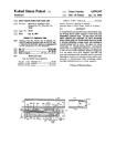
FIG. 1 shows an exterior view of one form of the
invention;
FIG. 2 shows the handle portion of one embodiment
in partial cutaway;
FIG. 3 shows a cross-sectional view of the handle
portion of the embodiment of FIG. 2;
FIG. 4 shows the handle portion of the embodiment
of FIGS. 2 and 3 in partial cross-section;
FIG. 5 shows an exploded view of the firing mecha-
nism in the handle, for the embodiment of FIGS. 2-4;
FIG. 6 shows the handle portion of a second embodi-
ment of the invention;
FIG. 7 shows a partial cross-section view of the han-
dle of FIG. 6;
FIG. 8 shows the handle portion of FIG. 7 in further
partial cross-section; and
FIG. 9 shows an exploded view of the firing mecha-
nism of the handle of FIGS. 6-8.
5,388,
3
DESCRIPTION OF THE PREFERRED
EMBODIMENT
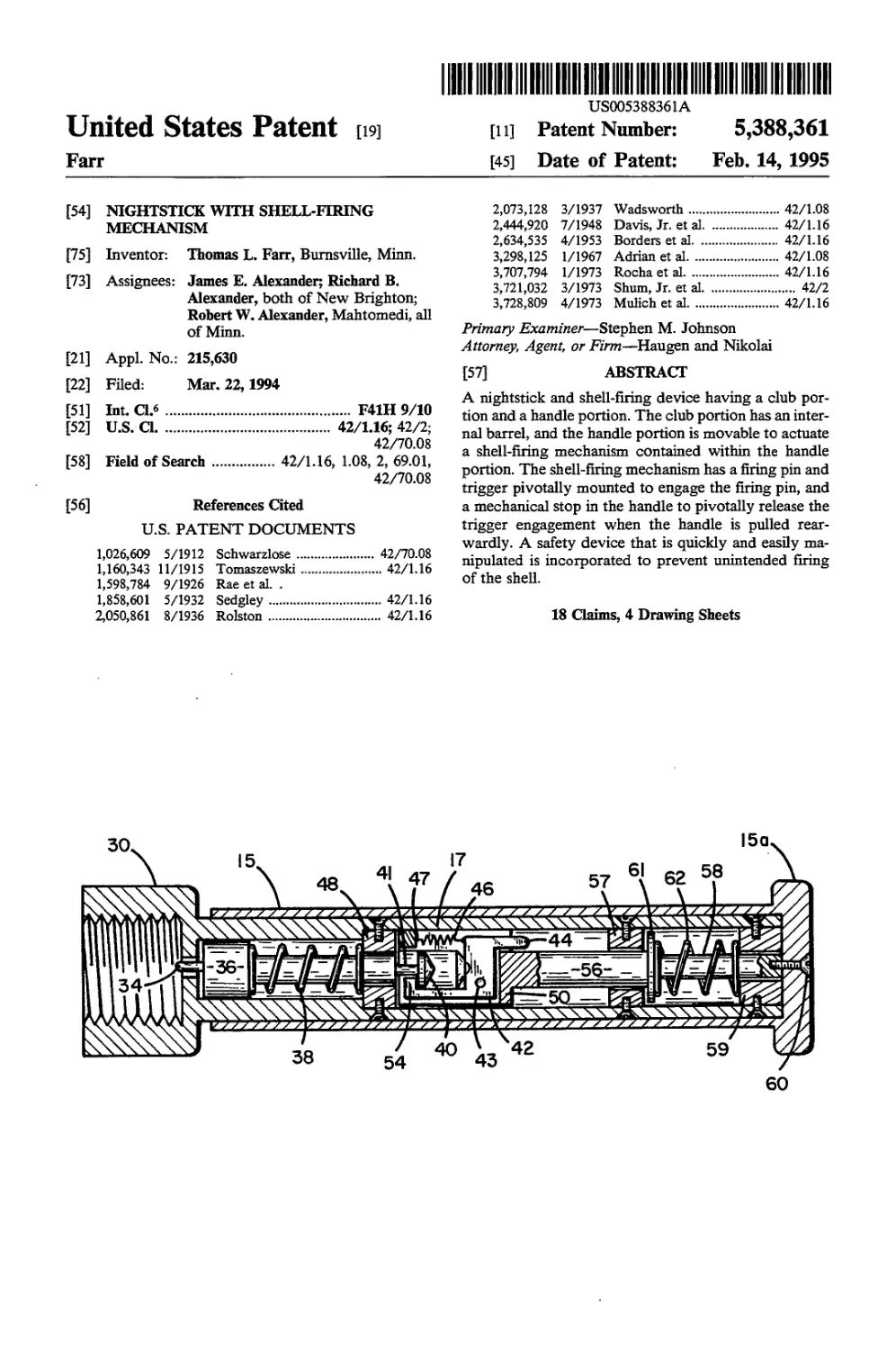
FIG. 1 shows one form of a nightstick 10, having a
club portion 12 and a handle portion 14. Nightstick 10
may be made from wood, metal or plastic material, or
may be made from metal with an exterior plastic or
rubberized cover. Nightstick 10 has an internal metal
barrel 16, typically sized to accommodate a shell, which
preferably is of 20-gauge shotgun variety. Barrel 16 has
exterior threads on its forward end 20 for securing it
into the interior of nightstick 10, and a threaded rear-
ward end 22 for engagement by a knurled nut 30 which
forms a part of handle 14. The rear end of barrel 16 is
enlarged to form a shell chamber 18, and is preferably
sized to accommodate a 20-gauge shotgun shell. To
conceal the bore of barrel 16, the forward end of night-
stick 10 may have a suitable cover 24 which is capable
of either being easily ejected from nightstick 10 or rup-
tured upon the firing of a shell through barrel 16. Han-
dle 14 has an access hole 26 in order to provide access
to a lock screw 28 which will be hereinafter described.
Referring next to FIGS. 2-4, handle portion 14 is
shown in various cutaway and cross-sectional views.
FIG. 2 shows handle portion 14 in partial cutaway,
illustrating an outer tube 15 which fits over inner hous-
ing 17 sufficiently loosely so as to permit relative move-
ment therebetween. An opening 26 (FIG. 1) through
tube 15 permits access to lock screw 28. An “H” slot 32
in housing 17 provides a guide path for respective
movement of the components, wherein lock screw 28
may be guided through the various channels formed by
“H” slot 32. “H” slot 32 has an elongated slot portion
32a which corresponds to the firing position of the
device; slot 32 has a shorter elongated portion 32Z>
which corresponds to the “safe” or deactivated posi-
tion; slot 32 has a transverse portion 32c which inter-
connects between slot portion 32Z> and slot portion 32a.
A groove 31 is formed in knurled nut 30, in longitudinal
alignment with elongated slot portion 32a; groove 31
serves as a visual identifier to permit a ready visual
reference to enable the operator to determine whether
the device is in a “safe” position or in a “fire” position.
Referring next to FIG. 3, handle portion 14 is shown
in elevation cross-sectional view. Inner housing 17 is
enclosed by outer tube 15, which has a rear expanded
radial flange 15a. Outer tube 15 is rotatable about inner
housing 17 and transversely movable relative to inner
housing 17, to the degree permitted by the movement of
lock screw 28 with “H” slot 32. Inner housing 17 has an
internal chamber for containing the firing mechanism
components associated with the device. A hammer 36
has a firing pin 34 formed at the forward end thereof.
Hammer 36 extends rearwardly through a guide mem-
ber 48, terminating in a hammer latch 40 which is sup-
ported on a neck 41. A firing spring 38 is compressed
between guide member 48 and a shoulder on hammer
36, to provide a forwardly directed spring force against
hammer 36. Guide member 48 is secured to housing 17
by means of appropriate fasteners.
A sear holder 50, best shown in FIGS. 4 and 5, is
slidably contained within housing 17. Sear holder 50 has
a forward opening sized to receive hammer latch 40,
and a diametric slot 51 to receive firing lever 42. Firing
lever 42 is pivotally connected to sear holder 50 in slot
51 by a pivot pin 43. Sear holder 50 also has a drilled
hole 52 sized to accommodate a firing lever spring 46. A
spring lock pin 47 holds firing lever spring 46 in com-
20
30
25
35
40
45
50
55
60
65
361
4
pression, between lock pin 47 and firing lever 42. Spring
46 exerts a clockwise force against lever 42 about pivot
pin 43, thereby holding contact head 44 in a rearwardly
projecting pivotally position. At the same time, a sear
54 is pivotally urged upwardly into neck 41 and behind
hammer latch 40. Sear 54 thereby holds hammer 36 in a
fixed position relative to sear holder 50. Sear holder 50
is connected to outer tube 15 by means of lock screw 28,
which is threadably secured to sear holder 50 and has an
upwardly projecting shank to pass through opening 26
in outer tube 15.
A guide shaft 58 extends rearwardly from sear holder
50, and is slidably guided by center guide member 57.
Center guide member 57 is affixed to housing 17 by
appropriate fasteners. Guide shaft 56 has a reduced
diameter portion 58 which passes through rear guide
member 59. A fastener 60 is threadably attached to the
reduced diameter portion 58, and serves to affix outer
tube 15 to guide shaft 56 and sear holder 50. A compres-
sion spring 62 is constrained between rear guide mem-
ber 59 and a washer 61.
The operation of the firing mechanism shown in
FIGS. 2-5 will now be explained. Outer tube 15 is lon-
gitudinally movable relative to housing 17 over two
limited distances, as determined by the relative position
of lock screw 28 in H-slot 32. If outer tube 15 is twisted
so as to place lock screw 28 into channel portion 32Z>,
the range of transverse movement of outer tube 15 rela-
tive to housing 17 is restricted to practically no move-
ment at all. When outer tube 15 is twisted so as to place
lock screw 28 into channel portion 32a, there is a con-
siderable range of transverse movement permitted. The
following description assumes that lock screw 28 is
positioned in channel portion 32a. As outer tube 15 is
manually pulled rearwardly relative to housing 17, lock
screw 28 and fastener 60 correspondingly pull sear
holder 50, guide shaft 56 and reduced diameter portion
58 rearwardly. As sear holder 50 moves rearwardly,
firing lever 42 moves rearwardly, and sear 54 pulls
hammer latch 40 rearwardly. Firing spring 38 is com-
pressed, as hammer 36 and firing pin 34 are correspond-
ingly moved rearwardly. As rearward motion contin-
ues, contact head 44 contacts against center guide mem-
ber 57, thereby causing firing lever 42 to pivot about pin
43. This pivoting motion causes sear 54 to disengage
from hammer latch 40, thereby releasing hammer 36,
and allowing it to move forwardly under the influence
of firing spring 38. Firing pin 34 forcibly moves for-
wardly into shell chamber 18, to contact against the
corresponding primer on a shell in chamber 18. This
causes the shell to fire, ejecting the shell contents
through barrel 16 and outwardly past cover 24. To reset
the mechanism, outer tube 15 is returned automatically
to its forward position, and knurled nut 30 may be
threadably detached from barrel 18. After knurled nut
30 is detached from barrel 18, the spent shell may be
removed from shell chamber 18 and replaced with a
new shell, and handle portion 14 may again be threaded
onto barrel 16 for a subsequent firing.
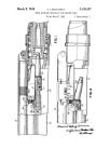
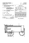
FIGS. 6-9 show an alternative embodiment of the
invention, having a further safety feature to prevent
unintentional discharge of a shell from the device. In
this embodiment, an outer tube 115 is movable about an
inner housing 117 in a manner similar to that described
hereinbefore. Housing 117 has a forward knurled nut
130 for attachment to barrel 16. Outer tube 115 has an
elongated slot 119, which guides a safety pin 121. Safety
pin 121 is further guided by a “U” slot 132 which passes
5,388,
5
through housing 117. A lock screw 128 also passes
through outer tube 115, and lock screw 128 is guided by
an “L” slot 133 which passes through housing 117.
Lock screw 128 is threadably secured against an inner
cylinder 150 in a manner similar to that described here- 5
inbelow.
When safety pin 121 is in the position shown in FIG.
6, the device is in a “safe” nonfiring condition. Outer
tube 115 cannot be rotatably moved about housing 117,
because safety pin 121 engages in one leg of “U” slot 10
132 to prevent such movement. Safety pin 121 is thread-
edly fastened into safety cylinder 202 (see FIG. 7),
which is slidable within the interior of housing 117.
Safety cylinder 202 is prevented from rearward sliding
movement by spacer 148, and is resiliently biased 15
against forward sliding movement by safety spring 203,
which is engaged between safety cylinder 202 and
safety slide tube 201. Safety slide tube 201 is held at the
forward end of the interior of housing 117 by the for-
ward wall of the housing. In order to activate the mech- 20
anism for firing, it is necessary to slide the safety pin 121
forwardly along slot 119 a short distance, to disengage
from “U” slot 132, and then to transversely rotate han-
dle tube 115 to engaged safety pin 121 in the leftmost leg
of slot 132; i.e., in alignment with groove 131. The 25
forward sliding of safety pin 121 is accomplished
against the force of safety spring 203, and a transverse
motion of safety pin 121 is accomplished by the rotat-
able motion of handle tube 115. Lock screw 128 corre-
spondingly moves transversely when handle tube 115 is 30
rotated, to move into the transverse elongated portion
of “L” slot 133.
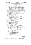
FIG. 7 shows a partial cross-section view of the inte-
rior of the handle section, illustrating the various tubu-
lar components which are found within housing 117. 35
Safety cylinder 202 is slidable by manual activation of
safety pin 121, over the outer surface of safety slide tube
201, against the force of compression spring 203. Spacer
148 is positioned adjacent safety cylinder 202, and a
tubular spacer 205 is adjacent spacer 148. Tubular 40
spacer 205 has an “L” slot corresponding identically to
slot 133, guiding the travel path of lock screw 128. A
spacer 157 is positioned adjacent tubular spacer 205, and
a tubular end spacer 207 is adjacent spacer 157. A
threadable rear lock nut 159 secures all of the compo- 45
nents into the interior of housing 117.
FIG. 8 shows a further cross-sectional view of the
handle mechanism, illustrating the components which
are slidable within the interior of the tubular members
described with reference to FIG. 7. These interior com- 50
ponents are similar to the interior components described
with reference to FIG. 4, and include a firing pin 134
projecting from a hammer 136, and a firing spring 138
which surges the hammer and firing pin forwardly. The
rear end of hammer 136 includes a hammer latch 140 55
which is received into an opening in sear holder 150.
Reference should be made to FIG. 9 for a further illus-
tration in exploded view of the components described
herein. Sear holder 150 has a diametric slot which con-
tains a firing lever 142 which is pivotable about a pin 60
143. Firing lever 142 has a sear 154 which is engageable
with hammer latch 140, and a contact head 144 which is
engageable against spacer 157. A firing lever spring 146
is transversely mounted in sear holder 150, and is com-
pressibly held between a spring lock pin 147 and an 65
edge of firing lever 142. The rear portion of sear holder
150 includes a guide shaft 156 and a reduced diameter
portion 158. A compression spring 162 is held between
361
6
a washer 161 and threadable lock nut 159. A fastener
160 is attached to the end of reduced portion 158, pass-
ing through threadable lock screw 159.
In operation, the device of FIGS. 6-9 operates simi-
larly to the earlier-described device, with the further
feature of a positive safety mechanism. When the outer
tube 115 is in the position shown in FIG. 6, safety pin
121 serves as a positive safety to prevent firing of the
mechanism. If safety pin 121 is manually moved for-
wardly along slot 119, and outer tube 115 is then rotated
about housing 117, safety pin 121 will slide into a second
leg of “U” slot 132, thereby placing the device in a
firing mode. In this mode, when outer tube 115 is pulled
rearwardly, cylinder 150 and hammer 136 are also
pulled rearwardly. Rearward motion is guided by lock
screw 128 in the elongated portion of slot 133. At a
predetermined point in rearward travel the contact
head 144 engages against spacer 157 to cause firing
lever 142 to move pivotally about pivot pin 143. This
causes sear 154 to disengage from contact with hammer
latch 140, thereby permitting firing spring 138 to force
hammer 136 forwardly. When hammer 136 moves for-
wardly, it causes firing pin 134 to enter the firing cham-
ber, to thereby fire any shell residing therein.
The present invention may be embodied in other
specific forms without departing form the spirit or es-
sential attributes thereof, and it is therefore desired that
the present embodiment be considered in all respects as
illustrative and not restrictive, reference being made to
the appended claims rather than to the foregoing de-
scription to indicate the scope of the invention.
What is claimed is:
1. A nightstick and shell-firing apparatus comprising:
(a) a nightstick having a club portion and a handle
portion, the handle portion being threadably at-
tached to the club portion at one end thereof;
(b) a hollow barrel affixed inside said club portion,
said barrel having a shell-receiving chamber proxi-
mate the end of said club portion which is thread-
ably attached to said handle portion;
(c) a movable sleeve surrounding said handle portion,
said sleeve being rearwardly slidable relative to
said handle and club portions;
(d) a firing mechanism inside said handle portion, said
firing mechanism linked to said movable sleeve,
and comprising a firing pin movably positionable
into said shell-receiving chamber, a pivotable trig-
ger connected to said movable sleeve, said trigger
having a sear for latching against said firing pin for
rearward movement and a contact surface for piv-
otally releasing said sear; a first fixed stop in said
handle portion engageable by said contact surface
after predetermined rearward movement of said
trigger; and a compression firing spring engageable
between said firing pin and a second fixed stop in
said handle portion;
whereby said sleeve may be moved rearwardly to
cause compression of said firing spring, and at a
predetermined rearward position said trigger piv-
otally releases said sear to permit said firing spring
to force said firing pin into said shell chamber.
2. The apparatus of claim 1, wherein said firing mech-
anism further comprises a sear holder slidable in said
handle portion, said sear holder being slidable with said
sleeve, said sear holder having a transverse slot for
pivotally mounting said trigger.
3. The apparatus of claim 2, further comprising spring
means engaged between said sear holder and said trig-
361
8
(f) a movable sleeve about said handle portion, said
sleeve having means for connecting to said trigger
mechanism;
(g) a fixed stop in said handle portion bore, positioned
rearwardly of said trigger mechanism for pivotally
engaging and disengaging said firing hammer,
whereby contact by said trigger mechanism against
said fixed stop causes disengagement of said firing
hammer; and
(h) a compression spring means for urging said firing
hammer forwardly upon disengagement from said
trigger mechanism.
12. The apparatus of claim 11, wherein said trigger
mechanism further comprises a cylindrical sear holder
having a forward opening sized to receive said firing
hammer, said sear holder having a diametric slot par-
tially therethrough; a trigger pivotally mounted in said
diametric slot, said trigger having said sear engaging
said firing hammer at one of its ends and having a
contact surface projecting rearwardly at another of its
ends.
13. The apparatus of claim 12, further comprising a
first slot through said handle portion, and an opening
through said sleeve alignable with said first slot, and a
first screw threadably attached to said sear holder and
passing through said first slot and said sleeve opening.
14. The apparatus of claim 13, further comprising a
second slot through the said handle portion, and third
slot through said sleeve alignable with said second slot,
and a second screw passing through said second and
third slots.
15. The apparatus of claim 14, wherein said first slot
has a circumferential segment about said handle portion
and a longitudinal segment parallel with said trigger
mechanism direction of slidable movement, and said
second slot is U-shaped with one leg of said U-shape
being aligned with said first slot longitudinal segment.
16. The apparatus of claim 12, wherein said trigger
mechanism further comprises a fixed tubular spacer
about said firing hammer, a slidable tubular member
about said fixed tubular spacer, and a compression
spring engaged between said slidable tubular member
and the handle portion end adjacent said shell-receiving
chamber.
17. The apparatus of claim 16, further comprising a
first slot through said handle portion, and an opening
through said sleeve alignable with said first slot, and a
first screw threadably attached to said sear holder and
passing through said first slot and said sleeve opening.
18. The apparatus of claim 17, further comprising a
second slot through said handle portion, and a third slot
through said sleeve alignable with said second slot, and
a second screw passing through said second and third
slots and threadably attached to said slidable tubular
member.
*****
5,388,
7
ger for urging said trigger means for latching toward
said firing pin.
4. The apparatus of claim 3, wherein said firing mech-
anism further comprises a further compression spring
engaged between said sear holder and said handle por- 5
tion, said further compression spring urging said sear
holder forwardly.
5. The apparatus of claim 1, wherein said handle
portion further comprises a slot and said firing mecha-
nism is linked to said movable sleeve by a pin passing 10
through said slot.
6. The apparatus of claim 5, wherein said slot further
comprises a first elongated portion to permit said sleeve
to move said firing mechanism rearwardly sufficiently
far to permit said trigger to pivotally release said sear, 15
and a second elongated portion to limit said sleeve from
said sufficient rearward movement to move said firing
mechanism rearwardly, and a transverse slot portion
between the first and second elongated portions;
whereby said sleeve may be transversely turned to en- 20
gage said pin in either said first elongated portion or
said second elongated portion.
7. The apparatus of claim 4, wherein said sear holder
further comprises a forward opening and said firing pin
further comprises a rearward shoulder projecting into 25
said opening; said sear engageable against said shoulder.
8. The apparatus of claim 7, wherein said sear further
comprises a lip engageable against said shoulder.
9. The apparatus of claim 8, wherein said trigger
contact surface further comprises a trigger extension leg 30
projecting rearwardly outside said sear holder.
10. The apparatus of claim 9, further comprising an
elongated cylinder extension extending rearwardly
through said handle portion, said elongated cylinder
extension being affixed to said movable sleeve. 35
11. A nightstick and shell-firing apparatus, compris-
ing:
(a) a nightstick having a club portion, and a handle
portion threadably attachable to said club portion;
(b) the interior of said club portion being formed into 40
a hollow barrel having a shell-receiving chamber at
the end threadably attachable to said handle por-
tion, the other end of said barrel opening through
the distal end of said club portion;
(c) the interior of said handle portion having a hollow 45
bore with an end adjacent the shell-receiving
chamber, said adjacent end having a small opening
therethrough;
(d) a firing hammer slidably movable in said handle
portion bore, said firing hammer having a firing pin 50
which is projectable through said small opening
into said shell-receiving chamber;
(e) a trigger mechanism slidably movable in said han-
dle portion bore, said trigger mechanism including
a sear for pivotally engaging and disengaging said 55
firing hammer;
60
65