/


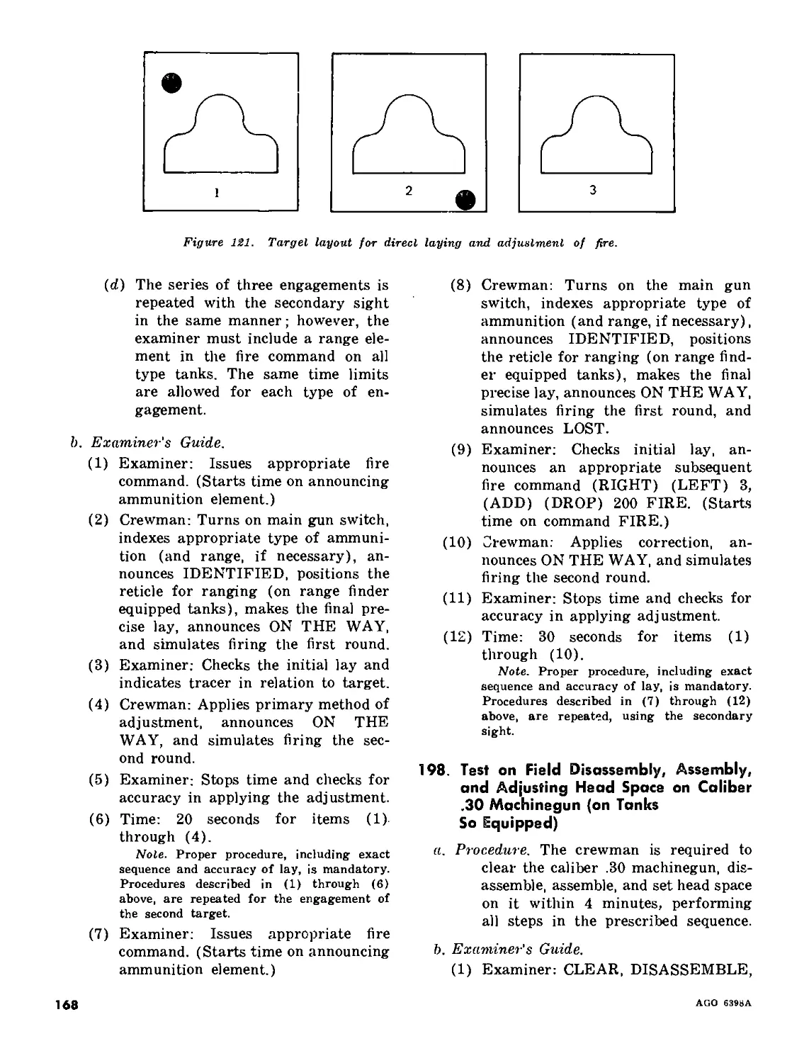


Tags: weapons military affairs machine gun
Year: 1964
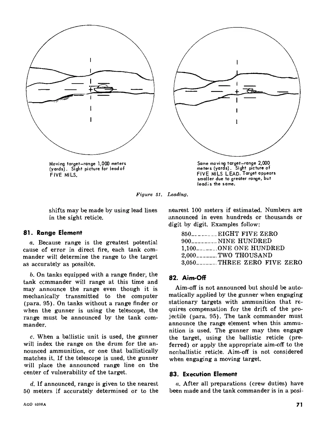
Text
MHI
СоруЗ
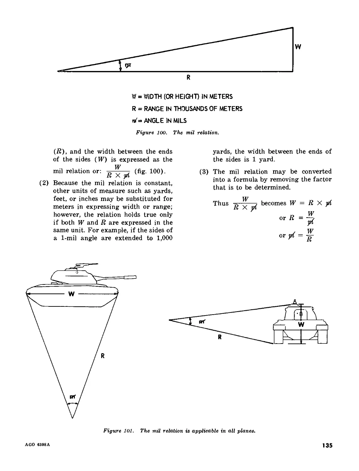
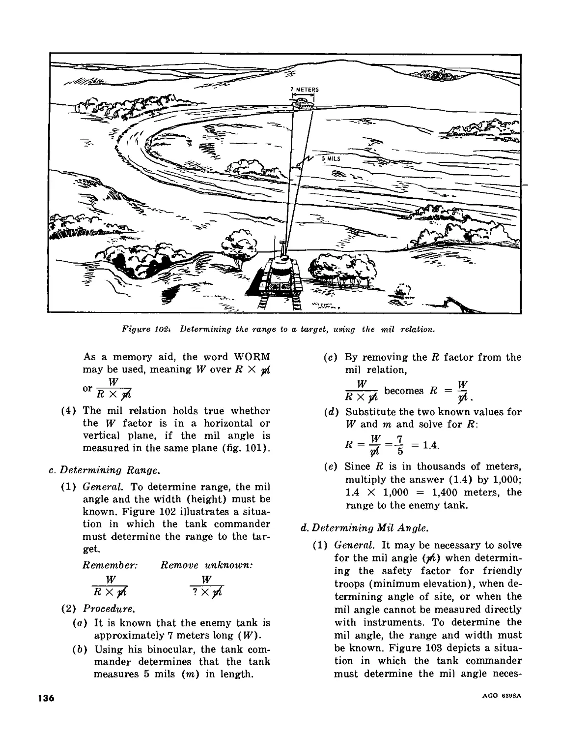
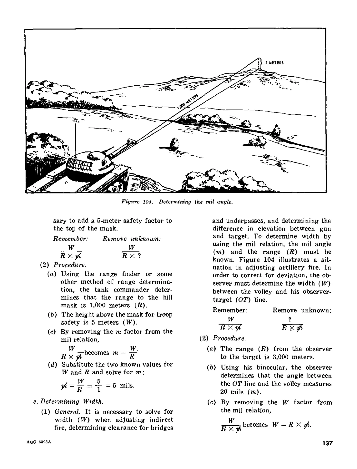
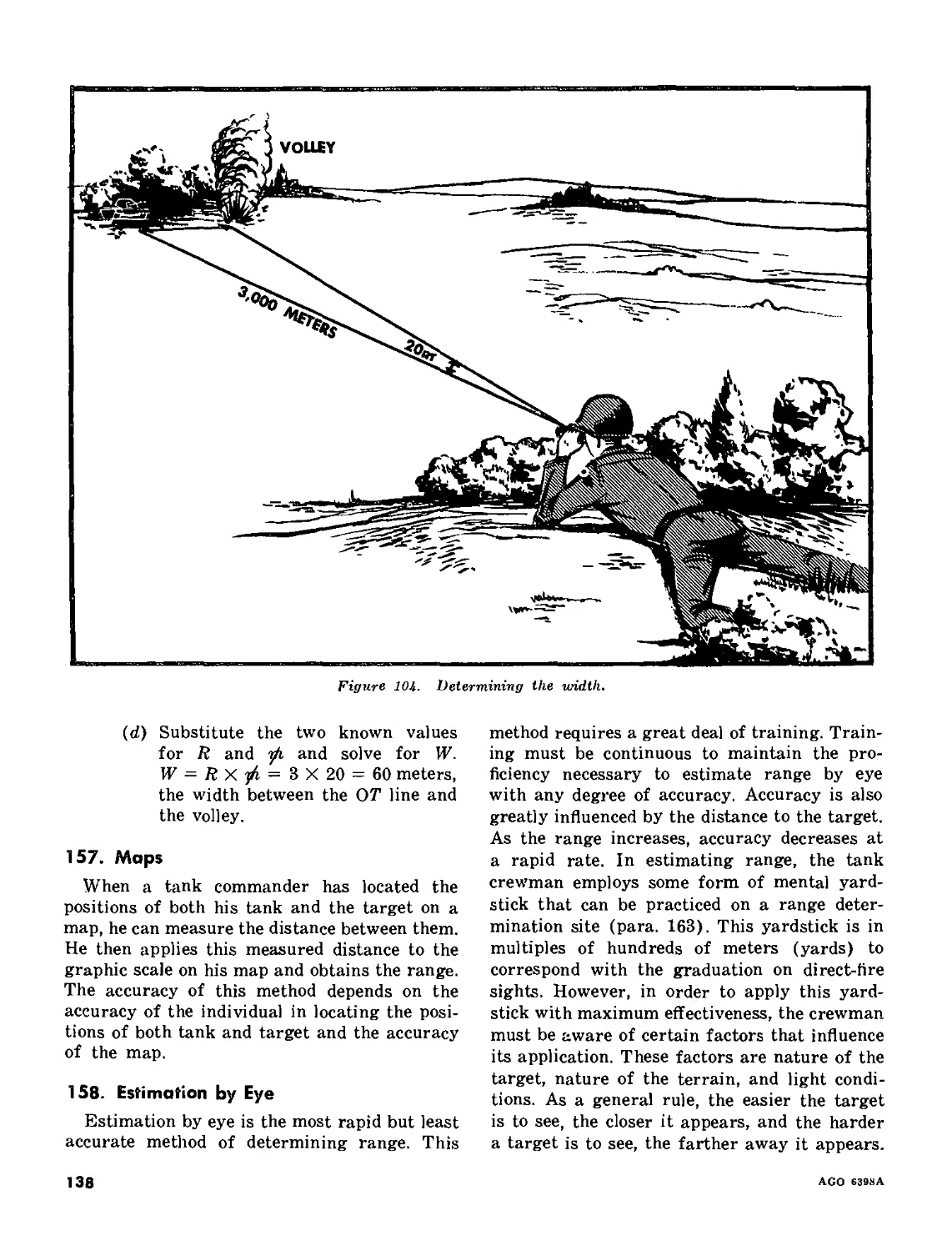
FM 17-12
DEPARTMENT OF THE ARMY FIELD MANUAL
TANK GUNNERY
HEADQUARTERS, DEPARTMENT OF THE ARMY
NOVEMBER 1964
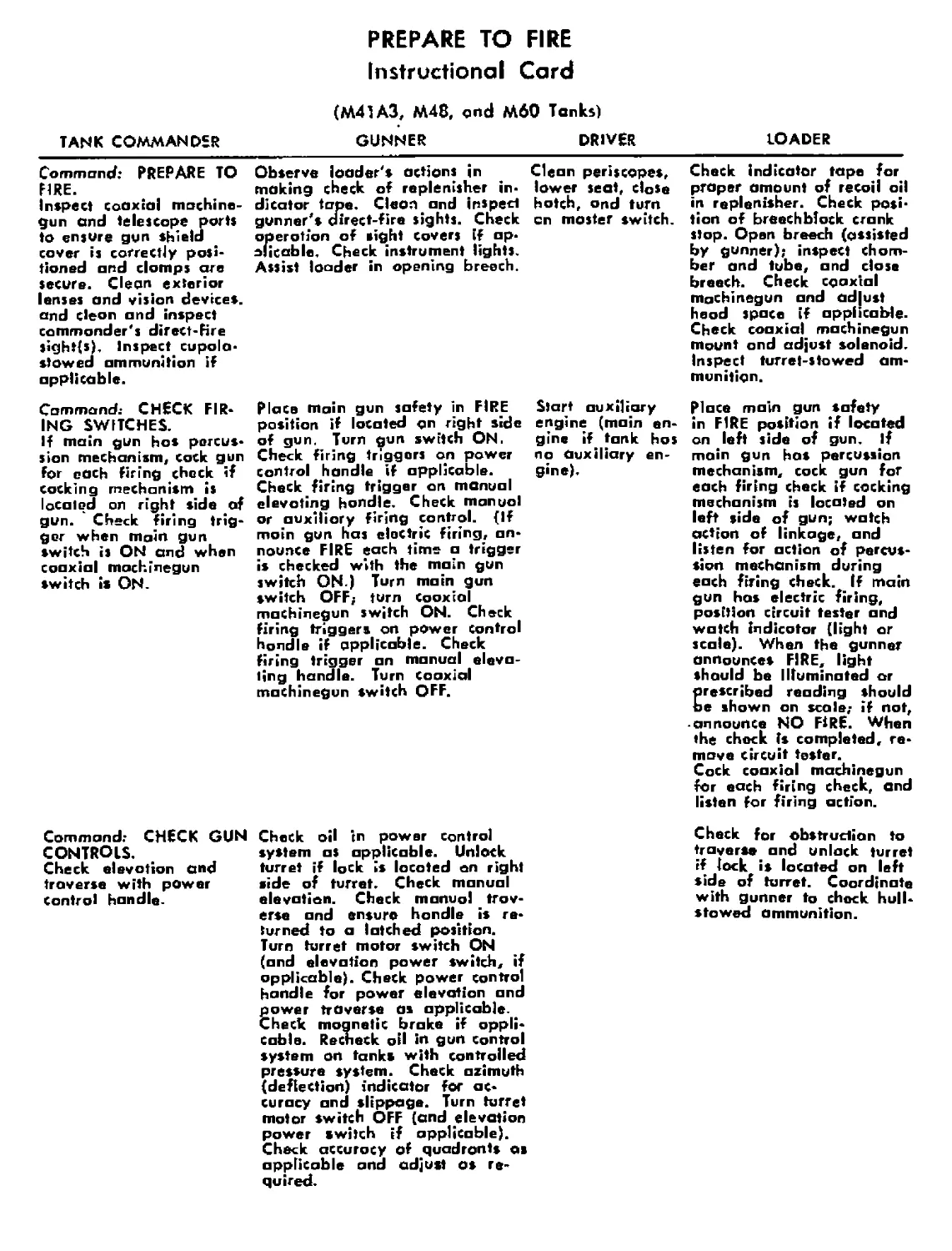
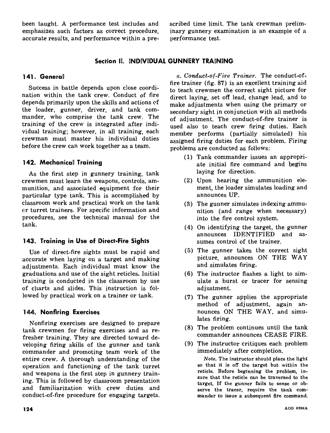
TANK COMMANDER
Command: PREPARE TO
FIRE.
Inspect coaxial machine-
gun and telescope ports
to ensure gun shield
cover is correctly posi-
tioned and clomps are
secure. Clean exterior
lenses and vision devices,
and clean and inspect
commander's direct-Fire
sight(s). Inspect cupola*
slowed ammunition if
applicable.
Command.- CHECK FIR-
ING SWITCHES.
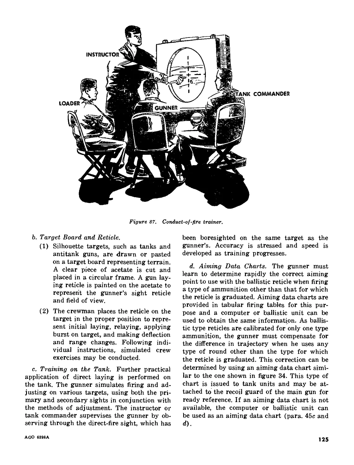
If main gun hos percus-
sion mechanism, cock gun
for each firing check if
cocking mechanism is
located on right side of
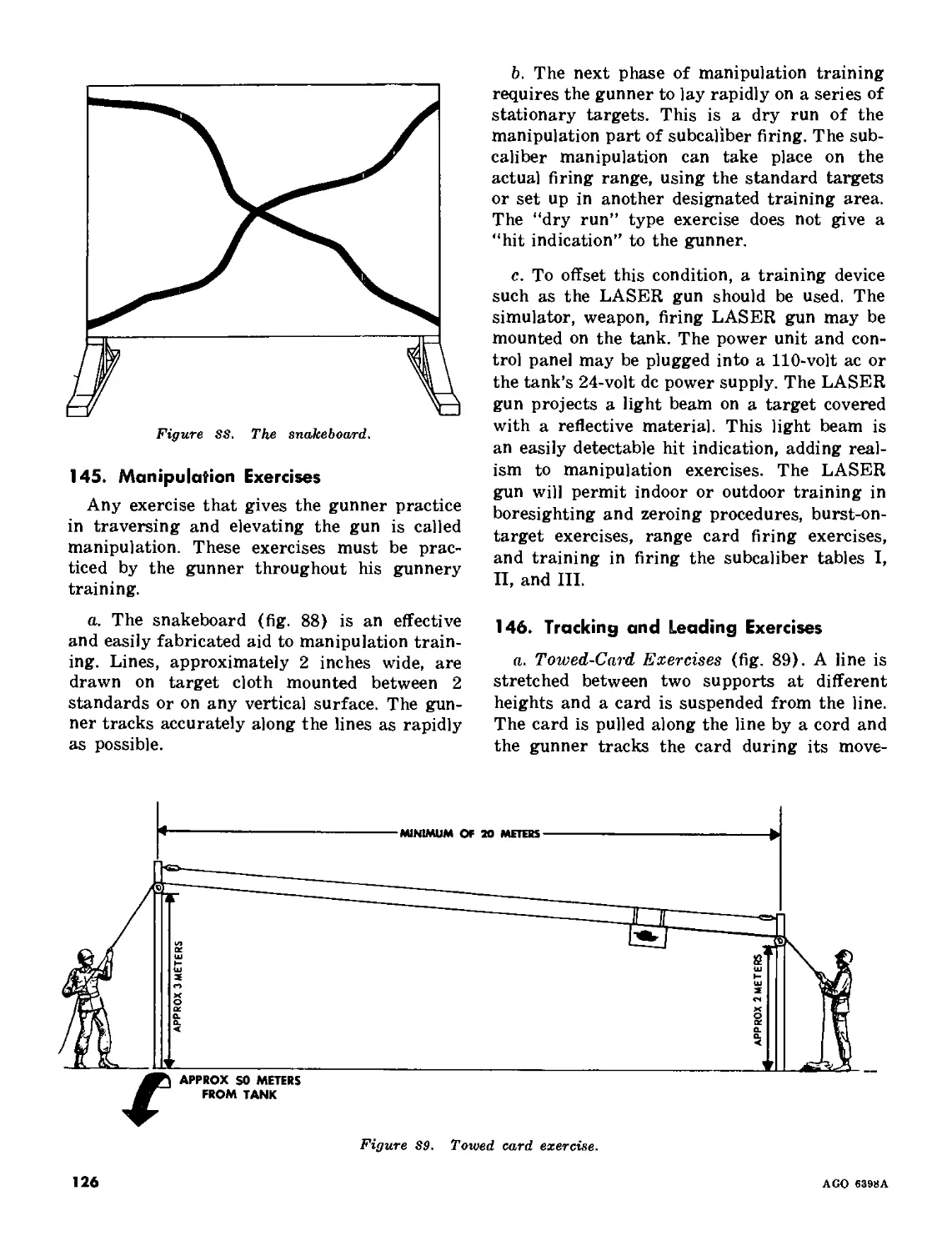
gun. Check firing trig-
ger when main gun
switch is ON and when
coaxial machinegun
switch is ON.
PREPARE TO FIRE
Instructional Card
(M41A3, M48, «nd M60 Tanks)
GUNNER DRIVER
Observe loader's actions in
making check of replenisher in*
dicator tape. Cleon and inspect
gunner's airect-fire sights. Check
operation of sight covers if ap*
olicable. Check instrument lights.
Assist loader in opening breech.
Clean periscopes,
lower seat, dose
hatch, ond turn
cn moster switch.
LOADER
Check indicator tape for
proper amount of recoil oil
in replenisher. Check posi-
tion of breechblock crank
slop. Open breech (assisted
by gunner); inspect cham-
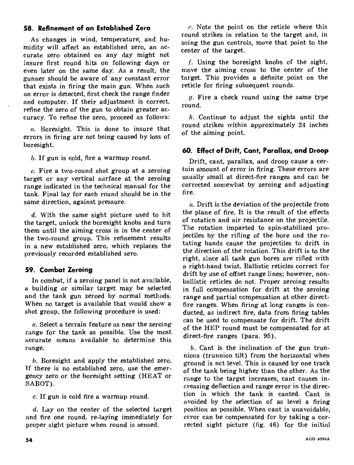
ber and tube, and close
breech. Check coaxial
machinegun and ad|ust
head space if applicable-
Check coaxial machinegun
mount ond adjust solenoid.
Inspect turret-stowed am-
munition.
Command; CHECK GUN
CONTROLS.
Check devotion and
traverse with power
control handle.
Place main gun safety in FIRE
position if located on right side
of gun. Turn gun switch ON.
Check firing triggers on power
control handle if applicable.
Check firing trigger on manual
elevating hondle. Check manual
or auxiliary firing control. (If
main gun has electric firing, an-
nounce FIRE each time a trigger
is checked with the main gun
switch ON ) Turn main gun
switch OFF; turn Cooxiol
machinegun switch ON. Check
firing triggers on power control
handle if applicable. Check
firing trigger an manual eleva-
ting handle. Turn Coaxial
machinegun switch OFF.
Start auxiliary
engine (main en-
gine if tank hos
no auxiliary en-
gine).
Place main gun safety
in FIRE position if located
on left side of gun. If
main gun hos percussion
mechanism, cock gun for
each firing check if cocking
mechanism is located on
left side of gun; watch
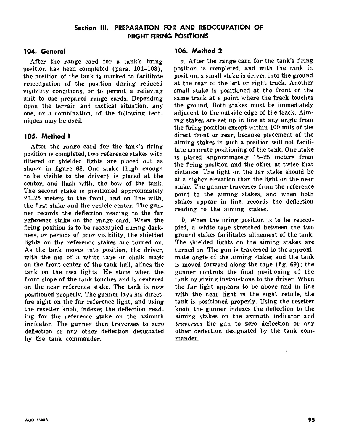
action of linkage, and
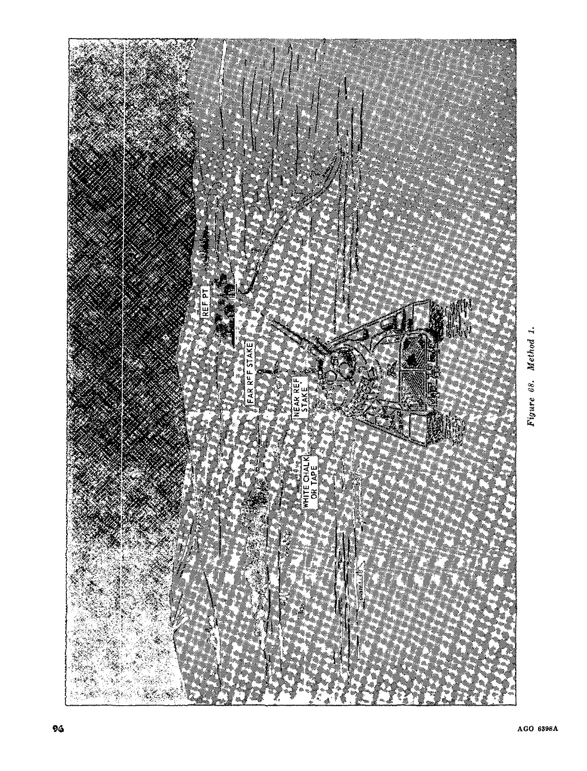
listen for action of percus-
sion mechanism during
each firing check. If main
gun hos electric firing,
position circuit tester and
watch indicator (light or
scale). When the gunner
announces FIRE, light
should be Illuminated or
Erescribed reading should
e shown on scale; if not,
announce NO FIRE. When
the chock Is completed, re-
move circuit tester.
Cock coaxial machinegun
for each firing check, and
listen for firing action.
Check oil tn power control
system as applicable. Unlock
turret if lock is located on right
side of turret. Check manual
elevation. Check manual trav-
erse and ensure hondle is re-
turned to a latched position.
Turn turret motor switch ON
(and elevation power switch, if
applicable). Check power control
handle for power elevation and
power traverse as applicable.
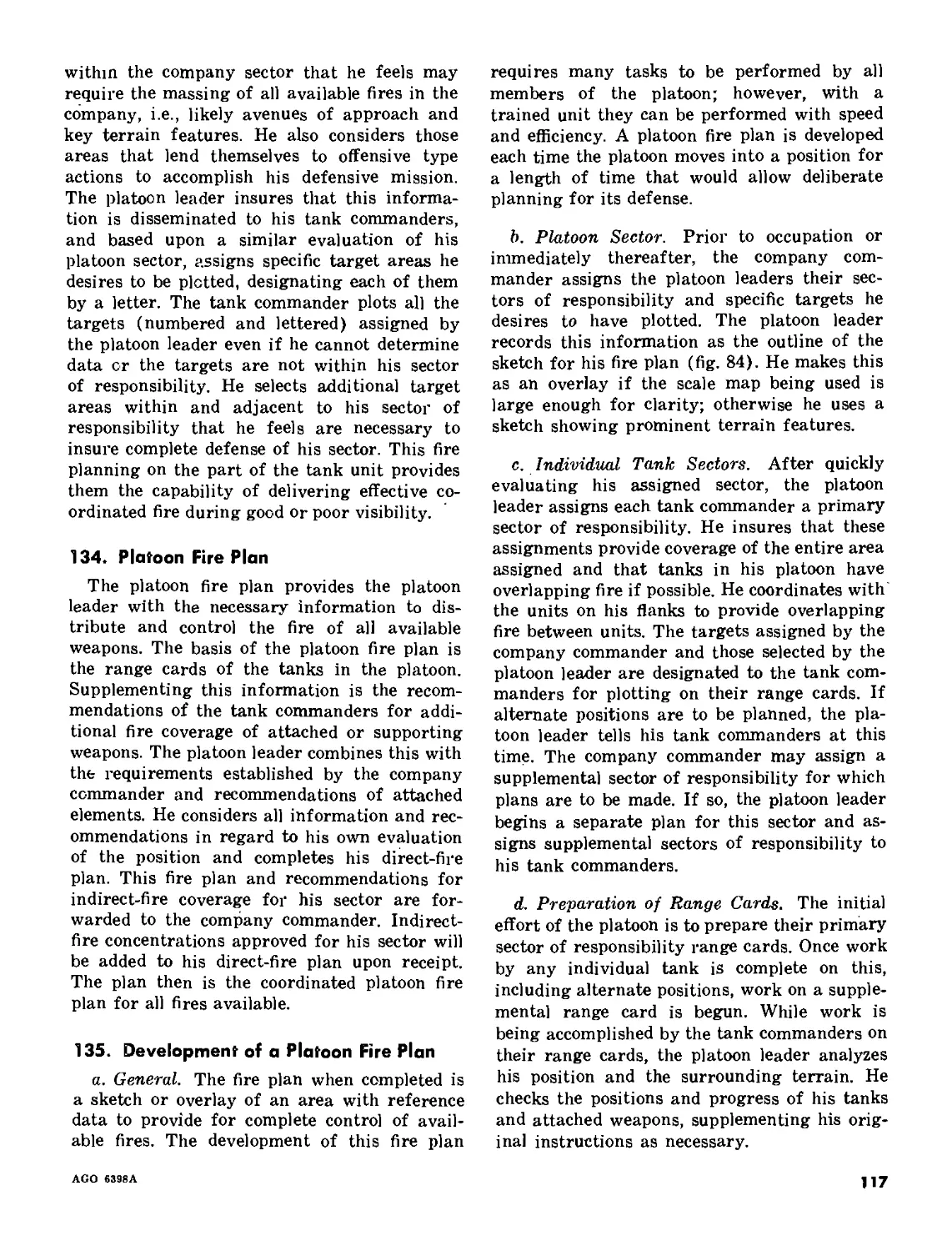
Check magnetic brake if appli-
cable. Recheck oil in gun control
system on tanks with controlled
pressure system. Check azimuth
(deflection) indicator for ac-
curacy and slippage. Turn turret
motor switch OFF (and elevation
power switch if applicable).
Check accuracy of quadrants as
applicable and adjust os re-
quired.
Check for obstruction to
traverse and unlock turret
if lock is located on left
side of turret. Coordinate
with gunner to chock hull-
stowed ammunition.
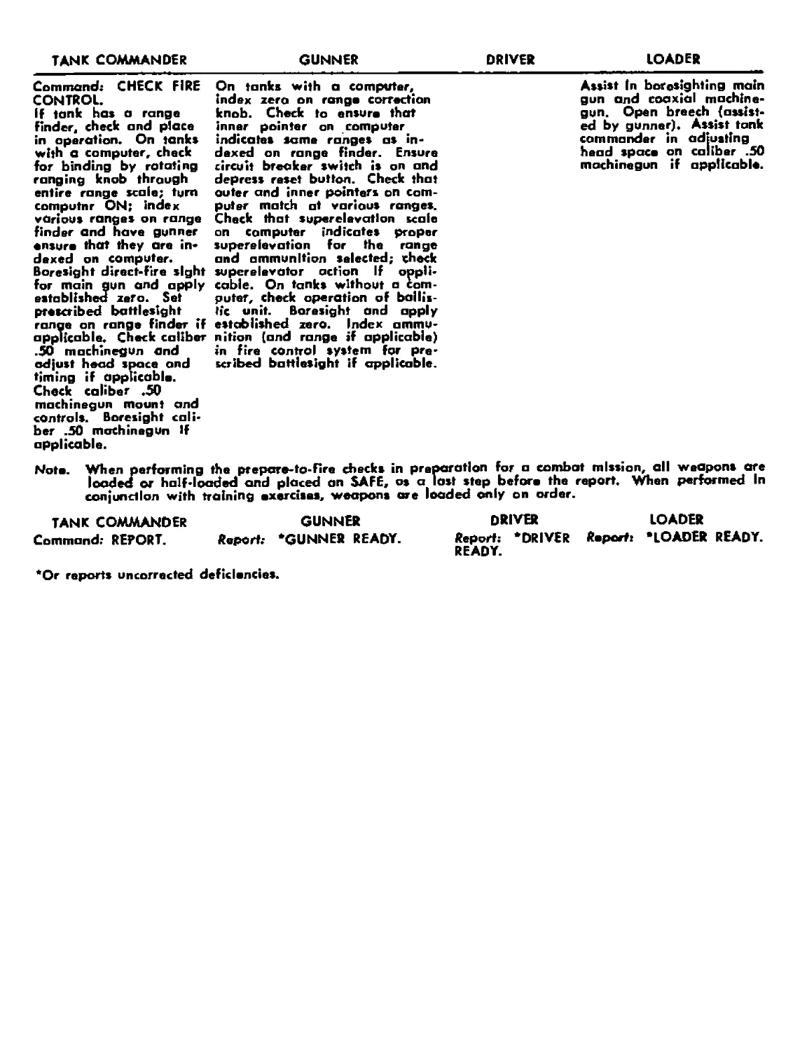
TANK COMMANDER
GUNNER
DRIVER
LOADER
Command: CHECK FIRE
CONTROL.
If tank ha» a range
finder, check and place
in operation. On tank»
with a computer, check
for binding by rotating
ranging knob through
entire range scale; turn
computnr ON; index
various range» on range
finder and have gunner
ensure that they are in-
dexed on computer.
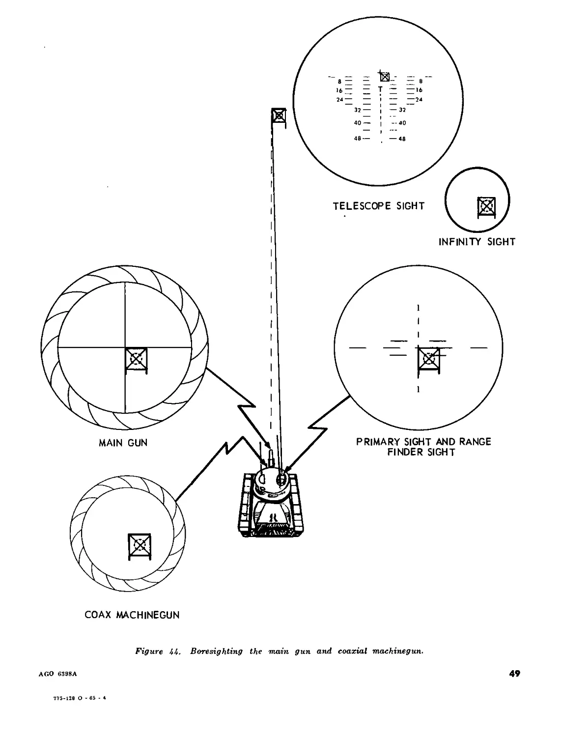
Boresight direct-fire sight
for main gun and apply
established zero. Set
prescribed battlesight
range on range finder if
applicable. Check caliber
.50 machinegun and
adjust head space and
timing if applicable.
Check caliber .50
machinegun mount and
controls. Boresight cali-
ber .50 machinegun If
applicable.
On tanks with a computer,
index zero on range correction
knob. Check to ensure that
inner pointer on computer
indicates same ranges as in-
dexed on range finder. Ensure
circuit breaker switch is on and
depress reset button. Check that
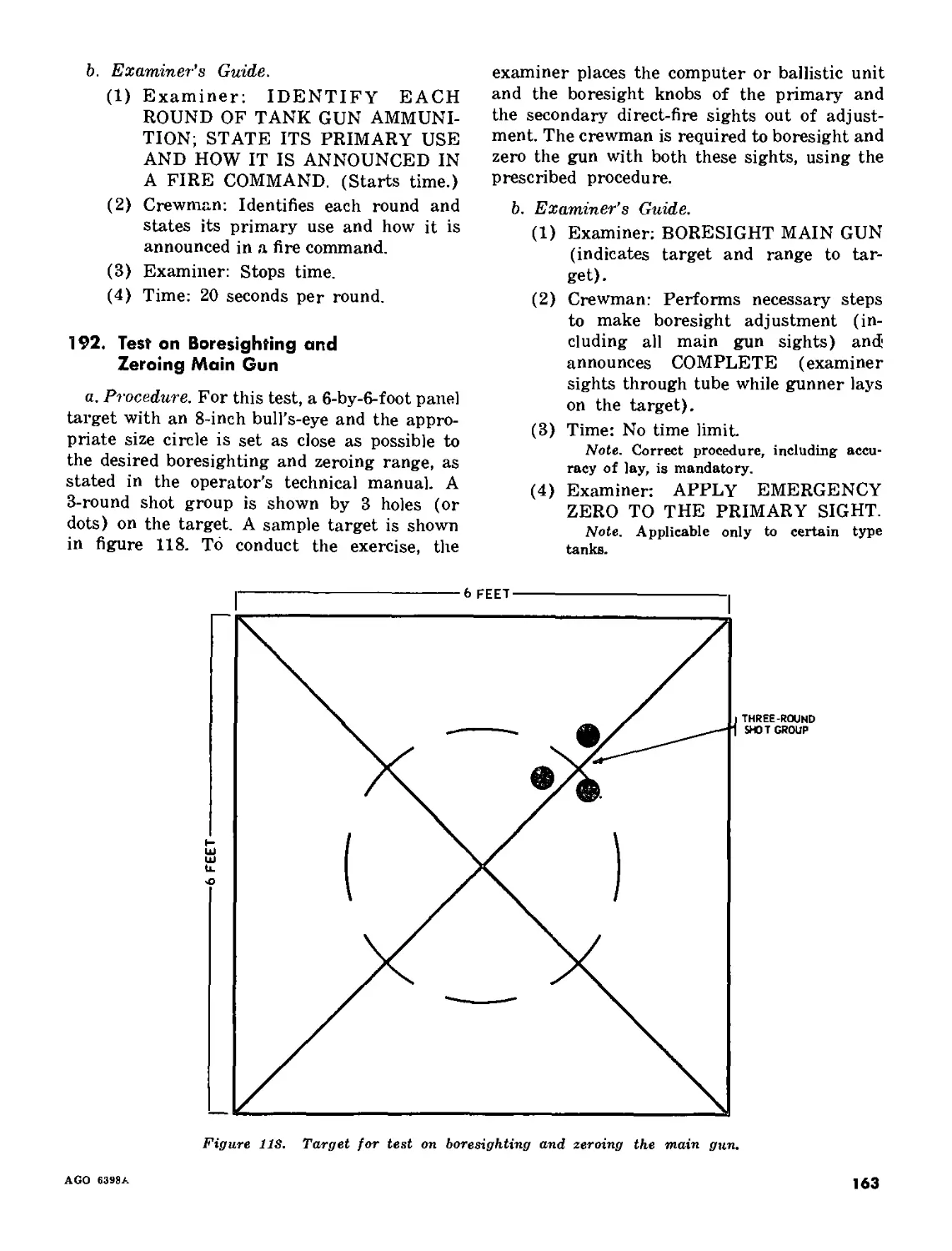
outer and inner pointers on com-
puter match at various ranges.
Check that superelevation scale
on computer indicates proper
superelevation for the range
and ammunition selected; check
superelevator action If appli-
cable. On tanks without a Com-
puter, check operation of ballis-
tic unit. Boresight and apply
established zero. Index ammu-
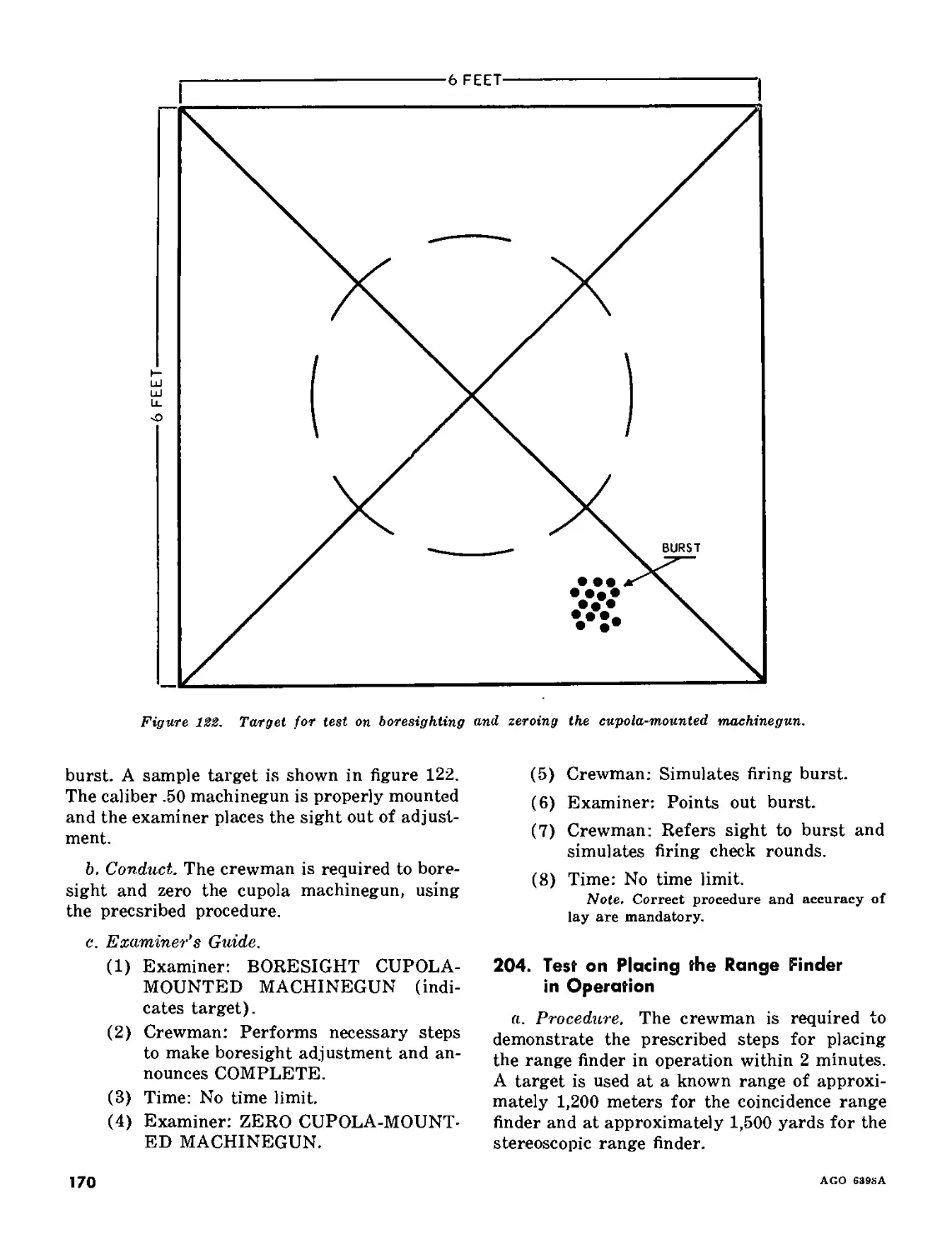
nition (and range if applicable)
in fire control system for pre-
scribed battlesight if applicable.
Assist In boresighting main
gun and coaxial machine-
gun. Open breech {assist-
ed by gunner). Assist tank
commander in adjusting
head Space on caliber .50
machinegun if applicable.
Noto. When performing die prepare-to-fire checks in preparation for a combat mission, all weapons are
loadea or half-loaded and placed an SAFE, as a last step before the report. Virtien performed In
conjunction with training exercises, weapons ore loaded only on order.
TANK COMMANDER
Command; REPORT.
GUNNER
Report.- ‘GUNNER READY.
DRIVER LOADER
Report: ‘DRIVER Report: ‘LOADER READY.
READY.
'Or reports uncorrected deficiencies.
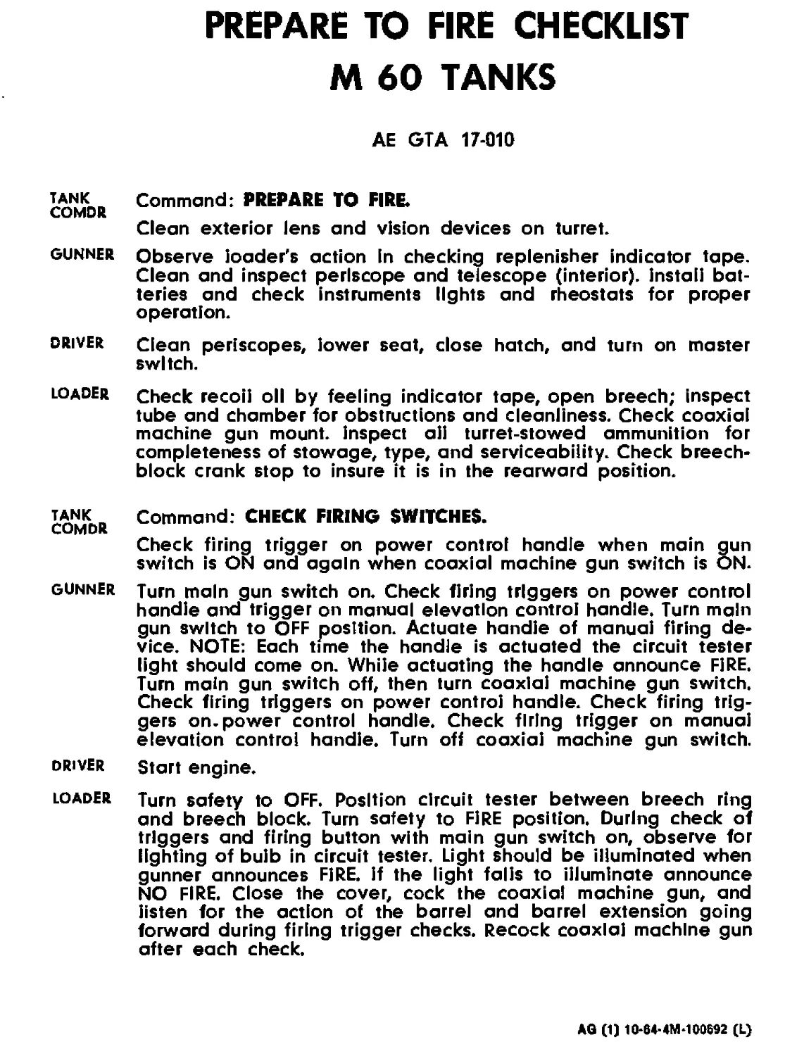
PREPARE TO FIRE CHECKLIST
M 60 TANKS
AE GTA 17-010
tank Command: PREPARE TO FIRE.
COMDR
Clean exterior lens and vision devices on turret.
gunner Observe loader's action in checking replenisher indicator tape.
Clean and inspect periscope and telescope (interior), install bat-
teries and check instruments lights and rheostats for proper
operation.
driver Clean periscopes, lower seat, close hatch, and turn on master
switch.
loader Check recoil oil by feeling indicator tape, open breech; inspect
tube and chamber for obstructions and cleanliness. Check coaxial
machine gun mount, inspect aii turret-stowed ammunition for
completeness of stowage, type, and serviceability. Check breech-
block crank stop to insure it is in the rearward position.
COMDR Command: CHECK FIRING SWITCHES.
Check firing trigger on power control handle when main gun
switch is ON and again when coaxial machine gun switch is ON.
gunner Tum main gun switch on. Check firing triggers on power control
handle and trigger on manual elevation control handle. Turn main
gun switch to OFF position. Actuate handle of manual firing de-
vice. NOTE: Each time the handle is actuated the circuit tester
light should come on. While actuating the handle announce FIRE.
Turn main gun switch off, then turn coaxial machine gun switch.
Check firing triggers on power control handle. Check firing trig-
gers on. power control handle. Check firing trigger on manual
elevation control handle. Turn off coaxial machine gun switch.
driver Start engine.
loader Turn safety to OFF. Position circuit tester between breech ring
and breech block. Turn safety to FIRE position. During check of
triggers and firing button with main gun switch on, observe for
lighting of bulb in circuit tester. Light should be illuminated when
gunner announces FjRE. if the light falls to illuminate announce
NO FIRE. Close the cover, cock the coaxial machine gun, and
listen for the action of the barrel and barrel extension going
forward during firing trigger checks. Recock coaxial machine gun
after each check.
AG (1) 10-04-4M-100692 (L)
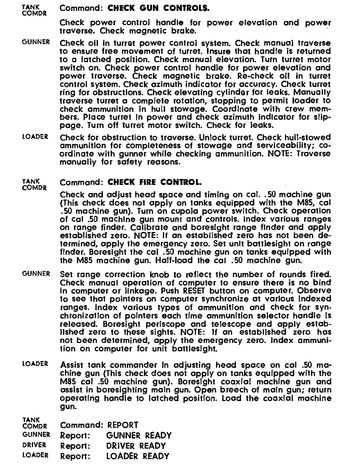
tank Command: CHECK GUN CONTROLS.
COMDR
Check power control handle for power elevation and power
traverse. Check magnetic brake.
gunner Check oil in turret power control system. Check manual traverse
to ensure free movement of turret. Insure that handle is returned
to a latched position. Check manual elevation. Turn turret motor
switch on. Check power control handle for power elevation and
power traverse. Check magnetic brake. Re-check oil in turret
control system. Check azimuth indicator for accuracy. Check turret
ring for obstructions. Check elevating cylinder for leaks. Manually
traverse turret a complete rotation, stopping to permit loader to
check ammunition in hull stowage. Coordinate with crew mem-
bers. Place turret In power and check azimuth indicator for slip-
page. Turn off turret motor switch. Check for leaks.
loader check for obstruction to traverse. Unlock turret. Check hull-stowed
ammunition for completeness of stowage and serviceability; co-
ordinate with gunner while checking ammunition. NOTE: Traverse
manually for safety reasons.
tank Command: CHECK FIRE CONTROL.
COMDR
Check and adjust head space and timing on cal. .50 machine gun
(This check does not apply on tanks equipped with the M85, cal
.50 machine gun). Turn on cupola power switch. Check operation
of cal .50 machine gun mount and controls. Index various ranges
on range finder. Calibrate and boresight range finder and apply
established zero. NOTE: If an established zero has not been de-
termined, apply the emergency zero. Set unit battlesight on range
finder. Boresight the cal .50 machine gun on tanks equipped with
the M85 machine gun. Half-load the cal .50 machine gun.
gunner Set range correction knob to reflect the number of rounds fired.
Check manual operation of computer to ensure there is no bind
in computer or linkage. Push RESET button on computer. Observe
to see that pointers on computer synchronize at various indexed
ranges. Index various types of ammunition and check for syn-
chronization of pointers each time ammunition selector handle is
released. Boresight periscope and telescope and apply estab-
lished zero to these sights. NOTE: If an established zero has
not been determined, apply the emergency zero. Index ammuni-
tion on computer for unit battlesight.
loader Assist tank commander In adjusting head space on cal .50 ma-
chine gun (This check does not apply on tanks equipped with the
M85 cal .50 machine gun). Boresight coaxial machine gun and
assist in boresighting main gun. Open breech of main gun; return
operating handle to latched position. Load the coaxial machine
gun.
tank _ .
Comdr Command: REPORT
GUNNER Report: GUNNER READY
DRIVER Report: DRIVER READY
loader Report: LOADER READY
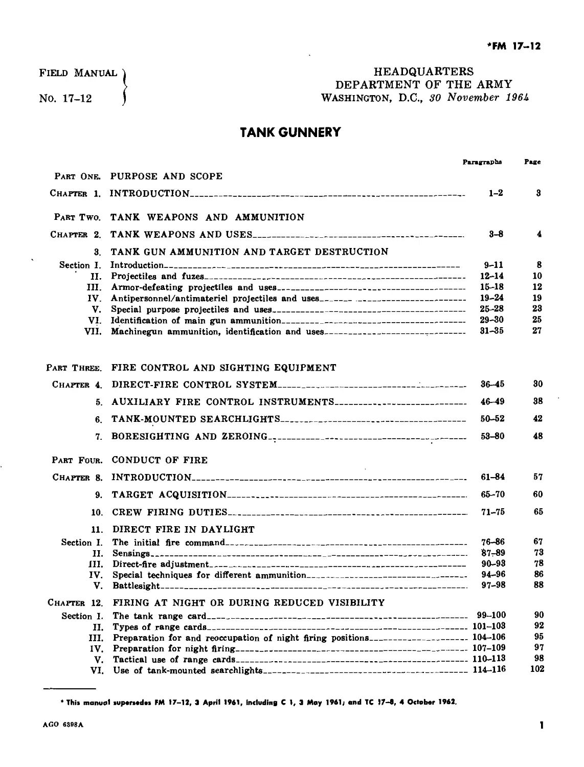
*FM 17-12
J, DEPARTMENT OF THE ARMY
Io. 17-12 ) WASHINGTON, D.C., 30 November 196k
TANK GUNNERY
Panmpbe Pace
Part One. PURPOSE AND SCOPE
Chapter 1. INTRODUCTION______________________________________________________ 1-2 3
Part Two. TANK WEAPONS AND AMMUNITION
Chapter 2. TANK WEAPONS AND USES_______________________________________________ 3-3 4
3. TANK GUN AMMUNITION AND TARGET DESTRUCTION
Section I. Introduction_______________________________________________________ 9-11 8
II. Projectiles and fuzes______________________________________________ 12-14 10
III. Armor-defeating projectiles and uses______________________________ 15-18 12
IV. Antipersonnel/antimateriel projectiles and uses____________________ 19-24 19
V. Special purpose projectiles and uses_______________________________ 25-28 23
VI. Identification of main gun ammunition_____________________________ 29-30 25
VII. Machinegun ammunition, identification and uses____________________ 31-35 27
Part Three. FIRE CONTROL AND SIGHTING EQUIPMENT
Chapter 4. DIRECT-FIRE CONTROL SYSTEM_____________________________________ 35-45 30
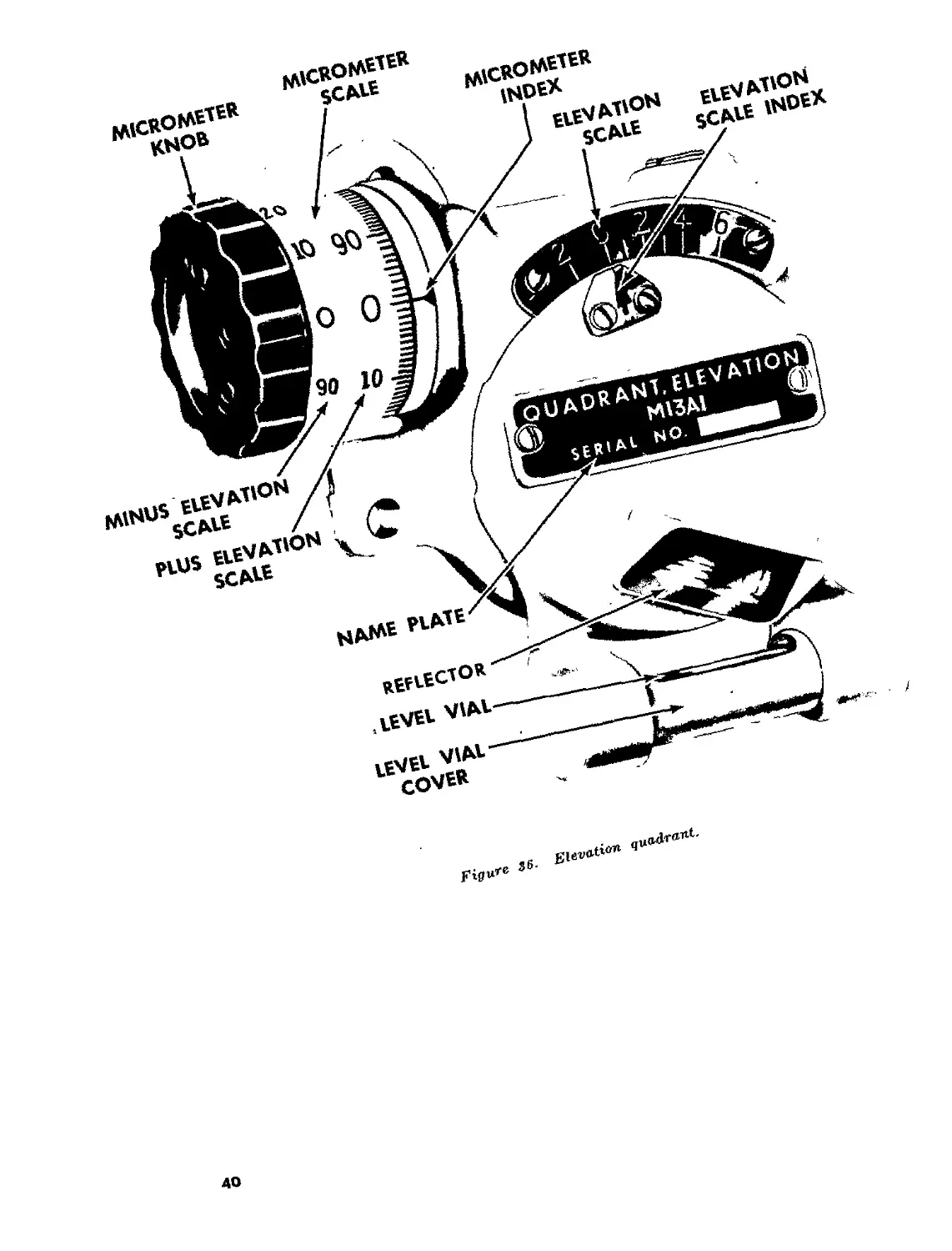
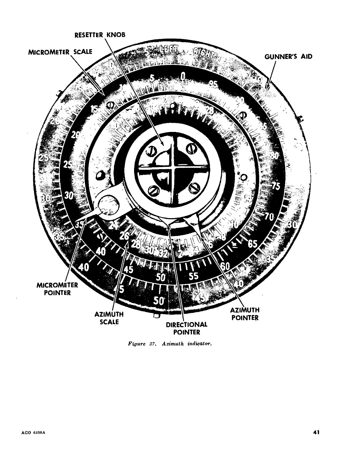
5. AUXILIARY FIRE CONTROL INSTRUMENTS_________________________________ 45-49 38
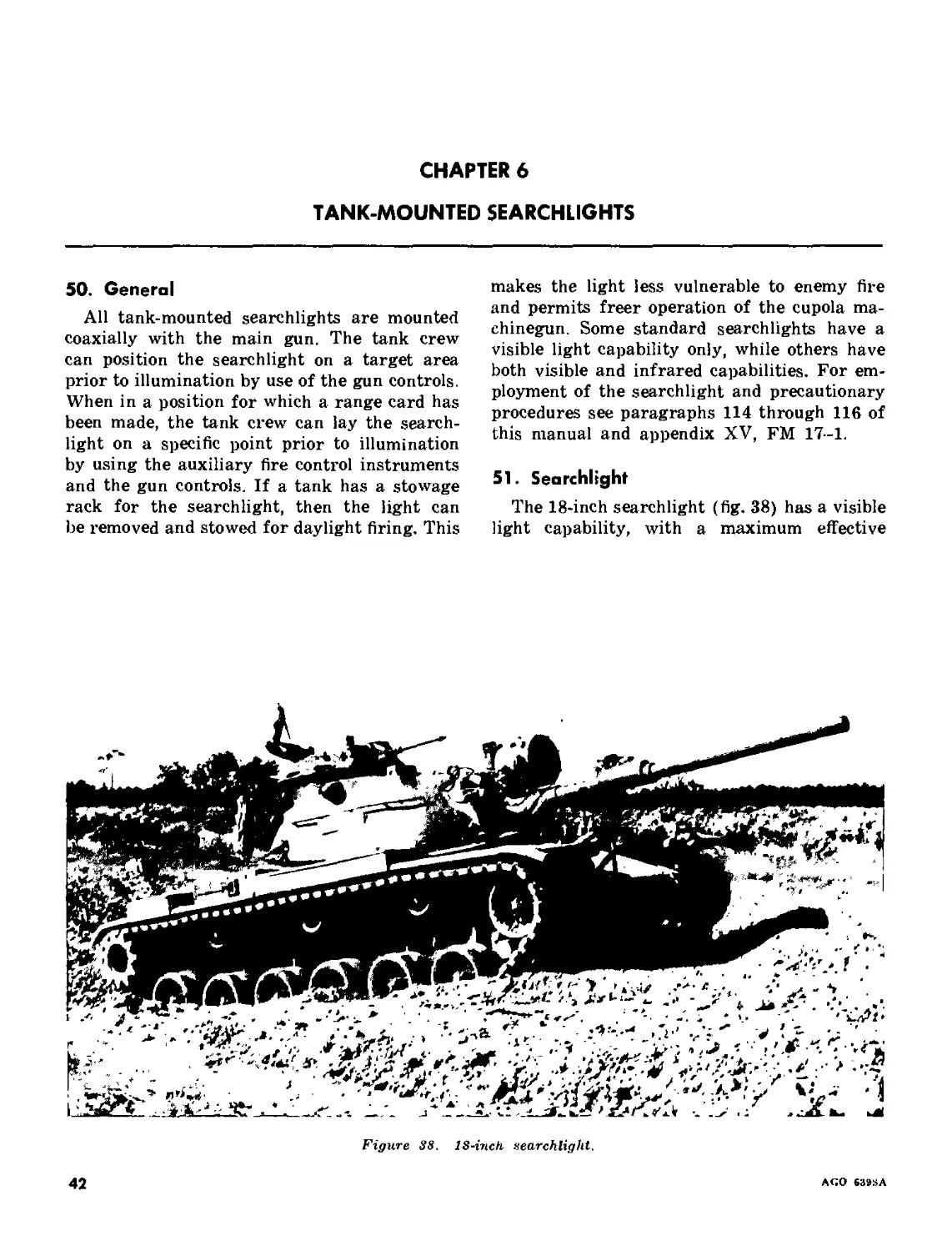
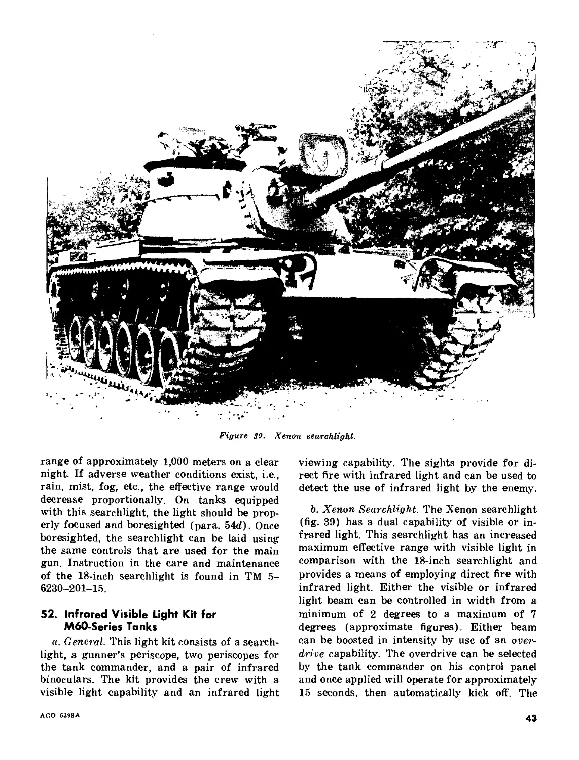
6. TANK-MOUNTED SEARCHLIGHTS__________________________________________ 50-52 42
7. BORESIGHTING AND ZEROING-.________________________________________ 53-80 48
Part Four. CONDUCT OF FIRE
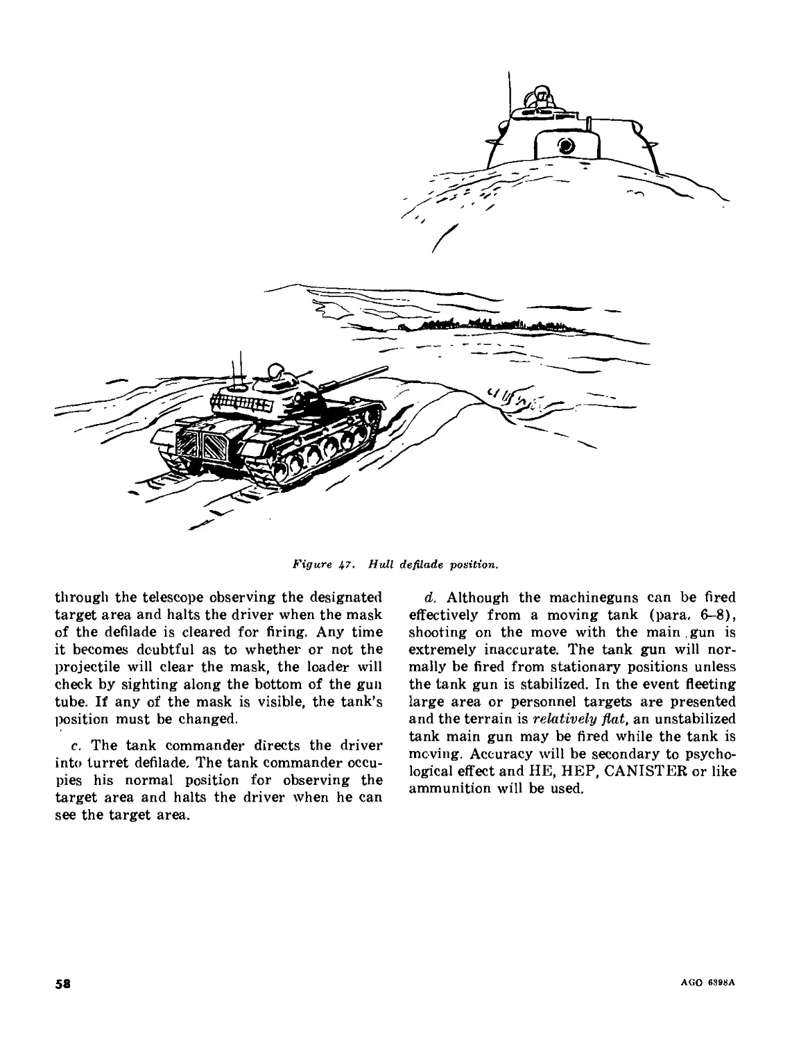
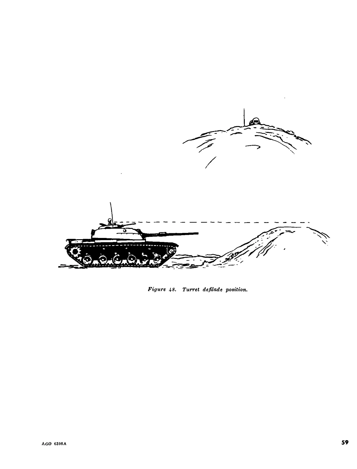
Chapter 8. INTRODUCTION______________________________________________________ 61-84 57
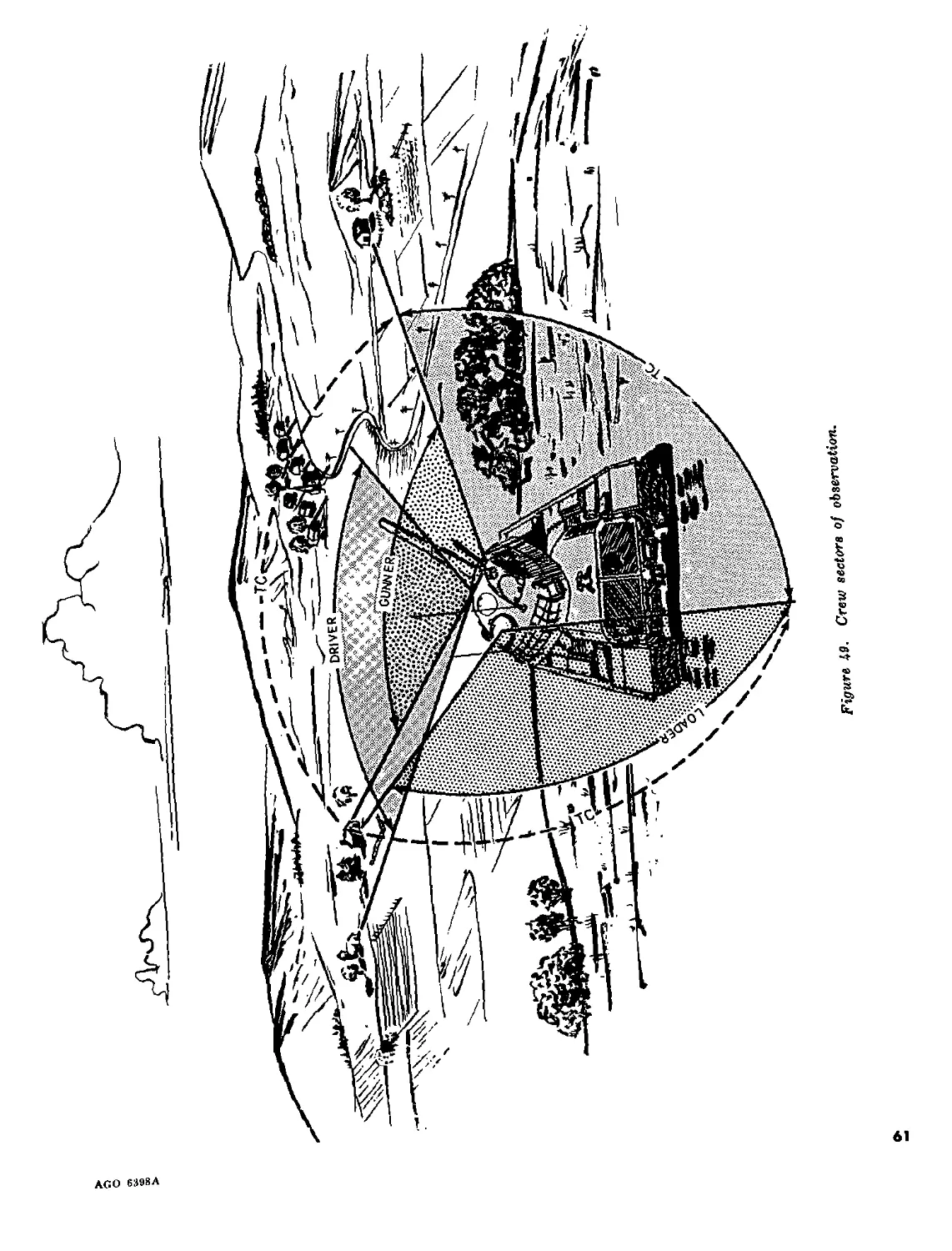
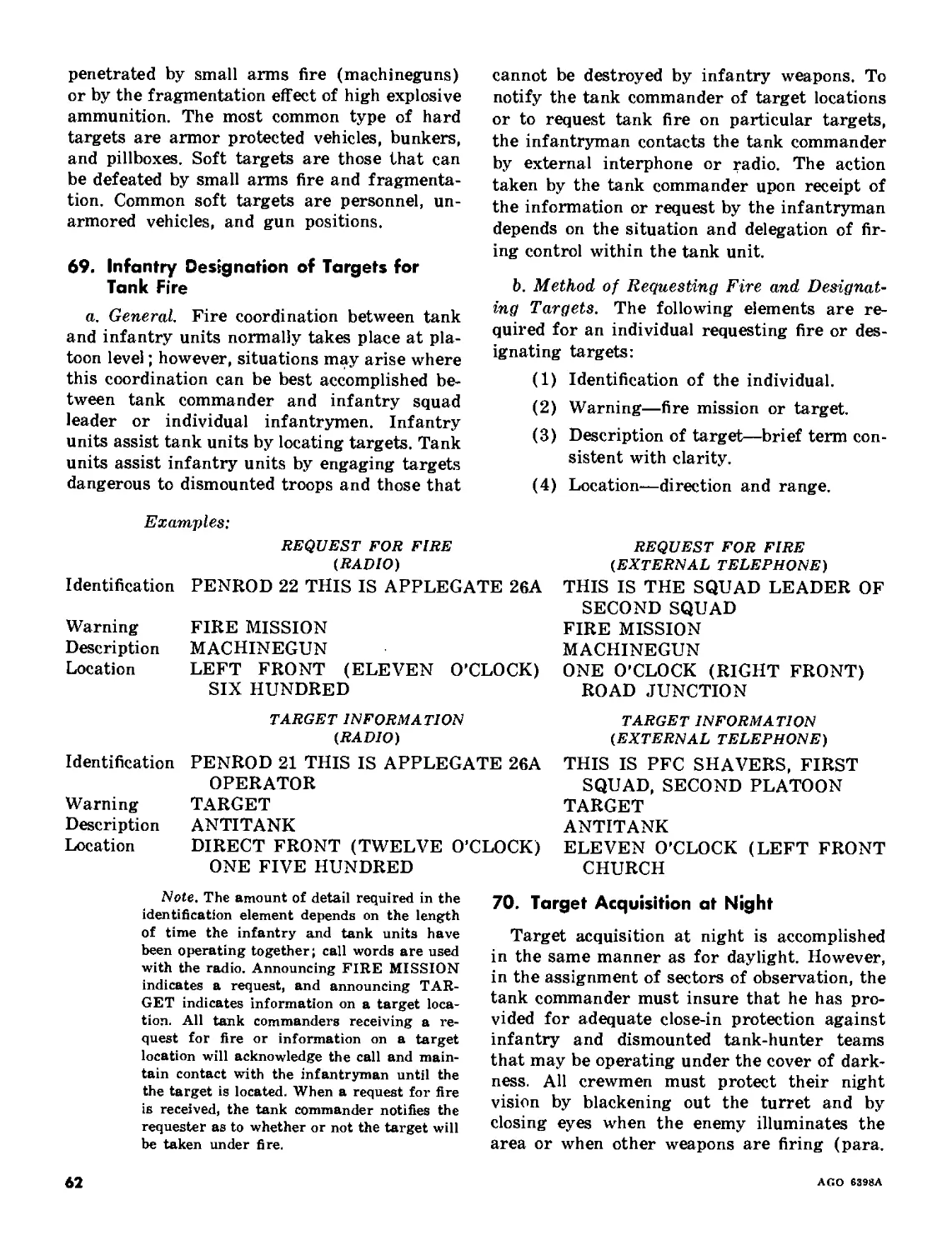
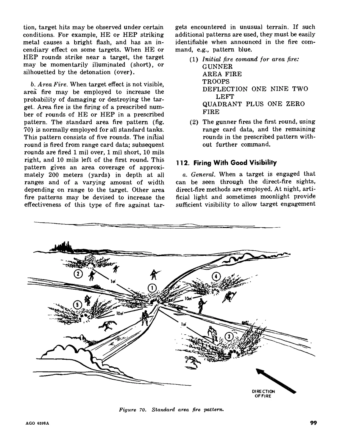
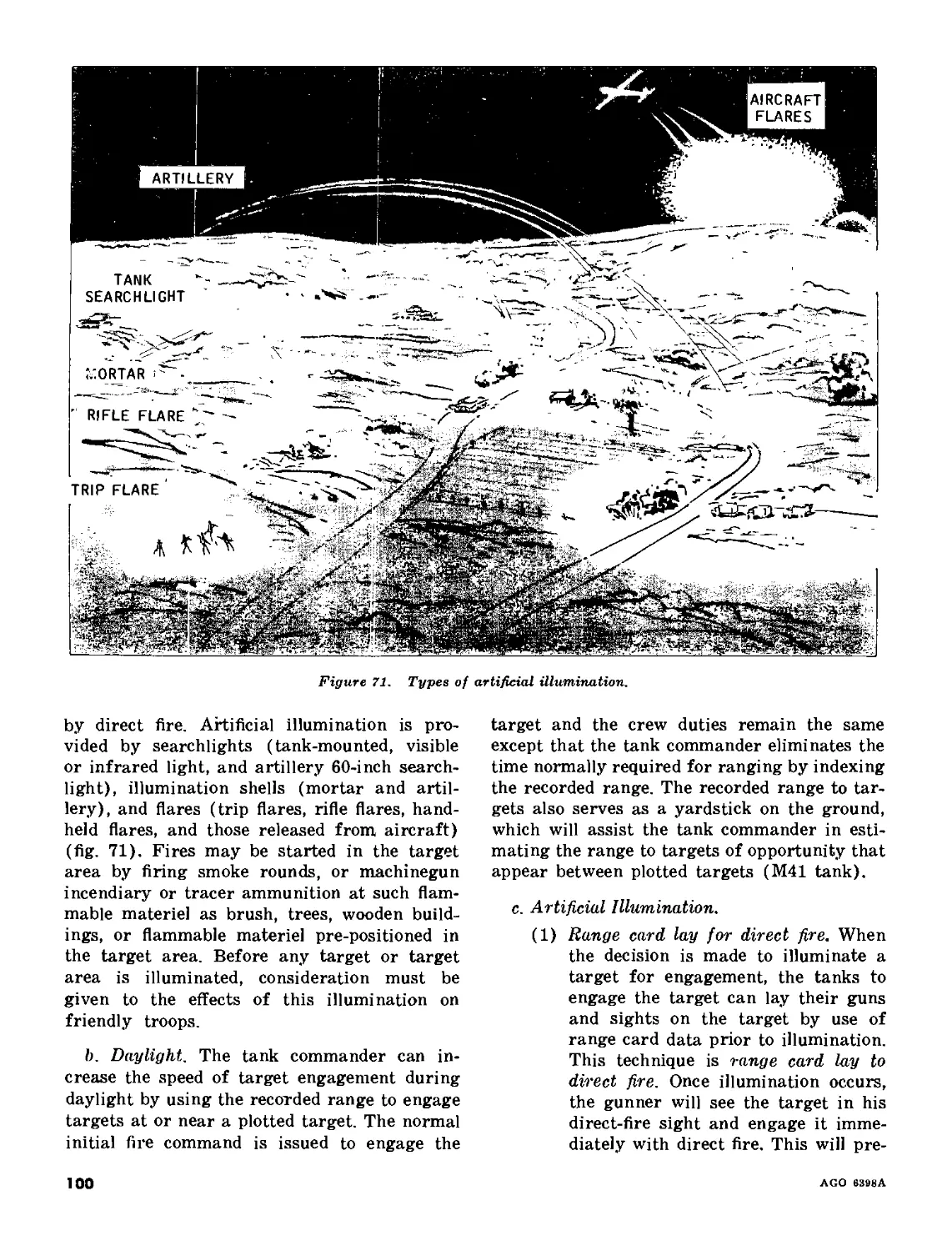
9. TARGET ACQUISITION________________________________________________ 65-70 60
10. CREW FIRING DUTIES_________________________________________________ 71-75 65
11. DIRECT FIRE IN DAYLIGHT
Section I. The initial fire command__________________________________________ 76-86 67
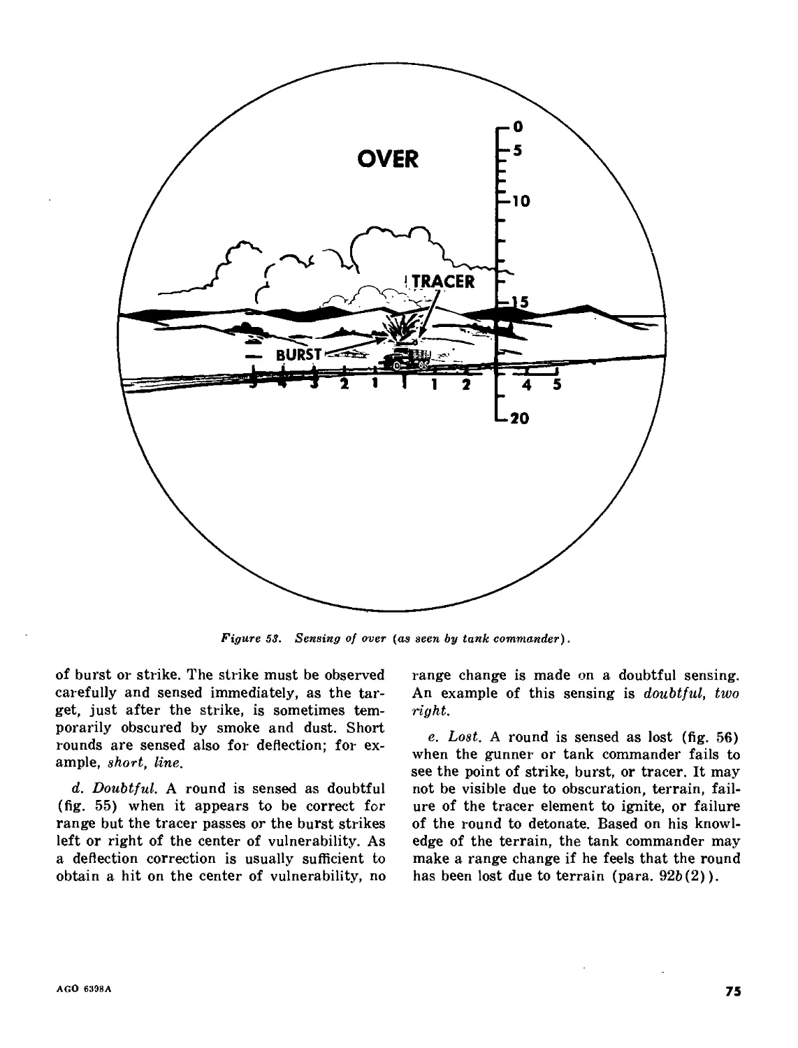
II. Sensings___________________________________________________________ 87t89 73
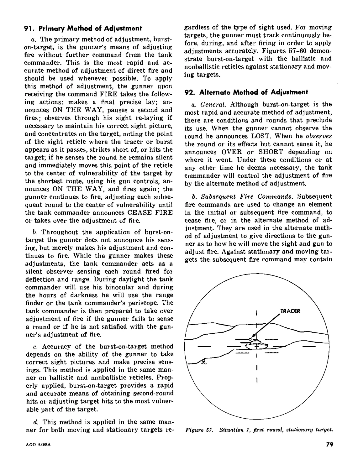
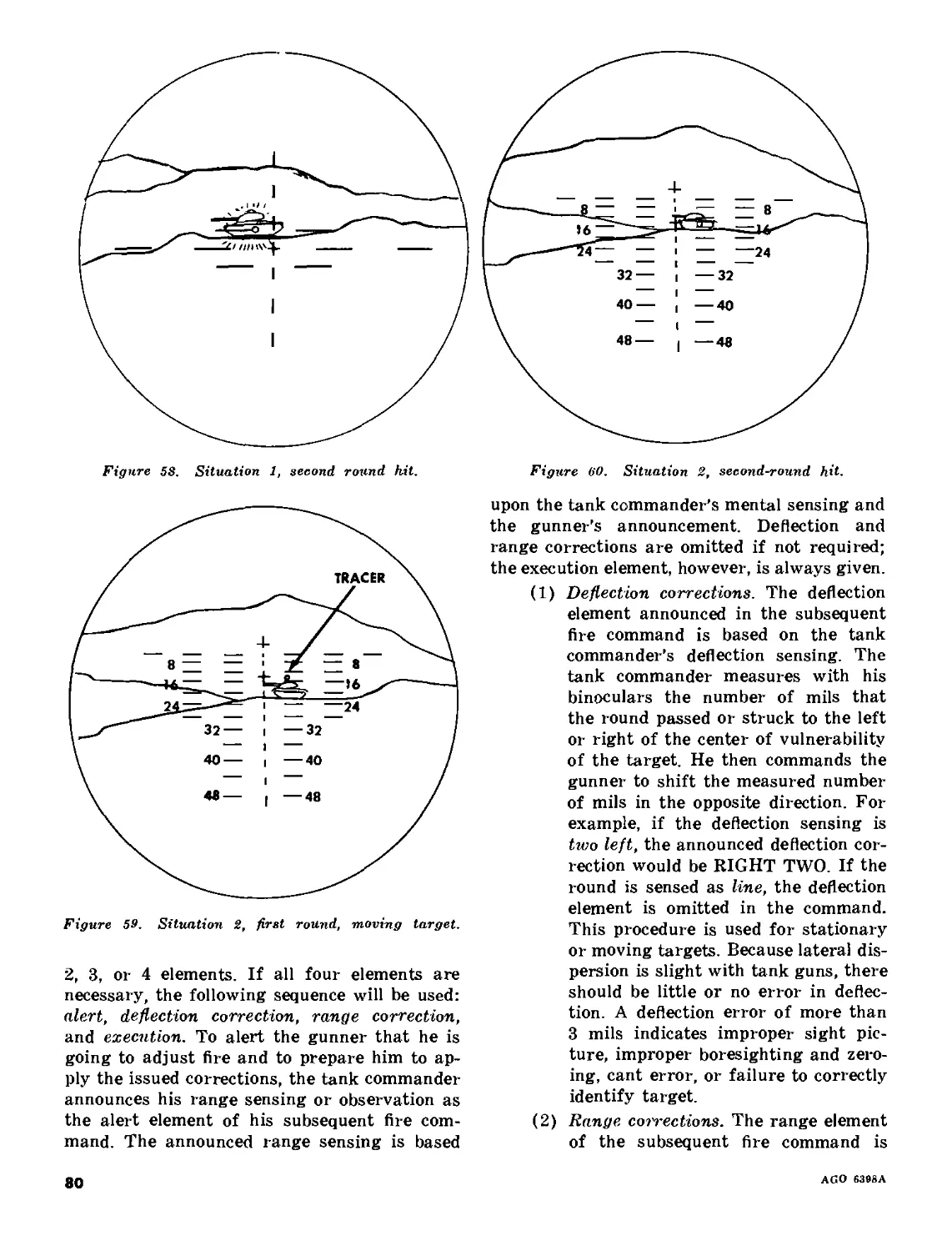
HI. Direct-fire adjustment____________________________________________ 90-93 78
IV. Special techniques for different ammunition_______________________ 94-96 86
V. Battlesight_______________________________________________________ 97-98 88
Chapter 12. FIRING AT NIGHT OR DURING REDUCED VISIBILITY
Section I. The tank range card______________________________________________ 99-100 90
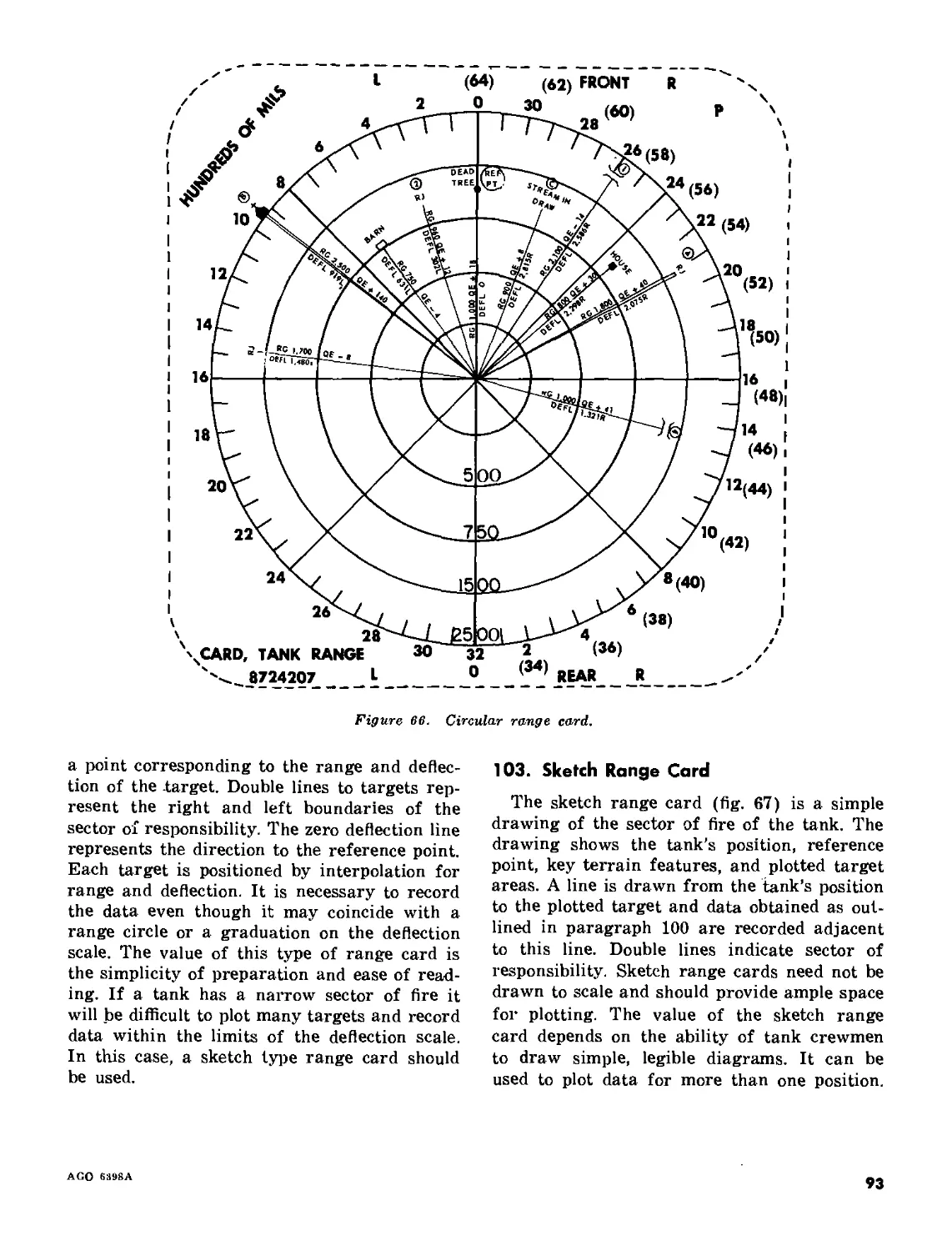
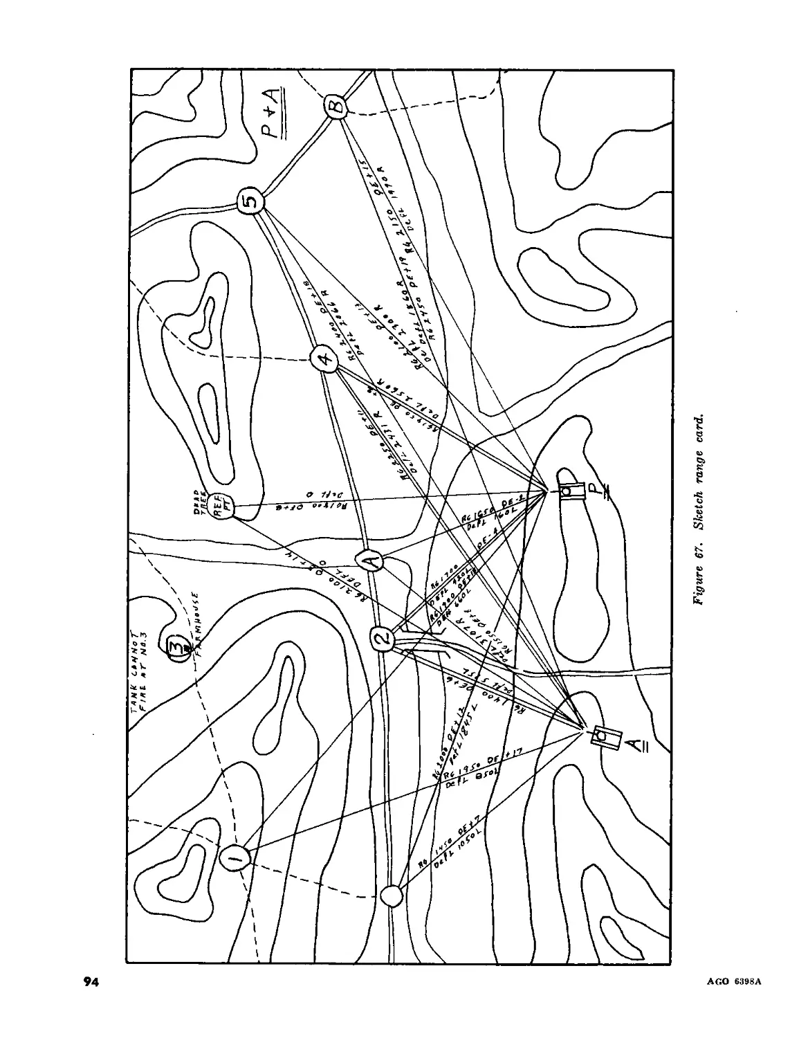
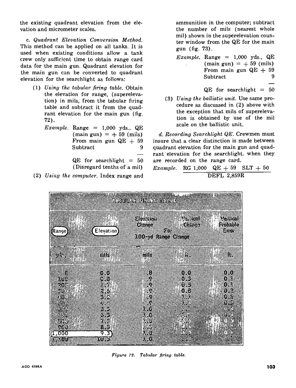
II. Types of range cards_____________________________________________ 101-103 92
III. Preparation for and reoccupation of night firing positions______ 104-106 95
IV. Preparation for night firing_____________________________________ 107-109 97
V. Tactical use of range cards______________________________________110-113 98
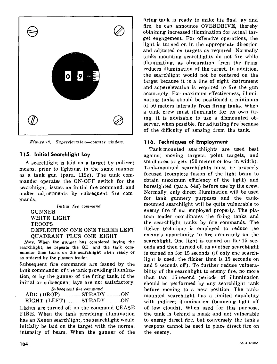
VI. Use of tank-mounted searchlights__________________________________114-116 102
* Thii manual luperiedoi FM 17-12, 3 April 1961, including С 1, 3 May 1961; and TC 17-4, 4 October 1962.
AGO 63B8A
1
Paragraphs Page
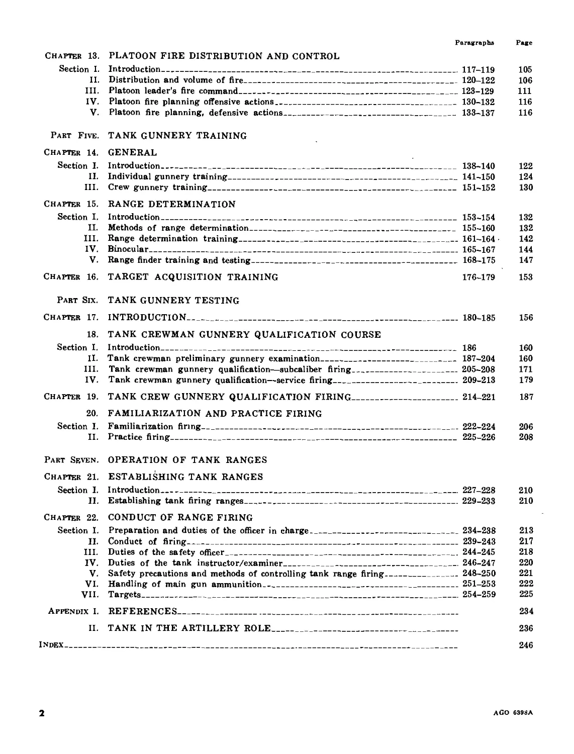
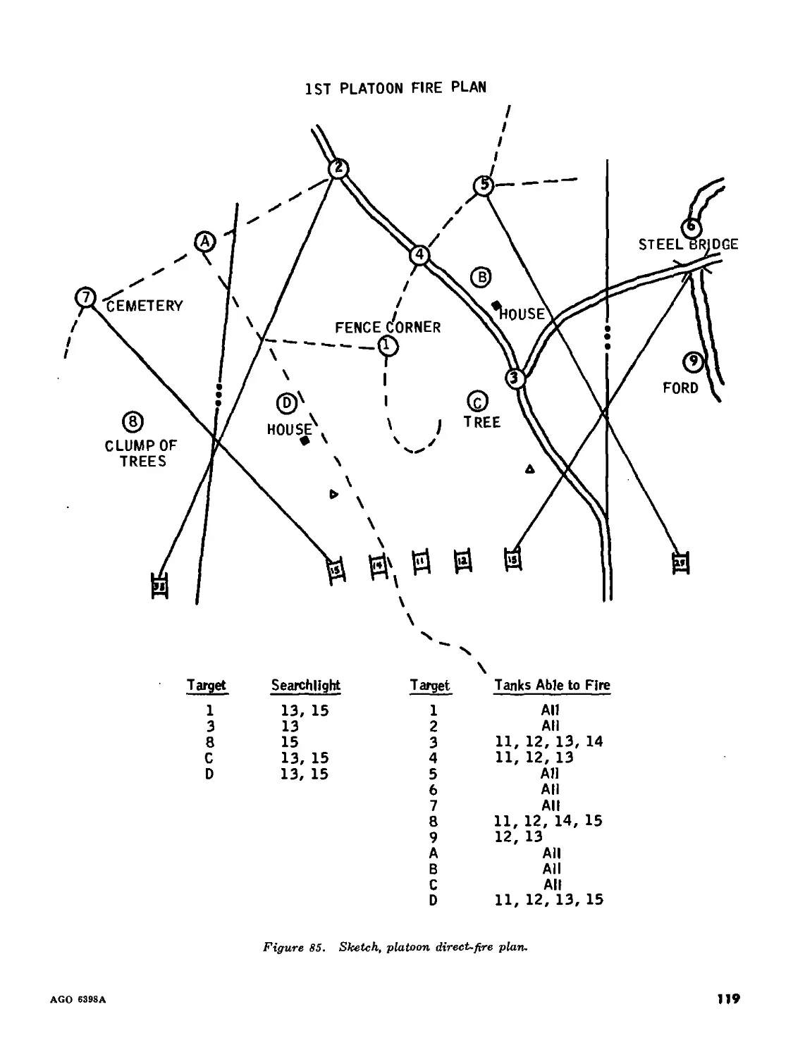
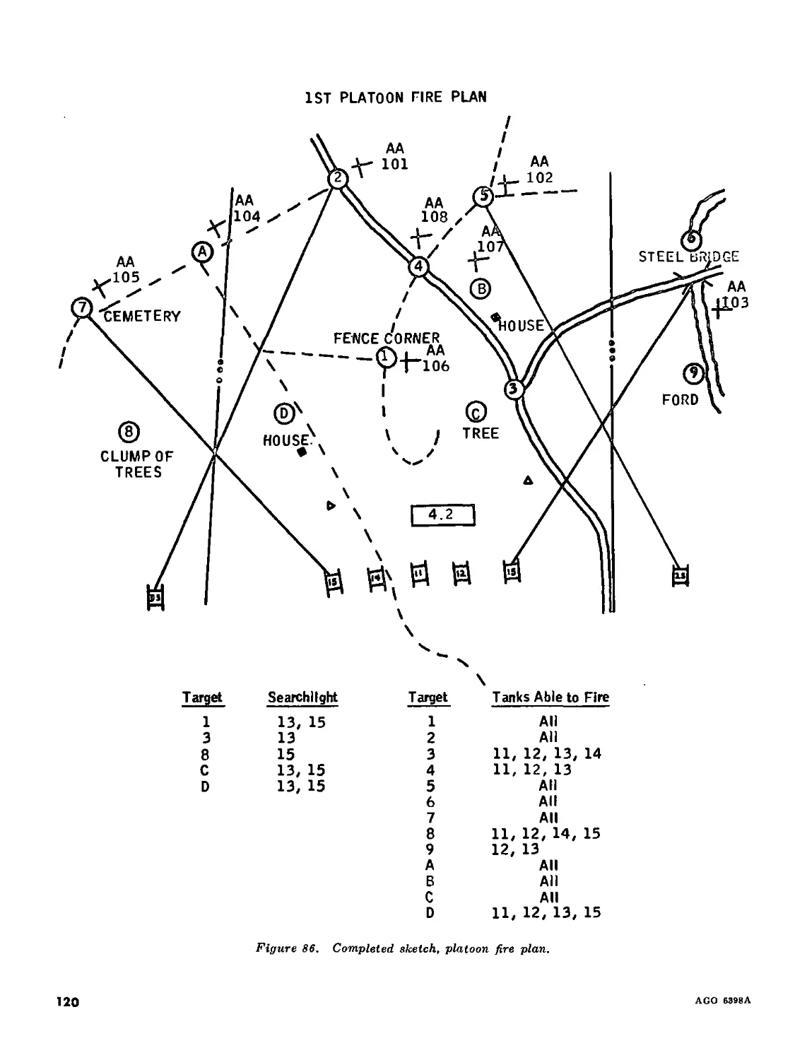
Chapter 13. PLATOON FIRE DISTRIBUTION AND CONTROL
Section I. Introduction_______________________-___________________________________117-119 105
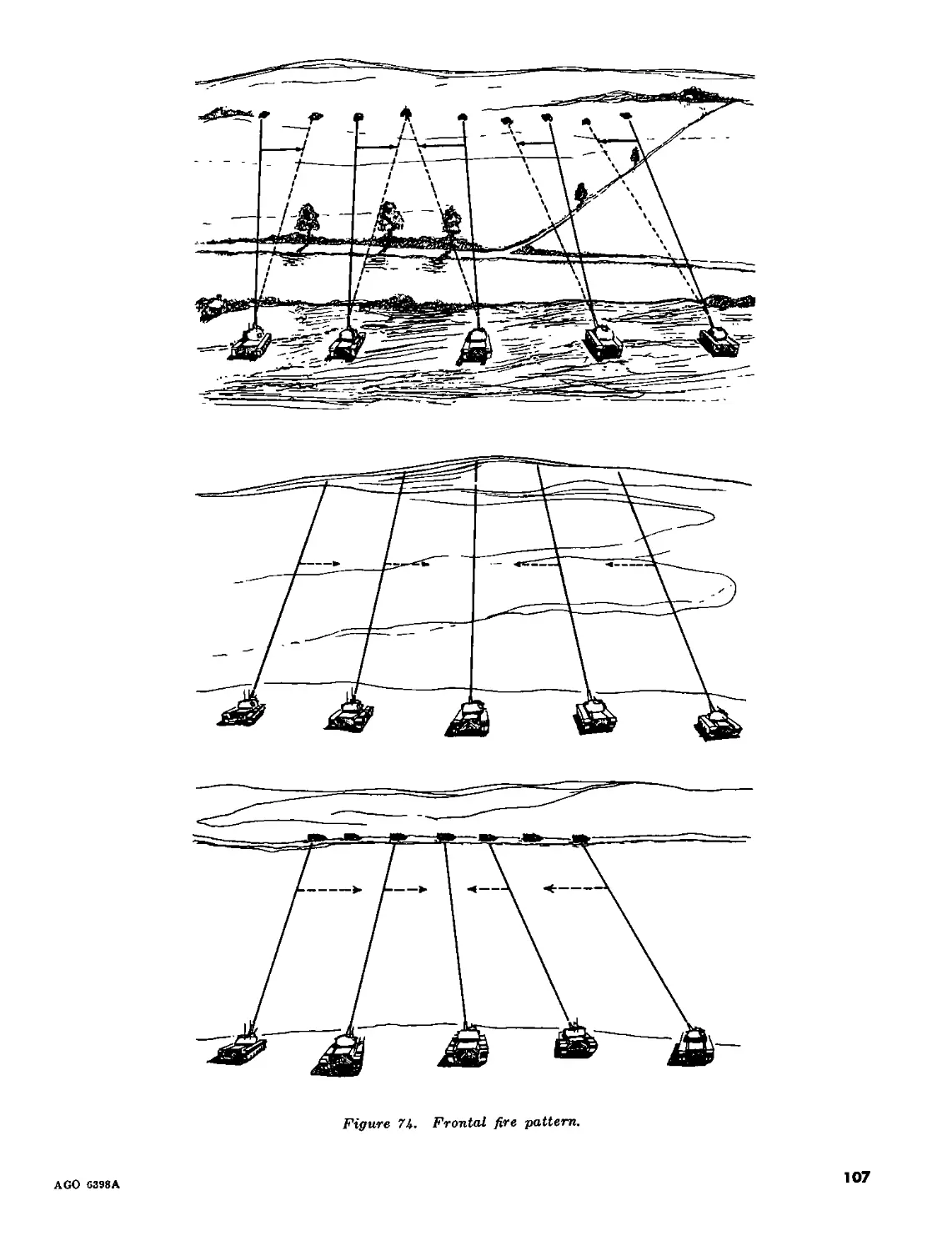
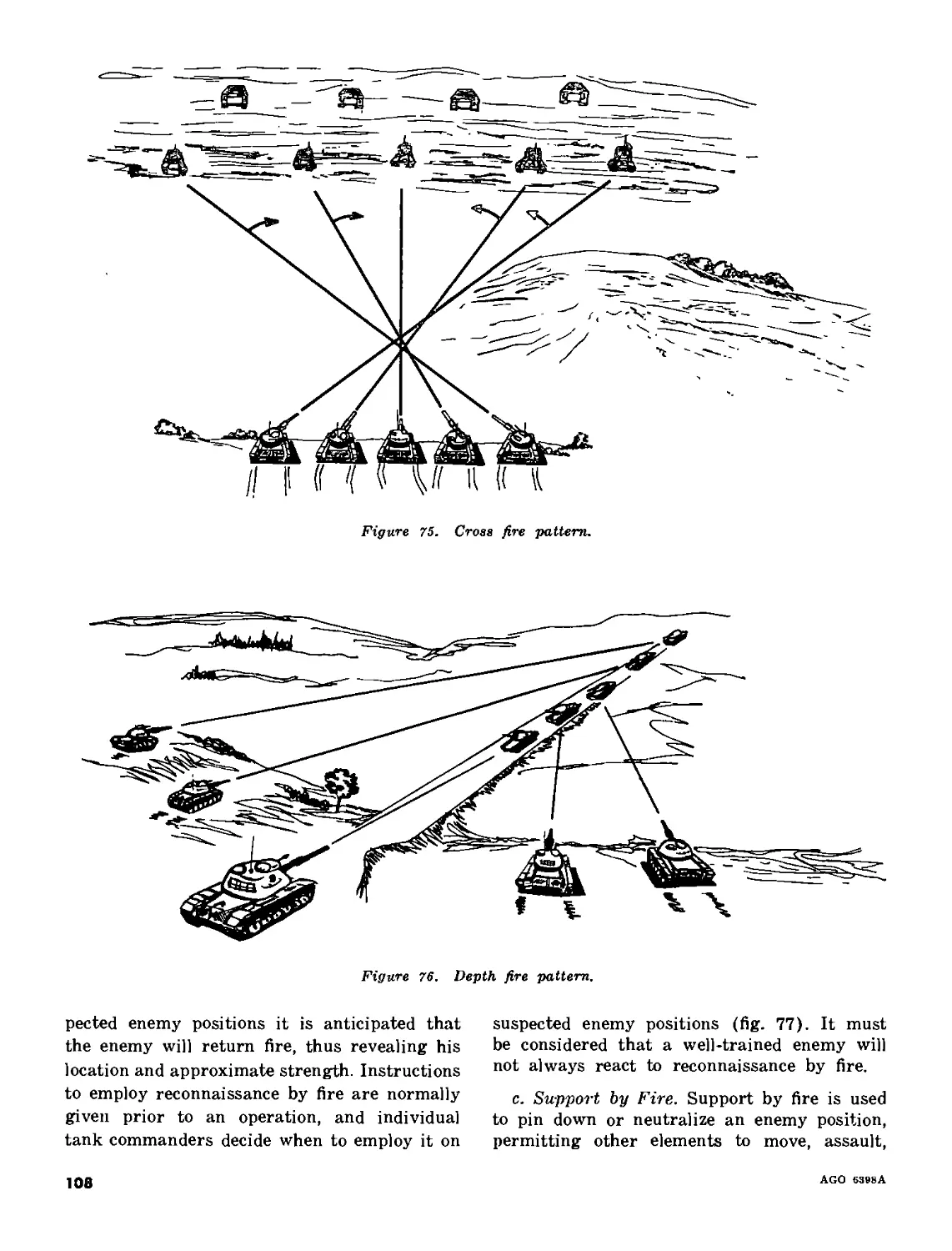
II. Distribution and volume of fire______________________________________ 120-122 106
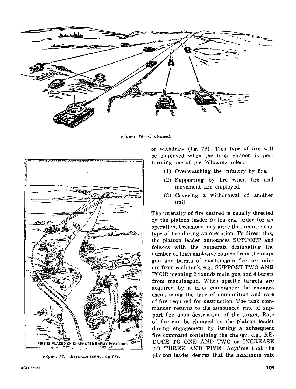
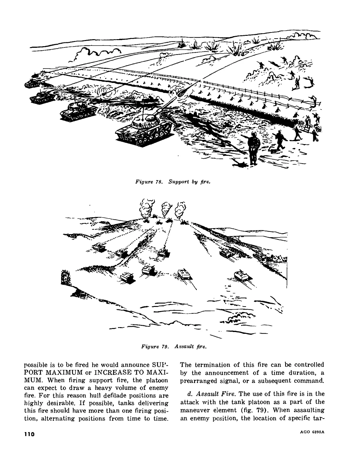
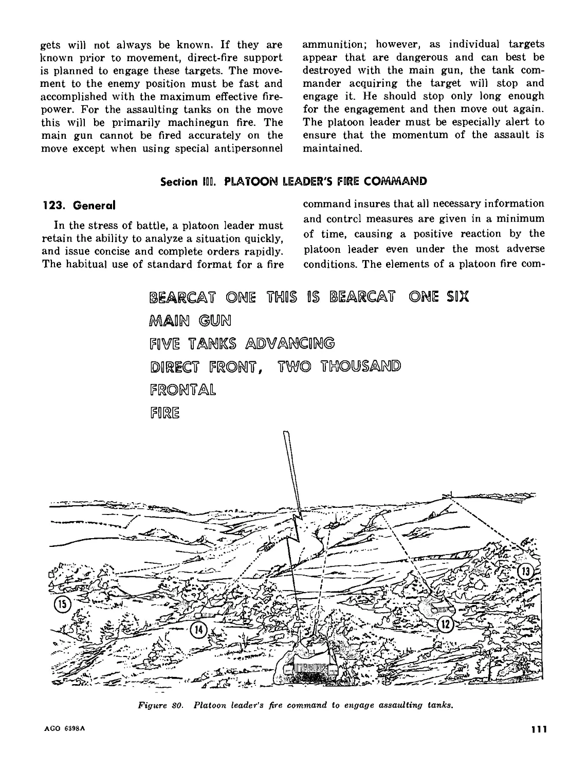
III. Platoon leader's fire command________________________________________ 123-129 111
IV. Platoon fire planning offensive actions______________________________ 130-132 116
V. Platoon fire planning, defensive actions_____________________________ 133-137 116
Part Five. TANK GUNNERY TRAINING
Chapter 14. GENERAL
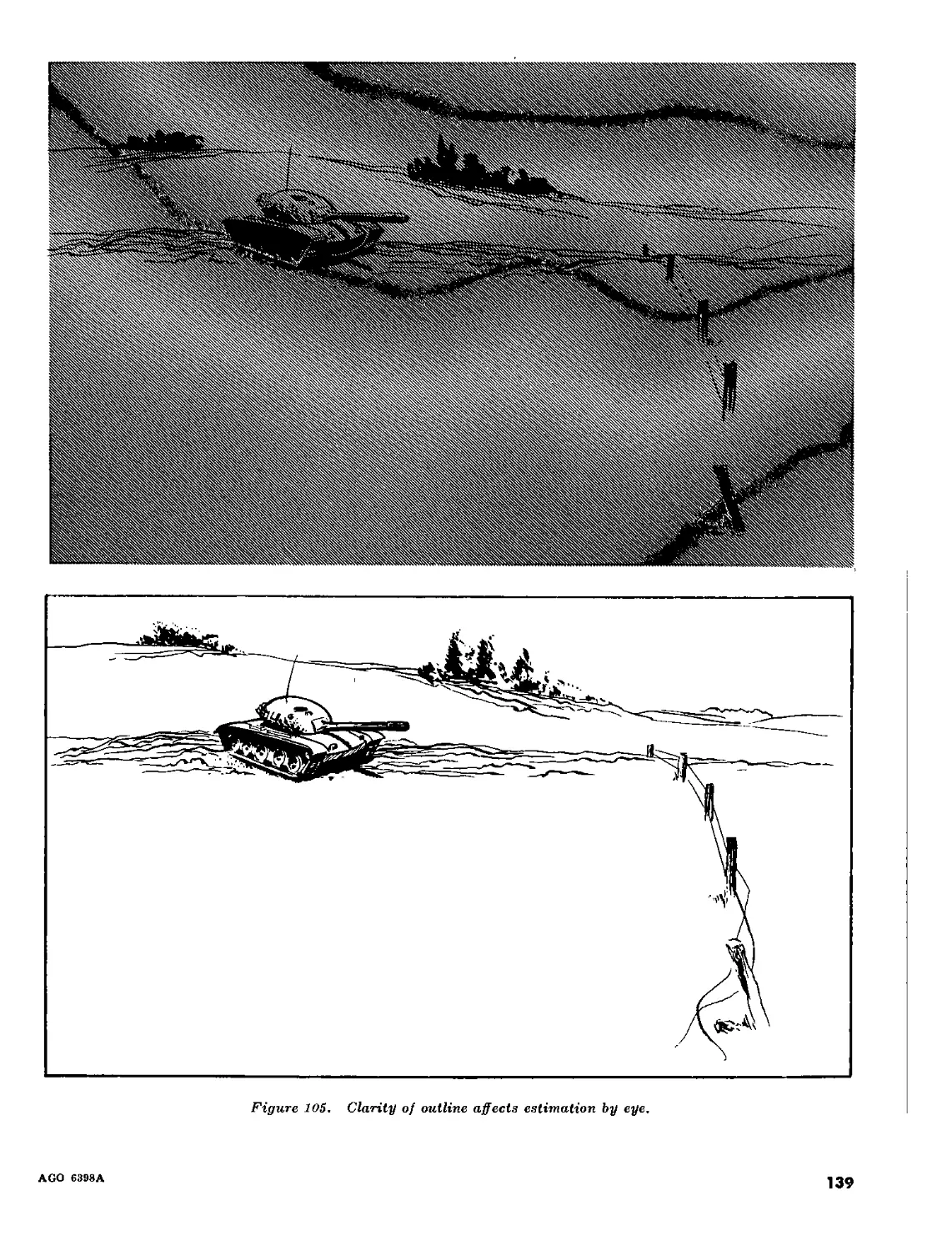
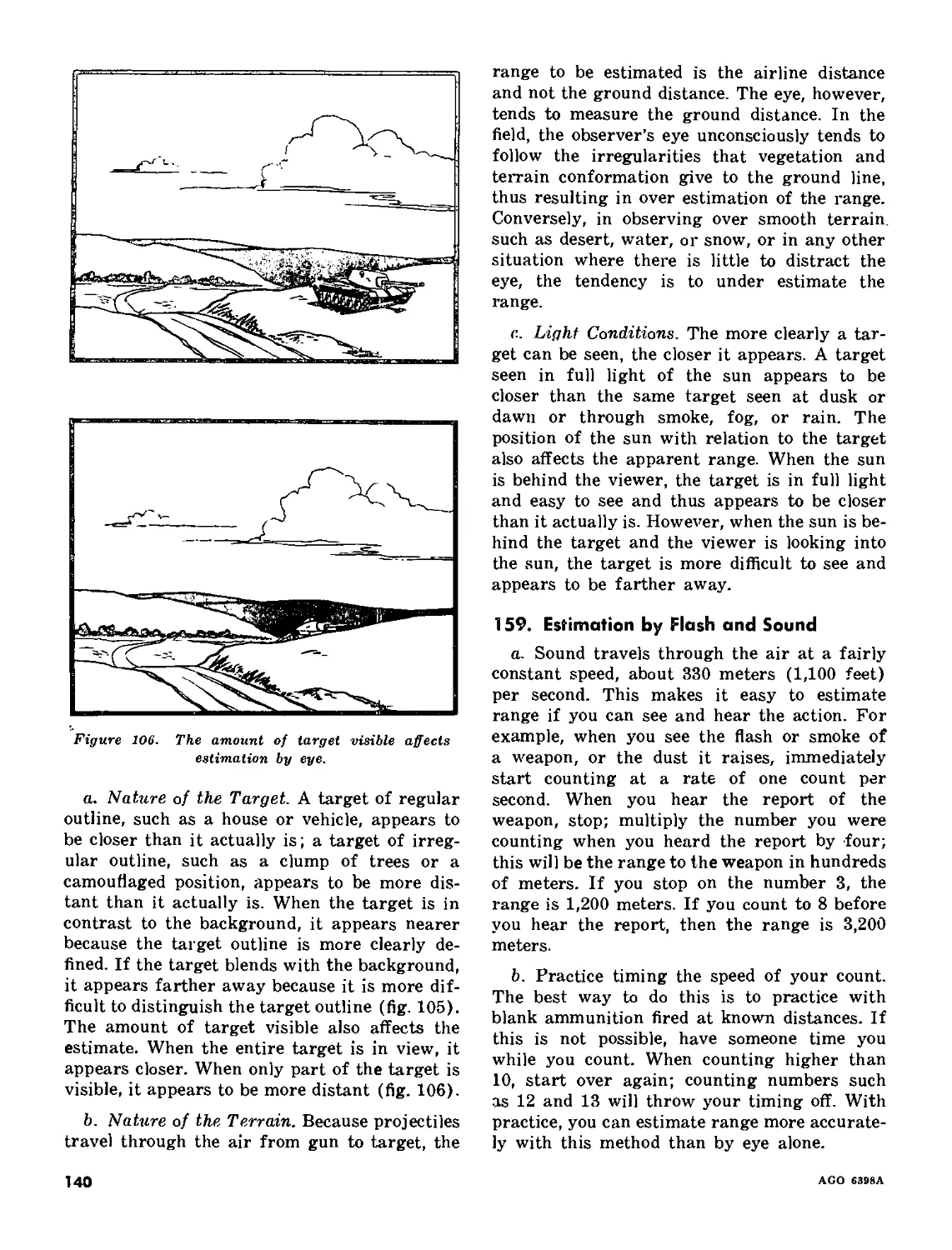
Section I. Introduction________________________________________________________ 138-140 122
II. Individual gunnery training___________________________________________141-150 124
III. Crew gunnery training________________________________________________ 151-152 130
Chapter 15. RANGE DETERMINATION
Section I. Introduction________________________________________________________ 153-154 132
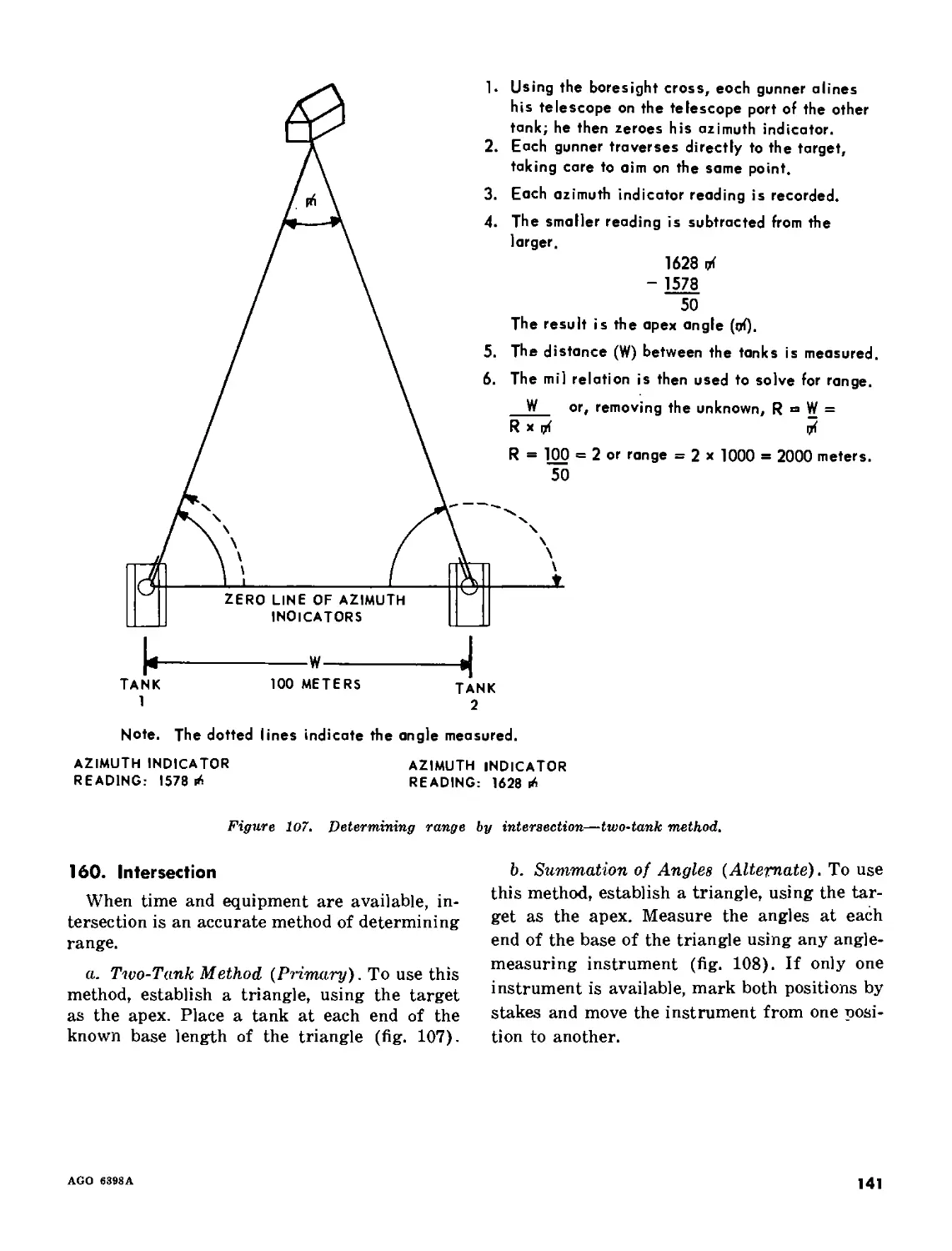
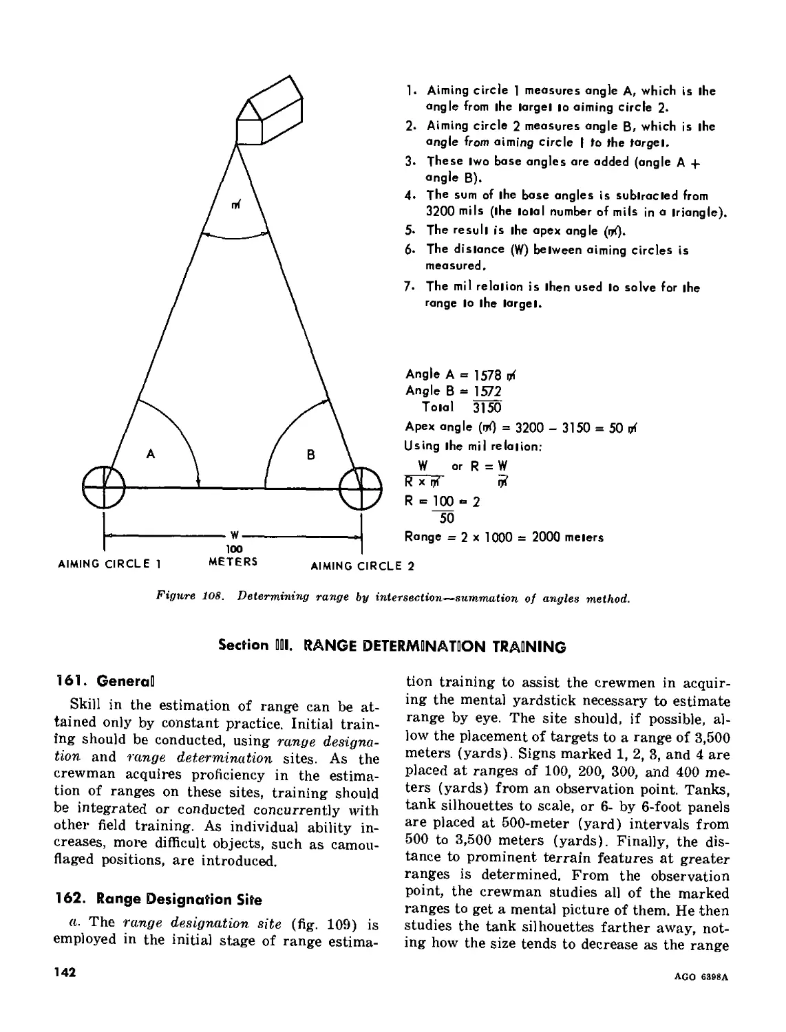
11. Methods of range determination_______________________________________ 155-160 132
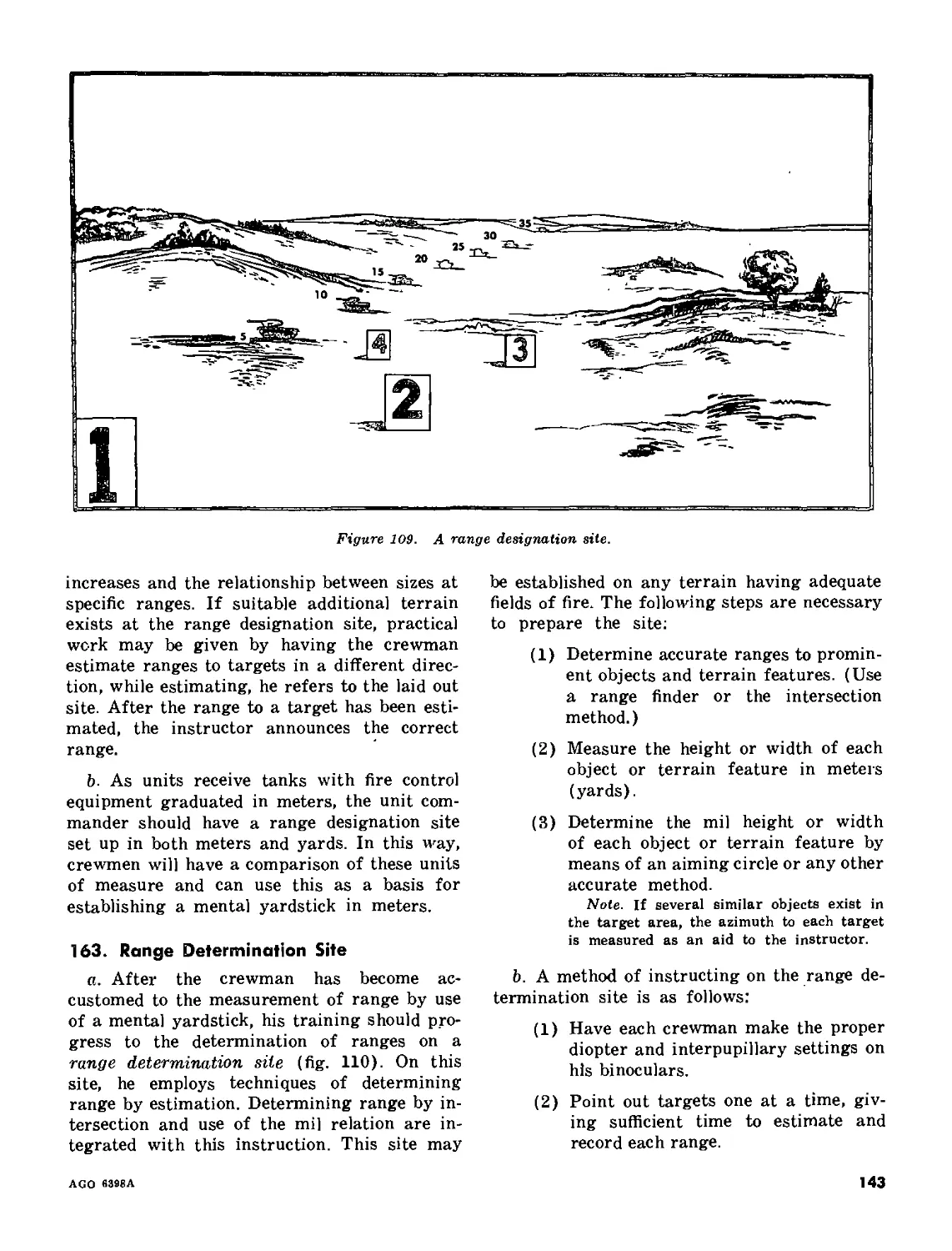
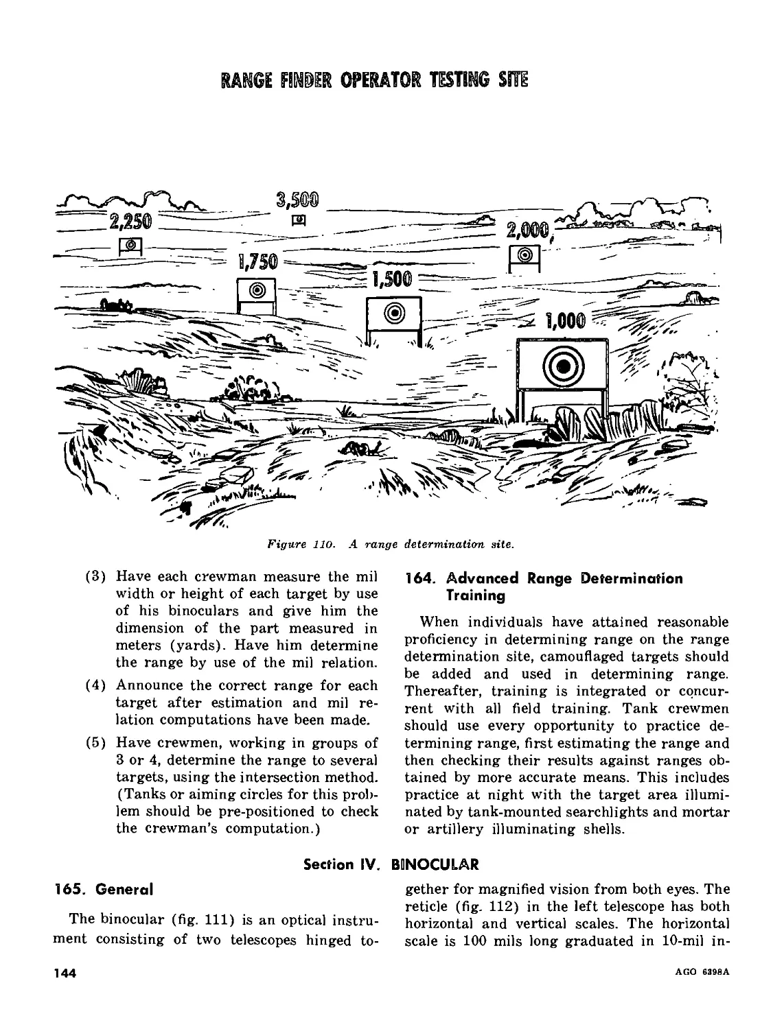
III. Range determination training_________________________________________161-164 • 142
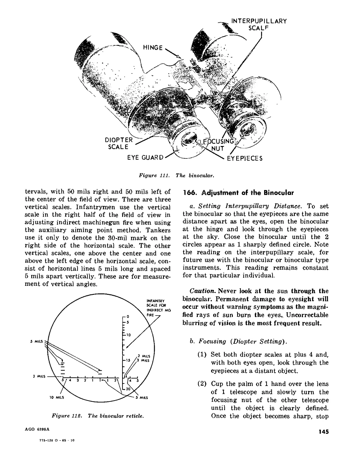
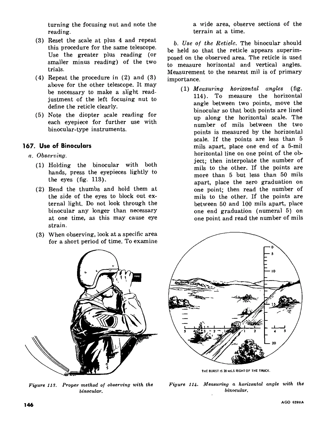
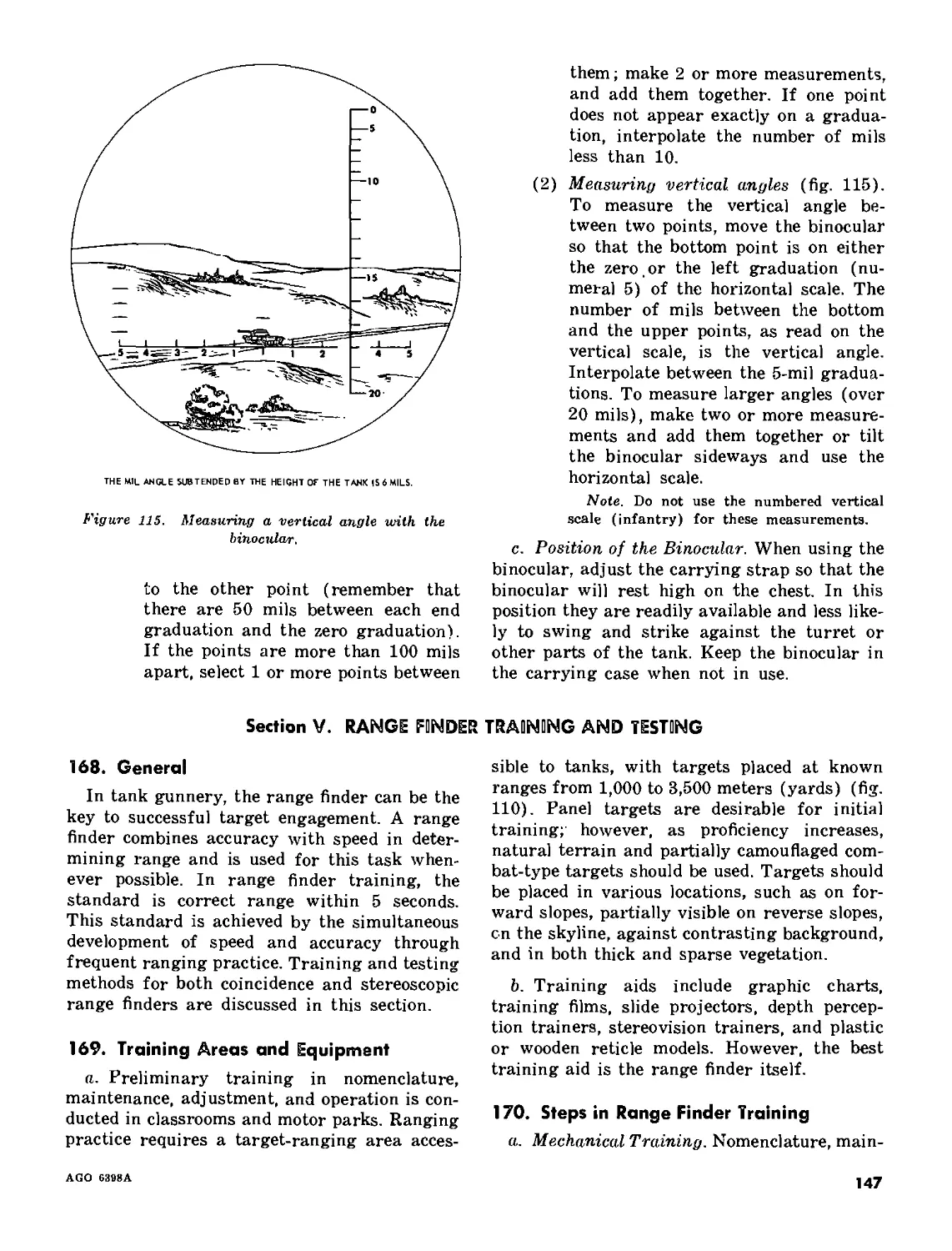
IV. Binocular____________________________________________________________ 165-167 144
V. Range finder training and testing____________________________________ 168-175 147
Chapter 16. TARGET ACQUISITION TRAINING 176-179 153
Part Six. TANK GUNNERY TESTING
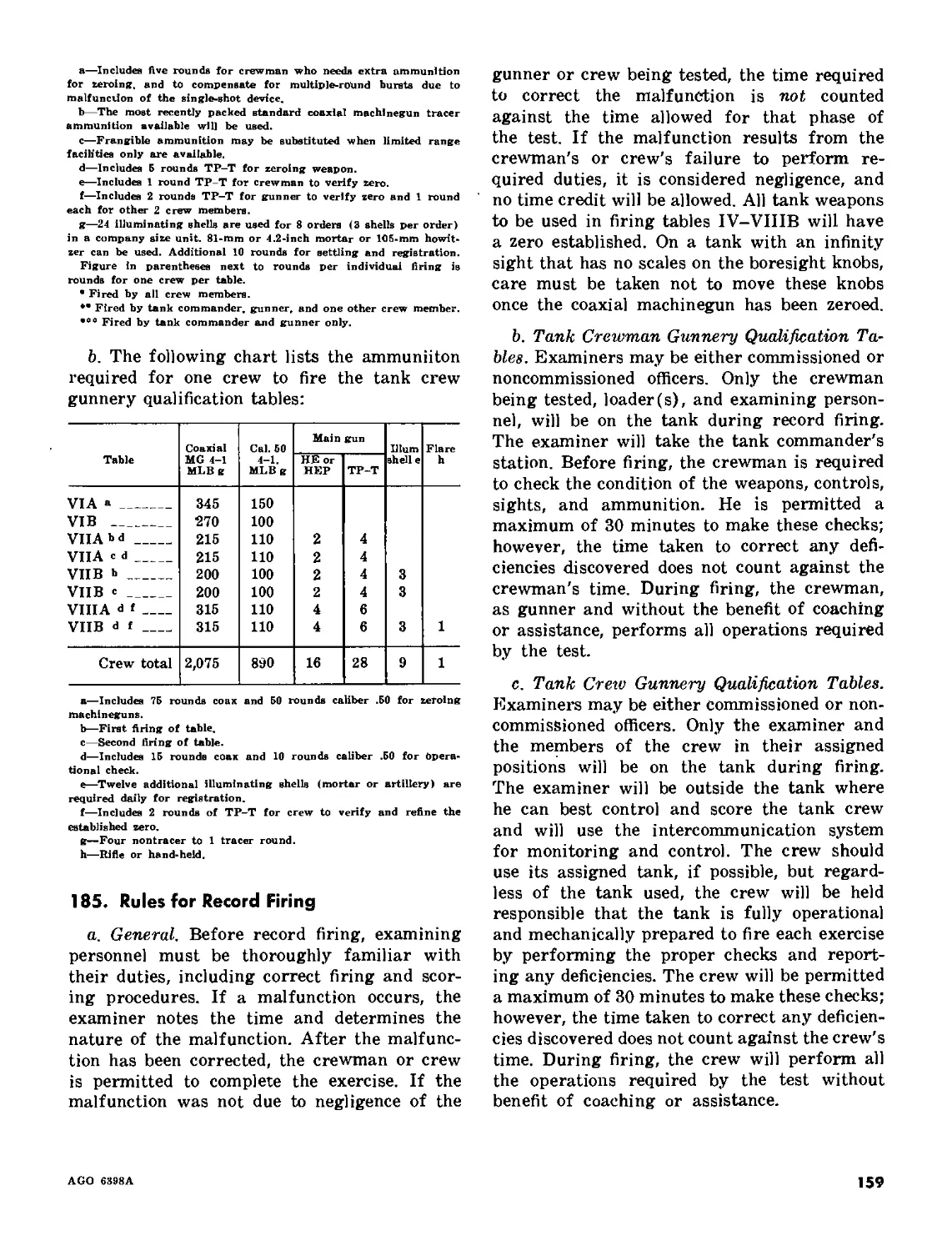
Chapter 17. INTRODUCTION_________________________________________________________ 180-185 156
18. TANK CREWMAN GUNNERY QUALIFICATION COURSE
Section I. Introduction_________________________________________________________ 186 160
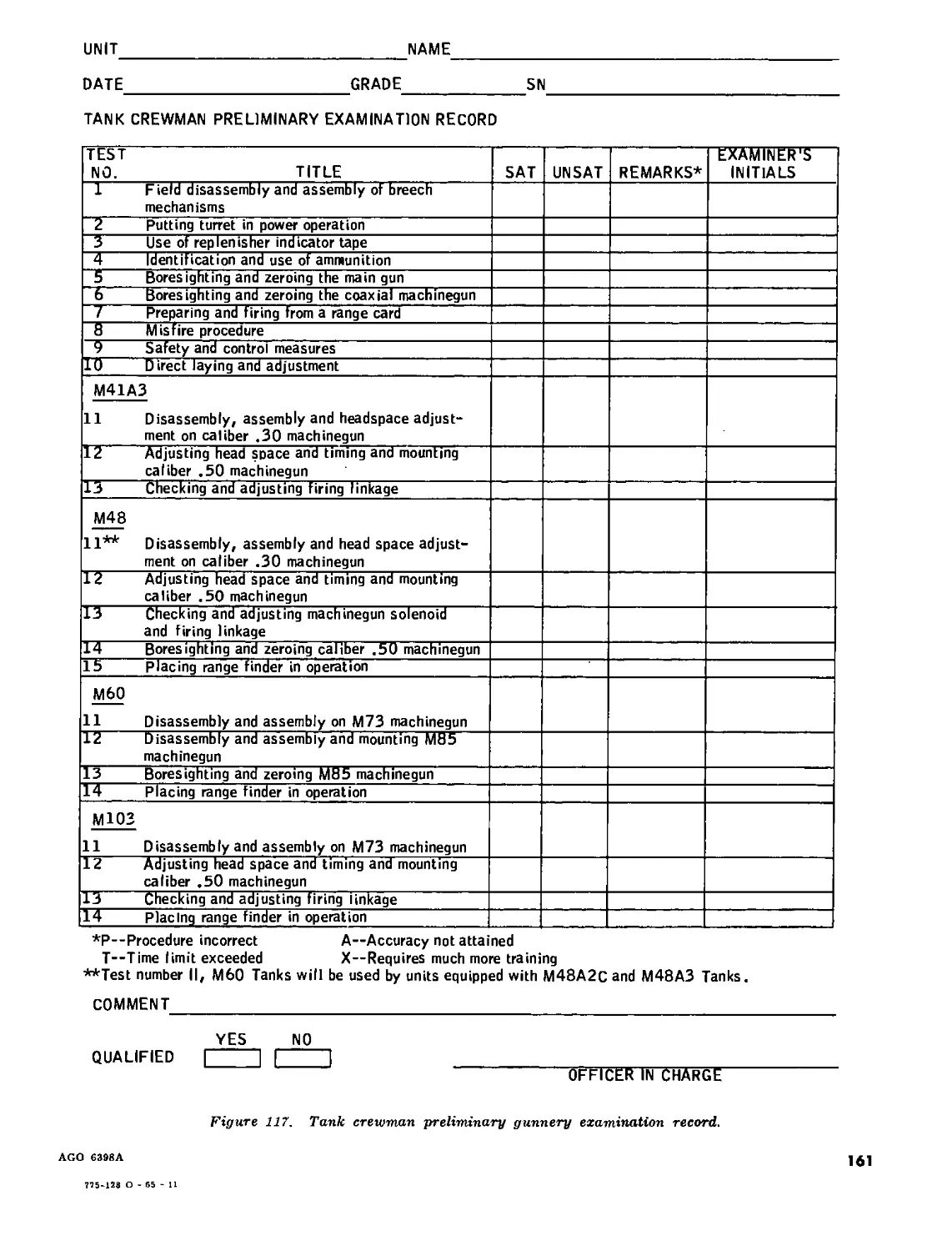
II. Tank crewman preliminary gunnery examination__________________________ 187-204 160
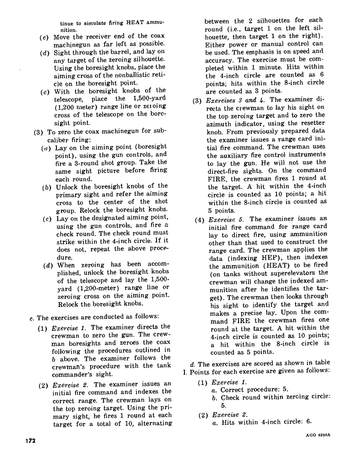
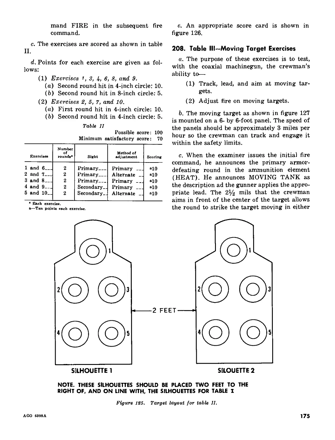
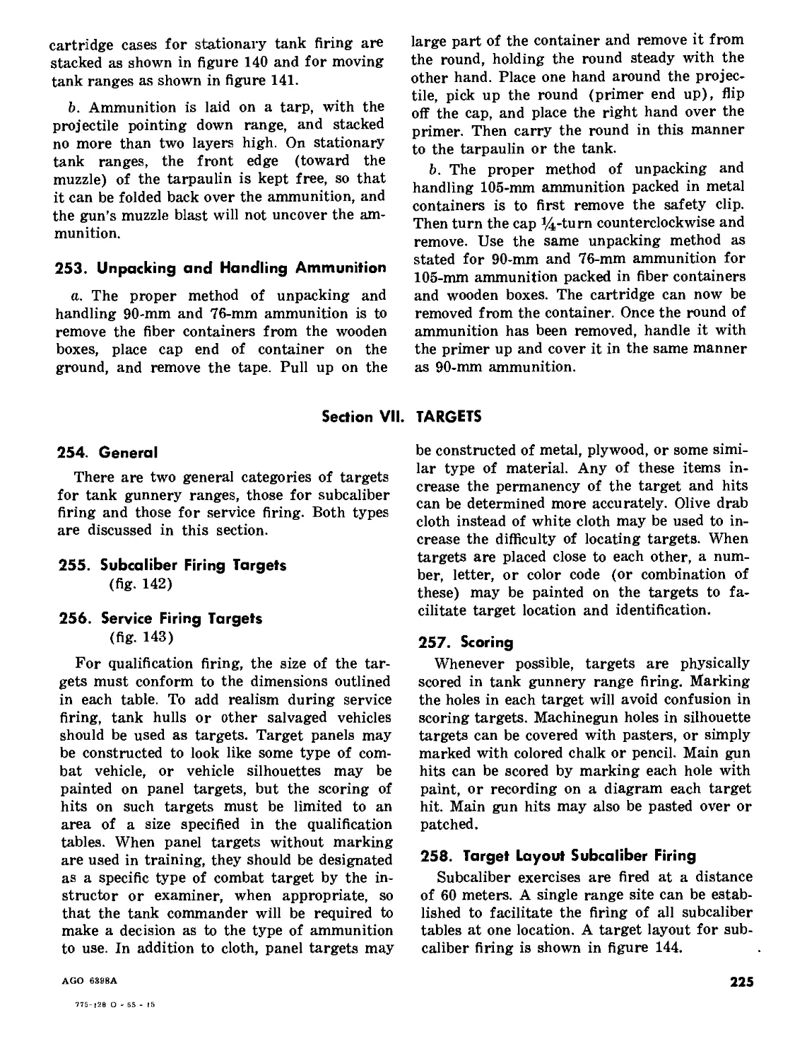
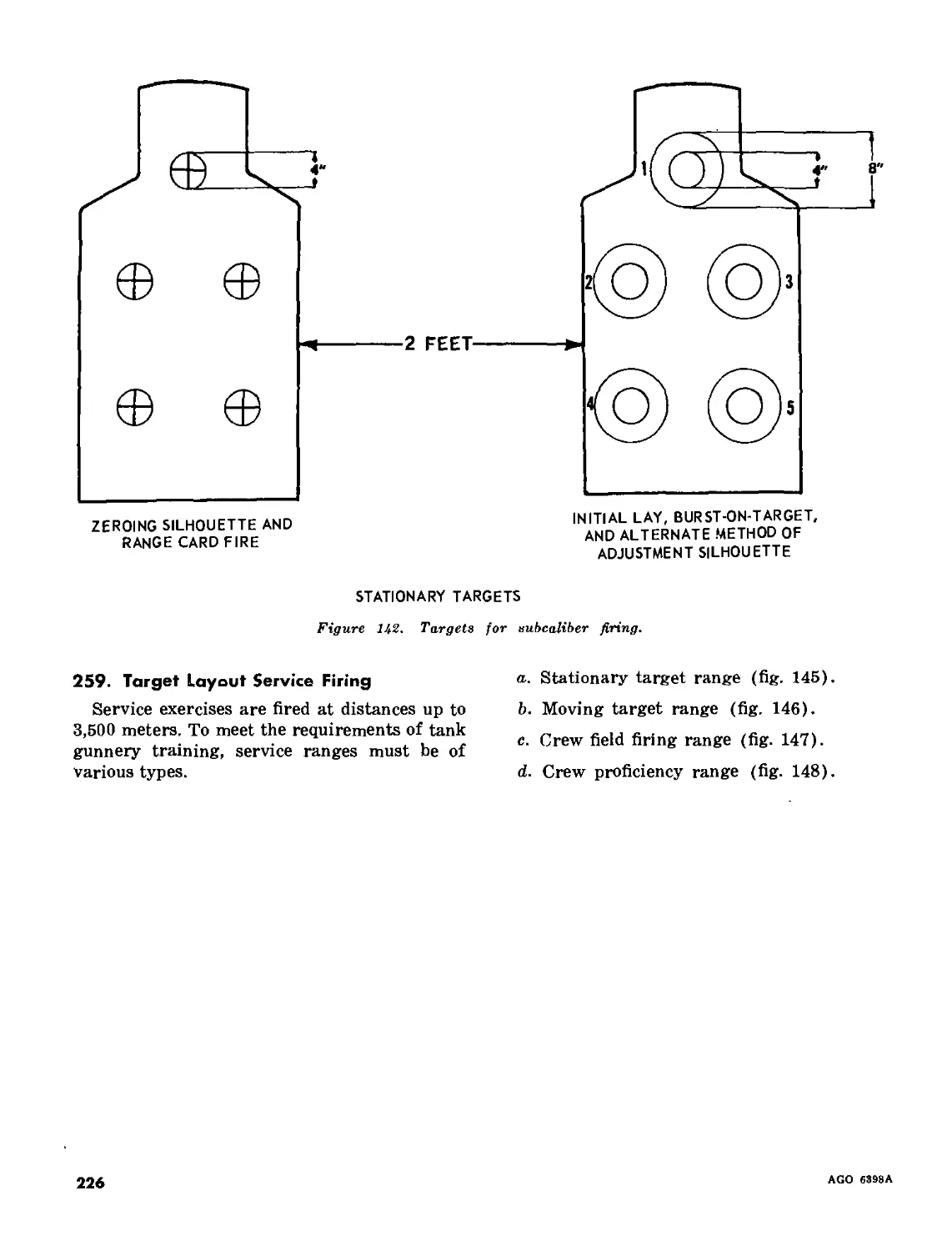
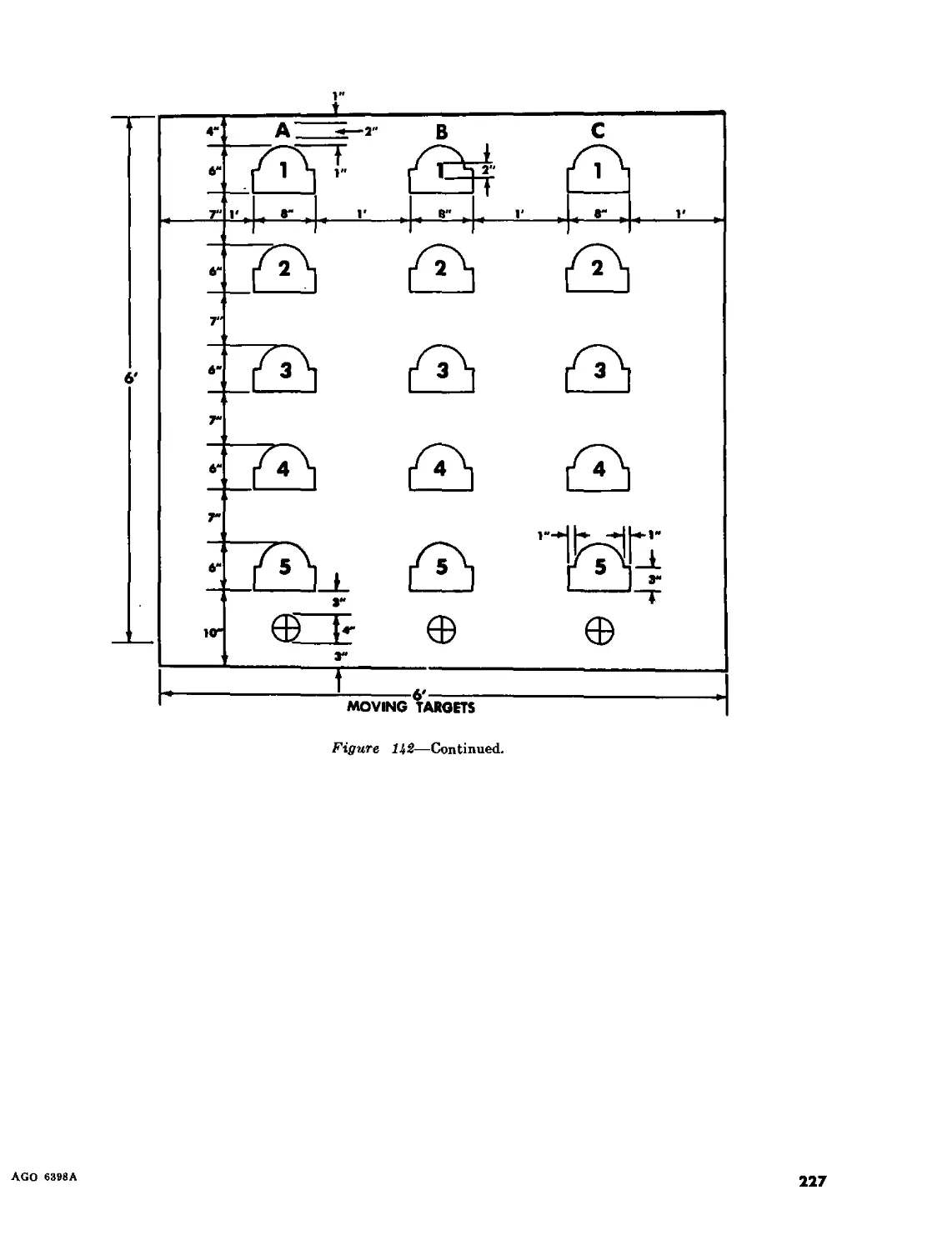
III. Tank crewman gunnery qualification—subcaliber firing_________________ 205-208 171
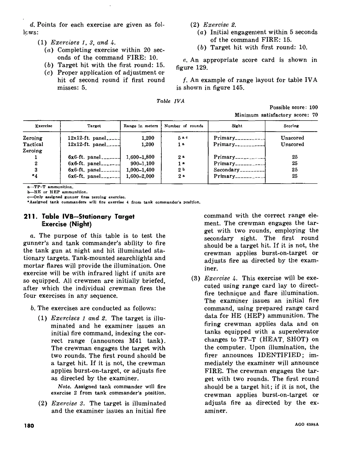
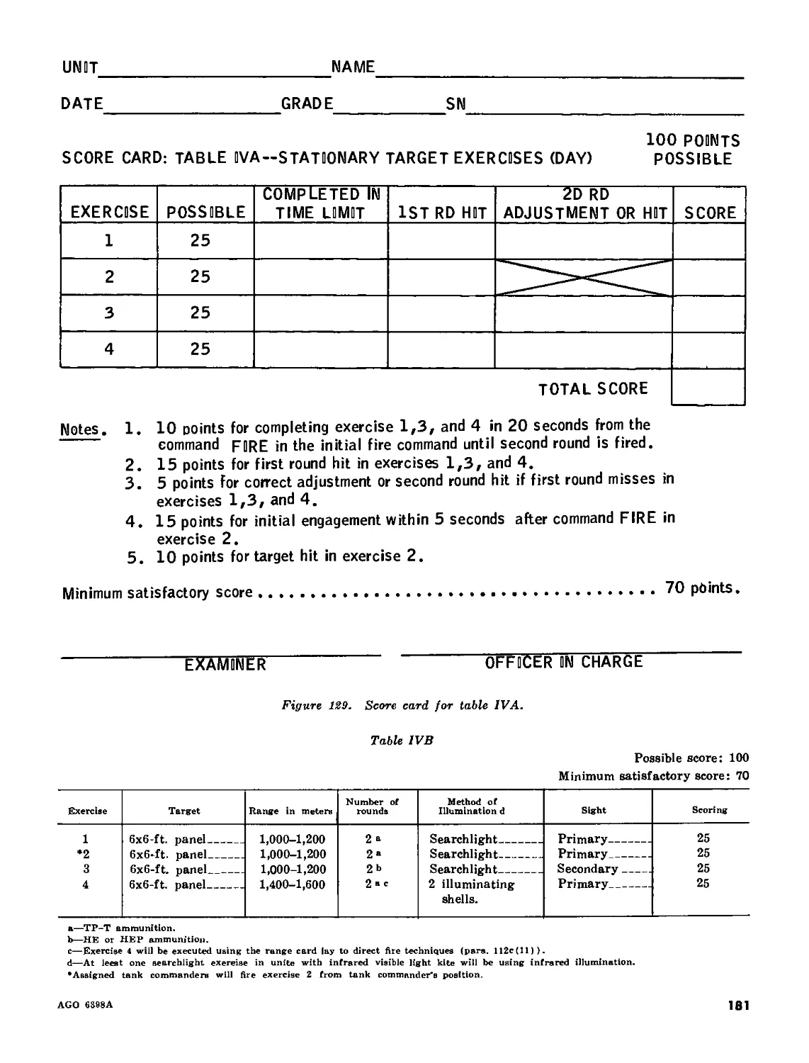
IV. Tank crewman gunnery qualification—service firing____________________ 209-213 179
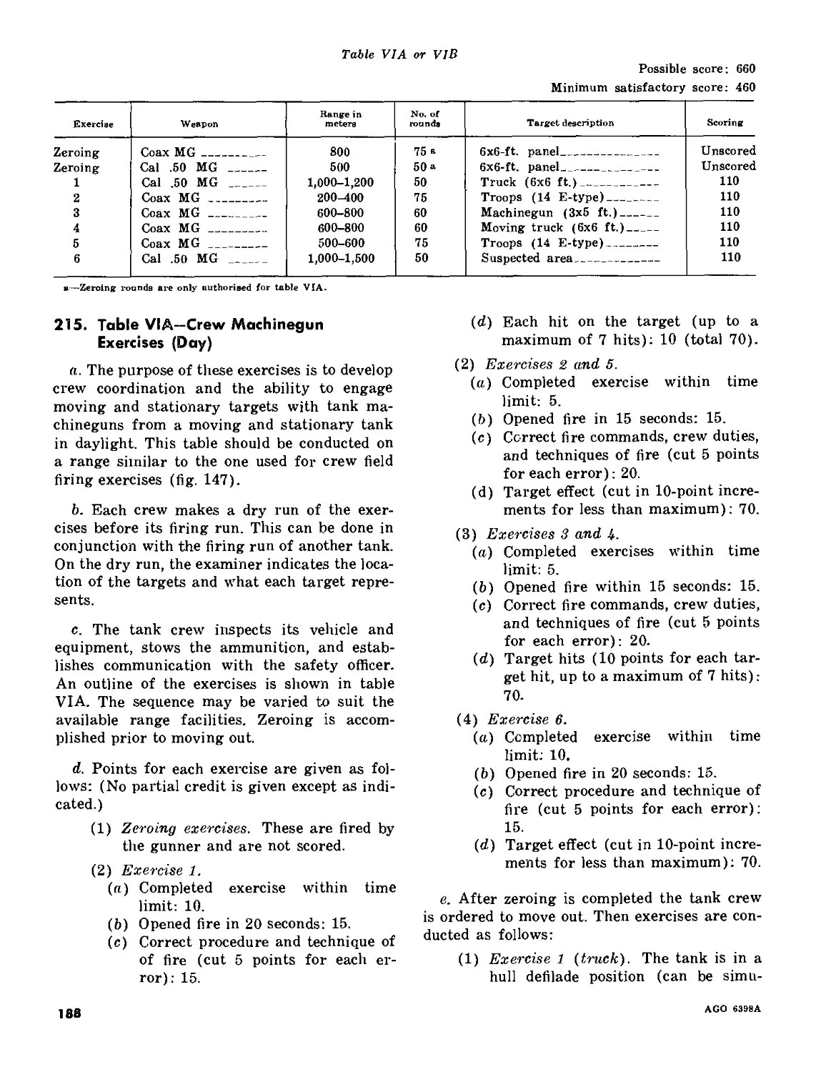
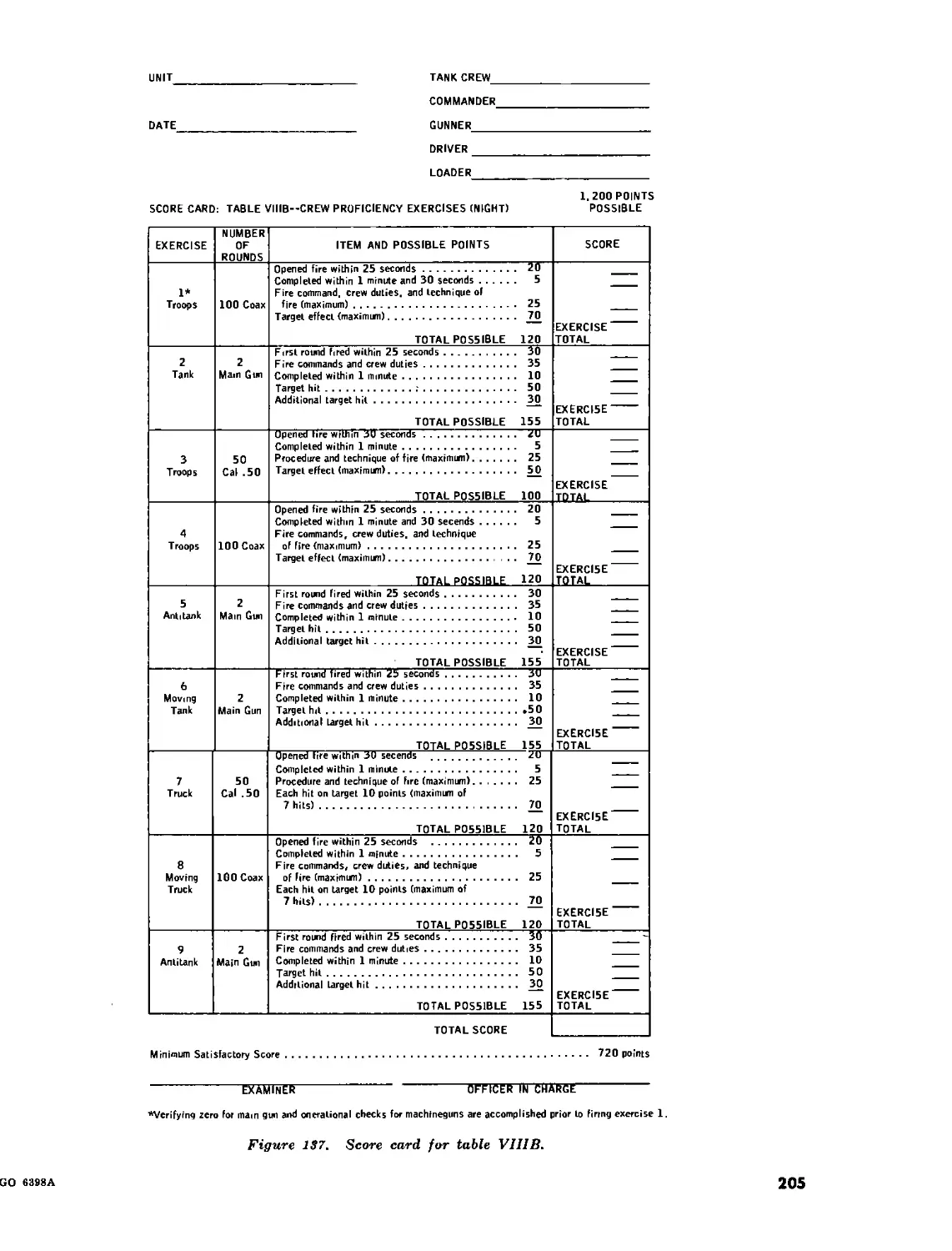
Chapter 19. TANK CREW GUNNERY QUALIFICATION FIRING_______________________________214-221 187
20. FAMILIARIZATION AND PRACTICE FIRING
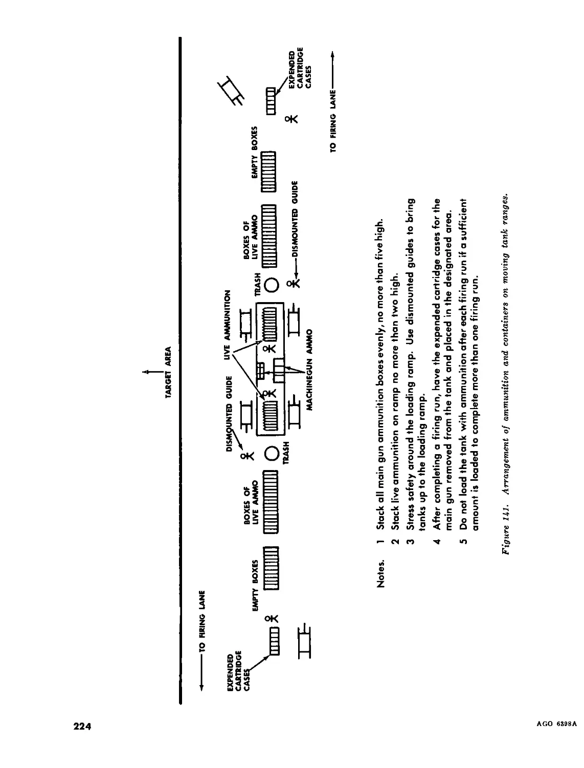
Section I. Familiarization firing_______________________________________________ 222-224 206
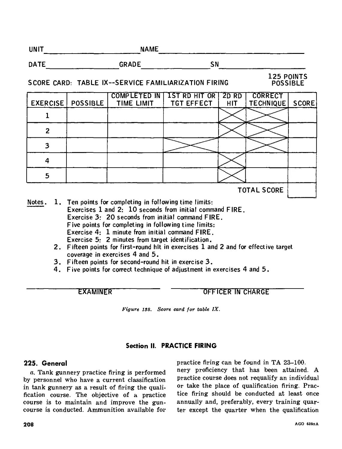
II. Practice firing______________________________________________________ 225-226 208
Part Seven. OPERATION OF TANK RANGES
Chapter 21. ESTABLISHING TANK RANGES
Section I. Introduction________________________________________________________ 227-228 210
II. Establishing tank firing ranges______________________________________ 229-233 210
Chapter 22. CONDUCT OF RANGE FIRING
Section I. Preparation and duties of the officer in charge_____________________ 234-238 213
II. Conduct of firing____________________________________________________ 239-243 217
III. Duties of the safety officer_________________________________________ 244-245 218
IV. Duties of the tank instructor/examiner_______________________________ 246-247 220
V. Safety precautions and methods of controlling tank range firing------ 248-250 221
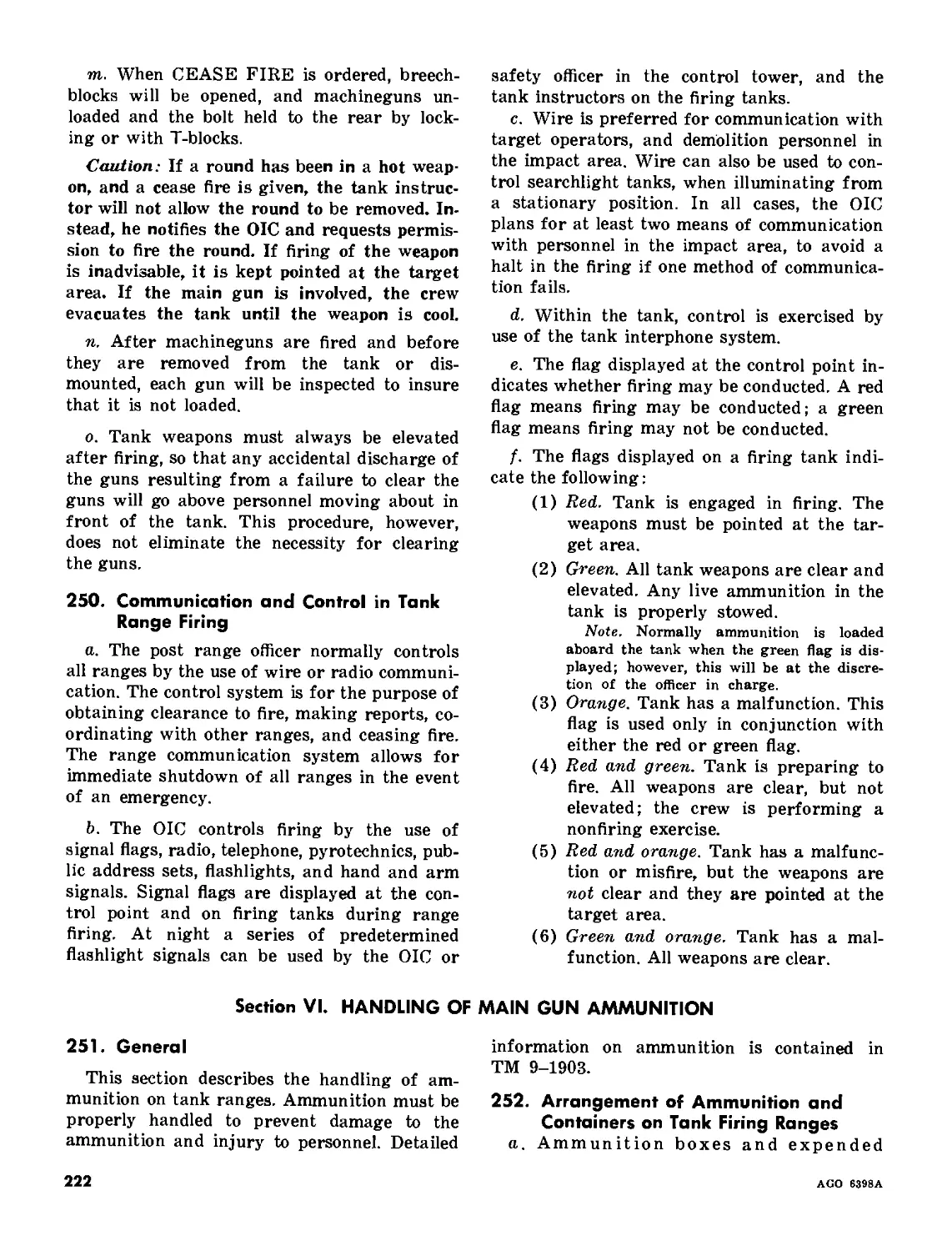
VI. Handling of main gun ammunition______________________________________ 251-253 222
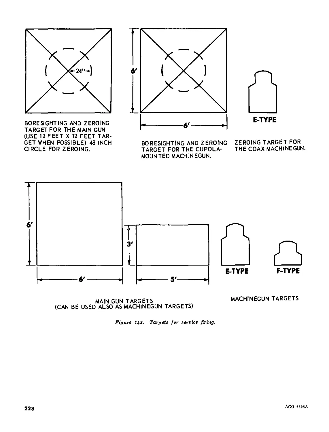
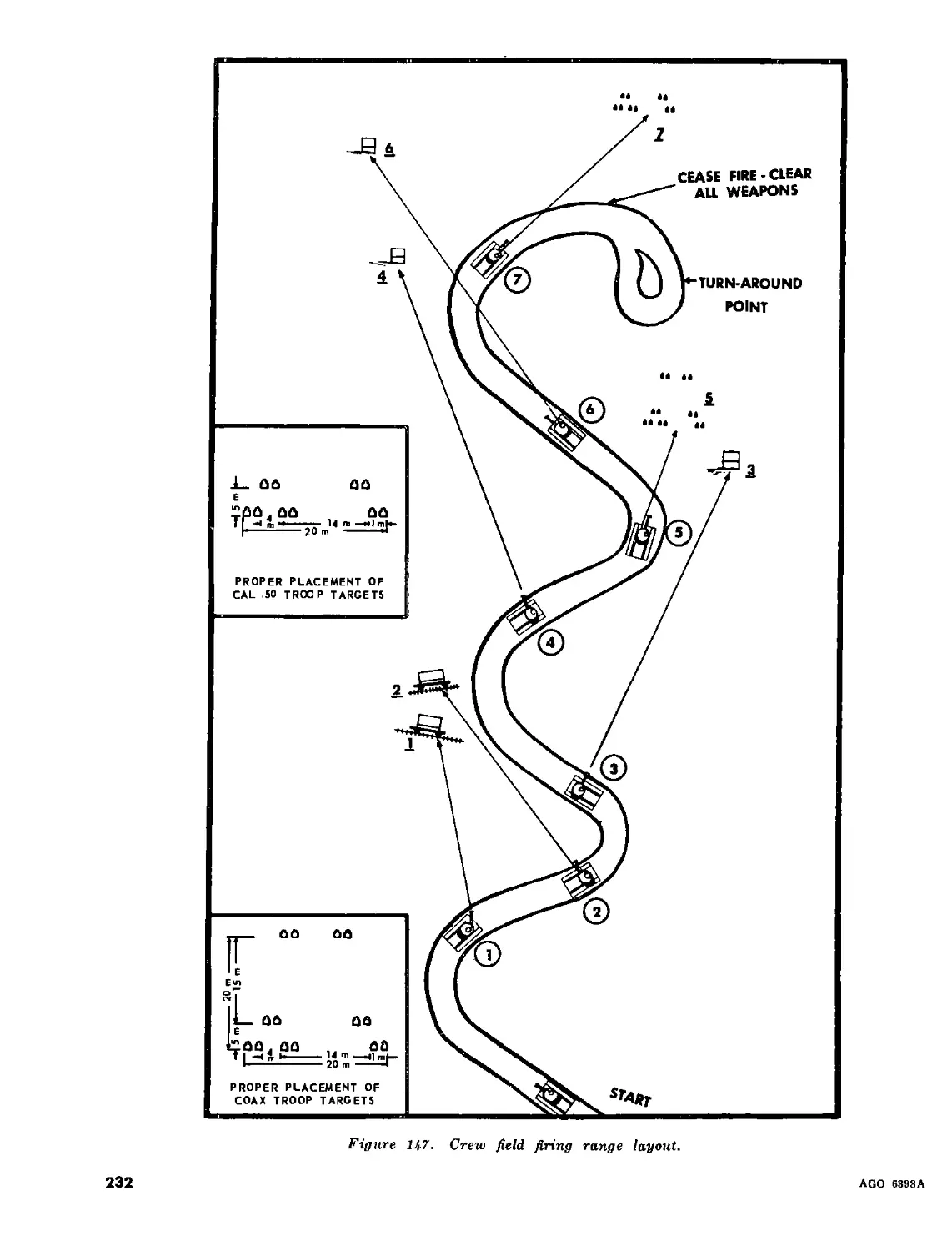
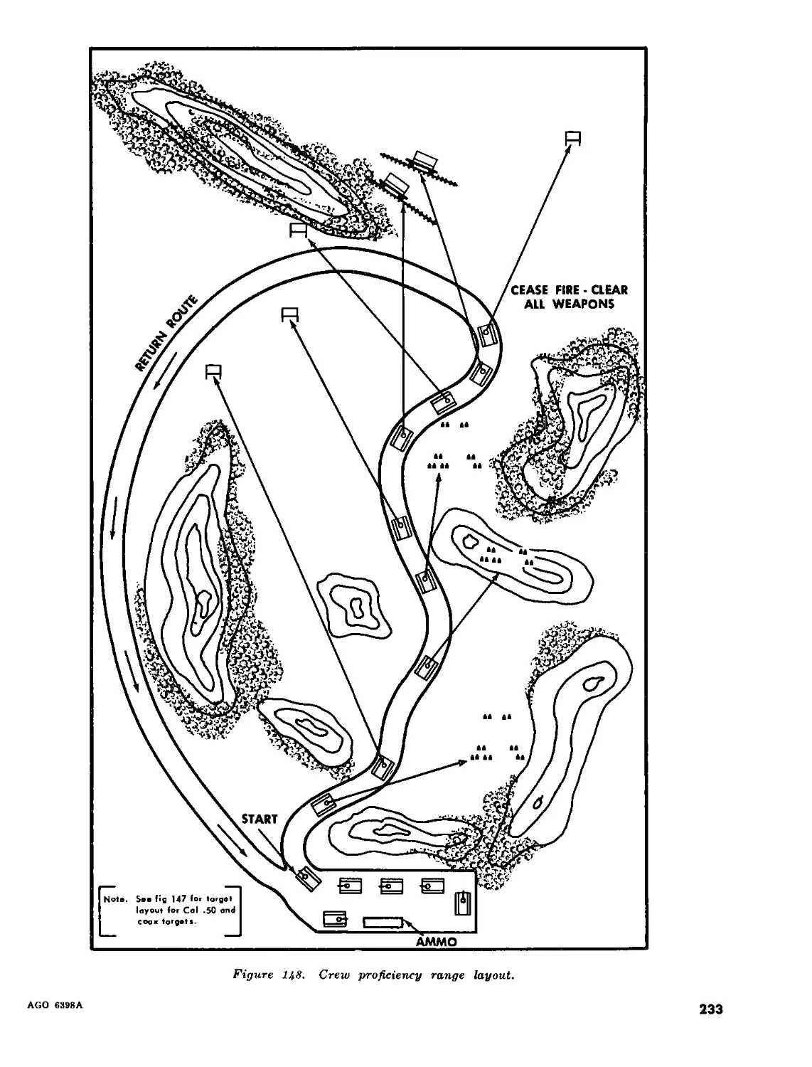
VII. Targets______________________________________________________________ 254-259 225
Appendix I. REFERENCES___________________________________________________________ 234
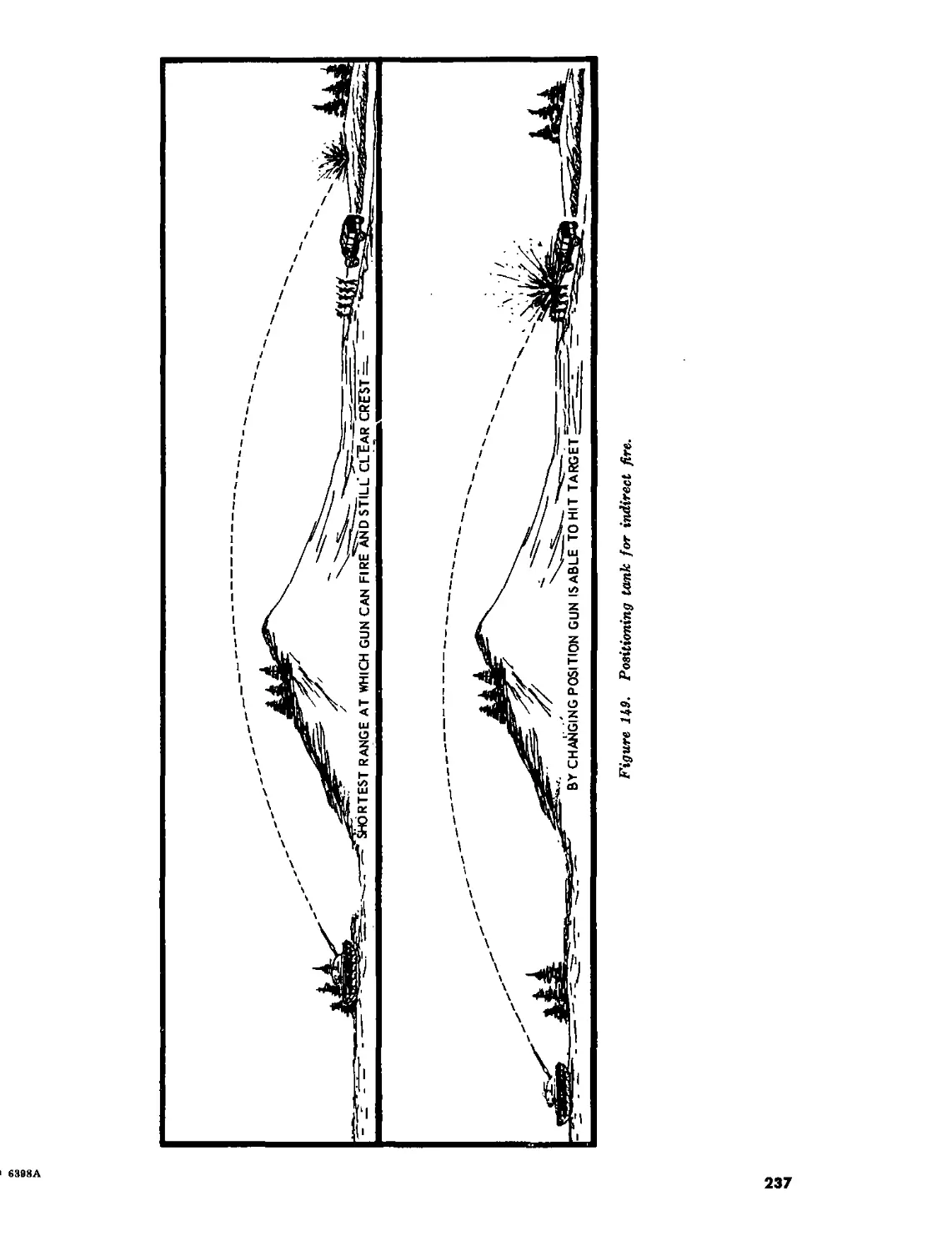
II. TANK IN THE ARTILLERY ROLE___________________________________________ 236
INDEX______________________________________________________________________________ 246
2
AGO 6398A
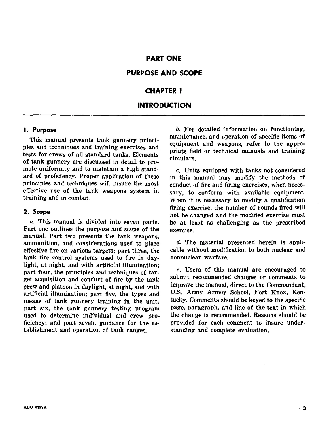
PART ONE
PURPOSE AND SCOPE
CHAPTER 1
INTRODUCTION
1. Purpose
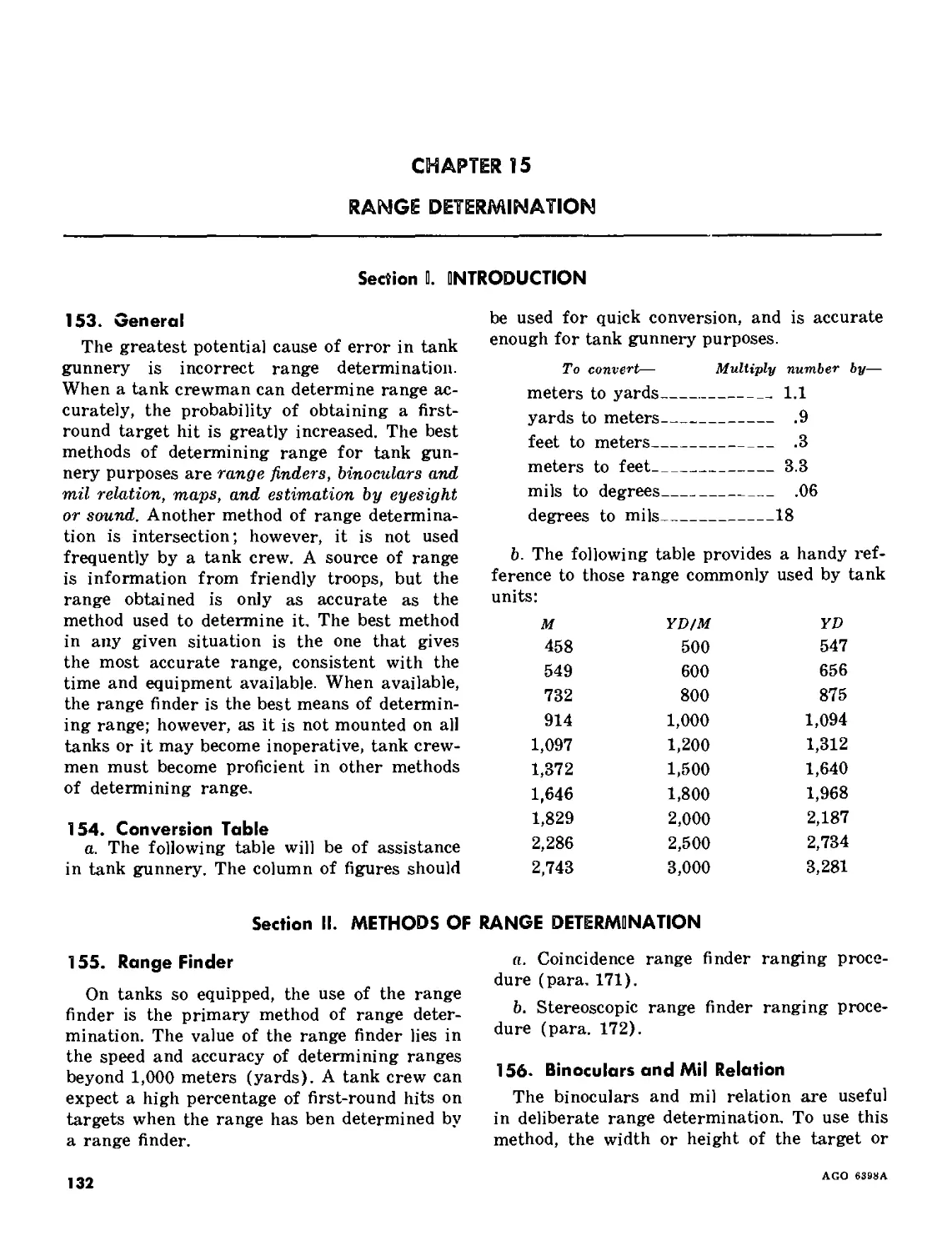
This manual presents tank gunnery princi-
ples and techniques and training exercises and
tests for crews of all standard tanks. Elements
of tank gunnery are discussed in detail to pro-
mote uniformity and to maintain a high stand-
ard of proficiency. Proper application of these
principles and techniques will insure the most
effective use of the tank weapons system in
training and in combat.
2. Scope
a. This manual is divided into seven parts.
Part one outlines the purpose and scope of the
manual. Part two presents the tank weapons,
ammunition, and considerations used to place
effective fire on various targets; part three, the
tank fire control systems used to fire in day-
light, at night, and with artificial illumination;
part four, the principles and techniques of tar-
get acquisition and conduct of fire by the tank
crew and platoon in daylight, at night, and with
artificial illumination; part five, the types and
means of tank gunnery training in the unit;
part six, the tank gunnery testing program
used to determine individual and crew pro-
ficiency; and part seven, guidance for the es-
tablishment and operation of tank ranges.
b. For detailed information on functioning,
maintenance, and operation of specific items of
equipment and weapons, refer to the appro-
priate field or technical manuals and training
circulars.
c. Units equipped with tanks not considered
in this manual may modify the methods of
conduct of fire and firing exercises, when neces-
sary, to conform with available equipment.
When it is necessary to modify a qualification
firing exercise, the number of rounds fired will
not be changed and the modified exercise must
be at least as challenging as the prescribed
exercise.
d. The material presented herein is appli-
cable without modification to both nuclear and
nonnuclear warfare.
e. Users of this manual are encouraged to
submit recommended changes or comments to
improve the manual, direct to the Commandant,
U.S. Army Armor School, Fort Knox, Ken-
tucky. Comments should be keyed to the specific
page, paragraph, and line of the text in which
the change is recommended. Reasons should be
provided for each comment to insure under-
standing and complete evaluation.
AGO 6398A
3
PART TWO
TANK WEAPONS AND AMMUNITION
CHAPTER 2
TANK WEAPONS AND USES
3. Introduction
United .States tanks have a large caliber
main gun, which is used for destruction of
enemy armor and other hard targets, and
those soft targets that are not within effective
range of the tank mounted machineguns. They
have a coaxially mounted machinegun (re-
ferred to hereafter as coax or coax machine-
gun) for engagement of soft targets (per-
sonnel, trucks, wooden structures, etc.) at close
ranges and to provide suppressive fire while
the tank is moving. The tank commander also
has a machinegun, which can be used against
soft targets and some lightly armored vehicles
and may be fired at different targets when the
main gun or coax machinegun is already em-
ployed. It can provide the tank commander
with a means for reconnaissance by fire. Ad-
ditionally, it provides the tank with an anti-
aircraft capability against low performance
aircraft.
4. Main Gun
The tank main gun with a variety of am-
munition can be used effectively against all
types of ground targets. The ballistic character-
istics (flat trajectory) of the projectiles make
the weapon very accurate. The tank com-
mander’s decision as to what type of ammuni-
tion to use against a target is based on his
knowledge of the capabilities of the ammuni-
tion (ch. 3).
5. Coox Machinegun
Because of the large amount of coax am-
munition that can be stowed in the tank and
the effectiveness of area fire with the gun from
a stationary or moving tank, the coax machine-
gun is used against soft targets when they ap-
pear within its effective range. This conserves
main gun ammunition for targets that cannot
be destroyed with coax fire either because of
range or type of target and reduces the supply
requirements of main gun ammunition.
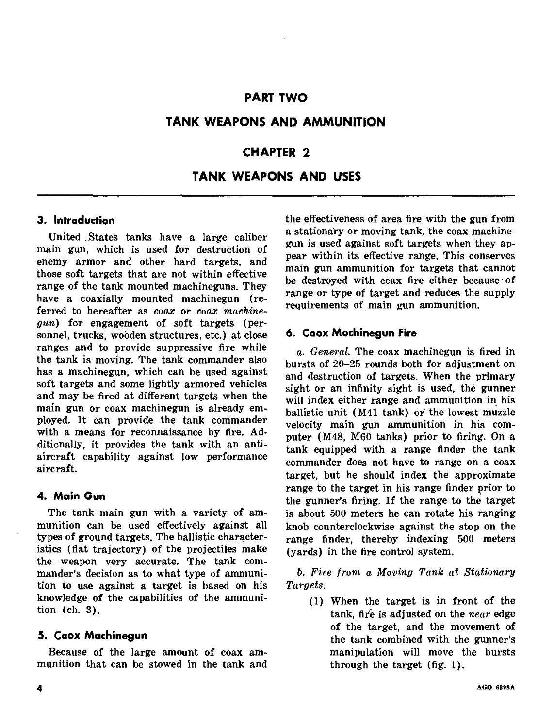
6. Coox Mochinegun Fire
a. General. The coax machinegun is fired in
bursts of 20-25 rounds both for adjustment on
and destruction of targets. When the primary
sight or an infinity sight is used, the gunner
will index either range and ammunition in his
ballistic unit (M41 tank) or the lowest muzzle
velocity main gun ammunition in his com-
puter (M48, M60 tanks) prior to firing. On a
tank equipped with a range finder the tank
commander does not have to range on a coax
target, but he should index the approximate
range to the target in his range finder prior to
the gunner’s firing. If the range to the target
is about 500 meters he can rotate his ranging
knob counterclockwise against the stop on the
range finder, thereby indexing 500 meters
(yards) in the fire control system.
b. Fire from a Moving Tank at Stationary
Targets.
(1) When the target is in front of the
tank, fire is adjusted on the near edge
of the target, and the movement of
the tank combined with the gunner’s
manipulation will move the bursts
through the target (fig. 1).
4
AGO 68Й8А
Figure 1. Coax fire—target direct front.
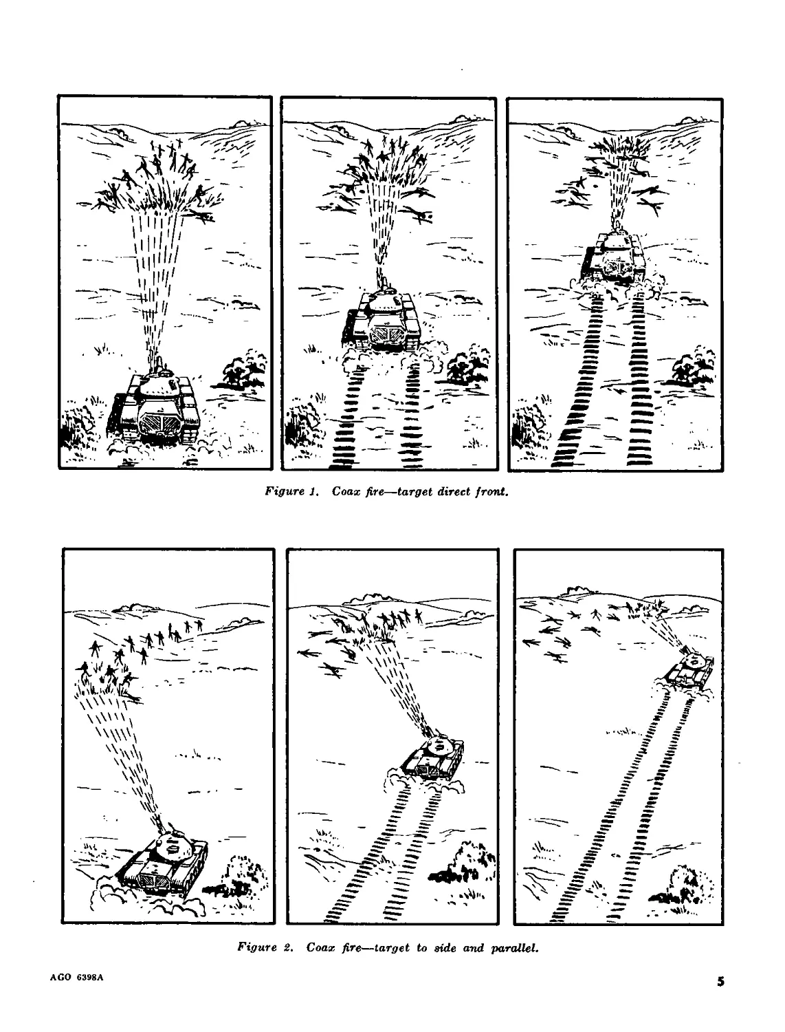
Figure 2. Coax fire—target to side and parallel.
AGO 6398A
5
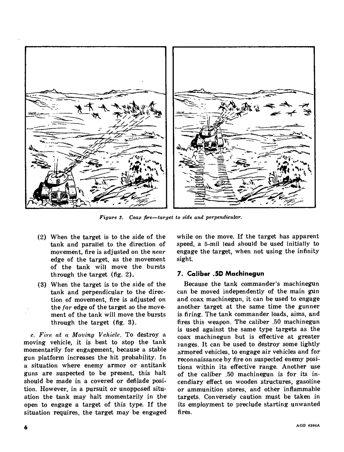
Figure 3. Coax fire—target to side and perpendicular.
(2) When the target is to the side of the
tank and parallel to the direction of
movement, fire is adjusted on the near
edge of the target, as the movement
of the tank will move the bursts
through the target (fig. 2).
(3) When the target is to the side of the
tank and perpendicular to the direc-
tion of movement, fire is adjusted on
the far edge of the target so the move-
ment of the tank will move the bursts
through the target (fig. 3).
c. Fire at a Moving Vehicle. To destroy a
moving vehicle, it is best to stop the tank
momentarily for engagement, because a stable
gun platform increases the hit probability. In
a situation where enemy armor or antitank
guns are suspected to be present, this halt
should be made in a covered or defilade posi-
tion. However, in a pursuit or unopposed situ-
ation the tank may halt momentarily in the
open to engage a target of this type. If the
situation requires, the target may be engaged
while on the move. If the target has apparent
speed, a 5-mil lead should be used initially to
engage the target, when not using the infinity
sight.
7. Caliber .5D Machinegun
Because the tank commander’s machinegun
can be moved independently of the main gun
and coax machinegun, it can be used to engage
another target at the same time the gunner
is firing. The tank commander loads, aims, and
fires this weapon. The caliber .50 machinegun
is used against the same type targets as the
coax machinegun but is effective at greater
ranges. It can be used to destroy some lightly
armored vehicles, to engage air vehicles and for
reconnaissance by fire on suspected enemy posi-
tions within its effective range. Another use
of the caliber .50 machinegun is for its in-
cendiary effect on wooden structures, gasoline
or ammunition stores, and other inflammable
targets. Conversely caution must be taken in
its employment to preclude starting unwanted
fires.
6
AGO 639HA
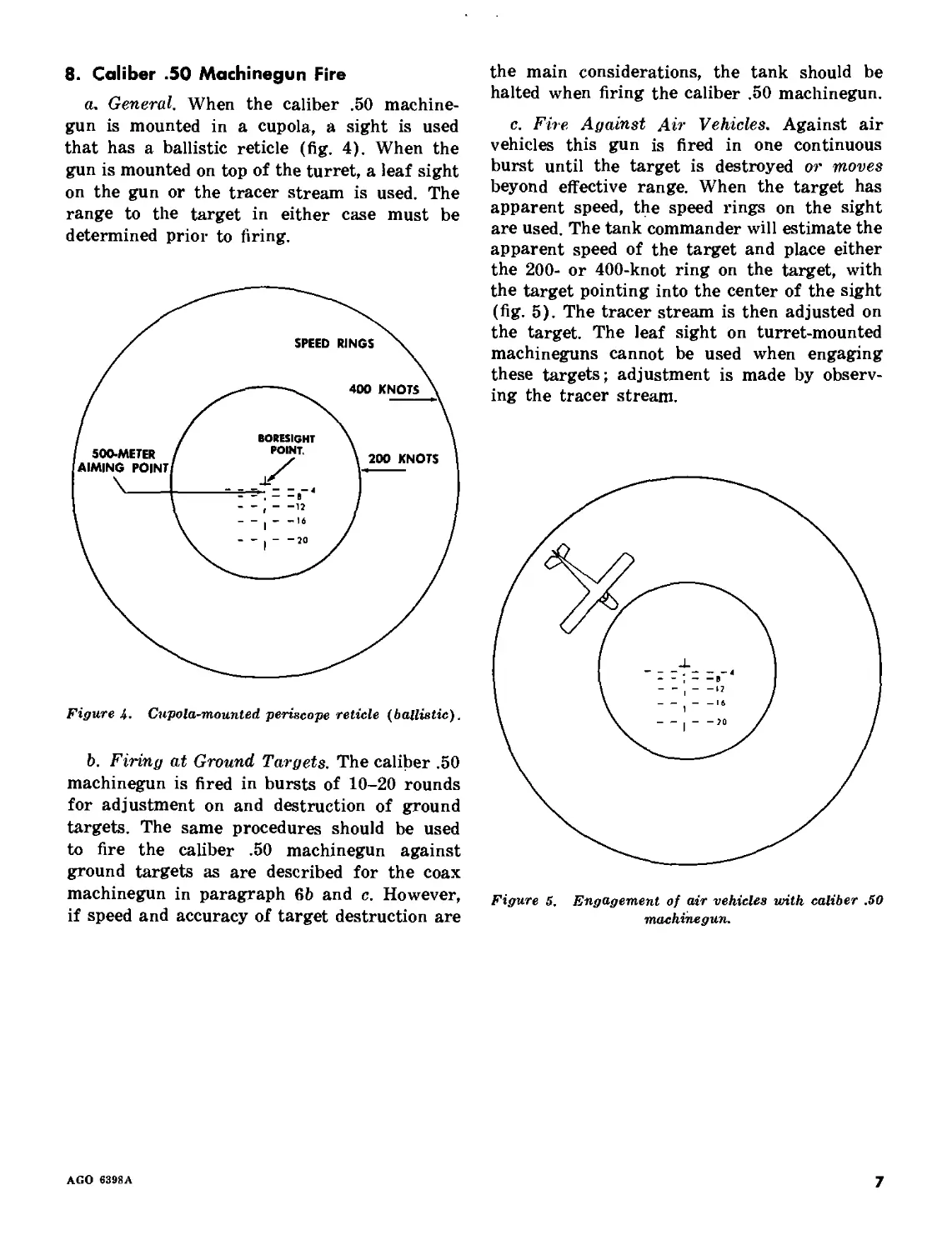
8. Caliber .50 Machinegun Fire
a. General. When the caliber .50 machine-
gun is mounted in a cupola, a sight is used
that has a ballistic reticle (fig. 4). When the
gun is mounted on top of the turret, a leaf sight
on the gun or the tracer stream is used. The
range to the target in either case must be
determined prior to firing.
Figure 4. Cupola-mounted periscope reticle (ballistic).
b. Firing at Ground Targets. The caliber .50
machinegun is fired in bursts of 10-20 rounds
for adjustment on and destruction of ground
targets. The same procedures should be used
to fire the caliber .50 machinegun against
ground targets as are described for the coax
machinegun in paragraph 65 and c. However,
if speed and accuracy of target destruction are
the main considerations, the tank should be
halted when firing the caliber .50 machinegun.
c. Fire Against Air Vehicles, Against air
vehicles this gun is fired in one continuous
burst until the target is destroyed or moves
beyond effective range. When the target has
apparent speed, the speed rings on the sight
are used. The tank commander will estimate the
apparent speed of the target and place either
the 200- or 400-knot ring on the target, with
the target pointing into the center of the sight
(fig. 5). The tracer stream is then adjusted on
the target. The leaf sight on turret-mounted
machineguns cannot be used when engaging
these targets; adjustment is made by observ-
ing the tracer stream.
Figure 5. Engagement of air vehicles with caliber .50
machinegun.
AGO 6398A
7
CHAPTER 3
TANK GUN AMMUNITION AND TARGET DESTRUCTION
Section I. INTRODUCTION
9. General
The tank commander’s decision regarding
the type of ammunition to use against a target
is based upon his knowledge of the capabilities
and limitations of the ammunition. The com-
mander must evaluate the vulnerability of a
target to determine rapidly the ammunition to
be employed. For the recommended employ-
ment of standard rounds of ammunition, see
paragraph 78. For maintenance of ammunition,
see appropriate operator’s manual for the
vehicle. For handling procedures of ammuni-
tion, see paragraph 253.
ID. Complete Round of Tank Gun
Ammunition
a. Components. A complete round of tank
gun ammunition has all of the components
necessary to fire the weapon once. These com-
ponents are a—
(1) Projectile which is fired to destroy the
target.
(2) Propelling charge to develop sufficient
gas pressure when ignited to propel
the projectile to the target.
(3) Primer (electrical or percussion type)
to ignite the propelling charge.
(4) Cartridge case to contain the primer
and propelling charge (fig. 6).
A projectile having a high explosive or chemical
filler must be fitted with a fuze in order to ex-
plode it upon impact or at the desired time.
Depending upon the manner in which these
components are loaded into the gun a complete
round is known as either fixed or separated
(fig. 7).
b. Fixed Round. A fixed round has a cartridge
case containing the primer and propelling
Figure a. A complete round of tank gun ammunition.
charge attached to the projectile. The complete
round is loaded into the weapon as a unit.
c. Separated Round. A separated round has
a cartridge case containing a primer and pro-
pelling charge, which is sealed with a closing
plug, and a separate projectile. The projectile
and the cartridge case are loaded into the gun
separately.
8
AGO 6398A
SEPARATED
FIXED
Fixed and separated complete rounds.
Figure 7.
11. Classification of Tank Gun Ammunition
a. Tank gun ammunition is classified accord-
ing to type and use. When classified according
to type, the ammunition will be identified as
service, target-practice, blank, drill, dummy, or
inert.
Caution. All tank gun ammunition must be
handled with care. The explosive elements, par-
ticularly the primer, are sensitive to shock. Pre-
scribed precautions for handling ammunition
are stated in paragraph 253 and TM 9-1903.
b. When tank gun ammunition is classified
according to use it will be identified as armor-
defeating, antipersonnel/antimateriel, and spe-
cial purpose.
AGO 6398A
9
Section II. PROJECTILES AND FUZES
12. General
Tank gun ammunition has two types of pro-
jectiles: inert (APDS, TP, AP) or filled (HE,
HEP, HEAT, WP). Armor defeating inert
projectiles, which do not contain an explosive,
obtain their destructive effect by mass and
velocity (kinetic energy). Target practice (TP)
rounds are used in training to duplicate the
in-flight ballistics of the more expensive combat
round. Filled projectiles contain either an ex-
plosive or chemical filler and obtain their effect
upon the target by blast, fragmentation, chem-
ical energy (shaped charge), fire, or smoke.
Filled projectiles will require a fuze to detonate
the explosive filler or spread the chemical filler.
In addition, canister projectiles which contain
a number of subprojectiles are available for
most tank guns.
13. Projectile Nomenclature
a. The forward portion of the projectile from
the point to the widest portion is called the
ogive, which may include a fuze (fig. 6). The
length of the ogive influences the flight of the
projectile by minimizing the effects of drag
(air resistance) upon it. Because the “slug”
of some inert projectiles are blunt to increase
penetration, an aluminum windshield is added
to streamline the ogive.
b. The bourrelet is the widest forward por-
tion of the projectile and forms the rear of
the ogive (fig. 6). The bourrelet is an accu-
rately machined surface that is slightly larger
in diameter than the body and by bearing upon
the rifling of the gun tube, centers the forward
portion of the projectile in its travel through
the bore.
c. The body (fig. 6) is slightly smaller in
diameter than the bourrelet and rotating bands
and when manufactured must be accurately
balanced in order for the projectile to main-
tain the required stability in flight. The body
may consist of a “slug” or contain an explosive
or chemical filler.
d. A common function of the rotating
band(s) (fig. 6) of all projectiles is to seal
the propellant gases behind the base of the
projectile. When spin-stabilized projectiles are
fired, the rotating bands will also impart spin
by being engraved by the rifling of the gun
tube and simultaneously act as a rear bearing
surface. When fin-stabilized projectiles are
fired, the rotating band(s) do not cause spin
to be imparted to the projectile and may act
as a rear bearing surface; their primary func-
tion is to seal the propellant gases.
e. The base (fig. 6) is that portion of the
projectile upon which the expanding propellant
gases act, causing the projectile to move for-
ward. With the exception of certain types of
canister and some white phosphorus ammuni-
tion, the base of the projectile is equipped
with a tracer. The tracer (-T) is used by the
crew to sense the projectile (para. 87-89).
14. Fuze Operation and Nomenclature
a. Fuze. A fuze is a mechanical device used
with a projectile to cause the projectile to func-
tion at the time and under the circumstances
desired. Fuzes are classified by:
(1) Position on the projectile.
(a) Base detonating.
(6) Point detonating.
(c) Point-initiating, base detonating.
(2) Method of functioning.
(ft) Impact.
(b) Timed (used with some types of
antipersonnel/antimateriel ammu-
nition).
b. Bore Safety and Methods of Arming. All
fuzes for tank gun ammunition are bore safe.
This means that the fuze will not be armed
until such time as the projectile clears the
muzzle of the gun tube. Sufficient centrifugal
force must be obtained or inertia overcome
to arm the fuze (methods of arming).
c. Fuze Settings. Normally, ammunition with
a point detonating fuze (HE and WP) will be
issued to function superquick (SQ). When the
slot in the setting sleeve of the fuze is rotated
one-quarter turn, in either direction, the fuze
will be set for delay (fig. 8). With the fuze
set for delay, the fuze will detonate the pro-
jectile a fraction of a second (.05) after impact.
10
AGO 6398A
BOOSTER-
SETTING SLEEVE
STANDARD SUPERQUICK-DELAY FUZE
NOTE. BOOSTERS ARE NOT INTERCHANGEABLE.
CONCRETE PIERCING FUZE
Figure 8. Paint detonating fuzes—impact type.
The concrete-piercing fuze with booster has
an established delay (.025), which cannot be
adjusted by the crew (fig. 8). This fuze, when
substituted by the crew for the standard point
detonating fuze on the HE round, will provide
for better penetration of concrete.
Caution. When substituting a concrete-pierc-
ing fuze and booster, be sure to remove both the
standard fuze and its booster.
AGO 6398A
11
Section III. ARMOR-DEFEATING PROJECTILES AND USES
15. General
Armor-defeating projectiles produce the de-
sired effects against armor targets by the use
of either kinetic or chemical energy.
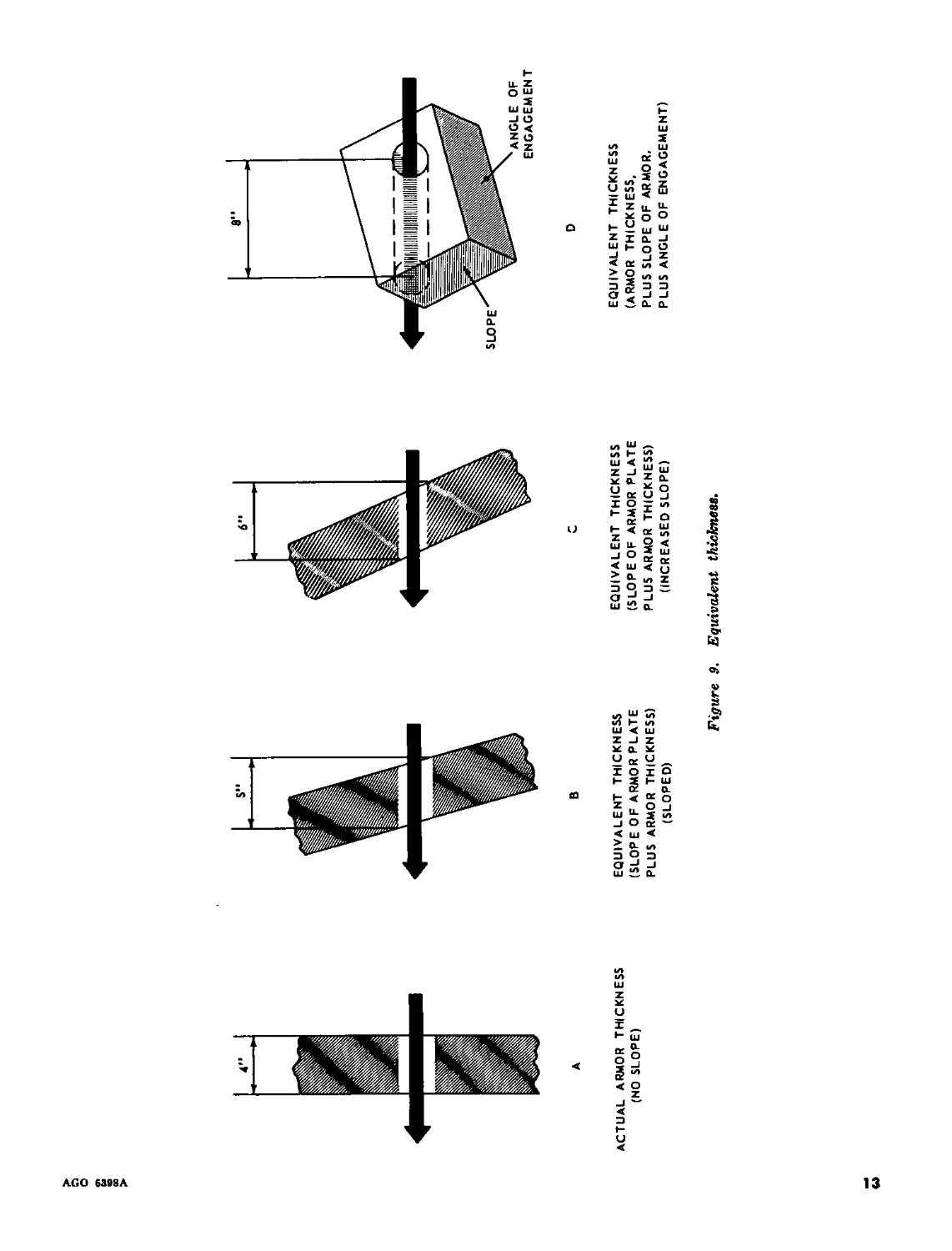
16. Kinetic Energy Projectiles
Kinetic energy armor-defeating projectiles
produce the desired target effects because of
their mass (hardness, density, and weight),
and the velocity of travel at the time of impact
with the target (striking velocity). Range and
angle of impact are two important factors that
will affect the degree of penetration possible
with these projectiles. As range to the target
increases, air resistance or drag continuously
reduces the velocity of the projectile. The angle
of impact is determined by the slope or shape
of the target and by the angle of target engage-
ment. An inspection of figure 9 should aid in
understanding that the thickness of armor to
be penetrated will increase as the slope in-
creases. The increase of armor protection is
called equivalent thickness. To determine muz-
zle velocity, striking velocity, and angle of fall
at various ranges, consult the firing table for
the appropriate weapon. There are two kinetic
energy armor-defeating projectiles: armor-
piercing and armor-piercing discarding sabot.
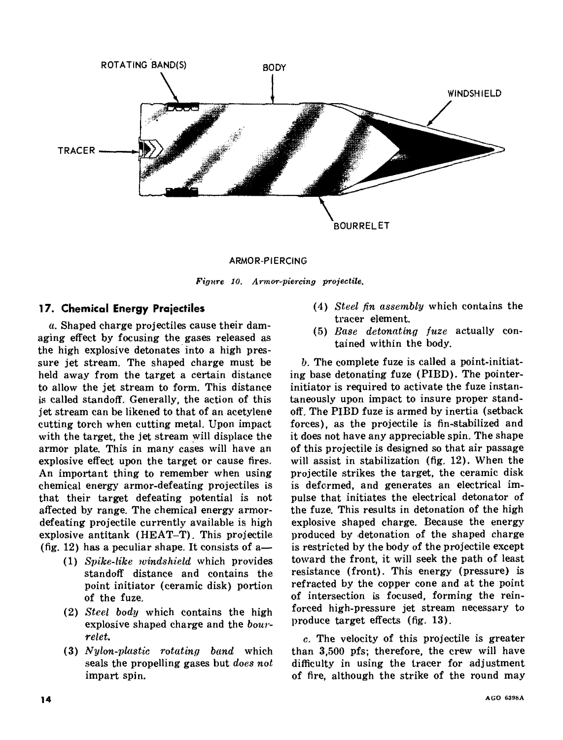
a. Armor Piercing (AP-T). The armor-pierc-
ing projectile (fig. 10) consists of—
(1) An aluminum windshield to improve
its ballistic performance.
(2) A solid steel body (slug) to destroy
the target.
(3) A tracer element.
(4) A copper rotating band to cause the
projectile to spin.
Upon impact, the windshield will shatter and
neither hinder nor assist the slug in its target
penetration. Armor-piercing projectiles are an-
nounced in the initial fire command as SHOT,
and are used with the 76, 90, and 120-mm guns.
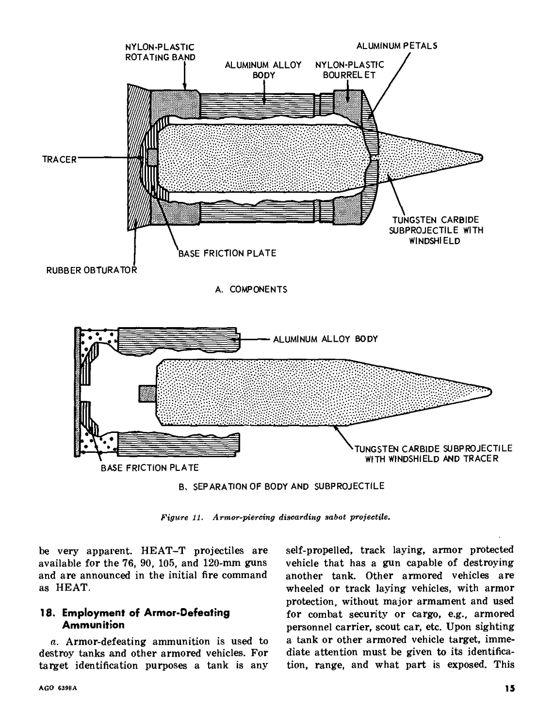
b. Armor-Piercing Discarding Sabot (APDS-
T). The armor-piercing discarding sabot pro-
jectile (fig. 11) consists of—
(1) A tungsten carbide subprojectile
sheathed in aluminum with a tracer
element attached.
(2) Three aluminum petals to center the
subprojectile with the plastic bour-
relet around them.
(3) An aluminum alloy sabot (body),
which houses the subprojectile and
contains the base friction plate.
(4) A nylon-plastic rotating band, which
causes the projectile to spin.
(5) A rubber obturator to help the rotat-
ing band seal off the propellant gases.
c. As a result of centrifugal force (spin) and
friction, soon after the projectile clears the
muzzle of the gun tube, the obturator, rotating
band, and bourrelet will rupture and fall free.
Air resistance and centrifugal force acting
.upon the three aluminum petals will cause
them to break away simultaneously. This dis-
carding will take place between 6-36 feet from
the muzzle of the gun. The absence of these
petals will allow air to pack into the open
end of the sabot. This resistance and centrifu-
gal force will overcome the grip of the friction
plate and separation of the subprojectile from
the sabot will take place. This separation will
occur between 50-500 meters from the muzzle.
From this point to the target, the subprojectile
with tracer is not hindered by carrier compo-
nents, which would unnecessarily reduce its
velocity. Because the velocity of the projectile
is greater than 3,500 fps, it is difficult for the
crew to use the tracer for adjustment of fire
up to a range of 2,500 meters. Upon impact
with a metal target, the tungsten carbide sub-
projectile produces a distinctive bright orange
flash. Because of its discarding of parts, this
projectile should not be fired overhead of
friendly troops without warning them. The
danger area extends up to 1,000 meters from
the gun along the trajectory and spreads out
to 70 meters on each side of the trajectory at
this range. Armor-piercing discarding sabot
projectiles are announced in the initial fire
command as SABOT, and used with the 105-mm
gun.
12
AGO 639ЙА
ACTUAL ARMOR THICKNESS
(NO SLOPE)
EQUIVALENT THICKNESS
(SLOPE OF ARMOR PLATE
PLUS ARMOR THICKNESS)
(SLOPED)
EQUIVALENT THICKNESS
(SLOPE OF ARMOR PLATE
PLUS ARMOR THICKNESS)
(INCREASED SLOPE)
EQUIVALENT THICKNESS
(ARMOR THICKNESS,
PLUS SLOPE OF ARMOR,
PLUS ANGLE OF ENGAGEMENT)
Figure 9. Equivalent thickness.
ROTATING BAND(S)
BODY
BOURRELET
ARMOR-PIERCING
Figure 10. Armor-piercing projectile.
17. Chemical Energy Projectiles
a. Shaped charge projectiles cause their dam-
aging effect by focusing the gases released as
the high explosive detonates into a high pres-
sure jet stream. The shaped charge must be
held away from the target a certain distance
to allow the jet stream to form. This distance
is called standoff. Generally, the action of this
jet stream can be likened to that of an acetylene
cutting torch when cutting metal. Upon impact
with the target, the jet stream will displace the
armor plate. This in many cases will have an
explosive effect upon the target or cause fires.
An important thing to remember when using
chemical energy armor-defeating projectiles is
that their target defeating potential is not
affected by range. The chemical energy armor-
defeating projectile currently available is high
explosive antitank (HEAT-T). This projectile
(fig. 12) has a peculiar shape. It consists of a—
(1) Spike-like windshield which provides
standoff distance and contains the
point initiator (ceramic disk) portion
of the fuze.
(2) Steel body which contains the high
explosive shaped charge and the bour-
relet.
(3) Nylon-plastic rotating band which
seals the propelling gases but does not
impart spin.
(4) Steel fin assembly which contains the
tracer element.
(5) Base detonating fuze actually con-
tained within the body.
b. The complete fuze is called a point-initiat-
ing base detonating fuze (PIBD). The pointer-
initiator is required to activate the fuze instan-
taneously upon impact to insure proper stand-
off. The PIBD fuze is armed by inertia (setback
forces), as the projectile is fin-stabilized and
it does not have any appreciable spin. The shape
of this projectile is designed so that air passage
will assist in stabilization (fig. 12). When the
projectile strikes the target, the ceramic disk
is deformed, and generates an electrical im-
pulse that initiates the electrical detonator of
the fuze. This results in detonation of the high
explosive shaped charge. Because the energy
produced by .detonation of the shaped charge
is restricted by the body of the projectile except
toward the front, it will seek the path of least
resistance (front). This energy (pressure) is
refracted by the copper cone and at the point
of intersection is focused, forming the rein-
forced high-pressure jet stream necessary to
produce target effects (fig. 13).
c. The velocity of this projectile is greater
than 3,500 pfs; therefore, the crew will have
difficulty in using the tracer for adjustment
of fire, although the strike of the round may
14
AGO 6398A
A. COMPONENTS
В. SEPARATION OF BODY AND SUBPROJECTILE
Figure 11. Armor-piercing discarding sabot projectile.
be very apparent. HEAT-T projectiles are
available for the 76, 90, 105, and 120-mm guns
and are announced in the initial fire command
as HEAT.
18. Employment of Armor-Defeating
Ammunition
a. Armor-defeating ammunition is used to
destroy tanks and other armored vehicles. For
target identification purposes a tank is any
self-propelled, track laying, armor protected
vehicle that has a gun capable of destroying
another tank. Other armored vehicles are
wheeled or track laying vehicles, with armor
protection, without major armament and used
for combat security or cargo, e.g., armored
personnel carrier, scout car, etc. Upon sighting
a tank or other armored vehicle target, imme-
diate attention must be given to its identifica-
tion, range, and what part is exposed. This
AGO 639BA
15
NYLON-PLASTIC
ROTATING BAND
BOURRELET
A. COMPONENTS
B. AIRFLOW PATTERN
Figure 12. High explosive antitank projectile.
information combined with a knowledge of the
ammunition capabilities will assist in rapid
destruction of the target. The vulnerability of
an armored vehicle depends on the combination
of actual armor thickness, slope of the armor
plate (equivalent thickness), and angle of en-
gagement. The slope of the armor plate is
determined by the construction of the vehicle
and its position in relation to the tank that is
taking it under fire (angle of engagement).
Equivalent thickness becomes greater as the
amount of slope increases and the angle of
engagement decreases, because there is more
armor placed in the path of the projectile (fig.
9). Thus, a tank of given armor thickness with
flat surfaces perpendicular to the line of fire
is more vulnerable than a tank of the same
thickness with sloped surfaces oblique to the
line of fire. Tanks have sloped surfaces when-
ever possible and have the heaviest armor on
the front of the hull and turret. The sides and
rear of the turret have less armor, and the sides
and rear of the hull have the least amount.
The sides and rear of the hull also have flatter
surfaces and are the most vulnerable parts of
a tank. The center of vulnerability varies with
the amount of target exposed and the angle
at which it is engaged. Figure 14 shows the
vulnerability of a typical tank; If it is possible
to get a flank or rear shot at a tank, the center
16
AGO 6398A
Figure 1J. Jet stream action of HEAT projectile.
of vulnerability is the center of the hull. The
center of vulnerability of a tank engaged head-
on is the turret ring. Vulnerability decreases
considerably when tanks are in hull defilade.
b. As a general rule, chemical energy armor-
defeating projectiles have a greater target-
defeating potential than the kinetic energy
armor-defeating projectiles; therefore, they
should be employed whenever the part of the
tank target that possesses the greatest equiva-
lent thickness of armor is exposed (frontal
engagement). Kinetic energy projectiles should
be employed when areas of lesser equivalent
thickness arc exposed (flank or rear engage -
nient). With this general rule in mind, rapid
and accurate target destruction within normal
combat ranges (0-2,000 meters) should be ac-
complished without waste of ammunition. With
the wide variety of armored vehicles known
today, in many cases, experience will have to
dictate the best round to employ. With some
armored vehicles, it may be found that destruc-
tion is possible by employing antipersonnel/
antimateriel ammunition or by employing ma-
chinegun fire. In this case, the armor-defeating
ammunition would be conserved for the engage-
ment of heavier, more dangerous targets.
Should the tank commander be in doubt regard-
ing what round is necessary to destroy a par-
ticular armored vehicle, it should be considered
as a tank and engaged with armor-defeating
ammunition. Surprise type targets, e.g., tanks,
other armored vehicles, and antitank guns, be-
cause of their mobility are of particular danger
to the tank crew. HEAT, because of its blast
and fragmentation, armor-defeating potential,
and penetrating capability, will enable the tank
crew to engage all types of surprise targets
with the assurance of some degree of target
destruction.
775-128 0 - 65 -2
AGO 6398A
17
GREATEST EQUIVALENT THICKNESS; MOST
DIFFICULT TO PENETRATE.
I LESSER EQUIVALENT THICKNESS; NEXT MOST
I DIFFICULT TO PENETRATE.
LEAST EQUIVALENT THICKNESS; MOST-EASILY
PENETRATED.
TYPICAL TANK
LEFT FRONT VIEW
60° ANGLE OF ENGAGEMENT
(LESS LEFT SUSPENSION)
Figure J4. Tank vulnerability.
18
AGO 6398A
Section IV. ANTIPERSONNEL/ANTIMATERIEL PROJECTILES AND USES
19. General
These projectiles are filled with either a high
explosive filler with fuze, to cause them to act
upon the target at the time and under the
circumstances desired, or many subprojectiles.
There are three projectiles available: high ex-
plosive, high explosive-plastic, and canister
(antipersonnel use only).
2D. High Explosive (HE-T)
a. High explosive projectiles (fig. 15) con-
sist of a—
(1) Point detonating fuze (para. 14),
which is issued set to function imme-
diately (superquick) upon impact. A
fuze wrench or screwdriver is used
to set the fuze to function in delay.
The fuze wrench is also used to re-
move the point detonating fuze and to
install the concrete-piercing fuze
(para. 14).
(2) Steel body which contains the high
explosive filler.
(3) Copper rotating band(s) which causes
the projectile to spin.
(4) Tracer element (for training, HE
without tracer may be issued).
b. Because this is a spin-stabilized projectile,
centrifugal force is used to arm the fuze. Upon
impact, the fuze will function and detonate the
high explosive filler. The primary target effects
of this projectile are blast, fragmentation, and
concussion. The bursting area is 5-8 meters
deep and 35^15 meters wide (fig. 16). The
HE-T projectile is available for the 76, 90,
and 120-mm guns. It is announced in the initial
fire command as HE, HE-DELAY, or HE-
CONCRETE, depending upon the fuze and its
setting.
21. High Explosive Plastic (HEP-T)
a. High explosive plastic projectiles (fig. 17)
consist of a—
(1) Steel body which contains the explo-
sive-plastic filler.
(2) Copper rotating band which causes
the projectile to spin.
(3) Base detonating fuze which functions
immediately (superquick) upon im-
pact.
(4) Tracer element.
b. The fuze setting cannot be changed and will
function upon impact, detonating the explosive
plastic filler, producing blast, fragmentation,
and concussion. The fragmentation effect pro-
Figure 15. High explosive projectile.
AGO 6398A
19
Figure 16. Approximate fragmentation pattern of HE burst.
APPROX 5 TO 8
ME ТЕ RS
20
AGO G398A
TRACER
STEEL BODY
Figure 17. High explosive plastic projectile.
Figure 18. Canister projectile.
duced by the HEP projectile is similar to that
produced by the HE projectile. It will vary
however, depending upon the angle of impact.
Because the ballistic characteristics of the
HEP-T projectile allows it to be affected more
readily than most other projectiles by wind,
drift, and cant, a first round hit is more diffi-
cult when engaging distant stationary or mov-
ing targets. When engaging close-in targets,
obscuration produced by firing presents a prob-
lem in adjustment of fire. Although these prob-
lems do exist, with the proper training (para.
95) tank crews can be trained to employ this
projectile very effectively. HEP-T is available
for the 105-mm gun only and is announced in
the initial fire command as HEP.
22. Conister
Canister projectiles (antipersonnel use only)
contain a large number of subprojectiles, a
slotted cylindrical body with rotating band, no
tracer element, and a flatnosed surface. As the
projectile (fig. 18) leaves the muzzle of the gun,
centrifugal force will rupture the projectile,
discharging the subprojectiles. The maximum
lethal effect of this round will take place be-
tween 150 and 200 meters. Canister is available
for the 76- and 90-mm guns and is announced
in the initial fire command as CANISTER.
Caution. Canister is not to be fired over vul-
nerable friendly troops.
AGO 639BA
21
23. Employment of Antipersonnel/
Antimateriel Ammunition
Antipei-sonnel/antimateriel ammunition (ex-
cept canister), because of its blast, fragmenta-
tion, and concussion effect will be employed
against field fortifications, bunkers, pill boxes,
personnel, buildings, some armored and all un-
armcred vehicles, built-up areas, and crew
served weapons. If experience proves that ma-
chinegun fire can be used to destroy any of
these targets, it should be used within its
effective range to conserve main gun ammuni-
tion.
a. Destruction of Unarmored and Lightly
Armored Vehicles. Unarmored vehicles can be
penetrated by coaxial machinegun fire. Lightly
armored vehicles can be penetrated by caliber
.50 machinegun fire or by the blast and frag-
mentation of antipersonnel/antimateriel am-
munition. Unarmored vehicles include trucks
and automobiles of all types; lightly armored
vehicles include scout cars, some types of ar-
mored cars, and personnel carriers. Vehicles
that cannot be penetrated by this fire should
be engaged with armor-defeating ammunition.
Unarmored vehicles are vulnerable to all types
of fire, but their speed often makes them diffi-
cult to hit. HE or HEP ammunition should be
used to destroy these targets when they are
beyond the maximum effective range of ma-
chineguns (para. 32-34).
b. Firing at Dismounted Troops. Dismounted
troops constitute an area target by varying
depth, width, dispersion, and vulnerability.
Attacking infantry should be engaged with
machinegun fire whenever possible; however,
the type weapon and ammunition employed
depends primarily on the range and the actions
of the enemy troops. Normally, HE or HEP
is employed against troops beyond effective ma-
chinegun ranges. At lesser ranges, the fire of
the machineguns is added to or substituted for
that of the main gun. Depending on the terrain,
ricochet fire may be effective against troops
advancing under cover. At close ranges, (150-
200 meters) canister is most effective against
mass attacks, but consideration must be given
to the location of vulnerable friendly troops
before this type of ammunition is fired. Assault-
ing tanks employ the coaxial and caliber .50
machineguns while moving, firing into trenches
and other vulnerable parts of the enemy de-
fense. SMOKE (para. 27) also can be employed
for its incendiary, screening, and casualty-
producing effect.
c. Destruction of Crew-Served Weapons.
Crew-served weapons include antitank guns,
towed artillery, recoilless rifles, machineguns,
and mortars. Crew-served weapons are some-
times encountered in hasty positions, but usu-
ally are placed in prepared positions with good
cover and concealment. They present small tar-
gets with low silhouettes. Normally HE or HEP
is employed to destroy these targets.
d. Destruction of Field Fortifications. Bunk-
ers and pillboxes provide good protection
against all types of fire, but they can be pene-
trated and defeated by employing the proper
type of ammunition. A direct hit with HE or
HEP at the aperture will result in part of the
force of the explosion and fragmentation being
directed inside the position. The possibilities of
achieving a detonation inside the bunker are
increased by employing HE delay. The HEP
round or the concrete-piercing fuze with the
HE round is most effective against concrete
or masonry (pillboxes). Replacing the standard
point detonating fuze with the concrete-pierc-
ing fuze should be accomplished prior to an
operation and stowed in the tank. Should HE-
CONCRETE or HEP prove to be ineffective,
HEAT ammunition may be used to weaken the
structure followed by an HE-CONCRETE or
HEP round. The choice of ammunition for en-
gagement of bunkers and pillboxes will depend
primarily on the combat experience of the
commander, ammunition availability, and tar-
get vulnerability. However, employment of HE
or HEP has a greater casualty-producing effect
and conserves armor-defeating ammunition.
24. Special Uses of Antipersonnel/
Antimateriel Ammunition
In addition to the specific techniques of tar-
get destruction previously mentioned, there are
other special uses of main gun ammunition that
have proved effective in battle. Combat situa-
tions may arise where the following fire tech-
niques could be employed effectively.
22
AGO 6398A
a. Use of HE and HEP. HE and HEP are
versatile types of ammunition as they can be
employed in numerous ways against a wide
variety of targets. The following special uses
are in addition to those discussed previously;
(1) They give excellent fragmentation ef-
fect when fired into treetops over the
heads of enemy troops. With HE,
superquick fuze normally is used;
however, if the trees are exceptionally
tall or the troops are deep in the
woods, delay fuze should be used.
(2) They may be employed in the reduc-
tion of certain obstacles such as road-
blocks. They are ineffective for clear-
ing minefields. Use of these rounds
for this purpose will result in a waste
of the limited amounts of ammunition
available.
(3) HE and HEP are effective for attack-
ing troops occupying masonry build-
ings. When firing HE, fuze delay is
usually the most effective for this
purpose.
(4) They may be used in reconnaissance
by fire of probable enemy positions
beyond the effective range of the cali-
ber .50 machinegun.
b. Use of HEP Against Armor. HEP is pri-
marily an antipersonnel/antimateriel round. It
is the only such round of ammunition for use
with the 105-mm tank gun; therefore, it should
be reserved for destruction of personnel and
materiel targets. However, in the event that
armor-piercing ammunition is in short supply
or has been expended during an operation, HEP
ammunition may be used to engage an armored
target. If used, and a direct hit is obtained,
HEP will produce varying results, with con-
cussion being the primary target effect. De-
pending upon the type and thickness of the
armor, spalling (chipping of the armor plate
opposite the point of impact) may occur simul-
taneously with concussion. These effects will
kill or injure the crew, produce damage to the
fire control instruments and other less rugged
components, and damage the structure of the
vehicle.
Section V. SPECIAL PURPOSE PROJECTILES AND USES
25. General
Special purpose projectiles include white
phosphorus, which is used in combat and in
training practice to train armor crewmen in
the proper technique of tank gunnery.
26. White Phosphorus (WP) Projectiles
This projectile (fig. 19) is similar in con-
struction to the HE projectile. It consists of a—
a. Point Detonating Fuze (para. 14) which
is issued set to function immediately (super-
quick) upon impact. A fuze wrench or screw-
driver is used to test the fuze to function in
delay. This fuze cannot be replaced with the
concrete-piercing fuze.
b. Steel Body which contains the white phos-
phorus filler and the burster tube.
c. Copper Rotating Band which causes the
projectile to spin. This projectile may or may
not have a tracer. The fuze is armed by cen-
trifugal force and functions on impact (super-
quick). The fuze action detonates the burster
tube, which ruptures the body and disseminates
the white phosphorus filler. When exposed to
air, white phosphorus will burn and produce
a dense white smoke. The white phosphorus
round is available for the 76, 90, 105, and
120-mm guns and is announced in the initial
fire command as SMOKE (hereafter referred
to as SMOKE or WP).
Caution. When white phosphorus is stored
or transported in temperature higher than
111® F. (melting point), it should be positioned
on its base. If positioned otherwise the filler
may become displaced, due to melting and con-
sequently, cause either premature detonation
after firing or erratic performance in flight
(TM 9-1903).
27. Use of White Phosphorus Ammunition
SMOKE is employed for screening, incen-
diary, casualty-producing, and marking pur-
poses. There are many combat situations where
AGO 6398A
23
Figure 19. White phosphorus projectile.
use of this round, particularly in conjunction
with other ammunition, will produce excellent
results.
a. Screening blinds the enemy, allowing
greater freedom of movement of friendly
forces. SMOKE may be placed in front of the
enemy to screen the maneuver of attacking
tanks or to cover their withdrawal. Tanks are
capable of temporarily screening short move-
ments of the tank platoon or company. Due to
the limited supply of this type of ammunition
and the tendency of WP smoke to dissipate and
rise rapidly, tank ammunition should be em-
ployed for screening purposes only when other
sources are not available. The basic factors
governing the employment of SMOKE are wind
direction and velocity. With a wind from the
flank, the screen is started upwind of the target
so that it will drift into and in front of the
enemy. With a tailwind, SMOKE should be
placed just in front of the target; with a head-
wind, SMOKE should be placed on or behind the
target. When the wind velocity is high, the rate
of fire must be increased to maintain the screen.
When firing into a strong headwind, considera-
tion must be given to smoke drifting over
friendly positions.
b. In addition to its incendiary effect on
buildings and log fortifications, SMOKE is ef-
fective in burning out enemy positions in woods
and brush. The factors of wind direction and
velocity that govern the employment of
SMOKE for screening apply also to its use
for burning purposes. HE, HEP, or machine-
gun fire should be employed in conjunction
with SMOKE to destroy and harass enemy
troops driven from cover by fires.
c. The casualty-producing effect of SMOKE
is a direct result of its incendiary nature. Best
results are obtained when it is fired into an
enclosure, such as a bunker or the ground floor
of a building. It is also effective against troops
in the open, because the burning phosphorus
sticks to the skin and clothing. Although
SMOKE does not have the destructive capa-
bility of HE or HEP, it has a much greater
psychological effect on enemy troops.
d. SMOKE can be used also to mark targets;
however, care must be taken so that the target
is not obscured.
28. Target Practice Projectiles (TP-T)
These projectiles are used only for training
purposes. They have the same shape and bal-
listic characteristics as the service (combat)
round for which they are substituted. However,
they do not contain an explosive filler nor cause
the same target effects. The firing of these
projectiles rather than service projectiles will
cause less damage to range facilities; also, it
is less expensive. They will be announced in the
initial fire command the same as the service
rounds they represent, e.g., target practice high
explosive antitank (HEAT/TP-T) would be
24
AGO 6393A
announced as HEAT. If it becomes necessary to
fire both service and target practice projectiles
of the same type during training, then the
service projectile would be properly announced
(HEAT) and the target practice projectile an-
nounced as TP-T.
Section VI. IDENTIFICATION
OF MAIN GUN AMMUNITION
29. General
Ammunition can be identified by its shape,
color code with markings, and by its location
prescribed by the stowage plan. For shape or
configuration, see figure 20.
a. Color Code. Ammunition is painted with a
special paint to prevent rust and other corro-
sion. In addition it provides a color code for
ease of identification, and to indicate primary
uses (fig. 21).
b. Markings. Ammunition is identified by
markings on the outside of its packing con-
tainers (fig. 22). Once removed from its pack-
ing, it may be identified by color and markings
found on the rounds (fig. 23). The lot number
of the ammunition is one of these markings.
It is stenciled on the projectile and stamped
on the base of the cartridge case and on its
packing box. The lot number is information
required for records, reports of condition, func-
tioning, and accidents in which the ammunition
is involved. To obtain the greatest accuracy
in firing, successive rounds should be from the
same ammunition lot whenever practicable.
3D. Ammunition Stowage Plan
The ammunition stowage plan should be
identical for all tanks in a battalion-size unit.
This stowage plan should include location of all
ammunition authorized for the basic load, by
type and number of rounds. All ammunition
loaded aboard the tank should be stowed in the
racks according to the stowage plan. The stow-
age plan not only serves as a guide for the
initial stowage of ammunition, but also serves
as an aid to the crew, regarding supply of
ammunition, by indicating the number of
rounds by type that have been fired. During
darkness, when the use of lights inside the
turret would reduce the crew’s night vision or
give away the tank’s position, the stowage plan
assists the loader in locating rapidly that type
of ammunition announced in the initial fire
command. When preparing this plan, consid-
eration must be given to the location of those
ammunition racks that have been specified for
only HEAT or SABOT.
AP-T ApDS-T HEaT-T HE-T
hep-t canister wp
Figure 20. Configuration of tank gun ammunition.
AGO 6398A
25
TYPE OF AMMUNITION BASIC COLOR WITH MARKINGS
Armor-Piercing Discording Sabo, (ApDS-T)..........Block with white markings
Armor-Piercing (AP-T)........................... Slack with white markings
Armor-Piercing Target Practice (TP-T)..............Blue with white markings
High Explosive Antitank (HEAT-T)..................Block with yellow markings
High Explosive Antitank Inert (HEAT-INERT)........Block with yellow and blue bond
High Explosive Antitank Target Practice
(HEAT/TP-T)....................................Blue with white markings
Canister .........................................Block with white markings
High Explosive, High Explosive Plastic
(HE-T, HEP-T).....................................Olive drab with yellow markings
White phosphorus (WP).............................Light green with light red markings
COLORS INDICATING PRIMARY USES
Yellow—High Explosive
Light Green-White Phosphorus
Block—Armor Piercing
Blue—Target Practice, Inert ond Drill
Lic^it Red—Incendiary
Olive Drab—Antipersonnel
Whi te—Lettering ond Marking Only
Figure 21. Ammunition color code.
Figure 22, Typical two-round packing box.
26
AGO 639SA
TYPE. MODEL, ANO ACTIONOF FUZE
THREE T’s INDICATE TRACER
CALIBER AND DE5IGNAT ION OF WEAPON
KIND OF FILLER
TYPE AND MODEL OF SHELL
AMMUNITION LOT NUMBER; AN X AFTER
THE SERIAL NUMBER INDICATES STEEL
CARTRIDGE CASE
CALIBER AND MODEL OF CASE
LOTNUMBEROF CASE
YEAR OF MANUFACTURE
PERFORMANCE OF ROUND UPON FIRING,
FLASHLESS OR SMOKELESS. FLASHLESS-
SMOKELESS
TYPE AND MODEL OF SHELL
Figure 23. Typical markings on ammunition.
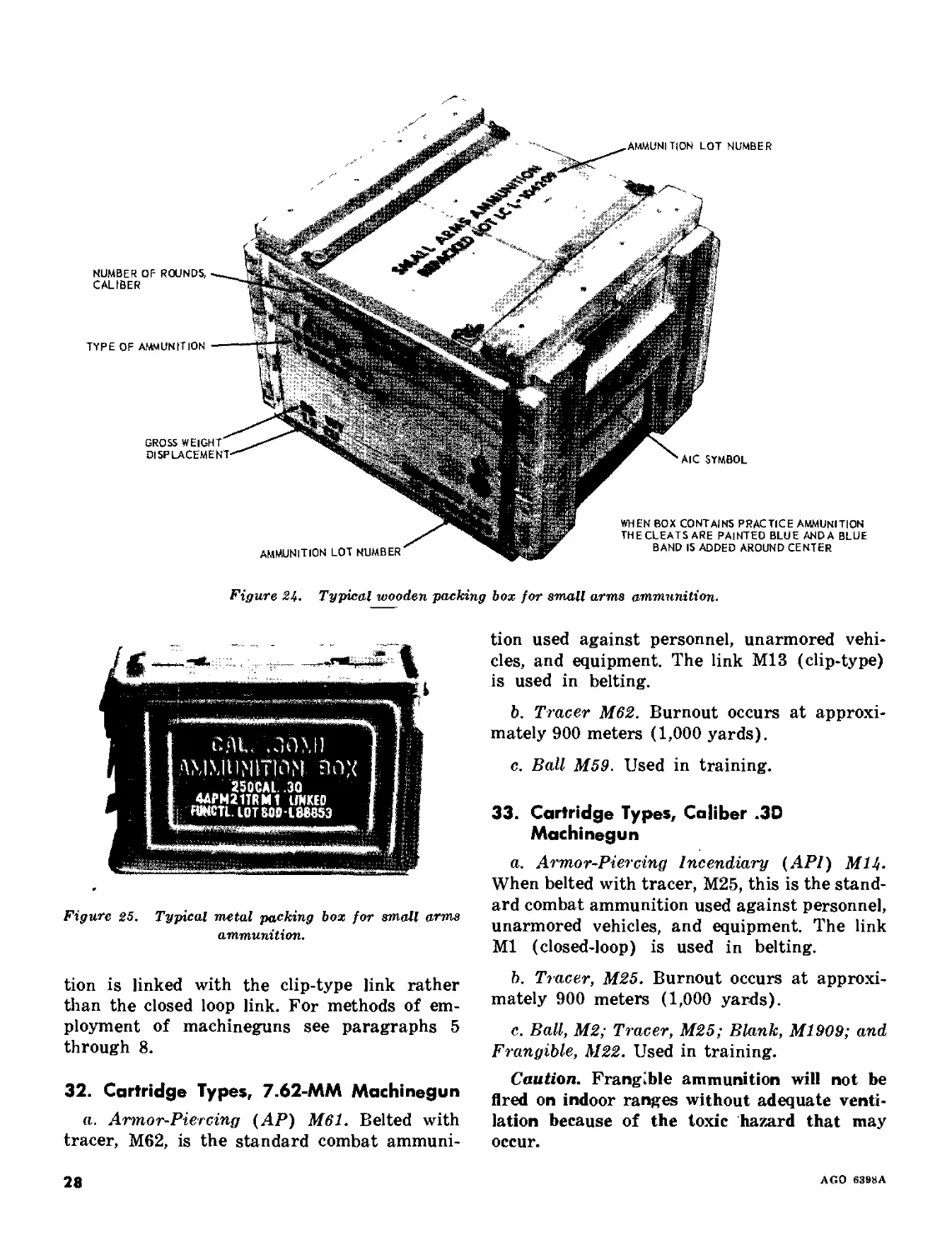
Section VII. MACHINEGUN AMMUNITION, IDENTIFICATION AND USES
31. General
Machinegun ammunition is belted in metallic
link belts (MLB). In tank gunnery training
and in combat, machinegun ammunition should
be linked together in a ratio of 4 nontracer to
1 tracer (except for subcaliber exercises, which
should be all ball or frangible). Tracer ammu-
nition of some type is included in each belt
to be used in automatic fire for observation
and subsequent adjustment of fire. As machine-
gun fire normally cannot be adjusted beyond
the range of tracer burnout, this determines
the maximum effective range of each type ma-
chinegun. Tracers of the same type do not burn
out at exactly the same range. The figures used
are averages and, therefore, approximate, but
they are accurate enough to use in establishing
a maximum effective range. Machinegun ammu-
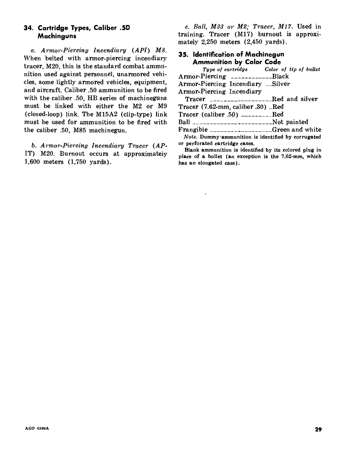
nition is identified by type, caliber, model, and
lot number. A color code on the bullet tip is
for identification by type. Markings are also
located on the original packing containers (figs.
24 and 25). Units equipped with M85 machine-
guns must insure that the caliber .50 ammuni-
AGO 6398A
27
Figure 2!f. Typical wooden packing box for small arms ammunition.
Figure 25. Typical metal packing box for small arms
ammunition.
tion is linked with the clip-type link rather
than the closed loop link. For methods of em-
ployment of machineguns see paragraphs 5
through 8.
32. Cartridge Types, 7.62-MM Machinegun
a. Armor-Piercing (АР) M61. Belted with
tracer, M62, is the standard combat ammuni-
tion used against personnel, unarmored vehi-
cles, and equipment. The link M13 (clip-type)
is used in belting.
b. Tracer M62. Burnout occurs at approxi-
mately 900 meters (1,000 yards).
c. Ball M59. Used in training.
33. Cartridge Types, Caliber .3D
Machinegun
a. Armor-Piercing Incendiary (API) M14.
When belted with tracer, M25, this is the stand-
ard combat ammunition used against personnel,
unarmored vehicles, and equipment. The link
Ml (closed-loop) is used in belting.
b. Tracer, M25. Burnout occurs at approxi-
mately 900 meters (1,000 yards).
c. Ball, М2; Tracer, M25; Blank, M1909; and
Frangible, M22. Used in training.
Caution. Frangible ammunition will not be
fired on indoor ranges without adequate venti-
lation because of the toxic hazard that may
occur.
28
AGO 6398A
34. Cartridge Types, Caliber .5D
Machinguns
a. Armor-Piercing Incendiary (API) M8.
When belted with armor-piercing incendiary
tracer, M20, this is the standard combat ammu-
nition used against personnel, unarmored vehi-
cles, some lightly armored vehicles, equipment,
and aircraft. Caliber .50 ammunition to be fired
with the caliber .50, HB series of machineguns
must be linked with either the М2 or M9
(closed-loop) link. The M15A2 (clip-type) link
must be used for ammunition to be fired with
the caliber .50, M85 machinegun.
b. Armor-Piercing Incendiary Tracer (AP-
IT) M20. Burnout occurs at approximately
1,600 meters (1,750 yards).
c. Ball, M33 or М2; Tracer, M17. Used in
training. Tracer (M17) burnout is approxi-
mately 2,250 meters (2,450 yards).
35. Identification of Machinegun
Ammunition by Color Code
Type of cartridge Color of tip of bullet
Armor-Piercing _______________Black
Armor-Piercing Incendiary_____Silver
Armor-Piercing Incendiary
Tracer _____________________Red and silver
Tracer (7.62-mm, caliber .30) -Red
Tracer (caliber .50)__________Red
Ball__________________________Not painted
Frangible_____________________Green and white
Note. Dummy’ammunition is identified by corrugated
or perforated cartridge cases.
Blank ammunition is identified by its colored plug in
place of a bullet (an exception is the 7.62-mm, which
has an elongated case).
AGO 6398A
29
PART THREE
FIRE CONTROL AND SIGHTING EQUIPMENT
CHAPTER 4
DIRECT-FIRE CONTROL SYSTEM
36. General
This chapter discusses the components of the
direct-fire control systems and their uses. When
a target can be seen through the sights, the
direct-fire control system is used. The compo-
nents included in the direct-fire control system
are—
a. For the tank commander—the range finder
and/or periscope, supplemented by hand held
binocular.
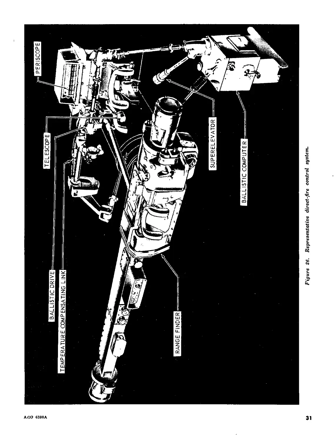
b. For the gunner—the computer or ballistic
unit, periscope, superelevator in the hydraulic
system, ballistic drive, and as the gunner’s
secondary sight, the telescope (fig. 26).
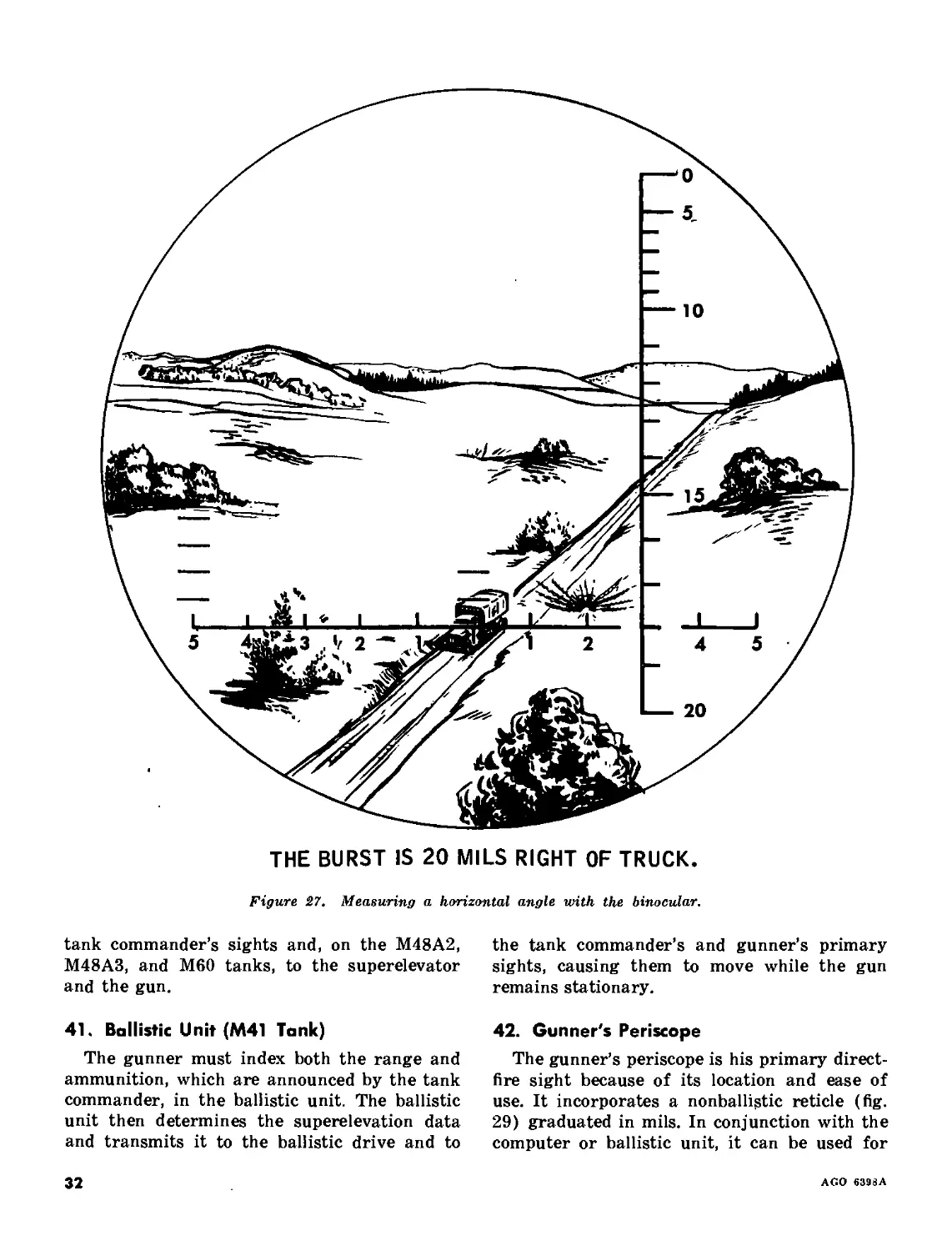
37. Binocular
The binocular is used by the tank commander
to acquire targets, and to observe and adjust
fire. By placing the center point of the hori-
zontal mil scale on the target, he can measure
deflection in mils that the round is to the left
or right of the target. The measurement will
form the basis of his deflection or lead correc-
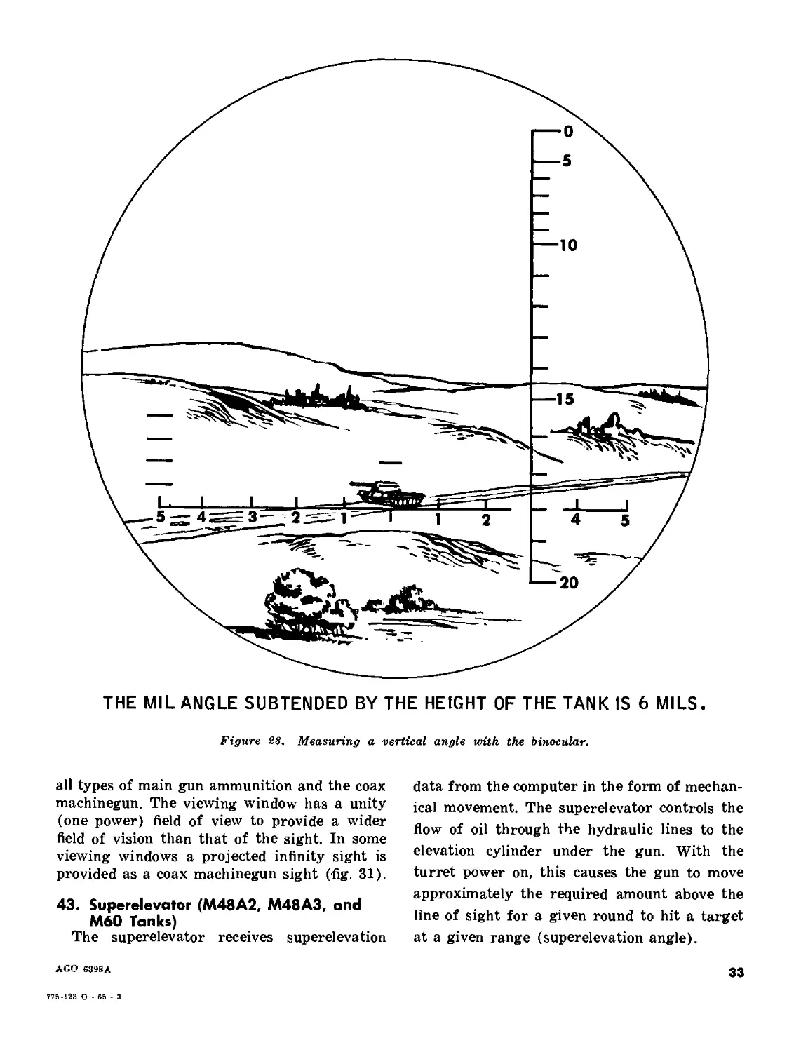
tion (fig. 27). He can also measure vertical
height in mils to aid in the determination of
range (fig. 28). For adjustment and uses of
the binocular see chapter 15.
38. Range Finder (M48 and M60 Tanks)
a. The range finder is used by the tank com-
mander:
(1) To determine accurate ranges.
(2) As a direct-fire sight.
(3) To sense rounds fired at night when
the target is illuminated by visible
light.
(4) To designate targets to the gunner.
b. Procedures for training range finder op-
erators are contained in chapter 15. Because
the range finder is linked to the computer, the
tank commander can index range into the
direct-fire control system on main battle tanks
when the periscope sight is used by the gunner.
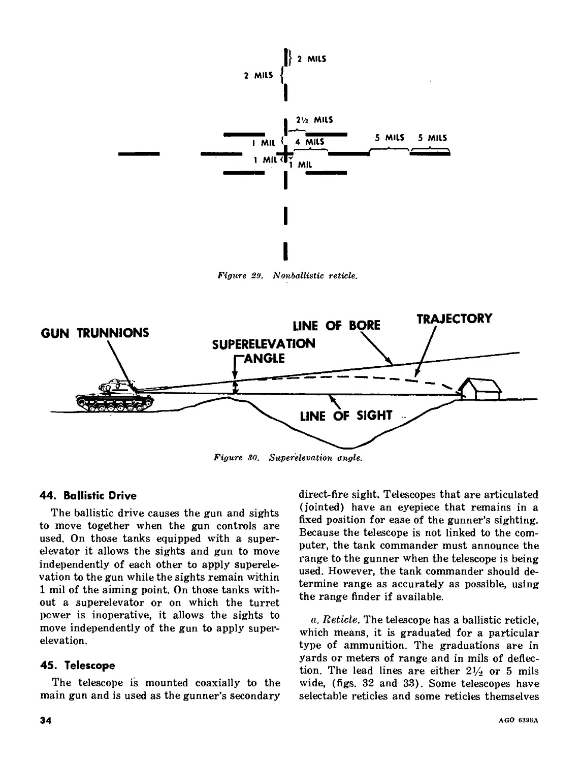
Range finders have a nonballistic reticle gradu-
ated in mils (fig. 29).
39. Tank Commander's Sight (M41 Tank)
a. The tank commander’s sight on the M41
tank moves with the gunner’s primary sight
and is used—
(1) To designate targets to the gunner.
(2) As a direct-fire sight.
(3) To sense rounds fired at night when
the target is illuminated.
b. It has a nonballistic reticle that is essen-
tially the same as the gunner’s periscope reticle
(fig. 29).
40. Computer (M48 and M60 Tanks)
The computer receives ammunition informa-
tion from the gunner and range information
from either the tank commander’s range finder
or the gunner by means of the superelevation
hand crank. The computer determines the
superelevation (fig. 30) and transmits it to the
fire control system based on the range and
ammunition indexed. This data is transmitted
to the ballistic drive and to the gunner’s and
30
AGO 63»«A
PERISCOPE
Figure 26. Representative direct-fire control system.
о
5
---10
THE BURST IS 20 MILS RIGHT OF TRUCK
Figure 27. Measuring a horizontal angle with the binocular.
tank commander’s
M48A3, and M60
and the gun.
sights and, on the M48A2,
tanks, to the superelevator
41. Ballistic Unit (M41 Tank)
The gunner must index both the range and
ammunition, which are announced by the tank
commander, in the ballistic unit. The ballistic
unit then determines the superelevation data
and transmits it to the ballistic drive and to
the tank commander’s and gunner’s primary
sights, causing them to move while the gun
remains stationary.
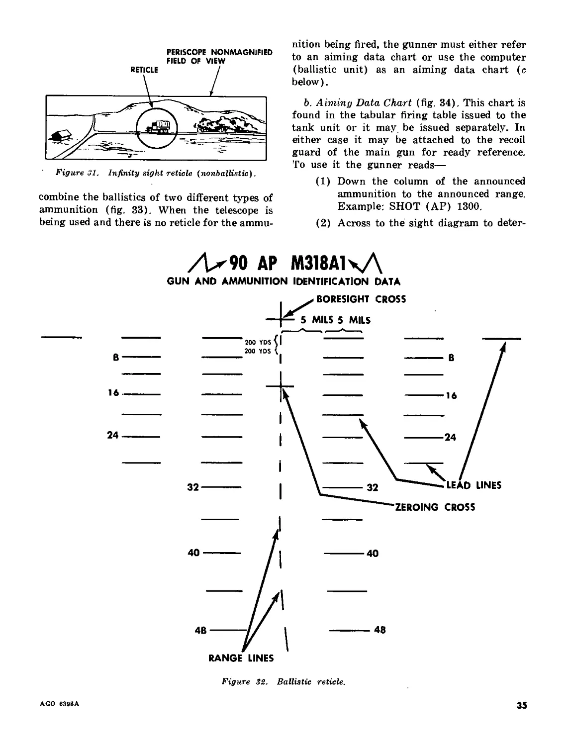
42. Gunner's Periscope
The gunner’s periscope is his primary direct-
fire sight because of its location and ease of
use. It incorporates a nonballistic reticle (fig.
29) graduated in mils. In conjunction with the
computer or ballistic unit, it can be used for
32
AGO 6398A
THE MIL ANGLE SUBTENDED BY THE HEIGHT OF THE TANK IS 6 MILS.
Figure 2S, Measuring a vertical angle with the binocular.
all types of main gun ammunition and the coax
machinegun. The viewing window has a unity
(one power) field of view to provide a wider
field of vision than that of the sight. In some
viewing windows a projected infinity sight is
provided as a coax machinegun sight (fig. 31).
43. Superelevator (M48A2, M48A3, and
M60 Tanks)
The superelevator receives superelevation
AGO 6398A
data from the computer in the form of mechan-
ical movement. The superelevator controls the
flow of oil through the hydraulic lines to the
elevation cylinder under the gun. With the
turret power on, this causes the gun to move
approximately the required amount above the
line of sight for a given round to hit a target
at a given range (superelevation angle).
33
775-128 0 - 65 -3
|} 2 MILS
2 MILS |
Tn MILS
I Mil <'TmUS 5 MllS 5 MllS
’ мн
I
Figure 29. Nonballistic reticle.
44. Ballistic Drive
The ballistic drive causes the gun and sights
to move together when the gun controls are
used. On those tanks equipped with a super-
elevator it allows the sights and gun to move
independently of each other to apply superele-
vation to the gun while the sights remain within
1 mil of the aiming point. On those tanks with-
out a superelevator or on which the turret
power is inoperative, it allows the sights to
move independently of the gun to apply super-
elevation.
45. Telescope
The telescope is mounted coaxially to the
main gun and is used as the gunner’s secondary
direct-fire sight. Telescopes that are articulated
(jointed) have an eyepiece that remains in a
fixed position for ease of the gunner’s sighting.
Because the telescope is not linked to the com-
puter, the tank commander must announce the
range to the gunner when the telescope is being
used. However, the tank commander should de-
termine range as accurately as possible, using
the range finder if available.
a. Reticle. The telescope has a ballistic reticle,
which means, it is graduated for a particular
type of ammunition. The graduations are in
yards or meters of range and in mils of deflec-
tion. The lead lines are either 21/2 or 5 mils
wide, (figs. 32 and 33). Some telescopes have
selectable reticles and some reticles themselves
34
AGO 6398A
PERISCOPE NONMAGNIFIED
FIELD OF VIEW
Figure 31. Infinity sight reticle (nonballistic).
combine the ballistics of two different types of
ammunition (fig. 33). When the telescope is
being used and there is no reticle for the ammu-
nition being fired, the gunner must either refer
to an aiming data chart or use the computer
(ballistic unit) as an aiming data chart (c
below).
b. Aiming Data Chart (fig. 34). This chart is
found in the tabular firing table issued to the
tank unit or it may be issued separately. In
either case it may be attached to the recoil
guard of the main gun for ready reference.
To use it the gunner reads—
(1) Down the column of the announced
ammunition to the announced range.
Example: SHOT (AP) 1300.
(2) Across to the sight diagram to deter-
/>90 АР М318А1чД
GUN AND AMMUNITION IDENTIFICATION DATA
40----- / | -----40
----- M --------------
4B----W । -----48
RANGE LINES
Figure 32. Ballistic reticle.
AGO 6398A
35
105-MM APDS-T М392
AND
HEP-T M393
32 - • ...
Figure 33. Ballistic combination reticle.
mine the range line to place on the
target to fire. Example: 1600.
c. Computer as an Aiming Data Chart.
(1) The gunner will index the announced
ammunition in the computer.
(2) The tank commander will range on the
target and turn the computer off.
(3) The gunner will then index the type
of ammunition for which the reticle
is graduated.
(4) The gunner will note the range indi-
36
AGO 6398A
TANK, 90-MM GUN, M48-SER1ES
W/CANNON, M4I AND TELESCOPE, M97G
HEAT-T, T300E54 IN METERS
ON RETICLE
ADC 90-X-1
HE, T300E54 HE-T,
M7I RETICLE M7IAI
PATTERN
WP, WP,
M3I3 M3I3C
1 I
2 2
3 3
4..................8 4
6 5
7 6
9 7
10................15 8
II................16 9
13 10
15................................12
17 14
20.................24............. 16
24 19
27................................22
31 25
36.................32..............29
41 34
46.................................38
43
................40...............49
AP-T,
M318A1
M353
3.
5.
7
9.
12.
13-
15
18.
21
24.
28
32.
36
41.
46
T300E54
RETICLE
PATTERN
15.
16.
• 24.
32
40.
CAL- 0.30
MACHINE
GUN
2
3
5
7
.9
10
12
13
14
15
16
18
Numbers and lines under the reticle column are those that appear on the reticle.
To use chort; I. Find the type of ammunition to be fired.
2. Rood down to the ronge ot which you will fire.
3. Move left (or right) ond find the corresponding sight sotting
under the reticle column.
4. U»® this point in the telescope to lay and fire.
Figure 3&. Aiming data chart.
cated by the outer pointer on the com-
puter range dial and place this range
line of the telescope reticle on the
target.
d. Ballistic Unit as an Aiming Data Chart.
(1) The gunner indexes the announced
range and ammunition in the ballistic
unit.
(2) He then notes the indexed range for
the ammunition for which the reticle
is graduated.
(3) He places this range line of the tele-
scope reticle on the target.
AGO 6398A
37
CHAPTER 5
AUXILIARY FIRE CONTROL INSTRUMENTS
46. General
The auxiliary fire control instruments are
designed to complement the direct-fire control
system in providing the tank crew with a 24-
hour capability of delivering effective fire. The
instruments are primarily used to obtain and
apply range card data for the tank’s armament
and searchlight. If the tank is used in the
artillery role then the instruments are used
to apply firing data from the fire direction cen-
ter. The instruments used in this system consist
of a gunner’s quadrant or elevation quadrant
and an azimuth indicator.
47. Gunner's Quadrant
This instrument (fig. 35) is OEM on all
standard tanks. It is used to measure and apply
angles of elevation on those tanks without
mounted elevation quadrants. On main battle
tanks this quadrant is used primarily to check
and adjust the mounted elevation quadrant. In
measuring and applying angles, it is possible
to interpolate the reading of this quadrant to
the nearest one-tenth of a mil. There are two
scales on this quadrant: the elevation scale
graduated in 10-mil increments, and the mi-
crometer scale graduted in increments of two-
tenths of a mil. Each scale has an index to
designate readings. A level vial is mounted on
the index arm. To measure or apply plus angles
of elevation, the black line-of-fire arrow must
be pointed to the muzzle end of the main gun.
Minus angles are measured or applied with
the black line-of-fire arrow pointing to the
breech end of the gun. To use the quadrant to
measure or apply angles of elevation, the quad-
rant shoes are placed on the seats or scribed
marks provided on the breechring of the main
gun. The index arm and micrometer knob or
the gun controls are manipulated to obtain the
proper reading. The quadrant must be checked
periodically for accuracy by the end-for-end
test. If the correction is greater than 0.4 mil
it must be turned in to Ordnance.
48. Elevation Quadrant
This instrument (fig. 36) is found only on the
main battle tanks and is used to measure and
apply gun elevation angles. Elevation angles
can be measured and applied to the nearest
1 mil. It is mounted on the ballistic drive cross
shaft or on the recoil guard of the main gun.
The elevation quadrant has two scales: the ele-
vation scale graduated in 100-mil increments
and the micrometer scale graduated in 1-mil in-
crements. Black figures indicate plus readings
and red figures minus readings. Each scale
has an index to designate readings. The quad-
rant has a level vial and a reflector to aid the
gunners when centering the bubble. Elevations
are applied or determined by rotation of the
micrometer knob and use of the gun controls.
The elevation quadrant is checked and adjusted
by using the gunner’s quadrant.
49. Azimuth Indicator
a. The azimuth indicator (fig. 37) is used
to lay the gun for direction and to measure
horizontal angles. It is mounted so that its
gear meshes with the turret ring gear and is
located on the right side of the turret where
it can be viewed by the gunner. The azimuth
indicator has three scales: an azimuth scale
graduated in 100-mil increments, a micrometer
scale graduated in 1-mil increments, and a gun-
ner’s aid scale graduated in 1-mil increments.
There are three pointers: an azimuth pointer
(middle) and a micrometer pointer (outer),
both of which are adjustable, and a directional
pointer (inner). The directional pointer indi-
cates the amount of turret traverse measured
from the front center of the tank and is non-
38
AGO 639BA
SHOE
MARKS
Figure 35. Gunner’s quadrant.
adjustable. To use the azimuth indicator, the
gun is laid on a reference point by use of the
direct-fire sights. The resetter knob is pushed
down and rotated to move the azimuth and
micrometer pointers to zero, then released. Any
subsequent turret rotation will be measured by
the azimuth and micrometer scales. For small
shifts (50 mils or less) in deflection, the gun-
ner’s aid is rotated to index the zero of its
scale opposite the micrometer pointer; then the
turret is traversed in the desired direction
until the micrometer pointer indicates the re-
quired deflection angle on the gunner’s aid.
b. Azimuth indicators must be checked peri-
odically for accuracy and slippage. As no error
is allowable, inaccurate instruments must be
repaired by Ordnance.
AGO 6398A
39
Figure 36- Elevation quadrant.
40
RESETTER KNOB
Figure 37. Azimuth indicator.
AGO 6398A
41
CHAPTER 6
TANK-MOUNTED SEARCHLIGHTS
50 . General
All tank-mounted searchlights are mounted
coaxially with the main gun. The tank crew
can position the searchlight on a target area
prior to illumination by use of the gun controls.
When in a position for which a range card has
been made, the tank crew can lay the search-
light on a specific point prior to illumination
by using the auxiliary fire control instruments
and the gun controls. If a tank has a stowage
rack for the searchlight, then the light can
be removed and stowed for daylight firing. This
makes the light less vulnerable to enemy fire
and permits freer operation of the cupola ma-
chinegun. Some standard searchlights have a
visible light capability only, while others have
both visible and infrared capabilities. For em-
ployment of the searchlight and precautionary
procedures see paragraphs 114 through 116 of
this manual and appendix XV, FM 17-1.
51 . Searchlight
The 18-inch searchlight (fig. 38) has a visible
light capability, with a maximum effective
Figure 38. 13-inch, searchlight.
42
AGO 639SA
Figure 39. Xenon searchlight.
range of approximately 1,000 meters on a clear
night. If adverse weather conditions exist, i.e.,
rain, mist, fog, etc., the effective range would
decrease proportionally. On tanks equipped
with this searchlight, the light should be prop-
erly focused and boresighted (para. 54d). Once
boresighted, the searchlight can be laid using
the same controls that are used for the main
gun. Instruction in the care and maintenance
of the 18-inch searchlight is found in TM 5-
6230-201-15.
52 , Infrared Visible Light Kit for
M60-Series Tanks
a. General. This light kit consists of a search-
light, a gunner’s periscope, two periscopes for
the tank commander, and a pair of infrared
binoculars. The kit provides the crew with a
visible light capability and an infrared light
viewing capability. The sights provide for di-
rect fire with infrared light and can be used to
detect the use of infrared light by the enemy.
b. Xenon Searchlight. The Xenon searchlight
(fig. 39) has a dual capability of visible or in-
frared light. This searchlight has an increased
maximum effective range with visible light in
comparison with the 18-inch searchlight and
provides a means of employing direct fire with
infrared light. Either the visible or infrared
light beam can be controlled in width from a
minimum of 2 degrees to a maximum of 7
degrees (approximate figures). Either beam
can be boosted in intensity by use of an over-
drive capability. The overdrive can be selected
by the tank commander on his control panel
and once applied will operate for approximately
15 seconds, then automatically kick off. The
AGO 6398A
43
RELEASE
HANDLE
UNITY
VIEWING
WINDOW
ELEVATION
WEDGE
COVER AND SHIELD
ASSEMBLY
HEADREST
ADJUSTING
SCREW
INFRARED BODY'
ASSEMBLY
‘(RIGHTSIGHT
ELBOW)
MOUNT
SUPPORT
INFRARED POWER SWITCH
. EYEPIECE/FOCUSING RING
EYELENS FOCUSING
RING (DIOPTER RING)
CLAMPING
LEVER
PLATE
ASSEMBLY .
SHIELD
OPERATING
HANDLE
Figure 40. Gunner’s periscope M22 (visible-infrared).
=*» PERISCOPE HEAD
‘M31 BODY ‘
ASSEMBLYt
(LEFT SIGHT
ELBOW)
INFRARED RETICLE
PROJECTOR
AGO 6398A
44
Figure 41. Tank commander’s periscope MS4 (visible light only).
control panel has a standby position, which will
allow warmup of the light for instant illumi-
nation without leakage of light to the exterior.
Conversely this standby position provides for
instant cutoff of illumination without an "after-
glow.” If adverse weather conditions exist, the
maximum effective range of either visible or
infrared light would decrease proportionally.
This searchlight is mounted coaxially to the
main gun. A stowage rack is provided so that
it can be placed in a less vulnerable position
during daylight operations. The light must be
focused and boresighted properly prior to op-
eration. Once boresighted the searchlight can
be laid using the same controls that are used
for the main gun. Care and maintenance of
the Xenon searchlights are outlined in TM
5-6230-204-12.
c. Gunner’s Periscope. The gunner’s periscope
(fig. 40) which is issued with the kit replaces
the original periscope on the tank. It has two
sight elbows. The left sight elbow for visible
light has 8-power magnification and contains
a nonballistic reticle. The right sight elbow
fcr infrared light has 8-power magnification
and contains a nonballistic reticle. A unity (1)
power wide angle viewing window is also
provided.
d. Tank Commander’s Periscopes. The tank
commander has two periscopes that use the
same head assembly. They replace the periscope
AGO 6398A
45
Figure 42.
Tank commander’s periscope MJ6 (visible-infrared).
for the cupola machinegun. One is a binocular
periscope for visible light viewing only (fig.
41). It has 7-power magnification and contains
a ballistic reticle in the left sight elbow for
use with the cupola machinegun. The second
periscope (fig. 42) is a combination visible-
infrared sight similar to the gunner’s periscope.
It consists of two sight elbows. The left sight
elbow is for viewing with visible light, has
7-power magnification, and contains a ballistic
reticle for use with the cupola machinegun. The
right sight elbow is for viewing with infrared
light, has 8-power magnification, and contains
a nonballistic reticle. Each periscope has a
unity (1) power wide angle viewing window.
e. Infrared Binocular. A pair of infrared
binocular (fig. 43) is issued as part of the light
kit. These binocular are for use with infrared
light; they have 3.5-power magnification and
do not contain a reticle. Their primary use is
for target surveillance by the tank commander
in conjunction with an infrared source. Once a
target is acquired, the tank commander will
use the infrared (right elbow) periscope for
observing and adjusting fire.
46
AGO 6398A
Tank Commander's Handheld Binocular, XM-18
Figure 43. Infrared binocular.
AGO 6398A
47
CHAPTER 7
BORESIGHTING AND ZEROING
53. General
Guns vary in their performance due to in-
herent differences such as wear, jump, and
droop. The range scales used in fire control
equipment are based on standard range table
angles of elevation and make no allowance for
the varying characteristics of individual weap-
ons. To compensate for the variation in per-
formance, sights must be adjusted. This adjust-
ment must be accomplished periodically, as the
movement of the tank and firing of the gun
may cause the sights to move out of adjustment.
Accurate sight adjustment is fundamental in
tank gunnery; it is impossible to fire accurately
without it. Sight adjustment includes bore-
sighting, zeroing, and verification and refine-
ment of the zero.
Note. Because of the extremely short ranges involved,
boresighting and zeroing procedures for subcaliber fir-
ing are not the same as those discussed in this chapter.
For boresighting and zeroing procedures for subcaliber
firing, see paragraph 206b.
54. Boresighting
Boresighting provides the basis for all sight
adjustment. It is performed to establish a
definite relationship between the axes of the
guns and the direct-fire sights, and is accom-
plished to facilitate zeroing or the indexing of
an established zero. Complete boresighting, per-
formed daily before firing, and as frequently as
practicable in combat, includes boresighting the
main gun, coaxial machinegun, cupola-mounted
machinegun, and coaxially mounted searchlight.
To boresight, position the tank as level as pos-
sible to eliminate or reduce cant error (para.
606), charge manual accumulator on those
tanks so equipped, and proceed as follows:
a Mdin Gun.
(1) Select a target with a clearly defined
right angle. Range to the target should
be as indicated in the technical manual
for the tank.
(2) Affix thread across the marks on the
muzzle of the gun to form a cross.
This cross is used as the front sight.
(3) Open the breechblock and insert the
breech boresight (if available). If no
breech boresight is available, use the
firing pin well as a rear sight.
(4) Place the range finder (if tank is so
equipped) in operation and index the
range to the target on the range scale.
(5) Remove all superelevation from the
sights by use of the computer or bal-
listic unit.
(6) Using the front and rear sights on
the gun ((2) and (3) above), aline the
axis of the bore on the target (aiming
point) by manually elevating and tra-
versing the gun. Use the right tele-
scope of the binocular to sight through
the gun tube (fig. 44).
(7) Without disturbing the alinement of
the gun, unlock the boresight knobs
of all sights for the main gun and
turn the knobs to move the aiming
crosses or boresight crosses of all reti-
cles to the aiming point (fig. 44).
Relock the boresight knobs.
(8) Slip the numbered scales on the bore-
sight knobs in order to establish a
known point from which to make cor-
rections. The normal setting to which
the scales are slipped is established
for the standard boresight range in
the technical manual for the tank. As
a target may not be available at the
standard boresighting range, some slip
scales have reference marks for bore-
sighting at other ranges. These alter-
nate settings correspond to various
48
AGO 6398A
COAX MACHINEGUN
Figure 44. Boresighting the main gun and coaxial machinegun.
AGO 6398A 49
775-128 0 -85 -4
ranges and are etched in red on the
slip scale. After boresighting at a
range other than the standard bore-
sight range, the scale should be slipped
to the corresponding red number. For
example, if a boresight range of 600
meters is used, the scales must be
slipped to the red 6.
(9) Recheck to insure that the gun and
boresight point of all direct-fire sights
are on the correct boresight point.
(10) After slipping the scales to the ap-
propriate numbers, index the estab-
lished zero or emergency zero by un-
locking the boresight knobs and turn-
ing them to the appropriate reading;
then relock the knobs.
b. Coaxial Machinegun. Boresighting the co-
axial machinegun takes place immediately after
boresighting the main gun.
(1) Select a target at the same range used
for the main gun (normally the same
target or aiming point).
(2) With all superelevation removed from
the fire control system, lay the aiming
cross of the primary sight on the aim-
ing point by use of the gun controls.
Then if a separate sight is available
for the coaxial machinegun, move this
sight to the aiming point by use of its
boresight knobs.
(3) Remove the backplate and bolt or re-
ceiver group from the machinegun.
(4) Looking through the barrel, move the
axis of the barrel to the same aiming
point by using the adjusting mecha-
nisms on the machinegun mount.
(5) Make a final check to insure that the
sights and machinegun are on the aim-
ing point and then replace the bolt and
backplate or receiver group.
c. Cupola-Mounted Machinegun.
(1) Select a target with a clearly defined
right angle at a range of 500 meters
(yards).
(2) Remove the backplate group and the
bolt from the machinegun.
Note. On the M85 caliber .50 machinegun,
hold the feed cam lever to the left to allow
a clear view through the barrel.
(3) With the elevating and traversing
controls, aline the axis of the machine-
gun barrel on the aiming point. En-
gage the azimuth (travel) lock and
use the vernier to make a precise
adjustment.
(4) Without moving the machinegun, re-
fer the boresight point of the machine-
gun sight reticle to the same aiming
point.
(5) Replace the bolt and backplate group.
d. Tank-Mounted Searchlight. Boresighting
the searchlight is alining the axis of the search-
light parallel to the axis of the gun tube. Before
such alinement is undertaken, the lamp must be
properly focused. Boresighting is best accom-
plished during the hours of darkness or, if done
in daylight, by placing the target in a shaded
area. To boresight the searchlight, proceed as
follows:
(1) Project the beam on a smooth, light-
colored, vertical surface, e.g., a 6 by
6-foot panel target. The target should
be approximately 60 meters from the
tank. Place two black dots approxi-
mately 2 inches in diameter on the
target. Space the dots vertically with
the same distance between them as
distance between the axes of the gun
tube and searchlight. With Xenon
(visible light and infrared light capa-
bilities) searchlights, either light can
be used for boresighting.
(2) Insert the breech boresight (if avail-
able) into the gun or remove the firing
mechanism. Place black thread on the
marks of the muzzle of the gun to
form a cross.
(3) Sight through the gun tube and, using
the gun controls, lay the axis of the
gun tube on the lower black dot. By
moving the searchlight independently
of the gun, place the center of the
beam on the upper black dot. When
this has been accomplished the search-
light is boresighted.
55. Emergency Zero
a. The emergency zero is used to compensate
for the characteristics of the main gun and for
50
AGO G39BA
drift of the projectile in flight. This setting is
applied to certain sights on the tank when no
established zero has been determined. It is
applied by unlocking the boresight knobs and
turning them to move the reticle a specified
number of mils in elevation and azimuth. The
knobs are then relocked.
b. If any main gun sight has an established
zero, all other main gun sights can be alined
with this one without the need to zero.
c. If an established zero has not been deter-
mined for any sight and zeroing cannot be ac-
complished, firing will take place with the
emergency zero.
d. If zeroing is to take place immediately
after boresighting, the emergency zero need
only be applied to the gunner’s primary sight
and the tank commander’s sight.
e. If zeroing with HEAT or SABOT, no
emergency zero is applied and zeroing is accom-
plished from boresight.
56. Zeroing
Both the tank commander and the gunner
will go through the zeroing procedure together
to insure accuracy. Zeroing is the firing of the
gun to adjust the sights so that, the point of
aim and the point of strike of the projectile
coincide at a given range, thereby increasing
the accuracy of fire at all direct-fire ranges.
When zeroing, all final lays of the main gun
should be made in the same direction, against
pressure, each time a round is fired to minimize
slippage in the turret controls. All zeroing
rounds should be of the same type and lot num-
ber and if the gun is cold, the first round fired
is a warming round and is not part of the zero-
ing procedure.
a. Main Gun (fig. 45). To zero the main gun
proceed as follows:
(1) Boresight and apply emergency zero
(if applicable).
(2) Select a well-defined point in the tar-
get area at a range as indicated in the
technical manual for the tank. The
boresight target will normally be used.
Note. To give a high probability of all
rounds in the shot group striking the target,
this should be a 12- by 12-foot target. The
target used will have a dotted circle, 24
inches in diameter.
(3) Determine the range to this target by
the most accurate means available.
Range finder is used on those tanks so
equipped.
(4) Index the range and type of ammuni-
tion to be fired in the fire control
system and make a precise lay on the
center of the target, using the manual
controls.
Note. Normally the most accurate armor-
defeating ammunition will be used to zero.
If the type used cannot be sensed from the
tank, position an observer (driver of tank)
approximately 10 meters to the windward
side of the tank to adjust fire if the first
round misses. All zeroing rounds should be of
the same type and lot number. Each final
lay of the gun should be in the same direc-
tion, against pressure, during entire zeroing
procedure.
(5) Fire one round with the correct sight
picture. If the gun is cold, the accur-
acy of this first round is doubtful;
therefore, the first round fired
through a cold gun is considered a
warming round and is not used in the
zeroing procedure..Re-lay on the aim-
ing point and fire another round. (To
obtain a correct sensing, re-lay im-
mediately after firing each round.) If
the first round fired (other than a
warming round) fails to hit the tar-
get, note the point on the reticle where
the strike of the round appeared in
relation to the target and move this
point to the center of the target by
using the gun controls. Then unlock
the boresight knobs; move the aiming
cross to the center of the target, and
lock the knobs. This procedure pro-
vides the gunner with a definite point
on the reticle for firing subsequent
rounds to establish a shot group. Con-
tinue to fire, re-laying on the center
of the target by use of the gun con-
trols for each round fired, until there
is a three-round shot group. Again
re-lay the gun with the sight on the
center of the target.
(6) Without disturbing the lay of the gun,
move the aiming cross to the center of
AGO 6398 A
51
SHOT
GROUP
A. FIRE A THREE-ROUND SHOT GROUP, USING THE
CENTER OF THE TARGET AS AN AIMING POINT.
aiming
CROSS
B. REFER THE AIMING CROSS TO THE CENTER OF THE
SHOT GROUP USING THE BORESIGHT KNOBS.
52
AGO 6398A
the shot group, using the boresight
knobs. Lock the boresight knobs.
(7) Use the manual gun controls to lay
the aiming cross back on the aiming
point.
(8) Fire a check round. The projectile
should strike within 24 inches of the
aiming point. If it does not, fire a
second check round. If either round
strikes within the specified distance
from the aiming point, the gun is
zeroed. If not, re-lay on aiming point;
unlock the boresight knob; move the
aiming cross to the center of the two
check rounds fired, and lock the knobs.
Using the manual gun controls re-lay
on the aiming point and fire a check
round. If this round falls within the
specified distance, the gun is zeroed.
The aiming cross or appropriate
range line of all sight reticles for the
main gun are then referred to the
aiming point. This is the established
zero.
(9) Record the zero settings and place
them in some convenient part of the
turret. In subsequent sight adjust-
ment, this established zero is applied
after boresighting to preclude repeat-
ing the zeroing procedure.
b. Zeroing the Coaxial Machinegun. Once
boresighted, the coaxial machinegun is zeroed
by firing to cause the center of the beaten zone
(dispersion area of one burst of 20-25 rounds)
to hit the target at a range of 800 meters
(yards). To zero the coaxial machinegun, pro-
ceed as follows:
(1) Index the known range to the target
in the fire control system.
(2) Index ammunition in the fire control
system. If machinegun ammunition
cannot be indexed, index the type of
main gun ammunition with the lowest
muzzle velocity.
(3) Use the coaxial machinegun sight to
lay on the aiming point and fire a burst
of 20 to 25 rounds. If the coaxial ma-
chinegun sight is not available, use
the main gun primary direct-fire
sight.
(4) If the main gun sight is to be used,
use the adjusting mechanism on the
ccaxial mount and adjust the beaten
zone to the main gun sight. Insure
that the mounting block does not con-
tact the gun port.
(5) Fire another burst of 20 to 25 rounds.
The beaten zone of the burst should
bracket the target. If not, repeat ad-
justment in (4) above and again fire
a burst of 20 to 25 rounds.
(6) If a machinegun sight (infinity) is
available, move the reticle with the
boresight knobs to the beaten zone.
c. Cupola-Mounted Machinegun.
(1) Select a target (normally the bore-
sight target) with a clearly defined
aiming point at a range of 500 meters
(yards).
(2) With the elevating and traversing
controls, lay the 500-meter (yard)
point of the periscope on the aiming
point of the zeroing target. Engage
the azimuth lock and make fine adjust-
ments with azimuth adjusting knob
(vernier).
(3) Fire a burst of 10 to 20 rounds. Re-lay
the gun if necessary after firing.
(4) Without disturbing the lay of the gun,
move the 500-meter (yard) point of
the reticle to the center of the beaten
zone,
(5) Fire another 10 to 20 round burst to
verify the zero. The weapon is zeroed
when the center of this beaten zone is
within 24 inches of the aiming point.
57. Verification of an Established Zero
Make periodic checks of the zero by bore-
sighting and indexing the established zero set-
ting. If the main gun is cold, fire a warmup
round. Then fire a check round or burst from
the machinegun at a definite aiming point at
the zeroing range. If the projectile strikes
within 24 inches of the aiming point, the zero
is correct. If the projectile fails to strike within
the prescribed -distance, refine the zero (para.
58). Repetition of the complete zeroing exercise
is necessary only on replacement of the gun
tube.
AGO 6398A
53
58. Refinement of an Established Zero
As changes in wind, temperature, and hu-
midity will affect an established zero, an ac-
curate zero obtained on any day might not
insure first round hits on following days or
even later on the same day. As a result, the
gunner should be aware of any constant error
that exists in firing the main gun. When such
an error is detected, first check the range finder
and computer. If their adjustment is correct,
refine the zero of the gun to obtain greater ac-
curacy. To refine the zero, proceed as follows:
a. Boresight. This is done to insure that
errors in firing are not being caused by loss of
boresight.
b. If gun is cold, fire a warmup round.
c. Fire a two-round shot group at a zeroing
target or any vertical surface at the zeroing
range indicated in the technical manual for the
tank. Final lay for each round should be in the
same direction, against pressure.
d. With the same sight picture used to hit
the target, unlock the boresight knobs and turn
them until the aiming cross is in the center of
the two-round group. This refinement results
in a new established zero, which replaces the
previously recorded established zero.
59. Combat Zeroing
In combat, if a zeroing panel is not available,
a building or similar target may be selected
and the tank gun zeroed by normal methods.
When no target is available that would show a
shot group, the following procedure is used:
a. Select a terrain feature as near the zeroing
range for the tank as possible. Use the most
accurate means available to determine this
range.
b. Boresight and apply the established zero.
If there is no established zero, use the emer-
gency zero or the boresight setting (HEAT or
SABOT).
c. If gun is cold fire a warmup round.
d. Lay on the center of the selected target
and fire one round, re-laying immediately for
proper sight picture when round is sensed.
r. Note the point on the reticle where this
round strikes in relation to the target and, in
using the gun controls, move that point to the
center of the target.
f. Using the boresight knobs of the sight,
move the aiming cross to the center of the
target. This provides a definite point on the
reticle for firing subsequent rounds.
(/. Fire a check round using the same type
round.
Л. Continue to adjust the sights until the
round strikes within approximately 24 inches
of the aiming point.
60. Effect of Drift, Cant, Parallax, and Droop
Drift, cant, parallax, and droop cause a cer-
tain amount of error in firing. These errors are
usually small at direct-fire ranges and can be
corrected somewhat by zeroing and adjusting
fire.
a. Drift is the deviation of the projectile from
the plane of fire. It is the result of the effects
of rotation and air resistance on the projectile.
The rotation imparted to spin-stabilized pro-
jectiles by the rifling of the bore and the ro-
tating bands cause the projectiles to drift in
the direction of the rotation. This drift is to the
right, since all tank gun bores are rifled with
a right-hand twist. Ballistic reticles correct for
drift by use of offset range lines; however, non-
ballistic reticles do not. Proper zeroing results
in full compensation for drift at the zeroing
range and partial compensation at other direct-
fire ranges. When firing at long ranges is con-
ducted, as indirect fire, data from firing tables
can be used to compensate for drift. The drift
of the HEP round must be compensated for at
direct-fire ranges (para. 95).
b. Cant is the inclination of the gun trun-
nions (trunnion tilt) from the horizontal when
ground is net level. This is caused by one track
of the tank being higher than the other. As the
range to the target increases, cant causes in-
creasing deflection and range error in the direc-
tion in which the tank is canted. Cant is
avoided by the selection of as level a firing
position as possible. When cant is unavoidable,
error can be compensated for by taking a cor-
rected sight picture (fig. 46) for the initial
54
AGO 6398A
CORRECTION FOR CANT
THE CORRECTION FOR CANT DEPENDS PRIMARILY ON
THE AMOUNT OF CANT AND THE RANGE TO A TARGET.
THE FOLLOWING CORRECTED SIGHT PICTURES
SERVE AS A GENERAL RULE FOR TANK GUNNERY PURPOSES:
RANGE: 1,000 METERS
TAKE 1-Mll AIM-OFF
RANGE: 2,000 METERS
TAKE 2-Mll AIM-OFF
CORRECTED SIGHT PICTURE FOR SMALL AMOUNT OF CANT (APPROXIMATELY 100 MILS);
RANGE: 1,000 METERS
TAKE 2-Mll AIM-OFF
RANGE: 2,000 METERS
TAKE 4-MIL AIM-OFF
CORRECTED SIGHT PICTURE'FOR LARGE AMOUNT OF CANT (APPROXIMATELY 300 MILS):
Figure 46. Corrected sight picture for cant.
round. The primary method of adjustment,
burst-on-target, decreases in accuracy if the
firing tank is canted.
c. Parallax is the apparent difference in the
position of an object when it is viewed from
two different points. A parallax error within
the optics is caused by the sights being offset
from the gun tube. This error is corrected at
the zeroing range or by adjustments on some
sights, and is of small consequence at any
direct-fire range. A parallax error from physi-
cal sight displacement is caused by not position-
ing the eye to the sight in the same manner for
each sight picture. This can be corrected
through gunnery training or by proper adjust-
ment of the headrest.
d. Droop is the bending of the gun tube as a
result of uneven cooling of the outside surface.
As rain or wind cools one portion of the tube
and not another, the cooled surface will con-
tract while the unaffected portion remains ex-
panded. This will cause the tube to droop or
bend slightly in the direction of the cooled
surface. The tank commander should be aware
of this problem because excessive droop can
cause the rounds to completely miss the target.
This condition can be compensated for by re-
fining the established zero. By noting the cli-
matic conditions when the gun is zeroed, the
tank commander can best be prepared to com-
pensate for changes in weather when they
occur.
56
AGO 6398A
PART FOUR
CONDUCT OF FIRE
CHAPTER 8
INTRODUCTION
61. Scope
Part four explains conduct of tank fire by
the tank crew and platoon. Conduct of fire con-
sists of the methods and techniques used by the
tank crew and tank platoon to detect, engage,
and destroy enemy targets with minimum ex-
penditure of time and ammunition.
62. General
a. The tank is an offensive weapon, possessing
armor-protected fire-power and a high degree
of mobility. The ability of armor to concentrate
devastating fire on the enemy while aggres-
sively advancing on his position produces the
shock effect essential to success in battle.
b. The primary mission of tank units is to
close with and destroy the enemy. Tank units
perform this mission by assaulting the enemy
position in mass; followed by exploitation and
pursuit of the defeated enemy forces. Even in a
defensive situation, every effort is made to use
tanks offensively. The defense mission is ac-
complished by employing fire and maneuver.
63. Firepower
The most effective firepower is obtained by
using direct fire, and concentrating the massed
fire of the entire tank unit. Direct fire can be
delivered by the tank crew on targets that can
be observed through the direct-fire sights. The
tank’s firepower is not limited to a direct-fire
capability. By proper preparation and use of
range cards and platoon fire plans, the tank
unit is able to deliver effective fire during dark-
ness or other periods of poor visibility. Under
exceptional conditions, the tank may be used
in the artillery role (app. II). This type of fire,
however, is not as effective as direct fire, or fire
using range cards, or supporting artillery fire.
64. Firing Positions
a. The ideal firing position is one that pro-
vides cover, concealment, and level hardstand-
ing. When possible, hull defilade positions,
where the hull is behind cover and the turret
exposed, are employed for direct fire (fig. 47).
When not in the act of engaging targets the
tank commander may position his tank in tur-
ret defilade (fig. 48). This affords maximum
cover from enemy direct fire yet allows the
tank commander to observe for targets. Once a
target is acquired the tank will be moved to a
hull defilade position for engagement of the
target. All firing positons must be as level as
possible in order to eliminate or reduce cant
(para. 606). In a static situation, selection and
occupation of positions are deliberate. How-
ever, in mobile situations ideal firing positions
are not always available. Rapid selection and
immediate occupation of a position is a crew
effort, requiring close teamwork among crew
members. Selection of the final position is the
tank commander’s responsibility, but a trained
driver will constantly search for good positions
so that he can move in immediately when or-
dered to do so. As rapid engagement of the
target has priority over selection of a firing
position, situations may arise when a danger-
ous target will be engaged from an exposed
firing position.
b. When moving into hull defilade, the tank
commander commands GUNNER TAKE
OVER. With the gun level, the gunner looks
AGO 6398A
57
Figure 47. Hull defilade position.
through the telescope observing the designated
target area and halts the driver when the mask
of the defilade is cleared for firing. Any time
it becomes doubtful as to whether or not the
projectile will clear the mask, the loader will
check by sighting along the bottom of the gun
tube. If any of the mask is visible, the tank’s
position must be changed.
c. The tank commander directs the driver
into turret defilade. The tank commander occu-
pies his normal position for observing the
target area and halts the driver when he can
see the target area.
d. Although the machineguns can be fired
effectively from a moving tank (para. 6-8),
shooting on the move with the main,gun is
extremely inaccurate. The tank gun will nor-
mally be fired from stationary positions unless
the tank gun is stabilized. In the event fleeting
large area or personnel targets are presented
and the terrain is relatively flat, an unstabilized
tank main gun may be fired while the tank is
moving. Accuracy will be secondary to psycho-
logical effect and HE, HEP, CANISTER or like
ammunition will be used.
58
AGO 6398A
Figure 48. Turret defilade position.
AGO 6398A
59
CHAPTER 9
TARGET ACQUISITION
65. General
Target acquisition for a tank requires the
combined efforts of all crewmen. It includes
detection, location, and identification of targets
by the crew. Subsequently, the target is ana-
lyzed by the tank commander to determine the
most effective employment of weapons and am-
munition. The tank crew that can fire the most
accurate and quickest first round will emerge
the victor from the battle. The speed of target
engagement for a crew is directly proportional
to their proficiency in target acquisition.
66. Responsibility and Duties of the Crew
Within the tank crew, target acquisition is
the responsibility of the tank commander, but
he is assisted by the other crew members. Ac-
quisition must be rapid and accurate, so that
the target can be engaged quickly with the cor-
rect weapon and type of ammunition. This is
not an easy task, because enemy position and
weapons will often be concealed and camou-
flaged. Even when an enemy gun opens fire, the
haze and noise of battle make target acquisition
difficult. Concealed and camouflaged targets are
not only more difficult to detect, but they are
also more difficult for the gunner to discern and
consequently make a precise lay. To assist the
tank commander in target acquisition, he will
assign each crew member a specific sector for
observation. In assigning sectors, provisions
must be made for all-around security. The
driver should be responsible to the front. The
gunner is assigned a sector covering the most
dangerous approach, because he must observe
in the same direction the gun is laid. He will
traverse the turret throughout his sector view-
ing through the observation window of his peri-
scope. Upon observing a suspected enemy loca-
tion, further detection will be made by using
either the periscope or telescope. The loader
should be assigned the left flank and rear. The
tank commander, at his discretion, will observe
the remainder of the area. The driver, loader,
and tank commander will be alert for aircraft.
If one or more crewmen are dismounted or
unable to observe sectors, sectors must be re-
assigned accordingly.
67. Identification and Alert
The tank crewman who observes a target will
alert the remainder of the crew to its presence.
The tank commander does this by issuing an
initial fire command. Other crewmen designate
a target by announcing the target description
and movement, direction, and range (esti-
mated), in that order. For example, TANK,
MOVING LEFT, DIRECT FRONT (12
O’CLOCK), 1,000. The use of the clock system
by the crew in reporting direction, will enable
the tank commander to engage targets more
rapidly. The driver gives direction in relation
to the tank hull. All other crewmen give direc-
tion in relation to the turret. Should the tank
commander decide to engage a target desig-
nated by another crewman, he will issue an
initial fire command. For the proper descrip-
tion of a target, see paragraph 79.
68. Classification of Targets by the
Tank Commander
a. Targets are broadly classified as point or
area, according to their nature. A point target
is one that consists of >a particular object or
structure, e.g., tank, gun position, or bunker.
An area target consists of a general location or
area on which fire is to be delivered, e.g., de-
fensive position, assembly area, or dispersed
troops.
b. Targets are further classified as hard or
soft. Hard targets are those that cannot be
60
AGO 6398A
Figure 49. Crew sectors of obseroMon.
AGO 6398A
penetrated by small arms fire (machineguns)
or by the fragmentation effect of high explosive
ammunition. The most common type of hard
targets are armor protected vehicles, bunkers,
and pillboxes. Soft targets are those that can
be defeated by small arms fire and fragmenta-
tion. Common soft targets are personnel, un-
armored vehicles, and gun positions.
69. Infantry Designation of Targets for
Tank Fire
a. General. Fire coordination between tank
and infantry units normally takes place at pla-
toon level; however, situations may arise where
this coordination can be best accomplished be-
tween tank commander and infantry squad
leader or individual infantrymen. Infantry
units assist tank units by locating targets. Tank
units assist infantry units by engaging targets
dangerous to dismounted troops and those that
cannot be destroyed by infantry weapons. To
notify the tank commander of target locations
or to request tank fire on particular targets,
the infantryman contacts the tank commander
by external interphone or radio. The action
taken by the tank commander upon receipt of
the information or request by the infantryman
depends on the situation and delegation of fir-
ing control within the tank unit.
b. Method of Requesting Fire and Designat-
ing Targets. The following elements are re-
quired for an individual requesting fire or des-
ignating targets:
(1) Identification of the individual.
(2) Warning—fire mission or target.
(3) Description of target—brief term con-
sistent with clarity.
(4) Location—direction and range.
Examples:
REQUEST FOR FIRE
(RADIO)
REQUEST FOR FIRE
(EXTERNAL TELEPHONE)
Identification PENROD 22 THIS IS APPLEGATE 26A
Warning FIRE MISSION
Description MACHINEGUN
Location LEFT FRONT (ELEVEN O’CLOCK)
SIX HUNDRED
THIS IS THE SQUAD LEADER OF
SECOND SQUAD
FIRE MISSION
MACHINEGUN
ONE O’CLOCK (RIGHT FRONT)
ROAD JUNCTION
TARGET INFORMATION
(RADIO)
TARGET INFORMATION
(EXTERNAL TELEPHONE)
Identification PENROD 21 THIS IS APPLEGATE 26A
OPERATOR
Warning TARGET
Description ANTITANK
Location DIRECT FRONT (TWELVE O’CLOCK)
ONE FIVE HUNDRED
THIS IS PFC SHAVERS, FIRST
SQUAD, SECOND PLATOON
TARGET
ANTITANK
ELEVEN O’CLOCK (LEFT FRONT
CHURCH
Note. The amount of detail required in the
identification element depends on the length
of time the infantry and tank units have
been operating together; call words are used
with the radio. Announcing FIRE MISSION
indicates a request, and announcing TAR-
GET indicates information on a target loca-
tion. All tank commanders receiving a re-
quest for fire or information on a target
location will acknowledge the call and main-
tain contact with the infantryman until the
the target is located. When a request for fire
is received, the tank commander notifies the
requester as to whether or not the target will
be taken under fire.
70. Target Acquisition at Night
Target acquisition at night is accomplished
in the same manner as for daylight. However,
in the assignment of sectors of observation, the
tank commander must insure that he has pro-
vided for adequate close-in protection against
infantry and dismounted tank-hunter teams
that may be operating under the cover of dark-
ness. All crewmen must protect their night
vision by blackening out the turret and by
closing eyes when the enemy illuminates the
area or when other weapons are firing (para.
62
AGO 6398A
107-109). But, if enemy illumination or friendly
gun flashes appear frequently, crewmen should
close one eye and take advantage of illumina-
tion to observe his assigned sector. Both the
gunner and tank commander will find that a
precise lay on the target will be difficult, be-
cause the target edges will blend into the back-
ground. In addition to protection of night vi-
sion, all crewmen must apply the following
principles during night observation:
«. Use of Off-Center Vision. During periods
of darkness, an individual must look out of the
corner of his eyes rather than straight at an
object. By experimentation, he can find the
most sensitive area of his eyes, one side or the
other, or, above or below normal view. For
most individuals, 6 to 10 degrees from normal
direction of vision is the most sensitive.
b. Scanning an Area. At night, observation
should be performed by short, jerky, abrupt
movement of the eyes until an object is located.
Then off-center vision should be used to observe
the object. While observing an object, short eye
movement is frequently necessary to prevent
object fadeout. Frequent periods of night train-
ing are necessary to produce confidence in night
observation. Cupping the hand around the eyes
will also increase night vision.
c. Use of Magnified Optics. Binoculars and
the magnified sights are the most valuable aids
to increase night observation without the use
of artificial illumination. These instruments
will allow the crew to detect targets at ranges
four times greater than possible with the un-
aided eye. They gather the available light and
magnify the target image. As a result of this,
objects that cannot be observed because of dis-
tance or their contrast with the surrounding
area, can be observed at greatly increased
ranges by tank crewmen using the binoculars,
telescope, periscopes, and range finder without
the use of artificial illumination. When using
binocular type (two eyepiece) instruments for
night use, the necessity for accurate interpupil-
lary distance adjustment is increased because
the images must be in alinement with the pupils
of each eye. Individuals may find that by using
only 1 eye and 1 of the eyepieces they can
increase their proficiency. Through training
and experience each crewman will be able to
determine which method is better for him.
When using the binoculars, the crewman must
brace his arms in an effort to reduce unsteadi-
ness, and cup the thumbs aside of the eyepieces
to restrict all light from the eye except that
seen through the binoculars. This problem does
not exist when using the magnified sight on the
tank. Regardless of the magnified instrument
used, off-center vision, and scanning by moving
the instrument must be employed.
d. Use of Gun Flash. The flash produced by
a gun being fired at night will aid the crewman
in target location. The flash will indicate the
direction, and by counting the number of sec-
onds that have lapsed from the flash to the
bang (sound of weapons), the range can be
estimated. Multiply the number of seconds
flash to bang) by four to obtain the approxi-
mate range in hundreds of yards (meters) to
the weapon position. Continued practice is nec-
essary to maintain the degree of accuracy de-
sired. Based on experience, the crew may be
able to determine the nature of the target, i.e.,
rifle, antitankgun, or tank. For additional in-
formation see paragraph 159.
e. Use of Artificial Illumination. When an
enemy is suspected to have occupied an area but
determination is not possible (no patrols avail-
able nor listening posts in that area), artificial
illumination may be used. The use of tank-
mounted searchlights should be considered
when mortar or artillery illumination is not
available. By requesting mortar or artillery
illumination, the tank’s position will not be
disclosed to enemy observation. Prior to the
use of the tank-mounted searchlight for this
purpose, permission must be granted by the
platoon leader or company commander. The
infrared (red light) searchlight is more desir-
able than the visible (white light) searchlight
for this use; however, the use of infrared may
also compromise the position because the enemy
must be expected to have detection equipment.
When employing mortar or artillery illumina-
tion the shell should be adjusted so that the
maximum illumination is slightly in front of
the enemy. Illumination in this manner will
blind or dazzle the enemy so that he will not
be able to effectively return fire to the tank’s
position, yet will provide sufficient target illu-
AGO 6398A
63
mination for the effective employment of the
tank’s weapons. The shell should burn out
before it hits the ground, because the glare
produced by a grounded shell will produce
smoke and haze, as well as blind or dazzle
friendly personnel.
64
AGO 6398A
CHAPTER 10
CREW FIRING DUTIES
71. General
Tc insure target destruction with a minimum
expenditure of time and ammunition, the tank
crew must work together as a team. Each mem-
ber of the tank crew must know his particular
job so well that certain orders from the tank
commander will stimulate automatic responses.
In so much as possible the tank crewmen must
be able to perform in all positions within the
crew so the loss of one member will not destroy
the effectiveness of the tank as a fighting ve-
hicle. Each crew member must fire the tank
crew qualification tables specified for his crew
position at least once annually. This is essential
in order to produce a tank crew capable of
functioning as an integrated team and to insure
a high degree of gunnery proficiency among all
crew members to permit the assignment of any
one of them as gunner in an emergency. Nor-
mal attrition and personnel turnover also make
this an essential requirement during peacetime
as well as combat. The specific firing duties of
the crew will be discussed in the following
paragraphs.
72. The Tank Commander
The tank commander controls the movement
and fire of the tank. The effectiveness of the
tank is dependent on the degree to which the
tank commander has trained his crew. When a
target appears he must decide whether or not
to engage the target with his tank. If the tank
is to engage the target the tank commander
determines rapidly what type of weapon and
ammunition will most effectively destroy the
target. This decision is based on the type of
target, the range to the target, and a thorough
knowledge of the capabilities and limitations of
the weapons and the type and quantity of am-
munition available. The tank commander then
AGO 6398A
causes his tank to engage the target by issuing
an initial fire'command. At the same time he
lays the gun to be fired near the target. If lie
uses the main gun or the coaxial machinegun,
he either estimates the range during his lay for
direction or, on main battle tanks, ranges on
the target after the gunner has placed his
sight on it. He tells the gunner to fire and
observes the target with his binocular during
daylight hours, and through the range finder
during hours of darkness to adjust fire if the
gunner cannot do so. After the target has been
destroyed, he will order cease fire. If the gun-
ner fails to identify the target or cannot prop-
erly adjust the rounds to bring accurate fire
on the target, the tank commander can fire and
adjust fire from his position, using his power
control handle and direct-fire sight. If the range
card is being used, the tank commander an-
nounces the data to be placed on the auxiliary
fire control equipment by the gunner.
73. The Gunner
The gunner normally fires and adjusts the
fire of the main gun and coaxial machinegun.
He ensures that the necessary switches are
turned on to cause the turret and weapon to
function properly. He indexes the ammunition
(and range if required) into the fire control
system. He takes the correct sight picture (in-
cluding lead and aimoff when applicable) and
fires in the prescribed manner and continues
to adjust fire, when possible, until the tank
commander announces cease fire. When firing
from range card data he applies the announced
data on the auxiliary fire control equipment.
Although observation from his position is lim-
ited, he assists the tank commander in acquir-
ing targets.
65
775-128 0 - 65 -5
74. The Loader
The loader aids the tank commander to ac-
quire targets. He insures that all ammunition
is in a serviceable condition and is ready to be
loaded in all weapons. He loads the ammunition
announced by the tank commander, ensures
that the weapon is ready to be fired, and an-
nounces UP to the crew to signify the weapon
is loaded. He continues to load until the tank
commander announces cease fire. He must be
prepared to rapidly reduce malfunctions in the
tank weapons.
75. The Driver
The driver must constantly be looking for
good firing positions that afford protection for
the tank and are fairly level to reduce cant
(para. 60). He must be prepared to stop the
tank on the tank commander’s order by bring-
ing the vehicle to a gradual halt. He must be
prepared to drive the vehicle forward as
smoothly as possible when the machineguns are
used against stationary targets. He aids the
tank commander in acquiring targets.
66
AGO 6398A
CHAPTER 11
DIRECT FIRE IN DAYLIGHT
Section I. THE INITIAL FIRE COMMAND
76. General
The initial fire command is issued by a tank
commander to his crew for each target engage-
ment. Standard terminology and logical se-
quence are used to achieve effectiveness and
speed in engagement. The tank commander will
Element Example Remarks
Alert Ammunition GUNNER SHOT Main gun AP-T ammunition
(weapon or COAX Coaxial machinegun
searchlight) WHITE LIGHT Visible searchlight
Description RED LIGHT TANK Infrared searchlight
Direction MOVING TANK FIRST TRUCK ANTITANK TRAVERSE RIGHT- To include word moving when target has apparent speed. Gunner will then apply appropriate lead for the type ammunition announced. Omitted when tank commander can lay for direction.
Range STEADY—ON ONE TWO Omitted when tank commander can index range into
Execution HUNDRED FIRE AT MY COMMAND —FIRE sighting system.
77. Alert Element
a. The alert is the first element of the initial
fire command. It alerts the crew to the presence
of a target to be engaged. This element is
always included in initial fire commands.
b. The tank commander alerts the entire
crew by the one word, GUNNER. The loader
checks to see that the turret is free of obstruc-
tions. The gunner insures that turret power
switch is on and the tank commander immedi-
ately lays the gun for direction.
include only those elements necessary to load,
aim, and fire the tank weapons. This may be
as few as 4 or as many as 6 elements, depending
on the type of equipment on the tank and its
serviceability. Given below is an example of
sequence and terminology used in an initial fire
command by the tank commander.
78. Ammunition (Weapon, or Searchlight
Element)
a. The tank commander must analyze the
target rapidly and select the best type of main
gun ammunition, machinegun, or illumination.
This decision is based upon a thorough knowl-
edge of the capabilities, limitations, and avail-
ability of the ammunitions, weapons, and
searchlights, and the tactical consideration. If
a target appears within the effective range and
destructive capability of the machineguns,
these weapons are used. This will conserve
AGO 6398A
67
main gun ammunition for those targets beyond
effective machinegun range or those targets
that cannot be destroyed with machinegun fire.
In addition, the use of machineguns will reduce
main gun supply requirements.
b. Listed below are the types of main gun
ammunition and the targets normally engaged
with each type. See also chapter 3.
Ammunition
Term
High explosive, HE- HE
T (super quick (AITCH-
fuze setting) 76-, EE)
90-, 120-mm.
High explosive, HE- HE-
T (delay fuze set* DELAY
ting) 76*. 90-, 120-
mm.
High explosive, HE- HE*CON-
T (concrete pierc- CRETE
ing fuze) 76*, 90*,
120-mm.
Armor-piercing AP- SHOT
T76-, 90-, 120-mm.
Armor-piercing, dis- SABOT
carding sabot, (SAY-
APDS-T, Юб-mm. BO)
Type target*
Troops, crew-served
weapons, and un-
armored and light-
ly armored vehi-
cles.
Dug-in troops, sand
bagged positions,
and wooden struc-
tures.
Bunkers and con-
crete fortifications.
Flank engagement
against tanks,
other armored ve-
hicles, flank or
frontal.
Flank engagement
against tanks.
Other armored ve-
hicles flank or
front.
Frontal engagement
against tanks.
High explosive anti- HEAT
tank HEAT-T,
76-, 90-, 105-, 120-
mm.
High explosive, plas- HEP
tic, HEP-T, 105-
mm.
Canister, 76-, 90-mm. CANIS-
TER
White phosphorus SMOKE
WP, 76-, 90-, 105-,
120-mm.
Troops, crew-served
weapons; unarm-
ored and lightly
armored vehicles;
bunkers, and con-
cretefortifications.
Troops within 200
meters.
For casualty pro-
ducing, incendiary,
marking or screen-
ing effect.
c. Listed below are the tank machineguns, the
types of targets normally engaged, and maxi-
mum effective range of each.
Weapon Term Type target* and range*
Coaxial machinegun, COAX Troops, crew-served
cal. .30 and 7.62- (KO- weapons, and un-
mm. AXE) armored vehicles
up to 900 meters.
Weapon Term
Caliber .50 machine- CALIBER
gun FIFTY
Type target* and range*
Same as coax up to
1,600 meters; lim-
ited capability
against lightly
armored vehicles.
d. Because the tank commander personally
loads, aims, and fires the caliber .50 machine-
gun, he does not issue an initial fire command
to use it. However, he announces CALIBER
FIFTY before firing, to warn the crew and to
indicate that they must assume responsibility
for observation in his sector. Tank commander
announces CEASE FIRE upon completion of
firing.
c. Listed below are the tank searchlights and
their uses, including their appropriate an-
nouncement in the fire command. Tank-mounted
searchlights are effective at ranges up to 1,000
meters or more.
Searchlight Term,
18-inch WHITE LIGHT
light
Xenon WHITE LIGHT
RED LIGHT
Use
Visible light illumi-
nation of targets.
Visible or infrared
illumination of
targets.
f. The loader, upon hearing the ammunition
element, sets the fuze if necessary, loads the
announced type, checks to ensure the path of
recoil is clear and the weapon safety is in the
I«TRE position, and announces UP. He con-
tinues to load this type of ammunition until the
tank commander gives a command to change it
or announces CEASE FIRE.
g. The gunner turns on the appropriate gun
switch. If the tank has a computer he indexes
the announced ammunition in the computer or
a type of ammunition that ballistically matches
the ammunition or weapon to be fired. On tanks
with the main gun safety on the gunner’s side,
the gunner places the safety in the FIRE posi-
tion. If the gunner is using the telescope, he
selects the proper reticle or uses an aiming
data chart. On tanks with a ballistic unit, the
gunner notes the type of ammunition and
awaits the range element. He then looks
through the periscope or telescope to locate the
target.
68
AGO 6398A
79. Description Element
a. The description element is always an-
nounced so that the gunner can rapidly identify
and lay on the target. To avoid misunderstand-
ing, the description must be clear and concise.
Most of the targets encountered can be desig-
nated by using the following standard termin-
ology:
Any tank or tank-like TANK,
vehicle*.
Any unarmored vehicle .TRUCK.
Any armored person- P.C. (PEE CEE),
nel carrier.
Any armored car P.C.
without major arm-
ament.
Personnel ____________TROOPS.
Any type of machine- MACHINEGUN,
gun.
Any antitank gun or ANTITANK,
towed artillery piece.
Any moving target_____MOVING — fol-
lowed by the
appropriate de-
scription of tar-
get.
Any other target______Briefest term con-
s i s t e n t with
clarity.
• Armor-protected, full-track vehicles with a gun capable of
destroying tanks, e.g., self-propelled artillery piece.
b. In some situations the tank commander
must desginate the specific target such as LAST
TRUCK or specific part of the target such as
HOUSETOP LEFT WINDOW TROOPS. When
the target is concealed, it is described as it
appears to the gunner such as GREEN BUSH
—MACHINEGUN.
c. When the gunner has positively identified
the target, he immediately announces IDENTI-
FIED, not waiting for the tank commander to
finish the initial fire command. The tank com-
mander releases control of the turret to the
gunner. The gunner then, using the nonballistic
reticle, places the aiming cross in the center of
vulnerability of the target. If the tank com-
mander is going to use the stereoscopic range
finder, the gunner will position the reticle to
facilitate ranging (para. 172b). When the tele-
scope is used, the gunner awaits the range ele-
ment to make a precise lay.
d. If the tank commander has described a
moving target in the initial fire command, the
gunner upon making a positive identification,
announces IDENTIFIED, If the tank com-
mander is going to range on the target the gun-
ner positions the reticle for ranging. Upon the
command of execution the gunner applies the
initial lead, using a standard lead element or a
lead element based upon the experience of the
crew. Lead is expressed in mils and is based
upon the type of ammunition to be fired. The
initial leads shown in this paragraph are those
leads required by the ammunition being fired to
hit a target moving perpendicular to the firing
tank at a speed of 10 MPH. These initial leads
should be used by tank crews until they have
sufficient experience to dictate a change.
Initial
Ammunition Lead
HEP-T___________________________________7% mils
HE-T, WP, AP-T__________________________5 mils
APDS-T, HEAT-T__________________________2% mils
80. Direction Element
a. This element is omitted by the tank com-
mander when he lays the gun for direction.
b. The tank commander uses his power con-
trol handle and sights through the cupola sight
cover (vane sight) if available or over the gun
tube to move the gun to the target. The gun
must be at the approximate elevation to enable
the gunner to see the target through the limited
field of view of the sights. The tank commander
can use one of the examples below to lay the
gun for direction if for some reason he is unable
to accomplish it with his power control handle.
(1) Traverse right (left)—steady—on.
The tank commander commands TRA-
VERSE RIGHT (LEFT), and the
gunner traverses rapidly in the an-
nounced direction. As the gun ap-
proaches the direction to the target,
the command STEADY is given, and
the gunner slows his traverse. When
the gun is laid on the target, the tank
commander commands ON; the gun-
ner stops traversing, and the target
should appear within the gunner’s
AGO 6398A
69
TANKS 1, 2, AND 3 ARE MOVING AT 10 M.P.H. TANK 1 HAS NO APPARENT SPEED.
TANK 2 AND 3 BOTH HAVE APPARENT SPEED, WITH TANK 3 HAVING THE GREATER.
Figure 50. Apparent speed.
field of view. The tank commander
may use his direct-fire sight to insure
that the gun is laid on the selected
target.
(2) Reference point and deflection. To
assist the gunner in identifying the
target, the tank commander may use a
reference point and a deflection shift
in mils. The reference point must be
one that the gunner can recognize
easily. The tank commander measures
the deflection from the reference point
with his binocular and announces the
shift. For example, he commands
REFERENCE POINT BRIDGE,
RIGHT THREE ZERO. The gunner
lays the aiming cross of his direct-fire
sight on the reference point, zeroes
his gunner’s aid, traverses right 30
mils, and looks for his target. Small
70
AGO 6398A
Moving target-range 1,000 meters
(yards). Sight picture for leadof
FIVE MILS.
Same moving target-range 2,000
meters (yaras). Sight picture of
FIVE MILS LEAD. Target appears
smaller due to greater range, but
lead i s the same.
Figure 51. Leading.
shifts may be made by using lead lines
in the sight reticle.
81. Range Element
a. Because range is the greatest potential
cause of error in direct fire, each tank com-
mander will determine the range to the target
as accurately as possible.
b. On tanks equipped with a range finder, the
tank ccmmander will range at this time and
may announce the range even though it is
mechanically transmitted to the computer
(para. 95). On tanks without a range finder or
when the gunner is using the telescope, the
range must be announced by the tank com-
mander.
c. When a ballistic unit is used, the gunner
will index the range on the drum for the an-
nounced ammunition, or one that ballistically
matches it. If the telescope is used, the gunner
will place the announced range line on the
center of vulnerability of the target.
d. If announced, range is given to the nearest
50 meters if accurately determined or to the
nearest 100 meters if estimated. Numbers are
announced in even hundreds or thousands or
digit by digit. Examples follow:
850______EIGHT FIVE ZERO
900______NINE HUNDRED
1,100____ONE ONE HUNDRED
2,000____TWO THOUSAND
3,050____THREE ZERO FIVE ZERO
82. Aim-Off
Aim-off is not announced but should be auto-
matically applied by the gunner when engaging
stationary targets with ammunition that re-
quires compensation for the drift of the pro-
jectile (para. 95). The tank commander must
announce the range element when this ammu-
nition is used. The gunner may then engage
the target, using the ballistic reticle (pre-
ferred) or apply the appropriate aim-off to the
nonballistic reticle. Aim-off is not considered
when engaging a moving target.
83. Execution Element
a. After all preparations (crew duties) have
been made and the tank commander is in a posi-
AGO 6398A
71
tion to observe the fire, the execution element
is given.
b. Upon hearing the command FIRE, the
gunner insures that he has the sight laid cor-
rectly (para. 86), announces ON THE WAY,
pauses 1 second, and fires. The loader continues
to load the type ammunition announced in the
initial fire command and the gunner continues
to fire, adjusting if necessary, without further
command until the tank commander assumes
control of firing or announces CEASE FIRE.
c. If the tank commander wishes to delay the
fire he announces AT MY COMMAND and
when he is ready, announces FIRE.
d. If the gunner has not announced IDENTI-
FIED, the tank commander will make a detail
lay of the gun, using his direct-fire sight. If
the gunner still fails to identify the target, the
tank commander will announce FROM MY
POSITION—ON THE WAY and fire, using his
direct-fire sight and power control handle. The
gunner should indicate his ability to adjust
subsequent rounds by announcing IDENTI-
FIED. At this time the tank commander has
the option of returning the adjustment of fire
to the gunner or continuing the engagement
from his position. Normally speed and accuracy
are best assured by returning adjustment to
the gunner.
84. Repeating Elements of the Initial
Fire Command
When a crew member fails to hear or under-
stand any element of an initial fire command,
he announces such elements as a question. Only
that element is repeated. For example, if the
gunner or loader asks AMMO?, the tank com-
mander repeats SHOT.
85. Correcting an Initial Fire Command
a. To correct an error in an initial fire com-
mand, the tank commander announces COR-
RECTION and corrects the element in error.
He then completes the command by announcing
all elements after the corrected element.
Examples:
GUNNER GUNNER
HE SHOT
TANK
CORRECTION
ANTITANK
FIRE.
TANK
ONE SIX HUNDRED
FIRE
CORRECTION
TWO SIX HUNDRED
FIRE.
b. The tank commander normally will not
correct an error in the ammunition element,
after the gun has been loaded unless the supply
of ammunition is critical; instead, he will allow
the gunner to fire the chambered round, then
will give a change in the ammunition as a sub-
sequent fire command. In the following exam-
ples the tank commander announced SHOT in
the initial fire command and the loader loaded
shot before the tank commander realized his
mistake.
Tank commander Tank commander desires
desires to unload to have chambered shot
chambered round fired:
round:
CORRECTION FIRE HE (loader announ-
HE ces HE, UP
ANTITANK after second
FIRE. round is loaded)
c. It is not necessary to correct an error in
sequence unless it prevents the crew from prop-
erly performing its duties; in this case, the
announcement of CORRECTION will be made
and a new fire command issued.
d. No attempt will be made to correct an
element that has been unnecessarily included;
e.g., direction element included when the tank
commander has laid the gun for direction.
c. The omission of an element is corrected
by the announcement of CORRECTION and
the omitted element, and the command is com-
pleted.
Example:
GUNNER
TANK
CORRECTION
SHOT
TANK
FIRE.
f. For method of correcting subsequent fire
commands see paragraph 936.
72
AGO 6398A
86. Center of Vulnerability
Regardless of type of target engaged, the
gunner places the aiming point on the center of
vulnerability and adjusts fire to that point.
This is the most vulnerable point of the ex-
posed part of the target, which if hit will most
likely destroy it. On many targets this will be
the exact center, but this is not always true.
The center of vulnerability varies with the type
of target and the angle at which it is engaged.
For example, the heaviest and most sloped
armor of a tank is normally the front slope
plate of the turret. The most vulnerable parts
are the sides and rear. When possible, the gun-
ner should aim at these parts rather than the
frontal armor. If only the front of a tank is
exposed, the center of vulnerability is the tur-
ret ring. If the side is exposed, the aiming
point becomes the hull just above the top of the
track. The purpose of aiming at the center of
vulnerability is to increase the probability of
rapid target destruction. However, to increase
the probability of target destruction at long
ranges, the aiming point is the center of the
target. The gunner should make his final pre-
cise lay on the target in the same direction
each time against pressure. This will reduce
error caused by slack in the linkage.
Section II. SENSINGS
87. General
Sensing is noting mentally where the round
appears in relation to the target. The round
and target must be seen at the same time;
otherwise, the round or effects of the round
only are observed. Every round fired is sensed,
when possible, for deflection and range, by both
the tank commander and the gunner. Tracer
equipped rounds are sensed where the tracer
strikes short of, passes, or hits the target;
nontracer rounds are sensed at the point of
burst. The strike or burst must be sensed im-
mediately to avoid errors caused by drifting
smoke or dust. When attempting to sense trac-
ers, crewmen must concentrate on the target
rather than the path of flight of the tracer.
The gunner uses his direct-fire sight and the
tank commander his binoculars except when
buttoned up or at night when he uses his direct-
fire sight. Some rounds cannot be sensed be-
cause of obscuration and velocity, which causes
the round to pass the target before either the
smoke and dust dissipate or the sights settle
from the recoil of firing. The gunner must be
cautioned that he can adjust fire only when he
actually senses the round in relation to the
target. At times, the gunner may be able to see
the tracer through the haze of the obscuration
but will not be able to see the target or he may
be able to see the tracer only after it passes
the target. In such cases he only has an ob-
servation and not a sensing. Also a residual
cloud of dust produced by a projectile striking
the ground may indicate the general location
cf the strike and provide an observation.
88. Deflection Sensings
Deflection sensings are mental notations of
whether the round is on line with or to the
side of the target. There are three deflection
sensings: right, left, or line. The gunner notes
the point on his sight reticle and the tank
commander measures the amount of error,
using the horizontal mil scale of the binocular
reticle. Deflection sensings are not announced
but form the basis of deflection corrections in
adjusting fire. With most ammunition there
will be little or no error in deflection on sta-
tionary targets if boresighting and zeroing are
performed properly.
89. Range Sensings and Observations
There are five range sensings: target, over,
short, doubtful, and lost. Although these sens-
ings are mental, they will be announced at
times. There are two observations—over and
short—which are made by the gunner or tank
commander when he observes some evidence of
the round being over or short, but cannot ac-
curately sense the round. In adjustment if the
gunner senses the round or burst, he will re-
main silent and apply the primary method of
adjustment burst-on-target. If the gunner does
not sense or observe either the tracer or burst
AGO 6398A
73
after firing, he announces LOST. However, if
he observes evidence of the round being over
or short he announces OVER or SHORT, al-
lowing the tank commander to adjust fire. The
tank commander announces his range sensings
or observation when the gunner makes an an-
nouncement or anytime the tank commander
takes over the adjustment of fire, using the
alternate method of adjustment. The five range
sensings are discussed in the following sub-
paragraphs.
a. Target. A round is sensed as target (fig.
52) when the round or shell fragments strike
any part of the target even though subsequent
adjustments may be necessary toward the cen-
ter of vulnerability to destroy the target. A hit
may cause the target to change shape, move,
disappear, or burn. When a round strikes a
metal target, a distinct bright orange flash is
seen.
b. Over. A round is sensed as over (fig. 53)
when the burst appears beyond or the tracer
passes above the target. A tracer round is
sensed at the point where it passes over the tar-
get; a nontracer round is sensed at the point
of burst. Over sensings are also sensed for
deflection; for example, over, three right.
c. Short. A round is sensed as short (fig. 54)
when either the burst or the strike appears be-
tween the gun and the target. Both tracer
and nontracer rounds are sensed at the point
Figure 52. Sensing of target {as seen by tank commander).
74
AGO 6898A
of burst or strike. The strike must be observed
carefully and sensed immediately, as the tar-
get, just after the strike, is sometimes tem-
porarily obscured by smoke and dust. Short
rounds are sensed also for deflection; for ex-
ample, short, line.
d. Doubtful. A round is sensed as doubtful
(fig. 55) when it appears to be correct for
range but the tracer passes or the burst strikes
left or right of the center of vulnerability. As
a deflection correction is usually sufficient to
obtain a hit on the center of vulnerability, no
range change is made on a doubtful sensing.
An example of this sensing is doubtful, two
right.
e. Lost. A round is sensed as lost (fig. 56)
when the gunner or tank commander fails to
see the point of strike, burst, or tracer. It may
not be visible due to obscuration, terrain, fail-
ure of the tracer element to ignite, or failure
of the round to detonate. Based on his knowl-
edge of the terrain, the tank commander may
make a range change if he feels that the round
has been lost due to terrain (para. 925(2)).
AGO 6398A
75
Figure 54. Sensing of short {as seen by tank commander).
AGO 6398A
Figure 55. Sensing of doubtful (as seen by tank commander).
AGO 6398A
77
Figure 56. Sensing of lost (as seen by the tank commander).
Section III. DIRECT-FIRE ADJUSTMENT
90. General
a. The ultimate goal in tank gunnery is
rapid target destruction with a first round hit,
if possible. With the excellent fire control equip-
ment and the relatively flat trajectory of tank
gun projectiles, it is within the capabilities of
a well-trained crew to achieve this goal con-
sistently. This standard, however, must be ap-
proached realistically. Such factors as crew
skill and target nature will obviously affect
achievement of this goal. If the target is not
hit or is not hit in a vulnerable spot, it is
necessary to adjust fire to the center of vulner-
ability of the target rapidly to destroy it with
the minimum number of rounds.
b. To obtain rapid destructive fire, accurate
boresighting and zeroing are required. This be-
comes increasingly important as muzzle velo-
cities of ammunitions increase and sensing be-
comes more difficult.
c. There are two basic methods of adjust-
ing direct fire. The primary method, known as
burst-on-target, is applied by the gunner. The
alternate method involves the tank commander
and the gunner. With both methods the gunner
aims and fires the gun.
78
AGO 639HA
91. Primary Method of Adjustment
a. The primary method of adjustment, burst-
on-target, is the gunner’s means of adjusting
fire without further command from the tank
commander. This is the most rapid and ac-
curate method of adjustment of direct fire and
should be used whenever possible. To apply
this method of adjustment, the gunner upon
receiving the command FIRE takes the follow-
ing actions: makes a final precise lay; an-
nounces ON THE WAY, pauses a second and
fires; observes through his sight re-laying if
necessary to maintain his correct sight picture,
and concentrates on the target, noting the point
of the sight reticle where the tracer or burst
appears as it passes, strikes short of, or hits the
target; if he senses the round he remains silent
and immediately moves this point of the reticle
to the center of vulnerability of the target by
the shortest route, using his gun controls, an-
nounces ON THE WAY, and fires again; the
gunner continues to fire, adjusting each subse-
quent round to the center of vulnerability until
the tank commander announces CEASE FIRE
or takes over the adjustment of fire.
b. Throughout the application of burst-on-
target the gunner does not announce his sens-
ing, but merely makes his adjustment and con-
tinues to fire. While the gunner makes these
adjustments, the tank commander acts as a
silent observer sensing each round fired for
deflection and range. During daylight the tank
commander will use his binocular and during
the hours of darkness he will use the range
finder or the tank commander’s periscope. The
tank commander is then prepared to take over
adjustment of fire if the gunner fails to sense
a round or if he is not satisfied with the gun-
ner’s adjustment of fire.
c. Accuracy of the burst-on-target method
depends on the ability of the gunner to take
correct sight pictures and make precise sens-
ings. This method is applied in the same man-
ner on ballistic and nonballistic reticles. Prop-
erly applied, burst-on-target provides a rapid
and accurate means of obtaining second-round
hits or adjusting target hits to the most vulner-
able part of the target.
d. This method is applied in the same man-
ner for both moving and stationary targets re-
gardless of the type of sight used. For moving
targets, the gunner must track continuously be-
fore, during, and after firing in order to apply
adjustments accurately. Figures 57-60 demon-
strate burst-on-target with the ballistic and
nonballistic reticles against stationary and mov-
ing targets.
92. Alternate Method of Adjustment
a. General. Although burst-on-target is the
most rapid and accurate method of adjustment,
there are conditions and rounds that preclude
its use. When the gunner cannot observe the
round he announces LOST. When he observes
the round or its effects but cannot sense it, he
announces OVER or SHORT depending on
where it went. Under these conditions or at
any other time he deems necessary, the tank
commander will control the adjustment of fire
by the alternate method of adjustment.
b. Subsequent Fire Commands. Subsequent
fire commands are used to change an element
in the initial or subsequent fire command, to
cease fire, or in the alternate method of ad-
justment. They are used in the alternate meth-
od of adjustment to give directions to the gun-
ner as to how he will move the sight and gun to
adjust fire. Against stationary and moving tar-
gets the subsequent fire command may contain
AGO 6398A
79
Figure 5S. Situation 1, second round hit.
Figure 59. Situation 2, first round, moving target.
2, 3, or 4 elements. If all four elements are
necessary, the following sequence will be used:
alert, deflection correction, range correction,
and execution. To alert the gunner that he is
going to adjust fire and to prepare him to ap-
ply the issued corrections, the tank commander
announces his range sensing or observation as
the alert element of his subsequent fire com-
mand. The announced range sensing is based
Figure 60. Situation 2, second-round hit.
upon the tank commander’s mental sensing and
the gunner’s announcement. Deflection and
range corrections are omitted if not required;
the execution element, however, is always given.
(1) Deflection corrections. The deflection
element announced in the subsequent
fire command is based on the tank
commander’s deflection sensing. The
tank commander measures with his
binoculars the number of mils that
the round passed or struck to the left
or right of the center of vulnerability
of the target. He then commands the
gunner to shift the measured number
of mils in the opposite direction. For
example, if the deflection sensing is
two left, the announced deflection cor-
rection would be RIGHT TWO. If the
round is sensed as line, the deflection
element is omitted in the command.
This procedure is used for stationary
or moving targets. Because lateral dis-
persion is slight with tank guns, there
should be little or no error in deflec-
tion. A deflection error of more than
3 mils indicates improper sight pic-
ture, improper boresighting and zero-
ing, cant error, or failure to correctly
identify target.
(2) Range corrections. The range element
of the subsequent fire command is
80
AGO 6398A
based on the tank commander’s range
sensing or observation. If the round is
short, the tank commander adds
range; if the round is over, he drops
range. Range is changed for the first
round adjusted for range by use of
the standard range change. The pur-
pose of the standard range change is
to obtain a target hit, to move the
strike of the round closer to the tar-
get so the gunner can sense the round
and apply burst-on-target, or to pro-
vide a mental yardstick on the ground
if the tank commander must continue
to adjust. The tank commander is
bound by the standard range change
only for the first round adjusted for
range with a sensing or observation of
over or short. Once an adjustment for
range has been made (either by burst-
on-target or the alternate method)
the tank commander is no longer held
to the standard range change, but may
make any range change he feels is
necessary to hit the center of vulner-
ability. Range changes are made in
multiples of 50 meters (yards). The
amount of the standard range change
has been determined by experience
and depends on the method initially
used to determine the range.
Note. If the primary method of adjust-
ment is employed first, then a range change
is presumed to have been made.
(a) Accurate range determination.
When a range finder or other ac-
curate means i.e., intersection
(para. 160) has been used to deter-
mine the initial range to the target,
the standard range change is made
by adding or dropping 200 meters
(yards) regardless of the tank-to-
target range. If the gunner fails to
sense or observe the first round, he
announces LOST. If he only ob-
serves the first round as over or
short, he announces OVER or
SHORT. The tank commander then
issues a subsequent fire command,
making any necessary deflection
change and adding or dropping 200
meters (yards) with a sensing or
observation of over or short. If the
next round does not destroy the tar-
get, the gunner applies burst-on-
target if possible. If this second
round is also sensed as lost or ob-
served as over or short by the gun-
ner, the tank commander continues
with the adjustment, making neces-
sary deflection and range changes
to destroy the target.
(b) Less accurate range determination.
When the initial range to the target
is determined by a less accurate
means (estimation, flash and
sound), the standard range change
depends on the determined range.
If the range is 1,500 meters (yards)
or less, the standard range change
is 200 meters (yards); if the range
is over 1,500 meters (yards), the
standard range change is 400
meters (yards). Subsequent adjust-
ment, if necessary, is accomplished
as explained in (2) above.
(c) Announcement of range correction.
The tank commander announces all
subsequent range corrections in
meters (yards).
(d) Application of range correction. In
applying range corrections the gun-
ner must consider the muzzle veloc-
ity of the ammunition and the type
reticle (ballistic or nonballistic) he
is using.
1. When the gunner is using the bal-
listic reticle, he merely adds or
drops (so many) meters (yards) as
announced by the tank commander.
This is possible because the ballistic
reticle is graduated in meters or
yards and the correction can easily
be made by the gunner.
2. When the gunner is using the non-
ballistic reticle, he must convert the
announced yards or meters to mils
before applying the correction be-
cause the reticle is graduated in
mils. To convert mils the gunner
uses a C factor. (The C factor for
any type of ammunition is the num-
AGO 6398A 81
775-128 0-65-6
ber of mils of change in elevation
necessary to move the strike of the
projectile 100 meters or yards on
the ground.) When ammunition
with a muzzle velocity of 3,500 feet
per second or less is fired, a 100-
meter (yard) change is equivalent
to a C factor of 1 mil for tank gun-
nery purposes. When ammunition
with a muzzle velocity in excess of
3,500 feet per second is fired, a 100-
meter (yard) change is equivalent
to a C factor of i/> mil for tank
gunnery purposes.
3. The application of the standard
range change, therefore, depends on
the method used to determine
range, the type of sight used by the
gunner, and the velocity of the am-
munition fired.
Examples follow:
Gunner’s correction
Muzzle velocity Means to determine range Tank commander's announced correction Nonballistic reticle (mils after conversion) Ballistic reticle (as announced) (meters/yards)
0-3,5000 fps - Range finder .ADD 200 .Adds 2 __Adds 200
DROP 200 .Drops 2 Drops 200
over 3,500 fps . . Range finder .ADD 200 . Adds 1 — Adds 200
DROP 200 .Drops 1 Drops 200
0-3,500 fps Estimation ..ADD 200 -Adds 2 —Adds 200
(0-1,500 yd/m) DROP 200 -Drops 2 Drops 200
over 3,500 fps__. Estimation -ADD 200 .Adds 1 .—Adds 200
(0-1,500 yd/m) DROP 200 -Drops 1 — Drops 200
0-3,500 fps Estimation -ADD 400 .Adds 4 Adds 400
(over 1,500 yds/m). DROP 400 -Drops 4 Drops 400
over 3,500 fps__. Estimation -ADD 400 -Adds 2 —Adds 400
(over 1,500 yds/m). DROP 400 -Drops 2 Drops 400
Note. Projectiles traveling faster than 4,500 feet per second may have as much as 200-meter (yard) change for
% mil; however, vertical change is the primary consideration; therefore, the guide for conversion listed above is
still applicable.
(<?) Large range error. If an extremely
large range error (more than 400
meters) is made in the initial range,
the tank commander should an-
nounce CEASE FIRE, and then is-
sue a new initial fire command to
insure target identification as well
as correct range.
(f) Target, doubtful, and lost rounds.
/.Regardless of the means of deter-
mining range, if the tank com-
mander senses the round as target,
doubtful, or lost, the tank com-
mander can make any range change
that he feels is necessary to destroy
the target. With a sensing of doubt-
ful, no range change is made, mere-
ly a deflection correction.
2. When the gunner fails to sense or
observe the round, he announces
LOST. If the tank commander fails
to sense or observe the round he
also announces LOST and completes
the subsequent fire command. De-
pending on the circumstances the
tank commander has four alterna-
tives. If the round is of such a
high muzzle velocity that it is not
normally sensed by the crew he
will assume the round is over and
announces LOST DROP 200 FIRE.
If he thinks that the round was lost
82
AGO 6ЭУ8А
because of obscuration or failure
of the tracer to ignite or explosive
to detonate, and that he has applied
the proper range, he may command
LOST FIRE. If he feels the round
was lost due to terrain features in
the vicinity of the target, he may
issue a range change based on his
knowledge of the terrain, i.e., LOST
c. Examples of Subsequent Fire Commands.
Alert OVER SHORT TARGET DOUBTFUL LOST
Deflection Correction LEFT 2 LEFT 3
Range Correction DROP 200 ADD 200 ADD 50
Execution FIRE FIRE FIRE FIRE FIRE
Further examples of subsequent fire commands are shown in figures 61 and 62.
93. Repeating and Correcting Subsequent
Fire Commands
a. Repeating Commands. The procedure for
repeating elements of subsequent fire com-
mands is the same as for initial fire commands
(para. 84). The crewman requests a repetition
by announcing the elements as a question, and
DROP 400 FIRE, to bring the
round close enough to the target to
be observed. If none of these con-
ditions apply, the tank commander
may say LOST, CEASE FIRE and
issue a new fire command, requir-
ing a complete re-engagement of
the target.
the tank commander repeats only the elements
requested. For example, if the gunner an-
nounces RANGE?, the tank commander repeats
ADD 200.
b. Correcting Commands. To correct an er-
ror in a subsequent fire command the tank
commander announces CORRECTION and
then issues an entire corrected command.
Examples.
OVER
RIGHT THREE
ADD 200
CORRECTION
OVER
RIGHT THREE
DROP 200
FIRE
DOUBTFUL
LEFT TWO
FIRE
CORRECTION
DOUBTFUL
RIGHT TWO
FIRE
SHORT
DROP 400
CORRECTION
OVER
DROP 400
FIRE
AGO 6398A
83
THE TANK COMMANDER MENTALLY SENSES THE FIRST ROUND AS OVER, TWO RIGHT;
ANNOUNCES OVER. AND COMMANDS LEFT TWO, DROP TWO HUNDRED, FIRE. THE
GUNNER APPLIES THE CORRECTION BY MOVING THE GUN 2 MILS LEFT AND 2 MILS
DOWN WHEN FIRING AMMUNITION WITH A MUZZLE VELOCITY OF LESS THAN 3,500
FEET PER SECOND.
Figure 61. Application of the alternate method, stationary target.
GUNNER'S INITIAL
SIGHT PICTURE
TANK COMMANDER’S
SENSING
GUNNER'S CORRECTED
SIGHT PICTURE
THE TANK COMMANDER MENTALLY SENSES THE ROUND AS SHORT. FIVE
RIGHT; ANNOUNCES SHORT, AND COMMANDS LEFT FIVE. ADD TWO HUNDRED,
FIRE. THE GUNNER APPUES THE CORRECTION BY MCVINGTHE GUN 5MILS
LEFT AND 200 YARDS UP, WHEN FIRING AMMUNITION WITH A MUZZLE
VELOCITY OF LESS THAN 3,500 FEET PER SECOND.
Figure 62. Application of the alternate method, moving target.
Section IV. SPECIAL TECHNIQUES FOR DIFFERENT AMMUNITION
94. General
Adjustment of fire and fire control equip-
ment has been designed, based on firing rounds
that have a muzzle velocity of approximately
3,000 feet per second. However, some, ammuni-
tion has much slower (HEP) and some faster
velocity (HEAT, SABOT), which require ad-
ditional techniques to insure the most effective
use of the ammunition.
95. HEP Gunnery
a. General. Because the combat zero on the
M60 tank will be established with either
SABOT or HEAT, an inherent error will be
introduced when firing HEP from either of
these zeroes when using the nonballistic reticle.
This is because the SABOT and HEAT rounds
have little or no drift, but HEP rounds drift
considerably at ranges beyond 1,400 meters. Jf
the gun is zeroed with HEP, the accuracy of
the SABOT and HEAT rounds will decrease.
As these rounds are rarely able to be sensed
this greatly decreases the effectiveness of tank
fire. Therefore periscopes on M60 tanks should
not be zeroed with HEP.
b. Aim-Off. With drift inherent in the HEP
round, the aiming cross of the nonballistic
reticle cannot be placed on the center of vulner-
ability of a stationary target with the expecta-
tion of getting target hits beyond 1,400 meters.
When firing HEP the tank commander glances
at the range indexed in the range finder and
announces it in the initial fire command. This
allows the gunner to use his telescope, which
has compensations for drift, or apply the neces-
sary aim-off shown below if using the nonbal-
listic reticle.
Range Aim-off
500-1,400 ____________No aim-off
1,400-2,000 _____________LEFT ONE
2,000-2,500 _____________LEFT TWO
2,500-3,000 _____________LEFT THREE
c. Telescope. No aim-off is required when
firing with the telescope as it is equipped with
a ballistic reticle. For this reason the tank crew
should use the telescope when engaging a tar-
get with HEP ammunition as it compensates
for drift.
d. Lead. As the time of flight of the HEP
round is considerable, the initial lead against a
moving target should be 7^ mils. This will
remain fairly constant regardless of range
when the ballistic reticle is used. At ranges
in excess of 1,400 meters moving targets should
be engaged with HEAT ammunition in prefer-
ence to HEP.
e. Adjustment. The propellant used with the
HEP round causes much obscuration at the
tank on windless days. As a result, the tank
commander should be prepared to use the al-
ternate method of adjustment when firing this
round.
96. SABOT, Heat Gunnery
a. General. The SABOT and HEAT rounds
have a very high muzzle velocity and, at ranges
up to 1,500 meters for HEAT and 2,500 meters
for SABOT, are almost impossible to sense;
conversely because of their speed they are very
accurate. As a result, if the target is not hit,
it will be very close and in most cases if it is
short, it can be observed. Most misses are due
to range error.
b. Lead. Due to the short amount of time
necessary for the round to travel to a moving
target, an initial lead of 2i/£ mils should be
given.
c. Adjustment.
(1) Because these rounds are used pri-
marily against tanks it is easy to
sense target hits by the distinct bright
flash of the round striking the metal
target. When the gunner senses the
round as target he remains silent and
fires another round with the same
sight picture unless the tank com-
mander announces CEASE FIRE. If
the gunner senses a miss he applies
burst-on-target. If, however, the
round misses and the gunner does
not sense or observe it, he announces
LOST. If he observes it he announces
OVER or SHORT. The tank com-
mander then announces his range
sensing or observation and gives a
subsequent fire command. If both the
86
AGO 6398A
gunner and tank commander fail to
see any effects of the round, the tank
commander announces LOST, DROP
200, FIRE. If either the tank com-
mander or gunner observes the round
as over, the tank commander an-
nounces OVER, DROP 200, FIRE. If
either the tank commander or gunner
observes the round as short, the tank
commander announces SHORT, ADD
200, FIRE.
(2) If the second round does not obtain
a target hit and no sensing or observa-
tion is made by the crew, the tank
commander re-ranges or re-estimates
range to the target and the gunner
places the aiming cross or appropriate
range line on the center of vulner-
ability and fires. If however, an ob-
servation is made, another 200-meter
range change is given by the tank
commander.
d. Other Methods of Adjusting Fire. To in-
crease the accuracy of firing ammunition that
cannot be sensed from the firing tank in de-
liberate or static situations, a dismounted ob-
server or a two-tank method of adjustment can
be used. In sensing from any position farther
than 10 meters from the firing tank, apparent
errors in deflection for tracer rounds that are
short, or for nontracer rounds that are over
or short, must be ignored or an erroneous de-
flection sensing will be obtained.
(1) Dismounted observer method. In the
dismounted observer method, the driv-
er or tank commander of the firing
tank dismounts to sense and adjust
the fire of his tank from a position
approximately 10 meters to the flank
(upwind side). The observer must be
able to see the target area from this
position and have cover and conceal-
ment. Communication between the
tank and observer is by voice. After
the initial round in the engagement
is fired, the observer announces a sub-
sequent fire command based on his
sensing of the round. Rounds are
sensed using the binoculars. Adjust-
ment of fire is continued in this man-
ner until the target is destroyed. This
method has the disadvantage of not
having all crew members mounted for
rapidly reverting to a mobile role.
(2) Two-tank methods. When using a 2-
tank method of adjusting fire, 2 tanks
form a firing team. The tanks are posi-
tioned approximately 50 meters apart
and 1 tank commander is designated
the team leader for purposes of de-
ciding target engagements, determin-
ing target destruction, and making
other decisions. The team leader is-
sues an initial fire command to initiate
the engagement and insure that the
location of the target is positively
known by the other tank crew. Before
employing a 2-tank method of adjust-
ment in preference to the dismounted
observer method, consideration must
be given to the fact that 2 tanks are
required for each target engagement
with the firepower of only one tank
being employed at a time. Commands
and announcements when using two
tanks for adjusting fire are usually
transmitted by radio, and either of
the following methods may be used:
(a ) Two-tank burst-on-target (ВОТ).
Both tanks must have the range
indexed as announced by the team
leader. One tank crew (No. 1) com-
mences firing as designated by the
team leader. The other tank crew
(No. 2) also lays its gun with the
correct initial sight picture and
senses the round fired from tank
No. 1. If the target is not destroyed,
the gunner of tank No. 2 applies
the primary method of adjustment
(burst-on-target) and fires a second
round at the target. If properly ap-
plied, ВОТ should produce a second-
round hit. The 2-tank method of
ВОТ can be applied more rapidly
than 1 tank applying ВОТ. It is
simple to perform once the team
leader has indicated that two-tank
ВОТ will be used, as no further
commands are necessary until tar-
get destruction has been obtained.
AGO 6898A
87
(b ) Firing tank and observing tank.
One tank is designated by the team
leader as the firing tank and the
other the observing tank. (These
designations can be reversed for
subsequent target engagements.)
When the firing tank fires, the tank
commander of the observing tank
senses the round, using his binocu-
lars and, based on this sensing, an-
nounces a subsequent fire command
to the gunner of the firing tank.
This procedure is continued until
the target is destroyed. The gunner
of the observing tank lays his sight
on the center of vulnerability of
the target and senses each round
fired, but remains silent unless his
tank commander announces LOST.
In this case, if the gunner of the ob-
serving tank has sensed the round,
he will announce a subsequent fire
command to the gunner of the
firing tank. If he also failed to sense
the round in this situation, he too
would announce LOST and his tank
commander would make corrections
based on his judgement of the sit-
uation (para. 92b (2) (/)). This
method is not as rapid as two-tank
ВОТ, but does have the advantage of
disclosing only one tank’s position.
Section V. BATTLESIGHT
97. General
Battlesight is a combination of a predeter-
mined range and ammunition setting (both in-
dexed in the fire control system) with the
specified ammunition loaded. It is employed
against dangerous surprise targets and fleeing
targets. The range and ammunition are deter-
mined by the unit commander (normally the
company or troop commander, but can be desig-
nated by the platoon leader or even a tank
commander when the situation dictates) as the
most effective combination for destruction of
the most dangerous target expected to be en-
countered in the immediate battle area. Bat-
tlesight is changed as necessary; it will vary
according to available information of the
enemy, terrain, and weather. The range is de-
termined by previous experience of reconnais-
sance. The ammunition selected normally de-
pends on the probability of tank or antitank
opposition. An example of a battlesight setting
could be range of 1,000 meters (yards) and
HEAT ammunition. This range-ammunition
combination will give a high hit probability on
targets up to approximately 1,200 meters
(yards). HEAT is the best battlesight ammuni-
tion in most situations as it will defeat armor
and give good effect against materiel and per-
sonnel targets. The effective use of battlesight
depends on rapid and accurate laying, with em-
phasis on speed. This means that both the main
gun and machineguns are kept loaded. With
guns loaded and sights set, a tank crew should
have an advantage on a dangerous target. The
flat trajectory of projectiles fired from the tank
gun gives a high probability of a first-round
hit, even though the target is not exactly the
range indexed in the fire control equipment.
If a hit is not obtained, the appropriate method
of adjustment is applied.
98. Action Upon Engagement
If the surprise target is one that is within
the battlesight range, which is up to 200 meters
beyond the indexed battlesight range, and the
target is one that can best be defeated with
the battlesight ammunition, the tank com-
mander will issue a normal 4 or 5-element initial
fire command except that he announces BAT-
TLESIGHT as the ammunition element. The
announcement of BATTLESIGHT will remind
the loader cf the type ammunition to be se-
lected for additional firing. The following ex-
ceptions may be encountered:
«. If the range to the target is estimated
to be more than 200 meters beyond the battle-
sight range, yet is best defeated by battlesight
ammunition, accuracy of fire will take prece-
dence over speed. Therefore, the tank com-
mander will announce the type of ammunition
loaded to indicate to the gunner that ranging
must take place and either range (M48 and
M60 tanks) on the target, or estimate and
88
AGO 6398A
announce the range element in his initial fire
command.
b. If the target is dangerous and within
battlesight range but not the type best de-
stroyed with the chambered ammunition, the
tank will fire the chambered round at the tar-
get and load a more suitable ammunition for
subsequent fire. The tank commander will im-
mediately follow the initial fire command with
a subsequent fire command to have the ammu-
nition changed.
Example.
GUNNER
BATTLESIGHT
TRUCK
FIRE
FIRE HEP
After the loader loads the new type of ammuni-
tion he will announce it as HEP UP to the
gunner who will index HEP in the fire control
system.
c. If the battlesight round will not defeat a
target of opportunity and sufficient time is
available, the tank commander, to conserve
ammunition, may issue an initial fire command
with the proper ammunition element.
Example.
GUNNER
HEP
TROOPS
FIRE
In this case the loader would be required to
unload the chambered round and load the round
announced in the initial fire command.
AGO 6398A
89
CHAPTER 12
FIRING AT NIGHT OR DURING REDUCED VISIBILITY
Section I. THE TANK RANGE CARD
99. General
The range card is a sketch or diagram of
an area showing the tank’s position, existing
and probable target areas, and in some cases,
prominent terrain features, plotted in relation
to their actual location on the ground. Range
cards are used to place effective fire on plotted
targets and targets of opportunity during
periods of good and poor visibility. The range
card serves as the individual tank’s fire plan
and provides the basis for coordinating and
concentrating the defensive fires of a unit.
100. Preparation of Range Cards
Range cards are prepared for all defensive
positions (primary, alternate, supplementary,
in order of priority) and all static positions
when contact with the enemy is possible, e.g.,
after occupying an objective when the time for
continuation of the attack is uncertain. Time-
liness is an important factor in the preparation
of range cards. Range cards must be made
during the time targets are visible through the
direct-fire sights; therefore, the preparation of
these cards must be given a high priority when
positions are occupied shortly before darkness,
or when reduced visibility conditions are immi-
nent. A range card must contain all informa-
tion necessary to place fire on a target under
all conditions of visibility, and it must be con-
structed so that it can be understood by all
tank crewmen. The tank commander analyzes
the terrain in his sector of responsibility and
selects a firing position (preferably hull defi-
lade) from which his tank can achieve maxi-
mum coverage of assigned or probable targets
and target areas. In selecting the tank position,
special consideration must be given to obscura-
tion when firing at night with illumination.
Obscuration at the tank’s position can be re-
duced by selecting a firing position that has
a cover of vegetation. If this is not possible,
the area around the firing position (especially
the ground just below the muzzle of the gun)
should be soaked with water or oil. Once the
tank is in its firing position, the necessary data
for a range card are obtained by use of the
fire control equipment of the tank. Specific
techniques for obtaining the data will vary for
different type tanks, but generally the method
is the same.
a. Reference Point. The tank commander
selects a reference point—a prominent, easily
located point on the terrain, fairly permanent,
and readily seen through the direct-fire sights
of the tank. The reference point serves as a
starting point to determine data to targets.
For each target plotted, including the reference
point, the following information (b-f below)
must be recorded.
b. Target Identification. Targets are recorded
on the range card by using a military symbol,
a brief word description, or both. In addition,
specific targets selected by the company com-
mander or platoon leader receive a designa-
tion in form of a number (company targets),
or a letter (platoon targets). All company and
platoon targets designated by the platoon
leader must be plotted. Targets that cannot
be engaged are plotted, but no data are recorded
for such targets.
c. Deflection. The gunner obtains deflection
by laying the aiming cross of the direct-fire
sight on the reference point and zeroes the
azimuth indicator with the resetter knob. The
deflection to the reference point will always be
0. The gunner then traverses to the target to
90
AGO 6398A
be plotted. The gunner reads the deflection
indicated by the azimuth and micrometer point-
ers of the azimuth indicator (fig. 63). The
deflection thus obtained is recorded, including
direction from the reference point, i.e., left or
right.
Example. Deflection 2,840 right; plotted as
DEFL 2,840 R.
d. Range. Range is obtained by use of the
range finder or by the most accurate means
available. If estimation is used initially, a more
accurate range should be determined at the
earliest opportunity. Range is recorded as RG
1,600, etc.
Example. Range 1,600; plotted as RG 1,600.
e. Quadrant Elevation. Quadrant elevation is
a combination of angle of sight and superele-
REF PT RJ
Figure 63. Azimuth indicator.
Figure 6^. Mounted elevation quadrant.
vation. Simpiy, the number oi mils the gun
tube must be elevated, or depressed in relation
to the horizontal to insure that a round will
strike the target at a given range. HE or HEP
ammunition is used during periods of poor
visibility to take advantage of the bursting
radius and fragmentation effect of the round.
Quadrant elevation is obtained as follows:
(1) Main battle tanks. With the computer
on, the range to the target and either
HE or HEP ammunition is indexed in
the fire control system. The gunner
lays the aiming cross of his direct-fire
sight on the center of the target,
centers the bubble in the elevation
quadrant by using the micrometer
knob, and reads the quadrant eleva-
tion from the elevation and microm-
eter scales.
Example. Quadrant Elevation + 90
mils. Recorded as QE -]- 90.
(2) Tank, МЦ. The gunner indexes the
range to the target on the HE scale
of the ballistic unit and lays the aim-
ing cross of his direct-fire sight on
the target. He then places the gun-
ner’s quadrant on the quadrant seats
of the breechring and centers the bub-
ble, using the index arm and microm-
AGO 6398A
91
Figure 65. Gunner’s quadrant.
eter knob. The existing quadrant ele-
vation is now read from the elevation
and micrometer scales.
Example. Quadrant Elevation 4- 55
mils. Recorded as QE 4- 55.
f. Range Card Identification. Each range card
is marked in the upper right-hand corner with
a P, an A, or an S, or a combination of these
letters, to indicate primary, alternate, or sup-
plementary firing positions. If a combination
of letters is used to indicate that the range
card contains data for two firing positions
(sketch-type range card only), then each posi-
tion should be marked with the appropriate
letter.
Section II. TYPES OF RANGE CARDS
101. General
The two types of range cards used in tank
gunnery are the circular and the sketch range
cards. The tank commander decides which type
of range card will be used. He bases his deci-
sion upon the terrain and the distribution of
targets within his sector of responsibility.
102. Circular Range Card
The circular range card (fig. 66), consists
of five concentric circles, each circle represent-
ing a range designated by the tank commander.
The outer range circle serves as a deflection
scale; it is a reproduction of the azimuth
(inner) scale of the azimuth indicator. Num-
bers in parentheses on the right side of the
card have no application in tank gunnery. All
targets are plotted for deflection and range in
their relation to the tank’s position. The tank’s
position is represented by the center of the
card. Target data obtained as outlined in para-
graph 100 are recorded on the range card
adjacent to a line drawn from the center to
92
AGO 6398A
Figure 66. Circular range card.
a point corresponding to the range and deflec-
tion of the -target. Double lines to targets rep-
resent the right and left boundaries of the
sector of responsibility. The zero deflection line
represents the direction to the reference point.
Each target is positioned by interpolation for
range and deflection. It is necessary to record
the data even though it may coincide with a
range circle or a graduation on the deflection
scale. The value of this type of range card is
the simplicity of preparation and ease of read-
ing. If a tank has a narrow sector of fire it
will be difficult to plot many targets and record
data within the limits of the deflection scale.
In this case, a sketch type range card should
be used.
103. Sketch Range Card
The sketch range card (fig. 67) is a simple
drawing of the sector of fire of the tank. The
drawing shows the tank’s position, reference
point, key terrain features, and plotted target
areas. A line is drawn from the tank’s position
to the plotted target and data obtained as out-
lined in paragraph 100 are recorded adjacent
to this line. Double lines indicate sector of
responsibility. Sketch range cards need not be
drawn to scale and should provide ample space
for plotting. The value of the sketch range
card depends on the ability of tank crewmen
to draw simple, legible diagrams. It can be
used to plot data for more than one position.
AGO 6398A
93
Figure 67. Sketch range card.
94
AGO 6398A
Section III. PREPARATION FOR AND REOCCUPATION OF
NIGHT FIRING POSITIONS
104. General
After the range card for a tank’s firing
position has been completed (para. 101-103),
the position of the tank is marked to facilitate
reoccupation of the position during reduced
visibility conditions, or to permit a relieving
unit to use prepared range cards. Depending
upon the terrain and tactical situation, any
one, or a combination, of the following tech-
niques may be used.
105. Method 1
After the range card for the tank’s firing
position is completed, two reference stakes with
filtered or shielded lights are placed out as
shown in figure 68. One stake (high enough
to be visible to the driver) is placed at the
center, and flush with, the bow of the tank.
The second stake is positioned approximately
20-25 meters to the front, and on line with,
the first stake and the vehicle center. The gun-
ner records the deflection reading to the far
reference stake on the range card. When the
firing position is to be reoccupied during dark-
ness, or periods of poor visibility, the shielded
lights on the reference stakes are turned on.
As the tank moves into position, the driver,
with the aid of a white tape or chalk mark
on the front center of the tank hull, alines the
tank on the two lights. He stops when the
front slope of the tank touches and is centered
on the near reference stake. The tank is now
positioned properly. The gunner lays his direct-
fire sight on the far reference light, and using
the resetter knob, indexes the deflection read-
ing for the reference stake on the azimuth
indicator. The gunner then traverses to zero
deflection or any other deflection designated
by the tank commander.
106. Method 2
a. After the range card for the tank’s firing
position is completed, and with the tank in
position, a small stake is driven into the ground
at the rear of the left or right track. Another
small stake is positioned at the front of the
same track at a point where the track touches
the ground. Both stakes must be immediately
adjacent to the outside edge of the track. Aim-
ing stakes are set up in line at any angle from
the firing position except within 100 mils of the
direct front or rear, because placement of the
aiming stakes in such a position will not facili-
tate accurate positioning of the tank. One stake
is placed approximately 15-25 meters from
the firing position and the other at twice that
distance. The light on the far stake should be
at a higher elevation than the light on the near
stake. The gunner traverses from the reference
point to the aiming stakes, and when both
stakes appear in line, records the deflection
reading to the aiming stakes.
b. When the firing position is to be reoccu-
pied, a white tape stretched between the two
ground stakes facilitates alinement of the tank.
The shielded lights on the aiming stakes are
turned on. The gun is traversed to the approxi-
mate angle of the aiming stakes and the tank
is moved forward along the tape (fig. 69); the
gunner controls the final positioning of the
tank by giving instructions to the driver. When
the far light appears to be above and in line
with the near light in the sight reticle, the
tank is positioned properly. Using the resetter
knob, the gunner indexes the deflection to the
aiming stakes on the azimuth indicator and
traverses the gun to zero deflection or any
other deflection designated by the tank com-
mander.
AGO 6398A
95
Figure 68. Method 1.
Figure 69. Method 2.
Section DV. PREPARATDON FOR NIGHT FDRDNG
107. BDockout Turret
All unnecessary lights must be turned off.
If lights cannot be independently turned off,
they should be covered so no light shows, or
the bulb should be removed. Intensity-controlled
lights necessary for firing must be adjusted
properly (dimmed as much as possible consist-
ent with continued use). Necessary lights with-
out intensity controls must be masked to re-
duce the amount of illumination. Shaded flash-
lights may be used to assist the crewman in
reading scales.
AGO 6398A
108. Night Vision
To acquire night vision, tank crewmen should
not be subjected to light for approximately 30
minutes before firing. Once night vision is ob-
tained, it must not be destroyed by exposure
to intense light. During firing, both the tank
commander and gunner must close their eyes
momentarily (from the announcement of ON
THE WAY until approximately 1 second after
the gun has fired) to avoid the blinding effect
of muzzle flash. The head must not be moved
away from the sight because repositioning of
97
775-128 0 - 65 -7
the head may cause an incorrect sight picture
and failure to sense the round. At night, the
tank commander uses his direct-fire sight rather
than his binocular to sense rounds. The direct-
fire sight remains on the target. Between tar-
get engagements, the tank commander should
position himself so he can observe his sector
of responsibility.
109. Reticle Dllumination
The reticle of a direct-fire sight usually must
be illuminated during night firing because arti-
ficial illumination is not always of an intensity
sufficient to provide contrast for viewing the
etched reticle. When a reticle is illuminated for
use, it must be kept as dim as possible by use
of the rheostat to avoid glare.
Section V. TACTICAL USE OF RANGE CARDS
110. General
The range card is used by the tank crew.
The platoon leader and company commander
use a fire plan, based on their unit’s range
cards, to increase the effectiveness of tank gun
fire during periods of both good and poor visi-
bility. Good visibility implies daylight hours
with no weather restrictions or the hours of
darkness when illumination is used. Poor visi-
bility implies daylight hours when weather
conditions restrict vision or the hours of dark-
ness when no illumination is used.
111. Firing During Poor Visibility
During periods of poor visibility, HE or HEP
ammunition is employed to obtain the benefit
of the blast and fragmentation effect in the
target area. Firing during poor visibility dis-
closes the tank’s position and often requires
a considerable expenditure of ammunition to
achieve the desired results. The decision to fire
is based on the importance of the target, the
knowledge that the firing position may be dis-
closed, and the ammunition supply. In this
last consideration, commanders at all echelons
should exercise control over expenditure of am-
munition when the effect of firing in the target
area cannot be determined. To fire on a plotted
target, range card data are applied to the aux-
iliary fire control instruments.
ft. Initial Fire- Command and Crew Duties.
Command Crew duties
GUNNER Gunner turns on turret pow-
TWO ROUNDS er. Loader loads a round
HE of HE, checks path of re-
coil, positions safety in
FIRE position, and an-
nounces UP. Gunner turns
Command
TROOPS
DEFLECTION
THREE TWO
FIVE LEFT
QUADRANT
PLUS ONE
SIX
FIRE
Crew duties
on main gun switch and
indexes HE in computer
or waits on range element
(M41 tank).
Gunner traverses to an-
nounce deflection, then
anounces reading on azi-
muth indicator. Tank com-
mander indexes recorded
range on range finder
(M48, M60 tanks) or an-
nounces it for the gunner
to index (M41 tank).
Gunner indexes announced
QE on quadrant, elevates
or depresses gun with
manual controls until lev-
eling bubble in quadrant
is centered, and announces
QE on quadrant.
Gunner announces ON THE
WAY and fires.
Note. Although turret power, range, and ammo are
not necessary to lay the gun back on the target, they
are used to return the sights to the target. In the
event the target becomes illuminated, the direct-fire
sights can be used.
The sequence of performing these steps is im-
portant because if the tank is canted, the gun
may not be laid properly unless the leveling
bubble in the quadrant is centered as the last
step. Also, the leveling bubble must be recen-
tered each time the weapon is fired. This is
accomplished after the weapon is loaded to
insure that the gun is laid correctly. When the
gun is laid for deflection, the gunner’s aid is
zeroed for use in making subsequent deflection
changes for firing at a particular target. Even
when it is impossible to adjust fire by observa-
98
AGO 6398A
tion, target hits may be observed under certain
conditions. For example, HE or HEP striking
metal causes a bright flash, and has an in-
cendiary effect on some targets. When HE or
HEP rounds strike near a target, the target
may be momentarily illuminated (short), or
silhouetted by the detonation (over).
b. Area Fire. When target effect is not visible,
area fire may be employed to increase the
probability of damaging or destroying the tar-
get. Area fire is the firing of a prescribed num-
ber of rounds of HE or HEP in a prescribed
pattern. The standard area fire pattern (fig.
70) is normally employed for all standard tanks.
This pattern consists of five rounds. The initial
round is fired from range card data; subsequent
rounds are fired 1 mil over, 1 mil short, 10 mils
right, and 10 mils left of the first round. This
pattern gives an area coverage of approxi-
mately 200 meters (yards) in depth at all
ranges and of a varying amount of width
depending on range to the target. Other area
fire patterns may be devised to increase the
effectiveness of this type of fire against tar-
gets encountered in unusual terrain. If such
additional patterns are used, they must be easily
identifiable when announced in the fire com-
mand, e.g., pattern blue.
(1) Initial fire comand for area fire:
GUNNER
AREA FIRE
TROOPS
DEFLECTION ONE NINE TWO
LEFT
QUADRANT PLUS ONE ZERO
FIRE
(2) The gunner fires the first round, using
range card data, and the remaining
rounds in the prescribed pattern with-
out further command.
112. Firing With Good Visibility
a. General. When a target is engaged that
can be seen through the direct-fire sights,
direct-fire methods are employed. At night, arti-
ficial light and sometimes moonlight provide
sufficient visibility to allow target engagement
OFFIRE
Figure 70. Standard area fire pattern.
AGO 6398A
99
Figure 71. Types of artificial illumination.
by direct fire. Artificial illumination is pro-
vided by searchlights (tank-mounted, visible
or infrared light, and artillery 60-inch search-
light), illumination shells (mortar and artil-
lery), and flares (trip flares, rifle flares, hand-
held flares, and those released from aircraft)
(fig. 71). Fires may be started in the target
area by firing smoke rounds, or machinegun
incendiary or tracer ammunition at such flam-
mable materiel as brush, trees, wooden build-
ings, or flammable materiel pre-positioned in
the target area. Before any target or target
area is illuminated, consideration must be
given to the effects of this illumination on
friendly troops.
b. Daylight. The tank commander can in-
crease the speed of target engagement during
daylight by using the recorded range to engage
targets at or near a plotted target. The normal
initial fire command is issued to engage the
target and the crew duties remain the same
except that the tank commander eliminates the
time normally required for ranging by indexing
the recorded range. The recorded range to tar-
gets also serves as a yardstick on the ground,
which will assist the tank commander in esti-
mating the range to targets of opportunity that
appear between plotted targets (M41 tank).
c. Artificial Illumination.
(1) Range card lay for direct fire. When
the decision is made to illuminate a
target for engagement, the tanks to
engage the target can lay their guns
and sights on the target by use of
range card data prior to illumination.
This technique is range card lay to
direct fire. Once illumination occurs,
the gunner will see the target in his
direct-fire sight and engage it imme-
diately with direct fire. This will pre-
100
AGO 6398A
elude any time for evasive action by
the enemy after illumination and prior
to engagement. If the target to be en-
gaged requires the same type ammuni-
tion for which the range card is
prepared, the fire command and crew
duties shown in example 1 below
would be used. If the target required a
type of ammunition other than that
for which the range card was pre-
pared, the fire command and crew
duties shown in example 2 below
would be used.
Initial fire command
Example 1.
Initial fire command
Crew duties
Initial fire command
GUNNER,
DIRECT
FIRE
INDEX HE
FIRE SHOT
GUNNER,
DIRECT
FIRE
HE
TROOPS
DEFLECTION
217L
QUADRANT
+ 6
AT MY COM-
MAND-
FIRE
Gunner insures that turret
power is on. Tank com-
mander turns computer
on.
Loader loads a round of HE,
checks path of recoil, in-
sures safety is in FIRE
position, and announces
UP. Gunner turns on main
gun switch and indexes
HE in computer. Tank
commander indexes plot-
ted range.
Gunner traverses to an-
nounced deflection and re-
peats the reading.
Gunner indexes quadrant
reading, uses his manual
gun controls to center
bubble, and repeats the
reading.
The tank commander calls
or waits for illumination.
When the target is il-
luminated the gunner
announces IDENTIFIED
when he sees it, make a
final precise lay, and upon
the command FIRE from
the tank commander en-
gages the target.
The tank commander an-
nounces FIRE after the
gunner has identified the
target. If the gunner fails
to identify the target,
Crew duties
the tank commander an-
nounces FROM MY POSI-
TION and engages the
target, using his direct-
fire sight.
Example 2,
TANK
DEFLECTION
2895R
QUADRANT
—18
AT MY COM-
MAND—
FIRE
Crew duties
Gunner insures that turret
power is on. Tank com-
mander turns the com-
puter on.
Loader loads a round of
shot, checks path of re-
coil, insures safety is in
FIRE position, and an-
nounces UP. Gunner turns
on main gun switch and
indexes HE in computer.
Tank commander indexes
plotted range.
Gunner traverses to an-
nounced deflection and re-
peats the reading.
Gunner indexes quadrant
reading, uses his manual
gun controls to center
bubble, and repeats the
reading. The gunner then
indexes SHOT in the com-
puter.
The tank commander calls
or waits for illumination.
When the target is il-
luminated, the gunner
announces IDENTIFIED
when he sees it, makes
a final precise lay, and
upon the command FIRE
from the tank commander
engages the target.
The tank commander an-
nounces FIRE after the
gunner has identified the
target. If the gunner fails
to identify the target,
the tank commander an-
nounces FROM MY POSI-
TION and engages the
target, using his direct-
fire sight.
AGO 6398A
101
The examples given are for tanks with
range finders and superelevators. If
the tank does not have a range finder
(M41 tank) the tank commander an-
nounces the range just before quad-
rant elevation. In example 2, if the
tank does not have a superelevator
the gunner waits until after illumina-
tion of the target and then indexes
SHOT prior to making his final pre-
cise lay. In both cases, the other crew
duties remain the same as in examples.
(2) Targets of opportunity. Unplotted tar-
gets may be illuminated when an area
of enemy activity has been located or
when accidental illumination is caused
by some means. In either case, if these
targets appear at or near plotted tar-
gets, the range can be obtained from
the range card and indexed by the
tank commander as he issues a normal
direct-fire initial fire command. If the
target is not located at or near a plot-
ted target, the normal direct-fire
initial fire command is issued and the
Section VI. USE OF TANK-
114. Quadrant EDevation
A tank equipped with a searchlight must
prepare a range card that contains all of the
data outlined in paragraph 100 to be used when
the tank is engaged in the firing role. In addi-
tion to this information, the searchlight tank
must obtain a separate quadrant elevation for
the searchlight. This is necessary because the
searchlight is a line of sight instrument. Quad-
rant elevation for the searchlight requires the
angle of sight only. Quadrant elevation for the
armament contains the line-of-sight angle and
superelevation to compensate for the trajectory
of the projectile. If the quadrant elevation for
the armament were used, it would place the
beam of the searchlight above the target to be
illuminated. This would necessitate the gun-
ner’s depressing the searchlight when it is
turned on. Quadrant elevation for the search-
light can be obtained by any of the following
. tank commander determines the range
to the target.
113. Firing Machineguns at Night
Both tank machineguns are effective for
firing at night with artificial illumination. Dur-
ing periods of poor visibility, the caliber .50
machinegun cannot be laid for elevation by
indirect means; therefore, its use is limited
vyiless the tank commander can determine the
target area, i.e., by use of illumination or fire
from one of the other tank weapons. The coaxial
machinegun, however, can be laid indirectly
by plotted range card data. When no illumina-
tion is available the gunner should search and
traverse the target area to insure coverage.
Tank machineguns are not laid on final protec-
tive lines as are ground-mounted machineguns.
The reasons are clear. The elevation of the
tank machinegun in relation to the ground pre-
vents the delivery of effective grazing fire,
which is an integral part of final protective
fires, and the use of the machinegun in this
manner would divert it and the tank main
gun from their primary mission of engaging
targets of opportunity.
MOUNTED SEARCHLIGHTS
methods, after the quadrant elevation for the
main gun has been determined.
a. Main Battle Tanks. With the turret power
on, the gunner uses the superelevation hand-
crank to index 0 mils in the superelevation
counter of the computer. Superelevation has
now been removed from the fire control sys-
tem. The gunner centers the bubble in the ele-
vation quadrant, using the micrometer knob,
and reads the existing quadrant elevation from
the elevation and micrometer scales.
b. Tanks Not Equipped with a Superelevator
(M£l and M48 tanks). The gunner removes
superelevation from the fire control system
by indexing 0 mils on the ballistic unit (M41
tank), or indexing 0 mils in the superelevation
counter of the computer (M48 tank). He lays
the aiming cross of the direct-fire sight on the
target and centers the bubble in the quadrant,
using the micrometer knob. The gunner reads
102
AGO 6398A
the existing quadrant elevation from the ele-
vation and micrometer scales.
c. Quadrant Elevation Conversion Method.
This method can be applied on all tanks. It is
used when existing conditions allow a tank
crew only sufficient time to obtain range card
data for the main gun. Quadrant elevation for
the main gun can be converted to quadrant
elevation for the searchlight as follows:
(1) Using the tabular firing table. Obtain
the elevation for range, (supereleva-
tion) in mils, from the tabular firing
table and subtract it from the quad-
rant elevation for the main gun (fig.
72).
Example. Range = 1,000 yds., QE
(main gun) = 59 (mils)
From main gun QE + 59
Subtract 9
QE for searchlight = 50
(Disregard tenths of a mil)
(2) Using the computer. Index range and
ammunition in the computer; subtract
the number of mils (nearest whole
mil) shown in the superelevation coun-
ter window from the QE for the main
gun (fig. 73).
Example. Range = 1,000 yds., QE
(main gun) = -|- 59 (mils)
From main gun QE 59
Subtract 9
QE for searchlight = 50
(3) Using the ballistic unit. Use same pro-
cedure as discussed in (2) above with
the exception that mils of supereleva-
tion is obtained by use of the mil
scale on the ballistic unit.
d. Recording Searchlight QE. Crewmen must
insure that a clear distinction is made between
quadrant elevation for the main gun and quad-
rant elevation for the searchlight, when they
are recorded on the range card.
Example. RG 1,000 QE + 59 SLT + 50
DEFL 2,859R
AGO 6398A
103
115. Initial Searchlight Lay
A searchlight is laid on a target by indirect
means, prior to lighting, in the same manner
as a tank gun (para. 112c). The tank com-
mander operates the ON-OFF switch for the
searchlight, issues an initial fire command, and
makes adjustments by subsequent fire com-
mands.
Initial fire command
GUNNER
WHITE LIGHT
TROOPS
DEFLECTION ONE ONE THREE LEFT
QUADRANT PLUS ONE EIGHT
Note. When the gunner has completed laying the
searchlight, he repeats the QE, and the tank com-
mander then turns on the searchlight when ready or
as ordered by the platoon leader.
Subsequent fire commands are issued by the
tank commander of the tank providing illumina-
tion, or by the gunner of the firing tank, if the
initial or subsequent lays are not satisfactory.
Subsequent fire command
ADD (DROP)___________STEADY________ON
RIGHT (LEFT)_________STEADY________ON
Lights are turned off on the command CEASE
FIRE. When the tank providing illumination
has an Xenon searchlight, the searchlight would
initially be laid on the target with the normal
intensity of beam. When the gunner of the
firing tank is ready to make his final lay and
fire, he can announce OVERDRIVE, thereby
obtaining increased illumination for actual tar-
get engagement. For offensive operations, the
light is turned on in the appropriate direction
and adjusted on targets as required. Normally
tanks mounting searchlights do not fire while
illuminating, as obscuration from the firing
reduces illumination of the target. In addition,
the searchlight would not be centered on the
target because it is a line of sight instrument
and superelevation is required to fire the gun
accurately. For maximum effectiveness, illumi-
nating tanks should be positioned a minimum
of 50 meters laterally from firing tanks. When
a tank crew must illuminate for its own fir-
ing, it is advisable to use a dismounted ob-
server, when possible, for adjusting fire because
of the difficulty of sensing from the tank.
116. Techniques of Employment
Tank-mounted searchlights are used best
against moving targets, point targets, and
small area targets (50 meters or less in width).
Tank-mounted searchlights must be properly
focused (complete fusion of the light beam to
obtain maximum efficiency of the light) and
boresighted (para. 54d) before use by the crew.
Normally, only direct illumination will be used
for tank gunnery purposes and the tank-
mounted searchlight will be quite vulnerable to
enemy fire if not employed properly. The pla-
toon leader coordinates the firing tanks and
the searchlight tanks by fire commands. The
flicker technique is employed to reduce the
enemy’s opportunity to fire accurately on the
searchlight. One light is turned on for 15 sec-
onds and then turned off as another searchlight
is turned on for 15 seconds (if only one search-
light is used, the flicker time is 15 seconds on
and 5 seconds off). To further reduce vulnera-
bility of the searchlight to enemy fire, no more
than two 15-second periods of illumination
should be performed by any searchlight tank
before moving to a new position. The tank-
mounted searchlight has a limited capability
with indirect illumination (bouncing light off
of low clouds). When used for this purpose,
the tank is behind a mask and not vulnerable
to enemy direct fire, but conversely the tank’s
weapons cannot be used to place direct fire on
the enemy.
104
AGO 6398A
CHAPTER 13
PLATOON FIRE DISTRIBUTION AND CONTROL
Section D. INTRODUCTION
117. General
This chapter provides guidance for the use
of basic technique to control and coordinate
the firepower of the tank platoon for target
engagement with long and short range fires.
The concentration or distribution of fires of
the tank platoon at the proper time and place
is essential to destroy, neutralize, or repel the
enemy. It is the platoon leader’s responsibility,
and requires a high degree of fire discipline
and responsiveness on the part of individual
tank commanders and crews. The tank platoon
leader must study techniques of fire*corltrol and
coordination and practice them until he has the
ability to take full advantage of his unit’s fire-
power, regardless of the physical or mental
strain imposed upon him by battle conditions.
The guidance given in this chapter is basic
and serves as fundamental techniques from
which the platoon leader can derive his own
methods as his training proficiency increases.
118. Firepower of the Tank Platoon
The tank’s main gun, machineguns, and any
supporting fires constitute the firepower of the
tank platoon. Direct fire is the most effective
type of fire delivered by the tank platoon. It
should be used whenever possible in offensive
or defensive action. Not only is it more readily
placed on a target during daylight, but due to
ever-increasing illumination capabilities, it can
be equally effective during darkness or periods
of reduced visibility. Range card fire is used
during darkness or periods of poor visibility
when illumination is not available or not de-
sired. It is not as effective as direct fire but
is vitally important in defensive actions. The
tank in the artillery role (app. II) is used only
in exceptional situations. It is slow and not very
effective, due to the flat trajectory and small
bursting radius of tank gun projectiles.
119. Target Acquisition and Analysis
a. For destruction of targets, the platoon
leader must first locate and then evaluate a
target to form a sound basis for the employ-
ment of his weapons. The platoon leader, like
the tank commander, must classify the target
to insure that the proper weapon and ammuni-
tion are employed. He must determine the
volume of fire required to destroy the target
based on the mission and the number and type
of weapons available.
b. Detection of targets is a platoon effort
the same as it is a crew effort on the individual
tank. The platoon leader assigns areas of ob-
servation and establishes a rapid reporting
system within his platoon. This enables him to
properly evaluate the acquired targets even if
they are not in his field of view. The location,
type, number, and action of the target (s) must
be given in the report. The platoon leader must
be careful to give guidance that will afford his
tank commanders immediate independent ac-
tion on targets within their capabilities. Sub-
sequent reporting on the progress of engage-
ment of independent targets is required.
c. The platoon leader has other means avail-
able for target detection and location. These
may include infantry, observation and listening
posts, the company radar sets, and air ob-
servers. The reports from these sources should
contain the same general information that the
platoon leader would receive from his tank
commanders. If applicable, he should give spe-
cific guidance to those elements in support to
insure that the information desired is contained
AGO 6398A
105
in their report. Spot report used for reporting
observations and actions will include as a mini-
mum, the following information:
(1) ALERT—Callwords followed by word
or words to alert person receiving the
message of action taken by reporting
station.
Example. PENROD TWO SIX, THIS
IS PENROD TWO THREE,
OBSERVING (ENGAG-
ING OR DESTROYED).
(2) DESCRIPTION AND ACTION OF
TARGET—Use words that best de-
scribe the target(s). Include the type,
number, and activity.
Example. TANK IN POSITION;
THREE TRUCKS MOV-
ING SOUTH; DEMOLI-
TION SQUAD WORKING.
(3) LOCATION—Use best means of locat-
ing targets (followed by the terminat-
ing proword).
Example. TARGET 4; FRONT OF
CHURCH, COORD I-
NATES 943785.
Section DO. DDSTRIBUTION AND VOLUME OF FORE
120. General
a. Speed and accuracy are essential in the
initial engagement of enemy targets. In many
encounters, for reasons of urgency, the pla-
toon leader will not be able to analyze the target
fully prior to the engagement. Control over
the fires of his platoon can be achieved rapidly
through commands calling for the employment
of a given fire pattern and a certain volume
of fire. Once a target has been engaged, the
platoon leader can issue subsequent commands
to adjust or change the initial pattern or volume
of fire.
b. Speed is essential in the initial engage-
ment; for this reason, the platoon leader nor-
mally should not require the acknowledgement
of his commands by individual tank com-
manders, nor should he attempt a time-con-
suming target description for those tanks that
have not immediately identified the target.
121. Basic Platoon Fire Patterns
Sound guidelines in the distribution of fire
must be established by the platoon leader to
ensure complete coverage of target(s) or target
area. Numerous patterns for distribution of
fire can be developed to fit different situations;
however, the possibility of confusion increases
with each pattern that is established. Since the
speed of effective initial engagement is critical,
the development &nd constant practice of a few
simple patterns that will fit most situations
are more desirable. Examples of patterns and
their explanations shown in figures 74, 75,
and 76 are sufficient for this purpose.
122. VoDume of Fire
a. General. When engaging specific targets,
i.e., tanks, trucks, or troops, the volume of fire
will be dictated by the amount of fire necessary
for destruction. In some situations specific
targets will not be observed by a part or all
of the tanks in the platoon. These situations
occur when the platoon is fired upon from a
well-concealed enemy position, when an enemy
position is being attacked but the exact location
of the target is not known, or when encounter-
ing suspected enemy positions. To insure that
proper use of firepower is obtained in these
situations, the platoon leader must provide
basic guidelines for his tank commanders to
use. Strength of the enemy, time required by
the maneuvering force, availability and effec-
tiveness of supporting fires, and ammunition
supply are factors that will govern the volume
of fire in these situations. The terms and ex-
planations discussed in this paragraph will fit
most situations that require the volume of fire
to be controlled.
b. Reconnaissance by Fire. As dictated by
the existing situation and mission, reconnais-
sance by fire is normally performed by indi-
vidual tanks without specific orders from the
platoon leader. It is used primarily in offensive
or patrol actions. By placing machinegun fire,
or a round of main gun ammunition, on sus-
106
AGO 6398A
Figure 74. Frontal fire pattern.
AGO 6398A
107
Figure 75. Cross fire pattern.
Figure 76. Depth fire pattern.
pected enemy positions it is anticipated that
the enemy will return fire, thus revealing his
location and approximate strength. Instructions
to employ reconnaissance by fire are normally
given prior to an operation, and individual
tank commanders decide when to employ it on
suspected enemy positions (fig. 77). It must
be considered that a well-trained enemy will
not always react to reconnaissance by fire.
c. Support by Fire. Support by fire is used
to pin down or neutralize an enemy position,
permitting other elements to move, assault,
108
AGO 6398A
Figure 76—Continued.
Figure 77. Reconnaissance by fire.
or withdraw (fig. 78). This type of fire will
be employed when the tank platoon is per-
forming one of the following roles:
(1) Overwatching the infantry by fire.
(2) Supporting by fire when fire and
movement are employed.
(3) Covering a withdrawal of another
unit.
The intensity of fire desired is usually directed
by the platoon leader in his oral order for an
operation. Occasions may arise that require this
type of fire during an operation. To direct this,
the platoon leader announces SUPPORT and
follows with the numerals designating the
number of high explosive rounds from the main
gun and bursts of machinegun fire per min-
ute from each tank, e.g., SUPPORT TWO AND
FOUR meaning 2 rounds main gun and 4 bursts
from machinegun. When specific targets are
acquired by a tank commander he engages
them, using the type of ammunition and rate
of fire required for destruction. The tank com-
mander returns to the announced rate of sup-
port fire upon destruction of the target. Rate
of fire can be changed by the platoon leader
during engagement by issuing a subsequent
fire command containing the change, e.g., RE-
DUCE TO ONE AND TWO or INCREASE
TO THREE AND FIVE. Anytime that the
platoon leader desires that the maximum rate
AGO 6398A
109
Figure 78. Support by fire.
Figure 79. Assault fire.
possible is to be fired he would announce SUP-
PORT MAXIMUM or INCREASE TO MAXI-
MUM. When firing support fire, the platoon
can expect to draw a heavy volume of enemy
fire. For this reason hull defilade positions are
highly desirable. If possible, tanks delivering
this fire should have more than one firing posi-
tion, alternating positions from time to time.
The termination of this fire can be controlled
by the announcement of a time duration, a
prearranged signal, or a subsequent command.
d. Assault Fire. The use of this fire is in the
attack with the tank platoon as a part of the
maneuver element (fig. 79). When assaulting
an enemy position, the location of specific tar-
110
AGO 6898A
gets will not always be known. If they are
known prior to movement, direct-fire support
is planned to engage these targets. The move-
ment to the enemy position must be fast and
accomplished with the maximum effective fire-
power. For the assaulting tanks on the move
this will be primarily machinegun fire. The
main gun cannot be fired accurately on the
move except when using special antipersonnel
ammunition; however, as individual targets
appear that are dangerous and can best be
destroyed with the main gun, the tank com-
mander acquiring the target will stop and
engage it. He should stop only long enough
for the engagement and then move out again.
The platoon leader must be especially alert to
ensure that the momentum of the assault is
maintained.
Section 100. PLATOON LEADER'S FORE COMMAND
123. General
In the stress of battle, a platoon leader must
retain the ability to analyze a situation quickly,
and issue concise and complete orders rapidly.
The habitual use of standard format for a fire
command insures that all necessary information
and control measures are given in a minimum
of time, causing a positive reaction by the
platoon leader even under the most adverse
conditions. The elements of a platoon fire com-
®IAB?GAT ©NE THBS IS SEAKGAT ©ME SIX
MAIM ©MM
[FDVE TANKS AWANGBN©
»iGT ra©NT, TW© TTOySANE)
ЕЮМТАВ.
[FOKtB
Figure SO. Platoon leader's fire command to engage assaulting tanks.
AGO 6398A
111
BEARCAT ONE THSS OS BEARCAT ONE SIX
FIRE MISSION
COLUMN OF TRUCKS
RIGHT FRONT, ONE FIVE HUNDRED
CROSS
Figure 81. Platoon leader’s fire command to ambush a truck column.
mand issued in sequence are: alert; weapon,
ammunition, or searchlight; description; loca-
tion; control; execution. Examples of the pla-
toon leader’s fire command are shown in figures
80-83. Correction of the platoon leader’s ini-
tial fire command is the same as for the tank
commander. Each element of the platoon fire
command is discussed separately in the follow-
ing paragraphs. Subsequent fire commands will
consist of the necessary elements to alter the
fire distribution or volume as the situation
develops.
124. ADert
The alert should consist of the radio call
signs of the tanks the platoon leader desires
to employ.
Examples. 1. PENROD TWO, THIS IS PEN-
ROD TWO SIX.
2. PENROD TWO TWO AND
TWO THREE, THIS IS PEN-
ROD TWO SIX.
125. Weapon, Ammunition, or SearchDight
a. This element directs the type weapon, am-
munition, and illumination to be used. When-
ever possible, the tank commander should be
given the freedom of selecting the type of main
gun ammunition or machinegun that he uses.
This allows the tank commander to take full
advantages of his armament capabilities, e.g.,
tank 22 has a frontal shot at a tank target
and HEAT would be more effective; tank 25
has a flank shot at a tank target and SABOT
would be more effective. Similar situations
could arise when engaging a target with the
machineguns e.g., tank 22 within coax range,
but tank 25 is beyond coax range yet within
112
AGO 6398A
BEARCAT TWO THIS IS BEARCAT TWO SIX
TWO THREE AND TWO FIVE WHITE LIGHT
TWO TWO AND TWO FOUR MAIN GUN
TANK
TARGET NUMBER FOUR
AT Ш COMMAND
FIRE
Figure 82. Platoon leader’s fire command to engage and illuminate a target.
caliber .50 range. The platoon leader could
indicate these options to the tank commanders
as shown in examples below.
Examples. 1. MAIN GUN.
2. MACHINEGUN.
b. If the tank commanders are well-trained
and briefed on ammunition supply rates, the
platoon leader could give a more general ele-
ment that would allow them to select the
weapon best suited for their tank positions.
Example. FIRE MISSION.
c. Occasions may arise that, because of sup-
ply availability, higher headquarters limita-
tions, platoon ammunition inventory during an
operation, or poor visibility, the platoon leader
must designate the type of machinegun, main
gun ammunition, and the quantity. He would
do so in this element of the fire command.
Examples. 1. HE.
2. COAX.
3. 2 ROUNDS HE.
4. AREA FIRE.
d. The platoon will face situations that re-
quire the use of both the main gun and machine-
gun simultaneously. This situation will dictate
whether all tanks employ both weapons or
AGO 6398A
113
775-129 О • 65 - 8
BEARCAT TWO THIS IS BEARCAT TWO SEX
DIRECT FIRE-FIRE MISSION
TANK AND TROOPS
TARGET BRAVO
FRONTAL
AT MY COMMAND-
FIRE
Figure S3.
Platoon leader’s fire command to engage
targets illuminated by a source outside the platoon.
whether the platoon leader directs some to
employ the main gun and others the machine-
gun. Other situations will require illumination
of the target area by the searchlights of some
tanks and firing by the remaining tanks of the
platoon. In either case this element is used
to direct the desired employment.
e. Unless otherwise stated in this element,
the announcement of WHITE (RED) LIGHT
by the platoon leader means that the flicker
illumination technique (para. 116) will be em-
ployed. Steady illumination is employed by the
searchlight tank(s) only when specifically an-
nounced by the platoon leader, i.e., WHITE
LIGHT-STEADY. If two tanks are used, the
tank call sign announced first begins the illumi-
nation.
Examples. 1. COAX AND HEP.
2. TWO TWO AND TWO FOUR,
COAX, TWO THREE AND
TWO FIVE MAIN GUN.
3. TWO THREE AND TWO FIVE
RED LIGHT TWO TWO
AND TWO FOUR MAIN
GUN.
/. If a target is to be engaged at night and
illumination is to be effected by a source outside
the platoon, the platoon leader notifies his tank
commanders in this element of the fire com-
114
AGO 6398A
mand so they will be ready to employ direct fire.
Example. DIRECT FIRE HE.
126. Description
The physical description of the target(s)
should be the same as in the tank commanders
initial fire command, i.e., tank, troops, etc. The
platoon leader should include when appropriate
the number and action of targets for clarity.
Examples. 1. TANKS.
2. TWO TANKS MOVING
SOUTH.
3. TROOPS CRAWLING.
127. Location
In most cases, location can be given briefly
and clearly by use of the platoon fire plan,
prominent terrain features, or code names.
Examples. 1. TARGET NUMBER FOUR.
2. STEEL BRIDGE.
3. RIGHT SLOPE OBJECTIVE
BANANA.
Direction and range or a combination of direc-
tion and a terrain feature can be used to locate
the target. The announced range is accurate
only for the platoon leader’s tank, and would
serve merely to locate the target for the other
tanks.
Examples. 1. RIGHT FRONT, ONE SIX
HUNDRED.
2. RIGHT FRONT, ROAD JUNC-
TION.
Marking is a detailed method of locating the
target. The platoon leader must realize that
the element of surprise will be lost when locat-
ing a target in this manner.
Examples. 1. WATCH MY BURST.
2. RIGHT FRONT WATCH MY
TRACER.
128. Control
Rapid engagement of a target with effective
distribution, intensity, and control of fire is
essential to the tank platoon’s success in com-
bat. General patterns of engagement pertaining
to distribution and intensity of fire should be
taught by the platoon leader and practiced by
the platoon. These patterns were discussed in
paragraphs 121 and 122. In training, the pla-
toon should be thoroughly indoctrinated that
this element, and specifically any of the pat-
terns announced, serves primarily for an initial
engagement and will be modified by the platoon
leader as the situation demands. The control
element may contain only the distribution de-
sired if specific targets are to be engaged.
Examples. 1. FRONTAL.
2. DEPTH TO CROSS WHEN
DISPERSED.
When no specific targets are visible and a
known enemy location or area is to be engaged,
the platoon leader designates distribution and
intensity.
Examples. 1. FRONTAL SUPPORT TWO
AND THREE.
2, CROSS ASSAULT.
If the platoon leader is issuing a fire command
to 1 or 2 of his tanks he may omit this element.
In these cases the tank commanders involved
control their fire and the platoon leader moni-
tors the engagement.
129. Execution
a. This element is used to designate when
the firing will commence. When the element of
surprise with the maximum tanks firing ini-
tially is not a consideration, the platoon leader
simply announces FIRE. If the target(s) is
desired to be hit with maximum firepower ini-
tially, the platoon leader announces AT MY
COMMAND, pauses to allow time for the tanks
to lay on the target, and then announces FIRE.
In certain instances, such as an ambush, he may
want to receive READY back from his tank
commanders before he announces FIRE. If this
situation exists, the platoon leader announces
AT MY COMMAND—READY REPORT. He
waits until all tank commanders have an-
nounced READY and then repeats the call sign
and announces FIRE, e.g., PENROD TWO,
THIS IS PENROD TWO SIX, FIRE.
b. If tank searchlights within the platoon are
being employed, the word FIRE is the com-
mand of execution for both illuminating and
firing tanks.
AGO 6398A
115
Section IV. PLATOON FIRE PLANNING OFFENSIVE ACTDONS
130. General
Offensive action requires the advance plan-
ning for the use of the platoon's firepower.
Detailed fire planning will generally not be
possible, but basic plans and techniques for
distribution of fire (para. 121) will enable the
platoon leader to quickly adapt them to most
situations. These plans should be designed to be
effective in both good and poor visibility. Most
operations during periods of poor visibility will
be supported in the assault phase by illumina-
tion, but the tank platoon should be prepared
to complete its mission in case of an illumina-
tion failure or loss through enemy action.
131. Surprise Targets
a. In the offense, many targets appearing on
the battlefield can be classified as surprise tar-
gets. The nature of many of these targets
requires immediate engagement and destruc-
tion by individual tanks. To retain control un-
der such circumstances, the platoon leader
establishes basic guidelines for his tank com-
manders. Before giving his guidance, the pla-
toon leader decides what instructions to give
concerning the following questions.
What actions:
(1) At various ranges.
(2) On single targets—-on two or more
targets.
(3) In good and poor visibility.
(4) If terrain is favorable to enemy.
b. This guidance will not cover every con-
ceivable situation, but it will provide for posi-
tive initial engagement on the part of each tank
commander when encountering surprise tar-
gets. An example of a part of a platoon leader’s
guidance might be as shown below.
Example. “In surprise engagement of enemy
tanks, 22, and 23 will work as a
team, and 24 and 25 as a team. If
a tank appears within range of
destruction, with the platoon in
any formation, the first tank com-
mander to see the tank will en-
gage it. He will be joined imme-
diately by the other tank in his
team. I will monitor the action
and, along with the remainder of
the platoon, observe for other
targets. If I am first to spot a
target, the tank to my right, or
to my rear if in column, will im-
mediately join me in engaging the
enemy. The platoon sergeant will
then monitor the action and take
control of the remaining tanks in
the platoon for the duration of
the engagement.”
132. Known or Suspected Targets
More specific planning and training can be
accomplished for the engagement of known or
suspected targets. The presence or suspected
presence of the enemy can be determined by
surveillance sources within the unit or a sup-
porting unit. The mission of the platoon dic-
tates the employment of its firepower. The
platoon leader controls this firepower, based on
his knowledge of enemy situation and by em-
ploying patterns for distribution and intensity
of fire as outlined in paragraphs 121 and 122.
Section V. PLATOON FIRE PLANNDNG, DEFENSDVE ACTDONS
133. General
In defensive situations, the fires of all avail-
able weapons are coordinated to obtain maxi-
mum effectiveness for the engagement of tar-
gets with long and short range fires. Sectors
of responsibility are assigned and fire plans
are developed for these sectors. The tank com-
pany fire plan is used to coordinate the fires of
the platoons. The platoon fire plan is used to
coordinate the fire of tanks in the platoon. In
addition to assigning sectors of responsibility
to his platoons, the company commander as-
signs specific target areas to be plotted on
range cards and designates them by number.
In the selection of these target areas, the
company commander considers those areas
116
AGO 6398A
within the company sector that he feels may
require the massing of all available fires in the
company, i.e., likely avenues of approach and
key terrain features. He also considers those
areas that lend themselves to offensive type
actions to accomplish his defensive mission.
The platoon leader insures that this informa-
tion is disseminated to his tank commanders,
and based upon a similar evaluation of his
platoon sector, assigns specific target areas he
desires to be plotted, designating each of them
by a letter. The tank commander plots all the
targets (numbered and lettered) assigned by
the platoon leader even if he cannot determine
data cr the targets are not within his sector
of responsibility. He selects additional target
areas within and adjacent to his sector of
responsibility that he feels are necessary to
insure complete defense of his sector. This fire
planning on the part of the tank unit provides
them the capability of delivering effective co-
ordinated fire during good or poor visibility.
134. Platoon Fire Plan
The platoon fire plan provides the platoon
leader with the necessary information to dis-
tribute and control the fire of all available
weapons. The basis of the platoon fire plan is
the range cards of the tanks in the platoon.
Supplementing this information is the recom-
mendations of the tank commanders for addi-
tional fire coverage of attached or supporting
weapons. The platoon leader combines this with
the requirements established by the company
commander and recommendations of attached
elements. He considers all information and rec-
ommendations in regard to his own evaluation
of the position and completes his direct-fire
plan. This fire plan and recommendations for
indirect-fire coverage for his sector are for-
warded to the company commander. Indirect-
fire concentrations approved for his sector will
be added to his direct-fire plan upon receipt.
The plan then is the coordinated platoon fire
plan for all fires available.
135. Development of a Platoon Fire Plan
a. General. The fire plan when completed is
a sketch or overlay of an area with reference
data to provide for complete control of avail-
able fires. The development of this fire plan
requires many tasks to be performed by all
members of the platoon; however, with a
trained unit they can be performed with speed
and efficiency. A platoon fire plan is developed
each time the platoon moves into a position for
a length of time that would allow deliberate
planning for its defense.
b. Platoon Sector. Prior to occupation or
immediately thereafter, the company com-
mander assigns the platoon leaders their sec-
tors of responsibility and specific targets he
desires to have plotted. The platoon leader
records this information as the outline of the
sketch for his fire plan (fig. 84). He makes this
as an overlay if the scale map being used is
large enough for clarity; otherwise he uses a
sketch showing prominent terrain features.
c. Individual Tank Sectors. After quickly
evaluating his assigned sector, the platoon
leader assigns each tank commander a primary
sector of responsibility. He insures that these
assignments provide coverage of the entire area
assigned and that tanks in his platoon have
overlapping fire if possible. He coordinates with
the units on his flanks to provide overlapping
fire between units. The targets assigned by the
company commander and those selected by the
platoon leader are designated to the tank com-
manders for plotting on their range cards. If
alternate positions are to be planned, the pla-
toon leader tells his tank commanders at this
time. The company commander may assign a
supplemental sector of responsibility for which
plans are to be made. If so, the platoon leader
begins a separate plan for this sector and as-
signs supplemental sectors of responsibility to
his tank commanders.
d. Preparation of Range Cards. The initial
effort of the platoon is to prepare their primary
sector of responsibility range cards. Once work
by any individual tank is complete on this,
including alternate positions, work on a supple-
mental range card is begun. While work is
being accomplished by the tank commanders on
their range cards, the platoon leader analyzes
his position and the surrounding terrain. He
checks the positions and progress of his tanks
and attached weapons, supplementing his orig-
inal instructions as necessary.
AGO 6398A
117
1ST PLATOON FIRE PLAN
Figure $4. Initial sketch, platoon fire plan.
e. Completion of Direct-Fire Plan. When the
tank commanders have completed their range
cards, the platoon leader examines them and
extracts the information necessary to complete
his direct-fire plan. The fire plan to be sub-
mitted to the company commander will nor-
mally contain the information shown by the
example in figure 85. Observation or listening
posts and location of other attached elements
are included if appropriate. Along with his
direct-fire plan the platoon leader submits any
recommendations (normally orally) for sup-
porting fires.
f. Completed Fire Plan. Once the indirect-
fire plan for the battalion is completed and ap-
proved, the concentrations and barrages
planned for the platoon sector are placed in the
platoon fire plan (fig. 86). If a supplemental
sector of responsibilty was assigned by the
company commander, the fire plan for it would
be similar to the primary fire plan.
136. Surprise Targets
If observation or listening posts and other
surveillance means available are employed
properly, very few surprise targets will be
encountered in defensive operations. These ac-
quisition sources will normally have reported
the progress of enemy elements prior to their
movement within engagement range. Despite
118
AGO 6398A
1ST PLATOON FIRE PLAN
1 13, 15 1 All
3 13 2 All
8 15 3 11, 12, 13, 14
C 13, 15 4 11, 12, 13
D 13, 15 5 All
6 All
7 All
8 11, 12, 14, 15
9 12, 13
A All
В All
C All
D 11, 12, 13, 15
Figure 85. Sketch, platoon direct-fire plan.
AGO 63Э8А
119
1ST PLATOON FIRE PLAN
Target Searchlight
1 13, 15
3 13
8 15
C 13, 15
D 13, 15
\
Target Tanks Able to Fire
1 All
2 All
3 11, 12, 13, 14
4 11, 12, 13
5 All
6 All
7 All
8 11, 12, 14, 15
9 12, 13
A All
В All
C All
D 11, 12, 13, 15
Figure 86. Completed sketch, platoon fire plan.
120
AGO 6398A
this fact, guidance for engagement of surprise
targets must be established in case they are
encountered. Unlike the engagement of surprise
targets in offensive action, immediate, inde-
pendent engagement by the individual tank
commander acquiring surprise targets in the
defense is not always desirable. In these cases
the acquisition should be reported and the pla-
toon leader decides whether immediate engage-
ment is consistent with the mission assigned.
For example, the platoon leader's primary con-
cern may be to cause the enemy to deploy at
maximum range consistent with the ammuni-
tion and weapons available, insuring that his
platoon does not become decisively engaged. If
he has continually studied the terrain around
him, the platoon leader knows at what point he
can best accomplish this and cause maximum
confusion and damage to the enemy. In addi-
tion, coordinated massed fire rather than piece-
meal engagement will be more effective. If a
surprise target appears that threatens a part
or all of the platoon’s position, the target
should be engaged by the tank commander who
acquired it and he should immediately report
actions taken. The platoon fire plan provides
good initial distribution of fire without com-
mand in case of surprise attack all across the
front. If this occurs each tank commander has
an assigned sector of responsibility in which
to initially concentrate his fire. Subsequent
changes in distribution can be made by the
platoon leader as the situation develops.
137. Known or Suspected Targets
When normal security measures have been
implemented by a unit in a defensive position,
most every enemy activity that will effect that
position will be reported by surveillance sources
prior to direct contact. With this information,
the platoon leader can begin formulating his
plans for the engagement of the enemy. Mis-
sion, terrain, forces available, and weather
(visibility conditions) will be the most decisive
factors for him to consider. Once these have
been considered the platoon leader can issue
orders to his platoon, using his prepared fire
plan to insure that the best use of available
firepower is made. Use of the basic platoon fire
patterns will provide definite control measures
to be established prior to encountering known
targets. This insures that the proper distribu-
tion of fire will be combined with surprise for
destruction of targets with the minimum ex-
penditure of time and ammunition.
AGO 6398A
121
PART FIVE
TANK GUNNERY TRAINING
CHAPTER 14
GENERAL
Section I. DNTRODUCTDON
138. General
a. The objectives of tank gunnery training
are to develop tank crewmen capable of deliver-
ing rapid, accurate fire to destroy enemy per-
sonnel and equipment. The tank crew must be
trained to function as a team. Each member of
a crew must be trained to perform the duties
of the other members, so that the loss of one
member, while reducing, will not completely
destroy the effectiveness of the tank as a fight-
ing vehicle. In addition, personnel in other sec-
tions of the tank unit must be sufficiently
trained to serve as replacements on the tanks.
This replacement should take place at the earli-
est opportunity to restore the tank to its full
effectiveness as a fighting vehicle.
b. To insure high standards of proficiency,
prescribed tests and exercises must be con-
ducted to measure the ability of tank crewmen
and crews to apply the skills taught during the
training cycle.
c. Parts five and six of this manual establish
procedures and standards for training and test-
ing tank crewmen and crews in all aspects of
tank gunnery.
139. Sequence of Tank Gunnery Training
a. To develop proficient tank crews, tank
gunnery training must be progressive. Crew-
men receive training first in individual duties
followed by crew exercises.
b. Gunnery skills and crew proficiency are
developed through instruction and practice in
the following:
(1) Machineguns. Characteristics, nomen-
clature, disassembly, assembly, func-
tioning, malfunctions, immediate ac-
tion, adjustments, and mounting.
(2) Tank armament, controls, and equip-
ment. Familiarization with the tank
turret, gun and turret controls, vision
devices, fire control equipment, and
searchlight; sight adjustment; preven-
tive maintenance services; and de-
struction of weapons and fire control
equipment to prevent enemy use.
(3) Tank ammunition. Identification,
characteristics, capabilities, uses, and
maintenance.
(4) Main gun. Characteristics, nomencla-
ture, disassembly, assembly, function-
ing, malfunctions, and adjustments;
loading and unloading; and removal
of stuck round or separated projectile.
(5) Range determination. The mil rela-
tion, registration, intersection, maps,
and estimation; practical work on
range designation and range deter-
mination sites.
(6) Range finder. Characteristics, nomen-
clature, adjustment, operation, rang-
ing practice, determining target image
coincidence (TIC), or internal cor-
rection system (ICS), and testing
proficiency.
122
AGO 6398A
(7) Conduct of direct fire. Initial fire
command; crew composition and fir-
ing duties; use of the binoculars;
sensings, observations, and adjust-
ments; firing the main gun at station-
ary and moving targets; firing the
tank-mounted machineguns; battle-
sight and practical application on
trainers or tanks.
(8) Preparation for firing. Prepare-to-
fire checks, safety precautions, flag
signals for range firing; handling,
loading, and stowing of ammunition;
mounting and dismounting the crew;
misfire and stoppage procedures; and
procedure to clear and secure guns.
(9) Crew duties and target acquisition.
Crew nonfiring exercises in all phases
of target acquisition and conduct of
direct fire (also conducted at night in
conjunction with range cards).
(10) Range cards and night firing tech-
niques. Types of range cards, deter-
mining data, plotting data, and use of
range cards under conditions of good
and poor visibility; practical exercises
in constructing range cards and apply-
ing the data to the fire control equip-
ment; use of the searchlight; and
nigh firing techniques in conjunction
with target acquisition.
(11) Tank crewman preliminary gunnery
examination.
(12) Subcaliber (coax machinegun) firing.
Zeroing the coax machinegun for sub-
caliber firing, correct sight picture
and accurate laying exercises, range
card exercises, primary method of ad-
justment exercises, alternate method
of adjustment exercises, and moving
target exercises.
(13) Service firing. Zeroing tank weapons,
firing at stationary and moving tar-
gets, adjustment of fire, and firing at
night with illumination; firing from a
moving tank with the coaxial ma-
chinegun; firing the cupola-mounted
or external turret-mounted caliber .50
machinegun at ground and air tar-
gets; and individual crew exercises.
Note. Subcaliber ana service exercises are
fired in the qualification and familiarization
courses and for practice.
(14) Platoon fire distribution and control.
Platoon target acquisition procedures,
distribution and volume of fire, offen-
sive and defensive fire planning, and
conduct of fire by the entire platoon.
(15) Indirect-fire from defilade. (Con-
ducted after crews are proficient in all
aspects of direct fire.) Laying tank
guns parallel, determining minimum
elevation, fire commands and crew
duties, and duties of the observer.
140. Methods of Testing Gunnery Training
To evaluate training, commanders must have
some means of measuring progress and profi-
ciency of tank crews. Although individuals or
crews may complete a training program, their
level of proficiency cannot be determined with-
out a method of testing. Methods of testing
include:
a. Examination by Observation. Many as-
pects of gunnery training can be measured only
by actual observation of the training or firing.
For example, a tank commander who is able to
write a correct fire command may not be able
to give the command quickly and accurately
during a live-firing exercise. Definite objectives
must be sought when observing a phase of
training.
b. Oral Examination. Normally used as an
on-the-spot check of training, it can be used to
check the effectiveness of the instructor and to
determine whether the tank crewman under-
stands the material being presented. Each oral
question should have a specific purpose and
emphasize one point.
c. Written Examination. This type of test
indirectly measures an individual’s knowledge
to apply gunnery skills and is best used to
determine the knowledge gained over a wide
area of subject matter.
d. Performance Test. Proficiency in tank
gunnery training can best be determined by
the performance test. This type of test can be
conducted in numerous phases of gunnery train-
ing by having the individual do what he has
AGO 6398A
123
been taught. A performance test includes and
emphasizes such factors as correct procedure,
accurate results, and performance within a pre-
scribed time limit. The tank crewman prelim-
inary gunnery examination is an example of a
performance test.
Section ID. DNDDVDDUAL GUNNERY TRADNDNG
141. GeneraD
Success in battle depends upon close coordi-
nation within the tank crew. Conduct of fire
depends primarily upon the skills and actions of
the loader, gunner, driver, and tank com-
mander, who comprise the tank crew. The
training of the crew is integrated after indi-
vidual training; however, in all training, each
crewman must master his individual duties
before the crew can work together as a team.
142. MechonicoD Training
As the first step in gunnery training, tank
crewmen must learn the weapons, controls, am-
munition, and associated equipment for their
particular type tank. This is accomplished by
classroom work and practical work on the tank
cr turret trainers. For specific information and
procedures, see the technical manual for the
tank.
143. Training in Use of Direct-Fire Sights
Use of direct-fire sights must be rapid and
accurate when laying on a target and making
adjustments. Each individual must know the
graduations and use of the sight reticles. Initial
training is conducted in the classroom by use
of charts and slides. This instruction is fol-
lowed by practical work on a trainer or tank.
144. Nonfiring Exercises
Nonfiring exercises are designed to prepare
tank crewmen for firing exercises and as re-
fresher training. They are directed toward de-
veloping firing skills of the gunner and tank
commander and promoting team work of the
entire crew. A thorough understanding of the
operation and functioning of the tank turret
and weapons is the first step in gunnery train-
ing. This is followed by classroom presentation
and familiarization with crew duties and
conduct-of-fire procedure for engaging targets.
a. Conduct-of-fire Trainer. The conduct-of-r
fire trainer (fig. 87) is an excellent training aid
to teach crewmen the correct sight picture for
direct laying, set off lead, change lead, and to
make adjustments when using the primary or
secondary sight in conjunction with all methods
of adjustment. The conduct-of-fire trainer is
used also to teach crew firing duties. Each
member performs (partially simulated) his
assigned firing duties for each problem. Firing
problems are conducted as follows:
(1) Tank commander issues an appropri-
ate initial fire command and begins
laying for direction.
(2) Upon hearing the ammunition ele-
ment, the loader simulates loading and
announces UP.
(3) The gunner simulates indexing ammu-
nition (and range when necessary)
into the fire control system.
(4) On identifying the target, the gunner
announces IDENTIFIED and as-
sumes control of the trainer.
(5) The gunner takes the correct sight
picture, announces ON THE WAY
and simulates firing.
(6) The instructor flashes a light to sim-
ulate a burst or tracer for sensing
adjustment.
(7) The gunner applies the appropriate
method of adjustment, again an-
nounces ON THE WAY, and simu-
lates firing.
(8) The problem continues until the tank
commander announces CEASE FIRE.
(9) The instructor critiques each problem
immediately after completion.
Note. The instructor should place the light
so that it is off the target but within the
reticle. Before beginning the problem, in-
sure that the reticle can be traversed to the
target. If the gunner fails to sense or ob-
serve the tracer, require the tank com-
mander to issue a subsequent fire command.
124
AGO 6398A
Figure S7. Conduct-of-fire trainer.
b. Target Board and Reticle.
(1) Silhouette targets, such as tanks and
antitank guns, are drawn or pasted
on a target board representing terrain.
A clear piece of acetate is cut and
placed in a circular frame. A gun lay-
ing reticle is painted on the acetate to
represent the gunner’s sight reticle
and field of view.
(2) The crewman places the reticle on the
target in the proper position to repre-
sent initial laying, relaying, applying
burst on target, and making deflection
and range changes. Following indi-
vidual instructions, simulated crew
exercises may be conducted.
c. Training on the Tank. Further practical
application of direct laying is performed on
the tank. The gunner simulates firing and ad-
justing on various targets, using both the pri-
mary and secondary sights in conjunction with
the methods of adjustment. The instructor or
tank commander supervises the gunner by ob-
serving through the direct-fire sight, which has
been boresighted on the same target as the
gunner’s. Accuracy is stressed and speed is
developed as training progresses.
d. Aiming Data Charts. The gunner must
learn to determine rapidly the correct aiming
point to use with the ballistic reticle when firing
a type of ammunition other than that for which
the reticle is graduated. Aiming data charts are
provided in tabular firing tables for this pur-
pose and a computer or ballistic unit can be
used to obtain the same information. As ballis-
tic type reticles are calibrated for only one type
ammunition, the gunner must compensate for
the difference in trajectory when he uses any
type of round other than the type for which
the reticle is graduated. This correction can be
determined by using an aiming data chart simi-
lar to the one shown in figure 34. This type of
chart is issued to tank units and may be at-
tached to the recoil guard of the main gun for
ready reference. If an aiming data chart is not
available, the computer or ballistic unit can
be used as an aiming data chart (para. 45c and
d).
AGO 6398A
125
Figure SS. The snakeboard.
145. Manipulation Exercises
Any exercise that gives the gunner practice
in traversing and elevating the gun is called
manipulation. These exercises must be prac-
ticed by the gunner throughout his gunnery
training.
a. The snakeboard (fig. 88) is an effective
and easily fabricated aid to manipulation train-
ing. Lines, approximately 2 inches wide, are
drawn on target cloth mounted between 2
standards or on any vertical surface. The gun-
ner tracks accurately along the lines as rapidly
as possible.
b. The next phase of manipulation training
requires the gunner to lay rapidly on a series of
stationary targets. This is a dry run of the
manipulation part of subcaliber firing. The sub-
caliber manipulation can take place on the
actual firing range, using the standard targets
or set up in another designated training area.
The "dry run” type exercise does not give a
"hit indication” to the gunner.
c. To offset this condition, a training device
such as the LASER gun should be used. The
simulator, weapon, firing LASER gun may be
mounted on the tank. The power unit and con-
trol panel may be plugged into a 110-volt ac or
the tank’s 24-volt de power supply. The LASER
gun projects a light beam on a target covered
with a reflective material. This light beam is
an easily detectable hit indication, adding real-
ism to manipulation exercises. The LASER
gun will permit indoor or outdoor training in
boresighting and zeroing procedures, burst-on-
target exercises, range card firing exercises,
and training in firing the subcaliber tables I,
II, and III.
146. Tracking and Leading Exercises
a. Towed-Card Exercises (fig. 89). A line is
stretched between two supports at different
heights and a card is suspended from the line.
The card is pulled along the line by a cord and
the gunner tracks the card during its move-
126
AGO 6398A
ment. The speed of the moving card is alter-
nately increased and decreased during its run.
b. Combat Tracking. Before firing at a mov-
ing target, the gunner performs dry run track-
ing. A vehicle, or the moving target on a
subcaliber or service range, may be used for
this purpose (fig. 90). The speed and direction
of the target should be varied. The gunner
tracks with proper lead. The gunner simulates
firing and adjusting by changing the range and
lead as directed by the tank commander, who
observes the direct-fire sight. The gunner tracks
with a smooth continuous motion, maintaining
a constant sight picture before, during, and
after firing. He does not stop traversing while
he simulates firing. When the situation permits,
gunners should practice in conjunction with
their other training. Various other types of
moving targets could be used for dry firing
(fig. 91),
147. Boresighting Exercises
The prescribed steps for boresighting tank
weapons should be followed closely and the
exercises repeated until the crew is able to
make precise adjustments. To check the crew’s
accuracy, the instructor selects a target with
well-defined intersecting horizontal and vertical
lines. The crew alines the sight and the weap-
ons (main gun and coaxial machinegun) on the
aiming point, locks the boresight knobs, and
slips the scales to the prescribed setting. The
instructor then traverses the gun off the target,
and unlocks and rotates the knobs to disturb the
reading. The crew then reboresights on the
same target and readings are compared. This
exercise is repeated until accuracy is obtained.
This same general procedure is followed in
boresighting the cupola-mounted machinegun;
however, accuracy is checked as each step is
performed.
148. Zeroing Exercises
The zeroing procedure for the main gun can
be simulated by placing large targets at the
zeroing range, with a shot group painted on
each target (fig. 92). The gunner simulates
firing a shot group, and simulates firing a check
round. Each time the exercise is completed, the
gunner records the azimuth and elevation knob
readings. To check the accuracy of the gunner,
his results are compared with previously deter-
mined zero readings on the same shot group.
Any variations in the reading can be directly
Figure 90. Manipulation and live fire moving target.
AGO 6398A
127
PULL-BACK WIRE
SLEDS
Figure 91. Various types of moving targets.
associated with the gunner’s ability to make
an accurate lay. This exercise is repeated until
accuracy is obtained. The zeroing procedures
for the coaxial machinegun and cupola-mounted
machinegun are simulated in the same general
manner, using target setups as shown in figures
93 and 94. Once crewmen have learned the
zeroing procedures in simulated exercises, they
are accomplished by actual firing.
149. Training in Use of Auxiliary
Fire Control Equipment
a. Each crewman must have practice in ob-
taining range card data and in simulating firing
from these data. This practice can be obtained
by integrating this instruction with target ac-
quisition training (ch. 16), although any area
with fields or fire up to at least 2,000 meters
(yards) can be used. The instructor tests the
accuracy of each crewman by first preparing
a range card for the area, to be used in checking
the crewman’s data. This range card should
have a minimum of six targets plotted, with
approximately half the targets on each side of
the referenced point. The crewman is then
shown the reference point and each target to
be plotted and is told the range to each target;
with this information, the crewman (gunner)
128
AGO 6Э98А
prepares a range card. The data must be ac-
curate and complete with a 1-mil tolerance
allowed for both quadrant elevation and deflec-
tion. After the crewman has satisfactorily pre-
pared a range card, he should be given practice
in applying these data to the auxiliary fire con-
trol equipment by simulating firing from range
card data. The instructor issues an initial fire
command to engage each target. The crewman
(gunner) is allowed 20 seconds to correctly
apply these data to the auxiliary fire control
equipment for each target, on tanks with an
Figure 93. Target for dry practice—zeroing
cupola machinegun.
elevation quadrant and 30 seconds when a gun-
ner’s quadrant must be used. Practice in simu-
lating firing the standard area fire pattern can
be accomplished in conjunction with this in-
struction. An additional minute should be al-
lowed when this is performed. Accuracy and
sequence of application are important. See para-
graphs 100 and 110 through 112 for obtaining
Q
E TARGET AT A RANGE OF 800 METERS (YARDS). ZEROING
TARGET FDR CDAX MACHINEGUN.
0
TARGET cldth representing the beaten zdne df the
INITIAL BURST DF THE CDAX MACHINEGUN APPROXIMATELY
200 METERS (YARDS) SHDRT (DVER) DF THE CDAX MACHINE-
GUN ZERDING TARGET.
DIRECTION DF FIRE
Figure Target for dry practice—zeroing coaxial machinegun.
AGO 6398A
129
rrs.i?. о - as a
and applying range card data and the area fire
pattern.
b. Other appropriate exercises in the use of
auxiliary fire control instruments are laying
tank guns parallel, determining minimum ele-
vation, and making deflection and range
changes for indirect firing.
150. Preparation for Firing
Classroom and practical work are given on
prepare-to-fire checks, safety precautions, and
flag signals for range firing; handling, loading,
and stowing ammunition; mounting and dis-
mounting the tank crew; and misfire and stop-
page procedures.
Section DDL CREW GUNNERY TRAINING
151. General
The training of the crew will begin with the
members in their assigned positions. Then the
crewmen will rotate within the tank to attain
proficiency in all gunnery skills.
152. Sequence of Crew Training
Crew gunnery training should follow the se-
quence list below.
a. Recognition. Crew exercises to train the
crew in recognition of enemy equipment on the
THE APPARATUS INCLUDES A PROJECTION LAMP (SUCH AS A JEEP HEAD
LAMP). A STAND FOR SUPPORTING VEHICLE MODELS AND A SCREEN SUS-
PENDED IN A CLASSROOM. THE ROOM NEED NOT BE TOTALLY DARK
Figure 95. Shadowgraph recognition trainer.
130
AGO 6898A
battlefield, in periods of good and poor visi-
bility, can be accomplished, by using flash card
pictures, actual vehicles, and visual projectors
(fig. 95).
b. Target Acquisition. This training includes
crew nonfiring exercises in all phases of target
acquisition and conduct of direct fire (also con-
ducted at night in conjunction with range cards
and with various types of illumination). The
crew trains first in a static position, then from
a moving tank (para. 178).
c. Machinegun Exercises. This training in-
cludes the firing of the cupola or externally
mounted machinegun and the coaxial machine-
gun at stationary and moving targets from sta-
tionary and moving tanks in daylight and at
night (ch. 19).
d. Crew Field Firing Exercise. This training
includes firing all tank-mounted weapons at
stationary and moving targets while moving
the tank over a prescribed course in daylight
and at night. The tank crew fires a practice and
a record course and the proficiency of the tank
crew is determined (ch. 19).
AGO 6398A
131
CHAPTER 15
RANGE DETERMINATION
Section D. DNTRODUCTION
153. General
The greatest potential cause of error in tank
gunnery is incorrect range determination.
When a tank crewman can determine range ac-
curately, the probability of obtaining a first-
round target hit is greatly increased. The best
methods of determining range for tank gun-
nery purposes are range finders, binoculars and
mil relation, maps, and estimation by eyesight
or sound. Another method of range determina-
tion is intersection; however, it is not used
frequently by a tank crew. A source of range
is information from friendly troops, but the
range obtained is only as accurate as the
method used to determine it. The best method
in any given situation is the one that gives
the most accurate range, consistent with the
time and equipment available. When available,
the range finder is the best means of determin-
ing range; however, as it is not mounted on all
tanks or it may become inoperative, tank crew-
men must become proficient in other methods
of determining range.
154. Conversion Table
a. The following table will be of assistance
in tank gunnery. The column of figures should
be used for quick conversion, and is accurate
enough for tank gunnery purposes.
To convert— Multiply number by—
meters to yards____________ 1.1
yards to meters------------- .9
feet to meters______________ .3
meters to feet______________3.3
mils to degrees______________ .06
degrees to mils______________18
b. The following table provides a handy ref-
ference to those range commonly used by tank
units:
M УВ/М YD
458 500 547
549 600 656
732 800 875
914 1,000 1,094
1,097 1,200 1,312
1,372 1,500 1,640
1,646 1,800 1,968
1,829 2,000 2,187
2,286 2,500 2,734
2,743 3,000 3,281
Section II. METHODS OF RANGE DETERMDNATION
155. Range Finder
On tanks so equipped, the use of the range
finder is the primary method of range deter-
mination. The value of the range finder lies in
the speed and accuracy of determining ranges
beyond 1,000 meters (yards). A tank crew can
expect a high percentage of first-round hits on
targets when the range has ben determined by
a range finder.
a. Coincidence range finder ranging proce-
dure (para. 171).
b. Stereoscopic range finder ranging proce-
dure (para. 172).
156. Binoculars and Mil Relation
The binoculars and mil relation are useful
in deliberate range determination. To use this
method, the width or height of the target or
AGO 6398A
132
MIL ANGLE MEASUREMENT 1 2 3 4 5 6 7 8 9 10
Aggressor medium tank Length: 6.5 meters 6500 3300 2200 1600 1300 1100 900 800 700 700
Width: 3.5 meters 3500 1800 1200 900 700 600 500 400 400 400
Aggressor heavy tank Length: 7.5 meters 7500 3800 2500 1900 1500 1300 1100 900 800 800
Width: 3.5 meters 3500 1800 1200 900 700 600 500 400 400 400
Notes. 1. The above chart, which facilitates use of the mil relation as a means of determining range,
is used as follows:
a. Measure mil angle of target with binocular.
K. Find length or width of target in the chart.
£. Find range to target by reading to the right to the range under the mil angle measured
. with binocular.
2. This chart may be made readily available in a convenient location near the tank commander's
position in the tank.
3. Range figures on above chart are rounded off to the nearest hundred.
Figure 96. A range determination chart.
Figure 97. A comparison of mils and degrees.
AGO 639BA
133
-------------------------------i g___________________________________________J METER
1,000 METERS
Figure 98. The mil relation at 1,000 meters.
к----------1.000 METERS-----------
1 MIL AT 1,000 METERS EQUALS 1 METER.
1 MIL AT 2,000 METERS EQUALS 2 METERS.
2 MILS AT 1,000 METERS EQUALS 2*METERS.
2 MILS AT 2,000 METERS EQUALS 4 METERS.
Figure 99. The mil relation is constant.
objects in the vicinity of the target must be
known. Measure the known width or height
with the binocular mil scale or a nonballistic
reticle; substitute the mil relation and compute
the range. Accuracy of this method depends on
knowledge of target dimensions and the ability
of the individual to make precise measurements
with the binoculars. The mil relation may be
used in constructing a range determination
chart as illustrated in figure 96.
a. Mil. The mil is the basic unit of angular
measurement used in tank gunnery, because of
the precise calculations and adjustments re-
quired. Tank weapons may be laid for deflection
and elevation by moving the gun right (or left)
and up (or down) a specified number of mils.
Tank fire control equipment is graduated in
mils to conform to the mil method of measure-
ment. There are approximately 18 mils in 1
degree (1° equals 17.777778 mils). The mil is a
unit of angular measurement equal to 1/6400 of
a circle (fig. 97). One mil, for tank gunnery
purposes, subtends a width (or height) of 1
meter at a range of 1,000 meters (fig. 98).
When the sides of a 1-mil angle are extended
until they are 2,000 meters long, the width
between the ends of the lines is 2 meters. The
relationship of the angle, the length of the sides
of the angle, and the width (height) between
the sides remains constant. Figure 99 demon-
strates this constant relation as the angle in-
creases from 1 mil to 2 mils and the range
increases from 1,000 meters to 2,000 meters.
b. The Mil Relation.
(1) The relationship of the size of the
angle the length of the sides
134
AGO 6398A
rr/e ANGLE IN MILS
Figure 100. The mil relation.
(R), and the width between the ends
of the sides (И7) is expressed as the
W
mil relation or: д x (fig. 100).
(2) Because the mil relation is constant,
other units of measure such as yards,
feet, or inches may be substituted for
meters in expressing width or range;
however, the relation holds true only
if both W and R are expressed in the
same unit. For example, if the sides of
a 1-mil angle are extended to 1,000
yards, the width between the ends of
the sides is 1 yard.
(3) The mil relation may be converted
into a formula by removing the factor
that is to be determined.
Thus
W
R X pt
becomes W = R X
or R
W
, и7
or/= Д-
Figure 101. The mil relation is applicable in all planes.
AGO 6398A
135
Figure 102i Determining the range to a target, using the mil relation.
As a memory aid, the word WORM
may be used, meaning W over R X pt
W
(4) The mil relation holds true whether
the W factor is in a horizontal or
vertical plane, if the mil angle is
measured in the same plane (fig. 101).
c. Determining Range.
(1) General. To determine range, the mil
angle and the width (height) must be
known. Figure 102 illustrates a situa-
tion in which the tank commander
must determine the range to the tar-
get.
Remember: Remove ипкпогоп:
W W
R X pt ? X pt
(2) Procedure.
(a) It is known that the enemy tank is
approximately 7 meters long (IF).
(b) Using his binocular, the tank com-
mander determines that the tank
measures 5 mils (m) in length.
(c) By removing the R factor from the
mil relation,
W W
o . becomes R = -7
R X pl pt.
(d) Substitute the two known values for
W and m and solve for R:
(e) Since R is in thousands of meters,
multiply the answer (1.4) by 1,000;
1.4 X 1,000 = 1,400 meters, the
range to the enemy tank.
d. Determining Mil Angle.
(1) General. It may be necessary to solve
for the mil angle (pi) when determin-
ing the safety factor for friendly
troops (minimum elevation), when de-
termining angle of site, or when the
mil angle cannot be measured directly
with instruments. To determine the
mil angle, the range and width must
be known. Figure 103 depicts a situa-
tion in which the tank commander
must determine the mil angle neces-
136
AGO 6398A
5 METERS
Figure 103. Determining the mil angle.
sary to add a 5-meter safety factor to
the top of the mask.
Remember: Remove unknown:
W W
RX-pt R X ?
(2) Procedure.
(a) Using the range finder or some
other method of range determina-
tion, the tank commander deter-
mines that the range to the hill
mask is 1,000 meters (R).
(b) The height above the mask for troop
safety is 5 meters (И7).
(c) By removing the m factor from the
mil relation,
W , W.
n „ -^becomes m =
RXjA R
(d) Substitute the two known values for
W and R and solve for m:
/ W 5 _
= = mils.
e. Determining Width.
(1) General. It is necessary to solve for
width (И7) when adjusting indirect
fire, determining clearance for bridges
and underpasses, and determining the
difference in elevation between gun
and target. To determine width by
using the mil relation, the mil angle
(m) and the range (R) must be
known. Figure 104 illustrates a sit-
uation in adjusting artillery fire. In
order to correct for deviation, the ob-
server must determine the width (И7)
between the volley and his observer-
target (ОТ) line.
Remember: Remove unknown:
W ?
H X yi RXfl
(2) Procedure.
(a) The range (R) from the observer
to the target is 3,000 meters.
(b) Using his binocular, the observer
determines that the angle between
the ОТ line and the volley measures
20 mils (m).
(c) By removing the W factor from
the mil relation,
W
p , becomes W = R X
AGO 6398A
137
(d) Substitute the two known values
for R and and solve for W.
W = RX'fi=3X20 = 60 meters,
the width between the ОТ line and
the volley.
157. Maps
When a tank commander has located the
positions of both his tank and the target on a
map, he can measure the distance between them.
He then applies this measured distance to the
graphic scale on his map and obtains the range.
The accuracy of this method depends on the
accuracy of the individual in locating the posi-
tions of both tank and target and the accuracy
of the map.
158. Estimation by Eye
Estimation by eye is the most rapid but least
accurate method of determining range. This
method requires a great deal of training. Train-
ing must be continuous to maintain the pro-
ficiency necessary to estimate range by eye
with any degree of accuracy. Accuracy is also
greatly influenced by the distance to the target.
As the range increases, accuracy decreases at
a rapid rate. In estimating range, the tank
crewman employs some form of mental yard-
stick that can be practiced on a range deter-
mination site (para. 163). This yardstick is in
multiples of hundreds of meters (yards) to
correspond with the graduation on direct-fire
sights. However, in order to apply this yard-
stick with maximum effectiveness, the crewman
must be aware of certain factors that influence
its application. These factors are nature of the
target, nature of the terrain, and light condi-
tions. As a general rule, the easier the target
is to see, the closer it appears, and the harder
a target is to see, the farther away it appears.
138
AGO 6398A
Figure 105. Clarity of outline affects estimation by eye.
AGO 6398A
139
Figure 106. The amount of target visible affects
estimation by eye.
a. Nature of the Target. A target of regular
outline, such as a house or vehicle, appears to
be closer than it actually is; a target of irreg-
ular outline, such as a clump of trees or a
camouflaged position, appears to be more dis-
tant than it actually is. When the target is in
contrast to the background, it appears nearer
because the target outline is more clearly de-
fined. If the target blends with the background,
it appears farther away because it is more dif-
ficult to distinguish the target outline (fig. 105).
The amount of target visible also affects the
estimate. When the entire target is in view, it
appears closer. When only part of the target is
visible, it appears to be more distant (fig. 106).
b. Nature of the Terrain. Because projectiles
travel through the air from gun to target, the
range to be estimated is the airline distance
and not the ground distance. The eye, however,
tends to measure the ground distance. In the
field, the observer’s eye unconsciously tends to
follow the irregularities that vegetation and
terrain conformation give to the ground line,
thus resulting in over estimation of the range.
Conversely, in observing over smooth terrain,
such as desert, water, or snow, or in any other
situation where there is little to distract the
eye, the tendency is to under estimate the
range.
c. Light Conditions. The more clearly a tar-
get can be seen, the closer it appears. A target
seen in full light of the sun appears to be
closer than the same target seen at dusk or
dawn or through smoke, fog, or rain. The
position of the sun with relation to the target
also affects the apparent range. When the sun
is behind the viewer, the target is in full light
and easy to see and thus appears to be closer
than it actually is. However, when the sun is be-
hind the target and the viewer is looking into
the sun, the target is more difficult to see and
appears to be farther away.
159. Estimation by Flash and Sound
a. Sound travels through the air at a fairly
constant speed, about 330 meters (1,100 feet)
per second. This makes it easy to estimate
range if you can see and hear the action. For
example, when you see the flash or smoke of
a weapon, or the dust it raises, immediately
start counting at a rate of one count per
second. When you hear the report of the
weapon, stop; multiply the number you were
counting when you heard the report by four;
this will be the range to the weapon in hundreds
of meters. If you stop on the number 3, the
range is 1,200 meters. If you count to 8 before
you hear the report, then the range is 3,200
meters.
b. Practice timing the speed of your count.
The best way to do this is to practice with
blank ammunition fired at known distances. If
this is not possible, have someone time you
while you count. When counting higher than
10, start over again; counting numbers such
as 12 and 13 will throw your timing off. With
practice, you can estimate range more accurate-
ly with this method than by eye alone.
140
AGO 6398A
Using the boresight cross, eoch gunner alines
his telescope on the telescope port of the other
tank; he then zeroes his azimuth indicator.
Each gunner traverses directly to the target,
taking care to aim on the same point.
Each azimuth indicator reading is recorded.
The smaller reading is subtracted from the
larger,
1628
“ 1578
50
The result is the apex angle (of).
The distance (W) between the tanks is measured.
The mil relation is then used to solve for range.
W or, removing the unknown, R я W =
R x
R = 100 = 2 or range = 2 x 1000 = 2000 meters.
50
Tank ioo meters tank
1 2
Note. The dotted lines indicate the angle measured.
AZIMUTH INDICATOR AZIMUTH INDICATOR
READING: 1578 * READING: 1628
Figure 107.
Determining range by intersection—two-tank method.
160. Intersection
When time and equipment are available, in-
tersection is an accurate method of determining
range.
a. Two-Tank Method (Primary). To use this
method, establish a triangle, using the target
as the apex. Place a tank at each end of the
known base length of the triangle (fig. 107).
b. Summation of Angles (Alternate). To use
this method, establish a triangle, using the tar-
get as the apex. Measure the angles at each
end of the base of the triangle using any angle-
measuring instrument (fig. 108). If only one
instrument is available, mark both positions by
stakes and move the instrument from one posi-
tion to another.
AGO 6398A
141
]. Aiming circle 1 measures angle A, which is lhe
angle from lhe target to aiming circle 2»
2. Aiming circle 2 measures angle B, which is lhe
angle from aiming circle | to the target.
3. These two base angles are added (angle A -f-
angle B).
4. The sum of lhe base angles is subtracted from
3200 mils (lhe total number of mils in a triangle).
5. The result is lhe apex angle
6. The distance (W) between aiming circles is
measured.
7. The mil relation is then used Io solve for the
range to lhe target.
Angle A = 1578 e*
Angle В = 1Ж
Toial 3150
Apex angle (aO = 3200 - 3150 = 50
Using lhe mil relation;
W or R = W
R x ryf ijl
R = 100 ° 2
50
Range = 2 x 1000 = 2000 meters
AIMING CIRCLE 1 METERS AIMING CIRCLE 2
Figure 108. Determining range by intersection—-summation of angles method.
Section DDL RANGE DETERMDNATDON TRADNING
161. GeneraD
Skill in the estimation of range can be at-
tained only by constant practice. Initial train-
ing should be conducted, using range designa-
tion and range determination sites. As the
crewman acquires proficiency in the estima-
tion of ranges on these sites, training should
be integrated or conducted concurrently with
other field training. As individual ability in-
creases, more difficult objects, such as camou-
flaged positions, are introduced.
162. Range Designation Site
a. The range designation site (fig. 109) is
employed in the initial stage of range estima-
tion training to assist the crewmen in acquir-
ing the mental yardstick necessary to estimate
range by eye. The site should, if possible, al-
low the placement of targets to a range of 3,500
meters (yards). Signs marked 1, 2, 3, and 4 are
placed at ranges of 100, 200, 300, and 400 me-
ters (yards) from an observation point. Tanks,
tank silhouettes to scale, or 6- by 6-foot panels
are placed at 500-meter (yard) intervals from
500 to 3,500 meters (yards). Finally, the dis-
tance to prominent terrain features at greater
ranges is determined. From the observation
point, the crewman studies all of the marked
ranges to get a mental picture of them. He then
studies the tank silhouettes farther away, not-
ing how the size tends to decrease as the range
142
AGO 6398A
Figure 109. A range designation site.
increases and the relationship between sizes at
specific ranges. If suitable additional terrain
exists at the range designation site, practical
work may be given by having the crewman
estimate ranges to targets in a different direc-
tion, while estimating, he refers to the laid out
site. After the range to a target has been esti-
mated, the instructor announces the correct
range.
b. As units receive tanks with fire control
equipment graduated in meters, the unit com-
mander should have a range designation site
set up in both meters and yards. In this way,
crewmen will have a comparison of these units
of measure and can use this as a basis for
establishing a mental yardstick in meters.
163. Range Determination Site
a. After the crewman has become ac-
customed to the measurement of range by use
of a mental yardstick, his training should pro-
gress to the determination of ranges on a
range determination site (fig. 110). On this
site, he employs techniques of determining
range by estimation. Determining range by in-
tersection and use of the mil relation are in-
tegrated with this instruction. This site may
be established on any terrain having adequate
fields of fire. The following steps are necessary
to prepare the site;
(1) Determine accurate ranges to promin-
ent objects and terrain features. (Use
a range finder or the intersection
method.)
(2) Measure the height or width of each
object or terrain feature in meters
(yards).
(3) Determine the mil height or width
of each object or terrain feature by
means of an aiming circle or any other
accurate method.
Note. If several similar objects exist in
the target area, the azimuth to each target
is measured as an aid to the instructor.
b. A method of instructing on the range de-
termination site is as follows:
(1) Have each crewman make the proper
diopter and interpupillary settings on
his binoculars.
(2) Point out targets one at a time, giv-
ing sufficient time to estimate and
record each range.
AGO 6398A
143
RANGE F1N0ER OPERATOR TESTING SITE
(3) Have each crewman measure the mil
width or height of each target by use
of his binoculars and give him the
dimension of the part measured in
meters (yards). Have him determine
the range by use of the mil relation.
(4) Announce the correct range for each
target after estimation and mil re-
lation computations have been made.
(5) Have crewmen, working in groups of
3 or 4, determine the range to several
targets, using the intersection method.
(Tanks or aiming circles for this prob-
lem should be pre-positioned to check
the crewman’s computation.)
164. Advanced Range Determination
Training
When individuals have attained reasonable
proficiency in determining range on the range
determination site, camouflaged targets should
be added and used in determining range.
Thereafter, training is integrated or concur-
rent with all field training. Tank crewmen
should use every opportunity to practice de-
termining range, first estimating the range and
then checking their results against ranges ob-
tained by more accurate means. This includes
practice at night with the target area illumi-
nated by tank-mounted searchlights and mortar
or artillery illuminating shells.
Section IV. BDNOCULAR
165. General
The binocular (fig. Ill) is an optical instru-
ment consisting of two telescopes hinged to-
gether for magnified vision from both eyes. The
reticle (fig. 112) in the left telescope has both
horizontal and vertical scales. The horizontal
scale is 100 mils long graduated in 10-mil in-
144
AGO 6398A
Figure 111. The binocular.
tervals, with 50 mils right and 50 mils left of
the center of the field of view. There are three
vertical scales. Infantrymen use the vertical
scale in the right half of the field of view in
adjusting indirect machinegun fire when using
the auxiliary aiming point method. Tankers
use it only to denote the 30-mil mark on the
right side of the horizontal scale. The other
vertical scales, one above the center and one
above the left edge of the horizontal scale, con-
sist of horizontal lines 5 mils long and spaced
5 mils apart vertically. These are for measure-
ment of vertical angles.
Figure 112. The binocular reticle.
166. Adjustment of the Binocular
a. Setting Interpupillary Distance. To set
the binocular so that the eyepieces are the same
distance apart as the eyes, open the binocular
at the hinge and look through the eyepieces
at the sky. Close the binocular until the 2
circles appear as 1 sharply defined circle. Note
the reading on the interpupillary scale, for
future use with the binocular or binocular type
instruments. This reading remains constant
for that particular individual.
Caution. Never look at the sun through the
binocular. Permanent damage to eyesight will
occur without warning symptoms as the magni-
fied rays of sun burn the eyes, Uncorrectable
blurring of vision is the most frequent result.
b. Focusing (Diopter Setting).
(1) Set both diopter scales at plus 4 and,
with both eyes open, look through the
eyepieces at a distant object.
(2) Cup the palm of 1 hand over the lens
of 1 telescope and slowly turn the
focusing nut of the other telescope
until the object is clearly defined.
Once the object becomes sharp, stop
775-120 0-65-10
AGO 6398A
145
turning the focusing nut and note the
reading.
(3) Reset the scale at plus 4 and repeat
this procedure for the same telescope.
Use the greater plus reading (or
smaller minus reading) of the two
trials.
(4) Repeat the procedure in (2) and (3)
above for the other telescope. It may
be necessary to make a slight read-
justment of the left focusing nut to
define the reticle clearly.
(5) Note the diopter scale reading for
each eyepiece for further use with
binocular-type instruments.
167. Use of Binoculars
a. Observing.
(1) Holding the binocular with both
hands, press the eyepieces lightly to
the eyes (fig. 113).
(2) Bend the thumbs and hold them at
the side of the eyes to block out ex-
ternal light. Do not look through the
binocular any longer than necessary
at one time, as this may cause eye
strain.
(3) When observing, look at a specific area
for a short period of time. To examine
Figure 11.3. Proper method of observing with the
binocular.
a wide area, observe sections of the
terrain at a time.
b. Use of the Reticle. The binocular should
be held so that the reticle appears superim-
posed on the observed area. The reticle is used
to measure horizontal and vertical angles.
Measurement to the nearest mil is of primary
importance.
(1) Measuring horizontal angles (fig.
114). To measure the horizontal
angle between two points, move the
binocular so that both points are lined
up along the horizontal scale. The
number of mils between the two
points is measured by the horizontal
scale. If the points are less than 5
mils apart, place one end of a 5-mil
horizontal line on one point of the ob-
ject; then interpolate the number of
mils to the other. If the points are
more than 5 but less than 50 mils
apart, place the zero graduation on
one point; then read the number of
mils to the other. If the points are
between 50 and 100 mils apart, place
one end graduation (numeral 5) on
one point and read the number of mils
Figure 1Ц. Measuring a horizontal angle with the
binocular.
146
AGO 6398A
Figure 115. Measuring a vertical angle with the
binocular.
to the other point (remember that
there are 50 mils between each end
graduation and the zero graduation).
If the points are more than 100 mils
apart, select 1 or more points between
them; make 2 or more measurements,
and add them together. If one point
does not appear exactly on a gradua-
tion, interpolate the number of mils
less than 10.
(2) Measuring vertical angles (fig. 115).
To measure the vertical angle be-
tween two points, move the binocular
so that the bottom point is on either
the zero.or the left graduation (nu-
meral 5) of the horizontal scale. The
number of mils between the bottom
and the upper points, as read on the
vertical scale, is the vertical angle.
Interpolate between the 5-mil gradua-
tions. To measure larger angles (over
20 mils), make two or more measure-
ments and add them together or tilt
the binocular sideways and use the
horizontal scale.
Note. Do not use the numbered vertical
scale (infantry) for these measurements.
c. Position of the Binocular. When using the
binocular, adjust the carrying strap so that the
binocular will rest high on the chest. In this
position they are readily available and less like-
ly to swing and strike against the turret or
other parts of the tank. Keep the binocular in
the carrying case when not in use.
Section V. RANGE FONDER TRADNDNG AND TESTDNG
168. General
In tank gunnery, the range finder can be the
key to successful target engagement. A range
finder combines accuracy with speed in deter-
mining range and is used for this task when-
ever possible. In range finder training, the
standard is correct range within 5 seconds.
This standard is achieved by the simultaneous
development of speed and accuracy through
frequent ranging practice. Training and testing
methods for both coincidence and stereoscopic
range finders are discussed in this section.
169. Training Areas and Equipment
a. Preliminary training in nomenclature,
maintenance, adjustment, and operation is con-
ducted in classrooms and motor parks. Ranging
practice requires a target-ranging area acces-
sible to tanks, with targets placed at known
ranges from 1,000 to 3,500 meters (yards) (fig.
110). Panel targets are desirable for initial
training; however, as proficiency increases,
natural terrain and partially camouflaged com-
bat-type targets should be used. Targets should
be placed in various locations, such as on for-
ward slopes, partially visible on reverse slopes,
c-n the skyline, against contrasting background,
and in both thick and sparse vegetation.
b. Training aids include graphic charts,
training films, slide projectors, depth percep-
tion trainers, stereovision trainers, and plastic
or wooden reticle models. However, the best
training aid is the range finder itself.
170. Steps in Range Finder Training
a. Mechanical Training. Nomenclature, main-
AGO 6398A
147
tenance, and operation of the instrument and
its components are taught as preliminary train-
ing. Crew maintenance is limited to changing
light bulbs and cleaning the instrument, in-
cluding the outside lens. All other maintenance
is restricted to higher echelon.
b. Adjustment. Inability to use the range
finder can be traced usually to improper ad-
justment. Operators must master the step-by-
step procedure of placing the instrument in
operation.
c. Ranging Practice. Crewmen practice rang-
ing on targets at varying ranges and locations.
Each reading is recorded. This training con-
tinues until crewmen are obtaining consistent
rangings on all targets. Crewmen should not
range for more than 20 to 30 minutes per
hour, or longer than 10 to 15 minutes at any
one time. Ranging practice should be conducted
in blocks of not more than 4 hours. Crewmen
work in pairs; the second man records the
range. Initially, the operator is allowed a max-
imum of 30 seconds for 1 ranging; this time is
gradually reduced until he is ranging accurate-
ly within 5 seconds. Ranging practice should
be conducted also during the hours of darkness
with artificial illumination of the target area
(tank-mounted searchlights and illuminating
shells).
d. Miscellaneous.
(1) The same range finder used to deter-
mine an individual’s target image
coincidence (TIC) adjustment or in-
ternal correction system (ICS) ad-
justment should be used for subse-
quent ranging. If a different range
finder is used, a new adjustment is
determined. In addition, the TIC ad-
justment is not permanent and must
be adjusted as necessary (para. 171).
(2) Range spread is the difference be-
tween the highest and the lowest read-
ings for one target. (Use a minimum
of 20 readings and subtract the low-
est from the highest reading.)
(3) Range bias is the average error in
ranging. (Determine the average of a
minimum of 20 readings and subtract
this average range from the known
range to the target.)
e. Testing. When the crewman has obtained
accuracy to the point that his range spread
is 100 yards (meters) or less on targets up to
3,000 yards (meters) he is tested. The number
of rangings required to achieve this degree of
proficiency varies with the ability of the in-
dividual. Once proficiency in the use of the
range finder is attained and initial testing is
completed, periodic drills and tests should be
conducted to insure that proficiency is main-
tained. Particular attention should be given
to checking proficiency in the use of the range
finder during the periods just before tank gun-
nery firing practice, tank gunnery annual
qualification, and Army training tests.
171. Coincidence Range Finder Training
Procedures and Techniques
a. During the first application phase of co-
incidence range finder training, crewmen must
be checked individually to insure that they
understand and can perform the correct meth-
od of placing the coincidence range finder in op-
eration as outlined below.
(1) Diopter adjustment. Place the occlu-
der knob in the R position and rotate
the diopter until the image is sharp
and clear. The correct diopter setting
will be indicated on the diopter scale.
(2) Light and filter check.
(a) Place the occluder knob in the cen-
ter position, the coincidence reticle
(3-position) switch in the ON (12
o’clock position), and check the il-
lumination of the coincidence
reticle. Adjust intensity of illumina-
tion by use of the coincidence reticle
(rheostat) knob. Place the coinci-
dence reticle (3-position) switch in
the AUX GUN-SIGHT (6 o’clock)
position and check the illumination
of the red illuminated reticle. Ad-
just intensity of illumination (if
necessary) by use of the coincidence
reticle knob.
(6) Turn on range scale lamp switch.
(c) Introduce filter (if necessary) by
positioning the filter lever to the
148
AGO 6398A
left. In using the filter, be careful
not to damage the range finder by
slamming the lever into position.
(3) Target image coincidence.
(a) With the occluder knob in the R
(right) position and the 3-position
switch in the OFF (center) posi-
tion, and using the gun controls, lay
the aiming cross of the black etched
reticle on a target at a known
range as near 1.200 meters as pos-
sible. Whenever possible this range
should be surveyed. The measured
range is always indexed on the
range scale of the range finder.
Place the occluder knob in the cen-
ter position. If target images over-
lap with the ghost image to the left,
use the vertical adjustment knob;
adjust the double target images in-
to coincidence vertically, and with
the horizontal adjustment knob,
bring the target images into coinci-
dence, moving from left to right
horizontally until a single target
image appears in the field of view.
Stop rotation of the knob the in-
stant correct alinement is obtained.
The target images need to be
brought into coincidence only once
in this manner for proper TIC ad-
justment.
(b) If the images are wide apart or
the ghost image is to the right of
the more distinct image, use the
horizontal adjustment knob to move
the ghost image to the left of the
distinct image. Then proceed as de-
scribed in (a) above.
(4) Initial coincidence reticle alinement.
With the occluder knob in the center
position, place the 3-position switch
in the ON (12 o’clock) position; use
knobs marked ICS and HALVING,
and adjust the upper right half of the
coincidence pattern until it is in aline-
ment with the lower left half of the
pattern, to form a cross. Turn the 3-
position switch to the OFF (center)
position. This completes placing the
range finder in operation.
b. Because temperature changes may disturb
optical alinement and cause separation of the
coincidence reticle, frequent checks of the
reticle will be made throughout the day. Sub-
sequent adjustments of the reticle, when neces-
sary, are made with the vertical and horizontal
adjustment knobs only.
c. The range finder should be in the carry
position: 500 or battlesight range indexed on
the range scale, the occluder knob in the R
position, and the 3-position switch in the OFF
position. During periods of darkness, the oc-
cluder knob is in the L position and the 3-posi-
tion switch is in the AUX GUN-SIGHT (6
o’clock) position.
d. With the range finder properly placed in
operation the crewman practices ranging to
develop proficiency. The proper ranging pro-
cedure is as follows:
(1) After the gunner has announced
IDENTIFIED and laid on the target
(crewman lays on target in practice
ranging) place the occluder knob in
the center position.
(2) Concentrating on a vertical or near
vertical part of the target, rotate the
range knob until the two target im-
ages merge. The range to the target
has been determined.
(3) The operator should habitually range
out to the target (moving the ghost
image from left to right) and stop
rotation of the range knob the instant
coincidence is obtained.
(4) Upon completion of target engage-
ment, return the range scale to 500
or the battlesight range setting.
When the crewman is familiar with the range
finder controls and adjustments, knows how to
place it in operation, and is ranging with an
average range spread not greater than 100
meters, he is ready to be tested.
172. Stereoscopic Range Finder Training
Procedures and Techniques
a. During the first application phase of
stereoscopic range finder training, crewmen
must be checked individually to insure they
understand and can perform the correct meth-
AGO 6398A
149
od of placing the stereoscopic range finder in
operation as outlined below.
(1) Diopter adjustment. Rotate each diop-
ter until the field of view is sharp and
clear. Adjust each eyepiece separately.
(2) Interpupillary adjustment.
(a) To determine interpupillary dis-
tance by the use of the binocular,
note the setting on the binocular
and place this setting on the inter-
pupillary scale of the range finder.
A finer adjustment may be neces-
sary, as outlined in (b) below.
(b) To determine interpupillary dis-
tance when the binoculars are not
used, one man stations himself be-
neath the range finder where he can
observe the operator’s eyes. With
the filter off, he will note two beams
of light from the eyepieces, shining
on or near the operator’s eyes. He
then instructs the operator to nar-
row or widen the interpupillary
distance with the adjusting knob
until the beams are centered in the
pupils of the operator’s eyes.
(3) Light check.
(a) Illuminate the stereopatterns (check
each eyepiece separately) and then
the red illuminated reticle. Adjust
the degree of illumination with the
brightness rheostat until the stereo-
patterns appear to have a pale yel-
low glow.
(b) Turn on range scale lamp switch.
(c) Introduce filter (if necessary) by
positioning the filter lever to the
left, being careful not to damage
the range finder by slamming the
lever into position.
(4) Halving adjustment. To adjust for
halving, rotate the range knob until
maximum range is indexed on the
range scale. Place the 3-position
switch in the STEREO (12 o’clock)
position. Lower the line of sight, with-
out looking through the instrument,
until the range finder is pointed at the
ground directly in front of the tank.
This will cause the ranging reticle
(fused stereopatterns) to separate.
Using the halving knob, adjust the
right stereopattern to the same ele-
vation as the left stereopattern. It
may be necessary to make a subse-
quent halving adjustment, after the
gun is elevated. This adjustment will
be very small and will cause the rang-
ing reticle to appear clearer.
(5) ICS adjustment.
(a) The operator will index his known
ICS adjustment on the scale of the
ICS knob. If the operator has to
determine an ICS adjustment, fol-
low the procedure in (b) below.
(b) The instructor will place the lower
vertical bar of the ranging reticle
over a target to show the student
the proper relationship between the
reticle and the target.
1. Index the known range on the range
scale of the range finder.
2. Using the ICS knob, move the rang-
ing reticle until the lower vertical
bar appears to be at the same range
as the target. Record the reading
now indexed on the ICS scale.
Note. Disturb the ICS knob in the
same direction before each ranging, to
eliminate being influenced by previous fig-
ures always ranging out (rotate from 50
toward 0).
3. Make a minimum of 10 ICS rang-
ings in this manner. Total the col-
umn and divide by the number of
ICS readings to obtain the ICS ad-
justment. This adjustment will then
be indexed on the ICS scale.
b. With the ICS adjustment indexed into the
range finder, the crewman will make practice
rangings, using the proper technique outlined
below.
(1) The range finder should be in the car-
ry position: 500 or battlesight range
indexed on the range scale, the range
scale switch in the ON position, and
the 3-position switch in the STEREO
(12 o’clock) position.
(2) After the gunner has announced
IDENTIFIED, he positions the reticle
150
ago 6398A
for ranging by laying the gun so that
the lower vertical bar is just above
or to the side of the target. If prac-
tice ranging is being conducted, the
crewman will position the ranging
reticle, using the tank commander’s
power control handle.
(3) Concentrating on the target, not on
the ranging reticle, rotate the range
knob to move the ranging reticle out
toward the target until the lower
vertical bar of the reticle appears to
be at the same range as the target.
The range to the target has been de-
termined.
(4) The operator should habitually range
out to the target and stop rotation
of the range knob the instant the low-
er vertical bar appears to be at the
same range as the target.
(5) Upon completion of target engage-
ment, return range scale to 500 or the
battlesight range setting.
When the crewman is familiar with the range
finder controls and adjustments, knows how to
place it in operation, and is ranging with an
average range spread not greater than 100
yards, he is ready to be tested.
173. Testing Range Finder Operators
The testing site should be in a different lo-
cation from the area for practice ranging; how-
ever, if this is not practicable, new targets may
be erected in the practice ranging area. A mini-
mum of six 6 by 6-foot panels are placed at
varying known ranges from 1,000 to 3,500
meters (yards). Using the crewman’s TIC or
ICS adjustments, the operator makes 20 rang-
ings on each of the targets. Each ranging starts
from an indexed range of 500 meters (yards)
in such a sequence that no 2 rangings on any
1 target are consecutive. The range scale on
the range finder is covered so that the operator
cannot read it and the operator is not informed
of the range to any target. The examiner notes
and records each reading from the computer,
re-indexing 500 meters (yards) on the range
finder for the next ranging. At the completion
of the test, the readings for all targets are com-
puted. The tested crewman is informed of his
spread, bias, and classification after computa-
tions are made. Operator proficiency is deter-
mined in the following manner:
a. The average range reading for each tar-
get is computed by adding all 20 readings for
that target and dividing by 20.
b. Range bias for each target is obtained by
determining the difference between the average
range reading and the known range for that
target.
c. Range spread for each target is obtained
by subtracting the smallest reading from the
largest.
d. Each crewman is classified as a qualified
or unqualified range finder operator. The stand-
ard for qualification is a range bias not greater
than plus or minus 50 meters (yards) on the
coincidence or stereoscopic range finder, with
a range spread not greater than 100 meters
(yards) for each type range finder at each
target. If this standard is not achieved, the
individual is unqualified.
174. Improving Proficiency in Ranging
a. Spread. When an operator has a spread
of more than 100 meters (yards), he is still
making inconsistent rangings. The only way to
develop consistency, or reduce spread, is
through more ranging practice; however, ad-
ditional practice is not a sure cure as all crew-
men eventually reach the point of their maxi-
mum ability. Beyond this point, more ranging
may not produce improvement, but it will en-
able the operator to maintain the proficiency
that he has gained.
b. Bias. When an operator has a bias ex-
ceeding that for qualification, but a good spread,
his lack of accuracy is probably due to an im-
proper TIC or ICS adjustment. To verify this,
his rangings should be checked for at least two
successive days. If he continues to range with
the same bias, his TIC or ICS adjustment
should be corrected accordingly. However, if he
is short one day and over the next, no correc-
tion is made.
Note. With a coincidence-type range finder, insure
that the operator establishes his TIC adjustment and
determines range by stopping rotation of the appro-
priate control the instant coincidence is obtained,
always moving the ghost image from left to right.
AGO 6398A
151
c. Lack of Stereovision. A few persons do
not have stereovision in the degree necessary
to obtain acceptable results with a stereoscopic
range finder, regardless of the amount of train-
ing and practice. When this condition exists
(determined by medical examination) the indi-
vidual can be taught to determine ranges rapid-
ly and with greater accuracy than by estima-
tion, using intersection with the range finder.
This method is less accurate and slower than
normal stereoscopic operation and should,
therefore, be taught only to and employed by,
individuals without stereovision. The method is
as follows (use one eye at a time):
(1) Using the gun controls, lay one edge
(left or right) of the lower vertical
bar of the fixed stereopattern in the
left eyepiece on a definite point on
the target.
(2) Using the ranging knob, move the cor-
responding edge of the lower vertical
bar of the movable stereopattern in
the right eyepiece to the same point on
the target. This completes ranging.
Note. When the ranging reticle (fused
image of both stereopatterns) is viewed
stereoscopically, it will appear to move in
depth. When viewed separately, right stereo-
pattern moves laterally. When lack of stereo-
vision is due to one eye being much weaker
than the other, the stronger eye should be
used to lay both stereopatterns in the inter-
section method. Care must be taken to posi-
tion head opposite each eyepiece in the same
manner.
175. Retesting Range Finder Operators
Personnel who achieved a good spread on
their initial test may be retested after their
TIC or ICS adjustment is corrected. Those who
had excessive spread should be retested after
additional practice.
152
AGO 6398A
CHAPTER 16
TARGET ACQUISITION TRAINING
176. General
a. Training of the crew in the art of target
acquisition is a training problem area that re-
quires extensive emphasis at all echelons. The
proficiency of the crew in the performance of
target acquisition is of the utmost importance
because armor combat demands rapidly at-
tained first-round hits. This basic fundamental
of modern warfare translates simply into "kill”
or "be killed.” Crew proficiency in target ac-
quisition is directly related to proficiency in
accuracy of fire. Target acquisition training
therefore must be supervised closely to insure
that all crewmen are participating and per-
forming those duties required by their posi-
tions.
b. Combat realism must be emphasized dur-
ing target acquisition training by employing
realistic combat targets, e.g., tanks, antitank
guns, personnel carriers, trucks, jeeps, and dis-
mounted infantry. These targets should be con-
cealed and camouflaged until their actions are
required. Once exposed target movement should
be tactically sound and typical of a well-trained
enemy. Training with realistic targets will en-
able the crew to get the proper idea of a target
in combat.
c. Target acquisition during periods of both
good and poor visibility should receive equal
emphasis. This will ensure a higher degree of
combat readiness and will increase the number
of crews that will attain a qualifying score on
the crew proficiency exercises, tables VIHA
and VIIIB.
d. Duties and procedures during target ac-
quisition are presented in chapter 9.
177. Target Acquisition Training Course
Layout
a. Target acquisition training is most ef-
fectively accomplished in an area that has roll-
ing terrain, wooded and open areas, trails, or
unimproved roads, hull defilade firing positions,
and good fields of fire (fig. 116). Both station-
ary and moving combat-type targets should be
placed in a camouflaged tactical position. These
targets should be positioned at varied ranges
out to 2,500 meters. The number of targets
necessary will depend on the size of the area
and the equipment available. Moving targets
should be controlled by radio; stationary tar-
gets by telephone or radio. Targets should be
equipped with gun simulators or fire blank am-
munition to indicate enemy fire. If simulators
or blank ammunition are not available for a
particular target, then TNT charges should be
emplaced. If this type of area or equipment is
not available, target acquisition training can
still be effective and realistic provided that the
targets represent a well-trained enemy and
that the actions of the crews are supervised
and critiqued properly. To allow the crew to
develop coordination and the basic skill of ac-
quiring a target, initially, target acquisition
should be simple with sufficient time between
engagements for a thorough critique. As the
crew becomes more proficient, training in tar-
get acquisition should be made more difficult
and extensive by increasing the target activity,
and by presenting multiple targets so that the
tank commander must evaluate each target,
select the most dangerous target, then engage
it with the proper weapon and ammunition.
b. Another weapon may be used to engage
the target(s) of lesser consequence, e.g., when
a tank and a personnel target are presented,
the main gun is employed to destroy the tank
and simultaneously, the tank commander em-
ploys the caliber .50 to destroy the personnel
target. After the crews have attained a high
degree of proficiency in target acquisition from
a stationary position, then they must be re-
quired to become proficient in target acquisi-
AGO 6398Д
153
Figure 116. Stationary tank target acquisition course.
tion while moving their tank over unimproved
terrain, employing all tank-mounted weapons
against surprise combat targets. The same type
live targets used for stationary tank target ac-
quisition are positioned along the course. Some
targets should be controlled, but others should
be free to simulate fire on the crew as soon as
they are visible and in range of the crew be-
ing trained. The crew must be required to re-
act rapidly to this type of surprise enemy ac-
tion. If the crew acquires and engages the
target first, that target should not participate
in its scheduled sequence during that particular
run. Type and location of targets should be
changed frequently. This training prepares the
crew for the crew's part of the qualification
course in addition to providing training in tac-
tical operations.
178. Conduct of Target Acquisition Exercises
a. The targets should be positioned before
the arrival of the crews. On stationary tank
target acquisition, when the crews arrive they
should move into a tactical position, prepare
range cards, and organize the position. With
both the targets and crews in their tactical
posture, the conduct of the exercise is ready
to begin. All targets should be controlled by one
individual who will order targets to move and
fire in a random order. The crews must not be
able to anticipate nor should they receive ad-
vanced notice of the next target to appear. They
must be required to acquire the target without
assistance. Additional combat realism is pro-
vided by having the targets respond with simu-
lated fire, immediately after being exposed. The
difficulty and rapidity of target engagements
must be commensurate with the crew's pro-
ficiency in target acquisition.
b. To measure crew proficiency in this ex-
ercise, the following factors are considered:
(1) Time elapsed before a target is lo-
cated after it has fired or moved.
(2) Identification of target.
(3) Selection of the most dangerous tar-
get.
(4) Selection of the correct weapon and
ammunition.
(5) Ranging time (when applicable).
(6) Accuracy of determined range.
(7) Speed and accuracy of lay.
(8) Execution of crew firing duties.
154
AGO 6398A
179. Target Acquisition Training-
Poor Visibility (Night)
Target acquisition training is continued dur-
ing periods of poor visibility. Course layout,
equipment, and target activity are generally the
same as above. In addition, the tank-mounted
searchlight and mortar or artillery illuminat-
ing shells may be employed to provide target
illumination. A range card is prepared for the
searchlight (para. 114) and indirect illumina-
tion is registered. During periods of poor visi-
bility, more simulators, blanks, and TNT are
required because the target should fire twice.
The crew should acquire the target by the flash
and bang of the first round (para. 159). They
should then apply range card data and request
illumination. Immediately upon illumination,
the crew must engage the target. Any delay
in engagement will allow the target sufficient
time to take evasive action. Once detected, the
target will fire the second round. The crew
should be required to engage several targets of
opportunity, and targets that expose themselves
by movement only. During the exercise, when
appropriate, the controller will act as a listen-
ing post or patrol and announce the presence
of a target to the crews who will then engage it.
Training in target acquisition should require
the crews to engage: illuminated targets of op-
portunity using daylight direct-fire techniques;
illuminated targets for which they have plotted
range card data and can engage with the am-
munition used when preparing the range card;
and illuminated targets for which they have
plotted range card data requiring the use of a
different round of ammunition (para. 112c).
AGO 6398A
155
PART SIX
TANK GUNNERY TESTING
CHAPTER 17
INTRODUCTION
180. General
The tank is an effective fighting machine
only when the crew is capable of delivering fire
with speed and accuracy. Firing exercises are
designed to provide the tank crew with train-
ing in the destruction of targets under varied
conditions so they will attain this proficiency.
These exercises are the most important type
of gunnery training. Range firing exercises af-
ford opportunities to apply by individual and
collective efforts, subject matter that was
learned previously in the form of theoretical
and nonfiring exercises. Tank firing should not
be limited to annual qualification firing. To at-
tain and maintain the proficiency of all tank
crews in gunnery, unit commanders should
schedule periods of practice firing and familiar-
ization firing.
181. Types of Firing Exercises
a. Tank crewman qualification firing (ch.'
18).
b. Tank crew qualification firing (ch. 19).
c. Familiarization and practice firing (ch.
20).
182. Firing Skills
Individual and crew firing skills are de-
veloped by firing subcaliber and service ex-
ercises in a logical sequence.
a. Subcaliber Firing. The purpose of sub-
caliber firing is to develop speed and accuracy
when engaging targets during good or poor
visibility. Subcaliber firing also trains and tests
crewmen in using the direct-fire sights, turret
controls, and fire control equipment without
subjecting them to the blast and recoil of the
main gun and without expending main gun am-
munition.
b. Service Firing. The purpose of service
firing is to test the crewman in firing the main
gun at various targets and ranges and to de-
velop skill, speed, and accuracy in applying
gunnery techniques. At the same time, per-
sonnel are conditioned mentally to the blast and
recoil of the main gun. In addition, these ex-
ercises provide training in gun and turret pre-
ventive maintenance services, handling and
stowage of ammunition, and safety precautions
connected with tank firing.
c. Crew Field Firing and Crew Proficiency
Exercises. The purpose of these exercises is
to train and test the speed and coordinated
actions of the tank crew. The crew is required
to move the tank over designated routes and
rapidly engage different types of targets at
varied ranges with the proper weapon and am-
munition. These combat-type exercises provide
the crew with the opportunity to achieve the
high standards of training and efficiency neces-
sary in combat.
d. Night Firing. The purpose of night firing
is to train and test the tank crew in rapid
engagement and destruction of both illuminated
and nonilluminated targets. Furthermore, night
firing exercises familiarize the crew with the
various methods of illumination (including in-
frared if units are so equipped) and instill
confidence in crew members by showing the ef-
fectiveness of tank weapons under these con-
ditions.
156
AGO 6398A
183. Tank Gunnery Qualification Course
Chapters 18 and 19 contain the prescribed
tank gunnery qualification course and gunnery
qualification standards. All members of a tank
crew (tank commander, gunner, loader, and
driver) and other personnel as outlined in AR
370-5 will fire all or parts of the tank gunnery
qualification course for qualification at least
once annually.
a. The purpose of the tank gunnery qualifi-
cation course is to provide a means of deter-
mining the proficiency of the tank crewman and
the tank crew in gunnery. Tables I—III (sub-
caliber) test each crewman as a gunner. Tables
IVA and VA (service firing (day) course A)
test three crewmen (tank commander, gunner,
and one other as a gunner). Tables IVB and
VB (service firing (night) course B) test the
tank commander and gunner as a gunner.
Tables VIA-VIIlB test the tank crew. All
tables serve as an adjunct to training in the
proper care and use of the weapons and their
accessories. The complete tank gunnery quali-
fication course is organized and conducted as
follows:
(1) Tank crewman preliminary gunnery
examination. (All crew members.)
(2) Tank crewman gunnery qualification
—subcaliber firing. (All crew mem-
bers fire for practice and record.)
Table I—zeroing and initial lay ex-
ercises.
Table II—adjustment of fire exercises.
Table III—moving target exercises.
(3) Tank crewman gunnery qualification
—service firing (day)—course A.
(Fired by tank commander, gunner,
and one other crew member.)
Table IVA—stationary target ex-
ercises (day).
Table VA—moving target exercises
(day).
(4) Tank crewman gunnery qualification
—service firing (night)—course B.
(Fired by tank commander and gun-
ner only.)
Table IVB—stationary target exer-
cises (night).
Table VB—moving target exercises
(night).
(5) Tank crew gunnery qualification
firing.
Table VIA—crew machinegun exer-
cises (day).
Table VIB—crew machinegun exer-
cises (night).
Table VIIA—crew field firing exer-
cises (day). (Fired twice.)
Table VIIB—crew field firing exer-
cises (night). (Fired twice.)
Table VIIA—crew proficiency exer-
cises (day).
Table VIIB—crew proficiency exer-
cises (night).
b. Each tank crewman must satisfactorily
complete the tank crewman preliminary gun-
nery examination before firing the subcaliber
exercises. The crewman fires the subcaliber ex-
ercises once for practice and once for a record.
He must qualify on the subcaliber exercises
before firing the service exercises. The crew-
man fires the service exercises for record only.
He must satisfactorily complete tables IVA-
VB (service firing courses A and B) to qualify
for the position of tank commander or gunner
of a tank crew participating in the tank crew
gunnery qualification exercises. Other members
of the tank crew must have fired the subcaliber
exercises (and tables IVA and VA (service fir-
ing course A, if applicable)) before participat-
ing as a member of a tank crew, other than
tank commander or gunner, in the tank crew
gunnery qualification exercises. An exception
may be made to this requirement if crew mem-
bers are assigned to a unit after the crewman’s
tables have been conducted, but before the crew
tables are fired. In such cases, these persons
may participate as crew members (other than
tank commander or gunner) after satisfactorily
completing the preliminary gunnery examine
ation.
c. Classification of tank crewmen and tank
crews is based on the score attained on the
appropriate tables. Both crewmen and crew
are classified as expert, sharpshooter, marks-
man, or unqualified.
(1) There are three separate qualification
categories for a crewman; one for
subcaliber firing and two for service
firing, but a qualification badge is
AGO 6398A
157
awarded for only one category at a
time. These scores are not combined
and a crewman who fires the service
tables is not awarded a badge for sub-
caliber firing; if such a badge has been
previously awarded, it is automatical-
ly revoked. The indicated minimum
satisfactory score must be attained
on each table for a classification of
marksman or higher to be awarded.
These classifications are the basis for
awarding arms qualification badges in
conjunction with the following stip-
ulations:
(a) In active Army units, both sub-
caliber and service tables must be
fired annually unless a waiver of
the service firing requirement is
obtained from the appropriate the-
ater commander. Such waivers are
granted only when a unit does not
have access to range facilities
where service firing can be con-
ducted.
(6) In Army reserve component and na-
tional guard units, the type and
amount of firing is based on annual
training requirements; therefore,
awards based on subcaliber firing
only are authorized in years when
service firing is not conducted.
(c) Individual classification—subcalibe.r
firing.
Score
Total possible_________________ 300
Expert -_____________________ 280
Sharpshooter___________________ 240
Marksman_______________________ 210
Unqualified _____________Below 210
Note. The second firing of each table
scored for record.
(d) Individual classification — service
firing (day)—course A.
Score
Total possible_________________ 200
Expert ________________________ 185
Sharpshooter___________________ 160
Marksman ______________________ 140
Unqualified______________Below 140
(e) Individual classification — service
firing {day and night)—courses A
and B.
Score
Total possible_____________ 400
Expert ____________________ 375
Sharpshooter_______________ 320
Marksman __________________ 280
Unqualified
___________Below 280
(2) Classification of tank crews is based
on the combined scores of tables
VIIIA and VIIIB (para. 221). The
indicated minimum satisfactory score
must be attained on each table or a
combined score of 1,800 points if score
on one table is below satisfactory, in
order for a classification of marksman
or better to be awarded. Arms quali-
fication badges are not awarded for
crew classifications; however, nota-
tions indicating crew position and
crew classification will be entered on
individual qualification records.
Crew classification Score
Total possible________________ 2,400
Expert________________________ 2,000
Sharpshooter _________________ 1,800
Marksman______________________ 1,560
Unqualified_______________Below 1,560
184. Ammunition Required for
Qualification Firing
a. The following chart lists the ammunition
required for a crewman to fire the tank crew-
man’s gunnery qualification tables applicable
to his position in the crew:
Table Coaxial MG 4-1 MLB Main run Ilium shell
HE or HEP TP-T
*1 a b c ~ •П b c вШ b c ••iVAde *«VA f . . 22(176) . 20(160) . 10(80) 2(6) 6(23) 8(25) 6(12) 8(16) 1(2)
— 2(4)
Total practice per firing crewman _ 52 0 0
Total record per firing crewman _ 52 4 28
Total per crew (416) (10) (76) (2)
158
AGO 6398A
a—Includes five rounds for crewman who needs extra ammunition
for zeroing, and to compensate for multiple-round bursts due to
malfunction of the single-shot device.
b—The most recently packed standard coaxial machinegun tracer
ammunition available will be used.
c—Frangible ammunition may be substituted when limited range
facilities only are available.
d—Includes 5 rounds TP-T for zeroing weapon.
e—Includes 1 round TP-T for crewman to verify zero.
f—Includes 2 rounds TP-T for gunner to verify zero and 1 round
each for other 2 crew members.
g—24 illuminating shells are used for 8 orders (3 shells per order)
in a company size unit. 81-mm or 4.2-inch mortar or 105-mm howit-
zer can be used. Additional 10 rounds for settling and registration.
Figure in parentheses next to rounds per individual firing is
rounds for one crew per table.
* Fired by all crew members.
* * Fired by tank commander, gunner, and one other crew member.
• ee Fired by tank commander and gunner only.
b. The following chart lists the ammuniiton
required for one crew to fire the tank crew
gunnery qualification tables:
Table Coaxial MG 4-1 MLB g Cal. 50 4-1. MLB g Main gun Ilium shell e Flare h
HE or HEP TP-T
VIA » 345 150
VIB 270 100
VIIAbd 215 110 2 4
VIIA c d _ 215 110 2 4
VIIB ь 200 100 2 4 3
VIIB c 200 100 2 4 3
VIIIA J < 315 110 4 6
VIIB d t 315 110 4 6 3 1
Crew total 2,075 890 16 28 9 1
a—Includes 75 rounds coax and 50 rounds caliber .50 for zeroing
machineguns.
b—First firing of table.
c—Second firing of table.
d—Includes 15 rounds coax and 10 rounds caliber .50 for Opera-
tional check.
e—Twelve additional illuminating shells (mortar or artillery) are
required daily for registration.
f—Includes 2 rounds of TP-T for crew to verify and refine the
established zero.
g— Four nontracer to 1 tracer round.
h—Rifle or hand-held.
185. Rules for Record Firing
a. General. Before record firing, examining
personnel must be thoroughly familiar with
their duties, including correct firing and scor-
ing procedures. If a malfunction occurs, the
examiner notes the time and determines the
nature of the malfunction. After the malfunc-
tion has been corrected, the crewman or crew
is permitted to complete the exercise. If the
malfunction was not due to negligence of the
gunner or crew being tested, the time required
to correct the malfunction is not counted
against the time allowed for that phase of
the test. If the malfunction results from the
crewman's or crew's failure to perform re-
quired duties, it is considered negligence, and
no time credit will be allowed. All tank weapons
to be used in firing tables IV-VIIIB will have
a zero established. On a tank with an infinity
sight that has no scales on the boresight knobs,
care must be taken not to move these knobs
once the coaxial machinegun has been zeroed.
b. Tank Crewman Gunnery Qualification Ta-
bles. Examiners may be either commissioned or
noncommissioned officers. Only the crewman
being tested, loader(s), and examining person-
nel, will be on the tank during record firing.
The examiner will take the tank commander's
station. Before firing, the crewman is required
to check the condition of the weapons, controls,
sights, and ammunition. He is permitted a
maximum of 30 minutes to make these checks;
however, the time taken to correct any defi-
ciencies discovered does not count against the
crewman's time. During firing, the crewman,
as gunner and without the benefit of coaching
or assistance, performs all operations required
by the test.
c. Tank Crew Gunnery Qualification Tables.
Examiners may be either commissioned or non-
commissioned officers. Only the examiner and
the members of the crew in their assigned
positions will be on the tank during firing.
The examiner will be outside the tank where
he can best control and score the tank crew
and will use the intercommunication system
for monitoring and control. The crew should
use its assigned tank, if possible, but regard-
less of the tank used, the crew will be held
responsible that the tank is fully operational
and mechanically prepared to fire each exercise
by performing the proper checks and report-
ing any deficiencies. The crew will be permitted
a maximum of 30 minutes to make these checks;
however, the time taken to correct any deficien-
cies discovered does not count against the crew's
time. During firing, the crew will perform all
the operations required by the test without
benefit of coaching or assistance.
AGO 6398A
159
CHAPTER 18
TANK CREWMAN GUNNERY QUALIFICATION COURSE
Section I. INTRODUCTION
186. General
a. This chapter outlines the procedures to
follow and standards required in the admin-
istration of the tank crewman preliminary gun-
nery examination and the firing of subcaliber
and service exercises by the crewman.
b. The complete tank crewman qualification
course is organized and conducted as follows:
(1) Tank crewman preliminary gunnery
examination. (All crew members.)
(2) Tank сгеги gunnery qualification—
subcaliber firing. (All crew members
fire for practice and record.)
Table I—zeroing and initial lay exer-
cises.
Table II—adjustment of fire exercises.
Table III—moving target exercises.
(3) Tank crewman gunnery qualification
—service firing (day)—course A.
(Fired by tank commander, gunner,
and one other crew member.)
Table IVA—stationary target exer-
cises (day).
Table VA—moving target exercises
(day).
(4) Tank crewman gunnery qualification
—service firing (night)—course B.
(Fired by tank commander and gun-
ner.)
Table IVB—stationary target exer-
cises (night).
Table VB—moving target exercises
(night).
Section II. TANK CREWMAN PRELIMINARY GUNNERY EXAMINATION
187. General
The tank crewman preliminary gunnery ex-
amination is designed to assist the commander
in determining whether his tank crewmen are
sufficiently trained to perform the functions
necessary for firing the qualification tables.
Accordingly, each member of the tank crew is
required to perform each test satisfactorily
within the time allotted before he is permitted
to fire the subcaliber tables or participate as
a member of the crew, firing the tank crew
gunnery qualification tables. Failure of any
part of a test means that the crewman fails
the examination and, after any necessary train-
ing, must be reexamined on the test(s) he has
failed. The examination is conducted under the
direction of an officer, by examiners who may be
officers or noncommissioned officers. Results are
recorded on an examination record (fig. 117).
Crewmen on all tanks will complete the first
10 tests. Then, depending on the type of tank
in the unit, additional tests will be required
as shown. Detailed, locally produced guides may
be used by the examiners.
188. Test on Field Disassembly and
Assembly of Breech Mechanism
a. Procedure. The breech cover is removed;
the gun travel lock is disengaged, and all de-
vices necessary to remove the breechblock are
present. The examiner assists when directed by
the crewman being tested. The examiner com-
mands DISASSEMBLE BREECH MECHA-
NISM (BLOCK). The crewman is required to
field disassemble the breech mechanism and
breechblock within 6 minutes, using the pre-
160
AGO 6398A
U NI т NA M E______________________________________________________________________
DATE GRADE SN
TANK CREWMAN PRELIMINARY EXAMINATION RECORD
TEST NO. TITLE SAT UNSAT REMARKS* EXAMINER’S INITIALS
1 Field disassembly and assembly ot breech mechanisms
2 Putting turret in power operation
3 Use ot replenisher indicator tape
4 Identification and use ot ammunition
5 Boresighting and zeroing the main gun
b Boresighting and zeroing the coaxial machinegun
/ Preparing and tiring from a range card
8 Misfire procedure
9 Safety and control measures
10 Direct laying and adjustment
M41A3 11 Disassembly, assembly and headspace adjust- ment on caliber .30 machinegun
12 Adjusting head space and timing and mounting caliber .50 machinegun
13 Checking and adjusting firing linkage
M48 11** Disassembly, assembly and head space adjust- ment on caliber .30 machinegun
12 Adjusting head space and timing and mounting caliber .50 machinegun
13 Checking and adjusting machinegun solenoid and firing linkage
14 Boresighting and zeroing caliber .50 machinegun
15 Placing range finder in operation
M60 11 Disassembly and assembly on M73 machinegun
12 Disassembly and assembly and mounting M85 machinegun
13 Boresighting and zeroing M85 machinegun
14 Placing range finder in operation
МЮЗ 11 Disassembly and assembly on M73 machinegun
12 Adjusting head space and timing and mounting caliber .50 machinegun
13 Checking and adjusting tiring linkage
14 Placing range finder in operation
*P--Procedure incorrect A—Accuracy not attained
T--Time limit exceeded X--Requires much more training
**Test number II, M60 Tanks will be used by units equipped with M48A2C and M48A3 Tanks.
С 0 M M E N T______________________________________________________________________________________
YES NO
QUALIFIED | | | |
OFFICER In Charge
Figure 117. Tank crewman preliminary gunnery examination record.
775-128 0 - 65 - 11
AGO 6398A
161
scribed methods. The examiner then com-
mands ASSEMBLE BREECH MECHANISM
(BLOCK). The mechanism will be disassem-
bled no further than to remove the breech-
block (mechanism), extractors, and that por-
tion of the firing train contained within the
breechblock (mechanism). The crewman is re-
quired to assemble the breechblock and breech
mechanism within the same time limits pre-
scribed for disassembly.
b. Examiner’s Guide.
(1) Examiner: DISASSEMBLE BREECH
MECHANISM (BLOCK). (Starts
time.)
(2) Crewman; Disassembles breech and
announces COMPLETE.
(3) Examiner: Stops time.
(4) Time: 6 minutes.
(5) Examiner: ASSEMBLE BREECH
MECHANISM (BLOCK). (Starts
time.)
(6) Crewman: Assembles breech and an-
nounces COMPLETE.
(7) Examiner: Stops time.
(8) Time: 6 minutes.
189. Test on Putting Turret in
Power Operation
a. Procedure. The crewman is required to put
the turret in power operation within 2 min-
utes, performing all steps in the prescribed
sequence.
b. Examiner's Guide.
(1) Examiner: PUT TURRET IN POW-
ER. (Starts time.)
(2) Crewman: Alerts crew (announces
POWER).
Checks oil. (Presence of oil or full be-
fore pumping according to type
of tank.)
Unlocks turret. (Traverses manually
to insure turret is unlocked.)
Turns on power.
Elevates and traverses.
(Again checks oil when applicable;
full after pumping.)
Announces COMPLETE.
(3) Examiner: Stops time.
(4) Time: 2 minutes.
Note. Sequence is important.
190. Test on Use of Replenisher
Indicator Tape
a. Procedure. The examiner hands an indi-
cator tape or training aid to the crewman and
directs him to identify the four sections of
the indicator tape, to explain what each indi-
cates, and to tell what action he would take
when each section is exposed before firing and
during firing. The crewman is required to do
this within 2 minutes.
b. Examiner's Guide.
(1) Examiner: IDENTIFY THE FOUR
SECTIONS OF THE INDICATOR
TAPE; EXPLAIN WHAT EACH IN-
DICATES, AND TELL WHAT AC-
TION YOU WOULD TAKE WHEN
EACH SECTION IS EXPOSED BE-
FORE FIRING AND DURING FIR-
ING. (Starts time.)
(2) Crewman: Identifies the different sec-
tions of the tape, explains their mean-
ing, and states action required:
(a) Two rough edges. (Low—add oil.)
(t>) One rough and 1 smooth edge. (Cor-
rect—no action.)
(c) Two smooth edges. (Before firing—
excess—drain.)
During firing — OK—watch for
change.)
(d) Two long notches (Excess oil—drain.)
(3) Examiner: Stops time.
(4) Time: 2 minutes.
191. Test on Identification and
Use of Ammunition
a. Proceditre. Three to five rounds of stand-
ard-type tank gun ammunition, with all nomen-
clature markings covered, are displayed before
the crewman. The crewman is required to
identify each round and state its primary use
and how it is announced in a fire command.
The crewman is required to do this within 20
seconds per round. (See chapters 3 and 11
for ammunition information.)
162
AGO 6398A
b. Examiner’s Guide.
(1) Examiner: IDENTIFY EACH
ROUND OF TANK GUN AMMUNI-
TION; STATE ITS PRIMARY USE
AND HOW IT IS ANNOUNCED IN
A FIRE COMMAND. (Starts time.)
(2) Crewman; Identifies each round and
states its primary use and how it is
announced in a fire command.
(3) Examiner: Stops time.
(4) Time: 20 seconds per round.
192. Test on Boresighting and
Zeroing Main Gun
a. Procedure. For this test, a 6-by-6-foot panel
target with an 8-inch bull’s-eye and the appro-
priate size circle is set as close as possible to
the desired boresighting and zeroing range, as
stated in the operator’s technical manual. A
3-round shot group is shown by 3 holes (or
dots) on the target. A sample target is shown
in figure 118. To conduct the exercise, the
examiner places the computer or ballistic unit
and the boresight knobs of the primary and
the secondary direct-fire sights out of adjust-
ment. The crewman is required to boresight and
zero the gun with both these sights, using the
prescribed procedure.
b. Examiner’s Guide.
(1) Examiner; BORESIGHT MAIN GUN
(indicates target and range to tar-
get).
(2) Crewman: Performs necessary steps
to make boresight adjustment (in-
cluding all main gun sights) and;
announces COMPLETE (examiner
sights through tube while gunner lays
on the target).
(3) Time: No time limit.
Note. Correct procedure, including accu-
racy of lay, is mandatory.
(4) Examiner: APPLY EMERGENCY
ZERO TO THE PRIMARY SIGHT.
Note. Applicable only to certain type
tanks.
Figure IIS. Target for test on boresighting and zeroing the main gun.
AGO 6398A
163
(5) Crewman: Unlocks the boresight
knobs and indexes the correct setting
on all main gun sights; then locks
knobs and announces COMPLETE.
(6) Time: No time limit.
Note. Accuracy is required.
(7) Examiner: SIMULATE ZEROING
MAIN GUN.
(8) Crewman: Indexes proper ammunition
(and range if necessary), lays on the
target, and simulates firing three
rounds. Announces COMPLETE.
(9) Time: No time limit.
Note. Proper procedure, including accu-
racy of lay and correct indexing of range
and ammunition, is mandatory.
(10) Examiner: THE LOCATION OF
YOUR THREE-ROUND SHOT
GROUP IS INDICATED BY THE
THREE DOTS ON THE TARGET.
COMPLETE THE ZEROING PRO-
CEDURE, INCLUDING FIRING A
CHECK ROUND AND ZEROING
THE SECONDARY SIGHT.
(11) Crewman: Lays on aiming point, un-
locks boresight knobs of the primary
sight, moves aiming cross to center
of shot group, locks the knobs, re-lays
on the aiming point by use of the gun
controls, announces ON THE WAY,
and simulates firing one round.
(12) Examiner: YOUR CHECK ROUND
HIT WITHIN THE PRESCRIBED
DISTANCE OF THE AIMING
POINT.
(13) Crewman: Unlocks boresight knobs of
secondary sight, moves the appropri-
ate point of the reticle onto the aim-
ing point, locks the boresight knobs,
and announces COMPLETE.
(14) Time: No time limit.
Note. Accuracy is required.
193. Test on Boresighting and Zeroing
Coaxial Machinegun
a. Procedure. For this test an E-type target
is set up 800 meters (yards) in front of the
tank and a 6-by-3-foot piece of target cloth is
laid out approximately 200 meters (yards)
short of and on line with the target to repre-
sent a machinegun burst. For boresighting the
coaxial machinegun, the main gun target is
used. A sample setup is shown in figure 119.
The coaxial machinegun is properly mounted
and the examiner places the coaxial machine-
gun, and sight on tanks so equipped with a
separate sight, out of adjustment.
b. Conduct. The crewman is required to bore-
sight and zero the coaxial machinegun, using
the prescribed procedure.
c. Examiner’s Guide.
(1) Examiner: BORESIGHT COAXIAL
MACHINEGUN (indicates target).
(2) Crewman; Performs necessary steps
to make boresight adjustment and
announces COMPLETE.
Note. The primary sight is laid on the
same target used to boresight the main gun,
by use of the gun controls. The coaxial
machinegun is laid on the aiming point by
use of the traversing and elevating controls
on the mount. Then if a separate sight is
available for the coaxial machinegun, the
sight is moved to the aiming point by use
of its boresight knobs.
(3) Time: No time limit.
Note. Correct procedure, including accu-
racy of lay, is mandatory.
(4) Examiner: ZERO COAXIAL MA-
CHINEGUN (indicates target and
range to target).
(5) Crewman: Indexes proper ammuni-
tion and range, and simulates firing a
burst.
(6) Examiner: Points out simulated burst.
(7) Crewman: Makes necessary adjust-
ments.
Note. The gun is moved by using the con-
trols on the mount so that the beaten zone
will bracket the target. If the crewman
moves the gun in the appropriate direction,
he will be considered correct, as the exact
amount of movement can be determined only
by firing. The crewman simulates firing
another burst to cheek the adjustment.
(8) Time: No time limit.
Note. Correct procedure is mandatory.
194. Test on Preparing and Firing From a
Range Card
a. Procedure. For this test, 5 targets with
1-inch bull's-eyes are placed or drawn on a
164
AGO 6398A
BORESIGHTING AND ZEROING TARGET FOR THE MAIN GUN,
USED TO BORESIGHT COAX MACHINEGUN.
E TARGET AT A RANGE OF 800 METERS (YARDS), ZEROING
TARGET FOR COAX MACHINEGUN.
TARGET CLOTH REPRESENTING THE BEATEN ZONE OF THE
INITIAL BURST OF THE COAX MACHINEGUN APPROXIMATELY
200 METERS (YARDS) SHORT (OVER) OF THE COAX MACHINE-
GUN ZEROING TARGET.
DIRECTION OF FIRE
Figure 119. Setup for test on boresighting and zeroing the coaxial machinegun.
4
Figure 120. Target layout for range card test.
AGO 6Э98А
165
vertical surface about 25 meters in front of
the tank; each target is set at a different eleva-
tion so as to provide plus and minus quadrant
readings. A sample target layout is shown
in figure 120. The center target is used as the
reference point. The azimuth indicator is
checked for accuracy. A range card, with data
to all of the targets, is prepared.
b. Examiner’s Guide.
(1) Examiner: Indicates the reference
point to the crewman.
(2) Crewman: Lays on the reference point,
zeroes the azimuth indicator and gun-
ner's aid, and announces the quadrant
elevation.
(3) Examiner: Indicates two targets to
the crewman.
(4) Crewman: Lays on the targets desig-
nated and announces the quadrant ele-
vation (plus or minus) and deflection
(right or left).
(5) Time limit: No time limit is placed on
determination of this data.
(6) Examiner: Covers the direct-fire
sights and, using the range card data,
issues a fire command to engage one of
the remaining two targets.
(7) Crewman: Lays the gun as directed
by this fire command.
(8) Time limit: 20 seconds are allowed for
the engagement of this target on tanks
with an elevation quadrant, and 30
seconds when a gunner’s quadrant
must be used.
(9) Examiner: Issues a fire command for
the remaining target.
(10) Crewman: Repeats the procedure.
195. Test on Misfire Procedure
a. Procedure. The crewman assumes the gun-
ner's position and the examiner is in the tank
commander's position during the conduct of
this test. When the crewman begins this test,
the turret power and the main gun firing switch
will be ON, with the breech closed.
b. Examiner's Guide.
(1) Examiner: THE MAIN GUN HAS
FAILED TO FIRE; PERFORM THE
STEPS OF THE MISFIRE PROCE-
DURE. (Starts time and cocks gun,
if applicable, for each firing attempt.)
(2) Crewman: Turns off the main gun
switch and announces MISFIRE.
Turns on the main gun switch and
attempts to fire with the appropriate
trigger; turns off the main gun
switch and announces MISFIRE.
Makes the last attempt to fire manu-
ally on tanks with a percussion
mechanism and with the auxiliary
unit on tanks that have electric firing;
anounces MISFIRE.
(3) Examiner: Stops time.
(4) Time: 30 seconds.
196. Test on Safety and Control Measures
n. Procedure. For this test, a tank, drill car-
tridge, tarpaulin, and a flag set are required.
The tank gun is positioned to the front; the
drill cartridge is placed on a tarpaulin laid
adjacent to the tank, with the flags laid on
top of the turret. The crewman is required to
demonstrate and explain various safety pre-
cautions and control measures.
b. Examiner’s Guide.
(1) Examiner: DEMONSTRATE THE
PROPER METHOD OF HANDLING
AMMUNITION AND PASS IT TO
ME. (Assists crewman by receiving
round on tank.)
(2) Crewman: Takes round from tarpau-
lin, carries it to tank, and hands it
to examiner. Round must be handled
properly.
(3) Time: No time limit.
(4) Examiner: DEMONSTRATE THE
PROPER METHOD OF MOUNTING
THE TANK (ON A STATIONARY
TANK FIRING RANGE) (ON A
MOVING TANK FIRING RANGE).
(The examiner may specify either
method.)
(5) Crewman: Mounts the tank in the
proper manner.
(6) Time: No time limit.
(7) Examiner: DEMONSTRATE THE
PROPER METHOD OF STOWING
A ROUND IN THE READY RACK.
(Passes round to crewman.)
166
AGO 6398A
(8) Crewman: Receives, stows, and locks
round in ready rack.
(9) Time: No time limit.
(10) Examiner: DEMONSTRATE THE
FLAG SIGNALS TO BE DIS-
PLAYED (IN THE EVENT OF
A MISFIRE) (WHEN FIRING)
(WHEN PREPARING TO FIRE)
(IN THE EVENT OF A MALFUNC-
TION WHEN ALL WEAPONS ARE
CLEAR) (WHEN YOU ARE NOT
FIRING).
(11) Crewman: Displays the appropriate
flag signals.
(12) Time: No time limit.
(13) Examiner: DEMONSTRATE THE
PROPER METHOD OF DISMOUNT-
ING THE TANK ON A (MOVING)
(STATIONARY) TANK FIRING
RANGE. (Requires method not used
in (4) above.)
(14) Crewman: Dismounts in the proper
manner.
(15) Time: No time limit.
197. Test on Direct Laying and Adjustment
a. Procedure.
(1) Preparation. For this test, three 6- by
6-foot panels painted with tank tar-
gets about 4 feet long and 2 feet high
are set up at a minimum distance of
300 meters in front of the exercise
tank. Two of the panels are marked
with a red dot, which represents a
projectile that has missed the target.
On the first panel, the red dot is
located about 1 foot above the painted
tank and near the left edge of the
panel; on the second panel, a red dot
is located 1 foot below the painted
tank and near the right edge of the
panel. A sample target layout is shown
in figure 121.
(2) Engagements. The crewman is re-
quired to engage the three targets
twice in response to initial fire com-
mands issued by the examiner. The
crewman first engages the three tar-
gets, using the primary sight. He then
engages the three targets, using the
secondary sight. When engaging the
first two targets, with either sight
the crewman will use the primary
method of adjustment, assuming that
the red dot on each panel is the first
round fired. When engaging the third
target, he will use the alternate
method of adjustment.
(3) Conduct.
(a) The examiner briefs the crewman
on the series of engagements. When
the crewman is ready, the examiner
issues an initial fire command while
laying the gun for direction and
simulates ranging (on tanks not
equipped with a range finder, a
range element is included in the
command). The crewman is re-
quired to—
I. Turn on the main gun switch.
Note. Turret power switch should be
on before this exercise beings.
2. Index the proper ammunition (and
range if necessary).
3. Announce IDENTIFIED.
4. Position the reticle to facilitate
ranging by the tank commander
(when applicable).
5. Make the final, precise lay (after
command FIRE).
6. Announce ON THE WAY.
7. Simulate firing one round. (The red
dot on the panel indicates a miss.)
8. Apply the primary method of ad-
justment.
9. Announce ON THE WAY, and sim-
ulate firing a second round.
(b) This sequence is repeated for the
second target. Twenty seconds are
allowed for completion of each of
the first two engagements.
(c) The sequence for engagement of the
third target is identical; however,
after simulating firing a round, the
crewman announces LOST and re-
ceives a subsequent fire command.
He then applies the corrections
given by the examiner, announces
ON THE WAY, and simulates fir-
ing a second round. Thirty seconds
are allowed for the completion of
the third engagement.
AGO 6398A
167
(d) The series of three engagements is
repeated with the secondary sight
in the same manner; however, the
examiner must include a range ele-
ment in the fire command on all
type tanks. The same time limits
are allowed for each type of en-
gagement.
b. Examiner's Guide.
(1) Examiner: Issues appropriate fire
command. (Starts time on announcing
ammunition element.)
(2) Crewman: Turns on main gun switch,
indexes appropriate type of ammuni-
tion (and range, if necessary), an-
nounces IDENTIFIED, positions the
reticle for ranging (on range finder
equipped tanks), makes the final pre-
cise lay, announces ON THE WAY,
and simulates firing the first round.
(3) Examiner; Checks the initial lay and
indicates tracer in relation to target.
(4) Crewman: Applies primary method of
adjustment, announces ON THE
WAY, and simulates firing the sec-
ond round.
(5) Examiner: Stops time and checks for
accuracy in applying the adjustment.
(6) Time: 20 seconds for items (1)
through (4).
Note. Proper procedure, including exact
sequence and accuracy of lay, is mandatory.
Procedures described in (1) through (6)
above, are repeated for the engagement of
the second target.
(7) Examiner: Issues appropriate fire
command. (Starts time on announcing
ammunition element.)
(8) Crewman: Turns on the main gun
switch, indexes appropriate type of
ammunition (and range, if necessary),
announces IDENTIFIED, positions
the reticle for ranging (on range find-
er equipped tanks), makes the final
precise lay, announces ON THE WAY,
simulates firing the first round, and
announces LOST.
(9) Examiner: Checks initial lay, an-
nounces an appropriate subsequent
fire command (RIGHT) (LEFT) 3,
(ADD) (DROP) 200 FIRE. (Starts
time on command FIRE.)
(10) Crewman: Applies correction, an-
nounces ON THE WAY, and simulates
firing the second round.
(11) Examiner: Stops time and checks for
accuracy in applying adjustment.
(12) Time: 30 seconds for items (1)
through (10).
Note. Proper procedure, including exact
sequence and accuracy of lay, is mandatory.
Procedures described in (7) through (12)
above, are repeated, using the secondary
sight.
198. Test on Field Disassembly, Assembly,
and Adjusting Head Space on Caliber
.30 Machinegun {on Tanks
So Equipped)
«. Procedure. The crewman is required to
clear the caliber .30 machinegun, dis-
assemble, assemble, and set head space
on it within 4 minutes, performing
all steps in the prescribed sequence.
b. Examiner's Guide.
(1) Examiner: CLEAR, DISASSEMBLE,
168
AGO 639ЦА
ASSEMBLE, ADJUST HEAD
SPACE COAX.
(2) Crewman: Performs necessary steps
to clear, field disassemble, assemble,
and adjust head space on caliber .30
machinegun.
(3) Time: 4 minutes.
Note. Proper procedure is important.
199. Test on Field Disassembly, Assembly
of M73 Machinegun {on Tanks
So Equipped)
a. Procedure. The crewman is required to
clear the M73 machinegun, disassemble and
assemble it within 4 minutes, performing all
steps in the prescribed sequence.
b. Examiner’s Guide.
(1) Examiner: CLEAR, DISASSEMBLE,
AND ASSEMBLE COAX.
(2) Crewman: Performs necessary steps
to clear, field disassemble, and assem-
ble M73 machinegun.
(3) Time: 4 minutes.
Note. Proper procedure is important.
200. Test on Adjusting Head Space, Timing,
and Mounting of CaDiber .50 М2 HB
Machinegun {on Tanks So Equipped)
a. Procedure. The crewman is required to
adjust head space and timing on the caliber
.50 machinegun and mount it on the pedestal
mount or in the cupola, performing all steps
in the prescribed sequence.
b. Examiners’ Guide.
(1) Examiner; ADJUST HEAD SPACE
AND TIMING AND MOUNT CALI-
BER .50 MACHINEGUN.
(2) Crewman: Performs necessary steps
to adjust head space and timing and
mounts caliber .50 machinegun.
(3) Time: No time limit.
Notes. 1. Examiner assists crewman in
mounting cupola machinegun from outside
of the cupola.
2. Proper procedure for adjustment is
necessary.
201. Test on Field Disassembly, Assembly,
and Mounting M85 Machinegun
{on Tanks So Equipped)
a. Procedure. The crewman is required to
perform all steps necessary to field disassem-
ble, assemble, and mount the M85 machinegun.
b. Examiner’s Guide.
(1) Examiner: CLEAR, DISASSEMBLE,
ASSEMBLE, AND MOUNT CUPO-
LA MACHINEGUN.
(2) Crewman: Performs necessary steps
to field disassemble and assemble, and
mounts M85 machinegun in cupola.
(3) Time: No time limit.
Notes. 1. Examiner assists crewman in
mounting the M85 from outside of cupola.
2. Correct procedure for disassembly and
assembly of M85 is necessary.
202. Test on Checking and Adjusting
Machinegun Solenoid and Firing
Linkage {on Tanks So Equipped)
a. Procedure. In preparation for the test, the
coaxial (M41 and M48 tanks) and cupola (M48
tank) machinegun solenoids and main gun
(M41, M48, M103 tanks) firing linkage are
adjusted so that the guns will not fire. The
examiner directs the crewman to turn on and
actuate the firing switches and triggers and
to adjust the solenoids and linkage so that the
guns will fire. All necessary tools are present.
b. Examiner’s Guide.
(1) Examiner: CHECK AND ADJUST
MACHINEGUN SOLENOIDS AND
MAIN GUN FIRING LINKAGE.
(2) Crewman: Performs the' checks and
adjustments and announces COM-
PLETE.
(3) Time: No time limit.
Note. Correct adjustment is required.
203. Test on Boresighting and Zeroing
Cupola Machinegun
a. Procedure. For this test а 6- by 6-foot panel
is set up at 500 meters (yards) distance in front
of the tank. The target must have a 10-inch
bull’s-eye and holes (or dots) representing the
AGO 6398A
169
6 FEET-
the cupola-mounted machinegun.
and zeroing
Figure 122. Target for test on boresighting
burst. A sample target is shown in figure 122.
The caliber .50 machinegun is properly mounted
and the examiner places the sight out of adjust-
ment.
(5)
(6)
(7)
b. Conduct. The crewman is required to bore-
sight and zero the cupola machinegun, using
the precsribed procedure.
c. Examiner’s Guide.
(1)
(8)
Crewman: Simulates firing burst.
Examiner: Points out burst.
Crewman: Refers sight to burst and
simulates firing check rounds.
Time: No time limit.
Note. Correct procedure and accuracy of
lay are mandatory.
(2)
(3)
(4)
Examiner: BORESIGHT CUPOLA-
MOUNTED MACHINEGUN (indi-
cates target).
Crewman: Performs necessary steps
to make boresight adjustment and an-
nounces COMPLETE.
Time: No time limit.
Examiner: ZERO CUPOLA-MOUNT-
ED MACHINEGUN.
Finder
required to
for placing
204. Test on Placing the Range
in Operation
a. Procedure. The crewman is
demonstrate the prescribed steps
the range finder in operation within 2 minutes.
A target is used at a known range of approxi-
mately 1,200 meters for the coincidence range
finder and at approximately 1,500 yards for the
stereoscopic range finder.
170
AGO 639SA
b. Examiner’s Guide.
(1) Examiner: PLACE RANGE FINDER
IN OPERATION. (Starts time).
(2) Crewman: Places range finder in oper-
ation, announcing each step as it is
performed. Announces COMPLETE.
Section III. TANK CREWMAN GUNNERY QUALIFICATION—
SUBCALIBER FIRING
205. General
a. Subcaliber firing exercises are conducted
with the coaxial machinegun to simulate main
gun firing. They are fired before firing the
main gun. Machineguns must be tightly secured
to minimize dispersion. The exercises are fired
single-shot throughout and ammunition must
be loaded with alternate dummy cartridges or
fired with a single-shot device. Targets are
physically scored during all subcaliber record
firing and the targets for tables I and II (except
the zeroing target) should be pasted or replaced
after each crewman fires. No credit is given for
rounds fired after the time limit prescribed for
the exercise.
b. A distance of 60 meters from weapon to
target is prescribed for the subcaliber exer-
cises. Range and ammunition requirements may
be modified to enable units to use permanent
range facilities now available. However, if the
gun-target distance is changed, the size of the
targets must be modified in proportion to the
change.
206. Table I—Zeroing and Initial
Lay Exercises
a. General. The purpose of these exercises is
to test, with the coaxial machinegun, the crew-
man's ability to—
(1) Zero the main gun.
(2) Lay with the correct sight picture and
fire during periods of good visibility.
(3) Lay and fire during periods of poor
visibility.
(4) Lay and fire during periods of poor
visibility with artificial illumination.
(Figure 123 shows target layout for
table I.)
b. Boresighting and Zeroing the Coax Ma-
chinegun for Subcaliber Firing.
(3) Examiner: Stops time.
(4) Time: 2 minutes.
Note. On all requirements in the prelimi-
nary gunnery examination with no time
limit, the crewman will be informed to cease
action if it becomes obvious that he does not
know how to perform the requirement.
(1) Sight adjustment for subcaliber firing
with the coax machinegun is generally
the same as for the main gun, except
that superelevation is introduced into
the fire control system for boresight-
ing as well as zeroing. This procedure
properly alines the sights for short
range firing with a service firing
range indexed to provide a starting
point for indexing range errors, when
applicable, and to further simulate
main gun firing. An emergency zero
is not used on any type tank for sub-
caliber firing.
(2) To boresight the coax machinegun for
subcaliber firing, use the following
procedure.
(a) The range from the tank to the
target is 60 meters.
(b) With the computer in electrical op-
eration, and the turret power switch
ON, index the appropriate range
and ammunition combinations into
the fire control system:
1. M41A3 tank—1,500 yards and
AP-T (M339) ammunition.
Note. The range and ammunition are
indexed into the ballistic unit on the
M41 tank.
2. M48A1 and M48A2 tanks—1,500
yards and HEAT (T300 or M431)
ammunition.
3. M48A3 and M48A2C tanks—1,200
meters and HEAT (T300 or M431)
ammunition.
4. M60 or M60A1 tanks—1,200 meters
and HEAT (M456) ammunition.
Notes. 1. If a HEAT reticle is not
available for the M105 telescope, index
1,200 meters and APDS.
2. If frangible ammunition is used it
may be necessary to index HEP for
exercises, although exercises will con-
AGO 6398A
171
tinue to simulate firing HEAT ammu-
nition.
(c) Move the receiver end of the coax
machinegun as far left as possible.
(d) Sight through the barrel, and lay on
any target of the zeroing silhouette.
Llsing the boresight knobs, place the
aiming cross of the nonballistic reti-
cle on the boresight point.
(c) With the boresight knobs of the
telescope, place the 1,500-yard
(1,200 meter) range line or zeioing
cross of the telescope on the bore-
sight point.
(3) To zero the coax machinegun for sub-
caliber firing:
(<i) Lay on the aiming point (boresight
point), using the gun controls, and
fire a 3-round shot group. Take the
same sight picture before firing
each round.
(b) Unlock the boresight knobs of the
primary sight and refer the aiming
cross to the center of the shot
group. Relock the boresight knobs.
(c) Lay on the designated aiming point,
using the gun controls, and fire a
check round. The check round must
strike within the 4-inch circle. If it
does not, repeat the above proce-
dure.
(d) When zeroing has been accom-
plished, unlock the boresight knobs
of the telescope and lay the 1,500-
yard (1,200-meter) range line or
zeroing cross on the aiming point.
Relock the boresight knobs.
c. The exercises are conducted as follows:
(1) Exercise 1. The examiner directs the
crewman to zero the gun. The crew-
man boresights and zeroes the coax
following the procedures outlined in
b above. The examiner follows the
crewman’s procedure with the tank
commander’s sight.
(2) Exercise 2. The examiner issues an
initial fire command and indexes the
correct range. The crewman lays on
the top zeroing target. Using the pri-
mary sight, he fires 1 round at each
target for a total of 10, alternating
between the 2 silhouettes for each
round (i.e., target 1 on the left sil-
houette, then target 1 on the right).
Either power or manual control can
be used. The emphasis is on speed and
accuracy. The exercise must be com-
pleted within 1 minute. Hits within
the 4-inch circle are counted as 6
points; hits within the 8-inch circle
are counted as 3 points.
(3) Exercises 3 and The examiner di-
rects the crewman to lay his sight on
the top zeroing target and to zero the
azimuth indicator, using the resetter
knob. From previously prepared data
the examiner issues a range card ini-
tial fire command. The crewman uses
the auxiliary fire control instruments
to lay the gun. He will not use the
direct-fire sights. On the command
FIRE, the crewman fires 1 round at
the target. A hit within the 4-inch
circle is counted as 10 points; a hit
within the 8-inch circle is counted as
5 points.
(4) Exercise 5. The examiner issues an
initial fire command for range card
lay to direct fire, using ammunition
other than that used to construct the
range card. The crewman applies the
data (indexing HEP), then indexes
the ammunition (HEAT) to be fired
(on tanks without superelevators the
crewman will change the indexed am-
munition after he identifies the tar-
get). The crewman then looks through
his sight to identify the target and
makes a precise lay. Upon the com-
mand FIRE the crewman fires one
round at the target. A hit within the
4-inch circle is counted as 10 points;
a hit within the 8-inch circle is
counted as 5 points.
d. The exercises are scored as shown in table
I. Points for each exercise are given as follows:
(1) Exercise 1.
a. Correct procedure: 5.
b. Check round within zeroing circle:
5.
(2) Exercise 2.
a. Hits within 4-inch circle: 6.
172
AGO 639BA
b. Hits within 8-inch circle: 3.
c. Hits after 1-minute time limit: 0.
(3) Exercises 3, 4, and 5.
a. Hit within 4-inch circle: 10.
b. Hit within 8-inch circle: 5.
e. An appropriate score card is shown in fig-
ure 124.
Table 1
Possible score: 100
Minimum satisfactory score: 70
Target
Type of exercise
Numbei
of
rounds
Sight
Scor-
1 Zeroing___Zeroing__________
2 Silhouette.Manipulation____
3 Silhouette Range card fire__
4 Silhouette-Range card fire_
5 Silhouette.Range card lay to
direct fire.
10
Primary
Primary
None___
1 None___
1 Primary
10
60
10
10
10
207. Table DD—Adjustment of Fire Exercises
a. The purpose of these exercises is to test,
with the coaxial machinegun, the crewman’s
ability to:
(1) Apply the primary method of adjust-
ment (ВОТ) with the gunner’s sights.
(2) Apply the alternate method of adjust-
ment with the gunner’s sights. (Fig-
ure 125 shows the target layout for
table II.)
b. The exercises are conducted as follows:
(1) Exercises 1, 3, 6, and 8. The examiner
issues an initial fire command and
indexes (announces on M41 tank) a
plus or minus 200-meter error in the
range finder. The crewman uses the
primary sight to lay and fire the first
round. The first round should miss the
target. The crewman senses the round
and immediately applies burst-on-
target with the next round. Twenty
seconds are given to complete each
exercise from the command FIRE in
the initial fire command.
(2) Exercises 2 and 7. The examiner is-
sues an initial fire command and
indexes (announces on M41 tank) a
plus or minus 200-meter error in the
range finder. The crewman takes the
correct sight picture with the primary
sight, simulates firing, and announces
LOST. The examiner issues a subse-
quent fire command to correct for the
range error (OVER, DROP 200,
FIRE). The crewman applies the
range correction to his sight and fires
the round. The round should hit the
target. If not, the crewman applies
burst-on-target and fires an additional
round. Twenty seconds are given to
complete the exercise from the com-
mand FIRE in the subsequent fire
command.
(3) Exercises k and 9. The examiner in-
troduces a plus or minus 200-meter
range error into the secondary sight
system. He then issues an initial fire
command, announcing 1,200 meters
Figure 123. Target layout for table 1.
AGO 6398A
173
U NIT N A M E
DATE GRADE SN
100 POINTS
SCORE CARD: TABLE I--ZEROING AND INITIAL LAY POSSIBLE
EXERCISE POSSIBLE CORRECT PROCEDURE Hit within 4-INCH CIRCLE Hit Within B-INCH CIRCLE SCORE
1 10
2 60
3 10
4 10
5 10
TOTAL SCORE
Notes. 1. 5 points for correct procedure in exercise 1.
2. 5 points for check round in zeroing circle in exercise 1.
3. 6 points for hit in 4-inch circle in exercise 2.
4. 3 points for hit in В-inch circle in exercise 2.
5. 10 points for hit in 4-inch circle in exercises 3-5.
6. 5 points for hit in В-inch circle in exercises 3-5.
Minimum satisfactory score...................................................................70 points.
EXAMINER
officer in charge
Figure 124. Score card for table 1.
as the range element. The crewman
uses his secondary sight, lays on the
target, and fires. The first round
should miss the target. The crewman
senses the round and immediately ap-
plies burst-on-target with the next
round. Twenty seconds are given to
complete the exercise from the com-
mand FIRE in the initial fire com-
mand.
(4) Exercises 5 and 10. The examiner
introduces a plus or minus 200-meter
range error into the secondary sight
system. He then issues an initial fire
command, announcing 1,200 meters
as the range element. The crewman
uses his secondary sight, lays on the
target, simulates firing, and an-
nounces LOST. The examiner issues
a subsequent fire command to correct
for range error (SHORT, ADD 200,
FIRE). The crewman applies the
range correction to his sight and fires
the round. The round should hit the
target. If not, the crewman applies
burst-on-target and fires an additional
round. Twenty seconds are given to
complete the exercise from the com-
174
AGO 6398A
mand FIRE in the subsequent fire
command.
c. The exercises are scored as shown in table
II.
d, Points for each exercise are given as fol-
lows:
(1) Exercises 1, 3, 4, 6, 8, and 9.
(a) Second round hit in 4-inch circle: 10.
(b) Second round hit in 8-inch circle: 5.
(2) Exercises 2, 5, 7, and 10,
(a) First round hit in 4-inch circle: 10.
(b) Second round hit in 4-inch circle: 5.
Table II
Possible score: 100
Minimum satisfactory score: 70
Number
of Method of
Exercises rounds* Sight adjustment Scoring
and 6___
and 7___
and 8___
and 9___
and 10__
Primary___
Primary___
Primary___
Secondary-
Secondary..
Primary____
Alternate
Primary____
Primary____
Alternate
*10
*10
*10
*10
*10
1
2
3
4
5
* Each exercise.
a—Ten points each exercise.
e. An appropriate score card is shown in
figure 126.
208. Table III—Moving Target Exercises
a. The purpose of these exercises is to test,
with the coaxial machinegun, the crewman’s
ability to—
(1) Track, lead, and aim at moving tar-
gets.
(2) Adjust fire on moving targets.
b. The moving target as shown in figure 127
is mounted on a 6- by 6-foot panel. The speed of
the panels should be approximately 3 miles per
hour so the crewman can track and engage it
within the safety limits.
c. When the examiner issues the initial fire
command, he announces the primary armor-
defeating round in the ammunition element
(HEAT). He announces MOVING TANK as
the description ad the gunner applies the appro-
priate lead. The 2^4 mils that the crewman
aims in front of the center of the target allows
the round to strike the target moving in either
NOTE. THESE SILHOUETTES SHOULD BE PLACED TWO FEET TO THE
RIGHT OF, AND ON LINE WITH, THE SILHOUETTES FOR TABLE I
Figure 125, Target layout for table II.
AGO 6398A
175
UNIT NA ME
D A ТЕ G RAD E S N
100 POINTS
SCORE CARD: TABLE ll-ADJUSTMENT OF FIRE EXERCISES
POSSIBLE
EXERCISE POSSIBLE FIRST ROUND 4-INCH CIRCLE Second ROUND 4-INCH CIRCLE SECOND ROUND 8-INCH CIRCLE SCORE
1 and 6 20
2 and 7 20
3 and 8 20
4 and 9 20
5 and 10 20
TOTAL SCORE
Notes. 1. 10 points for second round in 4-inch circle in exercises
1 and 6, 3 and 8, 4 and 9.
2. 5 points for second round in 8-inch circle in exercises
1 and 6, 3 and 8, 4 and 9.
3. 10 points for first round in 4-inch circle in exercises
2 and 7, 5 and 10.
4. 5 points for second round in 4-inch circle in exercises
2 and 7, 5 and 10.
Minimum satisfactory score...............................................................70 points.
EXAMINER
OFFICER IN CHARGE
Figure 126. Score card for table II.
direction. The direction of movement of the
target will be alternated so the crewman will
engage the target from right to left and left
to right. In the event that a lead other than 2^
mils is necessary because of target speed, the
examiner will indicate this to the crewman and
explain that it is due to the false subcaliber
situation.
Note. Before firing table III the error introduced into
the secondary sight system in table II must be removed
by a referral of sights, using the gunner’s periscope as
the zeroed sight.
d. The exercises are conducted as follows:
(1) Exercise 1. The examiner issues an
initial fire command with the correct
range indexed (announced on M41
tank) in the range finder and an-
nouncing moving tank as the descrip-
tion element. The crewman, using the
primary sight, tracks, leads, and lays
the sight on the target, using the
power controls. He fires two rounds.
The first round should hit the target.
If it does not, the crewman applies
burst-on-target before firing the sec-
176
AGO 6398A
ond round. To obtain maximum credit,
the target must be hit with both
rounds. Twenty seconds are given to
complete the exercise from the com-
mand FIRE in the initial fire com-
mand.
(2) Exercise 2. The examiner issues an
initial fire command, announcing the
correct range and moving tank as the
description element. The crewman,
using the secondary sight, tracks,
leads, and lays the sight on the target,
using the power controls. He fires two
rounds. The first round should hit the
target. If it does not, the crewman
applies burst-on-target before firing
second round. To obtain maximum
credit, both rounds must hit the tar-
get. Twenty seconds are given to com-
plete the exercise from the command
FIRE in the initial fire command.
(3) Exercise 3. The examiner issues an
initial fire command with moving tank
as the description element and an er-
ror of plus or minus 200 meters in-
dexed (announced on M41 tank) in the
range finder. The crewman, using the
primary sight, tracks, leads, and lays
the sight on the target, using the
power controls. He simulates firing
the round and announces LOST. The
examiner issues a subsequent fire com-
mand to correct the range error. The
crewman applies the correction and
fires two rounds. The first round
should hit the target. If it does not,
the crewman applies burst-on-target
before firing the second round. To ob-
tain maximum credit, both rounds
must hit the target. Twenty seconds
are given to complete the exercise
from the command FIRE in the subse-
quent fire command.
(4) Exercise b. The examiner issues an
initial fire command announcing a
range error of 200 meters. The crew-
man, using the secondary sight, tracks,
leads, and lays the sight on the target,
using the power controls. He simu-
lates firing the round and announces
LOST. The examiner issues a subse-
quent fire command to correct the
range error. The crewman applies the
correction and fires two rounds. The
first round should hit the target. If it
does not, the crewman applies burst-
on-target before firing the second
round. To obtain maximum credit,
both rounds must hit the target.
Twenty seconds are given to complete
the exercise from the command FIRE
in the subsequent fire command.
(5) Exercise 5. The examiner issues an
initial fire command with the correct
range indexed (announced on M41
tank) and moving tank as the descrip-
tion element. The crewman, using the
primary sight, tracks, leads, and lays
the sight on the target, using the
manual controls (power for assigned
tank commander). He fires two
rounds. The first round should hit the
target. If it does not, the crewman
applies burst-on-target before firing
the second round. To obtain maxi-
mum credit, both rounds must hit the
target. Twenty seconds are given to
complete the exercise from the com-
mand FIRE in the initial fire com-
mand.
Figure 127. Moving target for table 111.
177
745-128 0 - 85 - 12
Table III
Possible score; 100
Minimum satisfactory score: 70
Exercise Number of rounds Sight. Method of adjustment Scoring
1 2 Primary Primary b20
2 2 Secondary Primary b20
3 2 Primary Alternate— b20
4 2 Secondary Alternate b20
5 2 Primary a Primary b20
a—Manual controls are used,
b—Each exercise fired twice.
e. The exercises are scored as shown in table
III.
f. Points for each exercise are given as fol-
lows in exercises 1-5.
(1) Correct tracking: 5.
(2) First round hit: 10.
(3) Second round hit: 5.
g. An appropriate score card is shown in
figure 128.
UNIT NA ME
DA ТЕ GRAD E S N
100 POINTS
SCORE CARD: TABLE III—MOVING TARGET EXERCISES POSSIBLE
EXERCISE POSSIBLE CORRECT TRACKING 1ST RD HIT 2D RD HIT SCORE
1 2C
2 20
3 20
4 20
5 20
TOTAL SCORE Notes. 1. 5 ooints for correct tracking in exercises 1-5.
2. 10 points for first round hit in exercises 1-5.
3. 5 points for second round hit in exercises 1-5
4. Each exercise fired twice.
Minimum satisfactory score
70 points.
Z^Al/IINER
OFFICER IN CHARGE
Figure 12S. Score card for table III.
178
AGO 6388A
Section DV-TANK CREWMAN GUNNERY QUALIFICATION-
SERVICE FIRING
209. General
a. Service exercises are fired in order of
IVA, IVB, VA and VB. The crewman should
fire the applicable service tables on the same
tank.
b. Targets will be scored by scorers observing
from adjacent tanks or using battery com-
mander scopes or similar instruments. Enough
targets must be provided to preclude the possi-
bility of erroneous scoring. The appropriate de-
duction will be made from the score when the
time limit for an exercise is exceeded; how-
ever, all exercises will be completed.
c. In all exercises, if the crewman fails to
sense the first round, the examiner issues a
subsequent fire command for the second round.
The crewman will be given credit for a second
round hit, if obtained, or for correct application
of adjustment given by the examiner.
d. In each of the tables, when the assigned
tank commander is firing, one of the exercises
must be fired from the tank commander’s posi-
tion.
e. When units are equipped with infrared-
visible light kits at least one exercise on tables
IVB and VB will be with infrared illumination.
210. Table IVA—Stationary Target
Exercises (Day)
a. These exercises are designed to test the
crewman’s ability to fire the tank gun at sta-
tionary targets. Because of the problems cited
in paragraphs 94-96, these exercises, at times,
will necessitate both the examiner and crew-
man adjusting fire. The gunner will zero the
main gun with the rounds allotted in the table
if zero is not accomplished prior to range. Each
firing crewman fires one round of ammunition
as a check round, using tactical zeroing pro-
cedures (para. 59) before firing the scored
exercises. The zeroing rounds or exercise
rounds fired by the preceding firer are con-
sidered sufficient for warm-up. The crewman
fires this round at a zeroing target set up at
the range specified in the operator’s manual. He
then fires four exercises in any sequence. The
range to the target in exercises 1 and 4, 1,600
meters or greater, should allow the crewman
to sense the first round and apply burst-on-
target. In exercise 2, when using HEAT (TP-
T) ammunition he may not sense the round;
however, it is a first round hit exercise with
only one round allowed.
b. The exercises are conducted as follows:
(1) Exercise 1. The examiner issues an
initial fire command and indexes the
correct range (announced on M41
tank). The crewman engages the tar-
get with two rounds, using the pri-
mary sight. The first round should hit
the target. If it does not, the crewman
applies burst-on-target or adjusts fire
as directed by the examiner.
(2) Exercise 2. The examiner issues an
initial fire command and indexes the
correct range (announced on M41
tank). The crewman engages the tar-
get with one round, using the primary
sight. The first round should hit the
target. If it does not, the crewman can
receive credit only for the initial en-
gagement within time limit specified.
(3) Exercise 3. The examiner issues a fire
command with the correct range ele-
ment. The crewman engages the tar-
get with two rounds, using the sec-
ondary sight. The first round should
hit the target. If it does not, the crew-
man applies burst-on-target or adjusts
fire as directed by the examiner.
(4) Exercise 4- The examiner issues an
initial fire command and indexes the
correct range. The crewman engages
the target with two rounds, using the
primary sight. The first round should
hit the target. If it does not, the crew-
man applies burst-on-target or adjusts
fire as directed by the examiner.
Note. Assigned tank commanders will fire
this exercise from tank commander’s posi-
tion.
c. The exercises are scored as shown in table
IVA.
AGO 6390A
179
d. Points for each exercise are given as fol-
lows:
(1) Exercises 1, 3, and 4.
(a) Completing exercise within 20 sec-
onds of the command FIRE: 10.
(b) Target hit with the first round: 15.
(c) Proper application of adjustment or
hit of second round if first round
misses: 5.
(2) Exercise 2.
(a) Initial engagement within 5 seconds
of the command FIRE: 15.
(6) Target hit with first round: 10.
e. An appropriate score card is shown in
figure 129.
f. An example of range layout for table IVA
is shown in figure 145.
Table IVA
Possible score: 100
Minimum satisfactory score: 70
Exercise Target Range in meters Number of rounds Sight Scoring
Zeroing Tactical Zeroing 12xl2-ft. panel , - 1,200 1,200 5 a c Primary _ . Unscored
12xl2-ft. panel 1 a Primary Unscored
1 6x6-ft. panel 1,600-1,800 900-1,100 1,000-1,400 1,600-2,000 2 Primary _ 25
2 6x6-ft. panel - _ 1 ° Primary _ 25
3 6x6-ft. panel 2 b Secondary, _ 25
*4 6x6-ft. panel 2 a Primary 25
в—TP-T ammunition.
b—HE or HEP ammunition.
c—Only assigned gunner fires zeroing exercise.
‘Assigned tank commanders will fire exercise 4 from tank commander's position.
211. Table IVB—Stationary Target
Exercise {Night)
a. The purpose of this table is to test the
gunner’s and tank commander’s ability to fire
the tank gun at night and hit illuminated sta-
tionary targets. Tank-mounted searchlights and
mortar flares will provide the illumination. One
exercise will be with infrared light if units are
so equipped. All crewmen are initially briefed,
after which the individual crewman fires the
four exercises in any sequence.
b. The exercises are conducted as follows:
(1 ) Exercises 1 and 2. The target is illu-
minated and he examiner issues an
initial fire command, indexing the cor-
rect range (announces M41 tank).
The crewman engages the target with
two rounds. The first round should be
a target hit. If it is not, the crewman
applies burst-on-target, or adjusts fire
as directed by the examiner.
Note. Assigned tank commander will fire
exercise 2 from tank commander’s position.
(2 ) Exercise 3. The target is illuminated
and the examiner issues an initial fire
command with the correct range ele-
ment. The crewman engages the tar-
get with two rounds, employing the
secondary sight. The first round
should be a target hit. If it is not, the
crewman applies burst-on-target or
adjusts fire as directed by the exam-
iner.
(3 ) Exercise 4. This exercise will be exe-
cuted using range card lay to direct-
fire technique and flare illumination.
The examiner issues an initial fire
command, using prepared range card
data for HE (HEP) ammunition. The
firing crewman applies data and on
tanks equipped with a superelevator
changes to TP-T (HEAT, SHOT) on
the computer. Upon illumination, the
firer announces IDENTIFIED; im-
mediately the examiner will announce
FIRE. The crewman engages the tar-
get with two rounds. The first round
should be a target hit; if it is not, the
crewman applies burst-on-target or
adjusts fire as directed by the ex-
aminer.
180
AGO 6398A
UNIT NAME_____________________________________________________________________
DATE GRADE SN
100 POINTS
SCORE CARD: TABLE IVA--STATIONARY TARGET EXERCISES (DAY) POSSIBLE
EXERCISE POSSIBLE COMPLETED IN TIME LIMIT 1ST RD HIT 2D RD ADJUSTMENT OR HIT SCORE
1 25
2 25
3 25
4 25
TOTAL SCORE
Notes. 1. 10 ooints for completing exercise 1,3, and 4 in 20 seconds from the
command FIRE in the initial fire command until second round is fired.
2. 15 points for first round hit in exercises 1,3, and 4.
3. 5 points for correct adjustment or second round hit if first round misses in
exercises 1,3, and 4.
4. 15 points for initial engagement within 5 seconds after command FIRE in
exercise 2.
5. 10 points for target hit in exercise 2.
Minimum satisfactory score................................................................70 Points.
EXAMINER
OFFICER IN CHARGE
Figure 129. Score card for table IVA.
Table IVB
Possible score: 100
Minimum satisfactory score: 70
Exercise Target Range in meters Number of rounds Method of Illumination d Sight Scoring
1 6x6-ft. panel 1,000-1,200 2 a Searchlight Primary 25
*2 6x6»ft- panel 1,000-1,200 1,000-1,200 1,400-1,600 2» Searchlight Primary 25
3 6v6-ft. panel 2b Searchlight _ _ Secondary 25
4 6x6-ft. panel 2ac 2 illuminating shells. Primary 25
a—TP-T ammunition.
b—HE or HEP ammunition.
c—Exercise 4 will be executed using the range card lay to direct fire techniques (para. U2c(Il)>.
d—At leest one searchlight exereise in unite with infrared visible light kite will be using infrared illumination.
'Assigned tank commanders will fire exercise 2 from tank commander's position.
AGO 6398A
181
c. The exercises are scored as shown on table
IVB.
d. Points for each exercise are given as fol-
lows;
(1) Completing exercise within 30 seconds
of initial command FIRE; 10.
(2) First round hit; 15.
(3) Proper application of adjustment or
hit of second round if first round
misses: 5.
e. An appropriate score card is shown in fig-
ure 130.
f. An example of range layout for table IVB
is shown in figure 145.
g. Tanks mounting searchlights are placed on
the firing line as is appropriate for the range.
If range safety will permit they may be placed
on the flanks and forward of the firing line.
212. Table VA—Moving Target
Exercises (Day)
a. These exercises are designed to test the
ability of the crewman to lead, track, and ad-
just fire on moving targets with the tank gun.
The gunner fires two rounds of ammunition,
using tactical zeroing procedures (first round
is for warm-up) at a target set up at the
range specified in operator’s manual. (Only
TP-T ammunition is used in this exercise.) The
other two crewmen are allowed one round each
to check the zero prior to their firing exercises.
Then each crewman fires four exercises, using
an appropriate lead in any sequence, with the
exception that exercise 3 should never be first.
UNIT NAME.
DATE GRADE SN
100 POINTS
SCORE CARD: TABLE IVB—STATIONARY TARGET EXERCISES (NIGHT) POSSIBLE
EXERCISE POSSIBLE COMPLETED IN TIME LIMIT 1ST RD HIT 2D RD ADJUSTMENT OR HIT SCORE
1 25
2 25
3 25
4 25
TOTAL SCORE
Notes. 1. 10 points for completing exercises within 30 seconds from the initial
command FIRE until second round is fired.
2. 15 points for first round hit in all exercises.
3. 5 points for correct adjustment of second round if first round misses
or if second round hits in all exercises.
Minimum satisfactory score.................................................................. 70 points.
CXAMlNER
officer in Charge
Figure 130. Score card for table IVB.
182
AGO 6398A
In all cases except exercise 3, a second round
will be fired even if a first round hit is obtained,
to increase the training of the crewman in the
engagement of moving targets.
b. The exercises are fired from a stationary
tank at moving targets (6x6-ft. panels) at
ranges of 700-2,000 meters. The targets are
exposed for approximately 300 meters and
travel at a constant speed between 8 and 15
MPH.
c. The exercises are conducted as follows:
(1) Exercise 1. The examiner issues an
initial fire command with the correct
range indexed (announces on M41
tank). The crewman engages the tar-
get with two rounds, using the pri-
mary sight. Either manual or power
controls may be used. The first round
should hit the target. If it does not,
the crewman applies burst-on-target
or adjusts fire as directed by the
examiner.
(2) Exercise 2. The examiner issues an
initial fire command with the correct
range element. The crewman engages
the target with two rounds, using the
the secondary sight. Either manual or
power controls may be used. The first
round should hit the target. If it does
not, the crewman applies burst-on-
target or adjusts fire as directed by
the examiner.
(3) Exercise 3. The examiner issues an
initial fire command and indexes the
correct range (announced on M41
tank). The crew engages the target
with one round, using the primary
sight. Either manual or power con-
trols may be used. A first round hit
should be obtained; if not, the crew-
man can only receive credit for initial
engagement and proper tracking pro-
cedures.
(4) Exercise 4. The examiner issues an
initial fire command and indexes the
correct range (announced on M41
tank). The crewman engages the tar-
get with two rounds, using the pri-
mary sight. Either manual or power
controls may be used. The first round
should hit the target. If it does not,
the crewman applies burst-on-target
or adjusts fire as directed by the tank
commander.
Note. Assigned tank commanders will fire
exercise 4 from the tank commander's posi-
tion.
d. The exercises are scored as shown in table
VA.
e. Points for each exercise are given as fol-
lows:
(1) Exercises 1, 2, and 4.
(a) Completing exercise within 20 sec-
onds of the initial command FIRE:
5.
(6) Correct tracking: 5.
(c) First-round target hits: 10.
(d) Correct adjustment or hit of second
round if first round misses or hit
with second round if first round
hits: 5.
(2) Exercise 3.
(a) Completing exercise within 15 sec-
onds of initial command FIRE: 10.
(b) Correct tracking: 5.
(c) First round hit: 10.
f. An appropriate score card is shown in
figure 131.
g. An example of range layout for table VA
is shown in figure 146.
Table VA
Possible score: 100
Minimum satisfactory score:70
Exercise Range in metere Number of rounds a Sight b Scoring
Tactical zeroing. 1,200 1 e Primary— Unscored
1 700-1,400 2 Primary.. 25
2 700-1,400 2 Secondary 25
3 700-1,400 1 Primary— 25
*4 1,500-2,000 2 Primary.. 25
a—Al) rounds TP-T.
b—Initial engagement will be with appropriate lead.
c—One additional round of TP-T la authorised for the first crew-
man checking zero.
’Assigned tank commanders will fire exercise 4 from tank com-
mander's position.
213. Table VB—Moving Target
Exercises {Night)
a. These exercises are designed to test the
ability of the tank commander and gunner to
AGO 6398A
183
UNIT NAME______________________________________________________________________
DATE GRADE SN
SCORE CARD: TABLE VA--MOVING TARGET EXERCISES (DAY)
100 POINTS
POSSIBLE
EXERCISE POSSIBLE COMPLETED IN TIME LIMIT CORRECT TRACKING 1ST RD HIT 2D RD \DJUSTMEN1 OR HIT SCORE
1 25
2 25
3 25
4 25
TOTAL SCORE
Notes. 1. 5 points for completing exercises 1, 2, and 4 within 20 seconds from the
command FIRE in the initial fire command until second round is fired.
2. 10 points for completing exercise 3 within 15 seconds of initial command FIRE.
3. 5 points for correct tracking in all exercises.
4. 10 points for first round hit in all exercises.
5. 5 points for correct adjustment of second round if first round misses or if second
round hits in exercises 1, 2, and 4.
Minimum satisfactory score ...................................................................70 points.
EXAMINER
OFFICER IN CHARGE
Figure 131. Score card for table VA.
hit moving targets with the tank gun at night,
using artificial illumination. The crewman in-
dexes the zero obtained from tables IVA-VA
to fire these exercises. He then fires four exer-
cises in any sequence. The moving target in
exercises are illuminated by tank-mounted
searchlights. If unit firing is equipped with
infrared-visible light kits a minimum of one
exercise will be fired with infrared illumina-
tion. Both rounds must be fired to obtain maxi-
mum credit.
b. The exercises are conducted as follows:
(1) Exercise 1. The examiner issues an
initial fire command (range card lay
to direct fire from previously plotted
data, using a different type of ammu-
nition) and indexes the correct range
to the moving target. When the target
is illuminated, the examiner gives the
execution element and the crewman
engages the target with two rounds,
using the primary sight and the ap-
propriate lead. The first round should
hit the target. If it does not, the
crewman applies burst-on-target or
adjusts fire as directed by the exam-
iner.
(2) Exercises 2 and 4. The searchlight
illuminates the moving target and the
examiner issues an initial fire com-
mand and indexes the correct range.
The crewman engages the target with
two rounds, using the primary sight
and the appropriate lead. The first
round should hit the target. If it does
not, the crewman applies burst-on-
target or adjusts fire as directed by
the examiner.
Note. Assigned tank commanders will fire
exercise 4 from tank commander’s position.
(3) Exercise 3. The searchlight illumi-
nates the moving target and the exam-
iner issues an initial fire command,
announcing the correct range element.
The crewman engages the target with
two rounds, using the secondary sight
and the appropriate lead. The first
round should hit the target. If it does
not, the crewman applies burst-on-
target or adjusts fire as directed by
the examiner.
d. The exercises are scored as shown in table
VB.
e. Points for each exercise are given as fol-
lows for all exercises:
(1) Completing exercise within 20 seconds
of initial command FIRE: 5.
(2) Correct tracking: 5.
(3) First round hit: 10.
(4) Correct adjustment of second round
if first round misses or hit with second
round if first round hits: 5.
f. An appropriate score card is shown in fig-
ure 132.
g. The range layout for table VB would be
similar to that for table VA.
Table VB
Possible score: 100
Minimum satisfactory score: 70
Exercise Range in meters Number of Rounds a Method of Illumination b Sight Scoring
1 700 1 400 2 Searchlight _ _ Primary _ _ 25
1 700-1’400 2 Searchlight Primary 25
3 700-1,400 2 Searchlight Secondary 25
*4 700-1,400 2 Searchlight Primary 25
a—All rounds TP-T.
b—At least one exercise will be with infrared illumination for units equipped with the infrared-visible light kits.
9Assigned tank commanders will fire exercise 4 from tank commander's position.
AGO 6398A
185
UNIT NAME____________________________________________________________
DATE GRADE SN
100 POINTS
SCORECARD: TABLE VB—MOVING TARGET EXERCISES (NIGHT) POSSIBLE
EXERCISE POSSIBLE COMPLETED IN TIME LIMIT CORRECT TRACKING 1ST RD 2D RD ADJUSTMENT OR HIT SCORE
1 25
2 25
3 25
4 25
TOTAL SCORE
Notes. 1. 5 points for completing all exercises within 20 seconds from the command
FIRE in the initial fire command until second round is fired.
2. 5 points for correct tracking in all exercises.
3. 10 points for first round hit in all exercises.
4. 5 points for correct adjustment if first round misses or if second round hit in
all exercises.
Minimum satisfactory score................................................................... 70 points.
EXAMINER
OFFICER IN CHARGE
Figure 132. Score card for table VB.
186
AGO 639BA
CHAPTER 19
TANK CREW GUNNERY QUALIFICATION FIRING
214. General
a. Purpose. The purpose of tank crew gun-
nery qualification firing is to determine the
crew’s ability to employ all tank weapons effec-
tively during both daylight and darkness.
b. Sequence of Firing.
(1) Each crew fires tables VIA and VIE
once and tables VIIA and VIIB twice.
These tables are training exercises for
developing crew proficiency and they
afford the unit commander an oppor-
tunity to complete the organization
and training of crews before firing
tables VIIIA and VIIIB. The firing of
tables VIA, VIB, VIIA, and VIIB
should be scored to provide motivation
for the crews and to furnish the unit
commander with an indication of crew
progress. The minimum satisfactory
scores for these tables are guides to
progress and satisfactory perform-
ance. If a crew has not attained the
minimum satisfactory score on these
tables but, in the opinion of the unit
commander, has shown progressive
improvement, it may be allowed to fire
tables VIIIA and VIIIB.
(2) Tables VIIIA and VIIIB are fired for
qualification once by each crew.
c. Crew Composition.
(1) The firing crew should be the as-
signed crew. However, crew assign-
ments may be varied during the firing
of tables VIA, VIB, VIIA, and VIIB
to provide an even distribution of
skills among all crews in the unit.
(2) Crew composition should not be varied
after the crew begins firing tables
VIIIA and VIIIB.
d. Conduct of Exercises. The tank crew gun-
nery qualification course should be conducted
over designated routes providing as much real-
ism of crosscountry firing as safety will permit.
Combat realism should be emphasized con-
sistent with targets and range facilities avail-
able. Demolitions and surprise targets should
be used to add realism. The appropriate deduc-
tion will be made from the score when the time
limit for an exercise is exceeded; however, all
exercises will be completed.
e. Critique of Exercises. Examiners will
critique each crew after it has fired each table,
using the completed score card as the basis for
the critique.
f. Corrective Training. As the firing pro-
gresses, commanders will make every effort to
correct deficiencies noted so as to attain maxi-
mum performance when crews fire tables VIIIA
and VIIIB.
g. Range Facilities. Range facilities avail-
able to the unit may not permit firing the main
gun from a series of firing positions as re-
quired in the crew field firing and crew pro-
ficiency tables. Under such condiitons, unit
commanders should make one of the following
modifications, listed in order of desirability.
(1) Fire main gun exercises from a firing
line in a manner similar to tables IVA
and VA firing (figs. 145 and 146) and
machinegun exercises from a series
of positions as prescribed in the crew
qualification tables.
(2) Fire machinegun exercises of all crew
qualification tables as prescribed and
simulate firing the main gun exercises.
Note. Scoring will be modified as appro-
priate and notations in individual records
will indicate that modified main gun exer-
cises or the machinegun exercises only were
fired.
AGO 6398A
187
Table VIA or VIB
Possible score: 660
Minimum satisfactory score: 460
Exercise Weapon Range in meters No. of rounds Target description Scoring
Zeroing Coax MG 800 75 a 6x6-ft. panel Unscored
Zeroing Cal .50 MG 500 50 a 6x6-ft. panel — Unscored
1 Cal .50 MG 1,000-1,200 50 Truck (6x6 ft.) 110
2 Coax MG 200-400 75 Troops (14 E-type) 110
3 Coax MG 600-800 60 Machinegun (3x5 ft.) 110
4 Coax MG 600-800 60 Moving truck (6x6 ft.) 110
5 Coax MG 500-600 75 Troops (14 E-type) 110
6 Cal .50 MG 1,000-1,500 50 Suspected area 110
s—Zeroing rounds are only authorised for table VIA.
215. Table VIA—Crew Machinegun
Exercises (Day)
The purpose of these exercises is to develop
crew coordination and the ability to engage
moving and stationary targets with tank ma-
chineguns from a moving and stationary tank
in daylight. This table should be conducted on
a range similar to the one used for crew field
firing exercises (fig. 147).
b. Each crew makes a dry run of the exer-
cises before its firing run. This can be done in
conjunction with the firing run of another tank.
On the dry run, the examiner indicates the loca-
tion of the targets and what each target repre-
sents.
c. The tank crew inspects its vehicle and
equipment, stows the ammunition, and estab-
lishes communication with the safety officer.
An outline of the exercises is shown in table
VIA. The sequence may be varied to suit the
available range facilities. Zeroing is accom-
plished prior to moving out.
d. Points for each exercise are given as fol-
lows: (No partial credit is given except as indi-
cated.)
(1) Zeroing exercises. These are fired by
the gunner and are not scored.
(2) Exercise 1.
(ft) Completed exercise within time
limit: 10.
(b) Opened fire in 20 seconds: 15.
(c) Correct procedure and technique of
of fire (cut 5 points for each er-
ror): 15.
(d) Each hit on the target (up to a
maximum of 7 hits): 10 (total 70).
(2) Exercises 2 and 5.
(a) Completed exercise within time
limit: 5.
(b) Opened fire in 15 seconds: 15.
(c) Correct fire commands, crew duties,
and techniques of fire (cut 5 points
for each error): 20.
(d) Target effect (cut in 10-point incre-
ments for less than maximum): 70.
(3) Exercises 3 and 4.
(a) Completed exercises within time
limit: 5.
(b) Opened fire within 15 seconds: 15.
(c) Correct fire commands, crew duties,
and techniques of fire (cut 5 points
for each error): 20.
(d) Target hits (10 points for each tar-
get hit, up to a maximum of 7 hits):
70.
(4) Exercise 6.
(a) Completed exercise within time
limit: 10.
(b) Opened fire in 20 seconds: 15.
(c) Correct procedure and technique of
fire (cut 5 points for each error):
15.
(d) Target effect (cut in 10-point incre-
ments for less than maximum): 70.
e. After zeroing is completed the tank crew
is ordered to move out. Then exercises are con-
ducted as follows:
(1) Exercise 1 (truck). The tank is in a
hull defilade position (can be simn-
188
AGO 6398A
UN IT TAN К CREW
COM MAN D E R___________________
DATE___________________________ G UN N E R_________________________________
D R1VE R
DAY NIGHT (Circle One) LOADER
660 POINTS
SCORE CARD: TABLE VIA OR V1B—CREW MACHINEGUN EXERCISE POSSIBLE
EXERCISE NUMBER OF ROUNDS ITEM AND POSSIBLE POINTS SCORE
1* Truck (6x6 ft) 50 Cal .50 Completing within 1 minute 10 Opened fire in 20 seconds 15 Correct procedure and technique of fire 15 Each hit on target (maximum 7 hits) 10 TOTAL POSSIBLE HO EXERCISE TOTAL
2 Troops 75 Coax Completing within 55 seconds 5 Opened fire in 15 seconds 15 Fire commands, crew duties, and technique of fire 20 Target effect (cut 10-point increments for less than maximum) 70 TOTAL POSSIBLE 110 EXERCISE TOTAL
3 Machinegun 60 Coax Completing within 55 seconds 5 Opened fire within 15 seconds 15 Fire commands, crew duties, and technique of fire 20 Each hit on target (maximum 7 hits) 10 TOTAL POSSIBLE HO EXERCISE TOTAL
4 Moving Truck 60 Coax Completing within 55 seconds 5 Opened fire within 15 seconds 15 Fire commands, crew duties, and technique of fire 20 Each hit on the targt (maximum 7 hits) 10 TOTAL POSSIBLE HO EXERCISE TOTAL
5 Troops 75 Coax Completing within 55 seconds 5 Opened fire in 15 seconds 15 Fire commands, crew duties, and technique of fire 20 Target effect (cut in 10-point increments for less than maximum) 70 TOTAL POSSIBLE HO EXERCISE TOTAL
6 Suspected Area 50 Cal .50 Completing within 1 minute 10 Opened fire in 20 seconds 15 Correct procedure and technique of fire 15 Target effect (cut in 10-point increments for less than maximum) 70 TOTAL POSSIBLE HO EXERCISE TOTAL
*Zeroing accomplished prior to firing exercise 1 TOTAL SCORE ________________________
on table VIA.
Minimum Satisfactory Score.....................................................................460 points.
EXAMINER
OFFICER IN CHARGE
Figure 133. Score card for table VIA and V1B.
AGO 6398A
189
lated but should be made known to
crew). The target appears and is en-
gaged with the caliber .50 machine-
gun. The exercise must be completed
within 1 minute after target identi-
fication.
(2) Exercise 2 (troops). The targets ap-
pear and are engaged with the coaxial
machinegun as the tank continues to
move. The exercise must be completed
within 55 seconds from target identi-
fication. When the exercise is com-
pleted, the tank continues to move.
(3) Exercise 3 (machinegun). The target
appears and is engaged with the co-
axial machinegun as the tank contin-
ues to move. The exercise must b
completed within 55 seconds from tar-
get identification. When the exercise
is completed, the tank continues to
move.
(4) Exercise 4 (moving truck). The mov-
ing target appears. The tank halts
and engages the target with the co-
axial machinegun. The exercise must
be completed within 55 seconds from
the command to halt the tank. When
the exercise is completed, the tank
moves out.
(5) Exercise 5 (troops). The targets ap-
pear and are engaged with the coaxial
machinegun as the tank continues to
move. The exercise must be completed
within 55 seconds from the time the
tank commander identifies the target.
(6) Exercise 6 (suspected area). The cali-
ber .50 machinegun is reloaded, if
necessary, and the examiner desig-
nates a suspected area. The tank com-
mander reconnoiters by fire, using the
caliber .50 machinegun, while the tank
is moving. The exercise must be com-
pleted within 1 minute. Time starts
when the tank commander identifies
the target area.
f. The following control measures are ap-
plied:
(1) The safety officer follows the firing
tanks in a radio equipped vehicle.
(2) Radio communication is maintained
between the safety officer and the fir-
ing tanks. An examiner rides each fir-
ing tank and has communication with
the crew and the safety officer.
(3) The firing tank should move at least
50 meters between exercises.
(4) Upon completion of the last exercise,
all weapons are cleared.
g. The examiner times and scores the tank
crew, using the binocular to determine target
effect. An appropriate score card is shown in
figure 133.
216. Tab De VDB—Crew Machinegun
Exercises (Night)
a. The purpose of these exercises is to develop
crew coordination and the ability to engage
moving and stationary targets with tank ma-
chineguns from a moving and stationary tank
at night with artificial illumination. This table
may be conducted on the same range used for
table VIA, Crew Machinegun Exercises (Day).
b. Each crew makes a dry run of the exer-
cises before its firing run. This can be done in
conjunction with the firing run of another tank.
On the dry run, the examiner indicates the loca-
tion of the targets and what each target repre-
sents.
c. The tank crew inspects its vehicle and
equipment, and establishes communication with
the safety officer. Two searchlight tanks should
be used on the flanks of the firing lanes to illu-
minate the targets. If possible, flicker illumina-
tion should be used. In those units equipped
with infrared-visible light kits at least one coax
machinegun exercise and one caliber .50 ma-
chinegun exercise will be with infrared illumi-
nation.
d. The same procedure, ammunition, scoring,
and control outlined in table VIA is used except
that no zeroing is authorized for table VIB.
217. Table VDDA—Crew Field Firing
Exercises (Day)
a. The purpose of these exercises is to develop
the crew’s ability to engage moving and sta-
tionary targets during daylight with all tank
190
AGO 6398A
weapons and to prepare the crew for testing on
table VIIIA.
b. The crew is required to move over a desig-
nated course and engage a series of targets.
All firing crews are briefed on the conduct of
the course. The briefing should include informa-
tion on what each target represents and the
designated battlesight should be announced. An
outline of the exercises is shown in table VILA.
The sequence may be varied to suit the avail-
able range facilities. The main gun targets
should be alternated so that the gunner will be
required to change ammunition settings on the
computer, or refer to different range scale lines
on the range drum. Time for each exercise be-
gins when the tank commander can identify the
target and his tank is in a position to fire
safely, as determined by the examiner. In those
instances when the crew has not identified the
target before the opening fire time has elapsed,
the examiner will point out the target and the
crew will lose opening fire time. Communication
will be established by the tank commander with
the safety officer.
c. Each crew makes a dry run of the exer-
cises before making the first firing run. This
can be done in conjunction with a firing run
of another tank. On the dry run the examiner
indicates the location of the targets and what
each represents, but he does not reveal the
Table
range to the targets. If time and personnel per-
mit the dry run may be scored by using indi-
cated portion of each exercise of table VIIA
score card (fig. 134).
d. Points for each exercise are given as fol-
lows: (No partial credit is given except as indi-
cated.)
(1) Exercises 1, 3, and 1*.
(a) First round fired within 15 seconds'.
30.
(6) Completed within 45 seconds: 10.
(c) Fire commands and crew duties
(cut 5 points for each error): 35.
(d) Target hit with either round: 50.
(e) Additional target hit: 30.
(2) Exercise 2.
(a) Opened fire within 15 seconds: 20.
(6) Completed within 55 seconds: 5.
(c) Fire commands, crew duties, and
technique of fire (cut 5 points for
each error): 25.
(d) Target hits (10 points for each tar-
get hit, up to a maximum of 7 hits):
70.
(3) Exercise 5.
(a) Opened fire within 15 seconds: 20.
(6) Completed within 75 seconds: 5.
VHA
Possible score: 925
Minimum satisfactory score: 650
Exercise Weapon Range In meters No. of rounds Target description Scoring
Verifying zero Main gun Zeroing range *la Zeroing panel None
Operational Coax MG 200-400 15 (12xl2-ft. panel) None
Checks Cal .50 MG ___ 200-400 10 (3x5-ft. panel) None
1 Main gun 900-1,100 2» Moving tank (6x6-ft. 155
2 Coax MG 600-800 100 panel). Moving truck (3x5-ft. 120
3 Main gun 1,500-2,000 2b panel). Antitank (6x6-ft. panel). 155
4 Main gun 1,500-1,800 2 » Stationary tank (6x6-ft. 155
5 Coax MG 200-400 100 panel). Troops (14 E-type) 120
6 Cal .50 MG 1,200-1,400 50 Truck **(3x5-ft. panel) _ 120
7 Cal .50 MG ___ 1,000-1,200 50 Troops (10 E-type) 100
a—TP-T.
b—HE or HEP.
* A round not fired durins exercieea will be used to verify вето.
** 6x6-ft. panel for tanks using the flexible mounted cai .60 MG.
AGO 6398A
191
(c) Fire commands, crew duties, and
technique of fire (cut 5 points for
each error): 25.
(d) Target effect (cut in increments of
10 points for failure to get target
effect on each of the 7 portions of
the target area): 70.
(4) Exercise 6.
(a) Opened fire within 20 seconds: 20.
(6) Completed within 1 minute: 5.
(c) Procedure and technique of fire (cut
5 points for each error): 25.
(d) Target hits (10 points for each tar-
get hit, up to a maximum of 7 hits):
70.
(5) Exercise 7.
(a) Opened fire within 20 seconds: 20.
(6) Completed within 1 minute: 5.
(c) Procedure and technique of fire (cut
5 points for each error): 25.
(d) Target effect (cut in increments of
10 points for failure to get effect on
each of 5 portions of the target
area): 50.
e. Upon verifying zero and completing opera-
tional checks, the tank commander is directed
to move the tank to the starting point. The
exercises are conducted as follows:
(1) Exercise 1 (moving tank). The mov-
ing target moves out. The tank com-
mander observes the target, halts the
tank, and the tank crew engages the
target with the main gun. The target
may be engaged using a locally estab-
lished battlesight and lead, or by rang-
ing on the target and using the appro-
priate lead. The first round must be
fired within 15 seconds after the exer-
cise begins. The second round is fired
and points are awarded for an addi-
tional hit. The exercise must be
completed within 45 seconds. After
completing the exercise, the tank com-
mander gives the order to move out.
(2) Exercise 2 (moving truck). The tank
commander observes the target, halts
the tank, and the tank crew engages
the target with the coaxial machine-
gun. Firing must commence within 15
seconds after the exercise begins. The
exercise must be completed within 55
seconds. After completing the exer-
cise, the tank commander gives the
order to move out.
(3) Exercise 3 (antitank). The tank com-
mander observes the target, halts the
tank, and the tank crew engages the
target with the main gun. The first
round must be fired within 15 seconds
after the exercise begins. The second
round is fired and points are awarded
for an additional hit. The exercise
must be completed within 45 seconds.
After completing the exercise, the
tank commander gives the order to
move out.
(4) Exercise 4 (tank). The tank com-
mander observes the target, halts the
tank, and the tank crew engages the
target with the main gun. The first
round must be fired within 15 seconds
after the exercise begins. The second
round is fired and points are awarded
for an additional hit. The exercise
must be completed within 45 seconds.
After completing the exercise the tank
commander gives the order to move
out.
(5) Exercise 5 (troops). The tank com-
mander observes the targets. The tank
crew engages the targets with the co-
axial machinegun while moving. Fir-
ing must commence within 15 seconds
after the exercise begins. The exercise
must be completed within 1 minute.
(6) Exercise 6 (truck). The tank com-
mander observes the target, halts the
tank, and engages the target with the
caliber .50 machinegun. Firing must
commence within 20 seconds after the
exercise begins. The exercise must be
completed within 1 minute. After com-
pleting the exercise, the tank com-
mander gives the order to move out.
(7) Exercise 7 (troops). The tank com-
mander observes the targets. The tank
commander engages the targets with
the caliber .50 machinegun while the
tank is moving. Firing must com-
mence within 20 seconds after the
exercise begins. The exercise must be
completed within 1 minute.
192
AGO 63»8A
UNIT________________________________
TANK CREW______________________
COMMANDER______________________
DATE
GUNNER___________________________
DRIVER___________________________
LOADER___________________________
925 POINTS
SCORECARD: TABLE VIIA-CREW FIELD FIRING EXERCISES (DAY) POSSIBLE
EXERCISE nUMRER OF ROUNDS ITEM AND POSSIBLE POINTS SCORE
1* Moving Tank 2 Main Gun «First round fired within 15 seconds ЗО «Fire commands and crew duties 35 Completed with 45 seconds 10 T.trget hit 50 Additional target hit 30 TOTAL POSSIBLE 155 EXERCISE TOTAL
2 Moving Truck iOO Coax «Opened lire in 15 seconds ^0 Completed within 55 seconds 5 «Fire commands, crew duties, and technique of fire (maximum! 25 Each hit on target, 10 points (maximum of 7 hits! 70 TOTAL POSSIBLE 120 EXERCISE TOTAL
3 Antitank 2 Main Gun #First round fired within 15 seconds 30 «Fire commands and crew duties 35 Completed within 45 seconds 10 Target hit 50 Additional target hit 30 TOTAL POSSIBLE 155 EXERCISE TOTAL
4 Tank 2 Main Gun #First round tired within 15 seconds 3D «Fire commands and crew duties 35 Completed within 45 seconds 10 Target hit 50 Additional target hit 30 TOTAL POSSIBLE 155 EXERCISE TOTAL
5 Troops iOO Coax «Opened fire in 15 seconds 20 Completed within 75 seceads 5 «Fire commands, crew duties, and technique of fire (maximum) 25 Target effect (maximum) 70 TOTAL POSSIBLE 120 EXERCISE TOTAL
6 Antitank 50 Cal .50 «Opened fire in 20 seconds 20 Completed within 1 minute 5 «Procedure and technique of fire (maximum) 25 Each hit on target ID points (maximum ol 7 targets) 70 TOTAL POSSIBLE 120 EXERCISE TOTAL
7 Troops 50 Cal .50 «Opened fire in 20 seconds 20 Completed within 1 minute 5 «Procedure and technique ol fire 25 Target effect (maximum! 50 TOTAL POSSIBLE 100 EXERCISE TOTAL
TOTAL SCORE
Minimum Satisfactory Score........................................................... .
650 points.
EXAMINER
OFFICER IN CHARGE
♦Verifying zero and operational checks of machineguns are accomplished prior to firing exercise.
«These parts ol exercise can be used to score dry run for information only.
Maximum possible (dry run)—375 points.
Suggested minimum satisfactory—250 points.
Figure 13i. Score card for table VIIA.
AGO G398A
193
775-128 0 - 65 - 13
f. The following control measures are ap-
plied:
(1) The safety officer follows the firing
tank in a radio equipped vehicle and
controls the speed of the firing tank
between exercises.
(2) Radio communications are maintained
between the safety officer and the fir-
ing tank. An examiner rides on the
firing tank and has communication
with the tank crew and the safety
officer.
(3) The firing tank should move at least
150 meters between exercises at a
speed of 10-12 MPH.
(4) Upon completion of the last exercise,
and before clearing the range fan, all
weapons will be cleared by the tank
crew and checked by the examiner.
g. Scoring will be as follows:
(1) Scoring personnel will physically
score exercises 1, 2, 3, 4, and 6. Ex-
ercises 5 and 7 will be scored by the
examiner.
(2) When tank hulls or other hard targets
are used for the main gun exercises,
the examiner will score the target hits.
(3) The examiner determines time for
each exercise.
(4) The examiner scores firing procedures
of the tank crew. An appropriate
score card is shown in figure 134.
218. Table VIIB—Crew Field Firing
Exercises {Night)
a. The purpose of these exercises is to de-
velop the crew’s ability to engage moving and
stationary targets at night with all tank weap-
ons, and to prepare the crew for the test on
table VIIIB. The same range used for table
VIIA may be used for table VIIB.
b. The crew is required to move over a desig-
nated course and engage a series of illuminated
targets. A tank-mounted searchlight, hand-held
or rifle flare, and mortar or artillery shells,
are used for illumination. The searchlight
equipped tank accompanies the firing tank. All
firing crews are briefed on the conduct of the
Table VIIB
Possible score: 1,025
Minimum satisfactory score: 615
Exercise' Weapon Range in meters No. of rounds Target description Method of Illumination Scoring
1 Main gun 1,500-2,000 (simulated for QE). None Troops (simu- lated) (range card). None (range card) 100
2 Main gun 900-1,100 2a Moving tank (6x6-ft. panel). Tank searchlight 155
3 Coax MG 600-800 100 Moving truck (3x5-ft. panel). Tank searchlight 120
4 Coax MG 400-800 100 Troops (14 fl- type). Tank searchlight 120
5 Main gun 900-1,100 2b Antitank (6x6-ft. panel). Tank searchlight.- 155
6 Cal .50 MG _ 1,000-1,200 50 Troops (10 fl- type). Tank searchlight 100
7 Main gun 1,500-2,000 2a Stationary tank (6x6-ft. panel). 3 illuminating shells. 155
8 Cal .50 MG _ 1,000-1,400 50 Truck (3x5-ft. panel) **. Tank searchlight-- 120
a—TP-T.
b—HE or HEP.
'One main gun, one machinegun coax, and one caliber .60 machinegun exercise will be fired with infrared illumination in units
equipped with infrared-visible light kits.
"бхб-ft. panel used in those units with flexible mounted caliber .50 machineguns.
194
AGO «39SA
course. The briefing should include informa-
tion on what each target represents, illuminat-
ing procedures, and the designated battlesight
should be announced. An outline of the exer-
cises is shown in table VIIB. The sequence
may be varied to suit the available range facil-
ities. The main gun targets should be alternated
so that the gunner will be required to change
ammunition settings on the computer, or refer
to different range scale lines on the range drum.
The time for each exercise begins when the
targets are illuminated effectively and the tank
is in a position to fire safely as determined by
the examiner. In those instances when the crew
has not identified the target before the opening
fire time has elapsed, the examiner will point
out the target and the crew will lose opening
fire time. Communication will be established
by the tank commander with the safety officer.
c. Each crew will make a dry run of the
exercises before making the first firing run.
This can be done in conjunction with the firing
run of another tank. On the dry run the ex-
aminer indicates the location of the targets
and what each represents, but he does not re-
veal the range to the targets.
d. Points for each exercise are given as fol-
lows: (No partial credit is given except as in-
dicated.)
(1) Exercise 1.
(a) Completed within 90 seconds: 20.
(b) Fire commands and crew duties
(cut 5 points for each error): 30.
(c) Accuracy of lay (25 points for ele-
vation and 25 points for deflection;
both within 1 mil): 50.
(2) Exercises 2, 5, and 7.
(a) Opened fire within 25 seconds: 30.
(6) Completed within 1 minute: 10.
(c) Fire commands and crew duties
(cut 5 points for each error): 35.
(d) Target hit with either round: 50.
(e) Additional target hit: 30.
(3) Exercise 3.
(a) Opened fire within 25 seconds: 20.
(6) Completed within 1 minute: 5.
(c) Fire commands, crew duties, and
technique of fire (cut 5 points for
each error): 25.
(d) Target hits (10 points for each tar-
get hit, up to a maximum of 7
hits): 70.
(4) Exercise b.
(a) Opened fire within 25 seconds: 20.
(6) Completed within 90 seconds: 5.
(c) Fire commands, crew duties, and
technique of fire (cut 5 points for
each error): 25.
(d) Target effect (cut in increments of
10 points for failure to get target
effect on each of the 7 portions of
the target area): 70.
(5) Exercise 6.
(a) Opened fire within 30 seconds: 20.
(6) Completed exercise within 75 sec-
onds: 5.
(c) Procedure and technique of fire
(cut 5 points for each error): 25.
(d) Target effect (cut in increments of
10 points for failure to get target
effect on each of the 5 portions of
the target area): 50.
(6) Exercise 8.
(a) Opened fire within 30 seconds: 20.
(6) Completed within 75 seconds: 5.
(c) Procedure and technique of fire
(cut 5 points for each error): 25.
(d) Target hits (10 points for each tar-
get hit, up to a maximum of 7
hits): 70.
e. After the tank crew has been ordered
to move out, the exercises are conducted as fol-
lows:
(1) Exercise 1 {range card). The tank
occupies a prepared position. A range
card, prepared by examiner personnel,
is given to the tank commander of the
firing tank. The tank crew simulates
engaging a target with one round of
ammunition, using range card data
as designated by the examiner. The
exercise must be completed within 90
seconds. Time starts with the gun laid
on the reference point, and the azi-
muth indicator and gunner’s aid
AGO 6398A
195
zeroed. The exercise is completed
when the gunner announces ON THE
WAY. After completing the exercise,
the tank commander gives the order
to move out.
(2) Exercise 2 (moving tank). The target
is illuminated by a searchlight tank
employing continuous illumination.
The tank commander halts the firing
tank, and the crew engages the target
with-the main gun. The first round
must be fired within 25 seconds after
the exercise begins. The second round
is fired and points are awarded for an
additional hit. The exercise must be
completed in 1 minute. After complet-
ing the exercise, the tank commander
gives the order to move out.
(3) Exercise 3 (moving truck). The tar-
get is illuminated with a searchlight
tank employing continuous illumina-
tion. The tank commander halts the
firing tank and the crew engages the
target with the coaxial machinegun.
Firing must commence within 25 sec-
onds. The exercise must be completed
within 1 minute. After completing the
exercise, the tank commander gives
the order to move out.
(4) Exercise 4 (troops). The target area
is illuminated by a flare or a search-
light tank employing flicker illumina-
tion. The firing tank crew engages the
targets with the coaxial machinegun
while moving. Firing must commence
within 25 seconds after the exercise
begins. The exercise must be com-
pleted within 90 seconds.
(5) Exercise 5 (antitank). The target is
illuminated by a searchlight tank em-
ploying flicker illumination. The tank
commander halts the firing tank and
the crew engages the target with the
main gun. The first round must be
fired within 25 seconds after the ex-
ercise begins. The second round is
fired and points are awarded for an
additional hit. The exercise must be
completed within 1 minute. After com-
pleting the exercise, the tank com-
mander gives the order to move out.
(6) Exercise 6 (troops). The target area
is illuminated with a searchlight tank
employing flicker illumination. The
tank commander halts the firing tank
and engages the target with the cal-
iber .50 machinegun. Firing must com-
mence within 30 seconds after the ex-
ercise begins. The exercise must be
completed within 75 seconds. After
completing the exercise the tank com-
mander gives the order to move out.
(7) Exercise 7 (tank). The target is il-
luminated by three illuminating shells.
The tank commander halts the firing
tank and the crew engages the tar-
get with the main gun. The first
round must be fired within 25 seconds
after the exercise begins. The second
round is fired and points are awarded
for an additional hit. The exercise
must be completed within 1 minute.
After completing the exercise the tank
commander gives the order to move
out.
(8) Exercise 8 (truck). The target is il-
luminated with a searchlight tank
employing flicker illumination. The
tank commander halts the firing tank
and engages the target with the cal-
iber .50 machinegun. Firing must
commence within 30 seconds after the
exercise begins. The exercise must be
completed within 75 seconds. After
completing the exercise the tank com-
mander gives the order to move out.
f. Control Measures.
(1) The safety officer follows the firing
tank in a radio equipped vehicle and
controls the speed of the firing tank
between exercises.
(2) Radio communications are maintained
between the safety officer, search-
light tank, forward observer, and fir-
ing tank. An examiner rides on the
firing tank and has communications
with the firing tank crew and the
safety officer.
(3) The firing tank should move at least
150 meters between exercises at a
speed of 10-12 MPH.
196
AGO 6398A
UNIT________________________________
TANK CREW_______________________
COMMANDER_____________________
DATE___________________________
GUNNER__________________________
DRIVER_____________________________
LOADER__________________________
1,025 POINTS
SCORE CARO: TABLE VIIB-CREW FtELO FIRING EXERCISES (NIGHT) POSSIBLE
EXERClSg- NUMBER OF ROUNDS ITEM ANO POSSIBLE POINTS SCORE
1 Troops None (range card) ♦Completed within 1 minute and 30 seconds 20 ♦Fire commands and crew duties 30 ♦Correct elevation (within 1 mil) 25 ♦Correct deflection (within 1 mil) 25 ' TOTAL POSSIBLE 100 EXERCISE TOTAL
2 c Moving Tank 2 Main Gun ♦Opened fire in 25 seconds . . . . . . 30 / ♦Fire commands and crew duties .35 Completed exercise within 1 minute . /. 10. Target hit •...’ 50 Additional target hit 30 TOTAL POSSIBLE 155 EXERCISE TOTAL
3 Moving Truck 100 Coax ♦Opened fire in 25 seconds 20 Completed in 1 minute 5 ♦Fire commands, crew duties and technique of fire (maximin) 25 Each hit on target 10 points (maximum of 7 hits) 70 TOTAL POSSIBLE 120 EXERCISE TOTAL
4 Troops 100 Coax ♦Opened fire in 25 seconds 20 Completed In 1 minute and 30 seconds 5 ♦Fire commands, crew duties, and technique of fire (maximum). 25 Target effect (maximum) 70 TOTAL POSSIBLE 120 EXERCISE TOTAL
5 Antitank 2 Main Gun ♦Opened fire in 25 seconds 30 ♦Fire commands and crew duties 35 Completed exercise within 1 minute 10 Target hit 50 Additional target hit 30 TOTAL POSSIBLE 155 EXERCISE TOTAL
6 Troops 50 Cal .50 ♦Opened fire in 30 seconds 20 Completed within 1 minute and 15 seconds 5 ♦Procedure and technique of fire (maximum) 25 Target effect (maximum) 50 TOTAL POSSIBLE 100 EXERCISE TOTAL
7 Tank 2 Main Gun ♦Opened fire in 25 seconds 30 ♦Fire commands and crew duties 35 Completed exercise within 1 minute 10 Target hit 50 Additional target hit 30 TOTAL POSSIBIF 155 EXERCISE TOTAL
8 Truck 50 Cal .50 ♦Opened fire in 30 seconds 20 Completed within 1 minute and 15 seconds 5 ♦Procedure and technique of fire (maximum) 25 Each hit on a target 10 points (maximum of 7 hits) 70 TOTAL POSSIBLE 120 EXERCISE ТПТА1
TOTAL SCORE
Minimtm Satisfactory Score
615 points.
EXAMINER
OFFFCER IN CHARGE
♦These parts of exercises can be used to score dry run for information only.
Maximum possible (dry run)—475 points.
Suggested minimum satisfactory—340 points.
Figure 135. Score card for table VIIB.
AGO 6398A
197
g. The method of illumination may be varied
to conform with local conditions and admin-
istrative requirements. However, at least one
target must be illuminated by illuminating
shells.
h. Scoring.
(1) Scoring personnel will physically
score exercises 2, 3, 5, 7, and 8. Ex-
ercises 1, 4, and 6 will be scored by
the examiner. When tank hulls or
other hard t^.'rets are used for the
riih gun r\'3"uses, the examiner will
c* <n г l 1 i get hits.
(2) " examiner determines time for
'л i exercise.
• j) He examiner scores the firing pro-
cedures of the tank crew. An appro-
priate score card is shown in figure
135.
219. Table VIIIA—Crew Proficiency
Exercises (Day)
a. The purpose of this exercise is to test the
crew’s ability to engage moving and stationary
targets with all tank weapons during daylight.
This table, in conjunction with table VIIIB, is
the basis for the crew classification; therefore,
there will be no dry or practice runs.
b. The crew is required to move over desig-
nated course and engage a series of targets. A
sample range layout is shown in figure 148.
The terrain should be different from that used
in tables VILA and VIIB; however, if range
facilities are limited, the same terrain may be
used with the route of movement and target
locations varied. All firing crews are briefed
on the conduct of the course and the tactical
situation, including the mission of the tank
crew. The briefing should include information
on what each target represents and a desig-
nated battlesight should be announced. The
sequence of the exercises may be varied to fit
the available range facility. The main gun tar-
gets should be alternated so that the gunner will
be required to change ammunition settings on
the computer, or resort to different range
scale lines on the range drum. An outline of the
course is shown in table VIIIA. Time for each
Table VIIIA
Possible score: 1,200
Minimum satisfactory score: 840
Exercise Weapon Range in meters No. of rounds Target description Scoring
Verifying zero. Main gun Zeroing range 2“ Zeroing panel None
Operational check. Coax MG 200-100 15 3x5-ft. panel None
Operational check. Cal .50 MG __ 500 10 3x5-ft. panel None
1 Coax MG 200-400 mo Troops (14 E-type) 120
2 Main gun 1,500-2,000 л » Tank (6x6-ft. panel). 155
3 Cal .50 MG ___ 1,000-1,200 50 Troops (10 E-type) 100
4 Coax MG 500-600 100 Troops (14 E-type) 120
5 Main gun 900-1,100 2b Antitank (3x5 ft. panel). 155
6 Main gun 900-1,100 2 * Moving tank (6x6-ft. panel). 155
7 Cal .50 MG ___ 1,000-1,200 50 Truck (3x5-ft. panel)*. 120
8 Coax MG 500-800 100 Moving truck (6x6-ft. panel). 120
9 Main gun 1,500-2,000 2b House (6x6-ft. panel). 155
a—TP-T.
b- HE or HEP.
*—бхб-ft. panel used in those units with flexible mounted cal .50 machineguns.
198
AGO 639BA
exercise begins when the target is marked by
a blast or the tank commander can identify the
target and his tank is in a position to fire
safely, as determined by the examiner. In those
instances when the crew has not identified the
target before the opening fire time has elapsed,
the examiner will point out the target and the
crew will lose opening fire time.
c. Points for each exercise are as follows:
(No partial credit is given except as indicated.)
(1) Exercises 1 and 4.
(a) Opened fire within 15 seconds: 20.
(b) Completed within 75 seconds: 5.
(c) Fire commands, crew duties, and
technique of fire (cut 5 points for
each error): 25.
(d) Target effect (cut in increments of
10 points for failure to get target
effect on each of the 7 portions of
the target area): 70.
(2) Exercises 2, 5, 6, and 9.
(a) First round fired within 15 seconds:
30.
(b) Completed within 45 seconds: 10.
(c) Fire commands and crew duties
(cut 5 points for each error): 35.
(d) Target hit with either round: 50.
(e) Additional target hit: 30.
(3) Exercise 3.
(a) Opened fire within 20 seconds: 20.
(b) Completed within 1 minute: 5.
(c) Procedure and technique of fire
(cut 5 points for each error): 25.
(d) Target effect (cut in increments of
10 points for failure to get target
effect on each of the 5 portions of
the target area): 50.
(4) Exercise 7.
(a) Opened fire within 20 seconds: 20.
(b) Completed within 1 minute: 5.
(c) Procedure and technique of fire
(cut 5 points for each error): 25.
(d) Target hits (10 points for each tar-
get hit, up to a maximum of 7
hits): 70.
(5) Exercise 8.
(a) Opened fire within 15 seconds: 20.
(b) Completed within 55 seconds: 5.
(c) Fire commands, crew duties, and
technique of fire (cut 5 points for
each error): 25.
(d) Target hits (10 points for each tar-
get hit, up to a maximum of 7
hits): 70.
d. The tank commander is directed to move
the tank to the zeroing panel and halt. The
crew fires two rounds with the main gun at
a zeroing panel for verification of zero. The
crew makes an operational check with the co-
axial machinegun, by firing 15 rounds at a
3 by 5-ft. panel. The tank commander makes
an operational check with the caliber .50 ma-
chinegun by firing 10 rounds at the same 3 by
5-ft. panel. Upon completion of the verification
of zero and operational checks, the tank com-
mander moves the tank to the starting point
for the table. The exercises are conducted as
follows:
(1) Exercise 1 (troops). The tank com-
mander observes the targets. The tank
crew engages the targets with the
coaxial machinegun while the tank is
moving. Firing must commence with-
in 15 seconds after the exercise be-
gins. The exercise must be completed
within 75 seconds.
(2) Exercise 2 (tank). The tank com-
mander observes the target, halts the
tank, and the tank crew engages the
target with the main gun. The first
round must be fired within 15 seconds
after the exercise begins. The second
round is fired and points are awarded
for an additional hit. The exercise
must be completed within 45 seconds.
After completing the exercise, the
tank commander gives the order to
move out.
(3) Exercise 3 (troops). The tank com-
mander observes the targets. The tank
commander engages the targets with
the caliber .50 machinegun while the
tank is moving. Firing must com-
mence within 20 seconds after the ex-
ercise begins. The exercise must be
completed within 1 minute.
(4) Exercise 4 (troops). The tank com-
mander observes the targets. The tank
AGO 6398A
199
crew engages the targets with the co-
axial machinegun while the tank is
moving. Firing must commence with-
in 15 seconds after the exercise be-
gins. The exercise must be completed
within 75 seconds.
(5) Exercise 5 (antitank). The tank com-
mander observes the target, halts the
tank, and the tank crew engages the
target with the main gun. The first
round must be fired within 15 sec-
onds after the exercise begins. The
second round is fired and points are
awarded for an additional hit. The ex-
ercise must be completed within 45
seconds. After completing the exer-
cise, the tank commander gives the
order to move out.
(6) Exercise 6 (moving tank). The tank
commander observes the target, halts
the tank, and the tank crew engages
the target with the main gun. The first
round must be fired within 15 seconds
after the exercise begins. The second
round is fired and points are awarded
for an additional hit. The exercise
must be completed within 45 seconds.
After completing the exercise, the
tank commander gives the order to
move out.
(7) Exercise 7 (truck). The tank com-
mander observes the target, halts the
tank, and engages the target with the
caliber .50 machinegun. Firing must
commence within 20 seconds after the
exercise begins. The exercise must be
completed within 1 minute. After com-
pleting the exercise, the tank com-
mander gives the order to move out.
(8) Exercise 8 (moving truck). The tank
commander observes the target, halts
the tank, and the tank crew engages
the target with the coaxial machine-
gun. Firing must commence within
15 seconds after the exercise begins.
The exercise must be completed with-
in 55 seconds. After completing the
exercise, the tank commander gives
the order to move out.
(9) Exercise 9 (house). The tank com-
mander observes the target, halts the
tank, and the tank crew engages the
target with the main gun. The first
round must be fired within 15 seconds
after the exercise begins. The second
round is fired and points are awarded
for an additional hit. The exercise
must be completed within 45 seconds.
After completing the exercise, the
tank commander gives the order to
move out.
e. Control measures are the same as for
table VIIA.
f. Where range safety requirements will al-
low, all targets should be surprise targets, i.e.,
their location is not known by the crew being
tested and one target only is visible at a time.
Depending on the materials available, targets
should be activated by demolitions, by being
moved into view, by pop-up techniques, by be-
ing hidden behind terrain features, until the
firing tank reaches a certain position on the
course, or by a combination of these methods.
g. Scoring will be as follows:
(1) Scoring personnel will physically score
exercises 2, 5, 6, 7, 8, and 9. Exer-
cises 1, 3, and 4 will be scored by the
examiner. When tank hulls or other
hard targets are used for the main
gun exercises, the examiner scores the
target hits.
(2) The examiner determines time for
each exercise.
(3) The examiner scores the firing pro-
cedures of the tank crew. An appro-
priate score card is shown in figure
136.
220. Table VIIIB—Crew Proficiency
Exercises (Night)
a. The purpose of these exercises is to test
the crew’s ability to engage moving and station-
ary targets with all tank weapons at night.
This table, in conjunction with table VIIIA,
is the basis for the crew classification; there-
fore, there is no dry or practice run. The same
range used for table VIIIA may be used for
table VIIIB.
200
AGO 6398A
TANK CREW________________________
COMMANDER________________________
GUNNER___________________________
DRIVER___________________________
LOADER___________________________
1,200 POINTS
EXERCISES (DAY) POSSIBLE
UNIT_____________________________
DATE_____________________________
SCORE CARD: TABLE VIIIA-CREW PROFICIENCY
EXERCISE NUMULR OF ROUNDS ITEM AND POSSIBLE POINTS SCORE
1* Troops 100 Coax Opened fire within 15 seconds 20 Completed within 75 seconds 5 Fire commands, crew duties, and technique of fire (maximum) 25 Target effect (maximin) 70 TOTAL POSSIBLE 120 EXERCISE TOTAL
2 Tank 2 Main Gun First round fired within 15 seconds 30 F ire commands and crew duties 35 Completed within 45 seconds 10 Target hit 50 Additional target hit 30 TOTAL POSSIBLE 155 EXERCISE TOTAL
3 Troops 50 Cal .50 Opened fire within 20 seconds 20 Completed within 1 minute 5 Procedure and technique of fire (maximum) 25 Target effect (maximin) 50 TOTAL POSSIBLE 100 EXERCISE TOTAL
Troops 100 Coax Opened fire within 15 seconds 20 Completed within 75 seconds 5 Fire commands, crew duties, and technique of fire (maximum) 25 Target effect (maximin) 70 TOTAL POSSIBLE 120 EXERCISE TOTAL
5 Antitank 2 Main Gun First round fired within 15 seconds 30 Fire commands and crew duties 35 Completed within 45 seconds 10 Target hit 50 Additional target hit 30 TOTAL POSSIBLE 155 EXERCISE TOTAL
Moving Tank 2 Main Gun First round fired within 15 seconds 30 Fire commands and crew duties 35 Completed within 45 seconds 10 Target hit 50 Additional target hit 30 TOTAL POSSIBLE 155 EXERCISE TOTAL
7 Truck 50 Cal .50 Opened fire in 20 seconds 20 Completed within 1 minute 5 Procedure and technique of fire (maximin) 25 Each hit on target 10 points (maximin of 7 hits) 70 TOTAL POSSIBLE 120 EXERCISE TOTAI
8 Moving Truck 100 Coax Opened fire in 15 seconds 20 Completed within 55 seconds 5 Fire commands, crew duties, and technique of fire (maximum) 25 Each hit on target 10 points (maximin of 7 hits) 70 TOTAL POSSIBLE 120 EXERCISE TOTAL
9 2 Main Gun First round fired within 15 seconds 30 Fire commands and crew duties 35 Completed within 45 seconds 10 Target hit 50 Additional target hit 30 TOTAL POSSIBLE 155 EXERCISE TOTAL
TOTAL SCORE
Minimum Satisfactory Score...................................................................... 840 points.
EXAMINER
OFFICER IN СНАШ
*Verifying zero of main gun and operational check of machineguns will be accomplished prior to first exercise.
Figure 136. Score card for table VIIIA.
О 6398А
201
Table V111B
Possible score: 1,200
Minimum satisfactory score: 720
Exercise Weapon Range in meters No. of rounds Target description Method of illumination Scoring
Verifying Main gun 1,200 2« Zeroing panel Tank searchlight None
zero.
Operational Coax MG 200-400 _ 15 3x5-ft. panel Tank searchlight None
check.
Operational Cal .50 MG ... 500 ____ 10 3x5-ft. panel Tank searchlight None
check.
1 Coax MG 200-400 _ 100 Troops (14 E-type) . Flare 120
2 Main gun 900-1,000. 2* Tank (6x6-ft. panel) _ Tank searchlight 155
3 Cal .50 MG __ 1,000-1,300. 50 Troops (Ю E-type) _ Tank searchlight 100
4 Coax MG 400-600 - 100 Troops (14 E-type) . Tank searchlight 120
5 Main gun 1,400-1,600. 2b Antitank (6x6-ft. panel). 3 illuminating shells. 155
6 Main gun 900-1,100. 2« Moving tank (6x6-ft. panel). Tank searchlight 155
7 Cal .50 MG __ 800-1,000. 50 Truck (3x5-ft. panel)*"*. Tank searchlight 120
8 Coax MG 600-800 . 100 Moving truck (6x6-ft. panel). Tank searchlight 120
9 Main gun 1,200-1,400. 2b Antitank (6x6-ft. panel). Tank searchlight 155
b—HE or HEP.
* One main run. one coax MG, and one caliber .50 MG exercise will be fired with infrared illumination in unite equipped with
infrared-visible light kits.
*• 6x6-ft. panel used in those unite with flexible mounted cal .50 machineguns.
b. The crew is required to move over a desig-
nated course and engage a series of illuminated
targets. A tank-mounted searchlight, hand-
held or rifle flare, and mortar or artillery shells
are used for illumination. All firing crews are
briefed on the conduct of the course and the
tactical situation, including the mission of the
tank crew. The briefing should include informa-
tion on what each type of target represents,
on illuminating procedures, and the announce-
ment of a battlesight should be made. The
sequence of the exercise may be varied to fit
existing range facilities. The main gun targets
should be alternated so that the gunner will be
required to change ammunition settings on the
computer, or refer to different range scale lines
on the range drum. An outline of the exercise
is shown in table VIIIB. The time for the ex-
ercise begins when the targets are effectively
illuminated, as determined by the examiner.
In those instances when the crew has not identi-
fied the target before the opening fire time has
elapsed, the examiner will point out the target
and the crew will lose opening fire time.
c. Points for each exercise are given as fol-
lows: (No partial credit is given except as in-
dicated.)
(1) Exercises 1 and 4.
(a) Opened fire within 25 seconds: 20.
(b) Completed within 90 seconds: 5.
(c) Fire commands, crew duties, and
techniques of fire (cut 5 points for
each error): 25.
(d) Target effect (cut in increments of
10 points for failure to get target
effect on each of the 7 portions of
the target area): 70.
(2) Exercises 2, 5, 6, and 9.
(a) First round fired within 25 seconds:
30.
(b) Completed within 1 minute: 10.
(c) Fire commands and crew duties
(cut 5 points for each error): 35.
(d) Target hit with either round: 50.
(e) Additional target hit: 30.
(3) Exercise 3.
(a) Opened fire within 30 seconds: 20.
202
AGO 6398A
(b) Completed exercises within 75 sec-
onds: 5.
(c) Procedure and technique of fire
(cut 5 points for each error): 25.
(d) Target effect (cut in increments of
10 points for failure to get target
effect on each of the 5 portions of
the target area): 50.
(4) Exercise 7.
(a) Opened fire within 30 seconds: 20.
(b) Completed within 75 seconds: 5.
(c) Procedure and technique of fire
(cut 5 points for each error): 25.
(d) Target hits (10 points for each tar-
get hit, up to a maximum of 7 hits):
70.
(5) Exercise 8.
(a) Opened fire within 25 seconds: 20.
(b) Completed within 1 minute: 5.
(c) Fire commands, crew duties, and
technique of fire (cut 5 points for
each error): 25.
(d) Target hits (10 points for each tar-
get hit, up to a maximum of 7
hits): 70.
d. After the tank crew has been ordered to
move out, the exercises are conducted as fol-
lows:
(1) Exercise 1 (troops). The target area
is illuminated by a flare or with a
searchlight tank employing flicker il-
lumination. The firing tank crew en-
gages the targets with the coaxial ma-
chinegun while the tank is moving.
Firing must commence within 25 sec-
onds after the exercise begins. The
exercise must be completed within 90
seconds.
(2) Exercise 2 (tank). The target is il-
luminated with a searchlight tank em-
ploying flicker illumination. The tank
commander halts the firing tank and
the crew engages the target with the
main gun. The first round must be
fired within 25 seconds after the ex-
ercise begins. The second round is
fired and points are awarded for an
additional hit. The exercise must be
completed within 1 minute. After com-
pleting the exercise the tank com-
mander gives the order to move out.
(3) Exercise 3 (troops). The target area
is illuminated with a searchlight tank
employing flicker illumination. The
tank commander halts the firing tank
and engages the target with the cal-
iber .50 machinegun. Firing must com-
mence within 30 seconds after the
exercise begins. The exercise must be
completed within 75 seconds. After
completing the exercise the tank com-
mander gives the order to move out.
(4) Exercise 4 (troops). The target area
is illuminated with a searchlight em-
ploying flicker illumination. The tank
crew engages the targets with the
coaxial machinegun while the tank
is moving. Firing must commence
within 25 seconds after the exercise
begins. The exercise must be com-
pleted within 90 seconds.
(5) Exercise 5 (antitank). The target is il-
luminated by three illuminating shells.
The tank commander halts the firing
tank and the crew engages the tar-
get with the main gun. The first round
must be fired within 25 seconds after
the exercise begins. The second round
is fired and points are awarded for
an additional hit. The exercise must
be completed within 1 minute. After
completing the exercise the tank com-
mander gives the order to move out.
(6) Exercise 6 (moving tank). The target
is illuminated by a searchlight tank
employing continuous illumination.
The tank commander halts the firing
tank, and the crew engages the target
with the main gun. The first round
must be fired within 25 seconds after
the exercise begins. The second round
is fired and points are awarded for
an additional hit. The exercise must
be completed within 1 minute. After
completing the exercise the tank com-
mander gives the order to move out.
(7) Exercise 7 (truck). The target is il-
luminated with a searchlight tank em-
ploying flicker illumination. The tank
AGO 6398A
203
commander halts the firing tank and
engages the target with the caliber
.50 machinegun. Firing must com-
mence within 30 seconds after the ex-
ercise begins. The exercise must be
completed within 75 seconds. After
completing the exercise the tank com-
mander gives the order to move out.
(8) Exercise 8 (moving truck). The target
is illuminated with a searchlight tank
employing continuous illumination.
The tank commander halts the firing
tank and the crew engages the target
with the coaxial machinegun. Firing
must commence within 25 seconds
after the exercise begins. The exercise
must be completed within 1 minute.
After completing the exercise, the
tank commander gives the order to
move out.
(9) Exercise 9 (antitank). The target is
illuminated by a searchlight tank em-
ploying flicker illumination. The tank
commander halts the firing tank and
the crew engages the target with the
main gun. The first round must be
fired within 25 seconds after the ex-
ercise begins. The second round is
fired and points are awarded for an
additional hit. The exercise must be
completed within 1 minute. After
completing the exercise the tank com-
mander gives the order to move out.
e. Control measures are the same as for
table VIIB.
/. The method of illumination may be varied
to conform with local conditions and admin-
istrative requirements. However, at least one
target must be illuminated by illuminating
shells.
g. Scoring will be as follows:
(1) Scoring personnel will physically
score exercises 2, 5, 6, 7, 8, and 9.
Exercises 1, 3, and 4 will be scored
by the examiner. When tank hulls or
other hard targets are used for the
main gun exercises, the examiner will
score target hits.
(2) The examiner determines the time for
each exercise.
(3) The examiner scores the firing pro-
cedures of the crew. An appropriate
score card is shown in figure 137.
221. Crew Classification
Classification of tank crews is based on the
combined scores of tables VIIIA and VIIIB
(para. 219 and 220). The indicated minimum
satisfactory score must be attained on each
table, or a combined score of 1,800 points if
the score on one table is below satisfactory, in
order for a classification of marksman or bet-
ter to be awarded. Arms qualification badges
are not awarded for crew classifications; how-
ever, notations indicating crew position and
crew classification will be entered on individual
qualification records.
Crew clarification Score
Total possible___________________________ 2,400
Expert___________________________________ 2,000
Sharpshooter_____________________________ 1,800
Marksman_________________________________ 1,560
Unqualified ____________________________Below 1,560
204
AGO 689HA
TANK CREW_________________________
COMMANDER_________________________
G U N N E R_______________________
DRIVER____________________________
LOADER___________________________
1,200 POINTS
EXERCISES (NIGHT) POSSIBLE
UNIT_____________________________
DATE_____________________________
SCORE CARD: TABLE VIIIB—CREW PROFICIENCY
EXERCISE NUMBER OF ROUNDS ITEM AND POSSIBLE POINTS SCORE
1* Troops 100 Coax Opened fire within 25 seconds 20 Completed within 1 minute and 30 seconds 5 Fire command, crew duties, and technique of fire (maximum) 25 Target effect (maximin) 70 TOTAL POSSIBLE 120 EXERCISE TOTAL
2 Tank 2 Mam Gtm First round fired within 25 seconds 30 Fire commands and crew duties 35 Completed within 1 minute 10 Target hit 50 Additional target hit 30 TOTAL POSSIBLE 155 EXERCISE TOTAL
3 Troops 50 Cal .50 Opened tirewtuim ли seconds 2U Completed within 1 minute 5 Procedure and technique of fire (maximin) 25 Target effect (maximin) 50 TOTAL POSSIBLE 100 EXERCISE TOTAL
4 Troops 100 Coax Opened fire within 25 seconds 20 Completed within 1 minute and 30 secends 5 Fire commands, crew duties, and technique of fire (maximum) 25 Target effect (maximin) ... 70 TOTAL POSSIBLE 120 EXERCISE TOTAL
5 Antitank 2 Mam Gun First round fired within 25 seconds 30 Fire commands and crew duties 35 Completed within 1 minute 10 Target hit 50 Additional target hit 30 TOTAL POSSIBLE 155 EXERCISE TOTAL
6 Moving Tank 2 Main Gun First round tired within 2b seconds ЛО Fire commands and crew duties 35 Completed within 1 minute 10 Target hit »50 Additional target hit 30 TOTAL POSSIBLE 155 EXERCISE TOTAL
7 Truck 50 Cal .50 Opened tire within ли secends 2U Completed within 1 minute 5 Procedure and technique of fire (maximin)....... 25 Each hit on target 10 points (maximin of 7 hits) 70 TOTAL P0551BLE 120 EXERCI5E TOTAL
8 Moving Truck 100 Coax Opened fire within 25 seconds 20 Completed within 1 minute 5 Fire commands, crew duties, and technique of lire (maximin) 25 Each hit on target 10 points (maximum of 7 hits) 70 TOTAL POSSIBLE 120 EXERCISE TOTAL
Antitank 2 Main Gun First round fired within 25 seconds 30 Fire commands and crew duties 35 Completed within 1 minute 10 Target hit 50 Additional target hit 30 TOTAL POSSIBLE 155 EXERCISE TOTAL
TOTAL SCORE
Minimum Satisfactory Score
720 points
EXAMINER
OFFICER IN CHARGE"
*Verifyrng zero for mam gun and oneralional checks for machineguns are accomplished prior to firing exercise 1,
Figure 1S7. Score card for table VIIIB.
GO 6388A
205
CHAPTER 20
FAMILIARIZATION AND PRACTICE FIRING
Section I. FAMILIARIZATION FIRING
222. General
a. The objective of a familiarization course
is to give required personnel training in the ap-
plication of the fundamentals in the conduct of
direct fire. A familiarization course does not
qualify them as gunners and it does not replace
qualification firing. For personnel to fire famil-
iarization, see AR 370-5.
b. Before personnel are permitted to fire the
familiarization course, a minimum of 28 hours
of preliminary instruction should be given cov-
ering the following subjects:
(1) Weapons mechanical training: 6 hours.
(2) Turret familiarization: 8 hours.
(3) Conduct of fire (direct fire only): 4
hours.
(4) Range card preparation and use: 4
hours.
(5) Nonfiring exercises, including sight
adjustment, direct laying, adjustment
of fire, crew drill, manipulation exer-
cises, and tracking and leading exer-
cises: 4 hours.
(6) Tank crewman preliminary gunnery
examination: 2 hours.
Note. The preliminary gunnery examina-
tion must be successfully completed by per-
sonnel before participating in firing exer-
cises (para. 187-204).
c. Familiarization firing consists of firing
tables I-III (subcaliber) and table IX (main
gun and machinegun) one time only. Timing
and scoring is maintained for instruction and
information only.
d. Ammunition required to fire one indi-
vidual through the familiarization tables is
shown in the following chart.
Table Ammunition
Coaxial machinegun Cal .50 Main gun
Ball MLB 4-1. MLB MLB HE or HEP TP-T
I-III a Xb 52 50 50 2 2
Total __ 52 50 50 2 2
a—Subcaliber firing is the same ea tables I—III. section III, chap-
ter 18 except that the tables are fired only once.
b—Five rounds of TP-T per tank will be required to establish
the zero of the tank gun, if it hea not previously been established.
Seventy-five rounds of coaxial machinegun and 50 rounds of caliber
.50 machinegun ammunition will be required per tank for zeroing if
not accomplished previously.
223. Table l-lll—Subcaliber Familiarization
Exercises
a. The purpose of these exercises is to famil-
iarize personnel with laying and firing the tank
gun with a correct sight picture and adjusting
fire before firing service ammunition.
b. In these exercises the individual, as gun-
ner, will fire the subcaliber tables as prescribed
in paragraphs 205 through 208 except that he
will fire each table only one time.
224. Table IX—Service Familiarization Firing
a. These exercises are designed to familiarize
the individual with the methods and procedures
involved in firing tank weapons at stationary
targets. Firing commences from the established
zero for the main gun. Examiner personnel
zero the machineguns before service familiari-
zation exercises.
b. The exercises are conducted as follows:
(1) First-round hit (primary sight). The
examiner issues an initial fire com-
mand and indexes (announces on
tanks not equipped with a range
finder) the correct range. The indi-
206
AGO 6398A
vidual as gunner, engages the target
with one round. He should obtain a
first-round hit and complete the ex-
ercise within 10 seconds after the
command to fire.
(2) First-round hit exercise (secondary
sight). This exercise is fired and timed
in the same manner as in the first
exercise except that the range is an-
nounced and the secondary sight is
used.
(3) Primary method of adjustment exer-
cise. The examiner issues an initial
fire command and induces a 200-meter
(yard) range error into the range
finder or announces an erroneous
range on tanks not equipped with a
range finder. The individual lays and
fires two rounds, adjusting by the pri-
mary method of adjustment if possi-
ble. The exercise should be completed
within 20 seconds after the command
to fire.
Note. The second round is fired even
though a first-round hit is obtained. If the
individual is unable to sense the first round,
he announces LOST, and the examiner
issues a subsequent fire command. The indi-
vidual then fires the second round, using
the alternate method of adjustment. No
additional time is allowed.
(4) Coaxial machinegun exercise. The ex-
aminer issues an initial fire command
and the individual engages the target
with the coaxial machinegun and ad-
justs the fire by observation of the
beaten zone. The exercise should be
completed within 1 minute after the
command to fire.
(5) Caliber .50 machinegun exercise. The
examiner designates the target. The
individual loads the caliber .50 ma-
chinegun and engages the target,
adjusting fire by observation of the
beaten zone. The exercise should be
completed within 2 minutes after tar-
get identification.
c. The exercises are scored as shown in table
IX.
d. Points for each exercise are given as fol-
lows:
(1) Exercises 1 and 2.
(a) Completed exercise within 10 sec-
onds of the initial command FIRE:
10.
(b) Target hit: 15.
(2)Exercise 3.
(a) Completed exercise within 20 sec-
onds of the initial command FIRE:
10.
(b) Target hit with second round: 15.
(3) Exercise 4.
(a) Completed exercise within 1 minute
of the initial command FIRE: 5.
(b) Correct technique of adjustment: 5.
(c) Effective target coverage: 15.
(4) Exercise 5.
(a) Completed exercise within 2 min-
utes of target identification: 5.
(b) Correct technique of adjustment: 5.
(c) Effective target coverage: 15.
e. See figure 138 for illustration of appropri-
ate score card.
Table IX
Possible score: 125
Exercise Target Range in meters (yards) No. o( rounds Sight Method of adjustment Scoring
1 6x6-ft. panel 1,400-1,600 » 1 Primary (First-round hit) 25
2 6x6-ft. panel 1,400-1,600 « 1 Secondary (First-round hit) 25
3 3x5-ft. panel 1,200-1,400 b2 Primary Primary 25
4 10 E-type 500-800 c 50 Infinity* Primary 25
5 10 E-type 1,000-1,200 d 50 Cal. 50 Primary 25
a—TP-T.
b—HE or HEP.
c—Coaxial machinegun. 4-1, MLB.
d—Caliber .60 machinegun, 4—1, MLB.
e— Primary eight la used on tanka not equipped with separate coaxial machinegun eight.
AGO 6398A
207
UNIT NAME______________________________________________________________
DATE GRADE SN
125 POINTS
SCORE CARD: TABLE IX—SERVICE FAMILIARIZATION FIRING POSSIBLE
EXERCISE POSSIBLE COMPLETED IN TIME LIMIT 1ST RD HIT OR TGT EFFECT 2D RD HIT CORRECT TECHNIQUE SCORE
1
2
3
4
5
TOTAL SCORE
Notes. 1. Ten points for completing in following time limits:
Exercises 1 and 2: 10 seconds from initial command FIRE.
Exercise 3: 20 seconds from initial command FIRE.
Five points for completing in following time limits:
Exercise 4: 1 minute from initial command FIRE.
Exercise 5: 2 minutes from target identification.
2. Fifteen points for first-round hit in exercises 1 and 2 and for effective target
coverage in exercises 4 and 5.
3. Fifteen points for second-round hit in exercise 3.
4. Five points for correct technique of adjustment in exercises 4 and 5.
EXAMINER
officer in charge
Figure 1SS. Score card for table IX.
Section II. PRACTICE FIRING
225. General
a. Tank gunnery practice firing is performed
by personnel who have a current classification
in tank gunnery as a result of firing the quali-
fication course. The objective of a practice
course is to maintain and improve the gun-
course is conducted. Ammunition available for
practice firing can be found in TA 23-100.
nery proficiency that has been attained. A
practice course does not requalify an individual
or take the place of qualification firing. Prac-
tice firing should be conducted at least once
annually and, preferably, every training quar-
ter except the quarter when the qualification
208
AGO 630HA
course is conducted. Ammunition available for
practice firing can be found in TA 23-100.
b. Crewmen who are eligible to participate
in practice firing may do so with no additional
training except that considered necessary by
the unit commander.
226. Practice Firing Exercises
Practice firing consists of firing any or all
of the tables in the- qualification course either
as written or as modified by the unit com-
mander. A practice course is devised on the
basis of the needs of the unit and range facili-
ties, training time, and ammunition available.
Scoring and timing are for instruction and in-
formation available. Scoring and timing are for
instruction and information only. At least one-
third of all practice firing should be conducted
at night.
AGO 6398A
209
PART SEVEN
OPERATION OF TANK RANGES
CHAPTER 21
ESTABLISHING TANK RANGES
Section I. INTRODUCTION
227. General
a. Range firing is the type of training that
most closely approximates the ultimate in com-
bat—the destruction of the enemy. Realistic
training is achieved by the use of live ammuni-
tion on organized ranges. Tank ranges are of
various types. Some are permanent, such as
those at armor training centers, while others
are temporary. Range sites are designed for
specific purposes, types of weapons, and par-
ticular firing exercises.
b. Commanders must understand and comply
with the provisions of AR 385-63, technical
manuals, and field manuals concerning weapons
and ammunition, local range regulations, and
unit SOP’s.
228. Purpose
The purpose of this chapter is to—
a. Provide procedures and guidance for es-
tablishing and conducting tank firing ranges.
b. Supplement other publications by provid-
ing additional information and safety measures
to be used in the conduct of tank firing ranges.
Section II. ESTABLISHING TANK FIRING RANGES
229. General
The area required for establishing a range
for firing tank guns is dependent upon the cali-
ber of the weapons, the types of ammunition
to be fired, and the exercises to be conducted.
230. Permanent Tank Firing Ranges
A permanently established tank firing range
is one that has been designated a post facility,
and for which there is a surface danger area
diagram designating a firing line or area and
safety limits, both on a map of the area and
on the ground. Permanent ranges may exist in
various stages of completeness. Normally, if
the range is used frequently, the firing line and
safetly limits will be clearly marked. However,
if the ranges are used infrequently, it may be
necessary for the using unit to establish the
firing line and safety limits on the ground.
Each range is designed for specific purposes,
types of weapons and ammunition, and particu-
lar firing exercises; it cannot be used for other
types of firing unless approved by competent
authority. Requests to use such facilities must
include the information required by post range
regulations. Commanders or instructors in
charge of firing must be familiar with the es-
tablished surface danger area diagram for the
range.
231. Temporary Tank Firing Ranges
A temporary tank firing range is one that
has been approved for a particular tank firing
exercise and, because of limited use or inter-
210
AGO 6398A
ference with other ranges, has not been estab-
lished as a permanent range. These ranges are
designed for specific purposes or specific types
of weapons and ammunition. Normally a tem-
porary range is established for firepower dem-
onstrations, live fire exercises and combat
ranges. Requests to establish and use a tem-
porary tank firing range (unlike permanent
ranges) normally must be accompanied by a
surface danger area diagram to inform range
personnel of the specific requirements and area
desired. When the request has been approved,
it is normally the using unit’s responsibility to
establish the firing line or area and safety lim-
its on the ground. The procedure for conduct-
ing these type ranges is the same as for per-
manent range facilities, subject to any addi-
tional restrictions or requirements imposed by
the approving authority.
232. Surface Danger Area Diagram
Requests for firing in any area for which
there is no established range (or when the fir-
ing exercise to be conducted will not conform
to the limitations of an established range) will
be accompanied by a surface danger area dia-
gram (fig. 139). This diagram is made in over-
lay form in accordance with AR 385-63, and
illustrates the firing line or area and safety
limits for firing a particular type weapon and
ammunition for specific exercises in a given
area. It should include the following informa-
tion:
a. Date and time of firing.
b. Type of weapons and ammunition.
c. Moving or stationary vehicles. '
d. Moving or stationary targets. ,
e. Coordinates of firing points or lines.
f. Azimuth of right and left firing limits. ,
g. Location of safety markers (coordinates).
h. Minimum range at which weapons will be
fired.
i. Maximum range at which weapons wifll
be fired.
j. Range of weapon at maximum prescribed
elevation (considering the ammunition to be
fired with the greatest range).
Note. The maximum prescribed elevation is normally
15° for direct fire. See AR 385-63 for exceptions and
for indirect-fire limits.
k. Date of preparation.
I. Preparing agency.
m. Maps, to be included with overlay.
n. Miscellaneous information as required by
local regulations.
233. Establishing a Temporary Range
a. Range control must approve the surface
danger area diagram submitted by the officer
in charge (OIC), before firing is conducted on
a temporary range. In establishing a temporary
range, the OIC must consider the following
factors:
(1) The firing line, or all main gun firing
positions if the tank moves between
target engagements, are surveyed to
an accuracy of 1/1000.
(2) Safety limit markers designate the
firing limits of each range or firing
position, and are placed on the azi-
Figure 1J9. Surface danger area diagram.
AGO 6398A
211
OVERLAY: Tank Range No. 5
MAPS KENTUCKY, 1.25,000, FORT KNOX, PITTS POINT, COLESBURG,
and VINE GROVE
ORGANIZATION TO FIRE: 1/31 Armor.
DATE AND TIME OF FIRING; 0730 to 1630 hour», 2 June I960.
TYPE OF WEAPON AND AMMUNITION: Caliber .30 and caliber 50
MG—ball and tracer; 90-mm gun—AP-T and HE-T.
Stationary tank* firing at field targets, stationary panels, and
moving targets.
FIRING POINT COORDINATES:
Left ond—596101 Right end—597191
FIRING LIMITS;
Grid azimuth for left firing limit—1,071 mils.
Grid azimuth far right firing limit—1,507 mils.
Inner safety marker (common impact area).
Outer safety marker.
MINIMUM RANGE: 100 yards far MG, and 500 yards for tank gun.
MAXIMUM RANGE OF WEAPON: Range of weapon firing cartridge,
AP-T, T33E7, ot 15 degrees (267m)—12,800 yards.
MISCELLANEOUS;
Officer in ehorge of firing is responsible far raising and lowering
range flag ond manning roadblock as indicated.
PREPARED: 18 Aug, 1963, S3, 1/31 Armor
s:,»».,.J'nvjiA-'
8 I SMITH
Majer, Armor
S3
Figure 139—Continued.
muth (line) limiting the target angle
(fig. 139).
(3) If survey equipment is not available,
the firing line, (firing positions) and
safety limit markers are marked as
accurately as possible, using the larg-
est scale map available and an aiming
circle.
(4) On ranges with a wide firing line,
inner safety markers are used to keep
the firing within the impact area. If
two inner safety markers are used,
tanks right of center on the firing line
use the left inner marker and the
right outer marker as their safety
limits. Tanks left of center use the
right inner marker and the left outer
marker (fig. 139).
(a) To avoid confusion, inner and outer
markers are painted a different
color. Red and white poles are nor-
mally used for outer markers and
black and yellow poles for inner
markers. Safety markers are
painted a design similar to that of
barber poles and are of sufficient
size to be visible to the naked eye
from the firing line. (Solid color
safety markers may also be used.)
(b) When possible, safety markers are
placed at the zeroing range for the
tank so that they may be used for
boresighting, and for adjustment of
target image coincidence (TIC) or
adjustment of internal correction
system (ICS). Safety markers also
are placed on the last terrain fea-
ture visible from the firing line.
(c) To designate the limits of fire on
combat ranges over rolling terrain,
painted poles about 5 feet high can
be used. These poles are placed ap-
proximately every 200 meters along
the left and right limits of fire,
from the start to the end of the ma-
neuver area. These poles are in
addition to the safety markers men-
tioned above.
(5) When a range is first established, an
airspace request must be forwarded
through channels, to prevent aircraft
from flying over the range. This nor-
mally is accomplished by post range
personnel.
(6) Targets must be positioned in the
impact area in a manner so as to
preclude tanks firing above the maxi-
mum allowable elevation when engag-
ing the targets during all exercises.
(7) Live fire exercises conducted on tem-
porary ranges require the officer in
charge, safety officer, and tank in-
structor examiners to exercise ex-
treme care that weapons are pointed
into the impact area at all times, and
that all rounds land initially in the
impact area.
(a) Mechanical stops can be used to
restrict the movement of the cupola-
mounted caliber .50 machinegun for
elevation and deflection.
(b) Chalk marks placed on the tank
turret will assist control personnel
in restricting the movement of the
turret in deflection.
b. Field firing exercises or live fire exercises
must be strictly controlled by the OIC. The OIC
must insure that all personnel are instructed
on the problems involved in live fire exercises.
212
AGO 6898A
CHAPTER 22
CONDUCT OF RANGE FIRING
Section I. PREPARATION AND DUTIES OF THE OFFICER IN CHARGE
234. Preparation
An officer in charge (OIC) is designated for
each firing range. When given the mission of
conducting range firing, the officer in charge
analyzes his mission and begins planning to
conduct the firing exercise. The range firing
mission may be simply stated by the comman-
der to the OIC, or the commander may include
detailed guidance. In either instance, the OIC
must determine the answer to the questions
who, what, when, where, and how.
a. Who Will Fire? The personnel to fire may
be limited to the OIC’s company, or it may be
necessary for the OIC to conduct the firing ex-
ercises for personnel from other units in the
battalion or squadron. Occasionally, armor
units are required to sponsor and conduct fir-
ing for many units of battalion size.
b. What Type of Firing Will Be Conducted?
Armor units conduct qualification, familiariza-
tion, and practice firing. The OIC determines
the exercises, and types of weapons to be fired.
c. When Will the Firing Occur? Normally
ranges are tightly scheduled and units are noti-
fied well in advance of the dates for range fir-
ing. The unit’s training schedule and post
range firing bulletin will indicate the dates for
range firing.
d. Where Will the Firing Be Conducted? The
specific range or ranges will be designated to
the OIC. Firing is normally conducted from
permanent ranges (para. 230). However, if a
temporary range is to be established, the pro-
cedure outlined in paragraph 231 is followed. In
addition to listing the dates for firing, the post
range firing bulletin will specify the ranges to
be used by the OIC, and the weapons and
ammunition that may be fired on the assigned
range.
e. How Will the Firing Be Conducted? The
firing is conducted in accordance with a lesson
plan prepared by the OIC. The OIC has many
references available to assist him in preparing
the lesson plan. The basic guidance for the
preparation of a lesson plan is found in FM
21-6. The procedures for range safety and
range firing are listed in AR 385-63, and this
manual. For further assistance, the OIC re-
fers to the post range regulations, unit SOP,
and training directives. Finally the OIC re-
fers to the technical manuals and field man-
uals pertaining to the weapons and ammuni-
tion to be fired.
235. Planning Requirements
After the OIC has determined who, what,
when, and where, he prepares a tentative plan
for the conduct of range firing. He considers
the following requirements in his tentative
planning:
a. Ammunition. The ammunition required
for tank gunnery firing exercises is stated in
paragraph 184. The OIC coordinates with the
unit S3, to determine the availability of train-
ing ammunition as authorized by TA 23-100.
b. Tanks. The number of tanks required de-
pends on the size of the firing line, and the
number of personnel to fire. Each crew if pos-
sible, fires from their assigned tank.
c. Targets. Targets are described in detail
for each exercise in paragraphs 254-256. De-
pending on local policy, the OIC may be able to
obtain the targets from a central range supply
facility. If not available, the targets must be
constructed by unit personnel. Salvaged ve-
hicles or equipment add realism to range firing
and should be used if available. The OIC should
designate a NCO to obtain the targets and
supervise placing them in the impact area.
AGO 6398A
213
Finally, if a moving target is required, the
OIC determines who is responsible for its oper-
ation.
d. Supplies. Special supplies and equipment
should be requisitioned well in advance of the
firing date. The unit supply NCO normally as-
sists the OIC in requisitioning and maintaining
the various items of range supplies. Special
items to be considered by the OIC include stop
watches, public address sets, battery command-
der scopes for scoring targets, and cleaning
materials.
e. Transportation. Transportation require-
quirements are coordinated with the unit S4.
Personnel can move to the ranges on their
tanks, trucks, or a combination of both. De-
tailed plans should be made for transporting
ammunition to the range, and removing brass,
wooden boxes, and trash from the range. The
OIC works with the unit S4 or support platoon
leader to insure that ammunition arrives on the
range at the scheduled time. If necessary, the
OIC organizes a detail to load and unload
the ammunition vehicles of the support pla-
toon.
f. Medical Support. A trained aidman must
be present on all live firing ranges. In addition,
a vehicle capable of transporting a litter pa-
tient must be present on the range. Normally,
a frontline ambulance is used; however, other
types of vehicles such as the %-ton truck, or
armored personnel carrier may be used. If the
aidman or litter vehicle leaves the range, fir-
ing is halted until a replacement is obtained.
Helicopter evacuation is available on many
posts in the event a serious injury occurs. The
procedure for requesting helicopter evacuation
will be stated in the post range regulations.
Medical support is arranged through the unit
S4 or battalion/squadron medical section.
g. Assistants. The OIC will require several
assistants to help him organize and conduct
the range firing. The assistants must know
their jobs and understand exactly what the
OIC expects them to do. The assistants and
their duties are listed below.
(1) Safety officer. The safety officer,
normally a platoon leader from the
OIC’s company, is responsible to as-
sist the OIC in carrying out his safety
responsibilities. The duties of the
safety officer are outlined in para-
graph 245.
(2) 'Noncommissioned officer in charge.
The noncommissioned officer in charge
(NCOIC) supervises the various de-
tails connected with range firing. The
NCOIC may be the unit first sergeant
or a platoon sergeant. Some of the
duties normally assigned to the
NCOIC are as follows: He insures
that targets, supplies, and ammuni-
tion are obtained and properly placed
on the range. Personnel are normally
moved between the firing line and con-
current training under the super-
vision of the NCOIC. The NCOIC in-
sures that maintenance personnel are
readily available at all times, and he
supervises the movement of spare
tanks to the firing line on order of
the OIC. After weapons have been
cleared by the safety officer disabled
tanks are moved off the firing line,
under the supervision of the NCOIC.
Personnel arriving after firing has be-
gun, because of guard duty or fatigue
duty report to the NCOIC. The
NCOIC assigns them to firing tanks
as directed by the OIC. Additionally,
the NCOIC will insure that personnel
required to leave before the end of
firing for guard duty, etc., are re-
leased in sufficient time to report for
the required formation.
(3) Ammunition NCO. To insure that am-
munition is obtained and properly
placed on the range, the OIC desig-
nates an NCO to work with the am-
munition. This NCO works closely
with the members of the support pla-
toon to insure that the correct type
and amount of ammunition is placed
on each range. A diagram should be
given to the ammunition NCO by the
OIC, illustrating the placement of am-
munition on the range (figs. 140 and
141). The ammunition NCO insures
that each tank to fire receives one lot
number of main gun ammunition and
that empty wooden boxes are properly
214
AGO 6398A
stamped and turned-in, in accordance
with post supply procedures.
(4) Target NCO. The OIC designates one
noncommissioned officer to supervise
the placement of targets in the impact
area. The target NCO insures that the
targets are the size specified by the
OIC, and that they are placed at the
correct range from the firing line. The
OIC normally prepares a diagram
showing the location of targets in the
impact area to assist the target NCO
in correctly placing the targets. The
target NCO insures that the moving
target is operable, if required, and
that a trained operator is available.
Before entering the impact area, the
target NCO checks with range control
to obtain permission. Upon leaving
the impact area, he notifies range con-
trol.
(5) Tank instructors. Tank instructors
(examiners) are selected to control
the firing on each tank and concur-
rent training. Tank instructors must
be thoroughly trained in the proced-
ure for firing each exercise and safety
procedures. The tank instructors re-
quire extensive training to insure
uniformity in the conduct of the fir-
ing. Their duties are outlined in para-
graphs 246, 247.
(6) Scorers. To insure uniform scoring of
all targets, the OIC may form a scor-
ing detail. This detail is responsible
for scoring all firing as instructed by
the OIC. When the firing is conducted
for many company or battalion size
units it may be necessary to appoint
an officer as chief scorer. This officer
supervises the scoring detail and cer-
tifies the posted scores.
(7) Mess personnel. Based on the train-
ing schedule, the officer in charge ar-
ranges with the mess personnel to
insure the troops are fed. The OIC
may obtain and erect tents as tem-
porary mess halls on the firing ranges.
236. Reconnaissance of the Range
a. Based on his analysis of the mission, the
OIC prepares a tentative plan for the conduct
of firing. Before the plan is finalized, how-
ever, he inspects the range to insure that the
range facilities will support the firing. The
following items are checked by the OIC during
his reconnaissance.
(1) The route and condition of roads and
bridges between the motor park and
the range are determined. Each post
normally has designated a prescribed
tank route that must be followed.
(2) The OIC uses the surface danger area
diagram to insure that the firing line
is marked and that the safety markers
or “barber poles” are positioned
properly. On stationary tank ranges
the firing line may consist of a con-
crete pad or an area covered with
crushed gravel. Normally both ends
of the firing line are marked with
poles driven into the ground. On mov-
ing tank ranges the firing points are
normally marked by painted poles
placed in the ground alongside the fir-
ing lane or road. The limits of the
impact area are defined by the safety
markers or barber poles. If the safety
markers are missing, range control
must be notified. The OIC determines
the number of tanks to be placed on
the firing line. Sufficient space is left
between tanks to prevent obscuration
caused from firing to disturb the tanks
on either side of the firing tank. Dust
on the firing line can be reduced by
soaking the area with water, oil, or
calcium chloride. Additionally, ade-
quate space between tanks will per-
mit ammunition to be stacked as il-
lustrated in figure 140. The control
tower is checked by the OIC, or if a
tower is not available the OIC may
use an armored personnel carrier as a
control point.
(3) The communication facilities on the
range are checked. The OIC insures
that he can communicate with range
control, either by telephone or radio,
as stated in the range regulations, and
personnel in the impact area, such as
target operators, demolition men, or
AGO 6898A
215
scorers. If wire is layed into the
impact area, the OIC insures that it
is placed as far away from targets as
possible, to avoid having it “shot out’’
during the range firing.
(4) The OIC checks the pole from which
the red streamer will be displayed to
insure that a streamer can be flown.
(5) A misfire bunker will be located near
the firing line. The OIC checks the
condition of the misfire bunker and
notifies range control if it is in need
of repair.
(6) The OIC selects an area away from
the noise of the firing line for con-
current training, and a mess area.
(7) The OIC checks the target area and
prepares a diagram showing the
placement of targets in the impact
area to be given to the target NCO.
(8) The OIC or safety officer inspects each
range barrier shown on the surface
danger area diagram to insure that it
is in serviceable condition, and can
be placed across the road before fir-
ing. If a range guard is required, the
OIC prepares a written list of in-
structions to be given to the range
guard. It may be necessary for the
range guards to be in contact with
range control by either radio or tele-
phone. If this is required the OIC
provides the necessary communica-
tions equipment. During inclement
weather a shelter tent is used by the
range guard, if he is to remain in
position for a considerable time. Ad-
ditionally, the OIC arranges with the
mess personnel to feed the range
guards.
b. Upon his return from the range recon-
naissance, the OIC notifies the unit S3 or range
control of the deficiencies he noted on the range.
The OIC insures that the deficiencies have been
corrected before the scheduled date of firing.
237. Preparation of Lesson Plan
a. After completing his reconnaissance of
the range the OIC finalizes his plan for the
conduct of firing. He prepares a lesson plan
outlining in detail the procedure for operating
the range. The lesson plan follows the format
outlined in FM 21-6 and includes the follow-
ing:
(1) Objectives and standards of the range
firing.
(2) The exercises to be fired and the de-
tailed procedure to be followed.
(3) Plan for movement to and from the
range.
(4) Schedule for firing and concurrent
training.
(5) References.
(6) List of necessary equipment and per-
sonnel.
(7) Annexes that may be prepared for the
following personnel:
(a) Tank instructor guide.
(b) Safety procedure or SOP.
(c) Diagram of placement of targets in
impact area.
(d) Guide for concurrent training (if
applicable).
(e) Diagram of organization of firing
line, showing placement of ammo,
tanks, etc.
b. The OIC gives a copy of the complete les-
son plan to the safety officer and NCOIC.
Other assistants receive copies of the annexes
pertaining to their duties. A copy of the lesson
plan is normally available on the range to brief
inspectors, or visiting personnel. The lesson
plan is used by the OIC to brief the firing
personnel. Additionally, the lesson plan pro-
vides an excellent checklist that the OIC can
use to insure that all supplies have been loaded
and brought to the range.
238. Preparation of Range Facilities
a. After the OIC has inspected the range,
completed his plans, and prepared his lesson
plan, he insures that all deficiencies have been
corrected. Before firing, the OIC checks the
post range firing bulletin, to insure that he has
authorization to fire the type of weapons and
ammunition required by his firing exercise.
b. Before firing, the OIC conducts any neces-
sary training for his assistants. Coordination is
normally continuous with the S3 and S4, to in-
216
AGO 6398A
sure that ammunition and transportation is
available.
c. Final planning before the day of firing is
made with mess, supply, and maintenance per-
sonnel.
d. If possible the OIC has the targets placed
in the impact area the day before firing. This
enables the target detail to work during day-
light, and assists them in placing the targets
in the proper position. Although it is often
necessary for the target detail to install tar-
gets in the impact area during the hours of
darkness it is not desirable.
Section II. CONDUCT OF FIRING
239. General
The duties of the OIC during range firing are
presented in the following paragraphs. There
is no set sequence in which the actions must
occur, and they may be done simultaneously.
The procedure depends on the orders of the
OIC, and the type of firing being conducted.
240. Required Publications
The following publications are normally re-
quired on tank firing ranges:
a. AR 385-63.
b. Post range regulations.
c. Surface danger area diagram.
The OIC normally places the references, the les-
son plan, and pertinent manuals in a briefcase
to protect them from the elements.
241. Opening the Range
a. The OIC and his assistants may move to
the range before the arrival of the firers, or
the company may road march to the range as a
unit. The NCOIC normally supervises the place-
ment of the tanks on the firing line and con-
current training area. Any last minute details
or problems are resolved by the OIC with his
assistants on the range. The OIC normally
conducts a briefing for his assistants upon
their arrival on the range.
b. After the tanks have been positioned, and
the assistants briefed by the OIC, the safety
officer inspects all weapons to be fired, and the
DA Form 2408-4, “Weapon Record Data,” if
the main gun is to be fired, (para. 245a(3)). If
a basic load of ammunition is kept aboard the
unit’s tanks, a sufficient amount of the basic
load must be off-loaded to provide room for
ammunition to be fired. Care must be taken to
avoid mixing the ammunition to be fired, with
the ammunition comprising the basic load. If
ammunition to be fired is the same type as
found in the basic load, approval should be re-
quested to exchange with basic load. The OIC
may assist the safety officer in checking the
weapons. Tank crews will unbox the ammuni-
tion and perform a prepare-to-fire check on
their tanks.
c. Range guards are posted in accordance
with post range regulations and the surface
danger area diagram.
d. All personnel to fire are given a detailed
briefing by the OIC. The briefing is normally
given at a vantage point from which the firer
can see the firing line and the impact area.
The briefing for field firing exercises tables
VIIA and VIIB and VIIIA and VIIIB may be
given, using a sand table representation of the
range. The OIC discusses the purpose, objec-
tives, standards, and firing procedures to be
followed. The OIC reviews the tank gunnery
techniques applicable to the type of firing be-
ing conducted. He discusses:
(1) Initial fire commands.
(2) Crew duties.
(3) Sensings.
(4) Methods of adjusting fire.
(a) Burst on target.
(b) Alternate method.
Safety precautions are given to the firers. If
the OIC desires, the safety officer may brief
the firers on proper range safety procedures.
The safety precautions should be stated in the
lesson plan, possibly as an annex (para. 237).
The OIC issues score cards to the firers at this
time.
e. Before requesting permission to fire, the
OIC checks the following:
(1) That all road guards or range guards
AGO 6398A
217
have been posted, and the red
streamer (blinking red light at night)
is displayed.
(2) That a trained aidman, with first aid
kit, litter, and vehicle capable of
transporting a litter patient is pres-
ent on the range.
(3) That all personnel are clear of the
impact area.
(4) That no obstructions exist between the
firing line and impact area that may
cause a detonation of a filled projec-
tile (HE-T, HEP-T, HEAT-T).
/. The OIC obtains permission to fire from
range control. The name of the individual at
range control granting permission, and the
time of the conversation, are recorded by the
OIC. This will avoid difficulties later in the
day if anyone questions the OIC’s authority to
fire.
242. Conducting the Firing Exercises
a. The OIC controls the firing, and conducts
the exercises according to his lesson plan. Per-
sonnel move from the firing line to concurrent
training on order of the OIC, under the super-
vision of the NCOIC.
b. All accidents are investigated by the OIC
or safety officer and necessary reports sub-
mitted to higher headquarters. If it is neces-
sary to evacuate an injured firer, using the
litter vehicle, the OIC ceases firing until an-
other litter vehicle is available on the range. If
available, the OIC may request a helicopter to
evacuate injured personnel.
c. Misfires on the main gun are removed by
the OIC or safety officer after the proper mis-
fire procedure has been followed. All personnel,
except those necessary to remove the misfire
dismount from the tank. The OIC or safety
officer places the misfire in the misfire bunker,
and records the lot number for future refer-
Section III. DUTIES OF
244. General
A safety officer (SO) normally is detailed to
assist the officer in charge in fulfilling his
safety responsibilities. The safety officer’s $luty
ence. The misfire is reported in accordance with
the post range regulations. The OIC insures
that the range is continuously policed during
firing. Trash and empty cartridge cases are re-
moved by the ammunition NCO as vehicles are
made available.
d. If the firing cannot be completed within
the time specified by the range firing bulletin,
the OIC calls range control and requests per-
mission to continue firing.
243. Closing the Range
a. Upon completion of firing the OIC insures
that all weapons are clear, and that all live
ammunition (except basic combat loads) has
been removed from the firing tanks. Normally
the safety officer clears the weapon, or he may
be assisted by the OIC.
b. The OIC notifies range control that firing
has been completed. The OIC notes the name of
the individual at range control accepting the
message, and the time of the conversation.
c. The OIC critiques the firers. The weapons
are cleaned, after they have cooled, by the
firers as outlined in the applicable technical
manuals and lubrication orders.
d. During the firing, the ammunition NCO
continuously separates the empty cartridge
cases, trash, and boxes. If the range is policed
during the firing the amount of time required
to clear the range after firing will be shortened.
The OIC insures that all trash, empty cartridge
cases, etc., are removed from the range as ex-
peditiously as possible. Prior planning with the
S4 or support platoon leader will insure that
the necessary vehicles are available. Ammuni-
tion is turned in as prescribed by local regula-
tions.
e. The OIC prepares any reports required by
local SOP. He insures that the number of
rounds fired through the main gun are prop-
erly entered on the DA Form 2408-4.
THE SAFETY OFFICER
is to prevent any normally safe condition or
procedure from deteriorating into an unsafe
act, whenever he sees such a possibility. The
safety officer assists the OIC in planning and
218
AGO 6398A
conducting the firing. He may be from the same
unit as the OIC.
245. Duties of the Safety Officer
Basic duties may vary, and are as stated by
the OIC. To assist the OIC the safety officer
may prepare the safety annex for the range
firing lesson plan. During the range reconnais-
sance the safety officer may assist the OIC by
checking the misfire bunker, control tower,
pole for the red streamer, and any other items
specified by the OIC. The safety officer may
also conduct training in range safety for the
tank instructors, and firers. During the con-
duct of range firing, the safety officer will not
be assigned any duties that will interfere with
his primary responsibility for range safety.
Normally the OIC and safety officer work
together checking weapons and handling mis-
fires. The duties of the safety officer are out-
lined below:
a. Opening the Range.
(1) After the tanks have been placed on
the firing line, and the OIC has com-
pleted briefing his assistants the
safety officer checks the weapons to
be fired. The machineguns are checked
by running a cleaning rod with a
clean patch through the barrel. This
procedure insures that the barrels are
free of obstructions, and that any ex-
cess oil is removed.
(2) The main gun is checked to insure that
it is free of obstructions, and there
are no visible defects in the gun tube.
The bore evacuator and muzzle attach-
ment (if present) are checked to in-
sure that they are properly secured.
(3) The safety officer insures that a DA
Form 2408-9, “Proof Acceptance
Record,” is present in the equipment
log book of each firing tank. He then
checks the DA Form 2408-4 for the
following:
(a) That there are sufficient rounds re-
maining to be fired from the main
gun to enable the tank to be used
throughout the firing exercise. If
the number of EQUIVALENT
FULL CHARGE (EFC) rounds to
be fired, exceeds the estimated re-
maining life of the gun tube, ar-
rangements must be made to have
Ordnance re-evaluate the remaining
life of the gun tube.
(b) That the recoil mechanism has been
exercised within the past 6 months,
either through firing or using a
mechanical means as prescribed by
ТВ ORD 303.
(4) After checking the weapons the safety
officer insures that the tank instruc-
tors and firers know the safety limits
and the maximum allowable elevation.
He checks to insure that each firing
tank has a green, red, and orange
flag. The flag sets are an item of
OEM, and must be available as an
aid in controlling the firing.
b. Conducting the Firing.
(1) The safety officer normally operates
from the control tower on stationary
tank ranges. From this position, he
has excellent observation of the firing
line and impact area. Additionally, at
the control tower the safety officer
has all the means of communication
available to him. Hence, he can im-
mediately correct personnel who may
become careless on the firing line.
(2) On moving tank ranges the safety offi-
cer normally rides in the control jeep
behind the firing tank. From the con-
trol vehicle the safety officer can best
supervise the firing and insure that
proper safety procedures are followed.
(3) The safety officer displays a green flag
from the control tower or control ve-
hicle, until the OIC gives permission
to commence firing. At this time the
safety officer then displays a red flag.
(4) During the conduct of the firing the
safety officer insures that the follow-
ing procedures are enforced:
(a) Ammunition is handled correctly
(para. 253).
(b) Personnel mount and dismount from
the tanks correctly.
(c) No smoking near the tanks or am-
munition.
AGO 6398A
219
(d) Misfires are handled as stated in
AR 385-63.
(e) Accidents are investigated promptly,
as ordered by the OIC. Accidents
are reported as directed by the OIC,
or in accordance with the unit’s
SOP.
(/) Weapons are pointed into the im-
pact area at all times, and are not
fired above maximum elevation.
(g) Personnel are clear of the danger
area, except as authorized in AR
385-63 (target operators, scorers,
demolition personnel).
(h) All range regulations are enforced.
c. Closing the Range.
(1) Upon completion of firing the safety
officer checks the following:
(a) That all weapons are clear, and all
ammunition (except basic combat
loads) has been removed from the
firing tanks.
(b) That firing personnel do not have
any live ammunition or ammuni-
tion components in their possession.
(c) That any rounds placed in the mis-
fire bunker were reported in accord-
ance with post range regulations.
(2) The safety officer assists the OIC, in
closing the range, and in addition to
the above, he performs any other
duties ordered by the OIC.
Section IV. DUTIES OF THE TANK INSTRUCTOR/EXAMINER
246. General
The tank instructor on each firing tank acts
as a teacher or trainer during the practice part
of the tank gunnery qualification course. For
record firing the tank instructor serves as the
examiner. The tank instructor conducts the
firing as directed by the OIC. Normally the OIC
prepares an annex to the range lesson plan,
listing step by step the procedures to be fol-
lowed by the tank instructor. In addition to
training or examining the firers, the tank
instructor insures compliance with all safety
procedures.
247. Safety Procedures
a. General.
(1) No smoking near tanks or ammuni-
tion.
(2) No standing on top of the turret.
(3) Personnel mount stationary tanks on
a firing line from the right rear (right
center on tanks with exposed
mufflers).
(4) The driver be alert when personnel are
mounting the tank on moving tank
ranges. Firers mount over the right
front slope of the tank (opposite the
coaxial machinegun).
(5) All personnel keep clear of the path
of recoil and keep their bodies entirely
inside the turret basket.
(6) Misfires are reported promptly to the
OIC.
(7) DA Form 2408-4 is completed prop-
erly, and entries are correct for the
day’s firing.
(8) All live ammunition (except basic
combat loads) is removed from the
tank upon completion of the firing.
b. Tank Commander's Position.
(1) Keep fingers off the firing trigger un-
less firing.
(2) Be prepared to override the gunner
with power controls if he is commit-
ting an unsafe act (on tanks equipped
with a tank commander’s override).
(3) Remain clear of the recoil of main gun.
c. Gunner's Position.
(1) Keep fingers off the firing triggers un-
til ready to fire.
(2) Do not fire unless target is clearly
identified.
(3) Do not fire until after hearing the
loader announce UP.
(4) Select the proper firing switch.
(5) Announce ON THE WAY and pause 1
second before firing.
220
AGO 6398A
(6) In case of a misfire or stoppage, turn
off the firing switch and announce
MISFIRE (STOPPAGE).
d. Loader's Position.
(1) Insure that ammunition is properly
stowed and secured, and that the
primer is protected at all times.
(2) Use asbestos gloves to handle hot
brass.
(3) Do not throw empty brass out of the
turret unless the area alongside the
tank is clear.
(4) Use the ramming and extracting tool
to close the breech when a round is
not being loaded, to remove a stuck
round, and to chamber a round that
has failed to chamber during loading
of the weapon.
(5) Remain clear of the recoil of the main
gun.
(6) Remain clear of empty cartridge cases
as they are ejected from the breech-
ring.
e. Driver's position. Insure driver’s head re-
mains clear of moving gun.
Section V. SAFETY PRECAUTIONS AND METHODS OF
CONTROLLING TANK RANGE FIRING
248. General
This section lists the safety precautions that
must be followed on all tank firing ranges. The
safety requirements are given to the firers
before the conduct of the range firing. The
safety annex of the lesson plan can be pre-
pared, using this section as a guide. The con-
trol methods presented in this section, are
those used on all tank ranges.
249. Safety Precautions in Tank
Range Firing
a. The commander of the unit or units that
are firing is the officer in charge (OIC). He is
responsible for the development of the maneu-
ver and the firing phase to insure rigid com-
pliance with range regulations and safety
rules and practices, and for establishment of an
overall safety program. The OIC procures
from the range control officer the authorized
and assigned position areas or firing lines, im-
pact areas, and surface danger area. Addi-
tionally the OIC is responsible for ascertain-
ing the competence and for final acceptance of
safety officers. During Army training tests,
the chief umpire is the OIC; at all other times
the OIC is as previously described.
b. The safety officer is the direct representa-
tive of the officer in charge of firing and will
not be assigned other duties while acting in
this capacity. He must be competent and prop-
erly instructed in the performance of his
duties. He is responsible for the final deter-
mination that, before firing, settings placed on
the weapons and ammunition represent data
within prescribed safety limits.
c. The range must be scheduled for the type
weapon and ammunition to be fired. This sched-
uling appears in the post range firing bulletin.
d. Range guards and barriers will be posted
as directed by local regulations.
e. A red streamer or blinking red light at
night, will be displayed during firing exercises.
/. No firing of nonstabilized tank main
armament during movement of the tank.
g. Firing over the heads of personnel from
moving vehicles is prohibited.
h. Weapons will not be loaded (or half-
loaded) until a command to do so has been
given.
i. Before machinegun firing, all bolts will be
opened and a cleaning rod with a dry patch
run through, and removed from the muzzle
end of each machinegun barrel.
j. All trees or other obstructions in the line
of fire that might cause an explosion of an
HE, HEAT, or HEP round at close range,
must be removed.
k. Care must be taken when firing the cali-
ber .50 machinegun to preclude hitting the
main gun.
I. In emergencies, anyone may give the com-
mand CEASE FIRE. Firing will cease im-
mediately, regardless of the source of the
command.
AGO 6398A
221
m. When CEASE FIRE is ordered, breech-
blocks will be opened, and machineguns un-
loaded and the bolt held to the rear by lock-
ing or with T-blocks.
Caution: If a round has been in a hot weap-
on, and a cease fire is given, the tank instruc-
tor will not allow the round to be removed. In-
stead, he notifies the OIC and requests permis-
sion to fire the round. If firing of the weapon
is inadvisable, it is kept pointed at the target
area. If the main gun is involved, the crew
evacuates the tank until the weapon is cool.
n. After machineguns are fired and before
they are removed from the tank or dis-
mounted, each gun will be inspected to insure
that it is not loaded.
o. Tank weapons must always be elevated
after firing, so that any accidental discharge of
the guns resulting from a failure to clear the
guns will go above personnel moving about in
front of the tank. This procedure, however,
does not eliminate the necessity for clearing
the guns.
250. Communication and Control in Tank
Range Firing
a. The post range officer normally controls
all ranges by the use of wire or radio communi-
cation. The control system is for the purpose of
obtaining clearance to fire, making reports, co-
ordinating with other ranges, and ceasing fire.
The range communication system allows for
immediate shutdown of all ranges in the event
of an emergency.
b. The OIC controls firing by the use of
signal flags, radio, telephone, pyrotechnics, pub-
lic address sets, flashlights, and hand and arm
signals. Signal flags are displayed at the con-
trol point and on firing tanks during range
firing. At night a series of predetermined
flashlight signals can be used by the OIC or
safety officer in the control tower, and the
tank instructors on the firing tanks.
c. Wire is preferred for communication with
target operators, and demolition personnel in
the impact area. Wire can also be used to con-
trol searchlight tanks, when illuminating from
a stationary position. In all cases, the OIC
plans for at least two means of communication
with personnel in the impact area, to avoid a
halt in the firing if one method of communica-
tion fails.
d. Within the tank, control is exercised by
use of the tank interphone system.
e. The flag displayed at the control point in-
dicates whether firing may be conducted. A red
flag means firing may be conducted; a green
flag means firing may not be conducted.
f. The flags displayed on a firing tank indi-
cate the following:
(1) Red. Tank is engaged in firing. The
weapons must be pointed at the tar-
get area.
(2) Green. All tank weapons are clear and
elevated. Any live ammunition in the
tank is properly stowed.
Note. Normally ammunition is loaded
aboard the tank when the green flag is dis-
played; however, this will be at the discre-
tion of the officer in charge.
(3) Orange. Tank has a malfunction. This
flag is used only in conjunction with
either the red or green flag.
(4) Red and green. Tank is preparing to
fire. All weapons are clear, but not
elevated; the crew is performing a
nonfiring exercise.
(5) Red and orange. Tank has a malfunc-
tion or misfire, but the weapons are
not clear and they are pointed at the
target area.
(6) Green and orange. Tank has a mal-
function. All weapons are clear.
Section VI. HANDLING OF MAIN GUN AMMUNITION
251. General
This section describes the handling of am-
munition on tank ranges. Ammunition must be
properly handled to prevent damage to the
ammunition and injury to personnel. Detailed
information on ammunition is contained in
TM 9-1903.
252. Arrangement of Ammunition and
Containers on Tank Firing Ranges
a. Ammunition boxes and expended
222
AGO 6398A
Figure ЦО. Arrangement of ammunition and containers for stationary firing.
AGO 6398A
223
224
I
TARGET AREA
TO HRING LANE
EXPENDS)
CARTRIDGE
EMPTY BOXES
* пппипд
TO FIRING LANE'
Notes. 1 Stack all main gun ammunition boxes evenly, no more than five high.
2 Stack live ammunition on ramp no more than two high.
3 Stress safety around the loading ramp. Use dismounted guides to bring
tanks up to the loading ramp.
4 After completing a firing run, have the expended cartridge cases for the
main gun removed from the tank and placed in the designated area.
5 Do not load the tank with ammunition after each firing run if a sufficient
amount is loaded to complete more than one firing run.
Figure 141. Arrangement of ammunition and containers on moving tank ranges.
cartridge cases for stationary tank firing are
stacked as shown in figure 140 and for moving
tank ranges as shown in figure 141.
b. Ammunition is laid on a tarp, with the
projectile pointing down range, and stacked
no more than two layers high. On stationary
tank ranges, the front edge (toward the
muzzle) of the tarpaulin is kept free, so that
it can be folded back over the ammunition, and
the gun’s muzzle blast will not uncover the am-
munition.
253. Unpacking and Handling Ammunition
a. The proper method of unpacking and
handling 90-mm and 76-mm ammunition is to
remove the fiber containers from the wooden
boxes, place cap end of container on the
ground, and remove the tape. Pull up on the
large part of the container and remove it from
the round, holding the round steady with the
other hand. Place one hand around the projec-
tile, pick up the round (primer end up), flip
off the cap, and place the right hand over the
primer. Then carry the round in this manner
to the tarpaulin or the tank.
b. The proper method of unpacking and
handling 105-mm ammunition packed in metal
containers is to first remove the safety clip.
Then turn the cap %-turn counterclockwise and
remove. Use the same unpacking method as
stated for 90-mm and 76-mm ammunition for
105-mm ammunition packed in fiber containers
and wooden boxes. The cartridge can now be
removed from the container. Once the round of
ammunition has been removed, handle it with
the primer up and cover it in the same manner
as 90-mm ammunition.
Section VII. TARGETS
254. General
There are two general categories of targets
for tank gunnery ranges, those for subcaliber
firing and those for service firing. Both types
are discussed in this section.
255. Subcaliber Firing Targets
(fig. 142)
256. Service Firing Targets
(fig. 143)
For qualification firing, the size of the tar-
gets must conform to the dimensions outlined
in each table. To add realism during service
firing, tank hulls or other salvaged vehicles
should be used as targets. Target panels may
be constructed to look like some type of com-
bat vehicle, or vehicle silhouettes may be
painted on panel targets, but the scoring of
hits on such targets must be limited to an
area of a size specified in the qualification
tables. When panel targets without marking
are used in training, they should be designated
as a specific type of combat target by the in-
structor or examiner, when appropriate, so
that the tank commander will be required to
make a decision as to the type of ammunition
to use. In addition to cloth, panel targets may
AGO 6398A
be constructed of metal, plywood, or some simi-
lar type of material. Any of these items in-
crease the permanency of the target and hits
can be determined more accurately. Olive drab
cloth instead of white cloth may be used to in-
crease the difficulty of locating targets. When
targets are placed close to each other, a num-
ber, letter, or color code (or combination of
these) may be painted on the targets to fa-
cilitate target location and identification.
257. Scoring
Whenever possible, targets are physically
scored in tank gunnery range firing. Marking
the holes in each target will avoid confusion in
scoring targets. Machinegun holes in silhouette
targets can be covered with pasters, or simply
marked with colored chalk or pencil. Main gun
hits can be scored by marking each hole with
paint, or recording on a diagram each target
hit. Main gun hits may also be pasted over or
patched.
258. Target Layout Subcaliber Firing
Subcaliber exercises are fired at a distance
of 60 meters. A single range site can be estab-
lished to facilitate the firing of all subcaliber
tables at one location. A target layout for sub-
caliber firing is shown in figure 144.
225
775-|28 0-65-15
STATIONARY TARGETS
Figure 142.
Targets for subcaliber firing.
259. Target Layout Service Firing
Service exercises are fired at distances up to
3,500 meters. To meet the requirements of tank
gunnery training, service ranges must be of
various types.
a. Stationary target range (fig. 145).
b. Moving target range (fig, 146).
c. Crew field firing range (fig. 147).
d. Crew proficiency range (fig. 148).
226
AGO 6398A
Figure 142—Continued.
AGO 6398A
227
BORESIGHTING AND ZEROING
TARGET FOR THE MAIN GUN
(USE 12 FEET X 12 FEET TAR-
GET WHEN POSSIBLE) 48 INCH
CIRCLE FOR ZEROING.
BORESIGHTING AND ZEROING ZEROING TARGET FOR
TARGET FOR THE CUPOLA- THE COAX MACHINEGUN.
MOUNTED MACHINEGUN.
MACHINEGUN TARGETS
MAIN GUN TARGETS
(CAN BE USED ALSO AS MACHINEGUN TARGETS)
Figure US- Targets for service firing.
228
AGO 6398A
TARGET LAYOUT FOR SUBCALIBER EXERCISES, TANK
GUNNERY QUALIFICATION COURSE
FIRING LINE
Figure 144. Subcaliber range layout.
AGO 6398A
229
Figure 145. Stationary target range layout.
230
AGO 6398A
SIDES AND DOWN RANGE TO PROVIDE EFFECTIVE ILLUMINATION.
Figure 146. Moving target range layout.
AGO 6398A
231
232
AGO 6398A
Figure Ц8. Crew proficiency range layout.
AGO 6398A
233
APPENDIX I
REFERENCES
1. Field Manuals
FM 6-40 Field Artillery Cannon Gunnery.
FM 6-135 Adjustment of Artillery Fire by the Combat Soldier.
FM 17-1 Armor Operations.
FM 17-15 Tank Units, Platoon, Company, and Battalion.
FM 17-30 The Armored Division Brigade.
FM 17-79 Tank, 90-MM Gun, M48.
FM 17-80 Tanks, 76-MM Gun, M41 and M41A1.
FM 17-95 The Armored Cavalry Regiment.
FM 20-60 Battlefield Illumination.
FM 21-5 Military Training.
FM 21-6 Techniques of Military Instruction.
FM 21-30 Military Symbols.
FM 23-55 Browning Machineguns, Caliber .30, M1917A1, M1919A4.
FM 23-65 Browning Machinegun, Caliber .50 НВ, М2.
2. Technical Manuals
TM 9-1300-203 Ammunition for Antiaircraft, Tank, Antitank, and Field Artillery Weap- ons.
TM 9-1305-200 Small-Arms Ammunition.
TM 9-1900 Ammunition General.
TM 9-1903 Care, Handling, Preservation, and Destruction of Ammunition.
TM 9-2350-201-12 Operators and Organizational Maintenance Manual, Tank, Combat, Full-
TM 9-2350-215-10 Tracked, 76-MM Gun, M41, M41A1, and Trainer, Tank Gunnery, 76- MM Gun, M17. Operator’s Manual, Tank, Combat, Full-Tracked: 105-MM Gun, M60 and
TM 9-2350-224-10 M60A1 w/e; and Trainer, Tank Gunnery, Medium, XM30. Operator’s Manual, Tank, Combat, Full-Tracked, 90-MM Gun, M48A3.
TM 9-6166 Operation and Organizational Maintenance, Aiming Circle, М2.
TM 9-7012 Operational and Organization Maintenance, Tank Combat, Full-Tracked,
TM 9-7022 90-MM Gun, M48 and M48A1 and M48C, and Tank, Combat, Full- Tracked, Flamethrower, M67. Operator and Organizational Maintenance Manual, Tank, Combat, Full-
TM 38-750 Tracked, 90-MM Gun, M48A2, and M48A2C; and Tank, Combat, Full- Tracked, Flamethrower, M67A1. Army Equipment Record Procedures.
3. Regulations AR 320-5 Dictionary of United States Army Terms.
AR 320-50 Authorized Abbreviations and Brevity Codes.
AR 370-5 Qualification in Arms (Qualification and Familiarization).
234
AGO 6S98A
AR 385-63
AR 672-5-1
4. DA Pamphlets
DA Pam 108-1
DA Pam 310-Series
Safety (Safety Regulations for Firing Ammunition for Training, Target
Practice, and Combat).
Awards.
Index of Army Motion Pictures, Film Strips, Slides, and Phono-Record-
ings.
Military Publications (Indexes).
AGO 6398A
235
APPENDIX II
TANK IN THE ARTILLERY ROLE
1. General
Tank guns are not normally used in the
artillery (indirect fire) role. This is due to the
high velocity, flat trajectory, and short tube
life of tank guns and the small bursting radius
of the ammunition. However, under exceptional
circumstances, a command decision may be
made to employ tanks in an indirect-fire role
under the operational control of the supporting
field artillery. The tank unit may either be at-
tached, or given a reinforcing mission. The field
artillery unit is responsible for fire control,
communication, and survey. Whether attached
or reinforcing, the tank unit must retain the
capability of immediately reverting to its pri-
mary role of offensive combat. Therefore, the
tank unit’s basic load will not be used for in-
direct fire, and when such employment is con-
templated, ammunition is stockpiled before-
hand. The tank platoon is the basic fire unit in
an artillery fire role. The tank platoon leader
or company commander is normally responsible
for selecting and occupying a firing position
and for laying the tank guns parallel.
2. Selection and Occupation of
Firing Positions
a. When selecting a position for artillery-
type fire, the commander of the tank unit con-
siders the immediate mission, future mobile
missions, and the security of his command.
The following are characteristics of a good fir-
ing position for tanks in the artillery role:
(1) Located so fire can be placed on tar-
gets in the assigned sector. The posi-
tion must be well forward, behind a
mask providing cover, but not so near
a hill mask that close-in targets can-
not be engaged (fig. 149).
(2) Located so tank units can revert
rapidly to their primary role of offen-
sive combat. Multiple access routes,
concealed if possible, are required to
allow tanks to be moved without delay
and to permit resupply.
(3) Provide hardstanding with level
ground.
(4) Permit, 6,400-mil traverse, so that
tank crews can fire in any direction.
(5) Allow proper dispersion of tanks.
b. To occupy a firing position rapidly and
smoothly, the platoon leader’s tank moves in
on the right with each succeeding tank taking
position to the left. Tanks are positioned ap-
proximately 35 meters apart laterally, but not
in a straight line; staggering the tanks pro-
vides fire coverage in depth, permits firing to
the flanks, and provides passive defense against
enemy fire (fig. 50).
3. Determining Minimum Elevation
a. General. Upon occupation of the position,
the crew of each tank determines minimum
elevation. Minimum elevation is the lowest ele-
vation at which the gun can be fired with as-
surance that all projectiles will clear the mask
to the front, including allowance for the safety
of friendly troops occupying the mask, when
appropriate. Tanks are not permitted to fire
below minimum elevation.
b. Determining Minimum Elevation for the
Tank. The crew determines minimum elevation
for a tank gun by combining the following fac-
tors:
(1) Angle of site to mask. This is the
angle between the horizontal and the
line of the bore when the gun is laid
on the highest point of the mask (fig.
151). Determine it as follows:
(a) With the breech open, the loader
sights along the bottom of the
tube as the gunner elevates the gun
until the loader’s line of sight just
clears the highest part of the mask.
236
AGO 639SA
Figure 149. Positioning tank for indirect fire.
Figure 150. Positioning platoon for indirect fire.
The loader continues to sight along
the bottom of the tube while the
gunner traverses the gun between
the limits of the firing sector to in-
sure that the highest part of the
mask has been selected.
(b) With the gun laid on the highest
point of the mask, the gunner
measures the existing elevation of
the gun by using the gunner’s
quadrant. This reading is recorded
to the nearest tenth of a nil as the
angle of site to mask.
(2) Elevation for range to mask. Deter-
mine the elevation for range from the
firing position to the top of the mask
for HE or HEP ammunition as fol-
lows (fig. 151) :
(a) Determine the range to the mask by
the most accurate means available.
(b) Obtain the mil elevation for that
range from the tabular firing table
(or the ballistic computer), and
record it to the nearest one-tenth
of a mil as elevation for range to
mask.
238
AGO 6398A
AGO 6Э98А
239
(3) Clearance factor. To insure positive
clearance of the mask when firing, re-
cord a 2-mil clearance factor (fig.
151).
(4) Troop safety factor (fig. 151). If the
mask is occupied by friendly troops,
include a safety factor in the mini-
mum elevation. The safety factor con-
sists of the value, expressed in mils,
of a height of 5 meters at the range
to the mask. Determine it by using the
mil relation (para. 156).
c. Computation of Minimum Elevation (fig.
151). When the mask is not occupied by
friendly troops, the minimum elevation con-
sists of three elements:
(1) Angle of site.
(2) Elevation for range to mask.
(3) 2-mil clearance factor.
When the mask is occupied by friendly troops,
the minimum elevation consists of four ele-
ments :
(1) Angle of site.
(2) Elevation for range to mask.
(3) 2-mil clearance factor.
(4) Troop safety factor.
If the sum of the elements is fractional, round
off the sum to the next higher whole mil.
d. Platoon Minimum Elevation. Each tank
commander reports his minimum elevation to
the platoon leader as soon as it is determined.
The highest minimum elevation reported is
established as the minimum elevation for the
platoon and is recorded by each tank comman-
der for reference. When a tank commander/
gunner receives a quadrant elevation that falls
below the established platoon minimum eleva-
tion, he ceases fire and announces BELOW
MINIMUM ELEVATION.
4. Laying Tank Guns Parallel
a. Aiming Circle Method.
(1) Laying for direction by grid azimuth
(aiming circle method). When tanks
are to be laid parallel on a grid azi-
muth and an aiming circle is used for
this purpose, set up the instrument
at a point that is sufficiently distant
from all magnetic attractions.
Note. Minimum distances from objects
presenting magnetic attraction:
High tension power lines___150 meters.
Tanks, armored vehicles____ 75 meters.
Trucks, or telegraph lines_ 40 meters.
Barbed wire, steel helmets,
small arms, etc.__________10 meters.
Employ the following procedure to
lay tank guns parallel on a grid azi-
muth :
(a) The aiming circle operator sub-
tracts the given grid azimuth from
the declination constant of the in-
strument, adding 6,400 mils if
necessary; for example:
J. Declination constant is 200.
2. Announced azimuth is 4,000.
200 declination constant
+6,400
6ДЙЙГ
—4,000 Grid azimuth
2,600 Clockwise angle between
the given grid azimuth
and magnetic north.
(b) With the instrument level, the oper-
ator indexes the result on the azi-
muth and micrometer scales. Using
the lower motion, he centers the
compass needle. The 0-3,200 line of
the aiming circle is now pointing
along the given grid azimuth.
(c) The operator then commands AIM-
ING POINT THIS INSTRUMENT,
DIRECTION OF FIRE . . . (points
in the direction of fire). Subsequent
procedure and commands are iden-
tical to those stated in (2) below.
This procedure can also be used
when tank guns are to be laid
parallel on a magnetic azimuth, by
first converting this azimuth to a
grid azimuth, and then following
the steps outlined in (2) below.
(2) Tanks and target (or reference point)
visible. When the tanks and the target
area are both visible to the aiming
circle operator, use the following pro-
cedure :
(a) The operator levels the aiming
circle and zeroes the azimuth and
micrometer scales. Using the lower
motion, he sights on the target (a
240
AGO 6398A
point in the target area or a refer-
ence point in line with the firing
position and the target). He then
commands AIMING POINT THIS
INSTRUMENT, DIRECTION OF
FIRE . . . (points out direction of
fire).
(b) Each gunner lays the boresight
cross of his telescope on the tele-
scope reflector or center of the aim-
ing circle, using his gun controls.
The azimuth indicator is then set
at zero with the resetter knob.
When this has been accomplished,
the tank commander announces
NUMBER (ONE), READY.
Note. The hand light can be used to
illuminate the reflector on the aiming
circle to aid gunners in laying at night.
(c) Using the upper motion, the aiming
circle operator lays the vertical line
of the telescope reticle on the center
of the telescope port of tank num-
ber one.
(d) The aiming circle operator reads
the existing deflection from the azi-
muth and micrometer scales and an-
nounces :
Example. NUMBER ONE, DE-
FLECTION ONE
THREE FOUR ZERO.
Note. It may be necessary to take this
reading from the lower scales of the aim-
ing circle in order to obtain a deflection
announcement of less than 3,200 mils.
The aiming circle operator repeats
this process for each tank.
(e) The tank commander repeats the de-
flection reading received from the
aiming circle operator. The gunner
traverses his turret until the azi-
muth indicator reading corresponds
to the announced deflection.
Note. Repeating an announced deflec-
tion permits the aiming circle operator to
detect errors and allows him to issue
corrections immediately.
(f) As each tank is laid the aiming
circle operator commands AIM-
ING POINT, AIMING POST, DE-
FLECTION ZERO, REFERRED.
Upon this command, each gunner
zeroes his azimuth indicator, using
the resetter knob. Aiming stakes
may be placed out for each tank.
When every tank has completed this
procedure the tank guns are layed
parallel in the direction of fire.
b. Reciprocal Laying. If an aiming circle is
not available, tank guns can be laid parallel in
the direction of fire by reciprocal laying. Re-
ciprocal laying is a procedure by which the
0-3,200 line of an instrument (azimuth indi-
cator, etc.) and the axis of the tube of a weap-
on are laid parallel, or the tube of one weapon
is laid parallel to another and in the same di-
rection, or the 0-3,200 line of one instrument
is laid parallel to another.
(1) The gunner of the base tank (number
three tank) alines his telescope in the
direction of the target by laying on a
point that is in line with the target, or
by laying on aiming stakes placed in
line with the target. The gunner then
zeroes his azimuth indicator.
(2) The tank commander of the base tank
commands NUMBER TWO, LAY ON
ME, and the gunners of the center
(base) tank and tank on the immedi-
ate right (number two) traverse un-
til both telescopic sights are alined
on each other.
(3) The tank commander of the base tank
points in the direction of fire and
announces his existing azimuth indi-
cator reading.
Example. NUMBER TWO, DEFLEC-
TION ONE THREE
FOUR ZERO.
(4) The tank commander receiving the
command repeats it so that the tank
commander who originated the de-
flection can hear it and announce a
correction if it was repeated errone-
ously. The tank commander of the
tank being laid parallel adds the direc-
tion of fire (LEFT or RIGHT) to the
command that he received. The gun-
ner of the right tank (number two)
indexes the announced reading on the
azimuth indicator by using the reset-
ter knob. He indexes the deflection
reading on the scale opposite to the
AGO 6398A
241
direction of fire. For example, if the
gun must be traversed right to move
toward the desired direction of fire,
then the left half of the azimuth scale
is used. He then traverses the turret
in the prescribed direction until zero
is indicated on the azimuth indicator.
The gun of the right tank is now
parallel to the gun of the base tank
and the direction of fire. The crew of
the base tank repeats this procedure
to lay the gun of the tank on the left
(number four). Tanks 2 and 4 then
lay tanks 1 and 5 in the same manner
used by the base tank,
5. Initial Fire Command
The initial fire command for tanks employed
in an artillery role is based on the initial fire
request of the observer. The initial fire com-
mand originates at the fire direction center and
consists of six elements, issued in the same
sequence as the initial fire command for direct
fire.
a. Alert Element. This element alerts the
unit for the fire mission and designates the unit
or tanks to fire. The base tank fires alone when
an adjustment is necessary; the remainder of
the tanks follow the commands but do not fire.
This is announced as PLATOON ADJUST,
NUMBER THREE. If no adjustment is neces-
sary, the command PLATOON is given, or the
number designation of tanks to fire is an-
nounced, followed by FIRE MISSION, The
alert element further indicates whether VOL-
LEY or SALVO fire will be employed.
Figure 152. Sheaf—normal (dotted line) converged (solid line).
242
AGO 6398A
Note. In radio communications the callwords are
used in place of unit designation or tank number.
(1) Volley fire. This is the firing of a speci-
fied number of rounds by each firing
tank. Once the initial command to fire
has been issued, the number of rounds
specified are fired rapidly without any
further command. Normally, volley
fire is employed if the type of fire is
not specified.
(2) Salvo fire. This is the successive firing
by two or more tanks at a prescribed
time interval. The command for salvo
fire is SALVO RIGHT (LEFT). Upon
receipt of the command FIRE, the
right (left) flank tank of the unit
fires, followed in 2-second intervals
by each adjacent tank in succession.
To vary the time interval it is neces-
sary to specify the time. For example,
PLATOON, SALVO RIGHT, FIVE-
SECOND INTERVAL.
b. Ammunition Element. The ammunition
element is announced in the standard term-
inology used for direct fire. In addition, when
FIRE FOR EFFECT is ordered, the number
of rounds to be fired is announced.
c. Description Element. This is announced
for morale purposes and to maintain uni-
formity with the initial fire command for di-
rect fire.
d. Direction Element.
(1) To fire a normal (parallel) sheaf (a
pattern where the lines of fire are
parallel proportionately to the dis-
tance between firing tanks, normally
35 meters (fig. 152) the direction ele-
ment is announced as a deflection
(azimuth indicator reading) left or
right of the registration point (zero
deflection). Thus, when a target is
124 mils left of the registration point,
Alert
Ammunition
Description
Direction
Range
Execution
PLATOON ADJUST, NUMBER 3
HEP
TROOPS
DEFLECTION 2814 RIGHT
QUADRANT PLUS 116
AT MY COMMAND . . . FIRE
direction is announced as DEFLEC-
TION 124 LEFT, or if 124 mils right
of the registration point, as DEFLEC-
TION 3076 RIGHT.
(2) To fire a converged sheaf (a fire pat-
tern where all bursts in the target
area are planned to occur at a common
point (fig. 152)) each tank is given a
separate deflection.
Example. To fire at a target that is
on a deflection of 3076 R for the base
tank (number 3), the following com-
mand is given: CONVERGED
SHEAF, NUMBER ONE, DEFLEC-
TION 3090 RIGHT; NUMBER TWO,
DEFLECTION 3083 RIGHT; NUM-
BER THREE, DEFLECTION 3076
RIGHT; NUMBER FOUR, DE-
FLECTION 3069 RIGHT; NUMBER
FIVE, DEFLECTION 3062 RIGHT.
This fire pattern is used only when
firing for effect.
e. Range Element. When an elevation quad-
rant is used, range is announced as quadrant
elevation to the nearest mil. If a gunner’s
quadrant is used, quadrant elevation may be
announced in tenths of mils at the discretion
of the fire control officer. Quadrant elevation
is announced as QUADRANT PLUS (SO
MUCH) if plus and QUADRANT MINUS (SO
MUCH) if minus.
f. Execution Element. Tanks fire at the com-
mand of the fire control officer (FCO). The
command to fire is preceded by the announce-
ment AT MY COMMAND. When tank com-
manders of all firing tanks have signified
readiness by giving the proper hand (flag)
signal or by announcing READY, the FCO
commands FIRE. The individual tank com-
mander uses hand (flag) signal to signify when
rounds are fired.
Examples of initial fire command — Tanks
employed in the artillery role.
PLATOON, FIRE MISSION
2 ROUNDS HE
TRUCKS
DEFLECTION 66 LEFT
QUADRANT PLUS 88
AT MY COMMAND . . . FIRE
AGO 6398A
243
Alert
Ammunition
Description
Direction
Range
Execution
NUMBER 2, 3, AND 4,
FIRE MISSION
3 ROUNDS HE
ANTITANK
DEFLECTION 44 LEFT
QUADRANT PLUS 52
AT MY COMMAND . . . FIRE
PLATOON, SALVO RIGHT
1 ROUND HEP
TROOPS
DEFLECTION 1234 LEFT
QUADRANT PLUS 120
AT MY COMMAND . . . FIRE
6. End of Mission
When a fire mission has been completed, the
fire direction center announces CEASE FIRE*,
END OF MISSION, indicating that no further
firing will be accomplished.
7. Subsequent Fire Commands
a. When the tank is used in the artillery
role, subsequent fire commands are given for
the adjustment of rounds. The subsequent fire
command follows the same sequence as the
initial fire command and, with the exception of
range (QE) and execution (always given),
includes only those elements that have changed
from the initial or preceding subsequent fire
command.
b. The following example outlines the
various elements of a subsequent fire com-
mand and provides examples of their employ-
ment.
Element When announced
Alert __________Tanks to fire a given mission
have been changed, i.e.,
tank number 3 fired for
adjustment; all tanks in
the platoon are now to fire
for effect.
Ammunition______When a change in the type of
ammunition or fuze is de-
sired.
Description_____Not repeated during the same
fire mission.
Direction_______When changed.
Range __________Always announced.
Execution ______Always announced.
8. Crew Firing Duties, Tank in the
Artillery Role
To obtain speed in firing while retaining
accuracy, tank crews perform firing duties in
a logical sequence as the fire command is is-
sued. Each element of the fire command re-
quires specific actions by the crew.
a. Alert. All tank crews designated to fire
or adjust are alerted for the fire mission. Crew-
men assume their positions and prepare to
follow commands. The tank commander re-
peats each element of the fire command to the
crew.
b. Ammunition. All loaders select the desig-
nated ammunition and set the fuze, if neces-
sary. Only the tanks designated to fire are
loaded; commanders of nonfiring tanks an-
nounce DO NOT LOAD before repeating the
ammunition element of the fire command.
Loaders announce UP when the gun is loaded.
c. Description. Tank commanders repeat
this element to the crew.
d. Direction. All gunners traverse in the
appropriate direction until the announced de-
flection is indexed on the azimuth indicator.
The gunner then repeats deflection.
e. Range. All gunners index the announced
quadrant elevation and then center the bubble
in the quadrant, using the manual elevation
controls. The bubble must be centered after
the gun has been loaded to insure an accurate
lay of the weapon. The gunner now repeats
quadrant reading. Tank commanders of firing
tanks signify their readiness by announcing
READY or by giving a prearranged signal to
the fire control officer (FCO).
f. Execution. After announcing AT MY
COMMAND and receiving the appropriate
READY signal from all tank commanders, the
FCO commands FIRE. Gunners announce ON
THE WAY and fire; the FCO in turn, reports
ON THE WAY to the observer. After firing
the initial round, successive rounds are fired
as specified in the fire command. When more
than one volley has been ordered, the loader
loads immediately after the gun is fired. The
gunner checks his lay after the gun is loaded,
re-lays if necessary, and announces READY to
the tank commander. All subsequent com-
244
AGO 6398A
mands to fire are given by the tank com-
mander; the crew continues to fire rapidly
until the specified number of rounds are ex-
pended. After the last round is fired, the
loader stands by, but does not load; the gunner
checks the lay of the gun, turns off the gun
switch, and stands by. Tank commanders re-
port, or signal ROUNDS COMPLETE to the
FCO, or inform him of any malfunctions, such
as misfires.
AGO 6398A
245
INDEX
Paragraphs Paces Paragraphs Pages
Accurate laying and firing 56,86 51,73 Ammunition—Continued
Acquisition, target 65-70 60 Element (with weapon or
Conduct of exercises 178 154 searchlight) in fire
Course layout _ 177 153 commands:
Platoon 119 105 Direct fire 78 67
Responsibilities and duties Platoon 125 112
of crew 66 60 Range card lay 111 98
Training 176 153 Tanks in the artillery Арр. II 184 236 158
Actions of individual tanks in massed fire 121,122 106 role For qualification firing Machinegun:
Adjustment of fire tank crew: Belting 31-34 27
Direct fire: Cartridge types, cal .30 33 28
Initial fire commands 76 67 Cartridge types, cal. 50_ 34 29
Leading 79 69 Cartridge types, 7.62-mm 32 28
Machineguns: Identification 35 29
Coaxial 6 4 Special uses 24, 94-96 22, 86
Caliber .50 7 6 Tank gun:
From a moving tank 6 4 Classification 11 9
Moving targets: Fuzes _ 10,12-14, 8,10,14,
Alternate method 92 79 17,20-21 19, 22, 23
Primary method 91 79 23,24, 26
Stationary targets: Lot numbers 29 25
Alternate method 92 79 Painting and marking 29,31,35 25,27, 29
Primary method 91 79 Projectiles:
Subsequent fire Antipersonnel,
command 92 79 antimateriel 11,19-24 9,19
Tracking 91 79 Armor-defeating 11,15-18 9,12
Adjustment, sight. (See Sight, Nomenclature 12,13 10
direct fire.) 54 48 Special purpose 11,25-28 9,23
Aerial observation 119 105 Stowage plan 30 25
Antipersonnel, antimateriel
Circle: projectiles 11,19-24 9,19
Intersection _ _ 160 141 Angle of site Арр. II 236
Laying tank guns parallel 236 Apparent speed Application: 79 69
Data chart 45,144 34 Alternate method of adjust- 92
Stakes Арр. II 236 ment 79
Aim-off 82 71 ment 91 79
Alert element in fire commands: Armament:
Direct 77 67 Machineguns 3, 5,7 4,6
Platoon 124 112 Main 3,4, 54, 56 4,48, 51
Range card 111 98 Area fire 111 98
Tank in the artillery role Арр. II 236 Armor, equivalent thickness 16,18 12,15
Alternate method of adjustment. Armor-defeating projectiles 11,15-18 9,12
(See Adjustment of fire.) Armor-piercing discarding
Ammunition: sabot ammunition.
Arrangement, unpacking. (бее IS ABUT ammunition.)
and handling tank firing _ 251-253 222 Armored vehicles:
Capabilities 15, 28, 12,24 Classification for target
31-34 27 engagement 68 60
Changing 85, 97 72,88 Destruction. (See Destruc-
Complete round 10 8 tion of targeta.)
246
AGO 6398A
Paragraphs Pages Paragraphs Pages
Arrangement and handling of Checklist:
ammunition for tank firing 251-253 222 Officer in charge of tank
Artificial illumination 50,125, 42,112, range firing 234-243 213
1S3 157 Safety officer 245 219
Auxiliary fire control equipment: Safety precautions 249 221
Azimuth indicator 49 38 Tank instructor 247 220
Instruments 46-49 38 Chemical energy projectiles 17 14
Quadrants 47,48 38 Circular range card 102 92
Azimuth indicator - 49 38 Classification:
Ammunition .. . 11 9
Background, tank 158 Ido Target 68 60
Ballistic: Weapons qualification 183 157
Reticle 45 34 Clearance factor Арр. II 236
Unit 41 32 Coaxial machinegun 5 4
Banks, rotating 13,16,17, 10,12,14, Employment 5, 6, 54, 4,48,67,
20, 22, 26 19,21,23 78,122 106
Base: Coincidence range finder 171 148
Tank App. 11 236 Training procedures and
Battlesight 97 88 techniques 171 148
Bias, range 174 151 Use 38 30
Binoculars: Combat tracking 146 126
Description 165 144 Command:
Focusing 166 145 Fire. (See Fire commands.)
Observing 167 146 Light 78,125 67,112
Use 37,156, 30,132, Commander, tank. (See Crew.)
165,167 144,146 Communication and control for
Body, projectile 13,16,17, 10,12,14, tank range firing 250 222
20,21, 22,26 19,21,23 Components, ammunition 10,12-14 8,10
Boresighting 53,54 48 Concentrations 134 117
Coaxial machinegun 54 48 Conduct of:
Cupola-mounted machinegun 54 4S Direct fire (daylight) 76-98 67
Exercise 147,192, 127,163, Direct fire (at night and
193 164 with artificial illumination) 99-116 90
Main gun 54 48 Fire trainer 144 124
Searchlight 54 48 Platoon fire 117-137 105
Subcaliber range 206 171 Tank in the artillery role Арр. II 236
Test 192,193 163,164 Conducting:
Bourrelet, projectile 13,16,17 10,12,14 Tank range firing 239-247 217
Bunkers and pillboxes, Control and communication for
engagement 18,23 15,22 tank range firing 250 222
Burst-on-target 91 79 Converged sheaf App. 11 236
Conversion table 15 12
C factor 92 79 Correct sight picture 86 73
Canister ammunition 22 21 Correcting fire commands 85,93,123 72,83, 111
Use 23 22 Correction:
Cant 60 54 Deflection 92 79
Capabilities of ammunition 15-28, 31-34 12,27 Range Course: Familiarization firing 92 222-224 79 206
Cards, range 99-103 90 Practice firing 225-226 208
Care: Qualification firing 205-221 171
Azimuth indicator 49 38 Target acquisition 177 153
Binocular 167 146 Coaxial machinegun. (See
Center of vulnerability 86 73 Machinegun.)
Changing ammunition (fuze) 20,85, 98 19, 72, 88 Crew: Field firing 214-221 187
Characteristics: Range card firing positions _ 100 90 Firing duties: Direct fire 71 65
Tank firing positions 64 57 Range card fire 111 98
Tank in the artillery role Арр. II 236 Exercises 215-220 188
Chart, aiming data 45,144 34,124 Nonfiring exercises 151,152 130
AGO 6398A
247
Paragraphs Pages Paragraphs Pages
Crew—Continued Direct fire—Continued
Firing duties—Continued Methods of adjustment:
Proficiency firing 219-220 198 Alternate method 92 79
Qualification firing 219-221 198 Primary method 91 79
Sequence of training _ 152 130 Sensings 87 73
Crewman qualification firing __ _ 209-213 179 Direction, element in Are
Cupola-mounted machinegun 54 48 commands:
Employment 8,122 7,106 Direct Are 80 69
Platoon 127 115
Danger area diagram, surface 232 211 Range card Are 111 98
Data chart, aiming 45,144 34,124 Directional pointer 49 38
Defensive fire, massed 136,137 118,121 Dismounted:
Defilade: Observer 96 86
Hull 64 57 Troops, destruction 5,7,23, 4,6,22,
Turret 64 57 24, 32,33, 28,29
Deflection: 34
Corrections 92 79 Doubtful:
Determination 100 90 Range sensing 89 73
Sensings _ _ 86 73 Drift 60, 95 54,86
Descriptions: Driver 75 66
Binocular 165 144 Droop 60 54
Element in fire commands: Duties:
Direct Are 79 69 Crew, firing:
Platoon 126 115 Direct 71-75 65
Range card Are Designation: 111 98 Range card Are Tank in the artillery role Officer in charge of range 111 Арр. II 98 236
Range site 162 142 firing 234-243 213
Target 67.69 60, 62 Safety officer 245 219
Destruction: Tank insti4ictor 246 220
Armored vehicles _ 7,15-18, 6,12,22, Effects:
Crew-served weapons 24,32, 34 28, 29 Drift, Cant, and parallax 60 54
_ 5,7, 18,23, 32,33,34 4, 6, 15, 22,28,29 Range Angle of site __ _ 16,17 Арр. II 12,14 236
Dismounted troops . 5,7,23, 24, 4, 6, 22. Elements Are commands. (See
32.33,34 28,29 Fire commands.)
Field fortifications 18,33 15,28 Elevation quadrant 48,100 38,90
Unarmored and lightly Emergency zero _ __ _ 55 50
armored vehicles . 5,7,23,32, 4, 6,22, Employment. (See Use.)
33,34 28,29 Engagement:
Determination: Built-up areas 24 22
Angle of site 236 Bunkers and pillboxes 23 22
Deflection 100 90 Plotted targets 111,137 98,121
Factors in the mil relation 156 132 Targets of opportunity 112,131 99,116
Initial data for tanks in the Equipment, Are control. (See Fire
artillery role Арр. II 236 control equipment.)
Minimum elevation Арр. II 236 Equivalent thickness of armor 16,18 12,15 210
Quadrant elevation 100 90 Establishing tank firing ranges _ 227-233
Range .81,100,153 71,90,132 Estimation, range:
Range card data 100 90 By eye 158 138
Diagram, surface danger area _ 232 211 By sound and flash Examination, preliminary 159 140
Direct Are gunnery 187-205 160
Commands for tank crew: Execution element in fire
Correcting 85 72 commands 83,129 71,115
Elements 76,111 67, 98 Exercises. (See also Training
Initial 76,111 67,98 72,83 and drill.): Firing
Repeating 84,93 205-221 171
Subsequent 92 79 Familiarization 222 224 206
Commands for platoon 123-129 111 Practice 225-226 208
Control systems 36-45 30 Qualification 209-221 179
248
AGO 6398A
Exercises (See also Training
and drill.)—Continued
Nonfiring ___________________
Boresighting____________
Manipulation ___________
Prepare to fire ________
Target acquisition______
Tracking and leading____
Zeroing ________________
Use of auxiliary fire control
equipment ___________________
Use of direct-fire sights___
Familiarization firing___________
Field firing, crew:
Exercises ___________________
Range________________________
Field fortifications, destruction.
(See Destruction of targets.)
Fire:
Adjustment. (See Adjust-
ment of fire.)
Area ________________________
Assault _____________________
Commands for tank crew:
Direct, initial_________
Alert ______________
Ammunition, (weap-
on, or searchlight)
Correcting__________
Description ________
Direction __________
Execution __________
Lead _______________
Range ______________
Repeating __________
Platoon, initial _______
Alert ______________
Ammunition, (weap-
on, or searchlight)
Control_____________
Correcting__________
Description ________
Execution __________
Location ___________
Range card, initial_____
Alert ______________
Ammunition _________
Correcting__________
Description ________
Deflection _________
Execution __________
Range ______________
Repeating __________
Subsequent:
Correction _________
Direct _____________
Repeating __________
Platoon ____________
Paragraphs Pages Paragraphs Pages
Fire—Continued
Control equipment
144 124 Auxiliary:
147 127 Azimuth indicator _ 49 38
145 126 Quadrants _ 47, 48 38
150 130 Direct 36-45 30
178 154 Miscellaneous:
146 126 Aiming data chart _ 45,144 34
148 127 Binocular 165 144
Control officer App. II 236
46,149 38,128 Cross 121 106
143 124 Depth 121 106
Direct. (See Direct fire.)
222-224 206 Direction center App. II 236
During poor visibility or at
152, 130,187 night with illumination 99-116 90
214-221 Frontal 121 106
259 226 Machinegun. (See Machine-
gun fire.)
Planning 130-137 116
Reconnaissance by 122 106
Request 69 62
Ricochet 23 22
Salvo App. II 236
111 98 Supported by 122 106
122 106 Volley App. II 236
Firing:
76 67 By tank commander 83 71
77 67 Duties, crew:
For direct fire 71-75 65
78 67 For range card fire 111 98
85 72 Exercises. (See Exercises.)
79 69 Familiarization 222-224 206
80 69 From a moving tank 3,6,8,64 4,7, 57
83 71 Night, techniques 104-116 95
79 69 Positions:
81 71 Direct 64 57
84 72 Night 104 95
123 111 Practice 225-226 208
124 112 Service 209-221 179
Subcaliber 205-208 171
125 112 Tank machineguns 5, 7 4,6
128 115 Tank range 227-231 210
123 111 Techniques 94 86
126 115 Firepower
129 115 Tank 63 57
127 115 Platoon 118 105
111 98 Fixed round 10 8
111 98 Flash and sound, range deter-
111 98 mination _ 159 140
85 72 Focusing binocular 166 145
111 98 Fortification, field, destruction 18, 33 15,28
111 98 Friendly troops. (See Range
100 90 determination.)
84 72 Frontal fire * 121 106
Fuzes:
93 83 Changing 14,20,23 10,19, 22
92 79 Impact*.
93 83 Base detonating 14,21,26 10,19,23
123 111 Point detonating 14,20 10,19
AGO 6398A
249
Paragraphs Pages
Fuzes—Continued Impact—Continued Point initiating, based
detonating 14,17 10,14
Gun:
Coaxial 3,5,6 4
Cupola or external turret-
mounted 5,7 4,6
Laying tanks gun parallel Арр. 11 236
Main ammunition. (See Ammunition.)
Gunner 73 65
Examination, preliminary __ 187-204 160
Gunnery:
Testing 180-221 156
Training 138-179 122
High explosive antitank (HEAT)
ammunition 17 14
Special techniques 96 86
Use 18,78 15,67
High explosive (HE) ammunition:
Projectiles 20 19
Ricochet fire 23 22
Use 23,24,78 22, 67
High explosive plastic
(HEP) 21 19
Special techniques 95 86
Use 23,24,78 22,67
Hull defilade position 64 57
Identification, target 67,100, 119 60,90,105
Illuminated reticle 171,172 148,149
Illumination, artificial 50 42
Infrared visible light kit
Components 52 43
Binocular, infrared 52 43
Gunner’s periscope 52 43
Tank commander’s peri-
scopes 52 43
Xenon searchlight 52 43
Infantry designation of targets _ 69,119 62,105
Initial, fire command. (See Fire command.)
Intersection 160 141
Laying:
Aiming circle Арр. II 236
Direct 72 65
For direction 72 65
For range 111 98
Range card 111 98
Range card lay for direct fire 112 99
Reciprocal Арр. II 236
Searchlight 50-52,115 42,104
Tank guns parallel Арр. II 236
Lead 79 69
Leading 79 69
Light commands 78,115, 67,104,
125 112
Line, deflection sensing 88 73
Paragraphs Pages
Loader 74 66
Location, element 127 115
Lost, range sensing 89 73
Machinegun:
Ammunition. (See Ammunition.) Coaxial 3,5-6,122 4,106
Cupola or external turret-
mounted 3,7,8 4,6,7
Firing:
At night 113 102
From moving tank 6,8 4,7
Tactical employment 5-8,113 4,102
Magnetic:
Azimuth Арр. II 236
North Арр. II 236
Main gun:
Ammunition. (See Ammunition.)
Firing:
Direct 78-98 67
Range card fire 99-116 90
Tank in the artillery role Арр. II 236
Manipulation exercises 145 126
Map, use of, in range deter-
mination 157 138
Marking:
And painting of ammunition 29,31,35 25,27,29
Targets 27 23
Massed fire 123 111
Defensive 133,137 116,121
Offensive 130-132 116
Measuring angle
Aiming circle Арр. II 236
Azimuth indicator 49 38
Binocular 167 146
Method of adjustment, direct fire:
Alternate 92 79
Dismounted observer 96 86
Exercises 143 124
Primary 91 79
Two-tank method 96 86
Method of testing tank gunnery
training 140 123
Micrometer scale:
Azimuth indicator 49 38
Quadrant 47,48 38
Mil:
Conversion table 154 132
Definition 156 132
Relation and use 156 132
Minimum elevation Арр. II 236
Mission:
Direct fire 76 67
Range card fire 99 90
Light, white and red 114,125 102,112
Mortar illuminating shells 125 112
Moving:
Target exercises 146,208, 126,175
Target range 212,213 259 182,183 226
Tank exercises 214-221 187
Tank range 259 226
250
AGO 6398A
Paragraphs Pages
Night firing ____________________________ 99 90
Fire commands for firing
during poor visibility__ 111 98
Firing during poor visibility 111 98
Firing with artificial il-
lumination ________________ 112,115, 99,104,
116,125 112
Preparation and occupation
of positions________________ 100,104 90,95
Techniques ___________________ 107-109, 97,102
113
Night target acquisition_________________ 70 62
Night vision ________________________ 70,108 62,97
Nonballistic reticle ____________________ 42 32
Nonfiring exercises. (See
Exercises.) ____________________________ 114 124
Normal sheaf______________________ Арр. II 236
North:
Grid _________________________ Арр. II 236
Magnetic _____________________ Арр. II 236
Objects affecting operation of
aiming circle_____________________ Арр. II 236
Observation and sensing___________ 89 73
Observation procedure, night 70 62
Observer, report _________________ 69,119 62,105
Observing with binocular__________ 70, 87 62, 73
Obtaining data (range card)_______ 100 90
Occupation and preparation of
night firing positions____________ 100,104 90,95
Offensive fire, massed______________ 130-132 116
Officer in charge:
Tank range firing:
Checklist _______________ 241-243 217
Duties __________________ 235-238 213
Officer, safety
Tank range firing duties______ 245 219
Ogive ___________________________________ 13 10
Operations:
Binocular_______________________ 165-167 144
Range finders___________________ 171,172 148,149
Organic fire control of the tank
platoon ____________________________ 117-137 105
Over: range sensing______________________ 89 73
Overlay, range surface danger
area ___________________________________ 232 211
Painting and marking of am-
munition __________________________ 29,31,35 25,27,29
Parallax_________________________________ 60 54
Parallel laying of tank guns Арр. II 236
Parallel sheaf____________________ Арр. II 236
Periscopes _______________________ 39, 42, 52 30,32, 43
Permanent tank firing ranges______ 230 210
Platoon:
Distribution of fire
(patterns) ______________________ 121 106
Fire commands __________________ 123-129 111
Fire plan_______________________ 134-135 117
Fire planning___________________ 130-137 116
Minimum elevation ____________ App. 11,3 236
Paragraphs Pages
Platoon—Continued
Target acquisition 119 105
Volume of fire 122 106
Plotted targets, engagement 111, 112, 98, 99,
136,137 118,121
Point, reference 102 92
Pointers, azimuth indicator 49 38
Positions:
Defilade 64 57
Firing 64, Арр. II 57,236
Night firing, preparation and
occupation 100,104 90,95
Practice firing 225,226 208,209
Precautions, safety (tank firing) 249 221
Preparation and occupation of
night firing positions 100,104 90,95
Preparation for firing 150 130
Preparation of sights for firing _ 53-59 48
Preliminary gunnery examination 187-204 160
Primary method of adjustment 91 79
Procedures:
Aiming circle, use 160, Арр. II 141,236
Laying tank guns parallel — Арр. II 236
Mil relation 156 132
Proficiency exercises, crew 219-221 198
Proficiency range, crew 259 226
Projectiles:
Antipersonnel, antimateriel _ 11,19-24 9,19
Armor-defeating _ 11,15-18 9,12
Chemical energy 15,17,18 12,14,15
Classification 11 9
Kinetic energy 15,16,18 12,12,15
Nomenclature 12-13 10
Special purpose 11,25-28 9,23
Types 11 9
Quadrant:
Gunner’s 47 38
Elevation 48,100 38, 90
Qualification course: Tank crew field firing
exercises 214-218 187
Tank crewman gunnery qualification firing:
Service 209-213 179
Subcaliber 205-208 171
Tank crew gunnery qualifica-
tion firing 219-221 198
Tank crewman preliminary
gunnery examination 187-204 160
Range:
Cards 102,103 92,93
Obtaining data
(preparation) 100-102 90
Tactical use 110 98
Target designation 100 90
Types 101 92
When prepared 100 90
Change, standard 92 79
Corrections 92 79
AGO 6398A
251
Paragraphs Pages
Range—Continued
Crew field firing 214-221 187
Designation site 162 142
Determination Methods: Binocular and mil 153 132
relation 156 132
Estimation by eye _ Flash and sound 158 138
estimation 159 140
Intersection 160 141
Maps 157 138
Range finders 155 132
Site 163 143
Effects on ammunition Elements in fire commands. (See Fire commands.) 16,17 12,14
Finders 16b 147
Improving proficiency — 174 151
Retesting operators 175 152
Testing 170,173 147,151
Training 155,169, 132,147,
170,172 149
Firing 206-226 171
Mil relation 156 132
Sensings 89 73
Surface danger area diagram Ranges, tank firing: Arrangement and handling 232 211
of ammunition 252-253 222
Checklist for OIC 249 221
Communication and control _ 250 222
Conducting 239-247 217
Duties of OIC 234-243 213
Duties of safety officer 245 219
Duties of tank instructors — 246 220
Establishing 229 210
Safety precautions 247-249 220
Reciprocal laying App. II 236
Recoil mechanism, test 190 162
Red illuminated reticle 171,172 148,149
Reference point 49,100 38, 90
References App. I 236
Refinement of zero 58 54
Relation, mil 156 132
Report by observer 69,119 62,105
Request, fire Reticles: 69 62
Binocular 165 144
Infinity sight 42 32
Illumination 109,171, 98,148,
172 149
Periscope 42,52 32,43
Telescope 45 34
Ricochet fire 23 22
Rotating bands 13,16,17, 10,12,14,
20,21, 22, 26 19, 21, 23
Round, marking 27 23
Rules for record firing 185 159
Paragraphs Pages
Sabot, armor piercing discarding sabot (APDS) Description 16 12
Techniques 96 86
Use 18 15
Safety: Officer, duties in tank range firing 245 219
Precautions for tank range firing 247-249 220
Salvo, fire App. II 236
Scale: Azimuth indicator 49 38
Quadrant 47, 48 38
Score card: Tables I-III, subcaliber 206-208 171
Tables IVA-VB 210-213 179
Tables VIA-VIIB 215-218 188
Tables VIIIA and VIIIB 219-220 198
Table IX 224 206
Searchlight: Boresighting 54 48
Element of fire command 78,115, 67,104,
125 112
Tank-mounted: 18-inch 51 42
Laying and employment 114,116 102,104
Xenon 52 43
Sensings: Deflection 88 73
Direct fire 87 73
Range 89 73
Sensing and observation of tracer ammunition 87 73
Separated round of ammunition _ 10 8
Sequence, tank gunnery training 186-221 160
Service firing ranges 209-221 179
Setting up aiming circle App. II 236
Sheaf: Converged App. II 236
Parallel App. II 236
Shells illuminating 125,184 112,158
Short, range sensings 89 73
Shot (AP-T) ammunition: Description 16 12
Use 18 15
Sights, direct fire: Adjustment: Boresighting 54 48
Emergency zero 55 50
Zeroing 56 51
Description 38,39,42, 30,32,34,
45, 52 43
Filters 171,172 148,149
Reticles 38, 39, 42, 30, 32, 34,
45,52 43
Training in use 143,171, 124,148,
172 149
Site to mask, angle App. II 236
Sketch range card 103 93
252
AGO 6398A
Paragraphs Pages
Smoke (WP) ammunition:
Description ________________________ 26 23
Use ________________________________ 27 23
Snakeboard _____________________________ 145 126
Special equipment and personnel
for indirect firing_____________ Арр. II 236
Special uses, tank ammunition 24 22
Special purpose projectiles_____ 11,25-28 9, 23
Spread, range___________________ 174 151
Stakes, aiming__________________ Арр. II 236
Standard range change___________ 92 79
Stationary target range________________ 259 226
Stereoscopic range finder_______ 172 149
Subcaliber firing:
Range ----------------------------- 257 225
Tables ________________________ 206-208 171
Subsequent fire command.
(See Fire command.)
Surface danger area diagram______ 232 211
Superelevation angle ___________________ 40 30
Systems, direct-fire control____ 36-45 30
Tables, firing:
Familiarization _______________ 222-224 206
Practice ___________________ 225,226 208,209
Qualification:
Crew______________________ 209-213 179
Crewman __________________ 214-221 187
Subcaliber _______________ 206-208 171
Tactical employment, machinegun 6,8,113 4, 7,102
Tactical zeroing________________________ 59 54
Tank:
Base ----------------------- Арр. II 236
Characteristics ____________ 3 4
Commander __________________ 72 65
Crew. (See Crew and
exercises.)
Field firing:
Exercises__________ 152, 130,160
186-218
Range -------------------- 259 226
Proficiency firing:
Exercises_____________ 219-221 198
Range -------------------- 259 226
Crewman:
Familiarization firing __ 222-224 206
Practice firing________ 225, 226 208, 209
Qualification firing___ 214-218 187
Subealiber _______________ 206-208 171
Gun. (See Main gun.)
Gun ammunition. (See
Ammunition.)
Individual action in massed
fire ____________________ 130-132, 116,118,
136,137 121
Mounted searchlights________ 50,114 42,102
Parallel laying_____________ Арр. II 236
Platoon, organic fire control 117-137 105
Range. (See Range.)
Vulnerability ______________ 18 15
Paragraphs Pages
Tank—Continued
Weapons employment 3-8, 62, 78, 110,118, 120-137 4, 57, 67, 98,105, 106
Target:
Acquisition 65,119 60,105
Course layout 177 153
Platoon 119 105
Training 180,183 156,157
As a range sensing 89 73
Board and reticle 144 124
Classification 68 60
Designation (range card). (See Range card.)
Crewman 67 60
Infantryman 69 62
Location, platoon 127 115
Plotted engagement 112,137 99,121
Targets:
Machinegun 259 226
Main gun 256 225
Subcaliber 255 225
Teamwork, crew 71 65
Techniques:
Firing 94-96,116 86,104
Night firing 107-109, 113 97,102
Target destruction 18,23,24 15,22 34
Telescopes 45
Temporary rank firing ranges 233 211
Test. (See Examination.)
Thickness, equivalent (armor) 16,18 12,15
Tracking 91 79
And leading exercises 146 126
Trainer, conduct of fire 144 124
Training. (See Exercises.)
Gunnery 140, 186-221 123,160
Methods of testing 140 123
Sequence 139,152 122,130
Individual, tank gun crew 141 124
Mechanical 142 124
Range determination 153 132
Range finder 168 147
Target acquisition 176 153
Trajectory 40 30
Troop safety factor Арр. II 236
Towed-card exercise 146 126
Turret defilade position 64 57
Two-tank methods of adjustment 96 86
Unarmored and lightly armored
vehicles, destruction 5,7,23, 32,33,34 4,6,22, 28, 29
Verification of zero 57 53
Vision (optical) devices 70 62
Volley fire Арр. II 236
Vulnerability, center 86 73
AGO 6398A
253
Paragraphs
Pages
Weapon:
Element of fire command_____ 78, 111,
125
Employment _________________ 3-8, 78
Familiarization firing______ 222-224
Practice firing_____________ 225,226
Qualification firing. (See
67,98,
112
4, 67
206
208, 209
Tables, qualification firing.)
White phosphorous. (See
Smoke ammunition.)
Width, determining with mil
relation ________________________ 156 132
Paragraphs Pages
Zeroing:
Coaxial machinegun______________ 56 51
Cupola-mounted machinegun 56 51
Emergency __________________________ 55 50
Exercise __________________________ 148 127
Main Gun ___________________________ 56 51
Refinement _________________________ 58 54
Tactical ___________________________ 59 54
Verification _______________________ 57 53
By Order of the Secretary of the Army:
Official:
J. C. LAMBERT,
Major General, United States Army,
The Adjutant General.
HAROLD K. JOHNSON,
General, United States Army,
Chief of Staff.
Distribution: Units org under fol TOE:
Active Army: 1-17 (1)
ACSFOR (2) 5-5 (5)
DCSPER (2) 6-300 (3)
DCSOPS (2) 6-301 (1)
ACSI (2) 6-315 (5)
CNGB (1) 6-325 (5)
USCONARC (5) 7-19 (2)
Armies (7) except 7-25 (2)
Armies (OS) (25) 9-65 (5)
Corps (10) 12-27 (1)
Div (2) except 17-17 (22)
Armd Div (10) 17-22 (2)
USAC (3) 17-25 (71)
Br Svc Sch (2) except 17-32 (5)
USAAMS (15) 17-35 (71)
USAIS (55) 17-45 (33)
USAES (7) 17-51 (26)
USAOC&S (10) 17-55 (33)
USATSCH (3) 17-65 (71)
USACMLCS (10) 17-85 (33)
USACGSC (5) 17-105 (33)
USMA (25) 17-115 (5)
USAAMC (10)
NG: State AG (3); unita—same as Active Army.
VSAR: Units—same as Active Army.
For explanation of abbreviations used, see AR 320-50.
U. S. GOVERNMENT PRINTING OFFICE : 1985 О - 775-138
254
AGO 6398A