/


Text
MEMORANDUM REPORT BRL-MR-3733
BRL
1938 - Serving the Army for Fifty Years - 1988
/Ш -A2CL5 ЬЗЗ
THE AERODYNAMIC CHARACTERISTICS
OF 7.62MM MATCH BULLETS
ROBERT L. McCOY
DECEMBER 1988
DTIC
APPROVED FOR PUBLIC RELEASE; DISTRIBUTION UNLIMITED
U.S. ARMY LABORATORY COMMAND
BALLISTIC RESEARCH LABORATORY
ABERDEEN PROVING GROUND, MARYLAND
UNCLASSIFIED
SECURITY CLASSIFICATION OF T>-.S PAGE
REPORT DOCUMENTATION PAGE Form Approved CMS No. 0704-0188
la. REPORT SECURITY CLASS.F.CATION UNCLASSIFIED lb. RESTRICTIVE MARKINGS
2a. security classification authority 3. DISTRIBUTION/AVAILABILITY OF REPORT Approved for public release; distribution is unlimited
2b. DECLASSIFICATION/DOWNGRADING SCHEDULE
4. PERFORMING ORGANIZATION REPORT NUMBER(S) BRL-MR-3733 5. MONITORING ORGANIZATION REPORT NUMBER(S)
6a. NAME OF PERFORMING ORGANIZATION US Army Ballistic Research Laboratory 6b. OFFICE SYMBOL (If applicable) SLCBR-LF 7a. NAME OF MONITORING ORGANIZATION
6c ADDRESS (City, Stare, and ZIP Code) Aberdeen Proving Ground, MD 21005-5066 7b. ADDRESS kC/ry, Stare, and ZIP Code)
3a. NAME OF FUNDING/ SPONSORING ORGANIZATION US Army Ballistic Research Laboratory 8b. OFFICE SYMBOL (If applicable) SICBR-DD-T 9. PROCUREMENT INSTRUMENT IDENTIFICATION NUMBER
8c ADDRESS (City, State, and ZIP Code) Aberdeen Proving Ground, MD 21005-5066 10. SOURCE OF FUNDING NUMBERS
PROGRAM ELEMENT NO. 62618A PROJECT NO. ^il8AH80 Task NO. WORK UNIT ACCESSION NO.
11. TITLE (Include Security Classification) The Aerodynamic Characteristics of 7.62mm Match Bullets
12. PERSONAL AUTHOR(S) McCOY, ROBERT L.
13a. TYPE OF REPORT 13b. TIME COVERED FROM TQ 4. DATE OF REPORT {Year, Month. Day) 1S. PAGE COUNT
16. SUPPLEMENTARY NOTATION
17 COSATl COOES 18. SUBJEC- TERMS {Continue on reverse if necessary ага identity By Bicck numeer) 7.62mm Match Bullets Gyroscopic Stability Aerodynamic Characteristics Dynamic Stability Aerodynamic Drag Yaw Limit-Cycle
FIELD GROUP SUB-GROUP
01 01
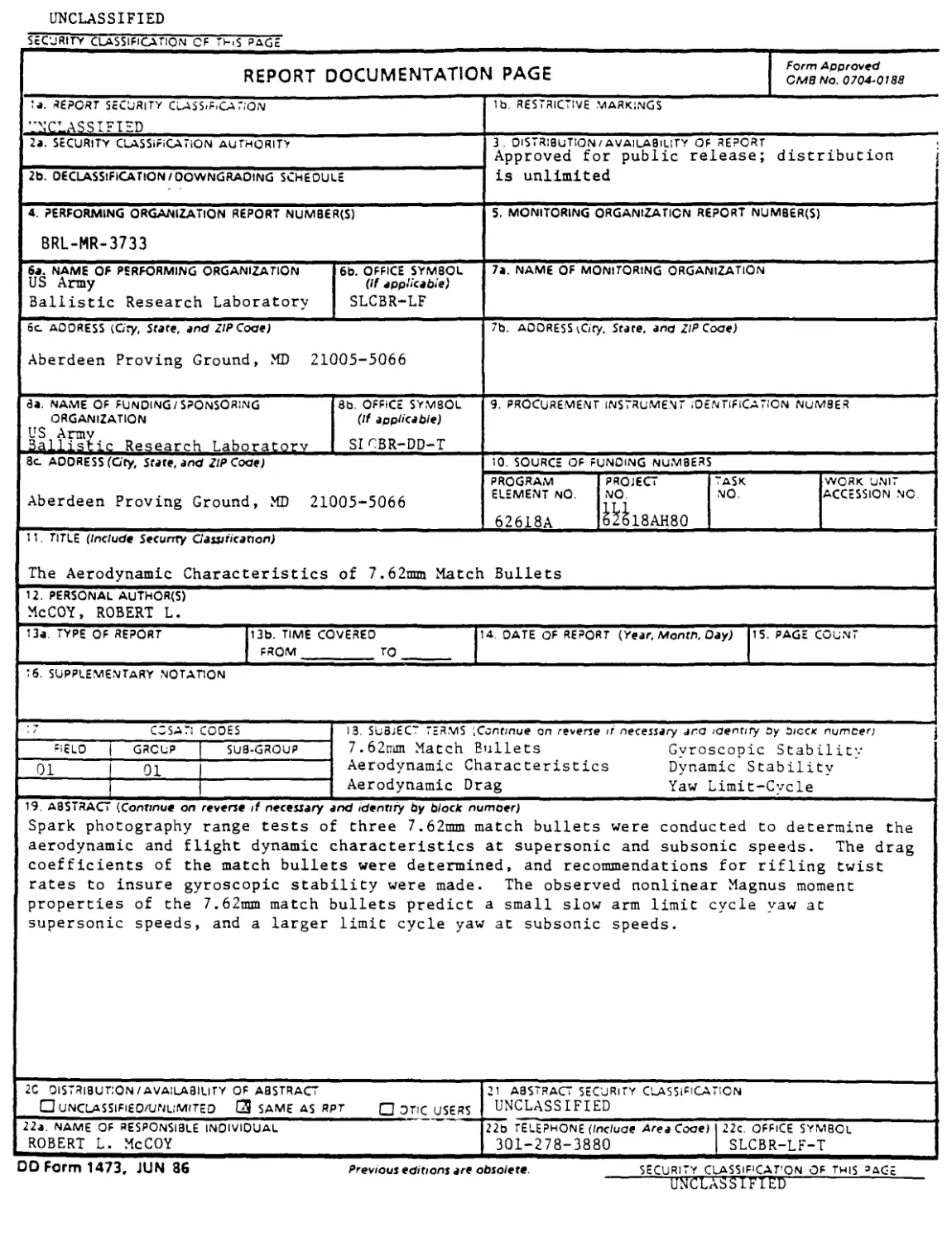
19. ABSTRACT {Continue on reverse if necessary and identify by block numoer) Spark photography range tests of three 7.62mm match bullets were conducted to determine the aerodynamic and flight dynamic characteristics at supersonic and subsonic speeds. The drag coefficients of the match bullets were determined, and recommendations for rifling twist rates to insure gyroscopic stability were made. The observed nonlinear Magnus moment properties of the 7.62mm match bullets predict a small slow arm limit cycle yaw at supersonic speeds, and a larger limit cycle yaw at subsonic speeds.
2C DISTRIBUTION/AVAILABILITY OF ABSTRACT □ UNCLASSlFlEO/UNUMITED C3 SAME AS RPT □ OTIC USERS 21 ABSTRACT SECURITY CLASSIFICATION UNCLASSIFIED
22a. NAME OF RESPONSIBLE INDIVIDUAL ROBERT L. McCOY 22b TELEPHONE (Include Area Code) 301-278-3880 22c. OFFICE SYMBOL SLCBR-LF-T
DO Form 1473, JUN 36 Previous editions are obsolete. SECURITY CLASSiF'CAT'ON Of this ’age
UNCLASSIFIED
Table of Contents
Page
List of Figures ......................................................... v
List of Tables......................................................... vii
I. Introduction.............................................................. 1
II. Test Facilities and Material.............................................. 1
III. Results.................................................................. 2
1. Drag Coefficient...................................................... 2
2. Overturning Moment Coefficient ....................................... 3
3. Gyroscopic Stability.................................................. 4
4. Lift Force Coefficient................................................ 4
5. Magnus Moment Coefficient and Pitch Damping Moment Coefficient . . 4
6. Damping Rates......................................................... 6
IV. Conclusions............................................................... 7
V. Recommendations........................................................... 8
References.............................................................. 59
List of Symbols......................................................... 61
Distribution List....................................................... 65
iii
List of Figures
Figure Page
1 Photograph of the BRL Free Flight Aerodynamics Range....................... 9
2 Coordinate System for the BRL Aerodynamics Range.......................... 10
3 Sketch of the Ml 18 Match (Special Ball) Bullet........................... 11
4 Sketch of the 190 Grain Sierra Matchking Bullet........................... 12
5 Sketch of the 168 Grain Sierre International (M852) Bullet................ 13
6 Shadowgraph of Ml 18 Bullet at Mach 2.2................................... 14
7 Shadowgraph of 190 Grain Sierra Bullet at Mach 2.2....................... 15
8 Shadowgraph of 168 Grain Sierra Bullet at Mach 2.2....................... 16
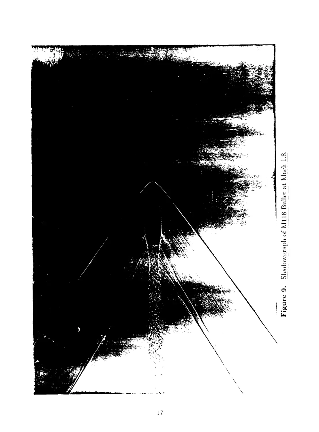
9 Shadowgraph of M118 Bullet at Mach 1.8.................................... 17
10 Shadowgraph of 190 Grain Sierra Bullet at Mach 1.8....................... 18
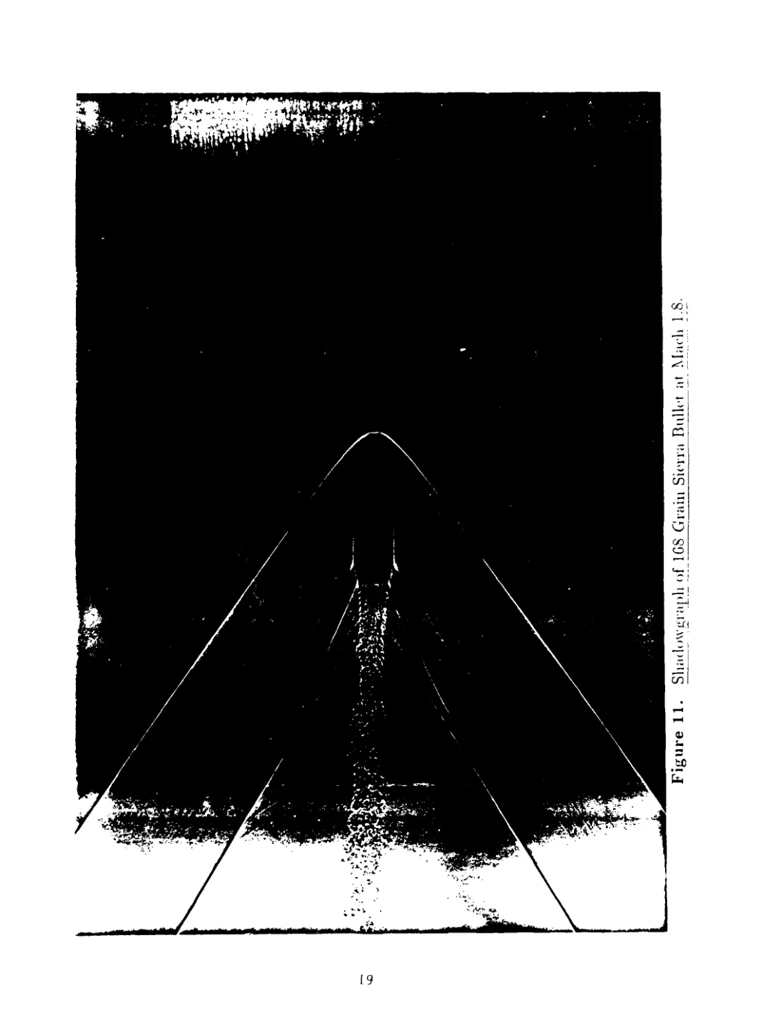
11 Shadowgraph of 168 Grain Sierra Bullet at Mach 1.8....................... 19
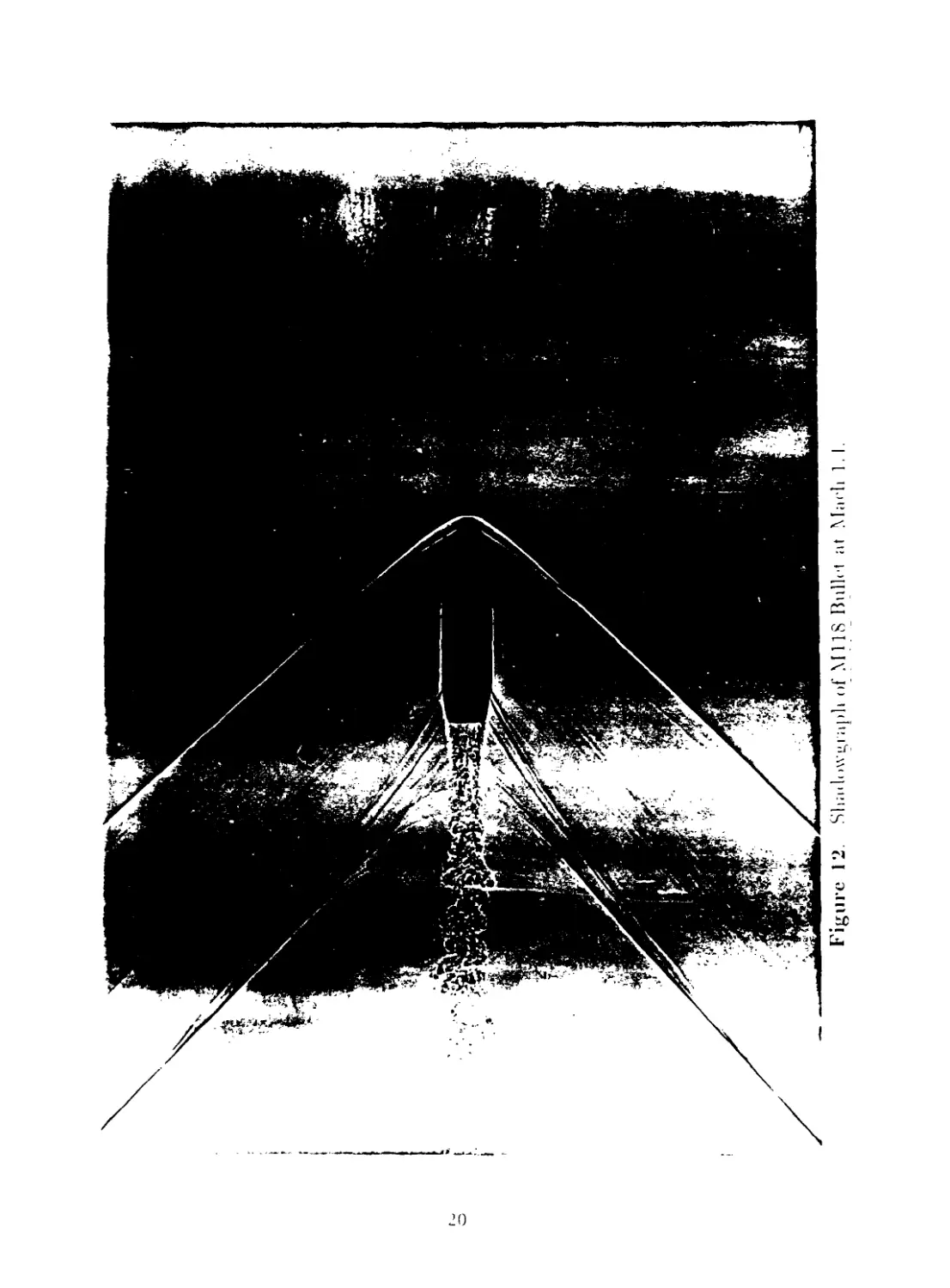
12 Shadowgraph of M118 Bullet at Mach 1.4.................................... 20
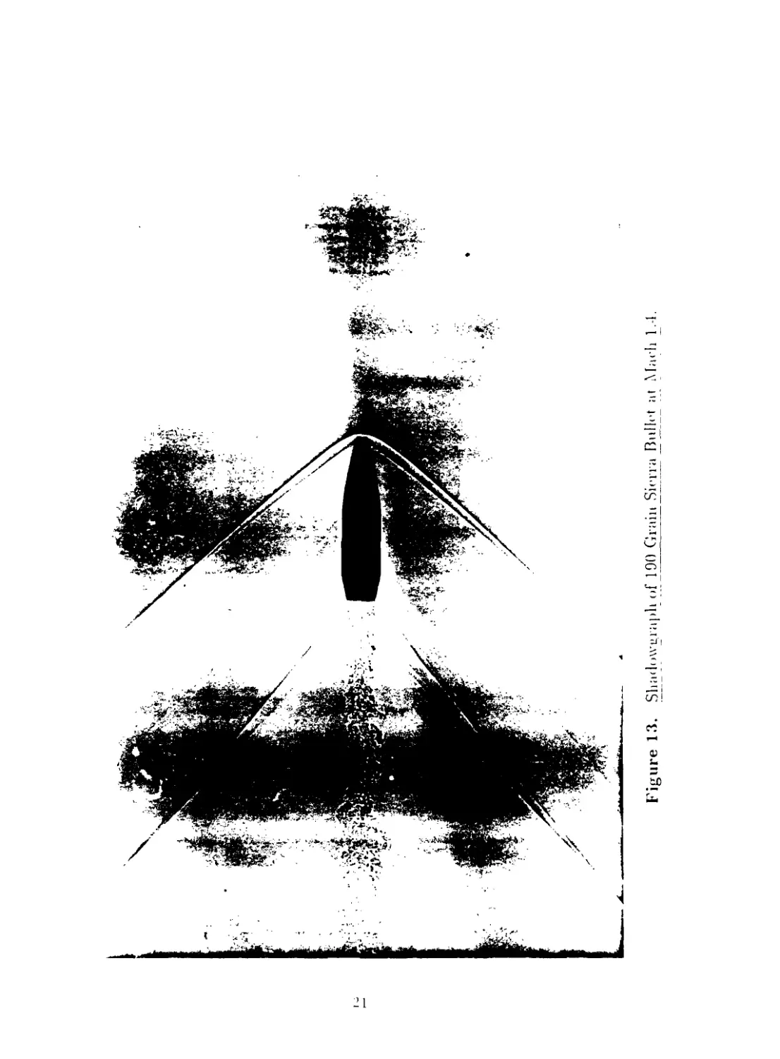
13 Shadowgraph of 190 Grain Sierra Bullet at Mach 1.4..................... 21
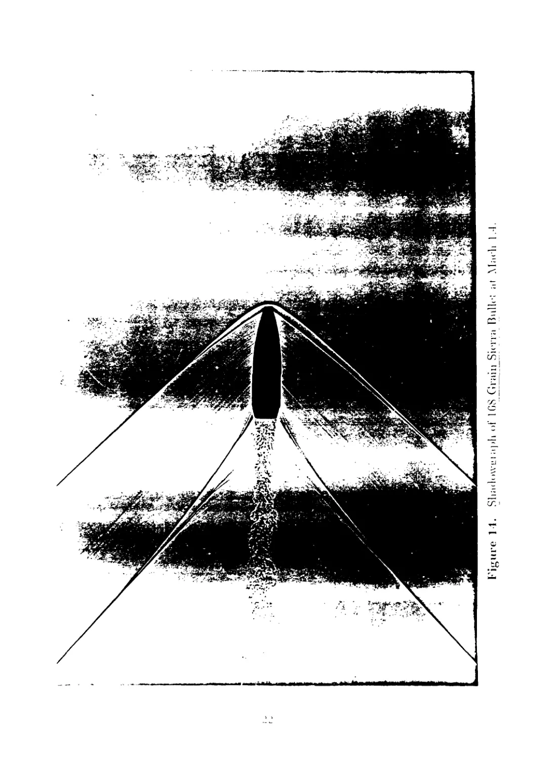
14 Shadowgraph of 168 Grain Sierra Bullet at Mach 1.4..................... 22
15 Shadowgraph of Ml 18 Bullet at Mach 1.1................................... 23
16 Shadowgraph of 190 Grain Sierra Bullet at Mach 1.1..................... 24
17 Shadowgraph of 168 Grain Sierra Bullet at Mach 1.1..................... 25
18 Zero-Yaw Drag Force Coefficient versus Mach Number, M118 Bullet.....26
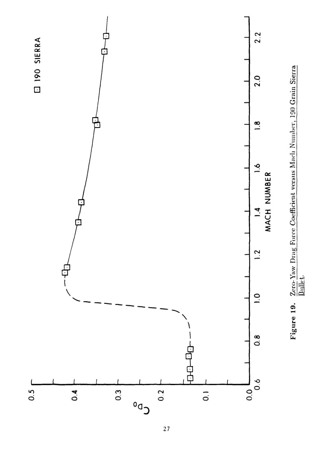
19 Zero-Yaw Drag Force Coefficient versus Mach Number, 190 Grain Sierra
Bullet.................................................................... 27
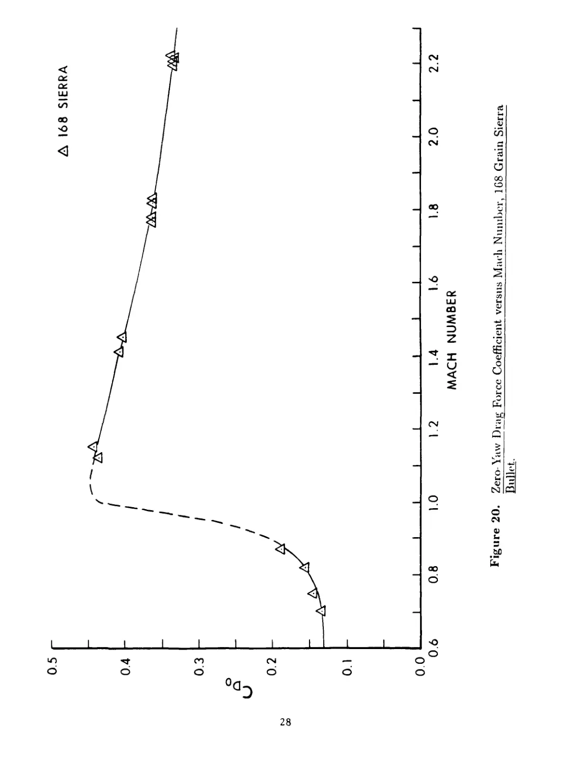
20 Zero-Yaw Drag Force Coefficient versus Mach Number, 168 Grain Sierra
Bullet.................................................................... 28
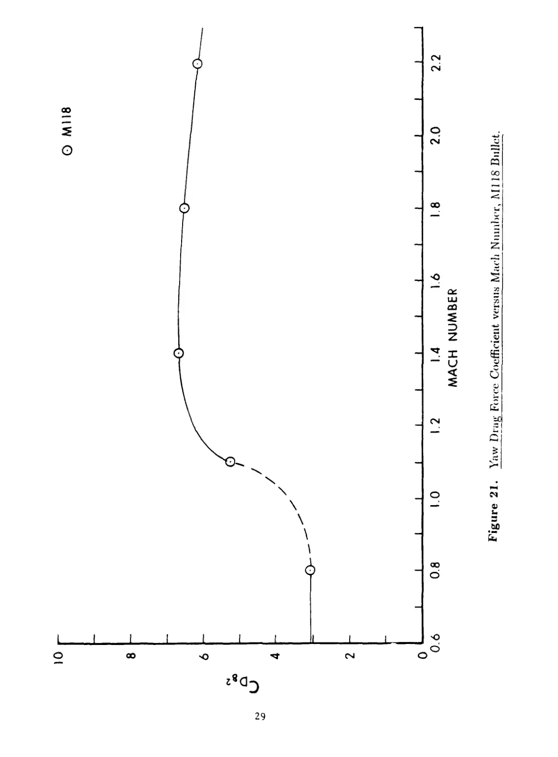
21 Yaw Drag Force Coefficient versus Mach Number, M118 Bullet......... 29
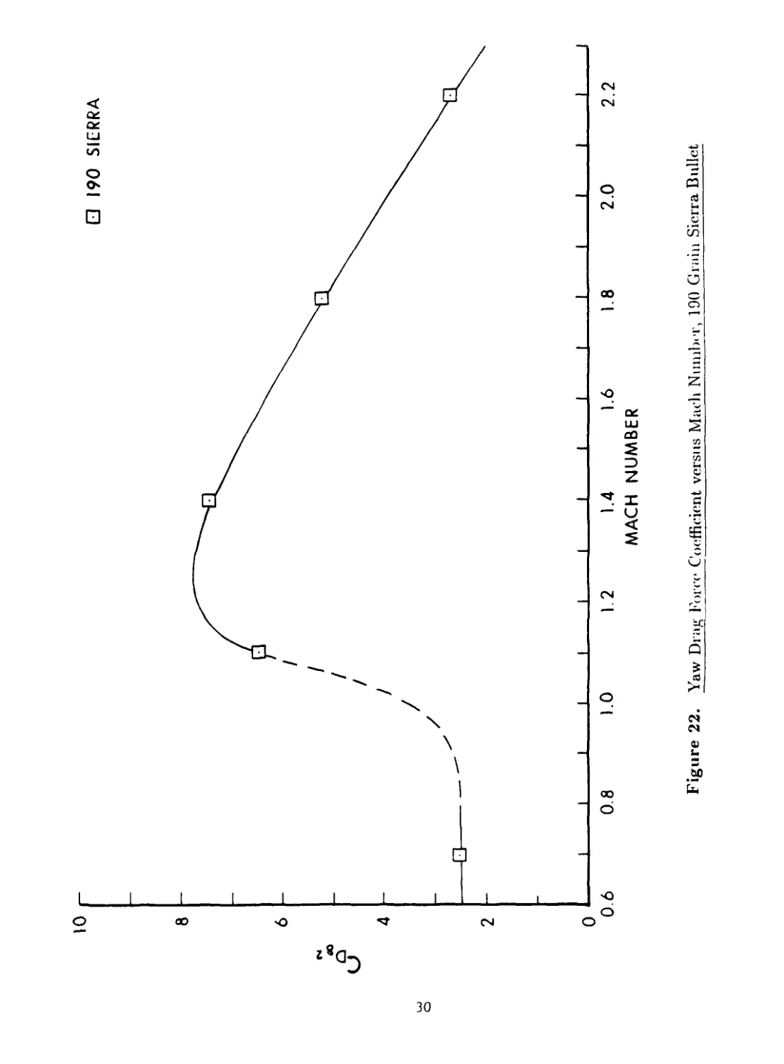
22 Yaw Drag Force Coefficient versus Mach Number, 190 Grain Sierra Bullet. . 30
23 Yaw Drag Force Coefficient versus Mach Number. 168 Grain Sierra Bullet. . 31
24 Zero-Yaw Overturning Moment Coefficient versus Mach Number, M11S Bullet. 32
V
List of Figures (Continued)
Figure Page
25 Zero-Yaw Overturning Moment Coefficient versus Mach Number, 190 Grain
Sierra Bullet....................................................................... 33
26 Zero-Yaw Overturning Moment Coefficient versus Mach Number, 168 Grain
Sierra Bullet....................................................................... 34
27 Gyroscopic Stability Factor versus Mach Number, Ml 18 Bullet.............. 35
28 Gyroscopic Stability Factor versus Mach Number, 190 Grain Sierra Bullet. . 36
29 Gyroscopic Stability Factor versus Mach Number, 168 Grain Sierra Bullet. . 37
30 Lift Force Coefficient versus Mach Number.................................. 38
31 Magnus Moment Coefficient versus Effective Squared Yaw..................... 39
32 Magnus Moment Coefficient versus Effective Squared Yaw..................... 40
33 Magnus Moment Coefficient versus Effective Squared Yaw..................... 41
34 Magnus Moment Coefficient versus Effective Squared Yaw..................... 42
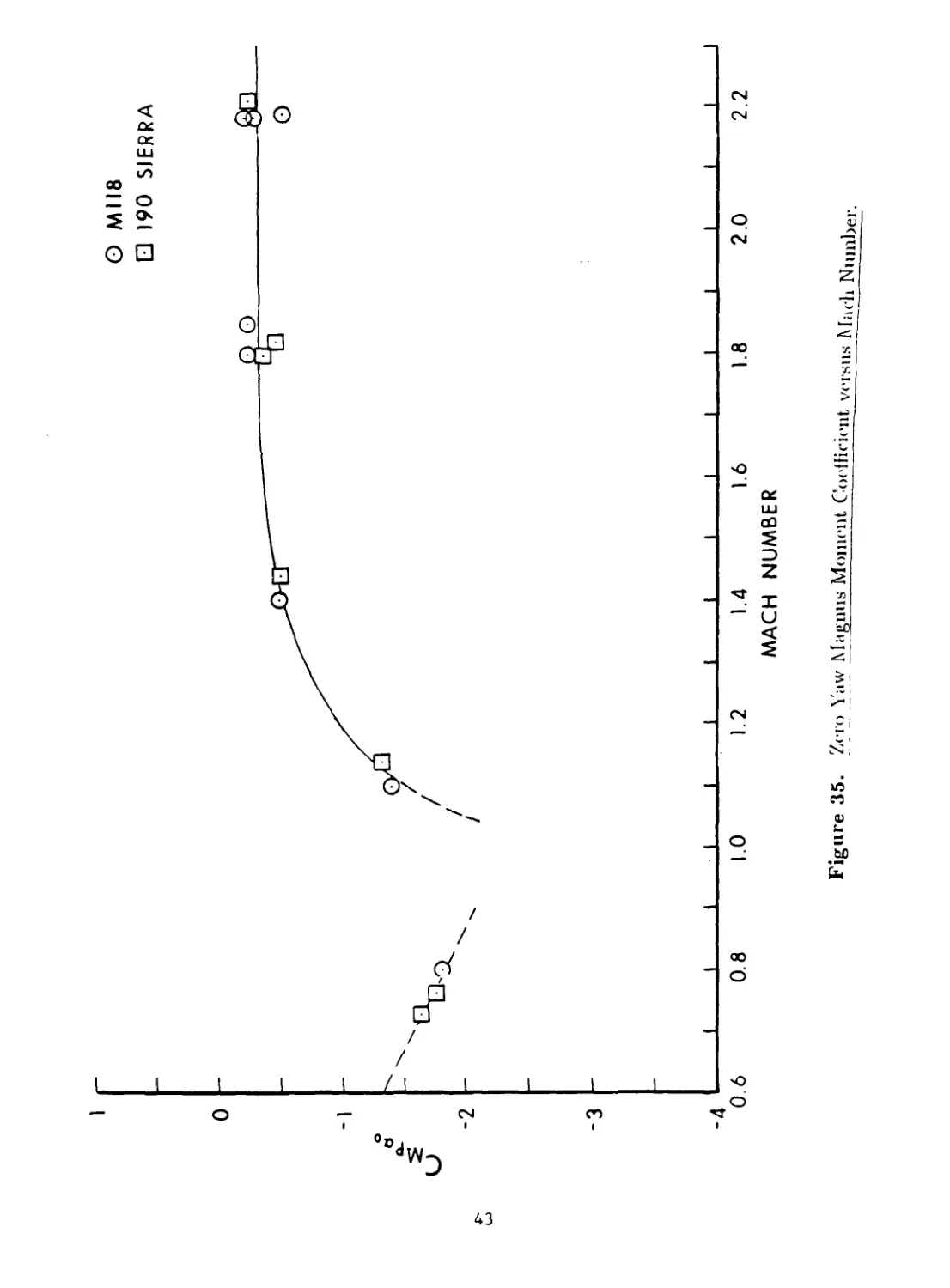
35 Zero-Yaw Magnus Moment Coefficient versus Mach Number......................... 43
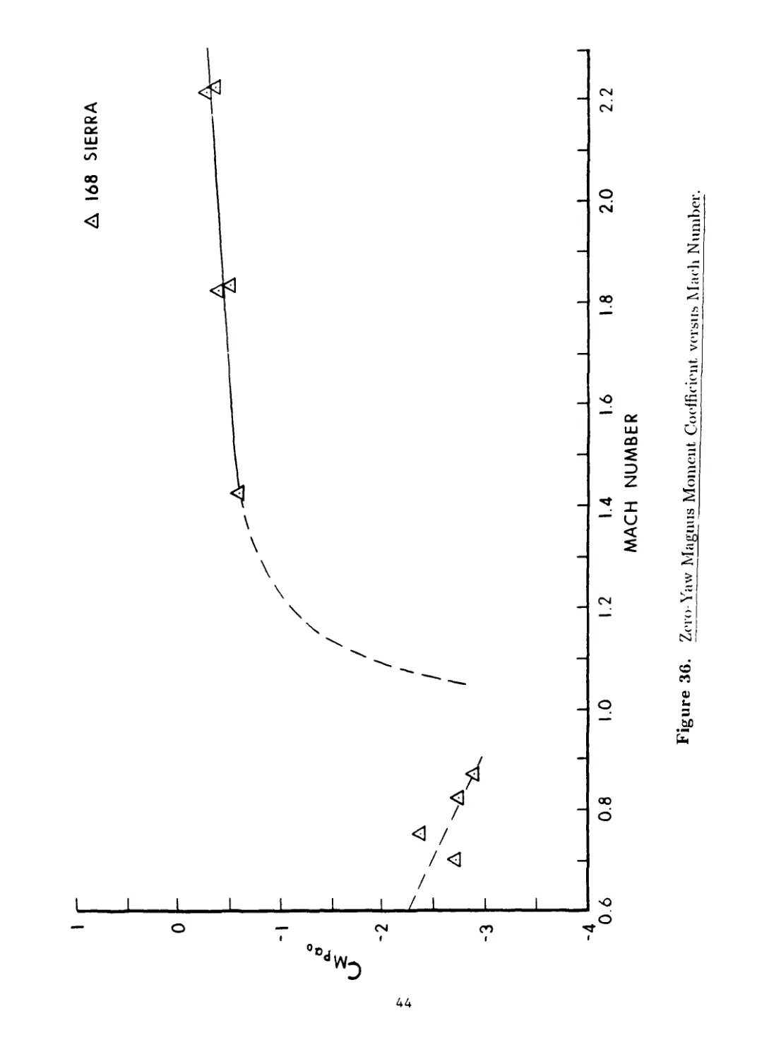
36 Zero-Yaw Magnus Moment Coefficient versus Mach Number......................... 44
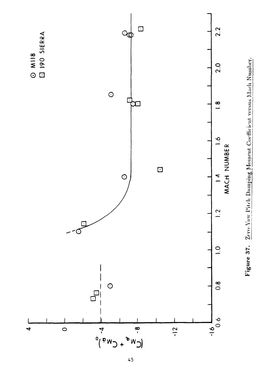
37 Zero-Yaw Pitch Damping Moment Coefficient versus Mach Number............... 45
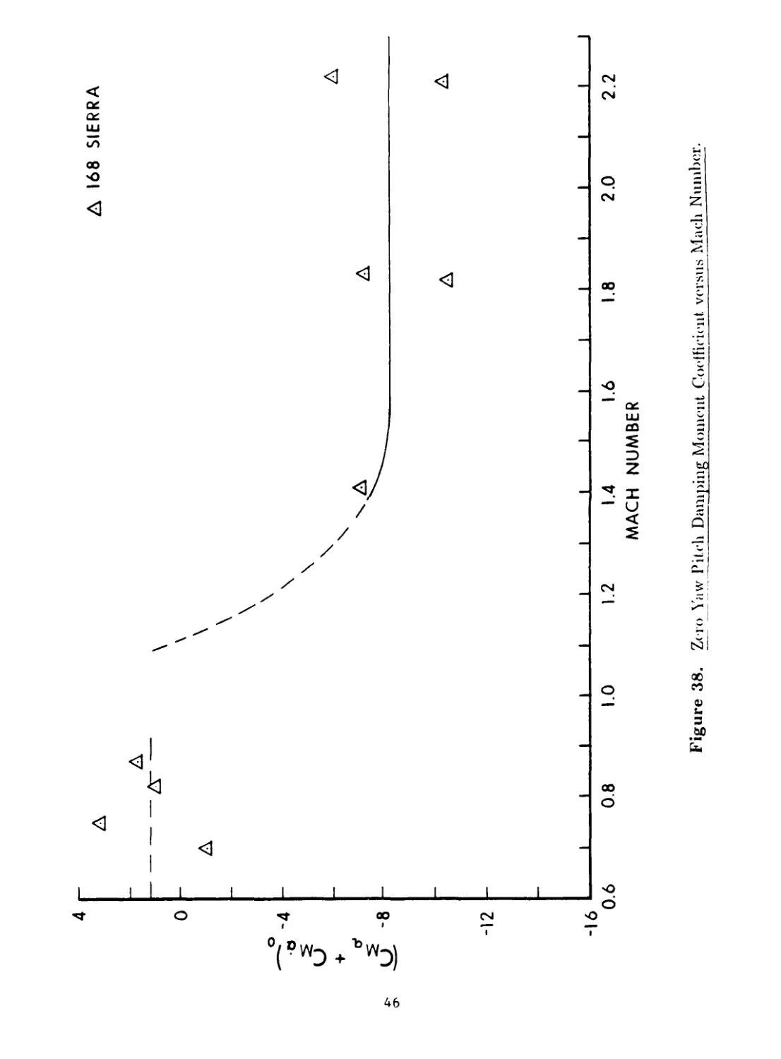
38 Zero-Yaw Pitch Damping Moment Coefficient versus Mach Number............... 46
39 Fast Arm Damping Rate versus Effective Squared Yaw.............................. 47
40 Slow Arm Damping Rate versus Effective Squared Yaw.............................. 48
41 Fast Arm Damping Rate versus Effective Squared Yaw.............................. 49
42 Slow Arm Damping Rate versus Effective Squared Yaw.............................. 50
vi
List of Tables
Table Page
1 Average Physical Characteristics of 7.62mm Match Bullets.................... 51
2 Aerodynamic Characteristics of the Ml 18 Match Bullet..................... 52
3 Aerodynamic Characteristics of the 190 Grain Sierra Matchking Bullet. . . 53
4 Aerodynamic Characteristics of the 168 Grain Sierra International Bullet. . 54
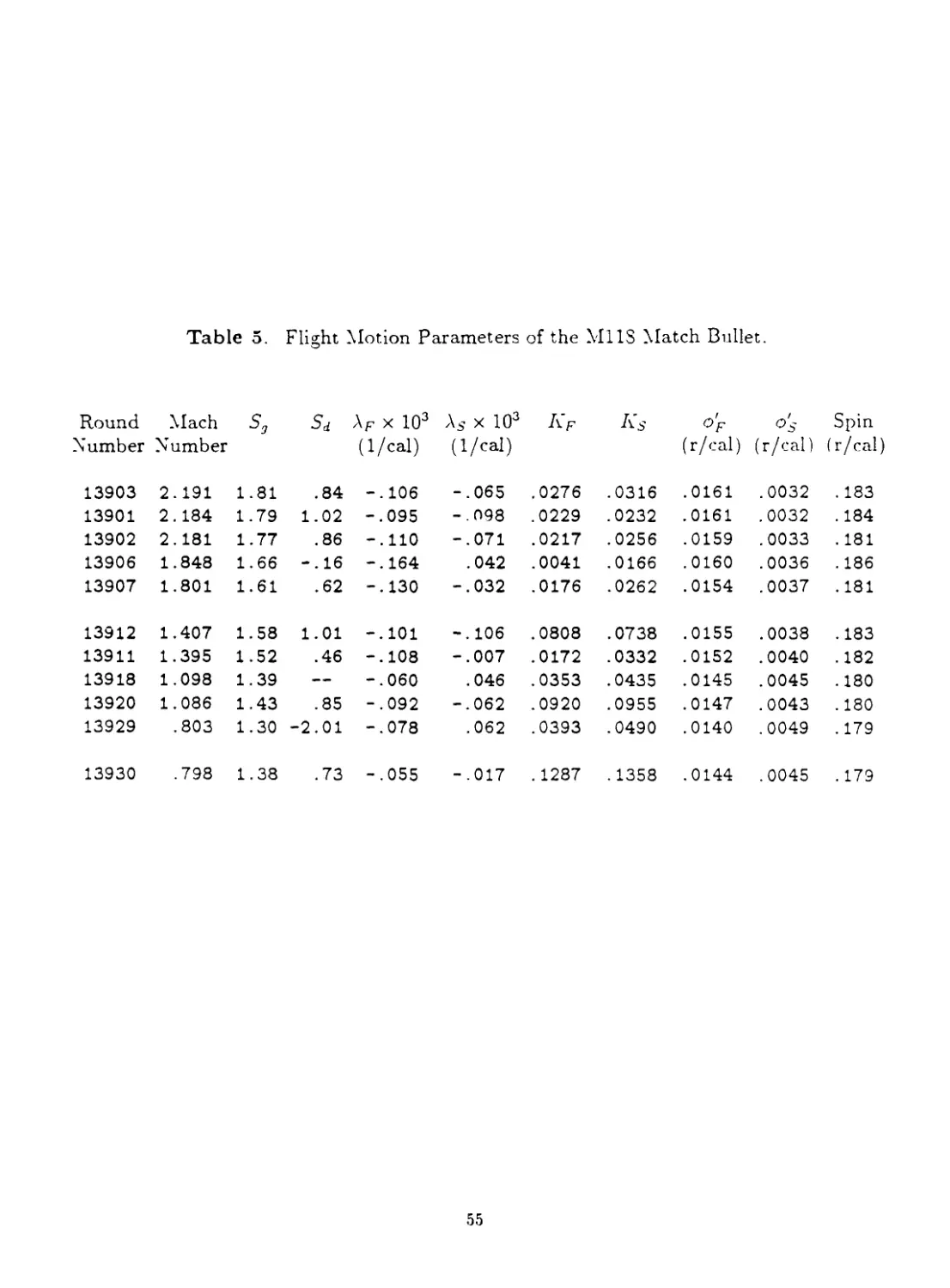
5 Flight Motion Parameters of the Ml 18 Match Bullet........................ 55
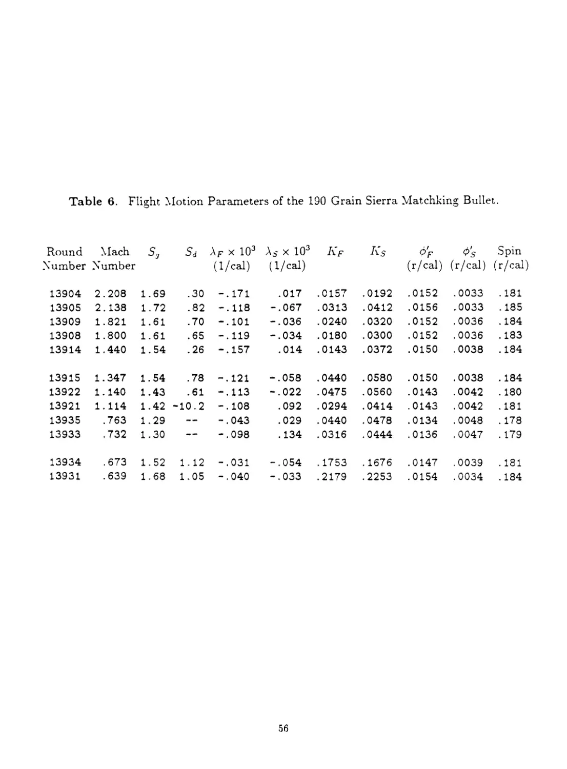
6 Flight Motion Parameters of the 190 Grain Sierra Matchking Bullet......... 5o
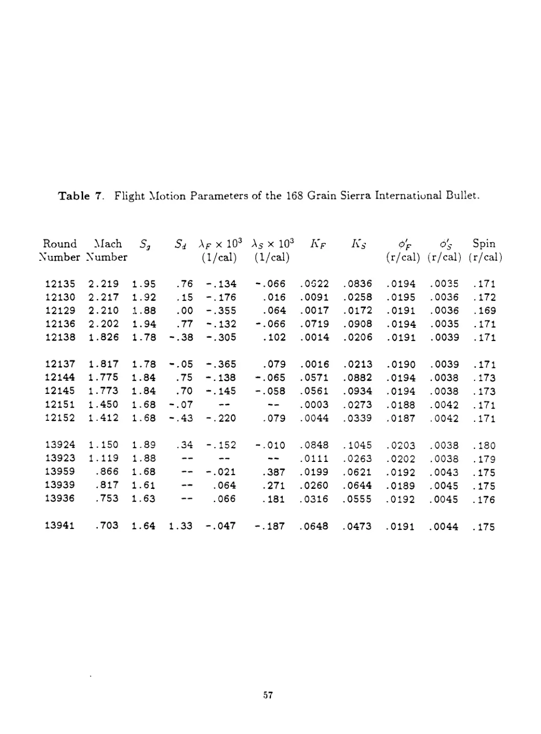
7 Flight Motion Parameters of the 168 Grain Sierra International Bullet. . . 57
vii
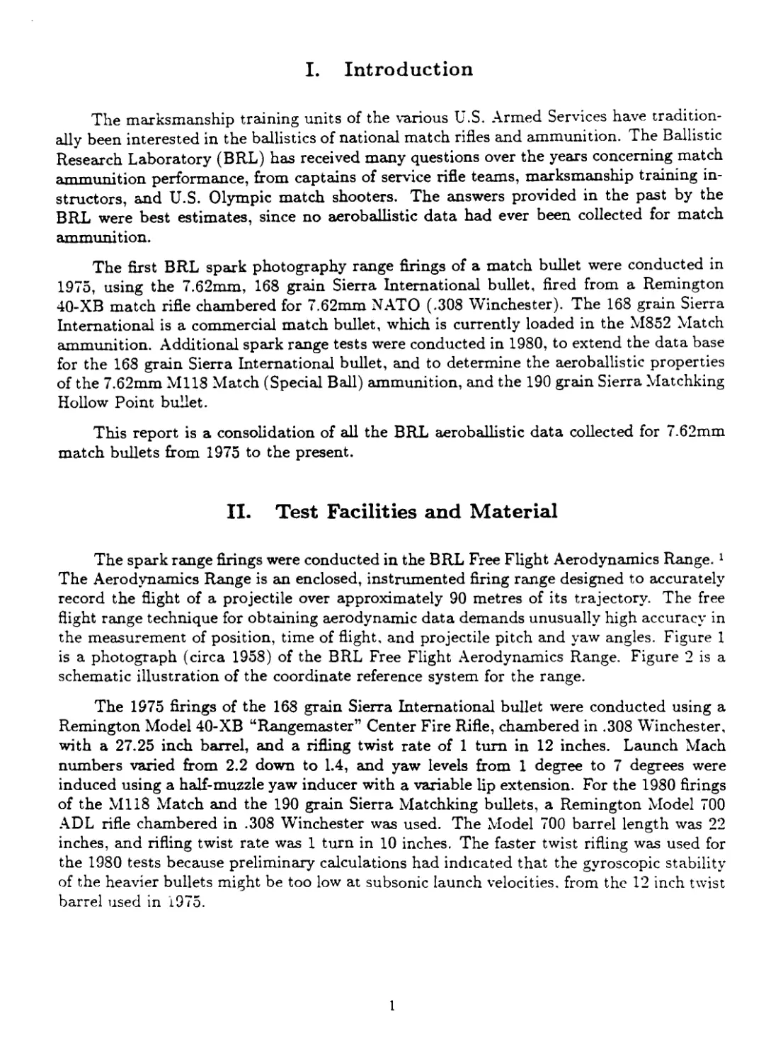
I. Introduction
The marksmanship training units of the various U.S. Armed Services have tradition-
ally been interested in the ballistics of national match rifles and ammunition. The Ballistic
Research Laboratory (BRL) has received many questions over the years concerning match
ammunition performance, from captains of service rifle teams, marksmanship training in-
structors, and U.S. Olympic match shooters. The answers provided in the past by the
BRL were best estimates, since no aeroballistic data had ever been collected for match
ammunition.
The first BRL spark photography range firings of a match bullet were conducted in
1975, using the 7.62mm, 168 grain Sierra International bullet, fired from a Remington
40-XB match rifle chambered for 7.62mm NATO (.308 Winchester). The 168 grain Sierra
International is a commercial match bullet, which is currently loaded in the M852 Match
ammunition. Additional spark range tests were conducted in 1980, to extend the data base
for the 168 grain Sierra International bullet, and to determine the aeroballistic properties
of the 7.62mm M118 Match (Special Ball) ammunition, and the 190 grain Sierra Matchking
Hollow Point bullet.
This report is a consolidation of all the BRL aeroballistic data collected for 7.62mm
match bullets from 1975 to the present.
II. Test Facilities and Material
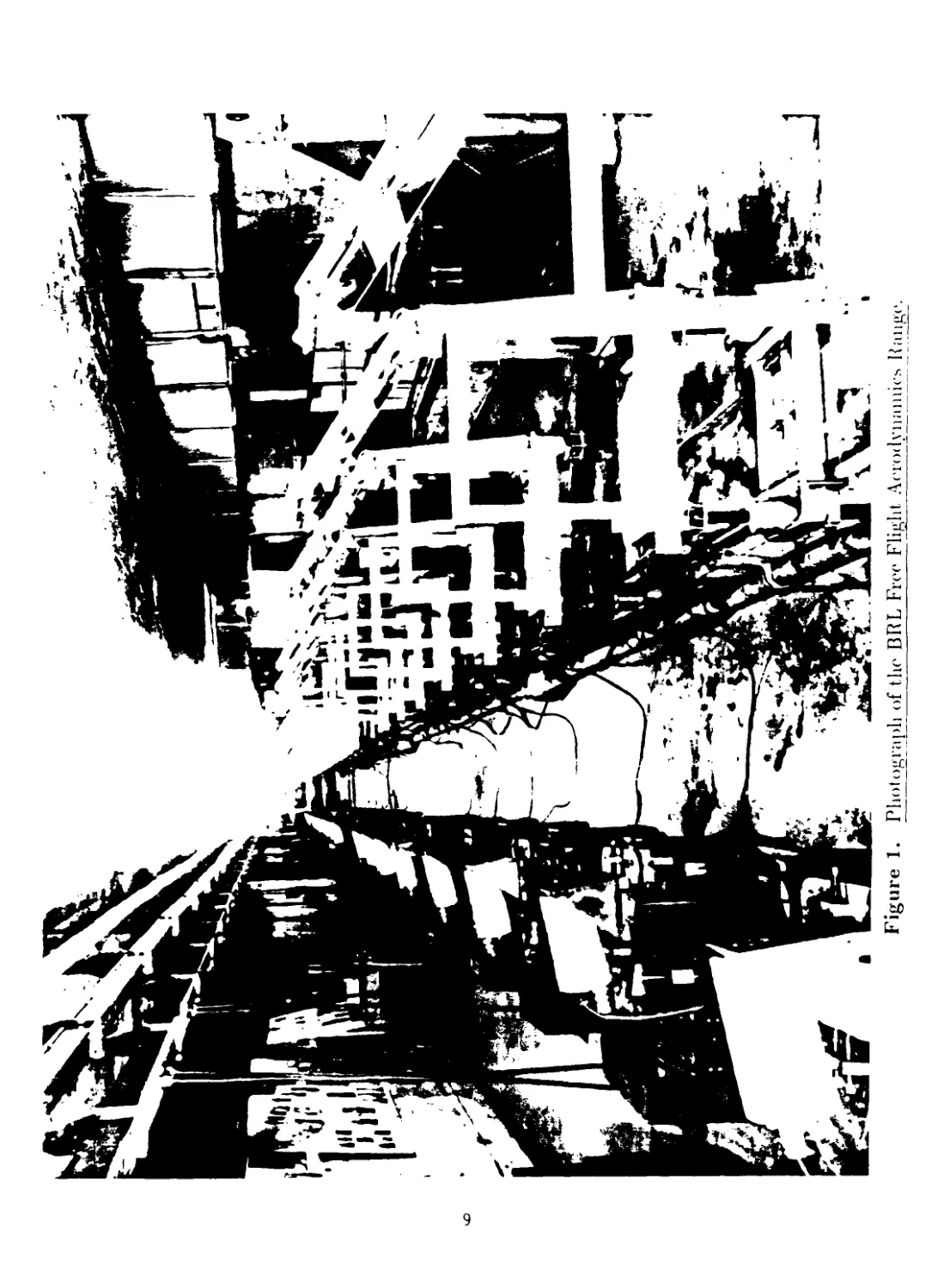
The spark range firings were conducted in the BRL Free Flight Aerodynamics Range. 1
The Aerodynamics Range is an enclosed, instrumented firing range designed to accurately
record the flight of a projectile over approximately 90 metres of its trajectory. The free
flight range technique for obtaining aerodynamic data demands unusually high accuracy in
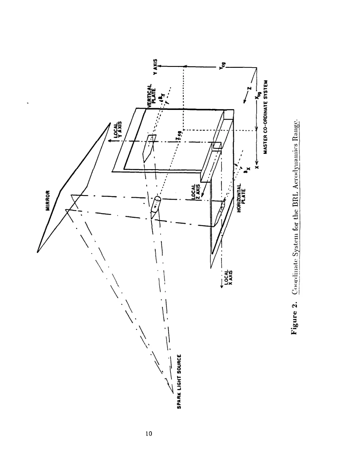
the measurement of position, time of flight, and projectile pitch and yaw angles. Figure 1
is a photograph (circa 1958) of the BRL Free Flight Aerodynamics Range. Figure 2 is a
schematic illustration of the coordinate reference system for the range.
The 1975 firings of the 168 grain Sierra International bullet were conducted using a
Remington Model 40-XB “Rangemaster” Center Fire Rifle, chambered in .308 Winchester,
with a 27.25 inch barrel, and a rifling twist rate of 1 turn in 12 inches. Launch Mach
numbers varied from 2.2 down to 1.4, and yaw levels from 1 degree to 7 degrees were
induced using a half-muzzle yaw inducer with a variable lip extension. For the 1980 firings
of the Ml 18 Match and the 190 grain Sierra Matchking bullets, a Remington Model 700
ADL rifle chambered in .308 Winchester was used. The Model 700 barrel length was 22
inches, and rifling twist rate was 1 turn in 10 inches. The faster twist rifling was used for
the 1980 tests because preliminary calculations had indicated that the gyroscopic stability
of the heavier bullets might be too low at subsonic launch velocities, from the 12 inch twist
barrel used in 1975.
1
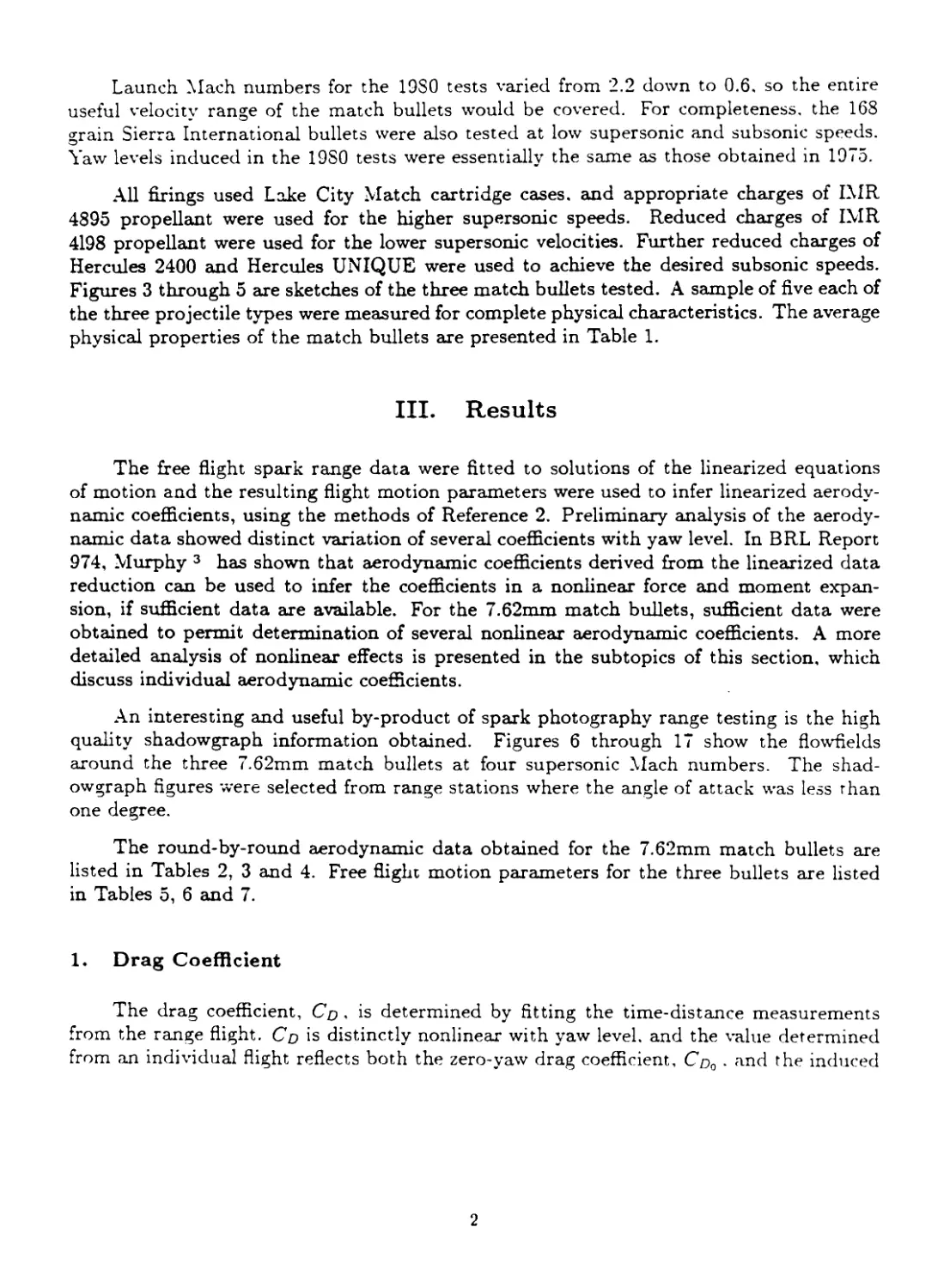
Launch Mach numbers for the 1980 tests varied from 2.2 down to 0.6. so the entire
useful velocity range of the match bullets would be covered. For completeness, the 168
grain Sierra International bullets were also tested at low supersonic and subsonic speeds.
Yaw levels induced in the 1980 tests were essentially the same as those obtained in 1975.
All firings used Lake City Match cartridge cases, and appropriate charges of IMR
4895 propellant were used for the higher supersonic speeds. Reduced charges of IMR
4198 propellant were used for the lower supersonic velocities. Further reduced charges of
Hercules 2400 and Hercules UNIQUE were used to achieve the desired subsonic speeds.
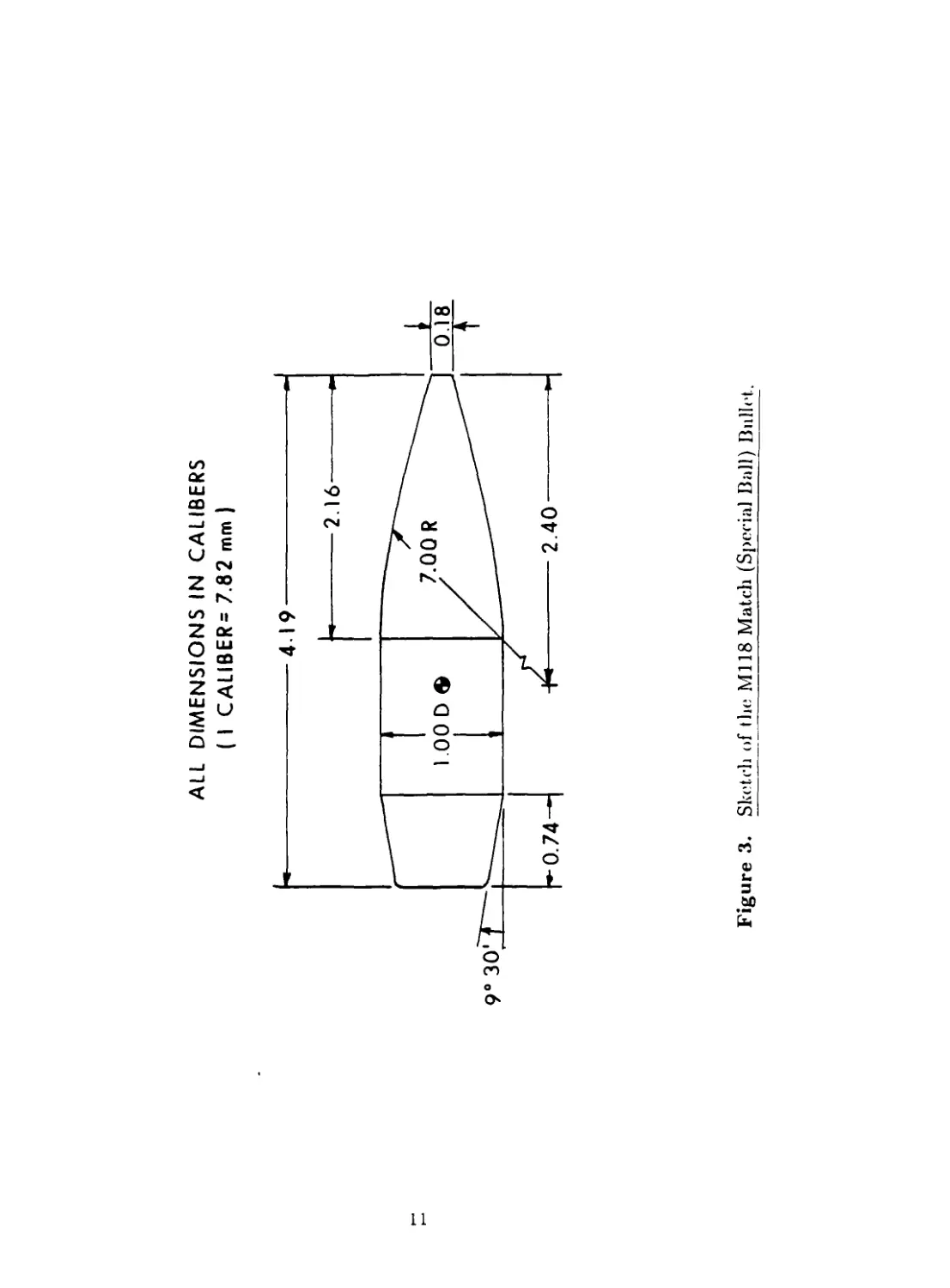
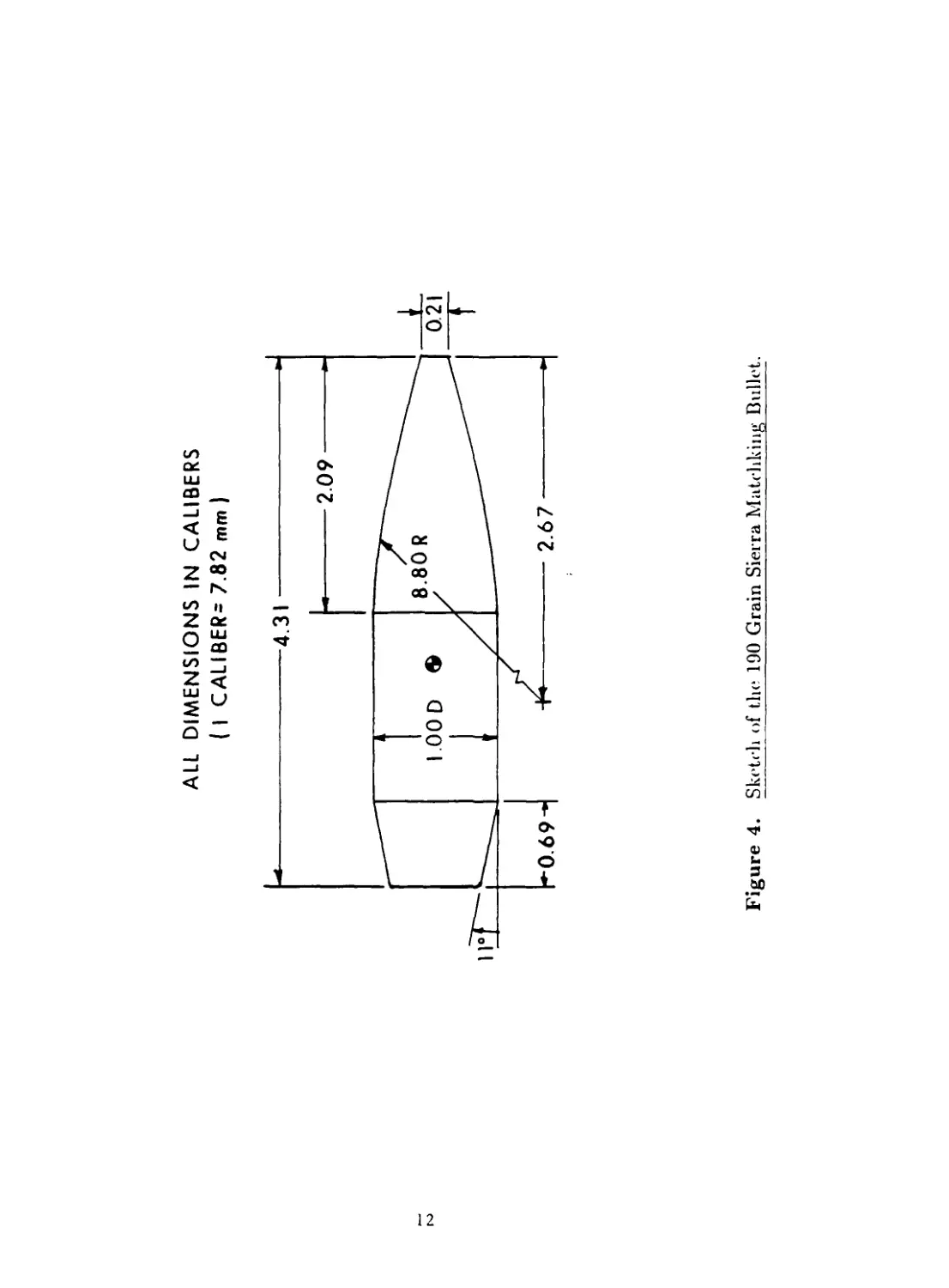
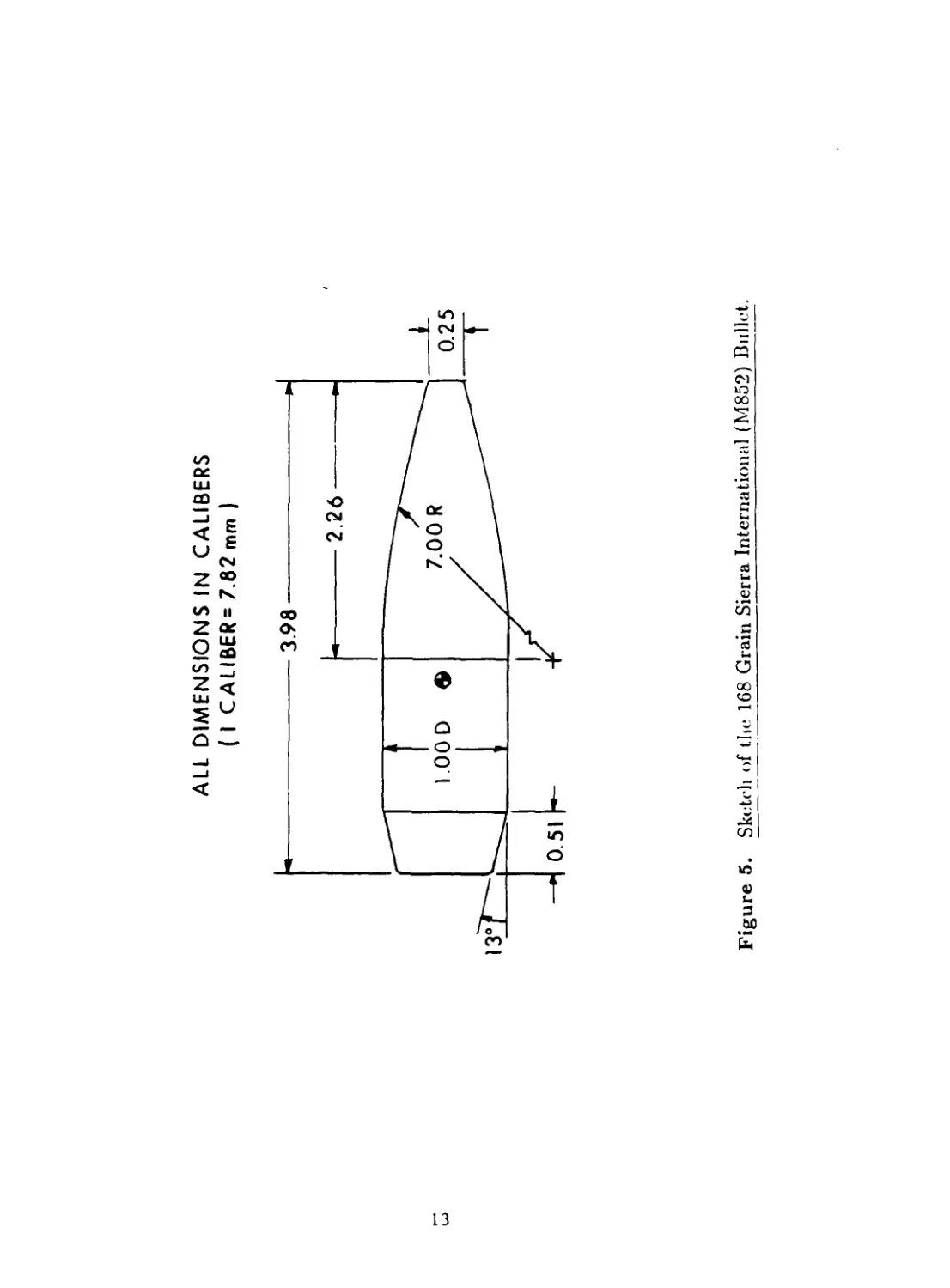
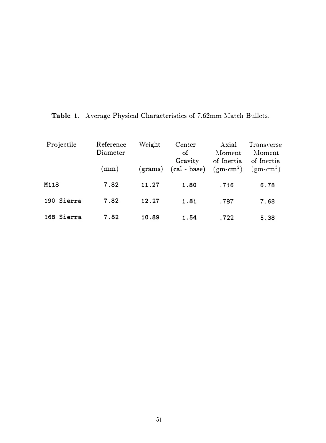
Figures 3 through 5 are sketches of the three match bullets tested. A sample of five each of
the three projectile types were measured for complete physical characteristics. The average
physical properties of the match bullets are presented in Table 1.
III. Results
The free flight spark range data were fitted to solutions of the linearized equations
of motion and the resulting flight motion parameters were used to infer linearized aerody-
namic coefficients, using the methods of Reference 2. Preliminary analysis of the aerody-
namic data showed distinct variation of several coefficients with yaw level. In BRL Report
974, Murphy 1 * 3 has shown that aerodynamic coefficients derived from the linearized data
reduction can be used to infer the coefficients in a nordinear force and moment expan-
sion, if sufficient data are available. For the 7.62mm match bullets, sufficient data were
obtained to permit determination of several nonlinear aerodynamic coefficients. A more
detailed analysis of nonlinear effects is presented in the subtopics of this section, which
discuss individual aerodynamic coefficients.
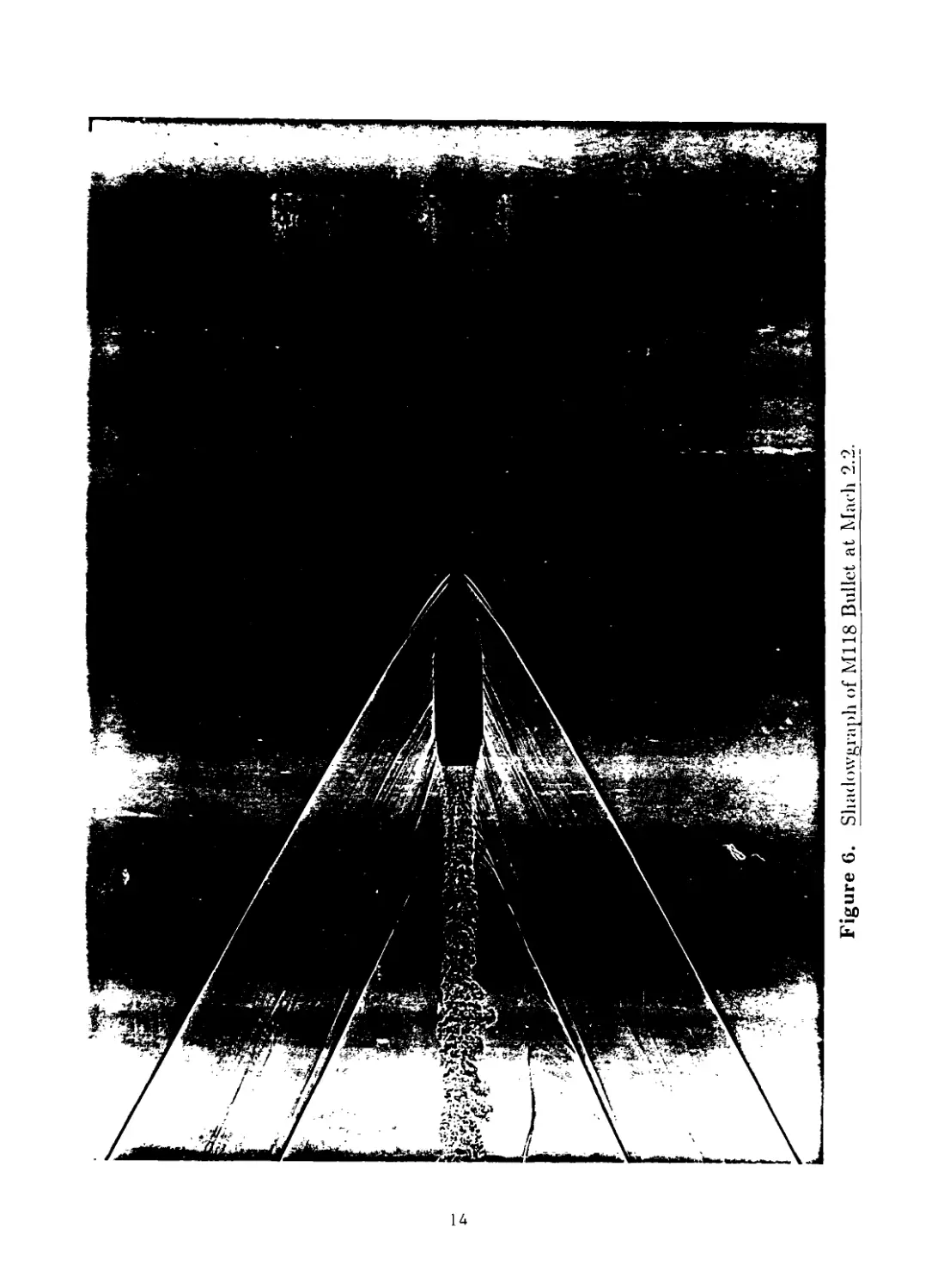
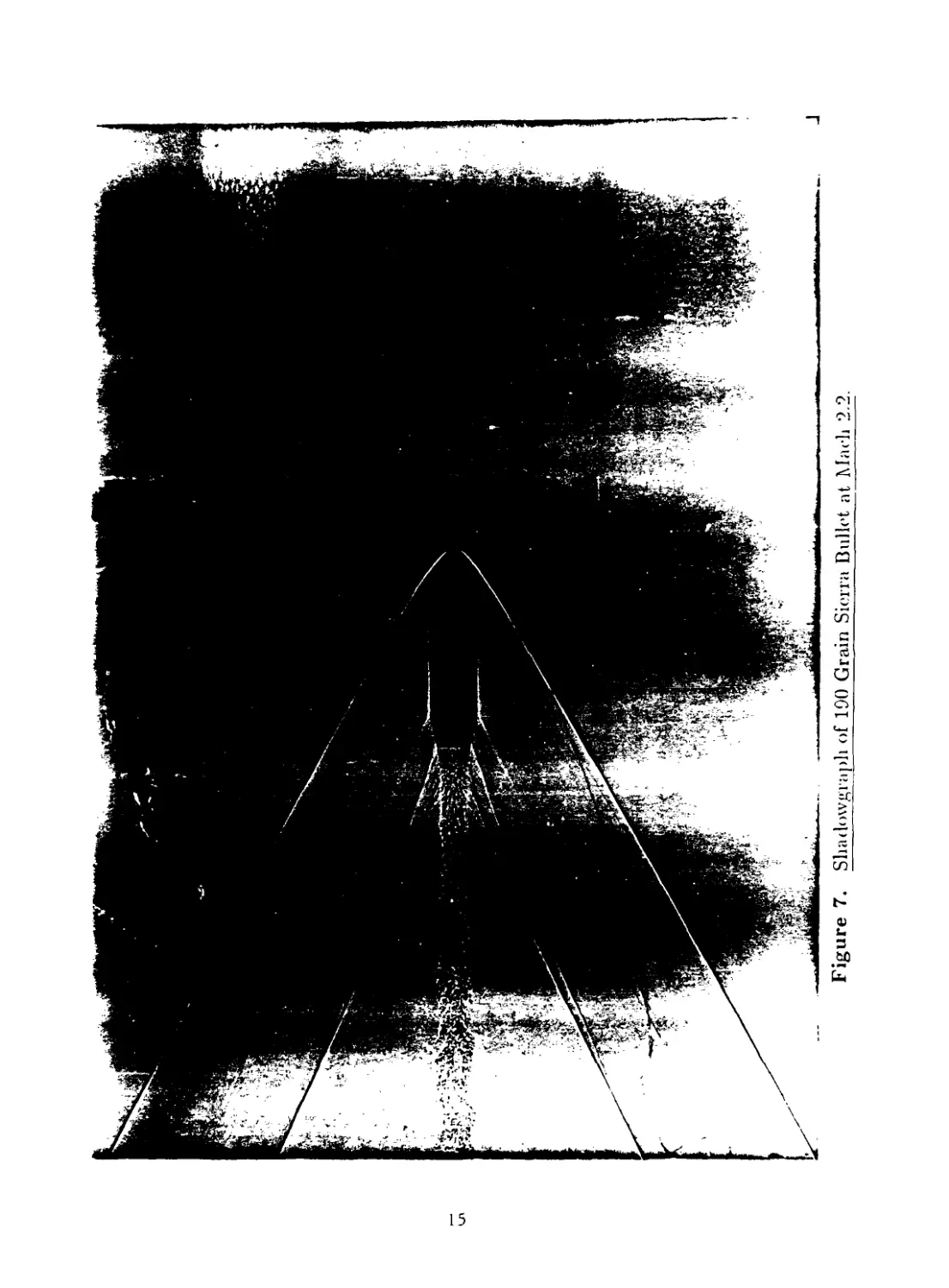
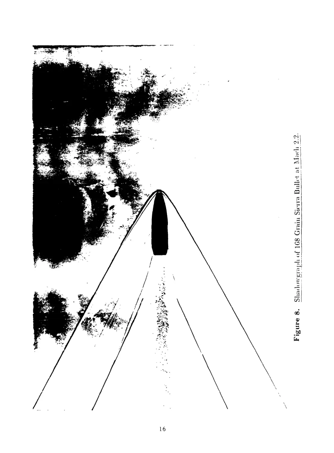
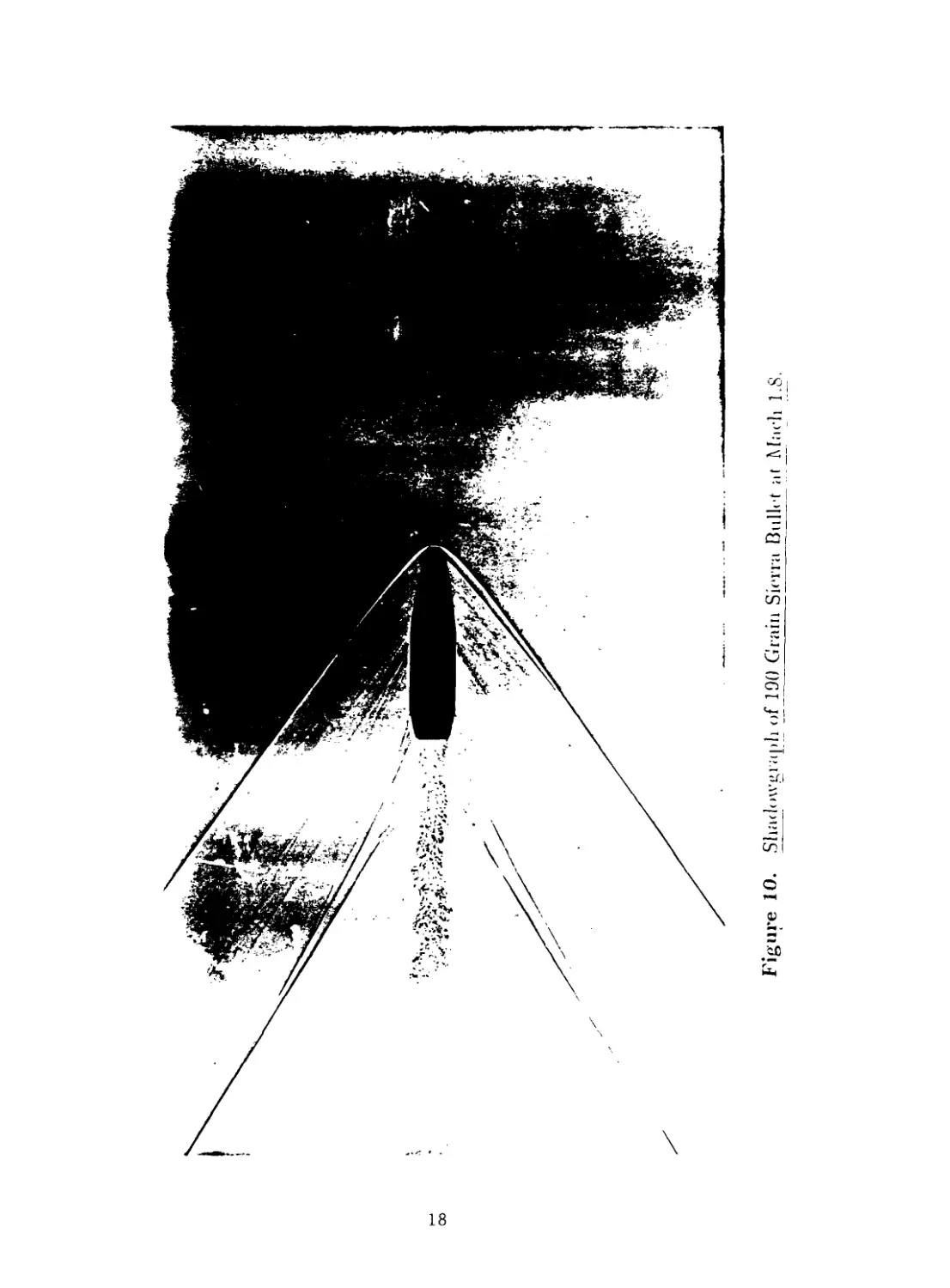
An interesting and useful by-product of spark photography range testing is the high
quality shadowgraph information obtained. Figures 6 through 17 show the flowfields
around the three 7.62mm match bullets at four supersonic Mach numbers. The shad-
owgraph figures were selected from range stations where the angle of attack was less rhan
one degree.
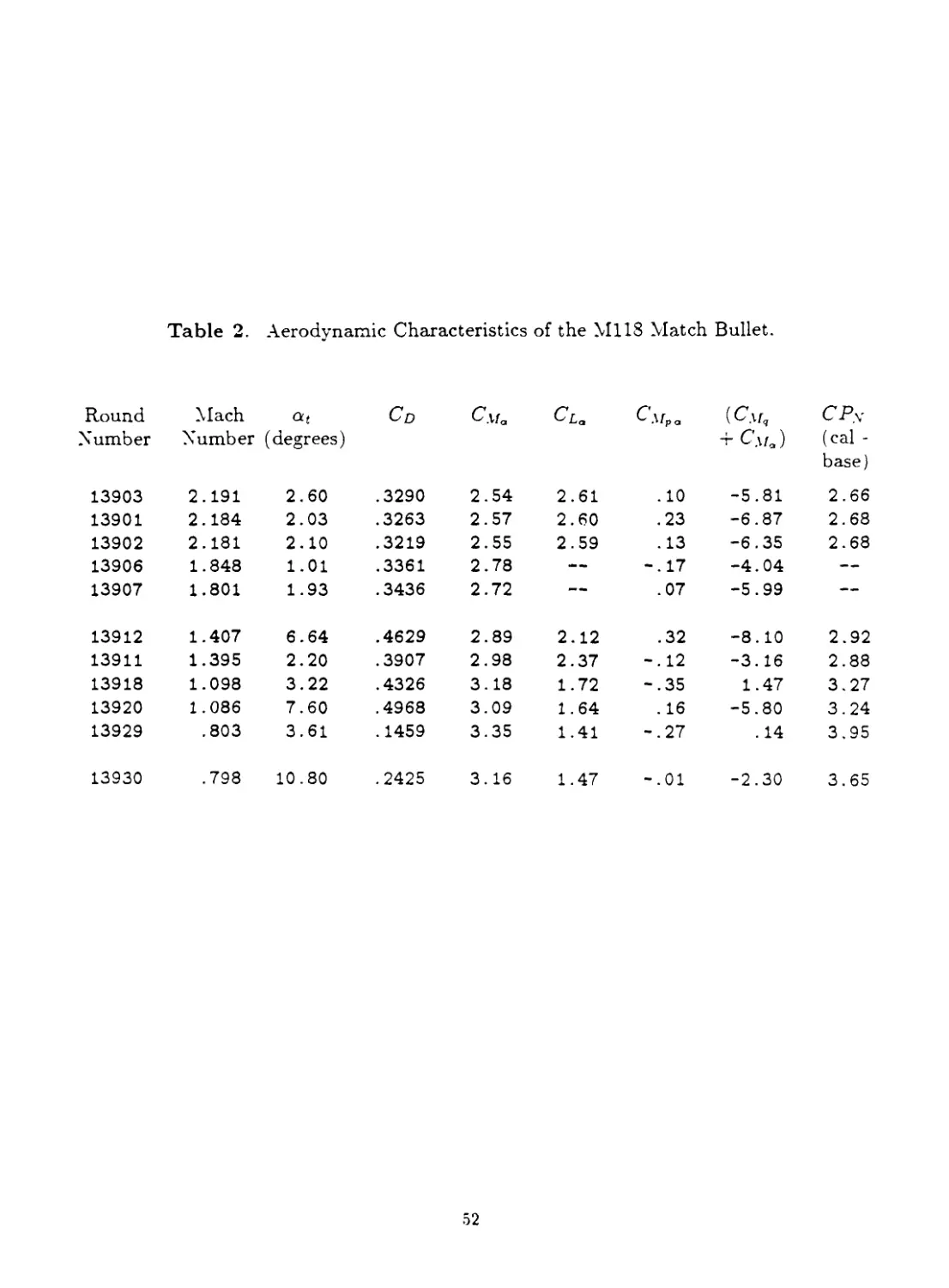
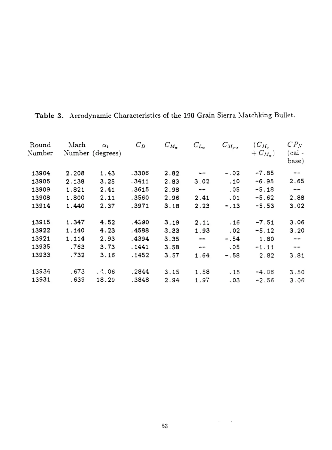
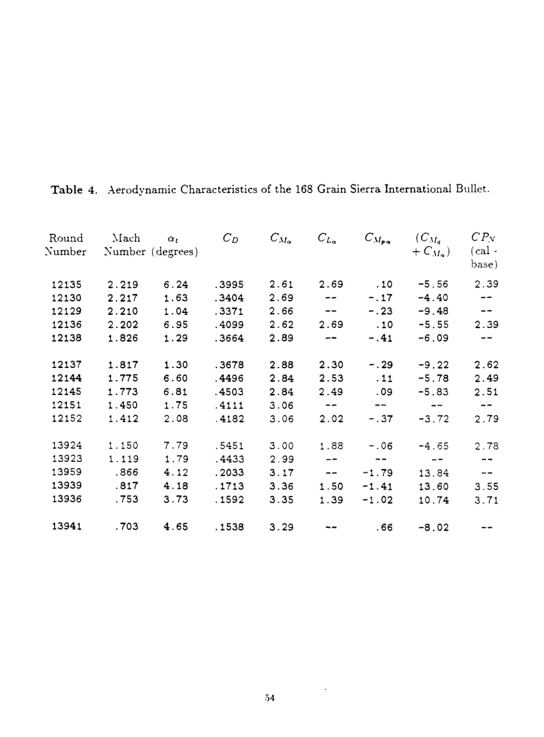
The round-by-round aerodynamic data obtained for the 7.62mm match bullets are
listed in Tables 2, 3 and 4. Free flight motion parameters for the three bullets are listed
in Tables 5, 6 and 7.
1. Drag Coefficient
The drag coefficient, Cd . is determined by fitting the time-distance measurements
from the range flight. Cd is distinctly nonlinear with yaw level, and the value determined
from an individual flight reflects both the zero-yaw drag coefficient, Co0 . and the induced
2
drag due to the average yaw level of the flight. The drag coefficient variation is
expressed as an even power series in yaw amplitude:
Cd = Cd0 + Cd62 + ... (1)
where Cd0 is the zero-yaw drag coefficient Coi2 is the quadratic yaw drag coefficient,
and 62 is the total angle of attack squared.
Analysis of the zero-yaw drag coefficient data for the 7.62mm match bullets showed
that the Ml 18 bullet had the lowest drag of the three designs tested, at supersonic speeds.
The 190 grain Sierra Matchking averaged four percent higher drag than the Ml 18. and the
168 grain Sierra International bullet averaged eight percent higher drag than the military
M118 design, over the Mach number range 2.2 to 1.1. At subsonic speeds, the zero-yaw
drag coefficients of the three bullets are nearly identical. Figures 18. 19 and 20 show the
variation of zero-yaw drag coefficient with Mach number for the three match bullets tested.
The variation of the quadratic yaw drag coefficients, Cds2 , with Mach number are shown in
Figures 21, 22 and 23, for the respective bullet designs. The yaw drag coefficients presented
were used to correct the range measured total drag coefficients to zero-yaw values. Dashed
portions of curves are used throughout this report to indicate trends, in regions where no
data were collected.
The round-to-round standard deviation in zero-yaw drag coefficient at supersonic
speeds was determined for each match bullet design, from the least-squares fit of the drag
data. All the 7.62mm match bullets showed standard deviations in Cq0 between 0.7 percent
and 0.8 percent, which represents significant improvement over the one to three percent
drag standard deviations typical of military ball projectiles. The standard deviation in
drag coefficient for an individual flight in the BRL Aerodynamics Range is of order of 0.2
percent, hence the measurement error does not contribute significantly to the observed
round-to-round standard deviation in drag.
2. Overturning Moment Coefficient
The range values of the overturning moment coefficient, Сма , were fitted using the
appropriate squared-yaw parameters from Reference 3. A weak dependence of Сма on yaw
level was observed for all the 7.62mm match bullets. The overturning moment is assumed
to be cubic in yaw level, and the coefficient variation is given by:
Cm — Cm 4- C% <52 4- ...
a »0
(2)
where Cm^ is the zero-yaw overturning moment coefficient, and C2 is the cubic coef-
ficient.
The variation of Cm^ with Mach number for the three 7.62mm match bullets is shown
in Figures 24 through 26. The cubic overturning moment coefficients. C> ’^ed to correct
the range values of Cm„ to zero-yaw conditions, axe included on the figui s.
3
3. Gyroscopic Stability
The variation of launch gyroscopic stability factor, 55 , with launch Mach number, at
standard atmospheric conditions, is shown for the three 7.62mm match bullets in Figures 27
through 29. The stability factors for 10 inch twist and 12 inch twist of rifling are illustrated.
For a launch Mach number of 2.3 (muzzle velocity approximately 2570 feet/second), the
M118 bullet from a 12 inch twist barrel has a gyroscopic stability factor of 1.4; the stability
factor of the 190 grain Sierra Matchking at the same muzzle velocity and twist rate is 1.3.
The corresponding value of Sg for the 168 grain Sierra International bullet at the same
conditions is 1.65. Thus all the above 7.62mm match bullets are gyroscopically stable
when fired from a 12 inch twist barrel at muzzle velocities greater than 2500 feet/second.
However, for the M118 bullet, and especially for the 190 grain Sierra Matchking, there is
no margin of safety for cold weather (high air density) atmospheric conditions, if a 12 inch
twist is selected.
A launch gyroscopic stability factor between 1.5 and 2.0 is usually specified, to insure
• mple safety margin under worst case conditions. Thus for the 7.62mm NATO cartridge,
the 12 inch twist rate is an excellent choice for the 168 grain Sierra International (M852)
bullet, and a 10 inch twist barrel should be selected for the Ml 18 or 190 grain Sierra
Matchking bullets.
4. Lift Force Coefficient
The range values of the lift force coefficient, Cl„ , were also analyzed using the methods
of Reference 3. No significant value of the cubic lift force coefficient could be found, for
any of the three 7 62mm match bullets. The range values of the lift force coefficient are
plotted against Mach number in Figure 30.
No significant difference in lift force coefficient with bullet type is observed in Fig-
ure 30. The curve in the plot was obtained from a least squares fit of the Сьа data, and
should be used for all three 7.62mm match bullets. The lift force coefficient is not as well
determined from spark range tests as is the overturning moment coefficient. This fact is
reflected in the larger round-to-round data scatter observed in Figure 30, compared with
the overturning moment coefficient data plotted in Figures 24 through 26.
5. Magnus Moment Coefficient and Pitch Damping Moment Coefficient
The Magnus moment coefficient, Смра , and the pitch damping moment coefficient,
1 axe discussed together, since if either coefficient is nonlinear with yaw level,
both coefficients exhibit nonlinear coupling in the data reduction process. 3 Due to mutual
reaction, the analysis of Смра and ( C\fq -Ь ) must be performed simultaneously,
althougl rhe aerodynamic moments are not, in themselves, directly physically related.
4
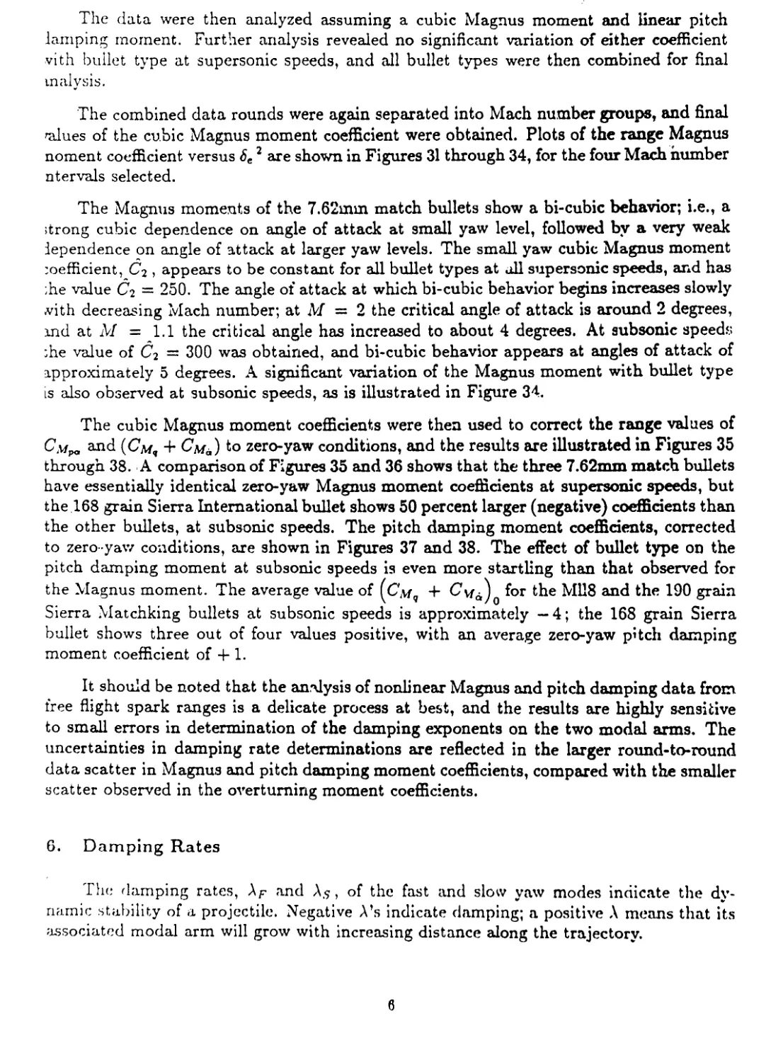
If the dependence of the Magnus moment and the pitch damping moment are cubic
in yaw level, the nonlinear variation of the two moment coefficients is of the general form:
C”pa = CxfpaQ + ^2 8 2
(3)
(Cw, + Cw<i) = (См, + Сл*а)0 4- d2<52
(4)
where CwPaQ and \Смч 4" ^e zero-yaw values of Magnus and pitch damp-
ing moment coefficients, respectively, and Ci and di are the associated cubic coefficients.
In Reference 3, it is shown that the non-linear coupling introduced through the data
reduction yields the following expressions for range values [Я-subscript] of C.wp and
(Cw, + См°у.
[C-v'pJa ” C-4paQ + + d2 8eTH (5)
[(Cv, 4- См6)]я = 4- 4- Ci^eur +
where the above effective squared yaws are defined as:
с 2
^TH
Г(к; o>2 - a-; ®'s2)
\fy Д (°F - o's2)
c 2 _
\<p'f 4- 4>'s) (К* - KF)'
Wf - *'s)
(S)
(9)
с 2
°ецн
(10)
The remaining symbols are defined in the List of Symbols in this report.
Preliminary analysis of the 7.62mm match bullet data showed strong nonlinearity in
the range values of Смрп and (C*.w7 4- Cv.J at angles of attack less than 2 degrees, for
both supersonic and subsonic speeds. The data rounds were separated into Mach number
groups, by bullet type, and an analysis was performed to determine the cubic coefficients at
both small and large yaw levels. No significant values of the cubic pitch damping moment
coefficient, di , could be found.
5
The data were then analyzed assuming a cubic Magnus moment and linear pitch
lamping moment. Further analysis revealed no significant variation of either coefficient
vith bullet type at supersonic speeds, and all bullet types were then combined for final
in al у sis.
The combined data rounds were again separated into Mach number groups, and final
values of the cubic Magnus moment coefficient were obtained. Plots of the range Magnus
noment coefficient versus 6e 2 are shown in Figures 31 through 34, for the four Mach number
ntervals selected.
The Magnus moments of the 7.62mm match bullets show a bi-cubic behavior; i.e., a
strong cubic dependence on angle of attack at small yaw level, followed by a very weak
dependence on angle of attack at larger yaw levels. The small yaw cubic Magnus moment
:oefficient, C2 , appears to be constant for all bullet types at all supersonic speeds, and has
;he value C2 = 250. The angle of attack at which bi-cubic behavior begins increases slowly
with decreasing Mach number; at M = 2 the critical angle of attack is around 2 degrees,
ind at M — 1.1 the critical angle has increased to about 4 degrees. At subsonic speeds
;he value of C2 — 300 was obtained, and bi-cubic behavior appears at angles of attack of
approximately 5 degrees. A significant variation of the Magnus moment with bullet type
is also observed at subsonic speeds, as is illustrated in Figure 34.
The cubic Magnus moment coefficients were then used to correct the range values of
C.v/po and (См, + to zero-yaw conditions, and the results are illustrated in Figures 35
through 38. A comparison of Figures 35 and 36 shows that the three 7.62mm match bullets
have essentially identical zero-yaw Magnus moment coefficients at supersonic speeds, but
the 168 grain Sierra International bullet shows 50 percent larger (negative) coefficients than
the other bullets, at subsonic speeds. The pitch damping moment coefficients, corrected
to zero yaw conditions, are shown in Figures 37 and 38. The effect of bullet type on the
pitch damping moment at subsonic speeds is even more startling than that observed for
the Magnus moment. The average value of (См, + Сиа)0 for the M118 and the 190 grain
Sierra Matchking bullets at subsonic speeds is approximately —4; the 168 grain Sierra
bullet shows three out of four values positive, with an average zero-yaw pitch damping
moment coefficient of + 1.
It should be noted that the analysis of nonlinear Magnus and pitch damping data from
free flight spark ranges is a delicate process at best, and the results are highly sensitive
to small errors in determination of the damping exponents on the two modal arms. The
uncertainties in damping rate determinations are reflected in the larger round-to-round
data scatter in Magnus and pitch damping moment coefficients, compared with the smaller
scatter observed in the overturning moment coefficients.
6. Damping Rates
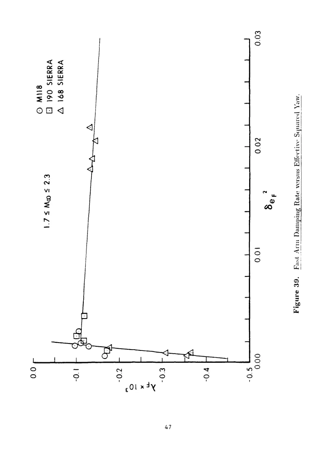
The damping rates, AF and A.$, of the fast and slow yaw modes indicate the dy-
namic stability of a projectile. Negative A’s indicate damping; a positive A means that its
associated modal arm will grow with increasing distance along the trajectory.
6
For a projectile whose Magnus or pitch damping moments are nonlinear with yaw
level, the damping rates also shew a nonlinear dependence on yaw, 4 Figures 39 through
42 illustrate the variations in damping rates with yaw level for the 7.62mm match bullets
at supersonic and subsonic speeds.
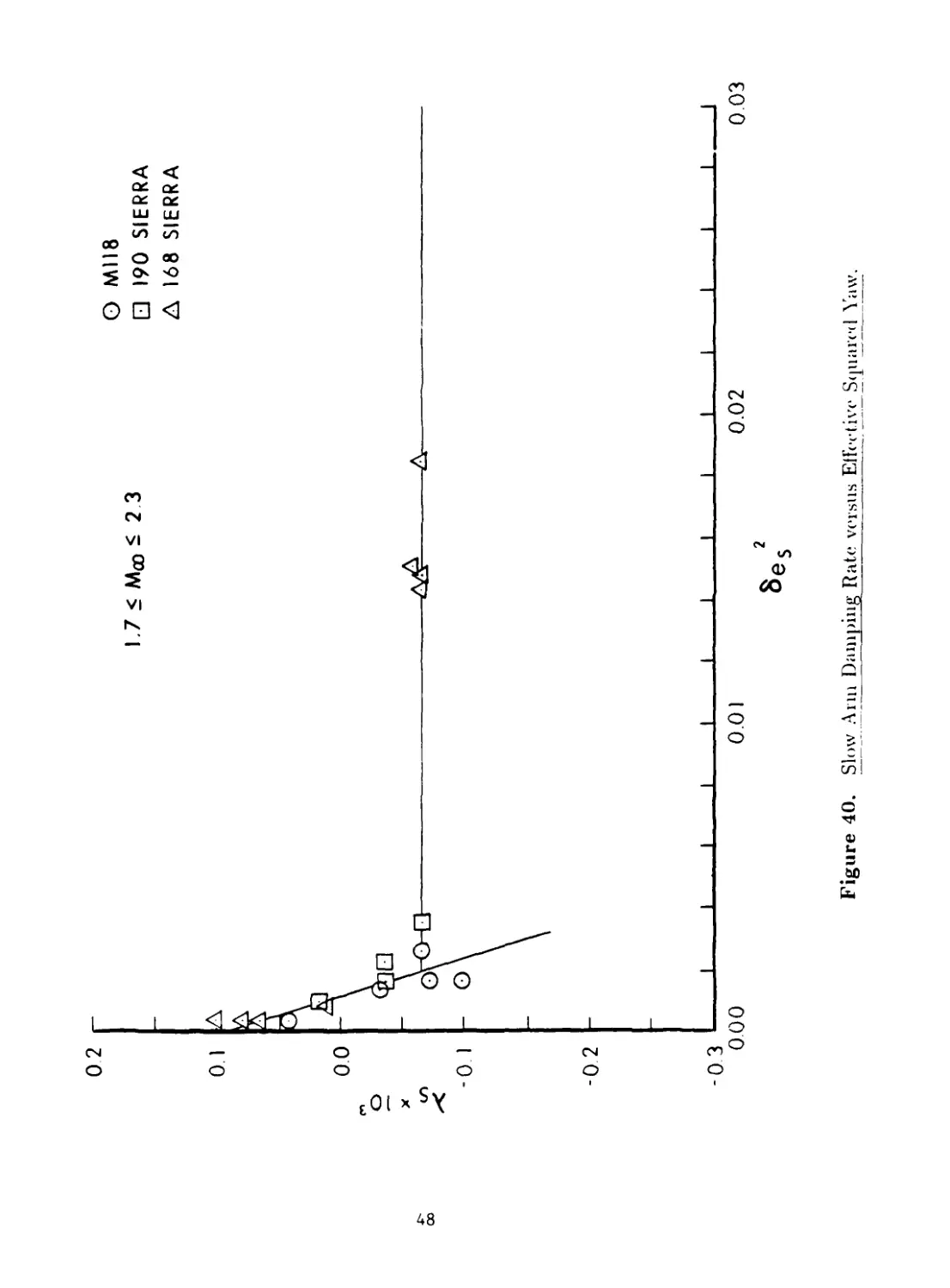
At supersonic speeds, the fast arm is always damped, for all the bullet types, at all
yaw levels tested. The slow arm is undamped at small yaw levels, but damped at larger
y.\w. Thus a slow arm limit cycle yaw is predicted at supersonic speeds; the expected
magnitude is about 2 degrees.
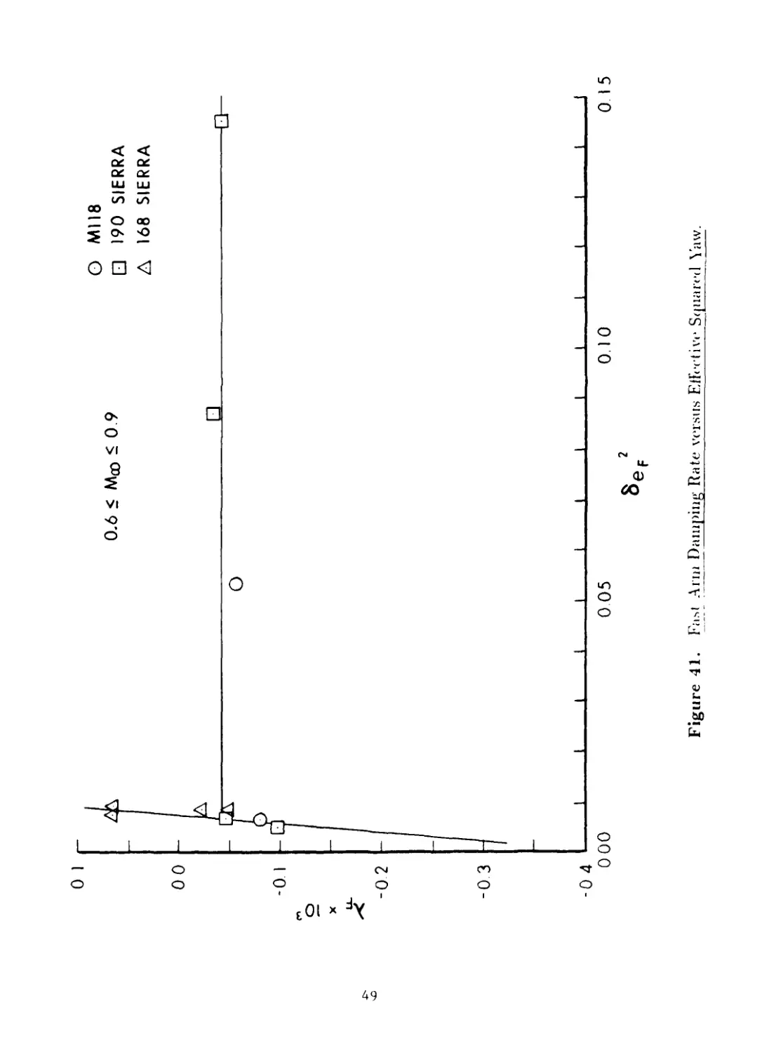
At subsonic speeds, the fast arm is damped at all yaw levels for the M118 and 190
grain Sierra Matchking bullets. The fast arm for the 168 grain Sierra International bullet
is essentially neutrally damped at small yaw, and is probably damped at larger yaw levels,
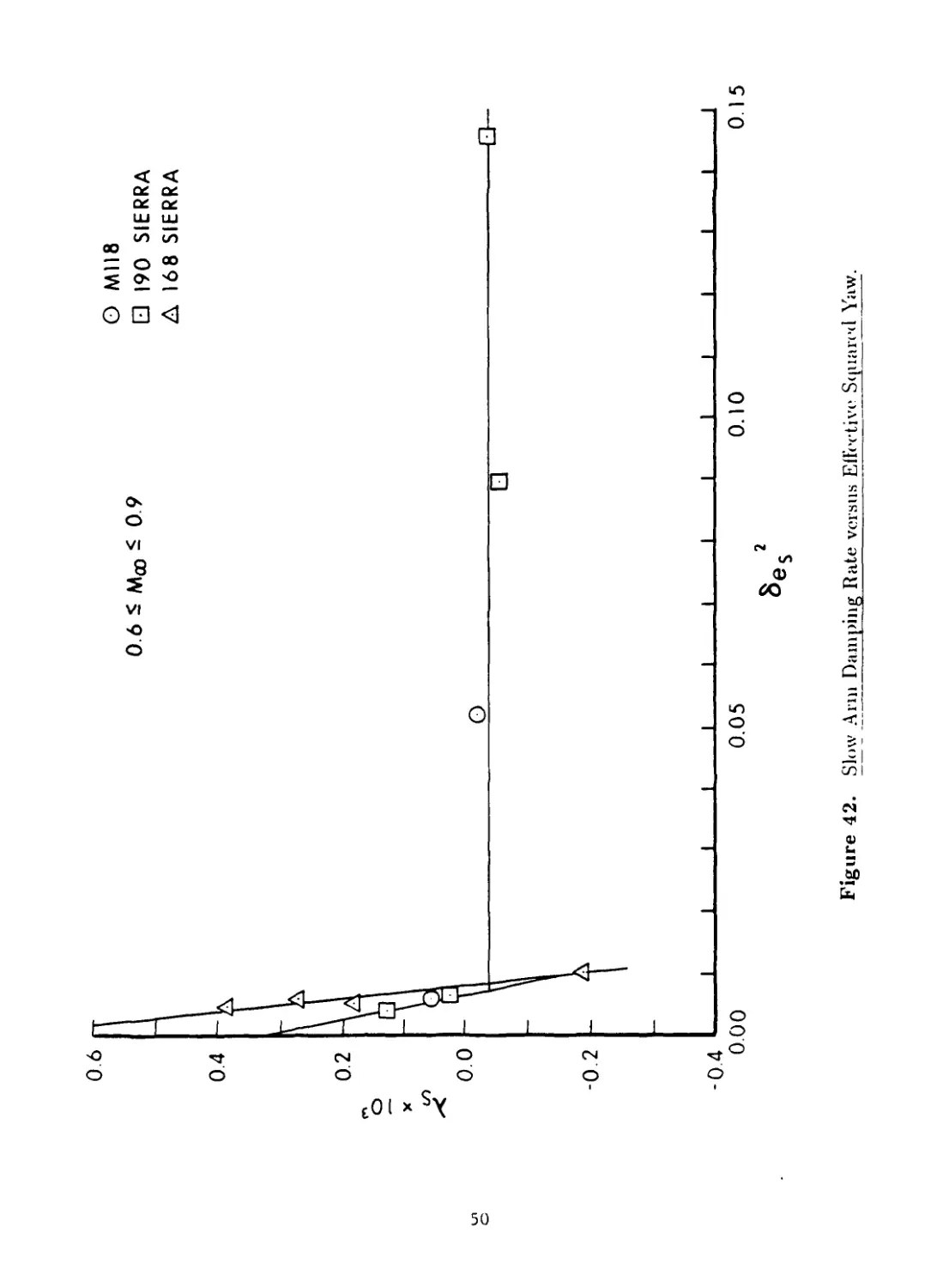
although no data were taken to substantiate this estimate. The slow arm at subsonic
speeds shows the same characteristic behavior observed at supersonic speeds; dynamically
unstable at small yaw, but stable at larger yaw levels. The predicted magnitude of the
slow arm limit cycle yaw at subsonic speeds is approximately 4.5 degrees for the M118
and 190 grain Sierra Matchking bullets, and about five degrees for the 168 grain Sierra
International (M852) bullet.
No direct measurement of limit cycle yaw at long range has been made for any of the
7.62mm match bullets. However, a two degree limit cycle yaw at supersonic speeds and
a four to five degree limit cycle yaw at subsonic speeds are consistent with unpublished
results obtained by Piddington for the similarly shaped 7.62mm, Ball M80 bullet, and with
results obtained by the author for 5.56mm M855 and SS-109 bullets. 5
IV. Conclusions
The Ml 18 Match (Special Ball) bullet has the lowest drag coefficient of the three
7.62mm match bullets tested, at supersonic speeds. The 190 grain Sierra Matchking bullet
shows four percent higher average drag coefficient than the Ml 18, and the 168 grain Sierra
International (M852) bullet shows eight percent higher average drag coefficient than the
Ml 18 design.
The round-to-round variation in drag coefficient for the 7.62mm match bullets is
significantly smaller than that observed for typical military ball bullets. The standard
deviation in Cd0 for the match bullets, at supersonic speeds, was found to be between 0.7
percent and 0.8 percent.
The three 7.62mm match bullets, launched at standard atmospheric conditions and
at muzzle velocities above 2500 feet per second, are gyroscopically stable from a 12 inch
twist of rifling. To insure an adequate margin of safety for cold weather (high air density)
conditions, a 10 inch twist rate should be selected for the M118 and 190 grain Sierra
Matchking bullets.
The nonlinear Magnus moment properties of the 7.62mm match bullets predict a slow
arm limit cycle yaw of approximately two degrees at supersonic speeds, growing to four
7
to five degrees at subsonic speeds. Although the predicted limit cycle yaws are consistent
with observations made for similarly shaped bullets, the long range flight dynamic results
need to be verified by an independent experiment.
Recommendations
It is recommended that a 12 inch twist of rifling be selected for firing the 168 grain
Sierra International (M852) bullet from the 7.62mm NATO cartridge case. A 10 inch twist
of rifling should be selected for the M118 or 190 grain Sierra Matchking bullets, to allow
a cold weather safety margin.
A long range limit cycle yaw test should be conducted with 7.62mm match bullets,
to verify the flight dynamic predictions made in this report.
8
Figure 1. Photograph of the BRL Free Flight Aerodynamics Range.
MIRROR
SPARK LIGHT SOURCE
MASTER CO-ORDINATE SYSTEM
Figure 2. Coordinate System for the BRL Aerodynamics Range.
ALL DIMENSIONS IN CALIBERS
( I CALIBER= 7.82 mm )
Figure 3. Sketch of the Ml 18 Match (Special Dall) Bullet.
ALL DIMENSIONS IN CALIBERS
( I CALIBER= 7.82 mm )
Figure 4. Sketch of the 190 Grain Sierra Matchking Bullet.
ALL DIMENSIONS IN CALIBERS
( I CALIBER= 7.82 mm )
Figure 5. Sketch of the 168 Grain Sierra International (M852) Pullet
Figure 6. Shadowgraph of M118 Bullet at Mach 2.2.
Figure 7. Shadowgraph of 190 Grain Sierra Bullet at Maeh 2.2.
Figure 8. Shadowgraph of 1G8 Grain Sierra Pullet at Mach 2.2.
Figure 10. Shadowgraph of 100 Grain Siena Bullet at Maeli l.S.
Figure 11. Slia< 1<Avgraph of 1GS Grain Siena Bullet at Mach 1.8.
Figure 12. SI>;мl«>\v<дг;11>I» of M11S Bullet at Miu'li 1. I.
Figure 13. Shadowgraph of 190 Grain Sierra Bullet at Marti l.-l.
I
Figure 11.
Shadowm aph of 1 GS Grain Sierra Bullet at Mach 1.4.
Figure 15. Shadowgraph of M1I8 Pullet at Mach 1.1.
Figure 16. Shadowgraph of 190 Grain Sierra Build at Mach 1.1.
Figure 17. Shadowgraph of 168 Grain Siena Pullet, at Mach 1.1.
0.5
0 MII8
0 0 1__I_Illi______। । ।_I__I__I J__I_I__I__I
0.6 0.8 1.0 1.2 1.4 1.6 1.8 2.0 2.2
MACH NUMBER
Figure 18. Zero-Yaw Drag Force Coefficient versus Mach Number, M118 Pullet.
0.5
□ 190 SIERRA
0.0 ----1----1----1----1----1___।_____।___।_____।___।_____I___।_____। । । ।
0.6 0.8 1.0 1.2 1.4 1.6 1.8 2.0 2.2
MACH NUMBER
Figure 19. Zero-Yaw Drag Forte Coefficient versus Mach Number, 190 Grain Sierra
Pullet.
0.5
A 168 SIERRA
rj
00
O.o 1 1 1 1 1 1 1 1____।----1____।----1-----•---1-----1---1----1
0.6 0.8 1.0 1.2 1.4 1.6 1.8 2.0 2.2
MACH NUMBER
Figure 20. Zero-Yaw Drag Force Coefficient versus Mach Number, 1G8 Grain Sierra
Pullet.
Figure 21. Yaw Drag Force Coefficient versus Mach Number, Ml 18 Pullet.
10
Figure 22. Yaw Drag Force <
□ 190 SIERRA
2.0
2.2
MACH NUMBER
Z'<efficient versus Mach Number, 190 Grain Sierra Bullet
10
A 168 SIERRA
0 -----1----1----1---1----1____I___I____I____I____I___I____1 I______। I I I
0.6 0.8 1.0 1.2 1.4 1.6 1.8 2.0 2.2
MACH NUMBER
Figure 23. Yaw Drag Force Coefficient versus Mach Number, 1G8 Grain Sierra Pullet
Figure 24. Zero-Yaw Overturning Moment Coefficient versus Mach Number, Ml 18
Bullet.
Figure 25. Zero-Yaw Overturning Moment Coefficient, versus Mach Number, 190 Grain
Sierra Bullet.
Figure 26. Zero-Yaw Overturning Moment Coefficient, versus Mach Number, 168 Grain
Sierra Bullet.
3.0
M118
LAUNCH
, ____I___I_____I___I_____I____I____I____I____I____I____I____I_____I___I_____I____L
0.6 0.8 1.0 1.2 1.4 1.6 1.8 2.0 2.2
LAUNCH MACH NUMBER
Figure 27. Gyroscopic Stability Factor versus Mach Number, Ml 18 Bullet.
LAUNCH
Figure 28. Gyroscopic Stability Factor versus Mach Number, 190 Grain Sierra Pullet
LAUNCH
Figure 29. Gyroscopic St ability Factor versus Mach Number, 168 Grain Sierra Pullet
3.5
3.0
0 MII8
□ 190 SIERRA
A 168 SIERRA
□
। о ----1-----1----1----1----1----1----1----1-----1----1----1----1----1----1----1-----1----1
06 0.8 1.0 1.2 1.4 1.6 1.8 2.0 2.2
MACH NUMBER
Figure 30. Lift Force Coefficient, versus Mach Number-
co
Figure 31. Magnus Moment Coefficient versus Effective Squared Yaw.
8е
Figure 32. Magnus Moment Coefficient versus Effective Squared Yaw.
Figure 33. Magnus Moment Coefficient versus Effective Squared Yaw.
rj
8e2
Figure 34. Magnus Moment Coefficient versus Effective Squared Yaw.
О MII8
□ 190 SIERRA
t I ।__________I___J____I—;—I----1----1----1---1----1---1-----1---1----1---1----1
0.6 0.8 1.0 1.2 1.4 1.6 1.8 2.0 2.2
MACH NUMBER
Figure 35. Zen> Yaw Magnus Moment Coefficient versus Mach Number
I
A 168 SIERRA
Figure 36. Zero-Yaw Magnus Moment Coefficient, versus Mach Number.
MACH NUMBER
Figure 37. Zero-\aw Pitch Damping Moment, Coefficient, versus Mach Number.
Figure 38. Zero Yaw Pitch Damping Moment Coefficient, versus Mach Number.
X
0 0
-0.1
-0.2
-0 3
-0.4
-0.5 L-
0.00
0 01
1.7 < Moo < 2.3
О MII8
□ 190 SIERRA
A 168 SIERRA
0 02
0.03
8 о ?
Figure 39. Fast Ann Damping Rate versus Effective Squared Yaw.
1.7 < Meo < 2 3
О ЛЛ118
□ 190 SIERRA
A 168 SIERRA
‘ 0
-0.1 - o
-0 2
-03
0.00
0.02
0.03
Figure 40. Slow Ann Damping Rate versus Effective Squared Yaw.
О 1
0.6 < М^ < 0.9
О М118
□ 190 SIERRA
А 168 SIERRA
00
-0 1
-0 2
-0 3
-04 L—
ООО
0 05
0.10
0 15
Figure 42. Slow Ann Damping Rate versus Effective Squared Yaw.
Table 1. Average Physical Characteristics of 7.62mm Match Bullets.
Projectile Reference Diameter (mm) Weight (grams) Center of Gravity (cal - base) Axial Moment of Inertia (gm-cm2) Transverse Moment of Inertia (gm-cm2)
M118 7.82 11.27 1.80 .716 6.78
190 Sierra 7.82 12.27 1.81 .787 7.68
168 Sierra 7.82 10.89 1.54 .722 5.38
51
Table 2. Aerodynamic Characteristics of the M118 Match Bullet.
Round Number Mach Number a-t (degrees) CD cLa Смра {Cylq + ) CP.v (cal - base)
13903 2.191 2.60 .3290 2.54 2.61 . 10 -5.81 2.66
13901 2.184 2.03 .3263 2.57 2.60 .23 -6.87 2.68
13902 2.181 2.10 .3219 2.55 2.59 . 13 -6.35 2.68
13906 1.848 1.01 .3361 2.78 — — -.17 -4.04 ——
13907 1.801 1.93 .3436 2.72 — .07 -5.99 — —
13912 1.407 6.64 .4629 2.89 2.12 .32 -8.10 2.92
13911 1.395 2.20 .3907 2.98 2.37 -.12 -3.16 2.88
13918 1.098 3.22 .4326 3.18 1.72 -.35 1.47 3.27
13920 1.086 7.60 .4968 3.09 1.64 . 16 -5.80 3.24
13929 .803 3.61 .1459 3.35 1.41 -.27 . 14 3.95
13930 .798 10.80 .2425 3.16 1.47 -.01 -2.30 3.65
52
Table 3. Aerodynamic Characteristics of the 190 Grain Sierra Matchking Bullet.
Round Number Mach Number (degrees) CD Сма CLa C\[pa (Cy[q + ) CPy (cal - base)
13904 2.208 1.43 .3306 2.82 — -.02 -7.85 — —
13905 2.138 3.25 .3411 2.83 3.02 .10 -6.95 2.65
13909 1.821 2.41 .3615 2.98 —— .05 -5.18 — —
13908 1.800 2.11 .3560 2.96 2.41 .01 -5.62 2.88
13914 1.440 2.37 .3971 3.18 2.23 -.13 -5.53 3.02
13915 1.347 4.52 .4390 3.19 2.11 .16 -7.51 3.06
13922 1.140 4.23 .4588 3.33 1.93 .02 -5.12 3.20
13921 1.114 2.93 .4394 3.35 — -.54 1.80 — —
13935 .763 3.73 . 1441 3.58 — — .05 -1.11 — *
13933 .732 3.16 .1452 3.57 1.64 -.58 2.82 3.81
13934 .673 . 1.06 .2844 3.15 1.58 . 15 -4.06 3.50
13931 .639 18.29 .3848 2.94 1.97 .03 -2.56 3.06
53
Table 4. Aerodynamic Characteristics of the 168 Grain Sierra International Bullet.
Round Mach CD Cs[a cLa Смра (Сщ CPy
Number Number (degrees) + ) (cal -
base)
12135 2.219 6.24 .3995 2.61 2.69 .10 -5.56 2.39
12130 2.217 1.63 .3404 2.69 — -.17 -4.40 —
12129 2.210 1.04 .3371 2.66 — -.23 -9.48 — —
12136 2.202 6.95 .4099 2.62 2.69 .10 -5.55 2.39
12138 1.826 1.29 .3664 2.89 —— -.41 -6.09 — —
12137 1.817 1.30 .3678 2.88 2.30 -.29 -9.22 2.62
12144 1.775 6.60 .4496 2.84 2.53 . 11 -5.78 2.49
12145 1.773 6.81 .4503 2.84 2.49 .09 -5.83 2.51
12151 1.450 1.75 .4111 3.06 — — — — —
12152 1.412 2.08 .4182 3.06 2.02 -.37 -3.72 2.79
13924 1.150 7.79 .5451 3.00 1.88 -.06 -4.65 2.78
13923 1.119 1.79 .4433 2.99 — — — •“ — —
13959 .866 4.12 .2033 3.17 — -1.79 13.84 —
13939 .817 4.18 .1713 3.36 1.50 -1.41 13.60 3.55
13936 .753 3.73 . 1592 3.35 1.39 -1.02 10.74 3.71
13941 .703 4.65 .1538 3.29 .66 -8.02
54
Table 5. Flight Motion Parameters of the Ml IS Match Bullet.
Round Number Mach Number s3 sd XF x IQ3 (1/cal) As x 103 (1/cal) A F A's °F (r/cal) Os (r/cal) Spin (r/cal)
13903 2.191 1.81 .84 -.106 -.065 .0276 .0316 .0161 .0032 . 183
13901 2.184 1.79 1.02 -.095 -.098 .0229 .0232 .0161 .0032 . 184
13902 2.181 1.77 .86 -.110 -.071 .0217 .0256 .0159 .0033 . 181
13906 1.848 1.66 -.16 -.164 .042 .0041 .0166 .0160 .0036 . 186
13907 1.801 1.61 .62 -.130 -.032 .0176 .0262 .0154 .0037 . 181
13912 1.407 1.58 1.01 -.101 -.106 .0808 .0738 .0155 .0038 . 183
13911 1.395 1.52 .46 -.108 -.007 .0172 .0332 .0152 .0040 . 182
13918 1.098 1.39 — -.060 .046 .0353 .0435 .0145 .0045 . 180
13920 1.086 1.43 .85 -.092 -.062 .0920 .0955 .0147 .0043 . 180
13929 .803 1.30 -2.01 -.078 .062 .0393 .0490 .0140 .0049 . 179
13930 .798 1.38 .73 -.055 -.017 . 1287 . 1358 .0144 .0045 . 179
55
Table 6. Flight Motion Parameters of the 190 Grain Sierra Matchking Bullet.
Round Number Mach Number s3 sd Af x 103 (1/cal) As x 103 (1/cal) A'f A's (r/cal) Q's (r/cal) Spin (r/cal)
13904 2.208 1.69 .30 -.171 .017 .0157 .0192 .0152 .0033 . 181
13905 2.138 1.72 .82 -.118 -.067 .0313 .0412 .0156 .0033 . 185
13909 1.821 1.61 .70 -.101 -.036 .0240 .0320 .0152 .0036 . 184
13908 1.800 1.61 .65 -.119 -.034 .0180 .0300 .0152 .0036 . 183
13914 1.440 1.54 .26 -.157 .014 .0143 .0372 .0150 .0038 . 184
13915 1.347 1.54 .78 -.121 -.058 .0440 .0580 .0150 .0038 . 184
13922 1.140 1.43 .61 -.113 -.022 .0475 .0560 .0143 .0042 . 180
13921 1.114 1.42 -10.2 -.108 .092 .0294 .0414 .0143 .0042 . 181
13935 .763 1.29 -- -.043 .029 .0440 .0478 .0134 .0048 . 178
13933 .732 1.30 — — -.098 . 134 .0316 .0444 .0136 .0047 . 179
13934 .673 1.52 1. 12 -.031 -.054 . 1753 . 1676 .0147 .0039 . 181
13931 .639 1.68 1.05 -.040 -.033 .2179 .2253 .0154 .0034 . 184
56
Table 7. Flight Motion Parameters of the 168 Grain Sierra International Bullet.
Round X umber Mach Number S3 sd Ap x 103 (l/cai) As x 103 (1/cal) A's (r/cal) °'s (r/cal) Spin (r/cal)
12135 2.219 1.95 .76 -.134 -.066 .0622 .0836 .0194 .0035 .171
12130 2.217 1.92 . 15 -.176 .016 .0091 .0258 .0195 .0036 . 172
12129 2.210 1.88 .00 -.355 .064 .0017 .0172 .0191 .0036 . 169
12136 2.202 1.94 .77 -.132 -.066 .0719 .0908 .0194 .0035 . 171
12138 1.826 1.78 -.38 -.305 .102 .0014 .0206 .0191 .0039 .171
12137 1.817 1.78 -.05 -.365 .079 .0016 .0213 .0190 .0039 .171
12144 1.775 1.84 .75 -.138 -.065 .0571 .0882 .0194 .0038 . 173
12145 1.773 1.84 .70 -.145 -.058 .0561 .0934 .0194 .0038 .173
12151 1.450 1.68 -.07 — — .0003 .0273 .0188 .0042 .171
12152 1.412 1.68 -.43 -.220 .079 .0044 .0339 .0187 .0042 .171
13924 1.150 1.89 .34 -.152 -.010 .0848 . 1045 .0203 .0038 . 180
13923 1.119 1.88 — — — — .0111 .0263 .0202 .0038 . 179
13959 .866 1.68 —— -.021 .387 .0199 .0621 .0192 .0043 .175
13939 .817 1.61 — — .064 .271 .0260 .0644 .0189 .0045 .175
13936 .753 1.63 — .066 . 181 .0316 .0555 .0192 .0045 . 176
13941 .703 1.64 1.33 -.047 -.187 .0648 .0473 .0191 .0044 .175
57
References
1. Braun, W.F., "The Free Flight Aerodynamics Range," US Army Ballistic Research
Laboratory, Aberdeen Proving Ground, Maryland, BRL Report No. 1048. August
1958. (AD 202249)
2. Murphy C.H., “Data Reduction for the Free Flight Spark Ranges,” US Army Ballistic
Research Laboratory, Aberdeen Proving Ground, Maryland, BRL Report No. 900,
February 1954. (AD 35833)
3. Murphy, C.H., “The Measurement of Non-Linear Forces and Moments by Means
of Free Flight Tests,” US Army Ballistic Research Laboratory, Aberdeen Proving
Ground. Maryland, BRL Report No. 974, February 1956. (AD 93521)
4. Murphy, C.H, “Free Flight Motion of Symmetric Missiles,” US Army Ballistic Research
Laboratory. Aberdeen Proving Ground, Maryland, BRL Report No. 1216, July 1963.
(AD 442757)
5. McCoy, R.L., “Aerodynamic and Flight Dynamic Characteristics of the New Family
of 5.56mm NATO Ammunition,” US Army Ballistic Research Laboratory, Aberdeen
Proving Ground, Maryland. MR Report No. 3476, October 1985. (AD A162133)
59
60
List of Symbols
Cj = cubic static moment coefficient
G = cubic Magnus moment coeffi- cient
CD Drag Force |(l/2)pV’S]
Cd0 = zero-yaw drag coefficient
Cdj'2 = quadratic yaw drag coefficient
Lift Force
[(1/2)P^S<5]
Positive coefficient: Force ir.
plane of total angle of attack.
at, ± to trajectory in direc-
tion of at. (at directed from
trajectory to missile axis.)
6 = sinoq.
CNa
c'Mpa
c"p„
Normed Force
[(l/2)p
Static Moment
[(l/2)p V2 Sd<5]
Magnus Moment
[(l/2)pV2Sd (pd/V) <5]
Magnus Force
[(l/2}l>V’S(pd/V)li]
Positive coefficient: Force in
plane of total angle of attack.
a(, ± to missile axis in direc-
tion of at. C.\’a = Clq + CD
Positive coefficient: Moment
increases angle of attack at.
Positive coefficient: Moment
rotates nose ± to plane of at
in direction of spin.
Negative coefficient: Force
acts in direction of 90е rota-
tion of the positive lift force
against spin.
61
List of Symbols (Continued)
For most exterior ballistic uses, where a ~ q. 3 % —r. the definition of the
damping moment sum is equivalent to:
(Cvr, 4- C.v/i) Damping Moment . . . — " Positive coefficient. A'loment [ (1/2) pV S d (qt d/V) ] increases angular velocity. Roll Damping Moment
= — ~~ Negative coefficient: Moment [(l/2)pV Sd(pd/V)i decreases rotational velocity.
Cpy = center of pressure of the nor- mal force, positive from base to nose
a. 3 = angle of attack, side slip
Oct = (a2 + 32)3 = sin-1 8, total angle of attack
= fast mode damping rate negative A indicates damping
= slow mode damping rate negative A indicates damping
P = air density
— fast mode frequency = slow mode frequency
c.rri. = center of mass
d = body diameter of projectile, reference length
= cubic pitch damping moment coefficient
= axial moment of inertia
62
List of Symbols (Continued)
ly — transverse moment of inertia
= magnitude of the fast yaw
mode
Ks = magnitude of the slow yaw
mode
I = length of projectile
m — mass of projectile
M = Mach number
p = roll rate
q, r = transverse angular velocities
Ъ = (q2 + r2)’
R = subscript denotes range value
s = dimensionless arc length along
the trajectory
S = (~d2/4), reference area
Srj = dynamic stability factor
Sg = gyroscopic stability factor
V
velocity of projectile
63
List of Symbols (Continued)
Et:<’crive \aw Parameters
b2
bQ
bQ
ЬёцТ
beFf{
8 2
°ецн
+ IQ
K? + A’/ -
Ap + 2 A 5"
2 IQ d- IQ
f Iу \ ( <i> p + Ф 5 ) ( A A i~ )
\ Q / . ( Q — Q)
f Q_\ (IQ tip - Q2)
Uy И - U)
( Q AQ - Q IQ )
(Q - <i>'s )
Distribution List
Copies Organization 12 Administrator Defense Technical Information Center ATTN: DTIC-DDA Cameron Station Alexandria. VA 22304-6145 1 HQDA (SARD-TR) Washington. DC 20310 1 Commander US Army Materiel Command ATTN: AMCDRA-ST 5001 Eisenhower Avenue Alexandria, VA 22333-0001 1 Commander US Army Laboratory Command ATTN: AMSLC-5L Adelphi, MD 20783-1145 1 Commander US Army Armament. Munitions and Chemical Command ATTN: AMCAR-ESP-L Rock Island. IL 61209-7300 1 Commander US Army Tank Automotive Command ATTN: AMSTA-TSL Warren, MI 48090 1 Commander L S Army Communications - Electronics Command ATTN: AMSEL-ED Fort Monmouth. NJ 07703 Copies Organization 1 Commander US Army Missile Command ATTN: AMSMI-RD Redstone Arsenal, AL 35898-5000 1 Commander US Army Missile Command ATTN: AMSMI-AS Redstone Arsenal. AL 35898-5500 1 Commander Armament Research. Development and Engineering Center US Army AMCCOM ATTN: SMCAR-MSI Picatinny Arsenal, NJ 07806-5000 1 Commander Armament Research. Development and Engineering Center US Army AMCCOM ATTN: SMCAR-TDC Picatinny Arsenal. NJ 07S06-5000 1 Director Benet Weapons Laboratory Armament Research. Development and Engineering Center US Army AMCCOM ATTN: SMCAR-LCB-TL Watervliet, NY 12189 1 Director US Army TRADOC Analysis Command ATTN:" ATAA-SL White Sands Missile Ranee. NM sxndo
65
Distribution List (Continued)
No. of
Copies Organization
1 Commandant
US Army Infantry School
ATTN: ATSH-CD-CSO-OR
Fort Benning, GA 31905-5400
1 Commander
US Army Aviation
Svstems Command
ATTN: AMSAV-DACL
4300 Goodfellow Blvd.
St. Louis. MO 63120-1798
1 Director
US Army Aviation Research
and Technology Activity
Ames Research Center
Moffett Field, CA 94035-1099
1 Air Force Armament Laboratory
ATTN: AFATL/DLODL
Eglin AFB, FL 32542-5000
1 AFWL/SUL
Kirtland AFB. NM 87117-6008
1 US Army JFK Center
ATTN: ATSU-CD-ML
Mr. S. Putnam
Fort Bragg, NC 28307-5007
1 Commander
US Army Materiel Command
ATTN: AMXSO
Mr. J. McKernan
5001 Eisenhower Avenue
Alexandria, VA 22333-0001
1 Commandant
US Army Infantry School
ATTN: ATSH-CD
Fort Benning, GA 31905-5400
No. of
Copies Organization
1 President
US Army Infantry Board
ATTN: ATZB-IB-SA
Mr. L. Tomlinson
Fort Benning, GA 31905-5800
1 Commander
Naval Sea Systems Command
ATTN: Code 62CE
Mr. R. Brown
Washington, DC 20362-5101
4 Commanding Officer
Naval Weapons Support Center
ATTN: Code 2021. Bldg. 2521
Mr. C. Zeller
ATTN: Code 2022
Mr. R. Henry
Mr. G. Dormick
Mr. J. Maassen
Crane. IN 47522-5020
1 Commanding General
MCDEC
ATTN: Code D091
Fire Power Division
Quantico. VA 22134-5080
1 US Secret Service
J. J. Rowley Training Center
ATTN: Mr. R. Lutz
9200 Powder Mill Road, RD 2
Laurel, MD 20707
66
Distribution List (Continued)
No. of
Copies Organization
14 Commander
Armament Research, Development
and Engineering Center
US Army AMCCOM
ATTN: SMCAR-SCJ
Mr. J. Ackley
Mr. V. Shisler
Mr. H. Wreden
Mr. J. Hill
ATTN: SMCAR-CCL-AD
Mr. F. Puzycki
Mr. W. Schupp
Mr. R. Mazeski
Mr. D. Conway
ATTN: SMCAR-CCL-FA
Mr. R. Schlenner
Mr. J. Fedewitz
Mr. P. Wyluda
ATTN: SMCAR-SCA-AP
Mr. W. Bunting
Mr. P. Errante
ATTN: SMCAR-ATE-AP
Mr. R. Kline
Picatinny Arsenal. NJ 07S06-5000
Aberdeen Proving Ground
Director, USAMSAA
ATTN: AMXSY-D
AMXSY-MP
Mr. H. Cohen
AMXSY-J
Mr. K. Jones
Mr. M. Carroll
Mr. J. Weaver
Mr. E. Heiss
AMXSY-GI
Mr. L. DeLattre
Commander, USATECOM
ATTN: AMSTE-TO-F
Cdr, CRDEC, AMCCOM
ATTN: SMCCR-MU
SMCCR-RSP-A
Mr. M. Miller
Mr. J. Huerta
SMCCR-SPS-IL
Director, USAHEL
ATTN: SLCHE-IS
Mr. B. Corona
Mr. P. Ellis
Director, USACSTA
ATTN: STECS-AS-LA
Mr. G. Niewenhous
67
USER EVALUATION SHEET/CHANGE OF ADDRESS
This laboratory undertakes a continuing effort to Improve the quality of the reports It publlsr.es. Your
comments.answers oelow will aid us in our efforts.
1. Toes this report satisfy a need? (Comment on purpose, related project, or other area of Interest for wnicn
tne report will oe used.) _____________________________________________________________________________________
2. How, specifically. Is the report being used? (Information source, design data, procedure, source of Ideas,
etc.) _________________________________________________________________________________________________________
3. Has the information in this report led to any quantitative savings as far as man-hours or dollars saved,
operating costs avoided, or efficiencies achieved, etc? If so, please elaborate.
4. General Comments. What do you think should be changed to improve future reports? (Indicate oranges to
organization, technical content, format, etc.)_________________________________________________________________
BRL Report Number Division Symbol
Check here if desire to be removed from distribution list.
Check here for address change.
Current address: Organization ____________________________________________
Address
FOLD AND TAPE CLOSED---------------------------
Director
U.S. Army Ballistic Research Laboratory
ATTN: SLCBR-DD-T(NET)
Aberdeen Proving Ground, MD 21005-5066
ofHOAi susiness
PENAUf РО» PPtvAtt USE $300
BUSINESS REPLY LABEL
FIRST CIASS PERMIT NO. >2062 WASHINGTON О C
POSTAGE Mil 0E PAID 0y DEPARTMENT Of ’HE army
Director
NO POSTAGE
NECESSARY
IF MAILED
IN THE
UNITED STATES
U.S. Army Ballistic Research Laboratory
ATTN: SLCBR-DD-T(NEI)
Aberdeen Proving Ground, MD 21005-9989