/


Tags: military affairs engineering design handbook
Year: 1967


Text
ШАКОН AND DEVELOPMENT
OE MATERIEL
ENGINEERING DESIGN HANDBOOK
GUNS SERIES
GUNS—GENERAL
ПШаЕШЖ
Г APR 19 1966
LfeEITOb’
и
'T ri ’ ILNT UNCI,I h'i I'll
. >чу>. ^тпл«**^«?^'<тдтм«гят^^г№^явям1гаямм№
*"- ”. e ARMY МАТ6.71ЕГ COMMAND
AUGUS7'
19C
PREFACE
This handbook has been prepared as one of a series on Guns and forms part
of the Engineering Design Handbook Series of the Army Materiel Command.
This handbook is intended to serve as an introduction to the series on Guns.
It presents the elements of which guns are constituted and the usual variations
in form '' these elements; surveys the current and recently used types designed
to serve van 'us military purposes; defines a number of terms used in referen'*"
to guns and their operation; and introduces physical, mechanical era icgL,
problems encountered in design, for which specific procedures for solution will
be presented in the other handbooks of the series.
The first draft of this handbook was prepared at Watervliet Arsenal of
the Weapons Command. Assistance by review services and the supplying of
additional material was obtained from Springfield Armory of the Weapons
Command and Frankford Arsenal of the Munitions Command. Final editing
and arranging was by the Engineering Handbook Office of Duke University,
prime contractor to the Army Research Office—Durham.
Agencies of the Department of Defense, having need for Handbooks, may
submit requisitions or official requests directly to the Publications and Repro-
duction Agency, Jjetterkenny Army Depot, Chambersburg, Pennsylvania 17201.
Contractors should submit such requisitions or requests to their contracting
officers.
Comments and suggestions on this handbook are welcome and should be
addressed to Army Research Office—Durham, Box CM, Duke Station, Durham,
North Carolina 27706.
TABLE OF CONTENTS
Paragraph Page
PREFACE ................................................ i
LIST OF ILLUSTRATIONS................................. vii
CHAPTER 1
INTRODUCTION
1-1 Scope of This Handbook................................ 1-1
1-2 Early Development .................................... 1-1
1-3 Smooth-bore Era ...................................... 1-1
1-4 Rifling Adopted ..................................... 1-3
1-5 Breech Loading Developed.............................. 1-3
1-6 Early United States Developments...................... 1-3
1-6.1 Fixed Artillery .................................. 1-3
1-6.2 Mobile Artillery.................................. 1-4
1-6.3 Small Arms........................................ 1-4
1-7 Development of Automatic Weapons............................ 1-4
1-8 Guns and History............................t............... 1-5
1-9 Gun Terminology....................................... 1-5
1-10 Major Elements of the Gun............................. 1-5
1-10.1 Gun Tube or Barrel............................... 1-5
1-10.2 Breech Closure .................................... 1-6
1-10.3 Breech Ring or Receiver.......................... 1-6
1-10.4 Firing Mechanism .................................. 1-6
1-10.5 Extracting Mechanism .............................. 1-6
1-10.6 Breech Operating Mechanism......................... 1-6
1-10.7 Loading Mechanism.................................. 1-6
1-10.8 Muzzle Devices..................................... 1-6
CHAPTER 2
CLASSIFICATION AND DESCRIPTION BY
MILITARY CHARACTERISTICS OR USAGE
2-1 General............................................... 2-1
2-2 Gun (General) ...................................... 2-1
2-2.1 Cannon (General) .................................. 2-1
2-2.1.1 Gun (Specific) ................................. 2-1
2-2.1.2 Mortar ......................................... 2-1
2-2.1.3 Howitzer ..................................... 2-1
2-2.1.4 Recoilless Cannon .............................. 2-5
2-2.1.5 Cannon (Specific) ............................ 2-5
2-2.1.6 Automatic Cannon ............................... 2-5
2-2.2 Small Arms ....'................................... 2-5
2-2.2.1 Pistol ......................................... 2-5
ii
TABLE OF CONTENTS (continued)
Paragraph Page
2-2.2.2 Shotgun ............................................. 2-5
2-2.2.3 Rifle ................................................. 2-5
2-2.24 Carbine .......................................... 2-6
2-2.2.5 Submachine Gun ....................................... 2-6
2-2.2.6 Machine Gun........................................... 2-6
CHAPTER 3
CLASSIFICATION AND DESCRIPTION BY
DESIGN FEATURES
3-1 Common Features .............................................. 3-1
3-2 Methods of Classification .................................. 3-1
3-3 Classification by Ammunition Type............................. 3-1
3-3.1 Fixed Ammunition ........................................ 3-1
3-3.2 Semifixed Ammunition.................................... 3-1
3-3.3 Separated Ammunition ...................................... 3-3
33.4 Separate Loading Ammunition................................ 3-4
3-4 Classification by Shape of Bore............................... 3-4
3-4.1 Cylindrical Bore......................................... 3-4
3-4.2 Tapered (Squeeze) and Choke Bores......................... 3-5
34.2.1 Tapered (Squeeze) Bore................................. 3-5
34.2.2 Choke Bore ............................................ 3-5
34.3 Classification by Surface of Bore........................... 34
34.3.1 Smooth Bore ......................................... 3-5
34.3.2 Rifled Bore .......................................... 3-5
3-5 Classification by Degree of Propellant Confinement................... 3-5
3-5.1 Open-breech Closures (Recoilless) ......................... 3-5
3-5.2 Closed Breech.............................................. 3-6
3-5.2.1 Permanent Closures..................................... 3-6
3-5.2.2 Mobile Closures ....................................... 3-6
3-5.2.2.1 Plug-type Breechblock Closures...................... 3-7
3-5.2.2.1.1. Obturation....................................... 3-7
3-5.2.2.1.2 Locking Arrangement.............................. 3-7
3-5.2.2.1.3 Ignition ...................................... 3-8
3-5.2.2.1.4 Operating Mechanism.............................. 3-9
3-5.2.2.2 Bolt-type Breechblock Closures...................... 3-9
3-5.2.2.2.1 Nonlocking Bolts (Blowback) .................... 3-10
3-5.2.2.2.2 Locking Bolts................................... 3-10
3-5.2.2.2.3 Delayed Action (Hesitation) Bolts................3-10
3-5.2.2.3 Sliding Breechblock Closures ...................... 3-12
3-5.2.2.3.1 Cannon Applications............................. 3-12
3-5.2.2.3.2 Small Arms Applications ....................... 3-12
3-5.2.2.4 Eccentric Screw Closures (Nordenfeld) ............. 3-13
3-6 Classification by Degree of Self Action..............................3-14
3-6.1 May.ual .................................................. 3-14
3-6.2 Automatic .................................................3-14
3-6.3 Semiautomatic ......................................... 3-14
iii
TABLE OF CONTENTS (continued)
Paragraph Page
3-7 Classification by Source of Power Operation .......................3-14
3-7.1 Externally Powered ..................................... 3-15
3-7.2 Gas Operation.......................................... 3-15
3-7.3 Recoil Operation ....................................... 3-15
3-7.3.1 Short Recoil ........................................ 3-15
3-7.3.2 Long Recoil ....................................... 3-15
3-7.4 Blowback Operation .................................... 3-16
3-8 Classification by Type of Feed ................................... 3-16
3-8.1 Cannon Feeding Methods.................................. 3-16
3-8.1.1 Nonautomatic Feeding................................. 3-16
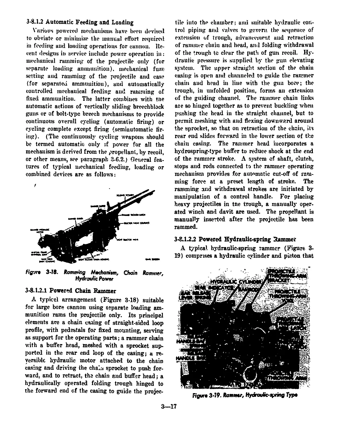
3-8.1.2 Automatic Feeding and Loading.........,.............. 3-17
3-3.1.2.1 Powered Chain Rammer ,............................ 3-17
3-8.1.2.2 Powered Hydraulic-spring Rammer................... 3-17
3-8.1.2.3 Power Rammer and Fuze Setter—Separate Units ... 3-19
3-8.1.2.3.1 Fuze Setter................................... 3-19
3-8.1.2.3.2 Rammer ....................................... 3°19
3-8.1.2.4 Combined Fuze Setter-Rammer....................... 3-20
3-8.1.2.5 Magazine Type Loader-Rammer....................... 3-21
3-8.1.2.6 Automatic Loader for Clipped Ammunition............ 3-24
3-8.2 Small Arms Feeding Methods.............................. 3-24
3-8.2.1 Manual Feeding...................................... 3-24
3-8.2.2 Magazine Feeding Methods............................. 3-25
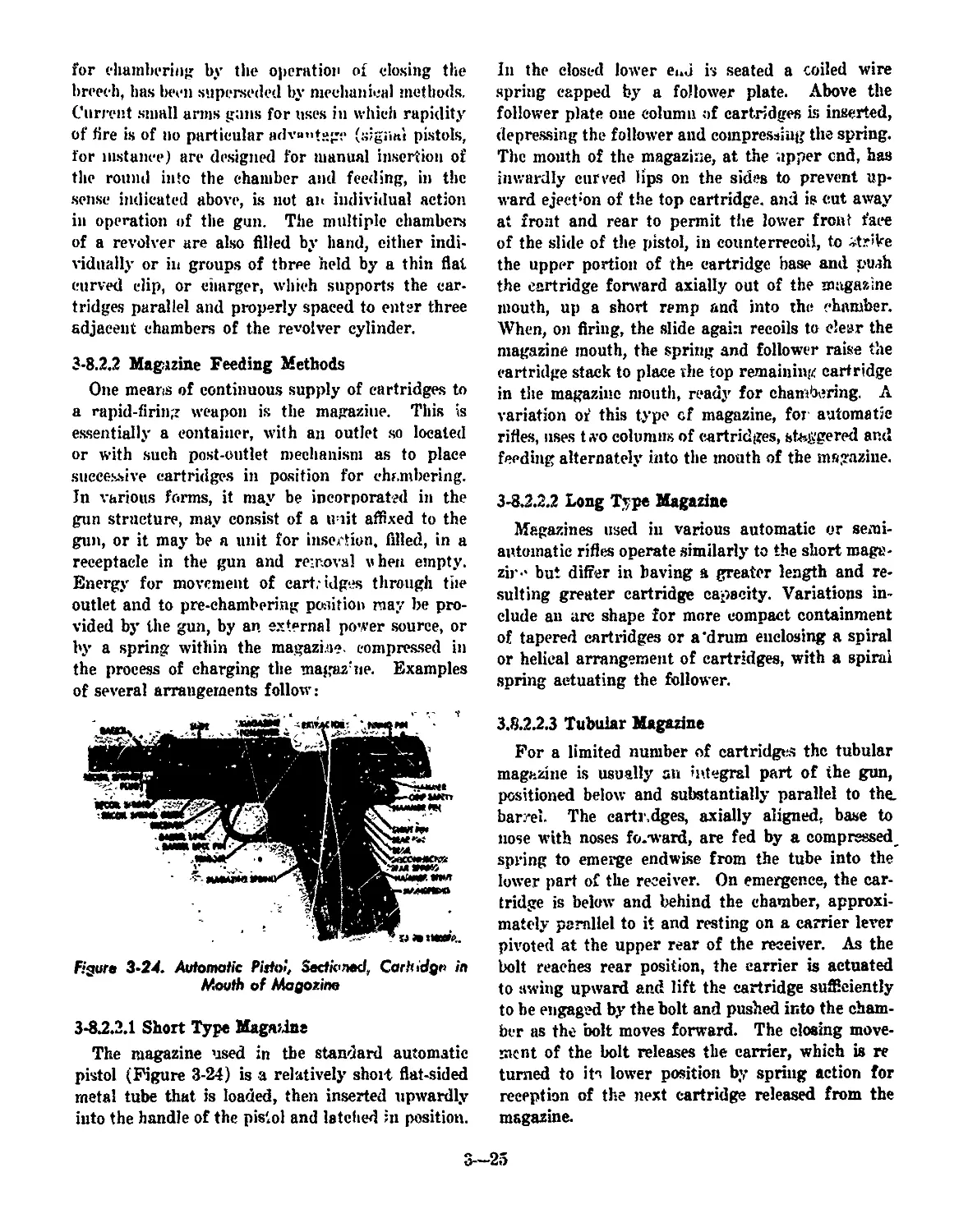
3-8.2.2.1 Short Type Magazine .............................. 3-25
3-8.2.2.2 Long Type Magazine ............................... 3-25
3-8.2.2.3 Tubular Magazine ................................. 3-25
3-8.2.2.4 Clip Feeding...................................... 3-26
3-8.2.3 Belt Feeding......................................... 3-26
3-8.2.3.1 Fabric Belts ..........................».......... 3-26
3-8.2.3.2 Metallic Belts.................................... 3-26
3-8.2.4 Hopper Feeding....................................... 3-27
CHAPTER 4
GUN INTERIOR REGIONS AND CHARACTERISTICS
4-1 Major Divisions and General Functions....................... 4-1
4-2 Chamber Characteristics ................................... 4-1
4-2.1 Size ot Chamber.......................................... 4-1
4-2.2 Shape of Chamber....................................... 4-2
4-2.2.1 Effect on Prapeilant Performance...................... 4-2
4-2.2.2 Effect on Gun Structure............................... 4-2
4-2.2.3 Effect on Other Features of Design.................... 4-2
4-3 Bore Characteristics ....................................... 4-2
4-3.1 Caliber................................................ 4-3
4-3.2 Bore Length ........................................ 4-3
4-3.3 Bore Surface Detail..................................... 4-3
4-4 Transition Region .......................................... 4-4
4-4.1 General Contours and Functions........................... 4-4
TABLE OF CONTENTS (continued)
Paragraph Page
44.2 Details of Contour and Function......................... 4-4
44.2.1 Forcing Cone ........................................ 4-4
44.2.2 Bullet Seat .......................................... 44
4-4.2.3 Band Cylinder......................................... 44
44.2.4 Case Clearance Shoulder.............................. 4-5
44.2.5 Band Rear Slope...................................... 4-5
44.2.6 Centering Slope ..................................... 4-5
44.2.7 Chamber Front Slope................................ 4-5
CHAPTER 5
INTER-RELATION WITH PROPELLANTS
5-1 General Considerations..................................... 5-1
5-2 Propellant Compositions and Characteristics................ 5-1
5-2.1 Composition........................................... 5-1
5-2.2 Total Energy ........................................... 5-1
5-2.3 Burning Rate and Pressure............................. 5-2
5-2.4 Stability............................................... 5-2
5-2.5 Mechanical Properties .................................. 5-2
5-2.6 Feasibility of Manufacture.............................. 5-2
5-2.7 Costs.................................................. 5-2
5-3 Granulation........................................................ 54
5-3.1 Purpose ................................................ 54
5-3.2 Effect of Grain Form..................................... 54
5-3.3 Effect of Web Thickness................................. 54
54 Form of Charge............................................. 5-5
5-4.1 Cased Charges..................................... 5-5
5-4.2 Noncased Charges ....................................... 5-5
5-5 Ignition Systems .......................................... 5-6
5-5.1 General .............................................. 5-6
5-5.2 Relation Between Ignition and Muzzle Velocity........... 5-6
5-5.3 Pressure Waves ....................................... 5-6
5-5.4 Primers and Igniters.................................... 5-6
5-5.4.1 Voids ............................................... 5-7
5-5.4.2 Ignition As a Factor in Design ...................... 5-7
5-6 Smoke and Flash................................................... 5-7
5-6.1 Causes ............................................. 5-7
5-6.2 Disadvantages........................................... 5-7
5-6.3 Correlation With Grain, Form, Charge and Tube Design .. 5-7
5-6.4 Elimination of Flash and Smoke......................... 5-8
5-6.1.1 Flash ............................................... 5-8
5-6.4.2 Smoke .............................................. 5-8
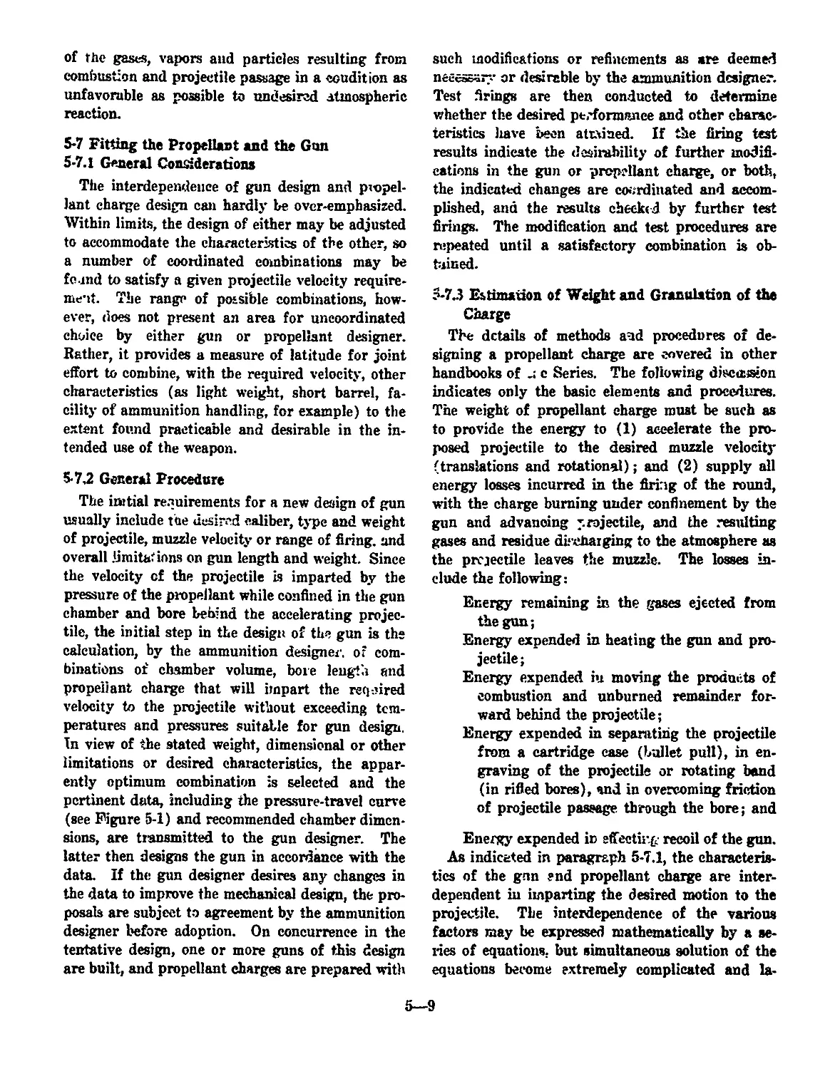
5-7 Fitting the Propellant and the Gun.............................. 5-9
5-7.1 General Considerations.................................. 5-9
5-7.2 General Procedure....................................... 5-9
5-7.3 Estimation of Weight and Granulation of the Charge...... 5-9
5-7.4 Correlation With Chamber Design...................... 5-10
v
TABLE OF CONTENTS (continued)
Paragraph
Page
CHAPTER fi
GUN DESIGN PROBLEMS
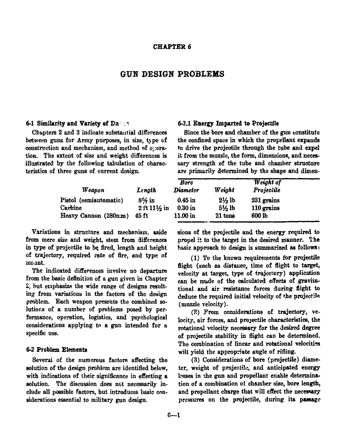
6-1 Similarity and Variety of Design........................ 6-1
6-2 Problem Elements........................................ 6-1
6-2.1 Energy Imparted to Projectile........................ 6-1
6-2.2 Accuracy .......................................... 6-2
6-2.2.1 Yaw .............................................. 6-2
6-2.2.2 Whip ............................................ 6-2
6-2.3 Erosion ........................................... 6-2
6-2.4 Firing Rate.......................................... 6-3
6-2.5 Weight............................................... 6-3
6-2.6 Safety ............................................... 64
6-2.7 Obturation .......................................... 6-4
6-2.8 Blast and Flash ..................................... 6-5
6-2.8.1 Blast............................................. 6-5
d-2.8.2 Flash .......................................... 6-5
6-2.8.S Muzzle Brakes .................................. 6-5
6-2.9 Bore Evacuation.................................... 6-5
6-2.10 Space Limitations ................................... 6-6
6-2.11 Temperature ..................................... 6-6
6-2.12 Manufacturing Limitations ........................... 6-6
6-2.13 Strategic Material Limitations ...................... 6-6
6-2.14 Logistic Requirements................................ 6-7
6-2.15 Maintenance Requirements ............................ 6-7
6-3 Balanced Solution................................... 6-7
64 Reasons for New Weapons................................. 6-7
GLOSSARY ............................................ G-l
REFERENCES ............................................ R-l
LIST OF ILLUSTRATIONS
Figure No. Title Page
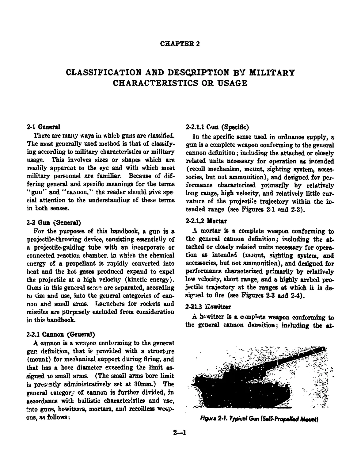
2-1 Typical Gun (Self-Propelled Mount) ...................... 2-1
2-2 Typical Gun Trajectories................................. 2-2
2-3 Typical Smooth-bore M >rtar.............................. 2-3
2-4 Typical Mortar Trajectory ............................. 2-3
2-5 Typical Howitzer (Self-Propel'ed Mount).................. 2-3
2-6 Typical Howitzer Trajectories............................. 24
2-7 Typical Recoilless Rifle ................................ 2-5
2-8 Typical Pistol........................................... 2-5
2-9 Typical Rifle (Semiautomatic) ........................... 2-6
2-10 Typical Machine Gun............................................ 2-6
3-1 Gun Tube (Barrel), Cartridge Case and Projectile—
Typical Features and Terminology.................................... 3-2
3-2 Typical Fixed Artillery Ammunition..................... 3-3
3-3 Typical Fixed Small Arms Ammunition .................... 3-3
34 Typical Semifixed Artillery Ammunition.................. 3-3
3-5 Typical Separated Artillery Ammunition ................ 34
3-6 Typical Separate Loading Artillery Ammunition............ 34
3-7 Riflled Bore (Muzzie) .......................................... 3-5
3-8 Plug-type Cannon Breech Closure—Stepped Thread,
Horizontal Swing ................................................... 3-7
3-9 Percussion Firing Mechanism for Cannon, Screw-type........ 3-8
3-19 Cannon Firing Lock, Electric or Percussion Ignition,
Sliding-wedge Type ................................... 3-8
3-11 Bolt-type Brw Ж Closure (Automatic Gun), Bolt
Closing to Chamber the Cartridge.................................... 3-9
3-12 Bolt-type Bi.ech Closure (Automatic Gun), Bolt Nearing
Closed (Firing) Position............................................ 3-9
3-13 Bolt-type Breech Closure (Automatic Gun), Bolt Nearing
Full Opening, Ejecting Fired Case..................... 3-10
3-14 Typical Sliding-block Breech Closure, Cannon.................. 3-11
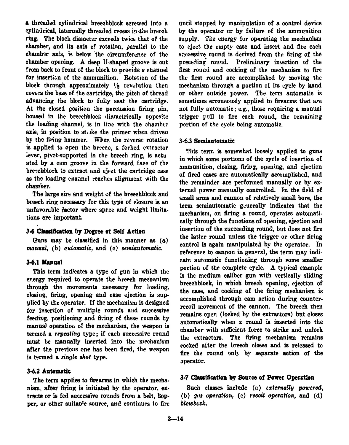
3-15 Typical Revolver, in Section, Cartridges Chambered
in Cylinder ......................................... 3-13
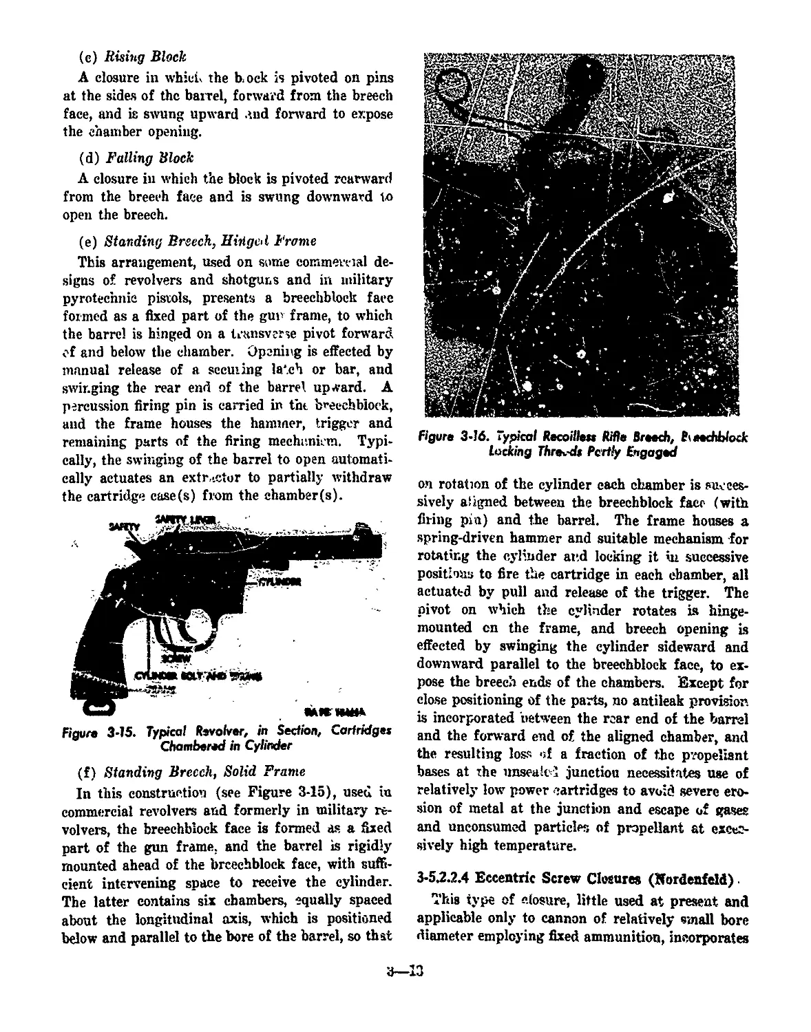
3-16 Typical Recoilless Rifle Breech, Breechblock Locking
Threads Partly Engaged ............................................ 3-13
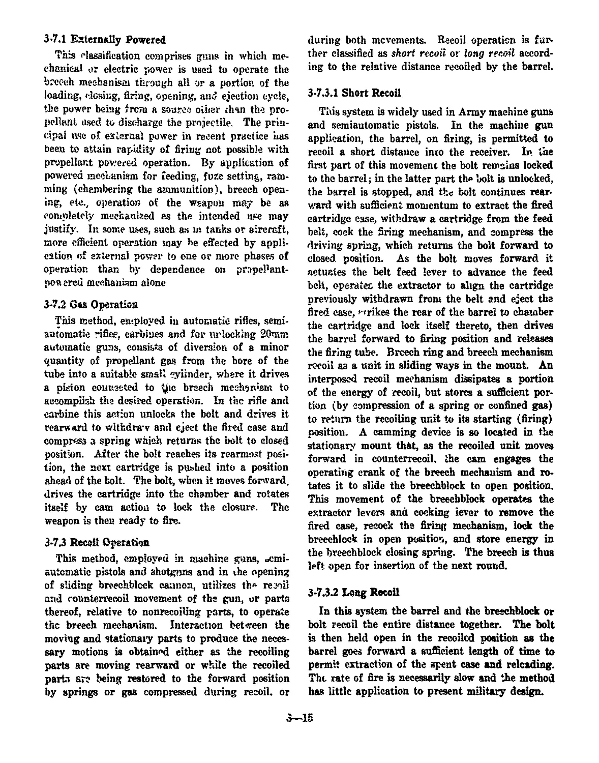
3-17 Bolt Unlocked to Permit Blowback Opening................ 3-16
3-18 Ramming Mechanism, Chain Rammer, Hydraulic Power.....347
3-19 Rammer, Hydraulic-spring Type........................... 3-17
3-20 Power Rammer, Arm Type, With Separate Fuze Setter
Unit, Single Electric Motor Driving Both Units....... 3-18
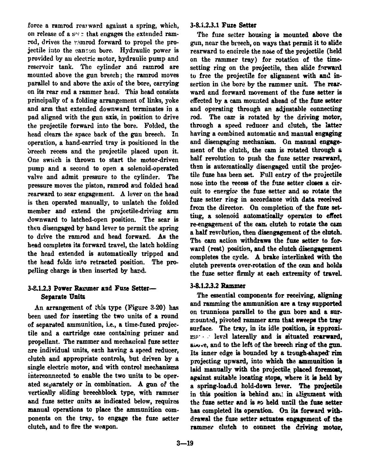
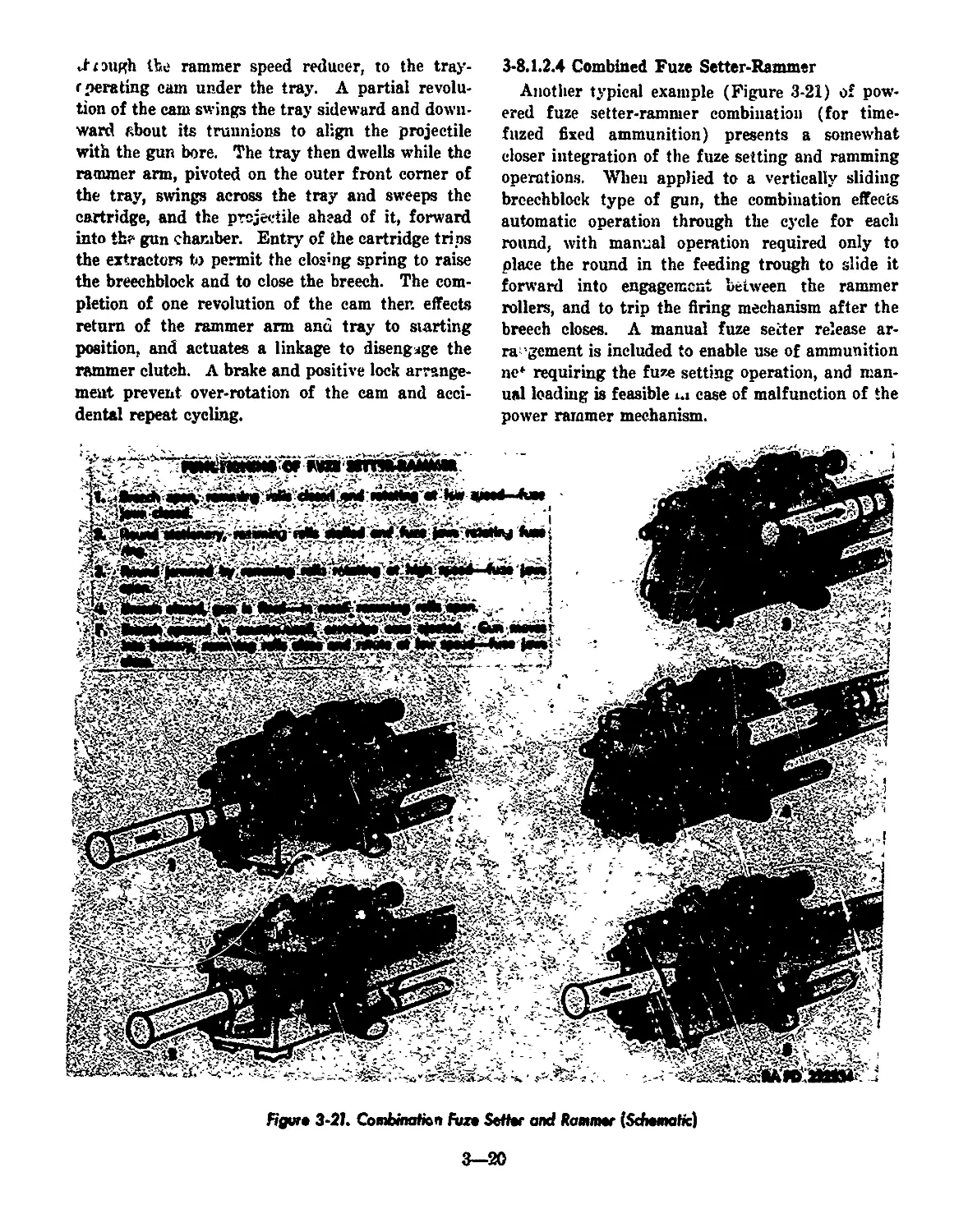
3-21 Combination Fuze Setter and Rammer (Schematic).......... 3-20
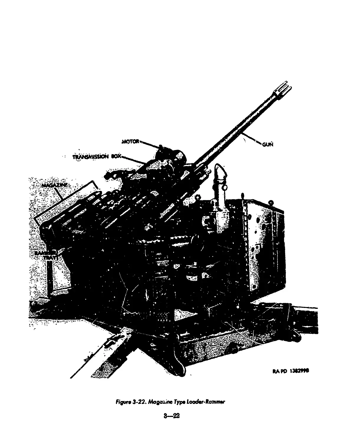
3-22 Magazine Type Loader-Rammer............................. 3-22
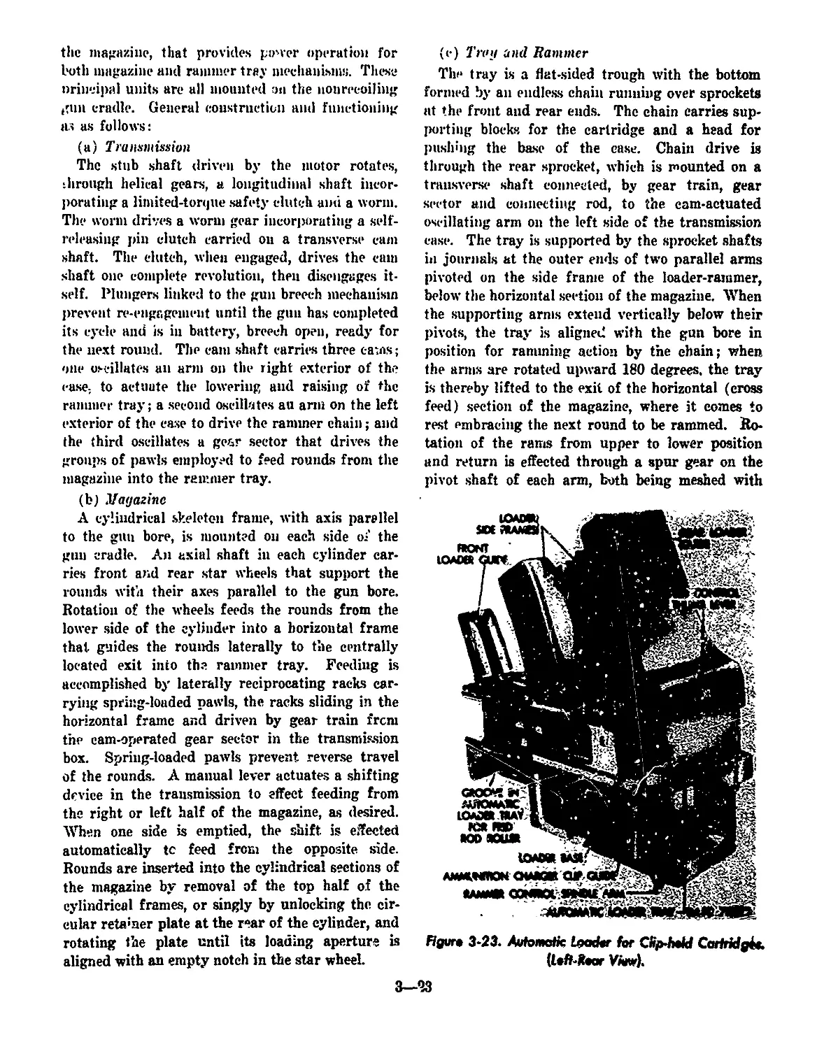
3-23 Automatic Loader for Clip-held Cartridges............... 3-23
vii
LIST OF ILLUSTRATIONS (continued)
Figure No. Title Page
3-24 Automatic Pistol, Sectioned, Cartridge in
Mouth of Magazine............................................ 3-25
5-1 Pressure-Travel Curves. Indicating Shape Variations
Resulting from Differing Propellant Granulations............... 5-3
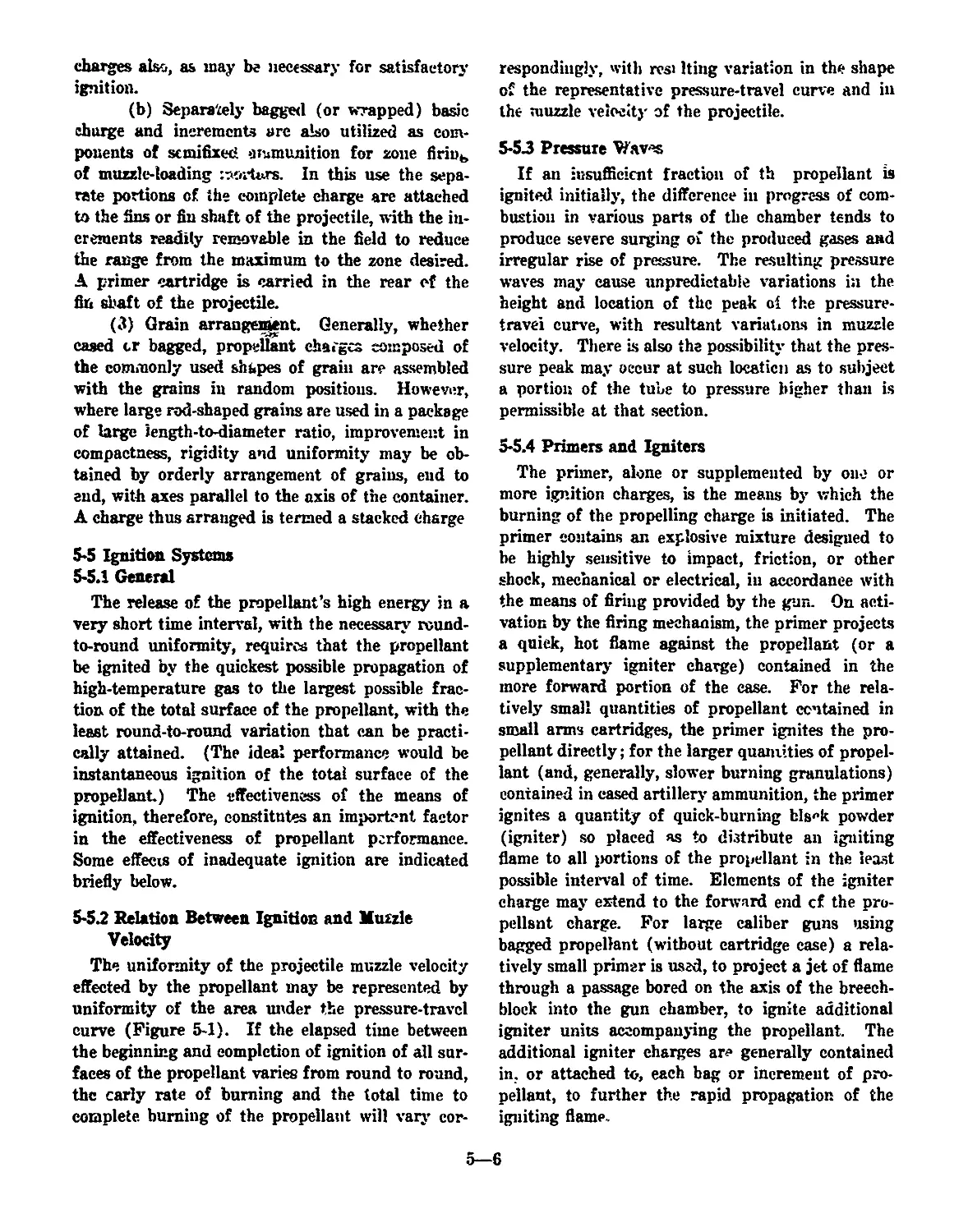
5-2 Flash Hider ......................................... 5-8
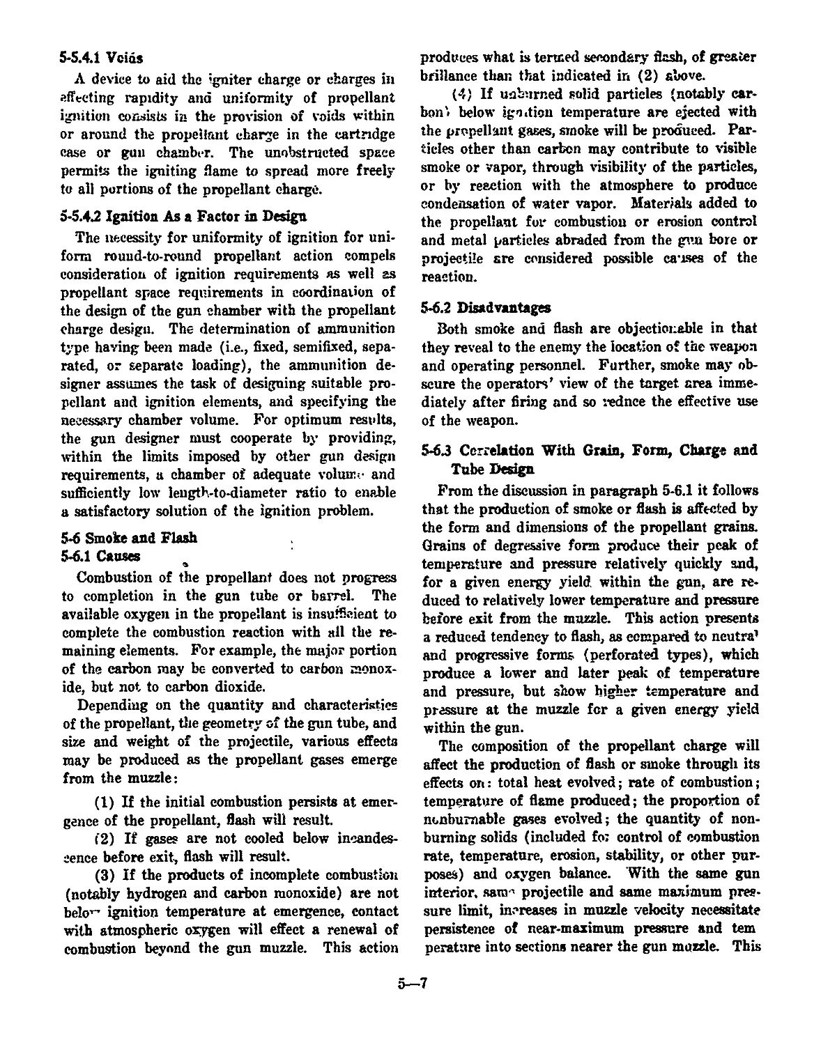
5-3 Flash Suppressor..................................... 5-8
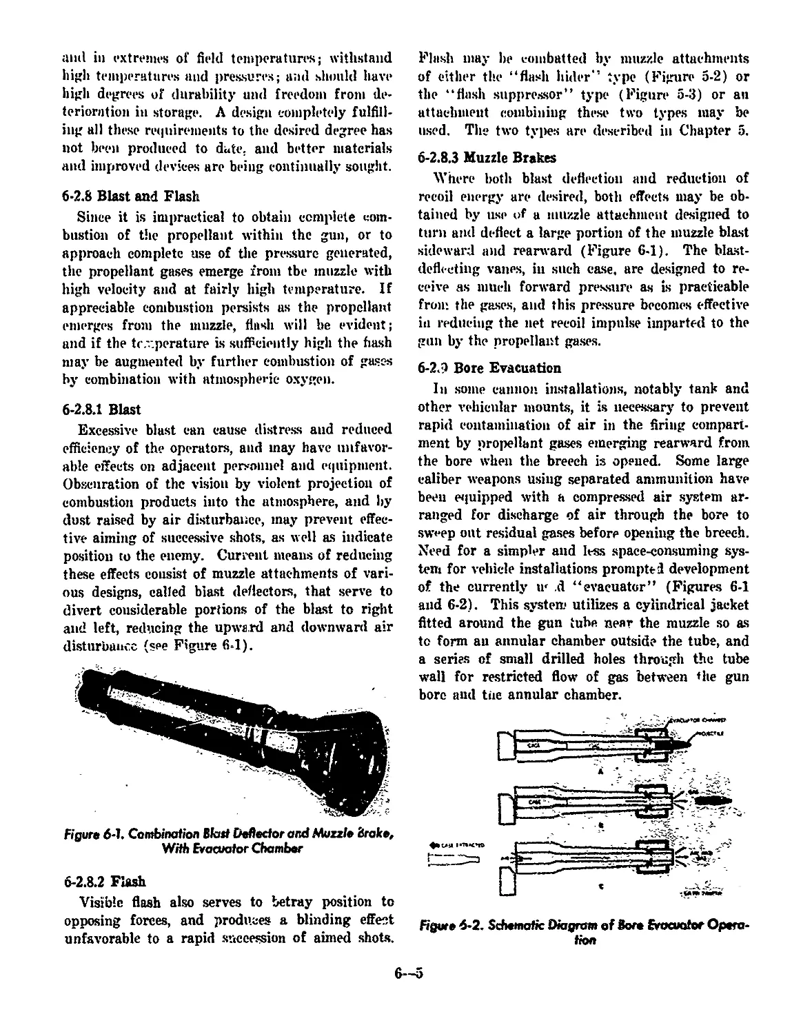
6-1 Combination Blast Deflector and Muzzle Brake,
With Evacvator Chamber ............................ 6-5
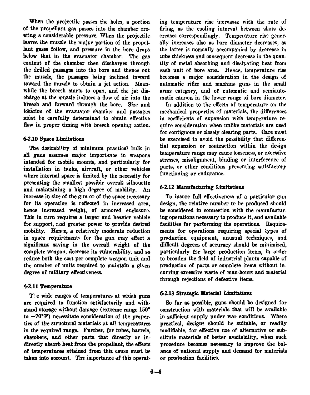
6-2 Schematic Diagram of Bore Evacuator Operation........ 6-5
viii
CHAPTER 1
INTRODUCTION
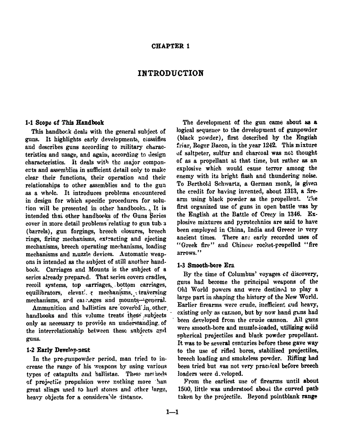
1-1 Scope of This Handbook
This handbock deals with the general subject of
guns. It highlights early developments, Classifies
and describes guns according to military charac-
teristics and usage, and again, according to design
characteristics. It deals with the major compon-
ents and assemblies in sufficient detail only to make
clear their functions, their operation and their
relationships to other assemblies and to the gun
as a whole. It introduces problems encountered
in design for which specific procedures for solu-
tion will be presented in other handbooks. It is
intended that other handbooks of the Guns Series
cover in more detail problems relating to gun tub; з
(barrels), gun forgings, breech closures, breech
rings, firing mechanisms, extracting and ejecting
mechanisms, breech operating mechanisms, loading
mechanisms and muzzle devices. Automatic weap-
ons is intended as the subject of still another hand-
book. Carriages and Mounts is the subject of a
series already prepared. That series covers cradles,
recoil systems, top carriages,.. bottom carriages,
equilibrators, elevat:. r mechanisms, •. traversing
mechanisms, ard callages and mounts—general.
Ammunition and ballistics are covered'in.other,
handbooks and this volume treats these .subjects
only as necessary to provide an understanding, of
the interrelationship between these subjects and
guns.
1-2 Early Develnp uect
In the pre-gunpowder period, man tried to in-
crease the range of his weapons by using various
types of catapults and ballistae. These methods
of projectile propulsion were nothing more han
great slings used to hurl stones and other large,
heavy objects for a considerable distance.
The development of the gun came about as a
logical sequence to the development of gunpowder
(black powder), first described by the English
friar, Roger Bacon, in the year 1242. This mixture
of saltpeter, sulfur and charcoal was not thought
of as a propellant at that time, but rather as an
explosive which would cause terror among the
enemy with its bright flash and thundering noise.
To Berthold Schwartz, a German monk, is given
the credit for having invented, about 1313, a fire-
arm using black powder as the propellant. The
first organized use of guns in open battle was by
the English at the Battle of Crecy in 1346. Ex-
plosive mixtures and pyrotechnics are said to have
been employed in China, India and Greece in very
ancient times. There аг; early recorded uses of
“Greek fire” and Chinese rocket-propelled “fire
arrows.”
1-3 Smooth-bore Era
By the time of Columbus’ voyages of discovery,
guns had become the principal weapons of the
Old World powers and were destined to play a
large part in shaping the history of the New World.
Earlier firearms were crude, inefficient aud heavy,
existing only as cannon, but by now hand guns had
been developed from the crude cannon. All guns
were smooth-bore and muzzle-ioaded, utilizing solid
spherical projectiles and black powder propellant
It was to be several centuries before these gave way
to the use of rifled bores, stabilized projectiles,
breech loading and smokeless powder. Rifling had
been tried but vas not very practical before breech
loaders were d.veloped.
From the earliest use of firearms until about
1500. little was understood about the curved path
taken by the projectile. Beyond pointblank range
1—1
the gunner was never sure of hitting his tai get.
Early cannon were made by casting the tube around
a core. As cannon evolved, they were later east
solid and the bore drilled, a practice which im-
proved the uniformity of the piece.
During the Hundred Years’ War Ц399-1453)
cannon name into general use. Those early pieces
were very small, made of iron or cast bronze, and
fired lead, ;ron, or stone balls. They were laid
directly on the ground, with muzzles elevated by
mounding up the earth. Cumbersome and ineffi-
cient, they played little part in battle, but were
quite useful in a siege.
Mohammed II of Turkey used gunpowder in his
famous military conquest of Constantinople in
1453. The single weapon possessed by the Turks
weighed 19 tons and hurled a 600-pound stone 7
times a day. It took 60 oxen and 200 men to move
the piece, and the difficulty of transporting such
heavy ordnance reduced its usefulness. It was
responsible, however, for u stroying the city walls
which had successfully resisted many attacks by
other weapons for more than 1,000 years.
Called bombards, weapons of this period were
very large, but the powder used was very weak
and the pressures in the barrels were low. Even
so, barrels frequently burst. The early barrels
were often made of staves and hooped like a barrel
and derived their name from this construction.
An increased knowledge of gunpowder and an
improvement in the art of casting caused the re-
placement of bombards with lighter cannon in the
16th century. From the time of their invention
until about 100 years ago, cannon were of extremely
simple construction—they had a cast barrel, wedge
elevating mechanism, and crude wheels and car-
riages. Such weapons were fired by igniting the
gunpowder by a live fire or match applied to the
touch hole at the breech. The improved weapons
were of decreased size and were soon cast in one
piece of cast iron or bronze. At the beginning of
the 15th century, cast-iron balls had made an
appearance. The greater efficiency of the iron
ball, together with an improvement in gunpowder,
further encouraged the building of smaller and
stronger guns. Before 1500, the siege gun bad
been the predominant piece. Now, forged-iron can-
non for field, garrison, and naval service—and
later, cast-iron pieces—were steadily developed
along with cast-bronze guns. Throughout the
1500’s, improvement was mainly toward lightening
the enormous weights of guns and projectiles as
well as finding better ways to move the artillery.
The casting of trunnions on the gun made eleva-
tion and transportation easier, and the cumbersome
beds of the early days gave way to crude artillery
carriages with trails and wheels. About 1500. the
French invented the limber and standardized the
calibers of their artillery.
The earliest small arm was nothing more than a
short metal tube of large caliber mounted on a rod
or stick. Tin* stick gradually became a stock which
permitted firing from the shoulder. Ignition of
the gunpowder charge was by fire or match applied
by hand to the touch hole, as for cannon. When
the match was later mounted on an S-sha^ed lever
called the “cock,” the weapon became the match
lock. A later development, the wheel lock, u?.cd a
serrated wheel against a piece of iron pyrites, pro-
ducing a shower of sparks for ignition. The sim-
pler flint lock was developed in the 17th century
and did not disappear completely until after the
close of our Civil War, when the percussion system
of ignition came into general use.
The first cannon were rolled along the ground
but soon were placed on wagons or carriages for
transportation. These early carriages supported
the cannon at their center of balance and at the
breech. Adjustments in elevation were secured by
a wedge under the breech. To move the ban-el, it
was necessary to move the entire carriage.
Mobile artillery came on the field with the cart
guns of John Ziska during the Hussite Wars of
Bohemia (1418-24). The French further improved
field artillery by using light guns, hauled uy the
best of horses instead of the usual oxen. The ma-
neuverable French guns proved to be an excellent
means for breaking up heavy masses of pikemen
in the Italian campaigns of the early 1500’s. The
Germans under Maximilian I, however, took the
armament leadership away from the French with
guns that ranged 1,500 yards and with men who
had earned the reputation of being the best gun-
ners in Europe.
About 1525, tbe fameue Spanish Square of
heavily armed pikemen and musketeers heg^n to
dominate the battlefield. In the face of musketry,
field artillery declined. Although artillery had
achieved some mobility, carriages were still cum-
1—2
bersome. To move a heavy English cannon, even
over good ground, required 23 horses.
Under the Swedish warrior, Gustavus Adolphus,
artillery began to take its true position un the
battlefield in the 17th century. It was he who
combined the powder charge and projectile into a
single cartridge to do away with ths old method
of ladling powder into the gun and so increased
the rapidity of fire. Recognizing the need for
mobile weapons, he made use of pieces which could
be moved by only 2 horses aud served by 3 men.
In the past, 1 cannon for each thousand infantry-
men had been standard. Gustavus brought the
ratio to 6 cannon per thousand men.
About 1750 Frederick II, King of Prussia, suc-
ceeded in developing artillery that was light enough
end mobile enough to accompany the anny and be
readily maneuvered on the battlefield.
1-4 Rifling Adopted
The principle of stabilization of an elongated
projectile by rotation has been known a long time.
However, difficulties in manufacture of the guns
and ammunition retarded the development. In
small arms there were some rifled muskets in use
in the 18th century, utilizing projectiles which
expanded at ths base to fit into the rifling grooves
of the muzzle loaders. The development could not
be successfully applied to the manufacture of can-
non and their ammunition until breech-loading was
developed.
Early cannon were.-not made very accurately,
and their accuracy of fire was correspondingly low.
These weapons could not be made better than the
tools which produced them, and good machinery
capable of boring cannon was first made about
1750. Rifling had already been applied to small
arms, but machinery of the necessary accuracy to
make cannon in this fashion was not available until
about a century later.
In 1816, Major Cavelli in Italy and Baron
Wahrendorff in Germany independently produced
rifled iron breech-leading cannon. The Cavelli gun
had two spiral grooves which fitted the %-inch
projecting bugs of a long projectile. About the
same time, an. enterprising British industrialist,
Joseph Whitworth, developed the helical hexagonal-
bore weapon. This weapon was one of many used
during the American Civil War (1861-1865). It
was an efficient piece, though subject to easy fouling
that made it dangerous.
The American Civil War began with smooth-bore
muzzle loader: and ended with rifled, muzzle load-
ers. When they wore out or were captured, smooth-
bore weapons were replaced with rifled pieces. One
specific weapon converted from a smooth-bore to
a rifled bore is noted in the Rodman gun. De-
veloped by Capt. T. J. Rodman (United States
Army Ordnance) in the mid-1800’s, this smooth-
bore weapon was cast around a water-cooled core.
Its inner walls thus solidified first and were com-
pressed by the contraction of the outer metal as it
cooled more slowly. By this process, it had much
greater strength to resist explosion of the charge.
The Rodman smooth-bore cannon, cast in 8-, 10-,
15-, and 20-inch calibers, was the best cast-iron
ordnance of its time. During the Civil War and
after, a number of the 10-inch Rodmans were con-
verted into 8-inch rifles by enlarging the bore and
inserting a grooved steel tube.
1-5 Breech Loading Developed
The first successful breech-loading guns were
made less than a century ago. There were some
breech-loading cannon made over 400 years ago,
but judged by our standards, they were far from
satisfactory and were not the forerunners of mod-
em breech-loading guns.
The ueed for breech loading was obvious; to
enable firing and reloading without exposing the
gunners to the enemy. Solution of the breech
loading problem depended primarily on finding a
mechanism that would seal the propellant gases
within the chamber. This was accomplished by
using soft metal (br^>) cartridge cases for the
smaller guns and more complex expanding asbestos
and metal seals for the larger cnee. The first gun
that may be called modem and in the sense that
it had all the features now in use was the “French
75.*’ This 75-mm gun, model of 1897, had modem
sights, firing mechanism, recoil mechanism, and
used cased ammunition. It was the backbone of
the artillery of the allied armies in World War I
(1914-18).
1*6 Early United State* Developments
1-6.1 Fixed Artillery
Design characteristics of United States artillery
nave followed generally those of other nations.
1—3
Before the Civil War, there was little manufac-
turing of cannon in this country, and at the be-
ginning of that conflict, it became necessary to
purchase much of this equipment abroad. At that
time, there were various models of various sizes
of cannon for use in fortifications. These weapons
included brass guns, brass mortars, iron guns, and
iron howitzers.
A distinctly American development in fixed or
harbor defense artillery was reached early in the
20th c< tury with the adoption of the disappearing
carriage. This enabled the gun to rise over a
parapet to fire, but was withdrawn, by recoil forces,
behind the parapet for reloading.
Another fixed artillery piece, the. barbette car-
riage, was a permanently emplaced carriage which
was capable of traversing through large angles
except as limited by protecting turret or casemate.
1-62 Mobile Artillery
The appearance of the French 75 in 1897 spurred
American designers to a series of notable develop-
ments, and many models were made in 3-, 4.7-, 6-,
and 8-inch calibers with various carriage and re-
coil mechanism arrangements. Little money was
available, however, to actually manufacture these
guns for issue, so that, upon entering World War I
in 1917, it was found desirable to adopt weapont
for which production facilities existed. At that
time, the French 75-mm, model of 1897, and the
American 75-mm gun, model of 1916, were adopted.
They were followed shortly by a 75-mm gun of
similar but British design, the model of 1917.
Similar action brought into our Armed Forces
the French 155-mm gun (Fil’oux). This weapon
was more familiarly known as the G.P.F. after its
French designation Grande e Puissance Fillouz
(gun of great power). There was also a French
155-mm howitzer of Schneider design adopted.
In order to facilitate coast defense, the railway
mount was put into service. Large caliber guns
up to 16 inches were mounted on specially built
railway cars. The materiel was fired from the rail-
way car mountings after suitable supports and
outriggers were in place.
1-62 Small Anas
The flintlock rifle served the American pioneer,
the Revolutionary War soldier and, to some extent,
the Civil War soldier. Most flintlocks were con-
verted to percussion locks prior to or during the
Civil War. This was made possible by the inven-
tion of the percussion primer, which in turn made
possible the metal cartridge case, which provided
effective obturation, which in turn resulted in
adoption of the breech-loading system. Then the
use of rifling became practicable in all guns.
As weapons improved and better ammunition
became available, the magazine rifle was developed
to meet the demand for increased firepower. The
famous Winchester ’73 was among the early suc-
cessful magazine rifles. It provided a magazine
which held several round? of ammunition, and
means for transferring them to the chamber. Re-
duction of caliber, improvement in propellants
which permitted use of smaller charges, and reduc-
tion of size and weight of cartridges simplified the
problem.
After the period of the Civil War interchange-
ability of parts was provided. This era had been
ushered in by Eli Whitney (of cotton gin fame)
who first applied the principle of interchangeable
parts and mass production in the manufacture of
a large number of rifles for the government.
The modern military rifle was perfected in all
its essentials by about 1890. Since that time de-
tails have been refined, smokeless powder has re-
placed black powder, improved ammuntion has
been provided, and belter metals have become
available. The trend has been toward higher
velocities, greater firepower, and less weight As
will be notes below, American inventors pioneered
in the development of machine guns.
1-7 Development of Automatic Weapons
The development of automatic features and of
full automatic weapons was in response to the
demand for increased firepower. The early weapons
employed multiple barrels on a single mount, which
could be fired simultaneously. Other arrange-
ments which were developed permitted the firing
of multiple barrels successively, or brought mul-
tiple chambers successively to a single barret These
did increase considerably the volume or rapidity
of fire but automatic loading bad not yet been
worked out. Moreover, they were very heavy and
cumbersome.
The development of automatic weapons was
hastened by the invention of the pv-ccussion primer,
the adoption of breech loading, and introduction
1—4
of the complete round assembled in a metal car-
tridge case. The first practicable machine gun was
the Gatling, invented by Dr. R. J. Gatling about
the time of the Civil War. Its adoption was fol-
lowed by others of the same general type, which
iu effect combined in one mount a considerable
number of breech-loading rifles that could be loaded
and fired mechanically.
In 1881 Sir Hiram Maxim, an American engi-
neer, designed the first truly automatic machine
gun. It employed a single barrel and utilized the
principle of recoil operation to secure continuous
and automatic functioning as long as the trigger
was held down. This weapon was an immediate
success; the soundness cf its design and principle
of operation were immediately recognized. It revo-
lutionized machine gun tactics and stimulated the
development of other automatic types. In modified
and improved form it was still being used by the
British, German and Russian armies at the begin-
ning of World War I; it has appeared also among
the variety of weapons used by the communist
forces in Korea.
The principle of gas operation, utilizing a small
portion of the expanding propellant gas, was first
successfully employed by John M. Browning, an
American, who brought out the Colt machine gun
in 1889. This was followed by the Hotchkiss,
employing the same system of operation. During
the period covering World War I, Browning’s short
recoil machine gun, which was originally patented
in 1901, reached the stage of development very
much as it is today. The Browning Automatic
Rifle, (BAR), answering the need to combine the
light weight and flexibility of the conventional
rifle with the greater firepower of the machine gun,
has served also through the two World Wars.
1-8 Guns and History
Beginning with the formation of the individual
American Colonies, guns of numerous types and
sizes have played a major role in the history of the
United States. Although the United Slates is not
primarily a military nation, its fusion into a single
nation, the expansion of its borders, the settlement
of its knd, its growth into the position of a major
world power, and the keeping of law and order
among itu people have been closely linked with the
story of guns, from the smallest pistol to the largest
cannon. Similar statements could be made about
other nations. Guns have now been augmented,
and in some cases replaced, by rockets and other
weapons; however, there is every indication that
the gun, in various present and future forms, will
continue to play a major role in the destiny of the
world and its people.
1-9 Gun Terminology
Although one will readily recognize components
and assemblies that perform identical functions in
Army guns of different types and sizes, it must be
borne in mind that design, development and use
of guns has, to a considerable extent and for gen-
erations, been specialized according to types or
sizes. A natural outgrowth of this condition has
been the development of differences -in terminology
and nomenclature; in fact, it is due almost entirely
to organized efforts that the basic nomenclature
shows any degree of uniformity. Recent efforts
have included Federal cataloging and assignments
of Federal item names with identifying definitions.
This effort requires time to reach agreements within
a servile, not to mention the necessary agreements
between services. And even after agreements are
reached and recorded, new names or new definitions
for old names are not accorded general acceptance
by users without a considerable period of re-
education.
In dealing with the broad subject of guns the
authors have made every effort to use terminology
which will not be confusing to the reader who may
have only a limited acquaintance in the field of
guns. The reader should bear in mind, however,
that in some instances a single term is accepted as
having different meanings in the general and spe-
cific senses, or different meanings with respect to,
say, cannon and small arms. The terms and defi-
nitions given in the handbook should be noted care-
fully in order to effect a clear understanding of
the text.
1-10 Major Elements of the Gun
1-10.1 Gun Tube or Barrel
The tube or barrel is the main pari of a gun.
It is essentially a hollow cylinder, usually of steel,
which surrounds the bore and guides the projectile
during its acceleration. In most designs the cham-
ber ia an integral part of the tube, the revolver type
being a notable exception. Tube is the more general
term and may be applied to all sizes, while barrel
1-3
is the term more often used in connection with
small arms. The term barrel auc.nbly may be used
for all calibers to denote the tub* and parts as-
sembled thereto.
1-10.2 Breech Closure
A breech closure, as the term implies, is я general
term denoting the closure of the breech end of a
gun. This closure permits the hot propellant gases
behind the projectile to act on it so as to impart
the greatest possible kinetic energy for a given
propellant charge. A closure may be of the per-
manent type or the mobile type. The latter type
remains closed during the firing but may be opened
afterwards to permit reloading from the breech.
Permanent closures are applicable only to muzzle
loaders, such м mortars. Another type, known
as the open-bi?ech closure, is used for rt-coilless
guns. Breech closures are discussed further and
illustrated in Chapter 3.
1-103 Breech Ring or Receiver
The breech ring is a principal unit of gun con-
struction, is attached to the gun tube at the breech
end and supports the breech closure and other
parts of the breech mechanism. In cannon termi-
nology the term breech rinr it commonly used,
while the term receiver is inure eqiiently used in
relation to small anus and automatic weapons.
The terms are discussal furtb- r Chapter 3.
1-10.4 Firing Mechanism
This is the mechanism whit, fit »s the primer to
initiate propelling charge ign’dou. The principal
types now in use are designated, according to the
method of firing the primer, as percussion, electric,
or combination percussion-electric. The subject is
discussed further and several types illustrated in
Chapter 3.
1-10.5 Extracting Mechanism
This refers to the mechanism, in a gun using
cartridge cases, for pulling the empty cartridge
case or an unfired cartridge out of the chamber.
1-lO.c Ejecting Mechanism
This refers to the mechanism, in a gun using
cartridge cases, for automatically throwing out an
empty cartridge ease or an unfired cartridge from
the breech or receiver.
1-10.7 Breech Operating Mechanism
This designates that, part of the breech mecha-
nism which must be operated to open or close the
breech mechanism. This mechanism is discussed
further in Chapter 3.
1-103 Loading Mechanism
This term includes all mechanisms used for plac-
ing the ammunition into the gun in position for
firing. The process differs greatly, according to
types and sizes of guns and ammunition. The term
includes feeding mechanisms, ramming mechanisms
and fuze-setting mechanisms when these are con-
structed so as to become part of the loading or
ramming operation. The subject is discussed fur-
ther and illustrated in Chapter 3.
1-10.9 Muzzle Devices
Muzzle devices, also called muzzle attachments,
are used in a number of forms and for a variety of
purposes. Devices presently in common use include
flash hiders (Fig. 5-2), flash suppressors (Fig. 5-3),
blast deflectors, muzzle brakes and bore evacuators.
A combination of the last three named devices is
shown in Fig. 6-1 and a schematic diagram of the
bore evacuawr operation is shown in Fig. 6-2.
1—6
CHAPTER 2
CLASSIFICATION AND DESCRIPTION BY MILITARY
CHARACTERISTICS OR USAGE
24 General
There are many ways in which guns are classified.
The most generally used method is that of classify-
ing according to military characteristics or military
usage. This involves sizes or shapes which are
readily apparent to the eye and with which most
military personnel are familiar. Because of dif-
fering general and specific meanings for the terms
“gun’’ and “cannon,”' the reader should give spe-
cial attention to the understanding of these terms
in both senses.
2-2 Gun (General)
For the purposes of this handbook, a gun is a
projectile-throwing device, consisting essentially of
a projectile-guiding tube with an incorporate or
connected reaction chamber, in whieh the chemical
energy of a propellant is rapidly converted into
heat and the hot gases produced expand to expel
the projectile at a high velocity (kinetic energy).
Guns in this general seren are separated, according
to 'ize and use, into the general categories of can-
non and small arms. Launchers for rockets and
missiles are purposely excluded from consideration
in this handbook.
2-2.1 Cannon (General.)
A cannon is a weapon conforming to the general
gun definition, that is provided with a struet;.re
(mount) for mechanical support during firing, and
that has a bore diameter exceeding the limit as-
signed w small arms. (The small arms bore limit
is presently administratively set at 30mm.) The
general category of cannon is further divided, in
accordance with ballistic characteristics and use,
into guns, howitzers, mortars, and recoilless weap-
ons, as follows:
2-2.1.1 Gun (Specific)
In the specific sense used in ordnance supply, a
gun is a complete weapon conforming to the general
cannon definition; including the attached or closely
related units necessary for operation as intended
(recoil mechanism, mount, sighting system, acces-
sories, but not ammunition), and designed for per-
formance characterized primarily by relatively
long range, high velocity, and relatively little cur-
vature of the projectile trajectory within the in-
tended range (see Figures 2-1 and 2-2).
2-2.12 Mortar
A mortar is a complete weapon conforming to
the general cannon definition; including the at-
tached or closely related units necessary for opera-
tion as intended (mount, sighting system, and
accessories, but not ammunition), and designed for
performance characterized primarily by relatively
low velocity, short range, and a highly arched pro-
jectile trajectory at the ranges at whieh it is de-
signed to fire (see Figures 2-3 and 2-4).
2-213 Howitzer
A howitzer is a complete weapon conforming to
the general cannon dennition; including the at-
figuts 2-1. Typfeol Gun (S^f-PropoMod Mount)
Flgen 2-2. Gun ТяДОогкл
2—2
Figaro 2-3. Typical Smooth-bore Mortar.
Figure 2-5. Typical Howitzer {Solf-PropolM Mount)
tached or closely related units necessary for opera-
tion as intended (recoil mechanism, mount, sighting
system, accessories, etc., but not ammunition), and
designed for performance characterized by velocity,
range, and trajectory curvature intermediate be-
tween those of a gun and a mortar (see Figures 2-5
and 2-6).
Figure 2-4. Typical Мойзг Trajectory
2-3
figw* 2-6. Typical Hvsnhar Trojadvriae
2-2.1.4 Recoilless Cannon
A recoilless cannon is a complete weapon con-
forming to the general cannon definition; including
the attached or closely related units necessary for
operation as intended (mount, sighting system,
accessories, etc., but not ammunition), and designed
to discharge the propellant gases in such a manner
as to impart substantially no recoil impulse to the
weapon. Recoilless cannon in current use are con-
fined to recoilless rifles, designed to fire cannon-
size projectiles, with low to medium velocity and
high accuracy, from a weapon of relatively light
weight and high portability (see Figure 2-7/.
Figure 2-7. Typical RecoiNeu Hide
2-2.13 Cannon (Specific).
The term “cannon” is used in a specific sense
to denote the shooting part of a complete weapon
(gun, howitzer, mortar or recoilless) comprising
only the tube and breech structures and such mech-
anism as it* supported hereon for opening and
closing the breech and firing the propelling charge.
2-2.1.6 Automatic Cannon
No definite distinction, except as to caliber, is
established between machine guns and automatic
cannon. The designation “cannon” is generally
not applied to guns of bore diameter under the
small arms limit (30mm).
?-22 Small Arms
The small arms category of guns comprises those
wi h bore diameter not exceeding an arbitrarily
assigned limit (present limit is aOmm). Small arm
guns include h.’nd guns (pistols), shoulder guns
(rifles, carbines, shotguns, submachine guns) and
Figure 2-B. "typical Pittol
mechanically supported weapons (machine or auto-
matic guns).
2-2J.1 Pistol
A pistol is a short-barreled weapon held and
fired with one hand, designed as an easily carried
short-range weapon for individual use (see Figure
2-8). Current designs provide for rapid firing of
six or more shots before reloading is necessary.
Some models operate -wmiautomatically or auto-
matically after the first shot (see paragraphs 3-8.2
and 3-6.3).
2222 Shotgun
A shotgun is a short-range gon designed for
firing from the shoulder, having a smooth bore suit-
able for expelling a group of pell* t?. Army shot-
guns, which are used chiefly for guard or police
duty and for training purposes, are of a magazine
type, capable of rapid firing of a limited number
of shots without reloading.
2-223 Rifle
A rifle is a shoulder-fired g uu having a relatively
long barrel with the bore helically grooved to im-
part a spinning motion to the projectile about its
longitudinal axis, for improved stability in flight
The rifle is designed to obtain relatively high ve-
locity, long range, and a high order of accuracy
with a projectile of small diameter. Present Army
rifles have small-capacity magazines, with semi-
automatic or automatic operation (see paragraphs
2-5
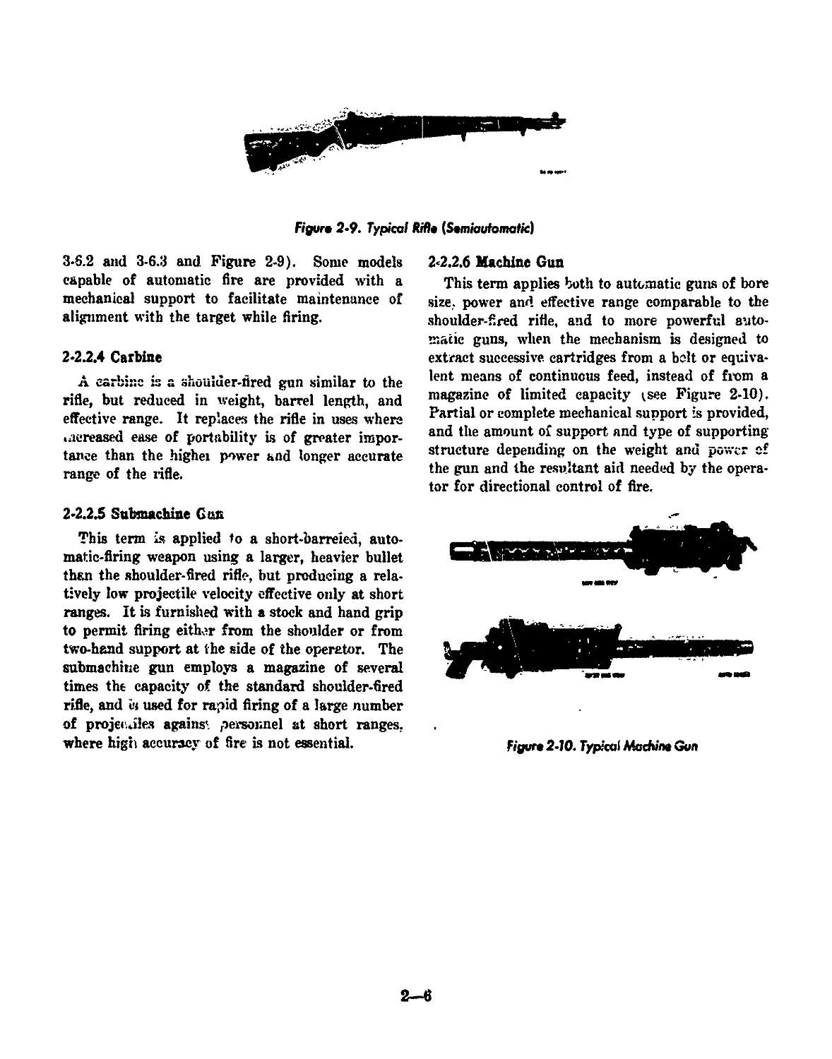
Figure 2-9. Typical Rifle {Semiautomatic]
3*6.2 and 3-6.3 and Figure 2*9). Some models
capable of automatic fire are provided with a
mechanical support to facilitate maintenance of
alignment with the target while firing.
2-22.4 Carbine
A carbine is a shoulder-fired gun similar to the
rifle, but reduced in weight, barrel length, and
effective range. It replaces the rifle in uses where
>aereased ease of portability is of greater impor-
tance than the higher power and longer accurate
range of the rifle.
2-22.5 Submachine Gun
This term is applied to a short-barreied, auto-
matic-firing weapon using a larger, heavier bullet
than the shoulder-fired rifle, but producing a rela-
tively low projectile velocity effective only at short
ranges. It Is furnished with a stock and hand grip
to permit firing either from the shoulder or from
two-hand support at the side of the operator. The
submachine gun employs a magazine of several
times the capacity of the standard shoulder-fired
rifle, and is used for rapid firing of a large number
of projecales against personnel at short ranges,
where high accuracy of fire is not essential.
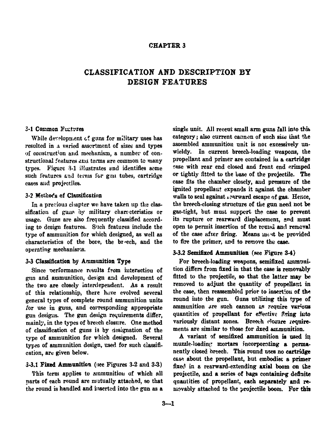
22.2.6 Machine Gun
This term applies both to automatic guns of bore
size, power and effective range comparable to the
shoulder-fired rifle, and to more powerful auto-
matic guns, when the mechanism is designed to
extract successive, cartridges from a bolt or equiva-
lent means of continuous feed, instead of from a
magazine of limited capacity <see Figure 2-10).
Partial or complete mechanical support is provided,
and the amount of support and type of supporting
structure depending on the weight and power of
the gun and the resultant aid needed by the opera-
tor for directional control of fire.
Figure 2-10. Typical Machine Gun
2-6
CHAPTER 3
CLASSIFICATION AND DESCRIPTION BY
DESIGN FEATURES
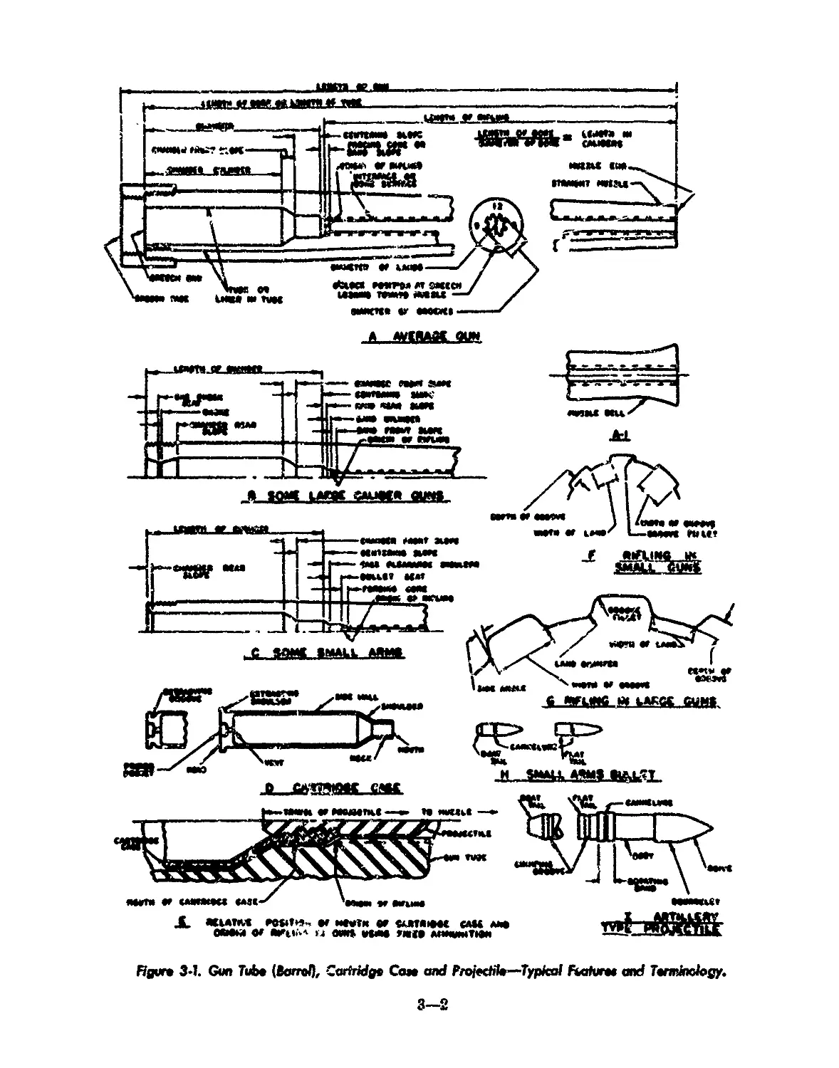
3-1 Common Fixtures
While development of guns for military uses has
resulted in a varied assortment of sizes and types
of construct’on and mechanism, a number of con-
structional features and terns are common to many
types. Figure 3-1 illustrates and identifies some
such features and terras for g:m tubes, cartridge
cases and projectiles.
3-2 Methods of Classification
In a previous chapter we have taken up the clas-
sification of guns by military chareeteristics or
usage. Guns are also frequently classified accord-
ing to design features. Such features include the
type of ammunition for which designed, as well as
characteristics of the bore, the breech, and the
operating mechanisms.
3-3 Classification by Ammunition Type
Since nerformanee results from interaction of
gnn and ammunition, design and development of
the two are closely interdependent. As a result
of this relationship, there hove evolved several
general types of complete round ammunition units
for use in guns, and coiresponding appropriate
gun designs. The gun design requirements differ,
mainly, in the types of breech closure. One method
of classification of guns is by designation of the
type of ammunition for which designed. Several
types of ammunition design, used for such classifi-
cation, are given below.
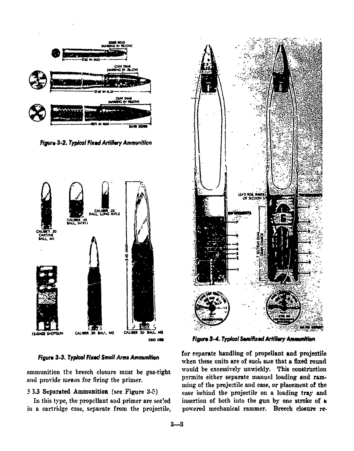
3-3.1 Fixed Ammunition (see Figures 3-2 and 3-3)
This term applies to ammunition of which all
parts of each round are mutually attached, so that
the round is handled and inserted into the gun as a
single unit. All recent small arm guns fall into this
category; also current cannon of such size that the
assembled ammunition unit is not excessively un-
wieldy. In current breech-loading weapons, the
propellant and primer are contained in a cartridge
case with rear end closed and front end crimped
or tightly fitted to the base of the projectile. The
case fits the chamber closely, and pressure of the
ignited propellant expands it against the chamber
walls to seal against л carward escape of gas. Hence,
the breech-closing structure of the gun need not be
gas-tight, but must support the case to prevent
its rupture or rearwaid displacement, and must
open to permit insertion of the round and removal
of the case after firing. Means iii< Ht be provided
to fire the primer, and to remove the case.
3-3.2 Semifixed Ammunition (see Figure 3-4)
For breech-loading weapons, semifixed ammuni-
tion differs from fixed in that the case is removably
fitted to the projectile, so that the latter may be
removed to adjust the quantity of propellant in
the case, then reassembled prior to insertion of the
round into tbe gun. Guns utilizing this type of
ammunition are such cannon as require various
quantities of propellant for effective firing into
variously distant zones. Breech closure require-
ments are similar to those for fixed ammunition.
A variant of semifixed ammunition is used in
muzzle-loading mortars incorporating a perma-
nently dosed breech. This round uses no cartridge
case about the propellant, but embodies a primer
fixed in a rearward-extending axial boom on the
projectile, and a series of hags containing definite
quantities of propellant, each separately and re-
movably attached to the projectile boom. For this
3—1
JL auonuo aosit^ v миги m mmihom cam aao
OMM or ОИЦ.-' U ОСИ» ИМО ВД1 АПМЫЖТЮй
эЫИ£
Ндим 34. Gun Tube (Вотто/), CarMdg» Сам and Projedil»—Typical FurivtM and Tamitnlogy.
3—2
Figure 3*2. Typical fixed Artillery Ammunition
Figure 3*4. Typical Semifixed Artillery Ammunition
«о ota
Figure 3*3. Typical Fixed Small Arm» Ammunition
ammunition the breech closure must be gas-tight
and provide means for firing the primer.
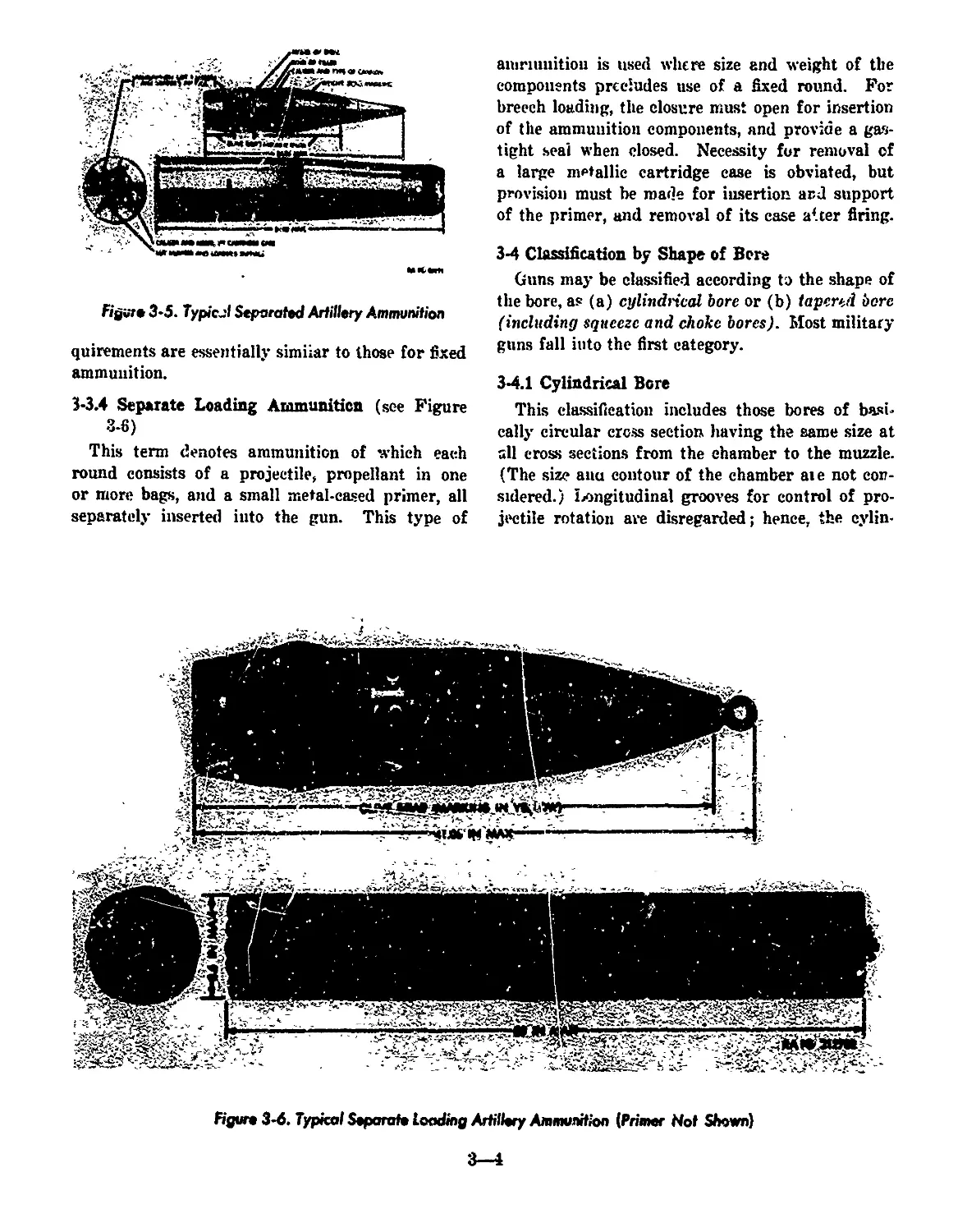
3 3.3 Separated Ammunition (see Figure 3-5)
In this type, the propellant and primer are sealed
in a cartridge case, separate from the projectile,
for separate handling of propellant and projectile
when these units are of such size that a fixed round
would be excessively unwieldy. This construction
permits either separate manual loading and ram-
ming of the projectile and case, or placement of the
case behind the projectile on a loading tray and
insertion of both into the gun by one stroke of a
powered mechanical rammer. Breech closure re-
3—3
МЛ
Figure 3-5. Typicjl Separated Artillery Ammunition
quirements are essentially simiiar to those for fixed
ammunition.
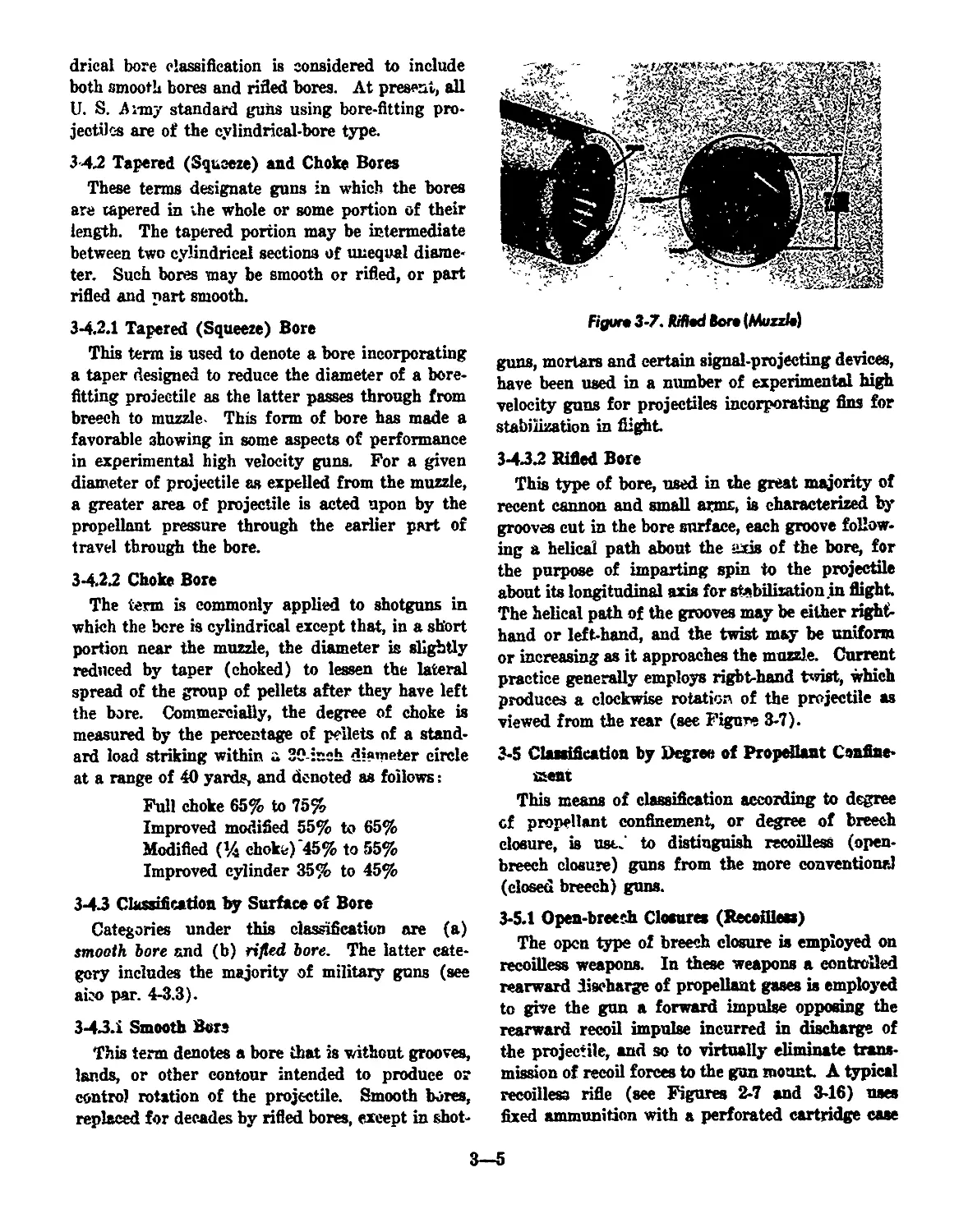
3-3.4 Separate Loading Ammunition (see Figure
3-6)
This term denotes ammunition of which each
round consists of a projectile» propellant in one
or more bags, and a small metal-cased primer, all
separately inserted into the gun. This type of
aiuriunitiou is used where size and weight of the
components precludes use of a fixed round. For
breech loading, the closure must open for insertion
of the ammunition components, and provide a gas-
tight seal when closed. Necessity for removal of
a large metallic cartridge case is obviated, but
provision must be made for insertion ar,J support
of the primer, and removal of its case after firing.
3-4 Classification by Shape of Bore
Guns may be classified according to the shape of
the bore, as (a) cylindrical bore or (b) tapered bore
(including squeeze and choke bores). Most military
guns fall into the first category.
3-4.1 Cylindrical Bore
This classification includes those bores of basi-
cally circular cross section having the same size at
all cross sections from the chamber to the muzzle.
(The size anu contour of the chamber aie not con-
sidered.) longitudinal grooves for control of pro-
jectile rotation are disregarded; hence, the cylin-
Figun 3-6. Typical Separate Loading Artillery Ammunition {Primer Not Shown)
drical bore classification is considered to include
both smooth bores and rifled bores. At present, all
U. S. Army standard guns using bore-fitting pro-
jectiles are of the cylindrical-bore type.
342 Tapered (Squeeze) and Choke Bores
These terms designate guns in which the bores
are tapered in the whole or some portion of their
length. The tapered portion may be intermediate
between two cylindrical sections of unequal diame-
ter. Such bores may be smooth or rifled, or part
rifled and part smooth.
3-42.1 Tapered (Squeeze) Bore
This term is used to denote a bore incorporating
a taper designed to reduce the diameter of a bore-
fitting projectile as the latter passes through from
breech to muzzle This form of bore has made a
favorable showing in some aspects of performance
in experimental high velocity guns. For a given
diameter of projectile as expelled from the muzzle,
a greater area of projectile is acted upon by the
propellant pressure through the earlier part of
travel through the bore.
3-422 Choke Bore
The term is commonly applied to shotguns in
which the bore is cylindrical except that, in a short
portion near the muzzle, the diameter is slightly
reduced by taper (choked) to lessen the lateral
spread of the group of pellets after they have left
the bore. Commercially, the degree of choke is
measured by the percentage of pellets of a stand-
ard load striking within a 20-:nch diameter circle
at a range of 40 yards, and denoted as follows:
Full choke 65% to 75%
Improved modified 55% to 65%
Modified (% chokv) ‘45% to 55%
Improved cylinder 35% to 45%
3-4.3 Classification by Surface of Bore
Categories under this classification are (a)
smooth bore and (b) rifled bore. The latter cate-
gory includes the majority of military guns (see
aieo par. 4-3.3).
3-43.1 Smooth Bora
This term denotes a bore that is without grooves,
lands, or other contour intended to produce or
control rotation of the projectile. Smooth bores,
replaced for decades by rifled bores, except in shot-
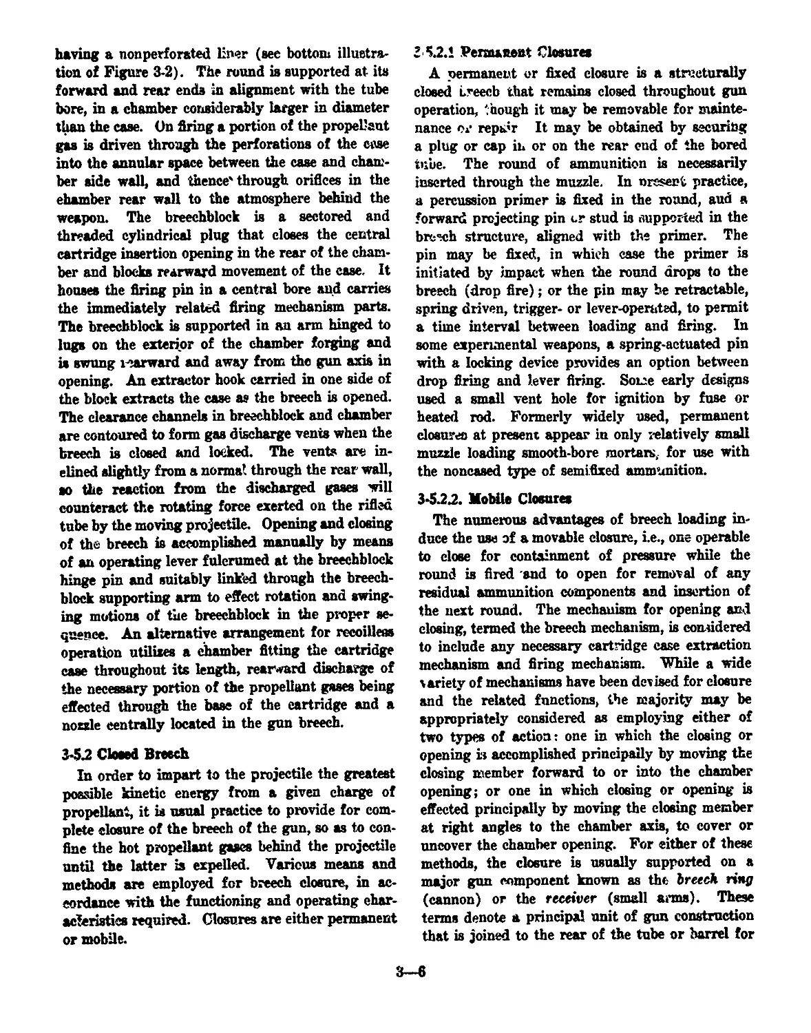
Figun 3-7. НИМ Bon (Muzzle)
guns, mortars and certain signal-projecting devices,
have been used in a number of experimental high
velocity guns for projectiles incorporating fins for
stabilization in flight.
3-432 Rifled Bore
This type of bore, used in the great majority of
recent cannon and small armc, is characterized by
grooves cut in the bore surface, each groove follow-
ing a helical path about the axis of the bore, for
the purpose of imparting spin to the projectile
about its longitudinal axis for stabilization .in flight
The helical path of the grooves may be either right-
hand or left-hand, and the twist may be uniform
or increasing as it approaches the muzzle. Current
practice generally employs right-hand twist, which
produces a clockwise rotation of the projectile as
viewed from the rear (see Figure 3-7).
3-5 Classification by Degree of Propellant Confine-
ment
This means of classification according to degree
cf propellant confinement, or degree of breech
closure, is usu' to distinguish recoilless (open-
breech closure) guns from the more conventional
(closed breech) guns.
3-5.1 Open-breech Closures (Recofflea)
The open type of breech closure is employed on
recoilless weapons. In these weapons a controlled
rearward discharge of propellant gases is employed
to give the gun a forward impulse opposing the
rearward recoil impulse incurred in discharge of
the projectile, and so to virtually eliminate trans-
mission of recoil forces to the gun mount A typical
recoilless rifle (see Figures 2-7 and 3-16) uses
fixed ammunition with a perforated cartridge case
3—5
having a nonperforated liner (see bottom illustra-
tion of Figure 3-2). The round is supported at its
forward and rear ends in alignment with the tube
bore, in a chamber considerably larger in diameter
than the case. On firing a portion of the propel'aut
gas is driven through the perforations of the case
into the annular space between the case and cham-
ber side wall, and thence'through orifices in the
chamber rear wall to the atmosphere behind the
weapon. The breechblock is a sectored and
threaded cylindrical plug that closes the central
cartridge insertion opening in the rear of the cham-
ber and blocks rearward movement of the case. It
houses the firing pin in a central bore and carries
the immediately related firing mechanism parts.
The breechblock is supported in an arm hinged to
lugs on the exterior of the chamber forging and
is swung i-?arward and away from the gun axis in
opening. An extractor hook carried in one side of
the block extracts the case as the breech is opened.
The clearance channels in breechblock and chamber
are contoured to form gas discharge vents when the
breech is dosed and locked. The vents are in-
elined slightly from a normal through the rear wall,
so the reaction from the discharged gases will
counteract the rotating force exerted on the rifled
tube by the moving projectile. Opening and dosing
of the breech is accomplished manually by means
of an operating lever fulcrumed at the breechblock
hinge pin and suitably linked through the breech-
block supporting arm to effect rotation and swing-
ing motions of the breechblock in the proper se-
quence. An alternative arrangement for recoilless
operation utilizes a chamber fitting the cartridge
case throughout its length, rearward discharge of
the necessary portion of the propellant gases being
effected through the base of the eartridge and a
nozzle centrally located in the gun breech.
3-52 Closed Breech
In order to impart to the projectile the greatest
possible kinetic energy from a given charge of
propellant, it is usual practice to provide for com-
plete closure of the breech of the gun, so as to con-
fine the hot propellant gazes behind the projectile
until the latter is expelled. Various means and
methods are employed for breech closure, in ac-
cordance with the functioning and operating char-
acteristics required. Closures are either permanent
or mobile.
2‘5.2.1 Permanent Closures
A permanent er fixed closure is a structurally
dosed Lreecb that remains dosed throughout gun
operation, though it may be removable for mainte-
nance or repair It may be obtained by securing
a plug or cap in or on the rear cud of the bored
tube. The round of ammunition is necessarily
inserted through the muzzle. In nrssent practice,
a percussion primer is fixed in the round, and a
forward projecting pin cr stud is supported in the
breach structure, aligned with the primer. The
pin may be fixed, in whieh case the primer is
initiated by impact when the round drops to the
breech (drop fire); or the pin may be retractable,
spring driven, trigger- or lever-operated, to permit
a time interval between loading and firing. In
some experimental weapons, a spring-actuated pin
with a locking device provides an option between
drop firing and lever firing. Some early designs
used a small vent hole for ignition by fuse or
heated rod. Formerly widely used, permanent
closures at present appear in only relatively small
muzzle loading smooth-bore mortars, for use with
the noncased type of semifixed ammunition.
3-5.22. Mobile Closures
The numerous advantages of breech loading in-
duce the use of a movable closure, i.e., one operable
to dose for containment of pressure while the
round is fired and to open for removal of any
residual ammunition components and insertion of
the next round. The mechanism for opening and
dosing, termed the breech mechanism, is considered
to include any necessary cartridge case extraction
mechanism and firing mechanism. While a wide
variety of mechanisms have been devised for closure
and the related functions, the majority may be
appropriately considered as employing either of
two types of action: one in which the dosing or
opening is accomplished principally by moving the
closing member forward to or into the chamber
opening; or one in which dosing or opening is
effected principally by moving the closing member
at right angles to the chamber axis, to cover or
uncover the chamber opening. For either of these
methods, the closure is usually supported on a
major gun component known as the breech ring
(cannon) or the receiver (small arms). These
terms denote a principal unit of gun construction
that is joined to the rear of the tube or band for
3—6
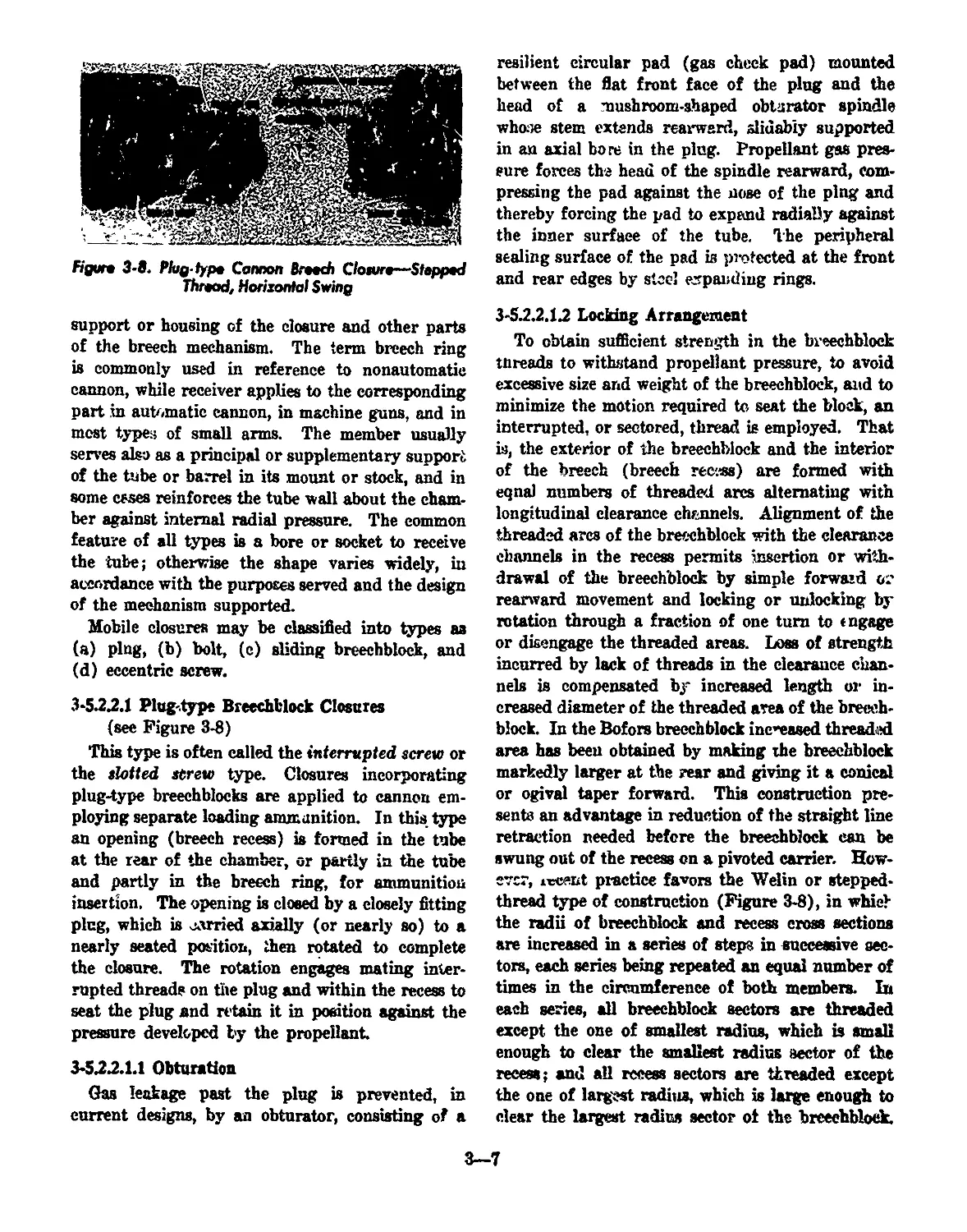
Figure 3-8. Phg-fypt Cannon Breech Closure-Stepped
Thread, Horizontal Swing
support or housing of the closure and other parts
of the breech mechanism. The term breech ring
is commonly used in reference to nonautomatic
cannon, while receiver applies to the corresponding
part in automatic cannon, in machine guns, and in
most types of small arms. The member usually
serves also as a principal or supplementary support
of the tube or barrel in its mount or stock, and in
some cases reinforces the tube wall about the cham-
ber against internal radial pressure. The common
feature of all types is a bore or socket to receive
the tube; otherwise the shape varies widely, iu
accordance with the purposes served and the design
of the mechanism supported.
Mobile closures may be classified into types as
(a) ping, (b) bolt, (c) sliding breechblock, and
(d) eccentric screw.
3-5.22.1 Plug-type Breechblock Closures
(see Figure 3-8)
This type is often called the interrupted screw or
the slotted screw type. Closures incorporating
plug-type breechblocks are applied to cannon em-
ploying separate loading ammunition. In this type
an opening (breech recess) is formed in the tube
at the rear of the chamber, or partly in the tube
and partly in the breech ring, for ammunition
insertion. The opening is closed by a closely fitting
plug, which is carried axially (or nearly so) to a
nearly seated position, then rotated to complete
the closure. The rotation engages mating inter-
rupted threads on the plug and within the recess to
seat the plug and retain it in position against the
pressure developed by the propellant
3-522.1.1 Obturation
Gas leakage past the plug is prevented, in
current designs, by an obturator, consisting of a
resilient circular pad (gas check pad) mounted
between the flat front face of the plug and the
head of a mushroom-shaped obturator spindle
whose stem extends rearward, slidably supported
in an axial bore in the plug. Propellant gas pres-
sure forces the head of the spindle rearward, com-
pressing the pad against the nose of the ping and
thereby forcing the pad to expand radially against
the inner surface of the tube. The peripheral
sealing surface of the pad is protected at the front
and rear edges by steel expanding rings.
3-52.2.12 Locking Arrangement
To obtain sufficient strength in the breechblock
threads to withstand propellant pressure, to avoid
excessive size and weight of the breechblock, and to
minimize the motion required to seat the block, an
interrupted, or sectored, thread is employed. That
is, the exterior of the breechblock and the interior
of the breech (breech rec'.«s) are formed with
eqnal numbers of threaded arcs alternating with
longitudinal clearance channels. Alignment of the
threaded arcs of the breechblock with the clearance
channels in the recess permits insertion or with-
drawal of the breechblock by simple forward 02
rearward movement and locking or unlocking by
rotation through a fraction of one turn to engage
or disengage the threaded areas. Loss of strength
incurred by lack of threads in the clearance chan-
nels is compensated by increased length or in-
creased diameter of the threaded area of the breech-
block. In the Bofors breechblock increased threaded
area has been obtained by making the breechblock
markedly larger at the rear and giving it a conical
or ogival taper forward. This construction pre-
sents an advantage in reduction of the straight line
retraction needed before the breechblock can be
swung out of the recess on a pivoted carrier. How-
ever, i^cent practice favors the Welin or stepped-
thread type of construction (Figure 3-8), in whiel
the radii of breechblock and recess cross sections
are increased in a series of steps in successive sec-
tors, each series being repeated an equal number of
times in the circumference of both members. In
each series, all breechblock sectors are threaded
except the one of smallest radius, which is small
enough to clear the smallest radius sector of the
recess; and all recess sectors are threaded except
the one of largest radius, which is large enough to
clear the largest radius sector of the breechblock.
3—7
The increment of radius between threaded steps is
such that each threaded sector of the breechblock
will engage a corresponding sector in the process,
but has clearance in the adjacent sector; hence,
rotation of the breechblock through an angle equal
to one sector serves to lock it, or disengage it for
withdrawal. Thus, on a breechblock having three
stepped sectors (two-threaded) in each quadrant,
nearly two-thirds of the circumference is threaded,
and rotation of slightly more than 30 degrees is
needed to lock or unlock.
3-52.2.1.3 Ignition
In current vveapo'is with plug-type closures, ig-
nition of the propellant is effected by use of a
cannon primer, resembling in appearance a small
arms blank cartridge, and which is chambered in
the rear portion of an axial bore piercing the
obturator spindle. The primer, when fired, dis-
charges hot gases through the spindle into the gun
chamber. The primer is fired by either a percus-
sion mechanism, an electrical circuit, or a combined
arrangement enabling use of either percussion or
electrical firing. (Electrically fired primers are
fired by heat generated in a resistive conductor
element within the case when an electric current is
passed through it. Percussion primers are fired
by a sharp blow of a firing pin on a primer cup
containing a sensitive mixture, the mixture being
thereby crushed against a firm metal face termed
the anvil.) Firing mechanisms, or firing locks,
used for insertion, rear support, firing and removal
of the primer cartridge case after firing include
screw- and sliding-block or sliding-wedge types as
follows:
figure 3-9. Pomnaon Firing Morhariutn for Cannon,
Scnjw-fypo
(a) The screw-type firing mechanism (see Figure
3-9) includes un externally threaded cylindrical
firing mechanism block, having a socket holder at
the forward end to support the base of the primer
case, and a firing pin behind the socket. The block
is seated in a threaded recess in the rear of the
breechblock. To load, the firing mechanism bloek
is unscrewed and removed manually from the
breechblock (e radial arm with knob facilitates
the operation), and the primer is inserted into the
holder of the firing mechanism block. Then the
block and prir lev are inserted into the breechblock
as a unit, thus seating the primer in its chamber.
The block latches when fully screwed iu. Firing
is effected by a pull on a lanyard attached to a
hammer pivoted on a bracket on the breechblock,
the hammer striking the firing pin to drive it
against the primer. The firing mechanism block
is agai. removed, thus withdrawing the attached
primer ease, and the empty case is manually re-
moved from the socket. Suitable interlocks prevent
insertion or removal of the firing block, or impact
of the hammer on the firing pin, while the gun
breechblock is not fully closed or locked.
figure 3-10. Cannon firing Lock, Electric or Porcvtrion
Ignition, Sliding-wodgo Typo
(b) One sliding-block type of firing lock is shown
in Figure 3-10 and consists of a small sliding-wedge
mechanism attached to the rear of the gun breech-
block. Its housing provides a longitudinal opening
f<,- insertion and withdrawal of the primer and
supports a sliding block, which is moved trans-
3—8
versely (ho.'izontally or vertically) to cover and
uncover the primer chamber opening. The block
is operated manually, by suitably connected knob,
handle, rod, or lever, and on opening actuates an
extractor lever to withdraw the primer case. Per-
cussion firing is effected by a firing pin carried
in the block, actuated by a spring-impelled striker
controlled by a sear and trigger mechanism man-
ually cocked. For electric firing, insulated con-
ductors and contacts are incorporated to provide
an electrical path through the firing pin, also in-
sulated. to the primer. Firing is effected by closing
the electrical circuit; hence, socking of the striker
is omitted, and the firing pin is moved into contact
with the primer without significant impact. In
older designs, for use of combined electric and
friction primers having a protrading, insulated,
friction wire with bare terminal button, the striker
is omitted from the design, and a firing leaf in-
corporated. The leaf is a pivoted plate actuated
by a lanyard and incorporates a slot and insulated
clip to accept the covered wire and its bare terminal
button, respectively. For friction ignition, a pull
on the lanyard rotates ‘he plate to pull the friction
wire and so ignite the primer. For electric firing
a conductor is plugged into the insulated clip and
connected to a power source through a circuit
breaker. Ignition is effected by closing the circuit.
3-5.22.1.4 Operating Mechanism
In cannon of recent design, the interrupted-
thread (plug) breechblock is mounted on the car-
rier (see Figure 3-8), a combined housing and
support me;uOer hinge-connected to exterior lugs
of the breech ring in such a manner as to swing
the breechblock rearward out of the breech. The
type shown uses a horizontal swing. Some types
employ a vertical swing. The breechblock support
comprises a hollow cylindrical stud projecting from
the carrier into the rear of the axial bore of the
block. A lateral shaft supported in the carrier
carries a crank and crosshead at its inner end to
rotate the breechblock to locked and unlocked po-
sitions. An operating lever attached to the outer
end of the shaft provides for- manual rotation of
the shaft, and for swinging the carrier to open and
closed positions. In some designs separate handles
are provided for swinging the carrier, and the
operating lever is used only to lock and unlock the
breechblock. A spring-loaded counterbalance mech-
anism is crank-connected to reduce the manual
effort needed to swing the carrier, and the crank
passes over center to secure the carrier in open
position. Various inter'oeks are provided to insure
that the breechblock is rotated to the correct un-
locked position before the carrier starts its opening
swing, that the breechblock Is secured against ro-
tation until it is again carried into the recess to
proper depth for meshing the locking threads, and
that the firing mechanism can operate only while
the breechblock is closed and locked.
figure 3-П. Boh-typo Breech Cloture (Automatic Gun),
Bolt Clotfng to Chamber the Cartridge
Figure 3-12. Bah-type Breech Cloture (Automatic Gun),
Boh Nearing Cloned (Firing) Petition
3-52.2.2 Bolt-type Breechblock Closures
Bolt-type closures are widely used on small arms
rifles, machine guns, and on automatic cannon of
small bore diameter. Fixed ammunition is em-
ployed. In this type (see Figures 3-11, 3-12 and
3-13), the opening and closing of the breech is
effected principally through rearward and forward
3—9
Nearing M Opening, Firwi Ojm
movement (parallel with rhe gun bore) n* the bolt,
a sliding component variously shaped,, b’-it generally
elongated in the direction of motion. At closed
position, the boli blocks, but does not seal, the rear
opening of the chamber; to open, it is moved rear-
чгахЛ sufficiently for extraction of the fired case
and insertion of the next cartridge. Forward move-
ment then аегЛа the cartridge m the chainber.
Obturation is proviucd by expansion of the car-
tridge ease against the chamber wall by propellant
pressure. Movement of the bolt is guided and
confined by a housing and support component
termed the receiver. Percussion firing of the car-
tridge is effected by a firing pin carried within
the bo)t and actuated by a i pring or spring-loaded
hammer, controlled by manually operated sear-and-
trigger mechanism, or automatically released; or
by inertia of the pin (and other weights sliding
with it) as the bob is stopped at the end of forward
travel. Electrically primed cartridges are fired by
the dosing of an electrical circuit that includes an
insulated firing pin. Where used, the firing spring
is'-eoinpressed by the movement of the bolt, a typical
arrangement comprising a cocking lever pivoted on
the belt arid actuated by a cam surface in the re-
ceiver. Withdrawal of the fired case is effected
by an exbwctor (hook or equivalent rim) on the
bolt front end, which engages the rim or groove at
the base of the cartridge case to draw the case as
the bolt moves rearward. Ejection of the empty
case is accomplished in some automatic mechanisms
by lateral displacement by the incoming cartridge;
in other designs a spring-loaded ejector lever on
the bolt or in the receiver presses or strikes the
base of the cartridge off center to tilt the case free
from the grip of the extractor and throw it from
the receiver ae the bolt moves rearward. Bolts
may be classified as nonlocking, locking, or delayed
action, in accordance with the method of operation.
3.5.22.2.1 Nonlocking Bolts (Blowback)
While not widely applied, bolts that do not lock
in the closed position have functioned reasonably
satisfactorily in some automatic and semiautomatic
weapons using relatively low power ammunition.
In this method, the rearward pressure of the pro-
pellant on the cartridge ease impels the bolt through
its rearward travel, but the weight of the bolt.is
such that inertia delays the'movement so that the
projectile has left the gun muzzle before the breech
is unsealed. In its rearward movement the holt
compzesses a spring that returns the belt to closed
position to complete the cycle. To interrupt the
firing, release of the trigger permits a sear to retain
the bolt in retracted position.
3-5.22.22 Locking Bolts
Bolts are locked in position by various means.
Typical methods used include: rotation of the bolt
through a small angle as it completes forward
travel, to engage corresponding lugs, or lugs and
grooves, on and in the bolt and receiver; tilting of
a member hinged to the bolt, io engage a recess in
the receiver as the bolt reaches closed position;
lateral or vertical movement of a bar carried in a
rearward extension member attached to the barrel,
to engage a recess in the bolt; and slight tilting of
the barrel to effect engagement of ribs on the rear
end of the barrel with grooves in a forward exten-
sion of the bolt.
3-5.2222 Delayed Action (Hesitation) Bolts
Not in current use in U. S. Army weapons, the
delayed action bolt lock was formerly employed in
some automatic weapons to prevent excessive ra-
pidity of fire. These arrangements provide no
positive lock of the closure; they permit the bolt
to be moved rearward by propellant pressure, but
delay the movement by forcing the pressure to over-
come a mechanical disadvantage other than inertia.
Delayed action bolts include:
(a) Crank-type. The bolt is linked by a con-
necting rod to a crank pivoted in the receiver, so
that reciprocating movement of the bolt produces
oscillation of the crank. At closed bolt position,
3-10
ciguK 3-14. Typical Slkiing-Ыоск Broach Ciaturo, Cannon
3—11
the crank am and connecting rod are nearly
aligned, so that rearward pressure on the bolt pro-
duces a very snail rotational component of force
at the crank pin and initial rearward movement of
the bolt is impeded.
(b) Rolling-eontact-type. This is a modification
of the crank-type, iu which the end of the crank
arm and the crank end of the connecting rod are
rounded abutting surfaces held in contact by an
additional link. The effect of this modification is
to retard the increase of the rotational component
of force on the crank arm during the initial stage
of rotation, and so to produce a greater delay than
the simple crank device.
(c) Inclined-contact- or wedge-type. In closed
position, the bolt and receiver (or barrel) are con-
nected by mating interrupted threads, or by a
transverse sliding bar, with the engaged surfaces
inclined at such an angle that л positive lock is not
obtained. When the propellant pressure acts on
the bolt, rearward movement is impeded until the
small component of force parallel to the inclined
surfaces rotates or slides the opposing members
out of engagement.
3-52.2.3 Sliding Breechblock Closures
This term, through custom, applies «о those de-
signs in which opening and closing of the breech
is accomplished principally by movement of a block
in ft direction normal to the axis of the chamber;
i.e., across the face of the opening. Sliding breech-
block types in service to the present provide no
gas seal, obturation being effected by use of a car-
tridge case.' Movement of the breechblock is guided
by suitable slide surfaces in the supporting breech
ring or receiver. Generally the bearing surfaces
are inclined slightly to obtain a wedging action to
ensure full seating of the cartridge, hence, this type
of closure is often called sliding wedge.
3-522.3.1 Cannon Applications (see Figure 8-14)
Tn cannon, the typical sliding closure consists
of a block (wedge) of roughly rectangular outline,
which slides in a corresponding recess through the
rear portion of the breech ring. The motion may
be horizontal or vertical; however, the vertical, or
drop block, arrangement is currently more gen-
erally used. Mating ribs and grooves on the block
and within the breech ring recess are inclined
slightly to wedge the cartridge forward into the
chamber as the block icoves to closed position, and
the front edge of the leading end ot the block (when
closing) is bevelcc to push iorward an incompletely
inserted cartridge, This end of the block is also
cylindrically grooved from front to rear to provide
a guiding trough for the entering cartridge. A
central bore in the block houses the firing pin
(usually percussion type) aud its immediate con-
trolling mechanism. The artillery primer, as this
type primer is called, is permanently inserted into
the cartridge case at the loading plant and requires
no sept rate action for insertion or removal at the
gun.
Extractor levers pivoted or fulcrum-mounted in
the breech ring recess are actuated through their
inujral follower lugs, which bear slidably in in-
clined camming grooves in the breechblock. Where
closing is accomplished by spring action, the ex-
tractor lugs engjте offset seats at the ends of tJ ?
cam grooves to lock the breechblock in open posi-
tion. Unlocking is then accomplished by insertion
of the next cartridge, its rim striking the extractors
to unseat the follower lugs and restore them to the
camming groove. Motion of the breechblock is cus-
tomarily effected by partial rotation of an operating
shaft carrying the breechblock crank whose crank
pin slides in an inclined slot on the breechblock to
slide it in opening and closing travel.
3-522.32 Small Arms Applications
Applications of the transversely sliding breech-
block principle in present Army small aims are
limited to revolver-type mechanisms. Former ap-
plications, U. S. and other, military and commer-
cial, include the following:
(a) Drop Block
A closure in which the breechblock slides upward
to close, downward to open, guided by grooves in
opposite sides of the receiver and actuated by suit-
able linkage connecting to an operating lever be-
neath the receiver. The lever handle is shaped to
form a trigger guard. Typically, a spring-loaded
pivoted hammer is released by the trigger to strike
a firing pin carried in the breechblock.
(b) Rolling Block
The block swings rearward and downward about
a transverse pivot below the chamber to open the
breech.
3—12
(e) Rising Block
A closure in which the bock is pivoted on pins
at the sides of the barrel, forward from the breech
face, and is swung upward and forward to expose
the chamber opening.
(d) Falling Block
A closure in which the block is pivoted rearward
from the breeeh face and is swung downward Ю
open the breech.
(e) Standing Breech, Hiriged Frame
This arrangement, used on some commercial de-
signs of revolvers and shotguns and in military
pyrotechnic pistols, presents a breechblock face
formed as a fixed part of the gun frame, to which
the barrel is hinged on a transverse pivot forward
of and below the chamber. Opening is effected by
manual release of a securing latch or bar, and
swinging the rear end of the barrel upward. A
percussion firing pin is carried in the breechblock,
and the frame houses the hammer, trigger and
remaining parts of the firing mechunicm. Typi-
cally, the swinging of the barrel to open automati-
cally actuates an extractor to partially withdraw
the cartridge case(s) from the chamber(s).
Figure 3-15. Typical Revolver, in Section, Cartridges
Chambered in Cylinder
(f) Standing Brccch, Solid Frame
In this construction (see Figure 3-15), used in
commercial revolvers and formerly in military re-
volvers, the breechblock face is formed as a fixed
part of the gun frame, and the barrel is rigidly
mounted ahead of the breechblock face, with suffi-
cient intervening space to receive the cylinder.
The latter contains six chambers, equally spaced
about the longitudinal axis, which is positioned
below and parallel to the bore of the barrel, so that
Figure 3-16. Typical Recoilless Rifle Breech, Breechblock
Lacking Threes Pertly Engaged
on rotation of the cylinder each chamber is succes-
sively aligned between the breechblock face (with
firing pin) and the barrel. The frame houses a
spring-driven hammer and suitable mechanism for
rotating the cylinder and locking it in successive
positions to fire the cartridge in each chamber, all
actuated by pull and release of the trigger. The
pivot on which the cylinder rotates is hinge-
mounted on the frame, and breech opening is
effected by swinging the cylinder sideward and
downward parallel to the breechblock face, to ex-
pose the breech ends of the chambers. Except for
close positioning of the parts, no antileak provision
is incorporated between the roar end of the barrel
and the forward end of the aligned chamber, and
the resulting loss *s£ a fraction of the propellant
bases at rhe unsealed junction necessitates use of
relatively low power cartridges to avoid severe ero-
sion of metal at the junction and escape of gases
and unconsumed particles of propellant at exces-
sively high temperature.
3-5J.2.4 Eccentric Screw Closures (Nordenfeld)
This type of closure, little used at present and
applicable only to cannon of relatively small bore
diameter employing fixed ammunition, incorporates
3—-13
& threaded cylindrical breechblock screwed into a
cylindrical, internally threaded recess in<the breech
ring. The block diameter exceeds twice that of the
chamber, and its axis cf rotation, parallel to the
chamber axis, is below the circumference of the
chamber opening. A deep U-shaped groove is cut
from back to front of the block to provide в channel
for insertion of the ammunition. Rotation of the
block through approximately 1% revolution then
covers the base of the cartridge, the pitch of thread
advancing the block to fully seat the cartridge.
At the closed position the percussion firing pin,
housed in the breechblock diametrically opposite
the loading channel, is in line with the chamber
axis, in position to st. ike the primer when driven
by the firing hammer. When the reverse rotation
is applied to open the breecn, a forked extractor
«ever, pivot-supported in the breech ring, is actu
ated by a cam groove in the forward face of the
breechblock to extract and eject the cartridge case
as the loading channel reaches alignment with the
chamber.
The large size and weight of the breechblock and
breech ring necessary for this type of closure is an
unfavorable factor where space and weight limita-
tions are important
3-6 Classification by Degree of Self Action
Guns may be classified in this manner as (a)
manual, (b) automatic, and (c) semiautomatic.
3*6.1 Manual
This term indicates a type of gun in which the
energy required to operate the breech mechanism
through the movements necessary for loading,
closing, firing, opening and case ejection is sup-
plied by the operator. If the mechanism is designed
for insertion of multiple rounds and successive
feeding, positioning and firing of these rounds by
manual operation of the mechanism, the weapon is
termed a repeating type; if each successive round
must be manually inserted into the mechanism
after the previous one has been fired, the weapon
is termed a single shot type.
3*6 J Automatic
The term applies to firearms in which the mecha-
nism, after firing is initiated by the operator, ex-
tractw or is fed successive rounds from a belt, hop-
per, or other suitab’e source, and continues to fire
until stopped by manipulation of a control device
by the operator or by failure of the ammunition
supply. The energy for operating the mechanism
to eject the empty case and insert and fire each
successive round is derived from the firing of the
preceding round. Preliminary insertion of the
first round and cocking of the mechanism to fire
the first round are accomplished by moving the
mechanism through a portion of its cycle by hand
or other outside power. The term automatic is
sometimes erroneously applied to firearms that are
not fully automatic; e.g., those requiring a manual
trigger pull to fire each round, the remaining
portion of the cycle being automatic.
3-6.3 Semiautomatic
This term is somewhat loosely applied to guns
in which some portions of the cycle of insertion of
ammunition, closing, firing, opening, and ejection
of fired cases are automatically accomplished, and
the remainder are performed manually or by ex-
ternal power manually controlled. In the field of
email arms and cannon of relatively small bore, the
term semiautomatic generally indicates that the
mechanism, on firing a round, operates automati-
cally through the functions of opening, ejection and
insertion of the succeeding round, but does not fire
the latter round unless the trigger or other firing
control is again manipulated by the operator. In
reference to cannon in general, the term may indi-
cate automatic functioning through some smaller
portion of the complete cycle. A typical example
is the medium caliber gun with vertically sliding
breechblock, in which breech opening, ejection of
the case, and cocking of the firing mechanism is
accomplished through cam action during counter-
recoil movement of the cannon. The breech then
1'emains open (locked by the extractors) but closes
automatically when a round is inserted into the
chamber with sufficient force to strike and unlock
the extractors. The firing mechanism remains
cocked after the breech closes and is released to
fire the round onlj by separate action of the
operator.
3-7 Classification by Source of Power Operation
Such classes include (a) externally powered,
(b) gas operation, (c) recoil operation, and (d)
blcwbctck.
3—14
3-7.1 Externally Powered
This classification comprises guns in which me-
chanical er electric power is used to operate the
brec-eh mechanism through all or a portion of the
loading, t-.lGsiug, firing, opening, and ejection cycle,
the power being from a source other than the pro-
pellant used to discharge the projectile. The prin-
cipal use of external power in recent practice has
been to attain rapidity of firing not possible with
propellant powered operation. By application of
powered mechanism for feeding, fuze setting, ram-
ming (chambering the ammunition), breech open-
ing, etc., operation of the weapon may be as
completely mechanized as the intended use may
justify. In some uses, such as in tanks or aircraft,
more efficient operation may he effected by appli-
cation of external power to one or more phases of
operation than by dependence on propel’ant-
pow ereu mechanism alone
3-7.2 Gas Operation
This method, employed in automatic rifles, semi-
automatic rifiee, carbines and for ui locking 20mm
automatic guns, consists of diversion of a minor
quantity of propellant gas from the bore of the
tube into a suitable small cylinder, where it drives
a piston connected to (jic breech mechanism to
accomplish the desired operation. In the rifle and
earbine this action unlocks the bolt and drives it
rearward to withdraw and eject the fired case and
compress a spring which returns the bolt to closed
position. After the bolt reaches its rearmost posi-
tion, the next cartridge is pushed into a position
ahead of the bolt. The bolt, when it moves forward,
drives the cartridge into the chamber and rotates
itself by cam action to lock the closure. The
weapon is then ready to fire.
3-73 Recdl Operation
This method, employed in machine guns, «cmi-
automatic pistols and shotguns and in the opening
of sliding breechblock cannon, utilizes the rejnil
and counterrecoil movement of the gun, or parts
thereof, relative to nonrecoiling parts, to operate
the breech mechanism. Interaction between the
moving and stationary parts to produce the neces-
sary motions is obtained either as the recoiling
parts are moving rearward or while the recoiled
parti are being restored to the forward position
by springs or gas compressed during recoil, or
during both movements. Recoil operation is fur-
ther classified as short recoil or long recoil accord-
ing to the relative distance recoiled by the barrel.
3-7.3.1 Short Recoil
This system is widely used in Army machine guns
and semiautomatic pistols. In the machine gun
application, the barrel, on firing, is permitted to
recoil a short distance inxo the receiver. In. the
first part of this movement the bolt remains locked
to the barrel; in the latter part the )x>lt is unlocked,
the barrel is stopped, and the bolt continues rear-
ward with sufficient momentum to extract the fired
cartridge ease, withdraw a cartridge from the feed
belt, cock the firing mechanism, and compress the
driving spring, which returns the bolt forward to
closed position. As the bolt moves forward it
actuates the belt feed lever to advance the feed
belt, operates the extractor to align the cartridge
previously withdrawn from the belt and eject the
fired case, ' trikes the rear of the barrel to chamber
the cartridge and lock itself thereto, then drives
the barrel forward to firing position and releases
the firing tube. Breech ring and breech mechanism
recoil as a unit in sliding ways in the mount. An
interposed recoil mechanism dissipates a portion
of the energy of recoil, but stores a sufficient por-
tion (by compression of a spring or confined gas)
to return the recoiling unit to its starting (firing)
position. A camming device is so located in the
stationary mount thkt, as the recoiled unit moves
forward in counterrecoil, the cam engages the
operating crank of the breech mechanism and ro-
tates it to slide the breechblock to open position.
This movement of the breechblock operates the
extractor levers and cocking iever to remove the
fired case, recock the firing mechanism, lock the
breechlcck in open position, and store energy in
the breechblock closing spring. The breech is thus
left open for insertion of the next round.
3-73.2 Long Recoil
In this system the barrel and the breechblock or
bolt recoil the entire distance together. The bolt
is then held open in the recoiled position as the
barrel goes forward a sufficient length of time to
permit extraction of the spent case and reloading.
The rate of fire is necessarily slow and the method
has little application to present military design.
3—15
3*7.4 Blowback Operation
The blowback principle, currently used in sub-
machine guns and some automatic guns, derives
energy from the pressure of the fired propellant
on the cartridge case, causing its rearward projec-
tion. to drive the bolt rearward from the barrel.
During this rearward movement, the bolt com-
presses a spring that, on completion of the recoil
travel, returns the bolt to the closed and locked
(firing) position. The barrel remains fixed in the
receiver. The initial rearward movement of the
bolt is delayed until propellant pressure in the
barrel ha, dropped to a safe magnitude by inertia
of the b,lt, by mechanical disadvantage (see De-
layed Action Bolts, paragraph 3-5.2.2.2.3), or by
a positive lock. In a 20mm gun application (see
Figure 3-17), a breechblock lock engages a fixed
fiigur» 3-17. iolt Unlocked to Permit Bio «hack Opening,
(lock Raised from Engagement with Sreedtblod: Key)
акая member of the receiver (breechblock key) to
l&tch the bolt-type breechblock in closed position.
Sliding members in the breechblock (breechblock
slides) bar disengaging movement of the lock.
When the fired propellant has moved the projectile
forward past a small lateral port in the bore, gas
passes through the port to drive a piston rearward,
this movement being transmitted by push rods to
move the breechblock slides rearward and so permit
disengagement of the lock. The lock, bearing on
the breechblock key at an unfavorable angle, is
forced upward out of engagement by rearward
pressure of the breechblock, and the latter is then
driven rearward by the residual propellant pres-
sure on the cartridge case. In the submachine gun
application, a bolt lock is not used, as bolt inertia
provides sufficient delay for adequate drop in pres-
sure of the relatively low powered propellant
charge used.
3-8 Classification by Type of Feed
Because of variations between cannon and small
arms in size and type of ammunition used, and in
their current characteristic types of closure and
breech operating mechanisms, feeding and loading
methods and mechanisms for the two classes sre
considered separately.
3-8.1 Cannon Feeding Methods
3-8.1.1 Nonautomatic Feeding
Where complete rounds of fixed or semifixed
ammunition, or the individual components of sepa-
rated or separate loading ammunition, are not ex-
cessively large or heavy, the entire series of opera-
tions necessary to feed the gun successive rounds
may be performed manually by the operator or
operator, with the aid of hand manipulated tools
or accessories where needed. The simplest opera-
tion is required to load a round of fixed ammuni-
tion, requiring no fuze adjustment, into a gun
having a vertically sliding breechblock (Figure 3-
14), a procedure consisting of sliding the round
forward through the channel in the top of th£
breechblock and into the chamber with sufficient
force to trip the extractors. (The breechblock then
rises by spring action and the gun is ready to fire.)
Where justified by size and weight of the round, a
loading tray or trough carried by gun ciew mem-
bers may be used to transport the round and place
it in position behind the breech ring, whence it is
pushed into the chamber by a loading rammer in
the hands of the gun crew. The hand loading ram-
mer is a straight shaft with a cylindrical head
sufficiently concave on the forward faee fn avoid
contacting the cartridge primer. Where separated
ammunition is used, the projectile and case arc
similarly handled in successive operations. Sepa-
rate loading ammunition requires successive inser-
tion and ramming of the projectile, insertion of
bags of propellant, and manual replacement of a
fired primer case by an unfired primer in the
primer block. If a projectile requiring fuze ad-
justment is used, the fuze is manually adjusted
(using an appropriate wrench) to the proper inter-
val before the projectile is inserted. The closing
of the interrupted screw-type breech used with
separate loading ammunition is also initiated by
manual operation of a lever.
3—16
3-8.1.2 Automatic Feeding and Loading
Various powered mechanisms have been devised
to obviate or minimize the manual effort required
in feeding and loading operations for cannon. Re-
cent designs in sendee include power operation in:
mechanical ramming of the projectile oidy (for
separate loading ammunition), mechanical fuze
setting and ramming of the projectile and case
(for separated ammunition), and automatically
controlled mechanical feeding and ramming of
fixed ammunition. The latter combines with the
automatic actions of vertically sliding breechblock
guns or of bolt-type breech mechanisms to provide
continuous overall cycling (automatic firing) or
cycling complete except firing (semiautomatic fir-
ing). (The continuously cycling weapons should
be termed automatic only if power for all the
mechanism is derived from the propellant, by recoil,
or other means, see paragraph 3-6.2.) General fea-
tures of typical mechanical feeding, loading or
combined devices are as follows:
tile into the chamber; and suitable hydraulic con-
trol piping and valves to govern the sequence of
extension of trough, advancement and retraction
of rammer chain and head, and folding withdrawal
of the trough tc clear the path of gun recoil. Hy-
draulic pressure is supplied by the gun elevating
system. The upper straight section of the chain
casing is open and channeled to guide the rammer
chain and head in line with the gun bore; the
trough, in unfolded position, forms an extension
of the guiding channel. The rammer chain links
are so hinged together as to prevent buckling when
pushing the head in the straight channel, but to
permit meshing with and flexing downward around
the sprocket, so that on retraction of the chain, its
rear end slides forward in the lower section of the
chain casing. The rammer head incorporates a
hydrospring-type buffer to reduce shock at the end
of the rammer stroke. A system of shaft, cluteh,
stops and rods connected to the rammer operating
mechanism provides for automatic cut-off of ram-
ming force at a preset length of stroke. The
ramming and withdrawal strokes are initiated by
manipulation of a control handle. For placing
heavy projectiles in tne trough, a manually oper-
ated winch and davit are used. The propellant is
manually inserted after the projectile has been
rammed.
3-8.12.2 Powered Hydraulic-spring Rammer
A typical hydraulic-spring rammer (Figure 3-
19) comprises a hydraulic cylinder and piston that
Figvn 3-18. Ramming Modwnim, Chain Rammer,
Hydraulic Power
3-8.1.2.1 Powered Chain Rammer
A typical arrangement (Figure 3-18) suitable
for large bore cannon using separate loading am-
munition rams the projectile only. Its principal
elements are a chain casing of straight-sided loop
profile, with pedestals for fixed mounting, serving
as support for the operating parts; a rammer chain
with a buffer head, meshed with a sprocket sup-
ported in the rear end loop of the casing; a re-
versible hydraulic motor attached to the chain
casing and driving the chala sprocket to push for-
ward, and to retract, the chain and buffer head; a
hydraulically operated folding trough hinged to
the forward end c.f the casing to guide the projec-
Figure 3-19. Rammer, HydrouSc-epring Typo
3—17
fipur* 3-20. Fowwr-fommer, Are Typo, With Separate Fvxt StWw Unit, Smgfo Bt&ric Mohr Driving 8oth Unftt.
3—^18
force a ramrod rearward against a spring, which,
on release of a ~ that engages the extended ram-
rod, drives the r?.mrod forward to propel the pro-
jectile into the eanrun bore. Hydraulic power is
provided by an electric motor, hydraulic pump and
reservoir tank. The cylinder and ramrod are
mounted above the gun breech; the ramrod moves
parallel to and above the axis of the bore, carrying
on its rear end a rammer head. This head consists
principally of a folding arrangement of links, yoke
and arm that extended downward terminates in a
pad aligned with the gun axis, in position to drive
the projectile forward into the bore. Folded, the
head clears the space back of the gun breech. In
operation, a hand-carried tray is positioned in the
breech recess and the projectile placed upon it.
One switch is thrown to start the motor-driven
pump and a second to open a solenoid-operated
valve and admit pressure to the cylinder. The
pressure moves the piston, ramrod and folded head
rearward to sear engagement. A lever on the head
is then operated manually, to unlatch the folded
member and extend the projectile-driving arm
downward to latched-open position. The sear is
then disengaged by hand lever to permit tbe spring
to drive the ramrod and head forward. As the
head completes its forward travel, the latch holding
the head extended is automatically tripped and
the head folds into retracted position. The pro-
pelling charge is then inserted by hand.
3-8.1.2.3 Power Rammer and Fuse Setter—
Separate Units
An arrangement of this type (Figure 3-20) has
been used for inserting the two units of a round
of separated ammunition, i.e., a time-fuzed projec-
tile and a cartridge case containing primer and
propellant. The rammer and mechanical fuze setter
are individual units, each having a speed reducer,
clutch and appropriate controls, but driven by a
single electric motor, and with control mechanisms
interconnected to enable the two units to be oper-
ated separately or in combination. A gun of the
vertically sliding breechblock type, with rammer
and fuze setter units as indicated below, requires
manual operations to place the ammunition com-
ponents on the tray, to engage the fuze setter
clutch, and to fire the weapon.
3-8.1.2.3.1 Fuze Setter
The fuze setter housing is mounted above the
gun, near the breech, on ways that permit it to slide
rearward to encircle the nose of the projectile (held
on the rammer tray) for rotation of the time-
setting ring on the projectile, then slide forward
to free the projectile for alignment with and in-
sertion in the bore by the rammer unit. The rear-
ward and forward movement of the fuze setter is
effected by a cam mounted ahead of the fuze setter
and operating through an adjustable connecting
rod. The cam is rotated by the driving motor,
through a speed reducer and clutch, the latter
having a combined automatic and manual engaging
and disengaging mechanism. On manual engage-
ment of the clutch, the cam is rotated through a
half revolution to push the fuze setter rearward,
then is automatically disengaged until the projec-
tile fuze has been set. Full entry of the projectile
nose into the recess of the fuze setter closes a cir-
cuit to energize the fuze setter and so rotate the
fuze setter ring in accordance with data received
from the director. On completion of the fuze set-
ting, a solenoid automatically operates to effect
re-engagement of the cam clutch to rotate the cam
a half revolution, then disengagement of the dutch.
The cam action withdraws the fuze setter to for-
ward (rest) position, and the clutch disengagement
completes the cycle. A brake interlinked with the
clutch prevents over-rotation of the cam and holds
the fuze setter firmly at each extremity of travel.
3-8.1.2.3.2 Rammer
The essential components for receiving, aligning
and ramming the ammunition are a tray supported
on trunnions parallel to the gun bore and a sur-
mounted, pivoted rammer arm that sweeps the tray
surface. The tray, in its idle position, is epproxi-
XTiP" • level laterally and is situated rearward,
aouve, and to the left of the breech ring of the gum
Its inner edge is bounded by a trough-shaped* rim
projecting upward, into which the ammunition is
laid manually with the projectile, placed foremost,
against suitable locating stops, where it is held by
a spring-loaded hold-down lever. The projectile
in this position is behind anC in «ligiuaent with
the fuze setter and is so held until the fuze setter
has completed its operation. Ou its forward with-
drawal the fuze setter actuates engagement of the
rammer clutch to connect the driving motor,
3—19
J rough the rammer speed reducer, to the tray-
r derating cam under the tray. A partial revolu-
tion of the cam swings the tray sideward and down-
ward about its trunnions to align the projectile
with the gun bore. The tray then dwells while the
rammer arm, pivoted on the outer front comer of
the tray, swings across the tray and sweeps the
cartridge, and the projectile ahead of it, forward
into th? gun chamber. Entry of the cartridge trips
the extractors to permit the closing spring to raise
the breechblock and to close the breech. The com-
pletion of one revolution of the cam then effects
return of the rammer arm and tray to starting
position, and actuates a linkage to disengage the
rammer clutch. A brake and positive lock arrange-
ment prevent over-rotation of the cam and acci-
dental repeat cycling.
3-8.1.2.4 Combined Fuze Setter-Rammer
Another typical example (Figure 3-21) of pow-
ered fuze setter-rammer combination (for time-
fuzed fixed ammunition) presents a somewhat
closer integration of the fuze setting and ramming
operations. When applied to a vertically sliding
breechblock type of gun, the combination effects
automatic operation through the cycle for each
round, with manual operation required only to
place the round in the feeding trough to slide it
forward into engagement between the rammer
rollers, and to trip the firing mechanism after the
breech closes. A manual fuze setter release ar-
rangement is included to enable use of ammunition
ne* requiring the fuze setting operation, and man-
ual loading is feasible ы case of malfunction of the
power rammer mechanism.
Figw» 3-2L Combination Fuze Setter and Rammer (Schematic)
3—20
(a) Arrangement and Functioning
Power for all mechanical operations is provided
by an electric motor, through a transmission case,
both mounted above the gun, forward of the breech,
on the n^nrecoiling recoil cradle. A housing sup-
porting the ammunition-contacting parts of the fuze
setter aii*i rammer, final drive gears and shafts,
opening and closing devices, operating control rods,
and a feeding trough is attached to and partially
encloses the breech ring. A drive shaft and control
rod for each unit (setting and ramming) extend for-
ward to appropriate connections with the transmis-
sion case, the connections being arranged to disen-
gage as the gun recoils and re-engage at completion
of counterrecoil. The feeding trough is a’igned with
the gun bore, sufficiently behind the breech ring to
accommodate the fuze setting and ramming opera-
tions in the intervening space. The ramming is
accomplished by gear-rotated hourglass-shaped rub-
ber rolls, mounted on pivoted arms, on opposite
sides of the gun line of bore, immediately forward
of the trough. A spring-cnshioned plunge»" linked
to the supporting arms governs lateral distance
between the rolls, release of the plunger on gun
recoil increasing the separation, and depression of
the plunger, on the gun’s return to battery, nar-
rowing the space to cartridge-gripping distance.
The increase of separation provides clearance for
fired case ejection. Two automatically shifted
speeds of roll rotation are provided: slow for feed-
ing the cartridge into the fuze setter and fast for
subsequently propelling it into the chamber. The
fuze setter presents, forward of the ramming rolls,
a gear-driven ring with internal retractable jaws
to seat the nose of the round and rotate the time-
fuze ring to the desired setting. The fuze setter
and ramming roll drive shafts are connected by a
differential mechanism in the transmission case,
and the amount of rotation permitted the fuze
setter is governed by a data receiver on the side of
the case. This un.’ ..“rates through suitable link-
age to disengage a elutv.. on the fuze-di iving trans-
mission shaft when the fuze has been set. Retrac-
tion of the fuze setter jaws then provides clearance
for the cartridge to pass through the ring into the
gun bore. Retraction and closing of the jaws »s
effected by a rack shaft (control rod) actuated from
the fuze setter shaft in the transmission case. The
jaws remain retracted (open) from completion of
fuze setting until the gun returns to battery after
recoil.
(b) Sequence of Operation»
Starting with the gun breech open and the fuze
setter-rammer motor running, the procedure is as
follows:
(1) The round is placed manually nose for-
ward on the loading trough and pushed gently
forward into the slowly rotating rammer rolls.
(2) The ramming rolls move the round for-
ward to seat the nose firmly in the fuze setter jaws.
"When the round is seated the rolls are stalled.
(3) Stalling of the rammer rolls actuates op-
eration of the differential in the transmission to
produce rotation of the fuze setter drive shaft and
set the fuze.
(4) Completion of the fuze setting actuates
the fuze jaw retracting rod to open the fuze setting
jaws and shifts, the rammer rolls into high speed.
(5) The rapidly driven rolls impel the round
into the chamber, tripping the extractors, and the
breech closes.
(6) The firing control is actuated by hand.
(7) The gun recoils and the ramming rolls
open.
(8) The gun returns to battery, opening the
breech, ejecting the fired case and cocking the firing
mechanism. The final action actuates shift of the
rammer rolls to feeding position and slow speed,
and the closing of the fuze setter jaws. The gun
is then ready for the next round.
3-8.12.5 Magazine Type Loader-Rammer
This type (Figure 3-22) of powered feeding de-
vice has been developed for vertically sliding
breechblock cannon using fixed ammunition. It
transfers the round from a previously leaded maga-
zine, rams it into the chamber, and actuates the
firing mechanism, requiring only that the operating
control be retained in the firing position. A typical
design combines a scroll-shaped magazine above
and rearward of the gun breech, feeding rounds
sideward from either right or left to the center; a
centrally located rammer tray, crank supported,
that receives each successive round from the maga-
zine, lowers it to alignment with the gun bore, and
impels it into the gun by means of an endless chain
rammer; and a cased motor driven transmission
ueit centrally mounted above the gun, forward of
3—21
меток
Figun 3-22. Мадаьпе Тур* Loacfer-Rommw
8-22
the magazine, that provides po'ver operation for
both magazine and rammer tray mechanism!;. These
nrineijial units are all mounted on the nonreeoiling
gun cradle. General construction and functioning
as as follows:
(a) Transmission
The stub shaft driven by the motor rotates,
through helical gears, a longitudinal shaft incor-
porating a limited-torque safety clutch and a worm.
The worm drives a worm gear incorporating a self-
releasing pin clutch carried on a transverse cam
shaft. The dutch, when engaged, drives the cam
shaft one complete revolution, then disengages it-
self. Plungers linked to the gun breech mechanism
prevent re-engagement until the gun has completed
its cycle and is in battery, breech open, ready’ for
the next round. The cam shaft carries three cams;
one oscillates an arm on the right exterior of the
case, to actuate the lowering and raising of the
rammer tray; a second oscillates au arm on the left
exterior of the ease to drive the rannner chain; and
the third oscillates a get>r sector that drives the
groups of pawls employed to feed rounds from the
magazine into the rammer tray.
(b) Magazine
A cylindrical .skeleton frame, with axis parallel
to the gun bore, is mounted on each side of the
gun cradle. An axial shaft in each cylinder car-
ries front and rear star wheels that support the
rounds with their axes parallel to the gun bore.
Rotation of the wheels feeds the rounds from the
lower side of the cylinder into a horizontal frame
that guides the rounds laterally to the centrally
located exit into the rammer tray. Feeding is
accomplished by’ laterally reciprocating racks car-
rying spring-loaded pawls, the racks sliding in the
horizontal frame and driven by gear train frem
the cam-operated gear sector in the transmission
box. Spring-loaded pawls prevent reverse travel
of the rounds. A manual lever actuates a shifting
device in the transmission to effect feeding from
the right or left half of the magazine, as desired.
When one side is emptied, the shift is effected
automatically tc feed from the opposite side.
Rounds are inserted into the cylindrical sections of
the magazine by removal of the top half of the
cylindrical frames, or singly by unlocking the cir-
cular retainer plate at the rear of the cylinder, and
rotating the plate until its loading aperture is
aligned with an empty notch in the star wheel.
(<•) Tray and Rammer
The tray is a flat-sided trough with the bottom
formed by an endless chain running over sprockets
at the front and rear ends. The chain carries sup-
porting blocks for the cartridge and a head for
pushing the base of the ease. Chain drive is
through the rear sprocket, which is mounted on a
transverse shaft connected, by gear train, gear
sector and connecting rod, to the cam-actuated
oscillating arm on the left side of the transmission
case. The tray is supported by the sprocket shafts
in journals at the outer ends of two parallel arms
pivoted on the side frame of the loader-rammer,
below the horizontal section of the magazine. When
the supporting arms extend vertically below their
pivots, the tray is aligned with the gun bore in
position for ramming action by the chain; when
the arms are rotated upward 180 degrees, the tray
is thereby lifted to the exit of the horizontal (cross
feed) section of the magazine, where it comes to
rest embracing the next round to be rammed. Ro-
tation of the rams from upper to lower position
and return is effected through a spur gear on the
pivot shaft of each arm, both being meshed with
Figure 3-23. Autoimtk Leader for Clip-held Cartridge.
(Left-Rear Vww).
3—23
a gear sector connected by rod to the cam-oscillated
arm on the right side of the transmission case.
3-8.12.6 Automatic X.oader for Clipped
Ammunition (see Figure 3-23)
For drop block cannon of relatively small bore
diameter using fixed ammunition in clips, current
practice is represented by an automatic feeding and
loading device, operated by movement of the gun
in recoil and counterrecoil and by action of a spring
compressed during counterrecoil. The mechanism
receives the cartridge in clips, disengages the car-
tridges, from the clips, ejects the clips, feeds one
cartridge at a time downward to a loading tray
affixed to the gun breech ring, and rams the car-
tridge into the chamber after counterrecoil, thereby
tripping the extractor to effect the closing of the
breech. A hand lever and suitable linkage arc
provided fcr manual operation of the rammer to
initiate the automatic cycle or for single-shot opera-
tion when desired.
(a) Loading Tray
The tray is a trough rigidly attached to the
breech ring in alignment with the gun bore. The
tray sides incorporate cam grooves that impart a
vertical reciprocating motion to ammunition feed
rods as the tray moves with the gun in recoil and
counterrecoil. Esch side of the tray features also
a cam slot for guidance of the two rammer levers
that are supported in the rammer shoe and extend
through the slots to clasp and drive the cartridge
forward during the ramming motion of the shoe.
(b) Rammer
The principal parts of the rammer, contained
within the housing in the under side of the tray,
are a rod and helical spring, a shoe attached to
the* rear end of the rod and slidably supported in
longitudinal grooves in downward-extending side
flanges of the tray, and the two rammer levels,
which are pivoted in the shoe and extend upward
through the cam slots in the sides of the tray to
clasp the rear end of the cartridge with a tong
action. The upper ends of the levers are grooved
for straddling engagement of the cartridge rim.
As the gun recoils, the rammer is carried rearward
by the tray. As the gun counterrecoils, the rammer
sho? is retained in the rearward position by a
catch lever mounted on the stationary breech hous-
ing. The forward movement of the tray then com-
presses the rammer spring. The next cartridge
is meanwhile fed downward into the tray, its rim
resting in the grooves of the rammer levers. As
the tray terminates its forward motion, it trips the
rammer catch lever and the rammer spring drives
the rammer rod forward, pulling the shoe, levers
and cartridge. When the rammer shoe neats its
forward limit or travel, the cam slots swing the
ramming levers outward sufficiently to release the
cartridge, which is carried into the chamber by its
own momentum.
(c) Feeding Mechanism
The feeding device, which serves also as a small-
capacity magazine, is supported in the nonrecciling
breech casing above the tray and rammer. Front;
and rear frame members are channeled to guide the
nose and base of the cartridge downward into the
tray in props’* position, with the rim of the base
entering the slots in the levers of the cocked ram-
mer shoe. Right and left side frame channels house
the upper portions of the reciprocating feed rods,
which carry spring-loaded pawls to pull 4 he car-
tridges downward as the cam grooves of the tray,
in engagement with the lower ends of the rods,
force the rods downward. Also in the side frames
are fixed pivot pawls to hold the cartridges down-
ward while the feed rods return to upper position.
The rear frame member incorpcrates a cam that
disengages the hooks of the cartridge clip from the
rim of successive cartridges as the latter are pushed
down and deflects the freed clip into an ejection
chute. The lower end of the feed mechanism, just
above the rammer tray, incorporates two parallel,
longitudinally disposed feed rollers, each having
four cylindrically concave sides. The space be-
tween rollers is such as to permit one cartridge at
a time to pass downward between them onto the
tray, by rotation of the rollers toward each other
through 90 degrees. An interlocked catch system
limits roller rotation to one such quarter-turn in
each recoil cycle of the gun and to that period
when the feed rods are pulling the stack of car-
tridges downward.
3-82 Small Arms Feeding Methods
3-82.1 Manual ’'ceding
Because of the growing demand for increased
- res of firing, the simple manual method of placing
,uch successive round in the receiver, in position
3—24
for chambering by the operation of closing the
breech, has been superseded by mechanical methods.
Currant small arms guns for uses in which rapidity
of fire is of no particular advantage (sigiitu pistols,
for instance) are designed for manual insertion of
the round into the chamber and feeding, in the
sense indicated above, is not an individual action
in operation of the gun. The multiple chambers
of a revolver are also filled by hand, either indi-
vidually or in groups of three held by a thin flat
curved clip, or eiiarger, which supports the car-
tridges parallel and properly spaced to enter three
adjacent chambers of the revolver cylinder.
3-8.22 Magazine Feeding Methods
One means of continuous supply of cartridges to
a rapid-firing weapon is the magazine. This is
essentially a container, with an outlet so located
or with such post-outlet mechanism as to place
successive cartridges in position for chambering.
In various forms, it may be incorporated in the
gun structure, may consist of a unit affixed to the
gun, or it may be a unit for insertion, filled, in a
receptacle in the gun and removal when empty.
Energy for movement of cartridges through tiie
outlet and to pre-chambering pewition may be pro-
vided by the gun, by an. external power source, or
by a spring within the magazine, compressed in
the process of charging the matpiz'ne. Examples
of several arrangements follow:
Figure 3-24. Automatic Puto!, Sectioned, Carfndgn in
Mouth of Magazine
3-822.1 Short Type Magazine
The magazine used in the standard automatic
pistol (Figure 3-24) is a relatively short flat-sided
metal tube that is loaded, then inserted upwardly
into the handle of the pistol and latched in position.
In the closed lower ei.J is seated a coiled wire
spring capped by a follower plate. Above the
follower plate one column of cartridges is inserted,
depressing the follower and compressing the spring.
The mouth of the magazine, at the upper end, has
inwardly curved lips on the sides to prevent up-
ward eject’on of the top cartridge, and is cut away
at front and rear to permit the lower front face
of the slide of the pistol, in counterrecoil, to strike
the upper portion of the cartridge base and push
the cartridge forward axially out of the magazine
mouth, up a short remp and into the chamber.
When, on firing, the slide again recoils to clear the
magazine mouth, the spring and follower raise the
cartridge stack to place the top remaining cartridge
in the magazine mouth, ready for chambering. A
variation of this typo of magazine, for automatic
rifles, uses two columns of cartridges, staggered and
feeding alternately into the mouth of the magazine.
3-82.2.2 Long Type Magazine
Magazines used iu various automatic or semi-
automatic rifles operate similarly to the short mage-
zir " but differ in having a greater length and re-
sulting greater cartridge capacity. Variations in-
clude an arc shape for more compact containment
of tapered cartridges or a'drum enclosing a spiral
or helical arrangement of cartridges, with a spiral
spring actuating the follower.
3.8.22.3 Tubular Magazine
For a limited number of cartridges the tubular
magazine is usually an integral part of the gun,
positioned below and substantially parallel to the.
bar/el. The cartr.dges, axially aligned, base to
nose with noses fo.-ward, are fed by a compressed
spring to emerge endwise from the tube into the
lower part of the receiver. On emergence, the car-
tridge is below and behind the chamber, approxi-
mately parallel to it and resting on a carrier lever
pivoted at the upper rear of the receiver. As the
bolt reaches rear position, the carrier is actuated
to swing upward and lift the cartridge sufficiently
to be engaged by the bolt and pushed into the cham-
ber as the bolt moves forward. The closing move-
ment of the bolt releases the carrier, which is re
turned to itT lower position by spring action for
reception of the next cartridge released from the
magazine.
3—25
3-82.2.4 CUp Feeding
The clip method of feeding, exemplified by the
U. S. Rifle, Cal. .30, Ml, presents a compromise
between the wholly integral and the separate unit
magazine. The clip compromises a thin spring-
steel casing bent to a flat-based U, forming (as in-
serted in the gun) two sides and rear wall, all
vertical. The free forwe. i t- ... s of the sides press
inward to clasp the si\ ft ei ’.n'o vertical columns
of four horizontal cartridges each, staggered, with
bases against the rear of the clip. The cartridges
project from th? open front and are retained at
top and bottom by inwardly curved Ups on the
sides. The loaded clip is inserted downward
through the top of the gun receiver into a recess in
the lower part ''f the receiver, depressing the
spring-loaded follower within the recess. The fol-
lower presses upward on the group of cartridges
so the* each time the bolt moves rearward suffi-
ciently <o clear, the topmost cartridge is moved
upward into the raouth of the clip. In its subse-
quent forward mov«-nent, the bolt then pushes this
top cartridge forward lengthwise between the lips
of the clip until free of the clip and on into the
chamber. When the last cartridge of the clip has
hecn fired the empty clip is ejected on completion
of the rearward travel of the bolt.
3-823 Belt Feeding
For continuous feeding of a greater number of
cartridges than can be contained in a magazine of
practical size, a belt system is used. Belts are
usually made either of fabric or of metal. The
belt consists of two layers of fabric strip stitched
together transversely at intervals to form a suc-
cession of loops io carry cartridges parallel to each
othei and at right angles to the length of the belt
or of a succession of articulated meta! links formed
for transverse insertiou of cartridges to provide a
chain of rounds of the desired length. In a typical
appUcation the belt is mechanically fed through
the gun receiver, where the cartridges are succes-
sively extracted from the belt and pushed into the
chamber by the reciprocating bolt Individual
operations of be’t feed and cartridge extraction
from the belt are effected by lever and pawl mecha-
nisms attached to or actuated by the moving bolt.
In a variation from this system, the belt is fed
through a separate feeding mechanism, attached to
the gun receiver. The mechanism advances the
belt, extracts the cartridges and feeds them suc-
cessively into the gun receiver in front of the re-
tracted bolt, whence they are chambered by the
forward bolt movement. The feed mechanism may
be powered, by gun recoil or by a separate power
source.
3-32.3.1 Fabric Bolts
Practical use of a fabric belt necessitates a mecha-
nism that will withdraw the cartridge rearward
from the belt then move the round at right angles
to its axis to clear the belt and align with the cham-
ber prior to ramming action by the bolt. In a
typical mechanism, the movement of the belt cen-
ters the incoming cartridge over the closed bolt,
with the base groove of the case engaged under
a hooked extractor lever mounted on the bolt.
As the bolt moves rearward, the extractor pulls the
cartridge from the belt then is cammed downward
to push che cartridge base into a vertical tee slot
in th-' front face of the bolt. In the- same bolt
movement, the fired case, with its base engaged
lower in the tee slot, is withdrawn from the cham-
ber. As the bolt returns forward the extractor is
cammed downward further +o push the live car-
tridge down to alignment with the chamber, Jis
place the fired case and eject it fr® the bottom
of the tee slot.
3-8.232 Metallic Belts
Permanently linked metallic belts may be oper-
rated in a manner similar to that indicated, for
fabric belt. However, by reducing the cartridge-
holding loops to a C-shape with slightly more than
a half-circle of grip, and disposing the loop open-
ings on th? side of the belt nearest the bolt, the bolt
can be arranged to push the cartridge forward
out of the loop and into the chamber in the coun-
terrecoil movement of the bolt. This permits de-
sirable simplification of the mechanism and action.
The open-side loop also permits lateral removal of
the cartridges from the belt, a method advanta-
geous when used with a disintegrating belt
The disintegrating belt is one in which each link,
as its cartridge is removed, is disconnected from
the following portion of che belt and is individually
rejected through a suitable chute, while the car-
tridge is guided into ramming position. In a typi-
cal disintegrating belt, a cartridge functions as the
hinge pin to provide an articulated joint between
3—2fi
each link and the next; removal of the cartridge
breaks the connection. To provide satiafactoiy air-
craft use of guns designed for magazine feed, a
disintegrating belt with lateral extraction of car-
tridges is used with an attached feeding mecha-
nism on some 20mm automatic guns. In this
application the cartridges are fed downward by
twin star wheels into the feed way in the top of the
gun receiver. Prior to the entrance of the cartridge
into the receiver, the link is separated from the
cartridge by stationary fingers over whieh pro-
jecting ears of the link ride as the cartridge is
forced downward. The pressure on the cartridge
forces the open side of the loop to spring open
sufficiently to release the cartridge, and the link is
shunted into the rejection chute of the feeder.
While links of disintegrating belts once used may
be serviceable for a second feeding, they are gen-
erally considered expendable, except for practice
firing.
3-8.2.4 Hopper Feeding
The use of a simple hopper to feed loose car-
tridges into the gun feedway has not to date proved
satisfactory for rapid-firing guns. Current weapons
utilize some form of power feeding to obtain posi-
tive action and maximum freedom from undesired
interruptions.
3—27
CHAPTER 4
GUN INTERIOR REGIONS AND CHARACTERISTICS
4-1 Major Divisions and General Functions
The interior of a gun tube (Fig. 3-1), with a few
exceptions noted below,* may be considered to con-
sist of three general divisions, identified by use or
function as follows:
a. The chamber: The inclosed space in which
the charge ef propellant is placed and ignited to
generate pressure for driving the projectile.
b. The bore: The passage through whieh the
projectile is driven by propellant pressure. The
bore provides confined space for expansion of the
propellant gases during acceleration of the projec-
t;,° and guides the projectile to exit.*
c. The transition region: The connecting pas-
sage between the chamber and the bore, with con-
tours designed to insure correct entry of ihe pro-
jectile into the bore and to provide such sealing
surfaces against the projectile and cartridge case
as are required to prevent leakage of propellant
gases.
4-2 Chamber Characteristics (References 5, 9 and
12)
4-2.1 Size of Chamber
The volure to be provided in the chamber is
based on its service as a combustion chamber and
• Because of the coaxial positioaa and continuity of the
inelceed space of the chamber, transition region, and bore,
the term bore is sometimes used to denote the entire interior
o2 the tube or barrel However, the restricte1 meaning
indicated in b. >bove is preferred, except in reference to
certain designs typified by the muzzle-loaded smooth-bore
mortar. In such mortars the chamber and the projeetile-
guiding portion of the bore are merely sones of a uniform
ryUndrieal bore, and no transition region is needed. For
this type of weapon the transition features described in
«obsequent paragraphs do not apply, and variations in
chamber proportions are practically limited to the varia-
tions in length that may be made without excessive de-
parture from optimum chamber volume.
as a portion of the propellant’s working expansion
space. Pertinent factors include the energy re-
quired to be transmitted to the projectile; the maxi-
mum propellant pressure permitted in the gun
structure; the rate of reduction and total reduction
of propellant pressure as the projectile advances
trough the bore to the muscle; and the quantity
of propellant to be burned to impart the required
velocity to the projectile and supply all losses.
(The losses include projectile engraving, friction,
acceleration of gases, acceleration of the gun in
rcco'l. heat lost to the gun, gas leakage, and heat
remaining in the propellant after the projectile
emerges from the gun muzzle-)
For a given quantity of propellant, the chamber
size may be varied somewhat to obtain desired
modifications in the shape of the pressure-travel
curve. (Typical pressure-travel curves are shown
in Fig. 5-1 and are discussed in Chapter 5.) In
current practice, however, the density of loading
(number of grams of propellant per cubic centime-
ter of chamber capacity) is generally limited to a
maximum of 0.75 for cannon, and 1.0 for small
arms, to avoid the increase of pressure variation
resulting from small differences in loading density
when tie above figures are exceeded. Reduction
in loading density has a reducing effect on the
maximum pressure produced, but extremely low
loading densities also tend to induce nonuniformity
of maximum pressures. Hence, both extremes are
avoided wherever practicable, in order to limit
round-to-round velocity variations to those insult-
ing from unavoidable variations in gun and ammu-
nition manufacture, or those occasionally resulting
from abnormal and unpredictable circumstances
encountered in service.
4—1
4-2.2-5h*pa of Chamber
Optimum chamber contours are established
through appropriate consideration of the effects of
chamber shape on propellant performance and on
gun structure, and of the details of contour best
suited to the type of round to be used and to the
manner of operation of the gun mechanism, Where
various factors exert opposing influences, a com-
promise is determined in accordance with the rela-
tive importance attached to the opposing factors
in the specific gun being designed.
4-2.2.1 Effect on Propellant Performance
Round-to-round uniformity of propellant action
requires uniformity of propellant ignition, com-
bustion, and resultant pressure generation. The
requisite rapid and complete ignition of all por-
tions of the propellant is promoted by a compact
shape of chamber, which shortens the necessary
travel of the igniting flame from its origin to the
remotest portions of the propellant
While breech loading requires that the chamber
diameter exceed the bore diameter sufficiently to
permit insertion of the projectile, comparative
firing testa indicate that projectile velocity is in-
creased somewhat by making the chamber diameter
substantially larger than the bore. Ratios in use
nlnge up to roughly 1.5 to 1. The considerations
favoring large chamber diameter must be recon-
ciled with opposing factors indicated below.
4-22 2 Effect on Gun Structure
For safe containment of a given pressure, the
larger the chamber cross section, the greater the
required wall thickness in the breech end of the
tube or barrel and in the breech closure. The
resultant greater weight in the breech closure also
necessitates the use of greater force in opening and
doting the breech. Influence of these factors tends
to limit the maximum diameter of the chamber.
Opposing this consideration, in some cannon de-
signs, is the desirability of limiting the length of
gun structure behind the supporting trunnions, to
minimize the clearance required for loading and
firing at high angles of elevation, or tn reduce the
required size of an enclosing turret
422.3 Effsci on Other Feature® of Design
(1) In guns using ca.'ridge eases (excepting
sone recoilless weapons), the chamber shape must
conform to that o* a manufacturable case, and be
tapered as required tc facilitate extraction of the
case after firing.
The determination of length-to-diameter ratio of
chambers for cartridge cases should include due
consideration of the effect of the case proportions
cn practicability of case manufacture, suitability of
ammunition units for storage and transportation,
and ease of handling the rounds in firing opera-
tions.
(2) In guns using separate loading ammunition,
the main cavity is commonly cylindrical, with a
slight flare near the rear end to provide a conical
seat for the obturating parts on the nose of the
breechblock. If the diameter of the chamber sub-
stantially exceeds that of the projectile, the rear
portion of the chamber may be conically reduced
to near projectile diameter to permit use of a
smaller obturator and breechblock. Such a conical
reduction of the chamber is designated as the cham-
ber rear eiope (see Fig. 3-i(B)), and the resulting
restriction of diameter is termed a choke.
(3) In recoilless guns, the required shape of
chamber may be such as to fit the cartridge closely
throughout, or to fit only at specified zones, the
requirement being dictated by the design of the
ease and the intended path of gases to the breech
nozzle or nozzles. While current designs are based
on a maximum propellant pressure substantially
lower than that employed in closed-breech guns, the
chamber retains its function as a pressure-contain-
ing vessel, and is subject to essentially the same
mechanical design considerations as are closed
breech chambers. Tlence, the chamber is basically
cylindrical or moderately tapered. The ratio of
diameter to length, degree of taper, and details
of contour of front and rear ends are subject to
the requirements established by the interior bal-
listics designed to obtain the desired projectile
acceleration, accompanied by balanced forward and
rearward impulse on the gun.
4-3 Bore Characteristics
The basic bon; functionc of guiding the initial
movement of the projectile and providing expan-
sion space for U.r propellant to perform its work i
acceleration, indicate that the bore should, in all
cases, embody the closest, practical approach to
providing: (1) at any cross section, a bal need
distribution of cross sectional area about a straight
4—2
longitudinal axis; and (2) a continuity and smooth-
ness of bore surface to enable maintenance of an
effective seal against escape of propellant gas
around the projectile before the latter emerges
from the muzzle. Other bore characteristics, sub-
ject to variation in accordance wi th the intended
use of the weapon, are (a) caliber, (b) bore length,
and (e) bore surface detail.
4-3.1 Caliber
The term caliber denotes the diameter of the
bore, exclusive of rilling grooves if such are prec^nt.
(It is also used to indicate the nominal diameter
of the projectile.) hi former U. S. Army design
practice, caliber was usuallj’ expressed in inches
and decimal fractions thereof; in recent practice,
the measurement is expressed in millimeters and
decimal fractions thereof. (The significance of
caliber as the bore diameter dimension should not
be confused with the practice of indicating the
length of bore or gun in calibers, for example, a
“6 inch 50 caliber gun” indicates a caliber of 6
inches and a length of 6 X 50 — 300 inches.)
The caliber, as a determinant of the sectional
area of the projectile exposed to propellant pres-
sure, is a major factor in projectile acceleration,
and in the rate of change of propellant gas volume
as the projectile moves through the bore.
Caliber may be characterized as follows:
(1) Constant Caliber (Cylindrical Bore). Con-
stant, or uniform, caliber denotes a bore having the
same caliber throughout its length. This is the
prevailing type in current military gun design
(see also par. 3-4.1).
(2) Decreasing Caliber (Tapered Bore). In
some experimental designs, bores having a larger
caliber at the rear than at the front have been used
for attainment of high velocity. In such designs
a deformable ring or skirt is used on the projectile
to seal against propellant gas loss, and this is com-
pressed or collapsed to smaller diameter as it moves
through the bore. The reduction in bore size may
be continuous through he bore length or confined
to some forward portion of the length. The larger
area subjected to gas pressure in the zones where,
pressure is at or near peak pressure effects an in-
crease in acceleration of the projectile. A slight
{eduction in caliber (choke) near the muzzle of
some shotguns is used to reduce the lateral spread
(scatter) of the pellets after they have left the
bore (see also par. 3-4.2).
4-3.2 Sore Length
The length of the bore, from chamber to muzzle,
combines with the bore diameter and chamber vol-
ume to determine the ratio of expansion (final
volume/initial volume) of the propellant gases
during their action of propelling the projectile
through the bore. All these factors, as well as
□rojectile weight and the amount and rate of pres-
sure production by the propellant charge, must be
considered in various combinations to obtain the
proportions for a new design of gun to meet most
satisfactorily the specified performance, dimen-
sional and weight requirements.
4-3.3 Bore Surface Detail
Bores are generally designated in accordance
with surface characteristics as follows:
(1) Smooth Bore. This designation indicates
.hat the bore is circular in cross section, without
any pattern of grooves or ridges designed to pro-
duce rotation of the projectile. Its chief military
use at present is in muzzle-loading mortars (see
also par. 34.3.1).
(2) Rifled Bore. This designation indicates
that the bore contains multiple, parallel grooves
following helical paths about the bore axis, de-
signed to engage the periphery of the projectile
(or a band fixed thereon) and so impart a desired
rotational velocity to the projectile as it is propelled
through the bore (see Fig. 3-7). The rotation
serves to maintain the axis of the projectile closely
coincident with the direction of projectile travel,
to reduce the amount and variations of air resist-
ance, and to insure a nose-first impact on the target
The number of and cross section of rifling
grooves must be made sufficient to provide the bear-
ing area necessary to impart the required projectile
rotation, without excessive stress in the material» of
the bore and projectile, in order to avoid rapid
wear and the possibility of stripping (shearing) the
lands (ridges) of either projectile or bore. Тле
needed number and size of grooves increases with
increases in the weight of projectile and in the ro-
tational acceleration necessary to attain the rota-
tional velocity required for stability. Itsigns in
current U. S. Army use show the number of grooves
and depth of grooves roughly proportional to
caliber.
The pitch of the helical path of the rifling
grooves, generally expressed as “one turn in (ap-
plicable number) calibers,” may be uniform
through the bore length, or the rate of turn may
be increased from a low value near the origin to
the required final value at or mar the muzzle.
The increasing twist method reduces the rotational
loading on the rear portion of the bore, which is
subject to more severe erosive condition than is the
portion n.v.rer the muzzle. However, increasing
twist squires alteration o' the angle of the en-
graved grooves in the projectile as the projectile
moves forward, and this iinucs the width of rotating
band that may be used without undesirably in-
creasing the force required to engrave the projec-
tile. It also increases the rotation-accelerating
forces io be applied by the rifling' in the forward
portion of the bore. U. S. Army design practice at
present generally favors uniform twist, in cannon
and increasing twist in small arms guns (see also
par. 3-4.3.2).
44 Transition Region
This region comprises the forward portion of the
chamber, from the rear of the chamber front slope
(see Fig. 3-1) through the forcing cone.
44.1 General Contours and Functions
The transition region consists of a series of ta-
pered sections (one or more cylindrical sections
may be included) connecting the forward section
of the principal cavity of the chamber with the
rear section of the main bore (rifled or smooth).
The general functions of the contours are:
(1 ) To center the projectile at the entrance to
the main bore, so it may enter the bore in proper
alignment, without undesired deformation, and
with the uniformity of round-to-round resistance
песеалгу to maintain uniform development of
pro .M ilant pressure and resultant muzzle velocity.
l2) To provide for such seating of the pro-
jectile, in loading, as will prevent. 1'akage of pro-
pellet gases past the projectile into the bore before
the projectile has .ompleted its entry into the bore
under propellant pressure.
44.2 Details of Contour and Function
Typical transition contours of breech-loading
guns are shown in Fig. 3-1. Their designations
and functions are as follows:
44.2.1 Forcing Cone
(1) This tapered section, immediately back of
the bore, is d 'signed to accomplish a centered, gas-
sealing entrance of the rearward section of the
projectile jacket or bana into the main bore, by
forcing a slight reduction in diameter as that sec-
tion of the projectile enters the bore. In loaded
position the nv is sufficiently snug to provide an
initial seal, except in some small arms using bullets
designed to be expanded to sealing diameter by
initial pressure of the propellant. In cannon usirig
separate loading ammunition, the taper must be
gradual enougl. to retain the rammed projectile in
proper firing position as any angle of gun elevation
at which the weapon may be fired.
(2) For rifled bores (except recoilless rifles)
the forcing cone effects a distribution of the work
of engraving the projectile (or its rotating bend)
over an appreciable' length of projectile travel,
thereby reducing the propellant pressure required
for initial movement of the ptojectile-
(3) For recoilless rifles, the rotating bands of
the projectiles are preengraved (grooved in manu-
facture) to fit the rifling of the bore in order to
minimize the propellant force required to start the
projectile. The rotating band is inserted into the
rifling in the loading operation. Hence, the forcing
cone is replaced by an abrupt taper or shoulder at
the origin of rifling, to facilitate the manual align-
ment and insertion. The taper may be preceded
bj an aligning cylinder, whieh, in turn, may be
preceded by a guiding taper.
44.2.2 Bullet Seat
This is a cylindieal section immediately back of
the forcing cone in small arms weapons, serving to
support the bullet centrally at the entrance to the
forcing cone.
44.23 Band Cylinder
This cylindrical section, a feature of some sepa-
rate loading cannon, supports the rear of the pro-
jectile rotating band in central position while the
front edge of the band is pushed into the forcing
cone.
442.4 Case Clearance Shoulder
This feature, appearing in some small arms, com-
prises an increase in diameter immediately back
of the bullet seat to dear the mouth of a cartridge
case crimped onto the bullet as the mouth expands
to release the bullet. For some noncrimped car-
tridges, the shoulder forms a seat for the eaitridge
mouth, and stops the case at the correct depth of
insertion when the cartridge is chambered.
4-4.2.5 Band Rear Slope
This is a tapered section used in separate loading
cannon, immediately back of the band cylinder.
It serves to guide the rotating band of the projec-
tile being inserted to the central position required
for entry into the band cylinder.
44.2.6 Centering Slope
The centering slope is a tapered section imme-
diately to the rear of the band rear slope (artillery)
or case clearance shoulder (small arms). It serves
to guide the projectile, cartridge case, or cartridge
being inserted toward concentricity with the bore.
In guns usina' conventional cartridge cases, the
taper is slight, and the section, closely encircling
the neck of the ease, provides the surface agaihst
which the mouth of the case is expanded by propel-
lant pressure to seal against rearward escape of
gases.
44.2.7 Chamber Front Slops
This tapered section accomplishes the reduction
from the main cavity of the chamber to a suitable
size for the centering slope- For some small arms
cartridges, this slope forms a seat for the shoulder
of the case, and so stops the cartridge at the proper
chambered position.
CHAPTER 5
INTER-RELATION WITH PROPELLANTS
5-1 General Considerations
The motion of the projectile at departure from
the gun muzzle is the net result of the forces
applied to the projectile by the propellant, the
inertia of the projectile, and mechanical interaction
between the gun and the projectile as the latter
passes through the bore. The summation of the
forces applied by the propellant is dependent on
(1) tlie quantity of gases produced; (2) the rate
and amount of hea<. evolution; (3) the volume and
-'zte of change of the space in which the gases are
confined while exerting pressure on the projectile;
and (4) the cross sectional area of projectile on
which the gases apply accelerating pressure. From
the combination of propellant properties and gun
geometry involved, it is apparent that the problems
in gun and ammunition design are mutually de-
pendent, one upon the other.
Generally, for a required weight of projectile, a
number of combinations of gun geometry and pro-
pellant charge may be found to satisfy the muzzle
velocity requirements; then a prof erred combina-
tion may be selected on the basis of appropriate
considerations of weight, size, producibility, re-
liability, operability, material availability, cost, and
such other factors as may be pertinent in the indi-
vidual case.
Various properties and characteristics of pro-
pellants and considerations of gun-propellant rela-
tionships that affect the performance obtained from
the combination of gun and propellant are pre-
sented briefly below:
5-2 Propellant Composition and Characteristics
5-2.1 Composition
The formulation and design of propellant charges
are covered in other handbooks of the Series. In
this handbook discussion is therefore limited to such
considerations as may serve to clarify the relation-
ship of g”n and propellant designs.
Propellants for guns are classed as low explo-
sives, Le., explosives which, when used under the in-
tended conditions, burn rather than detonate. A
detonation produces a destructive shock effect and
characterizes high explosives. Propellant charges
may contain high explosives for increased power,
but the properties of the final mixture must permit
combustion of the mixture without subjecting the
gun and projectile to the shattering effect of deto-
nation.
Quite a number of propellant compositions have
been standardized for use in Army guns. The
propellants currently most used in Army guns in-
clude: single-base propellants, consisting princi-
pally of nitrocellulose; double-base propellants,
basically nitrocellulose and nitroglycerin; and
triple-base propellants, basically nitrocellulose, ni-
troglycerin and nitroguanidine. Standard compo-
sitions contain minor quantities of other ingredi-
ents for desired effects on various characteristics,
including chemical stability, hygroscopicity, heat
of explosion, rate of combustion, muzzle flash, ero-
sion, smoke production, irsidue, electrical conduc-
tivity, moldability, strength of srain structure and
facility of manufacture.
5-2.2 Total Energy
The total energy developed through combustion
of a propellant in a gun is expended as follows:
(1} In expansion of the produced gases, to:
(a*, accelerate the projectile to exit velocity; (b)
accelerate the gun (and other recoiling parts) to
the velocity of recoil; (c) translate the propellant
gases (end any residue); (d) perform the work of
projectile engraving and overcoming friction of
projectile travel in the bore; and (e) overcome
friction and other resistances to movement of the
gen in recoil.
(2) In heat lost by: (a) raising the tempera-
ture of the gun, projectile and case (if used); and
(b) discharge of hot propellant gases (and any
residue) on exit of the projectile from the muzzle.
Consideration of the expenditures of energy
indicated above, with the factors given in para-
graph 6-1.1 affecting the energy spent on the pro-
jeoillc, emphasizes that the propellant characteris-
tics and fbe dimensions of the gun chamber and
bore, in combination, determine: (a) the kinetic
energy imparted to the projccti!?; (b) the maxi-
mum temperature and pressure developed; (cj the
exit temperature of the propellant gases; and (d)
the total energy that must be evolved to obtain the
required projectile motion. Hence, for optimum
overall results, it is imperative that gun tnd pro-
pellant charge designs be fully coordinated.
5-23 Burning Rate and Pressure
When combustion takes place in a closed space,
as in a gun, the combustion rate increases rapidly
as the temperature and pressure of the confined
gases rise. For effective designing of guns to ob-
tain prescribed performance, weight and size char-
acteristics, the rate of pressure rise and the maxi-
mum pressure must be restricted to appropriate
liipits. The propellant designer controls these
effects by: selection of basic propellant constitu-
ents; addition of combustion retardants; selection
of size and shape of propellant grains; and estab-
lishment of the chamber .olume to be provided in
designing the gun.
5-2.4 Stability
Effective service performance of the gun-propel-
lant combination requires that the propellant action
on firing shall not vary appreciably as t. result of
storage between manufacture and firing. Hence,
chemical stability must be considered a major ob-
jective in the design of a propellant
The nitrocellulose compounds used as basic in-
gredients of currently used propellants have less
inherent stability than is desirable, but materials
having their desirable properties plus greater sta-
bility are not adequately available. The stability
of nitrocellulose is made, adequate by addition of
various other materials, as coatings or dispersed
ingredients. The stability requirement necessarily
affects, to some degree, the volume of the chamber.
Most of the additions commonly used for stability
are also helpful for other purposes, such as reduc-
tion of flame temperature, erosion and flash, or
simplification of manufacture.
5-2.5 Mechanical Properties
The rime required to burn a charge of propellant
depends, to a significant degree, on the size and
shape of the propellant grains. Hence, the grains
should not only be strong and tough enough to
endure the loads and impacts incurred in transpor-
tation and handling before firing, but should with-
stand the pressures, motions and impacts developed
in the chamber and tube without shattering before
burning has been virtually completed.
5-2.6 Feasibility of Manufacture
The propellant designer’s choice of materials is
limited by the necessity for production of large
quantities of propellants during national emer-
gencies. The manufacturing processes should be
as simple and reliable us possible, and capable of
application to large quantity production without
compromise in quality and uniformity of product.
All operations should be as nearly free from hazard
as possible. As far as practicable, products and
manufacturing processes should be similar to those
normally used H industry, so that production may
be more readily expanded where necessary.
5-2.7 Costs
The cost of a propellaut should be the lowest
consistent with provision of the required behavior
characteristics. A relatively high cost may be
caused by limited supply of basic material or by
complicated and costly processes of manufacture.
However, when comparing propellant costs, the
designer should consider costs per unit of usable
energy rather than per unit of weight Further,
differences in temperature, pressure and expansion
space required for best use of various compositions
may entail such differences in the weight and cost
of the required gun structure as to substantially
affect the choice of propellant on an overall cost
basis.
5—2
5-3 Gnutulatioa
5-3.1 Purpose
Ths purpose of establishing a definite size and
shape of granulation is to so control the rate of
combustion (gas evolvement) that the requisite
energy will be applied to the projectile without
exceeding permissible pressure (and temperature)
at any stage of the projectile’s travel through the
barrel.
5-32 Effect of Grain Form
Grain form is used to influence the quantity rate
at which the propellant burns. Since combustion
takes place only at the grain surface, the amount of
propellant burned per unit of time, at a given
linear rate, is directly proportional to the surface
area of the burning grains.
The surface area of grains of solid section (rods
or strips) decreases as burning progresses, thus
exerting a decelerating influence on the quantity
rate of combustion. Propellants of such grain form
are termed degressive.
To effect other than degressive burning, perfo-
rated grains are employed. Cylindrical tubular
grains have one axial perforation (typical form
for U. S. small arms) maintain nearly the same area
of surface until practically consumed, since the
inner periphery’ increases as the outer periphery
decreases. A propellant tha* maintains a uniform
quantity rate of burning' is termed peatrai.
An increasing rate of burning may be effected
by using multiple longitudinal perforations through
a grain with cylindrical or fluied exterior. (Typi-
cal U. S. cannon propellants have a cylindrical
grain with seven perforations, one axial and six
equally spaced about the center, at mid-wall.)
With more than one perforation the interior sur-
face increases more rapidly than the outer surface
reduces, so that the quantity rate of combustion
increases as burning progresses. A propellant with
grains formed so as to effect an accelerating burn-
ing rate is termed progressive.
If a degressive grain is used, the maximum rate
of combustion will be reached quickly after com-
pletion of ignition, and a decreasing rate will fol-
low. With a progressive grain, the maximum rate
of combustion occurs somewhat later, when the
projectile is farther forward and advancing more
rapidly. Graphically, the eff * t is that the declin-
ing portion of the pressure-tra 'el curve is less steep
for progressive than for degressive propellants (see
Figure 5-1). If charges of the two types of granu-
lations are to impart the same muzzle velocity -to
t.T projectile, the areas under the resnective pres-
sure-travel curves must be equal. If the lengths of
travel arc alsc equal, the pressure curve of the
progressive propellant, having a more gradual de-
cline, will have a lower maximum. However, the
slower reduction of pressure (and temperature)
exhibited by progressive propellants results in
slightly higher gas pressure (and temperature) at
exit from the muzzle. This signifies a lower effi-
ciency, i.e., a smaller portion of the energy gen-
erated by the propellant is transmitted to the
projectile. Hence, for the same muzzl* velocity,
the quantity of propellant required is somewhat
larger for progressive than for degressive propel-
lants. An alternative to increasing the quantity of
propellant is to increase the length of the bore, and
so utilize a greater length of the declining pressure
curve. In general, the effect of shifting from
degressive to progressive granulation is to reduce
structural strength requirements in the chamber
region and increase strength requirements near the
muzzle. The resulting alteration of the gun tem-
perature curve corresponds to that of the pressure
curve.
5-3.3 Effect of Web Thickness
The web thickness is a most important factor in
the control of propellant combustion to obtain a
desired shape of pressure-travel curve. Web thick-
ness is defined as the least thickness of propellant
material between opposite surfaces on which burn-
ing occurs. The geometric shape of the grain
affects comparative rates of burning from ignition
to completion (all burnt;, while the web thickness
affects the total time required to completely con-
sume the grain and, hence, the time required to
completely burn the propellant charge. A web too
thin will permit completion of combustion before
the projectile can be moved a sufficient distance
forward in the bore, with resulting excessive pres-
sure and temperature. A web too thick will delay
the development of the peak of pressure until the
projectile is too far forward, so that the maximum
pressure ia undesirably low, subsequent expansion
is therefore less complete befr ~e exit, and gas pres-
sure and temperature remain undesirably high at
discharge from the muzzle.
5—4
5-4 Form of Charge
The propellant charge is tubjeeted to several
variations in form for adaptation to the type of
gun and the performance characteristic required
(see also paragraph 3-3 and subparagraphs there
under). The following principal forms an; in-
cluded.
5-4-1 Cased Charges
These charges are contained in a cartridge ease,
including a primer extending forward from the
rear end of the case sufficiently to obtain satisfac-
tory ignition. An ignition charge may be included
to aid in speeding ignition of all oortions of the
propellant. For closed-breech gun the case con-
tour closely fits the gun chamber and the case
provides obturation against rearward escape of
propellant gases. Variations include the following:
(1) For fixed ammur.'^on, in which the case
is firmly attached to the projectile, the charge is
enclosed without provision for subsequent dis-
assembly.
(2) For semifixed ammunition, in which the
case is loosely fitted to the rear of the projectile,
the propellant is bagged in portions or otherwise
separated into a basic charge and increments, the
-latter removable to adjust the propellant charge
for zone firing.
(3) For separated ammunition, in which the
case and projectile are separate units, separately
handled until chambered in the gun or inserted
into a mechanical loader-rammer, the full charge
of propellant is securely sealed by a ping in the
forward end of the case. No provision for zone
firing is made.
(4) For open-breech guns (recoilless types),
in which rearward discharge of a portion of the
propellant gases produces recoil-neutralizing forces,
a path must be provided for gas fiow to the vents
at the rear of the chamber. Present practice in-
cludes two methods, indicated below:
(a) The cartridge case is of smaller diame-
ter than the gun chamber, except at the forward
end, where the case is confined in the transition
from chamber to rifled bore, and the projectile
rotating band is fitted into the rifling of the bore.
The metal case walls are perforated to permit
escape of gas into the annular space between rise
and chamber wall and thence to the orifices at the
rear of the chamber. The perforated portion of the
meta) case is sealed by in unperforated combustible
liner until the liner is destroyed by firing the
round.
(b) The cartridge ease is not perforated,
and fits xle contours of tbc gun chamber. The rear
end wall (base) of the case, instead of all-metal
construction, incorporates a disk of a composition
that disintegrates under the heat and pressure of
the prcpe’nant gases, and so permits rearward
escape through a central orifice. A further varia-
tion combined with this design of case is the for-
mation of the propellant charge by stacking a large
number of thin washer-like flat disks of propellant
behind the projectile on the axial boom that carries
the projectile stabilizing fins. Each disk has ‘"dim-
ples” embossed on one face to space the disks and
expose both surfaces for ignition and combustion.
The outside diameters of the disks are substantially
less than the inside of the base and are progres-
sively smaller toward the rear, to reduce obstruc-
tion of gas flow to the rear orifice.
5-4.2 Noncased Charges
These are contained in one or more combustible
bags instead of a cartridge case. Guns utilizing
these charges must provide for obturation against
rearward escape of gases by features built into the
gun breech (see paragraph 3-3.4). Variations in-
clude the following:
(1) Complete propellant charge in one bag.
This arrangement may" be used where the resulting
size and shape is suitable for handling and loading.
One or more elements of ignited material (usually
black powder), formed as end pads or as a central
core, are fixed within the propellant bag to aug-
ment the primer flame in effecting thorough igni-
tion of the entire mass of propellant The pro-
pellant bag (sometimes termed cartridge bag)
constitutes one unit of separate loading ammuni-
tion, in which the projectile, propellant and primer
are separately inserted into the gun.
(2) Propellant charge in two or more bags.
(a) This arrangement is used in separate
loading ammunition either to divide the propellant
into portions more easily handled in gun loading,
or to provide a basic charge and increments for
zone firing. An ignition charge may be included
in the basic charge only, or in the increment
5—5
charges also, as may be necessary for satisfactory
ignition.
(b) Separately bagged (or wrapped) basic
charge and increments are also utilized as com-
ponents of semifixed •numunition for zone firinb
of muzzle-loading mortars. In this use the sepa-
rate portions of the complete charge are attached
to the fins or fin shaft of the projectile, with the in-
crements readily removable in the field to reduce
the range from the maximum to the zone desired.
A primer cartridge is carried in the rear of the
fin shaft of the projectile.
(3) Grain arrangement. Generally, whether
cased cr bagged, propellant charges composed of
the commonly used shapes of grain are assembled
with the grains in random positions. However,
where large rod-shaped grains are used in a package
of large iength-to-diameter ratio, improvement in
compactness, rigidity and uniformity may be ob-
tained by orderly arrangement of grains, end to
end, with axes parallel to the axis of the container.
A charge thus arranged is termed a stacked charge
5-5 Ignition Systems
5-5.1 General
The release of the propellant’s high energy in a
very short time interval, with the necessary round-
to-round uniformity, requires that the propellant
be ignited by the quickest possible propagation of
high-temperature gas to the largest possible frac-
tion of the total surface of the propellant, with the
least round-to-round variation that can be practi-
cally attained. (The ideal performance would be
instantaneous ignition of the total surface of the
propellant) The effectiveness of the means of
ignition, therefore, constitutes an important factor
in the effectiveness of propellant performance.
Some effects of inadequate ignition are indicated
briefly below.
5-5.2 Relation Between Ignition and Muzzle
Velocity
The uniformity of the projectile muzzle velocity
effected by the propellant may be represented by
uniformity of the area under the pressure-travel
curve (Figure 5-1). If the elapsed time between
the beginning and completion of ignition of all sur-
faces of the propellant varies from round to round,
the early rate of burning and the total time to
complete, burning of the propellant will vary cor-
respondingly, with resi Iting variation in the shape
of the representative pressure-travel curve and in
the muzzle velocity of the projectile.
5-53 Pressure Waves
If an insufficient fraction of th propellant is
ignited initially, the difference in progress of com-
bustion in various parts of the chamber tends to
produce severe surging oi the produced gases and
irregular rise of pressure. The resulting pressure
waves may cause unpredictable variations in the
height and location of the peak of the pressure-
travei curve, with resultant variations in muzzle
velocity. There is also the possibility that the pres-
sure peak may occur at such location as to subject
a portion of the tube to pressure higher than is
permissible at that section.
5-5.4 Primers and Igniters
The primer, alone or supplemented by one or
more ignition charges, is the means by which the
burning of the propelling charge is initiated. The
primer contains an explosive mixture designed to
be highly sensitive to impact, friction, or other
shock, mechanical or electrical, in accordance with
the means of firing provided by the gun. On acti-
vation by the firing mechanism, the primer projects
a quick, hot flame against the propellant (or a
supplementary igniter charge) contained in the
more forward portion of the case. For the rela-
tively small quantities of propellant contained in
small arms cartridges, the primer ignites the pro-
pellant directly; for the larger quantities of propel-
lant (and, generally, slower burning granulations)
contained in eased artillery ammunition, the primer
ignites a quantity of quick-burning bls^k powder
(igniter) so placed as to distribute an igniting
flame to all portions of the propellant in the least
possible interval of time. Elements of the igniter
charge may extend to the forward end cf the pro-
pellent charge. For large caliber guns using
bagged propellant (without cartridge case) a rela-
tively small primer is used, to project a jet of flame
through a passage bored on the axis of the breech-
block into the gun chamber, to ignite additional
igniter units accompanying the propellant. The
additional igniter charges are generally contained
in, or attached to, each bag or increment of pro-
pellant, to further the rapid propagation of the
igniting flame.
5—6
5-S.4.1 Voids
A device to aid the igniter charge or charges in
effecting rapidity and uniformity of propellant
ignition consists in the provision of voids within
or around the propellant charge in the cartridge
case or gun chamber. The unobstructed space
permits the igniting flame to spread more freely
to all portions of the propellant charge.
5-5.42 Ignition As a Factor in Design
The necessity for uniformity of ignition for uni-
form rouud-to-ronnd propellant action compels
consideration of ignition requirements as well as
propellant space requirements in coordination of
the design of the gun chamber with the propellant
charge design. The determination of ammunition
type having been made (i.e., fixed, semifixed, sepa-
rated, or separate loading), the ammunition de-
signer assumes the task of designing suitable pro-
pellant and ignition elements, and specifying the
necessary chamber volume. For optimum results,
the gun designer must cooperate by providing,
within the limits imposed by other gun design
requirements, a chamber of adequate volume and
sufficiently low length-to-diameter ratio to enable
a satisfactory solution of the ignition problem.
5-6 Smoke and Flash
5-6.1 Causes
Combustion of the propellant does not progress
to completion in the gun tube or barrel. The
available oxygen in the propellant is insufficient to
complete the combustion reaction with all the re-
maining elements. For example, the major portion
of the carbon may be converted to carbon monox-
ide, but not to carbon dioxide.
Depending on the quantity and characteristics
of the propellant, the geometry of the gun tube, and
size and weight of the projectile, various effects
may be produced as the propellant gases emerge
from the muzzle:
(1) If the initial combustion persists at emer-
gence of the propellant, flash will result.
(2) If gases are not cooled below incandes-
cence before exit, flash will result.
(3) If the products of incomplete combustion
(notably hydrogen and carbon monoxide) are not
belo’-’ ignition temperature at emergence, contact
with atmospheric oxygen will effect a renewal of
combustion beyond the gun muzzle. This action
produces what is termed secondary flash, of greater
brillance than that indicated in (2) above.
(4) If unbnrned solid particles (notably car-
bon'< below ig’i.tion temperature are ejected with
the propellant gases, smoke will be produced. Par-
ticles other than carbon may contribute to visible
smoke or vapor, through visibility of the particles,
or by reaction with the atmosphere to produce
condensation of water vapor. Materials added to
the propellant for combustion or erosion control
and metal particles abraded from the gun bore or
projectile are considered possible causes of the
reaction.
5-6.2 Disadvantages
Both smoke and flash are objectionable in that
they reveal to the enemy the location of the weapon
and operating personnel. Further, smoke may ob-
scure the operators’ view of the target area imme-
diately after firing and so reduce the effective use
of the weapon.
5-63 Correlation With Grain, Form, Charge and
Tube Design
From the discussion in paragraph 5-6.1 it follows
that the production of smoke or flash is affected by
the form and dimensions of the propellant grains.
Grains of degressive form produce their peak of
temperature and pressure relatively quickly and,
for a given energy yield within the gun, are re-
duced to relatively lower temperature and pressure
before exit from the muzzle. This action presents
a reduced tendency to flash, as compared to ncutra1
and progressive forms (perforated types), which
produce a lower and later peal: of temperature
and pressure, but show higher temperature and
pressure at the muzzle for a given energy yield
within the gun.
The composition of the propellant charge will
affect the production of flash or smoke through its
effects on: total heat evolved; rate of combustion;
temperature of flame produced; the proportion of
nonbumable gases evolved; the quantity of non-
burning solids (included fo; control of combustion
rate, temperature, erosion, stability, or other pur-
poses) and oxygen balance. With the same gun
interior, sara ' projectile and same maximum pres-
sure limit, increases in muzzle velocity necessitate
persistence of near-maximum pressure and tern
perature into sections nearer the gun muzzle. This
condition results in higher gas temperature at exit.
?ith attendant increase in flash. The effect of the
tube design ou the production of стоке and flash
becomes obvious from the discussion of the causes
in paragraph 5-6.1 The tube and propellant charge,
with sone contribution by the projectile, are jointly
responsible for the conditions represented by the
contour of the pressure-travel cu*ve, im lading the
composition, condition, and state of the propellant
charge mattrit'! at exit from the gun muzzle. These
attributes of the discharged material, in turn, sub-
stantially determine the occurrence or absence of
smoke and both primary and secondary flash.
5-6.4 Elimination of Flash and Smoke
5-6.4Л Flash
Flash may be most effectively reduced by such
combination of barrel, projectile and propellant
designs as will cause the combustion of the propel-
lant to be completed while the projectile is still near
the breech, so that subsequent expansion will suffi-
ciently cool the propellant gases before exit from
the muzzle. While this is feasible in some small
arms, it is unsuitable for many weapons because of
the opposing demand for obtaining high projectile
velocities from guns of least practical overall size
and weight. Consequently, where needed, other
methods of minimizing flash are used, with varying
degrees of effectiveness.
Chemical methods introduce additional material
into the propellant charge. One approach adds
material to evolve quantities of nitrogen or other
uonexplosive or partially combustible gases to ab-
sorb heat and so lower the exit temperature of the
propellant gas mixture to a point below the igni-
tion temperature of the combustible gases con-
tained. The resulting dilution of combustible gases
may further reduce the likelihood of occurrence of
secondaiy flash. The temperature red ’ct;>n ef-
fects by this method may entail some loss of
energy. Another approach is the addition of cer-
tain salts which have been found effective in
preventing re-ignition of hydrogen and carbon
monoxide in the ejected propellant gas. This
method, while suppressing flash, generally produces
smoke.
Mechanical means of flash reduction include
muzzle attachments designated as flash hiders or
flash suppressors (Figures 5-2 and 5-3). The flash
hider consists of a conical tube with its small end
алгомям
Figure 5-2. Ffafh НИвг
Figure 5-3. Flash Suppressor
attached to the muzzle of the barrel, and serves to
conceal the emerging flash from sideward view, but
is ineffective against observation from positions
well forward of the gun. The flash suppressor
comprises a muzzle attachment providing several
forward-projecting prongs extending from a collar
on the gun muzzle. This device eliminates or re-
duces the flash resulting from a secondary burning
of the propellant gases at the muzzle. The reduc-
tion is due to the cooling action on the emerging
gases.
5-6.4.3 Smoke
Means of minimizing the production of visible
smoke are the subject of continual investigation.
One approach is aimed at avoidance or reduction
of smoke-producing com’ unds in the propellant;
another has the objecti , of reducing the visible
products of incomplete combustion by improving
the co-ordination of design of gun and propellant,
so that desired ballistic performance can be
achieved witb (a) propellant charge composition
and combustion processes that will leave a practical
minimum of smoke-producing elements or com-
pounds in the discharged gases; and (b) ejection
of tiie gases, vapors and particles resulting from
combustion and projectile passage in a condition as
unfavorable as possible to undesired atmospheric
reaction.
5*7 Fitting the Propellant and the Gun
5-7.1 General Considerations
The interdependence of gun design and propel-
lant charge design can hardly be over-emphasized.
Within limits, the design of either may be adjusted
to accommodate the characteristics of the other, so
a number of coordinated combinations may be
found to satisfy a given projectile velocity require-
ment. The range of possible combinations, how-
ever, does not present an area for uncoordinated
choice by either gun or propellant designer.
Rather, it provides a measure of latitude for joint
effort to combine, with the required velocity, other
characteristics (as light weight, short barrel, fa-
cility of ammunition handling, for example) to the
extent found practicable and desirable in the in-
tended use of the weapon.
5-7,2 General Procedure
The initial requirements for a new design of gun
usually include the desired caliber, type and weight
of projectile, muzzle velocity or range of firing, and
overall .limitations on gun length and weight. Since
the velocity of the projectile is imparted by the
pressure of the propellant while confined in the gun
chamber and bore behind the accelerating projec-
tile, the initial step in the design of the gun is the
calculation, by the ammunition designer, of com-
binations of chamber volume, bore length and
propellant charge that will impart the required
velocity to the projectile without exceeding tem-
peratures and pressures suitable for gun design.
Tn view of the stated weight, dimensional or other
limitations or desired characteristics, the appar-
ently optimum combination is selected and the
pertinent data, including the pressure-travel curve
(see Figure 5-1) and recommended chamber dimen-
sions, are transmitted to the gun designer. The
latter then designs the gun in accordance with the
data. If the gun designer desires any changes in
the data to improve the mechanical design, the pro-
posals are subject to agreement by the ammunition
designer before adoption. On concurrence in the
tentative design, one or more guns of this design
are built, and propellant charges are prepared with
such modifications or refinements as are deemed
Псёс5о^~’ or desirable by the ammunition designer.
Test firings are then conducted to determine
whether the desired performance and other charac-
teristics liave been attained. If the firing test
results indicate the desirability of further modifi-
cations in the gun or propellant charge, or both,
the indicated changes are coordinated and accom-
plished, and the results checked by further test
firings. The modification and test procedures are
repeated until a satisfactory combination is ob-
tained.
5-7.3 Estimation of Weight and Granulation of the
Charge
The details of methods and procedures of de-
signing a propellant charge are covered in other
handbooks of u c Series. The following discasion
indicates only the basic elements and procedures.
The weight of propellant charge must be such as
to provide the energy to (1) accelerate the pro-
posed projectile to the desired muzzle velocity
(translations and rotational); and (2) supply all
energy losses incurred in the firing of the round,
with the charge burning under confinement by the
gun and advancing projectile, and the resulting
gases and residue dichaiging to the atmosphere as
the projectile leaves the muzzle. The losses in-
clude the following:
Energy remaining in the gases ejected from
the gun;
Energy expended in heating the gun and pro-
jectile ;
Energy expended iu moving the products of
combustion and unburned remainder for-
ward behind the projectile;
Energy expended in separating the projectile
from a cartridge case (bullet pull), in en-
graving of the projectile or rotating band
(in rifled bores), and in overcoming friction
of projectile passage through the bore; and
Energy expended in effective recoil of the gun.
As indicated in paragraph 5-7.1, the characteris-
tics of the gnn end propellant charge are inter-
dependent iu imparting the desired motion to the
projectile. The interdependence of the various
factors may be expressed mathematically by a se-
ries of equations, but simultaneous solution of the
equations become extremely complicated and la-
5—9
borious yni.ess simplified by vinous assumptions
that huff. been found to I» reasonably in harmony
with experimental res Ji-, In the development of
a new gun, the simplified equations are used in a
trinl-and-enur proceJu'., with assumed quantity,
COT.pesitK^, and granulation of propellant, and
several assumed chamber volume-bore length com-
binations, to obtain an approximation of the total
expansion volume necessary to effect required ve-
locity of the known projectile, without exceeding a
maximum pressure acceptable for gun or ammuni-
tion design. If a maximum permissible gun length
is specified, a eorresr . tding bore length may be
included in the original calculations, as rach a re-
striction will impose a corresponding minimum
volvme on the chamber.
When trial calculations indicate that the assumed
chamber and weight of charge will produce a fair
approximation of required velocity with permis-
sible pressures, several more calculations are made,
using the same chamber volume, but varying the
weight of charge and “quickness’’ (burning rate/
web thickness) of the assumed propellant, to find
the optimum combination for maximum velocity
at the desired pressure limit. Repeating this pro-
cedure with several variations in chamber size will
indicate the most desirable combination of chamber
size, weight of propellant chaise and propellant
granulation to meet the specified requirements with
the least possible incurrence of undesirable condi-
tion» or characteristics.
The number of trial calculations necessary to
approach a satisfactory final solution is reduced by
the use of tables compiled from the results of
numerous approximate calculations, showing rela-
tions between velocity, loading density, gun dimen-
sions, and pressure.
5-7.4 Correlation With Chamber Design
The calculations referred to in paragraph 5-7.3
enable the interior ballistician to determine the
optimum chamber volume for a gun that is to
satisfy a given set of requirements. The shape of
the chamber to provide the required volume then
becomes a matter for coordination between the gun
designer and the ammunition designer, and the
det emanation of the most .»• tisfactory compromise
where opposing preferences occur.
In the gun designer’s interest, principal con-
siderations include the following:
The chamber diameter should be kept as small
as possible, to reduce the size and weight of gun
breech necessary to withstand the propellant pres-
sure.
The chamber length should not be such as te
require a cartridge ease or propellant bags of length
unwieldy to handle, or necessitate undue length
and clearances for mechanical loading or ramming
devices.
In the ammunition designer’s interest, considera-
tions include th1: following:
Excessive leugib-to-diameter ratios should be
avoided to minimize ’..ridtion difficulties, handling
and storage problems, and difficulties of manufac-
ture of cartridge cases, if used.
Where metallic cartridge cases are used, ex-
cessive taper of main cavity should be avoided to
reduce problems of manufacture of cases. Main
cavity diameter and taper, and transition and
mouth proportions, must be suitable for effecting
proper obturation on firing and subsequent elastic
recover of case to permit satisfactory extraction.
Where obturation is provided by a cartridge ease,
the contour of the chamber, which must closely
encircle the ca- e, is principally determined by con-
siderations of desirable case contour and length-
to-diameter ratio. However, to avoid unnecessary
gun weight, all oossible Consideration is given to
keeping the ratio of chamber di? neter to projectile
diameter at a reasonably low vabie. Modifications
for advantage in gun design must be fully coordi-
nated with the case designer an. I icorporated only
on determination that а сазе to <uit the proposed
chamber will function satisfactorily end is practical
to manufacture.
In recoilless weapons, the chamber and closure
must combine an accurately determine! degree of
propellant confinement with a precisely sized and
proportioned nozzle outlet, in order to produce not
only the required projectile velocity bul ..ifective
recoil-neutralizing forces. It is, therefore, of prime
importance that the chamber and nozzle ir ^rior
size and shape be as specified or approved by the
interior ballistician.
5—10
CHAPTER б
GUN DESIGN PROBLEMS
6-1 Similarity and Variety of Da . 5
Chapters 2 and 3 indicate substantial differences
between guns for Amy purposes, in size, type of
construction and mechanism, and method of o;.• era-
tion. The extent of size and weight differences is
illustrated by the following tabulation of charac-
teristics of three guns of current design.
6-2.1 Energy Imparted to Projectile
Since the bore and chamber of the gun constitute
the confined space in which the propellant expands
to drive the projectile through the tube and expel
it from the muzzle, the form, dimensions, and neces-
sary strength of the tube and chamber structure
are primarily determined by the shape and dimen-
Weapon Length Bore Diameter Weight Weight of Projectile
Pistol (semiautomatic) 8% in 0.45 in 2% lb 231 grains
Carbine 2 ft 11% in 0.30 in 5% lb 110 grains
Heavy Cannon (280mm) 45 ft 11.00 in 21 tons 6001b
Variations in structure and mechanism, aside
from mere size and weight, stem from differences
in type of projectile to bq fired, length and height
of trajectory, required rate of fire, and type of
mount.
The indicated differences involve no departure
from the basic definition of a gun given in Chapter
2, hut emphasize the wide range of designs result-
ing from variations in the factors of the design
problem. Each weapon presents the combined so-
lutions of a number of problems posed by per-
formance, operation, logistics, and psychological
considerations applying tn a gun intended for a
specific use.
6-2 Problem Elements
Several of the numerous factors affecting the
solution of the design problem are identified below,
with indications of their significance in effecting a
solution. The discussion does not necessarily in-
clude all possible factors, but introduces basic con-
siderations essential to military gun design.
sions of the projectile and the energy required to
propel it to the target in the desired manner. The
basic approach to design is summarized as follows:
(1) To the known requirements for projectile
flight (such as distance, time of flight to target,
velocity at target, type of trajectory) application
can be made of the calculated effects of gravita-
tional and air resistance forces during flight to
deduce the required initial velocity of the projectile
(muzzle velocity).
(2) From considerations of trajectory, ve-
locity, air forces, and projectile characteristics, the
rotational velocity necessary for the desired degree
of projectile stability in flight can be determined.
The combination of linear and rotational velocities
will yield the appropriate angle of rifling.
(3) Considerations of bore (projectile) diame-
ter, weight of projectile, and anticipated energy
losses in the gun and propellant enable determina-
tion of a combination of chamber size, bore length,
and propellant charge that will effect the necessary
pressures on the projectile, during its passage
0—1
through the iwre, to accelerate it to th? required
muzzle velocity. Calculated curve» of propellant
premure (ordinate») versus projectile travel in the
bore (abcisna) are constructed for tentative com-
binations, and these provide useful means of selec-
tion of the optimum combination. The area under
the cur'e, from beginning of travel through the
length of bore, represents the work done in accel-
erating the projectile; while the ordinates provide
bases for strength requirements at all sections of
the tube and for pressure-resisting parts of the
breeeh closure (see Fig. 5-1).
6-22 Accuracy
While the external air forces affecting accuracy
of projectile flight to the target cannot be com-
pletely neutralized by forces applied to the pro-
jectile by the gun, certain features or details of
gun design may be employed to reduce or control
in some measure the effects of unbalanced air
forces.
6-22.1 Yaw
If a minimum of variability of flight is to be
achieved wivh a projectile having a length exceed-
ing its diameter, yaw must be minimized. That is,
at all times during flight, the longitudinal axis of
the projectile must be as nearly coincident as pos-
sible with the line of flight, so that, in still air, air
resistance forces will be distributed as evenly as
possible about the circumference of the projectile.
However, even assuming perfect launching, air
movement (wind) would effect an unbalance, tend-
ing to deflect the projectile from its theoretical
path. If the resultant of the unbalanced air forces
is ahead of the center of gravity of the projectile,
the turning movement may not only increase the
yaw, but tend to induce tumbling. To combat these
tendencies, the projectile may be provided with
flns at the rear to produce a correcting air force
moment; or the stability of the projectile may be
improved by imparting a spin about the longitu-
dinal axis by means of rifling in the bore of the
gun.
If the rifling method of stabilization is used, un-
necessarily rapid spin is to be avoided, as excessive
stability will cause the axis the projectile to
persist in upward inclination as the trajectory
curves downward, thus effecting excessive yaw in
the latter portion of the trajectory. Aside from
effects ou accuracy, a wide a r»een the pro-
jectile axis and ;iie line of trau . cause failure
of such artillery projectiles as depend, for effective-
ness, on detonation by nose impact or on penetra-
tion of armor or other structural material. To
reduce the spin necessary for stability’ in the earlier
portion of the trajectory, the projectile should be
discharged from the gun with as little yaw as prac-
ticable. To this end, the projectile and bore designs
should be so coordinated tbat: on insertion of the
projectile into the rear of the bore, the longitudinal
ax^s is aligned as accurately as possible with the
centerline of the bore; sealing of the propellant
gases is maintained as the projectile moves through
the bore; and contours of the rear of the projectile
and gun muzzle (including attachments) are no£
such as to cause unbalanced gas blast pressures on
the rear end of the projectile on emergence from
the bore.
6-2.22 Whip
Some cannon designed with relatively thin-walled
tubes composed of relatively high strength steels
have shown marked .elastic deflection normal to
the longitudinal axis (whip) on firing. Insufficient
study has been made to determine what relation
exists between tube rigidity and firing accuracy.
Pending accumulation of experimental data suffi-
cient to isolate the influence of whip from other
sources of inaccuracy, the effect of whip cannot
be rationally evaluated.
6-2.3 Erosion
The useful life of a gun depends largely on the
ability of the chamber and bore surfaces to resist
erosion and abrasion by the hot propellant gases,
projectile, and unburned particles of propellant.
The deterioration of these surfaces reduces the
velocity and accuracy by increasing the effective
chamber size, shortening the bore, increasing leak-
age of gases past the projectile, destruction of
rifling, and increasing clearances to aggravate
tendencies toward balloting and initial yaw. A
short gun life obviously increases the cost of an
adequate supply of replacement weapons, including
all logistic problems of storage, transportation, dis-
tribution, and quick availability in emergency.
Early failure by erosion may be combatted by:
use of heat abrasion resistant material for the
parts involved, or use of a liner or plating of such
6—2
material; by limiting the generated pressures and
temperatures to the extent that size, weight, and
performance requirements will permit; and by use
of such means as are practicable for minimizing
the heat absorbed by the interior surfaces of the
tube and for increasing the rate at which the ab-
sorbed heat can be removed from the critical inner
layers.
6-2.4 Firing Rate
In the brief period of burning of the propellant
and ejection of the projectile, the high teriperature
of the gases causes the transmission of heat into the
metal at the bore surface more rapidly than it can
be transmitted into the intermediate and outer
metal of the tube. The metal at the inner surface
is consequently heated to a temperature so high
that minute particles of softened metal may be
eroded and blown out of the bore by the propellant.
If firing is repeated before the surface metal has
cooled sufficiently to regain normal strength and
wear resistance, the weakened metal will he subject
to wear by the second projectile, plus firing stresses,
and to an additional increase in temperature.
Repetition of the cycle at short intervals can result
in rapid deterioration of the bore surfaces. The
rate of fire is thus an important determinant of the
service life of a gun, and a rapid rate should be
planned only with due regard for the penalty in
reduction of number of effective rounds that may
be fired before the tube requires replacement.
Where rapid fire is an accepted requirement, the
methods of combatting erosion indicated in para-
graph 6-2.3 should be carefully considered.
Since the effectiveness of small caliber weapons
may depend on the firing of a large number of
projectiles in a short time, and since relatively
small, light projectiles are more readily handled
either manually or by rapid automatic mechanisms,
the rate of fire is a matter of greater concern in
small arms and small caliber automatic cannon
than in the larger caliber weapons. Moreover, in
the relatively thin-walled barrels of small bore
guns, there is less heat-absorbing metal per unit of
bore surface, so a given thickness of excessively
heated metal about the bore effects a greater pro-
portionate loss in stress capacity of the small-bore
type of barrel than in those of larger caliber. From
these considerations, among others, the allowance
for thermal effects included in determining barrel
thickness by small arms procedure is greater than
that used in cannon procedure.
6-2.5 Weight
The weight and center of gravity of a gun must
be considered in connection with the manner of
transport and use. In shoulder- or hand-supported
guns, weight and its location are prime factors in
governing the amount of energy to be absorbetkby
the finer, and the amount and direction of deflection
of the gun from the line of sight on firing. Other
factors being equal, velocity of recoil and amount
of “jump” decrease with increasing weight and
doser alignment of bore axis, center of gravity and
center of support. However, greater weight de-
creases ease of carrying and handling, and some
degree of nonalignment of bore and support sim-
plifies practical solution of the sighting problem.
The most advantageous compromise between op-
posing considerations should be sought in each case.
Similarly, in cannon and other mounted guns,
stabi’ity in firing is favorably affected by increased
weight and by reduction of moment arms between
bore axes, centers of gravity, and supporting and
recoil-resisting forces. However, where mobility
is a desired characteristic, minimum practical
weight of the complete weapon is desirable, and
the designs of the gun and mount or carriage
should be coordinated to obtain the optimur-i over-
all solution for the intended use. When the mount
or carriage includes a recoil mechanism (to reduce
the firing forces applied to ground or supporting
structure), the weight and location of center of
gravity affect: (a) the length of recoil and resist-
ing forces required; (b) the energy needed for
counterrecoil movement of the recoiling parts; and
(c) the supporting forces necessary for stability
throughout the recoil and couuterrecoil movements
at all contemplated angles of gun devotion. Since
the weight characteristics are essential factors in
design of the carriage or mount, the carriage de-
signer is submitted a tentative design of gun tube
and parts carried thereon, with pertinent weight
data, for coordination prior to completion of de-
tails. In formulating the tentative design, con-
siderations of weight and its distribution will
normally yield precedence to those of strength,
performance, operation, etc.; within the latitude
permitted by other factors, the center of gravity
should generally lie on or near the axis of the bore
6—3
and as far rearward as is feasible. However, weight
no» otherwise needed shviild not be incorporated
for the purposes of increasing inertia or shifting
the center of gravity, unless coordination with
carriage design indicates such additic < to be ad-
vantageous.
6-2.6 Safety
Safety in guns is of two-fold importance. Ob-
viously, guns properly designed for safety in opera-
tion are more dependable in performance, so that
a smaller number are necessary to insure accom-
plishment- of a given mission. But in addition, the
safely-operable weapon not only reduces the like-
lihood of injury to its operators, bet engenders
confidence and morale favorable to efficient opera-
tion. Specific points to be considered follow:
(1) Provision of a method of loading that per-
mits rapid operation with minimum physical effort
and minimum possibility of injury in the pro-
cedure.
(2) Adequate lucking or interlocking devices
to prevent unintentional firing of the weapon, or
to prevent any violation of proper sequence of the
operating cycle in such manner as to cause damage
to the ₽qiii;»ment or endanger personnel. These
devices may be mechanical or electrical, as best
suited to the means of weapon operation.
Examples include: “safety” levers or slides
that block operation of firing mechanisms unless
moved to firing position; mechanical interlocks that
prevent mechanical ramming unless the breeeh is
fully open, or that prevent the firing me"hanism
from functioning unless the breech is closed and
locked; and electrical firing circuits -hat remain
open and inoperative until closed by completion
of breech locking. Thorough control of the firing
mechanism is particularly important, to prevent
possibility of igniting the propellant before it is
adequately confined in the chamber, or while being
removed after a misfire, or on termination of firing.
Automatic breeeh opening devices should also re-
main inoperative while an unfired propellant
charge remains in the chamber, so that, should a
hangfire occur, the delayed explosion may be nor-
mally confined rather than be free to blast through
the opened breech.
(3) Adequate tube strength to prevent failures
from pressures generated by propellants. This
requires not only adequate design foi a new gun
to withstand all stresses generated by firing ammu-
nition that develops the design pressures, but
provision of sufficient factor of safety to cover
unavoidable variations. These include: variations
in ammunition, from manufacturing tolerances or
from changes in properties occurring in periods
of storage; unavoidable variations in tube proper-
ties, arising in manufacture; and deterioration of
the tube from combined effects of heat, erosion,
chemical effects, and progressive failure starting at
minor cracks, inclusions, or other types of stress
raisers.
Avoidance of rupture of a tube in service is
of major importance, since such a failure involves
serious danger to the operators and to nearby
equipment; and it completely disables the weapon
in a manner not correctable in the field, unless the
weapon has been specifically designed for field tube
replacement.
(4) Minor mechanical failures. A high degree
of reliability of operation of all mechanical parts
is of prime importance in guns intended for use
against enemy personnel. Failure of a minor com-
ponent ean make the weapon inoperative in cir-
cumstances where neither time nor replacement
parts are available to remedy the deficiency, and
the defection can jeopardize not only the operating
individual or group, but ethers involved in the same
action.
6-2.7 Obturation
With few exceptions, satisfactory performance
and service life of guns are dependent on effective
sealing of the breech against rearward escape of
propellant gases.
In guns using cartridge cases, a seal is effected
by pressure-expansion of the case against cne
closely-fitting containing chamber surface, while
the bolt or breechblock of the gun blocks the closed
rear end of the case against rearward ejection.
Contour, finish, and clearance of the chamber must
be such that the case, when propellant pressure
decays, can be withdrawn rearward without exces-
sive effort.
In guns not employing a cartridge case, another
form of seal must be provided between the closing
member (breechblock) and the tube. The sealing
member must be capable of rapid sealing and un-
sealing as pressure is applied and released; retain
its elastic properties under high rates of loading
and in extremes of field temperatures; withstand
high temperatures and pressures; and should have
high degrees of durability and freedom from de-
terioration in storage. A design completely fulfill-
ing all these requirements to the desired degree has
not been produced to date, and better materials
and improved devices are being continually sought.
6-2.8 Blast and Flash
Since it is impractical to obtain complete com-
bustion of the propellant within the gun, or to
approach complete use of the pressure generated,
the propellant gases emerge from tbe muzzle with
high velocity and at fairly high temperature. If
appreciable combustion persists as the propellant
emerges from the muzzle, flash will be evident;
and if the temperature is sufficiently high the hash
may be augmented by further combustion of gases
by combination with atmospheric oxygen.
6-2.8.1 Blast
Excessive blast can cause distress and reduced
efficiency of the operators, and may have unfavor-
able effects on adjacent personnel and equipment.
Obscuration of the vision by violent projection of
combustion products into the atmosphere, and by
dust raised by air disturbance, may prevent effec-
tive aiming of successive shots, as well as indicate
position to the enemy. Current means of reducing
these effects consist of muzzle attachments of vari-
ous designs, called blast deflectors, that serve to
divert considerable portions of the blast to right
and left, reducing the upward and downward air
disturbance (see Figure 6Л).
Figure 6-1. Combination Blast Deflector and Muzzle Brake,
With Evaeuafor Chamber
6-2.8.2 Flash
Visible flash also serves to betray position to
opposing forces, and produces a blinding effect
unfavorable to a rapid succession of aimed shots.
Flash may be combatted by muzzle attachments
of either the “flash hider’’ type (Figure 5-2) or
the “flash suppressor’’ type (Figure 5-3) or an
attachment combining these two types may be
used. The two types are described in Chapter 5.
c-2.8.3 Muzzle Brakes
Where both blast deflection and reduction of
recoil energy are desired, both effects may be ob-
tained by use of a muzzle attachment designed to
turn and deflect a large portion of the muzzle blast
sideward and rearward (Figure 6-1). The blast-
deflecting vanes, in such ease, are designed to re-
ceive as much forward pressure as is practicable
from the gases, and this pressure becomes effective
in reducing the net reeoil impulse imparted to the
gun by the propellant gases.
6-2.9 Bore Evacuation
In some cannon installations, notably tank and
other vehicular mounts, it is necessary to prevent
rapid contamination of air in the firing compart-
ment by propellant gases emerging rearward from
the bore when the breech is opened. Some large
caliber weapons using separated ammunition have
been equipped with a compressed air system ar-
ranged for discharge of air through the bore to
sweep out residual gases before opening the breech.
Need for a simpler and less space-consuming sys-
tem for vehicle installations prompted development
of the currently m ,d “evacuator” (Figures 6-1
and 6-2). This system utilizes a cylindrical jacket
fitted around the gun tube near the muzzle so as
tc form an annular chamber outside the tube, and
a series of small drilled holes through the tube
wall for restricted flow of gas between <he gun
bore and tiie annular chamber.
figure 6-2. Schematic Diagram of flora Ewcvafor Opera-
tion
When the projectile passes the holes, a portion
of the propellant gas passes into the chamber cre-
ating a considerable pressure. When the projectile
leaves the muzzle the major portion of the propel-
lant gases follow, and pressure in the bore drops
below that in the evacuator chamber. The gas
content of the chamber then discharges through
the drilled passages into the bore and thenee out
the muzzle, the passages being inclined inward
toward the muzzle to obtain a jet action. Mean-
while the breech starts to open, and the jet dis-
charge at the muzzle induces a flow of air into the
breech and forward through the bore. Size and
location of the evacuator chamber and passages
must be carefully determined to ohtain effective
flow in proper timing with breech opening action.
6-2.10 Space Limitations
Tbe desirability of minimum practical bulk in
all guns assumes major importance in weapons
intended for mobile mounts, and particularly for
installation in tanks, aircraft, or other vehicles
where internal space is limited by the necessity for
presenting the smallest possible overall silhouette
and maintaining a high degree of mobility. An
increase in size of the gun or of the space necessary
for its operation is reflected in increased area,
hence increased weight, of armored enclosure.
This in tum requires a larger and heavier vehicle
for support, md greater power to provide desired
mobility. Hence, a relatively moderate reduction
in space requirements for the gun may effect a
significant saving in the overall weight of the
complete weapon, decrease its vulnerability, and so
reduce both the cost per complete weapon unit and
the number of units required to maintain a given
degree of military effectiveness.
6-2.11 Temperature
T' e wide ranges of temperatures at which guns
are required to function satisfactorily and with-
stand storage without damage (extreme range 150°
to —70°F) necessitate consideration of the proper-
ties of the structural materials at all temperatures
in the required range. Further, for tubes, barrels,
chambers, and other parts that directly or in-
directly absorb heat from the propellant, the effects
of temperatures attained from this cause must be
taken into account The importance of this operat-
ing temperature rise increases with the rate of
firing, as the cooling interval between shots de-
creases correspondingly. Temperature rise gener-
ally increases also as bore diameter decreases, as
the latter is normally accompanied by decrease in
tube thickness and consequent decrease in the quan-
tity of metal absorbing and dissipating heat from
each unit of bore area. Hence, temperature rise
becomes a major consideration in the design of
automatic rifles and machine guns in the small
arms category, and of automatic and semiauto-
matic cannon in the lower range of bore diameter.
In addition to the effects of temperature on the
mechanical properties of materials, the differences
in coefficients of expansion with temperature re-
quire consideration when unlike materials are used
for contiguous or closely clearing parts. Care must
be exercised to avoid the possibility that differen-
tial expansion or contraction within the design
temperature range may cauce looseness, or excessive
stresses, misalignment, binding or interference of
parts, or other conditions preventing satisfactory
functioning or endurance.
6-2.12 Manufacturing Limitations
To insure full effectiveness of a particular gun
design, the relative number to be produced should
be considered in connection with the manufactur-
ing operations necessary to produce it, and available
facilities for performing tee operations. Require-
ments for operations requiring special types of
production equipment, unusual techniques, and
difficult degrees of accuracy should be minimized,
particularly for large production items, in order
to broaden the field of industrial plants capable of
production of parts or complete items without in-
curring excessive waste of man-hours and material
through rejections of defective items.
6-2.13 Strategic Material Limitations
So far as possible, guns should be designed for
construction with materials that will be available
in sufficient supply under war conditions. Where
practical, designs should be suitable, or readily
modifiable, for effective use of alternative or sub-
stitute materials of better availability, when such
procedure becomes necessary to improve the bal-
ance of national supply and demand for materials
or production facilities.
6-2.14 Logistic Requirement?
The need for rapid mobility in modern tactics,
and the high demands oc national supply and
transportation resources make it highly desirable
to avoid unnecessary bulk and weight. Hence, the
military requirements for proposed weapons nor-
mally include not only the desired performance
characteristics, but limitations on weight and over-
all dimensions. These are particularly important
where transportability by air is required. The need
for minimizing demands on transportation, produc-
tion, and storage facilities also emphasizes the im-
portance of designing for high dependability and
long service life, in order .to minimize the need for
replacement items and parts.
6-2.15 Maintenance Requirements
For high and continued effectiveness of the gun
in field use, it is important that the operation, main-
tenance, and servicing be as simple as possible, and
not require highly skilled personnel, nor laborious
and time-consuming procedures. Standard tools
and equipment should be utilized as far as is prac-
ticable, and any special equipment necessary should
be as simple and compact as adequacy permits.
Maintenance considerations are given more fully
in Reference 13.
6-3 Balanced Solution
Obviously, some of the factors and characteristics
indicated above are in opposition to others, and
achievement of one characteristic in^ the desired
degree may require the sacrifice, in some degree,
of other desired characteristics. For example,
higher velocities (or shorter times of flight), de-
sirable for antiaircraft and antitank guns, involve
higher pressures and temperatures that not only
necessitate stronger and heavier structures, but
increase bore erosion to reduce the useful life of
the weapon. Design of a gun requires adjustment
between opposing factors. Each new weapon
should present a combination of satisfactory or
acceptable solutions of a number of problems in the
mandatory or preferential areas, achieved with the
least possible incurrence of undesirable conditions
in the opposing areas. The balance effected obvi-
ously will depend on the relative importance as-
signed to the various factors in the design project,
in accordance with the purpose and conditions of
use of the weapon.
6-4 Reasons for New Weapons
In military operations, as in production of com-
modities for peaceful consumption, the effectiveness
of manpower depends to a large extent on the
mechanical aids used to increase, concentrate and
apply that power. Hence, it is essential, for effec-
tiveness of the national defense, that new lesigns
be continually developed for improvement in both
weapon effectiveness and the relation between effec-
tiveness and overall cost in man-houra of labor.
Factors prompting new weapon design include the
following:
(1) The using services require a weapon hav-
ing a new combination of characteristic to imple-
ment new concepts or developmc.. in tactical
operations.
(2) New developments in projectiles or in pro-
pellants require new or modified gun designs for
proper utilization.
(3) Appropriate improvements iu attainable
solutions in one or more of the problem areas indi-
cated in paragraphs 6-2 through 6-2.15. These
improvements may be realized from:
(a) Extension of knowledge resulting from
research and development programs. Fields of
possible gain include: new materials, alloys, or
mixtures having favorable characteristics or be-
havior; new developments in shaping processes, or
in treatments of conventional materials to improve
their behavior under conditions of gun usage; more
accurate methods of evaluating the stresses and
dcstnu-tive factors produced in gun operation, and
of reducing or counteracting their effects; and new
or improved methods of detection of latent material
defects, that may enable reduction in design safety
factors without increase in the risk of failure of
materiel accepted for service.
(b) Ingenuity of designers. Designers may
evolve new arrangements, mechanisms, or com-
ponent details that present improvement in ease,
speed, or safety of operation, effectiveness of re-
liability of function, length of service life, elimina-
tion of excess weight, or economy of production or
maintenance.
(c) New manufacturing processes. New
procedures or processes in the production of semi-
manufactured materials (such as forgings, castings,
extrusions), may make feasible a redesign for more
efficient use of the improved material. New or im-
proved methods of forming, shaping, or fabrication
(casting, welding, machining, extrusion, ete.) to
required contours and dimensions may enable a
new design to reduce the number of parts or opera-
tions, or effect other savings in production costs.
GLOSSARY
ammunition. General term denoting all items ex-
pended in firing a gun, excluding the gun itself,
but including the complete projectile, propellant,
primer, ease, and other components contributing
to the firing operation and completing their
service life by functioning only once.
automatic. As applied to firearms: Having an
action that is initiated by manual operation to
fire the first round, and thereafter continues to
reload, fire and eject (cases), under power de-
rived from the ammunition, until the supply of
ammunition to the gun mechanism is interrupted
or operation is stopped by a mechanical control.
barreL The major unit (tube) of a gun, the bore
of whieh guides the projectile during its accelera-
tion to exit velocity. The term is preferred for
use in reference to small anns. In most current
designs, the barrel also contains the cartridge
chamber (revolver types are a notable excep-
tion). See: tube.
bolt. A type of breechblock, principally used in
small arms, characterized by elongation in the
direction of the barrel axis and opening and
closing travel parallel to the barrel axis.
bore. In reference to guns, the passage within the
gun tube or barrel through which the projectile
is driven by the propellant. The term is applied
to Loth the space and the bounding interior sur-
face of the tube.
breech. The rear part, of the bore of a gun, espe-
cially the opening that permits the projectile to
be inserted at the rear of the bore.
breechblock. The component that is moved to and
from the rear opening of the gun chamber, to
block the opening for firing and to expose the
opening for case extraction and reloading.
breech mechanism. The combination of mechanical
devices that accomplishes the opening and closing
of the breech and the firing of the round. Inci-
dental functions included, as required, are in-
sertion of the cartridge, extraction and ejection
of the case, obturation, and necessary safety in-
terlocks.
breech recess. Cavity within the breech ring of a
cannon, at the rear of the tube, designed to
properly confine the breechblock at closed posi-
tion and permit the necessary breechblock open-
ing and closing movements.
breech ring. Structural member screwed or shrunk
onto the breech end of a cannon tube, to house
the breechblock and support other parts of the
breech mechanism. It may provide lugs for
connection to a recoil mechanism.
bullet. A small projectile. Use of the term is
generally limited to small arms projectiles.
caliber. The magnitude of the diameter of the bore
of a gun tube or barrel, or (nominally) the
diameter of a projectile. The term does not
denote chamber diameter and excludes depth of
any rifling grooves. It is frequently employed
as a unit for gun length; that is, the gun length
in calibers expresses the ratio of gun length to
bore diameter. To clarify proportions, the cham-
ber diameter and length are also sometimes ex-
pressed in calibers.
cannon. 1. A gun having a bore larger them the
limit assigned to small arms, and supported by a
mechanical structure in firing. 2. The "shoot-
ing” part of a gun as in 1., including tube (or
barrel), breech opening and closing mechanism,
firing parts and muzzle attachments.
carbine. A small arms gun, hand-supported and
shoulder-fired, resembling a rifle, but of shorter
barrel, lighter weight, and lower power.
G—1
cartridge. A round of ammunition in which the
primer and propellant components are contained
in a case affixed to the projectile, the assembly
being stored, shipped, handled and loaded into
the ... *>pon as a unit; a round of fixed ammuni-
tion.
cartridge case. The container for the primer and
propellant of a cartridge, or of the ca,ed portion
of semifixed or separated ammunition.
chamber. That portion of the interior of a gun in
which the propelling charge is placed.
choke bore. A gun bore diminished in diameter
near the muzzle to reduce the lateral spread of
pellets. A characteristic of some shotguns.
density of loading. The weight of propelling charge
per unit of voltune of chamber with the projectile
seated in firing position. It is commonly ex-
pressed in grams per cubic centimeter.
firing mechanism. In guns, the mechanism whose
action effects the ignition of the primer that ig-
nites the propellant
fixed ammunition. Ammunition in which the primer
and propellant are contained in a cartridge case
firmly attached to the projectile, forming a round
to be handled and loaded as a unit; a cartridge.
forcing cone. A slightly conical passage from the
chamber tn the bore, into which the projectile
is firmly pressed or rammed in loading to prevent
escape of propellant gas past the projectile be-
fore the increasing gas pressure drives the pro-
jectile fully into the bore.
gun (General). A projectile-throwing device com-
prising a guiding tube through which a projectile
is propelled toward a target by force, with an in-
corporate or connected reaction chamber in which
the chemical energy of a propellant is rapidly
converted into hot gases which expand to propel
the projectile at a high velocity.
gun (Specific). A complete weapon of cannon cali-
ber, with mount and all equipment, designed for
high velocity, relatively long range and flat tra-
jectory.
howitzer. In Army supply usage, a complete
weapon of cannon-size bore, with mount and all
equipment, designed for medium velocity and
medium curvature of trajectory of projectile to
target
liner. An inner tubular member inserted in a gun
tube or barrel to improve resistance to corrosion,
erosion, heat effects and abrasion, or to provide
a practical means of replacing an unserviceable
bore surface. Any contribution to structural
strength of tube or barrel is considered inciden-
tal. A liner may include the entire length of the
bore or any portion of bore length.
machine gun. A gun of small arm bore diameter,
capable of automatically reloading and firing
rapidly a series of shots of indefinite number,
extracting the rounds from a belt of no arbitrary'
limit of length. May be mechanically supported
for firing.
mortar. A complete weapon of cannon-size bore,
with mount and all equipment, designed for low
velocity projectile and highly arched trajectory
to target.
muzzle. The forward end of a gun tube or barrel.
pistoL A short-barreled gun designed to be held
and fired by one hand. Capacity may be one or
more rounds per loading, and operation may be
manual, semiautomatic or automatic.
primer. A relatively small and sensitive explosive
assembly employed to ignite the propellant
charge in a gun. The primer may be designed
for actuation by one or more methods, including
percussion, electric current, friction, etc.
projectile. A body propelled by a gun toward the
object or area on which impact is desired.
propellant. A low explosive substance or mixture
whose combustion produces the hot gases that
propel the projectile through the gun bore.
range. The distance to which a gun can, or docs,
propel its projectile; also the distance from a
gun to target
receiver. A principal structural unit of a firearm,
particularly of small arms, which supports the
breech end of the barrel, houses the breech open-
ing and firing mechanism, and serves for attach-
ment of stock, handle, or other support feature.
recoilless gun. A gun, with mount, and all equip-
ment, designed for practical neutralization of
weapon recoil by forward thrust on the gun pro-
duced by rearward discharge of a portion of the
propellant gas.
rifle. A gun of relatively lon& barrel having a
rifled bore. The term is most commonly applied
to hand-supported, shoulder-fired small arms
weapons characterized by high velocity and
accuracy, but in some instances is used to desig-
nate a cannon with a rifled bore.
rifling. The helical grooves cut in a gun bore to
G—2
impart rotation to the projectile about its longi-
tudinal axis as the projectile is impelled through
the bore.
rotating band. A band of soft metal about the
circumference of a projectile, which, on being
forced into the bore, is deformed to fit the rifling,
and so (1) seals against the escape of propellant
gas past the projectile, and (2) follows the twist
of the rifling to impart spin to the projectile as
it moves forward through the bore.
round. All ammunition components needed to Are
a gun once (also termed a complete round).
semiautomatic. As applied to guns, the term com-
monly indicates that operations of ease ejection,
reloading and cocking are automatic, but each
round is fired only by an individual manual
operation of the trigger or equivalent releasing
device. Also used tv indicate a mechanism in
which some portion >f the complete cycle of
operations is automatic and the remaining opera-
tions are actuated manually or by other external
power.
semifixed ammunition. Ammunition in which the
cartridge case and projectile are joined for
handling and loading as a single unit, but sepa-
rable for adjustment of propelling charge.
separate loading ammunition. Ammunition in
which the projectile, propellant, and primer are
separate components of a round and are sepa-
rately loaded into a gun.
separated ammunition. Ammunition in which the
primer and propellant are contained in a car-
tridge case not attached to the projectile.
small arms. In application to guns, those having
a bore (projectile) diameter not larger than an
arbitrarily assigned limit (currently 30 milli-
meters).
squeeze bore. A gun bore tapered to progressively
reduce the diameter of a single projectile as it
advances toward the muzzle.
trajectory. The path traversed by a projectile
after its departure from the gun muzzle.
tube. The major unit of a gun, the bore of which
guides the projectile during its acceleration to
exit velocity. The term is preferred for use in
reference to cannon. In the commoner cannon
types the tube also contains the chamber. See:
barrel.
G—3
REFERENCES
1. TM 9-3305-1, Principles of Artillery Weapons, Department of the Army,
1956.
2. TM 9-2205, Fundamentals of Small Arms, Department of the Army, 1952.
3. TM 9-1900, Ammunition, General, Department of the Army, 1956.
4. Engineering Design Handbook, 244, Ammunition Series, Section 1, Artillery
Ammunition—General*
5. Engineering Design Handbook, 247, Ammunition Series, Section 4, Design
for Projection.*
6. Engineering Design Handbook, 106, Elements of Armament Engineering,
Part One, Sources of Energy*
7. Engineering Design Handbook, 107, Elements of Armament Engineering,
Part Two, Ballistics*
8. Engineering Design Handbook, 108, Elements of Armament Engineering,
Fart Three, Weapon Systems and Components*
9. Engineering Design Handbook, 150, Interior Ballistics of Guns*
10. Engineering Design Handbook, 340, Carriages and Mounts Series, Carriages
and Mounts—General*
11. Engineering Design Handbook, 175, Explosives Series, Solid Propellants,
Part One*
12. Engineering Design Handbook, 252, Guns Series, Gun Tubes.*
13. Engineering Design Handbook, 134, Maintenance Engineering Guide for
Ordnanfie Design.*
14. Thomas J. Hayes, Elements of Ordnance, John Wiley and Sornj, Inc.. N. Y.,
1938.
* Sie imide back cover for information on handbook designation.
«US GOVERNMENT PRINTING OFFICE |H7 О - JIS-OIJ (.НИЛ)
8—1