/


Tags: weapons military affairs patent
Year: 1990

Text
United States Patent [«]
Scanlon
[11] Patent Number:
[45] Date of Patent:
4,920,854
May 1,1990
[54] FLUIDIC NOISE SUPPRESSOR AND
STABILIZER
[75] Inventor: Michael V, Scanlon, Springfield, Va.
[73] Assignee: The United States of America as
represented by the Secretary of the
Army, Washington, D.C.
[21] Appl. No.: 374,126
[22] Filed: Jun. 27,1989
[51] Int. Cl? ...................... F41F 17/12
[52] U.S. a......................89/14.4; 181/223
[58] Field of Search....... 89/14.4; 181/223, 238,
181/270, 247; 137/835
[56] References Cited
U.S. PATENT DOCUMENTS
1,482,805 2/1924 Maxim................... 89/14.4
1,874,326 8/1932 Mason .................. 89/14.4
2,043,731 6/1936 Bourne ................. 89/14.4
3,158,166 11/1964 Warren ................. 137/835
3,238,960 3/1966 Hatch... ............... 137/835
3,452,771 7/1969 Kirshner et al. ........ 137/835
3,614,964 10/1971 Chen ................... 137/835
3,667,570 6/1972 WerBell ................ 89/14.4
3,952,629 4/1976 Boccarossa et al........ 89/14.4
4,291,610 9/1981 Waiser.................. 89/14.4
4,576,083 3/1986 Seberger, Jr............ 89/14.4
4,588,043 5/1986 Finn ................... 89/14.4
4,649,798 3/1987 Phillips................ 89/14.4
FOREIGN PATENT DOCUMENTS
63622 2/1914 Austria...................... 89/14.4
338641 3/1936 Italy ...................... 181/223
Primary Examiner—Deborah L. Kyle
Assistant Examiner—Stephen Johnson
Attorney, Agent, or Firm—Saul Elbaum; Paul S. Clohan
[57] ABSTRACT
A noise suppressor and stabilizer for a firearm having a
number of fluidic oscillator laminates each having a
number of fluidic pressure controlled oscillators dis-
posed thereon stacked and attached to the muzzle end
of a firearm. The pressure controlled oscillators exhaust
part of the propellant gases at a frequency either above
the range of detection by the human ear or at a less
sensitive region of hearing thus lowering the character-
istic muzzle blast heard as the bullet exits the muzzle of
the firearm. Additional laminates having the pressure
controlled oscillators asymmetrically placed are pro-
vided to compensate for muzzle climb. Twist of the
firearm is controlled by the placement of one or more
twist compensating laminates within the stack. One
embodiment of the invention provides for laminates of
different internal dimensions forms expansion chambers
within the noise suppressor.
9 Claims, 7 Drawing Sheets
2a
U.S. Patent May i, 1990
Sheet 1 of 3
4,920,854
FREQUENCY (HERTZ)
FIG. I
FIG. 2
2a
US. Patent May i, 1990
Sheet 2 of 3
4,920,854
30
FIG. 3
U.S. Patent May 1,1990 Sheet 3 of 3 4,920,854
FIG. 5
FIG. 7
4,920,
1
FLUIDIC NOISE SUPPRESSOR AND STABILIZER
RIGHTS OF THE GOVERNMENT
The invention described herein may be manufac- 5
tured, used and licensed by or for the United States
Government for Governmental purposes without pay-
ment to me of any royalty thereon.
BACKGROUND OF THE INVENTION 10
The present invention relates to gun silencers, and
more particularly to a silencer which uses fluidic oscil-
lators to raise the frequency of part of the sound emitted
from the muzzle of a gun barrel to a range that is not as 15
sensitive or in some cases even detectable by the human
ear.
The prior art is replete with gun silencer construc-
tions which have as a primary purpose the lowering of
the intensity of the sound caused by gun firing. One 2Q
form of silencers includes a number of conical partitions
which divide the interior of the silencer sleeve into
many individual chambers. The performance of this
type of silencer is reported to be less than satisfactory.
Another form of silencer consists of a tubular casing 25
which is mounted on the muzzle of the firearm. This
silencer has a number of chambers therein, with the
second chamber from the muzzle end of the silencer
having a tube for the passage of the bullet through it and
tapered openings in the partition between the first and
second chambers to admit discharged gases into the
second chamber. The third chamber from the muzzle
end of this silencer consists of a number of conical parti-
tions to divide this chamber into smaller individual
chambers. Here again, the performance of this silencer 35
is said to be less than satisfactory. A third type of si-
lencer consists of a tubular casing with a few partitions
which divide the interior of the silencer into a number
of chambers with a passage provided for the bullet. The
second chamber from the muzzle end of the silencer has 40
a type of construction that separates discharged gases
into a number of streams and then forces them to collide
among themselves. The effectiveness of this type of
silencer is somewhat limited. A fourth type of silencer
uses an internal cardiod-shaped cavity which utilizes 45
the principles of wave mechanics to attenuate the sound
of a gun firing. The silencer cavity is shaped in a manner
guiding and concentrating shock waves from a gun
firing to an exit port at which sound-absorbing material
is present. 50
None of the prior art utilizes the method provided by
applicant’s device which consists of modifying the
acoustic signature of the weapon’s blast so that it is
undetectable or less sensitive to the human ear.
OBJECTS AND SUMMARY OF THE 55
INVENTION
The primary object of the present invention is to
increase the frequency of part of the sound emitted from
the muzzle end of a firearm to a range that is not as 60
sensitive or in some cases even detectable by the human
ear.
A further Object of the present invention is to reduce
the effect of recoil, climb and twist of a weapon when it
is fired. 65
A still further object of this invention is to reduce
injury and fatigue to the shooter by reducing the noise
and overpressure of the muzzle blast.
854
2
Another object of the present invention is to stabilize
the weapon for better control and accuracy.
The current invention provides a noise suppressor
that uses the bullet’s propellant gases to supply a num-
ber of pressure controlled oscillators which will raise
the frequency of the muzzle blast. The rising propellant
gas pressure will cause the pressure controlled oscilla-
tor’s to produce a high frequency sound that is either
undetectable or in a less sensitive region of hearing to
the human ear. This allows the propellant gas to “qui-
etly” vent to atmosphere through the pressure con-
trolled oscillators as the bullet passes through the noise
suppressor. This gradual lowering of the propellant
pressure will reduce the rapid expansion noise that oc-
curs as the propellant gases leave the muzzle of the gun,
thus reducing the characteristic muzzle blast heard
when the bullet leaves the muzzle end of a gun. The
noise suppressor is a cylindrical muzzle end device
consisting of many thin annulus-shaped disks with the
pressure controlled oscillators oriented radially around
the disk’s perimeter. By proper placement and design of
the disks and pressure controlled oscillators, the noise
suppressor will also provide control forces to reduce
recoil, climb, and twist of the weapon when it is fired.
The sound and pressure are exhausted radially from the
noise suppressor, so that the effect on the shooter will
be less than conventional muzzle brakes, which tend to
deflect these back toward the shooter.
BRIEF DESCRIPTION OF THE DRAWINGS
FIG. 1 represents graphically the area of hearing of a
normal human adult.
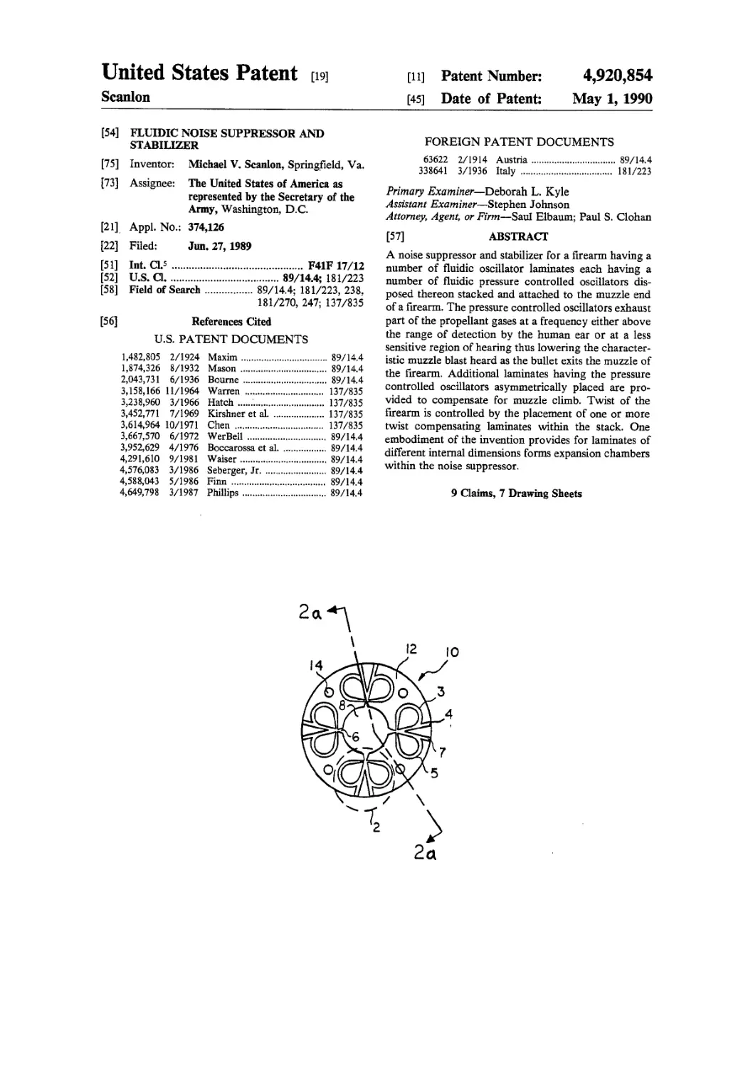
FIG. 2 is a front view of an oscillator laminate having
four pressure controlled oscillators thereon.
FIG. la is a cross section of the oscillator laminate of
FIG. 2.
FIG. 26 is an alternate embodiment of a pressure
controlled oscillator.
FIG. 3 is a cross section of a noise suppressor accord-
ing to the present invention.
FIG. 4 is a front view of an alternate embodiment of
an oscillator laminate.
FIG. 5 is a cross section of an alternate embodiment
of a noise suppressor according to the present invention.
FIG. 6 is a front view of an alternate embodiment of
an oscillator laminate.
FIG. 7 is a front view of a twist compensating lami-
nate.
DETAILED DESCRIPTION OF THE
PREFERRED EMBODIMENTS
The ear of an adult human can hear sounds at fre-
quencies ranging from 15 hertz (oscillations or cycles
per second) to 15,000 hertz, and children can hear
sounds at frequencies up to 20,000 hertz. Sounds at
frequencies lower than 15 hertz (infrasonic frequencies)
and higher than 20,000 hertz (ultrasonic frequencies)
also exist, although such frequencies are not audible to
man. FIG. 1 depicts graphically the range of hearing of
an adult human. The chart of FIG. 1 is obtained by
plotting two curves: the audibility curve, which is the
lower curve in FIG. 1, and the upper curve of “pain” or
“feeling”, which is usually known as the “threshold of
pain” curve. The audibility curve is determined by
measuring the hearing threshold for a series of frequen-
cies within the hearing range. The hearing threshold for
a given frequency is the lowest intensity at which that
frequency can be heard. The upper limit of the auditory
4,920,854
4
back channel 3 and right feedback channel 5 connect
the left and right oscillator output channels, respec-
tively, to the left and right control nozzles. In the center
of oscillator laminate 10 is a large aperture 8 extending
through laminate 10 from smooth side 11 to oscillator
side 12 (as shown in FIG. 2a) whose diameter is slightly
larger than the inside diameter of the gun barrel upon
which laminate 10 will later be mounted. The supply
nozzle 6 of each pressure controlled oscillator 2 opens
10 onto large aperture 8 and the left output channel 4 and
right output channel 7 of each pressure controlled oscil-
lator 2 exits to the atmosphere at the outer circumfer-
ence of oscillator laminate 10. Four small apertures 14
are also provided, each one extending through laminate
15 10 from smooth side 11 to oscillator side 12 of oscillator
laminate 10, as shown on FIG. 2a. Although many
variations are possible, FIG. 2b shows one alternate
embodiment of a pressure controlled oscillator. In this
embodiment, pressure controlled oscillator 80 consists
20 of a supply nozzle 82, a right feedback channel 86, a left
feedback channel 88 and an output channel 84. The
functioning of this pressure controlled oscillator is iden-
tical to the one described above.
The construction of a noise suppressor using multiple
oscillator laminates of the type shown in FIGS. 2 and 2a
is shown in FIG. 3. A noise suppressor 30 is constructed
by stacking any number of oscillator laminates (in this
case six, shown as items lOa-10/). The use of six oscilla-
tor laminates is not mandatory but for illustration only.
30 The number of oscillator laminates will depend upon
the particular weapon involved. The oscillator lami-
nates are arranged such that the oscillator side of each
oscillator laminate faces the muzzle end of gun barrel 36
while the smooth side of each oscillator laminate faces
away from muzzle end of gun barrel 36. This also means
the oscillator side of oscillator laminate 10/ faces the
smooth side of oscillator laminate lOe, the oscillator side
of oscillator laminate lOe faces the smooth side of oscil-
lator laminate lOd, etc. This arrangement of oscillator
40 side to smooth side of the oscillator laminates forms a
“sandwich” of oscillator laminates and the smooth side
of the oscillator laminate serves to restrict the fluid flow
to an approximately two-dimensional flow pattern
within the pressure controlled oscillator. The assembly
of oscillator laminates 10a-10/ are held together in this
instance by four bolts 32, which extend through small
aperture 14 (FIG. 2) of oscillator laminates 10a-10/and
fasten by threads to receiving block 34, which is firmly
attached to the muzzle end of gun barrel 36. The oscilla-
tor laminates could also be bonded together by any
suitable bonding method.
As bullet 40 exits through noise suppressor 30, some
of the bullet 40 propellant gas 33 is exhausted through
the four pressure controlled oscillators in oscillator
55 laminate 10a at a frequency above 15,000 hertz. In a
similar manner, as bullet 40 passes oscillator laminate
106, an additional amount of bullet 40 propellant gas 33
exhausts through laminate 106 pressure controlled oscil-
lators. By the time bullet 40 exits noise suppressor 30 at
60 end 42, most of the bullet 40 propellant gas has vented
through the twenty four pressure controlled oscillators
located in laminates 10a-10/and the characteristic muz-
zle blast, normally heard as bullet 40 leaves gun barrel
36, is significantly lowered.
65 A typical rifle produces anywhere from 12,000 psi
(M-16) to 50,000 psi (.50 caliber) in gun barrel 36 when
fired. The pressure at the exit point of a 7.62 mm NATO
(.30 cal) bullet is 3,500 psi. This amount of propellant
3
sensation area is determined by increasing the intensities
of tones until they produce a perception of pain, tickle,
or feeling. FIG. 1 shows that human individuals nor-
mally perceive as sound those frequencies between
about 15 hertz and 15,000 hertz, with the greatest sensi- 5
tivity around 1000-4000 hertz, i.e. the audibility curve,
showing hearing thresholds for different frequencies,
dips lowest for frequencies of around 1000-4000 hertz.
The intensity, or strength, of a sound is measured in
two principal ways: in terms of the energy carried by
the sound wave or of the alternating pressure changes
produced as the sound wave passes by. As a practical
matter, both measurements are usually converted into
the decibel scale - a logarithmic scale with an arbitrary
reference point, usually 2X10⁻⁵ newtons per square
meter. This arbitrary point is not far from the human
threshold of hearing, and it is designated as 0 decibels or
OdB.
An increase of 10 dB means a 10-fold increase in a
sound’s intensity; an increase of 20 dB, a 100-fold in-
crease; and a 30-dB increase, a 1,000-fold increase in
intensity. Ordinary conversation takes place at about 65
dB. Sounds become disagreeable to most people at
about 100 dB, and sounds above 120 dB can produce a
ticking or pricking sensation in the ears. Still more in- 25
tense sounds cause pain and often a temporary loss of
hearing.
Thus it can be seen from FIG. 1 that sounds above
15,000 hertz, no matter how high in intensity, will not
be detected by the adult human ear. In other words,
sound with a frequency of 5,000 hertz and an intensity
of 120 dB is well within the auditory sensation area of
the human ear; the same intensity of sound at a fre-
quency over 15,000 hertz will not be detected by the
adult human ear at all, and even if the intensity were 35
raised as high as possible, it is physically impossible for
the adult human ear to detect it. This then, is the princi-
pal behind the present invention. By converting the
frequency content of a portion of the muzzle blast of a
firearm to frequencies that are not as detectable to the
human ear, part of the the muzzle blast is effectively
silenced
Referring now to FIGS. 2 and 2a, an oscillator lami-
nate 10, made from any suitable steel, is shown. Smooth
side 11 of laminate 10 is shown in FIG. 2a, which is a 45
cross section along line 2a—2a. Opposite smooth side 11
is oscillator side 12 of oscillator laminate 10. Disposed
on oscillator side 12 of oscillator laminate 10 are four
pressure controlled oscillators 2 (shown enclosed
within the dashed lines) which are machined or molded 50
into laminate 10. The use of four pressure controlled
oscillators is for the purpose of illustration only; more
or less than four pressure controlled oscillators may be
used depending upon the particular weapon involved.
A typical oscillator, chosen for purposes of ease of
explanation only, will comprise a main supply nozzle 6
extending through the end wall of an interaction region.
Oscillator 12 is machined or molded to provide an end
wall, two sidewalls (left and right sidewalls), and a
divider disposed at a predetermined distance from the
end wall. The sidewalls of the divider in conjunction
with the interaction region sidewalls establish the re-
ceivers which are entrances to the oscillator’s left out-
put channel 4 and right output channel 7. Left and right
control orifices extend through the left and right side-
walls respectively, and terminate in control nozzles
which have their centerlines passing orthogonally
through the centerline of the supply nozzle 6. Left feed-
4,920,
5
gas pressure is more than adequate to cause the pressure
controlled oscillators in noise suppressor 30 to function
as described above. The particular oscillator geometry
can be varied to produce different frequencies if de-
sired. The supply nozzle width, depth, feedback chan- 5
nel length, and supply nozzle to splitter distances all
have an effect on the output frequency; design of these
items is well known in the prior art. To prevent the
oscillator from being saturated, the supply nozzle con-
figuration can be designed to be a converging supply 10
nozzle in order to choke the flow of the propellant gas
in the supply nozzle thus limiting the propellant gas
pressure going into the pressure controlled oscillator.
By modifying the placement of the pressure con-
trolled oscillators on the oscillator laminate, the noise 15
suppressor can also function as a climb compensator.
Shown in FIG. 4 is an oscillator laminate 50 in which
three pressure controlled oscillators 52 (shown sche-
matically) are placed asymmetrically around large aper-
ture 54. Again, the use of three pressure controlled 20
oscillators is for illustration only. Small apertures 55
serve the same function as those shown in FIG. 2. The
release of propellant gas through pressure controlled
oscillators 52 will result in a net force “F” on laminate
50 acting in the direction shown which can be used to 25
compensate for the weapon’s tendency to climb. In
comparison, an oscillator laminate of the type shown in
FIG. 2 has a net force of zero on laminate 10 because
the pressure controlled oscillators are placed symmetri-
cally around the large aperture. By stacking several 30
laminates of the type shown in FIG. 4 into a noise sup-
pressor of the type shown in FIG. 3 or FIG. 5 such that
the sections without a pressure controlled oscillator
align, the entire noise suppressor can be oriented in the
proper direction to counteract the characteristic climb 35
of any weapon.
Additional modifications to the basic noise suppres-
sor design of FIG. 3 can add the feature of a muzzle
brake. FIG. 5 shows a noise suppressor 60 mounted to
gun barrel 62 having both noise suppression, anti-climb, 40
and muzzle brake characteristics. A series of oscillator
laminates Юа-lOg constructed according to FIG. 2
and/or FIG. 4 is arranged as shown. Between these
laminates is interposed oscillator laminates built accord-
ing to FIG. 6. These laminates are designated lla-11/ 45
The use of seven oscillator laminates according to FIG.
2 and/or FIG. 4 and the use of six oscillator laminates
according to FIG. 6 is for the purpose of illustration
only. Any number of oscillator laminates may be
stacked in this manner depending upon the characteris- 50
tics of the particular weapon involved. In the oscillator
laminate 63 of FIG. 6, four pressure controlled oscilla-
tors 64 (shown schematically) are located around large
aperture 66 which is considerably larger than the large
aperture of FIGS. 2 and 4. Again, the use of four pres- 55
sure controlled oscillators is for illustration only. The
four small apertures 68 are located in the proper posi-
tion to align with the four small apertures 14 of FIG. 2
or the four small apertures 55 of FIG. 4. When the
laminates of FIG. 2 and/or FIG. 4 and FIG. 6 are then 60
stacked as shown in FIG. 5, a series of expansion cham-
bers 63a-63c is provided in noise suppressor 60. As
bullet 65 exits gun barrel 62, the bullet’s propellant gas
is forced to expand and contract as bullet 65 passes
through noise suppressor 60; this expansion and con- 65
traction of the propellant gas tends to act as a muffler
and slows down the expansion of the propellant gas as it
leaves end 67 of noise suppressor 60. The expansion and
854
6
contraction of the propellant gas also tends to increase
and lengthen the duration of propellant gas pressure to
the pressure controlled oscillators, therefore allowing
more time for the propellant gas pressure to be bled off
through the pressure controlled oscillators, which in
turn would lower the amount of propellant gas that will
rapidly expand at end 67. A further advantage of noise
suppressor 60 is that it will tend to act as a muzzle brake
and reduce recoil because when the pressure wave of
the propellant gas moves forward and hits surface 82 of
oscillator laminate 106, surface 84 of oscillator laminate
lOd, and surface 86 of oscillator laminate 10/, some of
the energy of the pressure wave is used to force noise
suppressor 60 to move forward, thus counteracting
some of the weapon’s recoil which tends to throw the
weapon back into the shooter’s shoulder.
A problem sometimes associated with the firing of a
modem weapon is the twisting or torquing of the
weapon as a result of the bullet traveling down the
weapon’s rifled gun barrel. The rifling groves inside the
barrel are meant to impart a spin on the bullet so as to
give the bullet stability in flight. The forces of the for-
ward moving bullet acting on the rifling tend to twist
the rifle. An additional item added to the basic noise
suppressor design can effectively counteract this ten-
dency for the weapon to twist. Using one or more twist
compensating laminates 70 of the type shown in FIG. 7
will produce an axial torque opposite the twisting mo-
tion of the weapon. Four spiral channels 76 are ma-
chined or molded into laminate 70 in a manner similar to
the creation of the pressure controlled oscillators.
Again, the use of four spirial channels is for illustration
only. Large aperture 74 is sized to the gun barrel and
small apertures 72 are arranged to align with the small
apertures of FIG. 2 and/or FIG. 4 and/or FIG. 6. The
jets of propellant gas exiting spiral channels 76 will
create a pure torque if symmetrically aligned around
large aperture 74. The configuration of spiral channel
76 can also be adapted to each particular weapon. Twist
compensating laminate 70 can be used in place of lami-
nate 10a in FIG. 3 or FIG. 5, or placed wherever it is
most beneficial to the weapon used on. More than one
twist compensating laminate 70 can also be incorpo-
rated into any particular noise suppressor design.
All of the laminates described above exhaust the bul-
let propellant gasses perpendicular to the gun barrel,
unlike some muzzle end devices which tend to redirect
the bullet propellant gas as a pressure wave back
toward the shooter, increasing fatigue due to blast over-
pressures and noise. The fluidic devices described
above will significantly lessen these effects.
To those skilled in the art, many modifications and
variations of the present invention are possible in light
of the above teachings. It is therefore to be understood
that the present invention can be practiced otherwise
than as specifically described herein and still will be
within the spirit and scope of the appended claims.
I claim:
1. A noise suppressor for a firearm having a breech
end, a muzzle end, and a bore comprising:
a plurality of fluidic oscillator laminates each com-
prising an annulus disk having a first surface, as
second surface opposed to said first surface, a cen-
ter, and an aperture having an axis, said aperture
located at the center of said annulus disk, said first
surface being smooth and said second surface hav-
ing a plurality of fluidic pressure controlled oscilla-
tors disposed thereon;
4,920,854
said aperture having a diameter slightly greater than
the diameter of the bore of said firearm;
said plurality of pressure controlled oscillators each
having a supply nozzle opening upon said aperture
of said annulus disk and at least one output channel 5
open at the circumference of said annulus disk;
said plurality of fluidic oscillator laminates fixedly
attached to one another forming a laminate stack
such that said first surface of each said fluidic oscil-
lator laminate is attached to said second surface of 10
an adjacent said fluidic oscillator laminate;
said laminate stack fixedly attached to the muzzle end
of said firearm such that the axis of said aperture of
each said fluidic oscillator laminate is coaxially
aligned with the bore of said firearm. 15
2. The device of claim 1 wherein at least one of said
plurality of fluidic pressure controlled oscillators is
configured so as to oscillate at a frequency above 15,000
hertz.
3. The device of claim 1 wherein said plurality of 20
fluidic pressure controlled oscillators disposed upon
said plurality of fluidic oscillator laminates are symmet-
rically arranged around said axis of said aperture.
4. The device of claim 1 wherein said plurality of
fluidic pressure controlled oscillators disposed upon 25
said plurality of fluidic oscillator laminates are asym-
metrically arranged around said axis of said aperture.
5. The device of claim 1 further comprising at least
one twist compensating laminate arranged within said
laminate stack, said twist compensating laminate com- 30
prising an annulus disk having a first surface, a second
surface opposed to said first surface, a center, and an
aperture located at the center of said twist compensat-
ing laminate, said first surface of said twist compensat-
ing laminate being smooth and said second surface of 35
said twist compensating laminate having a plurality of
spiral channels disposed thereon.
6. A noise suppressor for a firearm having a breech
end, a muzzle end, and a bore comprising:
a plurality of first fluidic oscillator laminates each 40
comprising an annulus disk having a first surface, a
second surface opposed to said first surface, a cen-
ter, and an aperture having an axis, said aperture
located t the center of said annulus disk, said first
surface being smooth, said second surface having a 45
plurality of fluidic pressure controlled oscillators
disposed thereon and said aperture having a diame-
ter slightly greater than the diameter of the bore of
said firearm;
a plurality of second fluidic oscillator laminates each 50
comprising an annulus disk having a first surface, a
second surface opposed to said first surface, a cen-
ter, and an aperture having an axis, said aperture
located at the center of said annulus disk of said
second fluidic oscillator laminate, said first surface 55
of said annulus disk of said second fluidic oscillator
laminate being smooth, said second surface of said
annulus disk of said second fluidic oscillator lami-
nate having a plurality of fluidic pressure con-
trolled oscillators disposed thereon and said aper-
ture of said annulus disk of said second fluidic oscil-
lator laminate having a diameter greater than the
diameter of said aperture of said first fluidic oscilla-
tor laminate;
said plurality of pressure controlled oscillators dis-
posed upon said first fluidic oscillator laminates
each having a supply nozzle opening upon said
aperture of said annulus disk of said first fluidic
oscillator laminates and a left and right output
channel open at the circumference of said annulus
disk of said first fluidic oscillator laminates;
said plurality of pressure controlled oscillators dis-
posed upon said second fluidic oscillator laminates
each having a supply nozzle opening upon said
aperture of said annulus disk of said second fluidic
oscillator laminates and a left and right output
channel open at the circumference of said annulus
disk of said second fluidic oscillator laminates;
said plurality of first and second fluidic oscillator
laminates fixedly attached to one another forming a
laminate stack having an alternating plurality of
said first and second fluidic oscillator laminates
thereby forming a plurality of expansion chambers
within said laminate stack;
said laminate stack fixedly attached to the muzzle end
of said firearm such that the axis of said aperture of
each of said first fluidic oscillator laminate is coaxi-
ally aligned with the bore of said firearm and the
axis of said aperture of each of said second fluid
oscillator laminate is coaxially aligned with the
bore of said firearm.
7. The device of claim 6 wherein said plurality of
fluidic pressure controlled oscillators disposed upon
said first fluidic oscillator laminate are symmetrically
arranged around said axis of said aperture of said first
fluidic oscillator laminates.
8. The device of claim 6 wherein said plurality of
fluidic pressure controlled oscillators disposed upon
said first fluidic oscillator laminate are asymmetrically
arranged around said axis of said aperture of said first
fluidic oscillator laminates.
9. The device of claim 6 further comprising at least
one twist compensating laminate arranged within said
laminate stack, said twist compensating laminate com-
prising an annulus disk having a first surface, a second
surface opposed to said first surface, a center, and an
aperture located at the center of said twist compensat-
ing laminate, said first surface of said twist compensat-
ing laminate being smooth and said second surface of
said twist compensating laminate having a plurality of
spiral channels disposed thereon.
*****
60
65