/


Tags: weapons military affairs
Year: 1930

Text
No.ZB 151 - 30
AUTOMATIC RIPLE WZH" Mod.2 9
CeskoelovenskA Zbrojovka a.s.
Brno
June 1930
h/ Preface
2*/ General Data of ZH 29
5./ Weight and Carrying of ZH 29
4»/ Description of ZH 29
5./ Action of ZH 29
6«/ Hofc to Attend to ZH 29
7*/ Dismounting of ZH 29
8./ List od Parts of ZH 29
9«/ Technical Data of ZH 29
oooOooo
PRE? AC S
The need of an automatic rifle, dependable and
simple to operate, was long felt in military circles and was
often discussed in military publications.
The Ceskoslovenskd Zbrojovka, akoiovA spolefcnost,
Brno, has since a long time endeavored to accomplish this and
has studied in its Experimental Departments several models of
different systems.
Model ,,ZH 29 ,, described- in this pamphlet, is
because of its purposeful construction and its durability
able to withstand even the most rigorous demands set upon an
automatic rifle.
АОТ0ШТ1С SYSTEM ZU 29
*«мо<^йе»м«***«ь4»**м«»***о*«г*»*<з**«»«
•
is constructed and manufactured at the CeskoslovenskA Zbrojov-
ka, akciovd spolednost, Бгпо. It may be supplied with any ca-
liber I : 7.92, 7.65, 1, or 6.5 m/a ; /, fur pointed or ogival
ammunition. The weight of the rifle Mth the magazine is 4.35
kg. Its efficiency and durability are — if not better — at
least equal to those of all normal magazine rifles. It is ba-
sed ^n the principle of utilising of gases9 carried from the
bored barrel to the piston tube, in which roves the piston •
f
It may be loaded either from clips or with full magazines
from below. Thu magazines contain five or ten rounds of ammu-
nition and are easily interchangeable. The construction is
simple. The rifle nay be easily dismounted and its parts in-
terchanged without any adjusting /: absolute interchangeabi-
lity :/• The practical firing-speed is 20 to 50 rounds a mi-
nute ; when loading with full magazines, this speed increases
up to 85 rounds a minute.
Main Advantages of Automatic Rifle ZH 29 .
The piston is carried in a short piston tube,
along a course of 20 m/m, and after the action is in operatic
the gases blow into the free space in the cooler and the stoc
so that they do not clog the gas cylinder.
Because the bolt mechanism has a sufficient re-
serve during its rearward movement, no careful regulating of
the recoil spring is necessary and the rifle functions proper
ly even if the cartridge should have either a smaller or a
larger quantity of powder.
Its simply construction and advatageously placed
guiding surfaces enable the rifle to operate with a minute .
exactness even with a soiled or dry mechanism.
It is not necessary to clean or oil the rifle
during firing.
After firing, the rifle may be cooled in water.
The entrance of water into the barrel, gas cylinder or bolt
or trigger mechanism — which causes trouble to other syster
of rifles — does not influence the proper functioning of rii
ZH 29.
The barrel may be of any length without alterin;
the principle of the rifle in any way.
г
A worn-out barrel may be easily exchanged, without
it being necessary to adjust any parts of the rifle.
The rifle may be opened easily and quickly, and
in this condition may be cleaned with facility. The cocking
handle is of the same piece as the bolt, which makes it possi-
ble — in case of necessity — to use the rifle as a magasine
rifle.
The entrance of the gases may be regulated, if
desired closed up entirely, and the rifle will then operate on
the principle of a magazine rifle.
The rifle may be adapted to a bayonet of any systei
The rifle is supplied with an aluminium cooler,
which absorbs the heat and lessens the wear of the rifle .
The breaking or injuring of any of the parts upon
which depends the automatic functioning, does not disqualify
the rifle.
The construction is so simple that the manufacture
is not in the least complicated, and its simplicity assures a
complete exchangeability. The principle of the breech is the
simplest imaginable ; there are no joints or pins used, thо to-
lerance of which, added, would make rational manufacture or ex-
changeability difficult.
The automatic rifle ZH 29 may be adapted to any
kind or caliber of ammunition, used for magazine r-if'los.
3
Weight and Portability of the Rifle»
— m— m x •«»«* м» • •• «•« j * «—• «в *«•«* » «•
The weight of this rifle, 4.20kg, differs very
little from that of the rifle now in use, and even the loops
for the sling may be so arranged that the automatic rifle ZJT
29 may be carried as easily and comfortably as the magazine
rifle. Its shape is so much like that of the normal rifle that
even at close range, the rifle does not strike one as somethin/
unusual or different from the iiormal rifle.
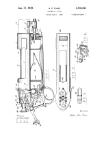
DESCRIPTION OF THE RIFDS
The main parts of the automatic rifle ZH 29 may
be divided into two groups :
1 ./ FIXED •
a/ barrel with the Gas Deriver and Cooler,
b./receiver,
o./ goora,
d.z stock,
e./ magazine,
2 ./ MOVABLE
f./ bolt carrier,
g./ bolt .
The BARREL
-1- is 590 m/m long. It is threaded in the rear in order
to be screwed into the Receiver - 15 -. The front part of the
Barrel is threaded for the Gas Deriver Nut - 7 - or the dummy
shooting attachment. The Gas Deriver - 3 • is attached to the
front part of the Barrel, sits on a shoulder on the Barrel and
is set in place through the Gas Deriver Nut -7». The projecti-
on on the rear side of the Gas Deriver is located in the groove
of the abovementioned shoulder and in that way holds the Gas
Deriver in its proper position.
The front part of the Gas Deriver forms a little
bridge for the Front Sight. Below the Gas Deriver is a catch
for the Bayonet, enforced through two lengthwise placed ribs.
The rear part passes into the Gas Cylinder, which is closed by
- 5 -
the Gas Stopper - 4 -, serving at the same time to regulate
the gas. The Gas Stopper is put into required positions by e
projection that fits into grooves in the Gas Deriver. The Stop-
per is held in position by the Gas Stopper Safety Stay Bolt -5-
and this again by the Gas Stopper Safety Stay.Bolt Pin - 6 -•
In the pert between the gas deriver and the Receiver is the Bar -
rel provided with a Curler - 12 - and a Front Stock - 14 -. The
Cooler is a duraluminum casting, with crosswise and lengthwise
placed ribs, fitted on the Barrel. Along its length, in its low-
*
er part, it has two openings: through the right one passes the
Bolt Carrier - 35 the left one is for better cooling. The Cool
er sits with Its front part on the Gas Deriver, while in its
rear side is held the Front Stock. This has two parts ; the
right side is provided with a groove for the Bolt Carrier - 35 -*
The Front Stock is secured both in a notch in the Receiver and
in the Cooler ; that part of the rifle which is covered with
wood is supplied with a Cooler. The connecting rod of the Gas .
Deriver and Cooler is covered by the Front Band -8-, provided
with the Front Band Swivel - 11 -, Front Band Screw -9-, and
Front Band Screw Nut - 10
The RECEIVER
-15- forms in its forward part a cylindrical projection
that contains threading for the Bdrrel. On its right side it
provided with a notch for the. B* It Carrier, on its left side
with guiding slides for the Bolt -37-. On its left side is plac-
e d д Bearing Plate - 21-, fasti red to the Receiver by th’< 'ear-
ing Plate Screw -27-. In the forward part of the Receiver .the^e
is a notch for the Magazine -70-, and Magazine Front and Baek-
- б -
Stops -16- and -17-> The Magazine Front Stop -16- has a Magazine
Front Stop Spring -20- and is secured by a Magazine Front Stop
Screw -L3-. The Magazine Back Stop -17- has a Magazine Back Stop
Spring -20- and is secured by a Magazine Back Stop Screw -19-.
The longer, lever-like part of the Magazine Back Stop projects
from the Receiver and by pressing it the Magazine is loosened
when it has to be exchanged for another one» On the upper sur-
face of the Receiver is a notch for the Rear Sight. This is of a
frame type and the arrangement and execution of its parts la li-
ke that of the Rear Sight used on Mauser Rifles» It consists of:
Rear Sight Ramps -30», Leaf -27-, Rear Sight Spring -29-, Rear
Sight Slide -51-, tn Rear Sight Catches -32-, Rear Sight Leaf
Pin -28- and two Rear Sight Catch Springs -33-. On the lower rear
part of the Receiver are placed the Front and Rear Guard Bolts
-23- and -24-, with their Guard Bolt Locking Pins -25- and Springs
-26-» The Guard -34- is connected with the Receiver -15- through
the help of these bolts»
The GUARD
-34-/: the lower part of which projects into a trigger-guard
bow and on the rear wall of which is adjusted the Stock : / forms
the bed of the Trigger and Recoil mechanism. On its right side is
placed the Recoil Spring -58- provided with the Recoil Spring Pin
-59-which sits on the Bolt Carrier» In the rear wall of the Guard
is fastened — on the Bayonet Lock— the Recoil Spring Bousing -60ч
The Guard Mechanism consists of the following parts : tha Striking
Hammer -46- pivoting on the Striking Kammer Pin -48-, this Pin
securing at the same time the Recoil Spring Pin against disloca-
ting. The Striking Hamer Spring -47 has two en*s; the shorter
one presses the Striking Hammer, the longer passes through the
Interrupter -53-e The upper part of the Striking Heimer is provi-
ded with an oval surface for the setting of firing readiness of
the Bolt -'oT- and a double-cogged catch for the Sear and the In-
terrupter. The Sear -49- has two arms, is provided with the In-
terrupter -5 5- and is connected with it through a riveted Inter-
rupter Pin -54-. The longer arm of the Sear is in contact with
the Trigger -51-. The rear arm of this frigger raises the Sear;
the front arm projects into a hooked nose and when in a secured
position, leans on the Safety Stay Bolt. The Safety Stay Bolt -35-
is pivot-like bedded in the Guard. It is secured in the required
position through the Safety Stay Bolt Pin -56-, and the Safety
Stay Bolt Spring -57, placed in the outer arm of the Safety Stay
Bolt. The Safety Stay Bolt Pin engages into the grooves on the
right side of the Guard. The pivotlike Pins -48-,-50? and -52-,
of the different parts of the Trigger and the Safety Stay Bolt,
are secured against falling out by the left side of the Receiver.
The Safety Stay Bolt is secured through the 3ear.
The STOCK :
-61- is fastened to the Guard through the Stock Screw -'3-,
/:with a square head :/ and the Stock Screw u'asher -64-.In the
Stock is bedded the Recoil Spring Housing -60-. The rear part is
provided with a Butt Plata -62- ma£e of pressed sheet-iron, which
is fastened with a Buxt Plat' Serov/ —65—, On the lower part of the
6
Stock la placed the Butt Swivel Plate -66- with the Butt Swi-
vel -67- and the Butt Swivel Pin -68-,The Butt Swivel Plate is
fastened to the Stock through Butt Swivel Plate Screws -69»,
The MAGAZINS
-70- is manufactured of pressed sheet-iron and is provided
with the Feeder and Feeder Spring -71- and -72-. The Feed is the
same for a magazine either for five or ten rounds. The Spring
-7й- is held by one of its ends in the Feeder -71-, by the other
in the’^gasina Bottom Stop -74- which is in turn secured by the
Magazine Bottom -73
The BOLT GABBIER
-ЗБ- changes in its front part into a piston rod, which engages
into the Gas Cylinder of the Gas Deriver -3-, The rear part is
provided with a Cocking Handle and the Bolt -37- is bedded in
it. Slides on the lower and upper part serve to guide the Carrier,
The movement of the Carrier is transmitted in the rear part
through a cog-like projection to the Reooil Spring Pin. The
opening for the bolt projection is covered by the Bolt Cover -36-,
The BOLT
«37« has on its right side a projection which is caught during
ite rearrard r^vamsnt by the Bolt Carrier. The front wall of the
Bolt forms a bed for the cartridge bottom. The oblique surface of
the rear left wall touches the Bearing Plate -21-. The elide on
the lower psrt of the Bolt serves for cooking of the Striking
Hammer and for holding the Bolt in firing readiness. In the right
fore part is placed in a groove-like manner the Extractor -41-,
pressed upon by a flat Extractor Spring -42-, which is held on its
lower wall by a milled oog and is fastened in a notch in the
Bolt* On the left side, on the lower part of the cartridge
bed, are placed two Ejectors *43- with its Ejector Spring
-44- and secured by an Ejector Safety Ping -45-» The Striker
-38- passes through the center of the Bolt and its rear end
projects outside of the Bolt* It has a Main Spring -40- and
is secured by a Striker Pin -39-*
-10-
ACTION OF THE RIFLE ZH 2 9.
The Sear -49- releases through the pressing of the
Trigger -51- the Striking Hemer -46-, which strikes the Striker
-38- through the pressure of the Striking Spring -47-, and fires
the cartridge. This operation causes some of the gases to enter
through the gas channel into the Gas Cylinder, acts on the fore,
piston-like end of the Belt Carrier -35- and moves it to the rear.
The notch in the rear part of the Carrier catches the Bolt, pulls
it out of the notch in the Bearing Plate -21-, and continuing in
its rearward movement cocks the Trigger mechanism. The Extractor
-41- extracts the fired cartridge case, which is then ejected by
the Ejector forward and a little to the right. The depressed Re-
coil Spring -58- moves again the Bolt Carrier forward, the Bolt
inserts a new cartridge into the chamber, and the rifle is ready
for further firing. This operation is repeated through depressing
of the Trigger. After the last cartridge has been fired, the Feeder
holds the Trigger mechanism in an open position and the rifle may
be loaded again.
The cartridges are being ejected through spring ejectors
forward and a little to the right , The ejecting is not violent
and the Ejector does not Injure the cartridge cases ; these are
ejected about one meter away from the operator.
DUMMY SHOOTING
The automatic rifle Ш 29 may be easily adjusted
for dummy shooting. Instead of the Gas Deriver Nut one screws
in the Dummy Shooting Attachment.
TO ATT2ND TO ZH 29 .
*»•* я» «» «• *• w «* w м «в
The rifle may be carried just like a normal magazine
rifle /; fig, 1 :/• Stable adjusting of the loops for the sling en-
ables one to carry it like a cerabin,
While firing, the rifle is held in the same manner
as the magazine rifle /< fig.2 :/, even the aiming is identical.
When using magazines for 20 rounds, the rifle must be
held on the magazine / : fig, 3,:/,
THX LOADING OF ZH 29 .
Loading from clips
eat—w •• • ее •» w «••••»•» •“
/: fig, 4 i / Is done in the same way as the
loading of a magazine rifle. The clip with the cartridges is push-
ed into the notch in the Receiver, the cartridges slipping into
the Magazine as a result of pressure exerted. The Feeder is de*
pressed at the same time, which causes the Bolt to take the posit ic
- 12 -
of firing readiness and now further cartridges nay be loaded
from clips without it being necessary to do any other securing*
Loading from below with full magazines
/ : fig. 5. and 6. :/.One
depresses the Magazine Back Stop with the right-hand thumb and
takes out the empty Magazine. This causes the Bolt to take auto-
matically the position of firing readiness. The new full Magazine
is loaded by simply pushing it into the Receiver from below. The
rifle, after it has been loaded by pulling the cooking handle to
the rear and releasing it, automatically pushes the cartridge Into
the chamber and closes It. Should the rifle be closed, one takes
the cocking handle and pulls the Bolt Carrier back. During the
rearward movement the Bolt catches the Feeder and the rifle mecha-
nism remains open, so that the rifle may be loaded from the top.
When the rifle is loaded but the cartridge is not in the
, we pull the Carrier back and its releasing causes the
cartridge to slide into the chamber •
SECURING OF THE RIFI3 .
_____ _____... "_ ____ I
Since the rifle has, after the firing of a cartridge,
always a new one In the chamber and is ready to fire, it Is
necessary to secure the rifle when firing is discontinued .
1./ Securing when cartridge is in the chamber .
--------—-------—--------------------—„-----... one
turns the Safety Stay Bolt into , ,0,, position . By turning the
- 13 -
Safety Stay Bolt into position ,, 1 ,, one may immediately press
the Trigger and fire» This securing is best for discontinuing of
fire for a short time,
2,/ Complete discontinuing of fire • One places the
Safety Stay Bolt into position ,,0», ; then presses the Magazine
Back Stop and pulls out the Magazine /5 fig. 6 : / ; pulls the
cocking handle of the Carrier beck and in this way throws the
cartridge out of the chamber ; empties the Magazine and places the
empty one into the rifle,
REGULATING OF THS ENTRANCE OF CASKS ,
The entrance of gases into the Gas Cylinder may be
left entirely open, or the gases may be shut half off, or they may
be shut off entirely. It may be done as follows : The Gas Stopper
Safety Stay Bolt is raised with the point of a cartridge / : fig.7 :
and turned 180° ; then we pull out the Gas Stopper /: fig. 8:/ and
place it into the required position /: fig, 9 :/, which causes the
Gas Stopper to take the required position, after which we again
secure the Safety Stay Bolt,
- 14
DISMOUNTING AND CLEANING OF ZH 29 .
The rifle ZH 29 nay be dismounted easily and quckly,
the only necessary tools being : a cartridge, a universal wrench
and a cap key*
In order to dismount the rifle only partially, a car-
tridge is sufficient*
1./ Gas Deriver Nut :
Is unscrewed with a universal wrench /: fig.^O :/•
2./ Gas Deriver, Cooler, Front Stock :
Is pulled off the Barrel / : fig* 11* : /*
3./ Bolt and Bolt Carrier :
The Guard Bolts are disengaged with a cartridge /: fig*
12* and 13. :/.
4*/ Trigger mechanism:
Pins are disengaged :
a./ The Striking Hammer Pin is disengaged with a cartridge
This disengages the Becoil Spring, Striking Hammer and
Striking Spring /: fig* 14.:/
b./ The Sear Pin is disengaged with a cartridge .
c./ The Trigger Fin is disengaged with the Striking Spring
/: fig. 15.:/.
d./ The Safety Stay Bolt is put betv/een positions ,,l,,and
- 15 -
,, О ,, and is pushed cut from the opposite side with
a cartridge /: fig. 16 :/•
5 ./ Butt Plate :
The Butt Plate Screw is unscrewed with a universal wrench,
6 ./ Stock :
The Stock Screw is loosened with a cap key
7 ./ Recoil Spring Housing :
Is turned 90° and pulled out.
8 ./ Butt Swivel Plate :
mmmmm — — •» — — —
Ths Butt Plate Screws are unscrewed with a universal
wrench.
9 ./ Striker :
The Striker Pin is pushed out with the Striking Spring
/: fig. 18.:/.
10 ./ Extractor and Extractor Spring :
Is wrenched out with a cartridge /:fig. 19. and
11 ./ Ejector with Springs :
The Ejector Pin is pushed out with the Striking Spring
/: fig. 21.:/.
12 ./ Magazine Front and Baok Stops :
• ••МММ—ММММ MM M M M MMMMMM M
Magazine Front and Back Stop Screws are unscrewed.
13 ./ Gas Stopper :
MMMMMMМММ МММ* MM МММ
The Gas Stopper Safety Stay Bolt is raised and curs’d
180° with a cartridge /: fig. 7. and fig. 8. ;/
16 «*
14 ./ Magazine :
Pulling out of the Magazine Bottom loosens the Feeder
with its Spring.
The rifle, dismounted according to the above, may be
now completely cleaned. It is not necessary to dismount the
parts that remained joined.
After discontinuing of fire it is sufficient to dis-
mount the rifle according to point 3, 4a, 9, 10 and 13, and to
use on these parts a little vaseline when mounting them again.
The mounting of the rifle is done in the' opposite manner.
?АНУЗ О? AUTOMATIC F.LFLE ZH CG
Number: Parts Number of pieces:
1. Barrel 1
2. Front Sight 1
♦5 t За» Derives» 1
4. Gaa Stopper 1
£>• Qas Stopper Safety Stay Bolt 1
6« G«a Stopper Safety Stay Bolt .Zin 1
7. Gas Deriver Nut 1
8. Front Band 1
$. Front' Band Screw 1
Iv. Front Band Screw Nut 1
11. Front Band Swivel 1
12. Cooler X
13* Front Stock Tube 1
14. Front stook/Kight and Left/ Я
lb* Receiver 1
16. Magazine Front Stop 1
17. Mag as inc Back Stop . ’.1 1
18. Magesine Front Stop Screw 1
19. Magazine Back Stop Sci’ew 1
GC. Magazine Stop Springs *
£1. Bearing Plate 1
18
22, Bearing Plate Screw 1
23. Guard Front Bolt 1
24. Guard Rear Bolt 1
25. Guard Bolt Locking Pins 2
26. Locking Pin Springs 2
27. Leaf 1
28. Leaf Fin 1
29. Rear Sight Spring 1
30. Rear Sight Raiaps 1
31. Rear Sight Slide 1
32. Rear Sight Catches 2
33. Rear Sight Catch Springs 2
34. Guard 1 /
35. Bolt Carrier 1
3G. Bolt Cover 1
37. Bolt 1
38. Striker 1
39. Striker Pin 1
40. Main Spring 1
41. Extractor 1
42. Extractor Spring 1
43. Ejectors 2
44. Ejector Springs 2
45. Ejector Safety Pin 1
46. Striking Hamner 1
19
47. Striking Spring 1
48. Striking Hammer Pin 1
49. Sear 1
50. Sear Pin 1
51. Trigger 1
S2. Trigger Pin 1
53. Interrupter 1
54. Interrupter Pin 1
55. Safety Stay Bolt 1
56. Safety Stay Bolt Pin 1
57. Safety Stay Bolt Spring 1
58. Recoil Spring 1
59. Recoil Spring Pin 1
60. Reooil Spring Housing 1
61. Stock 1
62. Butt Plate 1
63. Stock Screw 1
64. Stock Screw Washer 1
65. Butt Plate Screws 2
66. Butt Swivel Plate 1
67. Butt Swivel 1
68. Butt Swivel Pin 1
69. Butt Swivel Plate Screws 2
70. Magazine . 1
71 Feeder ’ 1
-20-
72. Feeder Spring 1
73. Magazine Bottom 1
74. Magazine Bottom Stop 1
The rifle consists of 79 portst the Magazine of
5 parts.
TECZSICAX. DATA ОУ APTOTIC H1FLE 3H 29,CAL*?.92m
Culibra................................. ............ 7.92вап.
Number of grooves .....................................* • 4
Depth of grooves ............. 0.17m
‘Uwiot ............................. right
2Itch of rifling ............................... ?.4CH--‘?ram
Course of the bullet In the barrel ............... 534aai
tftjszle velocity WOm/Sec
Length of barrel................................... 590 nn
length of rifle ................................. 114C m
Ler^th of rifle th bayonet ...................... 1295 ram
distance between sigh.tr ........................ 385 m
graduation of rear sight each 100 SjXVcea 300 up to 1600 m
Weight of rifle ....... • .••.................... > 4.20
Weight of aagaaii» i'c V ^ounda^eapty 0.1S
Weight of mp.gaairs for 6 rounde,full .. 0. £7
Weight of magasine for 10 roundatempty .......•• 0*19
Weight of a&g&zine for 10 rcunds^full • •».....•• 0.43
& £ Й fl-
Fig. 1.
Fig. 2.
co
£
Fig. 4
Fig. 5.
Fig. 6.
Fig. 10.
Fig. 13.
Fig. 18.
Fig. 19.
Fig. 20.
Fig. 21.