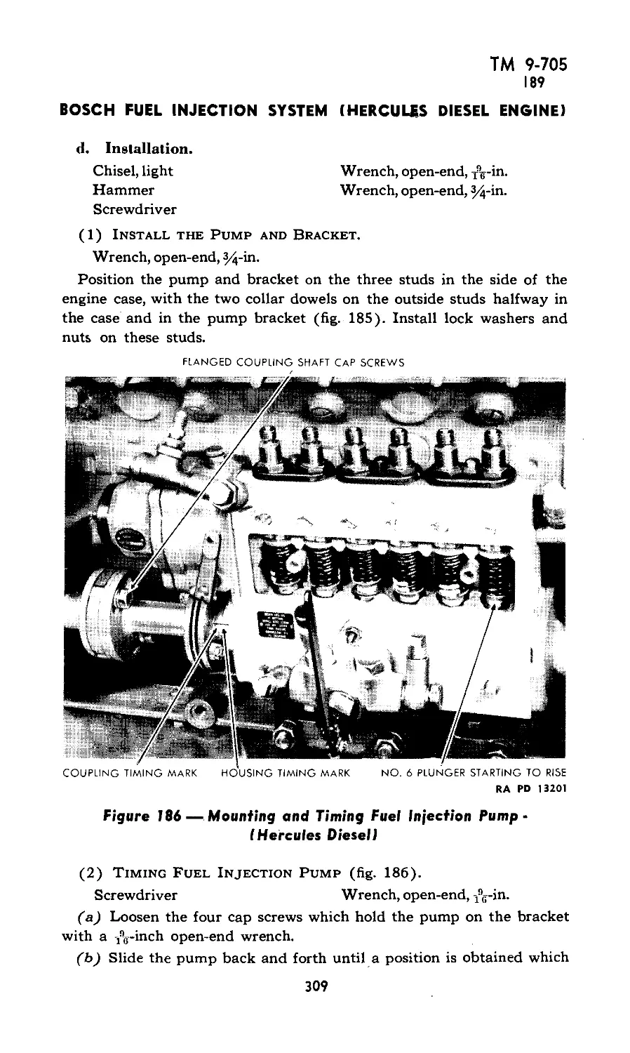
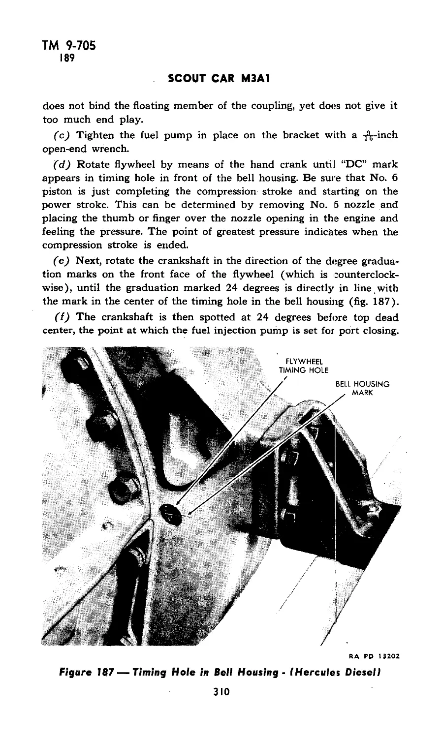
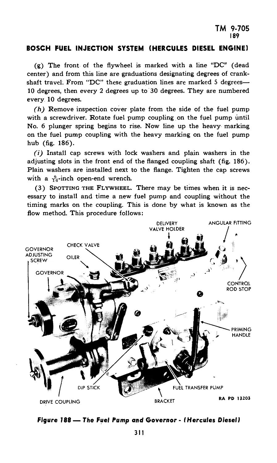
/


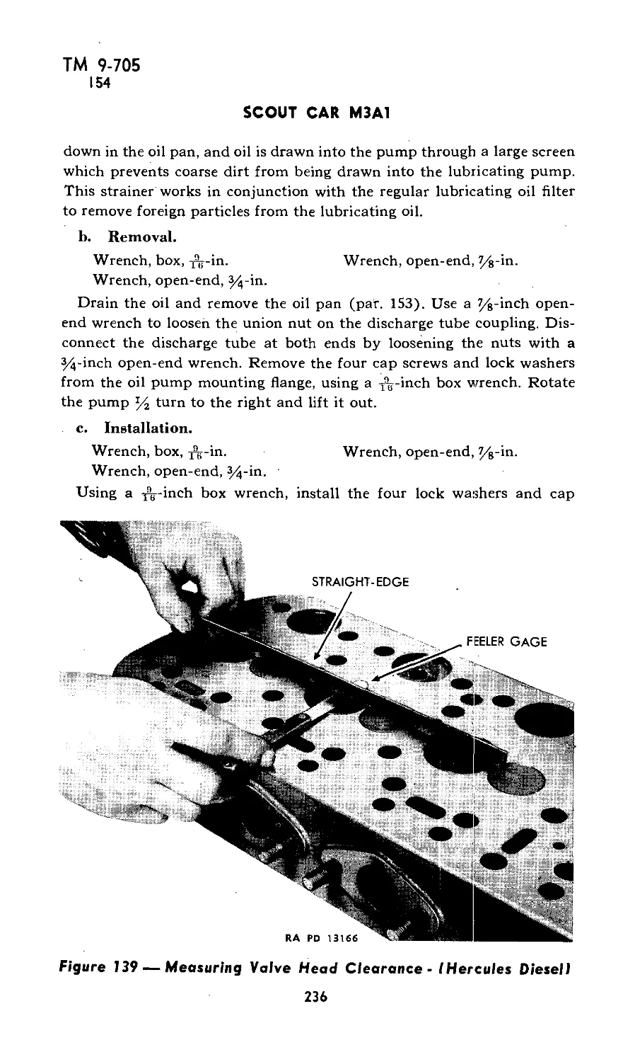


Tags: transport
Year: 1942


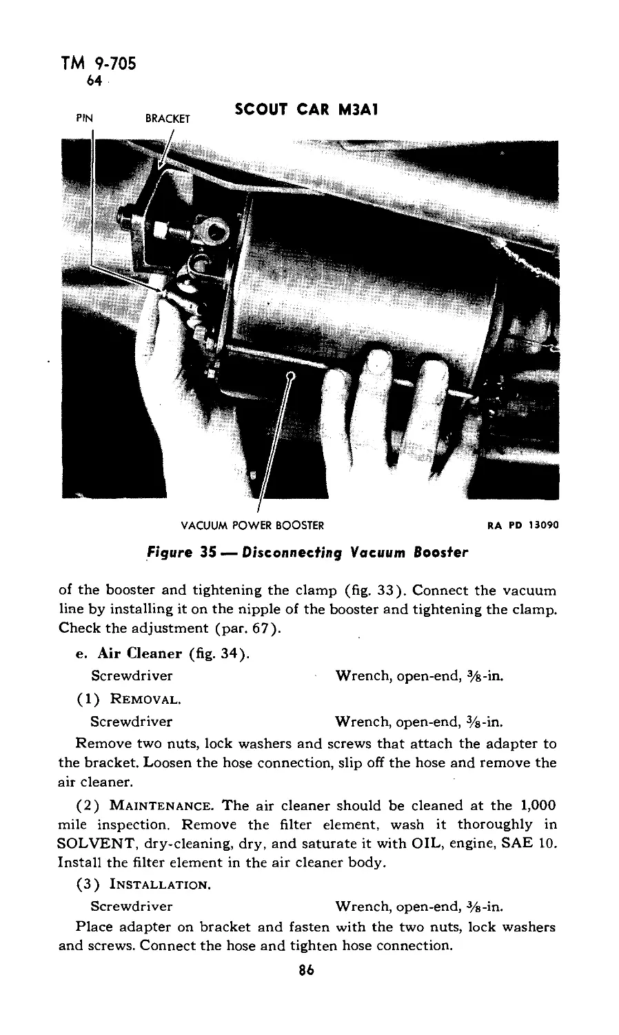
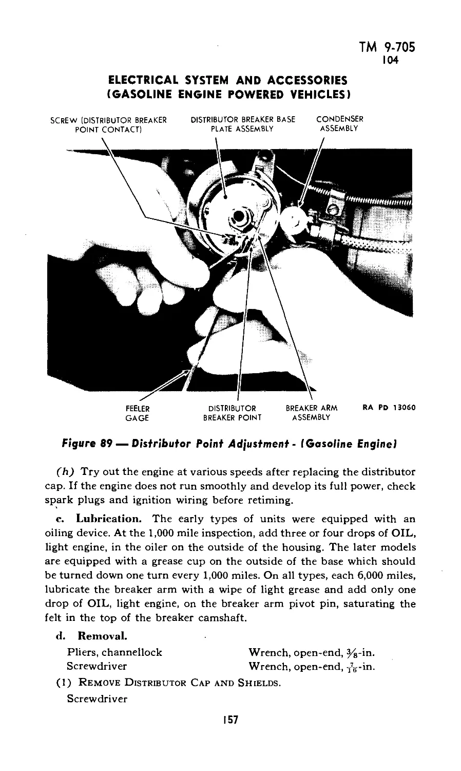
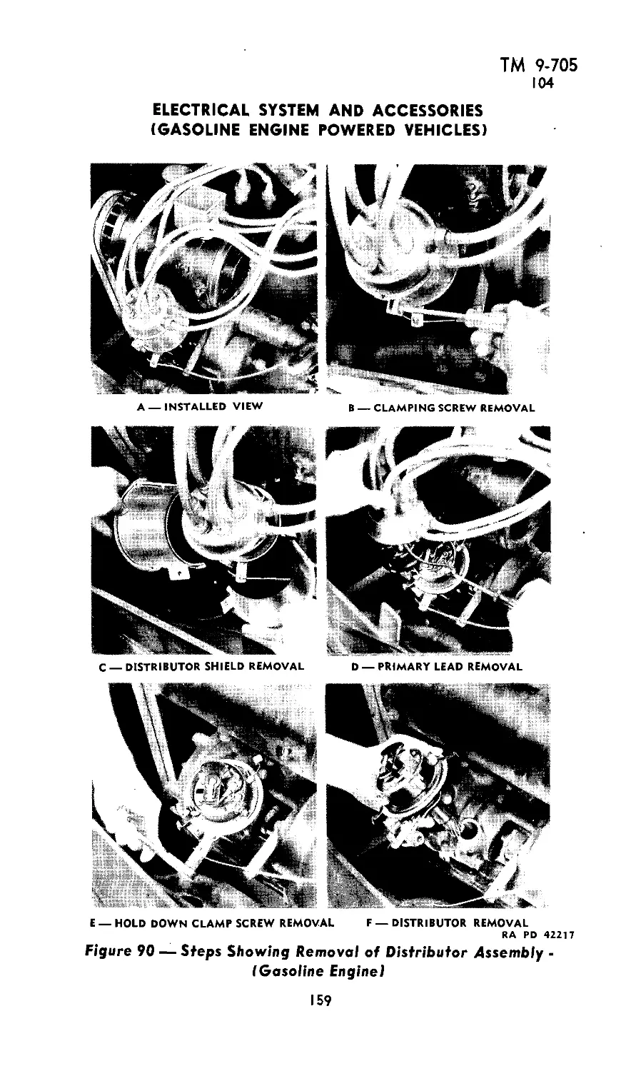
Text
UNCLASSIFIED
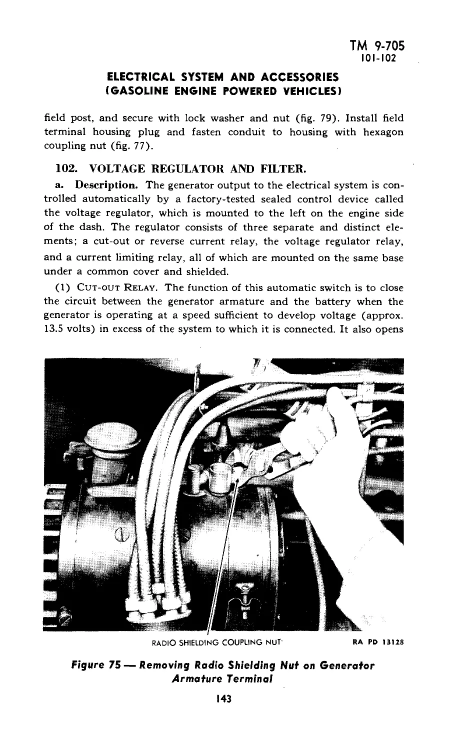
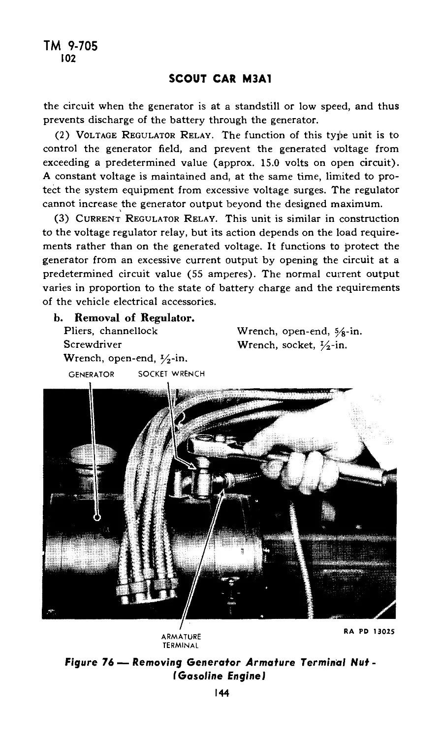
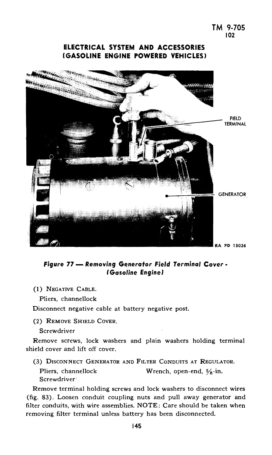
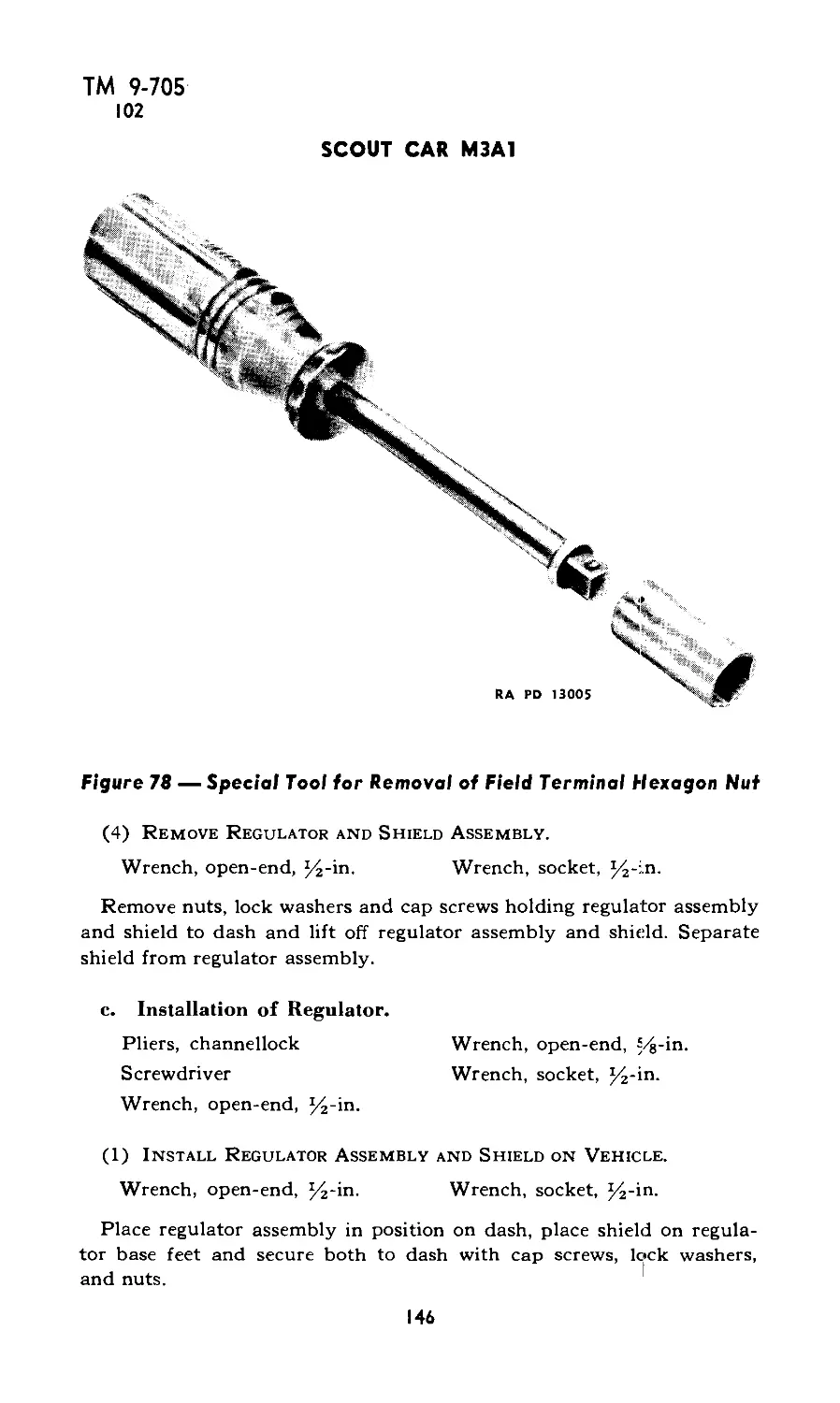
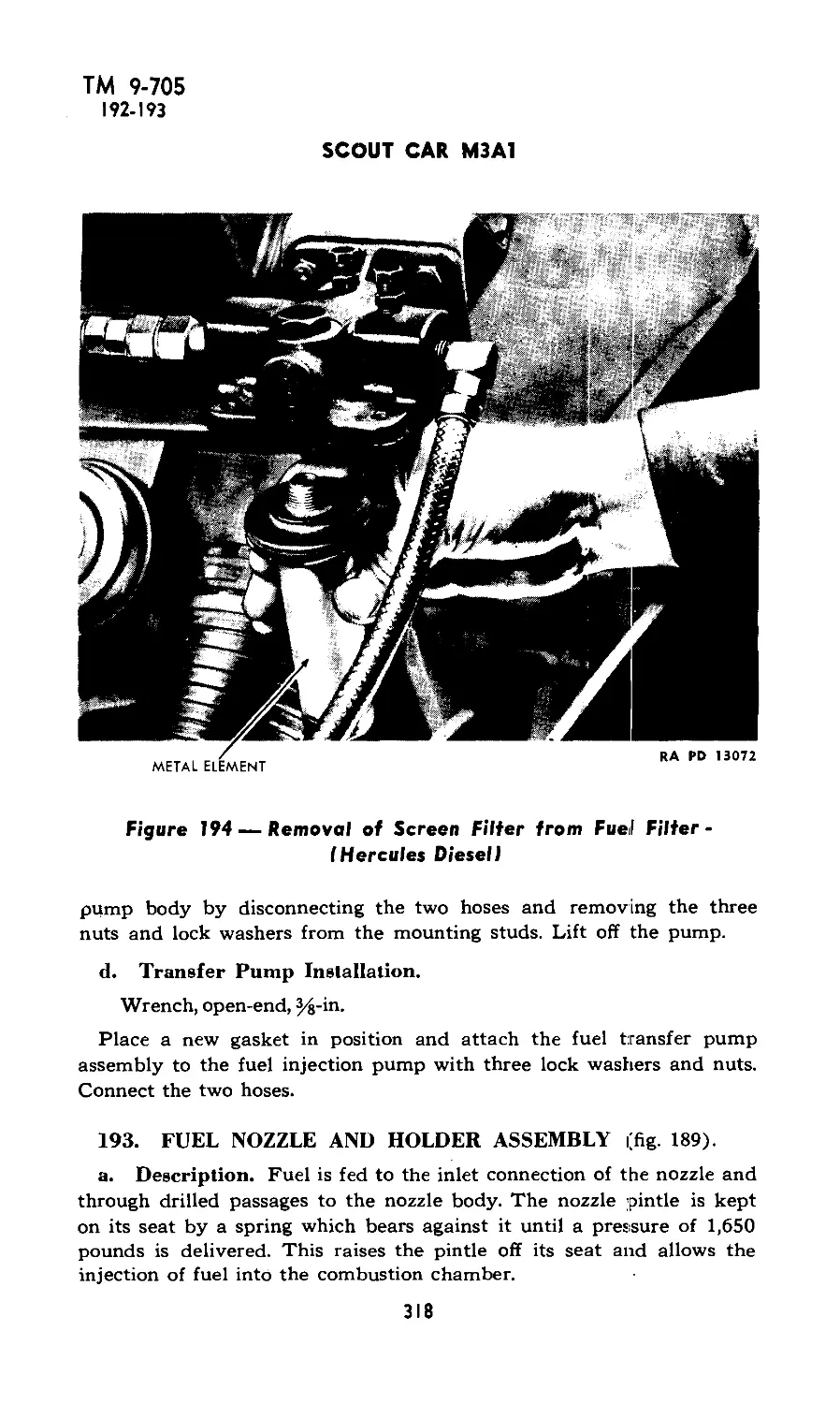
*TM 9-705
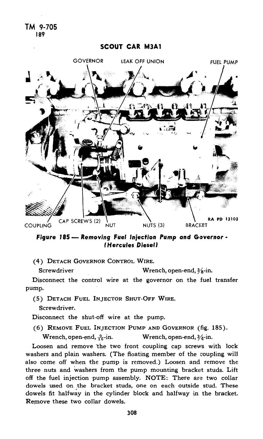
ЦЕ5Ч Il I L--МНВ
TECHNICAL MANUAL?
No. 9-705
WAR DEPARTMENT
Washington, October 26, 1942
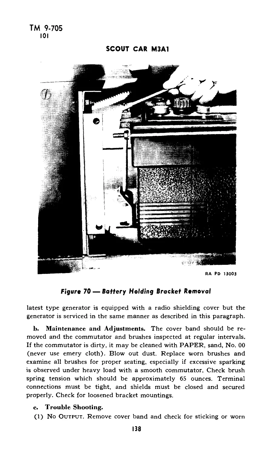
SCOUT CAR M3A1
Prepared under the direction of the
Chief of Ordnance
CONTENTS
PART I —OPERATING INSTRUCTIONS
Paragraphs Pages
Section I: Introduction 1-2 3-7
II: Description, operation and controls 3-8 8-21
III: Armament 9-13 22-26
IV: Inspection 14-19 27-34
V: Lubrication 20-25 35-41
VI: Care and preservation 26-32 42-45
VII: Tools and equipment on vehicle 33-37 46-48
VIII: Materiel affected by gas 38-41 49-51
PART II —ORGANIZATIONAL MAINTENANCE
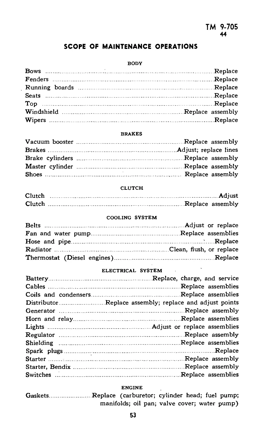
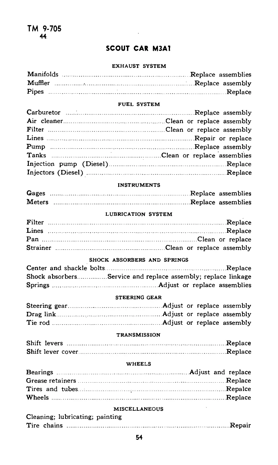
IX: Scope of maintenance operations. .. 42-45
X: Organization spare parts and
accessories .................... 46-47
XI: Front axle ......................... 48-52
XII: Rear axle........................... 53-57
52-55
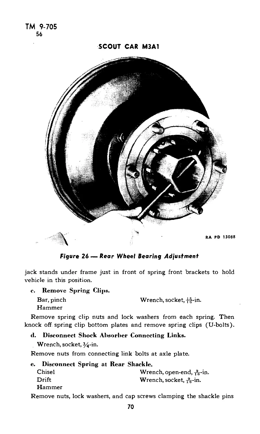
56
57-65
66-72
*This pamphlet supersedes TM 9-705, February 19, 1941; OFSB 6-G-67, May 1, 1942; ТВ 705-2,
ТМ 9-705
SCOUT CAR M3A1
PART II —ORGANIZATIONAL MAINTENANCE (Cont.)
Paragraphs Pages
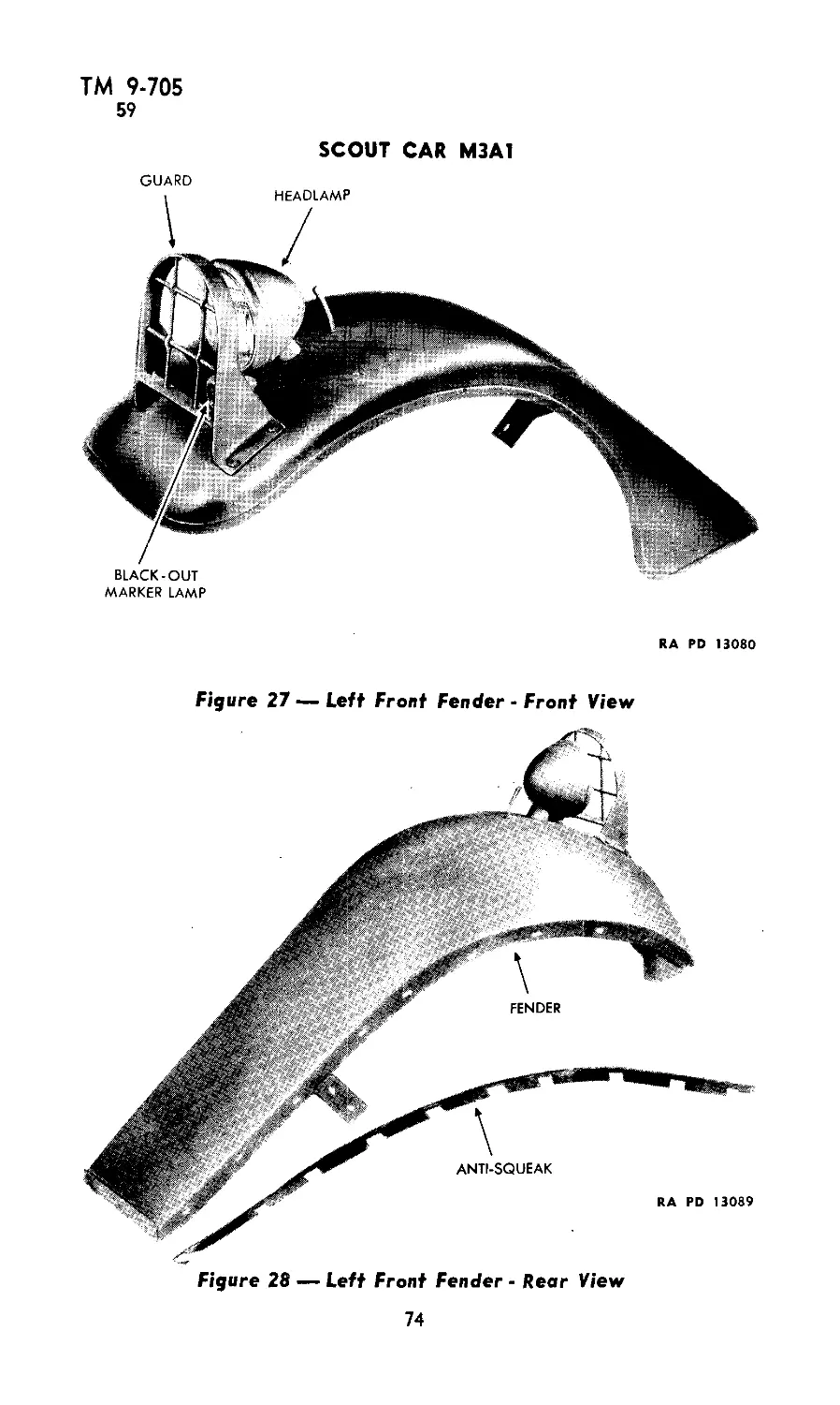
Section XIII: Body 58-60 73-78
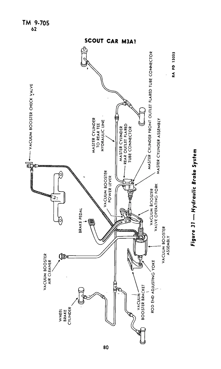
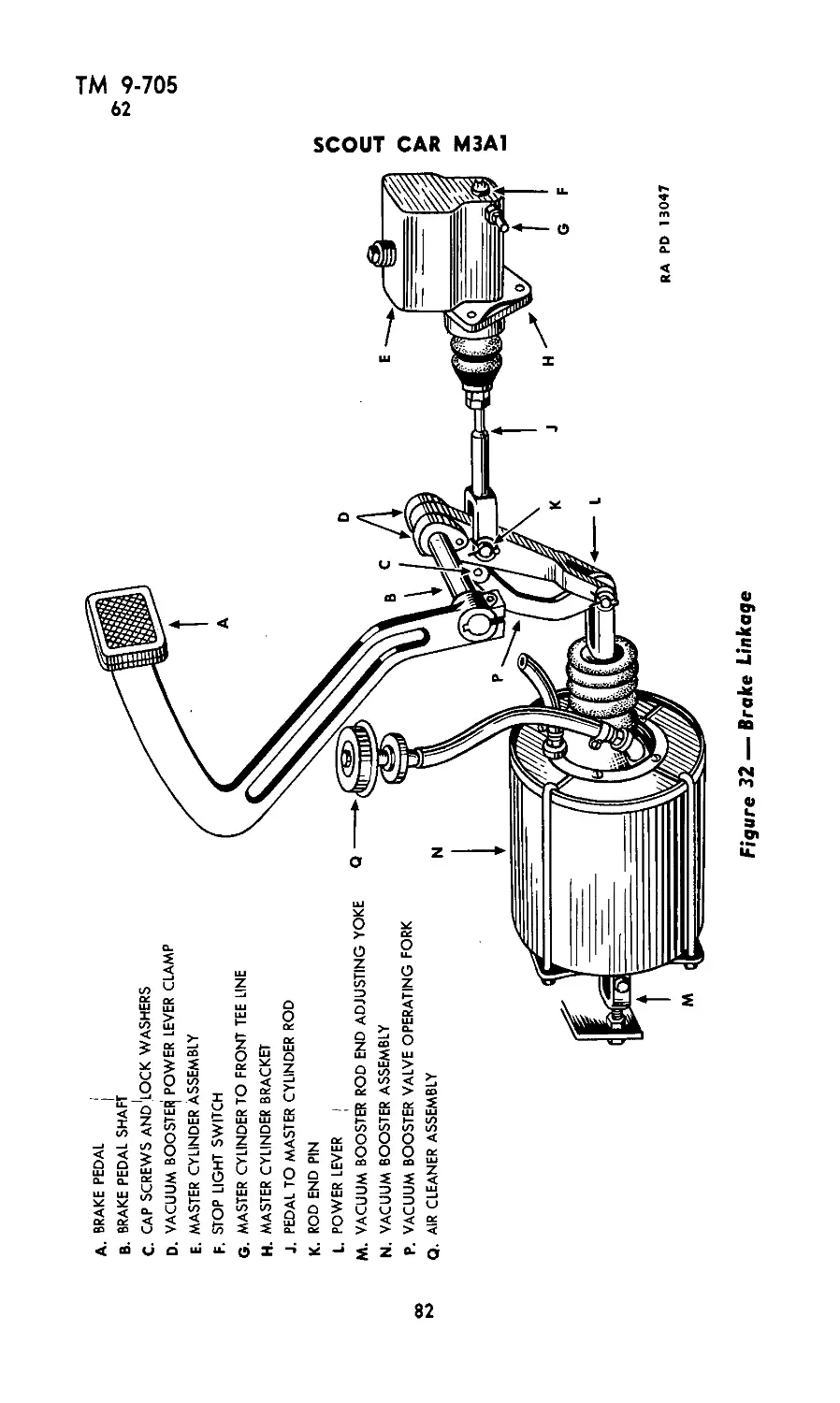
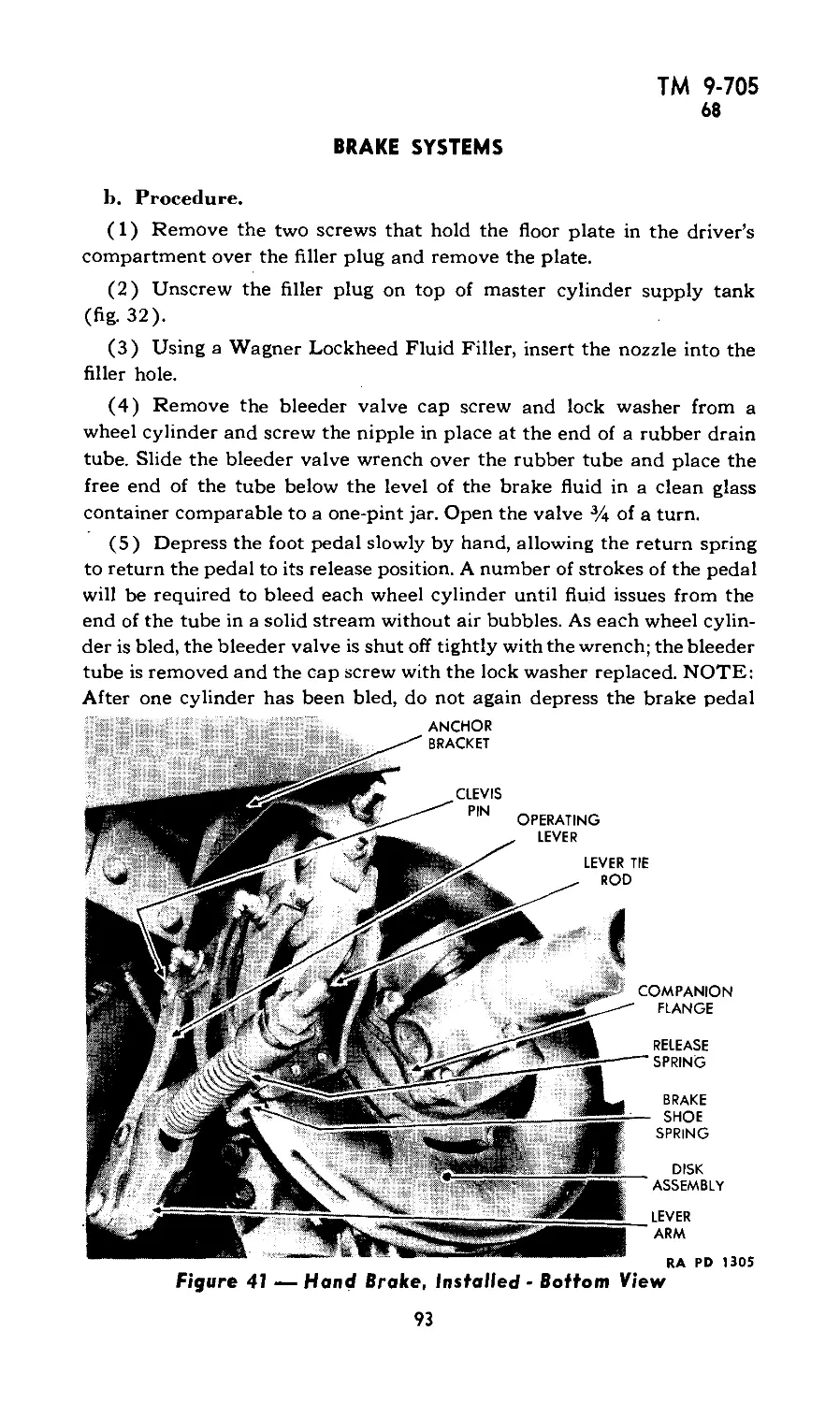
XIV: Brake systems 61-69 79-98
XV: Clutch 70-74 99-102
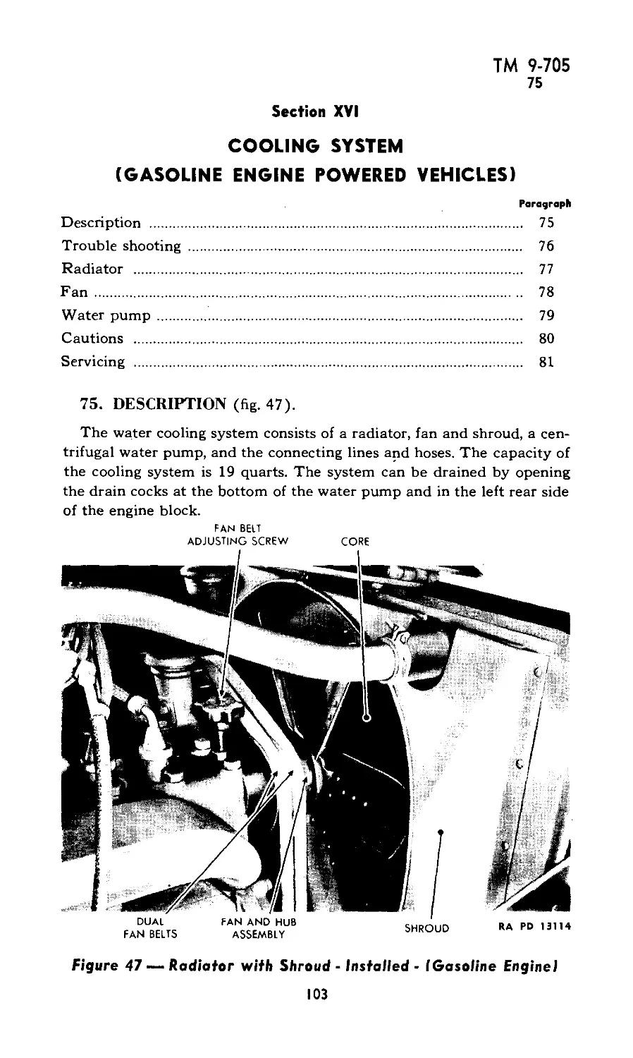
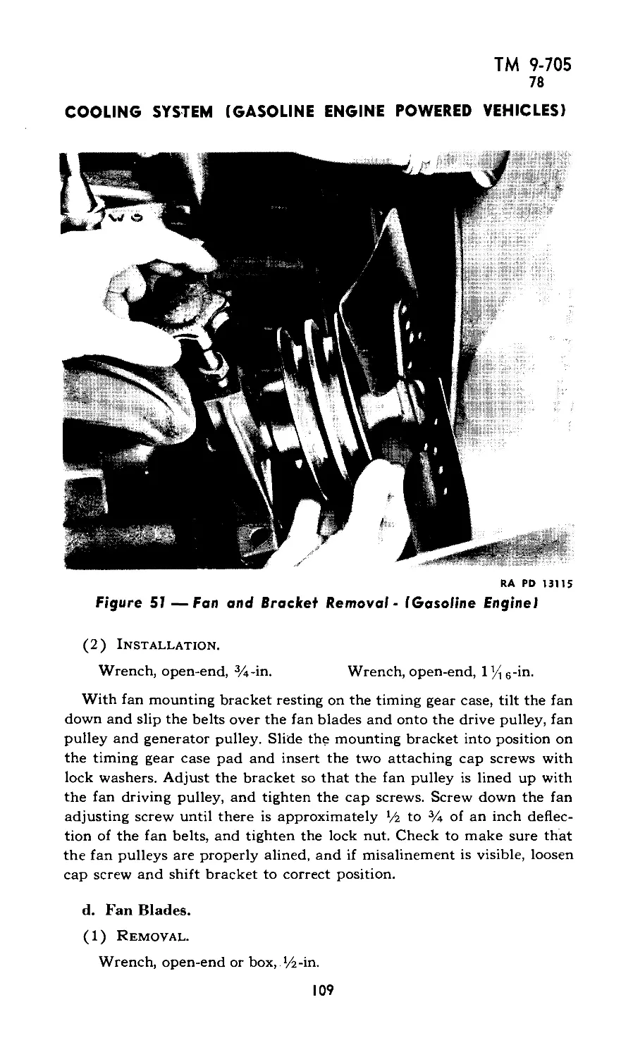
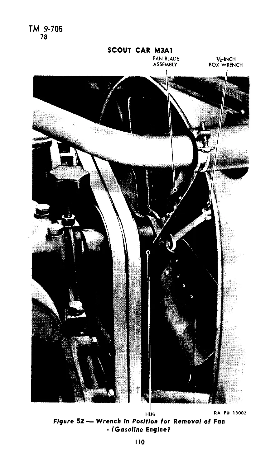
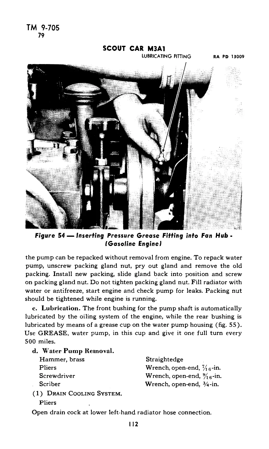
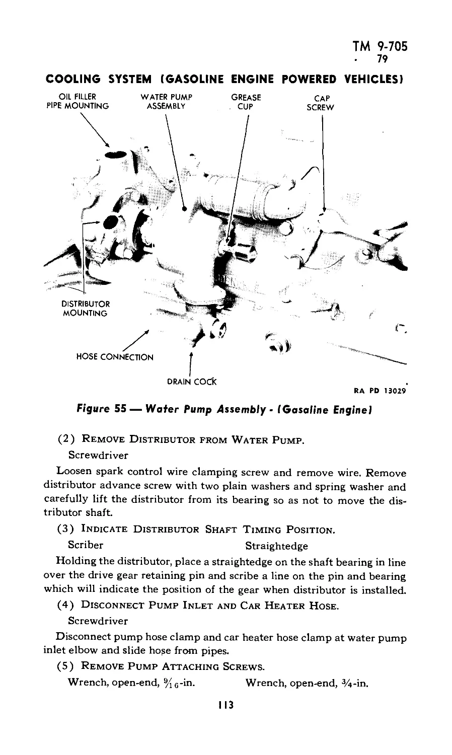
XVI: Cooling system (gasoline engine powered vehicles) 75-81 103-117
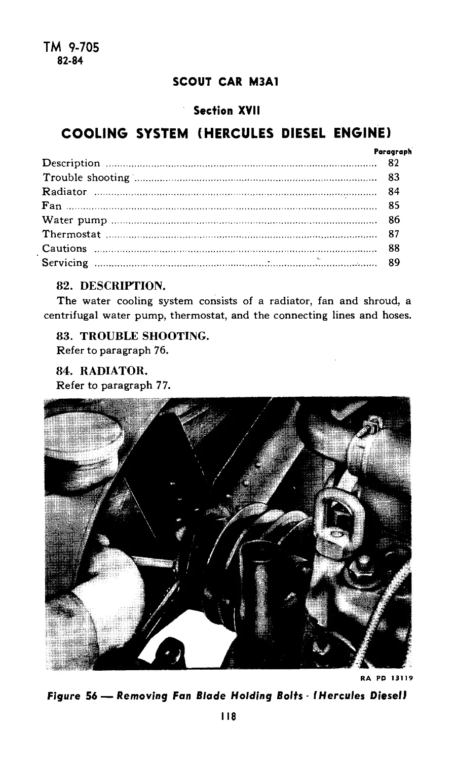
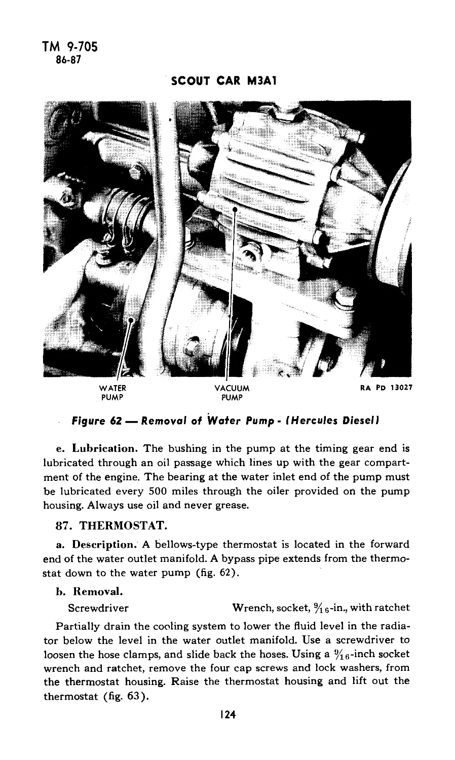
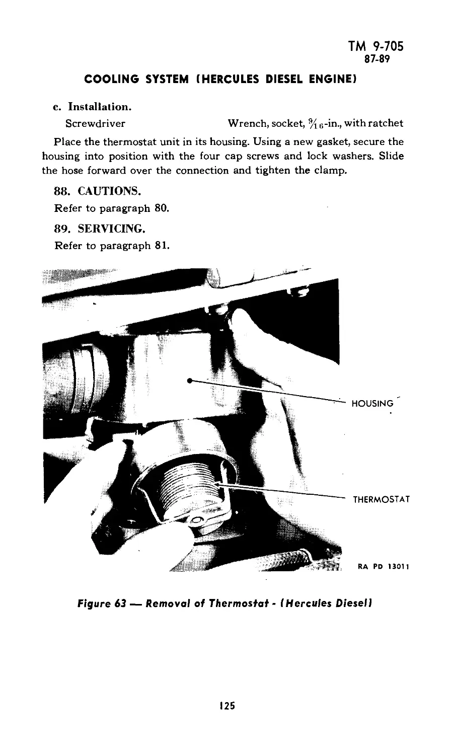
XVII: Cooling system (Hercules Diesel engine) 82-89 118-125
XVIII: Cooling system (Buda Diesel engine) 90-97 126-128
XIX: Electrical system and accessories (gasoline engine powered vehicles) 98-115 129-174
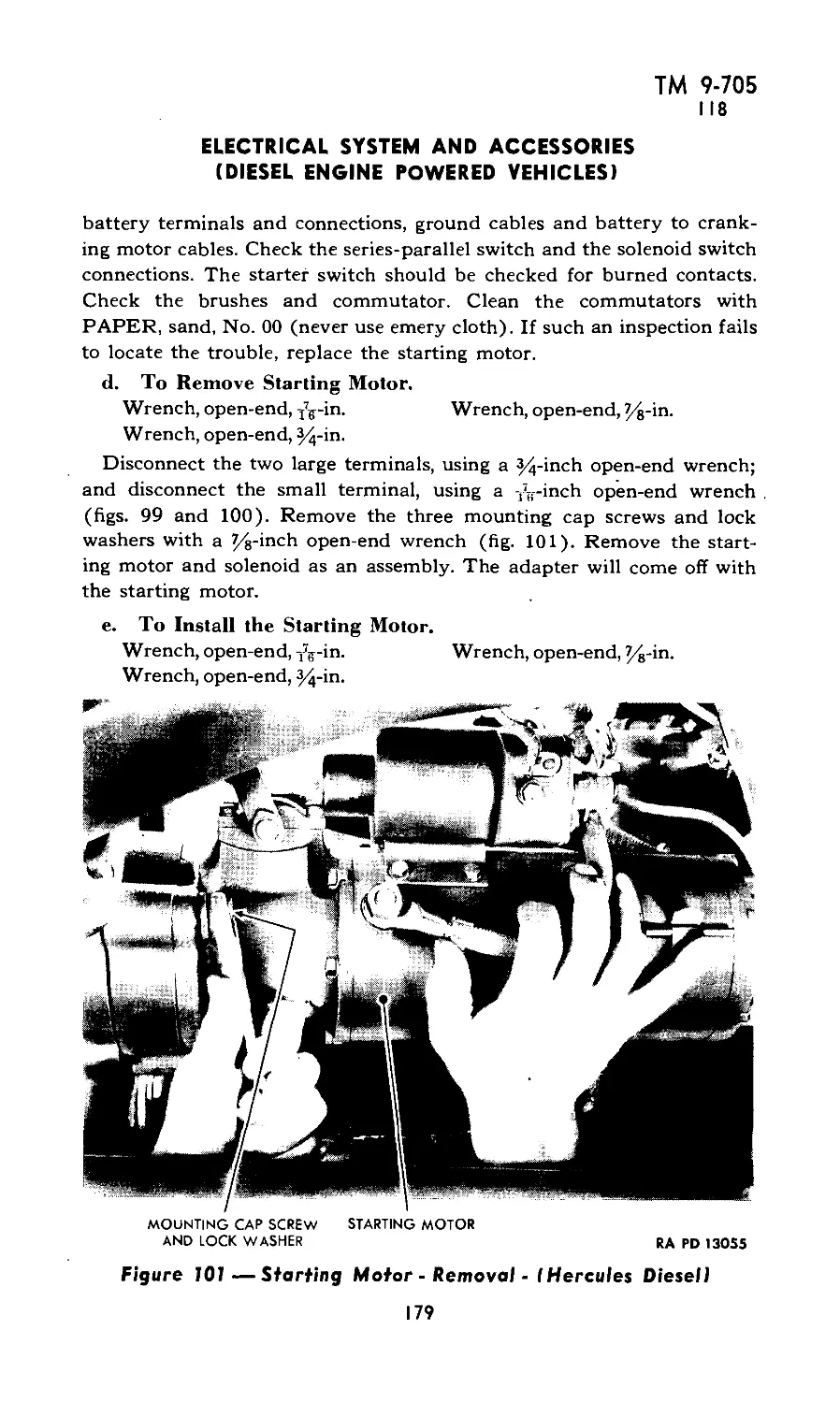
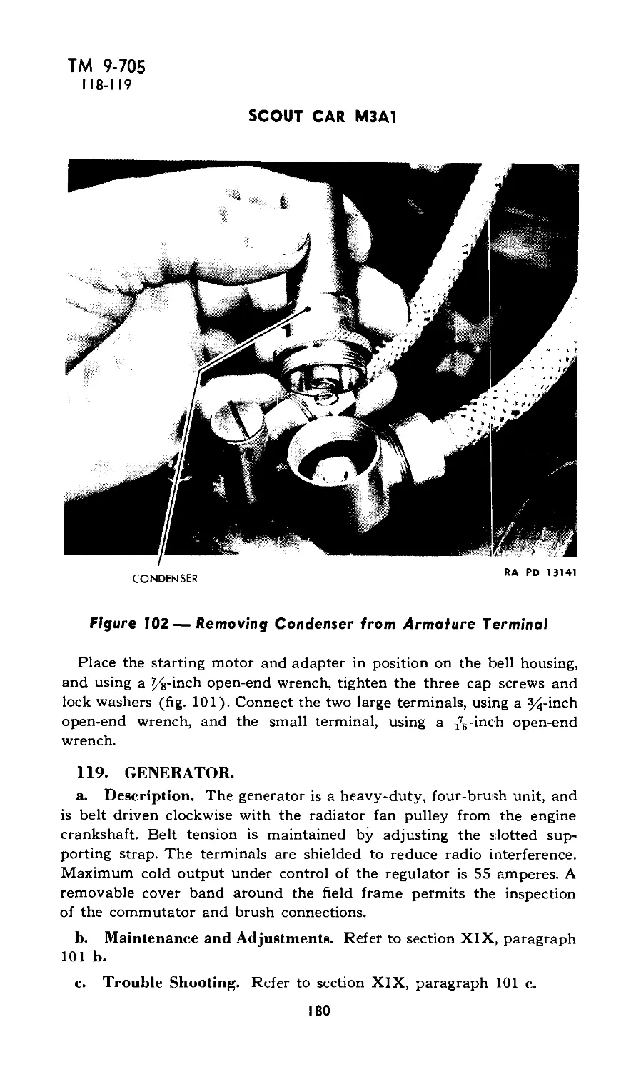
XX: Electrical system and accessories (Diesel engine powered vehicles) 116-130 175-189
XXI: Engine (Hercules gasoline) 131-145 190-216
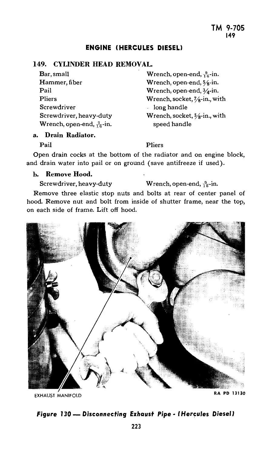
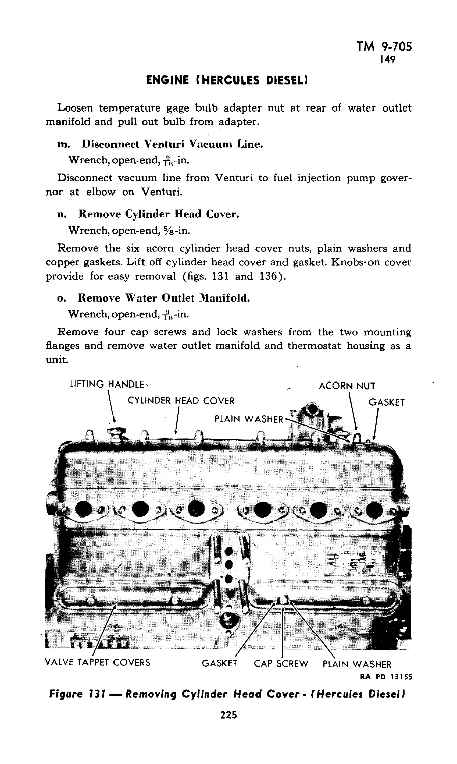
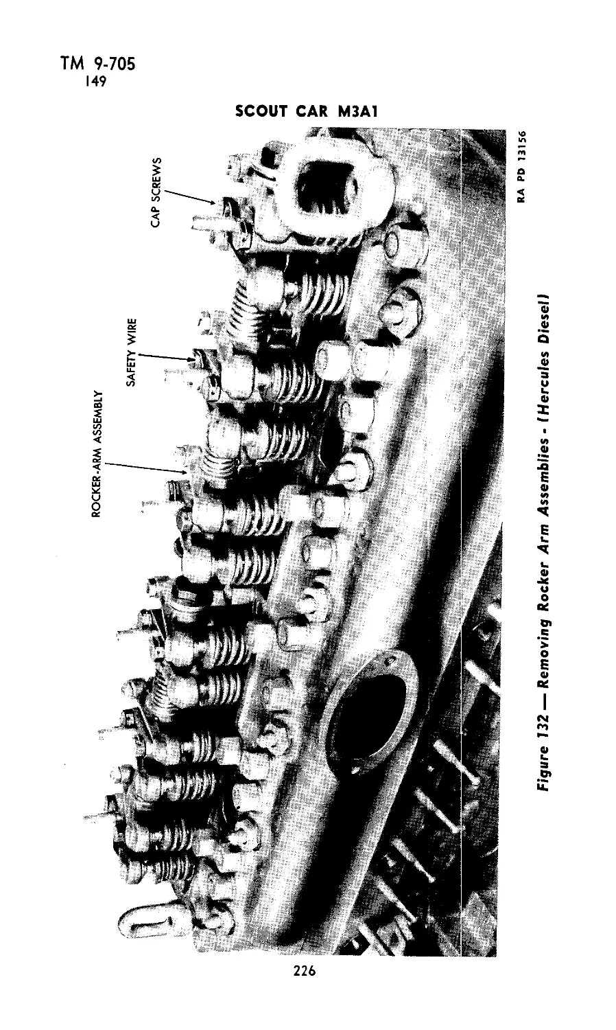
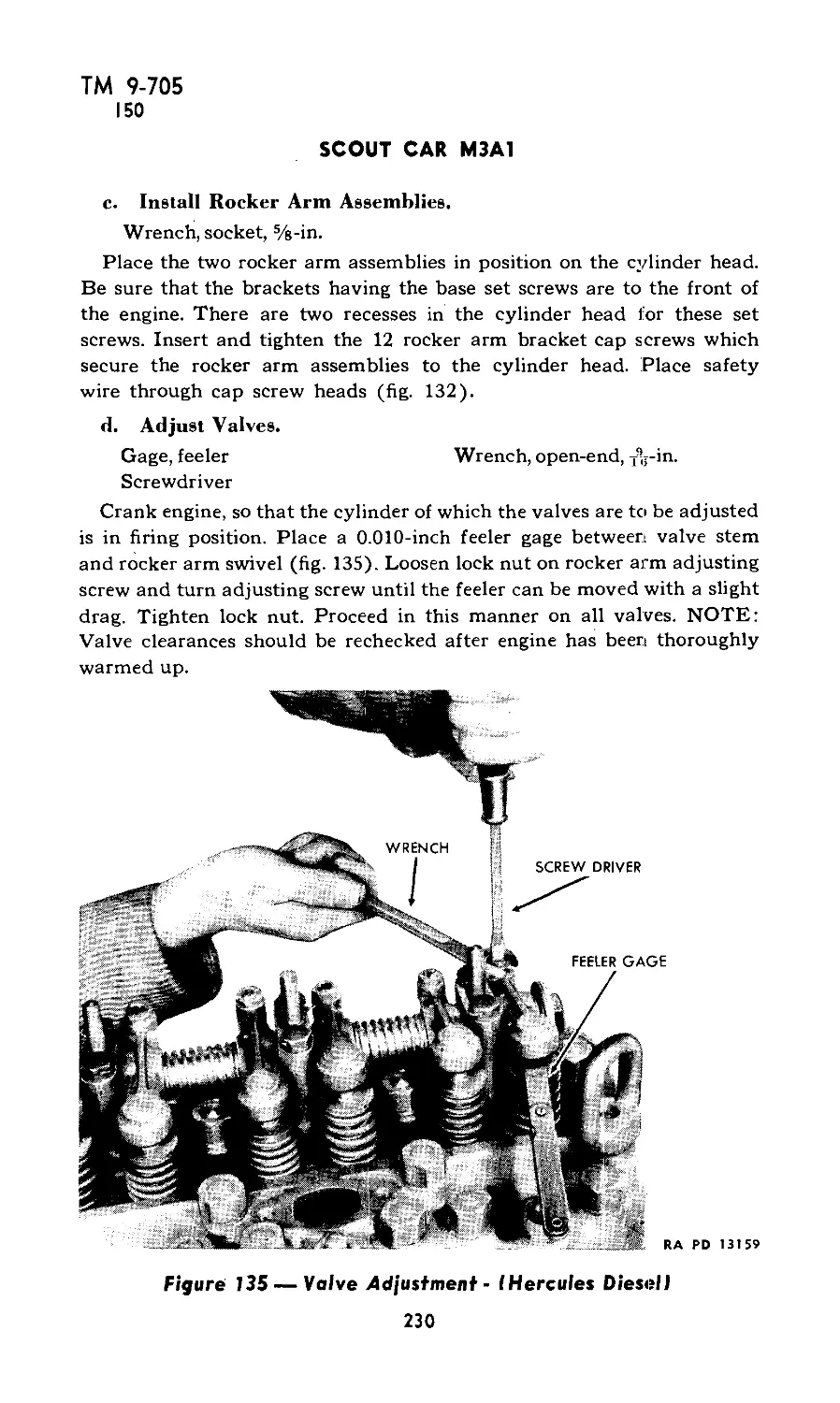
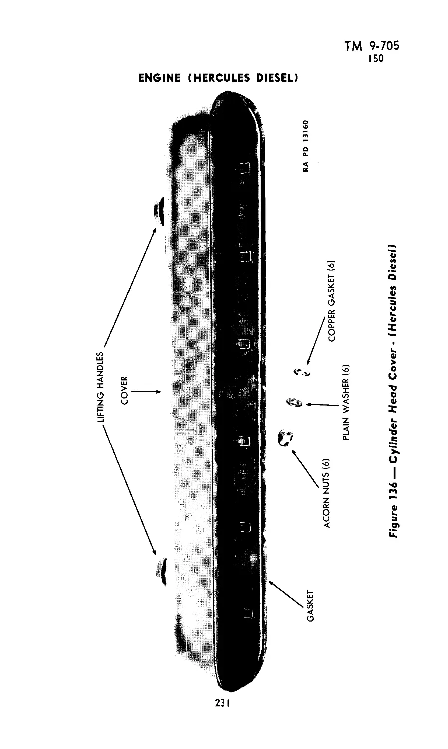
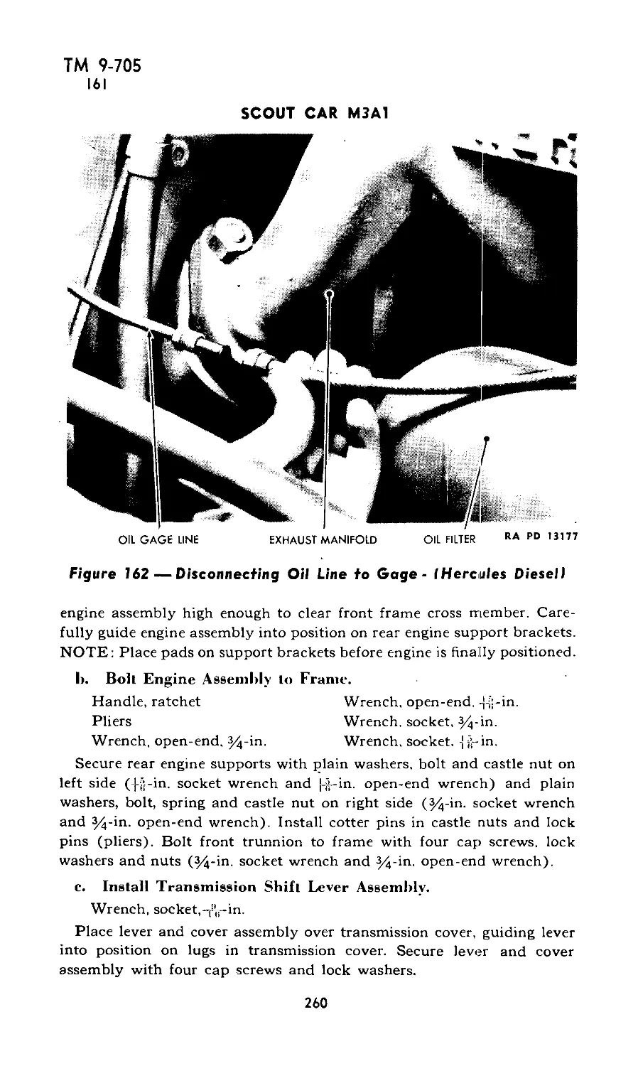
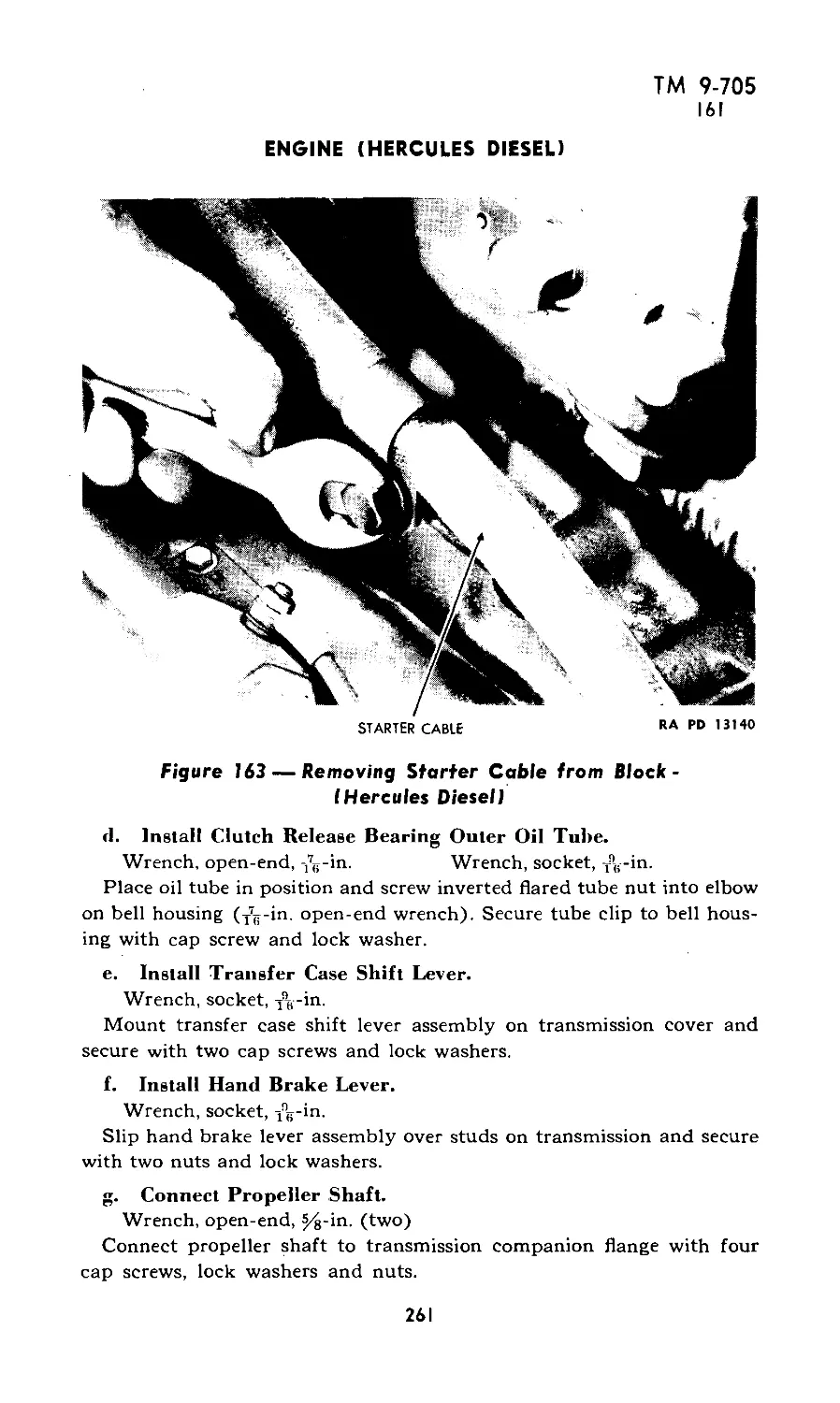
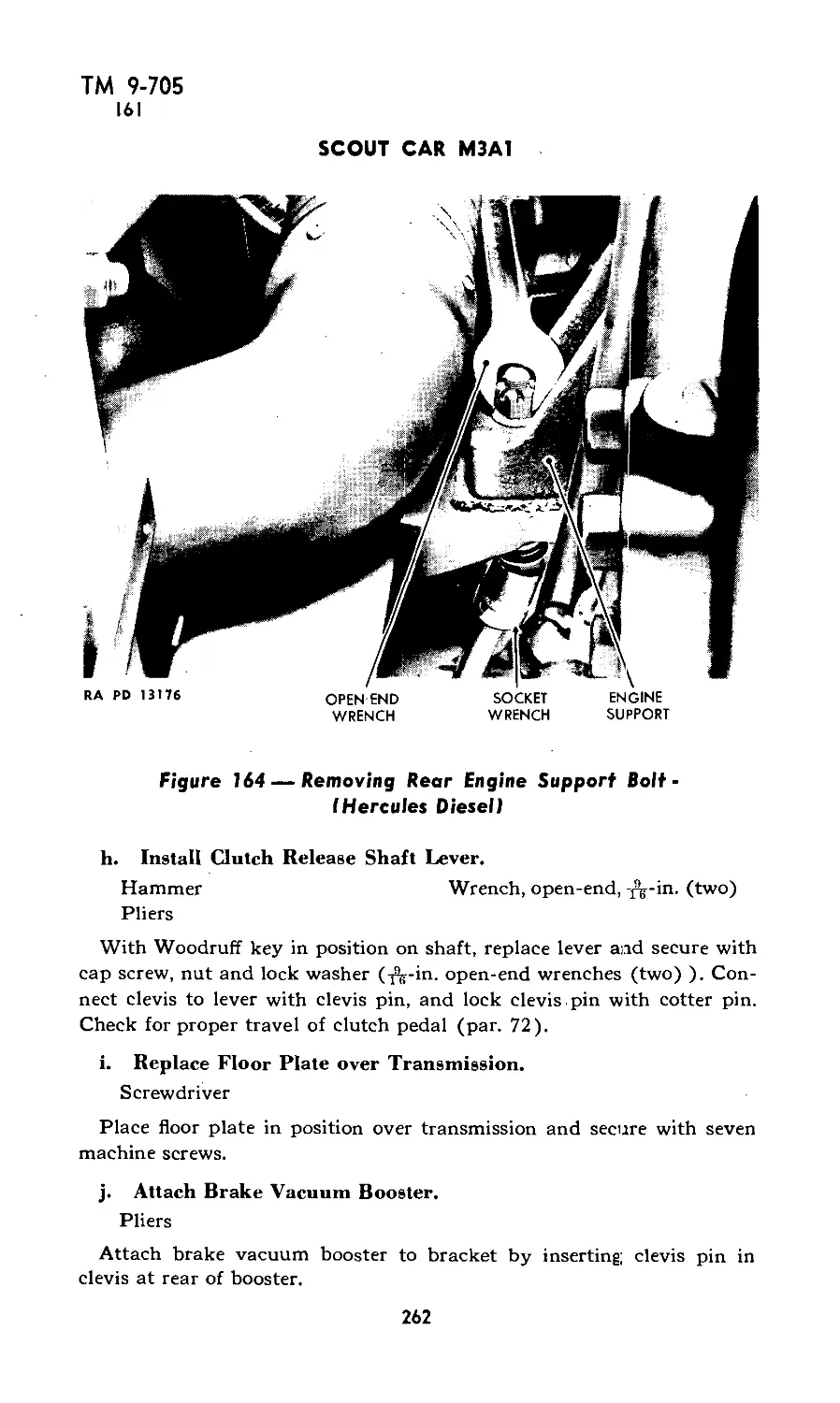
XXII: Engine (Hercules Diesel) 146-161 217-266
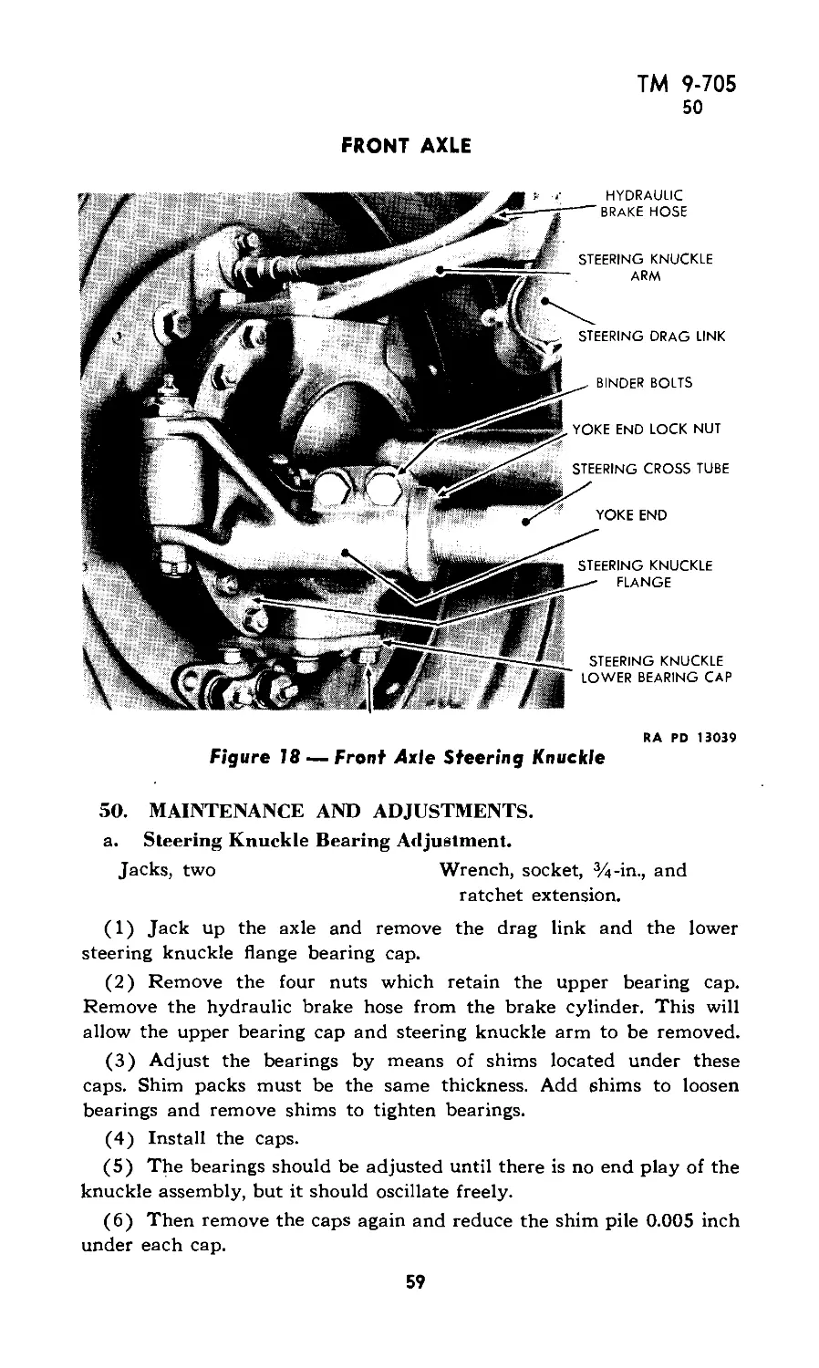
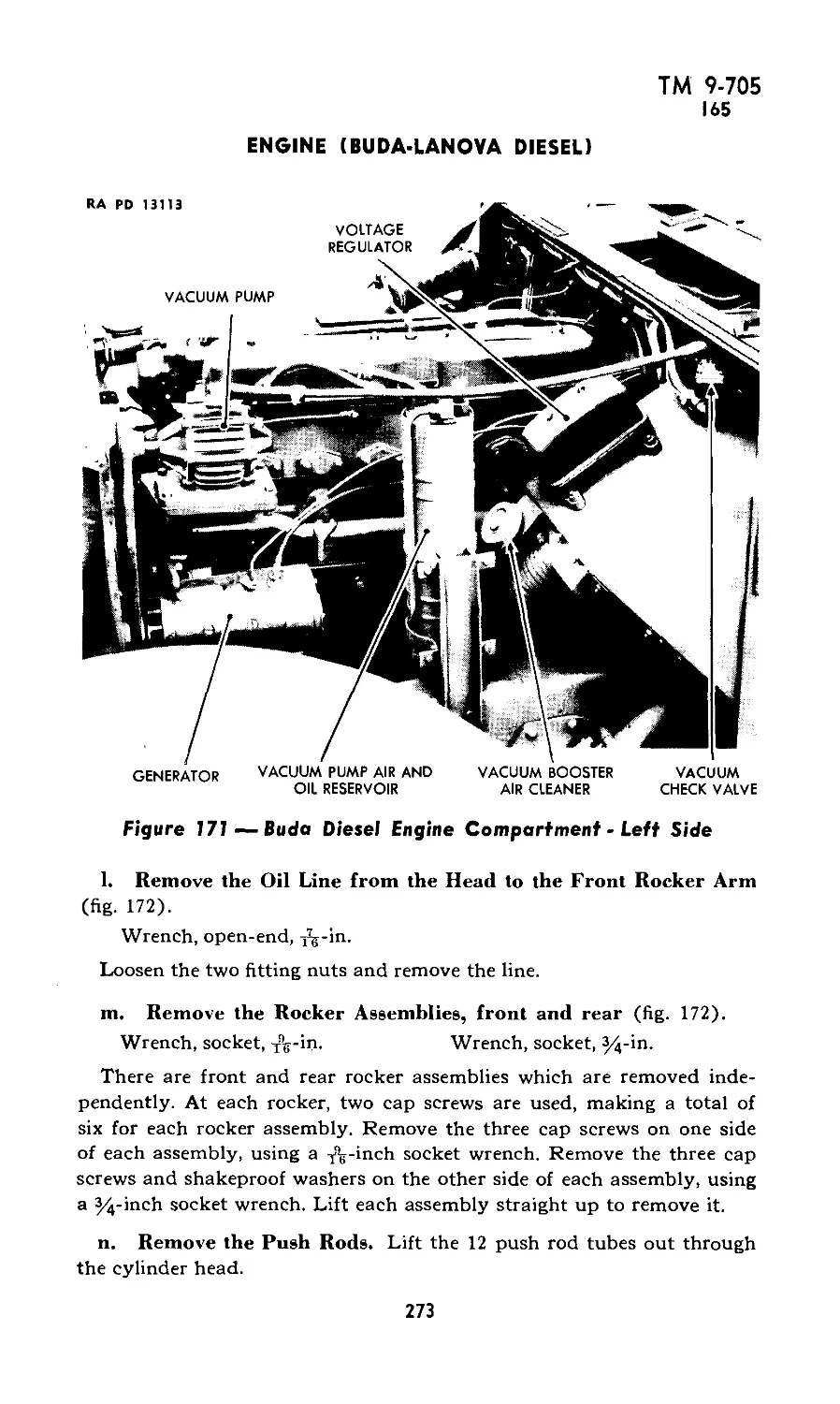
XXIII: Engine (Buda-Lanova Diesel) 162-174 267-292
XXIV: Exhaust system 175-176 293
XXV: Frame 177-180 294
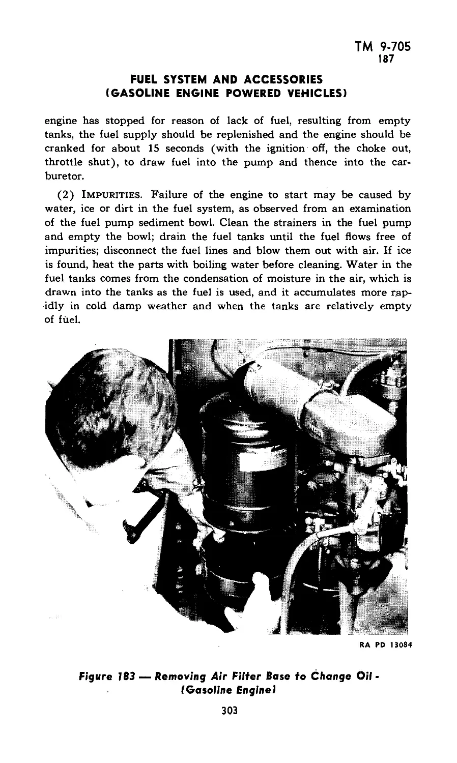
XXVI: Fuel system and accessories (gaso- line engine powered vehicles) 181-187 295-305
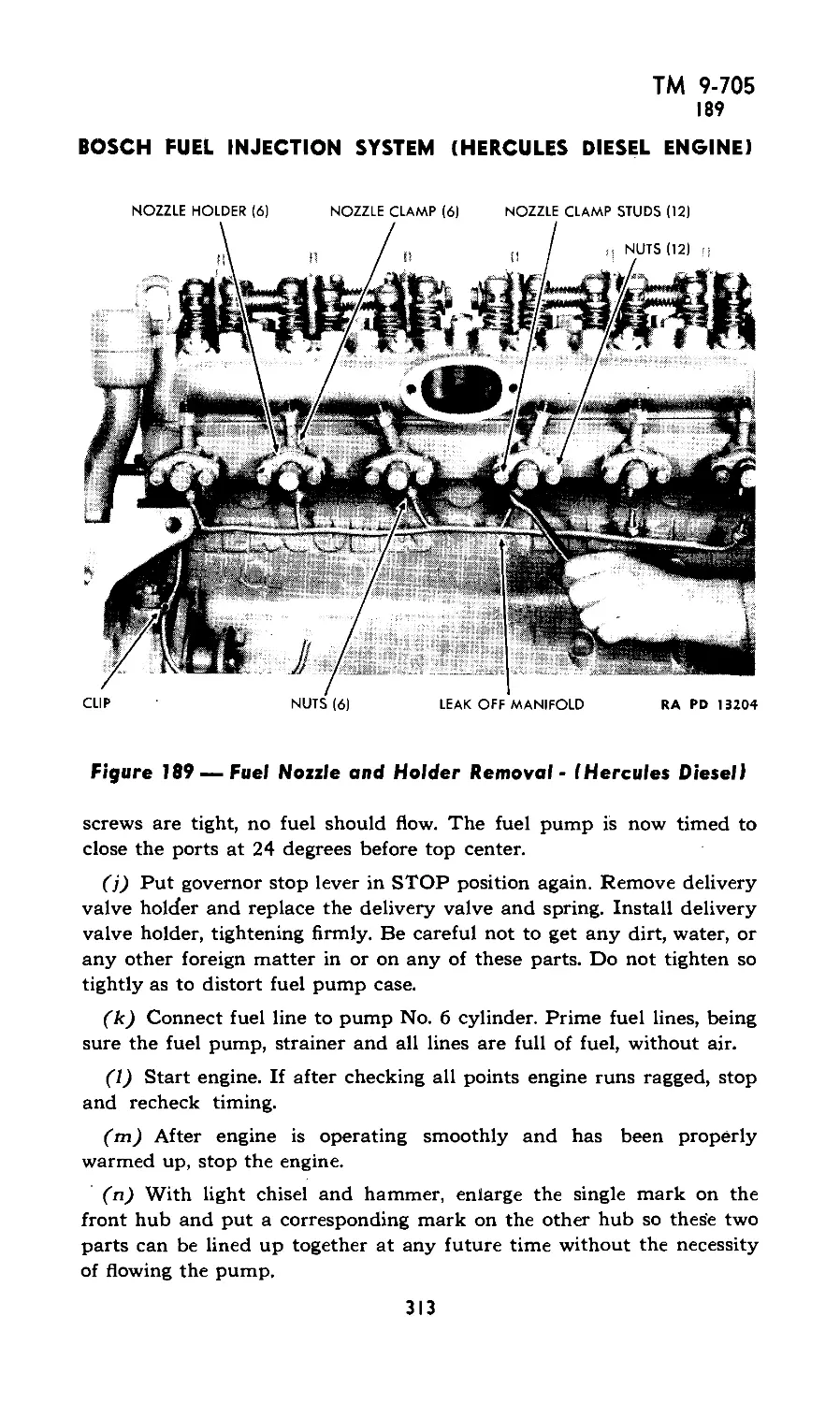
XXVII: Bosch fuel injection system (Hercules Diesel engine) 188-194 306-322
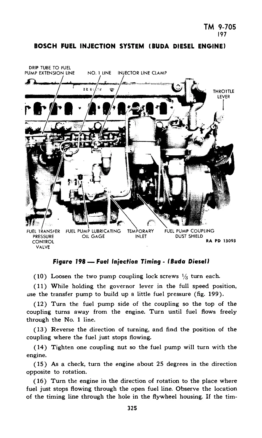
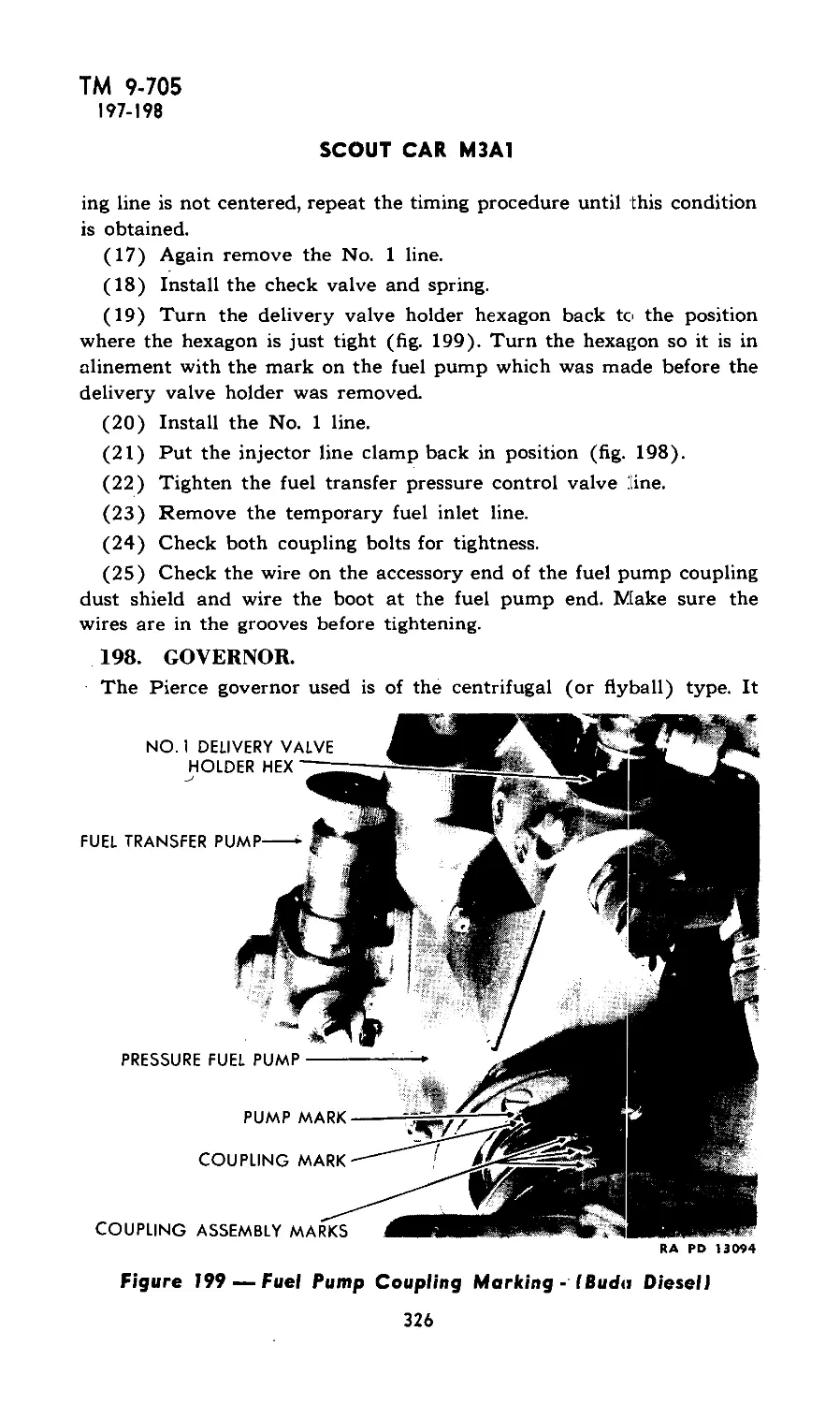
XXVIII: Bosch fuel injection system (Buda Diesel engine) 195-202 323-328
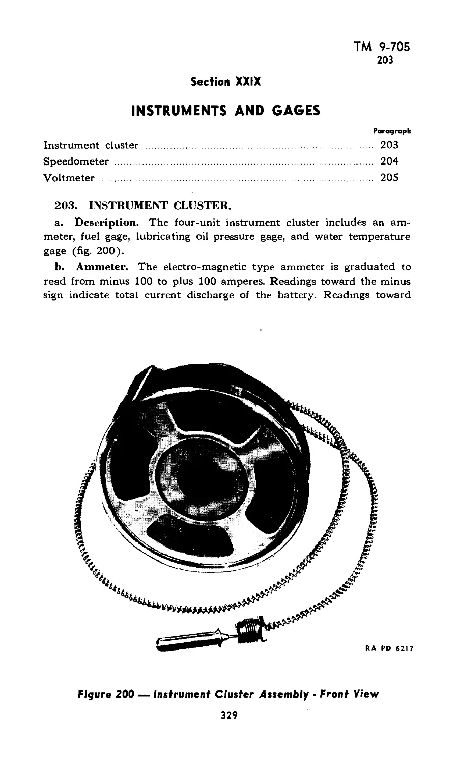
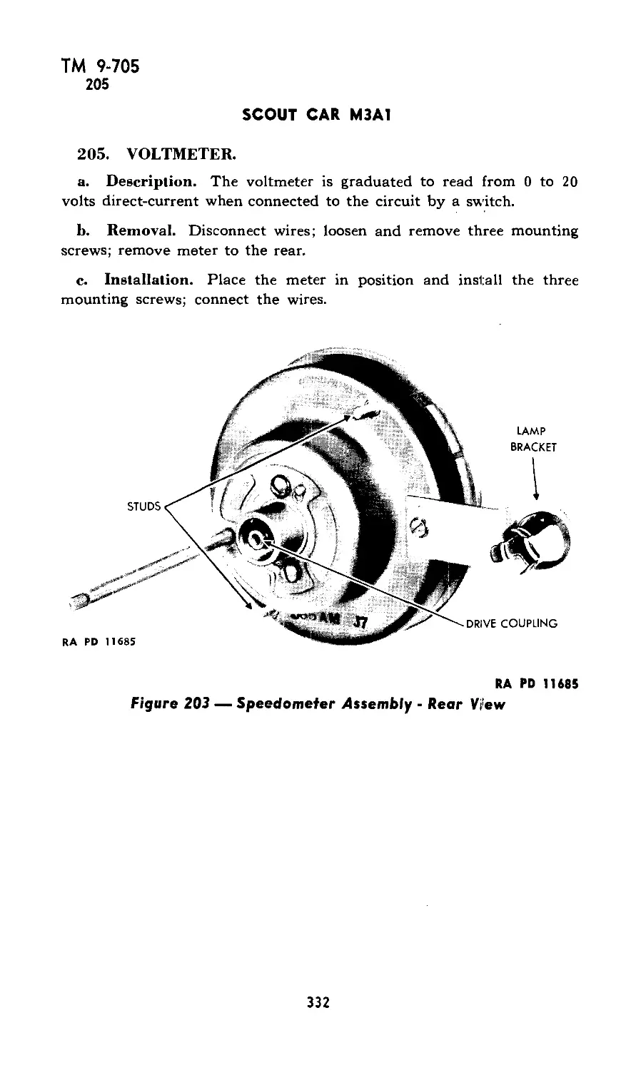
XXIX: Instruments and gages 203-205 329-332
XXX: Propeller shafts 206-208 333-334
XXXI: Springs and shock absorbers 209-213 335-338
XXXII: Steering gear 214-217 339-346
XXXIII: Transfer case 218-221 347-350
XXXIV: Transmission 222-225 351-358
XXXV: Wheels 226-229 359-362
XXXVI: Shipment and storage 230-233 363-368
XXXVII: References 234-235 369-370
Index 371-386
2
ТМ 9-705
1-2
PART I —OPERATING INSTRUCTIONS
Section I
INTRODUCTION
Paragraph
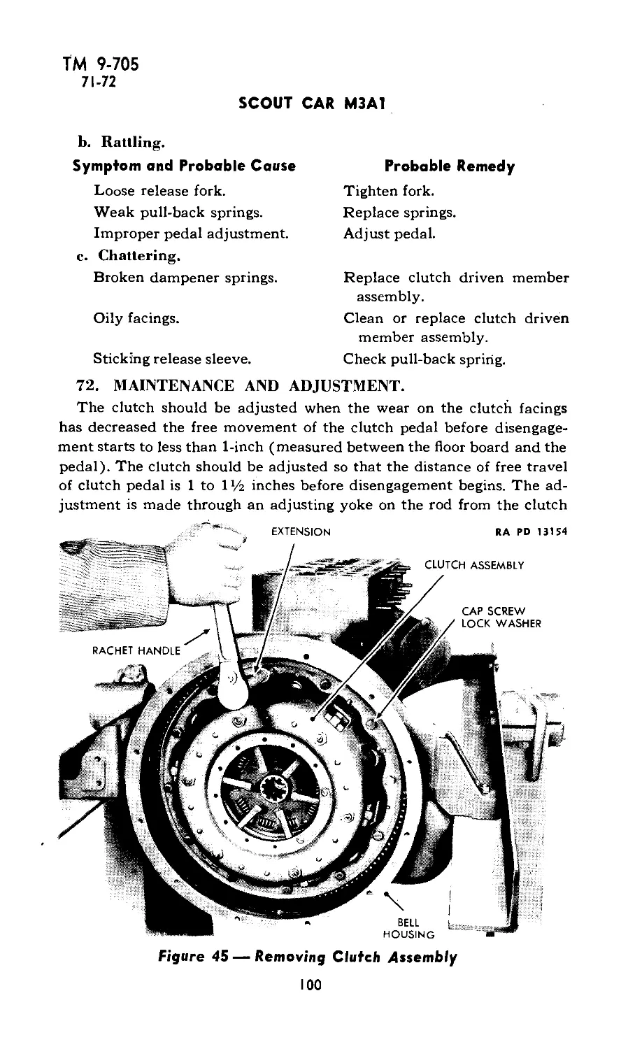
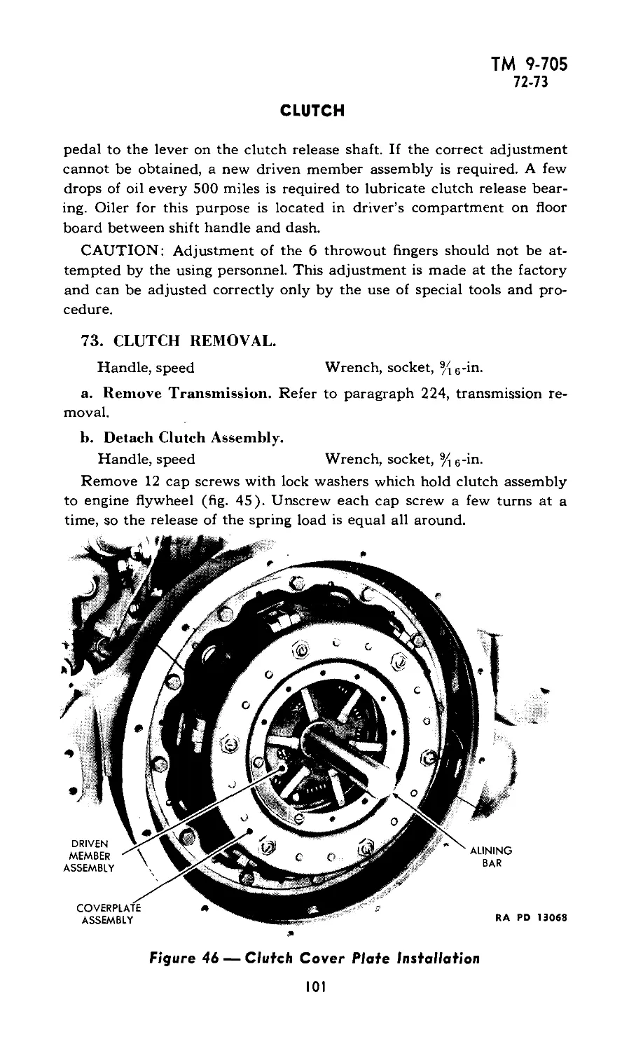
Scope ............................................ 1
Data ............................................. 2
1. SCOPE.
a. This manual is published for the information and guidance of
the using arms and services.
b. In addition to a description of the Scout Car М3 Al, this manual
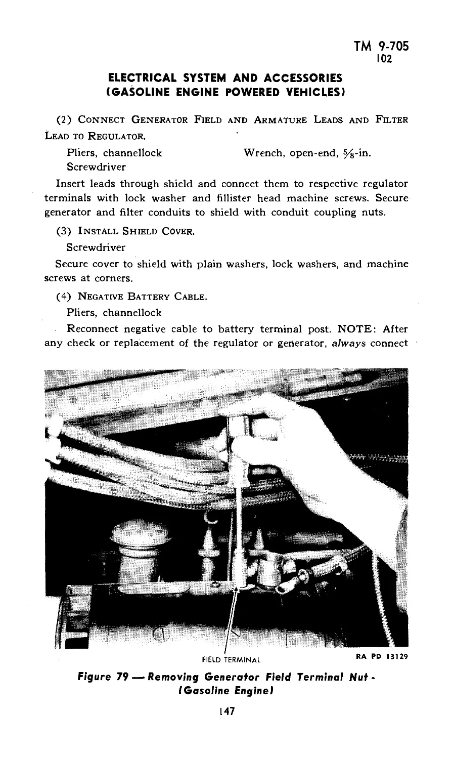
contains technical information required for the identification, use, and
care of the material. ................
c. Specific information for the guidance of operating personnel
(crew) is contained in part I. Information chiefly for the guidance of
organizational maintenance personnel (using arm’s unit mechanics)
is contained in part II.
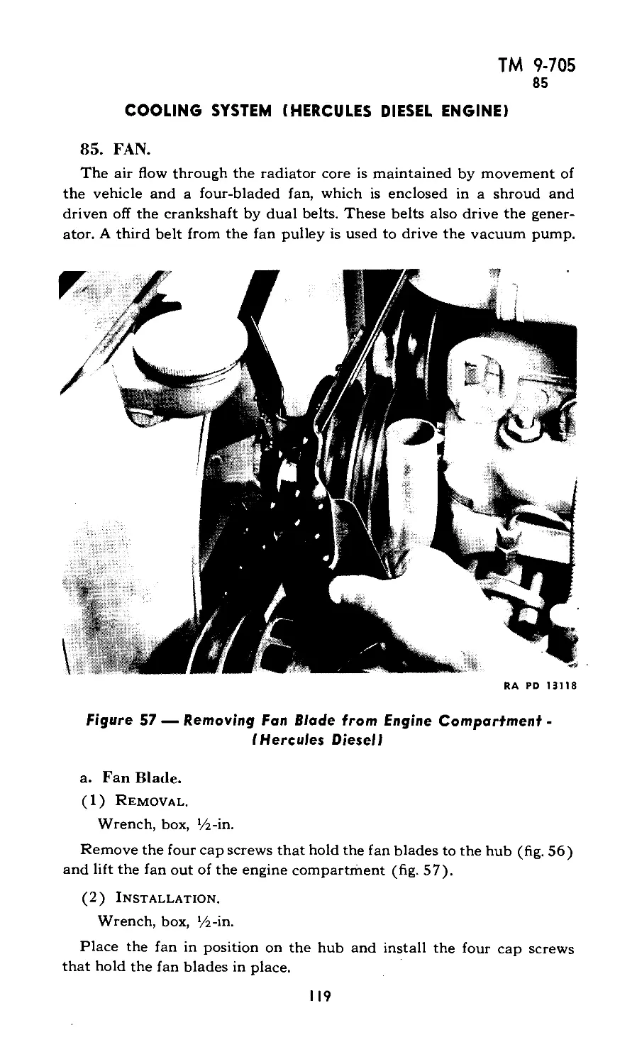
d. Disassembly, assembly, and such repairs as may be handled by
using arms personnel will be undertaken only under the supervision
of an officer or the chief mechanic.
e. In all cases where the nature of the repair, modification, or
adjustment is beyond the scope or facilities of the unit, the responsible
ordnance service should be informed in order that trained personnel
with suitable tools and equipment may be provided, or proper instruc-
tions issued.
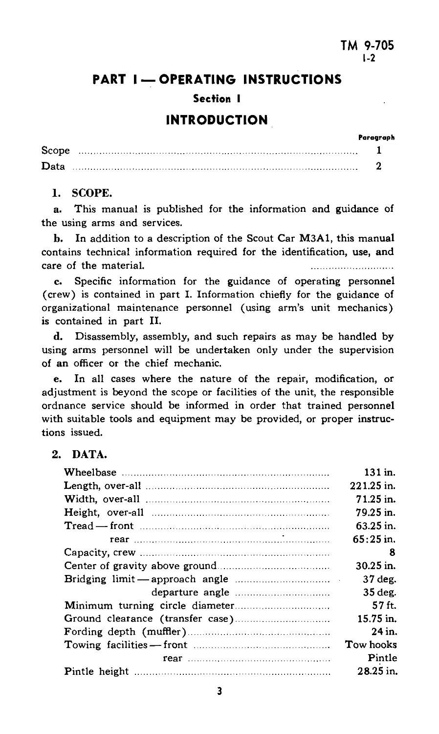
2. DATA.
Wheelbase ................................................. 131 in.
Length, over-all ....................................... 221.25 in.
Width, over-all ......................................... 71.25 in.
Height, over-all ........................................ 79.25 in.
Tread — front ........................................... 63.25 in.
rear ......................................... 65:25 in.
Capacity, crew .................................................. 8
Center of gravity above ground........................... 30.25 in.
Bridging limit — approach angle ............................ 37 deg.
departure angle ......................... 35 deg.
Minimum turning circle diameter............................. 57 ft.
Ground clearance (transfer case)......................... 15.75 in.
Fording depth (muffler)..................................... 24 in.
Towing facilities — front .............................. Tow hooks
rear .................................. Pintle
Pintle height ........................................... 28.25 in.
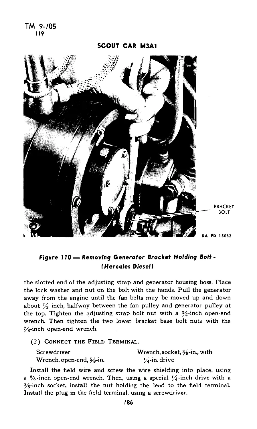
3
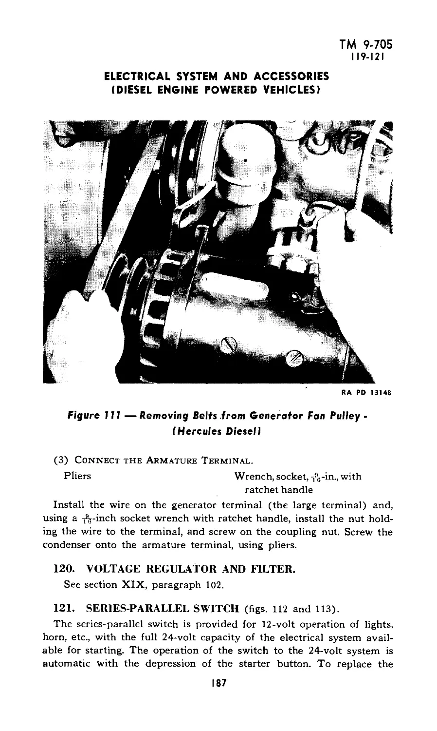
ТМ 9-705
2
SCOUT CAR M3A1
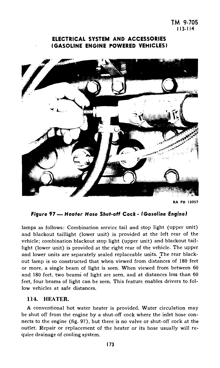
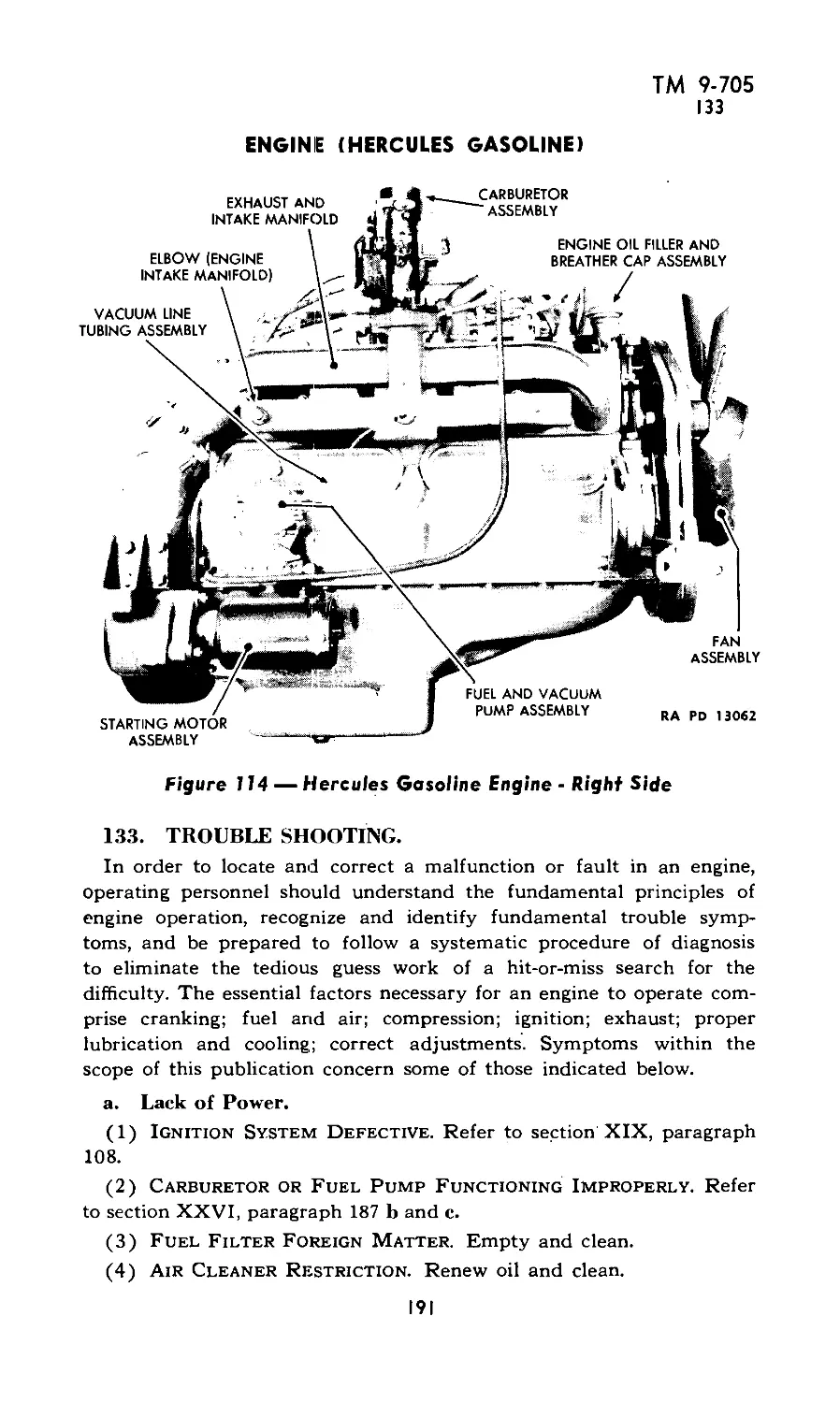
RA PD 3220
4
ТМ 9-705
2
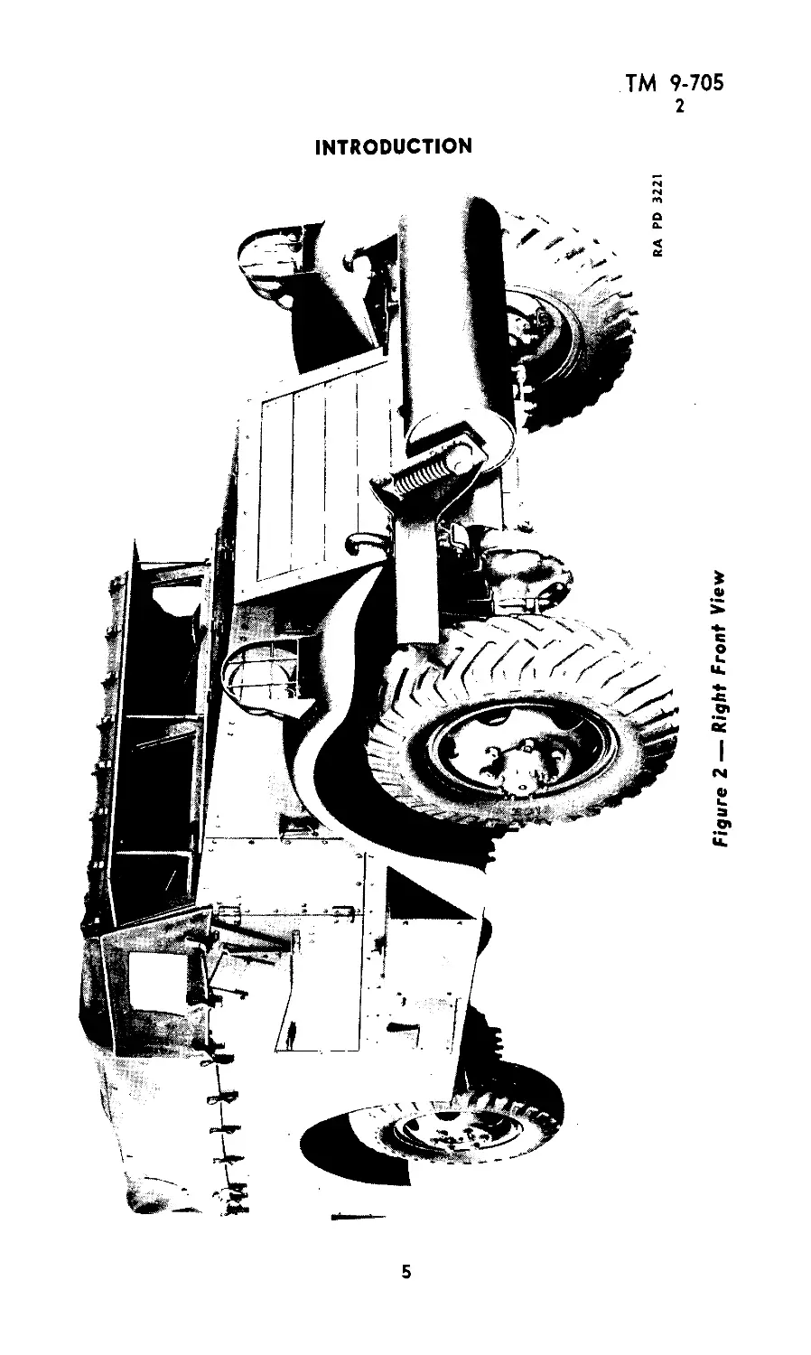
INTRODUCTION
Figure 2 — Right Front View
5
ТМ 9-705
2
SCOUT CAR M3A1
Low
Speed (transfer case low and high):
Reverse .............................. 5.05 mph
First ................................. 6.0 mph
Second ................................ 9.5 mph
Third ................................ 17.0 mph
Fourth ............................. 29.5 mph
Maximum allowable speed.............................
Transmission capacity ..............................
Transfer case capacity..............................
Front axle capacity.................................
Rear axle capacity..................................
Gasoline tank capacity (2 tanks)....................
Cooling system capacity (gasoline engine)...........
Crankcase capacity:
Gasoline engine-powered vehicles................
Hercules Diesel engine..........................
Buda Diesel engine..............................
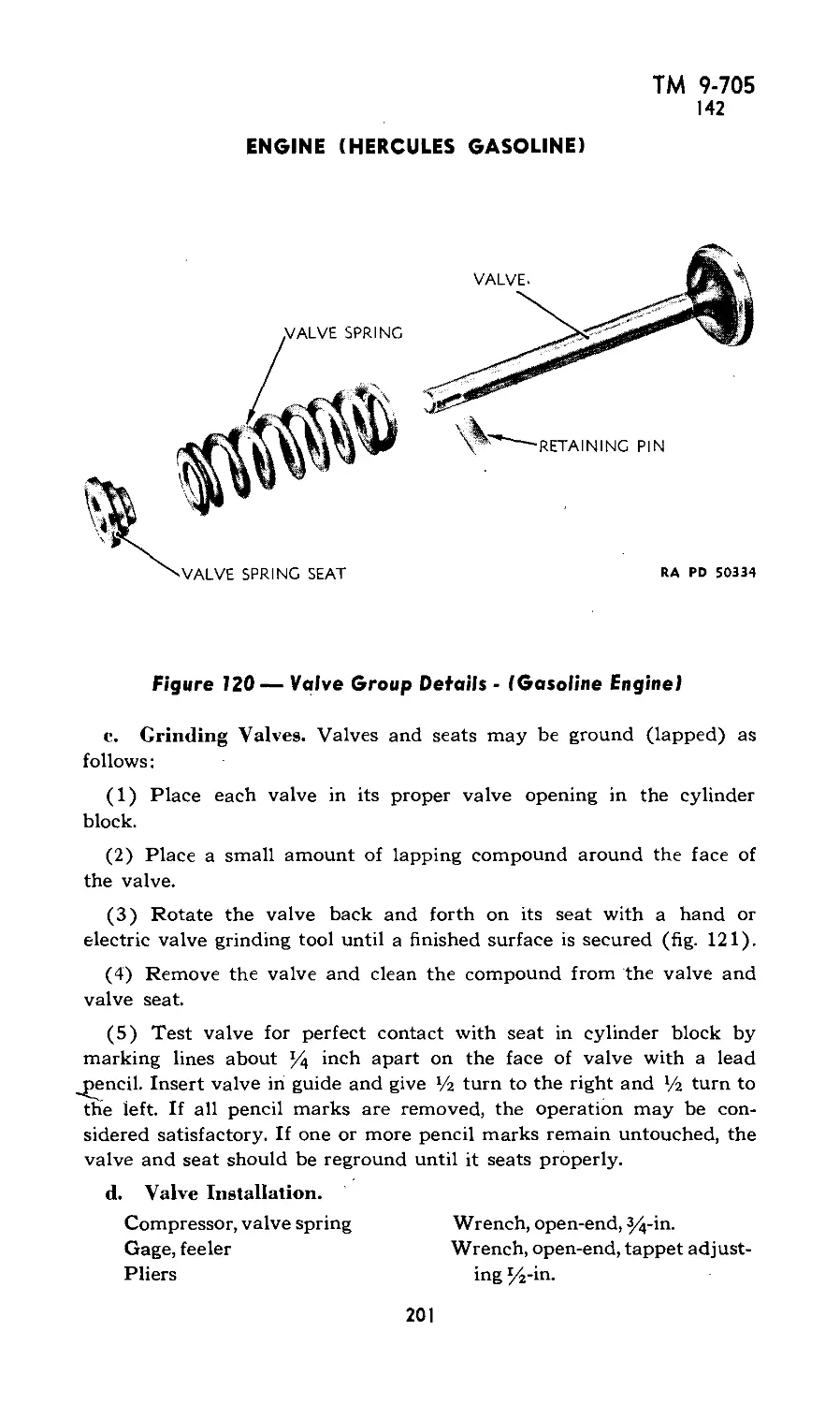
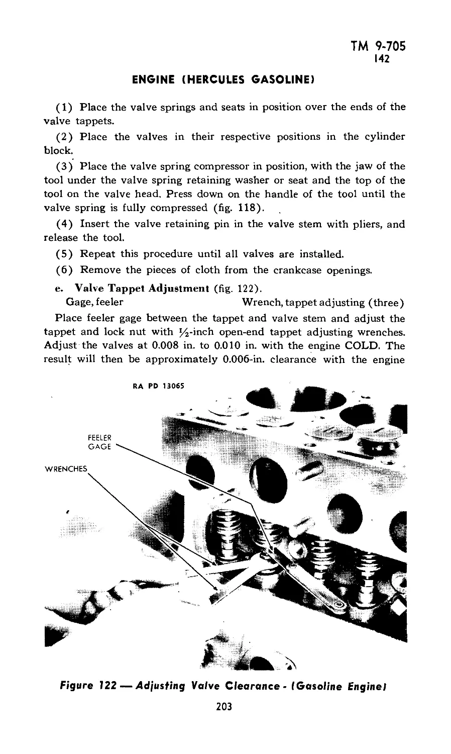
High
9.5 mph
11.1 mph
17.6 mph
32.3 mph
55.5 mph
45 mph
5 qt
3% qt
3 qt
3% qt
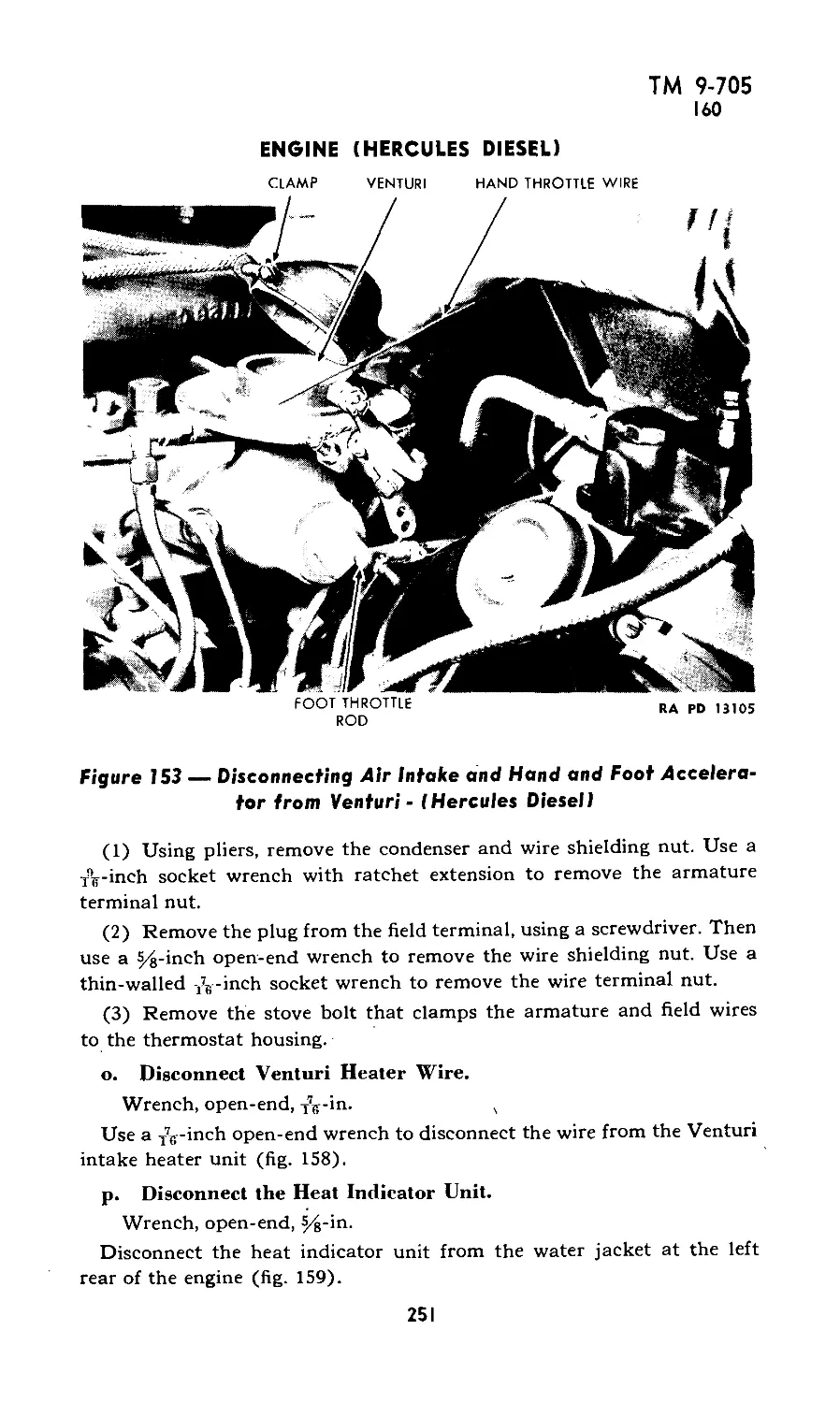
30 gal
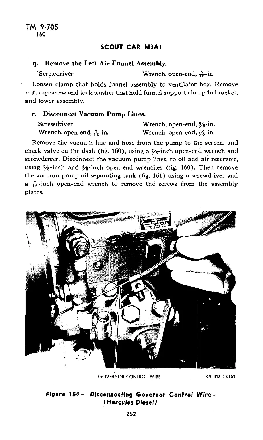
19 qt
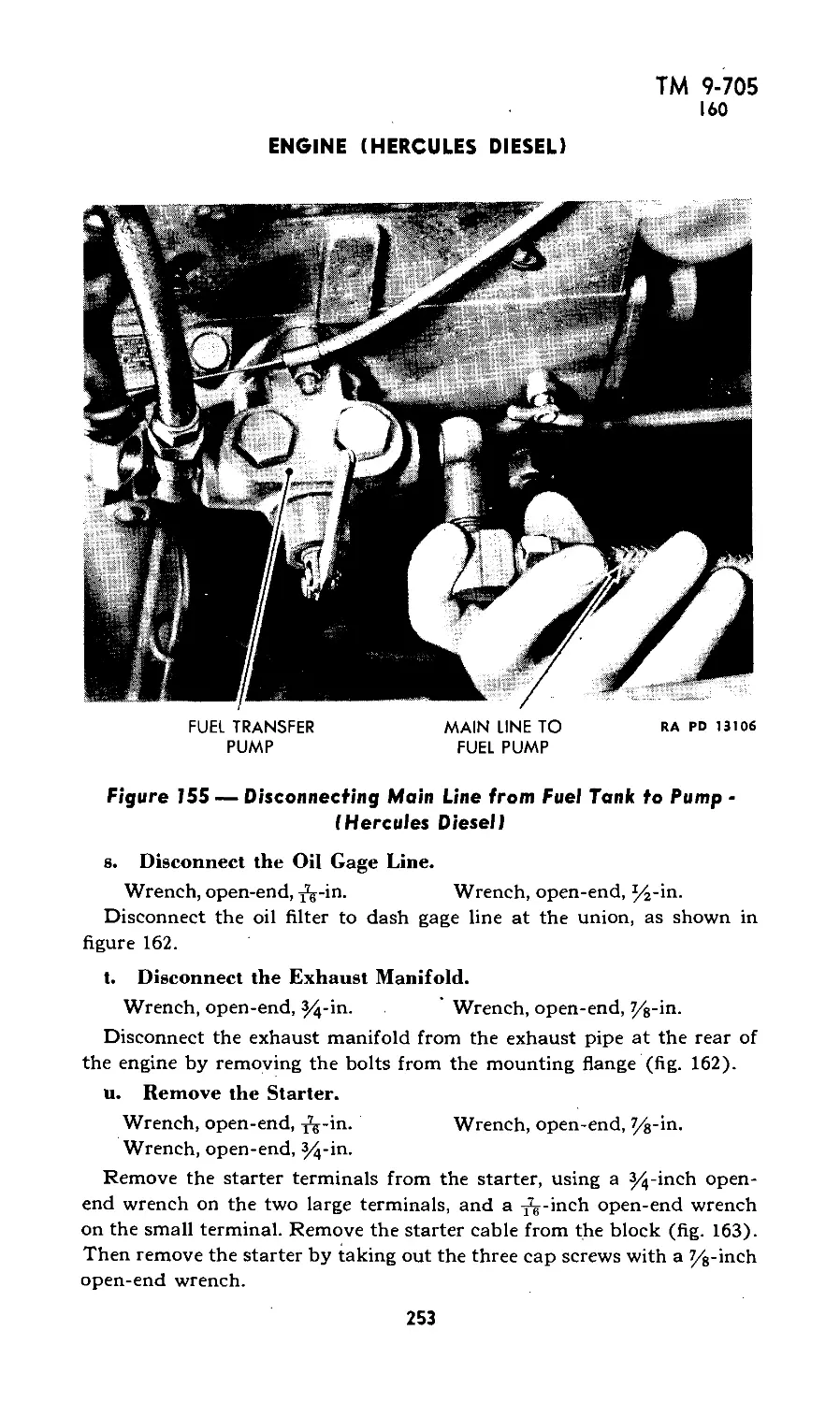
6 qt
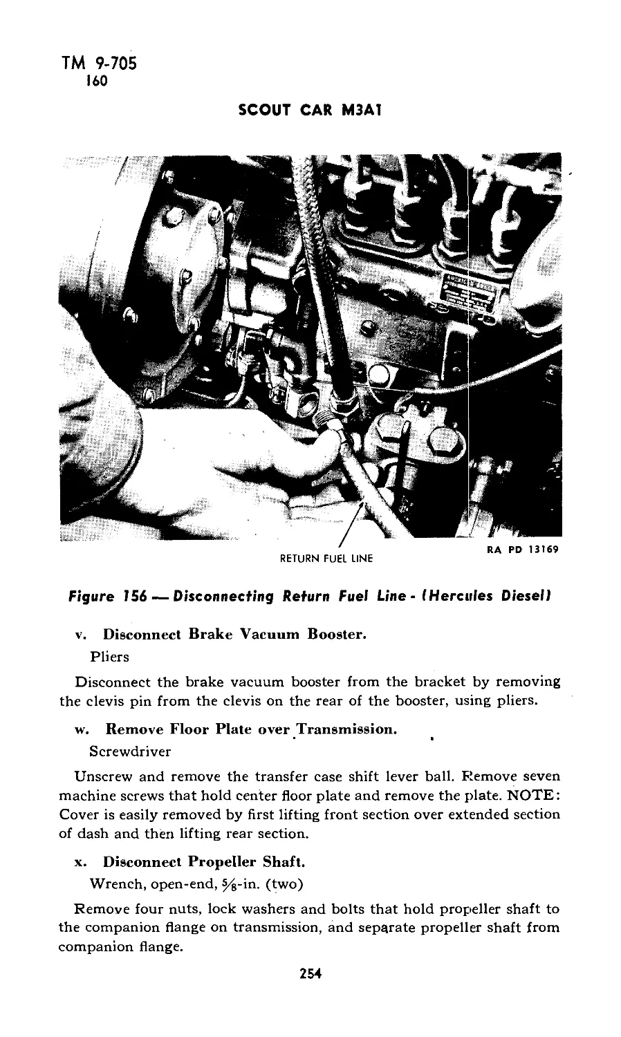
7qt
9 qt
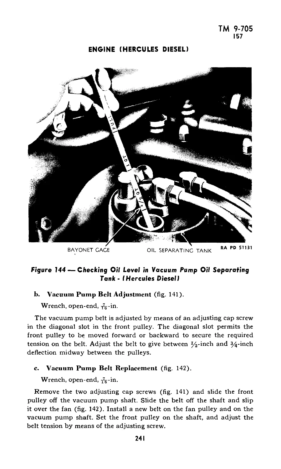
Chassis number — model and serial numbers are stamped on plate
on dash.
Engine number — engine number is stamped on name plate on
the right side of engine.
6
TM 9-705
2
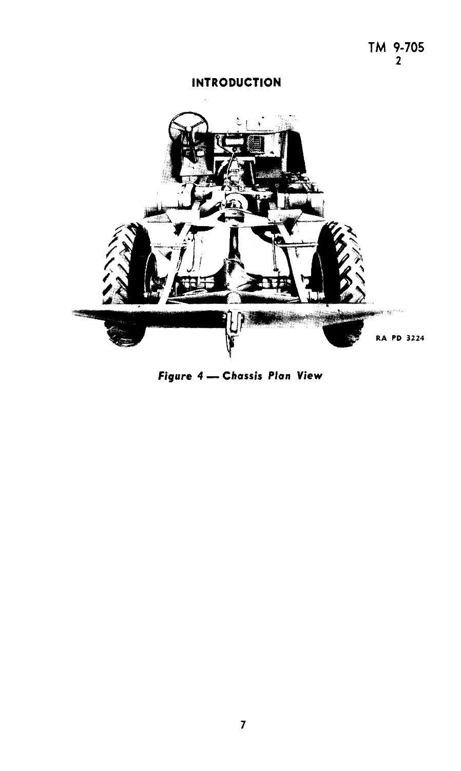
INTRODUCTION
Figure 4 — Chassis Plan View
7
ТМ 9-705
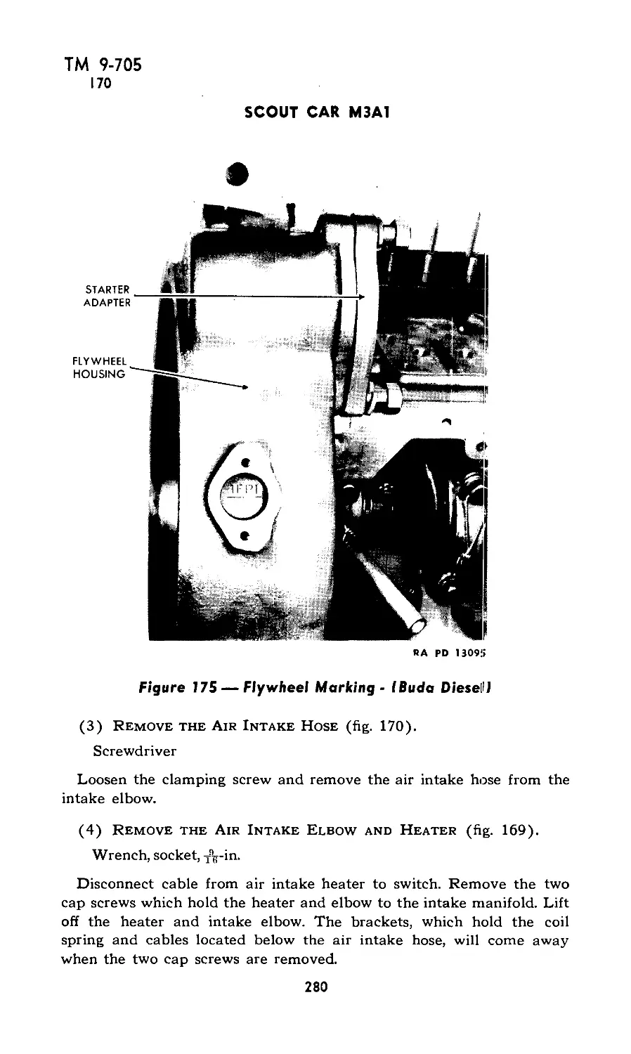
3
SCOUT CAR M3A1
Section II
DESCRIPTION, OPERATION AND CONTROLS
Paragraph
Description ..................................................... 3
Controls ........................................................ 4
Starting and warming up the gasoline engine..................... 5
Starting and warming up the Diesel engine...................... 6
Operating the vehicle ........................................... 7
Cold weather operation........................................... 8
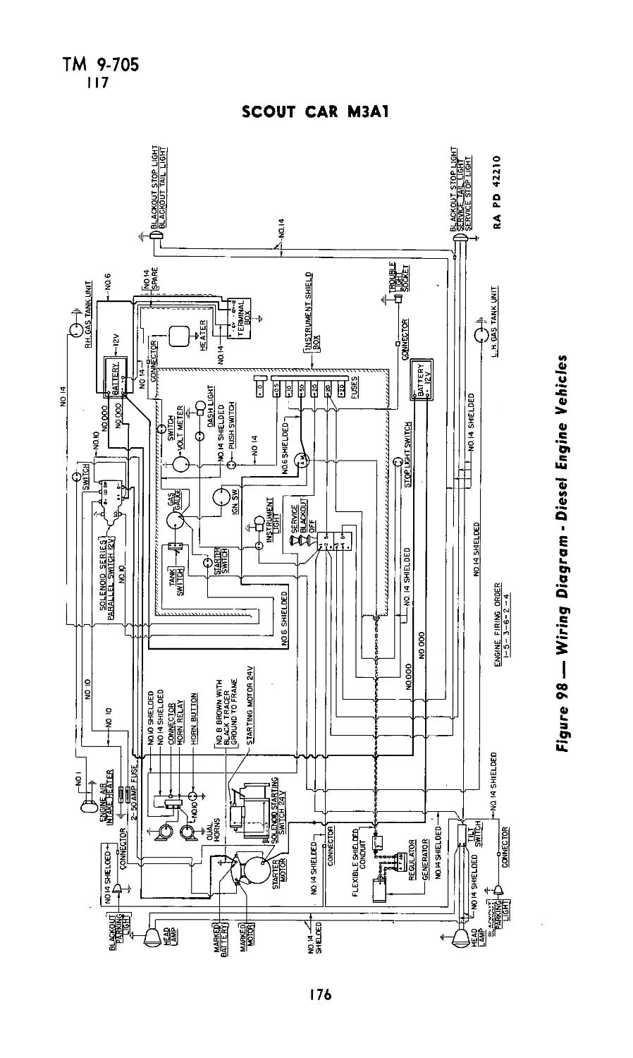
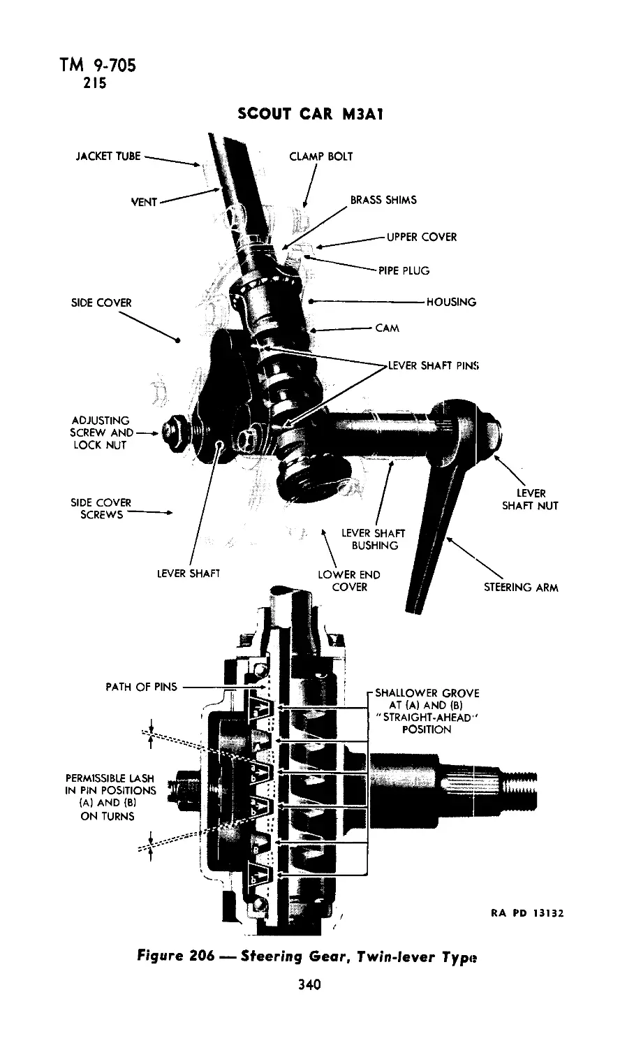
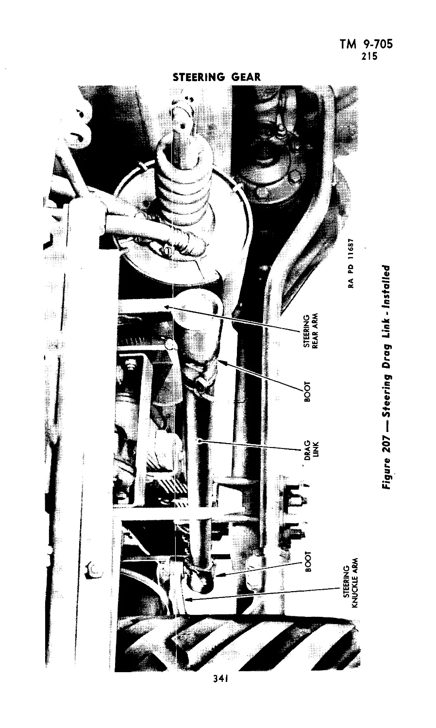
3. DESCRIPTION (figs. 1, 2, 3, and 4).
a. General. This vehicle consists of a specially designed commer-
cial type, four-wheel drive truck chassis. It is powered by a conven-
tional six cylinder gasoline engine or one of two makes of Diesel
engines. The chassis is surmounted by a special armored body mounted
on a double-drop type, channel section frame.
b. Hood. Top and side protection is afforded the engine by the
Vi-inch armor plate hood which is made of two double panels hinged
together to facilitate opening. Two latches on each side secure the
hood when closed. A four-blade, Vi-inch armor plate shutter is pro-
vided for radiator protection and is operated manually from the
driver’s compartment. Stops are provided to hold the shutters open in
three intermediate positions between the fully opened and closed posi-
tions.
c. Windshield. The shatterproof glass windshield, in two sections,
is clamped into and flush with the weather stripped frame structure.
It is necessary to loosen the clamps and remove the glass sections manu-
ally before lowering into place the protective shield of Vi-inch armor
plate, hinged at the top to the windshield supporting frame, and
held normally in a raised position by three cowl props. For observa-
tion purposes, vision slots are provided in the shield.
d. Body. The body is protected by Vi-inch armor plate at the
sides and rear. Each side door is provided with a quadrant to hold the
door open at various positions, and a folding armor shield to heighten
the armor protection for the driver’s compartment. The side shields
are hinged to the respective doors and held in an upright position by
vertical rods which extend up from and are latched to the doors.
Observation openings are provided in the side shields similar to the
vision slots in the front shield. Fuel tanks are placed under the seats
in the driver’s compartment and protected underneath by a steel plate.
Vents are provided for conducting fresh air from beneath the hood
into the driver’s compartment.
8
ТМ 9-705
3
DESCRIPTION, OPERATION AND CONTROLS
Figure 5 — Seating Arrangement
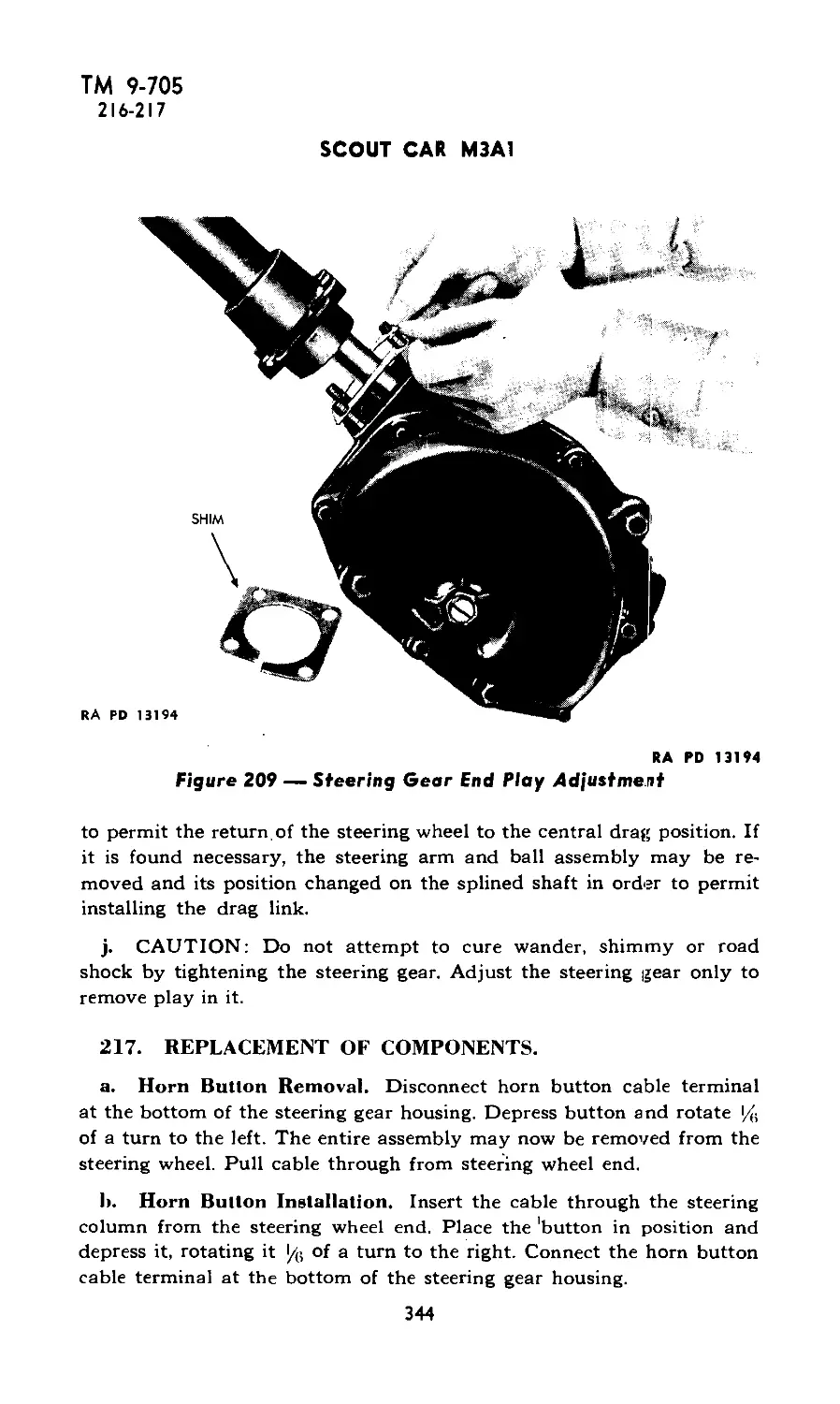
RA PD 3227
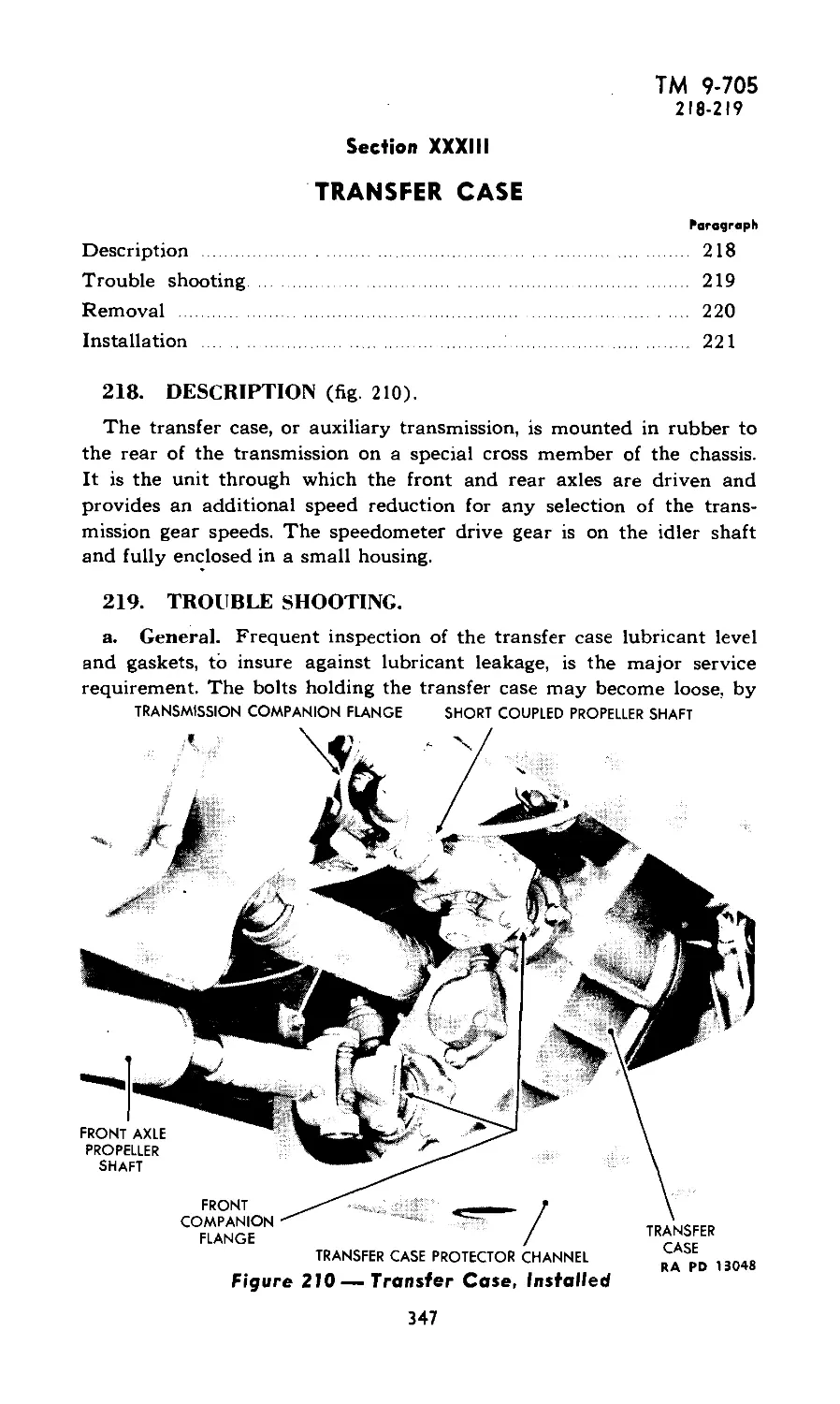
9
ТМ 9-705
3-4
SCOUT CAR M3A1
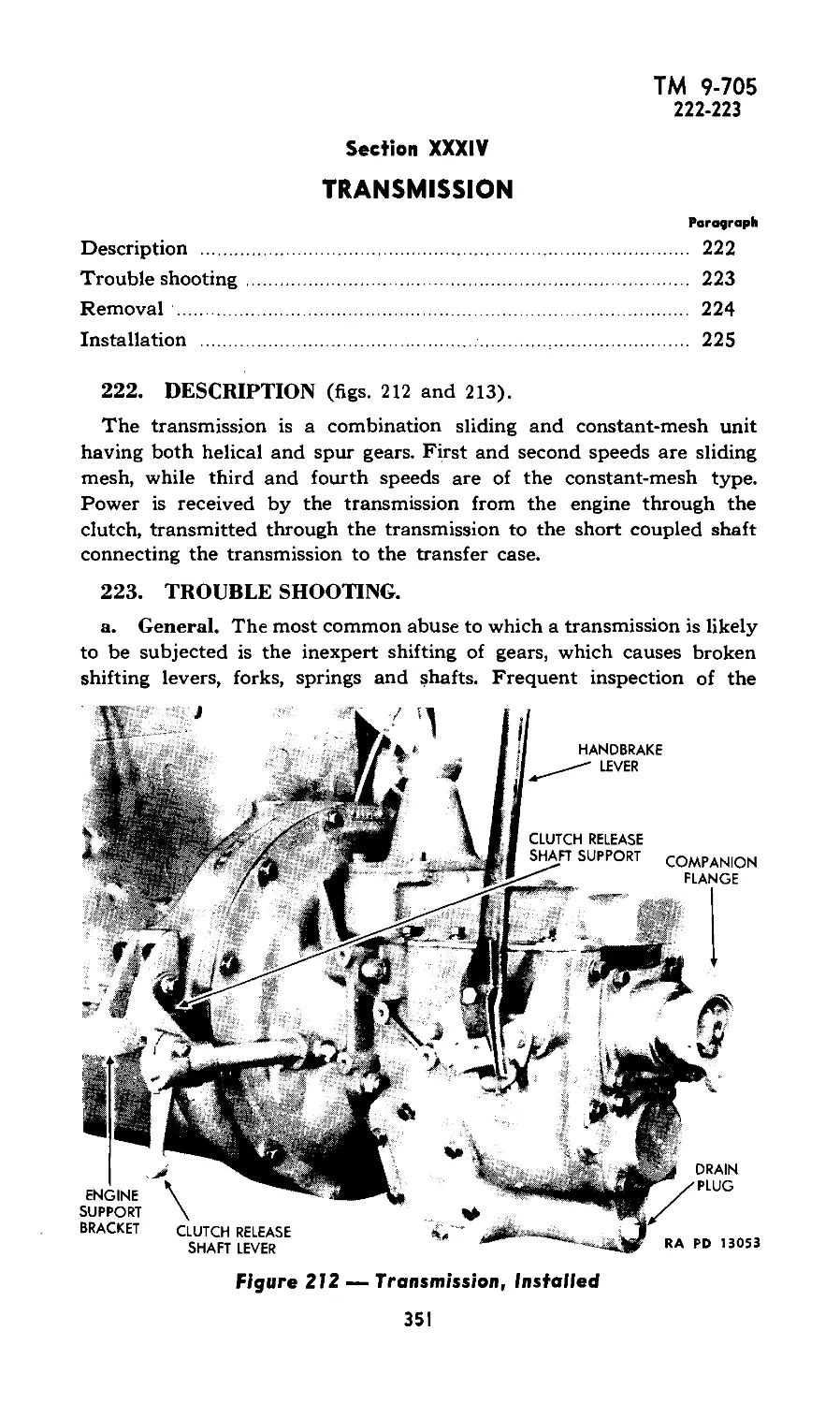
e. Seating Accommodations (fig. 5). A seat is provided in the driver’s
compartment for the driver at the left, and for the observation commander
at the right. Additional seats in the personnel compartment to the rear
provide accommodations for six.
f. Top. Three removable metal bows connected with web strips, to-
gether with the windshield frame, form a support for the detachable,
waterproofed duck top. The ends of the bows are set into brackets which
are secured inside the body. Integral side and rear curtains, without win-
dows, are secured by zipper fastenings to facilitate opening. They roll and
fasten on the inside. The top and its curtains overlap the body and wind-
shield frame and are secured by straps which extend through loops riveted
to the plates (fig. 2). Separate curtains and rods are provided for the side
doors. The top and side curtains, when not in use, are stowed in the bag
provided and are carried inside the vehicle.
(1) A wet top should not be permitted to dry in a lowered or folded
position as a top thus dried will usually shrink to such an extent that the
fit is seriously impaired. A wet top should be dried while in the raised
position, under tension if possible, before being lowered or stored.
(2) It is usually possible to restore a top which has shrunk to the
original dimensions by wetting it thoroughly and allowing it to dry while
held under tension.
g. Equipment (fig. 15). The tourelle gun mount, which encircles the
body interior, is provided with a cross-leveling device for firing from that
part of the gun rail which is sloped as a ramp, or when the vehicle is not
level. Ammunition racks are located over the rear wheel housings at
both sides of the vehicle, and another large compartment is provided
between the front seats for ammunition or a radio set. Smaller sections
for ammunition and water chests are provided to the rear of the front
seats, and the tool box is directly behind the right front seat. The radio
mast is mounted inside the body. Provision is made for storing the water-
bucket and crosscut saw at the rear of the body. Sponge rubber pads
are provided for the gun rail at the front seats and along the rear section.
h. Engines. Three types of six cylinder engines are used in the Scout
Car M3A1. These are a Hercules gasoline engine, Hercules Diesel engine,
and a Buda Diesel engine.
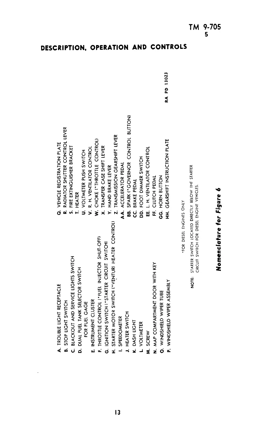
4. CONTROLS (fig. 6).
The controls are employed according to the usual automotive practice.
The driver must become thoroughly familiar with the location and use
of all control devices before attempting to operate the vehicle.
a. Steering Wheel. The vehicle is steered by use of the standard type
of steering mechanism.
10
ТМ 9-705
4-5
DESCRIPTION, OPERATION AND CONTROLS
b. Clutch and Brake Pedals. The pedals are located on the toe board
at the base of the steering column and operated in the conventional
manner.
c. Throttle. The throttle is controlled by a foot accelerator pedal, and
by a throttle control button on the instrument panel. The foot accelerator
pedal is connected to the throttle by mechanical linkage and the hand
control button is connected to the throttle by a cable. Hand control is
useful for starting but not for driving. The hand control is not affected by
pedal operation but the pedal is actuated when the hand control is pulled
out.
d. Shift Levers and Hand Brake. The main and auxiliary gearshift
levers and the propeller shaft brake lever are located and used in the
customary manner. Smooth, firm control is required, without the appli-
cation of excessive force. The ratios in the transfer case (auxiliary trans-
mission) should not be changed when the vehicle is in motion.
e. Radiator Shutters. The lever for closing or opening the radiator
shutters is to the right of the driver’s compartment.
f. Ventilators. The right and left ventilators on the toe board in the
driver’s compartment are controlled by cable-connected buttons mounted
on the instrument panel.
g. Windshield Wipers. These devices are controlled by buttons at
the base of the respective mechanism. They can be operated only when the
engine is running.
h. Instruments, Gages and Switches. The various other aids for
operation of the vehicle are described section XXIX.
5. STARTING AND WARMING UP THE GASOLINE ENGINE.
a. General Instructions. Before the engine is started, the prestarting
inspection outlined in paragraph 15 must be accomplished. Special care
should be taken during the starting and warming-up period to avoid
unnecessary engine wear. The procedure outlined below is satisfactory
under average operating conditions:
(1) Set the hand brake securely and place the transmission gearshift
lever in neutral position.
(2) Check fuel supply and position of fuel transfer valve.
(3) Pull out hand throttle button about % inch.
(4) Depress the clutch pedal to disengage the clutch and ease the start-
ing load.
(5) Turn the switch and push the starter button.
(6) Release the starter the moment the engine begins to run.
(7) After the engine has started, slowly release the clutch pedal and
11
Figure 6 — Driver's Compartment
RA PD 1848A
SCOUT CAR M3A1
A. TROUBLE LIGHT RECEPTACLE
B. STOP LIGHT SWITCH
c.
D.
E.
G.
H.
J.
K.
BLACKOUT AND SERVICE LIGHTS SWITCH
DUAL FUEL TANK SELECTOR SWITCH
FOR FUEL GAGE
INSTRUMENT CLUSTER
THROTTLE CONTROL I'FUEL INJECTOR SHUT-OFF)
IGNITION SWITCH I'STARTER CIRCUIT SWITCH!
STARTER MOTOR SWITCH ('VENTURI HEATER CONTROL)
SPEEDOMETER
HEATER SWITCH
DASH LIGHT
VOLTMETER
Q.
R.
S.
VEHICLE REGISTRATION PLATE
RADIATOR SHUTTER CONTROL LEVER
FIRE EXTINGUISHER BRACKET
HEATER
VOLTMETER PUSH SWITCH
R. H. VENTILATOR CONTROL
M.
N.
O.
P.
SCREW
MAP COMPARTMENT DOOR WITH KEY
WINDSHIELD WIPER TUBE
WINDSHIELD WIPER ASSEMBLY
u.
V.
W. CHOKE ('THROTTLE CONTROL)
X. TRANSFER CASE SHIFT LEVER
Y. HAND BRAKE LEVER
Z. TRANSMISSION GEARSHIFT LEVER
AA. ACCELERATOR PEDAL
BB. SPARK ('GOVERNOR CONTROL BUTTON)
CC. BRAKE PEDAL
DD. FOOT DIMMER SWITCH
EE. L. H. VENTILATOR CONTROL
FF. CLUTCH PEDAL
GG. HORN BUTTON
HH. GEARSHIFT INSTRUCTION PLATE
RA PD 13023
•FOR DIESEL ENGINES ONLY
NOTE: STARTER SWITCH LOCATED DIRECTLY BELOW THE STARTER
CIRCUIT SWITCH FOR DIESEL ENGINE VEHICLES.
DESCRIPTION, OPERATION AND CONTROLS
Nomenclature for Figure 6
О
сл
ТМ 9-705
5-6
SCOUT CAR M3A1
adjust the hand throttle to a position that prevents the engine from racing.
If the choke was used in starting, push in the choke control as soon as
the engine runs smoothly or warms up (approx. 140 F.).
b. Starting Hints. With the battery, fuel system, and ignition system
in satisfactory condition, difficulties other than mechanical failures may
develop in connection with the starter itself.
(1) The starter should not be engaged for periods longer than 10 to 15
seconds. After the starter has been engaged once, approximately 10 seconds
should be permitted to elapse before the starter is engaged again. During
this interval the hand should be held lightly on the shift lever, so that
engine vibrations may be detected if the engine has been started.
(2) If the starter device engages the engine flywheel and locks, release
the starter push button, turn off the switch, place the transmission in high
gear, release the brake, and rock the vehicle backward and forward. If
the gear still sticks, loosen the starting motor mounting screws and shake
the motor until its gear releases. Retighten the bolts and try the starter
again.
(3) If the starter does not turn, but the lights dim when the starting
button is depressed, the battery may be partially discharged or the starter
bearings may be gummed or “frozen.” To free gummed bearings, remove
the starter (see section XIX) and apply penetrating oil.
(4) If the starter turns when the starter button is pressed and the
starter does not engage the engine flywheel, the starter drive may be
gummed. To correct, remove the starter (see section XIX) and free the
drive by using penetrating oil.
(5) In emergencies, when the engine cannot be started with the starter,
it can be started by towing the vehicle. Prior to towing, the engine should
be turned over by hand (three revolutions). The towing vehicle should
be placed in first (low) gear. The vehicle to be towed should be placed in
fourth (high) gear and the transfer case in high range. The engine should
be primed or choked and the throttle slightly opened. After the towed
vehicle starts moving, the clutch should be engaged smoothly, and when
the engine starts turning over, the ignition switch should be turned on.
Even though the battery is weak the engine can be started in this
manner.
6. STARTING AND WARMING UP THE DIESEL ENGINE.
a. Precautions. The following precautions, if followed, will help elimi-
nate operating difficulties and abnormal wear.
(1) Do not allow oil level to fall much below the 4/4 mark on the
bayonet gage. As the lubricating oil is the medium for removing the fric-
14
ТМ 9-705
6
DESCRIPTION, OPERATION AND CONTROLS
tion heat in the bearings, the larger the volume the more heat can be
absorbed.
(2) Do not run engine at any time without lubricating oil or cooling
solution (water or antifreeze mixture).
(3) Do not use oil, fuel oil or kerosene in the cooling solution or as a
cooling medium as these will be detrimental to the synthetic rubber
water pump seal.
(4) Never run engine with water or antifreeze solution boiling. This
allows lubrication to break down and may seriously damage the engine.
(5) Do not put cold water in an overheated engine. It may crack
cylinder head, block, etc.
(6) Do not run an engine at high speed without load as this will
cause undue wear and shorten the life of the engine.
(7) Do not idle engine for long periods as it is detrimental to the engine.
(8) Do not use engine as a brake in intermediate or low gear in auto-
motive service. Using low or intermediate gear while descending steep
grades may increase the engine speed beyond the speed for which it is
designed, and damage will result unless vehicle speed is held to that used
in same gears on the level.
(9) Never allow engine to run without oil pressure showing on the
gage. Damage from lack of lubrication will result.
(10) Do not operate fuel injection pump with one or more lines shut
off or blocked, as the high pressure may ruin the pump.
(11) Do not allow fuel in tank to run low, as it may allow fuel transfer
pump line to uncover long enough to fill the lines with air and cause the
engine to stop, resulting in lost time taken for priming.
(12) Loss of power, erratic running and poor performance often result
from air in the fuel injection system. Be sure there are no leaks in fuel
lines and filters which will allow this condition to exist. Vent cocks on
top of filters are for bleeding off any air which may accumulate from
bubbles in the fuel and very minor leaks; therefore it is essential to bleed
these often until the operator is sure air is not entering the fuel system.
(13) Never run starting motor longer than 30 seconds at one time
without a rest period of at least 1 minute before allowing it to run again.
Failure to follow this procedure may result in a burnt-out starting motor.
b. Starting Engine After a Long Shut-Down.
(1) See that the engine turns freely by hand; a hand barring device
is provided for this purpose. Turn not less than two complete revolutions.
(2) Fill the engine with the required amount of lubricating oil. Check
with oil level gage.
15
ТМ 9-705
6
SCOUT CAR M3A1
(3) Fill cooling system with clean water or antifreeze solution.
(4) Completely lubricate the vehicle.
(5) Drain all fuel and lubricating oil filters until all water and sedi-
ment are removed.
(6) Fill the battery with clean, distilled water.
(7) Fill the fuel supply tank with a good grade of fuel oil, using a
strainer.
(8) Open fuel supply valves.
(9) Open throttle control lever l/3 on the quadrant.
(10) Thoroughly vent the entire fuel system. To assist in filling and
venting, most models are equipped with a manual operating lever on the
fuel transfer pump. By working the lever, the fuel can be forced through
the system to the suction compartment of the injection pump. Vent sys-
tem as follows:
(a) Vent the fuel filter by loosening the vent screw.
(b) Vent the fuel suction compartment of the injection pump by
loosening the vent plug or connections on the injection pump housing.
A small vent plug is provided at the top and on one end of the injection
pump housing, and a check valve and overflow line at the other end for
venting. Normally the check valve and overflow line will keep the injection
pump vented at all times while the engine is running. However, when
starting a dry system, it is well to loosen the small vent plug until the fuel
flows freely without air bubbles.
(c) Vent the fuel lines at the nozzles. Venting the nozzles can be
accomplished by loosening the pressure line at the nozzle, allowing the
fuel to drain until free from any air bubbles. This draining must be accom-
plished while the engine is turning over. If the engine is running, this will
also prevent the cylinder on which the line is vented from firing. This
will aid in locating a weak or missing cylinder.
(d) Crank the engine with the starter until fuel flows freely without
foaming at each vent, closing each vent opened. NOTE: Air in pump or
lines will cause poor operation and hard starting. The air must always
be released completely.
(11) Depress the clutch pedal to ease the starting load. Turn the switch
and press the starter button.
(12) Release the starter button the moment the engine begins to run.
(13) After the engine has started, slowly release the clutch pedal and
adjust the hand throttle to a position that prevents the engine from
racing. For temperatures below 50 F, see cold weather operation (par. 8).
16
ТМ 9-705
6-7
DESCRIPTION. OPERATION AND CONTROLS
c. Usual Routine Method of Starting. Follow steps (b) (11), (12)
and (13) for starting the engine.
7. OPERATING THE VEHICLE.
a. Starting on Level Ground. The engine having been thoroughly
warmed up and checked for satisfactory operation, the vehicle is placed
in motion as follows:
(1) Release the hand brake.
(2) Disengage the clutch fully.
(3) Move the transmission gearshift lever to selected position.
(4) Release the clutch pedal gradually, and at the same time slowly
depress the accelerator pedal to increase the speed of the engine, care
being taken not to race the engine. NOTE: The transfer case shift lever
should be in “high” position, unless starting on a hill or in heavy
pulling where greater gear reduction is necessary.
(5) Double-Clutching. It may be necessary to double-clutch to
assure smooth engagement of the transmission gears. This may be
accomplished when shifting from low to high gear ratio or from high
to low gear ratio. To double-clutch, disengage clutch and shift trans-
mission into neutral. Hold the transmission gearshift lever in this
position and reengage clutch at the same time decreasing (when shifting
from lower to higher ranges) or increasing (when shifting from higher
to lower ranges) the engine speed to suit engagement in the next gear.
Disengage the clutch again and shift transmission lever into the next
gear. When properly performed, double-clutching tends to synchronize
the mating gears. Double-clutching can be performed quickly and
allows better control. When shifting on steep grades, it is necessary to
double-clutch.
b. Starting on a Grade. If the vehicle is on a grade, one method of
starting is as follows:
(1) Release the hand brake and hold the vehicle with the foot brake.
(2) Disengage the clutch fully.
(3) Select low or high speed position to transfer case gearshift,
depending upon the steepness of the grade and road conditions.
(4) Move the gearshift lever to the first speed position.
(5) Gradually engage the clutch, and at the same time gradually
release the foot brake and accelerate the engine by means of the hand
throttle.
c. Gearshifts (fig. 7). Practice will enable a driver to judge at what
rates of speed the vehicle should be moving before he shifts from a
lower to a higher speed. An engine should never be permitted to labor
unduly when a change in gear ratios would improve operation.
17
ТМ 9-705
7
SCOUT CAR M3A1
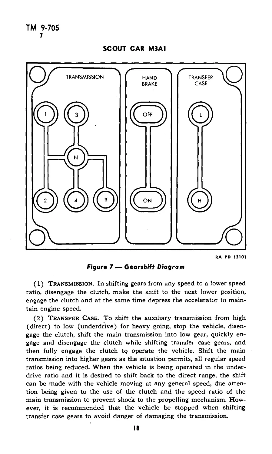
Figure 7 — Gearshift Diagram
RA RD 13101
(1) Transmission. In shifting gears from any speed to a lower speed
ratio, disengage the clutch, make the shift to the next lower position,
engage the clutch and at the same time depress the accelerator to main-
tain engine speed.
(2) Transfer Case. To shift the auxiliary transmission from high
(direct) to low (underdrive) for heavy going, stop the vehicle, disen-
gage the clutch, shift the main transmission into low gear, quickly en-
gage and disengage the clutch while shifting transfer case gears, and
then fully engage the clutch t<? operate the vehicle. Shift the main
transmission into higher gears as the situation permits, all regular speed
ratios being reduced. When the vehicle is being operated in the under-
drive ratio and it is desired to shift back to the direct range, the shift
can be made with the vehicle moving at any general speed, due atten-
tion being given to the use of the clutch and the speed ratio of the
main transmission to prevent shock to the propelling mechanism. How-
ever, it is recommended that the vehicle be stopped when shifting
transfer case gears to avoid danger of damaging the transmission.
18
ТМ 9-705
7
DESCRIPTION, OPERATION AND CONTROLS
(3) CAUTION: In shifting from one speed to another, do not skip
positions. Do not ride the clutch. The driver’s foot should rest on the
clutch pedal only when he is operating it. A sudden engagement is
injurious to the mechanism and may stall the engine. When the clutch
is to be disengaged, it should be disengaged fully to avoid gear damage
and shifting difficulties. Every effort should be made to prevent sudden
shock to the driving parts in any gear. Guard carefully against dropping
the clutch in suddenly at any time, and especially if the vehicle rolls
backwards, no matter how slowly. If there is any tendency for the
vehicle to roll backward, block the wheels before attempting a start
and then engage the clutch and accelerator carefully. If it is not con-
venient to block the wheels, and should conditions permit, by all means
allow the vehicle to coast back to a standstill under control of the
brakes before attempting to start forward. FAILURE TO OBSERVE
THESE SIMPLE PRECAUTIONS WILL RESULT IN CERTAIN
SNAPPING OF DRIVE GEARS AND SHAFTS.
d. Braking. The brakes should be in such condition that hard appli-
cations will cause all wheels to be locked, but the driver must realize
that the maximum retarding effect occurs just before the wheels lock.
Intermittent application will reduce the wear of brake linings and
drums. Application should be gradual with just enough force to accom-
plish the desired result.
(1) Usage. In anticipating a stop, the driver should make full use
of the engine braking effect, disengaging the clutch in time to avoid
stalling the engine. When descending hills, the driver should use the
engine as a brake by using the proper gear ratio and applying the
brakes from time to time to prevent overspeeding the engine. The
ignition should not be turned off. On steep hills, the gear necessary to
give the desired results should be engaged before the vehicle is started
up or down the hill. Any attempt to shift gears after the vehicle has
started down a steep slope may result in a run-away vehicle.
(2) Moisture Effect. After passing through water, the brakes
should be set slightly and the vehicle operated for a short period until
sufficient heat has been generated to dry the brakes.
(3) Stopping the Vehicle. Release throttle, apply foot brake, and
shift transmission into neutral before the engine stalls. Do not brake by
disengaging and engaging the clutch. When operating at a speed of
20 miles per hour on a dry, smooth, level road free from loose mate-
rial, the vehicle should be capable of stopping within 30 feet when the
foot brake is applied.
e. Traction Aide. Chains should always accompany the vehicle. They
should be kept in serviceable condition and in proper adjustment to
I?
ТМ 9-705
7-8
SCOUT CAR M3A1
permit installation with a minimum of delay. They should be removed
promptly as soon as their use is no longer necessary to prevent damage
to tires and roads. The chains should be installed before the vehicle
becomes mired, and in such a manner that rotation of the wheel tends
to close the chain fastenings. If the chains are improperly installed,
rotation of the wheels opens the fastenings and the chains will be lost.
Fairly loose adjustment gives better traction and less tire wear than
tight adjustment.
8. COLD WEATHER OPERATION.
a. Gasoline Engine Vehicles—Temperatures from —10 F to —30 F.
(1) It is possible to start gasoline engines with batteries at tem-
peratures as low as -30 F if the engines are properly lubricated and
in good mechanical condition. First “break” engine free with hand
crank. Every effort should be made to avoid having the engine fire a
few times and then stop.
(2) Prior to attempting a start, care should be taken that everything
is in readiness so that the engine will start on the first trial. Water is
one of the products of gasoline combustion. In a cold engine, this water
may form a frost and make it impossible to start without heating
the engine to above 32 F. Prolonged efforts to start will wear down
the battery.
(3) Pull the choke lever all the way out for starting and keep it
partially pulled out until the engine has warmed up. In a cold engine,
only the lightest components of the gasoline vaporize, and for this
reason a very rich mixture is necessary.
(4) When attempting a start, turn the engine over as rapidly as
possible. All engines have a “critical cranking speed,” that is, the engine
must be turned over at a certain rate of speed before any start at all
is possible. For engines in good mechanical condition, this critical rate
of speed may vary from 40 to 70 revolutions per minute. Below this
speed, the fuel pump will not deliver fuel fast enough to keep the
engine running.
(5) After the engine is started, idle it until it has warmed up suffi-
ciently to run smoothly. Idle engine at a low speed.
b. Gasoline Engine Vehicles—Temperatures Below —30 F.
(1) Cover engine with the tarpaulin, tent, or portable shed. Place
oil stove, fire pots, or four or five ordinary kerosene lanterns under
the covering about 3 hours prior to the time a start is to be made.
(2) Keep the vehicles in sheltered areas shielded from wind. Cold
winds increase starting difficulties.
(3) It is possible for ice to collect in the fuel line. If the engine does
20
ТМ 9-705
8
DESCRIPTION. OPERATION AND CONTROLS
not appear to be getting enough fuel, lightly heat the fuel line, but be
very cautious of fires.
c. Stopping Gasoline Engine. Before turning off the ignition, in-
crease engine speed, then turn off the ignition and release the throttle
at the same time. As the engine coasts to a stop, it will blow out all
the residual products of combustion, which include water vapor, and
leave only air and gasoline vapor in the engine.
d. Diesel Engine Vehicles. The increased temperature of the air due
to compression is the only means of igniting the fuel sprayed into the
combustion chamber. If the iron surrounding this chamber is extremely
cold, and in addition the air entering the cylinder before compression
is cold, the resultant temperature may not be sufficient to ignite the
mist of fuel. Two methods are available to increase this temperature:
(1) Heating the Air Before It Reaches the Cylinder.
Mounted in the Venturi of the air intake system is a heater element
which can be used to heat the air entering the combustion chamber
in cold weather. Pressing the heater button on the toe board sends
current through a heater element. Air passes over the heater element
and is warmed before entering the cylinder. Length of time will vary
with temperature conditions, usually from x/z to 1 minute. Remove
foot and start engine in the regular manner. CAUTION: Do not de-
press starter button while heater button is depressed. The heater should
be used only when necessary.
(2) Heating the Water or Cooling Solution. As an aid in cold
weather starting, the cooling solution should be drained into a drum
or suitable vessel and heated. (Caution should be taken against- fire
if alcohol solution is used.) When this heated solution is poured into
engine, the cold iron parts are heated and the oil on cylinders is thinned
down.
(3) At temperatures below 0 F, the heating of water, oil and air
may be desirable. Battery output is reduced at these low tempera-
tures so every means should be used to conserve the battery. At these
temperatures it is advisable to drain the oil at the end of the day’s run
and thoroughly heat and return to engine just before starting. Drain
the water and sediment from the filter housings frequently, as water
collects quickly due to condensation.
21
ТМ 9-705
9-12
SCOUT CAR M3A1
Section III
ARMAMENT
Paragraph
Weapons and mounts ......................................... 9
Tripod mount M1917A1 ...................................... 10
Tripod mount М3 ........................................... 11
Carriage .................................................. 12
Cradle mount M30 .......................................... 13
9. WEAPONS AND MOUNTS.
Characteristic armament for the vehicle is tabulated below:
Weapons per
Vehicle Weapons
1 Gun, machine, Browning,
cal. .30, M1917A1
1 Gun, machine, Browning,
cal. .50, М2, HB, flex-
ible
Mounts per
Vehicle Mounts
1 Mount, tripod, cal. .30,
M1917A1
1 Mount, tripod, cal. .50,
М3
1 Mount, gun, cal. ..50,
M30
10. TRIPOD MOUNT M1917A1 (fig. 8).
The tripod mount is a variable height, folding tripod, with tubular
legs and a cradle to mount the Browning machine gun, cal. . .30,
M1917A1. The cradle is designed so that the gun is mounted in the
approximate line of recoil to increase stability. The cradle permits
elevation to provide both for ground and antiaircraft fire.
11. TRIPOD MOUNT М3 (fig. 9).
This mount is a variable height folding tripod with telescoping legs.
Normal mounting of the tripod is with the front leg set at an angle of
60 degrees and all extensions projected and secured. In this position on
level ground, the center of the gun trunnion is at a height of 10 inches,
and the mount is stable. If this height is increased, the gun recoil
destroys stability and makes mandatory the extension of the rear legs
if stability is to be retained. No cradle is provided. Antiaircraft fire is
not possible with this mount.
12. CARRIAGE (fig. 10).
This rolling carriage is used for both the cal. .30 and the cal. .50
machine gun mounts. It provides for travel on the continuous track
22
ТМ 9-705
12
ARMAMENT
RA RD 13016
Figure 8 —Browning Machine Gun, Cai. .30, M1917A1 on Tripod
Mount, Ml917Al
which extends around the inner side of the vehicle. It can be locked
for firing at any position of the track and canted for any position of
the vehicle. The usual elevating mechanisms provided with the guns
are employed for accurate adjustment. An anticanting device for the
pintle compensates for the displacement of the track from a hori-
zontal plane.
MACHINE GUN, CAL. .50, М2 HB
Figure 9 — Browning Machine Gun, Cal. .50, М2 on Tripod Mount
23
ТМ 9-705
12
SCOUT CAR M3A1
ROLLER
RETAINER
BRAKE LEVER
•1'Ш
PINTLE
SLEEVE
CANTING
HANDWHEEL
TRACK CLAMP
HANDLE
PINTLE CLAMP
HANDLE
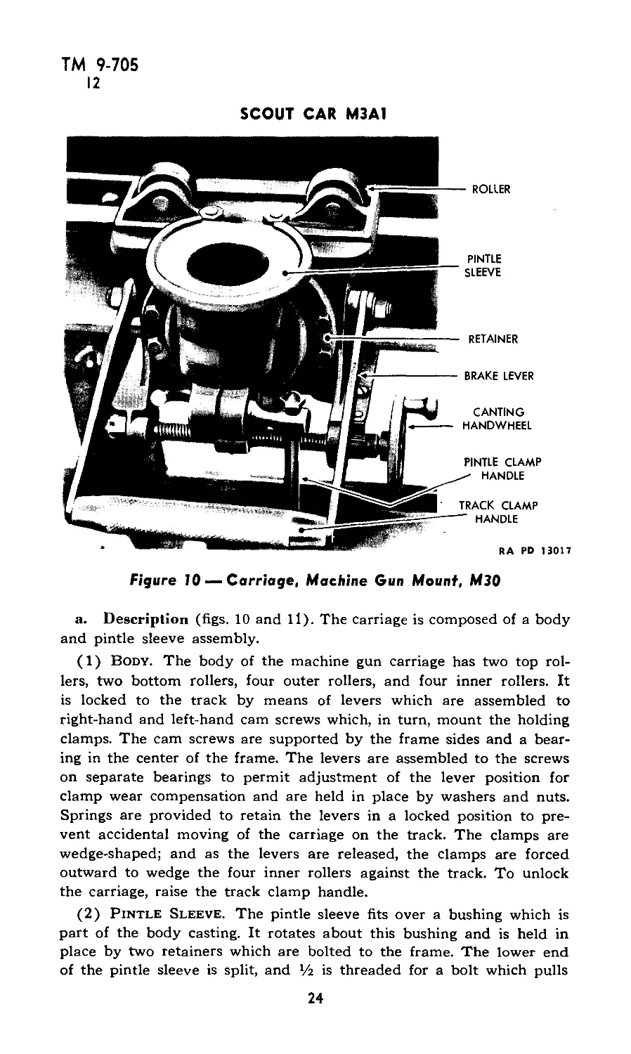
Figure 10 —Carriage, Machine Gun Mount, M30
RA PD 13017
a. Description (figs, 10 and 11). The carriage is composed of a body
and pintle sleeve assembly.
(1) Body. The body of the machine gun carriage has two top rol-
lers, two bottom rollers, four outer rollers, and four inner rollers. It
is locked to the track by means of levers which are assembled to
right-hand and left-hand cam screws which, in turn, mount the holding
clamps. The cam screws are supported by the frame sides and a bear-
ing in the center of the frame. The levers are assembled to the screws
on separate bearings to permit adjustment of the lever position for
clamp wear compensation and are held in place by washers and nuts.
Springs are provided to retain the levers in a locked position to pre-
vent accidental moving of the carriage on the track. The clamps are
wedge-shaped; and as the levers are released, the clamps are forced
outward to wedge the four inner rollers against the track. To unlock
the carriage, raise the track clamp handle.
(2) Pintle Sleeve. The pintle sleeve fits over a bushing which is
part of the body casting. It rotates about this bushing and is held in
place by two retainers which are bolted to the frame. The lower end
of the pintle sleeve is split, and */2 is threaded for a bolt which pulls
24
TM 9-705
12
ARMAMENT
the split together and locks the pintle in any position desired. The
split end also has a latch passing through it to hold the cradle pintle
in the sleeve. A sector is bolted to the bottom of the sleeve, and into
this is set a sector nut which is threaded onto a carriage screw. One
end of the screw has the handwheel pinned to it, and the other end
is secured by a nut. Turning this handwheel rotates the screw and
makes the center sector nut travel back and forth, causing the sector
and pintle sleeve to cant or tilt to the right or left and compensate
for the side slope of the track as the vehicle moves about. By turning
the control wheel clockwise, the vertical center line of the gun mount
will be displaced to the left, and vice versa. The pintle clamp, which
prevents the pintle from revolving, is independent of the anticanting
control.
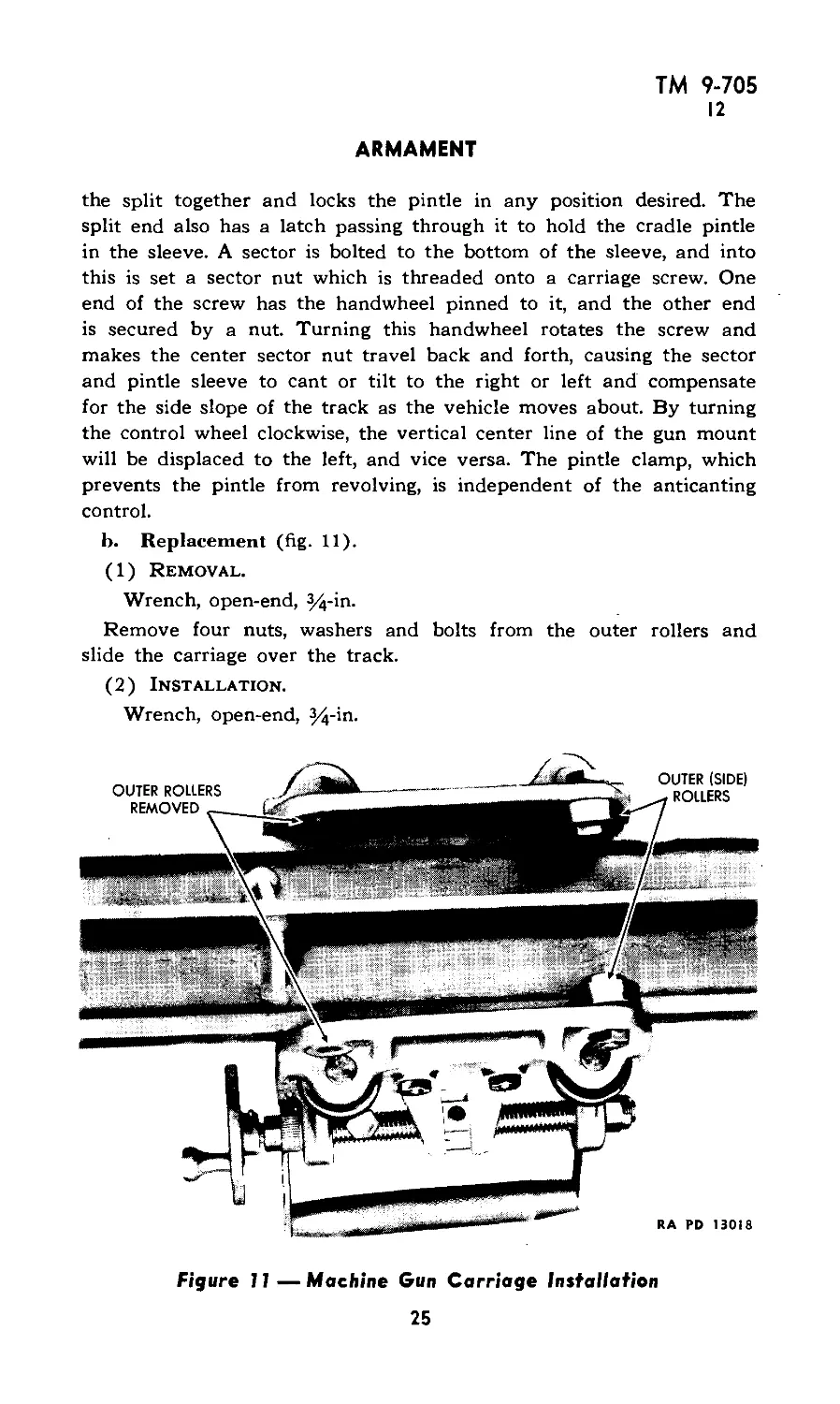
b. Replacement (fig. 11).
(1) Removal.
Wrench, open-end, %-in.
Remove four nuts, washers and bolts from the outer rollers and
slide the carriage over the track.
(2) Installation.
Wrench, open-end, 3^-in.
Figure 11 —Machine Gun Carriage Installation
25
ТМ 9-705
12-13
SCOUT CAR M3A1
Place carriage on the track and place the roller and washer on the
bolt, insert in position on the carriage and tighten the nut.
c. Lubrication. Excessive wear can be prevented by keeping the
materiel clean and well lubricated. OIL, lubricating, preservative, light,
should be used. The trunnion bearings, clamping devices, elevating
screw, carriage rollers and other bearings subject to wear should be
lubricated daily and before each period of firing. The track should be
wiped with an oily rag to protect it against rust.
13. CRADLE MOUNT M30 (fig. 12).
This mount is designed for the Browning machine gun, cal. .50, М2,
heavy barrel, and permits all-around ground fire from inside the vehicle.
RA RD 13020
Figure 12 — Cradle Mount, Cal. .50 - Installed
a. Dismounting Gun. For ground fire from the tripod, remove the
machine gun from the cradle of the mount by releasing the gun pintle,
disconnecting the elevating mechanism at the cradle, and lifting weapon
with gun pintle attached.
b. Dismounting Cradle. Dismount the cradle, or the gun and cradle,
with the cradle pintle attached, by releasing the carriage pintle clamp,
withdrawing pintle latch, and lifting the mount from the carriage sleeve.
c. Lubrication. Refer to paragraph 12, c.
26
ТМ 9-705
14
Section IV
INSPECTION
Paragraph
Purpose ........................................................ 14
Prestarting inspection ......................................... 15
Inspection during operation .................................... 16
Inspection at the halt ........................................ 17
Inspection after operation ..................................... 18
Periodic inspection ............................................ 19
14. PURPOSE.
a. To insure mechanical efficiency, it is necessary that vehicles be
systematically inspected at intervals in order that defects may be dis-
covered and corrected before they result in serious damage.
b. Cracks that develop in castings or other metal parts may often
be detected upon the completion of a run by the presence of dust
and oil deposits.
c. The Chief of Ordnance should be advised through the local
ordnance officer of any chronic troubles, technical failures or unsatis-
factory operation of any part or unit. Failures within the guarantee
period (1 year or 4,000 miles) will be reported promptly. Any sugges-
tions for the improvement of the inspection procedure based on actual
operating experience should likewise be forwarded so that all units may
benefit. The report will contain the following:
(1) Identity of vehicle and component assembly. The ordnance
designation of vehicle and component, including the U. S. registration
number, the ordnance serial number, the name of the manufacturer and
the manufacturer’s designation including the model, type and serial
number, the length of service in miles or hours and date on which the
defective component or assembly was installed in the vehicle.
(2) Description of failure, defects or improper functioning. The
name of the place and date of failure, the manner in which the com-
ponent is damaged, defective or improperly functioning, setting forth
the attending circumstances and known causes of the failure, defect or
improper functioning together with pertinent drawings, photographs,
sketches and sample specimens.
(3) Remedy or action taken, the present location of the replaced
or defective part, the source of the part used in making the repairs or
replacement, the source of labor used in making the repairs or replace-
ment if other than ordnance personnel.
(4) A separate report will be made for each failure unless there
are a number of identical failures to be reported. In that event the
27
ТМ 9-705
14-17
SCOUT CAR M3A1
single report may be submitted, provided each vehicle involved is
identical. The local ordnance officer will forward reports to Office,
Chief of Ordnance. These reports should not be addressed to an arsenal,
manufacturer, or contractor unless such action is specifically authorized.
(5) Defective or broken material that has been replaced and re-
ported by this procedure must be held pending disposal instructions
from the Office, Chief of Ordnance.
15. PRESTARTING INSPECTION.
a. Check fuel supply and position of fuel transfer valve, oil in
crankcase, water and antifreeze in radiator, and battery water. NOTE:
Never fill the fuel tank while the engine is running, or near an open
flame.
b. Examine surface under vehicle for evidence of leaks.
c. Check engine for loose parts and electrical connections, and check
fuel and lubricating oil lines for leaks.
d. Inspect tires for inflation and for casing injuries.
e. Inspect front axle and steering linkage.
f. Check lights and horn.
g. Check tools and equipment.
h. Check fan belt tension and adjust if required.
16. INSPECTION DURING OPERATION.
a. During operation, the driver should be alert to detect abnormal
functioning of the engine. He should be trained to detect unusual
engine sounds or noises. He should glance frequently at the instrument
panel gages to see if the engine is functioning properly.
b. Only under exceptional circumstances should a vehicle be oper-
ated after indications of trouble have been observed. When in doubt,
the engine should be stopped and assistance obtained. Inspection dur-
ing operation applies to the entire vehicle and should be emphasized
throughout the driving instruction period.
17. INSPECTION AT THE HALT.
a. At each halt the operator should make careful inspection of the
vehicle to determine its general mechanical condition. Minor defects
detected during the march, together with defects discovered at the halt,
should be corrected during the halt; and proper disposition of the
vehicle should be made so that unnecessary delay may be avoided and
major failure prevented.
b. A suitable general routine is as follows:
(1) Allow the engine to run a short time and listen for unusual
noises. If unusual sounds or knocks are heard with the engine running,
° 8
ТМ 9-705
17-19
INSPECTION
while the vehicle is stopped and the clutch disengaged, the trouble is
probably in the engine assembly.
(2) Look over the vehicle for fuel, oil, and water leaks. Check fuel,
lubricating oil (after engine is stopped a few minutes), and water sup-
ply.
(3) Inspect tires for correct inflation, cuts, imbedded objects and
misalignment.
(4) Feel brake bands, hubs, and gear cases for evidence of over-
heating.
18. INSPECTION AFTER OPERATION.
a. At the conclusion of the day’s operation, an inspection should be
made similar to that made at halts, but more thorough and detailed.
The inspection should be followed by preventive maintenance. If de-
fects cannot be corrected, they should be reported promptly to the
chief of section or other designated individual.
b. The following points should be covered:
(1) Raise the hood and look for loose, missing, or broken parts, and
indications of improper operation.
(2) Examine grease seals for evidence of failure or overlubrication.
(3) Check axles, springs and shackles for condition and attachment.
(4) Examine propeller shafts and brake linkage.
(5) Check body bolts; tighten or replace, as required.
(6) Check tools and equipment; secure replacements, if necessary.
(7) Check armament and ammunition.
19. PERIODIC INSPECTION.
a. 1,000 Mile Periodic Inspection. In addition to the daily checks,
every vehicle should be thoroughly inspected after every 1,000 miles
of operation. Any vehicle properly inspected at this interval should
not develop any mechanical trouble for at least another 1,000 miles,
unless various driving condition cause strain or breakage of material.
The following checks and inspections should be made at this period:
(1) Lubricate vehicle. Follow lubrication guide (fig. 13).
(2) Service and parking brake lining.
(3) Service and parking brake shoe clearance.
(4) Fluid level in master cylinder.
(5) Brake rods, clevis pins, and cotter pins.
(6) Brake pedal adjustment.
(7) Booster hoses and connections.
(8) Parking brake ratchet.
29
ТМ 9-705
I?
SCOUT CAR M3A1
(9) Brake lines and connections.
(10 Propeller shaft, for wear and bolts being loose.
(11) Clutch adjustment, slipping and grabbing.
(12) Rear and front differential for leaking oil.
(13) Play in front and rear differential.
(14) Transmission and transfer case mountings, for breaks and for
leaking oil.
(15) Front and rear springs for breaks.
(16) Loose spring U-bolt nuts.
(17) Spring shackles for wear and breaks.
(18) Loose and improperly adjusted wheel bearings.
(19) Drag link adjustment.
(20) Steering adjustment.
(21) Steering arms for cracks.
(22) Front and rear axle flange, tighten loose nuts, replace leaking
gaskets.
(23) Radiator mountings, tighten.
(24) Hood.
(25) Fan belts for wear and adjustments.
(26) Fan bracket, tighten, check for cracks.
(27) Condition of water hoses, tighten hose connections.
(28) Exhaust system, check for leaks, loose mountings.
(29) Engine mountings.
(30) Spark plugs, clean and regap.
(31) Valve clearances.
(32) Cylinder head, tighten, if necessary.
(33) Water pump and pump packing.
(34) Oil filter, change, if necessary. •
(35) Starter and generator brushes and commutator.
(36) Oil pressure.
(37) Oil filter cap, clean.
(38) Wires, connections, and shielding.
(39) Air cleaner, remove, clean and change oil.
(40) Sediment bowl, drain and clean filter element.
(41) Screen at carburetor, clean.
(42) Fuel lines, check for leaks and kinks.
30
ТМ 9-705
19
INSPECTION
(43) Fuel pump, clean sediment bowl and screen at pump, check
pump with tester.
(44) Carburetor control rods, tighten.
(45) Distributor, clean and check breaker point clearance, check
rotor, distributor cap and high tension wires.
(46) Generator output.
(47) Battery condition, mountings and connections.
(48) Ground connections, clean and tighten.
(49) Gages, replace broken units.
(50) Windshield wipers, replace faulty units and poor blades.
(51) Heater, check switch, motors, and connections.
(52) Defroster.
(53) Mirror, tighten, replace broken or discolored ones.
(54) Seats, tighten.
(55) Bumper, tighten, straighten.
(56) Roller.
(57) Pintle.
(58) Head lamps, tighten, clean reflectors, focus.
(59) Tires, check for uneven wear, valve caps, breaks.
(60) Wheels, tighten.
(61) Fire extinguisher.
(62) Door locks, handles and hinges.
b. Additional Inspection List for Diesel Engines.
(1) Fuel filters, remove and clean fuel filter elements, one on dash
and one under vehicle beneath driver’s seat.
(2) Lubricating oil filter, drain, remove element and clean.
(3) Fuel injection pump, tighten coupling and support, clean check
valve.
(4) Vacuum pump oil reservoir, drain oil and refill to proper level.
(5) Fuel injection pump drive chain, adjust slack.
(6) Thermostat operation.
(7) Oil screen at bottom of oil pan, remove and clean.
(8) Check fuel nozzle pressure.
(9) Drain and refill fuel injection pump with light machine oil.
31
u>
м
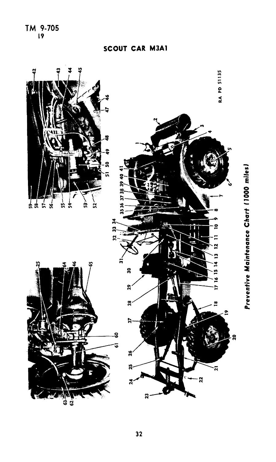
Preventive Maintenance Chart (1000 miles!
SCOUT CAR M3A1
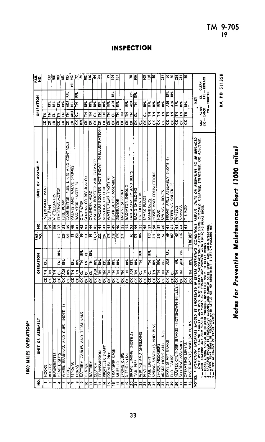
1000 MILES OPERATION*
NO. UNIT OR ASSEMBLY OPERATION PAR. NO. NO. UNIT OR ASSEMBLY OPERATION PAR. NO.
1 HOOKS CK TN RPL 34 INSTRUMENT PANEL CK TN
2 ROLLER CK TN 35 OIL PAN CK IN RPL 139
3 BUMPERETTES CK TN 36 AIR CLEANERS CK CL RPL 186
4 HEAD LIGHTS CK CL TN RPL 112 37 STARTING MOTOR CK TN RPL 100
5 WHEEL BEARINGS AND CUPS (NOTE 1) CK ADJ RPL 229 38 FUEL PUMP CK TN RPL 183
6 TIRES CK RPL 228 39 CARBURETOR, FUEL LINES AND CONTROLS CK TN ADJ RPL 185
7 FENDERS CK TN RPL 58 40 VALVES AND VALVE SPRINGS CK ADJ RPL 141, 142
8 HORNS CK TN RPL 150 41 RADIATOR (NOTE 3) CK CL TN RPL 77
9 BATTERY CABLES AND TERMINALS CK CL TN RPL 99 42 OIL FILTER RPL 24
10 HEATER CK CL TN RPL 114 43 GENERATOR REGULATOR CK TN RPL 102
11 BATTERY CK CL TN RPL 99 44 CYLINDER HEAD CK TN RPL 136
12 CLUTCH CK ADJ RPL 73, 74 45 VACUUM BOOSTER AIR CLEANER CK CL RPL 64
13 TRANSMISSION CK TN RPL 222 46 VACUUM BOOSTER INOT SHOWN IN ILLUSTRATION) CK TN RPL 64
14 PROPELLER SHAFT CK TN RPL 207 47 VENTILATOR TUBE CK TN RPL
15 EXHAUST PIPE CK TN RPL 175 48 WATER PUMP (NOTE 4) CK TN RPL 79
16 TRANSFER CASE CK TN RPL 219 49 DISTRIBUTOR ASSEMBLY CK CL ADJ RPL 104
17 MUFFLER CK TN RPL 175 50 GENERATOR CK TN RPL 101
18 SPRING CLIPS CK TN 211 51 ENGINE SUPPORT CK TN
19 DIFFERENTIAL CK TN RPL 52 RADIATOR SHROUD CK TN RPL
20 BRAKE LINING (NOTE 2) CK ADJ RPL 65 53 FAN ASSEMBLY AND BELTS CK TN ADJ RPL 78
21 TAIL PIPE CK TN RPL 175 54 RADIO SHIELDING CK CL TN RPL 106
22 WIRING AND SHIELDING CK CL TN RPL 106 55 OIL FILLER CAP CL
23 PINTLE CK TN 56 SPARK PLUGS ' CK CL RPL 105
24 TAIL LIGHT CK CL TN RPL 113 57 MANIFOLDS CK TN RPL 138
25 SPRING SHACKLES AND PINS CK TN RPL 211 58 HOSES AND CONNECTIONS CK TN RPL 80
26 SHOCK ABSORBERS CK TN RPL 213 59 HOOD CK TN RPL
27 BRAKE HOSES AND LINES CK TN RPL 67 60 SPRING U-BOLTS CK TN RPL 211
28 DRIVE SHAFT BRAKE CK TN ADJ RPL 69 61 FRONT AXLE ASSEMBLY (NOTE 5) CK TN ADJ RPL 50
29 FUEL TANKS CK CL 187 | 62 STEERING KNUCKLES CK TN ADJ RPL 50
30 MASTER CYLINDER IBRAKE) (NOTSHOWN IN ILLUS.) CK TN RPL 63 J 63 WHEELS CK TN RPL 228
31 STEERING ASSEMBLY CK TN ADJ RPL 216 64 SPRINGS CK TN RPL 211
32 OPERATING LEVERS CK 65 TIE ROD CK TN RPL 50
33 INSTRUMENTS AND SWITCHES CK TN RPL 110, 203
NOTES: • INSPECTION INTERVALS SHOULD BE SHORTENED IF SEVERE OPERATING CONDITIONS PREVAIL. UNITS OR ASSEMBLIES TO BE REPLACED ONLY WHEN FOUND FAULTY, AND WILL NOT OPERATE SATISFACTORILY AFTER BEING CHECKED, CLEANED, TIGHTENED. OR ADJUSTED. Y—WHEEL BEARINGS AND CUPS SHOULD BE THOROUGHLY CLEANED AND CHECKED WHEN REPLACING BRAKE SHOES. 2 —BRAKE LINING SHOULD BE CHECKED THROUGH INSPECTION HOLES IN BRAKE DRUMS. 3 —RADIATOR SHOULD BE THOROUGHLY CLEANED AND FLUSHED AFTER EVERY 6000 MILES OPERATION. 4—WATER PUMP SHALL BE REPACKED WHEN LITTLE OR NO ADJUSTMENT IS LEFT ON PACKING NUT. 5 —CHECK ALINEMENT OF FRONT WHEELS. . KEY ADJ —ADJUST CL —CLEAN CK —CHECK RPL —REPLACE TN —TIGHTEN
INSPECTION
RA PD 51135B
Notes for Preventive Maintenance Chart flOOO miles)
о
tn
ТМ 9-705
19
SCOUT CAR M3A1
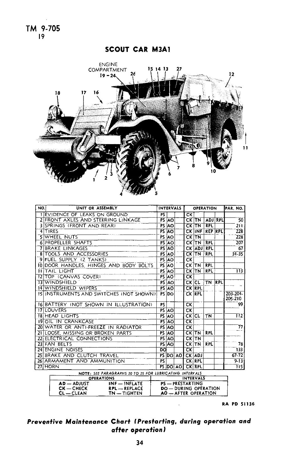
NO.| UNIT OR ASSEMBLY INTERVALS OPERATION PAR, NO.
1 EVIDENCE OF LEAKS ON GROUND PS CK
2 FRONT AXLES AND STEERING LINKAGE PS AO CK TN ADJ RPL 50
3 SPRINGS (FRONT AND REAR) PS AO CK TN RPL 211
4 TIRES PS AO CK INF REP RPL 228
5 WHEEL NUTS PS AO CK TN 228
6 PROPELLER SHAFTS PS AO CK TN RPL 207
7 BRAKE LINKAGES PS AO CK ADJ RPL 67
J 9 10 TOOLS AND ACCESSORIES PS AO CK TN RPL 34-35
FUEL SUPPLY (2 TANKS) PS PS AO AO CK CK
door handles, hinges and body bolts TN RPL
11 TAIL LIGHT PS AO AO CK TN RPL 113
12 TOP (CANVAS COVER) PS CK
13 WINDSHIELD PS AO CK CL TN RPL — _
14 WINDSHIELD WIPERS PS AO CK RPL
15 INSTRUMENTSAND SWITCHES (NOT SHOWN) PS DO CK RPL 203-204- 205-210
16 BATTERY (NOT SHOWN IN ILLUSTRATION) PS CK 99
17 LOUVERS PS AO CK
18 HEAD LIGHTS PS AO CK CL TN 112
19 OIL IN CRANKCASE PS AO CK
20 WATER OR ANTI-FREEZE IN RADIATOR PS AO CK 77
21 LOOSE, MISSING OR BROKEN PARTS PS AO CK TN RPL
22 ELECTRICAL CONNECTIONS PS AO CK TN TN
23 FAN BELTS PS AO CK RPL 78
24 ENGINE NOISES DC CK 133
25 BRAKE AND CLUTCH TRAVEL PS DO AO CK ADJ 67-72
26 ARMAMENT AND AMMUNITION PS CK RPL 9-13
27 HORN PS DO AO CK RPL 115
NOTE: Sff PARAGRAPHS 20 TO 25 FOR LUBRICATING INTERVALS
OPERATIONS INTERVALS
AD —ADJUST INF —INFLATE CK —CHECK RPL —REPLACE CL —CLEAN TN —TIGHTEN PS —prestarting DO—DURING OPERATION AO —AFTER OPERATION
RA PD 51136
Preventive Maintenance Chart I Prestarting, during operation and
after operation!
34
ТМ 9-705
20-22
Section V
LUBRICATION
Paragraph
Introduction ................................................. 20
Schedules .................................................... 21
Lubrication instructions for Diesel engines .................. 22
Methods ...................................................... 23
Engine lubricating system .................................... 24
Detailed lubrication and service instructions ................ 25
20. INTRODUCTION.
Lubrication is an essential part of preventive maintenance, determin-
ing to a great extent the serviceability of parts and assemblies. Lubri-
cation, or the lack of it, materially influences repairs and operations,
and is one of the most important factors effecting dependable service
and useful vehicle life.
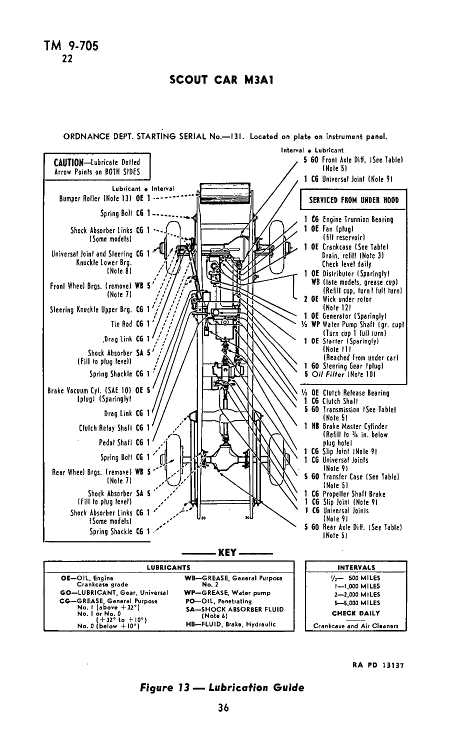
21. SCHEDULES.
a. In general, the chassis and slow-motion parts should be lubricated
every 1,000 miles of vehicle operation. The crankcase oil should be
checked daily and changed after not more than 1,000 miles of opera-
tion. The oil should be changed more often during prolonged periods
of cross country driving, hard pulls, or idling. Gear lubricants should
be checked weekly, and changed seasonally, unless operating mileages
require more frequent changes. Severe operating conditions may neces-
sitate immediate change, especially in cases where vehicle components
have been submerged in water, chemicals, snow or mud. All breathers
in housings and gear cases should be examined frequently to see that
they are clean and free. Refer to lubrication guide (fig. 13) for schedule
of lubrication.
b. Records. A complete record of lubrication will be kept for each
vehicle. Responsible personnel will execute a check sheet at regular
intervals to indicate the actual mileage and date at which each com-
ponent receives such attention as prescribed.
22. LUBRICATION INSTRUCTIONS FOR DIESEL ENGINES.
The following instructions cover the various points to be lubricated
at regular intervals, these being arranged on a mileage basis. Continue
lubrication at multiples of all mileages given. See that grease is actually
oozing from the parts. NOTE: Check level of engine oil daily, and
maintain the level marked on the gage.
a. Buda Diesel.
1,000 miles — oil.
Starter motor — 8-10 drops engine oil in each well.
35
ТМ 9-705
22
SCOUT CAR M3A1
ORDNANCE DEPT. STARTING SERIAL No.—131. Located on plate on instrument panel.
Interval • Lubricant
CAUTION—Lubricate Dolled
Arrow Points on BOTH SIDES
Lubricant •
Bumper Roller (Hole 131 OE 1
Spring Boll CG 1
Shock Absorber Links CG 1
(Some models!
Universal Join! and Sleering CG 1
Knuckle Lower Brg.
(Nole 81
Fronl Wheel Brgs. (removel WB 5
(Nole 71
Sleering Knuckle Upper Brg. CG 1
Tie Rod CG 1
.Drag Link CG 1
Shock Absorber SA S
(Fill to plug level)
Spring Shackle CG 1
Brake Vacuum Cyl. (SAL 10) OE 5
Iplugl (Sparingly!
Drag Link CG 1
Clulch Relay Shall CG 1
Pedal Shafi CG 1
Spring Boll CG 1
Rear Wheel Brgs. (remove) WB S
(Nole 71
Shock Absorber SA 5
(Fill Io plug level)
Shock Absorber Links CG 1
(Some modelsl
Spring Shackle C6 1
S 60 Fronl Axle Diff. iSee Table)
(Nole 5I
1 CG Universal Joint (Nole VI
SERVICED FROM UNDER HOOD
1 CG Engine Trunnion Bearing
1 OE Fan (plug)
(fill reservoir)
1 OE Crankcase (See Table!
Drain, refill iNofe 31
Check level daily
1 OE Distributor (Sparingly!
WB (late models, grease cupl
(Refill cup, turn I full turnl
1 OE Wick under rotor
(Note 121
1 OE Generator (Sparinglyl
'/i WP Water Pump Shaft Igr. cupl
(Turn cup 1 full lurnl
1 OE Starter (Sparingly!
{Nole HI
(Reached from under carl
1 GO Steering Gear Iplugl
S 0/7 Filter INo’e 101
'A OE Clutch Release Bearing
1 CG Clulch Shall
5 GO Transmission ISee Tablet
(Note 51
1 HB Brake Master Cylinder
(Refill Io % in. below
plug hole!
1 CG Slip Joint INole 9I
1 CG Universal Joints
INole 91
S 60 Transfer Case ISee Tablel
(Nole 51
1 CG Propeller Shaft Brake
1 CG Slip Joint INofe 91
1 CG Universal Joints
(Nole 91
5 GO Rear Axle Diff. ISee Table)
INofe 51
------KEY------
LUBRICANTS
OE—OIL, Engine
Crankcase grade
GO—LUBRICANT, Gear, Universal
CG—GREASE, General Purpose
No. t [above +32°)
No. I or No. 0
(+32° to I-10°)
No. 0 (below +10°)
WB—GREASE, General Purpose
No. 2
WP—GREASE, Water pump
PO—OIL, Penetrating
SA—SHOCK ABSORBER FLUID
(Note 6}
KB—FLUID, Brake, Hydraulic
_______INTERVALS________
'/2— 500 MILES
t—1,000 MILES
2—2,000 MILES
5—5.000 MILES
CHECK DAILY
Crankcase and Air Cleaners
RA PD 13137
Figure 13 — Lubrication Guide
36
ТМ 9-705
22
LUBRICATION
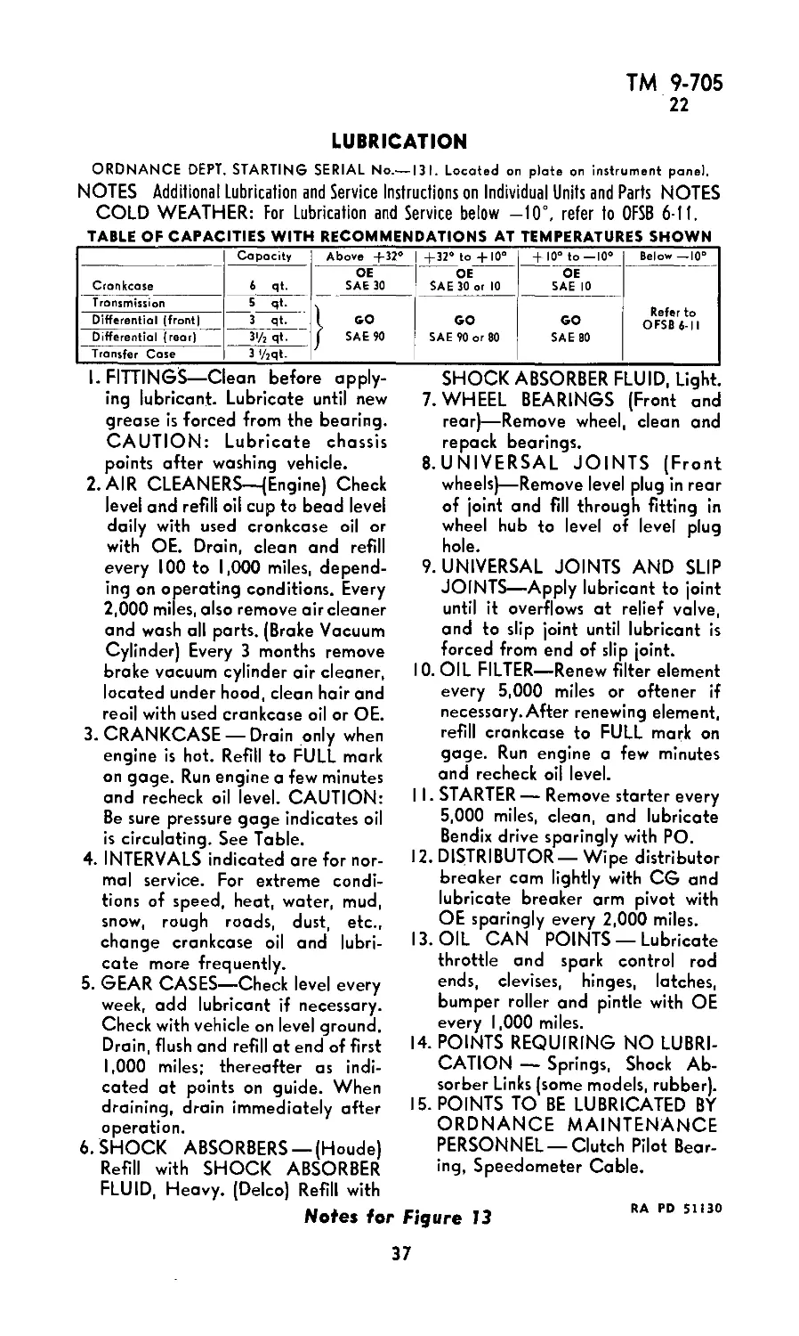
ORDNANCE DEPT. STARTING SERIAL No.—131. Located on plate on instrument pane).
NOTES Additional Lubrication and Service Instructions on Individual Units and Parts NOTES
COLD WEATHER: For Lubrication and Service below —10°, refer to OFSB 6-11.
TABLE OF CAPACITIES WITH RECOMMENDATIONSAT TEMPERATURES SHOWN
Capacity Above -f-32° -4-32° to +10° + 10° to—10° Below —10°
Crankcase 6 qt. OE SAE 30 OE SAE 30 or 10 OE SAE 10 Refer to OFSB 6-11
Transmission 5 qt. 1 GO j SAE 90 GO SAE 90 or 80 GO SAE 80
Differential (front) 3 qt.
Differential (rear) З'/г qt.
Transfer Case 3 '/2qt-
I. FITTINGS—Clean before apply-
ing lubricant. Lubricate until new
grease is forced from the bearing.
CAUTION: Lubricate chassis
points after washing vehicle.
2. AIR CLEANERS—(Engine) Check
level and refill oil cup to bead level
daily with used cronkcase oil or
with OE. Drain, clean and refill
every 100 to 1,000 miles, depend-
ing on operating conditions. Every
2,000 mi es, also remove air cleaner
and wash all parts. (Brake Vacuum
Cylinder) Every 3 months remove
brake vacuum cylinder air cleaner,
located under hood, clean hair and
reoil with used crankcase oil or OE.
3. CRANKCASE — Drain only when
engine is hot. Refill to FULL mark
on gage. Run engine a few minutes
and recheck oil level. CAUTION:
Be sure pressure gage indicates oil
is circulating. See Table.
4. INTERVALS indicated are for nor-
mal service. For extreme condi-
tions of speed, heat, water, mud,
snow, rough roads, dust, etc.,
change crankcase oil and lubri-
cate more frequently.
5. GEAR CASES—Check level every
week, add lubricant if necessary.
Check with vehicle on level ground.
Drain, flush and refill at end of first
1,000 miles; thereafter as indi-
cated at points on guide. When
draining, drain immediately after
operation.
6. SHOCK ABSORBERS —(Houde)
Refill with SHOCK ABSORBER
FLUID, Heavy. (Delco) Refill with
Notes for Figure 13
SHOCK ABSORBER FLUID, Light.
7. WHEEL BEARINGS (Front and
rear)—Remove wheel, clean and
repack bearings.
8. UNIVERSAL JOINTS (Front
wheels)—Remove level plug in rear
of joint and fill through fitting in
wheel hub to level of level plug
hole.
9. UNIVERSAL JOINTS AND SLIP
JOINTS—Apply lubricant to joint
until it overflows at relief valve,
and to slip joint until lubricant is
forced from end of slip joint.
10. OIL FILTER—Renew filter element
every 5,000 miles or oftener if
necessary. After renewing element,
refill crankcase to FULL mark on
gage. Run engine a few minutes
and recheck oil level.
11. STARTER— Remove starter every
5,000 miles, clean, and lubricate
Bendix drive sparingly with PO.
12. DISTRIBUTOR — Wipe distributor
breaker cam lightly with CG and
lubricate breaker arm pivot with
OE sparingly every 2,000 miles.
13. OIL CAN POINTS — Lubricate
throttle and spark control rod
ends, clevises, hinges, latches,
bumper roller and pintle with OE
every 1,000 miles.
14. POINTS REQUIRING NO LUBRI-
CATION — Springs, Shock Ab-
sorber Links (some models, rubber).
15. POINTS TO BE LUBRICATED BY
ORDNANCE MAINTENANCE
PERSONNEL —Clutch Pilot Bear-
ing, Speedometer Cable.
RA PD 51130
37
ТМ 9-705
22
SCOUT CAR M3A1
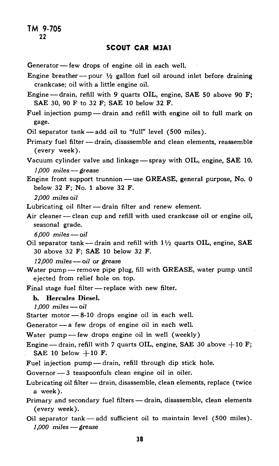
Generator — few drops of engine oil in each well.
Engine breather — pour >/г gallon fuel oil around inlet before draining
crankcase; oil with a little engine oil.
Engine — drain, refill with 9 quarts OIL, engine, SAE 50 above 90 F;
SAE 30, 90 F to 32 F; SAE 10 below 32 F.
Fuel injection pump — drain and refill with engine oil to full mark on
gage.
Oil separator tank — add oil to “full” level (500 miles).
Primary fuel filter — drain, disassemble and clean elements, reassemble
(every week).
Vacuum cylinder valve and linkage — spray with OIL, engine, SAE 10.
1,000 miles — grease
Engine front support trunnion — use GREASE, general purpose, No. 0
below 32 F; No. 1 above 32 F.
2,000 miles oil
Lubricating oil filter — drain filter and renew element.
Air cleaner — clean cup and refill with used crankcase oil or engine oil,
seasonal grade.
6,000 miles — oil
Oil separator tank — drain and refill with P/2 quarts OIL, engine, SAE
30 above 32 F; SAE 10 below 32 F.
12,000 miles — oil or grease
Water pump — remove pipe plug, fill with GREASE, water pump until
ejected from relief hole on top.
Final stage fuel filter — replace with new filter.
b. Hercules Diesel.
1,000 miles — oil
Starter motor — 8-10 drops engine oil in each well.
Generator — a few drops of engine oil in each well.
Water pump — few drops engine oil in well (weekly)
Engine — drain, refill with 7 quarts OIL, engine, SAE 30 above —|—10 F;
SAE 10 below -[-10 F.
Fuel injection pump — drain, refill through dip stick hole.
Governor — 3 teaspoonfuls clean engine oil in oiler.
Lubricating oil filter — drain, disassemble, clean elements, replace (twice
a week).
Primary and secondary fuel filters — drain, disassemble, clean elements
(every week).
Oil separator tank — add sufficient oil to maintain level (500 miles).
1,000 miles — grease
38
ТМ 9-705
22-24
LUBRICATION
Engine front support trunnion — use GREASE, general purpose No. 1
above 32 F; No. 0 below 32 F.
2,000 miles — oil
Air cleaner — clean cup and refill with used crankcase oil or engine
oil, seasonal grade.
Oil filler cap — remove, wash in SOLVENT, dry-cleaning, and reoil.
6,000 miles — oil
Oil separator tank — drain and refill with IV2 quarts OIL, engine, SAE
30 above 32 F; SAE 10 below 32 F.
12,000 miles — grease
Fan bearings — remove pipe plug, fill with GREASE, general purpose,
seasonal grade.
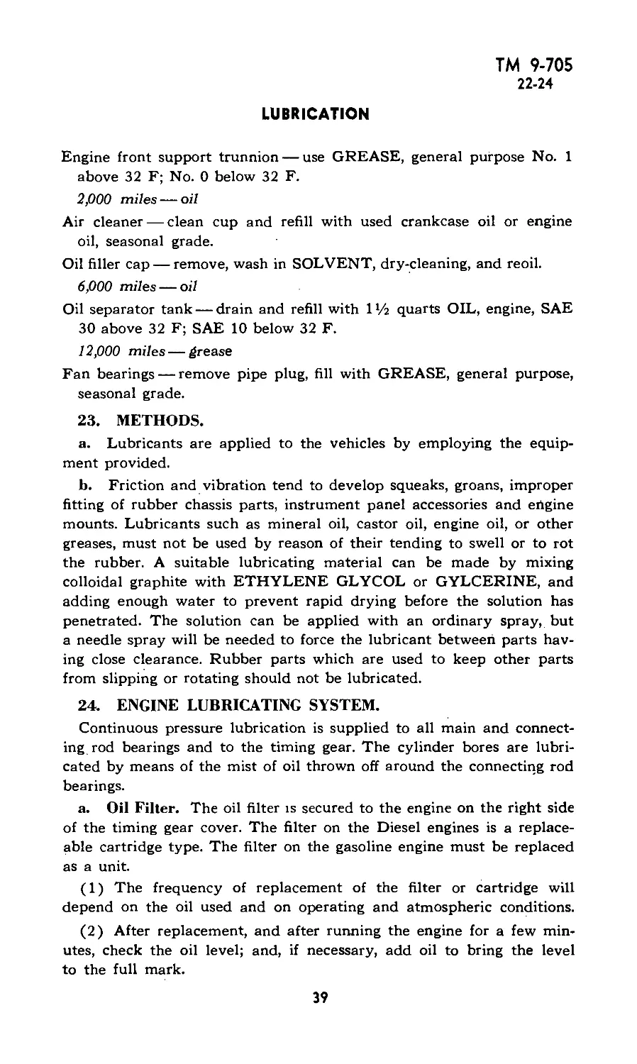
23. METHODS.
a. Lubricants are applied to the vehicles by employing the equip-
ment provided.
b. Friction and vibration tend to develop squeaks, groans, improper
fitting of rubber chassis parts, instrument panel accessories and ertgine
mounts. Lubricants such as mineral oil, castor oil, engine oil, or other
greases, must not be used by reason of their tending to swell or to rot
the rubber. A suitable lubricating material can be made by mixing
colloidal graphite with ETHYLENE GLYCOL or GYLCERINE, and
adding enough water to prevent rapid drying before the solution has
penetrated. The solution can be applied with an ordinary spray, but
a needle spray will be needed to force the lubricant between parts hav-
ing close clearance. Rubber parts which are used to keep other parts
from slipping or rotating should not be lubricated.
24. ENGINE LUBRICATING SYSTEM.
Continuous pressure lubrication is supplied to all main and connect-
ing rod bearings and to the timing gear. The cylinder bores are lubri-
cated by means of the mist of oil thrown off around the connecting rod
bearings.
a. Oil Filler. The oil filter is secured to the engine on the right side
of the timing gear cover. The filter on the Diesel engines is a replace-
able cartridge type. The filter on the gasoline engine must be replaced
as a unit.
(1) The frequency of replacement of the filter or cartridge will
depend on the oil used and on operating and atmospheric conditions.
(2) After replacement, and after running the engine for a few min-
utes, check the oil level; and, if necessary, add oil to bring the level
to the full mark.
39
ТМ 9-705
24-25
SCOUT CAR M3A1
b. Oil Level. The oil level is measured on the right side of the crank-
case with a bayonet-type gage. The oil level should be checked daily
and maintained at or near the “full” mark on the gage. In checking the
oil level, the gage blade should be removed and cleaned and then
reinserted in the reservoir to determine the oil level accurately.
c. Servicing. The crankcase should be drained and refilled with fresh
oil, according to the lubrication chart. If the oil pan is dropped, all
parts, including the screen, must be cleaned thoroughly. CAUTION:
The bayonet-type oil gage is bent at approximately the center of its
length to about a 30-degree angle. This permits it to reach full depth
without coming in contact with the oil pump strainer screen. This
curve should be maintained, as the placing of a straight bayonet gage
in this motor will pierce the strainer screen and allow dirt from the
crankcase to enter the oil pump.
d. CAUTION: Oil should be drained when the engine is hot, such
as after a day’s run, because the oil will then be agitated, flow more
freely, and carry off more sediment. Kerosene must not be used for
flushing. In replacing the fixed oil strainer on the line to the pump, care
should be exercised to secure proper fits of washers and tubing to
prevent entrance of dirty oil and sludge into the system. A tight joint
must be secured between the oil pan, the crankcase, and flywheel
housing, especially at the corners or angles. After all cap screw a are
started, draw them up gradually and progressively. Whenever it is
suspected that the oil in an engine has become frozen, the bayonet oil
level gage should be removed and examined to see whether or not the
adhering oil is in a solid, plastic or liquid state.
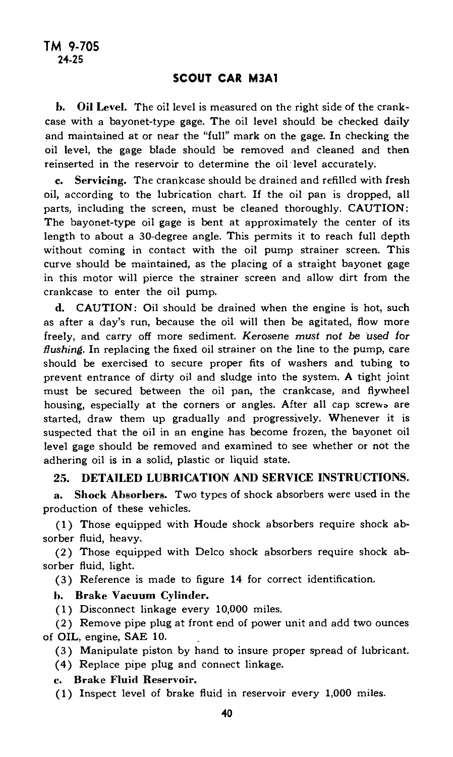
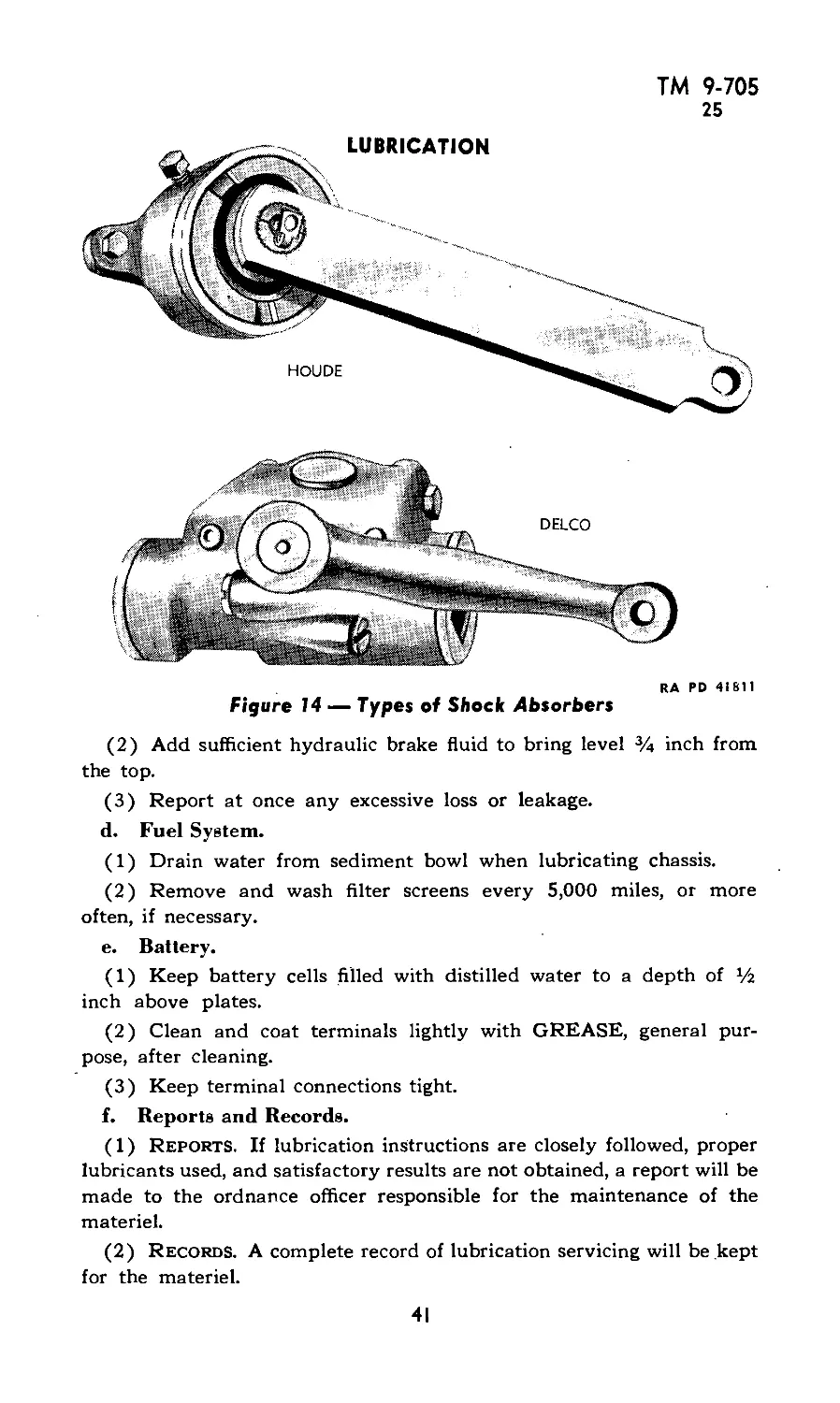
25. DETAILED LUBRICATION AND SERVICE INSTRUCTIONS.
a. Shock Absorbers. Two types of shock absorbers were used in the
production of these vehicles.
(1) Those equipped with Houde shock absorbers require shock ab-
sorber fluid, heavy.
(2) Those equipped with Delco shock absorbers require shock ab-
sorber fluid, light.
(3) Reference is made to figure 14 for correct identification.
b. Brake Vacuum Cylinder.
(1) Disconnect linkage every 10,000 miles.
(2) Remove pipe plug at front end of power unit and add two ounces
of OIL, engine, SAE 10.
(3) Manipulate piston by hand to insure proper spread of lubricant.
(4) Replace pipe plug and connect linkage.
c. Brake Fluid Reservoir.
(1) Inspect level of brake fluid in reservoir every 1,000 miles.
40
ТМ 9-705
25
(2) Add sufficient hydraulic brake fluid to bring level % inch from,
the top.
(3) Report at once any excessive loss or leakage.
d. Fuel System.
(1) Drain water from sediment bowl when lubricating chassis.
(2) Remove and wash filter screens every 5,000 miles, or more
often, if necessary.
e. Battery.
(1) Keep battery cells filled with distilled water to a depth of %
inch above plates.
(2) Clean and coat terminals lightly with GREASE, general pur-
pose, after cleaning.
(3) Keep terminal connections tight.
f. Reports and Records.
(1) Reports. If lubrication instructions are closely followed, proper
lubricants used, and satisfactory results are not obtained, a report will be
made to the ordnance officer responsible for the maintenance of the
materiel.
(2) Records. A complete record of lubrication servicing will be kept
for the materiel.
41
ТМ 9-705
26-27
SCOUT CAR M3A1
Section VI
CARE AND PRESERVATION
Paragraph
Cleaning ...................................................... 26
Painting ...................................................... 27
Preparing for painting......................................... 28
Painting metal surfaces....................................... 29
Paint as a camouflage.......................................... 30
Removing paint ................................................ 31
Painting lubricating devices................................... 32
26. CLEANING.
a. Grit, dirt, and mud are the sources of greatest wear to a vehicle. If
deposits of dirt and grit are allowed to accumulate, particles will soon
find their way into bearing surfaces, causing unnecessary wear and
eventually serious difficulty. Before removing engine parts or any other
units, making repairs and replacements, or inspecting where working
joints or bearing surfaces are to be exposed, carefully remove all dirt
and grit that might find their way to the exposed surfaces. Use clean
tools and exercise care to eliminate the possibilities of brushing dirt
or grit accidentally into the openings. To cut oil-soaked dirt and grit,
or road oil, use SOLVENT, dry-cleaning, applied with waste, rags, or
a brush.
b. The vehicle is so designed that the possibility of interfering with
its proper operation by the careless application of cleaning water is
very small. However, care should be taken to keep water from the
engine. Water should not be permitted to stand on exposed metal parts
as it will cause rust. Such exposed parts shall be painted as soon as
conditions permit. Rust may be softened by using SOLVENT, dry
cleaning or penetrating oil, then removed by scraping with a piece of
wood. Oilholes which have become clogged should be opened with a
piece of wire; wood should never be used for this purpose, as splinters
are likely to break off and permanently clog the passages..
27. PAINTING.
a. Ordnance materiel is painted before issue to the using arms and
one maintenance coat per year will ordinarily be ample for protection.
With but few exceptions this materiel will be painted with ENAMEL,
synthetic, olive drab, lusterless. The enamel may be applied over old
coats of long oil enamel and oil paint previously issued by the Ordnance
Department if the old coat is in satisfactory condition for repainting.
42
ТМ 9-705
27-29
CARE AND PRESERVATION
b. Paints and enamels are usually issued ready for use and are
applied by brush or spray. They may be brushed on satisfactorily when
used' unthinned in the original package consistency or when thinned
no more than 5 percent by volume with THINNER. The enamel will
spray satisfactorily when thinned with 15 percent by volume of THIN-
NER. (Linseed oil must not be used as a thinner since it will impart a
luster not desired in this enamel.) If sprayed, the enamel dries hard
enough for repainting within У2 hour and dries hard in 16 hours.
c. Certain exceptions to the regulations concerning painting exist.
Fire-control instruments, sighting equipment, and other items which
require a crystalline finish will not be painted with olive drab enamel.
d. Complete information on painting is contained in TM 9-850.
28. PREPARING FOR PAINTING.
a. If the base coat on the materiel is in poor condition, it is more
desirable to strip the old paint from the surface than to use sanding
and touch-up method. After stripping, it will then be necessary to apply
a primer coat.
b. PRIMER, ground, synthetic, should be used on wood as a base
coat for synthetic enamel. It may be applied either by brushing or
spraying. It will brush satisfactorily as received or after the addition
of not more than 5 percent by volume of THINNER. It will be dry
enough to touch in 30 minutes, and hard in 5 to 7 hours. For spraying,
it may be thinned with not more than 15 percent by volume of THIN-
NER. Lacquers must not be applied to the PRIMER, ground, synthetic,
within less than 48 hours.
c. PRIMER, synthetic, rust inhibiting, for bare metal should be
used on metal as a base coat. Its use and application is similar to that
outline in paragraph 28 b above.
d. The success of a job of painting depends partly on the selection
of a suitable paint, but also largely upon the care used in preparing the
surface prior to painting. All parts to be painted should be free from
rust, dirt, grease, kerosene, oil, and alkali, and must be dry.
29. PAINTING METAL SURFACES.
a. If metal parts are in need of cleaning, they should be washed in
a liquid solution consisting of У2 pound of SODA ASH in 8 quarts of
warm water, or an equivalent solution, then rinsed in clear water and
wiped thoroughly dry.
b. Wood parts in need of cleaning should be treated in the same
manner, but the alkaline solution must not be left on for more than
a few minutes and the surfaces should be wiped dry as soon as they
are washed clean.
43
ТМ 9-705
29-30
SCOUT CAR M3A1
c. When artillery or automotive equipment is in fair condition and
only marred in spots, the bad places should be touched with ENAMEL,
synthetic, olive drab, lusterless, and permitted to dry. The whole sur-
face should then be sandpapered with PAPER, flint, No. 1, and a
finish coat of ENAMEL, synthetic, olive drab, lusterless, applied and
allowed to dry thoroughly before the materiel is used.
d. If the equipment is in bad condition, all parts should be thor-
oughly sanded with PAPER, flint, No. 2, or equivalent, given a coat of
PRIMER, ground, synthetic, and permitted to dry for at least 16
hours. They will then be sandpapered with PAPER, flint, No. 00, wiped
free from dust and dirt, and a final coat of ENAMEL, synthetic, olive
drab, lusterless, applied and allowed to dry thoroughly before the
materiel is used.
30. PAINT AS A CAMOUFLAGE.
Camouflage is now a major consideration in painting ordnance vehi-
cles, with rust prevention secondary. The camouflage plan at present
employed utilizes three factors: color, gloss and stenciling.
a. Color. Vehicles are painted with ENAMEL, synthetic, olive drab,
lusterless, which was chosen because it blends in reasonably well with
the average landscape.
b. Gloss. The new lusterless enamel makes a vehicle difficult to see
from the air or from relatively great distances over land. A vehicle
painted with ordinary glossy paint can be detected more easily and at
greater distances.
c. Stenciling. White stencil numbers on vehicles have been elimin-
ated because they can be photographed from the air. A blue drab sten-
cil enamel is now used which cannot be so photographed. It is illegible
to the eye at distances exceeding 75 feet.
d. Preserving Camouflage.
(1) Continued friction or rubbing must be avoided, as it will smooth
the surface and produce a gloss. The vehicle should not be washed more
than once a week. Care should be taken to see that the washing is done
entirely with a sponge or a soft rag. The surface should never be rubbed
or wiped, except while wet, or a gloss will develop.
(2) It is not desirable that vehicles, painted with lusterless enamel,
be kept as clean as vehicles with glossy paint. A small amount of
dust increases the camouflage value. Grease spots should be removed
with SOLVENT, dry cleaning. Whatever portion of the spot cannot be
so removed should be allowed to remain.
44
ТМ 9-705
30-32
CARE AND PRESERVATION
(3) Continued friction of wax-treated tarpaulins on the sides of a
vehicle will also produce a gloss, which should be removed with
SOLVENT, dry cleaning.
(4) Tests indicate that repainting with olive drab paint will be nec-
essary once yearly, with blue drab paint twice yearly.
31. REMOVING PAINT.
a. After repeated paintings, the paint may become so thick that it
cracks and scales off in places, presenting an unsightly appearance.
If such is the case, remove the old paint by use of a lime-and-lye solu-
tion (see TM 9-850 for details) or by REMOVER, paint and varnish.
b. It is important that every trace of lye or other paint remover
be completely rinsed off and that the equipment be perfectly dry
before repainting is attempted. It is preferable that the use of lye solu-
tions be limited to iron or steel parts. If used on wood, the lye solution
must not be allowed to remain on the surface for more than a minute
before being thoroughly rinsed off and the surface wiped dry'with rags.
c. Crevices or cracks in wood should be filled with putty and the
wood sandpapered before refinishing. The surfaces thus prepared should
be painted according to directions in paragraph 29.
32. PAINTING LUBRICATING DEVICES. Oil cups, grease fittings,
oilholes, and similar lubricating devices, as well as a circle about three-
fourths of an inch in diameter at each point of lubrication, should be
painted with ENAMEL, red, water-resisting, so that they can be readily
located. Avoid painting the openings of the fittings through which
the lubricant passes.
45
ТМ 9-705
33-35
SCOUT CAR M3A1
Section VII
TOOLS AND EQUIPMENT ON VEHICLE
Paragraph
Introduction ................................................ 33
Equipment.................................................... 34
Tools ....................................................... 35
Ordnance motor book.......................................... 36
Manuals .................................................... 37
33. INTRODUCTION.
The materiel indicated herein includes tools and equipment for gen-
eral care, maintenance, and preservation; an Ordnance Motor Book to
record the vehicle history; commercial manuals pertinent to vehicle
operation and parts. Accessories should not be used for purposes other
than as prescribed and when not in use should be stored in the places
or receptacles provided.
34. EQUIPMENT.
Equipment issued with the Scout Car is listed below,
a. Accessories.
(1) Accessories carried on outside of vehicle include: Ax Mattock, pick Bag, top Shovel Bucket, water Strap, leather Cable, towing Top
(2) Accessories carried inside of vehicle include: Book, ordnance motor Extinguisher, fire Chain, non-skid Goggles Cover, crosscut saw Guide, lubrication, War Cover, headlight Dept. Crank, starting Lamp, inspection Cushion, seat Pad, track, 30-in. Cushion, seat, driver and Pad, track 39-in. commander Saw, crosscut
b. Armament Accessories. Information pertaining to the spare parts
and accessories issued with each gun and mount will be found in per-
tinent Standard Nomenclature Lists and appropriate Field Manuals.
35. TOOLS.
a. Tools issued with these vehicles are reviewed in Standard Nomen-
clature List No. G-67.
46
RADIO TERMINAL BOX
STORAGE BATTERY
TOOL BOX
ROLLER —
SHUTTERS-
BUMPERETTE
FUEL TANK FILLER CAP RADIO
AMMUNITION BOX
RADIO MAST
- FOOT WELL
RAIL PAD
TRIPOD MOUNTS
(MODEL 1917A1)
SEATS
-REAR BUMPER
Figure 15 — Equipment Installation
TOOLS AND EQUIPMENT ON VEHICLE
RA PD 13036
О
tn
ТМ 9-705
35-37
SCOUT CAR M3A1
b. Kits. Included in the tool kit assembly are the following:
Bag
Gun, alemite lever
Hammer, ball peen
Handle, wheel wrench
Handle, wrench
Lever, hydraulic jack
Oiler
Pliers, combination
Screwdriver, 6-in.
Screwdriver, 8-in.
c. Preservation of Tools.
Wrench, crescent
Wrench, double-end, ^-in. by *4-in.
Wrench, double-end, i%-in. by j-^-in.
Wrench, double-end, ^-in. by ^-in.
Wrench, double-end, -H-in. by -j-J-in.
Wrench, double-end, 1-in. by IfV-in.
Wrench, socket head set screw
Wrench, spark plug
Wrench, wheel bearing nut socket
Wrench, wheel nut socket
It is desirable to protect the tools sup-
plied with the vehicle from becoming rusty through exposure. Ade-
quate protection can be provided by periodically cleaning the surfaces
of the tools, and coating them with a film of engine oil of the same
type and grade as that which is being used in the engine. The oil
may be applied with a saturated swab. However, the swab should be
disposed of in such a manner that the fire hazard therefrom will be
minimized.
(1) In order to avoid the accumulation of water in the tool box, a
Vi-inch hole may be drilled through the lowest portion of the tool box
bottom and appropriately countersunk to remove any bur.
(2) Thoroughly clean the inside of the tool box and paint all ex-
posed metal surfaces. After the paint has dried, apply a film of engine
oil to the inside surfaces of the tool box.
36. ORDNANCE MOTOR BOOK.
An accurate record must be kept of each automotive vehicle issued
by the Ordnance Department. For this purpose, the Ordnance Motor
Book or “Log Book” is issued with each vehicle and should accompany
it in service at all times. The book will be kept in a canvas cover to
protect it from damage. Instructions for making the entries are printed
within the binder. NOTE: Data pertaining to the records of assign-
ment must be removed and destroyed prior to entering combat. All
other references which may be posted regarding the identity of the
organization must also be deleted.
37. MANUALS.
Manufacturers’ manuals describing operations and maintenance, and
listing parts, are usually shipped with the vehicles for initial delivery.
Such publications are a part of the equipment, should accompany the
vehicle at all times, or be available within the organization, and be
transferred with the vehicle.
48
ТМ 9-705
38-40
Section VIII
MATERIEL AFFECTED BY GAS
Paragraph
Protective measures ..................................... 38
Cleaning ................................................ 39
Decontamination ......................................... 40
Special precautions for automotive materiel.............. 41
38. PROTECTIVE MEASURES.
a. When materiel is in constant danger of gas attack, unpainted
metal parts will be lightly coated with engine oil. Instruments are
included among the items to be protected in this manner from chemical
clouds or chemical shells, but ammunition is excluded. Care will be
taken that the oil does not touch the optical parts of instruments or
leather or canvas fittings. Materiel not in use will be protected with
covers as far as possible. Ammunition will be kept in sealed containers.
b. Ordinary fabrics offer practically no protection against mustard
gas or lewisite. Rubber and oilcloth, for example, will be penetrated
within a short time. The longer the period during which they are
exposed, the greater the danger of wearing these articles. Rubber boots
worn in an area contaminated with mustard gas may offer grave danger
to men who wear them several days after the bombardment. Imperme-
able clothing will resist penetration more than an hour, but should not
be worn longer than this.
39. CLEANING.
a. All unpainted metal parts of materiels that have been exposed to
any gas except mustard and lewisite must be cleaned as soon as pos-
sible with SOLVENT, dry cleaning, or ALCOHOL, denatured, and
wiped dry. All parts should then be coated with engine oil.
b. Ammunition which has been exposed to gas must be thoroughly
cleaned before it can be fired. To clean ammunition use AGENT, de-
contaminating, non-corrosive, or if this is not available, strong soap and
cool water. After cleaning, wipe all ammunition dry with clean rags.
Do not use dry powdered AGENT, decontaminating (chloride of lime)
which is used for decontaminating certain types of materiel on or near
munition supplies, as flaming occurs through the use of chloride of lime
on liquid mustard.
40. DECONTAMINATION.
For the removal of liquid chemicals (mustard, lewisite, etc.) from
materiel, the following steps should be taken:
a. Protective measures.
(1) For all of these operations a complete suit of impermeable cloth-
49
ТМ 9-705
40
SCOUT CAR M3A1
ing and a service gas mask will be worn. Immediately after removal
of the suit, a thorough bath with soap and water (preferably hot) must
be taken. If any skin areas have come in contact with mustard, if even
a very small drop of mustard gets into the eye, or if the vapor of
mustard has been inhaled, it is imperative that complete first-aid meas-
ures be given within 20 to 30 minutes after exposure. First-aid instruc-
tions are given in TM 9-850 and FM 21-40.
(2) Garments exposed to mustard will be decontaminated. If the
impermeable clothing has been exposed to vapor only, it may be decon-
taminated by hanging in the open air, preferably in sunlight, for several
days. It may also be cleaned by steaming for 2 hours. If the imperme-
able clothing has been contaminated with liquid mustard, steaming for
6 to 8 hours will be required. Various kinds of steaming devices can
be improvised from materiels available in the field.
b. Procedure.
(1) Commence by freeing materiel of dirt through the use of sticks,
rags, etc., which must be burned or buried immediately after this
operation.
(2) If the surface of the materiel is coated with grease or heavy oil,
this grease or oil should be removed before decontamination is begun.
SOLVENT, dry cleaning, or other available solvents for oil should be
used with rags attached to ends of sticks.' Following this, decontaminate
the materiel with bleaching solution made by mixing one part AGENT,
decontaminating (chloride of lime), with one part water. This solution
should be swabbed over all surfaces. Wash off with water, dry, and oil
all surfaces.
(3) All unpainted metal parts and instruments exposed to mustard
or lewisite must be decontaminated with AGENT, decontaminating,
noncorrosive, mixed 1 part solid to 15 parts solvent (ACETYLENE
TETRACHLORIDE). If this is not available, use warm water and
soap. Bleaching solution must not be used because of its corrosive
action. Instrument lenses may be cleaned only with PAPER, lens,
tissue, using a small amount of ALCOHOL, ethyl. Coat all metal
surfaces lightly with engine oil.
(4) In the event AGENT, decontaminating (chloride of lime), is
not available, materiel may be temporarily cleaned with large volumes
of hot water. However, mustard lying in joints or in leather or canvas
webbing is not removed by this procedure and will remain a constant
source of danger until the materiel can be properly decontaminated.
All mustard washed from materiel in this manner lies unchanged on
the ground, necessitating that the contaminated area be plainly marked
with warning signs before abandonment.
50
ТМ 9-705
40-41
MATERIEL AFFECTED BY GAS
(5) The cleaning or decontaminating of materiel contaminated with
lewisite will wash arsenic compounds into the soil, poisoning many
water supplies in the locality for either men or animals.
(6) Leather or canvas webbing that has been contaminated should
be scrubbed thoroughly with bleaching solution. In the event this treat-
ment is insufficient, it may be necessary to burn or bury such materiel.
(7) Detailed information on decontamination is contained in FM
21-40, TM 9-850 and TC 38, 1941, Decontamination.
41. SPECIAL PRECAUTIONS FOR AUTOMOTIVE MATERIEL.
a. When vehicles have been subjected to gas attack with the engine
running, the air cleaner should be serviced by removing the oil, flushing
with SOLVENT, dry cleaning, and refilling with the proper grade of oil.
b. Instrument panels should be cleaned in the same manner as out-
lined for instruments.
c. Contaminated seat cushions will be discarded.
d. Washing the compartments thoroughly with bleaching solution is
the most that can be done in the field. Operators should constantly be
on the alert, when running under conditions of high temperatures, for
slow vaporization of the mustard or lewisite.
e. Exterior surfaces of vehicles will be decontaminated with bleach-
ing solution. Repainting may be necessary after this operation.
51
ТМ 9-705
42-44
SCOUT CAR M3A1
PART II— ORGANIZATIONAL MAINTENANCE
Section IX
SCOPE OF MAINTENANCE OPERATIONS
Paragraph
Scope 42
Definition of terms............................................... 43
Allocation of repairs............................................. 44
Trouble shooting, general......................................... 45
42. SCOPE.
The scope of maintenance and repairs by the vehicle crews and main-
tenance personnel of the using arm is determined by the ease with
which the project can be accomplished, the amount of time available,
weather conditions, concealment, shelter, proximity to hostile fire, equip-
ment and parts available, and skill of personnel. Since all of these
factors are variable, no exact sytem or procedure can be prescribed or
followed.
43. DEFINITION OF TERMS.
a. Servicing. Comprises cleaning, lubricating, tightening bolts and
nuts, and making external adjustments of subassemblies or assemblies
and controls.
b. Repairing. Comprises making repairs to or replacement of the
part, subassembly, or assembly that can be accomplished without dis-
assembling completely the materiel concerned, and does not require
heavy welding or riveting, machining, fitting, and/or alining.
c. Replacing. Comprises removing the part, subassembly, or assem-
bly from the vehicle and exchanging it for a new, reconditioned, or
rebuilt part, subassembly or assembly, as the case may be.
44. ALLOCATION OF REPAIR JOBS.
The list of operations that follows may be performed by personnel of
the using arm without securing permission from ordnance maintenance
personnel. Additional and more complicated maintenance operations
(removal and reinstallation of the engine, transmission, and front and
rear axle group assemblies) may also be accomplished by the using
arm, provided proper authority is received from ordnance maintenance
personnel before the work is started.
FRONT AXLE .
Alinement......................Adjust for toe-in and turning radius
Steering knuckle.....................................Replace arm
52
ТМ 9-705
44
SCOPE OF MAINTENANCE OPERATIONS
BODY
Bows ................................................. Replace
Fenders ...............................................Replace
Running boards ........................................Replace
Seats ..................................................Replace
Top ....................................................Replace
Windshield .....................................Replace assembly
Wipers .................................................Replace
BRAKES
Vacuum booster .....................................Replace assembly
Brakes ..........................................Adjust; replace lines
Brake cylinders ....................................Replace assembly
Master cylinder ....................................Replace assembly
Shoes ........................................... Replace assembly
CLUTCH
Clutch
Clutch
.........Adjust
Replace assembly
COOLING SYSTEM
Belts .....................
Fan and water pump.........
Hose and pipe..............
Radiator ..................
Thermostat (Diesel engines)
....Adjust or replace
....Replace assemblies
.... Replace
Clean, flush, or replace
....Replace
ELECTRICAL SYSTEM
Battery.................................Replace, charge, and service
Cables ...........................................Replace assemblies
Coils and condensers..............................Replace assemblies
Distributor...............Replace assembly; replace and adjust points
Generator ........................................Replace assembly
Horn and relay....................................Replace assemblies
Lights ...................................Adjust or replace assemblies
Regulator ........................................Replace assembly
Shielding ........................................Replace assemblies
Spark plugs..................................................Replace
Starter..... .....................................Replace assembly
Starter, Bendix ..................................Replace assembly
Switches .........................................Replace assemblies
Gaskets
ENGINE
Replace (carburetor; cylinder head; fuel pump;
manifolds; oil pan; valve cover; water pump)
53
ТМ 9-705
44
SCOUT CAR M3A1
EXHAUST SYSTEM
Manifolds .......................................Replace assemblies
Muffler ........ .....................................Replace assembly
Pipes .................................................... Replace
FUEL SYSTEM
Carburetor ........................................Replace assembly
Air cleaner...............................Clean or replace assembly
Filter ...................................Clean or replace assembly
Lines .............................................Repair or replace
Pump ..............................................Replace assembly
Tanks ....................................Clean or replace assemblies
Injection pump (Diesel).....................................Replace
Injectors (Diesel) .........................................Replace
INSTRUMENTS
Gages ...........................................Replace assemblies
Meters ..........................................Replace assemblies
LUBRICATION SYSTEM
Filter .....................................................Replace
Lines ......................................................Replace
Pan ...............................................Clean or replace
Strainer .................................Clean or replace assembly
SHOCK ABSORBERS AND SPRINGS
Center and shackle bolts.................................Replace
Shock absorbers..........Service and replace assembly; replace linkage
Springs ...................................Adjust or replace assemblies
STEERING GEAR
Steering gear............................Adjust or replace assembly
Drag link............................... Adjust or replace assembly
Tie rod..................................Adjust or replace assembly
TRANSMISSION
Shift levers ..............................................Replace
Shift lever cover..........................................Replace
WHEELS
Bearings .......................................Adjust and replace
Grease retainers.............................................Replace
Tires and tubes...:......................................... Repalce
Wheels ......................................................Replace
MISCELLANEOUS
Cleaning; lubricating; painting
Tire chains ..................................................Repair
54
ТМ 9-705
45
SCOPE OF MAINTENANCE OPERATIONS
45. TROUBLE SHOOTING, GENERAL.
a. Front Axle. Refer to paragraph 49.
b. Rear Axle. Refer to paragraph 54.
c. Brake System. Refer to paragraph 62.
d. Clutch. Refer to paragraph 71.
e. Cooling System. Refer to paragraphs 76, 83, and 91.
f. Ignition System. Refer to paragraph 108 and 124.
g. Engine. Refer to paragraphs 133, 148, and 164.
h. Fuel System. Refer to paragraph 187.
i. Springs and Shock Absorbers. Refer to paragraph 210.
j. Steering Gear and Drag Link. Refer to paragraph 215.
k. Transmission and Transfer Case. Refer to paragraphs 219 and
223.
1. Wheels, Tires, and Bearings. Refer to paragraph 227.
55
ТМ 9-705
46-47
SCOUT CAR M3A1
Section X
ORGANIZATION SPARE PARTS AND ACCESSORIES
Paragraph
Organization spare parts...................................... 46
Accessories...................................................... 47
46. ORGANIZATION SPARE PARTS.
a. A set of organization spare parts is supplied to the using arm for
field replacement of those parts most likely to become broken, worn,
or otherwise unserviceable. The set is kept complete by requisitioning
new parts for those used. Organization spare parts are listed in perti-
nent Standard Nomenclature Lists.
b. Care of organization spare parts is covered in the section of this
manual entitled “Care and Preservation” (section VI).
47. ACCESSORIES.
a. Accessories include tools and equipment required for such dis-
assembling and assembling as the using arm is authorized to perform,
and for the cleaning and preservation of the gun carriage, ammunition,
etc. They also include chests, covers, tool rolls, and other items neces-
sary to protect the materiel when it is not in use, or when traveling.
Accessories should not be used for purposes other than those prescribed,
and when not in use should be properly stored.
b. Accessories provided are listed in pertinent Standard Nomencla-
ture Lists, or see section VII of this manual.
56
ТМ 9-705
48,49
Section XI
FRONT AXLE
Paragraph
Description .................................................. 48
Trouble shooting ............................................. 49
Maintenance and adjustments................................... 50
Removal of front axle assembly................................ 51
Installation of front axle assembly........................... 52
48. DESCRIPTION (figs. 16 and 17). The front axle is of the spiral-
bevel, single-reduction, full-floating type, with a straddle-mounted pinion
gear and a standard-type differential. The front wheels are driven
through Rzeppa-type universal joints enclosed within knuckles at the
outer ends of the axle housing.
49. TROUBLE SHOOTING.
Symptom and Probable Cause
a. Hard Steering.
Front axle shifted.
Lack of lubrication.
Improper toe-in.
Tires under-inflated.
Bent frame.
Excessive caster.
I). Shimmy.
Knuckle bearings loose or worn.
Tie rod loose.
Front axle shifted.
Insufficient toe-in.
Steering gear loose.
Excessive or insufficient caster.
c. Wandering.
Spring center bolt sheared and
axle shifted.
Tight steering.
Brake dragging.
Tires unevenly inflated.
Bent axle parts.
Loose front wheel bearings.
Probable Remedy
Relocate and tighten spring clip
nuts.
Lubricate tie rod yoke, steering
gear, and steering drag link.
Adjust tie rod yoke.
Inflate tires to correct pressure
(par. 226c).
Report to ordnance personnel.
Report to ordnance personnel.
Readjust or replace.
Tighten or replace worn parts.
Relocate and tighten spring clip
nuts.
Readjust at tie rod yoke.
Tighten.
Report to ordnance personnel.
Replace center bolt and relo-
cate in spring seat.
Adjust steering gear.
Adjust.
Inflate to proper pressure
(par. 226b).
Report to ordnance personnel.
Adjust.
57
ТМ 9-705
49
SCOUT CAR M3A1
STEERING KNUCKLE
DRAG LINK
ARM ASSEMBLY
FRONT PROPELLER SHAFT
Figure 16 — Front Axle, Installed - Rear View
WHEEL BEARING OIL
Figure 17— Wheel Bearings, Brake Drum, and Steering Knuckle
- Exploded
OUTER
BRAKE
DRUM
RA PD 13038
58
TM 9-705
50
FRONT AXLE
STEERING DRAG LINK
BINDER BOLTS
YOKE END LOCK NUT
STEERING CROSS TUBE
YOKE END
STEERING KNUCKLE
LOWER BEARING CAP
HYDRAULIC
BRAKE HOSE
RA PD 13039
Figure 18 — Front Axle Steering Knuckle
STEERING KNUCKLE
ARM
STEERING KNUCKLE
FLANGE
50. MAINTENANCE AND ADJUSTMENTS.
a. Steering Knuckle Bearing Adjustment.
Jacks, two Wrench, socket, %-in., and
ratchet extension.
(1) Jack up the axle and remove the drag link and the lower
steering knuckle flange bearing cap.
(2) Remove the four nuts which retain the upper bearing cap.
Remove the hydraulic brake hose from the brake cylinder. This will
allow the upper bearing cap and steering knuckle arm to be removed.
(3) Adjust the bearings by means of shims located under these
caps. Shim packs must be the same thickness. Add shims to loosen
bearings and remove shims to tighten bearings.
(4) Install the caps.
(5) The bearings should be adjusted until there is no end play of the
knuckle assembly, but it should oscillate freely.
(6) Then remove the caps again and reduce the shim pile 0.005 inch
under each cap.
59
ТМ 9-705
50
SCOUT CAR M3A1
(7) After replacing the caps, there should be a small amount of drag
in rotating the steering knuckle but it should not bind. Replace brake
hose and drag link and bleed brake cylinder.
b. Toe-in Adjustment.
Extension, ratchet
Stick, measuring or toe-in
indicating apparatus
Wrench, open-end, T/g-in.
Wrench, socket, 1^-in.
Wrench,socket, lj^-in.
RA PD 13041
Figure 19 — Toe-in Adjustment
(1) The front wheels are not parallel when in the position of straight
ahead running, but are closer together at the front than at the rear.
This is called toe-in. Toe-in has the effect of causing the natural paths
of the wheels to approach each other, and is introduced for the purpose
of counteracting the tendency of the wheels to separate as a result of
camber. Wheel toe-in is originally set at Vs inch, plus or minus inch,
and should be maintained at this figure (fig. 20).
(2) A coarse toe-in adjustment can be made by disconnecting a
cross-tube end and turning it in or out on the cross-tube not less than
one complete turn (fig. 18).
(3) For a finer adjustment, it is necessary to give the cross-tube a
complete turn. A cross-tube of the tie rod assembly has different and
opposite pitch threads on each end.
(a) Disconnect one end of the tie rod at the pin end of the yoke by
removing the cotter pin and castellated nut and removing the pin.
Then, loosen the binder bolts on each cross-tube (fig. 18).
(b) While holding the ends rigid, give the cross-tube a complete
60
TM 9-705
50
FRONT AXLE
VERTICAL <£
VERTICAL ф
Caster
a
TOE-IN AND TURNING RADIUS
RA RD 3515
Figure 20 — Front Axle Alinement Chart
turn, increasing or decreasing the effective length, depending upon which
direction the tube is rotated. The length should be adjusted to produce
the proper toe-in (fig. 20).
(c) After correct adjustment has been obtained, bolts, yoke, and pin
must be secured in position once more.
61
ТМ 9-705
51
SCOUT CAR M3A1
FRONT SHOCK ABSORBER CONNECTING LINK
Figure 21 — Front Axle Removal
51. REMOVAL OF FRONT AXLE ASSEMBLY.
Jack
Link, drag
Stands, jack, two
Wrench, box, 54-in.
Wrench, open-end, n--in.
Wrench, open-end, 3^-in.
Wrench, open-end, J|-in.
Wrench, plug or heavy screw-
driver
Wrench, socket, Ji-in.
Wrench, wheel stud nut
a. Prepare Vehicle for Work.
Wrench, wheel stud nut
Place vehicle on level spot, apply hand brake, and block rear wheels.
Loosen, but do not remove the six wheel stud nuts on each wheel
(fig. 17).
b. Raise Front End of Vehicle.
Stands, jack, two
Raise the front end of the vehicle and place jack stands under frame
side rails, just behind front spring rear hanger bracket.
c. Disconnect Front Propeller Shaft.
Wrench, box, 5^-in.
62
TM 9-705
51
FRONT AXLE
Remove the four nuts, bolts, and lock washers holding propeller shaft
universal joint flange to front axle companion flange and lower pro-
peller shaft (fig. 16).
d. Disconnect Drag Link.
Screwdriver, heavy-duty Wrench, or drag link plug
Loosen plug at front end of drag link and disengage link from steering
arm stud (fig. 22).
e. Disconnect Shock Absorbers.
Wrench, socket, ^-f-in.
Remove eight U-bolt spring clip nuts and pull out U-bolt clips that
hold shock absorber links to axle spring seat (fig. 16).
f. Disconnect Brake Hoses at Frame.
Wrench, open-end, т^-in. Wrench, open-end, be-in.
Wrench, open-end, 3^-in.
Disconnect flared tube nut from hose fitting at inside of frame. Re-
move nut that holds hose assembly to frame.
Figure 22 — Steering Drag Link
63
ТМ 9-705
52
SCOUT CAR M3A1
g. Remove Axle and Wheel Assembly.
Roll axle and wheel assembly out from under the vehicle. Hold wheels
in a vertical position while removing the assembly. This is necessary
as the ball and socket joint will allow the wheels to move sideways.
52. INSTALLATION OF FRONT AXLE ASSEMBLY.
Jack Wrench, open-end, y^-in.
Stands, jack, two Wrench, open-end, 34-in.
W rench, box, 54-in. W rench, open-end, J|-in.
Wrench, drag link plug or Wrench, socket, J|-in.
heavy-duty screwdriver
a. Position Axle Assembly to Chassis.
Jack Stands, jack, two
Roll axle under chassis to its approximate running position. Then
raise assembly until springs rest in their proper positions in spring seats.
b. Install Spring Clips.
Wrench, socket, 4 в-in.
Set spring clips U-bolts in position over springs and through spring
seats (fig. 16). Install lock washers and nuts on rear clips.
c. Connect Shock Absorbers.
Wrench, socket, -J-g-in.
Slip shock absorber link plates onto front spring clips and replace
clip lock washers and nuts (fig. 16). Draw up all nuts evenly.
d. Connect Drag Link.
Wrench, drag link plug, or screwdriver, heavy-duty
Set front end of drag link onto steering arm ball stud and tighten end
plug (fig. 22).
e. Connect Propeller Shaft.
Wrench, box, 54-in. Wrench, socket, т%-т.
Hold propeller shaft in normal running position and replace the
bolts, lock washers and nuts holding propeller shaft flange to drive
pinion companion flange (fig. 16). Tighten nuts alternately to eliminate
possibility of distortion or uneven alinement.
f. Connect Brake Hoses.
Wrench, open-end, j^-in. Wrench, open-end, -f-g-in.
Wrench, open-end, 54-in.
Slip hose fitting through frame and replace holding nut. Then connect
hose to brake line by turning inverted flared tube nut onto hose fitting.
64
ТМ 9-705
52
FRONT AXLE
g. Lower Front End of Vehicle.
Jack Stands, jack, two
Raise front end of vehicle slightly, remove the jack stands, and
lower vehicle until its weight rests on the wheels. Remove jack.
h. Check Wheel Alinement. Check front wheel alinement as des-
cribed in paragraph 50.
i. Bleed Brake Lines. All wheel brake cylinders must be bled as
described in paragraph 68.
j. Check Lubrication in Differential Housing. See Lubrication
Guide, section V.
65
ТМ 9-705
53-55
SCOUT CAR M3A1
Section XII
REAR AXLE
Paragraph
Description ..................................................... 53
Trouble shooting ................................................ 54
Maintenance service and adjustments.............................. 55
Removal of rear axle assembly.................................... 56
Installation of rear axle assembly............................... 57
53. DESCRIPTION (fig. 23).
The rear axle is of the single-reduction, full-floating type, with a
straddle mounted pinion gear and a conventional-type differential. A
split-type housing is used. The drive pinion and differential assemblies
are exactly the same as those used in the front axle.
54ч TROUBLE SHOOTING.
Symptom and Probable Cause
a. Axle Noises.
Continuous hum.
Coasting hum.
Pulling hum.
b. Backlash.
Loose axle shaft flange.
Excessive clearance at axle
shaft splines.
Excessive pinion and bevel gear
clearance.
c. Grease Leakage.
Grease appearing on brakes.
Grease squeezing through hub
driving flange.
Probable Remedy
Readjust wheel bearings.
Inspect wheel bearings. If source
of trouble is not located there,
report to higher authority.
Report to ordnance personnel.
Retighten.
Replace worn parts.
Report to ordnance personnel.
Inspect seals and replace, if nec-
essary.
Inspect seals and breather,
smooth any rough spots on
flange, and tighten.
55. MAINTENANCE SERVICE AND ADJUSTMENTS.
a. Removal of Shaft (figs. 24 and 25).
Bar, pinch Wrench, socket, }(’-in.
Wrench, square, 54-in. Wrench, socket, 54-in., with
ratchet extension
66
TM 9-705
55
REAR AXLE
Figure 23 — Rear Axle Installed
Remove drive flange stud nuts (%-in. socket wrench), lock washers,
shakeproof washers and tapered split sleeves from each flange. Loosen
lock nuts on flange puller screws (54-in. socket wrench) and turn
puller screws in to break shaft loose from differential side gears ({-^•in-
socket wrench). Replace flange stud tapered split sleeves, lock washers,
necessary (fig. 25).
b. Installation of Shaft.
W rench, socket, 54-in. W rench, socket, 54-in-,
Wrench socket, }^-in. with ratchet extension
Insert shafts into housings until splines engage with differential side
gear splines. Adjust puller screws and fasten with lock nuts (54-in.
socket wrench). Replace flange stud tapered split sleeves, lock washers,
shakeproof washers, and nuts (54-in socket wrench).
c. Rear Wheel Bearing Adjustment (fig. 26).
Bar, short Wrench, wheel bearing nut
(1) Adjustment must be made with the axle jacked up and the
axle shaft removed (par. 55 a.).
(2) Remove the locking nut and washer.
(3) Using a wheel bearing nut wrench and about an 18-inch rod,
67
ТМ 9-705
55
SCOUT CAR M3A1
RATCHET
EXTENSION
TAPERED
SPLIT SLEEVES
3/e-INCH
SQUARE
WRENCH
%."-INCH SOCKET
WRENCH
EXTENSION------
PINCH
BAR
AXLE SHAFT
FLANGE
DRIVESHAFT
FLANGE
STUD NUTS
-INCH SOCKET
WRENCH
Figure 24 — Loosening Axle Shaft with Puller Screw
LOCK WASHERS
AND SHAKE
PROOF WASHERS
RA PD 13045
draw the inside adjusting nut as tightly as possible against the outer
cone assembly, meanwhile rotating the wheel, first in one direction, and
then in the other, until the bearings bind and the wheel turns hard.
Rotating the wheel in both directions causes the rollers to become fully
and evenly seated.
(4) Back off the adjusting nut Vs of a turn, so that the wheel turns
freely without perceptible end play in the bearing. It may be necessary
to tap the end of the rear axle shaft housing while loosening the
adjustment in order to move the cone on the axle.
(5) End play may be tested by placing the end of a short bar be-
tween the tire and the floor, and at the same time holding a finger on
the cage of the outer bearing. Work the bar up and down to detect any
excessive play or looseness. If but a barely perceptible shake can be felt
and the wheel turns freely, the adjustment is correct and can be
locked as set.
(6) Install the axle shaft (par. 55 b.).
68
ТМ 9-705
56
REAR AXLE
Figure 25 — Removal of Rear Axle Shaft
56. REMOVAL OF REAR AXLE ASSEMBLY (fig. 23).
Bar, pinch
Chisel
Drift
Hammer
Jack
Stands, jack, two, or hoist
Wrench, open-end, %-in.
Wrench, open-end, -Д-in.
Wrench, open-end, ^-in.
Wrench, open-end, зД-in.
Wrench, open-end, j^-in.
Wrench, socket, ^-in.
Wrench, socket, ^-in.
Wrench, socket, 34-in.
Wrench, socket, J|-in.
Wrench, wheel stud nut
a. Prepare Vehicle for Work.
Wrench, wheel stud nut
Place vehicle on level spot and block front wheels so that vehicle
will not move. Loosen, but do not remove wheel stud nuts on each
rear wheel.
b. Raise Rear End of Vehicle.
Jack Stands, jack, two, or hoist
Raise rear end of vehicle until stress is removed from springs. Place
69
ТМ 9-705
56
SCOUT CAR M3A1
Figure 26 — Rear Wheel Bearing Adjustment
jack stands under frame just in front of spring front brackets to hold
vehicle in this position.
c. Remove Spring Clips.
Bar, pinch Wrench, socket, -}^~in.
Hammer
Remove spring clip nuts and lock washers from each spring. Then
knock off spring clip bottom plates and remove spring clips (U-bolts).
<1. Disconnect Shock Absorber Connecting Links.
Wrench, socket, 3^-in.
Remove nuts from connecting link bolts at axle plate.
e. Disconnect Spring at Rear Shackle.
Chisel Wrench, open-end, /«-in.
Drift Wrench, socket, Л-in.
Hammer
Remove nuts, lock washers, and cap screws clamping the shackle pins
70
TM 9-705
56-57
REAR AXLE
in shackle assemblies. Loosen pins in shackles by forcing chisel into split
and then drive out pins. Lower rear end of springs to floor.
f. Disconnect Hydraulic Brake Hose at Bracket.
Wrench, open-end, %-in. Wrench, open-end, J|-in.
Wrench, open-end, 3^-in.
Disconnect inverted flared tube nut that holds line assembly (master
cylinder to rear brakes) to hose fitting at front of bracket. Then remove
nut that holds hose assembly to bracket.
g. Disconnect Propeller Shaft at Pinion Shaft Companion Flange.
Wrench, open-end, 5/8-in. Wrench, socket, 54-in.
Remove four nuts, lock washers and bolts that hold propeller shaft
flange to pinion shaft companion flange and lower the propeller shaft.
h. Remove Wheel and Tire Assemblies.
J ack W rench, wheel stud nut
Place jack under differential housing and raise axle assembly until
wheels are just off floor. Remove wheel stud nuts and pull off wheel
and tire assemblies. NOTE: Removal of these assemblies can be made
easier by slipping a greased board under the tires and just sliding
assemblies off studs onto boards.
i. Remove Axle Assembly. Lower the jack that holds the axle
assembly and pull out assembly.
Wrench, open-end, lii-in.
Wrench, socket, тП(Нп-
Wrench, socket, «4-in.
Wrench, socket, ^-in.
Wrench, socket, | g-in.
Wrench, wheel stud nut
57. INSTALLATION OF REAR AXLE ASSEMBLY.
Hammer
Jack, hydraulic or hoist
Wrench, open-end, %-in.
Wrench, open-end, -nj-in.
Wrench, open-end, 54-in.
Wrench, open-end, 54-in.
a. Place Axle Assembly in Position.
Jack, hydraulic
Place axle assembly on jack and raise it slightly above its normal
running position under vehicle.
b. Install Wheel and Tire Assemblies.
Wrench, wheel stud nut
Set assemblies on wheel studs and replace stud nuts. Use greased
board to facilitate assembly. Lower jack until axle assembly rests on
tires and remove jack.
71
ТМ 9-705
57
SCOUT CAR M3A1
c. Connect Springe at Rear Shackles.
Hammer Wrench, socket,
Wrench, open-end, A-in.
Lift springs into position in shackles and install shackle pins. Install
cap screws, lock washers and nuts, clamping shackle pins in shackles.
d. Connect Shock Absorbers to Axle.
Wrench, socket, з^-in.
Insert shock absorber connecting link bolts through axle plates and
install bolt nuts.
e. Connect Springs to Axles.
Wrench, socket, J|-in.
Set spring clips (U-bolts) in position over axle housing and install
Spring bottom plates, lock washers and nuts,
f. Connect Propeller Shaft to Pinion Shaft Companion Flange.
Wrench, open-end, 54-in. Wrench, socket, s^j-in.
Hold propeller shaft flange and pinion shaft companion flange to-
gether and install holding bolts, lock washers and nuts.
g. Connect Hydraulic Brake Hose to Line (Master Cylinder to
Rear Brakes) at Bracket.
Wrench, open-end, Vi-in. Wrench, open-end, Jj-in.
Wrench, open-end, з^-in.
Slip hose fitting through bracket and replace holding nut. Then con-
nect brake line to hose by turning inverted flared tube nut onto hose
fitting.
h. Lower Rear End of Vehicle.
Jack or hoist
Raise rear end of vehicle slightly, remove jack stands, and lower
vehicle until its weight rests on springs. Remove jack (or hoist).
i. Bleed Brake Lines. All wheel cylinders must be bled as explained
in paragraph 68.
72
ТМ 9-705
58-59
Section XIII
BODY
Paragraph
Body ................................................... 58
Fenders ................................................ 59
Windshield wipers ...................................... 60
58. BODY (figs. 1, 2 and 3). ’
a. General. The vehicle body is made of %-inch thick armor plate
with the exception of the windshield plate and windshield porthole
cover, which are Vi-inch thick. The plates are held to the body frame-
work by bolts and safety (elastic stop) nuts. The entire assembly is
bolted to the chassis frame assembly. The floor plates are made of
checkered aluminum and are bolted to the body framework.
b. Replacement of Components.
(1) The side doors, door shields, windshield plate, and hood plates,
are all hinged and are dismounted by removing the bolts and safety
nuts with which the hinges are bolted to these units.
(2) To detach the porthole covers on the windshield plate and side
doors, remove the bolts and safety nuts that hold the brackets.
(3) To remove the covers of the ammunition racks, unscrew the bolts
and nuts holding the angle bars by which the hinges are secured to the
sides of the body. An air wrench is usually necessary to remove the
safety nuts.
(4) The remaining body plates and the floor plates are removed by
removing the bolts and nuts holding them in place.
c. Maintenance.
(1) Plates which are pierced by shells should be replaced with new
plates. If this is not possible, temporary repairs can be made by bolting
a section of plate over the shell hole. Do not attempt to weld plates
together.
(2) Replace damaged springs on the radiator louver control lever
ratchet rod and porthole bracket plunger, hinges, and any other worn
or damaged parts.
59. FENDERS (figs. 27, 28 and 29).
a. Description. The front wheel fenders are made of pressed steel.
The outside edges are turned over to form a bead for reinforcing pur-
poses to prevent breaking or tearing (fig. 29). Each fender has two
supports which are welded to the fenders at their outer edges (fig. 29).
The front support is bolted to the frame and the rear support is bolted
73
ТМ 9-705
59
SCOUT CAR M3A1
RA PD 13080
Figure 27 — Left Front Fender - Front View
Figure 28 — Left Front Fender - Rear View
74
ТМ 9-705
59
BODY
Figure 29 — Left Front Fender - Inside View
to the engine side armor plate. The fenders are also bolted to the
engine side plates and running boards. The head lamps and guards are
bolted to the top of the fenders at the front. The head lamp cables are
disconnected by turning and extracting the terminal plugs at the rear
of the lamps; the blackout marker lamp wires are detached from the
connectors under the fenders and pulled through grommets in the fender
below the lamps.
b. Removal.
Wrench, open-end, Д-in.
Wrench, open-end, %-in.
Wrench, open-end, Д-in.
Wrench, socket, Д-in.
Wrench, socket, Vi-in.
Wrench, socket, -Д-in.
(1) Disconnect Marker Lamp.
connectors under the fenders and pulled through grommets in the fender
fender.
(2) Disconnect Head Lamp.
Disconnect head lamp wire at rear of lamp.
(3) Remove Fenders.
Wrench, open-end, Д-in.
Wrench, open-end, Уг-т.
Wrench, open-end, Д-in.
Remove two nuts, lock washers,
Wrench, socket, Д-in.
Wrench, socket, Vi-in.
Wrench, socket, -Д-in.
bolts and spacers that hold each
75
ТМ 9-705
59
SCOUT CAR M3A1
fender iron in place (Д-in. wrenches); nine nuts, lock washers and bolts
that hold fender to armor plate (V2-in. wrenches); and three nuts,
lock washers and bolts that hold rear of fender to running board support
(Д-in. wrenches); lift off fender assembly and remove anti-squeak
gasket.
c. Installation.
Wrench open-end, i7e-in-
Wrench, open-end, %-in.
Wrench, open-end, Д-in.
Wrench, socket, Д-in.
Wrench, socket, Уг-in.
Wrench, socket, Д-in.
(1) Install Fender.
Wrench, open-end, Д-in.
Wrench, open-end, Уг-in.
Wrench, open-end, Д-in.
Wrench, socket, Д-in.
Wrench, socket, Vi-in.
Wrench, socket, Д-in.
Place anti-squeak gasket and fender in position and install bolts, lock
washers and nuts to hold fenders to frame, armor plate and running
board support.
(2) Connect Head Lamps. Reconnect wire at rear of lamp.
(3) Connect Marker Lamp. Reconnect blackout marker lamp wire
Figure 30 — Windshield Wiper Assembly
76
ТМ 9-705
60
BODY
60. WINDSHIELD WIPERS.
a. Description. The windshield wipers are vacuum type, and are
mounted on the left- and right-hand side of the windshield frame over
the instrument panel.
b. Trouble Shooting.
Symptom and Probable Cause
(1) Wiper Moves Very Slowly.
Probable Remedy
Poor vacuum.
Check lines for leaks and replace
hose or tubing, if necessary.
Check vacuum pump for leaks
and tighten diaphragm screws.
Replace vacuum pump dia-
Clogged exhaust ports.
Lack of lubricant.
phragm, if necessary.
Replace wiper assembly.
Replace wiper assembly.
(2) Wiper Moves in One Direction Only.
One set of ports is clogged.
Lack of lubricant.
Replace wiper assembly.
Replace wiper assembly.
(3) Wiper Will Not Move.
Hose or pipe assembly split.
Check and replace damaged
Clogged ports.
Paddle frozen in one spot.
hose or pipe.
Replace assembly.
Replace wiper assembly.
(4) Wiper Streaking Windshield.
Worn or damaged wiper blade. Replace blade assembly.
c. Removal.
Wrench, open-end, -^-in.
(1) Remove Blade and Arm Assembly.
Wrench, open-end, ^j-in.
Lift blade arm and pull off spring clip. Then pull arm out of paddle
shaft hole.
(2) Remove Motor Assembly.
Wrench, open-end, -j^-in.
Detach vacuum hose from nipple. Then remove paddle shaft sleeve
nut and washer and dismount motor assembly from top of instrument
panel.
<1. Installation.
Wrench, open-end, rg-in.
77
ТМ 9-705
60
SCOUT CAR M3A1
(1) Attach Motor Assembly to Windshield.
Wrench, open-end, T7B-in.
Push paddle shaft through windshield frame, and fasten assembly
by replacing shaft sleeve washer and nut.
(2) Attach Wiper Arm to Paddle Shaft. Push hooked end of
arm into paddle shaft hole. Then set narrow end of arm spring clip
over spring, compress spring, and push wide end of clip into slot
cut around end of paddle shaft.
(3) Replace Wiper Blade Assembly. Hook blade assembly into
wiper arm slot.
78
ТМ 9-705
61-62
Section XIV
BRAKE SYSTEMS
Paragraph
General description .............................................. 61
Trouble shooting ................................................. 62
Master cylinder .................................................. 63
Vacuum power booster.............................................. 64
Service brake shoes............................................'. 65
Service brake pedal linkage....................................... 66
Service brake adjustments......................................... 67
Bleeding the lines................................................ 68
Drive shaft brake................................................. 69
61. GENERAL DESCRIPTION (fig. 31).
The service brakes operate on all four wheels. They are actuated under
the control of a hydraulic system which comprises the pedal, linkage, a
master cylinder, a vacuum power booster, an air cleaner and check valve
for the booster brake lines, wheel cylinders and shoes. The booster check
valve is attached to the dash on the engine side and is connected by tubing
to the rear of the booster. A disk-type mechanical brake for parking only
is mounted on a companion flange of the propeller shaft to the rear of the
transfer case.
62. TROUBLE SHOOTING.
Symptom and Probable Cause
a. Pedal Striking Floorboard.
Lining wear.
Incorrectly adjusted brake shoes.
Improper adjustment of master
cylinder clevis on master cyl-
inder brake rod.
Leaks.
Air in system (indicated by
“spongy” pedal action).
Insufficient brake fluid.
b. All Brakes Drag.
Insufficient brake shoe clearance.
Mineral oil in system.
Probable Remedy
Readjust upper ends of shoes
only; do not turn anchor pins.
Readjust shoes at both ends.
Adjust (par. 67).
Check system and repair.
Bleed lines (par. 68).
Refill master cylinder.
Reset shoes.
System will have to be flushed
with alcohol and serviced by
ordnance personnel to replace
cylinder cups, etc.
79
WHEEL
BRAKE
CYLINDER
VACUUM BOOSTER
AIR CLEANER
LEVER
ROD END ADJUSTING YOKE
vacuum Booster
VALVE OPERATING FORK
VACUUM BOOSTER
POWER
VACUUM BOOSTER CHECK VALVE
1Л
BRAKE PEDAL
vacuum
BOOSTER BRACKET
VACUUM BOOSTER
ASSEMBLY
MASTER CYLINDER
REAR OUTLET FLARED
TUBE CONNECTOR
MASTER CYLINDER
TO REAR TEE
HYDRAULIC LINE
MASTER CYLINDER FRONT OUTLET FLARED TUBE CONNECTOR
MASTER CYLINDER ASSEMBLY
RA PD 13033
Figure 31 — Hydraulic Brake System
SCOUT CAR M3A1
ТМ 9-705
62
BRAKE SYSTEMS
Symptom and Probable Cause Probable Remedy
Improper adjustment of master cylinder clevis on the master cylinder brake rod. Weak return spring. c. One Brake Drags. Weak or damaged brake shoes re- turn spring. Shoe binding on anchor pin. Insufficient brake shoe clearance. Loose wheel bearings. Adjust (par. 67). Replace. Replace. Free and lubricate. Reset. Readjust bearing to position, drum correctly around shoes.
Grease on linings. Check grease seals and overlu- brication, replace shoe assem- bly.
Tubing obstruction. Replace tubing.
d. Pulling to One Side.
Grease on linings. Check grease seals and replace if defective, check for overlu- brication, replace shoe assem- bly.
Shoe improperly adjusted. Readjust accurately and check with feeler gage.
Loose backing plates. Tighten plates and readjust brake shoes.
Different linings. Replace those that are different with shoe assemblies having linings of the same make.
Worn linings. Scored drums. Replace with shoe assembly. Replace, or have resurfaced.
e. Excessive Pedal Pressure Required for Stopping.
Brake shoes incorrectly adjusted. Improper linings. Partial contact between lining and drum. Readjust. Replace shoe assembly. Dress down high spots on linings, or adjust shoes at their ends.-
f. Noisy Brakes.
Bent or distorted backing plate. Straighten or replace with new plate.
Bent or distorted brake shoes. Dirt in linings. Loose lining rivets. Drums distorted. Replace with new shoe assembly. Remove any imbedded particles. Replace shoe assembly. Replace, or have reground.
81
co
A. BRAKE PEDAL j
B. BRAKE PEDAL SHAFT
C. CAP SCREWS AND'LOCK WASHERS
D. VACUUM BOOSTER] POWER LEVER CLAMP
E. MASTER CYLINDER ASSEMBLY
F. STOP LIGHT SWITCH
G. MASTER CYLINDER TO FRONT TEE LINE
H. MASTER CYLINDER BRACKET
J. PEDAL TO MASTER CYLINDER ROD
K. ROD END PIN
L. POWER LEVER I
M. VACUUM BOOSTER ROD END ADJUSTING YOKE
N. VACUUM BOOSTER ASSEMBLY
P. VACUUM BOOSTER VALVE OPERATING FORK
Q. AIR CLEANER ASSEMBLY
RA RD 13047
Figure 32 — Brake Linkage
О
о
О
СЛ
ТМ 9-705
62-63
BRAKE SYSTEMS
g. Drive Shaft Brake Does Not Hold When Lever Is Pulled Back.
Symptom and Probable Cause Probable Remedy
Linings and brake shoes improp- Inspect brake shoes and connec-
erly mounted. tions, and adjust or replace
parts as required.
Linings worn out. Replace shoe assemblies.
h. Drive Shaft Brake Lever Will Not Stay in ON Position.
Ratchet worn or broken. Replace with new ratchet.
Ratchet dog worn or broken. Replace with new dog.
63. MASTER CYLINDER (fig. 32).
a. Description. The master cylinder stores the fluid to actuate the
service brakes under the control of the brake pedal.
b. Servicing. The level of the fluid in the master cylinder supply
tank should be inspected at least once a month. The proper level of the
fluid is 3A of an inch below the top of the tank. There should be practically
no loss of fluid in the operation of the brakes. Any noticeable loss indicates
a leak in the system which should be located and stopped. If the tank be-
comes more than half empty, air may be drawn into the system when
the brake is released. In such a case, filling the tank to the proper level
is not enough. The system will have to be bled at each wheel cylinder to
remove the air entirely (par. 68). The master cylinder assembly should
be removed and replaced as a unit when any part of it is damaged.
c. Removal (fig. 32).
Pliers Wrench, open-end, % c. “in.
Screwdriver Wrench, open-end, Vz-in.
Remove the cotter pin and clevis pin from the cylinder piston rod at
the brake pedal power lever. Disconnect hydraulic lines at the cylinder
by removing the front and rear line flared tube nuts (Vz-in. open-end
wrench) from their fittings. Disconnect stop light switch wires. Remove
the three nuts, lock washers, and cap screws (%e-in- wrench) that attach
the master cylinder to the bracket and remove the complete assembly.
Drain reservoir through filler plug and pump fluid out of the cylinder by
pushing on the piston rod. Remove the pedal to master cylinder rod from
the master cylinder assembly.
d. Installation.
Plier Wrench, open-end, % c,-in.
Screwdriver Wrench, open-end, Vz-in.
Connect pedal to master cylinder rod to the master cylinder assembly
and install the cylinder in place on the bracket with cap screws, lock
washers and nuts (-^-in. open-end wrench). Connect the stop light
83
ТМ 9-705
63-64
SCOUT CAR M3A1
switch wires. Connect the front and rear hydraulic lines to the cylinder
by means of the flared tube nuts (Уг-ш. open-end wrench). Connect the
cylinder piston rod at the brake pedal power lever by installing the clevis
pin and cotter pin. Refill the cylinder with brake fluid. Bleed the lines.
Refer to paragraph 67 for adjustment procedure.
64. VACUUM POWER BOOSTER (fig. 33).
a. Description. The vacuum power unit acts as a power or booster
complement for the brake pedal, to actuate the master cylinder and re-
duce the amount of physical effort required to apply the brakes. The
booster is connected through the check valve to the engine intake mani-
fold (fig. 34).
b. Testing. Remove the pipe plug at the front of the booster and con-
nect a vacuum gage. Start the engine and note the gage reading, which
should be a vacuum of 17 to 20 inches; stop the engine and note if the
vacuum is retained for a reasonable length of time. If the gage shows a
rapid decrease (more than 10 in. in 10 sec.), a leak is indicated in the
booster which may often be corrected by a thorough lubrication of the
unit. (Refer to lubrication guide, fig. 13.) When the booster becomes
RUBBER VACUUM BOOSTER PISTON
DUST GUARD ROD-END ADJUSTING YOKE
VACUUM BOOSTER VACUUM BOOSTER VACUUM BOOSTER PISTON
BRACKET ASSEMBLY VALVE ROD YOKE END RA PD 13050
Figure 33 — Vacuum Booster Installed, Side View
84
TM 9-705
64
BRAKE SYSTEMS
CHECK VALVE TO ENGINE INLET MANIFOLD VACUUM LINE
CHECK VALVE TO VACUUM BOOSTER RA PD 13049
VACUUM BOOSTER PIPE AIR CLEANER
Figure 34 — Brake Booster Accessories - I Gasoline Engine)
damaged in any manner, it must be removed and replaced as a complete
unit.
c. Removal.
Pliers Screwdriver
Disconnect the vacuum line at the booster by loosening the screw in
the clamp holding the hose to the booster and remove the hose from the
nipple (fig. 33). Disconnect the air cleaner line by loosening the screws
in the clamp which holds the hose to the booster and remove the hose
from the nipple. Remove the cotter pin and rod-end pin at the bracket
end of the cylinder and lower the end of the cylinder (fig. 35). Remove
the cotter pin and the rod-end pin at the piston rod yoke end. Remove
the yokes from both ends of the booster assembly. Remove the booster
assembly (fig. 33).
d. Installation.
Pliers Screwdriver
Connect the yokes to the ends of the booster assembly. Place the as-
sembly in position and install the rod-end pin and cotter pin at the piston
rod yoke end (fig. 33 ). Install the cotter pin and rod-end pin at the bracket
end (fig. 35). Connect the air cleaner line by installing it on the nipple
85
ТМ 9-705
64
Figure 35 — Disconnecting Vacuum Booster
of the booster and tightening the clamp (fig. 33). Connect the vacuum
line by installing it on the nipple of the booster and tightening the clamp.
Check the adjustment (par. 67).
e. Air Cleaner (fig. 34).
Screwdriver Wrench, open-end, 3/e-in.
(1) Removal.
Screwdriver Wrench, open-end, %-in.
Remove two nuts, lock washers and screws that attach the adapter to
the bracket. Loosen the hose connection, slip off the hose and remove the
air cleaner.
(2) Maintenance. The air cleaner should be cleaned at the 1,000
mile inspection. Remove the filter element, wash it thoroughly in
SOLVENT, dry-cleaning, dry, and saturate it with OIL, engine, SAE 10.
Install the filter element in the air cleaner body.
(3) Installation.
Screwdriver Wrench, open-end, %-in.
Place adapter on bracket and fasten with the two nuts, lock washers
and screws. Connect the hose and tighten hose connection.
86
ТМ 9-705
64
Figure 36 — Vacuum Line Removal from Check Valve -
(Gasoline Engine)
f. Check Valve.
(1) Description. A check valve, mounted on the dash at the right
side of the engine compartment (fig. 34) is provided in the vacuum line
of the brake booster between the engine intake manifold and the booster
vacuum outlet. The function of the check valve is to seal the vacuum in
the booster when the engine stalls.
(2) Removal.
Wrench, open-end, %6->n- Wrench, open-end, %-in.
Loosen and remove two flared tube nuts from check valve inlet and
outlet fittings (%-in. open-end wrench). Loosen and remove two bolts,
lock washers and nuts from bracket mounting check valve to dash (7g-
in. open-end wrench), and remove valve (fig. 36).
(3) Installation.
Wrench, open-end, 34e->n- Wrench, open-end, %-in.
Place the check valve in position on the bracket and mount the bracket
to the dash with two bolts, lock washers and nuts (7i0-in. open-end
87
SCOUT CAR M3A1
ТМ 9-705
64-65
wrench). Install the lines at the inlet and outlet fittings by means of the
two flared tube nuts (%-in. open-end wrench) (fig. 36).
g. Vacuum Pump Air Cleaner (Diesel Engine Only) (figs. 37 and
38). This air cleaner is used to filter the air going to the vacuum pump.
It can be removed at regular intervals for cleaning by removing the hose
connection and unscrewing the assembly from the check valve elbow.
65. SERVICE BRAKE SHOES (fig. 39).
a. Description. The service brakes proper consist of a combination of
two internal expanding shoes, a brake drum, and a wheel cylinder for each
wheel. The shoes, lined with molded brake lining, are supported at the
lower end by eccentric anchor pins and connected at the top to the ac-
tuating cylinder.
b. Removal.
Clamp, cylinder Wrench, wheel stud nut
Jack
Jack up the vehicle until the wheel is free. Block the brake pedal in
the released position to prevent any possibility of movement. Remove
CHECK AIR RA PD 13071
VALVE CLEANER
Figure 37 — Brake Vacuum Booster Air Cleaner and Check Valve
(Diesel)
88
ТМ 9-705
65-66
BRAKE SYSTEMS
RA PD 13070
Figure 38 — Removing Brake Air Filter - (Diesel)
the wheel and brake drum assembly, using a wheel stud nut wrench.
Remove the brake shoe spring (fig. 39). Install a wheel brake cylinder
clamp to retain the pistons in place, as shown in figure 40. Mark the shoes
so that they can be replaced to their original positions, if relined. Remove
the guide and anchor pin washers (fig. 39). Lift the shoe off the anchor
pin, swinging it outward to clear the side pins, and withdraw link from
cylinder position at upper end.
c. Installation.
Clamp, cylinder Wrench, wheel stud nut
Jack
Place the shoe on the anchor pin. Install connecting link at upper end
of shoe. Install the guide and anchor pin washers. With the clamp holding
the pistons in place, install the brake shoe spring, then remove the clamp.
Reinstall the wheel and brake drum assembly in position.
66. SERVICE BRAKE PEDAL LINKAGE (fig. 32).
The clamping bolts for the brake pedal and its associated linkage must
be kept tight; loose leverage will adversely affect the operation of the
brakes. Replace return spring when it is weak or broken. Renew worn
89
ТМ 9-705
66-67
SCOUT CAR M3A1
Figure 39 — Front Wheel Brake Cylinder and Shoes
clevis pins connecting brake levers to master cylinder piston rod, and
power cylinder piston and valve rod.
67. SERVICE BRAKE ADJUSTMENTS.
Brake adjustments are necessary when brake linings have become
worn and excessive pedal travel exists, and should be made before it is
necessary to “pump” the brake pedal several times to secure proper
braking effort. Before attempting to make adjustments of brakes, it is
important to see that all wheel bearings are properly adjusted.
a. Pedal Linkage (fig. 32). Improper adjustments will affect the ap-
plication and operation of the brakes, especially where the vacuum
booster is concerned. The valve operating fork is attached to the brake
pedal shaft by two cap screws and a clamp with an oversize hole at the
lower cap screw to facilitate adjustment.
(1) Loosen valve operating fork anchorage screws and remove master
cylinder and power booster piston rod clevis pins (fig. 32).
(2) Be sure that the leverage system is clean, in correct alinement,
and not binding.
(3) Block brake pedal in release position.
(4) Adjust master cylinder clevis to permit about %2-inch lost motion
in the master cylinder piston rod; insert clevis pin and cotter pin (fig. 32).
90
ТМ 9-705
67
BRAKE SYSTEMS
Figure 40 — Clamping Wheel Brake Cylinder
(5) Push booster piston rod until the piston bottoms. Aline piston rod
clevis with power lever eye by adjusting cylinder position at the mounting
end. Never attempt to adjust piston rod clevis, as this affects valve posi-
tioning which is correctly set at the time of factory assembly.
(6) Check to see that the piston rod clevis pin is against the rear side
wall of the bushing; then tighten adjustment screws, exercising care not to
disturb the valve position. Be sure the valve operating fork is central and
square on the bushing to avoid binding.
(7) If adjustment has been made correctly, the valve rod will move
inward about Vi inch when the brake pedal is moved by hand, with the
engine running, before any movement of the power lever occurs.
(8) Check for insertion of cotter pins, tightness of lock nuts and cap
screws.
b. Lining Wear (fig. 39). To take up wear on the lining, only a minor
adjustment is necessary.
(1) Raise the vehicle until the wheels are free.
91
ТМ 9-705
67-68
SCOUT CAR M3A1
(2) Adjust one shoe at a time by turning the adjusting cam (fig. 39)
until the lining is pressed firmly against the drum and the wheel is locked.
(3) Back off the adjustment slightly until the wheel rotates freely
without drag.
(4) Adjust all eight brake shoes in this manner. The cams are auto-
matically locked in position by friction springs.
c. After Relining. Major adjustments are not ordinarily necessary
except after relining brakes, grinding drums, or in case of displaced anchor
pins.
(1) Leave wheels and drums in place and raise the vehicle.
(2) Remove inspection hole covers (%6-in. wrench) and insert thick-
ness gages through the holes in the drum.
(3) Loosen the anchor pin locking nut (1%6-in. wrench) at the rear
of the backing plate and turn the eccentric anchor pin at the “heel” or
lower end of the shoe. At a distance of approximately one inch from the
end of the lining near this pin, the clearance between the lining and drum
should be 0.005 inch.
(4) Tighten the holding nut and recheck the clearance.
(5) Rotate the wheel and drum assembly until the inspection hole is
at the “toe” or upper end of the shoe.
(6) Insert a thickness gage between the lining and drum, approxi-
mately one inch from the upper end of the lining, and turn the adjusting
arm bolt until the clearance is 0.010 inch.
(7) Replace inspection hole covers.
(8) Tighten bolts and check pedal travel after the adjustments.
d. Brake Lines. Any leaks in the metal tubing or flexible lines will
impair the effectiveness of the brakes. All couplings, connections and fit-
tings must be tightened by screwing up the nuts on the hose and tubing.
Tubing should be mounted to eliminate chafing against metal parts which
will cause fracture.
68. BLEEDING THE LINES.
a. Operation. Bleeding the lines consists of displacing all the air,
which may have accumulated in the system, by means of forcing the fluid
through the lines until it flows from the bleeder valve on each of the
four wheel cylinders in a solid stream. This procedure is necessary only
when some part of the hydraulic mechanism has been disconnected, or
when the fluid in the supply tank has become too low. Only approved
brake fluid should be used; never use oil.
92
ТМ 9-705
68
BRAKE SYSTEMS
Ь. Procedure.
(1) Remove the two screws that hold the floor plate in the driver’s
compartment over the filler plug and remove the plate.
(2) Unscrew the filler plug on top of master cylinder supply tank
(fig. 32).
(3) Using a Wagner Lockheed Fluid Filler, insert the nozzle into the
filler hole.
(4) Remove the bleeder valve cap screw and lock washer from a
wheel cylinder and screw the nipple in place at the end of a rubber drain
tube. Slide the bleeder valve wrench over the rubber tube and place the
free end of the tube below the level of the brake fluid in a clean glass
container comparable to a one-pint jar. Open the valve % of a turn.
(5) Depress the foot pedal slowly by hand, allowing the return spring
to return the pedal to its release position. A number of strokes of the pedal
will be required to bleed each wheel cylinder until fluid issues from the
end of the tube in a solid stream without air bubbles. As each wheel cylin-
der is bled, the bleeder valve is shut off tightly with the wrench; the bleeder
tube is removed and the cap screw with the lock washer replaced. NOTE:
After one cylinder has been bled, do not again depress the brake pedal
ANCHOR
BRACKET
CLEVIS
PIN
OPERATING
LEVER
LEVER TIE
ROD
И
COMPANION
FLANGE
RELEASE
SPRING
BRAKE
SHOE
SPRING
Jr
DISK
ASSEMBLY
LEVER
ARM
RA RD 1305
Figure 41 — Hand Brake, Installed - Bottom View
93
ТМ 9-705
68-69
SCOUT CAR M3A1
Figure 42 — Hand Brake, Installed - Top View
until the valve of the next cylinder is opened, since air may be forced from
a line yet to be bled into a line on which this operation has been completed.
(6) Follow this procedure for all brake cylinders, taking the one
farthest from the master cylinder first. When the bleeding has been com-
pleted, remove the fluid refiller from the supply tank and install the
filler plug.
69. DRIVE SHAFT BRAKE.
a. Description (figs. 41 and 42). The drive shaft brake incorporates
two shoes which operate on a disk that is mounted on a companion flange
of the propeller shaft to the rear of the transfer case. The brake shoes
are lined with a heavy-duty molded lining. This brake is to be applied
after the vehicle has been brought to a stop and not when the vehicle is
in motion.
b. Adjustment. Brake shoes must normally be concentric with and
not touch the disk when the brake is in the released position. When the
linings wear so that the brake will not hold, adjustment should be made
as follows:
Pliers Wrench, open-end, %-in.
Shims, two, or feeler gages Wrench, open-end, 1 'Zt-in.
94
ТМ 9-705
69
BRAKE SYSTEMS
Figure 43 — Drive Shaft Brake Shoe Adjustment
(1) Release the hand brake lever fully and disconnect the hand lever
pull rod clevis pin. Tighten the operating lever tie rod adjusting nut
(I Vi-in. wrench) so that the lever arm release spring on the tie rod will
draw the operating lever firmly against the front brake lever arm (fig. 41).
(2) Insrt a %2"inch shim or feeler gage between the front shoe lining
and disk (fig. 43). Adjust the hand lever pull rod to maintain this clear-
ance and replace the clevis pin.
(3) Adjust the rear shoe for the same clearance, using a %2‘inch shim
or feeler gage, with the disk (fig. 44), and turn the nut on the rear end
of the tie rod to keep this spacing.
(4) Make sure that the spring connecting the lower ends of the brake
shoes is in place, and adjust the top screws at the front and rear of the
anchor bracket to make shoes and linkage parallel to the disk (1 2 3 4/g-in.
open-end wrench).
(5) Remove the shims.
e. Removal of Assembly.
Pliers
Wrench, box, s/s-in.
Wrench, open-end, %-in.
Wrench, open-end, 5^-in
Wrench, open-end, 1%e-in.
Wrench, open-end, 1 Ц-in.
Wrench, socket, Уг-in.
95
ТМ 9-705
69
SCOUT CAR M3A1
Figure 44 — Drive Shaft Brake Shoe Adjustment
(1) Disconnect Pull Rod at Operating Lever.
Pliers
Pull out cotter pin and remove clevis pin rod and pin.
(2 ) Remove Brake Assembly.
Pliers Wrench, open-end, 13/16-in.
Wrench, open-end, %-in. Wrench, open-end, IVi-in.
Remove shoe spring. Loosen shoe adjusting set screws (3/s-in. open-end
wrench) and tie rod lock nut and adjusting nut (lVi-in. open-end
wrench). Then remove three cap screws and lock washers (1: * 3 4%0-in. open-
end wrench) that hold anchor bracket to frame bracket and lower brake
assembly (fig. 41).
(3) Remove Disk Assembly.
Wrench, box, %-in. Wrench, open-end, %-in.
Remove four nuts, lock washers and bolts that hold rear propeller shaft
flange and brake disk to companion flange to rear of transfer case (fig. 42 ).
Lower propeller shaft and disk assembly to floor.
(4) Remove Operating Lever Tie Rod.
Pliers Wrench, open-end, 1%-in.
96
TM 9-705
6?
BRAKE SYSTEMS
Wrench, open-end, Уг-in.
Wrench, open-end, 34-in.
Wrench, open-end, 1 Vi-in.
Wrench, open-end, 1%6-in.
Wrench, open-end, Р/4-in.
Wrench, socket, Уг-in.
Remove tie rod lock nut and spherical nut. Then pull out cotter pins
and clevis pins that hold operating lever to front brake shoe lever arm.
Remove operating lever, tie rod, release spring and washers (fig. 44).
(5) Remove Brake Shoe Assemblies.
Wrench, socket, Уг-in.
Remove brake shoe pin retainer cap screws, lock washers and pin re-
tainers. Then pull out brake shoe pins and remove shoe assemblies.
d. Replacement of Brake Shoes.
Shims, 1/32-in., two, or feeler gages
Wrench, open-end, %6-in-
Wrench, open-end, 3/e-in.
Wrench, open-end, У 6-in.
Move hand lever to fully released position. Remove the tie rod lock nut,
adjusting nut, and spring. Loosen the adjusting screws at the anchor
bracket. Remove the brake shoe pivot pin retainers and the brake shoes
will drop down. Remove the small spring connecting the lower ends of
the brake shoes and the brake shoe pivot pins. To install, reverse the
procedure given for removal of brake shoe.
e. Installation of Assembly.
Pliers
Wrench, box, s/s-in.
Wrench, open-end, %-in.
Wrench, open-end, 54-in.
(1) Install Brake Shoe Assemblies.
Wrench, socket. Уг-in.
Place brake shoe assemblies in position and install pins, pin retainers,
lock washers and cap screws.
(2) Install Operating Lever Tie Rod.
Pliers Wrench, open-end, 1%-in.
Place tie rod, release spring, washers and operating lever in position.
Install clevis pins and cotter pins to hold operating lever to lever arm.
Install tie rod nut and lock nut.
(3) Install Disk Assembly.
Wrench, box, s/g-in. Wrench, open-end, s/g-in.
Raise propeller shaft and disk assembly into position and install the
bolts, lock washers and nuts holding the rear propeller shaft flange to the
transfer case companion flange.
97
ТМ 9-705
6?
SCOUT CAR M3A1
(4) Install Brake Assembly.
Pliers Wrench, open-end, %-in. Wrench, open-end, Wrench, open-end, 1 Vi-in.
Place assembly in position and install three cap screws and lock wash-
ers to hold anchor bracket to frame bracket. Install shoe spring. Adjust
as described in paragraph 69 b.
(5) Connect Pull Rod at Operating Lever.
Pliers
Install rod and clevis pin and cotter pin to connect pull rod and operat-
ing lever.
98
ТМ 9-705
70-71
Section XV
CLUTCH
Paragraph
Description and operation.................................... 70
Trouble shooting ............................................ 71
Maintenance and adjustment................................... 72
Clutch removal ............................................ 73
Clutch installation .................................................. 74
70. DESCRIPTION AND OPERATION.
a. Description. The clutch is of the single-plate, dry-disk type which
transmits power from the engine to the transmission.
b. Operation. Depressing the clutch pedal causes the clutch throw-
out bearing to move toward the front and relieve spring pressure on a
set of operating levers. The pressure on the driving plate is thereby re-
moved and the clutch is in the “released” or “out” position. Letting the
clutch “in” is the reverse procedure. The clutch should be either fully in
or out while driving; and should be engaged, or let “in,” gradually and
not suddenly. A well adjusted clutch takes hold gradually, does not slip,
and releases instantly when the pedal is depressed.
71. TROUBLE SHOOTING.
Improper operation of the clutch will be indicated in most instances by
slipping, rattling, or chattering. Ordinarily the using arm will not attempt
any repairs except to take up normal wear on the clutch facings and made
a unit replacement. If any of the symptoms of defects arise, report to ord-
nance maintenance personnel.
a. Slipping.
Symptom and Probable Cause
Improper adjustment.
Oily facings.
Weak clutch spring.
Worn clutch facings.
Sticking release sleeve.
Probable Remedy
Adjust to give 1 to Р/г-т. free
travel (measured between the
floor board and the pedal) be-
fore engagement begins.
Clean and correct cause. Check
bell housing oil seal. Do not
overlubricate pilot or throw-
out bearing. Replace assembly
if surface cannot be restored
to proper condition for oper-
ation without slippage.
Replace spring.
Replace clutch driven member
assembly.
Check pull-back spring.
99
ТМ 9-705
71-72
SCOUT CAR M3A1
b. Rattling.
Symptom and Probable Cause
Loose release fork.
Weak pull-back springs.
Improper pedal adjustment.
c. Chattering.
Broken dampener springs.
Oily facings.
Sticking release sleeve.
Probable Remedy
Tighten fork.
Replace springs.
Adjust pedal.
Replace clutch driven member
assembly.
Clean or replace clutch driven
member assembly.
Check pull-back spring.
72. MAINTENANCE AND ADJUSTMENT.
The clutch should be adjusted when the wear on the clutch facings
has decreased the free movement of the clutch pedal before disengage-
ment starts to less than 1-inch (measured between the floor board and the
pedal). The clutch should be adjusted so that the distance of free travel
of clutch pedal is 1 to Р/г inches before disengagement begins. The ad-
justment is made through an adjusting yoke on the rod from the clutch
Figure 45 — Removing Clutch Assembly
100
ТМ 9-705
72-73
CLUTCH
pedal to the lever on the clutch release shaft. If the correct adjustment
cannot be obtained, a new driven member assembly is required. A few
drops of oil every 500 miles is required to lubricate clutch release bear-
ing. Oiler for this purpose is located in driver’s compartment on floor
board between shift handle and dash.
CAUTION: Adjustment of the 6 throwout fingers should not be at-
tempted by the using personnel. This adjustment is made at the factory
and can be adjusted correctly only by the use of special tools and pro-
cedure.
73. CLUTCH REMOVAL.
Handle, speed Wrench, socket, 9/i6-in.
a. Remove Transmission. Refer to paragraph 224, transmission re-
moval.
b. Detach Clutch Assembly.
Handle, speed
Wrench, socket, % 6-in.
Remove 12 cap screws with lock washers which hold clutch assembly
to engine flywheel (fig. 45). Unscrew each cap screw a few turns at a
time, so the release of the spring load is equal all around.
я
Figure 46 — Clutch Cover Plate Installation
101
ТМ 9-705
73-74
SCOUT CAR M3A1
c. Remove Cover Plate and Driven Member Assemblies. Take off
separately, cover plate assembly and driven member assembly. Take
care that driven member does not fall out while removing cover plate as-
sembly.
74. CLUTCH INSTALLATION.
Bar, pilot Wrench, socket, % e-in-
Handle, speed
a. Install Clutch.
Bar, pilot Wrench, socket, %(j-in.
Handle, speed
A transmission main drive shaft may be used as a pilot bar to aline the
splined hub with the flywheel pilot bearing. Place alining bar in clutch
disk hub and insert it into clutch pilot bearing (fig. 46). Place clutch in
position and secure to flywheel with 12 cap screws and lock washers
(fig. 45). Tighten cap screws evenly to avoid bending cover plate.
b. Install Transmission. Refer to paragraph 225, Transmission
Installation.
102
ТМ 9-705
75
Section XVI
COOLING SYSTEM
(GASOLINE ENGINE POWERED VEHICLES)
Paragraph
Description .................................................... 75
Trouble shooting ............................................... 76
Radiator ....................................................... 77
Fan ............................................................ 78
Water pump ..................................................... 79
Cautions ....................................................... 80
Servicing ...................................................... 81
75. DESCRIPTION (fig. 47).
The water cooling system consists of a radiator, fan and shroud, a cen-
trifugal water pump, and the connecting lines and hoses. The capacity of
the cooling system is 19 quarts. The system can be drained by opening
the drain cocks at the bottom of the water pump and in the left rear side
of the engine block.
Figure 47 — Radiator with Shroud - Installed - {Gasoline Engine!
103
ТМ 9-705
76-77
SCOUT CAR M3A1
76. TROUBLE SHOOTING.
Symptom and Probable Cause a. Overheating. Probable Remedy
Lack of water. Refill system.
Loose or damaged belts. Adjust or replace belts.
Defective pump. Replace pump.
Clogged system. Flush and clean.
Clogged radiator core. Clean.
Incorrect timing. Check timing.
Defective hose. Replace hose.
b. Leakage.
Defective hose. Replace hose.
Loose connections. Check and tighten.
Loose or open drain cocks and Check and tighten.
plugs. Damaged radiator core. Seal or replace radiator.
77. RADIATOR.
a. Description. The radiator is of reinforced sheet metal construction
with brass tanks, and incorporates a finned tubular-type core.
b. Removal.
Hoist Wrench, box, %G-in.
Pail Wrench, open-end, Vz-in.
Pliers Wrench, open-end, %6-in.
Rope, length of Wrench, socket, %-in.
Screwdriver, heavy-duty square Wrench, socket, %-in., with
shank universal attachment.
(1) Drain Radiator.
Pail Pliers
Open drain cock on lower left-hand hose connection and drain water
into pail or on ground (save antifreeze solution if used).
(2) Remove Hood.
Hoist Screwdriver, heavy-duty square
shank
Rope, length of Wrench, open-end, % fi-in.
Remove three elastic stop nuts and bolts at rear of center panel of
hood. Remove nut and bolt on inside of louver frame, near the top, on each
side of frame. Use rope and hoist to lift off hood with top of louver frame
left on hood. Hood can also be slipped over front of car by three men.
104
ТМ 9-705
77
COOLING SYSTEM (GASOLINE ENGINE POWERED VEHICLES)
(3) Remove Louver Assembly.
Hoist Wrench, box, 9/i6-in-
Screwdriver, heavy-duty Wrench, open-end, У2-1П.
Remove bolts and nuts that hold louver frame to engine side armor
plates. Disconnect louver control on lower right side of radiator. Lift
louver frame straight up and out.
(4) Remove Radiator Hose Connections.
Screwdriver
Loosen clamps holding inlet and outlet radiator hoses and pull hoses
loose from radiator.
Wrench, open-end, Уг-т.
Wrench, open-end, %6-in.
Wrench, socket, %-in.
Wrench, socket, %-in., with
universal attachment
(5) Remove Radiator.
Hoist Wrench, socket, %-in., with
Wrench, socket, %-in. universal attachment
Disconnect radiator from cross member by removing holding stud nuts,
springs, washers and pads. Then disconnect stay rods at frame by remov-
ing nuts from stay rod bolts underneath car on the bottom side of the top
frame flange (fig. 48). Remove radiator assembly by lifting up and slight-
ly forward.
c. Installation.
Hoist
Pliers
Rope, length of
Screwdriver, heavy-duty
square shank
Wrench, box, % 6-in.
(1) Install Radiator (fig. 48).
Hoist
Wrench, socket, %-in.
Set radiator in position on pads so that mounting studs pass through
holes in pads and frame member. Connect stay rods at frame with stay
rod stud nuts. Place springs and washers on mounting studs and secure
with nuts and cotter pins.
(2) Install Radiator Hose Assemblies.
Screwdriver
Install pipe and hose assemblies between cylinder head and radiator
inlet connections and secure hose clamps. Then install pipe and hose
assemblies between radiator outlet and water pump inlet connections and
secure hose clamps.
Wrench, socket, %-in., with
universal attachment
105
ТМ 9-705
77
SCOUT CAR M3A1
radiator louver assembly radiator
RADIATOR
STAY ROD FRAME
FLANGE
Figure 48 — Radiator Support Left Front View
106
ТМ 9-705
77
COOLING SYSTEM (GASOLINE ENGINE POWERED VEHICLES)
(3) Install Louver Assembly.
Hoist Wrench, box, %0-in.
Screwdriver, heavy-duty Wrench, open-end, Vfe-in.
Place louver assembly in position with hoist. Secure louver side plates
to body side plates with holding screws and nuts. Connect louver control
at lower right side of radiator.
(4) Install Hood Assembly.
Hoist Screwdriver, heavy-duty
Rope, length of . square shank
Wrench, open-end, %
Place hood assembly and top shutter louver in position on cowl and
shutter assembly. Install bolts and elastic stop nuts that secure rear of
hood to cowl and front of hood to louver assembly. Remove rope from
louver assembly.
(5) Fill Radiator. Fill radiator with water or antifreeze as required,
and check for leaks.
RA PD 13014
Figure 49 — Loosening Lock Nut on Adjusting Screw -
(Gasoline Engine!
107
ТМ 9-705
78
SCOUT CAR M3A1
Figure SO — Fan Bracket Mounting, Screw Removal *
IGasoline Engine)
78. FAN (fig. 47).
a. Description. The air flow through the radiator core is maintained
by movement of the vehicle and a six-bladed fan, which is enclosed in a
shroud and driven off the crankshaft by dual V-belts.
b. Adjusting Fan Belts (fig. 49). Using a %-inch open-end wrench,
loosen the fan belt adjusting screw lock nut. Then turn the fan belt ad-
justing screw by hand to move the fan hub assembly up or down until
there is between У2 and % of an inch deflection of the belts halfway be-
tween the pulleys, and tighten the lock nut.
c. Fan, Hub, and Bracket Assembly.
(1) Removal.
Wrench, open-end, %-in. Wrench, open-end, l]/[6-in.
Loosen the fan belts as in paragraph 78 b. Using a %-inch open-end
wrench, remove the two cap screws and lock washers that attach the fan
bracket to the timing gear case (fig. 50). Slide the belts off the fan drive
pulley, generator pulley and fan pulley and remove the belts by lifting
them up and over the fan blades.. Push the fan assembly back against the
cylinder block and tilt up the blade end to clear the radiator shroud.
Then lift out the fan assembly and bracket (fig. 51).
108
ТМ 9-705
78
COOLING SYSTEM (GASOLINE ENGINE POWERED VEHICLES)
RA PD 13115
Figure 51 —Fan and Bracket Removal - {Gasoline Engine)
(2) Installation.
Wrench, open-end, %-in.
Wrench, open-end, 16-in.
With fan mounting bracket resting on the timing gear case, tilt the fan
down and slip the belts over the fan blades and onto the drive pulley, fan
pulley and generator pulley. Slide the mounting bracket into position on
the timing gear case pad and insert the two attaching cap screws with
lock washers. Adjust the bracket so that the fan pulley is lined up with
the fan driving pulley, and tighten the cap screws. Screw down the fan
adjusting screw until there is approximately % to % of an inch deflec-
tion of the fan belts, and tighten the lock nut. Check to make sure that
the fan pulleys are properly alined, and if misalinement is visible, loosen
cap screw and shift bracket to correct position.
d. Fan Blades.
(1) Removal.
Wrench, open-end or box, Уг-т.
109
ТМ .9-705
78
SCOUT CAR M3A1
HUB RA PD 13002
Figure 52 — Wrench in Position for Removal of Fan
- (Gasoline Engine!
110
ТМ 9-705
78-79
COOLING SYSTEM (GASOLINE ENGINE POWERED VEHICLES)
RA PD 13116
Figure 53 — Removing Fan Blade Only - (Gasoline Engine)
Remove the four cap screws and lock washers that hold the fan blades
to the hub (fig. 52), then lift the fan blade out on the exhaust manifold
side (fig. 53).
(2) Installation.
Wrench, open-end or box, Va-in.
Place the blade assembly in position and install the four lock washers
and cap screws.
e. Lubrication. Every 1,000 miles the fan hub roller bearings should
be lubricated by removing the slotted head screw in the hub, filling
reservoir with OIL, engine seasonal grade (fig. 54).
79. WATER PUMP (fig. 55).
a. Description. The impeller-type water pump is supported by a
sleeve flange from the front of the crankcase on the left side and is gear
driven from the timing gear train. The pump may be removed without
disturbing the gear cover.
b. Servicing. The packing nuts require very little pressure due to the
ample width of packing used. When tightening the packing nuts to stop
a water leak, use very little force, and if the leak does not stop, the pump
should be repaired. Split ring type packing is furnished for service so that
III
ТМ 9-705
79
SCOUT CAR M3A1
LUBRICATING FITTING RA PD 13009
Figure 54 — Inserting Pressure Grease Fitting into Fan Hub -
(Gasoline Engine!
the pump can be repacked without removal from engine. To repack water
pump, unscrew packing gland nut, pry out gland and remove the old
packing. Install new packing, slide gland back into position and screw
on packing gland nut. Do not tighten packing gland nut. Fill radiator with
water or antifreeze, start engine and check pump for leaks. Packing nut
should be tightened while engine is running.
c. Lubrication. The front bushing for the pump shaft is automatically
lubricated by the oiling system of the engine, while the rear bushing is
lubricated by means of a grease cup on the water pump housing (fig. 55).
Use GREASE, water pump, in this cup and give it one full turn every
500 miles.
d. Water Pump Removal.
Hammer, brass
Pliers
Screwdriver
Scriber
(1) Drain Cooling System.
Pliers
Straightedge
Wrench, open-end, % c,-in.
Wrench, open-end, %6-in.
Wrench, open-end, %-in.
Open drain cock at lower left-hand radiator hose connection.
112
ТМ 9-705
. 79
COOLING SYSTEM (GASOLINE ENGINE POWERED VEHICLES)
OIL FILLER WATER PUMP GREASE CAP
PIPE MOUNTING ASSEMBLY CUP SCREW
RA PD 13029
Figure 55 — Wafer Pump Assembly - {Gasoline Engine)
(2) Remove Distributor from Water Pump.
Screwdriver
Loosen spark control wire clamping screw and remove wire. Remove
distributor advance screw with two plain washers and spring washer and
carefully lift the distributor from its bearing so as not to move the dis-
tributor shaft.
(3) Indicate Distributor Shaft Timing Position.
Scriber Straightedge
Holding the distributor, place a straightedge on the shaft bearing in line
over the drive gear retaining pin and scribe a line on the pin and bearing
which will indicate the position of the gear when distributor is installed.
(4) Disconnect Pump Inlet and Car Heater Hose.
Screwdriver
Disconnect pump hose clamp and car heater hose clamp at water pump
inlet elbow and slide hose from pipes.
(5) Remove Pump Attaching Screws.
Wrench, open-end, %6-in. Wrench, open-end, %-in.
113
ТМ 9-705
79
SCOUT CAR M3A1
Remove four cap screws and lock washers from water discharge inlet
pipe. Then remove three cap screws and lock washers holding pump as-
sembly to rear of gear housing.
(6) Remove Pump Assembly.
Hammer, brass.
Pull back water pump until gear is clear of timing gear housing and lift
out water pump assembly. Remove pump gasket and elbow gasket. It
may be necessary to tap the pump lightly with a brass hammer to free the
sleeve mounting from the gear case before the pump can be pulled out.
e. Water Pump Installation.
Screwdriver Wrench, open-end, %-in.
Wrench, open-end, %0-in.
(1) Install Water Pump Assembly.
Wrench, open-end, %(j-in. Wrench, open-end, %-in.
Place water pump assembly in position so that pump drive gear meshes
with idler gear in gear case. Use new gasket between pump assembly and
gear housing and between discharge pipe and block. Secure assembly be-
tween gear housing with lock washers and cap screws.
(2) Connect Radiator Outlet Hose and Car Heater Hose to
Pump Inlet Elbow. S>-
Screwdriver
Slide radiator heater hose on connections; then tighten hose clamps.
(3) Install Distributor on Pump Cover. Making sure that scribed
lines on distributor bearing and on drive gear retaining pin are in line,
slide distributor in mounting bearing on pump cover so that slot in dis-
tributor advance arm is over arm retaining screw lug.
(4) Connect Spark Control Wire and Secure Distributor.
Screwdriver
Insert spark control wire in swivel hole on advance arm and tighten
clamping screw. Then replace distributor arm advance control retaining
screw.with one shakeproof and two plain washers. NOTE: If the engine
is rotated for the disassembly of other parts, or for any other reason
during the time that the water pump and distributor are removed from
the engine, the ignition will have to be retimed. See section XIX for
timing procedure.
(5) Inspection. After the water pump has been installed and water
replaced in the cooling system, run the engine at idling speed. Inspect the
114
ТМ 9-705
79-80
COOLING SYSTEM (GASOLINE ENGINE POWERED VEHICLES)
hose connections, flanges and packing gland nut for water leaks. Inspect
the shaft, where it comes through the pump cover and the oil line con-
nections at the engine block elbow flange for oil leaks.
80. CAUTIONS.
The following precautions should be carefully noted:
a. There must always be a sufficient supply of water in the system.
b. If the engine should run, low on water, and overheat, it should be
stopped and allowed to cool before refilling the system.
c. Hose connections should be examined frequently and replaced if
they show signs of disintegration, to prevent leaks and obstructions in
the cooling system caused by loose particles.
d. Whenever it is necessary to operate the engine while the vehicle
is not moving, for the purpose of maintaining radio communication, the
heat indicator will be watched attentively. If the temperature of the en-
gine rises excessively (200 F or midway on the indicator gage between
180 F and 220 F), the engine will be stopped.
e. Every vehicle in which a tendency to overheat (temperature in-
crease above 180 F) is discovered will be given a complete check as
soon as possible, and the necessary corrections will be made to eliminate
the overheating tendency. Under no circumstances will an engine be per-
mitted to continue to run when the heat indicator shows an excessive
engine temperature.
f. Circumstances permitting, engine overheating may be relieved
somewhat by facing vehicle into the wind, and/or opening the hood.
Shutters normally must be open in any event. Prolonged engine operation,
with vehicle at standstill, for the purpose only of charging a battery will
be discouraged. Discharged batteries must be replaced and recharged
from another source.
g. Drain the system in cold weather if there is no antifreeze. It is advis-
able to run the engine for У2 minute after draining to insure elimination
of water pockets in the crankcase and pump.
h. In freezing weather, the cooling system should be filled with an
antifreeze solution. ETHYLENE GLYCOL (Prestone) is preferred for
the antifreeze solution. If ETHYLENE GLYCOL is not available, the
other materials shown in the table may be used. The table shows the
quantity of antifreeze needed to make a gallon of solution which will not
freeze at the indicated temperatures.
115
ТМ 9-705
80-81
SCOUT CAR M3A1
(1 ) Antifreeze Chart.
Freezing
Point
Pints
Ethylene Glycol
(Prestone)
Per Gallon of
System capacity
Pints
Glycerine
Grade A, U.S.P.
Per Gallon of
System capacity
Pints
Denatured
Alcohol
Per Gallon of
System capacity
10 F
OF
—10F
—20F
—30F
—40F
—50F
—60F
—70F
2
2%
3
3%
4
5
5
3
3%
3%
4
5
2%
3
3%
4
5
5/2
6
6%
(2 ) To prevent excessive cooling of the engine and poor combustion
in cold weather, the radiator louvers should be partly closed or the radia-
tor core partly covered in some manner.
81. SERVICING.
Cooling systems should be given a systematic servicing every 6,000
miles, or about twice a year (spring and fall). Cooling systems should
always be serviced before the introduction of an antifreeze solution into
the system and after its removal. Add %-pint rust solvent each time
system is serviced.
a. Cleaning. The servicing of the cooling system consists of dissolving
the dirt, rust, scale, and grease in the system, and flushing. The operation
is initiated by removing one gallon of water and adding a solution of one
pound of washing soda (sal soda) or */г pound of SODA ASH in one
gallon of clean water. The engine should then be run until the solution
boils thoroughly, after which it can be drained from the system by dis-
connecting the lower hose connection.
b. Flushing. Flushing of the system should be effected in the direc-
tion opposite to the direction of normal flow. The radiator should be
flushed up from the lower hose connection and out the upper hose con-
nection.
c. Refilling. Before reconnecting clamps and sections of hose, examine
carefully for serviceability, and replace unserviceable parts. System
should be made waterproof and refilled.
d. Thawing. If the water in the cooling system of a vehicle freezes
solid, it must be thawed by placing the vehicle in a warm place. Under
116
ТМ 9-705
81
COOLING SYSTEM (GASOLINE ENGINE POWERED VEHICLES)
no circumstances should the engine be run when the. water in the system
is completely frozen. In the case of mush ice, it is safer to place the
vehicle in a warm place, but the ice may be thawed by covering the
radiator and running the engine slowly. First remove the radiator filler
cap and start the motor. Run the engine slowly, meanwhile keeping the
level of the radiator fluid constant by addition of coolant as needed. Run
the engine until proper circulation is established.
CAUTION: Care should be taken to avoid possibility of personnel in-
jury due to sudden escapement of steam.
e. Linkages. Check radiator supports and tie rods and tighten when
necessary. Check connections of control linkage to louvers.
117
ТМ 9-705
82-84
SCOUT CAR M3A1
Section XVII
COOLING SYSTEM (HERCULES DIESEL ENGINE)
Paragraph
Description ................................................ 82
Troubleshooting ............................................ 83
Radiator ................................................... 84
Fan ........................................................ 85
Water pump ................................................. 86
Thermostat ................................................. 87
Cautions ................................................... 88
Servicing ..............................:.......".......... 89
82. DESCRIPTION.
The water cooling system consists of a radiator, fan and shroud, a
centrifugal water pump, thermostat, and the connecting lines and hoses.
83. TROUBLE SHOOTING.
Refer to paragraph 76.
84. RADIATOR.
Refer to paragraph 77.
RA PD 13119
Figure 56 — Removing Fan Blade Holding Bolts - (Hercules Diesel)
118
ТМ 9-705
85
COOLING SYSTEM (HERCULES DIESEL ENGINE)
85. FAN.
The air flow through the radiator core is maintained by movement of
the vehicle and a four-bladed fan, which is enclosed in a shroud and
driven off the crankshaft by dual belts. These belts also drive the gener-
ator. A third belt from the fan pulley is used to drive the vacuum pump.
RA PD 13118
Figure 57 — Removing Fon Blade from Engine Compartment -
(Hercules Diesel)
a. Fan Blade.
(1) Removal.
Wrench, box, V^-in.
Remove the four cap screws that hold the fan blades to the hub (fig. 56)
and lift the fan out of the engine compartment (fig. 57).
(2) Installation.
Wrench, box, Уг-т.
Place the fan in position on the hub and install the four cap screws
that hold the fan blades in place.
119
ТМ 9-705
85
SCOUT CAR M3A1
Ь. Fan Pulley and Bracket.
(1) Removal.
Wrench, open-end, %-in., offset Wrench, socket, 2 3/4-in., with ratchet
Remove the fan belts (par. 85 e). Using a %-inch socket wrench with
ratchet, remove the generator belt adjusting bracket. Remove the fan
blades from the hub (par. 85 a). Remove the vacuum pump belt from
the fan hub. Using a %-inch open-end offset wrench, remove the four
nuts that hold the fan and pulley bracket to the engine block (fig. 58).
Remove the oil filler cap, and lift the fan pulley and hub assembly out
over the oil filler pipe (fig. 59).
RA PD 13120
Figure 58 — Removing Pulley and Bracket Assembly Holding Cap
Screw - (Hercules Diesell
(2) Installation.
Wrench, open-end, 3/4-in., offset Wrench, socket, %-in., with ratchet
Place the fan pulley and hub assembly in position and install the four
nuts that hold the bracket to the engine block. Then install the oil filler
cap on the oil filler pipe. Install the vacuum pump belt on the fan hub and
adjust. Install the fan blades on the hub (par. 85 a). Install the generator
belt adjusting bracket (%-in. socket wrench with ratchet). Install the
fan belts and adjust.
120
ТМ 9-705
85
COOLING SYSTEM (HERCULES DIESEL ENGINE)
BRACKET PULLEY
Figure 59 — Removing Pulley and Bracket Assembly from Vehicle -
{Hercules Diesel)
c. Adjusting Fan Belts. The belt which drives the fan and generator
is adjusted by the generator adjusting bracket. Using a %-inch socket
wrench with ratchet, loosen the bolt on the bracket, and with %-inch
open-end wrench loosen the two bolts which hold generator to mounting
bracket. Move the generator until the desired tension on the belt is
achieved and tighten the bolts. For proper adjustment there should be
¥2- to %-inch deflection of fan belts midway between the two pulleys.
d. Lubricating. Every 1,000 miles of operation the fan bearing should
be lubricated. With a screwdriver, remove the plug in the fan hub (fig.
60). Fill reservoir with OIL, engine, seasonal grade.
e. Replacing Fan Belts.
Screwdriver, heavy Wrench, socket, %-in., with ratchet
Wrench, open-end, %-in.
Loosen, but do not remove, the two bolts which hold the generator to
the generator bracket. These bolts are located under the generator. The
bolts can be loosened with a 7/8-inch open-end wrench, and a ¥4-inch
socket wrench. Using a ^4-inch socket wrench with ratchet, loosen the
121
ТМ 9-705
85-86
SCOUT CAR M3A1
RA PD 13117
Figure 60 — Removing Lubricating Plugs on Fan Assembly -
(Hercules Diesel]
bolt which extends through the slotted end of the belt adjustment
bracket. Push the generator in toward the engine as far as it will go to
loosen the tension on the drive belts. Pry off the two generator drive belts
with a heavy screwdriver. Place the screwdriver under the belts at the
pulley on the generator. With a screwdriver, remove shroud crank tunnel
located under radiator, and remove belts. Install new belts, and pull the
generator out from the engine to produce the desired tension on the belts.
Then tighten the bolts on the adjusting bracket and underneath the gen-
erator. Replace shroud crank tunnel.
86. WATER PUMP.
a. Description. The centrifugal type water pump is supported at the
front of the crankcase on the right side, and is gear driven from the timing
gear train.
b. Removal.
Screwdriver Wrench, socket, Уг-т.
Wrench, open-end, % G-in.
Drain the cooling system. Disconnect bypass and radiator hose connec-
122
ТМ 9-705
86
COOLING SYSTEM (HERCULES DIESEL ENGINE)
Figure 61 — Water Pump, Installed - (Hercules Diesell
tion from water pump connection by removing two cap screws and lock
washers. Remove two cap screws and lock washers securing water con-
nection to cylinder block. Remove four cap screws from water pump
mounting flange at the front of the pump assembly. Pull pump back until
gear is clear and lift out pump assembly with cylinder block connection,
(fig. 62).
c. Servicing. There are two packless seals in the hub of the impeller.
If seals begin to leak, replacement of them will not correct the trouble.
Defective bearings are indicated. Report to ordnance personnel.
d. Installation.
Screwdriver Wrench, socket, Vz-in.
Wrench, open-end, %6-in.
Using a new gasket at each connection, place the pump in position on
the engine. Install the four cap screws and lock washers in the mounting
flange at the front of the pump assembly, and the two cap screws and lock
washers at the water connections at the side of the cylinder block. Secure
bypass and radiator hose connection with two cap screws and lock wash-
ers, and tighten all hose clamps. Fill radiator with water or antifreeze.
123
ТМ 9-705
86-87
SCOUT CAR M3A1
WATER VACUUM RA PD 13027
PUMP PUMP
Figure 62— Removal of Water Pump- (Hercules Diesel!
e. Lubrication. The bushing in the pump at the timing gear end is
lubricated through an oil passage which lines up with the gear compart-
ment of the engine. The bearing at the water inlet end of the pump must
be lubricated every 500 miles through the oiler provided on the pump
housing. Always use oil and never grease.
87. THERMOSTAT.
a. Description. A bellows-type thermostat is located in the forward
end of the water outlet manifold. A bypass pipe extends from the thermo-
stat down to the water pump (fig. 62).
b. Removal.
Screwdriver Wrench, socket, % 6-in., with ratchet
Partially drain the cooling system to lower the fluid level in the radia-
tor below the level in the water outlet manifold. Use a screwdriver to
loosen the hose clamps, and slide back the hoses. Using a %6-inch socket
wrench and ratchet, remove the four cap screws and lock washers, from
the thermostat housing. Raise the thermostat housing and lift out the
thermostat (fig. 63).
124
ТМ 9-705
87-89
COOLING SYSTEM (HERCULES DIESEL ENGINE)
c. Installation.
Screwdriver Wrench, socket, % B-in., with ratchet
Place the thermostat unit in its housing. Using a new gasket, secure the
housing into position with the four cap screws and lock washers. Slide
the hose forward over the connection and tighten the clamp.
88. CAUTIONS.
Refer to paragraph 80.
89. SERVICING.
Refer to paragraph 81.
Figure 63 — Removal of Thermostat - (Hercules Diesel)
125
ТМ 9-705
90-93
SCOUT CAR M3A1
Section XVIII
COOLING SYSTEM (BUDA DIESEL ENGINE)
Paragraph
Description ................................................. 90
Trouble shooting .............................................91
Radiator .................................................... 92
Fan ......................................................... 93
Water pump .................................................. 94
Thermostat .................................................. 95
Cautions .................................................... 96
Servicing ................................................... 97
90. DESCRIPTION.
The water cooling system consists of a radiator, fan and shroud, an
impeller type water pump, thermostat, and the connecting lines and
hoses. The water drawn to the pump passes through the water mani-
fold to the cylinder casting at points between each pair of cylinders.
At the points of entry, a brass water distributor tube is inserted in the
cylinder casting which directs the stream around the cylinder barrels.
The water then passes upward to the head and across the head to the
water outlet manifold.
91. TROUBLE SHOOTING.
See paragraph 76.
92. RADIATOR.
See paragraph 77.
93. FAN.
a. Description. The air flow through the radiator core is maintained
by movement of the vehicle and a six-bladed fan, which is enclosed in
a shroud and driven off the crankshaft by dual belts. These belts also
drive the generator.
b. Removing Fan and Pulley. The pulley and fan are mounted on
the water pump shaft. The water pump, fan, and pulley are removed
as a unit, and then disassembled. Refer to paragraph 94.
c. Adjusting Fan Belts. The belts which drive the fan and generator
are adjusted by loosening the bolt on the generator adjusting strap,
and moving the generator until the belt can be deflected between %
126
ТМ 9-705
93-95
COOLING SYSTEM (BUDA DIESEL ENGINE)
to % inch midway between the generator and crankshaft pulley. Then
tighten the bolt.
d. Removal and Installation.
Wrench, open-end, -fV-in.
Loosen, but do not remove, the bolts which hold the generator to the
mounting bracket. Loosen the locking bolt which extends through the
slotted end of the generator adjusting strap. Push the generator in
toward the engine as far as it will go to loosen the tension on the belts.
Pry off the unserviceable belts and install new belts. Pull the generator
out to produce the desired tension on the new belts, and tighten the
locking bolts.
94. WATER PUMP.
a. Description. The water pump is mounted at the front of the
engine. The fan and pulley are mounted on the water pump shaft.
b. Removal.
Pliers Wrench, open-end, -Д-in.
Screwdriver
Drain the cooling system. Remove the fan belts (par. 93 d). Free the
hose clamps and remove the hose from the water pump. Using a Д-inch
open-end wrench, remove the four mounting cap screws and lift off the
fan, pulley, and water pump assembly. Remove the gasket.
c. Installation.
Pliers Wrench, open-end, Д-in.
Screwdriver
Install the pump assembly in position with a new gasket, and secure
with the four mounting cap screws. Connect the hose to the water pump
and tighten the clamps. Install the fan belts on the pulley (par. 93 d).
Fill the cooling system.
95. THERMOSTAT.
a. Description. A thermostat is located in a thermostat housing at
She water outlet. A bypass pipe extends from the thermostat housing at
the water outlet. On a cold engine, the water from the outlet flows down-
ward through the bypass pipe to the inlet connection on the water pump
without passing through the radiator. As the engine warms up, the
thermostat gradually closes, permitting an ihcreasing amount of water
to pass through the radiator.
b. Removal.
Pliers Wrench, open-end, Д-in.
Screwdriver
Partially drain the cooling system to lower the water level in the
127
ТМ 9-705
95-97
SCOUT CAR M3A1
radiator below the level in the water outlet. Use a screwdriver to loosen
the hose clamps and remove the hose at the thermostat housing. Use a
j’jj-inch open-end wrench to remove the four thermostat housing mount-
ing cap screws, and pull the thermostat housing back from the water
outlet manifold. Remove the thermostat element from the housing.
c. Installation.
Pliers Wrench, open-end, i%-in.
Screwdriver
Install a thermostat element in the housing and attach the housing at
the water outlet manifold, using a new gasket. Install the hose and
tighten the clamps. Fill the cooling system.
96. CAUTIONS.
Refer to paragraph 80.
97. SERVICING.
Refer to paragraph 81.
128
ТМ 9-705
98-99
Section XIX
ELECTRICAL SYSTEM AND ACCESSORIES
(GASOLINE ENGINE POWERED VEHICLES)
Paragraph
General description ........................................... 98
Battery ....................................................... 99
Starting motor ................................................. 100
Generator ...................................................... 101
Voltage regulator and filter.................................... 102
Ignition coil ............................................... 103
Distributor .................................................. 104
Spark plugs..................................................... 105
Shielding ...................................................... 106
Timing ......................................................... 107
Ignition trouble shooting..................................... 108
Fuses .......................................................... 109
Switches ..................................................... 110
Terminal box ................................................... Ill
Head lamps ..................................................... 112
Tail lamps ................................................... 113
Heater ......................................................... 114
Horn ........................................................... 115
98. GENERAL DESCRIPTION.
The 12-volt electrical system is of the single-wire, ground-return type
and is energized from a storage battery with negative terminal grounded
to the frame. The system is divided into three general classifications to
include the battery, starter, generator, and voltage regulator; the closed
circuit battery and coil, high tension ignition group; and the miscellan-
eous lighting, protective, and control equipment. The electrical wiring
diagrams are shown in figures 64 and 65. Figure 65 shows the diagram
for the latest design which includes: Radio shielding on the electrical
system. The systems, however, are fundamentally the same.
' 99. BATTERY.
The 6-cell, 25-plate lead-acid type battery is rated at 168 ampere
hours, and is located in a compartment at the side of the frame below
the right door. Radio connection terminals are attached to ears on the
battery terminals by means of wing nuts.
a. Voltmeter Check. A direct-current voltmeter is provided and
can be used to indicate to some degree the battery’s condition as far as
its capacity to supply current is concerned. With the engine shut down
and no load on the battery, the open circuit reading should be approxi-
129
CM
о
RA PD 41919
Figure 64 — Wiring Diagram - Gasoline Engine Vehicles
О
сл
SCOUT CAR M3A1
Figure 65 — Wiring Diagram - Gasoline Engine Vehicles - Latest Design
ELECTRICAL SYSTEM AND ACCESSORIES
(GASOLINE ENGINE POWERED VEHICLES)
о
I
о
СЛ
ТМ 9-705
99
SCOUT CAR M3A1
mately 12 volts. An excessive drop (more than 2-3 volts) in voltage
under heavy load (starting motor engaged for example) will indicate
that something is wrong with the battery or its connections.
b. Battery Fluid. The battery fluid (electrolyte) should be checked
at regular intervals and maintained to a level of % inch above the
plates. Clean, distilled water should be used when available. In cold
weather, water should be added just before the vehicle is to be operated,
to assure thorough mixing, and avoid danger of freezing. The specific
gravity should be maintained above 1.250. A reading of 1.270 to 1.290
indicates a fully-charged battery when the temperature of the battery
fluid is 80 F. A reading of 1,220 indicates a half-charged battery, and a
reading of 1.150 or lower indicates complete discharge. Tests with a
battery hydrometer made immediately after water has been added will
not register correctly. Tests should be made before water is added, or
after battery has been on charge or in use for a few hours.
c. Maintenance.
(1) Cleaning. The battery and battery compartment must be kept
clean and dry and the vent plugs tightened, although the breather holes in
the latter must be kept open. If the electrolyte is spilled or any parts are
damp with acid, a solution of ordinary baking soda (1 lb soda to 1 gal
water) or weak ammonia should be applied and the surfaces should
then be rinsed with fresh water and dried. No cleaning solution should
be allowed to enter a cell. Cleaning cloths contaminated with acid should
be discarded, and special care must be exercised to keep them away
from materiel.
(2) Connections. Cables and terminals should be kept tight, or the
proper connections cannot be maintained. Scrape clean with a coarse
wire brush, and then wash the surface with hot water and soap. Coat
terminals with GREASE, general purpose, to prevent formation of
corrosion.
(3) Charging. Provision is made on the vehicle for normal charging
in service from a voltage-regulated, battery-charging, direct-current gen-
erator, as explained in the following paragraphs. Should the battery
become discharged through overloading or neglect, it should be re-
charged by a standard auxiliary battery charger.
<1. Temperature Effects. Check the battery for heating in warm
weather. If the battery feels more than blood warm to the touch
(approximately 100 F), check for short circuits and excessive charging.
(1) Hot Regions. In tropical regions, danger of overheating is much
greater than in cooler climates. The battery, when fully charged, should
have a gravity of 1.225 under such conditions.
132
ТМ 9-705
99
ELECTRICAL SYSTEM AND ACCESSORIES
(GASOLINE ENGINE POWERED VEHICLES)
(2) Cold Regions. Unless a full charge is maintained, the solution
may freeze and cause damage to plates and containers to such an extent
as to destroy the battery for all practicable purposes. A completely
discharged battery may freeze at approximately 20 F.
(3) Hydrometer Correction Chart (fig. 66). To determine the
actual specific gravity of the electrolyte, it is necessary to check the
temperature of the solution with a thermometer. If the temperature is
above or below 80 F it will be necessary to make an allowance to deter-
mine the actual specific gravity. The electrolyte expands when warm,
so that the same volume will weigh less than it does at normal tempera-
ture. This results in hydrometer readings which are lower than the true
reading at 80 F. The reverse is also true so that readings taken with
electrolyte temperature below 80 F will be greater than the true reading
at 80 F. The correction chart (fig. 66) shows the corrections in readings
to be used for different electrolyte temperatures to obtain a true
hydrometer reading. For example, when the specific gravity, as shown by
the hydrometer reading is 1.290 and the temperature of the electrolyte is
60 F, it will be necessary to subtract eight points or 0.008 from 1.290
which gives 1.282 as the actual specific gravity. If the hydrometer read-
ing shows 1.270, at a temperature of 110 F it will be necessary to add
12 points or 0.012 to the reading which gives 1.282 as the actual specific
gravity.
(4) Storage. Batteries tend to “self-discharge” while standing idle.
Batteries kept in hot surroundings will discharge much faster than those
stored in a cool place. Allowing batteries to stand in a discharged or
partially charged state may cause the positive plates to buckle in service.
e. Removal.
Pliers Wrench, socket, ^'s-in., on
Wrench, open-end, tV-in. %-in.- drive
Remove the three bolts and washers from the battery cover and lift
off the cover (fig. 67). Remove the four bolts and lock washers from
the battery cover side plate and lift off the side plate. Free the battery
cables and lift them off with pliers (fig. 68). Remove the ground or
negative lead first to prevent the possibility of destructive arcs if metal
tools accidentally short circuit a positive terminal to the compartment
or frame. Wrap tape around the lead terminals as shown in figure 69.
Remove the two nuts (one on each side of the battery) and take out
the two hook bolts (fig. 70). Unscrew the wing nuts, as shown in figure
71, and remove the radio connections. With a man at each end, lift the
battery out of its compartment.
133
ТМ 9-705
99
SCOUT CAR M3A1
120°
+ .016
---+ 014
110°
+ 012
----+ .010
100 0
+ .008
--+006
90°
+ .004
+ .002
NORMAL-
80°
70°
60°
50°
40°
30°
20°
10°
0°
-10°
— 2D°
-----.004
-.006
-----.008
------.010
-----012
-.014
-------.016
------.018
----020
-022
----02 4
-----.026
------.02 8
----034
-.036
------.03 8
-----.040
0
-.002
-.030
-----.032
RA PD 5851
Figure 66 — Hydrometer Correction Chart
134
ТМ 9-705
99-100
ELECTRICAL SYSTEM AND ACCESSORIES
(GASOLINE ENGINE POWERED VEHICLES)
Figure 67 — Removing Battery Compartment Cover
f. Installation.
Wrench, open-end, y^-in. Wrench, socket, J’g-in., on
%-in. drive.
Place the battery in position in the battery compartment. Install the
radio connections on the ears of the battery terminals, attaching them
by means of the wing nuts (fig. 71). Install the hook bolt at each end
of the battery, with the hook end through the hole in the bracket of the
compartment, and screw the nut on the straight end, as shown in figure
70. Remove the tape from the positive battery cable, and install the
cable on the inner terminal of the battery. Then remove the tape from
the negative cable and install the cable on the outer battery terminal.
Install the side plate and cover plate (fig. 67).
100. STARTING MOTOR.
a. Description. The starter or Cranking motor is a heavy-duty, four-
brush type, and is secured to the flywheel housing on the right side of
the engine by means of a three stud flange mounting. Power is trans-
mitted to the engine flywheel ring gear through a right-hand Bendix
135
ТМ 9-705
100
SCOUT CAR M3A1
drive. A removable cover band around the field frame permits inspection
of the commutator and brush connections.
b. Maintenance and Adjustments. The cover band should be re-
moved periodically and the brushes and commutator inspected. If
brushes wear with excessive rapidity, check for excessive brush spring
tension, roughness, or high mica of the commutator. Tension of the
springs should be maintained at 42 to 53 ounces. Brushes must seat
properly and not bind. Connections at the starting motor must be kept
tight and clean. Check for loosened flange mounting nuts, and oil seep-
age into the drive from the flywheel ring gear.
c. Trouble Shooting. If the cranking motor does not develop rated
torque and cranks the engine slowly or not at all, check the battery,
battery terminals and connection, ground cable and battery to cranking
motor cable. The starter switch should be checked for burned contacts.
Check the brushes and commutator. Clean the commutator with
PAPER, sand, No. 00 (never use emery cloth). If such an inspection
fails to locate the trouble, replace the motor.
BATTERY NEGATIVE
TERMINAL
RA PD 13013
Figure 68 — Disconnecting Battery Negative Lead
136
ТМ 9-705
100-101
ELECTRICAL SYSTEM AND ACCESSORIES
(GASOLINE ENGINE POWERED VEHICLES)
RA PD 13079
Figure 69— Insulating Battery Negative Lead Terminal
d. Removal (fig. 73).
Wrench, open-end, Y’,-in.
Disconnect lead at starting motor, remove the three mounting nuts
and lock washers and remove the motor.
e. Installation.
Wrench, open-end, -Д-in.
To install, place the starting motor on the mounting studs, install
the lock washers and nuts, and connect lead to the starting motor.
101. GENERATOR.
a. Description. The generator is a heavy-duty, four-brush, shunt-
wound unit, and is belt driven clockwise from the engine crankshaft in
connection with the radiator fan pulley. The terminals are shielded to
reduce radio interference. Maximum cold output under control of the
regulator is 55 amperes. A removable cover band around the field frame
permits the inspection of the commutator and brush connections. The
137
ТМ 9-705
101
SCOUT CAR M3A1
Figure 70 — Battery Holding Bracket Removal
latest type generator is equipped with a radio shielding cover but the
generator is serviced in the same manner as described in this paragraph.
b. Maintenance and Adjustments. The cover band should be re-
moved and the commutator and brushes inspected at regular intervals.
If the commutator is dirty, it may be cleaned with PAPER, sand, No. 00
(never use emery cloth). Blow out dust. Replace worn brushes and
examine all brushes for proper seating, especially if excessive sparking
is observed under heavy load with a smooth commutator. Check brush
spring tension which should be approximately 65 ounces. Terminal
connections must be tight, and shields must be closed and secured
properly. Check for loosened bracket mountings.
c. Trouble Shooting.
(1) No Output. Remove cover band and check for sticking or worn
138
ТМ 9-705
101
ELECTRICAL SYSTEM AND ACCESSORIES
(GASOLINE ENGINE POWERED VEHICLES)
RA PD 13004
Figure 7J — Disconnecting Radio Terminal from Battery
brushes and burned commutator bars. If brushes are making good con-
tact and the commutator looks satisfactory, further servicing is probably
beyond the scope of facilities available (unless voltage regulator replace-
ment corrects situation), and replacement of the generator is necessary.
(2) Unsteady or Low Output. First check the battery condition
with hydrometer. If battery is fully charged, unsteady or low output
indicates normal functioning of generator because of voltage regulation.
Check for drive belt tension, brush spring tension, sticking brushes, and
dirty commutator, and make necessary corrections.
(3) Excessive Output. High output, suddenly developed, usually re-
sults from trouble in voltage regulator unit. Check battery condition
with hydrometer. If battery is discharged, high output is probably
normal.
(4) Noise. Check for loose pulley and mounting details, lack of lubri-
cation, improperly seated brushes.
139
ТМ 9-705
101
SCOUT CAR M3A1
RA PD 13001
Figure 72 — Removing Battery
d. Removal of Generator.
Handle, ratchet Wrench, socket, ,%-in.
Pliers Wrench, socket, ¥4 -in.
Screwdriver Wrench, socket, thin wall,
Wrench, open-end, 54-in. 5/8_'n-
(1) Disconnect Armature Terminal.
Pliers Wrench, socket, -JV-in. and
ratchet handle
Use pliers to unscrew the condenser assembly on the armature ter-
minal (fig. 74). Remove the radio shielding nut from the generator
armature terminal (fig. 75). Using a у „-inch socket wrench and ratchet
handle, remove the upper terminal nut and plain washer and take out
the cable (fig. 76).
(2) Disconnect Field Terminal.
Screwdriver Wrench, socket, thin wall 54'in-
Wrench, open-end, 54-in.
Using a screwdriver, remove the screw plug or cover from the field
terminal (fig. 77). A special %-inch drive with a 54_inch thin wall socket
140
ТМ 9-705
101
ELECTRICAL SYSTEM AND ACCESSORIES
(GASOLINE ENGINE POWERED VEHICLES)
STARTING MOTOR
ADAPTER
STARTING MOTOR RA PD '3008
ASSEMBLY
Figure 73— Starting Motor Replacement - (Gasoline Engine)
wrench is necessary to remove the field terminal nut (fig. 78). Insert
the socket as shown in figure 79 and remove the nut. Disconnect the
terminal wire and pull the terminal out of the housing assembly.
(3) Remove the Generator and Bracket Assembly.
Handle, ratchet Wrench, socket, 3/4-in.
Remove the distributor cap and radio shielding to provide more con-
venient access to the generator (fig. 80). Remove the three cap screws
and lock washers that hold the generator frame mounting bracket to
engine block (fig. 81). Be sure to get a firm grip on the generator as it
is heavy and comes away easily after the cap screws have been re-
moved. Tilt the generator to remove the fan belts and lift out generator
and bracket assembly (fig. 82).
e. Installation of Generator.
Handle, ratchet
Pliers
Screwdriver
Wrench, open-end, 54-in.
Wrench, socket, 1%-in.
Wrench, socket, %-in.
Wrench, socket, thin wall,
^8-in.
141
ТМ 9-705
101
SCOUT CAR M3A1
Figure 74 — Removing Generator Armature Condenser -
{Gasoline Engine)
(1) Install Generator Assembly.
Handle, ratchet Wrench, socket, ^4-in.
With fan belt adjusting screw in its slack position, place fan belts on
pulley. Place generator in position and install the three cap screws and
lock washers.
(2) Connect Armature Conduit to Generator.
Pliers Wrench, socket, Д-in.
Remove upper hexagon nut and lock washer from generator frame
terminal post. Insert terminal through shield housing; place it on arma-
ture post and secure with washer and nut. Fasten conduit to housing
with nut (fig. 75). Install condenser in housing (fig. 74).
(3) Connect Field Conduit to Generator.
Screwdriver Wrench, socket, thin wall,
Wrench, open-end, 3'8-in.
Remove hexagon nut and lock washer from generator frame terminal
stud post. Insert terminal of wire through shield housing, place it on
142
ТМ 9-705
101-102
ELECTRICAL SYSTEM AND ACCESSORIES
(GASOLINE ENGINE POWERED VEHICLES)
field post, and secure with lock washer and nut (fig. 79). Install field
terminal housing plug and fasten conduit to housing with hexagon
coupling nut (fig. 77).
102. VOLTAGE REGULATOR AND FILTER.
a. Description. The generator output to the electrical system is con-
trolled automatically by a factory-tested sealed control device called
the voltage regulator, which is mounted to the left on the engine side
of the dash. The regulator consists of three separate and distinct ele-
ments; a cut-out or reverse current relay, the voltage regulator relay,
and a current limiting relay, all of which are mounted on the same base
under a common cover and shielded.
(1) Cut-out Relay. The function of this automatic switch is to close
the circuit between the generator armature and the battery when the
generator is operating at a speed sufficient to develop voltage (approx.
13.5 volts) in excess of the system to which it is connected. It also opens
Figure 75 — Removing Radio Shielding Nut on Generator
Armature Terminal
143
ТМ 9-705
102
SCOUT CAR M3A1
the circuit when the generator is at a standstill or low speed, and thus
prevents discharge of the battery through the generator.
(2) Voltage Regulator Relay. The function of this type unit is to
control the generator field, and prevent the generated voltage from
exceeding a predetermined value (approx. 15.0 volts on open circuit).
A constant voltage is maintained and, at the same time, limited to pro-
tect the system equipment from excessive voltage surges. The regulator
cannot increase the generator output beyond the designed maximum.
(3) Current Regulator Relay. This unit is similar in construction
to the voltage regulator relay, but its action depends on the load require-
ments rather than on the generated voltage. It functions to protect the
generator from an excessive current output by opening the circuit at a
predetermined circuit value (55 amperes). The normal current output
varies in proportion to the state of battery charge and the requirements
of the vehicle electrical accessories.
b. Removal of Regulator.
Pliers, channellock
Screwdriver
Wrench, open-end, %-in.
Wrench, open-end, s^-in.
Wrench, socket, %-in.
GENERATOR SOCKET WRENCH
Figure 76 — Removing Generator Armature Terminal Nut-
{Gasoline Engine 1
144
ТМ 9-705
102
ELECTRICAL SYSTEM AND ACCESSORIES
(GASOLINE ENGINE POWERED VEHICLES)
Figure 77 — Removing Generator Field Terminal Cover -
(Gasoline Engine!
(1) Negative Cable.
Pliers, channellock
Disconnect negative cable at battery negative post.
(2) Remove Shield Cover.
Screwdriver
Remove screws, lock washers and plain washers holding terminal
shield cover and lift off cover.
(3) Disconnect Generator and Filter Conduits at Regulator.
Pliers, channellock Wrench, open-end, 5'8-in.
Screwdriver’
Remove terminal holding screws and lock washers to disconnect wires
(fig. 83). Loosen conduit coupling nuts and pull away generator and
filter conduits, with wire assemblies. NOTE: Care should be taken when
removing filter terminal unless battery has been disconnected.
145
ТМ 9-705
102
SCOUT CAR M3A1
Figure 78 — Special Tool for Removal of Field Terminal Hexagon Nut
(4) Remove Regulator and Shield Assembly.
Wrench, open-end, %-in.
Wrench, socket, %-:.n.
Remove nuts, lock washers and cap screws holding regulator assembly
and shield to dash and lift off regulator assembly and shield. Separate
shield from regulator assembly.
c. Installation of Regulator.
Pliers, channellock
Screwdriver
Wrench, open-end, %-in.
Wrench, open-end, %-in.
Wrench, socket, %-in.
(1) Install Regulator Assembly and Shield on Vehicle.
Wrench, open-end, %-in. Wrench, socket, %-in.
Place regulator assembly in position on dash, place shield on regula-
tor base feet and secure both to dash with cap screws, lock washers,
and nuts. '
146
ТМ 9-705
102
ELECTRICAL SYSTEM AND ACCESSORIES
(GASOLINE ENGINE POWERED VEHICLES)
(2) Connect Generator Field and Armature Leads and Filter
Lead to Regulator.
Pliers, channellock Wrench, open-end, 5'8-in.
Screwdriver
Insert leads through shield and connect them to respective regulator
terminals with lock washer and fillister head machine screws. Secure
generator and filter conduits to shield with conduit coupling nuts.
(3) Install Shield Cover.
Screwdriver
Secure cover to shield with plain washers, lock washers, and machine
screws at corners.
(4) Negative Battery Cable.
Pliers, channellock
Reconnect negative cable to battery terminal post. NOTE: After
any check or replacement of the regulator or generator, always connect
Figure 79 — Removing Generator Field Terminal Nut -
(Gasoline Engine!
147
ТМ 9-705
102
SCOUT CAR M3A1
DISTRIBUTOR CAP RADIO SHIELDING
GENERATOR DISTRIBUTOR RA PD 13133
Figure 80 — Removing Distributor Cop and Radio Shielding -
{Gasoline Engine!
a jumper lead momentarily between the armature and battery terminals
of the regulator after it is reconnected, but before the engine is started.
This will correctly polarize the generator with the battery it is to charge.
d. Failure in Operation. In the event of an emergency involving
failure of the voltage regulator, disconnect the field terminal lead at the
generator. This prevents the generator from developing any voltage when
it is driven. The best procedure, if material is available, is to replace a
voltage regulator when there is any indication of trouble that cannot be
simply determined and corrected. Detailed testing recommendations for
this type of equipment are not within the scope of this manual. If con-
tacts of the regulator relays tend to seal, the generator has no protection
electrically other than to have its field and armature terminals discon-
nected. The generator cannot be removed without depriving the fan of
its driving belts since the same belts drive both units.
e. Filter.
(1) The filter is used in the electrical circuit to reduce radio inter-
ference, and is located under the dash board. Replace the unit if elec-
148
ТМ 9-705
102-103
ELECTRICAL SYSTEM AND ACCESSORIES
(GASOLINE ENGINE POWERED VEHICLES)
RA PD 13127
Figure 81 — Removing Generator Bracket Cap Screw -
(Gasoline Engine)
tricaltrouble or radio interference have shown it to be defective. To re-
place the unit, disconnect the leads and remove the cap screws from the
bracket holding the unit to the dash board.
(2) The radio interference filter used on early model scout cars was
of cylindrical shape and was set at 15.5 volts when the vehicle was
equipped with radio, and at 15 volts when not radio-equipped. If bat-
tery overcharge was experienced, the voltage setting could be made as
low as 14.5 volts.
(3) The new type rectangular-shaped filter should have a voltage reg-
ulator setting of not more than 15.0 volts for radio-equipped cars. Bat-
tery overcharge correction can be made by having the regulator set as
low as 14.1 volts.
103. IGNITION COIL.
a. Description. The ignition coil converts low voltage primary cur-
rent, from generator or battery, to a higher voltage which is strong
enough to jump the spark plug gaps. A shielding box on the engine side
149
ТМ 9-705
ЮЗ
SCOUT CAR M3A1
RA PD 13134
Figure 82—Removal of Generator - f Gasoline Engine]
of the dash encloses the coil. The center top high-tension terminal is for
the cable connection to the distributor cap. The negative low-tension
terminal is for connection to the distributor points. The positive low-
tension terminal is for connection to the filter coil.
b. Trouble Shooting and Maintenance. If in doubt as to coil’s per-
formance, substitute a unit known to be satisfactory and check difference
in operation, or if time permits, proceed as in paragraph 108 to locate
the trouble. Terminals must be kept tight, clean, and dry. Figure 84
shows the installation of the latest design of the voltage regulator and
the ignition coil.
c. Removal of Assembly (fig. 85).
Screwdriver Wrench, open-end, ^-in.
Wrench, open-end, t%-in. Wrench, open-end, ^-in.
Wrench, open-end, 5^-in. Wrench, open-end, J^-in.
(1) Remove Shield Assembly from Dash.
Wrench, open-end, T7K-in. Wrench, open-end, ^-in.
Wrench, open-end, %-in.
150
ТМ 9-705
103
ELECTRICAL SYSTEM AND ACCESSORIES
(GASOLINE ENGINE POWERED VEHICLES)
RA PD 10963
Figure 83 — Disconnecting Regulator Conduit with Wire Assembly
Remove ignition switch conduit coupling nut and remove holding nut
from shield fitting at rear of dash. Then remove two nuts, plain washers,
lock washers and screws, holding shield brackets to dash and pull shield
assembly away from dash.
(2) Remove Shield Upper Cap.
Screwdriver Wrench, open-end, 5'8-in.
Remove two screws and lock washers holding upper cap to shield
assembly. Pull cap away and disconnect distributor wires by pulling high-
tension wire from socket in coil and removing nut and lock washer from
negative terminal.
(3) Remove Ignition Coil.
Wrench, open-end, 5'8-in.
Remove nut and lock washer from positive terminal of coil; pull off
lead and slide coil out of shielding assembly.
(4) Remove Shield Assembly (fig. 86).
Screwdriver Wrench, open-end, -ft-in.
151
ТМ 9-705
ЮЗ
SCOUT CAR M3A1
A —TERMINAL A TO GENERATOR
В — TERMINAL F TO GENERATOR
C —TERMINAL AM TO FILTER
D —TO DISTRIBUTOR RA
E— IGNITION COIL
F — REGULATOR
Figure 84 — Installation of Ignition Coil and Voltage Regulator -
{Gasoline Engine 1
PD 42216
Remove screws and lock washers holding shield lower cap and pull
off cap. Disconnect ignition switch cable at filter coil by removing nut
and plain washer from terminal post. Remove shield assembly.
d. Installation of Assembly.
Screwdriver
Wrench, open-end, -fV-in.
Wrench, open-end, %-in.
Wrench, open-end, j^-in.
Wrench, open-end, %-in.
Wrench, open-end, %-in.
(1) Connect Ignition Switch Cable.
Screwdriver Wrench, open-end, %-in.
Push ignition cable into shielding at side fitting and fasten in position
on filter coil terminal with nut and plain washer. Replace and secure
lower shield cover with screws and lock washers.
(2) Install Ignition Coil.
Screwdriver Wrench, open-end, %-in.
Connect distributor cable with nut and lock washer to negative term-
inal and push high-tension wire into coil center terminal. Slide ignition
152
ТМ 9-705
103
ELECTRICAL SYSTEM AND ACCESSORIES
(GASOLINE ENGINE POWERED VEHICLES)
IGNITION COIL AND FILTER . BRACKET RA PD 13007
SHIELD ASSEMBLY
Figure 85 — Removing Ignition Coil and Shield Assembly -
(Gasoline Engine)
coil into sheld and connect cable from filter coil to positive terminal.
Replace upper cap and secure with screws and lock washers.
(3) Mount Shield Assembly to Dash.
Wrench, open-end, /^-in. Wrench, open-end, ^4-in.
Wrench, open-end, %-in.
Line ignition coil bracket up with shield bracket and place against
dash with coupling passing through its hole in dash. Fasten assembly to
dash with cap screws, flat washers, lock washers and nuts. Secure coil
fitting with hexagon nut and fasten ignition switch conduit with coupling
nut.
e. A different type ignition coil and radio shielding capable of with-
standing higher operating temperature will be found on vehicles manu-
factured after'June, 1942. This ignition filter and adapter assembly will
replace the filter assembly and ignition coil. The assembly includes a dif-
ferent type ignition coil, mounted in a better ventilated radio shielding
153
ТМ 9-705
103-104
SCOUT CAR M3A1
BASE COIL SHIELDING RA PD 13135
Figure 86— Removing the Ignition Coil from the Shielding -
(Gasoline Engine I
filter unit, together with the necessary adapter which makes it inter-
changeable with the old coil and radio shielding unit.
(1) To replace, redrill the dash to suit the ventilated radio shielding
filter unit.
(2) The new type of ignition coil assembly will be issued upon requisi-
tion from the field only after the stock of the old type has been depleted
at the supply depots.
104. DISTRIBUTOR.
a. Description. The two types of distributors used vary insofar as
the latest design is completely radio-shielded. The maintenance and tim-
ing procedures are identical and the two procedures are given for remov-
ing and installing the units. The distributor is mounted on the water
pump housing, and is driven from a gear which is keyed to the water
pump shaft, and held in place by a snap ring. A gear on the end of the
distributor shaft, the rotation of which is clockwise as viewed from the
top of the unit, engages with the gear on the water pump shaft. The unit
154
ТМ 9-705
104
ELECTRICAL SYSTEM AND ACCESSORIES
(GASOLINE ENGINE POWERED VEHICLES)
is a six-cylinder, semiautomatic, single breaker-arm type which contains
the battery circuit contact points, automatic advance mechanism, and
high-tension distributor.
b. Maintenance and Adjustments.
(1) Cap. The cap should be removed at regular intervals and examined.
Check the high-tension wiring for frayed or damaged insulation and
poor connections at the cap or plugs. Replace the cap or rotor if either
is cracked or shows carbonized paths, indicating that there is current
leakage to ground. Keep distributor housing and inside of distributor
cap free from dust, oil or moisture.
(2) Breaker Contacts. The breaker contacts should be inspected
every 2,000 miles for condition and adjustment. If the contacts are dirty
or gummy, they must be cleaned thoroughly; if rough or pitted, they
should be replaced by installing a new breaker arm and points. Work on
contacts should proceed as outlined below:
(a) Remove distributor cap shielding, cap and rotor (fig. 87).
DISTRIBUTOR CAP SHIELDING
Figure 87 — Distributor Shielding Upper Cover Removal -
(Gasoline Engine)
155
ТМ 9-705
104
SCOUT CAR M3A1
DISTRIBUTOR BREAKER
BASE PLATE ASSEMBLY
DISTRIBUTOR breaker;
ARM ASSEMBLY
DISTRIBUTOR BREAKER FEELER DISTRIBUTOR BREAKER
POINT CONTACT SCREW GAGE POINT
Figure 88 — Checking Distributor Points with Feeler Gage -
(Gasoline Engine 1
(b) Loosen the nut that holds the condenser wire and breaker arm
spring to the breaker arm and remove the latter. Loosen the lock nut on
the contact screw and remove it from breaker plate.
(c) Replace contacts and set breaker arm tension at 17 to 20 ounces
as measured by a spring scale. This tension may be obtained by shifting
the spring in the slot.
(d) Turn engine over until breaker contacts are fully separated.
(e) Loosen the lock nut on the contact screw, and with the use of a
feeler gage, adjust to obtain maximum gap of 0.020 inch with points fully
separated (figs. 88 and 89).
(f) Tighten nut on contact screw and recheck gap. Insert narrow strip
of soft paper between the contacts and turn the engine until the con-
tacts close. Draw the paper back and forth to remove any oil or grease
remaining on the point surfaces and obtain good contact.
(g) Replace the rotor and check the cam setting by rocking back and
forth as far as the slack in the distributor gears will permit. If the setting
is correct, the points should open and close.
156
ТМ 9-705
104
ELECTRICAL SYSTEM AND ACCESSORIES
(GASOLINE ENGINE POWERED VEHICLES)
Figure 89 — Distributor Point Adjustment - (Gasoline Engine)
(h) Try out the engine at various speeds after replacing the distributor
cap. If the engine does not run smoothly and develop its full power, check
spark plugs and ignition wiring before retiming.
c. Lubrication. The early types of units were equipped with an
oiling device. At the 1,000 mile inspection, add three or four drops of OIL,
light engine, in the oiler on the outside of the housing. The later models
are equipped with a grease cup on the outside of the base which should
be turned down one turn every 1,000 miles. On all types, each 6,000 miles,
lubricate the breaker arm with a wipe of light grease and add only one
drop of OIL, light engine, on the breaker arm pivot pin, saturating the
felt in the top of the breaker camshaft.
d. Removal.
Pliers, channellock Wrench, open-end, 9'8-in.
Screwdriver Wrench, open-end, j’g-in.
(1) Remove Distributor Cap and Shields.
Screwdriver
157
ТМ 9-705
104
SCOUT CAR M3A1
Loosen distributor cap shield locking screw. Release distributor cap
holding clips, twist cap and shield counter clockwise and remove (fig. 87).
NOTE: High-tension wires should not be removed from tljie distributor
cap unless close inspection shows defective cap; then install new cap by
pulling out one high-tension wire at a time and pushing it in proper
position on a new cap. Hold both caps in same position.
(2) Disconnect Spark Control.
Screwdriver
Loosen clamping screw holding control to arm assembly and pull out
control.
(3) Disconnect Primary Wire.
Pliers, channellock Wrench, open-end, ^-in.
Screwdriver
Remove distributor primary terminal shield by removing two machine
screws. Unscrew conduit coupling nut from condenser shield. Remove pri-
mary wire from distributor terminal by unscrewing nut and lock washer
and pull away primary wire and conduit assembly.
(4) Remove Distributor Assembly.
Wrench, open-end, TV-in.
Remove nut holding distributor arm to bracket on water pump and
lift out assembly. Note exact position of rotor, so that distributor can
be installed in correct timing position.
e. Installation.
Pliers, channellock Wrench, open-end, S^-in.
Screwdriver Wrench, open-end, j’^-in.
(1) Mount Distributor on Water Pump Casing.
Wrench, open-end, y76-in.
Place shaft into water pump casing, so that when gear on distributor
meshes with gear on water pump the rotor is in exact position as when
distributor was removed. If engine has been moved while distributor was
out, it will be necessary to retime distributor as explained in paragraph
107. Place spring washer between two plain washers in position on control
arm, and fasten distributor to bracket on water pump with special screw.
(2) Connect Dash Control Wire.
Screwdriver
Push wire through hole in machine screw in end of control arm and
secure with the screw.
158
ТМ 9-705
104
ELECTRICAL SYSTEM AND ACCESSORIES
(GASOLINE ENGINE POWERED VEHICLES)
E — HOLD DOWN CLAMP SCREW REMOVAL F — DISTRIBUTOR REMOVAL
RA PD 42217
Figure 90 — Steps Showing Removal of Distributor Assembly -
(Gasoline Engine)
159
ТМ 9-705
104
SCOUT CAR M3A1
(3) Connect Primary Wire.
Pliers, channellock Wrench, open-end, 3^-in.
Screwdriver
Remove condenser shield and place low-tension wire over condenser
lead terminal on terminal post. Secure with hexagon nut and lock washer.
Fasten conduit coupling nut to shield. Replace condenser shield and
secure with two screws and lock washers.
(4) Install Cap and Upper Shield.
Screwdriver
With high-tension wires in proper position, place cap over distributor
and secure with clips. Twist upper distributor shield clockwise to clamp
it and tighten locking screws.
f. Removal (for Latest Models) (fig. 90, step A). NOTE: Under
certain conditions, it is impossible to replace a distributor without timing
the engine. Where the engine has been turned over, the following proce-
dure cannot be followed and the engine must be retimed. Refer to this
section, paragraph 107.
Screwdriver Wrench, socket, -Д-in.
(1) Remove Distributor Shield Assembly (fig. 90, steps В and C).
Screwdriver
Screw out distributor shield assembly clamping screw. Remove both
halves of the shield assembly.
(2) Remove Distributor Cap (fig. 90, step D).
Screwdriver
Upon removal of distributor cap, note the firing position of rotor. Un-
screw primary lead and remove distributor cap. CAUTION: Engine must
not be turned over.
(3) Remove Distributor Assembly (fig. 90, steps E and F).
Screwdriver Wrench, socket, i^-in.
Disconnect manual control cable. Remove the clamp hold down screw.
Lift out distributor.
g. Installation (for Latest Models).
Screwdriver Wrench, socket, t^-in.
(1) Install Distributor Assembly (fig. 90, steps E and F).
Screwdriver Wrench, socket, n,-in.
Place the distributor assembly in the opening provided in the water
pump housing in such a way as to bring the grease cup on the distributor
at a right angle to and toward the outside of the engine block. Make
160
ТМ 9-705
104-105
ELECTRICAL SYSTEM AND ACCESSORIES
(GASOLINE ENGINE POWERED VEHICLES)
Figure 9 J — Spark Plug with Shielding - Installed • (Gasoline Engine)
certain that the gear at the bottom of the distributor shaft meshes proper-
ly with the gear on the pump shaft. Tighten the hold down clamp screw.
Connect manual control cable.
(2) Install Distributor Cap (fig. 90, step D).
Screwdriver
Replace spark plug cables in their proper firing order in distributor cap.
Connect and tighten primary lead. (It is most important that the rotor
be in the same firing position as on removal.)
(3) Install Distributor Shield Assembly (fig. 90, steps В and C).
Screwdriver
Place both halves of shield around cap and tighten clamping screw.
Make necessary spark adjustment, as required.
105. SPARK PLUGS (fig. 91).
a. Description. The spark plugs are of conventional construction
with a gap that can be set by bending the side electrode. When the
161
ТМ 9-705
105
SCOUT CAR M3A1
Figure 92 — Spark Plug Applications and Operating Conditions
162
ТМ 9-705
105
ELECTRICAL SYSTEM AND ACCESSORIES
(GASOLINE ENGINE POWERED VEHICLES)
Figure 93 — Spark Plug Applications and Operating Conditions
163
ТМ 9-705
105
SCOUT CAR M3A1
TOO COLD -
(OILY CARBON)
-TOO HOT
(BLISTERED
OR GLASSY)
TOO HOT (AFTER
PROLONGED
OPERATION AT
— HIGH SPEED
OR UNDER
HEAVY LOAD)
RA PD 43421
Figure 94— Spark Plug Applications and Temperature Effects
circuit is closed from the ignition coil to the plug, a spark jumps at the
gap and ignites the gas in the combustion chamber. Spark plug size is
14 mm. The spark at the points of each spark plug must be of full
strength at all engine speeds and under all conditions of operation.
b. Servicing. Gaps should be checked carefully with a feeler gage
every 500 miles. Plugs should be checked in a tester every 4,000 miles,
cleaned if necessary, and regapped to 0.025 inch.
c. Replacement (figs. 92, 93 and 94). Gaps are burned open by the
constant application of heat, spark, pressure, and the chemical action
of the fuel mixture. Electrodes become oxidized and corroded, causing
increased resistance to the passage of current. The firing end of the core
becomes crusted with carbon and other deposits, resulting in missing
because of current loss over and through these deposits. Plugs may
develop a gas leakage between the core and shell, or between the center
164
ТМ 9-705
105-106
ELECTRICAL SYSTEM AND ACCESSORIES
(GASOLINE ENGINE POWERED VEHICLES)
electrode and core. Experience indicates that by reason of all of the above,
spark plugs literally wear out and should be replaced after 10,000 miles.
d. Removal of Spark Plug.
Wrench, socket, with ratchet extension, -J-jl-in.
(1) Remove Shielding. Unscrew shield coupling nut by hand. Push
aside upper shield and remove insulator.
(2) Remove Spark Plug.
Wrench, socket, with ratchet extension, ^-g-in.
Place wrench on spark plug and screw it out of cylinder head. Remove
lower shield and copper gasket.
e. Installation of Spark Plug.
Wrench, socket, with ratchet extension, } J-in.
(1) Install Spark Plug.
Wrench, socket, with ratchet extension, j4Mn-
Place a new copper gasket on the seat in the cylinder head. Set plug in
its lower shield and screw it into head. Avoid using excessive pressure
when tightening plugs.
(2) Install Shielding. Place insulators in upper spark plug shields
so that wire terminals enter insulators. Insert lower ends of insulators
into lower shields so that wire terminals engage upper ends of plug elec-
trodes. Screw shield coupling nuts onto lower spark plug shields.
106. SHIELDING (fig. 95).
a. Description. In order that sensitive radio equipment may be
operated without interference, the ignition and wiring systems of the
vehicle are completely shielded and the shielding is grounded. Standard
unshielded ignition or automotive cable with eyelet terminals and rubber
sleeves is within the flexible metallic conduit. Knurled coupling nuts may
be turned by hand.
b. Precautions. The type of shielding employed in these vehicles
does not require frequent adjustment or excessive care but does require
frequent inspection to insure that it is tight and clean. In order to be
effective, the shielding system must be electrically continuous through-
out, with no breaks or high-resistance joints, and it is for this reason
that all joints must be kept very tight and free from oil, grease, or
insulating substances. If crushed, the inside weatherproofing conduit
spreads, thus opening the shielding to water and leaks. Oil, water, and
fuel may also enter the conduit if coupling nuts are allowed to work loose.
165
ТМ 9-705
106
SCOUT CAR M3A1
RA PD 13136
Figure 95 — Radio Shielding Removal
If abrasion takes place in the metal braid applied over the conduit, so
that gaps appear, the shielding will no longer be effective.
e.. Maintenance. Servicing of the vehicle should include inspection
of the shielding for crushed conduit, abrasion of shielding, and looseness
of coupling nuts. In cleaning couplings or plug shields, a solution of
CARBON TETRACHLORIDE should be used. In the event that oil or
fuel has seeped into the conduit, the latter and its wiring should be dis-
connected, removed, cleaned and replaced. In removing the length of
wire from a shield, a piece of strong twine should be attached to the end
of the wire and pulled through as the wire is removed; the “fish” line can
then be used to pull through cleaning rags and facilitate replacement of
wire later. Coupling threads should be cleaned to brightness with a small
wire brush to remove high-resistance oxidation.
d. Testing. An insulation or resistance testing instrument (Megger)
will be of invaluable service, if available, in testing shielding and conduit
insulation and resistance very, rapidly, and tracing circuit continuity.
166
ТМ 9-705
107
ELECTRICAL SYSTEM AND ACCESSORIES
(GASOLINE ENGINE POWERED VEHICLES)
Figure 96 — Timing the Engine - (Gasoline Engine)
107. TIMING.
a. The correct ignition timing is of the utmost importance for the
proper operation of the engine. In consequence, the ignition unit should
not be disturbed until it is positively known to be inoperative or out of
adjustment.
b. Adjustment. The timing should be checked and adjusted as
follows:
(1) First remove the cap assembly (fig. 96). Check the breaker points
carefully to make sure that they are in good condition and have the cor-
rect gap of 0.020 inch maximum, when fully separated (par. 104 b (2) ).
(2) Turn the engine over by hand in the direction of normal running
(counterclockwise looking at fan from driver’s seat) until the No. 1 piston
reaches top dead center on the compression stroke, as indicated by the
centering of the flywheel DC mark in the flywheel timing hole (fig. 96).
(3) Pull the spark control button out to the full limit for the manually
retarded position.
167
ТМ 9-705
107-108
SCOUT CAR M3A1
(4) With the spark plug wires, trace the lead from No. 1 plug; the
rotor contact should have a position opposite the No. 1 terminal in the
cap. If this is not the case, loosen the advance arm clamp screw (fig. 96)
and rotate the distributor body around the shaft until the No. 1 terminal
is opposite the rotor assembly contact (fig. 96), with the points just
beginning to open. The opening can be checked by a feeler of a very thin
strong paper, or by the ammeter when the ignition switch is turned on.
Be sure to tighten the advance arm clamp screw after making the adjust-
ment. On this position, therefore, the No. 1 cylinder wi'.ll fire at idling
speed with fully retarded spark at top dead center. The firing order is
1-5-3-6-2-4.
108. IGNITION TROUBLE SHOOTING.
A systematic analysis of fundamentals is of great value in locating
trouble. An accurate low scale direct-current ammeter will aid in localiz-
ing difficulties. The following is a suggested routine for trouble shooting:
a. Coil Distributor Circuit. Remove the coil distributor high-tension
(secondary) cable, and hold it y& inch from ground (any convenient
metal part of the engine, free of gasoline, oil, etc.). Make and break the
primary circuit with the ignition turned on, either by using the starting
motor or by moving the cam inside the distributor back and forth. A hot,
snappy spark should result and, if so, proceed to test as given in b in this
paragraph. If no spark occurs, check the coil distributor wire to make
sure it can conduct current, or substitute a wire known to be good, and
repeat. If a weak spark is obtained, either the condenser or coil, or both,
are at fault. Turn the engine over with the starting motor, and look for
excessive arcing at the breaker points, which would indicate a bad con-
denser. Replace condenser and repeat original test. If spark is still weak,
coil replacement is indicated.
b. Distributor Cover. With the coil distributor wire inserted in the
center well of the distributor cover, remove cover, and turn engine over
to produce current in the secondary circuit. Observe cover interior for
cracks and moisture,, and watch for leakage or a short circuit wherein
sparks jump from the center terminal to the spark plug terminals. Carbon
paths, which resemble cracks, will also be apparent in the bakelite of
the cover. To test whether the secondary circuit is established through
the center brush or terminal inside the distributor cover, hold one end
of a high-tension cable against this point, with its other end У& inch from
the ground. A spark should jump to ground when secondary current is
induced.
c. Distributor Rotor. A grounded rotor will interrupt the passage of
current between the center segment and the spark plug cables. To test
168
ТМ 9-705
108
ELECTRICAL SYSTEM AND ACCESSORIES
(GASOLINE ENGINE POWERED VEHICLES)
the insulation of the rotor, detach the cable leading from the coil (detach
at cover). Then, remove the distributor cover, and hold the coil dis-
tributor cable approximately ys inch from the rotor. Induce a secondary
voltage by making and breaking the primary circuit, and if a spark
occurs, the rotor is grounded and must be cleaned or replaced.
d. Spark Plug Cables. Having proved that the secondary current
reaches the spark plug cables, check the cables by removing each one in
turn from its plug, holding it approximately % inch from the ground,
and inducing a secondary voltage by turning over the engine with the
starting motor. If a spark does not occur with regularity in any cable,
the cable must be replaced.
e. Spark Plug Testing. With the secondary current checked as far
as the plugs, the latter must be tested to make sure that the spark jumps
its gap and ignites the charge in the cylinder. There are several ways
in which faulty plugs may be detected.
(1) A commercial spark plug tester may be used. This instrument
requires the plug to fire in a chamber of compressed air whose pressure
may be regulated. A mirror arrangement permits observation of sparks,
occuring at the electrodes, and external sparking or leaking may be
noted for faulty plugs.
(2) A spark that will jump the point or gap of a spark plug, when
the plug is out of the cylinder, may not have enough strength to jump
when the plug is screwed in the cylinder and under compression.
(3) If a plug does not fire satisfactorily after it has been cleaned and
adjusted for the correct gap setting, replace it.
f. Ammeter Indicates Constant Normal Discharge. Under such
circumstances, the primary circuit is complete, but it is not being inter-
rupted to induce a secondary discharge. Several tests can be made for
checking troubles of this kind in circuits beyond the ignition coil.
(1) Distributor. Disconnect the primary wire where it enters the
distributor; and if the ammeter needle returns to zero, the distributor or
condenser is at fault. Remove the distributor cover and watch for opening
of contact points; look for presence of foreign matter as a shunt around
the points; inspect terminal insulation To insure that the movable point is
not grounded; check condenser. If the condenser is shorted, a spark will
occur when the condenser “pigtail” is disconnected from the distributor
and touched to the live wire.
(2) Coil Distributor Wire. If the ammeter needle does not return
to zero when the primary circuit is opened at the distributor as above,
reconnect the wire to the distributor and disconnect the end at the pri-
169
ТМ 9-705
108-109
SCOUT CAR M3A1
тагу exit of the coil to check for a grounded coil distributor wire. If the
needle still does not return to zero, examine the coil terminal for a
ground, foreign material, etc. If no ground is found externally, the trouble
must be inside the coil where one of the primary windings near the exit
may be grounded. Coil replacement is necessary.
g. Ammeter Shows No Discharge. A zero reading on the ammeter,
with the ignition switch closed, indicates an open circuit. Ground the ter-
minal where the primary winding enters the distributor, and if a spark
results, the trouble is in the distributor. If no spark occurs., the fault lies
back toward the coil.
(1) Distributor. Check the points for closing and make sure that
there is a continuous path for the current through the points to ground
(distributor base).
(2) Primary Circuit. Test for current on the battery side of the
ammeter (hold one end of test wire at the terminal being checked and
strike the other end on a convenient ground). If the starting motor
turned the engine, current must be available, and by starting at the
ammeter, the trouble may be traced from there.
(a) If a spark is obtained on the battery side of the ammeter, place
this lead on the opposite terminal of the ammeter to shunt the ammeter
during remainder of the test and protect against excessive test currents.
(b) Continue the tests for the fuse, the battery (hot) side of the igni-
tion switch, the dead side with the switch closed, and so on to complete
the circuit to the distributor. The break or defect will be found between
the last terminal that showed the presence of current and the next
succeeding one that denoted its absence. After satisfactory repair or re-
placement has been accomplished, the ammeter should be reconnected
in the circuit.
h. Ammeter Shows Abnormal Discharge. Such a discharge may be
caused by a ground before the primary current passes through the
majority of the primary windings of the coil. The trouble can be localized
by observing the ammeter while turning the ignition switch.
(1) Switch “Off.” If the dash ammeter registers zero with the switch
“off,” trouble must be past the switch but short of the coil exit terminal.
(2) Switch “On,” or “Off.” If the discharge exists with the switch
either “on” or “off,” the trouble lies between the ammeter and switch,
involving an examination of the generator circuit and lead to the fuse
box. Remove the respective wires to note effect on ammeter and localize
fault. A large discharge or direct short should burn out a fuse.
109. FUSES.
Conventional automotive-type, glass-tube-inclosed fuses are mounted
170
ТМ 9-705
109-112
ELECTRICAL SYSTEM AND ACCESSORIES
(GASOLINE ENGINE POWERED VEHICLES)
on a fuse and junction block which is secured behind the instrument
panel within the instrument shielding box. Access to the fuses is obtained
by loosening the wing nuts below the box and removing, the cover plate.
A set of spare fuses should always be available.
110. SWITCHES.
a. Starter. Foot-operated. To remove, disconnect leads and remove
screws from toeboard.
b. Ignition. Key type.
c. Stop Light. Pressure type. To remove, disconnect leads and un-
screw from master cylinder fitting.
d. Head Lamp Beam. Foot-operated, push-button type. To remove,
disconnect leads and remove two screws from toeboard.
e. Panel Lights. Controlled from lighting switch.
f. Heater. Rheostat type. To remove, disconnect leads; pull off knob,
loosen and remove lock nut at front of panel with a з^-inch wrench; pull
out rheostat to the rear.
g. Voltmeter. Toggle type. To remove, disconnect leads; loosen lock
nut at rear of panel with ^-inch open-end wrench; unscrew and remove
knurled lock nut at front of panel by hand; pull out switch at rear.
h. Fuel Gage. Double-throw toggle type. To remove, disconnect leads;
loosen and remove two screws, nuts and lock washers with a screwdriver
and 13/32-inch wrench.
i. Horn Button. Refer to section XXXII, paragraph 217 a and b
for removal and installation procedure.
j. Light. Pull-out type with positions, “Off,” “Blackout” and
“Service.” To remove, disconnect leads; loosen small screw in switch
knob boss by inserting a small screwdriver; unscrew knob by hand;
loosen and back off switch-mounting nut behind panel, using a 5^-inch
open-end wrench; push down on lock-out button and slide off knob.
Remove switch to the rear.
111. TERMINAL BOX.
A radio terminal box, with several terminals for extending the battery
connections to a convenient point for the radio hook-up, is mounted on
the bulkhead, facing the crew compartment.
112. HEAD LAMPS.
a. Description. Two types of head lamps are mounted on each
vehicle: the service head lamp, used during normal operating conditions,
and the blackout head lamp.
171
ТМ 9-705
112-113
SCOUT CAR M3A1
(1) The Service Head Lamp. Two single bulb head lamp assemblies
are employed. A high or low beam can be obtained from the Mazda lamps
No. 1122 (32/21 c.p., 12-16 V., double-contact, Candelabra-bayonet
type). Lens are removable to facilitate removing the lamp and cleaning
the reflectors by loosening the screw at bottom of molding and removing
molding with the lens. The head lamps are the prefocused type, so the
only adjustment is the position in which the light is mounted. This can
be adjusted by loosening the mounting nut under the fender, and prop-
erly positioning the lamp.
(2) The Blackout Lamp. Two small separate front marker lamps
equipped with standard blackout devices are provided, comprising Mazda
lamps No. 67 (3 c.p., 12-16 V., single-contact, Candelabra-bayonet type).
The marker lamp can be changed by removing screw at bottom of mold-
ing and removing molding with lens.
(3) Late production vehicles are being equipped with a new type
blackout reflector lamp which is constructed to give the appearance of
one point of light at distances of 60 feet in advance of the vehicle, and
of two points of light at distances less than 60 feet, indicating caution to
the approaching driver.
b. Maintenance and Adjustments. Great care should be exercised
in dismantling and replacing lens and lamps because of their fragility.
Prying or grasping with tools, unless protected by some soft buffer mate-
rial, should be avoided. Lighting circuits should not be energized while
such equipment is being replaced, to protect against short circuits and
unnecessary blowing of fuses. In cases where lamps must be operated
without lenses, cover the fixture body to protect interior reflectors and
sockets against the atmosphere. Head lamps are protected by metal
guards. The head lamp wiring is disconnected at the base by pulling
out a plug.
113. TAIL LAMPS.
The units are of two types:
a. Left. Combination blackout tail lamp (upper element), service
tail and stop light (lower element) unit is provided at the left rear of
the vehicle. It includes a Mazda lamp No. 67 (3 c.p., 12-16 V., double-
contact, Candelabra-bayonet type) and a Mazda lamp No. 1176 (21/6
c.p., 12-16 V., double-contact, Candelabra-bayonet type).
b. Right. Combination blackout tail lamp (upper element) and
blackout stop light (lower element) unit is provided at the right rear of
the vehicle. It includes Mazda lamps No. 67 (3 c.p., 12-16V., single-con-
tact, Candelabra-bayonet type).
c. Current-production vehicles are equipped with improved rear
172
ТМ 9-705
113-114
ELECTRICAL SYSTEM AND ACCESSORIES
(GASOLINE ENGINE POWERED VEHICLES)
RA PD 13057
Figure 97 — Heater Hose Shut-off Cock - (Gasoline Engine)
lamps as follows: Combination service tail and stop light (upper unit)
and blackout taillight (lower unit) is provided at the left rear of the
vehicle; combination blackout stop light (upper unit) and blackout tail-
light (lower unit) is provided at the right rear of the vehicle. The upper
and lower units are separately sealed replaceable units. The rear black-
out lamp is so constructed that when viewed from distances of 180 feet
or more, a single beam of light is seen. When viewed from between 60
and 180 feet, two beams of light are seen, and at distances less than 60
feet, four beams of light can be seen. This feature enables drivers to fol-
low vehicles at safe distances.
114. HEATER.
A conventional hot water heater is provided. Water circulation may
be shut off from the engine by a shut-off cock where the inlet hose con-
nects to the engine (fig. 97), but there is no valve or shut-off cock at the
outlet. Repair or replacement of the heater or its hose usually will re-
quire drainage of cooling system.
173
ТМ 9-705
114-115
SCOUT CAR M3A1
a. Removal.
(1) Detach Hose Connections.
Screwdriver
Close shut-off valve at top of engine. Loosen two hose clamps at
heater tubes and disconnect hose. Loosen two similar clamps at engine
to remove hose for replacement purposes.
(2) Disconnect Motor Lead. Remove cable from connector.
(3) Remove Heater from Dash.
Wrench, open-end, -ft-*11-
Remove three nuts, three lock washers and three plain washers mount-
ing heater to dash and remove heater.
b. - Installation.
(1) Mount Heater on Inside of Dash.
Wrench, open-end, f^-in.
Pass tubes of core outward through holes in dash. See that spacers are
on three attaching studs of housing; slip studs through holes in dash.
Attach plain and lock washers and nuts at front of dash and tighten nuts.
(2) Connect Heater to Engine.
Screwdriver
Slip hose ends on tubes in front of dash and replace hose clamps.
Mount hose in supporting clips and tighten nuts on screws.
115. HORN.
A dual-type (high and low note) vibrator horn is provided and
mounted on the engine side of the dash at the right. A horn relay is also
required and installed therewith.
174
ТМ 9-705
116-117
Section XX
ELECTRICAL SYSTEM AND ACCESSORIES
(DIESEL ENGINE POWERED VEHICLES)
Paragraph
General description ........................................... 116
Batteries................................................... 117
Starting motor ................................................ 118
Generator ..................................................... 119
Voltage regulator and filter................................... 120
Series-Parallel switch ........................................ 121
Shielding ..................................................... 122
Fuses ......................................................... 123
Electrical system trouble shooting..............................124
Switches ...................................................... 125
Terminal box .................................................. 126
Head lamps .................................................... 127
Tail lamps .................................................... 128
Heater ....................................................... 129
Horn........................................................... 130
116. GENERAL DESCRIPTION.
The electrical system of the Diesel-powered vehicle is different from
that of gasoline-powered unit in that a 12-24 volt system is employed.
The extra horsepower required to crank the Diesel engine necessitates a
cranking unit of heavy construction, both mechanically and electrically.
To comply with this, special switches and controls are used. Due to the
torque and speed required to start a Diesel, a 24-volt starter unit is used.
A series-parallel switch connects the two 12-volt batteries in series for
starting the engine and when the starter button is released, the switch
connects the batteries in parallel. The batteries, in series, give the 24
volts necessary for starting, and in parallel, the 12 volts normal vehicle
voltage. The starter motor is energized through a solenoid starting switch.
The electrical wiring diagram of the system is shown in figure 98. The
system includes the two batteries, starting motor, generator, voltage
regulator, filter, series-parallel switch, solenoid switch and the miscel-
laneous lighting, protective and control equipment.
117. BATTERIES.
The two 6-cell, 12-volt batteries are located in separate compartments,
one on each side of the frame, directly behind the front fenders. Radio
connection terminals are provided. Each cell of the battery contains
25 plates.
175
NO 14
BLACKOUT STOP LIGHT
BLACKOUT TAIL LIGHT
NO. 14
BLACKOUT STOP LIGHT
। SERVICE TAIL LIGHT
SERVICE STOP LIGHT
RA PD 42210
SCOUT CAR M3A1
Figure 98 — Wiring Diagram - Diesel Engine Vehicles
ТМ 9-705
117
ELECTRICAL SYSTEM AND ACCESSORIES
(DIESEL ENGINE POWERED VEHICLES)
a. Voltmeter Check. The direct-current voltmeter may be used to
indicate, to some degree, the condition of each battery insofar as its
capacity to supply current is concerned. With the engine shut down and
no load on the battery, the open circuit reading should be approximately
12 volts.
b. Battery Fluid. Refer to section XIX, paragraph 99 b of this
manual for information relative to inspection and care of battery fluid.
c. Maintenance. See section XIX, paragraph 99 c.
d. Temperature Effects and Storage. See section XIX, paragraph
99 d.
e. Removing Battery from Compartment. See section XIX, para-
graph 99 e for removal of right-hand battery. The left-hand battery is
removed in the same way.
f. Replacing Battery in Compartment. See section XIX, paragraph
99 f for installing right-hand battery in compartment. The left-hand
battery is installed in the same way.
RA PD 13138
Figure 99 — Disconnecting Cables from Starting Motor-
{Hercules Diesell
177
ТМ 9-705
118
SCOUT CAR M3A1
SOLENOID STARTER TERMINAL RA PD 13139
Figure 100 — Disconnecting Starting Motor Terminals -
(Hercules Diesell
118. STARTING MOTOR.
a. Description. The starting motor is a 6-pole, 12-brush, 24-volt
unit which is mounted to the flywheel housing. It has the Dyer-type
drive which engages the pinion with the flywheel ring gear. The Dyer
drive provides for positive engagement of the starting motor pinion with
the flywheel before the starting motor switch contacts are closed, or the
armature is rotated. This eliminates clashing and the possibilities of
broken or burred teeth on either the pinion or flywheel. CAUTION:
Cranking of the motor should never be attempted for more than 30
seconds continuously without stopping and waiting 2 minutes or longer
for the starting motor to cool. If the engine does not start after one or
two attempts, do not continue to crank, as this is injurious to the starting
motor. Investigate and determine the condition that is preventing the
engine from starting.
b. Maintenance and Adjustments. See section XIX, paragraph'100 b.
c. Trouble Shooting. If the cranking motor does not develop rated
torque, and cranks the engine slowly or not at all, check the batteries,
178
ТМ 9-705
118
ELECTRICAL SYSTEM AND ACCESSORIES
(DIESEL ENGINE POWERED VEHICLES)
battery terminals and connections, ground cables and battery to crank-
ing motor cables. Check the series-parallel switch and the solenoid switch
connections. The starter switch should be checked for burned contacts.
Check the brushes and commutator. Clean the commutators with
PAPER, sand, No. 00 (never use emery cloth). If such an inspection fails
to locate the trouble, replace the starting motor.
d. To Remove Starting Motor.
Wrench, open-end, y^-in. Wrench, open-end, 7/g-in.
Wrench, open-end, %-in.
Disconnect the two large terminals, using a з^-inch open-end wrench;
and disconnect the small terminal, using a ^-inch open-end wrench
(figs. 99 and 100). Remove the three mounting cap screws and lock
washers with a 7/g-inch open-end wrench (fig. 101). Remove the start-
ing motor and solenoid as an assembly. The adapter will come off with
the starting motor.
e. To Install the Starting Motor.
Wrench, open-end, -/(j-in. Wrench, open-end, 7/g-in.
Wrench, open-end, ^-in.
MOUNTING CAP SCREW STARTING MOTOR
AND LOCK WASHER RA PD 13055
Figure 101 —Starting Motor - Removal - {Hercules Diesel)
179
ТМ 9-705
118-119
SCOUT CAR M3A1
Figure 102 — Removing Condenser from Armature Terminal
Place the starting motor and adapter in position on the bell housing,
and using a 7/g-inch open-end wrench, tighten the three cap screws and
lock washers (fig. 101). Connect the two large terminals, using a 5^-inch
open-end wrench, and the small terminal, using a j7s-inch open-end
wrench.
119. GENERATOR.
a. Description. The generator is a heavy-duty, four-brush unit, and
is belt driven clockwise with the radiator fan pulley from the engine
crankshaft. Belt tension is maintained by adjusting the slotted sup-
porting strap. The terminals are shielded to reduce radio interference.
Maximum cold output under control of the regulator is 55 amperes. A
removable cover band around the field frame permits the inspection
of the commutator and brush connections.
b. Maintenance and Adjustments. Refer to section XIX, paragraph
101 b.
c. Trouble Shooting. Refer to section XIX, paragraph 101 c.
180
ТМ 9-705
119
ELECTRICAL SYSTEM AND ACCESSORIES
(DIESEL ENGINE POWERED VEHICLES)
COUPLING NUT RA PD 13142
Figure 103 — Removing Coupling Nut from Armature Terminal
d. Removal of Generator.
Pliers
Screwdriver
Screwdriver, heavy
Wrench, open-end, 5'8-in.
Wrench, open-end, 54-in-
Wrench, open-end, %-in.
Wrench, socket, 5'6-in.
Wrench, socket, -jir*11'
(1) Disconnect the Armature Terminal.
Pliers Wrench, socket, -Д-in., with
ratchet handle
Using pliers, unscrew the condenser from the armature terminal
(fig. 102). This is the larger terminal. Use pliers to unscrew the coupling
nut (fig. 103). Using a -Д-inch socket wrench with ratchet handle, re-
move the nut holding the wire to the terminal (fig. 104). Remove the
wire from the generator terminal.
(2) Disconnect Field Terminal.
Screwdriver Wrench, socket, 5'8-in., with
Wrench, open-end, 54-in. %-in- drive
181
ТМ 9-705
119
SCOUT CAR M3A1
Figure 104— Removing Armature Terminal
RA PD 13143
FIELD TERMINAL
Figure 105 — Removing Plug from Field Terminal
RA PD 13144
182
ТМ 9-705
119
ELECTRICAL SYSTEM AND ACCESSORIES
(DIESEL ENGINE POWERED VEHICLES)
Figure 107 — Removing Coupling Nut on Field Terminal
183
ТМ 9-705
119
SCOUT CAR M3A1
Using a screwdriver, remove the plug from the field terminal (fig.
105), which is the smaller terminal. Using a special %-inch drive with a
^8-inch socket, remove the nut holding the lead to the field terminal
(fig. 106), and with a ^'e-inch open-end wrench, unscrew wire shield-
ing and remove the field wire (fig. 107).
(3) Loosen and Remove the Generator Belts.
Wrench, open-end, 3^-in.
Using a 3^-inch open-end wrench, remove ,the bolt, nut and lock
washer from the generator adjusting strap (fig. 108). Then, using the
same wrench, loosen the bracket at the fan base assembly, and move
the bracket out of the way. Loosen the bolts on the generator base,
using the ^4-inch open-end wrench, and rotate the generator toward
the engine. Slip the generator belts off the generator pulley (fig. 111).
(4) Remove Generator from Generator Support.,
Wrench, open-end, ^-in. Wrench, open-end, '/g-in.
Swing the generator away from the engine block, resting it on the
Figure 108 — Loosening Fan Belt Adjusting Strap Bolt -
{Hercules Diesel!
184
ТМ 9-705
119
ELECTRICAL SYSTEM AND ACCESSORIES
(DIESEL ENGINE POWERED VEHICLES)
RA PD 13147
Figure 109 — Removing Generator Bracket Holding Bolts -
{Hercules Diesell
frame. Remove the two nuts, lock washers and bolts that hold the
generator to the generator support, using a 3^-inch open-end wrench on
the bolt heads, and a 7/^-inch open-end wrench on the nuts (figs. 109
and 110). Lift out the generator.
e. Installing Generator on Engine.
Screwdriver Wrench, open-end, 3^-in.
Wrench, open-end, 3'8-in. Wrench, socket, 3^-in., with
Wrench, open-end, 5'8-in. %-in. drive
Wrench, open-end, 7'8-in.
(1) Install Generator Belts.
Wrench, open-end, %-in. Wrench, open-end, %-in.
Place the generator in position and line up the holes in the generator
end cover bosses with the holes in the bracket base. Insert the bolts.
Place lock washers and nuts on the bolts. Use hands, as nuts should not
be tightened. Push the generator towards the engine as far as it will go
and put on generator drive belts. Insert bolt with plain washer through
185
ТМ 9-705
119
SCOUT CAR M3A1
Figure 110 — Removing Generator Bracket Holding Bolt -
{Hercules Diesell
the slotted end of the adjusting strap and generator housing boss. Place
the lock washer and nut on the bolt with the hands. Pull the generator
away from the engine until the fan belts may be moved up and down
about % inch, halfway between the fan pulley and generator pulley at
the top. Tighten the adjusting strap bolt nut with a з^-inch open-end
wrench. Then tighten the two lower bracket base bolt nuts with the
^g-inch open-end wrench.
(2) Connect the Field Terminal.
Screwdriver Wrench, socket, J^-in.., with
Wrench, open-end, 54-in. /4-in- drive
Install the field wire and screw the wire shielding into place, using
a 54-inch open-end wrench. Then, using a special y^-inch drive with a
54-inch socket, install the nut holding the lead to the field terminal.
Install the plug in the field terminal, using a screwdriver.
186
ТМ 9-705
119-121
ELECTRICAL SYSTEM AND ACCESSORIES
(DIESEL ENGINE POWERED VEHICLES)
RA PD 13148
Figure 111 —Removing Belts from Generator Fan Pulley -
{Hercules Diesel)
(3) Connect the Armature Terminal.
Pliers Wrench, socket, i^-in., with
ratchet handle
Install the wire on the generator terminal (the large terminal) and,
using a -jSj-inch socket wrench with ratchet handle, install the nut hold-
ing the wire to the terminal, and screw on the coupling nut. Screw the
condenser onto the armature terminal, using pliers.
120. VOLTAGE REGULATOR AND FILTER.
See section XIX, paragraph 102.
121. SERIES-PARALLEL SWITCH (figs. 112 and 113).
The series-parallel switch is provided for 12-volt operation of lights,
horn, etc., with the full 24-volt capacity of the electrical system avail-
able for starting. The operation of the switch to the 24-volt system is
automatic with the depression of the starter button. To replace the
187
ТМ 9-705
121-125
SCOUT CAR M3A1
switch, disconnect the seven leads and remove the four nuts, lock-
washers and bolts (Jjf-in- wrench).
122. SHIELDING.
a. Description. In order that sensitive radio equipment may be
operated without interference’ the wiring system of the vehicle is com-
pletely shielded and the shielding is grounded. Standard unshielded
automotive cable, with eyelet terminals and rubber sleeves, is within
the flexible metallic conduit. Knurled coupling nuts may be turned by
hand.
b. Precautions. See section XIX, paragraph 106 b.
c. Maintenance. See section XIX, paragraph 106 c.
123. FUSES.
See section XIX, paragraph 109.
124. ELECTRICAL SYSTEM TROUBLE SHOOTING.
See section XIX, paragraphs 100 c and 101 c.
125. SWITCHES.
a. Starter. This switch, located on the instrument panel, operates
the magnetic switch which controls the starting motor.
Figure J12 —Series Parallel Switch - Right Side View •
(Hercules Diesell
188
ТМ 9-705
125-130
ELECTRICAL SYSTEM AND ACCESSORIES
(DIESEL ENGINE POWERED VEHICLES)
RA PD 13031
Figure 113— Series Parallel Switch - Installed - (Hercules Diesell
b. For stop light, head lamp beam, panel lights, heater, voltmeter,
fuel gage, horn button, and light switches see section XIX, para-
graph 110.
126. TERMINAL BOX.
See section XIX, paragraph 111.
127. HEAD LAMPS.
See section XIX, paragraph 112.
128. TAIL LAMPS.
See section XIX, paragraph 113.
129. HEATER.
See section XIX, paragraph 114.
130. HORN.
See section XIX, paragraph 115.
189
ТМ 9-705
131-132
SCOUT CAR M3A1
Section XXI
ENGINE (HERCULES GASOLINE)
Paragraph
General description ............................................ 131
Characteristics ................................................ 132
Trouble shooting ............................................... 133
Tune up ........................................................ 134
Cylinder head removal........................................... 135
Cylinder head installation...................................... 136
Flywheel marking ...............•............................... 137
Removal and installation of manifold............................ 138
Removal and installation of oil pan.......................... 139
Oil pump ....................................................... 140
Valves ......................................................... 141
Removal and installation of valves............................. 142
Cleaning carbon ................................................ 143
Engine removal................................................. 144
Engine installation ............................................ 145
131. GENERAL DESCRIPTION.
The gasoline engine is of the four-cycle, six-cylinder-in-line, L-head
type. The engine serial number is stamped on a name plate on the right-
side of the engine. Cylinders are numbered from front to rear, the engine
front (fan and timing gear end) being toward the front of the vehicle.
As viewed from the front end, engine crankshaft rotation is clockwise.
132. CHARACTERISTICS.
Model..............................................Hercules JXD
Cylinders .................................................. ...6
Bore .......................................................4-in.
Stroke .......................,..........................4%-in.
Displacement (cubic inches)................................ 320
Compression ratio .....................................5.88 to 1
Automotive Manufacturers’ Association horsepower...........38.4
Brake horsepower at 3,000 rpm.............................. 110
Maximum torque at 1,100 rpm (foot-pounds)...................241
Crankcase capacity (quarts) ......................................... 6
Oil filler location................................Front upper left side
Oil drain location....................................Bottom of oil pan
Oil pressure regulation...........................Spring-regulated valve
Water drain locations...:Bottom of water pump and rear lower left side
Cooling system capacity, quarts.........................................19
^Weight in pounds (less accessories)...................................650
* Includes engine, flywheel, timing drive, oil and water pumps.
190
ТМ 9-705
133
ENGINE (HERCULES GASOLINE)
Figure 114 — Hercules Gasoline Engine - Right Side
133. TROUBLE SHOOTING.
In order to locate and correct a malfunction or fault in an engine,
operating personnel should understand the fundamental principles of
engine operation, recognize and identify fundamental trouble symp-
toms, and be prepared to follow a systematic procedure of diagnosis
to eliminate the tedious guess work of a hit-or-miss search for the
difficulty. The essential factors necessary for an engine to operate com-
prise cranking; fuel and air; compression; ignition; exhaust; proper
lubrication and cooling; correct adjustments. Symptoms within the
scope of this publication concern some of those indicated below.
a. Lack of Power.
(1) Ignition System Defective. Refer to section XIX, paragraph
108.
(2) Carburetor or Fuel Pump Functioning Improperly. Refer
to section XXVI, paragraph 187 b and c.
(3) Fuel Filter Foreign Matter. Empty and clean.
(4) Air Cleaner Restriction. Renew oil and clean.
191
ТМ 9-705
133
SCOUT CAR M3A1
DISTRIBUTOR
CONDENSER ASSEMBLY
CYLINDER AND
CRANKCASE ASSEMBLY
Figure 115 — Hercules Gasoline Engine - Left Side
(5) Overheating. Refer to section XVI, paragraph 76 a and 80.
(6) Too Cold. Refer to section XVI, paragraph 81.
b. Overheating.
(1) Cooling System Defective. Refer to section XVI, paragraph
76 a.
(2) Fuel Mixture. (Refer to section XXVI, paragraph 187 b (4).
(3) Ignition System Defective. Refer to section XIX.
c. Excessive Oil Consumption.
(1) Overheating. Refer to section XVI.
(2) Improper Grade of Oil. Change oil.
(3) Oil Leaks at Gaskets and Seals. Check and tighten, or re-
place.
d. Low Oil Pressure.
(1) Improper Grade of Oil. Change.
(2) Oil Pump Screen Clogged. Remove oil pan and clean.
192
ТМ 9-705
133-135
ENGINE (HERCULES GASOLINE)
e. Popping, Spitting, and Spark Knock.
(1) Manifold Heat Control Defective. Refer to ordnance per-
"sonnel.
(2) Ignition System Defective. Refer to section XIX, paragraph
108.
(3) Carburetor Improperly Adjusted. Refer to ordnance per-
sonnel.
(4) Excessive Carbon Deposits. Clean.
(5) Inferior Grade of Fuel. Change.
134. TUNE-UP.
Before an engine tune-up is accomplished, a test of the engine com-
pression should be made, since excessively uneven compression in the
cylinders makes successful tuning impossible.
a. Spark Plugs. Check for proper size and heat range; fouled gap;
cracked porcelain; gap settings.
b. Battery and Ignition Cables. Inspect ground strap and starter
cable; check ignition wiring and shielding; terminals must be tight and
clean.
c. Distributor. Inspect points for evidence of pitting or burning;
check gap-and cam; inspect cap for cracks and pitted posts; check
operation and movement of centrifugal weights; check condenser.
d. Carburetor. Clean air cleaner and filter; check for leaks; adjust
idling screws, if necessary; check manifold heat control; check connec-
tions of controls.
e. Timing. Check ignition timing.
135. CYLINDER HEAD REMOVAL.
Hammer, fiber
Handle, speed
Pail
Pliers
Screwdriver
ar—Drain Block.
Pail
Wrench, open-end, %-in.
Wrench, open-end, 5'6-in.
Wrench, socket, 54-in.
Wrench, spark plug
Pliers
Open drain cock and drain water or antifreeze into pail.
b. Remove Upper Radiator Hose Connection.
Screwdriver.
Loosen clamp on upper radiator hose and pull hose loose from cylin-
der head.
193
ТМ 9-705
135
SCOUT CAR M3A1
c. Remove Heater Inlet Нове.
Screwdriver.
Loosen clamp holding inlet hose to cylinder head connection and pull
off hose.
Figure 116 — Removing Heat Indicator Unit from Cylinder Head -
{Gasoline Engine!
d. Remove Heat Indicator Unit Assembly (fig. 116).
Wrench, open-end, 5'8-in.
Loosen temperature gage bulb adapter nut at rear left side of engine
cylinder head and pull out bulb from adapter.
e. Disconnect Spark Plug Shielding.
Pliers Wrench, socket, з^-in.
Unscrew shielding nuts at all spark plug shieldings. Remove cap
screws that hold the shielding conduit support bracket to cylinder head.
Remove brackets and shielding assembly.
f. Remove Spark Plugs.
Wrench, spark plug
Remove all spark plugs and their shielding.
194
ТМ 9-705
135-136
ENGINE (HERCULES GASOLINE)
g. Remove Oil Filler and Breather Extension Pipe.
Hammer, fiber Wrench, open-end, %-in.
Remove cap screw and plain washer that hold the pipe to the engine
head clip. Then tap pipe with hammer, and lift out filler and breather
extension pipe, and cap assembly.
h. Remove Cylinder Head.
Wrench, socket, ^4-in., with speed handle
Loosen the cylinder head cap screws with a 3^-inch socket wrench.
After they have been loosened, they can be removed faster with a
%-inch socket wrench fitted with a speed handle. The oil filler and
breather clip and heater hose brackets come off when their respective
cap screws are removed. After the cap screws have been removed, the
cylinder head and gasket can be removed.
136. CYLINDER HEAD INSTALLATION.
Hammer, fiber
Handle, speed
Pliers
Screwdriver
Wrench, open-end, %-in.
a. Install the Cylinder Head.
Wrench, socket, з^-in.
Use a new gasket when
Wrench, open-end, %-in.
Wrench, socket, з^-in.
Wrench, spark plug
Wrench, tension
Wrench, tension
installing the cylinder head. Place the cylinder
Figure 117 — Tightening Cylinder Head Cap Screws -
{Gasoline Engine)
195
ТМ 9-705
136-137
SCOUT CAR M3A1
head in position on the cylinder block and secure with the cap screws.
No lock washers are used. Be sure to install the two conduit brackets
and the oil filler and breather clip in their proper locations with the-
cylinder head cap screws. The cylinder head cap screws should be
tightened in rotation, a few turns at a time, beginning at the center of
the head and working to the outside. They should be tightened with a
tension wrench to a tension of 52% foot-pounds (fig. 117). The finil
tightening should be done after the engine has been run and is thor-
oughly warmed up, and the tension readings should be checked after
500 miles of vehicle operation.
b. Install Oil Filler and Breather Extension Pipe.
Hammer, fiber Wrench, open-end, %-in.
Tap oil filler and breather extension pipe into position in engine
block and fasten to clip on cylinder head with a cap screw and plain
washer.
c. Install Spark Plugs.
Wrench, spark plug
Install spark plugs with gaskets and shielding in cylinder head.
Care should be taken not to make spark plugs too tight, to prevent
damage to cylinder head threads.
d. Connect Spark Plug Shielding.
Pliers
Attach spark plug conduits to respective spark plug shields with
shielding nuts.
e. Install Heat Indicator Unit Assembly.
Wrench, open-end, %-in.
Insert bulb into adapter at rear left side of engine cylinder head and
secure by tightening adapter nut (fig. 116).
f. Connect Heater Inlet Hose.
Screwdriver
Force hose onto cylinder head heater connection and secure with
clamps. Then clamp hoses to cylinder head hose brackets.
g. Connect Upper Radiator Hose.
Screwdriver
Force the hose cylinder head connections and secure with clamps.
137. FLYWHEEL MARKING.
The flywheel is marked “DC” to indicate top dead center for No. 1
piston, and is visible through the flywheel timing hole which is located
on the left side of the engine in the flywheel housing.
196
ТМ 9-705
138-139
ENGINE (HERCULES GASOLINE)
138. REMOVAL AND INSTALLATION OF MANIFOLD.
a. Removal.
Wrench, open-end, %-in. Wrench, open-end, %-in.
W rench, open-end, %-in. W rench, socket, %-in.
(1) Remove Carburetor. Refer to paragraph 185.
(2) Disconnect Line.
W rench, open-end, %-in. W rench, open-end, %-in.
Wrench, open-end, %-in.
Disconnect vacuum line to dash at the rear of intake manifold. Discon-
nect vacuum line to fuel pump at intake manifold. Remove two brass
nuts holding exhaust pipe to manifold.
(3) Remove Manifold.
Wrench, socket, %-in.
Remove the ten brass nuts and washers from the manifold studs and
lift off manifold and gaskets.
b. Installation.
Wrench, open-end, %-in. Wrench, open-end, %-in.
Wrench, open-end, %-in. Wrench, socket, %-in.
(1) Secure Manifold in Place.
. Wrench, open-end, %-in. Wrench, socket, %-in.
Place the manifold in position on the studs, using a new gasket.
Install the plain washers, and secure the manifold in position with the
brass nuts.
(2) Connect Lines.
Wrench, open-end, %-in. Wrench, open-end, %-in.
Wrench, open-end, %-in.
Connect the exhaust pipe to the manifold with the two nuts. Con-
nect the vacuum line to the fuel pump at the manifold. Connect the
vacuum line to dash at the rear of the intake manifold.
(3) Install the Carburetor. Refer to paragraph 185.
139. REMOVAL AND INSTALLATION OF OIL PAN.
—'Wf^nch, open-end, %-in. .Wrench, socket, j^-in., with
speed handle.
a. Removal.
Wrench, open-end, %-in. Wrench, socket, -p,-in., with
speed handle.
Drain oil. Remove the 20 cap screws and lock washers that hold the
oil pan to the crankcase (-f^-inch socket wrench with speed handle).
Using a %-inch open-end wrench remove the five cap screws and lock
197
ТМ 9-705
139-141
SCOUT CAR M3A1
washers that hold the oil pan to the flywheel housing. Lift off the oil
pan with its gasket.
b. Installation.
Wrench, open-end, ^-in. Wrench, socket, -^-in., with
speed handle.
Shellac a new gasket to the mounting flange of the oil pan. Place the
oil pan in position on the crankcase and up against the face of the
bell housing. Insert the five cap screws fitted with lock washers in the
pan and bell housing. Tighten with a з^-inch open-end wrench. Install
the 20 cap screws, fitted with lock washers, in the pan and crankcase.
Tighten these with a ^%-inch socket wrench fitted with a speed handle.
140. OIL PUMP.
a. Description. The lubricating oil pump is of the gear type, bolted
to the center main bearing web and driven from the camshaft. The
suction tube extends into the oil reservoir in the oil pan and needs no
priming, but its oil strainer must not become clogged. Oil pressure should
be 26 pounds at normal engine speed, and about 35 pounds at high
speed.
1). Removal.
Wrench, open-end, ^-in.
Remove oil pan (par. 139). Remove three cap screws and lock wash-
ers that hold the oil pump to main bearing web. Turn pump % turn
counterclockwise and lift out pump assembly and gasket.
c. Installation.
Wrench, open-end, -ja(j-in.
Place pump and new gasket in position and turn pump % turn clock-
wise. Install three cap screws and lock washers to hold pump to main
bearing web. Install oil pan (par. 139).
141. VALVES.
Valves are of the poppet type with a 45-degree angle seat. The inlet
valves are of chrome-nickel steel, and the exhaust valves arejifjjiteftfofi'ie*
steel. The valves are actuated by the cams through the valve tappets
which are of the mushroom type and provided with a suitable screw
and lock nut to facilitate adjustment of the valve stem clearance. Valve
tappet adjustment or clearance should be made with the engine hot
and should be set at 0.006 inch for both intake and exhaust. When
checking or setting the valve clearance, crank the engine to the firing
position for each cylinder before setting the valves on that cylinder.
198
ТМ 9-705
142
ENGINE (HERCULES GASOLINE)
142. REMOVAL AND INSTALLATION OF VALVES.
Lifter, valve spring
Pliers, round-nosed
Rack, valve
Screwdriver
Wrench, socket, 3^-in.
Figure 118 — Removing
Valves - (Gasoline Engine!
a. Valve Removal.
Lifter, valve spring Rack, valve
Pliers, round-nosed
(1) Remove cylinder head (par. 135).
(2) Remove valve chamber cover.
(3) Place pieces of cloth in the openings in the crankcase (fig. 118),
so that none of the parts being removed can drop down into the crank-
case and oil pan.
(4) Place the valve spring lifting tool in position, with the jaw of the
tool under the valve spring retaining washer and the top of the tool
centered on the valve head (fig. 118).
(5) Press down on the handle of.the tool until the valve spring is
199
ТМ 9-705
142
SCOUT CAR M3A1
fully compressed, so that the valve pin will be accessible for removal.
Remove the pin with round-nosed pliers or with the fingers.
(6) Lift out the valves and place them in a rack suitably marked, so
that the valves will be put back in their proper places.
(7) NOTE: It is advisable to rotate the crankshaft to a position
where each valve to be removed is in the fully closed position; other-
wise the valve spring will not be compressed enough to allow removal
of the keeper or pin.
Figure 119 — Removing Valve Springs • (Gasoline Engine)
b. Valve Spring Removal.
Screwdriver
(1) To remove the valve springs and valve spring seats, place'"a"
screwdriver under one of the lower coils of the spring (fig. 119). Be
sure the screwdriver is in far enough to get a “purchase” on the top of
the spring seat.
(2) Pry up with the screwdriver until the spring and spring seat
clear the valve tappets.
(3) Pull outward, and the spring and seat will come out (fig. 120).
200
ТМ 9-705
142
ENGINE (HERCULES GASOLINE)
Figure 120 — Valve Group Details - (Gasoline Engine)
c. Grinding Valves. Valves and seats may be ground (lapped) as
follows:
(1) Place each valve in its proper valve opening in the cylinder
block.
(2) Place a small amount of lapping compound around the face of
the valve.
(3) Rotate the valve back and forth on its seat with a hand or
electric valve grinding tool until a finished surface is secured (fig. 121).
(4) Remove the valve and clean the compound from the valve and
valve seat.
(5) Test valve for perfect contact with seat in cylinder block by
marking lines about % inch apart on the face of valve with a lead
pencil. Insert valve in guide and give У2 turn to the right and У2 turn to
the left. If all pencil marks are removed, the operation may be con-
sidered satisfactory. If one or more pencil marks remain untouched, the
valve and seat should be reground until it seats properly.
d. Valve Installation.
Compressor, valve spring Wrench, open-end, З/д-in.
Gage, feeler Wrench, open-end, tappet adjust-
Pliers ing %-in.
201
ТМ 9-705
142
SCOUT CAR M3A1
202
ТМ 9-705
142
ENGINE (HERCULES GASOLINE)
(1) Place the valve springs and seats in position over the ends of the
valve tappets.
(2) Place the valves in their respective positions in the cylinder
block.
(3) Place the valve spring compressor in position, with the jaw of the
tool under the valve spring retaining washer or seat and the top of the
tool on the valve head. Press down on the handle of the tool until the
valve spring is fully compressed (fig. 118).
(4) Insert the valve retaining pin in the valve stem with pliers, and
release the tool.
(5) Repeat this procedure until all valves are installed.
(6) Remove the pieces of cloth from the crankcase openings.
e. Valve Tappet Adjustment (fig. 122).
Gage, feeler Wrench, tappet adjusting (three)
Place feeler gage between the tappet and valve stem and adjust the
tappet and lock nut with %-inch open-end tappet adjusting wrenches.
Adjust the valves at 0.008 in. to 0.010 in. with the engine COLD. The
result will then be approximately 0.006-in. clearance with the engine
Figure 122— Adjusting Valve Clearance - (Gasoline Engine/
203
ТМ 9-705
142-144
SCOUT CAR M3A1
HOT. Tighten the lock nut when proper clearance is obtained. The
valve tappet body and the adjusting screw must be held from turning
when the lock nut is being tightened.
143. CLEANING CARBON.
Scraper Tool, carbon
Screwdriver
a. Whenever the engine cylinder head is removed, the combustion
chambers should be scraped clean of carbon accumulations. Any areas
on top of the motor block which show carbon should be scraped and
cleaned. Also scrape and clean the valve tops. When valves are re-
moved, remove any accumulation from the stems.
b. Instead of hand-scraping, carbon can also be removed by using
a wire brush designed for this work and fitted to a small electric drill
tool.
144. ENGINE REMOVAL.
Blocks, wood
Hammer
Handle, ratchet
Hoist
Pail
Pliers
Pliers, channellock
Rope, length of •
Screwdriver, heavy-duty
square shank
Screwdriver, thin
Wrench, box, -npin.
Wrench, open-end, %-in.
Wrench, open-end, Tftr-in.
Wrench, open-end, %-in.
a. Drain Radiator.
Pail
Wrench, open-end,-f(f-in. (two)
Wrench, open-end, %-in.
Wrench, open-end, ^4-in.
Wrench, open-end, ^e-in-
Wrench, open-end, Ti^-in.
Wrench, socket, y^-in.
Wrench, socket, з^-in.
Wrench, socket, ff-in.
Wrench, socket, 3^-in.
thin-walled
Wrench, socket, ^-in., thin-
walled
Wrench, socket, t^-in., with
speed handle
Wrench, socket, %-in., with
universal attachment
Pliers
Open drain cocks on radiator, water pump and engine block and drain
water or antifreeze into a pail.
b. Remove Hood.
Hoist Screwdriver, heavy-duty square
Rope, length of shank
Wrench, open-end,
Remove three elastic stop nuts and bolts at rear of center panel of
hood. Remove nut and bolt on inside of shutter frame, near the top, on
204
ТМ 9-705
144
ENGINE (HERCULES GASOLINE)
each side of frame. Use rope and hoist to lift off hood, with top of shut-
ter frame left on hood. Hood can also be slipped over front of car by
three men.
c. Remove Shutter Assembly.
Hoist, chain Wrench, box, ^-in.
Screwdriver, heavy-duty Wrench, open-end, %-in.
Remove bolts, and nuts that hold the shutter frame to the engine side-
armor plates. Disconnect shutter control on lower right side of radiator.
Lift shutter frame straight up and out.
d. Remove Radiator Hose Connections.
Screwdriver
Loosen clamps that secure the inlet and outlet radiator hoses, and
pull hoses loose from radiator.
e. Remove Radiator.
Hoist, chain Wrench, socket, ^g-in., with
Wrench, socket, %-in. universal attachment
Disconnect radiator from cross member by removing holding stud
nuts, springs, washers and pads. Then disconnect stay rods at frame by
removing nuts from stay rod bolts underneath car on the bottom side
of the top frame flange. Remove radiator assembly from car by lifting
upward and slightly forward (fig. 48).
f. Remove Heater Inlet and Return Hoses.
Screwdriver
Loosen clamp that holds the inlet hose to the cylinder head connec-
tion and pull off hose. Then loosen clamp that holds the return hose to
the water pump connection and the clip that holds the hose at the
cylinder head. Pull hose from water pump connection.
g. Disconnect Battery.
Wrench, open-end, ~nr-in.
Remove cap screws and lock washers that secure the battery com-
partment cover. Loosen nuts that clamp the cables to battery terminals
and pull off cables from terminals. Always pull off negative cable first
(fig. 68). Tape cable terminals (fig. 69).
h. Remove Carburetor Air Intake Pipe.
Screwdriver Wrench, open-end, %-in.
Loosen clamp that holds hose to air cleaner outlet. Then loosen cap
screws that hold air intake to carburetor air inlet. Lift intake pipe from
carburetor and remove (fig. 123).
i. Remove Pipe Assembly (Fuel Pump to Carburetor).
Wrench, open-end, %-in.
Disconnect flanged tube nuts at fuel filter inlet connection and at
fuel pump outlet connection, and remove pipe assembly.
205
ТМ 9-705
144
SCOUT CAR M3A1
Figure 123 — Removing Air Intake Pipe from Air Filter -
(Gasoline Engine)
j. Disconnect Carburetor Controls.
Screwdriver Wrench, open-end, j^-in.
Remove nut and lock washer that hold throttle control rod to throttle
lever, and lower rod. Then loosen screws that hold choke and throttle
controls at carburetor, and pull out controls (fig. 124).
k. Remove Pipe Assembly (Check Valve to Intake Manifold).
Wrench, open-end, %-in.
Disconnect flared tube nuts at check valve intake fitting and at intake
manifold fitting, and remove pipe assembly.
(1) Disconnect Fuel Feed Line and Windshield Wiper Pipe
Assembly at Fuel Pump.
Wrench, open-end, %-in. Wrench, open-end, %-in.
Disconnect main fuel line fitting at fuel pump inlet fitting. Then dis-
connect inverted flared tube nut that holds windshield wiper pipe
assembly to vacuum side of fuel pump (fig. 125).
206
TM 9-705
144
ENGINE (HERCULES GASOLINE)
RA PD 13124
Figure 124— Disconnecting Control at Carburetor -
(Gasoline Engine)
in. Remove Right-Hand Air Funnel Assembly.
Screwdriver Wrench, open-end, -Д-in.
Loosen clamp that holds funnel assembly to ventilator box. Remove
cap screw and lock washer which hold funnel support bracket to frame,
and lower funnel assembly.
n. Disconnect Exhaust Pipe at Manifold.
-Wrench, open-end, %-in.
Remove two brass nuts that hold exhaust pipe flange to manifold
flange.
o. Disconnect Cable from Starting Motor.
Wrench, open-end, хД-in.
Remove terminal put and pull cable from terminal.
207
ТМ 9-705
144
SCOUT CAR M3A1
Figure 125 — Removing Main Gas Line to Fuel Pump -
(Gasoline Engine!
p. Disconnect High-Tension and Low-Tension Wires from Igni-
tion Coil.
Screwdriver Wrench, open-end, %-in.
Remove two coil shielding cover screws and remove cover. Pull out
high-tension wire from coil. Remove nut that holds low-tension wire
to coil terminal and pull off wire.
q. Disconnect Manual Spark Control.
Screwdriver
Loosen screw that holds control wire to spark control arm and lousea
clamp screws at bracket. Pull out spark control.
r. Disconnect Armature Conduit and Wire Assembly at Generator.
Pliers, channellock Wrench, socket, t^-in.
Screwdriver, thin
Remove armature condenser from housing and screw off armature
conduit nut from housing. Then remove armature terminal post nut,
208
ТМ 9-705
144
ENGINE (HERCULES GASOLINE)
lift off cable terminal from armature terminal post and pull out conduit
and wire assembly (figs. 74, 75 and 76).
s. Remove Generator Field Conduit and Wire Assembly at Gen-
erator.
Screwdriver Wrench, socket, %-in., thin-
Wrench, open-end, ^-in. walled
Wrench, open-end, s^-in.
Remove generator field terminal housing plug and screw off conduit
nut from housing. Then remove field terminal post nut and pull out
conduit and wire assembly. Loosen clamp that holds generator field and
armature conduits to engine bracket, and free conduits (figs. 77, 78
and 79).
t. Disconnect Oil Filter and Pressure Gage Line Assemblies.
Wrench, open-end, ^-in. Wrench, open-end, %-in.
Disconnect oil filter inlet line assembly and oil pressure gage line
assembly by unscrewing inverted flared tube nuts from fittings at rear
left side of engine block. Break oil filter return line assembly at flared
tube fitting located between rear of block and filter.
u. Remove Temperature Gage Bulb Assembly.
Wrench, open-end, 5^-in.
Loosen temperature gage bulb adapter nut at rear left side of engine
cylinder head and pull out bulb from adapter (fig. 116).
v. Remove Vacuum Line Assembly from Check Valve to Booster
Hose.
Screwdriver Wrench, open-end, 7/g-in.
Wrench, open-end, з^-in.
Unscrew inverted flared tube nut at check valve. Remove cap screw
and lock washer that hold line clip to rear of engine block. Loosen
booster hose clamp screw and pull out line assembly.
w. Remove Left-Hand Air Funnel Assembly.
Screwdriver Wrench, open-end, -пт-in.
Loosen clamp that holds funnel assembly to ventilator box. Remove
nut, cap screw and lock washer that hold funnel support clamp to
bracket, and lower assembly.
x. Disconnect Brake Vacuum Booster and Bracket Assembly.
Wrench, socket, ну-in., with
speed handle
Remove three cap screws and lock washers that hold booster bracket
to engine crankcase, and lower bracket and booster assembly.
209
ТМ 9-705
144
SCOUT CAR МЗАТ
у. Remove Floor Plate over Transmission.
Screwdriver
Unscrew and remove the transfer case shift lever ball. Remove seven
machine screws that hold center floor plate and remove the plate.
NOTE: Cover is easily removed by first lifting front section over
extended section of dash and then lifting rear section.
z. Disconnect Propeller Shaft.
Wrench, open-end, 54-in. (two)
Remove four nuts, lock washers and bolts that hold propeller shaft
to the companion flange on transmission, and separate propeller shaft
from companion flange.
aa. Remove Clutch Release Bearing Outer Oil Tube.
Wrench, open-end, T%-in. Wrench, socket,,^-in-
Unscrew inverted flared tube nut from elbow on bell housing. Remove
cap screw and lock washer holding oil tube clip to bell housing and lift
out oil tube.
bb. Remove Transfer Case Shift Lever.
Wrench, socket, -/g-in.
Remove two cap screws and lock washers securing transfer case shift
lever to transmission and lift assembly out of the way.
cc. Remove Hand Brake Lever.
Screwdriver Wrench, socket, -fg-in,
Release hand brake and remove the two nuts and lock washers that
secure the hand brake lever assembly to transmission. Pry hand brake
lever assembly away from studs on transmission (screwdriver) and
allow it to drop down out of the way.
dd. Remove Transmission Shift Lever.
Wrench, socket, /д-in.
Remove four cap screws and lock washers and lift off shift lever and
top assembly. Cover opening to prevent dirt from entering transmission.
ее. Remove Clutch Release Pedal Shaft Lever.
Hammer Wrench, open-end, t^-in. (two)
Pliers
Remove cotter pin and pull out clevis pin at clutch release pedal
shaft lever. Loosen nut on cap screw clamping lever to shaft and drive
off lever. Remove lubricating fitting from shaft support to prevent it
from breaking off when removing engine.
210
ТМ 9-705
144
ENGINE (HERCULES GASOLINE)
FRONT ENGINE SUPPORT BOLTS RA PD 13085
Figure 126 •— Removing Front Engine Support Bolts
ff. Prepare Engine for Removal.
Hoist Rope, Manila, 34-in. (at least
14 ft)
Tie rope around engine in a figure eight. Place hoist hook in balanced
place of rope (slightly to rear of engine) and remove slack in rope by
raising hook.
gg. Disconnect Engine Supports.
Handle, ratchet Wrench, open-end, ^-in.
Pliers Wrench, socket, 34-in.
Wrench, open-end, 34-in. Wrench, socket, ^-in.
Remove cotter pins from castellated nuts at rear support bolts and
remove the nuts, bolts, washers and right support spring. Remove four
nuts, lock washers and cap screws from the front engine supports
(fig. 126).
hh. Remove Engine Assembly. Lift engine until free of supports
and move straight forward until transmission is clear of dash. NOTE:
Use care in guiding engine out, to prevent clutch lever shaft from catch-
21 I
ТМ 9-705
144-145
SCOUT CAR M3A1
ing on engine support brackets. Lift engine, with transmission, out of
vehicle and place in stand or on blocks.
145. ENGINE INSTALLATION.
Crank
Handle, ratchet
Handle, speed
Hoist
Pail, large, (or water hose)
Pliers, channellock
Rope, Manila, 3^-in.
Screwdriver
Screwdriver, heavy-duty
Screwdriver, heavy-duty
square shank
Wrench, box, -пт-in.
Wrench, open-end, 3'8-in.
Wrench, open-end, Д-in.
Wrench, open-end, Vz-in.
Wrench, open-end, Д-in. (two)
Wrench, open-end, s/g-in.
Wrench, open-end, 3^-in.
Wrench, open-end, /g-in.
Wrench, open-end, {il-in.
Wrench, socket,-Д-in,
Wrench, socket, %-in.
Wrench, socket, Д-in.
Wrench, socket, ^i-in.,
thin-walled
Wrench, socket, 3^-in.., with
universal attachment
a. Place Engine Assembly in Vehicle.
Hoist Rope, Manila, 3^-in.
With transmission mounted on engine, place rope around the assembly
in a figure eight. Place hoist hook in balanced position on rope and
raise engine assembly high enough to clear front frame cross member.
Carefully guide engine assembly into position on rear engine support
brackets. NOTE: Place pads on support brackets before engine is
finally positioned.
b. Bolt Engine Assembly to Frame.
Handle, ratchet Wrench, open-end, Д-in.
Pliers Wrench, socket, %-in.
W rench, open-end, з^-in. W rench, socket, Д-in,
Secure rear engine supports with plain washers, bolt and castle nut
on left side and plain washers, bolt, spring and castle nut on right side.
Install cotter pins in castle nuts and lock pins. Bolt front trunnion to
frame with four cap screws, lock washers and nuts.
c. Install Transmission Shift Lever Assembly.
Wrench, socket, Д-in.
Place lever and cover assembly over transmission cover, guiding lever
into position on lugs in transmission cover. Secure lever and cover assem-
bly with four cap screws and lock washers.
d. Install Clutch Release Bearing Outer Oil Tube.
W rench, open-end, Д-in. W rench, socket, Д-in.
212
ТМ 9-705
145
ENGINE (HERCULES GASOLINE)
Place oil tube in position and screw inverted flared tube nut into
elbow on bell housing. Secure tube clip to bell housing with cap screw
and lock washer.
e. Install Transfer Case Shift Lever.
Wrench, socket, i%-in.
Mount transfer case shift lever assembly on transmission cover and
secure with two cap screws and Jock washers.
f. Install Hand Brake Lever.
Wrench, socket, t^-in.
Slip hand brake lever assembly over studs on transmission and secure
with two nuts and lock washers.
g. Connect Propeller Shaft.
Wrench, open-end, 5'8-in. (two)
Connect propeller shaft to transmission companion flange with four
cap screws, lock washers and nuts.
h. Install Clutch Release Shaft Lever.
Hammer Wrench,open-end, -j%-in. (two)
Pliers
With Woodruff key in position on shaft, replace lever and secure
with cap screw, nut and lock washer. Connect clevis to lever with
clevis pin, and lock clevis pin with cotter pin. Check for proper travel
of clutch pedal (par. 72).
i. Replace Floor Plate over Transmission.
Screwdriver
Place floor plate in position over transmission and secure with seven
machine screws.
j. Connect Brake Vacuum Booster and Bracket Assembly.
Handle, speed Wrench, socket, x^-in.
Raise booster and bracket assembly into position and bolt to crank-
case with lock washers and cap screws.
k. Install Vacuum Line Assembly from Check Valve to Booster
Hose.
Screwdriver Wrench, open-end, 5'8-in.
Wrench, open-end, %-in.
Insert line into booster hose and fasten by tightening hose clamp
screw. Secure hose clip to engine block with lock washer and cap screw.
Attach upper end of line to check valve with inverted flared tube nut.
213
ТМ 9-705
145
SCOUT CAR M3A1
1. Install Temperature Gage Bulb Assembly.
Wrench, open-end, 54-in.
Insert bulb into adapter at rear left side of engine cylinder head and
secure by tightening adapter nut (fig. 116).
m. Connect Oil Filter and Pressure Gage Line Assemblies.
Wrench, open-end, T%-in. Wrench, open-end, %-in.
Connect oil filter inlet line assembly and oil pressure gage line assem-
bly to fittings in left rear side of engine block by means of their inverted
flared tube nuts. Connect oil filter return line assembly between rear
of engine block and filter.
n. Connect Generator Field Conduit and Wire Assembly at Gen-
erator.
Screwdriver Wrench, socket, thin wall, 54-in.
Wrench, open-end, 54-in-
Slide wire through shielding housing; place it on field post, and secure
with nut. Fasten conduit to housing with conduit nut. Install field ter-
minal housing plug (figs. 77, 78 and 79). Clamp field and armature
conduits to engine bracket.
o. Connect Armature Conduit and Wire Assembly at Generator.
Pliers, channellock Wrench, socket, -n;-in.
Slide wire through shielding housing; place it on armature post, and
secure with nut. Fasten conduit to housing with conduit nut. Install con-
denser in housing (figs. 74, 75 and 76).
p. Connect Manual Spark Control at Distributor.
Screwdriver
Insert wire through nut at spark control arm and tighten holding
screw. Fasten spark control, holding clip to bracket with screw.
q. Connect High-Tension and Low-Tension Wires at Ignition Coil.
Screwdriver Wrench, open-end, 54-in.
Place low-tension wire on coil terminal and secure with nut. Insert
high-tension wire into coil opening. Install coil shielding cover and
secure with screws (fig. 86).
r. Connect Cable to Starting Motor.
Wrench, open-end, то-in.
Place cable on starting motor terminal and secure with terminal nut.
s. Connect Exhaust Pipe to Manifold.
Wrench, open-end, 54-in.
Place a new gasket between exhaust and manifold flanges and secure
flanges with brass nuts.
214
ТМ 9-705
145
ENGINE (HERCULES GASOLINE)
t. Connect Fuel Feed Line and Windshield Wiper Pipe Assembly
to Fuel and Vacuum Pump.
Wrench, open-end, ^e-in. Wrench, open-end, %-in.
Connect fuel feed line to inlet fitting of fuel pump, and connect wind-
shield wiper pipe assembly to vacuum side of fuel pump with inverted
flared tube nut (fig. 125).
u. Connect Pipe Assembly (Check Valve to Intake Manifold).
Wrench, open-end, 7/g-in.
Install the vacuum line from intake manifold to check valve and
secure with flared tube nuts.
v. Connect Carburetor Controls.
Screwdriver Wrench, open-end, A-in.
Insert choke and throttle controls into their respective control
levers, and clamp them by tightening clamp screws (fig. 124). Insert
throttle foot control rod into throttle lever, and secure with lock washer
and nut.
w. Install Carburetor Air Horn and Rubber Hose Assembly.
Screwdriver Wrench, open-end, %-in.
Force hose onto air cleaner outlet and place air horn over carburetor
air inlet. Tighten hose clamp at air filter, and air horn clamp at carbu-
retor (fig. 123).
x. Connect Heater Inlet and Return Hoses to Engine Outlets.
Screwdriver
Force hoses onto water pump and cylinder head heater connections
and secure with clamps. Then clamp hoses to cylinder head hose
brackets.
y. Install Left-Hand Air Funnel Assembly.
Screwdriver Wrench, open-end, ^-in.
Place funnel assembly over ventilator box inlet and secure with clamp
screw. Bolt funnel support clamp to bracket with cap screw, lock washer
and nut.
z. Install Right-Hand Air Funnel Assembly.
Screwdriver Wrench, open-end, -Д-in.
Place funnel assembly over ventilator box inlet and secure with
clamp screw. Attach funnel support bracket to frame with lock washer
and cap screw.
aa. Install Radiator Assembly.
Hoist, chain Wrench, socket, ^e-in., with
Wrench, socket, %-in. universal attachment
215
ТМ 9-705
145
SCOUT CAR M3A1
Set radiator in position on pads, so that mounting studs pass through
holes in pads and frame member. Connect stay rods at frame with stay
rod stud nuts (fig. 48). Place springs and washers on mounting studs
and secure with nuts and cotter pins.
bb. Install Radiator Hose Assemblies.
Screwdriver
Install pipe and hose assemblies between cylinder head and radiator
inlet connections and secure hose clamps. Then install pipe and hose
assemblies between radiator outlet and water pump inlet connections,
and secure hose clamps.
cc. Install Shutter Assembly.
Hoist, chain Wrench, box, j^-in.
Screwdriver, heavy-duty Wrench, open-end, %-in.
Place shutter assembly in position with hoist. Secure shutter side
plates to body side plates by installing holding screws and nuts. Con-
nect shutter control at lower right side of radiator.
dd.. Install Hood Assembly.
Hoist Screwdriver, heavy-duty
Rope, length of square shank
Wrench, open-end, i%-in.
Place hood assembly and top shutter louver in position on cowl and
shutter assembly. Install bolts and elastic stop nuts, securing rear of
hood to cowl and front of hood to shutter assembly. Remove rope from
shutter.
ее. Connect Battery.
Wrench, open-end, -nj-in.
Place cable terminals on battery terminals and secure clamp nuts
(fig. 68). Be sure all terminals are clean and that cable terminals are
placed on correct battery terminals. Install battery compartment cover.
ff. Prepare Vehicle for Road.
Pail (of water hose ), large
Fill cooling system with liquid. Check oil level in crankcase. Start en-
gine and check oil pressure. Check cooling system and lubricating system-
for leaks.
216
ТМ 9-705
146-147
Section XXII
ENGINE (HERCULES DIESEL)
Paragraph
General description ............................................. 146
Characteristics................................................ 147
Trouble shooting................................................ 148
Cylinder head removal............................................ 149
Cylinder head installation....................................... 150
Flywheel marking................................................. 151
Removal and installation of manifold............................. 152
Removal and installation of oil pan........................... 153
Oil pump ........................................................ 154
Valve mechanism ................................................. 155
Cleaning carbon ................................................. 156
Vacuum pump ..................................................... 157
Engine vacuum pump oil separating tank........................... 158
Oil filter...................................................... 159
Engine removal .................................................. 160
Engine installation ............................................. 161
146. GENERAL DESCRIPTION.
The, Hercules Diesel engine is a six-cylinder, compression-ignition
type of engine. It has overhead valves and operates on the four-stroke
principle. The cylinders and crankcase are cast in a single block. The
cylinder head is detachable and contains the valves and rocker arm
assemblies.
147. CHARACTERISTICS.
Model .............................................. Hercules DJXD
Cylinders ..........................................................6
Bore ...........................................................4-in.
Stroke ......................................................41/2-in.
TJispTScement (cubic inches)......................................339
Compression ratio............................................14.5 to 1
Automotive Manufacturers’ Association horsepower.................38.4
Brake horsepower at 2,600 rpm.....................................103
Maximum torque at 1,600 rpm (foot-pounds).........................233
Crankcase capacity, including oil filter (quarts)................9'/2
Weight (including accessories)...............................3,380 lb.
217
218
Figure 127 — Hercules Diesel Engine - Installed -Right Side
RA PD 13151
SCOUT CAR M3A1
ТМ 9-705
148
ENGINE (HERCULES DIESEL)
Figure 128 — Right Side View of Hercules Diesel Engine
148. TROUBLE SHOOTING.
a. Engine Won’t Start or Hard Starting
Symptom and Probable Cause Probable Remedy
No fuel in tank.
No fuel in fuel pump.
Not properly prepared for start-
ing at the atmospheric tem-
perature being encountered.
Weak batteries will not turn the
engine over rapidly enough.
Fuel too heavy to flow through
pipes properly.
Water in fuel.
Leaking head gasket.
Air cleaner plugged, not allowing
sufficient air to pass through.
Governor stop lever stuck in
shut-off or stop position.
Fill tank.
See section XXVII.
See section II.
Recharge batteries.
Use fuel specified.
Drain fuel system and tanks.
Replace gasket.
Clean air cleaner.
Refer to ordnance maintenance
personnel.
219
ТМ 9-705
148
SCOUT CAR M3A1
b. Engine Stops Suddenly.
Symptom and Probable Cause
No fuel.
Fuel pumps or lines air or
gas bound.
Fuel filter plugged.
Obstruction in, or broken fuel
lines.
Water in fuel.
Broken fuel pump driving chain.
Fuel pump adjustable coupling
slipped due to not being prop-
erly tightened.
Probable Remedy
Fill tank, prime, and start.
See section XXVII.
Clean filter, then prime lines.
Check, starting with fuel tank to
strainer.
Drain entire system including
tank and clean. Fill with clean
fuel. Then proceed as in sec-
tion II.
Replace with new chain and
retime engine. See section
XXVII.
Retime pump, See section
XXVII.
Figure 129 — Left Side View of Hercules Diesel Engine
220
TM 9-705
148
ENGINE (HERCULES DIESEL)
c. Engine Missing Erratically or
Symptom and Probable Cause
Improper fuel.
Water in fuel.
Plugged air cleaner, reducing air
admitted to cylinders.
Intermittently on All Cylinders.
Probable Remedy
Drain system, including tank,
and refill with, clean fuel.
Drain system, including tank, of
all water and sediment. Refill
with clean fuel.
Clean air cleaner.
d. Engine Missing on One or Two Cylinders. To determine which
cylinder or cylinders are missing, loosen the nuts connecting the fuel
lines to the fuel nozzles, one at a time. If the engine speed remains the
same and exhaust sounds the same, that means that the cylinder on
which the fuel line is loosened is missing. If the engine speed slows
down and the exhaust loses its rhythm, then the cylinder is functioning.
Fuel valve stuck in body.
Air or gas binding in fuel pump
lines.
Exhaust or intake valve stuck.
Exhaust or intake valve spring
or spring retainer lock broken.
Improper exhaust or intake valve
clearance between valve and
rocker arm.
Remove and clean, or install new
injector.
Usually, when testing to see
what cylinder is missing this
condition will be cleared up,
as opening the nut allows the
air or gas to escape.
Remove valve cover and check
to locate which one is stuck.
Free with SOLVENT, dry
cleaning, or alcohol poured
down the stem. Alcohol is the
quickest solvent. If still stuck,
remove head and determine
cause.
Replace with a new one.
Check clearance and reset to
proper clearance.
e. Brown or Black Srnoke in Exhaust Gases.
Leaky cylinder head gasket.
Leaky valves.
Remove and clean, or replace.
Regrind.
221
ТМ 9-705
148
SCOUT CAR M3A1
Symptom and Probable Cause
Dirty spray nozzles.
Improper fuel oil.
Fuel injection timing too early,
usually accompanied with fuel
knocks or noisy engine.
Fuel injection timing too late,
accompanied with loss of power
but smooth and quiet running
engine.
Fuel pump drive chain too loose.
Probable Remedy
Clean.
Use specified fuel oil.
Adjust timing of injection.
Adjust timing of injection.
Tighten and retime engine.
f. Fuel Knocks in One Cylinder Only.
Spray nozzle valve sticking from dirt or corrosion. Clean valve with a cloth (not abrasives), and clean body with a piece of wood. Turn valve stem in body until free, then coat with clean engine oil and replace.
Spray nozzle spring broken. Replace complete holder. Never attempt to change nozzle springs in the field, as they must be accurately calibrated with instruments.
Fuel delivery valve in pump stuck open from dirt or corro- sion. Clean valve stem with cloth and valve seat with small piece of wood. Do not use abrasives or metallic tools as they will spoil these delicate parts.
Broken delivery valve spring in fuel pump. Replace.
Leaky cylinder head gasket. Clean or replace.
g. Fuel Knocking in More Than One Cylinder and Erratic and
Intermittent.
Sticking nozzle valve.
Water in fuel oil.
Dismantle and cleanse parts and
also fuel strainers.,
Drain fuel oil strainer sump and
fuel tank of all water and sedi-
ment.
222
TM 9-705
149
ENGINE (HERCULES DIESEL)
149. CYLINDER HEAD REMOVAL.
Bar, small
Hammer, fiber
Pail
Pliers
Screwdriver
Screwdriver, heavy-duty
Wrench, open-end, iVin.
a. Drain Radiator.
Pail
Wrench, open-end, Л,-in-
Wrench, open-end, 54-in.
Wrench, open-end, 54-in.
Wrench, socket, 7/8-in., with
long handle
Wrench, socket, 54-in-> with
speed handle
Pliers
Open drain cocks at the bottom of the radiator and on engine block,
and drain water into pail or on ground (save antifreeze if used).
b. Remove Hood.
Screwdriver, heavy-duty Wrench, open-end,
Remove three elastic stop nuts and bolts at rear of center panel of
hood. Remove nut and bolt from inside of shutter frame, near the top,
on each side of frame. Lift off hood.
Figure 130 — Disconnecting Exhaust Pipe - (Hercules Diesel)
223
ТМ 9-705
149
SCOUT CAR M3A1
c. Remove'Radiator Hose Connection.
Screwdriver.
Loosen hose clamps on upper radiator connection, and remove tube
with hoses.
d. Remove Intake Hose and Tube.
Screwdriver
Loosen clamp on rubber hose at air cleaner, and clamp on elbow at
Venturi. Lift up and remove air intake hose and tube.
e. Remove Heater Hose.
Screwdriver
Loosen hose clamp and slip off heater hose from shut-off cock at
rear of heater outlet manifold.
f. Remove Thermostat Bypass.
Screwdriver
Loosen two hose clamps, one at top and one at bottom of bypass,
and remove thermostat bypass.
g. Disconnect Vacuum Line to Dash.
Screwdriver Wrench, open-end, 7/g-in.
Remove line and hose from vacuum pump to vacuum pump air
cleaners. Unscrew vacuum pump air cleaner.
h. Disconnect Manifold at Exhaust Pipe.
Wrench, open-end, 3/4-in. Wrench, open-end, %-in.
Disconnect exhaust pipe flange from exhaust manifold flange (fig.
130).
i. Disconnect Generator Cables.
Screwdriver
Loosen screw on clamp fastening generator cables to thermostat hous-
ing, and pull cables out of the way.
j. Disconnect Venturi Controls.
Screwdriver Wrench, open-end, ^-in.
Disconnect the hand-operated throttle wire and the foot-operated
throttle rod from the Venturi.
k. Disconnect Venturi Heater Cable.
Wrench, open-end, тд-in.
Unscrew nut securing cable to Venturi and remove cable.
1. Disconnect Heat Indicator Unit.
Wrench, open-end, 5/e-in.
224
ТМ 9-705
149
ENGINE (HERCULES DIESEL)
Loosen temperature gage bulb adapter nut at rear of water outlet
manifold and pull out bulb from adapter.
m. Disconnect Venturi Vacuum Line.
Wrench, open-end, tVin.
Disconnect vacuum line from Venturi to fuel injection pump gover-
nor at elbow on Venturi.
n. Remove Cylinder Head Cover.
Wrench, open-end, 5/e-in.
Remove the six acorn cylinder head cover nuts, plain washers and
copper gaskets. Lift off cylinder head cover and gasket. Knobs-on cover
provide for easy removal (figs. 131 and 136).
o. Remove Water Outlet Manifold.
Wrench, open-end, -f^-in.
Remove four cap screws and lock washers from the two mounting
flanges and remove water outlet manifold and thermostat housing as a
unit.
RA PD 13155
Figure 131 — Removing Cylinder Head Cover - (Hercules Diesel)
225
226
Figure 132 — Removing Rocker Arm Assemblies - (Hercules Diesell
RA PD 13156
SCOUT CAR M3A1
TM 9-705
149-150
ENGINE (HERCULES DIESEL)
p. Remove Rocker Arm Assemblies.
Pliers Wrench, socket, s/e-in., with
speed handle
The rocker arms are mounted on the cylinder head in the two assem-
blies. Each assembly is supported by three brackets which are held in
place by two safety-wired cap screws. Remove safety wire and remove
cap screw. Lift off rocker arm assemblies (fig. 132).
q. Remove Oil Filler Pipe,
Hammer, fiber
Lift off breather cap and remove filler pipe by tapping with hammer.
r. Remove Cylinder Head.
Bar, small Wrench, socket, %-in., with
long handle
Using a small bar, remove engine lifting eyes. Remove 37 cylinder
head stud nuts and remove all the plain washers. With much care, lift
head straight up over studs and push rods. Lift off solid copper cylinder
head gasket (fig. 133).
Wrench,open-end, /«-in.
Wrench, open-end, i’B-in.
Wrench, open-end, %-in.
Wrench, open-end, 3/4-in.
Wrench, socket, s/8-in.
Wrench, socket, %-in.
Wrench, tension
Wrench, tension
150. CYLINDER HEAD INSTALLATION.
Bar, small
Gage, feeler
Hammer, fiber
Pail
Pliers
Screwdriver
Screwdriver, heavy-duty
a. Install Cylinder Head.
Bar, small
Wrench, socket, %-in.
Clean cylinder head and cylinder block surface and place a new solid
copper gasket in position on cylinder block. Lift cylinder head over
block studs and push rods and carefully lower into position on cylinder,
taking care not to damage push rods
under each nut and tighten the 37 stud
progressively tightened, working from
towards the sides and ends. These nuts
foot-pounds or 1,890 inch-pounds (fig. 134).
b. Install Oil Filler Pipe.
Hammer, fiber
Place oil filler pipe in position and make secure by tapping with ham-
mer. Put on breather cap.
or studs. Place plain washers
nuts. The stud nuts should be
the center of cylinder head
should be tightened to 157 %
227
228
RA PD 13157
Figure 133— Removing Cylinder Head - (Hercules Diesel)
SCOUT CAR M3A1
jt' 1
229
TENSION WRENCH
RA PD 13158
Figure 134— Tightening Cylinder Head Nuts - I Hercules Diesell
ENGINE (HERCULES DIESEL)
—i
о
cn
ТМ 9-705
150
SCOUT CAR M3A1
c. Install Rocker Arm Assemblies.
Wrench, socket, s/e-in.
Place the two rocker arm assemblies in position on the cylinder head.
Be sure that the brackets having the base set screws are to the front of
the engine. There are two recesses in the cylinder head for these set
screws. Insert and tighten the 12 rocker arm bracket cap screws which
secure the rocker arm assemblies to the cylinder head. Place safety
wire through cap screw heads (fig. 132).
d. Adjust Valves.
Gage, feeler Wrench, open-end, fjy-in.
Screwdriver
Crank engine, so that the cylinder of which the valves are to be adjusted
is in firing position. Place a 0.010-inch feeler gage between valve stem
and rocker arm swivel (fig. 135). Loosen lock nut on rocker arm adjusting
screw and turn adjusting screw until the feeler can be moved with a slight
drag. Tighten lock nut. Proceed in this manner on all valves. NOTE:
Valve clearances should be rechecked after engine has been thoroughly
warmed up.
Figure 135 — Valve Adjustment - (Hercules Diesell
230
PLAIN WASHER (6)
Figure 136— Cylinder Head Cover - (Hercules Diesel)
ENGINE (HERCULES DIESEL)
ТМ 9-705
150
- SCOUT CAR M3A1
e. Install Water Outlet Manifold.
Wrench, open-end, A'in.
Place two new gaskets in position on cylinder head and secure water
outlet manifold and thermostat housing with four cap screws and lock
washers.
f. Install Cylinder Head Cover.
Wrench, open-end, 5'8-in.
Place cylinder head cover and gasket in position over studs on cyl-
inder head. Place copper washer and plain washer on stud, and secure
cover with acorn nuts (figs. 131 and 136).
g. Connect Heat Indicator Unit.
Wrench, open-end,
Place temperature gage bulb into adapter on rear of water inlet mani-
fold and secure with adapter nut.
h. Connect Vacuum Line at Venturi.
Wrench, open-end, Y^-in.
Connect the flexible vacuum line from the fuel injection governor to
the elbow fitting on the Venturi.
i. Connect Venturi Heater Cable.
Wrench, open-end, j^-in.
Place cable terminal over post in back of Venturi and secure with nut
and lock washer.
j. Connect Venturi Controls.
Screwdriver Wrench, open-end, -j^-in.
Connect foot-operated throttle rod and hand-operated throttle wire
to Venturi control lever.
k. Connect Generator Cables.
Screwdriver
Place generator cables in position on clamp secured to thermostat hous-
ing and tighten in position with screw.
1. Connect Manifold to Exhaust Pipe.
Wrench, open-end, 5^-in. Wrench, open-end, Ve-in.
Place new gasket between exhaust pipe flange and exhaust manifold
flange. Connect the two flanges.
m. Connect Vacuum Line to Dash.
Screwdriver Wrench, open-end, :>£-in.
Screw vacuum pump air cleaner in position on elbow fitting of check
232
ТМ 9-705
150
ENGINE (HERCULES DIESEL)
VACUUM
Figure 137— Attaching Thermostat Bypass to Engine -
(Hercules Diesell
valve mounted on dash. Connect vacuum hose to vacuum pump air
cleaner, and vacuum line to vacuum pump.
n. Install Thermostat Bypass.
Screwdriver
Push the upper and lower hoses of the thermostat bypass in position
on the thermostat housing and water pump connection and secure with
hose clamps (fig. 137).
o. Connect Heater Hose.
Screwdriver
Push heater hose on shut-off cock fitting at rear of water outlet mani-
fold and secure with hose clamp.
p. Install Intake Hose and Tube.
Screwdriver
Push hose over air cleaner outlet, and position elbow on Venturi. Secure
assembly with clamps.
233
ТМ 9-705
150-153
SCOUT CAR M3A1
q. Install Radiator Hose Connections.
Screwdriver
Place tube and hose in position on upper radiator connection and water
outlet manifold. Secure hoses with hose clamps.
r. Fill Radiator.
Pail Pliers
Shut off drain cock at bottom of radiator and fill radiator with water
or suitable antifreeze solution.
s. Install Hood.
Screwdriver, heavy-duty Wrench, open-end, T9ff-in.
Lift hood in position on engine compartment and secure the front sec-
tion to shutter frame with nut, bolt and lock washer on each side, and the
rear section with three elastic stop nuts and bolts.
151. FLYWHEEL MARKING.
The flywheel is marked “DC” indicating top dead center for No. 1
piston, and is visible through the flywheel timing hole which is located
in the flywheel housing in front of the bell housing.
152. REMOVAL AND INSTALLATION OF MANIFOLD.
Wrench, open-end, 7>g-in. Wrench, socket, 5/g-in., with
speed handle
a. Removal. Use a T^-inch open-end wrench to loosen the manifold
two nuts connecting the manifold to the exhaust pipes. Use a 5^-inch
socket wrench with speed handle for loosening and removing the other
ten brass nuts from the manifold. Lift off the exhaust manifold and
remove the six composition asbestos gaskets.
b. Installation.
Wrench, open-end, 7/g-in. Wrench, socket, 5/g-in., with
speed handle
Place six new asbestos gaskets on the exhaust manifold studs and slide
the manifold in place. Secure the manifold to the engine with plain
washers and brass nuts. Connect the manifold to the exhaust pipe with
the two plain washers and brass nuts, using the %-in. open-end wrench.
153. REMOVAL AND INSTALLATION OF OIL PAN.
Wrench, open-end, %-in. Wrench, socket, -9(;-in., with
speed handle
a. Removal. Drain oil, remove the five cap screws and lock washers
which secure the oil pan to the flywheel housing, using a %-inch open-
234
TM 9-705
153-154
ENGINE (HERCULES DIESEL)
end wrench. Remove the 28 cap screws and lock washers which hold the
pan in position on the crankcase, using a -fl.-inch socket wrench with
speed handle. Remove the oil pan with the gasket that is shellacked to it.
b. Installation.
Gage, feeler Wrench, socket, -fl-in., with
Wrench, open-end, %-in. speed handle
Shellac a new gasket to the mounting flange of the oil pan. Place the
oil pan in position on the crankcase and up against the face of the bell
housing. Insert the five cap screws, fitted with lock washers, in the pan
and bell housing. Tighten with a з^-inch open-end wrench. Install the
28 cap screws, fitted with lock washers, in the pan and crankcase. Tighten
these with a fl(i-inch socket wrench, fitted with a speed handle.
154. OIL PUMP.
a. Description. The oil pump is attached to the cylinder block, and
is gear-driven by the camshaft. The lower end of the oil pump extends
Figure 138 — Removing Valve - (Hercules Diesel!
235
ТМ 9-705
154
SCOUT CAR M3A1
down in the oil pan, and oil is drawn into the pump through a large screen
which prevents coarse dirt from being drawn into the lubricating pump.
This strainer works in conjunction with the regular lubricating oil filter
to remove foreign particles from the lubricating oil.
b. Removal.
Wrench, box, Д-in. Wrench, open-end, %-in.
Wrench, open-end, %-in.
Drain the oil and remove the oil pan (par. 153). Use a %-inch open-
end wrench to loosen the union nut on the discharge tube coupling. Dis-
connect the discharge tube at both ends by loosening the nuts with a
%-inch open-end wrench. Remove the four cap screws and lock washers
from the oil pump mounting flange, using a Д-inch box wrench. Rotate
the pump % turn to the right and lift it out.
c. Installation.
Wrench, box, Д-in. Wrench, open-end, %-in.
Wrench, open-end, %-in.
Using a Д-inch box wrench, install the four lock washers and cap
Figure 139 — Measuring Valve Head Clearance - I Hercules Diesel!
236
TM 9-705
154-155
ENGINE (HERCULES DIESEL)
screws that secure the oil pump assembly to the under side of the crank-
case on the center bearing web. Be sure the pump drive gear meshes
properly with the gear on the camshaft. Connect the flexible line to the
crankcase web and to the oil. pump (%-in. and %-in. open-end
wrenches). Install the oil pan (par. 153).
155. VALVE MECHANISM.
a. Description. The valves, located in the cylinder head, are operated
by conventional type tappets with hollow push rods running from the
tappets to the rocker arm. The rocker arms are lubricated by means of
oil forced through the hollow shaft on which they rotate. The oil is
forced through small holes in the rocker arms to the special ball cup over
the valve stems. The valves are of the poppet type and have a 45-degree
angle seat.
b. Valve Removal (fig. 138).
Bar Screwdriver
Hammer Tool, valve spring lifting
Rack, valve
(1) Remove the Cylinder Head Assembly. Refer to paragraph 150.
RA PD 13107
Figure 140 — Vacuum Pump - Installed - (Hercules Diesel)
237
ТМ 9-705
155
SCOUT CAR M3A1
VACUUM ADJUSTING DRIVE
PUMP SCREW BEIT
Figure 141 —Adjusting Vacuum Pump Drive Belt • (Hercules Diesel)
(2) Remove Valve Springs.
Tool, valve spring lifting
Place a valve spring lifting tool in position on the cylinder head
assembly, as shown in figure 138. Remove the spring clip or snap ring
with a screwdriver. Remove the split cone (keepers) seat lock. Release
the spring lifting tool and remove the valve spring seat and concentric
springs.
(3) Remove Valves.
Rack, valve
Push the valve out. Repeat the same operations for the other eleven
valves. As each valve is removed from the cylinder head, place it in a
rack suitably marked, so that the valves will be put back in the same
places.
c. For grinding valves refer to paragraph 142 c.
d. Valve Installation.
Compressor, valve spring Straightedge
Gage, feeler
238
ТМ 9-705
155
ENGINE (HERCULES DIESEL)
FAN HUB
VACUUM PUMP PULLEY
Figure 142 — Removing Belt from Vacuum Pump Drive Pulley -
(Hercules Diesell
(1) Place Valves in Block and Check Clearance.
Gage, feeler Straightedge
Install the valves in their correct openings and check clearance with
head surface (fig. 139). Place a straightedge over the valve tops and
rest it on the cylinder head surface. Use a feeler gage to check the clear-
ance between the valve tops and the cylinder head surface. This clear-
ance is measured between the bottom of the straightedge and the top of
each valve and should be between 0.005 inch-0.007 inch. NOTE: If clear-
ance is more than 0.007 inch, a new valve should be used. If clearance
of a new valve is less than 0.005 inch, the valve should be ground until
the 0.005-inch clearance is obtained. If the new valve has a clearance of
more than 0.007 inch, ordnance personnel should be notified.
(2) Install Spring.
Compressor, valve spring
Place the concentric springs and the spring seats in position on the
239
ТМ 9-705
155-157
SCOUT CAR M3A1
Figure 143— Removal of Vacuum Pump- (Hercules Diesel)
valve stems. Place a valve spring compressing or lifting tool in position
and compress the springs. Insert the split cone keepers in their respec-
tive grooves in the valve stem.. Place a new snap ring in position and
remove the tool (fig. 133).
(3) Install Cylinder Head. Refer to paragraph 150.
156. CLEANING CARBON.
Whenever the cylinder head is removed, the combustion chambers
should be scraped clean of carbon accumulations. When valves are re-
moved, clean the stems of any accumulations. Instead of hand scraping,
carbon can be removed by using a wire brush designed for this work and
fitted to a small electric drill tool.
157. VACUUM PUMP.
a. Description (fig. 140). The vacuum pump is mounted at the front
of the engine on the right side, and is belt-driven from the fan pulley. It
provides a source of vacuum for the booster brake system.
240
ТМ 9-705
157
ENGINE (HERCULES DIESEL)
Figure 144— Checking Oil Level in Vacuum Pump Oil Separating
Tank - (Hercules Diesel)
b. Vacuum Pump Belt Adjustment (fig. 141).
Wrench, open-end, i^-in.
The vacuum pump belt is adjusted by means of an adjusting cap screw
in the diagonal slot in the front pulley. The diagonal slot permits the
front pulley to be moved forward or backward to secure the required
tension on the belt. Adjust the belt to give between %-inch and з^-inch
deflection midway between the pulleys.
c. Vacuum Pump Belt Replacement (fig. 142).
Wrench, open-end, ^-in.
Remove the two adjusting cap screws (fig. 141) and slide the front
pulley off the vacuum pump shaft. Slide the belt off the shaft and slip
it over the fan (fig. 142). Install a new belt on the fan pulley and on the
vacuum pump shaft. Set the front pulley on the shaft, and adjust the
belt tension by means of the adjusting screw.
241
ТМ 9-705
157
SCOUT CAR M3A1
Figure 145 — Disconnecting Lines to Oil Separating Tank-
(Hercules Diesel!
d. Vacuum Pump Removal.
Wrench, open-end, %-in. Wrench, open-end, ] ;'-in.
Wrench, open-end, %-in. Wrench, open-end, %-in.
Disconnect the lines to the vacuum pump oil separating tank, using
]i?-inch and %-inch open-end wrenches on the union of the discharge line,
and %-inch and %-inch open-end wrenches on the oil line union. Discon-
nect the tube nut at the top of the vacuum pump, using a %-inch open-
end wrench. Then use a %-inch open-end wrench to remove the flange
mounting cap screws (fig. 143). Lift off the vacuum pump.
e. Vacuum Pump Installation (fig. 143).
Wrench, open-end, %-in. Wrench, open-end, -in.
Wrench, open-end, %-in. Wrench, open-end, %-in.
Set the vacuum pump in position and install the flange mounting cap
screws, using a %-inch open-end wrench. Connect the lines to the oil
separating tank, using Jjl-inch and %-inch open-end wrenches on the
union of one line, and %-inch and %-inch open-end wrenches on the
242
ТМ 9-705
157
ENGINE (HERCULES DIESEL)
ASSEMBLY OIL SEPARATING
PLATES TANK
Figure 146 — Engine Vacuum Pump OH Separating Tank-
{Hercules Diesel)
243
Figure 147— Crankcase
Oil Filter - (Hercules Diesell
SCOUT CAR M3A1
TM 9-705
157-158
ENGINE (HERCULES DIESEL)
other union. Install the line connection at the top of the vacuum pump,
using a %-inch open-end wrench. Install and adjust belt to give between
%-inch and %-inch deflection midway between the pulleys.
158. ENGINE VACUUM PUMP OIL SEPARATING TANK.
The oil level in this tank should be maintained at the “full” level on
the gage at all times (fig. 144). After each 5,000 miles of operation, the
tank should be drained and refilled to the “full” mark with 1%-quarts of
OIL, engine, SAE 10. At least once each year, the tank should be removed
and flushed thoroughly with SOLVENT, dry cleaning.
a. Removal.
Screwdriver Wrench, open-end, s/e-in.
Wrench, open-end, -j^-in. Wrench, open-end, -f|-in.
Disconnect the lines from the vacuum pump at the tank, using %-inch
and open-end wrenches (fig. 145). Use a screwdriver and a ^-inch
open-end wrench to remove the screws from the assembly plates, and
lift out the tank (fig. 146).
Figure 148 — Removal of Drain Plug from Crankcase Oil Filter -
(Hercules Diesel)
245
ТМ 9-705
158-160
SCOUT CAR M3A1
b. Installation.
Screwdriver Wrench, open-end, 54-in.
Wrench, open-end, -in. Wrench, open-end, ’ j* -in.
Set the tank in position and install the screws in the assembly plates,
using a screwdriver and a /(/-inch open-end wrench (fig. 146). Connect
the lines from the vacuum pump at the tank (fig. 145).
159. OIL FILTER.
The lubricating oil filter consists of two elements enclosed in a shell.
These filtering or straining elements should be cleaned every 500 miles.
To clean the elements, pull the shell from filter body and remove ele-
ments from the shell. Clean the elements in SOLVENT, dry cleaning or
fuel oil, using a clean cloth or a soft bristle brush. Do not use wire or a
hard bristle brush or scraper, as these harsh methods will ruin the ele-
ment. The plug (fig. 148) should be removed every 500 miles to allow
dirt, water, and sludge which has accumulated to drain out of the filter.
160. ENGINE REMOVAL.
Extension, ratchet Wrench, open-end, 54-in.
Hoist Wrench, open-end,
Pail Wrench, open-end, |g-in.
Pliers Wrench, socket, -^j-in.
Rope, length of Wrench, socket, 54-in.
Screwdriver, large Wrench, socket, i^-in.
Wrench, open-end, 54-in. Wrench, socket, /g-in.,
Wrench, open-end, T%-in. thin-walled
Wrench, open-end, %-in. Wrench, socket, %-in., with
Wrench, open-end, 1%-in. universal attachment
Wrench, open-end, S'i-m-
a. Drain Radiator and Engine Block.
Pail Pliers
Open drain cocks and drain water into pail or on ground.
b. Remove Hood.
Hoist Screwdriver, large
Rope, length of Wrench, open-end, -Д -in.
Remove three elastic stop nuts and bolts at rear of center panel of
hood. Remove nut and bolt on inside of shutter frame, near the top, on
each side of frame. Use rope and hoist to lift off hood, with top of shutter
frame left on hood. Hood can also be slipped over front of car by three
men.
246
TM 9-705
160
ENGINE (HERCULES DIESEL)
Figure 149 — Disconnecting Hose from Block to Radiator -
(Hercules Diesel)
c. Remove Shutter Assembly.
Hoist, chain Wrench, box, -f^-in.
Screwdriver, heavy-duty Wrench, open-end, %-in .
Remove bolts and nuts that hold the shutter frame to engine side-
armor plates. Disconnect shutter control on lower right side of radiator.
Lift shutter frame straight up, and out.
d. Remove Radiator Hose Connections.
Screwdriver
Loosen clamps that hold the inlet and outlet radiator hoses, and pull
hoses loose from radiator (figs. 149 and 150).
e. Remove Radiator.
Hoist, chain Wrench, socket, %-in., with
Wrench, socket, %-in. universal attachment
Disconnect radiator from cross member by removing holding stud nuts,
springs, washers and pads. Then disconnect stay rods at frame by remov-
247
ТМ 9-705
160
SCOUT CAR M3A1
INLET HOSE RA PD 13179
Figure 150 — Removal of Lower Radiator Hose Connection-
(Hercules Diesel)
ing nuts from stay rod bolts underneath car, on the bottom side of the
top frame flange. Remove radiator assembly from car by lifting up and
slightly forward.
f. Remove Heater Inlet and Return Hoses.
Screwdriver
Loosen clamp that holds the inlet hose and pull off hose: (fig. 152).
Then loosen clamp holding return hose to water pump connection and
pull off hose (fig. 151).
g. Disconnect Batteries.
Wrench, open-end, t«-in.
Remove cap screws and lock washers that hold the battery compart-
ment covers. Loosen nuts clamping cables to battery terminals and pull
cables off of terminals. Always pull off negative cable first. Tape cable
terminals.
248
ТМ 9-705
160
ENGINE (HERCULES DIESEL)
Figure 151 — Disconnecting Lower Heat Hose - (Hercules Dieseli
h. Remove Air Intake Pipe.
Screwdriver
Loosen the clamps at the Venturi and at the air cleaner. Remove the
pipe (fig. 153).
i. Disconnect Throttle Controls.
Screwdriver Wrench, open-end, j^-in.
Use a screwdriver to remove the screw that holds the hand-operated
throttle wire at the Venturi. Remove the nut that holds the foot-operated
throttle rod at the Venuri lever. Detach the wire and rod (fig. 153).
j. Disconnect Fuel Injector Shut-Off Wire.
Screwdriver Wrench, open-end, 3'8-in.
Disconnect the shut-off wire at the pump.
k. Disconnect Governor Control Wire.
Screwdriver Wrench, open-end, 34-in.
Disconnect the control wire at the governor on the fuel pump (fig. 154).
249
ТМ 9-705
160
SCOUT CAR M3A1
Figure 152 — Disconnecting Upper Heater Hose - (Hercules Diesell
1. Disconnect Lines to Fuel Transfer Pump.
Wrench, open-end, %-in. Wrench, open-end, %-in.
Using a %-inch open-end wrench, disconnect the main line from the
fuel tank to the fuel transfer pump (fig. 155). Then use a %-inch open-
end wrench to disconnect the return line on the other side of the pump
(fig. 156).
m. Disconnect the Filter Lines.
Wrench, open-end, %-in.
Disconnect the fuel line from the pump to the filter at the pump end,
using a %-inch open-end wrench (fig. 157). Then disconnect the line
from the filter to the injector by removing the plug and screen assembly.
n. Disconnect the Generator Wires.
Pliers Wrench, socket, /ц-in.,
Screwdriver thin-walled
Wrench, open-end, %-in. Wrench, socket, -^-in., with
ratchet extension
250
ТМ 9-705
160
ENGINE (HERCULES DIESEL)
Figure 153 — Disconnecting Air Intake and Hand and Foot Accelera-
tor from Venturi - (Hercules Diesel)
(1) Using pliers, remove the condenser and wire shielding nut. Use a
Y^-inch socket wrench with ratchet extension to remove the armature
terminal nut.
(2) Remove the plug from the field terminal, using a screwdriver. Then
use a 54-inch open-end wrench to remove the wire shielding nut. Use a
thin-walled -/B--inch socket wrench to remove the wire terminal nut.
(3) Remove the stove bolt that clamps the armature and field wires
to the thermostat housing.
o. Disconnect Venturi Heater Wire.
Wrench, open-end, iV.-in. s
Use a -j7e-inch open-end wrench to disconnect the wire from the Venturi
intake heater unit (fig. 158).
p. Disconnect the Heat Indicator Unit.
Wrench, open-end, 54-in.
Disconnect the heat indicator unit from the water jacket at the left
rear of the engine (fig. 159).
251
SCOUT CAR M3A1
ТМ 9-705
160
q. Remove the Left Air Funnel Assembly.
Screwdriver Wrench, open-end, ^-in.
Loosen clamp that holds funnel assembly to ventilator box. Remove
nut, cap screw and lock washer that hold funnel support clamp to bracket,
and lower assembly.
r. Disconnect Vacuum Pump Lines.
Screwdriver Wrench, open-end, 5'8-in.
Wrench, open-end, ^-in. Wrench, open-end, %-in.
Remove the vacuum line and hose from the pump to the screen, and
check valve on the dash (fig. 160), using a J/g-inch open-end wrench and
screwdriver. Disconnect the vacuum pump lines, to oil and air reservoir,
using ^g-inch and 5^->псЬ open-end wrenches (fig. 160). Then remove
the vacuum pump oil separating tank (fig. 161) using a screwdriver and
a -j^-inch open-end wrench to remove the screws from the assembly
plates.
GOVERNOR CONTROL WIRE RA PD 13167
Figure J 54 — Disconnecting Governor Control Wire-
{Hercules Diesel!
252
ТМ 9-705
160
ENGINE (HERCULES DIESEL)
Figure 155 — Disconnecting Main Line from Fuel Tank to Pump -
(Hercules Diesel)
s. Disconnect the Oil Gage Line.
Wrench, open-end, ^-in. Wrench, open-end, %-in.
Disconnect the oil filter to dash gage line at the union, as shown in
figure 162.
t. Disconnect the Exhaust Manifold.
Wrench, open-end, %-in. Wrench, open-end, %-in.
Disconnect the exhaust manifold from the exhaust pipe at the rear of
the engine by removing the bolts from the mounting flange (fig. 162).
u. Remove the Starter.
Wrench, open-end, ^-in. Wrench, open-end, %-in.
Wrench, open-end, %-in.
Remove the starter terminals from the starter, using a %-inch open-
end wrench on the two large terminals, and a ^-inch open-end wrench
on the small terminal. Remove the starter cable from the block (fig. 163).
Then remove the starter by taking out the three cap screws with a %-inch
open-end wrench.
253
ТМ 9-705
160
SCOUT CAR M3A1
RETURN FUEL LINE
Figure 156 — Disconnecting Return Fuel Line - I Hercules Diesel)
v. Disconnect Brake Vacuum Booster.
Pliers
Disconnect the brake vacuum booster from the bracket by removing
the clevis pin from the clevis on the rear of the booster, using pliers.
w. Remove Floor Plate over Transmission.
Screwdriver
Unscrew and remove the transfer case shift lever ball. Remove seven
machine screws that hold center floor plate and remove the plate. NOTE:
Cover is easily removed by first lifting front section over extended section
of dash and then lifting rear section.
x. Disconnect Propeller Shaft.
Wrench, open-end, 5^-in. (two)
Remove four nuts, lock washers and bolts that hold propeller shaft to
the companion flange on transmission, and separate propeller shaft from
companion flange.
254
ТМ 9-705
160
ENGINE (HERCULES DIESEL)
Figure J 57 — Disconnecting Line from Fuel Filter to Pump -
(Hercules Diesel)
y. Remove Clutch Release Bearing Outer Oil Tube.
Wrench, open-end, ,7e-in. Wrench, socket,-in.
Unscrew inverted flared tube nut from elbow on bell housing, (-Л-in.
open-end wrench). Remove cap screw and lock washer holding oil tube
clip to bell housing (Л-in. socket wrench) and lift out oil tube.
z. Remove Transfer Case Shift Lever.
Wrench, socket, -j”,-in.
Remove two cap screws and lock washers securing transfer case shift
lever to transmission and lift assembly out of the way.
aa. Remove Hand Brake Lever.
Screwdriver Wrench, socket, Л-in.
Release hand brake and remove the two nuts and lock washers that
secure the hand brake lever assembly to transmission socket
wrench). Pry hand brake lever assembly away from studs on transmis-
sion (screwdriver) and allow it to drop down out of the way.
255
ТМ 9-705
160
SCOUT CAR M3A1
Figure 158 — Disconnecting Heater Element at Venturi -
{Hercules Diesel)
hh. Remove Transmission Shift Lever.
Wrench, socket, -j^-in.
Remove four cap screws and lock washers and lift off shift lever and
top assembly. Cover opening to prevent dirt from entering transmission.
cc. Remove Clutch Release Pedal Shaft Lever.
Hammer Wrench, open-end, -y^-in. (two)
Pliers
Remove cotter pin and pull out clevis pin at clutch release pedal shaft
lever. Loosen nut on cap screw clamping lever to shaft (y^-inch open-end
wrenches (two) ) and drive off lever. Remove lubricating fitting from
shaft support to prevent it from breaking off when removing engine
(y^-inch open-end wrench).
dd. Prepare Engine for Removal.
Hoist Rope, Manila, ^-in.
(at least 14 feet)
Tie rope around engine in a figure eight. Place hoist hook in balanced
256
ТМ 9-705
160
ENGINE (HERCULES DIESEL)
place of rope (slightly to rear of engine) and remove slack in rope by
raising hook.
ее. Disconnect Engine Supports.
Handle, ratchet Wrench, open-end, if-in.
Pliers Wrench, socket, 3^-in.
Wrench, open-end, %-in. Wrench, socket, -in-
Remove cotter pins from castellated nuts at rear support bolts and
remove the nuts, bolts, washers, and right support spring. Remove four
nuts, lock washers and cap screws from the front engine supports (fig.
126).
ff. Remove Engine Assembly. Lift engine until free of supports
and move straight forward until transmission is clear of dash. NOTE:
Use care in guiding engine out to prevent clutch lever shaft from catching
on engine support brackets. Lift engine, with transmission, out of vehicle
and place in stand, or on blocks.
RA PD 13171
Figure 159 — Disconnecting Heat Indicator Unit - (Hercules Diesel)
257
ТМ 9-705
161
SCOUT CAR M3A1
Figure 160 — Disconnecting Line from Vacuum Pump to Oil Separat-
ing Tank - (Hercules Diesell
161. ENGINE INSTALLATION.
Crank
Extension, ratchet
Hammer
Hoist, chain
Pail (or hose)
Pliers
Rope, Manila, %-in.
Screwdriver
Screwdriver, heavy
Wrench, box, А"'п-
Wrench, open-end, 54-in.
Wrench, open-end, Д-in.
Wrench, open-end, %-in.
Wrench, open-end, -Д-in. (two)
Wrench, open-end, %-in.
Wrench, open-end, %-in.
Wrench, open-end, %-in.
Wrench, open-end, -J-g-ln.
Wrench, socket, -Д-in.
Wrench, socket, %-in.
Wrench, socket, j-|-i.n.
Wrench, socket, -fg-in.,
thin-walled
Wrench, socket, %-in., with
universal attachment
a. Place Engine Assembly in Vehicle.
Hoist Rope, Manila, %-in.
With transmission mounted on engine, place rope around the assembly
in a figure eight. Place hoist hook in balanced position on rope and raise
258
ТМ 9- 70S
161
wish.)
assembly plate
fi’“re '«-«emovta,
L separatinc tank RA ₽D sttM
259
ТМ 9-705
161
SCOUT CAR M3A1
Figure 162 — Disconnecting Oil Line to Gage - {Hercules Diesell
engine assembly high enough to clear front frame cross member. Care-
fully guide engine assembly into position on rear engine support brackets.
NOTE: Place pads on support brackets before engine is finally positioned.
I). Bolt Engine Assembly to Frame.
Handle, ratchet Wrench, open-end. -}-^-in.
Pliers Wrench, socket, ^-in.
Wrench, open-end, з^-in. Wrench, socket, -J j>-in.
Secure rear engine supports with plain washers, bolt and castle nut on
left side (j-i;-in. socket wrench and {-J—in. open-end wrench) and plain
washers, bolt, spring and castle nut on right side (^-in. socket wrench
and з^-in. open-end wrench). Install cotter pins in castle nuts and lock
pins (pliers). Bolt front trunnion to frame with four cap screws, lock
washers and nuts (^-in. socket wrench and з^-in. open-end wrench).
c. Install Transmission Shift Lever Assembly.
Wrench, socket,-fV-in.
Place lever and cover assembly over transmission cover, guiding lever
into position on lugs in transmission cover. Secure lever and cover
assembly with four cap screws and lock washers.
260
ТМ 9-705
161
ENGINE (HERCULES DIESEL)
Figure 163 — Removing Starter Cable from Block -
(Hercules Diesel}
d. Install Clutch Release Bearing Outer Oil Tube.
Wrench, open-end, -/(f-in. Wrench, socket, tV-in.
Place oil tube in position and screw inverted flared tube nut into elbow
on bell housing (y’^-in. open-end wrench). Secure tube clip to bell hous-
ing with cap screw and lock washer.
e. Install Transfer Case Shift Lever.
Wrench, socket, y%-in.
Mount transfer case shift lever assembly on transmission cover and
secure with two cap screws and lock washers.
f. Install Hand Brake Lever.
Wrench, socket, i^-in.
Slip hand brake lever assembly over studs on transmission and secure
with two nuts and lock washers.
g. Connect Propeller Shaft.
Wrench, open-end, %-in. (two)
Connect propeller shaft to transmission companion flange with four
cap screws, lock washers and nuts.
261
ТМ 9-705
161
SCOUT CAR M3A1
Figure 164 — Removing Rear Engine Support Bolt -
(Hercules Diesell
h. Install Clutch Release Shaft Lever.
Hammer Wrench, open-end, -f^-in. (two)
Pliers
With Woodruff key in position on shaft, replace lever and secure with
cap screw, nut and lock washer (f^-in. open-end wrenches (two) ). Con-
nect clevis to lever with clevis pin, and lock clevis pin with cotter pin.
Check for proper travel of clutch pedal (par. 72).
i. Replace Floor Plate over Transmission.
Screwdriver
Place floor plate in position over transmission and secure with seven
machine screws.
j. Attach Brake Vacuum Booster.
Pliers
Attach brake vacuum booster to bracket by inserting; clevis pin in
clevis at rear of booster.
262
TM 9-705
161
ENGINE (HERCULES DIESEL)
k. Install the Starter.
Wrench, open-end, f,,-in. Wrench, open-end, 74-in.
Wrench, open-end, 34-in.
Place the starter in position and install the three cap screws that hold
the starter in place. Use a %-inch open-end wrench to tighten the cap
screws. Then connect the starter terminals to the starter. Use a -f^-inch
open-end wrench to attach the small terminal, and a 34-inch open-end
wrench to tighten the two large terminals.
1. Connect the Exhaust Manifold.
Wrench, open-end, 34-in. Wrench, open-end, 74-in.
Install a new gasket between the exhaust manifold and the exhaust
pipe flanges. Insert and tighten the bolts and nuts.
in. Connect the Oil Gage Line.
Wrench, open-end, T7ff-in. Wrench, open-end, %-in.
Join the oil filter to the dash gage line at the union, and tighten (fig.
162).
Figure 165 — Disconnecting Front Engine Support -
(Hercules Diesel)
263
ТМ 9-705
161
SCOUT CAR M3A1
n. Connect Vacuum Pump Lines.
Screwdriver Wrench, open-end, %-in.
Wrench, open-end, yg-in. Wrench, open-end, %-in.
Hold the vacuum pump oil and exhaust tank in position against the
mounting bracket and insert the stove bolts (fig. 161). Use a screwdriver
and T7^-inch open-end wrench to tighten the bolts. Install the vacuum
line and hose from the pump to the screen and check valve on the dash
(%-in. open-end wrench and screwdriver). Connect the other vacuum
pump lines (%-in. and %-in. open-end wrenches).
o. Install the Left Air Funnel Assembly.
Screwdriver Wrench, open-end, ^-in.
Place the funnel assembly in position at ventilator box inlet, and tighten
clamp. Insert and tighten the cap screw, lock washer and nut that hold
funnel support clamp to bracket.
p. Connect the Heat Indicator Unit.
Wrench, open-end, %-in.
Connect the heat indicator unit to the water jacket at the left rear of
the engine (fig. 159).
q. Connect the Venturi Heater Wire.
Wrench, open-end, r^-in.
Connect the wire to the Venturi (intake heater unit (fig. 158) ).
r.- Connect the Generator Wires.
Pliers Wrench, socket, -in.,
Screwdriver thin-walled
Wrench, open-end, s/8-in. Wrench, socket, &-ш., with
ratchet extension.
(1) Place the armature and field wires in position at the thermostat
housing, and insert and tighten the stove bolt that clamps them to the
housing.
(2) Install the field terminal cable and, using a thin-walled, y^-inch
socket wrench, install the field terminal nut. Install the wire shielding,
using a %-inch open-end wrench. Then, using a screwdriver, install the
plug on the field terminal.
(3) Install the armature terminal cable and the armature terminal nut,
using a ^-inch socket wrench with ratchet. Then install the condenser
and wire shielding nut, using pliers.
264
ТМ 9-705
161
ENGINE (HERCULES DIESEL)
8. Connect the Fuel Filter Lines.
Wrench, open-end, з^-in.
Connect the line from the filter to the injector by attaching the plug
and screen assembly. Connect the fuel line from the pump to the filter
at the pump end, using a %-inch open-end wrench (fig. 157).
t. Connect Lines to Fuel Transfer Pump.
Wrench, open-end, 5^-in. Wrench, open-end, %-in.
Connect the main line from the fuel tank to the fuel transfer pump,
using a з^-inch open-end wrench (fig. 155). Connect the fuel return line
on the other side of the pump, using a 5^-inch open-end wrench (fig. 156).
u. Connect Governor Control Wire.
Screwdriver Wrench, open-end, 9'8-in.
Connect the control wire at the governor on the fuel pump (fig. 154).
v. Connect Fuel Injector Shut-Off Wire.
Screwdriver Wrench, open-end, ^-in.
Connect the shut-off wire at the pump.
w. Connect the Throttle Controls.
Screwdriver Wrench, open-end, -fe-in.
Put the throttle wire and rod in place. Using a screwdriver, install the
screw that holds the hand-operated throttle wire at the Venturi. Then,
install the nut that holds the foot-operated throttle rod at the Venturi
lever (fig. 153).
x. Install Air Intake Pipe.
Screwdriver
Place the air intake pipe in position and tighten the clamps at the
Venturi and at the air cleaner (fig. 153).
y. Connect the Batteries.
Wrench, open-end, T%-in.
Remove tape from battery cable terminals. Attach the positive cable
first, then attach the negative cable, and tighten the nuts. Put on the
battery compartment covers, and insert and tighten the cap screws and
lock washers.
z. Install Heater Inlet and Return Hoses.
Screwdriver
Slide the return hose onto the water pump connection, and tighten the
clamp. Install the inlet hose, and tighten the clamp (figs. 151 and 152).
265
ТМ 9-705
161
SCOUT CAR M3A1
aa. Install Radiator.
Hoist, chain Wrench, socket, 7/g-in., with
Wrench, socket, з^-in. universal attachment
Place holding stud pads in position on cross member. Using a chain
hoist, carefully swing the radiator assembly into position on the car. Con-
nect the stay rods at the frame by installing stay rod bolts and nuts
underneath car, on the top frame flange. Connect radiator to cross mem-
ber by installing washers, springs and nuts.
bb. Install Radiator Hose Connections.
Screwdriver
Install the inlet and outlet radiator hoses and tighten the hose clamps
(figs. 149 and 150).
cc. Install the Shutter Assembly.
Hoist, chain Wrench, box, re-in.
Screwdriver, heavy-duty Wrench, open-end, %-in.
Carefully lower shutter into position, using a chain hoist. Connect
shutter control on lower right side of radiator. Insert and tighten the bolts
and nuts that hold the shutter frame to the engine side-armor plates.
dd. Install Hood.
Hoist Screwdriver, large
Rope, length of Wrench, open-end, j%-in.
Use a rope and hoist to lift hood (with top of shutter frame attached
to hood) into position. NOTE: Hood can also be slipped over front of
car into position by three men. Install and tighten the nut and bolt on
inside of shutter frame, near the top, on each side of frame. Install the
three elastic stop nuts and bolts at rear of center panel of hood.
ее. Prepare Vehicle for Road.
Pail (or hose) Pliers
Be sure all drain cocks are tightly closed. Fill cooling system with
liquid. Check oil level in crankcase. Start engine and check oil pressure,
and check cooling system and lubricating system for leaks.
266
ТМ 9-705
162-164
Section XXIII
ENGINE (BUDA-LANOVA DIESEL)
Paragraph
General description .............................................. 162
Characteristics .................................................. 163
Trouble shooting ................................................. 164
Cylinder head removal............................................ 165
Cylinder head installation........................................ 166
Removal and installation of valves................................ 167
Cleaning carbon .................................................. 168
Flywheel marking ............................................... 169
Removal and installation of manifold.............................. 170
Removal and installation of oil pan............................... 171
Oil pump.......................................................... 172
Engine removal ................................................... 173
Engine installation .............................................. 174
162. GENERAL DESCRIPTION (figs. 166, 167, 168 and 169).
The Buda-Lanova Diesel engine is of the four-cycle, compression-
ignition, solid-injection type. Cylinders are numbered from the timing
gear end. Rotation is determined by viewing engine from the timing
gear end. The cylinder head is the overhead-valve type. Valves are
operated by the conventional rocker arm and push rod mechanism. The
crankcase and cylinder housing are cast integral. Removable cylinder
sleeves of the dry type are used, firmly clamped in place by the cylinder
head. Pistons and connecting rods are removable from the top of the
engine. The pistons are aluminum alloy.
163. CHARACTERISTICS.
Model.................................................6DT-317
Cylinders ..................................................6
Bore ..................................................3^-in.
Stroke.................................................5%-in.
Displacement (cubic inches)...............................317
American Manufacturers’ Association horsepower..........31.54
Brake horsepower at 2,300 rpm..............................81
Maximum torque at 1,200-1,600 rpm (foot-pounds)..........220
Firing order .....................................1-5-3-6-2-4
164. TROUBLE SHOOTING.
Refer to paragraph 148.
267
ТМ 9-705
165
SCOUT CAR M3A1
Figure 766 — Front View of Buda Diesel Engine
165. CYLINDER HEAD REMOVAL.
Wrench, open-end, ^-in.
Wrench, open-end, (’-in.,
with narrow jaws
Wrench, socket, -196-in.
Wrench, socket, %-i.n.
Pliers
Screwdriver
Wrench, open-end, -,7jj-in.
Wrench, open-end, T9f-in.
Wrench, open-end, %-in.
a. Remove Cylinder Head Cover Breather Line (fig. 166).
Wrench, open-end, ^e-in.
Loosen the fitting nuts at each end of the line and remove the line.
b. Remove the Cylinder Head Cover (fig. 167).
Wrench, socket, t%-in.
Remove the four acorn head cap screws, steel washers and leather seals.
Then lift the cylinder head cover vertically and remove it from the cyl-
268
ТМ 9-705
165
ENGINE (BUDA-LANOVA DIESEL)
inder head. The gasket may come off with the cover. If it does not, use
a knife to remove it from the head.
c. Drain Cooling System and Disconnect the Thermostat (fig. 166).
Screwdriver Pliers
Drain the cooling system. Loosen the line clamps on the upper and
lower hoses and slide both hoses away from the thermostat housing.
d. Remove the Air Intake Hose (fig. 170).
Screwdriver
Loosen and remove the air intake hose from the intake elbow.
e. Disconnect Cable from Air Intake Heater to Switch (fig. 170).
Pliers
Disconnect cable at heater end.
Figure 167 — Rear View of Buda Diesel Engine
269
ТМ 9-705
165
SCOUT CAR M3A1
Figure 16B — Buda Diesel Engine — Left Side
f. Remove Hot Water Heater Intake Hose (fig. 170).
Screwdriver
Detach the hose from the cylinder head water outlet pipe.
g. Disconnect the Throttle Control Spring Below the Air Intake
Hose (fig. 170).
Pliers
Disconnect the throttle control coil spring located below the air intake
hose.
h. Remove the Water Pump to Head Elbow (fig. 166).
Screwdriver
Loosen the hose clamp and slide off the hose with the clamps.
i. Remove Oil Line from the Governor to the Head.
Wrench, open-end, tV-in.
Remove the cap screw from the clip on the line. Loosen the fitting nuts
at each end of the line and remove the line, being careful not to alter its
shape.
270
TM 9-705
165
ENGINE (BUDA-LANOVA DIESEL)
Figure 169 — Buda Diesel Engine — Right Side
j. Remove the Lines from the Fuel Pump to the Injectors (fig. 169).
Wrench, open-end, %-in. Wrench, open-end, |^-in.
with narrow jaws
The fuel lines are removed from the injectors, but left attached to the
fuel pressure pump. Completely loosen the nuts at the injector end of
the lines, using a з^-inch open-end wrench. Also, loosen the lines at the
pressure pump end sufficiently to permit removing the lines from the
injectors (jj-inch open-end wrench with narrow jaws). As the lines are
removed from the injectors, cover the ends of the lines with paper'held
in place by rubber bands, to keep dirt from getting into the pressure
pump.
k. Remove the Oil Line from the Front to the Rear Rocker Arm.
Wrench, open-end, Д-in. Wrench, open-end, Д-in.
Remove the cap screw from the line clamp, using a Д-inch open-end
wrench. Loosen the two fitting nuts on the line, using a Д-inch open-end
wrench, and remove the line with the clip.
271
AIR INTAKE
HOSE
XJ
ю
FUEL
PUMP
THROTTLE
CONTROL
SPRING
OIL
FILTER
EXHAUST
MANIFOLD
AIR_
CLEANER
AIR INTAKE
HEATER
GOVERNOR
RA PD 13112
FUEL
FILTER
HEATER
HOSE
BREATHER
AND OIL
FILLER
INTAKE
MANIFOLD
Figure 170 — Buda Diesel Engine Compartment - Right Side
1Л
О
О
с
n
>
я
z
>
ТМ 9-705
165
ENGINE (BUDA-LANOVA DIESEL)
GENERATOR VACUUM PUMP AIR AND VACUUM BOOSTER
OIL RESERVOIR AIR CLEANER
VACUUM
CHECK VALVE
Figure 171—Buda Diesel Engine Compartment - Left Side
1. Remove the Oil Line from the Head to the Front Rocker Arm
(fig. 172).
Wrench, open-end, ^-in.
Loosen the two fitting nuts and remove the line.
m. Remove the Rocker Assemblies, front and rear (fig. 172).
Wrench, socket, V'o-in. Wrench, socket, %-in.
There are front and rear rocker assemblies which are removed inde-
pendently. At each rocker, two cap screws are used, making a total of
six for each rocker assembly. Remove the three cap screws on one side
of each assembly, using a T9g-inch socket wrench. Remove the three cap
screws and shakeproof washers on the other side of each assembly, using
a %-inch socket wrench. Lift each assembly straight up to remove it.
n. Remove the Push Rods. Lift the 12 push rod tubes out through
the cylinder head.
273
ТМ 9-705
165-166
SCOUT CAR M3A1
о. Remove the Cylinder Head.
Wrench, socket, ^4-in.
In removing the cylinder head, care should be taken to loosen the
cylinder head nuts evenly. Loosen each of the head nuts turn in the
numerical order shown in figure 173, then loosen them another turn
in the same order. The cylinder head nuts can then be removed. Slide
the cylinder head off the studs. Do not hold the head by the valve
springs. Remove the two head gaskets. The two head dowels should
be left in the cylinder block.
166. CYLINDER HEAD INSTALLATION.
Drift, diameter brass, %-in.
Hammer
Pliers
Screwdriver
Wrench, open-end, -J^-in.
Wrench, open-end, 54-in.
Wrench, open-end, 5'4-in.
Wrench, open-end, -}£-in., with
narrow jaws
Wrench, socket, T9B--i:n.
Wrench, socket speed, 54-in.
Wrench, torque
RA PD 13034
Figure 172 — Rocker Arm Assembly - {Buda Diesel)
274
ТМ 9-705
166
ENGINE (BUDA-LANOVA DIESEL)
a. Install the Cylinder Head.
Drift, diameter brass, %-in. Wrench, socket speed, %-in.
Hammer Wrench, torque
Using a new major head gasket, cover both sides with a light coat
of OIL, engine, SAE 10, and put the gasket in place. Fit the minor
gasket in the major gasket. Set the cylinder head in position on the
studs, recheck the minor head gasket location with the head about one
inch from the block, then push the head into place. Put a flat washer
on each of the 15 head studs. Install the nuts on the studs and tighten
with a speed wrench until the nuts are just snug. Tighten the nuts in
the order shown in figure 173 to 30 pound-feet torque; tighten in the
same order to 50 pound-feet torque; then tighten in the same order to
157% pound-feet torque.
b. Install the Push Rods. Set the 12 push rod tubes in position in
the lifter.
c. Install the Rocker Assemblies (fig. 172).
Wrench, Д-in. Wrench, %-in.
Make sure there are two dowels in each rocker assembly. Install the
rear rocker assembly first. This assembly has the oil elbow in the top.
Put the assembly in place and insert the three large cap screws (%-in.
wrench) with shakeproof washers and the three smaller cap screws
(Д-in. wrench) and lock washers. Make sure the push rods are in
place before tightening the cap screws. Repeat the above procedure
for the front rocker arm assembly. Be sure the clip is on the inter-
rocker oil line.
d. Install the Oil Line from the Head to the Front Rocker Arm
(fig. 172).
Wrench, open-end, Д-in.
Put the line in position and tighten the two fitting nuts.
e. Install the Oil Line from Front to Rear Rocker Arm.
Wrench, open-end, -Д-in. Wrench, socket, Д-in.
Put the oil line in place and tighten the fitting nuts (Д-in. open-end
wrench). Fasten the clip under the cap screws in the rear support of
the front rocker assembly (Д-in. socket wrench).
f. Connect the Lines to the Injectors.
Wrench, open-end, %-in. Wrench, open-end, Д-in., with
narrow jaws
Make sure the fuel line clamps are in position. Remove the paper
covering the ends of the lines. With the fuel lines still % a turn loose at
the fuel pump, set the line ends in place on the injectors and start the
275
276
Figure 173— Top View - Cylinder Head and Valves Showing Order
of Tightening Cylinder Head Nuts - IBuda Diesel!
SCOUT CAR M3A1
cn
ТМ 9-705
166
ENGINE (BUDA-LANOVA DIESEL)
nuts with the fingers. Then give about % of a turn with the J^-inch
open-end wrench. When the nuts are snug, they are tight enough. In a
similar way, tighten the nuts at the fuel pump end of the lines, using
a narrow jaw |^-inch open-end wrench.
g. Install Oil Line from Governor to Head.
Wrench, open-end, -/‘«-in.
Set the line from the governor to the head in place, with the clamp
in the line. Tighten the two fitting nuts. Fasten the oil line clip to the
head with the cap screw, using the same wrench.
h. Install the Elbow from the Water Pump to the Head (fig. 166).
Screwdriver
Put the elbow in place, attaching first to the pump outlet. Be sure the
two hose clamps are in place. Tighten the hose clamps.
i. Connect the Throttle Control Spring Below the Air Intake Hose
(fig. 170).
Pliers
Connect the coil spring located below the air intake hose.
j. Connect Hot Water Heater Intake Hose (fig. 170).
Screwdriver
Slide the hose onto the cylinder head water outlet pipe connection,
and tighten the clamp.
k. Connect the Air Intake Hose (fig. 170).
Screwdriver
Slide the air intake hose onto the intake elbow, and tighten the hose
clamp.
1. Connect the Cable from Switch to Air Intake Heater.
Pliers
Connect the cable from the switch at the air intake heater.
m. Connect the Thermostat (fig. 166).
Screwdriver
Slide both hoses onto the thermostat housing; place the clamps in
position, and tighten.
n. Install the Cylinder Head Cover.
Wrench, socket, ^--in.
Set the graphite-covered gasket in place. Set the cover in place. In-
stall a steel washer and a leather washer on each of the acorn head cap
screws, and tighten to a snug fit.
277
ТМ 9-705
166-167
SCOUT CAR M3A1
о. Install the Cylinder Head Cover Breather Line (fig. 166).
Wrench, open-end, Ув-in.
Set the line in place and tighten the fitting nuts at each end.
p. Fill the Cooling System with Water or Antifreeze.
Figure 174 — Valve Removal - (Buda Diesel]
167. REMOVAL AND INSTALLATION OF VALVES.
Screw, cap, %-in. Wire, small
Stock, flat piece, %-in.
a. Remove the Cylinder Head. See paragraph 165, this section.
278
ТМ 9-705
167-170
ENGINE (BUDA-LANOVA DIESEL)
b. Remove the Valves (fig. 174).
Screw, cap, %-in. Wire, small
Stock, flat piece, %-in.
Take a flat piece of %-inch stock and make a spring compression tool
as shown in figure 174. One of the %-inch cap screws used for the
rocker arms can be used with this tool to compress the springs. With
the spring compressed, use a small wire to pick the two sections of the
retainer locks from the retainer cups. Then release the spring and
remove the retainer cups and the spring. Remove the valve stem re-
tainer. Repeat this procedure for each valve. The valves can be removed
from the other side of the head.
c. For Valve Grinding Instructions, see paragraph 142.
d. Valve Installation (fig. 174). Install the valve, valve stem retainers,
springs, and retainer cups in that order. Install the retainer locks, making
sure that the small diameter is toward the head so that lock will fit the
taper in the retainer cup.
e. Install Cylinder Head. Refer to paragraph 166.
168. CLEANING CARBON.
Refer to paragraph 156.
169. FLYWHEEL MARKING (fig. 175).
The flywheel is marked “1 FPI,” indicating top dead center for No. 1
piston, and is visible through the flywheel timing hole which is located
in the flywheel housing, in front of the bell housing.
170. REMOVAL AND INSTALLATION OF MANIFOLD.
Screwdriver Wrench, open-end, s/e-in.
Wrench, open-end, t^-in. Wrench, socket, %-in.
Wrench, socket, тНп-
a. Removal.
(1) Remove The Cylinder Head Breather Cover Line (fig.
166).
Wrench, open-end, s/e-in.
Loosen the fitting nuts at each end of the line, and remove-the line.
(2) Drain Cooling System and Remove the Hot Water Heater
Intake Hose (fig. 170).
Pliers Screwdriver
Drain cooling system (if not previously emptied). Detach the hose
from the cylinder head water outlet pipe.
279
ТМ 9-705
170
SCOUT CAR M3A1
Figure 175 — Flywheel Marking - IBuda Diesel! 1
(3) Remove the Air Intake Hose (fig. 170).
Screwdriver
Loosen the clamping screw and remove the air intake hose from the
intake elbow.
(4) Remove the Air Intake Elbow and Heater (fig. 169).
Wrench, socket, VV"*11-
Disconnect cable from air intake heater to switch. Remove the two
cap screws which hold the heater and elbow to the intake manifold. Lift
off the heater and intake elbow. The brackets, which hold the coil
spring and cables located below the air intake hose, will come away
when the two cap screws are removed.
280
ТМ 9-705
170
ENGINE (BUDA-LANOVA DIESEL)
(5) Remove the Intake Manifold Shield.
Wrench, socket, %-in.
Remove the two cap screws and spacers. Lift off the shield.
(6) Disconnect the Exhaust Pipe from the Exhaust Manifold.
Disconnect the exhaust pipe from the exhaust manifold at the flange.
(7) Remove the Manifolds (fig. 170).
Wrench, open-end, -j^-in. Wrench, socket, j^-in.
Loosen the 13 nuts on the manifolds wrench) only % turn
each. A socket wrench can be used on all, except the nut back of the
exhaust elbow which requires an open-end wrench. Remove the 10 nuts
and spacers which hold the intake manifold. Slide the intake manifold
out from the block and remove it. Remove the center and front end
nuts (^-in. wrench) and spacers from the exhaust manifold. Use a
T^-inch open-end wrench to remove the nut and washer located in back
of the exhaust elbow. Then slide the exhaust manifold out and remove
it. Remove the gasket.
b. Installation.
Screwdriver Wrench, socket, %-in.
Wrench, open-end, Wrench, socket,
Wrench, open-end, 5/g-in.
(1) Install the Manifolds (fig. 170).
Wrench, open-end, Wrench, socket, ^-in.
Cover the manifold gasket with light engine oil and set it in place.
Set the exhaust manifold in place. Put the washers and nuts on the two
end and center studs, using a ^-inch open-end wrench. Screw the nut
back of the elbow down against the washer, but do not tighten. Set the
screen assembly on the intake manifold, sticking it in ’place with oil.
Set the intake manifold in place, with the screen covering the inlet
opening. Put the 10 washers in place and start all the nuts onto the
studs. Tighten all the nuts uniformly, using the /^-in. wrenches.
(2) Connect the Exhaust Pipe. Connect the exhaust pipe to the
exhaust manifold at the flange.
(3) Install the Shield for the Intake Manifold.
Wrench, socket, %-in.
Put the intake shield in place with two %-inch spacers and two cap
screws. Tighten the cap screws.
(4) Install the Air Intake Elbow and Heater (fig. 169).
Wrench, socket, n^-in.
Set the heater and elbow in place, with the inlet toward the rear of
the engine. Place the brackets, which hold the coil spring and cables
281
ТМ 9-705
170-172
SCOUT CAR M3A1
(located below the air intake hose), in position and insert and tighten
the two cap screws. Tighten the cap screws. Attach cable from switch.
(5) Install the Air Intake Hose (fig. 170).
Screwdriver
Slide the air intake hose onto the intake elbow and tighten the hose
clamp.
(6) Connect the Hot Water Heater Intake Hose (fig. 170).
Screwdriver
Slide the hose onto the cylinder head water outlet pipe connection,
and tighten the clamp.
(7) Install the Line for the Cylinder Head Breather Cover
(fig. 166).
Wrench, open-end, 5'8-in.
. Set the line in place and tighten the fitting nuts at each end.
(8) Fill Cooling System with Water or Antifreeze.
171. REMOVAL AND INSTALLATION OF OIL PAN.
NOTE-. Drain engine oil and replace plug.
OIL, engine, seasonal grade Wrench, socket, A-i«-
Shellac
a. Removal.
Wrench, socket, i%-in.
Loosen all the cap screws % turn each, and then remove them. The
gasket is in four sections. Remove these from the pan.
b. Installation.
OIL, engine, seasonal grade Wrench, socket, т^-in.
Shellac
After the oil pan is thoroughly clean, shellac new oil pan gaskets in
place on the oil pan. Put a light coat of engine oil on the gasket surface
of the crankcase. Set the oil pan in place and start each of the 24 cap
screws by hand, tighten uniformly. Make sure the oil drain plug is in
place in the oil pan.
c. Refill Crankcase with Engine Oil.
172. OIL PUMP.
The oil is circulated by a gear-type oil pump driven by a fork and
pin directly from the rear end of the camshaft, without any intermediate
driving gears. The oil is drawn from the pan through a suction-type
screen and suction line to the pump. The oil pump assembly fits in a
282
TM 9-705
172-173
ENGINE (BUDA-LANOVA DIESEL)
recess in the flywheel enclosure of the crankcase and is held in place
by four cap screws. The connection to the pressure and suction passages
in the crankcase is made by hollow dowels and sealed against oil leaks
by copper asbestos gaskets. The oil pump is designed to retain its prime
after the engine is stopped, as long as it remains in a normal position,
making priming unnecessary.
Wrench, open-end, t^-in.
Wrench, open-end, s/e-in.
Wrench, open-end, %-in.
Wrench, open-end, %-in.
Wrench, open-end, -}-|-in.
Wrench, socket, re-in.
Wrench, socket, %-in.
Wrench, socket, H-iri.
Wrench, socket, iVin-,
thin-walled
Wrench, socket, %-in., with
universal attachment
Pliers
173. ENGINE REMOVAL.
Chain, hoist
Extension, ratchet
Hoist
Pail
Pliers
Rope, length of
Screwdriver, heavy-duty
Screwdriver, large
Wood, blocks
Wrench, open-end, %-in.
Wrench, open-end, ^-in.
Wrench, open-end, %-in.
a. Drain Radiator.
Pail
Open drain cocks on radiator and on the right rear side of the block,
and drain water into pail, or on ground.
b. Remove Hood.
Hoist Screwdriver, large
Rope, length of Wrench, open-end, nj-in.
Remove three elastic stop nuts and bolts at rear of center panel of
hood. Remove nut and bolt on inside of shutter frame, near the top, on
each side of frame. Use rope and hoist to lift off hood, with top of
shutter frame left on hood. Hood can also be slipped over front of car
by three men.
c. Remove Shutter Assembly.
Hoist, chain Wrench, box, t^-in.
Screwdriver, heavy-duty Wrench, open-end, %-in.
Remove bolts and nuts that hold the shutter frame to engine side-
armor plates. Disconnect shutter control on lower right side of radiator.
Lift shutter frame straight up, and out.
d. Remove Radiator Hose Connections.
Screwdriver
Loosen clamps that hold the inlet and outlet radiator hoses, and pull
hoses loose from radiator.
283
ТМ 9-705
173
SCOUT CAR M3A1
e. Remove Radiator.
Chain, hoist Wrench, socket, %-in., with
Wrench, socket, 3^-in. universal attachment
Disconnect radiator from cross member by removing holding stud
nuts, springs, washers and pads. Then disconnect stay rods at frame by
removing nuts from stay rod bolts underneath car, on the bottom side
of the top frame flange. Remove radiator assembly from car by lifting
up and slightly forward.
f. Remove Heater Inlet and Return Hoses.
Screwdriver
Loosen clamp that holds the inlet hose, and pull off hose. Disconnect
flared tube connection on the return line at the heater, and remove hose.
g. Disconnect Batteries.
Wrench, open-end, ^-in.
Remove cap screws and lock washers that hold the battery compart-
ment covers. Loosen nuts clamping cables to battery terminals, and
pull cables off terminals. Always pull off negative cable first. Tape cable
terminals.
h. Remove Air Intake Pipe.
Screwdriver
Loosen the clamps at the Venturi and at the air cleaner. Remove
the pipe.
i. Disconnect Throttle Controls.
Screwdriver Wrench, open-end, тс-in.
Use a screwdriver to remove the screw that holds the hand-operated
throttle wire at the Venturi. Remove the nut that holds the foot-
operated throttle rod at the Venturi lever. Detach the wire and rod.
j. Disconnect Fuel Injector Shut-Off Wire.
Screwdriver Wrench, open-end, 94-in.
Disconnect the shut-off wire at the pump.
k. Disconnect Governor Control Wire.
Screwdriver Wrench, open-end, 3/s-in.
Disconnect the control wire at the governor.
1. Disconnect Lines to Fuel Transfer Pump.
Wrench, open-end, %-in. Wrench, open-end, 94*in.
Using a 94‘>nch open-end wrench, disconnect the main line from the
fuel tank to the fuel transfer pump. Then, use a s/s-inch open-end
wrench to disconnect the return line on the other side of the pump.
284
ТМ 9-705
173
ENGINE (BUDA-LANOVA DIESEL)
in. Disconnect the Filter Lines.
Wrench, open-end, 3/^-in.
Disconnect the fuel line from the pump to the filter at the pump end,
using a %-inch open-end wrench. Then, disconnect the line from the
filter to the injector by removing the plug and screen assembly. ।
n. Disconnect the Generator Wires.
Pliers Wrench, socket, Jg-in., thin-walled
Screwdriver Wrench, socket, -fg-in., with
Wrench, open-end, 54-in. ratchet extension
Using pliers, remove the condenser and wire shielding nut. Use a
•jg-inch socket wrench, with ratchet extension, to remove the armature
terminal nut. Remove the plug from the field terminal, using a screw-
driver. Then, use a 5/g-inch open-end wrench to remove the wire
shielding nut. Use a thin-walled T7g-inch socket wrench to remove the
wire terminal nut. Remove the stove bolt that clamps the armature
and field wires to the thermostat housing.
o. Disconnect Venturi Heater Wire.
Wrench, open-end, -/g-in.
Use a T7g-inch open-end wrench to disconnect the wire from the
Venturi intake heater unit.
p. Disconnect the Heat Indicator Unit.
Wrench, open-end, s/e-in.
Disconnect the heat indicator unit from the right top side of the cylin-
der head water outlet.
q. Remove the Left Air Funnel Assembly.
Screwdriver Wrench, open-end, T9g-in.
Loosen clamp that holds funnel assembly to ventilator box. Remove
nut, cap screw and lock washer that hold funnel support clamp to
bracket, and lower assembly.
r. Disconnect Vacuum Pump Lines.
Screwdriver Wrench, open-end, %-in.
Wrench, open-end, T7g-in. Wrench, open-end, 74-in.
Remove the vacuum line and hose from the pump to the screen and
check valve on the dash, using a %-inch open-end wrench, and screw-
driver. Disconnect the vacuum pump lines, to oil and air reservoir,
using ^4-inch and 54-inch open-end wrenches. Then remove the vacuum
pump oil and exhaust tank, using a screwdriver and a jTg-inch open-end
wrench to remove the stove bolts from the brackets.
285
ТМ 9-705
173
SCOUT CAR M3A1
s. Disconnect the Oil Gage Line.
Wrench, open-end, ^-in. Wrench, open-end, %-in.
Disconnect the oil filter to dash gage line at the union.
t. Disconnect the Exhaust Manifold.
Wrench, open-end, %-in. Wrench, open-end, %-in.
Remove the seven self-tapping screws that hold the exhaust pipe
clearance dash cover to the dash. Disconnect the exhaust manifold from
the exhaust pipes at the rear of the engine by removing the nuts and
bolts from the mounting flange.
u. Remove the Starter.
Wrench, open-end, A’*n- Wrench, open-end, %-in.
Wrench, open-end, %-in.
Remove the starter terminals from the starter, using a %-inch open-
end wrench on the two large terminals, and a -f^-inch open-end wrench
on the small terminal. Remove the starter cable from the block. Then
remove the starter by taking out the three cap screws with a %-inch
open-end wrench.
v. Disconnect Brake Vacuum Booster.
Pliers
Disconnect the brake vacuum booster from the bracket by removing
the clevis pin from the clevis on the rear of the booster, using pliers.
w. Remove Floor Plate over Transmission.
Screwdriver
Unscrew and remove the transfer case shift lever ball. Remove seven
machine screws that hold center floor plate, and remove the plate.
NOTE: Cover is easily removed by first lifting front section over ex-
tended section of dash, and then lifting rear section.
x. Disconnect Propeller Shaft.
Wrench, open-end, s/e-in. (two)
Remove four nuts, lock washers and bolts that hold propeller shaft
to the companion flange on transmission, and separate propeller shaft
from companion flange.
y. Remove Clutch Release Bearing Outer Oil Tube.
Wrench, open-end, ^-in. Wrench, socket, -A-in.
Unscrew inverted flared tube nut from elbow on bell housing (А‘*п-
open-end wrench). Remove cap screw and lock washer holding oil tube
clip to bell housing (А-in. socket wrench), and lift out oil tube.
286
ТМ 9-705
173
ENGINE (BUDA-LANOVA DIESEL)
z. Remove Transfer Case Shift Lever.
Wrench, socket, n;-'n-
Remove two cap screws and lock washers securing transfer case shift
lever to transmission, and lift assembly out of the way.
aa. Remove Hand Brake Lever.
Screwdriver . Wrench, socket, -Д-in.
Release hand brake and remove the two nuts and lock washers that
secure the hand brake lever assembly to transmission (Д-in. socket
wrench). Pry hand brake lever assembly away from studs on transmis-
sion (screwdriver) and allow it to drop down out of the way.
bb. Remove Transmission Shift Lever.
Wrench, socket, Д-in.
Remove four cap screws and lock washers, and lift off shift lever and
top assembly. Cover opening to prevent dirt from entering transmission.
co. Remove Clutch Release Pedal Shaft Lever.
Hammer Wrench, open-end, Д. (two)
Pliers
Remove cotter pin and pull out clevis pin at clutch release pedal
shaft lever. Loosen nut on cap screw clamping lever to shaft (Д-inch
open-end wrenches (two)), and drive off lever. Remove lubricating fit-
ting from shaft support to prevent it from breaking off when removing
engine (Д-inch open-end wrench).
dd. Prepare Engine for Removal.
Hoist Rope, Manila, %-in. (at least
14 feet)
Tie rope around engine in a figure eight. Place hoist hook in balanced
place of rope (slightly to rear of engine) and remove slack in rope by
raising hook.
ее. Disconnect Engine Supports.
Handle, ratchet Wrench, open-end, Д-in.
Pliers Wrench, socket, %-in.
Wrench, open-end, %-in. Wrench, socket, Ц-in.
Remove cotter pins from castellated nuts at rear support bolts and
remove the nuts, bolts, washers, and right support spring. Remove four
nuts, lock washers and cap screws from the front engine supports
(fig. 126).
ff. Remove Engine Assembly. Lift engine until free of supports
and move straight forward until transmission is clear of dash. NOTE:
Use care in guiding engine out to prevent clutch lever shaft from catch-
287
ТМ 9-705
173-174
SCOUT CAR M3A1
ing on engine support brackets. Lift engine, with transmission, out of
vehicle and place in stand, or on blocks.
174. ENGINE INSTALLATION.
Chain, hoist Wrench, open-end, J4->n.
Crank Wrench, open-end, -^-in. (two)
Extension, ratchet ‘ Wrench, open-end, %-in.
Hammer Wrench, open-end, ^-in.
Pail (or hose) Wrench, open-end, 74-in.
Pliers Wrench, open-end, -Hf-in.
Rope, manila, length of 34-in. Wrench, socket, t’g-in.
Screwdriver Wrench, socket, 34-in.
Screwdriver, heavy-duty Wrench, socket, ^|-in.
Wrench, box, иу->п- Wrench, socket, rg-in.,
Wrench, open-end, 9'8-in. thin-walled
Wrench, open-end, /g-in. Wrench, socket, 74-in., with
universal attachment
a. Place Engine Assembly in Vehicle.
Hoist Rope, Manila, 34-in.
With transmission mounted on engine, place rope around the assem-
bly in a figure eight. Place hoist hook in balanced position on rope
and raise engine assembly high enough to clear front frame cross mem-
ber. Carefully guide engine assembly into position on rear engine
support brackets. NOTE: Place pads on support brackets before engine
is finally positioned.
b. Bolt Engine Assembly to Frame.
Handle, ratchet Wrench, open-end, ^-f-in.
Pliers ' Wrench, socket, 34-in.
Wrench, open-end, 34-in. Wrench, socket, }|-in..
Secure rear engine supports with plain washers, bolt and castle nut
on left side (j-^-in. socket wrench and |^-in open-end wrench) and
plain washers, bolt, spring and castle nut on right side (34-in. socket
wrench and 34-in. open-end wrench). Install cotter pins in castle nuts
and lock pins (pliers). Bolt front trunnion to frame with four cap
screws, lock washers and nuts (34-in. socket wrench and 34-in. open-
end wrench).
c. Install Transmission Shift Lever Assembly.
Wrench, socket, i%-in.
Place lever and cover assembly over transmission cover, guiding lever
into position on lugs in transmission cover. Secure lever and cover
assembly with four cap screws and lock washers.
288
ТМ 9-705
174
ENGINE (BUDA-LANOVA DIESEL)
d. Install Clutch Release Bearing Outer Oil Tube.
Wrench, open-end, y^-in. Wrench, socket, -re-in.
Place oil tube in position and screw inverted flared tube nut into
elbow on bell housing (yV-in> open-end wrench). Secure tube clip to bell
housing with cap screw and lock washer.
e. Install Transfer Case Shift Lever.
Wrench, socket, ^-in.
Mount transfer case shift lever assembly on transmission cover and
secure with two cap screws and lock washers.
f. Install Hand Brake Lever.
Wrench, socket, y^-in.
Slip hand brake lever assembly over studs on transmission and secure
with two nuts and lock washers.
g. Connect Propeller Shaft.
Wrench, open-end, %-in. (two)
Connect propeller shaft to transmission companion flange with four
cap screws, lock washers and nuts.
h. Install Clutch Release Shaft Lever.
Hammer Wrench, open-end, y^-in. (two)
Pliers
With Woodruff key in position on shaft, replace lever and secure with
cap screw, nut and lock washer (Д-in. open-end wrenches (two) ). Con-
nect clevis to lever with clevis pin and lock clevis pin with cotter pin.
Check for proper travel of clutch pedal (par. 72).
i. Replace Floor Plate over Transmission.
Screwdriver
Place floor plate in position over transmission and secure with seven
machine screws.
jC Attach Brake Vacuum Booster.
Pliers
Attach brake vacuum booster to bracket by inserting clevis pin in
clevis, at rear of booster.
k. Install the Starter.
Wrench, open-end,y^-in. Wrench, open-end, ^/g-in.
Wrench, open-end, %-in.
Place the starter in position and install the three cap screws that hold
the starter in place. Use a %-inch open-end wrench to tighten the cap
screws. Then connect the starter terminals to the starter. Use a iV -inch
289
ТМ 9-705
174
SCOUT CAR M3A1
open-end wrench to attach the small terminal, and a %-inch open-end
wrench to tighten the two large terminals.
1. Connect the Exhaust Manifold.
Wrench, open-end, з^-in. Wrench, open-end, 5'8-in.
Install a new gasket between the exhaust manifold and the exhaust
pipe flanges. Insert and tighten the bolts and nuts. Place the exhaust
pipe clearance dash cover on the dashboard, and install the seven self-
tapping screws.
m. Connect the Oil Gage Line.
Wrench, open-end,-Д-in. Wrench, open-end, %-in-
Join the oil filter to the dash gage line at the union, ,and tighten.
n. Connect Vacuum Pump Lines.
Screwdriver Wrench, open-end, s/e-in.
Wrench, open-end, Д-in. Wrench, open-end, Д-in.
Hold the vacuum pump oil and exhaust tank in position against
the mounting bracket, and insert the stove bolts. Use a screwdriver and
a Д-inch open-end wrench to tighten the bolts. Install the vacuum line
and hose from the pump to the screen and check valve on the dash
(5'8-in. open-end wrench and screwdriver). Connect the other vacuum
pump lines (5'8-in. and Д-in. open-end wrenches).
o. Install the Left Air Funnel Assembly.
Screwdriver Wrench, open-end, Д-in.
Place the funnel assembly in position at ventilator box inlet, and
tighten clamp. Insert and tighten the cap screw, lock washer and nut
that hold funnel support clamp to bracket.
p. Connect the Heat Indicator Unit.
Wrench, open-end, 9'8-in.
Connect the heat indicator unit to the water jacket at the right top
side of the cylinder head water outlet.
q. Connect the Venturi Heater Wire.
Wrench, open-end, Д-i n.
Connect the wire to the Venturi (intake) heater unit.
r. Connect the Generator Wires.
Pliers Wrench, socket, Д-in.
Screwdriver thin-walled
Wrench, open-end, Д-in. W rench, socket, Д-in., with
ratchet extension
Place the armature and field wires in position at the thermostat hous-
ing, and insert and tighten the stove bolt that clamps them to the
290
ТМ 9-705
174
ENGINE (BUDA-LANOVA DIESEL)
housing. Install the field terminal cable and, using a thin-walled -fg-inch
socket wrench, install the field terminal nut. Install the wire shielding
nut, using a %-inch open-end wrench. Then, using a screwdriver, install
the plug on the field terminal. Install the armature terminal cable and
the armature terminal nut, using a -,%-inch socket wrench with ratchet
Then install the condenser and wire shielding nut, using pliers.
s. Connect the Fuel Filter Lines.
Wrench, open-end, %-in.
Connect the line from the filter to the injector by attaching the plug
and screen assembly. Connect the fuel line from the pump to the filter
at the pump end, using a %-inch open-end wrench.
t. Connect Lines to Fuel Transfer Pump.
Wrench, open-end, 5'8-in. Wrench, open-end, %-in.
Connect the main line from the fuel tank to the fuel transfer pump,
using a %-inch open-end wrench. Connect the fuel return line on the
other side of the pump, using a %-inch open-end wrench.
n. Connect Governor Control Wire.
Screwdriver Wrench, open-end, %-in.
Connect the control wire at the governor.
v. Connect Fuel Injector Shut-Off Wire.
Screwdriver Wrench, open-end, %-in.
Connect the shut-off wire at the pump.
w. Connect the Throttle Controls.
Screwdriver Wrench, open-end, ^-in.
Put the throttle wire and rod in place. Using a screwdriver, install the
screw that holds the hand-operated throttle wire at the Venturi. Then,
install the nut that holds the foot-operated throttle rod at the Venturi
lever.
x. Install Air Intake Pipe.
Screwdriver
Place the air intake pipe in position, and tighten the clamps at the
Venturi and at the air cleaner.
y. Connect the Batteries.
Wrench, open-end, -Д-in.
Remove tape from battery cable terminals. Attach the positive cable
first, then attach the negative cable, and tighten the nuts. Put on the
battery compartment covers, and insert and tighten the cap screws and
lock washers.
291
ТМ 9-705
174
SCOUT CAR M3A1
z. Install Heater Inlet and Return Hoses.
Screwdriver
Connect the flared tube connector on the return line sit the heater.
Install the inlet hose, and tighten the clamp.
aa. Install Radiator.
Chain, hoist Wrench, socket, %-in., with
Wrench, socket, з^-in. universal attachment
Using a chain hoist, carefully swing the radiator assembly into
position on the car. Connect the stay rods at the frame by installing
stay rod bolts and nuts underneath car, on the top frame flange. Con-
nect radiator to cross member by installing holding stud pads, washers,
springs and nuts.
bb. Install Radiator Hose Connections.
Screwdriver
Install the inlet and outlet radiator hoses, and tighten the hose Clamps.
cc. Install the Shutter Assembly.
Chain, hoist Wrench, box, ^fc-in.
Screwdriver, heavy-duty Wrench, open-end, %-in.
Carefully lower shutter into position, using a chain hoist. Connect
shutter control on lower right side of radiator. Insert and tighten the
bolts and nuts that hold the shutter frame to the engine side-armor
plates.
dd. Install Hood.
Hoist Screwdriver, large
Rope, length of Wrench, open-end, i^-in.
Use a rope and hoist to lift hood (with top of shutter frame attached
to hood) into position. NOTE: Hood can also be slipped over front of
car into position by three men. Install and tighten the nut and bolt
on inside of shutter frame, near the top, on each side of frame. Install
the three elastic stop nuts and bolts at rear of center panel of hood.
ее. Prepare Vehicle for Road.
Pail (or hose) Pliers
Be sure the drain cock is tightly closed. Fill cooling system with
liquid. Check oil level in crankcase. Start engine and check oil pressure,
and check cooling system and lubricating system for leaks.
292
ТМ 9-705
175-176
Section XXIV
EXHAUST SYSTEM
Paragraph
Description and maintenance.............................. 175
Unit replacement ........................................ 176
175. DESCRIPTION AND MAINTENANCE.
a. Description. The exhaust system consists of the exhaust pipe from
the engine manifold, a three-pass muffler, and the exhaust tail pipe.
b. Maintenance. Keep cleaned out, because clogged muffler or ex-
haust pipe will adversely affect engine performance. Flange nuts and
pipe clamps must be kept tight at all times to prevent dangerous leaks.
As with all automotive units, the exhaust system must be frequently and
carefully checked for both inside and outside malfunctions to insure
continued satisfactory operation.
(1) Inside.
(a) Opened Seams in Muffler. Replace unit.
(b) Corroded Metal. Replace unit.
(c) Loose and Defective Gaskets and Baffles. Tighten or replace.
(2) Outside.
(a) Dents and Breaks from Flying Stones, Ruts and Stumps. Re-
place if metal is opened.
(b) Corrosion. Replace unit.
176. UNIT REPLACEMENT.
A unit should be replaced whenever leaks develop.
a. Exhaust Pipe. Remove manifold flange nuts, using a 5^-inch open-
end wrench; loosen pipe to muffler band clamp, remove gasket and take
down. Use new exhaust pipe flange gasket when replacing pipe.
b. Muffler.
Wrench, open-end, -f^-in. Wrench, socket,
Loosen exhaust to muffler band clamp, remove muffler and tail
pipe U-bolt clamps and slide-out muffler. To install a new muffler, place
muffler in position, install muffler and tail pipe U-bolt clamps, and
tighten exhaust to muffler band clamp.
c. Tail Pipe.
Wrench, open-end, i%-in. Wrench, socket, -fj-in.
Loosen U-bolt clamp nuts at muffler, remove U-bolt clamp nuts at
end of tail pipe, and slide out pipe.
293
ТМ 9-705
177-180
SCOUT CAR M3A1
Section XXV
FRAME
Paragraph
Frame .................................................. 177
Pintle and tow hooks.................................. 178
Roller ................................................ 179
Bumpers ................................................ 180
177. FRAME.
The chassis frame consists of channel sections braced and reinforced
with pressed steel cross members.
178. PINTLE AND TOW HOOKS.
Towing and lifting facilities are provided at the front of the vehicle
by two tow hooks, and at the rear by a standard pintle.
179. ROLLER.
The roller mounted on the front end of the frame is provided for aid
in maneuvering through ditches and holes. Two compression springs,
mounted on the roller support, act as shock absorbers.
180. BUMPERS.
Two bumperettes are mounted on the front of the frame at opposite
sides of the roller. A bumper is provided on the rear of the vehicle as
part of the body.
294
ТМ 9-705
181-183
Section XXVI
FUEL SYSTEM AND ACCESSORIES
(GASOLINE ENGINE POWERED VEHICLES)
Paragraph
Description ................................................ 181
Fuel tanks .................................................. 182
Fuel and vacuum pump......................................... 183
Filter ...................................................... 184
Carburetor .................................................. 185
Air cleaner ................................................. 186
Trouble shooting ...........•................................ 187
181. DESCRIPTION.
The air fuel system consists of two main fuel tanks, fuel lines, a trans-
fer and shut-off valve, a mechanical fuel pump, a carburetor, an air
cleaner, throttle control, and engine manifold. The fuel take-off from
each tank is through the transfer and shutoff valve where one tank
or the other may be selected for the < supply of fuel. Total capacity of
the system (2 tanks) is 30 gallons.
182. FUEL TANKS.
Two tanks of 15-gallon capacity each are provided for each vehicle.
Location of the tanks is under the two front seats. The filler cap is
readily accessible from the personnel compartment. Keep filler cap
tightly closed and the vent in the cap open. A drain plug is recessed
into the bottom of each tank.
183. FUEL AND VACUUM PUMP.
a. Description. Fuel is drawn from the supply tanks and pumped
to the carburetor by a mechanical diaphragm-type, combination fuel
and vacuum pump which is attached to the crankcase and operated by
an eccentric on the engine camshaft. The upper element of the pump
is the vacuum section, and the lower element is the fuel pump section.
The vacuum section acts as a booster in the operation of the windshield
wipers at open throttle when the inlet vacuum at the manifold is
too low.
b. Maintenance. The pump requires no adjustment within the scope
of this text, and working parts are lubricated by engine oil which comes
through the opening in the crankcase. Vacuum and fuel line connector
fittings should be checked regularly for leaks. Body screws which retain
the diaphragms must be kept tight to prevent air and fuel leaks, and
295
ТМ 9-705
183
SCOUT CAR M3A1
the mounting screws must be tight. The metal sediment bowl may be
removed for draining and cleaning.
c. Removal of Fuel and Vacuum Pump.
Screwdriver Wrench, open-end, %-in.
Wrench, open-end, ^4-in.
Disconnect vacuum lines at pump (56-in. open-end wrench). Discon-
nect fuel lines at pump (%-in. open-end wrench). Remove two cap
screws and lock washers that secure the pump, and remove pump
assembly with gasket.
d. Installation.
Screwdriver Wrench, open-end, %-in.
Wrench, open-end, %-in.
Use a new gasket, and place pump in position. Install two cap screws
and lock washers and secure the pump to the crankcase. Connect fuel
lines at pump (%-in. open-end wrench). Connect vacuum lines at pump
(5'6-in. open-end wrench).
Figure 176— Carburetor Filter Screw Removal - (Gasoline Engine)
296
ТМ 9-705
184
FUEL SYSTEM AND ACCESSORIES
(GASOLINE ENGINE POWERED VEHICLES)
Figure 177 — Carburetor Filter Screw and Screen Removal -
(Gasoline Engine)
184. FILTER.
a. A fuel filter between the pump and carburetor provides a settling
bowl for sediment and water. To clean, remove filter bowl spring
clip, and gasket (fig. 175), and the filtering element (figs. 173 and 174).
Carefully clean the latter with SOLVENT, dry-cleaning, or unleaded
gasoline, and blow out with compressed air. In replacing, mount gasket
carefully and hand-tighten filter and bowl elements. Keep fuel lines
tight. The carburetor filter plug should be removed and cleaned with
SOLVENT, dry-cleaning, or gasoline at the same time the fuel filter
is cleaned. To remove, disconnect the union plug and remove the union
assembly, then slide the screen from the plug.
b. Current production vehicles are being equipped with new type
metal bowl gasoline filter which eliminates failure of the filter due to
glass bowl breakage. Failure of the glass filter on older vehicles should
be corrected by installation of the metal bowl filter.
297
ТМ 9-705
185
SCOUT CAR M3A1
RA PD 13123
Figure 178— Carburetor Filter Bowl Removal {Gasoline Engine]
185. CARBURETOR.
a. Description. The carburetor is of the downdraft, double-venturi
type. Metering jets are fixed, with the exception of the idling adjusting
screws. The latest type carburetor (figs. 179 and 180) employs a sec-
ondary venturi to aid in complete vaporization of the fuel. It is designed
with a vacuum-controlled power jet and accelerating system. These
auxiliary jet systems are to provide the extra fuel needed for certain
operations. By adding fuel only when necessary, it is possible to obtain
good fuel economy in the normal range of operation without sacrificing
performance.
b. Maintenance and Adjustment. The carburetor needs very little
attention, if properly installed. Check carburetor to manifold attach-
ment and if an air leak appears, remove carburetor to check gasket,
and replace if faulty.
(1) Idling. Warm engine to at least 120 F and set throttle stop
screw for approximately 400 revolutions per minute. Adjust idling screw
with screwdriver, so that engine idles smoothly.
(2) Mixture. Turn adjusting screw clockwise to make richer, an'd
counterclockwise to make leaner.
298
ТМ 9-705
185
FUEL SYSTEM AND ACCESSORIES
(GASOLINE ENGINE POWERED VEHICLES)
(3) Choke. The choke control should be checked to see that the
choke valve is fully open with the button against the panel, and fully
closed with the button fully out.
A —ACCELERATOR CABLE C—IDLING ADJUSTING SCREW RA PD 42214
В — CHOKE CONTROL CABLE
Figure 179 — Carburetor - Installed - Left Side - (Gasoline Engine!
c. Removal of Carburetor.
Screwdriver Wrench, open-end, %-in.
Wrench, open-end, Д-in. Wrench, open-end, 5/g-in.
Remove air intake pipe by loosening the hose clamp, and loosening
the connection at top of carburetor. (For latest models, air intake pipe
is located to the rear of the carburetor looking from4 driver’s seat.)
Using a screwdriver, disconnect the hand throttle and choke wire. Dis-
connect the ball joint connection of the accelerator rod by removing
the nut and lock washer, using a Д-inch open-end wrench. Use a %-inCh
open-end wrench to disconnect the gas line to the fuel filter. Remove
two nuts and lock washers at the base of the carburetor, using a 5^-inch
open-end wrench (fig. 181). NOTE: Unscrew nuts evenly, lifting car-
buretor at the same time, so that the carburetor will not cock and break
the base. Lift the carburetor up and away from the studs (fig. 182).
299
ТМ 9-705
185-186
SCOUT CAR M3A1
A — ACCELERATOR CONTROL ROD C— IDLING ADJUSTING SCREW
В — FUEL FILTER (METAL BOWL) D — THROTTLE STOP SCREW
RA PD 42215
Figure 180 — Carburetor Installed - Right Side - (Gasoline Enginel
d. Installation,
Screwdriver Wrench, open-end, %-in.
Wrench, open-end, ^-in. Wrench, open-end, 54-in.
Place new gasket in position. Install the carburetor in position on the
studs. Install the two lock washers and nuts at the base of the carbu-
retor, using a %-inch open-end wrench. Connect the gas line to the
fuel filter, using a %-inch open-end wrench. Connect the ball joint con-
nection of the accelerator rod by installing the lock washer and nut,
using a T7^-inch open-end wrench. Connect the hand throttle and choke
wire, using a screwdriver. Install the air intake pipe, tightening the con-
nection at the top of the carburetor with a %-inch open-end wrench,
and tightening the hose clamp with a screwdriver.
186. AIR CLEANER.
a. Description. The air cleaner is of the oil-bath type and is mounted
on the dash.
b. Maintenance.
(1) All connections between air cleaner and carburetor should be
inspected and should be kept tight.
300
ТМ 9-705
186
FUEL SYSTEM AND ACCESSORIES
(GASOLINE ENGINE POWERED VEHICLES)
(2) The oil-bath cup should be inspected daily and kept filled with
used crankcase oil or OIL, engine, seasonal grade, to the oil level mark
indicated on the cup. Do not remove oil cup while engine is running.
(3) Each time the engine crankcase is drained, or at intervals of
2,000 miles, the air cleaner cup should be cleaned thoroughly and re-
filled with OIL, engine, seasonal grade. Oil that has been drained from
the engine crankcase is satisfactory for this purpose.
(4) Occasionally, the air cleaner should be removed from the dash
and cleaned by washing in SOLVENT, dry-cleaning, to remove the
accumulation of dust and dirt from the air filter element.
c. Removal.
Screwdriver Wrench, open-end, t^-in.
Wrench, open-end, Vi-in.
Remove the air intake pipe, using a screwdriver on the hose clamp
and a Vi-inch open-end wrench on the carburetor. Remove the four
CARBURETOR SCREW DRIVER
Figure 181 —Removing Nuts Holding Carburetor to Manifold -
(Gasoline Engine!
301
ТМ 9-705
186-187
SCOUT CAR M3A1
RA PD 13102
Figure 182 — Removing Carburetor - (Gasoline Engine)
nuts and bolts on the dash, using a t^-inch open-end wrench. Lift out
the assembly.
d. Installation.
Screwdriver Wrench, open-end, ts-in.
Wrench, open-end, %-inch
Place the assembly in position and install the four nuts and bolts,
using a Y^-inch open-end wrench. Install the air intake pipe, using a
screwdriver on the hose clamp and a %-inch open-end wrench on the
carburetor.
187. TROUBLE SHOOTING.
Many symptoms which might be attributed to the air fuel system are,
in reality, due to faulty ignition. Before attempting any but the obvi-
ously required adjustments, check the ignition system thoroughly.
a. Fuel.
(1) Supply. The fuel supply should be checked regularly; in the
case of an inaccurate fuel gage, a dip stick will prove useful. If the
302
ТМ 9-705
187
FUEL SYSTEM AND ACCESSORIES
(GASOLINE ENGINE POWERED VEHICLES)
engine has stopped for reason of lack of fuel, resulting from empty
tanks, the fuel supply should be replenished and the engine should be
cranked for about 15 seconds (with the ignition off, the choke out,
throttle shut), to draw fuel into the pump and thence into the car-
buretor.
(2) Impurities. Failure of the engine to start may be caused by
water, ice or dirt in the fuel system, as observed from an examination
of the fuel pump sediment bowl. Clean the strainers in the fuel pump
and empty the bowl; drain the fuel tanks until the fuel flows free of
impurities; disconnect the fuel lines and blow them out with air. If ice
is found, heat the parts with boiling water before cleaning. Water in the
fuel tanks comes from the condensation of moisture in the air, which is
drawn into the tanks as the fuel is used, and it accumulates more rap-
idly in cold damp weather and when the tanks are relatively empty
of fuel.
RA PD 13084
Figure 183 — Removing Air Filter Base to Change Oil -
(Gasoline Engine!
303
ТМ 9-705
187
SCOUT CAR M3A1
b. Carburetor.
(1) Flooding. Choking too long during cranking floods the cylinders
and prevents starting. Push in the choke, turn on the ignition switch,
open the throttle wide (do not pump), and crank the engine for about
10 seconds. When the engine starts, partly close the throttle; do not use
the choke again unless it is necessary to keep the engine from stalling.
(2) Choke Valve Setting. If the engine will not start after crank-
ing for 5 seconds, with the choke pulled out and with the ignition
satisfactory, the choke valve may not be closing completely. Examine
the choke valve at the carburetor when the choke button is pulled
out all the way; and if the valve has not closed, change the setting of
the choke wire so that the valve closes.
(3) No Fuel in Carburetor. If a hissing sound is not heard in the
carburetor when cranking with the choke out, a lack of gasoline is indi-
cated in the carburetor. Test by dismounting the fuel supply pipe to
the filter. If there is not a steady flow from the fuel pipe, the trouble
must be traced back through the fuel system, with the engine being
turned over for the test. If the trouble is in the carburetor, check with
proper authority, or replace.
(4) Mixture. If the engine runs irregularly at idling speed, or black
smoke appears in the exhaust and the muffler backfires, the carburetor
mixture is too rich. Dry soot in the shell, or porcelain near the points
of the spark lugs, also indicates this condition. If a warm engine back-
fires into the carburetor when accelerating or when the vehicle is run-
ning down hill in gear, the air fuel mixture is probably too lean. If the
spark plug porcelain is a light straw color, the mixture is: extremely
lean. Excessive burning of spark plug points also indicates a lean mixture,
or an incorrect plug. Adjust the carburetor correctly; summer driving
requires an adjustment different from that for winter driving. A dirty
air cleaner causes a rich mixture and loss of power.
c. Fuel Pump<
(1) No Fuel. Disconnect the fuel pipe at the carburetor, shut off the
ignition, and turn the engine with the starter. If no fuel appears, the
trouble may be in the supply line, pump or strainers. Examine the
tubing for kinks and leaks, and check strainer bowl for sediment. If the
bowl is dirty, remove and clean it, and clean the strainer screen. Replace
the gasket if it is broken, and replace the bowl if it has a chipped edge,
checking for a tight fit and proper gasket installation. Disconnect the
fuel pipe from the tank at the fuel pump, and apply air to the supply
tank to test the condition of fuel line and fuel flow. If the line is open
and the connections are tight, the pump is defective and must be repaired
or replaced.
304
ТМ 9-705
187
FUEL SYSTEM AND ACCESSORIES
(GASOLINE ENGINE POWERED VEHICLES)
(2) Leaks. In case of leakage at the diaphragm, tighten the cover
screws alternately and securely. Sometimes there appears to be a leak
at the diaphragm, whereas the leak actually exists at one of the pipe
fittings and the fuel runs down around the diaphragm flange. Leakage of
fuel through the body vent hole, a worn or punctured diaphragm, loose
diaphragm nut, or defective pull rod gasket requires replacement or
adjustments. Complete disassembly of fuel pumps is not authorized for
the using arms.
d. Manifold. A steady, whistling sound at the manifold indicates a
leaky gasket, and irregular engine running at idling speed usually results.
While the engine is running, squirt oil around the inlet manifold gasket
to locate points where whistling will cease. Examine hose connections
at the windshield wiper and check other accessories for air leaks. Re-
place hose and gaskets if necessary, and tighten manifold bolts and hose
connections.
e. Controls. Check for sticking linkage and frayed control wires
when response to operation • of the accelerator and controls becomes
unsatisfactory.
305
ТМ 9-705
188-189
SCOUT CAR M3A1
Section XXVII
BOSCH FUEL INJECTION SYSTEM
(HERCULES DIESEL ENGINE)
Paragraph
General description ........................................... 188
Fuel injection pump ............................................ 189
Governor ....................................................... 190
Check valve..................................................... 191
Fuel transfer pump.............................................. 192
Fuel nozzle and holder assembly................................. 193
Fuel filter..................................................... 194
188. GENERAL DESCRIPTION.
The fuel injection equipment used on this engine consists of the
following:
a. The fuel injection pump which forces the fuel, under pressure, to
the injectors.
b. A fuel supply pump mounted on the side of the lower part of the
injection pump case, which pumps the fuel through a filter to the injection
pump.
c. A vacuum governor which is mounted on the coupling end of the
injection pump, controls engine speed.
d. A check valve to maintain a constant pressure in the fuel mani-
fold.
e. Six fuel lines, through which fuel is pumped from the injection
pump to the injectors.
f. Six injectors to inject fuel into the combustion chambers of the
cylinders.
g. A leak-off manifold to return fuel, which was not injected, back
to the pump.
189. FUEL INJECTION PUMP.
a. Drive Gear. The fuel pump is driven by a chain and sprocket.
One sprocket is attached to the front of the camshaft and the other
sprocket is fastened to the fuel pump drive shaft. An adjustment for
the fuel pump drive chain is provided on the front of the gear cover.
The chain is adjusted by means of an idler sprocket mounted on an
eccentric, which is actuated by the adjusting screw on the front of the
case.
306
ТМ 9-705
189
BOSCH FUEL INJECTION SYSTEM (HERCULES DIESEL ENGINE)
b. Operation. A camshaft within the pump operates six plungers.
The plungers control the amount of fuel delivered to the fuel injection
nozzles. The plunger compresses the fuel and forces it through the de-
livery valve, fuel pipes and spring-loaded injector nozzle and into the
engine combustion chamber.
Figure 184 — Removing Governor Vacuum Line • (Hercules Diesell
c. Removal of Fuel Injection Pump.
Screwdriver Wrench, open-end, j-J-in.
Wrench, open-end, 54-in. Wrench, open-end, 54-in.
Wrench, open-end,
(1) Detach the Governor Vacuum Line.
Wrench, open-end, Д-in.
Unscrew the governor vacuum line at the lower connection by loosen-
ing the nut (fig. 184).
(2) Detach the Fuel Pump Fuel Lines
Wrench, open-end, Д-in.
Loosen the fuel pump fuel lines at the barrels on top of the fuel injection
pump (fig. 184).
(3) Detach Leak-Off Manifold from Pump.
Wrench, open-end, Д-in.
Loosen and remove the fuel nozzle leak-off manifold from the union
at the pump (fig. 185).
307
ТМ 9-705
189
SCOUT CAR M3A1
Figure 785 — Removing Fuel Injection Pump and Governor-
(Hercules Diesel)
(4) Detach Governor Control Wire.
Screwdriver Wrench, open-end, Ц-in.
Disconnect the control wire at the governor on the fuel transfer
pump.
(5) Detach Fuel Injector Shut-Off Wire.
Screwdriver.
Disconnect the shut-off wire at the pump.
(6) Remove Fuel Injection Pump and Governor (fig. 185).
Wrench, open-end, i9g-in. Wrench, open-end, Ц-in.
Loosen and remove "the two front coupling cap screws with lock
washers and plain washers. (The floating member of the coupling will
also come off when the pump is removed.) Loosen and remove the
three nuts and washers from the pump mounting bracket studs. Lift
off the fuel injection pump assembly. NOTE: There are two collar
dowels used on the bracket studs, one on each outside stud. These
dowels fit halfway in the cylinder block and halfway in the bracket.
Remove these two collar dowels.
308
ТМ 9-705
189
BOSCH FUEL INJECTION SYSTEM (HERCULES DIESEL ENGINE)
d. Installation.
Chisel, light
Hammer
Screwdriver
Wrench, open-end, jg-in.
Wrench, open-end, %-in.
(1) Install the Pump and Bracket.
Wrench, open-end, %-in.
Position the pump and bracket on the three studs in the side of the
engine case, with the two collar dowels on the outside studs halfway in
the case and in the pump bracket (fig. 185). Install lock washers and
nuts on these studs.
flanged coupling shaft cap screws
COUPLING TIMING MARK HOUSING TIMING MARK NO. 6 PLUNGER STARTING TO RISE
RA PD 13201
Figure 186 — Mounting and Timing Fuel Injection Pump-
I Hercules Diesel)
(2) Timing Fuel Injection Pump (fig. 186).
Screwdriver Wrench, open-end, -Д-in.
(a) Loosen the four cap screws which hold the pump on the bracket
with a Д-inch open-end wrench.
(b) Slide the pump back and forth until a position is obtained which
309
ТМ 9-705
189
SCOUT CAR M3A1
does not bind the floating member of the coupling, yet does not give it
too much end play.
(c) Tighten the fuel pump in place on the bracket with a -f^-inch
open-end wrench.
(d) Rotate flywheel by means of the hand crank until “DC” mark
appears in timing hole in front of the bell housing. Be sure that No. 6
piston is just completing the compression stroke and starting on the
power stroke. This can be determined by removing No. 5 nozzle and
placing the thumb or finger over the nozzle opening in the engine and
feeling the pressure. The point of greatest pressure indicates when the
compression stroke is ended.
(e) Next, rotate the crankshaft in the direction of the degree gradua-
tion marks on the front face of the flywheel (which is counterclock-
wise), until the graduation marked 24 degrees is directly in line with
the mark in the center of the timing hole in the bell housing (fig. 187).
(f) The crankshaft is then spotted at 24 degrees before top dead
center, the point at which the fuel injection pump is set for port closing.
RA PD 13202
Figure 187 — Timing Hole in Bell Housing - (Hercules Diesel)
310
ТМ 9-705
189
BOSCH FUEL INJECTION SYSTEM (HERCULES DIESEL ENGINE)
(g) The front of the flywheel is marked with a line “DC” (dead
center) and from this line are graduations designating degrees of crank-
shaft travel. From “DC” these graduation lines are marked 5 degrees—
10 degrees, then every 2 degrees up to 30 degrees. They are numbered
every 10 degrees.
(h) Remove inspection cover plate from the side of the fuel pump
with a screwdriver. Rotate fuel pump coupling on the fuel pump until
No. 6 plunger spring begins to rise. Now line up the heavy marking
on the fuel pump coupling with the heavy marking on the fuel pump
hub (fig. 186).
(i) Install cap screws with lock washers and plain washers in the
adjusting slots in the front end of the flanged coupling shaft (fig. 186).
Plain washers are installed next to the flange. Tighten the cap screws
with a ty-inch open-end wrench.
(3) Spotting the Flywheel. There may be times when it is nec-
essary to install and time a new fuel pump and coupling without the
timing marks on the coupling. This is done by what is known as the
flow method. This procedure follows:
DELIVERY ANGULAR FITTING
Figure 188 — The Fuel Pump and Governor - (Hercules Diesel)
311
ТМ 9-705
189
SCOUT CAR M3A1
(a) Rotate flywheel by means of hand crank until “DC” mark appears
in timing hole in bell housing. Be sure No. 6 piston is just completing
the compression stroke and beginning the power stroke, which can be
determined by observing that the No. 1 cylinder exhaust valve is nearly
closed.
(b) Rotate engine in direction of degree graduation marks, which is
counterclockwise, until the graduation marked 24 degrees is directly in
line with the mark in the center of the timing hole in the bell housing.
This will then have the crankshaft spotted at 24 degrees before top
center, at which point the fuel pump is set for port closing.
(c) Install pump assembly, tightening all attaching screws but leaving
the rear half of coupling loose from front half, so pump shaft can be
rotated while the drive shaft remains stationary.
(d) Connect all fuel suction and discharge pipes from fuel tank to
pump. Install all fuel lines, except to No. 6 cylinder.
(e) With governor stop lever in wide open or full load position,
prime the pump.
(f) Put governor stop lever in STOP position and remove pump
delivery valve holder from No. 6 pumping unit. Remove delivery valve
and spring, but not the seat. Replace delivery valve holder, finger-tight,
(g) Put governor stop lever in wide open or full load position. Fuel
should now rush out of the delivery valve holder. Rotate pump shaft
over the top and toward the engine by means of the rear half of
coupling until fuel flow stops. If fuel did not flow when governor stop
lever was first opened, rotate shaft in direction of its normal rotation
until fuel flows. Then rotate shaft in the opposite rotation to where
flow is just barely shut off. Use hand priming pump to keep fuel pump
manifold supplied with oil.
(h) Very carefully rotate shaft until fuel barely flows, then back to
point where flow is barely shut off. Repeat this two or three times until
a movement of less than inch on the circumference of the coupling
is the difference between fuel flowing and not flowing. This determines
where the pump plunger just closes the fuel port and begins the period
of building up pressure in the lines and nozzles so that injection can
start. This adjustment must be extremely accurate.
(i) With Cap screws provided, connect the front and rear half of the
coupling together. Be sure these screws are tight so no slippage can
occur, and yet do not strip the threads. It is not advisable to use a
wrench over 6 inches long for tightening. Also observe if any slight
movement, which might occur while tightening the screws, has started
the fuel flowing again from ths delivery valve holder. When these
312
ТМ 9-705
189
BOSCH FUEL INJECTION SYSTEM (HERCULES DIESEL ENGINE)
Figure 189 — Fuel Nozzle and Holder Removal - (Hercules Diesel)
screws are tight, no fuel should flow. The fuel pump is now timed to
close the ports at 24 degrees before top center.
(j) Put governor stop lever in STOP position again. Remove delivery
valve holder and replace the delivery valve and spring. Install delivery
valve holder, tightening firmly. Be careful not to get any dirt, water, or
any other foreign matter in or on any of these parts. Do not tighten so
tightly as to distort fuel pump case.
(k) Connect fuel line to pump No. 6 cylinder. Prime fuel lines, being
sure the fuel pump, strainer and all lines are full of fuel, without air.
(1) Start engine. If after checking all points engine runs ragged, stop
and recheck timing.
(m) After engine is operating smoothly and has been properly
warmed up, stop the engine.
(n) With light chisel and hammer, enlarge the single mark on the
front hub and put a corresponding mark on the other hub so these two
parts can be lined up together at any future time without the necessity
of flowing the pump.
313
ТМ 9-705
189
SCOUT CAR M3A1
VENT VALVES
Figure 190 — Fuel Filter Installed - (Hercules Diesel)
(4) Connect the Leak-Off Manifold to the Pump (fig. 185).
Wrench, open-end, t^-in.
Connect the leak-off manifold at the union at the pump.
(5) Attach the Fuel Pump Fuel Lines at the Pump (fig. 184).
Wrench, open-end, Ц-in.
Attach the fuel pump fuel lines at the barrels at the top of the fuel
pump.
(6) Attach Governor Vacuum Line at the Pump (fig. 184).
Wrench, open-end, ,^-in.
Install the lower connection of the governor vacuum line to the fuel
pump.
(7) Install Governor Control Wire.
Screwdriver Wrench, open-end, ^j-in.
Connect the control wire at the governor on the fuel transfer pump.
314
ТМ 9-705
189-190
BOSCH FUEL INJECTION SYSTEM (HERCULES DIESEL ENGINE)
(8) Install Fuel Injector Shut-Off Wire.
Screwdriver
Connect the shut-off wire at the pump.
e. Lubrication. The pump is oiled by means of a pool of oil in the
base of the pump; and the oil level should be maintained at all times to
the mark on the dip stick. New oil is added through the dip stick hole.
This oil should be the same as is used in the lubrication of the engine.
Drain and flush out and refill with clean engine oil every time the
engine crankcase oil is changed. A drain plug, is provided in the base
of the housing.
190. GOVERNOR.
a. Description (fig. 188). The vacuum-type governor is located at
the forward end of the fuel injection pump, and is connected to the air
intake Venturi housing by a flexible tube. It is operated by the change
in vacuum created when the throttle valve is open or closed.
RA PD 13077
Figure 191 — Removal of Drain Plug from Fuel Filter-
(Hercules Diesell
315
ТМ 9-705
190-191
SCOUT CAR M3A1
b. Adjustment. The governor is properly adjusted when the engine
leaves the factory, and further adjustment is rarely necessary. If the
governor fails to control the engine speed correctly, ordnance mainte-
nance personnel should be notified.
c. Governor Lubrication. Put about 1 tablespoon of engine oil in
the oiler opening at the top of the governor every 100 hours of opera-
tion.
Figure 192 — Removing Filter Case - (Hercules Diesel)
191. CHECK VALVE (fig. 188).
a. Description. The check valve on the fuel outlet maintains a set
pressure in the fuel manifold of the pump.
b. Maintenance. Should dirt or lint get between the valve and its
seat, the valve will cease to function and the pressure in the manifold
will be reduced, with a resultant drop in engine power. Remove the
.valve and hold it open while washing it out with SOLVENT, dry-
cleaning, or fuel oil, or gasoline. Do not completely disassemble the valve.
316
ТМ 9-705
192
BOSCH FUEL INJECTION SYSTEM (HERCULES DIESEL ENGINE)
192. FUEL TRANSFER PUMP (fig. 188).
a. Description. The fuel transfer pump is located on the lower side
of the injection pump case and is operated by one of the cams on the
injection pump camshaft. The pump plunger forces the fuel to the final
filter, located between the transfer pump and the injection pump.
b. Priming Device (fig. 188). The priming handle actuates the same
plunger as the camshaft. This device provides for pumping fuel through
the system to aid in priming and venting a dry system. Operate the
hand lever back and forth until the fuel flows freely without signs of air
bubbles at the opened vents in the filter and injection pump. Should the
engine be in the position where the piston in No. 4 cylinder is near the
end of the compression stroke and the beginning of the power stroke,
the plunger is inoperative. It will be necessary to rotate the crankshaft
to some other position before priming handle can be used.
c. Fuel Transfer Pump Removal.
Wrench, open-end, 54-in.
Remove the fuel transfer pump and gasket from the fuel injection
Figure 193 — Removal of Cloth Strainer from Fuel Filter -
(Hercules Diesel)
317
ТМ 9-705
192-193
SCOUT CAR M3A1
Figure 194 — Removal of Screen Filter from Fuel Filter-
(Hercules Diesel)
pump body by disconnecting the two hoses and removing the three
nuts and lock washers from the mounting studs. Lift off the pump.
d. Transfer Pump Installation.
Wrench, open-end, 2'8-in.
Place a new gasket in position and attach the fuel transfer pump
assembly to the fuel injection pump with three lock washers and nuts.
Connect the two hoses.
193. FUEL NOZZLE AND HOLDER ASSEMBLY (fig. 189).
a. Description. Fuel is fed to the inlet connection of the nozzle and
through drilled passages to the nozzle body. The nozzle pintle is kept
on its seat by a spring which bears against it until a pressure of 1,650
pounds is delivered. This raises the pintle off its seat and allows the
injection of fuel into the combustion chamber.
318
ТМ 9-705
193
BOSCH FUEL INJECTION SYSTEM (HERCULES DIESEL ENGINE)
b. Removal of Fuel Nozzle (fig. 189).
Screwdriver Wrench, open-end, fj-in.
Wrench, open-end, t^-in.
Disconnect the fuel pump fuel line at the injector nozzle by loosen-
ing the nut which holds the line to the injector. Disconnect the leak-
off manifold from the injector nozzle by loosening the union nut which
holds the manifold to the injector. Remove the nozzle clamp stud nuts
which hold the nozzle holder, and remove the nozzle holder and nozzle
assemblies. If the engine has been in operation for a considerable length
of time, it may be necessary to pry out the nozzle holder with a screw-
driver, due to carbon deposits.
c. Installation.
Wrench, open-end, -/V-in. Wrench, open-end, { J-in.
Insert the fuel nozzle in the nozzle opening in the side of the engine.
The nozzle will shoulder against the copper seal in the engine nozzle
Figure 195 — Disconnecting Inlet Hose to Fuel Filter -
(Hercules Diesel)
319
ТМ 9-705
193-194
SCOUT CAR M3A1
OUTLET LINE
RA PD 13082
Figure 196 — Disconnecting Outlet Hose from Fuel Filter -
(Hercules Diesell
opening. Place the nozzle clamp in position and secure in place loosely
by screwing the clamp stud nuts on by hand. Install the fuel pump fuel
line on the nozzle. Tighten the clamp stud nuts on the nozzle clamp.
Install the leak-off manifold connection on the nozzle.
194. FUEL FILTER.
a. Description. A metal and cloth combination filter is installed
between the fuel transfer pump and the fuel injection pump. It con-
tains a metal element surrounded by a fabric element. The metal ele-
ment not only acts as a second stage of filtration, but also acts as a
safeguard against cloth fibers from the fabric element passing into the
outgoing stream of filtered oil. It further prevents the release of accu-
mulated dirt if the fabric element is ruptured.
b. Cleaning. The filtering elements must be removed from the case
every 2,000 miles for cleaning. The procedure is as follows:
(1) Open both vent valves in the top of the filter (fig. 190).
320
ТМ 9-705
194
BOSCH FUEL INJECTION SYSTEM (HERCULES DIESEL ENGINE)
FILTER BRACKET
RA PD 13076
Figure 197 — Removing Fuel Filter Assembly - (Hercules Diesel)
(2) Drain the filter by removing the drain plug in the bottom of the
filter, using a 1 Vs-inch open-end wrench (fig. 191).
(3) Remove the case by unscrewing the four nuts with lock washers
that attach the case to the mounting flange, using a %-inch open-end
wrench (fig. 192).
(4) Remove the cloth element by twisting it to the right to release
the bayonet catch by which it is attached to the metal unit (fig. 193).
(5) Remove the metal element by unscrewing it from the head cast-
ing (fig. 194).
(6) Wash both elements and the case in gasoline or SOLVENT, dry-
cleaning. Do not use a wire brush or scraper. Use a soft cloth or bristle
brush. The fabric element should be cleaned by placing it, open end
down, in a partially filled can or bucket of cleaning fluid. Compress the
element and allow it to expand. Repeat until dirt on the outside of the
cloth is removed. Use care to prevent dirt from entering the inside of the
cloth. The fabric element should be replaced if worn or torn.
321
ТМ 9-705
194
SCOUT CAR M3A1
(7) Replace the element and case.
(8) Tighten the vent valves.
c. Removal of Fuel Filter.
Wrench, box, T7ff-in. Wrench, open-end, %-in.
Disconnect the inlet and outlet lines at the filter, using a 54-inch open-
end wrench (figs. 195 and 196). Remove the two nuts which hold the
filter to the filter bracket, using a T75-inch box wrench, as shown in
figure 197, and remove the filter.
d. Installation.
Wrench, box, T75-in. Wrench, open-end, 54-in.
Position the filter on the bracket and attach by installing the nuts on
the bolts, using a y^-inch box wrench (fig. 197). Connect the inlet and
outlet lines at the filter, using a 54*>псЬ open-end wrench (figs. 195 and
196). Prime the filter by loosening vent valves on the filter and using
the priming handle on the fuel pump; prime the filter until fuel is
noticed coming out of the vent valves, after which valves should be
tightened.
322
ТМ 9-705
195-196
Section XXVIII
✓
BOSCH FUEL INJECTION SYSTEM
(BUDA DIESEL ENGINE)
Paragraph
General description ........................................ 195
Fuel injection pump.......................................... 196
Fuel injection timing........................................ 197
Governor .................................................... 198
Check valve ................................................. 199
Fuel transfer pump........................................... 200
Fuel nozzle and holder assembly.............................. 201
Fuel filters................................................. 202
195. GENERAL DESCRIPTION.
The fuel injection system of the Buda Diesel engine is similar in
function and operation to that used on the Hercules Diesel engine.
See section XXVII.
196. FUEL INJECTION PUMP.
a. Description and Operation. Refer to paragraph 189.
b. Removal of Fuel Injection Pump.
Wrench, open-end, t^-in. Wrench, open-end, %-in.
Wrench, open-end, ^-in.
(1) Detach the fuel pump fuel inlet line at the top and front of the
fuel injection pump (%-in. open-end wrench). Detach the fuel pump
fuel outlet line at the rear of the fuel injection pump (54-in. open-end
wrench).
(2) Detach Leak-Off Manifold from Pump.
Wrench, open-end, т^-in.
Loosen and remove the fuel nozzle leak-off manifold from the union
at the pump.
(3) Remove Fuel Injection Pump.
Wrench, open-end, т^-in.
Remove pump by removing four bolts, washers, and nuts at the base
of the pump.
c. Installation of Fuel Injection Pump.
Wrench, open-end, т^-in. Wrench, open-end, %-in.
Wrench, open-end, 54-in.
323
ТМ 9-705
196-197
SCOUT CAR M3A1
(1) Install Fuel Injection Pump.
Wrench, open-end, Д-in.
Place the pump on the side of the engine case. Install the four bolts,
washers and nuts and tighten.
(2) Connect the Leak-Off Manifold to the Pump.
Wrench, open-end, i!„-in.
Connect the leak-off manifold at the union at the pump.
(3) Attach the Fuel Pump Fuel Lines at the Pump.
Wrench, open-end, 54-in. Wrench, open-end, 3A-in.
Connect the fuel pump fuel inlet line at the top and front of the fuel
injection pump (3/«-in. open-end wrench). Connect the fuel pump fuel
outlet line at the rear of the fuel injection pump (j4-in- open-end
wrench).
197. FUEL INJECTION TIMING.
a. Explanation. Timing is done on No. 1 cylinder. The object is to
have the piston in No. 1 cylinder at the specified number of degrees
before top center on the compression stroke. The fuel pump is then
turned so the fuel pressure pump is just ready to produce a hydraulic
pressure to force fuel to the No. 1 cylinder injector.
b. Procedure.
(1) Completely disconnect the No. 1 cylinder fuel line (fig. 198).
(2) Remove the injector line clamp (fig. 198).
(3) Remove the line from the pump connection.
(4) Mark the location of one of the corners of the hexagon of No. 1
delivery valve holder on top of the fuel pump (fig. 199). This is impor-
tant, because the delivery valve holder must be replaced in exactly the
same position. Then remove the delivery valve holder.
(5) Lift out the delivery valve spring and valve. Wrap the two in
a clean paper and put in a protected spot where they will be kept clean.
(6) Uncover the timing opening in the flywheel housing. Turn the
flywheel in direction of rotation by means of the hand crank, and stop
with the line under the No. 1 F.P.I. (fuel pump injection) centered
in the timing hole. The fuel pump coupling should be in the position
shown in figure 199. If not, turn the engine one complete revolution,
until the No. 1 F.P.I. line is again centered in the opening.
(7) Install the No. 1 line as shown in figure 198.
(8) Connect the inlet of the fuel transfer pump to a source of sup-
ply of clean fuel with a temporary inlet, as indicated in figure 198.
(9) Loosen one end of the fuel transfer pressure control valve line.
324
ТМ 9-705
197
BOSCH FUEL INJECTION SYSTEM (BUDA DIESEL ENGINE)
DRIP TUBE TO FUEL
PUMP EXTENSION LINE NO. 1 LINE INJECTOR LINE CLAMP
FUEL TRANSFER FUEL PUMP LUBRICATING TEMPORARY FUEL PUMP COUPLING
PRESSURE OIL GAGE INLET DUST SHIELD
CONTROL RA PD 13093
VALVE
Figure 198— Fuel Injection Timing - IBuda Diesel)
(10) Loosen the two pump coupling lock screws % turn each.
(11) While holding the governor lever in the full speed position,
use the transfer pump to build up a little fuel pressure (fig. 199).
(12) Turn the fuel pump side of the coupling so the top of the
coupling turns away from the engine. Turn until fuel flows freely
through the No. 1 line.
(13) Reverse the direction of turning, and find the position of the
coupling where the fuel just stops flowing.
(14) Tighten one coupling nut so the fuel pump will turn with the
engine.
(15) As a check, turn the engine about 25 degrees in the direction
opposite to rotation.
(16) Turn the engine in the direction of rotation to the place where
fuel just stops flowing through the open fuel line. Observe the location
of the timing line through the hole in the flywheel housing. If the tim-
325
ТМ 9-705
197-198
SCOUT CAR M3A1
ing line is not centered, repeat the timing procedure until this condition
is obtained.
(17) Again remove the No. 1 line.
(18) Install the check valve and spring.
(19) Turn the delivery valve holder hexagon back to the position
where the hexagon is just tight (fig. 199). Turn the hexagon so it is in
alinement with the mark on the fuel pump which was made before the
delivery valve holder was removed.
(20) Install the No. 1 line.
(21) Put the injector line clamp back in position (fig. 198).
(22) Tighten the fuel transfer pressure control valve line.
(23) Remove the temporary fuel inlet line.
(24) Check both coupling bolts for tightness.
(25) Check the wire on the accessory end of the fuel pump coupling
dust shield and wire the boot at the fuel pump end. Make sure the
wires are in the grooves before tightening.
198. GOVERNOR.
The Pierce governor used is of the centrifugal (or flyball) type. It
Figure 199 — Fuel Pump Coupling Marking - IBuda Diesell
326
ТМ 9-705
198-201
BOSCH FUEL INJECTION SYSTEM (BUDA DIESEL ENGINE)
is mounted on the fuel pump drive housing, and driven through spiral
gears. It is of the variable-speed type which will permit close regulation
from idle to full load speeds. Oiling is accomplished by means of a
pressure lead from the main gallery line in the crankcase which sup-
plies oil to all working parts. When the engine leaves the factory, the
control stop on the fuel injection pump is set for the maximum fuel the
engine will burn efficiently under full load and speed, and should never
be altered for any governor adjustment.
199. CHECK VALVE.
a. Description. The check valve on the fuel outlet maintains a set
pressure in the fuel manifold of the pump.
b. Removal.
Wrench, open-end, t^-in. Wrench, open-end, l^-in.
Wrench, open-end, ^g-in.
Loosen the flared tube nut (l-f^-in. open-end wrench) at the bottom
of the check valve, beyond the elbow. Loosen the flared tube nut (^g-in.
open-end wrench) at the top of the check valve. Remove the two
Vi-inch nuts, washers and bolts (-jVrin. open-end wrench) that hold the
check valve to the rear of the dash.
c. Maintenance. Should dirt or lint get between the valve and its
seat, the valve will cease to function and the pressure in the manifold
will be reduced with a resultant drop in engine power. Hold the valve
open while washing it out with fuel oil, SOLVENT, dry-cleaning or gaso-
line. Do not completely disassemble the valve.
(1. Installation.
Wrench, open-end, T\-in. Wrench, open-end, l^-in.
Wrench, open-end, V'g-in.
Place vacuum check valve on rear of dash and insert bolts, washers
and nuts (-/—in. open-end wrench) and tighten. Connect flared tube nut
(V^-in. open-end wrench) at the top of check valve. Connect flared tube
nut (l/^-in. open-end wrench) at the bottom of check valve.
200. FUEL TRANSFER PUMP.
Refer to paragraph 192.
201. FUEL NOZZLE AND HOLDER ASSEMBLY.
a. Description. Fuel is fed to the nozzle mouth, by means of small
drilled passages, to a small reservoir just behind the nozzle seat. The
nozzle pintle is kept on its seat by a spring which bears against it until
a pressure of 1,650 pounds is delivered, which raises the pintle off its
seat and allows the injection of fuel into the combustion chamber.
327
ТМ 9-705
201-202
SCOUT CAR M3A1
b. Removal of Fuel Nozzle and Holder Assembly.
Screwdriver Wrench, open-end, %-in.
Wrench, open-end, i%-in. Wrench, open-end, %-in.
Disconnect the fuel pump inlet line (%-in. open-end wrench) from
the injector. Disconnect the fuel pump outlet line (54-in open-end
wrench) from the injector. Remove two nuts, lock washers and copper
gasket (iVin- open-end wrench), and remove assembly. If the engine
has been in operation for a considerable length of time, it may be
necessary to pry out the nozzle holder with a screwdriver, due to
carbon deposits.
c. Installation of Fuel Nozzle and Holder Assembly.
Wrench, open-end, T^-in. Wrench, open-end. %-in.
Wrench, open-end, ¥s-in.
Insert new copper gasket, and place the fuel nozzle in the opening
in the side of the engine. Insert two nuts and lock washers, and tighten
(y^-in. open-end wrench). Connect the fuel pump outlet line (54-in
open-end wrench) to the injector. Connect the fuel pump inlet line
(3/4-in. open-end wrench) to the injector.
202. FUEL FILTERS.
a. Description. Two separate stages of filtration are provided for
the protection of the engine. The secondary filter is a sealed unit which
does not have replaceable elements. The Purolator or primary filter
combines two stages of filtration in the single unit. Refer to section
XXVII, paragraph 194, for this type of filter.
b. Maintenance of Secondary Filter. To maintain trouble-free,
dependable, uninterrupted service, clean fuel is essential. Periodically
unscrew the plug at the bottom to drain sludge and water. After drain-
ing, unscrew the plug at the top to bleed the air, operating the hand
priming pump device on the transfer pump until the fuel flows in a
solid stream without signs of air bubbles. Replace after 1.2,000 miles of
service, or if during engine operation, a loss of fuel pressure indicates a
clogged filter.
c. Removal and Installation. Remove the inlet and outlet lines, and
nut and bolt holding the filter in place. To install, place filter in posi-
tion, install bolt and nut holding filter to bracket, and. connect inlet
and outlet lines.
328
ТМ 9-705
203
Section XXIX
INSTRUMENTS AND GAGES
Paragraph
Instrument cluster ...................................... 203
Speedometer ............................................. 204
Voltmeter ............................................... 205
203. INSTRUMENT CLUSTER.
a. Description. The four-unit instrument cluster includes an am-
meter, fuel gage, lubricating oil pressure gage, and water temperature
gage (fig. 200).
b. Ammeter. The electro-magnetic type ammeter is graduated to
read from minus 100 to plus 100 amperes. Readings toward the minus
sign indicate total current discharge of the battery. Readings toward
Figure 200 — Instrument Cluster Assembly • Front View
329
ТМ 9-705
203
SCOUT CAR M3A1
the plus sign indicate the net current input to the battery. The total
output of the generator is not indicated by the ammeter readings.
c. Fuel Gage. The graduations on the dash unit are in the range
“Empty—%—%——Full.” A transfer switch permits checking (on
one gage) the amount of fuel in either tank (fig. 6). The ignition switch
must be on before any reading can be taken.
cl. Water Temperature Gage. The heat indicator is graduated to
read 100—180—220 degrees F. Normal operating temperature is 160 F.
e. Oil Pressure Gage. The gage is graduated in the range 0—40—80
pounds. With a warm engine, the normal operating range is from 30
to 35 pounds.
f. Cluster Removal (fig. 201). Disconnect wires at ammeter and fuel
gage; remove ignition switch condenser; disconnect oil line from gage;
disconnect heat indicator bulb adapter at engine with a s^-inch open-
end wrench; loosen and remove two L-clamp bracket stud nuts with a
%-inch open-end wrench; remove cluster to the front. NOTE: The heat
Figure 201 — Instrument Cluster Assembly - Rear View
330
ТМ 9-705
203-204
INSTRUMENTS AND GAGES
indicator bulb adapter is located at the left rear corner of cylinder head
for the gasoline engine, on the water manifold for the Hercules Diesel,
and the right top side of the cylinder head water outlet for the Buda
Diesel.
204. SPEEDOMETER (fig. 202).
a. Description. The dial-type speedometer reads from 0 to 80 miles
per hour. Total mileage of 99,999 miles, and trip miles from 0 to 999
are also recorded The speedometer is driven by a flexible drive shaft
which is connected to the driving mechanism in the transfer case.
b. Removal. Loosen and remove lamp bracket attaching screw with
a small screwdriver; disconnect flexible drive shaft coupling at speedom-
eter; loosen and remove two stud nuts with a ^g-inch open-end wrench;
remove instrument to front (fig. 203).
c. Installation. Place speedometer in position and install two stud
nuts with a 3/g-inch open-end wrench; connect the flexible drive shaft
at the speedometer; install lamp bracket attaching screw with a screw-
driver (fig. 203).
RA PD 13099
Figure 202 — Speedometer Assembly - Front View
331
ТМ 9-705
205
SCOUT CAR M3A1
205. VOLTMETER.
a. Description. The voltmeter is graduated to read from 0 to 20
volts direct-current when connected to the circuit by a switch.
b. Removal. Disconnect wires; loosen and remove three mounting
screws; remove meter to the rear.
c. Installation. Place the meter in position and install the three
mounting screws; connect the wires.
RA PD 11685
Figure 203 — Speedometer Assembly - Rear Vrew
332
ТМ 9-705
206-208
Section XXX
PROPELLER SHAFTS
Paragraph
Description ............................................... 206
Maintenance ............................................... 207
Unit replacement .......................................... 208
206. DESCRIPTION.
Power is transmitted from the transmission to the transfer case and
then to the front and rear axles by means of three propeller shafts
equipped with universal joints. The longest shaft is located between the
transfer case and front axles; the medium length shaft between the trans-
fer case and rear axle; and the shortest shaft as a coupling between the
transfer case and transmission. The short main propeller shaft coupling
between the transmission and transfer case incorporates a ball yoke uni-
versal assembly and splined shaft, a sleeve yoke universal assembly, yoke
flanges, and companion flanges for the transmission and transfer case
respectively. Arrows on the propeller shaft yokes must be in line to aline
yokes. The two longer propeller shafts to the axles incorporate a tube
assembly with a universal sleeve joint assembly at the splined end, and
a universal joint assembly at the yoke end. Beyond the universal joints
are the flanges that serve to connect the transfer case and the respec-
tive axles. Arrows on the propeller shaft yokes must be in line to aline
yokes.
207. MAINTENANCE.
Inspect all universal joints for wear and defective grease seals. Replace
bent or damaged shafts. Replace the slip joint members when there is
sufficient clearance to cause propeller shaft run-out and vibration.
208. UNIT REPLACEMENT.
a. General. Dropping respective propeller shafts permits removal of
the transmission and transfer case, front or rear axle without disturbing
the unit assembly at the other end of the shaft. A new shaft should be
installed in case of breakage. Welding of a broken shaft in the field is not
recommended. Install flange bolts with new lock washers or cotter pins
and draw up nuts alternately and evenly.
b. Propeller Shaft to Front Axle Replacement.
Wrench, open-end, ^g-in.
Remove the four bolts, nuts and lock washers which secure each uni-
versal joint to the companion flange; lower shaft assembly to the floor.
Install by placing the shaft in position and installing the bolts, lock
washers and nuts.
333
ТМ 9-705
208
SCOUT CAR M3A1
c. Propeller Shaft to Rear Axle Replacement.
Wrench, open-end, %-in.
Remove the four bolts, nuts and lock washers which secure each uni-
versal joint to the companion flange; lower shaft assembly to the floor.
Install by placing the shaft in position and installing the bolts, lock
washers and nuts.
d. Transmission to Transfer Case Propeller Shaft Replacement.
Wrench, open-end, %-in.
Remove the four bolts, lock washers and nuts which secure the uni-
versal joint to transmission and transfer case companion flanges; lower
the shaft to the floor. Install by placing the shaft in position and installing
the bolts, lock washers and nuts.
334
ТМ 9-705
209
Section XXXI
SPRINGS AND SHOCK ABSORBERS
Paragraph
Description ....................................................... 209
Trouble shooting ................................................. 210
Maintenance and adjustments........................................ 211
Removal and installation of springs................................ 212
Removal and installation of shock absorbers........................ 213
209. DESCRIPTION (figs. 204 and 205).
a. Springe.
(1) Semielliptic springs are used for the front and rear axles. They are
anchored at the front end and shackled at the rear.
(2) Two springs are used to suspend the vehicle on the front axle. Two
types of front springs are in current use. The early type front spring was
constructed so that a joint was formed between the center section and the
outer section of the third leaf. The appearance of this joint gives the
impression of a broken spring leaf. The later type spring is constructed
so that the three top leaves wrap about the shackle pin bushing and the
center section of the top leaf is articulated with the two intersections.
Figure 204 — Front Spring and Shock Absorber - Installed
335
ТМ 9-705
209-210
SCOUT CAR M3A1
Figure 205 — Rear Spring and Shock Absorber - Installed
b. Shock Absorbers (figs. 204 and 205). Double-acting shock absorb-
ers are used to control the action of the springs. The shock absorber
mechanism is bolted to the vehicle frame above the springs, the upper
end of each connecting link being held to the piston operating arm by
a special bolt and nut. The lower ends of the front shock absorber con-
necting links are attached to the spring U-bolt clips at the bottom of the
front axle spring seats by means of a bracket. The rear connecting links
are attached, by means of brackets, to clips fastened to the rear axle.
210. TROUBLE SHOOTING.
Defects in the springs during operation of the vehicle can cause hard
riding, excess flexibility, or excessive noises.
a. Hard Riding. Insufficient lubrication, broken shackle pins, broken
bracket bolts, overloading or uneven load distribution are possible causes
of hard riding.
b. Excess Flexibility. Broken spring leaves, lack of fluid in the shock
absorbers or improper action of the shock absorber will cause this
condition.
c. Excessive Noises. During operation of the vehicle, worn bolts, pins
and bushings in the shackles and brackets, loose spring clips or broken
leaves cause excessively noisy operation.
336
ТМ 9-705
211-212
SPRINGS AND SHOCK ABSORBERS
211. MAINTENANCE AND ADJUSTMENTS.
a. Springe. The spring clips which fasten the springs to the axles
should be examined regularly and kept tight. Loose spring clips allow
the shaft to shift and cause leaf breakage and improper alinement of the
wheels. The springs should be inspected for broken plates and missing
clips. They should be checked for any evidence of settling or overloading
of the spring, indicated by flattened or missing rubber bumpers. A check
should also be made for binding in the shackles.
b. Shock Absorbers. Adjustments, made at the factory to establish
shock absorber resistance, should not be changed.
212. REMOVAL AND INSTALLATION OF SPRINGS (figs. 204
and 205).
a. Replacement of Front Spring.
Hammer Punch
Jack (two) Wrench, socket, Jf-in.
Pliers
(1) Removal.
Hammer Punch
Jack (two) Wrench, socket, ff-in.
Pliers
Jack up vehicle at frame. Remove the hexagon nuts which hold U-bolt
spring clips, shock absorber connecting link bracket and rubber-padded
block. Remove the cotter pins and the special slotted nuts from the spring
shackle pins. Drive out the shackle pins and lift out the front spring.
(2) Installation.
Hammer Punch
Jack (two) Wrench, socket, ff-in.
Pliers
Place spring in position on front axle. Insert shackle pins and secure
with special slotted nuts and cotter pin. Lower jack until spring rests
solidly on front axle with spring center bolt head in position on axle. Place
rubber-padded block in position on spring and install U-bolt clips. Place
shock absorber connecting link bracket in position on front of U-bolt
clip and secure clips with lock washers and nuts. Remove jack.
b. Replacement of Rear Spring.
Hammer Wrench, open-end, TK-in.
Jack (two) Wrench, socket, Jf-in.
Punch
337
ТМ 9-705
212-213
SCOUT CAR M3A1
(1) Removal.
Hammer
Jack (two)
Punch
Wrench, open-end, 1’5-in.
Wrench, socket, -|f-in.
Jack up vehicle at frame until spring is relieved of the load. Remove
four hexagon nuts and lock washers. Remove rear spring U-bolt clips
and plate. Remove nuts and lock washers from cap screws securing
shackle pins, and drive out cap screws with thin punch. With a jack in
position under center of spring to keep spring from dropping, remove
the two shackle pins and lift out spring.
(2) Installation.
Hammer Wrench, open-end, 1!^-in.
Jack (two) Wrench, socket, Jf-in.
Punch
Place rear spring under rear axle and install front and rear shackle pins.
Secure pins with cap screws, nuts and lock washers. Jack up spring to rear
axle, so that center bolt nut rests in position. Place spring U-bolt clips
and spring clip plate in position and secure with nuts and lock washers.
Remove jacks.
213. REMOVAL AND INSTALLATION OF SHOCK ABSORBERS.
Hammer, soft metal
Wrench, open-end, JJ-in.
Wrench, socket, %->in.
Wrench, socket, J|-in.
a. Removal.
Hammer, soft metal
Wrench, open-end, Jg-in.
Wrench, socket, %-in.
Wrench, socket, JJ-in.
Remove nut and drive out the bolt holding lower end of connecting
link to bracket. Remove two nuts, lock washers and screws holding each
assembly to frame and lower assembly.
b. Installation.
Hammer, soft metal
Wrench, open-end, JJ-in.
Wrench, socket, 3^-in.
Wrench, socket, Jj-in.
Hold assembly in position and replace holding screws, lock washers and
nuts. Tap bolt through lower end of connecting link and bracket and
replace holding nut.
338
ТМ 9-705
214-215
Section XXXII
STEERING GEAR
Paragraph
Description ............................................... 214
Trouble shooting....... ................................... 215
Maintenance and adjustments.............................. 216
Replacement of components.................................. 217
214. DESCRIPTION.
a. Steering Gear (fig. 206). The steering gear is of the cam and twin-
lever type. The case is bracket-mounted to the frame, and the column
is supported by a rubber bushing in the dash bracket. The cam, lever and
shaft are mounted in an oil-tight case, with full provision for adjustment
of both the cam and cam follower.
b. Drag Link (fig. 207). The drag link is of the tubular type, with
adjustable ball sockets which are spring-loaded. At the axle end, the
spring and spacer are assembled between the ball seat and rod end (bot-
tom of socket), while at the steering gear end, the spring and spacer are
between the ball seat and the end plug.
c. Steering Wheel. The steering wheel is of the three-spoke type
and is 18 inches in diameter.
215. TROUBLE SHOOTING.
a. Steering Difficulties.
(1) Shimmy. Shimmy is an excessive vibration of the front wheels
from side to side, or up and down, causing a jerking motion of the
steering wheel. Low-speed shimmy occurs at speeds less than 30 miles
an hour, and is usually caused by excessive caster or excessive looseness
in any part of the system. High-speed shimmy usually occurs at speeds
above 35 miles an hour and may be caused by low or unequal tire
pressures, unbalanced front wheels, improperly acting shock absorbers,
too flexible springs, loose wheels or steering connections, or incorrect
toe-in. Shimmy which develops after lubrication of the steering system
and steering gear, indicates that parts should be checked for wear or
looseness.
(2) Side Pull. The most common causes of vehicle side-pulling are
unequal camber, unequal caster, unequal tire inflation, dragging brakes,
tight wheel bearings, or improper tracking.
(3) Wander or Weaving. Swinging of the vehicle to one side of the
road may be caused by insufficient or reversed caster; or it may be due
to excessive tightness in any part of the steering system that overcomes
the steadying effect of caster, causing the driver to steer first to one side
and then to the other.
339
ТМ 9-705
215
SCOUT CAR M3A1
CLAMP BOLT
JACKET TUBE
BRASS SHIMS
UPPER COVER
HOUSING
SIDE COVER
LEVER SHAFT PINS
PATH OF PINS
ADJUSTING
SCREW AND
LOCK NUT
SIDE COVER
SCREWS ~
PIPE PLUG
CAM
RA PD 13132
LEVER
SHAFT NUT
[-SHALLOWER GROVE
AT (A) AND (B)
"STRAIGHT-AHEAD''
POSITION
VENT
LEVER SHAFI
-I.
’f
PERMISSIBLE LASH
IN PIN POSITIONS
(A) AND (B)
ON TURNS
LEVER SHAFT
BUSHING
LOWER END
COVER
IM
IMh
IMI
STEERING ARM
Figure 206 — Steering Gear, Twin-lever Type
340
Figure 207—Steering Drag Link - Installed
о
<л
STEERING GEAR
ТМ 9-705
215-216
SCOUT CAR M3A1
(4) Hard Steering. Difficulty in steering around turns develops from
excessive caster, improper or unequal camber, twisted axle, excessive
tightness in the steering system, low or unequal tire pressure.
(5) Road Shock. Road shocks are sometimes felt on the steering
wheel when driving over rough roads, and may induce shimmy. They are
caused by misalined drag link, excessive spring flexibility, or improper
adjustment of the shock absorbers.
b. Steering Trouble Remedies. The various means employed to
correct steering troubles may be classified as:
(1) Correct troubles in the steering gear.
(2) Correct looseness in the steering system.
(3) Correct tightness in the steering system.
(4) Maintenance and adjustment of wheel bearings.
(5) Correct misalinement of wheels.
(6) Correct broken or shifted front springs.
c. Procedure. To locate the general source of trouble, disconnect the
drag link from the steering gear arm (fig. 207). Then, if any difficulty
is encountered in spinning the steering wheel with one finger, or if end
play of the steering gear cam and tube or lever shaft is found, the
trouble may be assumed to be in the steering system. However, wheel
alinement, wheel bearing adjustment, steering knuckle adjustment, and
tire inflation should also be checked. See section XI.
216. MAINTENANCE AND ADJUSTMENTS.
When making adjustments, first disconnect the drag link from the
steering gear arm and loosen the instrument panel bracket which holds
the steering gear jacket tube in place. Then follow the specific instruc-
tions indicated below, and in the order given.
a. Loosen the steering gear housing side cover adjusting screw and
lock nut to free the pins in the cam groove (fig. 208).
b. Remove the four upper cover screws and raise the cover about
% inch to permit the removal of the shims. A combination of 0.003-inch,
0.010-inch and 0.030-inch shims is used between paper gaskets (fig. 209).
c. Clip and remove one 0.003-inch shim, or more as required. Replace
cover and tighten screws.
d. Adjust side cover adjusting screw (fig. 208) to a barely perceptible
drag so the steering wheel can be turned freely.
e. Reclamp the steering column jacket tube, and test the turning
freedom again to insure that no binding has been introduced. Make sure
that the steering ball arm is tight on the splined shaft and that the lock
washer and nut are also tight.
342
ТМ 9-705
216
STEERING GEAR
RA PD 13193
Figure 208 — Loosening Adjusting Screw and Lock Nut
f. Tighten the side cover adjusting screw while the steering wheel
is turned slowly from extreme left to extreme right, until a very slight
drag is felt on the steering wheel in the straight-ahead steering position.
CAUTION: The gear must not bind at any place; only a very slight
drag should be felt. A closer adjustment will not correct any steering
condition, but-will damage and wear the steering gear parts and impair
operation.
g. Locate the center of the steering wheel drag and set the steering
wheel in that central position, making an appropriate scratch mark on
the wheel, so that this position can be quickly and accurately resumed
after any turning of the steering wheel (approx. 2% turns of steering
wheel from either the extreme right or extreme left position of the steer-
ing wheel).
h. Locate the straight-ahead position of the front wheels by using a
chalk line and lining the front wheels with the rear wheels, making due
allowance for the toe-in of the front wheels.
i. Install the drag link, noting the amount the steering wheel must
be turned to permit replacing the drag link. Adjust the rear ball socket
343
ТМ 9-705
216-217
SCOUT CAR M3A1
RA PD 13194
Figure 209 — Steering Gear End Play Adjustment
to permit the return, of the steering wheel to the central drag position. If
it is found necessary, the steering arm and ball assembly may be re-
moved and its position changed on the splined shaft in order to permit
installing the drag link.
j. CAUTION: Do not attempt to cure wander, shimmy or road
shock by tightening the steering gear. Adjust the steering gear only to
remove play in it.
217. REPLACEMENT OF COMPONENTS.
a. Horn Button Removal. Disconnect horn button cable terminal
at the bottom of the steering gear housing. Depress button and rotate i/;
of a turn to the left. The entire assembly may now be removed from the
steering wheel. Pull cable through from steering wheel end.
1». Horn Button Installation. Insert the cable through the steering
column from the steering wheel end. Place the 'button in position and
depress it, rotating it l/(; of a turn to the right. Connect the horn button
cable terminal at the bottom of the steering gear housing.
344
ТМ 9-705
217
STEERING GEAR
c. Steering Wheel Removal.
Puller, steering wheel Wrench, socket, 1%-in.
Screwdriver
Take out three wood screws from horn button base plate and remove
plate. Remove steering wheel nut from steering wheel tube. Using a
steering wheel puller, remove steering wheel and Woodruff key.
d. Steering Wheel Installation.
Screwdriver Wrench, socket, 1%-in.
Insert the Woodruff key and place the steering wheel over it on the
column. Install the steering wheel nut. Secure the horn button base
plate in position with the three wood screws.
e. Drag Link Removal (fig. 204).
Adjuster, drag link Pliers
Remove boots from drag link at both steering gear and steering knuckle
ends. Remove cotter pins at both ends. Using a drag link adjuster, re-
move drag link plugs. Remove drag link from balls.
f. Installation of Drag Link.
Adjuster, drag link Screwdriver, wide
(1) Replace Link.
Adjuster, drag link Screwdriver, wide
Set steering gear in mid-position for straight-ahead driving. Place
wheels in straight-ahead driving position and slip drag link into steering
gear and axle steering arm bolts. Turn up end plugs.
(2) Drag Link Adjustment.
Adjuster, drag link Screwdriver, wide
Pliers
The only adjustment possible on the drag link is the adjustment of
the end plugs. This is made after the link has been installed on the car.
Using a drag link adjuster, tighten up the plugs just tight enough to
prevent excessive looseness of the steering arm ball in the ball seats, but
not tight enough to cause binding. Back off enough to enable cotter pins
to be inserted in the drag link tube and end plugs to secure the plugs
in position.
g. Steering Gear Removal.
Wrench, open-end, %-in. Wrench, open-end, %-in.
Wrench, open-end, %-in.
Remove the brake and clutch pedal pull-back springs from the hook
on the steering gear housing. Remove U-bolt from adjustable support
at instrument panel. Remove the %-inch bolt which secures the steering
345
ТМ 9-705
217
SCOUT CAR M3A1
gear housing to the frame bracket. Remove two -f^-inch hexagon nuts
which hold the steering gear frame bracket cap. Remove the cap. Remove
the steering gear assembly by lowering it toward the floor. Care should
be taken not to bend or jar the steering jacket tube.
h. Steering Gear Installation.
Wrench, open-end, %-in. Wrench, open-end, 7/^-in.
Wrench, open-end, %-in.
Place the steering gear in position and install the steering gear frame
bracket cap and the two hexagon nuts to hold it. Install the %-inch bolt
which secures the steering gear housing to the frame bracket. Install the
U-bolt at the adjustable support at the instrument panel. Secure the
brake and clutch pedal pull-back springs to the hook washer on the
steering gear housing.
346
ТМ 9-705
218-219
Section XXXIII
TRANSFER CASE
Paragraph
Description ..................................................... 218
Trouble shooting................................................. 219
Removal ......................................................... 220
Installation .................................................. 221
218. DESCRIPTION (fig 210).
The transfer case, or auxiliary transmission, is mounted in rubber to
the rear of the transmission on a special cross member of the chassis.
It is the unit through which the front and rear axles are driven and
provides an additional speed reduction for any selection of the trans-
mission gear speeds. The speedometer drive gear is on the idler shaft
and fully enclosed in a small housing.
219. TROUBLE SHOOTING.
a. General. Frequent inspection of the transfer case lubricant level
and gaskets, to insure against lubricant leakage, is the major service
requirement. The bolts holding the transfer case may become loose, by
TRANSMISSION COMPANION FLANGE SHORT COUPLED PROPELLER SHAFT
TRANSFER CASE PROTECTOR CHANNEL
Figure 210 — Transfer Case, Installed
347
ТМ 9-705
219
SCOUT CAR M3A1
reason of the rubber mounting insulator taking a permanent set. These
bolts should be checked regularly (at least once a week) and adjusted
tightly at all times in order to avoid failures.
b. Noises. Peculiar noises or foreign sounds which seem to come
from the transfer case may actually originate in some other part of the
power train. A thorough check, by actual driving, should be made to
determine the real source of the noise before any mechanical work is
initiated on the transfer case. Attention should be directed especially
to the propeller shaft universal joints. Difficulties in the transfer case
may be created, however, by reason of the following:
(1) Improper or insufficient lubrication.
(2) Stripped gears.
(3) Worn bearings.
(4) Excessive gear lash resulting from worn teeth
(5) Loose gears.
• (6) Loose gaskets.
(7) Installation out of line.
Figure 211 — Transfer Case Removal
348
ТМ 9-705
220-221
TRANSFER CASE
220. REMOVAL (figs. 210 and 211).
Block, chain, and hook W
Hammer W
Pail W
Pliers W
Rope, 1-in. W
Wrench, box, ||-in.
Wrench, open-end, 5/g-in.
Wrench, open-end, %-in.
Wrench, open-end, |f-in.
Wrench, socket, ^/g-in.
a. Drain the transfer case; remove the floor plates.
b. Remove the protector channel under the transfer case by remov-
ing eight cap screws, nuts and lock washers, using 5/g-inch open-end and
socket wrenches.
c. Disconnect the transmission short coupled propeller shaft by re-
moving the four bolts, nuts and lock washers that hold the propeller
shaft to the transfer case companion flange. Use 5/g-inch socket and
open-end wrenches.
d. Disconnect the front and rear axle propeller shafts. Using 5/g-inch
socket and open-end wrenches, remove the four bolts holding the rear
axle shaft, four bolts holding front axle shaft, and eight nuts and lock
washers holding shafts to their respective companion flanges.
e. Place a sling around the transfer case assembly, making sure
that it will be balanced when lowered (fig. 211). (In place of the sling,
hand jacks may be placed under the transfer case and the transfer case
lowered for removal from the bottom.)
f. Remove the drive shaft brake assembly by removing the three
cap screws and lock washers that hold the shaft brake bracket to the
cross member (3/»-in. open-end wrench).
g. Disconnect the speedometer drive shaft from the idler shaft front
bearing cap (pliers).
h. Disconnect the shift rod yoke from the shift shaft by removing
the cotter pin and the rod end pin (pliers and hammer).
i. Cut the locking wire from four nuts on the transfer case mounting
studs, and remove the nuts (|f-in. box and open-end wrenches). Lift
out the assembly and lower it to the ground by means of the sling and
the chain block. Then remove the four insulators, four rubber bushings,
and the plain washers, from the mounting studs.
221. INSTALLATION.
Block, chain, and hook.
Hammer
Pliers
Rope, 1-in.
Wrench, box, ||-in.
Wrench, open-end, ^g-in.
Wrench, open-end, %-in.
Wrench, open-end, }f-in.
Wrench, socket, 54-in.
349
ТМ 9-705
221
SCOUT CAR M3A1
a. Slide the assembly under the vehicle and place sling around case.
Lift into position, with mounting studs passing through holes in frame
(fig. 211). Install eight washers, eight insulators, and four rubber bush-
ings on the mounting studs, and install four mounting nuts and locking
wire (if-in. box and open-end wrenches).
b. Install the drive shaft brake assembly, securing it to the cross
member by the three cap screws and lock washers (3/4-in. open-end
wrench).
c. Connect front and rear axle propeller shafts (fig. 210), installing
the four bolts, nuts and lock washers that hold each propeller shaft to
its companion flange (5/g-in. socket and open-end wrenches).
d. Connect transmission propeller shaft, installing the four bolts and
lock washers which hold the shaft to the companion flange (54-in. open-
end and box wrenches).
e. Using pliers, connect the speedometer drive shaft to the idler
shaft front bearing cup.
f. Connect the gearshift lever, installing the rod end pin and cotter
pin to hold the yoke to the shift shaft.
g. Install the protector channel under the transfer case, securing it
by the four cap screws and lock washers (5/g-in. socket and open-end
wrenches).
h. Replace the floor plates.
i. Fill the transfer case with lubricant.
350
ТМ 9-705
222-223
Section XXXIV
TRANSMISSION
Paragraph
Description .................................................. 222
Trouble shooting ............................................. 223
Removal ...................................................... 224
Installation ............................................... 225
222. DESCRIPTION (figs. 212 and 213).
The transmission is a combination sliding and constant-mesh unit
having both helical and spur gears. First and second speeds are sliding
mesh, while third and fourth speeds are of the constant-mesh type.
Power is received by the transmission from the engine through the
clutch, transmitted through the transmission to the short coupled shaft
connecting the transmission to the transfer case.
223. TROUBLESHOOTING.
a. General. The most common abuse to which a transmission is likely
to be subjected is the inexpert shifting of gears, which causes broken
shifting levers, forks, springs and shafts. Frequent inspection of the
Figure 212 — Transmission, installed
351
ТМ 9-705
223
SCOUT CAR M3A1
lubricant level and the gaskets, to insure against lubricant leakage, is
the major service requirement.
b. Noises. Peculiar or foreign sounds which seem to come from the
transmission may actually originate in some other part of the power
train. A thorough check, by actual driving, should be made to determine
the real source of the noise before any mechanical work is initiated on
the transmission. Attention should be directed especially to the pro-
peller shaft universal joints. Difficulties may be created, however, by
reason of the following:
(1) Improper or insufficient lubrication.
(2) Stripped gears.
(3) Worn bearings.
(4) Worn gear teeth.
(5) Worn clutch teeth.
(6) Worn shaft splines.
(7) Installation out of line.
352
ТМ 9-705
224
TRANSMISSION
Figure 214 — Disconnecting Engine from Bell Housing
224. REMOVAL (figs. 214 and 215).
Block, chain, and hook
Drift, brass
Hammer
Pail, large
Pliers
Rope, 1-in.
a. Drain the Transmission.
Pail
Remove the drain plug (fig. 212)
a large pail.
Screwdriver
Wrench, box, 5/g-in.
Wrench, open-end, -/y-in.
Wrench, open-end, jg-in.
Wrench, open-end, 5/g-in.
Wrench, socket, /g-in.
Wrench, open-end, S/g-in.
and allow the lubricant to drain into
b. Remove the Floor Plate over the Transmission.
Screwdriver.
Unscrew the transfer case shift lever ball and remove it. Remove six
machine screws that hold the center floor plate, and remove the plate by
lifting it over the transfer case shift lever.
c. Disconnect the Propeller Shaft.
Wrench, box, 54 in. Wrench, open-end, in.
353
ТМ 9-705
224
SCOUT CAR M3A1
Figure 215 — Removal of Transmission
354
ТМ 9-705
224
TRANSMISSION
Remove four nuts, bolts and lock washers that hold the propeller
shaft to the companion flange on the transmission (fig. 212).
d. Disconnect Clutch Release Shaft Lever.
Drift, brass Pliers
Hammer
Remove cotter pin, and drive out rod end pin which holds clutch
release shaft lever to the adjustable yoke.
e. Disconnect Clutch Release Shaft Support.
Wrench, open-end, ^-in.
Remove the two cap screws, plain washers and lock washers which
hold the shaft support to the engine support bracket. Remove shaft
support shims. The support will remain hanging on the clutch release
shaft.
f. Disconnect Transfer Case Shift Lever from Shift Rod.
Drift, brass Pliers
Hammer
Remove cotter pin, and drive out rod end pin that holds the shift
lever to the yoke and rod.
g. Remove Hand Brake Lever.
Wrench, open-end, ^„-in.
Remove two nuts which hold hand brake lever assembly to trans-
mission.
h. Disconnect Throwout Bearing Outer Oil Tube (fig. 213).
Wrench, open-end, -/y-in.
Remove inverted flared tube elbow on inner oil tube, to disconnect
outer oil tube from inner tube.
i. Remove Master Cylinder Push Rod.
Drift, brass Pliers
Hammer
Remove cotter pin, and drive out rod end pin that holds master
cylinder push rod to master cylinder operating lever, and remove rod.
j. Mount Sling under Transmission.
Block, chain, and hook Rope, 1-in.
Put rope around and under transmission, making certain that the
assembly will be balanced in the sling during removal, in order to pre-
vent injury to the splined shaft.
355
ТМ 9-705
224
SCOUT CAR M3A1
RA PD 13059
Figure 216 — Transmission Ready for Removal
356
ТМ 9-705
224-225
TRANSMISSION
к. Disconnect Transmission Bell Housing from Flywheel Housing.
Wrench, socket, yt.-in.
Remove the 12 cap screws and lock washers which hold bell housing
to flywheel housing (fig. 214).
1. Remove Transmission (fig. 215). Using the sling as a support,
push the transmission slowly toward the rear, rocking it slightly as it is
withdrawn, until the splined shaft is free from the clutch. Be sure to
keep the transmission in line, in order to prevent injury to the spline.
Lower assembly to floor and slide out from under vehicle.
225. INSTALLATION.
Bar, pinch Screwdriver
Block, chain, and hook Wrench, box, 54-in.
Drift, brass Wrench, open-end, -Д-in.
Hammer Wrench, open-end, Д-in.
Pliers Wrench, open-end, %-in.
Rope, 1-in. Wrench, socket, Д-in.
a. Install Transmission.
Bar, pinch Block, chain, and hook Rope, 1-in.
Slide transmission under vehicle in approximately the correct position
and put rope under and around assembly. Using a hoist, raise trans-
mission into position and push assembly forward, engaging the spline
in the clutch hub. Do not force spline into the hub. Be sure to keep the
transmission in line, in order to prevent injury to the spline.
b. Connect Bell Housing to the Flywheel Housing (fig. 214).
Wrench, socket, -Д-in.
Install 12 cap screws and lock washers that hold bell housing to fly-
wheel housing.
c. Install Master C'ylinder Push Rod.
Hammer Pliers
Set push rod into master cylinder, and install rod end pin and cotter
pin that hold master cylinder push rod to operating lever.
<1. Connect Throwout Bearing Outer Oil Tube.
Wrench, open-end, Д-in.
Connect outer oil tube (fig. 213) to inner tube by screwing in in-
verted flared tube nut into elbow on inner oil tube.
357
ТМ 9-705
225
SCOUT CAR M3A1
e. Install Hand Brake Lever.
Wrench, open-end, A-in.
Install the two nuts that hold the hand brake lever to the transmission
and connect the lever to the operating linkage of drive shaft brake
(fig. 212).
f. Connect Transfer Case Shift Lever to Shift Rod.
Hammer Pliers
Install rod end pin and cotter pin.
g. Connect Clutch Release Shaft Support.
Wrench, open-end, T9ff-in.
Install shims and two cap screws, plain washers and lock washers that
hold shaft support to engine support bracket.
h. Connect Clutch Release Shaft Lever to Linkage.
Hammer Pliers
Install rod end pin and cotter pin that hold release shaft lever to
adjustable yoke.
i. Connect Rear Propeller Shaft.
Wrench, box, %-in. Wrench, open-end, 54-in.
Set shaft in place and install the four nuts, bolts and lock washers
that hold the propeller shaft to the transmission companion flange.
j. Install Floor Board.
Screwdriver
Set floor plate down over transfer case shift lever and install six
screws. Install transfer case shift lever ball.
k. Replace Lubricant. Fill transmission to proper level with LU-
BRICANT, gear, universal, seasonal grade.
358
ТМ 9-705
226-228
Section XXXV
WHEELS
Paragraph
Description ................................................. 226
Trouble shooting ............................................ 227
Maintenance and adjustments.................................. 228
Wheel bearings .............................................. 229
226. DESCRIPTION.
a. The wheels are the demountable 20 x 7, steel-disk, spoke type.
They have six mounting holes and are carried on opposed tapered
roller bearings.
I». Two types of tires, both having mud and snow grip tread, are in
use on these vehicles. The size is 8.25 x 20.
c. Inflation Pressures.
(1) Standard casings of 10-ply construction, weighing 95 pounds
each, fitted with a bullet sealing tube, weighing 52 pounds each, were
original equipment on the vehicles. Proper inflation pressures for this
type of tire are 40 pounds per square inch for the front tires, and 65
pounds per square inch for the rear tires.
(2) Combat casings of 12-ply construction, weighing 145 pounds each,
fitted with a standard heavy-duty tube, a flap, and a metal bead lock
are now being used with a new divided rim wheel. Proper inflation pres-
sures for the combat tire are 45 pounds per square inch for front tires,
and 65 pounds per square inch for the rear tires.
227. TROUBLE SHOOTING.
a. Hard Steering.
Symptom and Probable Cause
Tires underinflated.
Wheel bearings out of adjustment.
b. Air Leakage.
Valve cap missing or cap seal
broken.
Valve core loose.
Valve core damaged.
Torn tube.
228.
a. Tires and Tubes.
(1)
Probable Remedy
Inflate to correct pressure
(par. 226c).
Adjust as specified in text.
Replace with new cap.
Retighten.
Replace with new core.
Repair by cold patching.
MAINTENANCE AND ADJUSTMENTS.
Tires should be repaired in accordance with conventional meth-
359
ТМ 9-705
228
SCOUT CAR M3A1
ods. Punctures and tears causing exposure of the cord or fabric should
be vulcanized. Holes in bullet-resisting and puncture-sealing inner tubes
should be repaired by cold patching. Hot patching or vulcanizing should
not be attempted.
(2) Tires must be properly inflated and not operated when underin-
flated. Balanced tire pressures (if correct) facilitate steering, improve
riding comfort, contribute to safer driving and maximum, tire mileage.
Before pumping air into tubes, depress valve momentarily to let old air
blow out any dirt in the valve. Keep caps on valves to prevent entrance
of foreign matter.
(3) Oil and grease have a harmful effect on rubber and every attempt
should be made to keep these substances from coming in contact with
tires or tubes.
b. Installation of Bullet Sealing Tube.
(1) The mounting instructions which follow apply to bullet-proof
type tubes on drop-center rims with removable side flanges.
(2) The tube to be mounted should be deflated by using a vacuum
line, or by removing its valve core and laying the tube on the floor under
a weight sufficient to exhaust the air. The valve core should then be
replaced and the weight removed. After the tube is inserted in the tire
case, the valve core should again be removed and the tube inflated until
it starts to spread the tire beads. The air chuck should then be removed
and the air allowed to escape. The inflation operation should be repeated
two or three times to insure proper seating of the tube inside the tire,
with the valve core remaining out of the valve stem during the entire
mounting procedure.
(3) The flange should be removed from the wheel and the latter laid
flat on the floor or bench; the side without flange being turned up
towards the operator. The assembled tire and tube should be examined
and special note made as to the side on which the valve offset is lo-
cated. The valve will be closer to one of the tire beads and will not
be on center, the amount of off-center being about 1 inch.
(4) The tire should be laid on the rim with the offset side of the
valve on top, or towards the operator, and the valve lined up with the
rim valve hole. The first bead should be mounted with the same tech-
nique as employed for regular drop-center rims. Special effort should
be made to keep the valve stem in line with the rim valve hole, so that
after the first bead is applied the valve stem can be pulled through
and the rim nut run down on the stem to hold :t in place. The second
bead should be mounted likewise.
(5) The rim flange should next be applied by forcing it down into
360
ТМ 9-705
228-229
WHEELS
the rim well on one side, in the manner similar to that used when
mounting a tire bead. In this connection, it should be noted that the
removable flange has two cutaway places on the inside circumference.
These places are 180 degrees apart and they must be in contact with
the rim ledge when the flange is forced into the rim well. This point
should be 90 degrees from each of the cutaway places.
(6) After the flange has been placed properly in the rim well, it
should be sprung over the rim ledge on the opposite side by prying it
lightly with a tire iron until it drops over this ledge. The rim flange
should be centered on the wheel, the valve core inserted, and the tire
inflated to 5 pounds over operating pressure. The tire should stand for
a period of 2 hours to allow trapped air to escape, whereupon the air
pressure should be adjusted for the desired operating range and the
tire placed in service.
c. Wheels. Check and tighten wheel stud nuts daily for the first 500
to 1,000 miles of service to compensate “setting in” of clamping sur-
faces. Use wrench provided for the purpose, and do not use an extension
on the handle or apply excessive force other than direct hand effort.
Successively tighten opposite nuts to prevent cocking wheel on studs.
Never use oil on wheel stud nuts.
229. WHEEL BEARINGS.
a. Adjustments.
Jack Wrench, wheel bearing nut
Pliers Wrench, wheel stud nut
Wrench, socket, with ratchet
extension, 54-in.
(1) Jack up axle to free wheel concerned.
(2 ) Remove eight hub cap nuts and cap.
(3) Remove axle nut cotter pin, nut and drive flange.
(4) With wheel bearing wrench, remove the bearing lock nut and
ring.
(5) Draw up the adjusting nut tightly against the outer bearing
cone assembly. Revolve the wheel back and forth until the bearings
bind and the wheel turns hard.
(6) Back off adjusting nut (about turn) until the wheel turns
freely without perceptible end play. It may be necessary to tap the
end of the axle sleeve while loosening the adjustment.
(7) Check end play by lifting with a pinch bar between the tire and
floor, while a finger is placed between the bearing cone and cup.
361
ТМ 9-705
229
SCOUT CAR M3A1
(8) Lock the assembly with the jam nut, making sure to prevent the
adjusting nut from turning.
(9) Reassemble and test wheel movement again before releasing
jack.
b. Wheel Bearing Removal.
Drift, brass Wrench, socket, with ratchet
Hammer extension, s/8-in.
Jack Wrench, wheel bearing nut
Pliers Wrench, wheel stud nut
Puller, bearing
(1) Jack up the axle to free the wheel concerned and remove the
wheel with tire.
(2) Remove hub cap nuts and cap.
(3) Remove axle nut cotter pin, nut and drive flange.
(4) With wheel bearing wrench, remove the bearing lock nut and
ring.
(5) Remove the bearing adjusting nut.
(6) Pull off brake drum assembly, carrying with it the outer bearing
and cup, and the inner bearing cup.
(7) Pull off the inner bearing.
(8) Knock out bearing cups from brake drum with brass drift and
hammer.
c. Wheel Bearing Installation.
Jack Wrench, wheel bearing nut
Pliers Wrench, wheel stud nut
Wrench, socket, with ratchet
extension, %-in.
(1) Lubricate with GREASE, general purpose, No. 2, and install,
or replace with new bearings.
(2) Install brake drum assembly.
(3) Install bearing adjusting nut, bearing lock nut and ring.
(4) Install drive flange, axle nut and cotter pin. Install hub cap
nuts and cap.
(5) Install the wheel and tire and remove the jack.
362
ТМ 9-705
230
Section XXXVI
SHIPMENT AND STORAGE
Paragraph
Shipment by rail........................................... 230
Shipment by water......................................... 231
Limited storage ........................................... 232
Indefinite storage ...................................... 233
230. SHIPMENT BY RAIL.
a. General Procedure. In case of shipment of individual vehicles or
where the organization does not accompany its transportation, vehicles
are turned over to the Quartermaster for shipment. In such a case, the
Quartermaster is responsible for furnishing the necessary personnel and
material for loading and blocking equipment. Vehicles are usually
shipped on flat cars (36 to 50 ft. long), gondolas (36 to 60 ft. long), or
special box cars (50 ft. long) designed for the handling of motor ve-
hicles. Automobile cars or flat cars with wooden floors are the most
desirable types because of the ease of loading and blocking.
b. Preparation of Railroad Care. Transportation must be inspected
to determine if the cars are in a suitable condition to carry the load
safely to its destination. Strong floors are required. All loose nails,
debris, and projections not an integral part of the car and the prescribed
blocking must be removed.
c. Preparation of Vehicles for Loading. The vehicle should be
completely lubricated in accordance with War Department Lubrication
Guide No. 20. If troops are not traveling with their vehicles, all loose
property and tools should be packed and secured in boxes, and hoods
should be sealed down with car seals, and radiator shutters should be
closed.
(1) When motor vehicles are shipped, fuel tanks, filters, fuel pumps
and carburetors should be completely drained and the engine run to
use up any remaining fuel. When vehicles are shipped with troops,
draining of fuel is not required and unloading will be expedited.
(2) Tires should be inflated to at least 10 pounds above their normal
pressure in order to avoid sagging or shifting of motor vehicles in blocks.
(3) Cooling system should be completely drained, and drain cocks
on radiator, engine block and water pump cleared by inserting a wire,
and left open. A large card reading “no water” will be firmly wired to
the steering wheel, thereby indicating that the coolant has been drained.
(4) The positive battery cable should be disconnected, taped, and
tied away from the battery. The ignition switch should be in the OFF
position.
363
ТМ 9-705
230
(5) Tops, curtains, and seat cushions should be secured against the
weather. Windshield armor should be blocked to prevent possibility of
crashing down on the windshield glass and windshield wipers. Doors
should be closed and lashed.
(6) A systematic inspection should be made with the aid of a check
sheet illustrated in figure 217.
(7) The key should be placed in a small cloth bag securely wired
to the steering wheel.
d. Facilities for Loading. Whenever possible, vehicles are loaded in
and unloaded from open cars under their own power, utilizing per-
manent end ramps and platforms. Movement from one flat car to
another, along the length of the train, is made possible by cross-over
plates or a spanning platform, after dismounting car hand brake. An
improvised ramp can be made from railroad ties. Vehicles may be
loaded readily in gondola cars without drop ends by utilizing a crane.
Secure slings through the pintle at the rear of the vehicle and the tow
364
ТМ 9-705
230-231
SHIPMENT AND STORAGE
hooks at the front. In case of shipment in side-door box cars, a dolly-
type jack should be used to warp the vehicle into position within the
car. Removal may be possible under vehicle power, after power
servicing.
e. Securing. In securing or blocking a vehicle, three motions (length-
wise, sidewise and bouncing) must be prevented.
(1) Material for blocking on wooden-floored cars should be not less
than 2 by 4 inches. Block cut from material 6 by 6, or 8 by 8 inches
are preferable. Straps should be placed over the axles and secured to
the floor. Canvas, cloth, or burlap should be placed between the blocks
and rubber to reduce wear. Blocking should be snug to eliminate play.
In case of metal floors, blocking between the side and end walk is
required.
(2) The drive shaft brake should be set and the gears placed in
neutral.
(3) Equipment moving from manufacturer to arsenal or proving
ground, or from arsenal or proving ground to army post, or individual
units moving from one army post to another must be placarded “DO
NOT HUMP.”
(4) Further details on loading are to be found in “Special Supple-
ment Containing Rules Governing the Loading of Mechanized and
Motorizing Army Equipment”; also, “Major Caliber Guns for the United
States Army and Navy, on Open Top Equipment,” published by the
Association of American Railroads, Operations and Maintenance De-
partment, April 1, 1941. Information on shipping instructions is also
given in FM 101-10.
231. SHIPMENT BY WATER.
Preparation is, with certain modifications, the same as that indicated
for rail shipment. However, the engine requires special attention to
prevent internal corrosion.
a. Spark plugs must be removed and the interior of the cylinders
sprayed thoroughly with OIL, lubricating, preservative, medium (pref-
erably while the motor is warm). The spray must be directed to the
valve parts and pistons while the engine is being cranked to get thor-
ough internal surface coverage. This operation can also be carried out
while the motor is running by spraying OIL, lubricating, preservative,
medium into the carburetor air intake, with the motor at idling speed. The
engine is speeded up, and when smoke starts to enter from the exhaust,
the ignition'is cut off and the spray is continued until the engine stops.
b. Fuel and cooling system will be completely drained, as indicated
in shipment by rail.
365
ТМ 9-705
231-233
SCOUT CAR M3A1
c. All apertures such as spark plug holes, crankcase breathers, front
and rear axle breathers, bore housing air vent, exhaust pipe, etc., will
be sealed. If carburetor is not removed, the air intake will be sealed. If
carburetor is removed, the opening of the intake manifold will be sealed.
Threaded metal plugs, corks, wooden plugs or tape may be used for
this purpose.
d. The crankcase will be drained completely and a large tag read-
ing “crankcase drained, refill with new oil before starting engine” must
be firmly wired to the steering wheel.
e. Opening in generator and starter will be sealed with adhesive
tape.
f. The clutch pedal must be blocked, with the clutch in the released
position, in order to release pressure on clutch plate. Unless, this is done
serious difficulty may result due to corrosion.
g. All exposed, unpainted metal and working parts should be pro-
tected with a coat of COMPOUND, rust preventive, light or OIL, lubri-
cating, preservative, medium.
h. Batteries will be removed and shipped dry, or packed in such a
way that the unit must be handled in aji upright position at all times.
Leads should be taped and terminals coated with COMPOUND, rust
preventive, light.
232. LIMITED STORAGE.
Vehicles in this category are those which are ready for immediate
service but not used for less than thirty days. Fuel and oil will be
retained to maximum capacity in the vehicles. Batteries will remain
in their respective vehicles and be kept charged. The vehicles must be
cleaned and lubricated thoroughly before they are placed in storage, and
various types of nonmetallic material must be protected according to
existing regulations. Brakes will not be set, and the transmission gear-
shift will be placed in neutral.
233. INDEFINITE STORAGE.
Vehicles in this category are those which will not be required for
service for an indefinite period. The storage of vehicles and equipment,
and the inspection thereof for this situation is reviewed in AR 30-1055.
a. Storage Conditions. Vehicles will be stored in closed buildings
or covered sheds, if available. In lieu thereof, cover with tarpaulins.
Storage surface should be solid, free from crushed rock, deep dust and
oil surfacing, and properly drained. Vehicles should be raised and
blocked to keep the tires off the ground. If not completely serviced and
maintenanced, each vehicle is tagged to indicate what repairs are required
before it is returned to service.
366
ТМ 9-705
233
SHIPMENT AND STORAGE
b. Drainage. Fuel tanks are drained and the openings plugged. The
cooling system is drained also, and all drain cocks are opened and
cleaned with a wire to insure removal of sediment that may block the
flow of water. A light oil should be placed in the water pump.
c. Parte Removal. Engine mechanical accessories such as carbure-
tors and fuel pumps, and electrical details such as distributors, lamps,
generators, shielding, spark plugs, starting motors, etc., and small tools
should be removed, wrapped in oiled paper to exclude moisture, and
packed in a separate box for each vehicle. Each box must be marked
to identify it with the proper vehicle but may be stored separately in
warehouses, if practicable. Tires and batteries are removed and stored
as indicated below.
d. Storage Batteries. Batteries removed from vehicles will be pooled
with the general stock of issue batteries and kept charged and in service
whenever possible.
e. Tires. Tires and tubes should be kept in a cool, dark, dry place.
Used casings should be repaired, cleaned and wrapped in burlap, paper
or cloth, and stored vertically side by side. Tubes should be deflated,
removed from the casing, cleaned, repaired, folded loosely, and stored
in pasteboard cartons. Care should be taken that there are no sharp
folds and that a small amount of air should be left in the tube to keep
creases from forming.
f. Rubber Parts. Rubber material such as engine mountings, grom-
metSj etc., must be suitably protected to prolong the life and spring of
the material by applying a so-called rubber lubricant recommended by
the quartermaster.
g. Bodies. All exposed metal parts of the bodies and chassis (gun
rails, etc.) should be slushed thoroughly. Oil drained from the crank-
case, gear oil thinned with crankcase oil, or oil purchased for the pur-
pose may serve as slushing oil.
h. Engines. The crankcase is drained and flushed with a light oil
other than kerosene which causes corrosion. About */2 pint of heavy
mineral oil is poured into each cylinder and distributed by cranking
the engine. Oil, grease, or graphite is placed in the threads of the spark
plug holes. All openings are plugged with tapered, fitted wooden plugs.
All exposed metal parts are given a coating of suitable slushing oil.
A tag is placed on the engine on which inspectors enter initials and
inspection dates.
367
ТМ 9-705
233
SCOUT CAR M3A1
i. Equipment. Leather equipment will be preserved in accordance
with instructions. contained in AR 30-3040. Web equipment, felt wash-
ers, and other textiles will be sprinkled with NAPTHALENE flake, as
a moth preventive. The recommended concentration is obtained with
about 1 pound of NAPTHALENE per 100 cubic feet of material. Thick
paper gaskets and paper gasket material will be kept impregnated
with light oil to prevent shrinkage and drying. CARBON TETRA-
CHLORIDE types of fire extinguishers must be kept filled with liquid
to avoid decomposition and deformation of the cork seats and washers
therein. Water is permissible in stored extinguishers, in lieu of regular
extinguisher liquid, in emergency only. Flashlights must be stored with-
out battery cells to avoid sulphation, which will otherwise occur with a
resultant ruination of the flashlight housing and terminals. All other
tools and accessories will be repainted or regreased if necessary.
j. Inspection of Vehicles in Storage. Inspection of vehicles in stor-
age will be made not less than once each month, under the: direct super-
vision of a commissioned officer, to see that instructions contained in
AR 850-15 are being complied with.
368
ТМ 9-705
234-235
Section XXXVIII
REFERENCES
Paragraph
Standard nomenclature lists.............................. 234
Explanatory publications ................................ 235
234. STANDARD NOMENCLATURE LISTS.
a. Armament.
Gun, machine, cal. .30, Browning, M1917 and
M1917A1, and mounts ......................... SNL A-5
Gun, machine, cal. .50, Browning, М2, heavy barrel
fixed and ground mounts ..................... SNL A-39
Gun, submachine, cal. .45, Thompson, M1928A1
and Ml ...................................... SNL A-32
b. Scout cars, M3A1............................ SNL G-67
c. Cleaning, preserving, and lubricating materiels,
recoil fluids, special oils, and similar items of issue. .. SNL K-l
Current Standard Nomenclature Lists are as tabu-
lated here. An up-to-date list of SNL’s is maintained
as the “Ordnance Publications for Supply Index”.... OPSI
235. EXPLANATORY PUBLICATIONS.
a. Armament.
Browning machine gun, cal. .50, M1917.......... FM 23-55
Browning machine gun, cal. .50, НВ, М2, ground..FM 23-60
Browning machine gun, cal. .50, НВ, М2 (mounted
in combat vehicles) ......................... FM 23-65
Grenades..................................... FM 23-30
Thompson submachine gun, cal. .45, M1928A1... FM 23-40
b. Automotive Materiel.
Automotive brakes ............................. TM 10-565
Automotive power transmission unit........... TM 10-585
Chassis, body, and trailer unit.............. TM 10-560
Ordnance maintenance: power train for scout cars—
now being published as TM 9-1705............. TM 9-1705A
Ordnance maintenance: Hercules JXD gas engine for
scout cars—now being published as TM 9-1706.. TM 9-1705B
Ordnance maintenance: Hercules DJXD Diesel
engine for scout cars........................ TM 9-1705C
Ordnance maintenance: Buda 6DT 317 engine for
scout cars .................................. TM 9-1705D
Ordnance maintenance: body and chassis for scout
cars—now being published as TM 9-1709........ TM 9-1705E
The motor vehicle............................ TM 10-510
369
ТМ 9-705
235
SCOUT CAR M3A1
c. Cleaning, preserving, lubricating, and welding mate-
riels and similar items issued by the Ordnance Dep’t TM 9-850
d. Maintenance and Inspection.
Automotive lubrication ................................ TM 10-540
Detailed lubrication instructions for ordnance materiel
OFSB 6 series
Echelon system of maintenance........................ TM 10-525
Fire prevention, safety precautions, accidents... TM 10-360
Hand, measuring, and power tools..................... TM 10-590
Maintenance and repair............................... TM 10-520
Motor transport inspection........................... TM 10-545
Tune up and adjustment .............................. TM 10-530
e. Miscellaneous.
Automotive electricity .............................. TM 10-580
Camouflage.............................................. FM 5-20
Defense against chemical attack...................... FM 21-40
Explosives and demolitions ............................. FM 5-25
Fuels and carburetion................................ TM 10-550
List of publications for training, including training
films and film strip ................................... FM 21-6
Military motor transportation........................ TM 10-505
Military motor vehicles.............................. AR 850-15
The internal combustion engine....................... TM 10-570
f. Storage of Motor Vehicle Equipment................. AR 850-18
370
ТМ 9-705
INDEX
A Page No.
Absorbers (See Shock absorber(s)
(connecting links) )
Accessories
carried in and out of vehicle........ 46
description, general ............... 56
(See also Electrical system and
accessories and Fuel system and
accessories)
Adjustments of: (See а/so Mainte-
nance (and adjustments) )
axle, rear .................... 66-68
fan belts (cooling system)
Euda-Lanova Diesel engine 126-127
gasoline engine................ 108
Hercules Diesel engine ........ 121
governor (Hercules Diesel engine) 216
ignition timing (gasoline
engine) ................... 167-168
service brake.................. 90-92
pedal linkage ............... 90-91
shock absorbers ................. 337
steering knuckle bearing......... 59-60
toe-in of wheels .............. 60-61
vacuum pump belt ................ 241
valve tappet (Hercules gasoline
engine) ................... 203-204
wheel bearings .............. 361-362
Air cleaner
Diesel engine ....................... 88
gasoline engine powered vehicles
description ................... 300
installation .................. 302
maintenance ............... 300-301
removal ................... 301-302
vacuum power booster ............. 86
Air leakage in tire................ 359
Ammeter
description ................. 329-330
gasoline engine powered vehicles
trouble shooting .......... 169-170
Ammunition, cleaning gas exposed.... 49
Antifreeze chart for cooling systems 116
Armament
accessories ........................ 46
carriage ................... 22-26
cradle mount .................... 26
tripod mount M1917A1............. 22
tripod mount М3.................. 22
weapons and mounts .............. 22
Page No.
Automotive materiel, special precau-
tions for .......................... 51
Axle (assembly)
front
description of ................... 57
installation of ............. 64-65
maintenance and adjustment
operations .............. 52, 59-61
removal of................... 62-64
trouble shooting ............... 57
rear
description of ................. 66
installation of ............. 71-72
maintenance service and adjust-
ments ..................... 66-68
removal of .................. 69-71
trouble shooting ............... 66
в
Batteries(-y)
Diesel engine ............... 175-177
gasoline engine ............. 129-135
battery fluid ................. 132
installation .................. 135
maintenance ................... 132
removal ....................... 133
temperature effects ....... 132-133
voltmeter check ........... 129-132
Hercules gasoline engine
checking in tune up ......... 193
lubrication and servicing instruc-
tions ............................ 41
storage ........................... 367
Bearings (See specific names)
Blackout lamp, Diesel and gasoline
engine powered vehicles............ 172
Bleeding brake lines ............ 92-94
Blocking or securing vehicle....... 365
Body of vehicle
description of ................... 8-10, 73
fenders
description ................. 73-75
installation ................... 76
removal ..................... 75-76
maintenance operations ........... S3
replacement and maintenance of..... 73
slushing of for storage.......... 367
371
TM 9-705
SCOUT CAR M3A1
INDEX
В—Cont'd Pogc No-
Body of vehicle — Cont’d
windshield wipers
description ......................... 77
installation ................. 77-78
removal ......................... 77
trouble shooting ................ 77
Bosch fuel injection system
Buda-Lanova Diesel engine,... 323-328
check valve .................... 327
description .................... 323
fuel filters ................... 328
fuel ignition timing........ 324-326
fuel injection pump ........ 323-324
fuel nozzle and holder as-
sembly .................... 327-328
fuel transfer pump.......... 317-318
governor ................... 326-327
Hercules Diesel engine........ 306-322
check valve .................... 316
description .................... 306
fuel filter ................ 320-322
fuel injection pump ........ 306-315
fuel nozzle and holder as-
sembly .................... 318-320
fuel transfer pump ......... 317-318
governor ................... 315-316
Brake fluid reservoir ............ 40-41
Brake hoses (axle, front)
connect at frame ................. 64-65
disconnect at frame ............... 63
Brake lines, bleeding............. 92-94
Brake systems .................. 79-98
bleeding the lines.............. 92-94
description, general .............. 79
drive shaft brake
adjustment ..................... 94-95
description ..................... 94
installation ................. 97-98
removal ...................... 95-97
replacement ..................... 97
maintenance operations ............ 53
master cylinder
description ....................... 83
installation ................. 83-84
removal ......................... 83
servicing ....................... 83
Page No.
service brake adjustments
after relining..................... 92
brake lines ..................... 92
lining wear .................. 91-92
pedal linkage ................ 90-91
service brake pedal linkage...... 89-90
service brake shoes
description ..................... 88
installation .................... 89
removal ...................... 88-89
trouble shooting ............... 79-83
vacuum power booster
air cleaner ..................... 86
check valve .................. 87-88
description ..................... 84
installation ................ 85-86
removal ......................... 85
testing ...................... 84-85
vacuum pump air cleaner (Diesel
engine only) ................. 88
Brake vacuum cylinder................ 40
Braking operation ....................19
Breaker contacts (gasoline engine
powered vehicles) ............. 155-157
Buda-Lanova Diesel engine
Bosch fuel injection system.... 323-328
(See under above name for de-
tailed information)
characteristics .................. 267
cleaning carbon .................. 240
cooling system ............... 126-128
(See under above name for de-
tailed information)
cylinder head
installation ................. 274-278
removal .................... 268-274
description ...................... 267
electrical system and acces-
sories ..................... 175-189
(See under above name for de-
tailed information)
flywheel marking ...........'..... 279
lubrication instructions for.... 35-38
manifold
installation ............... 281-282
removal .................... 279-281
372
ТМ 9-705
INDEX
В—Cont'd Poqe No
Buda-Lanova Diesel engine — Cont’d
oil pan, removal and installation.... 282
oil pump ...................... 282-283
trouble shooting ............ 219-222
valves, removal and installa-
tion ..................... 278-279
Bullet sealing tube, installation
of ......................... 360-361
Bumpers of frame............ 294
c
Camouflage, paint as
color, gloss, stenciling............ 44
preserving ..................... 44-45
Cap of distributor (gasoline engine) 155
Capacity of crankcase.............. 6
Carbon, cleaning ................... 240
Buda-Lanova Diesel engine....... 240
Hercules Diesel engine ........... 240
Hercules gasoline engine ......... 204
Carburetor
gasoline engine
description ........................ 298
installation ................... 300
maintenance and adjustment...... 298
removal ........................ 299
trouble shooting ............... 304
Hercules gasoline engine
checking tune up ................ 193
Carriage for machine gun mounts.. 22-26
description ..................... 24-25
lubrication ....................... 26
replacement ................... 25-26'
Cautions (See also Precautions
(special) )
cooling systems ................ 115-116
draining oil .................... 40
shifting gears .................. 19
Chains, description and use of on
vehicle ....................... 19-20
Characteristics of:
Buda-Lanova Diesel engine.......... 267
Hercules Diesel engine ........... 217
Hercules gasoline engine ......... 190
Charging the battery (gasoline en-
gine powered vehicle) ............. 132
Page No.
Chart, antifreeze (cooling systems).. 116
Charts, preventive maintenance,
inspection
1,000 miles ................. 32-33
prestarting, during and after op-
eration 34
Chattering in clutch ............... 100
Check valve
Bosch fuel injection system
Buda-Lanova Diesel engine........ 327
Hercules Diesel engine .......... 316
vacuum power booster .......... 87-88
Chemicals, liquid, removal of..... 49-51
Cleaning
carbon (See Carbon, cleaning)
engine parts, before removing..... 42
gas exposed materiel ............. 49
gasoline engine powered vehicles
battery ........................ 132
cooling system ................ 116
Hercules Diesel engine
fuel filter ................. 320-322
oil filter .................... 246
Cleaning and preservation
cleaning ........................... 42
paint(-ing) ................... 42-43
as camouflage .................. 44
lubricating devices............. 45
metal surfaces .............. 43-44
preparing for .................. 43
removing ....................... 45
preserving camouflage ......... 44-45
Clutch .......................... 99-102
description and operation of...... 99
installation of ................. 102
maintenance and adjust-
ment ...................... 53,100-101
removal of .................. 101-102
trouble shooting ............. 99-100
Clutch and brake pedals, location of 11
Coil distributor circuit (gasoline en-
gine) ............................ 168
Cold weather operation
Diesel engine vehicles ............. 21
gasoline engine vehicles ...... 20-21
373
TM 9-705
SCOUT CAR M3A1
INDEX
C—Cont'd p°9e No-
Color, paint as camouflage......... 44
Controls
description ..................... 10-11
trouble shooting (gasoline engine
powered vehicles) ............... 305
Cooling system
Buda-Lanova Diesel engine.,.. 126-128
cautions .................... 115-116
description of ................ 126
fan ....................... 126-127
radiator .................. 104-107
servicing ................. 116-117
thermostat ................ 127-128
trouble shooting............... 104
water pump .................... 127
gasoline engine ............. 103-117
cautions .................. 115-116
description of ................ 103
fan ....................... 108-111
radiator .................. 104-107
servicing ................. 116-117
trouble shooting............... 104
water pump................. 111-115
Hercules Diesel engine ...... 118-125
cautions .................. 115-116
description of ................ 118
fan ....................... 119-122
radiator .................. 104-107
servicing ................. 116-117
thermostat ................ 124-125
trouble shooting............... 104
water pump................. 122-124
maintenance operations ........... 53
Corrosion, prevention of in water
shipment ...................... 365-366
Cradle mount M30 (Browning ma-
chine gun, cal. .50, М2)............ 26
Crankcase, capacity of .............. 6
Crew ................................ 3
Current regulator relay (Diesel and
gasoline engine powered vehicles) 144
Cut-out relay (Diesel and gaso-
line engine powered vehicles).. 143-144
Page No.
Cylinder head
Buda-Lanova Diesel engine
installation ................ 274-278
removal ................... 268-274
Hercules Diesel engine
installation ................ 227-234
removal ................... 223-227
Hercules gasoline engine
installation ................ 195-196
removal .................. *193-195
Cylinders, missing (Buda-Lanova,
Hercules and Diesel engines)....... 221
D
Data, tabulated (vehicle) ......... 3-6
Decontamination
procedure for ................. 50-51
protective measures............ 49-50
Definitions of maintenance terms.... 52
Description
air cleaner (gasoline engine)...... 300
axles
front ............................ 57
rear ........................... 66
body of vehicle .................. 73
fenders ........................ 77
windshield wipers .............. 77
Bosch fuel injection system
Buda-Lanova Diesel engine........ 323
Hercules Diesel engine ........ 306
brake systems
bleeding the lines ............ 92-94
description, general ........... 79
drive shaft brake .............. 94
master cylinder ............... 83
service brake shoes ............ 88
vacuum power booster ........... 84
Buda-Lanova Diesel engine ....... 267
carburetor (gasoline engine) .... 298
carriage for machine gun mounts 24-25
clutch ........................... 99
controls ...................... 10-11
374
ТМ 9-705
INDEX
D—Cont'd Poge Ne
Description — Cont’d
cooling systems
Buda-Lanova Diesel engine..... 126
gasoline engine ............... 103
Hercules Diesel engine ........ 118
electrical system and accessories
Diesel engine ................. 175
gasoline engine ............... 129
exhaust system ................. 293
fuel system and accessories (gaso-
line engine powered vehicles).... 295
gasoline engine powered vehicles.... 108
Hercules Diesel engine ......... 217
Hercules gasoline engine ......... 190
instrument cluster ............... 329
mounts, tripod, M1917A1 and М3 22
oil pump
Hercules Diesel engine .... 235-236
Hercules gasoline engine ...... 198
propeller shafts ............... 333
shock absorbers ................ 336
speedometer ...................... 331
springs ....................... 335
steering gear .................... 339
transfer case .................... 347
transmission ................... 351
vacuum pump (Hercules Diesel en-
gine) .......................... 240
valve mechanism (Hercules Diesel
engine) ........................-237
valves (Hercules gasoline engine).. 198
vehicle ....................... 8-10
voltmeter ..................... 332
wheels ........................ 359
Diesel engine
cold weather operation ............ 21
starting and warming up of
precautions .................. 14-15
after long shut-down ........ 15-16
routine method ................. 17
(See also Buda-Lanova and Her-
cules Diesel engines)
Dimensions of vehicle ............... 3
Page No.
Dismounting gun and cradle mount
M30 ................................. 26
Distributor cover and rotor (gaso-
line engine) ................... 168-169
Distributor (electrical system)
gasoline engine
description ................. 154-155
installation ................ 158-160
latest models
installation ............... 160-1'
removal ..................... It
lubrication .................... IS
maintenance and adjust-
ment ..................... 155-157
removal ................... 157-158
Hercules gasoline engine checking
in tune up ....................... 193
Drag link
axle, front
connect ............................ 64
disconnect ..................... 63
steering gear ..................... 339
Draining
fuel tanks for storage ............. 367
oil (engine lubricating system).. 40
Drive gear, Bosch fuel injection sys-
tem (Hercules Diesel engine)........ 306
Drive shaft brake (See under Brake
systems)
E
Electrical system and accessories
Diesel engine powered vehicles
batteries .................. 175-177
description .................... 175
fuzes ...................... 170-171
generator .................. 180-187
head lamps ................. 171-172
heater ..................... 173-174
horn ........................... 174
series-parallel switch ..... 187-188
shielding ...................... 188
starting motor ............. 178-180
switches ................... 188-189
tail lamps ................. 172-173
trouble shooting ........136, 138-139
375
TM 9-705
SCOUT CAR M3A1
INDEX
E—Cont'd Pogc No-
Electrical system and accessories—Cont’d
gasoline engine powered
vehicles ............... 129-174
battery ................... 129-135
description ................... 129
distributor ............... 154-161
fuses ..................... 170-171
generator ................. 137-143
head lamps ................ 171-172
heater ................... 173-174
horn .......................... 174
ignition coil ............. 149-154
ignition trouble shooting .... 168-170
shielding ................. 165-166
spark plugs ............... 161-165
starting motor ............ 135-137
switches ...................... 171
tail lamps ................ 172-173
terminal box .................. 171
timing .................... 167-168
maintenance operations ........... 53
Engine lubricating system
oil filter ......................... 39
oil level ........................ 40
servicing ........................ 40
Engines (See also specific names)
maintenance operations ............. 53
parts removal for storage of vehicle 367
preparation of for storage....... 367
types used in Scout car M3A1...... 10
F
Fan (cooling system)
Buda-Lanova Diesel engine .... 126-127
adjusting fan belts ........ 126-127
description .................... 126
removal and installation ....... 127
removal of fan and pulley....... 126
gasoline engine
adjusting fan belt ............. 108
description .................... 108
fan blades
installation ................... Ill
removal ................. 109-111
Page No.
fan, hub, and bracket assembly
installation ................... 109
removal ...................... 108
lubrication ................... Ill
Hercules Diesel engine
fan belts
adjusting ...................... 121
replacing ................ 121-122
fan blade, removal and installa-
tion ........................... 119
fan pulley and bracket, removal
and installation ............... 120
function of .................... 119
Fenders
description ....................... 73-75
installation ....................... 76
removal ......................... 75-76
Filter, voltage regulator
Diesel and gasoline engine
powered vehicles ............ 148-149
(See also Fuel filters)
Fluid, battery (gasoline engine).... 132
Flywheel marking
Buda-Lanova Diesel engine ..... 279
Hercules Diesel engine ........... 235
Frame of vehicle ................... 294
Front end of vehicle (axle, front)
lower ............................. 65
raise ............................. 62
Fuel filters
Bosch fuel injection system
Buda-Lanova Diesel engine........... 328
Hercules Diesel engine
cleaning ................. 320-322
description ................. 320
installation and removal.. 322
Fuel gage
description ....................... 330
gasoline engine powered vehicles.. 171
376
TM 9-705
INDEX
F—Cont'd Pogc No-
Fuel injection pump
Bosch fuel injection system
Buda-Lanova Diesel engine
description and operation 306-307
installation ................. 323-324
removal .................... 323
Hercules Diesel engine
drive gear .................. 306
installation ........... 309-315
lubrication ................ 315
operation .................. 307
removal ................ 307-308
Fuel injection system (See Bosch
fuel injection system)
Fuel injection timing
Bosch fuel injection system
Buda-Lanova Diesel engine
explanation of ............... 324
procedure for .......... 324-326
Fuel knocks in cylinders .......... 222
Fuel nozzle and holder assembly
Bosch fuel injection system
Buda-Lanova Diesel engine
description .................. 327
removal and installation..... 328
Hercules Diesel engine
description .................. 318
installation ........... 319-320
removal .................... 319
Fuel pump (See under Fuel system
and accessories)
Fuel system
lubrication and servicing instruc-
tions ............................. 41
maintenance operations ............ 54
Fuel system and accessories
gasoline engine powered vehicles
air cleaner
description .................. 300
installation ............... 302
maintenance ............ 300-301
removal ................ 301-302
Page No.
carburetor
description .................... 298
installation ................. 300
maintenance and adjustment.. 298
removal ...................... 299
description .................... 295
filter ......................... 297
fuel and vacuum pump
description .................. 295
installation ................. 296
maintenance .............. 295-296
removal ...................... 296
trouble shooting ......... 304-305
fuel tanks ..................... 295
trouble shooting .......... 302-305
carburetor ................... 304
controls ,.................... 305
fuel .................... 302-303
fuel pump ................ 304-305
manifolds .................... 305
Fuel tanks
drainage of for storage of vehicle.... 367
gasoline engine powered vehicles.... 295
Fuel transfer pump
Bosch fueLinjection system
Hercules and Buda-Lanova
Diesel engines
description ......................... 317
installation ............... 318
priming device ............. 317
removal ................ 317-318
Fuel trouble (gasoline engine).... 302-303
Fuses (Diesel and gasoline en-
gine powered vehicles)............ 170-171
G
Gages (See Instruments and gages)
Gas, materiel affected by ....... 49-51
automotive materiel, special pre-
cautions for...................... 51
cleaning ......................... 49
decontamination ............... 49-51
procedure for ............... 50-51
protective measures ......... 49-50
protective measures .............. 49
377
ТМ 9-705
SCOUT CAR M3A1
INDEX
G—Cont'd Pag' No-
Gasoline engine powered vehicles
cold weather operation .......... 20-21
cooling system ............. 103-117.
electrical system and accessor-
ies ......................... 129-174
fuel system and accessories.... 295-305
(See under above names for de-
tailed information)
starting and warming up........... 11-14
stopping ......................... 21
(See also Hercules gasoline engine)
Gearshifts
caution ............................ 19
operation ..................... 17-19
transfer case .................... 18
transmission ..................... 18
Generator
Diesel engine
description .................... 180
installation .............. 185-187
maintenance and adjustment...... 138
removal ................... 181-185
trouble shooting .......... 138-139
gasoline engine
description ................. 137-138
installation ............. 141-143
maintenance and adjustment...... 138
removal ................... 140-141
trouble shooting .......... 138-139
Governor
Bosch fuel injection system
Buda-Lanova Diesel engine 326-327
Hercules Diesel engine
adjustment ................... 316
description ................ 315
lubrication ................ 316
Grinding valves (Hercules gasoline
engine) .......................... 201
H
Halt, inspection at the............. 28-29
Hand brake, location and use of....... 11
Head lamps (Diesel and gasoline
engine powered vehicles) ......... 171-172
Page No.
Heater
Diesel engine
function ......................... 173
removal and installation........ 174
gasoline engine
function of ...................... 173
installation and removal........ 174
type and removal of ............ 171
Hercules Diesel engine .......... 217-266
Bosch fuel injection system.... 306-322
(See under above name for detailed
information )
characteristics ................... 217
cleaning carbon ................... 240
cooling system ................ 118-128
(See under above name for de-
tailed information)
cylinder head
installation .............. 227-234
removal .................... 223-227
description, general .............. 217
electrical system and acces-
sories ..................... 175-189
(See under above name for de*
tailed information)
engine vacuum pump oil sep-
arating tank ............... 245-246
flywheel marking................... 234
installation of ............... 258-266
manifold, removal and installation
of ............................. 234
oil filter ....................... 246
oil pan ....................... 234-235
oil pump ...................... 235-237
removal of ................... 246-257
trouble shooting .............. 219-222
vacuum pump ................... 240-245
valve mechanism ............... 237-240
Hercules gasoline engine
characteristics ..................... 191
cleaning carbon ................... 204
378
TM 9-705
INDEX
H—Cont'd Рое* и»-
Hercules gasoline engine — Cont’d
cylinder head
installation ................ 195-196
removal ..................... 193-195
description, general .............. 190
flywheel marking .................. 196
installation of ............... 212-216
manifold, removal and installation
of .............................. 197
oil pan, removal and installa-
tion of ..................... 197-198
oil pump ........................ 198
removal of .................... 204-212
trouble shooting .............. 191-193
tune up ........................... 193
valves ............................ 198
removal and installation of.. 199-204
Hood of engine, description of.......... 8
Horn (button)
Diesel engine powered vehicles.... 175
gasoline engine powered vehicles.. 174
removal and installation ........ 344
Hydraulic brake hose (axle, rear)
connect ............................ 72
disconnect ......................... 71
Hydrometer correction chart ....... 133
I
Ignition (gasoline engine)
coil
description ................ 149-150
installation ............... 152-154
removal .................... 150-152
trouble shooting and mainte-
nance ....................... 150
timing, adjustment of ........ 167-168
trouble shooting
ammeter
abnormal discharge ............ 170
no discharge ................ 170
normal discharge ........ 169-170
coil distributor circuit and cover 168
distributor rotor .......... 168-169
spark plugs
cables ...................... 169
testing .................... 169
Page No.
type ............................ 171
Inflation pressures of tires....... 359
Inspection
at the halt ...................... 28-29
charts, preventive maintenance.. 32-34
operation
after ........................... 29
during ........................ 28
periodic
additional inspection list for
Diesel engines .............. 31
1,000 miles................. 29-31
prestarting ...................... 28
purpose ....................... 27-28
vehicles in storage ............. 368
Instrument cluster
ammeter ........................ 329-330
description of .................. 329
fuel gage ....................... 330
oil pressure gage ............... 330
removal of .................. 330-331
Instruments and gages ......... 329-332
instrument cluster .......... 329-331
maintenance operations .......... 54
speedometer ..................... 331
voltmeter ....................... 332
к
Kits, list of items in.............. 48
L
Leakage in cooling systems......... 104
Lights (gasoline engine powered ve-
hicles) ............................ 171
Liquid chemicals, removal of... 49-51
Loading
facilities for ................. 364-365
preparation of vehicles for. 363-364
“Log Book,” use of............... 48
Lubricating system (See Engine lub-
ricating system)
Lubricating devices, painting ...... 45
379
TM 9-705
SCOUT CAR M3A1
INDEX
L—Cont'd Page no.
Lubricating oil filter (See Oil filter)
Lubrication (system)
carriage for machine gun mounts.. 26
cooling system
gasoline engine
fan hub roller bearings........ Ill
water pump .................. 112
Hercules Diesel engine
fan ........................... 121
water pump .................. 124
cradle mount M30 ................. 26
detailed instructions ......... 40-41
battery ........................ 41
brake fluid reservoir........ 40-41
brake vacuum cylinder........... 40
fuel system .................... 41
reports and records ............ 41
shock absorbers ................ 40
distributor (gasoline engine).... 157
engine lubricating system ..... 39-40
general remarks on................ 35
governor (Hercules Diesel engine) 46
instructions for engines
Buda-Lanova Diesel .......... 35-38
Hercules Diesel ............. 38-39
maintenance operations ........... 54
methods of application ........... 39
schedules ........................ 35
M
Maintenance (and adjustments)
axle, front ....................... 59-61
steering knuckle bearing ..... 59-60
axle, rear ...................... 66-68
clutch ....................... 100-101
electrical system
Diesel engine powered vehicles
generator ...................... 138
head lamps ................... 172
shielding .................... 166
starting motor ............... 136
gasoline engine powered vehicles
battery ........................ 132
carburetor ................... 298
distributor .............. 155-157
Page No.
generator .................. 138
head lamps ................. 172
ignition coil .............. 150
shielding .................. 165
starting motor ............. 136
springs ......................... 337
steering gear ............... 342-344
tires and tubes ............. 359-360
Maintenance of:
body of vehicle .................... 73
Bosch fuel injection system
Buda-Lanova Diesel engine
check valve................... 327
secondary fuel filters ..... 328
Hercules Diesel engine
check valve................... 306
exhaust system .................. 293
gasoline engine powered vehicles
air cleaner ............... 300-301
fuel pump ................. 295-296
vacuum pump ............... 295-296
propeller shafts ................. 333 '
Maintenance operations .......... 52-55
definition of terms............... 52
repair jobs, allocation of .... 52-54
scope of ......................... 52
trouble shooting, general ........ 55
Maintenance, preventive) charts
1,000 miles ................... 32-33
prestarting, during operation and
after operation .................. 34
Manifold
Buda-Lanova Diesel engine
installation .................. 281-282
removal ................... 279-281
gasoline engine
trouble shooting ................ 305
Hercules Diesel engine:
removal and installation......... 234
Hercules gasoline engine ........ 197
Manuals, manufacturers*, use of .... 48
Marking flywheel fSee Flywheel
marking)
380
ТМ 9-705
INDEX
М—Cont'd Po*e No
Master cylinder (See under Brake
systems)
Materiel affected by gas (See Gas,
materiel affected by)
Metal parts (surfaces)
care of gas exposed .................. 49
painting ........................ 43-44
slushing for storage .............. 367
Mounts, tripod, M1917A1 and М3.... 22
N
Noises in:
transfer case .................. 348
transmission .................. 352
Number of crew .................... 3
о
Oil
engine lubricating system........ 40
Hercules gasoline engine ....... 192
Oil filter
description and location of......... 39
Hercules Diesel engine ......... 246
Oil pan
Buda-Lanova Diesel engine ......... 282
Hercules Diesel engine
installation ................. 235
removal .................. 234-235
Hercules gasoline engine
installation .................... 198
removal ................. 197-198
Oil pressure gage ................ 330
Oil pump
Buda-Lanova Diesel engine .... 282-283
Hercules Diesel engine
description .............. 235-236
installation ............. 236-237
Hercules gasoline engine ....... 198
Oil separating tank (See Hercules
Diesel engine under Vacuum pump)
Operation
brakes ........................... 19
clutch ........................... 99
Page No.
cold weather
Diesel engine powered vehicles.. 21
gasoline engine powered ve-
hicles ..................... 20-21
fuel injection pump (Hercules
Diesel engine) ................. 307
gearshifts ...................... 17-19
cautions 19
transfer case ................... 19
transmission .................... 18
inspection
after ........................... 29
during .......................... 28
traction aids ................... 19-20
vehicle
starting on a grade.............. 17
starting on level ground........ 17
voltage regulator (Diesel engine
powered vehicles) .............. 148
Ordnance Motor Book, use of.......... 48
Organization spare parts ............. 56
Overheating cooling systems ......... 104
P
Paint(-ing)
(as) camouflage
color, gloss, and stenciling..... 44
preserving ................... 44-45
lubricating devices ................ 45
metal surfaces................... 43-44
preparing for ...................... 43
removing ........................... 45
Panel lights (gasoline engine pow-
ered vehicles) .......................... 171
Periodic inspection
additional list for Diesel engines.... 31
1,000 miles ..................... 29-31
Pintle and toe hooks............... 294
Popping, spitting, and knock in
engines ................................ 193
Precautions (special)
automotive materiel ...................... 51
shielding (Diesel and gasoline en-
gines) ........................... 165-166
381
TM 9-705
SCOUT CAR M3A1
INDEX
P---Cont'd Page No.
Precautions (special) — Cont’d
starting and warming up (Diesel
engine) ......................... 14-15
Preservation (See Care and preser-
vation)
Prestarting inspection............. 28
chart ........................... 34'
Priming device (Buda-Lanova and
Hercules Diesel engines) ........ 317
Propeller shafts
axles
front
connect............................. 64
disconnect ................ 62-63
rear
connect ...................... 72
disconnect ................... 71
description and maintenance ..... 333
unit replacement ............ 333-334
Pumps (See specific names)
R
Radiator (cooling system)
description ..................... 104
installation ................. 105-107
removal ...................... 104-105
Radiator shutters, location of....... 11
Rail, shipment by............... 363-365
Rattling clutch .................... 100
Rear end of vehicle (axle, rear)
lower ............................. 72
raise .......................... 69-70
Records of lubrication ........... 35,41
Repair jobs, allocation of..... 52-54
Repairing, definition of............. 54
Replacement of:
carriage for machine gun mounts 25-26
components of body (vehicle)....... 73
exhaust system ................... 293
propeller shafts ............. 333-334
spark plugs .................. 164-165
Page No.
steering gear ............... 344-346
vacuum pump belt ................ 241
Replacing, definition of............ 52
Roller of frame ................... 294
Rubber parts, storage of........... 367
s
Schedules, lubrication ............. 35
Scout Car M3A1 (See Vehicle)
Seating accommodations ............. 10
Securing or blocking vehicle....... 365
Secondary fuel filter (Buda-Lanova
Diesel engine) .................... 328
Series-parallel switch (Dies<:l engine
powered vehicles) ............. 187-188
Service brake pedal linkage...... 88-90
adjustments ....................90-91
Service brake shoes and adjustments
(See under Brake systems)
Service head lamp.................. 172
Servicing
cooling systems
Buda-Lanova Diesel engine.. 116-117
gasoline engine ........... 116-117
water pump............... 111-112
Hercules Diesel engine..... 116-117
water pump .................. 123
definition of .................... 52
engine lubricating system......... 40
master cylinder .................. 83
spark plugs (gasoline engine)..... 164
Shielding (electrical system)
Diesel engine powered vehicles
description ................... 188
maintenance ................... 166
precautions ............... 165-166
gasoline engine powered vehicles
description ................... 165
maintenance ................... 166
precautions ............... 165-166
testing ..................... 166
382
ТМ 9-705
INDEX
S—Cont'd Page Ne
Shift levers ...................... 11
Shifting (See Gearshifts)
Shimmy
axle, front ........................ 57
steering system ................. 339
Shipment and storage .......... 363-368
shipment by rail............. 363-365
shipment by water............ 365-366
storage
indefinite .................. 366-368
limited ....................... 366
Shock absorber(s) (connecting links)
adjustments ....................... 337
axles
front
connect .......................... 64
disconnect .................. 63
rear
connect ....................... 72
disconnect ................. 70
description ..................... 336
lubrication and service instructions 40
maintenance operations ........... 54
removal and installation......... 338
Slipping clutch..................... 99
Slushing metal parts for storage... 367
Smoke in exhaust gases (Buda-
Lanova and Hercules Diesel
engines) ...................... 221-222
Spark plugs
gasoline engine powered vehicles
description ................. 161-164
installation .................. 165
removal ....................... 165
replacement ............... 164-165
servicing ..................... 164
trouble shooting............... 169
Hercules gasoline engine
checking in tune up.............. 193
Speed, data on....................... 6
Speedometer assembly .............. 331
Page No,
Spring clips
axles
front
disconnect ..................... 63
install ...................... 64
rear
connect ........................ 72
remove ....................... 70
Springs
axle, rear
connect ............................. 72
disconnect .................. 70-71
description ...................... 335
maintenance and adjustments.... 54, 337
removal and installation....... 337-338
trouble shooting ................ 336
Starter (gasoline engine)........... 171
Starting and warming up
Diesel engine
after long shut-down........... 15-16
precautions ................ 14-15
routine method.................. 17
gasoline engine ................ 11-14
Starting, hard (Buda-Lanova and
Hercules Diesel engines)........ 219
Starting hints ........................ 14
Starting motor
Diesel engine powered vehicles
description ....................... 178
installation ...........:.... 179-180
maintenance and adjustments.... 136
removal ......................... 179
trouble shooting ............ 178-179
gasoline engine powered vehicles
description .................. 135-136
installation .................... 137
maintenance and adjustments.... 136
removal ......................... 137
trouble shooting ................ 136
Starting the vehicle............... 17
Steering, hard
axle, front ........................... 57
trouble shooting .................. 342
wheels ............................ 359
383
TM 9-705
SCOUT CAR M3A1
INDEX
S—Cont'd Poge No
Steering gear
description ..................... 339
maintenance and adjust-
ments ................. 54, 342-344
replacement of components.... 344-346
trouble shooting .......... 339-342
Steering knuckle bearing, adjust-
ment of ....................... 59-60
Steering wheel ................... 10
Stopping
gasoline engine .................. 21
vehicle ........................ 19
Storage
batteries ....................... 367
care of ..................... 133
(See also Shipment and storage)
Switches
Diesel engine powered
vehicles ................ 171,188-189
gasoline engine powered v< hides.... 171
T
Tail lamps (Diesel and gasoline
engine powered vehicles)........ 172-173
Temperature effects on battery.. 132-133
Terminal box (Diesel and gasoline
engine powered vehicles) .......... 171
Terms, maintenance, definition of.... 52
Testing
gasoline engine powered vehicles
shielding ......................... 166
spark plugs ................... 169
vacuum power booster .......... 84-85
Thermostat (cooling system)
Buda-Lanova Diesel engine
description .................... 127
installation .................. 128
removal ................... 127-128
Hercules Diesel engine
description .................... 124
installation .................. 125
removal ....................... 124
Page No.
Throttle, location and use of...... 11
Timing, ignition, adjustment of.. 167-168
Tires and tubes
inflation pressure .................. 359
maintenance and adjustments.. 359-369
storage of ........................ 367
(See also Wheel and tire assem-
blies)
Toe hooks ........................... 294
Toe-in adjustment of front wheels.. 60-61
Tools and equipment........... 46-48
equipment .......................... 46
general remarks on.................. 46
manuals ............................ 48
Ordnance Motor Book................. 48
tools .......................... 46-48
Top of vehicle body................... 10
Traction aids ......................19-20
Transfer case
description ....................... 347
installation .................. 349-350
removal ........................... 349
trouble shooting .............. 347-348
use of in shifting.................. 18
Transfer pump (See Fuel transfer
pump)
Transmission
description ....................... 351
installation .................. 357-358
maintenance operations ............. 54
removal ....................... 353-357
trouble shooting .............. 351-353
use of in shifting.................. 18
Tripod mounts, M1917A1 and М3..,. 22
Trouble shooting
axles
front ................................ 57
rear ............................. 66
brake systems ................... 79-83
Buda-Lanova Diesel engine.... 219-222
384
TM 9-705
INDEX
T---Cont'd Page No.
Trouble shooting — Cont’d
clutch .......................... 99-100
cooling systems .................. 104
electrical system
Diesel engine ...........136, 138-139
generator ............... 138-139
starting motor........... 178-179
gasoline engine
ammeter .................... 169-170
generator ............... 138-139
ignition coil ............... 150
spark plug .................. 169
starting motor .............. 136
Hercules Diesel engine......... 219-222
Hercules gasoline engine....... 191-193
ignition (See under Ignition)
references to within text......... 55
springs .......................... 336
steering gear .........!...... 339-342
transfer case ................ 347-348
transmission ................. 351-352
wheels ........................... 359
windshield wipers ................. 77
Tune up of Hercules gasoline engine.. 193
V
Vacuum power booster (See under
Brake systems)
Vacuum pump
gasoline engine
description ..................... 295
maintenance ............. 295-296
removal and installation..... 296
Hercules Diesel engine
belt, adjustment and replace-
ment of ......................... 241
description ................... 240
installation .............. 242-245
oil separating tank
installation ............. 246
removal .................... 245
removal of .................... 242
Valve(s) (mechanism)
Buda-Lanova Diesel engine .. 278-279
' Page No.
Hercules Diesel engine
description ...................... 237
installation ............... 238-240
removal .................. 237-238
Hercules gasoline engine
description ...................... 198
grinding ....................... 201
installation ............... 201-203
removal .................... 199-200
spring, removal of.......... 200-201
tappet adjustment .......... 203-204
Vehicle
armament ......................... 22-26
axles
front ........................ 62-65
rear ......................... 66-72
body .......................... 73-78
brake systems .................. 79-98
clutch ........................ 99-102
cooling systems
Buda-Lanova Diesel engine 126-128
gasoline engine ............ 103-117
Hercules Diesel engine...... 118-125
data, tabulated .................. 3-6
description ..................... 8-10
controls ..................... 10-11
electrical system and accessories
Diesel engine .............. 175-189
gasoline engine ............ 129-174
engines (See specific names)
frame ............................ 294
fuel system and accessories... 295-305
inspection ........................ 34
maintenance operations, scope of 52-55
materiel affected by gas........ 49-51
operation instructions ......... 11-21
shipment and storage.......... 363-368
tools and equipment on.......... 46-48
wheels ....................... 359-362
Ventilators, control of.............. 11
Voltage regulator (Diesel and gas-
oline engines)
description .................... 143-144
failure in operation ............. 148
filter ....................... 148-149
385
ТМ 9-705
SCOUT CAR M3A1
INDEX
V—Cont'd Poqe No
Voltage regulator (Diesel and
gasoline engines) — Cont’d
installation ................. 146-148
removal .................... 144-146
Voltage regulator relay (Diesel and
gasoline engines) ................ 144
Voltmeter
description of ................... 332
gasoline engine................. 171
check .................... 129-132
w
Wandering (axle, front).............. 57
Warm up of engines (See Starting
and warming, up)
Water pump (cooling system)
Buda-Lanova Diesel engine........... 127
'gasojine engine
description .................... Ill
installation ............... 114-115
lubrication .................... 112
removal .................... 112-114
servicing .................. 111-112
Hercule's Diesel engine
description ..................... 122
installation ................... 123
lubrication .................... 124
remgyal .................... 122-123
servicing ...................... 123
Роде No.
Water, shipment by............. 365-366
Water temperature gage............. 330
Weapons and mounts.................. 22
Wheel and tire assemblies
axles
front, removal and positioning of
to chassis ......................... 64
rear, installation and removal of 71
Wheel bearings
adjustments..................... 361-362
installation and removal of..... 362
Wheels
description ....................... 359
maintenance and adjust-
ments ....................54,359-361
trouble shooting ................ 359
wheel bearings .............. 361-362
Windshield, description of........... 8
Windshield wipers
control of .......................... 11
description of ................... 77
installation of ............... 77-78
removal of ....................... 77
trouble shooting ................. 77
Wood parts, cleaning................ 43
Г A..G. 062.11 (8-11-42) 1
[О. O..461/21502 О. O. (8-11-42) J
By order of the Secretary of War:
G. C. MARSHALL,
Chief of Staff.
Official:
J. A. ULIO,
Major General,
The Adjutant General.
Distribution:
R 2 and 6(3); 9(1); IBn 9(1); IC 2, 6, 9 and 17(3)
(For explanation of symbols, see FM 21-6)
386
PUBLICATIONS DEPARTMENT — RARITAN ARSENAL