/


Tags: transport
Year: 1944


Text
Ш STffi
WAR DEPARTMENT TECHNICAL MANUAL
usarmy“'SsTX"e
CARLISLE BARRACK PA wv.
’/4-TON 4x4 TRUCK
(WILLYS - OVERLAND
MODEL MB and
EORD MODEL GPW)
T-fENT
22 FEBRUARY
U.S. ARMY MILITARY HISTORY •Ы^ТПЛЕ
CARLISLE BARRACKS, PA 17013-5008
WAR DEPARTMENT TECHNICAL MANUAL
*ТМ 9-803
U-TON 4x4 TRUCK
(WILLYS - OVERLAND
MODEL MB and
FORD MODEL GPW)
WAR DEPARTMENT
22 February 1944
♦This manual supersedes ТВ 9-803-4, 5 January 1944. For supersession of
Quartermaster Corps 10-series technical manuals, see paragraph 1.
WAR DEPARTMENT
Washington 25, D. C., 22 February 1944
TM 9-803, %-ton 4x4 Truck (Willys-Overland Model MB and Ford
Model GPW), is published for the information and guidance of all
concerned.
[A. G. 300.7 (17 November 43)]
By Order of The Secretary of War:
G. C. MARSHALL,
Chief of Staff.
Official:
J. A. ULIO,
Major General,
The Adjutant General.
Distribution: C 8b H (1).
(For explanation of symbols, see FM 21-6)
ТМ 9-803
#-T0N 4x4 TRUCK (WILLYS-OVERLAND MODEL
MB and FORD MODEL GPW)
CONTENTS
PART ONE-OPERATING INSTRUCTIONS
Paragraphs Pagsc
Section I Introduction 1 5-9
II Description and tabulated data.. 2-3 10-12
III Driving controls and operation.. 4-6 13-20
IV Operation under unusual conditions.. 7-11 21-27
V First echelon preventive maintenance service 12-16 28-36
VI Lubrication 17-18 37-48
VII Tools and equipment stowage on the vehicle 19-21 49-51
PART TWO—VEHICLE MAINTENANCE INSTRUCTIONS
Section VIII Record of modifications........... 22 52
IX Second echelon preventive
maintenance........................ 23 53-67
X New vehicle run-in test....... 24-26 68-72
XI Organization tools and
equipment....... .............. 27-28 73
XII Trouble shooting................. 29-49 74-103
XIII Engine—description, data,
maintenance, and adjustment
in vehicle..................... 50-59 104-115
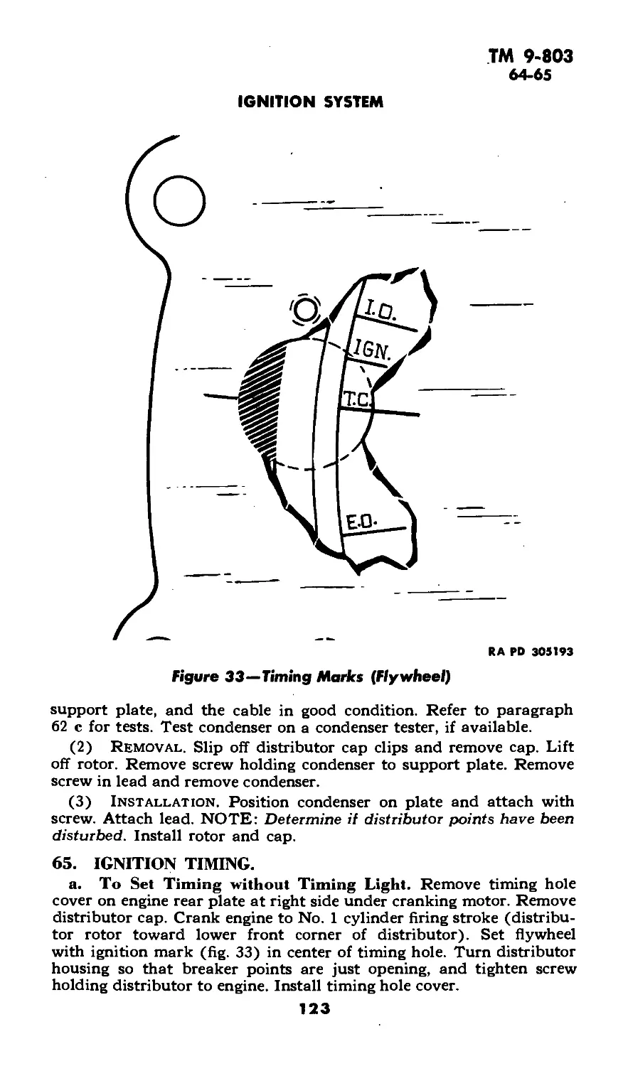
XIV Engine—removal and installation 60-61 116-117
XV Ignition system.................. 62-69 118-125
XVI Fuel and air intake and exhaust
systems........................ 70-78 126-136
XVII Cooling system................ 79-86 137-143
XVIII Starting system. ................ 87-90 144-145
XIX Generating system................ 91-94 146-149
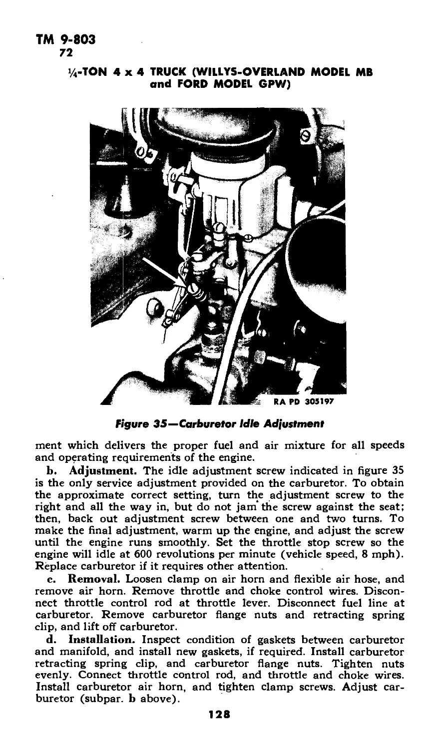
3
ТМ 9-803
1/4-TON 4x4 TRUCK (WILLYS-OVERLAND MODEL MB
and FORD MODEL GPW)
Paragraph! Pagsi
Section XX Battery and lighting system. . . . 95-106 150-166
XXI Clutch.................... 107-112 167-171
XXII Transmission.......... ........... 113-116 172-175
XXIII Transfer case............. 117-121 176-178
XXIV Propeller shafts and universal
joints............................. 122-125 179-180
XXV Front axle................. 126-137 181-188
XXVI Rear axle....................... 138-145 189-192
XXVII Brakes............................ 146-152 193-204
XXVIII Springs and shock absorbers.... 153-157 205-210
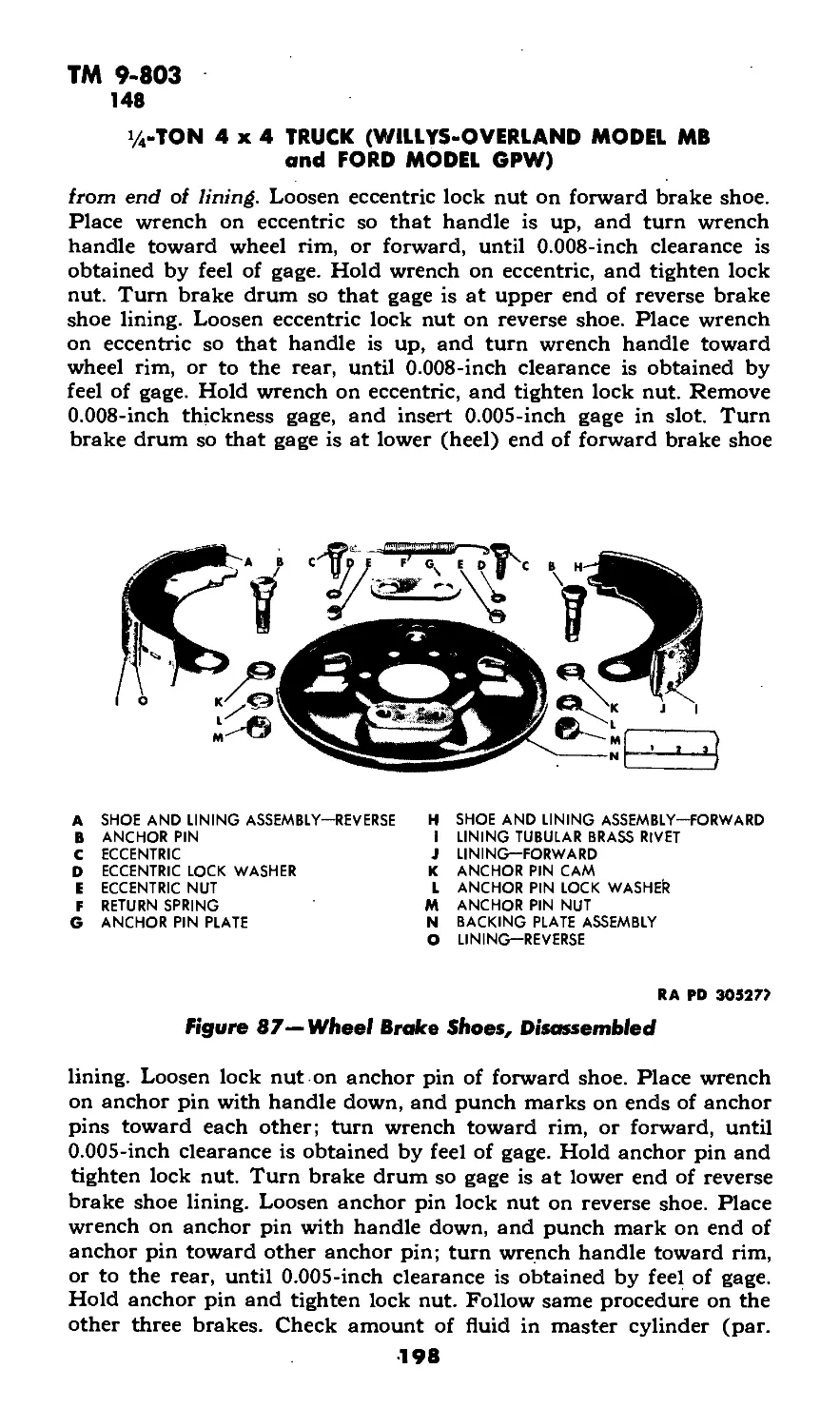
XXIX Steering gear............. 158-163 211-215
XXX Body and frame............. 164-175 216-220
XXXI Radio interference suppression
system....................... 176-179 221-227
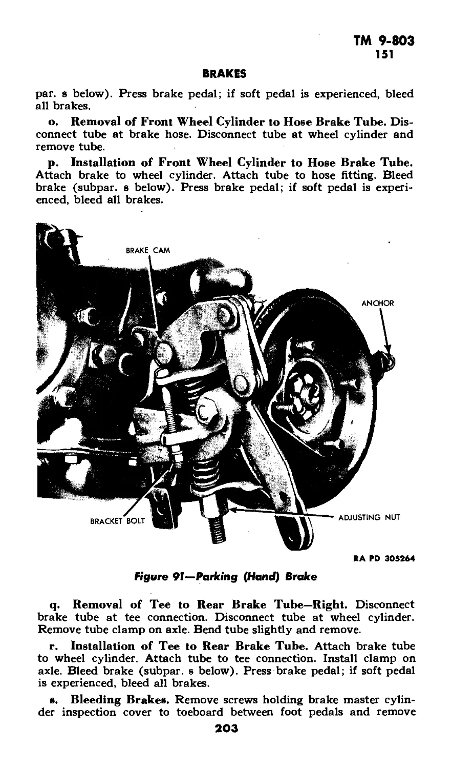
XXXII Shipment and temporary storage 180-182 228-232
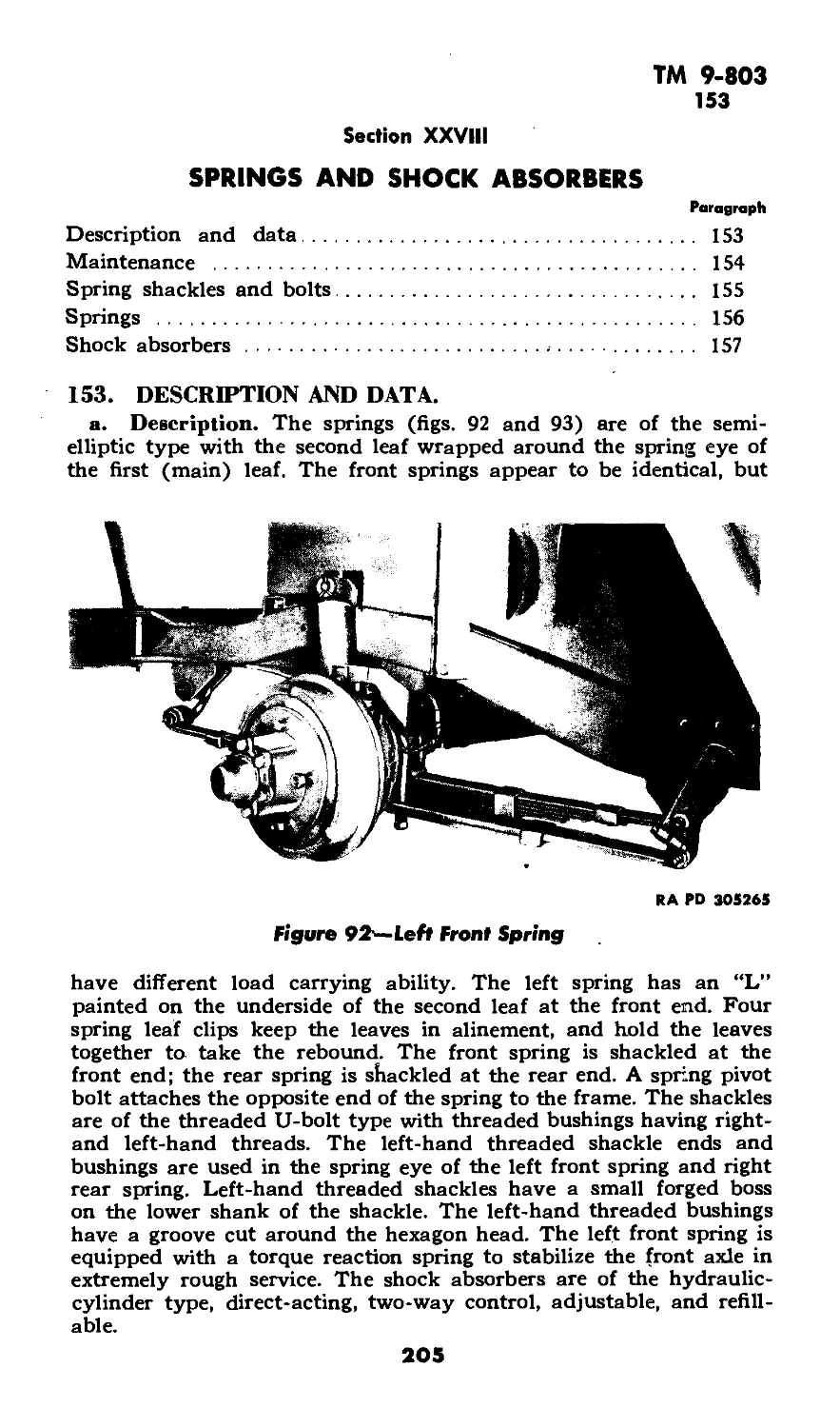
References............................................... 233-234
Index....................................................... 235
ТМ 9-803
1
PART ONE—OPERATING INSTRUCTIONS
Section I
INTRODUCTION
Paragraph
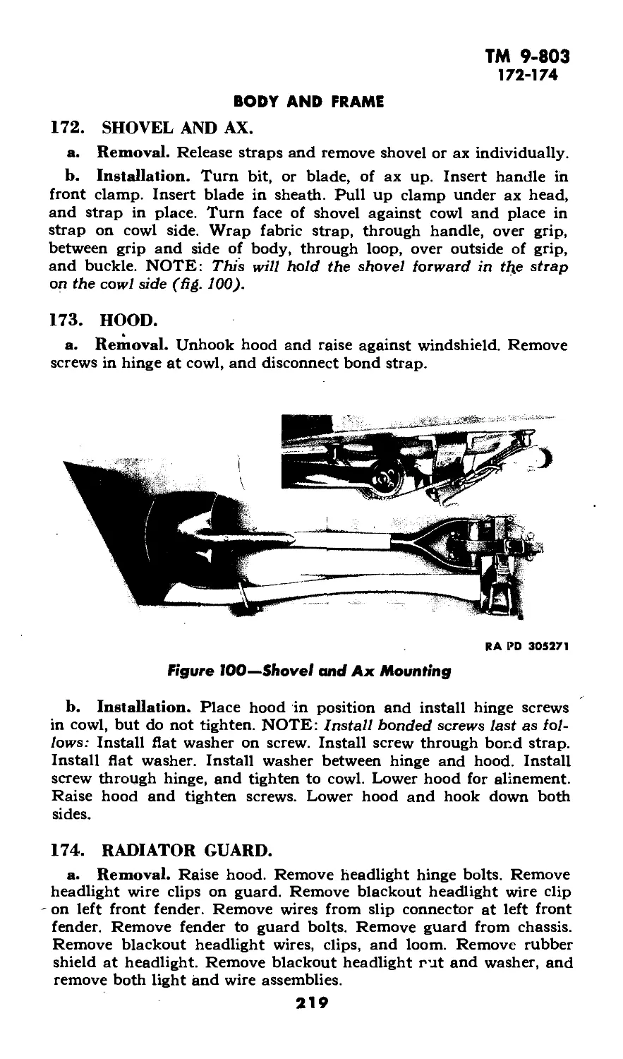
Scope ................................................... 1
1. SCOPE.
a. This technical manual* is published for the information and
guidance of the using arm personnel charged with the operation and
maintenance of this materiel.
b. In addition to a description of the %-ton 4x4 Truck (Willys-
Overland model MB and Ford GPW), this manual contains technical
information required for the identification, use, and care of the mate-
riel. The manual is divided into two parts. Part One, sections I
through VII, contains vehicle operating instructions. Part Two, sec-
tions VIII through XXXII, contains vehicle maintenance instructions
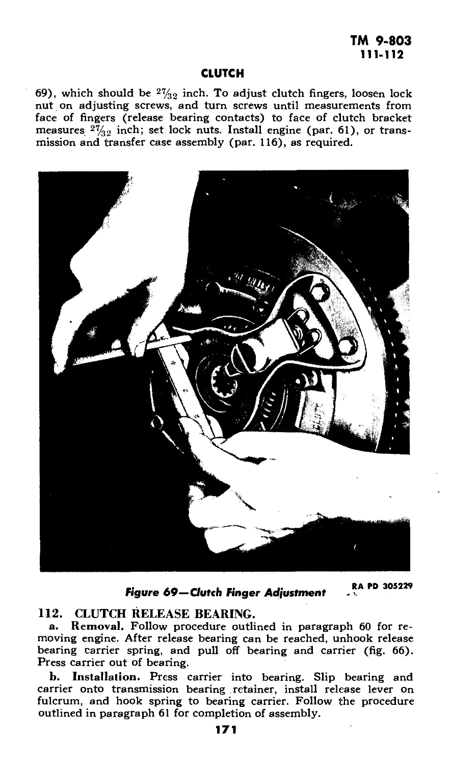
to using arm personnel charged with the responsibility of doing
maintenance work within their jurisdiction, including radio suppres-
sion and shipment and temporary storage information.
c. In all cases where the nature of the repair, modification, or
adjustment is beyond the scope of facilities of the unit, the respon-
sible ordnance service should be informed so that trained personnel
with suitable tools and equipment may be provided, or proper in-
structions issued.
d. This manual includes operating and organizational mainte-
nance instructions from the following Quartermaster Corps 10-series
technical manuals. Together with ТМ 9-1803A and ТМ 9-1803B,
this manual supersedes them:
(1) z TM 10-1103, 20 August 1941.
(2) 'TM 10-1207, 20 August 1941.
(3) xTM 10-1349, 3 January 1942.
(4) /I'M 10-1513, Change 1, 15 January 1943.
*To provide operating instructions with the materiel, this technical manual has
been published in advance of complete technical review. Any errors or omissions
will be corrected by changes of, if extensive, by an early revision.
5
ТМ 9-803
1
1/4-TON 4x4 TRUCK (WILLYS-OVERLAND MODEL MB
and FORD MODEL GPW)
Figure I—I/4-Ton 4x4 Truck—Left Front
6
Figure 2—1/4-Ton 4x4 Truck—Right Rear
u
INTRODUCTION
ТМ 9-803
1
%-TON 4x4 TRUCK (WILLYS-OVERLAND MODEL MB
and FORD MODEL GPW)
Figure З-1/4-Топ 4x4 Truck—Right Side
8
Figure 4—1/4-Ton 4x4 Truck—Right Front
u
INTRODUCTION
ТМ 9-803
2-3
1/4-TON 4x4 TRUCK (WILLYS-OVERLAND MODEL MB
and FORD MODEL GPW)
Section II
DESCRIPTION AND TABULATED DATA
Paragraph
Description ...................... 2
Data ...................................................... 3
2. DESCRIPTION.
a. Type. This vehicle is a general purpose, personnel, or cargo
carrier especially adaptable for reconnaisance or command, and
designated as %-ton 4x4 Truck. It is a four-wheel vehicle with
four-wheel drive. The engine is a 4-cylinder gasoline unit located in
the conventional place, under the hood at the front of the vehicle.
A conventional three-speed transmission equipped with a transfer
case provides additional speeds for traversing difficult terrain. The
body is of the open type with an open driver’s compartment. The
folding top can be removed and stowed; and, the windshield tilted
forward on top of the hood, or opened upward and outward. A spare
wheel equipped with a tire is mounted on the rear of the body, and a
pintle hook is provided to haul trailed loads. Specifications of the
vehicle are given under “Data” (par. 3). General physical character-
istics are shown in figures 1 through 4.
b. Identification. The manufacturer’s chassis serial number is
stamped on a plate inside the left frame side member at the front end,
and on the name plate^ 6). The engine serial number is stamped
on the right side of the cylinder block, front upper corner. The U.S.A,
registration number is painted on both sides of the hood.
3. DATA.
a. Vehicle Specifications.
Wheelbase ..........................................., ,80 in.
Length, over-all ................................ 132% 'n- '
Width, over-all ................................. 62 in.
Height, over-all—top up........................... 69% in.
—top down ..........................52 in.
Wheel size............................... combat 16 x 4.50 E
Tire size.................................... 16 x 6.00 in.
Tire pressure (front and rear) . . '................ 35 lb
Tire type ................................ mud and snow
• Tire plies ............................................ 6
Tread (center-to-center)—front .................... 49 in.
—rear....................... 49 in.
Crew, operating ........................................ 2
Passenger capacity including crew...................... 5
10
ТМ 9-803
3
DESCRIPTION AND TABULATED DATA
Weights:
Road, including gas and water............. 2,453 lb
Gross (loaded) ............................ 3,253 lb
Shipping (less water and fuel)............. 2,337 lb
Boxed gross ............................... 3,062 lb
Maximum pay load............................. 800 lb
Maximum trailed load....................... 1,000 lb
Ground clearance ............................... 8% in.
Pintle height (loaded).......................... 21 in.
Kind and grade of fuel (octane rating) Gasoline (68 min)
Approach angle ................................. 45 deg
Departure angle ................................ 35 deg
Shipping dimensions—cubic feet..................... 331
—square feet .................. 57
b. Performance.
Maximum allowable speeds (mph) with transfer case in
“HIGH” range:
High gear (3rd)..................................... 65?
Intermediate gear (2nd)............................... 41
Low gear (1st)........................................ 24
Reverse gear ......................................... 18
Maximum allowable speeds (mph) with transfer case in
“LOW” range:
High gear (3rd).................................... 33
Intermediate gear (2nd).......................... 21
Low gear (1st)................................... 12
Reverse gear ...................................... 9
Maximum grade ability.............................. 60 pct
Minimum turning radius—right ..................... ^7% ft
-left .................: 17% ft
Maximum fording depth.............................. 21 in.
Towing facilities—front ........................... none
—rear ........................ pintle hook
Maximum draw-bar pull........................... 1,930 lb
Engine idle speed................................ 600 rpm
Miles per gallon—(high gear—high range)
average conditions ............................... 20
Cruising range—(miles) average conditions.............г2&
c. Capacities.
Engine crankcase capacity—dry............................. 5 qt
-refill .................... 4 qt
Transmission capacity ............................... % qt
Transfer case capacity. ............................ 1% zqt
11
ТМ 9-803
3
'/«-TON 4x4 TRUCK (WILLYS-OVERLAND MODEL MB
and FORD MODEL GPW)
Front axle capacity (differential).................... 1% qt
Rear axle capacity (differential)..................... 1% qt-
Front axle steering knuckle universal joint............ % qt
Steering gear -housing................................. % qt
Air cleaner (oil bath)............................... 5/a qt
Fuel tank capacity.................................... 15 gal
Cooling system capacity............................... 11 qt
Brake system (hydraulic brake fluid)................... % qt
Shock absorbers—front ................................ 5 oz
—rear ............................... 5% oz
d. Communications.
(1) Radio Outlet Box. A radio outlet box is provided on the
later vehicles to use the vehicle battery (б-volt current supply). This
outlet is located against the body side panel at the right front seat.
(2) Auxiliary Generator. A 12-volt, 55-ampere auxiliary gen-
erator is furnished on some vehicles. The generator is driven by a
V-belt from a power take-off unit on the rear of the transfer case.
Instructions for operation and care accompany those vehicles.
12
TM 9-803
4
Section III
DRIVING CONTROLS AND OPERATION
Paragraph
Instruments and controls...................................... 4
Use of instruments and controls in vehicular operation...... 5
Towing the vehicle........................................... 6
A STEERING WHEEL
В HORN BUTTON
C WINDSHIELD WIPERS
D WINDSHIELD ADJUSTING ARMS
E AMMETER
F HAND BRAKE
G WINDSHIELD CLAMPS
H CAUTION PLATE
I NAME PLATE
J SHIFT PLATE
К TRANSMISSION GEAR SHIFT LEVER
L TRANSFER CASE SHIFT LEVER—FRONT AXLE DRIVE
M TRANSFER CASE SHIFT LEVER—AUXILIARY RANGE
N STARTING SWITCH
О TEMPERATURE GAGE
P ACCELERATOR FOOT REST
Q SPEEDOMETER
R ACCELERATOR (FOOT THROTTLE)
S OIL PRESSURE GAGE
T FUEL GAGE
U BRAKE PEDAL
V INSTRUMENT PANEL LIGHT SWITCH
W CLUTCH PEDAL
X FUEL TANK
Y FIRE EXTINGUISHER
Z SAFETY STRAP
AA HEADLIGHT FOOT SWITCH (BEAM CONTROL)
AB BLACKOUT LIGHT SWITCH
AC BLACKOUT DRIVING LIGHT SWITCH
AD REAR VISION MIRROR
AE CHOKE CONTROL
AF IGNITION SWITCH
AG HAND THROTTLE
AH RIFLE HOLDER
RA PD 334753
Figure 5—Instruments and Controls
4. INSTRUMENTS AND CONTROLS.
a. Instruments.
(1) Ammeter (fig. 5). The ammeter on the instrument panel
indicates the rate of current flow when the generator is charging the
battery, and also indicates the amount of current being consumed
when the engine i$ idle.
(2) Fuel Gage (fig. 5). The fuel gage on the instrument panel
13
TM 9-803
4
1/4-TON 4x4 TRUCK (WILLYS-OVERLAND MODEL MB
and FORD MODEL GPW)
Figure 6—Name Plate
RA PD 330838
Q
CAUTION
MAXIMUM PERMISSIBLE ROAD SPEEDS
IN THE FOLLOWING GEAR POSITIONS
TRANSMISSION
______IN_____
HIGH
INTERMEDIATE
LOW
REVERSE
TRANSFER CASE IN
HIGH RANGE
6OM.P.H
24
1 8
LOW RANGE-
33 M.P.H.
21
1 2
9
TO DRAIN COOLING SYSTEM: OPEN
RADIATOR DRAIN COCK LOCATED ON HOSE FITTING AT
RA PD 305162
Figure 7—Caution Plate
DISENGAGE FRONT AXLE DRIVE
WHEN OPERATING ON DRY
HARD SURFACED ROADS
О
О
RA PD 305161
Figure 8—Shift Plate
14
ТМ 9-803
4
DRIVING CONTROLS AND OPERATION
is an electrical unit which indicates the fuel level in the tank, and
only registers while the ignition switch is turned on.
(3) Oil Pressure Gage (fig. 5). The oil pressure gage located
on the instrument panel indicates the oil pressure when the engine
is running.
(4) Speedometer (fig. 5). The speedometer on the instrument
panel indicates in miles per hour the speed at which the vehicle is
being driven. The odometer (in upper part of speedometer face)
registers the total number of miles the vehicle has been driven. A
trip indicator (in lower part of speedometer face) gives distance
covered on any trip. Set trip indicator by turning the knurled con-
trol shaft extending through back of the speedometer.
(5) Temperature Gage (fig. 5). The temperature gage registers
the temperature of the solution in the cooling system.
b. Controls.
(1) Blackout Driving Light Switch (fig. 5). The blackout
driving light switch (B.O. DRIVE) on the instrument panel controls
the blackout driving light located on the left front fender, to furnish
additional light during blackout periods. To operate light, first pull
the blackout light switch button to the first position, then pull black-
out driving light switch knob. To switch off the light, push in black-
out driving light switch knob.
RA PD 64586
Figure 9—Blackout Light Switch Operating Positions
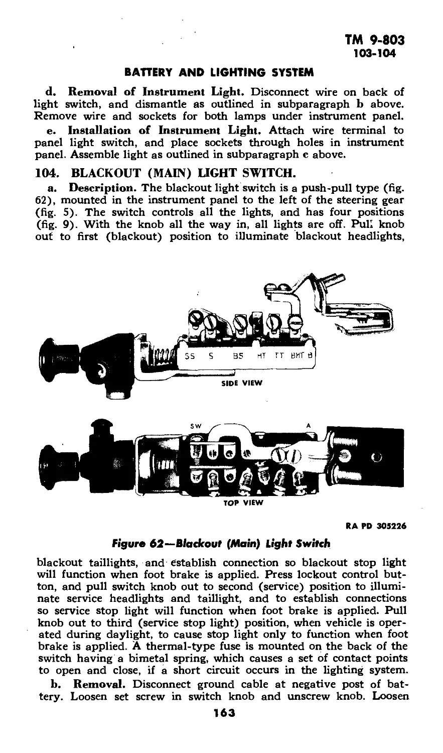
(2) Blackout Light Switch (fig. 5). The knob on the instru-
ment panel (LIGHTS^ controls the entire lighting system, including
the instrument panel li^bts> blackout driving light, and stop lights.
A circuit-breaker type fuse, on the back of the switch, opens when
a short circuit occurs, and closes when the thermostatic element cools.
The light switch is a four-position push-pull type with a safety lock
(fig. 9). When the control knob is pulled out to the first position, the
blackout headlights and blackout stop and taillights are turned on.
15
ТМ 9-803
4
%-TON 4x4 TRUCK (WILLYS-OVERLAND MODEL MB
and FORD MODEL GPW)
The switch-control knob travel is automatically locked in this position
by the lockout button to prevent accidentally turning on of the
service (brightX lights in a blackout area. To obtain service lights,
push in on lock-out control button on the left side of the switch, and
pull out control knob to second position. When switch is in this posi-
tion service headlights, service stop and taillights are turned on, and
the panel lights can be turned on by pulling out on the knob
(PANEL LIGHTS). CAUTION: When driving during the day, press
in lock-out control button, and pull control knob out to the last or
stop light position to cause only the regular stop light to function.
Figure 10—Generator Brace
RA PD 305165
(3) Panel Light Switch (fig. 5). The panel light switch knob
(PANEL LIGHTS), located on the instrument panel, controls the
lights to illuminate the panel instruments and controls. The blackout
light switch (subpar, b (2) above) must be in service (bright light)
position for this switch to control the panel lights.
(4) Fire Extinguisher (fig. 5). The fire extinguisher is mounted
inside the left cowl panel. To remove, pull outward on the clamp
release lever. To operate extinguisher, hold body in one hand and
with the other, turn handle to left one-quarter turn, which releases
plunger lock. Use pumping action to force liquid on base of fire. Read
instructions on fire extinguisher plate.
16
ТМ 9-803
4-5
DRIVING CONTROLS AND OPERATION
(5) Hand Brake (fig. 5). The hand brake is applied by pulling
out on the handle at the center of the instrument panel. Pull the
handle out in a vertical position when the vehicle is parked. The
brake is released by turning the handle one-quarter turn.
(6) Windshield Adjusting Arms (fig. 5). The windshield
adjustment arms are mounted on each end of the windshield frame.
To open windshield, loosen knobs and push forward on lower part,
then set by tightening the knobs.
(7) Windshield Clamps (fig. 5). The windshield clamps are
located on the lower part of the windshield. Pull up on both clamps
and unhook them, after which the windshield can be lowered on top
of the hood. Be sure to hook down the windshield, using the hold-
down catches on both sides of the hood.
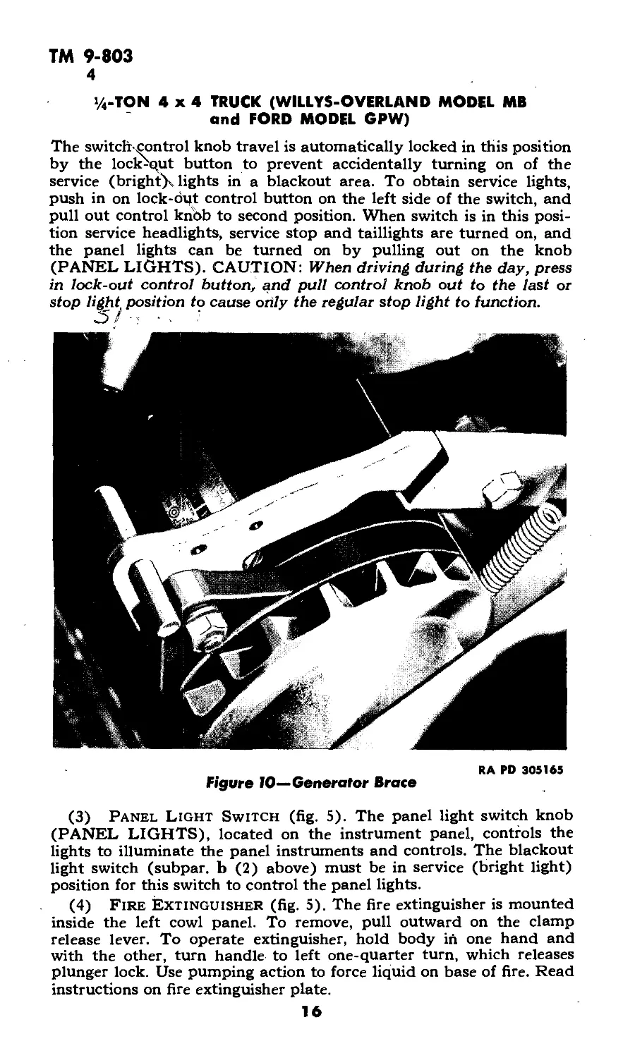
(8) Generator Brace (fig. 10). The generator brace can be
pulled up to release tension on the fan belt and stop the fan from
throwing water over the engine when crossing a stream. Pull gen-
erator out to running position as soon as possible thereafter, and it
will lock in place. CAUTION: Be sure fan belt is on pulleys.
(9) Other Instruments and Controls. Other instruments and
controls are of the conventional type, and are shown in figure 5.
5. USE OF INSTRUMENTS AND CONTROLS IN VEHICULAR
OPERATION.
a. Before-operation Service. Perform the services in paragraph
13 before attempting to start the engine. •./ ( >
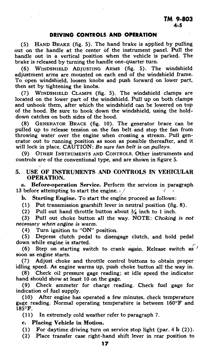
b. Starting Engine. To start the engine proceed as follows:
(1) Put transmission gearshift lever in neutral position (fig. 8).
(2) Pull out hand throttle button about % inch to 1 inch.
(3) Pull out choke button all the way. NOTE: Choking is not
necessary when engine is warm.
(4) Turn ignition to “ON” position.
(5) Depress clutch pedal to disengage clutch, and hold pedal
down while engine is started.
(6) Step on starting switch to crank again. Release switch as
soon as engine starts.
(7) Adjust choke and throttle control buttons to obtain proper
idling speed. As engine warms up, push choke button all the way in.
(8) Check oil pressure gage reading; at idle speed the indicator
hand should show at least 10 on the gage.
(9) Check ammeter for charge reading. Check fuel gage for
indication of fuel supply.
(10) After engine has operated a few minutes, check temperature
gage reading. Normal operating temperature is between 160°F and
185°F.
(11) In extremely cold weather refer to paragraph 7.
c. Placing Vehicle in Motion.
(1) For daytime driving turn on service stop light (par. 4 b (2)).
(2) Place transfer case right-hand shift lever in rear position to
17
ТМ 9-803
5
%-TON 4x4 TRUCK (WILLYS-OVERLAND MODEL MB
and FORD MODEL GPW)
engage “HIGH” range, then place center shift lever in forward posi-
tion to disengage front axle (fig. 8).
(3) Depress clutch pedal, and move transmission shift lever
toward driver and backward to engage low (1st) gear (fig. 8).
(4) Release parking (hand) brake.
(5) Slightly depress accelerator to increase engine speed, and at
the same time slowly release clutch pedal, increasing pressure on
accelerator as clutch engages and vehicle starts to move. NOTE:
During the following operations perform procedures outlined in para-
graph 14.
(6) Increase speed to approximately 10 miles per hour, depress
clutch pedal, and at the same time release pressure on accelerator.
Move transmission shift lever out of low gear into neutral, and then
into second gear. No double clutching is required. Release clutch
pedal and accelerate engine.
(7) After vehicle has attained a speed.of approximately 20 miles
per hour, follow the same procedure as outlined above in order to
shift into high (3rd) gear, moving the gearshift lever straight back.
d. Shifting to Lower Gears in Transmission. Shift to a lower
gear before engine begins to labor, as follows: Depress clutch pedal
quickly, shift to next lower gear, increase engine speed, release clutch
pedal slowly, and accelerate. When shifting to a lower gear at any
rate of vehicle speed, make sure that the engine speed is synchronized
with vehicle speed before clutch is engaged.
e. Shifting Gears in Transfer Case (fig. 8). The transfer case is
the means by which power is applied to the front and rear axles. In
addition, the low gear provided by the transfer case further increases
the number of speeds provided by the transmission. The selection of
gear ratios depends upon the road and load conditions. Shift gears
in the transfer case in accordance with the shift plate, (fig. 8), and
observe the instructions on the caution plate (fig. 7). The transmis-
sion gearshift does not in any way affect the selection or shifting of
the transfer case gears. Vehicle may be driven by rear axle, or by both
front and rear axles. The front axle cannot be driven independently.
(1) Front Axle Engagement. Front axle should be engaged
only in off-the-road operation, slippery roads, steep grades, or during
hard pulling. Disengage front axle when operating on average roads
under normal conditions.
(a) Engaging Front Axle with Transfer Case in “HIGH" Range.
With transfer case in “HIGH” range, move front axle drive shift lever
to “IN” position. Depressing the clutch pedal will facilitate shifting.
(b) Disengaging Front Axle with Transfer Case in “HIGH"
Range. Move front axle drive shift lever to “OUT” position. Depress
the clutch pedal to facilitate shifting.
(c) Disengaging Front Axle when Transfer Case is in “LOW."
1. Depress clutch pedal, then shift transfer case lever into
“HIGH.”
2. Shift front axle drive lever into “OUT” position.
18
ТМ 9-803
5-6
DRIVING CONTROLS AND OPERATION
3. Release clutch pedal and accelerate engine to desired speed.
(2) Engaging Transfer Case LOW Range. Transfer case LOW
range cannot be engaged until front axle drive is engaged.
(a) Engage front axle drive (subpar, e (1) above).
(b) Depress clutch pedal and move transfer case shift lever into
“N” (neutral) position.
(c) Release clutch pedal and accelerate engine.
(d) Depress clutch pedal again and move transfer case shift lever
forward into “LOW” position.
(e) Release clutch pedal, and accelerate engine to desired speed.
(3) Engaging Transfer Case—“LOW” to “HIGH.” This shift
can be made regardless of vehicle speed.
(a) Depress clutch pedal and move transfer case shift lever into
“HIGH” position.
(b) Release clutch pedal, and accelerate engine to desired speed.
f. Stopping the Vehicle. Remove foot from accelerator, and
apply brakes by depressing brake pedal.
(1) When vehicle speed has been reduced to engine idle speed,
depress clutch pedal and move transmission shift lever to “N”
(neutral) position (fig. 8).
(2) When vehicle has come to a complete stop, apply parking
(hand) brake, and release clutch and brake pedals.
g. Reversing the Vehicle. To shift into reverse speed, first bring
the vehicle to a complete stop.
(1) Depress clutch pedal.
(2) Move transmission shift lever to the left and forward into
“R” (reverse) position.
(3) Release clutch pedal slowly, and accelerate as load is picked
up.
h. Stopping the Engine. To stop the engine turn the ignition
switch to “OFF” position. NOTE: Before a new or reconditioned
vehicle is first put into service, make run-in tests as outlined in sec-
tion 10. .
6. TOWING THE VEHICLE.
a. Attaching Tow Line. To tow vehicle attach the chain, rope or
cable to the front bumper bar at the frame side rail gusset (fig. 11).
Do not tow from the middle of the bumper. To attach tow line, loop
chain, rope, or cable over top of bumper, bring tow line up across
front of bumper, and back on opposite side of frame, then hook or tie.
b. Towing to Start Vehicle. Place transfer case (aux. RANGE)
shift lever of towed vehicle to the rear (“HIGH”). Place front axle
drive shift lever in “OUT” (forward) position. Depress clutch pedal
and engage transmission in high (3rd) speed. Switch ignition “ON,”
pull out choke control knob (if engine is cold), pull out throttle knob
about 1 inch, release parking (hand) brake, and tow vehicle. After
19
ТМ 9-803
6
1/4-TON 4x4 TRUCK (WILLYS-OVERLAND MODEL MB
and FORD MODEL GPW)
vehicle is under way, release clutch pedal slowly. As engine starts,
regulate choke and throttle controls and disengage clutch, being
careful to avoid overrunning towing vehicle or tow line.
c. Towing Disabled Vehicle. When towing a disabled vehicle
exercise care so that no additional damage will occur.
(1) All Wheels on Ground.
(a) If transfer case is not damaged, shift transmission and trans-
fer case into neutral position and follow steps (c) and (d) below.
(b) If transfer case is damaged, disconnect both propeller shafts
at the front and rear axles by removing the universal joint U-bolts,
being careful not to lose the bearing races and rollers. Securely fasten
the shafts to the frame with wire or remove dust cap and pull apart
at the universal joint splines. Place bolts, nuts, rollers, and races in
the glove compartment.
Figure 11—Chain Tow
(c) If the front axle differential or propeller shaft is damaged,
remove front axle shaft driving flanges. Place front axle drive shift
lever in “OUT” (forward) position and drive vehicle under own
power.
(d) If the rear axle differential is damaged, remove the rear axle
shafts; remove rear propeller shaft at rear universal joint U-bolts and
front universal joint snap rings in forward flange, then drive out
bearing cups. Place front axle drive shift lever in “IN” (rear) position
and this will allow front axle drive to propel vehicle under own
power.
(e) If rear propeller shaft only is damaged, remove as described
in step (d) above.
(2) Towing Vehicle With Front or Rear Wheels Off
Ground. If vehicle is to be towed in this manner be sure that transfer
case shift lever is placed in “N” (neutral) position and front axle
drive shift lever is placed in “OUT” (disengaged) position.
20
ТМ 9-803
7
Section IV
OPERATION UNDER UNUSUAL CONDITIONS
Paragraph
Operation in cold weather................................ 7
Operation in hot weather................................. 8
Operation in sand.................................... 9
Operation in landing.................................. 10
Decontamination ......................................... 11
7. OPERATION IN COLD WEATHER.
a. Purpose. Operation of automotive equipment at subzero
temperatures presents problems that demand special precautions and
extra careful servicing from both operation and maintenance person-
nel, if poor performance and total functional failure are to be avoided.
b. Gasoline. Winter grade of gasoline is designed to reduce cold
weather starting difficulties; therefore, the winter grade motor fuel
should be used in cold weather operation.
c. Storage and Handling of Gasoline. Due to condensation of
moisture from the air, water will accumulate in tanks, drums, and
containers. At low temperatures, this water will form ice crystals that
will clog fuel lines and carburetor jets, unless the following precau-
tions are taken: .
(1) Strain the fuel through filter paper, or any other type of
strainer that will prevent the passage of water. CAUTION: Gasoline
Sowing over a surface generates static electricity that will result in a
spark, unless means are provided to ground the electricity. Always
provide a metallic contact between the container and the tank, to
assure an effective ground.
(2) Keep tank full, if possible. The more fuel there is in the tank,
the smaller will be the volume of air from which moisture can be
condensed.
(3) Add % pint °f denatured alcohol, Grade 3, to the fuel tank
each time it is filled. This will reduce the hazard of ice formation in
the fuel.
(4) Be sure that all containers are thoroughly clean and free from
rust before storing fuel in them.
(5) If possible, after filling or moving a container, allow the fuel
to settle before filling fuel tank from it.
(6) Keep all closures of containers tight to prevent snow, ice, dirt,
and other foreign matter from entering.
(7) Wipe all snow or ice from dispensing equipment and from
around fuel tank filler cap before removing cap to refuel vehicle.
d. Lubrication.
(1) Transmission and Differential.
21
ТМ 9-803
7
1/4-TON 4x4 TRUCK (WILLYS-OVERLAND MODEL MB
and FORD MODEL GPW)
(a) l^niversal gear lubricant, SAE 80, where specified on figure 14,
is suitable» for use at temperatures as low as — 20°F. If consistent
temperature below 0°F is anticipated, drain the gear cases while
warm, and refill with Grade 75 universal gear lubricant, which is suit-
able for operation at all temperatures below +32 °F. If Grade 75
universal gear lubricant is not available, SAE 80 universal gear lubri-
cant diluted with the fuel used by the engine, in the proportion of one
part fuel to six parts universal gear lubricant, may be used. Dilute
make-up oil in the same proportion before it is added to gear cases.
(b) After engine has been warmed up, engage clutch, and main-
tain engine speed at fast idle for 5 minutes, or until gears can be
engaged. Put transmission in low (first) gear, and drive vehicle for
100 yards, being careful not to stall engine. This will heat gear lubri-
cants to the point where normal operation can be expected.
(2) Chassis .Points. Lubricate chassis points with general
purpose grease, No. 0.
(3) StEe^ring Gear Housing. Drain housing, if possible, or use
suction gun TO\remove as much lubricant as possible. Refill with uni-
versal gear lubricant, Grade 75, or, if not available, SAE 80 universal
gear lubricant diluted with fuel used in the engine, in the proportion
of one part fuel to six parts SAE 80 universal gear lubricant. Dilute
make-up oil in the sairte proportion before it is added to the housing.
(4) Oilcan Points. For oilcan points where engine oil is pre-
scribed for above 0°F, use light lubricating, preservative oil.
e. Protection of Cooling Systems.
(1) Use Antifreeze Compound. Protect the system with, anti-
freeze compound (ethylene-glycol type) for operation below +32°F.
The following instructions apply to use of new antifreeze compound.
(2) Clean Cooling System. Before adding antifreeze compound,
clean the cooling system, and completely free it from rust. If the cool-
ing system has been cleaned recently, it may be necessary only to
drain, refill with clean water, and again drain. Otherwise the system
should be cleaned with cleaning compound.
(3) Repair Leaks. Inspect all hoses, and replace if deteriorated.
Inspect all hose clamps, plugs, and pet cocks and tighten if necessary.
Repair all radiator leaks before adding antifreeze compound. Correct
all leakage of exhaust gas or air into the cooling system.
(4) Add Antifreeze Compound. When the cooling system is
clean and tight, fill the system with water to about one-third capacity.
Then add antifreeze compound, using the proportion of antifreeze
compound to the cooling system capacity indicated below. Protect
the system to at least 10°F below the lowest temperature expected to
be experienced during the winter season.
22
ТМ 9-803
7
OPERATION UNDER UNUSUAL CONDITIONS
ANTIFREEZE COMPOUND CHART
(for 11 -quart capacity cooling system)
Temperalure Antifreeze Compound
(elhylene-glycol type)
+ 10°F............................... 3 qt
0°F............................ 334 qt
— 10°F............................ 4% qt
— 20°F............................ 4% qt
— 30°F............................ 5% qt
— 40°F............................. 6 qt
(5) Warm the Engine. After adding antifreeze compound, fill
with water to slightly below the filler neck; then start and warm the
engine to normal operating temperature.
(6) Test Strength of Solution. Stop the engine and check the
solution with a hydrometer, adding antifreeze compound if required.
(7) Inspect Weekly. In service, inspect the coolant weekly for
strength and color. If rusty, drain and clean cooling system thor-
oughly, and add new solution of the required strength.
(8) Cautions.
(a) Antifreeze compound is the only antifreeze material author-
ized for ordnance materiel.
(b) It is essential that antifreeze solutions be kept clean. Use only
containers and water that are free from dirt, rust, and oil.
(c) Use an accurate hydrometer. To test a hydrometer, use one
part antifreeze compound to two parts water. This solution will pro-
duce a hydrometer reading of 0°F.
(d) Do not spill antifreeze compound on painted surfaces.
f. Electrical Systems.
(1) Generator and Cranking Motor. Check the brushes,
commutators, and bearings. See that the commutators are clean. The
large surges of current which occur when starting a cold engine
require good contact between brushes and commutators.
(2) Wiring. Check, clean, and tighten all connections, especially
the battery terminals. Care should be taken that no short circuits are
present.
(3) Coil. Check coil for proper functioning by noting quality of
spark.
(4) Distributor. Clean thoroughly, and clean or replace points.
Check the points frequently. In cold weather, slightly pitted points
may prevent engine from starting.
(5) Spark Plugs. Clean and adjust or replace, if necessary. If it
is difficult to make the engine fire, reduce the gap to 0.005 inch less
than that recommended for normal operation (par. 67 b). This will
make ignition more effective at reduced voltages likely to prevail.
23
ТМ 9-803
7
1/4-TON 4x4 TRUCK (WILLYS-OVERLAND MODEL MB
and FORD MODEL GPW)
(6) Timing. Check carefully. Care should be taken that the spark
is not unduly advanced nor retarded.
(7) Battery.
(a) The efficiency of batteries decreases sharply with decreasing
temperatures, and becomes practically nil at — 40°F. Do not try to
start the engine with the battery when it has been chilled to tem-
peratures below — 30°F until battery has been heated, unless a warm
slave battery is available. See that the battery is always fully
charged, with the hydrometer reading between 1.275 and 1.300. A
fully charged battery will not freeze at temperatures likely to be
encountered even in arctic climates, but a fully discharged battery
will freeze and rupture at +5°F.
(b) Do not add water to a battery when it has been exposed to
subzero temperatures unless the battery is to be charged immediately.
If water is added and the battery not put on charge, the layer of water
will stay at the top and freeze before it has a chance to mix with
the acid.
(8) Lights. Inspect the lights carefully. Check for short circuits
and presence of moisture around sockets.
(9) Ice. Before every start, see that the spark plugs, wiring, or
other electrical equipment is free from ice.
g. Starting and Operating Engine.
(1) Inspect Cranking Motor Mechanism. Be sure that no
heavy grease or dirt has been left on the cranking motor throwout
mechanism. Heavy grease or dirt is liable to keep the gears from being
meshed, or cause them to remain in mesh after the engine starts run-
ning. The latter will ruin the cranking motor and necessitate repairs.
(2) Use of Choke. A full choke is necessary to secure the rich
air-fuel mixture required for cold weather starting. Check the butter-
fly valve to see that it closes all the way, and otherwise functions
properly.
(3) Carburetor and Fuel Pump. The carburetor, which will
give no appreciable trouble at normal temperatures, is liable not to
operate satisfactorily at low temperatures. Be sure the fuel pump has
no leaky valves or diaphragm, as this will prevent the fuel pump from
delivering the amount of fuel required to start the engine at low
temperatures, when turning speeds are reduced to 30 to 60 revolu-
tions per minute.
(4) Air Cleaners. At temperatures below 0°F do not use oil in
air cleaners. The oit will congeal and prevent the easy flow of air.
Wash screens in dry-clefening solvent, dry, and replace. Ice and frost
formations on the air clearer screens can cause an abnormally high
intake vacuum in the carburetorair horn hose, resulting in collapse.
(5) Fuel System. Remove and clean sediment bulb, strainers,
etc., daily. Also drain fuel tank sump daily to remove water and dirt.
24
ТМ 9-803
7
OPERATION UNDER UNUSUAL CONDITIONS
(6) Starting the Engine. Observe the following precautions in
addition to the normal starting procedure (par. 5 a and b).
(a) Clean ignition wires and outside of spark plugs of dirt and
frost.
(b) Free distributor point arm on post and clean points.
(c) Be sure carburetor choke closes fully.
(d) Operate fuel pump hand lever to fill carburetor bowl (fig.
12).
(e) Free up engine with hand crank or use slave battery.
(f) Stop engine if no oil pressure shows on gage.
Figure 12—Fuel Pump, Hand Operation
(&) Engage clutch to warm up transmission oil before attempting
to move vehicle.
(h) Check engine operation for proper condition (par. 13 b (22)).
h. Chassis.
(1) Brake Bands. Brake bands, particularly on new vehicles,
have a tendency to bind when they are very cold. Always have a
blowtorch handy to warm up these parts, if they bind prior to mov-
ing, or attempting to move, the vehicle. Parking the vehicle with the
brake released will eliminate most of the binding. Precaution must be
taken, under these circumstances, to block the wheels or otherwise
prevent movement of the vehicle.
25
ТМ 9-803
7-9
'/«-TON 4x4 TRUCK (WILLYS-OVERLAND MODEL MB
and FORD MODEL GPW)
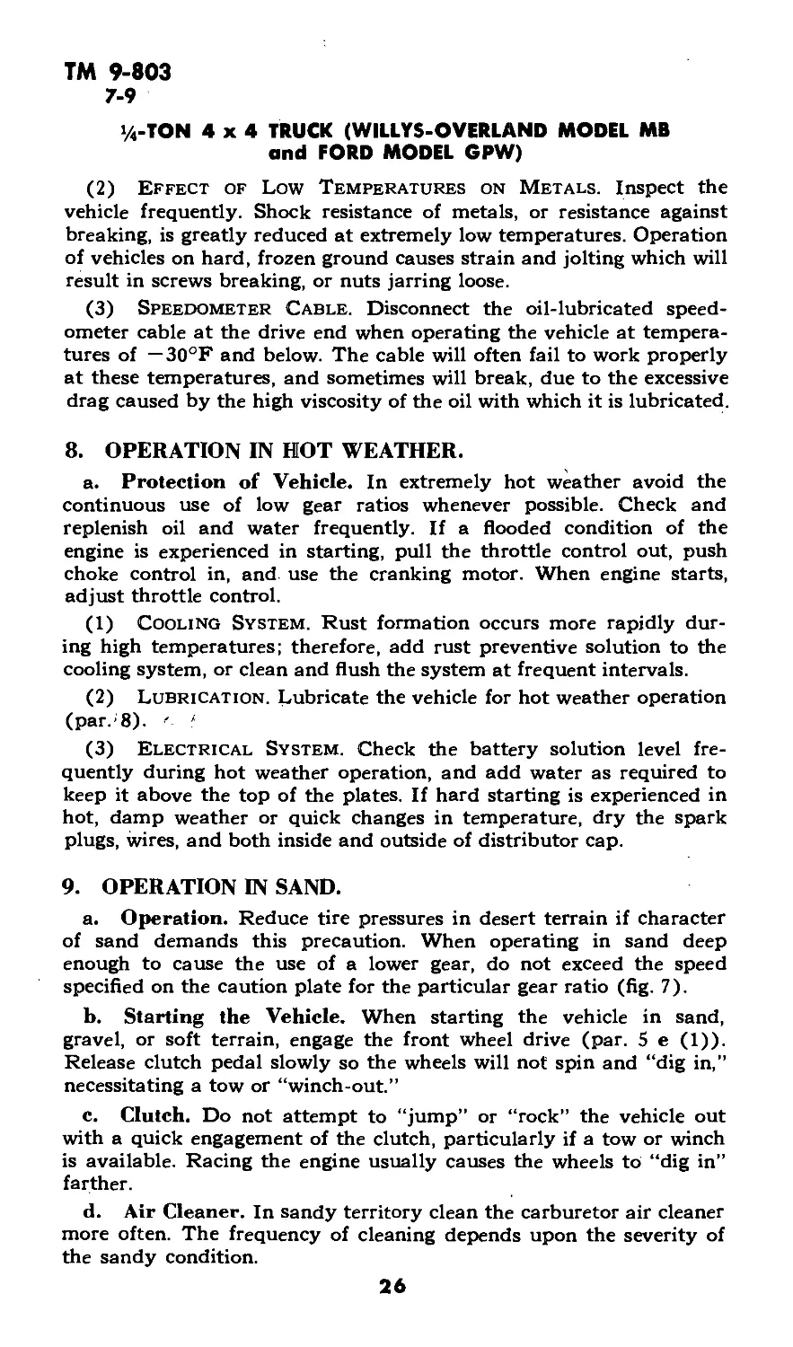
(2) Effect of Low Temperatures on Metals. Inspect the
vehicle frequently. Shock resistance of metals, or resistance against
breaking, is greatly reduced at extremely low temperatures. Operation
of vehicles on hard, frozen ground causes strain and jolting which will
result in screws breaking, or nuts jarring loose.
(3) Speedometer Cable. Disconnect the oil-lubricated speed-
ometer cable at the drive end when operating the vehicle at tempera-
tures of — 30°F and below. The cable will often fail to work properly
at these temperatures, and sometimes will break, due to the excessive
drag caused by the high viscosity of the oil with which it is lubricated.
8. OPERATION IN HOT WEATHER.
a. Protection of Vehicle. In extremely hot weather avoid the
continuous use of low gear ratios whenever possible. Check and
replenish oil and water frequently. If a flooded condition of the
engine is experienced in starting, pull the throttle control out, push
choke control in, and. use the cranking motor. When engine starts,
adjust throttle control.
(1) Cooling System. Rust formation occurs more rapidly dur-
ing high temperatures; therefore, add rust preventive solution to the
cooling system, or clean and flush the system at frequent intervals.
(2) Lubrication. Lubricate the vehicle for hot weather operation
(par.; 8). - 1
(3) Electrical System. Check the battery solution level fre-
quently during hot weather operation, and add water as required to
keep it above the top of the plates. If hard starting is experienced in
hot, damp weather or quick changes in temperature, dry the spark
plugs, wires, and both inside and outside of distributor cap.
9. OPERATION IN SAND.
a. Operation. Reduce tire pressures in desert terrain if character
of sand demands this precaution. When operating in sand deep
enough to cause the use of a lower gear, do not exceed the speed
specified on the caution plate for the particular gear ratio (fig. 7).
b. Starting the Vehicle. When starting the vehicle in sand,
gravel, or soft terrain, engage the front wheel drive (par. 5 e (1)).
Release clutch pedal slowly so the wheels will not spin and “dig in,”
necessitating a tow or “winch-out.”
c. Clutch. Do not attempt to “jump” or “rock” the vehicle out
with a quick engagement of the clutch, particularly if a tow or winch
is available. Racing the engine usually causes the wheels to “dig in”
farther.
d. Air Cleaner. In sandy territory clean the carburetor air cleaner
more often. The frequency of cleaning depends upon the severity of
the sandy condition.
26
ТМ 9-803
9-11
OPERATION UNDER UNUSUAL CONDITIONS
e. Radiator. In desert operation check the radiator coolant supply
frequently, and see that the air passages of the core do not become
clogged.
f. For additional information on technique of operating the
vehicle in sand, refer to FM 31-25.
10. OPERATION IN LANDING.
a.\ Inspection. As soon as possible after completing a landing or
operation in water, inspect the vehicle for water in the various units.
(1) Engine. Drain the engine crankcase oil. If water or sludge
is found, flush the engine, using a mixture of half engine oil SAE 10
and half kerosene. Before putting in new oil, clean the valve chamber,
drain and clean the oil filter, and install a new filter element.
(2) Fuel System. Inspect the carburetor bowl, fuel strainers,
fuel pump, filter, fuel tank, and lines. Clean the air cleaner and
change the oil.
(3) Power Train. Irtspect the front and rear axle housings,
wheel bearings, transmission, and transfer case lubricant for presence
of sludge. If sludge is found, renew the lubricant after cleaning the
units with a mixture of half engine oil SAE 10 and half kerosene.
Lubricate the propeller shaft universal joints and spring shackles to
force out any water which might damage parts.
11. DECONTAMINATION.
a. Protection. For protective measures against chemical attacks
and decontamination refer to FM 17-59.
27
ТМ 9-803
12
i/4-TON 4x4 TRUCK (WILLYS-OVERLAND MODEL MB
and FORD MODEL GPW)
Section V
FIRST ECHELON PREVENTIVE MAINTENANCE SERVICE
Paragraph
Purpose ...................................................... 12
Before-operation service ..................................... 13
During-operation service ..................................... 14
At-halt service .............................................. 15
After-operation and weekly service ........................... 16
12. PURPOSE.
a. To ensure mechanical efficiency it is necessary that the vehicle
be systematically inspected at intervals each day it is operated, also
weekly, so that defects may be discovered and corrected before they
result in serious damage or failure. Certain scheduled maintenance
services will be performed at these designated intervals. The services
set forth in this section are those performed by driver or crew before
operation, during operation, at halt, and after operation and weekly.
b. Driver preventive maintenance services are listed on the back
of “Driver’s Trip Ticket and Preventive Maintenance Service
Record,” W.D. Form No. 48, to cover vehicles of all types and models.
Items peculiar to specific vehicles, but not listed on W.D. Form No.
48, are covered in manual procedures under the items to which they
are related. Certain items listed on the form that do not pertain to
the vehicle involved are eliminated from the procedures as written
into the manual. Every organization must thoroughly school each
driver in performing the maintenance procedures set forth in manuals,
whether they are listed specifically on W.D. Form No. 48 or not.
c. The items listed on W.D. Form No. 48 that apply to this
vehicle are expanded in this manual to provide specific procedures
for accomplishment of the inspections and services. These services
are arranged to facilitate inspection and conserve the time of the
driver, and are not necessarily in the same numerical order as shown
on W.D. Form No. 48. The item numbers, however, are identical with
those shown on that form.
d. The general inspection of each item applies also to any sup-
porting member or connection, and generally includes a check to see
whether the item is in good condition, correctly assembled, secure,
or excessively worn.
(1) The inspection for “good condition” is usually an external
visual inspection to determine whether the unit is damaged beyond
safe or serviceable limits. The term “good condition” is explained
further by the following: not bent or twisted, not chafed or burned,
not broken or cracked, not bare or frayed, not dented or collapsed,
not tom or cut.
28
ТМ 9-803
12-13
FIRST ECHELON PREVENTIVE MAINTENANCE SERVICE
(2) The inspection of a unit to see that it is “correctly assembled”
is usually an external visual inspection to see whether or not it is in
its normal assembled position in the vehicle.
(3) The inspection of a unit to determine if it is “secure” is
usually an external visual examination, a hand-feel, wrench, or pry-
bar check for looseness. Such an inspection should include any
brackets, lock washers, lock nuts, locking wires, or cotter pins used
in assembly.
(4) “Excessively worn” will be understood to mean worn, close
to or beyond, serviceable limits, and likely to result in failure if not
replaced before the next scheduled inspection.
e. Any defects or-unsatisfactory operating characteristics beyond
the scope of the first echelon to correct must be reported at the
earliest opportunity to the designated individual in authority.
13. BEFORE-OPERATION SERVICE.
a. This inspection schedule is designed primarily as a check to
see that the vehicle has not been tampered with or sabotaged since
the After-operation Service was performed. Various combat condi-
tions may have rendered the vehicle unsafe for operation, and it is
the duty of the driver to'determine whether or not the vehicle is in
condition to carry out any mission to which it is assigned. This
operation will not be entirely omitted, even in extreme tactical
situations.
b. Procedures. Before-operation Service consists of inspecting
items listed below according to the procedure described, and correct-
ing or reporting any deficiencies. Upon completion of the service,
results should be reported promptly to the designated individual in
authority.
(1) Item 1, Tampering and Damage. Examine exterior of
vehicle, engine, wheels, brakes, and steering control for damage by
falling debris, shell fire, sabotage, or collision. If wet, dry the ignition
parts to ensure easy starting.
(2) Item 2, Fire Extinguisher. Be sure fire extinguisher is full,
nozzle is clean, and mountings secure.
(3) Item 3, Fuel, Oil, and Water. Check fuel tank, crankcase,
and radiator for leaks or tampering. Add fuel, oil, or water as
needed. Have value of antifreeze checked. If, during period when
antifreeze is used, it becomes necessary to replenish a considerable
amount of water, report unusual losses.
(4) Item 4, Accessories and Drives. Inspect carburetor, gener-
ator, regulator, cranking motor, and water pump for loose connec-
tions and security of mountings. Inspect carburetor and water pump
for leaks.
(5) Item 6, Leaks, General. Look on ground under vehicle for
indications of fuel, oil, water, brake fluid, or gear oil leaks. Trace
leaks to source, and correct or report to higher authority.
29
ТМ 9-803
13
’/«-TON 4x4 TRUCK (WILLYS-OVERLAND MODEL MB
and FORD MODEL GPW)
(6) Item 7, Engine Warm-up. Start engine, observe cranking
motor action, listen for unusual noise, and note cranking speed. Idle
engine only fast enough to run smoothly. Proceed immediately with
following services while engine is warming up.
(7) Item 8, Choke. As engine warms, push in choke as required
for smooth operation, and to prevent oil dilution.
(8) Item 9, Instruments.
(a) Fuel Gage. Fuel gage should indicate approximate amount
of fuel in tank.
(b) Oil Pressure Gage. Normal oil pressure should not be below
10 with engine idling, and should range from 40 to 50 at running
speeds (at normal operating temperature). If gage fails to register
within 30 seconds, stop engine, and correct or report to higher
authority.
(c) Temperature Indicator. Temperature should rise slowly dur-
ing warm-up. Normal operating temperature range is 160°F to 185°F.
(d) Ammeter. Ammeter should show high charge for short period
after starting and positive (plus) reading above 12 to 15 miles per
hour with lights and accessories off. Zero reading is normal with
lights and accessories on.
(9) Item 10, Horn and Windshield Wipers. Sound horn, tacti-
cal situation permitting, for proper operation and tone. Check both
wipers for secure attachment and normal full contact operation
through full stroke.
(10) Item 11, Glass and Rear View Mirror. Clean windshield
and rear view mirror and inspect for cracked, discolored, or broken
glass. Adjust mirror.
(11) Item 12, Lights and Reflectors. Try switches in each
position and see if lights respond^ Lights and warning reflectors must
be securely mounted, clean, and in good condition. Test foot control
of headlight beams.
(12) Item .13, Wheel and Flange Nuts. Observe whether or not
all wheel and flange nuts are present and tight.
(13) Item 14, Tires. If time permits, test tires with gage, includ-
ing spare; normal pressure is 35 pounds with tires cold. Inspect tread
and carcass for cuts and bruises. Remove imbedded objects from
treads.
(14) Item 15, Springs and Suspension. Inspect springs for
sagged or broken leaves, shifted leaves, and loose or missing rebound
clips.
(15) Item 16, Steering Linkage. Examine steering gear case,
connecting links, and Pitman arm for security and good condition.
Test steering adjustment, and free motion of steering wheel.
(16) Item 17, Fenders and Bumpers. Examine fenders and
bumpers for secure mounting and serviceable condition.
30
ТМ 9-803
13-14
FIRST ECHELON PREVENTIVE MAINTENANCE SERVICE
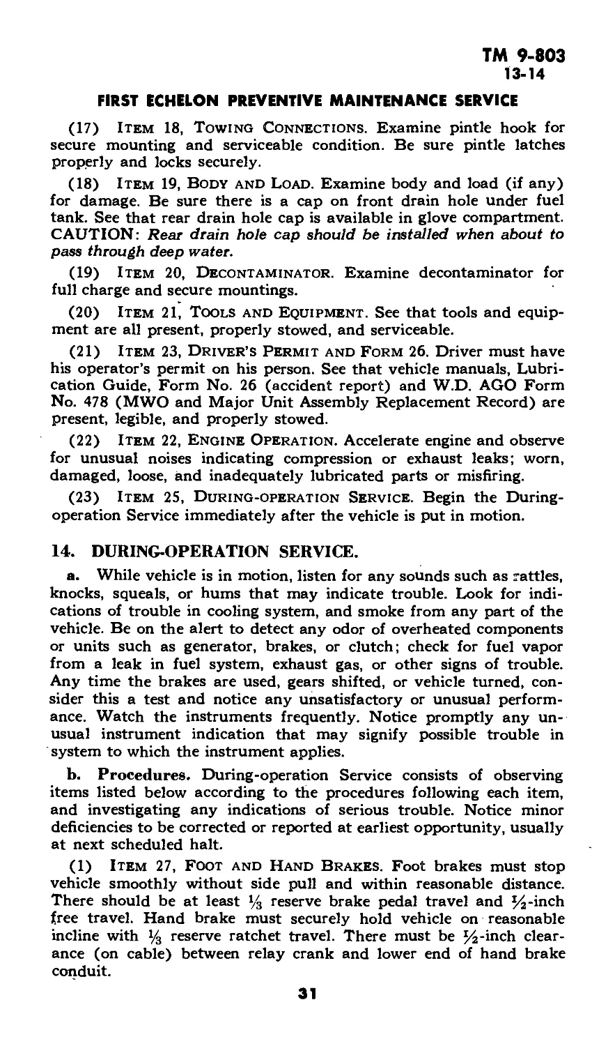
(17) Item 18, Towing Connections. Examine pintle hook for
secure mounting and serviceable condition. Be sure pintle latches
properly and locks securely.
(18) Item 19, Body and Load. Examine body and load (if any)
for damage. Be sure there is a cap on front drain hole under fuel
tank. See that rear drain hole cap is available in glove compartment.
CAUTION: Rear drain hole cap should be installed when about to
pass through deep water.
(19) Item 20, Decontaminator. Examine decontaminator for
full charge and secure mountings.
(20) Item 21, Tools and Equipment. See that tools and equip-
ment are all present, properly stowed, and serviceable.
(21) Item 23, Driver’s Permit and Form 26. Driver must have
his operator’s permit on his person. See that vehicle manuals, Lubri-
cation Guide, Form No. 26 (accident report) and W.D. AGO Form
No. 478 (MWO and Major Unit Assembly Replacement Record) are
present, legible, and properly stowed.
(22) Item 22, Engine Operation. Accelerate engine and observe
for unusual noises indicating compression or exhaust leaks; worn,
damaged, loose, and inadequately lubricated parts or misfiring.
(23) Item 25, During-operation Service. Begin the During-
operation Service immediately after the vehicle is put in motion.
14. DURING-OPERATION SERVICE.
a. While vehicle is in motion, listen for any sounds such as rattles,
knocks, squeals, or hums that may indicate trouble. Look for indi-
cations of trouble in cooling system, and smoke from any part of the
vehicle. Be on the alert to detect any odor of overheated components
or units such as generator, brakes, or clutch; check for fuel vapor
from a leak in fuel system, exhaust gas, or other signs of trouble.
Any time the brakes are used, gears shifted, or vehicle turned, con-
sider this a test and notice any unsatisfactory or unusual perform-
ance. Watch the instruments frequently. Notice promptly any un-
usual instrument indication that may signify possible trouble in
system to which the instrument applies.
b. Procedures. During-operation Service consists of observing
items listed below according to the procedures following each item,
and investigating any indications of serious trouble. Notice minor
deficiencies to be corrected or reported at earliest opportunity, usually
at next scheduled halt.
(1) Item 27, Foot and Hand Brakes. Foot brakes must stop
vehicle smoothly without side pull and within reasonable distance.
There should be at least % reserve brake pedal travel and 54-inch
free travel. Hand brake must securely hold vehicle on reasonable
incline with y3 reserve ratchet travel. There must be %-inch clear-
ance (on cable) between relay crank and lower end of hand brake
conduit.
31
ТМ 9-803
14-15
%-TON 4x4 TRUCK (WILLYS-OVERLAND MODEL MB
and FORD MODEL GPW)
(2) Item 28, Clutch. Clutch must operate smoothly without
chatter, grabbing, or slipping. Free clutch pedal travel of three-
quarter inch is normal.
(3) Item 29, Transmission. Gearshift mechanism- must operate
smoothly, and not creep out of mesh.
(4) Item 29, Transfer Case. Gearshift mechanism must operate
smoothly and not creep out of mesh.
(5) Item 31, Engine and Controls. Observe whether or not
engine responds to controls, and has maximum pulling power without
unusual noises, stalling, misfiring, overheating or unusual exhaust
smoke. If radio noise is reported during operation of the vehicle, the
driver will cooperate with the radio operator in locating the inter-
ference. See paragraph 178.
(6) Item 32, Instruments. During operation observe the read-
ings of all instruments frequently to see if they are indicating
properly.
(a) Fuel Gage. Fuel gage must register approximate amount of
fuel in tank.
(b) Oil Pressure Gage. Oil pressure gage should register 10 with
engine running idle, and 40 to 50 at operating speeds.
(c) Temperature Indicator. Temperature indicator should show
a temperature of 160°F to 185°F after warm-up under normal con-
ditions.
(d) Speedometer. Speedometer should show speed of vehicle
without noise or fluctuation of indicator needle. Odometer should
register accumulating trip and total mileage.
(e) Ammeter. Ammeter should show zero reading with lights on,
zero or positive (plus) charge with lights off, and slightly higher
positive (plus) charge for short time immediately after starting.
(7) Item 33, Steering Gear. Observe steering for excessive pull-
ing of vehicle to either side, wandering, or shimmy.
(8) Item 34, Chassis. Listen for unusual noises from wheel or
axles.
(9) Item 35, Body. Observe body for sagging springs, loose or
torn top or windshield cover, if in use.
15. AT-HALT SERVICE.
-a. At-halt Service may be regarded as the minimum mainte-
nance procedure, and should be performed under all tactical condi-
tions, even though more extensive maintenance services must be
slighted or omitted altogether.
b. Procedures. At-halt Service consists of investigating any
deficiencies noted during operation, inspecting items listed below
according to the procedures following the items, and correcting any
deficiencies found. Deficiencies not corrected should be reported
promptly to the designated individual in authority.
32
ТМ 9-803
15
FIRST ECHELON PREVENTIVE MAINTENANCE SERVICE
(1) Item 38, Fuel, Oil and Water. Check fuel supply, oil, and
coolant; add, as required, for complete operation of vehicle to the
next refueling point. If, during period when antifreeze is used, an
abnormal amount of water is required to refill radiator, have coolant
tested with hydrometer, and add antifreeze if required.
(2) Item 39, Temperatures. Feel each brake drum and wheel
hub, transmission, transfer case, and front and rear axles for over-
heating. Examine gear cases for excessive oil leaks.
(3) Item 40, Axle and Transfer Case Vents. Observe whether
axle and transfer case vents are present, and see that they are not
damaged or clogged.
(4) Item 41, Propeller Shaft. Inspect propeller shaft for loose-
ness, damage, or oil leaks.
(5) Item 42, Springs. Look for broken spring leaves or loose
clips and U-bolts.
(6) Item 43, Steering Linkage. Examine steering control
mechanism and linkage for damage or looseness. Investigate any
irregularities noted during operation.
(7) Item 44, Wheel and Flange Nuts. Observe whether or not
all wheel and axle flange nuts are present and-tight.
(8) Item 45, Tires. Inspect tires, including spare, for flats or
damage, and for cuts or foreign material imbedded in tread.
(9) Item 46, Leaks, General. Check around engine and on
ground beneath the vehicle for excessive leaks. Trace to source, and
correct cause or report to higher authority.
(10) Item 47, Accessories and Belts. See that fan, water pump
and generator are securely mounted, that fan belt is adjusted to
1-inch deflection, and is not badly frayed. If radio noise during
operation of the engine was observed, examine all radio noise sup-
pression capacitors, at coil, ignition and starting switches, generator,
regulator, and radio terminal box; suppressors at spark plugs and
distributor, and all bond straps for damage, and loose mountings or
connections.
(11) Item 48, Air Cleaner. If dusty or sandy conditions have
been encountered, examine oil sump for excessive dirt. Service if
required. CAUTION: Do not apply oil to element after cleaning.
(12) Item 49, Fenders and Bumpers. Inspect fenders and
bumpers for looseness or damage.
(13) Item 50, Towing Connections. Inspect pintle hook and
trailer light socket for serviceability.
(14) Item 51, Body Load and Tarpaulin. Inspect vehicle and
trailed vehicle loads for shifting; see that tarpaulins are properly
secured and. not damaged.
(15) Item 52, Appearance and Glass. Clean windshield, mirror,
light lenses, and inspect vehicle for damage.
33
ТМ 9-803
16
i/4-TON 4x4 TRUCK (WILLYS-OVERLAND MODEL MB
and FORD MODEL GPW)
16. AFTER-OPERATION AND WEEKLY SERVICE.
a. After-operation Service is particularly important because at
this time the driver inspects his vehicle to detect any deficiencies that
may have developed, and corrects those he is permitted to handle.
He should report promptly, to the designated individual in authority,
the results of his inspection. If this schedule is performed thoroughly,
the vehicle should be ready to roll again on short notice. The Before-
operation Service, with a few exceptions, is then necessary only to
ascertain whether the vehicle is in the same condition in which it was
left upon completion of the After-operation Service. The After-
operation Service should never be entirely omitted, even in extreme
tactical situations, but may be reduced, if necessary, to the bare
fundamental services outlined for the At-halt Service.
b. Procedures. When performing the After-operation Service the
driver must remember and consider any irregularities noticed during
the day in the Before-operation, During-operation, and At-halt Serv-
ices. The After-operation Service consists of inspecting and servicing
the following items. Those items of the After-operation Service that
are marked by an asterisk (*) require additional Weekly Service, the
procedures for which are indicated in step (b) of each applicable
item.
(1) Item 54, Fuel, Oil, and Water. Check coolant and oil
levels, and add as needed. \Fill fuel tank. Refill spare cans. During
period when antifreeze is used, have hydrometer test made of coolant
if loss from boiling or other cause has been considerable. Add anti-
freeze with water if required.
(2) Item 55, Engine Operation. Listen for miss, backfire, noise,
or vibration that might indicate worn parts, loose mountings, faulty
fuel mixture, or faulty ignition.
(3) Item 56, Instruments. Inspect all instruments to see that
they are securely connected, and not damaged.
(4) Item 57, Horn and Windshield Wipers. Test horn for
sound, if tactical situation permits. See that horn is securely mounted
and properly connected. Operate both windshield wipers. See that
blades contact the glass effectively throughout full stroke.
(5) Item 58, Glass and Rear View Mirror. Clean glass of
windshield and rear view mirror. Examine for secure mounting and
damage.
(6) Item 59, Lights and Reflectors. Observe whether or not
lights operate properly with the switch in “ON” positions, and go out
when switch is off. See that stop light operates properly. Clean lenses
and warning reflectors.
(7) Item 60, Fire Extinguisher. Be sure fire extinguisher is
full, nozzle is clean, and that extinguisher is mounted securely.
(8) Item 61, Decontaminator. Examine decontaminator for
good condition and secure mounting.
34
ТМ 9-803
16
FIRST ECHELON PREVENTIVE MAINTENANCE SERVICE
(9) Item 62, *Battery.
(a) See that battery is clean, securely mounted, and not leaking.
Inspect electrolyte level, which should be % inch above plates with
caps in place and vents open. Clean cables as required.
(b) Weekly. Clean top of battery. Remove battery caps, and add
water to % inch above plates. (Use distilled water if available; if not
use clean, drinkable water.) CAUTION: Do not overfill. Clean posts
and terminals if corroded, and apply light coat of grease. Tighten
terminals as needed. Tighten hold-down assembly. Clean battery
carrier if corroded.
(10) Item 63, * Accessories and Belts.
(a) Test fan belt for deflection of 1 inch. Examine belt for good
condition; it must not be frayed. Timing hole cover must be closed
and tightened.
(b) Weekly. Tighten all accessories such as carburetor, gener-
ator, regulator, cranking motor, fan, water pump, and hose connec-
tions; examine fan belt for fraying, wear, cracking, or presence of oil.
(11) Item 64, *Electrical Wiring.
(a) See that all ignition wiring and accessible low voltage wiring
is in good condition, clean, correctly and securely assembled and
mounted.
(b) Weekly. Tighten all loose wiring connections or electrical
unit mountings. Pay particular attention to radio noise suppression
units such as: capacitors, bond straps, and spark plug and distributor
suppressors.
(12) Item 65, *Air Cleaner.
(a) Examine oil in air cleaner oil cup to see that it is at proper
level, and not excessively dirty. Clean element and refill oil cup as
required. CAUTION: Do not apply oil to element after cleaning.
(b) Weekly. Remove, clean, and dry air cleaner element and oil
cup. Fill cup to indicated oil level (approximately % qt). Do not
apply oil to element after cleaning.
(13) Item 66, *Fuel Filters.
(a) Examine fuel filter for leaks.
(b) Weekly. Remove plug from bottom of dash-mounted fuel
filter. Allow water and sediment to drain out. Be sure plug is replaced
tightly, and does not leak.
(14) Item 67, Engine Controls.. Examine engine controls for
wear or disconnected linkage.
(15) Item 68, *Tires.
(a) Inspect tires for cuts or abnormal tread wear; remove foreign
bodies from tread; inflate to 35 pounds when tires are cold.
(b) Weekly. Replace badly worn or otherwise unserviceable tires.
(16) Item 69, *Springs.
(a) Examine springs for sag, broken or shifted leaves, loose or
missing rebound clips, or shackles.
(b) Weekly. Aline springs, and tighten U-bolts and shackles as
required.
35
ТМ 9-803
16
i/4-TON 4x4 TRUCK (WILLYS-OVERLAND MODEL MB
and FORD MODEL GPW)
(17) Item 70, Steering Linkage. Examine steering wheel
column, gear case, Pitman arm, drag link, tie rod, and steering arm
to see if they are bent, loose, or inadequately lubricated.
(18) Item 71, Propeller Shaft. Inspect propeller shaft and
universal joints for loose connections, lubrication leaks, or damage.
(19) Item 72, *Axle and Transfer Vents.
(a) See that axle and transfer case vents are in good condition,
clean, and secure.
(b) Weekly. Remove, clean, and replace vents.
(20) ’ Item 73, Leaks, General. Check under hood and beneath
\the vehicle for indications of fuel, oil, water, or brake fluid leaks.
, (21) Item 74, Gear Oil Levels. After units have cooled, inspect
differential transmission and transfer unit lubricant levels. Lubricant
should be level with bottom of filler hole. Observe gear cases for
leaks.
(22) Item 76, Fenders and Bumpers. Fenders and bumpers
must be in good condition and secure.
(23) Item 77, *Towing Connections.
(a) Inspect pintle hook and towed-load connections for looseness
or damage.
(b) Weekly. Tighten pintle hook mounting bolts, and lubricate
pintle hook as required.
(24) Item 78, Body and Tarpaulins. Inspect body, top, and
windshield cover for damage and proper stowage. Make sure rear
drain below fuel tank is open, and that cap is in glove compartment.
(25) Item 82, *Tighten.
(a) Tighten any loose wheel, axle drive flange, and spring U-bolt
nuts.
(b) Weekly. Tighten all vehicle assembly or mounting nuts or
screws that inspection indicates, require tightening.
(26) Item 83, *Lubricate as Needed.
(a) Lubricate spring shackles and steering linkage, if lubrication
is needed.
(b) Weekly. Lubricate points indicated on current vehicle Lubri-
cation Guide as requiring weekly attention, also points that experi-
ence and operating conditions indicate need lubrication. Observe
latest lubrication directives.
(27) Item 84, *Clean Engine and Vehicle.
(a) Clean dirt and trash from inside of body. Keep sump under
fuel tank cleaned of dirt and water. Remove excessive dirt or grease
from exterior of the engine.
(b) Weekly. Wash vehicle if possible. If not possible, wipe off
thoroughly; clean engine.
(28) Item 85, Tools and Equipment. Check to see that all tools
and equipment assigned to vehicle are present and secure.
36
TM 9-803
17-18
Section VI
LUBRICATION
Paragraph
Lubrication Guide ............................................. 17
Detailed lubrication instructions ............................. 18
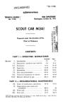
17. LUBRICATION GUIDE.
a. War Department Lubrication Guide No. SOI (figs. 13 and 14)
prescribes lubrication maintenance for the %-ton 4x4 truck.
b. A Lubrication Guide is placed on or is issued with each vehicle
and is to be carried with it at all times. In the event the vehicle is
received without a Guide, the using arm shall immediately requisi-
tion a replacement from the Commanding Officer, Fort Wayne Ord-
nance Depot, Detroit 32, Mich.
c. Lubrication instructions on the Guide are binding on all
echelons of maintenance and there shall be no deviations from these
instructions.
d. Service intervals specified on the Guide are for normal oper-
ation conditions. Reduce these intervals under extreme conditions
such as excessively high or low temperatures, prolonged periods of
high speed, continued operation in sand or dust, immersion in water,
or exposure to moisture, any one of which may quickly destroy the
protective qualities of the lubricant and require servicing in order
to prevent malfunctioning or damage to the materiel.
e. Lubricants are prescribed in the “Key” in accordance with
three temperature ranges; above +32°F, +32°F to 0°F, and below
0°F. Determine the time to change grades of lubricants by maintain-
ing a close check on operation of the vehicle during the approach to
change-over periods. Be particularly observant when starting the
engine. Sluggish starting is an indication of thickened lubricants and
the signal to change to grades prescribed for the next lower tempera-
ture range. Ordinarily it will be necessary to change grades of lubri-
cants only when air temperatures are consistently in the next higher
or lower range, unless malfunctioning occurs sooner due to lubricants
being too thin or too heavy. у
18. DETAILED LUBRICATION INSTRUCTIONS.
a. Lubrication Equipment. Each piece of materiel is supplied
with lubrication equipment adequate to maintain the materiel. Be
sure to clean this equipment both before and after use. Operate
lubricating guns carefully and in such manner as to insure a proper
distribution of the lubricant.
b. Points of Application.
(1) Red circles surrounding lubrication fittings, grease cups,
oilers and oil hales make them readily identifiable on the vehicle.
Wipe clean such lubricators and the surrounding surface before lubri-
cant is applied.
37
ы
«
0, flg. 18
A, flg. 17
A, flg. 19
C, flg. 18
B, flg. 17
C, flg. 17
GO
OE
OE
SA
CG
CG
OE
WB
OE
Universal Joint and Steering
CG
GO
Oil Filter -----------------
Drain (Nob 6)
Generator
)Early models) (Not* IS)
Crankcase (See Table)
Drain and refill (Note S)
Check level doily
Distributor Shaft—
Distributor — -
(Nolo 10)
Cranking Motor —
6 to В drops
Air Cleaner
Check level (Note 4)
Steering Gear --------
Lvbritaat <
CG
TRUCK, Уа TON, 4x4 (FORD-WILLYS)
5NL &-M3
Mo, 501
WAR DEPARTMENT О LUBRICATION GUIDE
ORDNANCE DEPARTMENT
О
а -«
u
ТАНЕ OF CAPACITIES AND LUBRICANTS TO BE USED
UNIT CAPACITY (Approt.| LOWEST EXPECTED AIR TEMPERATURE
+ 32* F. and above + 32’ F.toO’F. Below 0* F.
Сгапксам (Including Oil Filter} Sqt Ol SAE 30 Ol SAE 10 Refer to OFSB6-II
Trammitsien %Ч*- GO SAE 90 GO SAE 30 GO Grade 75
Transfer Сам U/2qt.
Differentials (each) |l/4ql
ПА11Т1ПМ LeWUote (Sotto* Arrow Potato —
UNWiivn both sims. Poteu — oppositu
Spring Shackle
Front Axle Differential
Drain «nd refill
Check level weekly (Nob 7)
Shock Absorbers
I Some models)
(Notts IS and 16)
' Tie Rod
Tie Rods (Inner)
Front Wheel Bearings
HftTE Kowrw sia* for
ItUIC— lobriMtlM of TtAttn
Serviced From Engine
Compartment
C, flg. 15
A, flg. 15
B, flg. 15
OE
OE
E, flg. 15
F, flg. 15
D, flg. 15
F, flg. 17
O~
so <
О <
О
</»
6
0
О
RA PD 305160
u
«
A, flg. 18
В, flg. 18
E, flg. 18
F, flg. 18
A, flg. 18
A, flg. 16
B, flg. 16
E, flg. 18
B, flg. 17
A, flg. 19
A, Яд. 17
D, flg. 18
Knuckle Bearings (н«ы)
HB
Brake Master Cylinder
CG
CG
CG
CG
CG
CG
CG
CG
IntervalB
GO
Labricants
bcopt сгапксам
CG
CH8K-CHAI1
CbMt Daily
Огмксме
tor Oleanr
0—01)1,
I— I.OOOallii
6—6,000 alias
₽S,.,w.n'F
GO—LUBRICANT.
ип>*«гм1
See Table
CG—GREASE, general
WE—GREASE, general
purpat*. Na. 2
NS—FLUID, brake, hydraulic
SA—FLUID, ihock-abterber,
tight
Rear Axle Differential GO
Drain end refill
Check lavalwaaHy (Noto 7)
- Spring Shackle CG
Transmission
Drain and rafiH
(Early WILLYS Modalt. right ride)
Check level weekly (Note 7)
Spring Bolt
— Rear Wheel Bearings WB
Figure 13—Lubrication Guide—Truck, 1/4-Ton, 4x4 (Ford-Willys)
' Drag Link
Steering Bellcrank
Universal Joint
(Mote?)
Spring Bolt
• Drag Link
Clutch and Brake Pedals
Shock Absorbers SA
(Soma modalt)
CG
GO
Universal and Slip Joints
(Hots?)
Trans. Case Shift Lever Shaft
Transfer Case----------------
Universal and Slip Joints
(Note?)
------KEY------------
B, flg. 19
E, flg. 16
F, flg. 16
D, flg. 16
C, flg. 16
E, flg. 16
F, flg. 16
LUBRICATION
NOTES Additional Lubrication ond Service Instructions on Individual Units and Ports NOTES
COLD WIATMER: F«r Lebrlcottoe end Service below O’F., refer to OFSI HI.
). FITTINGS—Clean before applying lubricant.
Lubricate until new lubricant is forced from
the bearing, unleu otherwise specified.
CAUTION: Lubricate chassis points after
washing truck and trailer.
2. INTERVALS indicated are for normal service.
For extreme conditions of speed, heat,
water, sand, mud, snow, rough roads, dust.
Мл dll I NOT TO BB BEMODUCED la wtaic part vlib-l
B"Ua WV I | act ponirim at the Oflct cd the Chid ef OrdMaet.l
etc., reduce interval by l/j or l/j, or more if
conditions warrant.
3. CLEANING —SOLVENT, dry cleaning, or
OIL, fuel, diesel, will be used to clean or
wash all parts. Use of gasoline for this
purpose is prohibited. Al) parts will be
thoroughly dry before relubrication.
4. AIR CLEANER—Daily, check level and re.
fill oil reservoir to bead level with used
crankcase oil or OE. Every 1,000 miles,
daily under extreme dust conditions, re>
move and wash eD parts. From O’F. to
— 40“F.. use SA. Below — 40eF., remove
oil and operate dry.
5. CRANKCASE—Drain only when engine is
2
RA PD 3O516OB
ы
SNL GW3.
OE
OE
OE
CG Spring Bolt
Hand Brake
Lever Shaft
Brake Bellcrank
Lever Shaft
Landing Gear Pivot
and Lock
CG Brake Cable
(Not. It)
Mo. 501
WAR DEPARTMENT Q LUBRICATION GUIDE
ORDNANCE DEPARTMENT
1/4-TON 4x4 TRUCK (WILLYS-OVERLAND MODEL MB
and FORD MODEL GPW)
RA PD 330851
Brake Cable
I Not* ll|
Wheel Bearings
Spring Shackle
TRAILER, l/4 TON. 2-WHEEL
NOTES Additional Labrlcatioa and Service Initrnctioni en Individual Units and Parts NOTES
COLO WIATHER: For LebriceHaa eed Service below 0*P4 refer to OFSI kl I.
hot. Refill to FULL mark on gage. Run en-
gine a few minute» and recneck oil level.
CAUTION: Be sure pressure gage indicates
oil is circulating.
6. OIL FILTER—Every 1,000 miles, drain sedi-
ment. Every 6,000 miles or more often if
filter becomes dogged, drain filter, dean
inside and renew element. Run engine a
few minutes, check crankcase level, add
OE to FULL mark on gage.
7. GEAR CASES—Weekly, check level with
truck on level ground and, if necessary, add
lubricant to plug level. Check only Before
operation while lubricant is cold. Drain and
refill at intervals indicated on guide. Drain
only after operation. On early WILLYS
models, skid plate must be removed to
reach drain plug.
B. UNIVERSAL JOINT AND STEERING
KNUCKLE BEARINGS—Every 1,000 miles.
remove plug at roar and add CG to level
ef filler plug hole. Every 6,000 miles, re-
move. dean, dry, inspect and refill to
plug level
9. UNIVERSAL JOINTS AND SUP JOINTS—
Apply CG to joints until it shows at joint
стой and to dip joint until rt shows at the
end of spline. Use hend gun only.
10. DISTRIBUTOR—Every bflOQ miles, wipe dis-
tributor breaker cam lightly with CG and
lubricate breaker arm pivot and wick under
rotor with I to 2 drops ef OE.
11. TRAILER BRAKE CABLES—Every 6,000
miles, slide cable conduit forward, dean
and coat with CG.
12. SPEEDOMETER CABLE—Every 6,000 miles,
remove core and coat lightly with CG No. 0.
13. RUBBER BUSHINGS —Every 1,000 miles,
apply HB to shock absorber linkage.
CAUTION: Do not use oil.
14. OIL CAN POINTS —Every 1,000 mile»,
lubricate ell carburetor, dutch, brake and
throttle linkage», pintle hook, handbrake
cable, trailer hendbraka connections and
linkage with OE.
15. POINTS REQUIRING NO LUBRICATION
SERVICE Clutch Release Bearing, Water
Pump, Fan, Shock Absorbers and Linkage
on aE FORD aed early WILLYS models,
Generator |)ate model»).
/6. POINTS TO BE SERVICED AND/OR
LUBRICATED BY ORDNANCE MAINTE-
NANCE PERSONNEL —Shock Absorbers
|)ate WILLYS). (Refer to TM.|
Copy of fhit Guide bill be carried on the
materiel at ail timet. These lubrication
instruction» are binding on all echelons of
maintenance.
Sy Order of the Secretary of War:
G. C. Manhall. Chief of Staff.
о
RegalslHeo reptocoaeet foMes frees tbe Ceaandlag Овеет. Port Weyee OrdMoce bepet, betrett, МкЫфва.
Alft Ч Л f f NOT TO «£ nenoouetn in *Wc w In pan «II»-1
"Va WW в I out perminion tl the QIStr rf iheCSkf ofOrdaanrt.J CHEK-CMACf
Figure И— Lubrication Guide—Trailer, 1/4-Ton, 2-wheel
ЯА PD 330851В
Ы
ТМ 9-803
18
1/4-TON 4x4 TRUCK (WILLYS-OVERLAND MODEL MB
and FORD MODEL GPW)
ENGINE CRANKCASE —OE
Oil level indicator in oil Aller pipe. Check level at leoit daily. Keep
oil up to FULL mark. Capacity Ave quarti, refill four quarts.
ENGINE CRANKCASE DRAINING —
Remove drain plug to drain. At leait once о year, remove the oil
pen and clean floating oil intake icreen.
Oil filter —oe
One Alter—Remove drain plug to drain. Ta replace element t
remove drain plug, filter cover then element. After completing
initollation run engine a few minutei and refill cronkcoie to FULL
mark on oil level indicator.__________________________
AIR CLEXNER —OE
One air cleaner. Clean cleaner and refill reservoir to indicated
level. Capacity И quart.
DISTRIBUTOR —OE
One diitributor. Total placet—four. Ute oil can for oiler and
lubricate iparingly wick and poit; greate com lightly.
CRANKING MOTOR —OE
Total oilen—one. Ute oil can, puth atide oil hole cover. Oil and
replace cover.
Figure 15—Engine Lubrication Points
42
RA PD 305166
ТМ 9-803
18
LUBRICATION
CLUTCH AND BRAKE PEDAL SHAFT—CO
One pedal shaft. Total fittings—two. Use pressure gun on fittings
until grease shows.
TRANSMISSION —OO
One transmission. Total plugs—two (filler and drain). Use gear oil
pump. Drain and refill to bottom of filler plug hole. Capacity
% quart.
TRANSFER CASE — OO
One transfer cose. Total plugs—two (filler and drain). Use gear
oil pump. Drain and refill to bottom of filler plug hole. Capacity
V/1 quarts.
TRANSFER CASE SHIFT LEVER SHAFT—CG
One shift lever shaft. Total fittings—one. Use pressure gun on
fitting until grease shows.
PROPELLER SHAFT UNIVERSAL JOINTS — CO
Four universal joint*. Total fittings—four. Use pressure gun (hand)
with adaptor. CAUTION-. Do not use high pressure grease gun
because of damage to seals.
PROPELLER SHAFT SLIP JOINT—CG
Two slip joints. Total fittings—two. Use pressure gun on fittings
until grease shows.
RA PD 305167
Figure 16—Pedal Shafts and Power Train Lubrication Points
43
ТМ 9-803
18
1/4-TON 4x4 TRUCK (WILLYS-OVERLAND MODEL MB
and FORD MODEL GPW)
WHEEL BEARINGS—WB
Four wheel». Total bearing»—eight. U»e bearing lubricator or hand
pock thoroughly. Apply grea»e ol»o around out»ide of cage and
roller*. Clean out wheefhub, in»pect bearing race», put three ounce»
of grea»e in each hub.
LINKAGE CLEVIS P|NS —OE
All clevit pin* and hood and wmdihield catches. U»e oil can and
apply in proper quantity.
Figure 17—Axle, Wheel, Pintle, and Steering Gear Housing
Lubrication Points
RA PD 305168
44
ТМ 9-803
18
LUBRICATION
E
SPRING BOLTS—CG
Four spring bolti. Total fittings—four. Use pressure gun on fittings
until grease shows.
TORQUE REACTION SPRING BOLT—CG
One ipring bolt. Total fittings—one (on vehicle! equipped with
this tprlng on the left front ipringl. Ute pressure gun on fitting
until grease shows.
RA PD 305169
Figure 18—Steering Gear and Spring Lubrication Points
45
ТМ 9-803
18
%-TON 4x4 TRUCK (WILLYS-OVERLAND MODEL MB
and FORD MODEL GPW)
Figure 19—Shock Absorber, Master Cylinder, and Battery
Lubrication Points
(2) Where relief valves are provided, apply new lubricant until
the old lubricant is forced from the vent. Exceptions are specified
in notes on the Lubrication Guide.
c. Cleaning. Use SOLVENT, dry-cleaning, or OIL, fuel, Diesel,
to clean or wash all parts. Use of gasoline for this purpose is pro-
hibited. After washing, dry all parts thoroughly before applying
lubricant.
d. Lubrication Notes on Individual Units and Parts. The fol-
lowing instructions supplement those notes on the Lubrication Guide
which pertain to lubrication and service of individual units and parts.
All note references in the Guide itself are to the paragraph below
having the corresponding number.
46
ТМ 9-803
18
LUBRICATION
(1) Fittings. Clean before applying lubricant. Lubricate until
new lubricant is forced from the bearing, unless otherwise specified.
CAUTION: Lubricate chassis points after washing truck and trailer.
(2) Intervals. Intervals indicated are for normal service. For
extreme conditions of speed, heat, water, sand, mud, snow, rough
ruads, dust, etc., reduce interval by one-third or one-half, or more
if conditions warrant.
(3) Cleaning. SOLVENT, dry-cleaning, or OIL, fuel, Diesel,
will be used to clean or wash all parts. Use of gasoline for this pur-
pose is prohibited. All parts will be thoroughly dry before relubri-
cation.
(4) Air Cleaner. Daily, check level and refill oil reservoir to
bead level with used crankcase oil or OIL, engine, SAE 30 above
+32 °F or SAE 10 from +32 °F to 0°F. Every 1,000 miles, daily
under extreme dust conditions, remove and wash all parts. From
0°F to — 40°F, use FLUID, shock-absorber, light. Below — 40°F,
remove oil and operate dry.
(5) Crankcase. Drain only when engine is hot. Refill to “FULL”
mark on gage. Run engine a few minutes and recheck oil level.
CAUTION: Be sure pressure gage indicates oil is circulating.
(6) Oil Filter. Every 1,000 miles, drain sediment. Every 6,000
miles or more often if filter becomes clogged, drain filter, clean inside
and renew element. Run engine a few minutes, check crankcase level,
add OIL, engine, to “FULL” mark on gage. (SAE 30 above +32°F;
SAE 10 from +32°F to 0°F; below 0°F, refer to OFSB 6-11.)
(7) Gear Cases. Weekly, check level with truck on level ground
and, if necessary, add lubricant to plug level. Check only before
operation while lubricant is cold. Drain and refill at intervals indi-
cated on Guide. Drain only after operation. On early Willys models,
skid plate must be removed to reach drain plug.
(8) Universal Joint and Steering Knuckle Bearings. Every
1,000 miles, remove plug at rear and add GREASE, general pur-
pose, No. 1 above +32 °F or No. 0 below +32 °F, to level of filler
plug hole. Every 6,000 miles, remove, clean, dry, inspect and refill to
plug level.
(a) Remove brake tube and brake backing plate screws. This
permits the removal of the axle spindle, the complete axle shaft, and
the universal joint assembly. Care should be taken not to injure the
outer oil seal assembly in the housing.
(b) Wash the axle shaft and universal joint thoroughly in SOL-
VENT, dry-cleaning, and dry.
(c) Clean and repack upper and lower steering spindle bearings
within the universal housing and reassemble entire unit.
(9) Universal Joints and Slip Joints. Apply GREASE, gen-
eral purpose, No. 1, above +32 °F, or No. 0 below +32 °F, to joints
until it shows at joint cross, and to slip joint until it shows at the
end of spline. Use hand gun only.
47
ТМ 9-803
18
'/«-TON 4x4 TRUCK (WILLYS-OVERLAND MODEL MB
and FORD MODEL GPW)
(10) Distributor. Every 6,000 miles, wipe distributor breaker
cam lightly with GREASE, general purpose, No. 1, above +32 °F or
No. 0, below +32 °F, and lubricate breaker arm pivot and wick under
rotor with 1 to 2 drops of OIL, engine, SAE 30 above +32°F; SAE
10 from +32°F to 0°F; OIL, lubricating, preservative, special, below
0°F.
(11) Trailer Brake Cables. Every 6,000 miles, slide cable con-
duit forward, clean and coat with GREASE, general purpose, No. 1
above +32 °F and No. 0 below +32 °F.
(12) Speedometer Cable. Every 6,000 miles, remove core and
coat lightly with GREASE, general purpose, No. 0.
(13) Rubber Bushings. Every 1,000 miles, apply FLUID, brake,
hydraulic, to shock absorber linkage. CAUTION: Do not use oil.
(14) Oilcan Points. Every 1,000 miles, lubricate all carburetor,
clutch, brake and throttle linkages, pintle hook and hand brake
cable with OIL, engine, SAE 30, above +32°F; SAE 10, +32°F to
0°F; OIL, lubricating, preservative, special, below 0°F.
(15) Points Requiring No Lubrication Service. These are the
clutch release bearing, water pump, fan, shock absorbers and linkage
on all Ford and early Willys models, generator (late models),
speedometer cable.
(16) Points to be Serviced and/or Lubricated by Ordnance
Maintenance Personnel Only. These are the shock absorbers
(late Willys). Every 6,000 miles, remove and disassemble the shock
absorbers. Unscrew linkage eye and refill with FLUID, shock-
absorber, light.
(17) Wheel Bearings. Remove bearing cone assemblies from
hub and wash spindle and inside of hub. Inspect bearing races and
replace if necessary. Wet the spindle and inside of hub and hub cap
with GREASE, general purpose, No. 2, to a maximum thickness of
У16 inch only to retard rust. Wash bearing cones and grease seals.
Inspect and replace if necessary. Lubricate bearings with GREASE,
general purpose, No. 2, with a packer or by hand, kneading lubricant
into all spaces in the bearing. Use extreme care to protect bearings
from dirt and immediately reassemble and replace wheel. The lubri-
cant in the bearings is sufficient to provide lubrication until the next
service period. Do not fill hub or hub cap. Any excess might result
in leakage into the brake drum.
e. Reports and Records. If lubrication instructions are closely
followed, proper lubricants used, and satisfactory results are not
obtained, make a report to the ordnance officer responsible for the
maintenance of the materiel. A complete record of lubrication servic-
ing may be kept in the Duty Roster (W.D., A.G.O Form No. 6).
f. Localized Views. The localized views of lubrication points
(figs. 15, 16, 17, 18, and 19) supplement the instructions on the Guide
and in the notes.
48
ТМ 9-803
19
Section VII
TOOLS AND EQUIPMENT STOWAGE ON THE VEHICLE
Paragraph
Vehicle tools ............................................... 19
Vehicle equipment ....................................... 20
Vehicle spare parts ................................... 21
19. VEHICLE TOOLS.
a. Unless the vehicle is equipped with extra tool equipment, the
following are supplied (one of each unless otherwise specified):
Tool Federal Stock No. Where Carried
Hammer, machinist’s, ball peen, 16 oz . . . : 41-H-523 Tool bag
Jack, screw type, 1%-ton, w/handle 41-J-66 Tool compartment
Pliers, combination, slip joint, 6-in 41-P-1650 Tool bag
Puller, wheel hub 41-P-2962-700 Tool compartment
Wrench, drain plug 41-W-1962-50 Tool bag
Wrench, engineer’s open-end, %- x 7/16-in 41-W-991 Tool bag
Wrench, engineer’s open-end, Уг- x i%2-in 41-W-1003 Tool bag
Wrench, engineer’s open-end, %6- x n/ie-in 41-W-1005-5 Tool bag
Wrench, engineer’s open-end, s/s- * 2%2'in 41-W-1008-10 Tool bag
Wrench, engineer’s open-end, %- x %-in 41-W-1012-5 Tool bag
Wrench, hydraulic brake, bleeder screw 41-W-1596-125 Tool bag
Wrench, adjustable, auto type, 11-in 41-W-449 Tool bag
Wrench, socket, screw fluted 41-W-2459-500 Tool bag
Wrench, socket, spark plug, w/handle 41-W-3335-50 Tool bag
Wrench, wheel bearing nut, 2%-in. hex 41-W-3825-200 Tool compartment
Wrench, wheel stud nut, 4%4-in. hex 41-W-3837-55 Tool compartment
49
ТМ 9-803
20-21
i/4-TON 4x4 TRUCK (WILLYS-OVERLAND MODEL MB
and FORD MODEL GPW)
20. VEHICLE EQUIPMENT.
a. Unless vehicle is equipped with special equipment, the follow-
ing are supplied (one of each unless otherwise specified):
Federal Whore
Tool Stock No. Carried
Adapter, lubr. gun Apparatus, decontaminating, Tool bag
Qt Driver’s compart- ment
Ax, chopping, single-bit 41-A-1277 Body left side
Bag, tool 41-B-15 Tool compartment
CATALOG, ord. std. nom. list. . SNL-G-503 Glove compart- ment
Chains, tire, 6.00 x 16 8-C-2358 Tool compartment
(4)
Container, 5-gallon . Bracket on rear
Cover, headlight Under right seat (2)
Cover, windshield Under right seat
Crank, starting Under rear seat
Extinguisher, fire 58-E-202 Inside cowl, left
Gage, tire pressure 8-G-615 Tool compartment
Gun, lubr., hand-type 41-G-1330-60 Tool compartment
Manual, technical TM 9-803 Glove compart- ment
Nozzle, flexible tube
Oiler, straight spout, %-pt. . 13-0-1530 Front of dash
Pump, tire, w/chuck 8-P-5000 Behind rear seat
Rifle On dash
Shovel, D-handle, rd. pt 41-S-3170 Body, left side
Tape, friction, roll 17-T-805 Parts bag
Wire, iron, roll 22-W-650 Parts bag
21. VEHICLE SPARE PARTS.
a. Unless the vehicle is equipped with a special assortment of
parts, the following are specified): supplied (one of Federal each unless otherwise Whore
Nami of Spare Part Stock No. Carried
Bag, spare parts .... 8-B-ll Glove compart- ment
Belt, fan .... 33-B-76 Parts bag
Caps, tire valve (boxed) . ... 8-C-650 Parts bag (5)
Cores, tire valve (boxed) ... 8-C-6750 Parts bag (5)
50
ТМ 9-803
21
TOOLS AND EQUIPMENT STOWAGE ON THE VEHICLE
Nam* of Spare Part Federal Stock No. Where Carried
Lamp, elec, incand. 6-8V sing- tung-fil., 3 cp (MZ63) 17-L-5215 Parts bag
Lamp-unit, blackout, stop, sealed, one opng., 6-8V, 3 cp 8-L-421 Parts bag
Lamp-unit, blackout, tail, sealed, 4 opngs., 6-8V, 3 cp 8-L-415 Parts bag
Lamp-unit, service tail and stop, sealed, 6-8V, 21-3 cp 8-L-419 Parts bag
Pin, cotter, split, s. type В boxed ass’t. 42-P-5347 Parts bag
Plug, spark, with gasket 17-P-5365 Parts bag
51
ТМ 9-803
22
1/4-TON 4x4 TRUCK (WILLYS-OVERLAND MODEL MB
and FORD MODEL GPW)
PART TWO
VEHICLE MAINTENANCE INSTRUCTIONS
Section VIII
RECORD OF MODIFICATIONS
Paragraph
MWO and major unit assembly replacement record.... 22
22. MWO AND MAJOR UNIT ASSEMBLY REPLACEMENT
RECORD.
a. Description. Every vehicle is supplied with a copy of A.G.O.
Form No. 478 which provides a means of keeping a record of each
MWO completed or major unit assembly replaced. This form in-
cludes spaces for the vehicle name and U.S.A, registration number,
instructions for use, and information pertinent to the work accom-
plished. It is very important that the form be used as directed, and
that it remain with the vehicle until the vehicle is removed from
service.
b. Instructions for Use. Personnel performing modifications or
major unit assembly replacements must record clearly on the form
a description of the work completed, and must initial the form in
the columns provided. When each modification is completed, record
the date, hours and/or mileage, and MWO number. When major
unit assemblies, such as engines, transmissions, transfer cases, are
replaced, record the date, hours and/or mileage, and nomenclature
of the unit assembly. Minor repairs and minor parts and accessory
replacements need not be recorded.
c. Early Modifications. Upon receipt by a third or fourth
echelon repair facility of a vehicle for modification or repair, main-
tenance personnel will record the MWO numbers of modifications
applied prior to the date of A.G.O. Form No. 478.
52
ТМ 9-803
23
Section IX
SECOND ECHELON PREVENTIVE MAINTENANCE
Paragraph
Second echelon preventive maintenance services.......... 23
23. SECOND ECHELON PREVENTIVE MAINTENANCE
SERVICES.
a. Regular scheduled maintenance inspections and services are
a preventive maintenance function of the using arms and are the
responsibility of commanders of operating organizations.
(1) Frequency. The frequency of the preventive maintenance
services outlined herein is considered a minimum requirement for
normal operation of vehicles. Under unusual operating conditions
such as extreme temperatures, and dusty or sandy terrain, it may be
necessary to perform certain maintenance services more frequently.
(2) First Echelon Participation. The drivers should ac-
company their vehicles and assist the mechanics while periodic sec-
ond echelon preventive maintenance services are performed. Ordi-
narily the driver should present the vehicle for a scheduled preven-
tive maintenance service in a reasonably clean condition: that is,
it should be dry and not caked with mud or grease to such an
extent that inspection and servicing will be seriously hampered;
however, the vehicle should not be washed or wiped thoroughly
clean, since certain types of defects, such as cracks, leaks, and loose
or shifted parts or assemblies are more evident if the surfaces are
slightly soiled or dusty.
(3) Instructions. If instructions other than those which are
contained in the general procedures in step (4), or in the specific
procedures in step (5) which follow, are required for the correct
performance of a preventive maintenance service or for correction
of a deficiency, other sections of the vehicle operators’ manual pertain-
ing to the item involved, or a designated individual in authority
should be consulted.
(4) General Procedures. These general procedures are basic
instructions which are to be followed when performing the services
on the items listed in the specific procedures. NOTE: The second
echelon personnel must be thoroughly trained in these procedures
so that they will apply them automatically.
(a) When new or overhauled subassemblies are installed to cor-
rect deficiencies, care should be taken to see that they are clean,
correctly installed, and properly lubricated and adjusted.
(b) When installing new lubricant retainer seals, a coating of
the lubricant should be wiped over the sealing surface of the lip of
the seal. When the new seal is a leather seal, it should be soaked
in engine oil SAE 10 (warm if practicable) for at least 30 minutes,
then, the leather lip should be worked carefully by hand before
installing the seal. The lip must not be scratched or marred.
(c) The general inspection of each item applies also to any sup-
porting member or connection, and usually includes a check to see
53
ТМ 9-803
23
%-TON 4x4 TRUCK (WILLYS-OVERLAND MODEL MB
and FORD MODEL GPW)
whether or not the item is in good condition, correctly assembled,
secure, or excessively worn. The mechanics must be thoroughly
trained in the following explanations of these terms.
1. The inspection for “good condition” is usually an external
visual inspection to determine if the unit is damaged beyond safe
or serviceable limits. The term “good condition” is explained further
by the following: not bent or twisted, not chafed or burned, not
broken or cracked, not bare or frayed, not dented or collapsed, not
torn or cut.
2. The inspection of a unit to see that it is “correctly assembled”
is usually an external visual inspection to see if it is in its normal
assembled position in the vehicle.
3. The inspection of a unit to determine if it is “secure” is usually
an external visual examination, a hand-feel, wrench, or a pry-bar
check for looseness. Such an inspection should include any brackets,
lock washers, lock nuts, locking wires, or cotter pins used in assembly.
4. “Excessively worn” will be understood to mean worn, close
to or beyond serviceable limits, and likely to result in a failure if
not replaced before the next scheduled inspection.
(d) Special Services. These are indicated by repeating the item
numbers in the columns which show the interval at which the serv-
ices are to be performed, and show that the parts or assemblies are
to receive certain mandatory services. For example, an item number
in one or both columns opposite a Tighten procedure means that the
actual tightening of the object must be performed. The special serv-
ices include:
1. Adjust. Make all necessary adjustments in accordance with
the pertinent section of the vehicle operator’s manual, special bul-
letins, or other current directives.
2. Clean. Clean units of the vehicle with dry-cleaning solvent
to remove excess lubricant, dirt, and other foreign material. After
the parts are cleaned, rinse them in clean fluid and dry them thor-
oughly. Take care to keep the parts clean until reassembled, and
be certain to keep cleaning fluid away from rubber or other mate-
rial which it will damage. Clean the protective grease coating from
new parts, since this material is not a good lubricant.
3. Special lubrication. This applies both to lubrication oper-
ations that do not appear on the vehicle Lubrication Guide and to
items that do appear on such charts, but which should be performed
in connection with the maintenance operations if parts have to be
disassembled for inspection or service.
4. Serve. This usually consists of performing special operations,
such as replenishing battery water, draining and refilling units with
oil, and changing the oil filter cartridge.
5. Tighten. All tightening operations should be performed with
sufficient wrench-torque (force on the wrench handle) to tighten
the unit according to good mechanical practice. Use torque-indicating
wrench where specified. Do not overtighten, as this may strip
54
ТМ 9-803
23
SECOND ECHELON PREVENTIVE MAINTENANCE
threads or cause distortion. Tightening will always be understood
to include the correct installation of lock washers, lock nuts, and
cotter pins provided to secure the tightening.
(e) Conditions. When conditions make it difficult to perform
the complete preventive maintenance procedures at one time, they
can sometimes be handled in sections, planning to complete all oper-
ations within the week, if possible. All available time at halts and
in bivouac areas must be utilized, if necessary, to assure that main-
tenance operations are completed. When limited by the tactical
situation, items with special services in the columns should be given
first consideration.
(f) The numbers of the preventive maintenance procedures that
follow are identical with those outlined on W.D., A.G.O. Form No.
461, which is the Preventive Maintenance Service Work Sheet for
Wheeled and Half-track Vehicles. Certain items on the work sheet
that do not apply to this vehicle are not included in the procedures
in this manual. In general, the numerical sequence of items on the
work sheet is followed in the manual procedures, but in some in-
stances there is deviation for conservation of the mechanic’s time
and effort.
(5) Specific Procedures. The procedures for performing each
item in the 1,000-mile (monthly) and 6,000-mile (б-month) main-
tenance procedures are described in the following chart. Each page
of the chart has two columns at the left edge corresponding to the
6,000-mile and the 1,000-mile maintenance respectively. Very often
it will be found that a particular procedure does not apply to both
scheduled maintenances. In order to determine which procedure to
follow, look down the column corresponding to the maintenance
due, and wherever an item appears, perform the operations indi-
cated opposite the number.
ROAD TEST
NOTE: When the tactical situation does not permit a
full road test, perform those items which require little
or no movement of the vehicle, namely, items 3, 4, 5,
6, 9, 10, and 14. Make a full road test of 5, but not
more than 10 miles, over varied terrain if possible.
Before-operation Service. Perform Before-operation
Service as outlined in paragraph 13.
Dash Instruments and Gages. Observe instruments
frequently during road test.
Ammeter. Ammeter should show high charge for short
time after starting, then zero or slight positive (plus)
reading above speeds of 12 to 15 miles per hour with
lights and accessories off. Zero reading is normal with
lights and accessories on.
Speedometer. See that speedometer indicates vehicle
speed, operates without excessive fluctuation or noise,
and that odometer registers accumulating trip and total
mileage correctly.
MAINTENANCE
Illi Mito Illi Mils
1 3 1 3
55
ТМ 9-803
23
1/4-TON 4x4 TRUCK (WILLYS-OVERLAND MODEL MB
and FORD MODEL GPW)
MAINTENANCE
6101 Mlle 1000 Mlh
4 5 6 7 8 9 10 13 4 5 6 7 8 9 10 13
Temperature Indicator. Temperature indicator
should gradually increase to normal operating range
of 160°F to 180°F.
Fuel Gage. Fuel gage must indicate the approximate
amount of fuel in tank.
Horn, tylirror, and Windshield Wiper. Test horn for
proper operation and tone, tactical situation permitting.
Adjust mirror, and inspect for broken or discolored
glass. Wiper should have sufficient arm tension to stay
in “UP” position. Examine blade for good condition
and full contact with glass throughout entire stroke.
Brakes. Test brakes for smooth, even stop, excessive
pedal travel before application, “spongy” pedal, or loss
of pedal pressure when brakes are held on. Brakes must
not squeak or require excessive pedal pressure. Test
pedal free travel, which should be % inch. Hand brake
must hold vehicle on a reasonable grade, must have
positive ratchet action and 1/з reserve handle travel.
There should be %-inch reserve clearance between
hand brake relay crank and lower end of hand brake
cable conduit.
Clutch. Clutch must have free pedal travel of three-
quarter inch. Test clutch for slip, grab, gear clash, or
rattle. Listen for noises that would indicate dry or
defective release bearing or pilot bushing.
Transmission and Transfer Case. Shift through en-
tire range of transmission and transfer, noting whether
the levers move easily and snap into each position.
With shifting levers in each position, accelerate and
decelerate engine, noting any unusual noises or
tendency of levers to slip into neutral. Inspect for loose
mountings.
Steering. Steering gear must not bind. There should
be no excessive free play with wheels in straightahead
position. Test for existence of front-end shimmy, wan-
der, or side pull.
Engine. Engine must idle smoothly without stalling.
Test acceleration and pulling power in each transmis-
sion speed. Listen for detonation and “ping,” misses,
popping, spitting, or other noises that might indicate
need for engine repair.
Unusual Noises. Listen for noises that might indicate
loose, damaged, or faulty parts.
Temperatures. Feel brake drums and wheel hubs for
abnormally high temperatures. Overheated brake drum
or wheel hub may indicate dragging brake or defective,
dry, or improperly adjusted wheel bearing. Examine
56
ТМ 9-803
23
SECOND ECHELON PREVENTIVE MAINTENANCE
MAINTENANCE
6111 Mils 1111 Mils
14 14
16 16
17 17
22 22
22 22
18 18
differentials, transmission, and transfer case for too-
high running temperature. NOTE: Transfer case oper-
ates at a higher temperature than other cases.
Leaks. Look on ground under vehicle for indications
of coolant, fuel, oil, or hydraulic fluid leaks.
Gear Oil Level and Leaks. Examine lubricant levels
of transmission, transfer case, and differentials. Inspect
cases for leaks. Safe level when cold is even with filler
plug. If an oil change is due, drain and refill, according
to Lubrication Guide (par. 18). Capacities: transmis-
sion, 54 quart; transfer case, 1% quarts; front differen-
tial, 1% quarts; rear differential, 1% quarts.
MAINTENANCE OPERATIONS
Unusual Noises. With engine running, proceed as
follows: Accelerate and decelerate engine slightly, and
listen for unusual engine noises. With transmission in
third gear, front wheel drive engaged, and engine at
fast idle, listen for unusual noises in operating units.
Observe propeller shaft and universal joints, wheels,
and axles for excessive vibration and run-out.
Battery. Inspect battery case for cracks and leaks.
Inspect cables, terminals, bolts, posts, straps, and hold-
downs for good condition and secure mounting. Clean
top of battery. Test specific gravity and voltage, and
record on W.D., A.G.O. Form No. 461. Specific gravity
readings below 1.225 indicate battery should be re-
charged or replaced. Electrolyte level should be above
top of plates, and may extend % inch above plates.
Serve. Perform high-rate discharge test according to
instructions for “condition” test which accompany test
instrument, and record voltage on W.D., A.G.O. Form
No. 461. Cell variation should not be more than 30
percent. NOTE: Specific gravity must be above 1.225
to make this test.
Clean. Clean entire battery and carrier, and repaint
carrier if corroded. Clean battery cable terminals,
terminal bolts and nuts, and battery posts; grease
lightly; inspect bolts for serviceability. Tighten termi-
nals and hold-downs carefully to avoid damage to
battery. Add clean water to y2 inch above plates.
Cylinder Head and Gasket. Look for cracks, and in-
dications of water or compression leaks. Tighten cyl-
inder head (only if leaks are indicated and after per-
forming item 21) with torque wrench; tighten head-
screws to from 65 to 75 foot-pounds; head stud nuts
57
ТМ 9-803
23
MAINTENANCE
6000 Mito 1000 Mito
19 20 21 23 23 24 24 25 19 20 21 23 24 25
Vi-TON 4x4 TRUCK (WILLYS-OVERLAND MODEL MB
and FORD MODEL GPW)
to from 60 to 65 foot-pounds. Tighten in correct order
(fig. 25). Be sure cylinder head to dash bond strap is
in good condition and securely connected.
Valve Mechanism. Adjust valves only if noisy.
Adjust. Check clearance and adjust valves. Proper
clearances are: intake valve, 0.014 inch 'when hot or
cold; exhaust valve, 0.014 inch when hot or cold.
Spark Plugs. Wipe off plugs without removing; inspect
for insulator cracks and leakage through insulators and
gaskets. Service if required.
Serve. Clean and adjust plugs to gap of 0.030 inch,
using round gage. Plugs with broken insulators, exces-
sive carbon deposits, electrodes burned thin or other-
wise unserviceable, must be replaced. Correct plug
(AN-7). NOTE: If sand blast cleaner is not available
install new or reconditioned plugs.
Compression. Test compression with all plugs re-
moved, and ’with throttle and choke wide open. Stand-
ard pressure is approximately 110 pounds at cranking
speed; minimum pressure is 70 pounds. Maximum
variation between cylinders must not be more than 10
pounds. If variation is greater than 10 pounds, recheck
weak cylinders, using oil test, and report to higher
authority. Record all readings.
Crankcase. Observe vehicle for crankcase, valve cover,
timing case, or flywheel housing oil leaks. Check oil
level. Drain and refill crankcase if change is due. See
Lubrication Guide (par. 18).
CAUTION: Do not start engine until completion of
item 24:
Oil Filters and Lines. Inspect filters, lines, and con-
nections for good condition or leaks.
Serve: Remove filter cartridge, clean filter case and
install new cartridge and gaskets. Refill crankcase (5
quarts with new filter cartridge). Again inspect for
leaks with engine running and check oil level after
engine is stopped.
Radiator. Observe radiator core, hose, cap and gaskets
for good condition and .inspect for leaks. CAUTION:
System operates under 3% to 4% pounds pressure (be
careful in removing cap). Examine air passages and
guards for obstructions and clean out any dirt, insects,
or trash. Test and record antifreeze value (as climate
demands). Examine coolant for oil, rust, or foreign
58
ТМ 9-803
23
SECOND ECHELON PREVENTIVE MAINTENANCE
MAINTENANCE
1101
Milt
25
26
27
27
29
mu
Mils
26
27
29
31 31
31
32 32
material. Clean and flush radiator as needed. CAU-
TION: Save and filter coolant if antifreeze is present.
Add inhibitor and antifreeze if needed.
Tighten. Tighten hose clamps. Inspect radiator cap
and gasket for tight seal.
Water Pump and Fan. Loosen fan belt; test water
pump shaft and bearing for play. Inspect pump for
secure attachment, good condition, and for leaks. In-
spect fan for alinement and secure mounting.
Generator, Cranking Motor, and Switch. Inspect
these units to see if they are in good condition, clean
and securely connected or mounted; particularly radio
noise suppression capacitor on generator and starting
switch terminal, and bond straps from generator and
cranking motor.
Serve. Inspect commutators and brushes for good con-
dition and wear. Brushes should be free in holders, and
have full contact with commutator. Clean commuta-
tors with 2/0 flint paper if needed. Blow out with com-
pressed air. Replace generator or cranking motor when
commutator is scored, rough, worn, or brushes are less
than half their original length.
Drive Belt and Pulleys. Inspect fan belt for fraying,
wear, and deterioration. Inspect pulleys for cracks and
misalinement. Replace or adjust belt as needed. Adjust
to deflection of 1 inch between pulleys.
Distributor. Clean and remove distributor cap. Exam-
ine cap and rotor arm for cracks, corrosion and burned
conductors. Clean breaker plate assembly, if dirty. In-
spect breaker points for burning, pitting, alinement, and
adjustment. Replace and aline burned or badly pitted
points. Feel to determine excessive distributor shaft
play. Turn distributor shaft (with rotor), and release to
test centrifugal advance for binding.
Special Lubrication. Sparingly lubricate cam sur-
faces, movable breaker arm pin, wick and camshaft
according to Lubrication Guide (par. 18). Adjust breaker
point gap to 0.020 inch.
Coil and Wiring. Examine coil, high tension, and ex-
posed low voltage wiring for cleanliness, and secure
connections and attachment. Clean and tighten as re-
quired. Pay particular attention to see that spark plug
59
ТМ 9-803
23
•/«-TON 4x4 TRUCK (WILLYS-OVERLAND MODEL MB
and FORD MODEL GPW)
MAINTENANCE and coil to distributor wire, radio noise suppressors, and
HOI Illi coil terminal capacitor are in good condition, and
Mill Mlh securely mounted or connected.
33 33 Manifolds and Heat Control. Tighten manifold stud nuts as required to from 31 to 35 foot-pounds. Inspect for gasket leaks. Heat control valve must be free and bimetal spring must be in good condition.
34 34 Air Cleaner. Examine air cleaner for good condition and secure mounting. Examine oil cup. If dirty, remove and clean filter element; do not apply oil to element after cleaning. Clean oil cup and refill (54 qt).
36 36 Carburetor. Make certain that the choke and throttle open and close fully. Lubricate linkage, and inspect for
worn parts.
37 37 Fuel Filter, Screens, and Lines. Clean fuel pump screen, renew gaskets, inspect unit for leaks. Remove disk filter element from fuel filter mounted on dash; clean element and bowl. Reinstall with new gasket.
Inspect for leaks after unit has been refilled.
38 38 Fuel Pump. Observe fuel pump for leaks, secure mounting, and pressure reading. Pressure should be 1% to 2% pounds with engine running at approximately 30 miles per hour vehicle road speed.
39 39 Cranking Motor. Start engine and observe cranking motor for positive action, normal speed, and unusual noise. Make sure oil pressure gage and ammeter read- ings are satisfactory.
40 40 Leaks. Look around engine and on ground under engine for oil, fuel, coolant, or hydraulic fluid leaks.
41 41 Ignition Timing. With neon light, check ignition tim- ing. Observe if spark advances automatically. Adjust timing as required (par. 65). CAUTION: Close timing hole cover and tighten screw.
42 42 Engine Idle and Vacuum Test. Adjust engine to smooth idle, using vacuum gage; obtain highest possible steady vacuum reading.
43 Regulator Unit. See that regulator and radio noise capacitors are in good condition, and that all connec- tions and mounting are secure.
43 Test. Connect low voltage circuit tester and test voltage regulator, current regulator, and cut-out for output control.
47 47 Tires and Rims. Inspect valve stems for correct posi- tion and missing caps. Inspect tires for cuts, bruises, blisters, irregular and excessive tread wear. Remove im- bedded glass, nails, or stones. Directional and non-
60
ТМ 9-803
23
MAINTENANCE
ton
Mlh
48
49
49
52
53
53
54
1100
Mlh
48
49
52
53
SECOND ECHELON PREVENTIVE MAINTENANCE
directional tires should not be installed on same vehicle.
If equipped with directional tires, open end of chevron
should meet ground first on front tires, and last on rear
tires. Tires should match on all wheels within |^-inch
over-all circumference, and as to type of tread. Take
measurements with all tires equally inflated. Inspect
tire carrier for looseness and damage. Tighten all lug
nuts securely. Inflate tires to 35 pounds (cold)’.
Rear Brakes. Remove grease and dirt from brake
drums and backing plates, and inspect for excessive
wear or scoring and loose mounting bolts. Inspect brake
hose for proper fit and for deterioration. Inspect wheel
cylinders (exterior) for good condition, secure mount-
ing, and for leaks. Tighten brake support and drum
mounting bolts securely.
Rear Brake Shoes. Remove right rear wheel and in-
spect linings for wear, oil, and dirt, and possibility of
rivets scoring drum before next 1,000-mile inspection.
If lining on right rear wheel requires replacement, re-
move all wheels for lining inspection.
SERVE. Remove all wheels and drums. Observe linings
for wear, oil, and dirt, and determine if shoes are secure
and guided by anchor pins. Inspect return springs for
good action. Lightly lubricate anchor pins. Adjust brake
shoes to 0.005 inch at heel, and 0.008 inch at toe.
Rear Wheels. Inspect wheel for good condition and,
without removal, test for evidence of looseness of wheel
bearing adjustment, and dry or damaged bearings. In-
spect around drive flanges, brake supports, and drums
for lubricant or brake fluid leaks. Tighten drive flange
and wheel nuts. CAUTION: If it is known that vehicle
has operated in deep water which may have entered
wheel bearings, inspect right wheel bearing for con-
tamination. Remove, clean, repack, and adjust as for
6,000-mile service. If contamination of lubricant has
occurred, service other wheel bearings likewise.
Clean. Disassemble wheel bearings and seals, clean,
and inspect for damage.
Special Lubrication. Pack wheel bearings, install new
seals, and adjust bearings.
Front Brakes. Examine brake hose for chafing, leakage,
and deterioration. Inspect wheel cylinders (exterior) for
good condition, secure mounting, and leaks.
Drums and Supports. Clean drums and backing plates
thoroughly, and tighten backing plate bolts. Inspect
drums for damage, looseness, excessive wear, and scor-
ing. Lightly lubricate anchor pins.
Front Brake Shoes. Inspect brake shoes, linings, and
anchors for damage or looseness. Replace worn parts
61
ТМ 9-803
23
MAINTENANCE
6011 Mile 1000 Mile
55 55
56 56
57 57
57
58 58
60 60
60
61 61
62 62
62
63 63
i/4-TON 4x4 TRUCK (WILLYS-OVERLAND MODEL MB
and FORD MODEL GPW)
and worn linings. Clean dust from linings. Adjust brake
shoes to 0.005-inch clearance at heel, and 0.008-inch
clearance at toe.
Steering Knuckles. Inspect steering knuckle housings
and oil seals for serviceable condition. Check lubricant
for contamination. Refill to bottom of filler hole.
Front Springs. Inspect front springs for good condi-
tion, correct alinement, and excessive deflection. Inspect
springs for excessive wear of spring bushing and clips.
Tighten U-bolts securely and uniformly. Examine U-
shackles and pivot bolts for wear.
Steering. Observe steering gear, Pitman arm, drag link,
tie rod, and steering connecting rods for good condition,
correct assembly, and secure mounting.
Tighten. Tighten and adjust assembly mounting nuts
and screws, arms, tie rods, drag link, Pitman arm, and
gear, and steering wheel nuts. Replace broken seals or
worn parts.
Front Shock Absorbers. Inspect shock absorbers to
see if they are in good condition and secure, if bodies
are leaking fluid, and if rubber bushings have deterior-
ated. If rubber bushings are hard or cracked, apply a
film of brake fluid. NOTE: If fluid is leaking or bodies
are defective, shock absorber must be replaced.
Front Wheels. Inspect for good condition, security, end
play, and lubricant leaks. Rotate wheels and observe
for loose, broken, or dry bearings.
Clean and Lubricate. Remove, clean, inspect, lubri-
cate, and replace bearings. Adjust bearings and test for
wheel shake before removing jack.
Front Axle. Examine front axle housing for good con-
dition and lubricant leaks. Inspect pinion shaft for end
play and grease leaks. Inspect axle for apparent aline-
ment, and see that vent is open.
Front Propeller Shaft. Inspect propeller shaft for
damage and incorrect assembly, excessive wear, and
lubricant z leaks. Inspect universal and slip joints for
alinement, wear, and leakage.
Tighten. Tighten flange yoke bolts.
Engine Mountings and Braces. See that engine mount-
ings and bond straps are in good condition and secure,
and that rubber mountings are not separated from metal
backing. Tighten front mountings if loose. Adjust rear
62
ТМ 9-803
23
SECOND ECHELON PREVENTIVE MAINTENANCE
MAINTENANCE
6010 1011
Mill Mila
64 64
64
65 65
65
66 66
66
67 67
71 71
71
72 72
72
73 73
mounting bolts to from 38 to 42 foot-pounds with torque
wrench. Tighten radio noise suppression bond strap
mountings securely.
Parking (Hand) Brake. See that drum is not scored
or oily; that lining is not oil-soaked nor worn thin. In-
spect ratchet for positive holding action. Lubricate
upper end of conduit tube at cable with engine oil.
Adjust. Adjust clearance between drum and lining to
from 0.005 inch to 0.010 inch. Reserve lever travel should
be one-third the ratchet range. There must be %-inch
reserve clearance (on cable) between relay crank and
lower end of hand brake conduit.
Clutch Pedal. Clutch pedal linkage must be secure and
not worn; return spring must be operative; clutch
should have free pedal travel of % inch.
Adjust. Adjust clutch pedal free travel to % inch.
Brake Pedal. Test brake pedal operation; brake linkage
must be secure and not worn excessively; return spring
must be operative; brake should have Ц reserve travel.
Adjust. Adjust brake pedal free travel to /г inch.
Brake Master Cylinder. Inspect master cylinder for
good condition and secure mounting; check master
cylinder boot for good condition and correct installa-
tion; inspect stop light switch for terminal attachment
and correct operation. Look for brake fluid leaks; clean
out filler plug vent. Fill master cylinder reservoir to %
inch below plug.
Transmission. Inspect oil seals and gaskets for leak-
age. Test control for looseness, excessive wear, and
improper operation. Inspect mounting and assembly
bolts and cap screws for looseness.
Tighten. Tighten mounting and assembly bolts and
cap screws.
Transfer Case. Inspect oil seals and gaskets for leak-
age. Test controls for looseness, excessive wear, and
improper operation. Inspect mounting and assembly
bolts and cap screws for looseness. Clean vent.
Tighten. Tighten mounting and assembly bolts, nuts,
and cap screws.
Rear Propeller Shaft. Remove any trash that may be
wrapped around shaft or universal joints. Inspect
63
ТМ 9-803
23
1/4-TON 4x4 TRUCK (WILLYS-OVERLAND MODEL MB
and FORD MODEL GPW)
MAINTENANCE
6000 Mito 1000 Mill
73 75 77 78 80 81 82 82 83 84 85 86 75 77 78 80 81 82 83 84 85 86
mounting of universal and slip joints for misalinement,
wear, and grease leaks.
Tighten. Tighten flange yoke cap screws.
Rear Axle. Inspect rear axle housing for leaks; feel for
excessive play in pinion shaft; clean vent. Make sure
differential carrier mounting cap screws are tight.
Rear Springs. Check springs for shifted leaves due to
broken center bolt, loose spring clips, or U-bolts. If
found loose, tighten U-bolts to from 50 to 55 foot-
pounds. Tighten spring pivot bolt nut to from 29 to 30
foot-pounds.
Rear Shock Absorbers. Inspect in the same manner as
for item 58.
Frame. Examine frame for loose side rails and cross
members. Tighten loose bolts. If frame appears to be
bent, or out of alinement, report condition to higher
authority.
Wiring, Conduits and Grommets. Inspect all wiring
for looseness and broken insulation; check conduits and
grommets for proper position and good condition.
Fuel Tank and Lines. Inspect tank and lines for good
condition, secure mounting, and leaks; check cap for
defective gasket or clogged vent.
Serve. Remove fuel tank drain plug briefly, and drain
off accumulated water and sediment.
Brake Lines and Connections. Inspect brake lines for
proper mounting, cracks, worn spots in lines, leaks,
deteriorated or damaged hose and connections.
Exhaust Pipe and Muffler. Inspect exhaust pipe and
muffler for secure mounting, rusted condition, damage
or leaks. Inspect tail pipe for stoppage.
Vehicle Lubrication. Lubricate according to Lubri-
cation Guide (par. 18) in this manual. Observe latest
issued lubrication directives.
LOWER VEHICLE TO GROUND
Toe-in and Turning Stops. With front wheels on
ground, straight-ahead position, use wheel alining gage,
and check toe-in. Normal toe-in range is %4-inch to
%2-inch- Turn front wheels fully in both right and left
64
ТМ 9-803
23
SECOND ECHELON PREVENTIVE MAINTENANCE
MAINTENANCE
Illi Mils Ш1 Mill
91 91
91
92 92
93 93
94 94
95 95
96 96
98 98
101 101
directions, and determine if turning stops hold tires
clear of all parts of vehicle in these positions. Examine
axle for loose turn stops.
Lights. Determine that switches for head, tail, instru-
ment, and blackout lights operate properly. Operate
stop light by depressing brake pedal. Test foot switch,
noting whether beam is controlled for high and low
positions. Inspect all lights; these must be clean,
securely mounted, and in good condition; lenses must
not be broken, cracked, or discolored; reflectors must
not be discolored; blackout lights must be in good con-
dition with shield in proper position.
Adjust. Adjust and aim headlight beams.
Safety Reflectors. Safety reflectors must be present,
clean, and secure. Replace if cracked or broken.
Front Bumper and Grille. Front bumper and grille
must be present, in good condition, and securely
mounted.
Hood, Hinges and Fasteners. Examine hood for aline-
ment and secure mounting when fastened; see that.
fasteners are present, secure, undamaged, artd not ex-
cessively worn or bent. Lubricate hinges and fasteners
lightly. See that radio noise bond straps from hood to
dash and grille are secure.
Front Fenders. Inspect front fenders for good condi-
tion and secure mounting.
Body Hardware. Inspect body of vehicle according to
following standards: Hardware should operate properly
and be adequately lubricated; top should be clean, hav-
ing no holes or tears, and all grommets must be present
and in good condition. Windshield should be free from
cracks or discoloration; windshield frame and hold-
down hooks at hood should be in good condition. Seats
and upholstery should be clean and undamaged; safety
straps should be present and in place; body handles
should be present, secure, and undamaged; floor drain
plugs (2) should be present, and in good condition.
Circuit Breaker, Terminal Blocks, or Boxes. Inspect
points of thermal circuit breaker (30 amperes, located
on main light switch) for pitting or corrosion. Be sure
all radio noise suppression bond straps and capacitor on
radio terminal box (if so equipped) are in good condi-
tion and secure.
Rear Bumpers and Pintle Hook. Latch and Lock Pin.
Inspect rear bumpers and pintle hook to see if they are
65
ТМ 9-803
23
'/«-TON 4x4 TRUCK (WILLYS-OVERLAND MODEL MB
and FORD MODEL GPW)
MAINTENANCE
6160 Mito 1110 Mlh
103 104 105 131 132 133 143 135 103 104 105 131 132 133 143 135
present, in good condition, and secure. Pintle hook
safety latch should be free, and lock securely.
Paint and Markings. Inspect paint of entire vehicle for
good condition and bright spots that might cause glare
or reflection. Vehicle markings and identification must
be legible. Inspect identification plates and their mount-
ings (if furnished) for good condition, secure mounting,
and legibility.
Radio Bonding (Suppressors, Filters, Condensers,
and Shielding). See that all units not covered in the
foregoing specific procedures are in good condition, and
securely mounted and connected. Be sure all additional
noise suppression bond straps and toothed lock washers
listed in paragraph 177, are inspected for looseness or
damage, and see that contact surfaces are clean. NOTE:
If objectionable radio noise from vehicle has been re-
ported, make tests in accordance with paragraph 178. If
cleaning and tightening of mountings and connections,
and replacement of defective radio noise suppression
units does not eliminate the trouble, the radio operator
will report the condition to the designated individual in
authority.
Armament. Examine gun mounts and covers (if pres-
ent) for good condition, cleanliness, and secure attach-
ment. NOTE: Guns, parts, and covers are to be referred
to armorer or gun commanders for all inspections or
service.
TOOLS AND EQUIPMENT
Tools and Equipment. Standard vehicle tools, Pioneer
tools, and equipment must be present, clean, serviceable,
and securely mounted. Sharpen cutting tools and darken
bright parts of exposed tools in combat areas.. Check
against stowage list (par. 19).
Fire Extinguisher. Inspect fire extinguisher for full
charge and secure mounting. See that nozzle is clean.
Decontaminator. Inspect decontaminator for damage,
secure mounting, and full charge. Make latter check by
removing filler plug. Drain and refill with fresh solution
every 90 days. See date of last filling on attached tag.
First Aid Kit. Examine contents of first aid kit for good
condition, completeness, and satisfactory packing. Re-
port any deficiency.
Publications and Form No. 26. See that the vehicle
manuals and Lubrication Guide, Form No. 26 (Acci-
66
MAINTENANCE
Illi Mito 1011 Mils
136 136
139 139
140 140
141 141
142 142
ТМ 9-803
23
SECOND ECHELON PREVENTIVE MAINTENANCE
dent Report) and W.D., A.G.O. Form No. 478 (MWO
and Major Unit Assembly Replacement Record), are
present, legible, and properly stowed.
Traction Devices. Inspect tire chains for broken or
worn links, missing cross chains, or damaged fasteners.
Fuel Can and Bracket. Inspect fuel can and bracket
for damage, leaks, loose mounting, and presence of cap
on chain.
Fuel Can Nozzle and Bucket. See that fuel can nozzle
and bucket are not damaged, are clean, and properly
stowed.
Modifications (Completed). Inspect entire vehicle to
be sure all Modification Work Orders have been com-
pleted, and enter any modifications or major unit re-
placements made at time of this service, on Form No.
478.
Final Road Test. Road test, rechecking. items 2 to 16.
Recheck transmission, transfer case, and differentials
for lubricant level and for leaks. Confine this test to
minimum distance necessary to satisfactory observa-
tions. NOTE: Correct or report all defects found during
final road test to higher authority.
Ь7
ТМ 9-803
24-26
i/4-TON 4x4 TRUCK (WILLYS-OVERLAND MODEL MB
and FORD MODEL GPW)
Section X
NEW VEHICLE RUN-IN TEST
Paragraph
Purpose .......................................................... 24
Correction of deficiencies....................................... 25
Run-in test procedures............................................ 26
24. PURPOSE.
a. When a new or reconditioned vehicle is first received at the
using organization, it is necessary for second echelon personnel to
determine whether or not the vehicle will operate satisfactorily when
placed in service. For this purpose, inspect all accessories, subassem-
blies, assemblies, tools, and equipment to see that they are in place
and correctly adjusted. In addition, they will perform a run-in test of
at least 50 miles as directed in AR 850-15, paragraph 25, table III,
according to procedures in paragraph 26 below.
25. CORRECTION OF DEFICIENCIES.
r
a. Deficiencies disclosed during the course of the run-in test will
be treated as follows:
(1) Correct any deficiencies within the scope of the maintenance
echelon of the using organization before the vehicle is placed in
service.
(2) Refer deficiencies beyond the scope of the maintenance
echelon of the using organization to a higher echelon for correction.
(3) Bring deficiencies of serious nature to the attention of the
supplying organization.
26. RUN-IN TEST PROCEDURES.
a. Preliminary Service.
(1) Fire Extinguisher. See that portable extinguisher is present
and in good condition. Test it momentarily for proper operation, and
mount it securely.
(2) Fuel, Oil, and Water. Fill fuel tank. Check crankcase oil
and coolant supply; add oil and coolant as necessary to bring to
correct levels. Allow room for expansion in fuel tank and radiator.
During freezing weather, test value of antifreeze, and add as neces-
sary to protect cooling system against freezing. CAUTION: If there
is a tag attached to filler cap or steering wheel concerning engine oil
in crankcase, follow instructions on tag before driving the vehicle.
(3) Fuel Filter. Inspect main fuel filter for leaks, damage, and
secure mountings and connections. Drain sediment bowl. Clean fuel
pump filter screen and bowl. If any appreciable amount of dirt or
water is present, remove main filter bowl and clean bowl and element
68
ТМ 9-803
26
NEW VEHICLE RUN-IN TEST
in dry-cleaning solvent. Also, drain accumulated dirt and water from
bottom of fuel tank. Drain only until fuel runs clean.
(4) Battery. Make hydrometer and voltage test of battery, and
add clean water to bring electrolyte % inch above plate.
(5) Air Cleaner. Examine carburetor air cleaner to see if it is in
good condition and secure. Remove element and wash thoroughly in
dry-cleaning solvent. Fill oil cup to indicated level with fresh oil,
and reinstall securely. Be sure oil cup and body gaskets are in good
condition, and that air horn connection is tight.
(6) Accessories and Belt. See that accessories such as carbu-
retor, generator, regulator, cranking motor, distributor, water pump,
fan, and oil filter, are securely mounted. Make sure that fan and
generator drive belt is in good condition, and adjusted to have 1-inch
finger-pressure deflection.
(7) Electrical Wiring. Examine all accessible wiring and con-
duits to see if they are in good condition, securely connected, and
properly supported.
(8) Tires. See that all tires, including spare, are properly inflated
to 35 pounds, cool; that stems are in correct position; all valve caps
present and finger-tight. Inspect for damage, and remove objects
lodged in treads and carcasses.
(9) Wheel and Flange Nuts. See that all wheel mounting and
axle flange nuts are present and secure.
(10) Fenders and Bumper. Examine fenders and front bumper
for looseness and damage.
(11) Towing Connections. Examine towing shackles and pintle
hook for looseness and damage, and see that pintle latch operates
properly and locks securely.
(12) Body. See that all body mountings are secure. Inspect
attachments, hardware, glass, seats, grab rails and safety straps, top
and frame, curtains and hood, to see if they are in good condition,
correctly assembled, and securely mounted or fastened. Examine
body paint or camouflage pattern for rust, or shiny surfaces that
might cause glare. See that vehicle markings are legible.
(13) Lubricate. Perform a complete lubrication service of the
vehicle, covering all intervals, according to instructions on Lubrica-
tion Guide (par. 18), except gear cases, wheel bearings, and other
units already lubricated or serviced in items (1) to (12). Check all
gear case oil levels, and add as necessary to bring to proper levels.
Change only if condition of oil indicates the necessity, or if gear oil
is not of proper grade for existing atmospheric temperatures. NOTE:
Perform following items (14) through (17) during lubrication.
(14) Springs and Suspensions. Inspect front and rear springs
and shocks to see that they are in good condition, correctly assembled,
secure, and that bushings and shackle pins are not excessively loose,
or damaged.
69
ТМ 9-803
26
1/4-TON 4x4 TRUCK (WILLYS-OVERLAND MODEL MB
and FORD MODEL GPW)
(15) Steering Linkage. See that all steering arms, rods, and
connections are in good condition and secure; and that gear case is
securely mounted and not leaking excessively.
(16) Propeller Shafts. Inspect all shafts and universal joints
to see if they are in good condition, correctly assembled, alined,
secure, and not leaking excessively.
(17) Axle and Transfer Vents. See that axle housing and
transfer case vents are present, in good condition, and not clogged.
(18) Choke. Examine choke to be sure it opens and closes fully
in response to operation of choke button.
(19) Engine Warm-up. Start engine and note if cranking motor
action is satisfactory, and if engine has any tendency toward hard
starting. Set hand throttle to run engine at fast idle during warm-up.
During warm-up, reset choke button so that engine will run smoothly,
and to prevent overchoking and oil dilution.
(20) Instruments.
(a) Oil Pressure Gage. Immediately after engine starts, observe
if oil pressure is satisfactory. (Normal operating pressure, hot, at
running speeds is 40 to 50 pounds; at idle, 10 pounds). Stop engine if
pressure is not indicated in 30 seconds.
(b) Ammeter. Ammeter should show slight positive ( + ) charge.
High charge may be indicated until generator restores to battery,
current used in starting.
(c) Temperature Gage. Engine temperature should rise gradually
during warm-up period to normal operating range, 160°F to 185°F
(d) Fuel Gage. Fuel gage should register “FULL” if tank has
been filled.
(21) Engine Controls. Observe if engine responds properly to
controls, and if controls operate without excessive looseness or
binding.
(22) Horn and Windshield Wipers. See that these items are in
good condition and secure. If tactical situation permits, test horn
for proper operation and tone. See if wiper arms will operate through
their full range, and that blade contacts glass evenly and firmly.
(23) Glass and Rear View Mirror. Clean all body glass,
curtain windows, and mirror, and inspect for looseness and damage.
Adjust mirror for correct vision.
(24) Lamps (lights) and Reflectors. Clean lenses and inspect
all units for looseness and damage. If tactical situation permits, open
and close all light switches to see if lamps respond properly.
(25) Leaks, General. Look under vehicle, and within engine
compartment, for indications of fuel, oil, coolant, and brake fluid
leaks. Trace to source any leaks found, and correct or report them
to designated authority.
(26) Tools and Equipment. Check tools and On Vehicle Stow-
age Lists, paragraphs 19 and 20, to be sure all items are present,
and see that they are serviceable, and properly mounted or stowed.
70
ТМ 9-803
26
, t NEW VEHICLE RUN-IN TEST
b. Run-in Test. Perform the following procedures, steps (1) to
(11) inclusive, during the road test of the vehicle. On vehicles which
have been driven 50 miles or more in the course of delivery from the
supplying to the using organization,- reduce the length of the road test
to the least mileage necessary to make observations listed below.
CAUTION: Continuous operation of the vehicle at speeds approach-
ing the maximum indicated on the caution plate should be avoided
during the test.
(1) Dash Instruments and Gages. Do not move vehicle until
engine temperature reaches 135°F. Maximum safe operating tem-
perature is 200°F. Observe readings of ammeter, oil temperature, and
fuel gages to be sure they are indicating the proper function of the
units to which they apply. Also see that speedometer registers the
vehicle speed, and that odometer registers accumulating mileage.
(2) Brakes: Foot and Hand. Test service brakes to see if they
stop vehicle effectively, without side pull, chatter, or squealing; and
observe if pedal has at least %-inch free travel before meeting push
rod-to-piston resistance. Parking brake- should hold vehicle on
reasonable incline, leaving one-third lever ratchet travel in 'reverse.
CAUTION: Avoid long application of brakes until shoes become
evenly seated to drums.
(3) Clutch. Observe if clutch operates smoothly without grab,
chatter, or squeal on engagement, or slippage (under load) when
fully engaged. See that pedal has %-inch free travel before meeting
resistance. CAUTION: Do not ride clutch pedal at any time, and do
not engage and disengage new clutch severely or unnecessarily.
(4) Transmission and Transfer. Gearshift mechanism should
operate easily and smoothly, and gears should operate without exces-
sive noise, and not slip out of mesh. Test front axle declutching for
proper operation.
(5) Steering. Observe steering action for binding or looseness,
and note any excessive pull to one side, wander, shimmy, or wheel
tramp. See that column, bracket, and wheel are secure.
(6) Engine. Be on the alert for any abnormal engine operating
characteristics or unusual noise, such as lack of pulling power or
acceleration, backfiring, misfiring, stalling, overheating, or exces-
sive exhaust smoke. Observe if engine responds properly to all con-
trols.
(7) Unusual Noise. Be on the alert throughout road test for
any unusual noise from body and attachments, running gear, suspen-
sion, or wheels, that might indicate looseness, damage, wear, inade-
quate lubrication, or underinflated tires.
(8) Halt Vehicle at 10-mile Intervals for Services (steps
(9) and (10) below).
(9) Temperatures. Cautiously hand-feel each brake drum and
wheel hub for abnormal temperatures. Examine the transmission,
transfer case, and differential housing for indications of overheating
71
ТМ 9-803
26
i/4-TON 4x4 TRUCK (WILLYS-OVERLAND MODEL MB
and FORD MODEL GPW)
and excessive lubricant leaks at seals, gaskets, or vents. NOTE:
Transfer case temperatures are normally higher than other gear cases.
(10) Leaks. With engine running, and fuel, engine oil, and cooling
systems under pressure, look within engine compartment and under
vehicle for indications of leaks.
c. Upon completion of run-in test, correct or report any defici-
encies noted. Report general condition of vehicle to designated indi-
vidual in authority.
72
ТМ 9-803
27-28
Section XI
ORGANIZATION TOOLS AND EQUIPMENT
Paragraph
Standard tools and equipment . . ..................... 27
Special tools ................................................. 28
27. STANDARD TOOLS AND EQUIPMENT.
a. All standard tools and equipment available to second echelon
are listed in SNL N-19, and their availability is determined by the
table of equipment for any particular organization.
28. SPECIAL TOOLS.
a. The special tools available to second echelon for repair of
this vehicle are listed in the Organizational Spare Parts and Equip-
ment List of SNL G-503. The special tools required for the operations
described in this manual are listed below:
Tool
Federal
Slock No.
Compressor, shock absorber grommet . 41-C-2554-400
Wrench, tappet, double-end,
И/32- x 1%2-in..................... 41-W-3575
73
ТМ 9-803
29-30
i/4-TON 4x4 TRUCK (WILLYS-OVERLAND MODEL MB
and FORD MODEL GPW)
Section XII
TROUBLE SHOOTING
Paragraph
General ................................................ 29
Engine ................................................. 30
Clutch ....................................,............ 31
Fuel system ............................................ 32
Intake and exhaust systems.............................. 33
Cooling system ......................................... 34
Ignition system ........................................ 35
Starting and generating systems......................... 36
Transmission ........................................... 37
Transfer case........................................... 38
Propeller shafts........................................ 39
Front axle ...... 40
Rear axle .............................................. 41
Brake system............................................ 42
Wheels, wheel bearings, and related parts............... 43
Springs and shock absorbers................b............ 44
Steering system ........................................ 45
Body and frame.......................................... 46
Battery and lighting system............................. 47
Radio suppression ...................................... 48
Instruments ............................................ 49
29. GENERAL.
a. The following listed possible vehicle troubles and remedies
will assist in determining the cause of unsatisfactory operation. A
separate list is provided for each unit. If the remedy is not given,
reference is made to a paragraph where more complete information
will be found.
b. The information in this section applies to operation of the
vehicle under normal conditions. If extreme conditions are en-
countered, it is assumed the vehicle has received the attention out-
lined in section IV.
30. ENGINE.
a. Diagnosing Troubles. Determine troubles in a general way
first as follows:
(1) Check Mechanical Condition. Check for mechanical
trouble such as broken or deficient parts in engine or cylinder com-
pression.
74
ТМ 9-803
30
TROUBLE SHOOTING
(2) Check Ignition System. Remove spark plug wire at a
plug. Hold terminal end of wire about /$ inch from a metal part of
engine, and check for a good spark by having someone turn ignition
switch on and operate cranking motor. If no spark is obtained, check
ammeter operation to determine condition of ignition primary circuit.
Ammeter must show slight deflection from zero to discharge side
(with lights off) when cranking motor is operated and ignition switch
is on. If ammeter drops to zero when starting switch is pressed, start-
ing system is defective, or battery is discharged.
(3) Check Fuel System. Operate priming lever on rear side of
fuel pump; to determine if fuel is reaching carburetor. Resistance to
operation indicates carburetor is empty or no fuel; no resistance indi-
cates carburetor is full. A flooded carburetor and engine may prevail
so the spark plugs are shorted.
b. Cranking Motor Will Not Crank Engine.
(1) Ammeter Drops Toward Zero When Starting Switch
is Pressed.
Possible Cause
Battery discharged.
Battery terminals or ground cables
loose or corroded.
Cranking motor drive gear jam-
med in flywheel teeth.
Excessive engine friction due to
seizure or improper oil.
(2) Ammeter Remains Unchanged When Starting Switch
is Pressed.
Battery cable terminal corroded
or broken.
Poor starting switch contacts.
(3) Cranking Motor Runs
When Switch is Pressed.
Cranking motor gear does not
engage flywheel.
Cranking motor or drive gear
faulty.
c. Engine Will Not Start.
(1) No Spark.
Possible Remedy
Replace or charge battery (par.
97).
Remove and clean.
Rock vehicle backwards or loosen
cranking motor (par. 89).
Change oil to proper grade (par.
18); if seizure has occurred,
report to higher authority.
Clean or replace.
Replace switch (par. 90).
but Fails to Crank Engine
Remove cranking motor and
clean gear (par. 89).
Replace cranking motor (par.
89).
(a) Ammeter Shows No Discharge (Zero Reading) with Ignition
Switch “ON."
Ignition switch partly on. Turn on fully.
Ignition switch faulty. Replace switch (par. 68).
75
ТМ 9-803
30
i/4-TON 4x4 TRUCK (WILLYS-OVERLAND MODEL MB
and FORD MODEL GPW)
Possible Cause
Ignition primary wires, or crank-
ing motor cables broken, or
connections loose.
Ignition coil primary winding
open.
Distributor points burned, pitted,
or dirty.
Distributor points not closing.
Loose or corroded ground or bat-
tery cable connections.
Open circuit in suppression filter.
(b) Ammeter Reading Normal.
High tension wire from coil to
distributor broken, grounded,
or out of terminals.
Short-circuited secondary circuit
in coil.
Short-circuited condenser.
Short-circuited or burned dis-
tributor cap or rotor.
Spark plugs, distributor cap, or
wires wet (shorted).
Spark plug gaps wrong.
Ignition timing incorrect.
Ignition wires installed wrong in
distributor cap.
(c)
Short-circuited wire between am-
meter and ignition switch or
coil.
Short-circuited primary winding
in ignition coil.
Radio filter short-circuited.
Short-circuited condenser
broken lead.
Ammeter Indicates Abnormal Discharge.
Possible Remedy
Repair or replace and tighten
Replace coil (par. 66).
Clean or replace and adjust (par.
64).
Clean and adjust; put one drop
of oil on arm post (par. 63).
Clean or replace and tighten.
Test for trouble by removing
ignition switch and coil wires,
and connect together; if filter
is faulty, report to higher
authority.
Repair or replace (par. 69).
Replace coil (par. 66).
Replace condenser (par. 64).
Replace part (par. 64).
Dry and clean thoroughly.
Reset gap’s (par. 67).
Set timing (par. 65).
Put in proper places (par. 69).
Repair or replace wire.
Install new coil (par. 66).
Disconnect temporarily, and re-
port to higher authority.
Repair lead or replace condenser
(par. 64).
ТМ 9-803
30
TROUBLE SHOOTING
Possible Cause
Distributor points not opening.
Distributor does not operate cam
to open points.
(2) Weak Spark.
Distributor points pitted or
burned.
Distributor condenser weak.
Ignition coil weak.
Primary wire connections loose.
High tension or spark plug wires
or distributor cap wet.
High tension or spark plug wires
or distributor cap damaged.
Distributor rotor burned or
broken.
(3) Good Spark.
Fuel tank empty.
Dirt or water in carburetor or
float stuck.
Carburetor and engine flooded by
excessive use of choke.
Choke control not operating
properly.
Fuel does not reach carburetor.
Dirt in fuel lines or tank.
Fuel line pinched.
Fuel strainer clogged.
Fuel pump does not pump.
Lack of compression.
(4) Backfiring.
Ignition out of time.
Spark plug wires in wrong places
in distributor cap or at spark
plugs.
Possible Remedy
Clean or replace and adjust (par.
63).
Report to higher authority.
Clean or replace and adjust (par.
64).
Replace (par. 64).
Replace (par. 66).
Tighten.
Dry thoroughly.
Replace (par. 69).
Replace (par. 64).
Refill tank (par. 75).
Report to higher authority.
Pull out throttle; crank engine
with motor; when engine starts,
regulate throttle; leave choke
control “IN.”
Adjust (par. 72).
Check for damaged or leaky lines;
air leak into line between tank
and fuel pump.
Disconnect drain tank and blow
out lines.
Repair or replace.
Dismantle and clean (par. 76).
Clean screen; replace pump if in-
operative (par. 74).
Report to higher authority.
Retime (par. 65).
Install in proper places (par. 69).
77
ТМ 9-803
30
1/4-TON 4x4 TRUCK (WILLYS-OVERLAND MODEL MB
and FORD MODEL GPW)
Poxible Cau>« Poxible Remedy
Distributorcapcrackedorshorted. Replace (par. 64).
Valve holding open—due to lack Report to higher authority,
of compression. z_
\1. Engine Runs but Backfires and Spits.
Overheated engine.
Improper ignition timing.
Spark plug wires in wrong place
in distributor cap.
Dirt or water in carburetor.
Carburetor improperly adjusted.
Carburetor float level low.
Valve sticking or not seating
properly, burned, or pitted.
Excessive carbon in cylinders.
Valve springs weak.
Heat control valve not operating.
Fuel pump pressure low.
Fuel strainer clogged.
Partly clogged or pinched fuel
line.
Intake manifold leak.
Distributor cap cracked or shorted.
e. Engine Stalls on Idle.
Carburetor throttle valve closes
too far, or idle mixture incor-
rect.
Carburetor choke valve sticks
closed.
Dirt or water in idle passages of
carburetor.
Air leak at intake manifold.
Heat control valve faulty.
Spark plugs faulty, gaps incor-
rect.
Ignition timing too early.
Low compression.
Check (subpar. 1 below).
Reset (par. 65).
Install in proper places (par. 69).
Clean and adjust (par. 72).
Check idle adjustment (par. 72).
Report to higher authority.
Report to higher authority.
Remove carbon (par. 54).
Report to higher authority.
Free-up and check thermostat
spring position (par. 53).
Clean screen; replace pump, if
faulty (par. 74).
Dismantle and clean (par. 76).
Clean or repair.
Check gaskets (par. 52).
Replace (par. 64).
Adjust (par. 72).
Free-up and lubricate.
Replace carburetor (par. 72).
Tighten manifold stud nuts or
replace gaskets (par. 52).
Free-up and adjust (par 53).
Clean or replace, set gaps (par.
67).
Reset (par. 65).
Report to higher authority.
78
ТМ 9-803
30
Clean and adjust or replace (par.
67).
Replace with correct type (par.
67).
Reset gap (par. 67).
Replace spark plug (par. 67).
Replace (par. 67).
Replace.
Install correctly (par. 69).
Replace (par. 64).
Service (par. 56).
Report to higher authority.
Replace gasket (par. 54).
Report to higher authority.
TROUBLE SHOOTING
Possible Cause Possible Remedy
Water leak in cylinder head or Replace gasket, or report cylin-
gasket. der head leak to higher author-
ity.
Crankcase ventilator valve stuck Clean (par. 59).
open.
/ •) / - ' 7 '
f. Engine Misfires on One or More Cylinders.
Dirty spark plugs.
Wrong type spark plugs.
Spark plug gap incorrect.
Cracked spark plug porcelain.
Spark plug or distributor sup-
pressors faulty.
Spark plug wires grounded.
Spark plug wires in wrong places
in cap or at spark plugs.
Distributor cap or rotor burned
or broken.
Valve tappet holding valve open.
Compression poor—valve trouble.
Leaky cylinder head gasket.
Cracked cylinder block or broken
valve tappet or tappet screw.
g. Engine Does Not Idle Properly—(Erratic)'.
Reset (par. 65).
Clean and adjust (par. 67)
Ignition timed too early.
Dirty spark plugs or gaps too
close.
Ignition coil or condenser weak.
Distributor points sticking, dirty
or improperly adjusted.
Distributor rotor or cap cracked
or burned.
Weak or broken valve spring.
Leaky cylinder head gasket.
Uneven cylinder compression.
High tension or spark plug wires
leaky—cracked insulation.
Dirt or water in carburetor, or
float level incorrect.
Carburetor adjustment or choke
not set right.
Replace (par. 66).
Adjust or replace (par. 64)
Replace (par. 64).
Report to higher authority.
Replace (par. 54).
Report to higher authority.
Replace.
Report to higher authority.
Adjust (par. 72).
79
ТМ 9=803
30
i/t-TON 4x4 TRUCK (WILLYS-OVERLAND MODEL MB
and FORD MODEL GPW)
Poxlble Cau>« Poxlble Remedy
Fuel pump pressure low. Clean screen; replace pump (par.
74).
Crankcase ventilator valve leaks. Clean (par. 59).
Leaky intake manifold. Tighten manifold stud nuts or
replace gaskets (par. 52).
h. Engine Misses On Acceleration.
Dirty spark plugs or gaps too
wide.
Wrong type spark plug.
Ignition coil or condenser weak.
Distributor breaker points stick-
ing, dirty or improperly ad-
justed.
Distributor cap or rotor cracked
or burned.
Distributor cap, spark plugs or
wire wet or dirty.
High tension or spark plug wires
leaky—cracked insulation.
Carburetor choke not adjusted.
Carburetor accelerating pump
system faulty, dirt in meter-
ing jets or float level incorrect.
Fuel pump faulty—lack of fuel.
Air cleaner dirty.
Heat control valve faulty.
Valves sticking—weak or broken
valve springs.
Overheated engine.
Fuel strainer clogged.
i. Engine Misses at High Speeds.
Clean and adjust (par. 64).
Distributor points sticking, ad-
justed too wide or burned.
Weak distributor arm spring.
Incorrect type of spark plugs.
Excessive play in distributor
shaft bearing.,
Spark plugs faulty, dirty or in-
correct gap.
Weak ignition coil or condenser.
80
Clean and adjust (par. 67).
Replace (par. 67).
Replace (par. 66).
Adjust or replace (par. 64).
Replace (par. 64).
Clean and dry thoroughly.
Replace (par. 69).
Adjust (par. 72).
Report to higher authority.
Clean screen; replace faulty
pump (par. 74).
Clean and reoil (par. 73).
Check and adjust (par. 53).
Report to higher authority.
Check (subpar. 1 below).
Dismantle and clean (par. 76).
Replace (par. 64).
Replace (par. 67).
Replace distributor (par. 64).
Clean, adjust or replace (par.
67).
Replace (par. 66).
ТМ 9-803
30
TROUBLE SHOOTING
Poxlble Cause
Valves sticking—weak or broken
springs.
Fuel supply lacking at car-
buretor.
Heat control valve faulty.
Air cleaner dirty.
Carburetor metering rod incor-
rectly set.
Possible Remedy
Report to higher authority.
Check fuel system (par. 71 a)
Free-up and adjust (par. 53).
Clean and reoil (par. 73).
Report to higher authority.
j. Engine Pings (Spark Knock).
Ignition timing early.
Distributor automatic spark ad-
vance stuck in advance posi-
tion or spring broken.
Overheated engine.
Excessive carbon deposit in
cylinders.
Heat control valve faulty.
Wrong type spark plug.
Old or incorrect fuel.
k. Engine Lacks Power.
Ignition timing late.
Ignition system faulty.
Old or incorrect fuel.
Leaky gaskets.
Engine overheated.
Excessive carbon formation.
Engine too cold.
Insufficient oil or improper
grade.
Oil system failure.
Air cleaner dirty.
Spark plug gaps too wide.
Choke valve partially closed or
throttle does not open fully.
Manifold heat control inoper-
ative.
Reset (par. 65).
Replace distributor (par. 64).
Check (subpar. 1 below).
Remove cylinder head and clean
(par. 54).
Free-up and adjust (par. 53).
Replace (par. 67).
Drain and use correct fuel (par.
3).
Reset (par. 65).
Check (subpar, c above).
Use correct gasoline.
Replace.
Check (subpar. 1 below).
Remove cylinder head and clean
(par. 54).
Test thermostat (par. 85); in
cold weather, cover radiator.
Use correct grade (par. 18).
Report to higher authority.
Clean; change oil in reservoir
(par. 73).
Reset (par. 67).
Adjust (par. 72).
Check valve operation; see that
spring is in proper position
(par. 53).
81
ТМ 9-803
30
1/4-TON 4x4 TRUCK (WILLYS-OVERLAND MODEL MB
and FORD MODEL GPW)
Possible Cause
Exhaust pipe, muffler or tail pipe
damaged or clogged.
Low compression—broken valve
springs or sticking valves or
improper tappet adjustment.
Lack of fuel.
1. Engine Overheats.
Cooling system deficient.
Radiator or water pump leaky.
Leaky cylinder head gasket.
Damaged or deteriorated hose or
fan belt.
Loose fan belt.
Cylinder block, head or core hole
plugs leaky.
Ignition timing incorrect.
Damaged muffler; bent or
clogged exhaust pipe.
Excessive carbon in cylinders.
Insufficient oil or improper grade.
Air cleaner restricted.
Inoperative thermostat or radi-
ator cap.
Ignition system faulty.
Water pump impeller broken.
Poor compression or valve timing
wrong.
Oil system failure (clogged
screen).
Possible Remedy
Service or replace (par. 78).
Report to higher authority.
Clean filter (par. 76) check
fuel pump (par. 74) check car-
buretor for water or dirt (par.
72).
Water low; air flow through
radiator core restricted, clean
from engine side; clogged core,
clean or replace radiator (par.
81).
Replace (par. 82).
Tighten or replace gasket (par.
54).
Replace (par. 83).
Adjust, or generator brace not
hooked (par. 83).
Report to higher authority.
Reset (par. 65).
Service or replace (par. 78).
Remove cylinder head and clean
(par. 54).
Use correct grade (par. 18).
Clean and renew oil (par. 73).
Replace (par. 85).
Check (subpar, c above).
Replace pump (par. 82).
Report to higher authority.
Check (subpar, p below).
m. Low Fuel Mileage.
High engine speeds (unneces- Correct driving practice,
sary and excessive driving in
lower gear range).
82
ТМ 9-803
30
TROUBLE SHOOTING
Possible Cause
Air cleaner clogged.
Carburetor float level too high.
Metering rod, accelerating
pump not properly adjusted.
Fuel line leaks.
Overheated engine.
Carburetor parts worn or broken.
Fuel pump pressure too high or
leaky diaphragm.
Engine running cold.
Heat control valve inoperative.
Choke partially closed.
Ignition timed wrong.
Spark advance stuck.
Leaky fuel pump bowl gasket.
Low compression.
Carburetor controls sticking.
Engine idles too fast.
Spark plugs dirty.
Weak coil or condenser.
Clogged muffler or bent exhaust
Pipe.
Loose engine mountings permit-
ting engine to shake and raise
fuel level in carburetor.
n. Low Oil Mileage.
High engine speeds or unneces-
sary and excessive driving in
low gear ranges.
Oil leaks.
Improper grade or diluted oil.
Overheating of engine causing
excessive temperature and thin-
ning of oil.
Oil filter clogged.
Possible Remedy
Clean and renew oil (par. 73).
Report to higher authority.
Tighten or replace.
Check (subpar. 1 above).
Replace carburetor (par. 72).
Replace fuel pump (par. 74).
Check thermostat (par. 85); cover
radiator.
Free-up and put spring on
bracket (par. 53).
Adjust (par. 72).
Reset (par. 65).
Replace distributor (par. 64).
Replace gasket (par. 74).
Report to higher authority.
Free-up and lubricate.
Adjust carburetor throttle stop
screw (par. 72).
Clean or replace (par. 67).
Replace (par. 64).
Service or replace (par. 78).
Tighten; if damaged replace.
Correct driving practice.
Replace leaky gaskets.
Use new oil of proper grade (par.
18).
Check (subpar. 1 above).
Clean; replace element (par. 58).
83
ТМ 9-803
30
14-TON 4x4 TRUCK (WILLYS-OVERLAND MODEL MB
and FORD MODEL GPW)
Possible Cause
Faulty pistons, or rings or rear
bearing oil return clogged; ex-
cessive clearance of intake
valves in guides; cylinder bores
worn (scored, out-of-round,
tapered); excessive bearing
clearance; misalined connect-
ing rods.
o. Poor Compression.
Incorrect tappet adjustment.
Leaky, sticking or burned valves;
sticking tappets; valve springs
weak or broken; valve stems
and guides worn; piston ring
grooves worn or rings worn,
broken or stuck; cylinders
scored or worn excessively.
p. Low Oil Pressure.
Insufficient oil supply.
Improper grade of oil or diluted
oil foaming at high speeds.
High oil temperature causing oil
to be thin.
Oil too heavy (funneling in cold
weather), t
Floating oil intake loose or
gasket leaky.
Oil screen clogged.
Oil leak causing lack of oil.
Faulty oil pump or pressure
regulator valve stuck or spring
broken.
Oil filter restriction hole too large.
Oil pressure too high.
г i
q. Faulty Valves.
Incorrect tappet adjustment.
Other valve troubles.
Possible Remedy
Report to higher authority.
Adjust (par. 56).
Report to higher authority.
Check oil level.
Change oil; check crankcase
ventilator (par. 59); check for
water in oil by inspecting dip
stick.
Check (subpar. 1 above).
Dilute engine oil (par. 18).
Renew gasket, tighten (par. 57).
Remove oil pan and clean screen
(par. 57).
Inspect and service.
Report to higher authority.
Replace oil filter (par. 58).
Faulty oil pump regulator valve
stuck closed or improperly ad-
justed, reporbto higher author-
ity.
Adjust tappets (par. 56).
Report to higher authority.
84
ТМ 9-803
30-31
TROUBLE SHOOTING
r. Abnormal Engine Noises.
Possible Cause
Loose fan, fan pulley or belt,
heat control valve, or noisy
generator brush.
Leaky intake or exhaust manifold
or gaskets, cylinder head gasket
or spark plug.
Overheated engine; clogged ex-
haust system.
Other abnormal engine noises.
31. CLUTCH.
a. Clutch Slips.
Improper pedal adjustment.
Release linkage binding. .
Clutch facings burned or worn,
tom loose from plate, or oil-
soaked.
Weak pressure spring.
Sticking pressure plate.
b. Clutch Grabs or Chatters.
Control linkage binding.
Loose engine mountings.
Engine stay cable not adjusted.
Facings burned, worn, or loose on
driven plate; driven plate
crimped or cushion flattened
out, worn, or binding on
splined shaft.
Pressure plate or flywheel face
scored or rough; pressure plate
broken; improper clutch lever
(finger) adjustment; excessive
looseness in power train.
c. Clutch Drags.
Too much pedal play.
Driven plate warped; facings
tom or loose.
Pressure plate warped or binds
in bracket; improper finger ad-
justment; excessive friction in
flywheel bushing.
Poxlble Remedy
Tighten or service.
Replace or tighten (pars. 52 and
54).
Remove obstruction from muffler
tail pipe. Check (subpar. 1
above).
Report to higher authority.
Adjust pedal free travel (par.
109).
Free-up and lubricate.
Replace clutch driven plate
(pars. 110 and 111).
Report to higher authority.
Report to higher authority.
Free-up and lubricate.
Tighten.
Adjust; just taut.
Replace clutch driven plate
(pars. 110 and 111).
Report to higher authority.
Adjust pedal free play (par. 109).
Replace clutch driven plate
(pars. 110 and 111).
Report to higher authority.
85
ТМ 9-803
31-32
i/4-TON 4x4 TRUCK (WILLYS-OVERLAND MODEL MB
and FORD MODEL GPW)
d. Clutch Rattles.
Possible Cause
Clutch pedal return spring is
broken or disconnected.
Release fork loose on ball stud.
Driven plate springs broken.
Worn release bearing.
Worn pressure plate or broken
return springs at driving lugs;
worn driven plate hub on
splined shaft; worn release
bearing; fingers improperly ad-
justed; pilot bushing worn in
flywheel.
Possible Remedy
Replace or connect.
Adjust clutch pedal free travel
to % inch (par. 109).
Replace (pars. 110 and 111).
Report to higher authority.
32. FUEL SYSTEM.
a. Fuel Does Not Reach Carburetor.
No fuel in tank. Fill tank.
Fuel filter clogged. Service fuel filter (par. 76).
Fuel pump inoperative. Replace.
Fuel line air leak between tank Locate and correct.
and fuel pump.
Fuel line clogged. Disconnect and blow out lines.
Fuel tank cap not functioning. Replace cap.
b. Fuel Reaches Carburetor but Does Not Enter Cylinders.
Choke does not close.
Fuel passages in carburetor
clogged.
Carburetor float valve stuck
closed.
c. Low Fuel Mileage.
Engine at fault.
Lubricant in power train too
heavy.
Tires improperly inflated.
Vehicle overloaded.
d. Low Fuel Pressure.
Air leak in fuel lines.
Free-up and lubricate; inspect
for proper operation.
Replace carburetor (par. 72).
Report to higher authority.
Check (par. 30 m above).
Use correct lubricant (par. 18).
Inflate (par. 3).
Reduce to 500 pounds if possible.
Tighten connections; repair if
damaged; hand-tighten fuel
pump dome nut.
86
ТМ 9-803
32-34
TROUBLE
Possible Cause
Fuel pump faulty; diaphragm
broken; valves leaky; linkage
worn.
Fuel lines clogged.
e. Engine Idles Too Fast.
Improper carburetor throttle ad-
justment.
Carburetor control sticking.
Control return spring weak.
SHOOTING
Possible Remedy
Replace fuel pump (par. 74).
Clean or replace lines.
Adjust throttle stop screw (par.
72).
Free-up and lubricate.
Replace.
f. Fuel Gage Does Not Register.
Loose wire connection at instru- Tighten connection,
ment panel or tank units.
Instrument panel unit or tank Replace (pars. 75 and 77).
unit inoperative.
33. INTAKE AND EXHAUST SYSTEMS.
a. Intake System.
Leaky gaskets, sand hole or crack
in manifold.
Leaky crankcase ventilator valve.
b. Exhaust System.
Leaky gaskets, sand hole or
crack in manifold.
Exhaust pipe and connections
loose or leaking.
Muffler leaks or rattles.
Exhaust system or muffler re-
stricted; exhaust pipe kinked
or tail pipe plugged.
Heat control valve inoperative,
causing miss on acceleration
or slow warm-up.
34. COOLING SYSTEM.
a. Overheating.
Abnormal conditions.
b. Loss of Cooling Solution.
Loose hose connection.
Damaged or deteriorated hose.
Replace (par. 52).
Replace (par. 59).
Replace (par. 52).
Service and/or replace (par. 78).
Replace (par. 78).
Service or replace parts.
Free-up; install spring in place
on bracket (par. 53).
Check (par. 30 1).
Tighten.
Replace.
87
ТМ 9-803
34-35
’/«-TON 4x4 TRUCK (WILLYS-OVERLAND MODEL MB
and FORD MODEL GPW)
Poxlbl* Cau>«
Leaky radiator.
Radiator cap inoperative.
c. Engine Running Too Cool.
Thermostat stuck open.
Low air temperatures.
d. Noises.
Frayed or loose fan belt.
Water pump faulty.
Fan blades striking.
35. IGNITION SYSTEM.
a. Ignition System Troubles.
No spark.
Weak spark.
Timing incorrect.
Moisture on distributor wires,
coil, or spark plugs.
Ignition switch “OFF.”
Ignition switch does not make
contact.
Primary or secondary wiring
loose, broken, or grounded.
Primary or secondary wiring
wrong.
Ground strap connections (en-
gine to frame) loose or dirty.
Coil faulty.
Distributor faulty.
Spark plug or distributor sup-
pressors faulty.
Filter unit open or grounded.
88
Poxlble Remedy
Replace (par. 81).
Replace.
Replace (par. 85).
Cover radiator; refer to oper-
ation under unusual condi-
tions (par. 7).
Replace or adjust (par. 83).
Replace (par. 82).
Aline blades.
Refer to paragraph 30 c (1).
Refer to paragraph 30 c (2).
Retime ignition (par. 65); refer
to paragraph 30 j for other
causes.
Dry and clean thoroughly with
cloth dampened with carbon
tetrachloride.
Turn “ON” fully.
Replace switch (par. 68).
Service.
Check against wiring diagram
(par. 62 and fig. 30); install
secondary wires correctly in
distributor cap and on spark
plugs.
Clean and tighten.
Refer to subparagraph b below.
Refer to subparagraph c below.
Replace (par. 67).
Replace filter (par. 69).
ТМ 9-803
35-36
TROUBLE SHOOTING
b. Ignition Coil Troubles.
Possible Cause
Connections loose; dirty or
broken external wire; wet.
Coil internal fault.
c. Distributor Troubles.
Distributor breaker points dirty
or pitted; gap incorrect.
Distributor breaker point arm
spring weak.
Distributor breaker points stuck
open.
Distributor automatic advance
faulty.
Distributor cap or rotor shorted,
cracked, or broken.
Distributor rotor does not turn.
Distributor cap cracked or
shorted.
Condenser or lead wire faulty.
d. Spark Plug Troubles.
Cracked, broken, leaky, or im-
proper type.
Spark plug wires installed on
wrong plugs, or in distributor
cap.
Spark plugs dirty; gaps incor-
rect.
Spark plug porcelain cracked or
broken.
Spark plugs wrong type.
Possible Remedy
Clean and tighten or repair; dry
thoroughly.
Replace coil (par. 66).
Clean or replace and adjust
(par. 64).
Replace breaker point arm (par.
64).
Free-up and lubricate arm on
post.
Lubricate and free up; if “frozen”
replace distributor (par. 64).
Replace.
Report to higher authority.
Replace cap (par. 64).
Replace condenser (par. 64).'
Replace spark plug (par. 67).
Install in correct place (par. 69).
Clean or replace; set gaps (par.
67).
Replace plug.
Replace with correct type (par.
67).
36. STARTING AND GENERATING SYSTEMS.
a. Cranking Motor Troubles.
(1) Cranking Motor Cranks Engine Slowly.
Engine oil too heavy.
Battery low.
Battery cell shorted.
Change to proper seasonal grade
(par. 18).
Replace or recharge (par. 97).
Replace battery (par. 97).
89
ТМ 9-803
36
1/4-TON 4x4 TRUCK (WILLYS-OVERLAND MODEL MB
and FORD MODEL GPW)
Possible Cause
Battery connections corroded,
broken, or loose; or engine
ground strap to frame connec-
tions dirty or loose.
Dirty commutator.
Poor brush contact.
Cranking motor internal fault.
Starting switch faulty.
(2) Cranking Motor Does
Engine oil too heavy.
Cranking motor, starting switch
or cables faulty; loose connec-
tions.
b. Generator Troubles.
(1) No Output.
Generator faulty.
Filter unit or suppressors faulty.
Regulator faulty.
Possible Remedy
Clean and tighten or replace
(par. 97).
Clean (par. 89).
Free-up brush or replace crank-
ing motor (par. 89).
Replace cranking motor.
Replace switch (par. 90).
Not Crank Engine.
Change to proper seasonal grade
(par. 18).
Replace; tighten loose connec-
tions.
Replace generator (par. 93).
Replace (par. 93).
Replace (par. 94).
(2) Low or Fluctuating Output.
Loose fan belt.
Poor brush contact, weak brush
springs; worn commutator;
broken or loose connections.
Dirty commutator.
Regulator faulty.
Loose or dirty connections in
charging circuit.
Ground strap (engine to frame)
broken.
Filter unit faulty.
(3) Excessive Output.
Short circuit between field coil
and armature leads.
Regulator faulty.
(4) Noisy.
Loose pulley or generator mount-
ing.
Adjust (par. 83); generator brace
not hooked (par. 4 b (8)).
Replace generator (par. 93).
Clean (par. 93).
Replace (par. 94).
Clean and tighten.
Replace.
Replace (par. 93).
Replace generator (par. 93).
Replace regulator (par. 94).
Tighten.
90
ТМ 9-803
36-37
TROUBLE SHOOTING
Possible Cause Possible Remedy
Faulty bearings, improperly Replace generator (par. 93).
seated brushes, or armature
rubbing on field poles.
c. Generator Regulator Troubles.
Loose connections or mounting.
Regulator internal defect.
37. TRANSMISSION.
a. Excessive Noise.
Incorrect driving practice.
Insufficient lubricant.
Incorrect lubricant.
Gears or bearings broken or
worn; shift fork bent; gears
worn on splines.
Overheated transmission.
b. Hard Shifting.
Clutch fails to release.
Clutch driven plate binds on
splines, or pressure plate faulty.
Gearshift binding in housing.
Shift rods binding in case.
Transmission loose on bell hous-
ing.
Clutch shaft pilot binding in
bushing case or shift housing
damaged.
c. Slips Out of Gear.
Weak or broken poppet spring.
Interlock plunger not in place.
Transmission gears or bearings
worn.
Shift fork bent, causing partial
gear engagement.
Transmission loose on bell hous-
ing.
Damaged bell housing.
d. Loss of Lubricant.
Worn or damaged seals or gas-
kets.
Clean and tighten.
Replace regulator (par. 94).
Correct practice (par. 5).
Add lubricant (par. 18).
Use correct lubricant (par. 18).
Replace transmission (pars. 115
and 116).
Check lubricant grade and sup-
ply (par. 18).
Adjust clutch pedal free travel
(par. 109).
Report to higher authority.
Lubricate and free-up.
Report to higher authority.
Tighten.
Report to higher authority.
Report to higher authority.
Install plunger (par. 116).
Replace transmission (pars. 115
and 116).
Report to higher authority.
Tighten.
Report to higher authority.
Report to higher authority.
91
-TON 4x4 TRUCK (WILLYS-OVERLAND MODEL MB
and FORD MODEL GPW)
Possible Remedy
Drain to proper level.
Tighten.
TM 9-803
37-38
У4
Possible Cause
Overfilled with lubricant.
Loose bolts and screws.
38. TRANSFER CASE.
a. Slips Out of Gear.
Shift rod poppet spring weak or
broken; gears not fully en-
gaged; shift fork bent; end
play in sliding gear shaft.
Parts damaged or worn.
b. Hard Shifting.
Improper driving practice.
Lack of lubrication.
Shift lever seizing on shaft.
Shift rod tight in case; poppet
scored or stuck; shift fork bent,
or parts worn or damaged.
Low or uneven tire pressures;
odd tires on (front and rear)
wheels.
c. Oil Leaks.
Leaks at gaskets or seals.
Lubricant level too high.
Vent on top of unit clogged.
d. Excessive Noise.
Insufficient lubricant.
Incorrect lubricant.
Gears or bearings worn, improp-
erly adjusted, or damaged.
e. Overheats.
Insufficient lubricant.
Vent on top of unit clogged.
Bearings adjusted too tight.
f. Backlash.
Universal joint yoke loose on
output shaft.
Report to higher authority.
Replace transfer case (pars. 119
and 120).
Use correct procedure (par. 5).
Replenish supply.
Lubricate and free-up.
Report to higher authority.
Service.
Report to higher authority.
Reduce to correct level.
Clean.
Replenish supply.
Drain and refill with correct lu-
bricant (par. 18).
Replace transfer case (pars. 119
and 120).
Replenish supply.
Clean.
Report to higher authority.
Report to higher authority.
92
ТМ 9-803
38-41
TROUBLE SHOOTING
Poxlble Cau>« Poxlbla Remedy
Transfer case loose on transmis- Tighten,
sion or snubbing rubber.
Parts worn or damaged. Report to higher authority.
39. PROPELLER SHAFTS.
a. Excessive Vibration or Noise.
Foreign material around shaft. Universal joints not in same plane. Lack of lubricant. Universal joint parts worn, or propeller shaft sprung. b. Universal Joint Leaks. Overfilled. Oil seals leak. Lubricant fitting leaks. 40. FRONT AXLE. a. Steering trouble. b. Noisy gears or backlash. c. Damaged axle. d. Abnormal tire wear. e. Lubrication leaks. 41. REAR AXLE. a. Noisy gears or backlash. b. Damaged axle. c. Lubrication leaks. Clean out. Match arrows on joint and pro- peller shaft (par. 125). Lubricate (par. 18). Replace shaft. Lubricate correctly (par. 18). Report to higher authority. Replace fitting. Refer to paragraph 45. Report to higher authority. Replace axle (pars. 136 and 137). Inflate tires (par. 13 b (13)) (do not use front wheel drive ex- cept where needed); correct toe-in; report to higher author- ity incorrect caster or camber. Replace steering knuckle oil seals; for other remedies refer to paragraph 41 c. Report to higher authority. Replace axle (par. 145). Drain excessive lubricant; clean housing vent; replace wheel bearing grease seals; remove excessive grease in wheel hubs; tighten or replace housing cover gasket.
93
ТМ 9-803
42
i/4-TON 4x4 TRUCK (WILLYS-OVERLAND MODEL MB
and FORD
42. BRAKE SYSTEM.
a. A11 Brakes Drag.
Possible Cause
Improper pedal adjustment.
Clogged master cylinder port.
Brake pedal return spring broken
or weak.
Brakes improperly adjusted.
Rubber parts swollen from use of
mineral oil in brake fluid.
b. One Brake Drags.
Brake shoe adjustment faulty.
Brake shoe anchor pin tight in
shoes.
Brake shoe return spring broken
or weak.
Brake hose clogged or pinched.
Loose or damaged wheel bear-
ings.
Wheel cylinder pistons or cups
faulty.
c. One Brake Grabs (Vehicle
Tires underinflated. / <
Tires worn unequally./
Insufficient brake shoe clearance
or brake anchor pin adjust-
ment faulty.
Axle spring clips or brake back-
ing plate loose.
Brake shoes binding on anchor
pin.
Weak or broken shoe return
spring.
Grease or brake fluid on linings.
Dirt imbedded in linings or rivet
holes.
Drums scored or rough.
MODEL GPW)
Possible Remedy
Adjust brake pedal free travel
(par. 148).
Replace (par. 150).
Replace.
Adjust (par. 148).
Report to higher authority.
Adjust (par. 148).
Free-up and lubricate lightly.
Replace.
Replace.
Adjust or replace (pars. 128 and
141).
Replace wheel cylinder (par.
150).
Pulls to One Side).
Inflate tires (par. 13).
Replace.
Adjust (par. 148).
Tighten.
Free-up and lubricate lightly.
Replace spring.
Correct leakage; clean up and in-
stall new shoes and lining as-
semblies.
Clean with wire brush.
Replace drums and brake shoe
and lining assemblies.
94
ТМ 9-803
42
TROUBLE SHOOTING
Possible Cause
Primary and secondary brake
shoes reversed in one wheel.
Odd kinds of brake lining on op-
posite wheels.
Loose or broken wheel bearings.
Obstruction in brake line.
d. Severe Brake Action on Light Pedal Pressure.
Brake shoes improperly adjusted.
Grease or brake fluid on linings.
Loose brake shoe anchor.
Improper linings.
e. Brakes Locked.
Brake pedal lacks free travel.
Bleed hole in master cylinder
clogged.
Dirt in brake fluid.
Wheel cylinder stuck.
Brakes frozen to drums (cold
weather).
f. Brakes Noisy or Chatter.
Brake lining worn out.
Grease or brake fluid on linings.
Improper adjustment of anchor
bolts.
Dirt imbedded in linings and
rivet holes.
Improper or loose linings.
Brake shoes, drums, or backing
plate distorted.
Loose spring clips or shackles.
Possible Remedy
Change shoes to proper place and
adjust brakes (par. 148).
Replace shoe and lining assem-
blies in both wheels.
Adjust or replace (pars. 128 and
141).
Clean or replace tube (par. 152).
Adjust (par. 148).
Correct leakage, clean up and re-
place shoe and lining assem-
blies.
Adjust and tighten (par. 148).
Replace shoe and lining assem-
blies (par. 148).
Adjust pedal free travel (par.
148).
Replace master cylinder (par.
150).
Flush system (par. 151).
Replace cylinder (par. 150).
Break ^oose by driving vehicle.
Replace shoe and lining assem
blies (par. 148).
Correct leakage, clean up and re-
place shoe and lining assem-
blies (par. 148).
Adjust (par. 148).
Clean with wire brush.
Replace shoe and lining assem-
blies (par. 148).
Straighten or replace.
Tighten.
95
ТМ 9-803
42
i/4-TON 4x4 TRUCK (WILLYS-OVERLAND MODEL MB
MODEL GPW)
Possible Remedy
Adjust brake eccentrics only
(par. 148).
Replace shoe and lining assem-
blies (par. 148).
Adjust (par. 148).
Adjust (par. 148).
Locate and tighten or repair.
Fill master cylinder and bleed
lines (par. 151).
Replace (pars. 131 and 144).
Replace with correct shoe and
lining assemblies.
Connect or replace faulty part
(par. 149).
Replace cylinder.
Correct cause, clean up and re-
place shoe and lining assem-
blies (par. 148).
Replace shoe and lining assem-
blies (par. 148).
Adjust (par. 148).
Replace damaged parts.
Clean system and fill with cor-
rect fluid.
Locate and correct.
Fill master cylinder and bleed
lines (par. 149).
Adjust (par. 148).
and FORD
g. Excessive Pedal Travel.
Poxlble Cau>«
Normal lining wear.
Lining worn out.
Brake not properly adjusted.
Improper pedal adjustment.
Brake line leaky or broken.
Low fluid level in master cylinder
or air in brake system.
Scored brake drums.
Incorrect brake lining.
Pedal goes to floorboard (discon-
nected from master cylinder).
Leaky piston cup in master or
wheel cylinders.
h. Excessive Pedal Pressure.
Grease or brake fluid on linings;
worn or glazed lining.
Warped shoes or improper brake
linings.
Shoes improperly adjusted.
Brake drums scored or distorted.
Improper brake fluid.
Obstructed main brake line.
i. Spongy Brake Pedal Action.
Air or insufficient fluid in brake
system.
Brake anchor adjustment faulty.
j. No Brakes—Pedal Will Pump Up.
Brake shoe clearance excessive. Adjust brake eccentrics (par.
148).
Leaky master or wheel cylinder Replace cylinder,
piston cup.
Leaky brake line or hose. Locate and tighten or replace.
96
ТМ 9-803
42-44
TROUBLE SHOOTING
к. Pedal Goes to Floor Slowly When Brakes Are Applied»
Possible Cause Possible Remedy
Leaky master cylinder piston Replace master cylinder (par.
cup. 149).
Leaky brake line or hose. Tighten or replace part.
43. WHEELS, WHEEL BEARINGS, AND RELATED PARTS.
a. Wheel Troubles.
Wheel wobbles; bent.
Wheel loose on hub.
Wheel out of balance.
Wheel bearings run hot (pull ve-
hicle to one side).
Wheels misalined.
Excessive or uneven tire wear.
Diameter of front tires not the
same in size or wear.
Check mounting on hub; replace
bent wheel.
Tighten.
Remount tire correctly.
Adjust (pars. 128 and 141).
Refer to paragraph 135.
Refer to paragraph 45.
Replace or match up.
44. SPRINGS AND SHOCK ABSORBERS,
a. Broken Springs.
Improper handling of vehicle on Use correct practice when pos-
rough terrain. sible (par. 5).
Overloaded vehicle. Reduce load .(par. 3).
Overlubricated springs. Do not lubricate unless rusty.
Rebound clips off or out of place. Service.
Shackles or pivot bolts too tight. Free-up and lubricate.
Main leaf broken at end. Replace spring (par. 156).
Axle clips loose (spring broken at center). Keep clips tight.
Shock absorbers not adjusted correctly, lack fluid, or dam- aged. Adjust or replace shock absorbers (par. 157).
Clutch or brakes grab. Service.
b. Noisy Springs.
Worn shackles, pivot pins, or bushings. Replace worn parts (par. 155).
Spring clips loose on axle or leaves. Tighten.
Spring hangers loose on frame. Report to higher authority.
Spring shackle bushing loose; in- ner spring eye opened up. Replace spring (par. 156).
97
ТМ 9-803
44-45
i/4-TON 4x4 TRUCK (WILLYS-OVERLAND MODEL MB
and FORD MODEL GPW)
Possible Cause
No fluid in shock absorbers, or
bushings worn out.
c. Bottomed Springs.
Overloaded vehicle.
Overlubricated springs.
Broken spring leaves.
Shock absorbers broken, lack
fluid or proper adjustment.
d. Overflexible Springs.
Overlubrication causes springs to
bottom.
Shock absorbers not adjusted
right, lack fluid, or are broken.
Rebound clips damaged or lost.
Broken spring.
e. Stiff Springs.
Rusted spring leaves.
Shackle or pivot bolts too tight.
Shock absorber adjustment not
right.
f. Noisy Shock Absorbers.
Rubber bushings worn out.
Mounting bracket loose.
Shock absorber faulty.
Possible Remedy
Replace (par. 157).
Reduce load (par. 3).
Do not lubricate unless rusty.
Replace spring (par. 156).
Replace shock absorbers (par.
159).
Do not lubricate springs.
Service, adjust, or replace shock
absorbers (par. 157).
Replace.
Replace spring (par. 156).
Lubricate.
Free-up and lubricate.
Adjust (par. 157).
Replace bushing (par. 157).
Report to higher authority.
Replace (par. 157).
g. Shock Absorber Control Too Stiff or Too Soft.
Shock absorber adjustment Adjust (par. 157).
wrong.
Shock absorber damaged or lacks Replace shock absorber (par.
fluid. 157).
45. STEERING SYSTEM.
a. Steering Difficult.
Lack of lubrication.
Lubricate (par. 18).
Tire pressures low.
Tight steering system connec-
’ tions.
Tight steering gear; misalined
front wheels (caster or cam-
ber) ; or bent frame.
Inflate (par. 13).
Lubricate and adjust (par. 159).
Report to higher authority.
98
ТМ 9-803
45
TROUBLE SHOOTING
Possible Cause
Improper front wheel toe-in.
Bent steering connecting parts.
Misalined steering gear mount-
ing.
b. Wander or Weaving.
Improper toe-in
Improper camber or caster (axle
twisted).
Front springs settled or broken.
Axle shifted (spring center bolt
broken).
Loose or lost spring clips.
Loose or worn spring shackles or
bolts.
Tire pressures uneven.
Steering system connections or
king pin bearings not properly
adjusted.
Loose wheel bearings.
Faulty shock absorbers.
Steering gear worn or out of ad-
justment.
Steering gear mounting loose.
Steering Pitman arm loose.
Possible Remedy
Adjust (par. 135).
Straighten or replace.
Adjust mounting.
Adjust (par. 135).
Report to higher authority.
Replace spring (par. 156).
Replace part.
Tighten or replace.
Replace or tighten.
Inflate (par. 13).
Lubricate and adjust (par. 159).
Adjust (pars. 128 and 141).
Replace (par. 157).
Report to higher authority./'
Tighten.
Tighten.
c. Low Speed Shimmy or Wobble.
Loose steering connections.
Spring clips or shackles loose.
Front axle loose on spring (broken
spring center bolt).
Insufficient toe-in.
Improper caster or twisted axle.
Steering gear worn, or adjust-
ments too loose.
Loose wheel or king pin bearings.
d. High Speed Shimmy or
listed in subparagraph c above).
Tire pressures low or uneven.
Wheels and tires out of balance.
Adjust.
Adjust or replace.
Replace bolt.
Adjust (par. 135).
Report to higher authority.
Report to higher authority.
Adjust (par. 128).
Tight Wheel (Refer to remedies
Inflate (par. 13).
Check tire mounting; report other
trouble to higher authority.
99
ТМ 9-803
45
%-TON 4x4 TRUCK (WILLYS-OVERLAND MODEL MB
and FORD MODEL GPW)
Possible Cause
Wheel run-out; tire radial run-
out or wheel camber incorrect.
Front springs settled or broken.
Bent steering knuckle arm.
Shock absorbers not effective.
Steering gear loose in frame.
Front springs too flexible.
Worn spring bolts, shackles, or
bushings.
Axle housing or frame damaged.
Poiilbla Remedy
Report to higher authority.
Replace spring (par. 156);
Report to higher authority.
Adjust or replace.
Tighten.
Do not lubricate.
Replace (par. 155).
Report to higher authority.
e. Wheel Tramp (High Speed).
Wheels and tires out of balance.
Uneven tire wear.
Shock absorbers ineffective.
f. Vehicle Pulls to One Side.
Tires not inflated evenly.
Unequal caster or camber (bent
axle).
Odd size, or new and old tires on
opposite front wheels.
Tight wheel bearing.
Bent steering arm or connection.
Brake drag.
g. Road Shock.
Tightness in steering connecting
parts.
Excessive spring flexibility.
Loose wheel bearings.
Loose Pitman arm or mounting.
Looseness in steering gear.
Shock absorbers out of adjust-
ment or faulty.
h. Steering Dive.
Steering gear loose on frame.
Broken front spring leaves.
Worn spring shackles, bushings
or bolts.
Check tire mounting; report other
trouble to higher authority.
Shift tires.
Replace or adjust (par. 157).
Inflate (par. 13).
Report to higher authority.
Switch tires.
Adjust (pars. 128 and 141).
Straighten or replace.
Adjust brakes (par. 148).
Adjust (par. 159).
Do not lubricate.
Adjust.
Tighten.
Report to higher authority.
Adjust or replace (par. 157).
Tighten.
Replace.
Replace.
100
TM 9-803
45-47
TROUBLE SHOOTING
Possible Cause
Spring gangers loose on frame.
Spring clips loose, broken, or lost.
Possible Remedy
Report to higher authority.
Tighten or replace.
Spring center bolt broken and/or Replace,
clips loose.
Axle housing on frame damaged. Report to higher authority.
I
i. Unequal Steering (Right and Left).
Pitman arm not installed in
proper position on steering
gear.
Drag link bent.
Remove and install in correct
position (par. 162).
Straighten or replace.
46. BODY AND FRAME.
a. Body.
Worn or damaged seat cushion.
Badly damaged fender, radiator
guard, hood, fuel can rack,
seats, top, or windshield.
Windshield wiper faulty.
b. Frame.
Badly damaged bumpers and
pintle hook.
Damaged frame.
47. BATTERY AND LIGHTING
a. Battery.
(1) Battery Discharged.
Battery solution level low.
Short in battery cell.
Generator not charging.
Loose or dirty connections;
broken cables.
Excessive use of cranking motor.
Idle battery, or excessive use of
lights.
Replace.
Replace; report minor damage to
higher authority.
Service or replace.
Replace; report minor damage to
higher authority.
Report to higher authority.
SYSTEM.
Add distilled water to bring level
above plates; check for cracked
case.
Replace battery (par. 97).
Check generator, fan belt and
regulator (par. 92).
Clean and tighten connections;
replace cables.
Tune up engine; charge battery.
Replace or charge battery.
(2) Battery (Other Troubles.)
Overheated battery. Check for short circuit or exces-
sive generator charge.
101
ТМ 9-803
47
1/4-TON 4x4 TRUCK (WILLYS-OVERLAND MODEL MB
and FORD MODEL GPW)
PoMibla Caul* Possible Remedy
Case bulged or out of shape. Check for overcharging and too tight hold-down screws.
b. Switch.
Loose or dirty connections or broken wire. Internal fault. c. Fuse (Circuit Breaker). Points dirty. Other troubles. d. Wiring. Loose or dirty connections, broken wire or terminal. Clean and tighten; replace broken wire. Replace switch. Clean. Replace fuse assembly (par. 104). Clean, tighten or replace.
e. Lights do Not Light. Switch not fully on. Loose or dirty connection, or broken wire or terminal. Wiring circuit shorted or open. Headlight, blackout driving light, tail or stop light burned out. Blackout headlight burned out. Turn switch on fully. Clean and tighten; replace or re- pair wire or terminal. Localize and repair. Replace lamp-unit (par. 96). Replace lamp (par. 100).
f. Lights Dim.
Loose or dirty connection or poor ground connection. Wire grounding. Poor switch contact. Headlight aim not right. Clean and tighten. Localize and replace (par. 98). Replace switch. Adjust lights (par. 99).
g. Trailer Connection Trouble.
No current supply. Tighten loose wires; connect to correct terminals.
h. Horn Troubles. Loose or dirty connections. Sounds continuously (short cir- cuit in wiring between horn and horn button). Improper tone. Clean and tighten. Replace wire. Adjust points; tighten cover or bracket screws; clean and tighten loose or dirty wiring connections.
102
ТМ 9-803
47-49
TROUBLE SHOOTING
Pottlbl* Cau>«
Internal defect.
Battery low.
48. RADIO SUPPRESSION,
a. Radio Interference.
Faulty ignition.
Possible Remedy
Replace horn.
Charge or replace battery.
Faulty generator.
Erratic noises.
Check distributor, spark plugs,
and suppressors. Tighten
braided bonding straps. Tighten
radiator and fender supporting
bolts. Check high-tension insu-
lation. Tighten loose wiring
connections, or replace cor-
roded distributor cap towers.
Replace defective switches or
gages (par. 178).
Tighten generator to regulator
bond. Check for faulty com-
mutator, brushes, or holders.
If defective, replace generator.
Check for discharged battery
causing high charging rate
(par. 178).
Tighten or clean loose or dirty
lock washer ground. Install
lock washers in correct posi-
tion (par. 178).
49. INSTRUMENTS.
a. Faulty Instruments.
Dirty or loose connections.
Internal defects.
Broken speedometer cable.
Clean and tighten.
Replace instrument.
Replace (par. 166).
103
ТМ 9-803
50-51
i/4-TON 4x4 TRUCK (WILLYS-OVERLAND MODEL MB
and FORD MODEL GPW)
Section XIII
ENGINE—DESCRIPTION, DATA, MAINTENANCE, AND
ADJUSTMENT IN VEHICLE
Paragraph
Description and tabulated data ......................... 50
Engine tune-up ....................................... 51
Intake and exhaust manifolds.......................... 52
Manifold heat control valve .......................... 53
Cylinder head gasket ................................. 54
Valve cover gasket.................................... 55
Valve tappet adjustment .............................. 56
Oil pan gasket ....................................... 57
Oil filter........................................... 58
Crankcase ventilator valve ........................... 59
50. DESCRIPTION AND TABULATED DATA.
a. Description. The engine (figs. 20 and 21) is of the conventional
4-cylinder, L-head, internal-combustion type. The engine with the
clutch, transmission, and transfer case is built into a unit power plant
which is mounted at four points in the chassis. For identification
refer to paragraph 2 b.
b. Tabulated Data.
Type ...................................... L-head
Number of cylinders ......................... 4
Bore ...................................... 3% in.
Stroke .................................. 4% in.
Piston displacement ................. 134.2 cu in.
Compression ratio ....................... 6.48 to 1
Net horsepower.................... 54 at 4,000 rpm
Compression............ 110 lb per sq in. at 185 rpm
SAE horsepower ............................ 15.63
Maximum torque ......./................ 95 ft-lb
Firing order .......................... 1-3-4-2
Tappet clearance—intake and exhaust
(hot or cold)..... .................... 0.014 in.
51. ENGINE TUNE-UP.
a. Procedure.
(1) Perform preventive maintenance and corrective operations
listed in paragraph 16.
(2) Remove spark plugs and clean. Adjust gaps (par. 67).
104
ТМ 9-803
51
ENGINE-DESCRIPTION, DATA, MAINTENANCE, AND
ADJUSTMENT IN VEHICLE
A FAN V CRANKSHAFT BEARING—REAR LOWER
В WATER PUMP BEARING AND SHAFT W VALVE TAPPET
C WATER PUMP SEAL WASHER X CRANKSHAFT
D WATER PUMP SEAL Y CONNECTING ROD CAP BOLT
E WATER PUMP IMPELLER Z OIL FLOAT SUPPORT
F PISTON AA OIL FLOAT
G PISTON PIN AB CRANKSHAFT BEARING—CENTER LOWER
H THERMOSTAT AC CONNECTING ROD
1 WATER OUTLET ELBOW AD CONNECTING ROD BOLT NUT LOCK
J THERMOSTAT RETAINER AE CRANKSHAFT BEARING—FRONT LOWER
К EXHAUST VALVE AF CRANKSHAFT THRUST WASHER
L INLET VALVE AG TIMING CHAIN COVER
M CYLINDER HEAD AH TIMING CHAIN
N EXHAUST MANIFOLD Al CRANKSHAFT SPROCKET
О VALVE SPRING AJ FAN BELT
P VALVE TAPPET ADJUSTING SCREW AK CRANKSHAFT PACKING—FRONT END
Q ENGINE PLATE—REAR AL STARTING CRANK NUT
R CAMSHAFT AM FAN AND GENERATOR DRIVE PULLEY
S FLYWHEEL RING GEAR AN CAMSHAFT THRUST PLUNGER
T CRANKSHAFT PACKING—REAR AO CAMSHAFT BUSHING—FRONT
и CRANKSHAFT REAR BEARING DRAIN PIPE AP CAMSHAFT THRUST WASHER
AQ CAMSHAFT SPROCKET
RA PD 30S283
Figure 20—Sectional View of Engine
105
ТМ 9-803
51
1/4-TON 4x4 TRUCK (WILLYS-OVERLAND MODEL MB
and FORD MODEL GPW)
A DISTRIBUTOR OILER
В IGNITION DISTRIBUTOR
C IGNITION COIL
D EXHAUST VALVE GUIDE
E INTAKE MANIFOLD
F VALVE SPRING COVER
G HEAT CONTROL VALVE
H CRANKCASE VENTILATOR BAFFLE
I EXHAUST MANIFOLD
J CRANKCASE VENTILATOR
К DISTRIBUTOR SHAFT FRICTION SPRING
L OIL PUMP DRIVEN GEAR
M OIL PUMP ROTOR DISK
N OIL PUMP
О OIL PUMP PINION
P OIL RELIEF PLUNGER SPRING RETAINER
Q OIL RELIEF PLUNGER SPRING SHIMS
R OIL RELIEF PLUNGER SPRING
S OIL RELIEF PLUNGER
T OIL PUMP SHAFT AND ROTOR
U OIL PAN
V OIL PAN DRAIN PLUG
W OIL FLOAT SUPPORT
X CRANKSHAFT BEARING DOWEL
Y CRANKSHAFT BEARING CAP TO CRANKCASE SCREW
Z OIL FLOAT
AB OIL FILLER TUBE
AC OIL FILLER CAP AND LEVEL INDICATOR
RA PD 3052B4
Figure 21—Sectional View of Engine
106
ТМ 9-803
51
ENGINE-DESCRIPTION, DATA, MAINTENANCE, AND
ADJUSTMENT IN VEHICLE
Figure 22—Manifolds
(3) Test cylinder compression with gage. The gage must read
more than 70 pounds, and the variation between cylinders remain less
than 10 pounds. Normal compression is approximately 110 pounds
per square inch at cranking speed. Report lack of compression to
higher authority.
(4) Make sure that ground strap at engine left front support is
in good condition and tight.
(5) Remove distributor cap and rotor. Check for cracks and
leaks. Clean or replace breaker points and adjust (par. 64).
107
ТМ 9-803
51
i/4-TON 4x4 TRUCK (WILLYS-OVERLAND MODEL MB
and FORD MODEL GPW)
A EXHAUST MANIFOLD
В INTAKE TO EXHAUST MANIFOLD GASKET
C INTAKE MANIFOLD
D ACCELERATOR SPRING CLIP
E INTAKE MANIFOLD PLUG
F INTAKE MANIFOLD TO CARBURETOR STUD
6 INTAKE TO EXHAUST MANIFOLD SCREW LOCKWASHER
H INTAKE TO EXHAUST MANIFOLD SCREW
I HEAT CONTROL VALVE BI-METAL SPRING STOP
J HEAT CONTROL VALVE BI-METAL SPRING WASHER
К HEAT CONTROL VALVE COUNTERWEIGHT LEVER
L HEAT CONTROL VALVE LEVER KEY
M HEAT CONTROL VALVE LEVER CLAMP SCREW
N HEAT CONTROL VALVE LEVER CLAMP SCREW NUT
О HEAT CONTROL VALVE BI-METAL SPRING
P EXHAUST PIPE TO EXHAUST MANIFOLD STUD NUT
Q EXHAUST PIPE TO EXHAUST MANIFOLD STUD
R HEAT CONTROL VALVE SHAFT
RA PD 334754
Figure 23—Manifolds, Disassembled
108
ТМ 9-803
51-52
ENGINE-DESCRIPTION, DATA, MAINTENANCE, AND
ADJUSTMENT IN VEHICLE
(6) Check ignition timing (par. 65).
(7) Check valve tappet clearance (par. 56).
(8) Install spark plugs, assemble distributor, start engine, and
allow to run until normal temperature is reached; then set throttle
valve stop screw so that engine will idle at 600 revolutions per
minute (vehicle speed 8 mph).
(9) Adjust idle adjustment screw until engine idles smoothly. If
carburetor float level, accelerating pump, or metering rod require
adjustment, report to higher authority.
Figure 24—Heat Control Valve
(10) Tighten cylinder head screws and nuts, using torque wrench
(par. 54).
(11) Check operation of manifold heat control (par. 53).
52. INTAKE AND EXHAUST MANIFOLDS.
a. Description. The intake and exhaust manifolds (figs. 22 and
23) are attached to each other with four screws, making a unit in
which a heat control valve is used to regulate the intake manifold
temperature (par. 53).
b. Remove Intake and Exhaust Manifolds. Remove carburetor
air horn at top of carburetor, and disconnect hand throttle, choke,
109
ТМ 9-803
54
1/4-TON 4x4 TRUCK (WILLYS-OVERLAND MODEL MB
and FORD MODEL GPW)
Figure 25—Cylinder Head Tightening Chart
RA PD 305188
A VALVE SPRING COVER GASKET G
В VALVE SPRING COVER H
c valve spring cover screw gasket i
D VALVE SPRING COVER SCREW—REAR J
E CRANKCASE VENTILATOR VALVE К
F CRANKCASE VENTILATOR VALVE ELBOW L
CRANKCASE VENTILATOR TUBE
VALVE SPRING COVER SCREW—FRONT
CRANKCASE VENTILATOR BODY ELBOW
CRANKCASE VENTILATOR BODY
CRANKCASE VENTILATOR BODY GASKET
CRANKCASE VENTILATOR BAFFLE
RA PD 334755
Figure 26—Valve Spring Cover, Disassembled
110
ТМ 9-803
52-54
ENGINE-DESCRIPTION, DATA, MAINTENANCE, AND
ADJUSTMENT IN VEHICLE
and accelerator at carburetor. Loosen fuel line at fuel pump, and
disconnect at carburetor. Remove two nuts attaching carburetor to
intake manifold, and remove carburetor with accelerator spring clip.
Loosen the valve spring cover front screw to relieve any pull on
crankcase ventilator tube, and then remove the tube. Disconnect
exhaust pipe at the manifold. Remove all nuts and washers from
manifold studs in cylinder block, remove manifolds as an assembly,
and remove ventilator valve.
c. Separate Intake Manifold from Exhaust Manifold. Remove
four screws holding intake and exhaust manifolds together, and
remove intake to exhaust manifold gasket.
d. Assemble Intake Manifold to Exhaust Manifold. Attach in-
take manifold to exhaust manifold loosely, using a new gasket.
Tighten screws only slightly until manifolds are installed on cylinder
block. Install ventilator valve.
e. Install Intake and Exhaust Manifolds. Clean contact sur-
faces of manifolds and cylinder block. Place new gasket on studs in
cylinder block, and install manifold. Install washers and nuts with
convex side of washers against manifolds, and tighten evenly (torque
wrench reading 31 to 35 ft-lb). Tighten the four screws attaching
intake manifold to exhaust manifold. Attach exhaust pipe to mani-
fold, using new gasket, and tighten in place with nut and screw.
Install ventilator tube, and tighten valve spring cover front screw.
Install carburetor, accelerator clip, and spring. Attach fuel line at
carburetor, and tighten at fuel pump. Connect accelerator rod, hand
throttle, and choke at carburetor. Push controls in on instrument
panel (throttle closed and choke fully open). Install carburetor air
horn and secure in place. Operate fuel pump priming lever to put
fuel in carburetor, then start engine, and check for leaky gaskets.
53. MANIFOLD HEAT CONTROL VALVE.
a. Description. The heat control valve (figs. 23 and 24) is con-
trolled thermostatically by a bimetal spring. This valve diverts ex-
haust gases around the central portion of the intake manifold during
the warm-up period of the engine. NOTE: The manifold heat control
valve is an integral part of the exhaust manifold. For replacement
follow procedure outlined in paragraph 52.
54. CYLINDER HEAD GASKET.
a. Removal. Drain the cooling system by opening the drain cock
under the radiator at the left front. If there is antifreeze in the cool-
ing system, drain into a pan so it can be used again. Disconnect spark
plug wires at the plugs, and remove distributor cap from distributor.
Remove two nuts on cylinder studs holding air cleaner tube bracket,
and remove bracket with wires and distributor cap. Remove radiator
upper tube with hoses attached. Disconnect oil filter upper tube,
remove two nuts holding filter to engine, and remove filter. Remove
all cylinder head screws and nuts. Remove cylinder head and bond-
111
ТМ 9-803
54-55
%-TON 4x4 TRUCK (WILLYS-OVERLAND MODEL MB
and FORD MODEL GPW)
ing strap, taking care not to damage oil filler tube, and discard
gasket.
b. Installation. Clean cylinder head, tops of pistons, and cylinder
block thoroughly. Place cylinder head gasket in position on cylinder
block. NOTE: The front and rear center studs are pilot studs to
correctly position the gasket. Install cylinder head. CAUTION: Do
not damage oil filler pipe. Install rear bonding strap, oil filter, and
air cleaner tube bracket. Install cylinder head bolts and nuts. Tighten
cylinder screws and nuts evenly and in sequence (fig. 25), using a
Figure 27—Valve Tappet Adjustment
torque-type wrench (screws, 65 to 70 ft-lb; nuts, 60 to 65 ft-lb).
Connect oil filter tube, install distributor cap, and attach sparK plug
wires to correct plugs. Install radiator upper tube, tighten hose
clamps, and close radiator drain cock. Fill the cooling system, giving
due attention to antifreeze, if required (par. 7). Start engine, and
check cooling system for leaks. See that cooling solution level has
not gone down; replenish if necessary.
55. VALVE COVER GASKET.
a. Removal. Remove front valve spring cover bolt (fig. 26). Re-
move crankcase ventilator tube at ventilator valve, and remove tube
and cap. Remove rear valve spring cover bolt, and slide valve spring
cover forward, up, and out over the fuel pump. Discard gasket.
b. Installation. Clean cover and gasket seat on cylinder block.
Cement cork gasket to cover. Position cover on cylinder block by
sliding it to the rear over fuel pump. Install cover rear screw and
copper gasket, but do not tighten. Install cover front screw and copper
112
ТМ 9-803
55-57
ENGINE-DESCRIPTION, DATA, MAINTENANCE, AND
ADJUSTMENT IN VEHICLE
gasket, with ventilator cap, baffle, and gasket. Connect ventilator
tube to valve, and tighten both cover screws evenly. Start engine and
check for oil leaks.
56. VALVE TAPPET ADJUSTMENT.
a. Adjustment. Remove the valve spring cover (par. 55). Adjust
the self-locking tappet screws while they are cold (or warm) to 0.014
inch (fig. 27). Set tappet screws, starting with No. 1 cylinder on
compression stroke at top center, then adjust valves in cylinder firing
order (par. 62 b), turhing the crankshaft one-half turn for each
cylinder. NOTE: The valve tappets will then be on the heel of the
cam. After adjusting, replace valve spring cover (par. 55).
A
в
c
D
E
F
G
H
I
J
К
I
SUPPORT
TO CRANKCASE
I
RA PD 334752
SUPPORT
SUPPORT
COTTER PIN
TO CRANKCASE
SCREW LOCKWASHER
DRAIN PLUG GASKET
DRAIN PLUG
SCREW
PAN
PAN GASKET
FLOAT
FLOAT
FLOAT
OIL
OIL
OIL
OIL
OIL
SCREW
OIL FLOAT
SCREW LOCKWASHER,
OIL FLOAT SUPPORT
OIL FLOAT SUPPORT GASKET
OIL PAN
OIL PAN
OIL' PAN
OIL PAN
Figure 28—Floating Oil Intake and Oil Pan
57. OIL PAN GASKET.
a. Removal. Drain oil by removing drain plug in lower left side
of oil pan (fig. 28). Remove oil pan screws, exercising care not to
lose spacers under fan belt guard. Remove oil pan, then remove
gasket.
113
ТМ 9-803
57-58
1/4-TON 4x4 TRUCK (WILLYS-OVERLAND MODEL MB
and FORD MODEL GPW)
b. Installation. First clean oil pan thoroughly. Check condition
of floating oil intake screen and if dirty, clean in dry-cleaning solu-
tion. Clean face of oil pan and crankcase where gasket is installed,
and cement gasket to oil pan. Put oil pan in position, and install
screws. Be sure that spacers under belt guard are in position, and
tighten all screws evenly. Torque wrench reading must be 10 to 14
foot-pounds.
58. OIL FILTER.
a. Description. The oil filter is the military standard type located
on the right front side of the engine (fig. 36). Part of the oil circu-
lated through the oiling system is sent through the filter. The filter-
A COVER BOLT
В COVER BOLT GASKET
C COVER ASSEMBLY
D COVER BOLT SPRING
E COVER GASKET
F ELEMENT ASSEMBLY
G CASE ASSEMBLY
H DRAIN PLUG
I CLAMP ASSEMBLY
RA PD 305275
Figure 29—Oil Filter, Disassembled
ing element is a cylindrical replaceable unit which should be changed
each 6,000 miles, more often if the oil gets dirty quickly. The inlet
line at the top of the filter connects to the oil distribution line at the
114
ТМ 9-803
58-59
ENGINE-DESCRIPTION, DATA, MAINTENANCE, AND
ADJUSTMENT IN VEHICLE
plug in the left front side of the engine. The outlet or oil return line
connects to the timing chain cover.
b. Remove Element. Unscrew cover bolt in top of unit and
remove cover, exercising care not to damage gasket (fig. 29). Remove
drain plug in lower side of filter to drain filter, then lift out element.
c. Installing Element. Clean filter thoroughly. Install drain
plug, and put new-element in filter.-Inspect cover gasket, and replace
if necessary. Install cover and tighten in place with cover bolt. Start
engine, and-check filter for oil leaks. Add enough oil to crankcase
to bring level up to “FULL” mark on gage.
d. Remove Filter. Drain filter by removing drain plug in lower
side. Disconnect upper and lower tubes at filter. Remove four bolts
holding filter in bracket, and remove filter. Remove tube fittings,
using care not to distort them; then install drain plug.
e. Install Filter. Install tube fittings, exercising care not to
damage them. Mount filter in bracket, and tighten in place. Connect
tubes, being careful not to cross threads. Start the engine and check
for oil leaks after which check engine oil level in crankcase and
replenish supply to “FULL” mark on gage.
59. CRANKCASE VENTILATOR VALVE.
a. Description. The crankcase ventilator valve (fig. 22) is located
at the center of the intake manifold. This valve is spring-loaded, and
is operated by the intake manifold vacuum. The valve is closed when
the engine is idling (manifold vacuum high). When the engine speed
is increased the manifold vacuum is lowered, and the valve opens
to allow clean air to be drawn from the air cleaner tube through the
engine oil filler pip^fo ventilate the crankcase. If this valve fails to
seat properly, an engine operating condition will occur similar to a
leaky intake manifold.
b. Remove Valve. Loosen valve spring cover front screw. Remove
ventilator tube at valve, and remove ventilator valve (fig. 22).
c. Installing Valve. Place ventilator valve in a vise and remove
top. Clean the valve and seat. Be sure that spring operates freely, and
reassemble valve. Install valve in manifold and attach tube. Tighten
valve spring cover front screw.
115
ТМ 9-803
60
Vi-TON 4x4 TRUCK (WILLYS-OVERLAND MODEL MB
and FORD MODEL GPW)
Section XIV
ENGINE—REMOVAL AND INSTALLATION
Paragraph
Removal .................................................... 60
Installation ............................................... 61
60. REMOVAL.
a. Open Hood. Unhook hood by pulling up catches at forward
sides of hood. Raise hood and lay back against windshield. Hook or
tie hood to windshield to avoid accidental closing.
b. Drain Cooling System. Open drain cocks at lower left-hand
corner of radiator, and at right-front lower corner of cylinder block.
c. Remove Battery. Disconnect battery cables. Remove two wing
nuts and washers from hold-down bolts. Remove battery hold-down
frame, and lift out battery.
d. Remove Radiator. Remove upper and lower radiator hoses.
Remove radiator stay rod nuts and remove rod. Remove two radi-
ator stud nuts on bottom of radiator, and lift off radiator. Do not
lose radiator pads.
e. Remove Air Cleaner. Disconnect air cleaner flexible hose at
cleaner. Loosen wing nuts on side toward engine. Remove nuts on
the opposite side, and remove cleaner. CAUTION: Do not tip and
spill oil from reservoir.
f. Remove Cranking Motor. Disconnect cranking motor wires.
Remove two bolts in engine rear plate, and one screw in side of crank-
case. Remove motor.
g. On Right Side of Vehicle. Disconnect wires on generator.
Disconnect ignition switch wire at ignition coil. Loosen fuel tank
cap to relieve any pressure, and disconnect fuel line at flexible con-
nection on right side of engine. Unscrew heat indicator unit from
cylinder head. Remove two bolts holding engine front support
insulator to frame, and disconnect bond strap.
h. On Left Side of Vehicle. Remove horn frorti bracket by
removing two screws. Remove rear center cylinder head stud nut,
and detach bond strap. Disconnect throttle and choke controls at
carburetor. Remove fuel line (fuel pump to carburetor). Disconnect
oil gage line at upper end of flexible tube on front of dash. Dis-
connect accelerator rod at lower end of bell crank on .back of engine.
Remove one bolt and one screw to separate exhaust pipe from mani-
fold. Remove two engine front support bolts in frame, and discon-
nect engine ground strap from frame.
i. Disconnect Bell Housing. Remove bell housing upper bolts.
Wrap a rope or cable around front and rear end of engine, attach
chain hoist, and pick up weight of engine. Underneath vehicle, remove
116
ТМ 9-803
60-61
ENGINE-REMOVAL AND INSTALLATION
the remaining bell housing bolts, and disconnect engine stay cable at
the frame crossmember. Drive out two bell housing bolts at side of
engine. Raise engine and guide out of frame.
61. INSTALLATION.
a. Installing Engine. Wrap rope or cable around front and rear
end of engine, and attach chain hoist. Raise engine and lower into
position. Insert transmission shaft in clutch driven plate hub, and
work engine back into place. Install dowel bolts from engine side.
Install bell housing bolts and tighten. Install engine front support
insulator bolts in frame. Attach engine ground strap at left support
and bond strap at right support. Install engine stay cable. Run rear
adjusting nut up to the bracket, then with cable just taut, tighten
lock nut on the front side of bracket.
b. On Right Side of Vehicle. Install cranking motor and attach
wires. Attach ignition coil wire. Install heat indicator unit in cylinder
head. Attach generator wires and ground strap. Connect flexible fuel
line. Check air cleaner oil in reservoir, and install cleaner on dash
with wing nuts. Tighten air flexible connection. Install battery, and
secure in place with hold-down frame and wing nuts. Clean cable
connections, grease, and attach to battery posts.
c. On Left Side of Vehicle. Install accelerator rod with cotter
pin. Connect oil gage tube. Attach exhaust pipe to manifold with
bolt and screw. Gasket must be in good condition. Install bond strap
on cylinder head rear stud,. and tighten nut to from 60 to 65 foot-
pounds. Install carburetor choke and throttle wires. NOTE: Controls
on instrument panel must be all the way in, the throttle in the carbu-
retor in the closed position, and the choke fully open. Install fuel line
between pump and carburetor. Attach horn to bracket.
d. Installing Radiator. See that radiator pads are in pLace, and
install radiator on frame. Install upper and lower radiator hoses. In-
stall radiator stay rod. Fill radiator, giving due attention to anti-
freeze, if required.
e. Inspection. Tighten fuel tank cap. Check engine oil (par. 18
c). Start engine, check for leaks, tune-up, and finally check level
of solution in radiator. Close hood and hook properly.
117
ТМ 9-803
62
%-TON 4x4 TRUCK (WILlYS-OVERLAND MODEL MB
and FORD MODEL GPW)
Section XV
IGNITION SYSTEM
Paragraph
Description and data.......................................... 62
Maintenance ................................................... 63
Distributor ................................................... 64
Ignition timing ............................................... 65
Coil .......................................................... 66
Spark plugs.................................................... 67
Ignition switch ............................................... 68
Ignition wiring ............................................... 69
62. DESCRIPTION AND DATA.
a. Description. The ignition system (fig. 30) is a 6-volt system
and consists of the spark’plugs, high- and low-tension ignition wires,
distributor, coil, and an ignition switch through which it is connected
to the electrical system of the vehicle. There are two separate circuits
in the ignition system (primary and secondary) which combine to
develop the high-voltage current necessary to make a spark jump the
plug gaps in the engine combustion chambers, and ignite the fuel
mixture. In operation, with the ignition switch turned on, and the
distributor points closed, current flows through the primary winding
of the ignition coil and builds up a strong magnetic field. When the
distributor points open, the magnetic field collapses and induces
a high-voltage current in the secondary, winding of the coil. This
118
ТМ 9-803
62
IGNITION SYSTEM
happens each time the points open. This high-voltage current is
delivered to the spark plugs at the correct time by the distributor
rotor, cap, and secondary wires. To prevent burning of the distribu-
tor points by current arcing across the open points, a condenser
is connected across the points (in parallel). This provides a place
(capacity) for current to go until the points open enough to prevent
arcing. Discharge of this condenser current back through the primary
winding of the coil causes the magnetic field to collapse much faster
in developing the high-voltage current for the spark plugs.
Data.
Distributor
Make and model............
Type advance .............
Rotation .................
Firing order .............
Point jjap ................
Breaker arm spring tension
Condenser capacity .......
Ignition coil
Make and model............
Voltage ...................
Draw (engine stopped) ....
Draw (engine idling)......
Spark plugs
Make and model............
Thread size ..............
Gap ......................
Ignition switch
Make and model............
Ignition wires
Primary (gage) ............
Secondary (gage) ..........
Tests. The following procedure will assist in localizing trouble
in the ignition system without the use of instruments:
(1) First check the brilliancy of the headlights and operate
cranking motor, to judge the condition of the battery and connec-
tions as far as the ammeter.
(2) Remove an ignition wire at a spark plug and hold about
three-eighths inch away from a bare metal part of the engine. A good
spark should result when the cranking motor is operated with the
ignition switch on. If spark is weak or absent, proceed as follows:
(3) Pull coil wire out of center of distributor cap; remove cap
and crank engine until distributor points are fully closed. Turn on
ignition switch, hold cap end of coil secondary wire about three-
eighths inch away from cylinder block, and open breaker points with
119
b.
Auto-Lite IAD-4008
....... Centrifugal
. . Counterclockwise
....... 1-3-4-2
....... 0.020 in.
....... 17 to 20 oz
. . . 0.18 to 0.26 mfd
Auto-Lite IG-4070L
......... 6-8
. 5 amps at 6.4 volts
.......... 2.5 amps.
Auto-Lite AN-7
...... 14-mm
...... 0.030 in.
Douglas No. 6282
No. 14
No. 16
c.
ТМ 9-803
62-64
1/4-TON 4x4 TRUCK (WILLYS-OVERLAND MODEL MB
and FORD MODEL GPW)
the fingers, or rock the distributor cam. If a good spark occurs, fault
is located in distributor cap, rotor, or wires; inspect cap and rotor
for cracks or carbon runners and ignition wires for short circuits.
To test distributor cap place wire back in cap and operate cranking
motor. Short circuit will be evidenced by a spark within or outside
the cap. To check rotor, remove from distributor; put end of coil
secondary wire in rotor, and hold top against cylinder block; operate
distributor points (spark will show where “short” occurs). If no spark
occurs,in preceding test, proceed as follows:
(4) Open distributor points and notice if a slight spark is ob-
tained. If spark occurs, current is reaching points. If no'spark occurs,
detach condenser, and repeat above operation. If spark is obtained,
condenser is at fault, and must be replaced. If no spark is obtained,
determine if coil primary wires are faulty, as follows:..,
(5) Remove switch wire at ignition coil, and strike wire terminal
against cylinder block. If no spark is obtained, check wiring up to
ammeter for loose connection or open circuit. If spark is obtained,
current is reaching coil, and this indicates coil is faulty. Replace coil.
63. MAINTENANCE.
a. The distributor requires periodic lubrication at various points
(par. 18). Keep coil and distributor wires pushed down in towers.
Keep distributor cap and spark plug porcelains free from dirt and
grease. All wire terminals must be clean and tight. Replace any wires
that are frayed or have cracked insulation. Clean and adjust spark
plugs and distributor points (par. 67).
64. DISTRIBUTOR.
a. Description. The distributor (fig. 32) is mounted on the right
side of the engine. A full automatic spark advance is mechanically
governed by two counterweights which advance the spark as the
engine speed increases. The distributor is driven by a shaft extend-
ing into the oil pump driven gear, which is driven by a gear on the
camshaft. The lower end of the distributor shaft has an offset tongue
which must be in correct relation to the oil pump shaft before the
two can be assembled. A friction spring on the distributor shaft
(fig. 21) engages in the oil pump gear to prevent backlash at this
point, and uneven engine performance.
b. Removal. After raising hood, remove wires from distributor
cap and primary wire from terminal on side of distributor. Remove
screw holding advance arm to crankcase, and pull out distributor
assembly.
c. Installation. Remove distributor cap. Insert distributor in
crankcase, pushing it down into place, turn rotor until offset tongue
on lower end of distributor shaft fits into oil pump shaft, then push
farther down into position. Some resistance will be experienced,
caused by friction of the spring on the lower end of the distributor
shaft fitting into the oil pump gear (fig. 21). Install screw in advance
arm loosely. Attach primary wire to distributor. Set timing (par.
65). Install distributor cap and wires (fig. 32).
120
ТМ 9-803
64
IGNITION SYSTEM
RA PD 305194
Figure 31—Distributor Points and Condenser
d. Distributor Points.
(1) Adjustment. Slip off the two clips holding the distributor
cap in place and remove cap. Lift off rotor. Crank engine until point
arm rubbing block is on top of a cam. Loosen lock screw (fig. 31),
and turn eccentric screw until point gap is 0.020 inch measured with
a thickness gage. Tighten lock screw and recheck gap. Install rotor
and cap. Push wires well down into cap.
(2) Removal. Slip off the two clips holding the distributor cap
in place and lift off cap, then remove rotor (fig. 31). Using a small
screwdriver, unscrew condenser lead which will release breaker arm
121
ТМ 9-803
64
1/4-TON 4x4 TRUCK (WILLYS-OVERLAND MODEL MB
and FORD MODEL GPW)
RA PD 305195
Figure 32 — Distributor Wires
spring, then lift off breaker arm. Remove screw in stationary breaker
point, and lift out point.
(3) Installation. Place stationary breaker point in distributor,
and install locking screw loosely. Lightly lubricate breaker arm pivot
pin, and install breaker arm. Place spring in position with condenser
lead, insert screw, and tighten securely in place. Aline points if
necessary. To adjust points refer to step (1) above.
e. Distributor Condenser.
(1) Description. The condenser is attached by one screw to the
support plate in the distributor, and connected by a short flexible
wire across the distributor points. The condenser functions to absorb
momentarily any current which has a tendency to arc across the
points when they open. The condenser must be firmly attached to the
122
TM 9-803
64-65
IGNITION SYSTEM
support plate, and the cable in good condition. Refer to paragraph
62 c for tests. Test condenser on a condenser tester, if available.
(2) Removal. Slip off distributor cap clips and remove cap. Lift
off rotor. Remove screw holding condenser to support plate. Remove
screw in lead and remove condenser.
(3) Installation. Position condenser on plate and attach with
screw. Attach lead. NOTE: Determine if distributor points have been
disturbed. Install rotor and cap.
65. IGNITION TIMING.
a. To Set Timing without Timing Light. Remove timing hole
cover on engine rear plate at right side under cranking motor. Remove
distributor cap. Crank engine to No. 1 cylinder firing stroke (distribu-
tor rotor toward lower front corner of distributor). Set flywheel
with ignition mark (fig. 33) in center of timing hole. Turn distributor
housing so that breaker points are just opening, and tighten screw
holding distributor to engine. Install timing hole cover.
123
ТМ 9-803
65-67
1/4-TON 4x4 TRUCK (WILLYS-OVERLAND MODEL MB
and FORD MODEL GPW)
b. To Set Timing with Timing Light. Remove timing hole covet
on engine rear plate at right side under cranking motor. Attach one
lead of timing light to No. 1 spark plug, without removing the high-
tension wire, and ground the other lead to the engine. Start engine,
and run slowly. Hold timing light in position to illuminate timing
hole. Observe timing mark on flywheel, as illuminated by light, in
relation to timing mark on engine plate. If marks do not coincide,
loosen distributor clamp screw, and turn distributor housing in
proper direction until marks do coincide. NOTE: Use mirror for
a better view. Tighten clamp screw. Accelerate engine speed, and
with light observe timing marks. They should separate to indicate
that centrifugal spark advance is functioning.
66. IGNITION COIL.
a. Description. The ignition coil is mounted on the right side of
the engine at the rear (fig. 21). A terminal is provided for the primary
wire from the switch, a terminal for the primary wire to the distribu-
tor, and a terminal for the high-tension wire to the distributor cap,
and a ground strap connection. The coil steps up the primary cur-
rent, furnished by the battery and generator, to high-tension current
of sufficient voltage to cause a spark to jump the gaps of the spark
plugs.
b. Removal. Remove air cleaner by loosening clamp on flexible
tube to carburetor; loosen wing nuts on air cleaner bracket at center
of dash, and remove those on the right side. Pull secondary wire out
of top of coil. Disconnect primary wires, then remove coil and bracket
from engine, after which remove the bond strap.
c. Installation. Attach bond strap to coil, and mount coil on
engine with bond strap on coil bracket front stud, and tighten
securely. Attach primary wires, and push secondary wire into top
of coil. Install air cleaner, and tighten hose clamp.
67. SPARK PLUGS.
a. Description. Spark plugs (fig. 22) are located in the top of the
cylinder head at the left side. The plugs are of the one-piece type.
A copper-silver alloy gasket is used on each plug for heat transfer to
the cylinder head, and to prevent leakage of compression. Push-on
type wire terminals are used with radio filters at each plug. A spark
plug insulator cap is fitted on each plug to protect the plugs from
water and dirt. No shielding is used on the plugs.
b. Adjustment. To adjust the gap, bend the side electrode only,
and gage the plug with a round thickness gage to a gap of 0.030 inch.
c. Removal. To avoid breakage of the porcelain, remove the
plugs with the socket wrench and handle furnished in the vehicle
tool equipment.
d. Installation. Install new plug gaskets if available. Tighten
spark plugs snug so that gasket will compress.
124
ТМ 9-803
68-69
IGNITION SYSTEM
68. IGNITION SWITCH.
a. Description. On the earlier production, a key-type ignition
switch was used which has been superseded by an interchangeable
lever-type switch (fig. 5). Turn the switch lever clockwise for “ON”
position.
b Removal. Disconnect battery positive cable at battery. Unscrew
retaining nut against face of instrument panel, and remove switch
from panel. Disconnect wires and remove switch.
c. Installation. Install the wires on proper terminals, then fit the
switch into the hole in the instrument panel, screw on retaining nut,
and tighten securely.
69. IGNITION WIRING.
a. Description. The ignition wiring (fig. 30) consists of low-
tension and high-tension wires. The low-tension, or primary wires,
carry the current from the ignition switch, which is connected to the
electrical system of the vehicle, to the ignition coil, and from the coil
to the distributor. The high-tension or secondary wires carry the
high-voltage current generated in the secondary wires of the coil, to
the distributor, where it is distributed to the spark plugs. No shield-
ing harness is used.
b. Removal. Before removing ignition switch wire, disconnect
the battery negative (ground) cable. It is not necessary to disconnect
the battery cable to replace the coil-to-distributor primary wire or
the secondary wires. Disconnect wires at terminals, and remove wire
or harness, opening wire clips on the harness in which the switch wire
is a part. When removing secondary wires mark terminal tower in
distributor cap for No. 1 cylinder spark plug. Pull wires out of dis-
tributor cap and off spark plug terminals.
c. Installation. To install primary wires, run wire or harness
through clips, and attach terminals securely. Install secondary wires,
for spark plugs, through support bracket. Push terminals down well
into the proper distributor towers (fig. 32). Push rubber secondary
wire tip down in place on distributor towers. Push terminals down
on proper spark plugs. Refer to firing order (par. 62 b).
125
ТМ 9-803
70
1/4-TON 4x4 TRUCK (WILLYS-OVERLAND MODEL MB
and FORD MODEL GPW)
Section XVI
FUEL AND AIR INTAKE AND EXHAUST SYSTEMS
Description and data
Maintenance ........
Carburetor..........
Air cleaner.........
Fuel pump ..........
Fuel tank ..........
Fuel strainer ......
Fuel gage...........
Exhaust system ....
Paragraph
. 70
. 71
. 72
. 73
. 74
. 75
. 76
. 77
. 78
CARBURETOR
Figure 34—Fuel System
RA PD 305196
70. DESCRIPTION AND DATA.
a. Description. The fuel system (fig. 34) consists of the fuel tank,
fuel lines, fuel strainer, fuel pump, carburetor, and air cleaner. In
126
ТМ 9-803
70-72
FUEL AND AIR INTAKE AND EXHAUST SYSTEMS
addition to these units an electric-type fuel gage is mounted on the
instrument panel, and is connected by one wire to a fuel tank unit.
b. Data.
Carburetor ....................... Carter WO-539S
Air cleaner ......................... Oakes 613300
Fuel pump ........................... AC 1538312
Fuel pump static pressure........ 4.5 lb at 1,800 rpm
Fuel tank capacity ......................... 15 gal
Fuel strainer................ Type Т-2; AC1595848
Fuel gage ...................... Electric actuation
c. Operation. Fuel in the tank is drawn through the fuel strainer
by the action of a pump mounted on the forward left side of the
engine. The pump also forces the fuel into the carburetor bowl until
the flow is shut off by the carburetor float valve. In the carburetor,
the fuel is proportioned and mixed with air drawn through the
carburetor, from the oil-bath type air cleaner, by the action of the
engine pistons. The fuel system must be inspected and cleaned
periodically (par. 16). Tighten connections wljich show signs of
leakage, and replace kinked or damaged lines.
71. MAINTENANCE.
a. The carburetor requires attention only to the idle adjustment.
Fuel lines and vacuum connections must be tight. All mounting
screws must be tight. Choke and throttle control clamp screws must
be tight. Exterior of carburetor must be kept clean. All linkage must
be lubricated at regular intervals, and be free to operate.
b. The air cleaner requires periodic check of correct oil level and
condition of oil. Element must be kept clean and free from dirt.
Mounting screws and clamps must be tight.
c. The fuel pump requires periodic cleaning of screen. Mounting
screws and fuel line connections must be tight. Failure to function
properly requires replacement of unit.
d. Drain fuel tank periodically to remove dirt and water. All
connections and mounting bolts must be tight. Filler cap must be
kept clean, and gasket checked for seat. Filler neck screen must be
cleaned at regular intervals.
e. Clean fuel strainer at regular intervals. Gasket must be replaced
if damaged. All connections and mounting bolts must be tight.
f. Fuel gage requires no attention other than that mounting
screws must be tight. Replace damaged or frayed wires. Electrical
connections ipust be clean and tight. Failure to operate requires
replacement of unit.
72. CARBURETOR.
a. Description. The carburetor (fig. 35) is of the conventional
downdraft, plain-tube type, with a throttle operated accelerator
pump and economizer device. The carburetor is a precision instru-
127
ТМ 9-803
72
%-TON 4x4 TRUCK (WILLYS-OVERLAND MODEL MB
and FORD MODEL GPW)
Figure 35—Carburetor Idle Adjustment
ment which delivers the proper fuel and air mixture for all speeds
and operating requirements of the engine.
b. Adjustment. The idle adjustment screw indicated in figure 35
is the only service adjustment provided on the carburetor. To obtain
the approximate correct setting, turn the adjustment screw to the
right and all the way in, but do not jam* the screw against the seat;
then, back out adjustment screw between one and two turns. To
make the final adjustment, warm up the engine, and adjust the screw
until the engine runs smoothly. Set the throttle stop screw so the
engine will idle at 600 revolutions per minute (vehicle speed, 8 mph).
Replace carburetor if it requires other attention.
c. Removal. Loosen clamp on air horn and flexible air hose, and
remove air horn. Remove throttle and choke control wires. Discon-
nect throttle control rod at throttle lever. Disconnect fuel line at
carburetor. Remove carburetor flange nuts and retracting spring
clip, and lift off carburetor.
d. Installation. Inspect condition of gaskets between carburetor
and manifold, and install new gaskets, if required. Install carburetor
retracting spring clip, and carburetor flange nuts. Tighten nuts
evenly. Connect throttle control rod, and throttle and choke wires.
Install carburetor air horn, and tighten clamp screws. Adjust car-
buretor (subpar, b above).
128
ТМ 9-803
73
FUEL AND AIR INTAKE AND EXHAUST SYSTEMS
Figure 36—Air Cleaner and Oil Filter
73. AIR CLEANER.
a. Description. The air cleaner (fig. 36) is of the oil-bath type,
and mounted on the right-front side of the dash. Air enters through
louvers in the dash side of the unit, passes down and across the sur-
face of the oil, up through the filtering element, then to the carbure-
tor. For servicing of air cleaner refer to subparagraph d below.
b. Removal of Oil Cup. Hold one hand under cup and spring
loose the two retaining clamps. Remove cup, clean, and refill to indi-
cated oil level. i
c. Installation. Place cup in position on bottom of cleaner, push
up into place, and lock with the retaining clamps.
d. Removal and Servicing of Air Cleaner. Loosen the hose'
clamp and two wing nuts at the center of the dash. Remove two
wing nuts on right side of dash, and lift out cleaner assembly. Un-
fasten the two clamps holding, oil cup in place, and remove cup (fig.
37). Unscrew element wing bolt in bottom center of cleaner, and pull
out cleaner element. Plunge the element up and down in dry-cleaning
solvent to wash out any dirt, then dry with compressed air.
129
ТМ 9-803
73-74
A FLEXIBLE HOSE CONNECTION
В TUBE AND BRACKET ASSEMBLY
C BUSHING
D HOSE CLAMP
E CARBURETOR AIR CLEANER HORN
К
F BODY ASSEMBLY
G ELEMENT AND WING BOLT ASSEMBLY
H CUP
I LOWER GASKET
J BODY GASKET
CLAMP
RA PD 305281
Figure 37—Air Cleaner, Disassembled
e. Installation. Install the element in cleaner housing, and secure
in place with retaining bolt. Clean and refill oil cup to indicated
level,^afad clamp into place on cleaner. Mount cleaner on dash, in-
stall and tighten mounting nuts, and tighten air hose clamp in place.
74. FUEL PUMP.
a. Description. The fuel pump (fig. 38) located on the forward,
left side of the engine is a diaphragm type, operated by a lever
against an eccentric on the engine camshaft. The pump is equipped
with a hand lever on the rear side which can be used to operate the
pump for priming the carburetor bowl. Lever must be placed down
for camshaft to operate pump. A filter screen in incorporated in the
fuel bowl, and should be cleaned periodically (subpar, b below).
b. To Clean Screen. Unscrew knurled nut on bowl clamp, swing
clamp aside and lift off bowl. Clean screen with dry-cleaning solvent
and small brush. Dry with compressed air. Blow out fuel chamber
lightly with compressed air and install screen in place. Install new
bowl gasket or turn over old one if serviceable. Install bowl, place
bail clamp in position and tighten securely.
130
ТМ 9-803
74-75
FUEL AND AIR INTAKE AND EXHAUST SYSTEMS
Figure 38—Fuel Pump
c. Removal. Remove the inlet and outlet lines, remove two
screws holding pump to side of engine and remove pump.
d. Installation. Install pump in place on crankcase and tighten
securely with two screws. Inspect gasket and replace if unserviceable.
Attach inlet and outlet lines and tighten. Prime pump by operating
priming lever, start engine, and check connections for leaks.
75. FUEL TANK.
a. Description. The fuel tank (fig. 39) is located under the
driver’s seat. An extension filler neck can be pulled up to facilitate
filling the tank from a container. After removing the filler cap, pull
up on the filler extension, and turn to the right to lock it in place.
To remove the filler extension from the tank turn it to the left and
pull up.
b. Removal. Drain fuel by removing drain plug in left side of
tank. Remove bolts in seat rear flange and front legs, then lift out
seat. Remove filler cap. Disconnect fuel gage wire and remove fuel
131
ТМ 9-803
75-76
1/4-TON 4x4 TRUCK (WILLYS-OVERLAND MODEL MB
and FORD MODEL GPW)
Figure 39—Fuel Tank
gage unit by taking out five screws. Disconnect fuel line from tank,
under vehicle. Remove bolt holding tank to wheel housing, remove
bolts in tank straps, and lift out tank.
c. Installation. Clean out fuel tank sump in body, and install
tank in place. Attach tank straps and bolts, also bolt holding tank
to wheel housing. Connect fuel line to tank. Install fuel gage in tank,
and attach wire to gage. Set seat in position and secure in place with
bolts in front legs and seat flange. Fill tank, install cap and check
tank and connections for leaks.
76. FUEL STRAINER.
a. Description. The fuel strainer (fig. 41) has a disk-type
(laminated) element, and a settling bowl for dirt and water. It is
located between the fuel tank and the pump, and is mounted on the
right-front side of the dash. Service this unit in accordance with pre-
ventive maintenance procedure (par. 16).
132
ТМ 9-803
76
FUEL AND AIR INTAKE AND EXHAUST SYSTEMS
A CAP
В FILLER TUBE EXTENSION
C HOLD DOWN STRAP
D FUEL TANK ASSEMBLY
E GAGE *TANK UNIT PROTECTOR
F GAGE TO TANK SCREW
G GAGE TO TANK SCREW LOCKWASHER
О STF
H GAGE TANK UNIT ASSEMBLY
I DRAIN PLUG
J GAGE GASKET
К HOLD DOWN CLAMP
L HOLD DOWN STRAP LOCK NUT
M HOLD DOWN STRAP NUT
N STRAP CLAMP SCREW
CLAMP
RA PD 334Z56
Figure 40—Fuel Tank, Disassembled
b. To Clean Strainer. Remove drain plug and allow strainer to
drain into a container. NOTE: Do not allow fuel to drain onto
cranking motor. Unscrew cover bolt and remove strainer bowl and
element. Do not damage bowl gasket. Remove element from bowl,
and clean thoroughly in dry-cleaning solvent. Be sure all dirt par-
ticles are removed from between disks of the element. Blow element
dry with compressed air, but do not use extreme pressure. Wash
strainer bowl, and dry with clean cloth. Install element spring and
element in bowl. Check condition of element gasket, bowl gasket and
cover bolt gasket, and replace, if damaged. Install gaskets in posi-
tion, and assemble bowl to cover. Install cover bolt and gasket, and
tighten securely. Install drain plug. Start engine, run a few minutes,
stop engine, and check for leaks.
133
ТМ 9-803
76-77
i/4-TON 4x4 TRUCK (WILLYS-OVERLAND MODEL MB
and FORD MODEL GPW)
A PIPE PLUG
В COVER CAP SCREW
C COVER CAP SCREW GASKET
D PIPE REDUCING BUSHING
E COVER
F STRAINER BOWL GASKET
G STRAINER UNIT GASKET
H STRAINER UNIT ASSEMBLY
I STRAINER UNIT SPRING
J STRAINER BOWL AND CENTER STUD ASSEMBLY
К STRAINER DRAIN PLUG
RA PD 305282
Figure 41—Fuel Strainer, Disassembled
c. Removal. Disconnect inlet and outlet lines from strainer (fig.
36). Open glove compartment door, and remove mounting bolt nuts,
then remove strainer.
d. Installation. Place mounting bolts in strainer bracket, and
reinstall on dash. Install nuts on bolts through glove compartment.
Attach inlet and outlet lines to strainer. Start engine, run a few
minutes, stop engine, and check for leaks.
77. FUEL GAGE.
a. Description. The fuel gage consists of an electrical indicating
unit located in the instrument panel, and a tank unit in the fuel
tank, for actuating the instrument panel unit. A float in the tank
operates a rheostat, which governs the current flowing through the
134
ТМ 9-803
77-78
FUEL AND AIR INTAKE AND EXHAUST SYSTEMS
instrument panel gage. The gage registers only while the ignition
switch is on. The fuel gage wiring circuit is shown in figure 42.
b. Removal of Tank Unit. Remove bolts in seat rear flange and
front legs. Take out seat. Disconnect fuel gage wire, and remove tank
unit, by unscrewing five screws.
c. Installation of Tank Unit. Inspect gasket, and replace if dam-
aged. Install tank unit, and secure with five screws. Attach wire to
fuel gage. Check operation of gage by turning ignition switch to “ON”
position; gage must register amount of fuel in tank. Turn off ignition
switch. Install seat, and secure in place with bolts in front legs and
seat rear flange.
d. Removal of Fuel Gage (Instrument Panel). Disconnect posi-
tive terminal cable at battery. Remove wires on back of gage, and
two retaining nuts on the retaining bracket. Remove bracket and
take gage out through front of panel.
e. Installation of Fuel Gage (Instrument Panel). Place gage in
panel, and install retaining clamp and nuts. Position gage correctly,
and tighten retaining clamp nuts. Attach wires (wire to tank unit is
attached to left terminal; wire from circuit breaker attaches to right-
hand terminal). Clean terminal, and install positive cable on battery.
78. EXHAUST SYSTEM.
a. Description. The exhaust system (fig. 43) consists of the
exhaust pipe which, for maximum road clearance, passes under the
vehicle to the muffler located under the right side of the body. A
135
ТМ 9-803
78
1/4-TON 4x4 TRUCK (WILLYS-OVERLAND MODEL MB
and FORD MODEL GPW)
flexible section of the exhaust pipe permits movement of the engine
in the frame. The muffler is mounted on brackets with fabric inserts.
Ъ. Removal of Exhaust Pipe. Remove three bolts in exhaust
pipe shield at right frame member and remove shield. Remove two
exhaust pipe clamp bolts in skid plate under transmission. Loosen
clamp on exhaust pipe, at front end of muffler. Remove bolt and
A MUFFLER SUPPORT INSULATOR PLATE
К PIPE EXTENSION TO SKID PLATE PLAIN WASHER
Figure 43—Exhaust System
RA PD 305257
screw in exhaust pipe flange at exhaust manifold. Drop front end of
exhaust pipe, and remove from the left side of vehicle. Discard
gasket.
c. Installation of Exhaust Pipe. Install pipe in position, and
insert rear end in muffler. Install exhaust pipe manifold flange
gasket, and attach pipe to manifold with screw and nut, and tighten
evenly. Attach clamp at muffler, and attach exhaust pipe shield with
three bolts.
d. Removal of Muffler. To remove the muffler, loosen exhaust
pipe clamp. Remove muffler front support bolt and tail pipe support
bolt. Remove muffler assembly, after which, remove muffler strap and
tail pipe clamp.
e. Installation of Muffler. Loosely install tail pipe clamp and
support clamp on muffler. Place muffler on exhaust pipe. Install bolt
through tail pipe clamp and flexible mounting. Tighten tail pipe
clamp bolt. Install bolt in muffler support and flexible mounting.
Tighten muffler strap bolt and exhaust pipe clamp.
136
ТМ 9-803
79
Section XVII
COOLING SYSTEM
Paragraph
Description and data................................. 79
Maintenance ........................................... 80
Radiator .............................................. 81
Water pump ............................................ 82
Fan belt .............................................. 83
Fan ................................................... 84
Thermostat ............................................ 85
Temperature gage ...................................... 86
79. DESCRIPTION AND DATA.
a. Description'. The cooling system (fig. 44) consists of the
radiator, pressure-type filler cap, fan, fan belt, water pump, ther-
mostat, and temperature gage. The system is of the sealed type,
operating under pressure when the engine is warmed up. When in
proper condition, the units ofothe cooling system automatically main-
tain the engine at the proper operating temperature. The filler pipe
is in the top of the radiator at the right side. There are two drain
cocks, one in the radiator outlet at the lower left corner, and the other
in the right side of the cylinder block at the forward end. In oper-
ation the water pump draws the coolant from the bottom of the
radiator through the hose connection, and forces it through the cylin-
der block, past the thermostat, and back to the radiator, where it is
cooled by the action of the fan drawing air through the radiator core.
The cooling system capacity is 11 quarts.
b. Data.
Cooling system
Capacity.................................. 11 qt
Radiator
Type .............................. Fin and tube
Filler cap.................'....... Pressure type
Water pump
Type .................................. Centrifugal
Drive .................................. Fan belt
Bearings ..................... Prelubricated bail
Fan belt
Type .......................................... Vee
Length .................................. 44% in.
Width .................................. 11/ie in-
Angle of Vee ............................. 42 deg
Fan
Blades........................................... 4
Diameter ................................. 15 in.
137
ТМ 9-803
79-80
%-TON 4x4 TRUCK (WILLYS-OVERLAND MODEL MB
and FORD MODEL GPW)
Thermostat
Opens ............................. 145° to 155°F
Fully open .............................. 170°F
Temperature gage type .................. Capillary
80. MAINTENANCE.
a. The cooling system must be inspected in accordance with pre-
ventive maintenance procedures (pars. 13 and 16). When draining
the cooling system refer to caution plate on the instrument panel (fig.
7). General maintenance of the cooling system consists of the follow-
ing procedures.
(1) Keep sufficient coolant in the system. Use clean water to
which must be added the specified rust inhibitor; at temperatures
below 32°F, add proper quantity of antifreeze solution (par. 7).
(2) Drain, flush, and refill system whenever inspection reveals
any accumulation of rust or scale. Clean system seasonally as well
as before and after using antifreeze solution.
(3) If engine overheats due to lack of coolant in the system, do
not add cold water immediately. Let engine cool so that radiator
does not boil, start engine, and add water slowly to prevent damage
to cylinder block and head.
(4) Do not overfill radiator. Fill radiator to bottom of baffie
visible through the radiator filler hole.
(5) Keep cylinder head, water pump, hose clamps, and connec-
tions leakproof. Replace deteriorated or leaky hose.
(6) Adjust fan belt and replace as required.
(7) Test periodically for air suction and exhaust gas leaking into
system (subpars, c and d below).
b. Draining and Refilling System.
(1) Drain the cooling system, when required, by opening the
drain cocks at the lower left comer of the radiator, and at the right
front corner of the cylinder block. Loosen the pressure-type radiator
cap to break any vacuum which might prevent proper draining. If
solution is to be saved, catch it in a clean container. If system is not
to be refilled immediately, attach a tag to the steering wheel, warning
personnel about the system being drained.
(2) Refill the cooling system by first closing the two drain cocks
tightly. Use clean water available, preferably soft water (water with
low alkali content or other substances that promote rust and scale).
Fill system through radiator filler pipe until level is up to lower edge
of baffie visible through filler hole. Install radiator cap, and turn
clockwise to tighten. Start engine and warm up. Check coolant level
in radiator, and add more if required.
c. Air Suction Test. The air suction test is used to determine
if air is entering the coolant, possibly due to low coolant level in the
radiator, leaky water pump, or loose hose connections. To make test,
138
ТМ 9-803
80
COOLING SYSTEM
Figure 44—Cooling System
fill system to bottom edge of baffle in top of radiator. Replace pres-
sure type cap with plain cap, and tighten securely (airtight). Attach
length of rubber tubing to lower end of overflow pipe (this connec-
tion must be airtight). Run engine, with transmission in neutral, at
a moderate speed until warmed up. Place tubing in glass container
of water, and without changing engine speed, watch for bubbles in
water. Continuous appearance of bubbles indicates that air is enter-
ing coolant. The cause will be one of the above, and must be
corrected.
d. Exhaust Gas Leakage Test. The exhaust gas leakage test Is
used to determine if gas is entering the coolant, possibly due to leaky
cylinder block, cylinder head, or gasket. NOTE: Make this test with
engine cold. Remove fan belt. Open radiator drain cock until coolant
is below cylinder head water outlet. NOTE: Determine by loosening
three screws holding outlet to head. Remove water outlet, and fill
cylinder head with coolant until level is up to top of head. With
139
ТМ 9-803
80-82
1/4-TON 4x4 TRUCK (WILLYS-OVERLAND MODEL MB
and FORD MODEL GPW)
transmission in neutral, start engine, “gun” it several times, and
watch for bubbles in water. Appearance of bubbles indicates leakage
from one of the above conditions, which must be corrected. Replace
leaky gasket; report other causes to higher authority.
e. Cleaning and Flushing Procedure. This procedure is used to
clean out loose rust. Run engine at moderate speed to stir up loose
rust. Drain cooling system. Close drain cocks, and fill system with
specified cleaning compound. Install radiator cap. Operate engine
as directed for prescribed solution. Stop engine and completely drain
system by opening both drain cocks. To flush system close drain
cocks, fill system with, water, run engine until warmed up again, or
run water through system, then completely drain. Close drain cocks,
refill system, and add inhibitor corrosion compound to prevent for-
mation of rust and scale. Inhibitor compound must be renewed
periodically to be effective.
81. RADIATOR.
a. Description. The radiator assembly (fig. 44) consists of the
fin-and-tube type core with a coolant tank at the top, and a sedi-
ment tank at the bottom. It is located in the conventional place at
the front of the vehicle. A pressure-type filler cap maintains up to
4%-pound pressure to give better engine efficiency, and prevent
evaporation of the coolant. When the engine is warm, release pressure
by turning cap slightly before removal.
b. Removal. Remove the radiator filler cap. Open the drain cock
on bottom of radiator outlet and right front corner of cylinder block
to drain system. Remove radiator stay rod nut at front end. Loosen
hose clamp on upper hose at front end. Loosen hose connection at
water pump. Remove two radiator hold-down nuts and lift off
radiator, then remove drain cock and pads.
c. Installation. Install drain cock and place pads on bracket; set
radiator in place. NOTE: A light coating of grease in hose connec-
tions will facilitate assembly. Install stay rod and tighten lock nut.
Tighten upper and lower hose clamps. Install hold-down nuts and
bond strap. Close radiator drain cock and cylinder block drain cock.
Fill radiator, install cap, and check system for leaks. Start engine,
check coolant level after engine is warmed up, and fill, if needed, to
proper level.
82. WATER PUMP.
a. Description. The water pump (fig. 44) is of the centrifugal-
impeller type and is located in the front end of the cylinder block.
A double-row ball bearing is integral with the shaft, and is packed
with lubricant when it is made. No lubrication attention is required.
A packless self-sealing gland is used to prevent water leakage, and
requires no attention. The water pump with the generator and fan
is driven by a belt from the engine crankshaft fan pulley.
T4O
ТМ 9-803
82-83
COOLING SYSTEM
Figure 45—Fan Belt Deflection
b. Removal. Open the radiator drain cock in outlet pipe at lower
left corner of radiator, and also drain cock in right side of cylinder
block at forward end. Remove radiator filler cap. Pull up on handle
of generator brace to loosen fan belt, and slip off belt. Loosen pump
hose clamp and remove hose. Remove fan blade screws. Remove
screws holding water pump in cylinder block, and remove water
pump.
•c. Installation. Check condition of pump to cylinder block
gasket. Replace if damaged. Install pump in cylinder block, and
tighten with screws. Install fan and screws. Install fan belt, and pull
out generator until brace drops into position. Attach hose connection.
Fill radiator, install cap, and check system for leaks. Start engine and
check radiator coolant level after engine is warmed up.
83. FAN BELT.
a. Description. The fan belt (fig. 45) is of the V-type and drives
the fan, water pump, and generator. Proper adjustment is necessary
141
ТМ 9-803
83-84
1/4-TON 4x4 TRUCK (WILLYS-OVERLAND MODEL MB
and FORD MODEL GPW)
for efficient operation and maximum life of belt. Do not adjust the
belt extremely tight, causing excessive wear on water pump and
generator bearings.
b. Removal. Pull up on generator brace handle, and move gener-
ator toward engine as far as it will go. Remove belt from generator,
pump, and crankshaft pulleys, and lift over fan blades.
c. Installation and Adjustment. Place belt over fan and crank-
shaft pulleys, then over the generator pulley. Pull generator out until
RA PD 305236
Figure 46—Thermostat, Disassembled
generator brace locks in position. To adjust fan belt tension, loosen
generator brace nut, and move generator until fan belt has about
one-inch deflection midway between fan and generator pulleys (fig.
45), then tighten nut.
84. FAN.
a. Description. A four-blade, 15-inch fan (fig. 44) draws air
through the radiator core. It is mounted on the front end of the water
pump shaft and is driven from the crankshaft by the same belt which
drives the generator.
142
ТМ 9-803
84-86
COOLING SYSTEM
b. Removal. Remove four screws holding fan on fan pulley, and
lift fan out of shroud.
c. Installation. Place fan in position on fan pulley, install four
screws, and tighten securely.
85. THERMOSTAT.
a. Description. The thermostat (fig. 44) is of the bellows-type,
and located in the water outlet elbow on top of the cylinder head.
It is designed to open between 140°F and 155°F, and is fully open
at 170°F.
b. Removal. Drain the cooling system by opening drain cock at
lower left side of radiator. Loosen hose clamp at cylinder head water
outlet elbow; remove three screws, and lift off elbow. Pull out ther-
mostat retaining ring in elbow, and take out thermostat (fig. 46).
c. Installation. Place thermostat in water outlet elbow with bel-
lows down, so that coolant can reach bellows, to cause valve to
operate. Install retaining ring with flanged edge against thermostat.
Check condition of gasket and cylinder head surface. Install new
gasket if necessary. Insert outlet elbow in hose connection. Install
outlet elbow on cylinder head, and tighten in place with three screws.
Tighten hose connection. Close radiator drain cock, and fill cooling
system, giving due attention to antifreeze, if required. Start engine,
and check for leaky connections after engine is warmed up.
86. TEMPERATURE GAGE.
a. Description. The temperature gage (fig. 5) is of the Bourdon-
type with a capillary tube connecting it to an expansion bulb in the
right side of the cylinder head. The entire system is sealed into one
assembly; if any difficulty is experienced, the whole assembly must
be replaced.
b. Removal. Drain the cooling system by opening drain cock
under left side of radiator. Remove engine unit in right side of cylin-
der head by unscrewing retaining nut in reducing bushing. Remove
two nuts holding retaining bracket on back of gage. Remove grommet
around tube through dash and draw out gage assembly, tube, and
engine unit through hole in panel.
c. Installation. Insert engine unit through hole in panel, mount-
ing bracket, and dash. Position gage correctly, install mounting
bracket and nuts; tighten securely. Insert grommet in dash. Install
engine unit, and tighten retaining nut. Fill cooling system, and check
for leaks.
143
ТМ 9-803
87-89
%-TON 4x4 TRUCK (WILLYS-OVERLAND MODEL MB
and FORD MODEL GPW)
Section XVIII
STARTING SYSTEM
Paragraph
Description and data ..................................... 87
Maintenance ............................................ 88
Cranking motor ....................................... 89
Starting switch .......................................... 90
87. DESCRIPTION AND DATA.
a. Description. The starting system (fig. 47) is a б-volt system.
It consists of the starting switch, cranking motor, an<J the cables
through which they are connected to the battery of the electrical
system. When the starting switch is pressed with the right foot, the
battery current energizes the cranking motor, causing the armature
to turn. This results in the inertia-type cranking motor gear engag-
ing the teeth on the outer circumference of the flywheel. When the
engine starts, the gear is automatically thrown out of engagement
with the flywheel teeth.
b. Data.
System voltage ................................ 6
Cranking motor
Normal engine cranking speed .'........ 185 rpm
Make and model........ ...... Auto-Lite MZ-4113
Bearings .................................... 3
Brushes .................................... . 4
Brush spring tension................. 42 to 53 oz
Drive (direct) ............ R.H. outboard Bendix
Starting switch
Make and model........'...... Auto-Lite SW-4015
88. MAINTENANCE.
a. The cranking motor requires lubrication only at the forward
end. Check tightness of mounting screws. Wire terminals must be in
good condition, clean, and tight. As part of the starting system, check
the battery condition periodically. Clean the cranking motor drive
periodically (par. 89).
89. CRANKING MOTOR.
a. Description. The cranking motor is a 6-volt, four-brush type,
located at the right-rear side of the engine. The drive is transmitted
to the engine from an inertia-type gear to the teeth on a removable
ring gear on the circumference of the flywheel. Rotation of the
cranking motor shaft causes the pinion of the cranking motor drive
144
ТМ 9-803
89-90
STARTING SYSTEM
to advance and mesh with the gear on the flywheel. After the engine
starts, and the speed of the flywheel exceeds that of the cranking
motor, the flywheel disengages the pinion automatically. A remov-
able cover at the front end of the cranking motor permits inspection
of the brushes and commutator.
b. Removal. Remove cable from motor. Remove screw from
front support bracket, and remove two attaching screws at flywheel.
Remove cranking motor. Remove front bracket.
c. Installation. Clean cranking motor gear. Do not oil drive.
Install front bracket and place cranking motor in position on engine.
Insert attaching screws, also bracket screw, and tighten securely.
Attach cable.
90. STARTING SWITCH.
a. Description. The starting switch is a push-button type oper-
ated with the right foot, and located to the right of the accelerator
treadle on the toeboard (fig. 5). Press the button to close the switch
and cause the cranking motor to operate.
b. Removal. Remove battery cable at negative post of battery.
Remove air cleaner (par. 73). Remove cable terminal nuts on switch,
and remove cables and wires. Remove two screws holding switch to
toeboard, and remove switch from underneath.
c. Installation. Remove cable terminal nuts, place switch in posi-
tion under toeboard, and tighten in place with two screws. Attach
cables and wires. NOTE: Battery positive cable and wires to radio
outlet box, filter, and ammeter are attached to top terminal. Install
air cleaner (par. 73), and connect battery cable to negative post on
battery.
145
ТМ 9-803
91-92
i/4-TON 4x4 TRUCK (WILLYS-OVERLAND MODEL MB
and FORD MODEL GPW)
Section XIX
GENERATING SYSTEM
Paragraph
Description and data.................................... 91
Maintenance ............................................ 92
Generator ............................................ 93
Regulator .............................................. 94
91. DESCRIPTION AND DATA.
a. Description. The generating system (fig. 49) is a б-volt sys-
tem, single-wire, ground-return type. This system consists of the
generator, regulator, and wires connecting it to the ammeter. For
information concerning the battery and lighting system refer to para-
graph 95. The system develops current to keep the battery charged,
and furnishes current for ignition, lighting, and other electrical
accessories if the engine operation is sufficient. The regulator gov-
erns the generator output in accordance with the condition of the
battery, and the requirements of the other electrical units used in
the operation of the vehicle.
b. Data.
System voltage...................................... 6 to 8
Generator:
Make and model................. Auto-Lite GEG-5101D
Ground polarity .......................... Negative
Controlled output ........................ 40 amps
Rotation (drive end) .................... Clockwise
Control................... Current voltage regulator
Brushes ......................................... 2
Output................ 8.0 amps; 7.6 volts; 955 rpm
40.0 amps; 7.6 volts; 1460 rpm
40.0 amps; 8.0 volts; 1465 rpm
Regulator:
Make and model................. Auto-Lite VRY-4203 A
Type ............................ Current voltage
Volts ........................................ 6
Amperes ..................................... 40
Ground polarity .............................. Negative
92. MAINTENANCE.
a. The generator requires attention to lubrication of those gener-
ators provided with oilers. Properly adjust the drive belt. Check
mounting screws and bracket attached to engine. Generator brace
must be in position. Wire terminals must be in good condition, clean,
146
TM 9-803
92-93
GENERATING SYSTEM
and tight. External connecting wires with damaged or cracked insu-
lation must be replaced. Bond straps must be cleaned and securely
tightened. If trouble is experienced with the generator, report to
higher authority.
93. GENERATOR.
a. Description. The generator is located on the right side of the
engine at the forward end (fig. 49). It is a 6-8 volt, shunt-wound,
two-brush unit rotating clockwise as viewed from the drive pulley
end. It has a controlled output of 40 amperes, and is air-cooled by
a fan built into the drive pulley. Air is drawn in at the back of the
generator, and discharged at the fan.
RA PD 305203
Figure 48—Generating System Circuit
b. Removal. Remove generator brace spring (fig. 10) and slip
fan belt off pulley. Disconnect wires at generator; remove radio
filter and ground strap. Remove two generator support bolts and
remove generator.
c. Installation. Place generator in position, and install a drift
or pin through front hole as a pilot. Install flat washer and bushing
at rear support, and install bolt through hole. Remove drift, and
install washer and bolt in front hole. Install generator brace spring.
Install fan belt, and adjust if necessary (par. 83). Attach wires, filter,
and ground strap, St^rt engine and check charging rate on ammeter
in instrument panel (fig. 5).
147
ТМ 9-803
94
'/«-TON 4x4 TRUCK (WILLYS-OVERLAND MODEL MB
and FORD MODEL GPW)
94. REGULATOR.
a. Description. The regulator (fig. 49) automatically governs
the output of the generator in accordance with the condition of the
battery and the current requirements in the operation of the vehicle,
thus, when the battery is low the output is increased, and as the
Figure 49—Generator and Regulator
battery becomes fully charged the generator develops less current
to avoid overcharging. The regulator is mounted inside the splasher
of the right front fender. It is a precision instrument, sealed at the
factory, and no attempt should be made to adjust it. The regulator
consists of three separate units: the cut-out or circuit breaker, the
voltage regulator, and the current regulator. The circuit breaker auto-
matically closes the circuit between the generator and the battery
when the generator voltage rises above that of the battery, and opens
the circuit when the generator current falls below that of the battery.
148
ТМ 9-803
94
GENERATING SYSTEM
The voltage regulator governs the generator so that it will not de-
velop more voltage than the value for which the voltage regulator
is set. The current regulator controls the generator current (amper-
age) output so that it will develop enough to keep the battery charged
(providing the engine is run sufficiently), and also prevent damage
to the generator due to an overload.
b. Removal. Remove battery cable at battery negative post.
Remove wires from regulator terminals. Mark wires to assure correct
installation. Remove bond strap, and remove four bolts holding
regulator to fender.
c. Installation. Place regulator in position on fender, and tighten
securely with four bolts. Install bond strap. Connect wires to proper
terminals. Install battery cable on post, and tighten securely. Start
engine and check charging rate of ammeter in instrument panel.
149
ТМ 9-803
95
1/4-TON 4x4 TRUCK (WILLYS-OVERLAND MODEL MB
and FORD MODEL GPW)
Section XX
BATTERY AND LIGHTING SYSTEM
Paragraph
Description and data ...................................... 95
Maintenance ............................................... 96
Battery .................................................. 97
Wiring system ............................................. 98
Headlights ................................................ 99
Blackout headlights ...................................... 100
Blackout driving light ................................... 101
Taillights and stop lights................................ 102
Instrument panel lights .................................. 103
Blackout (main) light switch............................ 104
Panel and blackout driving light switches................. 105
Trailer connection ...................................... 106
95. DESCRIPTION AND DATA.
a. Description. The lighting system (fig. 50) functions on 6 volts
supplied by a three-cell storage battery. The system Consists of two
service headlights, two blackout headlights, one blackout driving
light, service and blackout stop and taillights, two instrument” panel
lights, and operating switches and battery. The entire lighting sys-
tem is controlled by the blackout (main) light switch on the instru-
ment panel. When the blackout light switch is set in the proper
operating position, other light switches such as blackout driving
light, instrument panel, stop lights and dimmers, are controlled by
the respective switches. The lighting system is protected by a
thermal-type fuse on the back of the blackout switch.
b. Data.
Battery:
Make and model................... Auto-Lite-TS-2-15
Willard SW-2-119
Vo lts ...................................... 6
Plates per cell ................................ 15
Capacity (ampere hours) ....................... 116
Length ..................................... 10 in.
Width ....................................... 7 in.
Height .................................... 8%e in.
Ground terminal .......................... Negative
Wiring system:
Volts .......................................... 6
Wiring identification reference........... Fig. 50
150
ТМ 9-803
95
BATTERY AND LIGHTING SYSTEM
Figure 50—Wiring System—Phantom View
151
152
Figure 51—Lighting Circuits
1/4-TON 4x4 TRUCK TWiLLYS-O VERLAND MODEL MB
and FORD MODEL GPW)
153
A—HEADLIGHT WIRING HARNESS
A-l BLACKOUT HEADLIGHT JUNCTION BLOCK TO JUNCTION BLOCK
A-2 HEADLIGHT JUNCTION BLOCK TO JUNCTION BLOCK (UPPER BEAM)
A-3 HEADLIGHT JUNCTION BLOCK TO JUNCTION BLOCK (LOWER BEAM)
4— BODY WIRING HARNESS—LONG
B-l LIGHT SWITCH TERMINAL “B H T” TO BLACKOUT TAIL CONNECTION
В 2 LIGHT SWITCH TERMINAL "H T" TO FOOT DIMMER SWITCH CENTER TERMINAL
B-3 LIGHT SWITCH TERMINAL "B S" TO BLACKOUT STOPLIGHT
B-4 LIGHT SWITCH TERMINAL "H T" TO SERVICE TAILLIGHT AND INSTRUMENT LIGHT SWITCH
B-5 LIGHT SWITCH TERMINAL "S" TO SERVICE STOPLIGHT
B-6 HORN CIRCUIT BREAKER TO HORN
B-7 JUNCTION BLOCK TO FOOT DIMMER SWITCH (LOWER BEAM)
B-8 JUNCTION BLOCK TO FOOT DIMMER SWITCH (UPPER BEAM)
B-9 CONNECTOR TO BLACKOUT TAILLIGHT
B-ll LIGHT SWITCH TERMINAL "T T" TO COUPLING SOCKET TERMINAL 'T I"
B-12 LIGHT SWITCH TERMINAL "S S" TO COUPLING SOCKET TERMINAL "S L"
C—BODY WIRING HARNESS—LEFT SIDE—SHORT
C-l JUNCTION BLOCK TO LIGHT SWITCH TERMINAL 'S S"
C-2 JUNCTION BLOCK TO LIGHT SWITCH TERMINAL "S W"
C-3 JUNCTION BLOCK TO LIGHT SWITCH TERMINAL “В H V
C-4 BLACKOUT LIGHT SWITCH TO LIGHT SWITCH TERMINAL "В H T"
D—CHASSIS WIRING HARNESS—LEFT
D-l STOPLIGHT SWITCH TO JUNCTION BLOCK
D-2 STOPLIGHT SWITCH TO JUNCTION BLOCK
|—BODY WIRING HARNESS—RIGHT
E-l COIL TO IGNITION SWITCH TO GASOLINE GAGE CIRCUIT BREAKER
E-2 VOLTAGE REGULATOR TERMINAL "В H T" TO AMMETER
E-3 STARTING SWITCH TO AMMETER
E-4 AMMETER TO HORN CIRCUIT BREAKER
F—GENERATOR TO VOLTAGE REGULATOR AND FILTER HARNESS
F-l GENERATOR TO REGULATOR ARMATURE
F-2 GENERATOR TO REGULATOR FIELD
G—BLACKOUT DRIVING LIGHT CONNECTOR TO SWITCH
H—COUPLING SOCKET TO GROUND
I—CONNECTOR TO BLACKOUT TAILLIQHT
J—HEADLIGHT GROUND
K—GENERATOR TO VOLTAGE REGULATOR—GROUND
GAGI COLOR
14 YELLOW—2 BLACK TR.
12 RED—3 WHITE TR.
14 BLACK—2 WHITE TR.
14 YELLOW—2 BLACK TR.
12 BLUE—3 WHITE TR.
14 WHITE—2 BLACK.TR.
14 BLUE—2 WHITE TR.
14 RED—2 WHITE TR.
14 BLACK—2 RED TR.
14 BLACK—2 WHITE TR.
12 RED—3 WHITE TR.
14 YELLOW—2 BLACK TR.
14 GREEN—2 BLACK TR.
14 RED—2 BLACK TR.
14 RED—r2 WHITE TR.
14 GREEN—2 BLACK TR.
14 11 YELLOW—2 BLACK TR.
14 BLACK—2 WHITE TR.
14 RED—2 WHITE TR.
14 GREEN—2 BLACK TR.
14 BLACK—2 WHITE TR.
12 RED—3 WHITE TR.
12 BLACK—3 WHITE TR.
14 BLACK—2 RED TR.
12 RED—3 WHITE TR.
14 GREEN—2 BLACK TR.
14 BJ.ACK—2 WHITE TR.
14 BLACK—2 WHITE TR.
14 YELLOW—2 WHITE TR.
12 BLACK—3 WHITE TR.
FLEXIBLE BRAIDED STRAP
RA PD 3052158
О
z
-4
Z
G
V)
-<
V)
-4
m
2
Ul
Legend for Figure 51—Liahting Circuits
ТМ 9-803
95-96
%-TON 4x4 TRUCK (WILLYS-OVERLAND MODEL MB
and FORD MODEL GPW)
Lamps: /
Headlights ............................ Sealed unit
Blackout headlights .............. Mazda No. 1245
Blackout driving light ................ Sealed unit
Taillights and stop lights............. Sealed unit
Instrument lights .................... Mazda No. 51
Trailer connections:
Make ........................................ Wagner
Socket model ............................. No. 3604
Plug model ............................... No. 3544
96. MAINTENANCE.
a. The battery requires periodic checking of the proper level of
electrolyte. Battery case must be kept clean. All vent plugs must be
tight and breather holes kept open. Keep battery terminals and posts
clean and securely tightened. Clean battery carrier when corroded.
Tighten battery hold-down clamps. All light mounting screws and
154
ТМ 9-803
96-97
BATTERY AND LIGHTING SYSTEM
nuts must be kept clean and tight. Light lenses and reflectors must
be kept clean and securely fastened. Headlights must be aimed
properly. All loose and dirty electrical connections must be cleaned
and tightened. All damaged or frayed wires must be replaced. Bond
straps must be clean and securely tightened.
97. BATTERY.
a. Description. The battery (fig.- 36) is a 6-volt, 116-ampere-
hour storage battery consisting of three side-by-side cells of 15
plates each.^he battery is located under the hood at the right side,
RA PD 305217
Figure 53—Headlight, Disassembled
and has the negative (small) post grounded. In normal temperatures
the battery should be recharged when the specific gravity reads
1.175 or lower, and is fully charged when the specific gravity is
1.275 to 1.285.
b. Removal. Loosen bolts in cable terminals, and remove termi-
nals from battery. Loosen two nuts holding frame on battery, and
remove hold-down frame. Lift out battery.
c. Installation. Place battery in position with positive post to
rear. Place hold-down frame in position, and tighten securely with
nuts. Clean cable terminals, if necessary; grease and install on bat-
155
ТМ 9-803
97-98
1/4-TON 4x4 TRUCK (WILLYS-OVERLAND MODEL MB
and FORD MODEL GPW)
tery posts. Check level and specific gravity of electrolyte in battery.
Electrolyte level must be % inch above plates, and specific gravity
must be 1.275 to 1.285 at 80°F.
98. WIRING SYSTEM.
a. Description. The entire vehicle wiring system is shown in
figure 50, and the circuits of the lighting system are shown in figure
51. A single-wire system is used, and the negative terminal of the
battery is grounded. A single cable connects the battery positive
post to the upper terminal of the starting switch, to which are also
attached wires running to the radio outlet box, filter, and right-hand
terminal of the ammeter, where the horn wire is connected. From
the left-hand ammeter terminal wires run to the voltage regulator,
ignition switch, and blackout (main) light switch, which controls
Figure 54—Headlight Aiming Chart
all lights in the lighting system. The wiring system consists of the
harnesses and wires which are identified by colors and tracers as
shown in figure 50, and described in the accompanying legend.
b. Removal. When necessary to renew wires in the wiring’ sys-
tem, remove grounded (negative) cable at battery. Note location of
wires; disconnect wires at terminals; loosen clips along harness, and
remove wires.
c. Installation. When installing wires and harnesses see that all
connections are correctly located and secure. Double-check location
and tightness of connections; install retaining clips along wires.
156
ТМ 9-803
99
BATTERY AND LIGHTING SYSTEM
99. HEADLIGHTS.
a. Description. Two headlights (fig. 52) are mounted at the
front of the vehicle and are protected by the radiator guard. Each
headlight is mounted on a hinged bracket. By loosening the wing nut,
the light can be swung over and used as a trouble light in the engine
compartment. The headlights are of the double filament sealed
beam-unit type consisting of reflector, lamp, and lens, which can be
Figure 55—Blackout Headlight
replaced only as a unit (Mazda- No. 2400). The headlights light
when the blackout lighting switch is in service position. The upper
and lower beams are controlled by the foot-operated dimmer switch.
The lower beam filament is positioned slightly to one side of the
focal point deflecting the beam slightly to illuminate the right side
of the road.
b. Removal of Sealed Beam-unit. Remove door clamp screw
and remove door (fig. 53). Remove sealed beam assembly, and pull
connector from back of unit.
157
ТМ 9-803
99
1/4-TON 4x4 TRUCK (WILLYS-OVERLAND MODEL MB
and FORD MODEL GPW)
c. Installation of Sealed Beam-unit. Attach connector to back
of unit. Place unit in position in headlight housing. Install door, and
secure in place with screw.
d. Removal of Headlight. Disconnect headlight wires at junc-
tion block on left fender splash under hood. Remove clip on radiator
grille (two on right headlight wire). Remove nut on headlight.
Loosen headlight support wing nut, raise support, and remove
headlight.
e. Installation of Headlight. Mount the headlight on the sup-
port. Install wire clip on grille (two on right headlight wire). Con-
nect wires to junction block (red wire on bottom terminal; black
wire on top terminal). Lower support, and fasten with wing nut.
Aim headlight (subpar, f below).
Figure 56—Black-
out Headlight,
Disassembled
RA PD 305220
f. Aiming Headlights. Aim headlights by using headlight aimer,
aiming screen, or wall shown in figure 54. NOTE: Use a light back-
ground with black center line for centering vehicle on screen. Mark
two vertical lines on each side of center line equal to the distance
between headlight centers. Mark screen 7 inches less than the height
of centers of headlights. Inflate all tires to recommended pressure
(par. 3). Set vehicle so headlights are 25 feet away from screen and
Center line of vehicle is in line with center line of screen. To deter-
mine center line of vehicle, stand at rear and sight through wind-
shield down across cowl and hood. Turn on headlight upper beam,
cover one headlight, and observe location of upper beam on screen.
Adjust headlight so that center of bright light area is on intersection
of vertical and horizontal lines. Tighten headlight mounting nut.
Cover headlight just aimed, and adjust other in same manner.
158
ТМ 9-803
100-101
BATTERY AND LIGHTING SYSTEM
100. BLACKOUT HEADLIGHTS.
a. Description. There are two blackout headlights (fig. 55) with
lens which permit only horizontal rays to pass through. These head-
lights are illuminated only when the blackout (main) light switch
is in blackout position. Mazda No. 1245 lamps are used.
b. Removal of Lamp. Remove door screw in lower side of rim
and remove door by pulling out on lower side (fig. 56). NOTE:
The door and lens are in one unit. Push in on lamp, turn lamp to
left and remove.
c. Installation of Lamp. Insert lamp in socket, push in and
turn lamp to right. Replace door gasket, if damaged. Replace door
and tighten door screw. ♦
Figure 57—Blackout Driving Light
RA PD 305221
d. Removal of Blackout Headlight. Pull wire out of connection
just behind left headlight. (For right headlight remove three clips
across bottom of grille.) Remove mounting nut by reaching in from
the rear and lift out headlight.
e. Installation of Blackout Headlight. Put light in position and
tighten in place with mounting nut. (Attach three clips for right
headlight.) Attach wire in connector.
101. BLACKOUT DRIVING LIGHT.
a. Description. The blackout driving light (fig. 57) is a hooded
light having a sealed unit which throws a horizontal diffused beam
to illuminate any vertical object. This light is mounted on the left
front fender, and is controlled by a push-pull type switch (marked
“B.O. DRIVE”) in the instrument panel. The blackout driving light
159
ТМ 9-803
101-102
'/«-TON 4x4 TRUCK (WILLYS-OVERLAND MODEL MB
and FORD MODEL GPW)
can be illuminated only when the blackout (main) light switch is in
blackout position.
b. Removal of Sealed Unit. Remove screw at bottom of light
door (fig. 58). Pull bottom of door forward and up to remove.
Disconnect socket wire, and remove door by releasing mounting ring.
c. Installation of Sealed Unit. Place sealed unit in door, and
install unit mounting ring. Attach wire connection. Install door on
housing, and tighten retaining screw.
d. Removal of Blackout Driving Light. Pull wire out of con-
nector at dash. Remove three wire clips, and pull wire through
fender. Remove mounting nut on bottom of light, and lift off light.
HOUSING SUBASSEMBLY MOUNTING RING SEALED BLACKOUT UNIT DOOR ASSEMBLY
RA PD 305222
Figure 58—Blackout Driving Light, Disassembled
e. Installation of Blackout Driving Light. Install light on
bracket and tighten nut; run wire through fender and splasher;
attach three clips, and push wire into connector at dash.
f. Adjustment. The light is aimed with vehicle on a level surface
and loaded. Hold a 4-foot wood stick on floor close to the light,
and mark stick where bright spot appears. Move stick 10 feet ahead
of light; bright spot should be 2.1 inches lower than mark.
102. TAILLIGHTS AND STOP LIGHTS.
a. Description. Two combination taillights and stop lights (fig.
59) are located in the rear panel of the body. Each light consists
of two separate units in a housing. The left-hand light contains a
combination service tail and stop light unit in the upper part, and
a blackout taillight in the lower part. The upper unit consists of
160
ТМ 9-803
102-103
BATTERY AND LIGHTING SYSTEM
the taillight lens, gasket, reflector, and a 21-3-candlepower lamp.
The lower unit consists of blackout lens, gasket, reflector, and
3-candlepower lamp. The right-hand light contains a blackout stop
light unit in the upper part, and a blackout taillight in the lower
part. The upper unit consists of the blackout stop light lens, gasket,
reflector, and 3-candlepower lamp. The lower unit is the same as
the lower unit in the left light. When a lamp burns out, the unit
must be replaced. These lights are controlled by the blackout (main)
light switch.
b. Removal of Light Unit. Remove two screws in light door,
and remove door (fig. 60). Pull each unit straight out of socket.
c. Installation of Light Unit. Be sure that unit is correct type,
and push into socket. Install light door and screws.
RA PD 305223
Figure 59—Taillights and Stop Lights
d. Removal of Light. Reach up under body and disconnect
wire connector; push in on connector, turn counterclockwise and pull
connector out of socket. Remove two nuts holding light to bracket,
and remove light.
e. Installation of Light. Place light in position and secure with
nuts. Attach connectors. Double contact connector goes in upper
socket of left light. Turn on blackout (main) light switch to black-
out position to see if right blackout taillight (lower unit) lights; if
not, interchange connectors in sockets.
103. INSTRUMENT PANEL LIGHTS.
a. Description. There are two instrument panel lights (fig. 5)
located above instruments and on the outside of the instrument
panel. They are controlled by the panel light switch when the black-
out (main) light switch is in service position.
161
ТМ 9-803
103
1/4-TON 4x4 TRUCK (WILLYS-OVERLAND MODEL MB
. and FORD MODEL GPW)
RA PD 305224
Figure 60— Taillights and Stop Lights, Disassembled
RA PD 305225
Figure 61—Instrument Light, Disassembled
b. Removal of Lamp. Pry off shield by using a sharp tool
behind flange (fig. 61). Pull light socket out of shield; press in on
lamp, turn lamp counterclockwise, and remove.
c. Installation of Lamp. Put lamp in socket, push lamp in, and
turn clockwise. Push socket into shield, and push shield into instru-
ment lamp adapter.
162
ТМ 9-803
103-104
BATTERY AND LIGHTING SYSTEM
d. Removal of Instrument Light. Disconnect wire on back of
light switch, and dismantle as outlined in subparagraph b above.
Remove wire and sockets for both lamps under instrument panel.
e. Installation of Instrument Light. Attach wire terminal to
panel light switch, and place sockets through holes in instrument
panel. Assemble light as outlined in subparagraph c above.
104. BLACKOUT (MAIN) LIGHT SWITCH.
a. Description. The blackout light switch is a push-pull type (fig.
62), mounted in the instrument panel to the left of the steering gear
(fig. 5). The switch controls all the lights, and has four positions
(fig. 9). With the knob all the way in, all lights are off. Pull knob
out to first (blackout) position to illuminate blackout headlights,
RA PD 305226
Figure 62—iBlackout (Main) Light Switch
blackout taillights, and establish connection so blackout stop light
will function when foot brake is applied. Press lockout control but-
ton, and pull switch knob out to second (service) position to illumi-
nate service headlights and taillight, and to establish connections
so service stop light will function when foot brake is applied. Pull
knob out to third (service stop light) position, when vehicle is oper-
ated during daylight, to cause stop light only to function when foot
brake is applied. A thermal-type fuse is mounted on the back of the
switch having a bimetal spring, which causes a set of contact points
to open and close, if a short circuit occurs in the lighting system.
b. Removal. Disconnect ground cable at negative post of bat-
tery. Loosen set screw in switch knob and unscrew knob. Loosen
163
ТМ 9-803
104-105
%-TON 4x4 TRUCK (WILLYS-OVERLAND MODEL MB
\ and FORD MODEL GPW)
hexagon head screw at side of switch bushing on front of panel;
press lockout control button, and pull off bushing. Remove mount-
ing nut, and take switch out from under panel. Remove wire terminal
screws. As wires are removed, mark therti for identification.
c. Installation. Attach wires to proper terminals. NOTE: Switch
terminals are marked for easy identification. Wires are to be attached
as outlined below:
Figure 63—Light
Switch
RA PD 305227
Terminal Circuit Wire Color
A ... В ... BHT . . Extra Ammeter Blackout headlights .... Not used Red-white tr. Yellow-black tr.
Blackout taillights Yellow-black tr.
Blackout driving light . . Black-white tr.
BS . Blackout stop light White-black tr.
HT . Service headlight Blue-white tr.
s Serviee taillight Panel lights Service stop light Blue-white tr. Blue-white tr. Red-white tr.
ss . . Blackout driving light. . . Red-white tr.
Trailer coupling socket. . Red-black tr.
sw . . TT . . Stop light Trailer coupling socket. . Green-black tr. Green-black tr.
Install switch in panel and secure in place with mounting nut. Install
bushings and tighten screw. Install knob and tighten set screw.
Attach ground cable to battery.
105. PANEL AND BLACKOUT DRIVING LIGHT SWITCHES.
a. Description. The panel and blackout driving light switches
164
TM 9-803
105
BATTERY AND LIGHTING SYSTEM
Figure 64—Trailer Socket Terminals
RA PD 305228
ABC D E A nut
В LOCK WASHER—INTERNAL EXTERNAL
C LOCK WASHER—STANDARD
D SCREW—LONG
E SCREW—SHQRT
F COVER
G DUST SHIELD RETAINER
H DUST SHIELD
I BODY
0Q s=Cj
I H G F
RA PD 305276
Figure 65—Trailer Socket, Disassembled
165
ТМ 9-803
105-106
1/4-TON 4x4 TRUCK (WILLYS-OVERLAND MODEL MB
and FORD MODEL GPW)
are push-pull (off-and-on) type (fig. 63). The panel light switch
knob is marked “PANEL LIGHTS”; the blackout driving light
switch is marked “B.O. DRIVE.” The panel light switch controls
these lights only when the blackout (main) light switch is in the
service position. The blackout driving light switch controls that light
only when the blackout (main) light switch is in blackout position.
b. Removal. As a precaution remove ground cable from battery.
Loosen set screw in knob and unscrew knob. Remove mounting nut,
and remove switch from in back of panel. Remove screws in wire
terminals, and disconnect wires.
c. Installation. Attach wires to switch, install in place in panel,
and secure with mounting nut. Install knob • and secure with set
screw so that marking on knob is in correct position.
106. TRAILER CONNECTION.
a. Description. The trailer connection is a socket located in
the body rear panel at the left side (fig. 2). The blackout (main)
light switch controls the current to socket and trailer lights.
b. Removal. Remove equipment from left rear tool compart-
ment. Remove screw at top edge of protecting cover, and remove
cover. Remove four bolts holding socket in body panel. Pull out
socket, and remove cover over the terminals. Remove wires, noting
their proper place.
c. Installation. Attach wires to terminals. NOTE: Attach green
wire to terminal “TL”; attach red wire to terminal “SL"; attach
small terminal of black wire to terminal “GR.” Install cover over
terminals. To install socket in body, install the two long mounting
screws in socket cover hinge. Place dust shield retainer ring over
screws, followed by the dust shield with slot in center opening,
opposite the hinge. Place cover against outside of body panel with
the two screws through upper mounting holes so that cover opens
upward. Place internal-external lock washers on each bolt. Install
socket with drain hole down, and install lock washers and nuts loosely.
NOTE: Toothed lock washers must be installed as directed for a good
ground connection. Install the lower bolts with the lock washers
in correct position. Install ground wire on a lower bolt, and tighten
all four nuts holding socket in body panel. Install protecting cover,
and secure in place with screw at top edge to complete the installation.
166
TM 9-803
107-109
Section XXI
CLUTCH
Paragraph
Description and data ....................................... 107
Maintenance ................................................ 108
Pedal adjustment ........................................... 109
Removal .................................................... 110
Installation ............................................... Ill
Clutch release bearing ..................................... 112
107. DESCRIPTION AND DATA.
a. Description. The clutch (fig. 66) located between the engine
and the transmission is a single plate, dry-disk type. The clutch
consists principally of two units, the clutch driven plate which has
a spring-center-vibration neutralizer, and the clutch pressure plate
unit, which is bolted to the flywheel. The controlled pressure of the
driven plate against the flywheel provides a means of engaging and
disengaging the engine power to the transmission. A ball-type release
bearing operates three clutch release levers to control the clutch. The
release bearing is controlled by a rod and cable to the clutch pedal.
This type clutch has only one service adjustment. This adjustment is
for the foot pedal, and regulates the amount of free pedal travel. As
the clutch facings wear, adjust the free pedal travel to three-quarters
of an inch (fig. 68).
b. Data.
Type .......................................... Dry single plate
Torque capacity driven plate................... 132 foot-pounds
Make ............................... Borg and Beck No. 11123
Size .................................................. 7J4 in-
Facings .................................. 1 woven and 1 molded
Diameter ......................... 5% in. inside, 7J4 in. outside
Thickness ...................................... % in. (0.125)
Pressure plate:
Make ................................... Atwood No. TP-2B-7-1
Number of springs ......................................... 3
Clutch release bearing type.................... Prelubricated ball
Clutch shaft bushing (in flywheel) size........... I.D. 0.628 in.
Clutch pedal adjustment (free play) ....................... in.
108. MAINTENANCE.
a. The clutch requires attention to pedal adjustment. Pedal
adjustment must be periodically checked, due to the natural wear
of lining. Report grabbing or slipping condition of clutch to higher
authority.
109. PEDAL ADJUSTMENT.
a. Adjust Pedal. Loosen clutch control cable adjusting yoke lock
nut (figs. 67 and 68). Using a wrench, unscrew cable until clutch
pedal has % inch free play. Tighten lock nut.
167
ТМ 9-803
109
%-TON 4x4 TRUCK (WILLYS-OVERLAND MODEL MB
and FORD MODEL GPW)
A FACING—FRONT
В DRIVEN PLATE ASSEMBLY
C FACING—REAR
D PRESSURE PLATE
E CLUTCH PRESSURE PLATE ASSEMBLY
F RELEASE BEARING
G RELEASE BEARING CARRIER
H RELEASE BEARING CARRIER SPRING
I CLUTCH CONTROL LEVER FULCRUM
S PRESSURE
J CLUTCH CONTROL LEVER
К CLUTCH LEVER
L PRESSURE SPRING
M CLUTCH LEVER PIVOT PIN
N CONTROL LEVER CABLE
О ADJUSTING SCREW
P ADJUSTING SCREW LOCK NUT
Q ADJUSTING SCREW WASHER
R PRESSURE PLATE RETURN SPRING
SPRING CUP
P О
RA PD 305274
Figure 66—Clutch—Sectional View
168
ТМ 9-803
109
CLUTCH
A BRAKE PEDAL
В PEDAL SHAFT ASSEMBLY
C PEDAL SHAFT COTTER PIN
D LEVER CABLE
E LEVER
F RELEASE BEARING
G RELEASE BEARING CARRIER
H RELEASE BEARING CARRIER SPRING
I LEVER CABLE YOKE END LOCK NUT
J LEVER CABLE YOKE END
К LEVER CABLE CLEVIS PIN
L TUBE WASHER
M BALL STUD
N BALL STUD LOCK WASHER
О TUBE DUST WASHER
P TUBE FELT WASHER
Q SPRING
R TUBE SPRING COTTER PIN
S LEVER AND TUBE ASSEMBLY
T PEDAL ROD
U BALL STUD NUT
V FRAME BRACKET
W FRAME BRACKET SCREW
X PEDAL RETRACTING SPRING
AA PEDAL SHAFT WASHER
AB PEDAL CLAMP BOLT
AC PEDAL CLAMP BOLT LOCK WASHER
AD PEDAL SHAFT HYDRAULIC GREASE FITTING
AE PEDAL TO SHAFT KEY
AF PEDAL
AG PEDAL CLAMP BOLT
AH PEDAL PAD
RA PD 305286
Figure 67—Clutch Control
169
ТМ 9-803
110-111
1/4-TON 4x4 TRUCK (WILLYS-OVERLAND MODEL MB
and FORD MODEL GPW)
110. REMOVAL.
a. Remove engine assembly (par. 60) or transmission and trans-
fer case assembly (par. 115). NOTE: The easiest method is to remove
the engine assembly.
RA PD 305239
Figure 68—Clutch Pedal Free Travel
b. Mark clutch pressure plate and flywheel to assure correct
position when installing. Loosen evenly and remove screws holding
pressure plate to flywheel. Remove pressure plate; remove driven
plate.
111. INSTALLATION.
a. Clean flywheel and clutch. Install small amount of light
grease in clutch shaft flywheel bushing. Install driven plate against
flywheel with short end of hub toward flywheel. Install clutch pres-
sure plate loosely with screws. Use a clutch shaft or clutch pilot
arbor to aline driven plate, and tighten clutch pressure plate screws
evenly. Remove pilot and check adjustment of clutch fingers (fig.
170
TM 9-803
111-112
CLUTCH
69), which should be 2%2 inch. To adjust clutch fingers, loosen lock
nut on adjusting screws, and turn screws until measurements from
face of fingers (release bearing contacts) to face of clutch bracket
measures 2%2 inch; set lock nuts. Install engine (par. 61), or trans-
mission and transfer case assembly (par. 116), as required.
112. CLUTCH RELEASE BEARING.
a. Removal. Follow procedure outlined in paragraph 60 for re-
moving engine. After release bearing can be reached, unhook release
bearing carrier spring, and pull off bearing and carrier (fig. 66).
Press carrier out of bearing.
b. Installation. Press carrier into bearing. Slip bearing and
carrier onto transmission bearing retainer, install release lever on
fulcrum, and hook spring to bearing carrier. Follow the procedure
outlined in paragraph 61 for completion of assembly.
171
ТМ 9-803
113
1/4-TON 4x4 TRUCK (WILLYS-OVERLAND MODEL MB
and FORD MODEL GPW)
Section XXII
TRANSMISSION
Paragraph
Description and data ..................................... 113
Maintenance .......................................... 114
Removal .................................................. 115
Installation ............................................. 116
A MAIN DRIVE GEAR BEARING RETAINER
В MAIN DRIVE GEAR BEARING
C SHIFT RAIL—LOW AND REVERSE
D CONTROL HOUSING ASSEMBLY
E CONTROL LEVER ASSEMBLY
F CONTROL HOUSING CAP
G CONTROL HOUSING CAP WASHER
H CONTROL LEVER SUPPORT SPRING
I SHIFT PLATE
J LOW AND REVERSE SHIFT FORK
К LOW AND REVERSE SLIDING GEAR
L MAIN SHAFT BEARING
Y COUNTERSHAFT
M MAIN SHAFT
N OIL RETAINING WASHER
О MAIN SHAFT SECOND SPEED GEAR ASSEMBLY
P COUNTERSHAFT
Q REAR COUNTERSHAFT THRUST WASHER (STEEL)
R REAR COUNTERSHAFT THRUST WASHER (BRONZE)
S CASE
T SECOND AND DIRECT SPEED CLUTCH SLEEVE
U HIGH AND INTERMEDIATE CLUTCH HUB
V MAIN SHAFT PILOT ROLLER BEARING
W MAIN DRIVE GEAR
X COUNTERSHAFT GEAR ASSEMBLY
THRUST WASHER-FRONT
RA PD 30S285
Figure 70—Transmission—Sectional View
113. DESCRIPTION AND DATA.
a. Description. The transmission (fig. 70) is a selective, 3-speed,
synchromesh type with synchronized second and high speed gears.
172
ТМ 9-803
113-115
TRANSMISSION
It is located in the power plant unit with the engine, clutch, and
transfer case. Third speed is a direct drive through the transmission;
all other speeds are through gears of various sizes to obtain the
necessary gear reduction. The gears are shifted by a lever extending
out of the top of the transmission,-and through the floor at the right
of the driver. For shifting instructions, refer to paragraph 5 e.
b. Data.
Make and model ..................... Warner T-84-J
Type ................................ Synchromesh
Speeds ........................ 3 forward—1 reverse
Ratios:
Low (1st) ........................... 2.665 to 1
Intermediate (2nd) .................. 1.564 to 1
High (3rd) .............................. 1 to 1
Reverse ................................. 3.554
Lubricant capacity ......................... % qt
Lubricant grade reference ................ par. 18
114. MAINTENANCE.
a. The transmission requires periodic checking of lubrication
level. Mounting screws must be tight. Gearshift ball cap must be
removed and cleaned as required. Keep all bond straps clean and
securely tightened; Vent hole in transmission control housing must
be kept clean at all times. Report transmission gear noise to higher
authority..
115. REMOVAL.
a. Raise hood and fasten to windshield to prevent accidental
closing. Open drain cock at bottom of radiator and drain cooling
system. Remove radiator upper hose. Unscrew balls on shift levers.
Remove bolts around transmission cover on floor, and remove cover.
Remove transmission shift lever by unscrewing retainer collar at
top of shift housing. Remove transfer case shift lever pin set screw.
Remove lubricator in right end of shift shaft. Drive out shaft and
remove levers. Place jack under engine oil pan. Remove exhaust
pipe guard. Remove exhaust pipe clamp on skid plate. Remove skid
plate. Remove bolts in front and rear propeller shaft universal joint
flanges at transfer case end, and tie propeller shafts up to frame.
Disconnect speedometer cable at transfer case. Remove transfer case
support (snubber) bolt at cross member (fig. 73). Remove clevis pin
in lower end of hand brake cable, and remove hand brake retracting
spring. Remove clevis pin in clutch release cable yoke at cross tube
lever. Disconnect engine stay cable at cross member. Remove bond-
ing strap on transfer case and transmission. Unhook clutch pedal
pull-back spring. Remove nuts on engine rear support insulator
studs in cross member. Place a second jack under the transmission.
Remove frame to cross member bolts at each end, and remove cross
member. Place rope around the transmission. Push transmission to
173
ТМ 9-803
115
1/4-TON 4x4 TRUCK (WILLYS-OVERLAND MODEL MB
and FORD MODEL GPW)
right, and remove clutch release lever tube from ball joint on
transfer case. Remove four bolts holding transmission to bell hous-
ing. Remove two screws in inspection cover. Remove core and clutch
release fork. Hold weight of assembly with rope, and remove jack
from under transmission. Slide transmission assembly back until
clutch shaft clears bell housing, lowering jack under engine just
enough so that transmission will clear floor pan. Remove assembly
from under vehicle.
b. Remove Transmission from Transfer Case. Clean outside
of units. Drain lubricant from transmission and transfer case. Re-
move screws holding rear cover on transfer case, and remove cover
and gasket. Remove cotter pin, nut, and washer on rear end of
transmission main shaft. Pull off main shaft gear and oil slinger.
Figure 71—Gearshift Interlock Plunger
Remove four screws holding control housing on top of transmission,
and remove housing. Remove shifter plate spring, and remove shifter
plate. Loop piece of wire around main shaft to the rear of second
speed gear, and attach wire tightly to front of transmission. Remove
five screws holding transfer case to rear of transmission. Support
transfer case, and tap lightly on end of transmission main shaft; at
the same time draw transfer case away from transmission. NOTE:
Do not lose transmission gearshift interlock plunger (fig. 71).
174
ТМ 9-803
116
TRANSMISSION
116. INSTALLATION.
a. Assemble Transmission to Transfer Case. Install transmis-
sion shift interlock plunger in position, using grease to hold it tem-
porarily (fig. 71). Attach transfer case to transmission with five
screws. Install shifter plate and spring. Install control housing on
top of transmission with four screws. Using new gasket, install oil
retaining washer on transmission main shaft in transfer case, with
open face to rear. Install main drive gear with small power take-off
gear to rear. Install washer, nut, and cotter pin. Install rear cover
with screws and lock washers, using new gasket. Put lubricant in
transmission and transfer case (par. 18).
b. Install in Vehicle. Place unit under vehicle. Place rope around
transmission. Raise transmission, and insert transmission main drive
gear shaft (clutch shaft) in hub of clutch plate and flywheel.' Push
transmission forward into position. Place jack under transmission to
take the weight. Install clutch release fork on pivot ball, and install
clutch release cable in end. Install transmission to bell housing
bolts. Remove rope. Raise transmission with jacks. Push transmis-
sion to the right, and install clutch release tube on ball on transfer
case. Install frame cross member. Remove jack under transmission.
Install engine support insulator stud nuts at cross member. Place
transfer case support rubber in place, and install bolt through cross
member. Attach bond straps. Connect clutch release cable to lever.
Connect hand brake cable and spring. Install engine stay cable and
adjust so it is just taut. Install pedal pull-back spring. Adjust
clutch release cable for pedal play (par. 109). Remove jack under
engine. Connect speedometer cable at transfer case. Install transfer
case shift levers and springs, driving shaft in from right side. Install
shaft lock screw, and wire in place. Install lubricator in right end
of shaft. Attach front and rear propeller shafts at transfer case.
Install transmission skid plate. Install exhaust pipe clamp on skid
plate. Install exhaust pipe guard. Install transmission shift lever in
top of housing. Install transmission floor cover. Install gearshift
lever balls. Install radiator upper hose. Fill cooling system, giving
due attention to antifreeze, if required. Run engine until warm, and
check coolant supply. Check cooling system for leaks. Lower hood
and hook into place.
175
ТМ 9-803
117
‘/«-TON 4x4 TRUCK (WILLYS-OVERLAND MODEL MB
and FORD MODEL GPW)
Section XXIII
TRANSFER CASE
Paragraph
Description and data ........................................ 117
Maintenance . . „............................................ 118
Removal ..................................................... 119
Installation ................................................ 120
Shifting levers ............................................ 121
117. DESCRIPTION AND DATA.
a. Description. The transfer case (fig. 72) is an auxiliary gear
unit attached to the rear of the transmission. The transfer case is
essentially a two-speed transmission which provides an additional
RA PD 305231
Figure 72—Transfer Case—Rear View
176
ТМ 9-803
117-118
TRANSFER CASE
gear reduction for any selection of the transmission gears, also a
means of engaging and disengaging power to drive the front axle.
The shifting mechanism (fig. 73) is operated by two levers on the
top of the case. A power take-off aperture is located at the rear just
behind the transmission main shaft. The speedometer drive gear is
located in the output shaft housing for the drive to the rear axle,
and a hand brake is located on the same housing.
Figure 73—Transfer Case Shifting Mechanism
b. Data.
Make and model ........................ Spicer—18
Ratio—high ............................... 1 to 1
—low .......................... ... 1.97 to 1
Speedometer teeth—drive gear ................... 4
—driven gear ................. 14
Lubricant capacity.......................... 1% qt
118. MAINTENANCE.
a. The transfer case requires lubrication at regular intervals. All
mounting bolts must be kept tight. Universal joint yoke and com-
177
ТМ 9-803
118-121
'/«-TON 4x4 TRUCK (WILLYS-OVERLAND MODEL MB
and FORD MODEL GPW)
panion flange nuts must be tight. Bond strap must be clean and
tightened securely. Tighten drain and filler plugs. Report failure to
stay in gear and noisy gears to higher authority.
119. REMOVAL.
a. Remove transmission and transfer case as an assembly as out-
lined in paragraph 115.
120. INSTALLATION.
a. Attach transfer case to transmission, and install in vehicle as
outlined in paragraph 116.
121. SHIFTING LEVERS.
a. Removal. Unscrew accelerator footrest and remove 10 screws
holding transmission floor cover, also remove two screws holding
transfer case shift lever housing cover. Remove covers. Raise hood
and secure to windshield. Remove transfer case shift lever set screw
and lock wire. Unscrew hydraulic fitting from right end of shaft.
Drive out shaft, and remove levers (fig. 73).
b. Installation. Place shift levers and springs in position. Drive
in shaft. Install shaft set screw, arid wire in place. Install hydraulic
fitting in right end of shaft. Install transmission floor cover and
accelerator footrest.
178
ТМ 9-803
122
Section XXIV
PROPELLER SHAFTS AND UNIVERSAL JOINTS
Paragraph
Description and data ....................................... 122
Maintenance ................................................ 123
Removal .................................................... 124
Installation ............................................. 125
122. DESCRIPTION AND DATA.
a. Description. Two propeller shafts are used, one to drive each
axle. Two universal joints are used on each shaft (fig. 74). A splined
slip joint is used at the rear of the front shaft, and, at the front of
the rear shaft. NOTE: The slip joint is marked with an arrow on
the spline shaft and on the sleeve yoke, and these arrows must aline
RA PD 305234
Figure 74—Propeller Shafts and Universal Joints
for correct assembly (fig. 74). The propeller shaft connecting the
transfer case to the front axle has U-bolt type joints at both ends.
The rear propeller shaft has a U-bolt type joint at the rear where
it attaches to the rear axle, and a snap-ring type joint at the'front
end. The trunnion bearings are of the needle bearing type which
are lubricated through a hydraulic fitting and an X-channel in the
trunnion. Refer to lubrication instructions in paragraph 18.
179
ТМ 9-803
122-125
'/«-TON 4x4 TRUCK (WILLYS-OVERLAND MODEL MB
and FORD MODEL GPW)
b. Data.
Propeller shafts
Make ................................... Spicer
Installed length normal load-joint center to center
Front ............................... 212%2 in.
Rear ............................... 215-6 in.
Front Universal Joint (front shaft)
Type ...................... Snap-ring and U-boJt
Model .................................... 1268
Rear Universal Joint (front shaft)
Type ...................... Snap-ring and U-bolt
Model .................................... 1261
Front Universal Joint (rear shaft)
Type ................................ Snap-ring
Model .................................... 1261
Rear Universal Joint (rear shaft)
Type ...................... Snap-ring and U-bolt
Model ................................... 1268
123. MAINTENANCE.
a. Propeller and universal joints require proper lubrication at
regular intervals. Attaching bolts and nuts must be securely tight-
ened. The yokes of front and rear universal joints must be assembled
in the same plane. Snap rings must be securely locked in recess.
Trunnion gaskets must be grease-tight. Tighten U-bolts evenly.
124. REMOVAL.
a. Front Propeller Shaft. Remove exhaust pipe shield. Remove
U-bolts from universal joint yoke on axle. Remove U-bolts from
universal joint yoke on transfer case. Remove shaft and universal
joints as a unit.
b. Rear Propeller Shaft. Remove four bolts in front universal
joint yoke flange. Remove two U-bolts from rear universal joint
yoke on axle. Remove propeller shaft and universal joints as a unit.
125. INSTALLATION.
a. Front Propeller Shaft. Install propeller shaft and universal
joint assembly in position on vehicle. Install U-bolts at axle. Install
U-bolts at transfer case. NOTE: Tighten U-bolts evenly. Install
exhaust pipe shield. Lubricate universal joints (par. 18 c).
b. Rear Propeller Shaft. Install propeller shaft and universal
joint assembly in position. Install U-bolts in rear universal joint,
and tighten evenly. Attach front universal joint flange at transfer
case with four bolts. Lubricate universal joints (par. 18 c).
180
ТМ 9-803
126
Section XXV
FRONT AXLE
Paragraph
Description and data ...................................... 126
Maintenance ............................................... 127
Wheel bearings ......................................... 128
Wheel grease retainer .................................. 129
Wheel hub .............................................. 130
Brake drums ........................................... 131
Steering knuckle housing oil seal......................... 132
Steering tie rod .......................................... 133
Drag link bell crank....................................... 134
Wheel alinement (toe-in) .................................. 135
Removal ................................................... 136
Installation .............................................. 137
RA PD 3052S3
Figure 75—Front Axle
126. DESCRIPTION AND DATA.
a. Description. The front axle (fig. 75) is a full-floating type
enclosing a front wheel driving unit having a single-reduction, two-
pinion differential, and hypoid drive gears. The differential carrier
housing is offset to the right so that the propeller shaft is located to
the right of the engine for maximum ground clearance. A cover pro-
vides easy access to the differential unit. The front wheels are driven
by axle shafts, each equipped with a constant-velocity type universal
joint enclosed within a steering knuckle at the outer end of the axle
housing. The differential assembly is the same as used in the rear
axle. Power is transmitted by a propeller shaft from the transfer
case, where a shift lever permits the vehicle operator to engage or
disengage the drive.
b. Data.
Make and model .......................... Spicer—25
Drive gear ratio ......................... 4.88 to 1
181
ТМ 9-803
126
%-TON 4x4 TRUCK (WILLYS-OVERLAND MODEL MB
and FORD MODEL GPW)
Drive .............. Hotchkiss (through springs)
Type . ....................................... Full floating
Road clearance ................................... 87/16 in.
Differential type ............................... 2 pinion
Differential drive gears ......................... Hypoid
Differential bearings ....................... Tapered roller
Turning angle .................................... 26 deg
Figure 7f>—Front Wheel Hub
Tie rods:
Number ................................................ 2
Right-hand length, center-to-center ....... 24% in.
Left-hand length, center-to-center....... 17]%2 in.
Steering geometry:
King pin inclination .......................... 7% deg
Wheel camber .............................. 1% deg
Wheel caster ................................ 3 deg
Wheel toe-in......................... %4 in. to %2 in.
Bearings:
Differential side ........................ Tapered roller
Pinion shaft .......................... Tapered roller
Wheel hub ............................. Tapered roller
182
TM 9-803
126-128
FRONT AXLE
Steering knuckle .
Steering bell crank
Lubricant capacity
Tapered roller
Tapered roller
...... 1% qt
127. MAINTENANCE.
a. Correct any lubricant leakage. Lubricate differential and steer-
ing housings, wheel bearings, and steering control as required (par.
Figure 77—Removing Driving Flange, Using Puller (4I-P-29O5-6O)
18) . Keep vent cleared of dirt. Wheel bearings must be properly ad-
justed (par. 128). Replace damaged brake drums and hubs, and
steering control rods (par. 133). Check wheel toe-in periodically, and
correct if necessary (par. 135). Keep all mounting bolts tight. Report
to higher authority any caster and camber trouble, or unusual noises.
128. WHEEL BEARINGS.
a. Adjustment. Raise front of vehicle so that tire clears floor. Pry
off hub cap (fig. 76). Remove axle shaft nut cotter pin, nut, and
183
ТМ 9-803
128-129
%-TON 4x4 TRUCK (WILLYS-OVERLAND MODEL MB
and FORD MODEL GPW)
washer. Remove driving flange screws. With puller, pull off flange
(fig. 77). NOTE: Do not lose flange shims. Bend lip of nut lock
washer away from nut. Remove lock nut with box-type socket wrench
(fig. 78). Remove lock washer. Spin wheel and tighten wheel bearing
nut until wheel binds. Back off nut about one-sixth turn, or more if
necessary, until wheel turns freely. Install lock washer and lock nut.
NOTE: Bend over lip of lock washer against lock nut. Check adjust-
ment of bearings by gripping front and rear side of tire and moving
it from side to side. A slight perceptible shake should be felt in the
bearings. Install flange shims and flange. Check axle shaft end play
by tightening flange nut without the lock washer. Swing wheel to
maximum left or right; have punch mark on end of axle shaft up or
down. Back off nut until 0.050-inch thickness gage will go between
hub and nut. Shaft will move in by the amount of end play when end
is tapped with soft hammer. Measure clearance between nut and
flange, and deduct amount from 0.050 inch to determine end play.
If less than 0.015 inch or more than 0.035 inch, correct thickness of
shim pack (with Rzeppa joint disregard these instructions and use
0.060-inch shim pack). Install axle shaft lock washer, nut, and cotter
pin. Install new hub cap.
b. Removal. Loosen wheel stud nuts. NOTE: Wheel studs have
left-hand threads on left side of vehicle. Raise front of vehicle so that
tire clears floor. Remove wheel stud nuts and remove wheels. Pry off
hub cap. Remove axle shaft nut cotter pin, nut, and washer. Remove
driving flange screws and using puller, pull flange. NOTE: Do not
lose flange shims. Bend lip of nut lock washer away from lock nut and
remove nut. Remove lock washer. Remove wheel bearing nut and
bearing lock washer. Shake wheel until outer bearing comes free of
hub, and lift off wheel. Drive or press out inner bearing along with oil
seal. Turn wheel over, and drive or press out outer bearing cup. Clean
lubricant out of hub, and wash all parts in dry-cleaning solvent.
c. Installation. Press bearing cups solidly into place in hub.
Spread i/jg-inch layer of lubricant inside hub to prevent rust. Thor-
oughly lubricate inner bearing cone and roller assembly. NOTE: Pack
lubricant thoroughly into bearing rollers and cage. Install bearing in
hub. Press oil seal into hub (with lip of seal toward bearing), until
seal is even with end of hub. NOTE: Before installation, soak seal in
oil to soften leather. Lubricate outer bearing cone and roller assembly.
Install wheel on axle. Install outer bearing, lock washer, and nut.
Adjust wheel bearings, and complete installation of parts (subpar,
a above).
129. WHEEL GREASE RETAINER.
a. Removal. Remove retainer as outlined in paragraph 128 b.
b. Installation. Install retainer as outlined in paragraph 128 c.
184
ТМ 9-803
130-132
FRONT AXLE
130. WHEEL HUB.
a. Removal. Remove wheel and hub (par. 128 b). Support brake
drum inside at hub, and drive out studs. Remove brake drum.
b. Installation. Assemble brake drum on hub. Install new wheel
studs. NOTE: Left-hand thread studs are used in wheels for left side
of vehicle. Support studs and swedge shoulder over against tapered
hole in hub. Install hub on axle and mount wheel (par. 128 c).
RA PD 305235
Figure 78—Removing Lode Nut, Using Wrench (41- W-3825-200)
131. BRAKE DRUMS.
a. Removal. Remove wheel hub and drum as outlined in para-
graph 130 a.
b. Installation. Install drum and wheel hub as outlined in para-
graph 130 b. Adjust brakes (par. 148).
132. STEERING KNUCKLE HOUSING OIL SEAL.
a. Removal. Raise front of vehicle. Remove screws holding oil
seal in place, and remove both halves of oil seal assembly (fig. 79).
b. Installation. NOTE: Before installing new oil seal smooth
spherical surface of axle with aluminum oxide abrasive cloth. Grease
185
ТМ 9-803
132-134
1/4-TON 4x4 TRUCK (WILLYS-OVERLAND MODEL MB
and FORD MODEL GPW)
spherical surface of axle, also oil seal. Install seal in place so that
ends fit snugly together, and tighten in place. Check lubricant level
in steering knuckle housing, and replenish if necessary (par. 18).
133. STEERING TIE ROD.
a. Removal. Remove tie rod cotter pins and nuts from tie rod
ends (fig. 75). Drive out tie rod ends from steering arms, and remove
dust washers and springs.
b. Installation. Install dust washers and springs on tie rod ends.
Install tie rod ends in steering knuckle arm and bell crank, and
secure with nuts and cotter pins. Check wheel alinement, and adjust
if necessary (par. 135).
RA PD 305240
Figure 79—Steering Knuckle Oil Seal
134. DRAG LINK BELL CRANK.
a. Removal. Remove cotter pin in front end of steering connect-
ing rod. Remove slotted adjusting plug (ball seat). Lift rod off bell
crank ball. Remove cotter pins and nuts on tie rod ends at bell crank.
Drive tie rod ends out of bell crank. NOTE: Do not lose dust washers
and springs. Remove cotter pin in bell crank stud and remove nut,
dust washer, and thrust washer. Remove bell crank. Clean all parts
in dry-cleaning solvent. To remove bell crank stud, remove thrust
washer, and drive out tapered lock pin toward left front wheel. Drive
stud up out of axle.
b. Installation. If bell crank has been removed, drive stud into
axle so that slot will line up with tapered pin hole. Drive tapered pin
into position, and stake edge of hole at large end. Install thrust
washer on stud. Lubricate roller bearings, and install on stud. Install
186
ТМ 9-803
134-135
FRONT AXLE
thrust washer, dust washer, nut, and cotter pin. Install steering con-
necting rod. Install tie rod ends in bell crank arm, and secure each
with nut and cotter pin. Check front wheel toe-in, and adjust if
necessary (par. 135).
135. WHEEL ALINEMENT^TOE-IN). -
a. Caster and Camber. Caster is the backward tilt of the axle.
Camber is the outward tilt of the wheels at the top. If these condi-
tions reauire attention, notify higher authority.
Figure 80—Brcdce Hose
b. Toe-in. Wheel^tSfe-in is the difference in distance between the
front wheels at the front and at the rear of the axle. To adjust toe-in,
set tie rod arm of steering bell-crank at right angles to front axle.
Use straightedge or line against outside of left wheels, as a guide.
Adjust left tie rod so that left wheel is straight ahead. While bell
crank remains at right angle to axle, check right front wheel, and
adjust tie rod if necessary. Set toe-in of front wheels at %4 inch to
%2 inch by shortening right tie rod approximately one turn. ?"/
187
ТМ 9-803
136-137
%-TON 4x4 TRUCK (WILLYS-OVERLAND MODEL MB
and FORD MODEL GPW)
136. REMOVAL.
a. Loosen wheel stud nuts. Raise front of vehicle, and support
underframe side members at rear of spring pivot brackets. Remove
wheels. Disconnect brake line at front cross member (fig. 80). Re-
move universal joint U-bolts at front axle. Jack up front Springs.
Remove axle spring clip nuts and clips. Remove spring pivot bolt at
rear end of right spring. Remove jacks from under springs. Discon-
nect steering connecting rod at bell crank. Install a jack between left
spring and frame. Spread spring until axle assembly will clear. Move
axle assembly to the right, and remove. Remove brake hose from
axle.
137. INSTALLATION.
a. Attach brake hose at axle. Install axle assembly on springs.
Remove jack from between left spring and frame. Install right spring
pivot bolt. Position axle on springs. Jack up springs, and install
spring clips, plates, and nuts. Remove jacks from under springs.
Connect brake hose at cross member. Install dust cover on bell crank,
and attach steering connecting rod. Attach propeller shaft. Draw
universal joint U-bolts up evenly. Lubricate front axle universal
joints, and check axle lubricant (par. 18). Adjust brakes if necessary
(par. 147). Remove master cylinder inspection cover on toeboard
between foot pedals. Fill master cylinder, and bleed brakes (par. 151).
Replace master cylinder inspection cover. Install wheels and adjust
(par. 128 a). Lower vehicle to floor.
188
ТМ 9-803
138
Section XXVI
REAR AXLE
Paragraph
Description and data..................................... 138
Maintenance ............................................... 139
Axle shaft ............................................... 140
Wheel bearings .......................................... 141
Wheel bearing grease retainer............................ 142
Wheel hub ............................................... 143
Brake drum .............................................. 144
Rear axle replacement...................................... 145
Figure 81—Rear Axle
RA PD 305254
138. DESCRIPTION AND DATA.
a. Description. The rear axle (fig. 81) is a full-floating type
enclosing a single-reduction driving unit, two-pinion differential, and
hypoid-drive gears. The differential carrier housing is offset to the
right so that the propeller shaft will have a straight drive from the
transfer case. A cover provides easy access to the differential unit.
The axle shafts are splined to fit into the differential side gears, and
flanged at the outer end where they attach to the wheel hub. The
wheel bearings are adjusted by two nuts threaded onto the axle tube.
b. Data.
Make and model........................... Spicer 23-2
Drive gear ratio............................ 4.88 to 1
Drive.................... Hotchkiss (through springs)
Type ................................... Full floating
Road clearance ............................. 87/16 in.
Differential type ....................... Two-pinion
Differential bearings .................. Tapered roller
189
ТМ 9-803
139-140
1/4-TON 4x4 TRUCK (WILLYS-OVERLAND MODEL MB
and FORD MODEL GPW)
Figure 82—Rear Wheel Hub
139. MAINTENANCE.
a. Correct any lubricant leakage. Lubricate differential and
wheel bearings as required (par. 18). Keep vent cleared of dirt. Wheel
bearings must be properly adjusted (par. 141). Replace damaged
drums and hubs (par. 143). Keep all mounting bolts tight. Report
unusual noise to higher authority.
ь . .
140. AXLE SHAFT.
a. Removal. Remove six axle shaft flange screws and lock
washers. Pull out axle shaft (fig. 82), and remove flange gasket.
190
ТМ 9-803
140-143
REAR AXLE
b. Installation. Install new axle shaft flange gasket. Install axle
shaft in axle housing, rotating shaft so that shaft will enter differen-
tial side gear. Take care not to damage inner oil seal in axle housing.
Install axle flange screws and lock washers, and tighten securely.
141. WHEEL BEARINGS.
a. Adjustment. Place jack under axle housing, and raise wheel so
that tire clears floor. Remove axle shaft (par. 140 a). Bend lip of lock
washer away from lock nut, and remove nut with box-type, socket
wrench (fig. 78). Remove lock washer. Spin wheel, and tighten wheel
bearing nut until wheel just binds. Back off nut one-sixth turn or
more, if necessary, until wheel turns freely. Install lock washer and
lock nut. NOTE: Bend over lip of lock washer against lock nut.
Check adjustment by shake of wheel. Install axle shaft (par. 140 b).
Lower vehicle to floor.
b. Removal. Loosen wheel stud nuts. NOTE: Wheel studs have
left-hand threads on left side of vehicle. Raise vehicle so that tire
clears floor. Remove wheel stud nuts, and remove wheels. Remove
axle shaft (par. 140 a). Bend lip of lock washer away from lock nut,
and remove nut with box-type socket wrench (fig. 78). Remove lock
washer. Remove bearing adjusting nut and bearing lock washer.
Shake wheel until outer bearing comes free of hub, and lift off wheel.
Drive or press out inner bearing along with oil seal from .wheel hub.
Drive or press out bearing cups from hub. Clean old lubricant out of
hub, and wash all parts in dry-cleaning solvent. Examine parts for
excessive wear or damage, and replace if unserviceable.
c. Installation. Press bearing cups solidly into place in hub.
Spread i^g-inch layer of lubricant inside of hub to prevent rust.
Thoroughly lubricate inner bearing cone and roller assembly. NOTE:
Pack lubricant into bearing cage. Install bearing in hub. Press oil
seal into hub (with lip of seal toward bearing) until seal is even
with end of hub. NOTE: Before installation, soak seal in oil to soften
leather. Lubricate outer bearing cone and roller assembly. Install
wheel on axle. Install outer bearing lock washer and nut. Adjust
wheel bearings, and complete installation of parts (par. 141 a).
142. WHEEL BEARING GREASE RETAINER.
a. Removal. Remove retainer as outlined in paragraph 141 b.
b. Installation. Install retainer as outlined in paragraph 141 c.
143. WHEEL HUB.
a. Removal. Remove wheel and, hub as outlined in paragraph
141 b. To remove brake drum from hub, support brake drum at
hub, and drive out studs.
b. Installation. Place brake drum on hub. Install new wheel
studs. NOTE: Left-hand thread studs are used in wheels on left side
of vehicle. Support studs and swedge shoulder over against tapered
hole in hub. Install hub on axle and mount wheel (par. 141 c).
Tighten wheel stud nuts securely. Check brake action.
191
ТМ 9-803
144-145
%-TON 4x4 TRUCK (WILLYS-OVERLAND MODEL MB
and FORD MODEL GPW)
144. BRAKE DRUM.
a. Removal. Remove wheel hub and drum as outlined in para-
graph 143 a.
b. Installation. Install drum and wheel hub as outlined in para-
graph 143 b.
145. REAR AXLE REPLACEMENT.
a. Loosen wheel stud nuts. Raise rear of vehicle and support
underframe side member just ahead of spring pivot brackets. Re-
move wheels. Remove universal joint U-bolts at rear axle. Disconnect
brake hose at frame cross member. Remove brake hose at axle. Place
jack under each rear spring. Remove spring clip nuts, clips, and
plates. Remove jacks from under springs, place between frame and
spring, and spread spring. Remove axle, sliding it to left until right
end clears spring, then slide to right and remove.
b. Installation. Install axle assembly on springs. Remove jacks
from between springs, and place under each spring. Position axle on
springs. Install spring clips, plates, lock washers, and nuts. Tighten
nuts securely. Remove jacks from under springs. Attach propeller
shaft. Draw universal joint U-bolts up evenly. Attach brake hose at
axle, then at frame cross member. Check axle lubricant. Remove
master cylinder inspection cover on toeboard between foot pedals.
Fill master cylinder, and bleed brakes (par. 151). Replace master
cylinder inspection cover. Adjust brakes if necessary (par. 148).
Install wheels. Lower vehicle to floor.
192
ТМ 9-803
146
Section XXVII
BRAKES
Paragraph
Description and data....................................... 146
Maintenance and adjustment................................. 147
Service (foot) brakes ..................................... 148
Master cylinder ........................................... 149
Wheel cylinder ............................................ 150
Flexible lines, hoses and connections...................... 151
Parking (hand) brake....................................... 152
146. DESCRIPTION AND DATA.
a. Description. The service, or foot brake, system is of the
hydraulic type with brakes in all four wheels (fig. 83). The parking,
or hand brake, is cable-controlled and mounted on the rear side of
the transfer case (fig. 84). The service, or foot brakes, are of the
two-shoe, double-anchor type. The brake pedal, through a connec-
tion, operates a piston in the master cylinder to force brake fluid
through the lines to the brake cylinders in the wheels. The fluid
enters the wheel cylinders between two pistons of equal diameter,
forcing them apart to apply the brake shoes against the drums. Re-
leasing the brake pedal permits the brake fluid to flow back through
the lines to the master cylinder. Adjustments are provided to com-
pensate for wear of the brake linings. The hand brake is designed for
parking the vehicle, or as an emergency brake. The hand brake lever
is located at the center of the instrument panel. Pulling out on the
lever draws a flexible cable through a conduit to actuate an external
contracting brake band at the rear of the transfer casef( the brake
cable is of a predetermined length, and cannot be adjusted. When
adjustment is required, the brake band lining will be worn to the
point where replacement is necessary. Adjustments are provided on
the brake to set the band correctly, and to limit the release action.
b. Data.
Service brakes:
Type ........................... Four-wheel, hydraulic
Size ................................ 9 in. x 1% in.
Fluid capacity ............................... % qt
Master cylinder:
Type................ Combination reservoir and cylinder
Size ........................................ 1 inch
Wheel cylinders:
Type ................................... Straight bore
Size ...................... Front, 1 in.; rear, % in.
193
>6l
RA PD 305255
figun 83—Service (Foot) Brake System
ТМ 9-803
146-147
BRAKES
RA PD 305256
Figure 84—Parking (Hand) Brake System
Brake shoes:
Lining length—forward shoe (moulded).... 10%2 in.
Lining length—reverse shoe (moulded).... 63%4 in.
Width ..................................... 1% in.
Thickness.............................. 3/ie if-
Hand brake:
Type .................................. Mechanical
Lining length (woven).................... 18%e in.
Width ...................................... 2 in.
Thickness ................................. %2 *n-
147. MAINTENANCE AND ADJUSTMENT.
a. The service, or foot, brakes require periodic checking of the
brake fluid supply in the master cylinder. Keep master cylinder sup-
195
ТМ 9-803
147-148
%-TON 4x4 TRUCK (WILLYS-OVERLAND MODEL MB
and FORD MODEL GPW)
plied with fluid to avoid air entering the lines. Wheel bearings and
brakes must be properly adjusted to provide emergency stops. All
brake lines, hoses, and connections must be tight and leakproof.
Scored brake drums or saturated brake linings must be replaced.
Clean brake drums when wheels are removed. Brake anchor bolt and
eccentric adjustment bolt lock nuts must be kept tight. Brake back-
ing plate screws and axle spring clips must be kept tight. Brake pedal
must have y^-inch free travel to assure full release of brakes. Brake
control linkage must be free to operate, and should be inspected
periodically for condition.
Figure 85—Wheel Brake
RA PD 305260
b. Adjustment. Adjust brake pedal free travel by lengthening or
shortening brake master cylinder eyebolt so that pedal has %-inch
free play (par. 148). Follow procedure outlined in paragraph 148 to
adjust brakes when lining has worn so that brake pedal goes almost
to the toeboard. Three adjustments are provided on the hand brake
(par. 152).
148. SERVICE (FOOT) BRAKES.
a. Adjustment (minor). Adjust brake pedal free play to one-
half inch by lengthening or shortening brake master cylinder eye-
bolt. Set lock nut securely. Raise vehicle until tires clear floor. NOTE:
Do not adjust brakes when drums are hot. Loosen eccentric Доек nut
on forward shoe of one brake (fig?86). Place wrench~on eccentric sd
196
ТМ 9-803
148
BRAKES
Figure 86—Wheel Brake Adjustment Points
that handle extends up. Rotate wheel, and turn wrench handle toward
wheel rim, or forward, until brake drags. Turn wrench in opposite
direction until wheel turns freely. Hold wrench on eccentric, and
tighten lock nut. Loosen eccentric lock nut on reverse shoe. Place
wrench on eccentric with handle up. Rotate wheel, and turn wrench
toward wheel rim, or to the rear, until brake drags. Turn wrench in
opposite direction until wheel turns freely. Hold wrench on eccentric,
and tighten lock nut. Make the same adjustment on the other wheel
brakes. Replenish brake fluid in master cylinder (par. 149). Lower
vehicle to floor. Apply brake pedal to test brakes.
b. Adjustment (major). Adjust brake pedal free play to one-
half inch by lengthening or shortening brake master cylinder eye-
bolt. Set lock nut securely. Raise vehicle until tires clear floor. NOTE:
Do not adjust brakes when drums are hot. Remove wheel stud nuts,
and remove wheels from hubs. Insert 0.008-inch thickness gage
through slot in brake drum, and turn drum so that gage is at upper
(toe) end of forward brake lining. NOTE: Check clearance 1 inch
197
ТМ 9-803
148
1/4-TON 4x4 TRUCK (WiLLYS-OVERLAND MODEL MB
and FORD MODEL GPW)
from end of lining. Loosen eccentric lock nut on forward brake shoe.
Place wrench on eccentric so that handle is up, and turn wrench
handle toward wheel rim, or forward, until 0.008-inch clearance is
obtained by feel of gage. Hold wrench on eccentric, and tighten lock
nut. Turn brake drum so that gage is at upper end of reverse brake
shoe lining. Loosen eccentric lock nut on reverse shoe. Place wrench
on eccentric so that handle is up, and turn wrench handle toward
wheel rim, or to the rear, until 0.008-inch clearance is obtained by
feel of gage. Hold wrench on eccentric, and tighten lock nut. Remove
0.008-inch thickness gage, and insert 0.005-inch gage in slot. Turn
brake drum so that gage is at lower (heel) end of forward brake shoe
A SHOE AND LINING ASSEMBLY—REVERSE H
В ANCHOR PIN I
C ECCENTRIC 1
D ECCENTRIC LOCK WASHER К
E ECCENTRIC NUT L
F RETURN SPRING M
G ANCHOR PIN PLATE N
SHOE AND LINING ASSEMBLY—FORWARD
LINING TUBULAR BRASS RIVET
LINING—FORWARD
ANCHOR PIN CAM
ANCHOR PIN LOCK WASHEfe
ANCHOR PIN NUT
BACKING PLATE ASSEMBLY
LINING-REVERSE
О
RA PD 30527?
Figure 87—Wheel Brake Shoes, Disassembled
lining. Loosen lock nut .on anchor pin of forward shoe. Place wrench
on anchor pin with handle down, and punch marks on ends of anchor
pins toward each other; turn wrench toward rim, or forward, until
0.005-inch clearance is obtained by feel of gage. Hold anchor pin and
tighten lock nut. Turn brake drum so gage is at lower end of reverse
brake shoe lining. Loosen anchor pin lock nut on reverse shoe. Place
wrench on anchor pin with handle down, and punch mark on end of
anchor pin toward other anchor pin; turn wrench handle toward rim,
or to the rear, until 0.005-inch clearance is obtained by feel of gage.
Hold anchor pin and tighten lock nut. Follow same procedure on the
other three brakes. Check amount of fluid in master cylinder (par.
198
ТМ 9-803
148-149
BRAKES
149), and apply foot brake pedal to test brakes. Bleed brakes if
soft pedal is experienced (par. 151). Install wheel. Lower vehicle to
floor.
c. Removal of Brake Shoes and Linings. Raise vehicle. Remove
wheel hubs (pars. 128 and 141). Loosen eccentric lock nuts (fig. 87).
Turn eccentric so that low side is against the shoes. Install brake
cylinder clamp to hold pistons in place. Remove brake shoe return
spring. Remove anchor pin nuts, lock washers, anchor pins, and
anchor pin plate from backing plate. Remove brake shoes. RemoVe
brake shoe anchor pin cam. Inspect exterior of wheel brake cylinder
for leakage of brake fluid. If leakage is apparent, replace cylinder
assembly (par. 150).
^FILLER CAP
SUPPLY TANK
Figure 88— Master Cylinder
RA PD 305258
d. Installation of Brake Shoes and Linings. Install cam in
brake shoes.. Install anchor pin plate on anchor pins; install pins in
brake shoes, and mount assembly on brake backing plate. NOTE:
Forward shoe has longest lining. Install brake return spring, and
remove brake cylinder clamp. Install brake anchor pin lock washers
and nuts. NOTE: Turn brake anchor pins so that punch marks on
ends are toward each other. Do not tighten anchor nuts. Install hubs
(pars. 128 and 141). Make major brake adjustment (par. 149 b).
149. MASTER CYLINDER.
a. Removal. Raise hood and disconnect battery ground at battery
terminal. Remove two bolts holding master cylinder shield and re-
move shield. Pull stop light switch wires out of terminal on switch.
Remove stop light switch. Remove outlet fitting screw. Remove
199
ТМ 9-803
149-150
V4-TON 4x4 TRUCK (WILLYS-OVERLAND MODEL MB
and FORD MODEL GPW)
master cylinder front screw attaching cylinder to frame. Remove
master cylinder rear bolt nut. Remove cotter pin holding master
cylinder tie bar on pedal cross shaft. Remove master cylinder boot
(fig. 88). Remove master cylinder and tie bar. Remove tie bar from
master cylinder.
b. Installation. Fill master cylinder with brake fluid. Install tie
bar and rear bolt on master cylinder, and install master cylinder in
frame with tie bar on pedal shaft. Install cotter pin in pedal shaft.
Install eyebolt link in cylinder. Install master cylinder front screw.
CUP SPRING CYLINDER CUP
Figure 89—Wheel Cylinder
RA PD 305259
and tighten rear bolt. Install master cylinder boot with drain hole
down. Install outlet fitting bolt. Install stop light switch. Insert stop
light wires in terminals. Install master cylinder shield with two bolts.
Bleed brakes (par. 151). Attach battery ground cable. Lower hood
and hook.
150. WHEEL CYLINDER.
a. Removal. Raise vehicle so that tire clears floor. Remove wheel
and hub (pars. 128 and 141). Remove brake shoe return spring.
Spread shoes until clear of brake cylinder. Disconnect brake tube at
200
ТМ 9-803
150-151
BRAKES
backing plate. Remove two screws holding cylinder to backing plate,
and remove cylinder.
b. Installation. Place cylinder in position on backing plate, and
attach with two screws and lock washers. Attach brake tube. Enter
brake shoes in slots of cylinder pistons (fig. 89). Install brake shoe
return spring. Replace wheel and hub (pars. 128 and 141). Bleed
brake (par. 151). Apply foot brake pedal to test brakes. If soft pedal
is experienced, bleed all brakes. Lower vehicle to floor.
151. FLEXIBLE LINES, HOSES, AND CONNECTIONS.
a. Removal of Brake Hose at Front Wheels. Remove brake
tube connections at each end. With screwdriver slip hose lock off
ends of hose fitting, and remove hose.
b. Installation of Brake Hose at Front Wheels. Place hose in
brackets and drive locks into place in the fittings. Attach brake tube
connections. Bleed brake. Press brake pedal; if soft pedal is experi-
enced, bleed all brakes (subpar, s below).
c. Removal of Brake Hose at Frame and Front Axle. Remove
brake tube connection at frame bracket, upper end of hose. With
screwdriver, remove hose spring lock from fitting at bracket. Remove
fitting from bracket. Unscrew brake hose lower fitting from T-con-
nection on axle and remove.
d. Installation of Brake Hose at Frame and Front Axle. Screw
brake hose lower fitting into T-connection on axle. Insert upper fitting
into bracket, and install spring lock. Attach brake tube connection.
Bleed both front brakes (subpar, s below). Press brake pedal; if
soft pedal is experienced, bleed all brakes.
e. Removal of Rear Brake Hose. Remove brake tube connection
frame cross member. With screwdriver, drive brake hose spring lock
off hose fitting. Remove hose from frame. Unscrew hose fitting from
T-connection on rear axle housing.
f. Installation of Rear Brake Hose. Screw brake hose into
T-connection on rear axle housing. Insert hose fitting into frame, and
drive spring lock into fitting. Attach tube connection. Bleed both
rear brakes (subpar, s below). Press brake pedal; if soft pedal is
experienced, bleed all brakes.
g. Removal of Master Cylinder to Front Hose Brake Tube.
Remove clip from frame. Disconnect tube from brake hose fitting
(frame to axle). Disconnect tube from master cylinder connection,
and remove tube.
h. Installation of Master Cylinder to Front Hose Brake Tube.
Connect tube at master cylinder. Connect tube at brake hose (frame
to front axle). Install tube clip at frame. Bleed front brakes (subpar,
s below). Press brake pedal; if soft pedal is experienced, bleed all
brakes.
i. Removal of Master Cylinder to Rear Hose Brake Tube.
Remove clip on underside of frame rear cross member. Remove clip
201
ТМ 9-803
151
%-TON 4x4 TRUCK (WILLYS-OVERLAND MODEL MB
and FORD MODEL GPW)
on frame side member. Disconnect tube at rear brake hose. Remove
master cylinder shield. Disconnect tube at master cylinder. Withdraw
tube to rear of vehicle.
j. Installation of Master Cylinder to Rear Hose Brake Tube.
Install tube in frame side member. Connect tube to master cylinder,
and install master cylinder shield. Install tube in frame rear cross
member, and attach to hose fitting. Install tube clips on frame side
member and rear cross member. Bleed rear brakes (subpar, s below).
Press brake pedal; if soft pedal is experienced, bleed all brakes.
k. Removal of Tee to Front Hose Brake Tube—Left. Disconnect
brake tube at tee connection. Disconnect tube at brake hose fitting
and remove tube.
Figure 90—Bleeding Brakes
RA PD 305263
1. Installation of Tee to Front Hose Brake Tube—Left. Con-
nect brake tube at tee connection. Connect tube at hose fitting. Bleed
left brake (subpar, s below). Press brake pedal; if soft pedal is ex-
perienced, bleed all brakes.
m. Removal of Tee to Front Hose Brake Tube—Right. Remove
clips and clamps on axle. Disconnect tube at tee connection. Discon-
nect tube at hose fitting and remove tube.
n. Installation of Tee to Front Hose Brake Tube—Right. Con-
nect brake tube at tee connection. Connect tube at brake hose fit-
ting. Install clips and clamps on axle. Bleed right front brake (sub-
202
ТМ 9-803
151
BRAKES
par. s below). Press brake pedal; if soft pedal is experienced, bleed
all brakes.
o. Removal of Front Wheel Cylinder to Hose Brake Tube. Dis-
connect tube at brake hose. Disconnect tube at wheel cylinder and
remove tube.
p. Installation of Front Wheel Cylinder to Hose Brake Tube.
Attach brake to wheel cylinder. Attach tube to hose fitting. Bleed
brake (subpar, s below). Press brake pedal; if soft pedal is experi-
enced, bleed all brakes.
RA PD 305264
Figure 91—Parking (Hand) Brake
q. Removal of Tee to Rear Brake Tube—Right. Disconnect
brake tube at tee connection. Disconnect tube at wheel cylinder.
Remove tube clamp on axle. Bend tube slightly and remove.
r. Installation of Tee to Rear Brake Tube. Attach brake tube
to wheel cylinder. Attach tube to tee connection. Install clamp on
axle. Bleed brake (subpar, s below). Press brake pedal; if soft pedal
is experienced, bleed all brakes.
s. Bleeding Brakes. Remove screws holding brake master cylin-
der inspection cover to toeboard between foot pedals and remove
203
ТМ 9-803
151-152
1/4-TON 4x4 TRUCK (WILLYS-OVERLAND MODEL MB
and FORD MODEL GPW)
cover. Reach through hole, and clean around master cylinder filler
cap. Remove cap and fill master cylinder with brake fluid. Replace
cap temporarily. Clean all bleeder connections at wheel cylinders
(fig. 90). Attach bleeder hose to right rear wheel cylinder bleeder
screw, and place end in a glass jar or bottle so that the end is sub-
merged in brake fluid. Open bleeder screw a three-quarter turn. Press
brake pedal by hand, allowing it to return slowly. Continue action
until air bubbles cease to appear at end of bleeder hose. Tighten
bleeder screw and remove hose. Follow the same procedure on the
right front brake, then the left rear, and finally, the left front brake.
Replenish master cylinder brake fluid supply. Install filler cap and
inspection cover.
152. PARKING (HAND) BRAKE.
a. Adjustment. Place hand brake grip in released position. Check
brake levers to see that cable is free and released. Remove lock wire
from anchor adjusting screw (fig. 91). Place 0.005-inch thickness gage
between band and drum at anchor screw, and adjust screw to secure
clearance. Install lock wire. Tighten adjusting nut until brake band
is tight around drum. Loosen bracket bolt lock nut and rear nut.
Back nut off two turns and set lock nut. Loosen adjusting nut so that
brake band has approximately 0.010-inch clearance on drum.
b. Removal of Parking (Hand) Brake Band. Remove anchor
bolt lock wire. Remove anchor bolt. Remove bracket bolt. Remove
cotter pin from brake cam clevis pin and remove pin. Remove brake
band adjusting nut. Remove brake adjusting bolt and spring. Re-
move retracting spring, and remove brake band assembly.
c. Installation of Parking (Hand) Brake Band. Install brake
band on drum. Install brake release spring and adjusting bolt. Install
clevis pin in brake cam and head of adjusting bolt. Install cotter pin
in clevis pin. Install brake band adjusting nut. Install bracket bolt
and nuts. Install anchor bolt. Adjust brake (subpar, a above). Install
retracting spring.
204
ТМ 9-803
153
Section XXVIII
SPRINGS AND SHOCK ABSORBERS
Paragraph
Description and data.................................. 153
Maintenance ........................................... 154
Spring shackles and bolts.............................. 155
Springs ............................................... 156
Shock absorbers .................................. 157
153. DESCRIPTION AND DATA.
a. Description. The springs (figs. 92 and 93) are of the semi-
elliptic type with the second leaf wrapped around the spring eye of
the first (main) leaf. The front springs appear to be identical, but
RA PD 305265
Figure 92'—Left Front Spring
have different load carrying ability. The left spring has an “L”
painted on the underside of the second leaf at the front end. Four
spring leaf clips keep the leaves in alinement, and hold the leaves
together to take the rebound. The front spring is shackled at the
front end; the rear spring is shackled at the rear end. A spring pivot
bolt attaches the opposite end of the spring to the frame. The shackles
are of the threaded U-bolt type with threaded bushings having right-
and left-hand threads. The left-hand threaded shackle ends and
bushings are used in the spring eye of the left front spring and right
rear spring. Left-hand threaded shackles have a small forged boss
on the lower shank of the shackle. The left-hand threaded bushings
have a groove cut around the hexagon head. The left front spring is
equipped with a torque reaction spring to stabilize the front axle in
extremely rough service. The shock absorbers are of the hydraulic-
cylinder type, direct-acting, two-way control, adjustable, and refill-
able.
205
ТМ 9-803
153
1/4-TON 4x4 TRUCK (WILLYS-OVERLAND MODEL MB
and FORD MODEL GPW)
RA PD 305266
Figure 93—Left Hear Spring
b. Data.
Front Springs
Length—center line of eyebolts............ 36% in.
Width ................................. 1^4 in-
Number of leaves........................... 8
Spring center bolt.................. At center
Spring eye bushed...................... Rear
Rear Springs
Length—center line of eyes................. 42 in.
Width ................................. 1% in.
Number of leaves........................... 9
Spring center bolt................... At center
Spring eye bushed..................... Front
206
TM 9 803
153-155
SPRINGS AND SHOCK ABSORBERS
Shock Absorbers
Type .................................. Hydraulic
Action ................................... Double
Length—compressed—front ................ 10%6 *n-
Length—compressed—rear ................. 11%6 *n-
Length—extended—front .................... 16% in.
Length—extended—rear ..........-......... 18% in.
Adjustable .................................. Yes
Refillable ................................. Yes
Mountings ....................... Rubber bushings
D
в
COTTER PIN
SPRING BOLT NUT
REAR SPRING ASSEMBLY—RIGHT
SPRING BUSHING
SPRING BOLT
HYDRAULIC GREASE CONNECTION
Figure 94—Right Rear Spring Bolt
RA PD ЭО528О
154. MAINTENANCE.
a. The springs and shock absorbers should be inspected periodi-
cally in accordance with preventive maintenance (par. 23). Lubricate
springs to prevent breakage, and excessive wear of spring pivot bolts
and shackles (par. 18). Spring bushings and shackles must be free to
move. Adjust shock absorbers correctly (par. 157). Replace worn or
damaged shock absorber mounting bushings (par. .157).
155. SPRING SHACKLES AND BOLTS.
a. Removal of Spring Bolt. Raise vehicle frame until tires just
rest on floor. Pull cotter pin in spring pivot bolt nut. Remove nut and
drive out bolt (fig. 94).
207
ТМ 9-803
155
%-TON 4x4 TRUCK (WILLYS-OVERLAND MODEL MB
and FORD MODEL GPW)
A SHACKLE BUSHING RIGHT-HAND THREAD
В SHACKLE GREASE SEAL
C SHACKLE GREASE SEAL RETAINER
D SHACKLE U-BOLT
E SPRING ASSEMBLY
F SHACKLE BUSHING LEFT-HAND THREAD
RA PD 305279
Figure 95—Left Front Spring Shackle
b. Installation of Spring Bolt. Line up holes in spring bracket
and spring. Drive spring pivot bolt into place with oil groove up.
Install nut and cotter pin. Lubricate with high pressure grease gun.
Lower vehicle to floor.
c. Removal of Spring Shackle. Raise vehicle frame until tires
just rest on floor. Remove shackle bushings (fig. 95). NOTE: Left-
hand threaded bushings are used in spring end of shackles on left
front spring and right rear spring.
d. Installation of Spring Shackle. Install shackle grease seal and
retainer over threaded end, and up to the shoulder. Insert shackle
through frame bracket and eye of spring, giving due attention to
right- and left-hand .threads. Hold shackle tightly against frame, and
start upper bushing on shackle. Run in about half-way, then start
lower bushing, holding shackle tightly against spring eye. Run bush-
ing in about half-way. Then alternately tighten bushings until upper
bushing is tight against frame bracket, and lower bushing hexagon
208
ТМ 9-803
155-156
SPRINGS AND SHOCK ABSORBERS
head is about V32 inch away from spring eye. Lubricate bushings, and
try flex of shackle, which must be free. If tight, remove bushings and
reinstall.
156. SPRINGS.
a. Removal. Remove spring shackle and pivot bolt (par. 155).
Remove four axle spring clip bolt, nuts, and lock washers. Remove
spring plate, or torque spring, and pivot bolt lock. Remove spring.
Figure 96—Shock Absorber
b. Installation. Install spring pivot bolt (par. 155 b). Install
shackle (par. 155 d). Raise vehicle, and place center bolt in spring
saddle on axle. Install axle spring clips and nuts. NOTE: Axle spring
clip nut torque wrench reading should be 50 to 55 foot-pounds; spring
pivot bolt nut, 27 to 30 foot-pounds; torque reaction spring bolt, 60
to 65 foot-pounds.
209
ТМ 9-803
157
1/4-TON 4x4 TRUCK (WILLYS-OVERLAND MODEL MB
and FORD MODEL GPW)
157. SHOCK ABSORBERS.
a. Removal. Pull cotter pins holding upper and lower washers
against rubber bushing on mounting brackets. Remove washers, and
pull off shock absorbers and rubber bushings (fig. 96).
b. Installation. Check shock absorber adjustment; compress
shock absorber, and turn one end to engage adjusting keys in slots.
Turn end in clockwise direction until limit of adjustment is reached,
then turn end counterclockwise two turns for average adjustment.
NOTE: Turn end clockwise for firmer control, and counterclockwise
for softer control, allowing faster spring action. Install inner mount-
ing rubber bushing on upper and lower bracket pins. Install shock;
absorber. Install outer bushing and flat washer. Use bushing com-
pressor (41-C-2554-400) to compress bushing, and install cotter pin.
Spread both ends of cotter pin to hold washer evenly in proper
position.
210
ТМ 9-803
158
Section XXIX
STEERING GEAR
Paragraph
Description and data....................................... 158
Maintenance .............................................. 159
Steering connecting rod ................................... 160
Steering wheel ........................................ 161
Steering Pitman arm...................................... 162
Steering gear.............................................. 163
RA PD 305269
Figure 97—Steering Gear—Phantom View
158. DESCRIPTION AND DATA.
a. Description. The steering gear (figs. 97 and 99) is of the con-
ventional type, mounted on the left frame side member, and con-
nected to the front axle steering ball crank by a Pitman arm and
steering connecting rod (fig. 98). The steering gear is of the cam and
lever type with a variable-ratio cam. The steering wheel is of the
211
ТМ 9-803
158-159
%-TON 4x4 TRUCK (WILLYS-OVERLAND MODEL MB
and FORD MODEL GPW)
3-spoke, safety type, with 17%-inch diameter. The steering connect-
ing rod is of the adjustable, ball-and-socket type.
b. Data.
Make and model ......................... Ross T-12
Type...................... Cam and twin pin lever
Ratio ................... Variable; 14-12-14 to 1
Wheel .............. 3-spoke; safety type; 17% in.
159. MAINTENANCE,
a. Maintenance consists primarily of proper lubrication (par. 18)
and periodic inspection in accordance with preventive maintenance
A COTTER PIN
В ADJUSTING PLUG-LARGE
C BALL SEAT
D SPRING
E SAFETY PLUG
F DUST COVER
G DUST COVER SHIELD
H CONNECTING ROD ASSEMBLY
I ADJUSTING PLUG-SMALL
J HYDRAULIC GREASE FITTING
К HYDRAULIC GREASE FITTING
A RA PD 305278
Figure 98—Steering Connecting Rod, DisassemUed
procedures (par. 23) to include the Pitman arm and steering con-
necting rod. A systematic inspection for steering troubles is as follows:
(1) Equalize tire pressures and set car on level floor.
(2) Inspect king pin and wheel bearing for looseness.
(3) Check wheel run-out.
(4) Check for spring sag.
(5) Inspect brakes and shock absorbers.
(6) ' Check steering assembly and connecting rod.
(7) Check toe-in.
(8) Check toe-out on turns.
212
TM 9-803
159-161
STEERING GEAR
A STEERING WHEEL AND HORN BUTTON NUT
В HORN BUTTON
C- HORN CABLE UPPER TERMINAL
D
E F G H
N
К
Q
R
S
RA PD 305268
Figure 99—Steering Gear, Disassembled
CONTACT WASHER
INSULATING FERRULE
HORN BUTTON SPRING
HORN BUTTON SPRING CUP
HORN CABLE ASSEMBLY
STEERING COLUMN AND BEARING ASSEMBLY
COLUMN CLAMP ASSEMBLY
OIL FILLER PLUG
STEERING ARM NUT
STEERING ARM NUT LOCKWASHER
STEERING ARM
COLUMN-OIL HOLE COVER
HORN WIRE CONTACT BRUSH ASSEMBLY
COLUMN BEARING ASSEMBLY
COLUMN BEARING SPRING SEAT
COLUMN BEARING SPRING
STEERING WHEEL
(9) Check tracking of front and rear axle.
(10) Check frame alinement.
b. If steering difficulty is experienced after checking and correct-
ing the above items, report to higher authority, because the trouble
may be due to wheel balance, caster, camber, or king pin inclination.
160. STEERING CONNECTING ROD.
a. Removal. Pull cotter pin at each end of rod. Unscrew plugs
and remove rod.
b. Installation. Correct end of connecting rod to be attached to
front axle bell crank will have the lubrication hydraulic fitting to the
right. Install safety plug, spring, and ball seat in this end of rod.
Install rod on bell crank ball. Install adjusting plug. Screw plug in
firmly against ball, back off one-half turn, and lock with cotter pin.
Insert ball seat in other end of rod. Install rod on steering Pitman
arm. Install second ball seat, spring, safety plug, and adjusting plug
in order. Screw plug in firmly against ball, back off one-half turn,
and lock with cotter pin. Lubricate with high pressure gun.
161. STEERING WHEEL.
a. Removal. Raise hood, remove horn wire at steering post ter-
minal, and tape end so it will not ground. Remove steering wheel
213
ТМ 9-803
161-163
%-TON 4x4 TRUCK (WILLYS-OVERLAND MODEL MB
and FORD MODEL GPW)
nut, and lift off horn button. Pull steering wheel off with steering
wheel puller.
b. Installation. Set front wheels straight ahead. Install steering
wheel so that one spoke of wheel is in vertical position above steering
post. Drive wheel down on post. Install horn button and steering
wheel nut. Untape horn wire, attach to steering post terminal, try
horn, and lower hood.
162. STEERING PITMAN ARM.
a. Removal. Remove Pitman arm nut and lock washer. Remove
Pitman arm by using wedge type Pitman arm remover, or as follows:
Drive a chisel between the arm and the steering gear case at the
front side, and using a bar, strike rear side of arm to loosen it on the
tapered serrations. Pull cotter pin in rear end of steering connecting
rod, and remove adjusting plug. Take steering connecting rod off
Pitman arm ball.
b. Installation. Turn steering wheel maximum distance to right;
turn wheel to left, and count turns. Turn wheel to right exactly one-
half of the turns. Install steering connecting rod on Pitman arm (par.
160 b). Set front wheels in straight-ahead position, and install Pit-
man arm on steering gear. Install lock washer and nut. Tighten nut
securely. Lubricate connecting rod hydraulic fitting.
163. STEERING GEAR.
a. Removal. Raise hood and tie to windshield. Remove battery
ground cable at post on battery. Release headlight bracket wing nut
and tilt headlight away from fender. Remove headlight wires from
junction block on fender splasher. Remove blackout headlight wire
clip on fender. Remove horn from bracket. Remove headlight wires
from junction block on dash. Disconnect blackout driving light wire
from slip connector at dash. Remove two screws attaching horn wire
contact brush assembly to steering column. Loosen steering column
clamp bolt. Remove bolts attaching fender to body, frame, and
radiator grille. Remove fender support bolts in frame and remove
fender. Remove cotter pin from rear end of steering connecting rod,
unscrew adjusting plug, and remove from Pitman arm ball. Remove
steering wheel nut and horn button. Pull steering wheel with steering
wheel puller. Remove steering column bracket. Remove bolts in
steering column floor seal, and remove seal and retainer. Pull steer-
ing column up off tube. Remove steering column to frame bolts.
Lower upper end of steering column, and lift lower end out over
frame side member.
b. Installation. Check steering gear lubricant; replenish if neces-
sary. Insert upper end of steering gear through toeboard, and position
in chassis. Install steering gear to frame bolts, but do not tighten.
Install steering column floor seal, retainer, and screws. Install steer-
ing column over tube, with horn contact brush ooening up. Tighten
steering column clamp. Install horn wire contact brush, and tighten
214
ТМ 9-803
163
STEERING GEAR
screws. Attach steering column bracket, and tighten steering gear to
frame bolts. Install steering wheel (par. 161 b). Install steering con-
necting rod (par. 160 b). Install fender and support bolts, also screws
and bolts to frame, body, and radiator grille. Install blackout head-
light wire clip on fender. Attach headlight wires to junction block on
fender splasher. Connect blackout headlight wire at slip connector.
Attach headlight wire to junction block on dash. Connect blackout
driving light wire in slip connector at dash. Install horn on bracket.
Tilt headlight, and tighten wing nut. Attach battery cable. Check
operation of horn and lights. Lower hood and lock.
c. Adjustment. 'Loosen lock nut on side adjusting screw. With
front wheels straight ahead, adjust screw for minimum backlash of
studs in cam groove. Tighten lock nut. For other adjustments, report
to higher authority.
215
ТМ 9-803
164
%-TON 4x4 TRUCK (WILLYS-OVERLAND MODEL MB
and FORD MODEL GPW)
Section XXX
BODY AND FRAME
Paragraph
Description and data .................................... 164
Maintenance ............................................. 165
Instruments ............................................. 166
Seats and cushions....................................... 167
Windshield wiper......................................... 168
Windshield ............................................ 169
Top ..................................................... 170
Rifle holder ............................................ 171
Shovel and ax ........................................... 172
Hood...................................................... 173
Radiator guard ....................................... 174
Fenders ................................................. 175
164. DESCRIPTION AND DATA.
a. Description. The body (figs. 1 to 4) is of the open type, iden-
tified by a name plate located on the instrument panel (figs. 5 and 6).
There are two individual tubular frame front seats and a rear seat.
The left front seat cushion can be raised to fill the fuel tank; the
right front seat can be raised forward for stowage of the vehicle
removable top, curtains, and windshield and light covers. The rear
seat can be raised to reach the tire pump. Tools and accessories are
stowed in two compartments in the rear corners of the body. The
windshield is equipped with dual, hand-operated,/wipers, and can
be opened forward or folded down on top of the hood. A fire extin-
guisher and an adjustable rear vision mirror are mounted on the left
side of the cowl. Safety straps are provided in the entrance ways.
A rifle holder is mounted on the lower panel of the windshield over
the instrument panel. A strap and sheath carry a shovel and ax on
the left side of the body. Hand grips on the side of the body facilitate
lifting. The fuel tank sets in a sump in the floor pan under the driver’s
seat. The vehicle top is supported by top bows which can be folded
down along the body sides to form a hand rail. A fuel can rack,
trailer connection, and spare tire and wheel are mounted on the body
rear panel. The chassis has five cross members; the rear intermediate
cross member having a, gun platform. Box-type, reinforced frame side
members are used for maximum strength. Bumpers at the front and
rear, and a radiator guard provide protection against damage. A
pintle hook at the rear provides a means of hauling a trailed load.
b. Data.
Body type .............. Open Windshield type Folding
Driver’s position ... Left side Cross members ............ 5
Chassis frame type . . . Double drop
216
ТМ 9-803
165-167
BODY AND FRAME
165. MAINTENANCE.
a. General maintenance of the body requires periodic tightening
of all loose parts, and lubrication of wearing parts. Keep the body
clean and touch up bare spots to prevent rust. Keep the sump under
the fuel tank free of dirt, stones, and water. Keep the sump front
drain hole cover on so that dirt and water thrown by the front wheel
will npt enter. Keep the rear drain hole cover in the glove compart-
ment in the instrument panel except when crossing water, when it
must be installed. Water in the body can be drained by removing
drain plugs in the floor at the side of the cowl. Chassis maintenance
concerns primarily, proper lubrication of connecting parts (par. 18).
166. INSTRUMENTS.
a. Procedure for the removal and installation of the various panel
instruments is identical, and as follows:
b. Removal. Remove battery ground cable at battery post as
a safety precaution. Remove connecting wires or tubes. Remove two
nuts holding retaining clamp in place, and remove instrument
through face of instrument panel.
c. Installation. Install instrument in place in panel. Install retain-
ing clamp and nuts. Attach tubes or wires.
167. SEATS AND CUSHIONS.
a. Removal of Seat Cushions and Backs. Remove five screws
holding front seat cushion to frame at rear side, and remove cushion.
Remove 10 screws holding seat back to frame, and remove seat.back.
Lift up back edge of rear seat cushion, remove five screws holding
front edge of cushion to frame, and remove cushion. Remove five
screws in top edge of seat back and two in lower edge, and remove
seat back.
b. Installation of Seat Cushions and Backs. Place rear seat back
in position, and install two lower screws. Pull edge of seat back up
in place, and install five screws in top side. Place rear seat cushion
in position, top side down. Install screws, and turn cushion over into
place. Place front seat back in position, and install screws. Place seat
cushions in position, and install screws.
c. Removal of Front Seats. Remove three screws holding back
of driver’s seat to floor. Remove screw in wheel housing holding seat.
Remove two bolts holding front of seat frame to floor, and lift out
seat. Remove two bolts holding right front seat bracket to floor, and
lift out seat.
d. Installation of Front Seats. Place seat in position. Install bolts
in place at front of seat. On driver’s seat install screws and bolts hold-
ing seat back to floor and wheel housing.
e. Removal of Rear Seat. Pull up front edge of seat to fold seat.
Remove bolt in tool compartment holding retainer bracket at seat
217
ТМ 9-803
167-171
%-TON 4x4 TRUCK (WILLYS-OVERLAND MODEL MB
and FORD MODEL GPW)
bracket. On same side remove two bolts holding seat back bracket.
Raise end of seat and lift out.
f. Installation of Rear Seat. Place seat in position in brackets.
Install retainer bracket. Install seat back bracket and bolts.
168. WINDSHIELD WIPER.
a. Removal. Remove nuts holding wiper handle, and remove
handles. Remove plain washer, and remove wiper blades.
b. Installation. Install blades and arms in place through wind-
shield frame. Install plain washers, handles, and nuts.
169. WINDSHIELD.
a. Removal. Unhook windshield clamps on instrument panel
(fig. 5). Remove wing screws at sides of cowl, and lift off windshield.
b. Installation. Place windshield in position, and install wing
screws at sides of cowl. Clamp windshield to instrument panel.
170. TOP.
a. Installation. Loosen the two wing screws at the pivot brackets
(fig. 4). Slide tubular bows back out of front bracket. Install front
ends in rear brackets, and tighten winged screws. Allow front bow
to drop down over seats. Remove top from under right front seat.
Attach top to fasteners at top of windshield. Stretch top over bow
and down to body back panel. Place straps in metal loops, and attach
to body panel; stretch top, and buckle straps. Raise front bow into
position at bow flaps, and snap flaps around bow. The curtains are
attached in the conventional way with snap fasteners.
b. Removal. Remove curtains by releasing snap fasteners. Un-
snap bow flaps, and lower front bow on front seat. Unbuckle top
straps at body rear panel. Unsnap top at top of windshield, and
remove. Fold top and stow under right front seat. Loosen wing screws
in top rear brackets. Fold front bow against rear bow. Raise bows
out of rear brackets, and insert lower ends in front brackets. Tighten
rear bracket screws.
171. RIFLE HOLDER.
a. Removal. Swing the rifle bumper to the right, at the right end
of holder, and remove rifle. Remove two bolts holding rifle holder to
windshield lower panel, and remove holder (fig. 5).
b. Installation. Place rifle holder in position on windshield panel
with butt end to the left, insert bolts, and tighten securely. Swing
rifle bumper to the right. With barrel up, insert butt end of rifle in
holder at the left. Push rifle up against spring pressure, and turn
bumper to left under rifle.
218
ТМ 9-803
172-174
BODY AND FRAME
172. SHOVEL AND AX.
a. Removal. Release straps and remove shovel or ax individually.
b. Installation. Turn bit, or blade, of ax up. Insert handle in
front clamp. Insert blade in sheath. Pull up clamp under ax head,
and strap in place. Turn face of shovel against cowl and place in
strap on cowl side. Wrap fabric strap, through handle, over grip,
between grip and side of body, through loop, over outside of grip,
and buckle. NOTE: This will hold the shovel forward in tfie strap
on the cowl side (fig. 100).
173. HOOD.
a. Removal. Unhook hood and raise against windshield. Remove
screws in hinge at cowl, and disconnect bond strap.
RA PD 305271
Figure 100—Shove! and Ax Mounting
b. Installation. Place hood in position and install hinge screws
in cowl, but do not tighten. NOTE: Install bonded screws last as fol-
lows: Install flat washer on screw. Install screw through bond strap.
Install flat washer. Install washer between hinge and hood. Install
screw through hinge, and tighten to cowl. Lower hood for alinement.
Raise hood and tighten screws. Lower hood and hook down both
sides.
174. RADIATOR GUARD.
a. Removal. Raise hood. Remove headlight hinge bolts. Remove
headlight wire clips on guard. Remove blackout headlight wire clip
' on left front fender. Remove wires from slip connector at left front
fender. Remove fender to guard bolts. Remove guard from chassis.
Remove blackout headlight wires, clips, and loom. Remove rubber
shield at headlight. Remove blackout headlight rut and washer, and
remove both light and wire assemblies.
219
ТМ 9-803
174-175
%-TON 4x4 TRUCK (WILLYS-OVERLAND MODEL MB
and FORD MODEL GPW)
b. Installation. Install both blackout headlight, spacer, and wire
assemblies on guard. Install washer and nut. Install shield over wire.
Install loom on wire. Install wire clips on loom and clips on guard.
Install frame bolts in guard. Install guard on chassis. Install fender
to guard bolts loosely. Install guard to frame bolt nuts. Tighten
fender to guard bolts. Install headlight hinge bolts. Install headlight
wire clips on guard, install blackout headlight wire clip on fender.
Connect wires to slip connector. Check operation of lights. Lower
hood and lock down.
175. FENDERS.
a. Removal of Right Front Fender. Raise hood. Loosen wing
nut on headlight bracket, and tilt light up. Remove battery to front
fender strap. Remove battery ground cable at battery post. Remove
voltage regulator bolts. Remove fuel line clip to fender. Remove hood
catch assembly. Remove fender to radiator guard bolts. Remove
fender bolts in support, body, and frame. Rertiove fender.
b. Installation of Right Front Fender. Place fender on chassis.
Install one fender to body bolt. Install one fender to guard bolt. In-
stall other fender bolts and tighten all. Install fuel line clip. Install
voltage regulator. Install battery to fender strap. Install battery
cable. Position headlight, and tighten wing nut. Install hood catch.
Lower hood and lock.
c. Removal of Left Front Fender. Raise hood. Remove head-
light bracket wing nut, and tilt lamp up. Remove two wire clips on
splasher. Remove wires from junction block, and slip connector at
dash. Remove blackout driving light clip on top of fender. Remove
three bolts in blackout driving light bracket. Remove blackout driv-
ing light wire grommet and clips from fender. Remove junction block
on fender. Remove blackout headlight wire clip. Remove hood catch.
Remove fender shield to frame bolt. Remove bolts between fender
and guard support, body, and frame. Remove fender.
d. Installation of Left Front Fender. Place fender on chassis..
Install guard upper bolt. Install all fender bolts loosely. Install black-
out headlight wire clip (front) on fender. Install junction block to
fender. Install blackout driving light wire through fender and
splasher. Install three bolts in blackout driving light bracket and
fender. Install blackout headlight wire clip on fender. Install wire
grommet in fender. Install two wire clips to fender splasher. Connect
wires to junction block at dash and slip connector. Install hood
catch. Place headlight in position, and secure with wing nut. Check
operation of lights. Lower hood and lock down.
220
ТМ 9-803
176-177
Section XXXI
RADIO INTERFERENCE SUPPRESSION SYSTEM
Paragraph
Description ............................................ 176
Data .................................................. 177
Tests .................................................. 178
Maintenance, removal, and replacement . ................ 179
176. DESCRIPTION.
a. Description. Radio noise suppression is the elimination, or
minimizing, of electrical disturbances which interfere with radio
reception, or disclose the location of the vehicle to sensitive electrical
detectors. Electrical disturbances or radio frequency waves may
originate as static discharges between adjoining parts of the vehicle,
or may be given off by the electrical systems during operation of the
vehicle. These waves are actually radiated as disturbing signals that
interfere with any radio receiving apparatus that may be operating
in the vehicle or immediate vicinity. Each disturbance (at plugs,
breaker points, generator brushes, or elsewhere) creates a surge of
electricity, which produces interfering radio waves. Their origin can
generally be determined by the nature of the noise heard in the
receiver. Radio interference suppression, therefore, involves the sup-
pression of these waves at their sources, or confining them within an
area where they cannot be picked up by the antenna of a radio-
equipped vehicle. Suppression is accomplished by the use of resistor-
suppressors, and condensers. In addition, the hood and other metal
parts in the vicinity of the engine are made to form a shield by the
use of internal-external toothed lock washers and bond straps; thus,
the hood and side panels form a box within which radio frequency
waves are confined to prevent their acting on the antenna of receiv-
ing equipment. Wiring that may carry interfering surges to a point
where interference will affect radio reception, is shielded. In attach-
ing condensers and bond straps, the lock washers must be placed
between the parts to be grounded, and tinned spots must be cleaned,
but not painted. This is necessary to obtain good connections between
the component parts, and to permit electrical energy to dissipate
without causing electrical disturbances. The suppression components
have no effect on engine performance as long as they are maintained
in good condition. The sources of electrical noise interference may
be basically divided into three groups: the ignition system, including
coil, distributor, and spark plugs; the generator system, including
generator and regulator ; and the wiring.
177. DATA.
a. Ignition (both high-tension and primary-circuit suppression).
(1) High-tension suppression is of the resistor-suppressor type
and consists of:
(a) Coil to distributor high-tension wire at distributor, resistance
10,000 ohms.
221
ТМ 9-803
177
i/4-TON 4x4 TRUCK (WILLYS-OVERLAND MODEL MB
and FORD MODEL GPW)
(b) Spark plug high-tension wire at spark plugs, resistance 10,000
ohms.
(2) Primary circuit suppression is of the capacitive-filter type
and consists of:
(a) Ignition coil terminal ( + ) to cylinder block, capacity 0.10
microfarad.
(b) Ignition switch terminal (lower) to instrument panel, capac-
ity 0.01 microfarad.
b. Charging Circuits (includes generator, regulator, ammeter,
and battery).
(1) Generator suppression is of the capacitive-filter type and
consists of generator armature terminal (A) to ground on generator,
capacity 0.10 microfarad.
(2) Regulator suppression is of the capacitive-filter type and
consists of:
(a) Regulator field terminal (F) to ground, capacity 0.01 micro-
farad.
(b) Regulator field terminal (B) to ground, capacity 0.25 micro-
farad.
c. Miscellaneous Circuits (including radio box and starting
circuits).
(1) Radio terminal box suppression is of the capacitive-filter type
and consists of:
(a) Radio box terminal to ground, capacity 0.50 microfarad.
(b) Starting switch battery terminal to floor, capacity 0.50 micro-
farad.
d. Bonding.
(1) Bond Straps (ground straps) (figs. 101 and 102). Bond
straps are installed from:
(a) Hood to dash, right side (D).
(b) Hood to dash, left side (I).
(c) Cylinder head stud to dash (H).
(d) Cables (hand brake, speedometer, heat indicator) to dash
(E).
(e) Generator mounting bolt to cranking motor bracket to engine
support bracket (A).
(f) Generator to regulator wire shield to ground on generator and
regulator (B).
(g) Front engine bracket to frame, left side (J).
(h) Hood ground to grille, left side (L).
(i) Hood ground to grille, right side (N).
(j) Radio terminal box to ground wire (F).
(2) Toothed Lock Washers (figs. 101 and 102). Toothed lock
washers are supplied from:
222
ТМ 9-803
177-178
RADIO INTERFERENCE SUPPRESSION SYSTEM
(a) Radiator to frame, right side (O).
(b) Radiator to frame, left side (K).
(c) Body bracket ground to frame, right side (S).
(d) Body bracket ground to frame, left side (R).
(e) Fender splasher ground to frame, right side (U).
(f) Fender splasher ground to frame, left side (T).
(g) Air cleaner mounting (C).
(h) Body hold-down bolts (G).
(i) Radiator grille to cross member (M).
(j) Fender to cowl, left side (P).
(k) Fender to cowl, right side (Q).
178. TESTS.
a. General. Electrical disturbances which cause radio interfer-
ence are loose bonds, loose toothed lock washers, broken or cracked
resistor-suppressors, loose' connections, or faulty filters. Following
are tests which can be made to determine the cause of interference.
The radio equipment in the vehicle may be used as a test instrument
to localize troubles, and to determine when faulty parts or conditions
have been eliminated or corrected. If the vehicle has no radio equip-
ment, utilize a radio-equipped vehicle placed about 10 feet from the
vehicle under test. Here the cooperation of the radio operator is
required. Determine the circuits causing the noise by checking as
follows:
(1) Operate engine while listening to radio. A regular clicking
which varies with engine speed, and ceases the instant the ignition
is shut off, is caused by the ignition circuit.
(2) An irregular clicking which continues a few seconds after the
ignition is shut off, is caused by the regulator.
(3) A whining noise which varies with engine speed, and con-
tinues a few seconds after the ignition is shut off, is caused by the
generator.
b. Noise Caused by Ignition Circuit.
(1) Make certain ignition system is functioning properly (section
XV). Improper plug gaps, late timing, poor adjustment of breaker
points, and damaged or worn distributor, will affect the suppression
system.
(2) Inspect resistor-suppressors in spark plug leads. Replace any
that are scorched, cracked, or otherwise faulty. Be sure wires are
screwed in tightly.
(3) Inspect resistor-suppressor at distributor. Replace if neces-
sary.
(4) Inspect and tighten all bonds in engine compartment.
(5) Inspect capacitive-type filters in primary circuit at ignition
coil and ignition switch. Make certain mounting bolts are tight.
Replace filter and test for noise.
223
ТМ 9-803
178-179
%-TON 4x4 TRUCK (WILLYS-OVERLAND MODEL MB
and FORD MODEL GPW)
c. Noise Caused by Regulator.
(1) Check all connections to regulator.
(2) Check capacitive-type filter mounting bolts for tightness and
correct placement of lock washers.
(3) Check regulator mounting bolts for tightness and correct
placement of lock washers.
(4) Test for noise.
(5) If noise is still present, replace battery circuit filter attached
to regulator (B) terminal. Test for noise.
(6) Replace field circuit filter attached to regulator (F) terminal.
Test for noise.
(7) Replace armature circuit filter attached to generator (A)
terminal.
(8) Test for noise.
d. Noise Caused by Generator.
(1) Check to make certain there is no excessive sparking at
brushes. Correct if necessary.
(2) Inspect filter mounting, and check placement of lock washers.
Tighten.
(3) Inspect ground strap.
(4) Replace filter.
(5) Test for noise.
e. Noise Caused by Miscellaneous Circuits (radio box and start-
ing switch).
(1) Inspect mounting of filter attached to circuit. Tighten and
test.
(2) Replace filter.
(3) Test for noise.
f. Noise Observed While Vehicle Is in Motion, but Not When
Stopped.
(1) Inspect and tighten all body bonds (par. 177 d (1) above and
figs. 101 and 102).
(2) Inspect and tighten all points where toothed lock washers
are used (par. 177 d (2) above and figs. 101 and 102).
(3) Test for noise.
179. MAINTENANCE.
a. General. General maintenance of the radio suppression system
(par. 23 a (5), item 104) must be made in connection with preventive
maintenance items, particularly in regard to spark plugs, distributor
and wires, late ignition timing, generator brushes, loose switch con-
tacts, and discharged battery causing high generator charging rate.
224
Figure 101—Location of Bond Straps and Fastenings (1)
B—GENERATOR TO REGULATOR WIRE SHIELD TO
GROUND ON GENERATOR AND REGULATOR
C—AIR CLEANER MOUNTING
D—HOOD TO DASH—RIGHT SIDE
E—CABLES (HAND BRAKE, SPEEDOMETER, HEAT
INDICATOR), TO DASH
F—RADIO TERMINAL BOX TO GROUND WIRE
I—HOOD TO DASH—LEFT SIDE
J—FRONT ENGINE BRACKET TO FRAME—LEFT SIDE
K—RADIATOR TO FRAME—LEFT SIDE
L—HOOD GROUND TO GRILLE—LEFT SIDE
M—RADIATOR GRILLE TO CROSSMEMBER
N—HOOD GROUND TO GRILLE—RIGHT SIDE
O—RADIATOR TO FRAME—RIGHT SIDE
RADIO INTERFERENCE SUPPRESSION SYSTEM
Ы
226
R—BODY BRACKET GROUND TO FRAME—LEFT SIDE
U—FENDER SPLASHER GROUND TO FRAME—RIGHT SIDE
RA PD 334738
Vi-TON 4x4 TRUCK (WILLYS-OVERLAND MODEL MB
and FORD MODEL GPW)
figure 102—Location of Bond Straps and Fastenings (2)
ТМ 9-803
179
RADIO INTERFERENCE SUPPRESSION SYSTEM
b. Ignition Circuits.
(1) Resistor-suppressors, of which there are five (one at each
spark plug and one at the distributor), consist of a high resistance
element in an insulated housing. Inspect each suppressor for cracked
or broken housing. Each suppressor must be threaded tightly into
end of spark plug wire so that screw enters strands of cable. Wire
terminals must be tight, well pushed down into place, and free of
corrosion or dirt.
(2) Capacitive-filters, of which there are two in the ignition
circuit, are located at the ignition coil and ignition switch. Replace
if faulty by disconnecting wire at terminal, removing mounting nut
or screw, and removing filter. Install coil filter with toothed lock
washer between filter bracket and mounting nut. Install ignition
switch filter with toothed lock washer between filter bracket and
panel; also between bracket and mounting nut.
c. Charging Circuit.
(1) A capacitive-filter is mounted on the generator, and attached
to the armature (A) terminal. The mounting screw must be tight
with the internal-external toothed lock washer between the filter
bracket and the generator housing, and the external toothed lock
washer under the screw head.
(2) Two capacitive-filters are used on the regulator; one between
the battery terminal and ground, the other between the field coil
terminal and ground. The mounting screw must be tight with the
internal-external toothed lock washer between the filter bracket and
the regulator base.
(3) For battery removal and replacement, refer to paragraph 97.
d. Miscellaneous Circuits (radio box and starting circuits). The
capacitive-filter used in the radio box between the terminal and the
ground wire must be tight with the lock washer under the head of
the mounting screw. The capacitive-filter in the starting circuit is
mounted on the bottom of the starting switch with the connection
on the “live” terminal. The filter bracket is located under the left
mounting bolt with an internal-external toothed lock washer between
the bolt head and the bracket, and an internal-external toothed lock
washer between the nut and the rear side of the dash.
e. Bonding. Bonding points indicated in paragraph 117 d must
be clean and tight. Tinned spots must be clean but not painted.
Where bonding is obtained by use of an internal-external toothed
lock washer, the lock washer must be between the parts to be
grounded.
227
ТМ 9-803
180-181
1/4-TON 4x4 TRUCK (WILLYS-OVERLAND MODEL MB
and FORD MODEL GPW)
Section XXXII
SHIPMENT AND TEMPORARY STORAGE
Paragraph
General instructions .................................. 180
Preparation4Jor temporary storage or domestic shipment. 181
Loading andblocking for rail shipment.................. 182
180. GENERAL INSTRUCTIONS.
a. Preparation for domestic shipment of the vehicle is the same
as preparation for temporary storage or bivouac. Preparation for
shipment by rail includes instructions for loading and unloading the
vehicle, blocking necessary to secure the vehicle on freight cars, num-
ber of vehicles per freight car, clearance, weight, and other informa-
tion necessary to properly prepare the vehicle for rail shipment. For
more detailed information, and for preparation for indefinite storage
refer to AR 850-18.
181. PREPARATION FOR TEMPORARY STORAGE OR
DOMESTIC SHIPMENT.
a. Vehicles to be prepared for temporary storage or domestic ship-
ment are those ready for immediate service but not used for less than
30 days. If vehicles are to be indefinitely stored after shipment by
rail, they will be prepared for such storage at their destination.
b. If the vehicles are to be temporarily stored or bivouacked, take
the following precautions:
(1) Lubrication. Lubricate the vehicle completely (par. 18).
(2) Cooling System. If freezing temperature may normally be
expected during the limited storage or shipment period, test the
coolant with a hydrometer, and add the proper quantity of anti-
freeze compound to afford protection from freezing at the lowest
temperature anticipated during the storage or shipping period. Com-
pletely inspect the cooling system for leaks.
(3) Battery. Check battery and terminals for corrosion and if
necessary, clean and thoroughly service battery (par. 97).
(4) Tires. Clean, inspect, and properly inflate all tires. Replace
with serviceable tires, tires requiring retreading or repairing. Do not
store vehicles on floors, cinders, or other surfaces which are soaked
with oil or grease. Wash off immediately any oil, grease, gasoline, or
kerosene which comes in contact with the tires under any circum-
stances.
(5) Road Test. The preparation for limited storage will include
a road test of at least 5 miles, after the battery, cooling system, lubri-
cation, and tire service, to check on general condition of the vehicle.
Correct any defects noted in the vehicle operation, before the vehicle
228
ТМ 9-803
181
SHIPMENT AND TEMPORARY STORAGE
is stored, or note on a tag attached to the steering wheel, stating the
repairs needed or describing the condition present. A written report
of these items will then be made to the officer in charge.
(6) Fuel in Tanks. It is not necessary to remove the fuel from
the tanks for shipment within the United States, nor to label the
tanks under Interstate Commerce Commission Regulations. Leave
fuel in the tanks except when storing in locations where fire ordi-
nances or other local regulations require removal of all gasoline before
storage.
(7) Exterior of Vehicles. Remove rust appearing on any part
of the vehicle with flint paper. Repaint painted surfaces whenever
necessary to protect wood or metal. Coat exposed polished metal
surfaces susceptible to rust, such as winch cables, chains, and in the
case of track-laying vehicles, metal tracks, with medium grade rust-
preventive lubricating oil. Close firmly all cab doors, windows, and
windshields. Vehicles equipped with open-type cabs with collapsible
tops will have the tops raised, all curtains in place, and the wind-
shield closed. Make sure paulins and window curtains are in place
and firmly secured. Leave rubber mats, such as floor mats, where
provided, in an unrolled position on the floor; not rolled or curled up.
Equipment such as Pioneer and truck tools, tire chains, and fire
extinguishers will remain in place in the vehicle.
(8) ' Inspection. Make a systematic inspection just before ship-
ment or temporary storage to insure all above steps have been
covered, and that the vehicle is ready for operation on call. Make
a list of all missing or damaged items, and attach it to the steering
wheel. Refer to “Before-operation Service” (par. 13).
(9) Engine. To prepare the engine for storage, remove the air
cleaner from the carburetor. Start the engine, and set the throttle to
run the engine at a fast idle. Pour 1 pint of medium grade, preserva-
tive lubricating oil, Ordnance Department Specification AXS-674,
of the latest issue in effect, into the carburetor throat, being careful
not to choke the engine. Turn off the ignition switch as quickly as
possible after the oil has been poured into the carburetor. With the
engine switch off, open the throttle wide, and turn the engine five
complete revolutions by means of the cranking motor. If the engine
cannot be turned by the cranking motor with the switch off, turn it
by hand, or disconnect the high-tension lead and ground it before
turning the engine by means of the cranking motor. Then reinstall
the air cleaner.
(10) Brakes. Release brakes and chock the wheels.
c. Inspections in Limited Storage. Vehicles in limited storage
will be inspected weekly for conditions of tires and battery. If water is
added when freezing weather is anticipated, recharge the battery
with a portable charger, or remove the battery for charging. Do not
attempt to charge the battery by running the engine.
229
ТМ 9-803
182
Vi-TON 4x4 TRUCK (WILLYS-OVERLAND MODEL MB
and FORD MODEL GPW)
182. LOADING AND BLOCKING FOR RAIL SHIPMENT.
a. Preparation. In addition to the preparation described in para-
graph 181, when ordnance vehicles are prepared for domestic ship-
ment, the following preparations and precautions will be taken:
(1) Exterior. Cover the body of the vehicle with a canvas cover
supplied as an accessory.
(2) Tires. Inflate pneumatic tires from 5 to 10 pounds above
normal pressure.
(3) Battery. Disconnect the battery to prevent its discharge by
vandalism or accident. This may be accomplished by disconnecting
the positive lead, taping the end of the lead, and tying it back away
from the battery.
(4) Brakes. The brakes must be applied and the transmission
placed in low gear after the vehicle has been placed in position, with
a brake wheel clearance of at least 6 inches (fig. 101 “A”). The
vehicles will be located on the car in such a manner as to prevent
the car from carrying an unbalanced load.
(5) All cars containing ordnance vehicles must be placarded “DO
NOT HUMP.”
(6) Ordnance vehicles may be shipped on flat cars, end-door box
cars, side-door box cars, or drop-end gondola cars, whichever type
car is the most convenient.
b. Facilities for Loading. Whenever possible, load and unload
vehicles from open cars under their own power, using permanent end
ramps and spanning platforms. Movement from one flat car to
another along the length of the train is made possible by cross-over
plates or spanning platforms. If no permanent end ramp is available,
an improvised ramp can be made from railroad ties. Vehicles may
be loaded in gondola cars without drop ends by using a crane. In
case of shipment in side-door cars, use a dolly-type jack to warp the
vehicles into position within the car.
c. Securing Vehicles. In securing or blocking a vehicle, three
motions, lengthwise, sidewise, and bouncing, must be prevented.
There are two approved methods of blocking the vehicles on freight
cars, as described below. When blocking dual wheels, all blocking
will be located against the outside wheel of the dual.
(1 ) Method 1 (fig. 101). Locate eight blocks “B”, one to the
front and one to the rear of each wheel. Nail the heel of each block
to the car floor, using five 40-penny nails to each block. That portion
of the block under the tread will be toenailed to the car floor with two
40-penny nails to each block. Locate two blocks “D” against the
outside face of each wheel. Nail the lower block to the car floor with
three 40-penny nails, and the top block to the lower block with three
40-penny nails. Pass four strands, two wrappings, of No. 8 gage, black
annealed wire “C” around the bumper support bracket at the front
of the vehicle, and then through a stake pocket on the railroad car.
Perform the same operation at the rear of the vehicle, passing the
230
ТМ 9-803
182
SHIPMENT AND TEMPORARY STORAGE
CBD В BDBC
Figure 103—Blocking Requirements for Securing
Wheeled Vehicles on Railroad Cars
231
ТМ 9-803
182
1/4-TON 4x4 TRUCK (WILLYS-OVERLAND MODEL MB
and FORD MODEL GPW)
wire through the opening in the rear bumper. Duplicate these two
operations on the opposite side of the vehicle. Tighten the wires
enough to remove slack. When a box car is used, this strapping must
be applied in a similar fashion, and attached to the floor by the use
of blocking or anchor plates. This strapping is not required when
gondola cars are used.
(2 ) Method 2 (fig. 101). Place four blocks “G”, one to the front
and one to the rear of each set of wheels. These blocks are to be at
least 8 inches wider than the over-all width of the vehicle at the car
floor. Using sixteen blocks “F”, locate two against blocks “G” to the
front of each wheel, and two against blocks “G” to the rear of each
wheel. Nail the lower cleat to the floor with three 40-penny nails, and
the top cleat to the cleat below with three 40-penny nails. Locate
four cleats “H” on the outside of each wheel to the top of each block
“G” with two 40-penny nails. Pass four strands, two wrappings, of
No. 8 gage, black annealed wire “C” around the bumper support
bracket (front), and also opening in the rear bumper (rear), as
described in Method 1 above.
d. Shipping Data.
Length, over-all ......................... 132.25 in.
Width, over-all .............................. 62 in.
Height, top down............................... 32 in.
Shipping weight ............................. 2453 lb
Approximate floor area .................... 57 sq ft
Approximate volume ........................ 152 cu ft
Bearing pressure (lb per sq ft).................. 4%
232
ТМ 9-803
REFERENCES
PUBLICATIONS INDEXES.
The following publications indexes should be
consulted frequently for latest changes to, or
revisions of the publications given in this list of
references and for new publications relating to
materiel covered in this Manual:
Introduction to Ordnance Catalog (explains SNL
system) ................................... ASF Cat. ORD-1
IOC
Ordnance publications for supply index (index to
SNL’s) .................................... ASF Cat. ORD-2
OPSI
Index to Ordnance publications (lists FM’s, TM’s,
TC’s, and TB’s of interest to Ordnance person-
nel, MWO’s, OPSR’s, RSD, S of SR’s, OSSC’s,
and OFSB’s. Includes alphabetical listing of
Ordnance major items with publications per-
taining thereto) ........................... OFSB 1-1
List of publications for training (lists MR’s,
MTP’s, T/BA’s, T/A’s, FM’s, TM’s, and TR’s,
concerning training) ......................... FM 21-6
List of training films, film strips, and film bulle-
tins (lists TF’s, FS’s, and FB’s by serial number
and subject) ................................. FM 21-7
Military training aids (lists graphic training aids,
models, devices, and displays)................ FM 21-8
STANDARD NOMENCLATURE LISTS.
Truck %-ton, 4x4, command reconnaissance
(Ford and Willys) ............................ SNL G-503
Cleaning, preserving and lubrication materials, re-
coil fluids, special oils, and miscellaneous related
items .......................................... SNL K-l
Soldering, brazing and welding materials, gases
and related items .............................. SNL K-2
Tool sets—motor transport....................... SNL N-19
EXPLANATORY PUBLICATIONS.
Fundamental Principles.
Automotive electricity ............................ TM 10-580
Automotive lubrication ............................ TM 10-540
Basic maintenance manual .......................... TM 38-250
Driver’s manual ................................... TM 10-460
Driver selection and training...................... TM 21-300
Electrical fundamentals ........................... TM 1-455
233
ТМ 9-803
1/4-TON 4x4 TRUCK (WILLYS-OVERLAND MODEL MB
and FORD MODEL GPW)
Military motor vehicles ..................... AR 850-15
Motor vehicle inspections and preventive mainte-
nance service ............................... TM 9-2810
Precautions in handling gasoline............. AR 850-20
Standard Military Motor Vehicles............. TM 9-2800
The internal combustion engine .............. TM 10-570
Maintenance and Repair.
Cleaning, preserving, lubricating and welding ma-
terials and similar items issued by the Ordnance
Department .................................. TM 9-850
Cold weather lubrication and service of combat
vehicles and automotive materiel............. OFSB 6-11
Maintenance and care of pneumatic tires and
rubber treads ............................... TM 31-200
Ordnance Maintenance: Engine and engine acces-
sories for %-ton 4x4 truck (Ford and Willys). TM 9-1803A
Ordnance Maintenance: Power train, chassis, and
body for %-ton 4x4 truck (Ford and Willys). TM 9-1803B
Ordnance Maintenance: Electrical equipment
(Auto-Lite) ............................... TM 9-1825B
Ordnance Maintenance: Hydraulic brake system
(Wagner) .................................... TM 9-1827C
Ordnance Maintenance: Carburetors (Carter). . . . TM 9-1826A
Ordnance Maintenance: Fuel pumps............. TM 9-1828A
Tune-up and adjustment ...................... TM 10-530
Protection of Materiel.
Camouflage .................................. FM 5-20
Chemical decontamination, materials and equip-
ment ........................................ TM 3-220
Decontamination of armored force vehicles.... FM 17-59
Defense against chemical attack.............. FM 21-40
Desert operations ........................... FM 31-25
Explosives and demolitions .................. FM 5-25
Storage and Shipment.
Ordnance storage and shipment chart, group G—
Major items ................................. OSSC-G
Registration of motor vehicles .............. AR 850-10
Rules governing the loading of mechanized and
motorized army equipment, also major caliber
guns, for the United States Army and Navy, on
open top equipment published by Operations
and Maintenance Department of Association of
American Railroads.
Storage of motor vehicle equipment. . . . :.< AR 850-18
234
ТМ 9-803
INDEX
A Page Na.
Adjustment
blackout driving light............ 160
brakes.......................... 196
carburetor...................... 128
clutch pedal.................... 167
steering gear................... 215
valve tappet.................... 113
wheel bearings (rear axle)....... 191
Air cleaner
after-operation and weekly service 35
at-halt service.................... 33
description.................... 129
installation................... 129
lubrication..................... 47
operation in cold climates...... 24
operation in sand............... 26
removal and servicing.......... 129
removal from engine............ 116
run-in test preliminary service. . . 69
second echelon maintenance.......,60
Ammeter
description........................ 13
run-in test preliminary service. . . 70
second echelon service........... 55
Assembly
intake to exhaust manifold........ Ill
transmission to transfer case.... 175
Axle, front
brake drums....................... 185
description and data........... 181
drag link bell crank........... 186
installation................... 188
maintenance.................... 183
removal....................... 188
second echelon maintenance...... 62
steering knuckle housing oil seal.. 185
steering tie rod................ 186
trouble shooting................ 93
wheel alinement................. 187
wheel bearings.................. 183
wheel grease retainer........... 184
wheel hub....................... 185
Axle, rear
axle shaft........................ 190
brake drum...................... 192
description and data............ 189
maintenance..................... 190
replacement..................... 192
trouble shooting................. 93
wheelbearings................... 191
wheel hub....................... 191
Pegs Na.
Axle shaft
installation....................... 191
removal......................... 190
в
Battery
after-operation and weekly service 35
data............................... 150
description..................... 155
installation.................... 155
maintenance...................... 57
operation in cold weather........ 24
preparation for shipment......... 230
removal......................... 155
from engine.................. 116
run-in test preliminary service... 69
troubleshooting................. 101
Battery and lighting system
battery............................ 155
blackout driving light.......... 159
blackout headlights............. 159
blackout (main) light switch..... 163
description and data............ 150
headlights...................... 157
instrument panel lights......... 161
maintenance..................... 154
panel and blackout driving light
switches...................... 164
taillights and stop lights....... 160
trailer connection.............. 166
wiring system................... 156
Before-operation service........... 29
Blackout driving light
adjustment....................... . 160
description..................... 159
Blackout driving light switch,
description........................ 15
Blackout headlights............... 159
Blackout (main) light switch
description................. 15-16, 163
installation.................... 164
removal......................... 163
Brake bands, care in cold climates. . 25
Brake master cylinder, second
echelon maintenance................ 63
Brake shoes, front, second echelon
maintenance........................ 61
Brake shoes, rear, second echelon
maintenance........................ 61
235
TM 9-803
1/4-TON 4x4 TRUCK (WILLYS-OVERLAND MODEL MB
and FORD MODEL GPW)
В — Cont’d Page No.
Brakes
description ar d data............. 193
flexible lines, hoses, and
connections...................... 201
maintenance and adjustment... . 195
master cylinder................. 199
parking (hand) brake.............. 204
service (foot) brakes............. 196
trouble shooting................. 94
wheel cylinder.................... 200
c
Carburetor
adjustment.......................... 128
description.................... 127
operation under unusual
conditions...................... 24
second echelon maintenance...... 60
removal and installation........ 128
Circuit breakers, second echelon
maintenance....................... 65
Clutch
clutch release bearing.......... . . 171
description and data........... 167
. during-operation................ 31
installation................... 170
maintenance.................... 167
operation in sand............... 26
pedal adjustment............... 167
removal........................ 170
run-in test..................... 71
second echelon service.......... 56
trouble shooting................ 85
Cold weather operation............ 21
Communications.................... 12
Cooling system
description and data................ 137
fan............................ 142
fan belt....................... 141
maintenance.................... 138
operation in hot weather........ 26
preparation for storage or
shipment...................... 228
protection in cold weather...... 22
radiator....................... 140
temperature gage............... 143
thermostat..................... 143
trouble shooting................ 87
water pump..................... 140
Page No-
Crankcase
lubrication...................... 47
maintenance...................... 58
Crankcase ventilator valve, descrip-
tion, removal, and installation. . . . 115
Cranking motor
data.............................. 144
description..................... 144
protection in cold weather....... 23
removal and installation......... 145
removal from engine............. 116
second echelon maintenance... 59, 60
troubleshooting............... 75,89
Cranking motor mechanism, inspec-
tion before starting engine........ 24
Cylinder head gasket
installation...................... 112
maintenance...................... 57
removal......................... Ill
D
Data, tabulated
battery and lighting system....... 150
body and frame.................. 216
brakes.......................... 193
clutch.......................... 167
cooling system.'................ 137
engine.......................... 104
front axle...................... 181
fuel and air intake and exhaust
systems........................ 127
generating system............... 146
ignition system................. 119
propeller shafts and universal
joints......................... 180
radio interference suppression
system......................... 221
rear axle....................... 189
springs and shock absorbers...... 206
starting system................. 144
steering gear................... 212
transfer case................... 177
transmission.................... 173
Description
battery and lighting system....... 150
body and frame.................. 216
brakes.......................... 193
clutch.......................... 167
cooling system.................. 137
distributor..................... 120
236
TM 9-803
INDEX
D—Cont’d Page Na.
Description—Cont’d
engine............................. 104
front axle...................... 181
fuel and air intake and exhaust
systems......................... 126
generating system............... 146
ignition system................. 118
propeller shafts and universal
joints.......................... 179
radio interference suppression
system.......................... 221
rear axle....................... 189
springs and shock absorbers...... 205
starting system................. 144
steering gear................... 211
transfer case................... 176
transmission.................... 172
truck............................ 10
Differential, lubrication in cold
weather............................ 21
Distributor
care in cold weather................ 23
data............................ 119
description..................... 120
distributor condenser........... 122
distributor points.............. 121
lubrication...................... 48
removal and installation........ 120
second echelon maintenance....... 59
trouble shooting................. 89
Drag link bell crank
installation....................... 186
removal......................... 186
Dragging clutch, trouble shooting. . 85
Drive belt and pulleys, second
echelon maintenance................ 59
Driving controls and operation
instruments and controls........... 3
towing vehicle................... 19
use of instruments and controls in
vehicular operation.............. 17
E
Electrical system
operation in hot weather............ 26
protection in cold weather....... 23
Engine
crankcase ventilator valve......... 115
cylinder head gasket............. Ill
description and tabulated data... 104
installation.................... 117
intake and exhaust manifolds.... 109
Page No.
manifold heat control valve....... Ill
oil filter...................... 114
oil pan gasket.................. 113
preparation for storage or
shipment......................... 229
removal........................... 116
trouble shooting................. 74
tune-up........................... 104
valve cover gasket................ 112
valve tappet adjustment.......... 113
Exhaust system
description....................... 135
exhaust pipe...................... 136
muffler........................... 136
F
Fan
data.............................. 137
description..................... 142
removal and installation........ 143
Fan belt
adjustment and installation....... 142
data............................ 137
description..................... 141
removal......................... 142
Fenders, removal and installation. . 220
Fire extinguisher
after-operation and weekly
service............................ 34
run-in test preliminary service. . . 68
First echelon preventive mainte-
nance service
after-operation and weekly
service............................ 34
at-halt service................... 32
before-operation service......... 29
during-operation service.......... 31
Frame and body
description and data.............. 216
fenders........................... 220
hood.............................. 219
instruments....................... 217
mai ntenance...................... 217
radiator guard.................... 219
rifle holder...................... 218
seats and cushions................ 217
shovel and axe.................... 219
top............................... 218
troubleshooting................... 101
windshield....................... 218
windshield wiper.................. 218
237
ТМ 9-803
Vi-TON 4x4 TRUCK (WILLYS-OVERLAND MODEL MB
and FORD MODEL GPW)
F — Cont'd Page No.
Fuel and air intake and exhaust
systems
air cleaner....................... 129
carburetor...................... 127
description and data............ 126
exhaust system.................. 135
fuel gage....................... 134
fuel pump....................... 130
fuel strainer................... 132
fuel tank....................... 131
maintenance..................... 127
Fuel filter
run-in test preliminary service. . . 68
second echelon maintenance........... 60
Fuel gage
description..................... 13, 134
removal and installation........ 135
Fuel pump
description......................... 130
operation under unusual
conditions....................... 24
removal and installation........ 131
second echelon maintenance....... 60
Fuel strainer
description......................... 132
removal and installation......... 134
Fuel system
operation in cold climates........... 24
operation in landing............. 27
trouble shooting................. 86
Fuel tank
description......................... 131
removal and installation......131-132
G
Gear cases, lubrication............ 47
Generating system
description and data................ 146
generator....................... 147
maintenance..................... 146
regulator....................... 148
Generator
data................................ 146
description..................... 147
protection in cold weather....... 23
removal and installation........ 147
second echelon maintenance....... 59
trouble shooting................. 90
238
H Page No.
Hand brake
description.......................... 17
during-operation service.......... 31
second echelon service............ 56
Headlights
description......................... 157
installation..................... 158
sealed beam unit.............. 158
removal.......................... 158
sealed beam unit.............. 157
Hood, removal and installation. ... 219
I
Ignition coil
data................................ 119
description...................... 124
removal and installation......... 124
Ignition switch
data................................ 119
description...................... 125
removal and installation......... 125
Ignition system
description and data................ 118
distributor...................... 120
ignition coil.................... 124
ignition switch.................. 125
ignition timing.................. 123
ignition wiring.................. 125
maintenance...................... 120
spark plugs...................... 124
trouble shooting.................... 88
Ignition wiring
data................................ 119
description, removal, and
installation..................... 125
Inspection of vehicle in limited
storage............................ 229
Intake and exhaust manifolds
description......................... 109
installation..................... Ill
removal.......................... 109
trouble shooting.................. 87
Intervals of lubrication.............. 47
Instrument panel lights
description......................... 161
removal and installation......... 163
Instruments and controls
controls............................. 15
instruments......................... 13
TM 9-803
INDEX
L Page No.
Light switches
blackout.......................... 15
blackoutdriving.................. 15
panel light...................... 16
Lighting system, trouble shooting. . 102
Lubrication
cold weather....................... 21
vehicle for run-in test.......... 69
Lubrication guide.................. 37
M
Maintenance
battery and lighting system....... 154
body and frame.................. 217
brakes.......................... 195
clutch.......................... 167
cooling system.................. 138
front axle...................... 183
fuel and air intake and exhaust
systems......................... 127
generating system............... 146
ignition system................. 120
propeller shafts and universal
joints.......................... 180
radio interference suppression
system.......................... 224
rear axle....................... 190
springs and shock absorbers....... 207
starting system................ . 144
steering gear................... 212
transfer case................... 177
transmission.................... 173
Manifold heat control valve,
description....................... Ill
Manifolds, second echelon mainte-
nance ............................. 60
Master cylinder
data.............................. 193
installation...................... 200
removal.......................... 199
Modifications, record of........... 52
Muffler
installation...................... 136
removal........................... 136
MWO and major unit assembly
replacement record................. 52
N
New vehicle run-in test............ 68
239
О Рода No.
Oil filter (and lines)
description....................... 114
installation........................ 115
element........................... 115
lubrication....................... 47
maintenance....................... 58
removal............................. 115
element........................... 115
Oil pan gasket, removal and
installation..................... 113
Oil pressure gage
before-operation service........... 30
description....................... 15
Oilcan points....................... 22, 48
Operation
fuel and air intake and exhaust
systems............................ 127
under unusual conditions
cold weather..................... 21
decontamination................. 27
hot weather..................... 26
in sand......................... 26
in landing...................... 27
Organization tools and equipment .. 73
P
Parking (hand) brake
adjustment........................ 204
data............................ 195
Panel and blackout driving light
switches
description........................ 164
removal and installation........ 166
Panel light switch, description... 16
Pitman arm, steering, removal and
installation....................... 214
Power train, operation in landing. . 27
Propeller shafts (and universal
joints)
description and data............... 179
installation..................... 180
maintenance...................... 180
removal.......................... 180
run-in test preliminary service. . . 70
second echelon maintenance...... 62
trouble shooting.................... 93
R
Radiator
data.............................. 137
description...................... 140
TM 9-803
1/4-TON 4x4 TRUCK (WILLYS-OVERLAND MODEL MB
and FORD MODEL GPW)
R—Cont'd Page No.
Radiator—Cont’d
installation on engine........... 117
maintenance....................... 58
operation in sand................. 27
removal and installation......... 140
removal from engine.............. 116
Radiator guard
installation..................... 220
removal.......................... 219
Radio bonding, second echelon
maintenance......................... 66
Radio interference suppression
system
data.......................... 221
description................... 221
maintenance................... 224
tests......................... 223
trouble shooting.............. 103
Regulator
data............................. 146
description.................. 148-149
removal and installation...... 149
Reports and records of lubrication.. 48
Rifle holder, removal and
installation....................... 218
Road test chart..................... 55
Run-in test, new vehicle
correction of deficiencies........ 68
procedures........................ 68
s
Second echelon preventive mainte-
nance services
maintenance operations.............. 57
road test chart................... 55
tools and equipment............... 66
Service (foot) brakes
adjustment....................... 196
data............................. 193
removal and installation of brake
shoes and linings............. 199
Shipment and temporary storage
loading and blocking for rail
shipment........................... 230
preparation for temporary storage
or domestic shipment.......... 228
Shock absorbers and springs
description and data............. 205
maintenance...................... 207
Page No.
second echelon maintenance.......... 62
shock absorbers............, . .. . 210
spring shackles and bolts....... 207
springs......................... 209
trouble shooting................. 97
Shovel and ax, removal and
installation...................... 219
Spare parts, vehicle................ 50
Spark plugs
care in cold weather................ 23
data............................ 119
description and adjustment...... 124
maintenance...................... 58
trouble shooting................. 89
Special tools....................... 73
Speedometer
' description....................... 15
second echelon service........... 55
Springs and suspension
before-operation service............ 30
run-in test preliminary service. . . 69
Starting switch
data............................... 144
removal and installation........ 145
Starting system
cranking motor..................... 144
description and data............ 144
maintenance..................... 144
starting switch................. 145
trouble shooting................. 89
Steering connecting rod, removal
and installation.................. 213
Steering gear
adjustment......................... 215
description and data............ 211
during-operation service......... 32
installation.................... 214
maintenance..................... 212
steering connecting rod......... 213
steering Pitman arm............. 214
steering rod.................... 213
removal......................... 214
Steering gear housing, lubrication in
cold weather....................... 22
Steering knuckle bearings,
lubrication........................ 47
Steering knuckle housing oil seal
installation....................... 185
removal......................... 185
240
ТМ 9-803
INDEX
S—Cont'd Page No.
Steering knuckles, second echelon
maintenance....................... 62
Steering linkage
at-halt service .................. 33
after-operation and weekly service 36
before-operation service........ 30
run-in test preliminary service. . . 70
Steering system, trouble shooting 98-101
Steering tie rod, removal and
installation..................... 186
Steering wheel
installation..................... 214
removal........................ 213
T
Taillights and stop lights
description..................... 160
removal and installation....... 161
Temperature gage, removal and
installation..................... 143
Terminal blocks, second echelon
maintenance....................... 65
Thermostat
data............................. 138
description, removal, and installa-
tion ........................ 143
Tires, before-operation service... 30
Tools and equipment stowage on
vehicle
equipment....................... 50
spare parts..................... 50
tools........................... 49
Trailer connections
data........................... 154
removal and installation........ 166
Transfer case
description...................... 176
during-operation service........ 32
installation.................. 174
maintenance.................... 177
removal........................ 173
run-in test..................... 71
second echelon maintenance... 56, 63
shifting levers................ 178
troubleshooting................. 92
Transmission
description and data..........172-173
during-operation service........ 32
installation................... 175
Page No.
lubrication in cold weather........ 21
maintenance..................... 173
removal......................... 173
run-in test...................... 71
second echelon maintenance... 56, 63
trouble shooting................. 91
Trouble shooting
battery and lighting system........ 101
body and frame.................. 101
brake system..................... 94
clutch........................... 85
cooling system................... 87
engine........................... 74
front axle....................... 93
fuel system...................... 86
ignition system. ................ 88
instruments..................... 103
intake and exhaust systems....... 87
propeller shafts................. 93
radio suppression............... 103
rear axle........................ 93
springs and shock absorbers...... 97
starting and generating system... 89
steering system.................. 98
transfer case.................... 92
transmission..................... 91
wheels, wheel bearings, and
related parts.................... 97
Tune-up of engine................. 104
u
Universal joint lubrication........ 47
V
Valve cover gasket, installation and
removal........................... 112
Valve mechanism, maintenance.... 58
Valve tappet adjustment........... 113
Vehicle specifications............. 10
Vehicular operation, use of instru-
ments and controls in
before-operation service........... 17
placing vehicle in motion........ 17
reversing vehicle................ 19
shifting gears in transfer case.... 18
shifting to lower gears in
transmission..................... 18
starting engine.................. 17
stopping engine..... ............ 19
stopping the vehicle............. 19
241
TM 9-803
1/4-TON 4x4 TRUCK (WILLYS-OVERLAND MODEL MB
and FORD MODEL GPW)
W Page No.
Water pump (and fan)
data............................... 137
description..................... 140
maintenance...................... 59
removal and installation. ...... 141
Wlieel alinement................. 187
Wheel cylinder
data.............................. 193
installation.................... 201
removal......................... 200
Wheel bearings
adjustment......................... 183
lubrication...................... 48
removal and installation......... 184
trouble shooting................. 97
Pogo No.
Wheel bearings (rear axle), adjust-
ment, removal, and installation. .. 191
Wheel hub, removal and installation 185
Windshield adjusting arms,
description......................... 17
Windshield wipers
before-operation service............ 30
second echelon service............ 56
Wiring system
data............................... 150
description...................... 156
removal and installation......... 156
242