/


Text
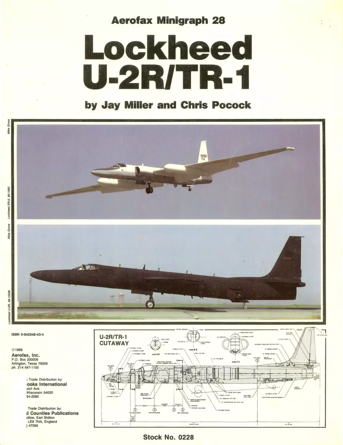
Aerofax Minigraph 28
Lockheed
U-2R/TR-1
by Jay Miller and Chris Pocock
ISBN 0·942548·43·4
©1988
Aerofax, Inc.
P.O. Box 200006
Arlington, Texas 76006
ph. 214647-1105
, Trade Distribution by:
looks International
lect Ave.
Wisconsin 54020
94-2090
Trade Distribution by:
d Cou nties Publications
ollow, Earl Shilton
, LEg 7NA, England
) 47256
"',X,,,,,,
Stock No. 0228
ABBREVIATIONS AND ACRONYMS
AB
AC
ADF
ADI
AEC
AF
AFB
ALSS
ASARS
AWACS
CIA
COMINT
DC
Det
DME
DOA
000
ELINT
EP-X
ER
EW
FDC
FDS
FEBA
FL
FS
HF
HSI
IFF
liS
ILS
Air Base
Alternating Current
Automatic Direction Finder
Attitude Director Indicator
Atomic Energy Commission
Air Force
Air Force Base
Airborne Location Strike System
Advanced Synthetic Aperture Radar System
Airborne Warning and Control System
Central Intelligence Agency
Communications Intelligence
Direct Current
Detachment
Distance Measuring Equipment
Direction of Arrival
Department of Defense
Electronics Intelligence
Electronics Patrol Experimental
Earth Resources
Electronic Warfare
Flight Director Computer
Flight Director System
Forward Edge of Battle Area
Focal Length
Fuselage Station
High-Frequency
Horizontal Situation Indicator
Identification Friend or Foe ,
International Imaging Systems
Instrument Landing System
IMC
KVA
LF
LOROP
MF
NACA
NASA
NRC
OL
PLSS
RAF
RBV
RPV
RTO
SAC
SIGINT
SPO
SRS
SRTS
SRW
TCN
TELl NT
TEREC
TLG
TOA
U
UHF
VHF
WL
WS
Image Motion Compensation
Kilo-Volt Ampere
Low-Frequency
Long Range Oblique Photography
Medium-Frequency
National Advisory Committee for Aeronautics
National Aeronautics & Space Administration
Nuclear Regulatory Commission
Operating Location
Precision Emitter Location Strike System
Royal Air Force
Return Beam Video
Remotely Piloted Vehicle
Responsible Test Organization
Strategic Air Command
Signal Intelligence
System Program Office
Strategic Reconnaissance Squadron
Strategic Reconnaissance Training Squadron
Strategic Reconnaissance Wing
TACAN
Telecommunications Intelligence
Tactical Electronic Reconnaissance System
Tail Landing Gear
Time of Arrival
Utility
Ultra-High Frequency
Very-High Frequency
Water Line
Wing Station
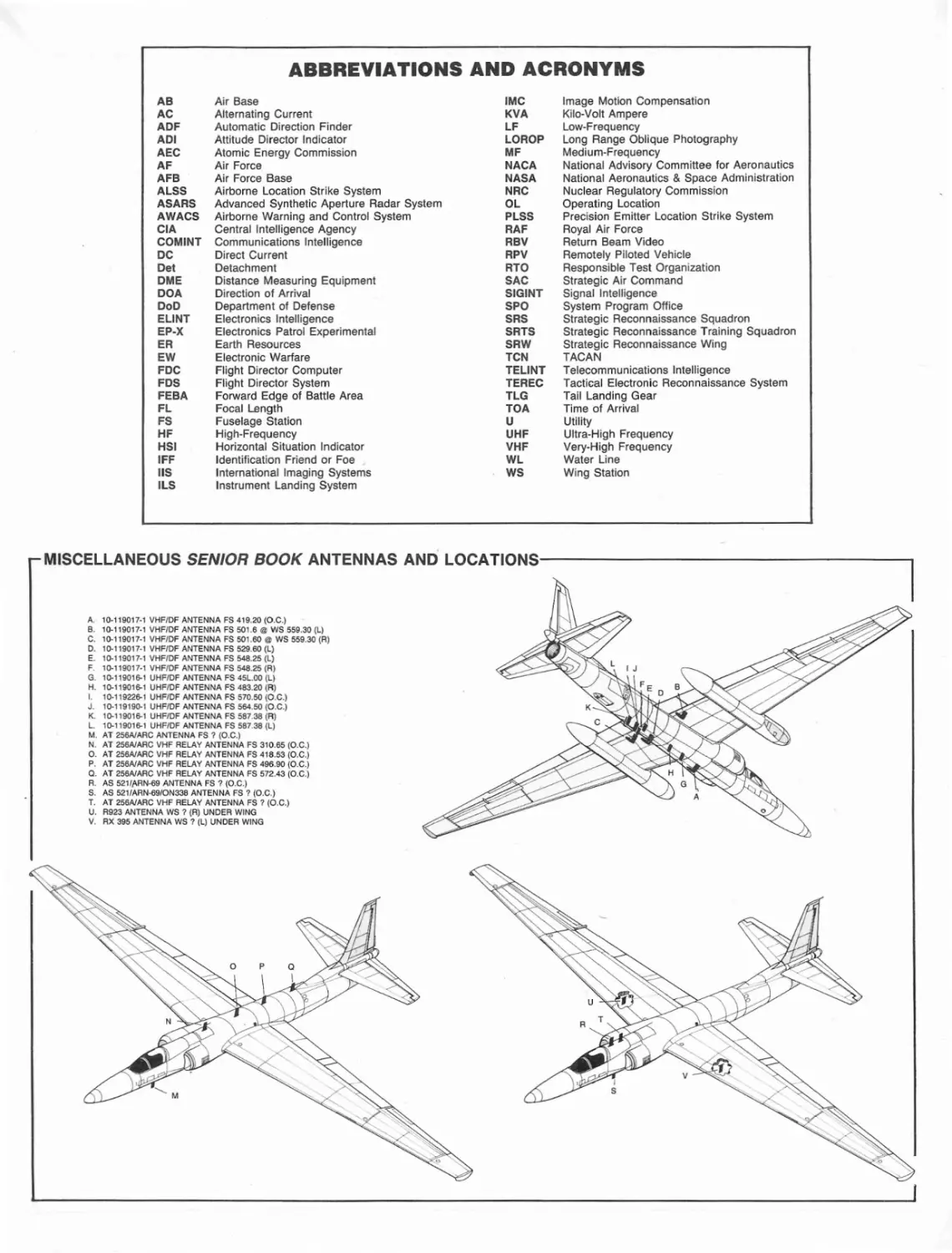
MISCELLANEOUS SENIOR BOOK ANTENNAS AND L O C A T I O N S - - - - - - - - - - - - - - - -
A.
B.
C.
O.
E.
F.
G.
H.
I.
J.
K.
L.
M.
N.
O.
P.
Q.
R.
S.
T.
U.
V.
10-119017-1 VHF/OF ANTENNA FS 419.20 (O.C.)
10-119017·1 VHF/OF ANTENNA FS 501.6 @ ws 559.30 (L)
'0-119017·1 VHF/OF ANTENNA FS 501.60 @ WS 559.30 (R)
'0-"9017·' VHF/OF ANTENNA FS 529.60 (L)
'0-"9017·' VHF/OF ANTENNA FS 548.25 (Ll
10-119017-1 VHF/OF ANTENNA FS 548.25 (R)
10-119016-1 UHF/OF ANTENNA FS 45L.OO (L)
10-119016-1 UHF/OF ANTENNA FS 483.20 (R)
10-119226-1 UHF/OF ANTENNA FS 570.50 (D.C.)
10-119190-' UHF/OF ANTENNA FS 564.50 (D.C.)
'0-119016-1 UHF/OF ANTENNA FS 587.38 (R)
10-119016-1 UHF/OF ANTENNA FS 587.38 (L)
AT 256A1ARC ANTENNA FS ? (D.C.)
AT 256A1ARC VHF RELAY ANTENNA FS 310.65 (D.C.)
AT 256A1ARC VHF RELAY ANTENNA FS 418.53 (O.C.)
AT 256A1ARC VHF RELAY ANTENNA FS 496.90 (O.C.)
AT 256A1ARC VHF RELAY ANTENNA FS 572.43 (O.C.)
AS 5211ARN·69 ANTENNA FS ? (O.C.)
AS 5211ARN·69/DN338 ANTENNA FS ? (O.C.)
AT 256A1ARC VHF RELAY ANTENNA FS 7 (D.C.)
R923 ANTENNA WS ? (R) UNDER WING
RX 395 ANTENNA ws ? (L) UNOER WING
·.......
:~~.
.
_.;;.~
..
THE LOCKHEED U·2R/TR·1/ER·2 STORY
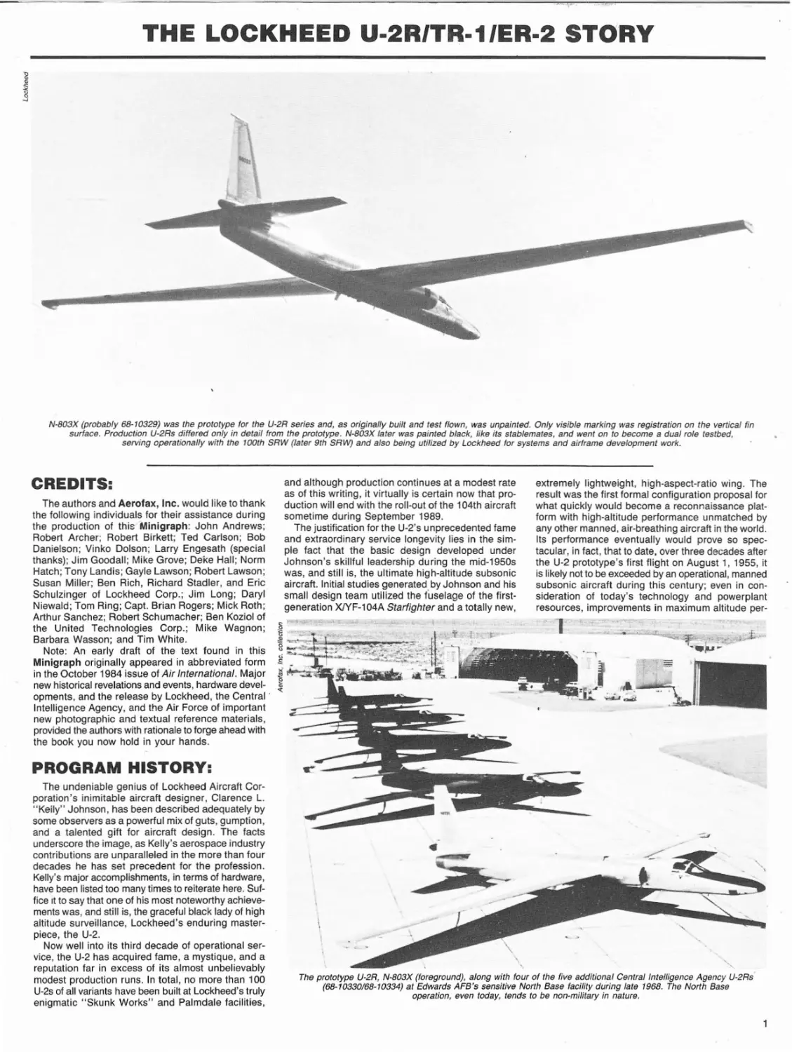
N-803X (probably 68-10329) was the prototype lor the U-2R series and, as originally buill and test flown, was unpainted. Only visible marking was registration on the vertical fin
surface. Production U-2Rs differed only in detail from the prototype. N-803X later was painted black, like its stablemates, and went on to become a dual role testbed,
serving operationally with the 100th SRW (later 9th SRVV) and also being utilized by Lockheed lor systems and airframe development work.
.
CREDITS:
and although production continues at a modest rate
as of this writing, it virtually is certain now that production will end with the roll-out of the 104th aircraft
sometime during September 1989.
The justification for the U-2's unprecedented fame
and extraordinary service longevity lies in the simple fact that the basic design developed under
Johnson's skillful leadership during the mid-1950s
was, and still is, the ultimate high-altitude subsonic
aircraft. Initial studies generated by Johnson and his
small design team utilized the fuselage of the firstgeneration XlYF-104A Starfighter and a totally new,
The authors and Aerofax, Inc. would like to thank
the following individuals for their assistance during
the production of this'Minigraph: John Andrews;
Robert Archer; Robert Birkett; Ted Carlson; Bob
Danielson; Vinko Dolson; Larry Engesath (special
thanks); Jim Goodall; Mike Grove; DeKe Hall; Norm
Hatch; Tony Landis; Gayle Lawson; Robert Lawson;
Susan Miller; Ben Rich, Richard Stadler, and Eric
Schulzinger of Lockheed Corp.; Jim Long; Daryl
Niewald; Tom Ring; Capt. Brian Rogers; Mick Roth;
Arthur Sanchez; Robert Schumacher; Ben Koziol of
the United Technologies Corp.; Mike Wagnon;
Barbara Wasson; and Tim White.
Note: An early draft of the text found in this
Minigraph originally appeared in abbreviated form
in the October 1984 issue of Air International. Major ~. ~~"l.
new historical revelations and events, hardware devel- ~
opments, and the release by Lockheed, the Central'
Intelligence Agency, and the Air Force of important
new photographic and textual reference materials,
provided the authors with rationale to forge ahead with
the book you now hold in your hands.
extremely lightweight, high-aspect-ratio Wing. The
result was the first formal configuration proposal for
what qUickly would become a reconnaissance platform with high-altitude performance unmatched by
any other manned, air-breathing aircraft in the world.
Its performance eventually would prove so spectacular, in fact, that to date, over three decades after
the U-2 prototype's first flight on August 1, 1955, it
is likely not to be exceeded by an operational, manned
subsonic aircraft during this century; even in consideration of today's technology and powerplant
resources, improvements in maximum altitude per-
PROGRAM HISTORY:
The undeniable genius of Lockheed Aircraft Corporation's inimitable aircraft designer, Clarence L.
"Kelly" Johnson, has been described adequately by
some observers as a powerful mix of guts, gumption,
and a talented gift for aircraft design. The facts
underscore the image, as Kelly's aerospace industry
contributions are unparalleled in the more than four
decades he has set precedent for the profession.
Kelly's major accomplishments, in terms of hardware,
have been listed too many times to reiterate here. Suffice It to say that one of his most noteworthy achievements was, and still is, the graceful black lady of high
altitude surveillance, Lockheed's enduring masterpiece, the U-2.
Now well into its third decade of operational service, the U-2 has acquired fame, a mystique, and a
reputation far in excess of its almost unbelievably
modest production runs. In total, no more than 100
U-2s of all variants have been built at Lockheed's truly
enigmatic "Skunk Works" and Palmdale facilities,
"
\
\,
"'-"
The prototype U-2R, N-803X (foreground), along with four of the five additional Central Intelligence Agency U-2Rs'
(68-10330/68-10334) at Edwards AFB's sensitive North Base facility during late 1968. The North Base
operation, even today, tends to be non-military in nature.
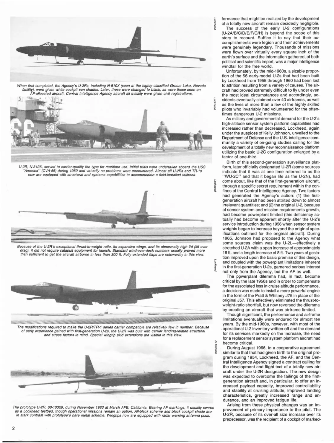
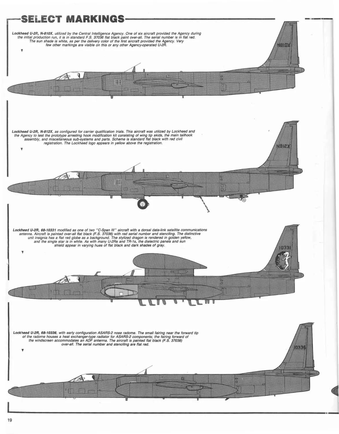
When first completed, the Agency's U-2Rs, including N-810X (seen at the highly classified Groom Lake, Nevada
facility), were given white cockpit sun shades. Later, these were changed to black, as were those seen on
AF-allocated aircraft. Central Intelligence Agency aircraft all initially were given civil registrations.
q _ J '\
....
I
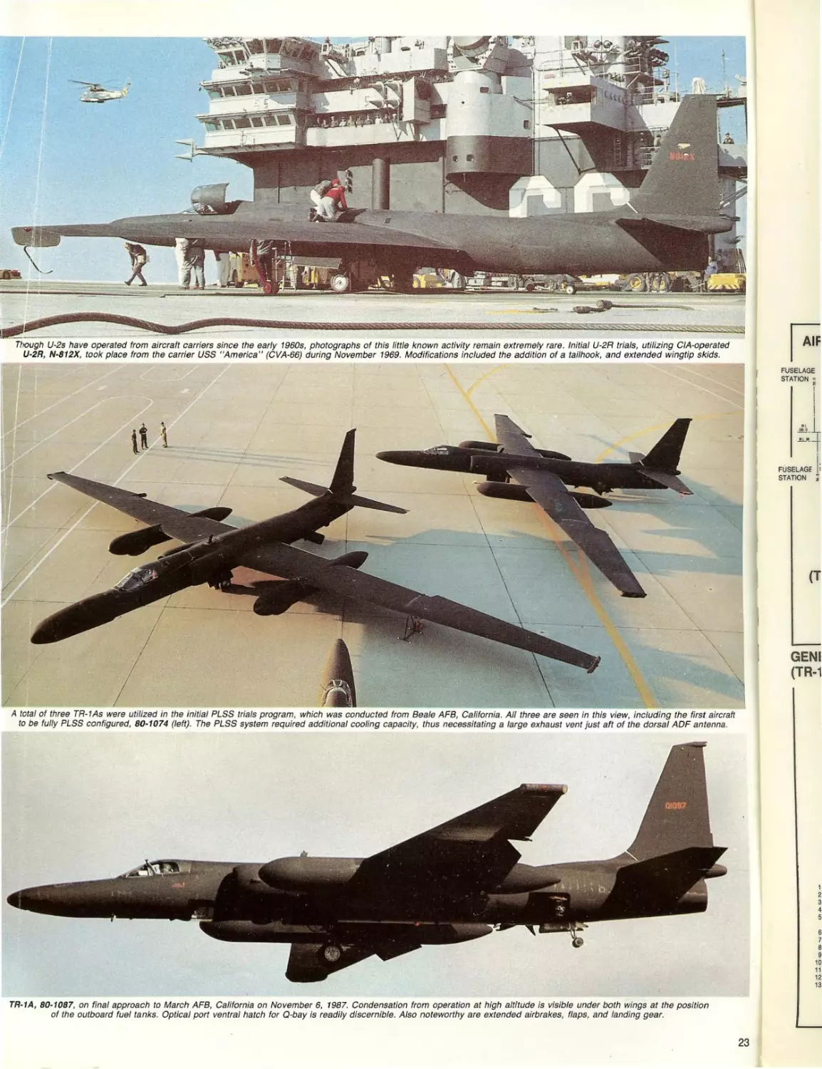
U-2R, N-812X, served to carrier-qualify the type for maritime use. Initial trials were undertaken aboard the USS
"America" (CVA-66) during 1969 and virtually no problems were encountered. Almost all U-2Rs and TR-1s
now are equipped with structural and systems capabilities to accommodate a field-installed tailhook.
Because of the U-2R's exceptional thrust-to-weight ratio, its expansive wings, and its abnormally high lId (lift over
drag), it did not require catapult equipment for launch. Standard wind-over-deck numbers usually proved more
than sufficient to get the aircraft airborne in less than 300 ft. Fully extended flaps are noteworthy in this view.
....
I
The modifications required to make the U-2RITR-1 series carrier compatible are relatively few in number. Because
of early experience gained with first-generation U-2s, the U-2R was built with carrier landing-related structural
and stress factors in mind. Special wingtip skid extensions are visible in this view.
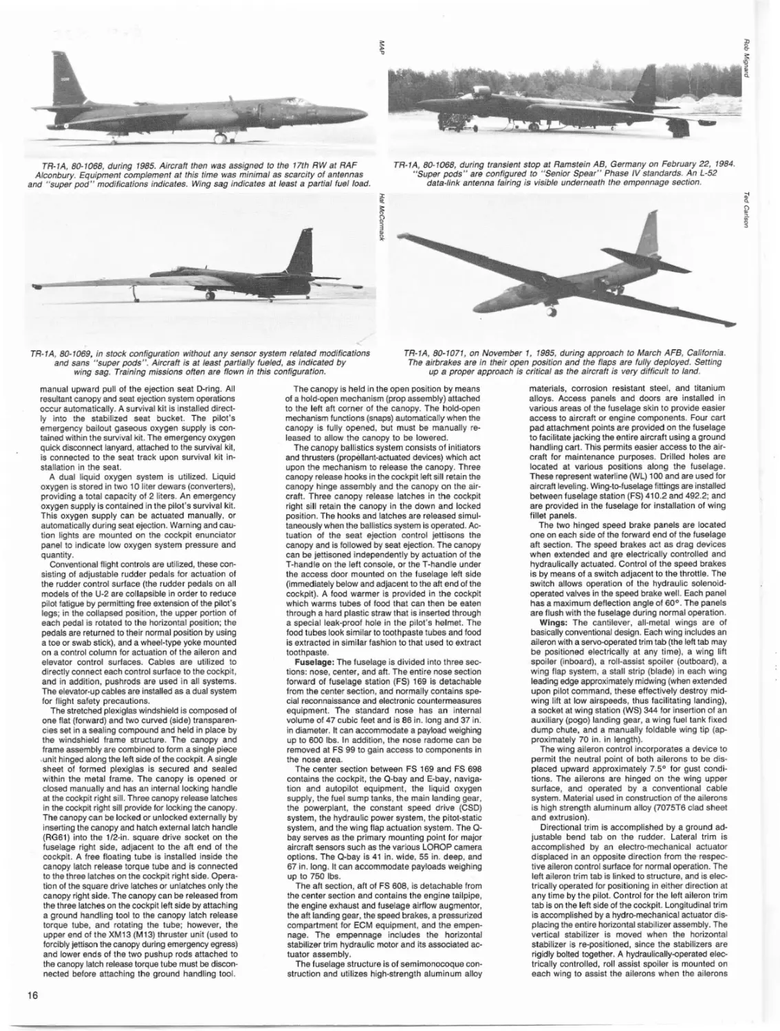
The prototype U-2R, 68-10329, during November 1983 at March AFB, California. Bearing AF markings, it usually serves
as a Lockheed testbed, though operational missions remain an option. All-black scheme and black cockpit shade are
in stark contrast with prototype's bare metal scheme. Wingtips now are equipped with radar warning antenna pods.
2
formance that might be realized by the development
of a totally new aircraft remain decidedly negligible.
The success of the early U-2 configurations
(U-2A1B/C/D/E/F/G/H) is beyond the scope of this
story to recount. Suffice it to say that their accomplishments were legion and their achievements
were genuinely legendary. Thousands of missions
were flown over virtually every square inch of the
earth's surface and the information gathered, of both
political and scientific import, was a major intelligence
windfall for the free world.
Unfortunately, by the mid-1960s, a sizable proportion of the 56 early-model U-2s that had been built
by Lockheed from 1955 through 1960 had been lost
to attrition resulting from a variety of causes. The aircraft had proved extremely difficult to fly under even
the most ideal circumstances and accordingly, accidents eventually claimed over 40 airframes, as well
as the lives of more than a few of the highly skilled
pilots who invariably had volunteered for the oftentimes dangerous U-2 missions.
As military and governmental demand for the U-2's
high-altitude sensor system platform capabilities had
increased rather than decreased, Lockheed, again
under the auspices of Kelly Johnson, unveiled to the
Department of Defense and the U.S. intelligence community a variety of on-going studies calling for the
development of a totally new reconnaissance platform
utilizing the basic U-2C configuration enlarged by a
factor of one-third.
Birth of this second-generation surveillance platform, later officially designated U-2R (some sources
indicate that it was at one time referred to as the
"WU-2C" and that it began life as the U-2N), had
come about, like that of the first-generation aircraft,
through a specific secret requirement within the confines of the Central Intelligence Agency. Two factors
had generated the Agency's action: (1) the firstgeneration aircraft had been attrited down to almost
irrelevant quantities; and (2) the original U-2, because
of sensor system and mission requirements growth,
had become powerplant limited (this deficiency actually had become apparent shortly after the U-2's
service introduction during 1956 when sensor system
weights began to increase beyond the original specifications outlined for the original aircraft). During
1965, Johnson had proposed to the Agency what
some sources claim was the U-2L-effectively a
stretched U-2A with a span increase of approximately
16 ft. and a length increase of 8 ft. Two years of gestation improved upon the basic premise of this design,
and coupled with the powerplant limitations inherent
in the first-generation U-2s, garnered serious interest
not only from the Agency, but the AF as well.
The pl'werplant dilemma had, in fact, become
critical by the late 1950s and in order to compensate
for the associated loss in cruise altitude performance,
a decision was made to install a more powerful engine
in the form of the Pratt & Whitney J75 in place of the
original J57. This effectively eliminated the thrust-toweight-ratio shortfall, but now reversed the dilemma
by creating an aircraft that was airframe limited.
Though significant, the performance and airframe
limitations eventually were endured for almost ten
years. By the mid-1960s, however, with most of the
.operational U-2 inventory written-off and the demand
for its services markedly on the increase, the need
for a replacement sensor system platform aircraft had
become critical.
During August 1966, in a cooperative agreement
similar to that that had given birth to the original program during 1954, Lockheed, the AF, and the Centrallntelligence Agency signed a contract calling for
the development and flight test of a totally new aircraft under the U-2R designation. The new design
was expected to overcome the failings of the firstgeneration aircraft and, in particular, to offer an increased payload capacity, improved controllability
and stability at cruising altitude, improved landing
characteristics, greatly increased range and endurance, and an improved fatigue life.
Arising from these physical changes was an improvement of primary importance to the pilot. The
U-2R, because of its over-all size increase over its
predecessor, was the recipient of a cockpit of marked-
Iy increased dimensions. This permitted the pilot, for
the first time in the U-2 program, to wear a fullpressure suit. First-generation U-2 pilots were limited
to partial-pressure suits of the S-4/T-1/T-1A variety
because of severe space constraints. Comfort was
a luxury under the early, somewhat primitive conditions generated by these suits, and it therefore was
considered a major ergonomic advance when it was
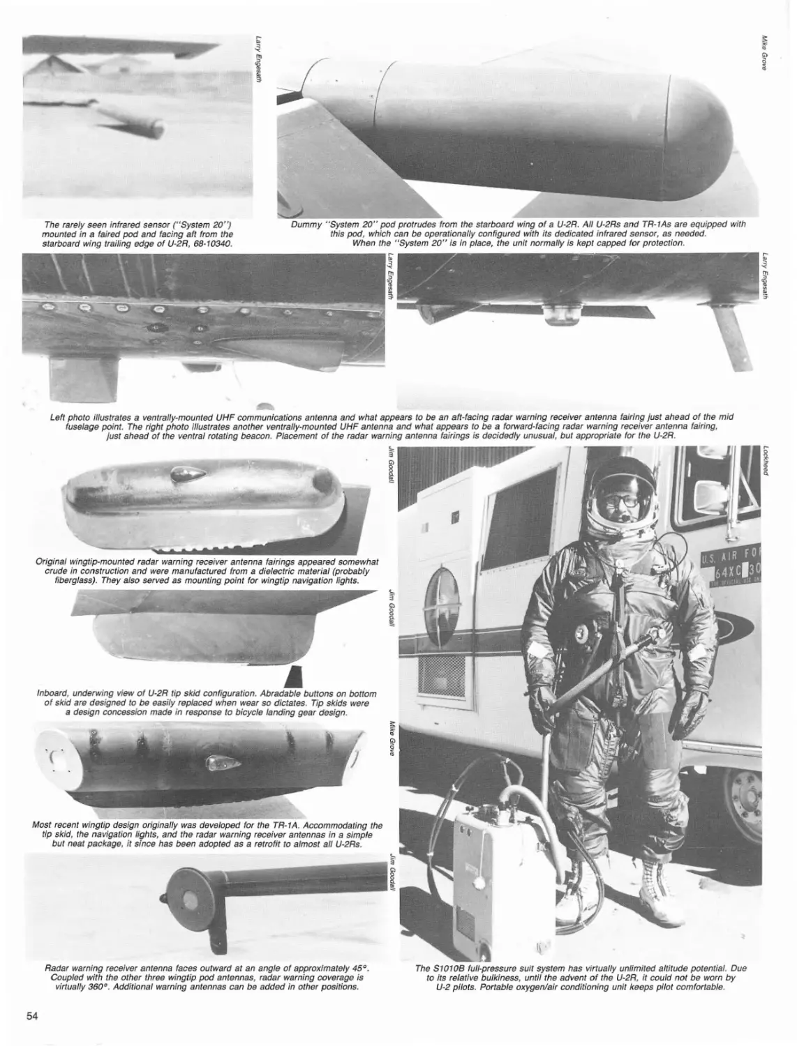
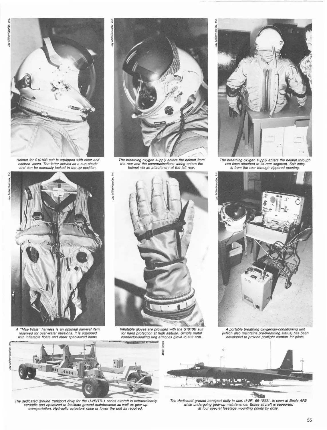
determined that improved, state-of-the-art fullpressure suit systems such as the A1P-22S-2 (consisting of the CSK-6/P suit and the HGK-13/P helmet),
and the newer S1010B could be worn without
difficulty.
The U-2R, developed by Kelly Johnson, Ben Rich,
Fred Cavanaugh and others, had risen from a series
of design studies that had explored the potential performance and payload improvements that might be
gained by incorporating such advances as supercritical airfoil sections for the wing and tail surfaces,
increased thrusUhigh-altitucfe optimized engines, and
refined aerodynamics.
The resulting final design became not simply an
updated first-generation airframe, but rather a totally new aircraft some 40% larger than its predecessor.
The wingspan was increased by 23 ft. (the original
stock NACA 64A airfoil was retained, however, but
proportionately enlarged; the supercritical airfoil section wing idea was dropped from contention because
of limited experience with it at very high' altitudes);
wing area was increased by 400 sq. ft.; wing structural weight was reduced by 31b. per sq. ft.; the wing
lift/drag ratio (UD) was improved to 27:1; and a totally
new and enlarged fuselage, with significantly improved fineness ratio, was created.
The fuselage r;hange proved as significant as that
for the wing as it provided nearly a third again as
much internal volume as the first-generation aircraft.
This increased volume permitted larger sensor
packages and more sophisticated and thus more
capable electronic countermeasures systems to be
carried. Additionally, the increased fuselage size permitted improved structural design techniques to be
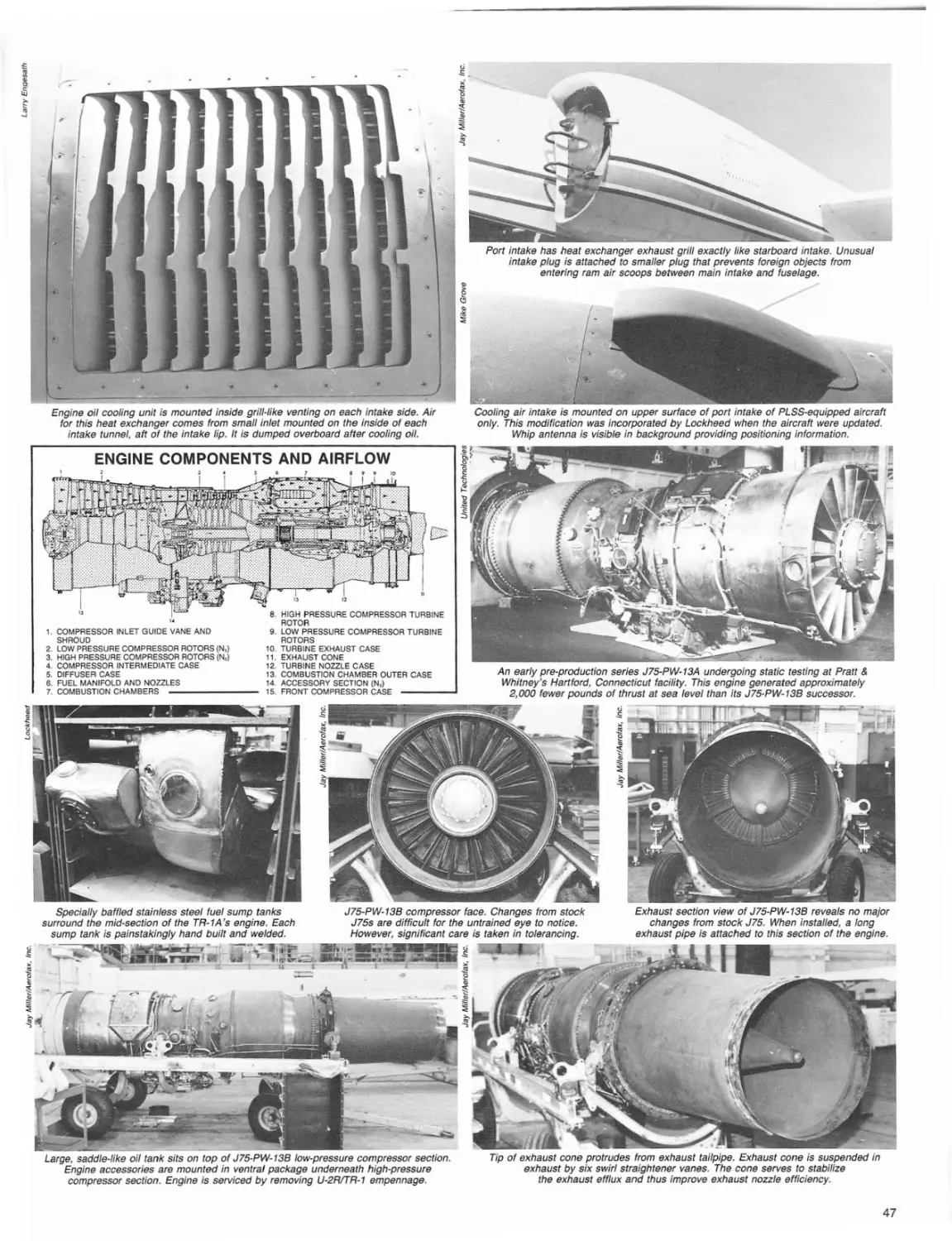
incorporated and consequently permitted the elimination of drag-inducing external oil cooler intakes. Importantly, the length of the empennage section
alleviated the need for the first-generation aircraft's
infrared signature lowering "sugar scoop" attachment
to the lower lip of the exhaust fairing-as it was long
enough in its own right to permit the exhaust efflux
to cool somewhat before exiting the aircraft.
Revised and enlarged horizontal and vertical. tail
surfaces also were created to accommodate the new
control moments resulting from the over-all increase
in size, and the outer wing panels were hinged to permit folding (partially in consideration of the fact the
aircraft was to be aircraft carrier capable, and partially to alleviate difficulties resulting from storage
space constraints).
Hydraulically-actuated roll (outboard) and lift dumping (inboard) spoilers were added to the top mid-span
surface of each wing (ahead of the flaps) in addition
to the conventional trailing edge ailerons and flaps.
Like the first-generation aircraft, however, aileron actuation remained strictly mechanical, with no boost.
Other new features were a zero-zero capability ejection seat (some of the very early, super-lightweight,
first-generation aircraft were not ejection seat
equipped at all); larger retractable leading edge stall
strips; accommod.ations for wing-mounted sensor
pods (which later would be increased in size considerably to become what today are referred to most
commonly as "super-pods"); and a strengthened
landing gear and brake system to accommodate the
resultant significant weight increases and associated
dynamic loads.
Significant emphasis was placed by Kelly Johnson
and his design team on increasing the new design's
range and endurance. This requirement was accommodated nicely by the improved volumetric efficiency permitted by the aircraft's vastly increased size.
As it were, the first-generation aircraft had suffered
from serious inherent fuel capacity limitations; with
some 1,320 gals. being their maximum internal load,
and another 200 gals. being permitted when carrying external underwing drop tanks, endurance rare-
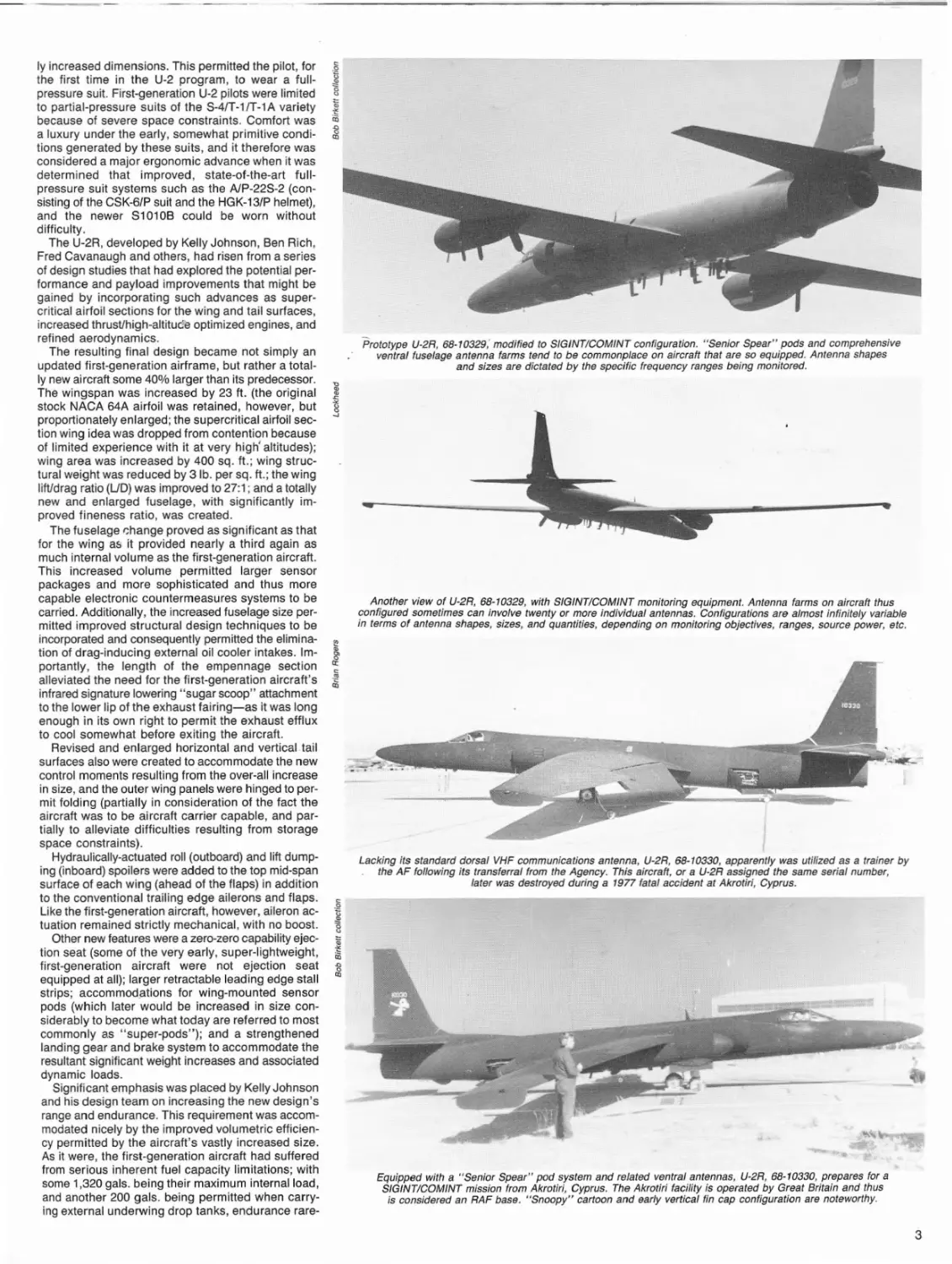
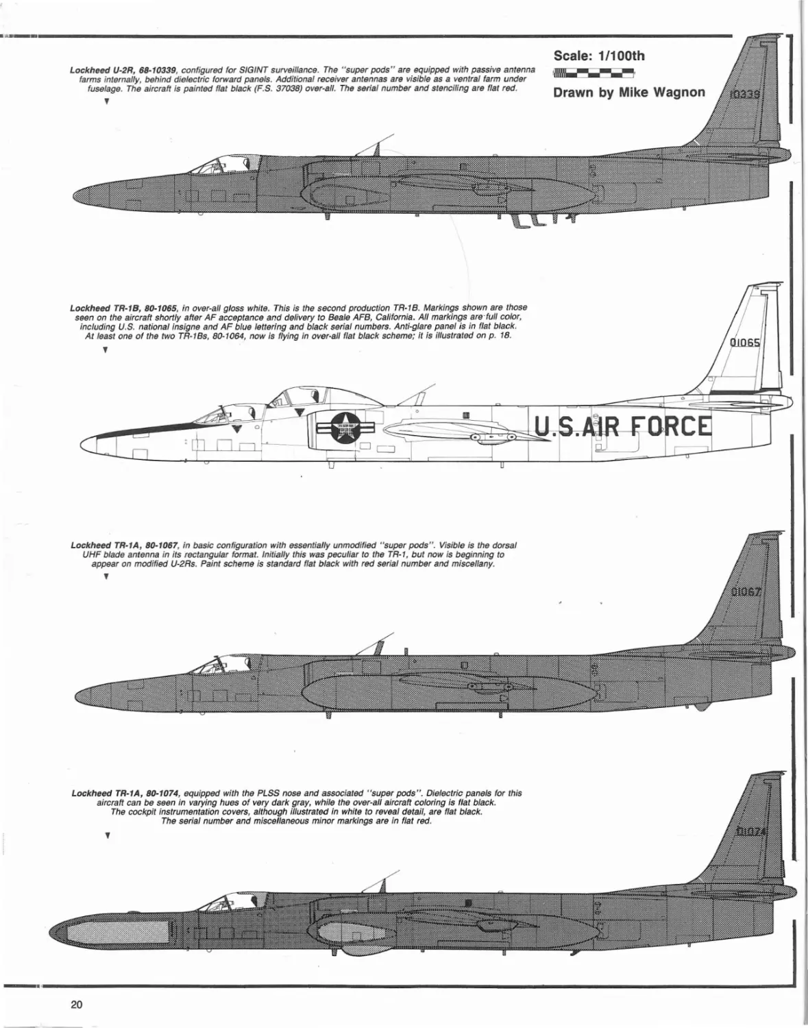
Prototype U-2R, 68-10329: modified to SfGfNTICOMINT configuration. "Senior Spear" pods and comprehensive
ventraf fuselage antenna farms tend to be commonplace on aircraft that are so equipped. Antenna shapes
and sizes are dictated by the specific frequency ranges being monitored.
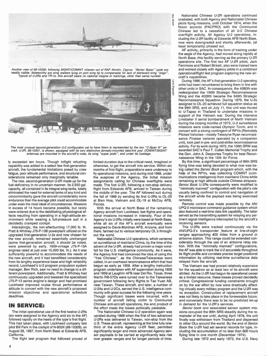
Another view of U-2R, 68-10329, with SIGINTICOMINT monitoring equipment. Antenna farms on aircraft thus
configured sometimes can involve twenty or more individual antennas. Configurations are almost infinitely variable
in terms of antenna shapes, sizes, and quantities, depending on monitoring objectives, ranges, source power, etc.
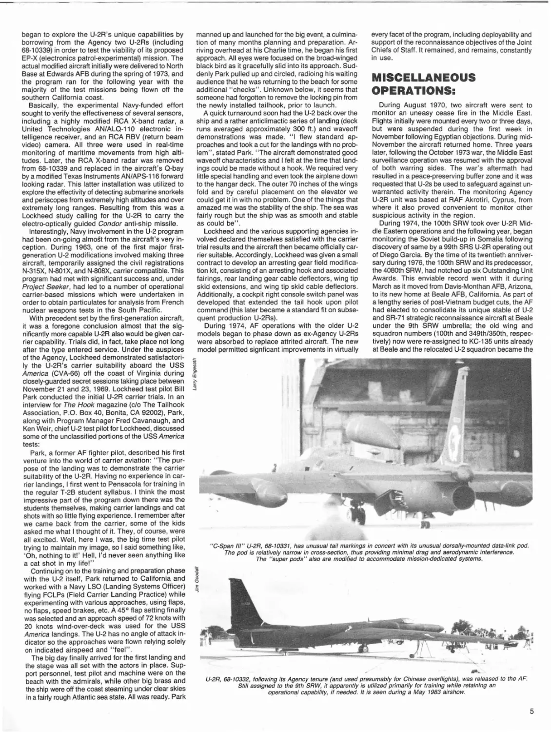
Lacking its standard dorsal VHF communications antenna, U-2R, 68-10330, apparently was utilized as a trainer by
the AF fol/owing its transferral from the Agency. This aircraft, or a U-2R assigned the same serial number,
later was destroyed during a 1977 fatal accident at Akrotiri, Cyprus.
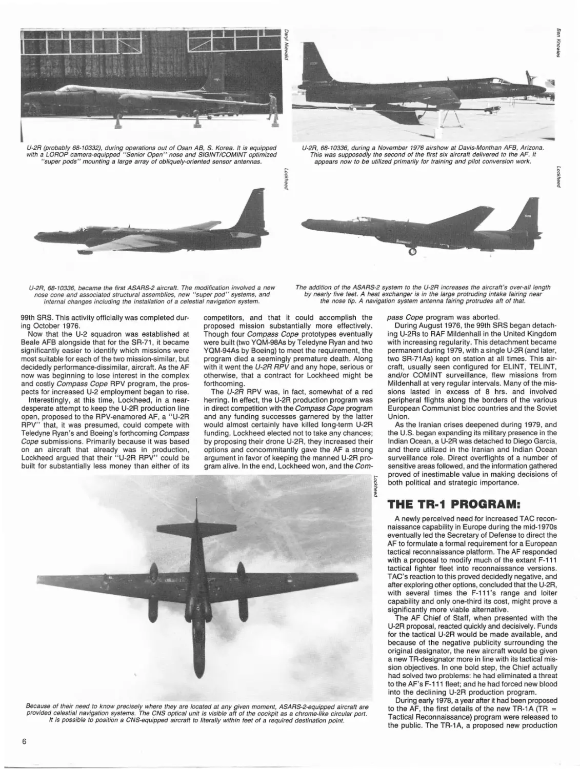
Equipped with a "Senior Spear" pod system and related ventral antennas, U-2R, 68-10330, prepares for a
SIGINTICOMINT mission from Akrotiri, Cyprus. The Akrotiri facility is operated by Great Britain and thus
is considered an RAF base. "Snoopy" cartoon and early vertical fin cap configuration are noteworthy.
3
Another view of 68-10330, following SIGINTICOMINT mission out of RAF Akrotiri, Cyprus. "Senior Spear" pods are
readily visible. Noteworthy are wing walkers lying on port wing tip to compensate for lack of starboard wing "pogo".
Typical of U-2Rs and TR-ls, this aircraft bears no national insigne or markings, other than serial number.
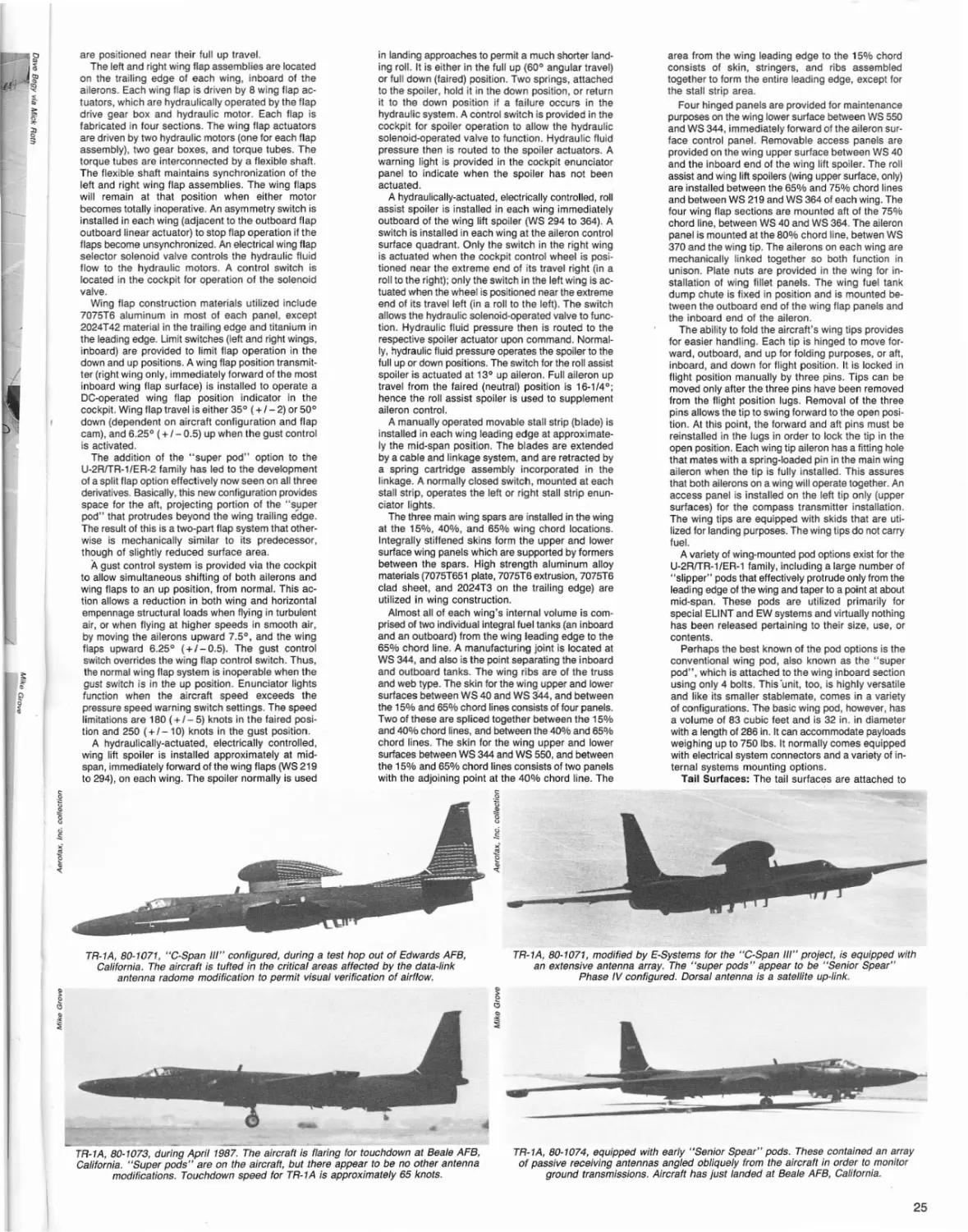
The most unusual second-generation U-2 configuraton yet to have flown is represented by the two "C-Span III" aircraft. U-2R, 68-10331, is shown, equipped with its very distinctive dorsally-mounted data-link pod. COMINTISIGINT
antennas are mounted in the aircraft's nose, its wing "super pods", and under its fuselage.
Iy exceeded ten hours. Though inflight refueling
capability was added to a select few first-generation
aircraft, the fundamental limitations posed by crew
fatigue, poor altitude performance, and structural considerations remained only marginally tenable.
The new, second-generation U-2R made up for the
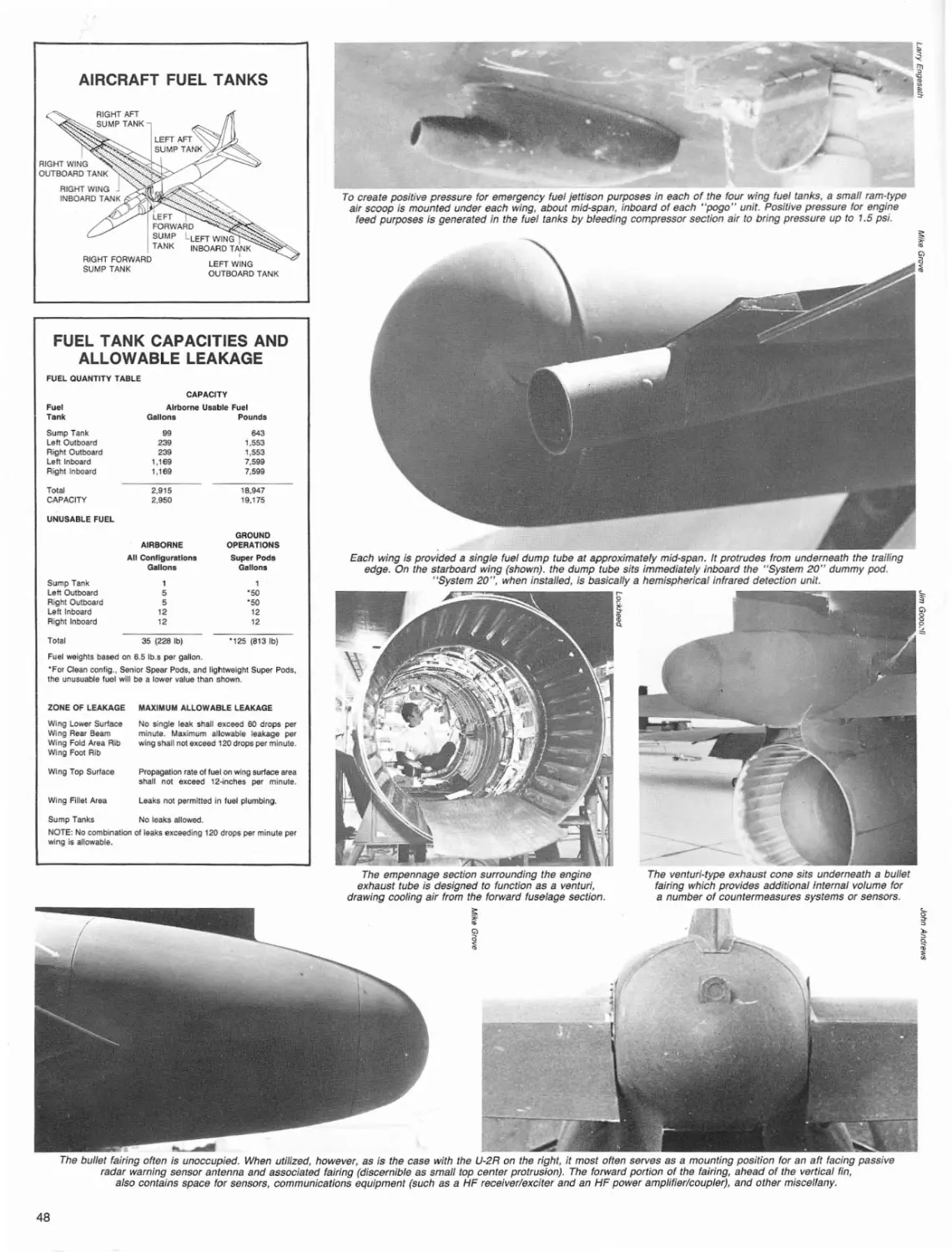
fuel deficiency in no uncertain manner. Its 2,950 gal.
capacity, all contained in its integral wing tanks, totally
eliminated the need for external tanks of any kind and
concommitantly gave the aircraft considerably more
endurance than the average pilot could accommodate
under even the most ideal of circumstances. Missions
in excess of 14 hours became possible, but rarely
were ordered due to the debilitating physiological effects resulting from operating in a high-altitude environment while wearing a full-pressure suit in a
decidedly cramped cockpit.
Interestingly, the non-afterburning 17,000 lb. tho
Pratt & Whitney J75-P-13B powerplant utilized on the
upgraded first-generation U-2s and now chosen for
the new aircraft, remained essentially unchanged
(some first-generation aircraft, it should be noted,
were powered by early, 1959-vintage J75-P-13A
engines rated at just over 15,000 Ibs. th.). As it was
sufficiently powerful to accommodate the needs of
.the new aircraft, and it had benefitted considerably
from its lengthy experience base and high reliability
record, Lockheed's U-2 program propulsion system
manager, Ben Rich, saw no need to change to a different powerplant. Additionally, Pratt & Whitney had
continuously upgraded and tweaked the specialized'
J75-P-13 series engine's design and had promised
Lockheed improved cruise thrust performance at
altitude in concert with the new aircraft's proposed
mission objectives and operational schedule
deadlines.
IN SERVICE:
The initial operational use of the first twelve U-2Rs
(six were assigned to the Agency and six to the AF)
followed rapidly on the heels of the type's first flight.
This had taken place, with Lockheed company test
pilot-Bill Park in the cockpit of N-803X (68-10329), on
August 28,1967, from North Base at Edwards AFB,
California.
The flight test program that followed proved of
4
limited duration due to the critical need, imagined or
otherwise, to get the aircraft into service. Within six
months of first flight, preparations were underway to
fly operational missions, and during mid-1968, under
the auspices of the Agency, the initial mission
assignments calling for Chinese overflights were
made. The first U-2R, following a non-stop delivery
flight from Edwards AFB, arrived in Taiwan during
the middle of the year. The AF followed suit during
the fall of 1968 by sending its first U-2Rs to OL-20
at Bien Hoa, Vietnam and OL-19 at McCoy AFB,
Florida.
With the arrival at North Base of the remaining
Agency aircraft from Lockheed, test flights and operational missions increased in intensity. Four of the
Agency's six U-2Rs initially were based at North Base,
while all six of the AF's aircraft eventually were
assigned to Davis-Monthan AFB, Arizona, and from
there, farmed out to various temporary OL's throughout the world.
Nationalist Chinese U-2 operations, which centered
on surveillance of mainland China, by the time of the
advent of the U-2R, already had proven a major windfall for the U.S. intelligence community. As it were,
the Agency first had conceived the idea of using the
"free Chinese", as the ChineselTaiwanese were
called, in an overhead reconnaisance effort that had
begun as early as 1958. After a lengthy instruction
program undertaken with AF supervision during 1958
and 1959 at Laughlin AFB near Del Rio, Texas, three
Martin RB-57Ds were turned over to the Taiwanese
government following ferry flights to Tao Yuan AB,
near Taiwan. These aircraft, and later, a number of
U-2As and U-2Cs, served the U.S. intelligence community with great success for the following nine years.
Though significant losses were incurred, with a
number of aircraft falling victim to Communist
Chinese anti-aircraft operations, the end product of
the effort made the losses politically palatable.
The Nationalist Chinese U-2 operation again was
uprated during 1968 when the first of two advanced
U-2Rs was delivered to Taiyvan, non-stop from the
U.S. These aircraft, representing at the time fully onethird of the entire Agency U-2R fleet, permitted
significantly larger and more advanced Agency sensor payloads to be carried at significantly less risk
over greater ranges and for longer periods of time.
Nationalist Chinese U-2R operations continued
unabated, with both Agency and Nationalist Chinese
pilots flying missions, until October 1974, when the
Nixon accords (PACPRO) with the Communist
Chinese led to a cessation of all U-2 Chinese
overflight activity. All Agency U-2 operations, including the U-2R facility at Edwards AFB North Base,
now were downgraded and shortly afterwards, (at
least temporarily) phased out.
AF activity, primarily in the form of training under
the aegis of the Agency, had moved along rapidly at
North Base, this facility serving as the primary U·2R
operations site. The first two AF U-2R pilots, Jack
Fenimore and Robert Birkett, also were trained here
and worked closely with Agency pilots in a combined
operationallflight test program exploring the new aircraft's capabilities.
During 1966, the AF's first-generation U-2 operating
units had been renumbered to bring them in line with
other units in SAC. In consequence, the 4080th was
redesignated the 100th Strategic Reconnaissance
Wing and the 4028th became the 349th Strategic
Reconnaissance Squadron. During 1970, the U-2s
assigned to OL-20 achieved full squadron status as
the 99th SRS, and on July 11, this unit was moved
to U-Tapao in Thailand to undertake missions in
support of the Vietnam war. During the intensive
Linebaker /I aerial bombardment of North Vietnam
during the closing months of 1972, U-2 surveillance
missions were code-named Olympic Torch, and in
concert with a strong contingent of RPVs (Remotely
Piloted Vehicles-mostly Teledyne Ryan reconnaissance Firebee variants operated by a companion
unit), took part in pre- and post-strike reconnaissance
activity. For its work during 1972, the 100th SRW was
awarded SAC's Paul T. Cullen Memorial Trophy and
the Gen. John A. Desportes Trophy for best Reconnaissance Wing in the 15th Air Force.
By this time, a significant percentage of 99th SRS
flying time was being devoted to what now was being called the Senior Book program Which, with the
help of the RPVs, was collecting COMINT (communications intelligence) from mainland China while
remaining at high altitude outside Chinese airspace.
Senior Book U-2Rs consequently were modified to
"minimally manned" configuration with the pilot's role
usually being confined to control and navigation of
the aircraft while the payload was being exercised
remotely.
Remote control was made possible by the ANI
UPQ-3 microwave command guidance system which
also featured a real-time data link capability. The latter
served as the transmitting system for relaying any pertinent signal intelligence intercepted by the aircraft's
receiving sensors.
The U-2Rs were tracked continuously via the
AN/UPQ-3's transponder .feature at line-of-sight
ranges approaching 400 miles from a ground or
airborne station. This range could be extended considerably through the use of an airborne relay station. With the "minimally manned" configurations,
the AF was able to track the U-2 accurately throughout
its flight profile and correlate precise target positional
information by utilizing real-time surveillance data
relayed from the aircraft.
The Vietnam war had proved relatively expensive
for the squadron as at least two of its aircraft were
attrited. As the U-2R had begun its operational career
as a limited resource, these losses proved decidedly
critical. Congressional funding constraints brought
on by the war effort by now were drastically affecting virtually every military program and the U-2R was
no exception. Construction of replace~nt aircraft
was not likely to take place in the foreseeable future,
and conversely there was to be no predicted let-up
in demand for the U-2R's services.
Senior book and associated sensor system missions occupied the 99th SRS steadily during the remainder of the war until, during April 1976, the unit
finally was withdrawn from Thailand and dispersed
to other OLs around the world. By the end of Senior
Book the U-2R had set several records for type, inclUding the accumulation of no less than 600 hours
flying time in one month (December 1974).
During late 1972 and early 1973, the U.S. Navy
began to explore the U-2R's unique capabilities by
borrowing from the Agency two U-2Rs (including
68-10339) in order to test the viability of its proposed
EP-X (electronics patrol-experimental) mission. The
actual modified aircraft initially were delivered to North
Base at Edwards AFB during the spring of 1973, and
the program ran for the following year with the
majority of the test missions being flown off the
southern California coast.
Basically, the experimental Navy-funded effort
sought to verify the effectiveness of several sensors,
including a highly modified RCA X-band radar, a
United Technologies AN/ALQ-110 electronic intelligence receiver, and an RCA RBV (return beam
video) camera. All three were used in real-time
monitoring of maritime movements from high altitudes. Later, the RCA X-band radar was removed
from 68-10339 and replaced in the aircraft's Q-bay
by a modified Texas Instruments AN/APS-116 forward
looking radar. This latter installation was utilized to
explore the effectivity of detecting submarine snorkels
and periscopes from extremely high altitudes and over
extremely long ranges. Resulting from this was a
Lockheed study calling for the U-2R to carry the
electro-optically guided Condor anti-ship missile.
Interestingly, Navy involvement in the U-2 program
had been on-going almost from the aircraft's very inception. During 1963, one of the first major firstgeneration U-2 modifications involved making three
aircraft, temporarily assigned the civil registrations
N-315X, N-801X, and N-808X, carrier compatible. This
program had met with significant success and, under
Project Seeker, had led to a number of operational
carrier-based missions which were undertaken in
order to obtain particulates for analysis from French
nuclear weapons tests in the South Pacific.
With precedent set by the first-generation aircraft,
it was a foregone conclusion almost that the significantly more capable U-2R also would be given carrier capability. Trials did, in fact, take place not long
after the type entered service. Under the auspices
of the Agency, Lockheed demonstrated satisfactorily the U-2R's carrier suitability aboard the USS
America (CVA-66) off the coast of Virginia during
closely-guarded secret sessions taking place between
November 21 and 23, 1969. Lockheed test pilot Bill
Park conducted the initial U-2R carrier trials. In an
interview for The Hook magazine (c/o The Tailhook
Association, P.O. Box 40, Bonita, CA 92002), Park,
along with Program Manager Fred Cavanaugh, and
Ken Weir, chief U-2 test pilot for Lockheed, discussed
some of the unclassified portions of the USS America
tests:
Park, a former AF fighter pilot, described his first
venture into the world of carrier aviation: "The purpose of the landing was to demonstrate the carrier
suitability of the U-2R. Having no experience in carrier landings, I first went to Pensacola for training in
the regular T-2B student syllabus. I think the most
impressive part of the program down there was the
students themselves, making carrier landings and cat
shots with so little flying experience. I remember after
we came back from the carrier, some of the kids
asked me what I thought of it. They, of course, were
all excited. Well, here I was, the big time test pilot
trying to maintain my image, so I said something like,
'Oh, nothing to it!' Hell, I'd never seen anything like
a cat shot in my life!"
Continuing on to the training and preparation phase
with the U-2 itself, Park returned to California and
worked with a Navy LSO (Landing Systems Officer)
flying FCLPs (Field Carrier Landing Practice) while
experimenting with various approaches, using flaps,
no flaps, speed brakes, etc. A 45 0 flap setting finally
was selected and an approach speed of 72 knots with
20 knots wind-over-deck was used for the USS
America landings. The U-2 has no angle of attack indicator so the approaches were flown relying solely
on indicated airspeed and "feel".
The big day finally arrived for the first landing and
the stage was all set with the actors in place. Support personnel, test pilot and machine were on the
beach with the admirals, while other big brass and
the ship were off the coast steaming under clear skies
in a fairly rough Atlantic sea state. All was ready. Park
manned up and launched for the big event, a culmination of many months planning and preparation. Arriving overhead at his Charlie time, he began his first
approach. All eyes were focused on the broad-winged
black bird as it gracefully slid into its approach. Suddenly Park pulled up and circled, radioing his waiting
audience that he was returning to the beach for some
additional "checks". Unknown below, it seems that
someone had forgotten to remove the locking pin from
the newly installed tailhook, prior to launch.
A quick turnaround soon had the U-2 back over the
ship and a rather anticlimactic series of landing (deck
runs averaged approximately 300 ft.) and waveoff
demonstrations was made. "I flew standard approaches and took a cut for the landings with no problem", stated Park. "The aircraft demonstrated good
waveoff characteristics and I felt at the time that landings could be made without a hook. We required very
little special handling and even took the airplane down
to the hangar deck. The outer 70 inches of the Wings
fold and by careful placement on the elevator we
could get it in with no problem. One of the things that
amazed me was the stability of the ship. The sea was
fairly rough but the ship was as smooth and stable
as could be".
Lockheed and the various supporting agencies involved declared themselves satisfied with the carrier
trial results and the aircraft then became officially carrier suitable. Accordingly, Lockheed was given a small
contract to develop an arresting gear field modification kit, consisting of an arresting hook and associated
fairings, rear landing gear cable deflectors, wing tip
skid extensions, and wing tip skid cable deflectors.
Additionally, a cockpit right console switch panel was
developed that extended the tail hook upon pilot
command (this later became a standard fit on subsequent production U-2Rs).
During 1974, AF operations with the older U-2
models began to phase down as ex-Agency U-2Rs
were absorbed to replace attrited aircraft. The new
model permitted signficant improvements in virtually
every facet of the program, including deployability and
support of the reconnaissance objectives of the Joint
Chiefs of Staff. It remained, and remains, constantly
in use.
MISCELLANEOUS
OPERATIONS:
During August 1970, two aircraft were sent to
monitor an uneasy cease fire in the Middle East.
Flights initially were mounted every two or three days,
but were suspended during the first week in
November following Egyptian objections. During midNovember the aircraft returned home. Three years
later, follOWing the October 1973 war, the Middle East
surveillance operation was resumed with the approval
of both warring sides. The war's aftermath had
resulted in a peace-preserving buffer zone and it was
requested that U-2s be used to safeguard against unwarranted activity therein. The monitoring Agency
U-2R unit was based at RAF Akrotiri, Cyprus, from
where it also proved convenient to monitor other
suspicious activity in the region.
During 1974, the 100th SRW took over U-2R Middle Eastern operations and the following year, began
monitoring the Soviet build-up in Somalia following
discovery of same by a 99th SRS U-2R operating out
of Diego Garcia. By the time of its twentieth anniversary during 1976, the 100th SRW and its predecessor,
the 4080th SRW, had notched up six Outstanding Unit
Awards. This enviable record went with it during
March as it moved from Davis-Monthan AFB, Arizona,
to its new home at Beale AFB, California. As part of
a lengthy series of post-Vietnam budget cuts, the AF
had elected to consolidate its unique stable of U-2
and SR-71 strategic reconnaissance aircraft at Beale
under the 9th SRW umbrella; the old wing and
squadron numbers (1 OOth and 349th/350th, respectively) now were re-assigned to KC-135 units already
at Beale and the relocated U-2 squadron became the
"C-Span III" U-2R, 68-10331, has unusual tail markings in concert with its unusual dorsally-mounted data-link pod.
The pod is relatively narrow in cross-section, thus providing minimal drag and aerodynamic interference.
The "super pods" also are modified to accommodate mission-dedicated systems.
--
U-2R, 68-10332, following its Agency tenure (and used presumably for Chinese overflights), was released to the AF.
Still assigned to the 9th SRW, it apparently is utilized primarily for training while retaining an
operational capability, if needed. It is seen during a May 1983 airshow.
5
-
U-2R (probably 68-10332), during operations out of Osan AB, S. Korea. It is equipped
wifh a LOROP camera-equipped "Senior Open" nose and SIGINTICOMINT optimized
"super pods" mounting a large array of obliquely-oriented sensor antennas.
U-2R, 68-10336, during a November 1976 airshow at Davis-Monthan AFB, Arizona.
This was supposedly the second of the first six aircraft delivered to the AF. It
appears now to be utilized primarily for training and pilot conversion work.
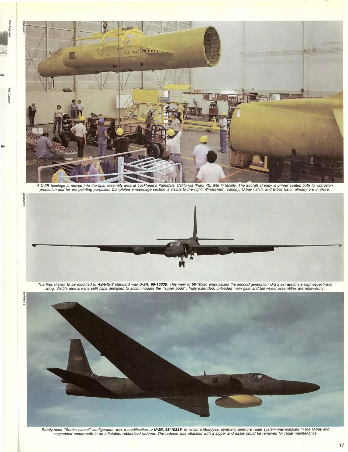
U-2R, 68-10336, became the first ASARS-2 aircraft. The modification involved a new
nose cone and associated structural assemblies, new "super pod" systems, and
internal changes including the installation of a celestial navigation system.
The addition of the ASARS·2 system to the U-2R increases the aircraft's over-all length
by nearly five feet. A heat exchanger is in the large protruding intake fairing near
the nose tip. A navigation system antenna fairing protrudes aft of that.
99th SRS. This activity officially was completed during October 1976.
Now that the U-2 squadron was established at
Beale AFB alongside that for the SR-71 , it became
significantly easier to identify which missions were
most suitable for each of the two mission-similar, but
decidedly performance-dissimilar, aircraft. As the AF
now was beginning to lose interest in the complex
and costly Compass Cope RPV program, the prospects for increased U·2 employment began to rise.
Interestingly, at this time, Lockheed, in a neardesperate attempt to keep the U-2R production line
open, proposed to the RPV-enamored AF, a "U-2R
RPV" that, it was presumed, could compete with
Teledyne Ryan's and Boeing's forthcoming Compass
Cope submissions. Primarily because it was based
on an aircraft that already was in production,
Lockheed argued that their "U-2R RPV" could be
built for substantially less money than either of its
competitors, and that it could accomplish the
proposed mission substantially more effectively.
Though four Compass Cope prototypes eventually
were built (two YQM-98As by Teledyne Ryan and two
YQM-94As by Boeing) to meet the requirement, the
program died a seemingly premature death. Along
with it went the U-2R RPV and any hope, serious or
otherwise, that a contract for Lockheed might be
forthcoming.
The U-2R RPV was, in fact, somewhat of a red
herring. In effect, the U-2R production program was
in direct competition with the Compass Cope program
and any funding successes garnered by the latter
would almost certainly have killed long-term U-2R
funding. Lockheed elected not to take any chances;
by proposing their drone U-2R, they increased their
options and concommitantiy gave the AF a strong
argument in favor of keeping the manned U-2R program alive. In the end, Lockheed won, and the Com-
pass Cope program was aborted.
During August 1976, the 99th SRS began detaching U-2Rs to RAF Mildenhall in the United Kingdom
with increasing regularity. This detachment became
permanent during 1979, with a single U-2R (and later,
two SR-71As) kept on station at all times. This aircraft, usually seen configured for ELI NT, TEllNT,
and/or COMINT surveillance, flew missions from
Mildenhall at very regular intervals. Many of the missions lasted in excess of 8 hrs. and involved
peripheral flights along the borders of the various
European Communist bloc countries and the Soviet
Union.
As the Iranian crises deepened during 1979, and
the U.S. began expanding its military presence in the
Indian Ocean, a U-2R was detached to Diego Garcia,
and there utilized in the Iranian and Indian Ocean
surveillance role. Direct overflights of a number of
sensitive areas followed, and the information gathered
proved of inestimable value in making decisions of
both political and strategic importance.
THE TR-1 PROGRAM:
Because of their need to know precisely where they are located at any given moment, ASARS·2-equipped aircraft are
provided celestial riavigation systems. The CNS optical unit is visible aft of the cockpit as a chrome-like circular port.
It is possible to position a CNS-equipped aircraft to literally within feet of a required destination point.
6
A newly perceived need for increased TAC reconnaissance capability in Europe during the mid-1970s
eventually led the Secretary of Defense to direct the
AF to formulate a formal requirement for a European
tactical reconnaissance platform. The AF responded
with a proposal to modify much of the extant F-111
tactical fighter fleet into reconnaissance versions.
TAC's reaction to this proved decidedly negative, and
after exploring other options, concluded that the U-2R,
with several times the F-111 's range and loiter
capability and only one-third its cost, might prove a
significantly more viable alternative.
The AF Chief of Staff, when presented with the
U-2R proposal, reacted quickly and decisively. Funds
for the tactical U-2R would be made available, and
because of the negative pUblicity surrounding the
original designator, the new aircraft would be given
a new TR-designator more in line with its tactical mission objectives. In one bold step, the Chief actually
had solved two problems: he had eliminated a threat
to the AF's F-111 fleet; and he had forced new blood
into the declining U-2R production program.
During early 1978, a year after it had been proposed
to the AF, the first details of the new TR-1A (TR =
Tactical Reconnaissance) program were released to
the public. The TR-1A, a proposed new production
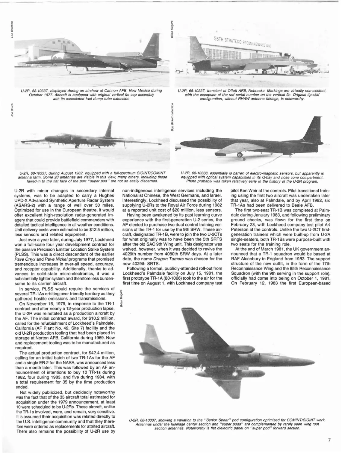
--~U-2R, 68-10337, displayed during an airshow at Cannon AFB, New Mexico during
October 1977. Aircraft is equipped with original vertical fin cap assembly
with its associated fuel dump tube extension.
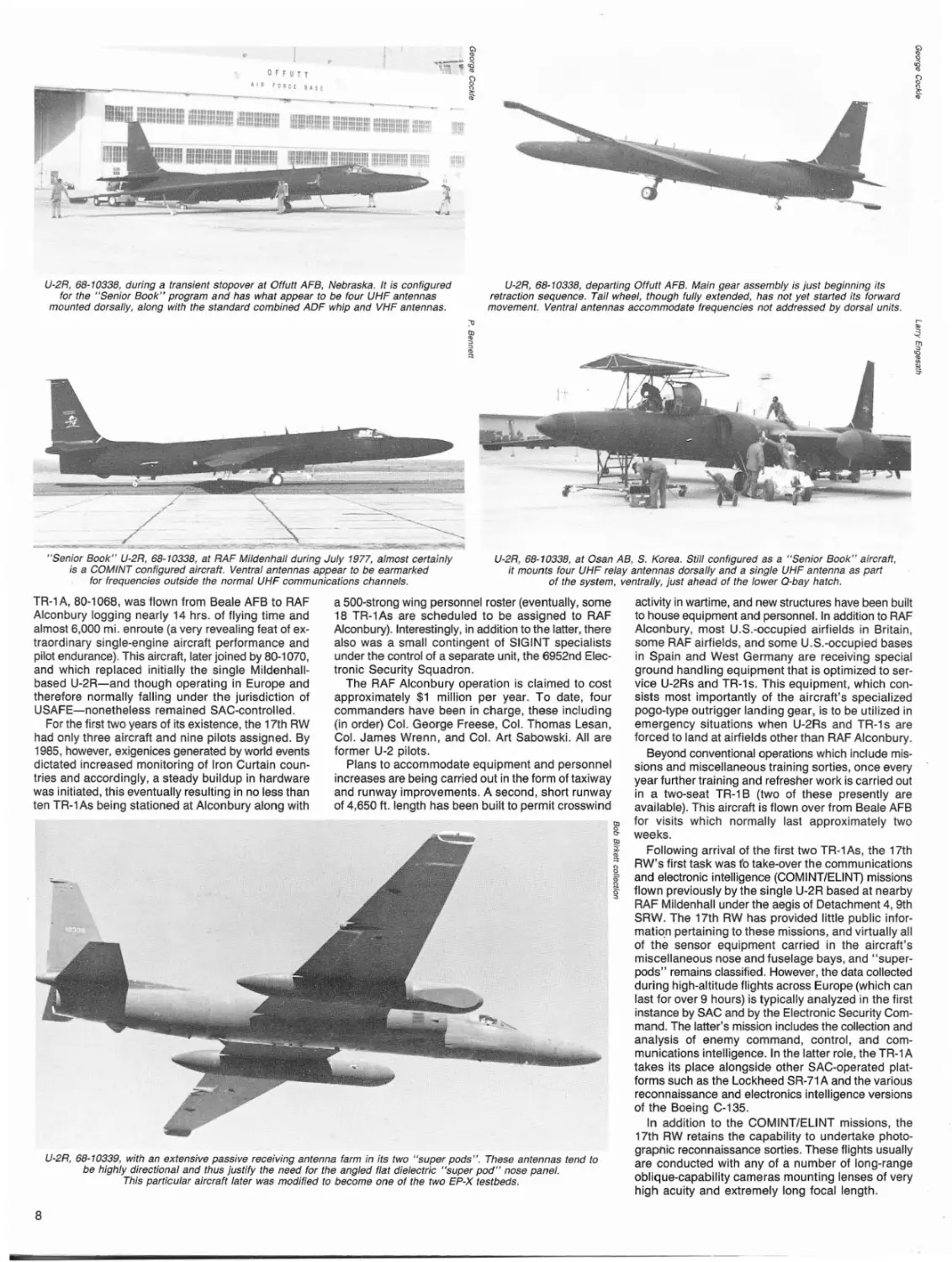
U-2R, 68-10337, transient at Offutt AFB, Nebraska. Markings are virtually non-existent,
with the exception of the red serial number on the vertical fin. Original tip-skid
configuration, without RHAW antenna fairings, is noteworthy.
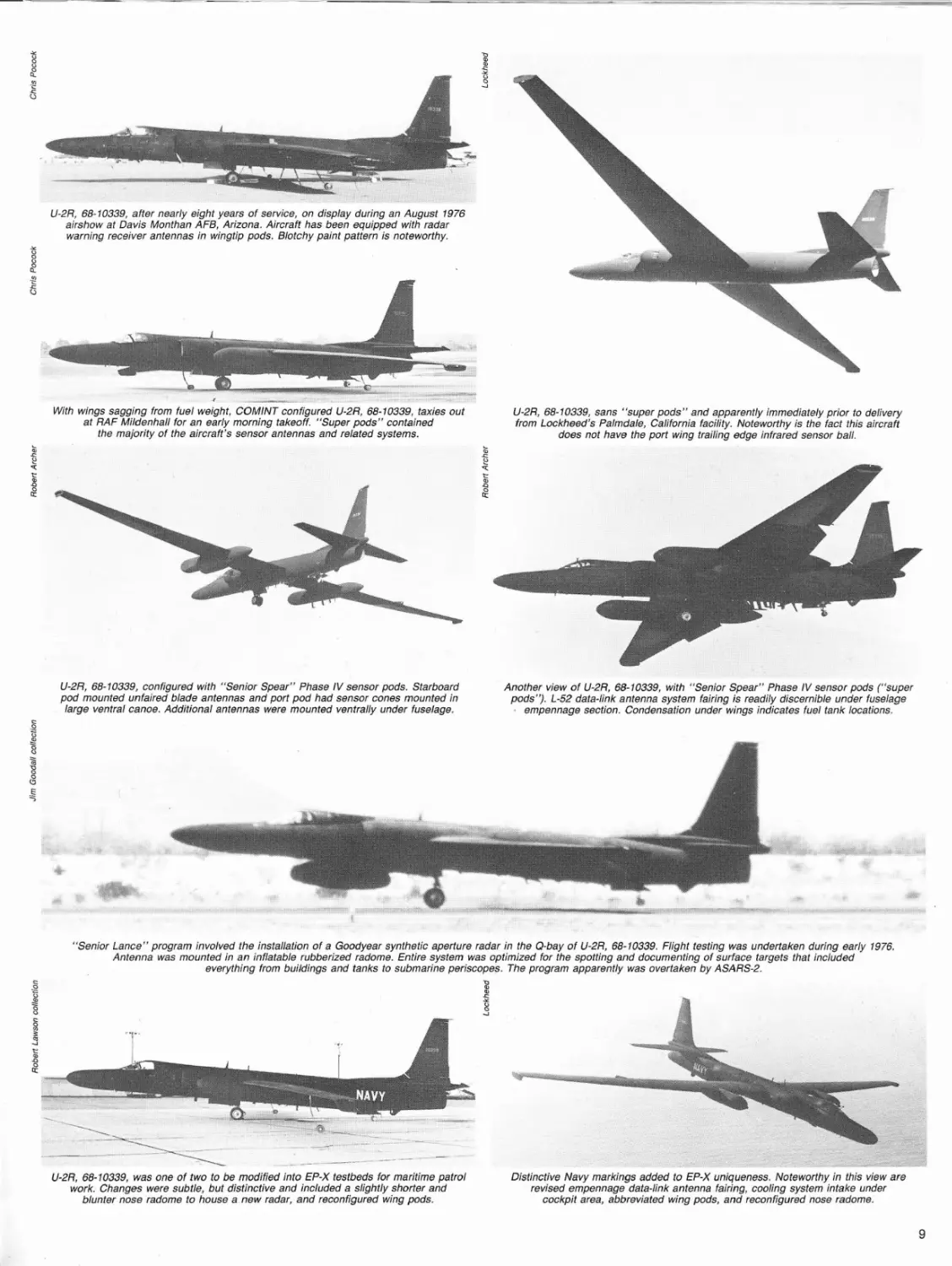
U-2R, 68·10337, during August 1982, equipped with a full-spectrum SIGINTICOMINT
antenna farm. Some 20 antennas are visible in this view; many others, including those
faired-in to the flat face of the port "super pod" are not so easily discerned.
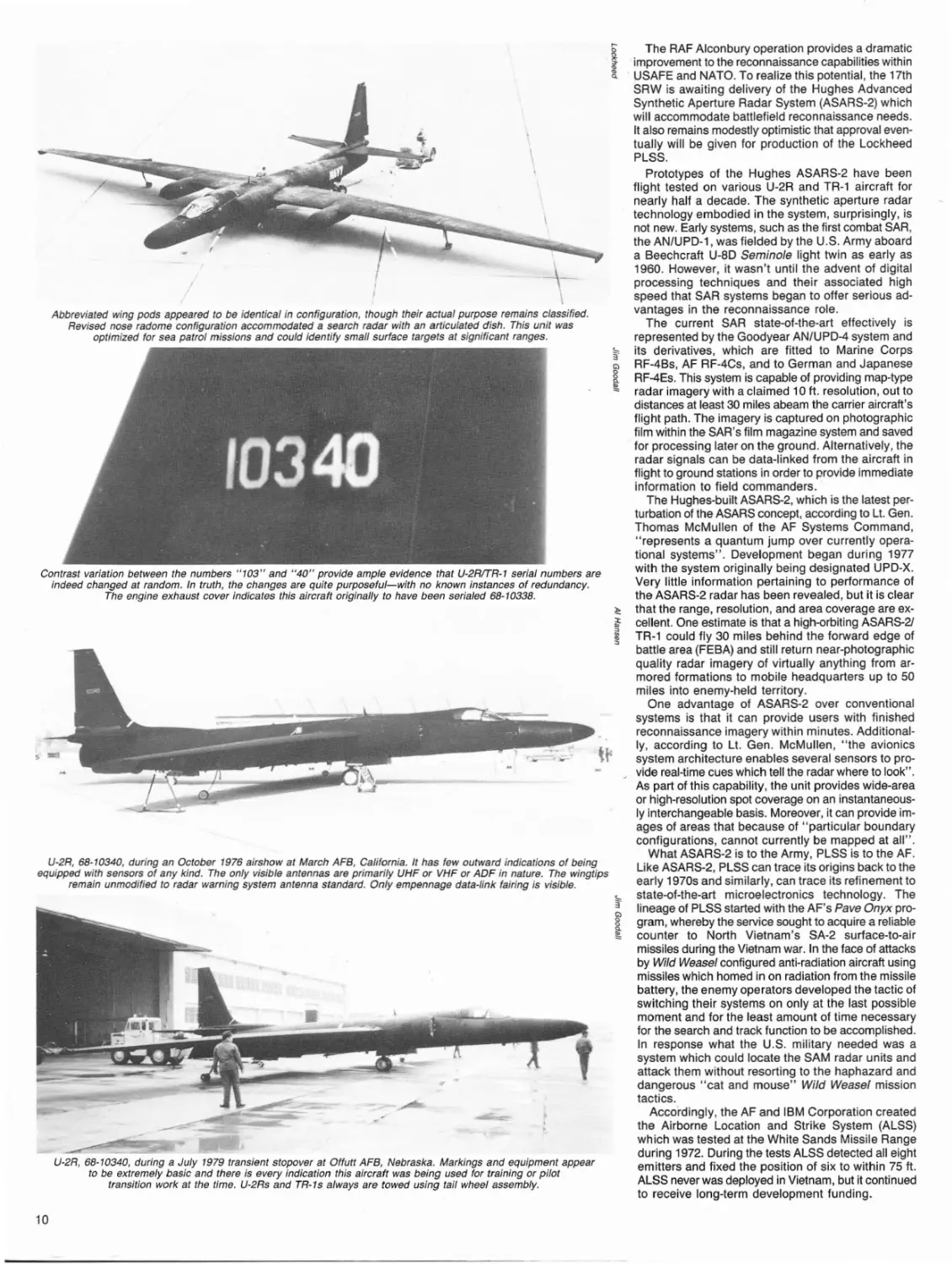
U-2R, 68-10338, essentially is barren of electro-magnetic sensors, but apparently is
equipped with optical system capabilities in its Q-bay and nose cone compartment.
Photo probably was taken relatively early in the history of the U-2R program.
U-2R with minor changes in secondary internal
systems, was to be adapted to carry a Hughes
UPD-X Advanced Synthetic Aperture Radar System
(ASARS-2) with a range of well over 50 miles.
Optimized for use in the European theatre, it would
offer excellent high-resolution radar·generated imagery that could provide battlefield commanders with
detailed tactical intelligence in all weather conditions.
Unit delivery costs were estimated to be $12.5 million,
less sensors and related equipment.
Just over a year later, during July 1977, Lockheed
won a full-scale four year development contract for
the passive Precision Emitter Location Strike System
(PLSS). This was a direct descendant of the earlier
Pave Onyx and Pave Nickel programs that promised
tremendous increases in over-all speed, accuracy,
and receptor capability. Additionally, thanks to ·advances in solid-state micro-electronics, it was a
substantially lighter system and therefore less burdensome to its carrier aircraft.
In service, PLSS would require the services of
several TR-1 As orbiting over friendly territory as they
gathered hostile emissions and transmissions.
On November 16,1979, in response to the TR-1
contract and after nearly a 12-year production lapse,
the U-2R was reinstated as a production aircraft by
the AF. The initial contract award, for $10.2 million,
called for the refurbishment of Lockheed's Palmdale,
California (AF Plant No. 42, Site 7) facility and the
old U-2R production tooling that had been placed in
storage at Norton AFB, California during 1969. New
and replacement tooling was to be manufactured as
required.
The actual production contract, for $42.4 million,
calling for an initial batch of two TR-1As for the AF
and a single ER-2 for the NASA, was announced less
than a month later. This was followed by an AF announcement of intentions to buy 10 TR-1s during
1982, four during 1983, and five during 1984, with
a total requirement for 35 by the time production
ended.
Not widely publicized, but decidedly noteworthy
was the fact that of the 35 aircraft total estimated for
acquisition under the 1979 announcement, at least
10 were scheduled to be U-2Rs. These aircraft, unlike
the TR·1s involved, were, and remain, very sensitive.
It is assumed their acquisition was related directly to
the U.S. intelligence community and that they therefore were ordered as replacements for attrited aircraft.
There also remains the possibility of U-2R use by
non-indigenous intelligence services including the
Nationalist Chinese, the West Germans, and Israel.
Interestingly, Lockheed discussed the possibility of
supplying U-2Rs to the Royal Air Force during 1982
at a reported unit cost of $20 million, less sensors.
Having been awakened by its past learning curve
experience with the first-generation U-2 series, the
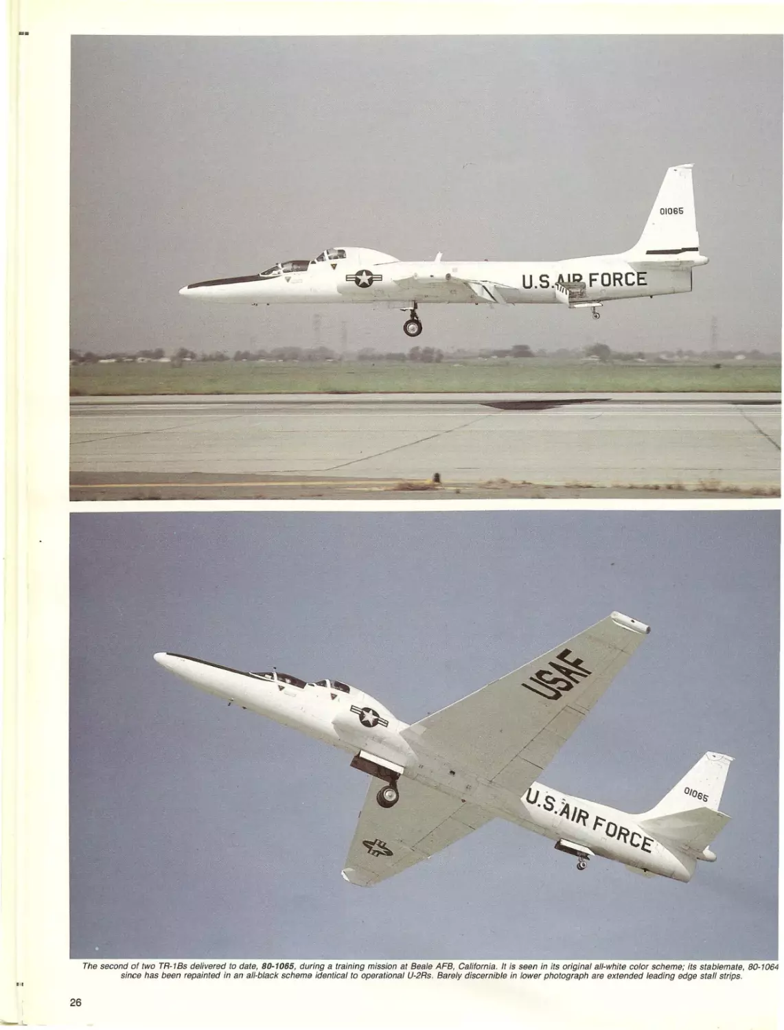
AF elected to purchase two dual control training versions of the TR-1 for use by the 9th SRW. These aircraft, designated TR-1 B, were to join the two U-2CTs
for what originally was to have been the 5th SRTS
after the old SAC 9th Wing unit. This designator was
waived, however, when it was decided to revive the
4029th number from 4080th SRW days. At a later
date, the name Dragon Tamers was chosen for the
new 4029th SRTS.
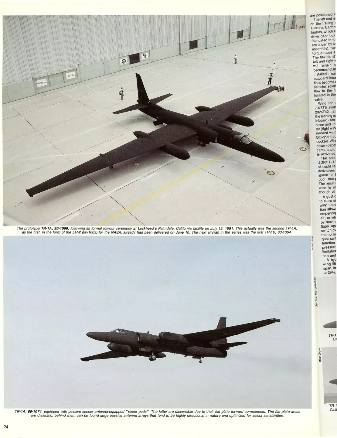
Following a formal, publicly-attended roll-out from
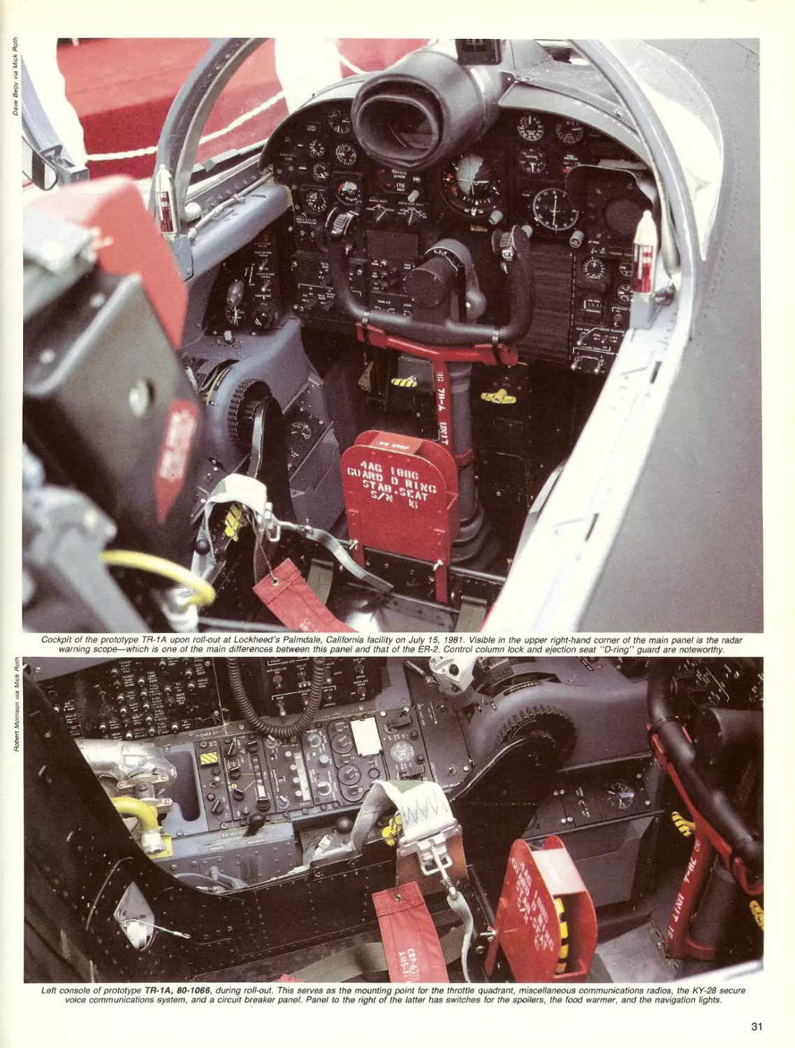
Lockheed's Palmdale facility on July 15, 1981, the
first prototype TR-1 A (80-1066) took to the air for the
first time on August 1, with Lockheed company test
pilot Ken Weir at the controls. Pilot transitional training using the first two aircraft was undertaken later
that year, also at Palmdale, and by April 1982, six
TR-1As had been delivered to Beale AFB.
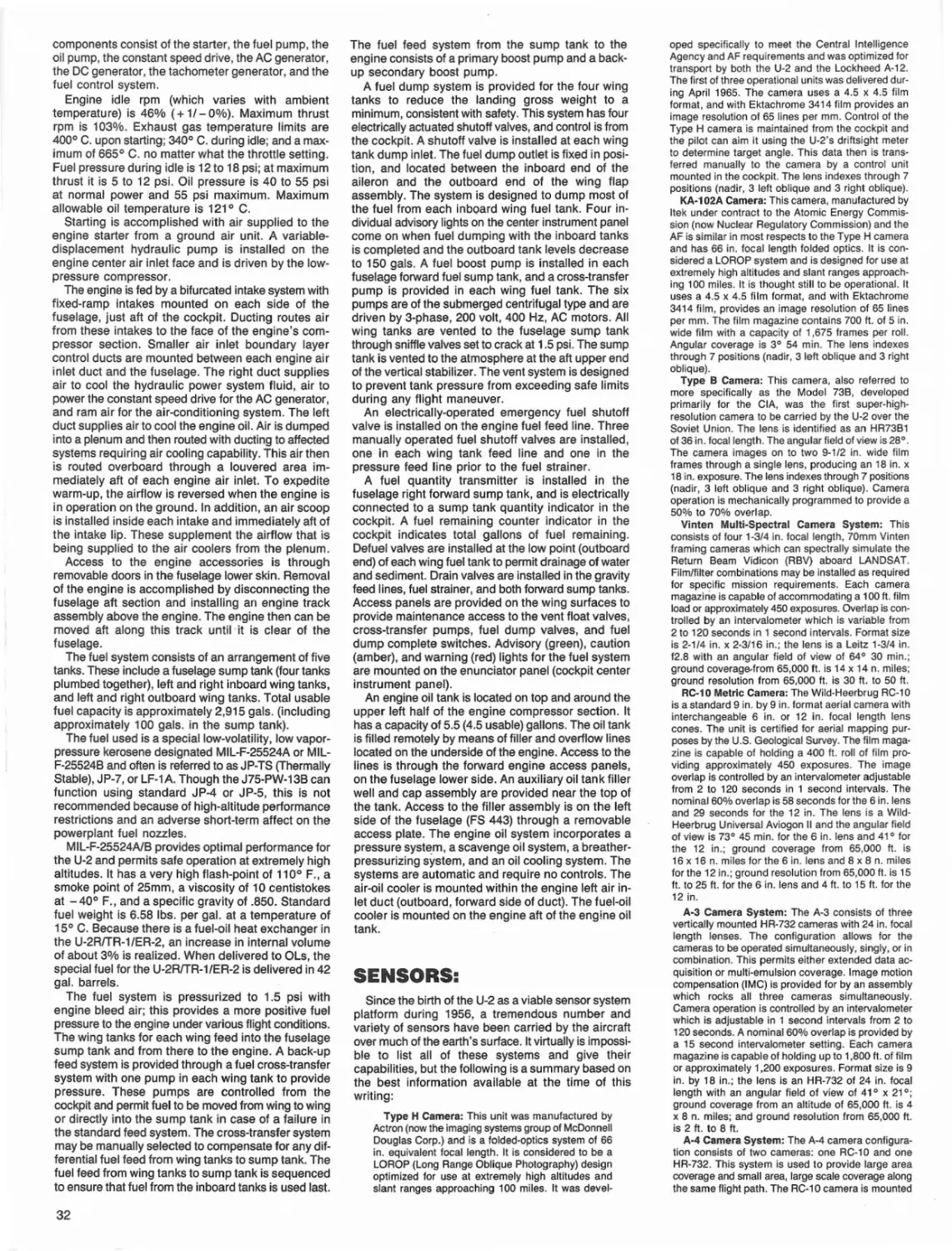
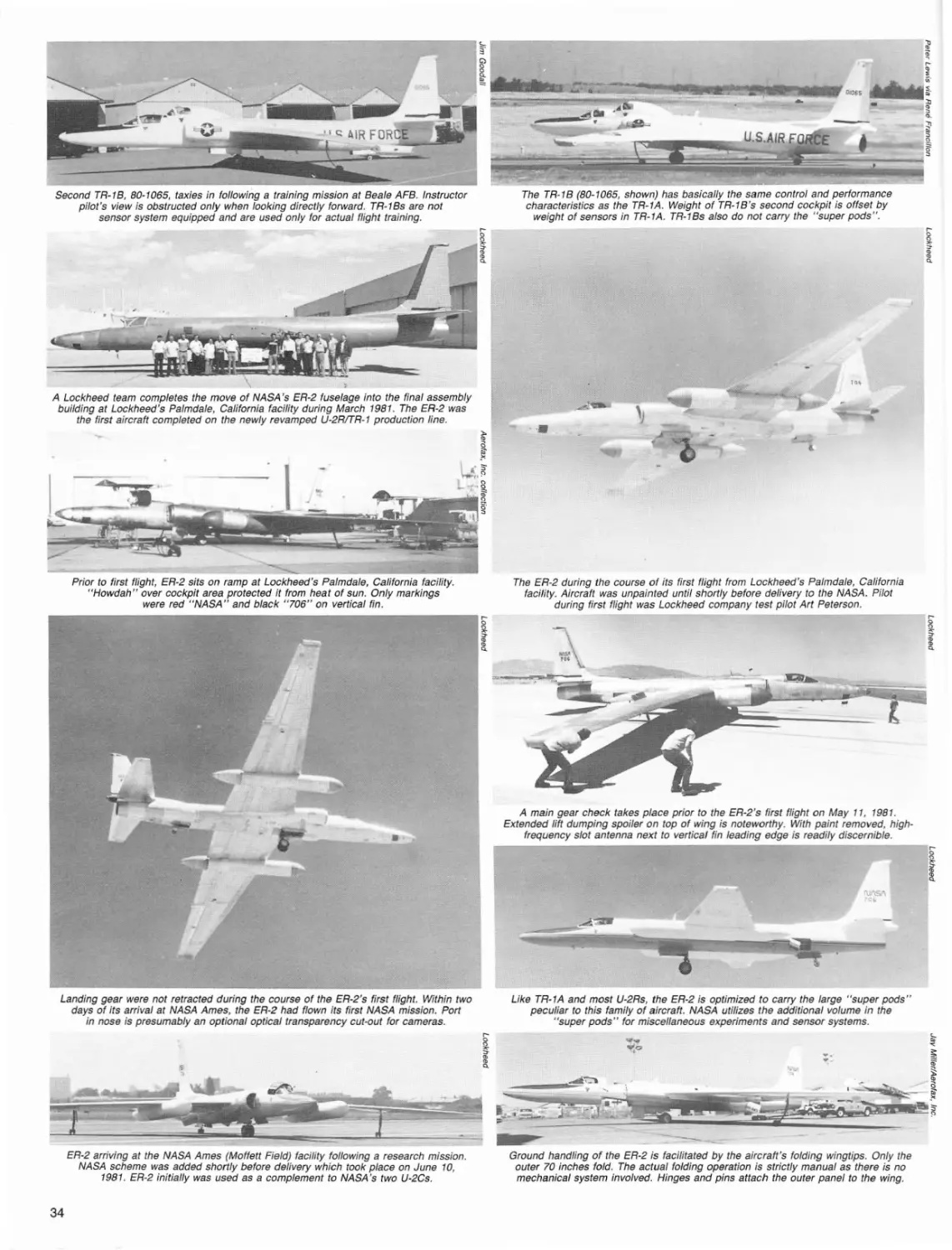
The first two-seat TR-1 B was completed at Palmdale during January 1983, and following preliminary
ground checks, was flown for the first time on
February 23, with Lockheed company test pilot Art
Peterson at the controls. Unlike the two U-2CT firstgeneration trainers which were built-up from U-2A
single-seaters, both TR-1 Bs were pu rpose-built with
two seats for the training role.
At the end of March ~ 981, the UK government announced that a TR-1 squadron would be based at
RAF Alconbury in England from 1983. The support
structure of the new outfit, in the form of the 17th
Reconnaissance Wing and the 95th Reconnaissance
Squadron (with the 9th serving in the support role),
officially had come into being on October 1, 1981.
On February 12, 1983 the first European-based
U-2R, 68-10337, showing a variation to the "Senior Spear" pod configuration optimized for COMINTISIGINT work.
Antennas under the fuselage center section and "super pods" are complemented by rarely seen wing root
section antennas. Noteworthy is flat dielectric panel on "super pod" forward section.
7
OFF
Ull
u1 1
rOller
&qt
,llll~
Ulfll
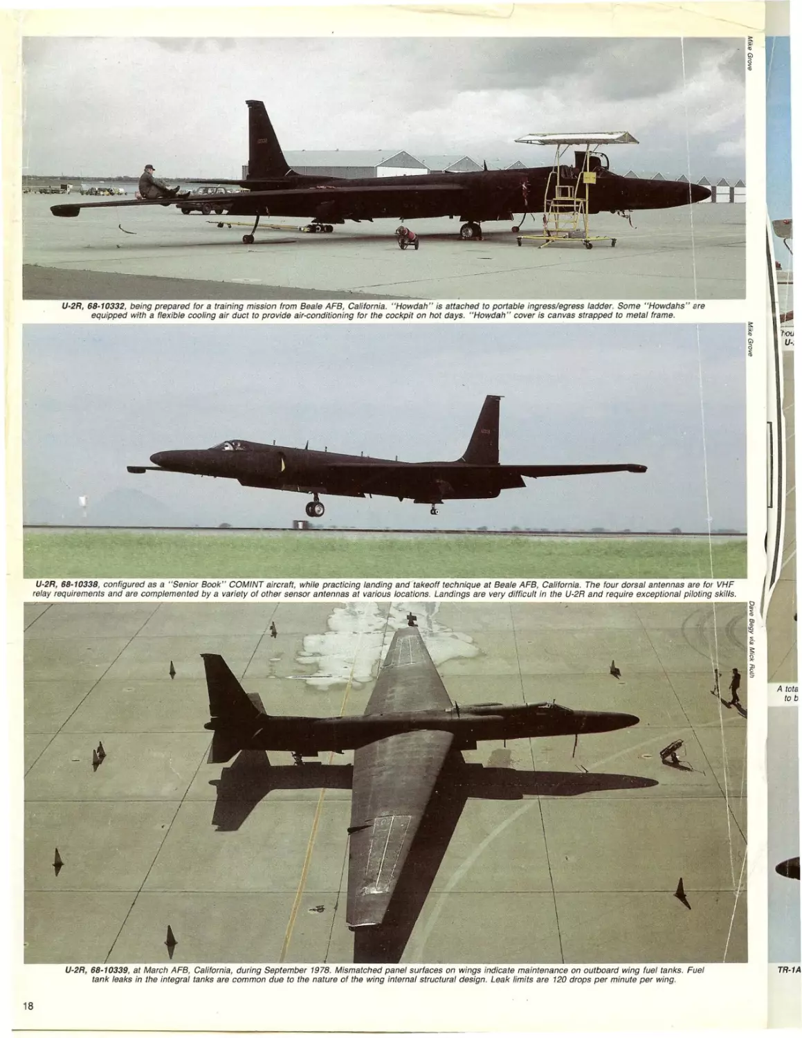
U-2R, 68-10338, during a transient stopover at Offutt AFB, Nebraska. It is configured
for the "Senior Book" program and has what appear to be four UHF antennas
mounted dorsally, along with the standard combined ADF whip and VHF antennas.
U·2R, 68-10338, departing Offutt AFB. Main gear assembly is just beginning its
retraction sequence. Tail wheel, though fully extended, has not yet started its forward
movement. Ventral antennas accommodate frequencies not addressed by dorsal units.
"Senior Book" U-2R, 68-10338, at RAF Mildenhall during July 1977, almost certainly
is a COMINT configured aircraft. Ventral antennas appear to be earmarked
for frequencies outside the normal UHF communications channels.
U-2R, 68-10338, at Osan AB, S. Korea. Still configured as a "Senior Book" aircraft,
it mounts four UHF relay antennas dorsally and a single UHF antenna as part
of the system, ventrally, just ahead of the lower Q-bay hatch.
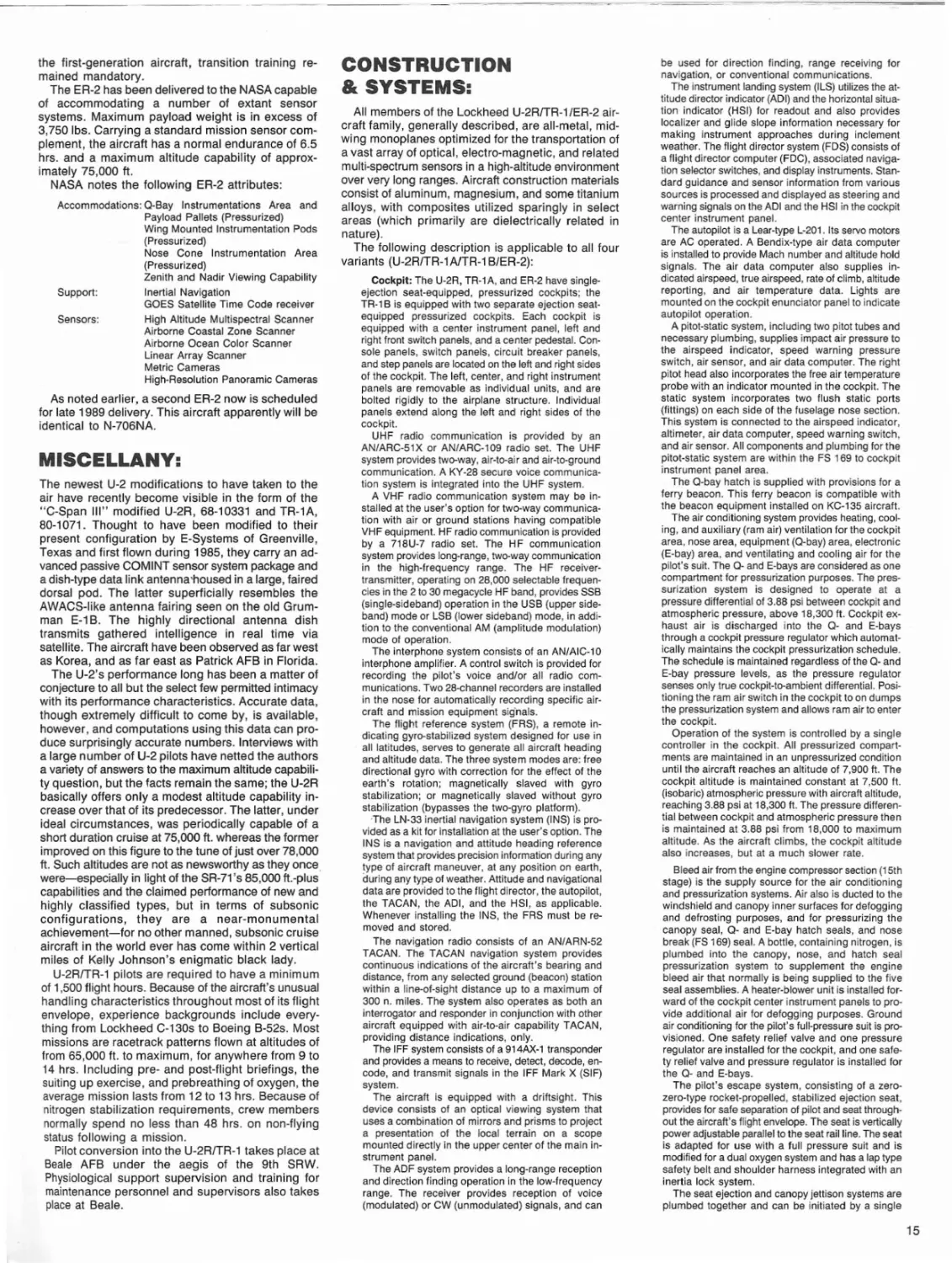
TR-1A, 80-1068, was flown from Beale AFB to RAF
Alconbury logging nearly 14 hrs. of flying time and
almost 6,000 mi. enroute (a very rel/ealing feat of extraordinary single-engine aircraft performance and
pilot endurance). This aircraft, later joined by 80-1070,
and which replaced initially the single Mildenhallbased U-2R-and though operating in Europe and
therefore normally falling under the jurisdiction of
USAFE-nonetheless remained SAC-controlled.
For the first two years of its existence, the 17th RW
had only three aircraft and nine pilots assigned. By
1985, however, exigenices generated by world events
dictated increased monitoring of Iron Curtain countries and accordingly, a steady buildup in hardware
was initiated, this eventually resulting in no less than
ten TR-1As being stationed at Alconbury along with
a 500-strong wing personnel roster (eventually, some
18 TR-1As are scheduled to be assigned to RAF
Alconbury). Interestingly, in addition to the latter, there
also was a small contingent of SIGINT specialists
under the control of a separate unit, the 6952nd Electronic Security Squadron.
The RAF Alconbury operation is claimed to cost
approximately $1 million per year. To date, four
commanders have been in charge, these including
(in order) Col. George Freese, Col. Thomas Lesan,
Col. James Wrenn, and Col. Art Sabowski. All are
former U-2 pilots.
Plans to accommodate equipment and personnel
increases are being carried out in the form of taxiway
and runway improvements. A second, short runway
of 4,650 ft. length has been built to permit crosswind
U-2R, 68-10339, with an extensive passive receiving antenna farm in its two "super pods". These antennas tend to
be highly directional and thus justify the need for the angled flat dielectric "super pod" nose panel.
This particular aircraft later was modified to become one of the two EP-X testbeds.
8
activity in wartime, and new structures have been built
to house equipment and personnel. In addition to RAF
Alconbury, most U.S.-occupied airfields in Britain,
some RAF airfields, and some U.S.-occupied bases
in Spain and West Germany are receiving special
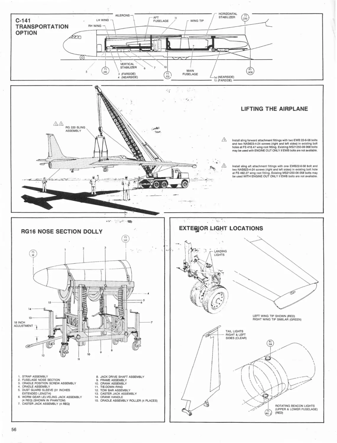
ground handling equipment that is optimized to service U-2Rs and TR-1s. This equipment, which consists most importantly of the aircraft's specialized
pogo-type outrigger landing gear, is to be utilized in
emergency situations when U-2Rs and TR-1s are
forced to land at airfields other than RAF Alconbury.
Beyond conventional operations which include missions and miscellaneous training sorties, once every
year further training and refresher work is carried out
in a two-seat TR-1 B (two of these presently are
available). This aircraft is flown over from Beale AFB
for visits which normally last approximately two
weeks.
Following arrival of the first two TR-1As, the 17th
RW's first task was fo take-over the communications
and electronic intelligence (COMINTIELlNT) missions
flown previously by the single U-2R based at nearby
RAF Mildenhall under the aegis of Detachment 4, 9th
SRW. The 17th RW has provided little public informatio.n pertaining to these missions, and virtually all
of the sensor equipment carried in the aircraft's
miscellaneous nose and fuselage bays, and "superpods" remains classified. However, the data collected
during high-altitude flights across Europe (which can
last for over 9 hours) is typically analyzed in the first
instance by SAC and by the Electronic Security Command. The latter's mission includes the collection and
analysis of enemy command, control, and communications intelligence. In the latter role, the TR-tA
takes its place alongside other SAC-operated platforms such as the Lockheed SR-71A and the various
reconnaissance and electronics intelligence versions
of the Boeing C-135.
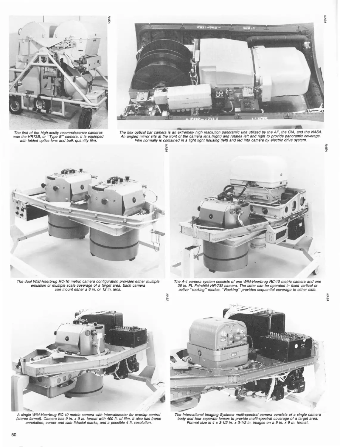
In addition to the COMINT/ELINT missions, the
17th RW retains the capability to undertake photographic reconnaissance sorties. These flights usually
are conducted with any of a number of long-range
oblique-capability cameras mounting lenses of very
high acuity and extremely long focal length.
U-2R, 68-10339, after nearly eight years of service, on display during an August 1976
airshow at Davis Monthan AFB, Arizona. Aircraft has been equipped with radar
warning receiver antennas in wingtip pods. Blotchy paint pattern is noteworthy.
With wings sagging from fuel weight, COMINT configured U-2R, 68-10339, taxies out
at RAF Mildenhall for an early morning takeoff. "Super pods" contained
the majority of the aircraft's sensor antennas and related systems.
U-2R, 68-10339, sans "super pods" and apparently immediately prior to delivery
from Lockheed's Palmdale, California facility. Noteworthy is the fact this aircraft
does not have the port wing trailing edge infrared sensor ball.
U-2R, 68-10339, configured with "Senior Spear" Phase IV sensor pods. Starboard
pod mounted unfaired blade antennas and port pod had sensor cones mounted in
large ventral canoe. Additional antennas were mounted ventrally under fuselage.
Another view of U-2R, 68-10339, with "Senior Spear" Phase IV sensor pods ("super
pods'}. L-52 data-link antenna system fairing is readily discernible under fuselage
. empennage section. Condensation under wings indicates fuel tank locations.
"Senior Lance" program involved the installation of a Goodyear synthetic aperture radar in the Q-bay of U-2R. 68-10339. Flight testing was undertaken during early 1976.
Antenna was mounted in an inflatable rubberized radome. Entire system was optimized for the spotting and documenting of surface targets that included
everything from buildings and tanks to submarine periscope!,. The program apparently was overtaken by ASARS-2.
U-2R, 68-10339, was one of two to be modified into EP-X testbeds for maritime patrol
work. Changes were subtle, but distinctive and included a slightly shorter and
blunter nose radome to house a. new radar, and reconfigured wing pods.
Distinctive Navy markings added to EP-X uniqueness. Noteworthy in this view are
revised empennage data-link antenna fairing. cooling system intake under
cockpit area, abbreviated wing pods, and reconfigured nose radome.
9
Abbreviated wing pods appeared to be identical in configuration, though their actual purpose remains classified.
Revised nose radome configuration accommodated a search radar with an articulated dish. This unit was
optimized for sea patrol missions and could identify small surface targets at significant ranges.
Contrast variation between the numbers "103" and "40" provide ample evidence that U-2RfTR-l serial numbers are
indeed changed at random. In truth, the changes are quite purposeful-with no known instances of redundancy.
The engine exhaust cover indicates this aircraft originally to have been serialed 68-10338.
U-2R, 68-10340, during an October 1976 airshow at March AFB, California. It has few outward indications of being
equipped with sensors of any kind. The only visible antennas are primarily UHF or VHF or ADF in nature. The wingtips
remain unmodified to radar warning system antenna standard. Only empennage data-link fairing is visible.
U-2R, 68-10340, during a July 1979 transient stopover at Offutt AFB, Nebraska. Markings and equipment appear
to be extremely basic and there is every indication this aircraft was being used for training or pilot
transition work at the time. U-2Rs and TR-ls always are towed using tail wheel assembly.
10
The RAF Alconbury operation provides a dramatic
.improvement to the reconnaissance capabilities within
. IJSAFE and NATO. To realize this potential, the 17th
SRW is awaiting delivery of the Hughes Advanced
Synthetic Aperture Radar System (ASARS-2) which
will accommodate battlefield reconnaissance needs.
It also remains modestly optimistic that approval eventually will be given for production of the Lockheed
PLSS.
Prototypes of the Hughes ASARS-2 have been
flight tested on various U-2R and TR-1 aircraft for
nearly half a decade. The synthetic aperture radar
technology embodied in the system, surprisingly, is
not new. Early systems, such as the first combat SAR,
the AN/UPD-1, was fielded by the U.S. Army aboard
a Beechcraft U-8D Seminole light twin as early as
1960. However, it wasn't until the advent of digital
processing techniques and their associated high
speed that SAR systems began to offer serious advantages in the reconnaissance role.
The current SAR state-of-the-art effectively is
represented by the Goodyear AN/UPD-4 system and
its derivatives, which are fitted to Marine Corps
RF-4Bs, AF RF-4Cs, and to German and Japanese
RF-4Es. This system is capable of providing map-type
radar imagery with a claimed 10ft. resolution, out to
distances at least 30 miles abeam the carrier aircraft's
flight path. The imagery is captured on photographic
film within the SAR's film magazine system and saved
for processing later on the ground. Alternatively, the
radar signals can be data-linked from the aircraft in
flight to ground stations in order to provide immediate
information to field commanders ..
The Hughes-built ASARS-2, which is the latest perturbation of the ASARS concept, according to Lt. Gen.
Thomas McMullen of the AF Systems Command,
"represents a quantum jump over currently operational systems". Development began during 1977
with the system originally being designated UPD-X.
Very little information pertaining to performance of
the ASARS-2 radar has been revealed, but it is clear
that the range, resolution, and area coverage are excellent. One estimate is that a high-orbiting ASARS-2I
TR-1 could fly 30 miles behind the forward edge of
battle area (FEBA) and still return near-photographic
quality radar imagery of virtually anything from armored formations to mobile headquarters up to 50
miles into enemy-held territory.
One advantage of ASARS-2 over conventional
systems is that it can provide users with finished
reconnaissance imagery within minutes. Additionally, according to Lt. Gen. McMullen, "the avionics
system architecture enables several sensors to provide real-time cues which tell the radar where to look".
As part of this capability, the unit provides wide-area
or high-resolution spot coverage on an instantaneously interchangeable basis. Moreover, it can provide images of areas that because of "particular boundary
configurations, cannot currently be mapped at all".
What ASARS-2 is to the Army, PLSS is to the AF.
Like ASARS-2, PLSS can trace its origins back to the
early 1970s and similarly, can trace its refinement to
state-of-the-art microelectronics technology. The
lineage of PLSS started with the AF's Pave Onyx program, whereby the service sought to acquire a reliable
counter to North Vietnam's SA-2 surface-to-air
missiles during the Vietnam war. In the face of attacks
by Wild Weasel configured anti-radiation aircraft using
missiles which homed in on radiation from the missile
battery, the enemy operators developed the tactic of
switching their systems on only at the last possible
moment and for the least amount of time necessary
for the search and track function to be accomplished.
In response what the U.S. military needed was a
system which could locate the SAM radar units and
attack them without resorting to the haphazard and
dangerous "cat and mouse" Wild Weasel mission
tactics.
Acco'rdingly, the AF and IBM Corporation created
the Airborne Location and Strike System (ALSS)
which was tested at the White Sands Missile Range
during 1972. During the tests ALSS detected all eight
emitters and fixed the position of six to within 75 ft.
ALSS never was deployed in Vietnam, but it continued
to receive long-term development funding.
During 1975, five SAC Lockheed U-2Cs, equipped
with ALSS, were deployed to RAF Weathersfield for
a two-month trial of the equipment in the European
environment (during the same year, the more advanced PLSS program received its first funding). The
aim of the tests was to improve ALSS capabilities by
providing wider coverage, better signal sorting and
data processing, and better maintainability and
reliability. PLSS would aim to locate continuous-wave,
as well as pulse emitters. Competitive contracts were
let, and two years later, it was announced that a team
led by Lockheed Missile and Space Company had
won, and would be undertaking full-scale development. Other contractors on the team included ESystems, Collins, Control Data, Harris Electronics,
Motorola, and Sperry Univac.
The TR-1 became the PLSS transport almost by
default. During the 1975 time-frame, no commitment
to any particular platform had been made, and only
the Compass Cope RPV program, with its proposed
high-altitude and long-endurance capabilities, was
considered a strong prospect. Compass Cope was
cancelled during the autumn of 1977, however, and
a few months later Lockheed received approval for
initial TR-1 production.
The PLSS and TR-1 programs proceeded in parallel, but it was not always apparent the two would
meet. The difficulty lay primarily in funding constraints
levied on the PLSS system itself. Its complexity was
to prove its achilles heel, and to date, no firm production commitment on behalf of the AF has been
made.
The PLSS system program office (SPO) was
located at Wright-Patterson AFB, Ohio and drew its
funding and support from the AF Systems Command.
Due to SAC involvement in providing pilots, and TAC
involvement in accommodating airframe and support
personnel needs, the PLSS SPO interfaced directly
with the two commands. Development and testing of
the system and its TR-1 A platforms was accommodated by the responsible test organization (RTO)
at Nellis AFB, Nevada and involved TR-1As from
Beale AFB. Later, initial operational testing, also at
Nellis with Beale TR-1As, brought together personnel from the Communications and Electronic Security
commands and from the Air Training and Operational
Test and Evaluation centers. Similar activity took
place between the AF and Lockheed Missiles and
Space Co.'s Austin, Texas division, which was the
prime contractor. Lockheed had thirteen different subcontractors and a considerable number of suppliers
and vendors involved in the program, as well.'
PLSS funding has been reduced significantly over
the past several years, and only five aircraft (one of
which is a spare) have been PLSS configured. The
first PLSS-equipped aircraft flew during late 1983, and
four additional PLSS equipped U-2Rs followed shortly
afterwards. The latter began full-scale test flights at
Beale AFB during September 1984. During 1987, the
consensus of opinion was that the program effectively
had been shelved; to date, no changes in program
status have become apparent.
Basically, PLSS works on the same principle as
ALSS. Intercept receiving systems are carried aloft
by three aircraft which set up racetrack patterns in
friendly skies parallel to the enemy front line. The position of each aircraft is determined precisely by its
reference to ground-based DME transponders. When
enemy electromagnetic emissions are picked up by
the receivers, the point from which they emanate can
be fixed by a sophisticated triangulation process,
whereby the time taken for the emissions to be intercepted by each aircraft in turn is measured and compared. This is called the "time-of-arrival" (TOA) technique, and it is complemented by "direction-of-arrival"
(DOA) measurements. The sophisticated processing
job of comparing the minute differences between the
two is accommodated by a ground station to which
the data is down-lined from each aircraft. The ground
station can then direct a strike aircraft towards the
target, and it can derive precise navigation data
enroute from anyone of the three cruising TOA/DOA
aircraft.
The great advantage to the PLSS system is that
the radiating target can be attacked even after it has
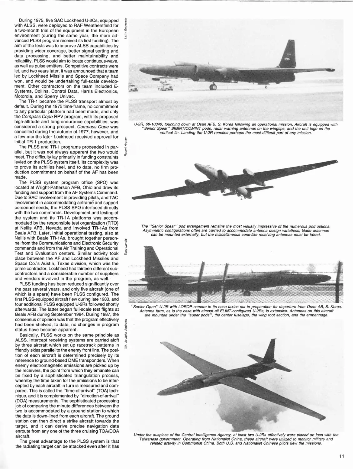
U-2R, 68-10340, touching down at Osan AFB, S. Korea following an operational mission. Aircraft is equipped with
"Senior Spear" BIGINT/COMINT pods, radar warning antennas on the wingtips, and the unit logo on the
vertical fin. Landing the U-2R remains perhaps the most difficult part of any mission.
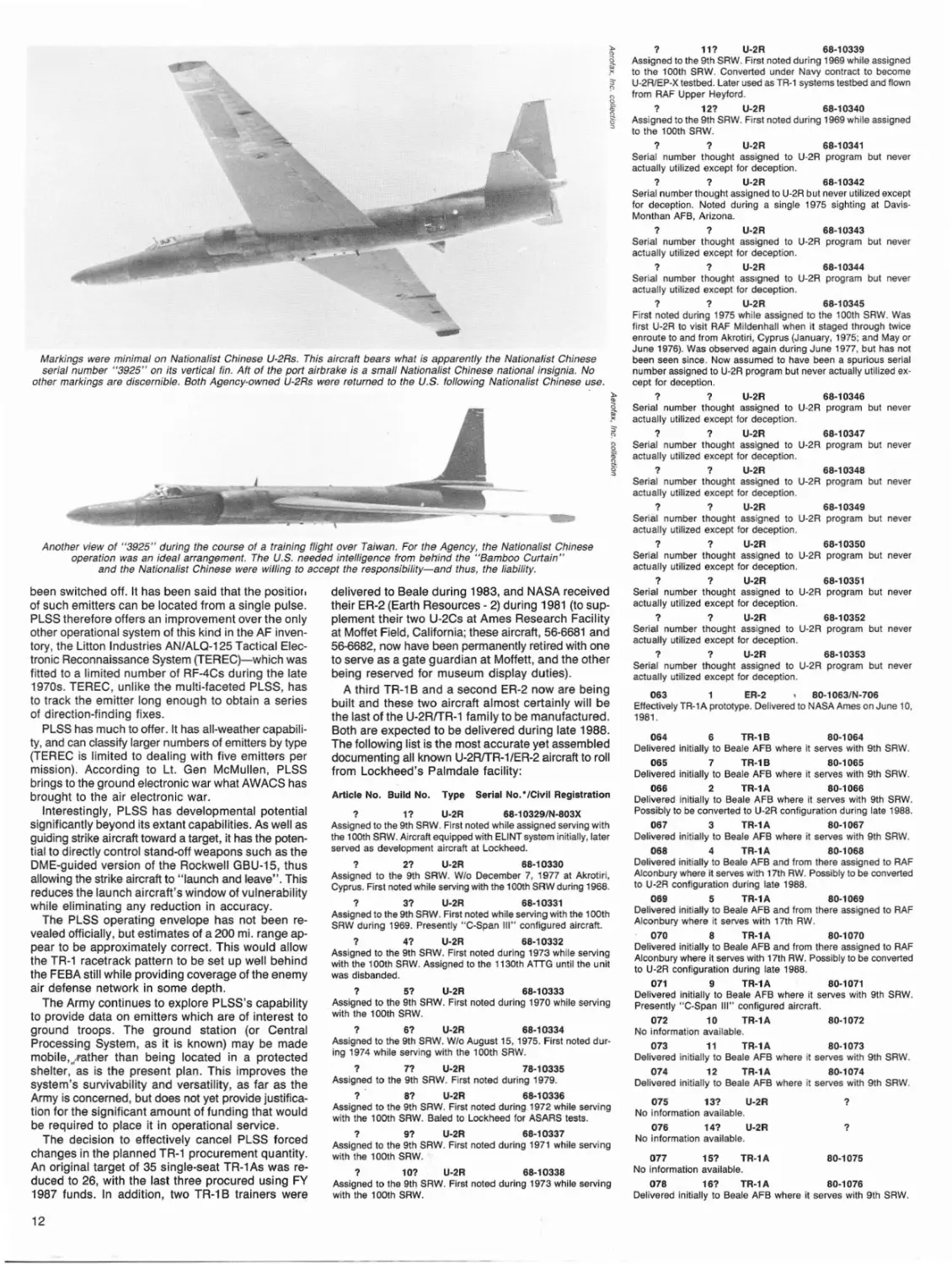
The "Senior Spear" pod arrangement remains the most visually impressive of the numerous pod options.
Asymmetric configurations often are carried to accommodate antenna design variations; blade antennas
can be mounted externally, but the miscellaneous cone-like receiving antennas must be faired.
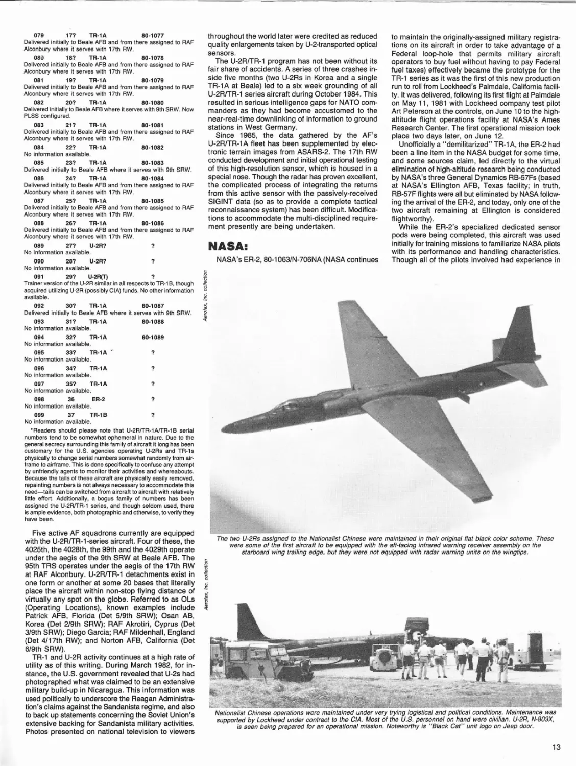
"Senior Open" U-2R with LOROP camera in its nose taxies out in preparation for departure from Osan AB, S. Korea.
Antenna farm, as is the case with almost all ELlNT-configuredU-2Rs, is extensive. Antennas on this aircraft
are mounted under the "super pods", the center fuselage, the wing root section, and the empennage.
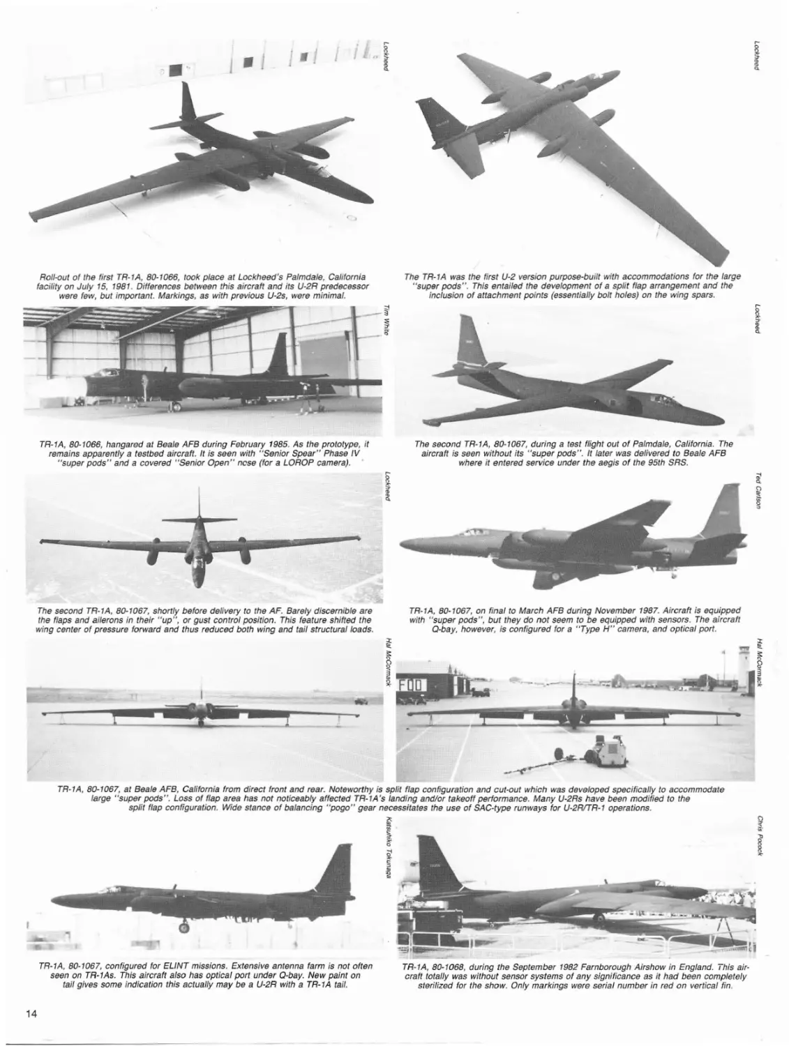
Under the auspices of the Central Intelligence Agency, at least two U-2Rs effectively were placed on loan with the
Taiwanese government. Operating from Nationalist China, these aircraft were utilized to monitor military and
related activity in Communist China. Both US. and Nationalist Chinese pilots flew the missions.
11
1
111
U-2R
68-10339
Assigned to the 9th SRW. First noted during 1969 while assigned
to the 100th SRW. Converted under Navy contract to become
U-2R1EP-X testbed. Later used as TR-1 systems testbed and flown
from RAF Upper Heyford.
1
121
U-2R
68-10340
Assigned to the 9th SRW. First noted during 1969 while assigned
to the 100th SRW.
1
1
U-2R
68-10341
Serial number thought assigned to U-2R program but never
actually utilized except for deception.
1
1
U-2R
68-10342
Serial number thought assigned to U-2R but never utilized except
for deception. Noted during a single 1975 sighting at DavisMonthan AFB, Arizona.
1
1
U-2R
68-10343
Seriai number thought assigned to U-2R program but never
actually utilized except for deception.
1
1
U-2R
68-10344
Serial number thought assIgned to U-2R program but never
actually utilized except for deception.
1
1
U-2R
68-10345
First noted during 1975 while assigned to the 100th SRW. Was
first U-2R to visit RAF Mildenhall when it staged through twice
emoute to and from Akrotiri, Cyprus (January, 1975; and Mayor
June 1976). Was observed again during June 1977, but has not
Markings were minimal on Nationalist Chinese U-2Rs. This aircraft bears what is apparently the Nationalist Chinese
serial number "3925" on its vertical fin. Aft of the port airbrake is a small Nationalist Chinese national insignia. No
other markings are discernible. Both Agency-owned U-2Rs were returned to the U.S. following Nationalist Chinese use.
Another view of "3925" during the course of a training flight over Taiwan. For the Agency, the Nationalist Chinese
operation was an ideal arrangement. The U.S. needed intelligence from betrind the "Bamboo Curtain"
and the Nationalist Chinese were willing to accept the responsibility-and thus, the liability.
been switched off. It has been said that the positior,
of such emitters can be located from a single pulse.
PLSS therefore offers an improvement over the only
other operational system of this kind in the AF inventory, the Litton Industries AN/ALQ-125 Tactical Electronic Reconnaissance System (TEREC)-which was
fitted to a limited number of RF-4Cs during the late
1970s. TEREC, unlike the multi-faceted PLSS, has
to track the emitter long enough to obtain a series
of direction-finding fixes.
PLSS has much to offer. It has all-weather capability, and can classify larger numbers of emitters by type
(TEREC is limited to dealing with five emitters per
mission). According to Lt. Gen McMullen, PLSS
brings to the ground electronic war what AWACS has
brought to the air electronic war.
Interestingly, PLSS has developmental potential
significantly beyond its extant capabilities. As well as
guiding strike aircraft toward a target, it has the potential to directly control stand·off weapons such as the
DME-guided version of the Rockwell GBU-15, thus
allowing the strike aircraft to "launch and leave". This
reduces the launch aircraft's window of vulnerability
while eliminating any reduction in accuracy.
The PLSS operating envelope has not been revealed officially, but estimates of a 200 mi. range appear to be approximately correct. This would allow
the TR-1 racetrack pattern to be set up well behind
the FEBA still while providing coverage of the enemy
air defense network in some depth.
The Army continues to explore PLSS's capability
to provide data on emitters which are of interest to
ground troops. The ground station (or Central
Processing System, as it is known) may be made
mobile,,.,,ather than being located in a protected
shelter, as is the present plan. This improves the
system's survivability and versatility, as far as the
Army is concerned, but does not yet provide justification for the significant amount of funding that would
be required to place it in operational service.
The decision to effectively cancel PLSS forced
changes in the planned TR-1 procurement quantity.
An original target of 35 single-seat TR-1 As was reduced to 26, with the last three procured using FY
1987 funds. In addition, two TR-1 B trainers were
12
delivered to Beale during 1983, and NASA received
their ER-2 (Earth Resources - 2) during 1981 (to supplement their two U-2Cs at Ames Research Facility
at Moffet Field, California; these aircraft, 56-6681 and
56-6682, now have been permanently retired with one
to serve as a gate guardian at Moffett, and the other
being reserved for museum display duties).
A third TR-1 B and a second ER-2 now are being
built and these two aircraft almost certainly will be
the last of the U-2RITR-1 family to be manufactured.
Both are expected to be delivered during late 1988.
The follOWing list is the most accurate yet assembled
documenting all known U-2R1TR-1/ER-2 aircraft to roll
from Lockheed's Palmdale facility:
been seen since. Now assumed to have been a spurious serial
number assigned to U-2R program but never actually utilized except for deception.
1
1
U-2R
68-10346
Serial number thought assigned to U-2R program but never
actually utilized except for deception.
1
1
U-2R
68-10347
Serial number thought assigned to U-2R program but never
actually utilized except for deception.
1
1
U-2R
68-10348
Serial number thought assigned to U-2R program but never
actually utilized except for deception.
1
1
U-2R
68-10349
Serial number thought assigned to U-2R program but never
actually utilized except for deception.
1
1
U-2R
68-10350
Serial number thought assigned to U-2R program but never
actually utilized except for deception.
1
1
U-2R
68-10351
Serial number thought assigned to U-2R program but never
actually utilized except for deception.
1
1
U-2R
68-10352
Serial number thought assigned to U-2R program but never
actually utilized except for deception.
1
1
U-2R
68-10353
Serial number thought assigned to U-2R program but never
actually utilized except for deception.
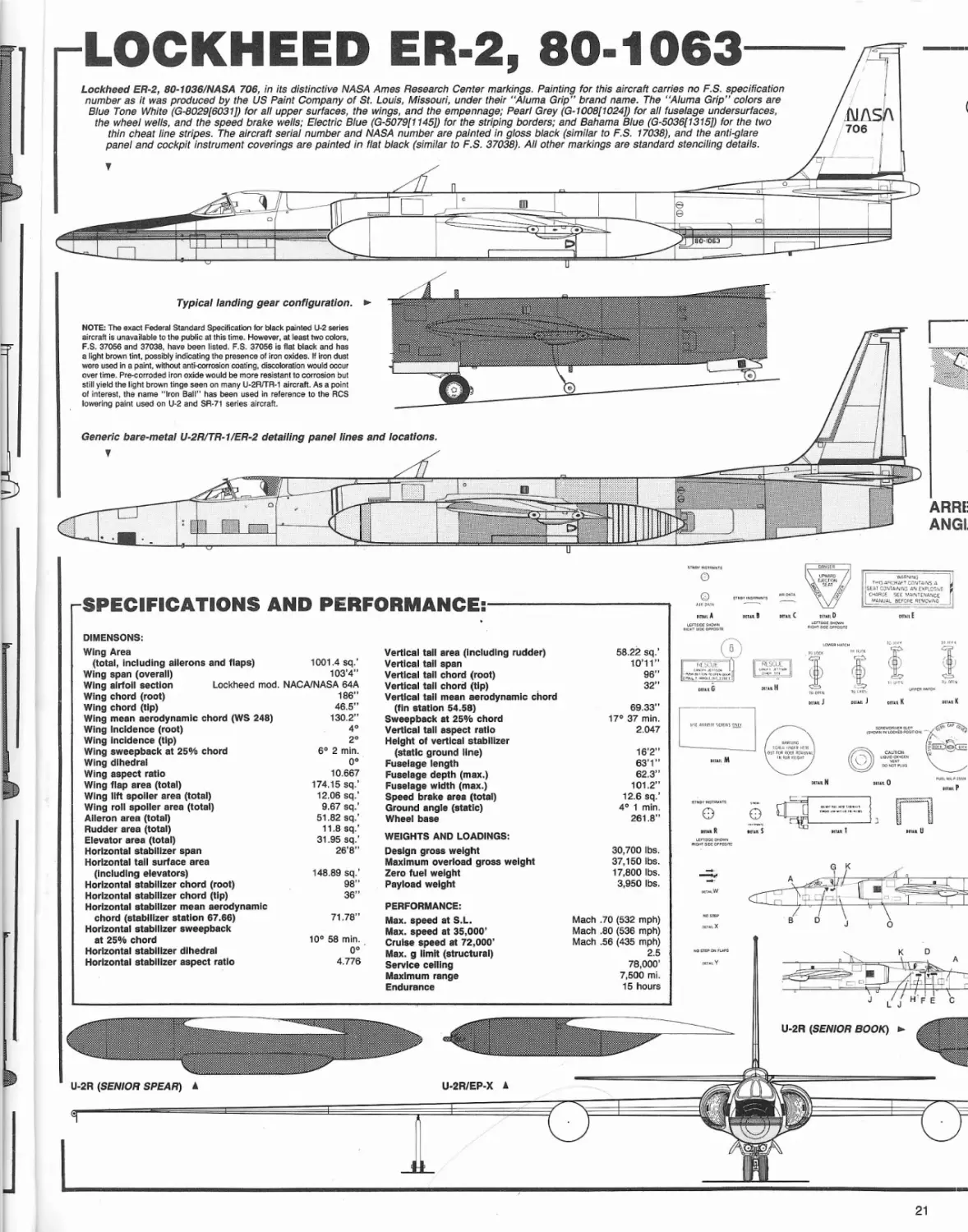
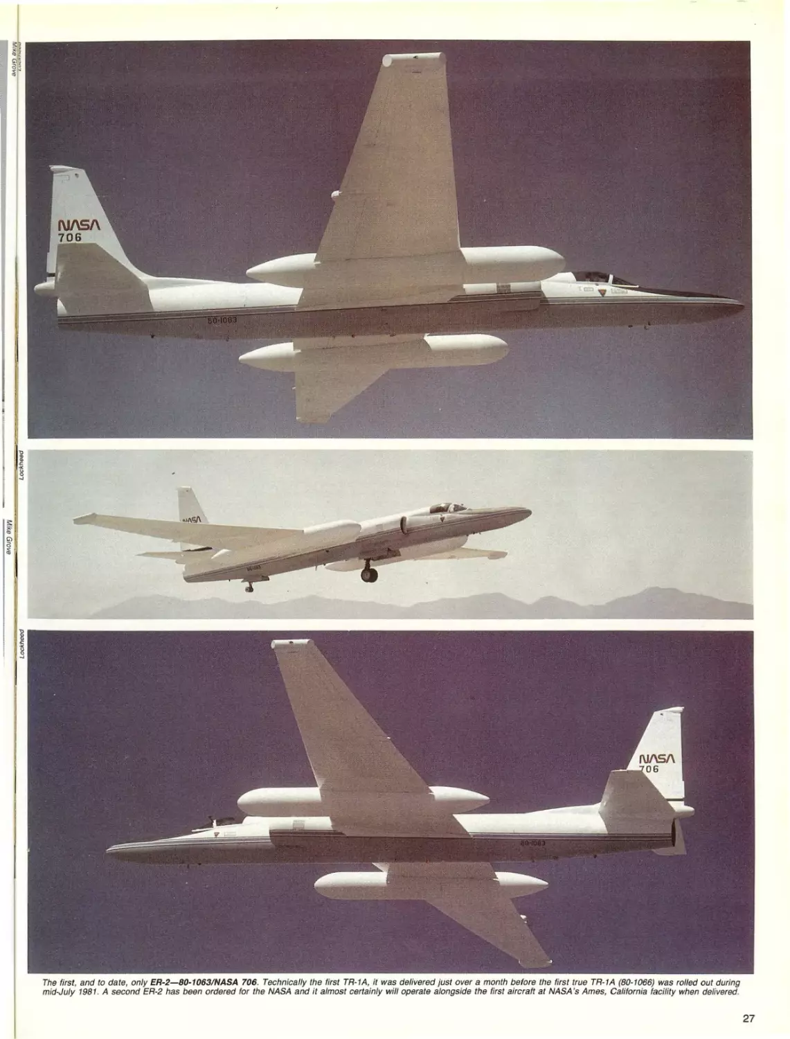
80-1063/N-706
063
1
ER-2
Effectively TR-1A prototype. Delivered to NASA Ames on June 10,
1981.
064
6
TR-1B
80-1064
Delivered initially to Beale AFB where it serves with 9th SRW.
065
7
TR-1B
80-1065
Delivered initially to Beale AFB where it serves with 9th SRW.
1
21
U-2R
68-10330
Assigned to the 9th SRW. Wlo December 7, 1977 at Akrotiri,
Cyprus. First noted while serving with the 100th SRW during 1968.
066
2
TR-1A
80-1066
Delivered initially to Beale AFB where it serves with 9th SRW.
Possibly to be converted to U-2R configuration during late 1988.
067
3
TR-1A
80-1067
Delivered initially to Beale AFB where it serves with 9th SRW.
068
4
TR-1A
80-1068
Delivered initially to Beale AFB and from there assigned to RAF
Alconbury where it serves with 17th RW. Possibly to be converted
to U-2R configuration during late 1988.
1
31
U-2R
68-10331
Assigned to the 9th SRW. First noted while serving with the 100th
SRW during 1969. Presently "C-Span III" configured aircraft.
069
5
TR-1A
80-1069
Delivered initially to Beale AFB and from there assigned to RAF
Alconbury where it serves with 17th RW.
Article No. Build No.
Type
Serial No. "/Clvll Registration
68-10329/N-803X
1
11
U-2R
Assigned to the 9th SRW. First noted while assigned serving with
the toOth SRW. Aircraft equipped with ELiNT system initially, later
served as development aircraft at Lockheed.
1
41
U-2R
68-10332
Assigned to the 9th SRW. First noted during 1973 while serving
with the 100th SRW. Assigned to the 1130th ATTG until the unit
was disbanded.
51
U-2R
68-10333
1
Assigned to the 9th SRW. First noted during 1970 while serving
with the 100th SRW.
61
U-2R
68-10334
1
Assigned to the 9th SRW. Wlo August 15, 1975. First noted during 1974 while serving with the 100th SRW.
7?
U-2R
78-10335
1
Assigned to the 9th SRW. First noted during 1979.
1 .
81
U-2R
68-10336
Assigned to the 9th SRW. First noted during. 1972 while serving
with the 100th SRW. Baled to Lockheed for ASARS tests.
1
91
U-2R
68-10337
Assigned to the 9th SRW. First noted during 1971 while serving
with the 100th SRW.....
1
101
U-2R
68-10338
Assigned to the 9th SRW. First noted during 1973 while serving
with the 100th SRW.
070
8
TR-1A
80-1070
Delivered initially to Beale AFB and from there assigned to RAF
Alconbury where it serves with 17th RW. Possibly to be converted
to U-2R configuration during late 1988.
071
9
TR-1A
80-1071
Delivered initially to Beale AFB where it serves with 9th SRW.
Presently "C-Span III" configured aircraft.
072
10
TR-1A
No information available.
80-1072
073
11
TR-1A
80-1073
Delivered initially to Beale AFB where it serves with 9th SRW.
074
12
TR-1A
80-1074
Delivered initially to Beale AFB where it serves with 9th SRW.
075
131
U-2R
1
076
141
U-2R
No information available.
1
077
151
TR-1A
No information available.
80-1075
No information available.
TR-1 A
80-1076
078
161
Delivered initially to Beale AFB where it serves with 9th SRW.
079
171
TR-1A
80-1077
Delivered initially to Beale AFB and from there assigned to RAF
Alconbury where it serves with 17th RW.
08D
18?
TR-1A
80-1078
Delivered initially to Beale AFB and from there assigned to RAF
Alconbury where it serves with 17th RW.
081
19?
TR-1A
80·1079
Delivered initially to Beale AFB and from there assigned to RAF
Alconbury where it serves with 17th RW.
082
20?
TR-1A
80·1080
Delivered initially to Beale AFB where it serves with 9th SRW. Now
PLSS configured.
083
21?
TR-1A
80·1081
Delivered initially to Beale AFB and from there assigned to RAF
Alconbury where it serves with 17th RW.
084
22?
TR-1A
80-1082
No information available.
085
23?
TR-1A
80-1083
Delivered initially to Beale AFB where it serves with 9th SRW.
086
24?
TR-1A
80-1084
Delivered initially to Beale AFB and from there assigned to RAF
Alconbury where it serves with 17th RW.
087
25?
TR-1A
80-1085
Delivered initially to Beale AFB and from there assigned to RAF
Alconbury where it serves with 17th RW.
088
26?
TR-1A
80-1086
Delivered initially to Beale AFB and from there assigned to RAF
Alconbury where it serves with 17th RW.
089
271
U-2R?
?
No information available.
090
28?
U-2R?
No information available.
?
throughout the world later were credited as reduced
quality enlargements taken by U-2-transported optical
sensors.
The U-2RrrR-1 program has not been without its
fair share of accidents. A series of three crashes inside five months (two U-2Rs in Korea and a single
TR-1A at Beale) led to a six week grounding of all
U-2RrrR-1 series aircraft during October 1984. This
resulted in serious intelligence gaps for NATO commanders as they had become accustomed to the
near-real-time downlinking of information to ground
stations in West Germany.
Since 1985, the data gathered by the AF's
U-2RrrR-1A fleet has been supplemented byelectronic terrain images from ASARS-2. The 17th RW
conducted development and initial operational testing
of this high-resolution sensor, which is housed in a
special nose. Though the radar has proven excellent,
the complicated process of integrating the returns
from this active sensor with the passively-received
SIGINT data (so as to provide a complete tactical
reconnaissance system) has been difficult. Modifications to accommodate the multi-disciplined requirement presently are being undertaken.
NASA:
NASA's ER-2, 80-1063/N-706NA (NASA continues
to maintain the originally-assigned military registrations on its ai rcraft in order to take advantage of a
Federal loop-hole that permits military aircraft
operators to buy fuel without having to pay Federal
fuel taxes) effectively became the prototype for the
TR-1 series as it was the first of this new production
run to roll from Lockheed's Palmdale, California facility. It was delivered, following its first flight at Palmdale
on May 11, 1981 with Lockheed company test pilot
Art Peterson at the controls, on June 10 to the highaltitude flight operations facility at NASA's Ames
Research Center. The first operational mission took
place two days later, on June 12.
Unofficially a "demilitarized" TR-1 A, the ER-2 had
been a line item in the NASA budget for some time,
and some sources claim, led directly to the virtual
elimination of high-altitude research being conducted
by NASA's three General Dynamics RB-57Fs (based
at NASA's Ellington AFB, Texas facility; in truth,
RB-57F flights were all but eliminated by NASA following the arrival of the ER-2, and today, only one of the
two aircraft remaining at Ellington is considered
flightworthy).
While the ER-2's specialized dedicated sensor
pods were being completed, this aircraft was used
initially for training missions to familiarize NASA pilots
with its performance and handling characteristics.
Though all of the pilots involved had experience in
091
29?
U-2R(T)
?
Trainer version of the U-2R similar in all respects to TR-1 B, though
acquired utilizing U-2R (possibly CIA) funds. No other information
available.
092
30?
TR-l A
80-1087
Delivered initially to Beale. AFB where it serves with 9th SRW.
093
31?
TR-1A
No information available.
80-1088
094
32?
TR-1A
No information available.
80-1089
095
33?
TR-1A
No information available.
?
096
34?
TR-1A
No information available.
?
097
No information
098
No information
099
No information
?
35?
TR-1A
available.
36
ER-2
available.
37
TR-l B
available.
?
?
• Readers should please note that U-2RITR-l AlTR-l B serial
numbers tend to be somewhat ephemeral in nature. Due to the
general secrecy surrounding this family of aircraft it long has been
customary for the U.S. agencies operating U-2Rs and TR-ls
physically to change serial numbers somewhat randomly from airframe to airframe. This is done specifically to confuse any attempt
by unfriendly agents to monitor their activities and whereabouts.
Because the tails of these aircraft are physically easily removed,
repainting numbers is not always necessary to accommodate this
need-tails can be switched from aircraft to aircraft with relatively
little effort. Additionally, a bogus family of numbers has been
assigned the U-2RITR-1 series, and though seldom used, there
is ample evidence, both photographic and othelWise, to verify they
have been.
Five active AF squadrons currently are equipped
with the U-2RrrR-1-series aircraft. Four of these, the
4025th, the 4028th, the 99th and the 4029th operate
under the aegis of the 9th SRW at Beale AFB. The
95th TRS operates under the aegis of the 17th RW
at RAF Alconbury. U-2RrrR-1 detachments exist in
one form or another at some 20 bases that literally
place the aircraft within non-stop flying distance of
virtually any spot on the globe. Referred to as OLs
(Operating Locations), known examples include
Patrick AFB, Florida (Det 5/9th SRW); Osan AB,
Korea (Det 2/9th SRW); RAF Akrotiri, Cyprus (Det
3/9th SRW); Diego Garcia; RAF Mildenhall, England
(Det 4/17th RW); and Norton AFB, California (Det
6/9th SRW).
TR-1 and U-2R activity continues at a high rate of
utility as of this writing. During March 1982, for instance, the U.S. government revealed that U-2s had
photographed what was claimed to be an extensive
military build-up in Nicaragua. This information was
used politically to underscore the Reagan Administration's claims against the Sandanista regime, and also
to back up statements concerning the Soviet Union's
extensive backing for Sandanista military activities.
Photos presented on national television to viewers
The two U-2Rs assigned to the Nationalist Chinese were maintained in their original flat black color scheme. These
were some of the first aircraft to be equipped with the aft-facing infrared warning receiver assembly on the
starboard wing trailing edge, but they were not equipped with radar warning units on the wingtips.
Nationalist Chinese operations were maintained under very trying logistical and political conditions. Maintenance was
supported by Lockheed under contract to the CIA. Most of the U.S. personnel on hand were civilian. U-2R, N-803X,
is seen being prepared for an operational mission. Noteworthy is "Black Cat" unit logo on Jeep door.
13
0."
I
The TR-IA was the first U-2 version purpose-built with accommodations for the large
"super pods". This entailed the development of a split flap arrangement and the
inclusion of attachment points (essentially bolt holes) on the wing spars.
Roll-out of the first TR-1A, 80-1066, took place at Lockheed's Palmdale, California
facility on July 15, 1981. Differences between this aircraft and its U-2R predecessor
were few, but important. Markings, as with previous U-2s, were minimal.
~
~
1_'-:::;";"'-"11--- ~
TR-l A, 80-1066, hangared at Beale AFB during February 1985. As the prototype, it
remains apparently a testbed aircraft. It is seen with "Senior Spear" Phase IV
"super pods" and a covered "Senior Open" ncse (for a LOROP camera).
The second TR-1A, 80-1067, during a test flight out of Palmdale, California. The
aircraft is seen without its "super pods". It later was delivered to Beale AFB
where it entered service under the aegis of the 95th SRS.
The second TR-1A, 80-1067, shortly before delivery to the AF. Barely discernible are
the flaps and ailerons in their "up", or gust control position. This feature shifted the
wing center of pressure forward and thus reduced both wing and tail structural loads.
TR-1A, 80-1067, on final to March AFB during November 1987. Aircraft is equipped
with "super pods", but they do not seem to be equipped with sensors. The aircraft
Q-bay, however, is configured for a "Type H" camera, and optical port.
TR-1A, 80-1067, at Beale AFB, California from direct front and rear. Noteworthy is split flap configuration and cut-out which was developed specifically to accommodate
large "super pods". Loss of flap area has not noticeably affected TR-1A's landing and/or takeoff performance. Many U-2Rs have been modified to the
split flap configuration. Wide stance of balancing "pogo" gear necessitates the use of SAC-type runways for U-2RITR-l operations.
~,
~
~O
~
§._
0<
I
TR-1A, 80-1067, configured for ELINT missions. Extensive antenna farm is not often
seen on TR-1As. This aircraft also has optical port under Q-bay. New paint on
tail gives some indication this actually may be a U-2R with a TR-IA tail.
14
TR-1A, 80-1068, during the September 1982 Farnborough Airshow in England. This aircraft totally was without sensor systems of any significance as it had been completely
sterilized for the show. Only markings were serial number in red on vertical fin.
the first-generation aircraft, transition training remained mandatory.
The ER-2 has been delivered to the NASA capable
of accommodating a number of extant sensor
systems. Maximum payload weight is in excess of
3,750 Ibs. Carrying a standard mission sensor complement, the aircraft has a normal endurance of 6.5
hrs. and a maximum altitude capability of approximately 75,000 ft.
NASA notes the following ER-2 attributes:
Accommodations: Q·Bay Instrumentations Area and
Payload Pallets (Pressurized)
Wing Mounted Instrumentation Pods
(Pressurized)
Nose Cone Instrumentation Area
(Pressurized)
Zenith and Nadir Viewing Capability
Support:
Inertial Navigation
GOES Satellite Time Code receiver
Sensors:
High Altitude Multispectral Scanner
Airborne Coastal Zone Scanner
Airborne Ocean Color Scanner
Linear Array Scanner
Metric Cameras
High-Resolution Panoramic Cameras
As noted earlier, a second ER-2 now is scheduled
for late 1989 delivery. This aircraft apparently will be
identical to N-706NA.
MISCELLANY:
The newest U-2 modifications to have taken to the
air have recently become visible in the form of the
"C-Span III" modified U-2R, 68-10331 and TR-1A,
80-1071. Thought to have been modified to their
present configuration by E-Systems of Greenville,
Texas and first flown during 1985, they carry an advanced passive COMINT sensor system package and
a dish-type data link antenna'housed in a large, faired
dorsal pod. The latter superficially resembles the
AWACS-like antenna fairing seen on the old Grumman E-1 B. The highly directional antenna dish
transmits gathered intelligence in real time via
satellite. The aircraft have been observed as far west
as Korea, and as far east as Patrick AFB in Florida.
The U-2's performance long has been a matter of
conjecture to all but the select few permitted intimacy
with its performance characteristics. Accurate data,
though extremely difficult to come by, is available,
however, and computations using this data can produce surprisingly accurate numbers. Interviews with
a large number of U-2 pilots have netted the auth'ors
a variety of answers to the maximum altitude capability question, but the facts remain the same; the U-2R
basically offers only a modest altitude capability increase over that of its predecessor. The latter, under
ideal circumstances, was periodically capable of a
short duration cruise at 75,000 ft. whereas the former
improved on this figure to the tune of just over 78,000
ft. Such altitudes are not as newsworthy as they once.
were-especially in light of the SR-71 's 85,000 ft.-plus
capabilities and the claimed performance of new and
highly classified types, but in terms of subsonic
configurations, they are a near-monumental
achievement-for no other manned, subsonic cruise
aircraft in the world ever has come within 2 vertical
miles of Kelly Johnson's enigmatic black lady.
U-2RfTR-1 pilots are required to have a minimum
of 1,500 flight hours. Because of the aircraft's unusual
handling characteristics throughout most of its flight
envelope, experience backgrounds include everything from Lockheed C-130s to Boeing B-52s. Most
missions are racetrack patterns flown at altitudes of
from 65,000 ft. to maximum, for anywhere from 9 to
14 hrs. Including pre- and post-flight briefings, the
suiting up exercise, and prebreathing of oxygen, the
average mission lasts from 12 to 13 hrs. Because of
nitrogen stabilization requirements, crew members
normally spend no less than 48 hrs. on non-flying
status following a mission.
Pilot conversion into the U-2RfTR-1 takes place at
Beale AFB under the aegis of the 9th SRW.
Physiological support supervision and training for
maintenance personnel and supervisors also takes
place at Beale.
CONSTRUCTION
& SYSTEMS:
All members of the Lockheed U-2RfTR-1/ER-2 aircraft family, generally described, are all-metal, midwing monoplanes optimized for the transportation of
a vast array of optical, electro-magnetic, and related
multi-spectrum sensors in a high-altitude environment
over very long ranges. Aircraft construction materials
consist of aluminum, magnesium, and some titanium
alloys, with composites utilized sparingly in select
areas (which primarily are dielectrically related in
nature).
The follOWing description is applicable to all four
variants (U-2R/TR-1 AlTR-1 B/ER-2):
Cockpit: The U-2R, TR-1A, and ER-2 have singleejection seat-equipped, pressurized cockpits; the
TR-1 B is equipped with two separate ejection seatequipped pressurized cockpits. Each cockpit is
equipped with a center instrument panel, left and
right front switch panels, and a center pedestal. Console panels, switch panels, circuit breaker panels,
and step panels are located on the left and right sides
of the cockpit. The left, center, and right instrument
panels are removable as individual units, and are
bolted rigidly to the airplane structure. Individual
panels extend along the left and right sides of the
cockpit.
UHF radio communication is provided by an
AN/ARC-51 X or AN/ARC-109 radio set. The UHF
system provides two-way, air·to-air and air-to-ground
communication. A KY-28 secure voice communication system is integrated into the UHF system.
A VHF radio communication system may be installed at the user's option for two-way communication with air or ground stations having compatible
VHF equipment. HF radio communication is provided
by a 718U-7 radio set. The HF communication
system provides long-range, two-way communication
in the high-frequency range. The HF receivertransmitter, operating on 28,000 selectable frequencies in the 2 to 30 megacycle HF band, provides SSB
(single-sideband) operation in the USB (upper sideband) mode or LSB (lower sideband) mode, in addition to the conventional AM (amplitude modulation)
mode of operation.
The interphone sys1em consists of an AN/AIC-10
interphone amplifier. A control switch is provided for
recording the pilot's voice and/or all radio communications. Two 28-ehannel recorders are installed
in the nose for automatically recording specific aircraft and mission equipment sig·nals.
The flight reference system (FRS), a remote indicating gyro-stabilized system designed for use in
all latitudes, serves to generate all aircraft heading
and altitude data. The three system modes are: free
directional gyro with correction for the effect of the
earth's rotation; magnetically slaved with gyro
stabilization; or magnetically slaved without gyro
stabilization (bypasses the two-gyro platform).
·The LN-33 inertial navigation system (INS) is provided as a kit for installation at the user's option. The
INS is a navigation and attitude heading reference
system that provides precision information duri ng any
type of aircraft maneuver, at any position on earth,
during any type of weather. Attitude and navigational
data are provided to the flight director, the autopilot,
the TACAN, the ADI, and the HSI, as applicable.
Whenever installing the INS, the FRS must be removed and stored.
The navigation radio consists of an AN/ARN-52
TACAN. The TACAN navigation system provides
continuous indications of the aircraft's bearing and
distance, from any selected ground (beacon) station
within a line-of-sight distance up to a maximum of
300 n. miles. The system aiso operates as both an
interrogator and responder in conjunction with other
aircraft equipped with air-to-air capability TACAN,
providing distance indications, only.
The IFF system consists of a 914AX-1 transponder
and provides a means to receive, detect, decode, encode, and transmit signals in the IFF Mark X (SIF)
system.
The aircraft is equipped with a driftsight. This
device consists of an optical viewing system that
uses a combination of mirrors and prisms to project
a presentation of the local terrain on a scope
mounted directly in the upper center of the main instrument panel.
The ADF system provides a long-range reception
and direction finding operation in the low-frequency
range. The receiver provides reception of voice
(modulated) or CW (unmodulated) signals, and can
be used for direction finding, range receiving for
navigation, or conventional communications.
The instrument landing system (ILS) utilizes the attitude director indicator (ADI) and the horizontal situation indicator (HSI) for readout and also provides
localizer and glide slope information necessary for
making instrument approaches during inclement
weather. The flight director system (FDS) consists of
a flight director computer (FOG), associated navigation selector switches, and display instruments. Standard guidance and sensor information from various
sources is processed and displayed as steering and
warning signals on the ADI and the HSI in the cockpit
center instrument panel.
The autopilot is a Lear-type L-201. Its servo motors
are AC operated. A Bendix-type air data computer
is installed to provide Mach number and altitude hold
signals. The air data computer also supplies indicated airspeed, true airspeed, rate of climb, altitude
reporting, and air temperature data. Lights are
mounted on the cockpit enunciator panel to indicate
autopilot operation.
A pitot-static system, including two pitot tubes and
necessary plumbing, supplies impact air pressure to
the airspeed indicator, speed warning pressure
switch, air sensor, and air data computer. The right
pitot head also incorporates the free air temperature
probe with an indicator mounted in the cockpit. The
static system incorporates two flush static ports
(fittings) on each side of the fuselage nose section.
This system is connected to the airspeed indicator,
altimeter, air data computer, speed warning switch,
and air sensor. All components and plumbing for the
pitot-static system are within the FS 169 to cockpit
instrument panel area.
The Q-bay hatch is supplied with provisions for a
ferry beacon. This ferry beacon is compatible with
the beacon equipment installed on KC-135 aircraft.
The air conditioning system provides heating, cooling, and auxiliary (ram air) ventilation for the cockpit
area, nose area, equipment (Q-bay) area, electronic
(E-bay) area, and ventilating and cooling air for the
pil01's suit. The Q- and E-bays are considered as one
compartment for pressurization purposes. The pressurization system is designed to operate at a
pressure differential of 3.88 psi between cockpit and
atmospheric pressure, above 18,300 ft. Cockpit exhaust air is discharged into the Q- and E-bays
through a cockpit pressure regulator which automatically maintains the cockpit pressurization schedule.
The schedule is maintained regardless of the Q- and
E-bay pressure levels, as the pressure regulator
senses only true cockpit-to-ambient differential. Positioning the ram air switch in the cockpit to on dumps
the pressurization system and allows ram air to enter
the cockpit.
Operation of the system is controlled by a single
controller in the cockpit. All pressurized compartments are maintained in an unpressurized condition
until the aircraft reaches an altitude of 7,900 ft. The
cockpit altitude is maintained constant at 7,500 ft.
(isobaric) atmospheric pressure with aircraft altitude,
reaching 3.88 psi at 18,300 ft. The pressure differential between cockpit and atmospheric pressure then
is maintained at 3.88 psi from 18,000 to maximum
altitude. As the aircraft climbs, the cockpit altitude
also increases, but at a much slower rate.
Bleed air from the engine compressor section (15th
stage) is the supply source for the air conditioning
and pressurization systems. Air also is ducted to the
windshield and canopy inner surfaces for defogging
and defrosting purposes, and for pressurizing the
canopy seal, Q- and E-bay hatch seals, and nose
break (FS 169) seal. A bottle, containing nitrogen, is
plumbed into the canopy, nose, and hatch seal
pressurization system to supplement the engine
bleed air that normally is being supplied to the five
seal assemblies. A heater-blower unit is installed forward of the cockpit center instrument panels to provide additional air for defogging purposes. Ground
air conditioning for the pilot's fUll-pressure suit is provisioned. One safety relief valve and one pressure
regulator are installed for the cockpit, and one safety relief valve and pressure regulator is installed for
the Q- and E-bays.
The pilot's escape system, consisting of a zerozero-type rocket-propelled, stabilized ejection seat,
provides for safe separation of pilot and seat throughout the aircraft's flight envelope. The seat is vertically
power adjustable parallel to the seat rail line. The seat
is adapted for use with a full pressure suit and is
modified for a dual oxygen system and has a lap type
safety belt and shoulder harness integrated with an
inertia lock system.
The seat ejection and canopy jettison systems are
plumbed together and can be initiated by a single
15
TR-l A, 80-1068, during 1985. Aircraft then was assigned to the 17th RW at RAF
Alconbury. Equipment complement at this time was minimal as scarcity of antennas
and "super pod" modifications indicates. Wing sag indicates at least a partial fuel load.
TR-1A, 80-1068, during transient stop at Ramstein AB, Germany on February 22, 1984.
"Super pods" are configured to "Senior Spear" Phase IV standards. An L-52
data-link antenna fairing is visible underneath the empennage section.
TR-1A, 80-1069, in stock configuration without any sensor system related modifications
and sans "super pods ". Aircraft is at least partially fueled, as indicated by
wing sag. Training missions often are flown in this configuration.
TR-1A, 80-1071, on November I, 1985, during approach to March AFB, California.
The airbrakes are in their open position and the flaps are fully deployed. Setting
up a proper approach is critical as the aircraft is very difficult to land.
manual upward pull of the ejection seat D-ring. All
resultant canopy and seat ejection system operations
occur automatically. A survival kit is installed directly into the stabilized seat bucket. The pilot's
emergency bailout gaseous oxygen supply is contained within the survival kit. The emergency oxygen
quick disconnect ianyard, attached to the survival kit,
is connected to the seat track upon survival kit installation in the seat.
A dual liquid oxygen system is utilized. Liquid
oxygen is stored in two 10 liter dewars (converters),
providing a total capacity of 2 liters. An emergency
oxygen supply is contained in the pilot's survival kit.
This oxygen supply can be actuated manually, or
automatically during seat ejection. Warning and caution lights are mounted on the cockpit enunciator
panel to indicate low oxygen system pressure and
quantity.
Conventional flight controls are utilized, these consisting of adjustable rudder pedals for actuation of
the rudder control surface (the rudder pedals on all
models of the U-2 are collapsible in order to reduce
pilot fatigue by permitting free extension of the pilot's
legs; in the collapsed position, the upper portion of
each pedal is rotated to the horizontal position; the
pedals are returned to their normal position by using
a toe or swab stick), and a wheel-type yoke mounted
on a control column for actuation of the aileron and
elevator control surfaces. Cables are utilized to
directly connect each control surface to the cockpit,
and in addition, pushrods are used in all systems.
The elevator-up cables are installed as a dual system
for flight safety precautions.
The stretched plexiglas windshield is composed of
one flat (forward) and two curved (side) transparencies set in a sealing compound and held in place by
the windshield frame structure. The canopy and
frame assembly are combined to form a singlEi piece
.unit hinged along the left side of the cockpit. A single
sheet of formed plexiglas is secured and sealed
within the metal frame. The canopy is opened or
closed manually and has an internal locking handle
at the cOCkpit right sill. Three canopy release latches
in the cockpit right sill provide for locking the canopy.
The' canopy can be locked or unlocked externally by
inserting the canopy and hatch external latch handle
(RG61) into the 1/2-in. square drive socket on the
fuselage right side, adjacent to the aft end of the
cockpit. A free floating tube is installed inside the
canopy latch release torque tube and is connected
to the three latches on the cockpit right side. Operation of the square drive latches or unlatches only the
canopy right side. The canopy can be released from
the three latches on the cockpit left side by attaching
a ground handling tool to the canopy latch release
torque tube, and rotating the tube; however, the
upper end of the XM13 (M13) thruster unit (used to
forcibly jettison the canopy during emergency egress)
and lower ends of the two pushup rods attached to
the canopy latch release torque tube must be disconnected before attaching the ground handling tool.
16
The canopy is held in the open position by means
of a hold-open mechanism (prop assembly) attached
to the left aft corner of the canopy. The hold-open
mechanism functions (snaps) automatically when the
canopy is fully opened, but must be manually released to allow the canopy to be lowered.
The canopy ballistics system consists of initiators
and thrusters (propellant-actuated devices) which act
upon the mechanism to release the canopy. Three
canopy release hooks in the cockpit left sill retain the
canopy hinge assembly and the canopy on the aircraft. Three canopy release latches in the cockpit
right sill retain the canopy in the down and locked
position. The hooks and latches are released simultaneously when the ballistics system is operated. Actuation of the seat ejection control jettisons the
canopy and is followed by seat ejection. The canopy
can be jettisoned independently by actuation of the
T-handle on the left console, or the T-handle under
the access door mounted on the fuselage left side
(immediately below and adjacent to the aft end of the
cockpit). A food warmer is provided in the cockpit
which warms tubes of food that can then be eaten
through a hard plastic straw that is inserted through
a special leak-proof hole in the pilot's helmet. The
food tubes look similar to toothpaste tubes and food
is extracted in similar fashion to that used to extract
tooth paste.
Fuselage: The fuselage is divided into three sections: nose, center, and aft. The entire nose section
forward of fuselage station (FS) 169 is detachable
from the center section, and normally contains special reconnaissance and electronic countermeasures
equipment. fhe standard nose has an internal
volume of 47 cubic feet and is 86 in. long and 37 in.
in diameter. It can accommodate a payload weighing
up to 600 lbs. In addition, the nose radome can be
removed at FS 99 to gain access to components in
the nose area.
The center section between FS 169 and FS 698
contains the cockpit, the a-bay and E-bay, navigation and autopilot equipment, the liquid oxygen
supply, the fuel sump tanks, the main landing gear,
the powerplant, the constant speed drive (CSD)
system, the hydraulic power system, the pitot-static
system, and the wing flap actuation system. The abay serves as the primary mounting point for major
aircraft sensors such as the various LOROP camera
options. The a-bay is 41 in. wide, 55 in. deep, and
67 in. long. It can accommodate payloads weighing
up to 750 Ibs.
The aft section, aft of FS 608, is detachable from
the center section and contains the engine tailpipe,
the engine exhaust and fuselage airflow augmentor,
the aft landing gear, the speed brakes, a pressurized
compartment for ECM equipment, and the empennage. The empennage includes the horizontal
stabilizer trim hydraulic motor and its associated actuator assembly.
The fuselage structure is of semimonocoque construction and utilizes high-strength aluminum alloy
materials, corrosion resistant steel, and titanium
alloys. Access panels and doors are installed in
various areas of the fuselage skin to provide easier
access to aircraft or engine components. Four cart
pad attachment points are provided on the fuselage
to facilitate jacking the entire aircraft using a ground
handling cart. This permits easier access to the aircraft for maintenance purposes. Drilled holes are
located at various positions along the fuselage.
These represent waterline (WL) 100 and are used for
aircraft leveli ng. Wing-te-fuselage fittings are installed
between fuselage station (FS) 410.2 and 492.2; and
are provided in the fuselage for installation of wing
fillet panels.
The two hinged speed brake panels are located
one on each side of the forward end of the fuselage
aft section. The speed brakes act as drag devices
when extended and Ilre electrically controlled and
hydraulically actuated. Control of the speed brakes
is by means of a switch adjacent to the throttle. The
switch allows operation of the hydrauiic solenoidoperated vaives in the speed brake well. Each panel
has a maximum deflection angle of 60 0 . The panels
are flush with the fuselage during normal operation.
Wings: The cantilever, all-metal wings are of
basically conventional design. Each wing includes an
aileron with a servo-operated trim tab (the left tab may
be positioned electrically at any time), a wing lift
spoiler (inboard), a roll-assist spoiler (outboard), a
wing flap system, a stall strip (blade) in each wing
leading edge approximately midwing (when extended
upon pilot command, these effectively destroy midwing lift at low airspeeds, thus facilitating landing),
a socket at wing station (WS) 344 for insertion of an
auxiliary (pogo) landing gear, a wing fuel tank fixed
dump chute, and a manually foldable wing tip (approximately 70 in. in length).
The wing aileron control incorporates a device to
permit the neutral point of both ailerons to be displaced upward approximately 7.5 0 for gust conditions. The ailerons are hinged on the wing upper
surface, and operated by a conventional cable
system. Material used in construction of the ailerons
is high strength aluminum alloy (7075T6 clad sheet
and extrusion).
Directional trim is accomplished by a ground adjustable bend tab on the rudder. Lateral trim is
accomplished by an electro-mechanical actuator
displaced in an opposite direction from the respective aileron control surface for normal operation. The
left aileron trim tab is linked to structure, and is electrically operated for positioning in either direction at
any time by the pilot. Control for the left aileron trim
tab is on the left side of the cockpit. Longitudinal trim
is accomplished by a hydro-mechanical actuator displacing the entire horizontal stabilizer assembly. The
vertical stabilizer is moved when the horizontal
stabilizer is re-positioned, since the stabilizers are
rigidly bolted together. A hydraulically-operated electrically controlled, roll assist spoiler is mounted on
each wing to assist the ailerons when the ailerons
84.
A U-2R fuselage is moveQ into the final assembly area at Lockheed's Palmdale, California (Plant 42, Site 7) facility. The aircraft already is primer coated both for corrosion
protection and for pre-painting purposes. Completed empennage section is visible to the right. Windscreen, canopy, Q-bay hatch, and E-bay hatch already are in place.
The first aircraft to be modified to ASARS-2 standard was U-2R, 68-10336. This view of 68-10336 emphasizes the second-generation U-2's extraordinary high-aspect-ratio
wing. Visible also are the split flaps designed to accommodate the "super pods". Fully extended, unloaded main gear and tail wheel assemblies are noteworthy.
Rarely seen "Senior Lance" configuration was a modification to U-2R, 68-10339, in which a Goodyear synthetic aperture radar system was installed in the Q-bay and
suspended underneath in an inflatable, rubberized radome. The radome was attached with a zipper and easily could be removed for radar maintenance.
17
----
-------_._~
U-2R, 68-10332, being prepared for a training mission from Beale AFB, California. "Howdah" is attached to portable ingress/egress ladder. Some "Howdahs" are
equipped with a flexible cooling air duct to provide air-conditioning for the cockpit on hot days. "Howdah" cover is canvas strapped to metal frame.
-.,..--
"t1OlJ
u-;
U-2R, 68-10338, configured as a "Senior Book" COMINT aircraft, while practicing landing and'takeoff technique at Beale AFB, California. The four dorsal antennas are for VHF
relay requirements and are complemented by a variety of other sensor antennas at various locations. Landings are very difficult in the U-2R and require exceplional piloling skills.
A tota
to b
;
U-2R, 68-10339, at March AFB, California, during September 1978. Mismatched panel surfaces on wings indicate maintenance on outboard wing fuel tanks. Fuel
tank leaks in the integral tanks are common due to the nature of the wing internal structural design. Leak limits are 120 drops per minute per wing.
18
TR-1A
SELECT M A R K I N G S - - - - - - - - - - Lockheed U-2R, N-810X, utilized by the Central Intelligence Agency. One of six aircraft provided the Agency during
the initial production run, it is in standard F.S. 37038 flat black paint over-all. The serial number is in flat red.
The sun shade is white, as per the delivery color of the first aircraft provided the Agency. Very
few other markings are visible on this or any other Agency-operated U-2R.
,
Lockheed U-2R, N-812X, as configured for carrier qualification trials. This aircraft was utilized by Lockheed and
the Agency to test the prototype arresting hook modification kit consisting of wing tip skids, the main tailhook
assembly, and miscellaneous sub-systems and parts. Scheme is standard flat black with red civil
registration. The Lockheed logo appears in yellow above the registration.
,
Lockheed U-2R, 68-10331 modified as one of two "C-Span 11/" aircraft with a dorsal data-link satellite communications
antenna. Aircraft is painted over-all ffat black (F.B. 37038) with red serial number and stenciling. The distinctive
unit insignia has a flat red globe as a background. The stylized dragon is rendered in golden yellow,
and the single star is in white. As with many U-2Rs and TR-1s, the dielectric panels and sun
shield appear in varying hues of flat black and dark shades of gray.
,
Lockheed U-2R, 68·10336, with early configuration ASARS-2 nose radome. Tire small fairing near the forward tip
of the radome houses a heat exchanger-type radiator for ASARS-2 components; the fairing forward of
the windscreen accommodates an ADF antenna. The aircraft is painted flat black (F.S. 37038)
over-all. The serial number and stenciling areffat red.
,
1--19
-----------------
Scale: 1/100th
Lockheed U-2R, 68-10339, configured for SIGINT surveillance. The "super pods" are equipped with passive antenna
farms internally, behind dielectric forward panels. Additional receiver antennas are visible as a ventral farm under
fuselage. The aircraft is painted flat black (F.S. 37038) over-all. The serial number and stenciling are flat red.
T
Drawn by Mike Wagnon
Lockheed TR-1S, 80-1065, in over-all gfoss white. This is the second production TR-IS. Markings shown are those
seen on the aircraft shortly after AF acceptance and delivery to Beale AFS, California. All markings are' full color,
inclUding U.S. national insigne and AF blue lettering and black serial numbers. Anti-glare panel is in flat black.
At least one of the two TR-1Bs, 80-1064, now is flying in over-all flat black scheme; it is illustrated on p. 18.
T
Lockheed TR·1A, 80-1067, in basic configuration with essentially unmodified "super pods". Visible is the dorsal
UHF blade antenna in its rectangular format. Initially this was peculiar to the TR-l, but now is beginning to
appear on modified U-2Rs. Paint scheme is standard flat black with red serial number and miscellany.
T
Lockheed TR-1A, 80-1074, equipped with the PLSS nose and associated "super pods". Dielectric panels for this
aircraft can be seen in varying hues of very dark gray, while the over-all aircraft coloring is flat black.
The cockpit instrumentation covers, although illustrated in white to reveal detail, are flat black.
The serial number and miscellaneous minor markings are in flat red.
T
_.,
1
20
LOCKHEED ER.2, 80·1063-Lockheed ER-2, BO-1036INASA 706, in its distinctive NASA Ames Research Center markings. Painting for this aircraft carries no F.S. specification
number as it was produced by the US Paint Company of St. Louis, Missouri, under their "Aluma Grip" brand name. The "Aluma Grip" colors are
Blue Tone White (G-8029{6031J) for all upper surfaces, the wings, and the empennage; Pearl Grey (G-1008{1024J) for all fuselage undersurfaces,
the wheel wells, and the speed brake wells; Electric Blue (G-S079{114SJ) for the striping borders; and Bahama Blue (G-S036{131SJ) for the two
thin cheat line stripes. The aircraft serial number and NASA number are painted in gloss black (similar to F.S. 17038), and the anti-glare
panel and cockpit instrument coverings are painted in flat black (similar to F.S. 37038). All other markings are standard stenciling details.
,
80·101>3
Typical landing gear configuration.
~
r---
NOTE: The exact Federal Standard Specification for black painted U-2 series
aircraft is unavailable to the pUblic at this time. However, at least two colors,
I
F.S. 37056 and 37038, have been listed. F.S. 37056 is flat black and has
a tight brown tint, possibly indicating the presence of iron oxides. If iron dust
were used in a paint, without anti-corrosion coating, discoloration would occur
over time. Pre-corroded iron oxide would be more resistant to corrosion but
still yield the light brown tinge seen on many U-2RfTR-1 aircraft. As a point
of interest, the name ''Iron BaH" has been used in reference to the ReS
lowering paint used on U-2 and SR·71 series aircraft.
,
Generic bare-metal U-2RITR-1/ER-2 detailing panel fines and locations.
ARRE:
ANGI.
o
SPECIFICATIONS AND PERFORMANCE:------......
DIMENSONS:
Wing Area
(total, Including ailerons and flaps)
1001.4 sq.'
Wing span (overall)
103'4"
Wing airfoil section
Lockheed mod. NACAINASA 64A
Wing chord (root)
186"
Wing chord (tip)
46.5"
Wing mean aerodynamic chord (WS 248)
130.2"
Wing Incidence (root)
4°
Wing Incidence (tip)
2°
Wing sweepback at 250/, chord
6° 2 min.
Wing dihedral
0°
Wing aspect ratio
10.667
Wing flsp area (total)
174.15 sq.'
12.06 sq.'
Wing 11ft spoiler area (total)
9.67 sq.'
Wing roll spoiler area (total)
Aileron area (total)
51.82 sq.'
Rudder area (total)
11.8 sq.'
Elevator area (total)
31.95 sq.'
Horizontal stabilizer span
26'8"
Horizontal tall surface area
148.89 sq.'
(Including elevators)
98"
Horizontal atabllizer chord (root)
36"
Horizontal stabilizer chord (tip)
Horizontal stabilizer mean aerodynamic
71.78"
chord (stabilizer station 67.66)
Horizontal stabilizer sweepback
10° 58 min.
at 25% chord
0° .
Horizontal stabilizer dihedral
4.776
Horizontal stabilizer aspect ratio
Vertical tall area (Including rudder)
Vertical tall span
Vertical tall chord (root)
Vertical tall chord (tip)
Vertical tall mean aerodynamic chord
(fin station 54.58)
Sweepback at 25% chord
Vertical tall aspect ratio
Height of vertical stabilizer
(static ground line)
Fuselage length
Fuselage depth (max.)
Fuselage width (max.)
Speed brake area (total)
Ground angle (static)
Wheel base
WEIGHTS AND LOADINGS:
Design gross weight
Maximum overload gross weight
Zero fuel weight
Payload weight
PERFORMANCE:
Max. speed at S.L.
Max. speed at 35,000'
Cruise speed at 72,000'
Max. g limit (structural)
Service ceiling
Maximum range
Endurance
l=
58.22 sq.'
10'11"
96"
32"
16'2"
63'1"
62.3"
101.2"
12.6 sq.'
4° 1 min.
261.8"
~I1U
DUIIIJ
69.33"
17° 37 min.
2.047
~l1Ill
J
•
K
DmnK
N
o
30,700Ibs.
37,150Ibs.
17,800Ibs.
3,950Ibs.
Mach .70 (532 mph)
Mach .80 (536 mph)
Mach .56 (435 mph)
2.5
78,000'
7,500 mi.
15 hours
,."... x
J
U-2R (SENfOR SPEAR)
~l!lll
L J
H' F E e
U·2R/EP-X •
J
21
..
EP-X NOSE RADOME
r~... ,lVJOI
~----.~_.
i-~;--~=-'-=:' ~:;:=@
\'' ,.~'\
t -_.&Fi:':::;:':~
"'\
::;~~:::>-
ARRESTING
ANGLES
~''\
HOOK'" ,":i',"~
AVAILABLE SCALE MODELS
AND DECALS:
'''_"'_----1
MODELS:
Testors (U-2RITR-1): lI48th
DECALS:
No decals other than those included with the kit are a'(ailable
at this time.
,r
b=d==CD_~.-=r..1
';~~
CANOPY
"~
rfe..
tll..
K
.nul
Scale: 1/100th
Drawn by Mike Wagnon
tliAiP
1
",uO
8
~U
"".I. ....... ~
mu V
U
N
M
o,
~
'
..~
~=0
:-(. oJ:D
-'
,I
'
i' F E
C
J
J l
DEC
A
BDGJSOQ
T
U
W
M
, _U·2R (SENIOR SPEAR)
o
I
-------------------------------21
2
-
.,.,;;""
II!!IJ!I!'!:_ _ ~ _ - - -..........- - -
-----~-
TllOUgh U-2s have operated from aircraft carriers since the early 1960s, photographs of this little known activity remain extremely rare. Initial U-2R trials, utilizing CIA-operated
U-2R, N-812X, took place from the carrier USS "America" (CVA-66) during November 1969. Modifications included the addition of a tailhook, and extended wingtip skids.
FUSELAGE
STATION.
I
i
.1
~·:i
I:
FUSELAGE
STATION ;
(T
GENI
(TR-1
A total of three TR-IAs were utilized in the initial PLSS trials program, which was conducted from Beale AFB, California. All three are seen in this view, including the first aircraft
to be fully PLSS configured, 80-1074 (left). The PLSS system required additional cooling capacity, thus necessitating a large exhaust vent just aft of the dorsal ADF antenna.
6
7
6
9
10
11
12
13
TR-IA, 80-1087, on final approach to March AFB, California on November 6, 1987. Condensation from operation at high altitude is visible under both wings at the position
of the outboard fuel tanks. Optical port ventral hatch for Q-bay is readily discernible. Also noteworthy are extended airbrakes, flaps, and landing gear.
23
/.
.
/-
//-.~
..
.--/
The prototype TR-1A, 80-1066, following its formal roll-out ceremony at Lockheed's Palmdale, California facility on July 15, 1981. This actually was the second TR-1A,
as the first, in the form of the ER-2 (80-1063) for the NASA, already had been delivered on June 10. The next aircraft in the series was the first TR-1B, 80-1064.
are positioned ~
The lelt and rI'
on the trailing I
ailerons. Each v
tuators, which a
drive gear box
fabricated in fo
are driven by t"
assembly), twe
torque tubes a
The flexible s~
left and right v
will remilin a
becomes totall
installed in ea'
outboard linea
flaps become I
selector soie
flow to the h
located in the
valve.
Wing flap (
7075T6 alum
2024142 mati
the leading e<
inboard) are
down and up
ter (right win!
inboard win(
DC-operatee
cockpit. Win
down (depe
cam), and 6.
is activated.
The addil
U-2RITR-1I1
of a split flal
derivatives.
space for t
pod" that ~
The result'
wise is m
though of
Agust c
to allow si
wing flaps
lion alioWl
empenna(
air, or whl
by movin!
flaps upv
switch ov
the norm,
gust swit
function
pressure
Iimitatior
tion and
A hyd
wing lilt
span, il11
to 294),
TR·/.
C,
TR-1A, 80-1074, equipped with passive sensor antenna-equipped "super pods". The latter are discernible due to their flat plate forward components. The lIat plate areas
are dielectric; behind them can be found large passive antenna arrays that tend to be highly directional in nature and optimized for select sensitivities.
24
TR-l
Calil
are positioned near their full up travel.
The left and right wing flap assemblies are located
on the trailing edge of each wing, inboard of the
ailerons. Each wing flap is driven by 8 wing flap actuators, which are hydraulically operated by the flap
drive gear box and hydraulic motor. Each flap is
fabricated in four sections. The wing flap actuators
are driven by two hydraulic motors (one for each flap
assembly), two gear boxes, and torque tubes. The
torque tubes are interconnected by a flexible shaft.
The fiexibie shaft maintains synchronization of the
left and right wing flap assemblies. The wing flaps
will remain at that position when either motor
becomes totally inoperative. An asym metry switch is
installed in each wing (adjacent to the outboard flap
outboard linear actuator) to stop flap operation if the
flaps become unsynchronized. An electrical wing flap
selector solenoid valve controls the hydraulic fluid
flow to the hydraulic motors. A control switch is
located in the cockpit for operation of the solenoid
vaive.
Wing flap construction materials utilized include
7075T6 aluminum in most of each panel, except
2024T42 material in the trailing edge and titanium in
the leading edge. Limit switches (left and right wings,
inboard) are provided to limit flap operation in the
down and up positions. A wing flap position transmitter (right wing only, immediately forward of the most
inboard wing flap surface) is installed to operate a
DC-operated wing flap position indicator in the
cockpit. Wing flap travel is either 35° (+ 1- 2) or 50°
down (dependent on aircraft configuration and flap
cam), and 6.25° (+ 1- 0.5) up when the gust control
is activated.
The addition of the "super pod" option to the
U-2RITR-1/ER-2 family has led to the development
of a split flap option effectively now seen on all three
derivatives. Basically, this new configuration provides
space for the aft, projecting portion of the "s.!'per
pod" that protrudes beyond the wing trailing edge.
The result of this is a two-part flap system that otherwise is mechanically similar to its predecessor,
though of slightly reduced surface area.
A gust control system is provided via the cockpit
to allow simultaneous shifting of both ailerons and
wing flaps to an up position, from normal. This action allows a reduction in both wing and horizontal
empennage structural loads when flying in turbulent
air, or when flying at higher speeds in smooth air,
by moving the ailerons upward 7.5°, and the wing
flaps upward 6.25° (+ /- 0.5). The gust control
switch overrides the wing flap control switCh. Thus,
the normal wing flap system is inoperable when the
gust switch is in the up position. Enunciator lights
function when the aircraft speed exceeds the
pressure speed warning switch settings. The speed
limitations are 180 (+/- 5) knots in the faired position and 250 (+/-10) knots in the gust position.
A hydraulically-actuated, electrically controlled,
wing lift spoiler is installed approximately at midspan, immediately forward of the wing flaps (WS 219
to 294), on each wing. The spoiler normally is used
in landing approaches to permit a much shorter landing roll. It is either in the full up (60° angular travel)
or full down (faired) position. Two springs, attached
to the spoiler, hold it in the down position, or return
it to the down position if a failure occurs in the
hydraulic system. A controi switch is provided in the
cockpit for spoiler operation to allow the hydraulic
solenoid-operated valve to function. Hydraulic fluid
pressure then is routed to the spoiler actuators. A
warning light is provided in the cockpit enunciator
panel to indicate when the spoiler has not been
actuated.
A hydraulically-actuated, electrically controlled, roll
assist spoiler is installed in each wing immediately
outboard of the wing lift spoiler (WS 294 to 364). A
switch is installed in each wing at the aileron control
surface quadrant. Only the switch in the right wing
is actuated when the cockpit control wheel is positioned near the extreme end of its travel right (in a
roll to the right); only the switch in the left wing is actuated when the wheel is positioned near the extreme
end of its travel left (in a roll to the left). The switch
allows the hydraulic solenoid-operated valve to function. Hydraulic fluid pressure then is routed to the
respective spoiler actuator upon command. Normally, hydraulic fluid pressure operates the spoiler to the
full up or down positions. The switch for the roll assist
spoiler is actuated at 13° up aileron. Full aileron up
travel from the faired (neutral) position is 16-1/4°;
hence the roll assist spoiler is used to supplement
aileron control.
A manually operated movable stall strip (blade) is
installed in each wing leading edge at approximately the mid-span position. The blades are extended
by a cable and linkage system, and are retracted by
a spring cartridge assembly incorporated in the
linkage. A normally closed switch, mounted at each
stall strip, operates the left or right stall strip enunciator lights.
The three main wing spars are installed in the wing
at the 15%, 40%, and 65% wing chord locations.
Integrally stiffened skins form the upper and lower
surface wing panels which are supported by formers
between the spars. High strength aluminum alloy
materials (7075T651 plate, 7075T6 extrusion, 7075T6
clad sheet, and 2024T3 on the trailing edge) are
utilized in wing construction.
Almost all of each wing's internal volume is comprised of two individual integral fuel tanks (an inboard
and an outboard) from the wing leading edge to the
65% chord line. A manufacturing joint is located at
WS 344, and also is the point separating the inboard
and outboard tanks. The wing ribs are of the truss
and web type. The skin for the wing upper and lower
surfaces between WS 40 and WS 344, and between
the 15% and 65% chord lines consists of four panels.
Two of these are spliced together between the 15%
and 40% chord lines, and between the 40% and 65%
chord lines. The skin for the wing upper and lower
surfaces between WS 344 and WS 550, and between
the 15% and 65% chord lines consists of two panels
with the adjoining point at the 40% chord line. The
area from the wing leading edge to the 15% chord
consists of skin, stringers, and ribs assembled
together to form the entire leading edge, except for
the stall strip area.
Four hinged panels are provided for maintenance
purposes on the wing lower surface between WS 550
and WS 344, immediately forward of the aileron surface control panel. Removable access panels are
provided on the wing upper surface between WS 40
and the inboard end of the wing lift spoiler. The roll
assist and wing lift spoilers (wing upper surface, only)
are installed between the 65% and 75% chord lines
and between WS 219 and WS 364 of each wing. The
four wing flap sections are mounted aft of the 75%
chord line, between WS 40 and WS 364. The aileron
panel is mounted at the 80% chord line, betwen WS
370 and the wing tip. The ailerons on each wing are
mechanically linked together so both function in.
unison. Plate nuts are provided in the wing for Installation of wing fillet panels. The wing fuel tank
dump chute is fixed in position and is mounted between the outboard end of the wing flap panels and
the inboard end of the aileron.
The ability to fold the aircraft's wing tips provides
for easier handling. Each tip is hinged to move forward, outboard, and up for folding purposes, or aft,
inboard, and down for flight position. It is locked in
flight position manually by three pins. Tips can be
moved only after the three pins have been removed
from the flight position lugs; Removal of the three
pins allows the tip to swing forward to the open position. At this point, the forward and aft pins must be
reinstalled in the lugs in order to lock the tip in the
open position. Each wing tip aileron has a fitting hole
that mates with a spring-loaded pin in the main wing
aileron when the tip is fully installed. This assures
that both ailerons on a wing will operate together. An
access panel is installed on the left tip only (upper
surfaces) for the compass transmitter installation.
The wing tips are equipped with skids that are utilized for landing purposes. The wing tips do not carry
fuel.
A variety of wing-mounted pod options exist for the
U-2RITR-lIER-1 family, including a large number of
"slipper" pods that effectively protrude only from the
leading edge of the wing and taper to a point at about
mid-span. These pods are utilized primarily for
special ELiNT and EW systems and virtually nothing
has been released pertaining to their size, use, or
contents.
Perhaps the best known of the pod options is the
conventional wing pod, also known as the "super
pod", which is attached to the wing inboard section
using only 4 bolts. This -unit, too, is highly versatile
and like its smaller stablemate, comes in a variety
of configurations. The basic wing pod, however, has
a volume of 83 cubic feet and is 32 in. in diameter
with a length of 286 in. It can accommodate payloads
weighing up to 750 Ibs. It normally comes equipped
with electrical system connectors and a variety of internal systems mounting options.
Tail Surfaces: The tail surfaces are attached to
TR-IA, 80-1071, "C-Span III" configured, during a test hop out of Edwards AFB,
California. The aircraft is tufted in the criticaf areas affected by the data-link
antenna radome modification to permit visual verification of airffow.
TR-IA, 80-1071, modified by E-Systems for the "C-Span III" project, is equipped with
an extensive antenna array. The "super pods" appear to be "Senior Spear"
Phase IV configured. Dorsal antenna is a satellite up-link.
TR-IA, 80-1073, during April 1987. The aircraft is ffaring for touchdown at Beale AFB,
California. "Super pods" are on the aircraft, but there appear to be no other antenna
modifications. Touchdown speed for TR-IA is approximately 65 knots.
TR-IA, 80-1074, equipped with early "Senior Spear" pods. These contained an array
of passive receiving antennas angled obliquely from the aircraft in order to monitor
ground transmissions. Aircraft has just landed at Beale AFB, California.
25
The second of two TR-1Bs delivered to date, 80-1065, during a training mission at Beale AFB, California. It is seen in its original all-white color scheme; its stablemate, 80-1064
since has been repainted in an all-black scheme identical to operational U-2Rs. Barely discernible in lower photograph are extended leading edge stall strips.
26
The first, and to date, only ER-2-80-1063/NASA 706. Technically the first TR-1A, it was delivered just over a month before the first true TR-IA (80-1066) was rolled out during
mid-July 1981. A second ER-2 has been ordered for the NASA and it almost certainly will operate alongside the first aircraft at NASA's Ames, California facility when delivered.
27
~
~
.t;r---~"":;'ft.Jl....--~
TR-IA, 80-1074, equipped with the Lockheed PLSS. PLSS remains an extremely
sophisticated ground radar locating system. The PLSS equipment occupies the
aircraft's special nose and much of the internal volume of the "super pods".
Port side view of PLSS·equipped TR-IA, 80-1074, hangared at Beale AFB, California.
The "super pods" appear to be mirror images of each other. PLSS nose, with
receiver antennas, is nearly 5 ft. longer than standard U-2RfTR-1 nose.
Some TR-IAs, such as 80-1080, shown at Beale AFB, California, appear to have a
faired data·link antenna mounted just ahead of the main gear well, rather
than under the empennage (as is the case with many U-2Rs).
At least four TR·IAs, including 80-1080 seen at Beale AFB, California during August
1986, have been configured with the PLSS system. This aircraft differs from
others in having standard L-51 data·link antenna fairing under empennage.
the aircraft empennage. Design is generally conven·
tional with a vertical stabilizer and rudder attached
to a horizontal stabilizer and eievator. All surfaces
are of conventional aluminum spar and rib construc·
tion. An update to the horizontal stabilizer has
become prominent throughout the U-2RITR-1/ER-2
fleet and is readily visible in the form of externally·
mounted ribs. These are the result of structural
strengthening measures taken to compensate for
adverse buffeting resulting from the addition of the
"super pods".
A servo-operated tab is provided on each elevator
on its inboard end. A bend·type trim tab is mounted
on the lower end of the rudder trailing edge to provide pre·set directional trim. The entire horizontal
stabilizer assembly can be positioned in a vertical
trim range of 5° to compensate for various equipment
loadings. Positioning is accomplished by a hydro·
mechanical actuator and is controlled by a switch on
the right grip of the cockpit and control yoke. The ver·
tical stabilizer is bolted to the horizontal stabilizer and
therefore is moved physically whenever the horizon·
tal stabilizer is moved for trim.
Landing Gear: The landing gear consists of an
unusual bicycle·type system made up of two fully
retractable, hydraulically operated units. Two (one for
each wing) free·fall, droppable auxiliary wing gear
(pogos), with 360° of freedom, are installed for
takeoff, taxiing, and towing (they can, however, be
locked in position for flight training purposes).
Each gear unit is equipped with two wheels. The
main and tail gear doors are compietely flush with
the fuselage when the gear are fully retracted. The
doors are actuated by a connecting linkage between
the door and shock strut of each gear. The main and
tail landing gear can be mechanically released by a
cable system, should the normal hydraulic power
system pressure fail. The main and tail landing gear
each consist of a single oleo-pneumatic shock strut
(mainly of titanium construction for the main gear and
aluminum alloy and steel for the tail gear) which
retracts forward into its own gear well. Each main
gear wheel is equipped with one self·adjusting
hydraulic disc brake assembly (there is no parking
brake).
The main gear tires are of the tubeless, pneumatic
type and are pressurized to 300 psi. The tail gear
wheels are 8 in. in diameter and are of solid rubber
construction. The tail gear is steerable (6° to either
side) through a cable connection to the rudder con·
trol cables and is operated by the rudder pedals. A
landing gear position and indicator system is pro·
vided in the cockpit for the main and tail gear.
A landing skid is fixed to the wing tip, and extends
downward approximately ten inches. Abradable
brads in a strip are mounted to the bottom of each
wing tip skid.
Provisions for an arresting hook are made in the
aircraft's structure to permit operation from aircraft
carriers. Necessary hydraulic and electrical com·
ponents are provided for operation of this field
modification. These provisions consist primarily of a
bridle cable that is connected permanently to the
emergency gear release cable, and a mechanically
actuated sector, to which a kit stored emergency ar·
resting gear uplock release cable is attached. Also
TR-IA, 80-1083, is one of the most recent ASARS-2 equipped aircraft to have been flown to RAF Alconbury and
placed in service. The ASARS-2 nose, like that for PLSS-equipped aircraft, is quite distinctive.
"Super pods" do not appear to be modified.
28
included are support fittings and provisions for installation of a kit installed uplock hook actuator, arresting gear hook and liquid spring, tail gear cable
deflectors, arresting gear fairings, a cockpit control
switch, a hook down enunciator panel light, and
associated electrical circuitry. Modified flap limit
switch cams, that permit an increase in maximum
flap travel from 35° to 50° also are contained in the
kit. A high-pressure liquid spring acts as a snubbing
device to control the rate of drop and to overcome
hook rebound. The spring contains special liquid
under very high pressure. The liquid is compressed
by pulling on a rod which develops a restraining force
of 1,400 Ibs. at an initial precharge of 20,000 psi. An
orifice in the piston head meters the contained liquid
to snub the rate of liquid movement or the rate of
hook movement. Geometry of the arresting gear
mechanism is such that the force to move the hook
from down to up is 85 to 115 Ibs.
Hydraulic System: A 3,000 psi hydraulic power
system supplies hydraulic fluid pressure for actuating
the main and tail landing gear, the main landing gear
uplock, the main gear wheel brakes, the speed
brakes, the wing flaps, the wing lift spoilers, the roll
assist spoilers, the horizontal stabilizer trim unit, and
a 10 KVA standby AC generator. The system incorporates an accumulator, a reservoir, filters, a
pressure transmitter, and an engine-driven hydraulic
pump. Specification MIL-H-5606 hydraulic fluid is
used. The hydraulic fluid is cooled with boundary
layer air. The hydraulic reservoir is filled remotely by
means of fill and full overflow lines located in the right
aft side of the main landing gear wheel well. The
hydraulic reservoir is pressurized with nitrogen. Maximum allowable hydraulic pressure is 3,250 psi.
Electrical System: An AC and a DC electrical
power system is incorporated for operation of electrical and electronic gear that is integrated with the
various aircraft systems. Electrical power normally
is supplied from an engine-driven 115/200 volt,
3-phase, 400 Hz, 30 KVA AC generator coupled to
a constant speed drive, and an engine-driven, aircooled 400 ampere, 30 volt, DC generator, derated
to 225 amperes. A standby AC generator, hydraulically driven by a constant speed motor, provides
essential AC power should the main AC generator
fail. The standby AC generator is rated at 10 KVA,
derated to 8 KVA for this installation. A 200 ampere
transformer-rectifier, energized from the AC system,
is the standby source to energize the complete DC
system in the event of a failure in the main DC
generator. A 250 VA rotary type inverter is provided
as a second standby source of power for the
emergency AC bus in event that electrical power is
lost from the main engine-driven AC generator and
the hydraulically-driven standby generator. Emergen·
cy DC power is supplied from two 50 ampere-hour,
16 cell silver zinc batteries in the event of failure of
the DC generator and the main AC generator or T-R
unit.
Regulation, protection, and control equipment for
the electrical system is installed in the E-bay.
Monitors are not required since the system basically is automatic in operation. Operation lights are pro-
vided on the cockpit enunciator panel to indicate a
malfunction in the electrical power equipment. Control switches are installed in the cockpit to monitor
this equipment.
Lighting: An anticollision light is installed on the
fuselage upper and lower surfaces (approxim<\tely
the wing 75% chord position). Landing and taxi lights
are installed on the main landing gear shock strut
assembly. Navigation lights also are installed on the
wingtips and vertical stabilizer.
POWERPLANT:
The standard engine utilized on the U-2RITR-1/
ER-2 family is the Pratt & Whitney J75-PW-13B rated
at 17,000 Ibs. tho (both takeoff and mil. power). Normal
cruise thrust is 15,100 Ibs., though this deteriorates
down to extremely low nominal values at maximum
cruising altitudes.
Historically, the J75 (civil designation is JT4) was
developed from the J57/JT3 engine with similar component arrangements but entirely new design features
with emphasis placed on weight control. Production
models in both non-afterburning and afterburning versions were manufactured and all had the same
number of compressor and turbine sections. All nonafterburning models had fixed area exhaust nozzles.
All "B" series engine compressors were redesigned
for improved high altitude performance.
What follows is a technical description of the basic
J75 powerplant and a brief overview of the configuration used in the U-2RITR-1/ER-2:
The dual axial flow compressor consists of an
8-stage low-pressure N1 section connected by a
through shaft to the second and third stage turbine
wheels, and a 7-stage high-pressure N2 section connected independently by a hollow concentric shaft
to the first stage turbine wheel. A low-pressure
overboard bleed valve is provided on each side of
the high-pressure compressor case. The rpm of the
high-pressure rotor is governed by the engine fuel
control but the rpm of the low-pressure rotor is independent of any direct governing devices. The lowpressure rotor rpm is a function of the pressure drop
across its turbines. The compressor delivers air to
the combustion chambers at a pressure ratio of about
12 to 1 for sea level takeoff ratings. Both high- and
low-pressure airbleed are available to the airframe
manufacturer for various aircraft services.
The combustion section has eight cylindrical combustion chambers with igniter plugs (connected to
dual high-energy ignition units of the capacitordischarge 20-joule type) mounted in the forward ends
of the no. 4 and no. 5 combustion chambers. The
chambers are supplied with fuel through dual orifice
nozzles mounted in clusters of six at the inlet of each
combustion chamber (in dedicated J75s used in the
U-2, the nozzles are modified to accommodate the
use of JP-TS fuel). Cross-over tubes propagate combustion to the other combustion chambers in the
burner section.
The split, three-stage turbine section has a 1st
stage that drives the high-pressure compressor and
accessory gear box and 2nd and 3rd stages that drive
the low-pressure compressor. The accessory gear
box provides three 5 in. diameter bolt-circle accessory
drive pads for starter (an air turbine starter is provided
for ground starts using a GPU nicknamed a "huffer"),
generator, and fluid pump. A 10 in. diameter power
takeoff drive is provided at the front of the lowpressure compressor.
The engine lubrication system provides lubricant
under pressure to the main engine bearings and accessory drives. It is equipped with a scavenge system
(consisting of five engine driven pumps) which returns
the oil from the bearing compartments and accessory
gearboxes to the oil tank. A breather system interconnects the various bearing compartments, the
accessory gearbox, and the oil tank with a pressurizing valve to maintain above ambient pressure on the
system at altitude. Oil cooling is furnished by an
airframe-supplied 14 in. air/oil cooler, and a 9 in. air/oil
cooler, connected in series with the engine fuel/oil
cooler in the oil supply line from the oil tank to the
engine.
The engine fuel supply system consists of a twostage gear-type pump, a Hamilton Standard hydromechanical fuel control, a fuel manifold, pressurizing and dump valves to drain the fuel manifold on
shutdown, and forty-eight dual orifice fuel nozzles
(specially modified on U-2s to facilitate the use of
JPITSfuel).
Major component specifications are:
Rotor assembly: dual rotors, each composed of
a multistage axial flow compressor driven by split turbine stages.
Direction of rotation: clockwise, viewed from the
aft end.
Compressor type: axial flow, two spool.
Compressor stages (total): 15 (8 low-pressure
and 7 high-pressure).
Turbine type: 3 stage, split.
Turbine stages (total): 3 (low-pressure compressor drive in the second and third stages and highpressure compressor drive in the first).
Combustion chamber type: can-annular with
eight burner cans.
Standard equipment: fuel pump; fuel control,
engine ignition system without power service exhaust
thermocouples and pressure probes.
Suspension: two plane (in front at the intermediate
compressor case and in the rear at the flange of the
turbine rear bearing support case).
The J75-PW-13B differs from conventional J75
configurations in being lightened through closer
machining of major and minor subassemblies, and
in being built to significantly closer physical
tolerances. The latter is particularly significant in
terms of the compressor section where leaks in the
turbine casing causing pressure losses and turbine
inefficiency simply can not be tolerated.
Dry weight of the J75-PW-13B is approximately
4,900 Ibs. It has a diameter of 43 in. and a length of
240 in. It has a fixed jet nozzle, an HSD JFC25-15
fuel control system, and a spool-up time from idle to
Mil. power of approximately 8 seconds.
The exhaust section consists of a two-section
tailpipe with a forward section bolted to the engine
that is approximately 4 ft. long. The aft section slips
over the forward section and is held in place with a
notched band clamp. An engine exhaust augmentor
is installed at the aft end of the tailpipe area. This
device is constructed of sheet alloy formed into the
shape of a venturi. It acts as a pump to create a
greater airflow through the fuselage, thus providing
more cooling air for fuselage components. The cooling air then is mixed with engine exhaust gases and
is ejected out the aft end of the fuselage.
The engine accessory section is located under, and
is driven by, the high-pressure compressor. System
--~--:s
~
~
TR-1A, 80-1086, during display at Edwards AFB. Aircraft appears to be quite stock.
Following completion of flight test work at Palmdale, California, it was delivered to
Beale AFB, and from there, to RAF Alconbury where it joined the 17th RW.
TR-1A, 80-1087, during final approach to March AFB, California on November 6, 1987.
It is equipped with a Q-bay lower hatch multiple-piece transparency optimized
for high-resolution LOROP cameras such as the "Type H".
't
-
I
TR-1A, 80-1087, on final to March AFB, California. Split flap configuration is readily
discerned. Also visible· is condensation under port wing resulting from low
fuel temperature after low-temperature soak at high altitude.
--....,_r-'1
.....
_
An unidentified U-2R, equipped with a "Senior Open" nose. Red cap covers infrared
sensor on starboard wing trailing edge. Antenna farm is quite dense and includes
a L-51 data"link antenna fairing under the empennage section.
29
The cockpit of the ER-2 differs only in minor details from that of the TR-IA. Basically, the ER-2 is not equipped with radar or infrared warning systems, and accordingly,
panels associated with these have been eliminated. Additionally, select communications radios and the IFF systems have been removed.
30
Cockpit 01 the prototype TR-IA upon rolf-out at Lockheed's Palmdale, Calilornia lacility on July 15, 1981. Visible in the upper right-hand corner 01 the main panel is the radar
warning scope-which is one 01 the main differences between this panel and thaI 01 the ER-2. Control column lock and ejection seat "O-ring" guard are noteworthy.
~
~
~
j
J
Lelt console 01 prototype TR-1A, 80-1066, during rolf-out. This serves as the mounting point lor the throttle quadrant, miscellaneous communications radios, the KY-28 secure
voice communications system, and a circuit breaker panel. Panel to the right 01 the latter has switches lor the spoilers, the food warmer, and the navigation lights.
31
components consist of the starter, the fuel pump, the
oil pump, the constant speed drive, the AC generator,
the DC generator, the tachometer generator, and the
fuel control system.
Engine idle rpm (which varies with ambient
temperature) is 46% (+ 1/- 0%). Maximum thrust
rpm is 103%. Exhaust gas temperature limits are
400 0 C. upon starting; 340 0 C. during idle; and a maximum of 665 0 C. no matter what the throttle setting.
Fuel pressure during idle is 12 to 18 psi; at maximum
thrust it is 5 to 12 psi. Oil pressure is 40 to 55 psi
at normal power land 55 psi maximum. Maximum
allowable oil temperature is 121 0 C.
Starting is accomplished with air supplied to the
engine starter from a ground air unit. A variabledisplacement hydraulic pump is installed on the
engine center air inlet face and is driven by the lowpressure compressor.
The engine is fed by a bifurcated intake system with
fixed-ramp intakes mounted on each side of the
fuselage, just aft of the cockpit. Ducting routes air
from these intakes to the face of the engine's compressor section. Smaller air inlet boundary layer
control ducts are mounted between each engine air
inlet duct and the fuselage. The right duct supplies
air to cool the hydraulic power system fluid, air to
power the constant speed drive for the AC generator,
and ram air for the air-conditioning system. The left
duct supplies air to cool the engine oil. Air is dumped
into a plenum and then routed with ducting to affected
systems requiring air cooling capability. This air then
is routed overboard through a louvered area immediately aft of each engine air inlet. To expedite
warm-up, the airflow is reversed when the engine is
in operation on the ground. In addition, an air scoop
is installed inside each intake and immediately aft of
the intake lip. These supplement the airflow that is
being supplied to the air coolers from the plenum.
Access to the engine accessories is through
removable doors in the fuselage lower skin. Removal
of the engine is accomplished by disconnecting the
fuselage aft section and installing an engine track
assembly above the engine. The engine then can be
moved aft along this track until it is clear of the
fuselage.
The fuel system consists of an arrangement of five
tanks. These include a fuselage sump tank (four tanks
plumbed together), left and right inboard wing tanks,
and left and right outboard wing tanks. Total usable
fuel capacity is approximately 2,915 gals. (including
approximately 100 gals. in the sump tank).
The fuel used is a special low-volatility, low vaporpressure kerosene designated Mll-F-25524A or MllF-25524B and often is referred to as JP-TS (Thermally
Stable), JP-7, or IF-1A. Though the J75-PW-13B can
function using standard JP-4 or JP-5, this is not
recommended because of high-altitude performance
restrictions and an adverse short-term affect on the
powerplant fuel nozzles.
Mll-F-25524A1B provides optimal performance for
the U-2 and permits safe operation at extremely high
altitudes. It has a very high flash-point of 110 0 F., a
smoke point of 25mm, a viscosity of 10 centistokes
at - 40 0 F., and a specific gravity of .850. Standard
fuel weight is 6.58 Ibs. per gal. at a temperature of
15 0 C. Because there is a fuel-oil heat exchanger in
the U-2RITR-1/ER-2, an increase in internal volume
of about 3% is realized. When delivered to Ols, the
special fuel for the U-2RITR-lIER-2 is delivered in 42
gal. barrels.
The fuel system is pressurized to 1.5 psi with
engine bleed air; this provides a more positive fuel
pressure to the engine under various flight conditions.
The wing tanks for each wing feed into the fuselage
sump tank and from there to the engine. A back-up
feed system is provided through a fuel cross-transfer
system with one pump in each wing tank to provide
pressure. These pumps are controlled from the
cockpit and permit fuel to be moved from wing to wing
or directly into the sump tank in case of a failure in
the standard feed system. The cross-transfer system
may be manually selected to compensate for any differential fuel feed from wing tanks to sump tank. The
fuel feed from wing tanks to sump tank is sequenced
to ensure that fuel from the inboard tanks is used last.
32
The fuel feed system from the sump tank to the
engine consists of a primary boost pump and a backup secondary boost pump.
A fuel dump system is provided for the four wing
tanks to reduce the landing gross weight to a
minimum, consistent with safety. This system has four
electrically actuated shutoff valves, and control is from
the cockpit. A shutoff valve is installed at each wing
tank dump inlet. The fuel dump outlet is fixed in position, and located between the inboard end of the
aileron and the outboard end of the wing flap
assembly. The system is designed to dump most of
the fuel from each inboard wing fuel tank. Four individual advisory lights on the center instrument panel
come on when fuel dumping with the inboard tanks
is completed and the outboard tank levels decrease
to 150 gals. A fuel boost pump is installed in each
fuselage forward fuel sump tank, and a cross-transfer
pump is provided in each wing fuel tank. The six
pumps are of the submerged centrifugal type and are
driven by 3-phase, 200 volt, 400 Hz, AC motors. All
wing tanks are vented to the fuselage sump tank
through sniffle valves set to crack at 1.5 psi. The sump
tank is vented to the atmosphere at the aft upper end
of the vertical stabilizer. The vent system is designed
to prevent tank pressure from exceeding safe limits
during any flight maneuver.
An electrically-operated emergency fuel shutoff
valve is installed on the engine fuel feed line. Three
manually operated fuel shutoff valves are installed,
one in each wing tank feed line and one in the
pressure feed line prior to the fuel strainer.
A fuel quantity transmitter is installed in the
fuselage right forward sump tank, and is electrically
connected to a sump tank quantity indicator in the
cockpit. A fuel remaining counter indicator in the
cockpit indicates total gallons of fuel remaining.
Defuel valves ar.e installed at the low point (outboard
end) of each wing fuel tank to permit drainage of water
and sediment. Drain valves are installed in the gravity
feed lines, fuel strainer, and both forward sump tanks.
Access panels are provided on the wing surfaces to
provide maintenance access to the vent float valves,
cross-transfer pumps, fuel dump valves, and fuel
dump complete switches. Advisory (green), caution
(amber), and warning (red) lights for the fuel system
are mounted on the enunciator panel (cockpit center
instrument panel).
An engine oil tank is located on top and around the
upper left half of the engine compressor section. It
has a capacity of 5.5 (4.5 usable) gallons. The oil tank
is filled remotely by means of filler and overflow lines
located on the underside of the engine. Access to the
lines is through the forward engine access panels,
on the fuselage lower side. An auxiliary oil tank filler
well and cap assembly are provided near the top of
the tank. Access to the filler assembly is on the left
side of the fuselage (FS 443) through a removable
access plate. The engine oil system incorporates a
pressure system, a scavenge oil system, a breatherpressurizing system, and an oil cooling system. The
systems are automatic and require no controls. The
air-oil cooler is mounted within the engine left air inlet duct (outboard, forward side of duct). The fuel-oil
cooler is mounted on the engine aft of the engine oil
tank.
SENSORS:
Since the birth of the U-2 as a viable sensor system
platform during 1956, a tremendous number and
variety of sensors have been carried by the aircraft
over much of the earth's surface. It virtually is impossible to list all of these systems and give their
capabilities, but the following is a summary based on
the best information available at the time of this
writing:
Type H Camera: This unit was manufactured by
Actron (now the imaging systems group of McDonnell
Douglas Corp.) and is a folded-optics system of 66
in. equivalent focal length. It is considered to be a
LOROP (Long Range Oblique Photography) design
optimized for use at extremely high altitudes and
slant ranges approaching 100 miles. It was devel-
oped specifically to meet the Central Intelligence
Agency and AF requirements and was optimized for
transport by both the U-2 and the Lockheed A-12.
The first of three operational units was delivered during April 1965. The camera uses a 4.5 x 4.5 film
format, and with Ektachrome 3414 film provides an
image resolution of 65 lines per mm. Control of the
Type H camera is maintained from the cockpit and
the pilot can aim it using the U-2's driftsight meter
to determine target angle. This data then is transferred manually to the camera by a control unit
mounted in the cockpit. The lens indexes through 7
positions (nadir, 3 left oblique and 3 right oblique).
KA-l02A Camera: This camera, manufactured by
Itek under contract to the Atomic Energy Commission (now Nuclear Regulatory Commission) and the
AF is similar in most respects to the Type H camera
and has 66 in. focal length folded optics. It is considered a LOROP system and is designed for use at
extremely high altitudes and slant ranges approaching 100 miles. It is thought still to be operational. It
uses a 4.5 x 4.5 film format, and with Ektachrome
3414 film, provides an image resoiution of 65 lines
per mm. The film magazine contains 700 ft. of 5 in.
wide film with a capacity of 1,675 frames per roll.
Angular coverage is 3° 54 min. The lens indexes
through 7 positions (nadir, 3 left oblique and 3 right
oblique).
Type B Camera: This camera, also referred to
more specifically as the Model 73B, developed
primarily for the CIA, was the first super-highresolution camera to be carried by the U-2 over the
Soviet Union. The lens is identified as an HR73Bl
of 36 in. focal length. The angular field of view is 26°.
The camera images on to two 9-112 in. wide film
frames through a single lens, producing an 18 in. x
18 in. exposure. The lens indexes through 7 positions
(nadir, 3 left oblique and 3 right oblique). Camera
operation is mechanically programmed to provide a
50% to 70% overlap.
Vinten Multi-Spectral Camera System: This
consists of four 1-3/4 in. focal length, 70mm Vinten
framing cameras which can spectrally simulate the
Return Beam Vidicon (RBV) aboard LANDSAT.
Film/filter combinations may be installed as required
for specific mission requirements. Each camera
magazine is capable of accommodating a 100 ft. film
load or approximately 450 exposures. Overlap is controlled by an intervalometer which is variable from
2to 120 seconds in 1 second intervals. Format size
is 2-1/4 in. x 2-3/16 in.; the lens is a Leitz 1-3/4 in.
f2.8 with an angular field of view of 64° 30 min.;
ground coverage-from 65,000 ft. is 14 x 14 n. miles;
ground resolution from 65,000 ft. is 30 ft. to 50 ft.
RC-l0 Metric Camera: The Wild-Heerbrug RC-l0
is a standard 9 in. by 9 in. format aerial camera with
interchangeable 6 in. or 12 in. focal length lens
cones. The unit is certified for aerial mapping purposes by the U.S. Geological Survey. The film magazine is capable of holding a 400 ft. roll of film providing approximately 450 exposures. The image
overlap is controlled by an intervalometer adjustable
from 2 to 120 seconds in 1 second intervals. The
nominal 60% overlap is 58 seconds for the 6 in. lens
and 29 seconds for the 12 in. The lens is a WildHeerbrug Universal Aviogon II and the angular field
of view is 73° 45 min. for the 6 in. lens and 41 ° for
the 12 in.; ground coverage from 65,000 ft. is
16 x 16 n. miles for the 6 in. lens and 8 x 8 n. miles
for the 12 in.; ground resolution from 65,000 ft. is 15
ft. to 25 ft. for the 6 in. lens and 4 ft. to 15 ft. for the
12 in.
A-3 Camera System: The A-3 consists of three
vertically mounted HR-732 cameras with 24 in. focal
length lenses. The configuration allows for the
cameras to be operated simultaneously, singly, or in
combination. This permits either extended data acquisition or multi~emulsion coverage. Image motion
compensation (IMC) is provided for by an assembly
which rocks all three cameras simultaneously.
Camera operation is controlled by an intervalometer
which is adjustable in 1 second intervals from 2 to
120 seconds. A nominal 60% overlap is provided by
a 15 second intervalometer setting. Each camera
magazine is capable of holding up to 1,600 ft. of film
or approximately 1,200 exposures. Format size is 9
in. by 18 in.; the lens is an HR-732 of 24 in. focal
length with an angular field of view of 41 ° x 21 0;
ground coverage from an altitude of 65,000 ft. is 4
x 8 n. miles; and ground resolution from 65,000 ft.
is 2 ft. to 8 ft.
A·4 Camera System: The A-4 camera configuration consists of two cameras: one RC-l0 and one
HR-732. This system is used to provide large area
coverage and small area, large scale coverage along
the same flight path. The RC-l0 camera is mounted
Only two TR-IB trainers have been delivered to date. The first of these was 80-1064,
seen during a test flight from Palmdale, California, shortly before delivery to the AF.
Distinctive, elevated rear cockpit occupies space normally reserved for Q-bay.
vertically and is identical to those previously described. The HR-732 camera can be operated in vertical or "rocking" modes. The rocking mode provides
sequential vertical, left oblique, and right oblique
coverage. Image motion compensation is provided
for the HR-732. Camera operation is controlled by
an intervalometer and is adjusted in 1 second intervals from 2 to 120 seconds. All other specifications
are the same as those listed for the cameras in
preceding configurations.
Dual RC-10 Camera System: The dual RC-10 configuration consists of two vertically mounted RC-10
cameras. The system normally is flown to provide
multi-emulsion or multi-scale coverage. Camera
operation is controlled by an intervalometer which is
variable from 2 to 120 seconds in 1 second intervals.
All other specifications are the same as those listed
for this camera in preceding configurations.
liS Multi-Spectral Camera: The liS (International
Imaging Systems) camera consists of a single
camera body and four separate lenses to provide for
multi-spectral coverage. All lenses image on the
same film emulsion, eliminating the chance of rollto-roll processing variation. Camera operation is controlled by an intervalometer which is variable from
2 to 120 seconds in 1 second intervals. Format size
is four 3-1/2 in. x 3-1/2 in. images on a 9 in. x 9 in.
format; the lens actually is four 3.95 in. lenses with
angular fields of view of 47°; ground coverage from
an altitude of 65,000 ft. is 9.5 x 9.5 miles; and ground
resolution from 65,000 ft. is 20 ft. to 30 ft.
Optical Bar Camera: The Itek optical bar camera
is a high resolution panoramic camera with a 24 in.
focal length Itek KA-BOA lens with an angular field
of view of 120°. The format size is 4-112 in. x 50 in.
The magazine is capable of holding up to 6,500 ft.
of film. Ground coverage from an altitude of 65,000
ft. is B5 square miles; ground resolution from 65,000
ft. is 2 ft.
Vinten Camera (tracker installation): This is
an experimental configuration used in conjunction
with the Ocean Color Scanner. It consists of the
Vinten Multi-Spectral Camera System as described
previously.
HP37 Panoramic Camera (tracker modification):
This is an experimental configuration using a Hycon
HP-307 panoramic camera fitted with a remote intervalometer mounted adjacent to the camera, which
can be adjusted to provide various percentages of
photo overlap.
T-35 Tracker Camera: A relatively small camera
used in conjunction with client developed experimental sensor payloads.
Almost all of the above optical sensor systems
were originally developed for use by the Central
Intelligence Agency andlor the AF. With few exceptions, they remain in service in one form or another,
many being utilized on a regular basis by the NASA.
Known U-2 optical sensor systems the authors were
unable to obtain descriptive information about include
the Delta III camera, the A-1 camera, the A-2 camera,
and the Perkin-Elmer Model 501 camera.
Joint Surveillance Target Attack Radar System
(J-Stars): An AFIArmy program under contract to
Hughes Aircraft Co., Grumman Aerospace, UTC, and
Norden Systems, to develop a common radar that
will satisfy the services' needs for a Fixed Target
Indicator, Moving Target Indicator, and Synthetic
Aperture Radar to detect, track, and direct weapons
against stationary and Slow-moving ground targets.
The system will consist of this radar integrated
aboard the TR-1, the Army OV-1, and the C-1B,
Latest color scheme for TR-1B, 80-1064, is all-black, like its TR-IA stablemates.
Markings apparently have only recently been applied, as aircraft first was seen in black
during summer 1988 visit to RAF Alconbury. Vertical fin serial number is in red.
ground stations, weapon guidance units, and suffieient aircraft to support the RDJTF mission all tied
together by a common data link with interfaces into
the existing C' (Command, Communications, and
Control) network.
Joint Tactical Information Distribution System
(JTIDS): An Air Force program under contract to
Hughes Aircraft Co., SingerlKearfot, IBM, and
Federal Systems Division to develop a high-capacity,
reliable, jam-protected, secure, digital information
distribution system that will provide a high degree of
interoperability among data collection elements and
command and control centers within a military
theatre of operations. The TR-1 is expected to be
made integral with this system.
Most of the U-2's sensor systems require specialized equipment bay (Q-bay) lower hatches. Accordingly, there are a large number of lower hatch configurations available with appropriate accommodations for
the respective sensor (including the EAQ-1 and
EAQ-1-500 Universal Racks).
NASA has utilized the U-2 in a wide-ranging set
of experiments with heavy emphasis on earth
resources. Details of all the many sensors developed
for this program are too extensive to list here, but
some of the more important systems include the
Aether Drift experiment; the Solar Energy Monitor in
Space (SEMIS); the CO 2 Collector; the Water Vapor
Radiometer (WVR); the Infrared Spectrometer (FLO);
the Resonance Fluorescence Experiment (REFLEX);
the Stratospheric Cryogenic Sampler (SCS); The
Stratospheric Air Sampler II (SAS II); the High Speed
Interferometer (HSI); the Filter Wheel Infrared
Radiometer (IRR); the Aerosol Particulate Sampler
(APS); the F-2 Air Particulate Sampler; the Ocean
Color Scanner (OCS); the Heat Capacity Mapper
Radiometer System (HCMR); and the Thermal Infrared Scanner (TIRS).
Conventional optical sensors for special intelligence
agency and military requirements now are rapidly being phased out of the inventory. In their place are
state-of-the-art digitized systems which use chargecoupled devices as the image detectors. These are
mounted in a focal plane array and thus provide imagery generated electronically. The distinct advantage to such capability lies in the ease of transmission
over extraordinary distances. Information obtained
using such systems can be data-linked from the aircraft to satellites to the user agency in a matter of
seconds anywhere in the world-thus providing nearreal-time intelligence in times of peace or war.
The disadvantage to the digitized systems is their
relatively poor resolution. Conventional optical
systems are good for approximately 12 in. at ranges
approaching 100 miles (according to Kodak, film still
offers the best resolution in good weather; film has
its best response to light in the visible spectrum
[0.4-0.7 microns); electro-optical detectors, on the
other hand, extend sensitivity to .85 microns and thus
penetrate haze better), whereas the digitized systems
are probably good for 20 in. at the same range. This
is sufficient, however, for all but the most critical
assessments of equipment, personnel emplacements, structures, missile silos and equipment, aircraft, boats, submarines, and similar items.
Some of the most advanced systems, interestingly, are capable of gathering both film and digitized
imagery. These units thus can gather information at
two levels of resolution and acuity and real-time
transmit preliminary imagery in digitized format, and
then later return to an OL with hard film images offering finer detail.
,
Unquestionably the most sensitive aspect of the
U-2RITR-1 intelligence gathering mission is its
COMINTfSIGINT capability. Very little has surfaced
pertaining to the systems and equipment involved,
but the basic objective is to gather electromagnetic
spectrum communications and signal intelligence
data and record it for later interpretation and analysis.
A variety of antennas are required to accommodate
this objective as COMINT and SIGINT activity occurs
in the electromagnetic spectrum anywhere from the
microwave (radar) to the VLF wavelengths. In between are UHF, VHF, HF, MF, and LF wavelengths
and the infinite variables available within each.
As with the optical side of the sensor spectrum, the
COMINT and SIGINT mission also has become significantly more sophisticated with the introduction of
highly advanced recorders and filters and systems
that now can data-link intelligence on a near-real-time
basis. COMINT and SIGINT intelligence now can be
gathered by the U-2RITR-1 and data-linked to virtually
any spot on the globe via satellite for virtually instantaneous interpretation and analysis.
As a final note it should be mentioned that
Lockheed, on occasion has proposed arming the
U-2RITR-1 series aircraft. Perhaps the most serious
of these was a study during the late 1970s calling for
the transport of at least two Condor anti-ship missiles
for maritime patrol missions.
Beauty of high-aspect ratio wing and highly tapered
fuselage is well accentuated in this pre-delivery
view of TR-1B, 80-1064.
33
I....
~
..
~,
"lM~''~
~.
Second TR-1B, 80-1065, taxies in following a training mission at Beale AFB. Instructor
pilot's view is obstructed only when looking directly forward. TR-l Bs are not
sensor system equipped and are used only for actual flight training.
A Lockheed team completes the move of NASA's ER-2 fuselage into the final assembly
building at Lockheed's Palmdale, California facility during March 1981. The ER-2 was
the first aircraft completed on the newly revamped U-2RfTR-l production line.
Prior to first flight, ER-2 sits on ramp at Lockheed's Palmdale, California facilily.
"Howdah" over cockpit area protected it from heat of sun. Only markings
were red "NASA" and black "706" on vertical fin.
~~~~~
~
The TR-t B (80-1065, shown) has basically the same control and performance
characteristics as the TR-IA. Weight of TR-1B's second cockpit is offset by
weight of sensors in TR-IA. TR-1Bs also do not carry the "super pods".
..
.,
The ER-2 during the course of its first flight from Lockheed's Palmdale, California
facility. Aircraft was unpainted until shortly before delivery to the NASA. Pilot
during first flight was Lockheed company test pilot Art Peterson.
A main gear check takes place prior to the ER-2's first flight on May 11, 1981.
Extended lift dumping spoiler on top of wing is noteworthy. With paint removed, highfrequency slot antenna next to verticaf fin leading edge is readily discernible.
....--------------------------------., ....
i
I\lASi\
'0'
Landing gear were not retracted during the course of the ER-2's first flight. Within two
days of its arrival at NASA Ames, the ER-2 had flown its first NASA mission. Port
in nose is presumably an optional optical transparency cut-out for cameras.
Like TR-IA and most U-2Rs, the ER-2 is optimized to carry the large "super pods"
peculiar to this family of aircraft. NASA utilizes the additional volume in the
"super pods" for miscellaneous experiments and sensor systems.
ER-2 arriving at the NASA Ames (Moffett Field) facility following a research mission.
NASA scheme was added shortly before delivery which took place on June 10,
1981. ER-2 initially was used as a complement to NASA's two U-2Cs.
Ground handling of the ER-2 is facilitated by the aircraft's folding wingtips. Only the
outer 70 inches fold. The actual folding operation is strictly manual as there is no
mechanical system involved. Hinges and pins attach the outer panel to the wing.
34
IN DETAIL:
U-2R INSTRUMENT PANEL
(NOT MODIFIED BY SIB 351-1098)
6' 65 I~\
63~
16
62~
61_.
28
29
.40
•
1. STANDBY AlTIMETER
2. TR1PLf DISP\.AY INDICATOR
3. STANDBY AIRSPEED
......TTTTUDEINDICATOR
5. V1EWSIGHT
S. STANoey COMPASS
7. TACHOl.'.ETER
8. ENGINE PAESSURE RATIO
9. MASTER CAUTION LIGHT
10. EXHAUST GAS TEMPERATURE
11. FREE ....tR TEMPERATURE
12. NACELlE FIRE WARNING
13. NACEllE OVERHE....T WARNlt-IG
I •. HORIZONTAl. SITUATION INDIC....TOR
15. INTEGRATED SYSTEM INDICATOR LIGHTS
16. SYSTEMS PANEL
17. SUMP TANK FUEL QUANTITY
lB. HyDRAULIC PRESSURE
19. FUEL PRESSURE
20. ENGINE OIL TEMPERATURE
21. ENGINE OIL PRESSURE
22.ST....LLSTRIPHANDLE
t·
J~
39
2:3. SAnERY SWITCH
2•• MAIN DC GENERATCfl SWITCH
25. TRANSFORMER RECTIAEA SWITCH
26. EMERGENCY INVERTER SWTlCH
27. EXTERNAL AC POWER SWITCH
28. DEFOG CONTROL
29. STANDBY AC GENERATOR SWITCH (~18)
30. MAIN AC GENERATOR SWITCH
31. FERRY BEACON SWITCH
32. FUE\. SYSTEM SELECTOR SWITCH
33. TRANSFER PUMP SElECTOR SWITCHES
~. FUEL BOOST PUMP SWITCHES
35. FUEL DUMP SWITCHES
3e. FUEL REMAINlt-IG COUNTER
37. ANNUNCIATOR PANel
38. lANONG GEAR EMERGENCY RELEASE
39. CARD HOlDERS
.I;l. INTERPHONE VOLUME CONTROL
.1.'NTERPHONE AUX LISTEN SWITCH
.2. NOSE PRESSURE CONTROL HANDLE
.3. INSTRUMENT LIGHT CONTROL
••. PANEL LIGHT CONTROL
.5. CIRCUIT BREAKERS (INSTRUMENTS.
FACE HEAT. L. G. CONT. AND FUEL cm.)
.(6. VARIATION SET CONTROl
.7. SYSTEMS PANEL
KACK WATCH
.9. LANCING GEAR POSITION INDICATORS
SO. REFRIGERATOR BYPASS SWITCH
51. TURBINE BYPASS SWITCH
52. CABIN TEMPERATURE CONTROl.
53. lANDING GEAR SELECTOR HANDlE
5'1_ OXYGEN OUANTITY INDICATOR
55. RAM AIR SELECTOR
56. DISPlAY MODE SELECTOR
57. BEARING SELECTOR
SB. CLOCK
59. STAN06Y ATTITUDE INDIC....TOR
60. ROlL SYNC INDICATOR
61. PITCH TRIM INDICATOR
62, PITCH SYNC INDICATOR
63. FLAP POSITION INDICATOR
64. VERTICAL VELOCITY INDICATOR
65, FOOD READY LIGHT
.e.
Cockpit of NASA's ER-2 (80-1063) is similar in almost all respects to that of AF U-2R
and TR-IA. Differences lie primarily in right console systems controls and radar
warning panel (usually mounted in the upper right-hand quadrant of instrument panel).
U-2R INSTRUMENT PANEL
TR-1B FORWARD COCKPIT
INSTRUMENT PANEL
(MODIFIED BY SIB 351-1098)
10
,11 12
6'
/
I"
1/'3/
J9
BATTERY SWfTCH
MAIN DC GENERATOA SWITCH
TRANSFORMER RECTIFIER SWITCH
....
.5.
26.
EMERGENCY INVERTER SWITCH
~.
VlEWSIGHT
STMmSY COMPASS
TACHOMETER
ENGINE PRESSlIRE RATIO
27.
EXTERNAL AI; POWEJ'I SWITCH
10.
11.
MASTER CAUTION LIGHT
EXHAUST GAS TEMPERATURE
FREE AlA TEMPERATURE
30.
31.
3Z.
12.
NACELLE FIRE WARNING
13.
I.,
15
NACEllE OVERHEAT WARNINQ
HORIZONTAL SITUATION INDICATOR
INTEGRATED SYSTEM INDIC....TOR lIGHTS
33.
34.
35.
36.
1.
2.
STAN06Y ALTIMETER
TRiPlE DISPLAY INOICATQA
~: r=~ ~~~~~igR
5.
e.
7.
S.
t.
:~: ~~~~~~~~lQUANTITY
23.
24.
25.
28
29.
FUEL SYSTEM SELECTOO SWITCH
TRANSFER PUMP SELECTOR SWITCHES
.'i.
SO.
51.
S2.
53.
$I.
55.
38
FUEL BOOST PUhAP SWITCHES
FUEL DUMP SWITCHES
FUEL REMAINING COUNTER
ANNUNCI....TOR P....NE\.
lANDING GEAR EMERGENCY RELEASE
:.
~~~5~RV~LUME
59.
60
81.
62
63.
64
37.
18
19,
HYORAULIC PRESSURE
FUEL PRESSURE
20.
2.l.
ENGINE OIL TEMPfRATURE
.1.
ENGIHEOILPRESSURE
STALL STRIP HANOtE
.2.
.3.
22.
OEFOO CON"mOl.
STANDBY AC OENEFlATOR SWITCH
(SIB-418)
MAIN At; GENERATOR SWITCH
FERRY BEACON SWITCH
CONTROl
INTERPHONE ....UX LISTEN SWITCH
NOSE PRESSURE CONTROLH....NDLE
INSTRUMENT LIGHT CONTROL
PANEL LIGHT CONTROL
CIRCUIT BREAKERS (INSTRUMENTS.
FACE HEAT. LG. CONT. AND FUel COHT.,
VAAlAn::lN SET CONTROL
O. SYSTEMS PANEL
.1..... HACKW....TCH
"8. lANDING GEAR POSrTK)N INDICATORS
~.
51.
SB.
REFRIGERATOR BYPASS SWITCH
TURBINE BYPASS SWITCH
CABIN TEMPERATURE CONTROl.
lANCING GEAR SELECTOR KANDlE
OXYGEN OUAtffiTY INDICATOR
RAM AIR SELECTOR
OlSPl,AY MODE SELECTOR
BEARING SELECTOR
ELECTRONIC DIGITAl Cl<X:K
STANDBY ....nlTUOE INOIC....TOR
ROLl SYNC .NDIC TOR
PITCH TRIM INDlC TQfI
PITCHSYNCINDlCATOR
FLAP POSITION INDIC....TOR
VERTICAL VELOCITY INDICATOR
FOOD READY LIGHT
1. STANOY ALTIMETER
2. TRIPlE OISP\.AY INDICATOR
3. STANDBY AlRSPEEO
•. AnTTUDE INDICATOR
5. VlEWSIGHT
6. STANcey COMPASS
1. TACHOMETER
6. ENGINE PRESSURE RATIO
9. MASTER CAUTION UGHT
10. EXHAUST GAS TEMPERATURE
11. FREE AIR TEMPERATURE
12. NACELLE FIRE WAANlt-IG
13. NACELlE OVERHEAT WARNING
1•. HORIZONTAL SITUATION INDIC....TOR
15. EGRESSS'MTCH
16. EGRESS LIGHTS
17. COVERS
19. SUMP TANI( FUEL QUANTITY
19. HYDRAULIC PRESSURE
20. FUEL PRESSURE
21. ENGINE OIL TEMPERATURE
22. ENGINE On.. PRESSURE
23. STAll STRIP HANDLE
2.. SAnERY SWITCH
2$. MAIN DC GENERATOA SWITCH
26. TRAN5FOFUlER RECTlFlEfI SWITCH
21. EMERGENCY INVERTER SwnCH
28. EXTERNAl AC POWER SWITCH
29. DEFOG CONTROl.
30. MAIN AC GENERATOR SWITCH
31. STANDBy AC GENERATOR SWITCH (St&l18)
3a. FUEL SYSTEM SELECTOR SWITCH
33. TRANSFER PUMP SElECTOR SWITCHES
304. FUEL BOOST PUMP SWITCHES
35. FUEL DUMP SWITCHES
36. FUEL REMAINING COONTER
37. ANNUNCIATOR PANEL
38. LANDING GEAR EMERGENCy RE1.EASE
39. CARD HOLDERS (5l
<1.0. NOSE PRESSURE CONTROL HANDlE
.1. INSTRUMENT LIGHT CONTROL
.2. PANEL LIGHT CONTROl
Q. CIRCUIT BREAKER (INST•• LG. WARN.,
FACE HEAT. LG. COHT. AND FUEL CTR.)
.... COORSE DEVIATION DEMOQULATOR
.5. SYSTEMS PANEL
~. HACK WATCH
.7_ lANDING GEAR POSITION INDICATORS
.e. REFRIGERATOR 8YPASS SWITCH
.9. CABIN TEMPERATURE CONTROL
SO. TURBINE BYPASS SWITCH
51. lANDING GEAR SELECTOR KANDlE
52. OXYGEN QUANTITY INDICATOR
53. RAM AIR SELECTOR
$I. DISPLAY MODE SELECTOR
55. BEAAlNG SELECTOR
56. ELECTRONIC OIGITAL CLOCK
57. ClOCK
58. STANDBY ATTITUDE INDICATOR
59. ROll SYNC INDICATOI'I
60. PITCH TRIM INDICATOR
61. PITCH SYNC INDICATOR
62. FLAP POSITION INOICATOR
63. VERTICAL VELOCITY INOICATOR
35
ER-2 main instrument panel is dominated by large driftsight optics at top center. Driftsight protrudes underneath nose of aircraft and provides pilot with a view of terrain below.
Flight instruments occupy the upper half of the panel, with powerplant and related systems instrumentation and control switches dominating lower half.
All U-2 variants utilize a yoke-type control column in order to give the pilot more mechanical leverage (able to use both arms).
~
I
~
~
»
a""
iii·
g
R
~.
'S
s:
"
~
'~"
The left console and related sub panels serve as mounting points for the throll/e
quadrant, the landing gear retraction/extension handle, various communications
radios, various circuit breakers, and miscellaneous environmental controls.
-
The right console and related sub panels serve as mounting points for various sensor
system controls, the Mk./V hand control panel for the T-35 tracker camera and
driftsight control, the autopilot, a map box, and miscellaneous circuit breakers.
36
The primary differences between the ER-2 and TR-1A (shown) main instrument panels
lie in the right upper quadrant and are notable by the installation of a radar
warning (System 20) sub-panel and indicator scope.
TR-1A/U-2R/ER-2
LEFT CONSOLE
FORWARD COCKPIT
TR-1B
LEFT CONSOLE
FORWARD COCKPIT
~~.~~~
/
.'
',",1;::3
///;
\'\
..
I
1 UHFCONTflOLPANEL
2: CANOPY SEAL CONTROL
3. EMERGENCY FUEL SHUTOFF
4. FLAP CONTROL SWITCH
17
~: ~~~~~~~ SWITCH
18
7. AIRSPEED PLACARD
::' ;t~~~~·::~:C;~~~1E~WITCH
~~: g~~~I~~~~~~RATURE GAUGE
19
1~, ~~i ~~~~~~Lv~~ig1~~ROL
~4: COCKPrT AIR SLICE CONTROL
20
~~: g~~g~~ ~~~~~~~g~~h'SON
18. ~~~g~~ EMERGENCY JEniSON
22
15 IFFCONTAOL PANEL
23, SUIT COOLING LEVER
24, SUIT VENTILATIDN LEVER
~~: ~1~5~iREAKER PANEL
~~~g~~ EMERGENCY JEniSON
~~~~'<iN~~~~T~:~~L
:::
~1~31~S~REAKER PANEL
~: ~~i~Eb~~o~OL7ci~~~~iITCH
23.
~: ~~I~~!~~O~OL~J~~~~ITCH
NAVLlGHT5-FLASH-QFF..sTEADY
30" NAV L1GHTS·FLASH·OFF·5TEADY
24 NAV LIGHTS DIM·BRIGHT
I
17
i
20
~: tc,~~I%~~~GSH~~;:;::b~HSWITCH
3'· NAV LIGHTS DIM·BAIGHl
~~~II~~~~G:~~~:6~HSWITCH
34: BLEEO VALVE CONTROL SWITCH
(ENGINE BLEED SELECTORj
GAUGE
GUST CONTROL SELECTOR
it gf~g~~T~~~£~~~g¢~~ISON
14.
(IF INSTALLED)
15 HI' CONTROL PANEL
16' SUIT COOLING LEVER
17: SUIT VENT Boo,ST LEVER
22 HFCONTRQLFANEL
35. COCKPIT FAN SWITCH
36 SEAT ADJUST SWITCH
37: FOOD HEATER SWITCH
~: ~~L~~~L~RIM SWITCH
9:~. g~I~P~TL~~Me;~~ATURE
13.
HANDLE SAFETY PIN
19 HF VOLUME CONTROL
20" FOOD HEATER
•
21: VHF CONTROL PANEL
::
1 UHF CONTROL PANEL
2' CANOPY SEAL CONTROL
3:4. FLAP
EMERGENCY FUEL SHUTOFF
CONTROL SWITCH
27: BLEED VALVE CONTROL SWITCH
(ENGINE BLEED SELECTOR)
28, COCKPIT FAN SWITCH
25
29. SEAT AOJUST SWITCH
30. COCKPIT FAN
38 PLACARDSPEEDS
39, COCKPIT FAN
TR-1A/U-2R/ER-2
RIGHT CONSOLE FORWARD COCKPIT
TR-1B
RIGHT CONSOLE
FqRWARD COCKPIT
12
LN-33 INS Only
Configuration
FRS Not Installed
\
COCKPIT AIR SLIDE CONTROL
2: FOOT WARMER VENT CONTROL
4: AUTOPiLOT CONTROL PANEL
3 TRANSMITTER SWITCH
~:~. ~T~~~~:;S~~~~~g~~~EL
~~GI~E
FIREIO'HEAT TEST SWITCH
9' AUTO TRIM FAIL TEST SWITCH
10: ARRESTING HOOK SWITCH
~~. ~~~6~~6~G~:N~~~I~I~I~~~TCH~S
13' PITCH TRIM SELECTOR SWITCHE
14: COMPASS POWER SWITCH
15, YAW BAlANCE
16, FACE HEAT
~~' i~~~K~~O~~ioT
HEAT SWITCH
19: WINDSHIELD OEFOGGER SWITCH
20, HOT MIC SWITCH
~~: ~~~~6:~~T:BSR~~;~R PANEL
~: ~2~~~6~TROLPANEL
~~: eg~~N6~~i:6'LN~~NEL
27. CAMERA CONTROL PANEL
37
TR-1B AFT COCKPIT
INSTRUMENT PANEL
TR-1B
LEFT CONSOLE
AFT COCKPIT
1. UHF CONTROl.. PANEL
2. EMERGENCY FUEL SHUTOFF
3. Fl.'\P CONTROL SWITCH
4. THROTTLE
MAP CASE
6, GUST CONTROl. SELECTOfI
7, OXYGEN CONTROL PANEL
8, CONTAINER
9, SUIT VENT BOOST LEVER
10, ~UIT COOLING HANDLE
11, CIRCUIT BREAKER PANEL
12. SPOTlIGHT
13. LIFT SPOILER CONTROLS
14. CONTINUOUS IGNITION SWITCH
15. BlEED VALVE CONTROl. SWITCH
(ENGINE BLEED SELECTOR)
16. COCKPIT FAN swrTCH
17. SEAT ADJUST swrTCH
18. COCKPIT FAN
19. RECESSED SWICH PANEL
5.
1. CLOCK
28. FUEL DUIdP SWTTCH (4)
2. TAIPlE DISPLAY INDICATOR
29. FUEL REMAINING COUNTER
30. ANNUNCIATOR PANEL
3. STANOOV AlRSPEEO INOICATOR
4. ATTITUDE INDICATOR
S. STANDBY AlTIMETER
31. lANDING GEAR EMERGENCY RElEASE
HANOLE
IS. NACEllE OVERHEAT WARNING LIGHT
7. NACEllE FIRE WARNING LIGHT
32. CARD HOlDER ($)
33. CABIN PRESSURE ALTIMETER
B. MASTER CAUTION LIGHT
3<1. INSTRUMENT LIGHT CONTROL
35. PANEL LIGHT CONTROL
9. ENGINE PRESSURE RATIO IND.
10. STANDBY COMPASS
11. TACHOMETER
12. EXHAUST GAS TeMPERATURE IND.
13. FREE AlA TEMPERATURE IND.
U. BAILOUT SWITCH
1S. BAILOUT lIGHT
le. AlERT lIGHT
17. ClACUITBREAKERC4j
18. HORIZONTAl SITUATION INDICATOR
1t. HYDAAlJUC PRESSURE INDICATOR
42.
'3.
20. ENGINE Oil TEMPERATURE INDICATOR
44.
45.
21. SUMP TANK FUEL OUANTITY INDICATOR
MI.
22. FUEL PRESSURE INOICATOA
47.
23. ENGINE OIL PRESSURE INOICATOR
24. FUEL SVSTEM SELECTQR SWITCH
25. TRANSFER PUMP SELECTOR SWITCH ("'j
'8.
49.
21S. FUEL BOOST PUMP SWITCH (2)
IJ
36. BEARINGIDISPALY MODE SELECT CONTROL
37.
38.
351.
40.
41.
50.
51.
PANEL
OXYGEN QUANTITY INDICATOR
HACI( WATCH HOlDER
CANOPY SEAl CONTROl HANDLE
COCKPIT TEMPERATURE: INOICATOR
AUXl.lARY HEATfR SWITCH
LANDtNG GEAR WARNING LIGHT
lANDING GEAR SWITCH
RAM AIR SELECTOR swrTCH
LANOING GEAR POSrTlON INDICATOR (2)
AUTOPILOT PITCHIROLlINDlCATOR (2)
PITCH TRIM INDICATOR
STANDBY ATTITUDE INDICATOR
FlAP POsmON INDICATOR
VERTICAL VELOCITY INDICATOR
DIGITAL ELECTRONIC CLOCK
I
12
11/
27. DEFOG CONTROL
TR-1B
RIGHT CONSOLE
AFT COCKPIT
TR·1A/B FORWARD AND AFT
COCKPIT CONTROL COLUMNS
13
TYPICAL PUSH ROD
10
'~~i
if
22
I. UHF. TCN ILS CONTAOl
TRANSFER SWITCHES
I.
20
2. AUTO PILOT MODE INDICATORS
J. NAV SYSTfM CONTAOl. PANEL
4. MASTER lIGHT TEST SWITCH
S. WINDSHIELD DEFOGGER SWITCH
8, ENGINE FIRE/O'HEATTEST SWITCH
7. FACE HEAT
8. BATTERY SWITCH
9.
10.
11.
12.
13.
I'"
TEMP PR08lPITOT HEAT SWITCH
RIGHT CIRCUIT BREMER PANEL
CONTAINER
itS CONTROl. PANEL
TACAN CONTROL PANEL
INTEAPtiONE CONTROL
1. AILERON DRIVE SPROCl<ET
2. AOllER CHAIN
3. CHAIN DRlVE IDlEI'! SPRO()(ET (2)
4. CHAlN-TQ.CA.EIlE AOAl'TER
ASSEMBLY
15. MAP CASE
5. AILERON INPUT PULLEY (2)
8. Al.EAON INPUT CABLE
1. FORWARD COCKPIT ElEVATOfl
8.
9.
10.
11.
12.
13.
14.
15.
16.
17.
18.
19.
PUSHROQ
PlVOTBEAfUNG
ELECTRICAL HARNESS
MANUAL TRIM POWEA SWITCH
MICROPHONE SWITCH
CENTERING INOICATOA
PITCH TRiM SWITCH
AUTOPILOT OISCONNECT
CONTROL WHEEL
CONTROl COlUMN ASSEMBLY
BOOT ASSEMBlY
NUT
WASHER
2I3.6OlT
21. CONTAOl COLUMN BASE
22. AFT COCXPIT ELEVATOfl PUSHROD
38
TR-1 B AIRCRAFT INTERIOR ARRANGEMENT
FS
325
CANTED
,
i
VIEWSIGHT DETAILS
NOSE BREAK
FS
169
DETAIL C
1.
2.
3.
4.
5.
6.
7.
,
FS
PUSH ROD
252
ELEVATOR TORQUE
TUBE ASSEMBLY
AILERON
AILERON
FS
INPUT
PUSHROD 319
AILERON
i3~~UE
LOOKING
FORWARD
LOOKING
AFT
SERVO REPEATER BOX
A COUPLING
A AND E COUPLING
O-RING
INPUT COUPLINGS
COUPLING SETSCREWS (4)
PURGE PORT
(FITTING REMOVED)
8. LARGE SECTOR GEAR
9. SMALL SECTOR GEAR
____
ASSEMBLY
_ _ _ _ _ _ 12
TR-1 A/U-2R/ER-2
EJECTION SEAT
16
1.
2.
3.
4.
5.
6.
7.
8.
9.
10.
11.
12.
13.
14.
15.
16.
SHOULDER HARNESS
HEAD REST
ANEROID INSPECTION WINDOW
SEAT BELT ATTACHMENT
EJECTION TEE HANDLE
FOOT RETRACTOR MECHANISM (L AND R)
FOOT RETENTION CABLES
EJECTION RING PIP IN HOLE
EJECTION RING
SCRAMBLE HANDLE
PILOT-SEAT SEPARATION WEBBING
DROGUE CHUTE
EJECTION RING GUARD
SCRAMBLE HANDLE GUARD
NORMAL OXYGEN FITTING
INITIATOR SAFETY PIN (ON SCRAMBLE
HANDLE GUARD)
17. INERTIAL REEL CONTROL (SHOULDER
HARNESS)
18. TEE HANDLE PIP PIN
HOWDAH
ASSEMBLY
I
~
t1s\
.~
@
\3l
fS
169
EXTENSION TUBE
FELT PAD
-~.....-....
..-:V--
~'
,.--..,
FELT PAD
STRAP ASSEMBLY
FORWARD YOKE
STRAP ASSEMBLY
,
VIEW B
(LOOKING AFT FROM FS173)
MAINTENANCE STAN D
AND HOWDAH ASSEMBLY
ENGINE AIR INLET SCOOP
VIEW A
(LOOKING AFT FROM FS307)
39
The TR-t Bs are optimized for flight training. The aft, instructor's seat is elevated so that the instructor has a
reasonably good view left, right, and forward. The instructor's position utilizes the space normally reserved
for the Q-bay. Additionally, the instructor's position is equipped with a full control system set.
ER-2 canopy is equipped with a sun shield, a trackmounted shield extension that can be positioned at
the pilot's convenience, and a de-fogging fan.
U-2R windscreen and canopy. Sun shield is an adhesive-backed opaque material
that is stuck to the inside of the canopy transparency. Externally-mounted
rear view mirror serves to provide aft-facing visual reference.
U-2RfrR-t canopy is hinged on the port side of the aircraft. It is opened manually
as there is no boost of any kind. Secondary sun shield can be seen in this
view as opaque rectangle just left of standard sun shield.
~
i
'"a
r?
~
Rear view mirror and yaw string. The latter, acquired
from sailplane technique, gives the pilot a visual
indication of aircraft directional stability during landing.
~
Nose cap of U-2R has T-35 tracker camera port
covered over. ADF or ILS antennas normally are
mounted in extreme forward portion of nose.
,..------------------------,
ADF SYSTEM COMPONENTS
.,
DETAIL A
VIEW LOOKING DOWN
(AIRPLANE W/BASIC NOSE)
NON-ROTATING .....--'
~
NOSESKIN
~
~
I
,
DETAILB
VIEW LOOKING DOWN
(AIRPLANE WITH SENIOR OPEN NOSE)
ADF SENSE
(WHIP) ANTENNA
.,
<\\
/..(
A-G BAY HATCH
There are many different nose options available for the U·2R and TR-t series aircraft.
Conventional nose is illustrated, with transparency port for T·35 tracker camera.
"Senior Open" nose is optimized for transport of LOROP cameras.
40
DETAIL C
II
r!
o
~
MAIN LANDING
GEAR ASSEMBLY
6----'
7------.-'-
14
8
16
10
_
ER-2 main landing gear is identical to that tound on
U-2RfTR-1 series. Hydraulically actuated main gear
retracts forward into capacious wheel well.
Ii.
18
"
U-2R main landing gear from the rear. Taxi/landing
lights are mounted directly to the main gear strut
assembly. Hydraulic lines are for disc brakes.
1. VENT HOLE
UPLOCK ACTUATOR
UPLOCK SWITCH
MANUAL GEAR RELEASE CABLE
DOWNLOCK MECHANISM
DOWN LOCK SWITCH
7. DRAG STRUT
8. CYLINDER
9. GEAR OOOR LINKAGE BRACKET
10. UPLOCK FITTING
11. MLG ACTUATOR
12. SHOCK STRUT
13. NITROGEN CHARGING VALVE
14. LANDING LIGHT ASSEMBLY
15. BRAKE HOSES
16. TORQUE ARMS
17. BRAKE MOUNTING FLANGE
18. BRAKE ASSEMBLY
19. AXLE
20. PISTON
2.
3.
4.
5.
6.
......
~
The main gear well doors are mechanically interconnected via attachment arms to the main gear strut assembly.
As the main gear retract forward, the doors move outboard, initially, and then follow the gear in sequence
until the gear are in the well. Piano hinges connect the gear well doors to the fuselage.
~
,-
.l!!
-~
:>
i
~
The main gear and gear well doors are simple in construction and design. The main
gear assembly provides energy absorption upon landing and is fixed in position and
can not be utilized to steer the aircraft. Steering is accomplished via the tail wheel.
---
ER-2's E-bay lower hatch is mounted just ahead of main gear well. Showing its TR-1
origins, the ER-2's E-bay hatch is equipped with a cutout to accommodate
data-link antennas or related systems. Q-bay is visible to the left.
I
//
, !r.:
;\-ror
Main gear tires are 26 x 6.6 16-ply rated tubeless units with a normal pressure of
300 psi. During landing, the main gear take the complete load, with the tail wheels
being utilized only after airspeed has deteriorated to nominal values.
I
•
U-2R main gear well looking forward. Color is yellow zinc chromate. Well is relatively
uncluttered with the exception of miscellaneous hydraulic lines and electrical
harnesses. Nitrogen bottle for purging is visible to the left.
41
TAIL LANDING
GEAR ASSEMBLY
iJ
VIEW A
....
1. SHQCKSTRUT
2. FILLER PLUG
3. NITROGEN CHARGING VALVE
~. DRAG ROD AND CRANK
5. OOWNLDCK MECHANISM
S. ACTUATOR SPRING
7, TlG ACTUATOR
8, flO OOWNLOCI< SAFETY PIN
~-
9. TlG UPLOCK SWITCH
10. TlO DOWNlOCI< SWlTCH
Tail wheel assembly looking aft. Unit is small, rugged,
and steerable via cables interconnected with the
rudder actuation system. Tires are solid rubber.
Anti-torque link assembly can be disconnected for
ground handling purposes. Other than oleo action
of strut, there is no shock damping of any kind.
11. STEERING CABLE BA,A,CKEr AND PULLEYS
(CABLES NOT SHOWN)
WHEEL ANO TIRE ASSEMBLY
STATIC GROUND WIRE ASSEMBLY (NOT SHOWN)
TORQUE ARMS
TAIL LANDING GEAR DOOR
DOOR LINKAGE ROD
BLOCK
12.
13,
14,
15,
16.
11.
18. ADJUST STOP BOlT
19. FIniNG
20. JAM NUT
ARRESTING GEAR
KIT INSTALLATION
PROCEDURAL STEPS
1. Remove and store CCNef plate. Install
aft arresting gear fairing using eight
existing cover plate attacn screws.
2. Remove and store fairing strips. Install
left TlG doo< cable dellector.
3. RElf'l"IO'Ie and store fairing strips. Install
right TLG door cable deflector.
4. lns1all deflector on TLG strut at location shown.
5. Remove and store support fitting cover plate and cover plate attach.
The tail wheel assembly retracts forward into a small well in the aft fuselage. Vent holes in the gear well doors
accommodate cooling requirements. Angled segments at forward end of doors serve as air scoops for
cooling. Heat is generated by engine exhaust pipe, mounted directly over tail wheel well.
~
~
The "pogo" gear sockets are equipped with spring
loaded doors that cover the socket hole after the
"pogos" have been released during the takeoff roll.
WING POGO GEAR
'111 AN~ ~"'N' MUST 1£ n:n
IN SlOllO '(UolllPOGO t>ist~lION
'lllOSAfm',1IiIS IlIruon __
r1-"""
.Pl>i&
The outrigger-type "pogo" gear free-fall from their wing
sockets after lift is attained. Normally, they are free to
rotate through 360°, but they can be locked in position.
42
~·;~':':C'~.,r.:.::.·
.• :•.•
IIrnoM
B-8
.. CI.... ~I~M
'~srAH"'I~ l\'IIM
'tn.
PO&O 'lO1
It;SI~IUO
1_1",1"
J _
- - - - - - - - - - &lI----------------------J
@
VI'. lOO'' G An
The U-2RffR-l is inherently unstable due to its unusual bicycle type landing gear arrangement. Following landing,
and particularly when cross winds are a significant factor, the aircraft usually falls off on one wingtip.
In anticipation of this, Lockheed designed the aircraft with special wingtip skids.
TOW~,~G SULKY
I
I
_~~<~
",
r
.::::::::,
1
[I
-~-
<J~
~
(BOTTOM SIDE)
HYDRAULIC
HANDPUMP
HYDRAULIC FLUID
PRESSURE RELEASE VALVE
I
GH370
_..__s:.::::~;;~J
~
f'
FUSELAGE CENTER SECTION
FUSELAGE CENTER SECTION
(TOP SIDE)
..L .•
-
r--A-C-C-ES-S-P-R-O-V-IS-I-O-N-S-------------------,
I
SULKY ASSEMBLY- - COMPLETE
"- j
There are two distinctively different towing sulkies.
One, shown, has four tires and the other has only
two. Both have integral hydraulic lifting units.
TOW BAR
ASSEMBLY
SULKY ASSEMBLY
COMPLETE
,-~.- ..
:c:
(
/'(~ ~~
/>
~ f.\?~~~~:M""
\1"
HYDRAULIC FLUID PRESSURE )
RELEASE VALVE
~
Jl
1
•
A U-2R fuselage is hoisted from its jigs and moved into final assembly at Lockheed's
Palmdale, California facility. Much of the U-2RffR-l assembly process is manual
as production rates and quantities do not merit mass production techniques.
The first TR-l B fuselage (viewed from the rear), 80-1064, in jigs at Lockheed's
Palmdale facility. Essentially circular cross-section of fuselage is easily
discerned, as is special, elevated rear cockpit fairing.
~.
TR-IA fuselage (looking aft) in jigs at Lockheed's
Palmdale facility. Bifurcated intake assembly is
discernible. Q-bay is visible, forward.
The special elevated rear cockpit of the first TR-1B, 80-1064, during construction. Also -:vis-:ib~/e-:i""s....
special intake cheek
bay that, on the U-2R and TR-1A, can be used to accommodate sensors or active defensive systems. Space
between external shell of intake and actual intake tunnel accommodates cooling air circulation requirements.
43
c
Fuselage mid-section, just aft of the flap hinge line. Engine exhaust pipe runs through
this area, and several ventral bays are provided for electronic systems accommodation.
This is a "Senior Book" aircraft as evidenced by the dorsal UHF antennas.
Wing root section is neatly faired into the fuselage mid-section. Intake services needs
of air conditioning unit. Rotating beacon is visible on top, along with ADFIVHF
antennas. Noteworthy are covered lightening holes at flap root to eliminate drag.
....
;\
--.,....,-".~
.. , .g:
Q.
~
The wing leading edge ribs are conventional and
designed to meet the minimum weight requirements
dictated by the basic U-2RfTR-l design philosophy.
...;..~...;....;,-.-----~
44
Size of wing is apparent in this bottom view of wing
in jig assembly at Palmdale. Integral tank feature is
made possible by sealants which prevent leakage.
The wing trailing edge consists primarily of the flaps and ailerons. The latter are
equipped with trim tabs which can be adjusted for roll stability in flight. The left trim
tab is electrically adjustable from the cockpit. Note extended spoiler to right.
U-2R trailing edge flap in its original, unsplit configuration. Each flap is driven by
8 actuators which are hydraulically operated by the flap drive gear box and
hydraulic motor. Each flap is sectioned to permit wing flex accommodation.
TR-IA trailing edge flap is segmented into two major panels with a gap in between
to accommodate "super pod" aft portion and associated fairings. Flaps are in
four panels, with groups of two connected to form two large surfaces.
Outboard edge of flap segment. Lightening holes are visible in exposed wing rib
have been covered over to prevent air leakage which would cause drag.
Fuel dump tube can be seen protruding from underneath trailing edge.
WING
LIFT AND ROLL SPOILERS
L::"
FLAP
PANEL
(REF)
ACCESS PROVISIONS - - - - - - - - - . . . . . . . . ,
SPOILER
HINGE
(TYPICAL)
NOTE: Right hand spoilers
and mechanism shown, left
hand similar.
NOTE
utt.,.;"'lKtfnprool~i"""h
......
R;qht"'ngloxrn",ovi.ion'OlIfIOS,t,•
..,epl"MI«l.
Each wing is equipped with a retractable, mechanically-actuated stall strip. This
is simply a thin metal blade which, when utilized during landing,
serves to help destroy lift in that wing segment.
STAL~E~J~~E~~I~~~..N.I.SM. ~ J"~
[
,,;{~'-f
l/A
•
,~~~
)p~~;~/~/ ~'
'
0....""'''..
~c;7f..
//11..,
11
DETAILS
<~//
'" / '
10
,:~,
.
"~
n
11. SWITCH ACTUATOR
12. CABLE RETAINER
24
dI J.
'''~
..,i
"
~:: ~I~~
DETAIL A
'. J
15.
16.
17.
18.
19
2
0'.
8
.
1l~~"
'.
,
l~
~.
.
~.
-,.\[Llo
II
WING TIP
SKID
/"'>
~
.' _.
I
,.~.
'::".;;
21.
22.
23.
24.
25.
26.
TUBE
LINK
BLADE STRIP
LEADING EDGE
BRACKET OUTBOARD
BRACKET INBOARD
TURN BARREL
GUIDE
SPRING
PLUG
TUBE
HANDLE SHAFT
1
~I'NG riP UNFOLDED
WING SUPPORT
I
\FOLDING WING TIP
WING TIP FOLDED AND
SECU~
.,-:..,/;
The horizontal stabifizer integral stiffeners result in a very strong, but very fight
structure. Other than spars, loads are all fed to the main airframe through
the stabilizer skins. Leading edge is preformed prior to installation.
45
Horizontal stabilizer design is simple and utilitarian. The elevators are faired into
the stabilizer very cleanly to provide a good seal in consideration of drag.
Each elevator is equipped with a root section trim tab.
Updated horizontal stabilizer has been given externally mounted ribs. These serve
to stiffen structure and thus lower fatigue and buffet sensitivity that has resulted
from turbulence generated by addition of "super pods".
ACCESS
PROVISIONS
FUSELAGE
AFT SECTION
The vertical tail and horizontal tail are technically an
integral structural unit. A single hinge attaches
both to the empennage of the aircraft.
The aluminum rudder is a single piece, unboosted
design with a manually adjustable trim tab
mounted just above its base root section.
The empennage pivot fitting assembly, which serves as the hinge connecting the horizontal and vertical tail surfaces
to the rest of the aircraft, is housed in the root/base fairing approximately 2 feet aft of the horizontal stabilizer
leading edge. The pitch trim actuator is mounted in the same fairing below the rudder.
aI
"-
-""_01:!'1"
~
The vertical fin tip of updated U-2Rs and all TR-ls
serves as the mounting point for the fuel system vent
and one of several tail warning receiver antennas.
46
The bifurcated intake tunnels do not utilize all the
volume available in the intake cheeks. Mounts are
provided for sensor and warning systems in this area.
Space between intake and fuselage has intakes for
boundary layer bleed and ram air cooling for
refrigerator/heat exchanger unit in fuselage.
Port intake has heat exchanger exhaust grill exactly like starboard intake. Unusual
intake plug is attached to smaller plug that prevents foreign objects from
entering ram air scoops between main intake and fuselage.
.
Cooling air intake is mounted on upper surface of port intake of PLSS-equipped aircraft
only. This modification was incorporated by Lockheed when the aircraft were updated.
Whip antenna is visible in background providing positioning information.
Engine oil cooling unit is mounted inside grill-like venting on each intake side. Air
for this heat exchanger comes from small inlet mounted on the inside of each
intake tunnel, aft of the intake lip. It is dumped overboard after cooling oil.
ENGINE COMPONENTS AND AIRFLOW
.'
I
1. COMPRESSOR INLET GUIDE VANE AND
SHROUD
2. LOW PRESSURE COMPRESSOR ROTORS (N,)
3. HIGH PRESSURE COMPRESSOR ROTORS (N,)
4. COMPRESSOR INTERMEDIATE CASE
5. DIFFUSER CASE
6. FUEL MANIFOLD AND NOZZLES
7. COMBUSTION CHAMBERS - - - - - - - -
HIGH PRESSURE COMPRESSOR TURBINE
ROTOR
9. LOW PRESSURE COMPRESSOR TURBINE
ROTORS
10. TURBINE EXHAUST CASE
11. EXHAUST CONE
12. TURBINE NOZZLE CASE
13. COMBUSTION CHAMBER OUTER CASE
14. ACCESSORY SECTION (N,)
15. FRONT COMPRESSOR CASE
Specially baffled stainless steel fuel sump tanks
surround the mid-section of the TR-1A's engine. Each
sump tank is painstakingly hand built and welded.
--t
J75-PW-138 compressor face. Changes from stock
J75s are difficult for the untrained eye to notice.
However, significant care is taken in tolerancing.
r:!t;'"
L~----':.r~'':::'''O:·='F==i'!r''
Large, saddle-like oil tank sits on top of J75-PW-138 low-pressure compressor section.
Engine accessories are mounted in ventral package underneath high-pressure
compressor section. Engine is serviced by removing U-2RrrR-l empennage.
Exhaust section view of J75-PW-138 reveals no major
changes from stock J75. When installed, a long
exhaust pipe is attached to this section of the engine.
~
Tip of exhaust cone protrudes from exhaust tailpipe. Exhaust cone is suspended in
exhaust by six swirl straightener vanes. The cone serves to stabilize
the exhaust efflux and thus improve exhaust nozzle efficiency.
47
AIRCRAFT FUEL TANKS
To create positive pressure for emergency fuel jettison purposes in each of the four wing fuel tanks, a small ram-type
air scoop is mounted under each wing, about mid-span, inboard of each "pogo" unit, Positive pressure for engine
feed purposes is generated in the fuel tanks by bleeding compressor section air to bring pressure up to 1.5 psi.
FUEL TANK CAPACITIES AND
ALLOWABLE LEAKAGE
FUEL QUANTITY TABLE
CAPACITY
Fuel
Tank
Sump Tank
Left Outboard
Right Outboard
Left Inboard
Right Inboard
Tolal
CAPACITY
Airborne Usable Fuel
Gallons
Pounds
99
239
239
1,169
1,169
1,553
7,599
7,599
2,915
2,950
18,947
19,175
643
1,553
UNUSABLE FUEL
Sump Tank
left Outboard
Right Outboard
Left Inboard
Right Inboard
Total
AIRBORNE
GROUNO
OPERATIONS
All Configurations
Gallons
Super Pods
Gallons
1
5
5
12
12
"50
12
12
35 (228 Ib)
"125 (813Ib)
1
Each wing is provided a single fuel dump tube at approximately mid-span. It protrudes from underneath the trailing
edge, On the starboard wing (shown). the dump tube sits immediately inboard the "System 20" dummy pod.
"System 20", when installed, is basically a hemispherical infrared detection unit.
"SO
Fuel weights based on 6.5 lb.s per gallon.
·For Clean contig., Senior Spear Pods, and lightweight Super Pods,
the unusuable fuel will be a lower value than shown.
ZONE OF LEAKAGE
MAXIMUM ALLOWABLE LEAKAGE
Wing Lower Surface
Wing Rear Beam
No single leak shall exceed 60 drops per
minute. Maximum allowable leakage per
wing shall not exceed 120 drops per minute.
Wi 09 Fold Area Rib
Wing Foot Rib
Wing Top Surface
Propagation rate of fuel on wing surface area
shall not exceed 12-inches per minute.
Wing Fillel Area
Leaks not permitted in fuel plumbing.
Sump Tanks
No leaks allowed.
NOTE: No combination of leaks exceeding 120 drops per minute per
wing is allowable.
The empennage section surrounding the engine
exhaust tube is designed to function as a venturi,
drawing cooling air from the forward fuselage section.
The venturi-type exhaust cone sits underneath a bullet
fairing which provides additional internal volume for
a number of countermeasures systems or sensors.
~
~
~
-.....
The bullet fairing often is unoccupied. When utilized, however, as is the case with the U-2R on the right, it most often serves as a mounting position for an aft facing passive
radar warning sensor antenna and associated fairing (discernible as small top center protrusion), The forward portion of the fairing, ahead of the vertical fin,
also contains space for sensors, communications equipment (such as a HF receiver/exciter and an HF power amplifier/coupler), and other miscellany.
48
The side·mounted airbrakes. located just ahead of the empennage removal separation point, are hydraulically actuated and serve to provide low speed control over aircraft
airspeed, usually during descent to landing. Each airbrake is independently operated by a single hydraulic actuator. Two hinges connect each unit to the
main airframe. The maximum deflection angle for each panel is 60°. A switch next to the throttle in the cockpit provides the actuation command.
SPEED BRAKE
1.
2.
3.
4.
5.
GH120 Q-BAY
HOIST
DOOR (REF)
ROD END
CYLINDER (REF)
BRACKET (REF)
DOOR BRACKET (REF)
.....
.....~
ER·2 Q·bay looking forward. The Q·bayarea is futly pressurized and air·conditioned.
Various structural options are provided for mounting sensors such as cameras and
gas and particulate samplers. Round objects near bottom are pressurization valves.
~.~
,
~
'>;;;G1.J;;;~~?~i;NK
ABLE'
/""'
EQUIPMENT BAY BALLAST
REMOVAL AND INSTALLAT~ION/.'.. ~~m
.
/'
D
SAFETY CHAIN
SHOT BAG ,
VIEW C
RG-57 Q-BAY BALLAST
HOIST FITTING
~
ATTACHMENT
FITTING
(4 PLACES)
BOLT
WASHER (2)
NUT
COTTER PIN
'ATTACHMENT FITTING
(4 PLACES)
ECCENTRIC LINK
(4 PLACES)
FWD HATCH
LATCHES
VIEW A
RG-52 Q-BAY EQUIPMENT HOIST
(INSTALLED ON D-BAY UPPER SILL)
I
I
'.
~~~~-~~~~~~FACE UNIT FAN RX781·3 RACK ="....------......
SYSTEM '3 ANTENNA (REF)-_
§
:R~ .~".I!i!!!"l!il!i~~~~~::~:~::~;;;~;i~~~~~~~~
o
S.
=
II
III
~
..
/ BOLT
WASHER
NUT
AIR COMPRESSORS
SENSOR
\
CONTROL
EXTENDED AMU (REF)
SERVO
ELECTRONIP\ UNIT
/
MARK
RX694
NOSE
ADF ANTENNA
(R,~F) IV HAND
~- (" MISSION RECORDER (REF)
ILS ANTENNA
_.~
1
I~
'-.--J\.....
(RE,
-
NOSE WINDOW..
I
iii
I
i
I,...
1:;::'1
,-'''''''~-_.''''''~'- ®
~,
\.V
~
(6J
.-
.+
8
",---"1
"-----'-"""'~~
;J
----~...,
'"
,
PRECONDITIONING
/--:> VALyE
SERVO DRIVE ~
SKEW BAR AIR LINE ACCESS PANEL I '
I
NON-ROTATION NOSE
_ ADF ANTENNA
LATCH
CLEVIS
(4 PLACES)
~~GULATOR
SENIOR OPEN
SYSTEM
ROTATING NOSE 1
PRECONDITIONING
VALVE
LOROP camera system, possibly a KA·l02 with a 66 in. equivalent focal length folded
optics lens, as installed in the "Senior Open" nose of a U·2R. Angled mirror
is articulated to provide coverage to left and right of flight path.
l RF ISOLATION
BLANKET
,SERVO ELECTRONIC UNIT
SENSOR
VIEW A
AX694 NOSE
ILS ANTENNA
49
The first of the high-acuity reconnaissance cameras
was the HR73B, or "Type B" camera. It is equipped
with folded optics lens and bulk quantity film.
The Itek optical bar camera is an extremely high resolution panoramic unit utilized by the AF, the CIA, and the NASA.
An angled mirror sits at the front of the camera lens. (right) and rotates left and right to provide panoramic coverage.
Film normally is contained in a light tight housing (left) and fed into camera by electric drive system.
~
~
~
~
~
fItt
~
50
The dual Wild-Heerbrug RC-10 metric camera configuration provides either multiple
emulsion or multiple scale coverage of a target area. Each camera
can mount either a 6 in. or 12 in. lens.
The A-4 camera system consists of one Wild-Heerbrug RC-10 metric camera and one
36 in. FL Fairchild HR-732 camera. The latter can be operated in fixed vertical or
active "rocking" modes. "Rocking" provides sequential coverage to either side.
A single Wild-Heerbrug RC-10 metric camera with intervalometer for overlap control
(stereo format). Camera has 9 in. x 9 in. format with 400 ft. of film. It also has frame
annotation, corner and side fiducial marks, and a possible 4 ft. resolution.
The International Imaging Systems multi-spectral camera consists of a single camera
body and four separate lenses to provide multi-spectral coverage of a target area.
Format size is 4 x 3-1/2 in. x 3-1/2 in. images on a 9 in. x 9 in. format.
-----
Hatch optimized for use with dual Wild-Heerbrug RC·l0
metric camera system as installed in the ER-2. Hatch
is mounted under Q-bay, ahead of main gear well.
When equipped to generate optical imagery, U-2Rs normally mount the larger camera systems in their Q-bays.
Special ventral hatches with optical transparencies built-in allow light to reach the lens and film. Ventral
hatches vary considerably in configuration, depending on camera type and angular coverage.
~
MARK IV CONTROLS
AND INDICATORS
::::---
~
ELECTRICAL
CONNECTOR
OBLIQUE ANGLE
LIGHT (TYP 4 PLACES)
SECTOR YOKE IND
GEAR
'
PANEL MOUNTING
FASTENER
HORIZON VIEWING /
(TYP. 4 PLACES)
LEVER
CONTROL
STICK
RESET BunON
SECTOR GEAR
~
CONTROL STICK
CLAMP LEVER
AIRFRAME INSULATION
r;;;-=.
There are a large number of upper and lower Q-bay and E-bay hatches available to accommodate a seemingly
endless number of optical and electro-magnetic sensors. Two optical system Q-bay ventral hatches, including
an EAQ-207-1 (right), are shown. All optical hatches come with defogging units to ensure transparency clarity.
"r"
cElFIOmROUCTIFtf.fl~
(Q-BAY LOWER .HA.TCHES)'
.(
- '~ , Itl:
Ii
""ir;;.","
L..JL.
III'}'" ~'H.
,'"
IW'-'
H
[
"r~li·~:'··l
I
_~
r?/
,...•",... •
I
_~l.""=-..F'"
~L!.
"11
~~ :;:k~
B HATCH
:;:'lfU;II.T~
J-i.•.•.1•.
~lJ
~ .~
l
I~K·K
L
JF=l:3
)".
tii!J
~
ti.lJ
lktlOIIL-L
r
l.OI~Cl<
M~X
H HATCH
VIEW LOOKING AT INSIDE OF HATCH
The U-2R, like first-generation U-2 configurations, has
a particulate sampler capability. The particulate
sampling unit mounts in the Q-bay.
\
Particulate sampler intake unit can be seen protruding
from the port side of the Q-bay area of this U-2R
on final approach to Davis-Monthan AFB.
Though of poor quality, this rare photograph illustrates just a few of the many sensor system payload options available
to the U-2R. At least two of the many modular nose configurations are shown, along with several "super pod" and
Q-bayoptions. "Super pod" forward component to right provides some insight into antenna configurations.
51
MISSION RECORDERS (REF)
LIQUID
ESA
""''' o~"m =,
~u~ ~~~
\(:~~j
:6 14::~-~
~-'--_~_
PLSS
COMPONENT
COOLER
HEAT
EXCHANGER
~
LOCATIONS
RX 1274-1
/
NOSE ASSY
FORWARD
POWER
~12L --J~-------.:==
k
-:t.
NOSE-BREAK
®
SUPPLY
ASSY~
. .~....'
PRESS SYS
ARRAY POWER
SUPPLY
trwD
~
EXC PROC'
PANEL
KG-45
COM SEC POD BREAK
Gf:
@l
POD BREAK
~\
"Q"
BAY
CONTROL'
(~I
AIRCRAFT
FREQUENCY
STAN DARD
INTERFACE
ASSY
:~t~~=~:-~~-R--:-LL~~>
XMIT ANT.
COOLING
,'ii',
RCV
A~T
XMIT ANT
IN.:=~
.~
.tIill········.···,
~~dlc----~::M ---:)
·'~LEFTPO:·· ~~~;~NS~ ·(£~A~~~~~-T
--.J-----B~i;K
.•.•....P6.'bBREAK
TOP VIEW
..
__
•.._.POO.BREA>_
MODEM
XMIT ANT
ASARS-2 component illustration provides insight into equipment and systems. Two
different antenna configurations have been tested, including the ESA (shown), and
the MSA. The latter appears to be more rounded and larger than the former.
--
The Lockheed PLSS-equipped TR-IAs have distinctive nose configurations with indented flat side panels and
miscellaneous ventral and dorsal antenna fairings. The extraordinary cost and military vulnerability
of PLSS have played key roles in leading to the program's unofficial cancellation.
MSA antenna for ASARS-2 is less angular than ESA.
An-MSA-series antenna is installed by Hughes in
the special TR-IA ASARS-2 radome assembly.
SUPER POD COMPONENT
LOCATIONS
• RX925·500L (LEFT POD)
RX925-500R (RIGHT POD)
"RX965-500L (LEFT POD)
RX965·500R (RIGHT POD)
(WITH RX934-1 CONE)
"Super pod" front and rear cones primarily are
fiberglass shells with aluminum stiffeners. Some "super
pod" configurations utilize other construction materials.
• RX985·IL (LEFT POD)
RX985·IR (RIGHT POD)
ill
"RX986·3L(LEFT POD)
RX986·3R(RIGHT POD)
ill
RX 914-1 forebody (typ left and right super pods)
or mission kit peculiar forebody as required.
In
Left super pod belly radoms RX11Q7 (not shown)
installed by installation kit RX530.
.....- - - - - - - - - - - - - - - - - - - - ~~W~T~~~TBOARD
~
.....lIIl.II••lIIIl
"Super pod" center section primarily is of aluminum
construction. "Super pods" bolt directly to wing
and are faired-in using special fillet assemblies.
52
Fixed flap (RW 360·2L for left wing and RW 360
2R for right wing) installed when super pod not
installed.
i
i
~
~
~
.
"Super pod" forward body assembly. This particular
unit appears to have an aluminum main body and a
fiberglass nose cone. Note release latches to left.
..1
~
"Super pod" aft body/tailcone assembly. Construction
is almost totally fiberglass. Screws, rather than latch
assemblies, mount it to center body section.
L
"Senior Spear" COMINTISIGINT pods are distinguished from others usually by their
antenna farms. An early "Senior Spear" Phase I or Phase /I pod is shown
with VHF and UHF communications antenna mounted ventrally.
"Senior Spear" pods internally consist of electronics optimized specifically to receive
and record COMINT andlor SIGINT energy. Numerous sensor options are
available, depending on the specific objectives of the mission.
;l;]I.~•••I-S
I
!
The individual antennas seen in U-2R an~enna farms, such as satellite communications
system-equipped "C-Span III" configured U-2R, 68-10331, are designed to be
highly sensitive to very specific frequencies and wavelengths.
The "C-Span III" configured U-2R, 68-10331, mounts a large up-link dish-type. satellite
communications antenna in its large dorsal radome and miscellaneous COMINT
and SIGINT antennas in its "super pods" and under its fuselage.
Several different data/down-link type antenna fairings, including that for the L-51 system (left), have been seen on
U-2Rs and TR-l As. These serve to transmit mission data to ground stations for real-time interpretation and
processing. The fairings are dielectric and are usually of fiberglass construction.
One of a number of passive warning antenna fairings
often visible on the U-2R andlor TR-IA. One such fairing is mounted on each of the aircraft's intake cheeks.
SENIOR SPEAR SYSTEM COMPONENT LOCATION
SENIOR SPEAR
POD
NOSE BREAK
1
RX631·2 nose cone is installed on right wing
pod.
RX612·26 pod assy is installed on right wing.
RX607·2A pod assy is installed on right
wing.
There are no antennas on right wing pod.
Left wing installation is shown; right wing
RQ150-15 SENIOR SPEAR
SYSTEMS CONTROL PANEL
installation is similar.
VIEW
A
RQ 135-10 SYSTEM 6
CONTROL PANEL
j
\~~, ......~~
The large, silvered protective covering appears to be a cooling jacket, possibly for
an early ASARS system_ A liquid oxygen or liquid nitrogen line is visible above
the suited-up pilot's head, and a inflation line is visible to the right.
53
Dummy "System 20" pod protrudes from the starboard wing of a U-2R. All U-2Rs and TR-1As are equipped with
this pod, which can be operationally configured with its dedicated infrared sensor, as needed.
When the "System 20" is in place, the unit normally is kept capped for protection.
The rarely seen infrared sensor ("System 20")
mounted in a faired pod and facing aft from the
starboard wing trailing edge of U-2R, 68-10340.
,..
Left photo illustrates a ventrally-mounted UHF communications antenna and what appears to be an aft-facing radar warning receiver antenna fairing just ahead of the mid
fuselage point. The right photo illustrates another ventrally-mounted UHF antenna and what appears to be a forward-facing radar warning receiver antenna fairing,
just ahead of the ventral rotating beacon. Placement of the radar warning antenna fairings is decidedly unusual, but appropriate for the U-2R.
~
I
Original wingtip-mounted radar warning receiver antenna fairings appeared somewhat
crude in construction and were manufactured from a dielectric material (probably
fiberglass). They also served as mounting point for wingtip navigation lights.
~
Inboard, underwing view of U-2R tip skid configuration. Abradable bul/ons on bol/om
of skid are designed to be easily replaced when wear so dictates. Tip skids were
a design concession made in response to bicycle landing gear design.
Most recent wingtip design originally was developed for the TR-IA. Accommodating the
tip skid, the navigation lights, and the radar warning receiver antennas in a simple
but neat package, it since has been adopted as a retrofit to almost all U-2Rs.
Radar warning receiver antenna faces outward at an angle of approximately 45 0 •
Coupled with the other three wingtip pod antennas, radar warning coverage is
virtually 360 0 • Additional warning antennas can be added in other positions.
54
The S1010B full-pressure sUit system has virtually unlimited altitude potential. Due
to its relative bulkiness, until the advent of the U-2R, it could not be worn by
U-2 pilots. Portable oxygen/air conditioning unit keeps pilot comfortable.
~r:
h
....
Helmet for 81010B suit is equipped with clear and
colored visors. The latter serves as a sun shade
and can be manually locked in the,up position.
The breathing oxygen supply enters the helmet from
the rear and the communications wiring enters the
helmet via an attachment at the left rear.
The breathing oxygen supply enters the helmet through
two lines attached to its rear segment. 8uit entry
is from the rear through zippered opening.
A "Mae West" harness is an optional survival item
reserved for over-water missions. It is. equipped
with inflatable floats and other specialized items.
Inflatable gloves are provided with the 81010B suit
for hand protection at high altitude. 8imple metal
connector/sealing ring attaches glove to suit arm.
A portable breathing oxygen/air-conditioning unit
(which also maintains pre-breathing status) has been
developed to provide preflight comfort for pilots.
-:-::::il-~-=-"""""'!!!!lI!!!!II!I!!!!!I~IIP"'lfIr!!lWII!::iIill:=- ~
&
~
The dedicated ground transport dolly for the U-2RITR-l series aircraft is extraordinarily
versatile and optimized to facilitate ground maintenance as well as gear-up
transportation. Hydraulic actuators raise or lower the unit as required.
The dedicated ground transport dolly in use. U-2R, 68-10331, is seen at Beale AFB
while undergoing gear-up maintenance. Entire aircraft is supported
at four special fuselage mounting points by dolly.
55
C-141
TRANSPORTATION
OPTION
~"~~'
RH WING
VDO
-Je::-r
HORIZONTAL
~
LIFTING THE AIRPLANE
RG 220 SLING
ASSEMBLY
Install sling forward attachment fittings with two EWe 22-6-58 bolts
and two NAS623·4·24 screws (right and left sides) in existing bolt
holes at FS 418.47 wing root fitting. Existing MS21250-0B 058 bolts
may be used with ENGINE OUT ONLY if EWB bolts are not available.
Install sling aft attachment fittings with one EWB22·6-58 bolt,and
two NAS623-4·24 screws (right and left sides) in existing bolt hole
at FS 492.27 wing root fitting. Existing MS21250..(lS 058 bolts may
be used WITH ENGINE OUT ONLY if EWe bolts are not available.
EXTEWORU~.HT
RG16 NOSE SECTION DOLLY
'.J
LOCATIONS
".
CoD
t
9
~
....
:
I
"---.,'LEFT WING TIP SHOWN (RED)
RIGHT WING TIP SIMILAR (GREEN)
131----11
18 INCH
ADJUSTMENT
1- .__..
TAIL LIGHTS
?:6f~+- RIGHT & LEFT
SIDES (CLEAR)
11
STRAP ASSEMBLY
FUSELAGE NOSE SECTION
CRADLE POSITION SCREW ASSEMBLY
CRADLE ASSEMBLY
DUST GUARD SLEEVE (31 INCHES
EXTENDED LENGTH)
6. WORM GEAR LELVELING JACK ASSEMBLY
(4 REO) (SHOWN IN PHANTOM)
7. CASTER JACK ASSEMBLY (4 REO)
1.
2.
3.
4.
5.
56
8.
9.
10.
11.
12.
13.
14.
15.
JACK DRIVE SHAFT ASSEMBLY
FRAME ASSEMBLY
CRANK ASSEMBLY
TIE-DOWN RING
TOW BAR ASSEMBLY
CASTER JACK ASSEMBLY
CRANK HANDLE
CRADLE ASSEMBLY ROLLER (4 PLACES)
ROTATING BEACON LIGHTS
(UPPER & LOWER FUSELAGE)
(RED)
Concerning references: Aerofax, Inc., in a conscientious effort to provide readers with the
most accurate and authentic monographic aircraft histories available in their price range, does
not print bibliographies in its Mlnlgraph or Datagraph series. This measure is taken only to
preserve precious space in books that are optimized to offer a maximum amount of information
at minimal expense.
In general, however, our primary references are official, unclassified government documents,
official, unclassified private sector (company) documents, and authoritative civilian publications
such as Jane's All The World's Aircraft and" Aviation Week & Space Technology". Our photo
sources consist primarily of contributions by professionals and amateurs from around the world,
various government agencies, the aerospace industry, and our own in-house morgue.
Specific requests from Aerofax customers for titles utilized as information sources in our books
will be provided as time permits. Photos from our negative files also will be provided based
on availability and the willingness of the requestor to pay reproduction charges.
Thanks for your consideration,
Jay Miller, Publisher
AEROFAX, INC. would like to take a moment to thank you for your patronage. In acquiring this
MINIGRAPH, you have given us a mandate to continue our efforts to provide you with the finest aircraft and aviation reference books available on the market today. These high-quality authoritative
booklets have been created specifically for you, the serious enthusiast and modeler, and are designed
to provide textual and pictorial detail usually not found in other readily available books of this type.
Each MINIGRAPH contains a minimum of 150 photographs, multiple drawings, an eight-page foldout, color scheme information, and highly detailed and accurate text.
If you find the MINIGRAPH series to your liking and would like to receive free, AEROFAX NEWS,
please drop us a line with your name and address at P.O. BOX 200006, Arlington, Texas 76006, or
call us direct (214 647-1105). We would enjoy hearing from you as your comments and criticisms do
influence our decisions.
AEROFAX also is in need of interesting, previously unpublished photos of aircraft for use in forthcoming MINIGRAPH titles and other AEROFAX publications. If you have such items in your files, please
consider loaning them to AEROFAX so that others may have a chance to see them, too. You will,
of course, be credited if your photo is used, and a free copy of the publication in which it is used
will be sent.
AEROFAX looks forward to hearing from you ...
Thanks for your interest,
Jay Miller and the AEROFAX, INC. Editorial Staff
-------------
VERTICAL STABILIZER STATION
V~R~~t;
I AIRCRAFT STATION DIAGRAM
FUSELAGE
STATION;
I
•
-'::~i1~"~
STABILIZER STATION
,
HORIZONTAL
STABILIZER
STATION
• • • ~~~~.~
(TR-1 A/U-2R/ER-2)
l<:~~g:::~
I
i i
4lli~~j~~W~'$.~~8:;;;;~@[]00S0ill08ii~llllr· _~_-ltlXl
ii
""
"
:::-1··
i!
I
I
I I
·.·.·.·.,.·,·,·••••••···." ••
,·~
",., "c.",."
•••••••••••• • • • •
,.·.·I· ,·,· · · · · ,·I· · ,·,·I· ·I·rl·niJi· ·~ .~';: ~:
ililililililililil ii iii iiiiililiiilililililiiiiiWililiUililililili!il! 1 !
FUSELAGf
STATION
;
1i21:l1lilli;IOI~I!SI~I~
HORIZONTAL
STABILIZER
It 1~1 1~1~lal~I~I:l!I~I~I~I~I~lal~111!;i1!1!1~IEI~1~1~1~1£i1!1
iii I
i i ~ J ;; ; ;; ! ;;; ~ ~ ~ i i
~ ~ ~
i
~- ~
iii
~ ~ ~ ~ ~ ~ ~
i
~ ~
e
~
FUSELAGE
STATION
(TR-1B)
FUSELAGE
STATION
GENERAL ARRANGEMENT
GENERAL ARRANGEMENT - - - - .
(TR-1 A/U-2R/ER-2)
(TR-1B)
PRESSURE
BULKHEAD
1.
2.
3.
4.
5.
6.
7.
8.
9.
10.
11.
12.
13.
ADF ANTENNA
WINDSHIELD HEATER/BLOWER
VIEWSIGHT
WINDSHIELD HEATER/BLOWER
LIQUID OXYGEN CONVERTER
10 LITER (2 MOUNTED SIDE BY SIDE)
AIR CONDITIONING UNIT
HYDRAULIC PUMP
FUEL SUMP TANK
ADF SENSE ANTENNA
VHF BLADE ANTENNA
J75-13B ENGINE
914X-IFF TRANSPONDER
H.F. RECEIVER-EXCITER
14. H.F. POWER AMPLIFIER/
ANTENNA COUPLER
15. HORIZONTAL STABILIZER
PITCH TRIM PIVOT
16. H.F. SLOT ANTENNA
17. FUEL SYSTEM VENT
18. RUDDER TORQUE TUBES
19. PITCH TRIM ACTUATOR ASSEMBLY
20. AIRFLOW AUGMENTER
21. TAILPIPE AND INSULATING BLANKETS
22. SPEED BRAKE (EACH SIDE)
23. ENGINE ACCESS DOORS
24. STARTER CONNECTION (CENTER)
25. D.C. GENERATOR (LEFT SIDE)
26. A.C. GENERATOR AND C.SD.
(RIGHT SIDE)
U.H.F. BLADE ANTENNA
LOAD CENTER
BATTERIES
AILERON SHIFTER MECHANISM
AUX. HEATER/BLOWER
AUX. HEATER/BLOWER
T35 TRACKER CAMERA
RADOME
27.
28.
29.
30.
31.
32.
33.
34.
,/
1.
2.
3.
4.
OUTBOARD FUEL TANK
AILERON
FLAP SECTION
ELEVATOR
5. RUDDER
6. FILLER CAP
~: ~~~:~~:~ELTANK6
9. FUEL DUMP
/