/


Tags: weapons military affairs patent
Year: 1882

Text
(No Model.)
2 Sheets—Sheet 1.
F. GAMMA.
MAGAZINE GUN.
INVENTOR
WITNESSES:
ATTORNEY
N PETERS Photo Lithographer Waihunalon, О C
(No Model.)
2 Sheets—Sheet 2,
F. GAMMA.
MAGAZINE GUN.
ATTORNEY
N PETERS Photo-UrtWeruphcr, Wwhingion. D C
United States Patent Office.
FRANZ GAMMA, OF ELIZABETH, NEW JERSEY.
MAGAZINE-GUN.
SPECIFICATION forming part of Letters Patent No. 269,660, dated December 26, 1832,
Application filed July 20, 1882. (No model.)
To all whom it may concern:
Be it known that I, Franz Gamma, of Eliza-
beth, in the county of Union and State of
New Jersey, have invented certain new and
5 useful Improvements in Magazine Fire-Arms,
of which the following is a specification.
This invention has reference to certain im-
provements in that class of breech - loading
magazine fire-arms in which a fulcrumed lever
io operates simultaneously the firing-pin, the
cartridge-cariier,and the locking-key by which
the breech-bolt is locked or released; and the
invention consists of certain detailsof construc-
tion which will be fully described hereinafter
15 and finally be pointed out in the claims.
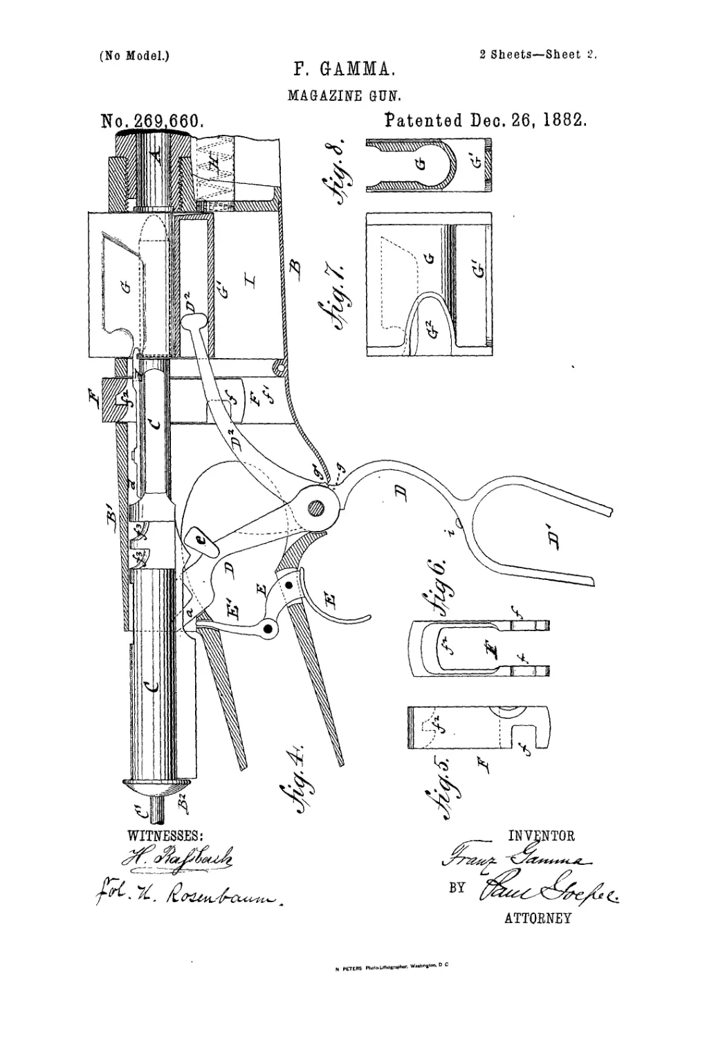
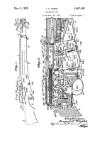
In the accompanying drawings, Figure 1
represents a side view of my magazine fire-arm.
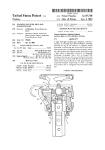
Fig. 2 represents a vertical longitudinal section
of the operating mechanism of the same on an
го enlarged scale, shown ready for firing. Fig.3
is a detail top view of the breech-bolt and the
extractor applied thereto. Fig. 4 is a vertical
longitudinal section of the magazine fire-arm,
shown with the breech-bolt drawn back and
25 the cartridge carrier raised, ready for setting
a cartridge into the barrel; and Figs. 5, 6, 7,
and 8 are details of the locking-key’, of the
breech-bolt, and of the cartridge-carrier.
Similar letters of reference indicate corre-
30 spending parts.
Referring to the drawings, A represents the
barrel; B, the shoe or receiver at the breech
end of the barrel; 0, the sliding breech-bolt,
which is accurately guided in the extended
35 rear part, B', of the receiver B.
The receiver В is provided with an opening,
I), at the top part, through which the shell is
thrown out after the same is drawn back from
the barrel by the extractor d, which is attached
40 to the breech-bolt. The extractor is held in
place by a fixed transverse recessed lug, d',
and a fixed longitudinal lug, d2, which project
from the breech-bolt through slots in the ex-
tractor. The breech-bolt C is provided at its
45 interior with a firing pin, O', which is guided
in longitudinal perforations of the tubular
breech-bolt C, the rear end of the firing-pin
projecting through a center perforation of the
closing screw-cap B2 of the breech-bolt, and
50 being acted upon by an interior spiral spring,
C2, that is interposed between the cap B2 and
a collar or socket, C3, of the firing-pin C2. The
firing-pin C' as well as the breech-bolt 0 are
engaged by an actuating-lever, D, which is
fulcrumed to a downwardly extending arm of 55
the receiver B, and which is provided at its
lower end with a loop-shaped handle, D', by
which the lever D is operated for setting the
different parts of the fire-arm. That portion of
the lever D between its fulcrum and the loop- 60
shaped handle D' is curved so as to form, when
in closed position, a guard for the trigger E,
as shown clearly in Fig. 2.
The upper end of the fulcrumed lever II is
provided with a central recess, forming a rect- 65
angular fork, the arms a of which engage the
convex cheeks e' of the firing-pin O', whereby-
said pin is pushed back against the spiral
spring C2 when the handle 15' of the lever D
is swung away from the stock. The tipper 70
part of the fulcrumed lever D is furthermore
provided intermediately between its fulcrum
and the forked-shaped upper end with sidewise
and forwardly projecting curved or rounded-
off cheeks e, which cheeks engage recesses /of 75
a U-shaped key, F, which is guided in vertical
recesses/' at the interior of the receiver B, the
U-shaped locking-key being provided at its
upper or bridge part with downwardly-pro-
jecting teeth /2, said teeth being curved at 80
the rear side and straight at the front side, as
shown clearly in Figs.2,4, 5, and 6. The teeth
of the loeking-key F engage corresponding re-
cesses, /3, at the upper middle part of the
breech-bolt C, so that when the breech-bolt is 85
in position at the breech of the barrel, and the
key is lowered to its full extent, said key locks
the breech-bolt rigidly’ and reliably into posi-
tion for firing.
The breech-bolt C is provided with longi- 90
tudinal recesses /4, through which the forked
end of the lever D extends to the inside of the
breech-bolt. When the upper part of the lever
is swung back the fork engages first the con-
cave side cheeks, e', of the firing-pin aud forces 95
said pin back until the shoulder e2 passes be-
hind the fulcrumed and spring-actuated lever
/5, arranged in the open lower part of the
breech-bolt C, which lever grasps and holdsthe
pin until released by the trigger. Simultane- 100
onsly with the backward movement of the
firing-pin 0' against the pressure of the spiral
2
269,66»
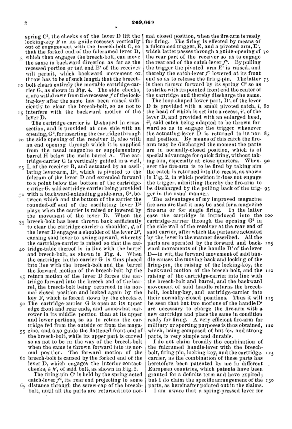
spring C2, the cheeks e of the lever D lift the
locking-key F in its guide-recesses vertically
out of engagement with the breech-bolt C, so
that the forked end of the fulcrumed lever D,
5 which then engages the breech-bolt, can move
the same in backward direction as far as the
recessed portion or tail end B' of the receiver
will permit, which backward movement or.
throw has to be of such length that the breech-
io bolt clears entirely the movable cartridge-car-
rier G, as shown in Fig. 4. The side cheeks,
e, are withdrawnfromtberecesses/of theloek-
ing-key after the same has been raised suffi-
ciently to clear the breech-bolt, so as not to
j 5 interfere with the backward motion of the
lever D.
The cartridge carrier is U-shaped in cross-
section, and is provided at one side with an
opening, G2, for inserting the cartridge t hrough
го the side opening of the receiver B, also with
an end opening through which it is supplied
from the usual magazine or supplementary
barrel H below the main barrel A. The car-
tridge-carrier G is vertically guided in a well,
25 I, of the receiver B, and actuated by an oscil-
lating lever-arm, D2, which is pivoted to the
fulcrum of the lever D and extended forward
to a point below the bottom of the cartridge-
carrier G, said cartridge-carrier being provided
~o with a backward-extending guide-arm, G', be-
tween which and the bottom of the carrier the
rounded-off end of the oscillating lever D2
plays when the carrier is raised or lowered by
the movement of the lever D. When the
35 breech-bolt has been thrown back sufficiently
to clear the cartridge-carrier a shoulder, </, of
the lever D engages a shoulder of the lever D2,
causing said lever to swing upward, whereby
the cartridge-carrier is raised so that the car-
40 tridge-table thereof is in line with the barrel
and breech-bolt, as shown in Fig. 4. When
the cartridge in. the carrier G is thus placed
into line with the breech-bolt and the barrel
the forward motion of the breech-bolt by the
45 return motion of the lever D forces the car-
tridge forward into the breech end of the bar-
rel, the breech-bolt being returned to its nor-
mal closed position and locked again by the
key F, which is forced down by the cheeks e.
50 The cartridge-carrier G is open at its upper
edge front and rear ends, and somewhat nar-
rower in its middle portion than at its upper
and lower portions, so as to return the car-
tridge fed from the outside or from the maga-
55 zine, and also guide the flattened front end of
the breech-bolt, while its upper part is curved
so as not to be in the way of the breech-bolt
when the same is thrown forward into its nor-
mal position. The forward motion of the
60 breech-bolt is caused by the forked end of the
lever D, which engages the interior contact-
cheeks, h h', of said bolt, as shown in Fig. 2.
The firing-pin C' is held by the spring-acted
catch-lever/5, its rear end projecting to some
65 distance through the screw-cap of the breech-
bolt, until all the parts are returned into nor-
mal closed position, when the fire arm is ready
for firing. The firing is effected by means of
a fulcrumed trigger, E, and a pivoted arm, E',
which latter passes through a guide-opening of 70
the rear part of the receiver so as to engage
the rear end of the catch lever f5. By pulling
the trigger the pivoted arm E' is raised, anil
thereby the catch-lever/3 lowered at its front
end so as to release the firing-pin. Thelatter 75
is then thrown forward by its spring C2 so as
to strike with its pointed iron t end the center of
the cartridge and thereby discharge the same.
The loop-shaped lower part, D', of the lever
D is provided with a small pivoted catch, i, 80
the head of which is set into a recess, i', of the
lever D, and provided with an enlarged head,
i2, said catch being adapted to be thrown for-
ward so as to engage the trigger whenever
the actuating-lever D is returned to its nor- 85
mal position. By means of this catch the fire-
arm may be discharged the moment the parts
are in normally-closed position, which is of
special advantage for quick firing, without tak-
ing aim, especially at close quarters. When- 90
ever the fire-arm is to be fired by taking aim
the catch is returned into the recess, as shown
in Fig. 2, in which position it does not engage
the trigger, admitting thereby the fire-arm to
be discharged by the pulling back of the trig- 95
ger in the usual manner.
The advantages of my improved magazine
fire-arm are that it may be used for a. magazine
fire-arm or for single firing. In the latter
case the cartridge is introduced into the 100
cartridge-carrier through the opening G2 in
the side wall of the receiver at the rear end of
said carrier, after which the parts are actuated
by the. lever in the manner described. All the
parts are operated by the forward and back- 105
ward movements of the handle D'of the lever
D—to wit, the forward movement of said han-
dle causes the moving back and locking of the
liring-pui, the raising of the locking-key, the
backward motion of the breech-bolt, and the no
raising of the cartridge-carrier into line with
the breech-bolt and barrel, and the backward
movement of said handle returns the breech-
bolt, locking-key, and cartridge-carrier into
their normally-closed positions. Thus it will 115
be seen that but two motions of the handleD'
are necessary to charge the fire-arm with a
new cartridge and place the same in condition
ready for firing. A very efficient fire-arm for
military or sporting purposes is thus obtained, 120
which, being composed of but few and strong
parts, is very simple and durable.
I do not claim broadly the combination of
the fulcrumed handle-lever with the breech-
bolt, firing-piu, locking-key, and the cartridge- 125
carrier, as the combination of these parts has
heretofore been patented by me in different .
European countries, which patents have been
granted for a definite term and have expired ;
but I do claim the specific arrangement of the 130
parts, as hereinafter pointed out in the claims.
1 am aware that a spring-pressed lever for
269,660
retaining the firiug-pin has been used in con-
nection with an ordinary trigger in a breech-
loading gun, and I do not claim the same
broadly.
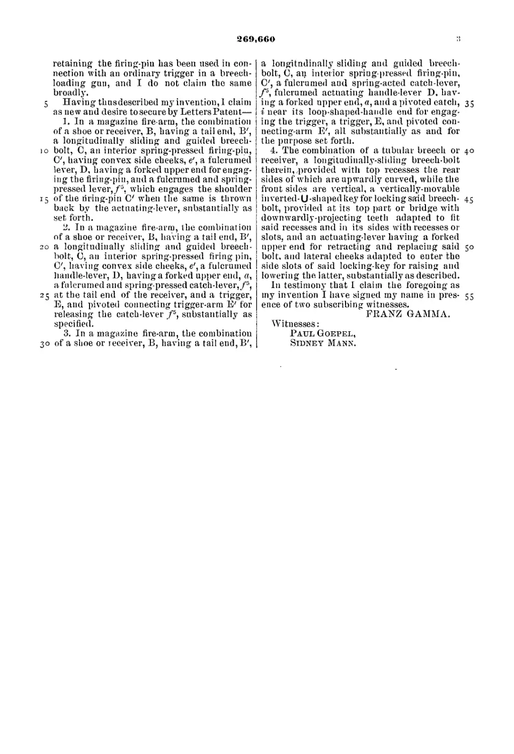
5 Having thusdescribed my invention,! claim
as new and desire to secure by LettersPatent—
1. In a magazine fire-arm, the combination
of a shoe or receiver, B, having a tail end, B',
a longitudinally sliding and guided breech-
)o bolt, C, an interior spring-pressed firing-piu,
C', having convex side cheeks, e', a fulcrumed
lever, D, having a forked upper end for engag-
ing the firing-pin, and a fulcrumed and spring-
pressed lever,/5, which engages the shoulder
15 of the riring-pin C when the same is thrown
back by the actuating-lever, substantially as
set forth.
2. In a magazine fire-arm, the combination
of a shoe or receiver, B, having a tail end, B',
20 a longitudinally sliding and guided breech-
bolt, 0, an interior spring-pressed firing pin,
O', having convex side cheeks, e', a fulcrumed
handle-lever, D, having a forked upper end, a,
a fulcrumed and spring-pressed catch-lever,/5,
25 at the tail end of the receiver, and a trigger,
E, and pivoted connecting trigger-arm E' for
releasing the catch-lever /5, substantially as
specified.
3. In a magazine fire-arm, the combination
30 of a shoe or receiver, B, having a tail end, B',
a longitudinally sliding and guided breech-
bolt, C, an interior spring-pressed firing-pin,
C', a fulcrumed and spring-acted catch-lever,
/5, fulcrumed actuating handle-lever D, hav-
ing a forked upper end,«, and a pivoted catch, 35
i near its loop-shaped-handle end for engag-
ing the trigger, a trigger, E, and pivoted con-
necting-arm E', all substantially as and for
the purpose set forth.
4. The combination of a tubular breech or 40
receiver, a longitudinally-sliding breech-bolt
therein,,provided with top recesses the rear
sides of which are upwardly curved, while the
front sides are vertical, a vertically-movable
inverted-U-shapedkeyfor lockingsaid breech- 45
bolt, provided at its top part or bridge with
downwardly-projecting teeth adapted to fit
said recesses and in its sides with recesses or
slots, and an actuating-lever having a forked
upper end for retracting and replacing said 50
bolt, and lateral cheeks adapted to enter the
side slots of said locking-key for raising and
lowering the latter, substantially as described.
In testimony that I claim the foregoing as
my invention I have signed my name in pres- 55
ence of two subscribing witnesses.
FRANZ GAMMA.
Witnesses:
Paul Goepel,
Sidney Mann.