/
Tags: weapons military affairs patent
Year: 1993
Text
Europaisches Patentamt
@ European Patent Office
Office europeen des brevets
©
© Publication number: 0 378 976 B1
EUROPEAN PATENT SPECIFICATION
(45) Date of publication of patent specification :
08.09.93 Bulletin 93/36
@ int. Cl.5: F41A3/72, F41A 17/42
@ Application number: 89830560.2
(22) Date of filing : 21.12.89
© Automatic safety device for fire arms.
(зо) Priority: 11.01.89 IT 510189
@ Date of publication of application :
25.07.90 Bulletin 90/30
@ Proprietor: FABBRICA D’ARMI P.BERETTA
S.p.A.
10, Via P. Beretta
I-25063 Gardone V.T. (Brescia) (IT)
@ Publication of the grant of the patent:
08.09.93 Bulletin 93/36
@ Inventor: Beretta, Pier Giuseppe
18 Via P. Beretta
i-25063 Gardone V.T. (Brescia) (IT)
@ Designated Contracting States :
AT BE CH DE ES FR GB GR IT LI LU NL SE
@ Representative : Manzoni, Alessandro
MANZONI & MANZONI - UFFICIO
INTERNAZIONALE BREVETTI P.le Arnaldo n.
(Ц) References cited :
BE-A- 795 653
DE-B- 1 213 761
FR-A- 1 447 906
2
1-25121 Brescia (IT)
ЕР 0 378 976 В1
Note: Within nine months from the publication of the mention of the grant of the European patent, any
person may give notice to the European Patent Office of opposition to the European patent granted.
Notice of opposition shall be filed in a written reasoned statement. It shall not be deemed to have been
filed until the opposition fee has been paid (Art. 99(1) European patent convention).
Jouve, 18, rue Saint-Denis, 75001 PARIS
1
ЕР 0 378 976 В1
2
Description
SPECIFICATION
The present invention generally concerns those
fire arms which are operated starting from their open-
bolt position, and in particular an automatic safety de-
vice for said fire arms and especially designed for au-
tomatic guns.
Fire arms which are operated starting from their
open-bolt position have to be first manually cocked by
taking back the bolt till it is engaged by the tripping
mechanism of the arm.
This operation may however cause an accidental
and therefore dangerous shot. In fact, a faulty or in-
complete manual move of the bolt or its release during
its cocking or a shock taking the ammunition into the
barrel causing an uncontrolled shot cannot be exclud-
ed.
The purpose of the present invention is instead to
prevent such an eventuality and thus its possible con-
sequences.
Specifically, it is the purpose of the present in-
vention to make available an automatic safety device
for the above mentioned type of fire arms which is
able to immediately stop the bolt in whichever position
in case of a faulty or incomplete operation or in case
it moves back by accident, in order to prevent said bolt
from advancing before it is safely engaged in the trip-
ping mechanism of the arm; thus "obliging" the oper-
ator, while he is cocking the arm, to take the boltlock
on the tripping mechanism.
Said purpose is fulfilled by an automatic safety
device for fire arms according to the characterizing
part of claim 1.
The device is therefore performinng the following
functions owing to its special design.
- It goes into action only the moment the arm is
cocked: while the arm is operating either auto-
matically or with individual shots, the whole
safety device is cut off and thus inactive;
- With the proposed solution the bolt of the arm
cannot be manually displaced without activat-
ing the safety device to allow it to exert its func-
tions;
- during manual cocking the device allows the
bolt to move in one directions only, i.e. its rear-
ward motion towards the tripping mechnism to
take it into its correct cocked position;
- in case of a faulty or incomplete move or if the
boltlock is released too soon, the safety device
makes any accidental shot impossible.
The document BE-A-795 653, for exam-
ple, disclose a fire arm having a bolt which is
manually displaceable by means of a slider in
a breech starting from an advanced closed
position against the barrel and ending in an
open rear position defined by a tripping mech-
5
10
15
20
25
30
35
40
45
50
55
anism, the breech being provide with a longi-
tudinal slot at least at one side of which a tooth-
ing is fitted made of a sequence of teeth trans-
versely oriented with respect to the direction in
which said bolt is displaced. Very advanta-
geously, the safety device according to the
present invention can be assembled not only
on new arms, but also to already used automat-
ic guns to transform them and improve their
safety.
More details of the invention will be more evident
in the following description made with reference to
the enclosed drawings which are merely illustrative
and by no means restrictive and where:
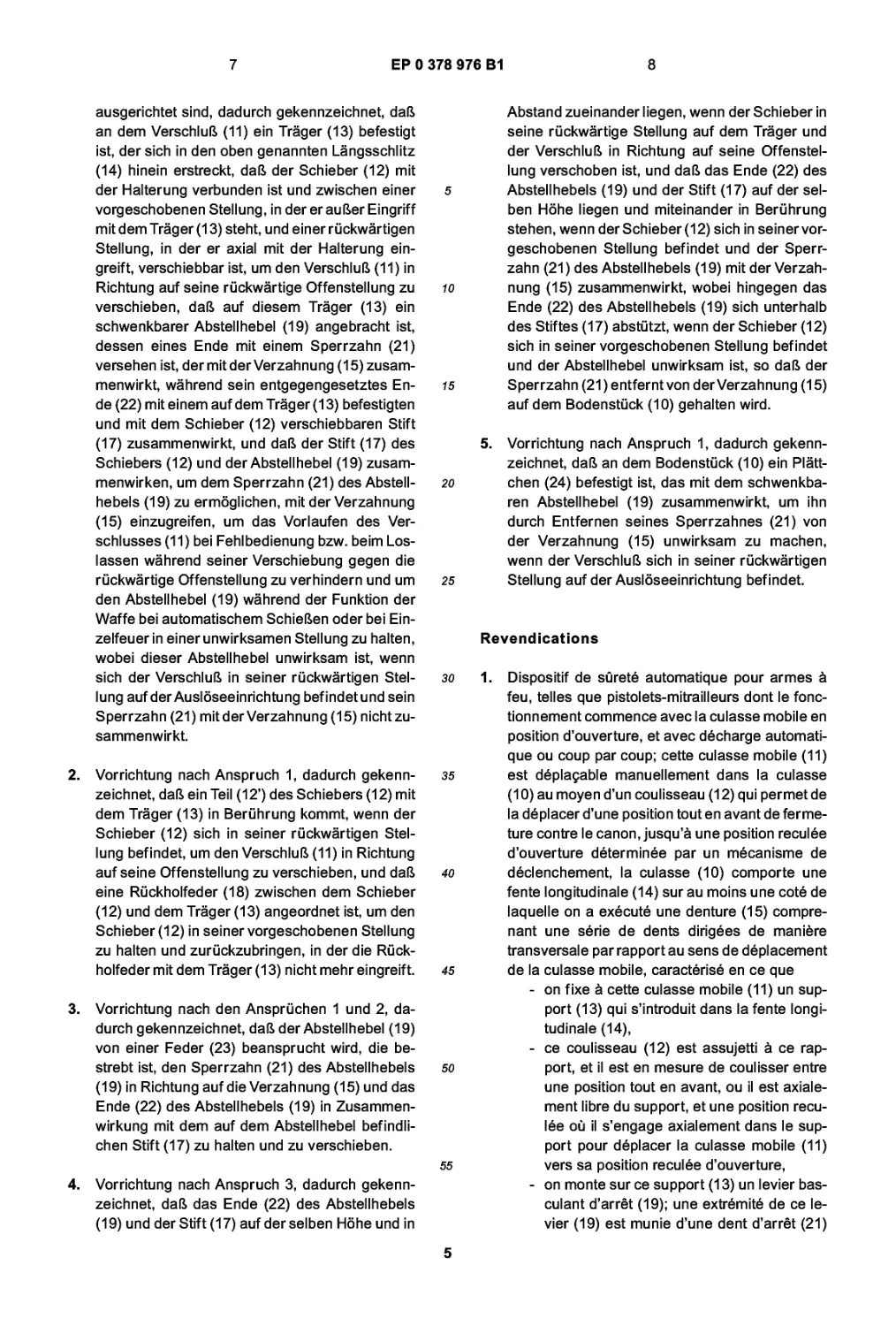
Fig. 1 shows a partial elevation of a fire arm in idle
position, fitted with a safety device;
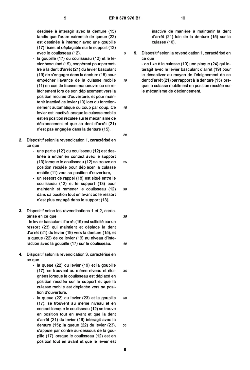
Fig. 2 shows a sectional view of an arm with its
bolt in forward closed position and with its safety
device in idle position;
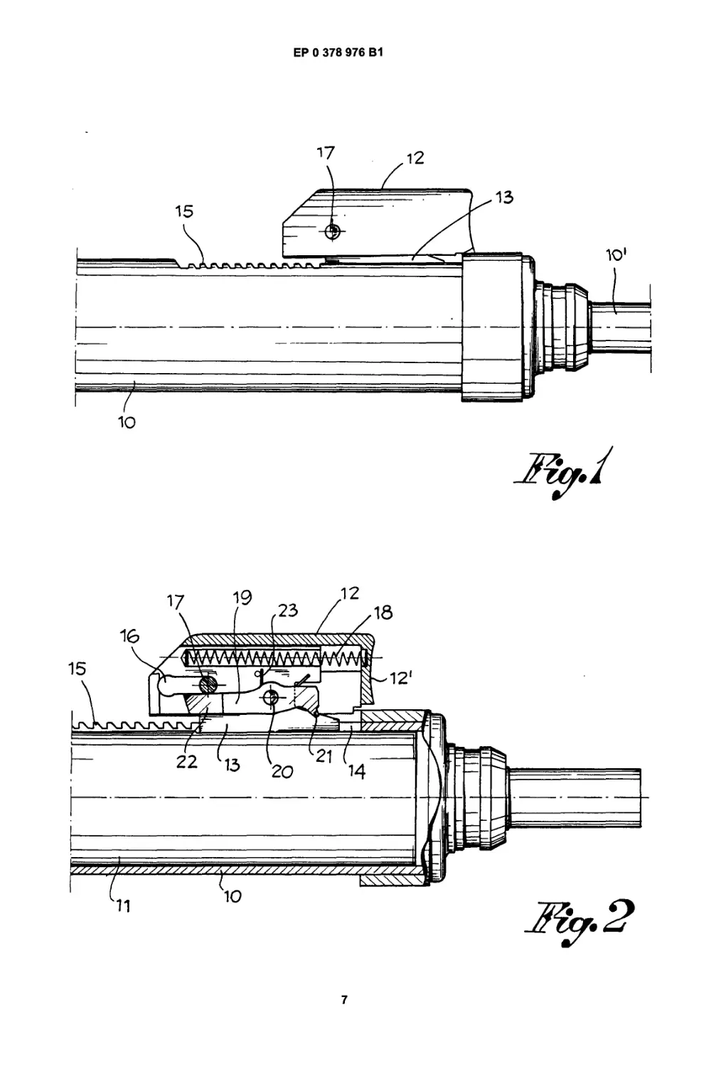
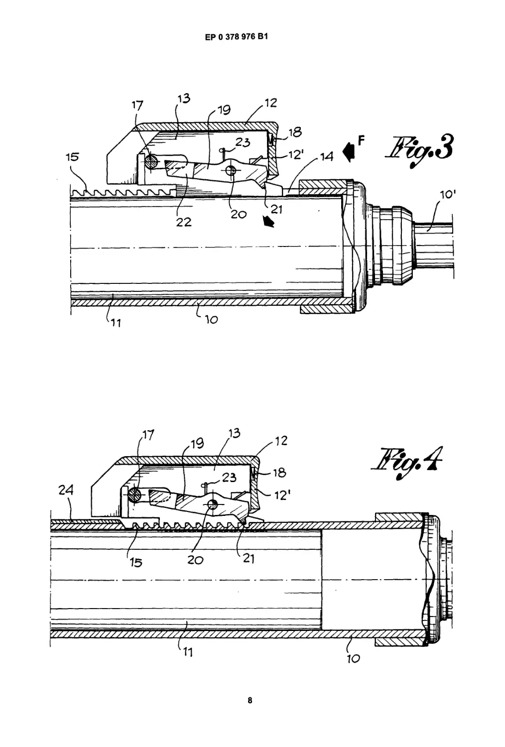
Figures 3,4,5,6,7 show a sequence of intermedi-
ate positions of the bolt and the safety device
during the manual cocking operation;
Figures 9 and 10 show the device while it is being
inactivated and in idle position at the end of man-
ual cocking respectively.
Said drawing shows a breech 10 with barrel
10’ of a fire arm, e.g. an automatic gun, and with a
bolt 11 which is manually displaceable, by means of
a slider 12, from a front and closed position resting
against the barrel to a rear and open position defined
by a tripping mechanism the moment in which the
arm is to be used.
Said slider 12 is assembled to the breech 11
through a support 13 which is fixed to the breech and
can thus be displaced together with it. Slider 12 is as-
sembled and guided on support 13 and sliding in the
direction in which the bolt is displaceable. Support 13
is inserted into a longitudinal slot 14 cut into the
breech 10 to allow the opening and closing displace-
ments of the bolt 11. At least at one end of said slot
14 the breech 10 is fitted with a sequence of teeth 15
sloping transversally to the sense of displacement of
bolt 11.
In support 13 a slot 16 which is parallel to the axis
of bolt 11 is provided to receive a pin 17 traversing the
support 13 and thus the slider 12. Slot 16 and pin 17
cooperate in delimiting the sliding motions of slider 12
on support 13 and taking back said support with the
bolt when the latter has to be manually taken into its
open position. In the illustrated embodiment said
rearward displacement of support 13 with bolt 11 is
actually obtained by placing the front end 12’ of the
slider against the head of support 13.
Between support 13 and slider 12 a spring 18 is
normally keeping the slider 12 displaced to the front
end of support 13, while the pin 17 is pushed against
the front end of slot 16.
In addition, on support 13a rocking catch lever 19
2
3
ЕР 0 378 976 В1
4
is pivoted on a pin 20, said pin crossing the direction
in which bolt 11 is displaced. The front end of said
rocking lever 19, i.e. its end directed towards the front
end of the breech 10, is fitted with a tooth 21 designed
to interact, from back to forth only, with the toothing
15 on the breech, while its rear end 22 is designed to
interact with pin 17, as will be explained here under.
Said lever 19 is also subject to a spring 23 to normally
keep its tooth 21 displaced towards the toothing 15
and its end 22 towards pin 17 or to engage it on said
pin.
The operation of the safety device will now be de-
scribed by specifying some of its characteristic opera-
tional stages.
A. Arm in neutral position
In Figures 1 and 2 the arm is shown in its neutral
position: bolt 11 is in its advanced position and resting
against the rear end of barrel 10’; the safety device
is released.
In particular, the position of the components of
said device is:
- slider 12 is in its advanced position owing to the
pressure exercised by spring 18 and kept in
this position by pin 17 cooperating with slot 16
in support 13;
- catch tooth 21 of rocking lever 19 is lifted above
the toothing 15 on breech 10; and
- tail 22 of said lever 19 is resting against pin 17
in slider 12.
B. Manual cocking
The first stage of manual cocking comprises a
pressure exercised in the direction of arrow F on slid-
er 12 to slightly displace it (by 10 mm approx.) on its
support 13 and thus in respect to bolt 11, support and
bolt not moving during this first stage.
After that, when slider 12 has compressed the
spring 18 like shown in Fig. 3, it is in such a position
that it disengages tall 22 of rocking lever 19 from pin
17 in the slider: now lever 19, pushed by its spring 23,
is able to move on till its front tooth 21 is resting on
the outer surface of breech 10, i.e. on its section com-
prising the toothing 15, while its tail end 22 is level
with pin 17 of the slider.
While the manual cocking is continued slider 12,
after eliminating the space (10 mm approx.) separat-
ing its front end 12’ from the head of support 13, will
start to actually push back bolt 11.
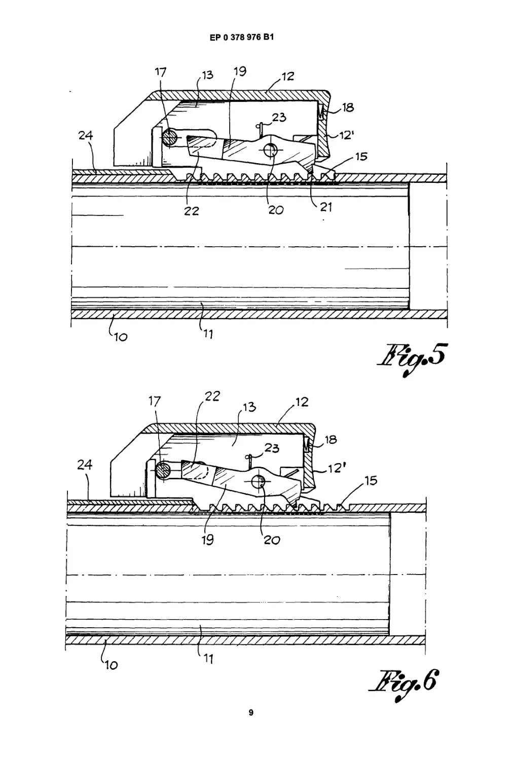
As shown in Figures 4 and 5, owing to spring 23,
the front tooth 21 of rocking lever 19 is constantly kept
in contact with breech 10, while its rear end 22 is at
interacting level with pin 17. As the backward motion
is continued (see Fig. 6) catch tooth 21 of lever 19 is
travelling on the toothing 15 till the end of the cocking
operation, i.e. till bolt 11 is catched and fastened by
5
10
15
20
25
30
35
40
45
50
55
the (not represented) tripping mechanism of the arm.
Before reaching this final condition of the bolt al-
lowing the actual use of the arm, some possibilities
ought to be taken into consideration.
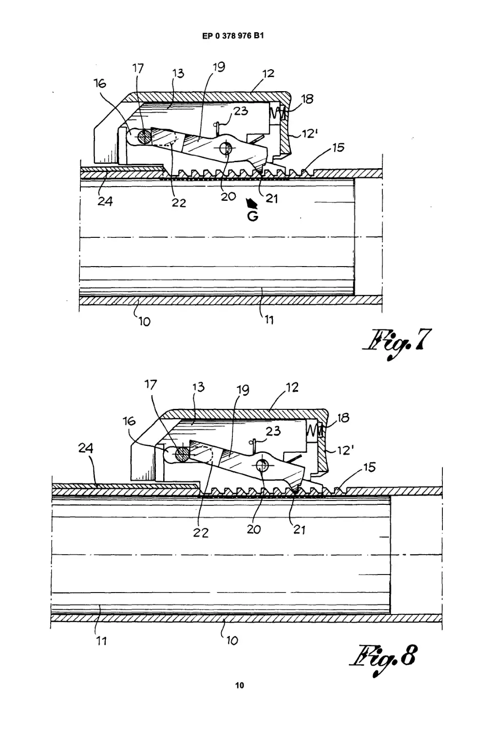
B. Faulty move of the operator
If during manual cocking the operator accidental-
ly lets go the slider 12 or lets it go being erroneously
convinced it has reached its correct position, he will
bring about the situation shown in Figures 7 and 8. In
fact, as the spring 18 of slider 12 is no longer com-
pressed by the operator it will extend and take slider
12 to its advanced position on support 13. But by mov-
ing on slider 12 takes pin 17 towards the tail end 22
of the rocking lever 19 which, as said before, is thus
engaged by said pin. In consequence, said rocking
lever is obliged to move in the direction of arrow G in
Fig. 7 and thus engage tooth 21 in the toothing 15 on
breech 10 (see Fig. 8). Lock 11 is therefore imme-
diately stopped in the position to which it has been
displaced and where it has been abandoned, thus be-
ing absolutely unable to reach its closed position.
The arm is thus in a static condition of partial
opening of its bolt and at any rate in a safe position,
while the trigger is fully indepennt from any motion of
the bolt.
B.2 Continuation of the cocking operation (after an
eventual blocking as in B.1.)
As it can be seen in Fig. 8, it is not possible to act
on the safety device to release it and allow the bolt
11 to advance towards the barrel 10’ into its closed
position. In fact, any action exerted on slider 12 in or-
der to push on the bolt 11 will only result in a tighter
engagement of the catch tooth 21 of rocking lever 19
in the toothing 15 on the breech. Thus the only thing
the operator can do is to restart the manual cocking
operation by grasping the slider 12 and push it back-
wards and when its front end 12’ is in tight contact
with support 13 he will be able to move back the bolt
till it is correctly engaged in the tripping mechanism.
B.3 . Correct cocking (interception of the bolt by the
tripping mechanism).
It is now obvious that the operator is still "obliged"
to displaced the lock towards the tripping mechanism,
as otherwise he will by no means able to use the arm
for shooting.
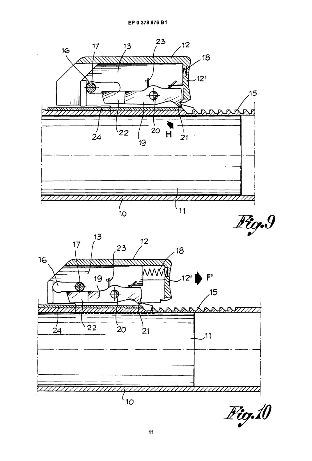
On the other hand, the safety device is inactivat-
ed only with the bolt engaged in the tripping mecha-
nism. To this purpose a release plate 24 is fitted on
the breech 11 after the rear end of toothing 15, said
plate 24 interacting with the locking lever 19 so as to
lift and displace it into its neutral position as soon as
the bolt has reached its correct cocked position. The
3
5
ЕР 0 378 976 В1
6
interaction of the release plate 24 with the rocking
lever 19 is shown in Fig. 9 of the drawing where it can
be seen how, on one hand, the catch tooth 21 of lever
19 is displaced by plate 14- arrow H - above toothing
15 and, on the other hand, tail 22 of said lever is sit-
uated below pin 17 of slider 12.
That is why, once the slider is no longer subject
to the manual traction of the operator, it is pushed on
by spring 18 and goes back to its rest position - see
arrow F - taking pin 17 against the top part of the tail
end 22 of lever 19, thus keeping said lever out of ac-
tion (as it was at the beginnig of the manual cocking
operation (see Fig.2).
Now the arm is ready for shooting both single
shots and automatically, while the safety device stays
totally inert but always ready to exert its function as
soon as the bolt of the arm has to be cocked again.
Claims
1. Automatic safety device for fire arms, like auto-
matic guns, to be operated starting with their bolt
is in open position both for automatic shooting
and single shots, said bolt (1) being manually dis-
placeable by means of a slider (12) in a breech
(10) starting from an advanced closed position
against the barrel and ending in an open rear
position defined by a tripping mechanism, the
breech (10) being provide with a longitudinal slot
(14) at least at one side of which a toothing (15)
is fitted made of a sequence of teeth transversely
oriented with respect to the direction in which
said bolt is displaced, characterized in that a
support (13) is fixed to said bolt (11) and extent-
ing into said longitudinal slot (14), in that said slid-
er (12) is assembled to said support (13) and able
to slide between an advanced position where it is
axially disengaged from the support and a rear
position where it is axially engaging said support
in order to take the bolt (11) to its rear, open pos-
ition, in that on said support (13) a rocking catch
lever (19) is assembled, one end of said lever (19)
being fitted with a catch tooth (21) designed to in-
teract with said toothing (15), while its opposite
tail end (22) is designed to interact with a pin (17)
fixed and displaceable with slider (12) on support
(13), in that the pin (17) of the slider (12) and the
rocking lever (19) cooperate in order to allow said
tooth (21) of lever (19) to engage in said toothing
(15) so as to prevent the bolt (11) from advancing
in case of a faulty move or release during its mo-
tion towards its rear open position, and to main-
tain said lever (19) in an inactive position as long
as the arm is used for automatic shooting or sin-
gle shots, said lever being inactivated when the
bolt is in its rear position on the tripping mecha-
nism and its catch tooth (21) is not engaged in
5
10
15
20
25
30
35
40
45
50
55
said toothing (15).
2. Device according to claim 1), wherein a part (12’)
of said slider (12) is designed to contact support
(13) when slider (12) is in its rear position to dis-
place the bolt (11) towards its open position, and
where a recuperating spring (18) is placed be-
tween slider (12) and support (13) to maintain
and retake slider (12) in its advanced position
where it is no longer engaging said support (13).
3. Device according to claims 1) and 2), wherein
said rocking catch lever (19) is subject to a spring
(23) tending to maintain and displace said catch
tooth (21) of lever (19) towards the toothing (15)
and tail end (22) of said lever (19) at an intercating
level with said pin (17) on said slider.
4. Device according to claim 3), wherein the tail end
(22) of said lever (19) and said pin (17) are at the
same level and spaced between each otherwhen
said slider is in its rear position on the support
while the bolt is displaced towards its open posi-
tion, and where said tail end (22) of lever (19) and
pin (17) are at the same level and contacting each
otherwhen said slider(12) is in its advanced pos-
ition and the catch tooth (21) of said lever (19) is
interacting with toothing (15), said tail (22) of lev-
er (19) resting instead below pin (17) when slider
(12) is in advanced position and said lever is in-
activated, so as to keep catch tooth (21) off the
toothing (15) on breech (10).
5. Device according to claims 1), wherein on breech
(10) a plate (24) is fixed, which interacts with the
rocking catch lever (19) in order to inactivate it by
moving off its catch tooth (21) from toothing (15)
when the bolt is in its rear position on the tripping
mechanism.
Patentanspriiche
1. Selbsttatige Sicherungsvorrichtung fur Feuer-
waffen, wie Maschinenpistolen, die mit ihrem
VerschluB in der Offenstellung ausgehend und
mit selbsttatiger SchuBfolge Oder mit Einzelfeuer
funktionieren und deren VerschluB (11) von Hand
ausgehend von einer vorgeschobenen
SchlieBstellung mit Hilfe eines Schiebers (12) in
einem Bodenstuck (10) gegen den Gewehrlauf
bis zu einer hinteren, durch eine Ausloseeinrich-
tung bestimmten Offenstellung verschiebbar 1st,
wobei das Bodenstuck (10) mit einem Langs-
schlitz (14) versehen 1st, an dessen mindestens
einer Seite eine Verzahnung (15) vorgesehen 1st,
die aus einer Reihe von Zahnen besteht, die quer
zur Richtung der Verschiebung des Verschlusses
4
7
ЕР 0 378 976 В1
8
ausgerichtet sind, dadurch gekennzeichnet, daB
an dem VerschluB (11) ein Trager (13) befestigt
ist, dersich in den oben genannten Langsschlitz
(14) hinein erstreckt, daB der Schieber (12) mit
der Halterung verbunden ist und zwischen einer
vorgeschobenen Stellung, in der er auBer Eingriff
mit dem Trager (13) steht, und einer ruckwartigen
Stellung, in der er axial mit der Halterung ein-
greift, verschiebbar ist, urn den VerschluB (11) in
Richtung auf seine ruckwartige Offenstellung zu
verschieben, daB auf diesem Trager (13) ein
schwenkbarer Abstellhebel (19) angebracht ist,
dessen eines Ende mit einem Sperrzahn (21)
versehen ist, dermitderVerzahnung (15) zusam-
menwirkt, wahrend sein entgegengesetztes En-
de (22) mit einem auf dem Trager (13) befestigten
und mit dem Schieber (12) verschiebbaren Stiff
(17) zusammenwirkt, und daB der Stiff (17) des
Schiebers (12) und der Abstellhebel (19) zusam-
menwirken, urn dem Sperrzahn (21) des Abstell-
hebels (19) zu ermoglichen, mitderVerzahnung
(15) einzugreifen, urn das Vorlaufen des Ver-
schlusses (11) bei Fehlbedienung bzw. beim Los-
lassen wahrend seiner Verschiebung gegen die
ruckwartige Offenstellung zu verhindern und urn
den Abstellhebel (19) wahrend der Funktion der
Waffe bei automatischem SchieBen Oder bei Ein-
zelfeuerin einer unwirksamen Stellung zu halten,
wobei dieser Abstellhebel unwirksam ist, wenn
sich der VerschluB in seiner ruckwartigen Stel-
lung aufderAusloseeinrichtung befindetund sein
Sperrzahn (21) mitderVerzahnung (15) nicht zu-
sammenwirkt.
2. Vorrichtung nach Anspruch 1, dadurch gekenn-
zeichnet, daB ein Tell (12’) des Schiebers (12) mit
dem Trager (13) in Beruhrung kommt, wenn der
Schieber (12) sich in seiner ruckwartigen Stel-
lung befindet, urn den VerschluB (11) in Richtung
auf seine Offenstellung zu verschieben, und daB
eine Ruckholfeder (18) zwischen dem Schieber
(12) und dem Trager (13) angeordnet ist, urn den
Schieber (12) in seiner vorgeschobenen Stellung
zu halten und zuruckzubringen, in der die Ruck-
holfeder mit dem Trager (13) nicht mehr eingreift.
3. Vorrichtung nach den Anspruchen 1 und 2, da-
durch gekennzeichnet, daB der Abstellhebel (19)
von einer Feder (23) beansprucht wird, die be-
strebt ist, den Sperrzahn (21) des Abstellhebels
(19) in Richtung auf die Verzahnung (15) und das
Ende (22) des Abstellhebels (19) in Zusammen-
wirkung mit dem auf dem Abstellhebel befindli-
chen Stiff (17) zu halten und zu verschieben.
4. Vorrichtung nach Anspruch 3, dadurch gekenn-
zeichnet, daB das Ende (22) des Abstellhebels
(19) und der Stiff (17) auf der selben Hohe und in
5
10
15
20
25
30
35
40
45
50
55
Abstand zueinander liegen, wenn der Schieber in
seine ruckwartige Stellung auf dem Trager und
der VerschluB in Richtung auf seine Offenstel-
lung verschoben ist, und daB das Ende (22) des
Abstellhebels (19) und der Stiff (17) auf der sel-
ben Hohe liegen und miteinander in Beruhrung
stehen, wenn derSchieber(12) sich in seiner vor-
geschobenen Stellung befindet und der Sperr-
zahn (21) des Abstellhebels (19) mit der Verzah-
nung (15) zusammenwirkt, wobei hingegen das
Ende (22) des Abstellhebels (19) sich unterhalb
des Stiftes (17) abstutzt, wenn der Schieber (12)
sich in seiner vorgeschobenen Stellung befindet
und der Abstellhebel unwirksam ist, so daB der
Sperrzahn (21) entfernt von der Verzahnung (15)
auf dem Bodenstuck (10) gehalten wird.
5. Vorrichtung nach Anspruch 1, dadurch gekenn-
zeichnet, daB an dem Bodenstuck (10) ein Platt-
chen (24) befestigt ist, das mit dem schwenkba-
ren Abstellhebel (19) zusammenwirkt, urn ihn
durch Entfernen seines Sperrzahnes (21) von
der Verzahnung (15) unwirksam zu machen,
wenn der VerschluB sich in seiner ruckwartigen
Stellung aufderAusloseeinrichtung befindet.
Revendications
1. Dispositif de surete automatique pour armes a
feu, telles que pistolets-mitrailleurs dont le fonc-
tionnement commence avec la culasse mobile en
position d’ouverture, et avec decharge automati-
que ou coup par coup; cette culasse mobile (11)
est deplagable manuellement dans la culasse
(10) au moyen d’un coulisseau (12) qui permet de
la deplacer d’une position tout en avant de ferme-
ture contre le canon, jusqu’a une position reculee
d’ouverture determinee par un mecanisme de
declenchement, la culasse (10) comporte une
fente longitudinals (14) sur au moins une cote de
laquelle on a execute une denture (15) compre-
nant une serie de dents dirigees de maniere
transversale par rapport au sens de deplacement
de la culasse mobile, caracterise en ce que
- on fixe a cette culasse mobile (11) un sup-
port (13) qui s’introduit dans la fente longi-
tudinale (14),
- ce coulisseau (12) est assujetti a ce rap-
port, et II est en mesure de coulisser entre
une position tout en avant, ou II est axiale-
ment libre du support, et une position recu-
lee ой II s’engage axialement dans le sup-
port pour deplacer la culasse mobile (11)
vers sa position reculee d’ouverture,
- on monte sur ce support (13) un levier bas-
culant d’arret (19); une extremite de ce le-
vier (19) est munie d’une dent d’arret (21)
5
9
ЕР 0 378 976 В1
10
destinee a interagir avec la denture (15)
tandis que I’autre extremite de queue (22)
est destinee a interagir avec une goupille
(17) f ixee, et deplagable sur le support (13)
avec le coulisseau (12),
- la goupille (17) du coulisseau (12) et le le-
vier basculant (19), cooperent pour permet-
tre a la dent d’arret (21) du levier basculant
(19) de s’engager dans la denture (15) pour
empecher I’avance de la culasse mobile
(11) en cas de fausse manoeuvre ou de re-
lachement lors de son deplacement vers la
position reculee d’ouverture, et pour main-
tenir inactive ce levier (13) lors du fonction-
nement automatique ou coup par coup. Ce
levier est inactive lorsque la culasse mobile
est en position reculee sur le mecanisme de
declancement et que sa dent d’arret (21)
n’est pas engagee dans la denture (15).
2. Dispositif selon la revendication 1, caracterise en
ce que
- une partie (12’) du coulisseau (12) est des-
tinee a entrer en contact avec le support
(13) lorsque le coulisseau (12) se trouve en
position reculee pour deplacer la culasse
mobile (11) vers sa position d’ouverture,
- un ressort de rappel (18) est situe entre le
coulisseau (12) et le support (13) pour
maintenir et ramener le coulisseau (12)
dans sa position tout en avant oil le ressort
n’est plus engage dans le support (13).
3. Dispositif selon les revendications 1 et 2, carac-
terise en ce que
- le levier basculant d’arret (19) est sol I icite par un
ressort (23) qui maintient et deplace la dent
d’arret (21) du levier (19) vers la denture (15), et
la queue (22) de ce levier (19) au niveau d’inte-
raction avec la goupille (17) sur le coulisseau.
4. Dispositif selon la revendication 3, caracterise en
ce que
- la queue (22) du levier (19) et la goupille
(17), se trouvent au meme niveau et eloi-
gnees lorsque le coulisseau est deplace en
position reculee sur le support et que la
culasse mobile est deplacee vers sa posi-
tion d’ouverture,
- la queue (22) du levier (23) et la goupille
(17), se trouvent au meme niveau et en
contact lorsque le coulisseau (12) se trouve
en position tout en avant et que la dent
d’arret (21) du levier (19) interagit avec la
denture (15); la queue (22) du levier (23),
s’appuie par contre au-dessous de la gou-
pille (17) lorsque le coulisseau (12) est en
position tout en avant et que le levier est
5
10
15
20
25
30
35
40
45
50
55
inactive de maniere a maintenir la dent
d’arret (21) loin de la denture (15) sur la
culasse (10).
5. Dispositif selon la revendication 1, caracterise en
ce que
- on fixe a la culasse (10) une plaque (24) qui in-
teragit avec le levier basculant d’arret (19) pour
le desactiver au moyen de I’eloignement de sa
dent d’arret (21) par rapport a la denture (15) lors-
que la culasse mobile est en position reculee sur
le mecanisme de declencement.
6
ЕР 0 378 976 В1
7
ЕР 0 378 976 В1
8
ЕР 0 378 976 В1
9
ЕР 0 378 976 В1
10
ЕР 0 378 976 В1
11