/
Tags: weapons military affairs patent
Year: 1988

Text
Europaisches Patentamt
European Patent Office
Office еигорёеп des brevets
@ Publication number: 0 277 921 B1
© EUROPEAN PATENT SPECIFICATION
© Date of publication of patent specification :
27.12.91 Bulletin 91/52
© Int CL5 : F41A 19/00
© Application number: 88830026.6
© Date of filing : 21.01.88
© Device for rapidly engaging and disengaging the trigger mechanism in the breech of a gun.
© Priority: 03.02.87 IT 511787
© Date of publication of application :
10.08.88 Bulletin 88/32
@ Proprietor: FABBR1CA D’ARMI P.BERETTA
S.p.A.
10, Via P. Beretta
I-25063 Gardone V.T. (Brescia) (IT)
@ Publication of the grant of the patent:
27.12.91 Bulletin 91/52
@ Inventor: Beretta, Pier Giuseppe
18, Via P. Beretta
I-25063 Gardone V.T. (Brescia) (IT)
© Designated Contracting States:
AT BE CH DE ES FR GB GR LI LU NL SE
© References cited :
EP-A- 0 078 867
DE-A- 2 004 186
FR-A- 1 519 013
© Representative: Manzoni, Alessandro
MANZONI & MANZONI - UFFICIO
INTERNAZIONALE BREVETTI P.le Arnaldo n.
2
1-25121 Brescia (IT)
ЕР 0 277 921 В1
Note: Within nine months from the publication of the mention of the grant of the European patent, any
person may give notice to the European Patent Office of opposition to the European patent granted.
Notice of opposition shall be filed in a written reasoned statement It shall not be deemed to have been
filed until the opposition fee has been paid (Art 99(1) European patent convention).
Jouve, 18, rue Saint-Denis, 75001 PARIS
1
ЕР 0 277 921 В1
2
Description
The invention relates to shotguns with two barrels
and a single trigger and, particularly, to a device for
rapidly engaging and disengaging the trigger
mechanism in the breech of these guns in accordance
with the preamble of claim 1 and described, for
example, in document FR-A-1,519,013.
In the field of double-barrelled shotguns, the bar-
rels being positioned either side by side or one over
the other, there are several trigger mechanisms
already known, hereinafter referred to as monotrigger
mechanisms, with two hammers corresponding to the
two barrels of the gun, and with a single trigger for
controlling, through levers and preloaded springs, the
disengagement of the cocked hammers.
In the conventional arrangements, see for
example DE-A-2,004,186 and EP-A-0,078,867 also,
the elements of a monotrigger mechanism may be
premounted on a support, hereinafter referred to as
the underguard, which is applicable to the lower por-
tion of the breech of a gun, in correspondence with a
suitable opening or slit.
In particular, the above mentioned document FR-
A-1,519,013 discloses a device for the rapid engage-
ment and disengagement of a monotrigger
mechanism in the breech of a shotgun, where the
trigger mechanism is mounted on an underguard
which can be sealed in the underside of the breech
and wherein:
— a tongue is provided in the front portion of said
underguard;
— a complementary seat is formed in said breech
for receiving said tongue ;
— an oscillating lever is mounted in said breech
and has a terminal interacting with a safety sled
on the upper part of the breech, and another ter-
minal which is designed to cause blocking and
unblocking of said underguard in the breech ;
— a biasing spring acting on said oscillating lever
to push it towards the blocking position of the
underguard.
In such an embodiment the blocking/unblocking
of the underguard, however, relies completely on an
added element, that being a piston placed between
the underguard and oscillating lever and the spring
acts on said lever through said element. This obvi-
ously requires an articulation between the oscillating
lever and piston which tends to complicate the con-
struction. Furthermore, the piston needs a sliding seat
formed in the back of the breech, this because sup-
porting it only on the spring is not reliable.
Document DE-A-2,004,186 describes a hook on
the rear of the trigger housing which, not having an
oscillating lever to hook, engages on the breech.
An object of this invention is to supply and simplify
a connecting device of the underguard to the breech
in which the blocking/unblocking action relies directly
5
10
15
20
25
30
35
40
45
50
55
on the oscillating lever, with the advantage of eliminat-
ing any other interpositioned element and simplifying
the operation since articulations and seats fo such an
element are no longer needed.
Thus, the object of this invention is a device in
accordance with the characterizing part of claim 1.
Greater details of the invention will become appa-
rent from the following description of the embodi-
ments thereof, with reference to the accompanying
drawings, in which :
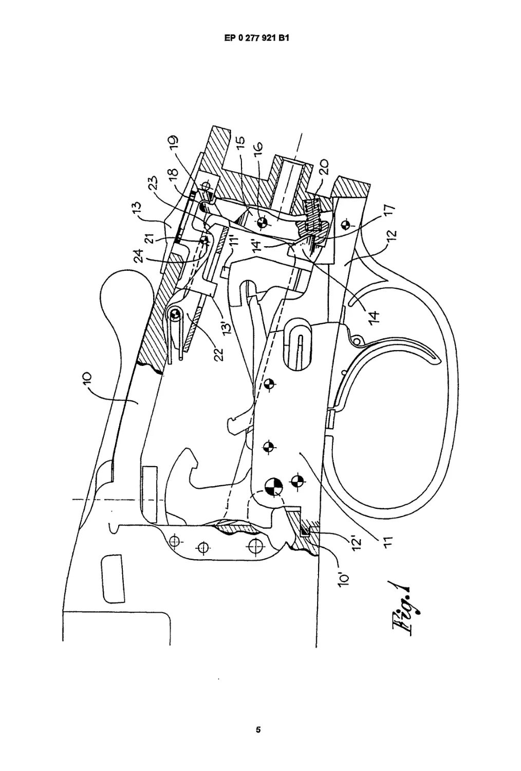
Figure 1 is a schematic view of the monotrigger
mechanism in the position of engagement in the
breech of the gun ;
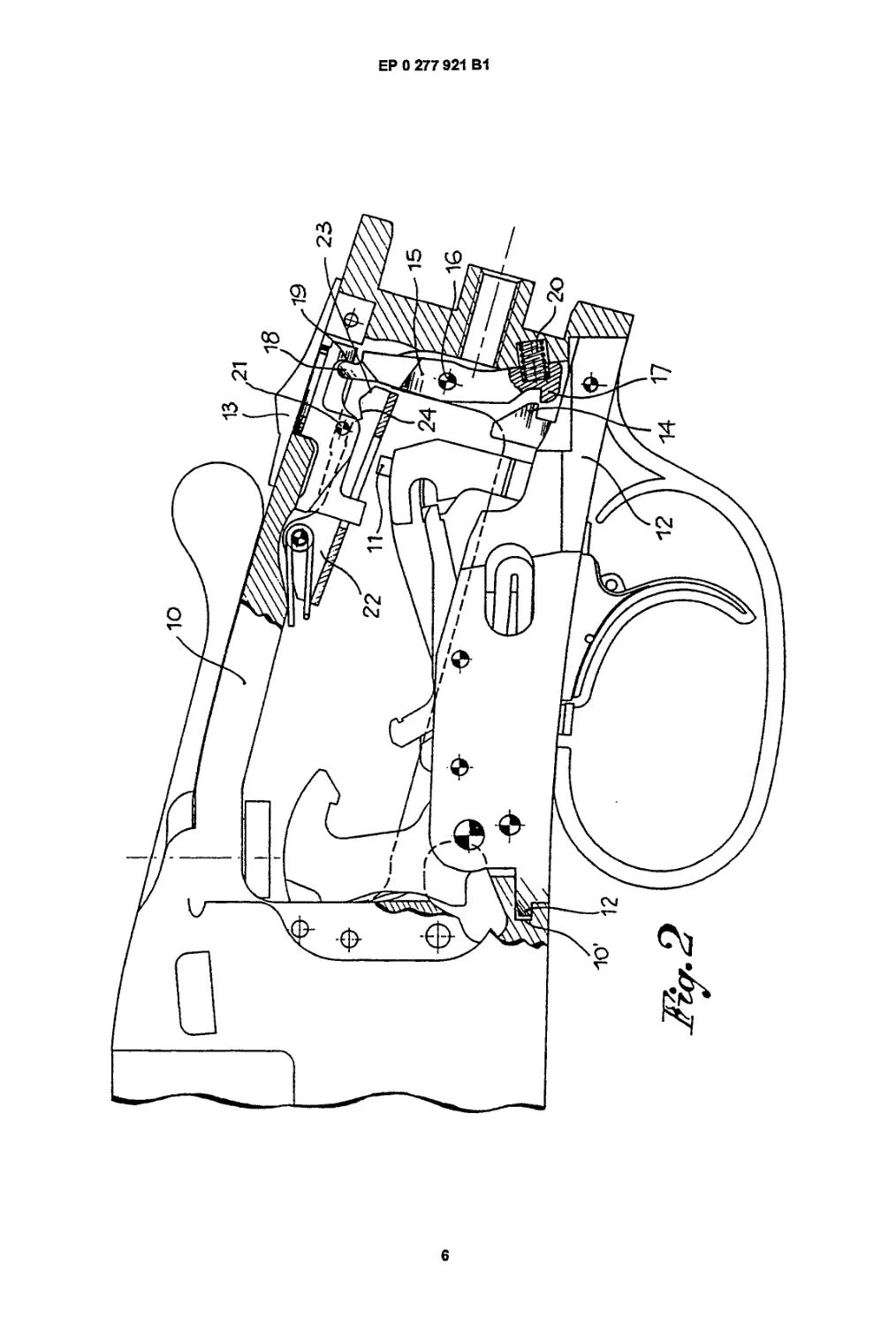
Figure 2 is a similar view, analogous to figure 1,
showing the monotrigger mechanism in a disen-
gaged condition; and
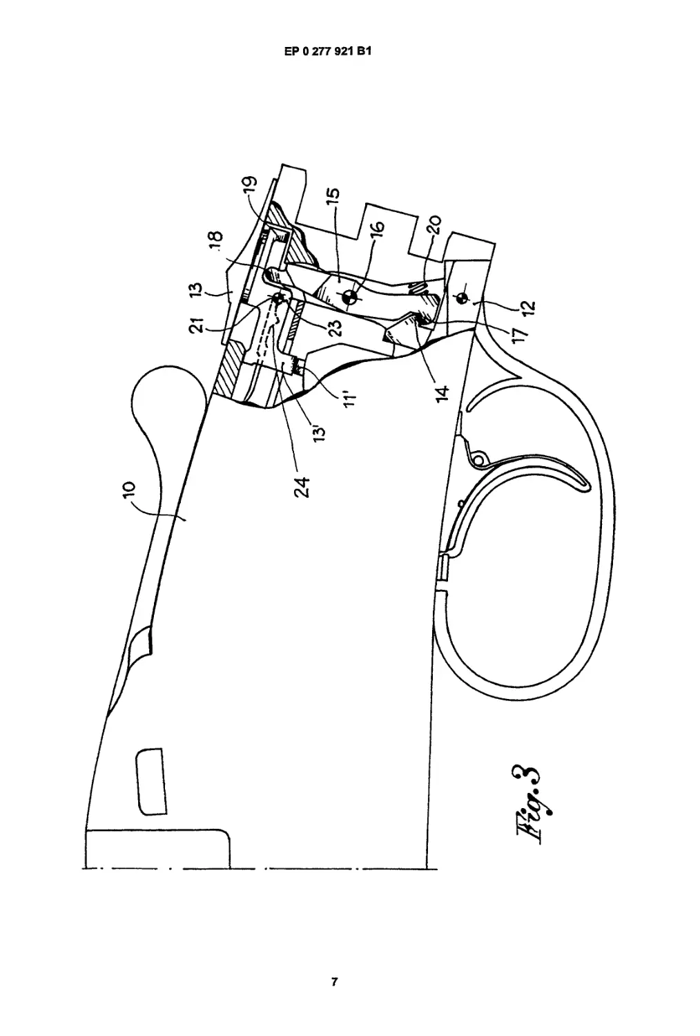
Figure 3 represents the condition of safety of the
monotrigger mechanism.
Referring now to the drawings, numeral 10 repre-
sents generally the breech of a gun, in which is to be
mounted a monotrigger mechanism 11. The members
of the monotrigger mechanism 11 are premounted, in
a manner known perse, on an underguard 12 which
is applicable to the lower portion of the breech 10. In
the upper portion of the breech 10 instead, there is
mounted a slidable safety sled 13, which has an
arresting portion 13' facing the monotrigger mechan-
ism 11 and intended to interfere with element 11' of
the latter to effect the safety positioning of the gun
(see figure 3).
In order to apply the underguard 12 to the breech
10, the former has a front tongue 12' which is intended
to be inserted in a complementary seat 10' provided
in the breech itself. In its rear part, the underguard 12
is integrally formed with a hook 14 which faces toward
the interior of the breech 10, behind the monotrigger
mechanism 11, and has a bevelled head 14'.
In the breech 10, between the hook 14 and the
safety sled 13, there is an oscillating lever 15 mounted
on an intermediate transverse pin 16. Lever 15 has,
on one side, a tooth 17 for engagement with the hook
14, integral with the underguard 12, and on the other
side, a terminal 18 for interacting with a shoulder 19
provided at the base of the safety sled 13. Lever 15
is, furthermore, actuated by a preloaded spring 20
which keeps the tooth 17 of the lever normally
engaged with the hook 14 and the terminal 18 dis-
placed toward the shoulder 19 of the safety sled 13.
In practice, the underguard 12, complete with
monotrigger mechanism 11, is mounted on and
attached to the breech 10 by, firstly, engaging the
front tongue 12' in its complementary seat 10' and,
subsequently, by pushing the monotrigger mechan-
ism 11 in the breech 10 until the hook 14 and the tooth
17 of the lever 15 are reciprocally engaged. The cou-
pling is facilitated by the bevelled head 14' of the hook
14 and by the action of the spring 20 on the lever 15,
without need of actuating any other member of the
2
3
ЕР 0 277 921 В1
4
gun.
The safety sled 13 is provided with a peg 21 that
interacts with a spring-loaded pusher 22. Pusher 22
has a ramp 23 which defines, together with the peg
21, the position of safety, and an intermediate cavity
24 which defines, again together with the peg 21, the
position of firing, that is to say, of operation of the gun.
In the position of safety, the sled 13 is displaced
fully to the rear, so that its arresting portion 13' inter-
feres with the member 1T of the monotrigger mechan-
ism, thus preventing the latter from operating. At the
same time, the shoulder 19 is moved away from the
terminal 18 of the lever 15, as it is shown in figure 3
of the drawings. In the position of firing, the safety sled
13 is halted in an intermediate position, due to the
positioning of its peg 21 in the cavity 24 of the pusher
22. The shoulder 19 is adjacent to the terminal 18 of
the lever 15, without, however, altering the position of
the latter (see figure 1).
In either position, of safety and of firing, the safety
sled has no influence whatever upon the lever 15, so
that the condition of engagement and of attachment
of the monotrigger mechanism in the breech of the
gun is not altered, when one passes from one position
to the other.
The safety sled 13 is, nevertheless, displaceable
manually toward the front and beyond the position of
firing. This permits the disengagement of the mono-
trigger mechanism 11, when it is necessary to remove
it from the breech 10. As a result of such a displace-
ment of the safety sled 13, the shoulder 19 acts
against the terminal 18 of the lever 15, displacing the
latter in opposition to the spring 20. Tooth 17 of the
lever 15 is, meanwhile moved away and disengaged
from the hook 14 of the underguard 12, as it is shown
in figure 2 of the drawings.
The monotrigger mechanism 11, nowfree, can be
removed from the breech 10. When the manual action
on the safety sled has ended, the spring 20 returns the
lever 15 and, through the contact of its terminal 18
with the shoulder 19, the safety sled 13 to the position
of firing, or to the position in which the described
device is preplaced for engaging and holding the
monotrigger mechanism, when the latter is remoun-
ted in the breech.
Claims
1. A device for the rapid engagement and disen-
gagement of a monotrigger mechanism in the breech
of a shotgun, where the trigger mechanism is moun-
ted on an underguard (12) which can be sealed in the
underside of the breech (10) and wherein :
— a tongue (12') is provided in the front portion
of said underguard (12);
— a complementary seat (1 O') is formed in said
breech for receiving said tongue ;
5
10
15
20
25
30
35
40
45
50
55
— an oscillating lever (15) is mounted in said
breech and has a teminal (18) interacting with a
safety sled (13) on the upper part of the breech,
and another terminal which is designed to cause
the blocking and unblocking of said underguard in
the breech ;
— a biasing spring (20) acting on said oscillating
lever so as to push it towards the blocking posi-
tion of the underguard, characterized in that the
other terminal of the oscillating lever (15) has a
tooth (17) designed to directly interact with a hook
(14) integral with the back end of the underguard
(12) for the blocking and unblocking of the under-
guard in the breech where the biasing spring (20)
directly acts against the oscillating lever.
2. A device as claimed in claim 1 characterized in
that said hook (14) extends inside the breech where
said hook (14) has a bevelled head (14'), interacting
with the tooth (17) of the oscillating lever when the
trigger mechanism is inserted in said breech.
Patentanspruche
1. Eine Vorrichtung zum raschen Ein- und Aus-
schalten eines Einzelabzugs im VerschluB einer
Jagdflinte, wobei die Abzugseinrichtung an einen
Abzugbugel (12) angebracht ist, der in den Unterteil
des Verschlusses (10) eingebaut werden kann und in
der:
— eine Zunge (12') im Vorderteil des Abzugbu-
gels vorgesehen ist;
— im VerschluB (10) eine entsprechende Aus-
nehmung (1 O') zur Aufnahme der genannten Zun-
ge dient;
— ein Schwenkhebel (15) auf dem VerschluB ein
miteinem Sicherheitsschieber 13) zusammenwir-
kendes Ende (18) auf der Oberseite des Ver-
schlusses und ein zweites Ende zum Verriegeln
und Entriegeln des Abzugbugels im VerschluB
aufweist;
— eine vorgespannte Feder (20) den Schwenk-
hebel in die verriegelte Stellung des Abzugbugels
bringt, dadurch gekennzeichnet, daB das entge-
gengesetzte Ende des Schwenkhebels mit einem
Zahn (17) versehen ist, der direkt mit einem
Haken (14) zusammenwirkt, der einstuckig am
Abzugbugel (12) vorgesehen ist und zum Verrie-
geln und Entriegeln des Abzugbugels im Ver-
schluB dient, wo die Feder (20) direkt auf den
Schwenkhebel einwirkt
2. Vorrichtung nach Anspruch 1, dadurch
gekennzeichnet, daB der Haken (14) in den Ver-
schluB hineinragt und sein abgeschragtes Ende (14')
mit dem Zahn (17) des Schwenkhebels zusammen-
wirkt wenn die Abzugseinrichtung in den VerschluB
eingesetzt ist.
3
5
ЕР 0 277 921 В1
6
Revendications
1. Un dispositif pour un rapide enclenchement et
d£clenchement d’un m£canismo monodetente dans
la culasse d'un fusil de Chasse, ou le mScanisme de
d^clenchement est monte sur la sous-garde (12)
qu’on peut sceller dans la partie inferieure de la
culasse (10) et dans lequel;
— une langue (12') est pr6vue dans la portion
frontal de la sous-garde (12);
— un siege compl6mentaire (1 O') dans la culasse
sert й recevoir la langue susdite ;
— un levier oscillant (15) est monte sur la culasse
susdite et pr6sente une extr6mite (18) interagis-
sante avec un curseur de surety (13) sur la partie
sup6rieure de la culasse, et une autre extr6mite
destin6e й bloquer et debloquer la sous-garde
susdite dans la culasse;
— un ressort precontract (20) agissant sur le
levier oscillant susdit de тапгёге й le pousser
vers la position de blocage de la sous-garde,
caracterise en ce que I’autre extremity du levier
oscillant (15) a un dent (17) destine & interagir
directement avec un crochet (14) int6gr6 avec
I’extremite атёге de la sous-garde (12) pour blo-
quer et debloquer la sous-garde dans la culasse
ou le ressort precontract (20) agit directement
sur le levier oscillant.
2. Dispositif conforme e la revendication 1, carac-
terise en ce que le crochet (14) s’6tend dans la
culasse ou le crochet (14) a une tete chanfrein6e (14')
interagissant avec le dent (17) du levier oscillant
quand le m6canisme de d6clenchement est ins6r6
dans la culasse.
5
10
15
20
25
30
35
40
45
50
55
4
ЕР 0 277 921 В1
5
ЕР 0 277 921 В1
6
ЕР 0 277 921 В1
7