/


Text
Tool Joints
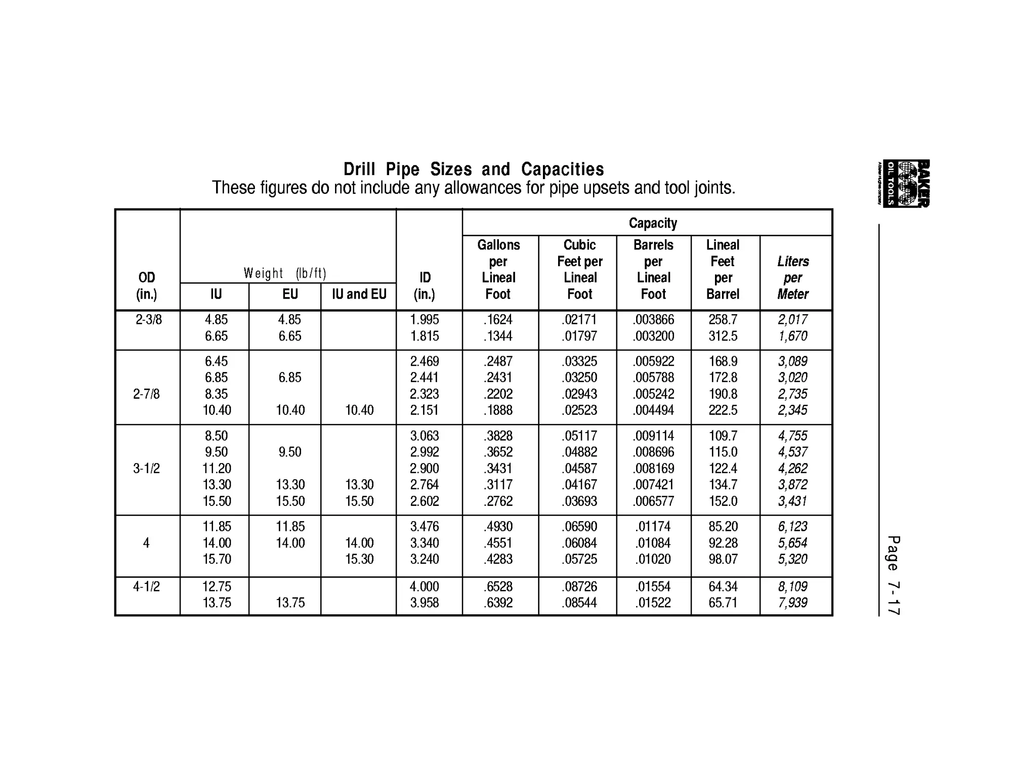
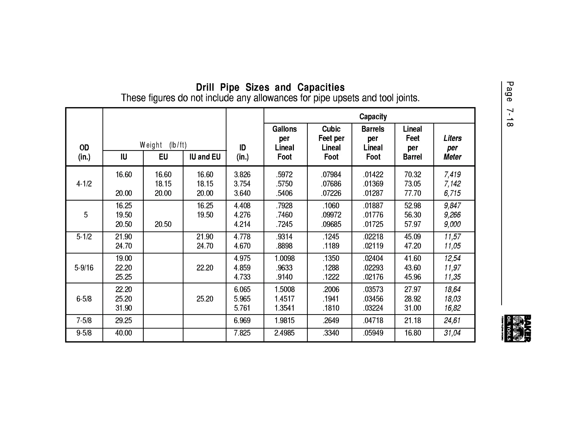
Drill Pipe
Drill Collars and
Connections
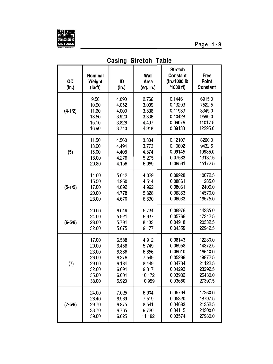
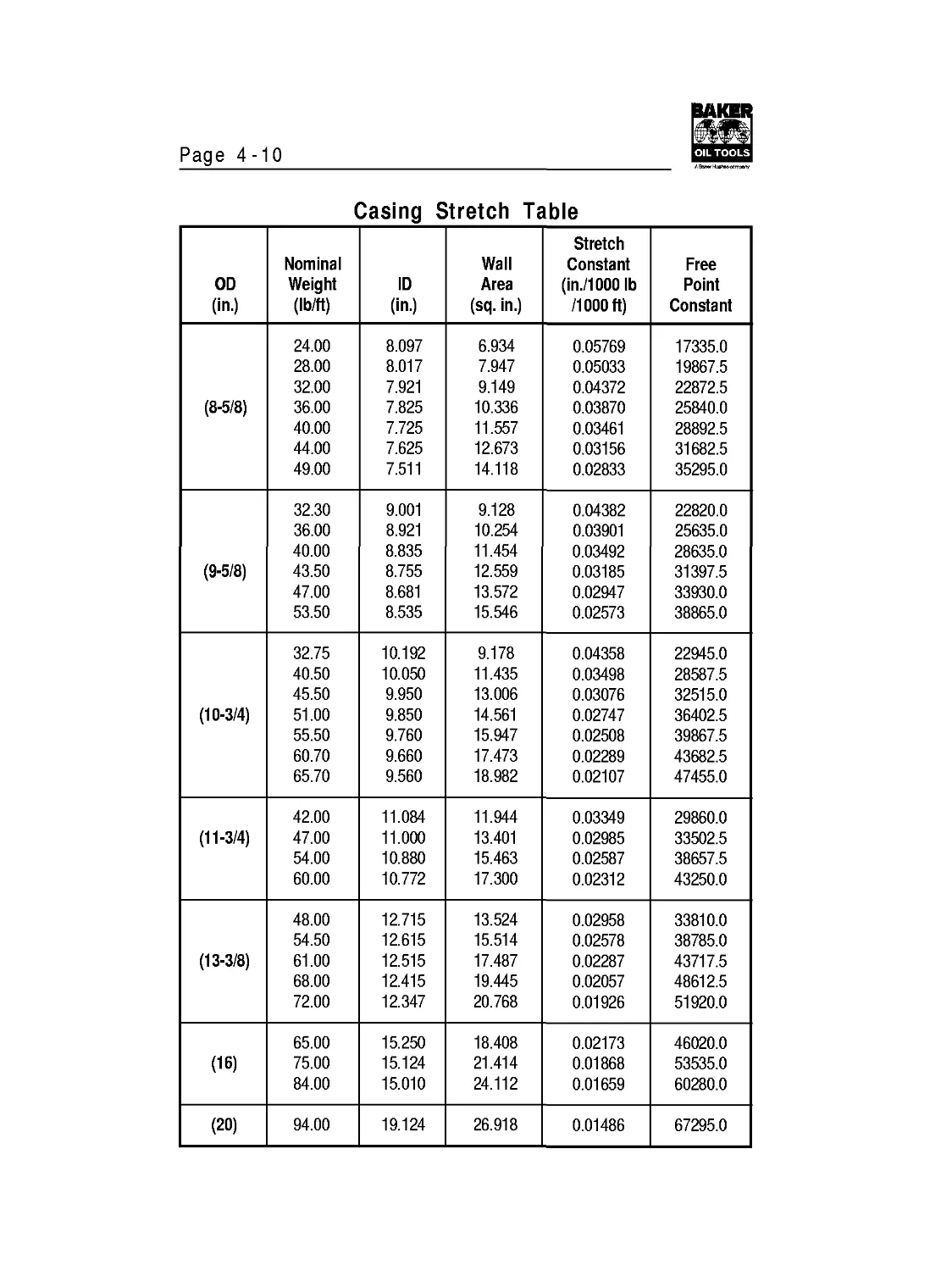
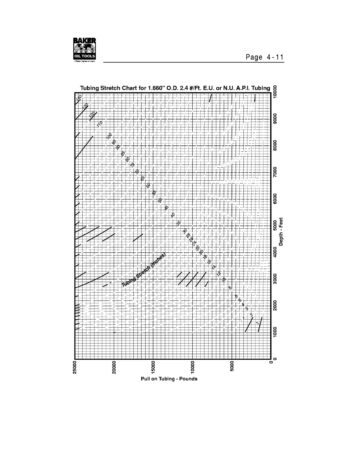
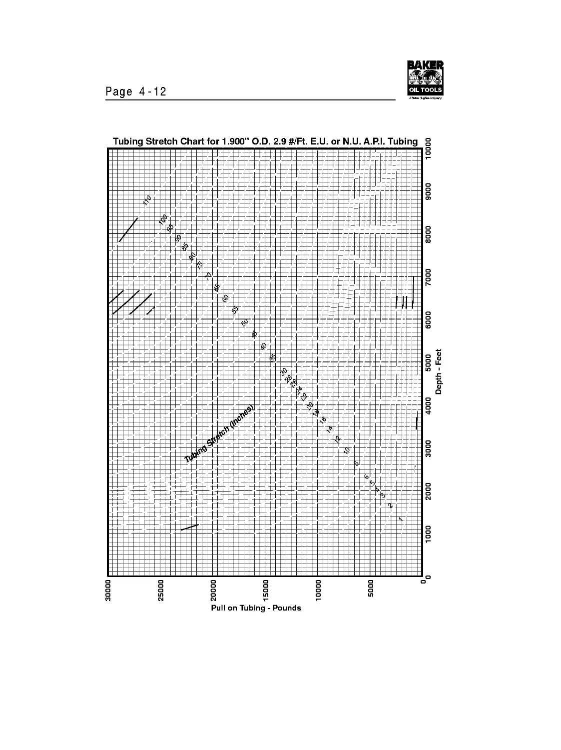
Stretch
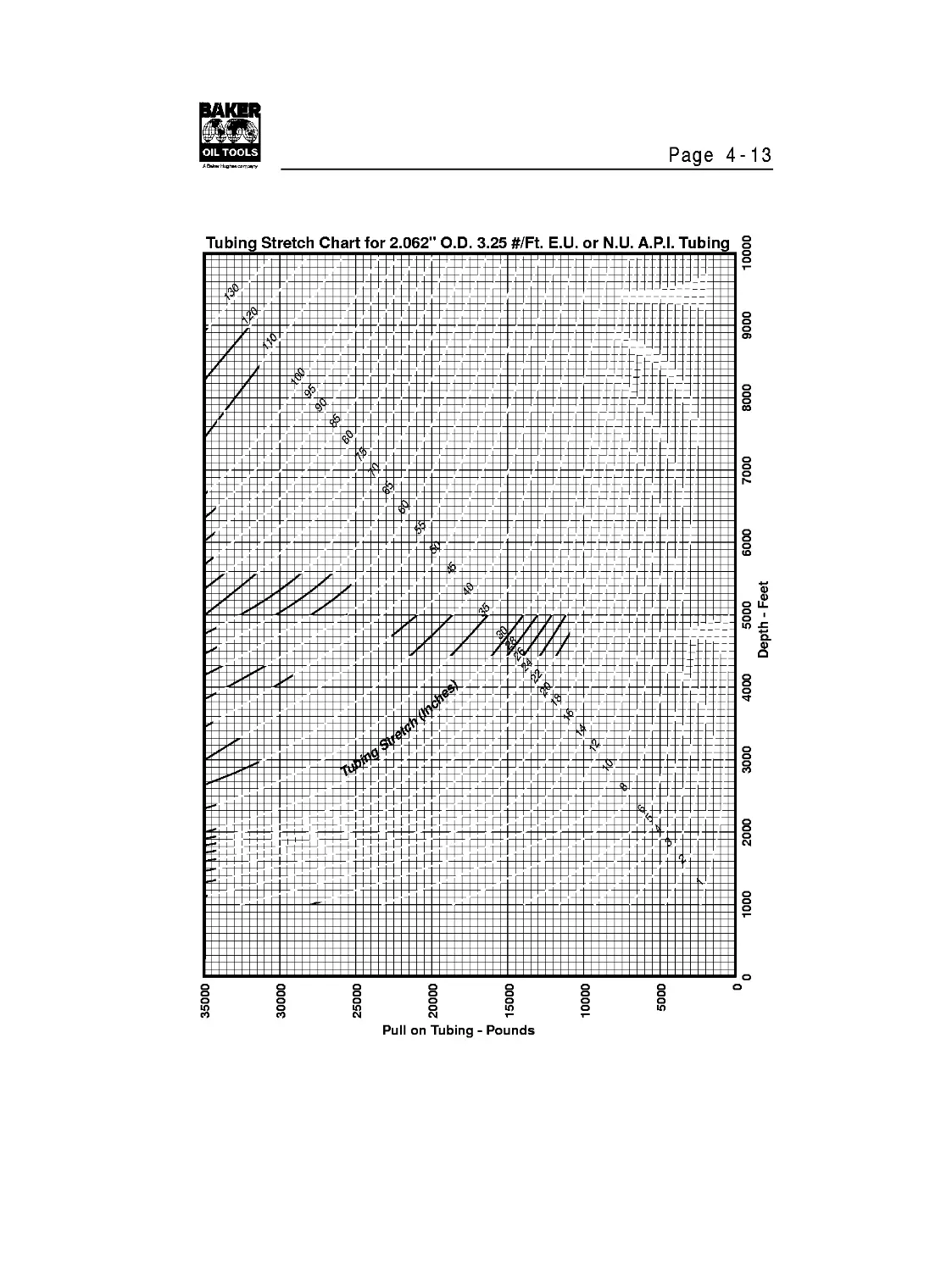
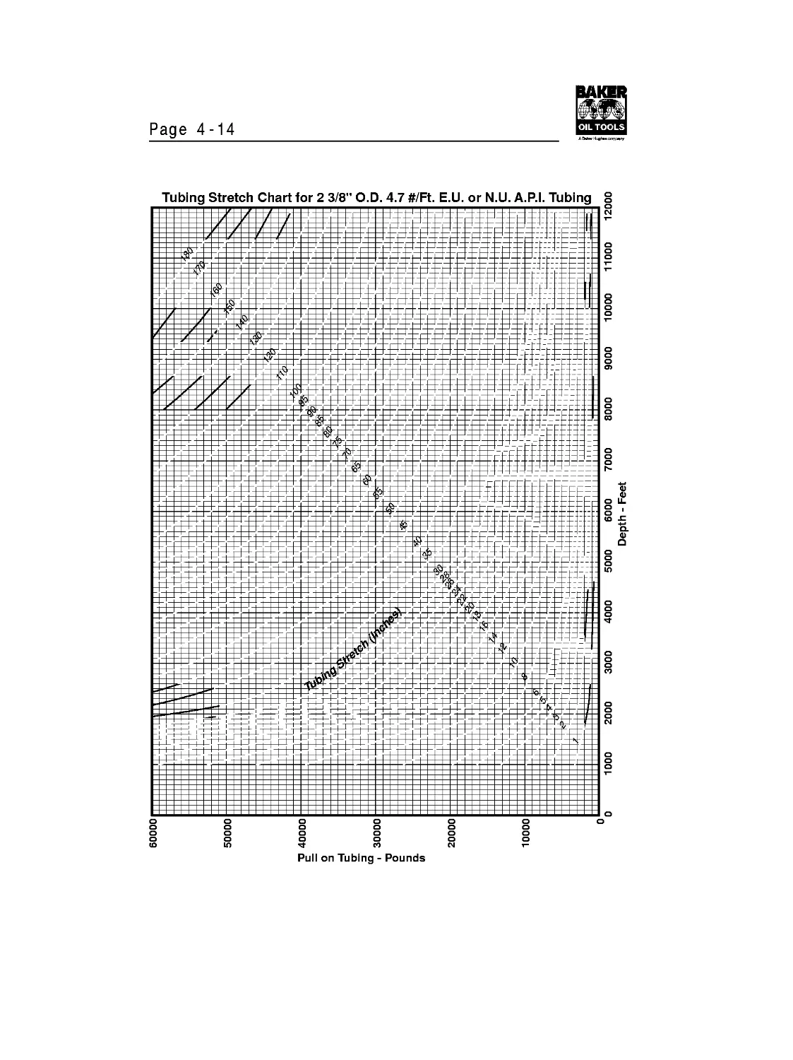
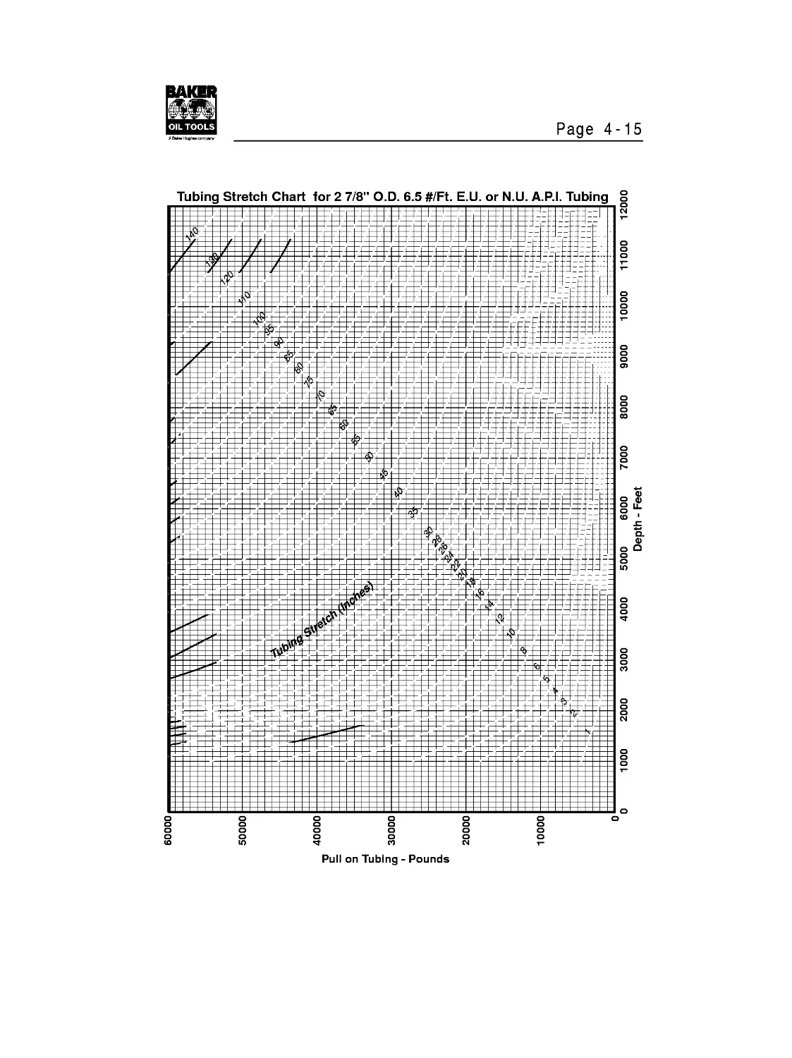
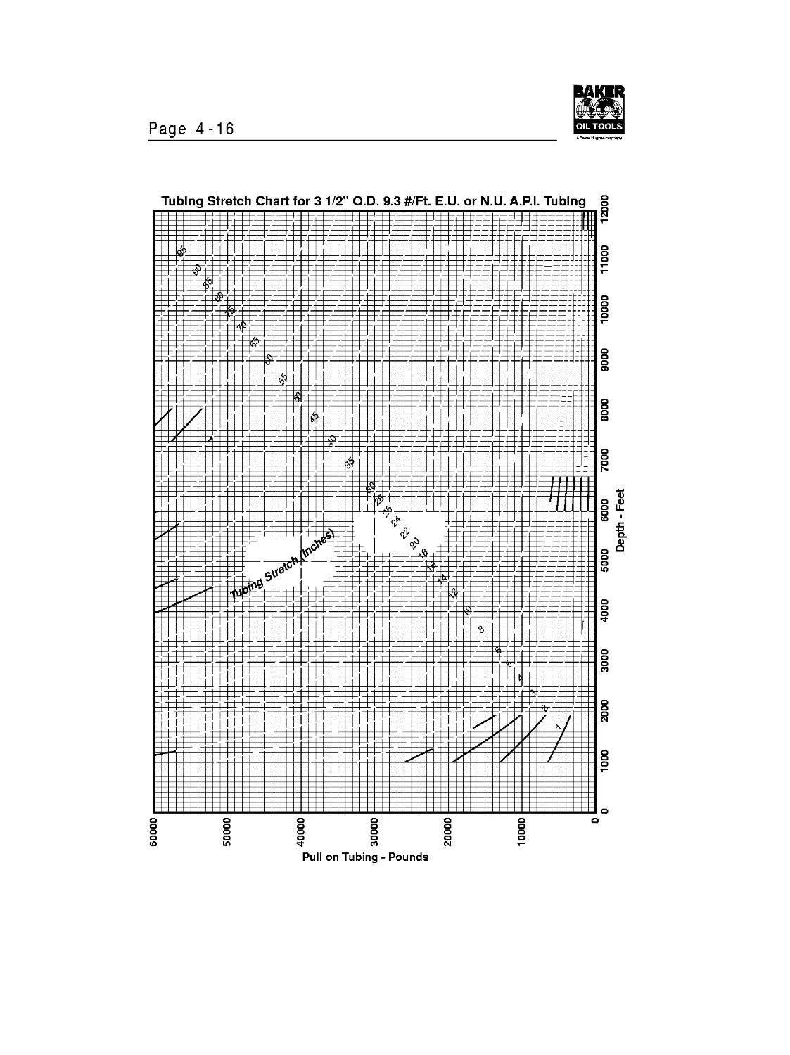
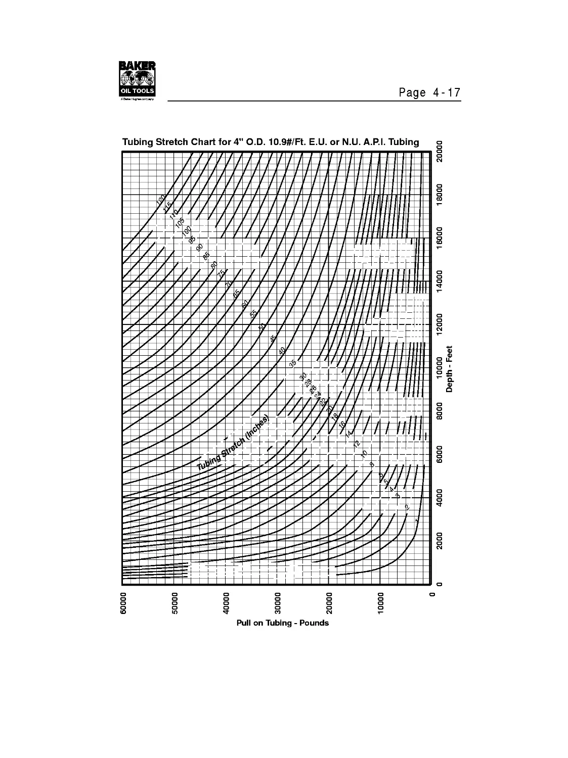
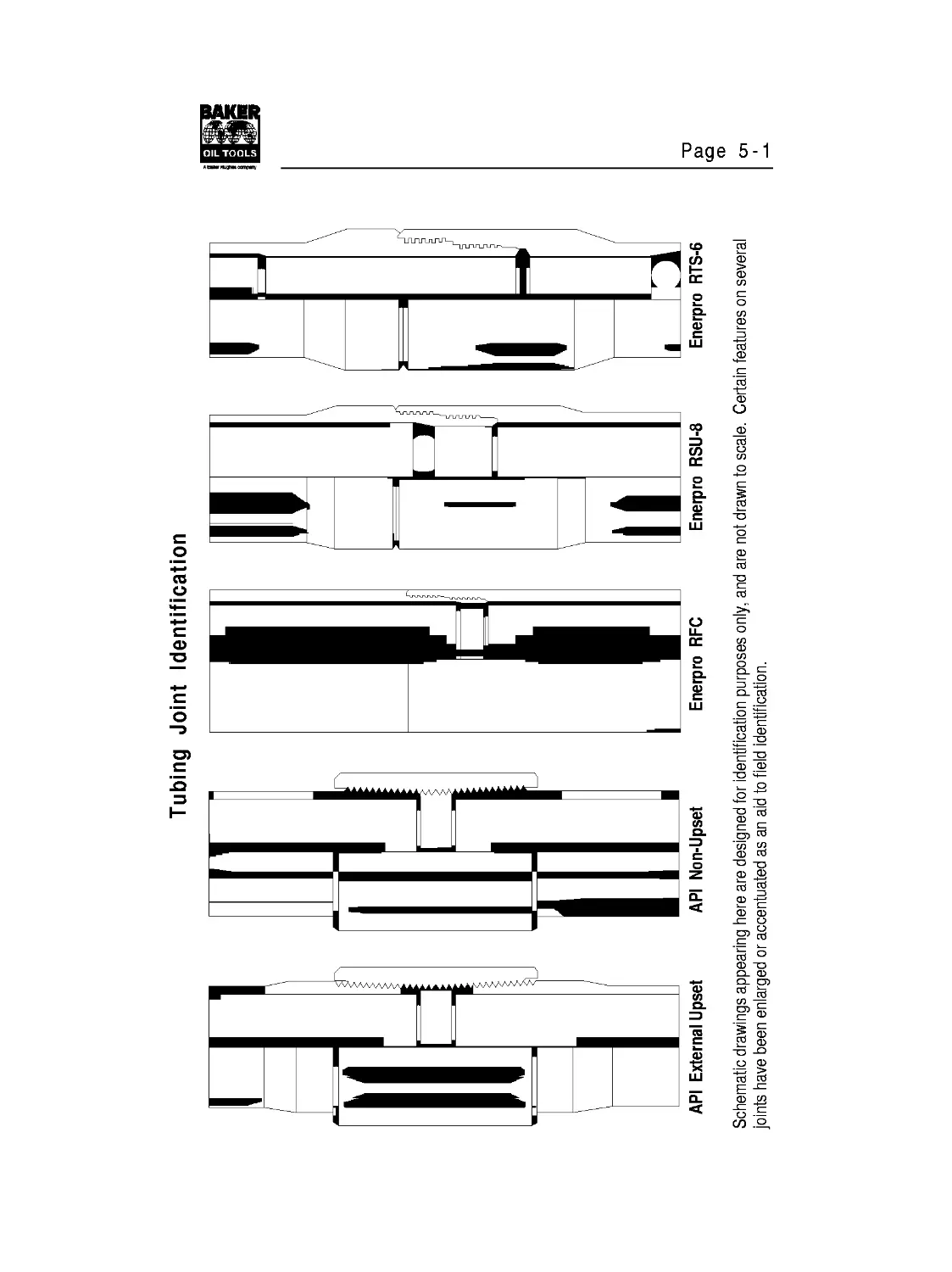
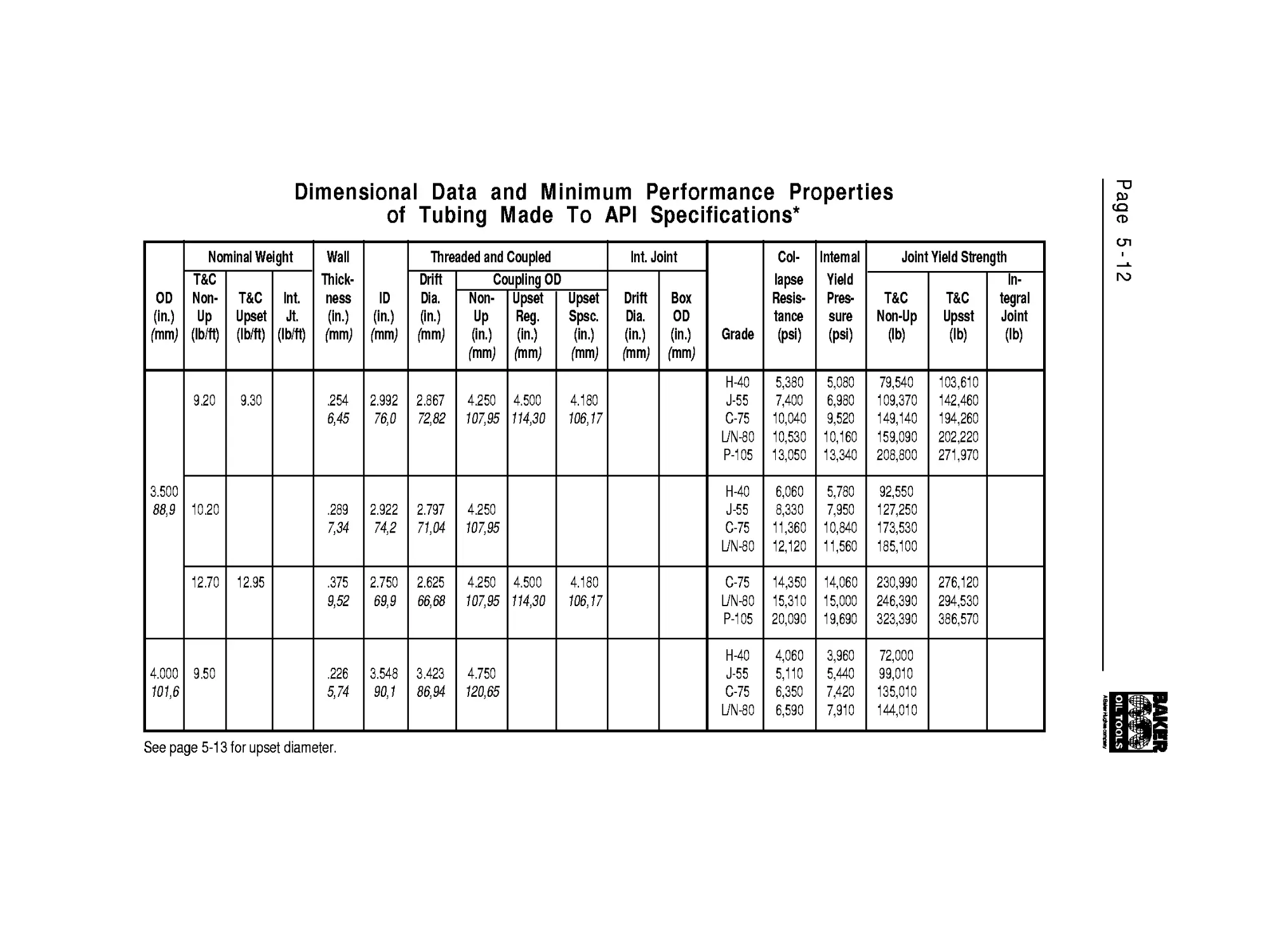
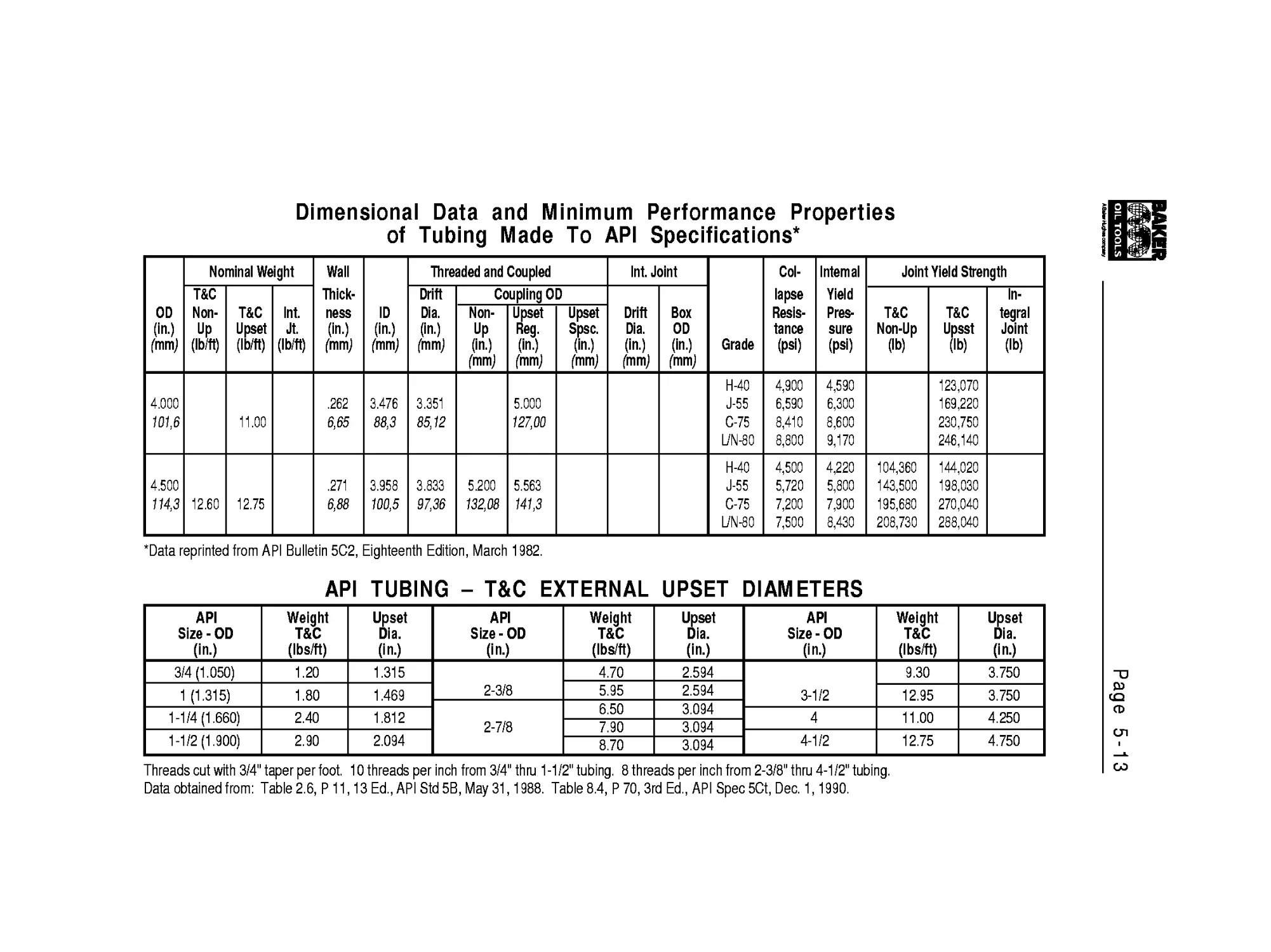
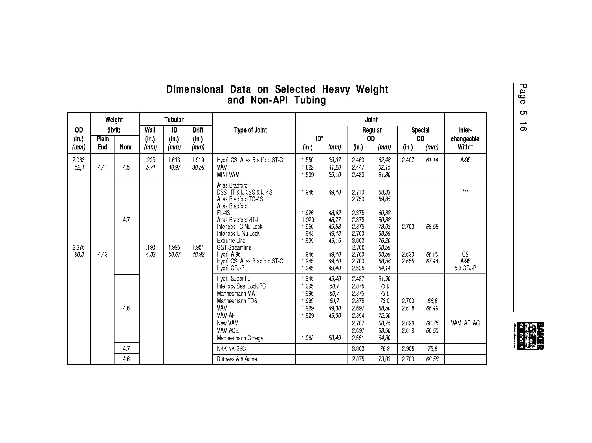
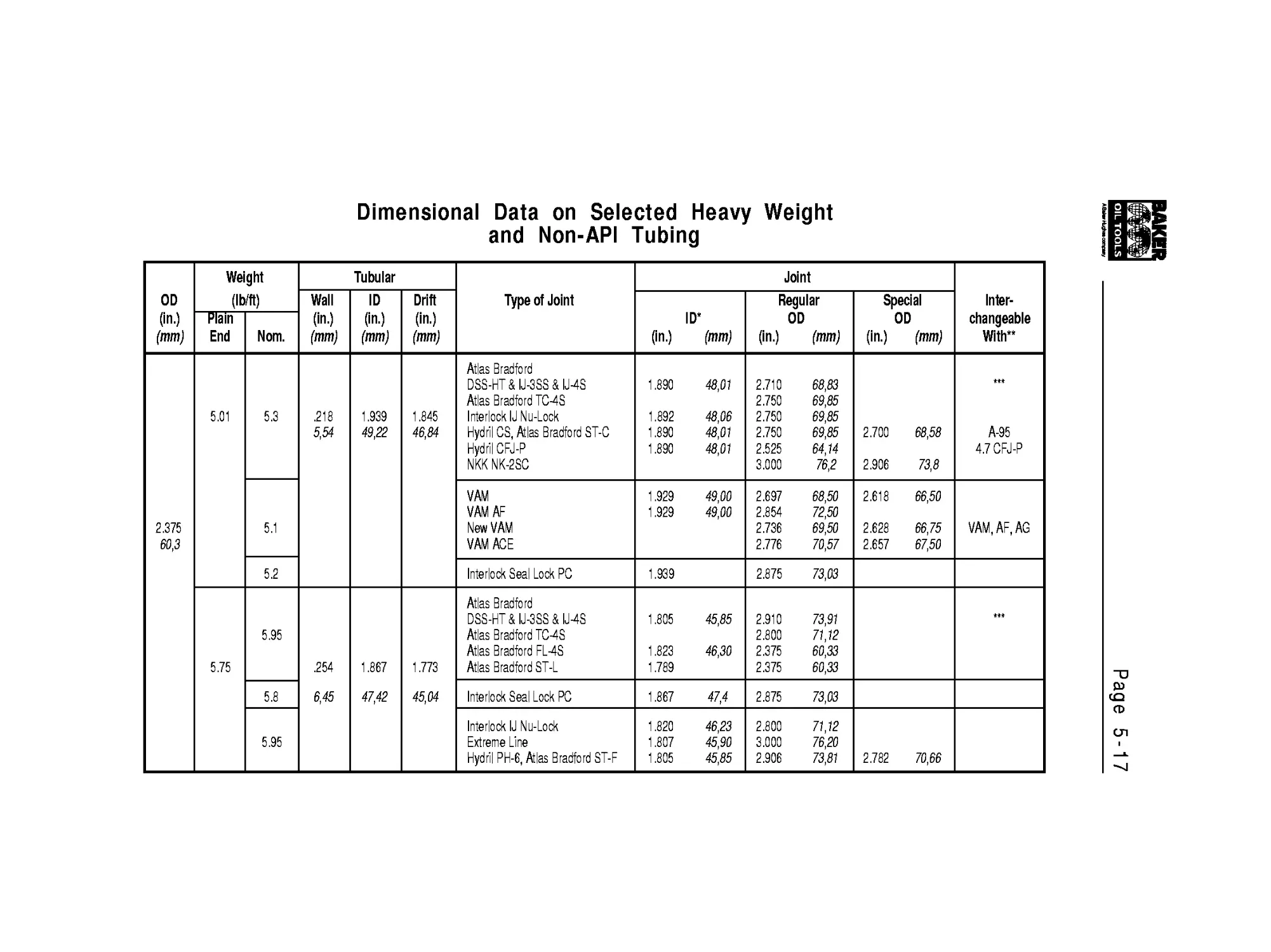
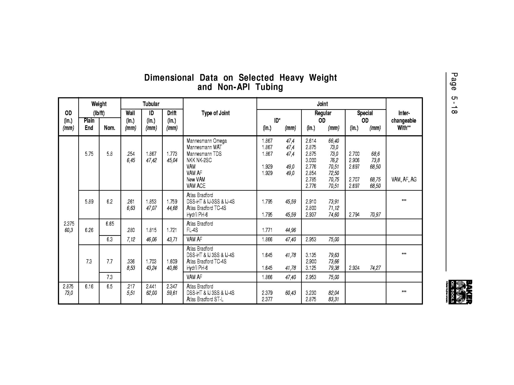
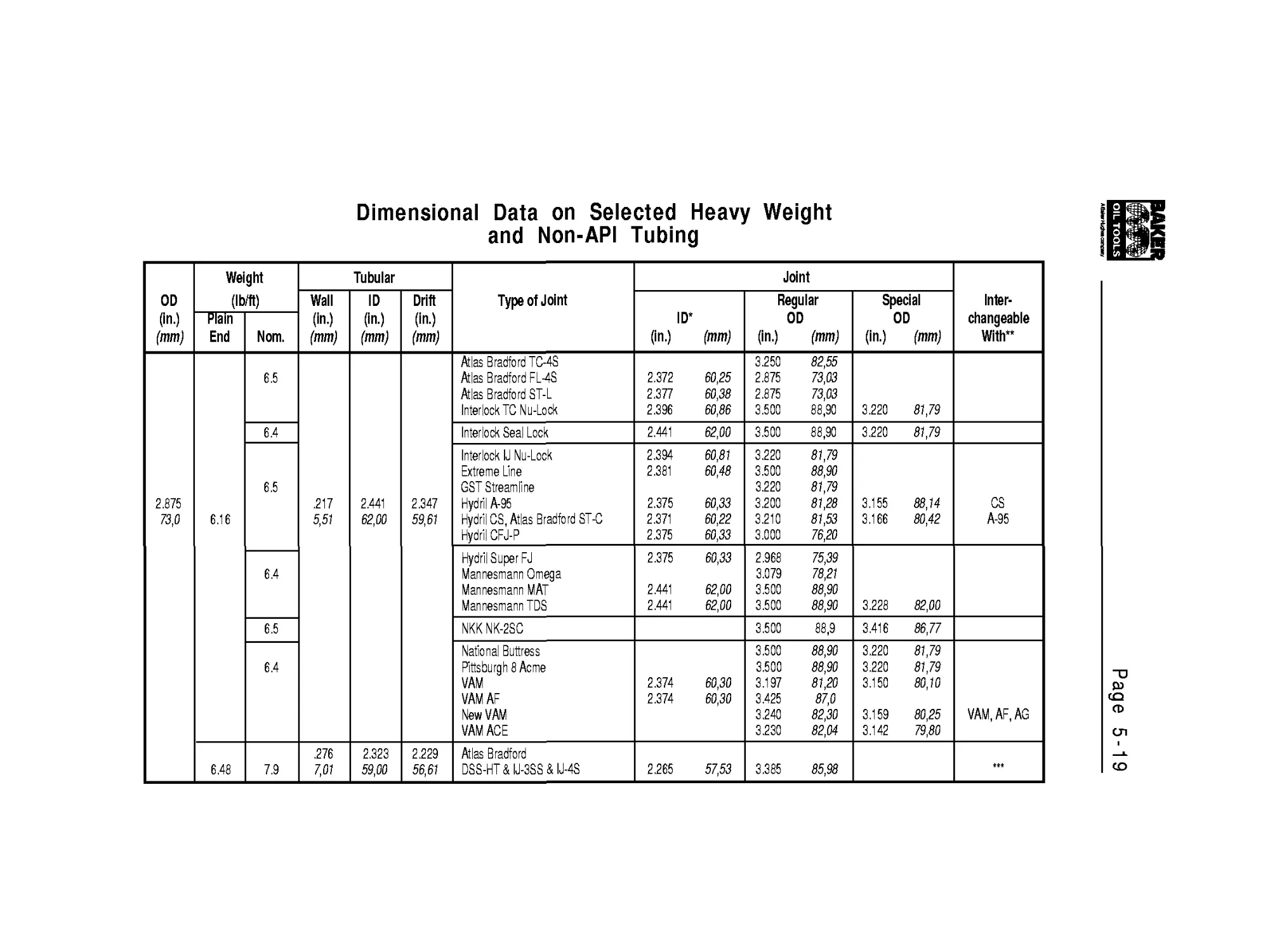
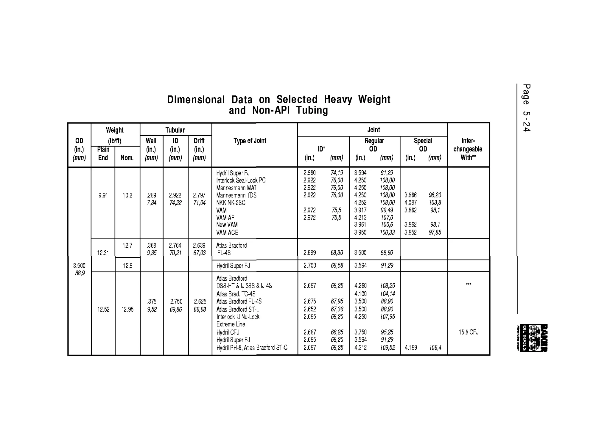
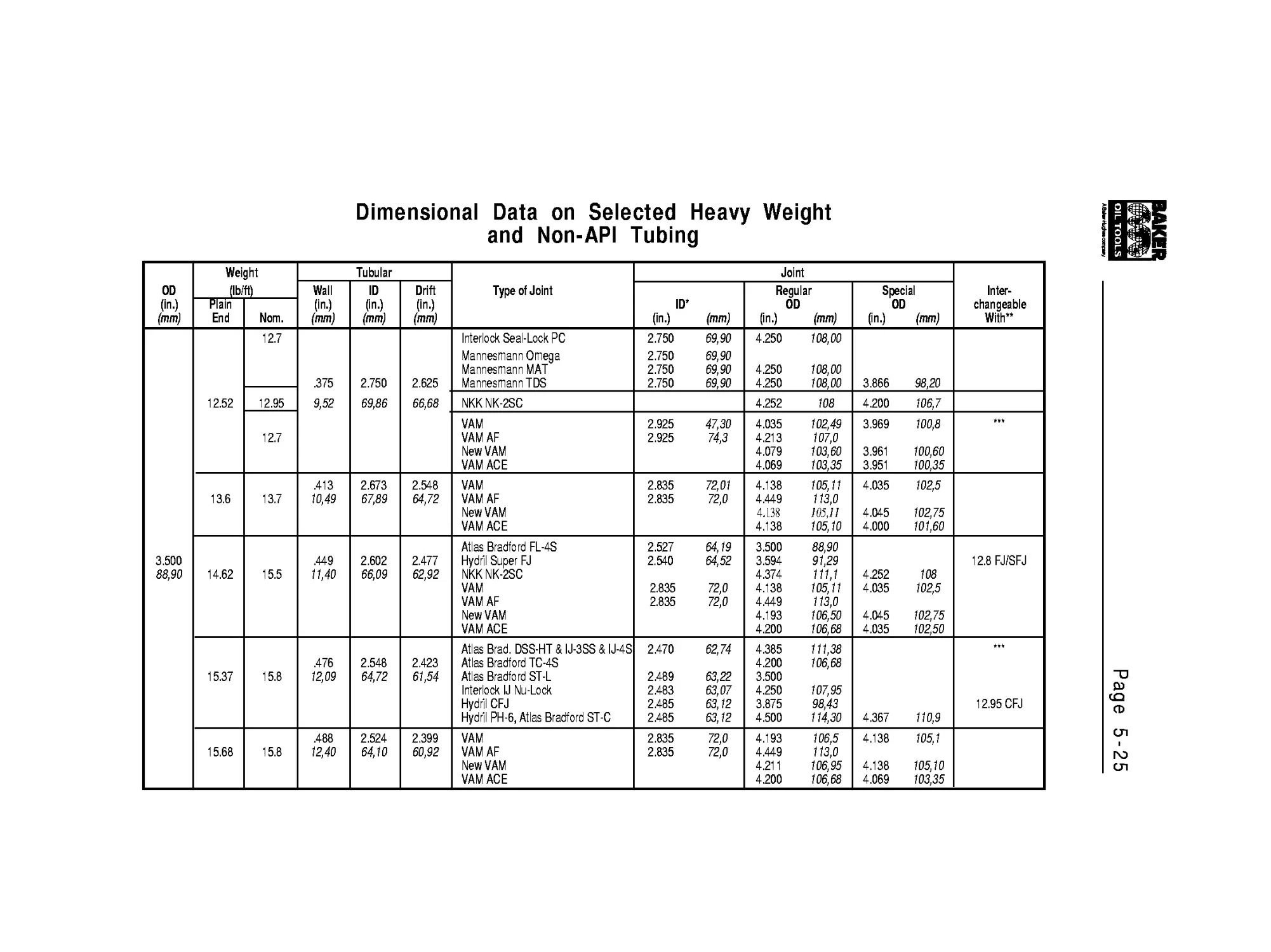
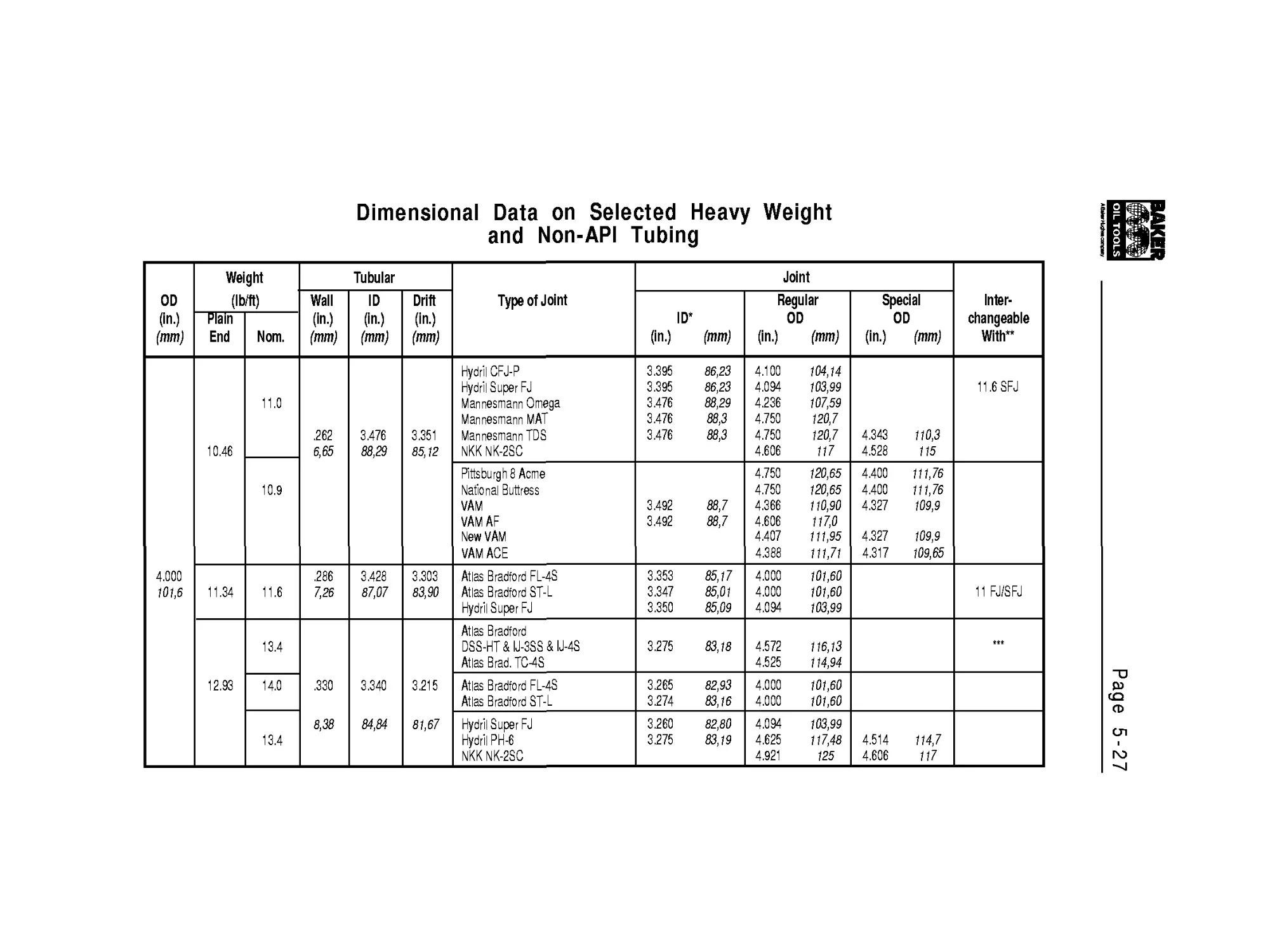
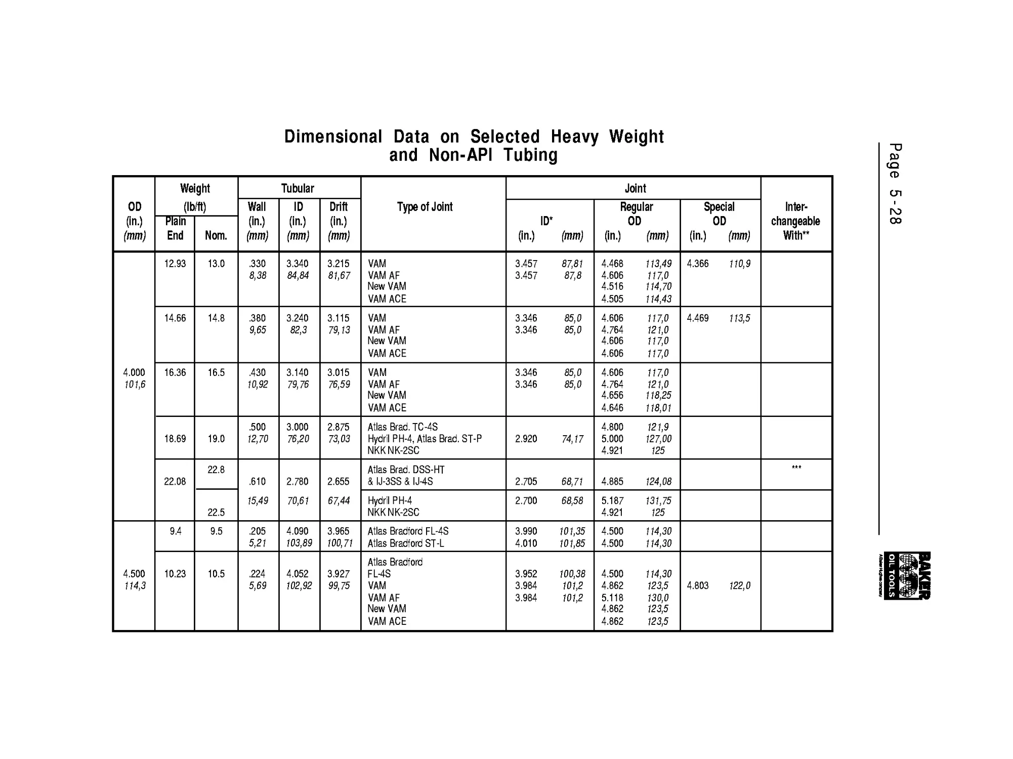
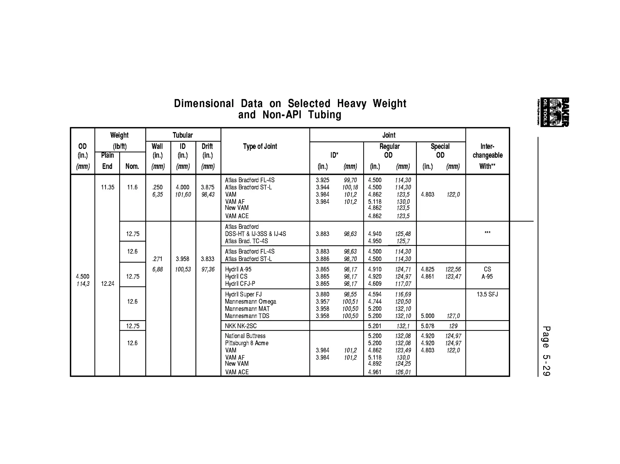
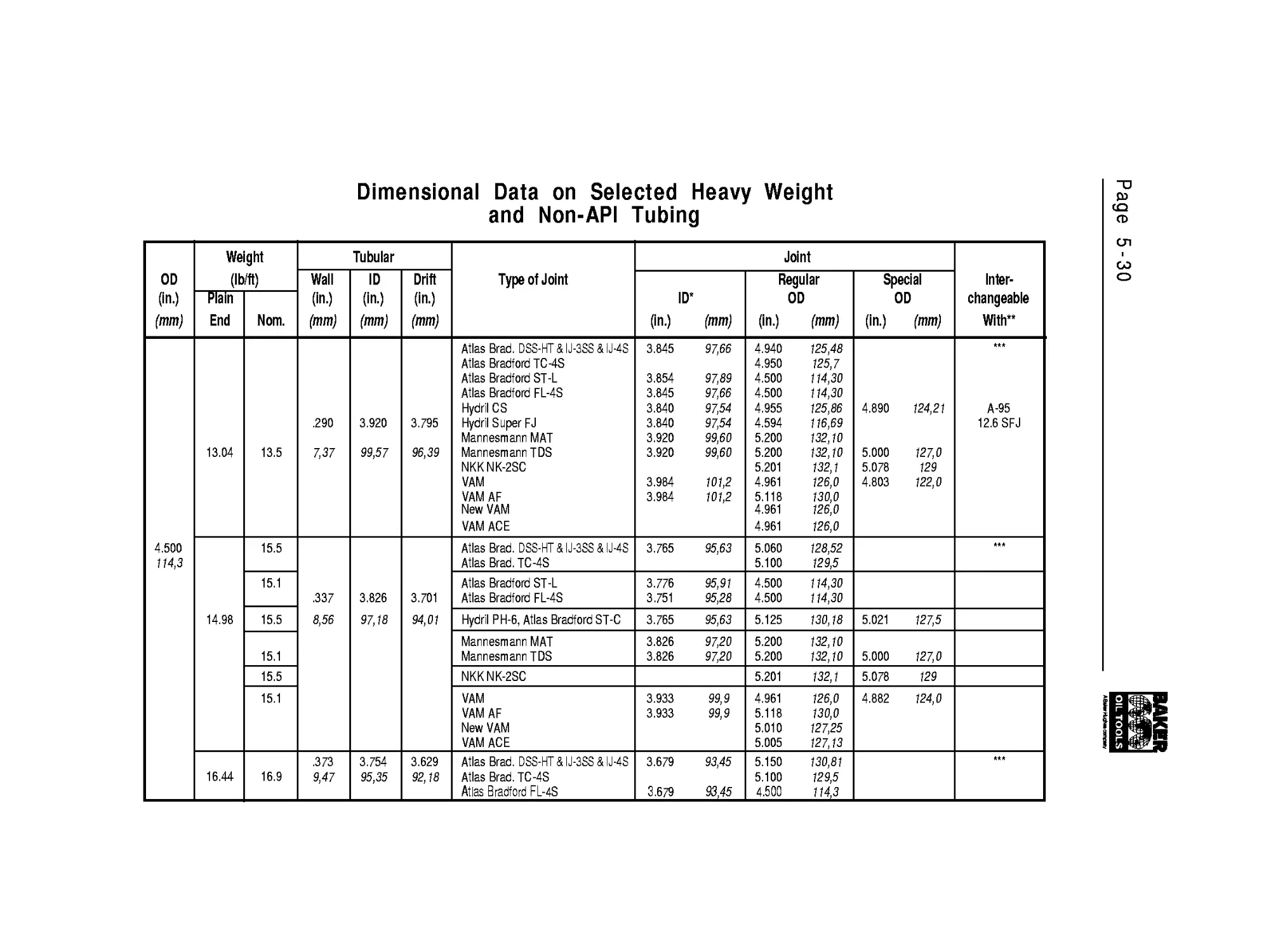
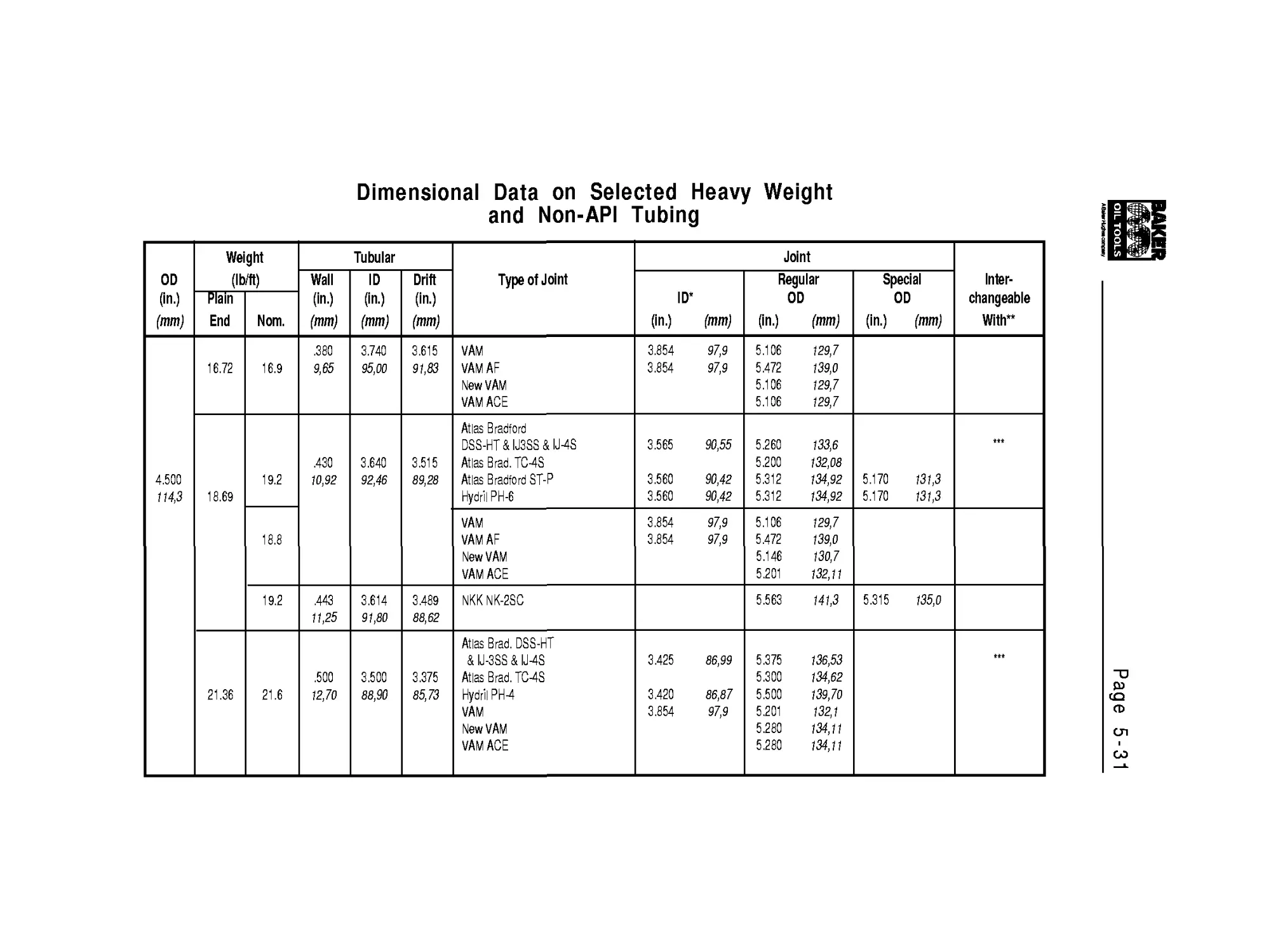
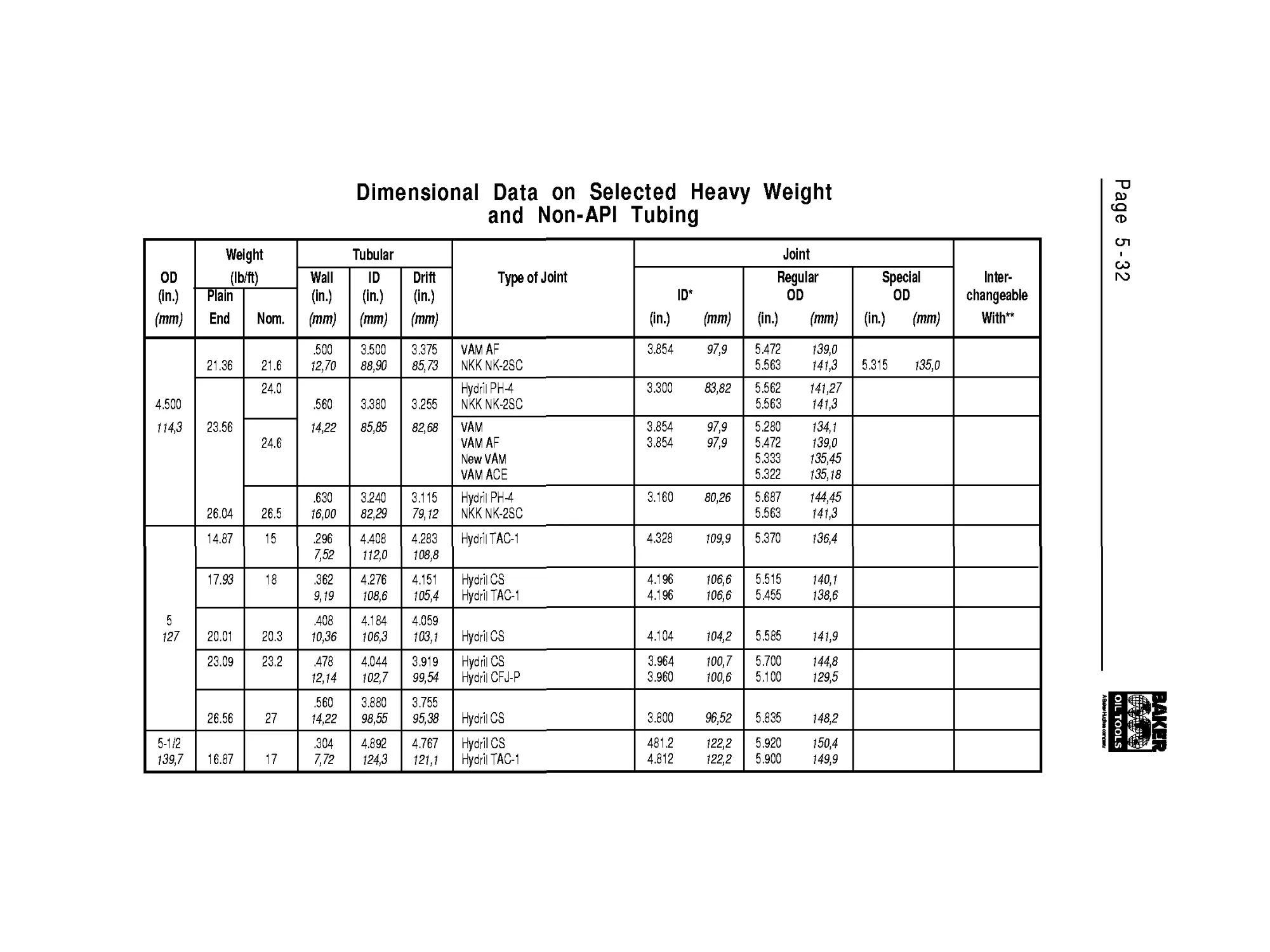
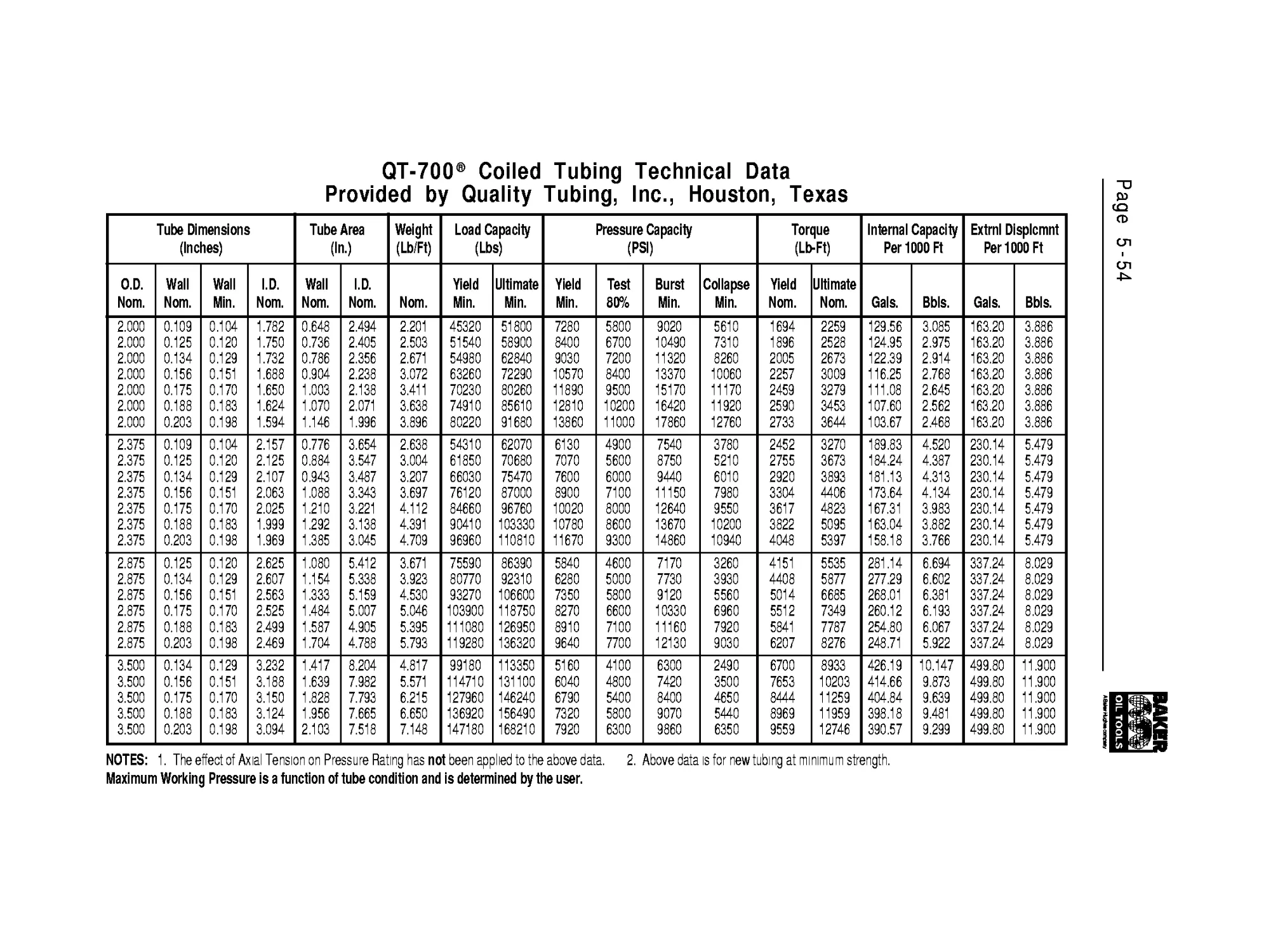
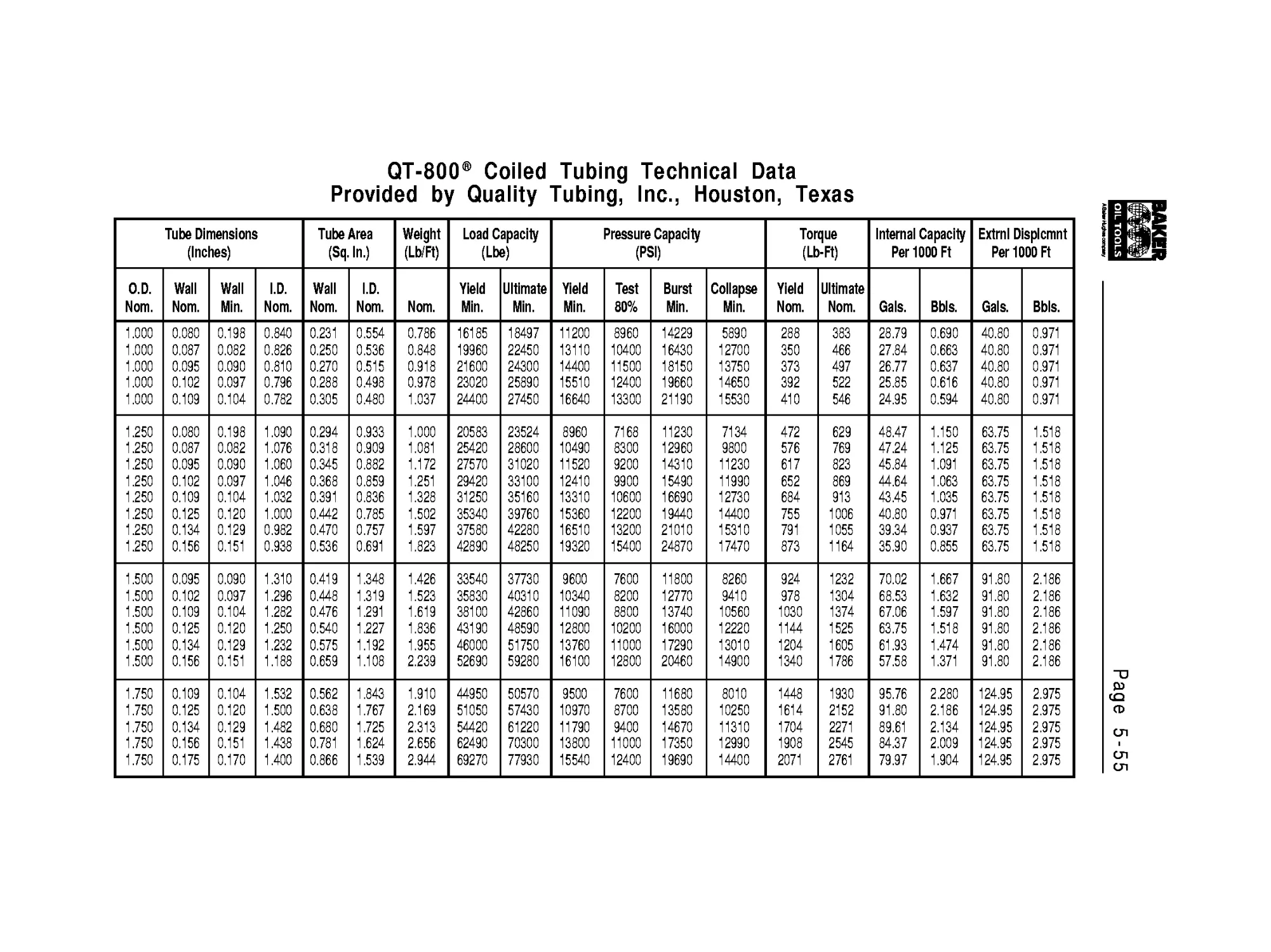
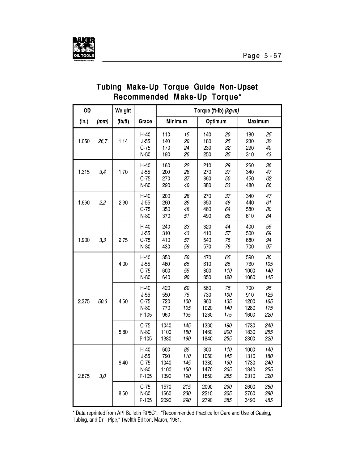
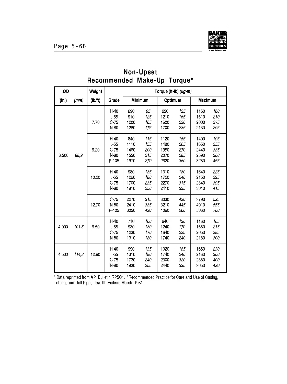
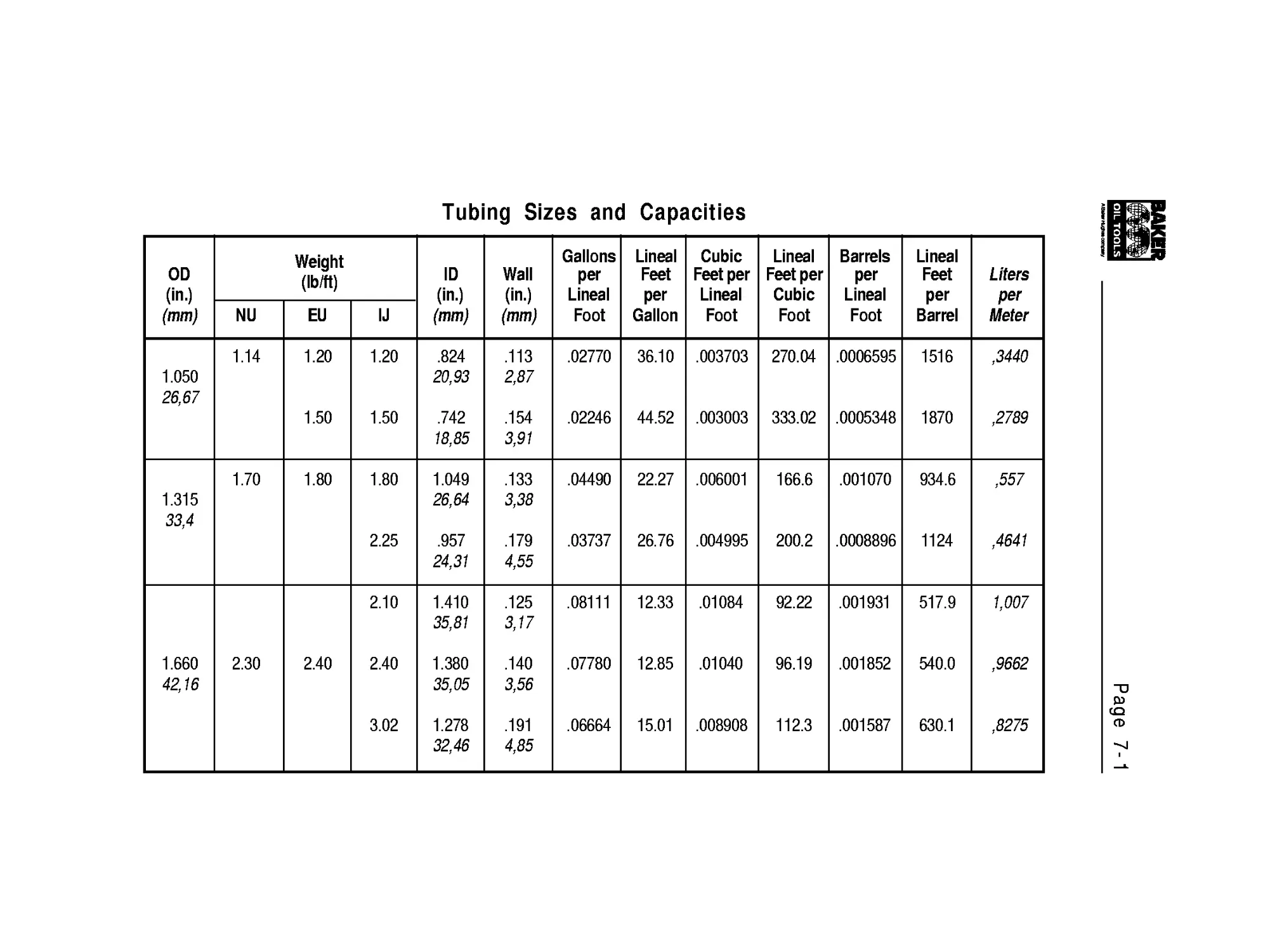
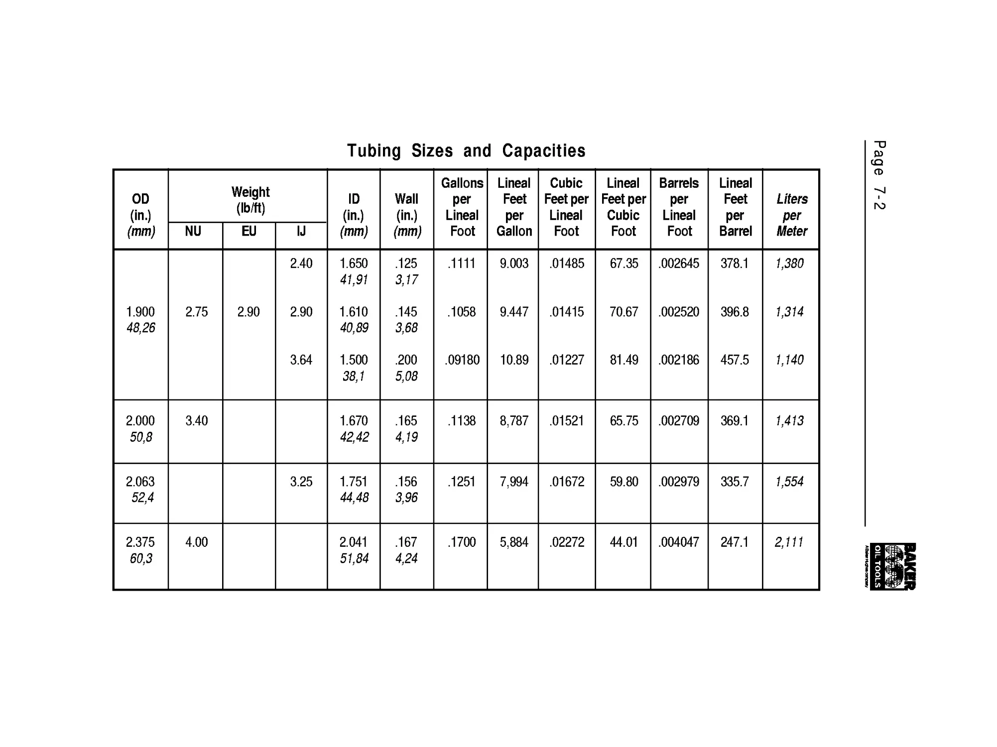
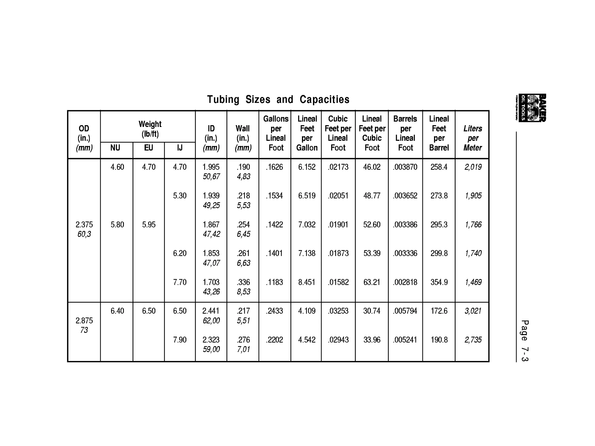
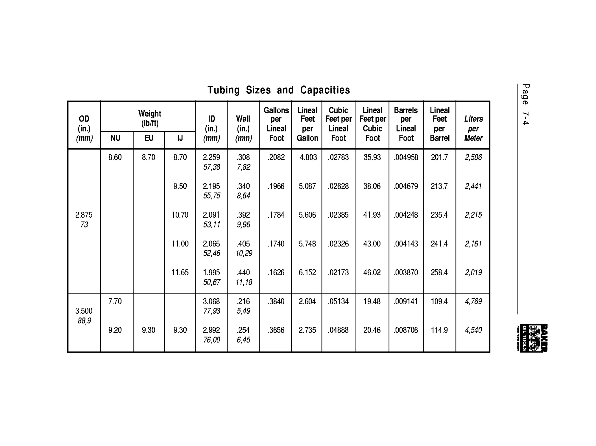
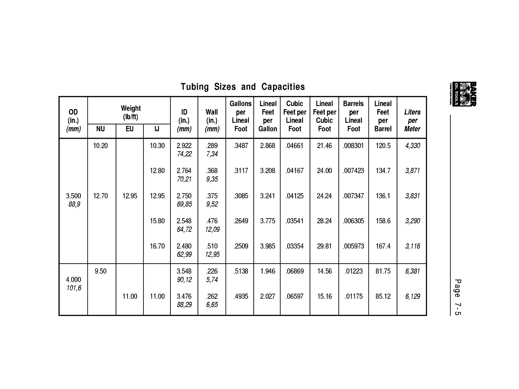
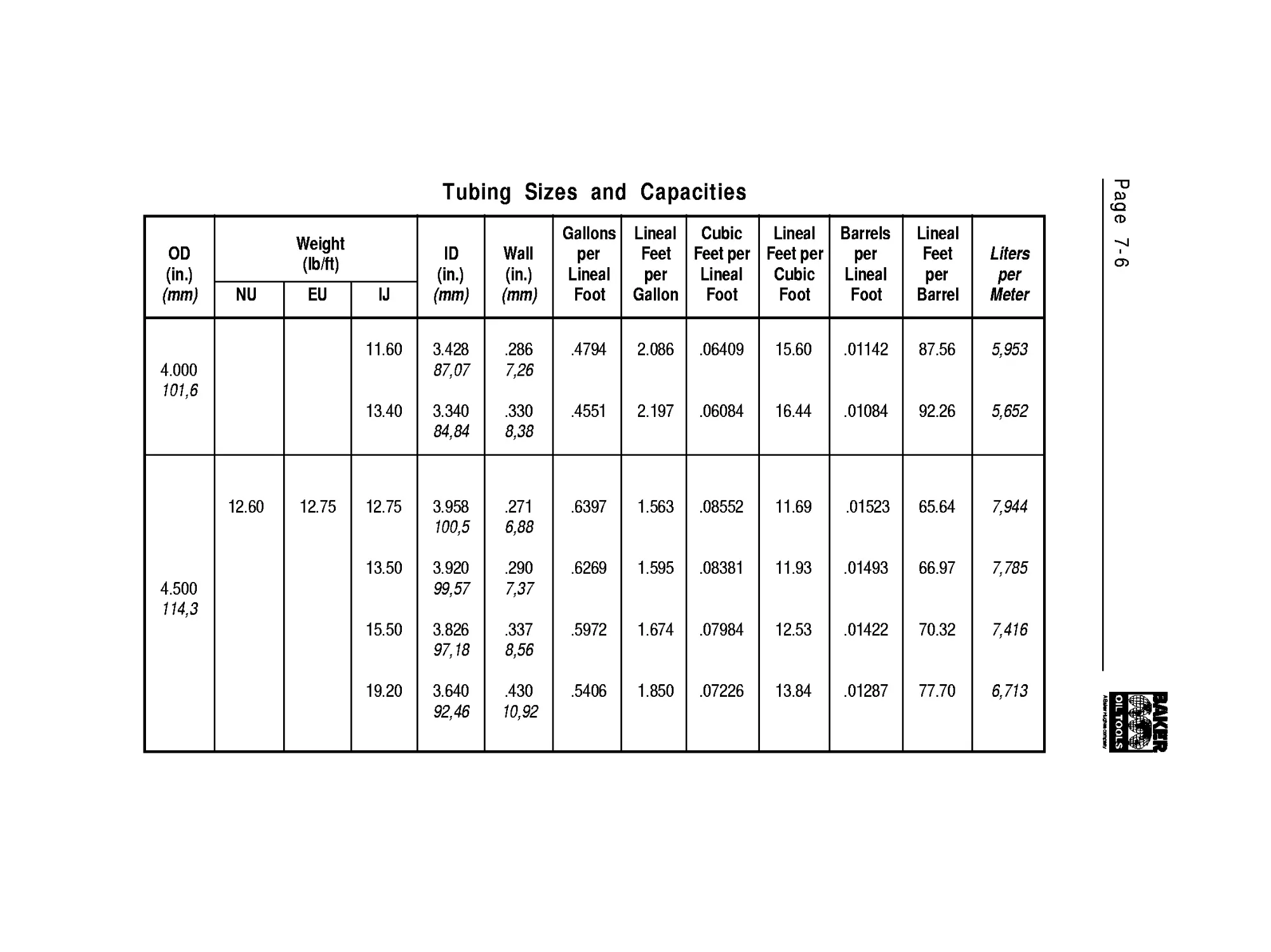
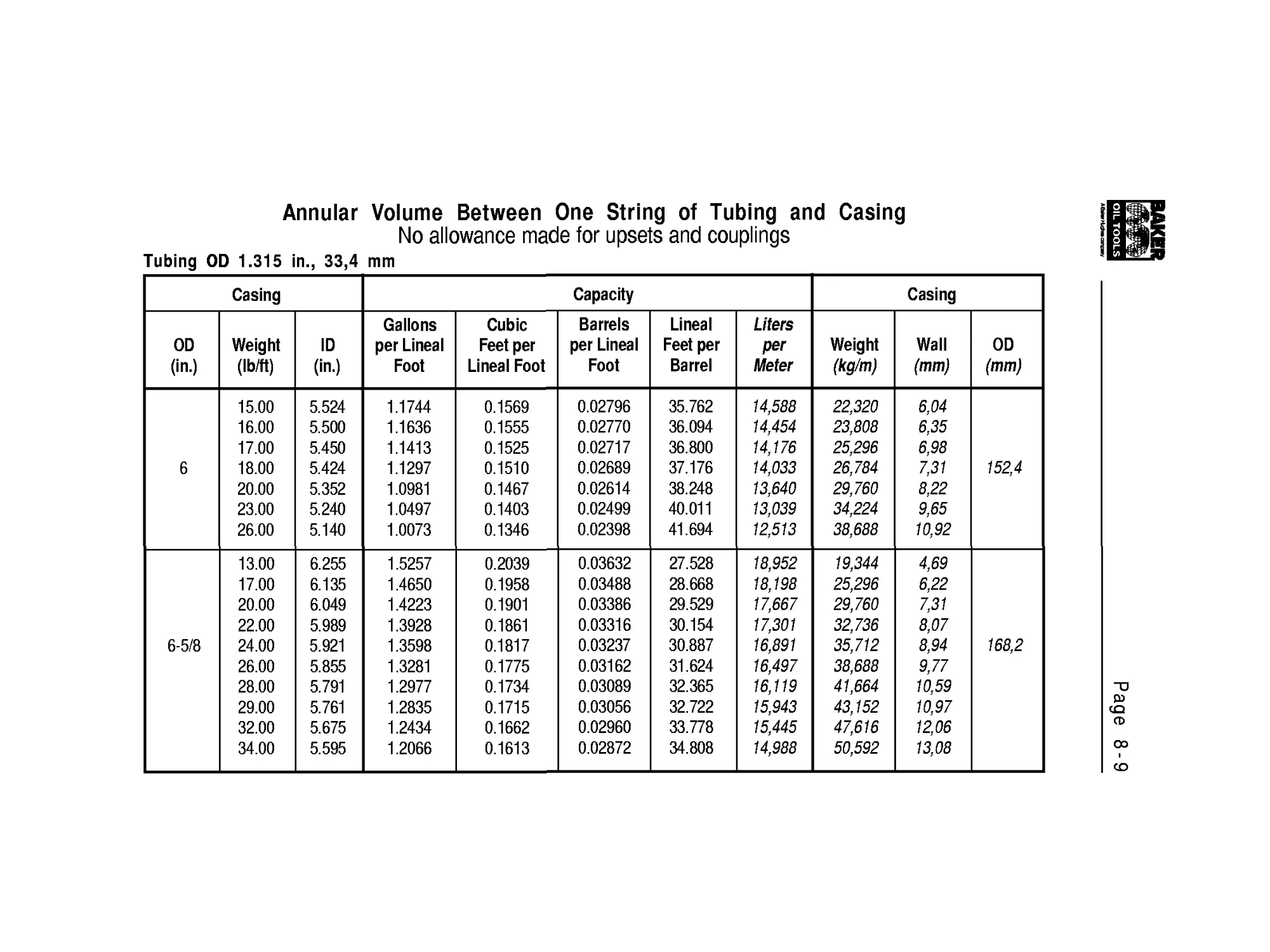
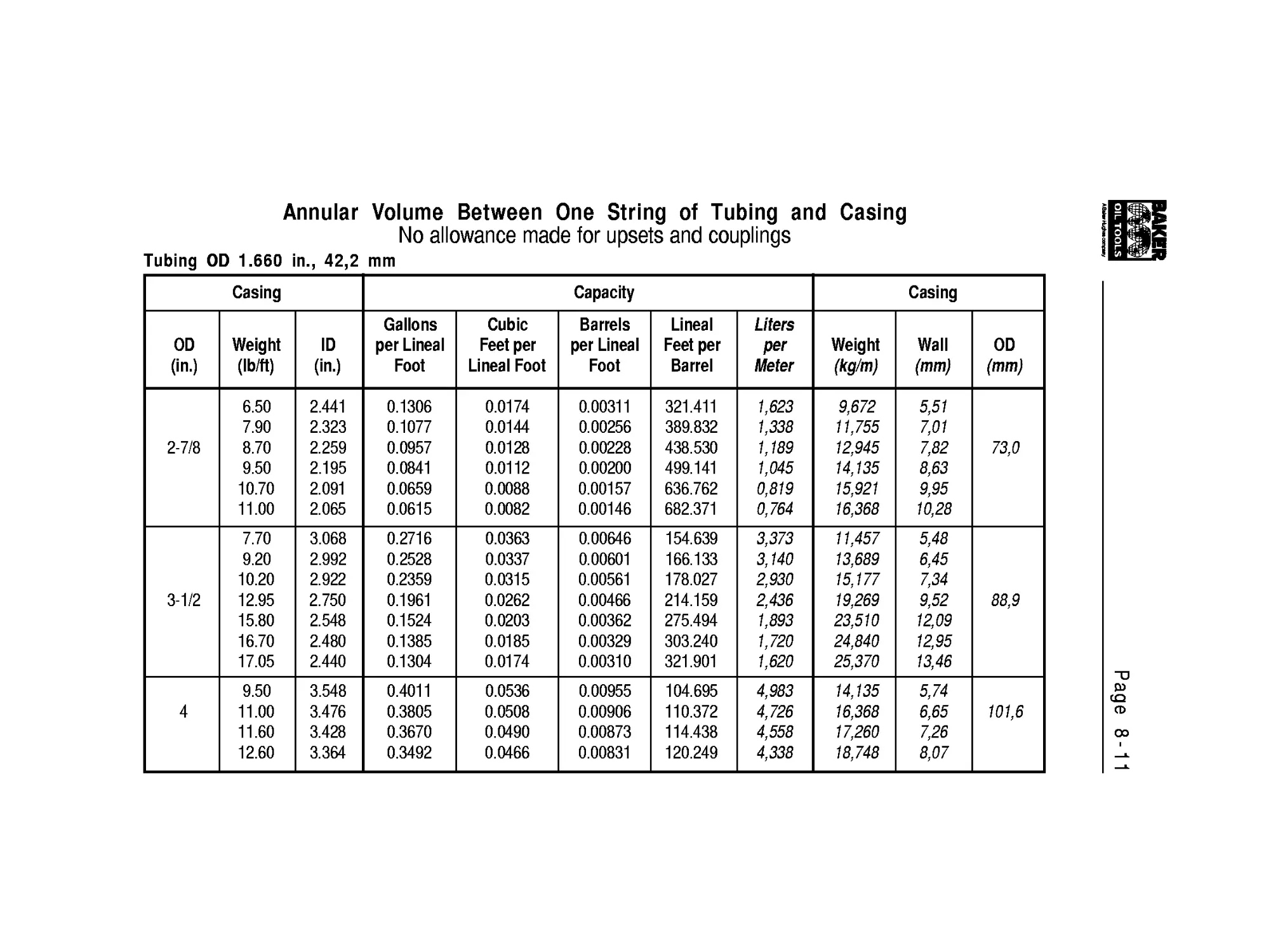
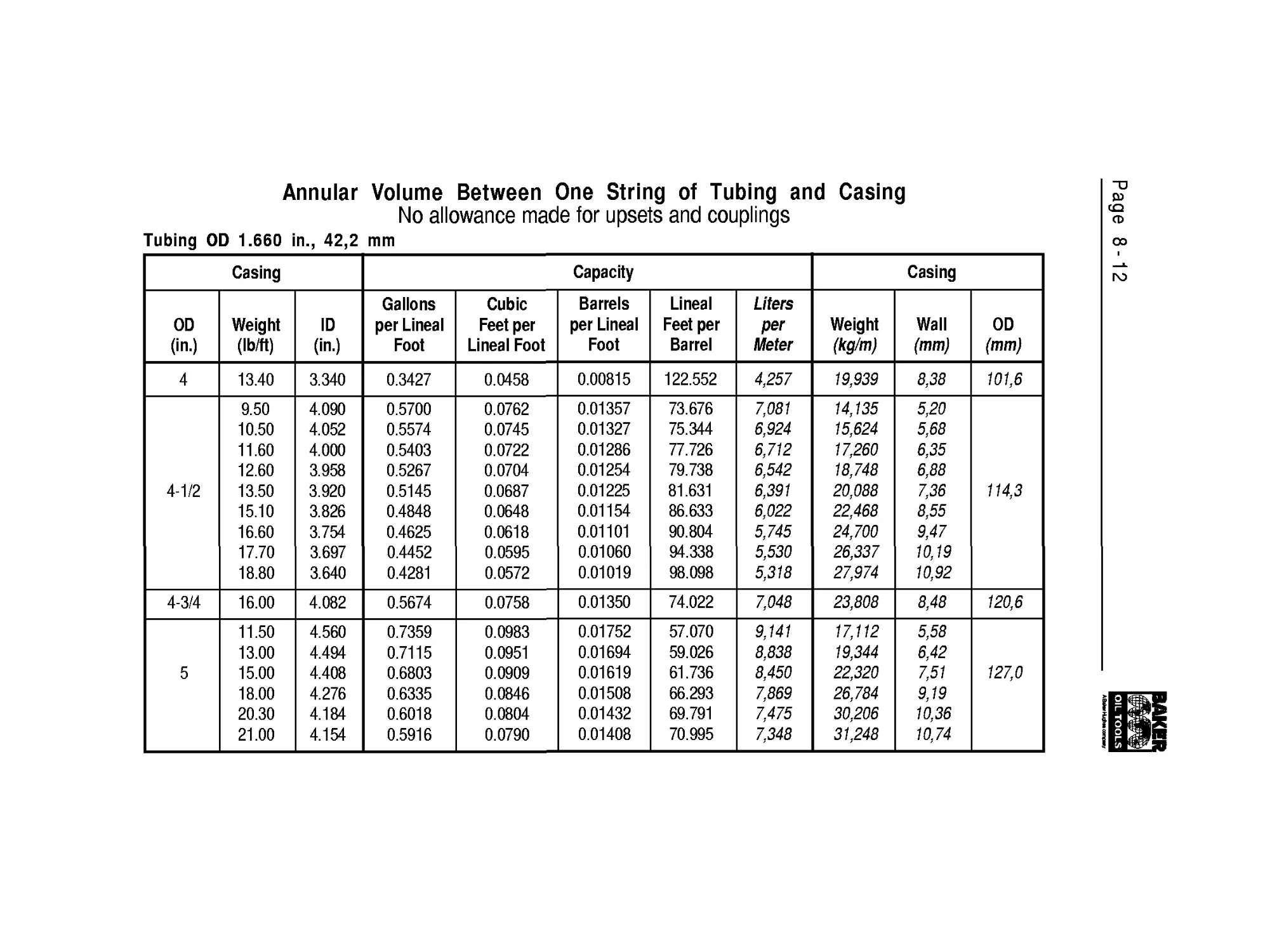
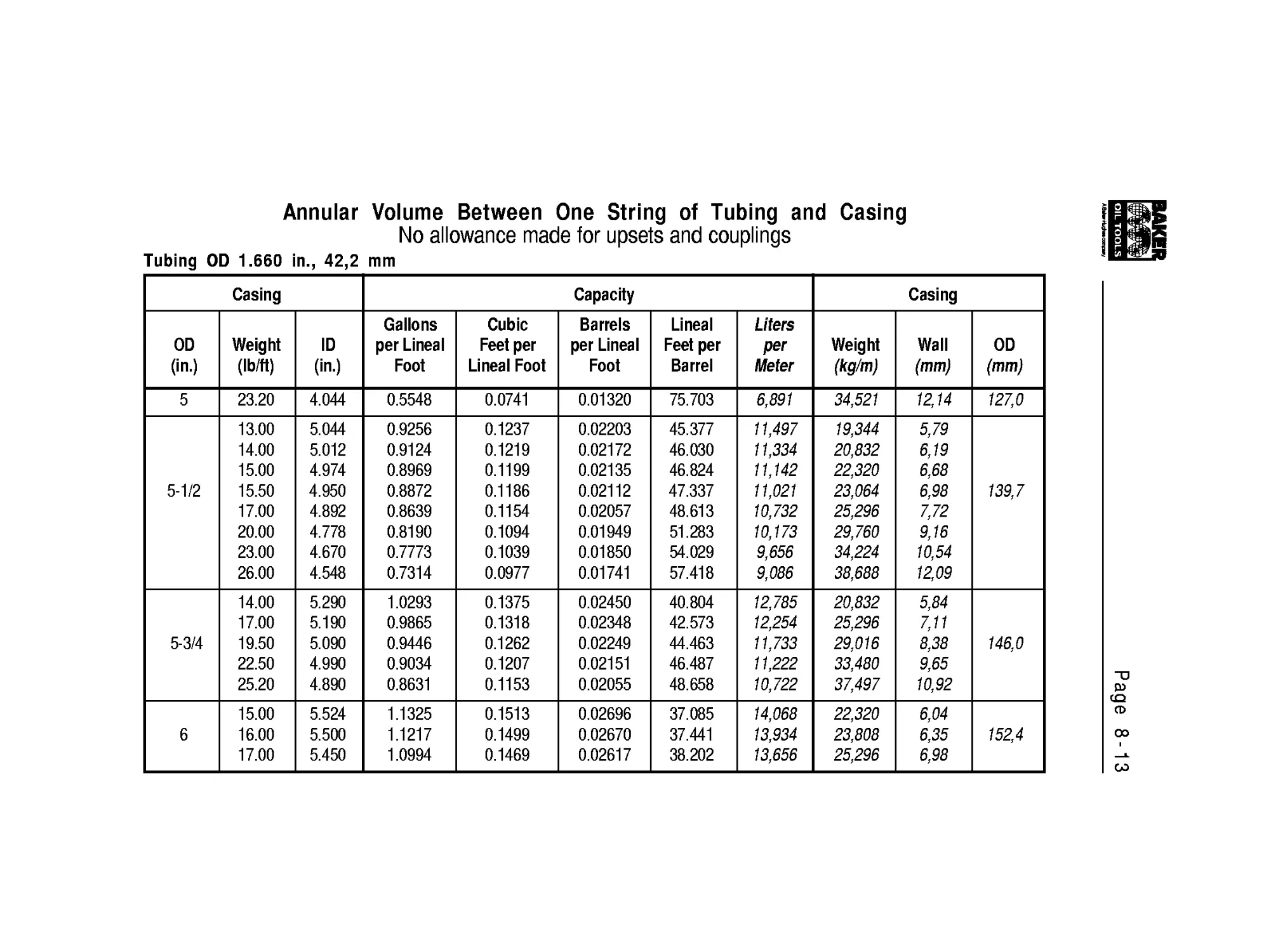
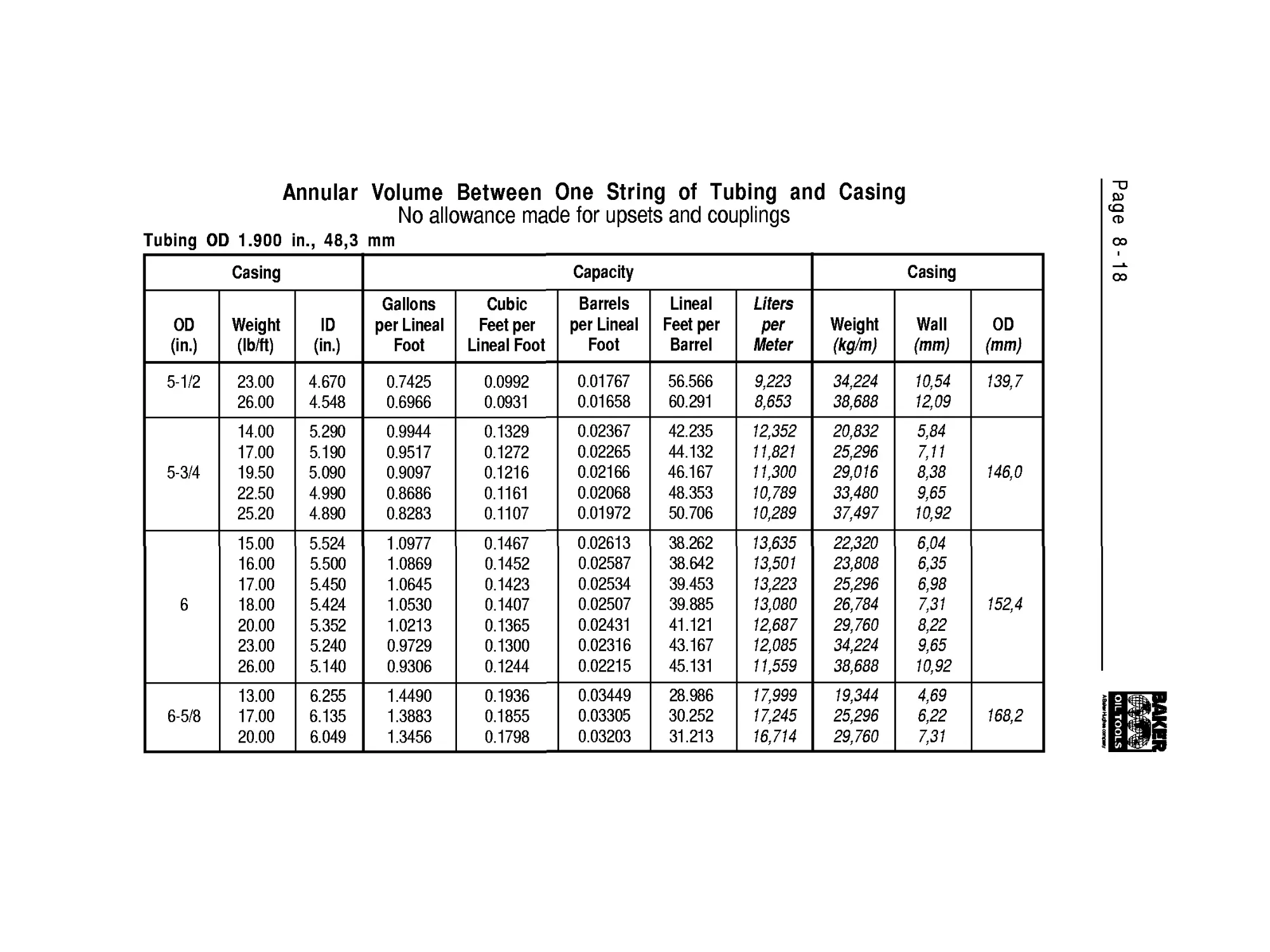
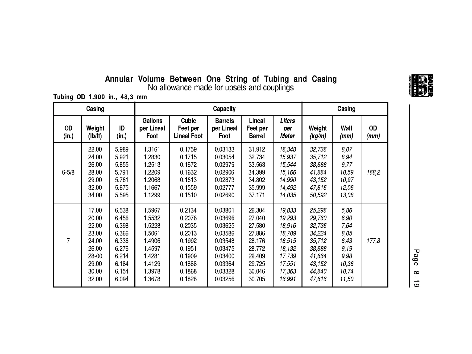
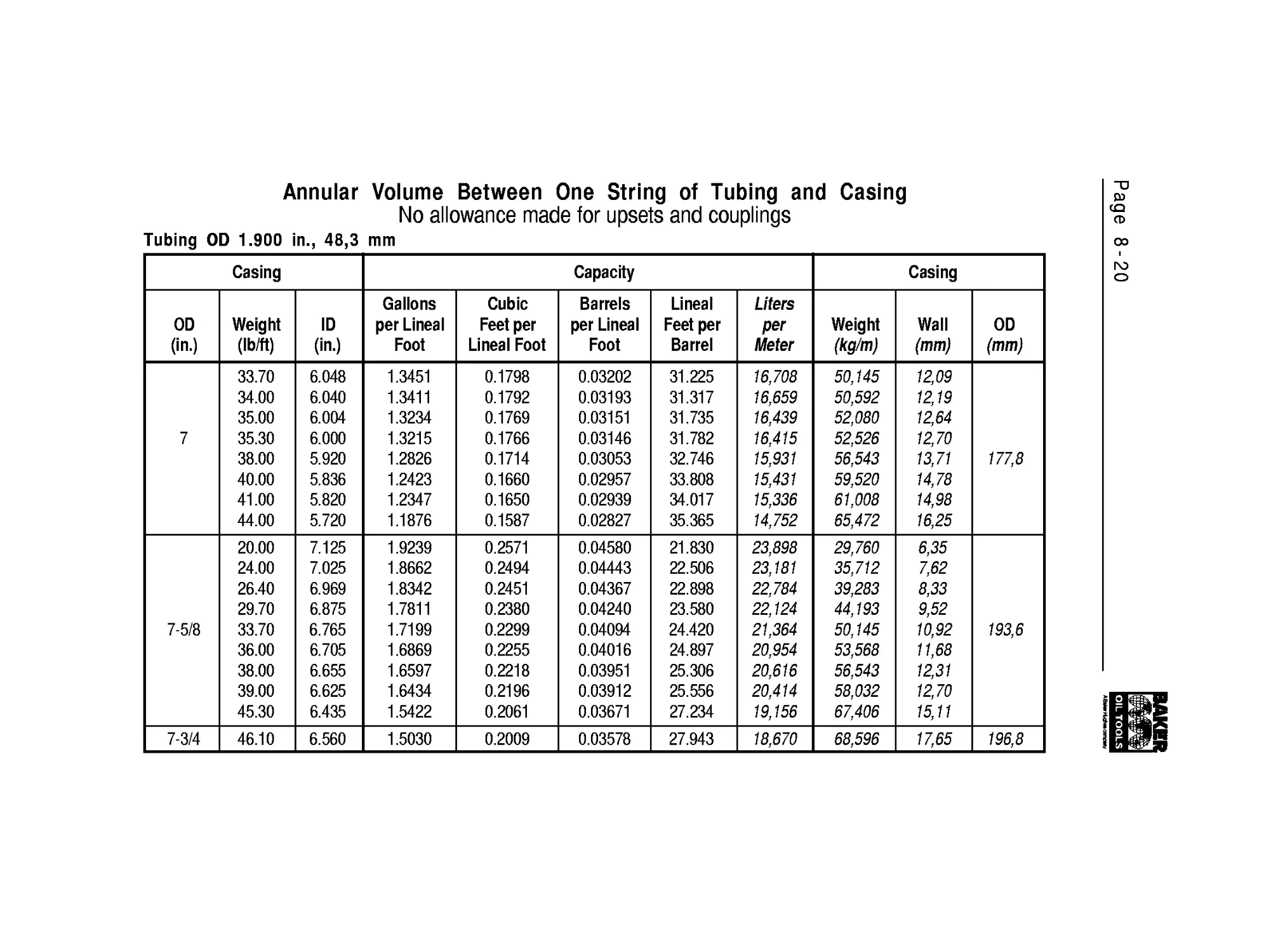
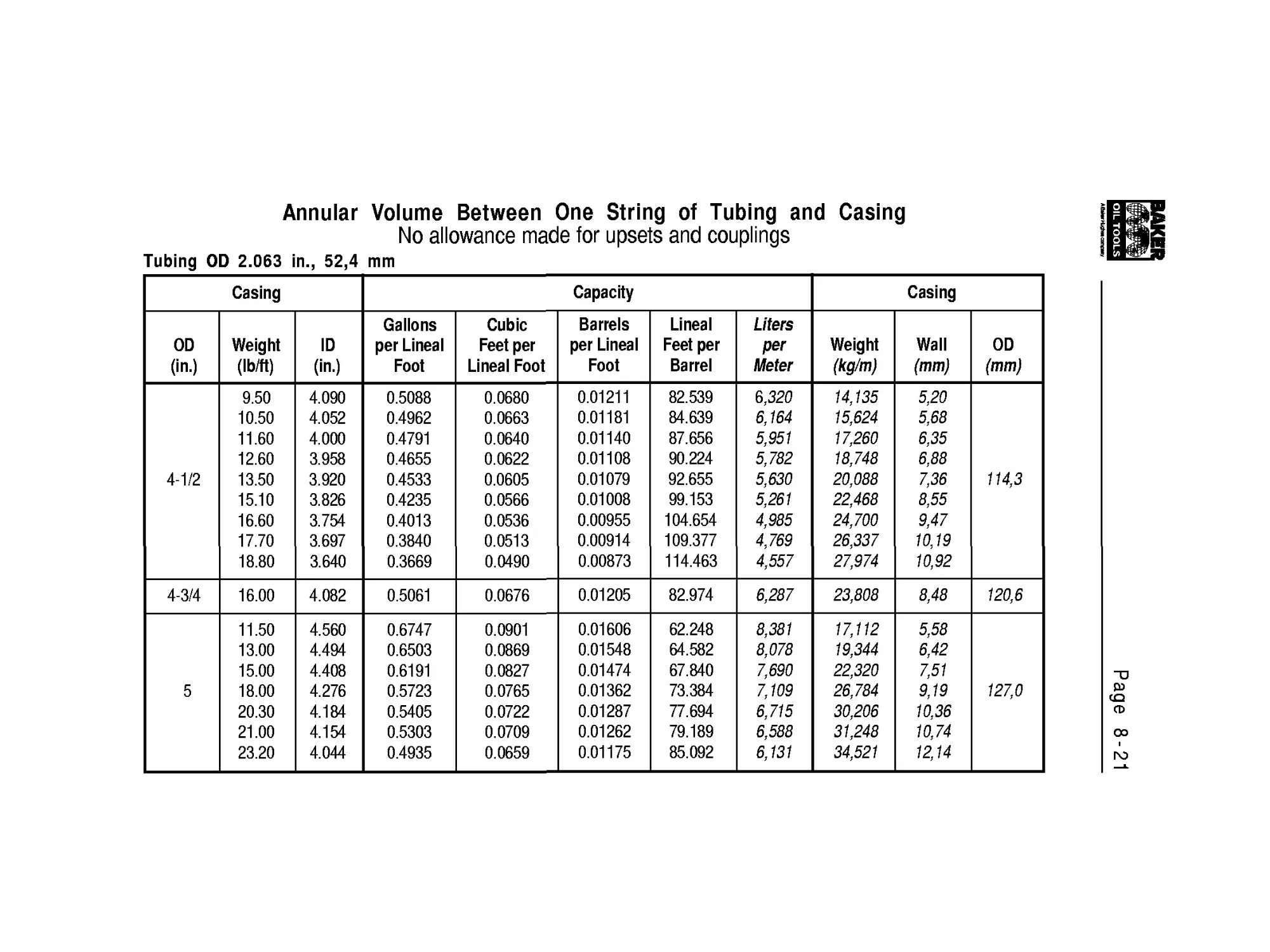
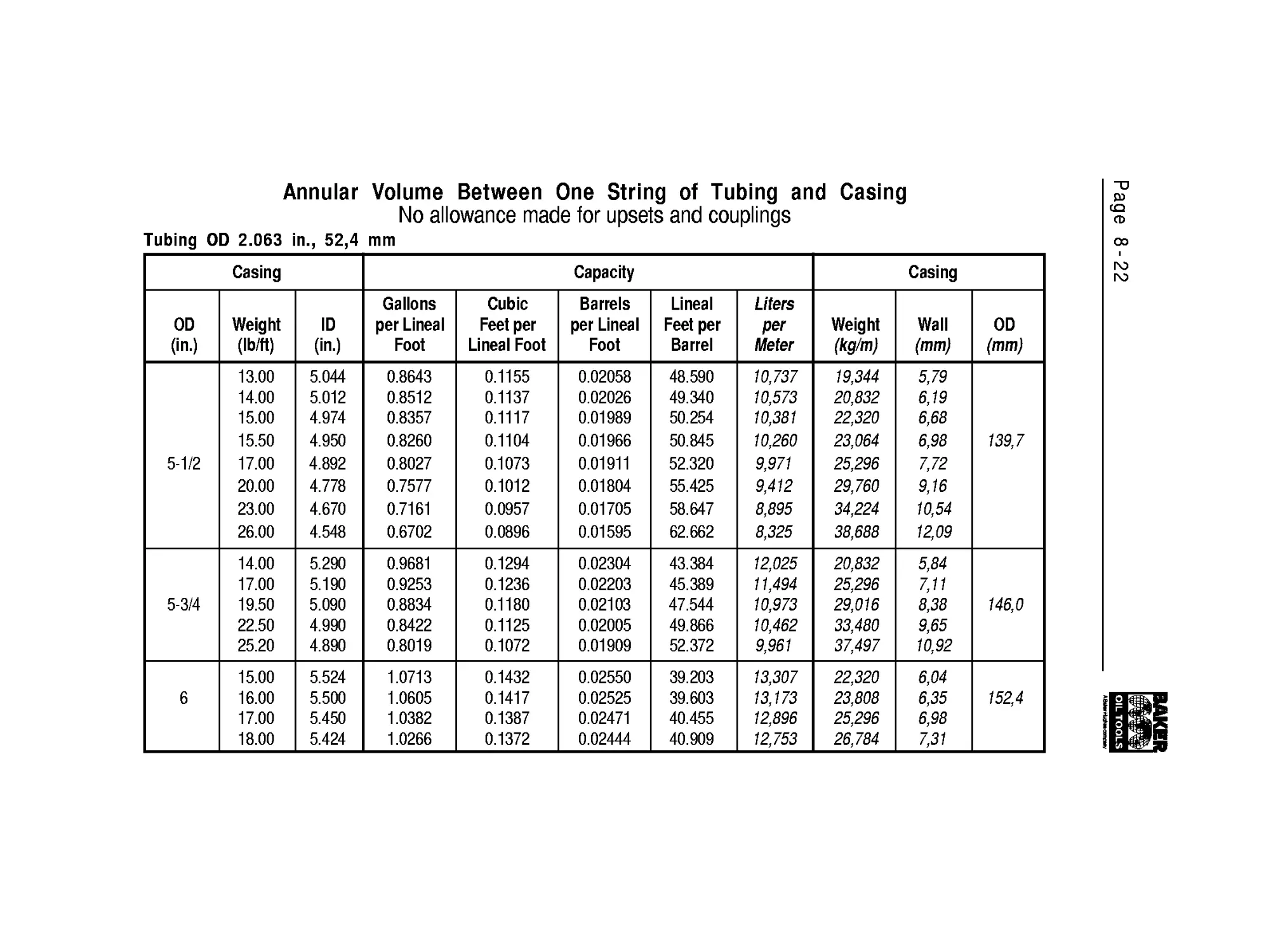
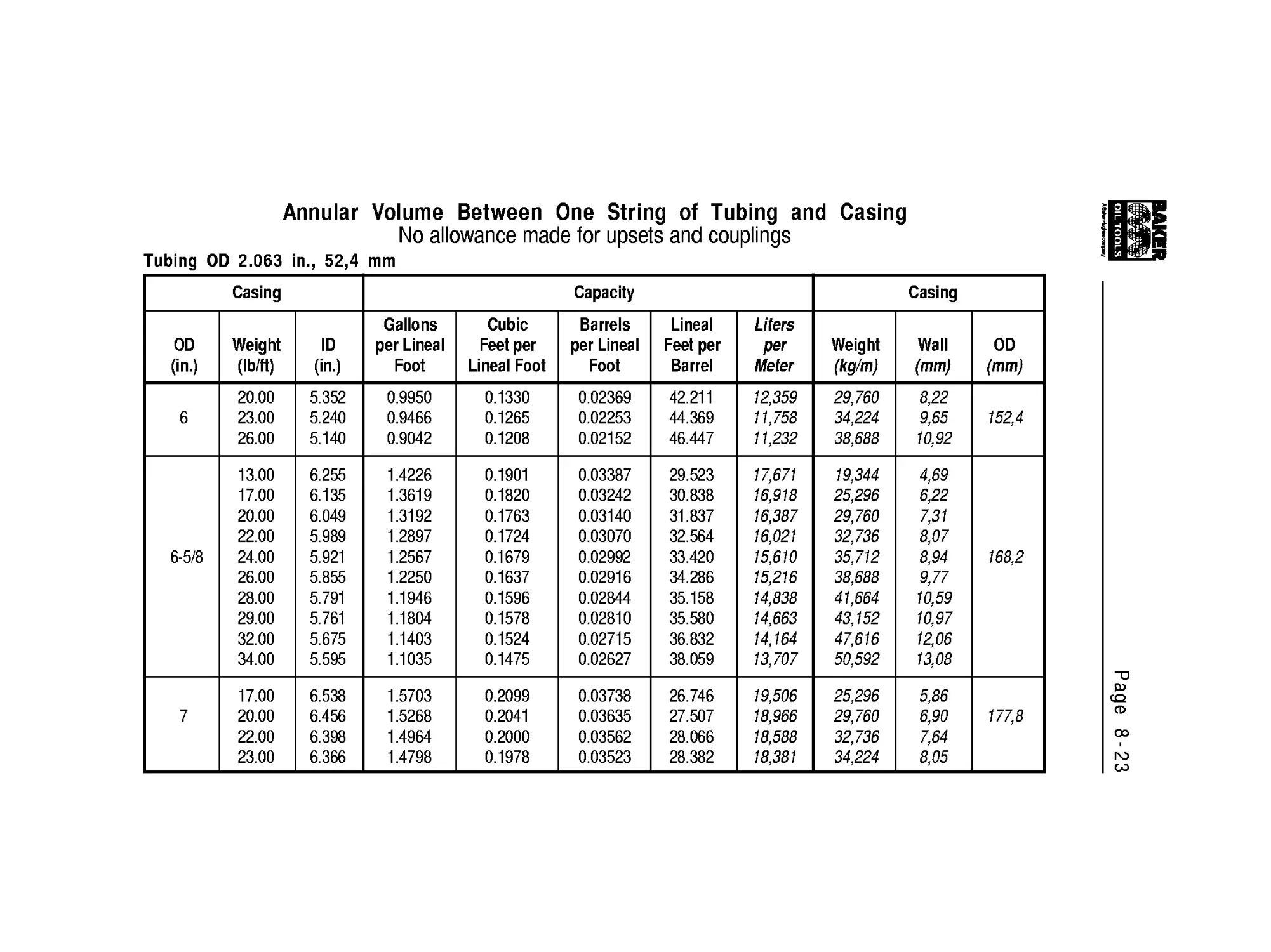
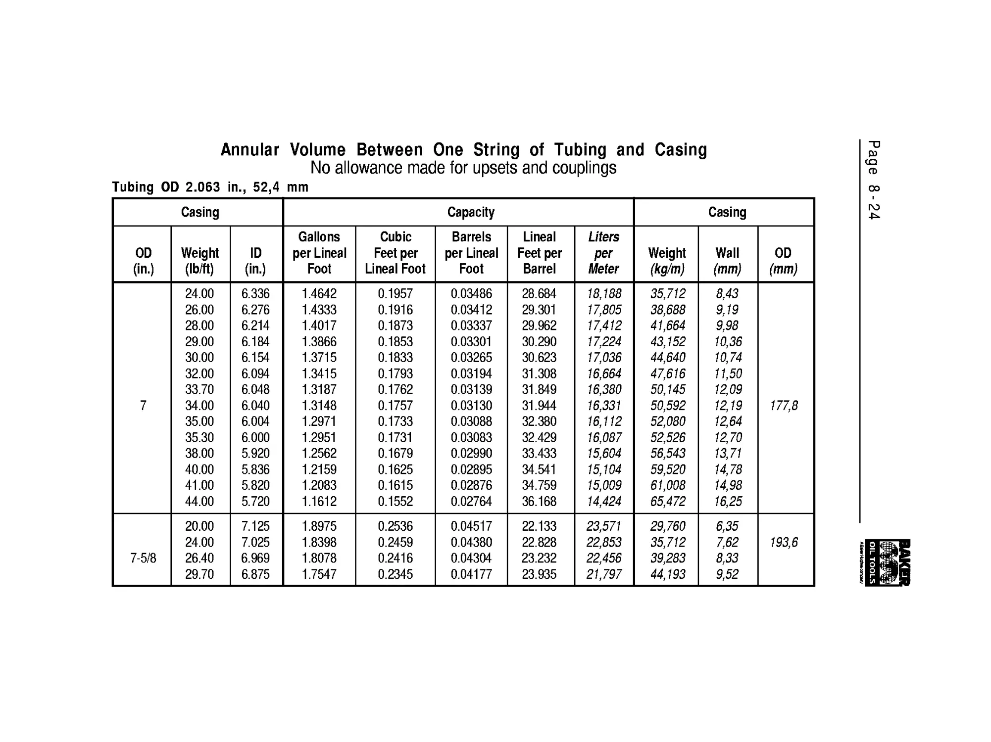
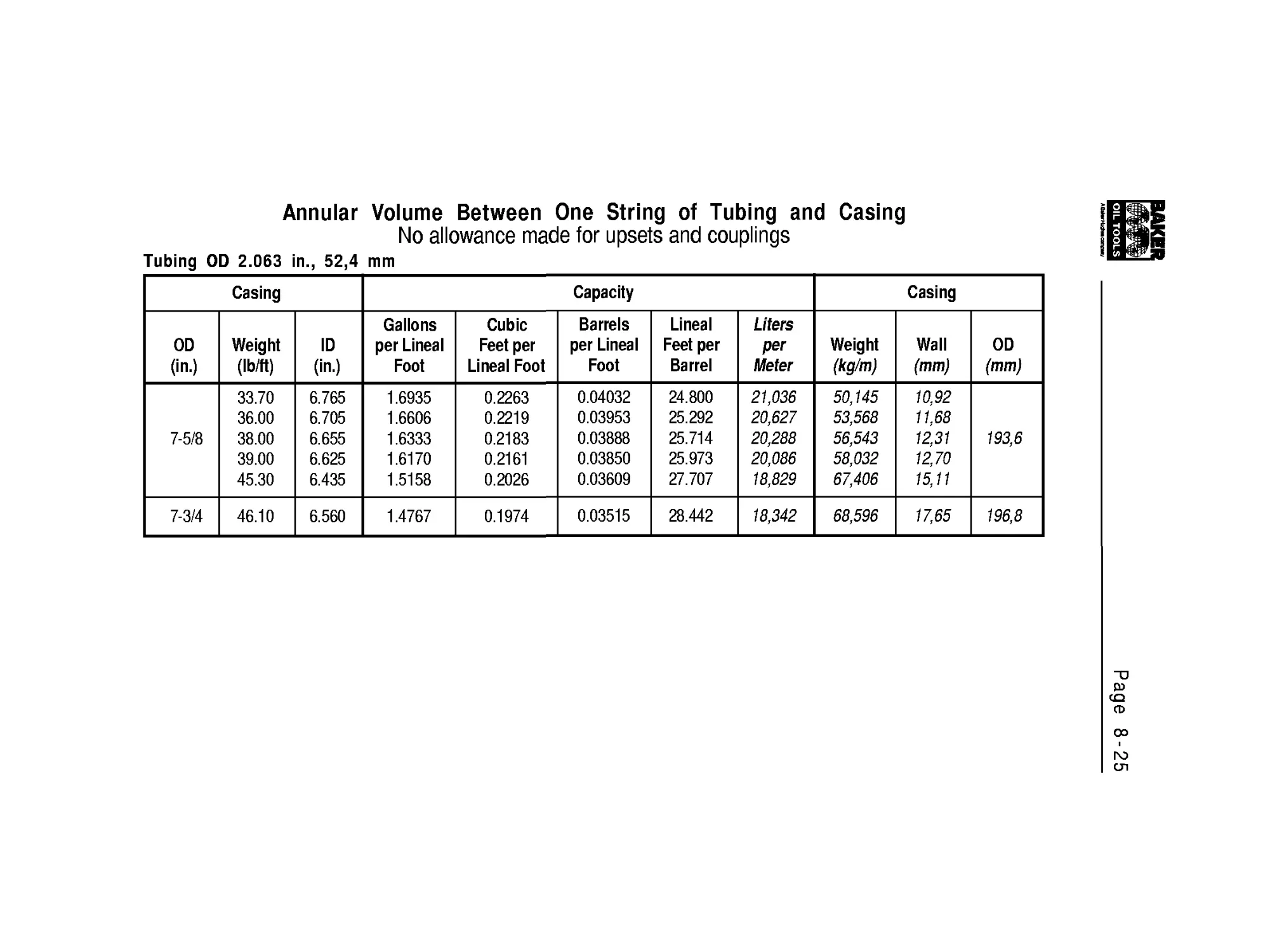
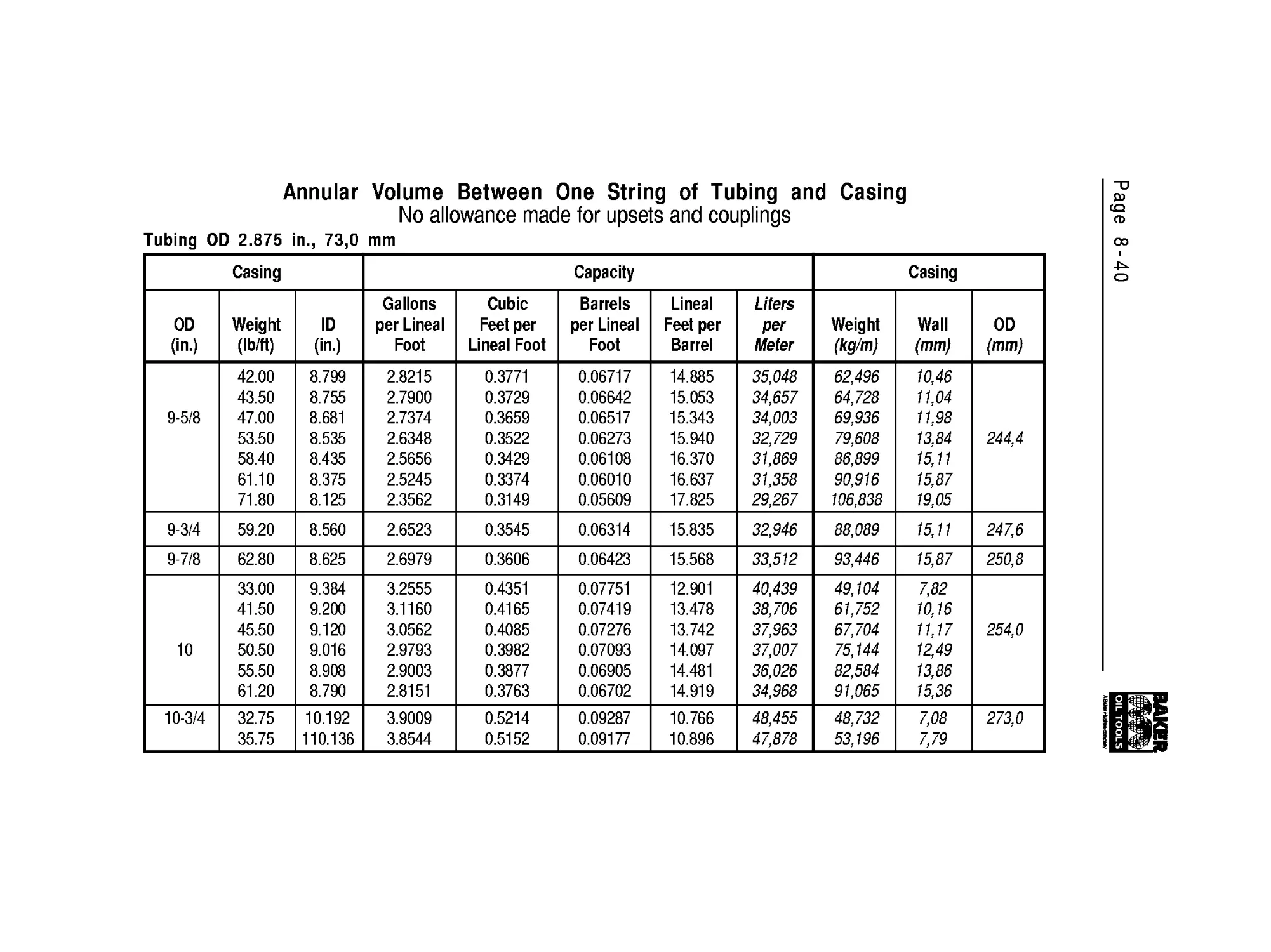
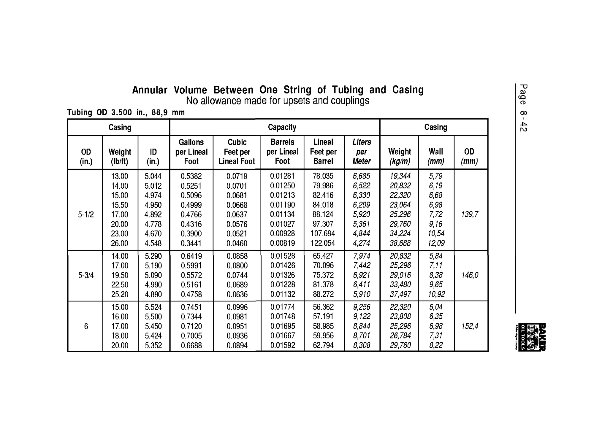
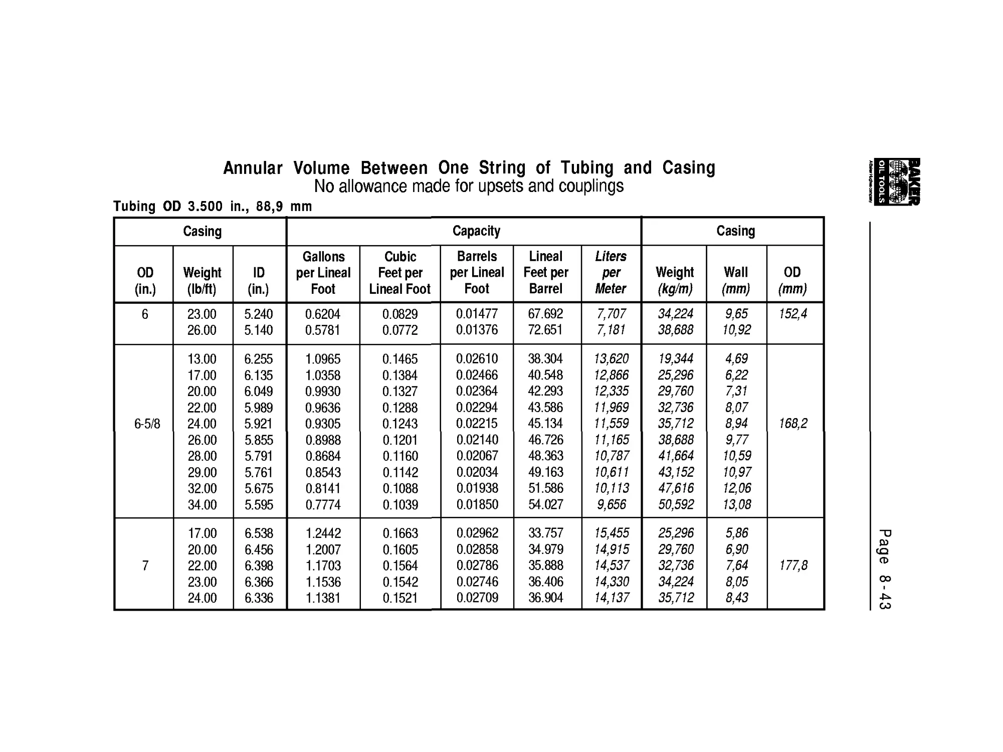
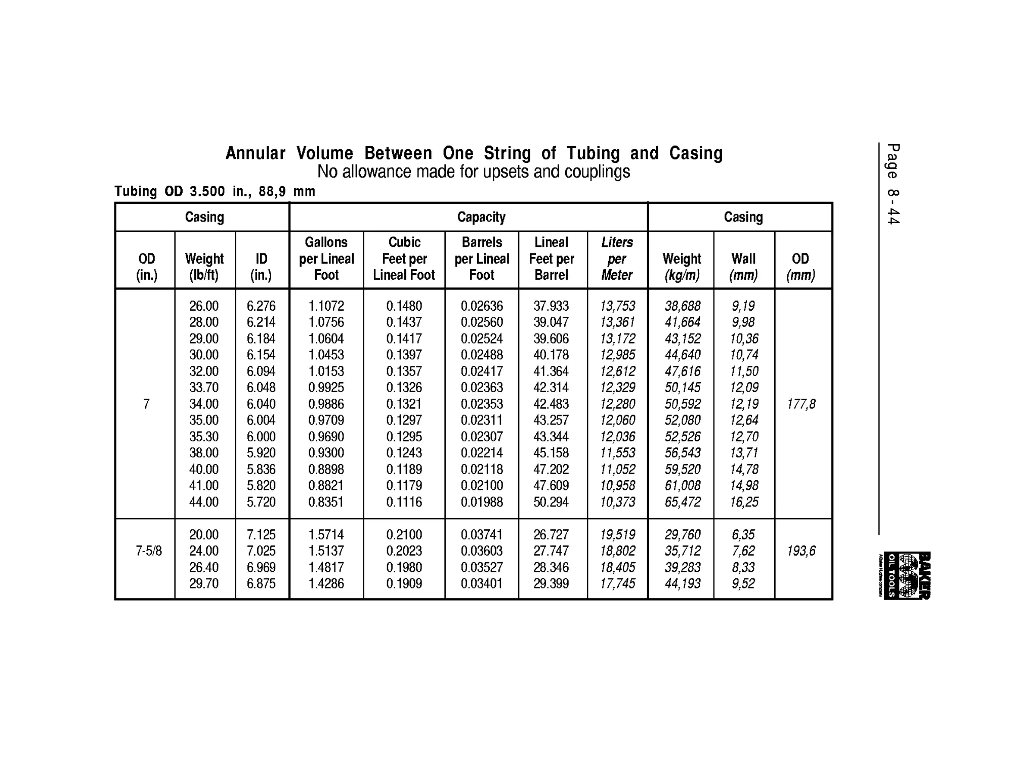
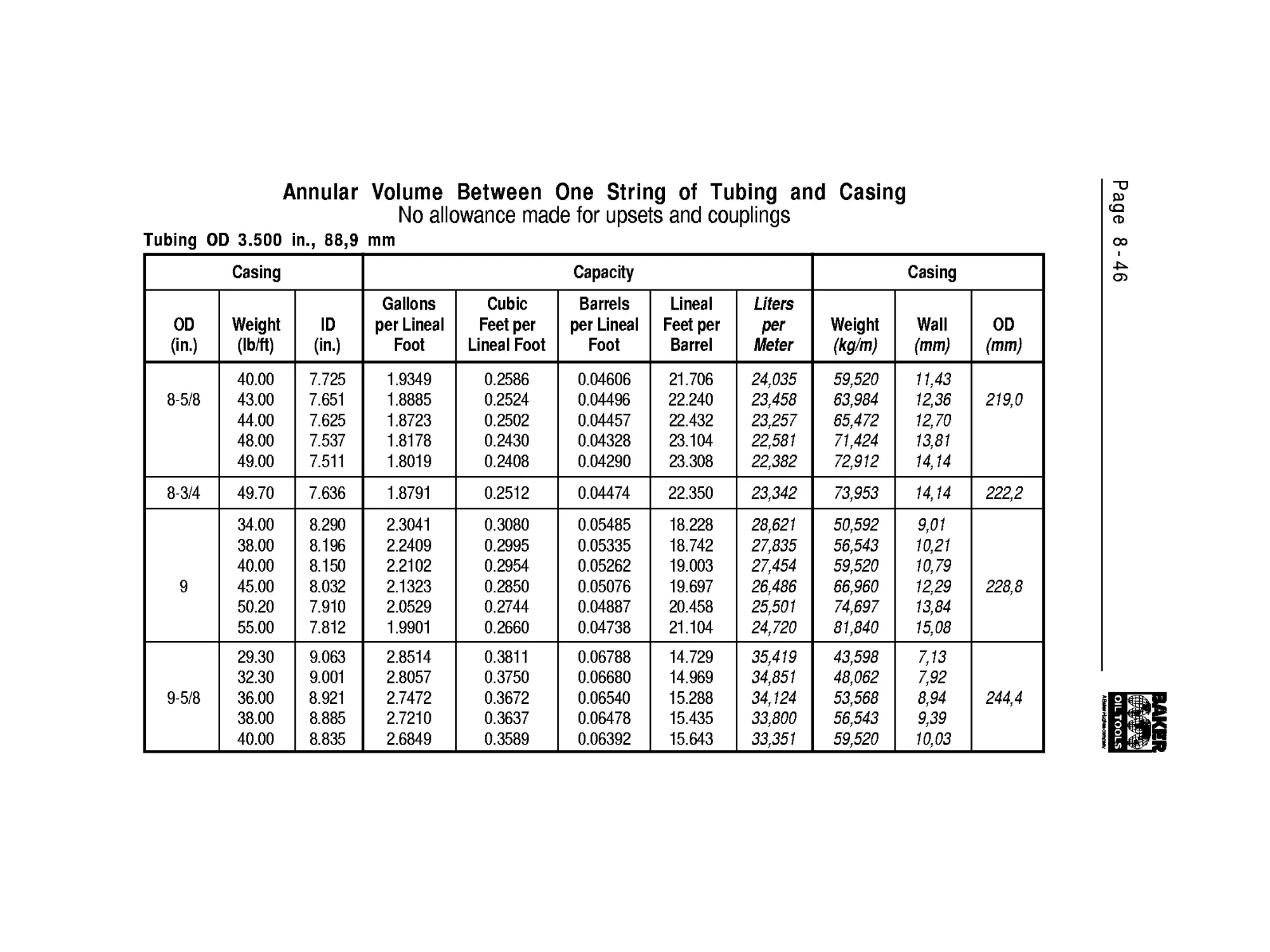
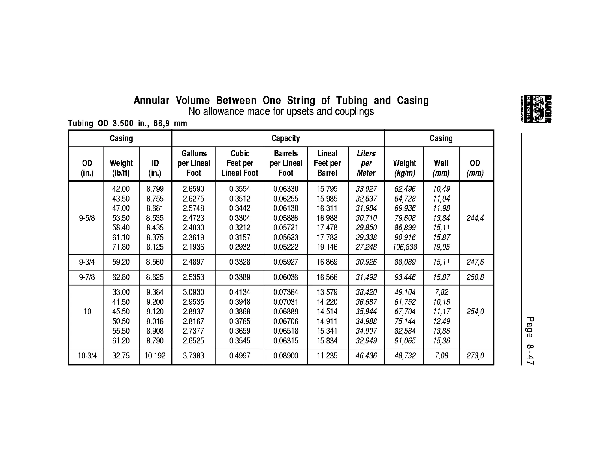
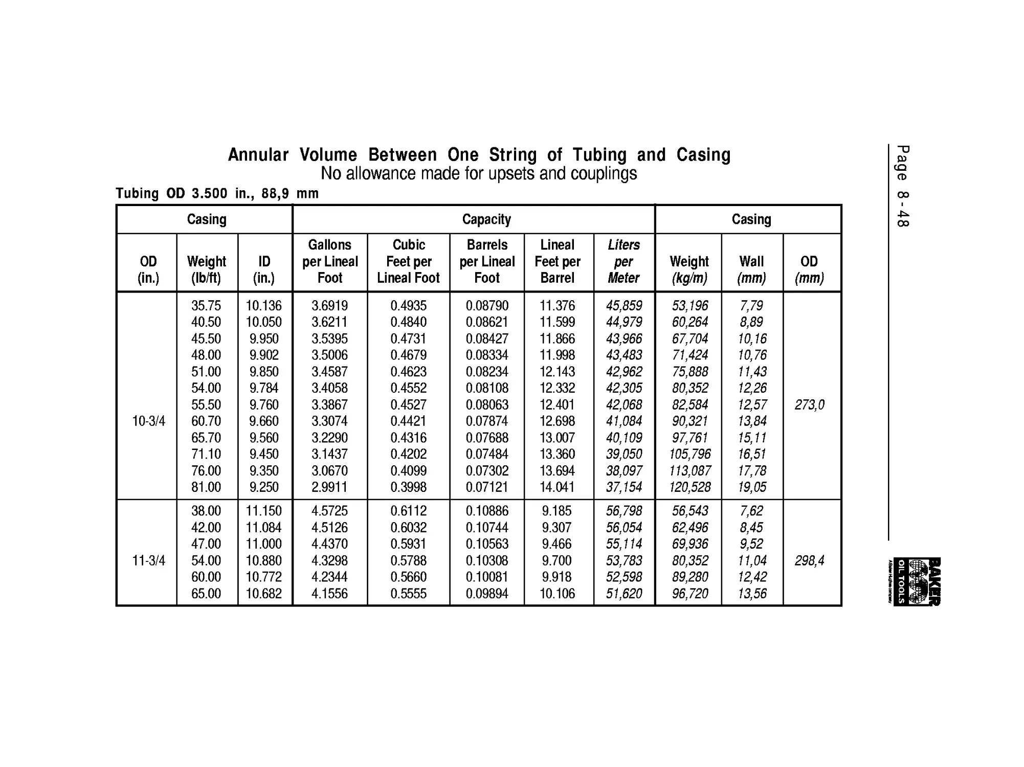
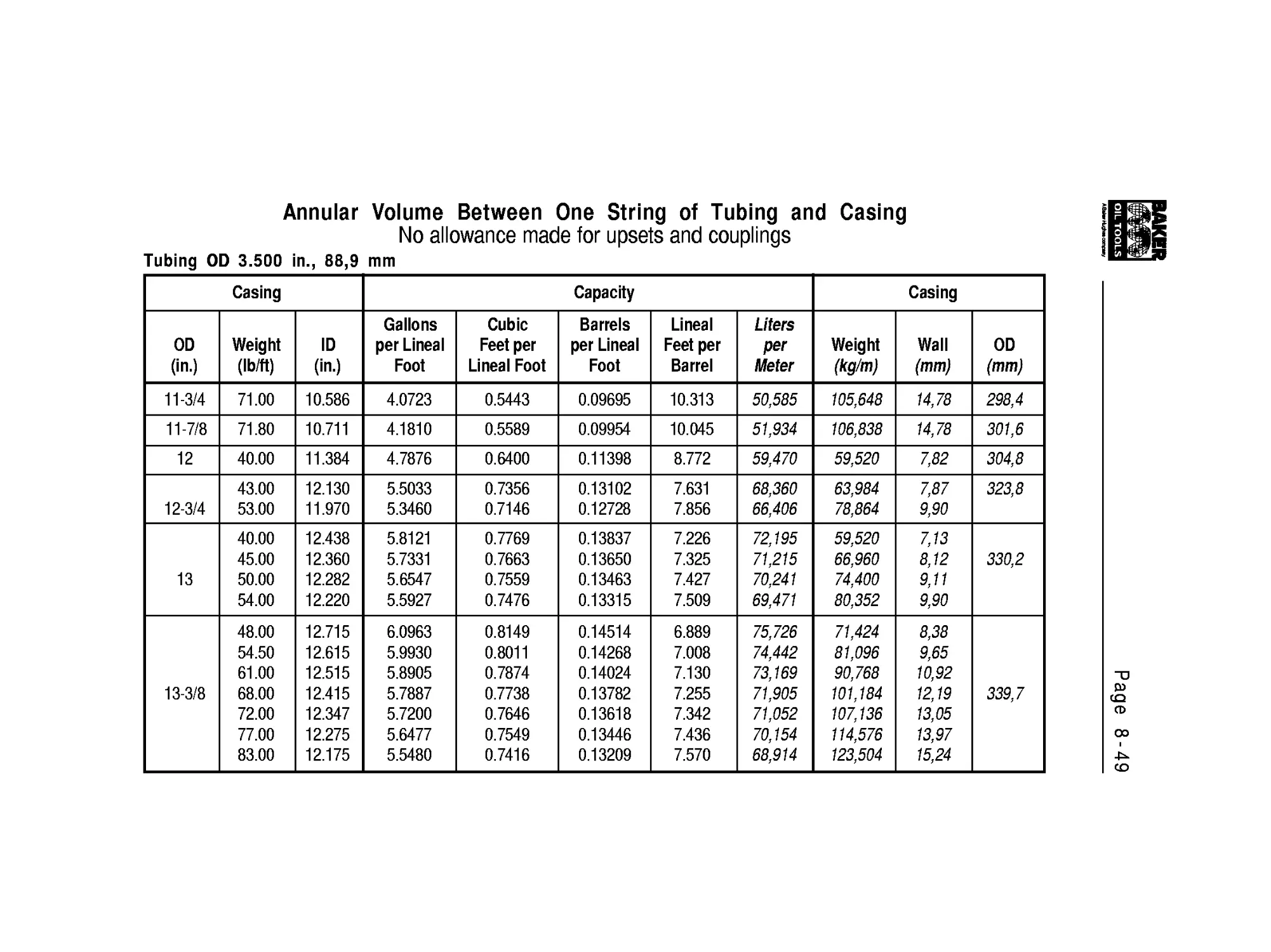
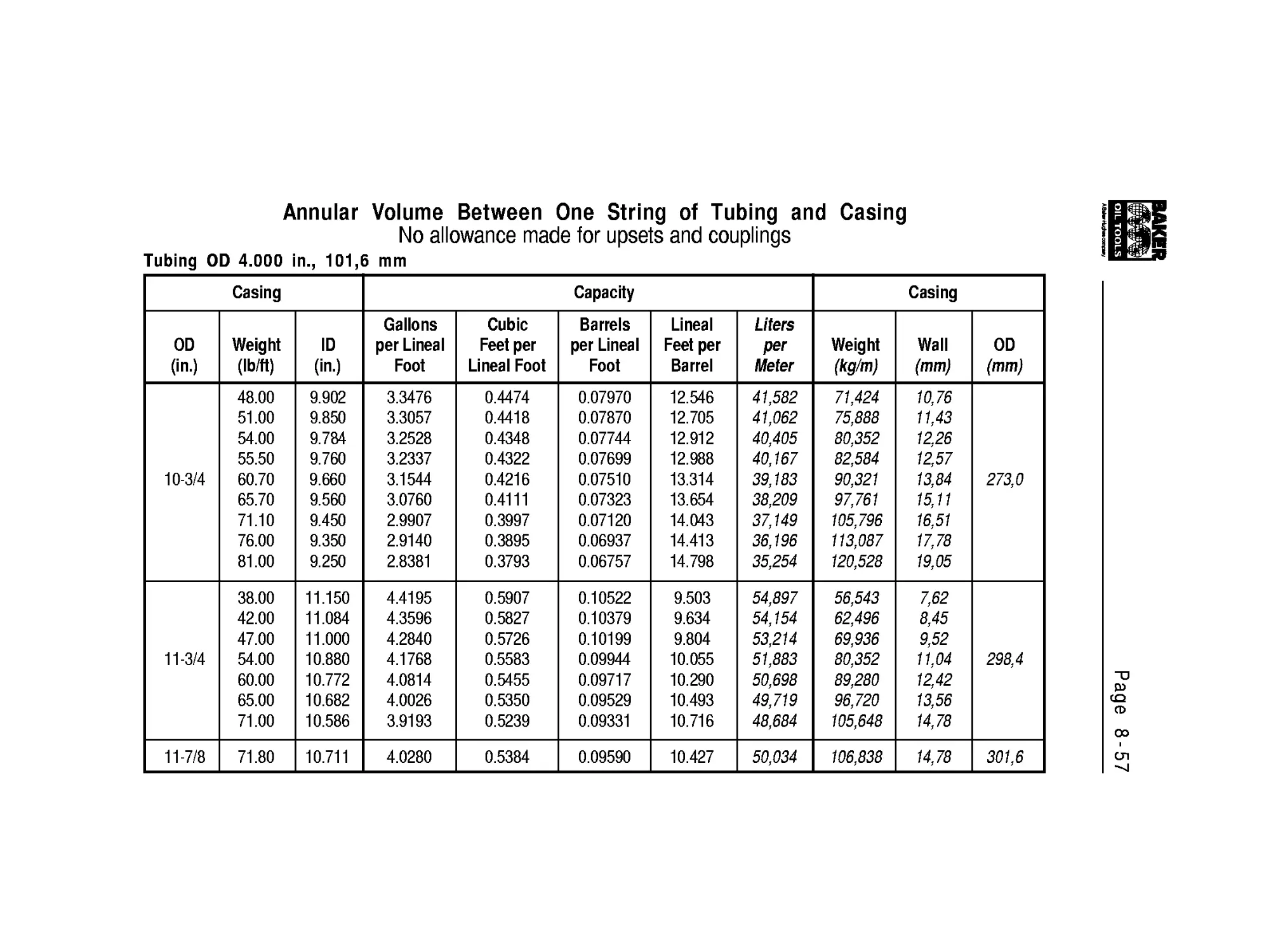
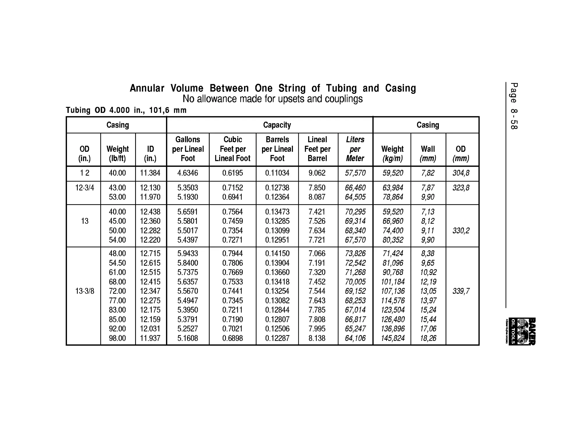
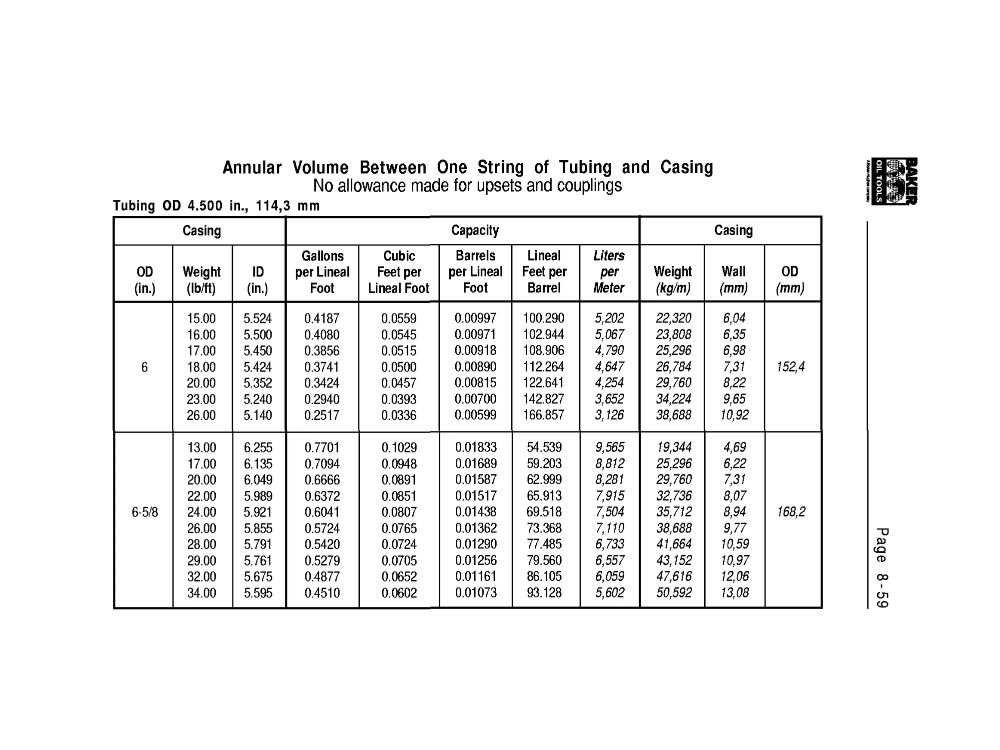
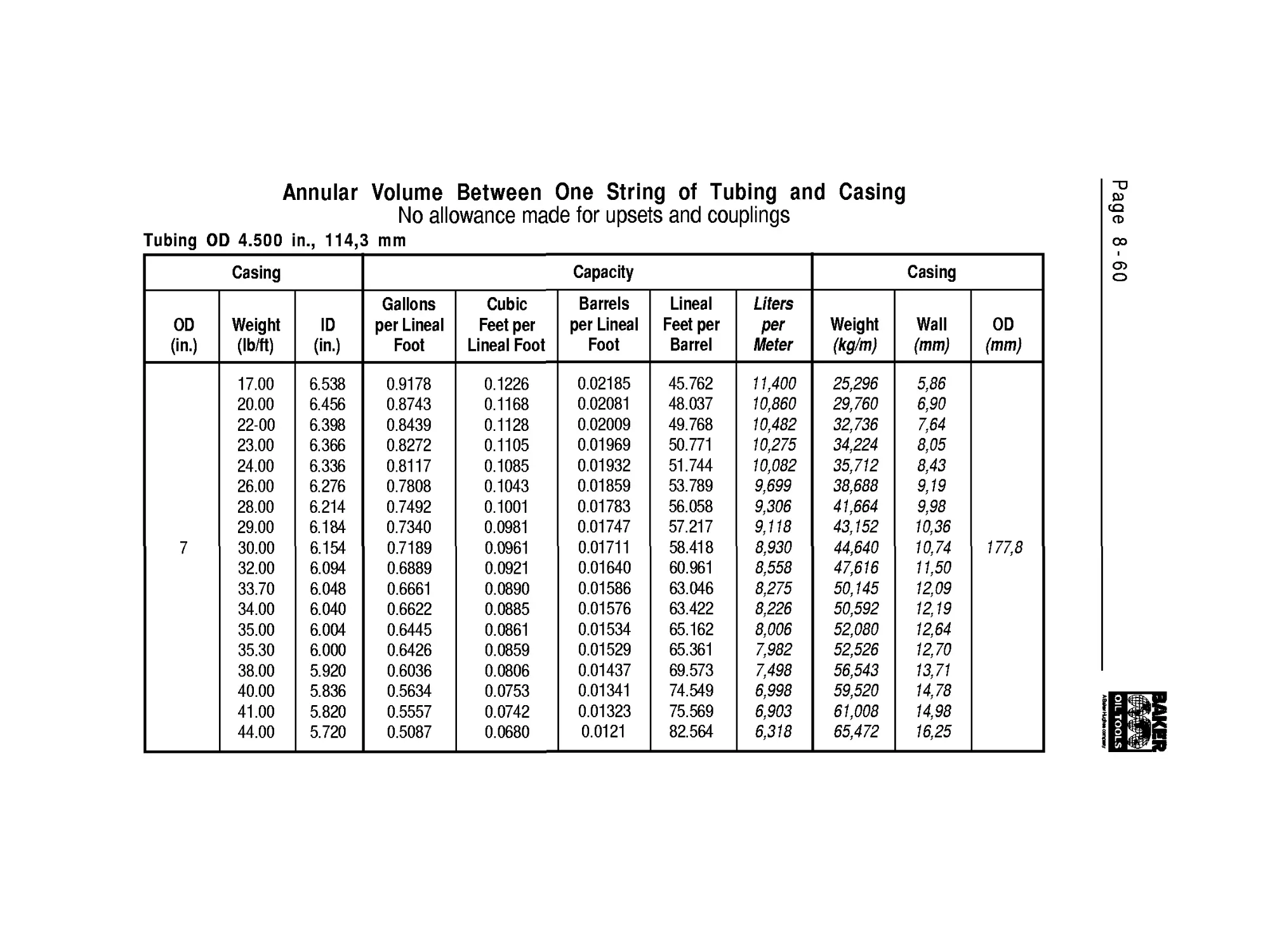
Tubing
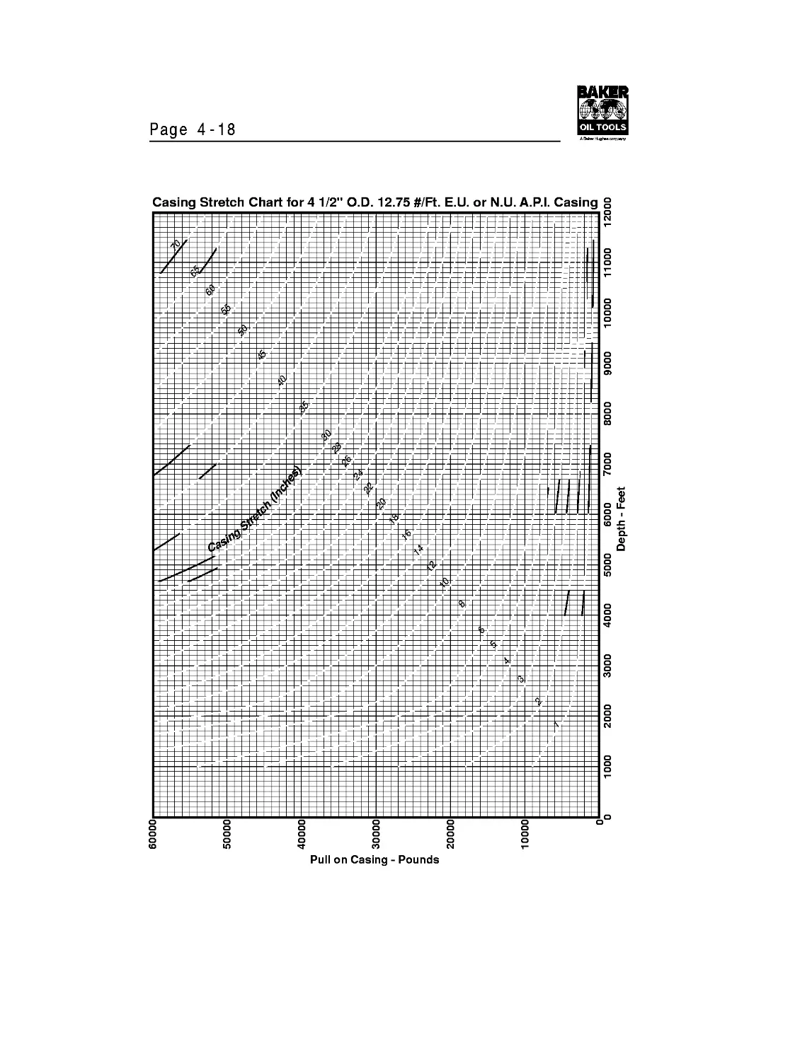
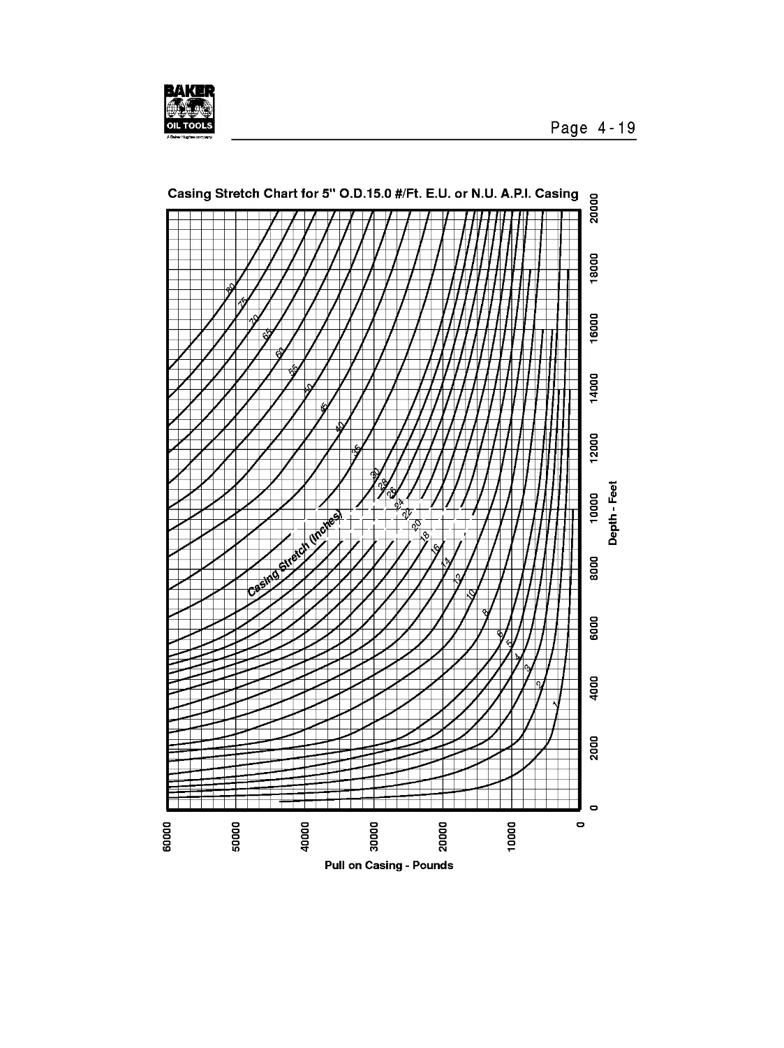
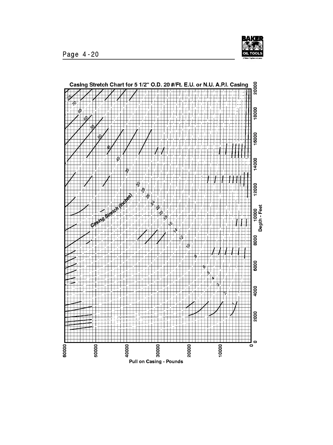
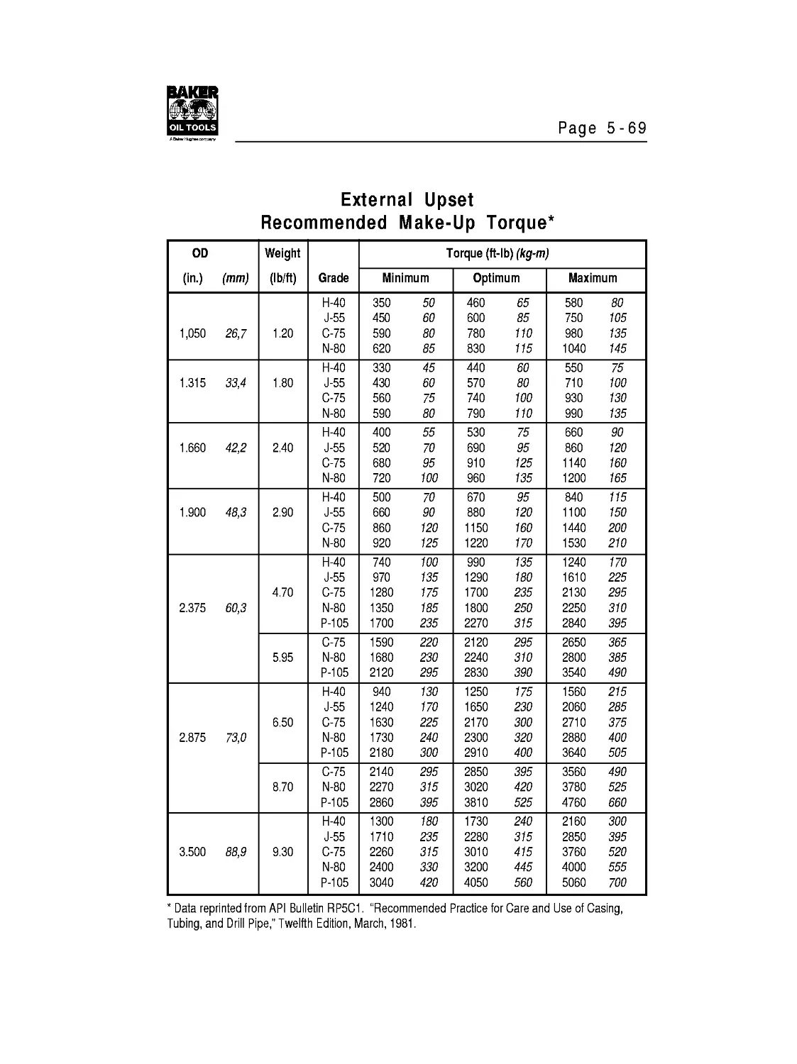
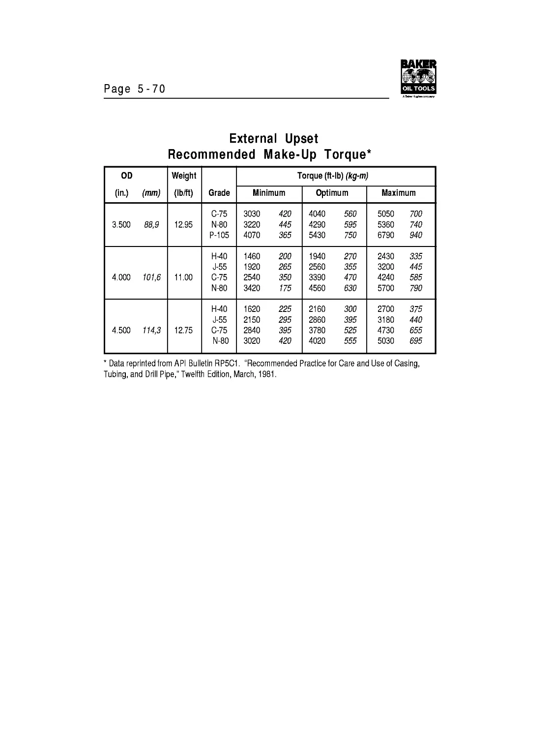
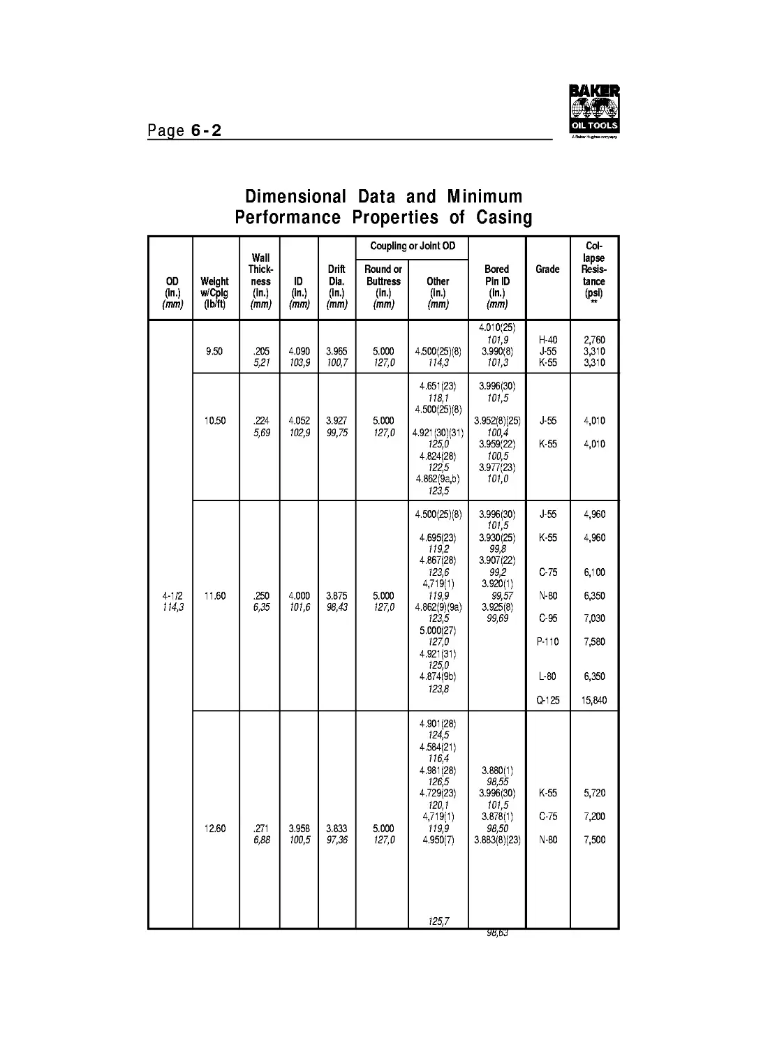
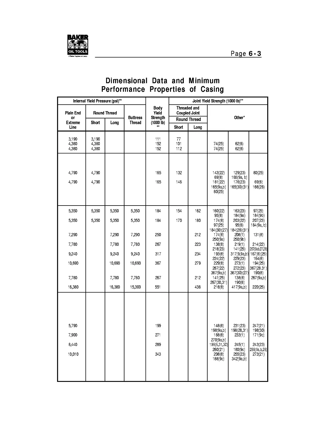
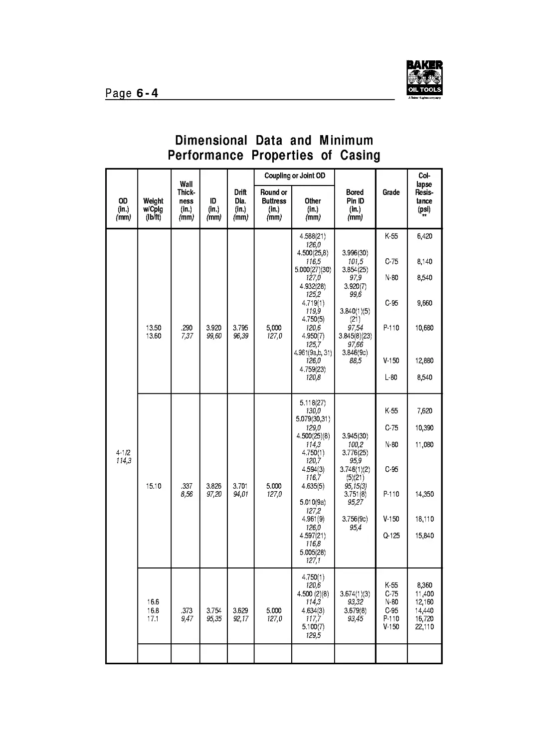
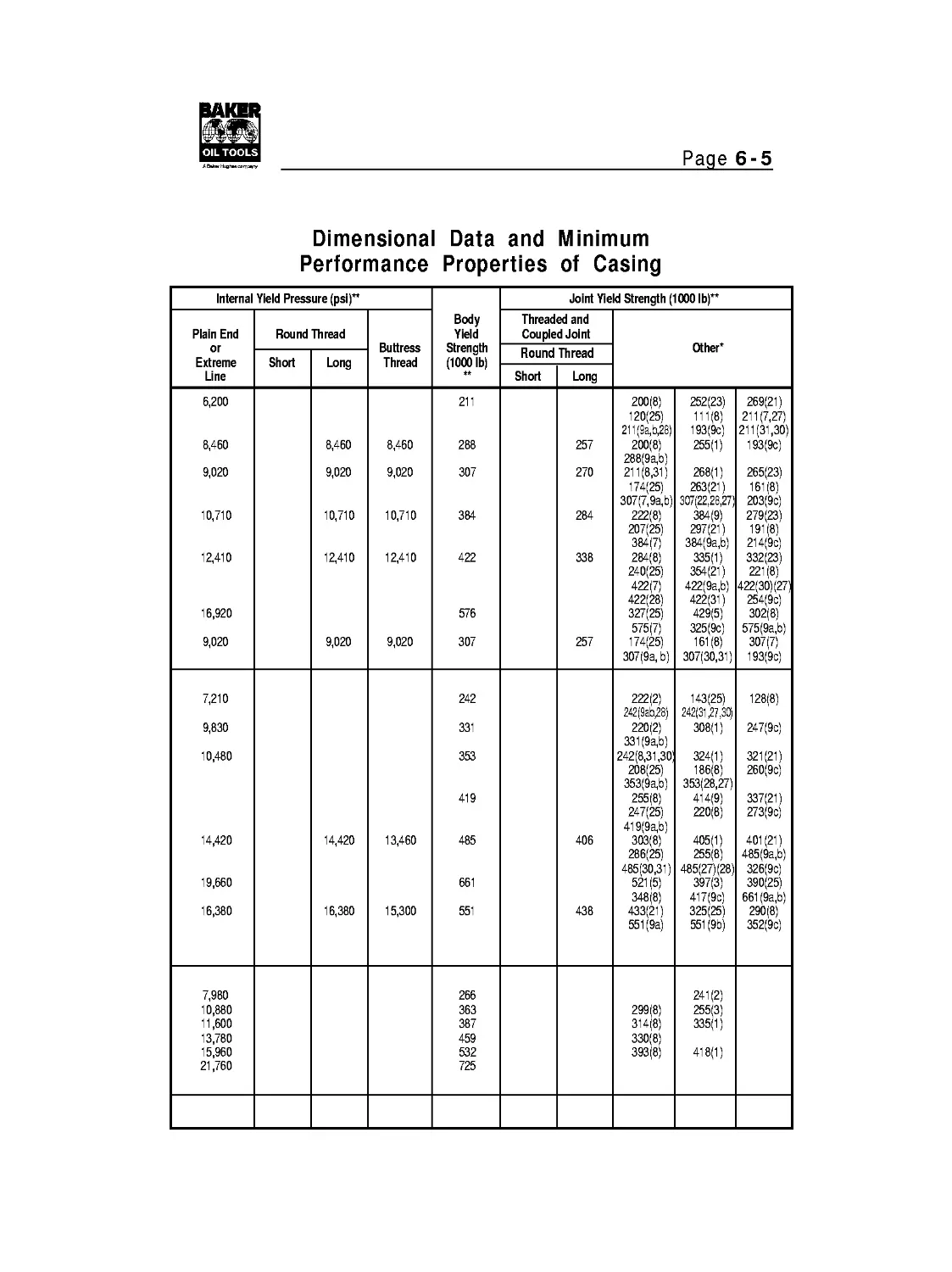
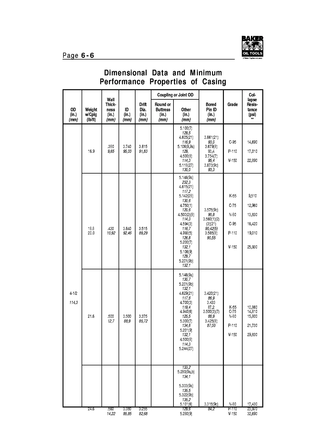
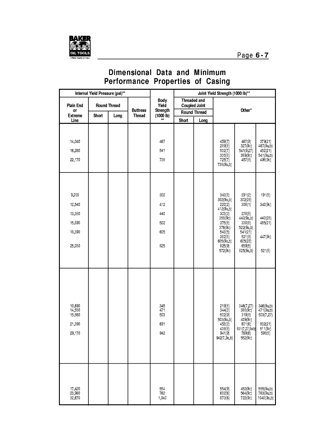
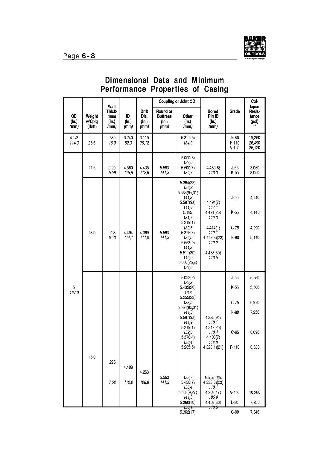
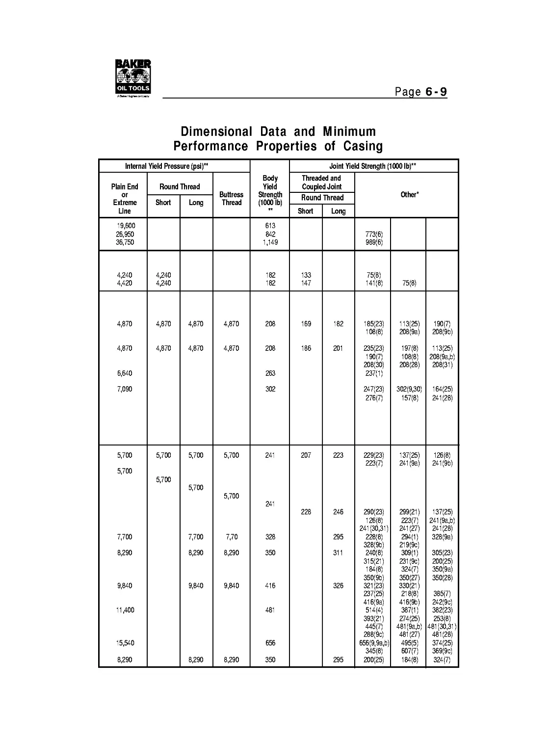
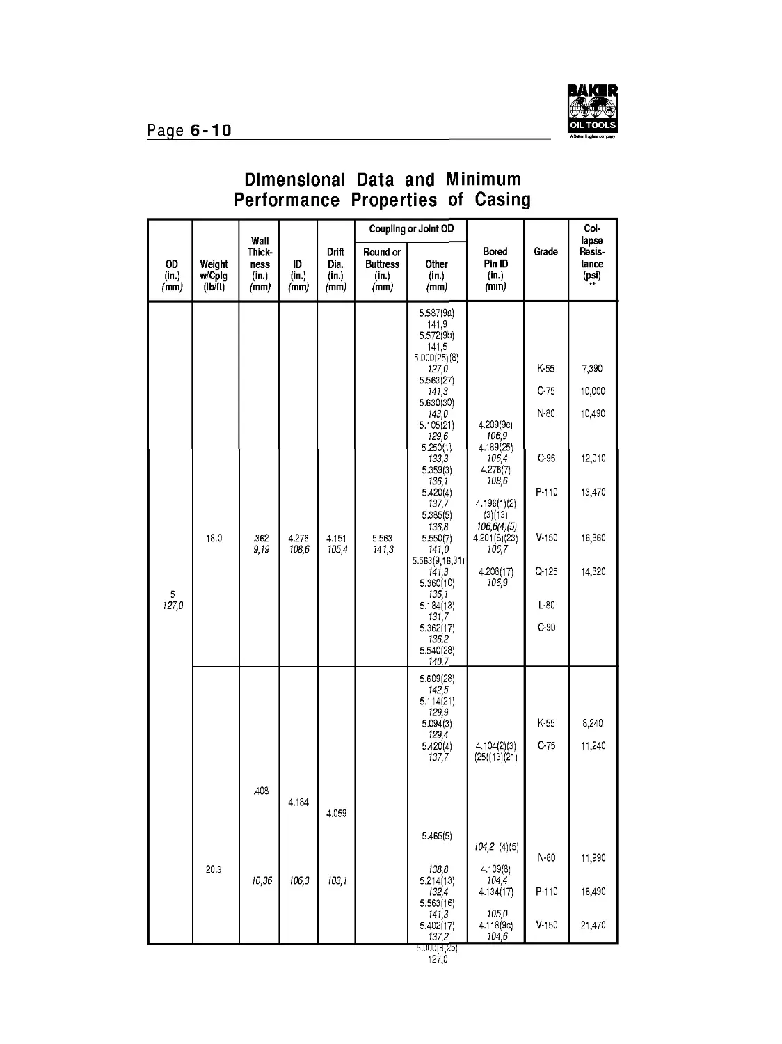
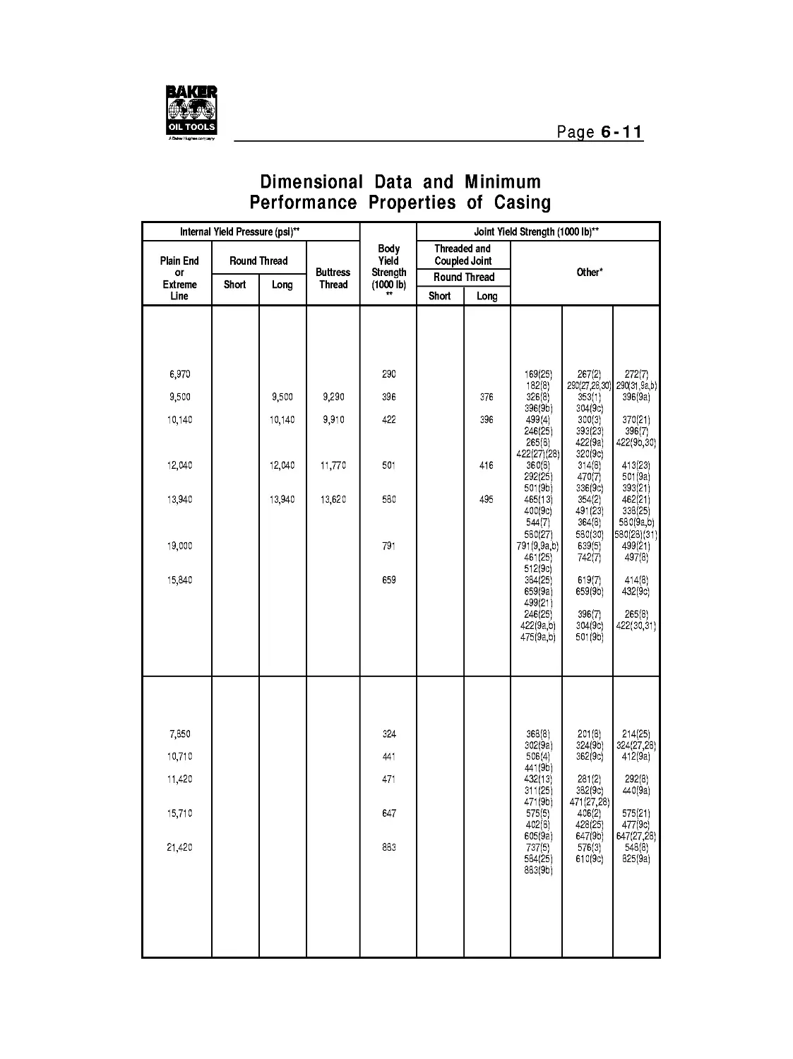
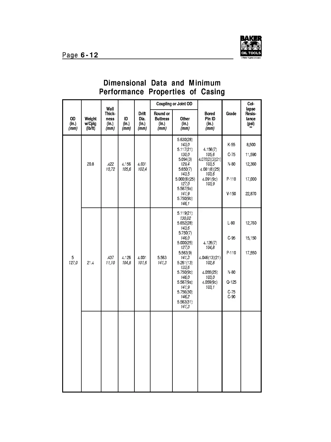
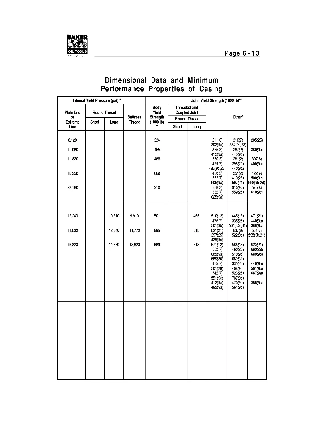
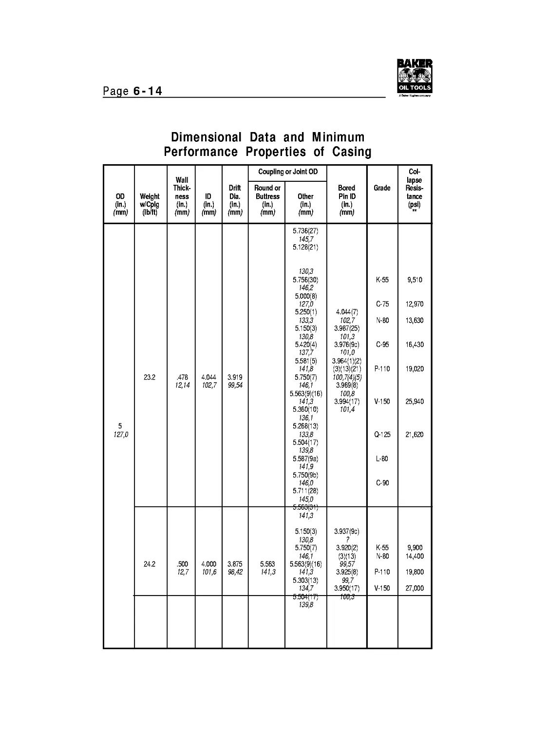
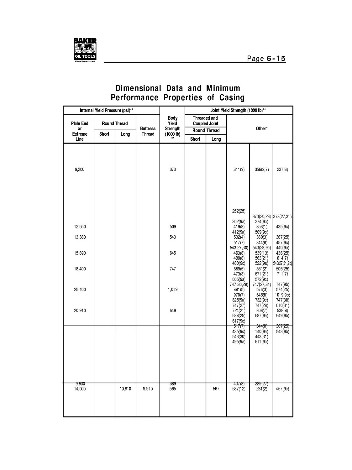
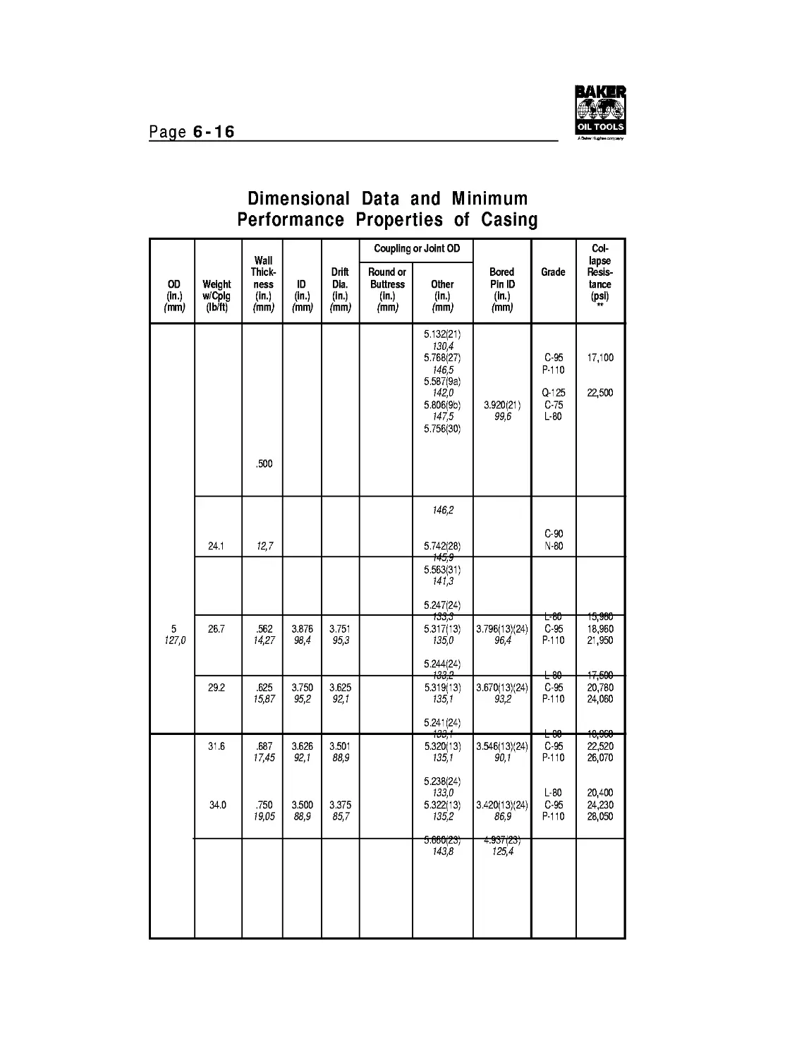
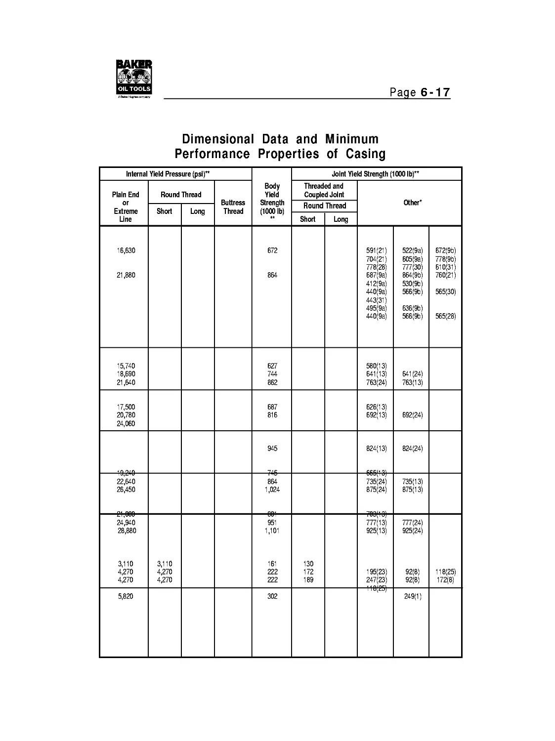
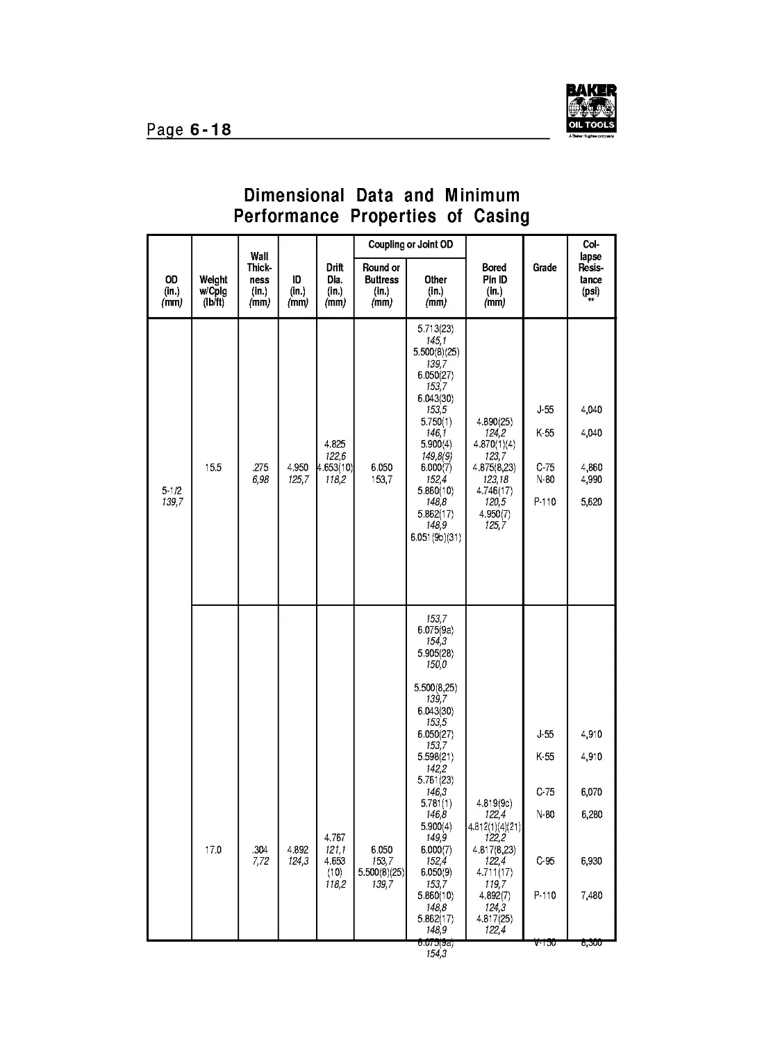
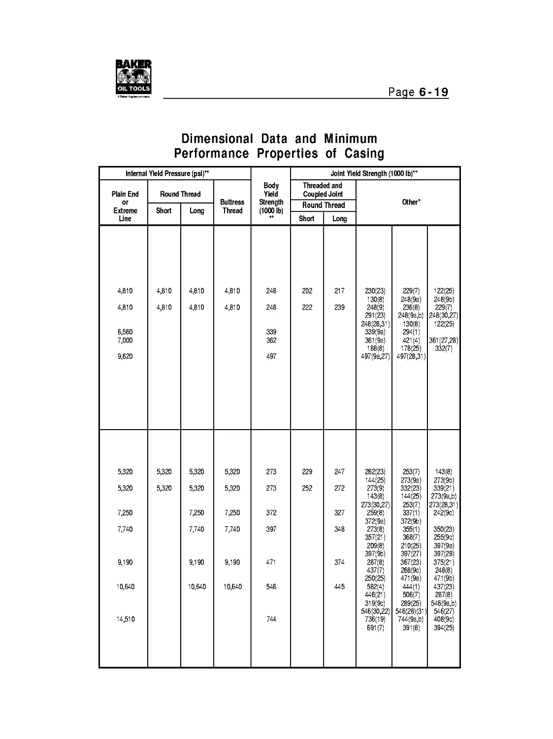
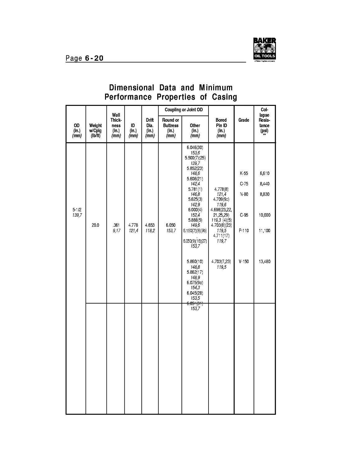
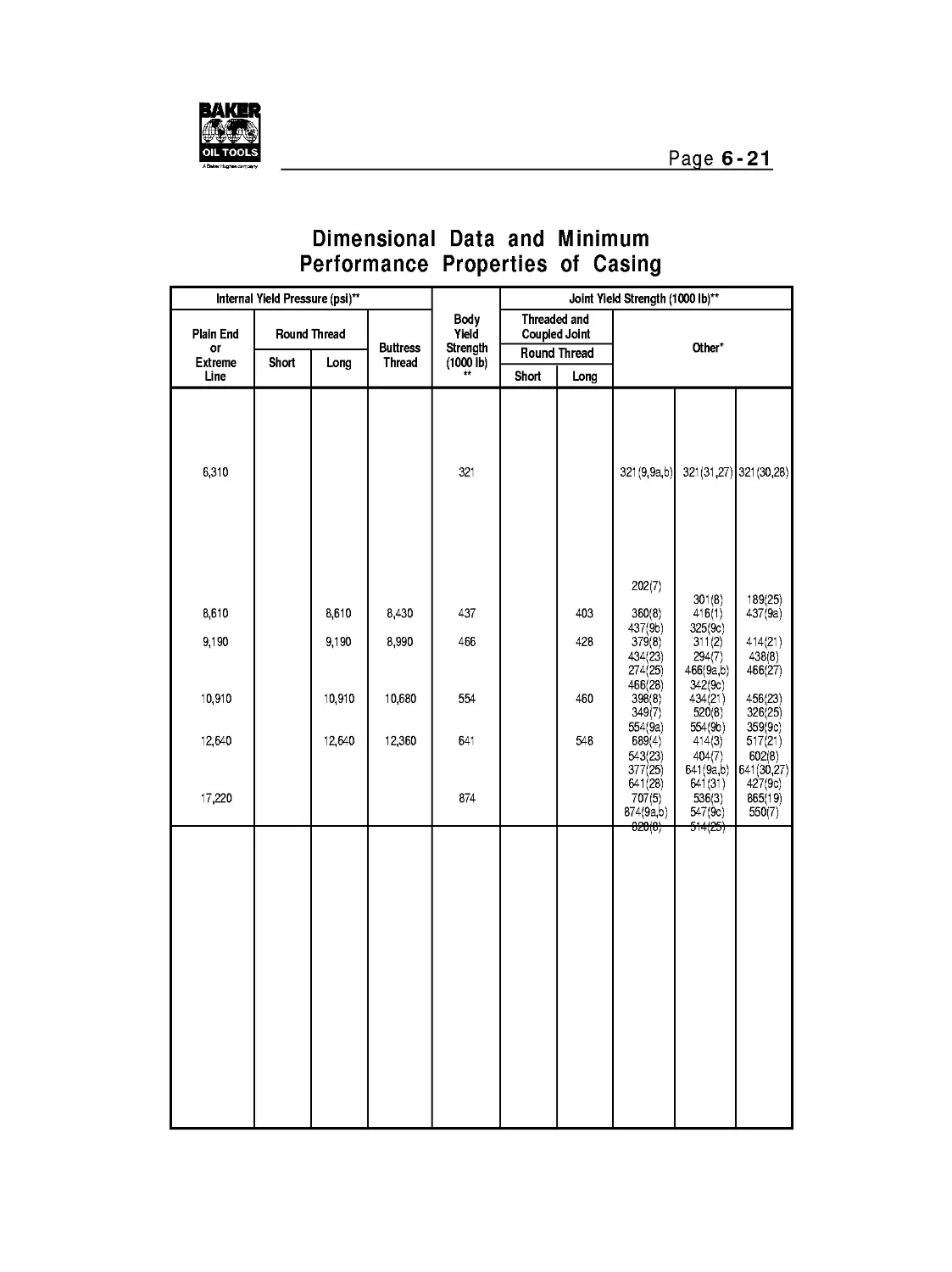
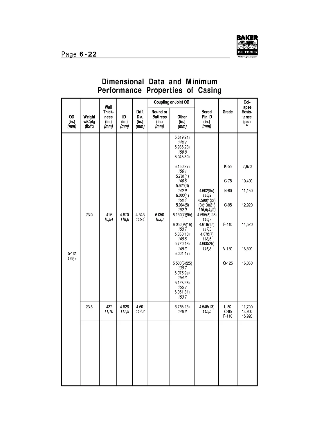
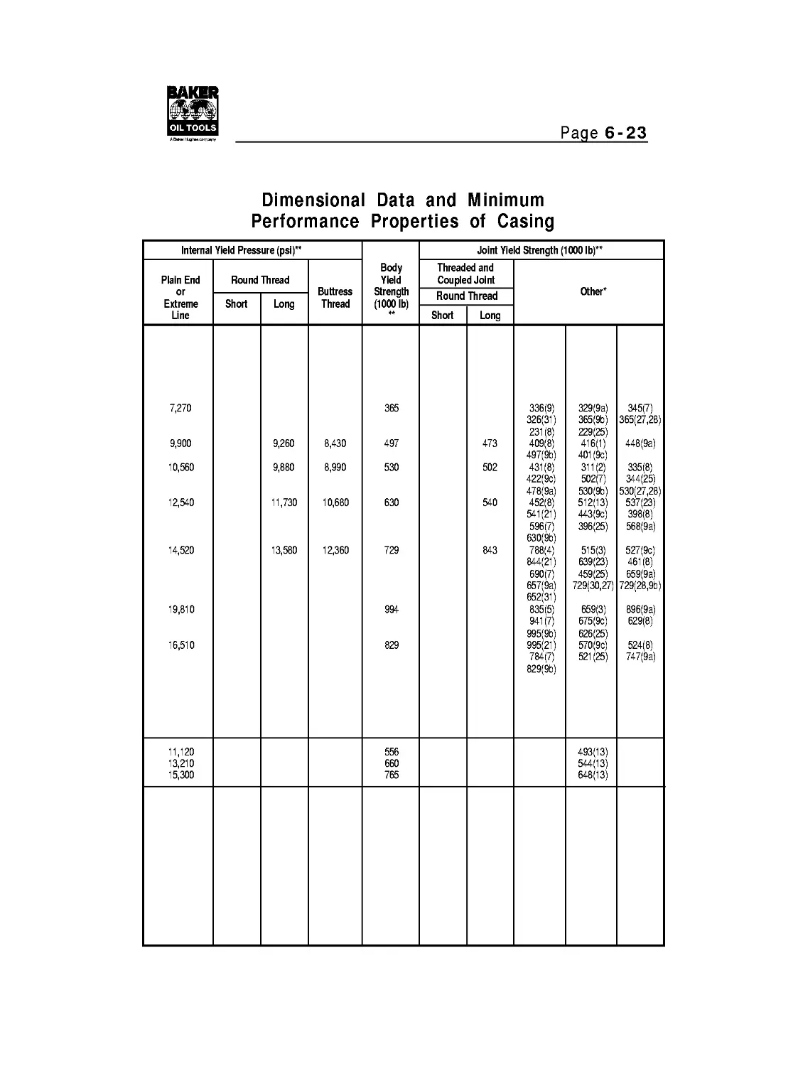
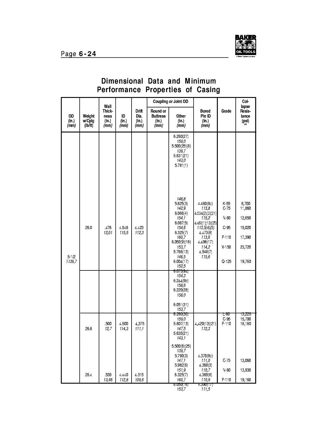
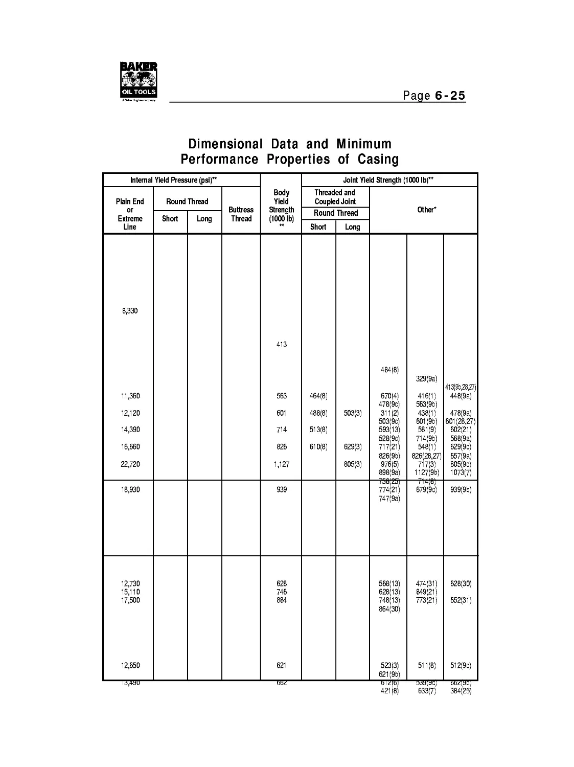
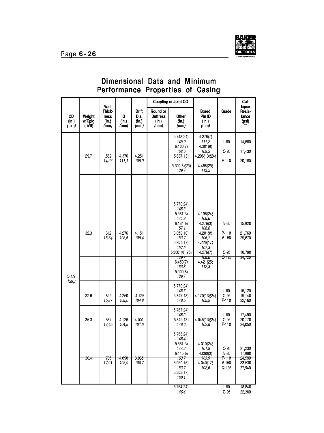
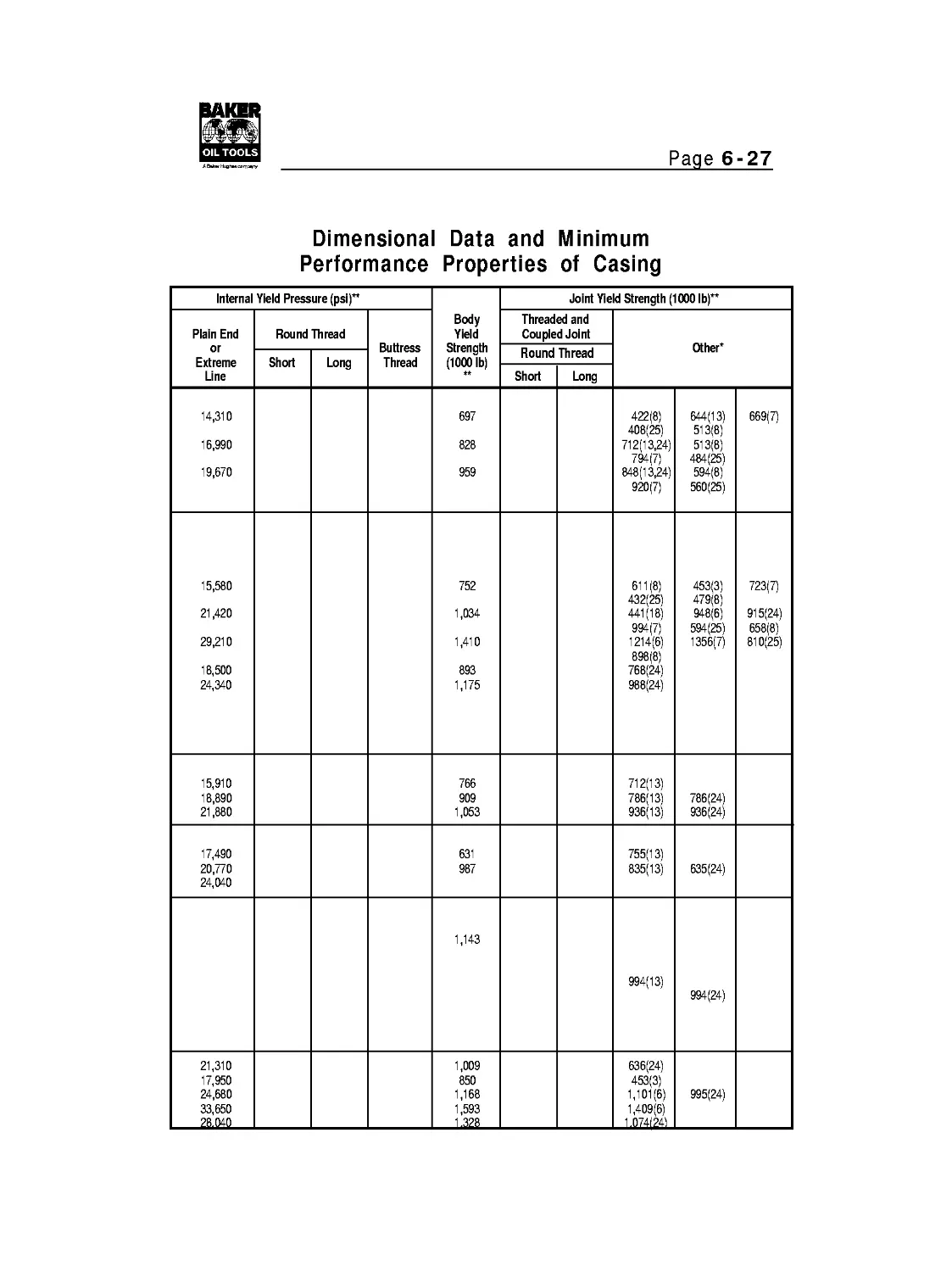
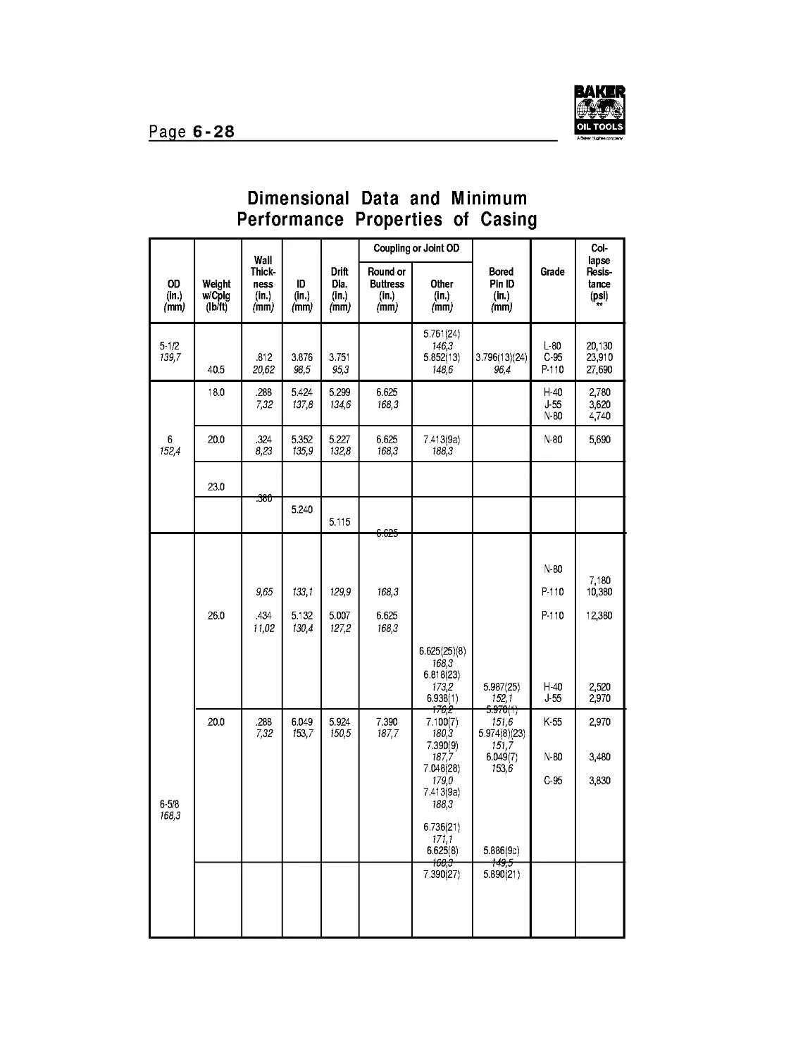
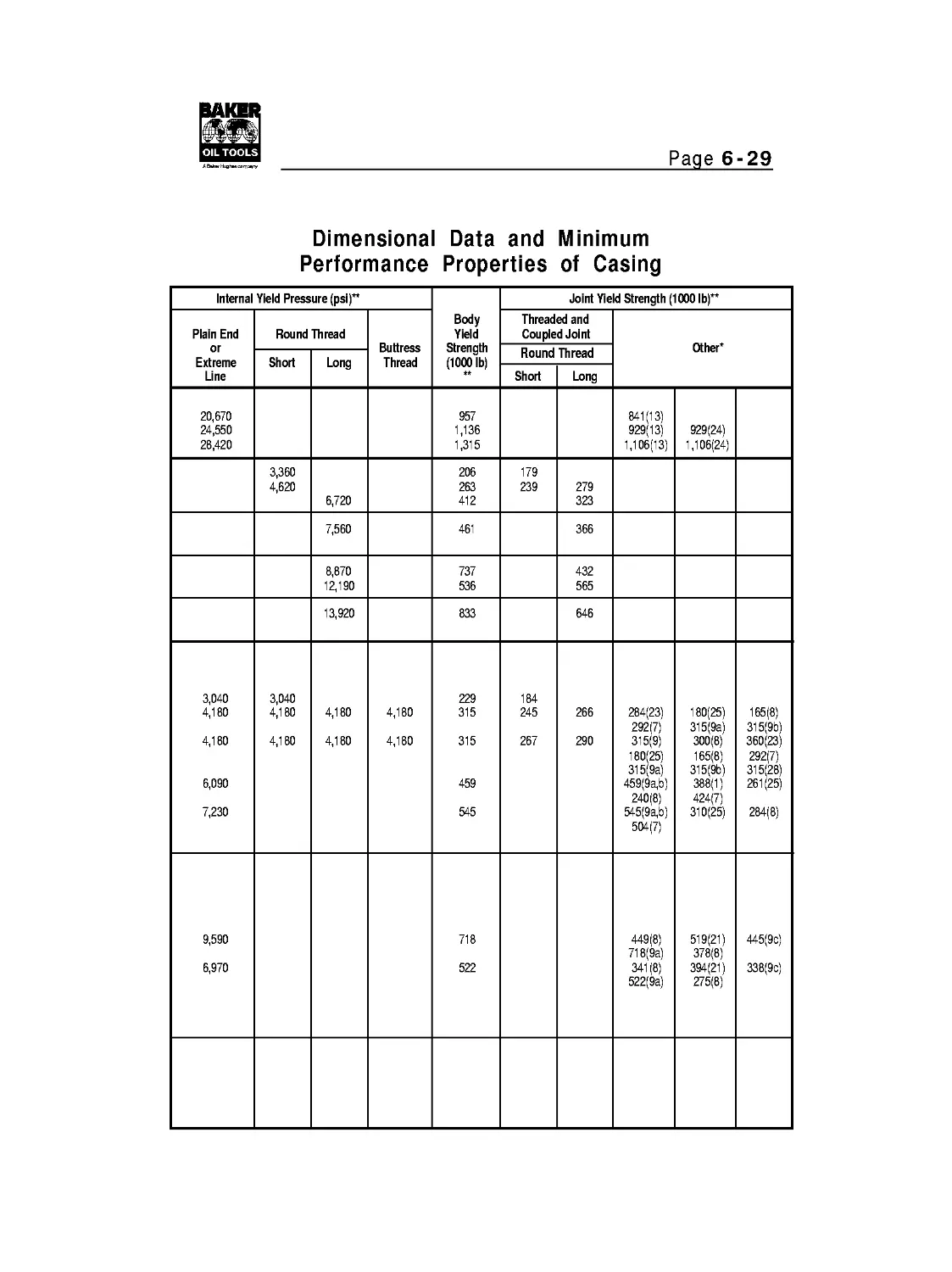
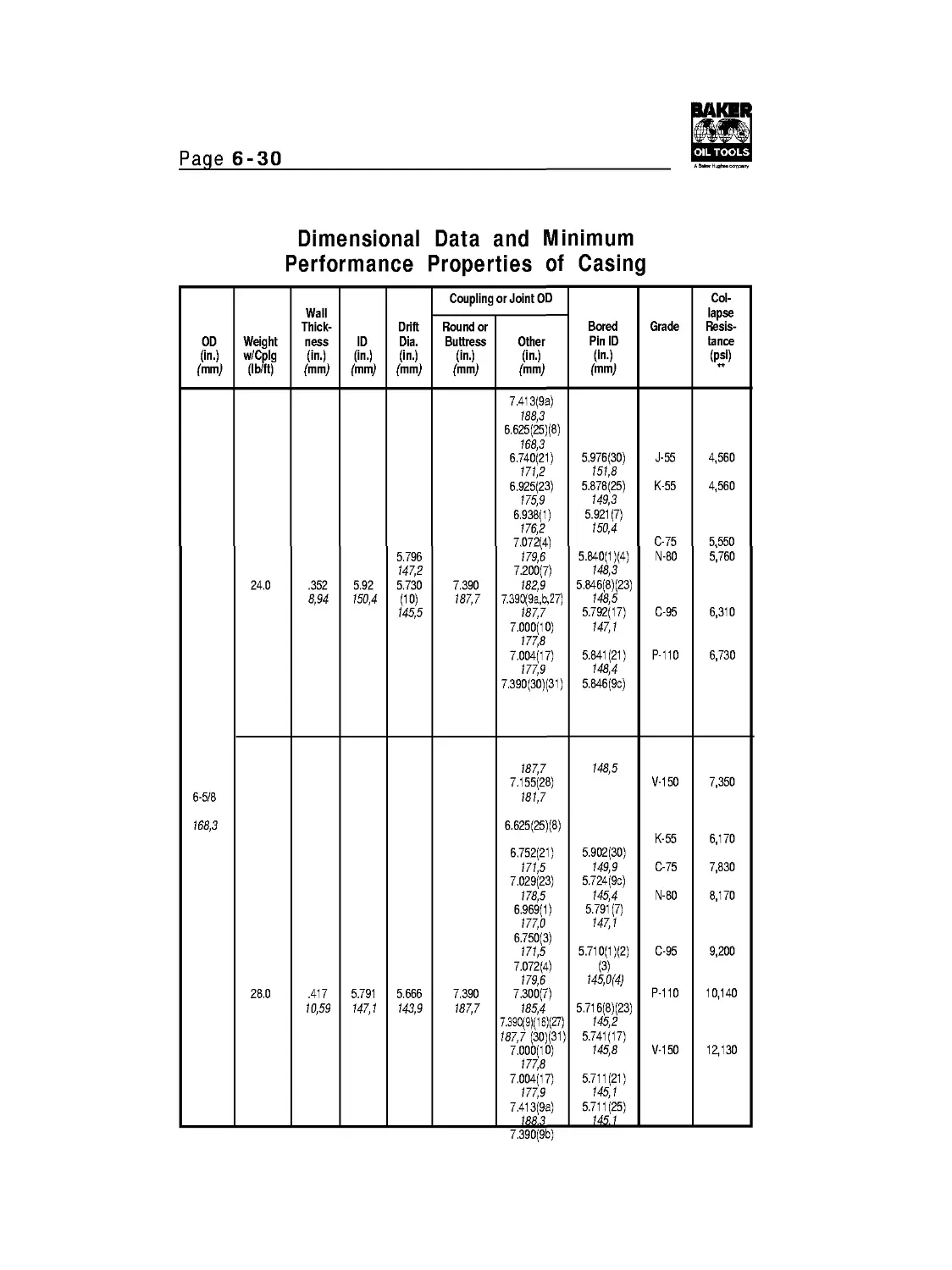
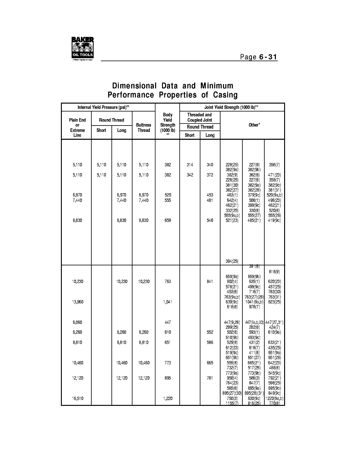
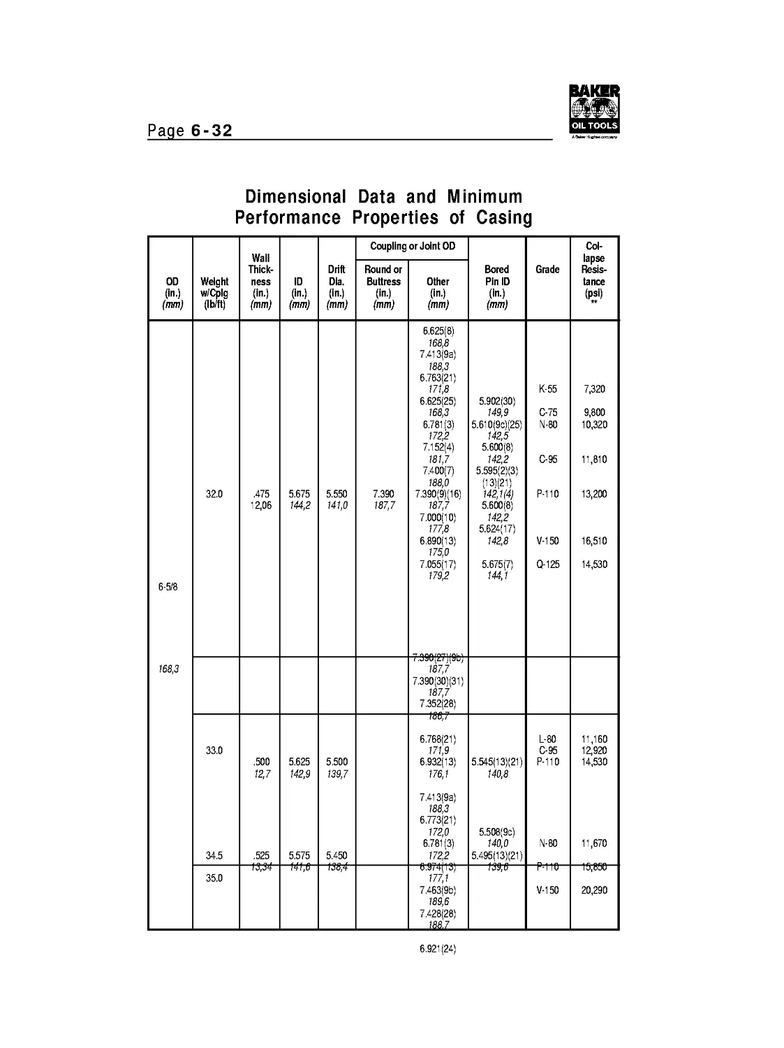
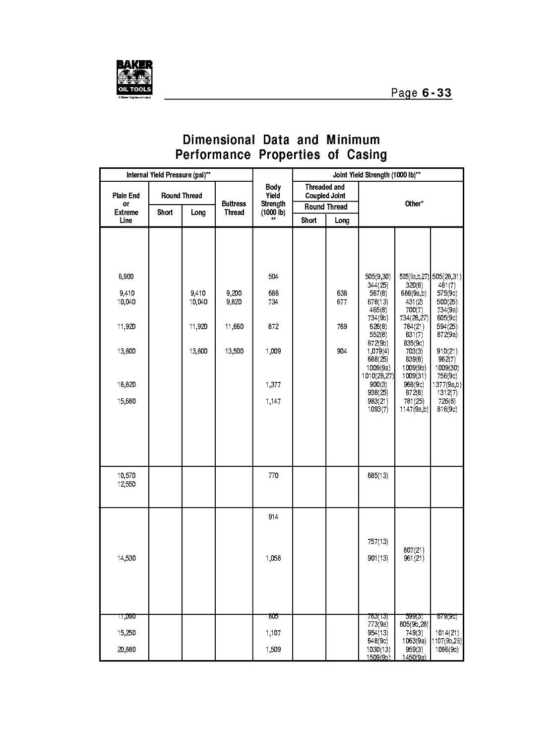
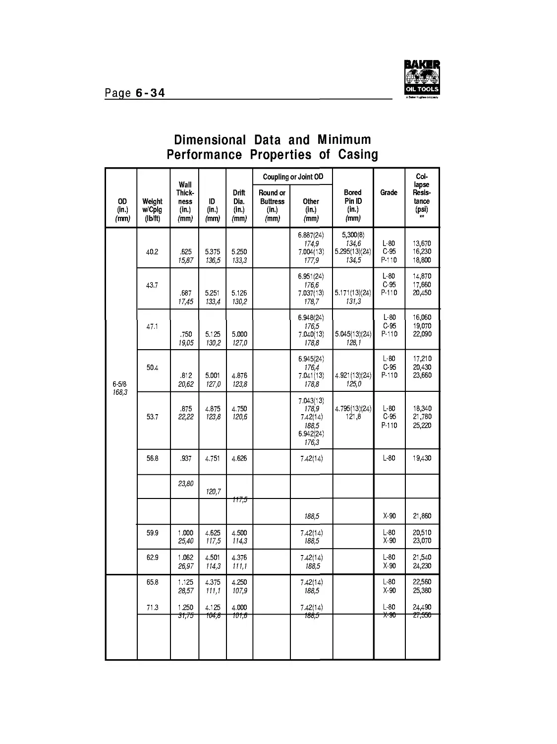
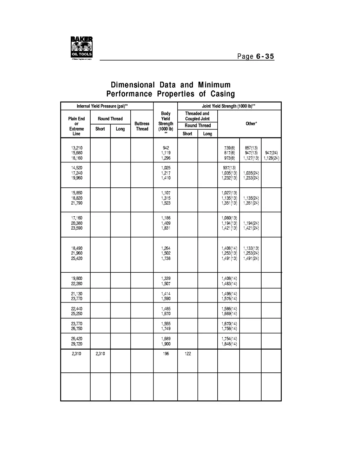
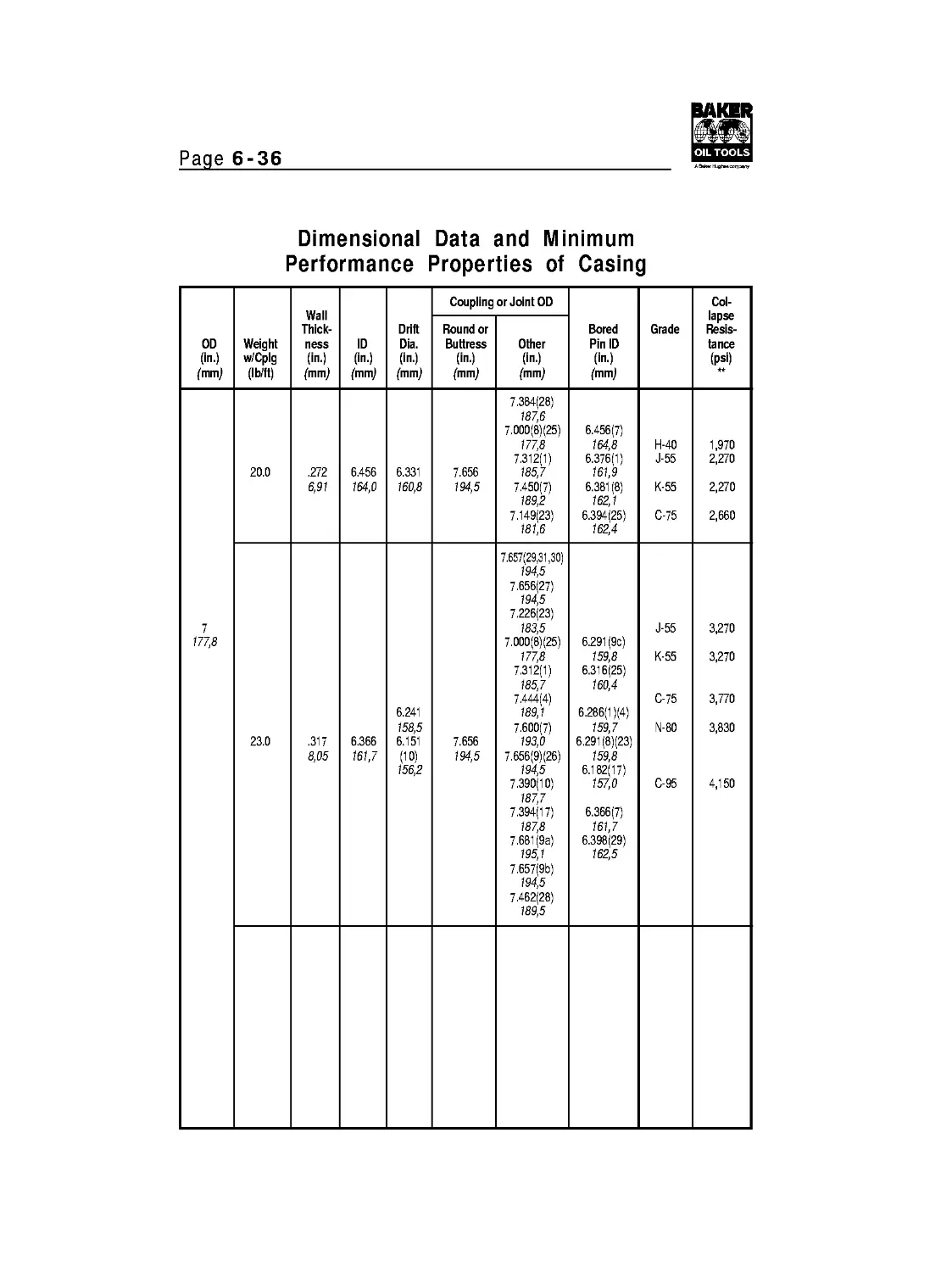
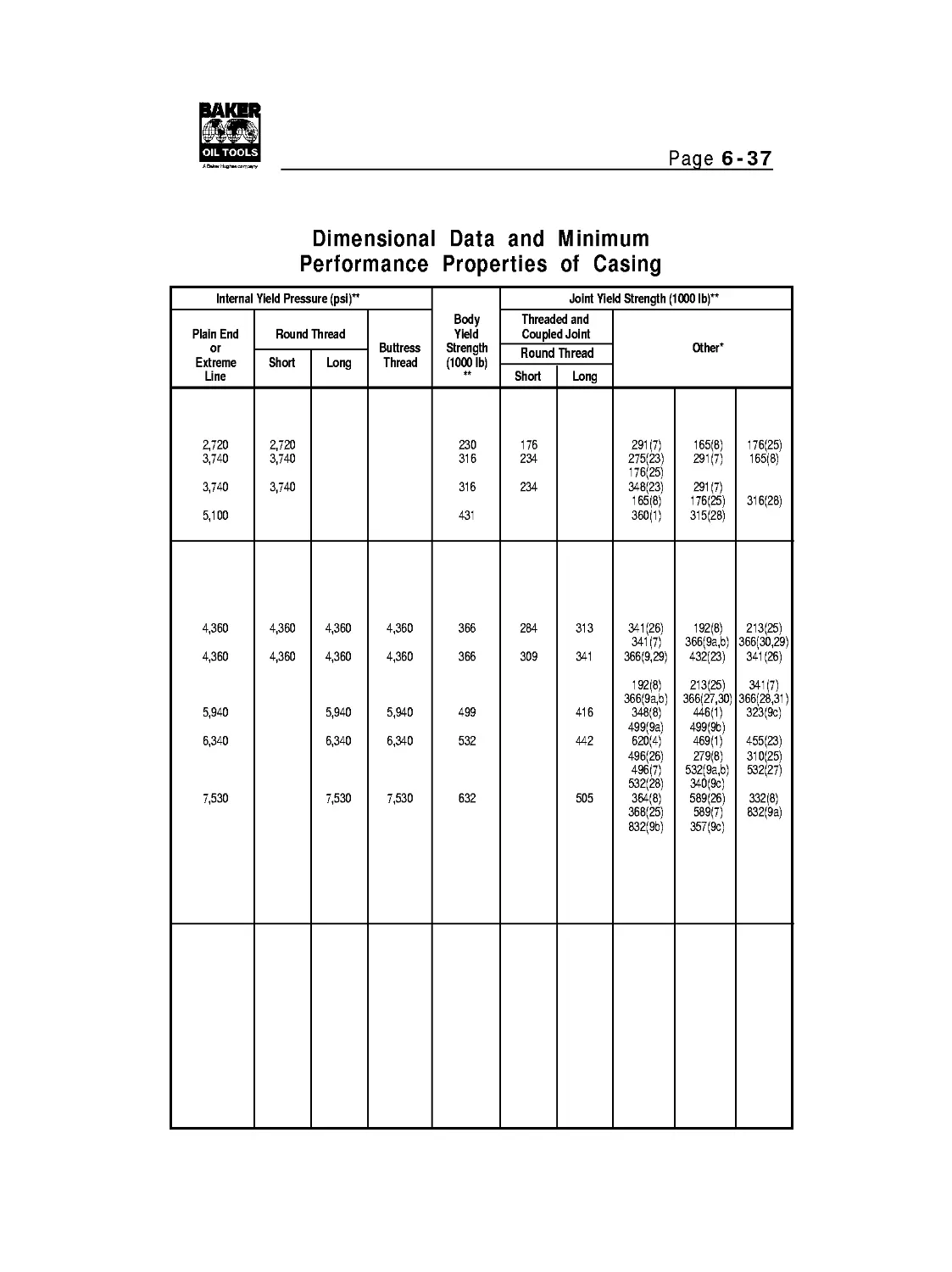
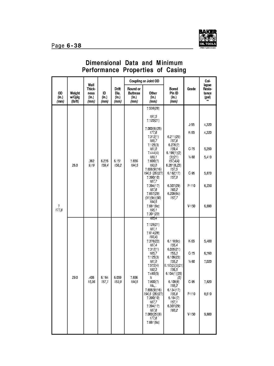
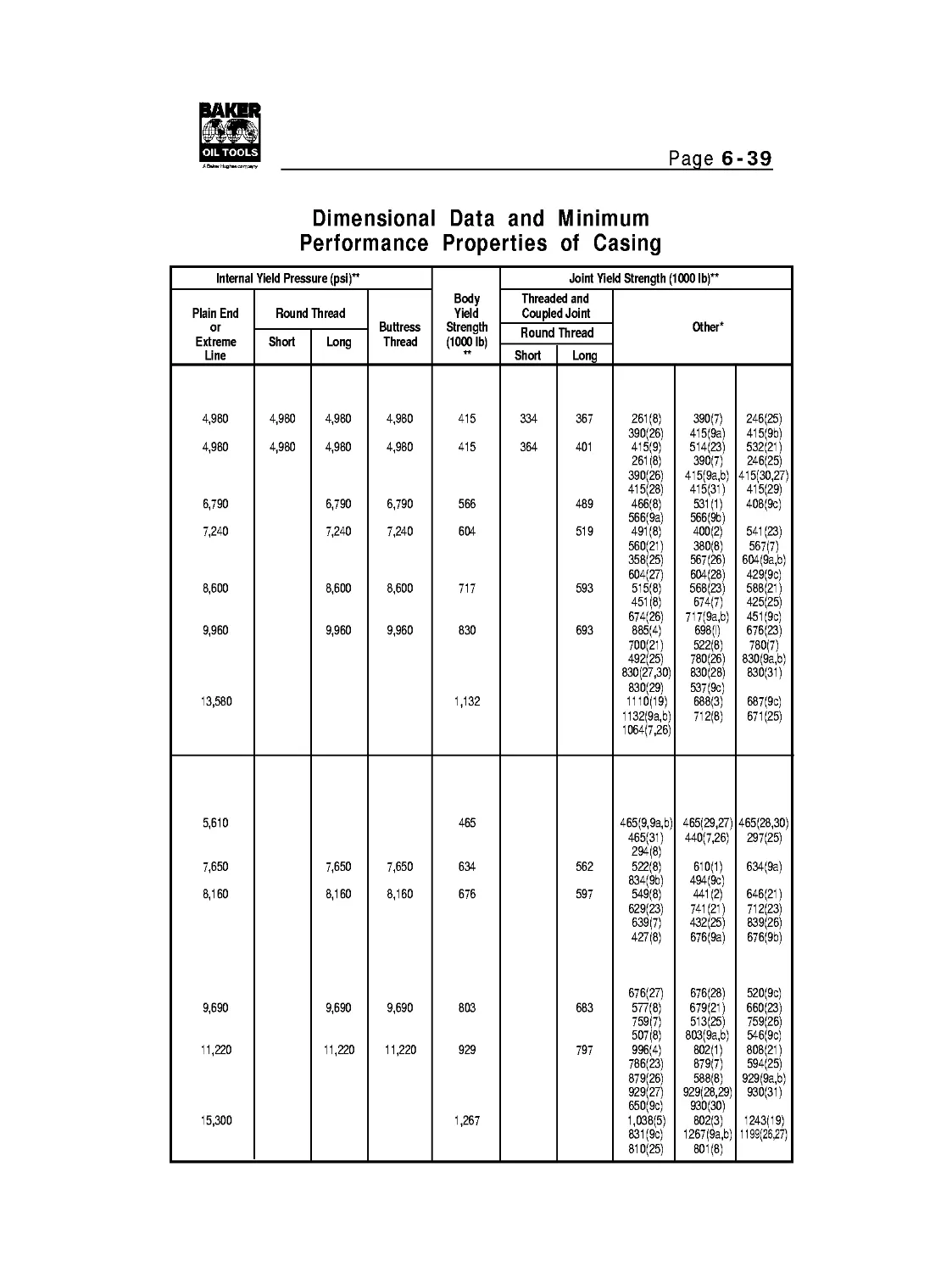
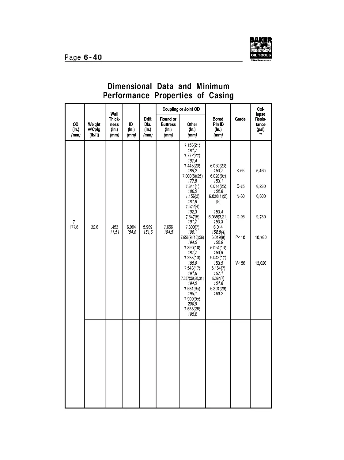
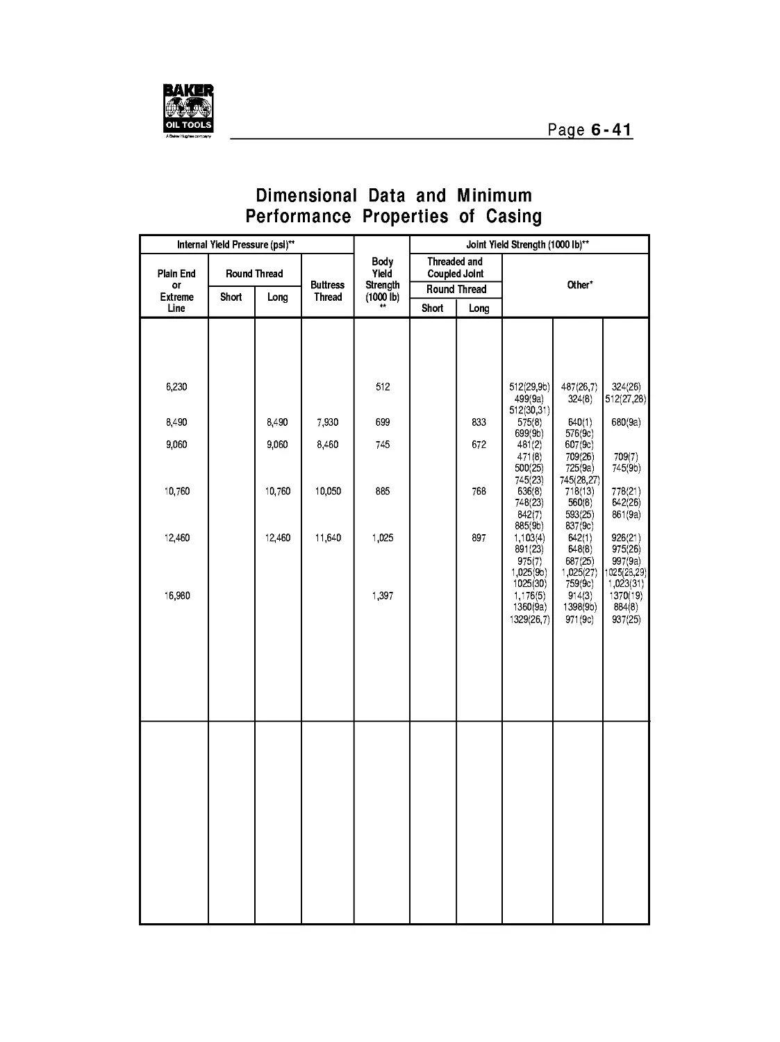
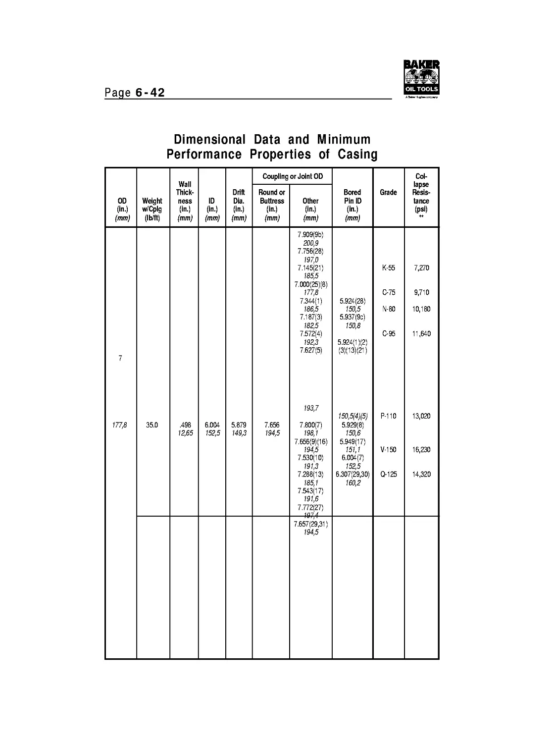
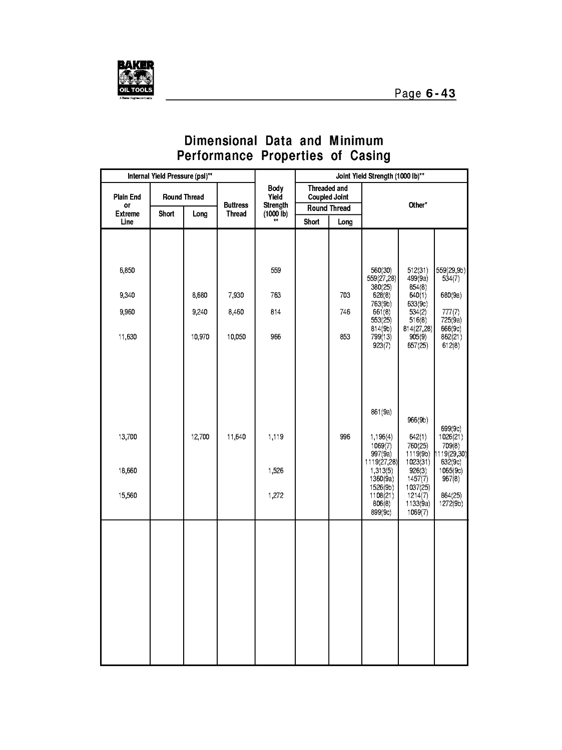
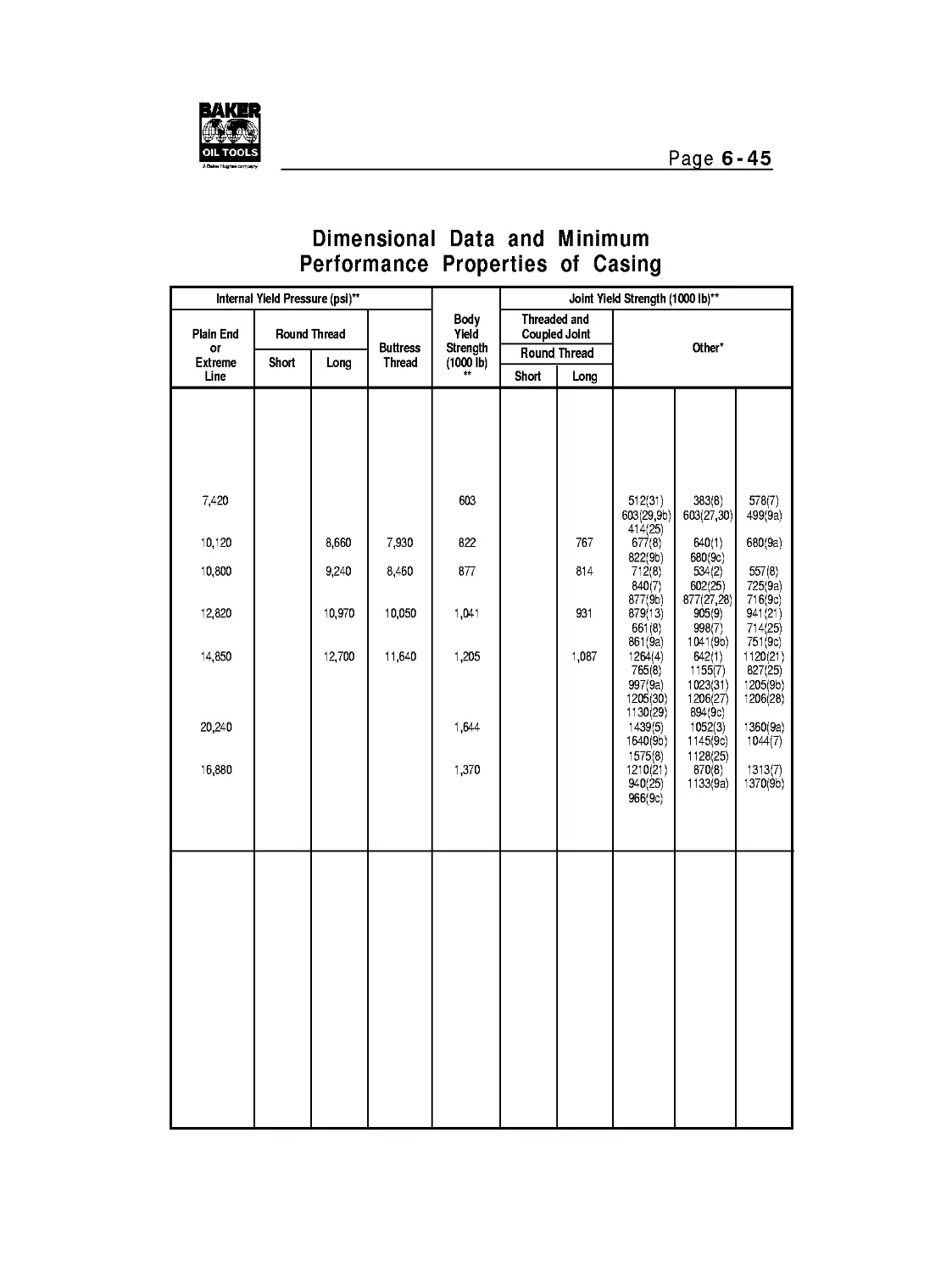
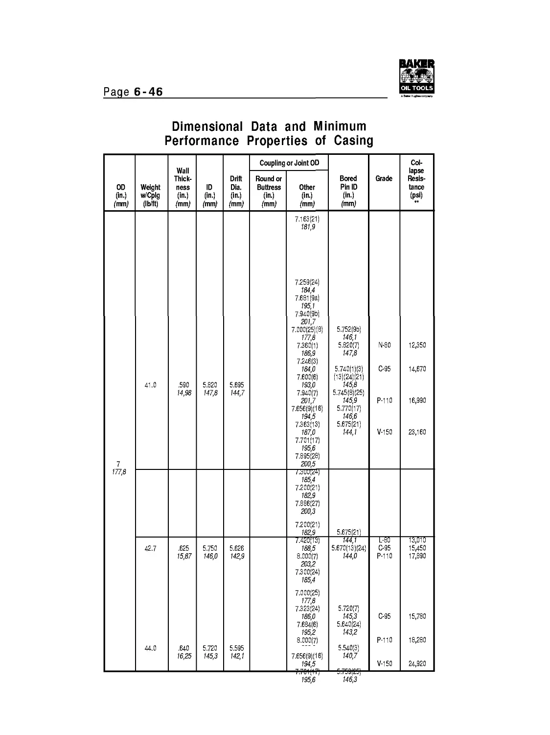
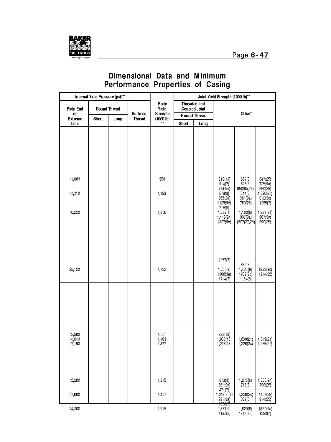
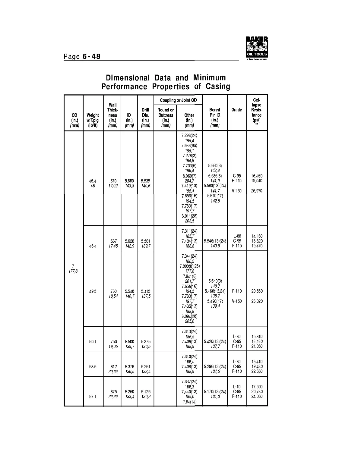
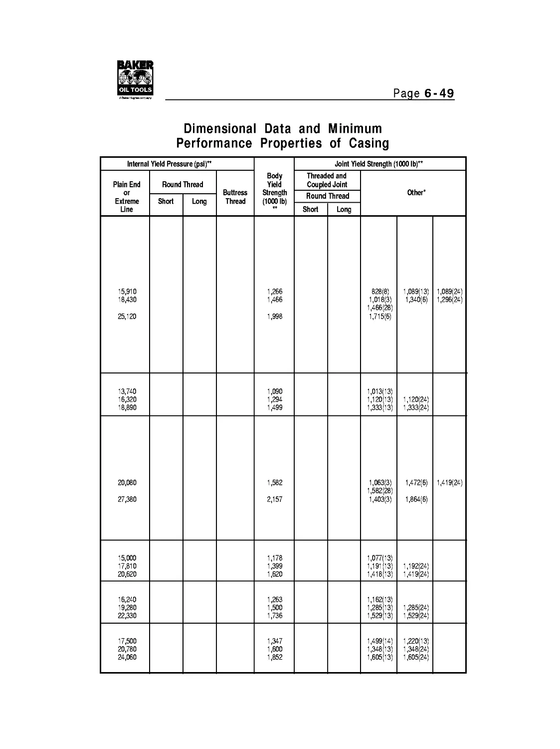
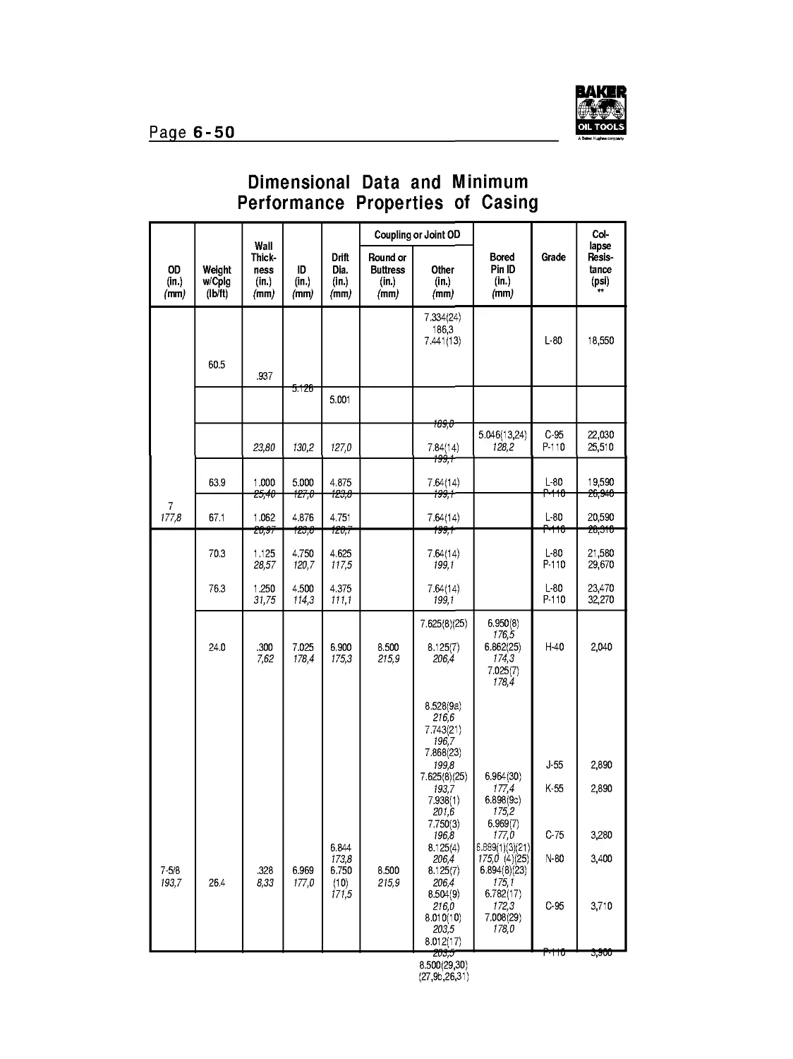
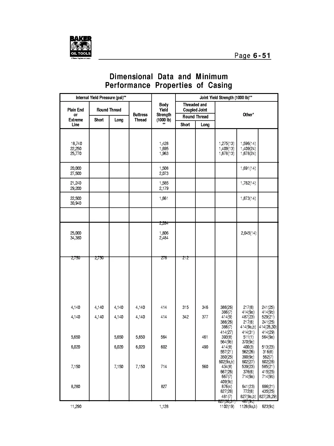
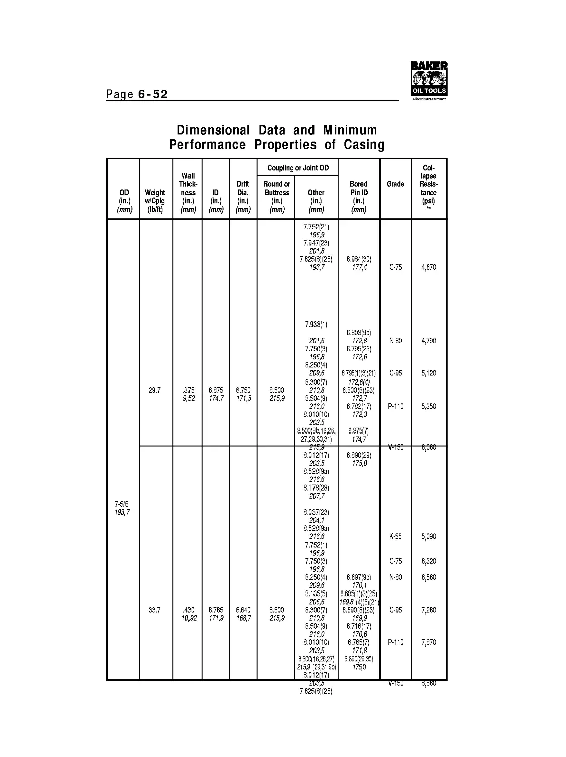
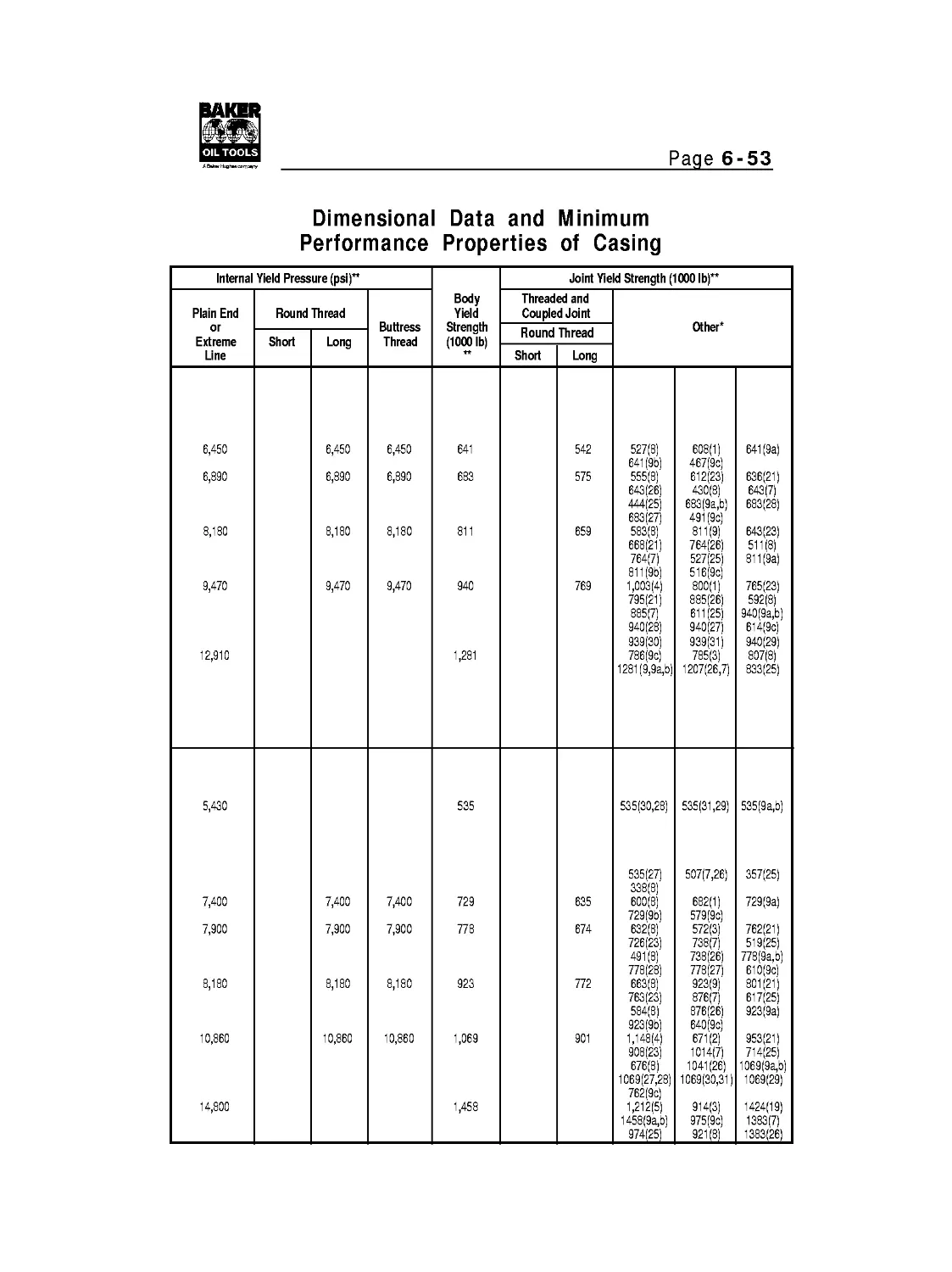
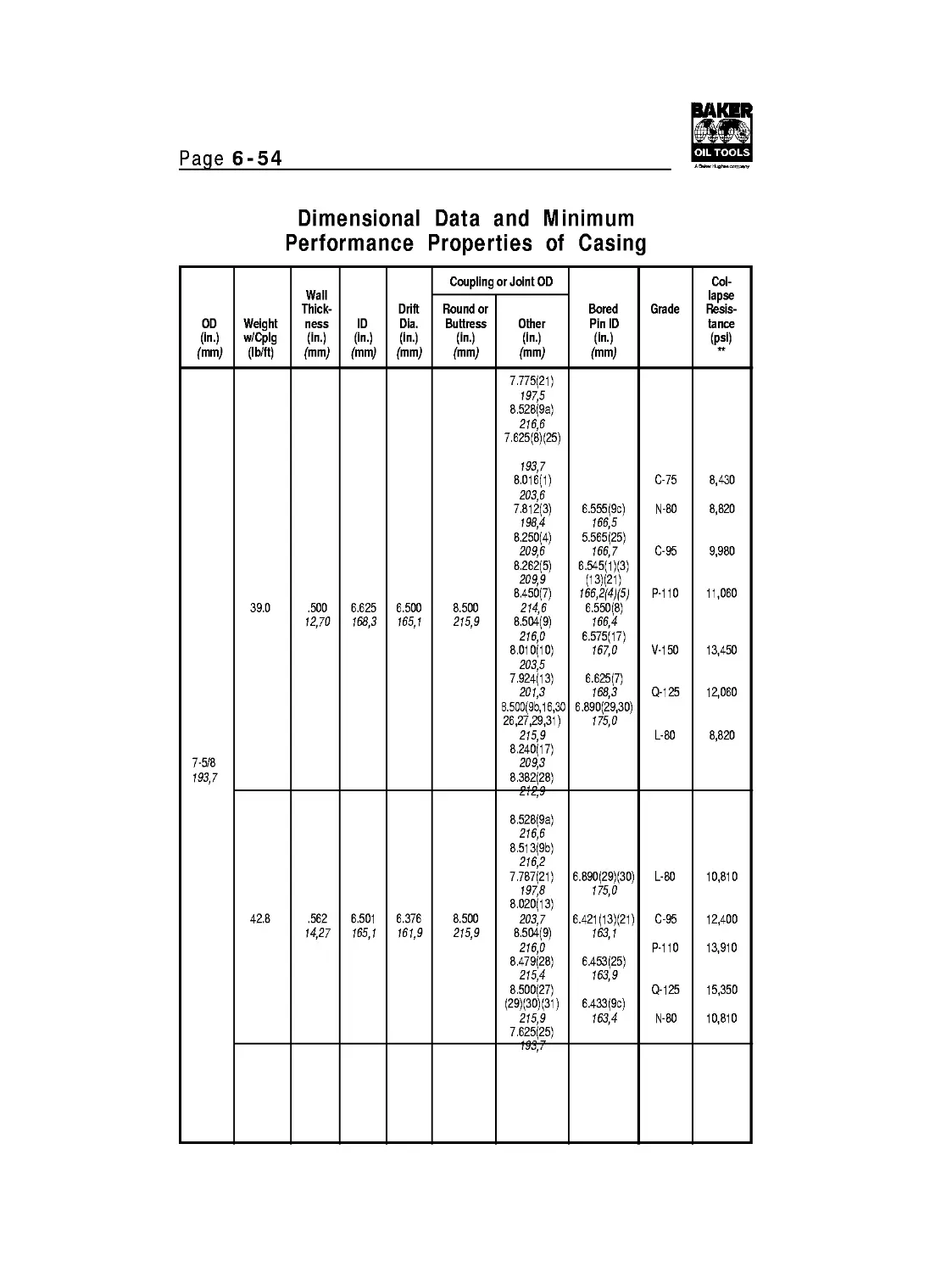
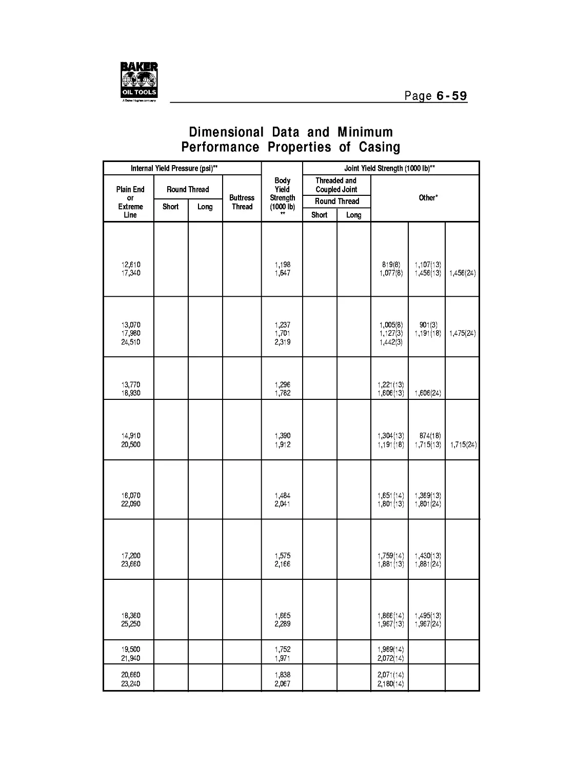
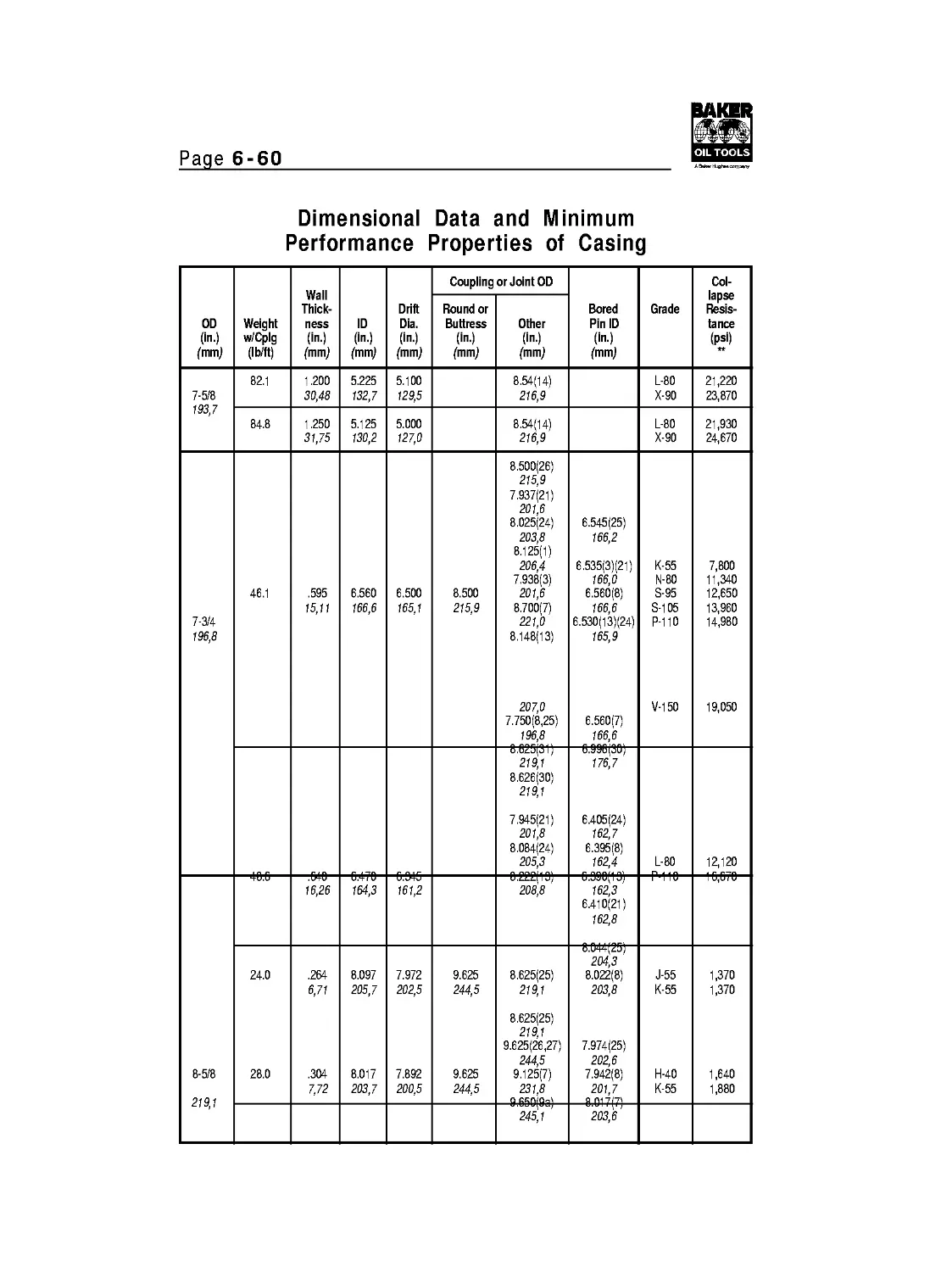
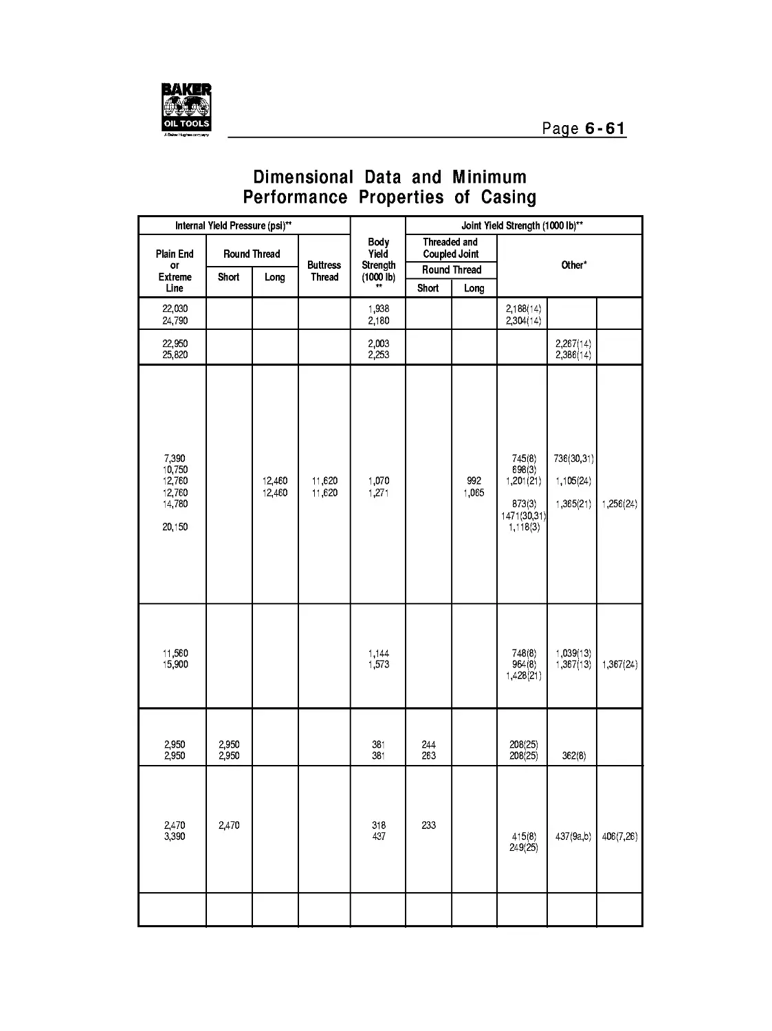
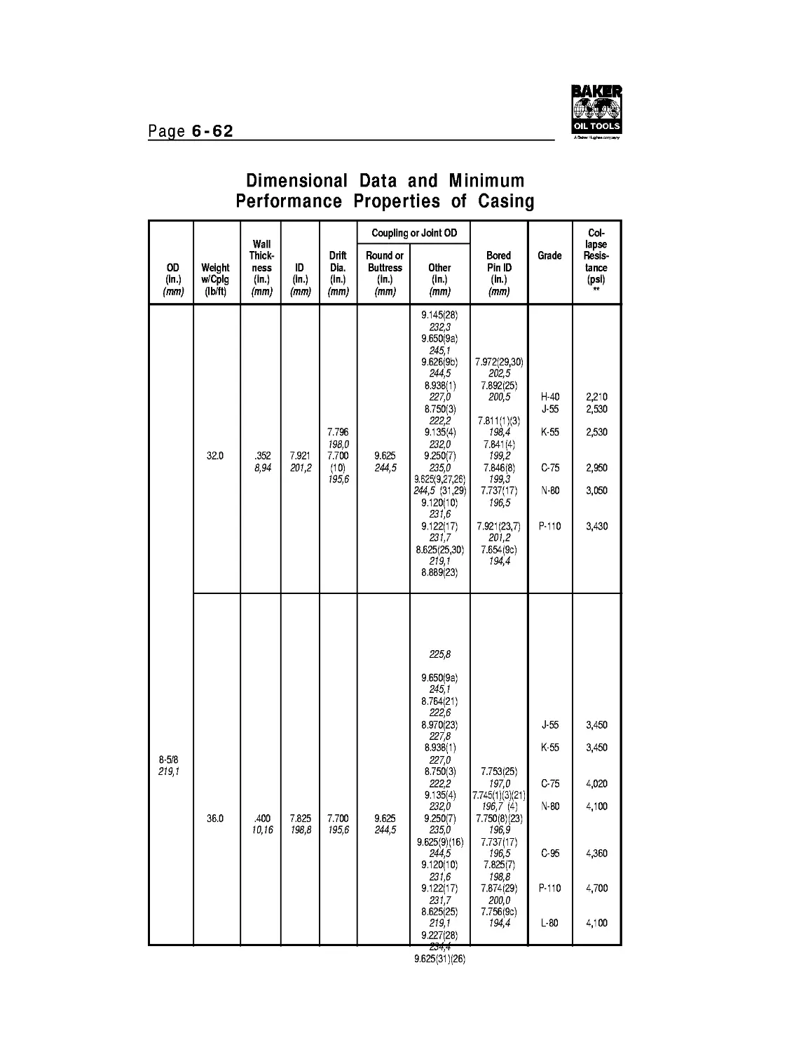
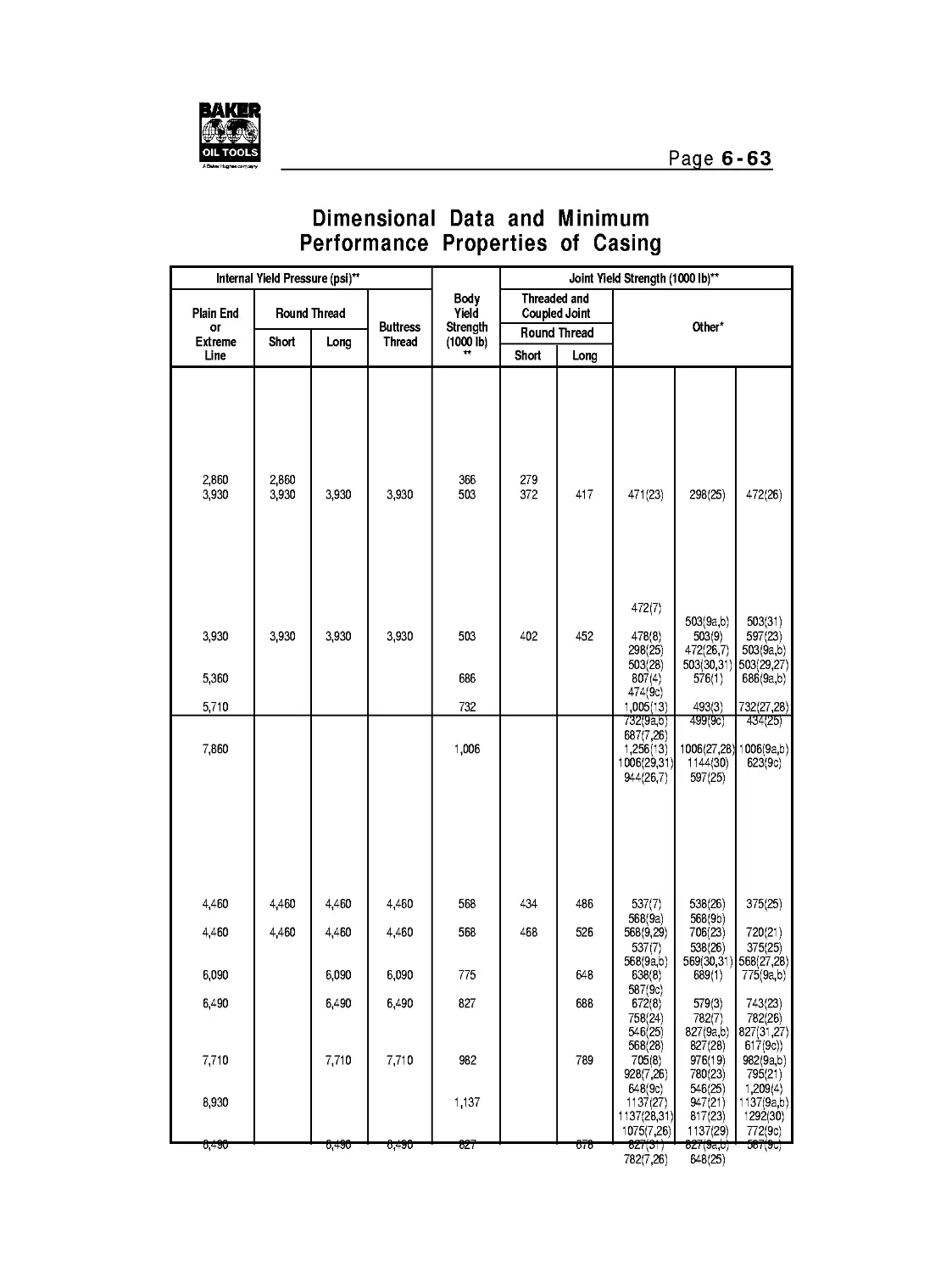
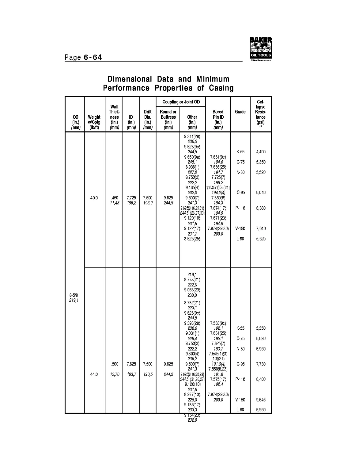
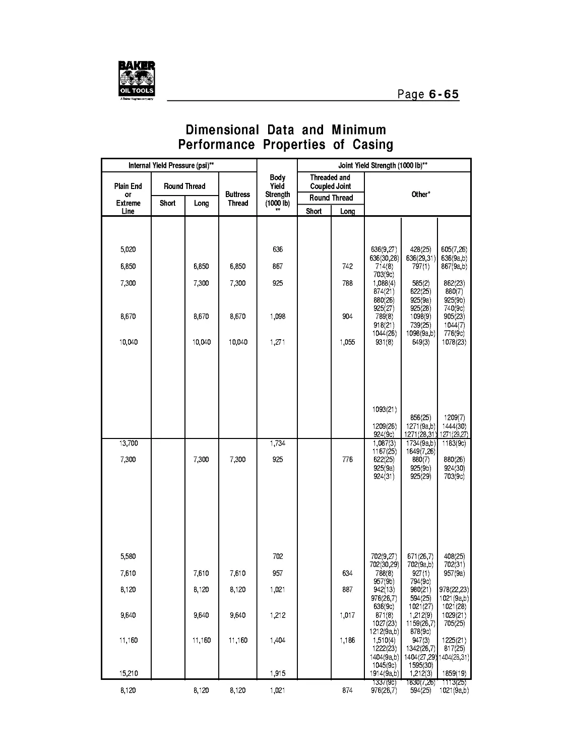
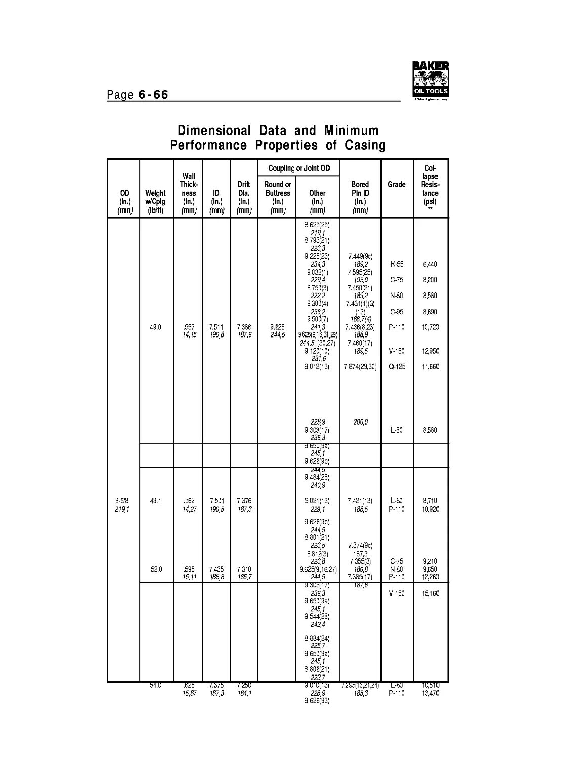
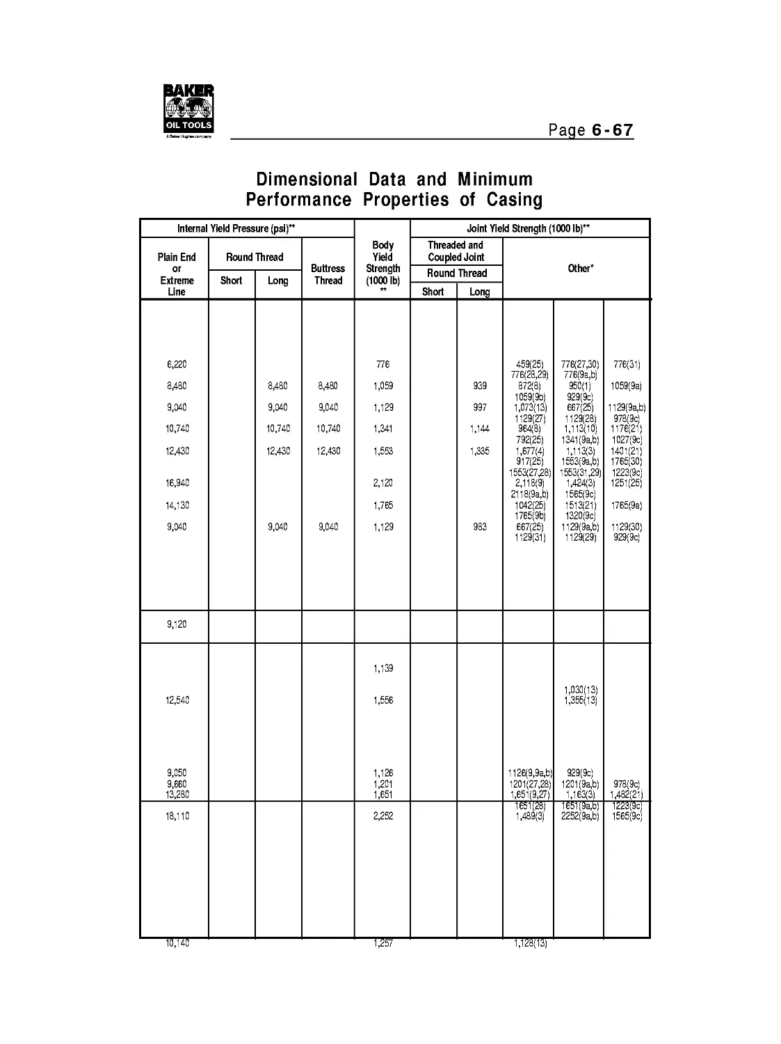
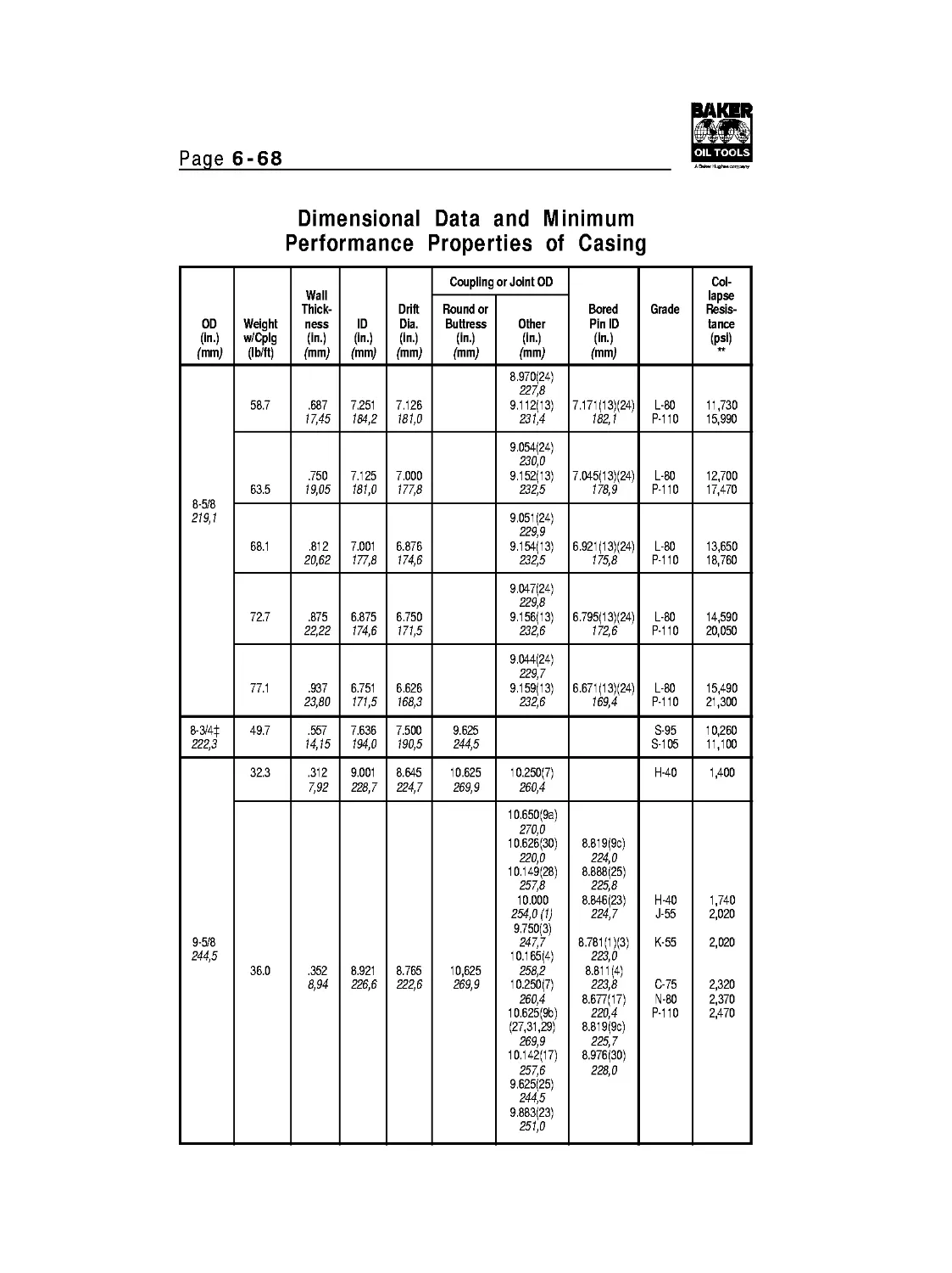
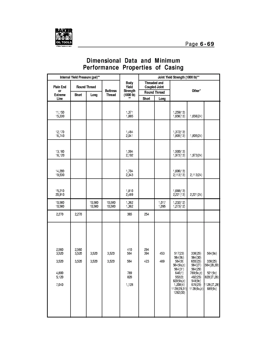
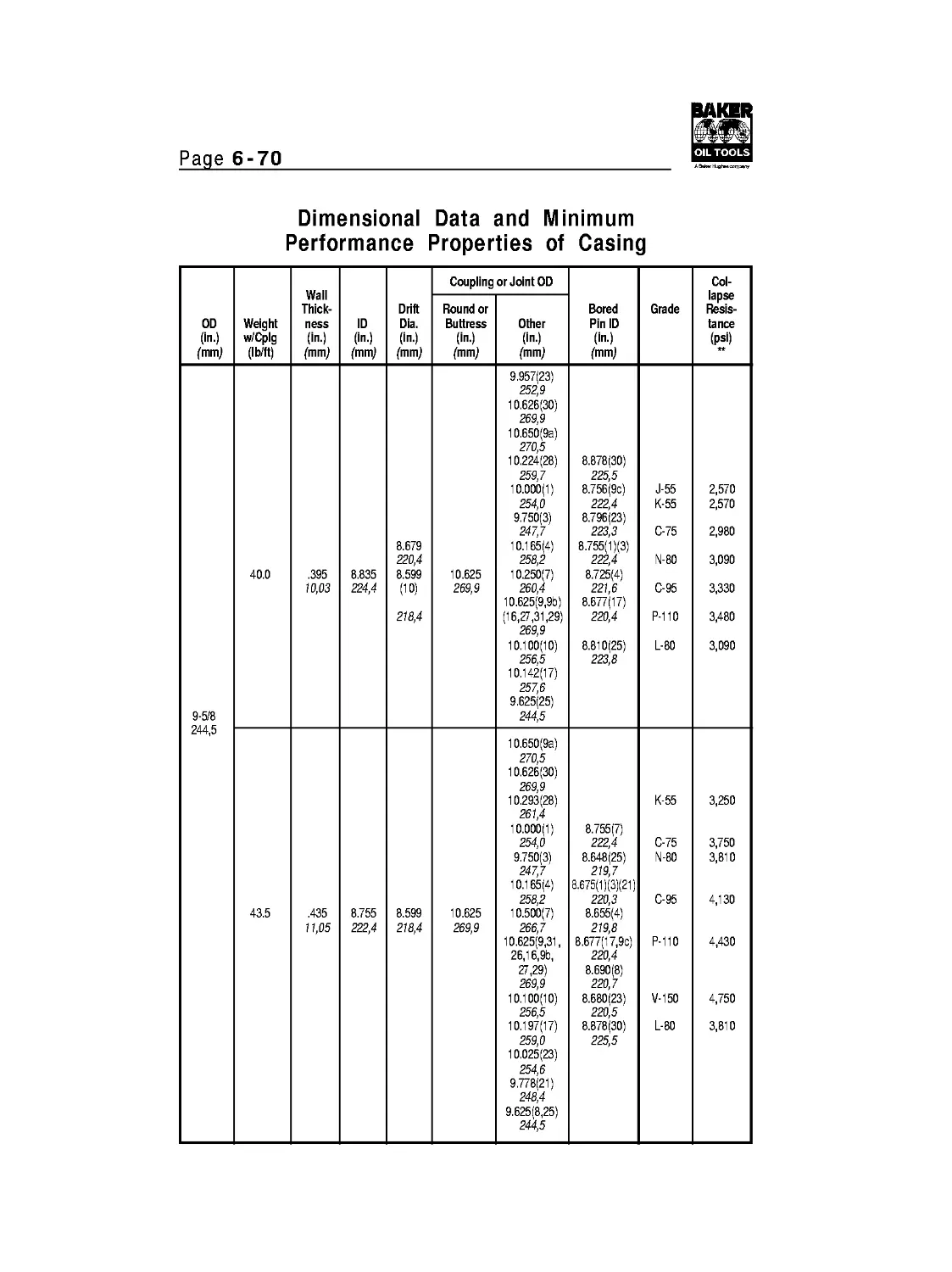
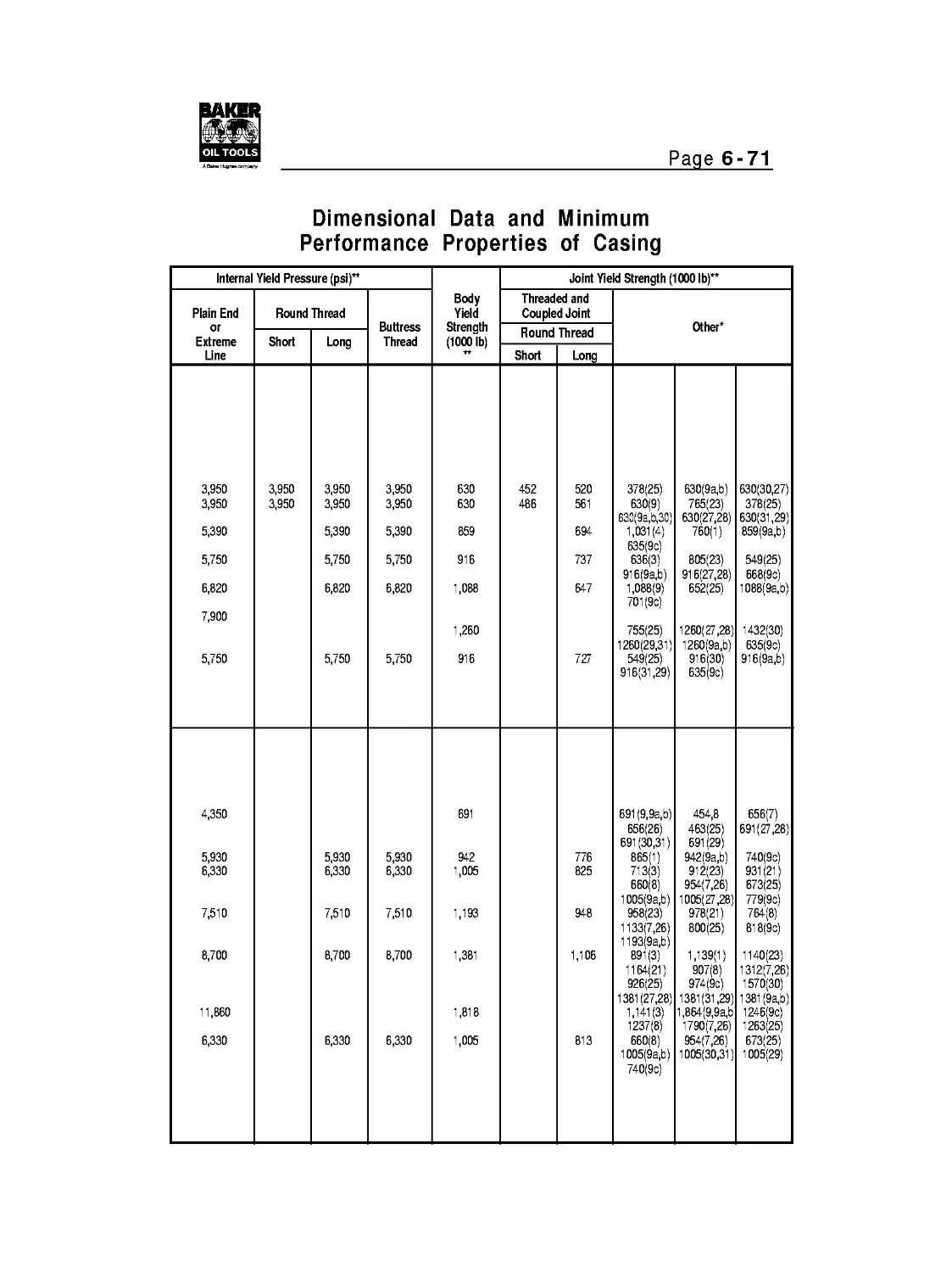
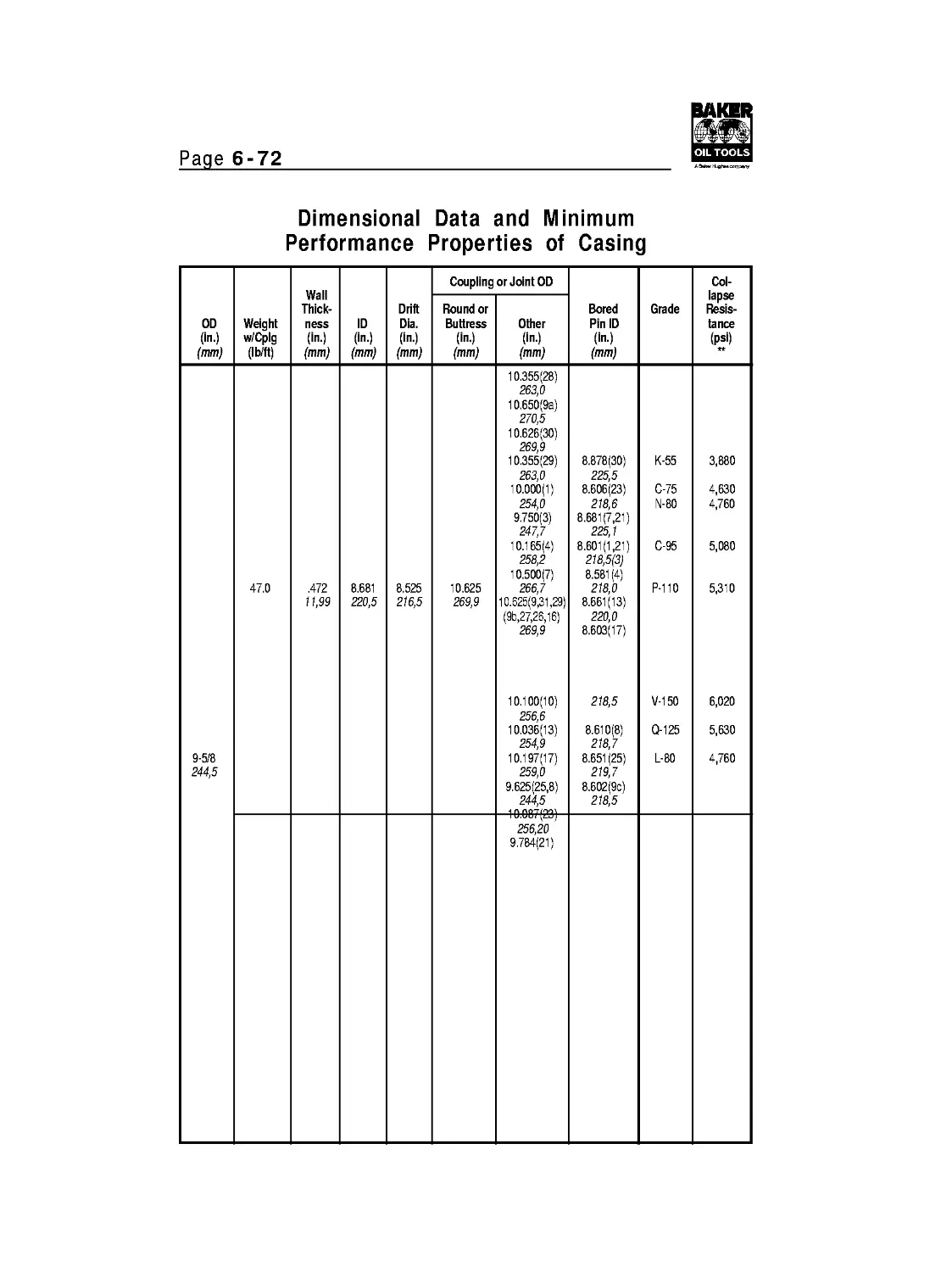
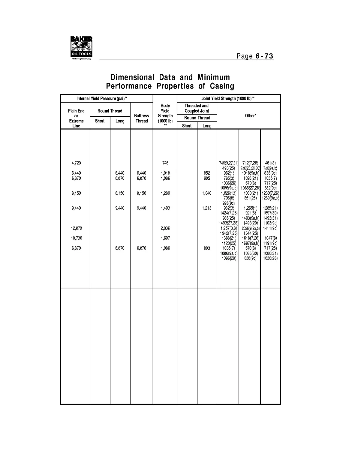
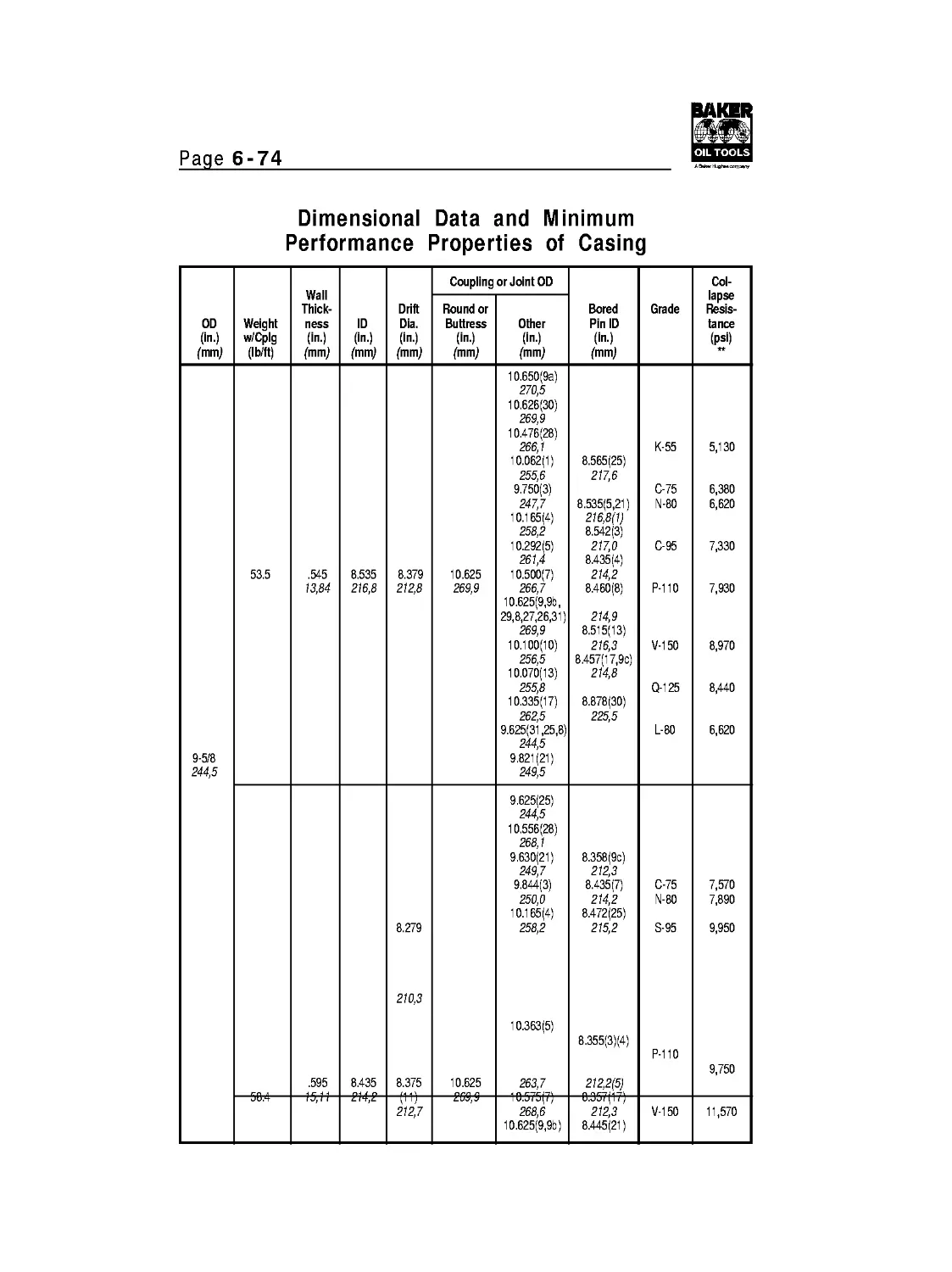
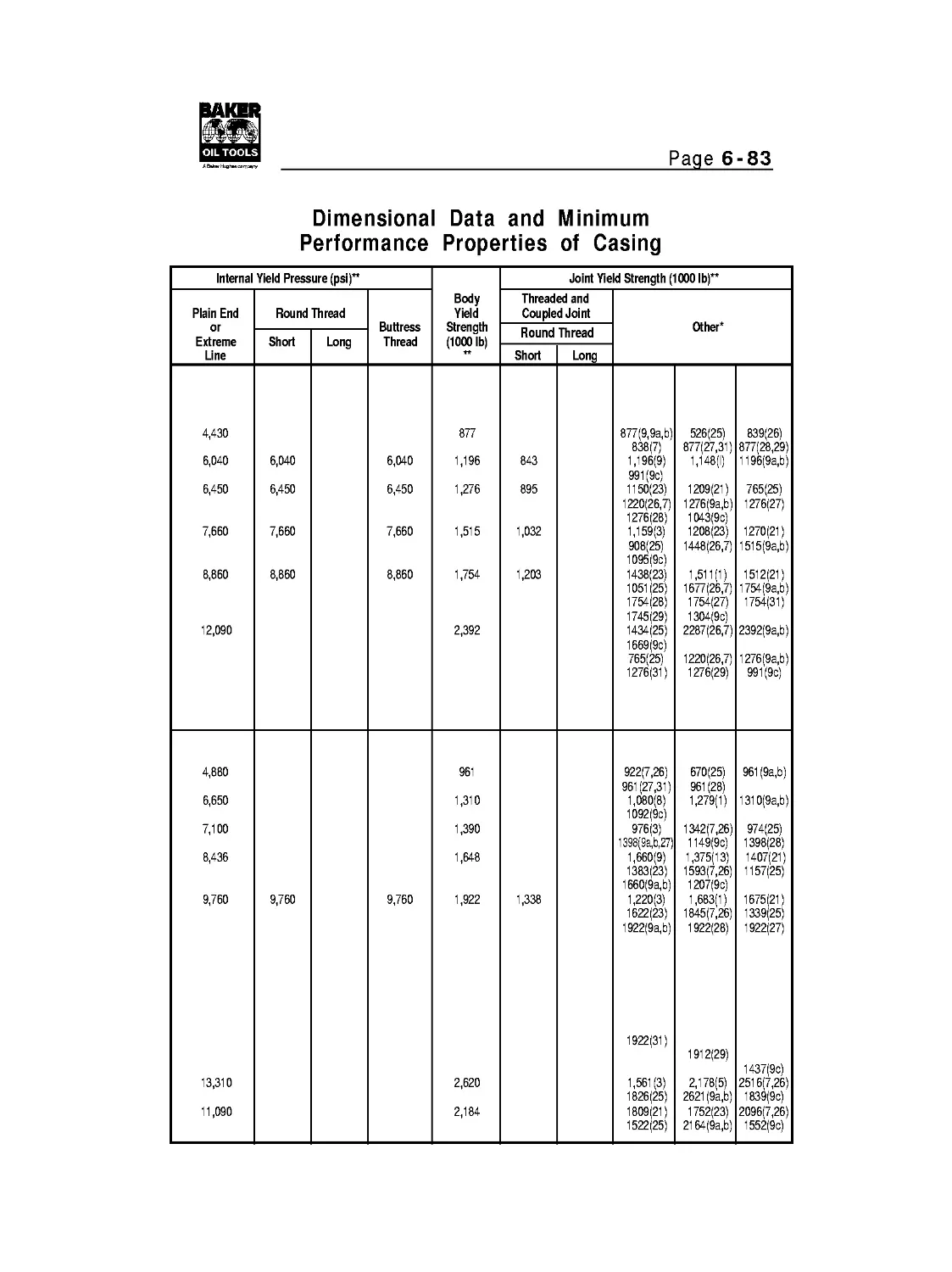
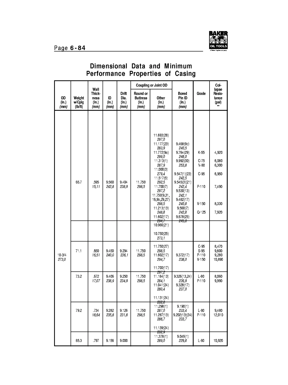
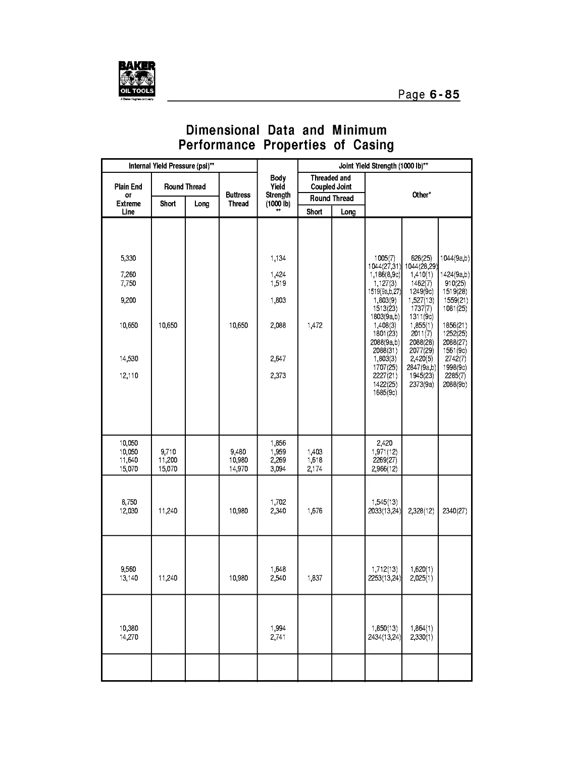
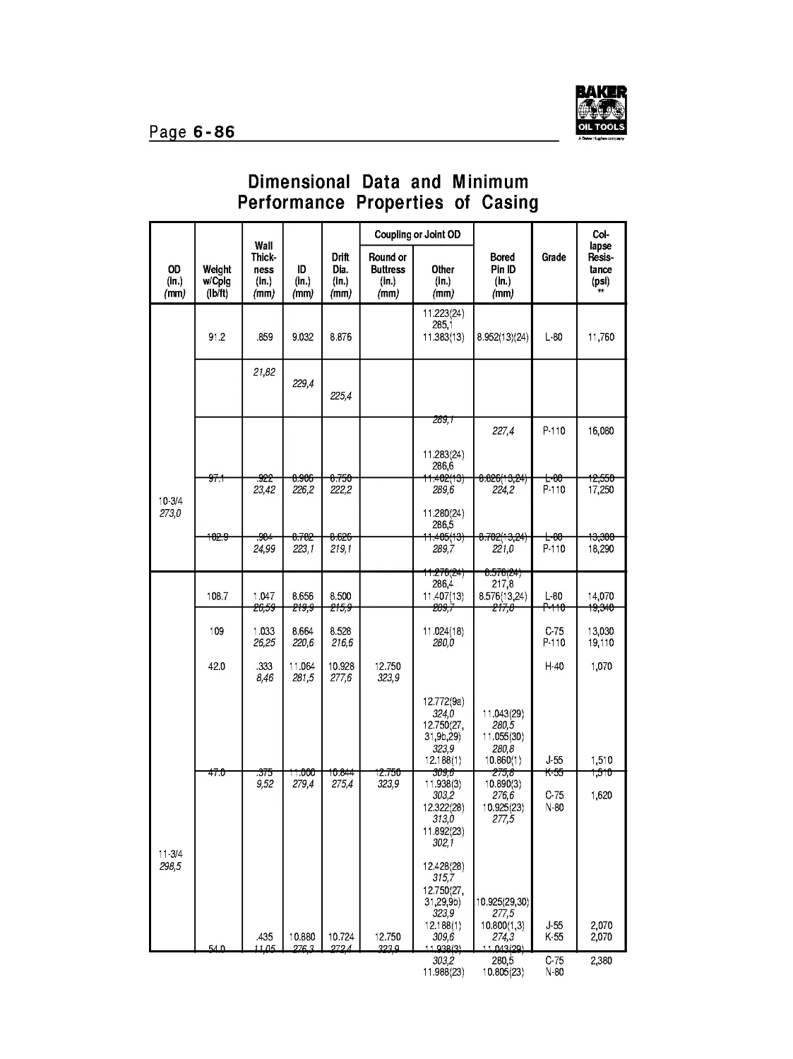
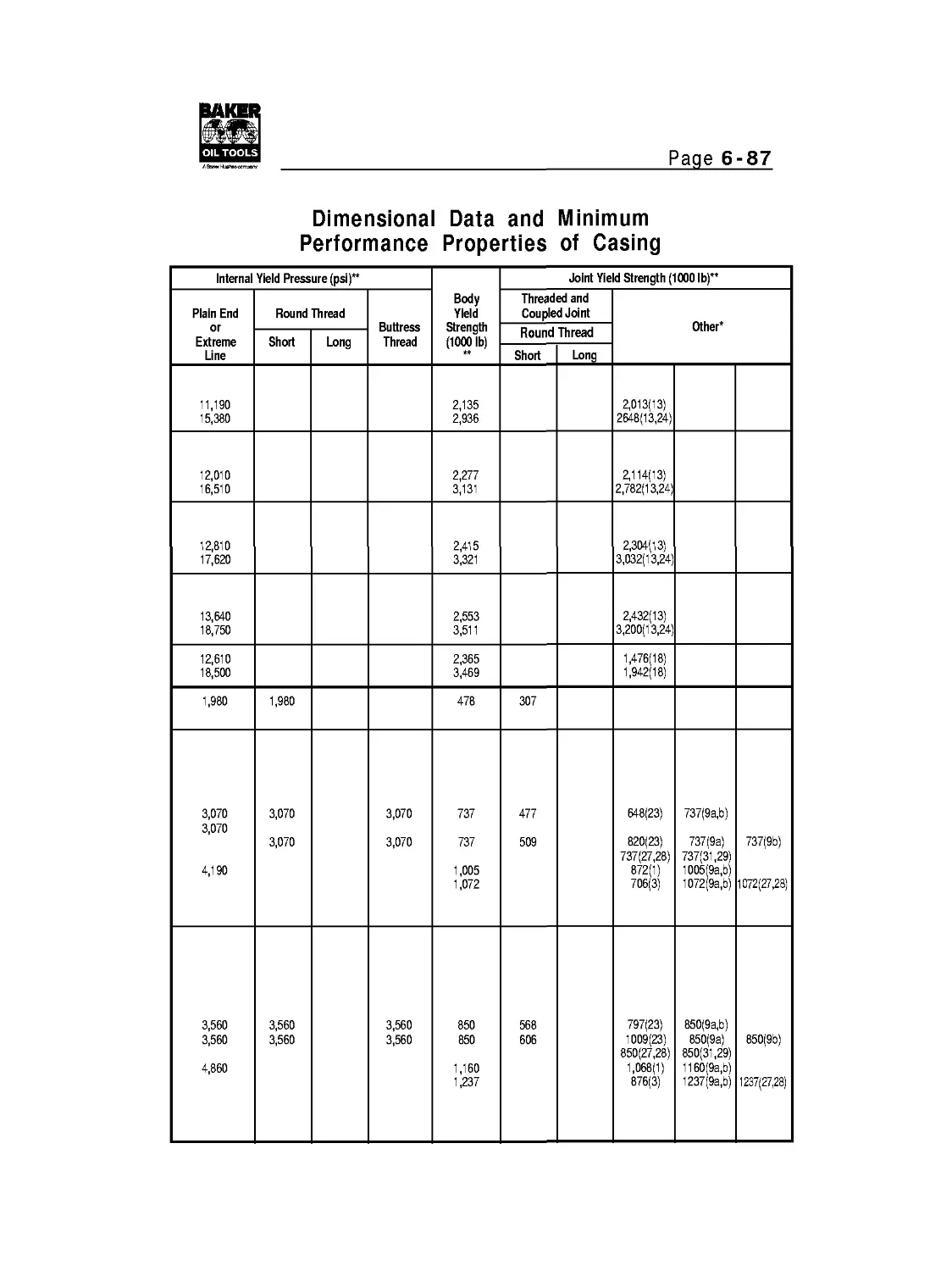
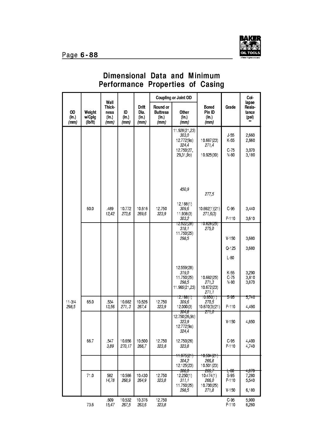
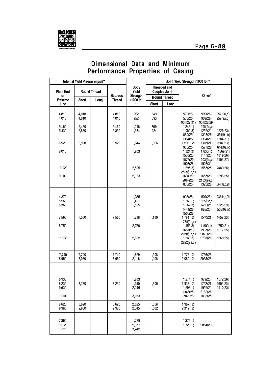
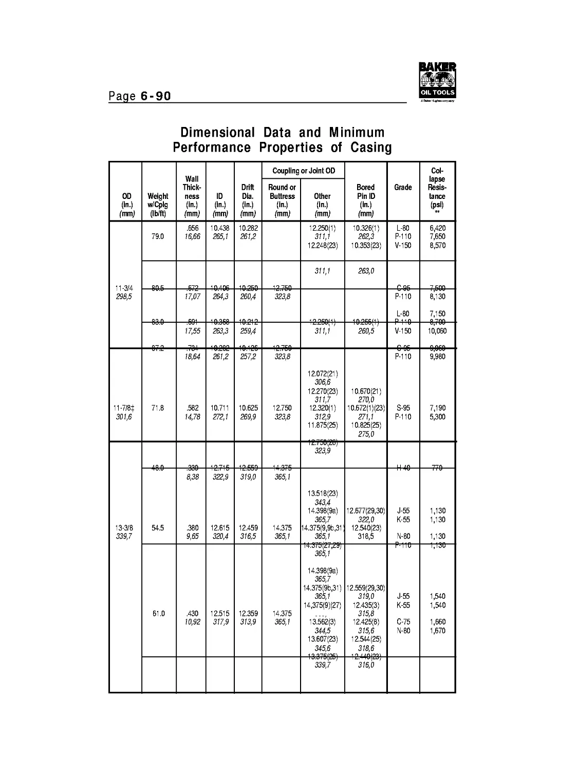
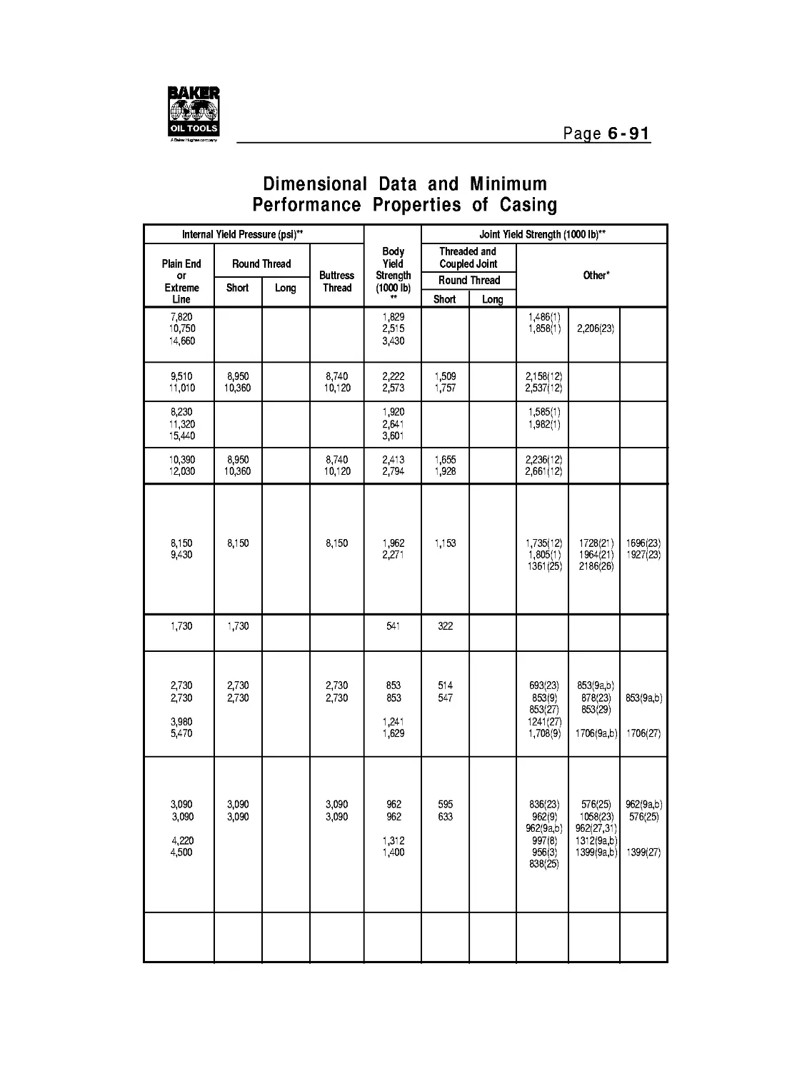
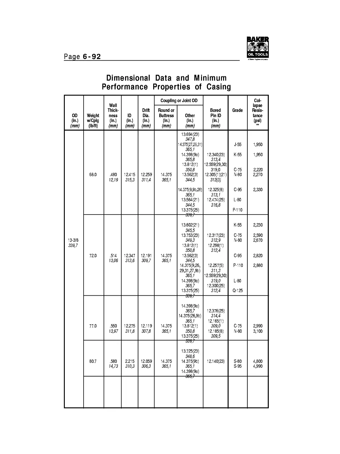
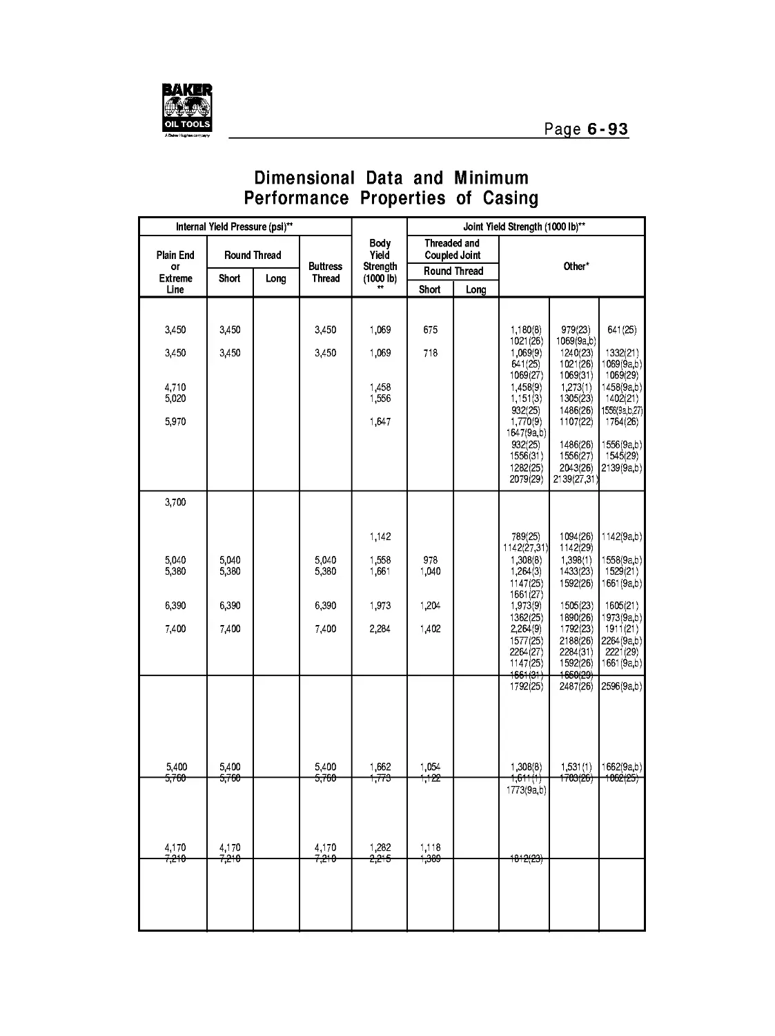
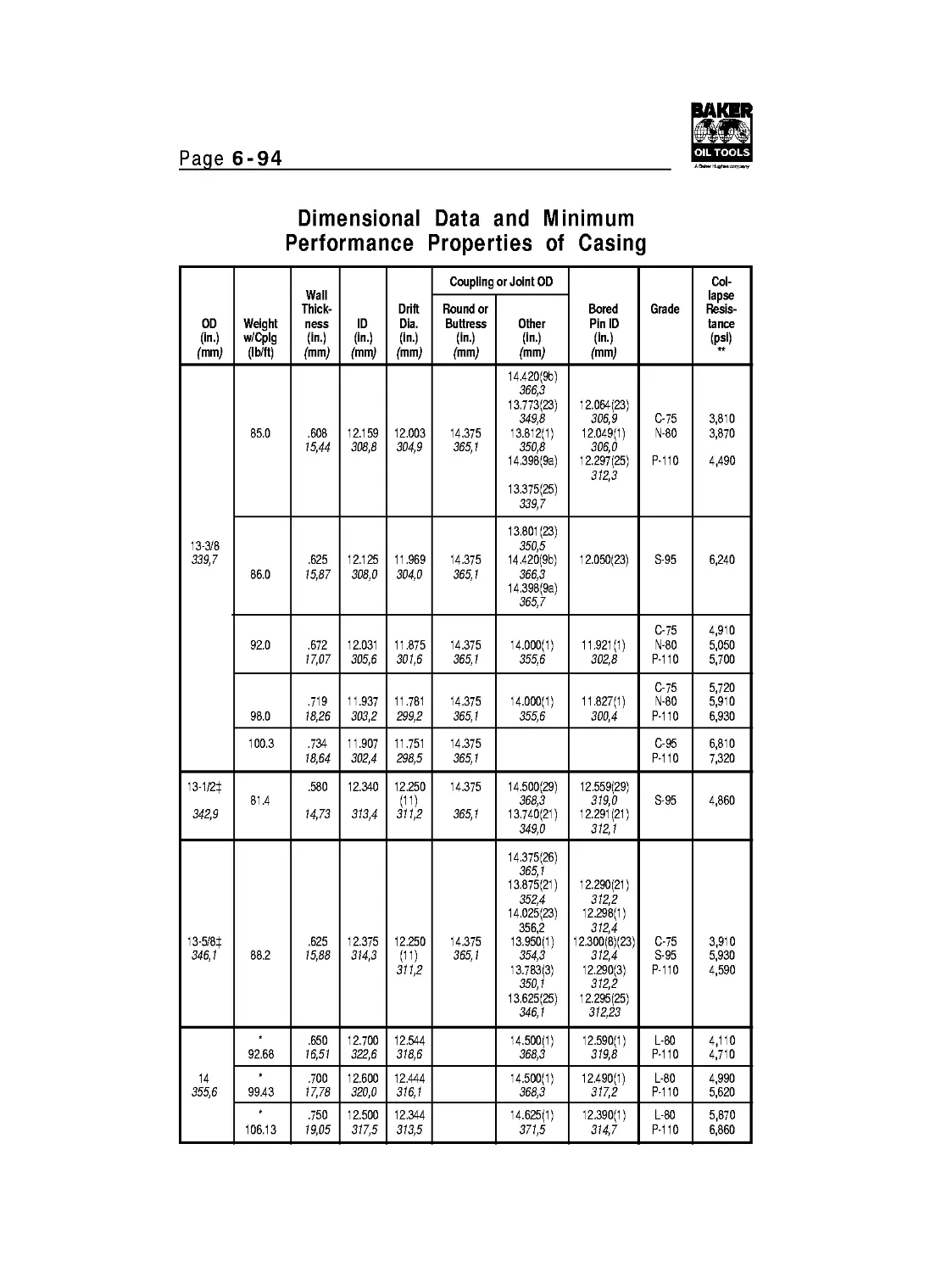
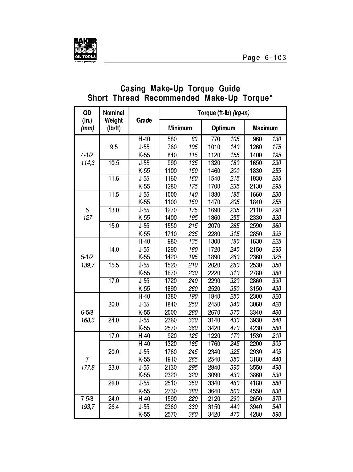
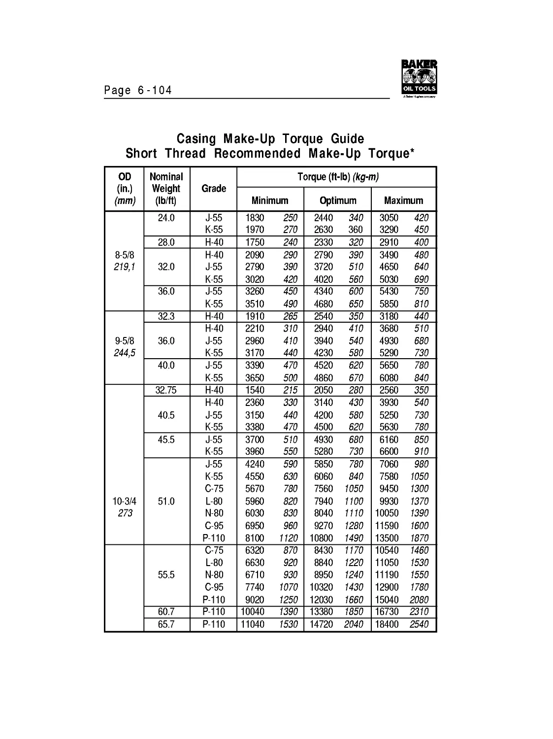
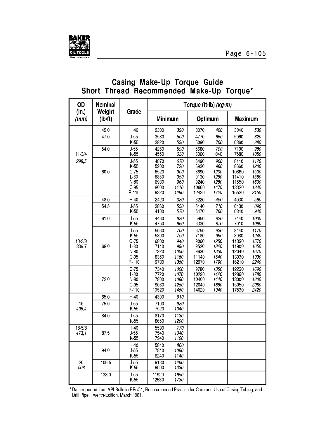
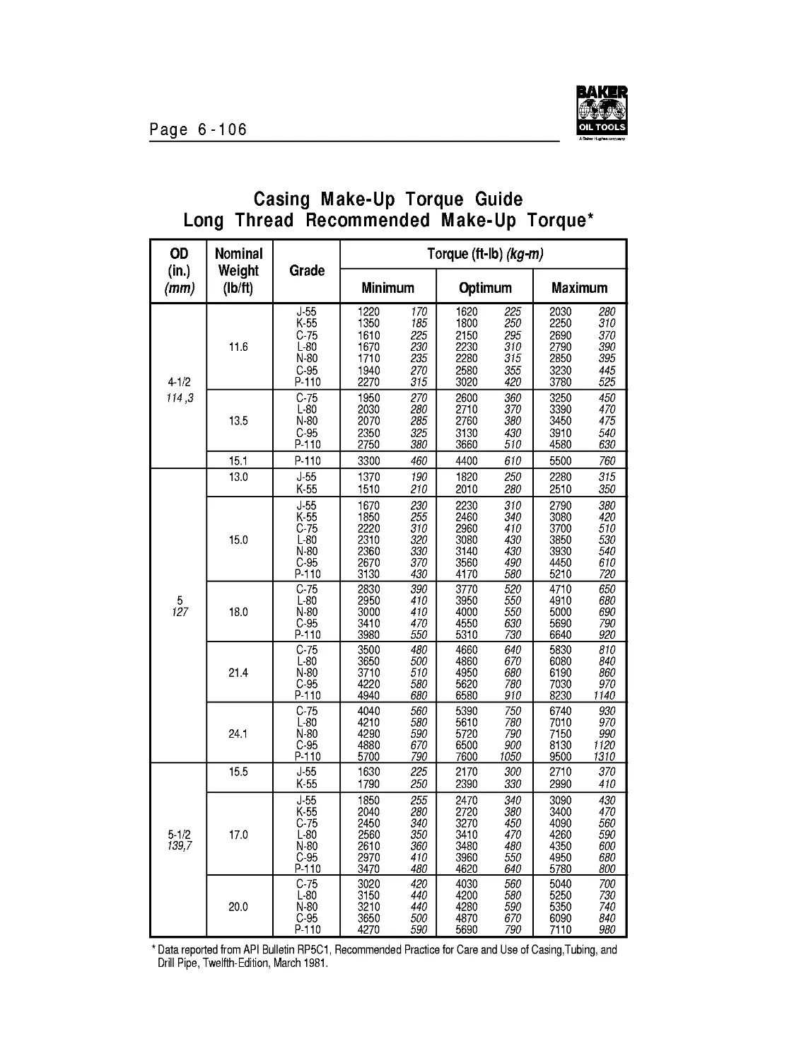
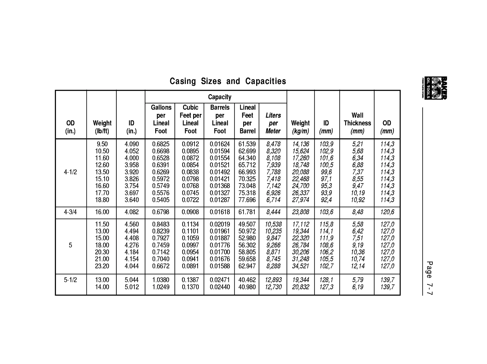
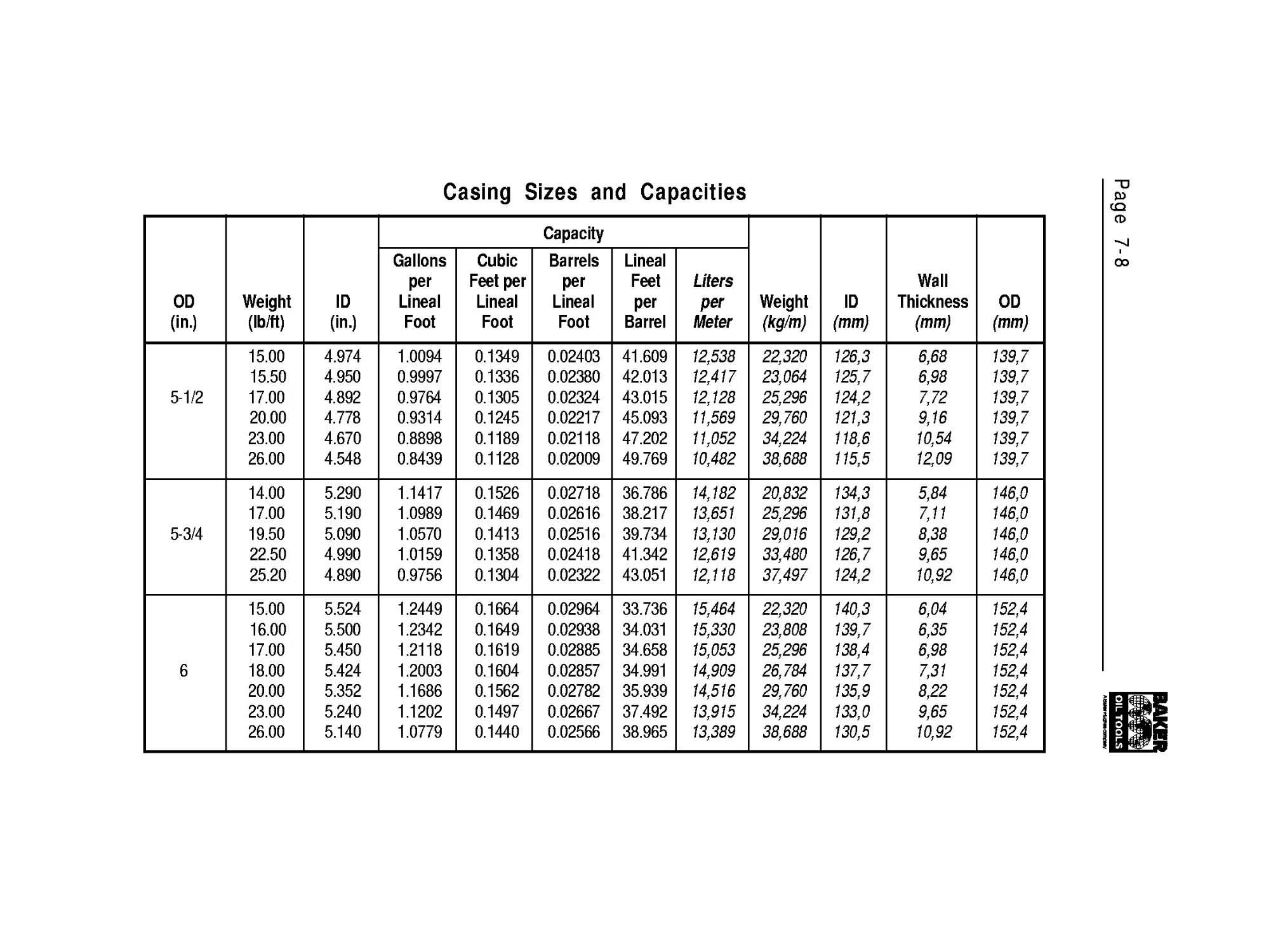
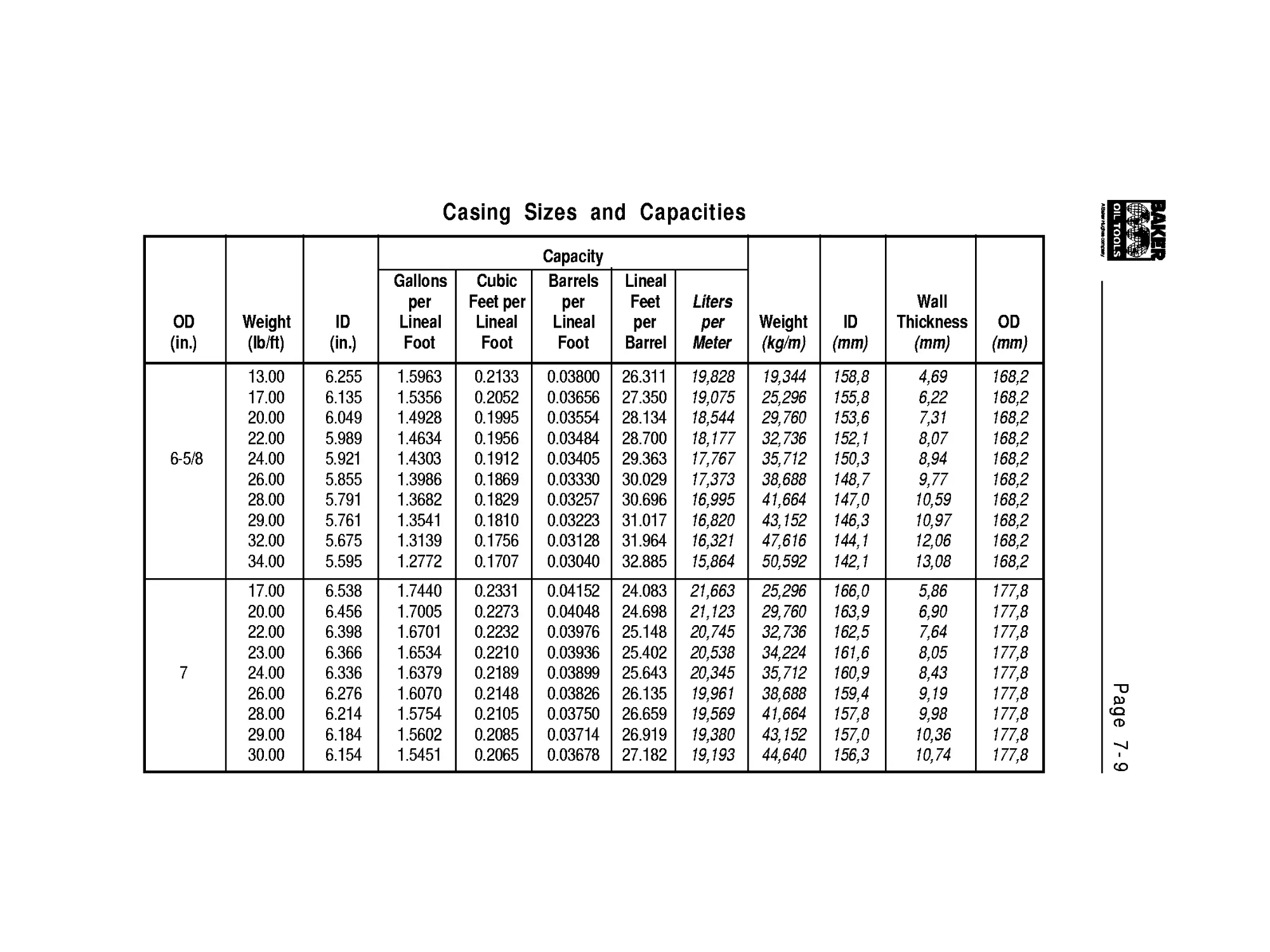
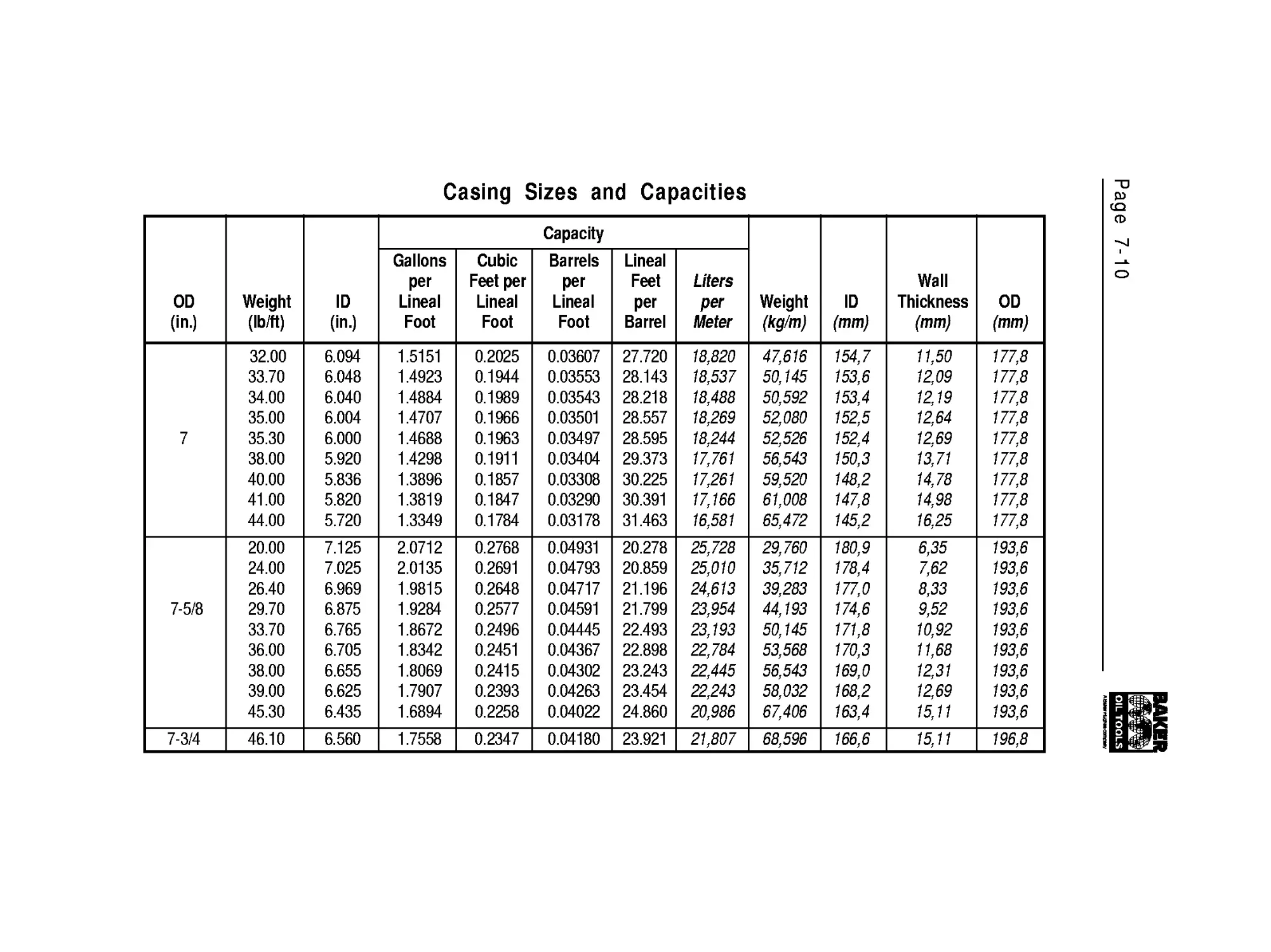
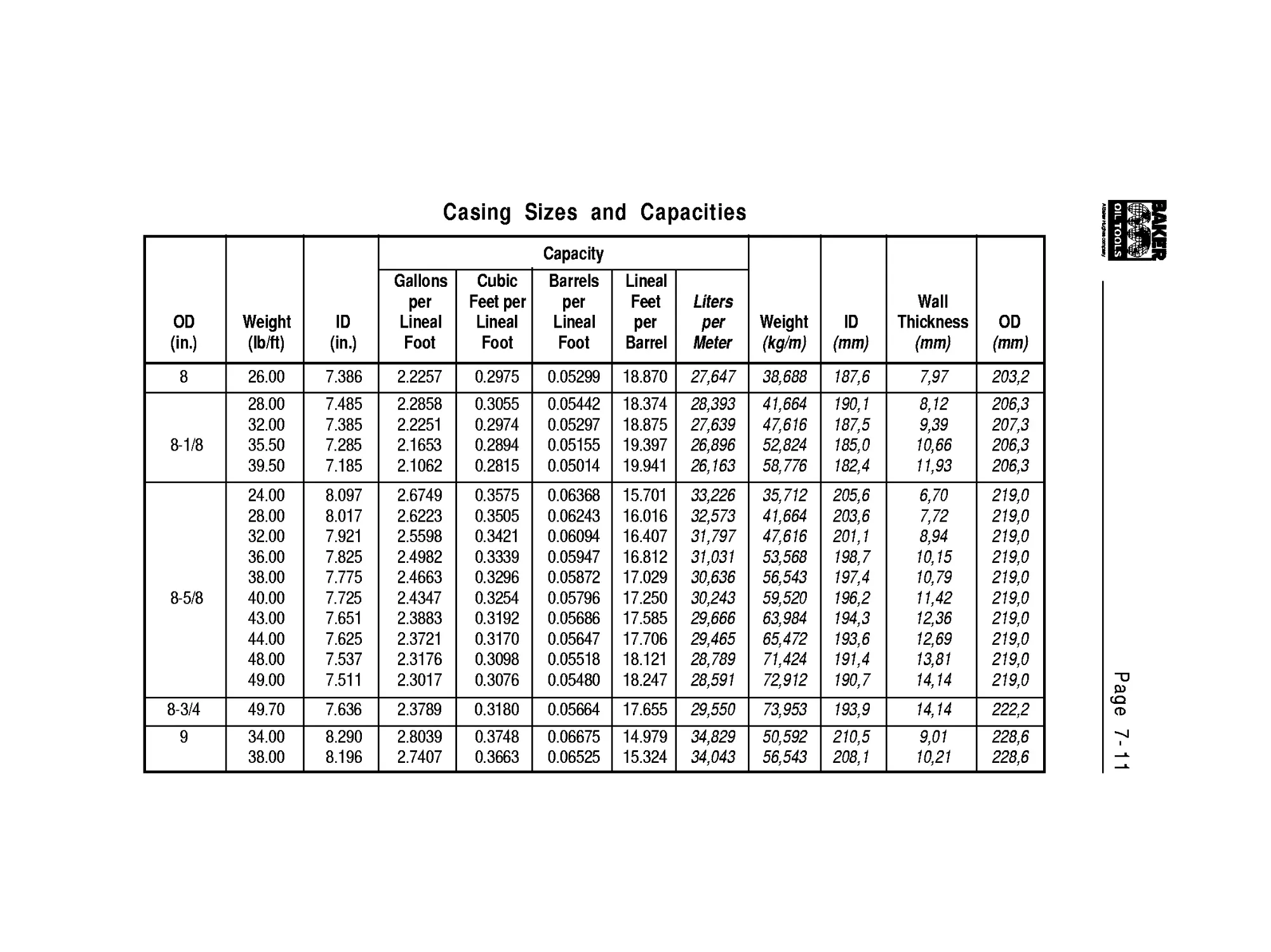
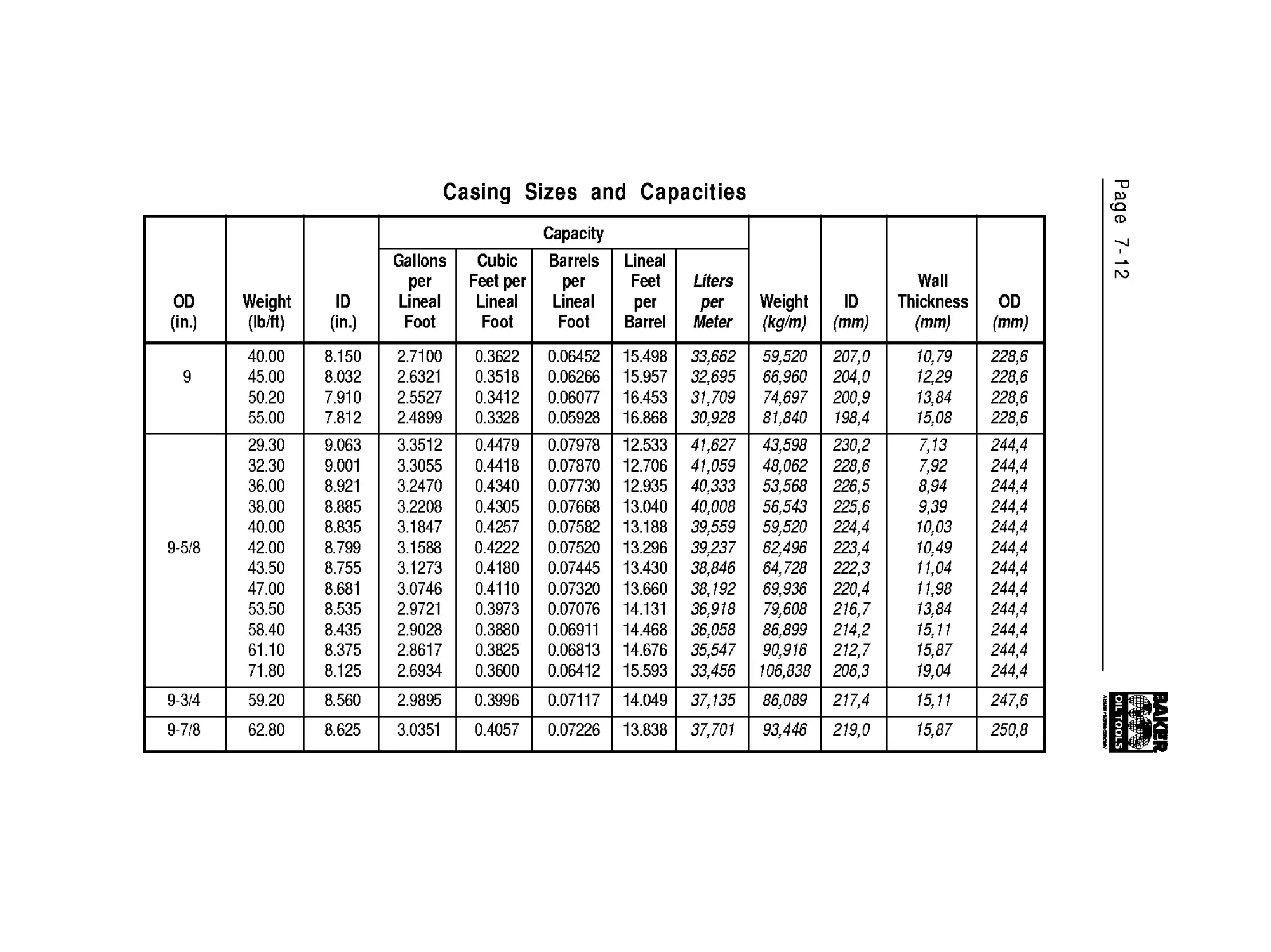
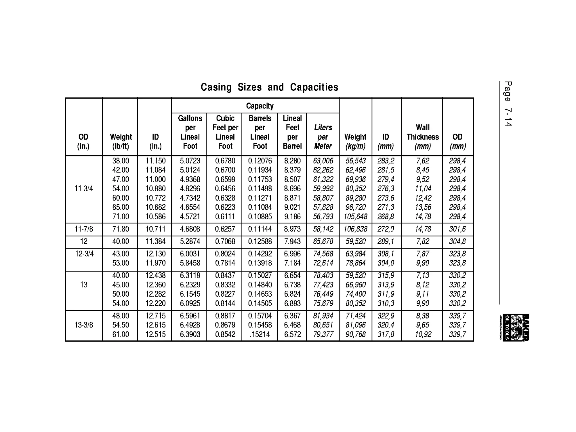
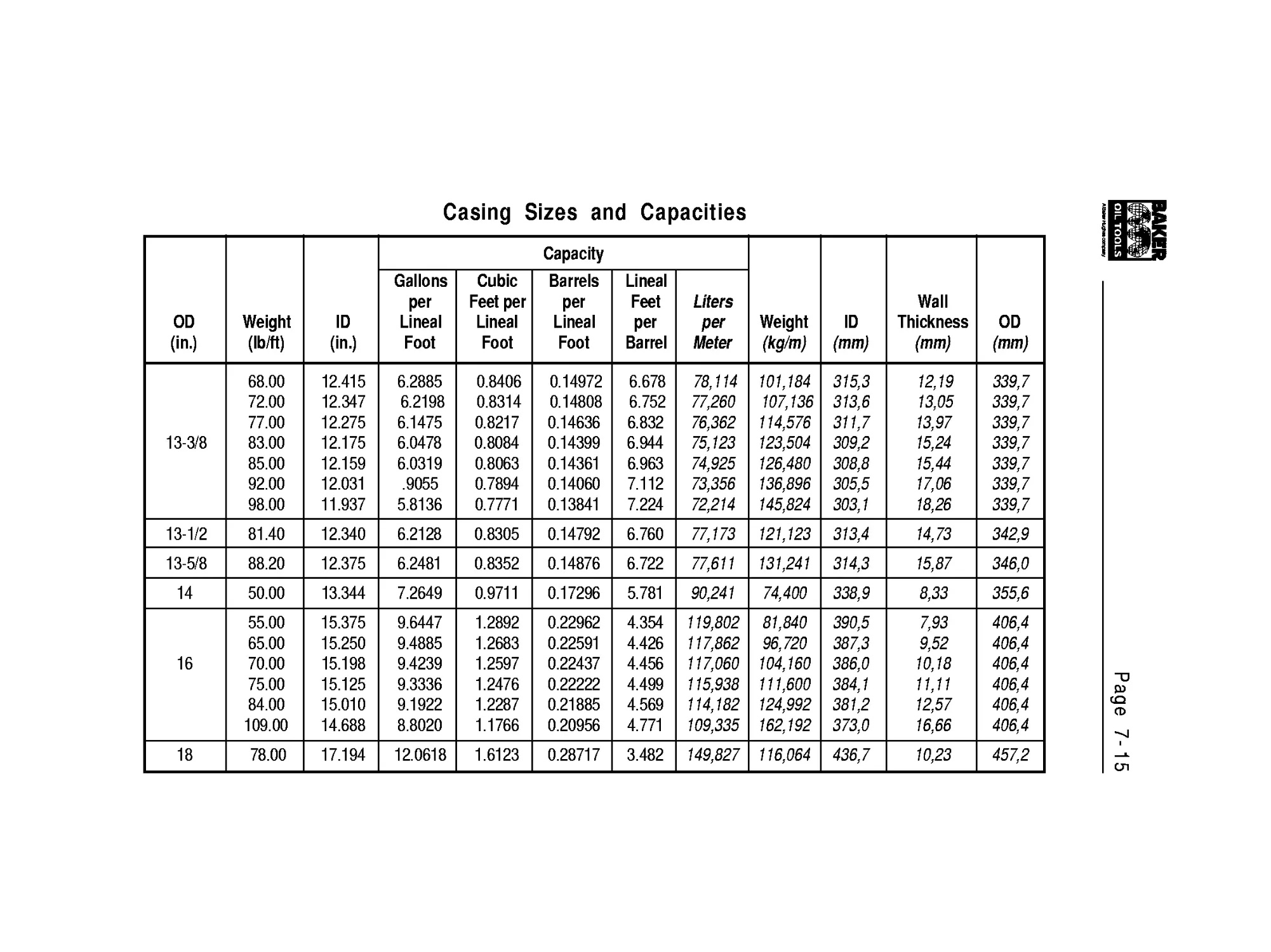
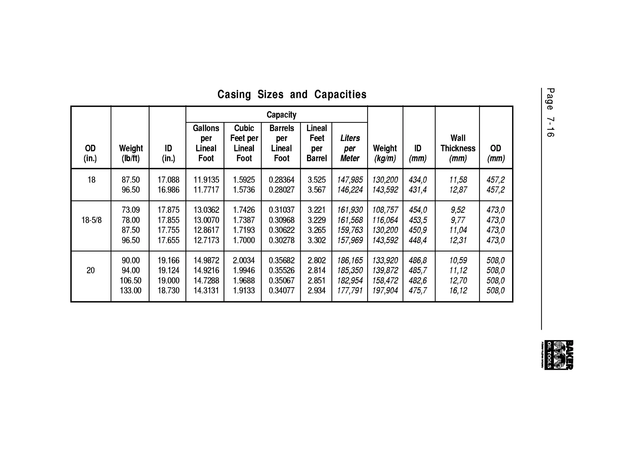
Casing
Data
Data
Data
Capacity
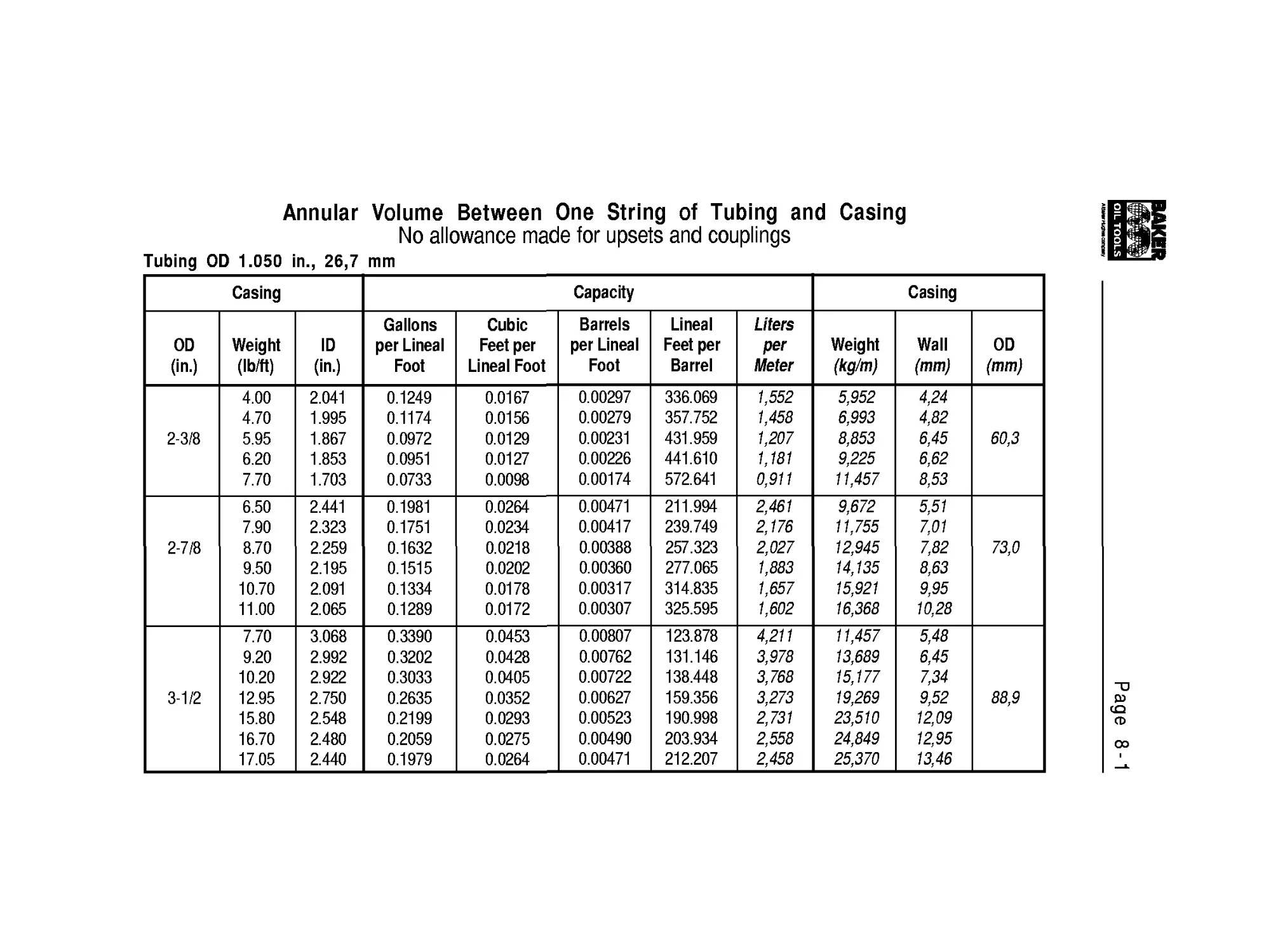
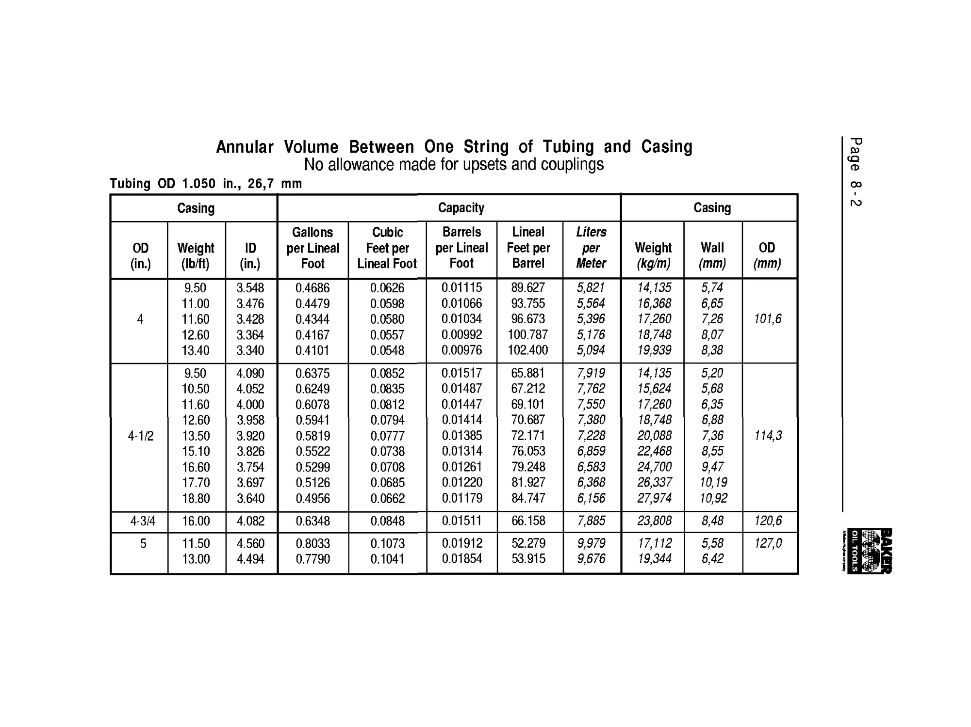
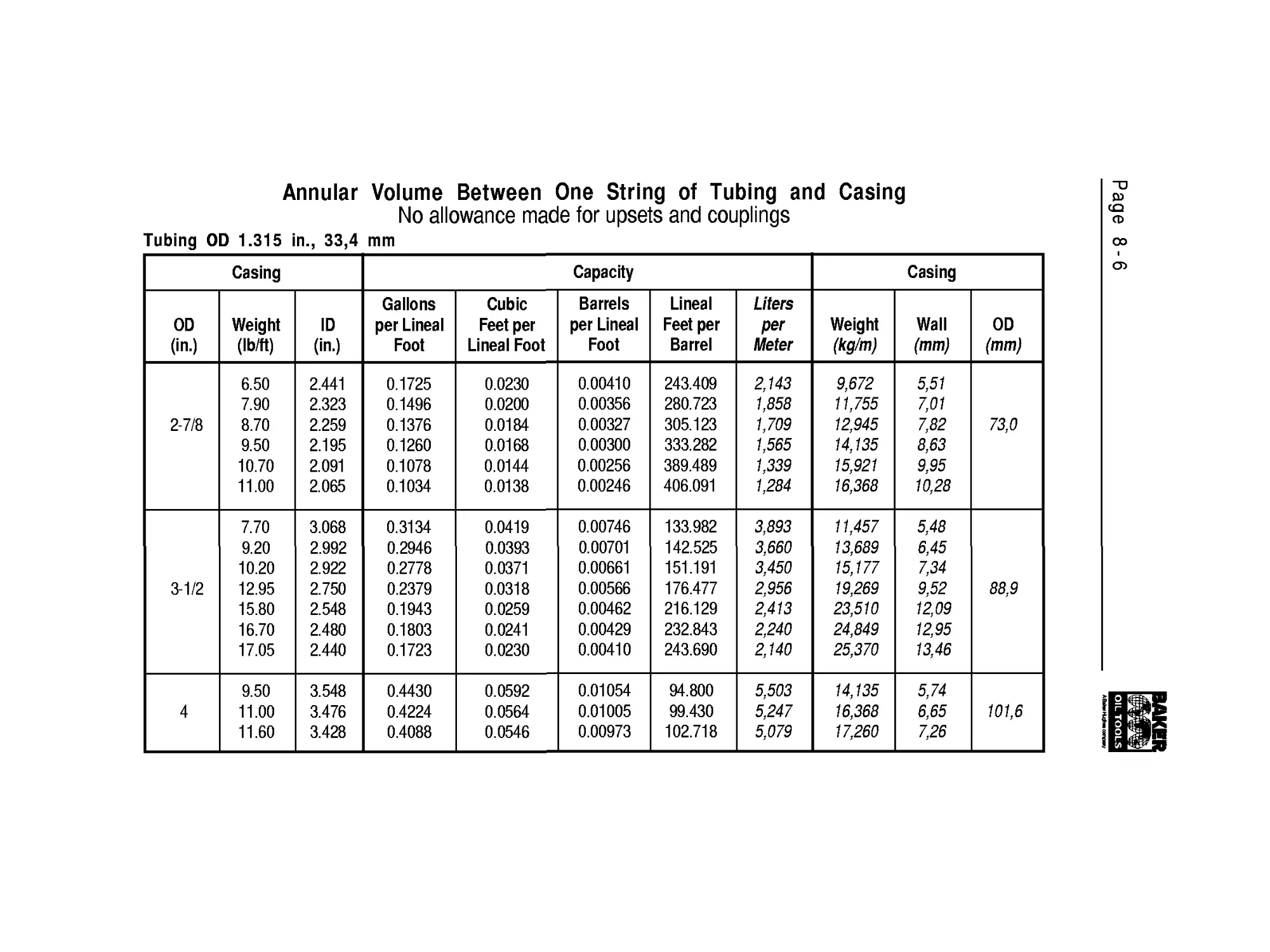
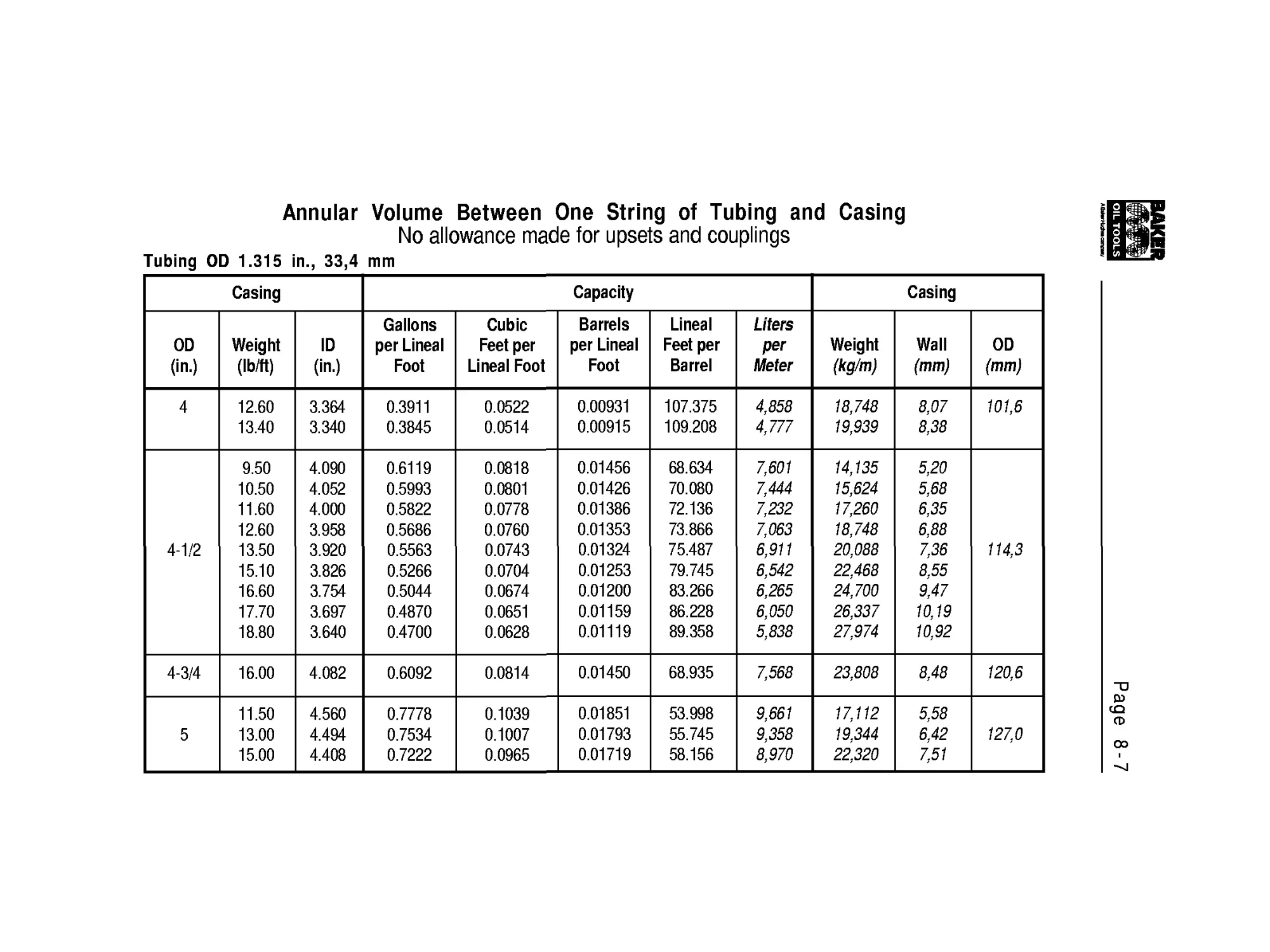
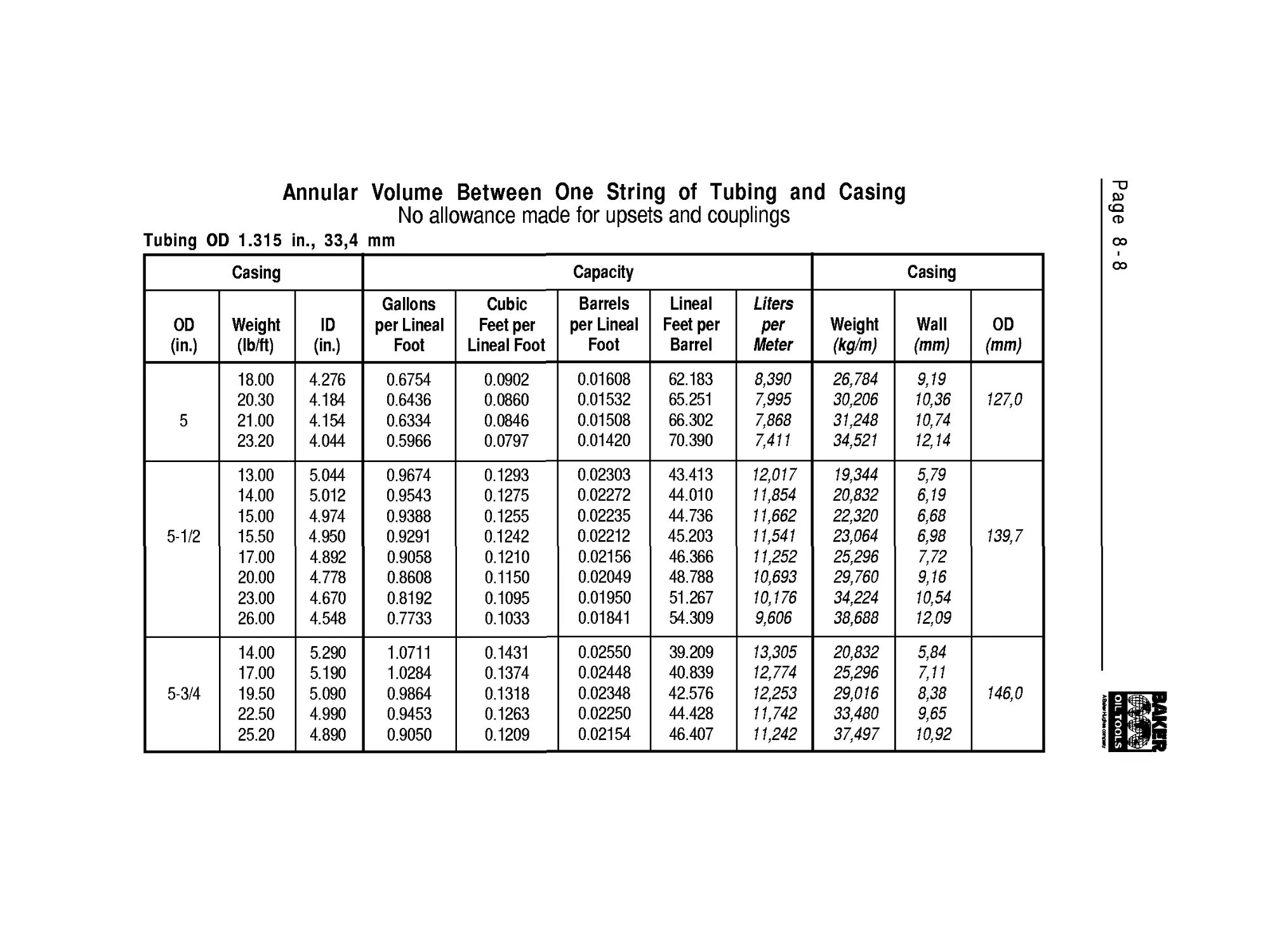
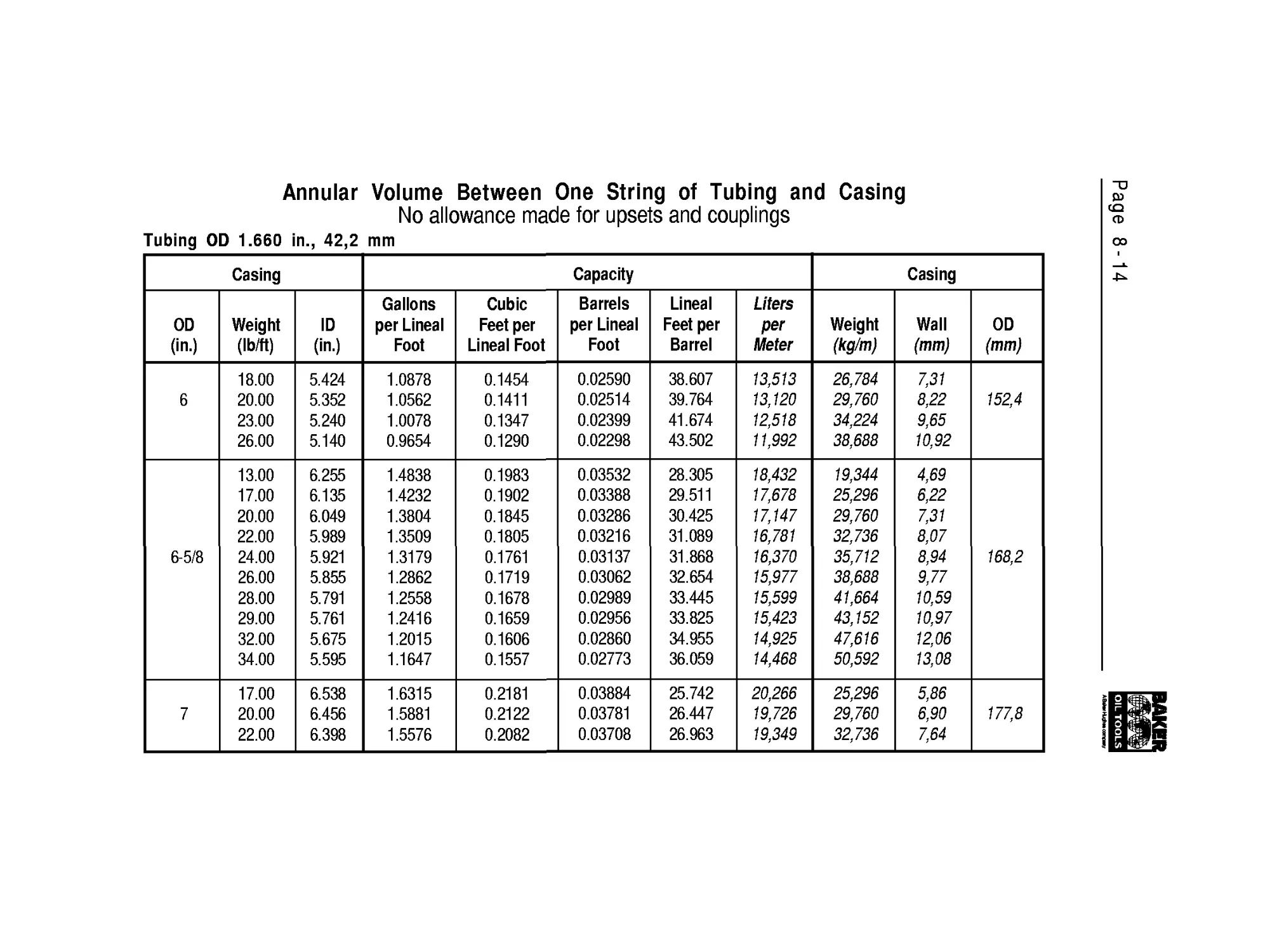
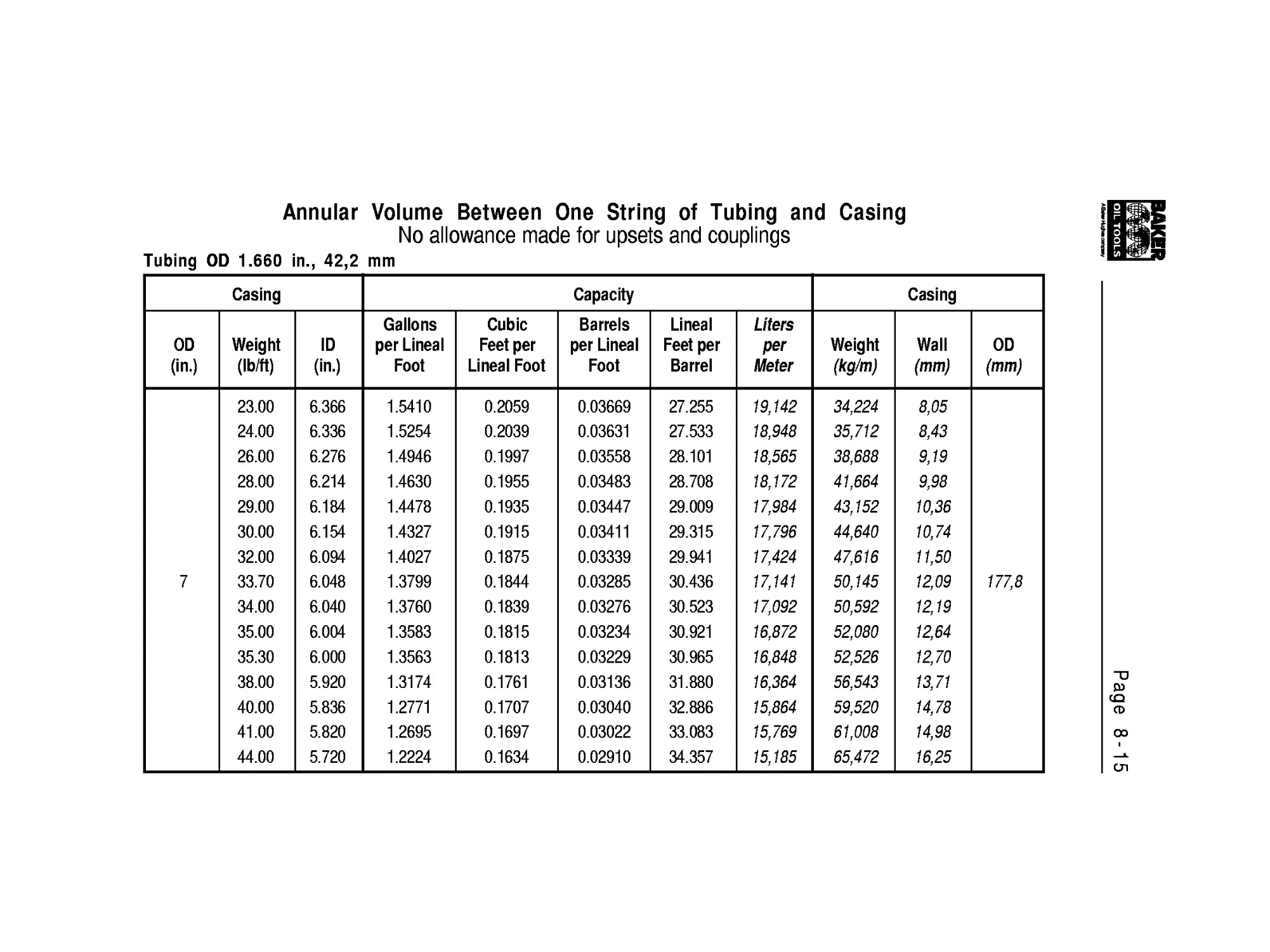
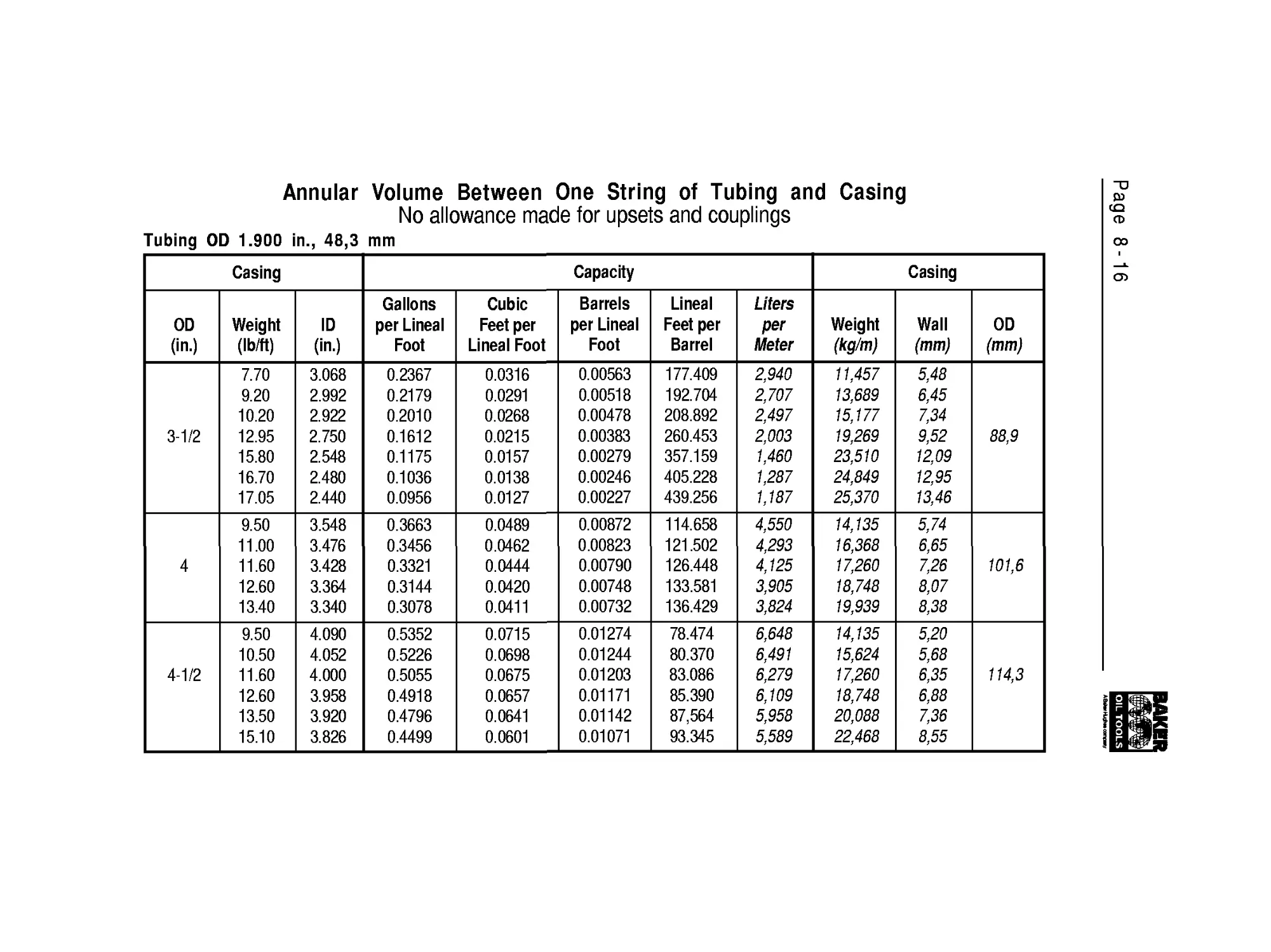
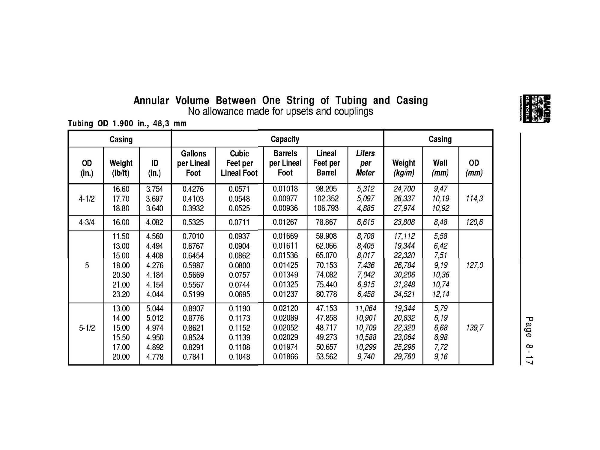
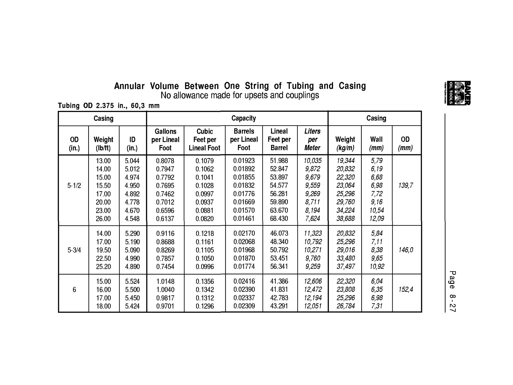
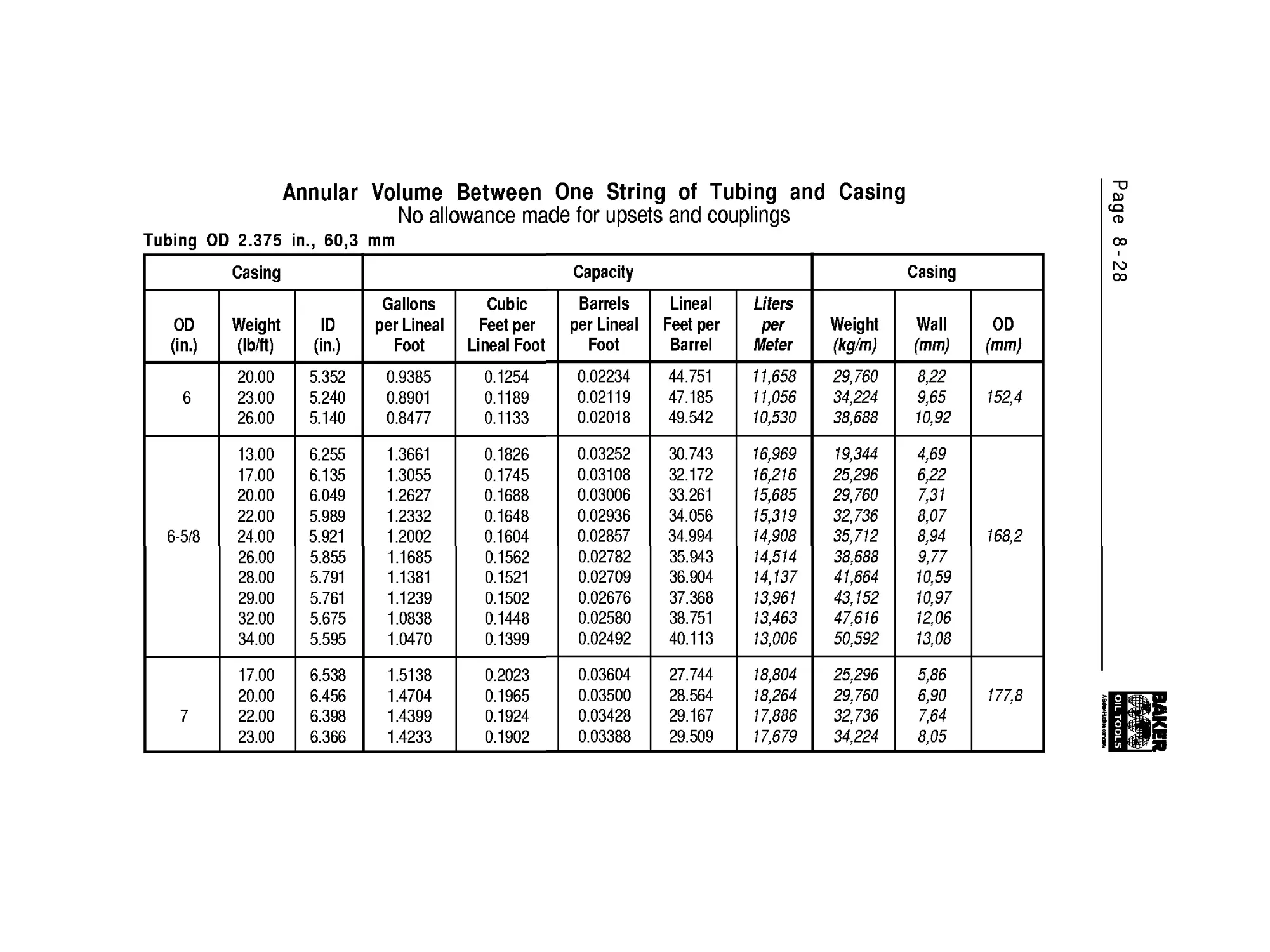
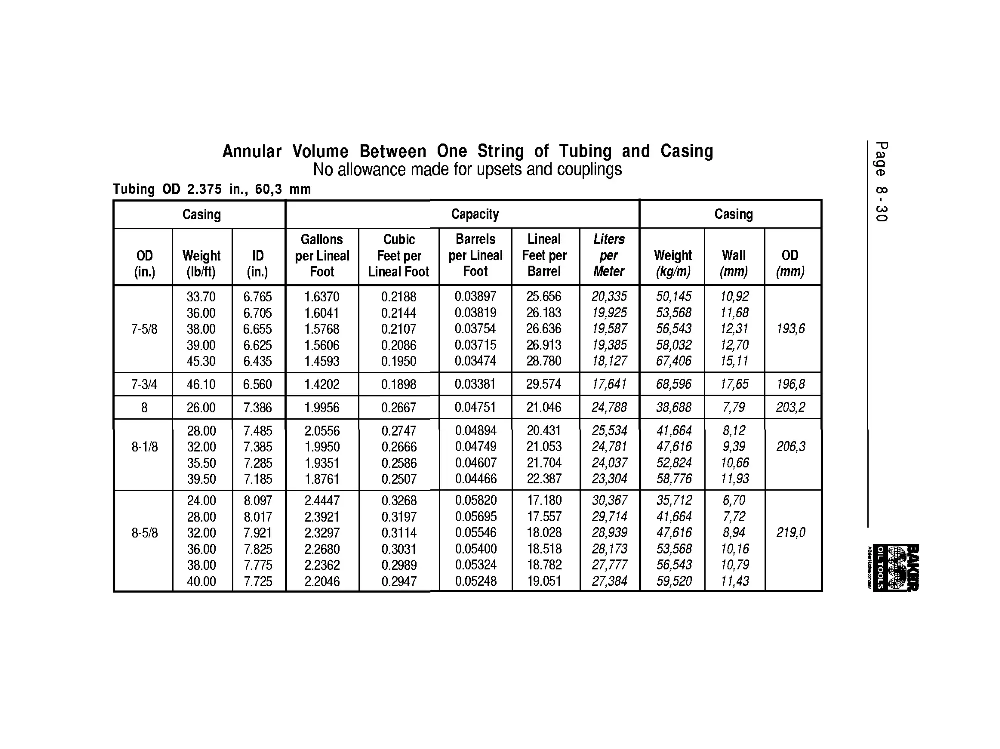
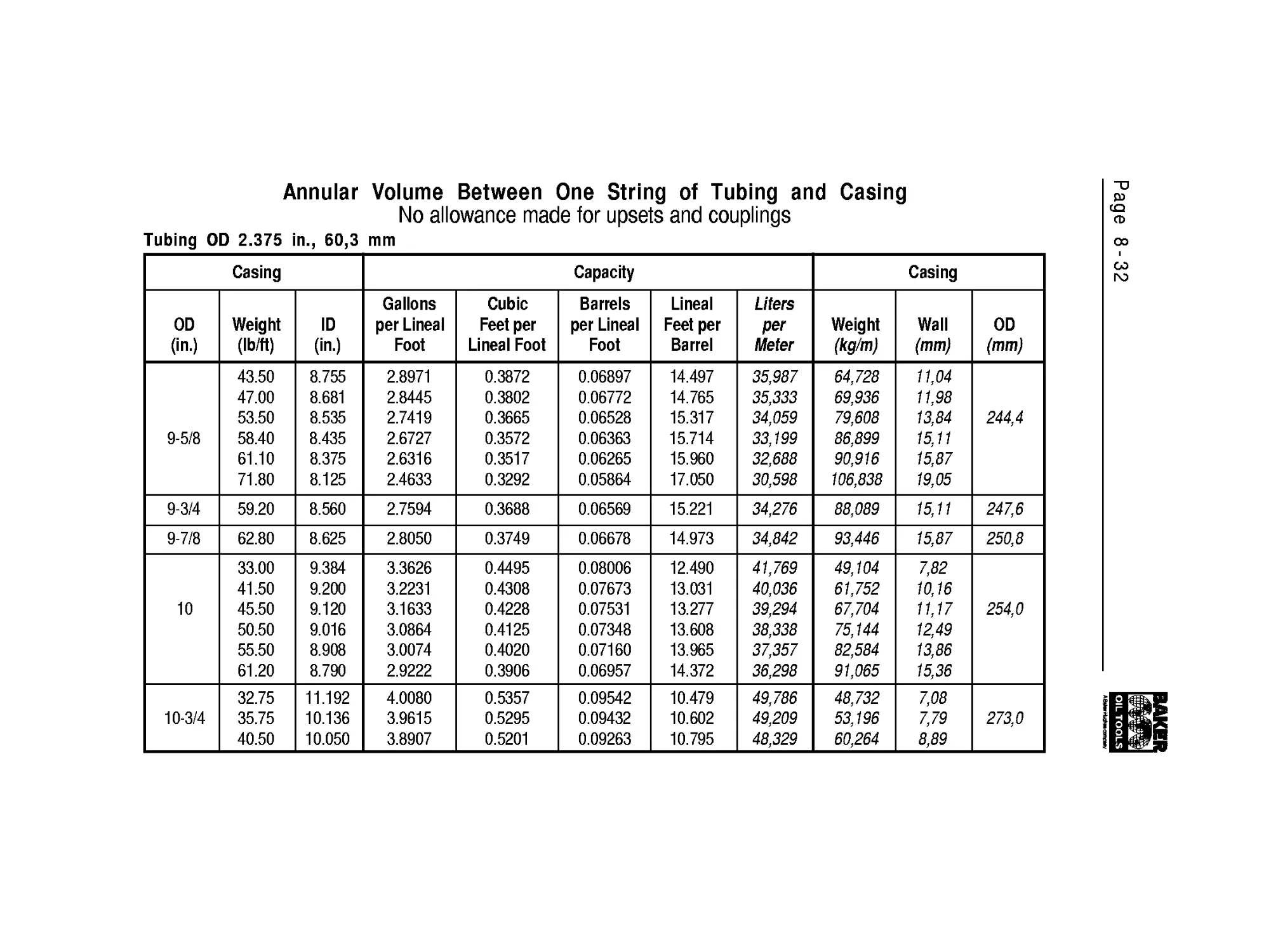
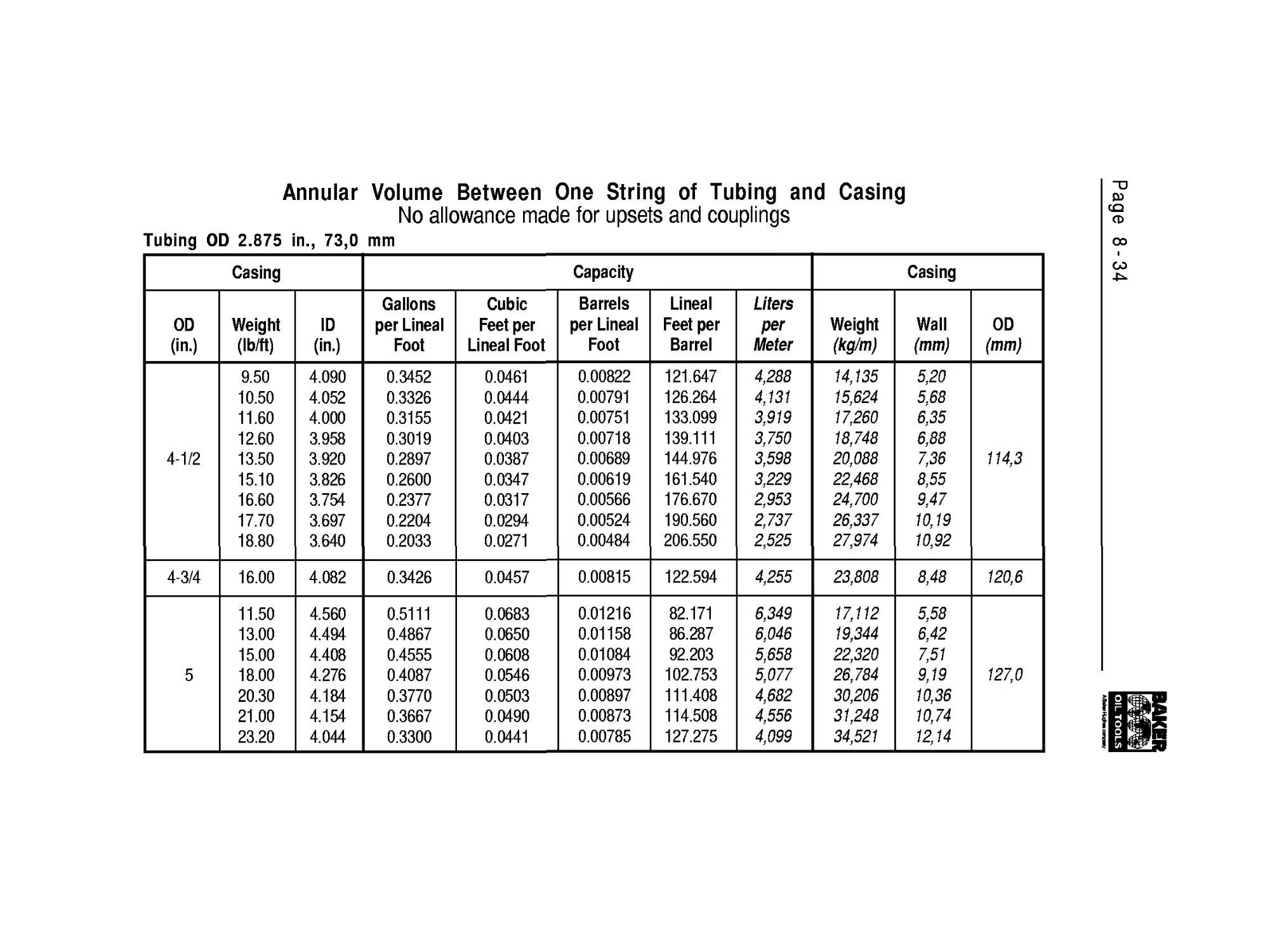
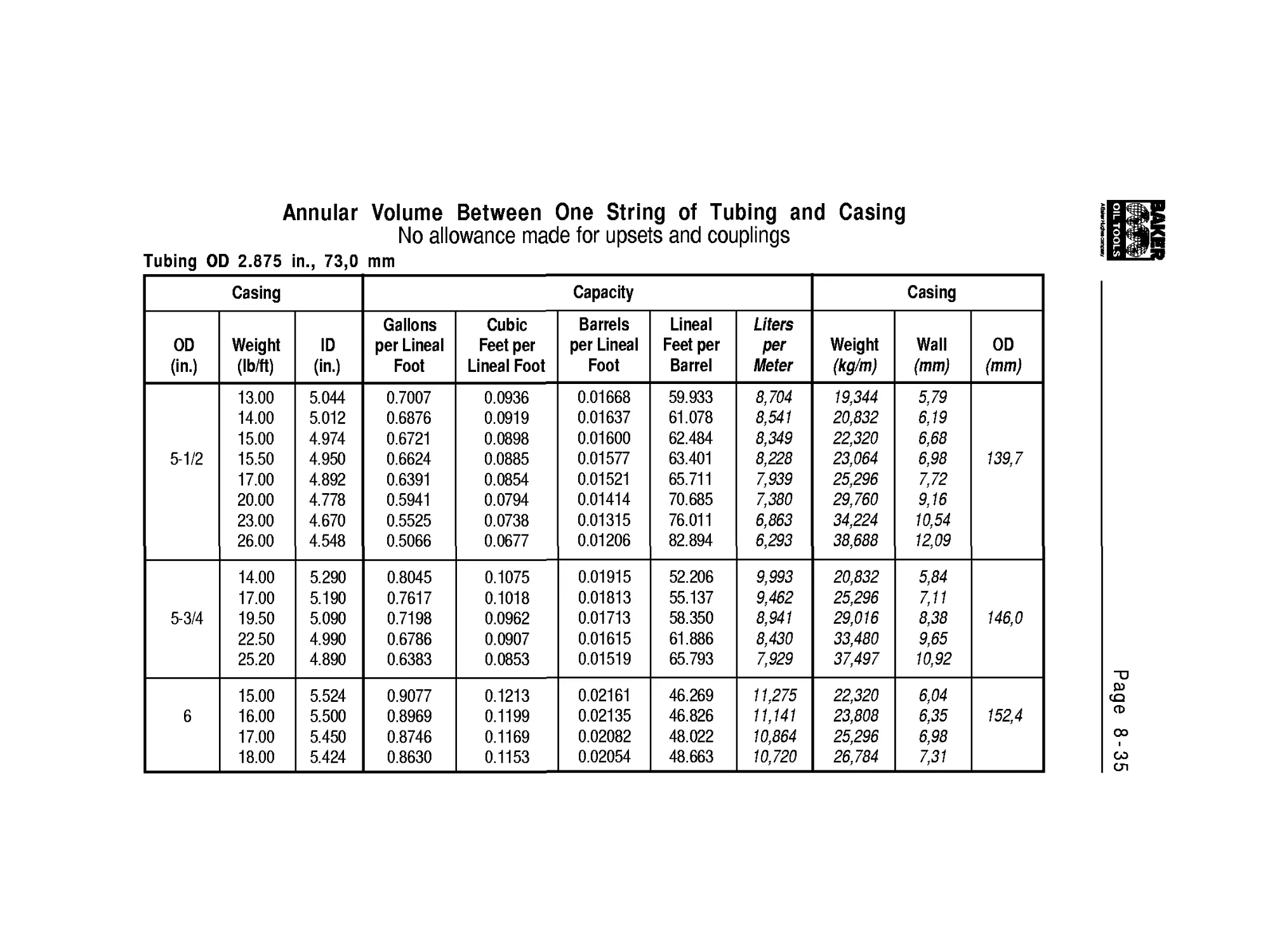
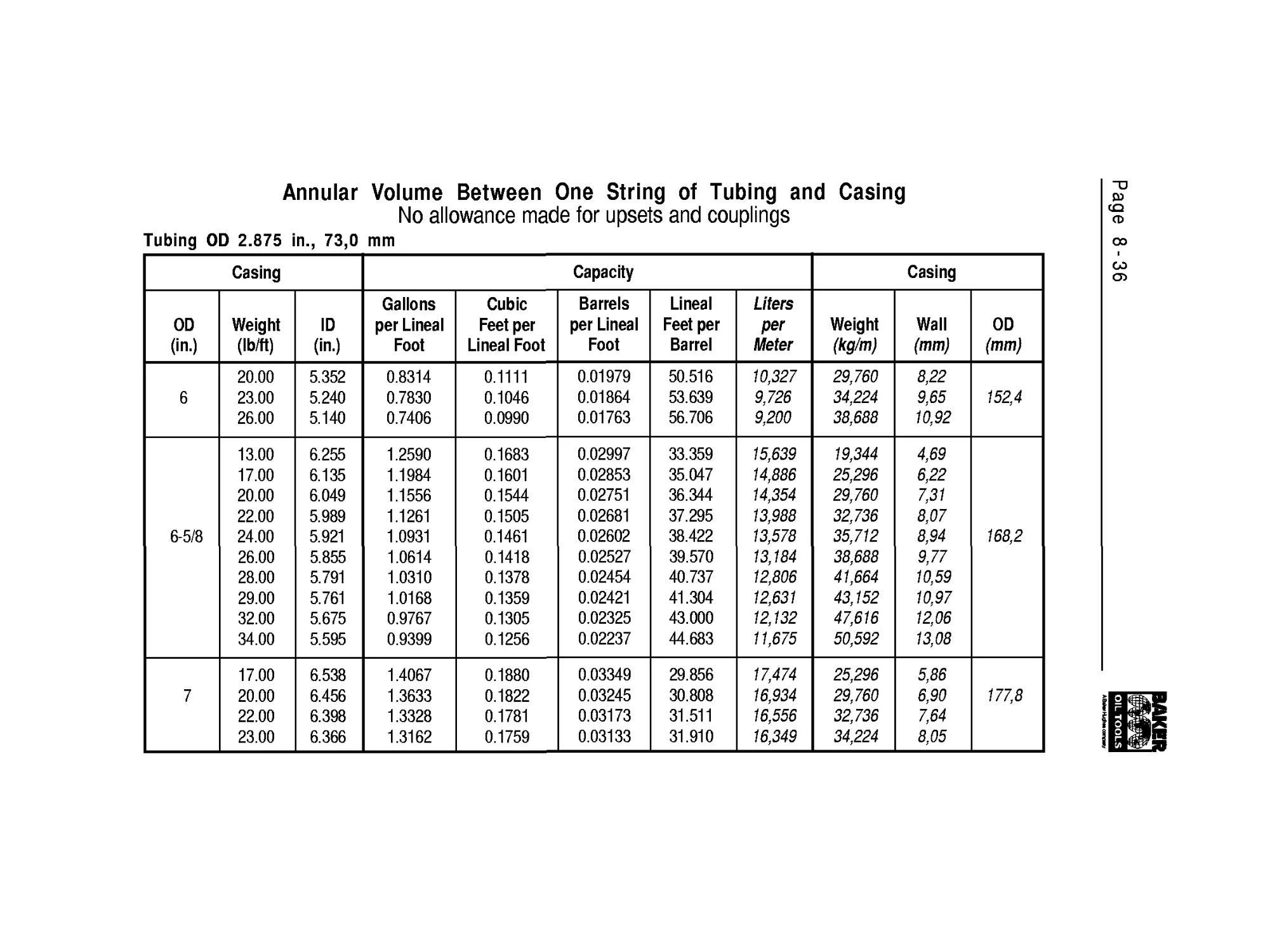
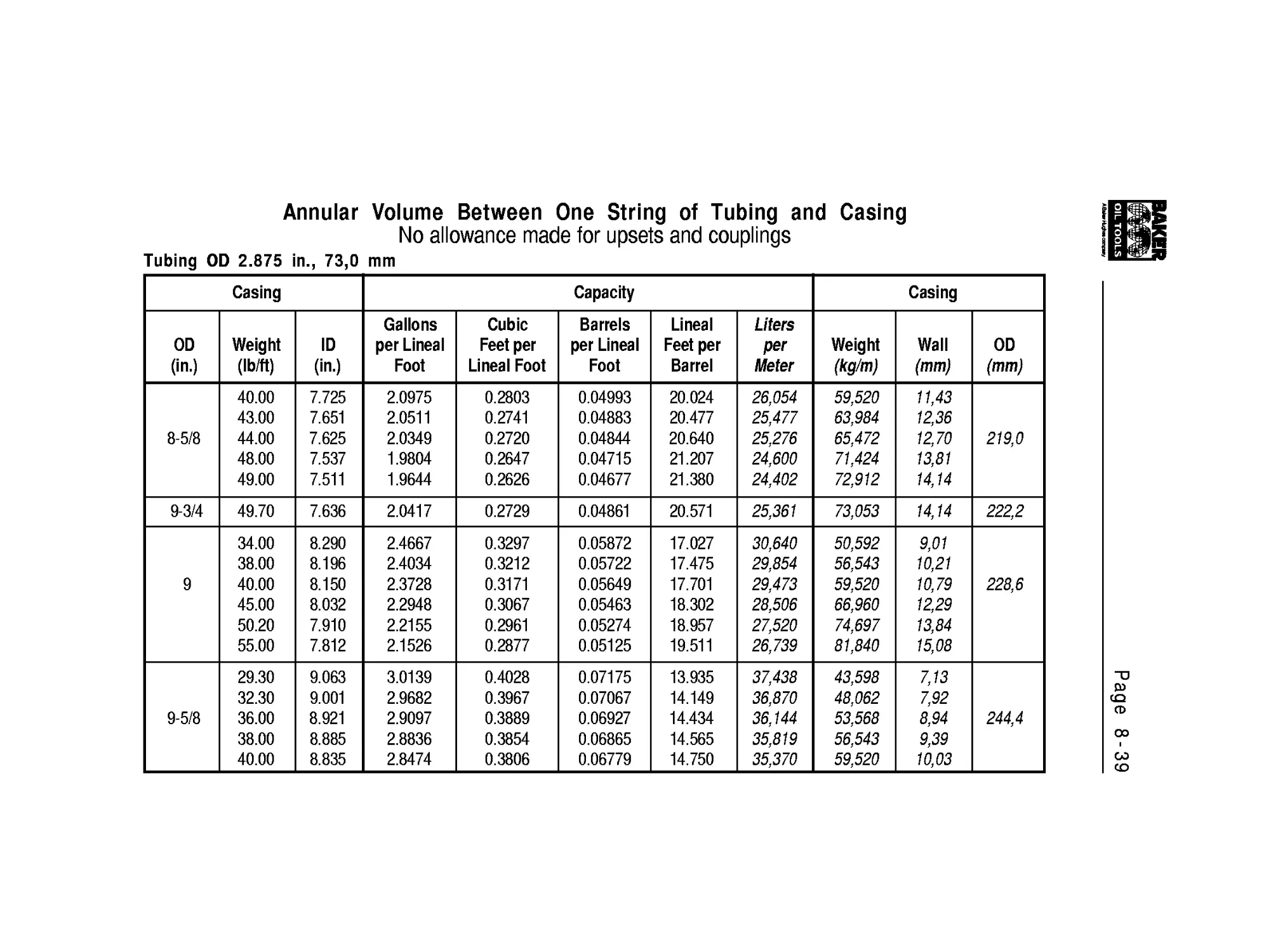
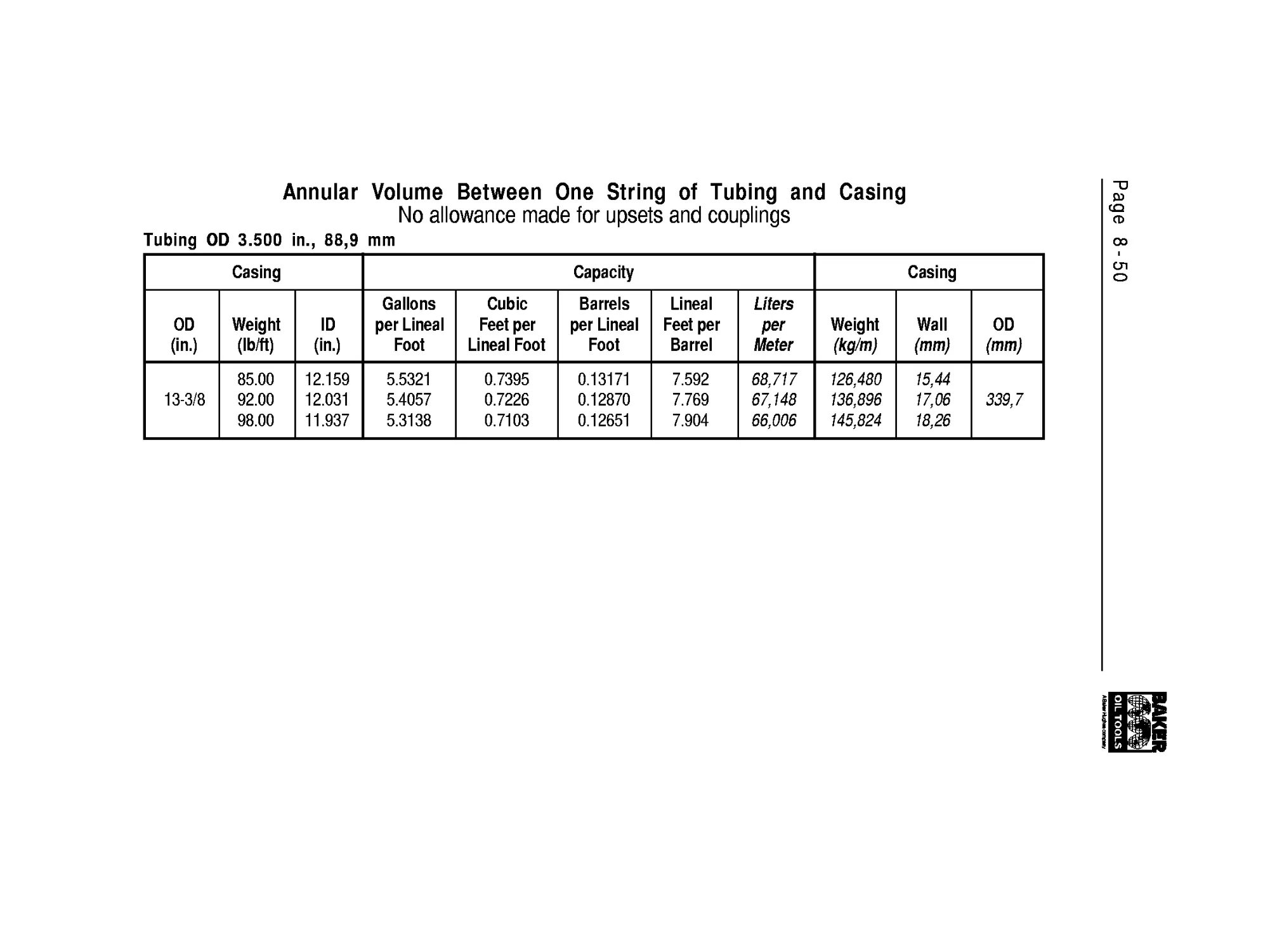
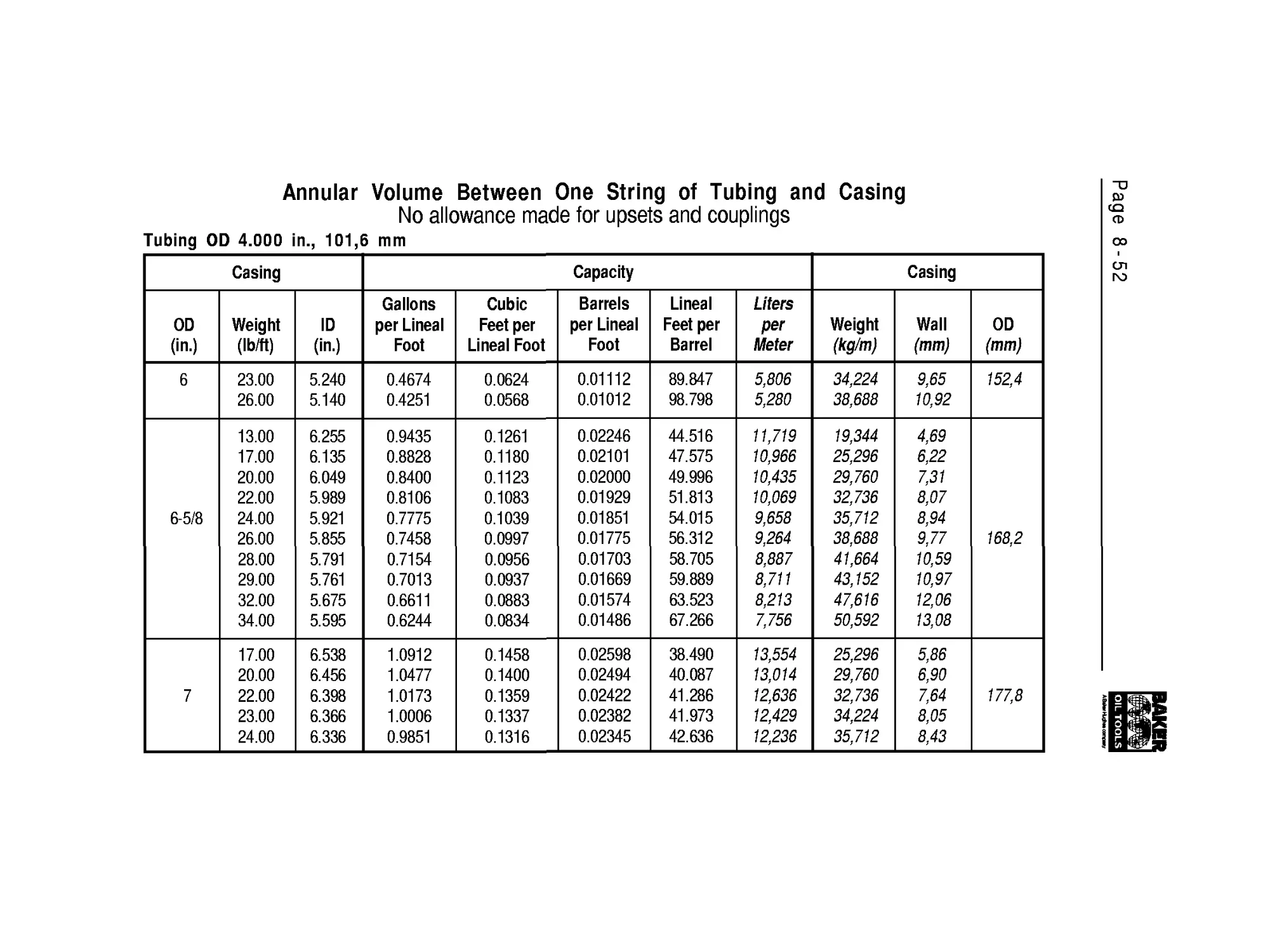
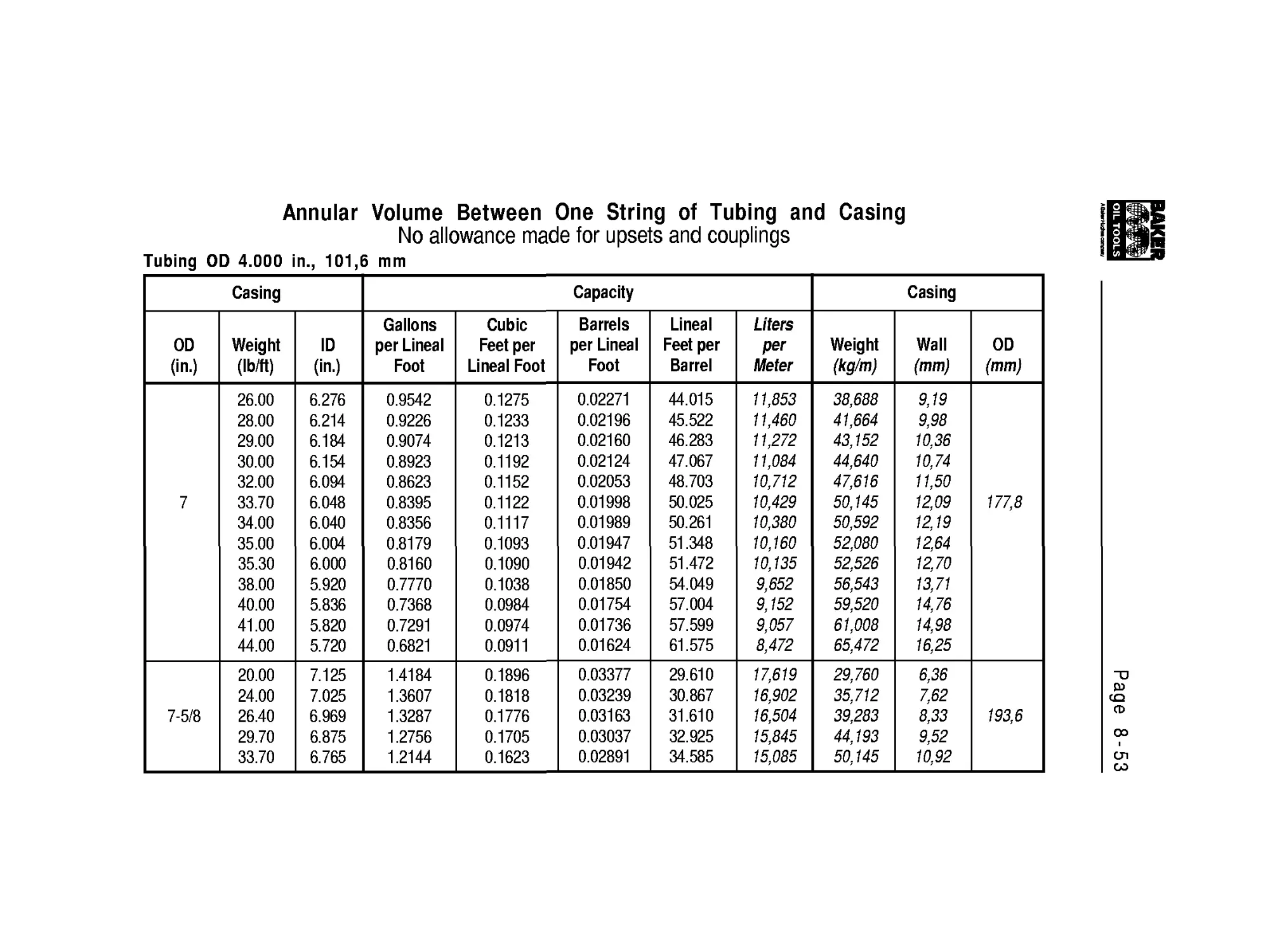
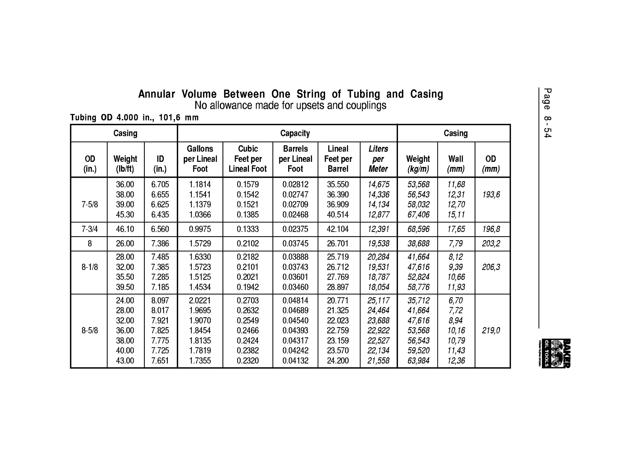
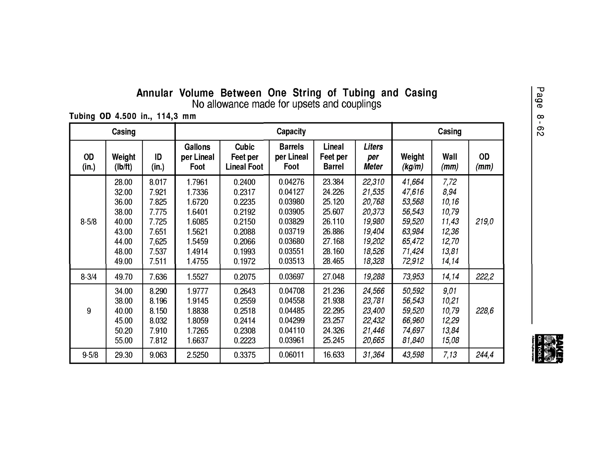
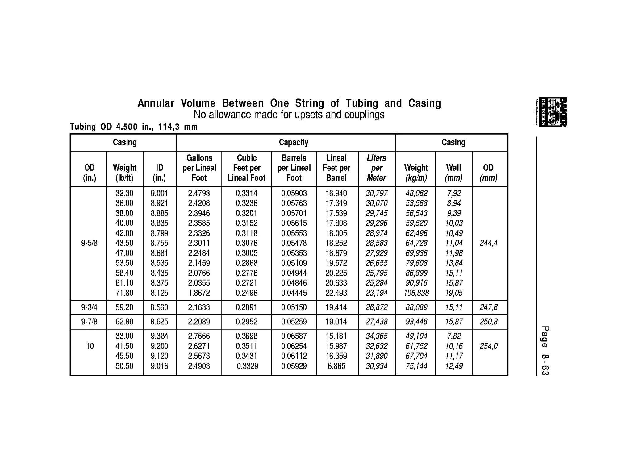
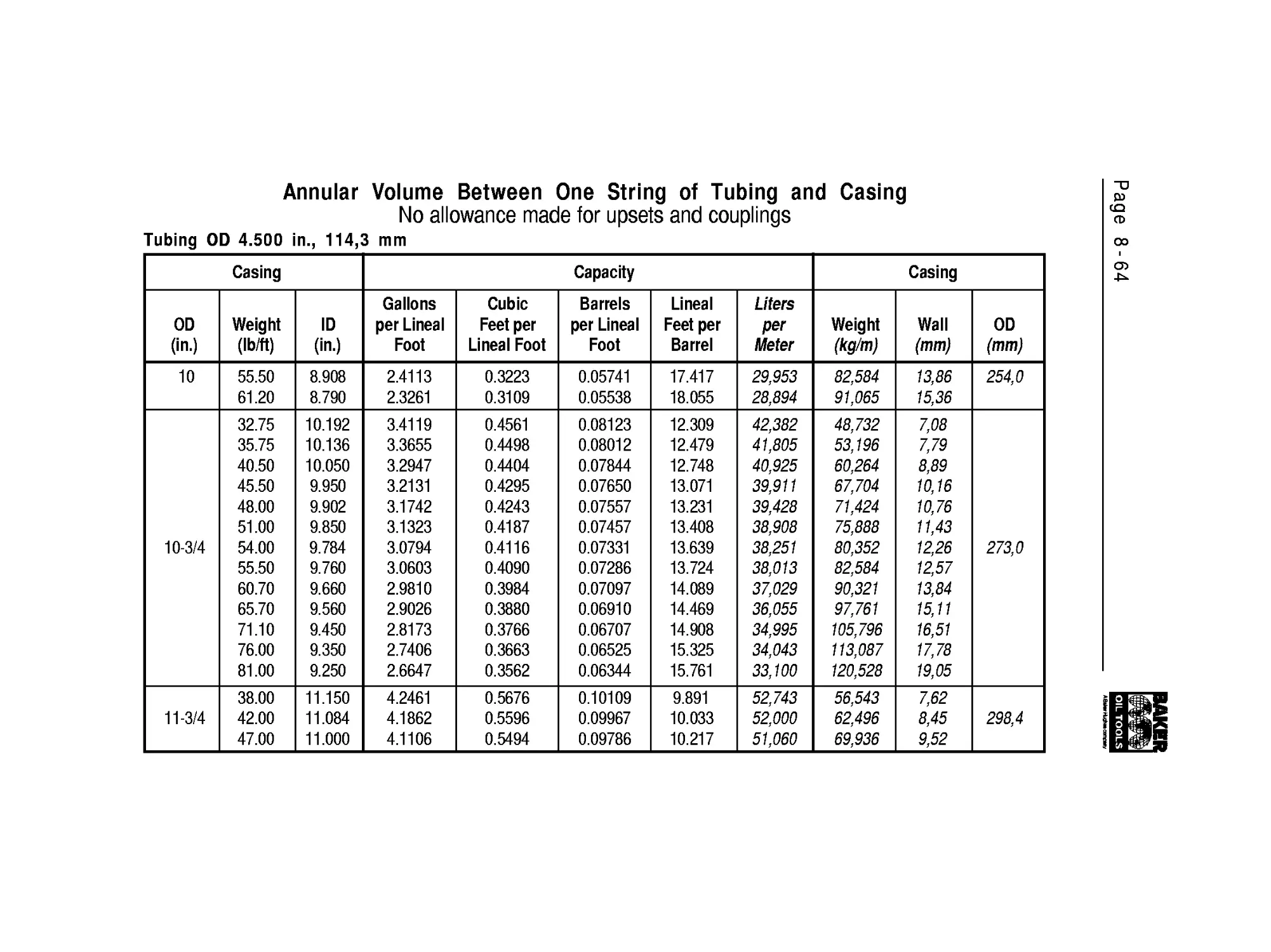
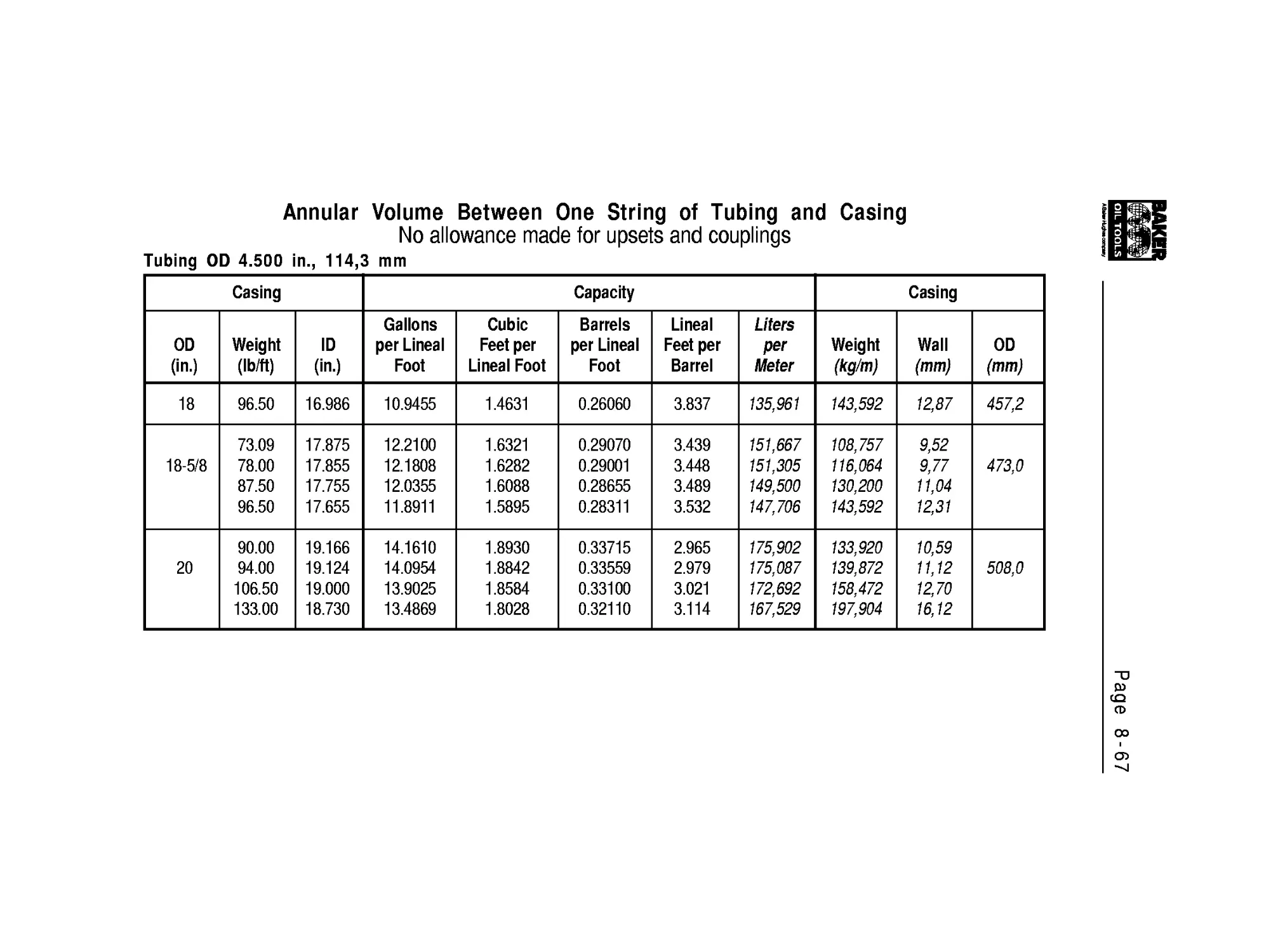
Annular Volume
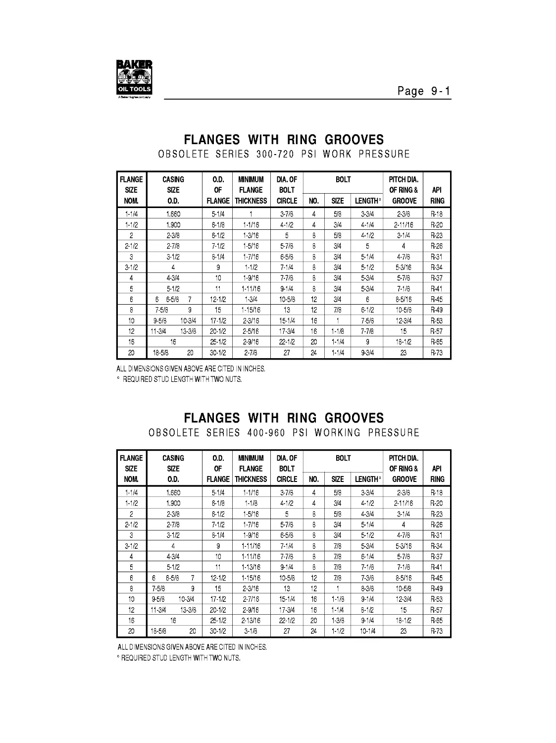
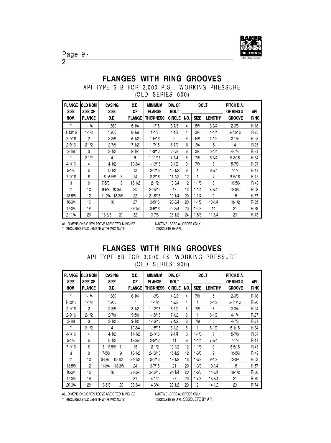
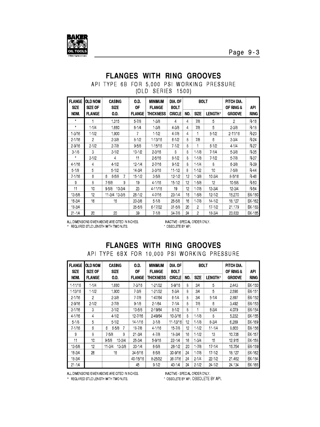
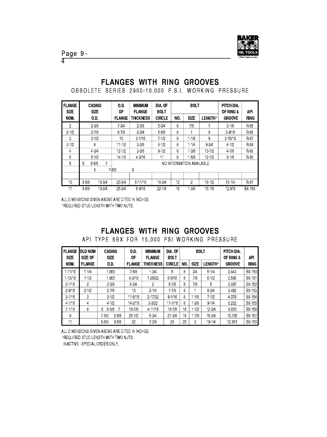
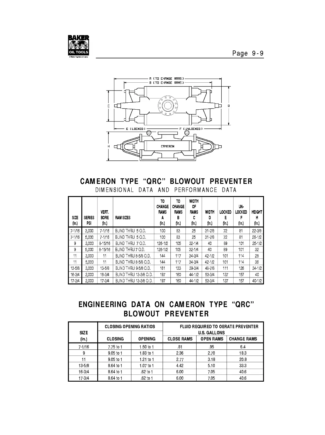
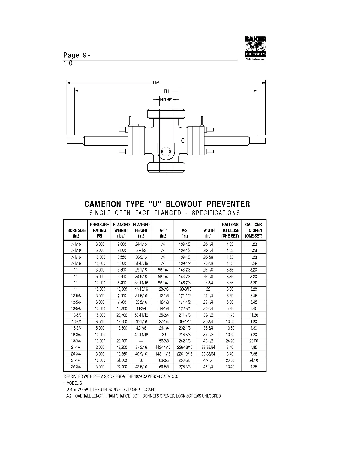
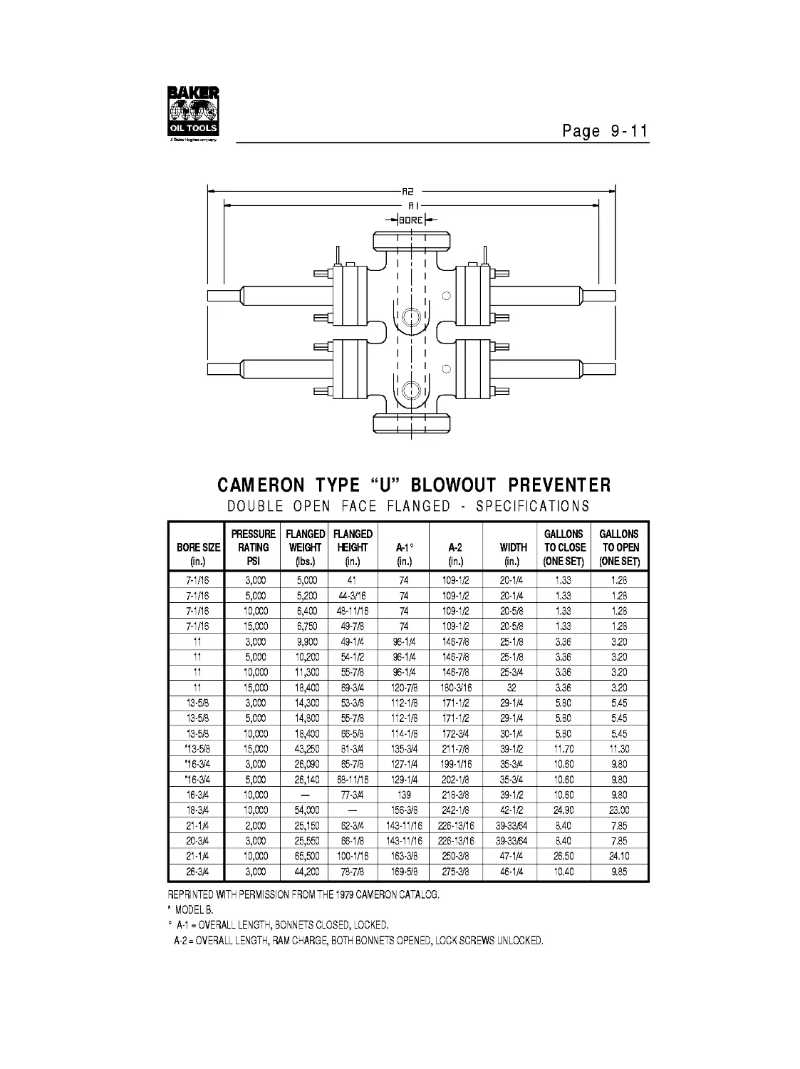
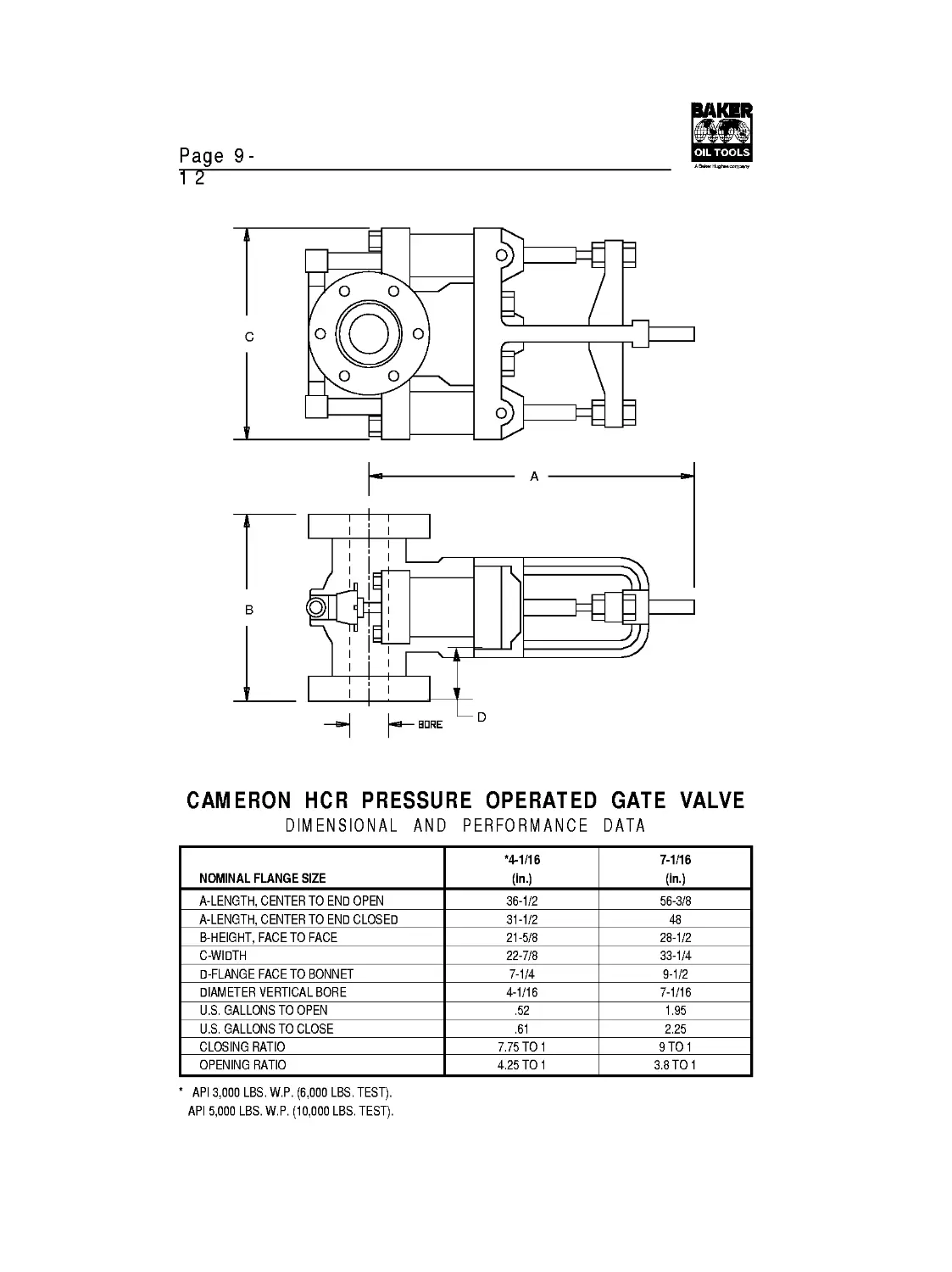
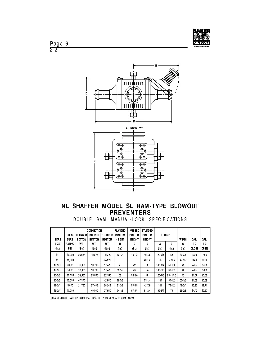
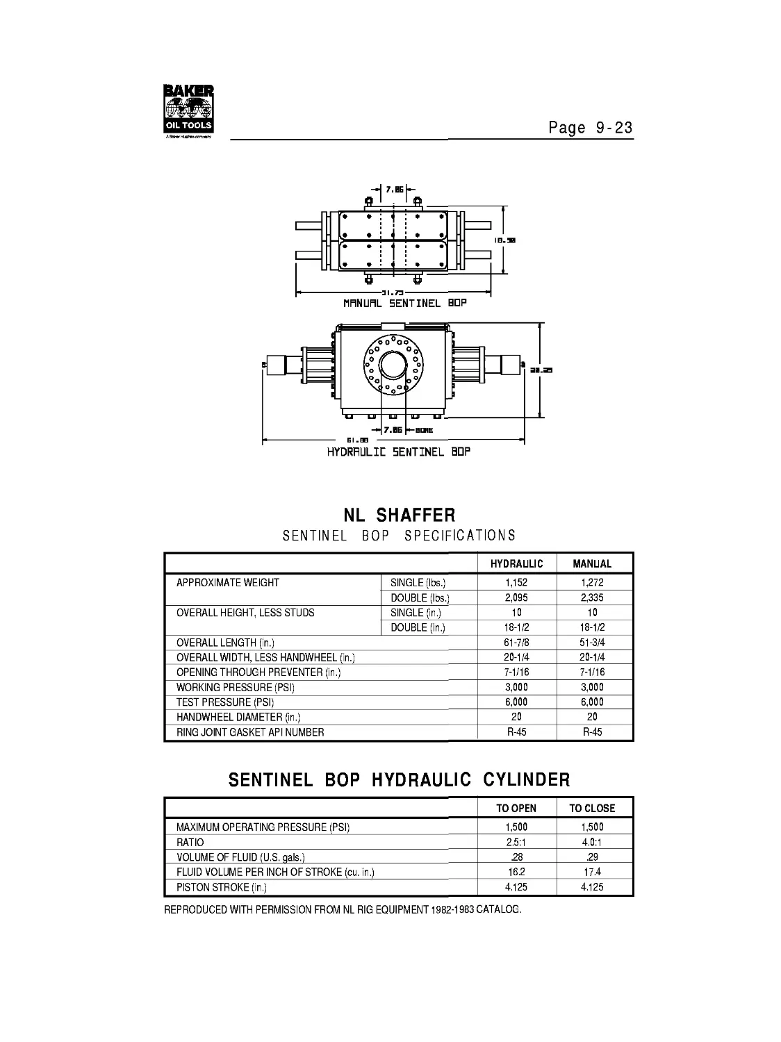
Flanges and
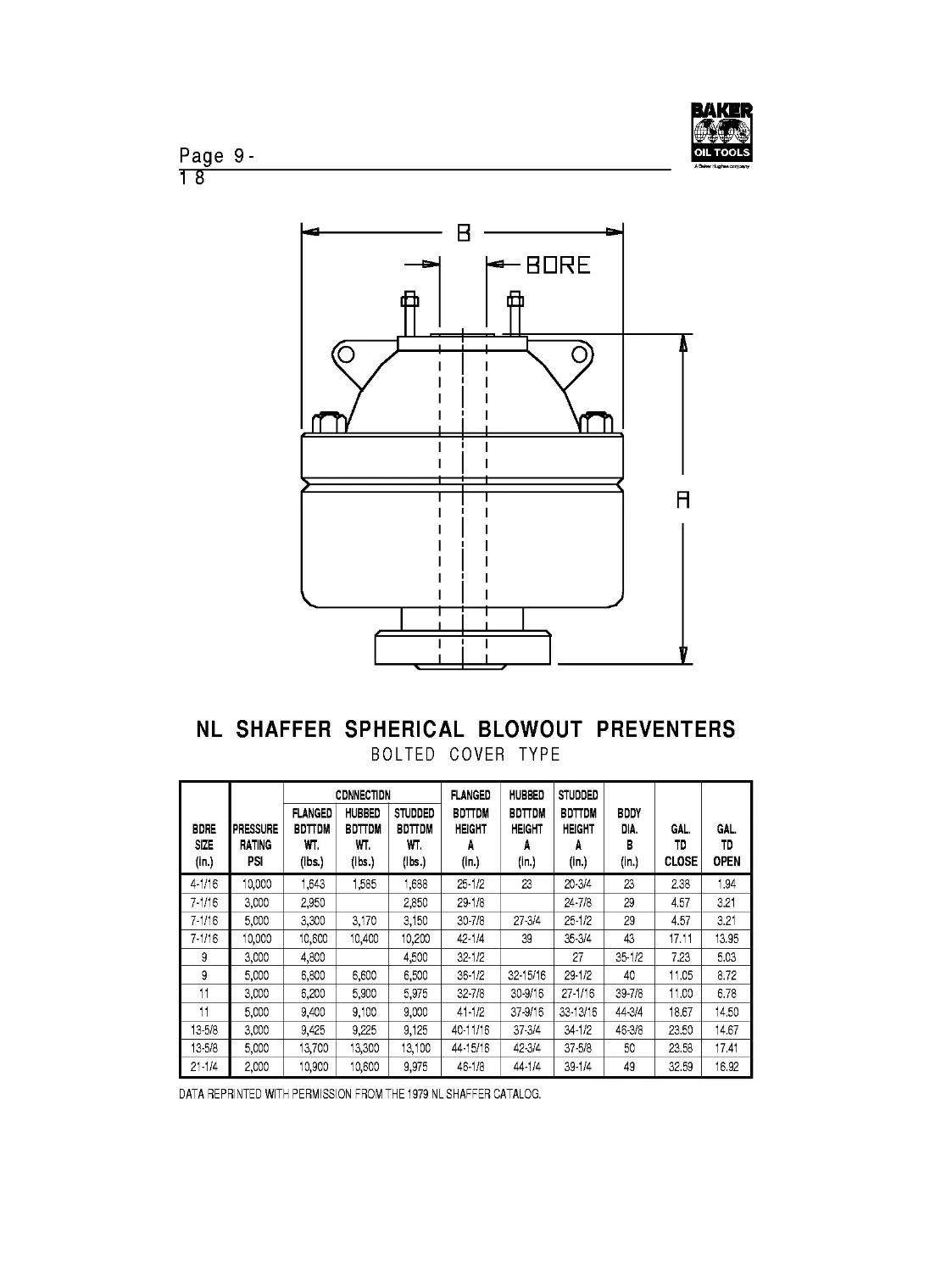
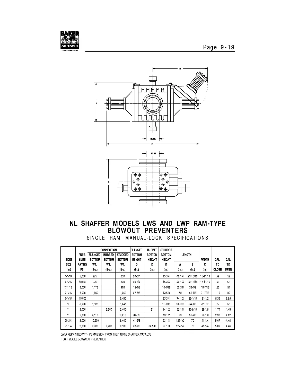
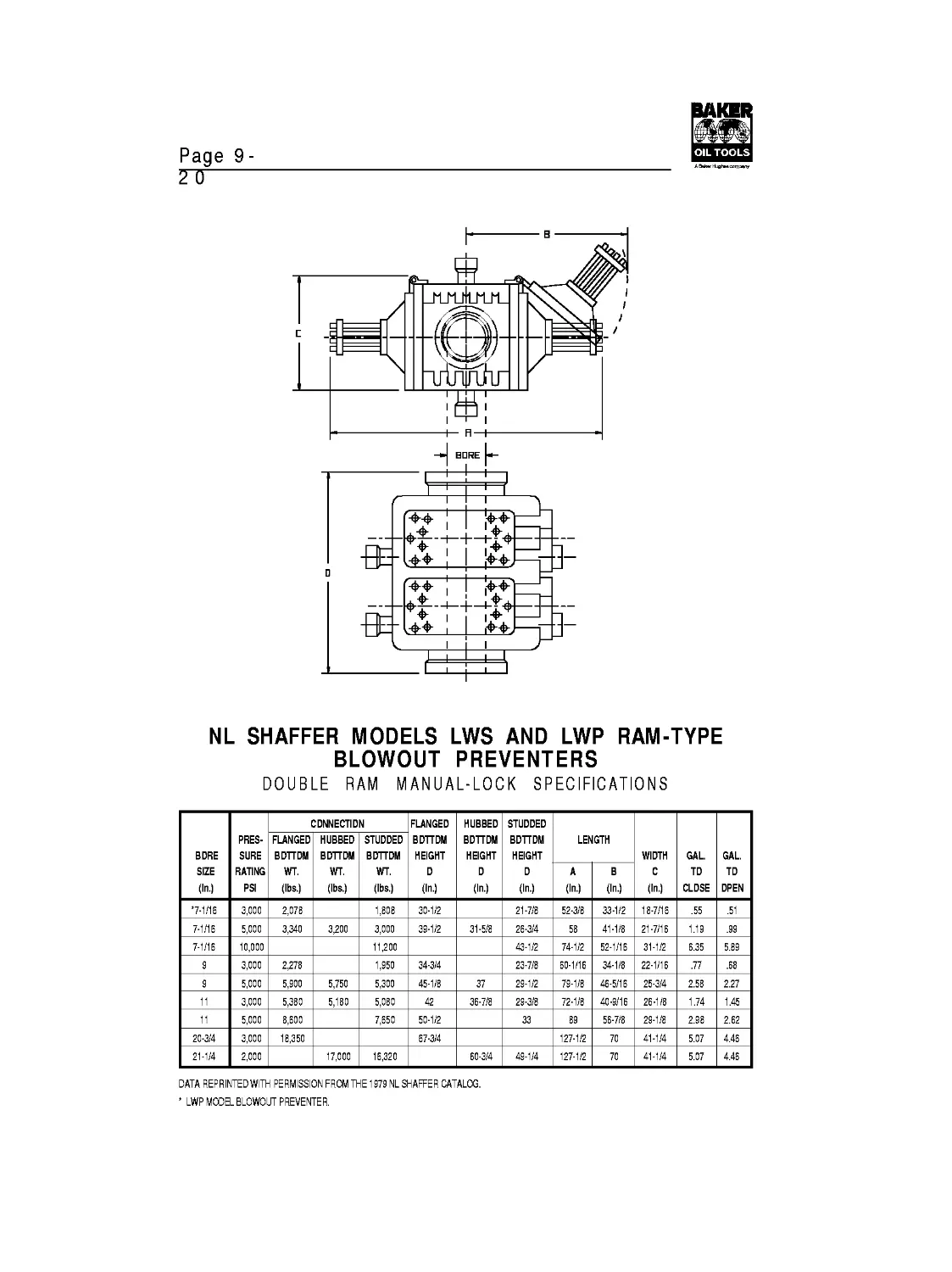
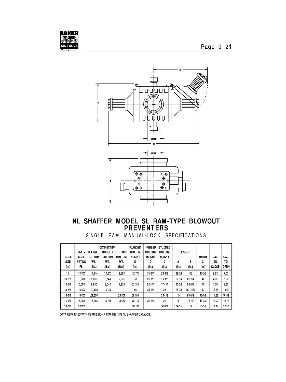
Blowout Preventers
General Information
10
SECTION 1 -Tool Joints
Contents
Page
Thread Details
API Regular...................................................1-1
Union Tool....................................................1-1
API Full Hole.................................................1-2
API Internal Flush............................................1-3
API Numbered Connections......................................1-4
American MT...................................................1-5
American РАС..................................................1-6
American Open Hole............................................1-7
Cable Tool Joints.............................................1-8
Gulf Tubing Joints............................................1-9
Hydril Joints................................................1-10
Hughes Double Streamline.....................................1-11
Hughes H-90..................................................1-12
Hughes Slim Hole.............................................1-14
Hughes Slimline H-90.........................................1-15
Hughes Extra Hole............................................1-16
Hughes External Flush........................................1-17
Humble “X” Type Joints.......................................1-18
Reed External Flush..........................................1-19
Reed Double Streamline.......................................1-20
Reed Wide Open...............................................1-21
Reed Full Hole...............................................1-21
Reed Extra Hole..............................................1-22
Sucker Rod (Includes Strength Data)..........................1-23
Rotary Shouldered Connection Interchange List....................1-25
Small Diameter Tool Joints — Strength Data.......................1-26
Large Diameter Tool Joints — Strength Data.......................1-27
Minimum/Maximum Tool Joint Dimensions............................1-28
Tool Joints — Interchangeability Charts..........................1-29
“X” Series Drill Rod.............................................1-34
“W” Series Drill Rod.............................................1-35
Fishing Necks —
Internal Dimensions..........................................1-36
External Dimensions..........................................1-37
Tech Facts
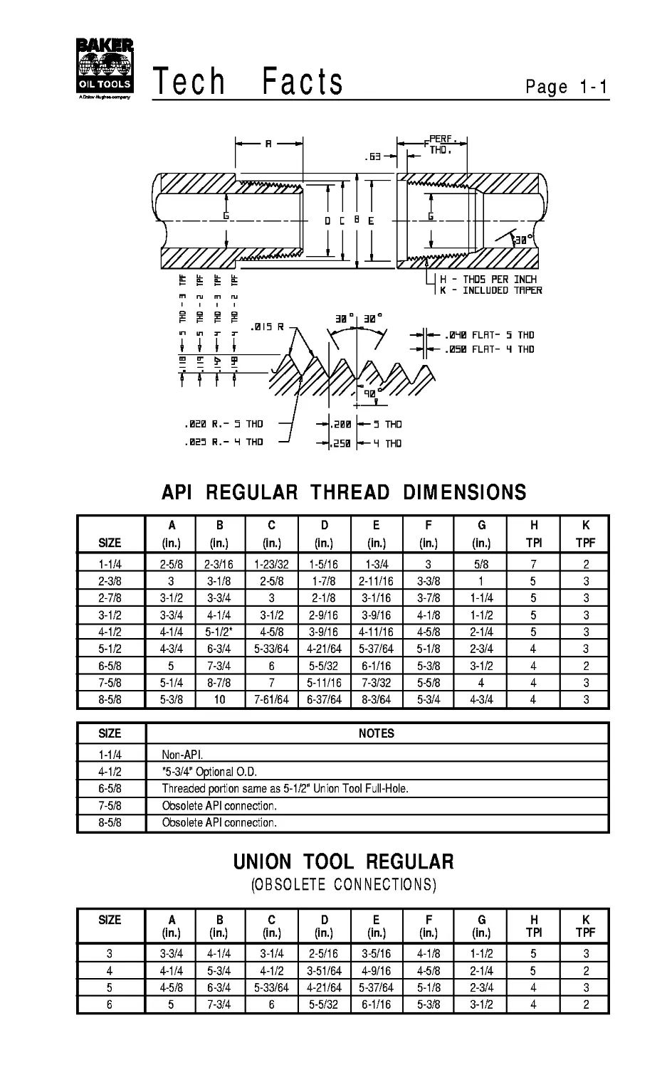
Page 1-1
API REGULAR THREAD DIMENSIONS
SIZE A (in.) В (in.) C (in.) D (in.) E (in.) F (in.) G (in.) H TPI К TPF
1-1/4 2-5/8 2-3/16 1-23/32 1-5/16 1-3/4 3 5/8 7 2
2-3/8 3 3-1/8 2-5/8 1-7/8 2-11/16 3-3/8 1 5 3
2-7/8 3-1/2 3-3/4 3 2-1/8 3-1/16 3-7/8 1-1/4 5 3
3-1/2 3-3/4 4-1/4 3-1/2 2-9/16 3-9/16 4-1/8 1-1/2 5 3
4-1/2 4-1/4 5-1/2* 4-5/8 3-9/16 4-11/16 4-5/8 2-1/4 5 3
5-1/2 4-3/4 6-3/4 5-33/64 4-21/64 5-37/64 5-1/8 2-3/4 4 3
6-5/8 5 7-3/4 6 5-5/32 6-1/16 5-3/8 3-1/2 4 2
7-5/8 5-1/4 8-7/8 7 5-11/16 7-3/32 5-5/8 4 4 3
8-5/8 5-3/8 10 7-61/64 6-37/64 8-3/64 5-3/4 4-3/4 4 3
SIZE NOTES
1-1/4 Non-API.
4-1/2 *5-3/4" Optional O.D.
6-5/8 Threaded portion same as 5-1/2" Union Tool Full-Hole.
7-5/8 Obsolete API connection.
8-5/8 Obsolete API connection.
UNION TOOL REGULAR
(OBSOLETE CONNECTIONS)
SIZE A (in.) В (in.) C (in.) D (in.) E (in.) F (in.) G (in.) H TPI К TPF
3 3-3/4 4-1/4 3-1/4 2-5/16 3-5/16 4-1/8 1-1/2 5 3
4 4-1/4 5-3/4 4-1/2 3-51/64 4-9/16 4-5/8 2-1/4 5 2
5 4-5/8 6-3/4 5-33/64 4-21/64 5-37/64 5-1/8 2-3/4 4 3
6 5 7-3/4 6 5-5/32 6-1/16 5-3/8 3-1/2 4 2
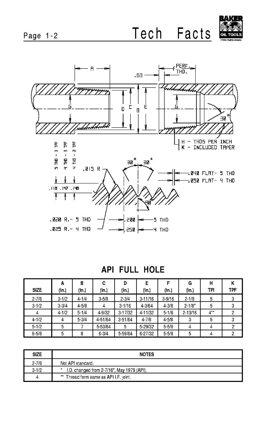
Page 1-2
Tech
Facts
API FULL HOLE
SIZE A (in.) В (in.) C (in.) D (in.) E (in.) F (in.) G (in.) H TPI К TPF
2-7/8 3-1/2 4-1/4 3-5/8 2-3/4 3-11/16 3-9/16 2-1/8 5 3
3-1/2 3-3/4 4-5/8 4 3-1/16 4-3/64 4-3/8 2-1/8* 5 3
4 4-1/2 5-1/4 4-9/32 3-17/32 4-11/32 5-1/8 2-13/16 4** 2
4-1/2 4 5-3/4 4-51/64 3-51/64 4-7/8 4-5/8 3 5 3
5-1/2 5 7 5-53/64 5 5-29/32 5-5/8 4 4 2
6-5/8 5 8 6-3/4 5-59/64 6-27/32 5-5/8 5 4 2
SIZE NOTES
2-7/8 Not API standard.
3-1/2 * I.D. changed from 2-7/16". Mav 1979 (API).
4 ** Thread form same as API I.F. joint.
Tech
Facts
Page 1-3
API INTERNAL FLUSH
SIZE A (in.) В (in.) C (in.) D (in.) E (in.) F (in.) G (in.) H TPI К TPF
2-3/8 3 3-3/8 2-7/8 2-3/8 2-15/16 3-5/8 1-3/4 4 2
2-7/8 3-1/2 4-1/8 3-25/64 2-13/16 3-29/64 4-1/8 2-1/8 4 2
3-1/2 4 4-3/4 4-1/64 3-11/32 4-5/64 4-5/8 2-11/16 4 2
4 4-1/2 5-3/4 4-53/64 4-5/64 4-29/32 5-1/8 3-1/4 4 2
4-1/2 4-1/2 6-3/8 5-1/4 4-1/2 5-5/16 5-1/8 3-3/4 4 2
5-1/2 5 7-3/8 6-25/64 5-9/16 6-29/64 5-5/8 4-13/16 4 2
Page 1-4
Tech
Facts
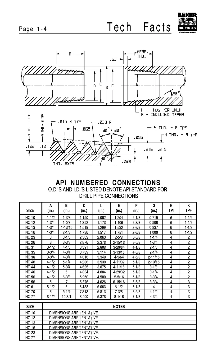
API NUMBERED CONNECTIONS
O.D.’S AND I.D.’S LISTED DENOTE API STANDARD FOR
DRILL PIPE CONNECTIONS
SIZE A (in.) В (in.) C (in.) 0 (in.) E (in.) F (in.) G (in.) H TPI К TPF
NC10 1-1/2 1-3/8 1.190 1.002 1.204 2-1/8 0.719 6 1-1/2
NC12 1-3/4 1-5/8 1.392 1.173 1.406 2-3/8 0.906 6 1-1/2
NC13 1-3/4 1-13/16 1.518 1.299 1.532 2-3/8 0.937 6 1-1/2
NC16 1-3/4 2-1/8 1.736 1.517 1.751 2-3/8 1.000 6 1-1/2
NC 23 3 3-1/8 2.563 2.063 2-5/8 3-5/8 1-1/4 4 2
NC26 3 3-3/8 2.876 2.376 2-15/16 3-5/8 1-3/4 4 2
NC31 3-1/2 4-1/8 3.391 2.808 3-29/64 4-1/8 2-1/8 4 2
NC35 3-3/4 4-3/4 3.739 3.114 3-13/16 4-3/8 2-1/4 4 2
NC38 3-3/4 4-3/4 4.016 3.349 4-5/64 4-5/8 2-11/16 4 2
NC40 4-1/2 5-1/4 4.280 3.530 4-11/32 5-1/8 2-13/16 4 2
NC44 4-1/2 5-3/4 4.625 3.875 4-11/16 5-1/8 3-1/8 4 2
NC46 4-1/2 6 4.834 4.084 4-29/32 5-1/8 3-1/4 4 2
NC50 4-1/2 6-3/8 5.250 4.500 5-5/16 5-1/8 3-3/4 4 2
NC56 5 7 5.876 4.626 6-15/16 5-5/8 3-3/4 4 3
NC61 5-1/2 8 6.438 5.063 6-1/2 6-1/8 4 4 3
NC 70 6 9-1/4 7.313 5.813 7-3/8 6-5/8 4-1/2 4 3
NC 77 6-1/2 10-3/4 8.000 6.376 8-1/16 7-1/8 4-3/4 4 3
SIZE NOTES
NC10 DIMENSIONS ARE TENTATIVE.
NC12 DIMENSIONS ARE TENTATIVE.
NC13 DIMENSIONS ARE TENTATIVE.
NC16 DIMENSIONS ARE TENTATIVE.
NC 23 DIMENSIONS ARE TENTATIVE.
NC 77 DIMENSIONS ARE TENTATIVE.
Tech
Facts
Page 1-5
HXI5 OF JOINT
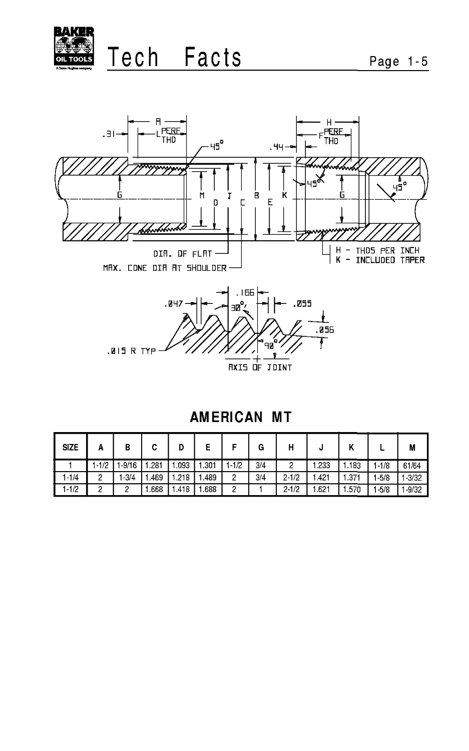
AMERICAN MT
SIZE A В C D E F G H J К L M
1 1-1/2 1-9/16 1.281 1.093 1.301 1-1/2 3/4 2 1.233 1.183 1-1/8 61/64
1-1/4 2 1-3/4 1.469 1.218 1.489 2 3/4 2-1/2 1.421 1.371 1-5/8 1 -3/32
1-1/2 2 2 1.668 1.418 1.688 2 1 2-1/2 1.621 1.570 1-5/8 1 -9/32
Page 1-6
Tech
Facts
DIFI DF STRAIGHT—
MFirDR CDNE DIR FIT 5HDULDER—
L
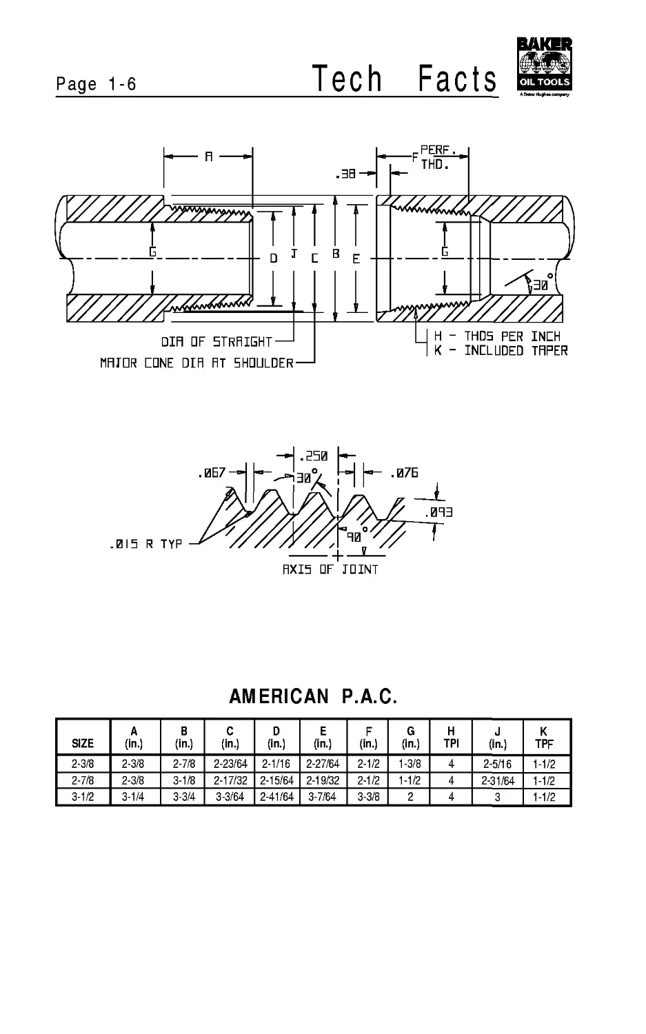
AMERICAN P.A.C.
SIZE A (in.) В (in.) C (in.) D (in.) E (in.) F (in.) G (in.) H TPI J (in.) К TPF
2-3/8 2-3/8 2-7/8 2-23/64 2-1/16 2-27/64 2-1/2 1-3/8 4 2-5/16 1-1/2
2-7/8 2-3/8 3-1/8 2-17/32 2-15/64 2-19/32 2-1/2 1-1/2 4 2-31/64 1-1/2
3-1/2 3-1/4 3-3/4 3-3/64 2-41/64 3-7/64 3-3/8 2 4 3 1-1/2
Tech
Facts
Page 1-7
□IFI HF STRAIGHT —
MAJOR GONE DIR AT SHOULDER
AXIS OF JOINT
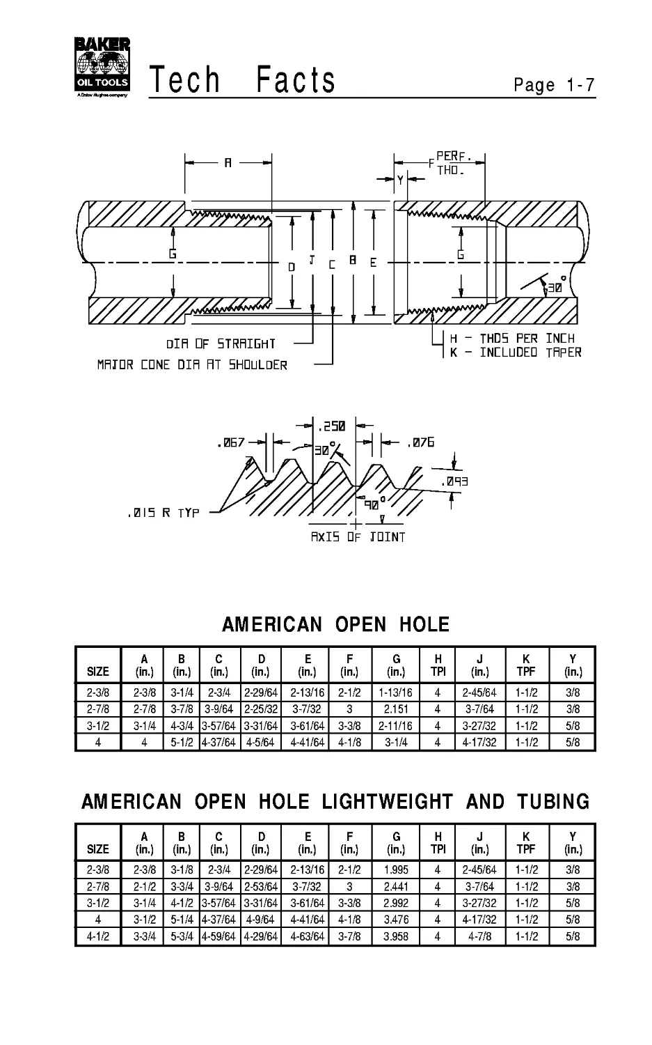
AMERICAN OPEN HOLE
SIZE A (in.) В (in.) C (in.) D (in.) E (in.) F (in.) G (in.) H TPI J (in.) К TPF Y (in.)
2-3/8 2-3/8 3-1/4 2-3/4 2-29/64 2-13/16 2-1/2 1-13/16 4 2-45/64 1-1/2 3/8
2-7/8 2-7/8 3-7/8 3-9/64 2-25/32 3-7/32 3 2.151 4 3-7/64 1-1/2 3/8
3-1/2 3-1/4 4-3/4 3-57/64 3-31/64 3-61/64 3-3/8 2-11/16 4 3-27/32 1-1/2 5/8
4 4 5-1/2 4-37/64 4-5/64 4-41/64 4-1/8 3-1/4 4 4-17/32 1-1/2 5/8
AMERICAN OPEN HOLE LIGHTWEIGHT AND TUBING
SIZE A (in.) В (in.) C (in.) D (in.) E (in.) F (in.) G (in.) H TPI J (in.) К TPF Y (in.)
2-3/8 2-3/8 3-1/8 2-3/4 2-29/64 2-13/16 2-1/2 1.995 4 2-45/64 1-1/2 3/8
2-7/8 2-1/2 3-3/4 3-9/64 2-53/64 3-7/32 3 2.441 4 3-7/64 1-1/2 3/8
3-1/2 3-1/4 4-1/2 3-57/64 3-31/64 3-61/64 3-3/8 2.992 4 3-27/32 1-1/2 5/8
4 3-1/2 5-1/4 4-37/64 4-9/64 4-41/64 4-1/8 3.476 4 4-17/32 1-1/2 5/8
4-1/2 3-3/4 5-3/4 4-59/64 4-29/64 4-63/64 3-7/8 3.958 4 4-7/8 1-1/2 5/8
Page 1-8
Tech
Facts
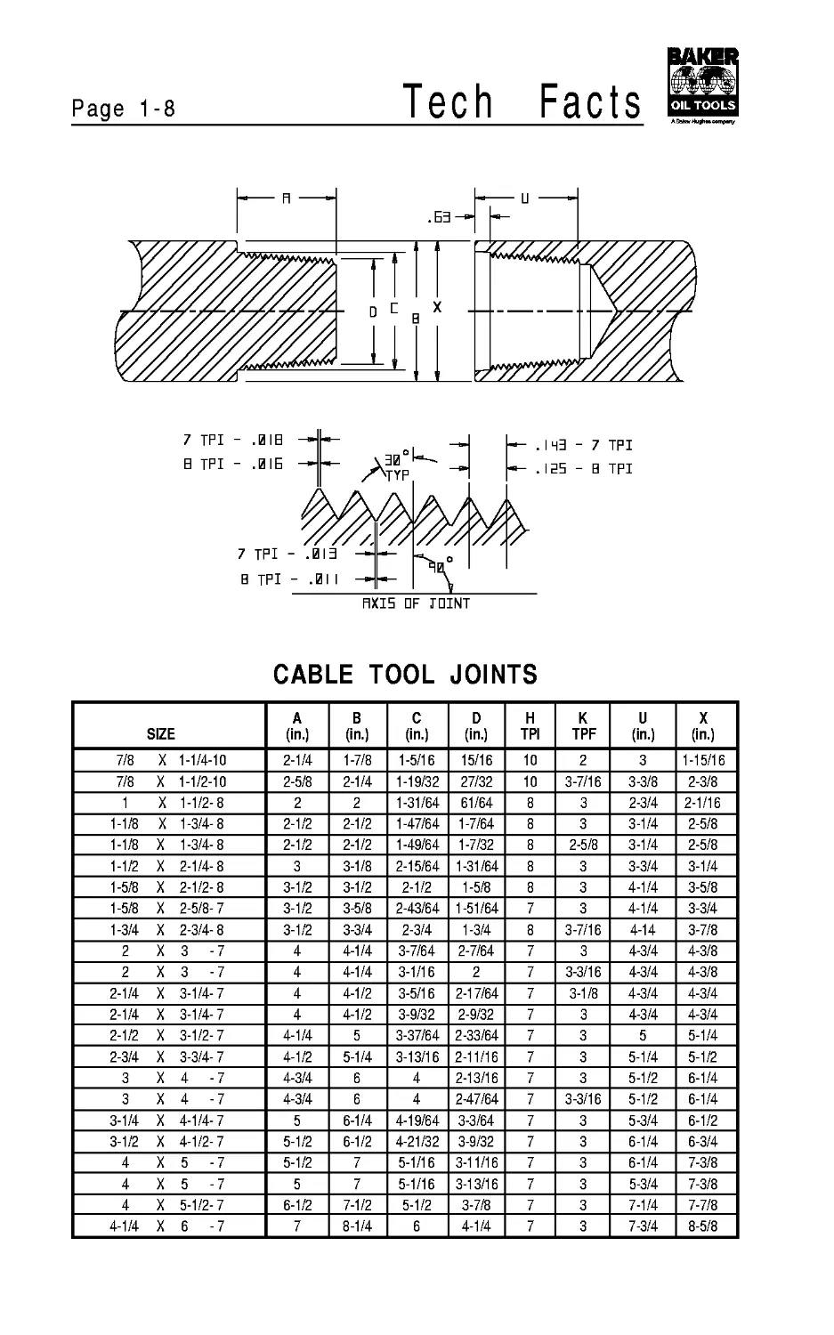
CABLE TOOL JOINTS
SIZE A (in.) В (in.) C (in.) D (in.) H TPI К TPF u (in.) X (in.)
7/8 X 1-1/4-10 2-1/4 1-7/8 1-5/16 15/16 10 2 3 1-15/16
7/8 X 1-1/2-10 2-5/8 2-1/4 1-19/32 27/32 10 3-7/16 3-3/8 2-3/8
1 X 1-1/2 8 2 2 1-31/64 61/64 8 3 2-3/4 2-1/16
1-1/8 X 1-3/4 8 2-1/2 2-1/2 1-47/64 1-7/64 8 3 3-1/4 2-5/8
1-1/8 X 1-3/4 8 2-1/2 2-1/2 1-49/64 1-7/32 8 2-5/8 3-1/4 2-5/8
1-1/2 X 2-1/4 8 3 3-1/8 2-15/64 1-31/64 8 3 3-3/4 3-1/4
1-5/8 X 2-1/2 8 3-1/2 3-1/2 2-1/2 1-5/8 8 3 4-1/4 3-5/8
1-5/8 X 2-5/8 7 3-1/2 3-5/8 2-43/64 1-51/64 7 3 4-1/4 3-3/4
1-3/4 X 2-3/4 8 3-1/2 3-3/4 2-3/4 1-3/4 8 3-7/16 4-14 3-7/8
2 X 3 7 4 4-1/4 3-7/64 2-7/64 7 3 4-3/4 4-3/8
2 X 3 7 4 4-1/4 3-1/16 2 7 3-3/16 4-3/4 4-3/8
2-1/4 X 3-1/4 7 4 4-1/2 3-5/16 2-17/64 7 3-1/8 4-3/4 4-3/4
2-1/4 X 3-1/4 7 4 4-1/2 3-9/32 2-9/32 7 3 4-3/4 4-3/4
2-1/2 X 3-1/2 7 4-1/4 5 3-37/64 2-33/64 7 3 5 5-1/4
2-3/4 X 3-3/4 7 4-1/2 5-1/4 3-13/16 2-11/16 7 3 5-1/4 5-1/2
3 X 4 7 4-3/4 6 4 2-13/16 7 3 5-1/2 6-1/4
3 X 4 7 4-3/4 6 4 247/64 7 3-3/16 5-1/2 6-1/4
3-1/4 X 4-1/4 7 5 6-1/4 4-19/64 3-3/64 7 3 5-3/4 6-1/2
3-1/2 X 4-1/2 7 5-1/2 6-1/2 4-21/32 3-9/32 7 3 6-1/4 6-3/4
4 X 5 7 5-1/2 7 5-1/16 3-11/16 7 3 6-1/4 7-3/8
4 X 5 7 5 7 5-1/16 3-13/16 7 3 5-3/4 7-3/8
4 X 5-1/2 7 6-1/2 7-1/2 5-1/2 3-7/8 7 3 7-1/4 7-7/8
4-1/4 X 6 7 7 8-1/4 6 4-1/4 7 3 7-3/4 8-5/8
Tech Facts
Page 1-9
'/7/7/7/forTrm
TAPER
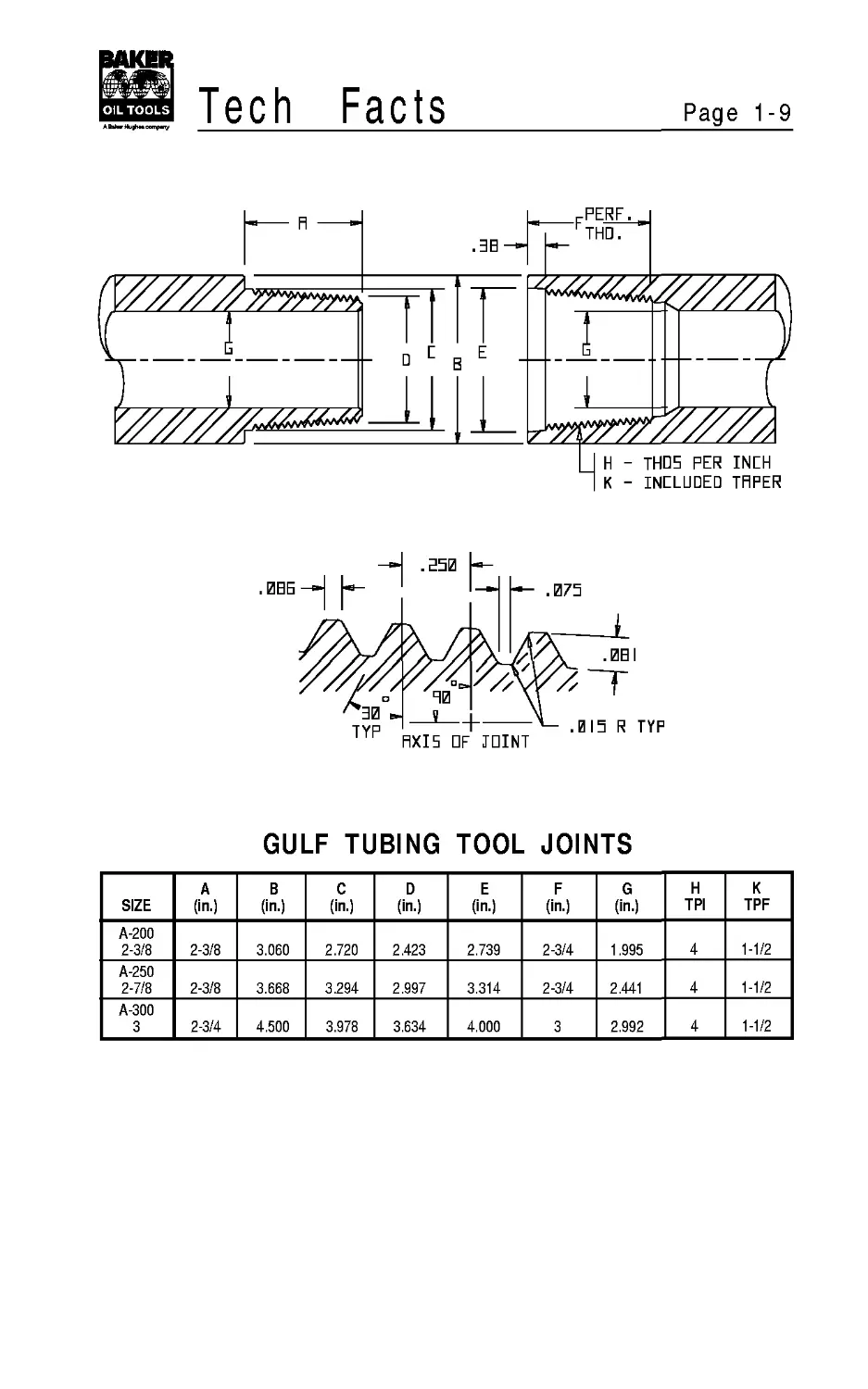
GULF TUBING TOOL JOINTS
SIZE A (in.) В (in.) c (in.) D (in.) E (in.) F (in.) G (in.) H TPI К TPF
A-200 2-3/8 2-3/8 3.060 2.720 2.423 2.739 2-3/4 1.995 4 1-1/2
A-250 2-7/8 2-3/8 3.668 3.294 2.997 3.314 2-3/4 2.441 4 1-1/2
A-300 3 2-3/4 4.500 3.978 3.634 4.000 3 2.992 4 1-1/2
Page 1-10
Tech
Facts
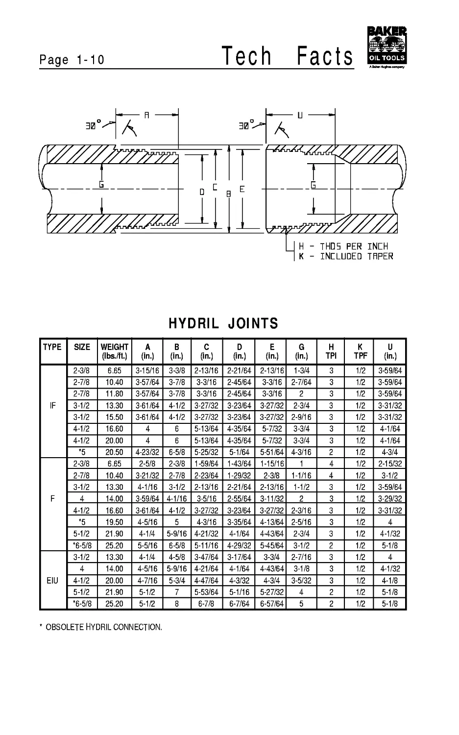
HYDRIL JOINTS
TYPE SIZE WEIGHT (Ibs./ft.) A (in.) В (in.) C (in.) D (in.) E (in.) G (in.) H TPI К TPF U (in.)
IF 2-3/8 6.65 3-15/16 3-3/8 2-13/16 2-21/64 2-13/16 1-3/4 3 1/2 3-59/64
2-7/8 10.40 3-57/64 3-7/8 3-3/16 2-45/64 3-3/16 2-7/64 3 1/2 3-59/64
2-7/8 11.80 3-57/64 3-7/8 3-3/16 2-45/64 3-3/16 2 3 1/2 3-59/64
3-1/2 13.30 3-61/64 4-1/2 3-27/32 3-23/64 3-27/32 2-3/4 3 1/2 3-31/32
3-1/2 15.50 3-61/64 4-1/2 3-27/32 3-23/64 3-27/32 2-9/16 3 1/2 3-31/32
4-1/2 16.60 4 6 5-13/64 4-35/64 5-7/32 3-3/4 3 1/2 4-1/64
4-1/2 20.00 4 6 5-13/64 4-35/64 5-7/32 3-3/4 3 1/2 4-1/64
*5 20.50 4-23/32 6-5/8 5-25/32 5-1/64 5-51/64 4-3/16 2 1/2 4-3/4
F 2-3/8 6.65 2-5/8 2-3/8 1 -59/64 1-43/64 1-15/16 1 4 1/2 2-15/32
2-7/8 10.40 3-21/32 2-7/8 2-23/64 1-29/32 2-3/8 1-1/16 4 1/2 3-1/2
3-1/2 13.30 4-1/16 3-1/2 2-13/16 2-21/64 2-13/16 1-1/2 3 1/2 3-59/64
4 14.00 3-59/64 4-1/16 3-5/16 2-55/64 3-11/32 2 3 1/2 3-29/32
4-1/2 16.60 3-61/64 4-1/2 3-27/32 3-23/64 3-27/32 2-3/16 3 1/2 3-31/32
*5 19.50 4-5/16 5 4-3/16 3-35/64 4-13/64 2-5/16 3 1/2 4
5-1/2 21.90 4-1/4 5-9/16 4-21/32 4-1/64 443/64 2-3/4 3 1/2 4-1/32
*6-5/8 25.20 5-5/16 6-5/8 5-11/16 4-29/32 545/64 3-1/2 2 1/2 5-1/8
EIU 3-1/2 13.30 4-1/4 4-5/8 3-47/64 3-17/64 3-3/4 2-7/16 3 1/2 4
4 14.00 4-5/16 5-9/16 4-21/64 4-1/64 4-43/64 3-1/8 3 1/2 4-1/32
4-1/2 20.00 4-7/16 5-3/4 4-47/64 4-3/32 4-3/4 3-5/32 3 1/2 4-1/8
5-1/2 21.90 5-1/2 7 5-53/64 5-1/16 5-27/32 4 2 1/2 5-1/8
*6-5/8 25.20 5-1/2 8 6-7/8 6-7/64 6-57/64 5 2 1/2 5-1/8
OBSOLETE HYDRIL CONNECTION.
Tech Facts
Page 1-11
R ----'
.031 R
□IH. DF FLRT
HRX. EDNE DIR RT 5HDLILDER—
H - THD5 PER INEH
К - INCLUDED THFER
—E' BDRE DIR. - TRPERED
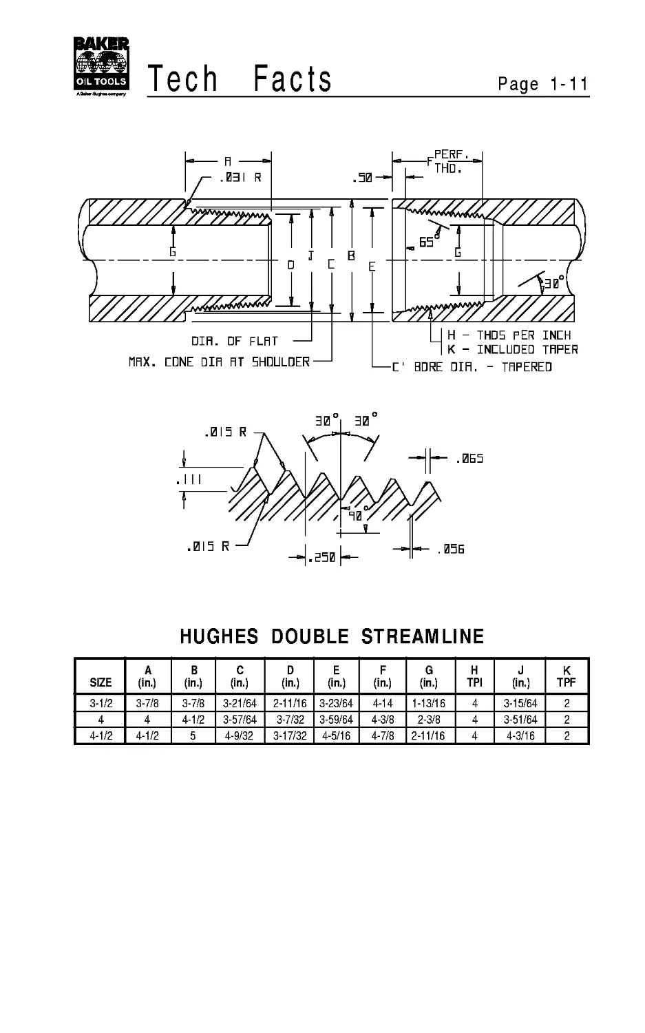
HUGHES DOUBLE STREAMLINE
SIZE A (in.) В (in.) C (in.) D (in.) E (in.) F (in.) G (in.) H TPI J (in.) К TPF
3-1/2 3-7/8 3-7/8 3-21/64 2-11/16 3-23/64 4-14 1-13/16 4 3-15/64 2
4 4 4-1/2 3-57/64 3-7/32 3-59/64 4-3/8 2-3/8 4 3-51/64 2
4-1/2 4-1/2 5 4-9/32 3-17/32 4-5/16 4-7/8 2-11/16 4 4-3/16 2
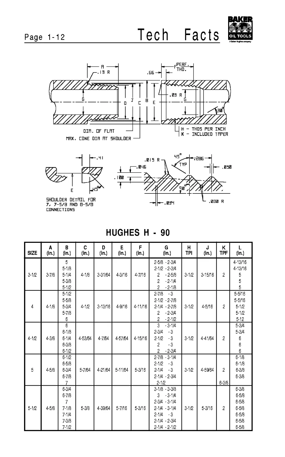
Page 1-12
Tech
Facts
.ББ
PERF.
THD.
DIH. DF FLAT
MAX. EDNE DIH FIT
5HDULDER —
INCH
TAPER
SHOULDER DETAIL FDR
7, 7-5/B HND B-5/B
CONNECTIONS
A —-
HUGHES H - 90
SIZE A (in.) В (in.) C (in.) D (in.) E (in.) F (in.) G (in.) H TPI J (in.) К L TPF (in.)
3-1/2 3-7/8 5 5-1/8 5-1/4 5-3/8 5-1/2 4-1/8 3-31/64 4-3/16 4-7/16 2-5/8 -2-3/4 2-1/2 -2-3/4 2 - 2-5/8 2 -2-1/4 2 -2-1/8 3-1/2 3-15/16 4-13/16 4-13/16 2 5 5 5
4 4-1/8 5-1/2 5-5/8 5-3/4 5-7/8 6 4-1/2 3-13/16 4-9/16 4-11/16 2-7/8 - 3 2-1/2 -2-7/8 2-1/4 -2-7/8 2 -2-3/4 2 -2-1/2 3-1/2 4-5/16 5-5/16 5-5/16 2 5-1/2 5-1/2 5-12
4-1/2 4-3/8 6 6-1/8 6-1/4 6-3/8 6-1/2 4-53/64 4-7/64 4-57/64 4-15/16 3 -3-1/4 2-3/4 - 3 2-1/2 -3 2 -3 2 -2-3/4 3-1/2 4-41/64 5-3/4 5-3/4 2 6 6 6
5 4-5/8 6-1/2 6-5/8 6-3/4 6-7/8 7 5-7/64 4-21/64 5-11/64 5-3/16 2-7/8 -3-1/4 2-1/2 -3 2-1/4 -3 2-1/4 -2-3/4 2-1/2 3-1/2 4-59/64 6-1/8 6-1/8 2 6-3/8 6-3/8 6-3/8
5-1/2 4-5/8 6-3/4 6-7/8 7 7-1/8 7-1/4 7-3/8 7-1/2 5-3/8 4-39/64 5-7/16 5-3/16 3-1/8 -3-3/8 3 -3-1/4 2-3/4 -3-1/4 2-1/4 -3-1/4 2-1/4 -3 2-1/4 -2-3/4 2-1/4 -2-1/2 3-1/2 5-3/16 6-3/8 6-5/8 6-5/8 2 6-5/8 6-5/8 6-5/8 6-5/8
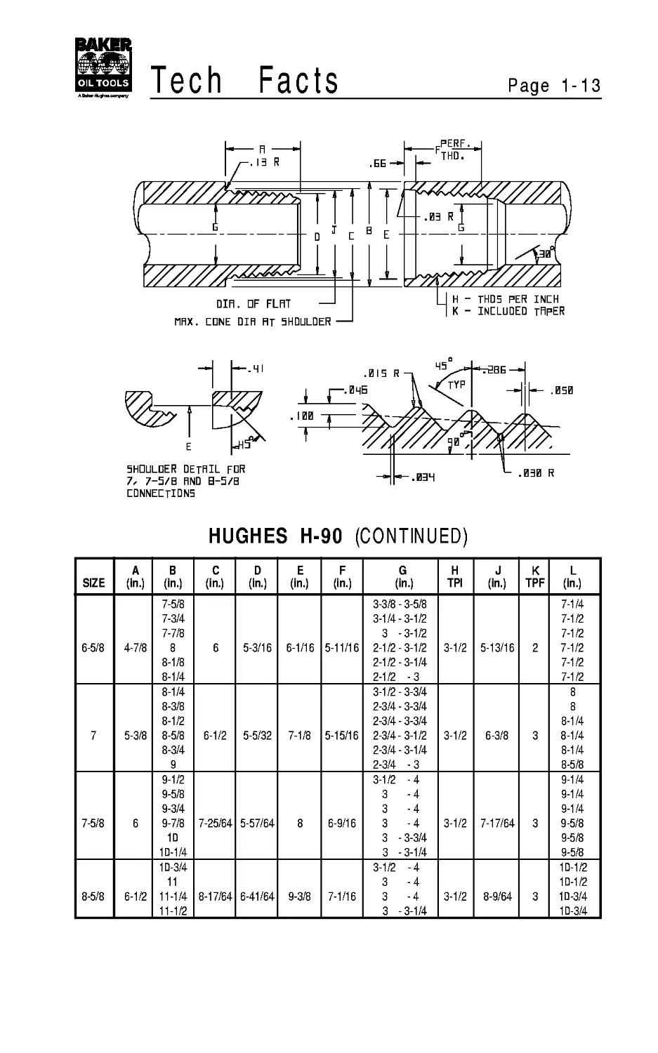
Tech Facts
Page 1-13
5HDULDER DETAIL FDR
7/ 7-5/B FIND B-5/B
CONNECTIONS
HUGHES H-90 (CONTINUED)
SIZE A (in.) В (in.) C (in.) D (in.) E (in.) F (in.) G (in.) H TPI J (in.) К TPF L (in.)
6-5/8 4-7/8 7-5/8 7-3/4 7-7/8 8 8-1/8 8-1/4 6 5-3/16 6-1/16 5-11/16 3-3/8 - 3-5/8 3-1/4-3-1/2 3 -3-1/2 2-1/2 - 3-1/2 2-1/2-3-1/4 2-1/2 -3 3-1/2 5-13/16 2 7-1/4 7-1/2 7-1/2 7-1/2 7-1/2 7-1/2
7 5-3/8 8-1/4 8-3/8 8-1/2 8-5/8 8-3/4 9 6-1/2 5-5/32 7-1/8 5-15/16 3-1/2-3-3/4 2-3/4 - 3-3/4 2-3/4 - 3-3/4 2-3/4-3-1/2 2-3/4-3-1/4 2-3/4 -3 3-1/2 6-3/8 3 8 8 8-1/4 8-1/4 8-1/4 8-5/8
7-5/8 6 9-1/2 9-5/8 9-3/4 9-7/8 10 10-1/4 7-25/64 5-57/64 8 6-9/16 3-1/2 -4 3 -4 3 -4 3 -4 3 -3-3/4 3 -3-1/4 3-1/2 7-17/64 3 9-1/4 9-1/4 9-1/4 9-5/8 9-5/8 9-5/8
8-5/8 6-1/2 10-3/4 11 11-1/4 11-1/2 8-17/64 6-41/64 9-3/8 7-1/16 3-1/2 -4 3 -4 3 -4 3 -3-1/4 3-1/2 8-9/64 3 10-1/2 10-1/2 10-3/4 10-3/4
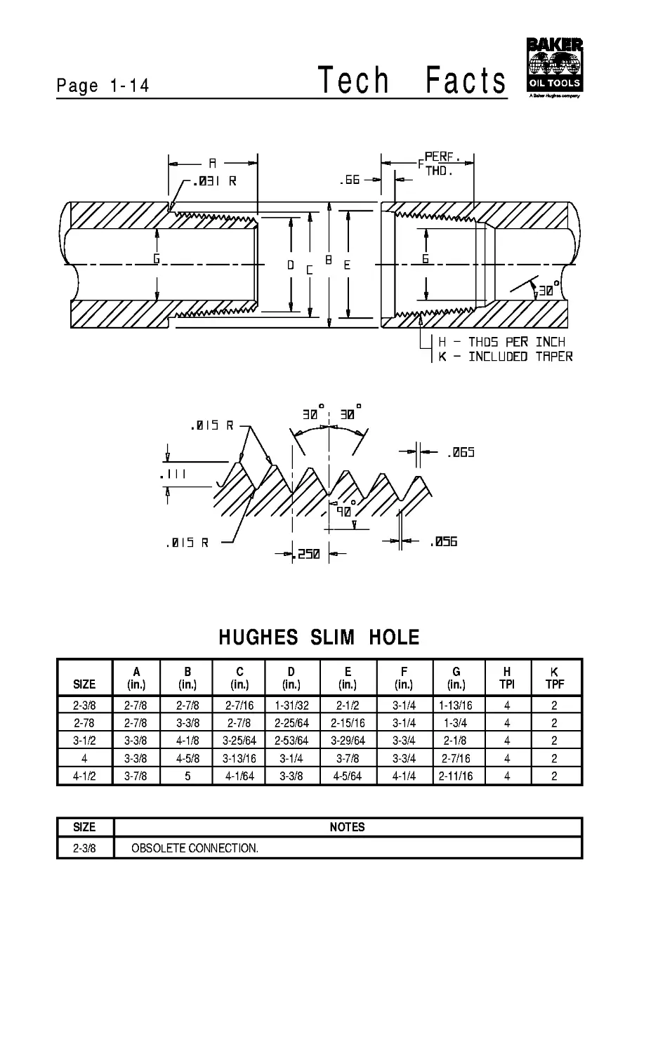
Page 1-14
Tech
Facts
Fl ----------*
.03 I R
HUGHES SLIM HOLE
SIZE A (in.) В (in.) C (in.) D (in.) E (in.) F (in.) G (in.) H TPI К TPF
2-3/8 2-7/8 2-7/8 2-7/16 1-31/32 2-1/2 3-1/4 1-13/16 4 2
2-78 2-7/8 3-3/8 2-7/8 2-25/64 2-15/16 3-1/4 1-3/4 4 2
3-1/2 3-3/8 4-1/8 3-25/64 2-53/64 3-29/64 3-3/4 2-1/8 4 2
4 3-3/8 4-5/8 3-13/16 3-1/4 3-7/8 3-3/4 2-7/16 4 2
4-1/2 3-7/8 5 4-1/64 3-3/8 4-5/64 4-1/4 2-11/16 4 2
SIZE NOTES
2-3/8 OBSOLETE CONNECTION.
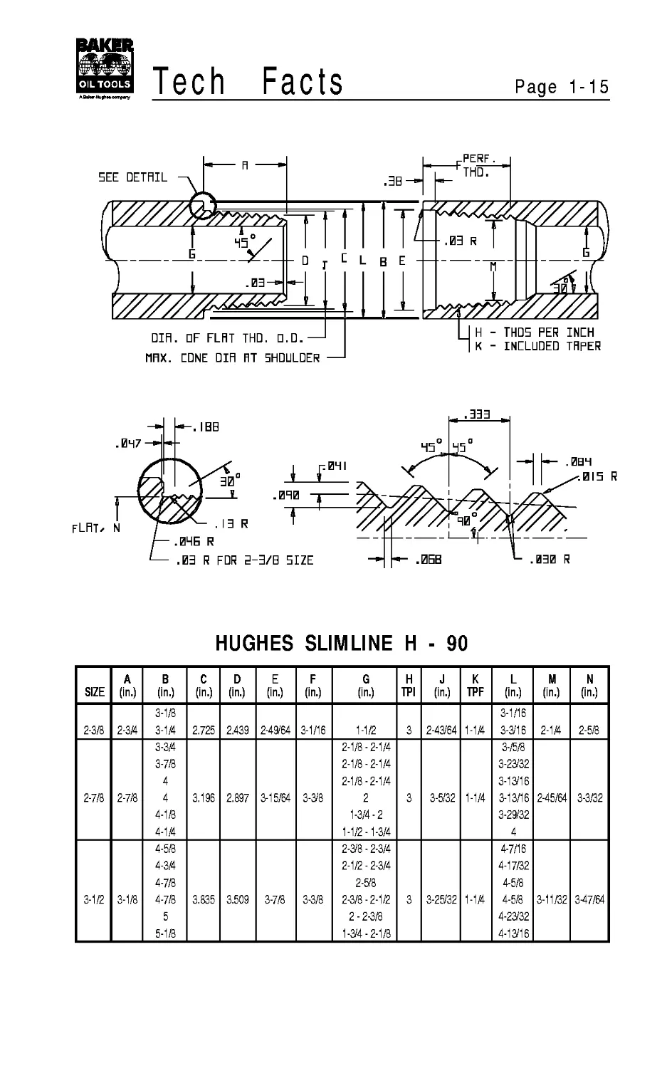
Tech Facts
Page 1-15
HHX. EDNE DIH RT SHOULDER —
HUGHES SLIMLINE H - 90
SIZE A (in.) В (in.) C (in.) D (in.) E (in.) F (in.) G (in.) H TPI J (in.) К TPF L (in.) M (in.) N (in.)
2-3/8 2-3/4 3-1/8 3-1/4 2.725 2.439 2-49/64 3-1/16 1-1/2 3 2-43/64 1-1/4 3-1/16 3-3/16 2-1/4 2-5/8
2-7/8 2-7/8 3-3/4 3-7/8 4 4 4-1/8 4-1/4 3.196 2.897 3-15/64 3-3/8 2-1/8-2-1/4 2-1/8-2-1/4 2-1/8-2-1/4 2 1-3/4-2 1-1/2 -1-3/4 3 3-5/32 1-1/4 3-/5/8 3-23/32 3-13/16 3-13/16 3-29/32 4 2-45/64 3-3/32
3-1/2 3-1/8 4-5/8 4-3/4 4-7/8 4-7/8 5 5-1/8 3.835 3.509 3-7/8 3-3/8 2-3/8 - 2-3/4 2-1/2-2-3/4 2-5/8 2-3/8-2-1/2 2 - 2-3/8 1-3/4 - 2-1/8 3 3-25/32 1-1/4 4-7/16 4-17/32 4-5/8 4-5/8 4-23/32 4-13/16 3-11/32 3-47/64
Page 1-16
Tech Facts
fl -----------*
PERF.
Г
В
E
G
30
DIR. DE FLAT
MRX. EDNE DIR AT 5HDULDER
TAPER
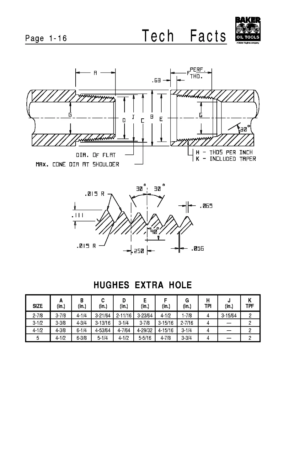
HUGHES EXTRA HOLE
SIZE A (in.) В (in.) C (in.) D (in.) E (in.) F (in.) G (in.) H TPI J (in.) К TPF
2-7/8 3-7/8 4-1/4 3-21/64 2-11/16 3-23/64 4-1/2 1-7/8 4 3-15/64 2
3-1/2 3-3/8 4-3/4 3-13/16 3-1/4 3-7/8 3-15/16 2-7/16 4 — 2
4-1/2 4-3/8 6-1/4 4-53/64 4-7/64 4-29/32 4-15/16 3-1/4 4 — 2
5 4-1/2 6-3/8 5-1/4 4-1/2 5-5/16 4-7/8 3-3/4 4 — 2
Tech
Facts
Page 1-17
RXI5 DF JOINT
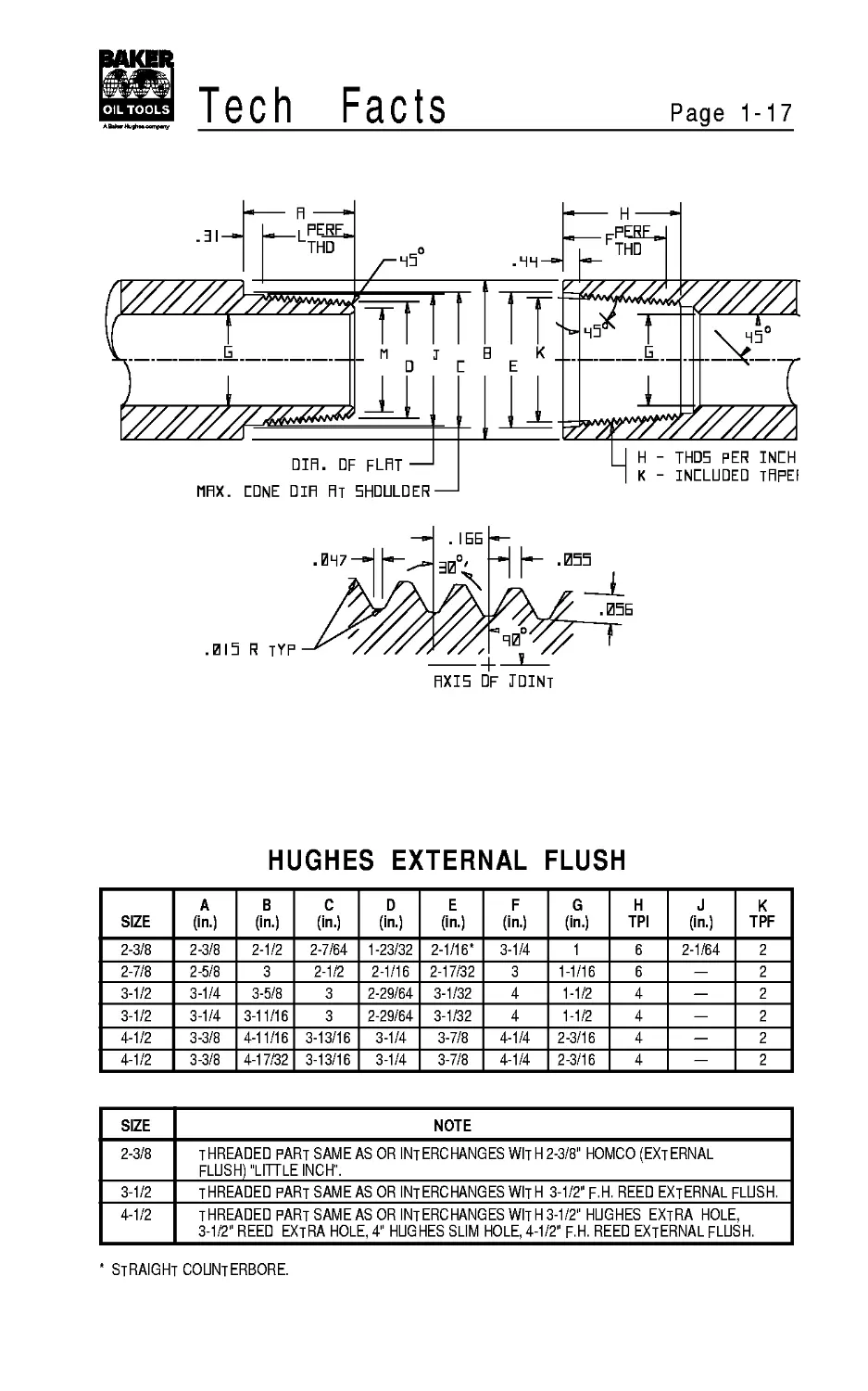
HUGHES EXTERNAL FLUSH
SIZE A (in.) В (in.) C (in.) D (in.) E (in.) F (in.) G (in.) H TPI J (in.) К TPF
2-3/8 2-3/8 2-1/2 2-7/64 1-23/32 2-1/16* 3-1/4 1 6 2-1/64 2
2-7/8 2-5/8 3 2-1/2 2-1/16 2-17/32 3 1-1/16 6 — 2
3-1/2 3-1/4 3-5/8 3 2-29/64 3-1/32 4 1-1/2 4 — 2
3-1/2 3-1/4 3-11/16 3 2-29/64 3-1/32 4 1-1/2 4 — 2
4-1/2 3-3/8 4-11/16 3-13/16 3-1/4 3-7/8 4-1/4 2-3/16 4 — 2
4-1/2 3-3/8 4-17/32 3-13/16 3-1/4 3-7/8 4-1/4 2-3/16 4 — 2
SIZE
NOTE
THREADED PART SAME AS OR INTERCHANGES WITH2-3/8" HOMCO (EXTERNAL
FLUSH) "LITTLE INCH".____
THREADED PART SAME AS OR INTERCHANGES WItH 3-1/2" F.H. REED EXTERNAL FLUSH.
THREADED PART SAMEAS OR INTERCHANGES WITH3-1/2" HUGHES EXTRA HOLE,
3-1/2" REED EXTRA HOLE, 4" HUGHES SUM HOLE, 4-1/2" F.H. REED EXTERNAL FLUSH.
straight counterbore.
Page 1-18
Tech
Facts
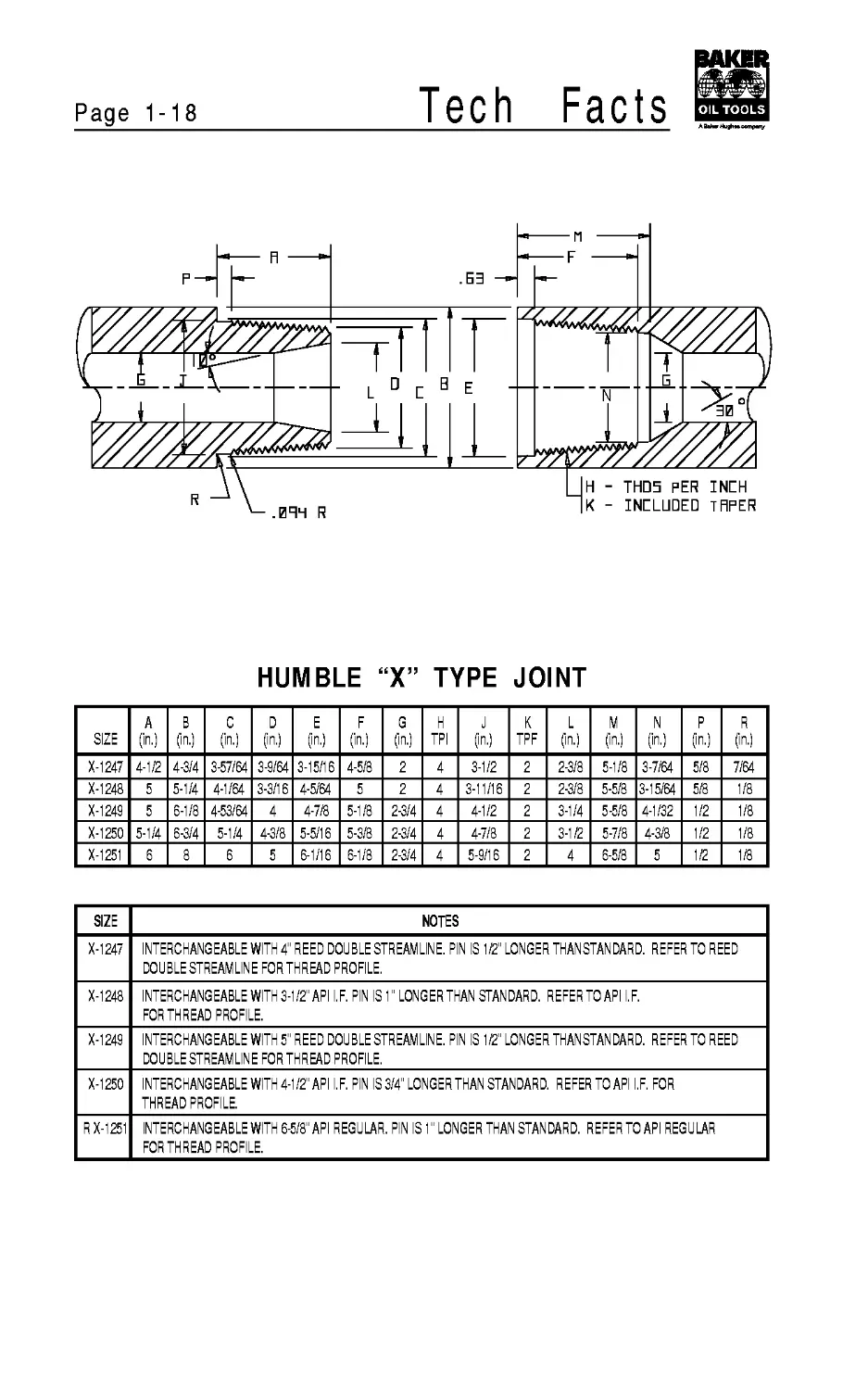
HUMBLE “X” TYPE JOINT
SIZE A (in.) В ?n.) C (in.) D ?n.) E ?n.) F (in.) G ?n.) H TPI J ?n.) К TPF L ?n.) M ?n.) N (in.) P ?n.) R ?n.)
X-1247 4-1/2 4-3/4 3-57/64 3-9/64 3-15/16 4-5/8 2 4 3-1/2 2 2-3/8 5-1/8 3-7/64 5/8 7/64
X-1248 5 5-1/4 4-1/64 3-3/16 4-5/64 5 2 4 3-11/16 2 2-3/8 5-5/8 3-15/64 5/8 1/8
X-1249 5 6-1/8 4-53/64 4 4-7/8 5-1/8 2-3/4 4 4-1/2 2 3-1/4 5-5/8 4-1/32 1/2 1/8
X-1250 5-1/4 6-3/4 5-1/4 4-3/8 5-5/16 5-3/8 2-3/4 4 4-7/8 2 3-1/2 5-7/8 4-3/8 1/2 1/8
X-1251 6 8 6 5 6-1/16 6-1/8 2-3/4 4 5-9/16 2 4 6-5/8 5 1/2 1/8
SIZE NOTES
X-1247 INTERCHANGEABLE WITH 4" REED DOUBLE STREAMLINE. PIN IS 1/2" LONGER THANSTANDARD. REFER TO REED DOUBLE STREAMLINE FOR THREAD PROFILE.
X-1248 INTERCHANGEABLE WITH 3-1/2" API I.F. PIN IS 1" LONGERTHAN STANDARD. REFERTOAPI I.F. FOR THREAD PROFILE.
X-1249 INTERCHANGEABLE WITH 5" REED DOUBLE STREAMLINE. PIN IS 1/2" LONGER THANSTANDARD. REFER TO REED DOUBLE STREAMLINE FOR THREAD PROFILE.
X-1250 INTERCHANGEABLE WITH 4-1/2" API I.F. PIN IS 3/4" LONGER THAN STANDARD. REFERTOAPI I.F. FOR THREAD PROFILE.
R X-1251 INTERCHANGEABLE WITH 6-5/8" API REGULAR. PIN IS 1" LONGER THAN STANDARD. REFERTOAPI REGULAR FOR THREAD PROFILE.
Tech Facts
Page 1-19
DIR. DF FLFIT—
ППХ. CONE Din FIT 5HDULDER —
.55>r*^
E
IB
INCH
ТПРЕП
c
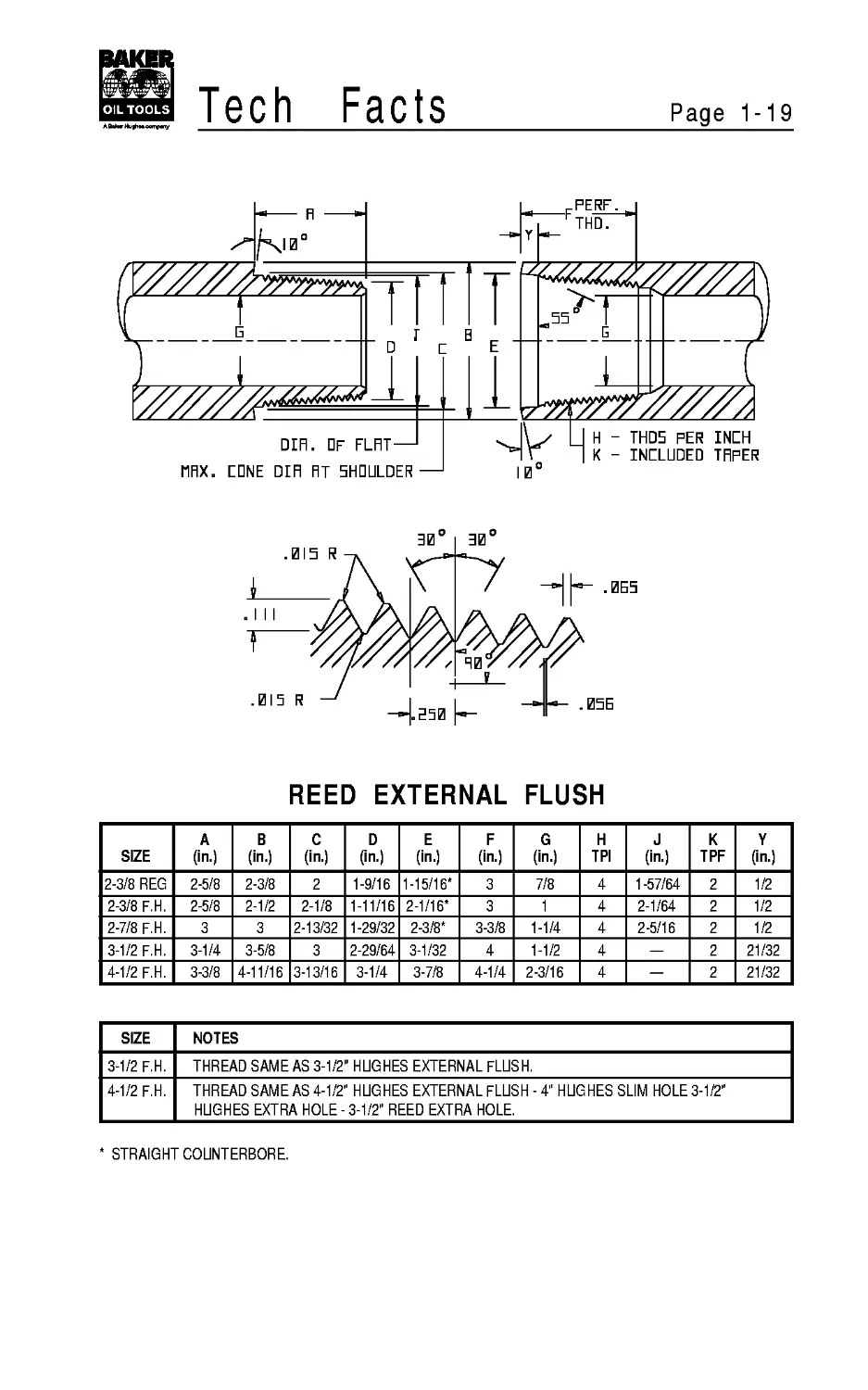
REED EXTERNAL FLUSH
SIZE A (in.) В (in.) C (in.) D (in.) E (in.) F (in.) G (in.) H TPI J (in.) К TPF Y (in.)
2-3/8 REG 2-5/8 2-3/8 2 1-9/16 1-15/16* 3 7/8 4 1-57/64 2 1/2
2-3/8 F.H. 2-5/8 2-1/2 2-1/8 1-11/16 2-1/16* 3 1 4 2-1/64 2 1/2
2-7/8 F.H. 3 3 2-13/32 1-29/32 2-3/8* 3-3/8 1-1/4 4 2-5/16 2 1/2
3-1/2 F.H. 3-1/4 3-5/8 3 2-29/64 3-1/32 4 1-1/2 4 — 2 21/32
4-1/2 F.H. 3-3/8 4-11/16 3-13/16 3-1/4 3-7/8 4-1/4 2-3/16 4 — 2 21/32
SIZE NOTES
3-1/2 F.H. THREAD SAME AS 3-1/2" HUGHES EXTERNAL FLUSH.______________________
4-1/2 F.H. THREAD SAME AS 4-1/2" HUGHES EXTERNAL FLUSH - 4" HUGHES SLIM HOLE 3-1/2"
HUGHES EXTRA HOLE-3-1/2" REED EXTRA HOLE.
STRAIGHT COUNTERBORE.
Page 1-20
Tech
Facts
.53
PERF.
I’THD.
DIR. DF FLRT —
MRX. LONE DIR RT SHOULDER----
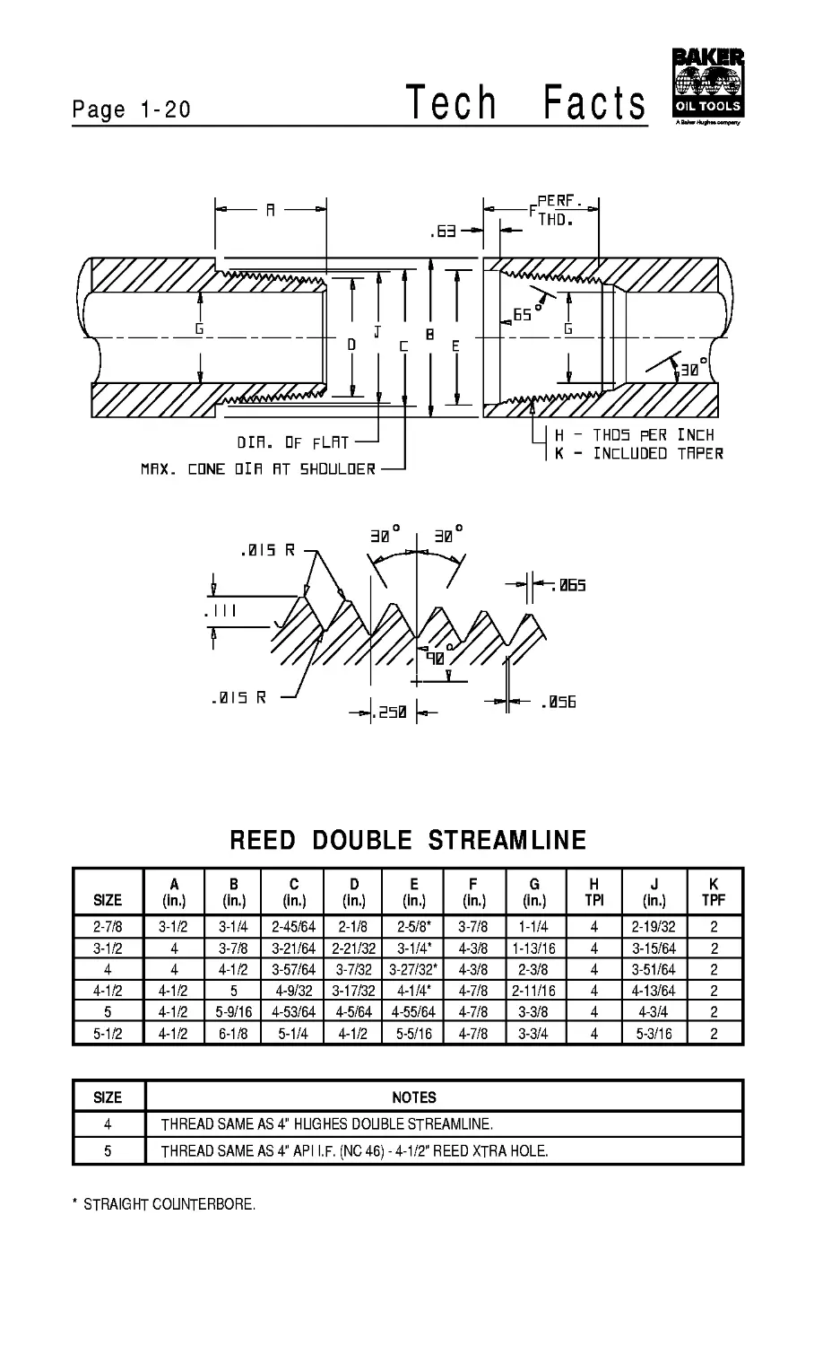
REED DOUBLE STREAMLINE
SIZE A (in.) В (in.) C (in.) D (in.) E (in.) F (in.) G (in.) H TPI J (in.) К TPF
2-7/8 3-1/2 3-1/4 2-45/64 2-1/8 2-5/8* 3-7/8 1-1/4 4 2-19/32 2
3-1/2 4 3-7/8 3-21/64 2-21/32 3-1/4* 4-3/8 1-13/16 4 3-15/64 2
4 4 4-1/2 3-57/64 3-7/32 3-27/32* 4-3/8 2-3/8 4 3-51/64 2
4-1/2 4-1/2 5 4-9/32 3-17/32 4-1/4* 4-7/8 2-11/16 4 4-13/64 2
5 4-1/2 5-9/16 4-53/64 4-5/64 4-55/64 4-7/8 3-3/8 4 4-3/4 2
5-1/2 4-1/2 6-1/8 5-1/4 4-1/2 5-5/16 4-7/8 3-3/4 4 5-3/16 2
SIZE NOTES
4 THREAD SAME AS 4" HUGHES DOUBLE STREAMLINE.
5 THREAD SAME AS 4" API I.F. (NC 46) -4-1/2" REED XTRA HOLE.
STRAIGHT COUNTERBORE.
Tech Facts
Page 1-21
PERF. i
THD.
INCH
TAPER
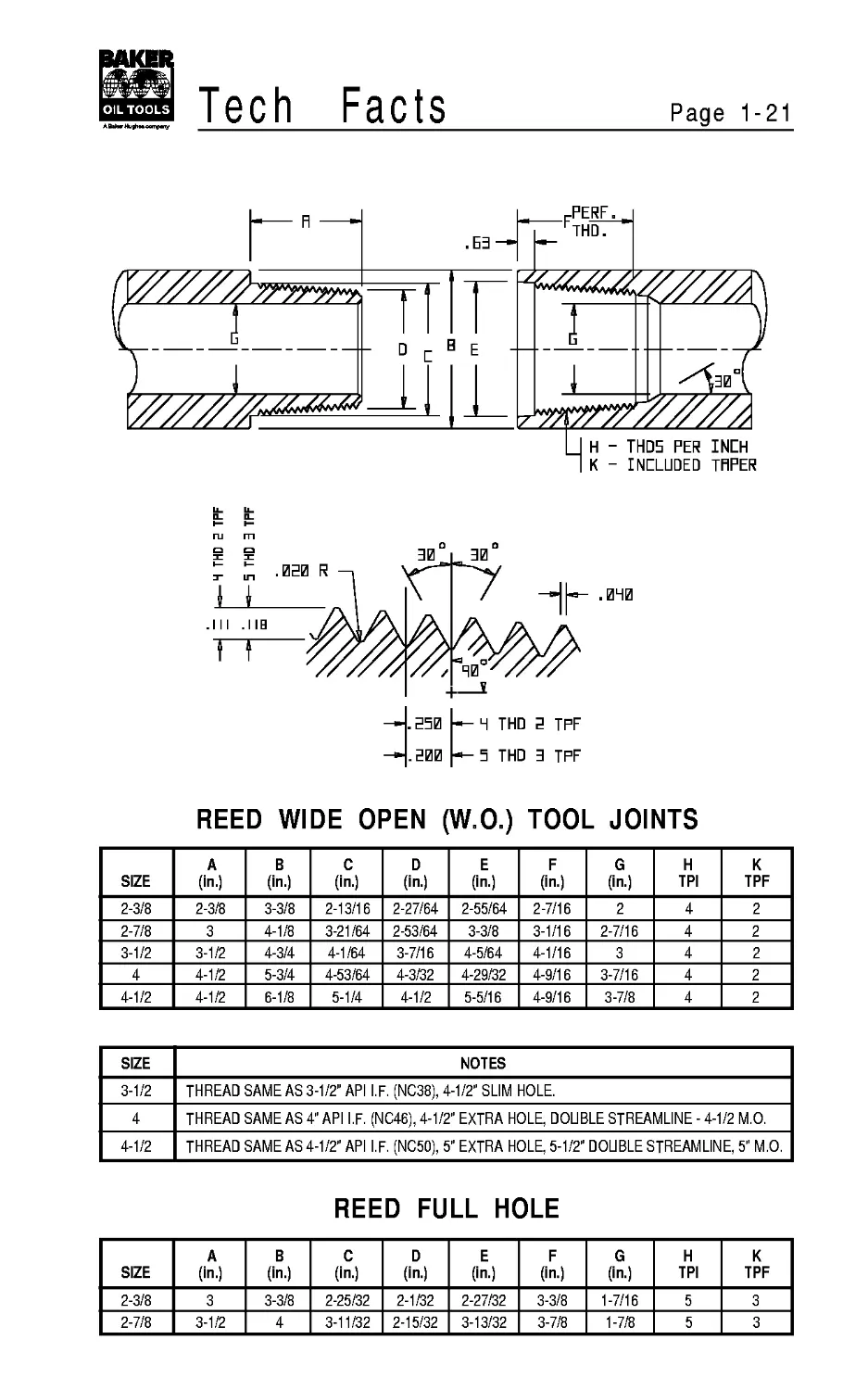
REED WIDE OPEN (W.O.) TOOL JOINTS
SIZE A (in.) В (in.) C (in.) D (in.) E (in.) F (in.) G (in.) H TPI К TPF
2-3/8 2-3/8 3-3/8 2-13/16 2-27/64 2-55/64 2-7/16 2 4 2
2-7/8 3 4-1/8 3-21/64 2-53/64 3-3/8 3-1/16 2-7/16 4 2
3-1/2 3-1/2 4-3/4 4-1/64 3-7/16 4-5/64 4-1/16 3 4 2
4 4-1/2 5-3/4 4-53/64 4-3/32 4-29/32 4-9/16 3-7/16 4 2
4-1/2 4-1/2 6-1/8 5-1/4 4-1/2 5-5/16 4-9/16 3-7/8 4 2
SIZE NOTES
3-1/2 THREAD SAME AS 3-1/2" API I.F. (NC38), 4-1/2" SLIM HOLE.
4 THREAD SAME AS 4" API I.F. (NC46), 4-1/2" EXTRA HOLE, DOUBLE STREAMLINE - 4-1/2 M.O.
4-1/2 THREAD SAME AS 4-1/2" API I.F. (NC50), 5" EXTRA HOLE, 5-1/2" DOUBLE STREAMLINE, 5" M.O.
REED FULL HOLE
SIZE A (in.) В (in.) C (in.) D (in.) E (in.) F (in.) G (in.) H TPI К TPF
2-3/8 3 3-3/8 2-25/32 2-1/32 2-27/32 3-3/8 1-7/16 5 3
2-7/8 3-1/2 4 3-11/32 2-15/32 3-13/32 3-7/8 1-7/8 5 3
Page 1-22
Tech
Facts
□ IH. DF FLAT —
MHX. CONE DIFI FIT 5HDULDER
— C BURE DIFI. - TFIPERED
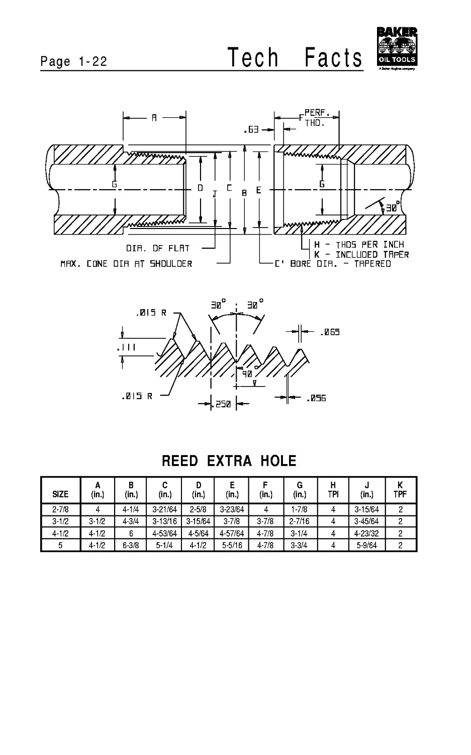
REED EXTRA HOLE
SIZE A (in.) В (in.) C (in.) D (in.) E (in.) F (in.) G (in.) H TPI J (in.) К TPF
2-7/8 4 4-1/4 3-21/64 2-5/8 3-23/64 4 1-7/8 4 3-15/64 2
3-1/2 3-1/2 4-3/4 3-13/16 3-15/64 3-7/8 3-7/8 2-7/16 4 3-45/64 2
4-1/2 4-1/2 6 4-53/64 4-5/64 4-57/64 4-7/8 3-1/4 4 4-23/32 2
5 4-1/2 6-3/8 5-1/4 4-1/2 5-5/16 4-7/8 3-3/4 4 5-9/64 2
Tech
Facts
Page 1-23
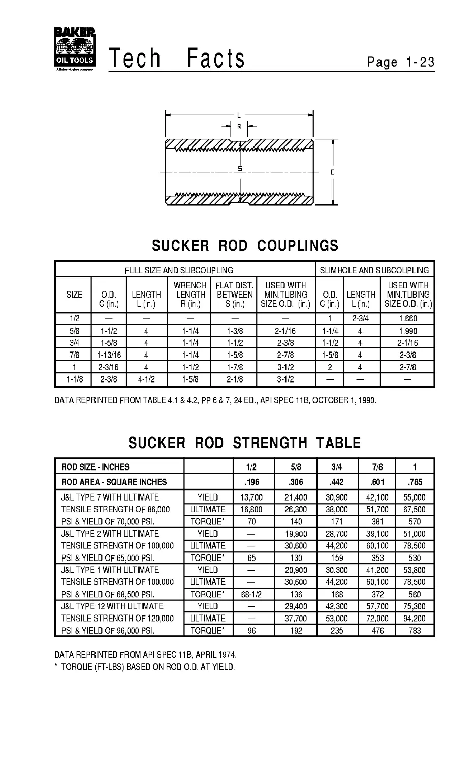
SUCKER ROD COUPLINGS
FULL SIZE AND SUBCOUPLING SLIMHOLE AND SUBCOUPLING
SIZE O.D. C(in.) LENGTH L(in.) WRENCH LENGTH R (in.) FLAT DIST. BETWEEN S (in.) USED WITH MIN.TUBING SIZE O.D. (in.) O.D. C(in.) LENGTH L (in.) USED WITH MIN.TUBING SIZEO.D. (in.)
1/2 — — — — — 1 2-3/4 1.660
5/8 1-1/2 4 1-1/4 1-3/8 2-1/16 1-1/4 4 1.990
3/4 1-5/8 4 1-1/4 1-1/2 2-3/8 1-1/2 4 2-1/16
7/8 1-13/16 4 1-1/4 1-5/8 2-7/8 1-5/8 4 2-3/8
1 2-3/16 4 1-1/2 1-7/8 3-1/2 2 4 2-7/8
1-1/8 2-3/8 4-1/2 1-5/8 2-1/8 3-1/2 — — —
DATA REPRINTED FROM TABLE 4.1 & 4.2, PP 6 & 7, 24 ED., API SPEC 11B, OCTOBER 1,1990.
SUCKER ROD STRENGTH TABLE
ROD SIZE-INCHES 1/2 5/8 3/4 7/8 1
ROD AREA-SQUARE INCHES .196 .306 .442 .601 .785
J<YPE7WITH ULTIMATE YIELD 13,700 21,400 30,900 42,100 55,000
TENSILE STRENGTH OF 86,000 ULTIMATE 16,800 26,300 38,000 51,700 67,500
PSI & YIELD OF 70,000 PSI. TORQUE* 70 140 171 381 570
J&L TYPE 2 WITH ULTIMATE YIELD — 19,900 28,700 39,100 51,000
TENSILE STRENGTH OF 100,000 ULTIMATE — 30,600 44,200 60,100 78,500
PSI & YIELD OF 65,000 PSI. TORQUE* 65 130 159 353 530
J&L TYPE 1 WITH ULTIMATE YIELD — 20,900 30,300 41,200 53,800
TENSILE STRENGTH OF 100,000 ULTIMATE — 30,600 44,200 60,100 78,500
PSI & YIELD OF 68,500 PSI. TORQUE* 68-1/2 136 168 372 560
J<YPE 12 WITH ULTIMATE YIELD — 29,400 42,300 57,700 75,300
TENSILE STRENGTH OF 120,000 ULTIMATE — 37,700 53,000 72,000 94,200
PSI & YIELD OF 96,000 PSI. TORQUE* 96 192 235 476 783
DATA REPRINTED FROM API SPEC 11B, APRIL 1974.
* TORQUE (FT-LBS) BASED ON ROD O.D. AT YIELD.
Page 1-24
Tech
Facts
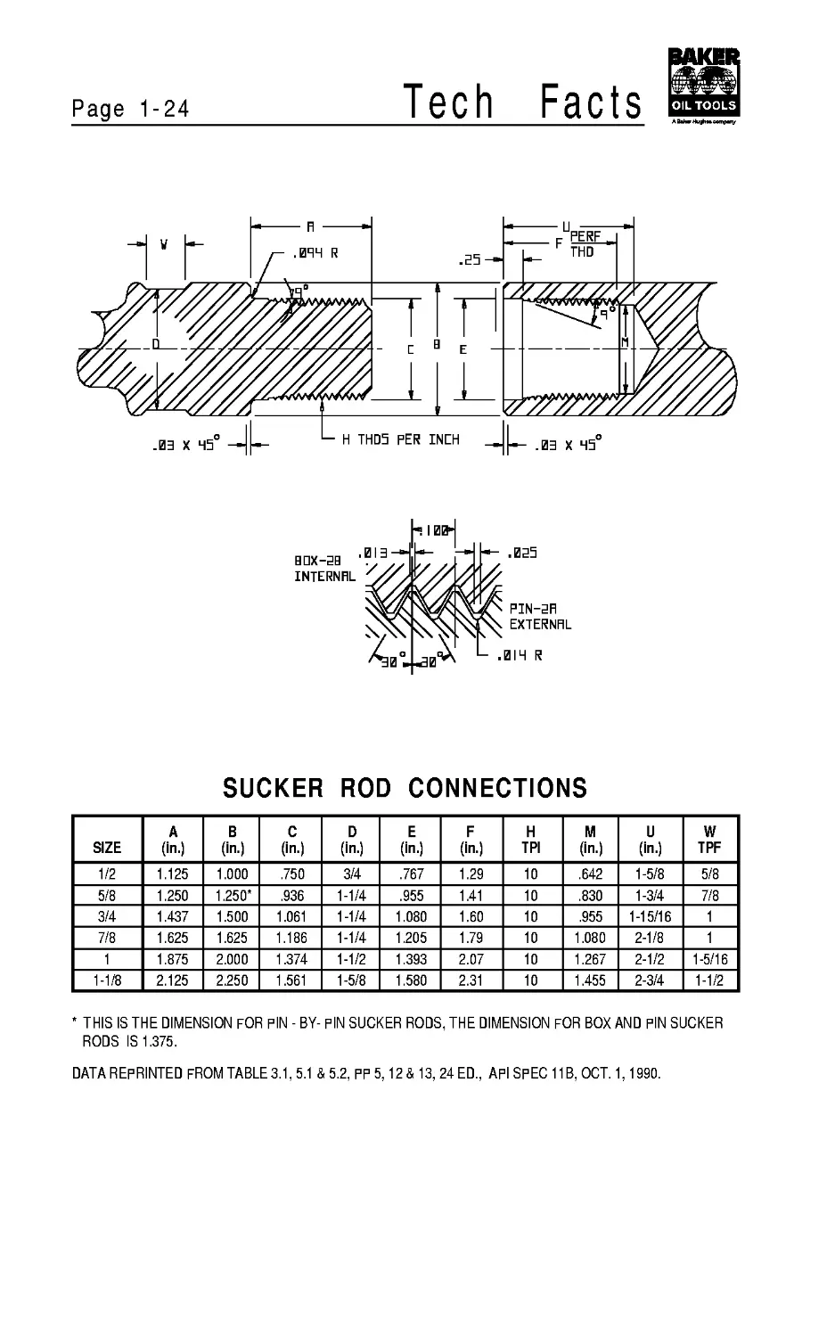
SUCKER ROD CONNECTIONS
SIZE A (in.) В (in.) C (in.) D (in.) E (in.) F (in.) H TPI M (in.) U (in.) W TPF
1/2 1.125 1.000 .750 3/4 .767 1.29 10 .642 1-5/8 5/8
5/8 1.250 1.250* .936 1-1/4 .955 1.41 10 .830 1-3/4 7/8
3/4 1.437 1.500 1.061 1-1/4 1.080 1.60 10 .955 1-15/16 1
7/8 1.625 1.625 1.186 1-1/4 1.205 1.79 10 1.080 2-1/8 1
1 1.875 2.000 1.374 1-1/2 1.393 2.07 10 1.267 2-1/2 1-5/16
1-1/8 2.125 2.250 1.561 1-5/8 1.580 2.31 10 1.455 2-3/4 1-1/2
THIS IS THE DIMENSION FOR PIN - BY- PIN SUCKER RODS, THE DIMENSION FOR BOX AND PIN SUCKER
RODS IS 1.375.
DATA REPRINTED FROM TABLE 3.1, 5.1 & 5.2, PP 5,12 & 13, 24 ED., API SPEC 11B, OCT. 1,1990.
Tech Facts
Page 1-25
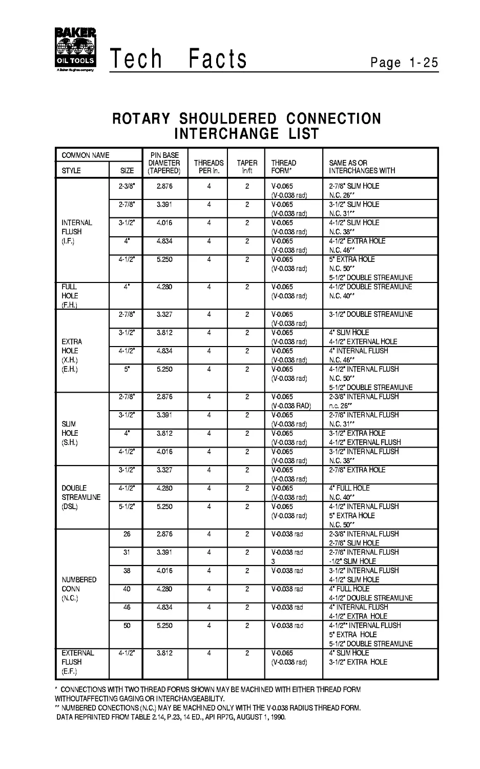
ROTARY SHOULDERED CONNECTION
INTERCHANGE LIST
COMMON NAME PIN BASE DIAMETER (TAPERED) THREADS PER in. TAPER in/ft THREAD FORM' SAME AS OR INTERCHANGES WITH
STYLE SIZE
INTERNAL FLUSH (I.F.) 2-3/8’ 2.876 4 2 V-0.065 (V-0.038 rad) 2-7/8’ SUM HOLE N.C. 26”
2-7/8’ 3.391 4 2 V-0.065 (V-0.038 rad) 3-1/2’ SUM HOLE N.C. 31”
3-1/2’ 4.016 4 2 V-0.065 (V-0.038 rad) 4-1/2’ SUM HOLE N.C. 38”
4’ 4.834 4 2 V-0.065 (V-0.038 rad) 4-1/2’ EXTRA HOLE N.C. 46”
4-1/2’ 5.250 4 2 V-0.065 (V-0.038 rad) 5’ EXTRA HOLE N.C. 50” 5-1/2’ DOUBLE STREAMUNE
FULL HOLE (F.H.) 4’ 4.280 4 2 V-0.065 (V-0.038 rad) 4-1/2’ DOUBLE STREAMUNE N.C. 40”
EXTRA HOLE (X.H.) (E.H.) 2-7/8’ 3.327 4 2 V-0.065 (V-0.038 rad) 3-1/2’ DOUBLE STREAMUNE
3-1/2’ 3.812 4 2 V-0.065 (V-0.038 rad) 4’ SUM HOLE 4-1/2’EXTERNAL HOLE
4-1/2’ 4.834 4 2 V-0.065 (V-0.038 rad) 4’INTERNAL FLUSH N.C. 46”
5’ 5.250 4 2 V-0.065 (V-0.038 rad) 4-1/2’INTERNAL FLUSH N.C. 50” 5-1/2’ DOUBLE STREAMUNE
SUM HOLE (S.H.) 2-7/8’ 2.876 4 2 V-0.065 (V-0.038 RAD) 2-3/8’INTERNAL FLUSH n.c. 26”
3-1/2’ 3.391 4 2 V-0.065 (V-0.038 rad) 2-7/8’INTERNAL FLUSH N.C. 31”
4’ 3.812 4 2 V-0.065 (V-0.038 rad) 3-1/2’ EXTRA HOLE 4-1/2’ EXTERNAL FLUSH
4-1/2’ 4.016 4 2 V-0.065 (V-0.038 rad) 3-1/2’INTERNAL FLUSH N.C. 38”
DOUBLE STREAMUNE (DSL) 3-1/2’ 3.327 4 2 V-0.065 (V-0.038 rad) 2-7/8’ EXTRA HOLE
4-1/2’ 4.280 4 2 V-0.065 (V-0.038 rad) 4’ FULL HOLE N.C. 40”
5-1/2’ 5.250 4 2 V-0.065 (V-0.038 rad) 4-1/2’INTERNAL FLUSH 5’ EXTRA HOLE N.C. 50”
NUMBERED CONN (N.C.) 26 2.876 4 2 V-0.038 rad 2-3/8’INTERNAL FLUSH 2-7/8’ SUM HOLE
31 3.391 4 2 V-0.038 rad 3 2-7/8’INTERNAL FLUSH -1/2’ SLIM HOLE
38 4.016 4 2 V-0.038 rad 3-1/2’INTERNAL FLUSH 4-1/2’ SUM HOLE
40 4.280 4 2 V-0.038 rad 4’ FULL HOLE 4-1/2’ DOUBLE STREAMUNE
46 4.834 4 2 V-0.038 rad 4’INTERNAL FLUSH 4-1/2’ EXTRA HOLE
50 5.250 4 2 V-0.038 rad 4-1/2’’INTERNAL FLUSH 5’ EXTRA HOLE 5-1/2’ DOUBLE STREAMUNE
EXTERNAL FLUSH (E.F.) 4-1/2’ 3.812 4 2 V-0.065 (V-0.038 rad) 4’ SUM HOLE 3-1/2’ EXTRA HOLE
' CONNECTIONS WITH TWO THREAD FORMS SHOWN MAYBE MACHINED WITH EITHER THREAD FORM
WITHOUTAFFECTI NG GAGI NG OR INTERCHANGEABIUTY.
” NUMBERED CONECTIONS (N.C.) MAY BE MACHINED ONLY WITH THE V-0.038 RADIUS THREAD FORM.
DATA REPRINTED FROM TABLE 2.14, P.23,14 ED., API RP7G, AUGUST 1,1990.
Page 1-26
Tech
Facts
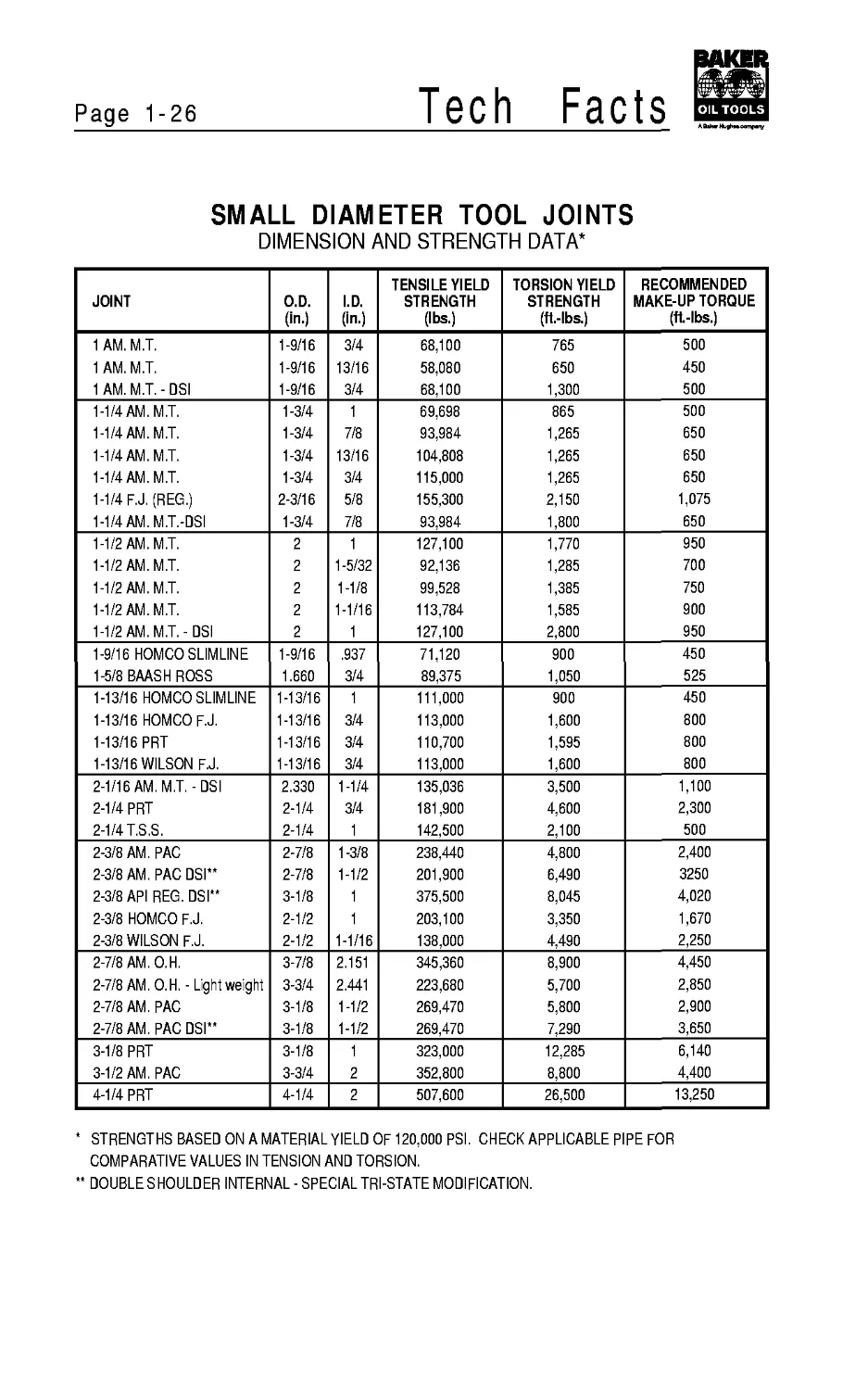
SMALL DIAMETER TOOL JOINTS
DIMENSION AND STRENGTH DATA*
JOINT O.D. (in.) I.D. (in.) TENSILE YIELD STRENGTH (lbs.) TORSION YIELD STRENGTH (ft.-lbs.) RECOMMENDED MAKE-UP TORQUE (ft-lbs.)
1 AM.M.T. 1-9/16 3/4 68,100 765 500
1 AM.M.T. 1-9/16 13/16 58,080 650 450
1 AM.M.T.-DSI 1-9/16 3/4 68,100 1,300 500
1-1/4 AM.M.T. 1-3/4 1 69,698 865 500
1-1/4 AM.M.T. 1-3/4 7/8 93,984 1,265 650
1-1/4 AM.M.T. 1-3/4 13/16 104,808 1,265 650
1-1/4 AM.M.T. 1-3/4 3/4 115,000 1,265 650
1-1/4 F.J. (REG.) 2-3/16 5/8 155,300 2,150 1,075
1-1/4 AM. M.T.-DSI 1-3/4 7/8 93,984 1,800 650
1-1/2 AM.M.T. 2 1 127,100 1,770 950
1-1/2 AM.M.T. 2 1-5/32 92,136 1,285 700
1-1/2 AM.M.T. 2 1-1/8 99,528 1,385 750
1-1/2 AM.M.T. 2 1-1/16 113,784 1,585 900
1-1/2 AM. M.T.-DSI 2 1 127,100 2,800 950
1-9/16 HOMCO SLIMLINE 1-9/16 .937 71,120 900 450
1-5/8 BAASH ROSS 1.660 3/4 89,375 1,050 525
1-13/16 HOMCO SLIMLINE 1-13/16 1 111,000 900 450
1-13/16 HOMCO F.J. 1-13/16 3/4 113,000 1,600 800
1-13/16 PRT 1-13/16 3/4 110,700 1,595 800
1-13/16 WILSON F.J. 1-13/16 3/4 113,000 1,600 800
2-1/16 AM. M.T.-DSI 2.330 1-1/4 135,036 3,500 1,100
2-1/4 PRT 2-1/4 3/4 181,900 4,600 2,300
2-1/4 T.S.S. 2-1/4 1 142,500 2,100 500
2-3/8 AM. РАС 2-7/8 1-3/8 238,440 4,800 2,400
2-3/8 AM. РАС DSI** 2-7/8 1-1/2 201,900 6,490 3250
2-3/8 API REG. DSI** 3-1/8 1 375,500 8,045 4,020
2-3/8 HOMCO F.J. 2-1/2 1 203,100 3,350 1,670
2-3/8 WILSON F.J. 2-1/2 1-1/16 138,000 4,490 2,250
2-7/8 AM.O.H. 3-7/8 2.151 345,360 8,900 4,450
2-7/8 AM. O.H. - Lightweight 3-3/4 2.441 223,680 5,700 2,850
2-7/8 AM. РАС 3-1/8 1-1/2 269,470 5,800 2,900
2-7/8 AM. РАС DSI** 3-1/8 1-1/2 269,470 7,290 3,650
3-1/8 PRT 3-1/8 1 323,000 12,285 6,140
3-1/2 AM. РАС 3-3/4 2 352,800 8,800 4,400
4-1/4 PRT 4-1/4 2 507,600 26,500 13,250
* STRENGTHS BASED ON A MATERIAL YIELD OF 120,000 PSI. CHECK APPLICABLE PIPE FOR
COMPARATIVE VALUES IN TENSION AND TORSION.
** DOUBLESHOULDER INTERNAL-SPECIALTRI-STATEMODIFICATION.
Tech Facts
Page 1-27
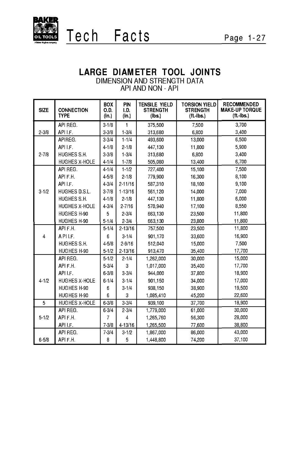
LARGE DIAMETER TOOL JOINTS
DIMENSION AND STRENGTH DATA
API AND NON - API
SIZE CONNECTION TYPE BOX O.D. (in.) PIN I.D. (in.) TENSILE YIELD STRENGTH (lbs.) TORSION YIELD STRENGTH (ft.-lbs.) RECOMMENDED MAKE-UP TORQUE (ft.-lbs.)
API REG. 3-1/8 1 375,500 7,500 3,700
2-3/8 API I.F. 3-3/8 1-3/4 313,680 6,800 3,400
APIREG. 3-3/4 1-1/4 493,600 13,000 6,500
API I.F. 4-1/8 2-1/8 447,130 11,800 5,900
2-7/8 HUGHES S.H. 3-3/8 1-3/4 313,680 6,800 3,400
HUGHES X-HOLE 4-1/4 1-7/8 505,080 13,400 6,700
APIREG. 4-1/4 1-1/2 727,400 15,100 7,500
API F.H. 4-5/8 2-1/8 779,900 16,300 8,100
API I.F. 4-3/4 2-11/16 587,310 18,100 9,100
3-1/2 HUGHES D.S.L. 3-7/8 1-13/16 561,120 14,000 7,000
HUGHES S.H. 4-1/8 2-1/8 447,130 11,800 6,000
HUGHES X-HOLE 4-3/4 2-7/16 570,940 17,100 8,550
HUGHES H-90 5 2-3/4 663,130 23,500 11,800
HUGHES H-90 5-1/4 2-3/4 663,130 23,800 11,800
API F.H. 5-1/4 2-13/16 757,500 23,500 11,800
4 A PI I.F. 6 3-1/4 901,170 33,600 16,900
HUGHES S.H. 4-5/8 2-9/16 512,040 15,000 7,500
HUGHES H-90 5-1/2 2-13/16 913,470 35,400 17,700
APIREG. 5-1/2 2-1/4 1,262,000 30,000 15,000
API F.H. 5-3/4 3 1,017,000 35,400 17,700
API I.F. 6-3/8 3-3/4 944,000 37,800 18,900
4-1/2 HUGHES X-HOLE 6-1/4 3-1/4 901,150 34,000 17,000
HUGHES H-90 6 3-1/4 938,150 38,900 19,500
HUGHES H-90 6 3 1,085,410 45,200 22,600
5 HUGHES X-HOLE 6-3/8 3-3/4 939,100 37,700 18,900
APIREG. 6-3/4 2-3/4 1,779,000 61,000 30,000
5-1/2 API F.H. 7 4 1,265,760 56,300 28,000
API I.F. 7-3/8 4-13/16 1,265,500 77,600 38,800
APIREG. 7-3/4 3-1/2 1,867,000 86,000 43,000
6-5/8 API F.H. 8 5 1,448,800 74,200 37,100
Page 1-28
Tech Facts
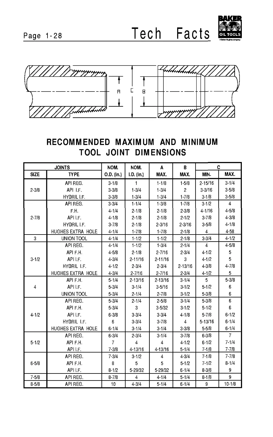
RECOMMENDED MAXIMUM AND MINIMUM
TOOL JOINT DIMENSIONS
JOINTS NOM. O.D. (in.) NOM. I.D. (in.) A MAX. В MAX. C
SIZE TYPE MIN. MAX.
API REG. 3-1/8 1 1-1/8 1-5/8 2-15/16 3-1/4
2-3/8 API I.F. 3-3/8 1-3/4 1-3/4 2 3-3/16 3-5/8
HYDRIL I.F. 3-3/8 1-3/4 1-3/4 1-7/8 3-1/8 3-5/8
API REG. 3-3/4 1-1/4 1-3/8 1-7/8 3-1/2 4
F.H. 4-1/4 2-1/8 2-1/8 2-3/8 4-1/16 4-5/8
2-7/8 API I.F. 4-1/8 2-1/8 2-1/8 2-1/2 3-7/8 4-3/8
HYDRIL I.F. 3-7/8 2-1/8 2-3/16 2-3/16 3-5/8 4-1/8
HUGHES EXTRA HOLE 4-1/4 1-7/8 1-7/8 2-1/8 4 4-58
3 UNION TOOL 4-1/4 1-1/2 1-1/2 2-1/8 3-3/4 4-1/2
API REG. 4-1/4 1-1/2 1-3/4 2-1/4 4 4-5/8
API F.H. 4-5/8 2-1/8 2-7/16 2-3/4 4-1/2 5
3-1/2 API I.F. 4-3/4 2-11/16 2-11/16 3 4-1/2 5
HYDRIL I.F. 4-1/2 2-3/4 2-3/4 2-13/16 4-3/8 4-7/8
HUGHES EXTRA HOLE 4-3/4 2-7/16 2-7/16 2-3/4 4-1/2 5
API F.H. 5-1/4 2-13/16 2-13/16 3-1/4 5 5-3/8
4 API I.F. 5-3/4 3-1/4 3-5/16 3-1/2 5-1/2 6
UNION TOOL 5-3/4 2-1/4 2-7/8 3-1/2 5-3/8 6
API REG. 5-3/4 2-1/4 2-5/8 3-1/4 5-3/8 6
API F.H. 5-3/4 3 3-5/32 3-1/2 5-1/2 6
4-1/2 API I.F. 6-3/8 3-3/4 3-3/4 4-1/8 5-7/8 6-1/2
HYDRIL I.F. 6 3-3/4 3-7/8 4 5-13/16 6-1/4
HUGHES EXTRA HOLE 6-1/4 3-1/4 3-1/4 3-3/8 5-5/8 6-1/4
API REG. 6-3/4 2-3/4 3-1/4 3-7/8 6-3/8 7
5-1/2 API F.H. 7 4 4 4-1/2 6-1/2 7-1/4
API I.F. 7-3/8 4-13/16 4-13/16 5-1/4 7-1/8 7-7/8
API REG. 7-3/4 3-1/2 4 4-3/4 7-1/8 7-7/8
6-5/8 API F.H. 8 5 5 5-1/2 7-1/2 8-1/4
API I.F. 8-1/2 5-29/32 5-29/32 6-1/4 8-3/8 9
7-5/8 API REG. 8-7/8 4 4-1/4 5-1/4 8-1/8 9
8-5/8 API REG. 10 4-3/4 5-1/4 6-1/4 9 10-1/8
Tech Facts
Page 1-29
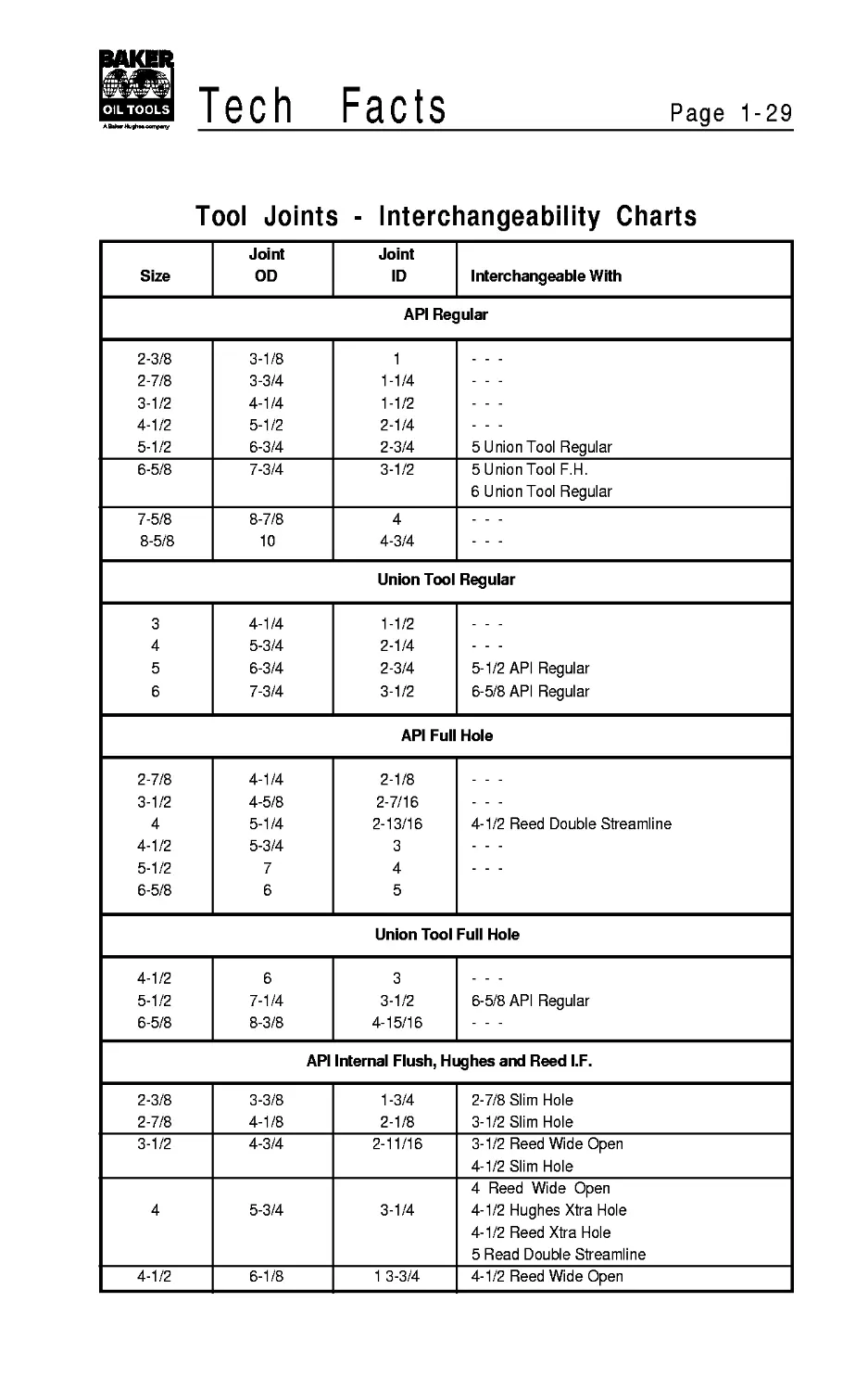
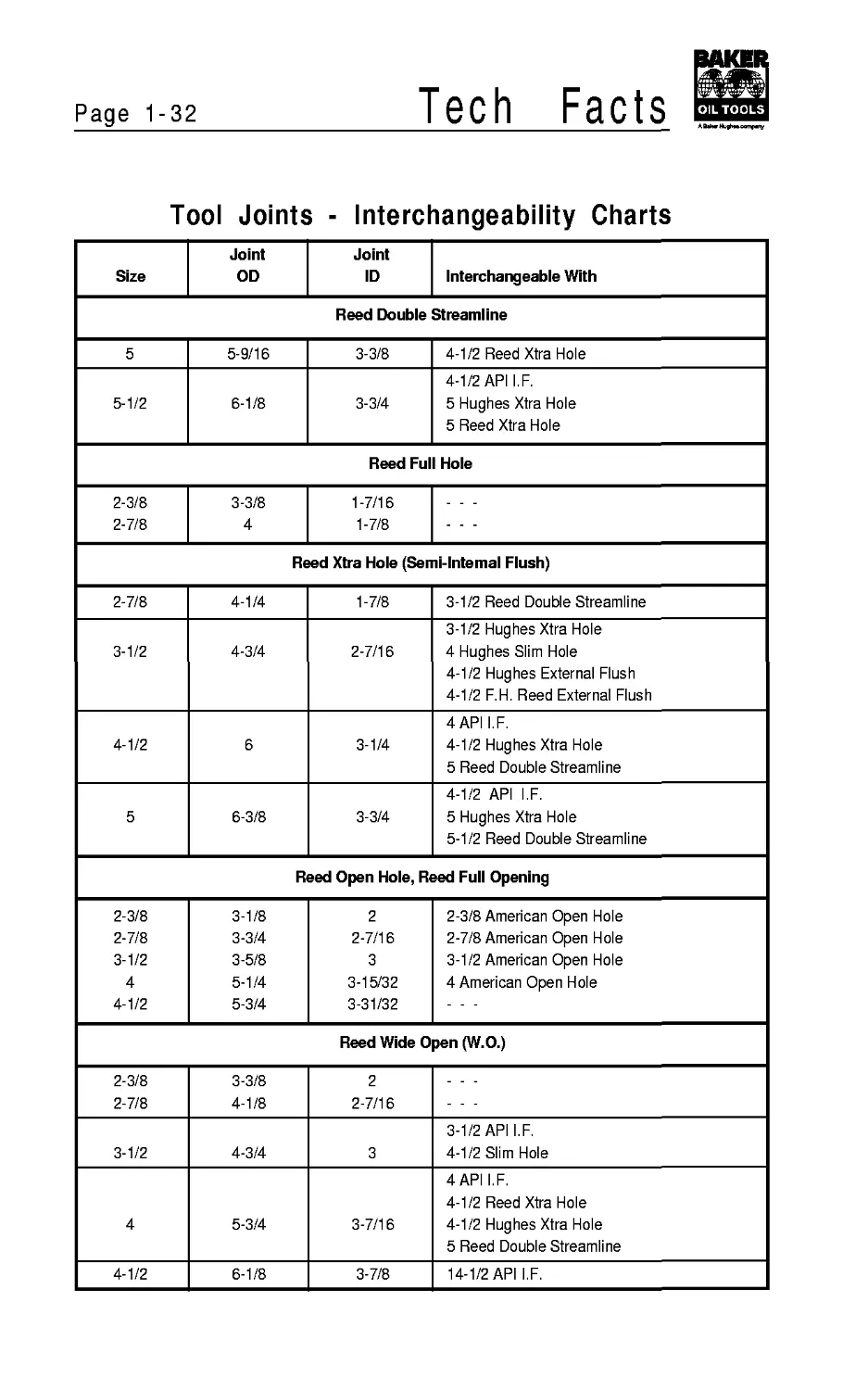
Tool Joints - Interchangeability Charts
Size Joint OD Joint ID Interchangeable With
API Regular
2-3/8 3-1/8 1
2-7/8 3-3/4 1-1/4
3-1/2 4-1/4 1-1/2
4-1/2 5-1/2 2-1/4
5-1/2 6-3/4 2-3/4 5 Union Tool Regular
6-5/8 7-3/4 3-1/2 5 Union Tool F.H. 6 Union Tool Regular
7-5/8 8-7/8 4
8-5/8 10 4-3/4
Union Tool Regular
3 4-1/4 1-1/2
4 5-3/4 2-1/4
5 6-3/4 2-3/4 5-1/2 API Regular
6 7-3/4 3-1/2 6-5/8 API Regular
API Full Hole
2-7/8 4-1/4 2-1/8
3-1/2 4-5/8 2-7/16
4 5-1/4 2-13/16 4-1/2 Reed Double Streamline
4-1/2 5-3/4 3
5-1/2 7 4
6-5/8 6 5
Union Tool Full Hole
4-1/2 6 3
5-1/2 7-1/4 3-1/2 6-5/8 API Regular
6-5/8 8-3/8 4-15/16
API Internal Flush, Hughes and Reed I.F.
2-3/8 3-3/8 1-3/4 2-7/8 Slim Hole
2-7/8 4-1/8 2-1/8 3-1/2 Slim Hole
3-1/2 4-3/4 2-11/16 3-1/2 Reed Wide Open 4-1/2 Slim Hole
4 Reed Wide Open
4 5-3/4 3-1/4 4-1/2 Hughes Xtra Hole 4-1/2 Reed Xtra Hole 5 Read Double Streamline
4-1/2 6-1/8 1 3-3/4 4-1/2 Reed Wide Open
Page 1-30
Tech
Facts
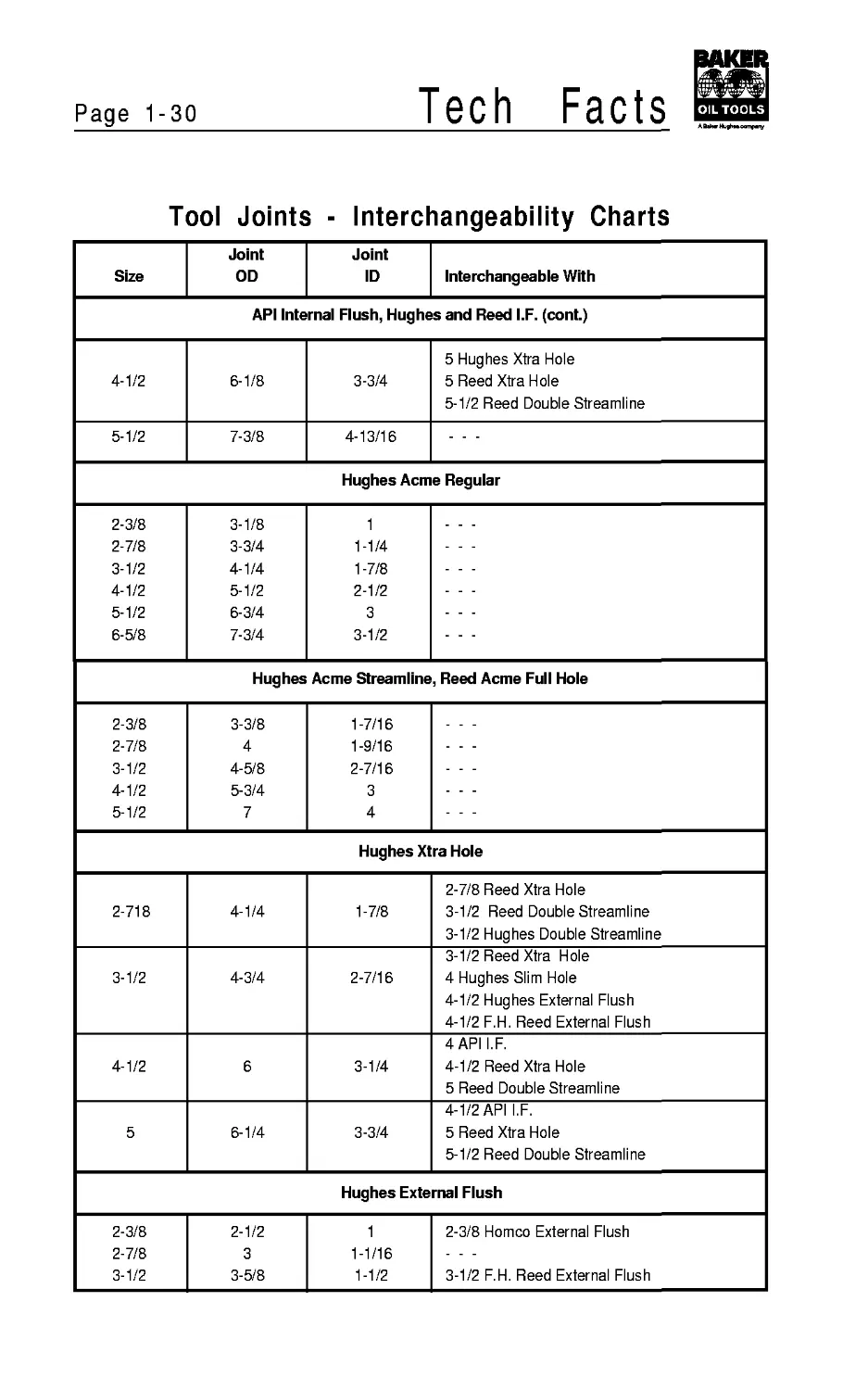
Tool Joints - Interchangeability Charts
Joint Joint
Size OD ID Interchangeable With
API Internal Flush, Hughes and Reed I.F. (cont.)
5 Hughes Xtra Hole
4-1/2 6-1/8 3-3/4 5 Reed Xtra Hole 5-1/2 Reed Double Streamline
5-1/2 7-3/8 4-13/16
Hughes Acme Regular
2-3/8 3-1/8 1
2-7/8 3-3/4 1-1/4
3-1/2 4-1/4 1-7/8
4-1/2 5-1/2 2-1/2
5-1/2 6-3/4 3
6-5/8 7-3/4 3-1/2
Hughes Acme Streamline, Reed Acme Full Hole
2-3/8 3-3/8 1-7/16
2-7/8 4 1-9/16
3-1/2 4-5/8 2-7/16
4-1/2 5-3/4 3
5-1/2 7 4
Hughes Xtra Hole
2-7/8 Reed Xtra Hole
2-718 4-1/4 1-7/8 3-1/2 Reed Double Streamline 3-1/2 Hughes Double Streamline
3-1/2 Reed Xtra Hole
3-1/2 4-3/4 2-7/16 4 Hughes Slim Hole 4-1/2 Hughes External Flush 4-1/2 F.H. Reed External Flush
4 API I.F.
4-1/2 6 3-1/4 4-1/2 Reed Xtra Hole 5 Reed Double Streamline
4-1/2 API I.F.
5 6-1/4 3-3/4 5 Reed Xtra Hole 5-1/2 Reed Double Streamline
Hughes External Flush
2-3/8 2-1/2 1 2-3/8 Homco External Flush
2-7/8 3 1-1/16
3-1/2 3-5/8 1-1/2 3-1/2 F.H. Reed External Flush
Tech Facts
Page 1-31
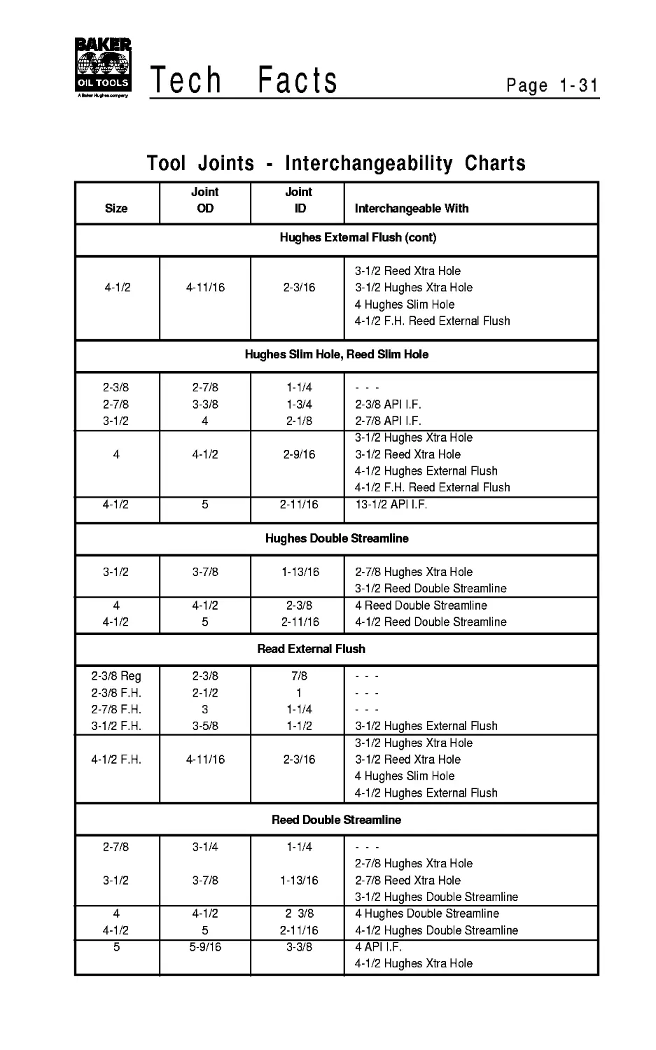
Tool Joints - Interchangeability Charts
Size Joint OD Joint ID Interchangeable With
Hughes External Flush (cont)
4-1/2 4-11/16 2-3/16 3-1/2 Reed Xtra Hole 3-1/2 Hughes Xtra Hole 4 Hughes Slim Hole 4-1/2 F.H. Reed External Flush
Hughes Slim Hole, Reed Slim Hole
2-3/8 2-7/8 3-1/2 2-7/8 3-3/8 4 1-1/4 1-3/4 2-1/8 2-3/8 API I.F. 2-7/8 API I.F.
4 4-1/2 2-9/16 3-1/2 Hughes Xtra Hole 3-1/2 Reed Xtra Hole 4-1/2 Hughes External Flush 4-1/2 F.H. Reed External Flush
4-1/2 5 2-11/16 13-1/2 API I.F.
Hughes Double Streamline
3-1/2 3-7/8 1-13/16 2-7/8 Hughes Xtra Hole 3-1/2 Reed Double Streamline
4 4-1/2 4-1/2 5 2-3/8 2-11/16 4 Reed Double Streamline 4-1/2 Reed Double Streamline
Read External Flush
2-3/8 Reg 2-3/8 F.H. 2-7/8 F.H. 3-1/2 F.H. 2-3/8 2-1/2 3 3-5/8 7/8 1 1-1/4 1-1/2 3-1/2 Hughes External Flush
4-1/2 F.H. 4-11/16 2-3/16 3-1/2 Hughes Xtra Hole 3-1/2 Reed Xtra Hole 4 Hughes Slim Hole 4-1/2 Hughes External Flush
Reed Double Streamline
2-7/8 3-1/2 3-1/4 3-7/8 1-1/4 1-13/16 2-7/8 Hughes Xtra Hole 2-7/8 Reed Xtra Hole 3-1/2 Hughes Double Streamline
4 4-1/2 4-1/2 5 2 3/8 2-11/16 4 Hughes Double Streamline 4-1/2 Hughes Double Streamline
5 5-9/16 3-3/8 4API I.F. 4-1/2 Hughes Xtra Hole
Page 1-32
Tech
Facts
Tool Joints - Interchangeability Charts
Size Joint OD Joint ID Interchangeable With
Reed Double Streamline
5 5-9/16 3-3/8 4-1/2 Reed Xtra Hole
5-1/2 6-1/8 3-3/4 4-1/2 API I.F. 5 Hughes Xtra Hole 5 Reed Xtra Hole
Reed Full Hole
2-3/8 2-7/8 3-3/8 4 1-7/16 1-7/8
Reed Xtra Hole (Semi-lntemal Flush)
2-7/8 4-1/4 1-7/8 3-1/2 Reed Double Streamline
3-1/2 4-3/4 2-7/16 3-1/2 Hughes Xtra Hole 4 Hughes Slim Hole 4-1/2 Hughes External Flush 4-1/2 F.H. Reed External Flush
4-1/2 6 3-1/4 4 API I.F. 4-1/2 Hughes Xtra Hole 5 Reed Double Streamline
5 6-3/8 3-3/4 4-1/2 API I.F. 5 Hughes Xtra Hole 5-1/2 Reed Double Streamline
Reed Open Hole, Reed Full Opening
2-3/8 2-7/8 3-1/2 4 4-1/2 3-1/8 3-3/4 3-5/8 5-1/4 5-3/4 2 2-7/16 3 3-15/32 3-31/32 2-3/8 American Open Hole 2-7/8 American Open Hole 3-1/2 American Open Hole 4 American Open Hole
Reed Wide Open (W.O.)
2-3/8 2-7/8 3-3/8 4-1/8 2 2-7/16
3-1/2 4-3/4 3 3-1/2 API I.F. 4-1/2 Slim Hole
4 5-3/4 3-7/16 4 API I.F. 4-1/2 Reed Xtra Hole 4-1/2 Hughes Xtra Hole 5 Reed Double Streamline
4-1/2 6-1/8 3-7/8 14-1/2 API I.F.
Tech Facts
Page 1-33
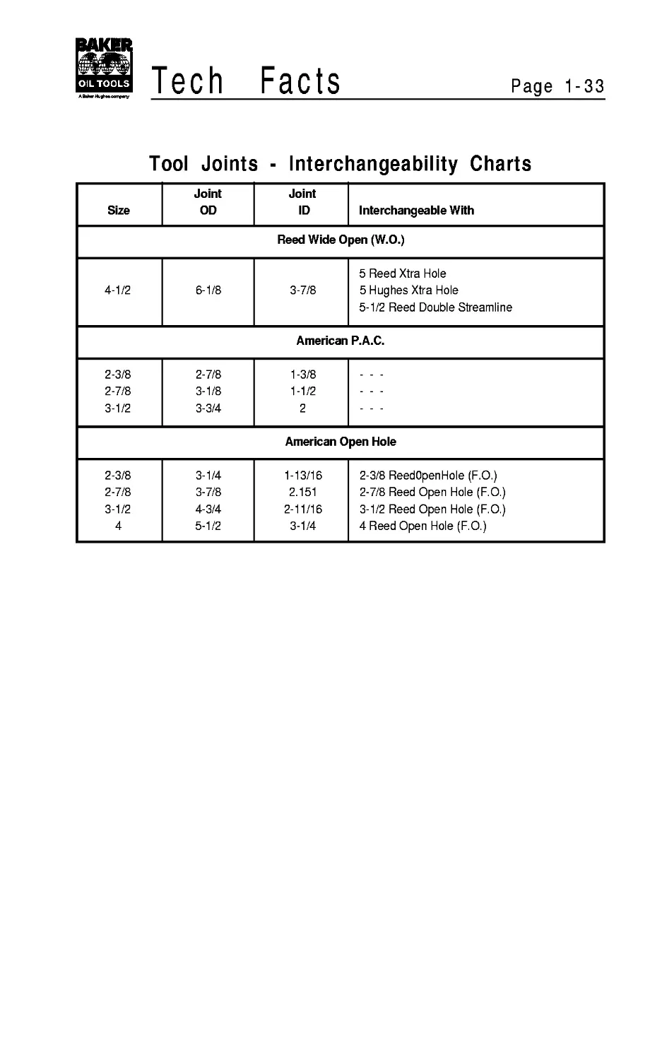
Tool Joints - Interchangeability Charts
Size Joint OD Joint ID Interchangeable With
Reed Wide Open (W.O.)
5 Reed Xtra Hole
4-1/2 6-1/8 3-7/8 5 Hughes Xtra Hole 5-1/2 Reed Double Streamline
American P.A.C.
2-3/8 2-7/8 1-3/8
2-7/8 3-1/8 1-1/2
3-1/2 3-3/4 2
American Open Hole
2-3/8 3-1/4 1-13/16 2-3/8 ReedOpenHole (F.O.)
2-7/8 3-7/8 2.151 2-7/8 Reed Open Hole (F.O.)
3-1/2 4-3/4 2-11/16 3-1/2 Reed Open Hole (F.O.)
4 5-1/2 3-1/4 4 Reed Open Hole (F.O.)
Page 1-34
Tech
Facts
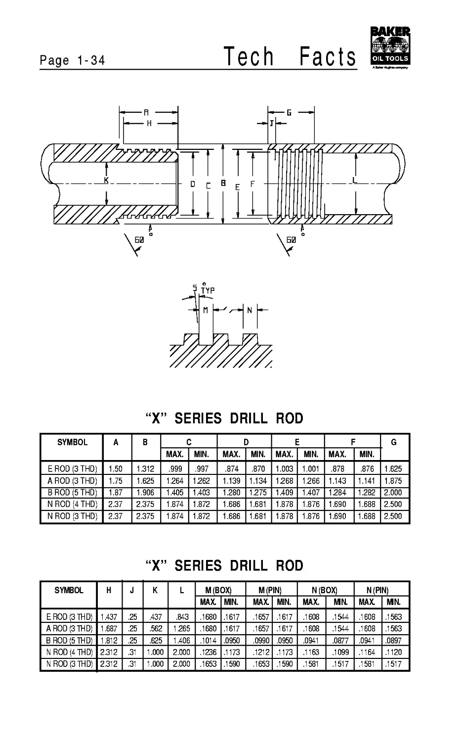
“X” SERIES DRILL ROD
SYMBOL A В C D E F G
MAX. MIN. MAX. MIN. MAX. MIN. MAX. MIN.
E ROD (3 THD) 1.50 1.312 .999 .997 .874 .870 1.003 1.001 .878 .876 1.625
A ROD (3 THD) 1.75 1.625 1.264 1.262 1.139 1.134 1.268 1.266 1.143 1.141 1.875
BROD (5THD) 1.87 1.906 1.405 1.403 1.280 1.275 1.409 1.407 1.284 1.282 2.000
NROD (4 THD) 2.37 2.375 1.874 1.872 1.686 1.681 1.878 1.876 1.690 1.688 2.500
NROD (3 THD) 2.37 2.375 1.874 1.872 1.686 1.681 1.878 1.876 1.690 1.688 2.500
“X” SERIES DRILL ROD
SYMBOL H J К L M(BOX) M(PIN) N(BOX) N(PIN)
MAX. MIN. MAX. MIN. MAX. MN. MAX. MN.
E ROD (3THD) 1.437 .25 .437 .843 .1680 .1617 .1657 .1617 .1608 .1544 .1608 .1563
A ROD (3THD) 1.687 .25 .562 1.265 .1680 .1617 .1657 .1617 .1608 .1544 .1608 .1563
BROD (5 THD) 1.812 .25 .625 1.406 .1014 .0950 .0990 .0950 .0941 .0877 .0941 .0897
NROD (4 THD) 2.312 .31 1.000 2.000 .1236 .1173 .1212 .1173 .1163 .1099 .1164 .1120
NROD (3THD) 2.312 .31 1.000 2.000 .1653 .1590 .1653 .1590 .1581 .1517 .1581 .1517
Tech Facts
Page 1-35
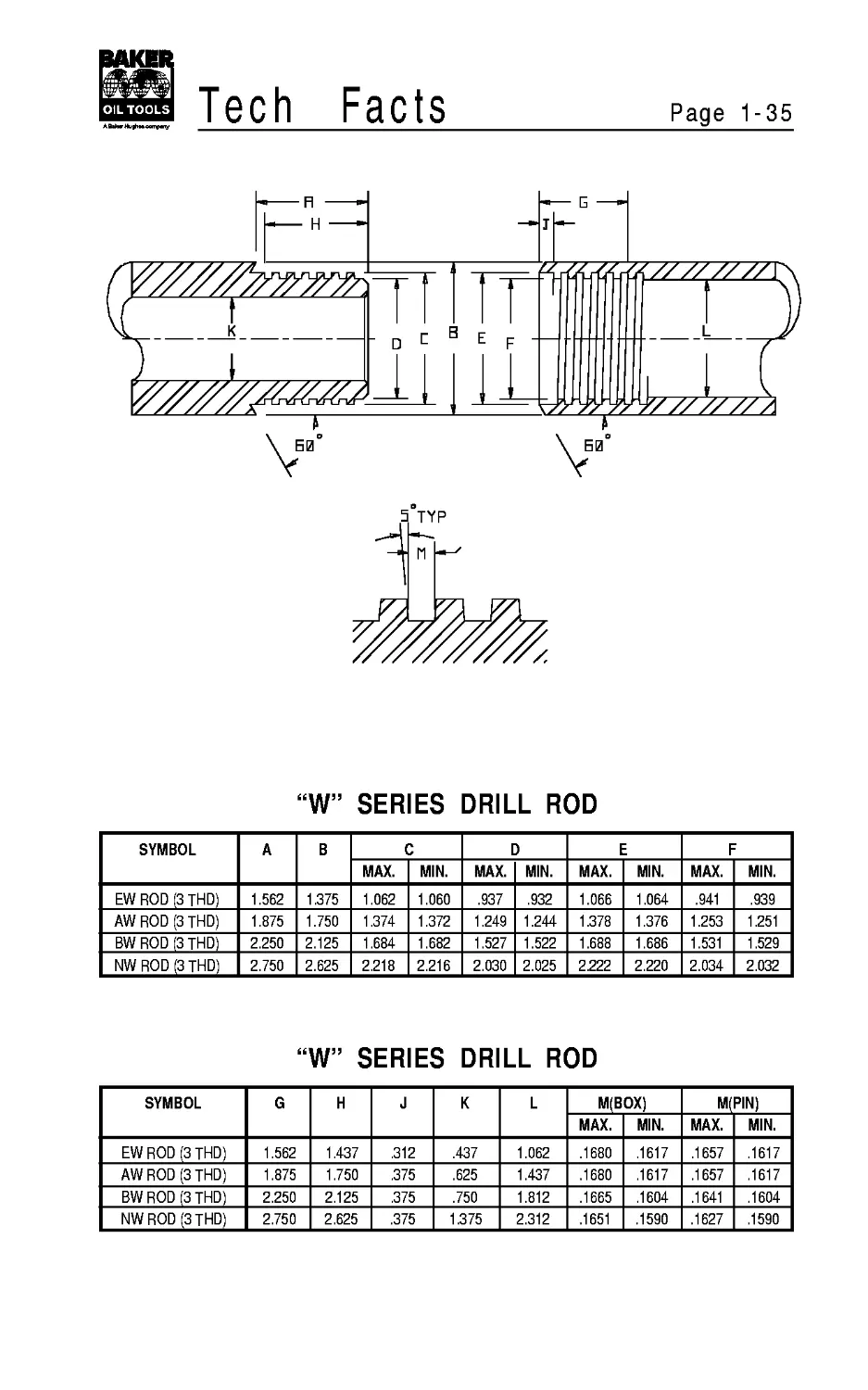
“W” SERIES DRILL ROD
SYMBOL A В C D E F
MAX. MIN. MAX. MIN. MAX. MIN. MAX. MIN.
EW ROD (3 THD) 1.562 1.375 1.062 1.060 .937 .932 1.066 1.064 .941 .939
AW ROD (3 THD) 1.875 1.750 1.374 1.372 1.249 1.244 1.378 1.376 1.253 1.251
BW ROD (3 THD) 2.250 2.125 1.684 1.682 1.527 1.522 1.688 1.686 1.531 1.529
NW ROD (3 THD) 2.750 2.625 2.218 2.216 2.030 2.025 2.222 2.220 2.034 2.032
“W” SERIES DRILL ROD
SYMBOL G H J К L M(BOX) M(PIN)
MAX. MIN. MAX. MIN.
EW ROD (3 THD) 1.562 1.437 .312 .437 1.062 .1680 .1617 .1657 .1617
AW ROD (3 THD) 1.875 1.750 .375 .625 1.437 .1680 .1617 .1657 .1617
BW ROD (3 THD) 2.250 2.125 .375 .750 1.812 .1665 .1604 .1641 .1604
NW ROD (3THD) 2.750 2.625 .375 1.375 2.312 .1651 .1590 .1627 .1590
Page 1-36
Tech Facts
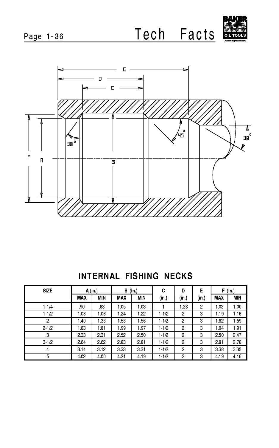
INTERNAL FISHING NECKS
SIZE A (in.) в (in.) C (in.) D (in.) E (in.) F in.)
MAX MIN MAX MIN MAX MIN
1-1/4 .90 .88 1.05 1.03 1 1.38 2 1.03 1.00
1-1/2 1.08 1.06 1.24 1.22 1-1/2 2 3 1.19 1.16
2 1.40 1.38 1.58 1.56 1-1/2 2 3 1.62 1.59
2-1/2 1.83 1.81 1.99 1.97 1-1/2 2 3 1.94 1.91
3 2.33 2.31 2.52 2.50 1-1/2 2 3 2.50 2.47
3-1/2 2.64 2.62 2.83 2.81 1-1/2 2 3 2.81 2.78
4 3.14 3.12 3.33 3.31 1-1/2 2 3 3.38 3.35
5 4.02 4.00 4.21 4.19 1-1/2 2 3 4.19 4.16
Tech
Facts
Page 1-37
C MIN
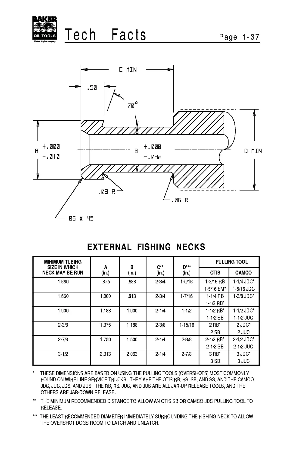
EXTERNAL FISHING NECKS
MINIMUM TUBING SIZE IN WHICH NECK MAY BE RUN A (in.) В (in.) c** (in.) (in.) PULLING TOOL
OTIS CAMCO
1.660 .875 .688 2-3/4 1-5/16 1-3/16 RB 1-5/16 SM* 1-1/4 JDC* 1-5/16 JDC
1.660 1.000 .813 2-3/4 1-7/16 1-1/4 RB 1-1/2 RB* 1-3/8 JDC*
1.900 1.188 1.000 2-1/4 1-1/2 1-1/2 RB* 1-1/2 SB 1-1/2 JDC* 1-1/2 JUC
2-3/8 1.375 1.188 2-3/8 1-15/16 2RB* 2 SB 2 JDC* 2 JUC
2-7/8 1.750 1.500 2-1/4 2-3/8 2-1/2 RB* 2-1/2 SB 2-1/2 JDC* 2-1/2 JUC
3-1/2 2.313 2.063 2-1/4 2-7/8 3RB* 3SB 3JDC* 3JUC
THESE DIMENSIONS ARE BASED ON USING THE PULLING TOOLS (OVERSHOTS) MOST COMMONLY
FOUND ON WIRE LINE SERVICE TRUCKS. THEY ARE THE OTIS RB, RS, SB, AND SS, AND THE CAMCO
JDC, JUC, JDS, AND JUS. THE RB, RS, JUC, AND JUS ARE ALL JAR-UP RELEASE TOOLS, AND THE
OTHERS ARE JAR-DOWN RELEASE.
THE MINIMUM RECOMMENDED DISTANCE TO ALLOWAN OTIS SB OR CAMCO JDC PULLING TOOL TO
RELEASE.
THE LEAST RECOMMENDED DIAMETER IMMEDIATELY SURROUNDING THE FISHING NECK TO ALLOW
THE OVERSHOT DOGS ROOM TO LATCH AND UNLATCH.
SECTION 2 - Drill Pipe
Contents
Page
API Drill Pipe Requirements...........................2-1
Mechanical Properties of New Tool
Joints and New Grade Drill Pipe...................2-2
Mechanical Properties of New Tool
Joints and New High Strength Drill Pipe...........2-4
Dimensional Data and Performance Properties
of Grades D, E, X-95, G-105 and S-135.............2-6
Drilco Hevi-Wate Drill Pipe...........................2-9
Aluminum Drill Pipe...................................2-9
Mill Slot & Groove Method of
Drill String Identification......................2-10
Drill Pipe Floats....................................2-11
Facts
Page 2-1
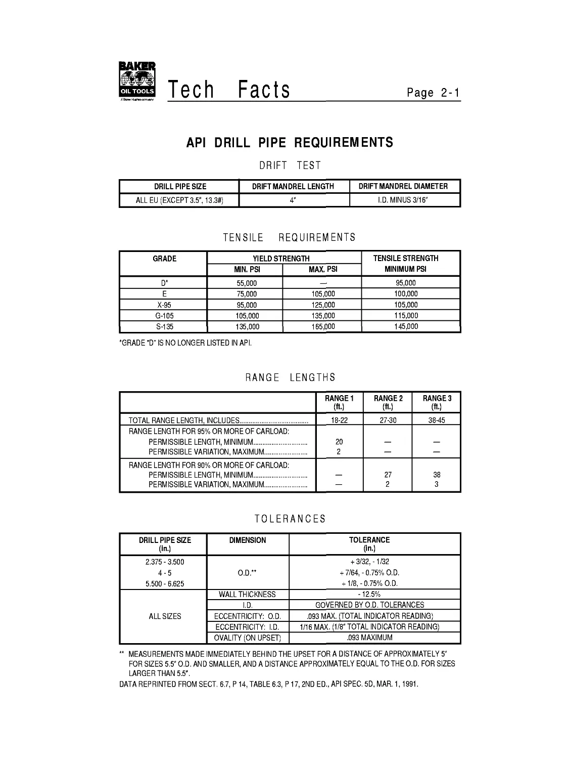
API DRILL PIPE REQUIREMENTS
DRIFT TEST
DRILL PIPE SIZE DRIFT MANDREL LENGTH DRIFT MANDREL DIAMETER
ALL EU (EXCEPT3.5", 13.3#) 4" I.D. MINUS 3/16"
TENSILE REQUIREMENTS
GRADE YIELD STRENGTH TENSILE STRENGTH MINIMUM PSI
MIN. PSI MAX. PSI
D* 55,000 — 95,000
E 75,000 105,000 100,000
X-95 95,000 125,000 105,000
G-105 105,000 135,000 115,000
S-135 135,000 165,000 145,000
•GRADE "D" IS NO LONGER LISTED IN API.
RANGE LENGTHS
RANGE 1 (ft-) RANGE 2 (ft-) RANGE 3 (ft-)
TOTAL RANGE LENGTH, INCLUDES 18-22 27-30 3845
RANGE LENGTH FOR 95% OR MORE OF CARLOAD: PERMISSIBLE LENGTH, MINIMUM 20
PERMISSIBLE VARIATION, MAXIMUM 2 — —
RANGE LENGTH FOR 90% OR MORE OF CARLOAD: PERMISSIBLE LENGTH, MINIMUM 27 38
PERMISSIBLE VARIATION, MAXIMUM — 2 3
TOLERANCES
DRILL PIPE SIZE (in.) DIMENSION TOLERANCE (in.)
2.375-3.500 4-5 5.500- 6.625 O.D.** + 3/32,-1/32 + 7/64,-0.75% O.D. + 1/8,-0.75% O.D.
ALL SIZES WALL THICKNESS -12.5%
I.D. GOVERNED BY O.D. TOLERANCES
ECCENTRICITY: O.D. .093 MAX. (TOTAL INDICATOR READING)
ECCENTRICITY: I.D. 1/16 MAX. (1/8" TOTAL INDICATOR READING)
OVALITY (ON UPSET) .093 MAXIMUM
** MEASUREMENTS MADE IMMEDIATELY BEHIND THE UPSET FOR A DISTANCE OF APPROXIMATELY 5”
FOR SIZES 5.5” O.D. AND SMALLER, AND A DISTANCE APPROXIMATELY EQUAL TO THE O.D. FOR SIZES
LARGER THAN 5.5”.
DATA REPRINTED FROM SECT. 6.7, P 14, TABLE 6.3, P 17,2ND ED., API SPEC. 5D, MAR. 1,1991.
Page 2-2
Tech
Facts
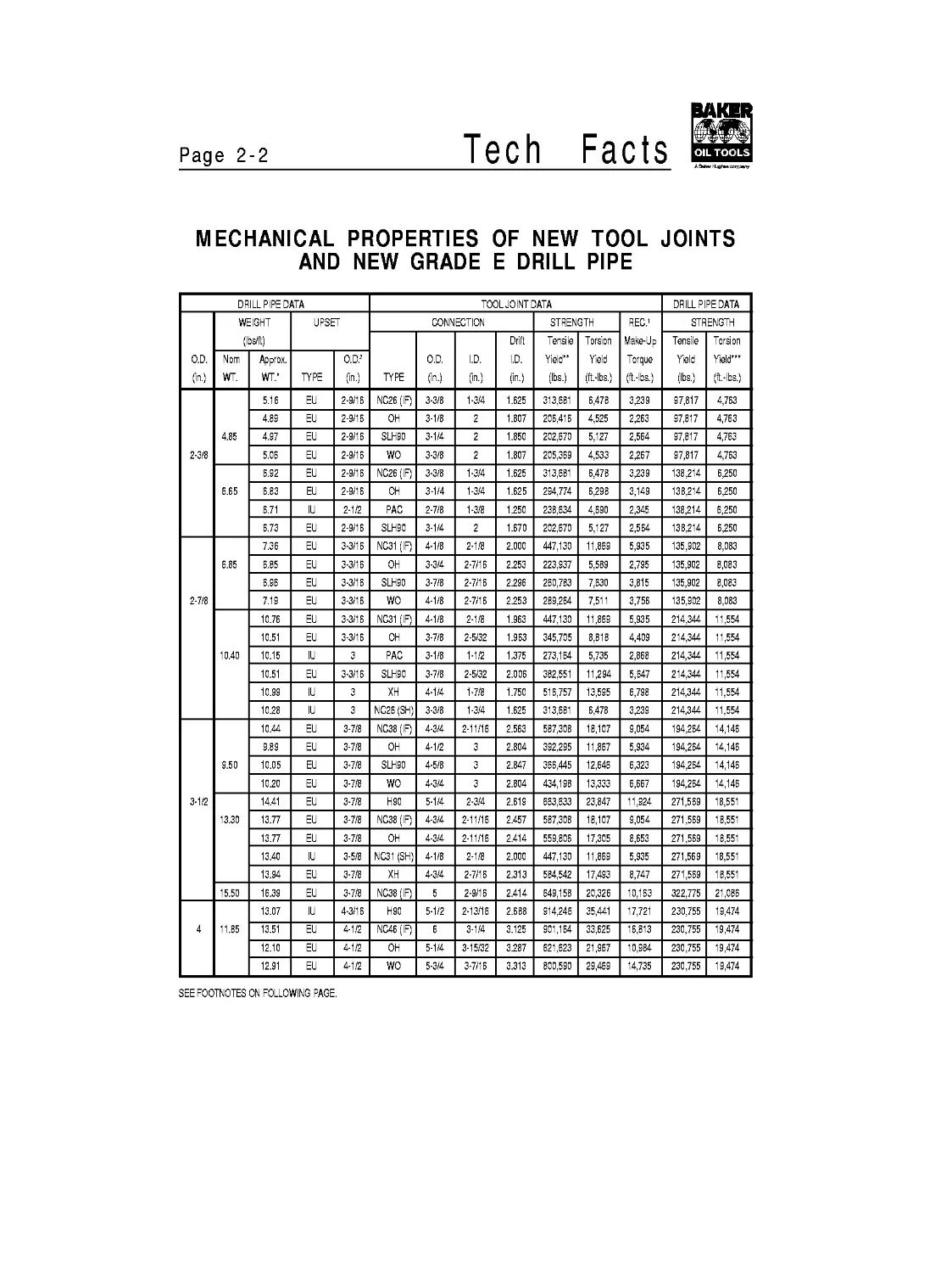
MECHANICAL PROPERTIES OF NEW TOOL JOINTS
AND NEW GRADE E DRILL PIPE
DRILLPIPE DATA TOOL JOINT DATA DRILL PIPE DATA
O.D. (in.) WEIGHT (Ibs/ft) UPSET CONNECTION STRENGTH REC.1 Make-Up Torque (ft.-lbs.) STRENGTH
TYPE O.D. (in.) I.D. (in.) Drift I.D. (in.) Tensile Yield” (lbs.) Torsion Yield (ft.-lbs.) Tensile Yield (lbs.) Torsion Yield'” (ft.-lbs.)
Nom WT. Approx. WT.' TYPE O.D.2 (in.)
2-3/8 4.85 5.16 EU 2-9/16 NC26 (IF) 3-3/8 1-3/4 1.625 313,681 6,478 3,239 97,817 4,763
4.89 EU 2-9/16 OH 3-1/8 2 1.807 206,416 4,525 2,263 97,817 4,763
4.97 EU 2-9/16 SLH90 3-1/4 2 1.850 202,670 5,127 2,564 97,817 4,763
5.06 EU 2-9/16 WO 3-3/8 2 1.807 205,369 4,533 2,267 97,817 4,763
6.65 6.92 EU 2-9/16 NC26 (IF) 3-3/8 1-3/4 1.625 313,681 6,478 3,239 138,214 6,250
6.83 EU 2-9/16 OH 3-1/4 1-3/4 1.625 294,774 6,298 3,149 138,214 6,250
6.71 IU 2-1/2 РАС 2-7/8 1-3/8 1.250 238,634 4,690 2,345 138,214 6,250
6.73 EU 2-9/16 SLH90 3-1/4 2 1.670 202,670 5,127 2,564 138,214 6,250
2-7/8 6.85 7.36 EU 3-3/16 NC31 (IF) 4-1/8 2-1/8 2.000 447,130 11,869 5,935 135,902 8,083
6.85 EU 3-3/16 OH 3-3/4 2-7/16 2.253 223,937 5,589 2,795 135,902 8,083
6.96 EU 3-3/16 SLH90 3-7/8 2-7/16 2.296 260,783 7,630 3,815 135,902 8,083
7.19 EU 3-3/16 WO 4-1/8 2-7/16 2.253 289,264 7,511 3,756 135,902 8,083
10.40 10.76 EU 3-3/16 NC31 (IF) 4-1/8 2-1/8 1.963 447,130 11,869 5,935 214,344 11,554
10.51 EU 3-3/16 OH 3-7/8 2-5/32 1.963 345,705 8,818 4,409 214,344 11,554
10.15 IU 3 РАС 3-1/8 1-1/2 1.375 273,164 5,735 2,868 214,344 11,554
10.51 EU 3-3/16 SLH90 3-7/8 2-5/32 2.006 382,551 11,294 5,647 214,344 11,554
10.99 IU 3 XH 4-1/4 1-7/8 1.750 516,757 13,595 6,798 214,344 11,554
10.28 IU 3 NC26 (SH) 3-3/8 1-3/4 1.625 313,681 6,478 3,239 214,344 11,554
3-1/2 9.50 10.44 EU 3-7/8 NC38 (IF) 4-3/4 2-11/16 2.563 587,308 18,107 9,054 194,264 14,146
9.89 EU 3-7/8 OH 4-1/2 3 2.804 392,295 11,867 5,934 194,264 14,146
10.05 EU 3-7/8 SLH90 4-5/8 3 2.847 366,445 12,646 6,323 194,264 14,146
10.20 EU 3-7/8 WO 4-3/4 3 2.804 434,198 13,333 6,667 194,264 14,146
13.30 14.41 EU 3-7/8 H90 5-1/4 2-3/4 2.619 663,633 23,847 11,924 271,569 18,551
13.77 EU 3-7/8 NC38 (IF) 4-3/4 2-11/16 2.457 587,308 18,107 9,054 271,569 18,551
13.77 EU 3-7/8 OH 4-3/4 2-11/16 2.414 559,806 17,305 8,653 271,569 18,551
13.40 IU 3-5/8 NC31 (SH) 4-1/8 2-1/8 2.000 447,130 11,869 5,935 271,569 18,551
13.94 EU 3-7/8 XH 4-3/4 2-7/16 2.313 584,542 17,493 8,747 271,569 18,551
15.50 16.39 EU 3-7/8 NC38 (IF) 5 2-9/16 2.414 649,158 20,326 10,163 322,775 21,086
4 11.85 13.07 IU 4-3/16 H90 5-1/2 2-13/16 2.688 914,246 35,441 17,721 230,755 19,474
13.51 EU 4-1/2 NC46 (IF) 6 3-1/4 3.125 901,164 33,625 16,813 230,755 19,474
12.10 EU 4-1/2 OH 5-1/4 3-15/32 3.287 621,623 21,967 10,984 230,755 19,474
12.91 EU 4-1/2 wo 5-3/4 3-7/16 3.313 800,590 29,469 14,735 230,755 19,474
SEE FOOTNOTES ON FOLLOWING PAGE.
Facts
Page 2-3
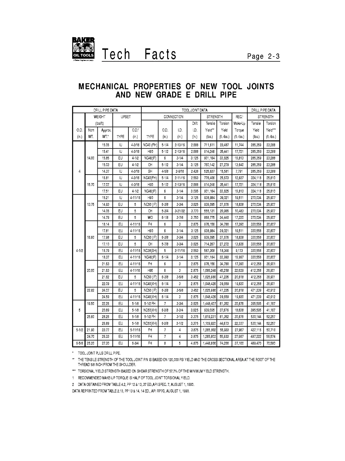
MECHANICAL PROPERTIES OF NEW TOOL JOINTS
AND NEW GRADE E DRILL PIPE
DRILL PIPE DATA TOOL JOINT DATA DRILL PIPE DATA
O.D. (in.) WEIGHT (Ibs/ft) UPSET CONNECTION STRENGTH REC.1 Make-Up Torque (ft.-lbs.) STRENGTH
TYPE O.D. (in.) I.D. (in.) Drift I.D. (in.) Tensile Yield” (lbs.) Torsion Yield (ft.-lbs.) Tensile Yield (lbs.) Torsion Yield’” (ft.-lbs.)
Nom WT. Approx. WT.' TYPE O.D.2 (in.)
4 14.00 15.06 IU 4-3/16 NC40 (FH) 5-1/4 2-13/16 2.688 711,611 23,487 11,744 285,359 23,288
15.41 IU 4-3/16 H90 5-1/2 2-13/16 2.688 914,246 35,441 17,721 285,359 23,288
15.85 EU 4-1/2 NC46(IF) 6 3-1/4 3.125 901,164 33,625 16,813 285,359 23,288
15.03 EU 4-1/2 OH 5-1/2 3-1/4 3.125 760,142 27,279 13,640 285,359 23,288
14.37 IU 4-3/16 SH 4-5/8 2-9/16 2.438 525,637 15,581 7,791 285,359 23,288
15.70 16.81 IU 4-3/16 NC40(FH) 5-1/4 2-11/16 2.563 776,406 25,673 12,837 324,118 25,810
17.07 IU 4-3/16 H90 5-1/2 2-13/16 2.688 914,246 35,441 17,721 324,118 25,810
17.51 EU 4-1/2 NC46(IF) 6 3-1/4 3.095 901,164 33,625 16,813 324,118 25,810
4-1/2 13.75 15.21 IU 4-11/16 H90 6 3-1/4 3.125 938,984 39,021 19,511 270,034 25,907
14.93 EU 5 NC50 (IF) 6-3/8 3-3/4 3.625 939,095 37,676 18,838 270,034 25,907
14.06 EU 5 OH 5-3/4 3-31/32 3.770 555,131 20,965 10,483 270,034 25,907
14.79 EU 5 wo 6-1/8 3-7/8 3.750 868,775 34,440 17,220 270,034 25,907
16.60 18.14 IEU 4-11/16 FH 6 3 2.875 976,156 34,780 17,390 330,558 30,807
17.81 IEU 4-11/16 H90 6 3-1/4 3.125 938,984 39,021 19,511 330,558 30,807
17.98 EU 5 NC50 (IF) 6-3/8 3-3/4 3.625 939,095 37,676 18,838 330,558 30,807
17.10 EU 5 OH 5-7/8 3-3/4 3.625 714,267 27,272 13,636 330,558 30,807
16.79 IEU 4-11/16 NC38(SH) 5 2-11/16 2.563 587,308 18,346 9,173 330,558 30,807
18.37 IEU 4-11/16 NC46(IF) 6-1/4 3-1/4 3.125 901,164 33,993 16,997 330,558 30,807
20.00 21.63 IEU 4-11/16 FH 6 3 2.875 976,156 34,780 17,390 412,358 36,901
21.63 IEU 4-11/16 H90 6 3 2.875 1,086,246 45,258 22,629 412,358 36,901
21.62 EU 5 NC50 (IF) 6-3/8 3-5/8 3.452 1,025,980 41,235 20,618 412,358 36,901
22.09 IEU 4-11/16 NC46(XH) 6-1/4 3 2.875 1,048,426 39,659 19,830 412,358 36,901
22.82 24.07 EU 5 NC50 (IF) 6-3/8 3-5/8 3.452 1,025,980 41,235 20,618 471,239 40,912
24.59 IEU 4-11/16 NC46(XH) 6-1/4 3 2.875 1,048,426 39,659 19,830 471,239 40,912
5 19.50 22.26 IEU 5-1/8 5-1/2 FH 7 3-3/4 3.625 1,448,407 61,352 30,676 395,595 41,167
20.89 IEU 5-1/8 NC50(XH) 6-3/8 3-3/4 3.625 939,095 37,676 18,838 395,595 41,167
25.60 28.26 IEU 5-1/8 5-1/2 FH 7 3-1/2 3.375 1,619,231 61,352 30,676 530,144 52,257
26.89 IEU 5-1/8 NC50(XH) 6-3/8 3-1/2 3.375 1,109,920 44,673 22,337 530,144 52,257
5-1/2 21.90 23.77 IEU 5-11/16 FH 7 4 3.875 1,265,802 55,933 27,967 437,116 50,710
24.70 26.33 IEU 5-11/16 FH 7 4 3.875 1,265,802 55,933 27,967 497,222 56,574
6-5/8 25.20 27.30 IEU 6-3/4 FH 8 5 4.875 1,448,800 74,200 37,100 489,470 70,580
' TOOL JOINT PLUS DRILL PIPE.
” THE TENSILE STRENGTH OFTHETOOL JOINT PIN IS BASED ON 120,000 PSI YIELD AND THE CROSS SECTIONAL AREA AT THE ROOT OF THE
THREAD 5/8 INCH FROM THE SHOULDER.
TORSIONAL YIELD STRENGTH BASED ON SHEAR STRENGTH OF 57.7% OFTHE MINIMUM YIELD STRENGTH.
1 RECOMMENDED MAKE-U P TORQUE IS HALF OF TOOL JOINT TORSIONAL YIELD.
2 DATA OBTAINED FROM TABLE 4.2, PP12 & 13,37 ED.,API SPEC. 7, AUGUST 1,1990.
DATA REPRINTED FROM TABLE 2.10, PP 13 & 14,14 ED., API RP7G, AUGUST 1,1990.
Page 2-4
Tech
Facts
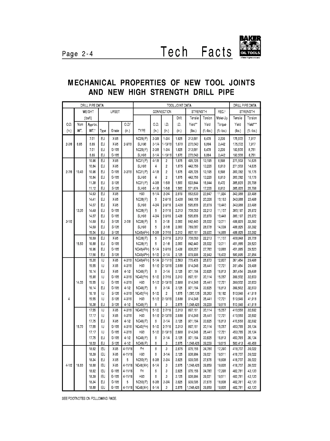
MECHANICAL PROPERTIES OF NEW TOOL JOINTS
AND NEW HIGH STRENGTH DRILL PIPE
DRILL PIPE DATA TOOL JOINT DATA DRILL PIPE DATA
WEIGHT UPSET CONNECTION STRENGTH REC.1 STRENGTH
( s/ft) Drift Tensile Torsion Make-Up Tensile Torsion
O.D. Nom Approx. O.D.2 O.D. I.D. I.D. Yield” Yield Torque Yield Yield'”
(in.) WT. WT.' Type Grade (in.) TYPE (in.) (in.) (in.) (lbs.) (ft.-lbs.) (ft.-lbs.) (lbs.) (ft.-lbs.)
7.01 EU X-95 NC26(IF) 3-3/8 1-3/4 1.625 313,681 6,478 3,239 175,072 7,917
2-3/8 6.65 6.89 EU X-95 2-9/16 SLH90 3-1/4 1-13/16 1.670 270,043 6,884 3,442 175,072 7,917
7.01 EU G-105 NC26(IF) 3-3/8 1-3/4 1.625 313,681 6,478 3,239 193,500 8,751
6.89 EU G-105 SLH90 3-1/4 1-13/16 1.670 270,043 6,884 3,442 193,500 8,751
10.96 EU X-95 NC31(IF) 4-1/8 2 1.875 495,726 13,195 6,598 271,503 14,635
10.84 EU X-95 SLH90 4 2 1.875 443,756 13,226 6,613 271,503 14,635
2-7/8 10.40 10.96 EU G-105 3-3/16 NC31(IF) 4-1/8 2 1.875 495,726 13,195 6,598 300,082 16,176
10.84 EU G-105 SLH90 4 2 1.875 443,756 13,226 6,613 300,082 16,176
11.38 EU S-135 NC31(IF) 4-3/8 1-5/8 1.500 623,844 16,944 8,472 385,820 20,798
11.12 EU S-135 SLH90 4-1/8 1-5/8 1.500 571,874 17,226 8,613 385,820 20,798
14.63 EU X-95 H90 5-1/4 2-3/4 2.619 663,633 23,847 11,924 343,988 23,498
14.41 EU X-95 NC38(IF) 5 2-9/16 2.438 649,158 20,326 10,163 343,988 23,498
14.07 EU X-95 SLH90 4-3/4 2-9/16 2.438 595,806 20,879 10,440 343,988 23,498
13.30 14.49 EU G-105 NC38(IF) 5 2-7/16 2.313 708,063 22,213 11,107 380,197 25,972
14.07 EU G-105 SLH90 4-3/4 2-9/16 2.438 595,806 20,879 10,440 380,197 25,972
3-1/2 14.69 EU S-135 3-7/8 NC38(IF) 5 2-1/8 2.000 842,440 26,022 13,011 488,825 33,392
14.69 EU S-135 SLH90 5 2-1/8 2.000 789,087 28,078 14,039 488,825 33,392
15.04 EU S-135 NC40(4FH) 5-3/8 2-7/16 2.313 897,161 29,930 14,965 488,825 33,392
16.69 EU X-95 NC38(IF) 5 2-7/16 2.313 708,063 22,213 11,107 408,848 26,708
15.50 16.88 EU G-105 NC38(IF) 5 2-1/8 2.000 842,440 26,022 13,011 451,885 29,520
16.96 EU G-105 NC40(4FH) 5-1/4 2-9/16 2.438 838,257 27,760 13,880 451,885 29,520
17.56 EU S-135 NC40(4FH) 5-1/2 2-1/4 2.125 979,996 32,943 16,472 580,995 37,954
15.30 IU X-95 4-3/16 NC40(4FH) 5-1/4 2-11/16 2.563 776,406 25,673 12,837 361,454 29,498
15.55 IU X-95 4-3/16 H90 5-1/2 2-13/16 2.688 914,246 35,441 17,721 361,454 29,498
16.14 EU X-95 4-1/2 NC46(IF) 5 3-1/4 3.125 901,164 33,625 16,813 361,454 29,498
15.90 IU G-105 4-3/16 NC40(FH) 5-1/2 2-7/16 2.313 897,161 30,114 15,057 399,502 32,603
14.00 15.55 IU G-105 4-3/16 H90 5-1/2 2-13/16 2.688 914,246 35,441 17,721 399,502 32,603
16.14 EU G-105 4-1/2 NC46(IF) 5 3-1/4 3.125 901,164 33,625 16,813 399,502 32,603
16.18 IU S-135 4-3/16 NC40(FH) 5-1/2 2 1.875 1,080,135 36,363 18,182 513,646 41,918
4 15.55 IU S-135 4-3/16 H90 5-1/2 2-13/16 2.688 914,246 35,441 17,721 513,646 41,918
16.38 EU S-135 4-1/2 NC46(IF) 5 3 2.875 1,048,426 39,229 19,615 513,646 41,918
17.55 IU X-95 4-3/16 NC40(FH) 5-1/2 2-7/16 2.313 897,161 30,114 15,057 410,550 32,692
17.17 IU X-95 4-3/16 H90 5-1/2 2-13/16 2.688 914,246 35,441 17,721 410,550 32,692
17.75 EU X-95 4-1/2 NC46(IF) 5 3-1/4 3.125 901,164 33,625 16,813 410,550 32,692
15.70 17.55 IU G-105 4-3/16 NC40(FH) 5-1/2 2-7/16 2.313 897,161 30,114 15,057 453,765 36,134
17.17 IU G-105 4-3/16 H90 5-1/2 2-13/16 2.688 914,246 35,441 17,721 453,765 36,134
17.75 EU G-105 4-1/2 NC46(IF) 5 3-1/4 3.125 901,164 33,625 16,813 453,765 36,134
18.03 EU S-135 4-1/2 NC46(IF) 3 2.875 1,048,426 39,229 19,615 583,413 46,458
18.62 IEU X-95 4-11/16 FH 6 3 2.875 976,156 34,780 17,390 418,707 39,022
18.39 IEU X-95 4-11/16 H90 5 3-1/4 3.125 938,984 39,021 19,511 418,707 39,022
18.34 EU X-95 5 NC50(IF) 6-3/8 3-3/4 3.625 939,095 37,676 18,838 418,707 39,022
4-1/2 16.60 18.88 IEU X-95 4-11/16 NC46(XH) 6-1/4 3 2.875 1,048,426 39,659 19,830 418,707 39,022
18.62 IEU G-105 4-11/16 FH 5 3 2.625 976,156 34,780 17,390 462,781 43,130
18.39 IEU G-105 4-11/16 H90 5 3 3.125 938,984 39,021 19,511 462,781 43,130
18.34 EU G-105 5 NC50(IF) 6-3/8 3-3/4 3.625 939,095 37,676 18,838 462,781 43,130
18.88 IEU G-105 4-11/16 NC46(XH) 6-1/4 3 2.875 1,048,426 39,659 19,830 462,781 43,130
SEE FOOTNOTES ON FOLLOWING PAGE.
Facts
Page 2-5
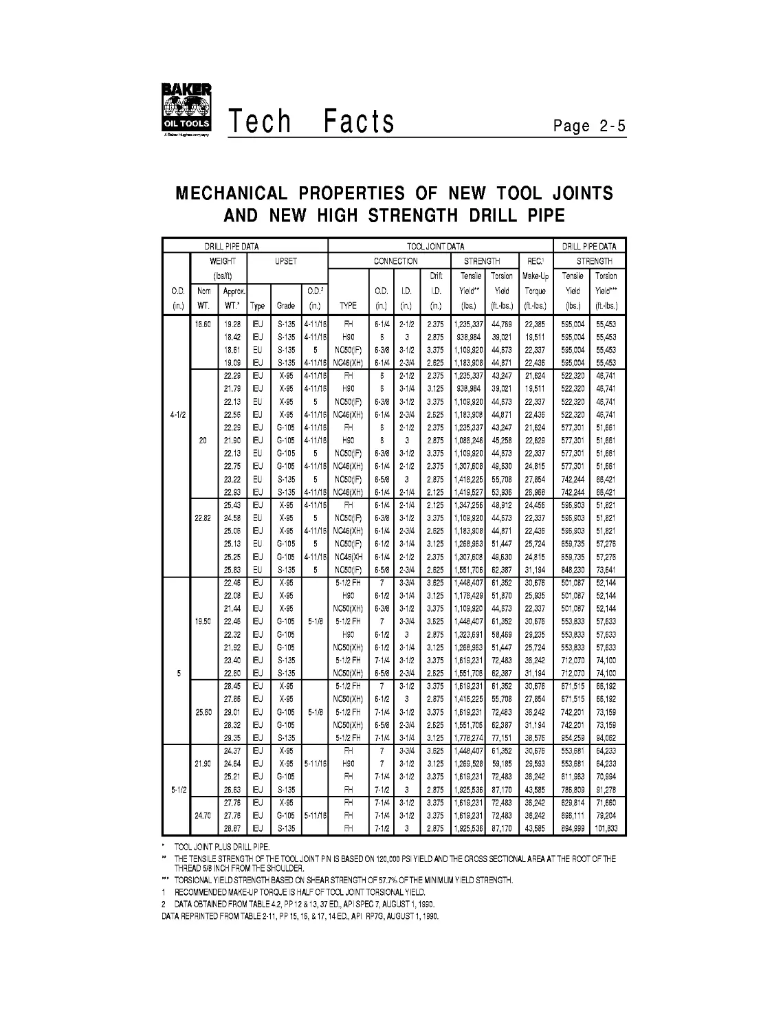
MECHANICAL PROPERTIES OF NEW TOOL JOINTS
AND NEW HIGH STRENGTH DRILL PIPE
DRILLPIPE DATA TOOL JOINT DATA DRILL PIPE DATA
WEIGHT UPSET CONNECTION STRENGTH REC.1 STRENGTH
( s/ft) Drift Tensile Torsion Make-Up Tensile Torsion
O.D. Nom Approx. O.D.2 O.D. I.D. I.D. Yield” Yield Torque Yield Yield’”
(in.) WT. WT.' Type Grade (in.) TYPE (in.) (in.) (in.) (lbs.) (ft.-lbs.) (ft.-lbs.) (lbs.) (ft.-lbs.)
16.60 19.28 IEU S-135 4-11/16 FH 6-1/4 2-1/2 2.375 1,235,337 44,769 22,385 595,004 55,453
18.42 IEU S-135 4-11/16 H90 5 3 2.875 938,984 39,021 19,511 595,004 55,453
18.61 EU S-135 5 NC50(IF) 6-3/8 3-1/2 3.375 1,109,920 44,673 22,337 595,004 55,453
19.09 IEU S-135 4-11/16 NC46(XH) 6-1/4 2-3/4 2.625 1,183,908 44,871 22,436 595,004 55,453
22.29 IEU X-95 4-11/16 FH 5 2-1/2 2.375 1,235,337 43,247 21,624 522,320 46,741
21.79 IEU X-95 4-11/16 H90 6 3-1/4 3.125 938,984 39,021 19,511 522,320 46,741
22.13 EU X-95 5 NC50(IF) 6-3/8 3-1/2 3.375 1,109,920 44,673 22,337 522,320 46,741
4-1/2 22.56 IEU X-95 4-11/16 NC46(XH) 6-1/4 2-3/4 2.625 1,183,908 44,871 22,436 522,320 46,741
22.29 IEU G-105 4-11/16 FH 5 2-1/2 2.375 1,235,337 43,247 21,624 577,301 51,661
20 21.90 IEU G-105 4-11/16 H90 5 3 2.875 1,086,246 45,258 22,629 577,301 51,661
22.13 EU G-105 5 NC50(IF) 6-3/8 3-1/2 3.375 1,109,920 44,673 22,337 577,301 51,661
22.75 IEU G-105 4-11/16 NC46(XH) 6-1/4 2-1/2 2.375 1,307,608 49,630 24,815 577,301 51,661
23.22 EU S-135 5 NC50(IF) 6-5/8 3 2.875 1,416,225 55,708 27,854 742,244 66,421
22.93 IEU S-135 4-11/16 NC46(XH) 6-1/4 2-1/4 2.125 1,419,527 53,936 26,968 742,244 66,421
25.43 IEU X-95 4-11/16 FH 6-1/4 2-1/4 2.125 1,347,256 48,912 24,456 596,903 51,821
22.82 24.58 EU X-95 5 NC50(IF) 6-3/8 3-1/2 3.375 1,109,920 44,673 22,337 596,903 51,821
25.06 IEU X-95 4-11/16 NC46(XH) 6-1/4 2-3/4 2.625 1,183,908 44,871 22,436 596,903 51,821
25.13 EU G-105 5 NC50(IF) 6-1/2 3-1/4 3.125 1,268,963 51,447 25,724 659,735 57,276
25.25 IEU G-105 4-11/16 NC46(XH 6-1/4 2-1/2 2.375 1,307,608 49,630 24,815 659,735 57,276
25.83 EU S-135 5 NC50(IF) 6-5/8 2-3/4 2.625 1,551,706 62,387 31,194 848,230 73,641
22.46 IEU X-95 5-1/2 FH 7 3-3/4 3.625 1,448,407 61,352 30,676 501,087 52,144
22.08 IEU X-95 H90 6-1/2 3-1/4 3.125 1,176,429 51,870 25,935 501,087 52,144
21.44 IEU X-95 NC50(XH) 6-3/8 3-1/2 3.375 1,109,920 44,673 22,337 501,087 52,144
19.50 22.46 IEU G-105 5-1/8 5-1/2 FH 7 3-3/4 3.625 1,448,407 61,352 30,676 553,833 57,633
22.32 IEU G-105 H90 6-1/2 3 2.875 1,323,691 58,469 29,235 553,833 57,633
21.92 IEU G-105 NC50(XH) 6-1/2 3-1/4 3.125 1,268,963 51,447 25,724 553,833 57,633
23.40 IEU S-135 5-1/2 FH 7-1/4 3-1/2 3.375 1,619,231 72,483 36,242 712,070 74,100
5 22.60 IEU S-135 NC50(XH) 6-5/8 2-3/4 2.625 1,551,706 62,387 31,194 712,070 74,100
28.45 IEU X-95 5-1/2 FH 7 3-1/2 3.375 1,619,231 61,352 30,676 671,515 66,192
27.86 IEU X-95 NC50(XH) 6-1/2 3 2.875 1,416,225 55,708 27,854 671,515 66,192
25.60 29.01 IEU G-105 5-1/8 5-1/2 FH 7-1/4 3-1/2 3.375 1,619,231 72,483 36,242 742,201 73,159
28.32 IEU G-105 NC50(XH) 6-5/8 2-3/4 2.625 1,551,706 62,387 31,194 742,201 73,159
29.35 IEU S-135 5-1/2 FH 7-1/4 3-1/4 3.125 1,778,274 77,151 38,576 954,259 94,062
24.37 IEU X-95 FH 7 3-3/4 3.625 1,448,407 61,352 30,676 553,681 64,233
21.90 24.64 IEU X-95 5-11/16 H90 7 3-1/2 3.125 1,269,528 59,185 29,593 553,681 64,233
25.21 IEU G-105 FH 7-1/4 3-1/2 3.375 1,619,231 72,483 36,242 611,963 70,994
5-1/2 26.63 IEU S-135 FH 7-1/2 3 2.875 1,925,536 87,170 43,585 786,809 91,278
27.76 IEU X-95 FH 7-1/4 3-1/2 3.375 1,619,231 72,483 36,242 629,814 71,660
24.70 27.76 IEU G-105 5-11/16 FH 7-1/4 3-1/2 3.375 1,619,231 72,483 36,242 696,111 79,204
28.87 IEU S-135 FH 7-1/2 3 2.875 1,925,536 87,170 43,585 894,999 101,833
' TOOL JOINT PLUS DRILL PIPE.
” THE TENSILE STRENGTH OFTHETOOL JOINT PIN IS BASED ON 120,000 PSI YIELD AND THE CROSS SECTIONAL AREA AT THE ROOT OF THE
THREAD 5/8 INCH FROM THE SHOULDER.
TORSIONAL YIELD STRENGTH BASED ON SHEAR STRENGTH OF 57.7% OFTHE MINIMUM YIELD STRENGTH.
1 RECOMMENDED MAKE-U P TORQUE IS HALF OF TOOL JOINT TORSIONAL YIELD.
2 DATA OBTAINED FROM TABLE 4.2, PP12 & 13,37 ED., API SPEC 7, AUGUST 1,1990.
DATA REPRINTED FROM TABLE 2-11, PP15,16,&17,14ED., API RP7G, AUGUST 1,1990.
Page 2-6
Tech
Facts
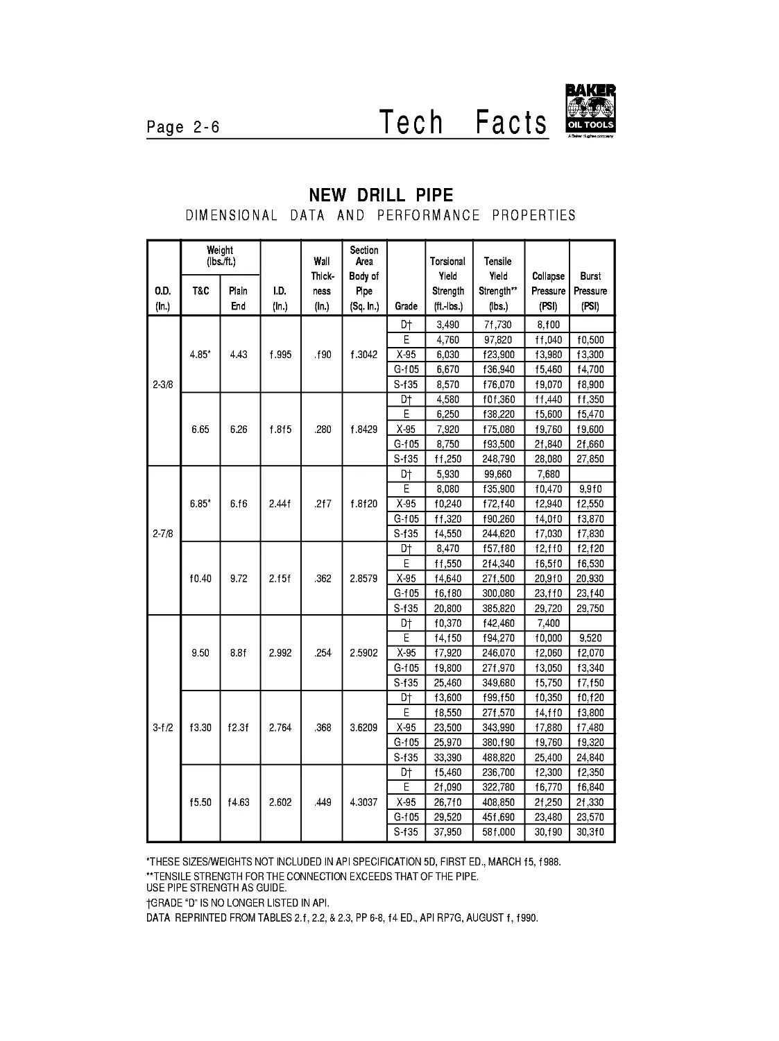
NEW DRILL PIPE
DIMENSIONAL DATA AND PERFORMANCE PROPERTIES
O.D. (In.) Weight (Ibs./ft.) I.D. (In.) Wall Thick- ness (In.) Section Area Body of Pipe (Sq.ln.) Grade Torsional Yield Strength (ft.-lbs.) Tensile Yield Strength” (lbs.) Collapse Pressure (PSI) Burst Pressure (PSI)
T&C Plain End
2-3/8 4.85* 4.43 f .995 Л90 f .3042 Dt 3,490 7f ,730 8Л00
E 4,760 97,820 ff,040 f0,500
X-95 6,030 f 23,900 f3,980 f 3,300
G-f 05 6,670 f 36,940 f 5,460 f4,700
S-f35 8,570 f76,070 f9,070 f8,900
6.65 6.26 f.8f5 .280 f .8429 Dt 4,580 f0f,360 ff,440 ff,350
E 6,250 f 38,220 f5,600 f 5,470
X-95 7,920 f 75,080 f9,760 f9,600
G-f 05 8,750 f 93,500 2f,840 2f,660
S-f35 ff,250 248,790 28,080 27,850
2-7/8 6.85* 6Л6 2.44f .2f7 f ,8f20 Dt 5,930 99,660 7,680
E 8,080 f 35,900 f 0,470 9,9f0
X-95 f 0,240 f72,f40 f 2,940 f2,550
G-f 05 ff,320 f 90,260 f4,OfO f3,870
S-f35 f4,550 244,620 f7,030 f7,830
f0.40 9.72 2.f5f .362 2.8579 Dt 8,470 f57,f80 f2,ffO {2Л20
E ff,550 2f4,340 f6,5f0 f6,530
X-95 f4,640 27f,500 20,9f0 20,930
G-f 05 f6,f80 300,080 23,ffO 23Л40
S-f35 20,800 385,820 29,720 29,750
3-f/2 9.50 8.8f 2.992 .254 2.5902 Dt f 0,370 f42,460 7,400
E f4,f50 f 94,270 fO.OOO 9,520
X-95 f7,920 246,070 f2,060 f2,070
G-f 05 f9,800 27f ,970 f3,050 f3,340
S-f35 25,460 349,680 f5,750 f7,f50
f3.30 f2.3f 2.764 .368 3.6209 Dt f3,600 f99,f50 f0,350 ^Л20
E f8,550 27f .570 f4,ffO f3,800
X-95 23,500 343,990 f7,880 f 7,480
G-f 05 25,970 380Л90 f9,760 f 9,320
S-f35 33,390 488,820 25,400 24,840
f5.50 f4.63 2.602 .449 4.3037 Dt f 5,460 236,700 f 2,300 f 2,350
E 2f,090 322,780 f6,770 f6,840
X-95 26,7f0 408,850 2f,250 2f ,330
G-f 05 29,520 45f,690 23,480 23,570
S-f35 37,950 58f,000 30Л90 30,3f0
’THESE SIZES/WEIGHTS NOT INCLUDED IN API SPECIFICATION 5D, FIRST ED., MARCH f 5, f 988.
"TENSILE STRENGTH FOR THE CONNECTION EXCEEDS THAT OF THE PIPE.
USE PIPE STRENGTH AS GUIDE.
tGRADE "D" IS NO LONGER LISTED IN API.
DATA REPRINTED FROM TABLES 2.f, 2.2, & 2.3, PP 6-8, f4 ED., API RP7G, AUGUST f, f990.
Facts
Page 2-7
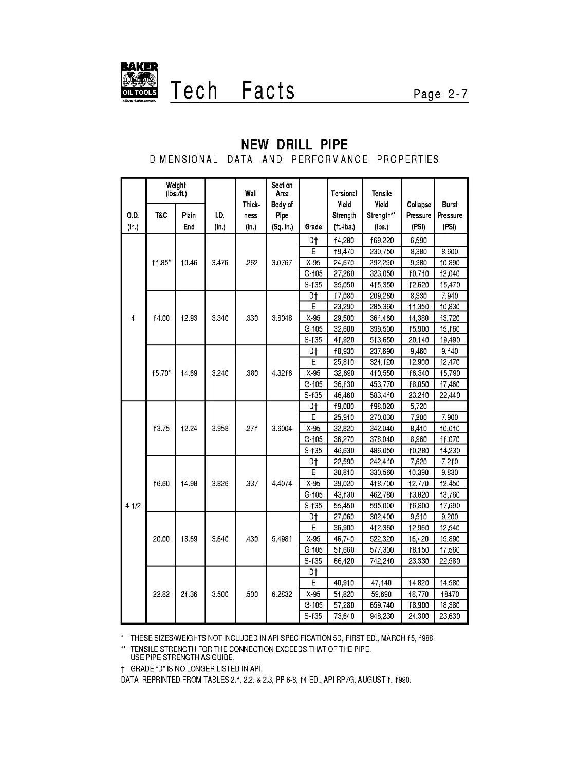
NEW DRILL PIPE
DIMENSIONAL DATA AND PERFORMANCE PROPERTIES
O.D. (In.) Weight (Ibs./ft.) I.D. (In.) Wall Thick- ness (In.) Section Area Body of Pipe (Sq. In.) Grade Torsional Yield Strength (ft.-lbs.) Tensile Yield Strength” (lbs.) Collapse Pressure (PSI) Burst Pressure (PSI)
T&C Plain End
4 f f .85* ** f0.46 3.476 .262 3.0767 Dt f4,280 f 69,220 6,590
E f9,470 230,750 8,380 8,600
X-95 24,670 292,290 9,980 f0,890
G-f05 27,260 323,050 fO,7fO f2,040
S-f35 35,050 4f5,350 f 2,620 f 5,470
f4.00 f2.93 3.340 .330 3.8048 Dt f7,080 209,260 8,330 7,940
E 23,290 285,360 ff,350 f0.830
X-95 29,500 36f,460 f4,380 f3,720
G-f05 32,600 399,500 f5,900 f5,f60
S-f35 4f,920 5f3,650 20,f40 f 9,490
f5.70* f4.69 3.240 .380 4.32f6 Dt f8,930 237,690 9,460 9,f40
E 25,8f0 324,f20 f 2,900 f2,470
X-95 32,690 4f0,550 f 6,340 f5,790
G-f05 36,f30 453,770 f8,050 f 7,460
S-f35 46,460 583,4f0 23,2 fO 22,440
4-f/2 f3.75 f2.24 3.958 .27f 3.6004 Dt f9,000 f 98,020 5,720
E 25,9f0 270,030 7,200 7,900
X-95 32,820 342,040 8,4f0 fO.OfO
G-f05 36,270 378,040 8,960 ff,070
S-f35 46,630 486,050 f0,280 f4,230
f 6.60 f4.98 3.826 .337 4.4074 Dt 22,590 242,4f0 7,620 7,2f0
E 30,8f0 330,560 f0,390 9,830
X-95 39,020 4f8,700 f2,770 f 2,450
G-f05 43,f30 462,780 f3,820 f3,760
S-f35 55,450 595,000 f6,800 f 7,690
20.00 f8.69 3.640 .430 5.498f Dt 27,060 302,400 9,5f0 9,200
E 36,900 4f2,360 f 2,960 f2,540
X-95 46,740 522,320 f 6,420 f5,890
G-f05 5f,660 577,300 f8,f 50 f7,560
S-f35 66,420 742,240 23,330 22,580
22.82 2f .36 3.500 .500 6.2832 Dt
E 40,9f0 47,f40 f4.820 f4,580
X-95 5f ,820 59,690 f8,770 f8470
G-f05 57,280 659,740 f8,900 f8,380
S-f35 73,640 948,230 24,300 23,630
* THESE SIZES/WEIGHTS NOT INCLUDED IN API SPECIFICATION 5D, FIRST ED., MARCH f 5, f 988.
** TENSILE STRENGTH FOR THE CONNECTION EXCEEDS THAT OF THE PIPE.
USE PIPE STRENGTH AS GUIDE.
t GRADE "D" IS NO LONGER LISTED IN API.
DATA REPRINTED FROM TABLES 2.f, 2.2, & 2.3, PP 6-8, f4 ED., API RP7G, AUGUST f, f990.
Page 2-8
Tech
Facts
NEW DRILL PIPE
DIMENSIONAL DATA AND PERFORMANCE PROPERTIES
O.D. (In.) Weight (Ibs./ft.) I.D. (In.) Wall Thick- ness (In.) Section Area Body of Pipe (Sq.ln.) Grade Torsional Yield Strength (ft.-lbs.) Tensile Yield Strength” (lbs.) Collapse Pressure (PSI) Burst Pressure (PSI)
T&C Plain End
5 f6.25 f4.87 4.408 .296 4.3743 Dt 25,700 204,590 5,560
E 35,040 328,070 6,940 7,770
X-95 44,390 4f5,560 8,ff0 9,840
G-f 05 49,060 459,300 8,620 f0,880
S-f35 63,080 590,530 9,830 f3,990
f9.50 f7.93 4.276 .362 5.2746 Dt 30,f90 290,fOO 7,390 6,970
E 4f,f70 395,600 fO.OOO 9,960
X-95 52Л40 50f,090 f 2,030 f 2,040
G-f05 57,600 553,830 f3,000 f3,300
S-f35 74, fOO 7f2,070 f5,670 f7,ffO
25.60 24.03 4.000 .500 7.0686 Dt 38,320 388,770 9,900 9,620
E 52,260 530,f50 f3,500 f3,f30
X-95 66,f90 67f,520 f7,fOO f 6,630
G-f05 73,f60 742,200 f8,900 f8,380
S-f35 94,060 954,260 24,300 23,630
5-f/2 f9.20* ** f6.87 4.892 .304 4.9624 Dt 32,320 272,930 4,9f0
E 44,070 372, f 80 6,040 7,250
X-95 55,830 47f,430 6,940 9,f90
G-f 05 6f,700 52f,050 7,3f0 f0,f60
S-f35 79,330 669,930 8,090 f3,060
2f .90 f9.8f 4.778 ,36f 5.8282 Dt 37, f90 320,550 6,6f0 6,320
E 50,7f0 437,f20 8,4f0 8,6f0
X-95 64,230 553,680 f0,020 f0,9f0
G-f 05 70,990 6f f ,960 f0,750 f2,060
S-f35 9f,280 786,8f 0 f2,680 f5,5f0
24.70 22.54 4.670 ,4f5 6.6296 Dt 4f,490 364,630 7,670 7,260
E 56,570 497,220 f 0,460 9,900
X-95 7f,660 629,8f0 f 2,930 f 2,540
G-f 05 79,200 696,ff0 f4,000 f3,860
S-f35 f0f,830 895,000 f7,020 f7,830
6-5/8 25.20 22.f9 5.965 .330 6.5262 Dt 5f,760 358,940 4,0f0 4,790
E 70,580 489,470 4,790 6,540
X-95 89,400 6f9,990 5,3f0 8,280
G-f 05 98,8f0 685,250 5,490 9,f 50
S-f35 f27,050 88f,040 6,040 ff,770
* THESE SIZES/WEIGHTS NOT INCLUDED IN API SPECIFICATION 5D, FIRST ED., MARCH f 5, f 988.
** TENSILE STRENGTH FOR THE CONNECTION EXCEEDS THAT OF THE PIPE.
USE PIPE STRENGTH AS GUIDE.
t GRADE "D" IS NO LONGER LISTED IN API.
DATA REPRINTED FROM TABLES 2.f, 2.2, & 2.3, PP 6-8, f4 ED., API RP7G, AUGUST f, f990.
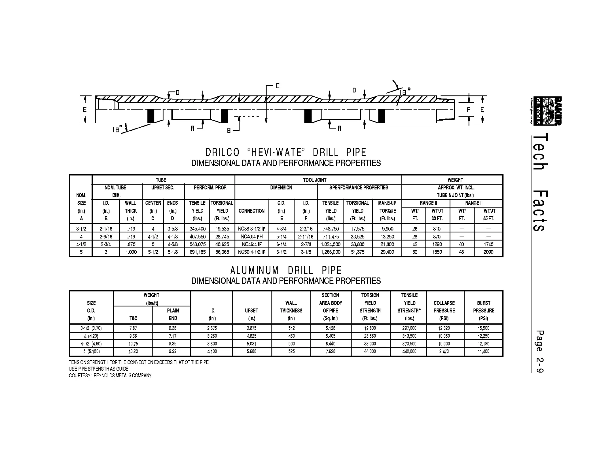
DRILCO “HEVI-WATE” DRILL PIPE
DIMENSIONAL DATA AND PERFORMANCE PROPERTIES
NOM. SIZE (In.) A TUBE TOOL JOINT WEIGHT
NOM. TUBE DIM. UPSET SEC. PERFORM. PROP. DIMENSION S PERFORMANCE PROPERTIES APPROX. WT. INCL. TUBE & JOINT (lbs.)
I.D. (In.) В WALL THICK (In.) CENTER (In.) C ENDS (In.) D TENSILE YIELD (lbs.) TORSIONAL YIELD (Ft. lbs.) CONNECTION O.D. (In.) E I.D. (In.) F TENSILE YIELD (lbs.) TORSIONAL YIELD (Ft. lbs.) MAKE-UP TORQUE (Ft. lbs.) RANGE II RANGE III
WT/ FT. WT/JT 30 FT. WT/ FT. WT/JT 45 FT.
3-1/2 2-1/16 .719 4 3-5/8 345,400 19,535 NC383-1/2 IF 4-3/4 2-3/16 748,750 17,575 9,900 26 810 — —
4 2-9/16 .719 4-1/2 4-1/8 407,550 28,745 NC4O:4 FH 5-1/4 2-11/16 711,475 23,525 13,250 28 870 — —
4-1/2 2-3/4 .875 5 4-5/8 548/175 40,625 NC46:4 IF 6-1/4 2-7/8 1,024,500 38,800 21,800 42 1290 40 1745
5 3 1.000 5-1/2 5-1/8 691,185 56,365 NC50:4-1/2 IF 6-1/2 3-1/8 1,266/300 51,375 29,400 50 1550 48 2090
ALUMINUM DRILL PIPE
DIMENSIONAL DATA AND PERFORMANCE PROPERTIES
SIZE O.D. (In.) WEIGHT (Ibs/ft) I.D. (In.) UPSET (In.) WALL THICKNESS (In.) SECTION AREA BODY OF PIPE (Sq.ln.) TORSION YIELD STRENGTH (Ft lbs.) TENSILE YIELD STRENGTH" (lbs.) COLLAPSE PRESSURE (PSI) BURST PRESSURE (PSI)
T&C PLAIN END
3-1/2 (3.70) 7.87 6.36 2.675 3.875 .512 5.126 19,830 297,000 12,320 15,500
4 (420) 9.68 7.17 3.280 4625 .460 5.405 23,580 313,500 10,050 12,250
4-1/2 (460) 10.75 8.35 3.600 5.031 .500 6.440 33,000 373,500 10,000 12,180
5 (5.150) 13.20 9.99 4100 5.688 .525 7.628 44,000 442,000 9,470 11,400
TENSION STRENGTH FOR THE CONNECTION EXCEEDS THAT OF THE PIPE.
USE PIPE STRENGTH AS GUIDE.
COURTESY: REYNOLDS METALS COMPANY.
Tech Facts Page 2-9
Page 2-10
Tech
Facts
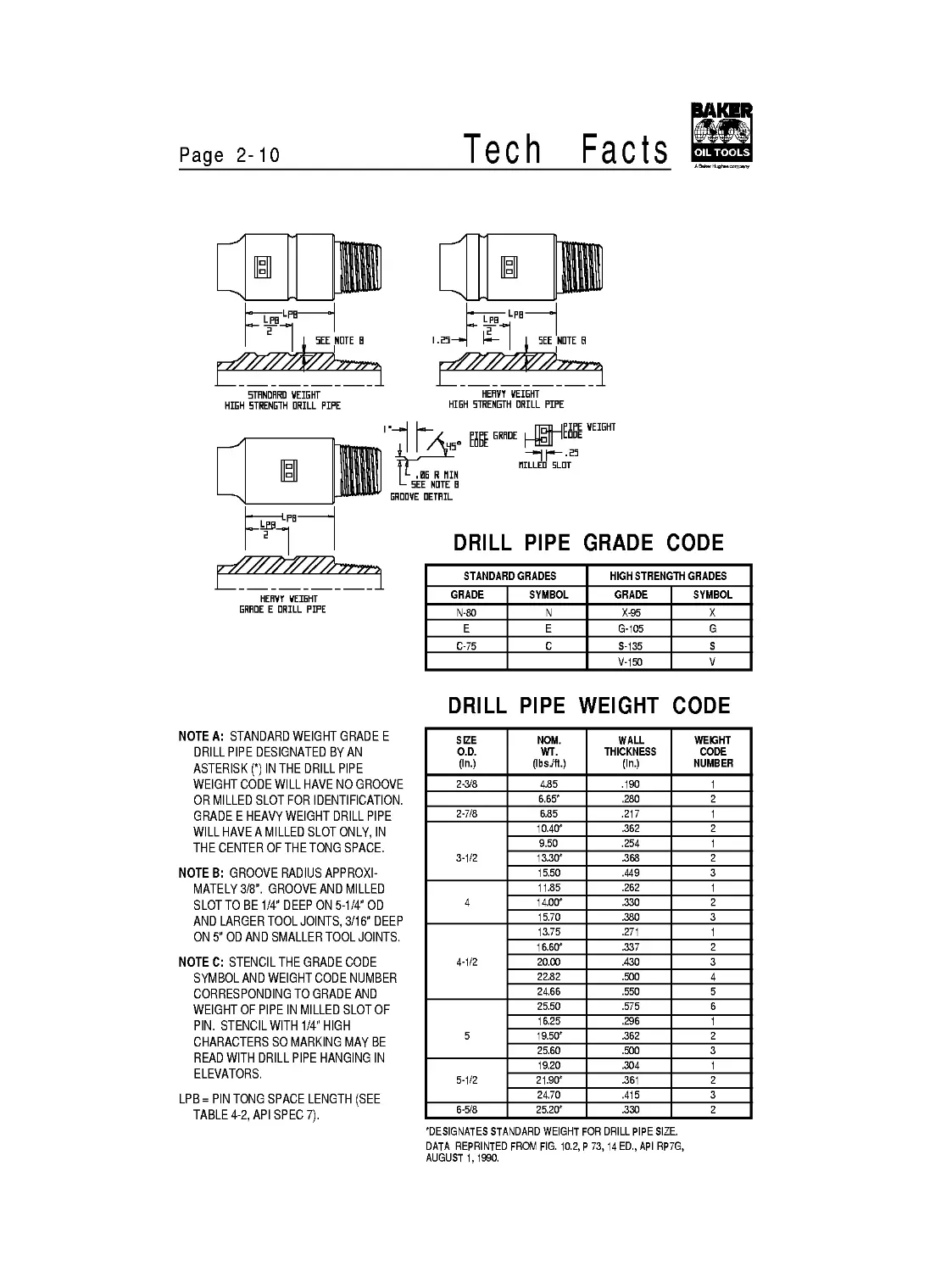
HEHVY WEIGHT
HIGH STRENGTH DRILL PIPE
5THNDRRD WEIGHT
HIGH STRENGTH DRILL PIPE
HEflVT WEIGHT
GRADE E DRILL PIPE
DRILL PIPE GRADE CODE
STANDARD GRADES HIGH STRENGTH GRADES
GRADE SYMBOL GRADE SYMBOL
N-80 N X-95 X
E E G-105 G
C-75 C S-135 S
V-150 V
DRILL PIPE WEIGHT CODE
NOTEA: STANDARD WEIGHT GRADE E
DRILL PIPE DESIGNATED BY AN
ASTERISK (*) IN THE DRILL PIPE
WEIGHT CODE WILL HAVE NO GROOVE
OR MILLED SLOT FOR IDENTIFICATION.
GRADE E HEAVY WEIGHT DRILL PIPE
WILL HAVE A MILLED SLOT ONLY, IN
THE CENTER OF THE TONG SPACE.
NOTEB: GROOVE RADIUS APPROXI-
MATELY 3/8". GROOVE AND MILLED
SLOTTO BE 1/4" DEEP ON 5-1/4" OD
AND LARGER TOOL JOINTS, 3/16" DEEP
ON 5" OD AND SMALLER TOOL JOINTS.
NOTEC: STENCIL THE GRADE CODE
SYMBOL AND WEIGHT CODE NUMBER
CORRESPONDING TO GRADE AND
WEIGHT OF PIPE IN MILLED SLOT OF
PIN. STENCIL WITH 1/4" HIGH
CHARACTERS SO MARKING MAY BE
READ WITH DRILL PIPE HANGING IN
ELEVATORS.
LPB = PIN TONG SPACE LENGTH (SEE
TABLE 4-2, API SPEC 7).
SIZE O.D. (In.) NOM. WT. (IbsJft.) WALL THICKNESS (In.) WEIGHT CODE NUMBER
2-3/8 4.85 .190 1
6.65' .280 2
2-7/8 6.85 .217 1
3-1/2 10.40' .362 2
9.50 .254 1
13.30' .368 2
15.50 .449 3
4 11.85 .262 1
14.00' .330 2
15.70 .380 3
4-1/2 13.75 .271 1
16.60' .337 2
20.00 .430 3
22.82 .500 4
24.66 .550 5
5 25.50 .575 6
16.25 .296 1
19.50' .362 2
25.60 .500 3
5-1/2 19.20 .304 1
21.90' .361 2
24.70 .415 3
6-5/8 25.20' .330 2
'DESIGNATES STANDARD WEIGHT FOR DRILL PIPE SIZE.
DATA REPRINTED FROM FIG. 10.2, P 73,14 ED., API RP7G,
AUGUST 1,1990.
Facts
Page 2-11
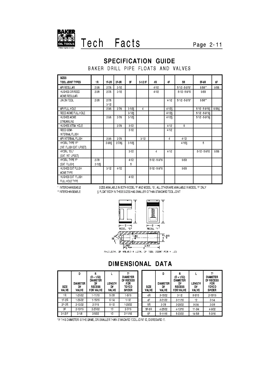
SPECIFICATION GUIDE
BAKER DRILL PIPE FLOATS AND VALVES
SIZES TOOL JOINT TYPES 1R 1F-2R 2F-3R 3F 3-1/2 IF 4R 4F 5R 5F-6R 6F
API REGULAR 2-3/8 2-7/8 3-1/2 4-1/2 5-1/2-5-9/16* 6-5/8** 8-&8
HUGHES OR REED ACME REGULAR 2-3/8 2-7/8 3-1/2 4-1/2 5-1/2-5-9/16 6-5/8
UNIDNTDDL 2-3/8 2-7/8 3-1/2 4-1/2 5-1/2-5-9/16* 6-5/8**
API FULL HDLE 2-3/8 2-7/8 3-1/2§ 4 4-12§ 5-1/2-5-9/16$ 6-5/8$
REED ACME FULL HOLE 3-1/2S 4-1/2S 5-1/2-5-9/16§
HUGHES ACME STREAMUNE 2-3/8 2-7/8 3-1/2§ 4-1/2§ 5-1/2-5-9/16§
HUGHES XTRA HDLE 2-7/8 3-1/2 4-1/2 5
REED SEMI- INTERNALFLUSH 3-1/2 4-1/2
API INTERNAL FLUSH 2-3/8 2-7/8 3-1/2 4 4-1/2
HYDRIL TYPE "IF" (INT FLUSH EXT UPSET) 2-3/8§ 2-7/8§ 3-1/2§ 4-1/2§ 5
HYDRIL "EIU" (EXT. INT UPSET) 3-1/2 4 4-1/2 5-1/2-5-9/16 6-&8
HYDRIL TYPE "F" (EXT FLUSH) 2-7/8 3-1/2§ 4-1/2 5 5-1/2-5-9/16 6-5/8
HUGHES EXT FLUSH ACME TYPE 3-1/2 4-1/2 5-1/2-5-9/16 6-5/8
HUGHES EXT FLUSH FULL HDLE TYPE 4-1/2
' INTERCHANGEABLE SIZES AVAILABLE IN BOTH M DDEL "F" AND MODEL "G", ALL OTHER ARE AVAILABLE IN MODEL "F" ONLY
" INTERCHANGEABLE § FLDAT BDDYIN THESESIZES HAS SMALLER IDTHAN STANDARD TDDLJDINT
H=LCLETH. OF VRLVE) t LOTH. OF TOOL JOINT PIN + .55
DIMENSIONAL DATA
SIZE VALVE D DIAMETER DF VALVE R (D+1/32) DIAMETER DF RECESS FDR VALVE L LENGTH DF VALVE Г DIAMETER DF RECESS FDR TOTCD SPIDER
1R 1-21/32 1-11/16 5-7/8 1-5/16
1F-2R 1-29/32 1-15/16 6-1/4 1-1/2
2F-3R 2-13/32 2-7/16 6-1/2 1-29/32
3F 2-13/16 2-27/32 10 2-7/16
3-1/2IF 3-1/8 3-5/32 10 2-11/16
SIZE VALVE D DIAMETER DF VALVE R (D + 1/32) DIAMETER DF RECESS FDR VALVE L LENGTH DF VALVE Г DIAMETER DF RECESS FDR TDTCD SPIDER
4R 3-15/32 3-1/2 8-5/16 2-15/16
4F 3-21/32 3-11/16 12 3-1/4
5R 3-7/8 3-29/32 9-3/4 3-3/8
5F-6R 4-25/32 4-13/16 11-3/4 4-9/32
6F 5-11/16 5-23/32 14-5/8 5-3/16
'IF THIS DIAMETER ISTHESAME, DR SMALLERTHAN STANDARD TDDLJDINT ID, DISREGARD IT.
SECTION 3 - Drill Collars & Connections
Contents
Page
Connections and Make-Up.................................3-1
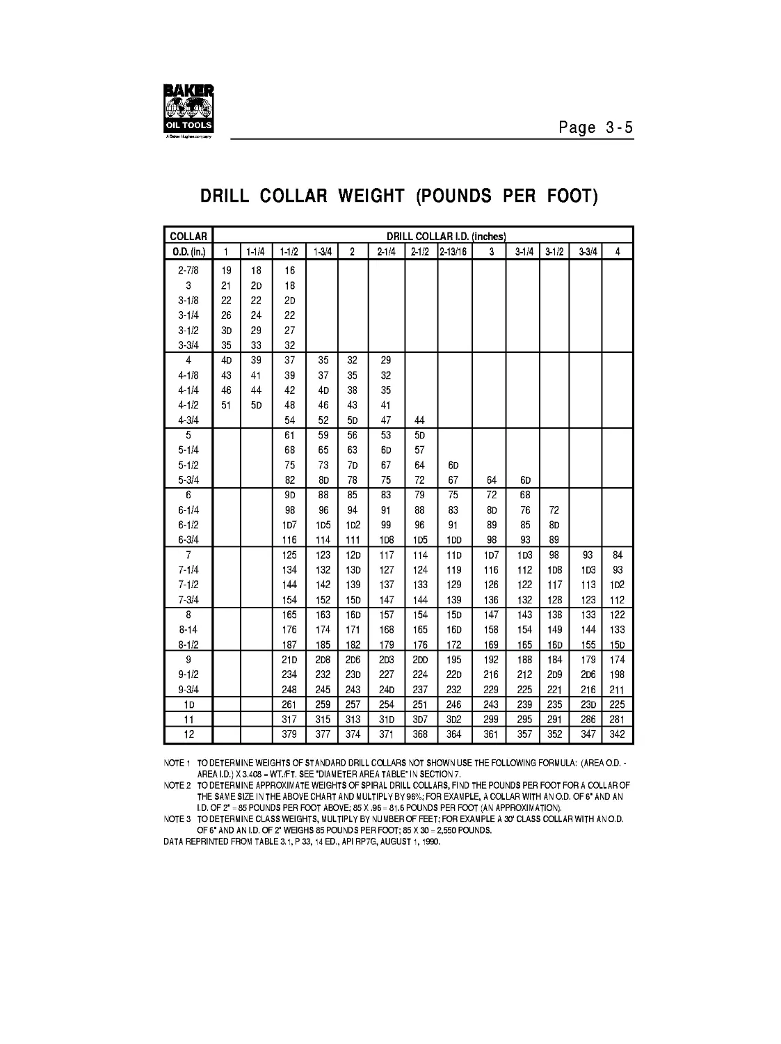
Weights.................................................3-5
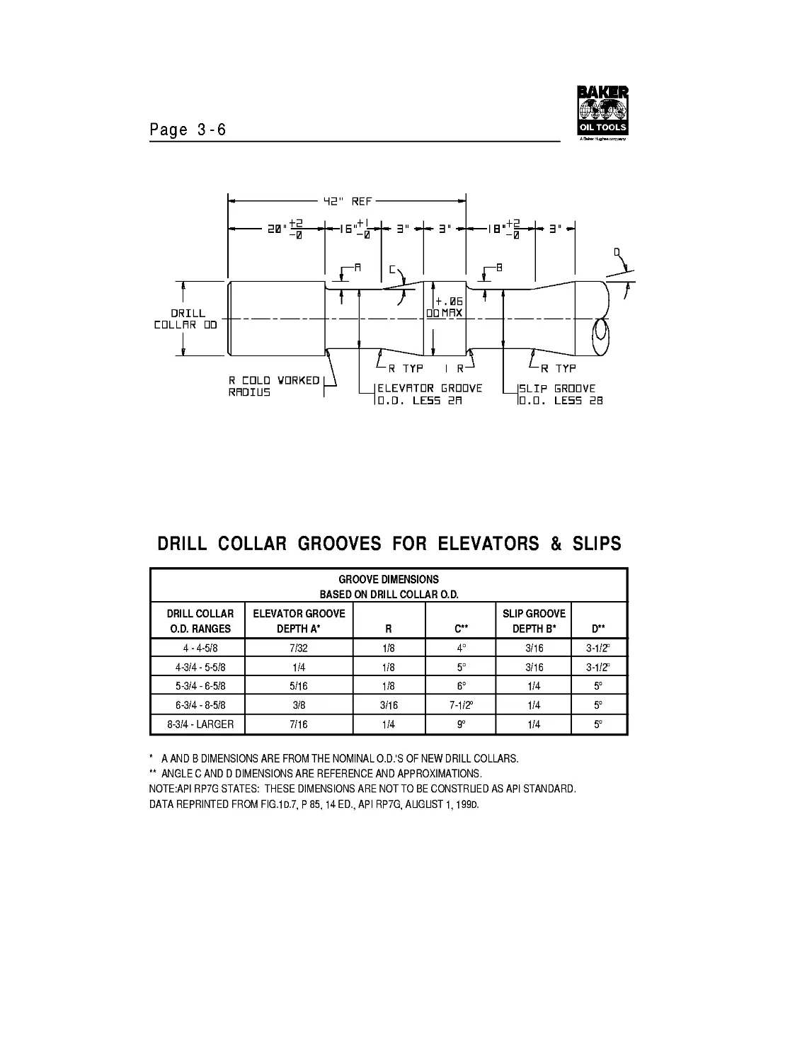
Grooves for Elevators and Slips.........................3-6
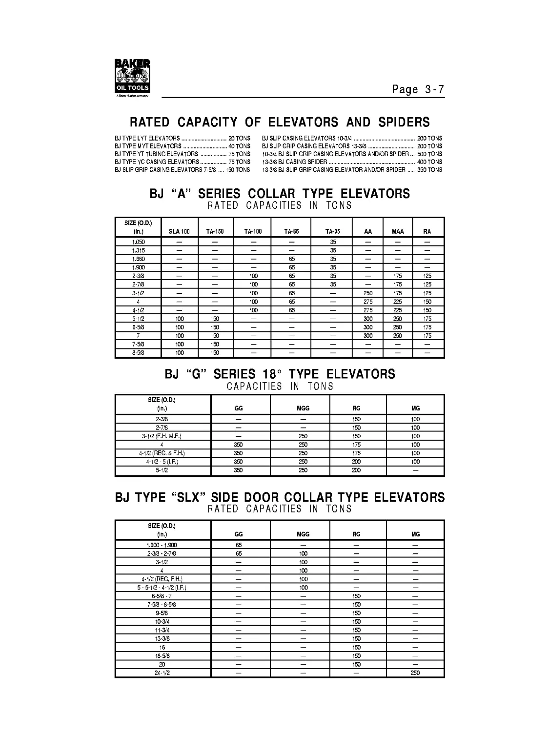
Capacities of Elevators and Spiders.....................3-7
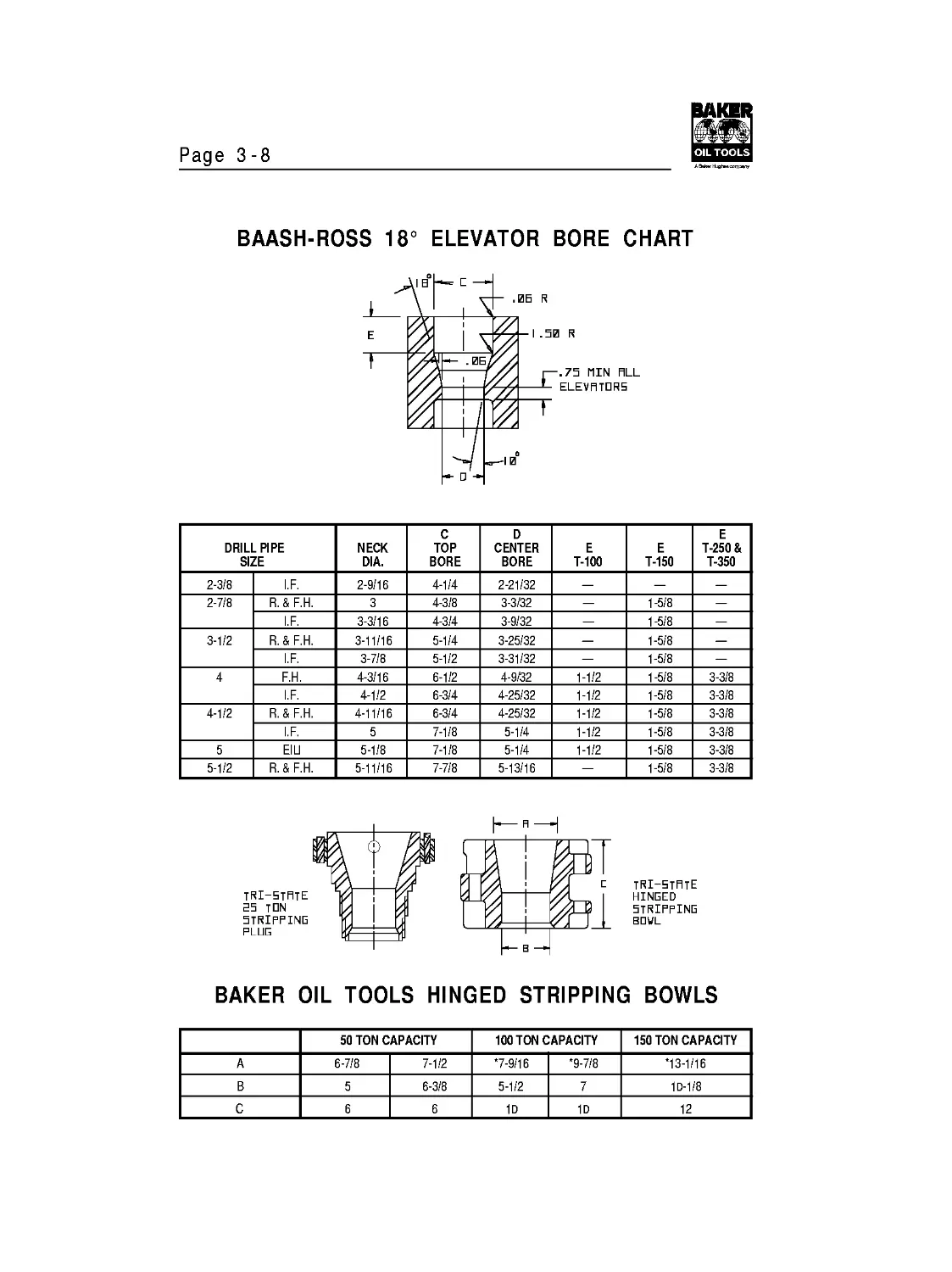
Bottleneck Elevator Bores...............................3-8
Hinged Stripping Bowls and Plugs........................3-8
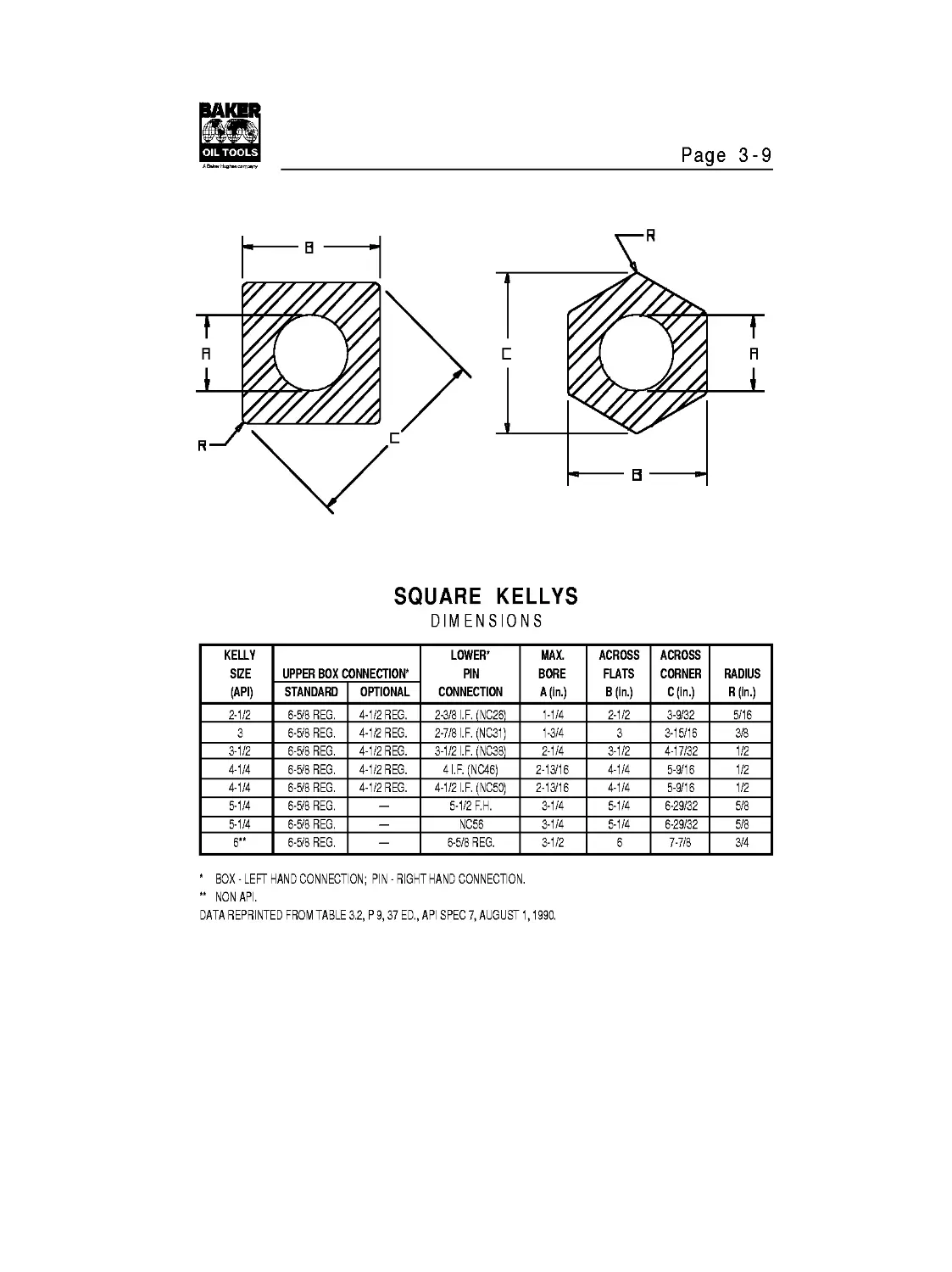
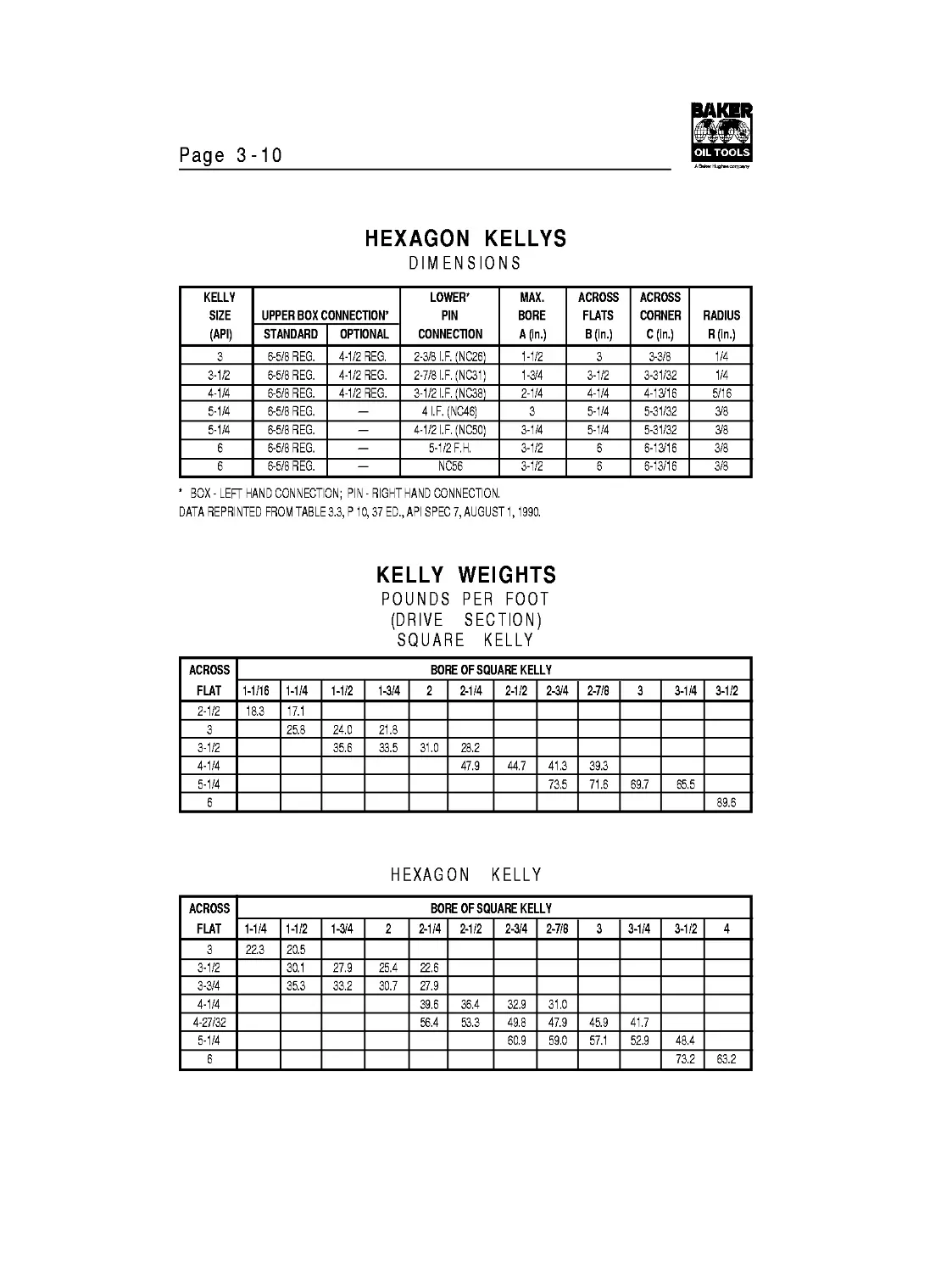
Kellys..................................................3-9
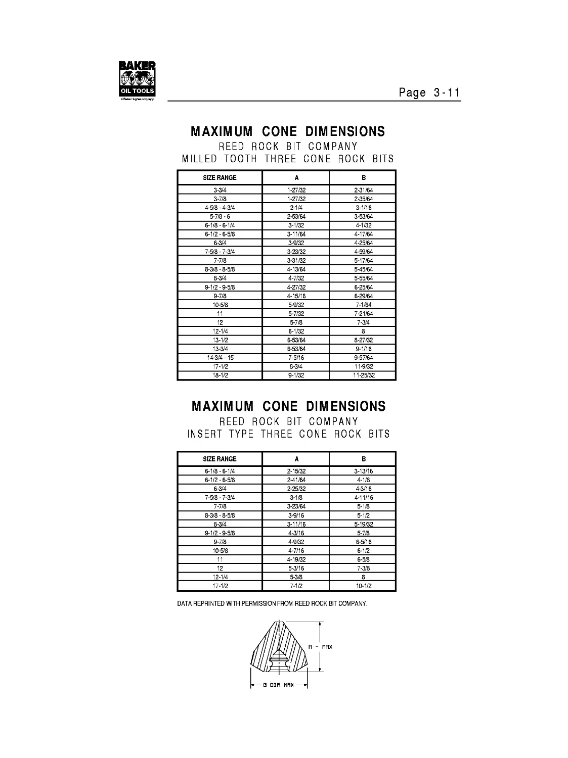
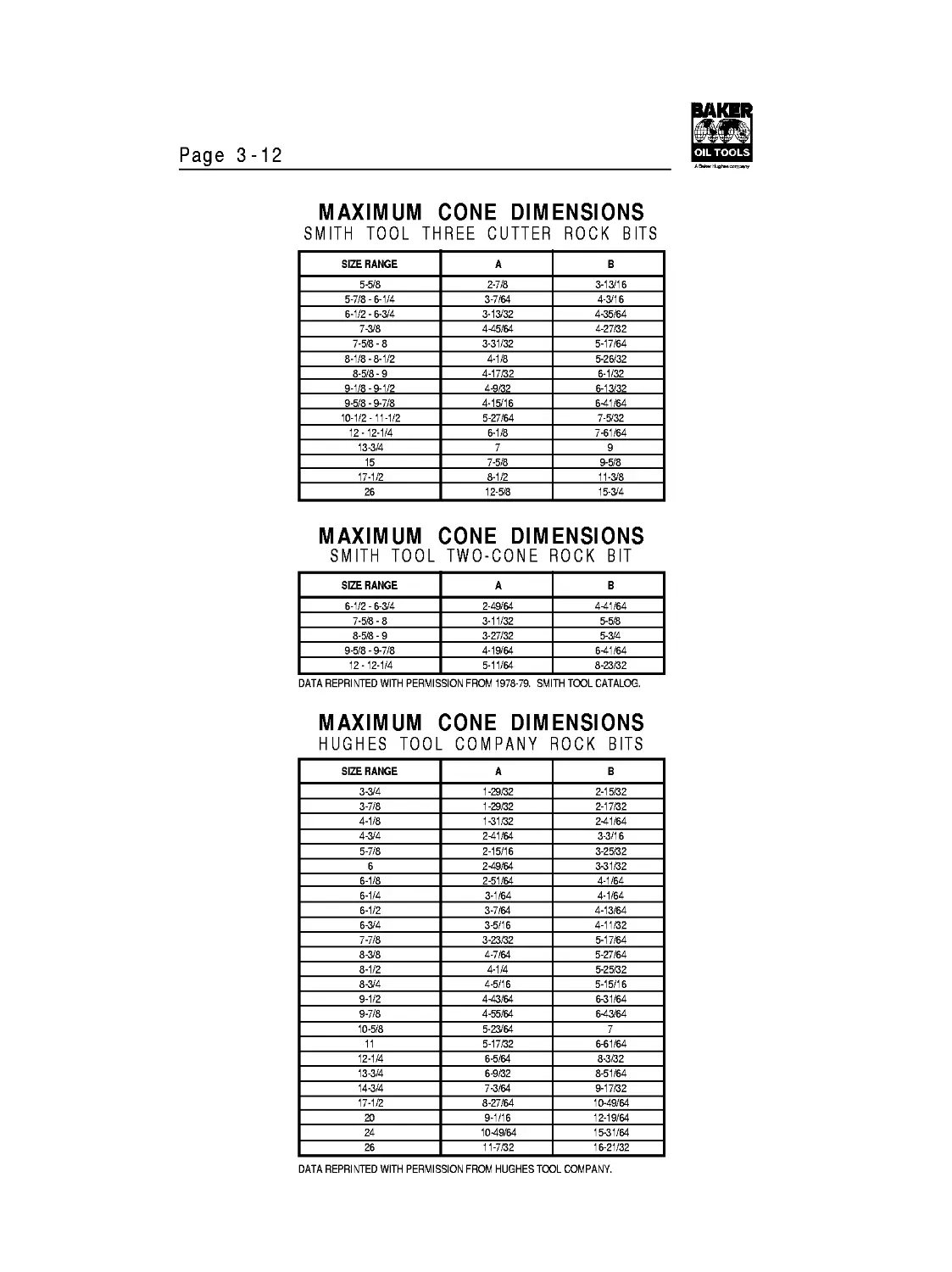
Maximum Cone Dimensions................................3-11
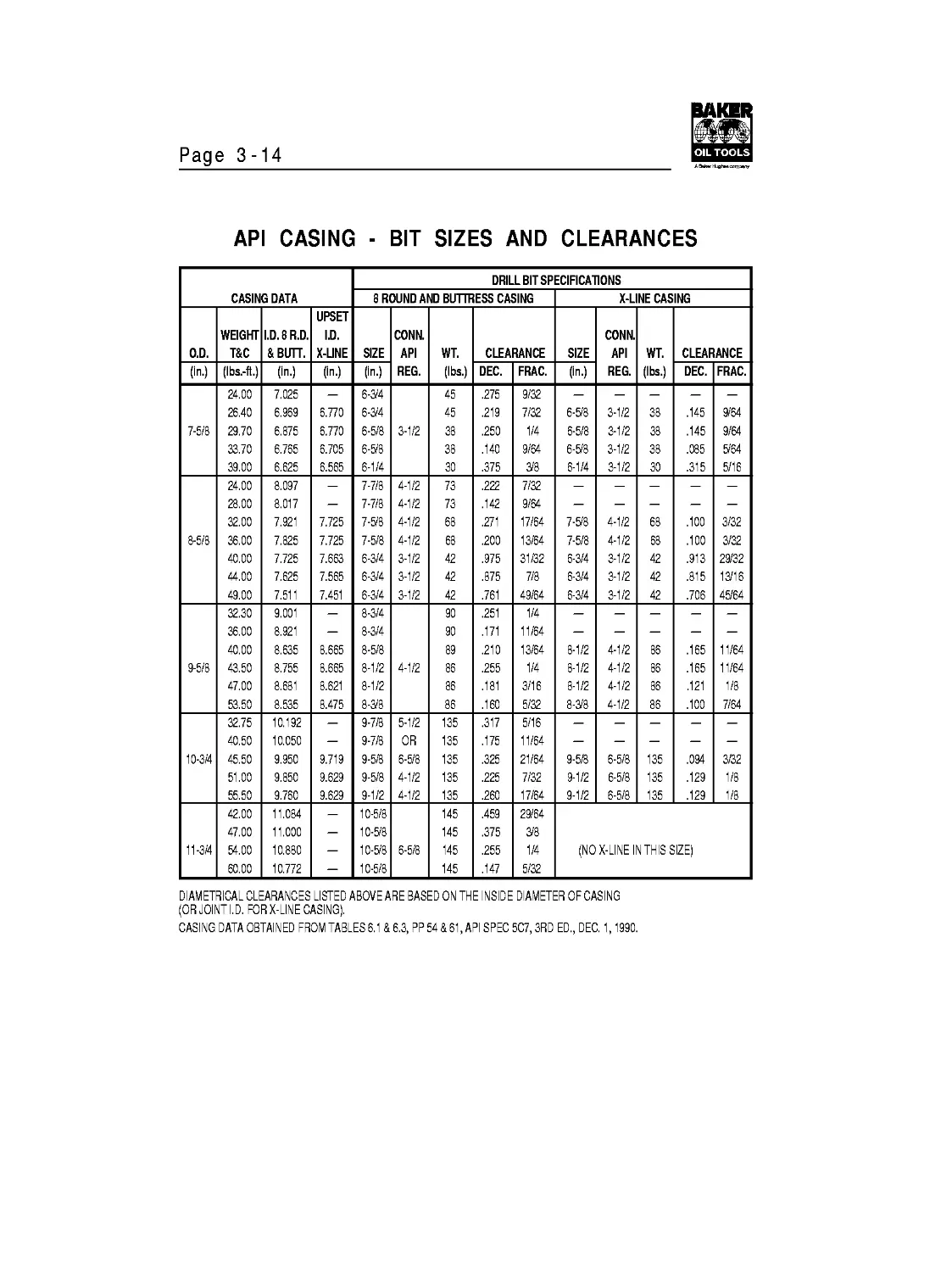
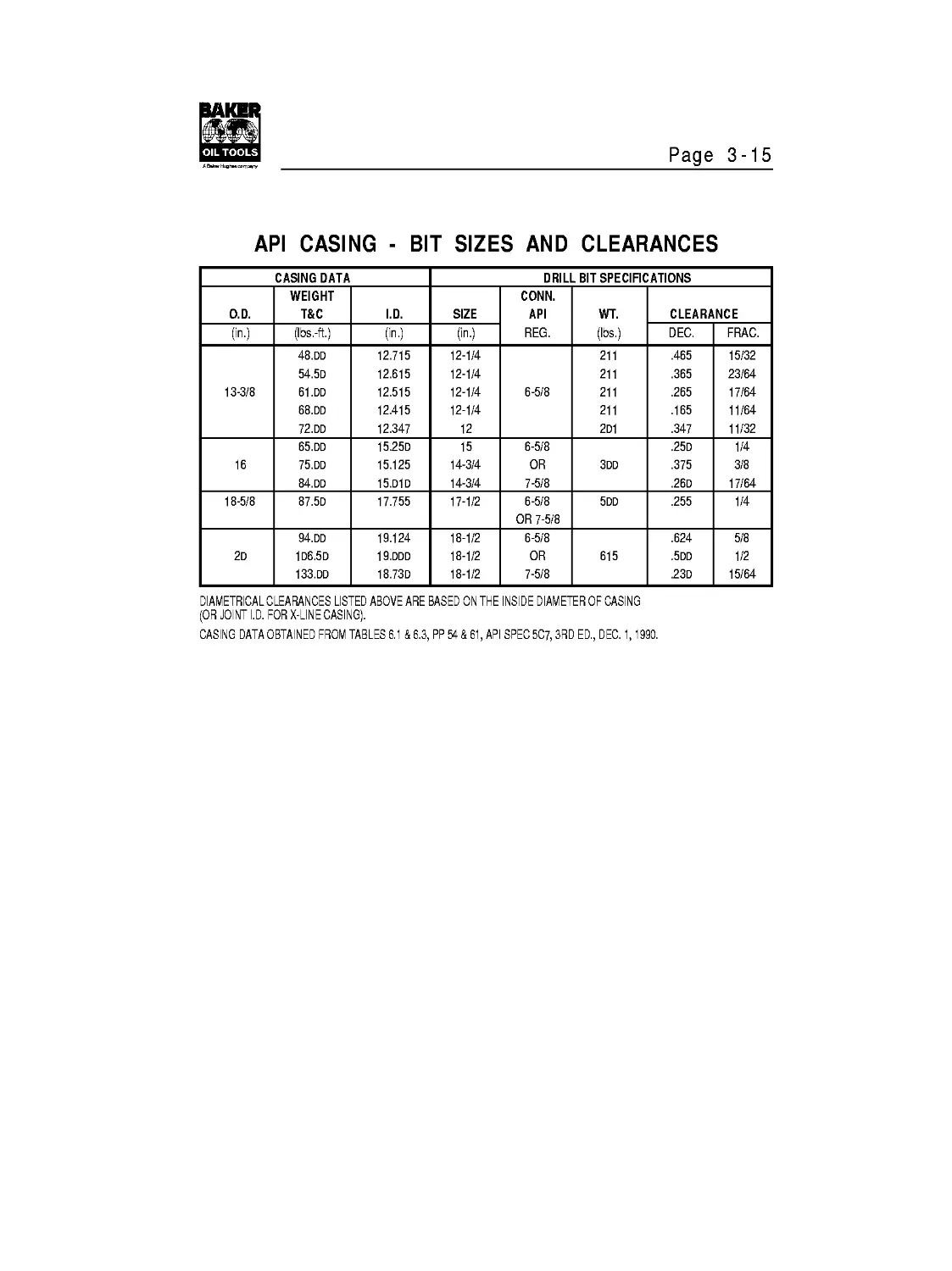
Bit Sizes and Clearances...............................3-13
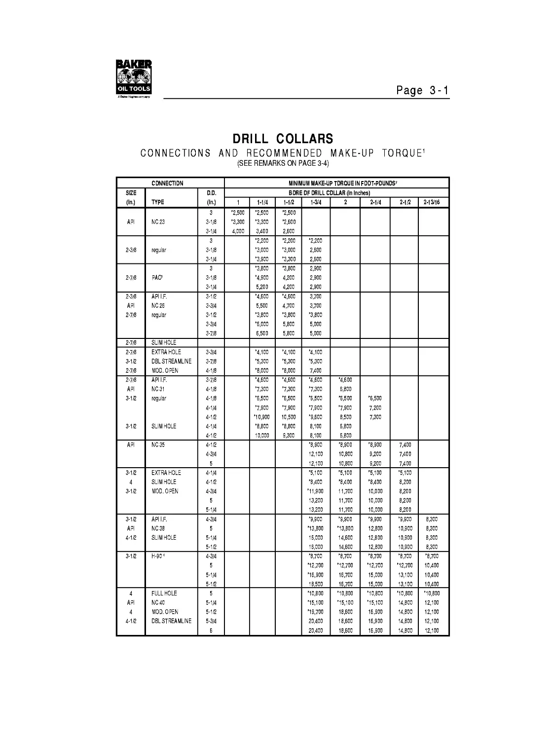
Page 3-1
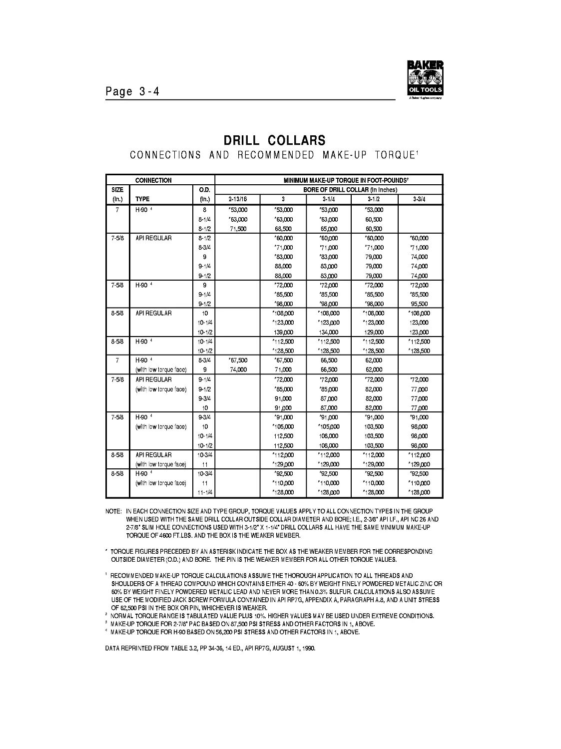
DRILL COLLARS
CONNECTIONS AND RECOMMENDED MAKE-UP TORQUE1
(SEE REMARKS ON PAGE 3-4)
CONNECTION MINIMUM MAKE-UP TDRQUE IN FDDT-PDUNDS2
SIZE (In.) TYPE D.D. (In.) BDREDF DRILL COLLAR (In Inches)
1 1-1/4 1-1/2 1-3/4 2 2-1/4 2-1/2 2-13/16
API NC23 3-1/8 3-1/4 *2,500 *3,300 4,000 *2,500 *3,300 3,400 '2,500 '2,600 2,600
2-3/8 regular 3-1/8 3-1/4 *2,200 *3,000 *3,900 '2,200 '3,000 '3,300 '2,200 2,600 2,600
2-7/8 РАС5 3-1/8 3-1/4 *3,800 '4,900 5,200 '3,800 4,200 4,200 2,900 2,900 2,900
2-3/8 API 2-7/8 API I.F. NC26 regular 3-1/2 3-3/4 3-1/2 3-3/4 3-7/8 '4,600 5,500 '3,800 '6,000 6,500 '4,600 4,700 '3,800 5,800 5,800 3,700 3,700 '3,800 5,000 5,000
2-7/8 SLIM HOLE
2-7/8 3-1/2 2-7/8 EXTRA HOLE DEL STREAMLINE MOD. OPEN 3-3/4 3-7/8 4-1/8 '4,100 '5,300 '8,000 '4,100 '5,300 '8,000 '4,100 '5,300 7,400
2-7/8 API 3-1/2 3-1/2 API I.F. NC31 regular SLIM HOLE 3-7/8 4-1/8 4-1/8 4-1/4 4-1/2 4-1/4 4-1/2 '4,600 '7,300 '6,500 '7,900 '10,900 '8,800 10,000 '4,600 '7,300 '6,500 '7,900 10,500 '8,800 9,300 '4,600 '7,300 '6,500 7,900 '9,600 8,100 8,100 '4,600 6,800 '6,500 '7,900 8,500 6,800 6,800 '6,500 7,200 7,300
API NC35 4-1/2 4-3/4 5 '8,900 12,100 12,100 '8,900 10,800 10,800 '8,900 9,200 9,200 7,400 7,400 7,400
3-1/2 3-1/2 EXTRA HOLE SLIM HOLE MOD. OPEN 4-1/4 4-1/2 4-3/4 5 5-1/4 '5,100 '8,400 *11,900 13,200 13,200 '5,100 '8,400 11,700 11,700 11,700 '5,100 '8,400 10,000 10,000 10,000 '5,100 8,200 8,200 8,200 8,200
3-1/2 API 4-1/2 API I.F. NC38 SLIM HOLE 4-3/4 5 5-1/4 5-1/2 '9,900 '13,800 16,000 16,000 '9,900 '13,800 14,600 14,600 '9,900 12,800 12,800 12,800 '9,900 10,900 10,900 10,900 8,300 8,300 8,300 8,300
3-1/2 H-904 4-3/4 5 5-1/4 5-1/2 '8,700 *12,700 *16,900 18,500 '8,700 *12,700 16,700 16,700 '8,700 *12,700 15,000 15,000 '8,700 *12,700 13,100 13,100 '8,700 10,400 10,400 10,400
API 4-1/2 FULL HOLE NC 40 MOD. OPEN DEL STREAMLINE 5 5-1/4 5-1/2 5-3/4 6 *10,800 '15,100 *19,700 20,400 20,400 *10,800 *15,100 18,600 18,600 18,600 *10,800 *15,100 16,900 16,900 16,900 *10,800 14,800 14,800 14,800 14,800 *10,800 12,100 12,100 12,100 12,100
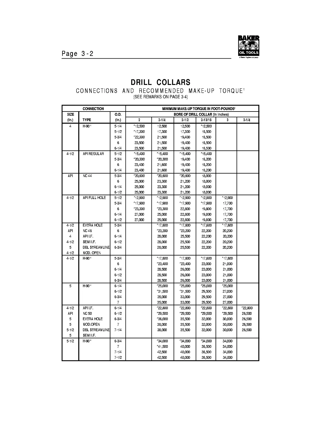
Page 3-2
DRILL COLLARS
CONNECTIONS AND RECOMMENDED MAKE-UP TORQUE1
(SEE REMARKS ON PAGE 3-4)
CONNECTION MINIMUM MAKE-UP TORQUE IN FOOT-POUNDS2
SIZE (Ш.) TYPE O.D. (Ш.) BORE OF DRILL COLLAR (In Inches)
2 2-1/4 2-1/2 2-13/16 3 3-1/4
H-904 5-1/4 5-1/2 5-3/4 6 6-1/4 '12,500 '17,300 '22,300 23,500 23,500 12,500 17,300 21,500 21,500 21,500 12,500 17,300 19,400 19,400 19,400 '12,500 16,500 16,500 16,500 16,500
4-1/2 API REGULAR 5-1/2 5-3/4 6 6-1/4 '15,400 '20,300 23,400 23,400 '15,400 '20,300 21,600 21,600 '15,400 19,400 19,400 19,400 '15,400 16,200 16,200 16,200
API NC44 5-3/4 6 6-1/4 6-1/2 '20,600 25,000 25,000 25,000 '20,600 23,300 23,300 23,300 '20,600 21,200 21,200 21,200 18,000 18,000 18/300 18/300
4-1/2 API FULL HOLE 5-1/2 5-3/4 6 6-1/4 6-1/2 '12,900 '17,900 '23,300 27,000 27,000 '12,900 '17,900 '23,300 25,000 25,000 '12,900 '17,900 22,800 22,800 22,800 '12,900 '17,900 19,800 19,800 19,800 '12,900 17,700 17,700 17,700 17,700
4-1/2 API 4-1/2 5 4-1/2 EXTRA HOLE NC46 API I.F. SEMI I.F. DBL STREAMLINE MOD. OPEN 5-3/4 6 6-1/4 6-1/2 6-3/4 '17,600 '23,200 28,000 28,000 28,000 '17,600 '23,200 25,500 25,500 25,500 '17,600 22,200 22,200 22,200 22,200 '17,600 20,200 20,200 20,200 20,200
4-1/2 H-904 5-3/4 6 6-1/4 6-1/2 6-3/4 '17,600 '23,400 28,500 28,500 28,500 '17,600 '23,400 26,000 26,000 26,000 '17,600 23,000 23/300 23/300 23/300 '17,600 21/300 21,000 21,000 21,000
5 H-904 6-1/4 6-1/2 6-3/4 7 '25,000 '31,500 35,000 35,000 '25,000 '31,500 33,000 33,000 '25/300 29,500 29,500 29,500 '25,000 27/300 27,000 27,000
4-1/2 API 5 5 5-1/2 5 API I.F. NC 50 EXTRA HOLE MOD.OPEN DBL STREAMLINE SEMI I.F. 6-1/4 6-1/2 6-3/4 7 7-1/4 '22,800 '29,500 '36,000 38,000 38,000 '22,800 '29,500 35,500 35,500 35,500 '22,800 '29,500 32,000 32,000 32,000 '22,800 '29,500 30/300 30,000 30/300 '22,800 26,500 26,500 26,500 26,500
5-1/2 H-904 6-3/4 7 7-1/4 7-1/2 '34,000 '41,500 42,500 42,500 '34,000 40,000 40,000 40,000 '34/300 36,500 36,500 36,500 34/300 34,000 34,000 34,000
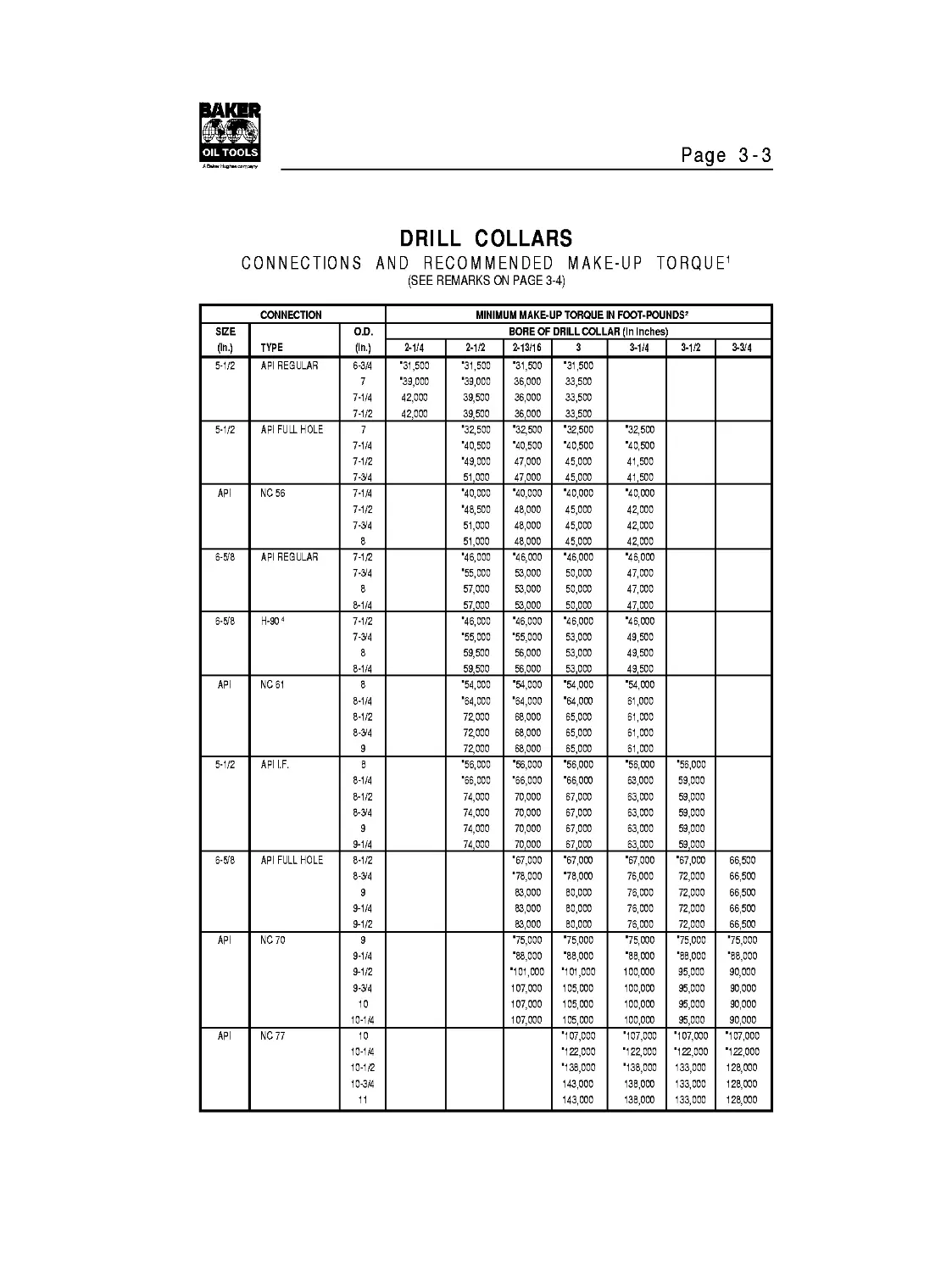
Page 3-3
DRILL COLLARS
CONNECTIONS AND RECOMMENDED MAKE-UP TORQUE1
(SEE REMARKS ON PAGE 3-4)
CONNECTION MINIMUM MAKE-UP TORQUE IN FOOT-POUNDS2
SIZE (Ш.) TYPE O.D. (Ш.) BORE OF DRILL COLLAR (In Inches
2-1/4 2-1/2 2-13/16 3 3-1/4 3-1/2 3-3/4
5-1/2 API REGULAR 6-3/4 7 7-1/4 7-1/2 31,500 '39,000 42,000 42,000 '31,500 '39,000 39,500 39,500 '31,500 36,000 36,000 36,000 '31,500 33,500 33,500 33,500
5-1/2 API FULL HOLE 7 7-1/4 7-1/2 7-3/4 '32,500 '40,500 '49,000 51,000 '32,500 '40,500 47,000 47,000 '32,500 '40,500 45,000 45,000 '32,500 '40,500 41,500 41,500
API NO 56 7-1/4 7-1/2 7-3/4 8 '40,000 '48,500 51,000 51,000 '40,000 48,000 48,000 48,000 '40,000 45,000 45,000 45,000 '40,000 42,000 42,000 42,000
6-&8 API REGULAR 7-1/2 7-3/4 8 8-1/4 '46,000 '55,000 57,000 57,000 '46,000 53,000 53,000 53,000 '46,000 50,000 50,000 50,000 '46,000 47,000 47,000 47,000
6-&8 H-904 7-1/2 7-3/4 8 8-1/4 '46,000 '55,000 59,500 59,500 '46,000 '55,000 56,000 56,000 '46,000 53,000 53,000 53,000 '46,000 49,500 49,500 49,500
API NO 61 8 8-1/4 8-1/2 8-3/4 9 '54,000 '64,000 72,000 72,000 72,000 '54,000 '64,000 68,000 68,000 68,000 '54,000 '64,000 65,000 65,000 65,000 '54,000 61,000 61,000 61,000 61,000
5-1/2 API I.F. 8 8-1/4 8-1/2 8-3/4 9 9-1/4 '56,000 '66,000 74,000 74,000 74,000 74,000 '56,000 '66,000 70,000 70,000 70,000 70,000 '56,000 '66,000 67,000 67,000 67,000 67,000 '56,000 63,000 63,000 63,000 63,000 63,000 '56,000 59,000 59,000 59,000 59,000 59,000
6-&8 API FULL HOLE 8-1/2 8-3/4 9 9-1/4 9-1/2 '67,000 '78,000 83,000 83,000 83,000 '67,000 '78,000 80,000 80,000 80,000 '67,000 76,000 76,000 76,000 76,000 '67,000 72,000 72,000 72,000 72,000 66,500 66,500 66,500 66,500 66,500
API NC70 9 9-1/4 9-1/2 9-3/4 10 10-1/4 '75,000 '88,000 '101,000 107,000 107,000 107,000 '75,000 '88,000 '101,000 105,000 105,000 105,000 '75,000 '88,000 100,000 100,000 100,000 100,000 '75,000 '88,000 95,000 95,000 95,000 95,000 '75,000 '88,000 90,000 90,000 90,000 90,000
API NO 77 10 10-1/4 10-1/2 10-3/4 '107,000 '122,000 '138,000 143,000 143,000 '107,000 '122,000 '138,000 138,000 138,000 '107,000 '122,000 133,000 133,000 133,000 1' 1' 1' 1' 1'
Page 3-4
DRILL COLLARS
CONNECTIONS AND RECOMMENDED MAKE-UP TORQUE1
CONNECTION MINIMUM MAKE-UP TORQUE IN FOOT-POUNDS2
SIZE (Ш.) TYPE O.D. (Ш.) BORE OF DRILL COLLAR (In Inches)
2-13/16 3 3-1/4 3-1/2 3-3/4
7 H-90 4 8 8-1/4 8-1/2 '53,000 '63,000 71,500 '53,000 '63,000 68,500 '53 BOO '63BOO 65/300 '53,000 60,500 60,500
7-5/8 API REGULAR 8-1/2 8-3/4 9 9-1/4 9-1/2 '60,000 '71,000 '83,000 88,000 88,000 '6OB0O 71 BOO '83BOO 83/300 83/300 '60,000 '71,000 79,000 79,000 79,000 '60,000 71,000 74,000 74BOO 74BOO
7-5® H-90 4 9 9-1/4 9-1/2 '72,000 '85,500 '98,000 72BOO '85,500 '98BOO '72,000 '85,500 '98,000 72BOO '85,500 95,500
8-5® API REGULAR 10 10-1/4 10-1/2 '108/100 '123,000 139/100 '108,000 '123/300 134,000 '108,000 '123,000 129,000 '108BOO 123,000 123BOO
8-5® H-90 4 10-1/4 10-1/2 '112,500 '128,500 '112,500 '128,500 '112,500 '128,500 '112,500 '128,500
7 H-90 4 (with low torque face) 8-3/4 9 '67,500 74,000 '67,500 71,000 66,500 66,500 62,000 62,000
7-5/8 API REGULAR (with low torque face) 9-1/4 9-1/2 9-3/4 10 '72,000 '85,000 91,000 91 BOO 72BOO '85 BOO 87/300 87,000 '72,000 82,000 82,000 82,000 72,000 77/300 77BOO 77BOO
7-5® H-90 4 (with low torque face) 9-3/4 10 10-1/4 10-1/2 '91,000 '105,000 112,500 112,500 *91 BOO 'Ю5ВОО 108,000 108,000 '91,000 103,500 103,500 103,500 *91,000 98BOO 98BOO 98BOO
8-5® API REGULAR (with low torque face) 10-3/4 '112BOO '129 BOO '112,000 '129,000 '112,000 '129,000 *112/300 '129/300
8-5® H-90 4 (with low torque face) 10-3/4 11-1/4 '92,500 '11OB0O '128,000 *92,500 '110,000 '128/300 '92,500 '110,000 '128,000 *92,500 '110/300 '128BOO
NOTE: IN EACH CONNECTION SIZE AND TYPE GROUP, TORQUE VALUES APPLY TO ALL CONNECTION TYPES IN THE GROUP
WHEN USED WITH THE SAME DRILL COLLAR OUTSIDE COLLAR DIAMETER AND BORE; I.E., 2-3®' API I.F., API NC 26 AND
2-7®' SLIM HOLE CONNECTIONS USED WITH 3-1/2' X 1-1/4' DRILL COLLARS ALL HAVE THE SAME MINIMUM MAKE-UP
TORQUE OF 4600 FT.LBS. AND THE BOX IS THE WEAKER MEMBER.
* TORQUE FIGURES PRECEDED BY AN ASTERISK INDICATE THE BOX AS THE WEAKER MEMBER FOR THE CORRESPONDING
OUTSIDE DIAMETER (O.D.) AND BORE. THE PIN IS THE WEAKER MEMBER FOR ALL OTHER TORQUE VALUES.
1 RECOMMENDED MAKE-UP TORQUE CALCULATIONS ASSUMETHETHOROUGH APPLICATION TO ALL THREADS AND
SHOULDERS OF A THREAD COMPOUND WHICH CONTAINS EITHER 40 - 60% BYWEIGHT FINELY POWDERED MET ALIC ZINC OR
60% BY WEIGHT FINELY POWDERED METALIC LEAD AND NEVER MORETHANO.3% SULFUR. CALCULATIONS ALSO ASSUME
USE OF THE MODIFIED JACK SCREW FORMULA CONTAINED IN API RP7G, APPENDIX A, PARAGRAPH A.8, AND A UNIT STRESS
OF 62,500 PSI IN THE BOX OR PIN, WHICHEVER IS WEAKER.
2 NORMAL TORQUE RANGEIS TABULATED VALUE PLUS 10%. HIGHER VALUES MAY BE USED UNDER EXTREME CONDITIONS.
3 MAKE-UP TORQUE FOR 2-7/8' РАС BASED ON 87,500 PSI STRESS AND OTHER FACTORS IN 1, ABOVE.
4 MAKE-UP TORQUE FOR H-90 BASED ON 56,200 PSI STRESS AND OTHER FACTORS IN 1, ABOVE.
DATA REPRINTED FROM TABLE 3.2, PP 34-36,14 ED., API RP7G, AUGUST 1,1990.
Page 3-5
DRILL COLLAR WEIGHT (POUNDS PER FOOT)
COLLAR DRILL COLLAR I.D. inches
O.D. (in.) 1 1-1/4 1-1/2 1-3/4 2 2-1/4 2-1/2 2-13/16 3 3-1/4 3-1/2 3-3/4 4
2-7/8 19 18 16
3 21 2D 18
3-1/8 22 22 2D
3-1/4 26 24 22
3-1/2 3D 29 27
3-3/4 35 33 32
4 4D 39 37 35 32 29
4-1/8 43 41 39 37 35 32
4-1/4 46 44 42 4D 38 35
4-1/2 51 5D 48 46 43 41
4-3/4 54 52 5D 47 44
5 61 59 56 53 5D
5-1/4 68 65 63 6D 57
5-1/2 75 73 7D 67 64 6D
5-3/4 82 8D 78 75 72 67 64 6D
6 9D 88 85 83 79 75 72 68
6-1/4 98 96 94 91 88 83 8D 76 72
6-1/2 1D7 1D5 1D2 99 96 91 89 85 8D
6-3/4 116 114 111 1D8 1D5 1DD 98 93 89
7 125 123 12D 117 114 11D 1D7 1D3 98 93 84
7-1/4 134 132 13D 127 124 119 116 112 1D8 1D3 93
7-1/2 144 142 139 137 133 129 126 122 117 113 1D2
7-3/4 154 152 15D 147 144 139 136 132 128 123 112
8 165 163 16D 157 154 15D 147 143 138 133 122
8-14 176 174 171 168 165 16D 158 154 149 144 133
8-1/2 187 185 182 179 176 172 169 165 16D 155 15D
9 21D 2D8 2D6 2D3 2DD 195 192 188 184 179 174
9-1/2 234 232 23D 227 224 22D 216 212 2D9 2D6 198
9-3/4 248 245 243 24D 237 232 229 225 221 216 211
1D 261 259 257 254 251 246 243 239 235 23D 225
11 317 315 313 31D 3D7 3D2 299 295 291 286 281
12 379 377 374 371 368 364 361 357 352 347 342
NOTE 1 TO DETERMINE WEIGHTS OF STANDARD DRILL COLLARS NOT SHOWN USE THE FOLLOWING FORMULA: (AREA O.D.
AREA I.D.) X3.408 = WT./FT. SEE 'DIAMETER AREA TABLE' IN SECTION?.
NOTE 2 TO DETERMINE APPROXIMATE WEIGHTS OF SPIRAL DRILL COLLARS, FIND THE POUNDS PER FOOT FOR A COLLAR OF
THE SAME SIZE IN THE ABOVE CHART AND MULTIPLYBY96%; FOR EXAMPLE, A COLLAR WITH AN O.D. OF 6'AND AN
I.D. OF2' =85 POUNDS PER FOOT ABOVE; 85 X .96 = 81.6 POUNDS PER FOOT (AN APPROXIMATION).
NOTE 3 TO DETERMINE CLASS WEIGHTS, MULTIPLY BY NUMBER OF FEET; FOR EXAMPLE A 30' CLASS COLLAR WITH AN O.D.
OF 6' AND AN I.D. OF 2' WEIGHS 85 POUNDS PER FOOT; 85 X 30 = 2,550 POUNDS.
DATA REPRINTED FROM TABLE3.1, P 33,14 ED., API RP7G, AUGUST 1,1990.
Page 3-6
DRILL COLLAR GROOVES FOR ELEVATORS & SLIPS
GROOVE DIMENSIONS BASED ON DRILL COLLAR O.D.
DRILL COLLAR O.D. RANGES ELEVATOR GROOVE DEPTH A* R c** SLIP GROOVE DEPTH B* D**
4-4-5/8 7/32 1/8 4° 3/16 3-1/2°
4-3/4 - 5-5/8 1/4 1/8 5° 3/16 3-1/2°
5-3/4 - 6-5/8 5/16 1/8 6° 1/4 5°
6-3/4 - 8-5/8 3/8 3/16 7-1/2° 1/4 5°
8-3/4 - LARGER 7/16 1/4 9° 1/4 5°
* A AND В DIMENSIONS ARE FROM THE NOMINAL O.D.'S OF NEW DRILL COLLARS.
** ANGLE C AND D DIMENSIONS ARE REFERENCE AND APPROXIMATIONS.
NOTE:API RP7G STATES: THESE DIMENSIONS ARE NOT TO BE CONSTRUED AS API STANDARD.
DATA REPRINTED FROM FIG.1 D.7, P 85,14 ED., API RP7G, AUGUST 1,199D.
Page 3-7
RATED CAPACITY OF ELEVATORS AND SPIDERS
BJ TYPE LYT ELEVATORS............20 TONS
BJ TYPE MYT ELEVATORS. 40 TONS
BJ TYPE YT TUBI NG ELEVATORS....75 TONS
BJ TYPE YC CASING ELEVATORS.....75 TONS
BJ SLIP GRIP CASING ELEVATORS 7-5/8 .... 150 TONS
BJ SLIP CASING ELEVATORS 10-3/4 ............ 200TONS
BJ SLIP GRIP CASING ELEVATORS 13-3/8 ....... 200 TONS
10-3/4 BJ SLIP GRIP CASING ELEVATORS AND/OR SPIDER... 500 TONS
13-3/8 BJ CASING SPIDER..................... 400TONS
13-3/8 BJ SLIP GRIP CASING ELEVATOR AND/OR SPIDER. 350 TONS
BJ “A” SERIES COLLAR TYPE ELEVATORS
RATED CAPACITIES IN TONS
SIZE (O.D.) (In.) SLA100 TA-150 TA-100 TA-65 TA-35 AA MAA RA
1.050 — — — — 35 — — —
1.315 — — — — 35 — — —
1.660 — — — 65 35 — — —
1.900 — — — 65 35 — — —
2-3/8 — — 100 65 35 — 175 125
2-7/8 — — 100 65 35 — 175 125
3-1/2 — — 100 65 — 250 175 125
4 — — 100 65 — 275 225 150
4-1/2 — — 100 65 — 275 225 150
5-1/2 100 150 300 250 175
6-5/8 100 150 — — — 300 250 175
7 100 150 — — — 300 250 175
7-5/8 100 150 — — — — — —
8-5/8 100 150 — — — — — —
BJ “G” SERIES 18° TYPE ELEVATORS
CAPACITIES IN TONS
SIZE (O.D.) (In.) GG MGG RG MG
2-3/8 — — 150 100
2-7/8 — — 150 100
3-1/2 (F.H. &I.F.) — 250 150 100
4 350 250 175 100
4-1/2 (REG. & F.H.) 350 250 175 100
4-1/2 -5 (I.F.) 350 250 200 100
5-1/2 350 250 200 —
BJ TYPE “SLX” SIDE DOOR COLLAR TYPE ELEVATORS
RATED CAPACITIES IN TONS
SIZE (O.D.) (In.) GG MGG RG MG
1.600- 1.900 65
2-3/8 - 2-7/8 65 100
3-1/2 100
4 100
4-1/2 (REG, F.H.) — 100 — —
5 -5-1/2 -4-1/2 (I.F.) — 100 — —
6-5/8 - 7 — — 150 —
7-5/8 - 8-5/8 — — 150 —
9-5/8 — — 150 —
10-3/4 — — 150 —
11-3/4 — — 150 —
13-3/8 — — 150 —
16 — — 150 —
18-5/8 — — 150 —
20 — — 150 —
24-1/2 — — — 250
Page 3-8
BAASH-ROSS 18° ELEVATOR BORE CHART
DRILL PIPE SIZE NECK DIA. C TOP BORE D CENTER BORE E T-100 E T-150 E T-250 & T-350
2-3/8 I.F. 2-9/16 4-1/4 2-21/32 — — —
2-7/8 R. & F.H. 3 4-3/8 3-3/32 — 1-5/8 —
I.F. 3-3/16 4-3/4 3-9/32 — 1-5/8 —
3-1/2 R. & F.H. 3-11/16 5-1/4 3-25/32 — 1-5/8 —
I.F. 3-7/8 5-1/2 3-31/32 — 1-5/8 —
4 F.H. 4-3/16 6-1/2 4-9/32 1-1/2 1-5/8 3-3/8
I.F. 4-1/2 6-3/4 4-25/32 1-1/2 1-5/8 3-3/8
4-1/2 R. & F.H. 4-11/16 6-3/4 4-25/32 1-1/2 1-5/8 3-3/8
I.F. 5 7-1/8 5-1/4 1-1/2 1-5/8 3-3/8
5 EIU 5-1/8 7-1/8 5-1/4 1-1/2 1-5/8 3-3/8
5-1/2 R. & F.H. 5-11/16 7-7/8 5-13/16 — 1-5/8 3-3/8
TRI-5THTE
35 TON
STRIPPING
PLUG
TRI-5THTE
HINGED
STRIPPING
BDVL
BAKER OIL TOOLS HINGED STRIPPING BOWLS
50 TON CAPACITY 100 TON CAPACITY 150 TON CAPACITY
A 6-7/8 7-1/2 *7-9/16 *9-7/8 *13-1/16
В 5 6-3/8 5-1/2 7 1D-1/8
C 6 6 1D 1D 12
Page 3-9
SQUARE KELLYS
DIMENSIONS
KELLY SIZE (API) UPPER BOX CONNECTION* LOWER’ PIN CONNECTION MAX. BORE A (in.) ACROSS FLATS В (in.) ACROSS CORNER C(in.) RADIUS R (in.)
STANDARD OPTIONAL
2-1/2 6-5/8 REG. 4-1/2 REG. 2-3/8 I.F. (NC26I 1-1/4 2-1/2 3-9/32 5/16
3 6-5/8 REG. 4-1/2 REG. 2-7/8 I.F. (NC31) 1-3/4 3 3-15/16 3/8
3-1/2 6-5/8 REG. 4-1/2 REG. 3-1/2 I.F. (NC38) 2-1/4 3-1/2 4-17/32 1/2
4-1/4 6-5/8 REG. 4-1/2 REG. 4 I.F. (NC46) 2-13/16 4-1/4 5-9/16 1/2
4-1/4 6-5/8 REG. 4-1/2 REG. 4-1/2 I.F. (NC50) 2-13/16 4-1/4 5-9/16 1/2
5-1/4 6-5/8 REG. — 5-1/2 F.H. 3-1/4 5-1/4 6-29/32 5/8
5-1/4 6-5/8 REG. — NC56 3-1/4 5-1/4 6-29/32 5/8
6” 6-5/8 REG. — 6-5/8 REG. 3-1/2 6 7-7/8 3/4
* BOX LEFT HAND CONNECTION; PIN RIGHT HAND CONNECTION.
” NON API.
DATA REPRINTED FROM TABLE 3.2, P 9,37 ED., API SPEC 7, AUGUST 1,1990.
Page 3-10
HEXAGON KELLYS
DIMENSIONS
KELLY SIZE (API) UPPER BOX CONNECTION’ LOWER’ PIN CONNECTION MAX. BORE A (in.) ACROSS FLATS В (in.) ACROSS CORNER C(in.) RADIUS R (in.)
STANDARD OPTIONAL
3 6-5/8 REG. 4-1/2 REG. 2-3/8 I.F. (NC26) 1-1/2 3 3-3/8 1/4
3-1/2 6-5/8 REG. 4-1/2 REG. 2-7/8 I.F. (NC31) 1-3/4 3-1/2 3-31/32 1/4
4-1/4 6-5/8 REG. 4-1/2 REG. 3-1/2 I.F. (NC38| 2-1/4 4-1/4 4-13/16 5/16
5-1/4 6-5/8 REG. — 4 I.F. (NC46) 3 5-1/4 5-31/32 3/8
5-1/4 6-5/8 REG. — 4-1/2 I.F. (NC50) 3-1/4 5-1/4 5-31/32 3/8
6 6-5/8 REG. — 5-1/2 F.H. 3-1/2 6 6-13/16 3/8
6 6-5/8 REG. — NC56 3-1/2 6 6-13/16 3/8
• BOX -LEFT HAND CONNECTION; PIN RIGHTHAND CONNECTION.
DATA REPRINTED FROM TABLE 3.3, P 10,37 ED, API SPEC 7, AUGUST 1,1990.
KELLY WEIGHTS
POUNDS PER FOOT
(DRIVE SECTION)
SQUARE KELLY
ACROSS FLAT BORE OF SQUARE KELLY
1-1/16 1-1/4 1-1/2 1-3/4 2 2-1/4 2-1/2 2-3/4 2-7/8 3 3-1/4 3-1/2
2-1/2 18.3 17.1
3 25.8 24.0 21.8
3-1/2 35.6 33.5 31.0 28.2
4-1/4 47.9 44.7 41.3 39.3
5-1/4 73.5 71.6 69.7 65.5
6 89.6
HEXAGON KELLY
ACROSS FLAT BORE OF SQUARE KELLY
1-1/4 1-1/2 1-3/4 2 2-1/4 2-1/2 2-3/4 2-7/8 3 3-1/4 3-1/2 4
3 22.3 20.5
3-1/2 30.1 27.9 25.4 22.6
3-3/4 35.3 33.2 30.7 27.9
4-1/4 39.6 36.4 32.9 31.0
4-27/32 56.4 53.3 49.8 47.9 45.9 41.7
5-1/4 60.9 59.0 57.1 52.9 48.4
6 73.2 63.2
Page 3-11
MAXIMUM CONE DIMENSIONS
REED ROCK BIT COMPANY
MILLED TOOTH THREE CONE ROCK BITS
SIZE RANGE A В
3-3/4 1-27/32 2-31/64
3-7/8 1-27/32 2-35/64
4-5/8 -4-3/4 2-1/4 3-1/16
5-7/8 - 6 2-53/64 3-53/64
6-1/8-6-1/4 3-1/32 4-1/32
6-1/2-6-5/8 3-11/64 4-17/64
6-3/4 3-9/32 4-25/64
7-5/8 - 7-3/4 3-23/32 4-59/64
7-7/8 3-31/32 5-17/64
8-3/8 - 8-5/8 4-13/64 5-45/64
8-3/4 4-7/32 5-55/64
9-1/2-9-5/8 4-27/32 6-25/64
9-7/8 4-15/16 6-29/64
10-5/8 5-9/32 7-1/64
11 5-7/32 7-21/64
12 5-7/8 7-3/4
12-1/4 6-1/32 8
13-1/2 6-53/64 8-27/32
13-3/4 6-53/64 9-1/16
14-3/4-15 7-5/16 9-57/64
17-1/2 8-3/4 11-9/32
18-1/2 9-1/32 11-25/32
MAXIMUM CONE DIMENSIONS
REED ROCK BIT COMPANY
INSERT TYPE THREE CONE ROCK BITS
SIZE RANGE A В
6-1/8-6-1/4 2-15/32 3-13/16
6-1/2-6-5/8 2-41/64 4-1/8
6-3/4 2-25/32 4-3/16
7-5/8 - 7-3/4 3-1/8 4-11/16
7-7/8 3-23/64 5-1/8
8-3/8 - 8-5/8 3-9/16 5-1/2
8-3/4 3-11/16 5-19/32
9-1/2-9-5/8 4-3/16 5-7/8
9-7/8 4-9/32 6-5/16
10-5/8 4-7/16 6-1/2
11 4-19/32 6-5/8
12 5-3/16 7-3/8
12-1/4 5-3/8 8
17-1/2 7-1/2 10-1/2
DATA REPRINTED WITH PERMISSION FROM REED ROCK BIT COMPANY.
Page 3-12
MAXIMUM CONE DIMENSIONS
SMITH TOOL THREE CUTTER ROCK BITS
SIZE RANGE A В
5-5/8 2-7/8 3-13/16
5-7/8 - 6-1/4 3-7/64 4-3/16
6-1/2-6-3/4 3-13/32 4-35/64
7-3/8 4-45/64 4-27/32
7-5/8-8 3-31/32 5-17/64
8-1/8-8-1/2 4-1/8 5-26/32
8-5/8 - 9 4-17/32 6-1/32
9-1/8-9-1/2 4-9/32 6-13/32
9-5/8 - 9-7/8 4-15/16 6-41/64
10-1/2-11-1/2 5-27/64 7-5/32
12-12-1/4 6-1/8 7-61/64
13-3/4 7 9
15 7-5/8 9-5/8
17-1/2 8-1/2 11-3/8
26 12-5/8 15-3/4
MAXIMUM CONE DIMENSIONS
SMITH TOOL TWO-CONE ROCK BIT
SIZE RANGE A В
6-1/2-6-3/4 2-49/64 4-41/64
7-5/8-8 3-11/32 5-5/8
8-5/8-9 3-27/32 5-3/4
9-5/8 - 9-7/8 4-19/64 6-41/64
12-12-1/4 5-11/64 8-23/32
DATA REPRINTED WITH PERMISSION FROM 1973-79. SMITH TOOL CATALOG.
MAXIMUM CONE DIMENSIONS
HUGHES TOOL COMPANY ROCK BITS
SIZE RANGE A В
3-3/4 1-29/32 2-15/32
3-7/8 1-29/32 2-17/32
4-1/8 1-31/32 2-41/64
4-3/4 2-41/64 3-3/16
5-7/8 2-15/16 3-25/32
6 2-49/64 3-31/32
6-1/8 2-51/64 4-1/64
6-1/4 3-1/64 4-1/64
6-1/2 3-7/64 4-13/64
6-3/4 3-5/16 4-11/32
7-7/8 3-23/32 5-17/64
8-3/8 4-7/64 5-27/64
8-1/2 4-1/4 5-25/32
8-3/4 4-5/16 5-15/16
9-1/2 4-43/64 6-31/64
9-7/8 4-55/64 6-43/64
10-5/8 5-23/64 7
11 5-17/32 6-61/64
12-1/4 6-5/64 8-3/32
13-3/4 6-9/32 8-51/64
14-3/4 7-3/64 9-17/32
17-1/2 8-27/64 10-49/64
20 9-1/16 12-19/64
24 10-49/64 15-31/64
26 11-7/32 16-21/32
DATA REPRINTED WITH PERMISSION FROM HUGHES TOOL COMPANY.
Page 3-13
API CASING - BIT SIZES AND CLEARANCES
CASING DATA DRILL ВГТ SPECIFICATIONS
8 ROUND AND BUTTRESS CASING X-LINE CASING
UPSET
WEIGHT I.D. 8 R.D. I.D. CONN. CONN.
O.D. T&C &BUTT. X-LINE SIZE API WT. CLEARANCE SIZE API WT. CLEARANCE
(in.) (Ibs.-ft.) (In.) (in.) (In.) REG. (lbs.) DEC. FRAC. (In.) REG. (lbs.) DEC. FRAC.
9.50 4.090 — 3-7/8 .215 7/32 — — — — —
10.50 4.052 — 3-7/8 .177 11/64 — — — — —
4-1/2 11.60 4.000 — 3-7/8 2-3/8 10 .125 1/8 — — — — —
13.50 3.920 — 3-3/4 .170 11/64 — — — — —
11.50 4.560 — 4-1/4 .310 5/16 — — — — —
13.00 4.494 — 4-1/4 .244 1/4 — — — — —
5 15.00 4.408 4.198 4-1/4 2-3/8 11 .158 5/32 4-1/8 2-3/8 11 .073 5/64
18.00 4.276 4.198 4-1/8 .151 5/32 4-1/8 2-3/8 11 .073 5/64
14.00 5.012 — 4-3/4 2-7/8 16 .262 17/64 — — — — —
15.50 4.950 4.736 4-3/4 2-7/8 16 .200 13/64 4-5/8 2-7/8 16 .111 7/64
5-1/2 17.00 4.892 4.701 4-3/4 2-7/8 16 .142 9/64 4-5/8 2-7/8 16 .076 5/64
20.00 4.778 4.701 4-5/8 2-7/8 16 .153 5/32 4-5/8 2-7/8 16 .076 5/64
23.00 4.670 4.610 4-1/2 2-3/8 12 .170 11/64 4-1/2 2-3/8 12 .110 7/64
20.00 6.049 — 5-7/8 3-1/2 29 .174 17/64 — — — — —
24.00 5.921 5.781 5-5/8 3-1/2 24 .296 19/64 5-5/8 3-1/2 24 .156 5/32
6-5/8 28.00 5.791 5.731 5-5/8 3-1/2 24 .166 11/64 5-5/8 3-1/2 24 .106 7/64
32.00 5.675 5.615 4-3/4 2-7/8 15 .925 59/64 4-3/4 2-7/8 15 .865 55/64
17.00 6.538 — 6-1/4 30 .288 9/32 — — — — —
20.00 6.456 — 6-1/4 30 .206 13/64 — — — — —
23.00 6.366 6.171 6-1/8 30 .241 1/4 6-1/8 3-1/2 30 .046 3/64
26.00 6.276 6.171 6-1/8 30 .151 5/32 6-1/8 3-1/2 30 .046 3/64
7 29.00 6.164 6.123 6 3-1/2 29 .184 3/16 6 3-1/2 29 .123 1/8
32.00 6.094 6.032 6 29 .219 7/32 5-7/8 3-1/2 29 .157 5/32
35.00 6.004 5.940 5-7/8 29 .129 1/8 5-7/8 3-1/2 29 .065 1/16
38.00 5.920 5.860 5-7/8 24 .295 3/64 5-5/8 3-1/2 24 .235 15/64
DIAMETRICAL CLEARANCES LISTED ABOVE ARE BASED ON THE INSIDE DIAMETER OF CASING
(OR JOINT I.D. FOR X-LINE CASING).
CASING DATA OBTAINED FROM TABLES 6.1 & 6.3, PP 54 & 61, API SPEC 5C7,3RD ED., DEC. 1,1990.
Page 3-14
API CASING - BIT SIZES AND CLEARANCES
CASING DATA DRILL BIT SPECIFICATIONS
8 ROUND AND BUTTRESS CASING X-LINE CASING
UPSET
WEIGHT I.D.8R.D. I.D. CONN. CONN.
O.D. T&C &В1ЛТ. X-UNE SIZE API WT. CLEARANCE SIZE API WT. CLEARANCE
(in.) (lbs.-ft.) (In.) (in.) (In.) REG. (lbs.) DEC. FRAC. (In.) REG. (lbs.) DEC. FRAC.
24.00 7.025 — 6-3/4 45 .275 9/32 — — — — —
26.40 6.969 6.770 6-3/4 45 .219 7/32 6-5/8 3-1/2 38 .145 9/64
7-5/8 29.70 6.875 6.770 6-5/8 3-1/2 38 .250 1/4 6-5/8 3-1/2 38 .145 9/64
33.70 6.765 6.705 6-5/8 38 .140 9/64 6-5/8 3-1/2 38 .085 5/64
39.00 6.625 6.565 6-1/4 30 .375 3/8 6-1/4 3-1/2 30 .315 5/16
24.00 8.097 — 7-7/8 4-1/2 73 .222 7/32 — — — — —
28.00 8.017 — 7-7/8 4-1/2 73 .142 9/64 — — — — —
32.00 7.921 7.725 7-5/8 4-1/2 68 .271 17/64 7-5/8 4-1/2 68 .100 3/32
8-5/8 36.00 7.825 7.725 7-5/8 4-1/2 68 .200 13/64 7-5/8 4-1/2 68 .100 3/32
40.00 7.725 7.663 6-3/4 3-1/2 42 .975 31/32 6-3/4 3-1/2 42 .913 29/32
44.00 7.625 7.565 6-3/4 3-1/2 42 .875 7/8 6-3/4 3-1/2 42 .815 13/16
49.00 7.511 7.451 6-3/4 3-1/2 42 .761 49/64 6-3/4 3-1/2 42 .706 45/64
32.30 9.001 — 8-3/4 90 .251 1/4 — — — — —
36.00 8.921 — 8-3/4 90 .171 11/64 — — — — —
40.00 8.635 8.665 8-5/8 89 .210 13/64 8-1/2 4-1/2 86 .165 11/64
9-5/8 43.50 8.755 8.665 8-1/2 4-1/2 86 .255 1/4 8-1/2 4-1/2 86 .165 11/64
47.00 8.681 8.621 8-1/2 86 .181 3/16 8-1/2 4-1/2 86 .121 1/8
53.50 8.535 8.475 8-3/8 86 .160 5/32 8-3/8 4-1/2 86 .100 7/64
32.75 10.192 — 9-7/8 5-1/2 135 .317 5/16 — — — — —
40.50 10.050 — 9-7/8 OR 135 .175 11/64 — — — — —
10-3/4 45.50 9.950 9.719 9-5/8 6-5/8 135 .325 21/64 9-5/8 6-5/8 135 .094 3/32
51.00 9.850 9.629 9-5/8 4-1/2 135 .225 7/32 9-1/2 6-5/8 135 .129 1/8
55.50 9.760 9.629 9-1/2 4-1/2 135 .260 17/64 9-1/2 6-5/8 135 .129 1/8
42.00 11.084 — 10-5/8 145 .459 29/64
47.00 11.000 — 10-5/8 145 .375 3/8
11-3/4 54.00 10.880 — 10-5/8 6-5/8 145 .255 1/4 (NO X-LINE IN THIS SIZE)
60.00 10.772 — 10-5/8 145 .147 5/32
DIAMETRICAL CLEARANCES LISTED ABOVE ARE BASED ON THE INSIDE DIAMETER OFCASING
(OR JOINT I.D. FOR X-LINE CASING).
CASING DATA OBTAINED FROM TABLES 6.1 & 6.3, PP 54 & 61, API SPEC 5C7,3RD ED., DEC. 1,1990.
Page 3-15
API CASING - BIT SIZES AND CLEARANCES
CASING DATA DRILL BIT SPECIFICATIONS
O.D. WEIGHT T&C I.D. SIZE CONN. API REG. WT. (lbs.) CLEARANCE
(in.) (Ibs.-ft.) (in.) (in.) DEC. FRAC.
48. DD 12.715 12-1/4 211 .465 15/32
54.5D 12.615 12-1/4 211 .365 23/64
13-3/8 61 .DD 12.515 12-1/4 6-5/8 211 .265 17/64
68.DD 12.415 12-1/4 211 .165 11/64
72. DD 12.347 12 2D1 .347 11/32
65.DD 15.25D 15 6-5/8 .25D 1/4
16 75.DD 15.125 14-3/4 OR 3DD .375 3/8
84.DD 15.D1D 14-3/4 7-5/8 .26D 17/64
18-5/8 87.5D 17.755 17-1/2 6-5/8 OR 7-5/8 5DD .255 1/4
94.DD 19.124 18-1/2 6-5/8 .624 5/8
2D 1D6.5D 19.DDD 18-1/2 OR 615 .5DD 1/2
133.DD 18.73D 18-1/2 7-5/8 .23D 15/64
DIAMETRICAL CLEARANCES LISTED ABOVE ARE BASED ON THE INSIDE DIAMETER OF CASING
(OR JOINT I.D. FOR X-LINE CASING).
CASING DATA OBTAINED FROM TABLES 6.1 & 6.3, PP 54 & 61, API SPEC 5C7,3RD ED., DEC. 1,1990.
SECTION 4 - Stretch Data
Contents
Page
Tubing, Drill Pipe, and Casing Stretch Data..............4-1
Tubing Stretch Table.....................................4-6
Drill Pipe Stretch Table.................................4-8
Casing Stretch Table.....................................4-9
Tubing Stretch Graphs...................................4-11
Casing Stretch Graphs...................................4-18
Set-Down and Slack Off Weights..........................4-22
Slack Off Graphs........................................4-23
Page 4-1
Tubing, Drill Pipe, and Casing
Stretch Data
The stretch or elongation of oil well tubular material resulting
from an applied pulling force is a commonly required determi-
nation. Robert Hooke (1635-1702), discovered the law
(Hooke’s Law) that strain or distortion is proportional to stress
or force if the elastic limit of the material is not exceeded.
(The elastic limit of a material is the maximum stress that can
be developed within it without causing permanent deformation,
or permanent stretch in oil field terms.)
The amount of stretch that will occur when a pull force is
applied varies with the amount of pull, the length of material
being stretched, the elasticity of the material, and its cross-
sectional area, as given in the general stretch formula that
follows, provided the elastic limit is not exceeded.
General Stretch Formula:
AL = FxLx 12
Exas
where A L = stretch, in inches
F = pull force, in pounds
L = length, in feet
E = modulus of elasticity, in pounds per square inch
(for steel, E = 30,000,000 psi)
as = cross-sectional area (wall area or OD area minus
ID area for tubular material), in square inches
Note:
It is a common misconception that the rate of stretch for oil
field tubular material also is affected by the grade of steel
(J-55, N-80, etc.). This is not true.
Page 4-2
Higher grades of steel have greater elastic limits and can
therefore be stretched farther before reaching their elastic limits
than can the lower grades, but the rate of stretch is the same for
all grades. The only factors that affect the rate of stretch are
those shown in the preceeding general stretch formula.
Stretch Tables:
Stretch tables in this section (Pages 4-6 through 4-10) cover a
wide range of sizes and weights of tubing, drill pipe, and casing.
Columnar tabulations in the tables show outside diameter
weight per foot, inside diameter, pipe wall cross-sectional area,
Stretch Constant (S.C.) and Free Point Constant (F.P.C.).
Determining Stretch:
Amount of stretch is determined by using the correct Stretch
Constant from the tables in the following formula:
AL = FxLx S.C.
where A L = stretch, in inches
F = pull force, in thousands of pounds
L = length, in thousands of feet
S.C. = charted Stretch Constant, in inches of stretch
per thousand pounds of pull per thousand
feet of length
Example:
Determine the amount of stretch for 30,000 pounds of pull on
6,500 feet of 2.375 OD, 4.7 Ib/ft, 1.995 ID tubing.
AL = FxLxS.C.
= 30 x 6.5 x 0.30675
= 59.8 inches of stretch
Page 4-3
Determining Free Point:
The charted Free Point Constant makes it possible to determine
very easily the length of pipe being stretched, commonly
referred to as determining the free point in a string of stuck or
anchored pipe, when the amount of pull force and amount of
stretch are known. Read the correct Free Point Constant from
the chart for the pipe involved, and use in the following
formula:
L= ALxEP.C.
F
where: L = *minimum length of free pipe, or length being
stretched, in feet.
A L= stretch, in inches
F = pull force, in thousands of pounds
F.P.C. = charted Free Point Constant
‘Because of friction forces, which cannot be determined readily,
the actual length of free pipe may be longer than calculated. The
formula necessarily assumes complete absence of friction.
Example:
Determine the minimum length of free pipe being stretched
when a string of 4-1/2 OD, 16.60 Ib/ft drill pipe stretches 18.6
inches with an applied pull of 25,000 pounds.
L = AL x F.P.C.
F
= 18.6x11,017.5
25
= 8,197 feet, or approximately 8,200 feet
Page 4-4
Calculation of Stretch Constants and Free Point
Constants:
For any pipe sizes not included in the tabulated stretch chart
data, Stretch Constants and Free Point Constants can be
calculated as follows:
S.C. = 0.4
F.P.C. = 2500 x as
where:
as = pipe wall cross-sectional area,in
square inches
Example:
Determine the Stretch Constant for 2.375 OD, 4.7 Ib/ft tubing
which has a pipe wall cross-sectional area (as) of 1.304 square
inches.
S.C.= 04
as
= 0.4
1.304
= 0.30675
Example:
Determine the Free Point Constant for 4-1/2 OD, 16.60 Ib/ft
drill pipe which has a pipe wall cross-sectional area (as) of
4.407 square inches.
F.P.C. = 2500 x as
= 2500x4.407
= 11,017.5
Page 4-5
Stretch Graphs:
Stretch graphs are included in this section (Pages 4-11 through
4-21) for 1.660 through 7 OD external upset or non-upset API
tubing in the most common weight and wall thickness for each
size. For tubing having any other cross-sectional wall area,
stretch must be determined from the general stretch formula or
from the stretch charts also included in this section.
Each stretch graph involves only three variables: amount of
pull force, depth (or length), and amount of stretch. When any
two of the variables are known, the third can be read directly
from the graph as follows:
1. If depth and pull force are known, the amount of
stretch can be found.
2. If depth and stretch are known, the amount of pull
can be found.
3. If pull force and stretch are known, the depth or
length of tubing being stretched can be found.
Page 4-6
Tubing Stretch Table
OD (in.) Weight (Ib/ft) ID (in.) Wall Area (sq. in.) Stretch Constant (in./1000 lb /1000 ft) Free Point Constant
1.050 1.14 0.824 0.333 1.20120 832.5
(3/4) 1.20 0.824 0.333 1.20120 832.5
1.30 1.125 0.364 1.09890 910.0
1.43 1.097 0.413 0.96852 1032.5
1.315 1.63 1.065 0.467 0.85653 1167.5
(1) 1.70 1.049 0.494 0.80972 1235.0
1.72 1.049 0.494 0.80972 1235.0
1.80 1.049 0.494 0.80972 1235.0
2.10 1.410 0.603 0.66335 1507.5
1.660 2.30 1.380 0.669 0.59791 1672.5
(1-1/4) 2.33 1.380 0.669 0.59791 1672.5
2.40 1.380 0.669 0.59791 1672.5
2.40 1.650 0.697 0.57389 1742.5
2.60 1.610 0.799 0.50063 1997.5
1.900 2.72 1.610 0.799 0.50063 1997.5
(1-1/2) 2.75 1.610 0.799 0.50063 1997.5
2.76 1.610 0.799 0.50063 1997.5
2.90 1.610 0.799 0.50063 1997.5
2.000 3.30 1.670 0.951 0.42061 2377.5
(2) 3.40 1.670 0.951 0.42061 2377.5
2.66 1.813 0.761 0.52562 1902.5
2.063 3.25 1.751 0.935 0.42781 2337.5
(2-1/16) 3.30 1.751 0.935 0.42781 2337.5
3.40 1.751 0.935 0.42781 2337.5
3.10 2.125 0.884 0.45249 2210.0
3.32 2.107 0.943 0.42418 2357.5
4.00 2.041 1.158 0.34542 2895.0
4.60 1.995 1.304 0.30675 3260.0
2.375 4.70 1.995 1.304 0.30675 3260.0
(2-3/8) 5.30 1.939 1.477 0.27082 3692.5
5.80 1.867 1.692 0.23641 4230.0
5.95 1.867 1.692 0.23641 4230.0
6.20 1.853 1.733 0.23081 4332.5
7.70 1.703 2.152 0.18587 5380.0
Page 4-7
Tubing Stretch Table
OD (in.) Weight (Ib/ft) ID (in.) Wall Area (sq. in.) Stretch Constant (in./1000 lb /1000 ft) Free Point Constant
4.36 2.579 1.268 0.31546 3170.0
4.64 2.563 1.333 0.30008 3332.5
6.40 2.441 1.812 0.22075 4530.0
6.50 2.441 1.812 0.22075 4530.0
7.90 2.323 2.254 0.17746 5635.0
2.875 8.60 2.259 2.484 0.16103 6210.0
(2-7/8) 8.70 2.259 2.484 0.16103 6210.0
8.90 2.243 2.540 0.15748 6350.0
9.50 2.195 2.708 0.14771 6770.0
10.40 2.151 2.858 0.13996 7145.0
11.00 2.065 3.143 0.12727 7857.5
11.65 1.995 3.366 0.11884 8415.0
5.63 3.188 1.639 0.24405 4097.5
5.75 3.188 1.639 0.24405 4097.5
7.70 3.068 2.228 0.17953 5570.0
9.20 2.992 2.590 0.15444 6475.0
9.30 2.992 2.590 0.15444 6475.0
10.20 2.922 2.915 0.13722 7287.5
3.500 10.30 2.922 2.915 0.13722 7287.5
(3-1/2) 12.80 2.764 3.621 0.11047 9052.5
12.95 2.750 3.682 0.10864 9205.0
13.70 2.673 4.010 0.09975 10025.0
14.70 2.601 4.308 0.09285 10770.0
15.10 2.602 4.304 0.09294 10760.0
15.80 2.524 4.618 0.08662 11545.0
17.05 2.440 4.945 0.08089 12362.5
9.40 3.548 2.680 0.14925 6700.0
9.50 3.548 2.680 0.14925 6700.0
4.000 10.80 3.476 3.077 0.13000 7692.5
(4) 10.90 3.476 3.077 0.13000 7692.5
11.00 3.476 3.077 0.13000 7692.5
11.60 3.428 3.337 0.11987 8342.5
13.40 3.340 3.805 0.10512 9512.5
12.60 3.958 3.600 0.11111 9000.0
12.75 3.958 3.600 0.11111 9000.0
4.500 15.10 3.826 4.407 0.09076 11017.5
(4-1/2) 15.50 3.826 4.407 0.09076 11017.5
16.90 3.754 4.836 0.08271 12090.0
19.20 3.640 5.498 0.07275 13745.0
Page 4-8
Drill Pipe Stretch Table
OD (in.) Nominal Weight (Ib/ft) ID (in.) Wall Area (sq. in.) Stretch Constant (in./1000 lb /1000 ft) Free Point Constant
4.85 1.995 1.304 0.30675 3260.0
(2-3/8) 6.65 1.815 1.843 0.21704 4607.5
6.85 2.441 1.812 0.22075 4530.0
(2-7/8) 10.40 2.151 2.858 0.13996 7145.0
9.50 2.992 2.590 0.15444 6475.0
(3-1/2) 13.30 2.764 3.621 0.11047 9052.5
15.50 2.602 4.304 0.09294 10760.0
11.85 3.476 3.077 0.13000 7692.5
(4) 14.00 3.340 3.805 0.10512 9512.5
13.75 3.958 3.600 0.11111 9000.0
16.60 3.826 4.407 0.09076 11017.5
(4-1/2) 18.10 3.754 4.836 0.08271 12090.0
20.00 3.640 5.498 0.07275 13745.0
16.25 4.408 4.374 0.09145 10935.0
(5) 19.50 4.276 5.275 0.07583 13187.5
21.90 4.778 5.828 0.06863 14570.0
(5-1/2) 24.70 4.670 6.630 0.06033 16575.0
(6-5/8) 25.20 5.965 6.526 0.06129 16315.0
Page 4-9
Casing Stretch Table
OD (in.) Nominal Weight (Ib/ft) ID (in.) Wall Area (sq. in.) Stretch Constant (in./1000 lb /1000 ft) Free Point Constant
9.50 4.090 2.766 0.14461 6915.0
10.50 4.052 3.009 0.13293 7522.5
(4-1/2) 11.60 4.000 3.338 0.11983 8345.0
13.50 3.920 3.836 0.10428 9590.0
15.10 3.826 4.407 0.09076 11017.5
16.90 3.740 4.918 0.08133 12295.0
11.50 4.560 3.304 0.12107 8260.0
13.00 4.494 3.773 0.10602 9432.5
(5) 15.00 4.408 4.374 0.09145 10935.0
18.00 4.276 5.275 0.07583 13187.5
20.80 4.156 6.069 0.06591 15172.5
14.00 5.012 4.029 0.09928 10072.5
15.50 4.950 4.514 0.08861 11285.0
(5-1/2) 17.00 4.892 4.962 0.08061 12405.0
20.00 4.778 5.828 0.06863 14570.0
23.00 4.670 6.630 0.06033 16575.0
20.00 6.049 5.734 0.06976 14335.0
24.00 5.921 6.937 0.05766 17342.5
(6-5/8) 28.00 5.791 8.133 0.04918 20332.5
32.00 5.675 9.177 0.04359 22942.5
17.00 6.538 4.912 0.08143 12280.0
20.00 6.456 5.749 0.06958 14372.5
23.00 6.366 6.656 0.06010 16640.0
26.00 6.276 7.549 0.05299 18872.5
(7) 29.00 6.184 8.449 0.04734 21122.5
32.00 6.094 9.317 0.04293 23292.5
35.00 6.004 10.172 0.03932 25430.0
38.00 5.920 10.959 0.03650 27397.5
24.00 7.025 6.904 0.05794 17260.0
26.40 6.969 7.519 0.05320 18797.5
(7-5/8) 29.70 6.875 8.541 0.04683 21352.5
33.70 6.765 9.720 0.04115 24300.0
39.00 6.625 11.192 0.03574 27980.0
Page 4-10
Casing Stretch Table
OD (in.) Nominal Weight (Ib/ft) ID (in.) Wall Area (sq. in.) Stretch Constant (in./1000 lb /1000 ft) Free Point Constant
24.00 8.097 6.934 0.05769 17335.0
28.00 8.017 7.947 0.05033 19867.5
32.00 7.921 9.149 0.04372 22872.5
(8-5/8) 36.00 7.825 10.336 0.03870 25840.0
40.00 7.725 11.557 0.03461 28892.5
44.00 7.625 12.673 0.03156 31682.5
49.00 7.511 14.118 0.02833 35295.0
32.30 9.001 9.128 0.04382 22820.0
36.00 8.921 10.254 0.03901 25635.0
40.00 8.835 11.454 0.03492 28635.0
(9-5/8) 43.50 8.755 12.559 0.03185 31397.5
47.00 8.681 13.572 0.02947 33930.0
53.50 8.535 15.546 0.02573 38865.0
32.75 10.192 9.178 0.04358 22945.0
40.50 10.050 11.435 0.03498 28587.5
45.50 9.950 13.006 0.03076 32515.0
(10-3/4) 51.00 9.850 14.561 0.02747 36402.5
55.50 9.760 15.947 0.02508 39867.5
60.70 9.660 17.473 0.02289 43682.5
65.70 9.560 18.982 0.02107 47455.0
42.00 11.084 11.944 0.03349 29860.0
(11-3/4) 47.00 11.000 13.401 0.02985 33502.5
54.00 10.880 15.463 0.02587 38657.5
60.00 10.772 17.300 0.02312 43250.0
48.00 12.715 13.524 0.02958 33810.0
54.50 12.615 15.514 0.02578 38785.0
(13-3/8) 61.00 12.515 17.487 0.02287 43717.5
68.00 12.415 19.445 0.02057 48612.5
72.00 12.347 20.768 0.01926 51920.0
65.00 15.250 18.408 0.02173 46020.0
(16) 75.00 15.124 21.414 0.01868 53535.0
84.00 15.010 24.112 0.01659 60280.0
(20) 94.00 19.124 26.918 0.01486 67295.0
Page 4-11
Tubing Stretch Chart for 1.660" O.D. 2.4 #/Ft. E.U. or N.U. A.P.I. Tubing
25000
1000 2000 3000 4000 5000 6000 7000 8000 9000 10000
Depth - Feet
Pull on Tubing - Pounds
Page 4-12
Tubing Stretch Chart for 1.900" O.D. 2.9 #/Ft. E.U. or N.U. A.P.I. Tubing
30000
CM
CM
1000 2000 3000 4000 5000 6000 7000 8000 9000 10000
Depth - Feet
Pull on Tubing - Pounds
Page 4-13
Tubing Stretch Chart for 2.062" O.D. 3.25 #/Ft. E.U. or N.U. A.P.I. Tubing
1000 2000 3000 4000 5000 6000 7000 8000 9000 10000
Depth - Feet
OOOSE
Pull on Tubing - Pounds
Pull on Tubing - Pounds
Tubing Stretch Chart for 2 3/8" O.D. 4.7 #/Ft. E.U. or N.U. A.P.I. Tubing
Page 4-15
Tubing Stretch Chart for 2 7/8" O.D. 6.5 #/Ft. E.U. or N.U. A.P.I. Tubing
00009
1000 2000 3000 4000 5000 6000 7000 8000 9000 10000 11000 12000
Depth - Feet
Pull on Tubing - Pounds
Page 4-16
Tubing Stretch Chart for 3 1/2" O.D. 9.3 #/Ft. E.U. or N.U. A.P.I. Tubing
00009
1000 2000 3000 4000 5000 6000 7000 8000 9000 10000 11000 12000
Depth - Feet
Pull on Tubing - Pounds
Tubing Stretch Chart for 4" O.D. 10.9#/Ft. E.U. or N.U. A.P.I. Tubing
Pull on Tubing - Pounds
Page 4-18
60000
Casing Stretch Chart for 4 1/2" O.D. 12.75 #/Ft. E.U. or N.U. A.P.I. Casing
1000 2000 3000 4000 5000 6000 7000 8000 9000 10000 11000 12000
Depth - Feet
Pull on Casing - Pounds
Depth - Feet
Casing Stretch Chart for 5" O.D.15.0 #/Ft. E.U. or N.U. A.P.I. Casing
Page 4-20
Casing Stretch Chart for 5 1/2" O.D. 20 #/Ft. E.U. or N.U. A.P.I. Casing
2000 4000 6000 8000 10000 12000 14000 16000 18000 20000
Depth - Feet
60000
Pull on Casing - Pounds
Pull on Casing - Pounds
Depth - Feet
Casing Stretch Chart for 7" O.D. 26.0 #/Ft. E.U, or N.U. A.P.I. Casing
Page 4-22
Set-Down and Slack Off Weights
When a string of tubing is lowered to put weight on bottom, as
in setting a packer, the tubing buckles in the form of a helix and
a significant amount of the applied weight is supported by
friction between the tubing and casing. The accompanying
slack off graphs (Pages 4-23 through 4-28) indicate the magni-
tude of the effect of friction and provide a means of determining
the approximate amount of weight applied on bottom as the
tubing is lowered and the weight loss is measured at the surface.
Graphs are provided for most common tubing/casing
combinations.
The graphs were developed from mathematical calculations
using an assumed average value for the coefficient of friction.
They are presented for information and may not be exactly
accurate for any specific case because of the possibility that the
coefficient of friction actually involved may vary from the
assumed value; however, actual tests run in a variety of well
fluids indicate that variations are relatively small.
In situations where the amount of effective tubing weight
on bottom may be marginal or inadequate to completely pack
off a set-down type packer, it is suggested that an attempt be
made to pressure the casing. Pressure in the casing/tubing
annulus tends to straighten the tubing and put more weight on
the packer. Casing pressure will also increase the pack off force
in the packing element of a partially packed off set-down type
packer.
Page 4-23
Force on Packer 1000 Lbs.
Slack-Off Force 1.000 Lbs.
Page 4-24
Force on Packer 1,000 Lbs.
Slack-Off Force 1,000 Lbs.
Page 4-25
Slack-Off Force 1,000 Lbs.
Page 4-26
Slack-Off Force 1,000 Lbs.
Page 4-27
Force on Packer 1,000 Lbs.
Slack-Off Force 1,000 Lbs.
Page 4-28
Slack-Off Force 1,000 Lbs.
SECTION 5 - Tubing Data
Contents
Page
Tubing Joint Identification.............................5-1
API Tubing Requirements.................................5-7
Interchangeability of 10 RD Integral Joint
Tubing Thread............................................5-8
Minimum Performance Properties of Tubing
Made to API Specifications...............................5-9
Dimensional Data on Selected Heavy Weight
and Non-API Tubing......................................5-14
Performance Data for Selected Heavy Weight
and Non-API Tubulars....................................5-35
QT-700® /QT-800® Coiled Tubing Technical Data
Provided by Quahty Tubing, Inc., Houston, Texas.......5-53
Dimensions, Specifications, and Physical Properties
of Centron Fiberglass Epoxy Integral Joint Tubing
Manufactured by Centron Corporation,
Mineral Wells, Texas.................................5-57
Dimensions Specification Fiberglass Tubing
Manufactured by Sepma, Mulhouse, France.................5-59
Specifications and Physical Properties of Fiberglass
Tubing, Manufactured by Smith Fiberglass
Products, Inc., Eittle Rock, Arkansas................5-60
Dimensions Specification Fiberglass Tubing
Manufactured by Fiberglass Systems, Inc.,
Big Spring, Texas....................................5-61
Specifications of Fiberglass Tubing Manufactured by the
Tubular Fiberglass Company, Inc., Houston, Texas......5-64
Recommended Tubing Joint Make-Up Torque................5-66
Fine Pipe Dimensional Data and Standard Steel Pipe......5-101
Tubing Joint Identification
Schematic drawings appearing here are designed for identification purposes only, and are not drawn to scale. Certain features on several
joints have been enlarged or accentuated as an aid to field identification.
Page 5-
Scnematic drawings appearing nere are designed rar identification purpeses only, and are net drawn tc scale, certain reatures cn several
joints have been enlarged cr accentuated as an aid tc field identificaticn.
Page 5-2
Tubing Joint Identification
Schematic drawings appearing here are designed for identification purposes only, and are not drawn to scale. Certain features on several
joints have been enlarged or accentuated as an aid to field identification.
Page 5-3
Tubing Joint Identification
Hydril Type 501
Wedge Thread
Hydril Type 503
Wedge Thread
Hydril Type 561
Wedge Thread
Page 5-4
Schematic drawings appearing here are designed for identification purposes only, and are not drawn to scale. Certain features on several
joints have been enlarged or accentuated as an aid to field identification.
Tubing Joint Identification
Hydril Type 563 & 565
Wedge Threads
Kawasaki/
Hunting Fox
Schematic drawings appearing here are designed for identification purposes only, and are not drawn to scale. Certain features on several
joints have been enlarged or accentuated as an aid to field identification.
Page 5-5
Tubing Joint Identification
Smith Fiberglass Star Fiber Glass
Products SDT Systems Act Coupled
Page 5-6
Schematic drawings appearing here are designed for identification purposes only, and are not drawn to scale. Certain features on several
joints have been enlarged or accentuated as an aid to field identification.
Page 5-7
API Tubing Requirements
DRIFT TEST
TUBING SIZE DRIFT MANDREL LENGTH DRIFT MANDREL DIAMETER
2-7/8 AND SMALLER 42" I.D. MINUS 3/32"
3-1/2 AND larger 42" I.D. MINUS 1/8"
TENSILE REQUIREMENTS
GRADE YIELD STRENGTH TENSILE STRENGTH MINIMUM PSI
MIN. PSI MAX. PSI
H-40 40,000 80,000 60,000
J-55 55,000 80,000 75,000
k-55 55,000 80,000 95,000
L-80 80,000 95,000 95,000
N-80 80,000 110,000 100,000
C-90 90,000 105,000 100,000
C-95 95,000 110,000 105,000
T-95 95,000 110,000 105,000
P-110 110,000 140,000 125,000
Q-125 125,000 150,000 135,000
RANGE LENGTHS
RANGE 1 (ft.) RANGE 2 (ft.) RANGE 3 (ft.)
TOTAL RANGE LENGTH, INCLUsive 20-24 28-32 —
RANGE LENGTH FOR 100% OF CAR LOAD: PERMISSIBLE LENGTH, MINIMUM 20 28
PERMISSIBLE VARIATION, MAXIMUM 2 2 —
TOLERANCES
TUBING SIZE O.D. (in.) TYPE DIMENSION TOLERANCE (in.)
1.050 -3.500 4 4.50 EUE O.D. + 3/32,-1/32 + 7/64,-0.75% O.D. + 7/64,-0.75% O.D.
4 AND SMALLER 4.50 AND LARGER NUE O.D. + 0.031,- 0.031 + 1.00%*,-0.50%
— WALL THICKNESS -12.5%
ALL SIZES — i.d. Governed by O.D. and Weight Tolerances
* UPPER LIMIT OF O.D. SHALL NOT EXCEED 0.125 INCHES.
DATA REPRINTED FROM TABLE 4.1 & 6.7, PP 21 & 65,3RD ED, API SPEC 5CT, DEC. 1,1990.
Interchangeability of 10 RD
Integral Joint Tubing Thread
Description Joint OD ID Equivalent Thread Form Joints Interchangeable with 10 Rd Integral Joint
1.315 OD 10 Rd API Integral Jt 1.550 .970 1.315 NU 10 Rd Atlas, Aztec, Jal-Con-Weld 55, J & L Aztec, W.C. Norris, Kilby Steel SW Pipe
1.660 ODIORd API Integral Jt 1.880 1.301 1.660 NUIORd Atlas, Aztec, Jal-Con-Weld 55, J & L Aztec, Southwestern Pipe, W.C. Norris, Kilby Steel, Tex-Tube
1.900 ODIORd API Integral Jt 2.110 1.531 1.900 NUIORd Atlas, Aztec, Jal-Con-Weld 55, J & L Aztec, Southwestern Pipe, W.C. Norris, Kilby Steel, Tex-Tube
2.000 ODIORd Integral Jt 2.340 1.649 1.900 EU10Rd Atlas
2.063 ODIORd API Integral Jt 2.325 1.672 1.900 EU 10 Rd Atlas, Aztec, Jal-Con-Weld 55, J & L Aztec, Southwestern Pipe, W.C. Norris, Kilby Steel, Tex-Tube, Youngstown YCO50
2.375 ODIORd Integral Jt 2.625 1.926 2.375 NUIORd Atlas, Aztec, Jal-Con-Weld 55, J & L Aztec
2.875 ODIORd Integral Jt 3.150 2.372 2.875 NUIORd Aztec, Jal-Con-Weld 55, J & L Aztec
Page 5-8
Dimensional Data and Minimum Performance Properties
of Tubing Made To API Specifications*
Г
I
Nominal Weight Wall Threaded and Coupled Int. Joint Col- Internal Joint Yield Strength
T&C Thick- Drift Coupling OD lapse Yield In-
OD (in.) (mm) Non- Up (Ib/ft) T&C Upset (Ib/ft) Int. Jt. (Ib/ft) ness (in.) (mm) ID (in.) (mm) Dia. (in.) (mm) Non- Up (in.) (mm) Upset Reg. (in.) (mm) Upset Spsc. (in.) (mm) Drift Dia. (in.) (mm) Box OD (in.) (mm) Grade Resis- tance (psi) Pres- sure (psi) T&C N on-Up (lb) T&C Upsst (lb) tegral Joint (lb)
1.050 26,7 1.14 1.20 .113 2,87 .824 21,0 .730 18,54 1.313 33,35 1.660 42,16 H40 J-55 C-75 UN-80 7,680 10,560 14,410 15,370 7,530 10,360 14,120 15,070 6,360 8,740 11,920 12,710 13,310 18,290 24,950 26,610
1.315 33,4 1.70 1.80 1.72 .133 3,38 1.049 26,6 .955 24,26 1.660 42,16 1.900 48,26 .955 24,26 1.550 39,37 H40 J-55 C-75 UN-80 7,270 10,000 13,640 14,550 7,080 9,730 13,270 14,160 10,960 15,060 20,540 21,910 19,760 27,160 37,040 39,510 15,970 21,960 29,940 31,940
2.10 .125 3,17 1410 41,9 1,286 32,66 1.880 47,75 H-40 J-55 5,570 7,660 5,270 7,250 22,180 30,500
1.660 42,2 2.30 2.40 2.33 .140 3,56 1.380 35,1 1.286 32,66 2.054 52,17 2.200 55,88 1.286 32,66 1.880 47,75 H-40 J-55 C-75 UN-80 6,180 8,490 11,580 12,360 5,900 8,120 11,070 11,810 15,530 21,360 29,120 31,060 26,740 36,770 50,140 53,480 22,180 30,500 41,600 44,370
1.900 48,3 2.40 .125 3,17 1.650 41,9 1.516 38,51 2.110 53,59 H40 J-55 4,920 6,640 4,610 6,330 26,890 36,970
’Data reprinted from API Bulletin 5C2, Eighteenth Edition, March 1982.
See page 5-13 for upset diameter.
Page 5-9
Dimensional Data and Minimum Performance Properties
of Tubing Made To API Specifications*
OD (in.) (mm) Nominal Weight Wall Thick- ness (in.) (mm) ID (in.) (mm) Threaded and Coupled Int. Joint Grade Col- lapse Resis- tance (psi) Internal Yield Pres- sure (psi) Joint Yield Strength
T&C Non- Up (Ib/ft) T&C Upset (Ib/ft) Int. Jt. (Ib/ft) Drift Dia. (in.) (mm) Coupling OD Drift Dia. (in.) (mm) Box OD (in.) (mm) T&C N on-Up (lb) T&C Upsst (lb) In- tegral Joint (lb)
Non- Up (in.) (mm) Upset Reg. (in.) (mm) Upset Spsc. (in.) (mm)
1.900 48,3 2.75 2.90 2.76 .145 3,68 1.610 40,9 1.516 38,50 2.200 55,88 2.500 63,50 1.516 38,51 2.110 53,59 H-40 J-55 C-75 UN-80 5,640 7,750 10,570 11,280 5,340 7,350 10,020 10,680 19,090 26,250 35,800 38,180 31,980 43,970 59,960 63,960 26,890 36,970 50,420 53,780
2.063 52,4 3.25 .156 3,96 1.751 44,5 1.657 42,09 2.325 59,06 H-40 J-55 C-75 UN-80 5,590 7,690 10,480 11,180 5,290 7,280 8,920 10,590 35,690 49,070 66,910 71,370
2.375 60,3 4.00 .167 4,24 2.041 51,8 1.947 49,45 2.875 73,03 H-40 J-55 C-75 UN-80 5,230 7,190 9,520 9,980 4,920 6,770 9,230 9,840 30,130 41,430 56,500 60,260
4.60 4.70 .190 4,83 1,995 50,6 1.901 48,29 2.875 73,03 3.063 77,80 2.910 73,91 H-40 J-55 C-75 UN-80 P-105 5,890 8,100 11,040 11,780 15,460 5,600 7,700 10,500 11,200 14,700 35,960 49,450 67,430 71,930 94,410 52,170 71,730 97,820 104,340 136,940
See page 5-13 for upset diameter.
Dimensional Data and Minimum Performance Properties
of Tubing Made To API Specifications*
OD (in.) (mm) Nominal Weight Wall Thick- ness (in.) (mm) ID (in.) (mm) Threaded and Coupled Int. Joint Grade Col- lapse Resis- tance (psi) Internal Yield Pres- sure (psi) Joint Yield Strength
T&C Non- Up (Ib/ft) T&C Upset (Ib/ft) Int. Jt. (Ib/ft) Drift Dia. (in.) (mm) Coupling OD Drift Dia. (in.) (mm) Box OD (in.) (mm) T&C N on-Up (lb) T&C Upsst (lb) In- tegral Joint (lb)
Non- Up (in.) (mm) Upset Reg. (in.) (mm) Upset Spsc. (in.) (mm)
2.375 60,3 5.80 5.95 .254 6,45 1.867 47,4 1.773 45,03 2.875 73,03 3.063 77,80 2.910 73,91 C-75 UN-80 P-105 14,330 15,280 20,060 14,040 14,970 19,650 96,560 102,990 135,180 126,940 135,400 177,710
6.40 6.50 .217 5,51 2.441 62,0 2.347 59,61 3.500 88,90 3.668 93,17 3.460 87,88 H-40 J-55 C-75 UN-80 P-105 5,580 7,680 10,470 11,160 14,010 5,280 7,260 9,910 10,570 13,870 52,780 72,580 98,970 105,570 138,560 72,480 99,660 135,900 144,960 190,260
2.875 73,0 7.80 7.90 .276 7,01 2.323 59,0 2.229 56,6 3.500 88,9 3.668 93,17 3460 87,88 C-75 UN-80 P-105 13,020 13,890 18,220 12,600 13,440 17,640 132,100 140,900 184,900 169,000 180,300 236,600
8.60 8.70 .308 7,82 2.259 57,4 2.165 54,99 3.500 88,90 3.668 93,17 3460 87,88 C-75 UN-80 P-105 14,350 15,300 20,090 14,060 15,000 19,690 149,360 159,310 209,100 186,290 198,710 260,810
3.500 88,9 7.70 .216 5,49 3.068 77,9 2.943 74,75 4.250 107,95 H-40 J-55 C-75 UN-80 4,630 5,970 7,540 7,870 4,320 5,940 8,100 8,640 65,070 89,470 122,010 130,140
’Data reprinted from API Bulletin 5C2, Eighteenth Edition, March 1982.
See page 5-13 for upset diameter.
Dimensional Data and Minimum Performance Properties
of Tubing Made To API Specifications*
OD (in.) (mm) Nominal Weight Wall Thick- ness (in.) (mm) ID (in.) (mm) Threaded and Coupled Int. Joint Grade Col- lapse Resis- tance (psi) Internal Yield Pres- sure (psi) Joint Yield Strength
T&C Non- Up (Ib/ft) T&C Upset (Ib/ft) Int Jt. (Ib/ft) Drift Dia. (in.) (mm) Coupling OD Drift Dia. (in.) (mm) Box OD (in.) (mm) T&C N on-Up (lb) T&C Upsst (lb) In- tegral Joint (lb)
Non- Up (in.) (mm) Upset Reg. (in.) (mm) Upset Spsc. (in.) (mm)
3.500 88,9 9.20 9.30 .254 6,45 2.992 76,0 2.867 72,82 4.250 107,95 4.500 114,30 4.180 106,17 H-40 J-55 C-75 UN-80 P-105 5,380 7,400 10,040 10,530 13,050 5,080 6,980 9,520 10,160 13,340 79,540 109,370 149,140 159,090 208,800 103,610 142,460 194,260 202,220 271,970
10.20 .289 7,34 2.922 74,2 2.797 71,\04 4.250 107,95 H-40 J-55 C-75 UN-80 6,060 8,330 11,360 12,120 5,780 7,950 10,840 11,560 92,550 127,250 173,530 185,100
12.70 12.95 .375 9,52 2.750 69,9 2.625 66,68 4.250 107,95 4.500 114,30 4.180 106,17 C-75 UN-80 P-105 14,350 15,310 20,090 14,060 15,000 19,690 230,990 246,390 323,390 276,120 294,530 386,570
4.000 101,6 9.50 .226 5,74 3.548 90,1 3.423 86,94 4.750 120,65 H-40 J-55 C-75 UN-80 4,060 5,110 6,350 6,590 3,960 5,440 7,420 7,910 72,000 99,010 135,010 144,010
See page 5-13 for upset diameter.
Dimensional Data and Minimum Performance Properties
of Tubing Made To API Specifications*
OD (in.) (mm) Nominal Weight Wall Thick- ness (in.) (mm) ID (in.) (mm) Threaded and Coupled Int. Joint Grade Col- lapse Resis- tance (psi) Internal Yield Pres- sure (psi) Joint Yield Strength
T&C Non- Up (Ib/ft) T&C Upset (Ib/ft) Int. Jt. (Ib/ft) Drift Dia. (in.) (mm) Coupling OD Drift Dia. (in.) (mm) Box OD (in.) (mm) T&C N on-Up (lb) T&C Upsst (lb) In- tegral Joint (lb)
Non- up (in.) (mm) Upset Reg. (in.) (mm) Upset Spsc. (in.) (mm)
4.000 101,6 11.00 .262 6,65 3.476 88,3 3.351 85,12 5.000 127,00 H-40 J-55 C-75 UN-80 4,900 6,590 8,410 8,800 4,590 6,300 8,600 9,170 123,070 169,220 230,750 246,140
4.500 114,3 12.60 12.75 .271 6,88 3.958 100,5 3.833 97,36 5.200 132,08 5.563 141,3 H-40 J-55 C-75 UN-80 4,500 5,720 7,200 7,500 4,220 5,800 7,900 8,430 104,360 143,500 195,680 208,730 144,020 198,030 270,040 288,040
’Data reprinted from API Bulletin 5C2, Eighteenth Edition, March 1982.
API TUBING - T&C EXTERNAL UPSET DIAMETERS
API Size OD (in.) Weight T&C (Ibs/ft) Upset Dia. (in.) API Size-OD (in.) Weight T&C (Ibs/ft) Upset Dia. (in.) API Size OD (in.) Weight T&C (Ibs/ft) Upset Dia. (in.)
3/4 (1.050) 1.20 1.315 2-3/8 4.70 2.594 3-1/2 9.30 3.750
1 (1.315) 1.80 1.469 5.95 2.594 12.95 3.750
1-1/4 (1.660) 2.40 1.812 2-7/8 6.50 3.094 4 11.00 4.250
7 90 3 094
1-1/2 (1.900) 2.90 2.094 8.70 3.094 4-1/2 12.75 4.750
Threads cut with 3/4" taper per foot. 10 threads per inch from 3/4" thru 1-1/2" tubing. 8 threads per inch from 2-3/8" thru 4-1/2" tubing.
Data obtained from: Table 2.6, P 11,13 Ed., API Std 5B, May 31,1988. Table 8.4, P 70,3rd Ed., API Spec 5Ct, Dec. 1,1990.
Dimensional Data on Selected Heavy Weight
and Non-API Tubing
OD (in.) (mm) Weight (Ib/ft) Tubular Type of Joint Joint Inter- changeable With"
Wall (in.) (mm) ID (in.) (mm) Drift (in.) (mm) ID* (in.) (mm) Regular OD (in.) (mm) Special OD (in.) (mm)
Plain End Nom.
1.050 26,7 1.13 1.20 .113 2,87 .824 20,93 .730 18,54 GST Streamline Hydril CS, Atlas Bradford ST-C MINI-VAM .687 17,45 .807 20,49 1.310 33,27 1.327 33,71 1.299 32,99 1.300 33,02
1.47 1.50 .154 3,91 .742 18,85 .648 16,46 Hydril CS, Atlas Bradford ST-C MINI-VAM .687 17,45 .728 18,49 1.327 33,71 1.339 34,01
1.315 33,4 1.68 1.80 .133 3,38 1.049 26,64 .955 24,26 Atlas Bradford DSS-HT& IJ-3SS GST Streamline Hydril CS, Atlas Bradford ST-C MINI-VAM .985 25,02 .970 24,64 1.004 25,50 1.562 39,67 1.550 39,37 1.552 39,42 1.555 39,49 1.525 38,74 ***
2.17 2.25 .179 4,55 .957 24,31 .848 21,54 Hydril CS, Atlas Bradford ST-C MINI-VAM .864 21,95 .906 23,01 1.600 40,64 1.614 40,99
1.660 42,2 2.27 2.40 .140 3,56 1.380 35,05 1.286 32,66 Atlas Bradford DSS-HT&IJ-3SS GST Streamline Hydril A-95 Hydril CS, Atlas Bradford ST-C MINI-VAM 1.301 33,05 1.300 33,02 1.300 33,02 1.307 33,19 1.893 48,08 1.880 47,75 1.898 48,21 1.883 47,83 1.913 48,59 1.858 47,19 1.858 47,19 CS A-95
2.99 3.02 .191 4,85 1.278 32,46 1.184 30,07 Hydril CS, Atlas Bradford ST-C MINI-VAM 1.218 30,94 1.205 30,60 1.927 48,95 1.976 50,19 A-95
Dimensional Data on Selected Heavy Weight
and Non-API Tubing
OD (in.) (mm) Weight (Ib/ft) Tubular Type of Joint Joint Inter- changeable With"
Wall (in.) (mm) ID (in.) (mm) Drift (in.) (mm) ID* (in.) (mm) Regular OD (in.) (mm) Special OD (in.) (mm)
Plain End Nom.
1.660 42,2 3.09 3.24 .198 5,03 1.264 32,11 1.170 29,72 Hydril CS 1.200 30,48 1.927 48,95 A-95
1.900 48,3 2.75 2.90 .145 3,68 1.610 40,89 1.516 38,51 Atlas Bradford DSS-HT&IJ-3SS GST Streamline Hydril A-95 Hydril CS, Atlas Bradford ST-C Mannesmann Omega MINI-VAM 1.531 38,89 1.530 38,86 1.530 38,86 1.594 40,49 1.535 38,98 2.123 53,92 2.110 53,59 2,134 54,20 2,113 53,67 2.039 51,79 2.142 54,40 2.094 53,19 2.094 53,19 CS A-95
3.63 3.64 .200 5,08 1.500 38,1 1406 35,71 Hydril CS, Atlas Bradford ST-C MINI-VAM 1.440 36,58 1429 36,29 2.162 54,91 2.220 56,38 A-95
3.93 4.19 .219 5,56 1.462 37,13 1.368 34,75 Hydril CS 1.390 35,31 2.179 55,35 A-95
2.000 50,8 3.23 3.4 .165 4,19 1.670 42,42 1.576 40,03 National Buttress Pittsburgh 8 Acme 2.500 63,50 2.500 63,50 2.300 58,42 2.300 58,42
2.063 52,4 3.18 3.4 .156 3,96 1.750 44,45 1.656 42,06 Atlas Bradford DSS-HT&IJ-3SS GST Streamline 1.700 43,18 2.340 59,44 2.310 58,57 ***
3.25 Hydril A-95 Hydril CS, Atlas Bradford ST-C MINI-VAM 1.700 43,18 1.700 43,18 1.677 42,59 2.325 59,06 2.330 59,18 2.331 59,20 2.300 58,42 2.295 58,29 CS A-95
Dimensional Data on Selected Heavy Weight
and Non-API Tubing
OD (in.) (mm) Weight (Ib/ft) Tubular Type of Joint Joint Inter- changeable With"
Wall (in.) (mm) ID (in.) (mm) Drift (in.) (mm) ID* (in.) (mm) Regular OD (in.) (mm) Special OD (in.) (mm)
Plain End Nom.
2.063 52,4 4.41 4.5 .225 5,77 1.613 40,97 1.519 38,58 Hydril OS, Atlas Bradford ST-C VAM MINI-VAM 1.550 39,37 1.622 41,20 1.539 39,10 2.460 62,48 2.447 62,15 2.433 61,80 2.407 61,14 A-95
2.375 60,3 4.43 4.7 .190 4,83 1.995 50,67 1.901 48,92 Atlas Bradford DSS-HT&IJ 3SS&IJ-4S Atlas Bradford TC4S Atlas Bradford FL-4S Atlas Bradford ST-L Interlock TC Nu-Lock Interlock IJ Nu-Lock Extreme Line GSTStreamline Hydril A-95 Hydril CS, Atlas Bradford ST-C Hydril CFJ-P 1.945 49,40 1.926 48,92 1.920 48,77 1.950 49,53 1.948 49,48 1.935 49,15 1.945 49,40 1.945 49,40 1.945 49,40 2.710 68,83 2.750 69,85 2.375 60,32 2.375 60,32 2.875 73,03 2.700 68,58 3.000 76,20 2.700 68,58 2.700 68,58 2.700 68,58 2.525 64,14 2.700 68,58 2.630 66,80 2.655 67,44 CS A-95 5.3 CFJ-P
4.6 Hydril Super FJ Interlock Seal Lock PC Mannesmann MAT Mannesmann TDS VAM VAM AF New VAM VAM ACE Mannesmann Omega 1.945 49,40 1.995 50,7 1.995 50,7 1.995 50,7 1.929 49,00 1.929 49,00 1.988 50,49 2.437 61,90 2.875 73,0 2.875 73,0 2.875 73,0 2.697 68,50 2.854 72,50 2.707 68,75 2.697 68,50 2.551 64,80 2.700 68,6 2.618 66,49 2.628 66,75 2.618 66,50 VAM.AF.AG
4.7 N KK NK-2SC 3.000 76,2 2.906 73,8
4.6 Buttress & 8 Acme 2.875 73,03 2.700 68,58
Dimensional Data on Selected Heavy Weight
and Non-API Tubing
OD (in.) (mm) Weight (Ib/ft) Tubular Type of Joint Joint Inter- changeable With"
Wall (in.) (mm) ID (in.) (mm) Drift (in.) (mm) ID* (in.) (mm) Regular OD (in.) (mm) Special OD (in.) (mm)
Plain End Nom.
2.375 60,3 5.01 5.3 .218 5,54 1.939 49,22 1.845 46,84 Atlas Bradford DSS-HT & IJ-3SS & IJ-4S Atlas Bradford TC4S Interlock IJNu-Lock Hydril CS, Atlas Bradford ST-C Hydril CFJ-P NKK NK-2SC 1.890 48,01 1.892 48,06 1.890 48,01 1.890 48,01 2.710 68,83 2.750 69,85 2.750 69,85 2.750 69,85 2.525 64,14 3.000 76,2 2.700 68,58 2.906 73,8 A-95 4.7 CFJ-P
5.1 VAM VAMAF New VAM VAM ACE 1.929 49,00 1.929 49,00 2.697 68,50 2.854 72,50 2.736 69,50 2.776 70,57 2.618 66,50 2.628 66,75 2.657 67,50 VAM.AF.AG
5.2 Interlock Seal Lock PC 1.939 2.875 73,03
5.75 5.95 .254 6,45 1.867 47,42 1.773 45,04 Atlas Bradford DSS-HT & IJ-3SS & IJ-4S Atlas Bradford TC-4S Atlas Bradford FL-4S Atlas Bradford ST-L 1.805 45,85 1.823 46,30 1.789 2.910 73,91 2.800 71,12 2.375 60,33 2.375 60,33 ***
5.8 Interlock Seal Lock PC 1.867 47,4 2.875 73,03
5.95 Interlock IJ Nu-Lock Extreme Line Hydril PH-6, Atlas Bradford ST-F 1.820 46,23 1.807 45,90 1.805 45,85 2.800 71,12 3.000 76,20 2.906 73,81 2.782 70,66
Dimensional Data on Selected Heavy Weight
and Non-API Tubing
OD (in.) (mm) Weight (Ib/ft) Tubular Type of Joint Joint Inter- changeable With"
Wall (in.) (mm) ID (in.) (mm) Drift (in.) (mm) ID* (in.) (mm) Regular OD (in.) (mm) Special OD (in.) (mm)
Plain End Nom.
2.375 60,3 5.75 5.8 .254 6,45 1.867 47,42 1.773 45,04 Mannesmann Omega Mannesmann MAT Mannesmann TDS NKK NK-2SC VAM VAM AF New VAM VAM ACE 1.867 47,4 1.867 47,4 1.867 47,4 1.929 49,0 1.929 49,0 2.614 66,40 2.875 73,0 2.875 73,0 3.000 76,2 2.776 70,51 2.854 72,50 2.785 70,75 2.776 70,51 2.700 68,6 2.906 73,8 2.697 68,50 2.707 68,75 2.697 68,50 VAM.AF.AG
5.89 6.2 .261 6,63 1.853 47,07 1.759 44,68 Atlas Bradford DSS-HT& IJ-3SS & IJ-4S Atlas Bradford TC-4S Hydril PH-6 1.795 45,59 1.795 45,59 2.910 73,91 2.800 71,12 2.937 74,60 2.794 70,97 ***
6.26 6.65 .280 7,72 1.815 46,06 1.721 43,71 Atlas Bradford FL-4S 1.771 44,96
6.3 VAM AF 1.866 47,40 2.953 75,00
7.3 7.7 .336 8,53 1.703 43,24 1.609 40,86 Atlas Bradford DSS-HT&IJ 3SS&IJ-4S Atlas Bradford TC-4S Hydril PH-6 1.645 41,78 1.645 41,78 3.135 79,63 2.90 0 73,66 3.125 79,38 2.924 74,27 ***
7.3 VAM AF 1.866 47,40 2.953 75,00
2.875 73,0 6.16 6.5 .217 5,57 2.441 62,00 2.347 59,61 Atlas Bradford DSS-HT&IJ 3SS&IJ-4S Atlas Bradford ST-L 2.379 60,43 2.377 3.230 82,04 2.875 83,31 ***
Dimensional Data on Selected Heavy Weight
and Non-API Tubing
OD (in.) (mm) Weight (Ib/ft) Tubular Type of Joint Joint Inter- changeable With"
Wall (in.) (mm) ID (in.) (mm) Drift (in.) (mm) ID* (in.) (mm) Regular OD (in.) (mm) Special OD (in.) (mm)
Plain End Nom.
2.875 73,0 6.16 6.5 .217 5,57 2.441 62,00 2.347 59,67 Atlas Bradford TC-4S Atlas Bradford FL-4S Atlas Bradford ST-L Interlock TC Nu-Lock 2.372 60,25 2.377 60,38 2.396 60,86 3.250 82,55 2.875 73,03 2.875 73,03 3.500 88,90 3.220 81,79
6.4 Interlock Seal Lock 2.441 62,00 3.500 88,90 3.220 81,79
6.5 Interlock IJ Nu-Lock Extreme Line GST Streamline Hydril A-95 Hydril CS, Atlas Bradford ST-C Hydril CFJ-P 2.394 60,81 2.381 60,48 2.375 60,33 2.371 60,22 2.375 60,33 3.220 81,79 3.500 88,9b 3.220 81J9 3.200 81,28 3.210 81,53 3.000 76,20 3.155 88,14 3.166 80,42 CS A-95
6.4 Hydril Super FJ Mannesmann Omega Mannesmann MAT Mannesmann TDS 2.375 60,33 2.441 62,00 2.441 62,00 2.968 75,39 3.079 78,21 3.500 88,90 3.500 88,90 3.228 82,00
6.5 NKK NK-2SC 3.500 88,9 3.416 86,77
6.4 National Buttress Pittsburgh 8 Acme VAM VAM AF New VAM VAM ACE 2.374 60,30 2.374 60,30 3.500 88,90 3.500 88,90 3.197 81,20 3.425 87,0 3.240 82,30 3.230 82,04 3.220 81,79 3.220 81J9 3.150 80,10 3.159 80,25 3.142 79,80 VAM.AF.AG
6.48 7.9 .276 7,07 2.323 59,00 2.229 56,61 Atlas Bradford DSS-HT & IJ-3SS & IJ-4S 2.265 57,53 3.385 85,98 ***
Dimensional Data on Selected Heavy Weight
and Non-API Tubing
OD (in.) (mm) Weight (Ib/ft) Tubular Type of Joint Joint Inter- changeable With"
Wall (in.) (mm) ID (in.) (mm) Drift (in.) (mm) ID* (in.) (mm) Regular OD (in.) (mm) Special OD (in.) (mm)
Plain End Nom.
2.875 73,0 6.48 7.8 .276 7,07 2.323 59,00 2.229 56,61 Mannesmann MAT Mannesmann TDS 2.323 59,00 2.323 59,00 3.500 88,90 3.500 88,90 3.228 82,00
7.9 Atlas BradfordTC-4S Atlas Bradford FL-4S Atlas Bradford ST-L Interlock IJ Nu-Lock Hydrif PH-6, Atlas Bradford ST-P NKK NK-2SC 2.279 57,89 2.247 57,08 2.276 57,81 2.265 57,53 3,375 85,73 2.875 73,03 2.875 73,03 3.375 85,72 3.437 87,30 3.626 92,1 3.312 84,12 3.500 88,9
7.7 VAM VAM AF New VAM VAM ACE 2.374 60,30 2.374 60,30 3.327 84,51 3.425 87,0 3.337 84,75 3.327 84,50 3.264 82,91 3.274 83,15 3.230 82,05 VAM.AF.AG
8.44 .308 7,82 2.259 57,36 2.165 55,00 Interlock Seal Lock PC 2.323 59,00 3.500 88,90
8.7 Atlas Bradford DSS-HT & IJ-3SS & IJ-4S Atlas Bradford TC-4S Atlas Bradford FL-4S Atlas Bradford ST-L Interlock IJ Nu-Lock Extreme Line Hydril PH-6, Atlas Bradford ST-P 2.200 55,88 2.215 56,26 2.196 55,78 2.212 56,18 2.199 55,85 2.200 55,88 3.510 89,15 3.375 85,73 2.875 73,03 2.875 73,03 3.375 85,72 3.625 92,08 3.500 88,90 3.365 85,47 ***
8.6 Interlock Seal Lock PC Mannesmann Omega Mannesmann MAT Mannesmann TDS 2.259 57,40 2.259 57,40 2.259 57,40 3.500 88,90 3.154 80,11 3.500 88,90 3.500 88,90 3.228 82,00
8.7 NKK NK-2SC 3.626 92,1 3.500 88,9
Dimensional Data on Selected Heavy Weight
and Non-API Tubing
OD (in.) (mm) Weight (Ib/ft) Tubular Type of Joint Joint Inter- changeable With"
Wall (in.) (mm) ID (in.) (mm) Drift (in.) (mm) ID* (in.) (mm) Regular OD (in.) (mm) Special OD (in.) (mm)
Plain End Nom.
2.875 73,0 8.44 8.6 .308 7,82 2.259 57,36 2.165 55,80 VAM VAM AF New VAM VAM ACE 2.323 59,0 2.323 59,0 3.327 84,51 3.425 87,0 3.364 85,45 3.355 85,22 3.264 82,91 3.274 83,15 3.264 82,90 VAM.AF.AG
9.78 9.5 .340 8,64 2.195 55,75 2.101 53,37 Atlas Bradford DSS-HT & IJ-3SS & IJ-4S Atlas Bradford TC-4S Interlock IJ Nu-Lock Hydril PH-6, Atlas Bradford ST-P 2.133 54,18 2.148 54,56 2.130 54,10 3.635 92,33 3.450 87,63 3.450 87,63 3.625 92,08 3.419 86,84 ***
9.69 10.4 9.8 .362 9,19 2.151 54,64 2.057 52,26 VAM VAM AF New VAM VAM ACE 2.260 57,40 2.260 57,40 3.500 88,9 3.583 91,0 3.435 87,25 3.426 87,02 3.327 84,5 3.337 84,75 3.327 84,50 VAM.AF.AG
10.39 10.7 .392 9,96 2.091 53,11 1.997 50,72 Hydril PH-6 2.03 0 51,56 3.687 93,65 3.509 89,13
10.66 11.0 .405 10,28 2.065 52,46 1.972 50,08 Atlas Bradford DSS-HT & IJ-SS & IJ-4S Atlas Bradford TC-4S Interlock IJ Nu-Lock Hydril PH-4 2.003 50,88 2.018 51,26 2.000 50,80 3.760 95,50 3.500 88,90 3.500 88,90 3.750 95,25 ***
10.7 VAM VAM AF VAM ACE 2.205 56,0 2.260 57,4 3.453 87,71 3.583 91,0 3.480 88,39 3.354 85,20
Dimensional Data on Selected Heavy Weight
and Non-API Tubing
OD (in.) (mm) Weight (Ib/ft) Tubular Type of Joint Joint Inter- changeable With"
Wall (in.) (mm) ID (in.) (mm) Drift (in.) (mm) ID* (in.) (mm) Regular OD (in.) (mm) Special OD (in.) (mm)
Plain End Nom.
2.875 73,0 11.44 11.65 .440 TT,T8 1.995 50,67 1.901 48,29 Atlas Bradford DSS-HT & IJ-3SS & IJ-4S Atlas Brad.TC4S Interlock IJ Nu-Lock Hydril PH-4 NKK NK-2SC 1.933 49,10 1.948 49,40 1.945 49,40 3.760 95,50 3.550 90,17 3.500 88,90 3.750 95,25 3.669 93,2 ***
3.500 88,9 7.57 7.7 .216 5,49 3.068 77,93 2.943 74,75 Atlas Bradford FL-4S Mannesmann Omega Mannesmann MAT VAM VAM AF New VAM VAM ACE 2.968 75,39 3.067 77,90 3.068 77,90 2.972 75,49 2.972 75,5 3.500 88,90 3.701 94,01 4.250 108,00 3.803 96,60 4.213 107,0 3.841 97,55 3.830 95,20
8.81 9.3 .254 6,45 2.992 76,00 2.867 72,82 Atlas Bradford DSS-HT &IJ 3SS&IJ-4S Atlas Brad.TC-4S Atlas Bradford FL-4S Atlas Bradford ST-L Interlock TC Nu-Lock Interlock IJ Nu-Lock Extreme Line 2.920 74,16 2.917 74,09 2.992 75,10 2.947 74,85 2.927 74,35 2.907 73,84 3.875 98,43 3.950 100,33 3.500 88,90 3.500 88,90 4.250 107,95 3.900 99,06 4.250 107,95 3.865 98,17 ***
Dimensional Data on Selected Heavy Weight
and Non-API Tubing
OD (in.) (mm) Weight (Ib/ft) Tubular Type of Joint Joint Inter- changeable With"
Wall (in.) (mm) ID (in.) (mm) Drift (in.) (mm) ID* (in.) (mm) Regular OD (in.) (mm) Special OD (in.) (mm)
Plain End Nom.
3.500 88,9 8.81 9.3 .254 6,45 2.992 76,00 2.867 72,82 GST Streamline Hydril A-95 Hydril CS, Atlas Bradford ST-C Hydril CFJ-P 2.920 74,17 2.920 74,17 2.920 74,17 3.865 98,17 3.905 99,19 3.915 99,44 3.609 91,67 3.805 96,65 3.859 98,02 CS A-95 10.3 CFJ-P
9.2 Hydril Super FJ Interlock Seal-Lock PC Mannesmann Omega Mannesmann MAT Mannesmann TDS 2.930 74,42 2.992 76,00 2.992 76,00 2.992 76,00 2.992 76,00 3.594 91,29 4.250 107,95 4.250 107,95 4.250 108,00 4.250 108,00 3.866 98,20
9.3 NKK NK-2SC 4.252 108 4.087 103,8
9.2 National Buttress Pittsburgh 8 Acme VAM VAM AF New VAM VAM ACE 3.012 76,5 3.012 76,5 4.250 107,95 4.250 107,95 3.862 98,1 4.213 107,0 3.900 99,05 3.890 98,8 3.865 98,17 3.865 98,17 3.803 96,6 3.803 96,6 3.799 96,5 VAM.AF.AG
9.91 10.3 .289 7,34 2.922 74,22 2.797 71,04 Atlas Bradford DSS-HT & IJ-3SS & IJ-4S Allas Brad.TC-4S Atlas Bradford FL-4S Atlas Bradford ST-L Interlock IJ Nu Lock Hydril CS, Atlas Bradford ST-C Hydril CFJ-P 2.878 73,10 2.847 72,31 2.845 72,26 2.857 72,57 2.878 73,10 2.878 73,10 3.947 100,25 3.950 100,33 3.500 88,90 3.500 88,90 3.950 100,3 3.955 100,46 3.609 91,67 3.914 99,42 A-95 9.3 CFJ-P
Dimensional Data on Selected Heavy Weight
and Non-API Tubing
OD (in.) (mm) Weight (Ib/ft) Tubular Type of Joint Joint Inter- changeable With"
Wall (in.) (mm) ID (in.) (mm) Drift (in.) (mm) ID* (in.) (mm) Regular OD (in.) (mm) Special OD (in.) (mm)
Plain End Nom.
3.500 88,9 9.91 10.2 .289 7,34 2.922 74,22 2.797 71,04 Hydril Super FJ Interlock Seal-Lock PC Mannesmann MAT Mannesmann TDS NKK NK-2SC VAM VAMAF New VAM VAM ACE 2.860 74,19 2.922 76,00 2.922 76,00 2.922 76,00 2.972 75,5 2.972 75,5 3.594 91,29 4.250 108,00 4.250 108,00 4.250 108,00 4.252 108,00 3.917 99,49 4.213 107,0 3.961 100,6 3.950 100,33 3.866 98,20 4.087 103,8 3.862 98,1 3.862 98,1 3.852 97,85
12.31 12.7 .368 9,35 2.764 70,21 2.639 67,03 Atlas Bradford FL-4S 2.689 68,30 3.500 88,90
12.8 Hydril Super FJ 2.700 68,58 3.594 91,29
12.52 12.95 .375 9,52 2.750 69,86 2.625 66,68 Atlas Bradford DSS-HT&IJ 3SS&IJ-4S Atlas Brad. TC-4S Atlas Bradford FL-4S Atlas Bradford ST-L Interlock IJ Nu-Lock Extreme Line Hydril CFJ Hydril Super FJ Hydril PH-6, Atlas Bradford ST-C 2.687 68,25 2.675 67,95 2.652 67,36 2.685 68,20 2.687 68,25 2.685 68,20 2.687 68,25 4.260 108,20 4.100 104,14 3.500 88,90 3.500 88,90 4.250 107,95 3.750 95,25 3.594 91,29 4.312 109,52 4.189 106,4 15.8 CFJ
Dimensional Data on Selected Heavy Weight
and Non-API Tubing
OD (in.) (mm) Weight (Ib/ft) Tubular Type of Joint Joint Inter- changeable With”
Wall (in.) (mm) ID (in.) (mm) Drift (in.) (mm) ID’ (in.) (mm) Regular OD (in.) (mm) Special OD (in.) (mm)
Plain End Nom.
3.500 88,90 12.52 12.7 .375 9,52 2.750 69,86 2.625 66,68 Interlock Seal-Lock PC Mannesmann Omega Mannesmann MAT Mannesmann TDS 2.750 69,90 2.750 69,90 2.750 69,90 2.750 69,90 4.250 108,00 4.250 108,00 4.250 108,00 3.866 98,20
12.95
NKK NK-2SC 4.252 108 4.200 106,7
12.7 VAM VAMAF New VAM VAM ACE 2.925 47,30 2.925 74,3 4.035 102,49 4.213 107,0 4.079 103,60 4.069 103,35 3.969 100,8 3.961 100,60 3.951 100,35
13.6 13.7 .413 10,49 2.673 67,89 2.548 64,72 VAM VAMAF New VAM VAM ACE 2.835 72,01 2.835 72,0 4.138 105,11 4.449 113,0 4.L38 105,11 4.138 105,10 4.035 102,5 4.045 102,75 4.000 101,60
14.62 15.5 .449 11,40 2.602 66,09 2.477 62,92 Atlas Bradford FL-4S Hydril Super FJ NKK NK-2SC VAM VAMAF New VAM VAM ACE 2.527 64,19 2.540 64,52 2.835 72,0 2.835 72,0 3.500 88,90 3.594 91,29 4.374 111,1 4.138 105,11 4.449 113,0 4.193 106,50 4.200 106,68 4.252 108 4.035 102,5 4.045 102,75 4.035 102,50 12.8FJ/SFJ
15.37 15.8 .476 12,09 2.548 64,72 2.423 61,54 Atlas Brad. DSS-HT & IJ-3SS & IJ-4S Atlas Bradford TC-4S Atlas Bradford ST-L Interlock IJ Nu-Lock Hydril CFJ Hydril PH-6, Atlas Bradford ST-C 2.470 62,74 2.489 63,22 2.483 63,07 2.485 63,12 2.485 63,12 4.385 111,38 4.200 106,68 3.500 4.250 107,95 3.875 98,43 4.500 114,30 4.367 110,9 12.95 CFJ
15.68 15.8 .488 12,40 2.524 64,10 2.399 60,92 VAM VAMAF New VAM VAM ACE 2.835 72,0 2.835 72,0 4.193 106,5 4.449 113,0 4.211 106,95 4.200 106,68 4.138 105,1 4.138 105,10 4.069 103,35
Dimensional Data on Selected Heavy Weight
and Non-API Tubing
OD (in.) (mm) Weight (Ib/ft) Tubular Type of Joint Joint Inter- changeable With"
Wall (in.) (mm) ID (in.) (mm) Drift (in.) (mm) ID* (in.) (mm) Regular OD (in.) (mm) Special OD (in.) (mm)
Plain End Nom.
3.500 88,9 16.28 16.7 .510 12,95 2.480 62,99 2.355 59,82 Atlas Brad. IJ-3SS Atlas Brad. IJ-4S Atlas Brad.TC4S Interlock IJ Nu-Lock Hydril PH-4 2.420 61,41 2.420 61,47 2.415 61,34 2.406 61,11 4.525 114,94 4.573 116,2 4.250 107,95 4,250 107,95 4.500 114,3
16.81 17.05 .530 13,46 2.440 61,98 2.315 58,80 Atlas Brad.TC-4S Extreme Line Hydril PH-4 NKK NK-2SC 2.398 60,91 2.375 60,33 4.300 109,2 4.374 111,10 4.562 115,87 4.374 111,1
4.000 101,6 9.11 9.5 .226 5,74 3.548 90,12 3.423 86,45 Atlas Bradford ST-L Atlas Bradford FL-4S Mannesmann Omega Mannesmann MAT VAM VAMAF New VAM VAM ACE 3.468 88,09 3.448 87,58 3.547 90,09 3.548 90,10 3.457 87,8 3.457 87,8 4.000 101,60 4.000 101,60 4.209 106,91 4.750 120,7 4.327 109,9 4.606 117,0 4.348 110,45 4.339 110,21
10.46 11.0 .262 6,65 3.476 88,29 3.351 85,12 Atlas Bradford DSS-HT &IJ 3SS&IJ-4S Atlas Brad.TC-4S Atlas Bradford FL-4S Hydril A-95 Hydril CS, Atlas Bradford ST-C 3.401 86,39 3.401 86,39 3.395 86,23 3.395 86,23 4.385 111,38 4.450 113,03 4.000 101,60 4.405 111,89 4.417 112,19 4.315 109,60 4.359 110,72 CS A-95
Dimensional Data on Selected Heavy Weight
and Non-API Tubing
Weight Tubular Joint
OD (Ib/ft) Wall ID Drift Type of Joint Regular Special Inter-
(in.) (mm) Plain End Nom. (in.) (mm) (in.) (mm) (in.) (mm) ID* (in.) (mm) OD (in.) (mm) (in.) OD (mm) changeable With"
10.46 11.0 .262 6,65 3.476 88,29 3.351 85,12 Hydril CFJ-P Hydril Super FJ Mannesmann Omega Mannesmann MAT Mannesmann TDS NKKNK-2SC 3.395 3.395 3.476 3.476 3.476 86,23 86,23 88,29 88,3 88,3 4.100 4.094 4.236 4.750 4.750 4.606 104,14 103,99 107,59 120,7 120,7 117 4.343 4.528 110,3 115 11.6SFJ
10.9 Pittsburgh 8 Acme National Buttress VAM VAMAF New VAM VAM ACE 3.492 3.492 88,7 88,7 4.750 4.750 4.366 4.606 4.407 4.388 120,65 120,65 110,90 117,0 111,95 111,71 4.400 4.400 4.327 4.327 4.317 111,76 111,76 109,9 109,9 109,65
4.000 101,6 11.34 11.6 .286 7,26 3.428 87,07 3.303 83,90 Atlas Bradford FL-4S Atlas Bradford ST-L Hydril Super FJ 3.353 3.347 3.350 85,17 85,01 85,09 4.000 4.000 4.094 101,60 101,60 103,99 11 FJ/SFJ
13.4 Atlas Bradford DSS-HT & IJ-3SS & IJ-4S Atlas Brad.TC4S 3.275 83,18 4.572 4.525 116,13 114,94 ***
12.93 14.0 .330 3.340 3.215 Atlas Bradford FL-4S Atlas Bradford ST-L 3.265 3.274 82,93 83,16 4.000 4.000 101,60 101,60
13.4 8,38 84,84 81,67 Hydril Super FJ Hydril PH-6 NKKNK-2SC 3.260 3.275 82,80 83,19 4.094 4.625 4.921 103,99 117,48 125 4.514 4.606 114,7 117
Dimensional Data on Selected Heavy Weight
and Non-API Tubing
Weight Tubular Joint
OD (Ib/ft) Wall ID Drift Type of Joint Regular Special Inter-
(in.) (mm) Plain End Nom. (in.) (mm) (in.) (mm) (in.) (mm) ID* (in.) (mm) (in.) OD (mm) (in.) OD (mm) changeable With"
12.93 13.0 .330 8,38 3.340 84,84 3.215 81,67 VAM VAMAF New VAM VAM ACE 3.457 3.457 87,81 87,8 4.468 4.606 4.516 4.505 113,49 117,0 114,70 114,43 4.366 110,9
14.66 14.8 .380 9,65 3.240 82,3 3.115 79,13 VAM VAMAF New VAM VAM ACE 3.346 3.346 85,0 85,0 4.606 4.764 4.606 4.606 117,0 121,0 117,0 117,0 4.469 113,5
4.000 101,6 16.36 16.5 .430 10,92 3.140 79,76 3.015 76,59 VAM VAMAF New VAM VAM ACE 3.346 3.346 85,0 85,0 4.606 4.764 4.656 4.646 117,0 121,0 118,25 118,01
18.69 19.0 .500 12,70 3.000 76,20 2.875 73,03 Atlas Brad. TC-4S Hydril PH-4, Atlas Brad.ST-P NKKNK-2SC 2.920 74,17 4.800 5.000 4.921 121,9 127,00 125
22.08 22.8 .610 2.780 2.655 Atlas Brad. DSS-HT & IJ-3SS & IJ-4S 2.705 68,71 4.885 124,08 ...
22.5 15,49 70,61 67,44 Hydril PH-4 NKKNK-2SC 2.700 68,58 5.187 4.921 131,75 125
9.4 9.5 .205 5,21 4.090 103,89 3.965 100,71 Atlas Bradford FL-4S Atlas Bradford ST-L 3.990 4.010 101,35 101,85 4.500 4.500 114,30 114,30
4.500 114,3 10.23 10.5 .224 5,69 4.052 102,92 3.927 99,75 Atlas Bradford FL-4S VAM VAMAF New VAM VAM ACE 3.952 3.984 3.984 100,38 101,2 101,2 4.500 4.862 5.118 4.862 4.862 114,30 123,5 130,0 123,5 123,5 4.803 122,0
Dimensional Data on Selected Heavy Weight
and Non-API Tubing
OD (in.) (mm) Weight (Ib/ft) Tubular Type of Joint Joint Inter- changeable With"
Wall (in.) (mm) ID (in.) (mm) Drift (in.) (mm) ID* (in.) (mm) Regular OD (in.) (mm) Special OD (in.) (mm)
Plain End Nom.
4.500 114,3 11.35 12.24 11.6 .250 6,35 4.000 101,60 3.875 98,43 Atlas Bradford FL-4S Atlas Bradford ST-L VAM VAMAF New VAM VAM ACE 3.925 99,70 3.944 100,18 3.984 101,2 3.984 101,2 4.500 114,30 4.500 114,30 4.862 123,5 5.118 130,0 4.862 123,5 4.862 123,5 4.803 122,0
12.75 .271 6,88 3.958 100,53 3.833 97,36 Atlas Bradford DSS-HT & IJ-3SS & 1J-4S Atlas Brad. TC-4S 3.883 98,63 4.940 125,48 4.950 125,7 ...
12.6
Atlas Bradford FL-4S Atlas Bradford ST-L 3.883 98,63 3.886 98,70 4.500 114,30 4.500 114,30
12.75 Hydril A-95 Hydril CS Hydril CFJ-P 3.865 98,17 3.865 98,17 3.865 98,17 4.910 124,71 4.920 124,97 4.609 117,07 4.825 122,56 4.861 123,47 CS A-95
12.6 Hydril Super FJ Mannesmann Omega Mannesmann MAT Mannesmann TDS 3.880 98,55 3.957 100,51 3.958 100,50 3.958 100,50 4.594 116,69 4.744 120,50 5.200 132,10 5.200 132,10 5.000 127,0 13.5 SFJ
12.75 NKK NK-2SC 5.201 132,1 5.078 129
12.6 National Buttress Pittsburgh 8 Acme VAM VAMAF New VAM VAM ACE 3.984 101,2 3.984 101,2 5.200 132,08 5.200 132,08 4.862 123,49 5.118 130,0 4.892 124,25 4.961 126,01 4.920 124,97 4.920 124,97 4.803 122,0
e 5-29
Dimensional Data on Selected Heavy Weight
and Non-API Tubing
OD (in.) (mm) Weight (Ib/ft) Tubular Type of Joint Joint Inter- changeable With"
Wall (in.) (mm) ID (in.) (mm) Drift (in.) (mm) ID* (in.) (mm) Regular OD (in.) (mm) Special OD (in.) (mm)
Plain End Nom.
4.500 114,3 13.04 13.5 .290 7,37 3.920 99,57 3.795 96,39 Atlas Brad. DSS-HT & IJ-3SS &IJ-4S Atlas Bradford TC-4S Atlas Bradford ST-L Atlas Bradford FL-4S Hydril CS Hydril Super FJ Mannesmann MAT Mannesmann TDS NKKNK-2SC VAM VAMAF New VAM VAM ACE 3.845 97,66 3.854 97,89 3.845 97,66 3.840 97,54 3.840 97,54 3.920 99,60 3.920 99,60 3.984 101,2 3.984 101,2 4.940 125,48 4.950 125,7 4.500 114,30 4.500 114,30 4.955 125,86 4.594 116,69 5.200 132,10 5.200 132,10 5.201 132,1 4.961 126,0 5.118 130,0 4.961 126,0 4.961 126,0 4.890 124,21 5.000 127,0 5.078 129 4.803 122,0 A-95 12.6 SFJ
14.98 15.5 .337 8,56 3.826 97,18 3.701 94,01 Atlas Brad. DSS-HT & IJ-3SS &IJ-4S Atlas Brad. TC-4S 3.765 95,63 5.060 128,52 5.100 129,5 ...
15.1 Atlas Bradford ST-L Atlas Bradford FL-4S 3.776 95,91 3.751 95,28 4.500 114,30 4.500 114,30
15.5 Hydril PH-6, Atlas Bradford ST-C 3.765 95,63 5.125 130,18 5.021 127,5
15.1 Mannesmann MAT Mannesmann TDS 3.826 97,20 3.826 97,20 5.200 132,10 5.200 132,10 5.000 127,0
15.5 NKKNK-2SC 5.201 132,1 5.078 129
15.1 VAM VAMAF New VAM VAM ACE 3.933 99,9 3.933 99,9 4.961 126,0 5.118 130,0 5.010 127,25 5.005 127,13 4.882 124,0
16.44 16.9 .373 9,47 3.754 95,35 3.629 92,18 Atlas Brad. DSS-HT & IJ-3SS &IJ-4S Atlas Brad. TC-4S Atlas Bradford FL-4S 3.679 93,45 3.679 93,45 5.150 130,81 5.100 129,5 4.500 114,3
Dimensional Data on Selected Heavy Weight
and Non-API Tubing
Weight Tubular Joint
OD (Ib/ft) Wall ID Drift Type of Joint Regular Special Inter-
(in.) (mm) Plain End Nom. (in.) (mm) (in.) (mm) (in.) (mm) ID* (in.) (mm) OD (in.) (mm) OD (in.) (mm) changeable With"
16.72 16.9 .380 9,65 3.740 95,00 3.615 91,83 VAM VAMAF New VAM VAM ACE 3.854 3.854 97,9 97,9 5.106 5.472 5.106 5.106 129,7 139,0 129,7 129,7
4.500 114,3 18.69 19.2 .430 10,92 3.640 92,46 3.515 89,28 Atlas Bradford DSS-HT & IJ3SS & IJ-4S Atlas Brad. TC-4S Atlas Bradford ST-P Hydril PH-6 3.565 3.560 3.560 90,55 90,42 90,42 5.260 5.200 5.312 5.312 133,6 132,08 134,92 134,92 5.170 131,3 5.170 131,3 ***
18.8 VAM VAMAF New VAM VAM ACE 3.854 3.854 97,9 97,9 5.106 5.472 5.146 5.201 129,7 139,0 130,7 132,11
19.2 .443 11,25 3.614 91,80 3.489 88,62 NKKNK-2SC 5.563 141,3 5.315 135,0
21.36 21.6 .500 12,70 3.500 88,90 3.375 85,73 Atlas Brad. DSS-HT & IJ-3SS & IJ-4S Atlas Brad.TC-4S Hydril PH-4 VAM New VAM VAM ACE 3.425 3.420 3.854 86,99 86,87 97,9 5.375 5.300 5.500 5.201 5.280 5.280 136,53 134,62 139,70 132,1 134,11 134,11 ***
Dimensional Data on Selected Heavy Weight
and Non-API Tubing
OD (in.) (mm) Weight (Ib/ft) Tubular Type of Joint Joint Inter- changeable With"
Wall (in.) (mm) ID (in.) (mm) Drift (in.) (mm) ID* (in.) (mm) Regular OD Special OD (in.) (mm)
Plain End Nom.
(in.) (mm)
21.36 21.6 .500 12,70 3.500 88,90 3.375 85,73 VAMAF NKKNK-2SC 3.854 97,9 5.472 5.563 139,0 141,3 5.315 135,0
4.500 24.0 .560 3.380 3.255 Hydril PH-4 NKKNK-2SC 3.300 83,82 5.562 5.563 141,27 141,3
114,3 23.56 24.6 14,22 85,85 82,68 VAM VAMAF New VAM VAM ACE 3.854 3.854 97,9 97,9 5.280 5.472 5.333 5.322 134,1 139,0 135,45 135,18
26.04 26.5 .630 16,00 3.240 82,29 3.115 79,12 Hydril PH-4 NKKNK-2SC 3.160 80,26 5.687 5.563 144,45 141,3
14.87 15 .296 7,52 4.408 112,0 4.283 108,8 Hydril TAC-1 4.328 109,9 5.370 136,4
17.93 18 .362 9,19 4.276 108,6 4.151 105,4 Hydril CS Hydril TAC-1 4.196 4.196 106,6 106,6 5.515 5.455 140,1 138,6
5 127 20.01 20.3 .408 10,36 4.184 106,3 4.059 103,1 Hydril CS 4.104 104,2 5.585 141,9
23.09 23.2 .478 12,14 4.044 102,7 3.919 99,54 Hydril CS Hydril CFJ-P 3.964 3.960 100,7 100,6 5.700 5.100 144,8 129,5
26.56 27 .560 14,22 3.880 98,55 3.755 95,38 Hydril CS 3.800 96,52 5.835 148,2
5-1/2 139,7 16.87 17 .304 7,72 4.892 124,3 4.767 121,1 Hydril CS Hydril TAC-1 481.2 4.812 122,2 122,2 5.920 5.900 150,4 149,9
Dimensional Data on Selected Heavy Weight
and Non-API Tubing
OD (in.) (mm) Weight (Ib/ft) Tubular Type of Joint Joint Inter- changeable With"
Wall (in.) (mm) ID (in.) (mm) Drift (in.) (mm) ID* (in.) (mm) Regular OD Special OD (in.) (mm)
Plain End Nom.
(in.) (mm)
19.81 20 .361 9,17 4.788 121,8 4.653 118,2 Hydril CS Hydril TAC-1 4.698 4.698 119,3 119,3 6.005 6.000 152,5 152,4
5-1/2 139,7 22.54 23 415 10,54 4.670 118,6 4.545 115,4 Hydril CS Hydril TAC-1 4.590 4.590 116,6 116,6 6.090 6.035 154,7 153,3
25.54 26 .476 12,09 4.548 115,5 4.423 112,3 Hydril CS 4.468 113,5 6.185 157,1
28.13 28.4 .530 13,46 4.440 112,8 4.315 109,6 Hydril CS 4.360 110,7 6.275 159,4
23.58 24 .352 8,94 5.921 150,4 5.796 147,2 Hydril TAG 5.841 148,4 7.072 179,6
27.65 28 417 10,59 5.791 147,1 5.666 143,9 Hydril CS 5.710 145,0 7.210 183,1
6-5/8 168,3 31.20 32 .475 12,07 5.675 144,2 5.550 141,0 Hydril CS 5.595 142,1 7.300 185,4
34.20 35 .525 3,34 5.575 141,6 5.450 138,4 Hydril CS 5.495 139,6 7.380 187,5
7 22.63 23 .317 8,05 6.366 161,7 6.241 158,5 Hydril TAG 6.286 159,7 7.444 189,1
7,8 25.66 26 .362 9,19 6.276 159,4 61.51 156,2 Hydril TAG 6.196 157,4 7.444 189,1
Dimensional Data on Selected Heavy Weight
and Non-API Tubing
OD (in.) (mm) Weight (Ib/ft) Tubular Type of Joint Joint Inter- changeable With"
Wall (in.) (mm) ID (in.) (mm) Drift (in.) (mm) ID* ** *** (in.) (mm) Regular OD (in.) (mm) Special OD (in.) (mm)
Plain End Nom.
7 177,8 28.72 29 .408 10,36 6.184 157,1 6.059 153,9 Hydril CS Hydril TAG 6.104 155,0 6.104 155,0 7.570 192,3 7.572 192,3
31.68 32 .453 11,51 6.094 154,8 5.969 151,6 Hydril CS Hydril TAG 6.014 152,8 6.014 152,8 7.640 194,1 7.580 192,5
34.58 35 .498 12,65 6.004 152,5 5.879 149,3 Hydril CS 5.924 150,5 7.710 195,8
37.26 38 .540 13,72 5.920 150,4 5.795 147,2 Hydril CS 5.840 148,3 7.775 1 97,5
40.39 41 .590 14,99 5.820 147,8 5.695 144,7 Hydril CS 5.740 145,8 7.855 199,5
* Joint ID listed only when bored, otherwise same as tubular ID.
** IJ and T & C joints listed are mechanically interchangeable through entire weight range in each size. Flush joints are not interchangeable from one weight to another
in same size except as indicated for some special Hydril weights.
*** DS-HT, DSS-H, IJ-3S and IJ-3SS joints are mechanically interchangeable although mixed connections can renderthe metal-to-metal pm nose seal of the IJ-3S and
IJ3SS joints ineffective. Atlas Bradford ST-C is interchangeable with Hydril CS. Atlas Bradford ST-P is interchangeable with Hydril PH-G.
Atlas Bradford ST-C is interchangeable with Hydril CS.
Atlas Bradford ST-P is interchangeable with Hydril PH-6.
Performance Data for Selected Heavy Weight
and Non-API Tubulars*
OD (in.) (mm) Wall Thicknese (in.) (mm) Weight (Ib/ft) Grade Collapse Pressure (pei) (kg/sq cm) Internal Yield Pressure (psi) (kg/sq cm) Tensile Strength (lb)
Plain End Nominal Dependent on Type of Joint
1.050 26,7 .154 3,91 1.47 1.5 J-55 13,770 968 14,120 993 24,000 10.900
C-75 18,770 1.320 19,250 1.353 33,000 15.000
UN-80 20,020 1.408 20,530 1.443 35,000 15.900
P-105 26,280 1.848 26,950 1.895 46,000 20.900
1.315 33,4 .179 4,55 2.17 2.25 J-55 12,940 910 13,100 921 35,000 15.900
C-75 17,640 1.240 17,870 1.256 48,000 21.800
N-80 18,820 1.323 19,060 1.340 51,000 23.100
P-105 24,700 1.737 25,010 1.758 67,000 30.400
1.660 42,2 .191 4,85 2.99 3.02 J-55 11,200 787 11,070 778 48,000 21.800
Performance Data for Selected Heavy Weight
and Non-API Tubulars*
OD (in.) (mm) Wall Thicknese (in.) (mm) Weight (Ib/ft) Grade Collapse Pressure (pei) (kg/sq cm) Internal Yield Pressure (psi) (kg/sq cm) Tensile Strength (lb)
Plain End Nominal Dependent on Type of Joint
1.660 42,2 .191 4,85 2.99 3.02 C-75 15,270 1.074 15,100 1.062 66,000 29.900
UN-80 16,290 1.145 16,110 1.133 71,000 32.200
P-105 21,380 1.503 21,140 1.486 93,000 42.200
.198 5,03 3.09 3.24 J-55 11,560 813 11,480 807 50,000 22.700
C-75 15,760 1.108 15,660 1.101 68,000 30.800
UN-80 16,810 1.182 16,700 1.174 73,000 33.100
P-105 22,060 1.551 21,920 1.541 95,000 43.100
1.900 48,3 .200 5,08 3.63 3.64 J-55 10,360 728 10,130 712 57,000 25.900
C-75 14,130 993 13,820 972 80,000 36.300
Performance Data for Selected Heavy Weight
and Non-API Tubulars*
OD (in.) (mm) Wall Thickness (in.) (mm) Weight (Ib/ft) Grade Collapse Pressure (psi) (kg/sq cm) Internal Yield Preseure (psi) (kg/sq cm) Tensile Strength (lb) {kg)
Plain End Nominal Dependent on Type of Joint
1.900 48,3 .200 5,08 3.63 3.64 L/N-80 15,070 1.060 14,740 1.036 84,000 38.100
P-105 19,780 1.391 19,340 1.360 110,000 49.900
.219 5,56 3.93 4.19 J-55 11,220 789 11,090 780 64,000 29.000
C-75 15,300 1.076 15,130 1.064 87,000 39.500
L/N-80 16,320 1.147 16,140 1.135 93,000 42.200
P-105 21,420 1.506 21,180 1.489 121,000 54.900
2.000 ' 50,8 .165 4,19 3.23 3.4 J-55 8,320 585 7,940 558 52,320 23.730
C-75 11,350 798 10,830 761 71,330 32.360
L/N-80 12,110 851 11,550 812 76,080 34.510
Performance Data for Selected Heavy Weight
and Non-API Tubulars*
OD (in.) (mm) Wall Thicknese (in.) (mm) Weight (Ib/ft) Grade Collapse Pressure (pei) (kg/sq cm) Internal Yield Preseure (psi) (kg/sq cm) Tensile Strength (lb) №
Plain End Nominal Dependent on Type of Joint
2.000 50,8 .165 4,19 3.23 3.4 P-105 15,890 1.117 15,160 1.066 99,800 45.296
2.062 52,4 .225 5,71 4.41 4.5 J-55 10,690 752 10,500 738 71,000 32.200
C-75 14,580 1.025 14,320 1.007 97,000 44.000
UN-80 15,550 1.093 15,270 1.074 104,000 47.200
P-105 20,410 1.435 20,050 1.410 136,000 61.700
2.375 60,3 .218 5,54 5.01 5.1-5.3 J-55 9,170 645 8,840 622 81,000 36.700
C-75 12,510 880 12,050 847 111,000 50.300
UN-80 13,340 938 12,860 904 118,000 53.500
P-105 17,510 1.231 16,870 1.186 155,00 70.300
Performance Data for Selected Heavy Weight
and Non-API Tubulars*
OD (in.) (mm) Wall Thickness (in.) (mm) Weight (Ib/ft) Grade Collapse Pressure (psi) (kg/sq cm) Internal Yield Preseure (psi) (kg/sq cm) Tensile Strength (lb) {kg)
Plain End Nominal Dependent on Type of Joint
2.375 60,3 .261 6,63 5.89 6.2 J-55 10,760 757 10,580 744 95,000 43.100
C-75 14,670 1.031 14,420 1.014 130,000 59.000
L/N-80 15,650 1.100 15,390 1.082 139,000 63.100
P-105 20,540 1.444 20,200 1.420 182,000 82.600
.280 7J2 6.26 6.3-6.5 J-55 11,440 804 11,350 798 101,000 45.800
C-75 15,600 1.097 15,740 1.088 138,000 62.600
L/N-80 16,640 1.170 16,500 1.160 147,000 66.700
P-105 21,840 1.536 21,660 1.523 193,000 87.500
.366 8,53 7.3 7.3-7.7 J-55 13,360 939 13,620 958 118,000 53.500
Performance Data for Selected Heavy Weight
and Non-API Tubulars*
OD (in.) (mm) Wall Thicknese (in.) (mm) Weight (Ib/ft) Grade Collapse Pressure (pei) (kg/sq cm) Internal Yield Pressure (psi) (kg/sq cm) Tensile Strength (lb) №
Plain End Nominal Dependent on Type of Joint
2.375 60,3 .336 8,53 7.3 7.3-7.7 C-75 18,220 1.281 18,570 1.306 161,000 73.000
UN-80 19,430 1.366 18,810 1.393 172,000 78.000
P-105 25,510 1.794 26,010 1.829 226,000 102.500
2.875 73,0 .276 7,01 6.48 7.7-7.Э J-55 9,550 671 9,250 650 124,000 56.200
C-75 13,020 915 12,600 886 169,000 76.700
UN-80 13,890 977 13,450 946 180,000 81.600
P-105 18,230 1.282 17,650 1.241 236,000 107.000
.308 7,82 8.44 8.7 J-55 10,530 740 10,320 726 137,000 62.100
C-75 14,350 1.009 14,060 989 186,000 84.400
Performance Data for Selected Heavy Weight
and Non-API Tubulars*
OD (in.) (mm) Wall Thicknese (in.) (mm) Weight (Ib/ft) Grade Collapse Pressure (pei) (kg/sq cm) Internal Yield Pressure (psi) (kg/sq cm) Tensile Strength (lb) №
Plain End Nominal Dependent on Type of Joint
2.875 73,0 .308 7,82 8.44 8.7 UN-80 15,300 1.076 15,000 1.055 199,000 90.300
P-105 20,090 1.413 19,690 1.384 261,000 118.400
.340 8,64 9.18 9.5 J-55 11,470 806 11,390 801 149,000 67.600
C-75 15,640 1.100 15,520 1.091 203,000 92.100
UN-80 16,690 1.173 16,560 1.164 217,000 98.400
P-105 21,900 1.540 21,730 1.528 285,000 129.300
.362 9,19 9.69 9.7-10.4 J-55 12,110 851 12,120 852 157,000 71.200
C-75 16,510 1.161 16,530 1.162 214,000 97.100
UN-80 17,610 1.238 17,630 1.240 229,000 103.900
P-105 23,110 1.625 23,140 1.627 300,000 136.100
Performance Data for Selected Heavy Weight
and Non-API Tubulars*
OD (in.) (mm) Wall Thicknese (in.) (mm) Weight (Ib/ft) Grade Collapse Pressure (pei) (kg/sq cm) Internal Yield Pressure (psi) (kg/sq cm) Tensile Strength (lb) №
Plain End Nominal Dependent on Type of Joint
2.875 73,0 .392 9,96 10.39 10.7 J-55 12,960 911 13,120 922 168,000 76.200
C-75 17,610 1.242 17,890 1.258 229,000 103.900
UN-80 18,850 1.325 19,090 1.342 245,000 111.100
P-105 24,740 1.739 25,050 1.761 321,000 145.600
.405 10,28 10.66 10.7-11.0 J-55 13,310 936 13,570 954 173,000 78.500
C-75 18,150 1.276 18,490 1.300 236,000 107.000
UN-80 19,360 1.361 19,730 1.387 251,000 113.900
P-105 25,410 1.787 25,890 1.820 329,000 149.200
.440 11,18 11.4 11.65 J-55 14,260 1.003 14,730 1.036 185,000 83.900
Performance Data for Selected Heavy Weight
and Non-API Tubulars*
OD (in.) (mm) Wall Thickness (in.) (mm) Weight (Ib/ft) Grade Collapse Pressure (psi) (kg/sq cm) Internal Yield Preseure (psi) (kg/sq cm) Tensile Strength (lb) №
Plain End Nominal Dependent on Type of Joint
2.875 73,0 .440 11,18 11.44 11.65 C-75 19,440 1.367 20,090 1.412 252,000 114.300
L/N-80 20,740 1.458 21,430 1.507 269,000 122.000
P-105 27,220 1.914 28,120 1.977 353,000 160.100
3.500 88,9 .368 9,35 12.31 12.7-12.8 J-55 10,350 728 10,120 712 199,000 90.300
C-75 14,110 992 13,800 970 272,000 123.400
L/N-80 15,060 1.059 14,730 1.036 290,000 131.500
P-105 19,760 1.389 19,320 1.389 380,000 172.400
.413 10,49 13.6 13.7 J-55 11,520 810 11,440 804 222,000 100.700
C-75 15,710 1.105 15,600 1.097 302,000 137.000
Performance Data for Selected Heavy Weight
and Non-API Tubulars*
OD (in.) (mm) Wall Thicknese (in.) (mm) Weight (Ib/ft) Grade Collapse Pressure (pei) (kg/sq cm) Internal Yield Pressure (psi) (kg/sq cm) Tensile Strength (lb) №
Plain End Nominal Dependent on Type of Joint
3.500 88,9 .413 10,49 13.6 13.7 UN-80 16,760 1.178 16,640 1.170 322,000 146.100
P-105 21,990 1.546 21,8404 1.536 423,000 191.900
.449 11,40 14.62 14.7-15.5 J-55 12,300 865 12,370 870 237,000 107.500
C-75 16,770 1.179 16,870 1.186 323,000 146.500
UN-80 17,890 1.258 17,990 1.265 345,000 156.500
P-105 23,480 1.651 23,610 1.660 452,000 205.000
.476 12,09 15.37 15.8 J-55 12,930 909 13,090 920 249,000 112.900
C-75 17,630 1.240 17,850 1.255 339,000 153.800
UN-80 18,800 1.322 19,040 1.339 362,000 164.200
P-105 24,680 1.735 24,990 1.757 475,000 215.500
Performance Data for Selected Heavy Weight
and Non-API Tubulars*
OD (in.) (mm) Wall Thicknese (in.) (mm) Weight (Ib/ft) Grade Collapse Pressure (pei) (kg/sq cm) Internal Yield Pressure (psi) (kg/sq cm) Tensile Strength (lb) №
Plain End Nominal Dependent on Type of Joint
3.500 88,9 .488 12,39 15.68 15.8 J-55 13,200 928 13,420 944 254,000 115.200
C-75 18,000 1.266 18,300 1.287 346,000 156.900
UN-80 19,200 1.350 19,520 1.372 369,000 167.400
P-105 25,200 1.772 25,610 1.801 485,000 220.000
.510 12,95 16.28 16.7 J-55 13,690 963 14,020 986 264,000 119.800
C-75 18,670 1.313 19,130 1.345 359,000 162.800
UN-80 19,920 1.401 20,400 1.434 383,000 173.700
P-105 26,140 1.838 26,770 1.882 503,000 228.200
.530 13,46 16.81 17.05 J-55 14,130 993 14,580 1.025 272,000 123.400
Performance Data for Selected Heavy Weight
and Non-API Tubulars*
OD (in.) (mm) Wall Thlcknese (in.) (mm) Weight (Ib/ft) Grade Collapse Pressure (pei) (kg/sq cm) Internal Yield Pressure (psi) (kg/sq cm) Tensile Strength (lb) №
Plain End Nominal Dependent on Type of Joint
3.500 88,9 .530 13,46 16.81 17.05 C-75 19,270 1,355 19,880 1,398 371,000 168.300
UN-80 20,560 1.446 21,200 1,491 396,000 179.600
P-105 26,980 1.897 27,830 1,957 519,000 235.400
4.000 101,6 .286 7,26 11.34 11.6 J-55 7,300 513 6,880 484 183,000 83.000
C-75 9,790 688 9,390 660 250,000 113.400
UN-80 10,270 722 10,010 704 267,000 121.100
P-105 12,690 892 13,140 924 350,000 158.800
.330 8,38 12.93 13.0-13.4-14.0 J-55 8,330 586 7,940 558 209,000 94.800
C-75 11,350 798 10,830 761 285,000 129.300
Performance Data for Selected Heavy Weight
and Non-API Tubulars*
OD (in.) (mm) Wall Thicknese (in.) (mm) Weight (Ib/ft) Grade Collapse Pressure (pei) (kg/sq cm) Internal Yield Pressure (psi) (kg/sq cm) Tensile Strength (lb) №
Plain End Nominal Dependent on Type of Joint
4.000 101,6 .330 8,38 12.93 13.0-13.4-14.0 UN-80 12,110 851 11,550 812 304,900 137.900
P-105 15,900 1.118 15,160 1.066 400,000 181.400
.380 9,65 14.66 14.8 J-55 9,460 665 9,140 643 238,000 108.00
C-75 12,900 907 12,470 877 324,000 147.000
UN-80 13,760 967 13,300 935 346,000 156.900
P-105 18,060 1.270 17,460 1.228 454,000 205.900
430 10,92 16.36 16.5 J-55 10,550 742 10,350 728 265,000 120.200
C-75 14,390 1.012 14,110 992 362,000 164.200
UN-80 15,350 1.079 15,050 1.058 386,000 175.100
Performance Data for Selected Heavy Weight
and Non-API Tubulars*
OD (in.) (mm) Wall Thicknese (in.) (mm) Weight (Ib/ft) Grade Collapse Pressure (pei) (kg/sq cm) Internal Yield Pressure (psi) (kg/sq cm) Tensile Strength (lb) №
Plain End Nominal Dependent on Type of Joint
4.000 101,6 430 10,92 .500 12,70 16.36 18.69 16.5 19.0 P-105 20,150 1.417 19,750 1.389 506,000 229.500
J-55 12,030 846 12,030 846 302,000 137.000
C-75 16,410 1.154 16,410 1.154 412,000 186.900
UN-80 17,500 1.230 17,500 1.230 440,000 199.600
P-105 22,970 1.615 22,970 1.615 577,000 261.700
.610 15,49 22.08 22.5-22.8 J-55 14,220 1.000 14,680 1.032 357,000 161.900
C-75 19,390 1.363 20,020 1.408 487,000 220.900
UN-80 20,680 1.454 21,350 1.501 520,000 235.900
P-105 27,140 1.908 28,020 1.970 682,000 309.400
Performance Data for Selected Heavy Weight
and Non-API Tubulars*
OD (in.) (mm) Wall Thlcknese (in.) (mm) Weight (Ib/ft) Grade Collapse Pressure (pei) (kg/sq cm) Internal Yield Pressure (psi) (kg/sq cm) Tensile Strength (lb) №
Plain End Nominal Dependent on Type of Joint
4.500 114,3 .205 5,21 9.4 9.5 J-55 3,310 233 4,380 308 151,000 68.500
.224 5,69 10.23 10.5 J-55 4,010 282 4,790 337 165,000 74.800
.250 6,35 11.35 11.6 J-55 4,960 349 5,350 376 184,000 83.500
C-75 6,130 431 7,290 513 250,000 113.400
UN-80 6,350 446 7,780 547 267,000 121.100
P-105 7,560 532 10,690 752 350,000 158.800
.290 7,37 13.04 13.5 J-55 6,420 451 6,200 436 211,000 95.700
C-75 8,170 574 8,460 595 288,000 130.600
UN-80 8,540 600 9,020 634 307,000 139.300
P-105 10,350 728 11,840 832 403,000 182.800
Performance Data for Selected Heavy Weight
and Non-API Tubulars*
OD (in.) (mm) Wall Thicknese (in.) (mm) Weight (Ib/ft) Grade Collapse Pressure (pei) (kg/sq cm) Internal Yield Pressure (psi) (kg/sq cm) Tensile Strength (lb) №
Plain End Nominal Dependent on Type of Joint
4.500 114,3 .337 8,56 14.98 15.1-15.5 J-55 7,620 536 7,210 507 242,000 109.800
C-75 10,390 730 9,830 691 331,000 150.100
UN-80 11,090 780 10,480 737 353,000 160.100
P-105 13,820 972 13,760 967 463,000 210.000
.373 9,47 16.44 16.9 C-75 11,400 801 10,880 765 363,000 164.700
UN-80 12,160 855 11,600 816 387,000 175.500
P-105 15,960 1.122 15,230 1.071 508,000 230.400
430 10,92 18.69 19.2 J-55 9,510 669 9,200 647 302,000 137.000
C-75 12,960 876 12,540 882 412,000 186.900
Performance Data for Selected Heavy Weight
and Non-API Tubulars*
OD (in.) (mm) Wall Thicknese (in.) (mm) Weight (Ib/ft) Grade Collapse Pressure (pei) (kg/sq cm) Internal Yield Pressure (psi) (kg/sq cm) Tensile Strength (lb) №
Plain End Nominal Dependent on Type of Joint
4.500 114,3 .430 10,92 18.69 19.2 UN-80 13,830 972 13,380 941 439,000 199.100
P-105 18,150 1.276 17,560 1.235 577,000 261.700
.500 12,70 21.36 21.6 J-55 10,860 764 10,690 752 346,000 156.900
C-75 14,810 1.041 14,580 1.025 471,000 213.600
UN-80 15,800 1.111 15,560 1.094 503,000 228.200
P-105 20,740 1.458 20,420 1.436 660,000 299.400
.560 14,22 23.56 24.6 J-55 11,990 843 11,980 842 381,000 172.800
C-75 16,340 1.149 16,330 1.148 520,000 235.900
UN-80 17,430 1.225 17,420 1,225 555,000 251.700
P-105 22,880 1.609 22,870 1.608 728,000 330.200
Performance Data for Selected Heavy Weight
and Non-API Tubulars*
OD (in.) (mm) Wall Thicknese (in.) (mm) Weight (Ib/ft) Grade Collapse Pressure (pei) (kg/sq cm) Internal Yield Pressure (psi) (kg/sq cm) Tensile Strength (lb) №
Plain End Nominal Dependent on Type of Joint
4.500 114,3 .630 16,00 26.04 26.5 J-55 13,240 931 13,480 948 421,000 191.000
C-75 18,060 1.270 18,380 1.292 575,000 260.800
UN-80 19,260 1.354 19,600 1.378 613,000 278.100
P-105 25,280 1.777 25,730 1.809 804,000 364.700
*Based on pipe body and calculated for J-55 = 55,000 lb yield, C-75 75,000 lb yield, L-80 and N-80 80,000 lb yield, and P-105 = 105,000 lb yield.
QT-700® Coiled Tubing Technical Data
Provided by Quality Tubing, Inc., Houston, Texas
Tube Dimensions (Inches) Tube Area (Sq.ln.) Weight (Lb/Ft) Load Capacity (Lbe) Preseure Capacity (PSI) Torque (Lb-Ft) Internal Capacity Per 1000 Ft Extrnl Displcmnt Per 1000 Ft
O.D. Nom. Wall Nom. Wall Min. I.D. Nom. Wall Nom. I.D. Nom. Nom. Yield Min. Ultimate Min. Yield Min. Test 80% Burst Min. Collapse Min. Yield Nom. Ultimate Nom. Gals. Bbls. Gals. Bbls.
1.000 0.080 0.075 0.840 0.231 0.554 0.786 16185 18497 10500 8400 13427 5152 329 438 28.79 0.690 40.80 0.971
1.000 0.087 0.082 0.826 0.250 0.536 0.848 17460 19960 11470 9100 14600 11120 306 408 27.84 0.663 40.80 0.971
1.000 0.095 0.090 0.810 0.270 0.515 0.918 18900 21600 12600 10000 16130 12030 326 435 26.77 0.637 40.80 0.971
1.000 0.102 0.097 0.796 0.288 0.498 0.978 20140 23020 13570 10800 17480 12820 343 457 25.85 0.616 40.80 0.971
1.000 0.109 0.104 0.782 0.305 0.480 1.037 21350 24400 14560 11600 18830 13590 359 478 24.95 0.594 40.80 0.971
1.250 0.080 0.075 1.090 0.294 0.933 1.000 20583 23524 8400 6720 10580 7631 539 719 48.47 1.150 63.75 1.518
1.250 0.087 0.082 1.076 0.318 0.909 1.081 22250 25420 9180 7300 11520 8820 504 673 47.24 1.125 63.75 1.518
1.250 0.095 0.090 1.060 0.345 0.882 1.172 24120 27570 10080 8000 12720 9830 540 720 45.84 1.091 63.75 1.518
1.250 0.102 0.097 1.046 0.368 0.859 1.251 25750 29420 10860 8600 13770 10490 570 760 44.64 1.063 63.75 1.518
1.250 0.109 0.104 1.032 0.391 0.836 1.328 27350 31250 11640 9300 14830 11140 599 798 43.45 1.035 63.75 1.518
1.250 0.125 0.120 1.000 0.442 0.785 1.502 30920 35340 13440 10700 17280 12600 660 881 40.80 0.971 63.75 1.518
1.250 0.134 0.129 0.982 0.470 0.757 1.597 32880 37580 14440 11500 18680 13390 692 923 39.34 0.937 63.75 1.518
1.250 0.156 0.151 0.938 0.536 0.691 1.823 37530 42890 16910 13500 22110 15290 764 1018 35.90 0.855 63.75 1.518
1.500 0.095 0.090 1.310 0419 1.348 1426 29350 33540 8400 6700 10490 7480 808 1078 70.02 1.667 91.80 2.186
1.500 0.102 0.097 1.296 0.448 1.319 1.523 31350 35830 9050 7200 11350 8480 856 1141 68.53 1.632 91.80 2.186
1.500 0.109 0.104 1.282 0.476 1.291 1.619 33340 38100 9700 7700 12220 9430 902 1202 67.06 1.597 91.80 2.186
1.500 0.125 0.120 1.250 0.540 1.227 1.836 37790 43190 11200 8900 14220 10690 1001 1334 63.75 1.518 91.80 2.186
1.500 0.134 0.129 1.232 0.575 1.192 1.955 40250 46000 12040 9600 15360 11380 1053 1404 61.93 1.474 91.80 2.186
1.500 0.156 0.151 1.188 0.659 1.108 2.239 46100 52690 14090 11200 18180 13040 1172 1563 57.58 1.371 91.80 2.186
1.750 0.109 0.104 1.532 0.562 1.843 1.910 39330 44950 8320 6600 10380 7260 1267 1689 95.76 2.280 124.95 2.975
1.750 0.125 0.120 1.500 0.638 1.767 2.169 44660 51050 9600 7600 12070 9210 1413 1883 91.80 2.186 124.95 2.975
1.750 0.134 0.129 1.482 0.680 1.725 2.313 47620 54420 10320 8200 13040 9890 1491 1988 89.61 2.134 124.95 2.975
1.750 0.156 0.151 1.438 0.781 1.624 2.656 54680 62490 12080 9600 15420 11360 1670 2227 84.37 2.009 124.95 2.975
1.750 0.175 0.170 1.400 0.866 1.539 2.944 60610 69270 13590 10800 17500 12600 1812 2416 79.97 1.904 124.95 2.975
QT-700® Coiled Tubing Technical Data
Provided by Quality Tubing, Inc., Houston, Texas
Tube Dimensions (Inches) Tube Area (In.) Weight (Lb/Ft) Load Capacity (Lbs) Pressure Capacity (PSI) Torque (Lb-Ft) Internal Capacity Per 1000 Ft Extrnl Displcmnt Per 1000 Ft
O.D. Nom. Wall Nom. Wall Min. I.D. Nom. Wall Nom. I.D. Nom. Nom. Yield Min. Ultimate Min. Yield Min. Test 80% Burst Min. Collapse Min. Yield Nom. Ultimate Nom. Gals. Bbls. Gals. Bbls.
2.000 0.109 0.104 1.782 0.648 2.494 2.201 45320 51800 7280 5800 9020 5610 1694 2259 129.56 3.085 163.20 3.886
2.000 0.125 0.120 1.750 0.736 2.405 2.503 51540 58900 8400 6700 10490 7310 1896 2528 124.95 2.975 163.20 3.886
2.000 0.134 0.129 1.732 0.786 2.356 2.671 54980 62840 9030 7200 11320 8260 2005 2673 122.39 2.914 163.20 3.886
2.000 0.156 0.151 1.688 0.904 2.238 3.072 63260 72290 10570 8400 13370 10060 2257 3009 116.25 2.768 163.20 3.886
2.000 0.175 0.170 1.650 1.003 2.138 3411 70230 80260 11890 9500 15170 11170 2459 3279 111.08 2.645 163.20 3.886
2.000 0.188 0.183 1.624 1.070 2.071 3.638 74910 85610 12810 10200 16420 11920 2590 3453 107.60 2.562 163.20 3.886
2.000 0.203 0.198 1.594 1.146 1.996 3.896 80220 91680 13860 11000 17860 12760 2733 3644 103.67 2.468 163.20 3.886
2.375 0.109 0.104 2.157 0.776 3.654 2.638 54310 62070 6130 4900 7540 3780 2452 3270 189.83 4.520 230.14 5.479
2.375 0.125 0.120 2.125 0.884 3.547 3.004 61850 70680 7070 5600 8750 5210 2755 3673 184.24 4.387 230.14 5.479
2.375 0.134 0.129 2.107 0.943 3.487 3.207 66030 75470 7600 6000 9440 6010 2920 3893 181.13 4.313 230.14 5.479
2.375 0.156 0.151 2.063 1.088 3.343 3.697 76120 87000 8900 7100 11150 7980 3304 4406 173.64 4.134 230.14 5.479
2.375 0.175 0.170 2.025 1.210 3.221 4.112 84660 96760 10020 8000 12640 9550 3617 4823 167.31 3.983 230.14 5.479
2.375 0.188 0.183 1.999 1.292 3.138 4.391 90410 103330 10780 8600 13670 10200 3822 5095 163.04 3.882 230.14 5.479
2.375 0.203 0.198 1.969 1.385 3.045 4.709 96960 110810 11670 9300 14860 10940 4048 5397 158.18 3.766 230.14 5.479
2.875 0.125 0.120 2.625 1.080 5412 3.671 75590 86390 5840 4600 7170 3260 4151 5535 281.14 6.694 337.24 8.029
2.875 0.134 0.129 2.607 1.154 5.338 3.923 80770 92310 6280 5000 7730 3930 4408 5877 277.29 6.602 337.24 8.029
2.875 0.156 0.151 2.563 1.333 5.159 4.530 93270 106600 7350 5800 9120 5560 5014 6685 268.01 6.381 337.24 8.029
2.875 0.175 0.170 2.525 1.484 5.007 5.046 103900 118750 8270 6600 10330 6960 5512 7349 260.12 6.193 337.24 8.029
2.875 0.188 0.183 2.499 1.587 4.905 5.395 111080 126950 8910 7100 11160 7920 5841 7787 254.80 6.067 337.24 8.029
2.875 0.203 0.198 2.469 1.704 4.788 5.793 119280 136320 9640 7700 12130 9030 6207 8276 248.71 5.922 337.24 8.029
3.500 0.134 0.129 3.232 1417 8.204 4.817 99180 113350 5160 4100 6300 2490 6700 8933 426.19 10.147 499.80 11.900
3.500 0.156 0.151 3.188 1.639 7.982 5.571 114710 131100 6040 4800 7420 3500 7653 10203 414.66 9.873 499.80 11.900
3.500 0.175 0.170 3.150 1.828 7.793 6.215 127960 146240 6790 5400 8400 4650 8444 11259 404.84 9.639 499.80 11.900
3.500 0.188 0.183 3.124 1.956 7.665 6.650 136920 156490 7320 5800 9070 5440 8969 11959 398.18 9.481 499.80 11.900
3.500 0.203 0.198 3.094 2.103 7.518 7.148 147180 168210 7920 6300 9860 6350 9559 12746 390.57 9.299 499.80 11.900
NOTES: 1. The effect of Axial Tension on Pressure Rating has not been applied to the above data. 2. Above data is for newtubmg at minimum strength.
Maximum Working Pressure is a function of tube condition and is determined by the user.
QT-800® Coiled Tubing Technical Data
Provided by Quality Tubing, Inc., Houston, Texas
Tube Dimensions (Inches) Tube Area (Sq.ln.) Weight (Lb/Ft) Load Capacity (Lbe) Pressure Capacity (PSI) Torque (Lb-Ft) Internal Capacity Per 1000 Ft Extrnl Displcmnt Per 1000 Ft
O.D. Nom. Wall Nom. Wall Min. I.D. Nom. Wall Nom. I.D. Nom. Nom. Yield Min. Ultimate Min. Yield Min. Test 80% Burst Min. Collapse Min. Yield Nom. Ultimate Nom. Gals. Bbls. Gals. Bbls.
1.000 0.080 0.198 0.840 0.231 0.554 0.786 16185 18497 11200 8960 14229 5890 288 383 28.79 0.690 40.80 0.971
1.000 0.087 0.082 0.826 0.250 0.536 0.848 19960 22450 13110 10400 16430 12700 350 466 27.84 0.663 40.80 0.971
1.000 0.095 0.090 0.810 0.270 0.515 0.918 21600 24300 14400 11500 18150 13750 373 497 26.77 0.637 40.80 0.971
1.000 0.102 0.097 0.796 0.288 0.498 0.978 23020 25890 15510 12400 19660 14650 392 522 25.85 0.616 40.80 0.971
1.000 0.109 0.104 0.782 0.305 0.480 1.037 24400 27450 16640 13300 21190 15530 410 546 24.95 0.594 40.80 0.971
1.250 0.080 0.198 1.090 0.294 0.933 1.000 20583 23524 8960 7168 11230 7134 472 629 48.47 1.150 63.75 1.518
1.250 0.087 0.082 1.076 0.318 0.909 1.081 25420 28600 10490 8300 12960 9800 576 769 47.24 1.125 63.75 1.518
1.250 0.095 0.090 1.060 0.345 0.882 1.172 27570 31020 11520 9200 14310 11230 617 823 45.84 1.091 63.75 1.518
1.250 0.102 0.097 1.046 0.368 0.859 1.251 29420 33100 12410 9900 15490 11990 652 869 44.64 1.063 63.75 1.518
1.250 0.109 0.104 1.032 0.391 0.836 1.328 31250 35160 13310 10600 16690 12730 684 913 43.45 1.035 63.75 1.518
1.250 0.125 0.120 1.000 0.442 0.785 1.502 35340 39760 15360 12200 19440 14400 755 1006 40.80 0.971 63.75 1.518
1.250 0.134 0.129 0.982 0.470 0.757 1.597 37580 42280 16510 13200 21010 15310 791 1055 39.34 0.937 63.75 1.518
1.250 0.156 0.151 0.938 0.536 0.691 1.823 42890 48250 19320 15400 24870 17470 873 1164 35.90 0.855 63.75 1.518
1.500 0.095 0.090 1.310 0419 1.348 1.426 33540 37730 9600 7600 11800 8260 924 1232 70.02 1.667 91.80 2.186
1.500 0.102 0.097 1.296 0.448 1.319 1.523 35830 40310 10340 8200 12770 9410 978 1304 68.53 1.632 91.80 2.186
1.500 0.109 0.104 1.282 0.476 1.291 1.619 38100 42860 11090 8800 13740 10560 1030 1374 67.06 1.597 91.80 2.186
1.500 0.125 0.120 1.250 0.540 1.227 1.836 43190 48590 12800 10200 16000 12220 1144 1525 63.75 1.518 91.80 2.186
1.500 0.134 0.129 1.232 0.575 1.192 1.955 46000 51750 13760 11000 17290 13010 1204 1605 61.93 1.474 91.80 2.186
1.500 0.156 0.151 1.188 0.659 1.108 2.239 52690 59280 16100 12800 20460 14900 1340 1786 57.58 1.371 91.80 2.186
1.750 0.109 0.104 1.532 0.562 1.843 1.910 44950 50570 9500 7600 11680 8010 1448 1930 95.76 2.280 124.95 2.975
1.750 0.125 0.120 1.500 0.638 1.767 2.169 51050 57430 10970 8700 13580 10250 1614 2152 91.80 2.186 124.95 2.975
1.750 0.134 0.129 1.482 0.680 1.725 2.313 54420 61220 11790 9400 14670 11310 1704 2271 89.61 2.134 124.95 2.975
1.750 0.156 0.151 1.438 0.781 1.624 2.656 62490 70300 13800 11000 17350 12990 1908 2545 84.37 2.009 124.95 2.975
1.750 0.175 0.170 1.400 0.866 1.539 2.944 69270 77930 15540 12400 19690 14400 2071 2761 79.97 1.904 124.95 2.975
QT-800® Coiled Tubing Technical Data
Provided by Quality Tubing, Inc., Houston, Texas
Tube Dimensions (Inches) Tube Area (Sq.ln.) Weight (Lb/Ft) Load Capacity (Lbe) Preseure Capacity (PSI) Torque (Lb-Ft) Internal Capacity Per 1000 Ft Extrnl Displcmnt Per 1000 Ft
O.D. Nom. Wall Nom. Wall Min. I.D. Nom. Wall Nom. I.D. Nom. Nom. Yield Min. Ultimate Min. Yield Min. Test 80% Burst Min. Collapse Min. Yield Nom. Ultimate Nom. Gals. Bbls. Gals. Bbls.
2.000 0.109 0.104 1.782 0.648 2.494 2.201 51800 58270 8320 6600 10150 6090 1936 2581 129.56 3.085 163.20 3.886
2.000 0.125 0.120 1.750 0.736 2.405 2.503 58900 66260 9600 7600 11800 8060 2167 2889 124.95 2.975 163.20 3.886
2.000 0.134 0.129 1.732 0.786 2.356 2.671 62840 70690 10320 8200 12730 9160 2291 3055 122.39 2.914 163.20 3.886
2.000 0.156 0.151 1.688 0.904 2.238 3.072 72290 81330 12080 9600 15050 11500 2579 3439 116.25 2.768 163.20 3.886
2.000 0.175 0.170 1.650 1.003 2.138 3411 80260 90300 13590 10800 17070 12770 2810 3747 111.08 2.645 163.20 3.886
2.000 0.188 0.183 1.624 1.070 2.071 3.638 85610 96310 14640 11700 18470 13620 2960 3946 107.60 2.562 163.20 3.886
2.000 0.203 0.198 1.594 1.146 1.996 3.896 91680 103140 15840 12600 20100 14590 3123 4164 103.67 2.468 163.20 3.886
2.375 0.109 0.104 2.157 0.776 3.654 2.638 62070 69830 7000 5600 8480 3980 2802 3737 189.83 4.520 230.14 5.479
2.375 0.125 0.120 2.125 0.884 3.547 3.004 70680 79520 8080 6400 9850 5630 3149 4198 184.24 4.387 230.14 5.479
2.375 0.134 0.129 2.107 0.943 3.487 3.207 75470 84900 8690 6900 10620 6570 3337 4449 181.13 4.313 230.14 5.479
2.375 0.156 0.151 2.063 1.088 3.343 3.697 87000 97870 10170 8100 12540 8840 3776 5035 173.64 4.134 230.14 5.479
2.375 0.175 0.170 2.025 1.210 3.221 4.112 96760 108850 11450 9100 14220 10810 4134 5512 167.31 3.983 230.14 5.479
2.375 0.188 0.183 1.999 1.292 3.138 4.391 103330 116250 12320 9800 15380 11660 4368 5823 163.04 3.882 230.14 5.479
2.375 0.203 0.198 1.969 1.385 3.045 4.709 110810 124660 13330 10600 16720 12500 4626 6168 158.18 3.766 230.14 5.479
2.875 0.125 0.120 2.625 1.080 5412 3.671 86390 97190 6670 5300 8070 3470 4744 6326 281.14 6.694 337.24 8.029
2.875 0.134 0.129 2.607 1.154 5.338 3.923 92310 103840 7170 5700 8700 4150 5038 6717 277.29 6.602 337.24 8.029
2.875 0.156 0.151 2.563 1.333 5.159 4.530 106600 119920 8400 6700 10260 6030 5730 7640 268.01 6.381 337.24 8.029
2.875 0.175 0.170 2.525 1.484 5.007 5.046 118750 133590 9460 7500 11620 7660 6300 8399 260.12 6.193 337.24 8.029
2.875 0.188 0.183 2.499 1.587 4.905 5.395 126950 142820 10180 8100 12560 8770 6675 8900 254.80 6.067 337.24 8.029
2.875 0.203 0.198 2.469 1.704 4.788 5.793 136320 153360 11010 8800 13650 10050 7094 9458 248.71 5.922 337.24 8.029
3.500 0.134 0.129 3.232 1417 8.204 4.817 113350 127520 5890 4700 7090 2640 7657 10209 426.19 10.147 499.80 11.900
3.500 0.156 0.151 3.188 1.639 7.982 5.571 131100 147490 6900 5500 8350 3650 8746 11661 414.66 9.873 499.80 11.900
3.500 0.175 0.170 3.150 1.828 7.793 6.215 146240 164520 7770 6200 9450 4990 9650 12867 404.84 9.639 499.80 11.900
3.500 0.188 0.183 3.124 1.956 7.665 6.650 156490 176050 8360 6600 10210 5900 10251 13668 398.18 9481 499.80 11.900
3.500 0.203 0.198 3.094 2.103 7.518 7.148 168210 189230 9050 7200 11090 6950 10925 14567 390.57 9.299 499.80 11.900
NOTES: 1. The effect of Axial Tension on Pressure Rating has not been applied to the above data. 2. Above data is for newtubmg at minimum strength.
Maximum Working Pressure is a function of tube condition and is determined by the user.
Dimensions, Specifications, and Physical Properties
of Centron® Fiberglass Epoxy Integral Joint Tubing
Manufactured by Centron Corporation, Mineral Wells, Texas
Size Inside Diameter Inches Nominal Wall Thicknese Inches Outside Diameter Inches Nominal Box Dia. Inches Weight Ibs/ft Weight Ibs/Joint Rated Opsrating Values Typical Ultimate Values1
Static Internal Pressure* External Collapse PSI Rated Axial Load Ibe Short’ Term Wesp PSI External Collapse PSI Axial Thread Load Ibe Axial Wall Load Ibe
75" F PSI 150" F PSI
1-1/2 DH2000 1.60 .175 1.95 2.95 0.93 27.4 2000 1500 2000 6500 5000 5000 35000 29000
DH2500 1.60 .215 2.03 3.05 1.15 33.9 2500 1875 2500 8500 5500 6200 35000 36000
DH3000 1.60 .255 2.11 3.15 1.40 41.3 3000 2250 3000 10000 6000 7500 35000 44000
DH3500 1.60 .275 2.15 3.25 1.63 48.1 3500 2625 3500 12000 6500 9000 35000 52000
DH4000 1.60 .310 2.22 3.40 1.85 54.6 4000 3000 4000 13500 7000 11000 35000 60000
2-3/8 DH1500 1.95 .200 2.35 3.35 1.29 38.1 1500 1125 1500 10000 4500 4000 50000 36000
DH2000 1.95 .240 2.43 3.45 1.53 45.1 2000 1500 2000 12000 5000 5000 50000 45000
DH2500 1.95 .275 2.50 3.55 1.72 50.7 2500 1875 2500 14000 5500 6200 50000 57000
DH3000 1.95 .310 2.57 3.65 2.04 60.2 3000 2250 3000 16000 6000 7500 50000 66000
DH3500 1.95 .330 2.61 3.70 2.18 64.2 3500 2625 3500 17000 6500 9000 50000 70000
2-7/8 DH1500 2.48 .225 2.93 4.00 1.78 52.5 1500 1125 1500 14000 4500 3600 60000 55000
DH2000 2.48 .275 3.03 4.20 2.09 61.7 2000 1500 2000 17000 5000 5000 60000 71000
DH2500 2.48 .325 3.13 4.40 2.61 77.0 2500 1875 2500 20000 5500 6000 60000 85000
DH3000 2.48 .360 3.20 4.50 2.93 86.4 3000 2250 3000 22000 6000 8000 60000 96000
Dimensions, Specifications, and Physical Properties
of Centron® Fiberglass Epoxy Integral Joint Tubing
Manufactured by Centron Corporation, Mineral Wells, Texas
Size Inside Diameter Inches Nominal Wall Thicknese Inches Outside Diameter Inches Nominal Box Dia. Inches Weight Ibs/ft Weight Ibs/Joint Rated Opsrating Values Typical Ultimate Values1 2
Static Internal Pressure* External Collapse PSI Rated Axial Load Ibe Short1 Term Wesp PSI External Collapse PSI Axial Thread Load Ibe Axial Wall Load Ibe
75" F PSI 150" F PSI
3-1/2 DH1200 2.98 .225 3.43 4.50 2.10 62.0 1200 900 1200 16000 3600 2500 70000 67000
DH1500 2.98 .250 3.48 4.70 2.30 68.0 1500 1125 1400 18000 4500 2800 70000 76000
DH2000 2.98 .300 3.58 4.85 2.80 82.6 2000 1500 2000 21000 5000 4500 70000 92000
DH2500 2.98 .350 3.68 4.90 3.36 99.1 2500 1875 2500 26000 5500 6800 70000 109000
4-1/2 DH1200 3.98 .250 4.48 5.60 2.93 86.0 1200 900 600 22000 3600 1300 90000 99000
DH1500 3.98 .300 4.58 5.75 3.52 103.0 1500 1125 1100 26000 4500 2200 90000 120000
DH2000 3.98 .385 4.75 5.85 4.62 156.0 2000 1500 1400 31000 5000 2900 90000 136000
DH2500 3.98 475 4.93 6.00 5.94 175.0 2500 1875 2000 36000 5500 4000 90000 150000
1. CENTRON® Tubing can be used in many applications to 180°F and in some cases above. In all applications, chemical compatibility must be established and physical capabilities
ofthetubmg for the expected conditions must be determined. Contact Centron Corporation for technical assistance. Ultimate properties listed are at 75 °F.
2. Quasi - steady
3. Unrestrained across the joint strength.
4. Rated operating pressures are at rated axial load. GENERAL PHYSICAL PROPERTIES
Density 0.07 Ibs/in3 4 (Sp. Gr. = 1.95) Axial Tensile Strength... 30,000 PSl (207 MPa)
Axial Modulus of Elasticity... 2.7 x 10⁶ PSl (18.6 x 10³ MPa) Thermal Coefficient of Expansion... 7.0 x 10 6 in/in/° F. (1.26 x 10 5 m/m °C)
Hoop Modulus... 4.0 x 10⁶ PSl (27.4 x 10³ MPa) Data reprinted from November 1983 Literature.
Specifications and Physical Properties of Fiberglass Tubing
Manufactured by Sepma, Mulhouse, France
Nominal Diameter 2-3/8 2-7/8 3-1/2 3-1/2 4-1/2 4-1/2
Physical Specifications Outside Diameter (in.) 2.375 2.875 3.5 3.66 4.5 4.72
Inside Diameter (in.) 1.97 2.44 2.95 2.95 3.94 3.94
Total Wall Thickness (in.) 0.20 0.22 0.27 0.35 0.28 0.39
Outside Diameter Coupling 3.52 4.17 4.95 4.95 6.12 6.12
Weight Per Foot (Ib/ft) 1.27 1.67 2.49 3.46 3.43 5.23
Density 1.8 1.8 1.8 1.8 1.8 1.8
Maximum Operating Specifications at 190°F Internal Pressure (psi) 1400 1300 1350 1900 1100 1750
External Pressure (psi) 850 850 870 1700 800 1500
Tensile Across Joint (lbs) 8150 13000 16500 28900 22250 33400
Performance Properties Burst Pressure (psi) 3478 3070 3308 3850 2614 3200
Collapse Pressure (psi) 2175 1595 1987 2900 1030 2400
Tensile Joint Strength (lbs) 23440 31020 49160 50900 66400 68200
Threads are similar to API Spec. 5AR 8 RD and with T&C Connections.
Data provided by Coflexip.
Specifications and Physical Properties of Fiberglass Tubing
Manufactured by Smith Fiberglass Products Inc., Little Rock, Arkansas
Size Nominal I.D. Nominal O.D. Nominal Wall Thickness Make-Up Length Nominal Coupling O.D. Weight Fill Capacity Pressure Rating Tensile Rating Collapse Rating Ultimate Burst Ultimate Collapse Ultimate Tensile
1-1/2 1.50 1.77 .14 2.1 2.7 0.71 2.2 1,500 6,850 1,100 4,800 3,300 24,000
1.50 1.87 .19 2.1 2.7 0.92 2.2 2,000 9,300 2,250 6,300 6,750 31,100
1.50 1.98 .24 2.1 2.7 1.17 2.2 2,500 11,100 4,000 6,800 10,000+ 33,250
1.50 2.04 .27 2.1 2.7 1.32 2.2 3,000 11,500 4,500 7,300 10,000+ 35,200
2-3/8 2.16 2.48 .16 2.6 3.0 1.06 4.5 1,000 9,200 800 4,200 1,900 30,600
2.00 2.38 .19 2.6 3.3 1.22 3.9 1,500 11,700 1,200 5,800 3,600 41,400
2.00 2.50 .25 2.6 3.3 1.57 3.9 2,000 15,400 2,350 6,600 7,100 46,200
1.88 2.42 .27 2.6 3.3 1.66 3.4 2,500 16,200 3,400 7,100 10,000+ 48,700
1.88 2.50 .31 2.6 3.5 1.91 3.4 3,000 16,900 4,500 7,700 10,000+ 50,700
2-7/8 2.43 2.79 .18 2.9 3.5 1.45 5.7 1,000 12,500 800 4,200 1,900 40,700
2.43 2.89 .23 2.9 3.9 1.77 5.7 1,500 15,900 1,200 5,500 3,600 49,700
2.43 2.98 .28 2.9 3.9 2.14 5.7 2,000 18,100 2,000 6,200 5,800 54,500
2.23 2.85 .31 2.9 3.9 2.27 4.8 2,500 19,900 3,100 6,700 9,400 59,800
2.23 2.98 .38 2.9 4.0 2.75 4.8 3,000 20,100 4,500 7,100 10,000+ 60,400
3-1/2 3.19 3.64 .23 3.1 4.3 2.20 9.9 1,000 20,500 750 4,000 1,800 65,100
3.00 3.51 .26 3.1 4.7 2.45 8.7 1,500 23,200 1,100 5,500 3,250 78,400
3.00 3.64 .32 3.1 4.7 3.00 8.7 2,000 26,100 2,000 6,000 5,800 83,400
2.72 3.51 .39 3.1 4.7 3.50 7.2 2,500 28,300 3,400 6,500 10,000+ 85,100
2.72 3.64 .46 3.1 4.9 4.09 7.2 3,000 28,900 4,500 6,400 10,000+ 86,500
4-1/2 4.00 4.54 .27 3.4 5.3 3.39 15.5 1,000 29,000 600 4,000 1,500 90,000
4.00 4.64 .32 3.4 5.8 3.92 15.5 1,500 33,000 900 5,000 2,700 103,000
3.75 4.55 .40 3.4 5.8 4.75 13.7 2,000 36,000 1,600 5,600 4,700 108,700
3.35 4.31 .48 3.4 5.8 5.42 10.9 2,500 38,300 3,400 6,000 10,000+ 115,100
Page 5-61
Dimensions, Specifications, and Physical Properties
of Star® Fiberglass Tubing Manufactured by Fiber Glass
Systems, Inc., San Antonio and Big Spring, Texas
(Operating Temperature 200 °F)**
1500 DHT*
Size Nominal (in) 1-1/2 2-3/8 2-7/8 3-1/2 4 4-1/2
Pressure Rating (psi) (1) 1500 1500 1500 1500 1500 1500
Star Ultimate (psi) (2) 3,000 3,900 3,100 2,500 2,500 2,200
ASTM Ultimate D-1 599 (2) 5,500 6,000 5,300 4,700 4,700 4,700
Tensile Rating (lbs) (1) 5,000 11,500 14,000 18,500 25,000 34,000
Star Ultimate (lbs) (2) 20,000 42,000 55,000 71,000 85,000 95,000
Collapse Rating (psi) (1) 1,500 2,400 2,000 1,600 1,800 1,800
ASTM Ultimate D-2924 4,500 4,800 4,200 3,300 3,600 3,700
Nominal Inside Diameter (in) 1.44 1.94 2.36 2.95 3.37 3.95
Pipe Mln. Drift Dia. (In) 1.38 1.88 2.30 2.89 3.31 3.89
Dimensions Outside Diameter (in) 1.71 2.31 2.75 3.38 3.86 4.53
Wall Thickness (In) 0.14 0.18 0.19 0.21 0.25 0.29
T&C Coupled Weight (Ibs/ft) 0.64 1.17 1.51 2.06 2.68 3.61
IJ Weight (Ibs/ft) 0.72 1.11 1.42 1.92 — 3.44
Joint Length (ft) 30 cm. API Re nge 2,28 to 32
Joining T&C Collar O.D. (In) (3) 2.80 3.25 3.80 4.60 5.00 5.80
System IJ Box O.D. (in) (3) 2.60 3.20 3.80 4.45 — 5.80
Pin Upset O.D. (In) 2.15 2.60 3.10 3.75 4.25 4.80
Thread size (In) 1.90 2-3/8 2-7/8 3-1/2 4 4-1/2
Thread Length (In) 2.36 2.94 3.25 3.50 4.00 4.38
Make-up Length Loss (In/jt) 2.11 2.69 3.00 3.25 3.75 4.13
Thread type (4) EUE10RD EUE8RD EUE8RD EUE8RD EUE8RD EUE8RD
Moduli Hoop (psi x 10л6) 3.4 4.5 4.6 4.6 4.6 4.9
Axial (psi x 10л6) 2.6 2.9 2.9 2.8 3.0 2.9
Poisson’s Ratio (minor) 0.38 0.25 0.25 0.25 0.24 0.22
Page 5-62
Dimensions, Specifications, and Physical Properties
of Star® Fiberglass Tubing Manufactured by Fiber Glass
Systems, Inc., San Antonio and Big Spring, Texas
(Operating Temperature 200°F)**
2000 DHT*
Size Nominal (in) 1-1/2 2-3/8 2-7/8 3-1/2 4 4-1/2
Pressure Rating (psi) (1) 2000 2000 2000 2000 2000 2000
Star Ultimate (psi) (2) 4,000 4,600 3,700 3,000 3,200 3,200
ASTM Ultimate D-1599 (2) 7,200 7,000 6,200 5,900 5,800 5,900
Tensile Rating (lbs) (1) 7,500 14,500 18,000 25,000 34,000 45,000
Star Ultimate (lbs) (2) 25,000 46,000 58,000 74,000 90,000 100,000
Collapse Rating (psi) (1) 2,800 2,800 2,400 2,300 2,300 2,300
ASTM Ultimate D-2924 5,700 5,600 4,900 4,700 4,600 4,600
Nominal Inside Diameter (in) 1.44 1.94 2.36 2.95 3.37 3.95
Pips Mln. Drift Dia. (In) 1.38 1.88 2.30 2.89 3.31 3.89
Dimensions Outside Diameter (in) 1.78 2.38 2.82 3.51 3.99 4.69
Wall Thickness (In) 0.17 0.22 0.23 0.28 0.31 0.37
T&C Coupled Weight (Ibs/ft) 0.85 1.39 1.77 2.62 3.33 4.56
IJ Weight (Ibs/ft) 0.78 1.34 1.70 2.52 — 4.44
Joint Length (ft) 30 No m.API Ranc 2,28 to 32
Joining T&C Collar O.D. (In) (3) 2.80 3.40 4.00 4.80 5.25 6.10
System IJ Box O.D. (in) (3) 2.70 3.40 4.00 4.70 — 6.20
Pin Upset O.D. (In) 2.15 2.60 3.10 3.75 4.25 4.80
Thread size (In) 1.90 2-3/8 2-7/8 3-1/2 4 4-1/2
Thread Length (In) 2.36 2.94 3.25 3.50 4.00 4.38
Make-up Length Loss (In/jt) 2.11 2.69 3.00 3.25 3.75 4.13
Thread type (4) EUE1ORD EUE 8RD EUE 8RD EUE 8RD EUE 8RD EUE 8RD
Moduli Hoop (ps1x10A6) 4.0 4.5 4.5 4.6 4.6 5.0
Axial (psi x 10л6) 3.0 3.1 3.1 2.9 3.0 2.9
Poisson’s Ratio (minor) 0.31 0.25 0.24 0.25 0.24 0.22
Page 5-63
Dimensions, Specifications, and Physical Properties
of Star® Fiberglass Tubing Manufactured by Fiber Glass
Systems, Inc., San Antonio and Big Spring, Texas
(Operating Temperature 200 °F)**
2500 DHT*
Size Nominal (in) 1-1/2 2-3/8 2-7/8 3-1/2 4 4-1/2
Pressure Rating (psi) (1) 2500 2500 2500 2500 2500 2500
Star Ultimate (psi) (2) 5,100 5,600 4,500 4,100 3,900 3,900
ASTM Ultimate D-1599 (2) 8,600 8,600 7,600 6,600 7,000 6,800
Tensile Rating (lbs) (1) 10,000 17,000 22,000 30,000 40,000 55,000
Star Ultimate (lbs) (2) 25,000 47,000 60,000 80,000 90,000 110,000
Collapse Rating (psi) (1) 3,300 3,300 3,000 2,600 2,700 2,700
ASTM Ultimate D-2924 6,700 6,800 6,100 5,200 5,600 5,400
Nominal Inside Diameter (in) 1.44 1.94 2.36 2.95 3.37 3.95
Pipe Mln. Drift Dia. (In) 1.38 1.88 2.30 2.89 3.31 3.89
Dimensions Outside Diameter (in) 1.85 2.50 2.95 3.58 4.14 4.81
Wall Thickness (In) 0.21 0.28 0.30 0.31 0.39 0.43
T&C Coupled Weight (Ibs/ft) 1.02 1.76 2.25 2.97 4.13 5.34
IJ Weight (Ibs/ft) 0.96 1.71 2.20 2.87 — 5.26
Joint Length (ft) 30 cm. API Ra nge 2,28 to 32
Joining T&C Collar O.D. (In) (3) 2.90 3.60 4.20 5.10 5.55 6.40
System IJ Box O.D. (in) (3) 2.80 3.50 4.20 4.90 — 6.50
Pin Upset O.D. (in) 2.15 2.60 3.10 3.75 4.25 4.80
Thread size (in) 1.90 2-3/8 2-7/8 3-1/2 4 4-1/2
Thread Length (in) 2.36 2.94 3.25 3.50 4.00 4.38
Make-up Length Loss (In/jt) 2.11 2.69 3.00 3.25 3.75 4.13
Thread type (4) EUE1ORD EUE 8RD EUE 8RD EUE8RD EUE8RD EUE 8RD
Moduli Hoop (psi x 10л6) 4.0 4.7 4.8 4.5 4.8 5.0
Axial (psi x 10л6) 3.2 2.9 2.9 3.0 2.9 3.0
Poisson’s Ratio (minor) 0.30 0.24 0.24 0.25 0.23 0.21
’Notes
1. Ratings All ratings are maximum operating limits. Exceeding these limits will void the warranty on Star pipe.
2. Ultimates Star uses an extended test period to determine ultimate values for pressure and tensile. There is a significant increase in these
factors if the ASTM test method is employed. The typical mode of failure for pressure is a weep and for tensile it is an across thejoint shear.
3. Collars-Smaller O.D. collars available upon request, subject to application approval. Any orderfor Integral joint product may include up to 15%
threaded and coupled pipe.
4. Threads EUE10RD and EUE8RD threads conform to API 5B Table 2.6a (L4 is minimum). 0.D.8RD casing threads conform to API 5B
Table 2.3 (L4is minimum).
5. Thermal Properties-Coef. of thermal conductivity 2.5 BTU in./H R/SQ FT/DEG.F. (3,1 ca|.cm/hr/cm2 /deg c); Coef. of thermal expansion (axial)
8.7 x 10€ iN/lN/DEG.F. (1,7 cm/cm/deg c).
6. Flow Factors HazenWilliams c= 150; Effective Roughness 0.00006in.
7. Physical Properties - Density (ibs/cu.in) 122; Density (kgs/cu.cm) 3,38; Specific gravity 1.96.
“Data reprinted from Star® Fiber Glass Systems, inc., literature dated January 1,1993.
Specifications of Fiberglass Tubing Manufactured by the
Tubular Fiberglass Company, Houston, Texas
2-3/8 2-7/8 3-1/2 4-1/2
Red Box 1250 OD (inches) ID (inches) Wall Thickness (inches) Box OD (inches) max. Weight (Ib/ft) Internal Pressure Rating (psi) Collapse Pressure Rating (psi) Joint Tensile Rating (lbs) 8rd Thread Type 2.24 2.00 0.12 3.35 0.8 1,250 900 11,900 2-3/8 EUE Long 2.79 2.50 0.15 3.88 1.2 1,250 900 18,100 2-7/8 EUE Long 3.38 3.00 0.18 4.68 1.8 1,250 900 26,800 3-1/2 EUE Long 4.47 4.00 0.24 5.67 2.9 1,250 900 47,200 4-1/2 EUE Long
Red Box 1500 OD (inches) ID (inches) Wall Thickness (inches) Box OD (inches) max. Weight (Ibslft) Internal Pressure Rating (psi) Collapse Pressure Rating (psi) Joint Tensile Rating (lbs) 8rd Thread Type 2.29 2.00 0.15 3.35 1.0 1,500 1,500 14,600 2-3/8 EUE Long 2.85 2.50 0.18 3.88 1.4 1,500 1,500 22,300 2-7/8 EUE Long 3.44 3.00 0.22 4.66 2.0 1,500 1,500 32,900 3-1/2 EUE Long 4.57 4.00 0.29 5.67 3.4 1,500 1,500 47,800 4-1/2 EUE Long
Red Box 2000 OD (inches) ID (inches) Wall Thickness (inches) Box OD (inches) max. Weight (Ibs/ft) Internal Pressure Rating (psi) Collapse Pressure Rating (psi) Joint Tensile Rating (lbs) 8rd Thread Type 2.40 2.00 0.20 3.35 1.3 2,000 2,600 18,300 2-3/8 EUE Long 2.97 2.50 0.24 3.88 1.8 2,000 2,600 24,900 2-7/8 EUE Long 3.60 3.00 0.30 4.66 2.7 2,000 2,600 33,200 3-1/2 EUE Long 4.78 4.00 0.39 5.67 4.6 2,000 2,600 47,800 4-1/2 EUE Long
Specifications of Fiberglass Tubing Manufactured by the
Tubular Fiberglass Company, Houston, Texas
2-3/8 2-7/8 3-1/2 4-1/2
Red Box 2500 OD (inches) ID (inches) Wall Thickness (inches) BoxOD (inches) max. Weight (Ib/ft) Internal Pressure Rating (psi) Collapse Pressure Rating (psi) Joint Tensile Rating (lbs) 8rd Thread Type 250 2.00 0.25 3.35 1.6 2,500 3,300 16,300 2-3/8 EUE Long 3.11 2.50 0.31 3.88 2.3 2,500 3,300 24,900 2-7/8 EUE Long 3.77 3.00 0.38 4.68 3.4 2,500 3,300 33,200 3-1/2 EUE Long 5.01 4.00 0.51 5.67 5.9 2,500 3,300 47,800 4-1/2 EUE Long
Red Box 3000 OD (inches) ID (inches) Wall Thickness (inches) BoxOD (inches) max. Weight (Ib/ft) Internal Pressure Rating (psi) Collapse Pressure Rating (psi) Joint Tensile Rating (lbs) 8rd Thread Type 2.63 2.00 0.32 3.35 1.9 3,000 4,000 18,300 2-3/8 EUE Long 3.25 2.50 0.39 3.88 2.9 3,000 4,000 24,900 2-7/8 EUE Long 3.95 3.00 0.47 4.66 4.3 3,000 4,000 33,200 3-1/2 EUE Long -
Page 5-66
Recommended Tubing Joint
Make-Up Torque
Values shown are applicable to standard couplings with
standard box OD and are based on use of an API modified-type
thread lubricant according to API Bulletin 5A2. Other thread
lubricants might require correction factors for make-up torque.
Contact manufacturers of premium threads for their
recommendations.
Page 5-67
Tubing Make-Up Torque Guide Non-Upset
Recommended Make-Up Torque*
OD (in.) (mm) Weight (Ib/ft) Grade Torque (ft-lb) (kg-m)
Minimum Optimum Maximum
1.050 26,7 1.14 H-40 J-55 C-75 N-80 110 15 140 20 170 24 190 26 140 20 180 25 230 32 250 35 180 25 230 32 290 40 310 43
1.315 3,4 1.70 H-40 J-55 C-75 N-80 160 22 200 28 270 37 290 40 210 29 270 37 360 50 380 53 260 36 340 47 450 62 480 66
1.660 2,2 2.30 H-40 J-55 C-75 N-80 200 28 260 36 350 48 370 51 270 37 350 48 460 64 490 68 340 47 440 61 580 80 610 84
1.900 3,3 2.75 H-40 J-55 C-75 N-80 240 33 310 43 410 57 430 59 320 44 410 57 540 75 570 79 400 55 500 69 680 94 700 97
2.375 60,3 4.00 H-40 J-55 C-75 N-80 350 50 460 65 600 55 640 90 470 65 610 85 800 110 850 120 590 80 760 105 1000 140 1060 145
4.60 H-40 J-55 C-75 N-80 P-105 420 60 550 75 720 100 770 105 960 135 560 75 730 100 960 135 1020 140 1280 175 700 95 910 125 1200 165 1280 175 1600 220
5.80 C-75 N-80 P-105 1040 145 1100 150 1380 190 1380 190 1460 200 1840 255 1730 240 1830 255 2300 320
2.875 3,0 6.40 H-40 J-55 C-75 N-80 P-105 600 85 790 110 1040 145 1100 150 1390 190 800 110 1050 145 1380 190 1470 205 1850 255 1000 140 1310 180 1730 240 1840 255 2310 320
8.60 C-75 N-80 P-105 1570 215 1660 230 2090 290 2090 290 2210 305 2790 385 2600 360 2760 380 3490 485
* Data reprinted from API Bulletin RP5C1. “Recommended Practice for Care and Use of Casing,
Tubing, and Drill Pipe,” Twelfth Edition, March, 1981.
Page 5-68
Non-Upset
Recommended Make-Up Torque*
OD Weight (Ib/ft) Grade Torque (ft-lb) (kg-m)
(in.) (mm) Minimum Optimum Maximum
hMO 690 95 920 125 1150 160
J-55 910 125 1210 165 1510 210
7.70 C-75 1200 165 1600 220 2000 275
N-80 1280 175 1700 235 2130 295
hMO 840 115 1120 155 1400 195
J-55 1110 155 1480 205 1850 255
9.20 C-75 1460 200 1950 270 2440 335
3.500 88,9 N-80 1550 215 2070 285 2590 360
P-105 1970 270 2620 360 3280 455
hMO 980 135 1310 180 1640 225
10.20 J-55 1290 180 1720 240 2150 295
C-75 1700 235 2270 315 2840 395
N-80 1810 250 2410 335 3010 415
C-75 2270 315 3030 420 3790 525
12.70 N-80 2410 335 3210 445 4010 555
P-105 3050 420 4060 560 5080 700
hMO 710 100 940 130 1180 165
4.000 101,в 9.50 J-55 930 130 1240 170 1550 215
C-75 1230 170 1640 225 2050 285
N-80 1310 180 1740 240 2180 300
hMO 990 135 1320 185 1650 230
4.500 114,3 12.60 J-55 1310 180 1740 240 2180 300
C-75 1730 240 2300 320 2880 400
N-80 1830 255 2440 335 3050 420
* Data reprinted from API Bulletin RP5C1. “Recommended Practice for Care and Use of Casing,
Tubing, and Drill Pipe,” Twelfth Edition, March, 1981.
Page 5-69
External Upset
Recommended Make-Up Torque*
OD (in.) (mm) Weight (Ib/ft) Grade Torque (ft-lb) (kg-m)
Minimum Optimum Maximum
1,050 26,7 1.20 H-40 J-55 C-75 N-80 350 50 450 60 590 80 620 85 460 65 600 85 780 110 830 115 580 80 750 105 980 135 1040 145
1.315 33,4 1.80 H-40 J-55 C-75 N-80 330 45 430 60 560 75 590 80 440 60 570 80 740 100 790 110 550 75 710 100 930 130 990 135
1.660 42,2 2.40 H-40 J-55 C-75 N-80 400 55 520 70 680 95 720 100 530 75 690 95 910 125 960 135 660 90 860 120 1140 160 1200 165
1.900 48,3 2.90 H-40 J-55 C-75 N-80 500 70 660 90 860 120 920 125 670 95 880 120 1150 160 1220 170 840 115 1100 150 1440 200 1530 210
2.375 60,3 4.70 H-40 J-55 C-75 N-80 P-105 740 100 970 135 1280 175 1350 185 1700 235 990 135 1290 180 1700 235 1800 250 2270 315 1240 170 1610 225 2130 295 2250 310 2840 395
5.95 C-75 N-80 P-105 1590 220 1680 230 2120 295 2120 295 2240 310 2830 390 2650 365 2800 385 3540 490
2.875 73,0 6.50 H-40 J-55 C-75 N-80 P-105 940 130 1240 170 1630 225 1730 240 2180 300 1250 175 1650 230 2170 300 2300 320 2910 400 1560 215 2060 285 2710 375 2880 400 3640 505
8.70 C-75 N-80 P-105 2140 295 2270 315 2860 395 2850 395 3020 420 3810 525 3560 490 3780 525 4760 660
3.500 88,9 9.30 H-40 J-55 C-75 N-80 P-105 1300 180 1710 235 2260 315 2400 330 3040 420 1730 240 2280 315 3010 415 3200 445 4050 560 2160 300 2850 395 3760 520 4000 555 5060 700
* Data reprinted from API Bulletin RP5C1. “Recommended Practice for Care and Use of Casing,
Tubing, and Drill Pipe,” Twelfth Edition, March, 1981.
Page 5-70
External Upset
Recommended Make-Up Torque*
OD Weight (Ib/ft) Grade Torque (ft-lb) (kg-m)
(in.) (mm) Minimum Optimum Maximum
C-75 3030 420 4040 560 5050 700
3.500 88,9 12.95 N-80 3220 445 4290 595 5360 740
P-105 4070 365 5430 750 6790 940
hMO 1460 200 1940 270 2430 335
J-55 1920 265 2560 355 3200 445
4.000 101,в 11.00 C-75 2540 350 3390 470 4240 585
N-80 3420 175 4560 630 5700 790
hMO 1620 225 2160 300 2700 375
J-55 2150 295 2860 395 3180 440
4.500 114,3 12.75 C-75 2840 395 3780 525 4730 655
N-80 3020 420 4020 555 5030 695
* Data reprinted from API Bulletin RP5C1. “Recommended Practice for Care and Use of Casing,
Tubing, and Drill Pipe,” Twelfth Edition, March, 1981.
Page 5-71
Integral Joint
Recommended Make-Up Torque*
OD Weight (Ib/ft) Grade Torque (ft-lb) (kg-m)
(in.) (mm) Minimum Optimum Maximum
H-40 230 30 310 45 390 55
1.315 33,4 1.72 J-55 300 40 400 55 500 70
C-75 390 55 520 70 650 90
N-80 410 55 550 75 690 95
2.10 & H-40 280 40 380 55 480 65
1.660 42,2 2.33 J-55 380 55 500 70 630 85
2.33 C-75 490 70 650 90 810 110
N-80 620 70 690 95 860 120
2.40 & H-40 340 45 450 69 560 75
1.900 48,3 2.76 J-55 440 60 580 80 730 100
2.76 C-75 570 80 760 105 950 110
N-80 610 85 810 110 1010 140
H-40 430 60 570 80 710 100
2.063 52,4 3.25 J-55 560 75 740 100 920 125
C-75 730 100 970 135 1210 165
N-80 770 910 1030 142 1290 180
* Data reprinted from API Bulletin RP5C1. “Recommended Practice for Care and Use of Casing,
Tubing, and Drill Pipe,” Twelfth Edition, March, 1981.
Page 5-72
Atlas Bradford IJ-3SS/DSS
Connection Torque Values
Size O.D. Nominal Weight J-55/C-75 L-80/P-105
Min. Max. Min. Max.
in. ft-lbs ft-lbs ft-lbs ft-lbs ft-lbs
2-3/8 4.70 1000 1300 1200 1700
5.30 1100 1400 1400 1900
5.95 1300 1600 1600 2200
6.20 1500 1800 1800 2400
7.70 1800 2100 2000 2600
2-7/8 6.50 1300 1600 1800 2500
7.90 1400 1700 2600 3400
8.70 1600 1900 3000 4000
8.90 1600 1900 3000 4000
9.50 2100 2800 3500 4300
10.40 2100 2800 3500 4300
11.00 2500 3200 4000 4800
11.65 2700 3400 4500 5300
3-1/2 9.30 2100 2600 2400 3400
10.30 2200 2700 2800 3800
12.80 2500 3000 3200 4200
12.95 2500 3000 3500 4600
15.50 2800 3400 4200 5200
15.80 2800 3400 4500 5800
16.70 2900 3600 4500 5800
4 9.50 2100 2500 2400 2800
11.00 2300 2800 2500 3000
11.60 2500 3100 2800 3700
13.40 2500 3100 2800 3700
22.50 2900 3500 3400 4300
4-1/2 12.75 2400 2900 3000 3600
13.50 2400 2900 3000 3600
15.50 2700 3200 3300 3900
16.90 2800 3300 3400 4000
19.20 3000 3500 3700 4300
21.60 3100 3600 3900 4500
Atlas Bradford Premium Connectionsis a product line produced by Grant TFW™. Data reprinted from Grant TFW™ 1993 Catalog.
Page 5-73
Atlas Bradford ST-C and CST-C Make-Up Torque
Size O.D. Nominal Weight J-55 L-80/N-80 P-110
Min. Max. Min. Max. Min. Max.
in. Ibs/ft ft-lbs ft-lbs ft-lbs ft-lbs ft-lbs ft-lbs
3/4 1.20 200 250 300 375 300 375
1.50 200 250 300 375 300 375
1 1.80 300 375 400 500 400 500
2.25 300 375 400 500 400 500
1-1/4 2.40 400 500 600 750 600 750
3.02 400 500 600 750 600 750
1-1/2 2.90 600 750 800 1000 800 1000
3.64 600 750 800 1000 800 1000
2-1/16 3.25 700 875 900 1125 900 1125
4.50 700 875 900 1125 900 1125
2-3/8 4.70 1100 1375 1500 1875 1500 1875
5.30 1100 1375 1500 1875 1500 1875
2-7/8 6.50 1500 1875 2100 2625 2100 2625
3-1/2 9.30 2500 3125 3000 3750 3000 3750
10.30 2500 3125 3000 3750 3000 3750
4 11.00 3000 3750 3500 4375 3500 4375
4-1/2 12.75 3500 4375 4500 5625 4500 5625
13.50 3500 4375 4500 5625 4500 5625
Note: The torque values listed are recommended. The actual torque required can be affected by field
conditions such as temperature, thread compound, speed of makeup, weather conditions, etc.
Atlas Bradford ST-P and CST-P Make-Up Torque
Size O.D. Nominal Weight L-80/N-80 P-110
Min. Max. Min. Max.
in. ft-lbs ft-lbs ft-lbs ft-lbs ft-lbs
2-3/8 5.95 2200 2800 2700 3400
6.20 2200 2800 2700 3400
7.70 2200 2800 2700 3400
2-7/8 7.90 3000 3800 3500 4400
8.70 3000 3800 3500 4400
9.50 4500 5700 5500 6900
3-1/2 12.95 5500 6900 7000 8800
15.80 5500 6900 7000 8800
4 13.40 5500 6900 7000 8800
4-1/2 15.50 6000 7500 7500 9400
19.20 7500 9400 9500 11900
Note: The torque values listed are recommended. The actual torque required can be affected by field
conditions such as temperature, thread compound, speed of makeup, weather conditions, etc.
Atlas Bradford Premium Connectionsis a product line produced by Grant TFW™. Data reprinted from Grant TFW™ 1993 Catalog.
Page 5-74
Atlas Bradford TC-4S
Make-Up Torque
Size O.D. Nominal Weight L-80/P-105
Min. Max.
in. ft-lbs ft-lbs ft-lbs
2-3/8 4.70 1200 1400
5.30 1500 1750
5.95 1800 2050
6.20 1800 2100
7.70 1900 2200
2-7/8 6.50 1400 1650
7.90 2000 2300
8.70 2400 2800
9.50 2400 2800
11.00 2800 3300
11.65 3000 3500
3-1/2 9.30 2100 2450
10.30 2600 3050
12.95 3400 4000
15.80 4000 4700
16.70 4000 4700
17.05 4000 4700
4 11.00 2300 2700
13.40 3600 4200
19.00 5500 6500
4-1/2 12.75 3600 4200
13.50 4000 4700
15.50 4200 4900
16.90 4800 5600
19.20 5800 6800
21.60 6000 7000
Atlas Bradford Premium Connections is a product line produced by Grant TFW™. Data reprinted from Grant TFW™ 1993 Catalog.
Page 5-75
Atlas Bradford IJ-4S
Make-Up Torque(1)
OD (in) Weight (Ib/ft) Torque
Grade
J-55 C-75 & N-80 P-105
4.7 1100 1300 1500
5.3 1300 1500 1700
2-3/8 5.95 1500 1700 1900
6.2 1700 1900 2100
7.7 2000 2200 2400
6.5 1600 1800 2200
7.9 2200 2600 3000
2-7/8 8.7 2600 3000 3500
9.5 3000 3500 4000
11.0 3600 4000 4400
11.65 4000 4500 5000
9.3 2200 2600 3000
10.3 2600 3000 3500
3-1/2 12.95 3000 3500 4000
15.8 4000 4500 5000
16.7 4500 5000 5500
11.0 2400 2800 3200
4 13.4 3200 3600 4000
22.5 4000 4500 5000
12.75 2500 3000 3500
13.5 3000 3500 4000
4-1/2 15.5 3500 4000 4500
16.9 4000 4500 5000
19.2 4500 5000 5500
21.6 5000 1 5500 6000
(1) Maximum torque is 125% of minimum.
Atlas Bradford Premium Connections is a product line produced by Grant TFW™.
Page 5-76
Atlas Bradford FL-4S Make-Up Torque
Size O.D. Plain End Weight J-55/K-55 L-80/N-80 P-110
Min. Max. Min. Max. Min. Max.
in. Ibs/ft ft-lbs ft-lbs ft-lbs ft-lbs ft-lbs ft-lbs
2-3/8 4.43 400 500 500 600 550 650
5.75 400 500 500 600 600 700
2-7/8 6.16 600 700 800 900 800 1000
7.66 600 700 800 900 800 1000
3-1/2 7.58 900 1000 1100 1300 1150 1350
8.81 900 1000 1400 1600 1600 1800
9.91 1000 1200 1400 1600 1600 1800
12.52 1300 1500 1500 1700 1700 1900
4 9.11 1100 1400 1300 1500 1400 1600
10.46 1200 1500 1400 1600 1400 1750
11.34 1300 1600 1600 1900 2200 2600
4-1/2 9.40 1800 2300 1800 2300 1800 2400
10.23 1800 2300 1800 2300 1800 2400
10.79 1800 2300 2200 2800 2300 3000
11.35 2100 2600 2200 2900 2300 3100
12.24 2100 2600 2200 3000 2400 3300
13.04 2200 2700 2300 3100 2800 3400
5 11.23 1200 1800 1200 1800 1200 1800
12.83 1200 1800 1200 1800 1200 1800
14.87 3000 3600 3000 3900 3600 4300
17.93 3000 3600 3100 3700 3600 4300
5-1/2 13.70 1900 2400 1900 2500 1900 2500
15.35 2300 2700 2800 3400 3100 3600
1 6.87 2400 2900 3000 3600 4000 4600
19.81 2800 3300 3400 4100 4400 5200
22.54 2900 3400 4400 5200 4600 5600
Atlas Bradford Premium Connectionsis a product line produced by Grant TFW™. Data reprinted from Grant TFW™ 1993 Catalog.
Page 5-77
Atlas Bradford ST-L Make-Up Torque
Size O.D. Nominal Weight J-55/K-55 L-80/Q-125
Min. Max. Min. Max.
in. ft-lbs ft-lbs ft-lbs ft-lbs ft-lbs
2-3/8 4.43 400 600 500 700
5.75 600 800 800 1000
2-7/8 6.16 600 800 800 1000
7.66 800 1000 1000 1400
8.44 1000 1200 1100 1500
3-1/2 8.81 1050 1350 1400 1800
9.91 1050 1350 1400 1800
12.52 1600 2000 2000 2600
15.37 2000 2600 2500 3300
4 9.11 1000 1200 1200 1600
10.46 1150 1450 1400 1800
11.34 1200 1600 1600 2000
12.93 1450 1900 1800 2400
4-1/2 9.40 900 1100 1100 1500
10.23 950 1250 1200 1600
10.79 1150 1450 1400 1800
11.35 1150 1450 1500 1900
12.24 1300 1700 1700 2100
13.04 1400 1800 1800 2400
14.98 1700 2100 2200 2800
Atlas Bradford Premium Connectionsis a product line produced by Grant TFW™. Data reprinted from Grant TFW™ 1993 Catalog.
Extreme Line Recommended Make-Up Torque*
OD Weight (Ib/ft) Grade Torque (ft-lb) (kg-m)
(in.) (mm) Optimum Maximum
J-55 1700 235 2300 320
2.375 60,3 4.70 & 5.95 N-80 1700 235 2800 385
P-105 1700 235 3300 455
J-55 2100 290 2600 360
2.875 73,0 6.5 & 8.7 N-80 2100 290 3100 430
P-105 2100 290 3600 500
J-55 2400 330 3000 415
3.500 88,9 9.3 & 12.95 N-80 2400 330 3500 485
P-105 2400 330 4000 555
* Data reprinted from API Bulletin RP5C1. “Recommended Practice for Care and Use of Casing,
Tubing, and Drill Pipe,” Twelfth Edition, March, 1981.
Page 5-78
Hydril CS and A-95
Minimum Make-Up Torque*
OD Weight (Ib/ft) Torque (ft-lb) (kg-m)
Grade
J-55 L-80, N-80 & P-110
(in.) (mm)
1.050 26,7 1.2 & 1.5 200 30 300 40
1.315 33,4 1.8 & 2.25 300 40 400 55
1.660 42,2 2.4, 3.02 & 3.24 400 55 600 85
1.900 48,3 2.9, 3.64 & 4.19 600 85 800 110
2.063 52,4 3.25 & 4.50 700 95 900 125
2.375 60,3 4.7 & 5.3 1100 150 1500 205
2.875 73,0 6.5 1500 205 2100 290
3.500 88,9 9.3 & 10.3 2500 345 3000 415
4.000 101,6 11.0 3000 415 3500 485
4.500 114,3 12.75 & 13.5 3500 485 4500 620
’Data reprinted from Hydril Bulletin No. 9204. Hydril recommends using afigure of 12-1/2% over
minimum to ensure that minimum torque is obtained since many factors influence torque application.
Torque should never exceed 25% over minimum.
Page 5-79
Hydril CS (5" to 7" OD) Connection
Minimum Make-Up Torque*
Important Note: Torque for these products
should never exceed 15% over minimum.
OD (in.) (mm) Weight (Ib/ft) Torque (ft-lb) (kg-m)
Grade
J-55 K-55 L-80 N-80 P-110
18.0 5000 690 6900 950 9200 1290
20.3 5200 720 7100 980 9400 1320
5 127,0 23.2 6900 950 9500 1330 12500 1750
27.0 7300 1010 9900 1390 12900 1810
17.0 4200 580 5800 810 7700 1080
20.0 6200 870 8500 1190 11200 1570
5-1/2 139,7 23.0 6500 910 8800 1230 11600 1620
26.0 8500 1190 11500 1610 15200 2130
28.4 8800 1230 11900 1670 15600 2180
28.0 9800 1370 13600 1900 18200 2550
6-5/8 168,3 32.0 10300 1440 14100 1970 18700 2620
35.0 10700 1500 14500 2030 19100 2670
29.0 10800 1510 15000 2100 20200 2830
32.0 11100 1550 15400 2160 20500 2870
7 177,8 35.0 11500 1610 15800 2210 20900 2930
38.0 14500 2030 19900 2790 26500 3710
41.0 14900 2090 20400 2860 26900 3770
’Data reprinted from Hydril Bulletin No. 9204. Hydril recommends using a figure of 12-1/2% over
minimum to ensure that minimum torque is obtained since many factors influence torque application.
Page 5-80
Hydril PH-6
Minimum Make-Up Torque*
OD Weight (Ib/ft) Torque (ft-lb) (kg-m)
Grade
(in.) (mm) L-80 & N-80 P-110
2.375 60,3 5.95, 6.20 &7.70 2200 305 2700 375
7.9 & 8.7 3000 415 3500 485
2,875 73,0 9.5 & 10.7 4500 620 5500 760
3,500 88,9 12.95 & 15.8 5500 760 7000 970
4,000 101,в 13.4 5500 760 7000 970
15.5 6000 830 7500 1035
4,500 114,3 19.2 7500 1035 9500 1315
Hydril PH-4
Minimum Make-Up Torque*
OD Weight (Ib/ft) Torque (ft-lb) (kg-m)
Grade
(in.) (mm) L-80 & N-80 P-110
2.875 73,0 11.0 & 11.65 5000 690 6500 900
16.7 7500 1035 9500 1315
3.500 88,9 17.05 8000 1105 10000 1385
19.0 8500 1175 10500 1450
4.000 101,в 22.5 9500 1315 11500 1590
21.6 9500 1315 12000 1BB0
4.500 114,3 24.0 10000 1385 13000 1800
26.5 11500 1590 14500 2005
’Data reprinted from Hydril Bulletin No. 9204. Hydril recommends using afigure of 12-1/2% over
minimum to ensure that minimum torque is obtained since many factors influence torque application.
Torque should never exceed 25% over minimum.
Page 5-81
MANNESMANN TDS TUBING
carbonsteelRECOMMENDED MAKE'UP TORQUES
OD WT. SMYS MAKE-UP TORQUE
(in) (Ib/ft) REGULAR COUPLING SPECIAL CLEARANCE
(mm) 1000 psi minimum maximum minimum maximum
(FT-LB) (Nm) (FT-LB) (Nm) (FT-LB) (Nm) (FT-LB) (Nm)
55 740 1000 920 1250 440 600 590 800
75 890 1200 1100 1500 590 800 740 1000
80 1000 1350 1220 1650 660 900 810 1100
4.60 85 1020 1380 1240 1680 700 950 850 1150
90 1030 1400 1250 1700 740 1000 890 1200
95 1070 1450 1330 1800 810 1100 960 1300
2-3/8 105& 110 1100 1500 1400 1900 850 1150 1030 1400
55 810 1100 960 1300 440 600 590 800
60,3 75 1100 1500 1330 1800 590 800 740 1000
80 1180 1600 1400 1900 660 900 810 1100
5.80 85 1220 1650 1480 2000 700 950 850 1150
90 1250 1700 1550 2100 740 1000 890 1200
95 1330 1800 1620 2200 810 1100 960 1300
105& 110 1480 2000 1840 2500 850 1150 1030 1400
55 1100 1500 1330 1800 770 1050 960 1300
75 1330 1800 1550 2100 960 1300 1180 1600
80 1360 1850 1700 2300 1000 1350 1220 1650
6.40 85 1420 1930 1770 2400 1040 1410 1290 1750
90 1480 2000 1840 2500 1070 1450 1360 1850
95 1550 2100 1920 2600 1110 1500 1400 1900
105& 110 1770 2400 2210 3000 1250 1700 1550 2100
55 1290 1750 1620 2200 770 1050 960 1300
2-7/8 75 1620 2200 1990 2700 960 1300 1220 1650
80 1660 2250 2070 2800 1000 1350 1250 1700
73,0 7.80 85 1750 2370 2180 2960 1060 1440 1330 1800
90 1840 2500 2290 3100 1110 1500 1400 1900
95 1920 2600 2360 3200 1180 1600 1480 2000
105& 110 2070 2800 2660 3600 1330 1800 1700 2300
55 1440 1950 1840 2500 810 1100 1030 1400
75 1840 2500 2210 3000 1000 1350 1250 1700
80 1920 2600 2360 3200 1030 1400 1290 1750
8.60 85 2030 2750 2510 3400 1110 1500 1390 1880
90 2140 2900 2660 3600 1180 1600 1480 2000
95 2210 3000 2730 3700 1250 1700 1550 2100
105& 110 2360 3200 2950 4000 1400 1900 1770 2400
55 1920 2600 2210 3000 1360 1850 1700 2300
75 2140 2900 2730 3700 1620 2200 2070 2800
80 2360 3200 2950 4000 1730 2350 2140 2900
3-1/2 9.20 85 2400 3250 3030 4110 1790 2430 2200 3010
88,9 90 2430 3300 3100 4200 1840 2500 2290 3100
95 2660 3600 3320 4500 1920 2600 2360 3200
105& 110 2950 4000 3690 5000 2210 3000 2730 3700
Data provided by Mannesmann.
Page 5-82
MANNESMANN TDS TUBING
carbonsteelRECOMMENDED MAKE'UP TORQUES
OD WT. SMYS MAKE-UP TORQUE
(in) (Ib/ft) REGULAR COUPLING SPECIAL CLEARANCE
(mm) 1000 psi minimum maximum minimum maximum
(FT-LB) (Nm) (FT-LB) (Nm) (FT-LB) (Nm) (FT-LB) (Nm)
55 2140 2900 2430 3300 1480 2000 1840 2000
75 2360 3200 3020 4100 1770 2400 2210 3000
80 2580 3500 3250 4400 1840 2500 2290 3100
10.20 85 2620 3550 3320 4500 1880 2550 2360 3200
90 2660 3600 3390 4600 1920 2600 2430 3300
95 2880 3900 3610 4900 1990 2700 2510 3400
3-1/2 105 & 110 3320 4500 4200 5700 2290 3100 2880 3900
88,9 55 2360 3200 2660 3600 1660 2250 2100 2850
75 2880 3900 3610 4900 1990 2700 2510 3400
80 2950 4000 3690 5000 2070 2800 2580 3500
12.70 85 3210 4350 4060 5500 2140 2900 2660 3610
90 3470 4700 4430 6000 2210 3000 2730 3700
95 3690 5000 4650 6300 2290 3100 2800 3800
105 & 110 4500 6100 5610 7600 2660 3600 3320 4500
55 2290 3100 2800 3800 1620 2200 1990 2700
75 2580 3500 3250 4400 1840 2500 2360 3200
4 80 2730 3700 3390 4600 1990 2700 2510 3400
10.80 85 2880 3900 3620 4910 2070 2810 2590 3510
101,6 90 3020 4100 3840 5200 2140 2900 2660 3600
95 3170 4300 3980 5400 2290 3100 2800 3800
105 & 110 3540 4800 4420 6000 2580 3500 3250 4400
55 2660 3600 3320 4500 2660 3600 3320 4500
75 3100 4200 3840 5200 3100 4200 3840 5200
80 3170 4300 3910 5300 3170 4300 3910 5300
12.60 85 3250 4410 4060 5500 3250 4410 4060 5500
90 3320 4500 4200 5700 3320 4500 4200 5700
95 3390 4600 4280 5800 3390 4600 4280 5800
105 & 110 3980 5400 4940 6700 3980 5400 4940 6700
55 2800 3800 3540 4800 2730 3700 3390 4600
75 3320 4500 4200 5700 3170 4300 3980 5400
4-1/2 80 3470 4700 4350 5900 3320 4500 4130 5600
13.50 85 3660 4960 4570 6200 3470 4700 4320 5860
114,3 90 3840 5200 4790 6500 3610 4900 4500 6100
95 3980 5400 4940 6700 3690 5000 4570 6200
105 & 110 4350 5900 5460 7400 4350 5900 5380 7300
55 3390 4600 4200 5700 2800 3800 3470 4700
75 3840 5200 4790 6500 3390 4600 4280 5800
80 4060 5500 5020 6800 3470 4700 4350 5900
15.10 85 4200 5690 5240 7100 3620 4910 4540 6160
90 4350 5900 5460 7400 3760 5100 4720 6400
95 4500 6100 5610 7600 3840 5200 4790 6500
105 & 110 4870 6600 6050 8200 4500 6100 5610 7600
Data provided by Mannesmann.
Page 5-83
MANNESMANN TDS TUBING
RECOMMENDED MAKE-UP TORQUES
13% chromium steel MW Cr 13
OD (in) (mm) WT. (Ib/ft) GRADE MAKE-UP TORQUE
REGULAR COUPLING SPECIAL CLEARANCE
minimum maximum minimum maximum
(FT-LB) (Alm) (FT-LB) (Alm) (FT-LB) (Alm) (FT-LB) (Alm)
2-3/8 4.60 5.80 MW Cr 13-80 1000 1110 1350 1500 1220 1400 1650 1900 660 660 900 900 810 810 1100 1100
60.3 4.60 5.80 MW Cr 13-95 1070 1330 1450 1800 1330 1620 1800 2200 770 770 1050 1050 960 960 1300 1300
2-7/8 6.40 7.80 8.60 MW Cr 13-80 1360 1660 1920 1850 2250 2600 1700 2070 2360 2300 2800 3200 1000 1000 1030 1350 1350 1400 1220 1250 1290 1650 1700 1750
73,0 6.40 7.80 8.60 MW Cr 13-95 1550 1920 2210 2100 2600 3000 1920 2360 2730 2600 3200 3700 1110 1180 1250 1500 1600 1700 1400 1480 1550 1900 2000 2100
3-1/2 9.20 10.20 12.70 MW Cr 13-80 2360 2580 2950 3200 3500 4000 2950 3250 3690 4000 4400 5000 1730 1840 2070 2350 2500 2800 2140 2290 2580 2900 3100 3500
88,9 9.20 10.20 12.70 MW Cr 13-95 2660 2880 3690 3600 3900 5000 3320 3610 4650 4500 4900 6300 1920 1990 2290 2600 2700 3100 2360 2510 2800 3200 3400 3800
4 101,6 10.80 10.80 MW Cr 13-80 MW Cr 13-95 2730 3170 3700 4300 3390 3980 4600 5400 1990 2290 2700 3100 2510 2800 3400 3800
4-1/2 12.60 13.50 15.10 MW Cr 13-80 3760 4130 4600 5100 5600 6200 4650 5240 5750 6300 7100 7800 3170 3320 3390 4300 4500 4600 3910 4130 4280 5300 5600 5800
114,3 12.60 13.50 15.10 MW Cr 13-95 4070 4780 5220 5520 6480 7080 5140 5930 6550 6970 8040 8880 3390 3690 3760 4600 5000 5100 4280 4570 4720 5800 6200 6400
Data provided by Mannesmann.
Page 5-84
New VAM® and VAM® ACE
Recommended Make-Up Torque*
X^box PIN^\ NEW VAM NEW VAM M.S. (1) VAM VAM ATAC VAM AG VAM AF NEW VAM S.C. VAM S.C. (2)
NEW VAM NEW VAM M.S. (1) NEW VAM torque NEW VAM torque NEW VAM minimum torque ±10% NEW VAM torque
VAM VAM ATAC NEW VAM torque NEW VAM torque NEW VAM minimum torque ±10% NEW VAM torque
VAM AG VAM AF NEW VAM torque NEW VAM torque NEW VAM minimum torque ±10% NEW VAM torque
NEWVAMS.C. VAM S.C. (2) NEW VAM torque NEW VAM torque NEW VAM minimum torque ±10% NEW VAM torque
(1) M.S. = Matched Strength
(2) S.C. = Special Clearance
Example: 31/2"-9.20 - L80 VAM box and NEW VAM pin:
use 3250 ft.lb ±10% i.e. min.: 2930 ft.lb
opt. :3250 ft. lb
max.: 3570 ft.lb
Example: 31/2"-9.20 - L80 VAM AG box and NEW VAM pin:
use 2930 ft. lb ±10%.
1. The reference value is the optimum make-up torque. Minimum and maximum are at
minus and plus 10% of optimum. For ease of use, these have been listed in foot-
pounds. These figures apply when using a thread compound with a friction correction
factor equal to 1.0.
2. NEW VAM threads are compatible with the previous VAM, VAM ATAC, VAM AG &
VAM AF connections. The following chart instructs which torque is applicable when
previous products and NEW VAM are assembled together in the same string, on pipe
or accessory connections.
3. The VAM ACE thread is not compatible with any existing VAM product.
Data reprinted from VAM literature dated October 1985.
Vallourec New VAM®
Recommended Make-Up Torque*
Size (O.D.) Nomi- nal Wt. Wall Thick- ness 55 ksi 75-80-85 ksi 90-95-100 ksi 105-110-115 ksi 120-125-130 ksi 135-140 ksi 145-150-155 ksi
min. opt. max. min. opt. max. min. opt. max. min. opt. max. min. opt. max. min. opt. max. min. opt. max.
mm. Ib./ft. mm. ft.lb m.kg
2-3/8 60,32 4.60 5.10 5.80 .190 4,83 .218 5,54 .254 6,45 1050 1160 1270 160 1050 1160 1270 160 1110 1230 1350 170 1440 1590 1740 220 1440 1590 1740 220 1500 1660 1820 230 1630 1810 1990 250 1700 1880 2060 260 1760 1950 2140 270 1830 2030 2230 280 1890 2100 2310 290 1960 2170 2380 300 2080 2310 2540 320 2080 2310 2540 320 2160 2390 2620 330 2280 2530 2780 350 2280 2530 2780 350 2340 2600 2860 360 2420 2680 2940 370 2480 2750 3020 380 2540 2820 3100 390
2-7/8 73,02 6.40 7.70 8.60 9.80 .217 5,51 .276 7,01 .308 7,82 .362 9,19 1570 1740 1910 240 1700 1880 2060 260 1890 2100 2310 290 2160 2390 2620 330 2160 2390 2620 330 2280 2530 2780 350 2540 2820 3100 390 2930 3250 3570 450 2540 2820 3100 390 2610 2890 3170 400 2930 3250 3570 450 3390 3760 4130 520 2870 3180 3490 440 3000 3330 3660 460 3390 3760 4130 520 3850 4270 4690 590 3190 3540 3890 490 3330 3690 4050 510 3780 4200 4620 580 4300 4770 5240 660 3520 3910 4300 540 3650 4050 4450 560 4110 4560 5010 630 4690 5210 5730 720 3780 4200 4620 580 3910 4340 4770 600 4430 4920 5410 680 5080 5640 6200 780
3-1/2 88,90 7.70 9.20 10.20 12.70 13.70 14.70 15.80 .216 5,49 .254 6,45 .289 7,34 .375 9,53 .413 10,49 .449 11,4 .476 12,09 2080 2310 2540 320 2160 2390 2620 330 2420 2680 2940 370 2870 3180 3490 440 3330 3690 4050 510 3850 4270 4690 590 3910 4340 4770 600 2800 3110 3420 430 2930 3250 3570 450 3330 3690 4050 510 3850 4270 4690 590 4500 4990 5480 690 5280 5860 6440 810 5340 5930 6520 820 3260 3620 3980 500 3390 3760 4130 520 3850 4270 4690 590 4430 4920 5410 680 5220 5790 6360 800 5860 6510 7160 900 5860 6510 7160 900 3650 4050 4450 560 3850 4270 4690 590 4370 4850 5330 670 5020 5570 6120 770 5930 6580 7230 910 6840 7590 8340 1050 6840 7590 8340 1050 4110 4560 5010 630 4300 4770 5240 660 4880 5420 5960 750 5670 6290 6910 870 6840 7590 8340 1050 7470 8300 9130 1150 7470 8300 9130 1150 4430 4920 5410 680 4630 5140 5650 710 5340 5930 6520 820 6120 6800 7480 940 7470 8300 9130 1150 8150 9050 9950 1250 8150 9050 9950 1250 4760 5280 5800 730 4950 5500 6050 760 5740 6370 7000 880 6510 7230 7950 1000 7830 8700 9570 1200 8780 9750 10720 1350 8780 9750 10720 1350
e 5-85
Vallourec New VAM®
Recommended Make-Up Torque*
Size (O.D.) Nomi- nal Wt. Wall Thick- ness 55 ksi 75-80-85 ksi 90-95-100 ksi 105-110-115 ksi 120-125-130 ksi 135-140 ksi 145-150-155 ksi
min. opt. max. min. opt. max. min. opt. max. min. opt. max. min. opt. max. min. opt. max. min. opt. max.
mm. Ib./ft. mm. ft.lb m.kg
4 101,6 9.50 10.90 13.00 14.80 16.50 .226 5,74 .262 6,65 .330 8,38 .380 9,65 .430 10,92 2610 2890 3170 400 2740 3040 3340 420 3130 3470 3810 480 3910 4340 4770 600 4040 4480 4920 620 3590 3980 4370 550 3710 4120 4530 570 4300 4770 5240 660 5400 6000 6600 830 5480 6080 6680 840 4170 4630 5090 640 4300 4770 5240 660 4950 5500 6050 760 6250 6940 7630 960 6390 7090 7790 980 4690 5210 5730 720 4880 5420 5960 750 5600 6220 6840 860 7170 7960 8750 1100 7170 7960 8750 1100 5220 5790 6360 800 5400 6000 6600 830 6320 7020 7720 970 8150 9050 9950 1250 8150 9050 9950 1250 5670 6290 6910 870 5860 6510 7160 900 6840 7590 8340 1050 8780 9750 10720 1350 9150 10150 11150 1400 6120 6800 7480 940 6320 7020 7720 970 7470 8300 9130 1150 9500 10500 11500 1450 9850 10850 11850 1500
4-1/2 114,3 10.50 11.60 12.60 13.50 15.10 16.90 18.80 21.60 24.60 .224 5,69 .250 6,35 .271 6,88 .290 7,37 .337 8,56 .380 9,65 .430 10,92 .500 12,7 560 14,22 3060 3400 3740 470 3130 3470 3810 480 3190 3540 3890 490 3330 3690 4050 510 3780 4200 4620 580 4560 5060 5560 700 4690 5210 5730 720 5540 6150 6760 850 5670 6290 6910 870 4040 4480 4920 620 4170 4630 5090 640 4300 4770 5240 660 4430 4920 5410 680 5220 5790 6360 800 6250 6940 7630 960 6390 7090 7790 980 7830 8700 9570 1200 8150 9050 9950 1250 4690 5210 5730 720 4820 5350 5880 740 4950 5500 6050 760 5080 5640 6200 780 5990 6650 7310 920 7170 7960 8750 1100 7470 8300 9130 1150 9150 10150 11150 1400 9500 10500 11500 1450 5280 5860 6440 810 5400 6000 6600 830 5540 6150 6760 850 5740 6370 7000 880 6840 7590 8340 1050 8150 9050 9950 1250 8460 9400 10340 1300 10850 11950 13050 1650 10850 11950 13050 1650 5930 6580 7230 910 6060 6730 7400 930 6190 6870 7550 950 6320 7020 7720 970 7470 8300 9130 1150 9150 10150 11150 1400 9500 10500 11500 1450 11700 13000 14300 1800 12100 13400 14700 1850 6390 7090 7790 980 6510 7230 7950 1000 6510 7230 7950 1000 7170 7960 8750 1100 8150 9050 9950 1250 10100 11200 12300 1550 10450 11550 12650 1600 12450 13750 15050 1900 12450 13750 15050 1900 6840 7590 8340 1050 7170 7960 8750 1100 7170 7960 8750 1100 7470 8300 9130 1150 8780 9750 10720 1350 11100 12300 13500 1700 11100 12300 13500 1700 13050 14450 15850 2000 13050 14450 15850 2000
5-86
Vallourec New VAM®
Recommended Make-Up Torque*
Size (O.D.) Nomi- nal Wt. Wall Thick- ness 55 ksi 75-80-85 ksi 90-95 -100 ksi 105-110-115 ksi 120-125-130 ksi 135-140 ksi 145-150-155 ksi
min. opt. max. min. opt. max. min. opt. max. min. opt. max. min. opt. max. min. opt. max. min. opt. max.
mm. Ib./ft. mm. ft.lb m.kg
13.00 .253 6,43 3780 4200 580 4620 4110 4560 630 5010 4370 4850 670 5330 4560 5060 700 5560 4760 5280 730 5800 4950 5500 760 6050 5140 5710 790 6280
15.00 .296 7,52 4230 4700 650 5170 4630 5140 710 5650 4820 5350 740 5880 5020 5570 770 6120 5280 5860 810 6440 5480 6080 840 6680 5670 6290 870 6910
18.00 .362 9,19 5140 5710 790 6280 5540 6150 850 6760 5800 6440 890 7080 6060 6730 930 7400 6390 7090 980 7790 6510 7230 1000 7950 6640 7590 1050 8340
5 127,0 20.30 .408 10,36 6190 6870 950 7550 6840 7590 1050 8340 7170 7960 1100 8750 7470 8300 1150 9130 7830 8700 1200 9570 8150 9050 1250 9950 6460 9400 1300 10340
20.80 .422 10,72 8320 7020 970 7720 6840 7590 1050 8340 7170 7960 1100 8750 7830 8700 1200 9570 8150 9050 1250 9950 8460 9400 1300 10340 8780 9750 1350 10720
21.40 .437 11,1 6450 7160 990 7870 7170 7960 1100 8750 7470 8300 1150 9130 7830 8700 1200 9570 8150 9050 1250 9950 8460 9400 1300 10340 8780 9750 1350 10720
23.20 .478 12,14 6840 7590 1050 8340 7470 8300 1150 9130 7830 8700 1200 9570 8150 9050 1250 9950 8460 9400 1300 10340 8780 9750 1350 10720 9150 10150 1400 11150
24.10 .500 12,7 6840 7590 1050 8340 7470 8300 1150 9130 7830 8700 1200 9570 8460 9400 1300 10340 8780 9750 1350 10720 9150 10150 1400 11150 9500 10500 1450 11500
15.50 .ZI5 6,99 4230 4700 650 5170 4630 5140 710 5650 4880 5420 750 5960 5140 5710 790 6280 5400 6000 830 6600 5670 6290 870 6910 5860 6510 900 7160
17.00 .304 7,72 4560 5060 700 5560 4950 5500 760 6050 5220 5790 800 6360 5480 6080 840 6680 5740 6370 880 7000 5990 6650 920 7310 6190 6870 950 7550
5-1/2 139,7 20.00 .361 9,17 5340 5930 820 6520 5860 6510 900 7160 6120 6800 940 7480 6450 7160 990 7870 6640 7590 1050 8340 7170 7960 1100 8750 7170 7960 1100 8750
23.00 .415 10,54 8390 7090 980 7790 7170 7960 1100 8750 7470 8300 1150 9130 7830 8700 1200 9570 8460 9400 1300 10340 8780 9750 1350 10720 9150 10150 1400 11150
26.80 .476 12,09 6840 7590 1050 8340 7470 8300 1150 9130 8150 9050 1250 9950 8460 9400 1300 10340 8780 9750 1350 10720 9500 10500 1450 11500 9850 10850 1500 11850
e 5-87
Vallourec New VAM®
Recommended Make-Up Torque*
Size (O.D.) Nomi- nal Wt. Wall Thick- ness 55 ksi 75-80-85 ksi 90-95 -100 ksi 105-110-115 ksi 120-125-130 ksi 135-140 ksi 145-150-155 ksi
min. opt. max. min. opt. max. min. opt. max. min. opt. max. min. opt. max. min. opt. max. min. opt. max.
mm. Ib./ft. mm. ft.lb m.kg
20.00 .288 7,32 5080 5640 780 6200 5740 6370 880 7000 6060 6730 930 7400 6450 7160 990 7870 6840 7590 1050 8340 7170 7960 1100 8750 7470 8300 1150 9130
23.20 .330 8,38 5600 6220 S60 6840 6250 6940 960 7630 6510 7230 1000 7950 7170 7960 1100 8750 7470 8300 1150 9130 7830 8700 1200 9570 8150 9050 1250 9950
6-5/8 168,3 24.00 .352 S,94 6250 6940 960 7630 7170 7960 1100 8750 7470 8300 1150 9130 7830 8700 1200 9570 8460 9400 1300 10340 8780 9750 1350 10720 9150 10150 1400 1115
28.00 .417 /0,59 7830 8700 1200 9570 8780 9750 1350 10720 9500 10500 1450 11500 10100 11200 1550 12300 10450 11550 1600 12650 11100 12300 1700 13500 11700 13000 1800 14300
32.00 .475 12,07 8150 9050 1250 9950 9500 10500 1450 11500 10100 11200 1550 12300 10450 11550 1600 12650 11100 12300 1700 13500 11700 13000 1800 14300 12450 13750 1900 15050
35.00 .525 13,34 8780 9750 1350 10720 9850 10850 1500 11850 10450 11550 1600 12650 11100 12300 1700 13500 11700 13000 1800 14300 12450 13750 1900 15050 12700 14100 1950 1550
23.00 .317 8,05 5600 6220 S60 6840 6320 7020 970 7720 6840 7590 1050 8340 7170 7960 1100 8750 7470 8300 1150 9130 8150 9050 1250 9950 8460 9400 1300 10340
26.00 .362 9,19 6510 7230 1000 7950 7470 8300 1150 9130 7830 8700 1200 9570 8460 9400 1300 10340 9150 10150 1400 11150 9500 10500 1450 11500 9850 10850 1500 11850
29.00 .408 10,36 7470 8300 1150 9130 8460 9400 1300 10340 9150 10150 1400 11150 9850 10850 1500 11850 10450 11550 1600 12650 11100 12300 1700 13500 11450 12650 1750 13850
32.00 .453 11,51 8150 9050 1250 9950 9150 10150 1400 11150 9850 10850 1500 11850 10450 11550 1600 12650 11100 12300 1700 13500 11700 13000 1850 14300 12100 13400 1900 14700
7 177,8 35.00 .498 12,65 8460 9400 1300 10340 9500 10500 1450 11500 10100 11200 1550 12300 10850 11950 1650 13050 11450 12650 1750 13850 12100 13400 1850 14700 12450 13750 1900 15050
38.00 .540 13,72 8780 9750 1350 10720 10100 11200 1550 12300 10450 11550 1600 12650 11100 12300 1700 13500 11700 13000 1800 14300 12450 13750 1900 15050 13050 14450 2000 15850
41.00 .590 14,99 9500 10500 1450 11500 10450 11550 1600 12650 11100 12300 1700 13500 11700 13000 1800 14300 12450 13750 1900 15050 13050 14450 2000 15850 13700 15200 2100 16700
44.00 .640 16,26 11100 12300 1700 13500 12450 13750 1900 15050 13050 14450 2000 15850 13700 15200 2100 16700 14400 15900 2200 17400 14400 15900 2200 17400 14400 15900 2200 17400
46.00 .670 17.02 11700 13000 1800 14300 12700 14100 1950 15500 13050 14450 2000 15850 13700 15200 2100 16700 14400 15900 2200 17400 14400 15900 2200 17400 14400 15900 2200 17400
5-88
Vallourec New VAM®
Recommended Make-Up Torque*
Size (O.D.) Nomi- nal Wt. Wall Thick- ness 55 ksi 75-80-85 ksi 90-95-100 ksi 105-110-115 ksi 120-125-130 ksi 135-140 ksi 145-150-155 ksi
min. opt. max. min. opt. max. min. opt. max. min. opt. max. min. opt. max. min. opt. max. min. opt. max.
mm. Ib./ft. mm. ft.lb m.kg
26.40 .328 8,33 64 50 7160 990 7870 7170 7960 1100 8750 7830 8700 1200 9570 8150 9050 1250 9950 8780 9750 1350 10720 9500 10500 1450 11500 9850 10850 1500 11850
29.70 .375 9,53 7470 8300 1150 9130 64 60 9400 1300 10340 9150 10150 1400 11150 9850 10850 1500 11850 10450 11550 1600 12650 11100 12300 1700 13500 11450 12650 1750 13850
33.70 .430 10,92 9150 10150 1400 11150 10450 11550 1600 12650 11100 12300 1700 13500 12100 13400 1850 14700 12700 14100 1950 15500 13700 15200 2100 16700 14400 15900 2200 17400
7-5/8 193,7 35.80 .465 11,81 9500 10500 1450 11500 10850 11950 1650 13050 11700 13000 1800 14300 12450 13750 1900 15050 13050 14450 2000 15850 13700 15200 2100 16700 14400 15900 2200 17400
39.00 .500 12,70 9850 10850 1500 11850 11100 12300 1700 13500 12100 13400 1850 14700 12700 14100 1950 15500 13700 15200 2100 16700 14400 15900 2200 17400 14400 15900 2200 17400
42.80 .562 14,27 10850 11950 1650 13050 12100 13400 1850 14700 12700 14100 1950 15500 13700 15200 2100 16700 14400 15900 2200 17400 14400 15900 2200 17400 14400 15900 2200 17400
45.30 .595 15,11 11100 12300 1700 13500 12450 13750 1900 15050 13050 14450 2000 15850 13700 15200 2100 16700 14400 15910 2200 1740 14400 15900 2200 17400 14400 15900 2200 17400
28.00 .304 7,72 6840 7590 1050 8340 7830 8700 1200 9570 6460 9400 1300 10340 9150 10150 1400 11150 9850 10850 1500 11850 10450 11550 1600 12650 10850 11950 1650 13050
32.00 .352 8,94 7470 8300 1150 9130 64 60 9400 1300 10340 9150 10150 1400 11150 9850 10850 1500 11850 10450 11550 1600 12650 11100 12300 1700 13500 11700 13000 1800 14300
36.00 .400 10,16 9150 10150 1400 11150 10450 11550 1600 12650 11100 12300 1700 13500 12100 13400 1850 14700 13050 14450 2000 15850 13700 15200 2100 16700 14400 15900 2200 17400
8-5/8 219,1 40.00 .450 11,43 9850 10850 1500 11850 11100 12300 1700 13500 12100 13400 1850 14700 12700 14100 1950 15500 13700 15200 2100 16700 14400 15900 2200 17400 14400 15900 2200 17400
44.00 .500 12,7 10450 11550 1600 12650 11700 13000 1800 14300 12700 14100 1950 15500 13700 15200 2100 16700 14400 15900 2200 17400 14400 15900 2200 17400 14400 15900 2200 17400
49.00 .557 14,15 11 100 12300 1700 13500 12450 13750 1900 15050 13700 15200 2100 16700 14400 15900 2200 17400 14400 15900 2200 17400 14400 15900 2200 17400 14400 15900 2200 17400
52.00 .595 15,11 11700 13000 1800 14300 13050 14450 2000 15850 13700 16200 2100 16700 4400 15900 2200 17400 4400 15900 2200 17400 14400 15900 2200 17400 14400 15900 2200 17400
e 5-89
Vallourec New VAM®
Recommended Make-Up Torque*
Size (O.D.) Nomi- nal Wt. Wall Thick- ness 55 ksi 75-80-85 ksi 90-95 -100 ksi 105-110-115 ksi 120-125-130 ksi 135-140 ksi 145-150-155 ksi
min. opt. max. min. opt. max. min. opt. max. min. opt. max. min. opt. max. min. opt. max. min. opt. max.
mm. Ib./ft. mm. ft.lb m.kg
36.00 .352 8,94 7830 8700 1200 9570 9150 10150 1400 11150 10100 11200 1550 12300 10850 11960 1650 13050 11700 13000 1800 14300 12450 13750 1900 15050 13050 14450 2000 15850
40.00 .395 10,03 9500 10500 1450 11500 11100 12300 1700 13500 12100 13400 1850 14700 13050 14450 2000 15850 14400 15900 2200 17400 14400 15900 2200 17400 14400 15900 2200 17400
43.50 .435 11,05 10850 11950 1650 13050 12700 14100 1950 15500 13700 15200 2100 16700 14400 15900 2200 17400 14400 15900 2200 17400 14400 15900 2200 17400 14400 15900 2200 17400
9-5/8 47.00 .472 11,99 11100 12300 1700 13500 13050 14450 2000 15850 14400 15900 2200 17400 14400 15900 2200 17400 14400 15900 2200 17400 14400 15900 2200 17400 14400 15900 2200 17400
244,5 53.50 .545 13,84 12100 13400 1850 14700 14400 15900 2200 17400 14400 15900 2200 17400 14400 15900 2200 17400 14400 15900 2200 17400 14400 15900 2200 17400 14400 15900 2200 17400
58.40 .595 15,11 12700 14100 1950 15500 14400 15900 2200 17400 14400 15900 2200 17400 14400 15900 2200 17400 14400 15900 2200 17400 14400 15900 2200 17400 14400 15900 2200 17400
59.40 .609 15,47 13050 14450 2000 15850 14400 15900 2200 17400 14400 15900 2200 17400 14400 15900 2200 17400 14400 15900 2200 17400 14400 15900 2200 17400 14400 15900 2200 17400
62.80 .625 15.88 13050 14450 2000 15850 14400 15900 2200 17400 14400 15900 2200 17400 14400 15900 2200 17400 14400 15900 2200 17400 14400 15900 2200 17400 14400 15900 2200 17400
40.50 .350 8,89 8460 9400 1300 10340 10100 11200 1550 12300 11100 12300 1700 13500 12100 13400 1850 14700 13050 14450 2000 15850 13700 15200 2100 16700 14400 15900 2200 17400
43.50 .400 10,16 10450 11550 1600 12650 12700 14100 1950 15500 13700 15200 2100 16700 14400 15900 2200 17400 14400 15900 2200 17400 14400 15900 2200 17400 14400 15900 2200 17400
10-3/4 51.00 .450 11,43 11100 12300 1700 13500 13050 14450 2000 15850 14400 15900 2200 17400 14400 15900 2200 17400 14400 15900 2200 17400 14400 15900 2200 17400 14400 15900 2200 17400
273,1 55.50 .495 12,57 11700 13000 1800 14300 13700 15200 2100 16700 14400 15900 2200 17400 14400 15900 2200 17400 14400 15900 2200 17400 14400 15900 2200 17400 14400 15900 2200 17400
60.70 .545 13,84 12450 13750 1900 15050 14400 15900 2200 17400 14400 15900 2200 17400 14400 15900 2200 17400 14400 15900 2200 17400 14400 15900 2200 17400 14400 15900 2200 17400
65.70 .595 15,11 13050 14450 2000 15850 14400 15900 2200 17400 14400 15900 2200 17400 14400 15900 2200 17400 14400 15900 2200 17400 14400 15900 2200 17400 14400 15900 2200 17400
5-90
Vallourec New VAM®
Recommended Make-Up Torque*
Size (O.D.) Nomi- nal Wt. Wall Thick- ness 55 ksi 75-80-85 ksi 90-95 -100 ksi 105-110-115 ksi 120-125-130 ksi 135-140 ksi 145-150-155 ksi
min. opt. max. min. opt. max. min. opt. max. min. opt. max. min. opt. max. min. opt. max. min. opt. max.
mm. Ib./ft. mm. ft.lb m.kg
47.00 .375 9,53 9500 10500 1450 11500 11450 12650 1750 13850 12700 14100 1950 15500 13700 15200 2100 16700 14400 15900 2200 17400 14400 15900 2200 17400 14400 15900 2200 17400
11-3/4 54.00 .435 11,05 13050 14450 2000 15850 14400 15900 2200 17400 14400 15900 2200 17400 14400 15900 2200 17400 14400 15900 2200 17400 14400 15900 2200 17400 14400 15900 2200 17400
298,5 60.00 .489 12,42 13700 15200 2100 16700 14400 15900 2200 17400 14400 15900 2200 17400 14400 15900 2200 17400 14400 15900 2200 17400 14400 15900 2200 17400 14400 15900 2200 17400
65.00 .534 13,56 14400 15900 2200 17400 14400 15900 2200 17400 14400 15900 2200 17400 14400 15900 2200 17400 14400 15900 2200 17400 14400 15900 2200 17400 14400 15900 2200 17400
54.50 .380 9,65 10450 11550 1600 12650 13050 14450 2000 15850 14400 15900 2200 17400 14400 15900 2200 17400 14400 15900 2200 17400 14400 15900 2200 17400 14400 15900 2200 17400
61.00 .430 10,92 13700 15200 2100 16700 14400 15900 2200 17400 14400 15900 2200 17400 14400 15900 2200 17400 14400 15900 2200 17400 14400 15900 2200 17400 14400 15900 2200 17400
68.00 .480 12,19 14400 15900 2200 17400 14400 15900 2200 17400 14400 15900 2200 17400 14400 15900 2200 17400 14400 15900 2200 17400 14400 15900 2200 17400 14400 15900 2200 17400
13-3/8 72.00 .514 13,06 14400 15900 2200 17400 14400 15900 2200 17400 14400 15900 2200 17400 14400 15900 2200 17400 14400 15900 2200 17400 14400 15900 2200 17400 14400 15900 2200 17400
339,7 77.00 .550 13,97 14400 15900 2200 17400 14400 15900 2200 17400 14400 15900 2200 17400 14400 15900 2200 17400 14400 15900 2200 17400 14400 15900 2200 17400 14400 15900 2200 17400
80.70 .580 14,73 14400 15900 2200 17400 14400 15900 2200 17400 14400 15900 2200 17400 14400 15900 2200 17400 14400 15900 2200 17400 14400 15900 2200 17400 14400 15900 2200 17400
85.00 .608 15,44 14400 15900 2200 17400 14400 15900 2200 17400 14400 15900 2200 17400 14400 15900 2200 17400 14400 15900 2200 17400 14400 15900 2200 17400 14400 15900 2200 17400
86.00 .625 15,88 14400 15900 2200 17400 14400 15900 2200 17400 14400 15900 2200 17400 14400 15900 2200 17400 14400 15900 2200 17400 14400 15900 2200 17400 14400 15900 2200 17400
e 5-9
Vallourec VAM® ACE
Recommended Make-Up Torque*
Size (O.D.) Nomi- nal Wt. Wall Thick- ness 55 ksi 75-80-85 ksi 90-95 -100 ksi 105-110-115 ksi 120-125-130 ksi 135-140 ksi 145-150-155 ksi
min. opt. max. min. opt. max. min. opt. max. min. opt. max. min. opt. max. min. opt. max. min. opt. max.
mm. Ib./ft. mm. ft.lb m.kg
4.60 .190 4,83 850 940 130 1030 910 1010 140 1110 980 1080 150 1180 1050 1160 160 1270 1110 1230 170 1350 1240 1370 190 1500 1310 1450 200 1590
2-3/8 5.10 .218 5,54 850 940 130 1030 910 1010 140 1110 980 1080 150 1180 1050 1160 160 1270 1110 1230 170 1350 1240 1370 190 1500 1310 1450 200 1590
60,32 5.80 .254 6,45 1050 1160 160 1270 1170 1300 180 1430 1240 1370 190 1500 1370 1520 210 1670 1440 1590 220 1740 1570 1740 240 1910 1830 1810 250 1990
6.30 .280 7,11 1310 1450 200 1590 1440 1590 220 1740 1500 1660 230 1820 1830 1810 250 1990 1830 2030 280 2230 1960 2170 300 2380 2020 2240 310 2460
7.30 .336 8,53 1630 1810 250 1990 1960 2170 300 2380 2020 2240 310 2460 2160 2390 330 2620 2280 2530 350 2780 2480 2750 380 3020 2610 2890 400 3170
6.40 .217 5,51 1310 1450 200 1590 1630 1810 250 1990 1760 1950 270 2140 1960 2170 300 2380 2080 2310 320 2540 2220 2460 340 2700 2280 2530 350 2780
2-7/8 7.70 .276 7,01 1630 1810 250 1990 1830 2030 280 2230 2020 2240 310 2460 2220 2460 340 2700 2340 2600 360 2860 2480 2750 380 3020 2610 2890 400 3170
73,02 8.60 .308 7,82 1960 2170 300 2380 2220 2460 340 2700 2420 2680 370 2940 2610 2890 400 3170 2800 3110 430 3420 3000 3330 460 3660 3130 3470 480 3810
9.80 .362 9,19 2280 2530 350 2780 2800 3110 430 3420 3060 3400 470 3740 3260 3620 500 3980 3590 3980 550 4370 3780 4200 580 4620 3910 4340 600 4770
10.70 .405 10,29 2610 2890 400 3170 3130 3470 480 3810 3450 3830 530 4210 3780 4200 580 4620 4110 4560 830 5010 4370 4850 670 5330 4560 5060 700 5560
5-92
Vallourec VAM® ACE
Recommended Make-Up Torque*
i
I
Size (O.D.) Nomi- nal Wt. Wall Thick- ness 55 ksi 75-80-85 ksi 90-95 -100 ksi 105-110-115 ksi 120-125-130 ksi 135-140 ksi 145-150-155 ksi
min. opt. max. min. opt. max. min. opt. max. min. opt. max. min. opt. max. min. opt. max. min. opt. max.
mm. Ib./ft. mm. ft.lb m.kg
7.70 .216 5,49 1570 1740 240 1910 1760 1950 270 2140 1890 2100 290 2310 2080 2310 320 2540 2220 2460 340 2700 2340 2600 360 2860 2480 2750 380 3020
9.20 .254 6,45 2220 2460 340 2700 2540 2820 390 3100 2740 3040 420 3340 2930 3250 450 3570 3130 3470 480 3810 3260 3620 500 3980 3390 3760 520 4130
3-1/2 10.20 .289 7,34 2800 3110 430 3420 3130 3470 480 3810 3330 3690 510 4050 3590 3980 550 4370 3850 4270 590 4690 4040 4480 620 4920 4230 4700 650 5170
88,90 12.70 .375 9,52 3910 4340 600 4770 4430 4920 680 5410 4760 5280 730 5800 5080 5640 780 6200 5540 6150 850 6760 6060 6730 930 7400 6510 7230 1000 7950
13.70 .413 10,49 4230 4700 650 5170 4880 5420 750 5960 5220 5750 800 6360 5860 6510 900 7160 6190 6870 950 7550 6510 7230 1000 7950 6640 7590 1050 8340
14.70 .450 11,43 4880 5420 750 5960 5540 6150 850 6760 6190 6870 950 7550 6640 7590 1050 8340 7170 7960 1100 8750 7470 8300 1150 9130 7830 8700 1200 9570
15.80 .476 12,09 5220 5790 800 6360 5860 6510 900 7160 6510 7230 1000 7950 7170 7960 1100 8750 7830 8700 1200 9570 8150 9050 1250 9950 6460 9400 1300 10340
9.50 .226 5,74 2280 2530 350 2780 2610 2890 400 3170 2930 3250 450 3570 3260 3620 500 3980 3590 3980 550 4370 3780 4200 580 4620 3910 4340 600 4770
10.90 .262 6,65 2930 3250 450 3570 3450 3830 530 4210 3780 4200 580 4620 4110 4560 630 5010 4430 4920 680 5410 4690 5210 720 5730 4880 5420 750 5960
4 13.00 .330 8,38 3260 3620 500 3980 3910 4340 600 4770 4230 4700 650 5170 4560 5060 700 5560 4880 5420 750 5960 5220 5790 800 8360 5540 6150 850 6760
101,60 14.80 .380 9,65 4230 4700 650 5170 5080 5640 780 6200 5540 6150 850 6760 6060 6730 930 7400 6510 7230 1000 7950 6640 7590 1050 8340 7170 7960 1100 8750
16.50 .430 10,92 4880 5420 750 5960 5860 6510 900 7160 6510 7230 1000 7950 7170 7960 1100 8750 7830 8700 1200 9570 8150 9050 1250 9950 6460 9400 1300 10340
e 5-93
Vallourec VAM® ACE
Recommended Make-Up Torque*
Size (O.D.) Nomi- nal Wt. Wall Thick- ness 55 ksi 75-80-85 ksi 90-95-100 ksi 105-110-115 ksi 120-125-130 ksi 135-140 ksi 145-150-155 ksi
min. opt. max. min. opt. max. min. opt. max. min. opt. max. min. opt. max. min. opt. max. min. opt. max.
mm. Ib./ft. mm. ft.lb m.kg
10.50 .224 5,69 2480 2750 380 3020 3000 3330 460 3660 3260 3620 500 3980 3590 3980 550 4370 3910 4340 600 4770 4110 4560 630 5010 4230 4700 650 5170
11.60 .250 6,35 2930 3250 450 3570 3590 3980 550 4370 3910 4340 600 4770 4230 4700 650 5170 4560 5060 700 5560 4880 5420 750 5960 5220 5790 800 6360
12.60 .271 6,88 2930 3250 450 3570 3260 3620 500 3980 3590 3980 550 4370 3910 4340 600 4770 4230 4700 650 5170 4560 5060 700 5560 4880 5420 750 5960
13.50 .290 7,37 3260 3620 500 3980 3780 4200 580 4620 4110 4560 630 5010 4430 4920 680 5410 4880 5420 750 5960 5220 5790 800 6360 5540 6150 850 6760
4-1/2 114,30 15.10 .337 8,56 3910 4340 600 4770 4880 5420 750 5960 5220 5790 800 6360 5540 6150 850 6760 5860 6510 900 7160 6190 6870 950 7550 6510 7230 1000 7950
16.90 .380 9,65 4880 5420 750 5960 5860 6510 900 7160 6190 6870 950 7550 6510 7230 1000 7950 7170 7960 1100 8750 7470 8300 1150 9130 7830 8700 1200 9570
17.70 .402 10,21 5220 5790 800 6360 6190 6870 950 7550 6840 7590 1050 8340 7470 8300 1150 9130 8150 9050 1250 9950 8780 9750 1350 10720 9150 10150 1400 11150
18.80 .430 10,92 5860 6510 900 7160 6840 7590 1050 8340 7470 8300 1150 9130 8150 9050 1250 9950 8780 9750 1350 10720 9500 10500 1450 11500 9850 10850 1500 11850
21.60 .500 12,70 7170 7960 1100 8750 8460 9400 1300 10340 9150 10150 1400 11150 9850 10850 1500 11850 10450 11550 1600 12650 11000 12300 1700 13500 11700 13000 1800 14300
24.60 .560 14,22 8460 9400 1300 10340 10450 11550 1600 12650 11100 12300 1700 13500 11700 13000 1800 14300 12450 13750 1900 15050 13050 14450 2000 15850 13700 15200 2100 16700
Vallourec VAM® ACE
Recommended Make-Up Torque*
Size (O.D.) Nomi- nal Wt. Wall Thick- ness 55 ksi 75-80-85 ksi 90-95 -100 ksi 105-110-115 ksi 120-125-130 ksi 135-140 ksi 145-150-155 ksi
min. opt. max. min. opt. max. min. opt. max. min. opt. max. min. opt. max. min. opt. max. min. opt. max.
mm. Ib./ft. mm. ft.lb m.kg
13.00 .253 6,43 3260 3620 500 3980 3590 3980 550 4370 3910 4340 600 4770 4230 4700 650 5170 4560 5060 700 5560 4880 5420 750 5960 5220 5790 800 6360
15.00 .296 7,52 3260 3620 500 3980 3590 3980 550 4370 3910 4340 600 4770 4230 4700 650 5170 4560 5060 700 5560 4880 5420 750 5960 5220 5790 800 6360
18.00 .362 9,19 4230 4700 650 5170 5220 5790 800 6360 5860 6510 900 7160 6190 6870 950 7550 6840 7590 1050 6340 7470 8300 1150 9130 7630 8700 1200 9570
5 127,0 20.30 .408 10,36 5220 5790 800 6360 6510 7230 1000 7950 7170 7960 1100 8750 7630 8700 1200 9570 8460 9400 1300 10340 9150 10150 1400 11150 9850 10850 1500 11850
20.80 .422 10,72 5540 6150 850 6760 6510 7230 1000 7950 7170 7960 1100 8750 8150 9050 1250 9950 8780 9750 1350 10720 9500 10500 1450 11500 9850 10850 1500 11850
21.40 .437 11,10 5860 6510 900 7160 7170 7960 1100 8750 7830 8700 1200 9570 8460 9400 1300 10340 9150 10150 1400 11150 9850 10850 1500 11850 10450 11550 1600 12650
23.20 .478 12,14 6510 7230 1000 7950 8460 9400 1300 10340 9150 10150 1400 11150 10100 11200 1550 12300 11100 12300 1700 13500 11700 13000 1800 14300 12450 13750 1900 15050
24.10 .500 12,70 7170 7960 1100 8750 9150 10150 1400 11150 9850 10850 1500 11850 11100 12300 1700 13500 11700 13000 1800 14300 12450 13750 1900 15050 13050 14450 2000 15850
15.50 .ZI5 6,99 2610 2890 400 3170 3260 3620 500 3980 3590 3980 550 4370 3910 4340 600 4770 4230 4700 650 5170 4560 5060 700 5560 4560 5060 700 5560
17.00 .304 7,72 3590 3980 550 4370 4560 5060 700 5560 4880 5420 750 5960 5220 5790 800 6360 5540 6150 850 6760 5860 6510 900 7160 6190 6870 950 7550
5-1/2 139,7 20.00 .361 9,17 4880 5420 750 5960 5860 6510 900 7160 6510 7230 1000 7950 6840 7590 1050 8340 7470 8300 1150 9130 7630 8700 1200 9570 8150 9050 1250 9950
23.00 .415 10,54 5860 6510 900 7160 7170 7960 1100 8750 7830 8700 1200 9570 8780 9750 1350 10720 9500 10500 1450 11500 10100 11200 1550 12300 10450 11550 1600 1265
26.80 .476 12,09 7470 6300 1150 9130 9500 10500 1450 11500 10450 11550 1600 12650 11450 12650 1750 13850 12450 13750 1900 15050 13700 15200 2100 16700 14400 15900 2200 17400
28.40 .530 13,46 9150 10150 1400 11150 11450 12650 1750 13850 12450 13750 1900 15050 13050 14450 2000 15850 14400 15900 2200 17400 14400 15900 2200 17400 14400 15900 2200 17400
e 5-95
Vallourec VAM® ACE
Recommended Make-Up Torque*
Size (O.D.) Nomi- nal Wt. Wall Thick- ness 55 ksi 75-80-85 ksi 90-95 -100 ksi 105-110-115 ksi 120-125-130 ksi 135-140 ksi 145-150-155 ksi
min. opt. max. min. opt. max. min. opt. max. min. opt. max. min. opt. max. min. opt. max. min. opt. max.
mm. Ib./ft. mm. ft.lb m.kg
20.00 .288 7,32 3590 3980 550 4370 4560 5060 700 5560 4880 5420 750 5960 5220 5790 800 6360 5540 6150 850 6760 5860 6510 900 7160 5860 6510 900 7160
24.00 .352 8,94 5220 5790 800 6360 6510 7230 1000 7950 7170 7960 1100 8750 7470 8300 1150 9130 8150 9050 1250 9950 8780 9750 1350 10720 9150 10150 1400 11150
6-5/8 168,3 28.00 .417 /0,59 7170 7960 1100 8750 8460 9400 1300 10340 19150 10150 1400 11150 9850 10850 1500 11850 11100 12300 1700 13500 11700 13000 1800 14300 12450 13750 1900 15050
32.00 .475 12,06 9150 10150 1400 11150 10450 11550 1600 12650 11700 13000 1800 14300 13050 14450 2000 15850 14400 15900 2200 17400 14400 15900 2200 17400 14400 15900 2200 17400
35.00 .525 13,33 10450 11550 1600 12650 12450 13750 1900 15050 13700 15200 2100 16700 14400 15900 2200 17400 14400 15900 2200 17400 14400 15900 2200 17400 14400 15900 2200 17400
23.00 .317 8,05 4230 4700 650 5170 5220 5790 800 6360 5540 6150 850 6760 5860 6510 900 7160 6510 7230 1000 7950 6840 7590 1050 6340 7170 7960 1100 8750
26.00 .362 9,20 5860 6510 900 7160 7170 7960 1100 8750 7630 8700 1200 9570 8460 9400 1300 10340 9150 10150 1400 11150 9850 10850 1500 11850 10450 11550 1600 12650
29.00 .408 10,36 7170 7960 1100 8750 8460 9400 1300 10340 9150 10150 1400 11150 10450 11550 1600 12650 11100 12300 1700 13500 11700 13000 1800 14300 12450 13750 1900 15050
7 177,8 32.00 .453 11,51 8460 9400 1300 10340 9850 10850 1500 11850 11100 12300 1700 13500 12450 13750 1900 15050 113050 14450 2000 15850 13700 15200 2100 16700 14400 15900 2200 17400
35.00 .498 12,65 9850 10850 1500 11850 11700 13000 1800 14300 13050 14450 2000 15850 14400 15900 2200 17400 14400 15900 2200 17400 14400 15900 2200 17400 14400 15900 2200 17400
38.00 .540 13,72 11100 12300 1700 13500 13700 15200 2100 16700 14400 15900 2200 17400 14400 15900 2200 17400 14400 15900 2200 17400 14400 15900 2200 17400 14400 15900 2200 17400
41.00 .590 14,99 13050 14450 2000 15850 14400 15900 2200 17400 14400 15900 2200 17400 14400 15900 2200 17400 14400 15900 2200 17400 14400 15900 2200 17400 14400 15900 2200 17400
Vallourec VAM® ACE
Recommended Make-Up Torque*
Size (O.D.) Nomi- nal Wt. Wall Thick- ness 55 ksi 75-80-85 ksi 90-95 -100 ksi 105-110-115 ksi 120-125-130 ksi 135-140 ksi 145-150-155 ksi
min. opt. max. min. opt. max. min. opt. max. min. opt. max. min. opt. max. min. opt. max. min. opt. max.
mm. Ib./ft. mm. ft.lb m.kg
26.40 .328 8,33 4880 5420 750 5960 5540 6150 850 6760 6190 6870 950 7550 6840 7590 1050 8340 7470 8300 1150 9130 7830 8700 1200 9570 8150 9050 1250 9950
29.70 .375 9,52 6510 7230 1000 7950 7830 8700 1200 9570 8460 9400 1300 10340 9150 10150 1400 11150 9850 10850 1500 11850 10450 11550 1600 12650 10850 11950 1650 13050
33.70 .430 10,92 7830 8700 1200 9570 9150 10150 1400 11150 10450 11550 1600 12650 11100 12300 1700 13500 11700 13000 1800 14300 12450 13750 1900 15050 13050 14450 2000 15850
7-5/8 35.80 .465 11,81 9150 10150 1400 11150 10450 11550 1600 12650 11700 13000 1800 14300 12450 13750 1900 15050 13050 14450 2000 15850 13700 15200 2100 16700 14400 15900 2200 17400
193,7 39.00 .500 12,70 10450 11550 1600 12650 11700 13000 1800 14300 13050 14450 2000 15850 13700 15200 2100 16700 14400 15900 2200 17400 14400 15900 2200 17400 14400 15900 2200 17400
42.80 .562 14,27 12450 13750 1900 15050 13700 15200 2100 16700 14400 15900 2200 17400 14400 15900 2200 17400 14400 15900 2200 17400 14400 15900 2200 17400 14400 15900 2200 17400
45.30 .595 15,11 13700 15200 2100 16700 14400 15900 2200 17400 14400 15900 2200 17400 14400 15900 2200 17400 14400 15900 2200 17400 14400 15900 2200 17400 14400 15900 2200 17400
28.00 .304 7,72 4880 5420 750 5960 5540 6150 850 6760 5860 6510 900 7160 6190 6870 950 7550 6510 7230 1000 7950 6840 7590 1050 8340 7170 7960 1100 8750
32.00 .352 8,94 5860 6510 900 7160 6510 7230 1000 7950 7170 7960 1100 8750 7830 8700 1200 9570 8460 9400 1300 10340 9150 10150 1400 11150 9500 10500 1450 11500
8-5/8 36.00 .400 10,16 7170 7960 1100 8750 8150 9050 1250 9950 9150 10150 1400 11150 9850 10850 1500 11850 10450 11550 1600 12650 11100 12300 1700 13500 11700 13000 1800 14300
219,1 40.00 .450 11,43 9150 10150 1400 11150 10450 11550 1600 12650 11700 13000 1800 14300 12450 13750 1900 15050 13050 14450 2000 15850 13700 15200 2100 16700 14400 15900 2200 17400
44.00 .500 12,70 11100 12300 1700 13500 12450 13750 1900 15050 13700 15200 2100 16700 14400 15900 2200 17400 14400 15900 2200 17400 14400 15900 2200 17400 14400 15900 2200 17400
49.00 .557 14,15 13050 14450 2000 15850 14400 15900 2200 17400 14400 15900 2200 17400 14400 15900 2200 17400 14400 15900 2200 17400 14400 15900 2200 17400 14400 15900 2200 17400
56.00 .595 15,11 14400 15900 2200 17400 14400 15900 2200 17400 14400 15900 2200 17400 14400 15900 2200 17400 14400 15900 2200 17400 14400 15900 2200 17400 14400 15900 2200 17400
e 5-97
Vallourec VAM® ACE
Recommended Make-Up Torque*
Size (O.D.) Nomi- nal Wt. Wall Thick- ness 55 ksi 75-80-85 ksi 90-95 -100 ksi 105-110-115 ksi 120-125-130 ksi 135-140 ksi 145-150-155 ksi
min. opt. max. min. opt. max. min. opt. max. min. opt. max. min. opt. max. min. opt. max. min. opt. max.
mm. Ib./ft. mm. ft.lb m.kg
36.00 .352 8,94 6510 7230 1000 7950 7830 8700 1200 9570 8460 9400 1300 10340 9150 10150 1400 11150 9850 10850 1500 11850 10450 11550 1600 12650 11100 12300 1700 13500
40.00 .395 10,03 7830 8700 1200 9570 9150 10150 1400 11150 10450 11550 1600 12650 11100 12300 1700 13500 12450 13750 1900 15050 13050 14450 2000 15850 13700 15200 2100 16700
43.50 .435 11,05 9850 10850 1500 11850 11100 12300 1700 13500 12450 13750 1900 15050 13050 1445 2000 15850 14400 15900 2200 17400 14400 15900 2200 17400 14400 15900 2200 17400
9-5/8 47.00 .472 11,99 11700 13000 1800 14300 13050 14450 2000 15850 14400 15900 2200 17400 14400 15900 2200 17400 14400 15900 2200 17400 14400 15900 2200 17400 14400 15900 2200 17400
244,5 53.50 .545 13,84 13050 14450 2000 15850 14400 15900 2200 17400 14400 15900 2200 17400 14400 15900 2200 17400 14400 15900 2200 17400 14400 15900 2200 17400 14400 15900 2200 17400
58.40 .595 15,11 14400 15900 2200 17400 14400 15900 2200 17400 14400 15900 2200 17400 14400 15900 2200 17400 14400 15900 2200 17400 14400 15900 2200 17400 14400 15900 2200 17400
59.40 .609 15,47 14400 15900 2200 17400 14400 15900 2200 17400 14400 15900 2200 17400 14400 15900 2200 17400 14400 15900 2200 17400 14400 15900 2200 17400 14400 15900 2200 17400
62.80 .625 15,87 14400 15900 2200 17400 14400 15900 2200 17400 14400 15900 2200 17400 14400 15900 2200 17400 14400 15900 2200 17400 14400 15900 2200 17400 14400 15900 2200 17400
40.50 .350 8,89 7170 7960 1100 8750 8460 9400 1300 10340 9850 10850 1500 11850 10450 11550 1600 12650 11100 12300 1700 13500 11700 13000 1800 14300 12450 13750 1900 15050
45.50 .400 10,16 9150 10150 1400 11150 10450 11550 1600 12650 11700 13000 1800 14300 13050 14450 2000 15850 14400 15900 2200 17400 14400 15900 2200 17400 14400 15900 2200 17400
10-3/4 51.00 .450 11,43 11100 12300 1700 13500 12450 13750 1900 15050 13700 15200 22100 16700 14400 15900 2200 17400 14400 15900 2200 17400 14400 15900 2200 17400 14400 15900 2200 17400
273,1 55.50 .495 12,57 13050 14450 2000 15850 14400 15900 2200 17400 14400 15900 2200 17400 14400 15900 2200 17400 14400 15900 2200 17400 14400 15900 2200 17400 14400 15900 2200 17400
60.70 .545 13,84 14400 15900 2200 17400 14400 15900 2200 17400 14400 15900 2200 17400 14400 15900 2200 17400 14400 15900 2200 17400 14400 15900 2200 17400 14400 15900 2200 17400
65.70 .595 15,11 14400 15900 2200 17400 14400 15900 2200 17400 14400 15900 2200 17400 14400 15900 2200 17400 14400 15900 2200 17400 14400 15900 2200 17400 14400 15900 2200 17400
Vallourec VAM® ACE
Recommended Make-Up Torque*
i
I
Size (O.D.) Nomi- nal Wt. Wall Thick- ness 55 ksi 75-80-85 ksi 90-95 -100 ksi 105-110-115 ksi 120-125-130 ksi 135-140 ksi 145-150-155 ksi
min. opt. max. min. opt. max. min. opt. max. min. opt. max. min. opt. max. min. opt. max. min. opt. max.
mm. Ib./ft. mm. ft.lb m.kg
47.00 .375 9,52 9850 10850 11850 11100 12300 1700 13500 11700 13000 1800 14300 13050 14450 2000 15850 14400 15900 2200 17400 14400 15900 2200 17400 14400 15900 2200 17400
11-3/4 54.00 .435 11,05 12450 13750 1900 15050 13700 15200 2100 16700 14400 15900 2200 17400 14400 15900 2200 17400 14400 15900 2200 17400 14400 15900 2200 17400 14400 15900 2200 17400
298,5 60.00 .489 12,42 14400 15900 2200 17400 14400 15900 2200 17400 14400 15900 2200 17400 14400 15900 2200 17400 14400 15900 2200 17400 14400 15900 2200 17400 14400 15900 2200 17400
65.00 .534 13,56 14400 15900 2200 17400 14400 15900 2200 17400 14400 15900 2200 17400 14400 15900 2200 17400 14400 15900 2200 17400 14400 15900 2200 17400 14400 15990 2200 17400
54.50 .380 9,65 11100 12300 1700 13500 13050 14450 2000 15850 14400 15900 2200 17400 14400 15900 2200 17400 14400 15900 2200 17400 14400 15900 2200 17400 14400 15900 2200 17400
61.00 .430 10,92 13700 15200 2100 16700 14400 15900 2200 17400 14400 15900 2200 17400 14400 15900 2200 17400 14400 15900 2200 17400 14400 15900 2200 17400 14400 15900 2200 17400
68.00 .480 12,19 14400 15900 2200 17400 14400 15900 2200 17400 14400 15900 2200 17400 14400 15900 2200 17400 14400 15900 2200 17400 14400 15900 2200 17400 14400 15900 2200 17400
13-3/8 72.00 .514 13,06 14400 15900 2200 17400 14400 15900 2200 17400 14400 15900 2200 17400 14400 15900 2200 17400 14400 15900 2200 17400 14400 15900 2200 17400 14400 15900 2200 17400
339,7 77.00 .550 13,97 14400 15900 2200 17400 14400 15900 2200 17400 14400 15900 2200 17400 14400 15900 2200 17400 14400 15900 2200 17400 14400 15900 2200 17400 14400 15900 2200 17400
80.70 .580 14,73 14400 15900 2200 17400 14400 15900 2200 17400 14400 15900 2200 17400 14400 15900 2200 17400 14400 15900 2200 17400 14400 15900 2200 17400 14400 15900 2200 17400
85.00 .608 15,44 14400 15900 2200 17400 14400 15900 2200 17400 14400 15900 2200 17400 14400 15900 2200 17400 14400 15900 2200 17400 14400 15900 2200 17400 14400 15900 2200 17400
86.00 .625 15,88 14400 15900 2200 17400 14400 15900 2200 17400 14400 15900 2200 17400 14400 15900 2200 17400 14400 15900 2200 17400 14400 15900 2200 17400 14400 15900 2200 17400
e 5-99
Page 5-100
Vallourec Mini-VAM® Joint
Recommended Make-Up Torque*
Body Diameter Weight Lb/Ft Wall Thick- ness mm Drawing VLR St.d J-55 C-75-N-80 P-105
Min. Optim. Max. Min. Optim. Max. Min. Optim. Max.
1.050 1.16 .113 429.02 110 150 200 150 200 250 150 200 250
1.60 .154
1.315 1.72 .133 430.02 150 200 350 250 300 450 250 300 450
2.20 .179
1.660 2.33 .140 431.02 250 350 500 400* 300 650 400* 500 650
3.05 .191
1.900 2.76 .145 432.02 300 450 550 450* 600 700 450* 600 700
4.10 .200
2.063 3.25 .156 433.02 400 500 650 550 650 850 550 650 850
4.50 .225
Values resulting from mill tests.
’Although prepared with the greatest care and attention the technical information appearing in this
catalog is for general information only due in particular to the evolving nature of the numerous
factors involved in this compilation Vallourec accepts no responsibility for this information and
customers should therefore carry out all necessary investigations to choose for themselves the
technical solution, suited to the installation and operating conditions under which our products
will be used.
Page 5-101
DIMENSIONAL DATA
LINE PIPE - STANDARD WEIGHT, THREADED - DIMENSIONAL DATA
SIZE NOM. O.D. I.D. WEIGHT PER FOOT THDS. PER IN. TAPER PER FT. MALE THD. LENGTH QSUEUHG
PLAIN T&C LENGTH DIAMETER
(In.) (In.) (In.) (lbs.) (lbs.) (In.) (In.) (In.)
1/8 .405 .269 .24 .25 .27 3/4 .392 1-1/16 .563
1/4 .540 .364 .42 .43 18 3/4 .595 1-5/8 .719
3/8 .675 .493 .57 .57 18 3/4 .601 1-5/8 .875
1/2 .840 .622 .85 .86 14 3/4 .782 2-1/8 1.063
3/4 1.050 .824 1.13 1.14 14 3/4 .794 2-1/8 1.313
1 1.315 1.049 1.68 1.70 11-1/2 3/4 .985 2-5/8 1.576
1-1/4 1.660 1.380 2.27 2.30 11-1/2 3/4 1.009 2-3/4 2.054
1-1/2 1.900 1.610 2.72 2.75 11-1/2 3/4 1.025 2-3/4 2.200
2 2.375 2.067 3.65 3.75 11-1/2 3/4 1.058 2-7/8 2.875
2-1/2 2.875 2.469 5.79 5.90 8 3/4 1.571 4-1/8 3.375
3 3.500 3.068 7.58 7.70 8 3/4 1.634 4-1/4 4.000
3-1/2 4.000 3.548 9.11 9.25 8 3/4 1.684 4-3/8 4.625
4 4.500 4.026 10.79 11.00 8 3/4 1.734 4-1/2 5.200
5 5.563 5.047 14.62 15.00 8 3/4 1.840 4-5/8 6.296
6 6.625 6.065 18.97 19.45 8 3/4 1.946 4-7/8 7.390
8 8.625 8.071 24.70 25.55 8 3/4 2.146 5-1/4 9.625
8 8.625 7.981 28.55 29.35 8 3/4 2.146 5-1/4 9.625
10 10.750 10.192 31.20 32.75 8 3/4 2.359 5-3/4 11.750
10 10.750 10.136 34.24 35.75 8 3/4 2.359 5-3/4 11.750
10 10.750 10.020 40.48 41.85 8 3/4 2.359 5-3/4 11.750
12 12.750 12.090 43.77 45.45 8 3/4 2.559 6-1/8 14.000
12 12.750 12.000 49.56 51.15 8 3/4 2.559 6-1/8 14.000
14D 14.000 13.250 54.57 57.00 8 3/4 2.684 6-3/8 15.000
16D 16.000 15.250 62.58 65.30 8 3/4 2.884 6-3/4 17.000
18D 18.000 17.250 70.59 73.00 8 3/4 3.084 7-1/8 19.000
20D 20.000 19.250 78.60 81.00 8 3/4 3.284 7-5/8 21.000
DATA OBTAINED FROM: TABLE6.1 & 8.1, PP29&46,39 ED., API SPEC 5L, JUNE 1,1991.
TABLE 2.1, P 8,13 ED., API STD 5B, MAY 31,1988.
STANDARD STEEL PIPE
DIMENSION AND STRENGTH DATA
Size Nom. (Ш.) O.D. (Ш.) Standard -Weight Extra-Strong Double-Extra-Strong
I.D. (Ш.) Wall Thick- ness (Ш.) WT/FT Plain (lbs.) Grade A Test Pressure PSI I.D. (Ш.) Wall Thick- ness (Ш.) WT/FT Plain (lbs.) Grade A Test Pressure PSI I.D. (Ш.) Wall Thick- ness (Ш.) WT/FT Plain (lbs.) Grade A Test Pressure PSI
1/8 .405 .269 .068 .24 700 .215 .095 .31 850
1/4 .540 .364 .088 .42 700 .302 .119 .54 850
3/8 .675 .493 .091 .57 700 .423 .126 .74 850
1/2 .840 .622 .109 .85 700 .546 .147 1.09 850 .252 .294 1.71 1,000
3/4 1.050 .824 .113 1.13 700 .742 .154 1.47 850 .434 .308 2.44 1,000
1 1.315 1.049 .133 1.68 700 .957 .179 2.17 850 .599 .358 3.66 1,000
1-1/4 1.660 1.380 .140 2.27 1,200 1.278 .191 3.00 1,800 .896 .382 5.21 2,200
1-1/2 1.900 1.610 .145 2.72 1,200 1.500 .200 3.63 1,800 1.100 .400 6.41 2,200
2 2.375 2.067 .154 3.65 2,330 1.939 .218 5.02 2,500 1.503 .436 9.03 2,500
2-1/2 2.875 2.469 .203 5.79 2,500 2.323 .276 7.66 2,500 1.771 .552 13.69 2,500
3 3.500 3.068 .216 7.58 2,220 2.900 .300 10.25 2,500 2.300 .600 18.58 2,500
3-1/2 4.000 3.548 .226 9.11 2,930 3.364 .318 12.50 2,800
4 4.500 4.026 .237 10.79 1,900 3.826 .337 14.98 2,700 3.152 .674 27.54 2,800
5 5.563 5.047 .258 14.62 1,670 4.813 .375 20.78 2,430 4.063 .750 38.55 2,800
6 6.625 6.065 .280 18.97 1,520 5.761 .432 28.57 2,350 4.897 .864 53.16 2,800
8 8.625 7.981 .322 28.55 1,340 7.625 .500 43.39 2,090 6.875 .875 72.42 2,800
10 10.750 10.020 .365 40.48 1,220 9.750 .500 54.74 1,670 8.750 1.000 104.13 2,800
12 12.750 12.000 .375 49.56 1,060 11.750 .500 65.42 1,410 10.750 1.000 125.49 2,800
DATA OBTAINED FROM TABLE 6.2, PP 31 42,39 ED., API SPEC 5L, JUNE 1,1991.
SECTION 6 - Casing Data
Contents
Page
API Casing Requirements.............................6-1
Dimensional Data and Minimum Performance
Properties of Casing................................6-2
Composite Casing Dimensional Data
(Non API & Discontinued API Casing................6-100
Casing Make-Up Torque Guide.......................6-103
Atlas-Bradford Minimum Make-Up Torque.............6-111
Hydril Minimum Make-Up Torque.....................6-114
Mannesmann Recommended Make-Up Torque.............6-119
Vallourec Recommended Make-Up Torque..............6-130
Tubular Fiberglass Casing Specifications..........6-134
Star Fiberglass Casing Specifications.............6-135
Centron Fiberglass Casing Specifications..........6-137
Sepma Fiberglass Casing Specifications............6-139
Standard and Line Pipe Data.......................6-140
Page 6-1
API Casing Requirements
DRIFT TEST*
CASING SIZE DRIFT MANDREL LENGTH DRIFT MANDREL DIAMETER
8-5/8" AND SMALLER 6" I.D. MINUS 1/8"
9-5/8" TO 13-3/8" 12" I.D. MINUS 5/32"
16" AND LARGER 12" I.D. MINUS 3/16"
TENSILE REQUIREMENTS
GRADE YIELD STRENGTH TENSILE STRENGTH MINIMUM PSI
MIN. PSI MAX. PSI
H-40 40,000 80,000 60,000
J-55 55,000 80,000 75,000
К-55 55,000 80,000 95,000
C-90 90,000 105,000 100,000
L-80 80,000 95,000 95,000
N-80 80,000 110,000 100,000
T-95 95,000 110,000 105,000
P-110 110,000 140,000 125,000
Q-125 125,000 150,000 135,000
RANGE LENGTHS*
RANGE 1 (ft.) RANGE 2 (ft.) RANGE 3 (ft.)
TOTAL RANGE LENGTH, INCLUSIVE 16-25 25-34 3448
RANGE LENGTH FOR 95% or more OF CAR LOAD: PERMISSIBLE LENGTH, MINIMUM 18 28 36
PERMISSIBLE VARIATION, MAXIMUM 6 5 6
TOLERANCES
CASING SIZE O.D. (in.) TYPE DIMENSION TOLERANCE (in.)
4.000 -5.000 5.500 -8.625 9.625 & LARGER UPSET O.D. (D)1 + 7/64, -.75% O.D. + 1/8, -.75% O.D. + 5/32, -.75%O.D.
4.5 AND LARGER NON UPSET O.D. (D)1 + 1.00%; -.50%
ALL — WALL THICKNESS -12.5%
SIZES — I.D. Governed by O.D. Tolerances
* Values listed also apply to liners.
1 Measurements made immediately behind the upset for a distance oF approximately 5 inches for sizes 5.5 inches
O.D. and smaller, and a distance approximately equal to the O.D. for sizes larger than 5.5 inches.
2 Upper limit tolerance of O.D. shall not exceed 0.125 inches.
Data obtained from Tables 4.1,5.1,6.7, 6.8, PP.21, 51 & 65,3RD ED., API SPEC 5CT.
Page 6-2
Dimensional Data and Minimum
Performance Properties of Casing
OD (in.) (mm) Weight w/CpIg (Ib/ft) Wall Thick- ness (in.) (mm) ID (in.) (mm) Drift Dia. (in.) (mm) Coupling or Joint OD Bored Pin ID (in.) (mm) Grade Col- lapse Resis- tance (psi)
Round or Buttress (in.) (mm) Other (in.) (mm)
9.50 .205 5,21 4.090 103,9 3.965 100,7 5.000 127,0 4.500(25)(8) 114,3 4.010(25) 101,9 3.990(8) 101,3 H-40 J-55 K-55 2,760 3,310 3,310
10.50 .224 5,69 4.052 102,9 3.927 99,75 5.000 127,0 4.651(23) 118,1 4.500(25)(8) 4.921 (30)(31) 125,0 4.824(28) 122,5 4.862(9a,b) 123,5 3.996(30) 101,5 3.952(8)(25) 100,4 3.959(22) 100,5 3.977(23) 101,0 J-55 K-55 4,010 4,010
4-1/2 114,3 11.60 .250 6,35 4.000 101,6 3.875 98,43 5.000 127,0 4.500(25)(8) 4.695(23) 119,2 4.867(28) 123,6 4,719(1) 119,9 4.862(9)(9a) 123,5 5.000(27) 127,0 4.921(31) 125,0 4.874(9b) 123,8 3.996(30) 101,5 3.930(25) 99,8 3.907(22) 992 3.920(1) 99,57 3.925(8) 99,69 J-55 K-55 C-75 N-80 C-95 P-110 L-80 Q-125 4,960 4,960 6,100 6,350 7,030 7,580 6,350 15,840
12.60 .271 6,88 3.958 100,5 3.833 97,36 5.000 127,0 4.901(28) 124,5 4.584(21) 116,4 4.981(28) 126,5 4.729(23) 120,1 4,719(1) 119,9 4.950(7) 3.880(1) 98,55 3.996(30) 101,5 3.878(1) 98,50 3.883(8)(23) K-55 C-75 N-80 5,720 7,200 7,500
125,7
Page 6-3
Dimensional Data and Minimum
Performance Properties of Casing
Internal Yield Pressure (psi)4
Joint Yield Strength (10001b)4
Plain End or Extreme Line Round Thread Buttress Thread Body Yield Strength (1000 lb) Threaded and Coupled Joint Other*
Short Long Round Thread
Short Long
3,190 3,190 111 77
4,380 4,380 152 101 74(25) 62(8)
4,380 4,380 152 112 74(25) 62(8)
4,790 4,790 165 132 143(22) 129(23) 80(25)
69(8) 165(9a, b)
4,790 4,790 165 146 181 (22) 176(23) 69(8)
165(9a,b) 165(30) (31’ 166(28)
80(25)
5,350 5,350 5,350 5,350 184 154 162 160(22) 163(23) 97(25)
95(8) 184(9a) 184(9b)
5,350 5,350 5,350 5,350 184 170 180 174(8) 203(22) 207(23)
97(25) 95(8) 184(9a, b)
184(30)(27) 184(28) (31’
7,290 7,290 7,290 250 212 174(8) 208(1) 131 (8)
250(9a) 250(9b)
7,780 7,780 7,780 267 223 138(8) 219(1) 214(22)
218(23) 141 (25) 267(9ab2728)
9,240 9,240 9,240 317 234 193(8) 317(9,9a,b’ 167(8)(25)
224(22) 229(23) 164(8)
10,690 10,690 10,690 367 279 229(8) 273(1) 194(25)
267(22) 272(23) 367(28.31)
367(9a,b) 367(30) (27’ 190(8)
7,780 7,780 7,780 267 212 141 (25) 138(8) 267(9a,b)
267(30,31) 190(8)
16,380 16,380 15,300 551 438 216(8) 417(9a,b) 220(25)
5,790 199 148(8) 231 (23) 247(21)
198(9a,b) 198(28,31) 198(30)
7,900 271 188(8) 233(1) 171 (9c)
270(9a,b)
8,440 289 198(8,31,30' 245(1) 243(23)
260(21) 180(9c) 288(9a,b,28)
10,010 343 208(8) 255(23) 273(21)
188(9c) 342(9a,b)
Page 6-4
Dimensional Data and Minimum
Performance Properties of Casing
Wall Coupling or Joint OD Col- lapse Resis- tance (psi)
OD (in.) (mm) Weight w/Cpig (Ib/ft) Thick- ness (in.) (mm) ID (in.) (mm) Drift Dia. (in.) (mm) Round or Buttress (in.) (mm) Other (in.) (mm) Bored Pin ID (in.) (mm) Grade
13.50 13.60 .290 7,37 3.920 99,60 3.795 96,39 5,000 127,0 4.588(21) 126,0 4.500(25,8) 116,5 5.000(27)(30) 127,0 4.932(28) 125,2 4.719(1) 119,9 4.750(5) 120,6 4.950(7) 125,7 496l(9a,b, 31) 126,0 4.759(23) 120,8 3.996(30) 101,5 3.854(25) 97,9 3.920(7) 99,6 3.840(1 )(5) (21) 97,54 3.845(8)(23) 97,66 3.846(9c) 88,5 K-55 C-75 N-80 C-95 P-110 V-150 L-80 6,420 8,140 8,540 9,660 10,680 12,880 8,540
4-1/2 114,3 15.10 .337 8,56 3.826 97,20 3.701 94,01 5.000 127,0 5.118(27) 130,0 5.079(30,31) 129,0 4.500(25)(8) 114,3 4.750(1) 120,7 4.594(3) 116,7 4.635(5) 5.010(9a) 127,2 4.961(9) 126,0 4.597(21) 116,8 5.005(28) 127,1 3.945(30) 100,2 3.776(25) 95,9 3.746(1)(2) (5)(21) 95,15(3) 3.751 (8) 95,27 3.756(9c) 95,4 K-55 C-75 N-80 C-95 P-110 V-150 Q-125 7,620 10,390 11,080 14,350 18,110 15,840
16.6 16.8 17.1 .373 9,47 3.754 95,35 3.629 92,17 5.000 127,0 4.750(1) 120,6 4.500 (2)(8) 114,3 4.634(3) 117,7 5.100(7) 129,5 3.674(1 )(3) 93,32 3.679(8) 93,45 K-55 C-75 N-80 C-95 P-110 V-150 8,360 11,400 12,160 14,440 16,720 22,110
Page 6-5
Dimensional Data and Minimum
Performance Properties of Casing
Internal Yield Pressure (psi)4
Joint Yield Strength (10001b)4
Plain End or Extreme Line Round Thread Buttress Thread Body Yield Strength (1000 lb) Threaded and Coupled Joint Round Thread Other*
Short Long
Short Long
6,200 8,460 9,020 10,710 12,410 16,920 9,020 8,460 9,020 10,710 12,410 9,020 8,460 9,020 10,710 12,410 9,020 211 288 307 384 422 576 307 257 270 284 338 257 200(8) 120(25) 211 (9a, b, 28) 200(8) 288(9a,b) 211(8,31) 174(25) 307(7,9a,b) 222(8) 207(25) 384(7) 284(8) 240(25) 422(7) 422(28) 327(25) 575(7) 174(25) 307(9a, b) 252(23) 111(8) 193(9c) 255(1) 268(1) 263(21) 307(22,28,27) 384(9) 297(21) 384(9a,b) 335(1) 354(21) 422(9a,b) 422(31) 429(5) 325(9c) 161 (8) 307(30,31) 269(21) 211(7,27) 211(31,30) 193(9c) 265(23) 161(8) 203(9c) 279(23) 191(8) 214(9c) 332(23) 221(8) 422(30) (27 254(9c) 302(8) 575(9a,b) 307(7) 193(9c)
7,210 9,830 10,480 14,420 19,660 16,380 14,420 16,380 13,460 15,300 242 331 353 419 485 661 551 406 438 222(2) 242(9ab,28) 220(2) 331 (9a,b) 242(8,31,30 208(25) 353(9a,b) 255(8) 247(25) 419(9a,b) 303(8) 286(25) 485(30,31) 521 (5) 348(8) 433(21) 551 (9a) 143(25) 242(31,27,30) 308(1) 324(1) 186(8) 353(28,27) 414(9) 220(8) 405(1) 255(8) 485(27) (28) 397(3) 417(9c) 325(25) 551 (9b) 128(8) 247(9c) 321(21) 260(9cj 337(21) 273(9cj 401 (21) 485(9a,b) 326(9c) 390(25) 661 (9a,b) 290(8) 352(9c)
7,980 10,880 11,600 13,780 15,960 21,760 266 363 387 459 532 725 299(8) 314(8) 330(8) 393(8) 241(2) 255(3) 335(1) 418(1)
Page 6-6
Dimensional Data and Minimum
Performance Properties of Casing
OD (in.) (mm) Weight w/CpIg (Ib/ft) Wall Thick- ness (in.) (mm) ID (in.) (mm) Drift Dia. (in.) (mm) Coupling or Joint OD Bored Pin ID (in.) (mm) Grade Col- lapse Resis- tance (psi)
Round or Buttress (in.) (mm) Other (in.) (mm)
16.9 .380 9,65 3.740 95,00 3.615 91,83 5.100(7) 129,5 4.605(21) 116,9 5.106(9,9a) 129, 4500(8) 114,3 5.118(27) 130,0 3.661(21) 93,0 3.679(8) 93,4 3.754(7) 95,4 3.673(9c) 93,3 C-95 P-110 V-150 14,690 17,010 22,890
18.8 20.0 .430 10,92 3.640 92,46 3.515 89,29 5.146(9a) 232,3 4.615(21) 117,2 5.142(28) 130,6 4750(1) 120,6 4.500(2)(8) 114,3 4594(3) 116,7 4993(5) 126,8 5.200(7) 132,1 5.106(9) 129,7 5.201 (9b) 132,1 3.575(9c) 90,8 3.560(1)(2) (3)(21) 90,42(5) 3.565(8) 90,55 K-55 C-75 N-80 C-95 P-110 V-150 9,510 12,960 13,830 16,420 19,010 25,930
41/2 114,3 21.6 .500 12,7 3.500 88,9 3.375 85,72 5.146(9a) 130,7 5.201 (9b) 132,1 4629(21) 117,6 4700(3) 119,4 4940(6) 125,5 5.300(7) 134,6 5.201(9) 132,1 4500(8) 114,3 5.244(27) 3.420(21) 86,9 3.433 87,2 3.500(3)(7) 88,9 3.425(8) 87,00 K-55 C-75 N-80 P-110 V-150 10,860 14,810 15,800 21,730 29,830
133,2 5.280(9a,b) 134,1
5.333(9a) 135,5 5.322(9b) 135,2 5.101(6) 3.315(9c) N-80 17,430
14,22 85,85 82,68 5.280(9) V-150 32,690
Page 6-7
Dimensional Data and Minimum
Performance Properties of Casing
Internal Yield Pressure (psi)** Body Yield Strength (1000 lb) Joint Yield Strength (10001b)**
Plain End or Extreme Line Round Thread Buttress Thread Threaded and Coupled Joint Round Thread Other*
Short Long
Short Long
14,040 16,260 22,170 467 541 738 459(7) 289(8) 532(7) 335(8) 725(7) 738(9a,b) 467(9) 327(9c) 541(9,27) 389(9c) 457(8) 379(21) 467(9a,b) 452(21) 541(9a,b) 498(9c)
9,200 12,540 13,380 15,890 18,390 25,080 302 412 440 522 605 825 340(8) 302(9a,b) 220(2) 412(9a,b) 303(3) 358(9c) 375(8) 376(9c) 543(5) 382(8) 605(9a,b) 825(9) 572(9c) 291(2) 302(28) 308(1) 278(8) 440(9a,b) 330(8) 522(9a,b) 541(21) 521(8) 605(28) 659(5) 825(9a,b) 191(8) 340(9c) 440(28) 455(21) 447(9c) 521(8)
10,690 14,580 15,560 21,390 29,170 345 471 503 691 942 219(8) 344(3) 502(9) 503(9a,b) 453(3) 438(8) 941(9) 942(7,9a,b) 346(7,27) 388(9c) 319(8) 409(9c) 601(6) 691(7,27,9ab) 769(6) 552(9c) 346(9a,b) 47l(9a,b) 503(7,27) 832(21) 511 (9c) 598(8)
17,420 23,960 32,670 554 762 1,040 554(9) 682(6) 873(6) 452(9c) 564(9c) 722(9c) 555(9a,b) 763(9a,b) 1040(9a,b)
Page 6-8
Dimensional Data and Minimum
Performance Properties of Casing
OD (in.) (mm) Weight w/CpIg (Ib/ft) Wall Thick- ness (in.) (mm) ID (in.) (mm) Drift Dia. (in.) (mm) Coupling or Joint OD Bored Pin ID (in.) (mm) Grade Col- lapse Resis- tance (psi)
Round or Buttress (in.) (mm) Other (in.) (mm)
4-1/2 114,3 26.5 .630 16,0 3.240 82,3 3.115 79,12 5.311(6) 134,9 N-80 P-110 V-150 19,260 26,490 36,120
11.5 2.20 5,59 4.560 115,8 4.435 112,6 5.563 141,3 5.000(8) 127,0 5.500(7) 139,7 4.460(8) 113,3 J-55 K-55 3,060 3,060
13.0 .253 6,43 4.494 114,1 4.369 111,0 5.563 141,3 5.364(28) 136,2 5.563(9b,31) 141,3 5.587(9a) 141,9 5.185 131,7 5.219(1) 132,6 5.375(7) 136,5 5.563(9) 141,3 5.511(30) 140,0 5.000(25,8) 127,0 4.494(7) 114,1 4.421 (25) 112,3 4.414(1) 112,1 4.419(8)(23) 112,2 4.468(30) 113,5 J-55 K-55 C-75 N-80 4,140 4,140 4,990 5,140
5 127,0 5.092(2) 129,3 5.435(28) 13,8 5.255(23) 133,5 5.563(9b,31) 141,3 5.587(9a) 141,9 5.219(1) 132,6 5.370(4) 136,4 5.265(5) 4.335(9c) 110,1 4.347(25) 110,4 4.408(7) 112,0 4.328(1 )(21) J-55 K-55 C-75 N-80 C-95 P-110 5,560 5,500 6,970 7,250 8,090 8,630
15.0 .296 7,52 4.408 112,0 4.263 108,8 5.563 141,3 133,7 5.450(7) 138,4 5.563(9,27) 141,3 5.360(10) 109,9(4)(5) 4.333(8)(23) 110,1 4.208(17) 106,9 4.468(30) V-150 L-80 10,260 7,250
5.362(17) C-90 7,840
Page 6-9
Dimensional Data and Minimum
Performance Properties of Casing
Internal Yield Pressure (psi)** Body Yield Strength (1000 lb) Joint Yield Strength (10001b)**
Plain End or Extreme Line Round Thread Buttress Thread Threaded and Coupled Joint Other*
Round Thread
Short Long
Short Long
19,600 26,950 36,750 613 842 1,149 773(6) 989(6)
4,240 4,420 4,240 4,240 182 182 133 147 75(8) 141(8) 75(8)
4,870 4,870 6,640 7,090 4,870 4,870 4,870 4,870 4,870 4,870 208 208 263 302 169 186 182 201 185(23) 108(8) 235(23) 190(7) 208(30) 237(1) 247(23) 276(7) 113(25) 208(9a) 197(8) 108(8) 208(28) 302(9,30) 157(8) 190(7) 208(9b) 113(25) 208(9a,b) 208(31) 164(25) 241(28)
5,700 5,700 7,700 8,290 9,840 11,400 15,540 8,290 5,700 5,700 5,700 5,700 7,700 8,290 9,840 8,290 5,700 5,700 7,70 8,290 9,840 8,290 241 241 328 350 416 481 656 350 207 228 223 246 295 311 326 295 229(23) 223(7) 290(23) 126(8) 241 (30,31) 228(8) 328(9b) 240(8) 315(21) 184(8) 350(9b) 321 (23) 237(25) 416(9a) 514(4) 393(21) 445(7) 288(9c) 656(9,9a,b) 345(8) 200(25) 137(25) 241 (9a) 299(21) 223(7) 241 (27) 294(1) 219(9c) 309(1) 231 (9c) 324(7) 350(27) 330(21) 218(8) 416(9b) 387(1) 274(25) 481 (9a,b) 481 (27) 495(5) 607(7) 184(8) 126(8) 241 (9b) 137(25) 241 (9a,b) 241(28) 328(9a) 305(23) 200(25) 350(9a) 350(28) 385(7) 242(9c) 382(23) 253(8) 481 (30,31) 481(28) 374(25) 369(9cj 324(7)
Page 6-10
Dimensional Data and Minimum
Performance Properties of Casing
OD (in.) (mm) Weight w/Cpig (Ib/ft) Wall Thick- ness (in.) (mm) ID (in.) (mm) Drift Dia. (in.) (mm) Coupling or Joint OD Bored Pin ID (in.) (mm) Grade Col- lapse Resis- tance (psi)
Round or Buttress (in.) (mm) Other (in.) (mm)
5 127,0 18.0 .362 9,19 4.276 108,6 4.151 105,4 5.563 141,3 5.587(9a) 141,9 5.572(9b) 141,5 5.000(25) (8) 127,0 5.563(27) 141,3 5.630(30) 143,0 5.105(21) 129,6 5.250(1) 133,3 5.359(3) 136,1 5.420(4) 137,7 5.385(5) 136,8 5.550(7) 141,0 5.563(9,16,31) 141,3 5.360(10) 136,1 5.184(13) 131,7 5.362(17) 136,2 5.540(28) 140.7 4.209(9c) 106,9 4.189(25) 106,4 4.276(7) 108,6 4.196(1)(2) (3)(13) 106,6(4)(5) 4.2O1(8)(23) 106,7 4.208(17) 106,9 K-55 C-75 N-80 C-95 P-110 V-150 Q-125 L-80 C-90 7,390 10,000 10,490 12,010 13,470 16,860 14,820
5.609(28) 142,5 5.114(21) 129,9 5.094(3) 129,4 5.420(4) 137,7 4.1O4(2)(3) (25((13|(21| K-55 C-75 8,240 11,240
.408 4.184 4.059
20.3 10,36 106,3 103,1 5.465(5) 138,8 5.214(13) 132,4 5.563(16) 141,3 5.402(17) 137,2 W (4)(5| 4.109(8) 104,4 4.134(17) 105,0 4.1 18(9c) 104,6 N-80 P-110 V-150 11,990 16,490 21,470
b.UUU|H,25)
127,0
Page 6-11
Dimensional Data and Minimum
Performance Properties of Casing
Internal Yield Pressure (psi)** Joint Yield Strength (1000 lb)**
Plain End or Extreme Line Round Thread Buttress Thread Body Yield Strength (1000 lb) Threaded and Coupled Joint Round Thread Other*
Short Long
Short Long
6,970 9,500 10,140 12,040 13,940 19,000 15,840 9,500 10,140 12,040 13,940 9,290 9,910 11,770 13,620 290 396 422 501 580 791 659 376 396 416 495 169(25) 182(8) 326(8) 396(9b) 499(4) 246(25) 265(8) 422(27) (28) 360(8) 292(25) 501 (9b) 465(13) 400(9c) 544(7) 580(27) 791 (9,9a,b) 461(25) 512(9c) 384(25) 659(9a) 499(21) 246(25) 422(9a,b) 475(9a,b) 267(2) 290(27,28,30) 353(1) 304(9c) 300(3) 393(23) 422(9a) 320(9c) 314(8) 470(7) 336(9c) 354(2) 491(23) 364(8) 580(30) 639(5) 742(7) 619(7) 659(9b) 396(7) 304(9c) 501 (9b) 272(7) 290(31,9a,b) 396(9a) 370(21) 396(7) 422(9b,30) 413(23) 501 (9a) 393(21) 462(21) 338(25) 580(9a,b) 580(28)(31) 499(21) 497(8) 414(8) 432(9c) 265(8) 422(30,31)
7,850 10,710 11,420 15,710 21,420 324 441 471 647 883 368(8) 302(9a) 506(4) 441 (9b) 432(13) 311(25) 471 (9b) 575(5) 402(8) 605(9a) 737(5) 584(25) 883(9b) 201(8) 324(9b) 362(9c) 281(2) 382(9c) 471(27,28) 406(2) 428(25) 647(9b) 576(3) 610(9c) 214(25) 324(27,28) 412(9а) 292(8) 440(9a) 575(21) 477(9c) 647(27,28) 548(8) 825(9a)
Page 6-12
Dimensional Data and Minimum
Performance Properties of Casing
OD (in.) (mm) Weight w/CpIg (Ib/ft) Wall Thick- ness (in.) (mm) ID (in.) (mm) Drift Dia. (in.) (mm) Coupling or Joint OD Bored Pin ID (in.) (mm) Grade Col- lapse Resis- tance (psi)
Round or Buttress (in.) (mm) Other (in.) (mm)
20.8 422 10,72 4.156 105,6 4.031 102,4 5.630(28) 143,0 5.117(21) 130,0 5.094(3) 129,4 5.650(7) 143,5 5.000(8)(25) 127,0 5.587(9a) 141,9 5.750(9b) 146,1 4.156(7) 105,6 4.O76(2)(3)(21) 103,5 4.081 (8)(25) 103,6 4.091 (9c) 103,9 K-55 C-75 N-80 P-110 V-150 8,500 11,590 12,360 17,000 22,870
5 127,0 214 .437 11,10 4.126 104,8 4.001 101,6 5.563 141,3 5.119(21) 130,02 5.652(28) 143,6 5.750(7) 146,0 5.000(25) 127,0 5.563(9) 141,3 5.261(13) 133,6 5.750(9b) 146,0 5.587(9a) 141,9 5.756(30) 146,2 5.563(31) 141,3 4.126(7) 104,8 4.046(13)(21) 102,8 4.055(25) 103,0 4.059(9c) 103,1 L-80 C-95 P-110 N-80 Q-125 C-75 C-90 12,760 15,150 17,550
Page 6-13
Dimensional Data and Minimum
Performance Properties of Casing
Internal Yield Pressure (psi)4
Joint Yield Strength (10001b)4
Plain End or Extreme Line Round Thread Buttress Thread Body Yield Strength (1000 lb) Threaded and Coupled Joint Round Thread Other*
Short Long
Short Long
8,120 11,080 11,820 16,250 22,160 334 455 486 668 910 211(8) 302(9a) 375(8) 412(9a) 360(3) 459(7) 486(9b,28) 450(3) 632(7) 605(9a) 576(3) 862(7) 825(9a) 316(7) 334(9b,28) 267(2) 445(9b) 281(2) 298(25) 440(9a) 351(2) 410(25) 597(21) 910(9b) 559(25) 205(25) 380(9c) 307(8) 400(9c) 422(8) 500(9c) 668(9b,28) 575(8) 640(9c)
12,240 14,530 16,820 10,810 12,640 14,870 9,910 11,770 13,620 501 595 689 466 515 613 510(12) 475(7) 501(9b) 521(21) 397(25) 429(9cj 671(12) 653(7) 605(9a) 689(30) 475(7) 501(28) 742(7) 551 (9c) 412(9a) 495(9a) 445(13) 335(25) 501 (30)(31) 537(9) 522(9a) 586(13) 460(25) 510(9cj 689(31) 335(25) 408(9cj 523(25) 787(9b) 470(9b) 564(9b) 471 (21) 440(9a) 388(9cj 564(7) 595(9b,31) 620(21) 689(28) 689(9b) 440(9a) 501 (9b) 687(9a) 388(9c)
Page 6-14
Dimensional Data and Minimum
Performance Properties of Casing
OD (in.) (mm) Weight w/CpIg (Ib/ft) Wall Thick- ness (in.) (mm) ID (in.) (mm) Drift Dia. (in.) (mm) Coupling or Joint OD Bored Pin ID (in.) (mm) Grade Col- lapse Resis- tance (psi)
Round or Buttress (in.) (mm) Other (in.) (mm)
5 127,0 23.2 .478 12,14 4.044 102,7 3.919 99,54 5.736(27) 145,7 5.128(21) 130,3 5.756(30) 146,2 5.000(8) 127,0 5.250(1) 133,3 5.150(3) 130,8 5.420(4) 137,7 5.581(5) 141,8 5.750(7) 146,1 5.563(9)(16) 141,3 5.360(10) 136,1 5.268(13) 133,8 5.504(17) 139,8 5.587(9a) 141,9 5.750(9b) 146,0 5.711(28) 145,0 4.044(7) 102,7 3.987(25) 101,3 3.976(9c) 101,0 3.964(1)(2) (3)(13)(21) W(4(5) 3.969(8) 100,8 3.994(17) 101,4 K-55 C-75 N-80 C-95 P-110 V-150 Q-125 L-80 C-90 9,510 12,970 13,630 16,430 19,020 25,940 21,620
24.2 .500 ?2,7 4.000 101,6 3.875 98,42 5.563 141,3 141,3 5.150(3) 130,8 5.750(7) 146,1 5.563(9)(16) 141,3 5.303(13) 134,7 3.937(9c) 2 3.920(2) (3)(13) 99,57 3.925(8) 99 7 3.950(17) K-55 N-80 P-110 V-150 9,900 14,400 19,800 27,000
j.j04^ 11) 139,8
Page 6-15
Dimensional Data and Minimum
Performance Properties of Casing
Internal Yield Pressure (psi)** Body Yield Strength (1000 lb) Joint Yield Strength (10001b)**
Plain End or Extreme Line Round Thread Buttress Thread Threaded and Coupled Joint Round Thread Other*
Short Long
Short Long
9,200 12,550 13,380 15,890 18,400 25,100 20,910 373 509 543 645 747 1,019 649 311(9) 252(25) 302(9a) 419(8) 412(9a) 532(4) 517(7) 543(27,30) 463(8) 409(8) 480(9c) 689(5) 473(8) 605(9a) 747(30,28) 881 (5) 970(7) 825(9a) 747(27) 724(21) 688(25) 617(9cj 356(2,7) 373(30,28) 374(9b) 353(1) 509(9b) 360(3) 344(8) 543(28,9b) 539(13) 563(21) 522(9a) 351(2) 671 (21) 572(9cj 747(27,31) 576(3) 645(8) 732(9c) 747(28) 808(7) 687(9a) 237(8) 373(27,31) 435(9c) 367(25) 457(9cj 440(9a) 436(25) 614(7) 543(27,31,9b) 505(25) 711(7) 747(9b) 574(25) 1019(9b) 747(38) 610(31) 538(8) 649(9b)
017(7) 435(9c) 543(30) 495(9a) 140(9a) 443(31) 611 (9b) 543(9b)
9,030 14,000 10,810 9,910 565 567 537(12) 281 (2) 457(9c)
Page 6-16
Dimensional Data and Minimum
Performance Properties of Casing
OD (in.) (mm) Weight w/Cpig (Ib/ft) Wall Thick- ness (in.) (mm) ID (in.) (mm) Drift Dia. (in.) (mm) Coupling or Joint OD Bored Pin ID (in.) (mm) Grade Col- lapse Resis- tance (psi)
Round or Buttress (in.) (mm) Other (in.) (mm)
5.132(21) 130,4 5.768(27) 146,5 5.587(9a) 142,0 5.806(9b) 147,5 5.756(30) 3.920(21) 99,6 C-95 P-110 Q-125 C-75 L-80 17,100 22,500
.500
146,2
24.1 ?2,7 5.742(28) C-90 N-80
5.563(31) 141,3
5.247(24)
5 127,0 26.7 .562 14,27 3.876 98,4 3.751 95,3 5.317(13) 135,0 3.796(13)(24) 96,4 C-95 P-110 Г5,900 18,960 21,950
5.244(24)
29.2 .625 15,87 3.750 95,2 3.625 92,1 5.319(13) 135,1 3.670(13)(24) 93,2 C-95 P-110 20’,780 24,060
5.241(24)
31.6 .687 17,45 3.626 92,1 3.501 88,9 5.320(13) 135,1 3.546(13)(24) 90,? C-95 P-110 22,520 26,070
34.0 .750 19,05 3.500 88,9 3.375 85,7 5.238(24) 133,0 5.322(13) 135,2 3.420(13)(24) 86,9 L-80 C-95 P-110 20,400 24,230 28,050
143,8 125,4
Page 6-17
Dimensional Data and Minimum
Performance Properties of Casing
Internal Yield Pressure (psi)** Body Yield Strength (1000 lb) Joint Yield Strength (10001b)**
Plain End or Extreme Line Round Thread Buttress Thread Threaded and Coupled Joint Other*
Round Thread
Short Long
Short Long
16,630 21,880 672 864 591 (21) 704(21) 778(28) 687(9a) 412(9a) 440(9a) 443(31) 495(9a) 440(9a) 522(9a) 605(9a) 777(30) 864(9b) 530(9b) 566(9b) 636(9b) 566(9b) 672(9b) 778(9b) 610(31) 760(21) 565(30) 565(28)
15,740 18,690 21,640 627 744 862 580(13) 641(13) 763(24) 641 (24) 763(13)
17,500 20,780 24,060 687 816 626(13) 692(13) 692(24)
945 824(13) 824(24)
22’,640 26,450 864 1,024 735(24) 875(24) 735(13) 875(13)
24,940 28,880 3,110 4,270 4,270 3,110 4,270 4,270 951 1,101 161 222 222 130 172 189 777(13) 925(13) 195(23) 247(23) 777(24) 925(24) 92(8) 92(8) 118(25) 172(8)
5,820 302 110(20) 249(1)
Page 6-18
Dimensional Data and Minimum
Performance Properties of Casing
OD (in.) (mm) Weight w/CpIg (Ib/ft) Wall Thick- ness (in.) (mm) ID (in.) (mm) Drift Dia. (in.) (mm) Coupling or Joint OD Bored Pin ID (in.) (mm) Grade Col- lapse Resis- tance (psi)
Round or Buttress (in.) (mm) Other (in.) (mm)
5.713(23) 145,1 5.500(8)(25) 139,7 6.050(27) 153,7 6.043(30)
153,5 J-55 4,040
5.750(1) 4.890(25)
146,1 124,2 K-55 4,040
4.825 5.900(4) 4.870(1)(4)
122,6 149,8(9) 123,7
15.5 .275 4.950 1.653(10’ 6.050 6.000(7) 4.875(8,23) C-75 4,860
6,98 125,77 118,2 153,7 152,4 123,18 N-80 4,990
5-1/2 5.860(10) 4.746(17)
139,7 148,8 120,5 P-110 5,620
5.862(17) 4.950(7)
148,9 6.051 (9b)(31) 125,7
153,7 6.075(9a) 154,3 5.905(28)
150,0
5.500(8,25) 139,7 6.043(30) 153,5 6.050(27) J-55 4,910
153,7 5.598(21) 142,2 5.761(23) K-55 4,910
146,3 C-75 6,070
5.781(1) 4.819(9c)
146,8 122,4 N-80 6,280
5.900(4) 4812(1)(4)(21)
4.767 149,9 122,2
17.0 .304 4.892 121,1 6.050 6.000(7) 4.817(8,23)
7,72 124,.3 4.653 153,7 152,4 122,4 C-95 6,930
(10) 5.500(8)(25) 6.050(9) 4.711(17)
118,2 139,7 153,7 119,7
5.860(10) 4.892(7) P-110 7,480
148,8 124,3
5.862(17) 4.817(25)
148,9 122,4
154,3
Page 6-19
Dimensional Data and Minimum
Performance Properties of Casing
Internal Yield Pressure (psi)** Joint Yield Strength (10001b)**
Plain End Round Thread Body Yield Strength (1000 lb) Threaded and Coupled Joint Other*
Extreme Line Short Long Thread Round Thread
Short Long
4,810 4,810 6,560 7,000 9,620 4,810 4,810 4,810 4,810 4,810 4,810 248 248 339 362 497 202 222 217 239 230(23) 130(8) 248(9) 291(23) 248(28,31) 339(9a) 361 (9a) 188(8) 497(9a,27) 229(7) 248(9a) 236(8) 248(9a,b) 130(8) 294(1) 421(4) 178(25) 497(28,31) 122(25) 248(9b) 229(7) 248(30,27) 122(25) 361 (27,28) 332(7)
5,320 5,320 7,250 7,740 9,190 10,640 14,510 5,320 5,320 5,320 5,320 7,250 7,740 9,190 10,640 5,320 5,320 7,250 7,740 9,190 10,640 273 273 372 397 471 546 744 229 252 247 272 327 348 374 445 262(23) 144(25) 273(9) 143(8) 273(30,27) 259(8) 372(9a) 273(8) 357(21) 209(8) 397(9b) 287(8) 437(7) 250(25) 582(4) 446(21) 319(9cj 546(30,22) 736(19) 691 (7) 253(7) 273(9a) 332(23) 144(25) 253(7) 337(1) 372(9b) 355(1) 368(7) 210(25) 397(27) 367(23) 268(9cj 471 (9a) 444(1) 506(7) 289(25) 546(28) (31) 744(9a,b) 391(8) 143(8) 273(9b) 339(21) 273(9a,b) 273(28,31) 242(9c) 350(23) 255(9cj 397(9a) 397(28) 375(21) 248(8) 471 (9b) 437(23) 287(8) 546(9a,b) 546(27) 408(9cj 394(25)
Page 6-20
Dimensional Data and Minimum
Performance Properties of Casing
OD (in.) (mm) Weight w/CpIg (Ib/ft) Wall Thick- ness (in.) (mm) ID (in.) (mm) Drift Dia. (in.) (mm) Coupling or Joint OD Bored Pin ID (in.) (mm) Grade Col- lapse Resis- tance (psi)
Round or Buttress (in.) (mm) Other (in.) (mm)
5-1/2 139,7 20.0 .361 9,17 4.778 121,4 4.653 118,2 6.050 153,7 6.046(30) 153,6 5.500 (7)(25) 139,7 5.852(23) 148,6 5.608(21) 142,4 5.781(1) 146,8 5.625(3) 142,9 6.000(4) 152,4 5.888(5) 149,6 6.150(7)(8)(9Ь) 6.050(9)(16)(27) 153,7 4.778(8) 121,4 4.709(9c) 119,6 4.698(23,22, 21,25,29) 119,3 (4)(5) 4.703(8)(23) 119,5 4.711(17) 119,7 K-55 C-75 N-80 C-95 P-110 6,610 8,440 8,830 10,000 11,100
5.860(10) 148,8 5.862(17) 148,9 6.075(9a) 154,3 6.045(28) 153,5 4.703(7,23) 119,5 V-150 13,480
153,7
Page 6-21
Dimensional Data and Minimum
Performance Properties of Casing
Internal Yield Pressure (psi)** Body Yield Strength (1000 lb) Joint Yield Strength (10001b)**
Plain End or Extreme Line Round Thread Buttress Thread Threaded and Coupled Joint Other*
Round Thread
Short Long
Short Long
6,310 8,610 9,190 10,910 12,640 17,220 8,610 9,190 10,910 12,640 8,430 8,990 10,680 12,360 321 437 466 554 641 874 403 428 460 548 321 (9,9a,b) 202(7) 360(8) 437(9b) 379(8) 434(23) 274(25) 466(28) 398(8) 349(7) 554(9a) 689(4) 543(23) 377(25) 641(28) 707(5) 874(9a,b) 321 (31,27) 301(8) 416(1) 325(9c) 311 (2) 294(7) 466(9a,b) 342(9c) 434(21) 520(8) 554(9b) 414(3) 404(7) 641 (9a,b) 641 (31) 536(3) 547(9c) 321 (30,28) 189(25) 437(9a) 414(21) 438(8) 466(27) 456(23) 326(25) 359(9cj 517(21) 602(8) 641 (30,27) 427(9c) 865(19) 550(7)
014(20)
Page 6-22
Dimensional Data and Minimum
Performance Properties of Casing
OD (in.) (mm) Weight w/Cpig (Ib/ft) Wall Thick- ness (in.) (mm) ID (in.) (mm) Drift Dia. (in.) (mm) Coupling or Joint OD Bored Pin ID (in.) (mm) Grade Col- lapse Resis- tance (psi)
Round or Buttress (in.) (mm) Other (in.) (mm)
5-1/2 139,7 23.0 .415 10,54 4.670 118,6 4.545 115.4 6.050 153,7 5.619(21) 142,7 5.936(23) 150,8 6.046(30) 6.150(27) 156,1 5.781(1) 146,8 5.625(3) 142,9 6.000(4) 152,4 5.984(5) 152,0 6.150(7)(9b) 6.050(9)(16) 153,7 5.860(10) 148,8 5.720(13) 145,3 6.004(17) 5.500(8)(25) 139,7 6.075(9a) 154,3 6.128(28) 155,7 6.051(31) 153,7 4.602(9c) 116,9 4.590(1 )(2) (3)(13)(21) П6,6(4(^ 4.595(8)(23) 116,7 4.619(17) 117,3 4.670(7) 118,6 4.600(25) 116,8 K-55 C-75 N-80 C-95 P-110 V-150 Q-125 7,670 10,400 11,160 12,920 14,520 18,390 16,060
23.8 .437 11,10 4.626 117,5 4.501 114,3 5.756(13) 146,2 4.546(13) 115,5 L-80 C-95 P-110 11,700 13,900 15,920
Page 6-23
Dimensional Data and Minimum
Performance Properties of Casing
Internal Yield Pressure (psi)** Body Yield Strength (1000 lb) Joint Yield Strength (10001b)**
Plain End or Extreme Line Round Thread Buttress Thread Threaded and Coupled Joint Other*
Round Thread
Short Long
Short Long
7,270 9,900 10,560 12,540 14,520 19,810 16,510 9,260 9,880 11,730 13,580 8,430 8,990 10,680 12,360 365 497 530 630 729 994 829 473 502 540 843 336(9) 326(31) 231 (8) 409(8) 497(9b) 431(8) 422(9c) 478(9a) 452(8) 541(21) 596(7) 630(9b) 788(4) 844(21) 690(7) 657(9a) 652(31) 835(5) 941 (7) 995(9b) 995(21) 784(7) 829(9b) 329(9a) 365(9b) 229(25) 416(1) 401 (9c) 311 (2) 502(7) 530(9b) 512(13) 443(9cj 396(25) 515(3) 639(23) 459(25) 729(30,27) 659(3) 675(9c) 626(25) 570(9cj 521 (25) 345(7) 365(27,28) 448(9a) 335(8) 344(25) 530(27,28) 537(23) 398(8) 568(9a) 527(9c) 461(8) 659(9a) 729(28,9b) 896(9a) 629(8) 524(8) 747(9a)
11,120 13,210 15,300 556 660 765 493(13) 544(13) 648(13)
Page 6-24
Dimensional Data and Minimum
Performance Properties of Casing
OD (in.) (mm) Weight w/CpIg (Ib/ft) Wall Thick- ness (in.) (mm) ID (in.) (mm) Drift Dia. (in.) (mm) Coupling or Joint OD Bored Pin ID (in.) (mm) Grade Col- lapse Resis- tance (psi)
Round or Buttress (in.) (mm) Other (in.) (mm)
6.260(27) 159,0 5.500(25)(8) 139,7 5.631(21) 143,0 5.781(1)
5-1/2 1139,7 26.0 .476 12,01 4.548 115,5 4.423 112,3 146,8 5.625(3) 142,9 6.068(4) 154,1 6.087(5) 154,6 6.325(7) 160,7 6.050(9)(16) 153,7 5.768(13) 146,5 6.004(17) 152,5 4.480(9c) 113,8 4.534(2)(3)(21) 115,2 4468(1)(13)(25) H3,5(4)(5) 4.473(8) 113,6 4.498(17) 114,2 4.548(7) 115,6 K-55 C-75 N-80 C-95 P-110 V-150 Q-125 8,700 11,860 12,650 15,020 17,390 23,720 19,760
0.0/ j^9a( 154,3 6.244(9b) 158,6 6.220(28) 158,0
6.051(31) 153,7
26.8 .500 12,7 4.500 114,3 4,375 111,1 6.2bU(3b) 159,0 5.807(13) 147,5 5.635(21) 143,1 4,420(13)(21) 112,3 —180— C-95 P-110 I 15,700 18,180
28.4 .530 13,46 4.440 112,8 4.315 109,6 5.500(8)(25) 139,7 5.790(3) 147,1 5.982(6) 151,9 6.325(7) 160,7 4.370(9c) 111,0 4.360(3) 110,7 4.365(8) 110,9 C-75 N-80 P-110 13,060 13,930 19,160
b.U5U(lb) 4.3У11(1/)
153,7 111,5
Page 6-25
Dimensional Data and Minimum
Performance Properties of Casing
Internal Yield Pressure (psi)** Joint Yield Strength (10001b)**
Plain End Round Thread Body Yield Strength (1000 lb) Threaded and Coupled Joint Other*
Extreme Line Short Long Buttress Thread Round Thread
Short Long
8,330 413
11,360 12,120 14,390 16,660 22,720 563 601 714 826 1,127 464(8) 488(8) 513(8) 610(8) 503(3) 629(3) 805(3) 484(8) 670(4) 478(9c) 311(2) 503(9c) 593(13) 528(9cj 717(21) 826(9b) 976(5) 898(9a) 329(9a) 416(1) 563(9b) 438(1) 601 (9b) 581(9) 714(9b) 548(1) 826(28,27) 717(3) 1127(9b) 413(9Ь,28,27) 448(9a) 478(9a) 601 (28,27) 602(21) 568(9a) 629(9cj 657(9a) 805(9cj 1073(7)
18,930 939 < 5U(25j 774(21) 747(9a) 679(9c) 939(9b)
12,730 15,110 17,500 628 746 884 568(13) 628(13) 748(13) 864(30) 474(31) 849(21) 773(21) 628(30) 652(31)
12,650 621 523(3) 621 (9b) 511(8) 512(9c)
421 (8) 633(7) 384(25)
Page 6-26
Dimensional Data and Minimum
Performance Properties of Casing
OD (in.) (mm) Weight w/Cpig (Ib/ft) Wall Thick- ness (in.) (mm) ID (in.) (mm) Drift Dia. (in.) (mm) Coupling or Joint OD Bored Pin ID (in.) (mm) Grade Col- lapse Resis- tance (psi)
Round or Buttress (in.) (mm) Other (in.) (mm)
29.7 .562 14,27 4.376 111,1 4.251 108,0 5.743(24) 145,9 6.400(7) 162,6 5.837(13) 1‘ 5.500(8)(25) 139,7 4.376(7) 111,2 4.301 (8) 109,2 4.296(13)(24) 4.468(25) 113,5 L-80 C-95 P-110 14,680 17,430 20,180
32.3 .612 15,54 4.276 108,6 4.151 105,4 5.770(24) 146,5 5.581 (3) 141,8 6.184(6) 157,1 6.050(16) 153,7 6.201(17) 157,5 5.500(18)(25) 4.196(24) 106,6 4.276(3) 108,6 4.201(8) 106,7 4.226(17) 107,3 4.276(7) N-80 P-110 V-150 C-95 15,820 21,760 29,670 18,790
5-1/2 139,7 U9,J 6.450(7) 163,8 5.500(8) 139,7 4.421 (25) 112,3
32.6 .625 15,87 4.250 108,0 4.125 104,8 5.770(24) 146,6 5.847(13) 148,5 4.170(13)(24) 105,9 L-80 C-95 P-110 16,120 19,140 22,160
35.3 .687 17,45 4.126 104,8 4.001 101,6 5.767(24) 146,5 5.849(13) 148,6 4.046(13)(24) 102,8 L-80 C-95 P-110 17,490 20,770 24,050
5.766(24) 146,4 5.681 (3) 144,3 6.445(6) 4.010(24) 101,9 4.090(3) C-95 N-80 21,230 17,880
17,91 103,9 З.ЗСи 100,7 6.050(16) 153,7 6.303(17) 160,1 4.040(17) 102,6 V-150 Q-125 33,530 27,940
5.764(24)
146,4
L-80 18,840
C-95 22,380
Page 6-27
Dimensional Data and Minimum
Performance Properties of Casing
Internal Yield Pressure (psi)** Body Yield Strength (1000 lb) Joint Yield Strength (10001b)**
Plain End or Extreme Line Round Thread Buttress Thread Threaded and Coupled Joint Round Thread Other*
Short Long
Short Long
14,310 16,990 19,670 697 828 959 422(8) 408(25) 712(13,24) 794(7) 848(13,24) 920(7) 644(13) 513(8) 513(8) 484(25) 594(8) 560(25) 669(7)
15,580 21,420 29,210 18,500 24,340 752 1,034 1,410 893 1,175 611(8) 432(25) 441(18) 994(7) 1214(6) 898(8) 768(24) 988(24) 453(3) 479(8) 948(6) 594(25) 1356(7) 723(7) 915(24) 658(8) 810(25)
15,910 18,890 21,880 766 909 1,053 712(13) 786(13) 936(13) 786(24) 936(24)
17,490 20,770 24,040 631 987 755(13) 835(13) 635(24)
1,143 994(13) 994(24)
21,310 17,950 24,680 33,650 28-040 1,009 850 1,168 1,593 1-328 636(24) 453(3) 1,101(6) 1,409(6) 1-0741241 995(24)
Page 6-28
Dimensional Data and Minimum
Performance Properties of Casing
OD (in.) (mm) Weight w/CpIg (Ib/ft) Wall Thick- ness (in.) (mm) ID (in.) (mm) Drift Dia. (in.) (mm) Coupling or Joint OD Bored Pin ID (in.) (mm) Grade Col- lapse Resis- tance (psi)
Round or Buttress (in.) (mm) Other (in.) (mm)
5-1/2 139,7 40.5 .812 20,62 3.876 98,5 3.751 95,3 5.761(24) 146,3 5.852(13) 148,6 3.796(13)(24) 96,4 L-80 C-95 P-110 20,130 23,910 27,690
18.0 .288 7,32 5.424 137,8 5.299 134,6 6.625 168,3 H-40 J-55 N-80 2,780 3,620 4,740
6 152,4 20.0 .324 8,23 5.352 135,9 5.227 132,8 6.625 168,3 7.413(9a) 188,3 N-80 5,690
23.0
5.240 5.115
9,65 133,1 129,9 168,3 N-80 P-110 7,180 10,380
26.0 .434 11,02 5.132 130,4 5.007 127,2 6.625 168,3 P-110 12,380
6.625(25)(8) 168,3 6.818(23) 173,2 6.938(1) 5.987(25) 152,1 H-40 J-55 2,520 2,970
6-5/8 168,3 20.0 .288 7,32 6.049 153,7 5.924 150,5 7.390 187,7 7.100(7) 180,3 7.390(9) 187,7 7.048(28) 179,0 7.413(9a) 188,3 6.736(21) 171,1 6.625(8) 151,6 5.974(8)(23) 151,7 6.049(7) 153,6 5.886(9c) K-55 N-80 C-95 2,970 3,480 3,830
7.390(27) 5.890(21)
Page 6-29
Dimensional Data and Minimum
Performance Properties of Casing
Internal Yield Pressure (psi)** Body Yield Strength (1000 lb) Joint Yield Strength (10001b)**
Plain End or Extreme Line Round Thread Buttress Thread Threaded and Coupled Joint Other*
Round Thread
Short Long
Short Long
20,670 24,550 28,420 957 1,136 1,315 841(13) 929(13) 1,106(13) 929(24) 1,106(24)
3,360 4,620 6,720 206 263 412 179 239 279 323
7,560 461 366
8,870 12,190 737 536 432 565
13,920 833 646
3,040 4,180 4,180 6,090 7,230 3,040 4,180 4,180 4,180 4,180 4,180 4,180 229 315 315 459 545 184 245 267 266 290 284(23) 292(7) 315(9) 180(25) 315(9a) 459(9a,b) 240(8) 545(9a,b) 504(7) 180(25) 315(9a) 300(8) 165(8) 315(9b) 388(1) 424(7) 310(25) 165(8) 315(9b) 360(23) 292(7) 315(28) 261(25) 284(8)
9,590 6,970 718 522 449(8) 718(9a) 341 (8) 522(9a) 519(21) 378(8) 394(21) 275(8) 445(9c) 338(9c)
Page 6-30
Dimensional Data and Minimum
Performance Properties of Casing
OD (in.) (mm) Weight w/Cpig (Ib/ft) Wall Thick- ness (in.) (mm) ID (in.) (mm) Drift Dia. (in.) (mm) Coupling or Joint OD Bored Pin ID (in.) (mm) Grade Col- lapse Resis- tance (psi)
Round or Buttress (in.) (mm) Other (in.) (mm)
6-5/8 168,3 24.0 .352 8,94 5.92 150,4 5.796 147,2 5.730 (Ю) 145,5 7.390 187,7 7.413(9a) 188,3 6.625(25)(8) 168,3 6.740(21) 171,2 6.925(23) 175,9 6.938(1) 176,2 7.072(4) 179,6 7.200(7) 182,9 7.390(9a,b,27) 187,7 7.000(10) 177,8 7.004(17) 177,9 7.390(30)(31) 5.976(30) 151,8 5.878(25) 149,3 5.921 (7) 150,4 5.840(1 )(4) 148,3 5.846(8)(23) 148,5 5.792(17) 147,1 5.841 (21) 148,4 5.846(9c) J-55 K-55 C-75 N-80 C-95 P-110 4,560 4,560 5,550 5,760 6,310 6,730
28.0 .417 10,59 5.791 147,1 5.666 143,9 7.390 187,7 187,7 7.155(28) 181,7 6.625(25)(8) 6.752(21) 171,5 7.029(23) 178,5 6.969(1) 177,0 6.750(3) 171,5 7.072(4) 179,6 7.300(7) 185,4 7.390(9)(16)(27) 187,7 (30)(31) 7.000(10) 177,8 7.004(17) 177,9 7.413(9a) 188.3— 148,5 5.902(30) 149,9 5.724(9c) 145,4 5.791 (7) 147,1 5.710(1 )(2) (3) 145,0(4) 5.716(8)(23) 145,2 5.741(17) 145,8 5.711(21) 145,1 5.711(25) 145.1 V-150 K-55 C-75 N-80 C-95 P-110 V-150 7,350 6,170 7,830 8,170 9,200 10,140 12,130
7.390(9b)
Page 6-31
Dimensional Data and Minimum
Performance Properties of Casing
Internal Yield Pressure (psi)** Body Yield Strength (1000 lb) Joint Yield Strength (10001b)**
Plain End or Extreme Line Round Thread Buttress Thread Threaded and Coupled Joint Other*
Round Thread
Short Long
Short Long
5,110 5,110 6,970 7,440 8,830 5,110 5,110 5,110 5,110 6,970 7,440 8,830 5,110 5,110 6,970 7,440 8,630 382 382 520 555 659 314 342 340 372 453 481 546 228(25) 382(9a) 382(9) 228(25) 381(30) 382(27) 463(1) 642(4) 462(21) 332(25) 555(9a,b) 521 (23) 394(25( 227(8) 382(9b) 362(8) 227(8) 382(9a) 382(28) 379(9cj 508(1) 399(9c) 330(8) 555(27) 485(21) 358(7) 471 (23) 358(7) 382(9b) 381(31) 520(9a,b) 496(23) 462(21) 520(8) 555(28) 419(9cj
10,230 13,960 6,060 8,260 8,810 10,460 12,120 16,510 10,230 8,260 8,810 10,460 12,120 10,230 8,260 8,810 10,460 12,120 763 1,041 447 610 651 773 895 1,220 841 552 586 665 781 659(9a) 802(4) 578(21) 453(8) 763(9a,b) 639(9c) 618(8) 447(9,28) 299(25) 502(8) 610(9b) 529(8) 612(23) 519(9cj 651(9b) 555(8) 732(7) 773(9a) 950(4) 764(23) 565(8) 895(27)(30) 750(3) 1155(71 391 (8) 659(9b) 635(1) 499(9c) 716(7) 763(27) (28) 1041 (9a,b) 976(7) 447(9a,b,30) 282(8) 593(1) 493(9c) 431 (2) 616(7) 411(8) 651 (27) 665(21) 517(25) 773(9b) 586(3) 847(7) 895(9a) 895(28)(31) 630(9c) 816(251 618(9) 620(23) 457(25) 763(30) 763(31) 623(25) 447(27,31) 424(7) 610(9a) 633(21) 435(25) 651 (9a) 651(28) 642(23) 488(8) 545(9c) 792(21) 598(25) 895(9b) 849(9cj 1220(9a,b) 770(81
Page 6-32
Dimensional Data and Minimum
Performance Properties of Casing
OD (in.) (mm) Weight w/CpIg (Ib/ft) Wall Thick- ness (in.) (mm) ID (in.) (mm) Drift Dia. (in.) (mm) Coupling or Joint OD Bored Pin ID (in.) (mm) Grade Col- lapse Resis- tance (psi)
Round or Buttress (in.) (mm) Other (in.) (mm)
6-5/8 32.0 .475 12,06 5.675 144,2 5.550 141,0 7.390 187,7 6.625(8) 168,8 7.413(9a) 188,3 6.763(21) 171,8 6.625(25) 168,3 6.781 (3) 172,2 7.152(4) 181,7 7.400(7) 188,0 7.390(9)(16) 187,7 7.000(10) 177,8 6.890(13) 175,0 7.055(17) 179,2 5.902(30) 149,9 5.610(9c)(25) 142,5 5.600(8) 142,2 5.595(2)(3) (13)(21) 142,1(4) 5.600(8) 142,2 5.624(17) 142,8 5.675(7) 144,1 K-55 C-75 N-80 C-95 P-110 V-150 Q-125 7,320 9,800 10,320 11,810 13,200 16,510 14,530
168,3 187,7 7.390(30)(31) 187,7 7.352(28)
33.0 .500 12,7 5.625 142,9 5.500 139,7 6.768(21) 171,9 6.932(13) 176,1 5.545(13)(21) 140,8 L-80 C-95 P-110 11,160 12,920 14,530
34.5 .525 5.575 5.450 7.413(9a) 188,3 6.773(21) 172,0 6.781 (3) 172,2 5.508(9c) 140,0 5.495(13)(21) N-80 11,670
35.0 177,1 7.463(9b) 189,6 7.428(28) >88.7 V-150 1 b,BDU 20,290
6.921(24)
Page 6-33
Dimensional Data and Minimum
Performance Properties of Casing
Internal Yield Pressure (psi)** Body Yield Strength (1000 lb) Joint Yield Strength (10001b)**
Plain End or Extreme Line Round Thread Buttress Thread Threaded and Coupled Joint Round Thread Other*
Short Long
Short Long
6,900 9,410 10,040 11,920 13,800 18,820 15,680 9,410 10,040 11,920 13,800 9,200 9,820 11,660 13,500 504 688 734 872 1,009 1,377 1,147 638 677 769 904 505(9,30) 344(25) 567(8) 678(13) 465(8) 734(9b) 626(8) 552(8) 872(9b) 1,079(4) 688(25) 1009(9a) 1010(28,27) 900(3) 938(25) 983(21) 1093(7) 505(9a,b,27) 320(8) 688(9a,b) 431 (2) 700(7) 734(28,27) 764(21) 831(7) 835(9c) 703(3) 839(8) 1009(9b) 1009(31) 968(9c) 872(8) 781 (25) 1147(9a,b) 505(28,31) 481(7) 575(9c) 500(25) 734(9a) 605(9cj 594(25) 872(9a) 910(21) 962(7) 1009(30) 756(9c) 1377(9a,b) 1312(7) 726(8) 816(9c)
10,570 12,550 770 685(13)
14,530 914 1,058 757(13) 901(13) 807(21) 961(21)
11,090 15,250 20,880 803 1,107 1,509 1 b3( 13) 773(9a) 954(13) 648(9cj 1030(13) 150919b) 599(3) 805(9b,28) 749(3) 1063(9a) 959(3) U5OI9a) 6/9(93) 1014(21) 1107(9Ь,28) 1086(9c)
Page 6-34
Dimensional Data and Minimum
Performance Properties of Casing
Wall Thick- ness (in.) (mm) Coupling or Joint OD Col- lapse Resis- tance (psi)
OD (in.) (mm) Weight w/CpIg (Ib/ft) ID (in.) (mm) Drift Dia. (in.) (mm) Round or Buttress (in.) (mm) Other (in.) (mm) Bored Pin ID (in.) (mm) Grade
40.2 .625 15,87 5.375 136,5 5.250 133,3 6.887(24) 174,9 7.004(13) 177,9 5,300(8) 134,6 5.295(13)(24) 134,5 L-80 C-95 P-110 13,670 16,230 18,800
43.7 .687 17,45 5.251 133,4 5.126 130,2 6.951(24) 176,6 7.037(13) 178,7 5.171 (13)(24) 131,3 L-80 C-95 P-110 14,870 17,660 20,450
47.1 .750 19,05 5.125 130,2 5.000 127,0 6.948(24) 176,5 7.040(13) 178,8 5.045(13)(24) 128,1 L-80 C-95 P-110 16,060 19,070 22,090
6-5/8 168,3 50.4 .812 20,62 5.001 127,0 4.876 123,8 6.945(24) 176,4 7.041(13) 178,8 4.921 (13)(24) 125,0 L-80 C-95 P-110 17,210 20,430 23,660
53.7 .875 22,22 4.875 123,8 4.750 120,6 7.043(13) 178,9 7.42(14) 188,5 6.942(24) 176,3 4.795(13)(24) 121,8 L-80 C-95 P-110 18,340 21,780 25,220
56.8 .937 4.751 4.626 742(14) L-80 19,430
23,80 120,7
188,5 X-90 21,860
59.9 1.000 25,40 4.625 117,5 4.500 114,3 7.42(14) 188,5 L-80 X-90 20,510 23,070
62.9 1.062 26,97 4.501 114,3 4.376 111,1 7.42(14) 188,5 L-80 X-90 21,540 24,230
65.8 1.125 28,57 4.375 111,1 4.250 107,9 7.42(14) 188,5 L-80 X-90 22,560 25,380
71.3 1.250 4.125 4.000 742(14) L-80 24,490
31,/!)
Page 6-35
Dimensional Data and Minimum
Performance Properties of Casing
Internal Yield Pressure (psi)** Body Yield Strength (1000 lb) Joint Yield Strength (10001b)**
Plain End or Extreme Line Round Thread Buttress Thread Threaded and Coupled Joint Other*
Round Thread
Short Long
Short Long
13,210 15,680 18,160 942 1,119 1,296 739(8) 817(8) 973(8) 857(13) 947(13) 1,127(13) 947(24) 1,128(24)
14,520 17,240 19,960 1,025 1,217 1,410 937(13) 1,035(13) 1,232(13) 1,035(24) 1,233(24)
15,850 18,820 21,790 1,107 1,315 1,523 1,027(13) 1,135(13) 1,351(13) 1,135(24) 1,351(24)
17,160 20,380 23,590 1,186 1,409 1,831 1,080(13) 1,194(13) 1,421(13) 1,194(24) 1,421 (24)
18,490 21,960 25,420 1,264 1,502 1,738 1,408(14) 1,253(13) 1,491(13) 1,133(13) 1,253(24) 1,491(24)
19,800 22,280 1,339 1,507 1,408(14) 1,483(14)
21,130 23,770 1,414 1,590 1,498(14) 1,576(14)
22,440 25,250 1,485 1,670 1,586(14) 1,669(14)
23,770 26,750 1,555 1,749 1,670(14) 1,758(14)
26,420 29,720 1,689 1,900 1,754(14) 1,846(14)
2,310 2,310 196 122
Page 6-36
Dimensional Data and Minimum
Performance Properties of Casing
Wall Thick- ness (in.) (mm) Coupling or Joint OD Col- lapse Resis- tance (psi)
OD (in.) (mm) Weight w/Cpig (Ib/ft) ID (in.) (mm) Drift Dia. (in.) (mm) Round or Buttress (in.) (mm) Other (in.) (mm) Bored Pin ID (in.) (mm) Grade
20.0 .272 6,91 6.456 164,0 6.331 160,8 7.656 194,5 7.384(28) 187,6 7.000(8)(25) 177,8 7.312(1) 185,7 7.450(7) 189,2 7.149(23) 181,6 6.456(7) 164,8 6.376(1) 161,9 6.381 (8) 162,1 6.394(25) 162,4 H-40 J-55 K-55 C-75 1,970 2,270 2,270 2,660
7 177,8 23.0 .317 8,05 6.366 161,7 6.241 158,5 6.151 (Ю) 156,2 7.656 194,5 7.657(29,31,30) 194,5 7.656(27) 194,5 7.226(23) 183,5 7.000(8)(25) 177,8 7.312(1) 185,7 7.444(4) 189,1 7.600(7) 193,0 7.656(9) (26) 194,5 7.390(10) 187,7 7.394(17) 187,8 7.681 (9a) 195,1 7.657(9b) 194,5 7.462(28) 189,5 6.291 (9c) 159,8 6.316(25) 160,4 6.286(1 )(4) 159,7 6.291 (8)(23) 159,8 6.182(17) 157,0 6.366(7) 161,7 6.398(29) 162,5 J-55 K-55 C-75 N-80 C-95 3,270 3,270 3,770 3,830 4,150
Page 6-37
Dimensional Data and Minimum
Performance Properties of Casing
Internal Yield Pressure (psi)" Joint Yield Strength (10001b)"
Body Threaded and
Plain End Round Thread Yield Coupled Joint
Round Thread ulher
Extreme Short Long Thread (1000 lb)
Line ** Short Long
2,720 2,720 230 176 291(7) 165(8) 176(25)
3,740 3,740 316 234 275(23) 291(7) 165(8)
176(25)
3,740 3,740 316 234 348(23) 291 (7)
165(8) 176(25) 316(28)
5,100 431 360(1) 315(28)
4,360 4,360 4,360 4,360 366 284 313 341(26) 192(8) 213(25)
341 (7) 366(9a,b) 366(30,29)
4,360 4,360 4,360 4,360 366 309 341 366(9,29) 432(23) 341 (26)
192(8) 213(25) 341(7)
366(9a,b) 366(27,30) 366(28,31)
5,940 5,940 5,940 499 416 348(8) 446(1) 323(9c)
499(9a) 499(9b)
6,340 6,340 6,340 532 442 620(4) 469(1) 455(23)
496(26) 279(8) 310(25)
496(7) 532(9a,b) 532(27)
532(28) 340(9c)
7,530 7,530 7,530 632 505 364(8) 589(26) 332(8)
368(25) 589(7) 832(9a)
832(9b) 357(9c)
Page 6-38
Dimensional Data and Minimum
Performance Properties of Casing
OD (in.) (mm) Weight w/CpIg (Ib/ft) Wall Thick- ness (in.) (mm) ID (in.) (mm) Drift Dia. (in.) (mm) Coupling or Joint OD Bored Pin ID (in.) (mm) Grade Col- lapse Resis- tance (psi)
Round or Buttress (in.) (mm) Other (in.) (mm)
7 177,8 26.0 .362 9,19 6.276 159,4 6.151 156,2 7.656 194,5 7.538(28) 191,5 7.120(21) 7.000(8)(25) 177,8 7.312(1) 185,7 7.125(3) 181,0 7.444(4) 189,1 7.600(7) 193,0 7.656(9)(16) 194,5 (26)(27) 7.390(10) 187,7 7.394(17) 187,8 7.657(29) (31)(9b)(30) 194,5 7.681 (9a) 195,1 7.301(23) 6.211(25) 157,8 6.276(7) 159,4 6.196(1)(2) (3)(21) 157,4(4) 6.201(8,23) 157,5 6.182(17) 157,0 6.307(29) 160,2 6.209(9c) 157,7 J-55 K-55 C-75 N-80 C-95 P-110 V-150 4,320 4,320 5,250 5,410 5,870 6,230 6,890
29.0 .408 10,36 6.164 157,1 6.059 153,9 7.656 194,5 185,4 7.128(21) 181,1 7.614(28) 193,4) 7.376(23) 187,4 7.312(1) 185,7 7.125(3) 181,0 7.572(4) 192,3 7.465(5) n 7.800(7) 19L,. 7.656(9)(16) 194,5 (26)(27) 7.390(10) 187,7 7.394(17) 187,8 7.000(25)(8) 177,8 7.681 (9a) 6.118(9c) 155,4 6.035(21) 153,3 6.109(23) 155,2 6.16O(2)(3)(21) 156,5 6.104(1 )(25) (5) 6.109(8) 155,2 6.134(17) 155,8 6.164(7) 157,1 6.307(29) 160,2 K-55 C-75 N-80 C-95 P-110 V-150 5,400 6,760 7,020 7,820 8,510 9,800
Page 6-39
Dimensional Data and Minimum
Performance Properties of Casing
Internal Yield Pressure (psi)4
Joint Yield Strength (10001b)4
Plain End or Extreme Line Round Thread Buttress Thread Body Yield Strength (1000 lb) Threaded and Coupled Joint Other*
Round Thread
Short Long
Short Long
4,980 4,980 4,980 4,980 415 334 367 261(8) 390(7) 246(25)
390(26) 415(9a) 415(9b)
4,980 4,980 4,980 4,980 415 364 401 415(9) 514(23) 532(21)
261 (8) 390(7) 246(25)
390(26) 415(9a,b) 415(30,27)
415(28) 415(31) 415(29)
6,790 6,790 6,790 566 489 466(8) 531(1) 408(9cj
566(9a) 566(9b)
7,240 7,240 7,240 604 519 491(8) 400(2) 541 (23)
560(21) 380(8) 567(7)
358(25) 567(26) 604(9a,b)
604(27) 604(28) 429(9c)
8,600 8,600 8,600 717 593 515(8) 568(23) 588(21)
451 (8) 674(7) 425(25)
674(26) 717(9a,b) 451 (9cj
9,960 9,960 9,960 830 693 885(4) 698(l) 676(23)
700(21) 522(8) 780(7)
492(25) 780(26) 830(9a,b)
830(27,30) 830(28) 830(31)
830(29) 537(9cj
13,580 1,132 1110(19) 688(3) 687(9c)
1132(9a,b) 1064(7,26) 712(8) 671(25)
5,610 465 465(9,9a,b) 465(29,27) 465(28,30)
465(31) 440(7,26) 297(25)
294(8)
7,650 7,650 7,650 634 562 522(8) 610(1) 634(9a)
834(9b) 494(9c)
8,160 8,160 8,160 676 597 549(8) 441 (2) 646(21)
629(23) 741 (21) 712(23)
639(7) 432(25) 839(26)
427(8) 676(9a) 676(9b)
676(27) 676(28) 520(9c)
9,690 9,690 9,690 803 683 577(8) 679(21) 660(23)
759(7) 513(25) 759(26)
507(8) 803(9a,b) 546(9cj
11,220 11,220 11,220 929 797 996(4) 802(1) 808(21)
786(23) 879(7) 594(25)
879(26) 588(8) 929(9a,b)
929(27) 929(28,29) 930(31)
650(9cj 930(30)
15,300 1,267 1,038(5) 802(3) 1243(19)
831 (9c) 1267(9a,b) 1199(26,27)
810(25) 801(8)
Page 6-40
Dimensional Data and Minimum
Performance Properties of Casing
Wall Thick- ness (in.) (mm) Coupling or Joint OD Col- lapse Resis- tance (psi)
OD (in.) (mm) Weight w/Cpig (Ib/ft) ID (in.) (mm) Drift Dia. (in.) (mm) Round or Buttress (in.) (mm) Other (in.) (mm) Bored Pin ID (in.) (mm) Grade
7 177,8 32.0 .453 11,51 6.094 154,8 5.969 151,6 7,656 194,5 7.153(21) 181,7 7.772(27) 197,4 7.448(23) 189,2 7.000(8)(25) 177,8 7.344(1) 186,5 7.156(3) 181,8 7.572(4) 192,3 7.547(5) 191,7 7.800(7) 198,1 7.656(9)(16)(26) 194,5 7.390(10) 187,7 7.283(13) 185,0 7.543(17) 191,6 7.657(29,30,31) 194,5 7.681 (9a) 195,1 7.909(9b) 200,9 7.686(28) 195,2 6.050(23) 153,7 6.028(9c) 153,1 6.014(25) 152,8 6.038(1)(2) (5) 153,4 6.035(3,21) 153,3 6.014 152,8(4) 6.019(8) 152,9 6.054(13) 153,8 6.042(17) 153,5 6.164(7) 157,1 6.094(7) 154,8 6.307(29) 160,2 K-55 C-75 N-80 C-95 P-110 V-150 6,460 8,230 8,600 9,730 10,760 13,020
Page 6-41
Dimensional Data and Minimum
Performance Properties of Casing
Internal Yield Pressure (psi)** Body Yield Strength (1000 lb) Joint Yield Strength (10001b)**
Plain End or Extreme Line Round Thread Buttress Thread Threaded and Coupled Joint Other*
Round Thread
Short Long
Short Long
6,230 8,490 9,060 10,760 12,460 16,980 8,490 9,060 10,760 12,460 7,930 8,460 10,050 11,640 512 699 745 885 1,025 1,397 833 672 768 897 512(29,9b) 499(9a) 512(30,31) 575(8) 699(9b) 481 (2) 471 (8) 500(25) 745(23) 636(8) 748(23) 842(7) 885(9b) 1,103(4) 891(23) 975(7) 1,025(9b) 1025(30) 1,176(5) 1360(9a) 1329(26,7) 487(26,7) 324(8) 640(1) 576(9c) 607(9c) 709(26) 725(9a) 745(28,27) 718(13) 560(8) 593(25) 837(9cj 642(1) 648(8) 687(25) 1,025(27) 759(9c) 914(3) 1398(9b) 971 (9c) 324(26) 512(27,28) 680(9a) 709(7) 745(9b) 778(21) 642(26) 861 (9a) 926(21) 975(26) 997(9a) 1025(28,29) 1,023(31) 1370(19) 884(8) 937(25)
Page 6-42
Dimensional Data and Minimum
Performance Properties of Casing
OD (in.) (mm) Weight w/Cpig (Ib/ft) Wall Thick- ness (in.) (mm) ID (in.) (mm) Drift Dia. (in.) (mm) Coupling or Joint OD Bored Pin ID (in.) (mm) Grade Col- lapse Resis- tance (psi)
Round or Buttress (in.) (mm) Other (in.) (mm)
7 7.909(9b) 200,9 7.756(28) 197,0 7.145(21) 185,5 7.000(25)(8) 177,8 7.344(1) 186,5 7.187(3) 182,5 7.572(4) 192,3 7.627(5) 5.924(28) 150,5 5.937(9c) 150,8 5.924(1 )(2) (3)(13)(21) K-55 C-75 N-80 C-95 7,270 9,710 10,180 11,640
177,8 35.0 .498 12,65 6.004 152,5 5.879 149,3 7.656 194,5 193,7 7.800(7) 198,1 7.656(9)(16) 194,5 7.530(10) 191,3 7.288(13) 185,1 7.543(17) 191,6 7.772(27) 150,5(4)(5) 5.929(8) 150,6 5.949(17) 151,1 6.004(7) 152,5 6.307(29,30) 160,2 P-110 V-150 Q-125 13,020 16,230 14,320
7.657(29,31) 194,5
Page 6-43
Dimensional Data and Minimum
Performance Properties of Casing
Internal Yield Pressure (psi)** Body Yield Strength (1000 lb) Joint Yield Strength (10001b)**
Plain End or Extreme Line Round Thread Buttress Thread Threaded and Coupled Joint Other*
Round Thread
Short Long
Short Long
6,850 9,340 9,960 11,630 13,700 18,660 15,560 8,680 9,240 10,970 12,700 7,930 8,460 10,050 11,640 559 763 814 966 1,119 1,526 1,272 703 746 853 996 560(30) 559(27,28) 380(25) 628(8) 763(9b) 661(8) 553(25) 814(9b) 799(13) 923(7) 861 (9a) 1,196(4) 1069(7) 997(9a) 1119(27,28) 1,313(5) 1360(9a) 1526(9b) 1108(21) 806(8) 899(9c) 512(31) 499(9a) 854(8) 640(1) 633(9c) 534(2) 516(8) 814(27,28) 905(9) 657(25) 966(9b) 642(1) 760(25) 1119(9b) 1023(31) 926(3) 1457(7) 1037(25) 1214(7) 1133(9a) 1069(7) 559(29,9b) 534(7) 680(9a) 777(7) 725(9a) 666(9cj 862(21) 612(8) 699(9c) 1026(21) 709(8) 1119(29,30) 632(9c) 1065(9c) 967(8) 864(25) 1272(9b)
Page 6-44
Dimensional Data and Minimum
Performance Properties of Casing
Wall Thick- ness (in.) (mm) Coupling or Joint OD Col- lapse Resis- tance (psi)
OD (in.) (mm) Weight w/CpIg (Ib/ft) ID (in.) (mm) Drift Dia. (in.) (mm) Round or Buttress (in.) (mm) Other (in.) (mm) Bored Pin ID (in.) (mm) Grade
7 177,8 38.0 .540 13,72 5.920 150,4 5.795 147,2 7.656 194,5 7.657(29,30,31) 194,5 7.886(27) 200,3 7.169(21) 182,1 7.000(8)(25) 177,8 7.344(1) 186,5 7.187(3) 182,5 7.635(4) 193,9 7.700(5) 195,6 7.940(7) 201,7 7.656(9)(16) 194,5 7.530(10) 191,3 7.358(13) 186,9 7.701(17) 195,6 7.681 (9a) 195,1 7.909(9b) 200,9 7.821 (28) 198,6 5.840(25) 148,3 5.920(7) 150,4 5.910(2)(3)(21) 150,1 5.640(1 )(13) ?48,3(4)(5) 5.845(8) 148,5 5.869(17) 149,1 6.307(29,30) 160,2 5.854(9c) 148,7 K-55 C-75 N-80 C-95 P-110 V-150 Q-125 7,830 10,680 11,390 13,420 15,110 19,240 16,740
Page 6-45
Dimensional Data and Minimum
Performance Properties of Casing
Internal Yield Pressure (psi)** Body Yield Strength (1000 lb) Joint Yield Strength (10001b)**
Plain End or Extreme Line Round Thread Buttress Thread Threaded and Coupled Joint Other*
Round Thread
Short Long
Short Long
7,420 10,120 10,800 12,820 14,850 20,240 16,880 8,660 9,240 10,970 12,700 7,930 8,460 10,050 11,640 603 822 877 1,041 1,205 1,644 1,370 767 814 931 1,087 512(31) 603(29,9b) 414(25) 677(8) 822(9b) 712(8) 840(7) 877(9b) 879(13) 661 (8) 861 (9a) 1264(4) 765(8) 997(9a) 1205(30) 1130(29) 1439(5) 1640(9b) 1575(8) 1210(21) 940(25) 966(9cj 383(8) 603(27,30) 640(1) 680(9c) 534(2) 602(25) 877(27,28) 905(9) 998(7) 1041 (9b) 642(1) 1155(7) 1023(31) 1206(27) 894(9c) 1052(3) 1145(9c) 1128(25) 870(8) 1133(9a) 578(7) 499(9a) 680(9a) 557(8) 725(9a) 716(9cj 941 (21) 714(25) 751 (9c) 1120(21) 827(25) 1205(9b) 1206(28) 1360(9a) 1044(7) 1313(7) 1370(9b)
Page 6-46
Dimensional Data and Minimum
Performance Properties of Casing
Wall Thick- ness (in.) (mm) Coupling or Joint OD Col- lapse Resis- tance (psi)
OD (in.) (mm) Weight w/CpIg (Ib/ft) ID (in.) (mm) Drift Dia. (in.) (mm) Round or Buttress (in.) (mm) Other (in.) (mm) Bored Pin ID (in.) (mm) Grade
7.163(21) 181,9
7 41.0 .590 14,98 5.820 147,8 5.695 144,7 7.259(24) 184,4 7.681 (9a) 195,1 7.940(9b) 201,7 7.000(25)(8) 177,8 7.360(1) 186,9 7.246(3) 184,0 7.600(6) 193,0 7.940(7) 201,7 7.656(9)(16) 194,5 7.363(13) 187,0 7.701(17) 195,6 7.895(28) 200,5 5.752(9b) 146,1 5.820(7) 147,8 5.740(1)(3) (13)(24)(21) 145,8 5.745(8)(25) 145,9 5.770(17) 146,6 5.675(21) 144,1 N-80 C-95 P-110 V-150 12,350 14,670 16,990 23,160
177,8 /.3UU|24) 185,4 7.200(21) 182,9 7.886(27) 200,3
7.200(21) 182,9 5.675(21)
42.7 .625 15,87 5.750 146,0 5.626 142,9 7.420(13) 188,5 8.000(7) 203,2 7.300(24) 185,4 144,1 5.67O(13)(24) 144,0 L-S0 C-95 P-110 15,010 15,450 17,890
44.0 .640 16,25 5.720 145,3 5.595 142,1 7.000(25) 177,8 7.323(24) 186,0 7.684(6) 195,2 8.000(7) 7.656(9)(16) 194,5 5.720(7) 145,3 5.640(24) 143,2 5.540(3) 140,7 C-95 P-110 V-150 15,780 18,280 24,920
J .J U Ц IJ J
195,6 146,3
Page 6-47
Dimensional Data and Minimum
Performance Properties of Casing
Internal Yield Pressure (psi)** Body Yield Strength (1000 lb) Joint Yield Strength (10001b)**
Plain End or Extreme Line Round Thread Buttress Thread Threaded and Coupled Joint Other*
Round Thread
Short Long
Short Long
11,800 14,010 16,220 22,120 950 1,129 1,306 1,782 919(13) 914(7) 774(9c) 879(9) 965(24) 1129(9Ь) 718(8) 1,039(1) 1,149(24) 1307(9Ь) 1257(7) 1,387(9) 1360(9а) 1714(7) 657(3) 605(8) 950(9b,27) 811(8) 861 (9a) 769(25) 1,160(6) 997(9a) 1307(27,28) 832(8) 1,484(6) 1782(9b) 1134(8) 647(25) 725(9a) 950(28) 1,026(21) 812(9c) 1085(7) 1,221(21) 967(9c) 890(25) 1238(9c) 1214(25)
12,500 14,840 17,190 15,200 17,600 1,001 1,189 1,377 1,215 1,407 932(13) 1,030(13) 1,226(13) 879(9) 861 (9a) 471(7) 1,O17(9)(6) 997(9a) 1,030(24) 1,226(24) 1,273(6) 718(8) 1,226(24) 832(8) 1,079(21) 1,285(21) 1,030(24) 790(25) 1407(28) 914(25)
24,000 1,918 1,387(9) 1,629(6) 1360(9а)
1134(8) 1247(25) 1850(7)
Page 6-48
Dimensional Data and Minimum
Performance Properties of Casing
OD (in.) (mm) Weight w/CpIg (Ib/ft) Wall Thick- ness (in.) (mm) ID (in.) (mm) Drift Dia. (in.) (mm) Coupling or Joint OD Bored Pin ID (in.) (mm) Grade Col- lapse Resis- tance (psi)
Round or Buttress (in.) (mm) Other (in.) (mm)
7 177,8 45.4 46 .670 17,02 5.660 143,8 5.535 140,6 7.298(24) 185,4 7.683(9a) 195,1 7.278(3) 184,9 7.733(5) 196,4 8.060(7) 204,7 7.419(13) 188,4 7.656(16) 194,5 7.783(17) 197,7 8.011(28) 203,5 5.660(3) 143,8 5.585(8) 141,9 5.580(13)(24) 141,7 5.610(17) 142,5 C-95 P-110 V-150 16,450 19,040 25,970
46.4 .687 17.45 5.626 142.9 5.501 139.7 7.311(24) 185,7 7.434(13) 188,8 5.546(13)(24) 140,9 L-80 C-95 P-110 14,160 16,820 19,470
49.5 .730 18,54 5.540 140,7 5.415 137,5 7.344(24) 186,5 7.000(8)(25) 177,8 7.941(6) 201,7 7.656(16) 194,5 7.783(17) 197,7 7.435(13) 188,8 8.094(28) 205,6 5.540(3) 140,7 5.460(13,24) 138,7 5.490(17) 139,4 P-110 V-150 20,550 28,020
50.1 .750 19,05 5.500 139,7 5.375 136,5 7.343(24) 186,5 7.436(13) 188,9 5.420(13)(24) 137,7 L-80 C-95 P-110 15,310 18,180 21,050
53.6 .812 20,62 5.376 136,5 5.251 133,4 7.340(24) 186,4 7.438(13) 188,9 5.296(13)(24) 134,5 L-80 C-95 P-110 16,410 19,480 22,560
57.1 .875 22,22 5.250 133,4 5.125 130,2 7.337(24) 186,3 7,440(13) 189,0 7.84(14) 5.170(13)(24) 131,3 L-10 C-95 P-110 17,500 20,780 24,060
Page 6-49
Dimensional Data and Minimum
Performance Properties of Casing
Internal Yield Pressure (psi)** Body Yield Strength (1000 lb) Joint Yield Strength (10001b)**
Plain End or Extreme Line Round Thread Buttress Thread Threaded and Coupled Joint Other*
Round Thread
Short Long
Short Long
15,910 18,430 25,120 1,266 1,466 1,998 828(8) 1,018(3) 1,466(28) 1,715(6) 1,089(13) 1,340(6) 1,089(24) 1,296(24)
13,740 16,320 18,890 1,090 1,294 1,499 1,013(13) 1,120(13) 1,333(13) 1,120(24) 1,333(24)
20,080 27,380 1,582 2,157 1,063(3) 1,582(28) 1,403(3) 1,472(6) 1,864(6) 1,419(24)
15,000 17,810 20,620 1,178 1,399 1,620 1,077(13) 1,191(13) 1,418(13) 1,192(24) 1,419(24)
16,240 19,280 22,330 1,263 1,500 1,736 1,162(13) 1,285(13) 1,529(13) 1,285(24) 1,529(24)
17,500 20,780 24,060 1,347 1,600 1,852 1,499(14) 1,348(13) 1,605(13) 1,220(13) 1,348(24) 1,605(24)
Page 6-50
Dimensional Data and Minimum
Performance Properties of Casing
Wall Thick- ness (in.) (mm) Coupling or Joint OD Col- lapse Resis- tance (psi)
OD (in.) (mm) Weight w/Cpig (Ib/ft) ID (in.) (mm) Drift Dia. (in.) (mm) Round or Buttress (in.) (mm) Other (in.) (mm) Bored Pin ID (in.) (mm) Grade
7.334(24) 186,3 7.441(13) L-80 18,550
60.5 .937
j. 120 5.001
23,80 130,2 127,0 7.84(14) 5.046(13,24) 128,2 C-95 P-110 22,030 25,510
63.9 1.000 5.000 4.875 7.64(14) L-80 19,590
7 177,8 67.1 1.062 4.876 4.751 7.64(14) L-80 20,590
70.3 1.125 28,57 4.750 120,7 4.625 117,5 7.64(14) 199,1 L-80 P-110 21,580 29,670
76.3 1.250 31,75 4.500 114,3 4.375 111,1 7.64(14) 199,1 L-80 P-110 23,470 32,270
24.0 .300 7,62 7.025 178,4 6.900 175,3 8.500 215,9 7.625(8)(25) 8.125(7) 206,4 6.950(8) 176,5 6.862(25) 174,3 7.025(7) 178,4 H-40 2,040
7-5/8 193,7 26.4 .328 8,33 6.969 177,0 6.844 173,8 6.750 (Ю) 171,5 8.500 215,9 8.528(9a) 216,6 7.743(21) 196,7 7.868(23) 199,8 7.625(8)(25) 193,7 7.938(1) 201,6 7.750(3) 196,8 8.125(4) 206,4 8.125(7) 206,4 8.504(9) 216,0 8.010(10) 203,5 8.012(17) 6.964(30) 177,4 6.898(9c) 175,2 6.969(7) 177,0 6.889(1 )(3)(21) 175,0 (4)(25) 6.894(8)(23) 175,1 6.782(17) 172,3 7.008(29) 178,0 J-55 K-55 C-75 N-80 C-95 2,890 2,890 3,280 3,400 3,710
8.500(29,30)
(27,9b ,26,31)
Page 6-51
Dimensional Data and Minimum
Performance Properties of Casing
Internal Yield Pressure (psi)** Body Yield Strength (1000 lb) Joint Yield Strength (10001b)**
Plain End or Extreme Line Round Thread Buttress Thread Threaded and Coupled Joint Other*
Round Thread
Short Long
Short Long
18,740 22,250 25,770 1,428 1,695 1,963 1,275(13) 1,409(13) 1,678(13) 1,596(14) 1,409(24) 1,678(24)
20,000 27,500 1,508 2,073 1,691(14)
21,240 29,200 1,585 2,179 1,782(14)
22,500 30,940 1,661 1,873(14)
25,000 34,380 2,284 1,806 2,484 2,045(14)
2,13u 4,140 4,140 5,650 6,020 7,150 8,280 2,730 4,140 4,140 4,140 4,140 5,650 6,020 7,150 4,140 4,140 5,650 6,020 7,150 2/b 414 414 564 602 714 827 212 315 342 346 377 461 490 560 386(26) 386(7) 414(9) 386(26) 386(7) 414(27) 393(8) 564(9b) 414(8) 557(21) 350(25) 602(9a,b) 434(8) 667(26) 667(7) 409(9c) 876(4) 827(28) 481 (7) 217(8) 414(9a) 487(23) 217(8) 414(9a,b) 414(31) 511(1) 370(9c) 400(3) 562(26) 390(9cj 602(27) 539(23) 376(8) 714(9a) 641 (23) 772(8) 827(9a,b) 241 (25) 414(9b) 529(21) 241(25) 414(28,30) 414(29) 564(9a) 513(23) 316(8) 562(7) 602(28) 585(21) 415(25) 714(9b) 696(21) 435(25) 827(28,29)
11,290 1,128 1102(19) 1128(9a,b) 623(9c)
Page 6-52
Dimensional Data and Minimum
Performance Properties of Casing
Wall Thick- ness (in.) (mm) Coupling or Joint OD Col- lapse Resis- tance (psi)
OD (in.) (mm) Weight w/CpIg (Ib/ft) ID (in.) (mm) Drift Dia. (in.) (mm) Round or Buttress (in.) (mm) Other (in.) (mm) Bored Pin ID (in.) (mm) Grade
7.752(21) 196,9 7.947(23) 201,8 7.625(8)(25) 193,7 6.984(30) 177,4 C-75 4,670
29.7 .375 9,52 6.875 174,7 6.750 171,5 8.500 215,9 7.938(1) 201,6 7.750(3) 196,8 8.250(4) 209,6 8.300(7) 210,8 8.504(9) 216,0 8.010(10) 203,5 8.5ОО(9Ь,16,26, 27,29,30,31) 6.803(9c) 172,8 6.795(25) 172,6 6795(1)(3)(21) /72,6(4) 6.800(8)(23) 172,7 6.782(17) 172,3 6.875(7) 174,7 N-80 C-95 P-110 4,790 5,120 5,350
7-5/8 193,7 33.7 .430 10,92 6.765 171,9 6.640 168,7 8.500 215,9 8.012(17) 203,5 8.528(9a) 216,6 8.178(28) 207,7 8.037(23) 204,1 8.528(9a) 216,6 7.752(1) 196,9 7.750(3) 196,8 8.250(4) 209,6 8.135(5) 206,6 8.300(7) 210,8 8.504(9) 216,0 8.010(10) 203,5 8500(16,26,27) 2159 (29,31,9b) 8.012(17) 6.890(29) 175,0 6.697(9c) 170,1 6.685(1)(3)(25) 169,8 (4)(5)(21) 6.690(8)(23) 169,9 6.716(17) 170,6 6.765(7) 171,8 6 890(29,30) 1750 K-55 C-75 N-80 C-95 P-110 5,090 6,320 6,560 7,260 7,870
7.625(8)(25)
Page 6-53
Dimensional Data and Minimum
Performance Properties of Casing
Internal Yield Pressure (psi)4
Joint Yield Strength (10001b)4
Plain End or Extreme Line Round Thread Buttress Thread Body Yield Strength (1000 lb) Threaded and Coupled Joint Other*
Round Thread
Short Long
Short Long
6,450 6,450 6,450 641 542 527(8) 608(1) 641 (9a)
641 (9b) 467(9c)
6,890 6,890 6,890 683 575 555(8) 612(23) 636(21)
643(26) 430(8) 643(7)
444(25) 683(9a,b) 683(28)
683(27) 491 (9c)
8,180 8,180 8,180 811 659 583(8) 811(9) 643(23)
668(21) 764(26) 511(8)
764(7) 527(25) 811 (9a)
811 (9b) 516(9c)
9,470 9,470 9,470 940 769 1,003(4) 800(1) 765(23)
795(21) 885(26) 592(8)
885(7) 611(25) 940(9a,b)
940(28) 940(27) 614(9c)
939(30) 939(31) 940(29)
12,910 1,281 786(9c) 785(3) 807(8)
1281 (9,9a,b) 1207(26,7) 833(25)
5,430 535 535(30,28) 535(31,29) 535(9a,b)
535(27) 507(7,26) 357(25)
338(8)
7,400 7,400 7,400 729 635 600(8) 682(1) 729(9a)
729(9b) 579(9c)
7,900 7,900 7,900 778 674 632(8) 572(3) 762(21)
726(23) 738(7) 519(25)
491(8) 738(26) 778(9a,b)
778(28) 778(27) 610(9c)
8,180 8,180 8,180 923 772 663(8) 923(9) 801(21)
763(23) 876(7) 617(25)
584(8) 876(26) 923(9a)
923(9b) 640(9c)
10,860 10,860 10,860 1,069 901 1,148(4) 671 (2) 953(21)
908(23) 1014(7) 714(25)
676(8) 1041 (26) 1069(9a,b)
1069(27,28) 1069(30,31) 1069(29)
762(9c)
14,800 1,458 1,212(5) 914(3) 1424(19)
1458(9a,b) 975(9c) 1383(7)
974(25) 921(8) 1383(26)
Page 6-54
Dimensional Data and Minimum
Performance Properties of Casing
OD (in.) (mm) Weight w/CpIg (Ib/ft) Wall Thick- ness (in.) (mm) ID (in.) (mm) Drift Dia. (in.) (mm) Coupling or Joint OD Bored Pin ID (in.) (mm) Grade Col- lapse Resis- tance (psi)
Round or Buttress (in.) (mm) Other (in.) (mm)
7.775(21) 197,5 8.528(9a) 216,6 7.625(8)(25)
7-5/8 193,7 39.0 .500 12,70 6.625 168,3 6.500 165,1 8.500 215,9 193,7 8.016(1) 203,6 7.812(3) 198,4 8.250(4) 209,6 8.262(5) 209,9 8.450(7) 214,6 8.504(9) 216,0 8.010(10) 203,5 7.924(13) 201,3 8.500(9b,16,30 26,27,29,31) 215,9 8.240(17) 209,3 8.382(28) 6.555(9c) 166,5 5.565(25) 166,7 6.545(1)(3) (13)(21) 166,2(4)(5) 6.550(8) 166,4 6.575(17) 167,0 6.625(7) 168,3 6.890(29,30) 175,0 C-75 N-80 C-95 P-110 V-150 Q-125 L-80 8,430 8,820 9,980 11,060 13,450 12,060 8,820
42.8 .562 14,27 6.501 165,1 6.376 161,9 8.500 215,9 8.528(9a) 216,6 8.513(9b) 216,2 7.787(21) 197,8 8.020(13) 203,7 8.504(9) 216,0 8.479(28) 215,4 8.500(27) (29)(3O)(31) 215,9 7.625(25) 6.890(29)(30) 175,0 6.421 (13)(21) 163,1 6.453(25) 163,9 6.433(9c) 163,4 L-80 C-95 P-110 Q-125 N-80 10,810 12,400 13,910 15,350 10,810
Page 6-55
Dimensional Data and Minimum
Performance Properties of Casing
Internal Yield Pressure (psi)** Body Yield Strength (1000 lb) Joint Yield Strength (10001b)**
Plain End or Extreme Line Round Thread Buttress Thread Threaded and Coupled Joint Other*
Round Thread
Short Long
Short Long
8,610 9,180 9,380 12,620 17,220 14,340 9,180 8,610 9,180 9,380 12,620 9,180 8,610 9,180 9,380 12,620 9,180 839 895 923 1,231 1,679 1,399 895 691 (8) 839(9b) 1,064(4) 856(26,7) 569(8) 764(8) 930(21) 678(25) 1,131 (5) 1108(21) 785(25) 1231(29,27) 1,448(5) 1167(9c) 1070(25) 1196(21) 892(25) 1399(9Ь) 895(31) 856(7,26) 738(1) 693(9c) 831(3) 571 (25) 895(9a,b) 878(13) 676(8) 1016(7) 746(2) 782(8) 1176(7) 1231 (28,31) 1,010(3) 1067(8) 889(8) 1337(7) 985(9c) 895(9a,b) 569(8) 839(9a) 729(9c) 895(27,28) 766(9c) 1016(26) 1083(9a,b) 912(9c) 1176(26) 1231 (9a,b) 1231(30) 1679(9a,b) 1604(7,26) 1337(26) 1399(9а) 693(9c) 571(25)
10,320 12,250 14,190 1,6120 10,320 12,250 11,800 9,790 11,620 12,680 998 1,185 1,372 1,559 892 1,037 1,210 998(9) 998(9a,b) 998(29) 1,185(9) 823(25) 1,372(9) 953(25) 1372(27,28) 1373(21) 911(13) 998(30) 771 (9c) 1,007(13) 1,185(9а,Ь) 1,199(13) 1,372(9a,b) 1372(31,29) 1084(25) 693(25) 998(31) 1,068(21) 852(9c) 1,272(21) 1372(30) 1014(9c) 1559(9а)
10,320 10,320 9,790 998 905 1339(9U) 998(9a,b) 1093(91!) 811 (9c) 693(25)
Page 6-56
Dimensional Data and Minimum
Performance Properties of Casing
OD (in.) (mm) Weight w/Cpig (Ib/ft) Wall Thick- ness (in.) (mm) ID (in.) (mm) Drift Dia. (in.) (mm) Coupling or Joint OD Bored Pin ID (in.) (mm) Grade Col- lapse Resis- tance (psi)
Round or Buttress (in.) (mm) Other (in.) (mm)
7.885(24) 200,3 8.528(9a) 216,6 8.564(9b) 217,5 8.000(1) 203,2 7.812(3) 198,4 6.435(7) 163,2 K-55 C-75 N-80 7,910 10,790 11,510
45.3 .595 15,11 6.435 163,5 6.310 160,3 8.312(4) 211,1 8.427(5) 214,0 8.550(7) 217,2 8.504(9) 216,0 7.994(13) 203,0 8.500(15,30) 215,9 (29,31) 8.240(17) 209,3 7.793(21) 197,9 6.409(25) 162,8 6.355(1)(3) (13)(24)(21) J6f,4(4)(5) 6.360(8) 161,5 6.385(17) 162,2 6.890(29,30) 175,0 P-110 V-150 C-95 Q-125 L-80 15,420 19,680 17,110 11,510
/93,7 216,6 7.625(25)(8) 193,7
47.1 .625 15,87 6.375 161,9 6.250 158,7 8.500 215,9 7.921(24) 201,2 7.625(8,25) 193,7 8500(7,31,29,26) 215,9 8.543(30) 217,0 8.044(13) 204,3 7.799(21) 198,1 8.626(27) 219,1 8.528(9a) 216,6 6.375(7) 161,9 6.359(25) 161,5 6.300(8) 160,0 6.295(13,21,24) 159,9 6.890(29,30) 175,0 L-80 C-95 P-110 Q-125 12,040 14,300 16,550 18,810
C-75 11,290
Page 6-57
Dimensional Data and Minimum
Performance Properties of Casing
Internal Yield Pressure (psi)** Body Yield Strength (1000 lb) Joint Yield Strength (10001b)**
Plain End or Extreme Line Round Thread Buttress Thread Threaded and Coupled Joint Other*
Round Thread
Short Long
Short Long
7,510 10,240 10,920 15,020 20,480 17,070 10,920 10,500 9,790 723 986 1,051 1,446 1,971 1,643 1,051 947 811(8) 723(31,9b) 460(8) 1,098(4) 986(9b) 730(2) 1011(7) 1051 (9b) 1,375(5) 1270(24) 920(8) 1446(30) 1971 (9b) 1,760(5) 1379(25) 1136(21) 1201 (7) 1248(9Ь) 1461(21) 1580(7) 1643(9Ь) 1051 (31,9b) 1011(7) 709(9a) 506(25) 761(1) 801(1) 669(8) 1051(28) 977(3) 1011(25) 1419(9a) 1446(31,9b) 1446(9b,30) 1,250(3) 1254(8) 1067(24) 794(8) 1445(28) 1372(24) 1045(8) 1032(9а) 669(8) 723(30,29) 695(7) 967(9a) 735(25) 1032(9а) 1352(21) 1391(7) 1445(29) 1896(7) 1935(9а) 873(25) 1225(9а) 1149(25) 1б12(9а) 735(25)
11,480 13,630 15,780 17,930 10,760 11,480 10,490 12,460 11,800 9,840 9,790 11,620 12,680 9,190 1,100 1,306 1,512 1,718 1,031 997 1,159 1,353 953 1,021(13) 772(25) 1100(30,29) 1,300(12) 1258(7) 1128(24) 1,343(13) 1414(21) 1457(7) 1512(27,29) 1527(21) 1207(25) 1245(26) 967(9a) 819(8) 1060(7) 1053(31) 819(8) 1225(9а) 946(26) 1,077(8) 948(8) 1419(9a) 1096(26) 1450(24) 1656(7) 689(8) 1032(9а) 797(26) 917(25) 1188(21) 1343(24) 1062(25) 1512(30) 1447(31) 1077(8) 1б12(9а)
9,790 1,100
1032(9а)
1,013
Page 6-58
Dimensional Data and Minimum
Performance Properties of Casing
OD (in.) (mm) Weight w/CpIg (Ib/ft) Wall Thick- ness (in.) (mm) ID (in.) (mm) Drift Dia. (in.) (mm) Coupling or Joint OD Bored Pin ID (in.) (mm) Grade Col- lapse Resis- tance (psi)
Round or Buttress (in.) (mm) Other (in.) (mm)
51.2 .687 17,45 6.251 158,8 6.126 155,6 8.500(7) 215,9 7.625(25,8) 193,7 8.094(13) 205,6 8.004(24) 203,3 6.402(25) 162,6 6.176(8) 156,9 6.171 (13)(24) 156,7 6.251 (7) 158,8 L-80 P-110 13,120 18,040
52.8 .712 6.201 6.076 8.003(24) 203,3 7.725(3) 196,2 6.121 (3)(24) 155,5 N-80 P-110 13,550 18,640
157,5 154,3 7.650(18)
194,3 0.141 (8) 156,0 V-150 25,420
8.001(24) 203,2
19,05 155fi 152,4 205,6 153,5 P-110 19,510
59.2 .812 6.001 5.876 7.998(24) 203,1 8.098(13) 205,7 5.921 (13)(24) L-80 15,220
7-5/8 193,7 63.2 20,62 .875 152,4 5.875 149,2 5.750 7.724(18) 196,2 7.994(24) 203,0 8.100(13) 205,7 /50,4 5.795(13)(24) —р=ш— L-80 20,930— 16,250
216,9
66.9 .937 5.751 5.626 7.991(24) 203,0 8.102(13) 205,8 5.671 (13)(24) L-80 17,250
216,9
7.989(24) 202,9 8.104(13)
fft.f "^9^ 25,40 ^!92^ 142,9 ^99^ 139,7 "^95/^^^ 8.54(14) J. 343\ I Зд24^ 140,8 L-80 P-110 "^29^“ 25,070
Page 6-59
Dimensional Data and Minimum
Performance Properties of Casing
Internal Yield Pressure (psi)** Body Yield Strength (1000 lb) Joint Yield Strength (10001b)**
Plain End or Extreme Line Round Thread Buttress Thread Threaded and Coupled Joint Other*
Round Thread
Short Long
Short Long
12,610 17,340 1,198 1,647 819(8) 1,077(8) 1,107(13) 1,456(13) 1,456(24)
13,070 17,980 24,510 1,237 1,701 2,319 1,005(8) 1,127(3) 1,442(3) 901(3) 1,191(18) 1,475(24)
13,770 18,930 1,296 1,782 1,221(13) 1,606(13) 1,606(24)
14,910 20,500 1,390 1,912 1,304(13) 1,191(18) 874(18) 1,715(13) 1,715(24)
16,070 22,090 1,484 2,041 1,651(14) 1,801(13) 1,369(13) 1,801(24)
17,200 23,660 1,575 2,166 1,759(14) 1,881(13) 1,430(13) 1,881(24)
18,360 25,250 1,665 2,289 1,866(14) 1,967(13) 1,495(13) 1,967(24)
19,500 21,940 1,752 1,971 1,969(14) 2,072(14)
20,660 23,240 1,838 2,067 2,071(14) 2,180(14)
Page 6-60
Dimensional Data and Minimum
Performance Properties of Casing
OD (in.) (mm) Weight w/Cpig (Ib/ft) Wall Thick- ness (in.) (mm) ID (in.) (mm) Drift Dia. (in.) (mm) Coupling or Joint OD Bored Pin ID (in.) (mm) Grade Col- lapse Resis- tance (psi)
Round or Buttress (in.) (mm) Other (in.) (mm)
7-5/8 193,7 82.1 1.200 30,48 5.225 132,7 5.100 129,5 8.54(14) 216,9 L-80 X-90 21,220 23,870
84.8 1.250 31,75 5.125 130,2 5.000 127,0 8.54(14) 216,9 L-80 X-90 21,930 24,670
7-3/4 196,8 46.1 .595 15,11 6.560 166,6 6.500 165,1 8.500 215,9 8.500(26) 215,9 7.937(21) 201,6 8.025(24) 203,8 8.125(1) 206,4 7.938(3) 201,6 8.700(7) 221,0 8.148(13) 6.545(25) 166,2 6.535(3)(21) 166,0 6.560(8) 166,6 6.53O(13)(24) 165,9 K-55 N-80 S-95 S-105 P-110 7,800 11,340 12,650 13,960 14,980
207,0 7.750(8,25) 196,8 6.560(7) 166,6 V-150 19,050
8.625(31) 219,1 8.626(30) 219,1 176,7
7.945(21) 201,8 8.084(24) 205,3 6.405(24) 162,7 6.395(8) 162,4 L-80 12,120
16,26 164,3 /6^2 208,8 162,3 6.410(21) 162,8
24.0 .264 6,71 8.097 205,7 7.972 202,5 9.625 244,5 8.625(25) 219,1 204,3 8.022(8) 203,8 J-55 K-55 1,370 1,370
8-5/8 219,1 28.0 .304 7,72 8.017 203,7 7.892 200,5 9.625 244,5 8.625(25) 219,1 9.625(26,27) 244,5 9.125(7) 231,8 7.974(25) 202,6 7.942(8) 201,7 H-40 K-55 1,640 1,880
"245,Г 203,6'
Page 6-61
Dimensional Data and Minimum
Performance Properties of Casing
Internal Yield Pressure (psi)** Body Yield Strength (1000 lb) Joint Yield Strength (10001b)**
Plain End or Extreme Line Round Thread Buttress Thread Threaded and Coupled Joint Other*
Round Thread
Short Long
Short Long
22,030 24,790 1,938 2,180 2,188(14) 2,304(14)
22,950 25,820 2,003 2,253 2,267(14) 2,386(14)
7,390 10,750 12,760 12,760 14,780 20,150 12,460 12,460 11,620 11,620 1,070 1,271 992 1,065 745(8) 698(3) 1,201(21) 873(3) 1471(30,31) 1,118(3) 736(30,31) 1,105(24) 1,365(21) 1,256(24)
11,560 15,900 1,144 1,573 748(8) 964(8) 1,428(21) 1,039(13) 1,367(13) 1,367(24)
2,950 2,950 2,950 2,950 381 381 244 263 208(25) 208(25) 362(8)
2,470 3,390 2,470 318 437 233 415(8) 249(25) 437(9a,b) 406(7,26)
Page 6-62
Dimensional Data and Minimum
Performance Properties of Casing
Wall Thick- ness (in.) (mm) Coupling or Joint OD Col- lapse Resis- tance (psi)
OD (in.) (mm) Weight w/CpIg (Ib/ft) ID (in.) (mm) Drift Dia. (in.) (mm) Round or Buttress (in.) (mm) Other (in.) (mm) Bored Pin ID (in.) (mm) Grade
32.0 .352 8,94 7.921 201,2 7.796 198,0 7.700 (Ю) 195,6 9.625 244,5 9.145(28) 232,3 9.650(9a) 245,1 9.626(9b) 244,5 8.938(1) 227,0 8.750(3) 222,2 9.135(4) 232,0 9.250(7) 235,0 9.625(9,27,26) 244,5 (31,29) 9.120(10) 231,6 9.122(17) 231,7 8.625(25,30) 219,1 8.889(23) 7.972(29,30) 202,5 7.892(25) 200,5 7.811(1)(3) 198,4 7.841 (4) 199,2 7.846(8) 199,3 7.737(17) 196,5 7.921(23,7) 201,2 7.654(9c) 194,4 H-40 J-55 K-55 C-75 N-80 P-110 2,210 2,530 2,530 2,950 3,050 3,430
225,8
8-5/8 219,1 36.0 .400 10,16 7.825 ?98,S 7.700 195,6 9.625 244,5 9.650(9a) 245,1 8.764(21) 222,6 8.970(23) 227,8 8.938(1) 227,0 8.750(3) 222,2 9.135(4) 232,0 9.250(7) 235,0 9.625(9)(16) 244,5 9.120(10) 231,6 9.122(17) 231,7 8.625(25) 219,1 9.227(28) 29*4 7.753(25) 197,0 7.745(1 )(3)(21) 196,7 (4) 7.750(8)(23) 196,9 7.737(17) 196,5 7.825(7) 198,8 7.874(29) 200,0 7.756(9c) 194,4 J-55 K-55 C-75 N-80 C-95 P-110 L-80 3,450 3,450 4,020 4,100 4,360 4,700 4,100
9.625(31 )(26)
Page 6-63
Dimensional Data and Minimum
Performance Properties of Casing
Internal Yield Pressure (psi)** Body Yield Strength (1000 lb) Joint Yield Strength (10001b)**
Plain End or Extreme Line Round Thread Buttress Thread Threaded and Coupled Joint Other*
Round Thread
Short Long
Short Long
2,860 3,930 2,860 3,930 3,930 3,930 366 503 279 372 417 471 (23) 298(25) 472(26)
472(7) 503(9a,b) 503(31)
3,930 3,930 3,930 3,930 503 402 452 478(8) 503(9) 597(23)
298(25) 472(26,7) 503(9a,b)
503(28) 503(30,31) 503(29,27)
5,360 686 807(4) 576(1) 686(9a,b)
474(9c)
5,710 732 1,005(13) 493(3) 732(27,28)
/32(Уа,о) 687(7,26) 499(ta) 434(25)
7,860 1,006 1,256(13) 1006(27,28 1006(9a,b)
1006(29,31’ 1144(30) 623(9c)
944(26,7) 597(25)
4,460 4,460 4,460 4,460 568 434 486 537(7) 538(26) 375(25)
568(9a) 568(9b)
4,460 4,460 4,460 4,460 568 468 526 568(9,29) 706(23) 720(21)
537(7) 538(26) 375(25)
568(9a,b) 569(30,31) 568(27,28)
6,090 6,090 6,090 775 648 638(8) 689(1) 775(9a,b)
587(9c)
6,490 6,490 6,490 827 688 672(8) 579(3) 743(23)
758(24) 782(7) 782(26)
546(25) 827(9a,b) 827(31,27)
568(28) 827(28) 617(9c))
7,710 7,710 7,710 982 789 705(8) 976(19) 982(9a,b)
928(7,26) 780(23) 795(21)
648(9c) 546(25) 1,209(4)
8,930 1,137 1137(27) 947(21) 1137(9a,b)
1137(28,31’ 817(23) 1292(30)
1075(7,26) 1137(29) 772(9c)
---------- 0,490——W—--------82?---------—8?8— 027(31) 827(9d,b) 387(9l)
782(7,26) 648(25)
Page 6-64
Dimensional Data and Minimum
Performance Properties of Casing
OD (in.) (mm) Weight w/Cpig (Ib/ft) Wall Thick- ness (in.) (mm) ID (in.) (mm) Drift Dia. (in.) (mm) Coupling or Joint OD Bored Pin ID (in.) (mm) Grade Col- lapse Resis- tance (psi)
Round or Buttress (in.) (mm) Other (in.) (mm)
9.311(28) 236,5 9.626(9b) 244,5 9.650(9a) 7.661 (9c) K-55 4,400
245,1 194,6 C-75 5,350
8.938(1) 7.665(25)
227,0 194,7 N-80 5,520
8.750(3) 7.725(7)
222,2 196,2
9.135(4) 7.645(1 )(3)(21)
232,0 194,2(4) C-95 6,010
40.0 .450 7.725 7.600 9.625 9.500(7) 7.650(8)
11,43 196,2 193,0 244,5 241,3 194,3
9 625(9,16,29,31) 7.674(17) P-110 6,380
244,5 (26,27,30) 194,9
9.120(10) 7.671 (23)
231,6 194,9
9.122(17) 7.874(29,30) V-150 7,040
231,7 8.625(25) 200,0 L-80 5,520
219,1 8.773(21) 222,8 9.053(23)
8-5/8 230,0
219,1 8.782(21) 223,1 9.626(9b) 244,5 9.393(28) 7.563(9c)
238,6 192,1 K-55 5,350
9.031(1) 7.681 (25)
229,4 195,1 C-75 6,680
8.750(3) 7.625(7)
222,2 193,7 N-80 6,950
9.300(4) 7.545(1)(3)
236,2 (13)(21)
.500 7.625 7.500 9.625 9.500(7) 191,6(4) C-95 7,730
241,3 7.550(8,23)
44.0 12,70 193,7 190,5 244,5 9 625(9,16,30,29) 191,8
244,5 (31,26,27) 7.575(17) P-110 8,400
9.120(10) 192,4
231,6 8.977(13) 7.874(29,30)
228,0 9.185(17) 200,0 V-150 9,645
233,3 L-80 6,950
232,0
Page 6-65
Dimensional Data and Minimum
Performance Properties of Casing
Internal Yield Pressure (psi)** Body Yield Strength (1000 lb) Joint Yield Strength (10001b)**
Plain End or Extreme Line Round Thread Buttress Thread Threaded and Coupled Joint Other*
Round Thread
Short Long
Short Long
5,020 636 636(9,27) 428(25) 605(7,26)
636(30,28) 636(29,31) 636(9a,b)
6,850 6,850 6,850 867 742 714(8) 797(1) 867(9a,b)
703(9c)
7,300 7,300 7,300 925 788 1,088(4) 585(2) 862(23)
874(21) 622(25) 880(7)
880(26) 925(9a) 925(9b)
925(27) 925(28) 740(9cj
8,670 8,670 8,670 1,098 904 789(8) 1098(9) 905(23)
918(21) 739(25) 1044(7)
1044(26) 1098(9a,b) 776(9cj
10,040 10,040 10,040 1,271 1,055 931(8) 649(3) 1078(23)
1093(21) 856(25) 1209(7)
1209(26) 1271 (9a,b) 1444(30)
924(9c) 1271 (28,31 1271(29,27)
13,700 1,734 1,087(3) 1734(9a,b) 1183(9c)
1167(25) 1649(7,26)
7,300 7,300 7,300 925 776 622(25) 880(7) 880(26)
925(9a) 925(9b) 924(30)
924(31) 925(29) 703(9cj
5,580 702 702(9,27) 671 (26,7) 408(25)
702(30,29) 702(9a,b) 702(31)
7,610 7,610 7,610 957 634 788(8) 927(1) 957(9a)
957(9b) 794(9c)
8,120 8,120 8,120 1,021 887 942(13) 980(21) 978(22,23)
976(26,7) 594(25) 1021 (9a,b)
636(9c) 1021 (27) 1021(28)
9,640 9,640 9,640 1,212 1,017 871(8) 1,212(9) 1029(21)
1027(23) 1159(26,7) 705(25)
1212(9a,b) 878(9c)
11,160 11,160 11,160 1,404 1,186 1,510(4) 947(3) 1225(21)
1222(23) 1342(26,7) 817(25)
1404(9a,b) 1404(27,29 1404(28,31)
1045(9c) 1595(30)
15,210 1,915 1914(9a,b) 1,212(3) 1859(19)
8,120 8,120 8,120 1,021 874 976(26,7) 594(25) 1021 (9a,b)
Page 6-66
Dimensional Data and Minimum
Performance Properties of Casing
OD (in.) (mm) Weight w/CpIg (Ib/ft) Wall Thick- ness (in.) (mm) ID (in.) (mm) Drift Dia. (in.) (mm) Coupling or Joint OD Bored Pin ID (in.) (mm) Grade Col- lapse Resis- tance (psi)
Round or Buttress (in.) (mm) Other (in.) (mm)
49.0 .557 14,15 7.511 190,8 7.386 187,6 9.625 244,5 8.625(25) 219,1 8.793(21) 223,3 9.225(23) 234,3 9.032(1) 229,4 8.750(3) 222,2 9.300(4) 236,2 9.500(7) 241,3 9625(9,16,31,29) 244,5 (30,27) 9.120(10) 231,6 9.012(13) 7.449(9c) 189,2 7.595(25) 193,0 7.450(21) 189,2 7.431(1)(3) (13) 188,7(4) 7.436(8,23) 188,9 7.460(17) 189,5 7.874(29,30) K-55 C-75 N-80 C-95 P-110 V-150 Q-125 6,440 8,200 8,580 8,690 10,720 12,950 11,660
228,9 9.303(17) 236,3 200,0 L-80 8,580
я.ьзцяа) 245,1 9.626(9b)
^44,3 9.484(28) 240,9
8-5/8 219,1 49.1 .562 14,27 7.501 190,5 7.376 187,3 9.021(13) 229,1 7.421(13) 188,5 L-80 P-110 8,710 10,920
52.0 .595 15,11 7.435 188,8 7.310 185,7 9.626(9b) 244,5 8.801(21) 223,5 8.812(3) 223,8 9.625(9,16,27) 244,5 7.374(9c) 187,3 7.355(3) 186,8 7.385(17) C-75 N-80 P-110 9,210 9,650 12,260
а.зиз( i / ) 236,3 9.650(9a) 245,1 9.544(28) 242,4 lb/,b V-150 15,160
8.884(24) 225,7 9.650(9a) 245,1 8.806(21) 223.7
m— .иь лы ------------------------------------ а.овд жад l-йо над
15,87 187,3 184,1 228,9 185,3 P-110 13,470
9.626(93)
Page 6-67
Dimensional Data and Minimum
Performance Properties of Casing
Internal Yield Pressure (psi)** Body Yield Strength (1000 lb) Joint Yield Strength (10001b)**
Plain End or Extreme Line Round Thread Buttress Thread Threaded and Coupled Joint Other*
Round Thread
Short Long
Short Long
6,220 8,480 9,040 10,740 12,430 16,940 14,130 9,040 8,480 9,040 10,740 12,430 9,040 8,480 9,040 10,740 12,430 9,040 776 1,059 1,129 1,341 1,553 2,120 1,765 1,129 939 997 1,144 1,335 983 459(25) 776(28,29) 872(8) 1059(9Ь) 1,073(13) 1129(27) 964(8) 792(25) 1,677(4) 917(25) 1553(27,28) 2,118(9) 2118(9а,Ь) 1042(25) 1765(9b) 667(25) 1129(31) 776(27,30) 776(9a,b) 950(1) 929(9c) 667(25) 1129(28) 1,113(10) 1341 (9a,b) 1,113(3) 1553(9а,Ь) 1553(31,29) 1,424(3) 1565(9c) 1513(21) 1320(9c) 1129(9а,Ь) 1129(29) 776(31) 1059(9а) 1129(9а,Ь) 978(9c) 1176(21) 1027(9c) 1401(21) 1765(30) 1223(9c) 1251(25) 1765(9a) 1129(30) 929(9c)
9,120
12,540 1,139 1,556 1,030(13) 1,355(13)
9,050 9,660 13,280 1,126 1,201 1,651 1126(9,9a,b) 1201(27,28) 1,651(9,27) 929(9c) 1201(9а,Ь) 1,163(3) 978(9c) 1,482(21)
18,110 2,252 1651(28) 1,489(3) i бы (9a,oj 2252(9a,b) 1223(9c) 1565(9c)
w
WT
Page 6-68
Dimensional Data and Minimum
Performance Properties of Casing
OD (in.) (mm) Weight w/CpIg (Ib/ft) Wall Thick- ness (in.) (mm) ID (in.) (mm) Drift Dia. (in.) (mm) Coupling or Joint OD Bored Pin ID (in.) (mm) Grade Col- lapse Resis- tance (psi)
Round or Buttress (in.) (mm) Other (in.) (mm)
58.7 .687 17,45 7.251 184,2 7.126 181,0 8.970(24) 227,8 9.112(13) 231,4 7.171 (13)(24) 182,1 L-80 P-110 11,730 15,990
8-5/8 219,1 63.5 .750 19,05 7.125 181,0 7.000 177,8 9.054(24) 230,0 9.152(13) 232,5 7.045(13)(24) 178,9 L-80 P-110 12,700 17,470
68.1 .812 20,62 7.001 177,8 6.876 174,6 9.051(24) 229,9 9.154(13) 232,5 6.921 (13)(24) 175,8 L-80 P-110 13,650 18,760
72.7 .875 22,22 6.875 174,6 6.750 171,5 9.047(24) 229,8 9.156(13) 232,6 6.795(13)(24) 172,6 L-80 P-110 14,590 20,050
77.1 .937 23,80 6.751 171,5 6.626 168,3 9.044(24) 229,7 9.159(13) 232,6 6.671 (13)(24) 169,4 L-80 P-110 15,490 21,300
8-3/4} 222,3 49.7 .557 14,15 7.636 194,0 7.500 190,5 9.625 244,5 S-95 S-105 10,260 11,100
32.3 .312 7,92 9.001 228,7 8.645 224,7 10.625 269,9 10.250(7) 260,4 H-40 1,400
9-5/8 244,5 36.0 .352 8,94 8.921 226,6 8.765 222,6 10,625 269,9 10.650(9a) 270,0 10.626(30) 220,0 10.149(28) 257,8 10.000 254,0 (1) 9.750(3) 247,7 10.165(4) 258,2 10.250(7) 260,4 10.625(9b) (27,31,29) 269,9 10.142(17) 257,6 9.625(25) 244,5 9.883(23) 251,0 8.819(9c) 224,0 8.888(25) 225,8 8.846(23) 224,7 8.781 (1 )(3) 223,0 8.811(4) 223,8 8.677(17) 220,4 8.819(9c) 225,7 8.976(30) 228,0 H-40 J-55 K-55 C-75 N-80 P-110 1,740 2,020 2,020 2,320 2,370 2,470
Page 6-69
Dimensional Data and Minimum
Performance Properties of Casing
Internal Yield Pressure (psi)** Body Yield Strength (1000 lb) Joint Yield Strength (10001b)**
Plain End or Extreme Line Round Thread Buttress Thread Threaded and Coupled Joint Round Thread Other*
Short Long
Short Long
11,150 15,330 1,371 1,885 1,259(13) 1,656(13) 1,656(24)
12,170 16,740 1,484 2,041 1,372(13) 1,805(13) 1,805(24)
13,180 18,120 1,594 2,192 1,500(13) 1,973(13) 1,973(24)
14,200 19,530 1,704 2,343 1,606(13) 2,113(13) 2,113(24)
15,210 20,910 1,810 2,489 1,688(13) 2,221(13) 2,221(24)
10,580 10,580 10,580 10,580 10,580 10,580 1,362 1,362 1,017 1,095 1,232(12) 1,273(12)
2,270 2,270 365 254
2,560 3,520 3,520 4,800 5,120 7,040 2,560 3,520 3,520 3,520 3,520 3,520 3,520 410 564 564 789 820 1,128 294 394 423 453 489 517(23) 564(9b) 564(9) 564(9a,b) 564(31) 646(1) 553(3) 820(9a,b) 1,208(4) 1128(29,31) 1282(30) 338(25) 564(30) 655(23) 564(27) 564(29) 769(9a,b) 492(25) 548(9cj 676(25) 1128(9a,b) 564(9a) 338(25) 564(28,30) 521 (9c) 820(27,28) 1128(27,28) 685(9c)
Page 6-70
Dimensional Data and Minimum
Performance Properties of Casing
OD (in.) (mm) Weight w/Cpig (Ib/ft) Wall Thick- ness (in.) (mm) ID (in.) (mm) Drift Dia. (in.) (mm) Coupling or Joint OD Bored Pin ID (in.) (mm) Grade Col- lapse Resis- tance (psi)
Round or Buttress (in.) (mm) Other (in.) (mm)
9-5/8 244,5 40.0 .395 10,03 8.835 224,4 8.679 220,4 8.599 (Ю) 218,4 10.625 269,9 9.957(23) 252,9 10.626(30) 269,9 10.650(9a) 270,5 10.224(28) 259,7 10.000(1) 254,0 9.750(3) 247,7 10.165(4) 258,2 10.250(7) 260,4 10.625(9,9b) (16,27,31,29) 269,9 10.100(10) 256,5 10.142(17) 257,6 9.625(25) 244,5 8.878(30) 225,5 8.756(9c) 222,4 8.796(23) 223,3 8.755(1)(3) 222,4 8.725(4) 221,6 8.677(17) 220,4 8.810(25) 223,8 J-55 K-55 C-75 N-80 C-95 P-110 L-80 2,570 2,570 2,980 3,090 3,330 3,480 3,090
43.5 .435 11,05 8.755 222,4 8.599 218,4 10.625 269,9 10.650(9a) 270,5 10.626(30) 269,9 10.293(28) 261,4 10.000(1) 254,0 9.750(3) 247,7 10.165(4) 258,2 10.500(7) 266,7 10.625(9,31, 26,16,9b, 27,29) 269,9 10.100(10) 256,5 10.197(17) 259,0 10.025(23) 254,6 9.778(21) 248,4 9.625(8,25) 244,5 8.755(7) 222,4 8.648(25) 219,7 8.675(1 )(3)(21) 220,3 8.655(4) 219,8 8.677(17,9c) 220,4 8.690(8) 220,7 8.680(23) 220,5 8.878(30) 225,5 K-55 C-75 N-80 C-95 P-110 V-150 L-80 3,250 3,750 3,810 4,130 4,430 4,750 3,810
Page 6-71
Dimensional Data and Minimum
Performance Properties of Casing
Internal Yield Pressure (psi)4
Joint Yield Strength (10001b)4
Plain End or Extreme Line Round Thread Buttress Thread Body Yield Strength (1000 lb) Threaded and Coupled Joint Other*
Round Thread
Short Long
Short Long
3,950 3,950 3,950 3,950 630 452 520 378(25) 630(9a,b) 630(30,27)
3,950 3,950 3,950 3,950 630 486 561 630(9) 765(23) 378(25)
630(9a,b,30) 630(27,28) 630(31,29)
5,390 5,390 5,390 859 694 1,031(4) 760(1) 859(9a,b)
635(9c)
5,750 5,750 5,750 916 737 636(3) 805(23) 549(25)
916(9a,b) 916(27,28) 668(9cj
6,820 6,820 6,820 1,088 647 1,088(9) 652(25) 1088(9a,b)
701 (9c)
7,900
1,260 755(25) 1260(27,28) 1432(30)
1260(29,31) 1260(9a,b) 635(9c)
5,750 5,750 5,750 916 727 549(25) 916(30) 916(9a,b)
916(31,29) 635(9cj
4,350 691 691 (9,9a,b) 454,8 656(7)
656(26) 463(25) 691(27,28)
691 (30,31) 691 (29)
5,930 5,930 5,930 942 776 865(1) 942(9a,b) 740(9c)
6,330 6,330 6,330 1,005 825 713(3) 912(23) 931 (21)
660(8) 954(7,26) 673(25)
1005(9a,b) 1005(27,28) 779(9cj
7,510 7,510 7,510 1,193 948 958(23) 978(21) 764(8)
1133(7,26) 800(25) 818(9c)
1193(9a,b)
8,700 8,700 8,700 1,381 1,106 891(3) 1,139(1) 1140(23)
1164(21) 907(8) 1312(7,26)
926(25) 974(9c) 1570(30)
1381 (27,28) 1381 (31,29) 1381 (9a,b)
11,860 1,818 1,141 (3) 1,864(9,9a,b 1246(9c)
1237(8) 1790(7,26) 1263(25)
6,330 6,330 6,330 1,005 813 660(8) 954(7,26) 673(25)
1005(9a,b) 1005(30,31) 1005(29)
740(9c)
Page 6-72
Dimensional Data and Minimum
Performance Properties of Casing
OD (in.) (mm) Weight w/CpIg (Ib/ft) Wall Thick- ness (in.) (mm) ID (in.) (mm) Drift Dia. (in.) (mm) Coupling or Joint OD Bored Pin ID (in.) (mm) Grade Col- lapse Resis- tance (psi)
Round or Buttress (in.) (mm) Other (in.) (mm)
47.0 .472 11,99 8.681 220,5 8.525 216,5 10.625 269,9 10.355(28) 263,0 10.650(9a) 270,5 10.626(30) 269,9 10.355(29) 263,0 10.000(1) 254,0 9.750(3) 247,7 10.165(4) 258,2 10.500(7) 266,7 10.625(9,31,29) (9b,27,26,16) 269,9 8.878(30) 225,5 8.606(23) 218,6 8.681(7,21) 225,1 8.601(1,21) 218,5(3) 8.581 (4) 218,0 8.661(13) 220,0 8.603(17) K-55 C-75 N-80 C-95 P-110 3,880 4,630 4,760 5,080 5,310
9-5/8 244,5 10.100(10) 256,6 10.036(13) 254,9 10.197(17) 259,0 9.625(25,8) 244,5 218,5 8.610(8) 218,7 8.651 (25) 219,7 8.602(9c) 218,5 V-150 Q-125 L-80 6,020 5,630 4,760
256,20 9.784(21)
Page 6-73
Dimensional Data and Minimum
Performance Properties of Casing
Internal Yield Pressure (psi)** Body Yield Strength (1000 lb) Joint Yield Strength (10001b)**
Plain End or Extreme Line Round Thread Buttress Thread Threaded and Coupled Joint Other*
Round Thread
Short Long
Short Long
4,720 6,440 6,870 8,150 9,440 12,870 10,730 6,870 6,440 6,870 8,150 9,440 6,870 6,440 6,870 8,150 9,440 6,870 746 1,018 1,086 1,289 1,493 2,036 1,697 1,086 852 905 1,040 1,213 893 746(9,27,31) 493(25) 962(1) 785(3) 1036(26) 1086(9a,b) 1,026(13) 796(8) 926(9c) 982(3) 1424(7,26) 986(25) 1493(27,28) 1,257(3,8) 1942(7,26) 1388(21) 1120(25) 1035(7) 1086(9a,b) 1086(29) 712(7,26) 746(28,29,30) 1018(9a,b) 1028(21) 670(8) 1086(27,28) 1080(21) 851 (25) 1,265(1) 921(8) 1493(9a,b) 1493(29) 2036(9,9a,b) 1344(25) 1618(7,26) 1697(9a,bj 670(8) 1086(30) 638(9c) 461(8) 746(9a,b) 838(9c) 1035(7) 717(25) 882(9c) 1230(7,26) 1289(9a,b) 1285(21) 1697(30) 1493(31) 1103(9c) 1411 (9c) 1047(8) 1191 (9c) 717(25) 1086(31) 1036(26)
Page 6-74
Dimensional Data and Minimum
Performance Properties of Casing
Wall Thick- ness (in.) (mm) Coupling or Joint OD Col- lapse Resis- tance (psi)
OD (in.) (mm) Weight w/Cpig (Ib/ft) ID (in.) (mm) Drift Dia. (in.) (mm) Round or Buttress (in.) (mm) Other (in.) (mm) Bored Pin ID (in.) (mm) Grade
9-5/8 244,5 53.5 .545 13,84 8.535 216,8 8.379 212,8 10.625 269,9 10.650(9a) 270,5 10.626(30) 269,9 10.476(28) 266,1 10.062(1) 255,6 9.750(3) 247,7 10.165(4) 258,2 10.292(5) 261,4 10.500(7) 266,7 10.625(9,91), 29,8,27,26,31) 269,9 10.100(10) 256,5 10.070(13) 255,8 10.335(17) 262,5 9.625(31,25,8) 244,5 9.821(21) 249,5 8.565(25) 217,6 8.535(5,21) 216,8(1) 8.542(3) 217,0 8.435(4) 214,2 8.460(8) 214,9 8.515(13) 216,3 8.457(17,9c) 214,8 8.878(30) 225,5 K-55 C-75 N-80 C-95 P-110 V-150 Q-125 L-80 5,130 6,380 6,620 7,330 7,930 8,970 8,440 6,620
8.279 9.625(25) 244,5 10.556(28) 268,1 9.630(21) 249,7 9.844(3) 250,0 10.165(4) 258,2 8.358(9c) 212,3 8.435(7) 214,2 8.472(25) 215,2 C-75 N-80 S-95 7,570 7,890 9,950
210,3
.595 8.435 8.375 10.625 10.363(5) 263,7 8.355(3)(4) 212,2(5) P-110 9,750
(11) 212,7 268,6 10.625(9,9b) 212,3 8.445(21) V-150 11,570
Page 6-75
Dimensional Data and Minimum
Performance Properties of Casing
Internal Yield Pressure (psi)** Body Yield Strength (1000 lb) Joint Yield Strength (10001b)**
Plain End or Extreme Line Round Thread Buttress Thread Threaded and Coupled Joint Other*
Round Thread
Short Long
Short Long
5,450 7,430 7,930 9,410 10,900 14,860 12,390 7,930 7,430 7,930 9,410 10,900 7,930 7,430 7,930 9,410 10,900 7,930 855 1,166 1,244 1,477 1,710 2,332 1,943 1,244 999 1,062 1,220 1,422 1,047 820(7,26) 538(25) 855(29,30) 1076(1) 916(3) 782(25) 1244(28) 1,297(10) 1417(7,26) 1065(9c) 1,544(10) 1641(7,26) 1267(9c) 1710(30) 1,466(3) 2238(26) 2332(9a) 1628(21) 1223(25) 1369(9cj 1193(7,26) 1244(9a,b) 1244(29) 855(27,28) 556(8) 855(31,9a) 1166(9a,b) 1193(7,26) 1244(9a,b) 1014(9c) 1 Л77(9) 961(8) 1477(9a,b) 1,415(1) 1076(25) 1710(9a,b) 1710(27,31) 1,935(5) 1517(8) 1622(9c) 1865(7,26) 1943(9a,bj 809(8) 1244(30) 963(9c) 963(9c) 809(8) 1244(27) 1267(21) 929(25) 1508(21) 1710(28,29) 1113(8) 2238(7) 1467(25) 1264(8) 1943(30) 782(25) 1244(31)
8,110 8,650 10,280 11,900 16,230 10,280 10,280 1,266 1,350 1,604 1,857 2,530 1,357 1,270(9) 1,311(4) 1350(9a,b) 1350(27) 1,679(5) 1207(25) 1857(9a,b) 2,149(5) 2438(7) 1266(9a,b) 878(25) 1102(9c) 1604(9a,b) 1,312(3) 1788(7) 1377(9c) 1,679(3) 2532(9a,b) 1047(9c) 1350(28) 1300(7) 1157(9c) 1622(21) 1857(27,28) 1646(25) 1763(9cj
Page 6-76
Dimensional Data and Minimum
Performance Properties of Casing
OD (in.) (mm) Weight w/CpIg (Ib/ft) Wall Thick- ness (in.) (mm) ID (in.) (mm) Drift Dia. (in.) (mm) Coupling or Joint OD Bored Pin ID (in.) (mm) Grade Col- lapse Resis- tance (psi)
Round or Buttress (in.) (mm) Other (in.) (mm)
9-5/8 244,5 59.4 .609 15,47 8.407 213,5 8.251 209,6 10.625 269,9 9.873(24) 250,8 10.650(9a) 270,5 10.625(9,9b) 269,9 10.010(13) 254,3 8.331 (9c) 211,6 10.579(28) 268,7 8.327(13)(24) 211,5 8.331 (9c) 211,6 L-80 P-110 8,250 10,260
61.1 .625 15,87 8.375 212,7 8.219 208,8 10.625 269,9 10.650(9a) 270,5 10.637(9b) 270,1 10.625(9) (16)(27) 269,9 10.433(17) 265,0 9.889(24) 251,2 10.579(28) 268,7 8.295(24) 8.297(17) 210,7 C-95 S-95 P-110 V-150 9,800 10,500 10,640 13,130
64.9 .672 17,07 8.281 210,3 8.125 206,4 10.625 269,9 10.625(31) 269,9 10.650(30) 270,5 10.111(13) 256,8 9.965(24) 253,1 8.819(30) 224,0 8.201 (13)(24) 208,3 L-80 P-110 9,860 12,550
70.3 .734 18,64 8.157 207,2 8.001 203,2 10.625 269,9 10.047(24) 255,2 10.145(13) 257,7 8.077(13)(24) 205,2 L-80 P-110 11,270 14,800
71.8 .750 19,05 8.125 206,4 7.969 202,4 10.625 269,9 10.060(24) 255,5 9.625(8) 244,5 8.045(24) 204,3 8.050(8) 204,5 P-110 V-150 15,810 19,640
75.6 10.099(24) 256,5 7.951 (24) 202,0
—797“ 20,24 8.031 204,0 7.875 200,0 10.210(13) 259,3 7.951(13) 201,9 L-80 P-110 12,150 16,710
10.10£(£4)
256,6
Page 6-77
Dimensional Data and Minimum
Performance Properties of Casing
Internal Yield Pressure (psi)** Body Yield Strength (1000 lb) Joint Yield Strength (10001b)**
Plain End or Extreme Line Round Thread Buttress Thread Threaded and Coupled Joint Other*
Round Thread
Short Long
Short Long
8,860 12,180 12,180 12,140 1,380 1,897 1,603 1380(9,9a,b) 1,897(9,28) 1898(9a,b) 1,238(13) 1,629(13) 1405(9c) 1068(9c) 1,629(24)
10,800 10,800 12,500 17,050 10,800 10,490 1,680 1,679 1,944 2,650 1,430 1,411(24) 1,679(9a,b) 1,680(24) 265(9a,bj 1679(9a,b) 1944(27) 1944(9a,b)
9,770 13,440 13,240 12,140 1,512 2,079 1,778 1,389(13) 2,089(12) 2362(30) 1512(30) 1,828(13) 2056(31) 1495(31) 1828(24)
10,680 14,680 13,240 12,140 1,640 2,255 1,948 1,522(13) 2,002(13) 2,196(12) 2002(24)
15,000 20,450 18,060 16,560 2,300 3,137 2,672 2051 (24) 2,692(12) 1076(8) 2019(8) 1481 (8)
11,590 15,940 1,768 2,431 1,668(13) 2,195(13) 2195(24)
12,490 17,180 1,892 2,602 1,764(13) 2,347(13) 2347(24)
Page 6-78
Dimensional Data and Minimum
Performance Properties of Casing
OD (in.) (mm) Weight w/CpIg (Ib/ft) Wall Thick- ness (in.) (mm) ID (in.) (mm) Drift Dia. (in.) (mm) Coupling or Joint OD Bored Pin ID (in.) (mm) Grade Col- lapse Resis- tance (psi)
Round or Buttress (in.) (mm) Other (in.) (mm)
9-5/8 244,5 86.0 .922 23,42 7.781 197,6 7.625 193,7 10.098(24) 256,5 10.214(13) 259,4 7.701 (13)(24) 195,6 L-80 P-110 13,860 19,060
91.0 .984 24,99 7.657 194,5 7.501 190,5 10.095(24) 256,5 10.216(13) 259,5 7.577(13)(24) 192,5 L-80 P-110 14,690 20,190
92.7 1.000 25,40 7.625 193,7 7.500 190,5 C-75 P-110 13,970 20,480
9-3/4} 247,7 59.2 .595 15,11 8.560 217,4 8.500 215,9 10.625 269,9 9.956(21) 252,9 8.570(21) 217,7 S-95 S-105 9,750 10,470
9-7/8} 250,8 62.8 .625 15,88 8.625 219,1 8.500 (11) 215,9 10.625 269,9 10.065(21) 255,7 10.147(24) 257,8 10.825(30,31) 275,0 10.000(3) 254,0 10.280(13) 261,1 10.700(7) 271,8 9.875(25) 250,9 8.514(25) 216,3 9.102(30) 231,2 8.535(3)(21) 216,8 8.565(13)(24) 217,5 8.625(7) 219,1 S-95 P-110 S-105 10,180 10,260 11,010
10-3/4 273,0 32.75 .ZI9 7,09 10.192 258,8 10.036 254,9 11.750 298,5 11.300(7) 287,0 H-40 880
40.5 .350 8,89 10.050 255,3 9.894 251,3 11.750 298,5 11.772(9a) 299,0 10.863(23) 275,9 11.188(1) 284,2 11.300(7) 287,0 11.750(9,27,7) (9b ,29,31,26) 298,5 11.274(28) 286,4 10.050(7) 225,3 11.110(30) 282,2 10.098(29) 256,5 9.910(1) 251,7 10.021 (25) 254,5 9.949(9c) 252,7 9.975(23) H-40 J-55 K-55 C-75 1,420 1,580 1,580 1,720
Page 6-79
Dimensional Data and Minimum
Performance Properties of Casing
Internal Yield Pressure (psi)** Body Yield Strength (1000 lb) Joint Yield Strength (10001b)**
Plain End or Extreme Line Round Thread Buttress Thread Threaded and Coupled Joint Other*
Round Thread
Short Long
Short Long
13,410 18,440 2,017 2,773 1,920(13) 2,527(13) 2,527(24)
14,310 19,680 2,137 2,938 2,004(13) 2,637(13) 2,637(24)
13,640 20,000 2,032 2,981
10,150 10,150 10,150 10,150 10,150 10,150 1,626 1,626 1,204 1,279 1,469(12) 1,524(12) 1,425(21) 1,425(21)
10,520 12,180 10,520 10,520 10,520 10,490 10,490 1,725 1,998 1,725 1,123 1,210 1,385(12) 1,707(13) 1,405(25) 1,437(12) 1,579(21) 988(3) 1,998(31) 1,502(24) 1,927(7)
1,820 1,820 367 205
2,280 3,130 3,130 4,270 2,280 3,130 3,130 3,130 3,130 457 629 629 858 314 420 450 545(23) 629(9aj 629(9,28) 377(25) 629(31) 858(9,9a,b) 590(7,26) 629(9b) 690(23) 629(9a,b) 629(29) 720(1) 377(25) 629(28) 590(7,26) 629(27) 569(9c)
Page 6-80
Dimensional Data and Minimum
Performance Properties of Casing
Wall Thick- ness (in.) (mm) Coupling or Joint OD Col- lapse Resis- tance (psi)
OD (in.) (mm) Weight w/CpIg (Ib/ft) ID (in.) (mm) Drift Dia. (in.) (mm) Round or Buttress (in.) (mm) Other (in.) (mm) Bored Pin ID (in.) (mm) Grade
10-3/4 273,0 45.5 .400 10,16 9.950 252,7 9.794 248,5 11.750 298,8 11,772(9a) 299,0 11.363(28) 288,6 11.188(1) 284,2 10.875(3) 276,2 11.500(7) 292,1 11.750(9) 298,5 11.460(10) 291,1 11.461(17) 291,1 10.950(23) 278,1 10.750(25) 273,1 11.750(27,31) (9b,29,26) 9.922(23) 252,0 9.992(30) 253,8 9.980(29) 253,5 9.870(1) 250,7(3) 9.872(17) 250,7 9.950(7) 252,7 9.949(25) 252,7 9.850(9c) 250,2 J-55 K-55 C-75 N-80 P-110 2,090 2,090 2,410 2,480 2,610
51.0 .450 11,43 9.850 250,1 9.694 246,2 11.750 298,5 11.449(28) 290,8 11.037(23) 280,3 11.750(27,29,9b) 298,5 11.188(1) 284,2 10.875(3) 276,2 11.500(7) 292,1 11.750(9) (16)(26)(31) 298,5 11.460(10) 291,1 11,461(17) 291,1 10.914(21) 277,2 11,772(9a) 299,0 10.750(25) 273,1 9.775(23) 248,3 9.980(29) 253,5 9.992(30) 253,8 9.770(1 )(3)(21) 248,2 9.772(17) 248,2 9.850(7) 250,19 9.764(25) 248,0 9.748(9c) 247,6 J-55 K-55 C-75 N-80 C-95 P-110 L-80 2,700 2,700 3,100 3,220 3,490 3,670
Page 6-81
Dimensional Data and Minimum
Performance Properties of Casing
Internal Yield Pressure (psi)** Body Yield Strength (1000 lb) Joint Yield Strength (10001b)**
Plain End or Extreme Line Round Thread Buttress Thread Threaded and Coupled Joint Other*
Round Thread
Short Long
Short Long
3,580 3,580 4,880 5,210 7,160 3,580 3.580 3,580 3,580 715 715 975 1,041 1,430 493 528 653(23) 715(9a,b) 715(9) 429(25) 715(31) 975(9,9a,b) 1040(9,9a, b) 624(25) 1040(29,30) 1353(7,26) 945(9c) 1431(27,28) 677(7,26) 725(28) 827(23) 715(9a,b) 715(29,28) 869(1) 722(3) 756(9c) 1040(31) 858(25) 1423(29) 429(25) 677(7,26) 715(27) 718(9c) 964(7,26) 1040(27,28) 1431 (9a,b) 1431(31)
4,030 4,030 5,490 5,860 6,960 8,060 4,030 4,030 5,490 5,860 6,960 8,060 4,030 4,030 5,490 5,860 6,960 8,060 801 801 1,092 1,165 1,383 1,602 565 606 756 804 927 1,080 762(7,26) 801(9) 762(7) 801 (31,29) 1,017(1) 832(3) 786(25) 911 (9c) 1081 (23) 934(25) 957(9cj 1,338(1) 1525(26) 1602(31,27) 1602(9a,b) 786(25) 1165(9a,b) 541(25) 762(26) 801 (9a,b) 1092(9a,b) 1030(23) 1109(7,26) 1165(27,28) 1130(21) 1317(7) 1287(23) 1081(25) 1594(29) 1602(28) 1109(26,7) 1165(31,29) 801 (9a,b) 541 (25) 801(27,28) 866(9c) 1077(21) 1310(9a,b) 1165(9a,b) 1317(26) 1363(9a,b) 1346(21) 1524(7) 1139(9c) 1602(9a,b) 866(9c)
Page 6-82
Dimensional Data and Minimum
Performance Properties of Casing
Wall Thick- ness (in.) (mm) Coupling or Joint OD Col- lapse Resis- tance (psi)
OD (in.) (mm) Weight w/CpIg (Ib/ft) ID (in.) (mm) Drift Dia. (in.) (mm) Round or Buttress (in.) (mm) Other (in.) (mm) Bored Pin ID (in.) (mm) Grade
10.750(25)
55.5 .495 12,57 9.760 247,9 9.604 243,9 11.750 298,5 273,1 10.922(21) 277,4 11.010(3) 279,7 11.188(1) 284,2 10.875(3) 276,2 11.700(7) 297,2 11.750 (9)(16) 298,5 11.460(10) 291,1 11.461(17) 291,1 11,750(9b,29, 27,31,26) 11,772(9a) 299,0 9.685(23) 246,0 9.980(29) 253,5 9.992(30) 253,8 9.680(1 )(3)(21) 245,9 9.682(17) 245,9 9.815(25) 249,3 9.760(7) 248,0 9.665(9c) 245,5 K-55 C-75 N-80 C-95 P-110 V-150 L-80 3,320 3,950 4,020 4,300 4,630 5,040
10-3/4 273,0 60.7 .545 13,84 9.660 245,4 9.504 241,4 11.750 298,5 292,8 11.610(28) 294,9 11.094(23) 281,8 11.772(9a) 299,0 11.250(1) 285,7 10.906(3) 277,0 11.424(5) 290,2 11.700(7) 297,2 11,750(9b,31, 9,29,16,27,26) 298,5 11.460(10) 291,1 11.208(13) 284,7 11.602(17) 294,7 10.931 (21) 277,6 10.750(25,29) 2Ш 9.567(9c) 243,0 9.992(30) 253,8 9.580(1)(3)(21 243,3(5) 9.585(8)(23) 243,4 9.630(13) 244,6 9.582(17) 243,4 9.764(29) 248,0 9.660(7) 245,4 9.746(25) 247,5 K-55 C-75 N-80 C-95 P-110 V-150 Q-125 4,160 5,020 5,160 5,566 5,860 6,560 6,070
Page 6-83
Dimensional Data and Minimum
Performance Properties of Casing
Internal Yield Pressure (psi)** Body Yield Strength (1000 lb) Joint Yield Strength (10001b)**
Plain End or Extreme Line Round Thread Buttress Thread Threaded and Coupled Joint Other*
Round Thread
Short Long
Short Long
4,430 6,040 6,450 7,660 8,860 12,090 6,040 6,450 7,660 8,860 6,040 6,450 7,660 8,860 877 1,196 1,276 1,515 1,754 2,392 843 895 1,032 1,203 877(9,9a,b) 838(7) 1,196(9) 991 (9c) 1150(23) 1220(26,7) 1276(28) 1,159(3) 908(25) 1095(9c) 1438(23) 1051 (25) 1754(28) 1745(29) 1434(25) 1669(9cj 765(25) 1276(31) 526(25) 877(27,31) 1,148(1) 1209(21) 1276(9a,b) 1043(9c) 1208(23) 1448(26,7) 1,511(1) 1677(26,7) 1754(27) 1304(9cj 2287(26,7) 1220(26,7) 1276(29) 839(26) 877(28,29) 1196(9a,b) 765(25) 1276(27) 1270(21) 1515(9a,b) 1512(21) 1754(9a,b) 1754(31) 2392(9a,b) 1276(9a,b) 991 (9c)
4,880 6,650 7,100 8,436 9,760 13,310 11,090 9,760 9,760 961 1,310 1,390 1,648 1,922 2,620 2,184 1,338 922(7,26) 961 (27,31) 1,080(8) 1092(9c) 976(3) 1398(9a,b,27) 1,660(9) 1383(23) 1660(9a,b) 1,220(3) 1622(23) 1922(9a,b) 1922(31) 1,561 (3) 1826(25) 1809(21) 1522(25) 670(25) 961 (28) 1,279(1) 1342(7,26) 1149(9c) 1,375(13) 1593(7,26) 1207(9c) 1,683(1) 1845(7,26) 1922(28) 1912(29) 2,178(5) 2621 (9a,b) 1752(23) 2164(9a,b) 961 (9a,b) 1310(9a,b) 974(25) 1398(28) 1407(21) 1157(25) 1675(21) 1339(25) 1922(27) 1437(9c) 2516(7,26) 1839(9c) 2096(7,26) 1552(9c)
Page 6-84
Dimensional Data and Minimum
Performance Properties of Casing
OD (in.) (mm) Weight w/Cpig (Ib/ft) Wall Thick- ness (in.) (mm) ID (in.) (mm) Drift Dia. (in.) (mm) Coupling or Joint OD Bored Pin ID (in.) (mm) Grade Col- lapse Resis- tance (psi)
Round or Buttress (in.) (mm) Other (in.) (mm)
65.7 .595 ?5,?? 9.560 242,8 9.404 238,9 11.750 298,5 11.693(28) 297,0 11.177(23) 283,9 11.772(9a) 299,0 11.313(1) 287,9 11.000(3) 279,4 11.517(5) 292,5 11.700(7) 297,2 11.750(9,31, 16,9b ,29,27) 298,5 11.213(13) 248,8 11.602(17) 9.468(9c) 240,5 9.764(29) 248,0 9.992(30) 253,8 9.547(1 )(23) 242,5 9.545(3)(21) 242,4 9.530(13) 242,1 9.482(17) 240,8 9.560(7) 242,8 9.678(25) K-55 C-75 N-80 C-95 P-110 V-150 Q-125 4,920 6,080 6,300 6,950 7,490 8,330 7,920
10.966(21)
10.750(25) 273,1
10-3/4 273,0 71.1 .650 16,51 9.450 240,0 9.294 236,1 11.750 298,5 11.750(27) 298,5 11.602(17) 294,7 9.372(17) 238,0 C-95 S-95 P-110 V-150 8,470 9,600 9,280 10,890
11.700(17)
73.2 .672 17,07 9.406 238,9 9.250 234,9 11.750 298,5 11.184(13) 284,1 11.041 (24) 280,4 9.326(13,24) 236,9 9.328(17) 237,0 L-80 P-110 8,060 9,990
11.131 (24)
79.2 .734 18,64 9.282 235,8 9.126 231,8 11.750 298,5 11.298(1) 287,0 11.287(13) 286,7 9.190(1) 233,4 9.202(13)(24) 233,7 L-80 P-110 9,480 12,010
11.139(24)
85.3 .797 9.156 9.000 11.378(1) 289,0 9.049(1) 229,8 L-80 10,920
Page 6-85
Dimensional Data and Minimum
Performance Properties of Casing
Internal Yield Pressure (psi)** Body Yield Strength (1000 lb) Joint Yield Strength (10001b)**
Plain End or Extreme Line Round Thread Buttress Thread Threaded and Coupled Joint Round Thread Other*
Short Long
Short Long
5,330 7,260 7,750 9,200 10,650 14,530 12,110 10,650 10,650 1,134 1,424 1,519 1,803 2,088 2,647 2,373 1,472 1005(7) 1044(27,31) 1,186(8,9c) 1,127(3) 1519(9a,b,27) 1,803(9) 1513(23) 1803(9a,b) 1,408(3) 1801 (23) 2088(9a,b) 2088(31) 1,803(3) 1707(25) 2227(21) 1422(25) 1685(9cj 626(25) 1044(28,29) 1,410(1) 1462(7) 1249(9c) 1,527(13) 1737(7) 1311 (9c) 1,855(1) 2011 (7) 2088(28) 2077(29) 2,420(5) 2847(9a,b) 1945(23) 2373(9a) 1044(9a,b) 1424(9a,b) 910(25) 1519(28) 1559(21) 1081(25) 1856(21) 1252(25) 2088(27) 1561 (9c) 2742(7) 1998(9c) 2285(7) 2088(9b)
10,050 10,050 11,640 15,070 9,710 11,200 15,070 9,480 10,980 14,970 1,856 1,959 2,269 3,094 1,403 1,618 2,174 2,420 1,971(12) 2269(27) 2,966(12)
8,750 12,030 11,240 10,980 1,702 2,340 1,676 1,545(13) 2033(13,24) 2,328(12) 2340(27)
9,560 13,140 11,240 10,980 1,648 2,540 1,837 1,712(13) 2253(13,24) 1,620(1) 2,025(1)
10,380 14,270 1,994 2,741 1,850(13) 2434(13,24) 1,864(1) 2,330(1)
Page 6-86
Dimensional Data and Minimum
Performance Properties of Casing
OD (in.) (mm) Weight w/CpIg (Ib/ft) Wall Thick- ness (in.) (mm) ID (in.) (mm) Drift Dia. (in.) (mm) Coupling or Joint OD Bored Pin ID (in.) (mm) Grade Col- lapse Resis- tance (psi)
Round or Buttress (in.) (mm) Other (in.) (mm)
91.2 .859 9.032 8.876 11.223(24) 285,1 11.383(13) 8.952(13)(24) L-80 11,760
21,82 229,4 225,4
289,1 227,4 P-110 16,080
11.283(24) 286,6
10-3/4 273,0 23,42 226,2 222,2 289,6 11.280(24) 286,5 224,2 P-110 17,250
24,99 223J 219, 289,7 221,0 P-110 18,290
108.7 1.047 8.656 8.500 286,4 11.407(13) 217,8 8.576(13,24) L-80 14,070
109 1.033 26,25 8.664 220,6 8.528 216,6 11.024(18) 280,0 C-75 P-110 13,030 19,110
42.0 .333 8,46 11.064 281,5 10.928 277,6 12.750 323,9 H-40 1,070
12.772(9a) 324,0 12.750(27, 31,9b,29) 323,9 12.188(1) 11.043(29) 280,5 11.055(30) 280,8 10.860(1) J-55 1,510
11-3/4 298,5 4<.O А/ n 9,52 .435 11,05 279,4 10.880 ?76,3 275,4 10.724 ?7?,4 12.730 323,9 12.750 309,6 11.938(3) 303,2 12.322(28) 313,0 11.892(23) 302,1 12.428(28) 315,7 12.750(27, 31,29,9b) 323,9 12.188(1) 309,6 11 938(3) 10.890(3) 276,6 10.925(23) 277,5 10.925(29,30) 277,5 10.800(1,3) 274,3 11 (YI3(?9) K-uu C-75 N-80 J-55 K-55 1,510— 1,620 2,070 2,070
303,2 280,5 C-75 2,380
11.988(23) 10.805(23) N-80
Page 6-87
Dimensional Data and Minimum
Performance Properties of Casing
Internal Yield Pressure (psi)** Body Yield Strength (1000 lb) Joint Yield Strength (10001b)**
Plain End or Extreme Line Round Thread Buttress Thread Threaded and Coupled Joint Other*
Round Thread
Short Long
Short Long
11,190 15,380 2,135 2,936 2,013(13) 2648(13,24)
12,010 16,510 2,277 3,131 2,114(13) 2,782(13,24)
12,810 17,620 2,415 3,321 2,304(13) 3,032(13,24)
13,640 18,750 2,553 3,511 2,432(13) 3,200(13,24)
12,610 18,500 2,365 3,469 1,476(18) 1,942(18)
1,980 1,980 478 307
3,070 3,070 4,190 3,070 3,070 3,070 3,070 737 737 1,005 1,072 477 509 648(23) 820(23) 737(27,28) 872(1) 706(3) 737(9a,b) 737(9a) 737(31,29) 1005(9a,b) 1072(9a,b) 737(9b) 1072(27,28)
3,560 3,560 4,860 3,560 3,560 3,560 3,560 850 850 1,160 1,237 568 606 797(23) 1009(23) 850(27,28) 1,068(1) 876(3) 850(9a,b) 850(9a) 850(31,29) 1160(9a,b) 1237(9a,b) 850(9b) 1237(27,28)
Page 6-88
Dimensional Data and Minimum
Performance Properties of Casing
OD (in.) (mm) Weight w/CpIg (Ib/ft) Wall Thick- ness (in.) (mm) ID (in.) (mm) Drift Dia. (in.) (mm) Coupling or Joint OD Bored Pin ID (in.) (mm) Grade Col- lapse Resis- tance (psi)
Round or Buttress (in.) (mm) Other (in.) (mm)
11.928(21,23) 303,0 12.772(9a) 324,4 12.750(27, 29,31,9b) 10.687(23) 271,4 10.925(30) J-55 K-55 C-75 N-80 2,660 2,660 3,070 3,180
450,9 277,5
60.0 .489 12,42 10.772 273,6 10.616 269,6 12.750 323,9 12.188(1) 309,6 11.938(3) 303,2 10.692(1 )(21) 271,6(3) C-95 P-110 3,440 3,610
Г2.522(28) 318,1 11.750(25) 298,5 rb.ozo(z5) 275,0 V-150 3,680
Q-125 3,680
L-80
12.559(28) 319,0 11.750(25) 298,5 11.965(21,23) 10.682(25) 271,3 10.672(23) 271,1 K-55 C-75 N-80 3,290 3,810 3,870
11-3/4 298,5 65.0 .534 13,56 10.682 271,3 10.526 267,4 12.750 323,9 I2. Iftft(l) 309,6 12.000(3) rb.b5U( I) 270,5 10.670(3)(21) S-95 P-110 —57740— 4,490
12.750(26,9b) 323,9 12.772(9a) 324,4 271,0 V-150 4,850
66.7 .547 3,89 10.656 270,17 10.500 266,7 12.750 323,8 12.750(26) 323,8 C-95 P-110 4,400 4,740
304,2 12.125(23) 266,8 10.501 (23)
71.0 582 14,78 10.586 268,9 10.430 264,9 12.750 323,8 12.250(1) 311,1 11.750(25) 298,5 10.474(1) 266,0 10.700(25) 271,8 S-95 P-110 V-150 /280 5,540 6,180
73.6
.609 10.532 10.376 12.750
15,47 267,5 263,6 323,8
C-95
P-110
5,900
6,260
Page 6-89
Dimensional Data and Minimum
Performance Properties of Casing
Internal Yield Pressure (psi)** Body Yield Strength (1000 lb) Joint Yield Strength (10001b)**
Plain End or Extreme Line Round Thread Buttress Thread Threaded and Coupled Joint Other*
Round Thread
Short Long
Short Long
4,010 4,010 5,460 5,830 6,920 8,010 10,920 9,100 4,010 4,010 5,460 5,830 6,920 4,010 4,010 5,460 5,830 6,920 952 952 1,298 1,384 1,644 1,903 2,595 2,163 649 693 869 924 1,066 570(25) 570(25) 951 (27,31) 1,242(1) 1,060(3) 830(25) 1364(27) 1,596(12) 985(25) 1,324(3) 1533(23) 1877(29) 1903(28) 1,695(3) 2595(9a,b) 1694(21) 2067(26) 830(25) 909(26) 909(26) 951(28,29) 1298(9a,b) 1255(21) 1323(26) 1384(28) 1318(21) 1571(26) 1,635(1) 1141(25) 1903(9a,b) 1903(31) 1555(25) 1655(23) 2183(9a,b) 1323(26) 952(9a,b) 952(9a,b) 1226(23) 1364(9a,b) 1384(31) 1287(23) 1644(9a,b) 1569(21) 1819(26) 1903(27) 2480(26) 1296(25) 1384(9а,Ь,29)
4,370 5,960 6,360 7,560 8,750 11,930 7,560 7,560 1,035 1,411 1,505 1,788 2,070 2,822 1,189 993(26) 1,368(1) 1,164(3) 1444(26) 1506(28) 1,781(12) 1788(9a,b) 1,455(3) 1657(23) 2070(9a,b) 1,883(3) 2822(9a,b) 609(25) 1035(9a,b) 1400(21) 885(25) 1540(21) 1,800(1) 1985(26) 2070(28) 2707(26) 1035(9а,Ь,28) 1326(23) 1505(9a,b) 1459(23) 1750(21) 1217(25) 1660(25)
7,740 8,960 7,740 8,960 7,740 8,960 1,829 2,118 1,208 1,408 1,776(12) 2,089(12) 1756(26) 2033(26)
6,930 8,230 9,530 13,000 8,230 8,230 1,833 1,940 2,246 3,063 1,306 1,274(1) 1,933(12) 1,592(1) 1346(25) 2948(26) 979(25) 1722(21) 1957(21) 2162(26) 1836(25) 1572(26) 1605(23) 1910(23)
8,620 9,980 8,620 9,980 8,620 9,980 2,025 2,345 1,358 1,582 1,967(12) 2,312(12)
7,360 10,120 13,810 1,729 2,377 3,242 1,376(1) 1,720(1) 2054(23)
Page 6-90
Dimensional Data and Minimum
Performance Properties of Casing
OD (in.) (mm) Weight w/CpIg (Ib/ft) Wall Thick- ness (in.) (mm) ID (in.) (mm) Drift Dia. (in.) (mm) Coupling or Joint OD Bored Pin ID (in.) (mm) Grade Col- lapse Resis- tance (psi)
Round or Buttress (in.) (mm) Other (in.) (mm)
79.0 .656 16,66 10.438 265,1 10.282 261,2 12.250(1) 311,1 12.248(23) 10.326(1) 262,3 10.353(23) L-80 P-110 V-150 6,420 7,650 8,570
311,1 263,0
11-3/4 298,5
17,07 264,3 260,4 323,8 P-110 8/30
L-80 7,150
17,55 263,3 259,4 311,1 260,5 V-150 10,060
18,64 261,2 257,2 323,8 P-110 Й80
11-7/8} 301,6 71.8 .582 14,78 10.711 272,1 10.625 269,9 12.750 323,8 12.072(21) 306,6 12.270(23) 311,7 12.320(1) 312,9 11.875(25) 10.670(21) 270,0 10.672(1)(23) 271,1 10.825(25) 275,0 S-95 P-110 7,190 5,300
323,9
8,38 322,9 319,0 365,1
13-3/8 339,7 54.5 .380 9,65 12.615 320,4 12.459 316,5 14.375 365,1 13.518(23) 343,4 14.398(9a) 365,7 14.375(9,9b, 31 365,1 12.677(29,30) 322,0 12.540(23) 318,5 J-55 K-55 N-80 1,130 1,130 1,130
I4.j( ,49/ 365,1 —P=tT0—
61.0 .430 10,92 12.515 317,9 12.359 313,9 14.375 365,1 14.398(9a) 365,7 14.375(9b,31) 365,1 14,375(9)(27) 13.562(3) 344,5 13.607(23) 345,6 12.559(29,30) 319,0 12.435(3) 315,8 12.425(8) 315,6 12.544(25) 318,6 J-55 K-55 C-75 N-80 1,540 1,540 1,660 1,670
339,7 316,0
Page 6-91
Dimensional Data and Minimum
Performance Properties of Casing
Internal Yield Pressure (psi)** Body Yield Strength (1000 lb) Joint Yield Strength (10001b)**
Plain End or Extreme Line Round Thread Buttress Thread Threaded and Coupled Joint Other*
Round Thread
Short Long
Short Long
7,820 10,750 14,660 1,829 2,515 3,430 1,486(1) 1,858(1) 2,206(23)
9,510 11,010 8,950 10,360 8,740 10,120 2,222 2,573 1,509 1,757 2,158(12) 2,537(12)
8,230 11,320 15,440 1,920 2,641 3,601 1,585(1) 1,982(1)
10,390 12,030 8,950 10,360 8,740 10,120 2,413 2,794 1,655 1,928 2,236(12) 2,661(12)
8,150 9,430 8,150 8,150 1,962 2,271 1,153 1,735(12) 1,805(1) 1361 (25) 1728(21) 1964(21) 2186(26) 1696(23) 1927(23)
1,730 1,730 541 322
2,730 2,730 3,980 5,470 2,730 2,730 2,730 2,730 853 853 1,241 1,629 514 547 693(23) 853(9) 853(27) 1241 (27) 1,708(9) 853(9a,b) 878(23) 853(29) 1706(9a,b) 853(9a,b) 1706(27)
3,090 3,090 4,220 4,500 3,090 3,090 3,090 3,090 962 962 1,312 1,400 595 633 836(23) 962(9) 962(9a,b) 997(8) 956(3) 838(25) 576(25) 1058(23) 962(27,31) 1312(9a,b) 1399(9a,b) 962(9a,b) 576(25) 1399(27)
Page 6-92
Dimensional Data and Minimum
Performance Properties of Casing
OD (in.) (mm) Weight w/Cpig (Ib/ft) Wall Thick- ness (in.) (mm) ID (in.) (mm) Drift Dia. (in.) (mm) Coupling or Joint OD Bored Pin ID (in.) (mm) Grade Col- lapse Resis- tance (psi)
Round or Buttress (in.) (mm) Other (in.) (mm)
68.0 .480 12,19 12.415 315,3 12.259 311,4 14.375 365,1 13.694(23) 347,8 14.375(27,29,31) 365,1 14.398(9a) 365,8 13.812(1) 350,8 13.562(3) 344,5 12.340(23) 313,4 12.559(29,30) 319,0 12.305(1 )(21) 312(3) J-55 K-55 C-75 N-80 1,950 1,950 2,220 2,270
14.375(9,9b,26) 365,1 13.564(21) 344,5 13.375(25) 12.325(8) 313,1 12.474(25) 316,8 C-95 L-80 P-110 2,330
13-3/8 339,7 72.0 .514 13,06 12.347 313,6 12.191 309,7 14.375 365,1 13.602(21) 345,5 13.753(23) 349,3 13.812(1) 350,8 13.562(3) 344,5 14.375(9,26, 29,31,27,9b) 365,1 14.398(9a) 365,7 13.375(25) 12.317(23) 312,9 12.298(1) 312,4 12.257(5) 311,3 12.559(29,30) 319,0 12.300(25) 312,4 K-55 C-75 N-80 C-95 P-110 L-80 Q-125 2,230 2,590 2,670 2,820 2,880
77.0 .550 13,97 12.275 311,8 12.119 307,8 14.375 365,1 14.398(9a) 365,7 14.375(26,9b) 365,1 13.812(1) 350,8 13.375(25) 12.376(25) 314,4 12.165(1) 309,0 12.185(8) 309,5 C-75 N-80 2,990 3,100
80.7 .580 14,73 2.215 310,3 12.059 306,3 14.375 365,1 13.725(23) 348,6 14.375(9b) 365,1 14.398(9a) 12.140(23) S-80 S-95 4,800 4,990
Page 6-93
Dimensional Data and Minimum
Performance Properties of Casing
Internal Yield Pressure (psi)** Body Yield Strength (1000 lb) Joint Yield Strength (10001b)**
Plain End or Extreme Line Round Thread Buttress Thread Threaded and Coupled Joint Other*
Round Thread
Short Long
Short Long
3,450 3,450 4,710 5,020 5,970 3,450 3,450 3,450 3,450 1,069 1,069 1,458 1,556 1,647 675 718 1,180(8) 1021 (26) 1,069(9) 641(25) 1069(27) 1,458(9) 1,151(3) 932(25) 1,770(9) 1647(9a,b) 932(25) 1556(31) 1282(25) 2079(29) 979(23) 1069(9a,b) 1240(23) 1021(26) 1069(31) 1,273(1) 1305(23) 1486(26) 1107(22) 1486(26) 1556(27) 2043(26) 2139(27,31) 641 (25) 1332(21) 1069(9a,b) 1069(29) 1458(9a,b) 1402(21) 1556(9а,Ь,27) 1764(26) 1556(9a,b) 1545(29) 2139(9a,b)
3,700 5,040 5,380 6,390 7,400 5,040 5,380 6,390 7,400 5,040 5,380 6,390 7,400 1,142 1,558 1,661 1,973 2,284 978 1,040 1,204 1,402 789(25) 1142(27,31) 1,308(8) 1,264(3) 1147(25) 1661 (27) 1,973(9) 1362(25) 2,264(9) 1577(25) 2264(27) 1147(25) 1094(26) 1142(29) 1,398(1) 1433(23) 1592(26) 1505(23) 1890(26) 1792(23) 2188(26) 2284(31) 1592(26) 1142(9a,b) 1558(9a,b) 1529(21) 1661 (9a,b) 1605(21) 1973(9a,b) 1911(21) 2264(9a,b) 2221(29) 1661 (9a,b)
5,400 5,400 5,400 1,662 1,054 1792(25) 1,308(8) 2487(26) 1,531(1) 2596(9a,b) 1662(9a,b)
4,170 4,170 4,170 1,282 1,118 1773(9a,b)
Page 6-94
Dimensional Data and Minimum
Performance Properties of Casing
OD (in.) (mm) Weight w/CpIg (Ib/ft) Wall Thick- ness (in.) (mm) ID (in.) (mm) Drift Dia. (in.) (mm) Coupling or Joint OD Bored Pin ID (in.) (mm) Grade Col- lapse Resis- tance (psi)
Round or Buttress (in.) (mm) Other (in.) (mm)
85.0 .608 15,44 12.159 308,8 12.003 304,9 14.375 365,1 14.420(9b) 366,3 13.773(23) 349,8 13.812(1) 350,8 14.398(9a) 13.375(25) 339,7 12.064(23) 306,9 12.049(1) 306,0 12.297(25) 312,3 C-75 N-80 P-110 3,810 3,870 4,490
13-3/8 339,7 86.0 .625 15,87 12.125 308,0 11.969 304,0 14.375 365,1 13.801 (23) 350,5 14.420(9b) 366,3 14.398(9a) 365,7 12.050(23) S-95 6,240
92.0 .672 17,07 12.031 305,6 11.875 301,6 14.375 365,1 14.000(1) 355,6 11.921(1) 302,8 C-75 N-80 P-110 4,910 5,050 5,700
98.0 .719 18,26 11.937 303,2 11.781 299,2 14.375 365,1 14.000(1) 355,6 11.827(1) 300,4 C-75 N-80 P-110 5,720 5,910 6,930
100.3 .734 18,64 11.907 302,4 11.751 298,5 14.375 365,1 C-95 P-110 6,810 7,320
13-1/2} 342,9 81.4 .580 14,73 12.340 313,4 12.250 (11) 311,2 14.375 365,1 14.500(29) 368,3 13.740(21) 349,0 12.559(29) 319,0 12.291 (21) 312,1 S-95 4,860
13-5/8} 346,1 88.2 .625 15,88 12.375 314,3 12.250 (11) 311,2 14.375 365,1 14.375(26) 365,1 13.875(21) 352,4 14.025(23) 356,2 13.950(1) 354,3 13.783(3) 350,1 13.625(25) 346,1 12.290(21) 312,2 12.298(1) 312,4 12.300(8)(23) 312,4 12.290(3) 312,2 12.295(25) 312,23 C-75 S-95 P-110 3,910 5,930 4,590
92.68 .650 16,51 12.700 322,6 12.544 318,6 14.500(1) 368,3 12.590(1) 319,8 L-80 P-110 4,110 4,710
14 355,6 99.43 .700 17,78 12.600 320,0 12.444 316,1 14.500(1) 368,3 12.490(1) 317,2 L-80 P-110 4,990 5,620
106.13 .750 19,05 12.500 317,5 12.344 313,5 14.625(1) 371,5 12.390(1) 314,7 L-80 P-110 5,870 6,860
Page 6-95
Dimensional Data and Minimum
Performance Properties of Casing
Internal Yield Pressure (psi)** Body Yield Strength (1000 lb) Joint Yield Strength (10001b)**
Plain End or Extreme Line Round Thread Buttress Thread Threaded and Coupled Joint Other*
Round Thread
Short Long
Short Long
5,970 6,360 8,750 5,970 6,360 5,970 6,360 1,829 1,951 2,682 1,177 1,252 1,741(1) 1,832(1) 1951 (9a,b) 2,290(1) 2682(9a,b) 1341 (9a,b) 1752(23) 2190(23) 1169(25) 1608(25)
7,770 7,770 7,750 2,378 1,507 2,333(12) 2378(9b) 1995(23) 2364(9a)
6,590 7,030 9,670 9,190 8,980 2,011 2,145 2,950 1,878 1,973(1) 2,077(1) 2,868(12) 2,596(1)
7,060 7,530 10,350 2,144 2,287 3,145 2,128(1) 2,240(1) 2,800(1)
9,120 10,560 7,940 9,190 7,750 8,980 2,769 3,206 1,771 2,062 2,534(12) 3,017(12)
7,140 7,140 7,140 2,236 1,225 1,948(12) 1964(21)
6,020 7,630 8,830 7,630 7,830 1,914 2,425 2,807 1,178 1,300(3) 1,885(12) 1,711(3) 2307(23) 1,464(1) 2146(21) 1,927(1) 2710(26) 2030(23) 2438(21) 1985(25)
6,500 8,940 2,181 2,999 2,061(1) 2,576(1) 2,170(20) 2,924(20)
7,000 9,630 2,340 3,217 2,259(1) 2,824(1)
7,500 10,310 2,498 3,434 2,456(1) 3,070(1)
Page 6-96
Dimensional Data and Minimum
Performance Properties of Casing
OD (in.) (mm) Weight w/CpIg (Ib/ft) Wall Thick- ness (in.) (mm) ID (in.) (mm) Drift Dia. (in.) (mm) Coupling or Joint OD Bored Pin ID (in.) (mm) Grade Col- lapse Resis- tance (psi)
Round or Buttress (in.) (mm) Other (in.) (mm)
14 112.78 .800 20,32 12.400 315,0 12.244 311,0 14.625(1) 371,5 12.290(1) 312,2 L-80 P-110 6,740 8,110
355,6 119.38 .850 21,59 12.300 312,4 12.144 308,5 14.625(1) 371,5 12.190(1) 309,6 L-80 P-110 7,620 9,360
65.0 .375 9,52 15.250 387,4 15.062 382,6 17.000 431,8 17.000(26) 431,8 H-40 670
75.0 .438 11,13 15.124 384,1 14.936 379,4 17.000 431,8 16.155(23) 410,3 17.105(15) 434,5 15.049(23) 382,2 15.000(15) 381,0 J-55 K-55 1,020 1,020
84.0 .495 12,57 15.010 381,3 14.822 376,5 17.000 431,8 17.000(26) 431,8 16.257(23) 412,9 14.935(23) 379,3 15.000(15) 381,0 J-55 K-55 1,410 1,410
16 406,4 64 .500 12,70 15.000 381,0 14.812 376,2 17.105(15) 434,5 15.000(15) 381,0 X-52 X-60 1,410 1,480
109.0 .656 16,6 14.688 373,1 14.500 368,3 17.000 431,8 16.465(23) 418,2 16.706(24) 424.3 17.000(26) 431,8 14.613(23) 371,2 14.608(24) 371,0 K-55 L-80 P-110 2,560 3,080 3,470
128.0 .781 19,84 14.438 366,7 14.250 362,0 17.000 431,8 17.000(26) 431,8 16.706(24) 424,3 14.358(24) 364,7 L-80 P-110 4,700 5,260
146.0 .906 23,01 14.188 360,4 14.000 355,6 17.000 431,8 16.706(24) 424,3 14.108(24) 358,3 L-80 P-110 6,620 7,930
87.5 435 11,05 17.755 451,0 17.567 446,2 19.625 498,5 18.835(23) 478,4 19.625(15) 498,5 20.000(26) 508,0 17.573(15) 446,3 17.655(23) 448,4 H-40 J-55 K-55 830 630 630
18-5/8 473,1 94.5 .468 11,89 17.689 449,3 17.501 444,5 18.835(23) 19.625(15) 498,5 17.605(23) 447,2 17.573(15) 446,4 K-55 X-60 780 780
97.7 .486 12,34 17.653 448,4 17.465 443,6 18.882(23) 479,6 19.625(15) 498,5 17.553(23) 445,8 17.573(15) 446,4 K-55 X-60 880 880
106.0 .531 13,49 17.583 446,1 17.375 441,3 20.000 508,0 K-55 1,140
117.5 .593 15,06 17.439 443,0 17.251 438,2 20.000 508,0 K-55 1,500
Page 6-97
Dimensional Data and Minimum
Performance Properties of Casing
Internal Yield Pressure (psi)** Body Yield Strength (1000 lb) Joint Yield Strength (10001b)**
Plain End or Extreme Line Round Thread Buttress Thread Threaded and Coupled Joint Round Thread Other*
Short Long
Short Long
8,000 11,000 2,654 3,649 2,652(1) 3,315(1)
8,500 11,690 2,809 3,863 2,846(1) 3,557(1)
1,640 1,640 1,640 736 439 614(12)
2,630 2,830 2,630 2,630 2,830 2,830 1,178 1,178 710 752 987(23) 2,156(15) 1120(26) 1251(23) 1120(26)
2,980 2,980 2,980 2,980 2,980 2,980 1,326 1,326 817 885 1183(23) 2,156(15) 1269(26) 1498(23) 1269(26)
2,840 3,280 1,266 1,461 2,156(15) 2,156(15)
3,950 5,740 7,890 3,950 5,740 7,890 3,950 5,740 7,890 1,739 2,530 3,478 1,181 1,578 2,151 1,965(12) 2,441(12) 3,302(12) 2147(23) 2147(23) 2825(23) 1682(26) 2446(26) 3383(26)
6,830 9,400 5,800 7,970 6,080 8,350 2,987 4,108 1,900 2,590 2,883(12) 3,899(12) 2678(24) 3524(24) 2904(26) 3993(26)
7,930 10,900 5,800 7,970 6,080 8,350 3,437 4,726 2,216 3,021 2,993(12) 3,938(12) 3190(24) 4197(24)
1,630 2,250 2,250 1,630 2,250 2,250 2,250 2,250 994 1,367 1,367 559 754 794 2,182(15) 1064(23) 1373(23) 1300(26) 1300(26)
2,420 2,640 1,468 1,602 2,182(15) 2,182(15) 1498(23)
2,510 2,740 1,523 1,662 2,182(15) 2,182(15) 1833(23)
2,740 2,740 2,740 1,660 998 1,733(12)
3,060 3,060 3,060 1,648 1,129 1,929(12)
Page 6-98
Dimensional Data and Minimum
Performance Properties of Casing
OD (in.) (mm) Weight w/CpIg (Ib/ft) Wall Thick- ness (in.) (mm) ID (in.) (mm) Drift Dia. (in.) (mm) Coupling or Joint OD Bored Pin ID (in.) (mm) Grade Col- lapse Resis- tance (psi)
Round or Buttress (in.) (mm) Other (in.) (mm)
20 508 94.0 .438 11,13 19.124 485,7 18.936 481,01 21.000 533,4 21.000(15,26) 533,4 19.000(15) 482,6 H-40 J-55 520 520
.500 1О7Л 19.000 18.812 21.000 RQQ A 21.000(15,26) 19.000(15) J-55 V RR 770
131.0 .625 18.750 18.562 21.000(15) 18.730(15) X-52 1,410
133.0 15,87 .835 476,3 18.730 471,5 18.542 21 .000 jJJ,4 21.000(15,26) 4/j,/ 19.000(15) —x=w— J-55 1,480— 1,500
183.0 .781^ 18.438 18.250 21.000 L-80 2,770
169.0 .812 18.376 18.188 21.000(15,26) 18.376(15) K-55 V СЛ 2,500
175.0 .843 18.314 18.126 21.000 L-80 3,270
187.0 .906 18.188 18.000 ^33,4 21.000 L-80 3,830
‘Joint strength of Hydril (except NCT) and Mannesmann casing threads calculated using minimum ultimate
tensile strength (psi) C-75 and L-80 = 95,000 N-80 = 100,000; C-95 = 105,000; P-110 = 125,000. Atlas
Bradford joint strength is equal to the connection critical area times the minimum yield strength of the
material. Hydril NCT is connection parting load. Joint strength of Vallourec VAM casing calculated as
elastic limit based on API Bulletin 5C3 Section 4.4 relating to tubing joint strength. Joint strength of
various threads is listed and identified for some representative grades. This will provide an approximation
of joint efficiency in other grades.
** Collapse Resistance, Internal Yield Pressure, and Joint Yield Strengths are minimum values with no safety
factor, reproduced from API Bulletin 5C2, Bulletin on Performance Properties of Casing and Tubing, and
from published literature of manufacturers of premium threads and tubular goods. All Atlas Bradford
connections, with the exception of a few FL-4S casing sizes, are rated to the API pipe body ratings in burst
and collapse.
{These casing sizes have standard API 8 Round or Buttress threads or, in some sizes, certain Hydril or
Atlas Bradford premium threads, of the next smaller OD and the threads are interchangeable. For
example, 7-3/4 in. casing will have the same thread as standard 7-5/8 in. casing and will use standard
casing collars.
Page 6-99
Dimensional Data and Minimum
Performance Properties of Casing
Internal Yield Pressure (psi)** Body Yield Strength (1000 lb) Joint Yield Strength (10001b)**
Plain End or Extreme Line Round Thread Buttress Thread Threaded and Coupled Joint Other*
Round Thread
Short Long
Short Long
1,530 2,110 2,110 1,530 2,110 2,110 1,530 2,110 2,110 2,110 2,110 1,077 1,480 1,480 581 784 824 907 955 1,041(12) 1,402(12) 1,479(12) 1409(26) 2,524(15) 1409(26)
2,410 2,410 2,400 2,400 2,400 2,400 2,320 2,320 1,685 1,685 913 960 1,057 1,113 1,596(12) 1,683(12) 1613(26) 2,524(15) 1613(26)
2,840 3,280 1,978 2,283 2,848(15) 2,848(15)
3,060 3,060 2,400 2,400 2,400 2,400 2,320 2,320 2,125 2,125 1,192 1,253 1,380 1,453 2,012(12) 2,123(12) 2053(26) 2,848(15) 2053(26)
5,470 7,520 4,710 6,470 4,920 6,760 3,772 5,187 2,114 2,885 2,423 3,306 3,478(12) 4,744(12)
3,910 4,260 3,200 3,400 2,692 2,937 1,831 3,028(15) 3,028(15) 2,689(12) 2620(26)
5,900 8,110 4,710 6,470 4,920 6,760 4,059 5,581 2,291 3,127 2,626 3,583 3,725(12) 4,902(12)
6,340 8,720 4,710 6,470 4,920 6,760 4,348 5,978 2,470 3,371 2,831 3,883 3,725(12) 4,902(12)
Data for premium threads and tubular goods are identified as follows:
(1) Hydril TS Tripleseal
(2) Hydril FJ-P Flush Joint
(joint OD and ID same as pipe)
(3) Hydril Super FJ-P
(4) Hydril Super EU
(5) Hydril GTS
(6) Hydril CTS-4
(7) NL Atlas-Bradford TC-4S
(8) NL Atlas-Bradford FL-4S
(9) Vallourec VAM
(9a) New VAM
(9b) VAM ACE
(9c) VAM FJL
(10) Extreme Line
(11) Lone Star Steel Company
(12) Buttress Thread
(13) Hydril MAC
(14) Hydril Supreme HTC
(15) Hydril NCT
(16) NKK NK-2SC
(17) NKK NK-EL
(18) Mannesmann MUST
(19) Mannesmann BDS
(20) Mannesmann Big Omega
(21) Hydril Supreme LX
(22) Hydril 500 Type 511
(23) Hydril 500 Type 521
(24) Hydril Mac-Il
(25) Atlas Bradford ST-L
(26) Atlas Bradford BTB
(27) NKK NK3SB
(28) Kawasaki Fox
(29) Dalmine Antares
(30) Dalmine Antares MS 28
(31) Dalmine Antares MS
Page 6-100
DIMENSIONAL DATA
COMPOSITE CASING DIMENSIONAL DATA
NON API & DISCONTINUED API CASING
SIZE O.D. (in.) WEIGHT (ft-lbs.) INSIDE DIA. (in.) DRIFT DIA. (in.)
NOM. T&C PLAIN END
4-1/2 6.75 6.59 4.216 4.091
— 8.64 4.124 3.999
11.00 10.79 4.062 3.937
— 11.77 3.980 3.855
12.60 12.24 3.958 3.833
16.60 16.52 3.754 3.629
17.70 — 3.696 3.571
18.80 18.69 3.640 3.515
19.10 18.96 3.626 3.501
21.60 — 3.500 3.375
24.60 — 3.380 3.255
26.50 — 3.240 3.115
4-3/4 7.25 7.11 4.460 4.335
9.50 9.39 4.364 4.239
— 12.47 4.230 4.105
‘16.00 15.75 4.082 3.957
18.00 17.52 4.000 3.875
20.00 19.40 3.910 3.785
21.00 20.66 3.850 3.725
5 8.00 7.80 4.696 4.571
12.80 12.53 4.506 4.381
20.30 20.01 4.164 4.059
20.80 20.63 4.156 4.031
21.00 20.67 4.154 4.029
23.20 23.09 4.044 3.919
24.20 24.03 4.000 3.875
— 25.34 3.938 3.813
5-1/4 8.50 8.32 4.944 4.819
10.00 9.85 4.886 4.761
13.00 12.89 4.768 4.643
16.00 15.91 4.648 4.523
5-1/2 9.00 8.79 5.192 5.068
‘13.00 12.84 5.044 4.919
‘15.00 14.71 4.974 4.849
— 15.08 4.960 4.835
— 13.86 4.730 4.605
25.00 24.76 4.580 4.455
SIZE O.D. (in.) WEIGHT (ft.lbs.) INSIDE DIA. (in.) DRIFT DIA. (in.)
NOM. T&C PLAIN END
5-1/2 26.00 25.54 4.548 4.423
26.80 26.70 4.500 4.375
— 28.18 4.438 4.313
29.70 29.64 4.376 4.251
32.00 31.95 4.276 4.151
32.54 4.250 4.125
36.40 — 4.090 3.965
5-9/16 15.00 14.62 5.047 4.922
— 20.78 4.813 4.688
5-3/4 ‘14.00 13.55 5.290 5.165
‘17.00 16.35 5.190 5.065
‘19.50 19.10 5.090 4.965
‘22.50 21.79 4.990 4.865
25.20 24.43 4.890 4.765
6 10.50 10.22 5.672 5.547
12.00 11.79 5.620 5.495
14.00 13.82 5.552 5.472
‘15.00 14.65 5.542 5.399
‘16.00 15.35 5.500 5.375
— 16.52 5.460 5.335
17.00 16.81 5.450 5.325
‘18.00 17.57 5.424 5.299
‘20.00 19.64 5.352 5.227
‘23.00 22.81 5.240 5.115
26.00 25.58 5.140 5.012
6-5/8 12.00 11.65 6.287 6.162
13.00 12.72 6.255 6.130
‘17.00 16.69 6.135 6.010
18.33 6.085 5.960
19.45 18.97 6.065 5.940
22.00 21.42 5.989 5.864
25.20 22.18 5.965 5.840
26.50 26.21 5.837 5.712
‘29.00 28.57 5.761 5.636
34.00 33.61 5.595 5.047
7 13.00 12.65 6.652 6.527
— 19.41 6.460 6.335
* Discontinued API Casing.
Page 6-101
DIMENSIONAL DATA
COMPOSITE CASING DIMENSIONAL DATA
NON API & DISCONTINUED API CASING
SIZE O.D. (in.) WEIGHT (ft.-lbs.) INSIDE DIA. (in.) DRIFT DIA. (in.)
NOM. T&C PLAIN END
7 33.00 31.88 6.384 6.259
*22.00 21.54 6.398 6.273
*24.00 23.64 6.336 6.151
*28.00 27.73 6.214 6.089
29.5Л 29.25 6.168 6.043
*30.00 29.71 6.154 6.029
33.7Л 33.17 6.048 5.923
34.ЛЛ 33.42 6.040 5.915
35.30 34.71 6.000 5.875
4Л.ЛЛ 39.89 5.836 5.711
40 29 5 820 5R95
42.7Л 42.55 5.750 5.625
44.ЛЛ 4.3.47 5.720 5.595
45.3Л 5.660 5.535
47.1Л 5.562 5.500
48.88 5.540 5.415
50.06 5.500 5.375
52 97 5 400 5 275
53.72 5.374 5.260
55.49 5.312 5.187
7-5/8 14.75 14.39 7.263 7.138
*20.00 19.69 7.125 7.000
21.21 7.085 6.960
3R ПП 35 20 R705 R580
38.00 36.98 6.655 6.530
42 8П 42 29 R 501 R37R
45.3Л 44.67 fi.435 6.310
47.74 6.345 6.250
51.2Л 50.97 6.249 6.125
52.57 6.201 6.076
55.07 6.125 6.000
59.15 5.999 5.875
7-3/4 46.10 45.47 6.560 6.500
48.60 6.470 6.375
51.89 6.374 6.250
56.07 6.250 6.125
8 16.00 15.52 7.628 7.503
2Л.ЛЛ 19.57 7.528 7.403
23.09 7.440 7.315
26.ЛЛ 25.22 7.386 7.261
8-1/8 *28.00 26.67 7.485 7.360
*32.00 30.64 7.385 7.260
*35.50 34.56 7.285 7.160
*39.50 38.42 7.185 7.060
41.7Л 40.70 7.125 7.000
SIZE O.D. (in.) WEIGHT (ft.lbs.) INSIDE DIA. (in.) DRIFT DIA. (in.)
NOM. T&C PLAIN END
8-5/8 17.50 16.94 8.249 8.124
20.00 19.49 8.191 8.066
25.55 24.70 8.071 7.94R
24.96 8.065 7.940
29.35 28.55 7.981 7.856
32.40 31.27 7.917 7.792
*38.00 37.22 7.775 7.590
*43.00 42.32 7.651 7.526
48.00 46.95 7.537 7.412
52.00 51.03 7.435 7.310
8-3/4 49.70 7.636 7.500
9 19.00 18.42 8.608 8.483
26.98 8.420 8.295
*34.00 32.78 8.290 8.165
*38.00 36.91 8.196 8.071
50.20 49.21 7.910 7.785
*55.00 53.32 7.812 7.687
*40.00 38.92 8.150 8.025
*45.00 44.02 8.032 7.907
9-5/8 *29.30 28.04 9.063 8.907
38.00 36.57 8.885 8.760
42.00 40.63 8.799 8.674
58.40 57.38 8.435 8.279
59.40 58.64 8.407 8.251
60.08 8..375 8.250
61.10 60.71 8..375 8.219
64.90 64.26 8.281 8.125
65.67 8.249 8.093
70.30 69.70 8.157 8.001
71.80 71.09 8.125 7.969
76.51 7.999 7.843
9-3/4 59.20 8.560 8.500
9-7/8 62.80 8.625 8.500
10 22.75 21.85 9.582 9.457
30.25 29.37 9.434 9.309
30.07 9.420 9.295
41.50 41.01 9.200 9.075
45.50 44.22 9.120 8.995
50.50 49.96 9.016 8.891
55.50 55.13 8.908 8.783
10-3/4 35.75 34.24 10.136 10.011
40.00 38.66 10.054 9.929
45.00 43.68 9.960 9.835
48.00 46.76 9.902 9.777
Discontinued API Casing.
Page 6-102
DIMENSIONAL DATA
COMPOSITE CASING DIMENSIONAL DATA
NON API & DISCONTINUED API CASING
SIZE O.D. (in.) WEIGHT (ft-lbs.) INSIDE DIA. (in.) DRIFT DIA. (in.)
NOM. T&C PLAIN END
10-3/4 54.00 52.96 9.784 9.659
54.74 9.750 9.625
71.10 69.89 9.450 9.294
73.20 72.33 9.406 9.250
79.20 78.52 9.282 9.126
81.00 79.10 9.250 9.094
11 25.75 25.78 10.552 10.396
35.39 10.380 10.224
11-3/4 *38.00 36.69 11.150 10.996
40.25 11.090 10.934
65 00 10 682 10 526
66.70 65.45 10.656 10.500
71.00 10.586 10.430
73.60 72.46 10.532 10.376
80.50 79.51 10.406 10.250
87.20 86.36 10.282 10.126
12 31.50 30.51 11.514 11.358
40 00 .35 46 11.384 11 228
38.70 11.350 11.194
12-3/4 43.00 41.19 12.130 11.974
45.45 43.77 12.090 11.934
51.15 49.56 12.000 11.844
53.00 51.48 11.970 11.814
65 42 11 750 11 594
13 36.50 35.25 12.482 12.326
40 00 35 17 12 438 12 282
45.00 43.33 12.360 12.204
47.29 12.300 12.144
50.00 48.47 12.282 12.126
54.00 52.52 12.220 12.064
13-3/8 77.00 10.711 10.625
80.70 12.215 12.059
*83.00 81.86 12.175 12.019
85.00 82.90 12.159 12.003
86.00 12.125 11.969
92.60 91.17 12.031 11.875
98.00 97.16 11.937 11.781
13-1/2 81.40 12.340 12.250
13-5/8 88.20 12.375 12.250
14 42.00 40.45 13.448 13.292
50.00 47.89 13.344 13.188
51.02 13.300 13.144
57.00 54.57 13.250 13.094
SIZE O.D. (in.) WEIGHT (ft.lbs.) INSIDE DIA. (in.) DRIFT DIA. (in.)
NOM. T&C PLAIN END
15 47.50 45.71 14.418 14.262
61.15 58.57 14.250 14.094
59.33 14.240 14.084
16 52.50 50.63 15.396 15.209
*55.00 52.36 15.375 15.188
63.39 15.240 15.053
70.00 66.80 15.198 15.011
109.00 107.50 14.688 14.500
128.00 126.94 14.438 14.250
146.00 146.05 14.188 14.000
17 73.20 69.70 16.214 16.027
18 70.58 17.250 17.063
78.00 75.74 17.194 17.007
81.20 76.84 17.182 16.995
81.60 17.130 16.943
81.97 17.126 16.939
84.00 82.06 17.124 16.937
87.50 85.44 17.088 16.900
96.50 94.72 16.986 16.799
18-5/8 78.00 75.00 17.855 17.668
73.09 17.875 17.688
96.50 93.96 17.655 17.468
20 90.00 87.22 19.166 18.979
90.00 85.58 19.182 18.995
90.00 84.75 19.190 19.003
104.10 19.000 18.818
133.00 18.750 18.563
169.00 18.376 18.188
21-1/2 92.50 89.03 20.710 20.523
103.00 100.07 20.610 20.423
114.00 111.05 20.510 20.323
22 92.50 89.78 21.222 21.035
101.00 21.125 20.938
103.00 100.41 21.128 20.941
114.00 111.67 21.028 20.841
114.80 21.000 20.813
24 100.50 97.60 23.226 23.039
113.00 110.22 23.124 22.937
304.00 21.500 21.313
24-1/2 100.50 92.60 23.750 23.563
113.00 109.28 23.650 23.463
30 235.00 28.500 28.313
310.00 — 28.000 27.813
Discontinued API Casing.
Page 6-103
Casing Make-Up Torque Guide
Short Thread Recommended Make-Up Torque*
OD (in.) (mm) Nominal Weight (Ib/ft) Grade Torque (ft-lb) (kg-m)
Minimum Optimum Maximum
4-1/2 114,3 9.5 H-40 J-55 K-55 580 80 760 105 840 115 770 105 1010 140 1120 155 960 130 1260 175 1400 195
10.5 J-55 K-55 990 135 1100 150 1320 180 1460 200 1650 230 1830 255
11.6 J-55 K-55 1160 160 1280 175 1540 215 1700 235 1930 265 2130 295
5 127 11.5 J-55 K-55 1000 140 1100 150 1330 185 1470 205 1660 230 1840 255
13.0 J-55 K-55 1270 175 1400 195 1690 235 1860 255 2110 290 2330 320
15.0 J-55 K-55 1550 215 1710 235 2070 285 2280 315 2590 360 2850 395
5-1/2 139,7 14.0 H-40 J-55 K-55 980 135 1290 180 1420 195 1300 180 1720 240 1890 260 1630 225 2150 295 2360 325
15.5 J-55 K-55 1520 210 1670 230 2020 280 2220 310 2530 350 2780 380
17.0 J-55 K-55 1720 240 1890 260 2290 320 2520 350 2860 390 3150 430
6-5/8 168,3 20.0 H-40 J-55 K-55 1380 190 1840 250 2000 280 1840 250 2450 340 2670 370 2300 320 3060 420 3340 460
24.0 J-55 K-55 2360 330 2570 360 3140 430 3420 470 3930 540 4230 580
7 177,8 17.0 H-40 920 125 1220 170 1530 210
20.0 H-40 J-55 K-55 1320 185 1760 245 1910 265 1760 245 2340 325 2540 350 2200 305 2930 405 3180 440
23.0 J-55 K-55 2130 295 2320 320 2840 390 3090 430 3550 490 3860 530
26.0 J-55 K-55 2510 350 2730 380 3340 460 3640 500 4180 580 4550 630
7-5/8 193,7 24.0 H-40 1590 220 2120 290 2650 370
26.4 J-55 K-55 2360 330 2570 360 3150 440 3420 470 3940 540 4280 590
Page 6-104
Casing Make-Up Torque Guide
Short Thread Recommended Make-Up Torque*
OD (in.) (mm) Nominal Weight (Ib/ft) Grade Torque (ft-lb) (kg-m)
Minimum Optimum Maximum
8-5/8 219,1 24.0 J-55 K-55 1830 250 1970 270 2440 340 2630 360 3050 420 3290 450
28.0 H-40 1750 240 2330 320 2910 400
32.0 H-40 J-55 K-55 2090 290 2790 390 3020 420 2790 390 3720 510 4020 560 3490 480 4650 640 5030 690
36.0 J-55 K-55 3260 450 3510 490 4340 600 4680 650 5430 750 5850 810
9-5/8 244,5 32.3 H-40 1910 265 2540 350 3180 440
36.0 H-40 J-55 K-55 2210 310 2960 410 3170 440 2940 410 3940 540 4230 580 3680 510 4930 680 5290 730
40.0 J-55 K-55 3390 470 3650 500 4520 620 4860 670 5650 780 6080 840
10-3/4 273 32.75 H-40 1540 215 2050 280 2560 350
40.5 H-40 J-55 K-55 2360 330 3150 440 3380 470 3140 430 4200 580 4500 620 3930 540 5250 730 5630 780
45.5 J-55 K-55 3700 510 3960 550 4930 680 5280 730 6160 850 6600 910
51.0 J-55 K-55 C-75 L-80 N-80 C-95 P-110 4240 590 4550 630 5670 780 5960 820 6030 830 6950 960 8100 1120 5850 780 6060 840 7560 1050 7940 1100 8040 1110 9270 1280 10800 1490 7060 980 7580 1050 9450 1300 9930 1370 10050 1390 11590 1600 13500 1870
55.5 C-75 L-80 N-80 C-95 P-110 6320 870 6630 920 6710 930 7740 1070 9020 1250 8430 1170 8840 1220 8950 1240 10320 1430 12030 1660 10540 1460 11050 1530 11190 1550 12900 1780 15040 2080
60.7 P-110 10040 1390 13380 1850 16730 2310
65.7 P-110 11040 1530 14720 2040 18400 2540
Page 6-105
Casing Make-Up Torque Guide
Short Thread Recommended Make-Up Torque*
OD (in.) (mm) Nominal Weight (Ib/ft) Grade Torque (ft-lb) (kg-m)
Minimum Optimum Maximum
11-3/4 298,5 42.0 H-40 2300 320 3070 420 3840 530
47.0 J-55 K-55 3580 500 3820 530 4770 660 5090 700 5960 820 6360 880
54.0 J-55 K-55 4260 590 4550 630 5680 790 6060 840 7100 980 7580 1050
60.0 J-55 K-55 C-75 L-80 N-80 C-95 P-110 4870 670 5200 720 6520 900 6850 950 6930 960 8000 1110 9320 1290 6490 900 6930 960 8690 1200 9130 1260 9240 1280 10660 1470 12420 1720 8110 1120 8660 1200 10860 1500 11410 1580 11550 1600 13330 1840 15530 2150
13-3/8 339,7 48.0 H-40 2420 330 3220 450 4030 560
54.5 J-55 K-55 3860 530 4100 570 5140 710 5470 760 6430 890 6840 940
61.0 J-55 K-55 4460 620 4750 660 5950 820 6330 870 7440 1030 7910 1090
68.0 J-55 K-55 C-75 L-80 N-80 C-95 P-110 5060 700 5390 750 6800 940 7140 990 7220 1000 8360 1160 9730 1350 6750 930 7180 990 9060 1250 9520 1320 9630 1330 11140 1540 12970 1790 8440 1170 8980 1240 11330 1570 11900 1650 12040 1670 13930 1930 16210 2240
72.0 C-75 L-80 N-80 C-95 P-110 7340 1020 7720 1070 7800 1080 9030 1250 10520 1450 9780 1350 10290 1420 10400 1440 12040 1660 14020 1940 12230 1690 12860 1780 13000 1800 15050 2080 17530 2420
16 406,4 65.0 H-40 4390 610
75.0 J-55 K-55 7100 980 7520 1040
84.0 J-55 K-55 8170 1130 8650 1200
18-5/8 473,1 87.5 H-40 J-55 K-55 5590 770 7540 1040 7940 1100
20 508 94.0 H-40 J-55 K-55 5810 800 7840 1080 8240 1140
106.5 J-55 K-55 9130 1260 9600 1330
133.0 J-55 K-55 11920 1650 12530 1730
* Data reported from API Bulletin RP5C1, Recommended Practice for Care and Use of Casing,Tubing, and
Drill Pipe, Twelfth-Edition, March 1981.
Page 6-106
Casing Make-Up Torque Guide
Long Thread Recommended Make-Up Torque*
OD Nominal Torque (ft-lb) (kg-m)
(in.) Weight Grade
(mm) (Ib/ft) Minimum Optimum Maximum
J-55 1220 170 1620 225 2030 280
K-55 1350 185 1800 250 2250 310
C-75 1610 225 2150 295 2690 370
11.6 L-80 1670 230 2230 310 2790 390
N-80 1710 235 2280 315 2850 395
C-95 1940 270 2580 355 3230 445
4-1/2 P-110 2270 315 3020 420 3780 525
114,3 C-75 1950 270 2600 360 3250 450
L-80 2030 280 2710 370 3390 470
13.5 N-80 2070 285 2760 380 3450 475
C-95 2350 325 3130 430 3910 540
P-110 2750 380 3660 510 4580 630
15.1 P-110 3300 460 4400 610 5500 760
13.0 J-55 1370 190 1820 250 2280 315
K-55 1510 210 2010 280 2510 350
J-55 1670 230 2230 310 2790 380
K-55 1850 255 2460 340 3080 420
C-75 2220 310 2960 410 3700 510
15.0 L-80 2310 320 3080 430 3850 530
N-80 2360 330 3140 430 3930 540
C-95 2670 370 3560 490 4450 610
P-110 3130 430 4170 580 5210 720
C-75 2830 390 3770 520 4710 650
5 L-80 2950 410 3950 550 4910 680
127 18.0 N-80 3000 410 4000 550 5000 690
C-95 3410 470 4550 630 5690 790
P-110 3980 550 5310 730 6640 920
C-75 3500 480 4660 640 5830 810
L-80 3650 500 4860 670 6080 840
21.4 N-80 3710 510 4950 680 6190 860
C-95 4220 580 5620 780 7030 970
P-110 4940 680 6580 910 8230 1140
C-75 4040 560 5390 750 6740 930
L-80 4210 580 5610 780 7010 970
24.1 N-80 4290 590 5720 790 7150 990
C-95 4880 670 6500 900 8130 1120
P-110 5700 790 7600 1050 9500 1310
15.5 J-55 1630 225 2170 300 2710 370
K-55 1790 250 2390 330 2990 410
J-55 1850 255 2470 340 3090 430
K-55 2040 280 2720 380 3400 470
C-75 2450 340 3270 450 4090 560
5-1/2 17.0 L-80 2560 350 3410 470 4260 590
139,7 N-80 2610 360 3480 480 4350 600
C-95 2970 410 3960 550 4950 680
P-110 3470 480 4620 640 5780 800
C-75 3020 420 4030 560 5040 700
L-80 3150 440 4200 580 5250 730
20.0 N-80 3210 440 4280 590 5350 740
C-95 3650 500 4870 670 6090 840
P-110 4270 590 5690 790 7110 980
Data reported from API Bulletin RP5C1, Recommended Practice for Care and Use of Casing,Tubing, and
Drill Pipe, Twelfth-Edition, March 1981.
Page 6-107
Casing Make-Up Torque Guide
Long Thread Recommended Make-Up Torque*
OD (in.) (mm) Nominal Weight (Ib/ft) Grade Torque (ft-lb) (kg-m)
Minimum Optimum Maximum
C-75 3550 490 4730 650 5910 820
L-80 3700 510 4930 680 6160 850
5-1/2 23.0 N-80 3770 520 5020 690 6280 870
139,7 C-95 4290 590 5720 790 7150 990
P-110 5010 690 6680 920 8350 1150
J-55 2000 280 2660 370 3330 460
20.0 K-55 2180 300 2900 400 3630 500
J-55 2550 350 3400 470 4250 590
K-55 2790 390 3720 510 4650 640
C-75 3400 470 4530 630 5660 780
24.0 L-80 3550 490 4730 650 5910 820
N-80 3610 500 4810 670 6010 830
C-95 4120 570 5490 760 6860 950
6-5/8 P-110 4810 670 6410 890 8010 1110
168,3 C-75 4140 570 5520 760 6900 950
L-80 4320 600 5760 800 7200 1000
28.0 N-80 4400 610 5860 810 7330 1010
C-95 5020 690 6690 930 8360 1160
P-110 5860 810 7810 1080 9760 1350
C-75 4790 660 6380 880 7980 1100
L-80 5000 690 6660 920 8330 1150
32.0 N-80 5080 700 6770 940 8460 1170
C-95 5810 800 7740 1070 9680 1340
P-110 6780 940 9040 1250 11300 1560
J-55 2350 330 3130 430 3910 540
K-55 2560 350 3410 470 4260 590
23.0 C-75 3120 430 4160 580 5200 720
L-80 3260 450 4350 600 5440 750
N-80 3320 460 4420 611 5530 760
C-95 3790 520 5050 700 6310 870
J-55 2750 380 3670 510 4590 630
K-55 3010 420 4010 550 5010 690
7 C-75 3670 510 4890 680 6110 840
117,8 26.0 L-80 3830 530 5110 710 6390 880
N-80 3890 540 5190 720 6490 900
C-95 4450 620 5930 820 7410 1020
P-110 5200 720 6930 960 8660 1200
C-75 4220 580 5620 780 7030 970
L-80 4400 610 5870 810 7340 1020
29.0 N-80 4480 620 5970 830 7460 1030
C-95 5120 710 6830 940 8540 1180
P-110 5980 830 7970 1100 9960 1380
Page 6-108
Casing Make-Up Torque Guide
Long Thread Recommended Make-Up Torque*
OD (in.) (mm) Nominal Weight (Ib/ft) Grade Torque (ft-lb) (kg-m)
Minimum Optimum Maximum
C-75 4750 660 6330 880 7910 1090
L-80 4960 690 6610 910 8260 1140
32.0 N-80 5040 700 6720 930 8400 1160
C-95 5760 800 7680 1060 9600 1330
P-110 6730 930 8970 1240 11210 1550
C-75 5270 730 7030 970 8790 1220
L-80 5510 760 7340 1020 9180 1270
7 35.0 N-80 5600 770 7460 1030 9330 1290
177,8 C-95 6400 890 8530 1180 10660 1470
P-110 7470 1030 9960 1380 12450 1720
C-75 5750 800 7670 1060 9590 1330
L-80 6010 830 8010 1110 10010 1380
38.0 N-80 6110 850 8140 1130 10180 1410
C-95 6980 970 9310 1290 11640 1610
P-110 8150 1130 10870 1500 13590 1880
J-55 2600 360 3460 480 4330 600
K-55 2830 390 3770 520 4710 650
26.4 C-75 3460 480 4610 640 5760 800
L-80 3620 500 4820 670 6030 830
N-80 3680 510 4900 680 6130 850
C-95 4200 580 5600 770 7000 970
C-75 4070 560 5420 750 6780 940
L-80 4250 590 5670 780 7090 980
29.7 N-80 4310 600 5750 800 7190 990
C-95 4940 680 6590 910 8240 1140
P-110 5770 800 7690 1060 9610 1330
C-75 4760 660 6350 880 7940 1100
L-80 4980 690 6640 920 8300 1150
33.7 N-80 5060 700 6740 930 8430 1160
C-95 5790 800 7720 1070 9650 1330
7-5/8 P-110 6760 930 9010 1250 11260 1560
193,7 C-75 5630 780 7510 1040 9390 1300
L-80 5900 820 7860 1090 9830 1360
39.0 N-80 5980 830 7980 1100 9980 1380
C-95 6860 950 9140 1260 11430 1580
P-110 8000 1110 10660 1470 13330 1840
C-75 6390 880 8520 1180 10650 1470
L-80 6680 920 8910 1230 11140 1540
42.8 N-80 6800 940 9060 1250 11330 1570
C-95 7780 1080 10370 1430 12960 1790
P-110 9080 1260 12100 1670 15130 2090
Page 6-109
Casing Make-Up Torque Guide
Long Thread Recommended Make-Up Torque*
OD (in.) (mm) Nominal Weight (Ib/ft) Grade Torque (ft-lb) (kg-m)
Minimum Optimum Maximum
C-75 7150 990 9530 1320 11910 1650
7-5/8 L-80 7480 1030 9970 1380 12460 1720
193,7 47.1 N-80 7600 1050 10130 1400 12660 1750
C-95 8690 1200 11590 1600 14490 2000
P-110 10150 1400 13530 1870 16910 2340
J-55 3130 430 4170 580 5210 720
32.0 K-55 3390 470 4520 630 5650 780
J-55 3650 500 4860 670 6080 840
K-55 3950 550 5260 730 6580 910
C-75 4860 670 6480 900 8100 1120
36.0 L-80 5090 700 6780 940 8480 1170
N-80 5160 710 6880 950 8600 1190
C-95 5920 820 7890 1090 9860 1360
C-75 5570 770 7420 1030 9280 1280
L-80 5820 800 7760 1070 9700 1340
40.0 N-80 5910 820 7880 1090 9850 1360
C-95 6780 940 9040 1250 11300 1560
P-110 7910 1090 10550 1460 13190 1820
8-5/8 C-75 6260 870 8340 1150 10430 1440
219,1 L-80 6560 910 8740 1210 10930 1510
44.0 N-80 6650 920 8870 1230 11090 1530
C-95 7630 1060 10170 1410 12710 1760
P-110 8900 1230 11860 1640 14830 2050
C-75 7040 970 9390 1300 11740 1620
L-80 7370 1020 9830 1360 12290 1700
49.0 N-80 7480 1030 9970 1380 12460 1720
C-95 8580 1190 11440 1580 14300 1980
P-110 10010 1380 13350 1850 16690 2310
36.0 J-55 3400 470 4530 630 5660 780
K-55 3670 510 4890 680 6110 850
J-55 3900 540 5200 720 6500 900
K-55 4210 580 5610 780 7010 970
40.0 C-75 5210 720 6940 960 8680 1200
9-5/8 L-80 5450 750 7270 1010 9090 1260
244,5 N-80 5530 760 7370 1020 9210 1270
C-95 6350 880 8470 1170 10590 1460
C-75 5820 800 7760 1070 9700 1340
L-80 6100 840 8130 1120 10160 1410
43.5 N-80 6190 860 8250 1140 10310 1420
C-95 7110 980 9480 1310 11850 1640
P-110 8300 1150 11060 1530 13830 1910
Page 6-110
Casing Make-Up Torque Guide
Long Thread Recommended Make-Up Torque*
OD (in.) (mm) Nominal Weight (Ib/ft) Grade Torque (ft-lb) (kg-m)
Minimum Optimum Maximum
9-5/8 244,5 47.0 C-75 L-80 N-80 C-95 P-110 6390 880 6700 930 6790 940 7800 1080 9100 1260 8520 1180 8930 1240 9050 1250 10400 1440 12130 1680 10650 1470 11160 1540 11310 1560 13000 1800 15160 2100
53.5 C-75 L-80 N-80 C-95 P-110 7490 1040 7850 1090 7970 1100 9150 1270 10670 1480 9990 1380 10470 1450 10620 1470 12200 1690 14220 1970 12490 1730 13090 1810 13280 1840 15250 2110 17780 2460
20 508 94.0 J-55 K-55 9070 1250 9550 1320
106.5 J-55 K-55 10570 1460 11130 1540
133.0 J-55 K-55 13800 1910 14530 2010
’Data reported from API Bulletin RP5C1, Recommended Practice for Care and Use of
Casing,Tubing, and Drill Pipe, Twelfth-Edition, March 1981.
Page 6-111
Atlas-Bradford TC-4S Make-Up Torque
Size O.D. Nominal Weight L-8D/P-11D
Minimum Maximum
in. Ibs/ft ft-lbs ft-lbs
5 13.00 3500 4400
15.00 3500 4400
18.00 4600 6900
20.80 6000 7900
23.20 7000 9800
24.20 8000 10000
5-1/2 15.50 3500 4400
17.00 6000 7300
20.00 6000 7300
23.00 7000 9200
26.00 8500 10000
28.40 8500 10000
29.70 8500 10000
32.30 11000 12700
35.00 11000 12700
6-5/8 20.00 6000 7300
24.00 6000 7300
28.00 7000 9200
32.00 7000 9200
7 20.00 6000 7300
23.00 6100 7400
26.00 8000 9200
29.00 9000 11500
32.00 10000 12700
35.00 10000 12700
38.00 10500 13300
41.00 10500 13300
44.00 11000 13800
46.00 12000 15000
Size Nominal L-8D/P-11D
O.D. Weight Minimum Maximum
in. Ibs/ft ft-lbs ft-lbs
7-5/8 24.00 6800 8300
26.40 6800 8300
29.70 7800 9200
33.70 9000 11500
39.00 11000 13800
45.30 11000 13800
47.10 11500 14200
51.20 11500 14200
7-3/4 46.10 12000 13800
8-5/8 28.00 7000 8500
32.00 7000 8500
36.00 8100 9800
40.00 8300 10000
44.00 9500 11800
9-5/8 43.50 8300 10000
47.00 10000 12000
53.50 16000 18400
58.40 16000 18400
9-7/8 62.80 16200 19200
10-3/4 40.50 9100 11000
45.50 9100 11000
51.00 10000 12000
55.50 12500 15000
60.70 12500 15000
65.70 14000 17000
Atlas Bradford Premium Connectionsis a product line produced by Grant TFW™. Data reprinted from Grant TFW™ 1993 Catalog.
Page 6-112
Atlas-Bradford ST-L Make-Up Torque
Plain
Size End J-55/K-55 L-80/Q-125
O.D. Wt. Min. Max. Min. Max.
in. Ibs/ft ft-lbs ft-lbs ft-lbs ft-lbs
5 12.83 1400 1600 1800 2200
14.87 1700 2100 2100 2700
17.93 2100 2700 2700 3500
20.01 2500 3300 3200 4200
20.63 2500 3300 3200 4200
23.08 3000 3800 3800 4900
24.03 2700 3500 3400 4400
5-1/2 13.70 1400 1800 1800 2200
15.35 1500 1900 2200 2800
16.87 1750 2250 2400 3200
19.81 1900 2500 2900 3700
22.54 2200 3000 3700 4700
25.54 3300 4300 4200 5400
28.13 3500 4800 4000 5200
29.64 3150 4050 4200 5400
31.95 3500 4500 4500 5700
6-5/8 19.49 2100 2700 2700 3500
23.58 2700 3500 3400 4400
27.65 3500 4800 4500 5900
31.20 4100 5300 5200 6600
7 16.70 1700 2100 2200 2800
19.54 2100 2700 2600 3400
22.63 2500 3300 3200 4200
25.66 3300 4200 4200 5400
28.72 3700 4700 4700 6100
31.67 4100 5300 5200 6800
34.58 4500 5900 5800 7400
37.26 5000 6400 6300 8100
40.39 5400 7000 6900 8900
43.47 5400 7000 6900 8900
45.30 5700 7300 7200 9200
48.88 6500 8300 8200 10600
7-5/8 23.47 2600 3400 3300 4300
25.56 2900 3700 3700 4800
29.04 3700 4700 4600 6000
33.04 4300 5500 5400 7000
38.05 4900 6300 6200 8000
44.67 6000 7800 7600 9800
46.73 6300 8100 8000 10300
50.91 5900 7600 7500 9700
52.57 6000 7800 7700 9900
Plain
Size End J-55/K-55 L-80/Q-125
O.D. Wt. Min. Max. Min. Max.
in. Ibs/ft ft-lbs ft-lbs ft-lbs ft-lbs
7-3/4 45.47 6100 7900 7800 10000
8-5/8 23.57 2400 3200 3100 4100
27.02 3000 3800 3800 4800
31.10 3600 4600 4500 5900
35.14 4500 5700 5700 7300
39.29 5100 6500 6500 8300
43.39 4900 6300 6200 8000
9-5/8 38.94 4500 5700 5700 7300
42.69 5600 7200 7100 9100
46.14 5300 8100 8000 10200
52.85 7100 9100 8900 11500
57.38 7200 9200 9100 11700
9-7/8 61.74 8400 10800 10700 13800
10-3/4 38.88 4500 5700 5700 7300
44.22 5100 6500 6500 8300
49.50 6600 8400 8200 10600
54.21 6300 8100 8000 10200
59.40 6900 8900 8700 11200
64.53 7400 9600 9400 12100
11-3/4 58.81 6800 8800 8600 11000
63.97 7300 9300 9200 11800
69.42 8100 10350 10100 13000
73.47 8500 10900 10700 13800
11-7/8 70.19 8100 10400 10100 13000
13-3/8 59.45 6900 8900 8700 11200
66.10 7600 9800 9700 12500
70.60 9500 12300 10900 13800
75.33 8800 11200 11000 14200
82.90 9600 12400 12200 15600
13-5/8 86.78 11900 15300 15100 19500
Atlas Bradford Premium Connectionsis a product line produced by Grant TFW™. Data reprinted from Grant TFW™ 1993 Catalog.
Page 6-113
Atlas-Bradford FL-4S Make-Up Torque
Size O.D. Nom. Weight Recommended Torque Range
K-55 Min. L-80/C-95 Opt. Max. Min. P-110/Q-12. Opt. Max.
Min. Max.
in. Ibs/ft ft-lbs ft-lbs ft-lbs ft-lbs ft-lbs ft-lbs ft-lbs ft-lbs
5 11.50 1200 1800 1200 1600 1800 1200 1600 1800
13.00 1200 1800 1200 1600 1800 1200 1600 1800
15.00 3000 3600 3000 3600 3900 3600 3900 4300
18.00 3000 3600 3100 3400 3700 3600 3900 4300
20.30 3100 3700 3200 3500 3800 4000 4400 4800
20.80 3100 3700 3200 3500 3800 4000 4400 4800
23.60 3500 4200 3800 4100 4600 4100 4500 4900
24.20 3500 4200 3800 4100 4600 4100 4500 4900
5-1/2 14.00 1900 2400 1900 2200 2500 1900 2200 2500
15.50 2300 2700 2800 3100 3400 3100 3300 3600
17.00 2400 2900 3000 3300 3600 4000 4300 4600
20.00 — — 3400 3700 4100 4400 4800 5200
23.00 — — 4400 4800 5200 4600 5000 5600
26.00 — — 4500 4900 5400 5300 5800 6400
28.40 — — 4700 5100 5700 5800 6200 6900
29.70 — — 4900 5500 6000 6200 6800 7200
32.30 — — 5500 5800 6400 6600 7100 7600
6-5/8 20.00 3000 4000 3000 3500 4000 3100 3600 4200
23.20 3200 4200 3300 3800 4300 3600 4100 4700
24.00 3300 4300 5200 5700 6200 6000 6500 6800
28.00 — — 5400 5900 6400 6200 6700 7000
32.00 — — 5500 6000 6500 6300 6800 7100
40.80 — — 6500 7200 7500 7500 8000 8500
7 17.00 2500 3500 2800 3300 3800 2900 3400 3900
20.00 2500 3500 2800 3300 3800 2900 3400 3900
23.00 3800 4400 4900 5400 5900 5100 5600 6100
26.00 — — 6000 6600 7200 6400 7000 7400
29.00 — — 6000 6600 7200 6400 7000 7400
32.00 — — 6500 7100 7500 7500 8300 8700
35.00 — — 6900 7600 8000 7600 8400 8800
38.00 — — 7500 8200 8700 7800 8600 9000
41.00 — — 8000 8600 9200 8500 9400 10000
46.00 — — 8200 8900 9500 9000 9800 10500
49.50 — — 10000 10800 11500 10000 10800 11500
7-5/8 24.00 4000 4800 4500 4900 5500 4700 5100 5800
26.40 4300 5100 6200 6800 7300 7000 7700 8100
29.70 4400 5200 6200 6800 7300 7200 7900 8300
33.70 — — 6400 7000 7400 7400 8100 8500
39.00 — — 6500 7100 7500 7500 8200 8600
45.30 — — 7000 7700 8100 8000 8700 9200
47.10 — — 7100 7800 8200 8100 8800 9300
51.20 — — 8300 8800 9400 9900 10500 11500
53.06 — — 9000 9500 10100 10000 10700 11700
7-3/4 46.10 9000 9700 10400 9500 10500 10900
8-5/8 24.00 4500 5600 4500 4800 6200 4600 4900 6300
28.00 4500 5600 4500 4800 6200 4600 4900 6300
29.35 5000 6000 4900 5200 6600 5000 5300 6700
32.00 5500 6500 7000 7700 8200 7200 7900 8400
36.00 — — 7200 7900 8300 7400 8100 8500
40.00 — — 8000 8800 9200 8200 9000 9400
44.00 — — 8500 9300 9800 9500 10500 11000
49.00 — — 8800 9500 10100 9700 10700 11200
9-5/8 43.50 5000 5800 5400 5900 6300 6200 6800 7200
47.00 — — 6500 7000 7500 7400 8000 8500
53.50 — — 8000 8800 9200 10500 11600 12100
71.80 — — 12000 13200 15000 14000 16000 18000
Atlas Bradford Premium Connectionsis a product line produced by Grant TFW™. Data provided by Grant TFW™.
Page 6-114
Hydril Series 500 Type 511
Minimum Make-Up Torque*
OD Weight (Ib/ft) Torque All Grades
(in.) (mm) (ft-lb) (Nm)
2.063 52.4 3.25 400 540
2.375 60.3 4.60 600 810
5.10 700 950
2.875 73.0 6.40 750 1020
3.500 88.9 9.20 1250 1700
10.20 1400 1900
4.000 101.6 9.50 1300 1760
11.00 1500 2030
11.60 1600 2170
4.500 114.3 10.50 1500 2030
11.00 1600 2170
11.60 1650 2240
* MANY FACTORS INFLUENCE TORQUE APPLICATION. TO INSURE THAT MINIMUM TORQUE
IS ATTAINED, HYDRIL RECOMMENDS A TARGET TORQUE OF 15% OVER MINIMUM.
Data provided by Hydril.
Page 6-115
Hydril Series 500 Type 521 Minimum Make-Up Torque*
OD (in.) (mm) Weight (Ib/ft) Torque All Grades OD (in.) (mm) Weight (Ib/ft) Torque All Grades
(ft-lb) (Nm) (ft-lb) (Nm)
4.000 101.6 9.50 2600 3500 10.750 273.1 40.50 10000 13600
11.00 3100 4200 45.50 11800 16000
11.60 3400 4600 51.00 13600 18400
4.500 114.3 10.50 3100 4200 55.50 17700 24000
11.00 3300 4500 60.70 19900 27000
11.60 3600 4900 65.70 22100 30000
12.60 3900 5300 11.750 296.5 47.00 11400 1 bbUU
13.50 4200 5700 54.00 13600 18400
5.000 127.0 13.00 4100 5600 60.00 17900 24300
15.00 4900 6600 65.00 19600 26600
18.00 6100 8300 71.00 22400 30400
b.bUU 139./ 14.00 4000 54UU 74.60 24000 32500
15.50 4600 6200 78.80 25700 34800
17.00 5200 7100 11.875 301.6 71.80 22600 30600
20.00 6300 8500 13.375 339.7 54.50 15200 20600
23.00 7300 9900 61.00 17600 23900
6.625 168.3 20.00 5500 7500 68.00 20100 27300
24.00 6900 9400 72.00 21800 29600
28.00 8300 11300 77.00 27700 37600
32.00 9600 13000 80.70 29500 40000
7.000 177.8 20.00 5200 7100 85.00 31200 42300
23.00 6200 8400 86.00 32200 43700
26.00 7200 9800 13.625 346.1 88.20 32400 43900
29.00 8300 11300 15.000 381.0 77.43 21900 29700
32.00 9300 12600 16.000 406.4 75.00 20100 27300
7.625 193.7 26.40 7200 9800 84.00 23300 31600
29.70 8400 11400 84.80 23600 32000
33.70 9800 13300 94.70 26600 36100
8.625 219.1 32.00 8600 11700 109.00 39500 53600
36.00 10200 13800 118.00 43600 59100
40.00 11600 15700 16.125 409.6 95.60 23300 31600
44.00 13000 17600 18.625 473.1 87.50 26100 35400
49.00 14600 19800 94.50 27400 37200
9.625 244.5 36.00 9200 12500 97.70 29200 39600
40.00 10500 14200 109.35 44500 60300
43.50 11700 15900 112.00 46000 62400
47.00 12800 17400
53.50 14900 20200
* MANY FACTORS INFLUENCE TORQUE APPLICATION. TO INSURE THAT MINIMUM TORQUE IS
ATTAINED, HYDRIL RECOMMENDS A TARGET TORQUE OF 15% OVER MINIMUM.
Data provided by Hydril.
Page 6-116
Hydril Series 500 Type 563 Minimum Make-Up Torque*
OD Weight Torque OD Weight Torque
All Grades All Grades
(in.) (mm) (Ib/ft) (ft-lb) (Nm) (in.) (mm) (Ib/ft) (ft-lb) (Nm)
5.000 127.0 13.00 4500 6100 9.625 244.5 36.00 10000 13600
15.00 5500 7500 40.00 10800 14600
18.00 6500 8800 43.50 11900 16100
21.40 9700 13200 47.00 13200 17900
23.20 10900 14800 53.50 15500 21000
24.10 11300 15300 58.40 22600 30600
5.500 139.7 14.00 4500 6100 59.40 23200 31500
15.50 5200 7100 61.10 24000 32500
17.00 5800 7900 9.875 250.8 62.80 24000 32500
20.00 6600 8900 10.750 273.1 40.50 12200 16500
23.00 7700 10400 45.50 13500 18300
26.00 11000 14900 51.00 15500 21000
26.80 12000 16300 55.50 22800 30900
28.40 12500 17000 60.70 25000 33900
29.70 16100 21800 65.70 27000 36600
32.60 17600 23900 73.20 31000 42000
6.625 168.3 20.00 5900 8000 11.750 298.5 47.00 13000 17600
24.00 7500 10200 54.00 15400 20900
28.00 8600 11700 60.00 22500 30500
32.00 9900 13400 65.00 24000 32500
7.000 177.8 20.00 5600 7600 71.00 27000 36600
23.00 6700 9100 75.00 28000 38000
26.00 7800 10600 79.00 31000 42000
29.00 8400 11400 11.875 301.6 71.80 27000 36600
32.00 9500 12900 13.375 339.7 54.50 17400 23600
35.00 14800 20100 61.00 20000 27100
38.00 16200 22000 68.00 21000 28500
41.00 17300 23500 72.00 23000 31200
42.70 18700 25400 77.00 34000 46100
7.625 193.7 26.40 7800 10600 80.70 36000 48800
29.70 8600 11700 85.00 36000 48800
33.70 10100 13700 86.00 37000 50200
39.00 16100 21800 13.500 342.9 81.40 31000 42000
42.80 17800 24100 13.625 346.1 88.20 37000 50200
45.30 19000 25800 14.000 555.6 52.63 45000 61000
7.750 196.9 46.10 19700 26700 99.43 51000 69200
48.60 20900 28300 106.13 54000 73200
8.625 219.1 32.00 9400 12700 112.78 56000 75900
36.00 10500 14200 16.000 406.4 75.00 24000 32500
40.00 12000 16300 84.00 26000 35300
44.00 18200 24700 109.00 49000 66400
49.00 19800 26800 118.00 52000 70500
52.00 21200 28700 18.625 473.1 87.50 29000 39300
54.00 22600 30600 94.50 31000 42000
97.70 31000 42000
109.35 49000 66400
112.00 50000 67800
136.00 59000 80000
* MANY FACTORS INFLUENCE TORQUE APPLICATION. TO INSURE THAT MINIMUM TORQUE IS ATTAINED,
HYDRIL RECOMMENDS A TARGET TORQUE OF 15% OVER MINIMUM.
Data provided by Hydril.
Page 6-117
Hydril SuPreme LX
Minimum Make-Up Torque*
Torque
OD Weight Grade
L-80/N-80 T-95/HC-95 P-110 Q-125
(in.) (mm) (Ib/ft) (ft-lb) (Nm) (ft-lb) (Nm) (ft-lb) (Nm) (ft-lb) (Nm)
4.500 114.3 12.60 1900 2600 2100 2800 2200 3000 2400 3300
13.50 2000 2700 2200 3000 2400 3300 2600 3500
15.10 2600 3500 3000 4100 3200 4300 3400 4600
17.00 2400 3300 2700 3700 2900 3900 3100 4200
18.80 2700 3700 2900 3900 3100 4200 3300 4500
21.60 3300 4500 3600 4900 3800 5200 4100 5600
5.000 127.0 15.00 2400 3300 2700 3700 2900 3900 3100 4200
18.00 2900 3900 3200 4300 3400 4600 3700 5000
20.30 2900 3900 3200 4300 3500 4700 3800 5200
20.80 3100 4200 3400 4600 3600 4900 3900 5300
21.40 3200 4300 3500 4700 3800 5200 4000 5400
23.20 3500 4700 3800 5200 4100 5600 4400 6000
24.10 3700 5000 4000 5400 4300 5800 4700 6400
5.500 139.7 17.00 2800 3800 3100 4200 3400 4800 3700 5000
20.00 3300 4500 3600 4900 3900 5300 4200 5700
23.00 3400 4600 3800 5200 4100 5600 4500 6100
26.00 4000 5400 4400 6000 4800 6500 5200 7100
26.80 4500 6100 4900 6600 5300 7200 5700 7700
0.025 168.3 22.60 5200 7100 5900 8000 6500 8800 7200 9800
24.00 5600 7600 6200 8400 6900 9400 7500 10200
24.60 5700 7700 6400 8700 7000 9500 7700 10400
28.00 4700 6400 5200 7100 5800 7900 6300 8500
32.00 5400 7300 6000 8100 6500 8800 7000 9500
33.00 5800 7900 6400 8700 7000 9500 7600 10300
34.50 6100 8300 6700 9100 7400 10000 8000 10800
7.000 177.8 23.00 4700 6400 5200 7100 5800 7900 6400 8700
26.00 5200 7100 5800 7900 6300 8500 6900 9400
29.00 4700 6400 5300 7200 5800 7900 6400 8700
32.00 5400 7300 6000 8100 6500 8800 7100 9600
35.00 5900 8000 6600 8900 7200 9800 7800 10600
38.00 6200 8400 6800 9200 7400 10000 8100 11000
41.00 7200 9800 7900 10700 8600 11700 9300 12600
42.70 8400 11400 9200 12500 9900 13400 11000 14900
7.625 193.7 26.40 5800 7900 6600 8900 7300 9900 8100 11000
29.70 6400 8700 7200 9800 7900 10700 8700 11800
33.70 5800 7900 6500 8800 7200 9800 7900 10700
39.00 6800 9200 7400 10000 8100 11000 8800 11900
42.80 7400 10000 8200 11100 9000 12200 9800 13300
45.30 7900 10700 8700 11800 9500 12900 10000 13600
47.10 8700 11800 9600 13000 11000 14900 12000 16300
Page 6-118
Hydril SuPreme LX
Minimum Make-Up Torque*
Torque
OD Weight Grade
L-80/N-80 T-95/HC-95 P-110 Q-125
(in.) (mm) (Ib/ft) (ft-lb) (Nm) (ft-lb) (Nm) (ft-lb) (Nm) (ft-lb) (Nm)
7.750 196.9 46.10 8500 11500 9400 12700 10000 13600 11000 14900
48.60 9400 12700 10300 14000 11000 14900 12000 16300
54.20 11000 14900 12000 16300 13000 17600 14000 19000
8.625 219.1 36.00 7100 9600 8000 10800 8900 12100 9900 13400
40.00 7900 10700 8900 12100 9800 13300 11000 14900
44.00 8600 11700 9600 13000 11000 14900 12000 16300
49.00 11000 14900 12000 16300 13000 17600 14000 19000
52.00 10000 13600 11000 14900 12000 16300 14000 19000
54.00 11000 14900 12000 16300 13000 17600 14000 19000
9.625 244.5 43.50 8800 11900 9900 13400 11000 14900 12000 16300
47.00 9500 12900 11000 14900 12000 16300 13000 17600
53.50 11000 14900 13000 17600 14000 19000 15000 20300
58.40 14000 19000 15000 20300 16000 21700 18000 24400
9.750 247.7 59.20 14000 19000 16000 21700 17000 23100 19000 25800
9.875 250.8 62.80 14000 19000 16000 21700 17000 23100 19000 25800
10.000 254.0 66.95 15000 20300 17000 23100 18000 24400 20000 27100
68.42 15000 20300 17000 23100 18000 24400 20000 27100
10.750 273.1 51.00 11000 14900 12000 16300 13000 17600 15000 20300
55.50 12000 16300 14000 19000 15000 20300 16000 21700
60.70 14000 19000 16000 21700 18000 24400 19000 25800
65.70 15000 20300 17000 23100 18000 24400 20000 27100
11.750 298.5 60.00 14000 19000 16000 21700 18000 24400 20000 27100
65.00 15000 20300 17000 23100 19000 25800 21000 28500
71.00 19000 25800 21000 28500 23000 31200 25000 33900
11.875 301.6 71.80 18000 24400 21000 28500 23000 31200 25000 33900
12.000 304.8 74.80 20000 27100 22000 29800 25000 33900 27000 36600
12.063 306.4 78.10 20000 27100 22000 29800 25000 33900 27000 36600
13.375 339.7 68.00 17000 23100 20000 27100 22000 29800 24000 32500
72.00 18000 24400 21000 28500 23000 31200 25000 33900
77.00 22000 29800 24000 32500 27000 36600 29000 39300
80.70 24000 32500 27000 36600 30000 40700 33000 44700
85.00 25000 33900 28000 38000 31000 42000 34000 46100
86.00 26000 35300 29000 39300 32000 43400 35000 47500
13.500 342.9 81.40 21000 28500 23000 31200 26000 35300 28000 38000
13.025 346.1 88.20 25000 33900 28000 38000 31000 42000 35000 47500
* MANY FACTORS INFLUENCE TORQUE APPLICATION. TO INSURE THAT MINIMUM TORQUE
IS ATTAINED, HYDRIL RECOMMENDS A TARGET TORQUE OF 15% OVER MINIMUM.
Data provided by Hydril.
Page 6-119
MANNESMANN BDS CASING
riRRnN4TFFI RECOMM ENDED MAKE-UP TORQUES
CAKdUN ОI ttL
OD (in) (mm) WT. (Ib/ft) SMYS 1000 psi MAKE-UP TORQUE
REGULAR COUPLING SPECIAL CLEARANCE
minimum maximum minimum maximum
(FT-LB) (Nm) (FT-LB) (Nm) (FT-LB) (Nm) (FT-LB) (Nm)
55 3840 5200 4790 6500 3100 4200 3840 5200
75 4200 5700 5240 7100 3610 4900 4570 6200
80 4350 5900 5380 7300 3760 5100 4720 6400
16.90 85 4650 6300 5790 7850 4060 5500 5090 6900
90 4940 6700 6200 8400 4350 5900 5460 7400
4-1/2 95 5090 6900 6340 8600 4500 6100 5610 7600
110 5900 8000 7380 10000 5090 6900 6340 8600
125 6790 9200 8480 11500 5900 8000 7380 10000
55 3980 5400 5020 6800 3320 4500 4130 5600
(114.3) 75 4790 6500 6050 8200 3980 5400 4940 6700
80 4940 6700 6200 8400 4130 5600 5160 7000
21.60 85 5200 7050 6500 8810 4430 6000 5530 7500
90 5460 7400 6790 9200 4720 6400 5900 8000
95 5610 7600 7010 9500 4870 6600 6050 8200
110 6490 8800 8110 11000 5460 7400 6790 9200
125 7380 10000 9220 12500 6200 8400 7740 10500
55 3020 4100 3610 4900 2660 3600 3240 4400
75 3170 4300 3980 5400 3020 4100 3840 5200
80 3320 4500 4130 5600 3170 4300 3980 5400
15.00 85 3540 4800 4430 6010 3430 4650 4320 5860
90 3760 5100 4720 6400 3690 5000 4650 6300
95 3910 5300 4870 6600 3840 5200 4790 6500
110 4280 5800 5310 7200 4280 5800 5310 7200
125 4430 6000 5530 7500 4430 6000 5530 7500
55 3540 4800 4430 6000 2800 3800 3540 4800
75 4130 5600 5160 7000 3540 4800 4430 6000
80 4280 5800 5310 7200 3690 5000 4570 6200
18.00 85 4430 6010 5420 7350 3770 5110 4720 6400
90 4570 6200 5530 7500 3840 5200 4870 6600
95 4720 6400 5900 8000 3980 5400 5020 6800
110 5310 7200 6640 9000 4940 6700 6200 8400
125 5900 8000 7380 10000 5610 7600 7010 9500
55 4060 5500 4940 6700 3390 4600 4280 5800
75 4500 6100 5310 7200 3910 5300 4790 6500
80 4870 6600 5750 7800 4130 5600 5020 6800
5 21.40 85 5020 6810 5860 7950 4280 5800 5200 7050
90 5160 7000 5970 8100 4430 6000 5380 7300
95 5310 7200 6200 8400 4570 6200 5530 7500
110 5830 7900 6930 9400 5460 7400 6710 9100
(127,0) 125 6340 8600 7670 10400 6120 8300 7380 10000
55 4280 5800 5160 7000 3610 4900 4430 6000
75 4650 6300 5460 7400 4060 5500 4940 6700
80 5090 6900 5900 8000 4280 5800 5160 7000
23.20 85 5240 7100 6090 8260 4430 6000 5350 7250
90 5380 7300 6270 8500 4570 6200 5530 7500
95 5530 7500 6420 8700 4720 6400 5680 7700
110 6050 8200 7150 9700 5830 7900 7080 9600
125 6710 9100 7820 10600 6340 8600 7670 10400
55 4350 5900 5240 7100 3690 5000 4500 6100
75 4720 6400 5530 7500 4130 5600 5090 6900
80 5240 7100 5970 8100 4350 5900 5310 7200
24.10 85 5390 7310 6230 8450 4540 6160 5460 7400
90 5530 7500 6490 8800 4720 6400 5610 7600
95 5680 7790 6640 9000 4870 6600 5900 8000
110 6270 8500 7380 10000 6050 8200 7380 10000
125 6860 9300 7970 10800 6560 8900 7820 10600
Data provided by Mannesmann.
Page 6-120
MANNESMANN BDS CASING
riRRnN4TFFIRECOMMENDED MAKE-UP TORQUES
CAKdUN ОI ttL
OD (in) (mm) WT. (Ib/ft) SMYS 1000 psi MAKE-UP TORQUE
REGULAR COUPLING SPECIAL CLEARANCE
minimum maximum minimum maximum
(FT-LB) (Nm) (FT-LB) (Nm) (FT-LB) (Alm) (FT-LB) (Alm)
55 2950 4000 3610 4900 2800 3800 3540 4800
75 3170 4300 3980 5400 3170 4300 3980 5400
80 3320 4500 4130 5600 3320 4500 4130 5600
15.50 85 3470 4700 4350 5900 3470 4700 4350 5900
90 3610 4900 4570 6200 3610 4900 4570 6200
95 3760 5100 4720 6400 3760 5100 4720 6400
110 4060 5500 5090 6900 4060 5500 5090 6900
125 4200 5700 5310 7200 4200 5700 5310 7200
55 3500 4400 4060 5500 2880 3900 3610 4900
75 3840 5200 4870 6600 3690 5000 4650 6300
80 3980 5400 5020 6800 3840 5200 4790 6500
17.00 85 4210 5710 5320 7210 4100 5560 5130 6960
90 4430 6000 5610 7600 4350 5900 5460 7400
95 4570 6200 5750 7800 4500 6100 5610 7600
110 4940 6700 6200 8400 4940 6700 6200 8400
125 5160 7000 6490 8800 5160 7000 6490 8800
55 3760 5100 4790 6500 3170 4300 3980 5400
75 5020 6800 6270 8500 4130 5600 5240 7100
80 5160 7000 6420 8700 4280 5800 5380 7300
20.00 85 5460 7400 6830 9260 4610 6250 5790 7850
90 5750 7800 7230 9800 4940 6700 6200 8400
95 5900 8000 7380 10000 5030 6900 6340 8600
110 6270 8500 7890 10700 5680 7700 7150 9700
5-1/2 125 6640 9000 8330 11300 6340 8600 7970 10800
55 4200 5700 5310 7200 3540 4800 4500 6100
75 5460 7400 6860 9300 4570 6200 5750 7800
80 5610 7600 7010 9500 4720 6400 5900 8000
(139,7) 23.00 85 5980 8110 7490 10160 5050 6850 6350 8610
90 6340 8600 7970 10800 5380 7300 6790 9200
95 6490 8800 8110 11000 5530 7500 6930 9400
110 6860 9300 8630 11700 6270 8500 7890 10700
125 7230 9800 9070 12300 6930 9400 8700 11800
55 4570 6200 5680 7700 3910 5300 4870 6600
75 5970 8100 7380 10000 5020 6800 6200 8400
80 6200 8400 7600 10300 5160 7000 6340 8600
26.00 85 6570 8910 8080 10960 5530 7500 6710 9100
90 6930 9400 8560 11600 5900 8000 7080 9600
95 7080 9600 8700 11800 6050 8200 7230 9800
110 7450 10100 9220 12500 7010 9500 8560 11600
125 7820 10600 9660 13100 7520 10200 9070 12300
55 5020 6800 6050 8200 4350 5900 5380 7300
75 6420 8700 7740 10500 5460 7400 6640 9000
80 6640 9000 7970 10800 5610 7600 6790 9200
28.40 85 7010 9500 8410 11400 5940 8050 7120 9650
90 7380 10000 8850 12000 6270 8500 7450 10100
95 7520 10200 9000 12200 6420 8700 7600 10300
110 7970 10800 9590 13000 7740 10500 9290 12600
125 8410 11400 10030 13600 8040 10900 9590 13000
55 4430 6000 5160 7000 3910 5300 4870 6600
75 4430 6000 5530 7500 4200 5700 5310 7200
80 4790 6500 5900 8000 4430 6000 5530 7500
6-5/8 20.00 85 5050 6850 6160 8350 4730 6410 5940 8050
90 5310 7200 6420 8700 5020 6800 6340 8600
(168,23) 95 5530 7500 6640 9000 5310 7200 6640 9000
110 5900 8000 7380 10000 5900 8000 7380 10000
125 6490 8800 8110 11000 6490 8800 8110 11000
Data provided by Mannesmann.
Page 6-121
MANNESMANN BDS CASING
riRRnN4TFFI RECOMM ENDED MAKE-UP TORQUES
CAKdUN ОI ttL
OD (in) (mm) WT. (Ib/ft) SMYS 1000 psi MAKE-UP TORQUE
REGULAR COUPLING SPECIAL CLEARANCE
minimum maximum minimum maximum
(FT-LB) (Nm) (FT-LB) (Nm) (FT-LB) (Nm) (FT-LB) (Nm)
55 4720 6400 5900 8000 4570 6200 5750 7800
75 5900 8000 7380 10000 5750 7800 7080 9600
80 6270 8500 7740 10500 5900 8000 7380 10000
24.00 85 6680 9060 8190 11100 6270 8500 7900 10710
90 7080 9600 8630 11700 6640 9000 8410 11400
95 7300 9900 8850 12000 7080 9600 8850 12000
110 7380 10000 9590 13000 7380 10000 9590 13000
125 8110 11000 10330 14000 8110 11000 10330 14000
55 5900 8000 7380 10000 5090 6900 6340 8600
75 8110 11000 9880 13400 6270 8500 7820 10600
80 8560 11600 10330 14000 6490 8800 8110 11000
6-5/8 28.00 85 9080 12310 10960 14860 6790 9210 8700 11800
90 9590 1300 11580 15700 7080 9600 9290 12600
95 9810 13300 11800 16000 7380 10000 9590 13000
110 10330 14000 12540 17000 8850 12000 11060 15000
(168,23 125 11060 15000 13280 18000 9590 13000 11800 16000
55 7080 9600 8850 12000 5310 7200 6640 9000
75 9590 13000 11360 15400 6560 8900 8110 11000
80 10030 13600 11800 16000 7080 9600 8850 12000
32.00 85 10550 14300 12430 16850 7380 10000 9370 12700
90 11070 15000 13060 17700 7670 10400 9880 13400
95 11280 15300 13280 18000 8120 11000 10330 14000
110 11800 16000 14010 19000 9590 13000 11800 16000
125 12170 16500 14380 19500 10330 14000 12540 17000
55 8110 11000 10330 13000 5530 7500 6860 9300
75 11070 15000 12830 17400 6790 9200 8560 11600
80 11510 15600 13280 18000 7380 10000 9150 12400
35.00 85 12030 16310 13540 18360 7750 10510 9740 13200
90 12540 16000 13790 18700 8110 11000 10330 14000
95 12020 16300 14010 19000 8480 11500 10690 14500
110 12540 17000 14750 20000 9960 13500 12170 16500
125 12910 17500 15120 20500 11060 15000 13280 18000
55 5160 7000 5610 7600 4430 6000 5610 7600
75 5530 7500 7010 9500 5530 7500 7010 9500
80 5900 8000 7380 10000 5900 8000 7380 10000
23.00 85 6010 8150 7560 10250 6010 8150 7560 10250
90 6120 8300 7740 10500 6120 8300 7740 10500
95 6490 8800 8110 11000 6490 8800 8110 11000
110 6860 9300 8480 11500 6860 9300 8480 11500
7 125 7380 10000 9590 13000 7380 10000 9590 13000
55 5530 7500 7010 9500 4650 6300 6120 8300
75 6710 9100 8480 11500 6120 8300 7740 10500
80 7080 9600 8850 12000 6490 8800 8110 11000
(177,8) 26.00 85 7410 10050 9300 12610 6750 9150 8670 11750
90 7740 10500 9740 13200 7010 9500 9220 12500
95 8110 11000 10330 14000 7380 10000 9590 13000
110 9590 13000 11800 16000 8850 12000 11060 15000
125 10330 14000 12540 17000 10330 14000 12540 17000
55 6710 9100 8480 11500 5160 7000 6560 8900
75 8480 11500 10690 14500 6710 9100 8480 11500
80 8850 12000 11060 15000 7080 9600 8850 12000
29.00 85 9220 12500 11430 15500 7410 10050 9410 12760
90 9590 13000 11800 16000 7740 10500 9960 13500
95 10330 14000 12540 17000 8120 11000 10330 14000
110 11070 15000 13280 18000 9590 13000 11800 16000
125 11800 16000 14010 19000 11060 15000 13280 18000
Data provided by Mannesmann.
Page 6-122
MANNESMANN BDS CASING
RECOMMENDED MAKE-UP TORQUES
CARBON STEEL
OD (in) (mm) WT. (Ib/ft) SMYS 1000 psi MAKE-UP TORQUE
REGULAR COUPLING SPECIAL CLEARANCE
minimum maximum minimum maximum
(FT-LB) (Nm) (FT-LB) (Nm) (FT-LB) (Nm) (FT-LB) (Nm)
55 7010 9500 9220 12500 5530 7500 7010 9500
75 9220 12500 11430 15500 7010 9500 9220 12500
80 9590 13000 11800 16000 7380 10000 9590 13000
32.00 85 9960 13500 12170 16500 7930 10750 10140 13750
90 10330 14000 12540 17000 8480 11500 10690 14500
95 11070 15000 13280 18000 8850 12000 11060 15000
110 12170 16500 14380 19500 10330 14000 12540 17000
125 12540 17000 14750 20000 11800 16000 14010 19000
55 7380 10000 9590 13000 5900 8000 7380 10000
75 9960 13500 12170 16500 7380 10000 9590 13000
80 10330 14000 12540 17000 7740 10500 9960 13500
39.00 85 10700 14510 12910 17500 8480 11500 10700 14510
90 11070 15000 13280 18000 9220 12500 11430 15500
95 11800 16000 14010 19000 9590 13000 11800 16000
7 110 12540 17000 14750 20000 11060 15000 13280 18000
125 12910 17500 15120 20500 12540 17000 14750 20000
55 7740 10500 9960 13500 6200 8400 7740 10500
75 10690 14500 12910 17500 7740 10500 9960 13500
(177,8) 80 11070 15000 13280 18000 8110 11000 10330 14000
38.00 85 11440 15510 13650 18500 8850 12000 11070 15010
90 11800 16000 14010 19000 9590 13000 11800 16000
95 12540 17000 14750 20000 9960 13500 12170 16500
110 12910 17500 15120 20500 11800 16000 14010 19000
125 13280 18000 15490 21000 13280 18000 15490 21000
55 8110 11000 10330 14000 6420 8700 7970 10800
75 11060 15000 13280 18000 8120 11000 10330 14000
80 11430 15500 13650 18500 8480 11500 10690 14500
41.00 85 11800 16000 14020 19010 9220 12500 11430 15500
90 12170 16500 14380 19500 9960 13500 12170 16500
95 12910 17500 15120 20500 10330 14000 12540 17000
110 13280 18000 15490 21000 12170 16500 14380 19500
125 13650 18500 15860 21500 13650 18500 15860 21500
55 5380 7300 6270 8500 3980 5400 5020 6800
75 6050 8200 7670 10400 4720 6400 6050 8200
80 6490 8800 8110 11000 5160 7000 6490 8800
26.40 85 6750 9150 8480 11500 5350 7250 6750 9150
90 7010 9500 8850 12000 5530 7500 7010 9500
95 7380 10000 9220 12500 5900 8000 7380 10000
110 8110 11000 10330 14000 7080 9600 8850 12000
125 8850 12000 11060 15000 8110 11000 10330 14000
55 6490 8800 8110 11000 4430 6000 5530 7500
75 7820 10600 10030 13600 5610 7600 7010 9500
80 8110 11000 10330 14000 5610 7600 7010 9500
7-5/8 29.70 85 8670 11750 10880 14750 6020 8160 7560 10250
90 9220 12500 11430 15500 6420 8700 8110 11000
95 9590 13000 11800 16000 6790 9200 8480 11500
110 11060 15000 13280 18000 7380 10000 9590 13000
(193,7) 125 11800 16000 14010 19000 8850 12000 11060 15000
55 7380 10000 9590 13000 5020 6800 6270 8500
75 9960 13500 12170 16500 6120 8300 7740 10500
80 10330 14000 12540 17000 6490 8800 8110 11000
33.70 85 10880 14750 13090 17750 6750 9150 8480 11500
90 11430 15500 13640 18500 7010 9500 8850 12000
95 11800 16000 14010 19000 7380 10000 9220 12500
110 12540 17000 14750 20000 8850 12000 11060 15000
125 12540 17000 14750 20000 10330 14000 12540 17000
Data provided by Mannesmann.
Page 6-123
MANNESMANN BDS CASING
RECOMMENDED MAKE-UP TORQUES
CARBON STEEL
OD (in) (mm) WT. (Ib/ft) SMYS 1000 psi MAKE-UP TORQUE
REGULAR COUPLING SPECIAL CLEARANCE
minimum maximum minimum maximum
(FT-LB) (Nm) (FT-LB) (Nm) (FT-LB) (Nm) (FT-LB) (Nm)
55 8850 12000 11060 15000 5830 7900 7080 9600
75 11060 15000 13280 18000 6640 9000 8480 11500
80 11800 16000 14010 19000 7080 9600 8850 12000
39.00 85 11990 16260 14200 19250 7780 10550 9770 13250
90 12170 16500 14380 19500 8480 11500 10690 14500
95 12540 17000 14750 20000 8850 12000 11060 15000
110 14010 19000 16230 22000 10690 14500 12910 17500
125 14010 19000 16230 22000 11800 16000 14010 19000
55 9590 13000 11800 16000 6270 8500 7520 10200
7-5/8 75 11800 16000 14010 19000 7080 9600 9220 12500
80 12500 17000 14750 20000 7740 10500 9960 13500
42.80 85 12890 17480 15120 20500 8850 12000 11070 15010
90 13280 18000 15490 21000 9960 13500 12170 16500
(193,7) 95 14010 19000 16230 22000 10690 14500 12910 17500
110 15120 20500 17330 23500 11430 15500 13650 18500
125 16600 22500 18810 25500 13650 18500 15860 21500
55 10330 14000 12540 17000 6790 9200 8110 11000
75 12540 17000 14750 20000 7740 10500 9960 13500
80 13280 18000 15490 21000 8480 11500 10690 14500
45.30 85 13650 18500 15860 21500 9590 13000 11800 16000
90 14010 19000 16230 22000 10690 14500 12910 17500
95 14750 20000 16600 22500 11430 15500 13650 18500
110 15860 21500 18070 24500 12170 16500 14380 19500
125 17330 23500 19550 26500 14380 19500 16600 22500
55 6490 8800 8110 11000 4720 6400 5900 8000
75 7010 9500 9960 13500 5530 7500 7010 9500
80 7380 10000 9590 13000 5900 8000 7380 10000
32.00 85 8120 11010 10330 14010 6490 8800 8120 11010
90 8850 12000 11060 15000 7080 9600 8850 12000
95 9220 12500 11430 15500 7380 10000 9220 12500
110 10330 14000 12540 17000 8110 11000 10330 14000
125 11060 15000 13280 18000 8850 12000 11060 15000
55 7380 10000 9590 13000 5310 7200 6640 9000
75 8480 11500 10690 14500 6710 9100 8480 11500
80 8850 12000 11060 15000 7080 9600 8850 12000
36.00 85 9590 13000 11800 16000 7600 10300 9590 13000
90 10320 14000 12540 17000 8110 11000 10320 14000
95 10690 14500 12910 17500 8480 11500 10690 14500
110 11800 16000 14010 19000 9590 13000 11800 16000
8-5/8 125 12540 17000 14750 20000 10330 14000 12540 17000
55 8850 12000 11060 15000 5900 8000 7380 10000
75 10690 14500 12910 17500 7380 10000 9590 13000
80 11060 15000 13280 18000 7740 10500 9960 13500
(219.1) 40.00 85 11800 16000 14020 19010 8670 11750 10880 14750
90 12540 17000 14750 20000 9590 13000 11800 16000
95 12910 17500 15120 20500 9960 13500 12170 16500
110 14010 19000 16230 22000 11800 16000 14010 19000
125 14750 20000 16970 23000 12540 17000 14750 20000
55 10330 14000 12540 17000 6490 8800 8110 11000
75 12170 16500 14380 19500 8480 11500 10690 14500
80 12540 17000 14750 20000 8850 12000 11060 15000
44.00 85 13280 18010 15490 21000 9770 13250 11990 16290
90 14010 19000 16230 22000 10690 14500 12910 17500
95 14380 19500 16600 22500 11060 15000 13280 18000
110 15490 21000 17700 24000 12540 17000 14750 20000
125 16600 22500 18810 25500 13280 18000 15490 21000
Data provided by Mannesmann.
Page 6-124
MANNESMANN BDS CASING
RECOMMENDED MAKE-UP TORQUES
CARBON STEEL
OD (in) (mm) WT. (Ib/ft) SMYS 1000 psi MAKE-UP TORQUE
REGULAR COUPLING SPECIAL CLEARANCE
minimum maximum minimum maximum
(FT-LB) (Nm) (FT-LB) (Nm) (FT-LB) (Alm) (FT-LB) (Alm)
55 11800 16000 14010 19000 7080 9600 8850 12000
75 13640 18500 15860 21500 9220 12500 11430 15500
80 14010 19000 16230 22000 9590 13000 11800 16000
49.00 85 14750 20000 16970 23010 10700 14510 12910 17500
90 15490 21000 17700 24000 11800 16000 14010 19000
95 15860 21500 18070 24500 12170 16500 14380 19500
110 16600 22500 18810 25500 14010 19000 16230 22000
8 5/8 125 16600 22500 18810 25500 14380 19500 16600 22500
55 12540 17000 14750 20000 7740 10500 9510 12900
75 14380 19500 16600 22500 9960 13500 12170 16500
80 15120 20500 17330 23500 10330 14000 12540 17000
(219,1) 52.00 85 15680 21260 17890 24260 11440 15510 13650 18510
90 16230 22000 18440 25000 12540 17000 14750 20000
95 16600 22500 18810 25500 12910 17500 15120 20500
110 16600 22500 18810 25500 14750 20000 16970 23000
125 16600 22500 18810 25500 15120 20500 17330 23500
55 8110 11000 10320 14000 5900 8000 7380 10000
75 10330 14000 12540 17000 8110 11000 10330 14000
80 10690 14500 12910 17500 8480 11500 10690 14500
40.00 85 11620 15750 13830 18750 9410 12760 11620 15750
90 12540 17000 14750 20000 10330 14000 12540 17000
95 13280 18000 15490 21000 10690 14500 12910 17500
110 15490 21000 17700 24000 12540 17000 14750 21000
125 17330 23500 19550 26500 14380 19500 16600 22500
55 9590 13000 11800 16000 7080 9600 8850 12000
75 11800 16000 14010 19000 9590 13000 11800 16000
80 12170 16500 14380 19500 9960 13500 12170 16500
43.50 85 13090 17750 15310 20760 10880 14750 10390 17750
90 14010 19000 16230 22000 11800 16000 14010 19000
95 14750 20000 16970 23000 12170 16500 14380 19500
110 17330 23500 19550 26500 14010 19000 16230 22000
125 17330 23500 19550 26500 15860 21500 18070 24500
55 11060 15000 13280 18000 7740 10500 9960 13500
75 12540 17000 14750 20000 10320 14000 12540 17000
80 12910 17500 15120 20500 10690 14500 12910 17500
47.00 85 14390 19510 16600 22510 11620 15750 13830 18750
9-5/8 90 15860 21500 18070 24500 12540 17000 14750 20000
95 16600 22500 18810 25500 12910 17500 15120 20500
110 17330 23500 19550 26500 14750 20000 16970 23000
125 17330 23500 19550 26500 17330 23500 19550 26500
(244.5) 55 12540 17000 14750 20000 8850 12000 11060 15000
75 14010 19000 16230 22000 11800 16000 14010 19000
80 14380 19500 16600 22500 12170 16500 14380 19500
53.50 85 15860 21500 18080 24510 13090 17750 15310 20760
90 17330 23500 19550 26500 14010 19000 16230 22000
95 17330 23500 19550 26500 14380 19500 16600 22500
110 17330 23500 19550 26500 16230 22000 18440 25000
125 17330 23500 19550 26500 17330 23500 19550 26500
55 13640 18500 15860 21500 9590 13000 11800 16000
75 15120 20500 17330 23500 12910 17500 15120 20500
80 15490 21000 17700 24000 13280 18000 15490 21000
58.40 85 16410 22250 18630 25260 14760 20010 16970 23010
90 17330 23500 19550 26500 16230 22000 18440 25000
95 17330 23500 19550 26500 16600 22500 18810 25500
110 17330 23500 19550 26500 17330 23500 19550 26500
125 17330 23500 19550 26500 17330 23500 19550 26500
Data provided by Mannesmann.
Page 6-125
MANNESMANN BDS CASING
„recommended MAKE-UP TORQUES
CARBON STEEL
OD WT. SMYS MAKE-UP TORQUE
(in) (Ib/ft) REGULAR COUPLING SPECIAL CLEARANCE
(mm) 1000 psi minimum maximum minimum maximum
(FT-LB) (Nm) (FT-LB) (Nm) (FT-LB) (Nm) (FT-LB) (Nm)
55 14380 19500 16600 22500 10180 13800 12390 16800
75 15860 21500 18070 24500 13640 18500 15860 21500
9-5/8 80 16230 22000 18440 25000 14010 19000 16230 22000
61.10 85 16780 22750 19000 25760 15670 21250 17890 24260
(244.5) 90
TO 17330 23500 19550 26500 17330 23500 19550 26500
125
55 8110 11000 10330 14000 6490 8800 8110 11000
75 11060 15000 13280 18000 8850 12000 11060 15000
80 11800 16000 14010 19000 9590 13000 11800 16000
40.50 85 12720 17250 14940 20260 10330 14010 12540 17000
90 13640 18500 15860 21500 11060 15000 13280 18000
95 14380 19500 16600 22500 11800 16000 14010 19000
110 16600 22500 18810 25500 14010 19000 16230 22000
125 18440 25000 20650 28000 16230 22000 18440 25000
55 11060 15000 13280 18000 7380 10000 9590 13000
75 12540 17000 14750 20000 10330 14000 12540 17000
80 13280 18000 15490 21000 11060 15000 13280 18000
45.50 85 14020 19010 16230 22000 11800 16000 14020 19010
10-3/4 90 14750 20000 16970 23000 12540 17000 14750 20000
95 15490 21000 17700 24000 13280 18000 15490 21000
110 17700 24000 19910 27000 15490 21000 17700 24000
125 18440 25000 20650 28000 17700 24000 19910 27000
(273,10) 55 12540 17000 14750 20000 8850 12000 11060 15000
75 14010 19000 16230 22000 12540 17000 14750 20000
80 14750 20000 16970 23000 13280 18000 15490 21000
51.00 85 15680 21260 17890 24260 14020 19010 16230 22000
90 16600 22500 18810 25500 14750 20000 16970 23000
95 17330 23500 19550 26500 15490 21000 17700 24000
110 18440 25000 20650 28000 16970 23000 19180 26000
125 18440 25000 20650 28000 18440 25000 20650 28000
55 14380 19500 16600 22500 9960 13500 12170 16500
75 15860 21500 18070 24500 13640 18500 15860 21500
80 16600 22500 18810 25500 14380 19500 16600 22500
55.50 85 17520 23750 19730 26750 15120 20500 17340 23510
90 18440 25000 20650 28000 15860 21500 18070 24500
95 18440 25000 20650 28000 16970 23000 19180 26000
110 18440 25000 20650 28000 18440 25000 20650 28000
125 18440 25000 20650 28000 18440 25000 20650 28000
55 16230 22000 18440 25000 11060 15000 13280 18000
75 17700 24000 19910 27000 15120 20500 17330 23500
80 18440 25000 20650 28000 15860 21500 18070 24500
60.70 85 18440 25000 20650 28000 16420 22260 18620 25250
90 18440 25000 20650 28000 16970 23000 19180 26000
95
TO 18440 25000 20650 28000 18440 25000 20650 28000
125
55 18440 25000 20650 28000 12540 17000 14750 20000
75 18440 25000 20650 28000 16230 22000 18440 25000
80 18440 25000 20650 28000 16970 23000 19180 26000
65.70 85 18440 25000 20650 28000 17710 24010 19920 27010
90
TO 18440 25000 20650 28000 18440 25000 20650 28000
125
‘NOTE FOR BDS CONNECTIONS IN GRADES HIGHER THAN 125 ksi SMYS, PLEASE CONTACT YOUR
NEAREST MANNESMANN REPRESENTATIVE.
Data provided by Mannesmann.
Page 6-126
MANNESMANN BDS CASING
carbonsteelRECOMMENDED MAKE'UP TORQUES
OD (in) (mm) WEIGHT (Ib/ft) SMYS 1000 psi MAKE-UP TORQUE
minimum maximum optimum
(FT-LB) (Nm) (FT-LB) (Nm) (FT-LB) (Nm)
11-3/4 (298,4) 47.00 54.00 60.00 65.00 71.00 75.00 55 12540 17000 15490 21000 18440 25000 14750 20000 17700 24000 20650 28000 13280 18000 16230 22000 19180 26000
19180 26000 21390 29000 19910 27000
47.00 54.00 60.00 65.00 71.00 75.00 75 14750 20000 17700 24000 16970 23000 19910 27000 15490 21000 18440 25000
19180 26000 21390 29000 19910 27000
47.00 54.00 60.00 65.00 71.00 75.00 80 16230 22000 18440 25000 16970 23000
19180 26000 21390 29000 19910 27000
47.00 54.00 60.00 65.00 71.00 75.00 85 17710 24010 19920 27010 18450 25010
19180 26000 21390 29000 19910 27000
ALL WTS. 90 TO 125 19180 26000 21390 29000 19910 27000
13-3/8 (339,7) 54.50 61.00 68.00 72.00 77.00 80.70 85.00 55 16970 23000 19180 26000 17700 24000
19910 27000 22130 30000 20650 28000
ALL WTS. 75 TO 125 19910 27000 22130 30000 20650 28000
"NOTE - FOR BDS CONNECTIONS IN GRADES HIGHER THAN 125 ksi SMYS, PLEASE CONTACT YOUR
NEAREST MANNESMANN REPRESENTATIVE.
Data provided by Mannesmann.
Page 6-127
MANNESMANN BDS CASING
RECOMMENDED MAKE-UP TORQUES
13% chromium steel MW Cr 13
OD (in) (mm) WT. (Ib/ft) GRADE MAKE-UP TORQUE
REGULAR COUPLING SPECIAL CLEARANCE
minimum maximum minimum maximum
(FT-LB) (Nm) (FT-LB) (Nm) (FT-LB) (Nm) (FT-LB) (Nm)
16.20 MW Cr 13-80 5240 7100 6400 8700 3760 5100 4720 6400
4-1/2 21.60 5900 8000 7450 10100 4130 5600 5160 7000
(114,3) 16.20 MW Cr 13-95 6110 8280 7610 10320 4500 6100 5610 7600
21.60 6730 9120 8410 11400 4870 6600 6050 8200
15.00 MW Cr 13-80 4000 5400 4950 6700 3170 4300 3980 5400
5 18.00 5160 7000 6340 8600 3690 5000 4570 6200
(127,0) 15.00 MW Cr 13-95 4510 6120 5660 7670 3690 5000 4650 6300
18.00 5660 7670 7080 9600 4280 5800 5310 7200
15.50 4000 5400 4950 6700 3320 4500 4130 5600
17.00 MW Cr 13-80 4800 6500 6000 8130 3840 5200 4800 6500
20.00 6200 8400 7670 10400 4280 5800 5380 7300
5-1/2 23.00 6700 9100 8400 11400 4720 6400 5900 8000
(139,7) 15.50 4510 6120 5660 7670 3760 5100 4720 6400
17.00 MW Cr 13-95 5480 7430 6900 9360 4500 6100 5610 7600
20.00 7080 9600 8860 12010 5090 6900 6340 8600
23.00 7790 10560 9730 13190 5530 7500 6930 9400
20.00 5300 7190 6650 9020 4430 6000 5530 7500
24.00 MW Cr 13-80 7080 9600 8850 12000 5900 8000 7380 10000
28.00 9750 13200 12390 16800 6490 8800 8110 11000
6-5/8 32.00 9750 13200 12390 16800 7080 9600 8850 12000
(168,23) 20.00 6370 8640 7970 10810 5310 7200 6640 9000
24.00 MW Cr 13-95 8500 11520 10620 14400 7080 9600 8850 12000
28.00 11510 15610 14160 19200 7380 10000 9590 13000
32.00 11510 15610 14160 19200 8110 11000 10330 14000
23.00 6800 9200 8500 11500 5900 8000 7380 10000
26.00 8150 11050 10180 13800 6490 8800 8110 11000
29.00 MW Cr 13-80 10180 13800 12750 17300 7080 9600 8850 12000
32.00 11050 15000 13570 18400 7380 10000 9590 13000
35.00 11050 15000 13570 18400 7740 10500 9960 13500
7 38.00 11050 15000 13570 18400 8110 11000 10330 14000
(177,8) 23.00 7460 10110 9330 12650 6490 8800 8110 11000
26.00 9330 12650 11880 16110 7380 10000 9590 13000
29.00 MW Cr 13-95 12720 17250 15270 20700 8110 11000 10330 14000
32.00 13570 18400 16110 21840 8850 12000 11060 15000
35.00 13570 18400 16110 21840 9590 13000 11800 16000
38.00 13570 18400 16110 21840 9960 13500 12170 16500
26.40 7800 10600 9750 13200 5160 7000 6490 8800
29.70 MW Cr 13-80 9750 13200 12390 16800 5610 7600 7010 9500
33.70 12390 16800 15050 20400 6490 8800 8110 11000
7 5/8 39.00 12390 16800 15050 20400 7080 9600 8850 12000
(193,7) 26.40 8860 12010 11060 15000 5900 8000 7380 10000
29.70 MW Cr 13-95 11510 15610 14160 19200 6790 9200 8480 11500
33.70 14160 19200 16810 22790 7380 10000 9220 12500
39.00 14160 19200 16810 22790 8550 12000 11060 15000
32.00 8850 12000 11500 15600 5900 8000 7380 10000
36.00 10620 14400 13280 18000 7080 9600 8850 12000
40.00 MW Cr 13-80 13280 18000 15930 21600 7740 10500 9960 13500
44.00 15050 20410 17700 24000 8850 12000 11060 9590
8 5/8 49.00 15050 20410 17700 24000 9590 13000 11800 16000
(219,1) 32.00 10620 14400 13270 17990 7080 9600 8110 11000
36.00 12400 16810 15050 20410 8110 11000 10330 14000
40.00 MW Cr 13-95 15050 20410 17700 24000 9590 13000 11800 16000
44.00 15050 20410 17700 24000 11060 15000 13280 18000
49.00 15050 20410 17700 24000 11800 16000 14010 19000
Data provided by Mannesmann.
Page 6-128
MANNESMANN BDS CASING
RECOMMENDED MAKE-UP TORQUES
13% chromium steel MW Cr 13
OD (in) (mm) WT. (Ib/ft) GRADE MAKE-UP TORQUE
REGULAR COUPLING SPECIAL CLEARANCE
minimum maximum minimum maximum
(FT-LB) (Nm) (FT-LB) (Nm) (FT-LB) (Nm) (FT-LB) (Nm)
40.00 43.50 MW Cr 13-80 12390 14160 16800 19200 15050 16820 20400 22800 8110 9590 11000 13000 10330 11800 14000 16000
9-5/8 47.00 53.00 15050 15050 20410 20410 17700 17700 24000 24000 10330 11800 14000 16000 12540 14010 17000 19000
(244,5) 40.00 15050 20410 17700 24000 10330 14000 12540 17000
43.50 MW Cr 13-95 15050 20410 17700 24000 11800 16000 14010 19000
47.00 53.00 15050 15050 20410 20410 17700 17700 24000 24000 12540 12540 17000 17000 14750 14750 20000 20000
MANNESMANN MUST CASING
RECOMMENDED MAKE-UP TORQUES
OD (in) (mm) WEIGHT (Ib/ft) WALL (in) TYPE* GRADE MAKE-UP TORQUE
FT-LB Nm
min. max. min. max.
5-1/2 (139,7) 32 0.612 NU C-75 L-80 C-95 P-110 5200 6600 5200 6600 6600 8100 8100 9600 7000 9000 7000 9000 9000 11000 11000 13000
7-5/8 (193,7) 59 0.811 NU C-75 L-80 C-95 P-110 11060 13280 11060 13280 12540 15490 14010 16960 15000 18000 15000 18000 17000 21000 19000 23000
7-5/8 (193,7) 53 0.712 IU C-75 L-80 C-95 P-110 11060 13280 11060 13280 12540 15490 14010 16960 15000 18000 15000 18000 17000 21000 19000 23000
10-3/4 (273,1) 109 1.033 NU C-75 L-80 C-95 P-110 14750 18440 14750 18440 14750 18440 14750 18440 20000 25000 20000 25000 20000 25000 20000 25000
10-3/4 (273,1) 109 1.033 IEU C-75 L-80 C-95 P-110 14750 18440 14750 18440 14750 18440 14750 18440 20000 25000 20000 25000 20000 25000 20000 25000
•CONNECTION TYPE: Non Upset NU
Internal Upset IU
Internal-External Upset IEU
ADDITIONAL INFORMATION
FOR INFORMATION AND RUNNING RECOMMENDATIONS FOR THE FOLLOWING CONNECTIONS, PLEASE
CONTACT YOUR NEAREST MANNESMANN REPRESENTATIVE:
SIZE RANGE
MOS
HPC
BDS-TG (Tubing)
MID OMEGA
7-5/8" —16"
5" —16"
5", 5-1/2", & 7"
9-5/8" -13-5/8"
Data provided by Mannesmann.
Page 6-129
MANNESMANN BIG OMEGA CASING
RECOMMENDED MAKE-UP TORQUES**
OD WEIGHT WALL OPTIMUM MAKE-UP TORQUE VALUES WITH (WITH API MODIFIED THREAD COMPOUND)
J-55 K-55 C-75 N-80 L-80 C-95 P-110 J-55 K-55 C-75 N-80 L-80 C-95 P-110
(in) (Ib/ft) (in) FT-LB Nm
(mm) (±1500 FT-LB (±2000Nm)
82.50 0.562 8500 9500 11000 11500 13000 15000
14 94.80 0.656 9000 10000 11000 12000 13500 15000
(355,6) 99.30 0.688 9000 10000 11000 12000 13500 15000
111.00 0.779 9000 12000
75.00 0.438 8000 10500
84.00 0.495 8500 9500 11500 13000
16 94.50 0.562 9500 10500 13000 14000
(406,4) 109.00 0.656 10000 11000 13500 15000
118.00 0.715 10500 11500 14000 15500
128.00 0.781 11000 12000 15000 16500
87.50 0.435 9500 10500 13000 14000
96.50 0.485 10500 11500 14000 15500
18 5/8 109.35 0.563 11500 12500 15500 17000
(473,1) 112.00 0.579 11500 12500 14000 15500 17000 19000
136.00 0.693 12000 13000 15000 16500 17500 20500
94.00 0.438 9500 13000
106.50 0.500 10500 14000
20 117.00 0.563 11000 12500 14500 15000 17000 20000
(508,0) 133.00 0.635 11500 13000 15500 15500 17500 21000
147.00 0.709 12000 13500 15500 16500 18500 21000
169.00 0.812 12000 13500 16000 16500 18500 22000
162.00 0.635 12000 13000 16500 18000
24 174.00 0.688 12000 13000 16500 18000
(609,6) 189.00 0.750 12500 13500 17000 18500
203.00 0.812 13000 18000
140.00 0.531 11500 15500
241/2 165.00 0.635 12500 13500 17000 18500
(622,3) 182.00 0.709 13000 14000 17500 19000
207.00 0.812 13500 18500
207.00 0.750 13500 14500 18500 20000
26 223.00 0.812 14500 15500 20000 21000
(660,4) 237.00 0.866 15000 16500 20500 20500 22500 28000
270.00 1.000 15500 17500 21000 24000
Commonly experienced torque factors:
API modified thread compound 1.0
Liquid-O-Ring 104 .75
For additional torque factors, please consult thread compound manufacturer.
’’With Big Omega connections, a triangle stamp serves as additional orientation for proper make-up. Proper make-
up is obtained when the coupling face has advanced to a point between 5/16" from the triangle base and not closer
than 1/4" from the apex of the triangle. Nominal make-up occurs when the coupling face has advanced to the base
of the triangle. Make-up torques may be adjusted to produce this position make-up.
Data provided by Mannesmann.
VAM® FJL Recommended Make-Up Torque*
Size (O.D.) Nominal Wt. Wall Thickness 75-80-85 ksi 90-95-100 ksi 105-110-115 ksi 120-125-130 ksi 135-140 ksi 145-150-155 ksi
min. opt. max. min. opt. max. min. opt. max. min. opt. max. min. opt. max. min. opt. max.
mm. Ib./ft. mm. ft.lb m.kg
11.60 0.25 6,35 1960 2176 300 2380 2160 2390 330 2620 2420 2680 370 2940 2680 2970 410 3260 2940 3260 450 3580 3190 3540 490 3890
12.60 0.271 6,88 2020 2240 310 2460 2220 2460 340 2700 2480 2750 380 3020 2740 3040 420 3340 3000 3330 460 3660 3260 3620 500 3980
13.50 0.29 7,37 2090 2320 320 2550 2280 2530 350 2780 2540 2820 390 3100 2800 3110 430 3410 3060 3400 470 3740 3330 3690 510 4050
4-1/2 114,3 15.10 0.337 8,56 2280 2530 350 2780 2480 2750 380 3020 2740 3040 420 3340 3000 3330 460 3660 3190 3S40 490 3890 3520 3910 640 4300
16.90 0.Й80 9,65 2480 2750 390 3020 2740 3040 420 3340 3000 3330 460 3690 3260 3620 500 3980 3520 3910 540 4300 3850 42/0 W 4690
18.80 0.430 10,92 2680 2970 410 3260 2940 3260 450 3580 3330 3690 510 4050 3590 3980 550 4370 3850 4270 590 4690 4230 4/00 660 5170
21.60 0.500 12,70 3000 3330 460 3660 3260 3620 500 3980 3650 4050 560 4450 3910 4340 600 4770 4300 4770 660 5240 4560 5060 700 5560
24.60 0.560 14.22 3000 3330 460 3660 3520 3910 540 4300 3910 4340 600 4770 4230 4700 650 5170 4560 5060 700 6560 4890 5430 750 5970
13.00 0.25 6,43 1630 1810 250 1990 1890 2100 290 2310 2160 2390 330 2620 2420 2880 370 2940 2610 2890 400 3170 2800 3110 430 3420
15.00 0.296 7,52 1760 1950 270 2140 2020 2240 310 2460 2280 2530 350 2780 2480 2750 380 3020 2680 2970 410 3260 2940 3260 460 3580
18.00 0.362 9,19 2870 3180 440 3490 3000 3330 460 3660 3260 3620 500 3980 3590 3980 550 4370 3850 4270 590 4690 4170 4630 640 5090
5 127,0 20.30 0.408 10,36 3190 3540 490 3890 3390 3760 520 4130 3590 3980 550 4370 3780 4200 580 4620 4040 4480 620 4920 4370 4850 670 5330
20.80 0.422 10,72 3450 3830 530 4210 3590 3980 550 4370 3710 4120 570 4530 3850 4270 590 4690 4110 4560 630 5010 4220 4920 680 5410
21.40 0.437 11.10 3520 3910 540 4300 3780 4200 580 4620 3910 4340 600 4770 4040 4480 620 4920 4230 4700 650 5170 4500 4990 690 5480
23.20 0.478 12,14 3590 3980 550 4370 3910 4340 600 4770 4230 4700 650 5170 4630 5140 710 5650 4760 5280 730 5800 4890 5430 760 5970
24.10 o.Soo 12.70 3650 4050 560 4450 4040 4480 620 4920 4430 4920 660 5410 4760 5280 730 5800 4890 5430 750 5970 5020 55/0 7'70 6120
15.50 0.275 6,99 2420 2680 370 2940 2740 3040 420 3340 3130 3470 480 3810 3450 3830 530 4210 3780 4200 580 4620 4040 4480 620 4920
17.00 0.304 7,72 2540 2820 390 3100 2870 3180 440 3490 3190 3540 490 3890 3590 3980 550 4370 3850 4270 590 4690 3810 4230 640 4650
5-1/2 20.00 0.361 9,17 3190 3540 490 3890 3650 4050 560 4450 4040 4480 620 4920 4500 4990 680 5480 4890 5430 750 5970 5340 5930 820 6520
139,7 23.00 0.415 10,54 3850 4270 590 4690 3970 4410 610 4850 4370 4850 670 5330 4760 5280 730 5800 5140 5710 790 6280 5540 6150 860 6760
26.00 0.476 12,09 3810 4230 640 4650 4430 4920 680 5410 4690 5210 720 5730 5080 5640 780 6200 5480 6080 840 6680 5860 6510 900 7160
28.40 0.530 13.46 4430 4920 680 5410 5080 5640 780 6200 5280 5860 810 6440 5400 6000 830 6600 5800 6440 890 7080 6190 68/0 950 7550
Data reprinted from VAM literature, RDPF-91, dated January 1991. 1 _ 1Q00 psi
Page 6-130
VAM® FJL
Recommended Make-Up Torque*
Size (O.D.) Nominal Wt. Wall Thickness 75-80-85 ksi 90-95-100 ksi 105-110-115 ksi 120-125-130 ksi 135-140 ksi 145-150-155 ksi
min. opt. max. min. opt. max. min. opt. max. min. opt. max. min. opt. max. min. opt. max.
mm. Ib./ft. mm. ft.lb m.kg
23.20 0.300 8,38 4230 4700 650 5170 4890 5430 750 5970 5540 6150 850 6760 6190 6070 950 7550 6840 7600 1050 8360 7490 5320 1150 9150
24.00 0.352 8,94 4370 4850 670 5330 5020 5570 770 6120 5670 6290 870 6910 6320 7020 970 7720 6840 7600 1050 8360 7490 8320 1150 9150
6-5/8 168,3 28.00 0.417 10,59 4690 5210 720 5730 5340 5930 820 6520 5990 6650 920 7310 6510 7230 1000 7950 7170 7960 1100 8750 7820 8680 1200 9540
32.00 0.475 12,07 5020 5570 770 6120 5670 6290 870 6910 8320 7020 970 7720 6840 7600 1050 8360 7490 8320 1150 9150 8140 9040 1250 9940
35.00 0.525 13,34 5340 5930 820 6520 5990 6650 920 7310 6510 7230 1000 7950 7170 7960 1100 8750 7820 8680 1200 9540 8460 9400 1300 10340
23.00 0.317 8,05 5280 5860 810 6440 6060 6730 930 7400 6840 7600 1050 8360 7490 8320 1150 9150 8460 9400 1300 10340 9150 10150 1400 11150
26.00 0.362 9,19 5480 6080 840 6680 6250 6940 960 7830 7170 7960 1100 8750 7820 8680 1200 9540 8460 9400 1300 10340 9150 10150 1400 11150
29.00 0.408 10,36 5740 8370 880 7000 6510 7230 1000 7950 7170 7960 1100 8750 8140 9040 1250 9940 8800 9770 1350 10740 9500 10500 1450 11500
7 177,8 32.00 0.453 11,51 6060 6730 930 7400 6840 7600 1050 8360 7490 8320 1150 9150 8460 9400 1300 10340 9150 10150 1400 11150 9850 10850 1500 11850
35.00 0.498 12,65 6390 7090 980 7790 7170 7960 1100 8750 7820 8680 1200 9540 8800 9770 1350 10740 9500 10500 1450 11500 10100 11200 1550 12300
38.00 0.54 13,72 6840 7600 1050 8360 7490 8320 1150 9150 8140 9040 1250 9940 9150 10150 1400 11150 9850 10850 1500 11850 10450 11550 1600 12650
41.00 0.590 14,99 7170 7960 1100 8750 7820 8680 1200 9540 8800 9770 1350 10740 9500 10500 1450 11500 10100 11200 1550 12300 10850 11950 1650 13050
Data reprinted from VAM literature, RDPF-91, dated January 1991. 1 Ksi = 1000 psi
Page 6-131
VAM® FJL
Recommended Make-Up Torque*
Size (O.D.) Nominal Wt. Wall Thickness 75-80-85 ksi 90-95-100 ksi 105-110-115 ksi 120-125-130 ksi 135-140 ksi 145-150-155 ksi
min. opt. max. min. opt. max. min. opt. max. min. opt. max. min. opt. max. min. opt. max.
mm. Ib./ft. mm. ft.lb m.kg
26.40 0.328 8,33 6390 7090 980 7790 7490 8320 1150 9150 8460 9400 1300 10340 9500 10500 1450 11500 10100 11200 1550 12300 11100 12300 1700 13500
29.70 0.375 9,53 6510 7230 1000 7950 7490 8320 1150 9150 8460 9400 1300 10340 9500 10500 1450 11500 10450 11550 1600 12650 11450 12650 1750 13850
7-5/8 193,7 33.70 0.430 10,92 6840 7600 1050 8360 7820 8680 1200 9540 8800 9770 1350 10740 9850 10850 1500 11850 10850 11950 1650 13050 11450 12650 1750 13850
35.80 0.465 11,81 7170 7960 1100 9750 8140 9040 1250 9940 9150 10150 1400 11150 10100 11200 1550 12300 10850 11950 1650 13050 11700 13000 1800 14300
39.00 0.500 12,70 7490 8320 1150 9150 8460 9400 1300 10340 9500 10500 1450 11500 10450 11550 1600 12650 11100 12300 1700 13500 12100 13400 1850 14700
42.80 0.562 14,27 7820 8680 1200 9540 8800 9770 1350 10740 9850 10850 1500 11850 10850 11950 1650 13050 11700 13000 1800 14300 12450 13750 1900 15050
32.00 0.352 8,94 8140 9040 1250 9940 9500 10500 1450 11500 10850 11950 1650 13050 12100 13400 1850 14700 13050 14450 2000 15850 14400 15900 2200 17400
36.00 0.400 10,16 8460 9400 1300 10340 9850 10850 1500 11850 11100 12300 1700 13500 12450 13750 1900 15050 13050 14450 2000 15850 14400 15900 2200 17400
8-5/8 219,1 40.00 0.450 11,43 8800 9770 1350 10740 10100 11200 1550 12300 11100 12300 1700 13500 12450 13750 1900 15050 13700 15200 2100 16700 14400 15900 2200 17400
44.00 0.500 12,70 9150 10150 1400 11500 10450 11550 1600 12650 11700 13000 1800 14300 13050 14450 2000 15850 13700 15200 2100 16700 14400 15900 2200 17400
49.00 0.557 14,15 9850 10850 1500 11850 10850 11950 1650 13050 12100 13400 1850 14700 13050 14450 2000 15850 14400 15900 2200 17400 14400 15900 2200 17400
52.00 0.595 15,11 10100 11200 1550 12300 11450 12650 1750 13850 12700 14100 1950 15500 13700 15200 2100 16700 14400 15900 2200 17400 14400 15900 2200 17400
Data reprinted from VAM literature, RDPF-91, dated January 1991.
1 Ksi = 1000 psi
Page 6-132
VAM® FJL
Recommended Make-Up Torque*
Size (O.D.) Nominal Wt. Wall Thickness 75-80-85 ksi 90-95 -100 ksi 105-110-115 ksi 120-125-130 ksi 135-140 ksi 145 -150-155 ksi
min. opt. max. min. opt. max. min. opt. max. min. opt. max. min. opt. max. min. opt. max.
mm. Ib./ft. mm. ft.lb m.kg
9-5/8 244,5 36.00 40.00 43.50 47.00 53.50 58.40 59.40 61.10 0.352 8,94 0.395 10,03 0.435 11,05 0.472 11,99 0.545 13,84 0.595 15,11 0.609 15,47 0.625 15,88 10100 11200 12300 1550 10450 11550 12650 1600 10850 11950 13050 1650 11100 12300 13500 1700 11700 13000 14300 1800 12100 13400 14700 1850 12100 13400 14700 1850 12450 13750 15050 1900 11700 13000 14300 1800 12100 13400 14700 1850 12450 13750 15050 1900 12700 14100 15500 1950 13050 14450 15850 2000 13700 15200 16700 2100 13700 15200 16700 2200 13700 15200 16700 2100 13700 15200 16700 2100 13700 15200 16700 2100 13700 15200 16700 2100 14400 15900 17400 2200 14400 15900 17400 2200 14400 15900 17400 2200 14400 15900 17400 2200 14400 15900 17400 2200 14400 15900 17400 2200 14400 15900 17400 2200 14400 15900 17400 2200 14400 15900 17400 2200 14400 15900 17400 2200 14400 15900 17400 2200 14400 15900 17400 2200 14400 15900 17400 2200 14400 15900 17400 2200 14400 15900 17400 2200 14400 15900 17400 2200 14400 15900 17400 2200 14400 15900 17400 2200 14400 15900 17400 2200 14400 15900 17400 2200 14400 15900 17400 2200 14400 15900 17400 2200 14400 15900 17400 2200 14400 15900 17400 2200 14400 15900 17400 2200 14400 15900 17400 2200 14400 15900 17400 2200 14400 15900 17400 2200 14400 15900 17400 2200
10-3/4 273,0 40.50 45.50 51.00 55.50 60.70 65.70 0.350 8,89 0.400 10,16 0.450 11,43 0.495 12,57 0.545 13,84 0.595 15,11 13050 14450 15850 2000 13050 14450 15850 2000 13050 14450 15850 2000 13700 15200 16700 2100 14400 15900 17400 2200 14400 15900 17400 2200 14400 15900 17400 2200 14400 15900 17400 2200 14400 15900 17400 2200 14440 15900 17400 2200 14400 15900 17400 2200 14400 15900 17400 2200 14400 15900 17400 2200 14400 15900 17400 2200 14400 15900 17400 2200 14400 15900 17400 2200 14400 15900 17400 2200 14400 15900 17400 2200 14400 15900 17400 2200 14400 15900 17400 2200 14400 15900 17400 2200 14400 15900 17400 2200 14400 15900 17400 2200 14400 15900 17400 2200 14400 15900 17400 2200 14400 15900 17400 2200 14400 15900 17400 2200 14400 15900 17400 2200 14400 15900 17400 2200 14400 15900 17400 2200 14400 15900 17400 2200 14400 15900 17400 2200 14400 15900 17400 2200 14400 15900 17400 2200 14400 15900 17400 2200 14400 15900 17400 2200
Data reprinted from VAM literature dated January 1991.
Page 6-133
Page 6-134
Specifications of Fiberglass Casing
Manufactured by the Tubular Fiberglass
Company, Houston, Texas
Red Box 1250 4-1/2" 5-1/2" 6-5/8" 7-5/8" 9-5/8"
OD (inches) 4.46 4.93 6.10 6.96 8.82
ID (inches) 4.00 4.41 5.44 6.21 7.84
Wall Thickness (inches) 0.24 0.26 0.33 0.38 0.49
Coupling OD (inches) 5.67 6.78 8.00 9.23 11.60
Weight (Ib/ft) 2.90 3.70 5.50 7.20 11.90
Burst Rating (psi) 1,250 1,250 1,250 1,250 1,250
Collapse Rating (psi) 900 900 900 900 1,000
Joint Tensile Rating (lbs) 47,200 54,500 73,600 90,700 114,800
8rd Thread Form 4-1/2 EUE Long 5-1/2 LTC 6-5/8 LTC 7-5/8 LTC 9-5/8 LTC
Red Box 1500 4-1/2" 5-1/2" 6-5/8" 7-5/8" 9-5/8"
OD (inches) 4.57 5.05 6.24 7.13 9.03
ID (inches) 4.00 4.41 5.44 6.21 7.84
Wall Thickness (inches) 0.29 0.32 0.40 0.46 0.59
Coupling OD (inches) 5.67 6.78 8.00 9.23 11.60
Weight (Ib/ft) 3.40 4.30 6.50 8.50 14.00
Burst Rating (psi) 1,500 1,500 1,500 1,500 1,500
Collapse Rating (psi) 1,500 1,500 1,500 1,500 1,700
Joint Tensile Rating (lbs) 47,800 54,500 73,600 90,700 114,800
8rd Thread Form 4-1/2 EUE Long 5-1/2 LTC 6-5/8 LTC 7-5/8 LTC 9-5/8 LTC
Red Box 2000 4-1/2" 5-1/2" 6-5/8" 7-5/8" 9-5/8"
OD (inches) 4.78 5.28 6.54 7.46 9.47
ID (inches) 4.00 4.41 5.44 6.21 7.84
Wall Thickness (inches) 0.39 0.44 0.55 0.63 0.81
Coupling OD (inches) 5.67 6.78 8.00 9.23 11.60
Weight (Ib/ft) 4.60 5.70 8.70 11.40 18.60
Burst Rating (psi) 2,000 2,000 2,000 2,000 2,000
Collapse Rating (psi) 2,600 2,600 2,700 2,700 2,700
Joint Tensile Rating (lbs) 47,800 54,500 73,600 90,700 114,800
8rd Thread Form 4-1/2 EUE Long 5-1/2 LTC 6-5/8 LTC 7-5/8 LTC 9-5/8 LTC
Red Box 2500 4-1/2" 5-1/2" 6-5/8" 7-5/8" 9-5/8"
OD (inches) 5.01 5.53 6.85 7.82 9.82
ID (inches) 4.00 4.41 5.44 6.21 7.84
Wall Thickness (inches) 0.51 0.56 0.71 0.81 0.99
Coupling OD (inches) 5.80 6.78 8.08 9.27 11.73
Weight (Ib/ft) 5.90 7.30 11.20 14.50 23.80
Burst Rating (psi) 2,500 2,500 2,500 2,500 2,500
Collapse Rating (psi) 3,300 3,300 3,400 3,400 3,400
Joint Tensile Rating (lbs) 47,200 54,500 73,600 90,700 114,800
8rd Thread Form 4-1/2 EUE Long 5-1/2 LTC 6-5/8 LTC 7-5/8 LTC 9-5/8 LTC
Page 6-135
Specifications of Star Fiberglass Casing
Manufactured by Fiber Glass Systems, Inc.,
San Antonio and Big Spring, Texas
1500 DHC*
Size Nominal (in) 5-1/2 7 9-5/8
Pressure Rating (psi) (1) 1500 1500 1500
Star Ultimate (psi) (2) 2,600 2,400 2,400
ASTM Ultimate D-1599 (psi) (2) 4,600 4,500 4,700
Tensile Rating (lbs) (1) 48,000 75,000 130,000
Star Ultimate (lbs) (2) 120,000 140,000 200,000
Collapse Rating (psi) (1) 1,800 1,800 1,800
ASTM Ultimate D-2924 3,600 3,600 3,700
Nominal Inside Diameter (in) 4.75 5.95 7.75
Pipe Min. Drift Dia. (in) 4.69 5.89 7.69
Dimensions Outside Diameter (in) 5.43 6.78 8.87
Wall Thickness (in) 0.34 0.42 0.56
T&C Coupled Weight (Ibs/ft) 4.90 7.61 13.95
IJ Weight (Ibs/ft) — 7.24 —
Joint Length (ft) 30 Mom. API Range2,28 to 32
Joining T&C Collar O.D. (in) (3) 6.60 8.40 11.50
System IJ Box O.D. (in) (3) — 8.40 —
Pin Upset O.D. (in) 5.55 7.05 9.65
Thread size (in) 5-1/2 7 9-5/8
Thread Length (in) 4.75 4.88 5.13
Make-up Length Loss (in/jt) 4.50 4.63 4.88
Thread type (4) OD8RD OD8RD OD8RD
Moduli Hoop (psi x 10л6) 4.5 4.4 4.8
Axial (psi x 10л6) 3.0 3.0 2.9
Poisson’s Ratio (minor) 0.24 0.26 0.23
See notes.
Page 6-136
Specifications of Star Fiberglass Casing
Manufactured by Fiber Glass Systems, Inc.,
San Antonio and Big Spring, Texas
2000 DHC*
Size Nominal (in) 5-1/2 7 9-5/8
Pressure Rating (psi) (1) 2000 2000 2000
Star Ultimate (psi) (2) 3,100 3,000 2,900
ASTM Ultimate D-1599 (psi) (2) 5,500 5,600 4,800
Tensile Rating (lbs) (1) 58,000 90,000 160,000
Star Ultimate (lbs) (2) 130,000 150,000 210,000
Collapse Rating (psi) (1) 2,100 2,200 2,200
ASTM Ultimate D-2924 4,300 4,400 4,400
Nominal Inside Diameter (in) 4.75 5.95 7.75
Pipe Min. Drift Dia. (in) 4.69 5.89 7.69
Dimensions Outside Diameter (in) 5.57 6.99 9.10
Wall Thickness (in) 0.41 0.52 0.68
T&C Coupled Weight (Ibs/ft) 5.91 9.40 16.63
IJ Weight (Ibs/ft) — 9.06 —
Joint Length (ft) 30 'lorn. API Range2,28 to 32
Joining T&C Collar O.D. (in) (3) 7.00 8.75 11.90
System IJ Box O.D. (in) (3) — 8.70 —
Pin Upset O.D. (in) 5.55 7.05 9.65
Thread size (in) 5-1/2 7 9-5/8
Thread Length (in) 4.75 4.88 5.13
Make-up Length Loss (in/jt) 4.50 4.63 4.88
Thread type (4) OD8RD OD8RD OD8RD
Moduli Hoop (psi x 10л6) 4.50 4.4 4.9
Axial (psi x 10л6) 3.0 3.0 2.9
Poisson’s Ratio (minor) 0.24 0.25 0.22
’Notes
1. Ratings All ratings are maximum operating limits. Exceeding these limits will void the warranty on Star pipe.
2. Ultimates Star uses an extended test period to determine ultimate values for pressure and tensile. There is asignificant increase in these
factors if the ASTM test method is employed. The typical mode of failure for pressure is a weep and fortensile it is an across the joint shear.
3. Collars Smaller O.D. collars available upon request, subject to application approval. Any order for integral joint product may include up to 15%
threaded and coupled pipe.
4. Threads - EUE 10RD and EUE 8RD threads conform to API 5B Table2.6a (L4 is minimum). O.D. 8RD casing threads conform to API 5B
Table 2.3 (L4is minimum).
5. Thermal Properties Coef. of thermal conductivity 2.5 BTU in./H R/SQ FT/DEG.F. (3,1 cal.cm/hr/cm2/deg c); Coef. of thermal expansion (axial)
8.7 x 10€ IN/IN/D EG. F. (1,7 cm/cm/deg c).
6. Flow Factors HazenWilliams c= 150; Effective Roughness 0.00006in.
7. Physical Properties - Density (Ibs/cu.in) 122; Density (kgs/cu.cm) 3,38; Specific gravity 1.96.
Data reprinted from Star® Fiber Glass Systems, Inc., literature dated January 1,1993.
Specifications of Centron Fiberglass Epoxy Integral Joint Casing
Manufactured by Centron Corporation, Mineral Wells, Texas
Size Nominal Wall Tk. (inches) Outside Diameter (Inches) Maximum Box O.D. (Inches) Wt/Ft. (Pounds) Performance Properties @ 75 ° F
Maximum Operating Conditions Ultimate Physical Values
External Collapse (PSI) Internal Operating (PSI) Axial Load (Lbs) Internal Weep (PSI) External Collapse (PSI) Axial Wall Load (Lbs)
4-1/2 DHC150 .150 4.28 5.40 1.75 150 1000 9.0 2500 350 23
DHC200 .200 4.38 5.50 2.40 300 1250 12 3100 750 30
DHC250 .250 4.48 5.60 3.00 550 1500 15 3750 1350 39
DHC300 .300 4.58 5.70 3.60 900 1800 18 4300 2200 48
DHC350 .350 4.68 5.80 4.25 1350 2000 21 4500 3300 57
DHC400 .400 4.78 5.90 4.90 1850 2500 25 5000 4600 65
5 DHC150 .150 4.63 5.25 1.90 110 900 9.5 2250 275 25
DHC175 .175 4.68 5.40 2.20 160 1000 11 2500 400 29
DHC200 .200 4.73 5.50 2.53 240 1200 13 3000 600 34
DHC250 .250 4.83 5.60 3.20 440 1400 16 3500 1100 43
DHC280 .280 4.89 5.75 3.61 600 1600 18 4000 1600 48
5-1/2 DHC150 .150 5.15 6.30 2.10 80 800 10 2000 200 28
DHC175 .175 5.20 6.35 2.45 120 900 13 2250 300 32
DHC200 .200 5.25 6.40 2.85 180 1000 14 2500 440 38
DHC250 .250 5.35 6.50 3.60 320 1250 18 3100 800 48
DHC300 .300 5.45 6.60 4.40 520 1500 22 3750 1300 58
DHC350 .350 5.55 6.70 5.15 sw 1800 26 4300 2000 68
DHC400 .400 5.65 6.80 5.90 1150 2000 30 4500 2800 78
Specifications of Centron Fiberglass Epoxy Integral Joint Casing
Manufactured by Centron Corporation, Mineral Wells, Texas
Size Nominal Wall Tk. (inches) Outside Diameter (Inches) Maximum Box O.D. (Inches) Wt/Ft. (Pounds) Performance Properties @ 75° F
Maximum Operating Conditions Ultimate Physical Values
External Collapse (PSI) Internal Operating (PSI) Axial Load (Lbs) Internal Weep (PSI) External Collapse (PSI) Axial Wall Load (Lbs)
6-5/8 DHC200 .200 6.500 8.10 3.52 90 800 18 2000 225 47
DHC250 .250 6.600 8.20 4.50 170 1000 22 2500 425 59
DHC300 .300 6.700 8.35 5.40 290 1250 27 3100 725 72
DHC350 .350 6.800 8.50 6.50 440 1500 32 3750 1100 85
DHC400 .400 6.900 8.65 7.35 620 1650 37 4125 1550 95
DHC450 .450 7.000 8.80 8.40 850 1800 42 4300 2100 111
DHC500 .500 7.100 8.95 9.30 1150 2000 48 4500 2800 120
7 DHC200 .200 6.800 8.10 3.75 80 800 18 2000 200 49
DHC250 .250 6.900 8.20 4.75 150 1000 24 2500 380 60
DHC300 .300 7.000 8.35 5.70 250 1200 29 3000 625 74
DHC350 .350 7.100 8.40 7.60 400 1400 34 3500 950 86
DHC400 .400 7.200 8.45 7.70 550 1600 39 4000 1350 100
DHC450 .450 7.300 8.55 8.65 750 1750 44 4300 1850 115
DHC500 .500 7.400 8.65 9.65 1000 2000 50 4500 2400 128
9-5/8 DHC250 .250 8.920 10.10 6.10 70 750 30 1875 175 78
DHC300 .300 9.020 10.25 7.45 120 900 37 2250 300 95
DHC350 .350 9.120 10.40 8.70 180 1000 44 2500 450 114
DHC400 .400 9.220 10.55 9.95 260 1200 50 3000 650 130
DHC450 .450 9.320 10.70 11.25 360 1400 57 3500 900 148
DHC500 .500 9.420 10.90 12.60 480 1500 64 3750 1200 165
Centron® Casing Joints are 29.5'overall with a made-up length of 29.125'. 1. Ultimate values are at 75° F. 2. Elevated temperature ratings are lower.
Data provided by Centron Corporation literature dated 7/92. 3. Chemical compatibility must be determined before use.
Specifications and Physical Properties of Fiberglass Casing
Manufactured by Sepma, Mulhouse, France
Nominal Diameter 5-1/2 7 7 7-5/8 8-5/8 9-5/8 10-3/4 13-3/8
Physical Specifications
Outside Diameter in inches 5.5 7 7 7.625 8.625 9.625 10.750 15.35
Inside Diameter in inches 4.92 6.30 5.91 6.90 7.87 8.58 9.84 13.78
Total Wall Thickness in inches 0.29 0.35 0.55 0.37 0.38 0.52 0.45 0.78
Outside Diameter Coupling in inches 6.50 8.25 8.25 9.125 9.75 11.25 12.625 17.79
Weight Per Foot (Ib/ft) 4.1 6.3 9.4 7.4 8.4 12.9 13.1 26.6
Density 1.8 1.8 1.8 1.8 1.8 1.8 1.8 1.8
Maximum Operating Specifications at 190°F
Internal Pressure (psi) 880 850 1380 825 740 940 710 905
External Pressure (psi) 425 425 1000 355 255 355 285 350
Tensile Across Joint (lbs) 27500 44000 48500 50900 59500 79000 65000 100000
Performance Properties
Burst Pressure (psi) 2148 2085 3471 2014 1895 2407 1842 2150
Collapse Pressure (psi) 890 1571 2143 557 420 855 810 850
Tensile Joint Strength (lbs) 124.340 196.190 307.890 226.000 165.000 246.000 154.000 218.340
Note: Upon request, certain dimensions can be changed in order to obtain different characteristics.
As per AP115 AR
Data provided by Coflexip.
Page 6-140
Standard and Line Pipe Data
Seamless, Electric Weld, Plain End
Size Nom. Size O.D. Wall Thickness WT. Plain End Schedule Mill Test Pressure
Grade A Grade В
(in.) (in.) (in.) (ft.-lbs.) Class No. PSI PSI
14 14.000 .188 27.73 600 700
.203 29.91 650 760
.210 30.93 670 790
.219 32.23 700 820
.250 36.71 800 940
.281 41.17 900 1,050
.312 45.61 20 1,000 1,170
.344 50.17 1,110 1,290
.375 54.57 Std. 30 1,210 1,410
.406 58.94 1,300 1,520
.438 63.44 40 1,410 1,640
.459 67.78 1,510 1,760
.500 72.09 XS 1,610 1,880
.562 80.66 1,810 2,110
.594 85.05 60 1,910 2,230
.625 89.28 2,010 2,340
.688 97.81 2,210 2,580
.750 106.13 80 2,410 2,800
.812 114.37 2,610 2,800
.938 130.85 100 2,800 2,800
1.094 150.79 120 2,800 2,800
1.250 170.21 140 2,800 2,800
1.406 189.11 160 2,800 2,800
1.500 200.25 2,800 2,800
2.000 256.32 2,800 2,800
16 16.000 .188 31.75 530 620
.203 34.25 570 670
.219 36.91 620 720
.250 42.05 700 820
.281 47.17 790 920
.312 52.27 20 880 1,020
.344 57.52 970 1,130
.375 62.58 Std. 30 1,050 1,230
.406 67.62 1,140 1,330
.438 72.80 1,230 1,440
.469 77.79 1,320 1,540
.500 82.77 XS 40 1,410 1,640
.562 92.66 1,580 1,840
.625 102.63 1,760 2,050
.656 107.50 60 1,840 2,150
.688 112.51 1,930 2,260
.750 122.15 2,110 2,460
.812 131.71 2,280 2,660
.844 136.61 80 2,370 2,770
Courtesy of United States Steel.
Some O.D.’s, walls, and grades are listed for information only and are not necessarily regular production items.
Some O.D.’s, walls, and grades are Non-API.
Page 6-141
Standard and Line Pipe Data
Seamless, Electric Weld, Plain End
Size Nom. Size O.D. Wall Thickness WT. Plain End Schedule Mill Test Pressure
Grade A Grade В
(in.) (in.) (in.) (ft.-lbs.) Class No. PSI PSI
16 16.000 1.031 164.82 100 2.800 2.800
1.219 192.43 120 2,800 2,800
1.438 223.64 140 2,800 2,800
1.594 245.25 160 2,800 2,800
1.618 248.52 2,800 2,800
2.000 299.04 2,800 2,800
18 18.000 .219 41.59 550 640
.250 47.39 630 730
.281 53.18 700 820
.312 58.94 20 780 910
.344 64.87 860 1,000
.375 70.59 Std. 940 1,090
.406 76.29 1,010 1,180
.438 82.15 30 1,090 1,280
.469 87.81 1,170 1,370
.500 93.45 XS 1,250 1,460
.562 104.67 40 1,400 1,640
.625 115.98 1,560 1,820
.688 127.21 1,720 2,010
.750 138.17 60 1,880 2,190
.812 149.06 2,030 2,370
.938 170.92 80 2,340 2,740
1.156 207.96 100 2,800 2,800
1.375 244.14 120 2,800 2,800
1.500 264.33 2,800 2,800
1.562 274.22 140 2,800 2,800
1.652 288.43 2,800 2,800
20 20.000 .219 46.27 490 570
.250 52.73 560 660
.281 59.18 630 740
.312 65.60 700 820
.344 72.21 770 900
.375 78.60 Std. 20 840 980
.406 84.96 910 1,070
.438 81.51 990 1,150
.469 97.83 1,060 1,230
.500 104.13 XS 30 1,130 1,310
.562 116.67 1,260 1,480
.594 123.11 40 1,340 1,560
.625 129.33 1,410 1,640
.688 141.90 1,550 1,810
.750 154.19 1,690 1,970
.812 166.40 60 1,830 2,130
1.031 208.87 80 2,320 2,710
1.281 256.10 100 2,750 2,750
1.375 273.51 2,800 2,800
Courtesy of United States Steel.
Some O.D.’s, walls, and grades are listed for information only and are not necessarily regular production items.
Some O.D.’s, walls, and grades areNon-API.
Page 6-142
Standard and Line Pipe Data
Seamless, Electric Weld, Plain End
Size Nom. Size O.D. Wall Thickness WT. Plain End Schedule Mill Test Pressure
Grade A Grade В
(in.) (in.) (in.) (ft.-lbs.) Class No. PSI PSI
22 22.000 .375 86.61 Std. 20 770 890
.406 93.63 830 970
.438 100.86 900 1,050
.469 107.85 960 1,120
.500 114.81 XS 30 1,020 1,190
.562 128.67 1,150 1,340
.625 142.68 1,280 1,490
.688 156.60 1,410 1,640
.750 170.21 1,530 1,790
.812 183.75 1,660 1,940
.875 197.41 60 1,790 2,090
1.125 250.81 80 2,300 2,500
1.219 270.55 2,500 2,500
24 24.000 .250 63.41 470 550
.281 71.18 530 610
.312 78.93 580 680
.344 86.91 640 750
.375 94.62 Std. 20 700 820
.406 102.31 760 890
.438 110.22 820 960
.469 117.86 880 1,030
.500 125.49 XS 940 1,090
.562 140.68 30 1,050 1,230
.625 156.03 1,170 1,370
.688 171.29 40 1,290 1,500
.750 186.23 1,410 1,640
.812 201.09 1,520 1,780
.875 216.10 1,640 1,910
.938 231.03 1,760 2,050
.969 238.35 60 1,820 2,120
1.219 296.58 90 2,280 2,660
1.312 317.91 2,340 2,340
26 26.000 .250 68.75 430 500
.281 77.18 490 570
.312 85.60 540 630
.344 94.26 600 690
.375 102.63 Std. 650 760
.406 110.98 700 820
.438 119.57 760 880
.469 127.88 810 950
.500 136.17 XS 20 870 1,010
.562 152.68 970 1,130
.625 169.38 1,080 1,260
.656 177.56 1,140 1,320
.688 185.99 1,190 1,390
.750 202.25 1,300 1,510
.875 234.79 1,510 1,770
1.188 314.81 2,000 2,000
Courtesy of United States Steel.
Some O.D.’s, walls, and grades are listed for information only and are not necessarily regular production items.
Some O.D.’s, walls, and grades are Non-API.
Page 6-143
Standard and Line Pipe Data
Double Submerged Arc Weld and Plain End
Size Nom. Size O.D. Wall Thickness WT. Plain End Mill Test Pressure
Grade A Grade В
(in.) (in.) (in.) (ft-lbs.) PSI PSI
30 30.000 .250 79.43 380 440
.281 89.19 420 490
.312 98.93 470 550
.344 108.95 520 600
.375 118.65 560 660
.406 128.32 610 710
.438 138.29 660 770
.469 147.92 700 820
.500 157.53 750 880
.562 176.69 840 980
.625 196.08 940 1,090
.656 205.59 980 1,150
.688 215.38 1,030 1,200
.750 234.29 1,130 1,310
32 32.000 .250 84.77 350 410
.281 95.19 400 460
.312 105.59 440 510
.344 116.30 480 560
.375 126.66 530 620
.406 136.99 570 670
.438 147.64 620 720
.469 157.94 660 770
.500 168.21 700 820
.562 188.70 790 920
.625 209.43 880 1,030
.656 219.60 920 1,080
.688 230.08 970 1,130
.750 250.31 1,050 1,230
Courtesy of United States Steel.
Some O.D.’s, walls, and grades are listed for information only and are not necessarily regular production items.
Some O.D.’s, walls, and grades areNon-API.
Page 6-144
Standard and Line Pipe Data
Double Submerged Arc Weld and Plain End
Size Nom. Size O.D. Wall Thickness WT. Plain End Mill Test Pressure
Grade A Grade В
(in.) (in.) (in.) (ft.-lbs.) PSI PSI
34 34.000 .250 90.11 330 390
.281 101.19 370 430
.312 112.25 410 480
.344 123.65 460 530
.375 134.67 500 580
.406 145.67 540 630
.438 157.00 580 680
.469 167.95 620 720
.500 178.89 660 770
.562 200.70 740 870
.625 222.78 830 970
.656 233.61 870 1,010
.688 244.77 910 1,060
.750 266.33 990 1,160
36 36.000 .250 95.45 310 360
.281 107.20 350 410
.312 118.92 390 450
.344 131.00 430 500
.375 142.68 470 550
.406 154.34 510 590
.438 166.35 550 640
.469 177.97 590 680
.500 189.57 630 730
.562 212.70 700 820
.625 236.13 780 910
.656 247.62 820 960
.688 259.47 860 1,000
.750 282.35 940 1,090
Courtesy of United States Steel.
Some O.D.’s, walls, and grades are listed for information only and are not necessarily regular production items.
Some O.D.’s, walls, and grades are Non-API.
Page 6-145
Standard and Line Pipe Data
Double Submerged Arc Weld and Plain End
Size Nom. Size O.D. Wall Thickness WT. Plain End Mill Test Pressure
Grade A Grade В
(in.) (in.) (in.) (ft-lbs.) PSI PSI
40 40.000 .312 132.25 350 410
.344 145.69 390 450
.375 158.70 420 490
.406 171.68 460 530
.438 185.06 490 570
.469 198.01 530 620
.500 210.93 560 660
.562 236.71 630 740
.625 262.83 700 820
.688 288.86 770 900
.750 314.39 840 980
42 42.000 .312 138.91 330 390
.344 153.04 370 430
.375 166.71 400 470
.406 180.35 430 510
.438 194.42 470 550
.469 208.03 500 590
.500 221.61 540 630
.562 248.72 600 700
.625 276.18 670 780
.688 303.55 740 860
.750 330.41 800 940
44 44.000 .344 160.39 280 330
.375 174.72 310 360
.406 189.03 330 390
.438 203.78 360 420
.469 218.04 380 450
.500 232.29 410 480
.562 260.72 460 540
.625 289.53 510 600
.688 318.25 560 660
.750 346.43 610 720
Courtesy of United States Steel.
Some O.D.’s, walls, and grades are listed for information only and are not necessarily regular production items.
Some O.D.’s, walls, and grades areNon-API.
The weight per foot of pipe with threads and couplings is based on a length of 20 ft. including the coupling.
A-106 pipe furnished plain end only. A-53 and A-120 pipe furnished plain end or threaded and coupled, as ordered.
Dimensions and plain end weights are based on ANSI Standard B36.10 - 1970.
Page 6-146
Standard and Line Pipe Data
Double Submerged Arc Weld and Plain End
Size Nom. Size O.D. Wall Thickness WT. Plain End Mill Test Pressure
Grade A Grade В
(in.) (in.) (in.) (ft.-lbs.) PSI PSI
46 46.000 .344 167.74 270 310
.375 182.73 290 340
.406 197.70 320 370
.438 213.13 340 400
.469 228.06 370 430
.500 242.97 390 460
.562 272.73 440 510
.625 302.88 490 570
.688 332.95 540 630
.750 362.45 590 680
.812 391.88 640 740
.875 421.69 680 800
.938 451.42 730 860
1.000 480.60 780 910
48 48.000 .375 190.74 280 330
.406 206.37 300 360
.438 222.49 330 380
.469 238.08 350 410
.500 253.65 380 440
.562 284.73 420 490
.625 316.23 470 550
.688 347.64 520 600
.750 378.47 560 650
.812 409.22 610 710
.875 440.38 660 770
.938 471.46 700 820
1.000 501.96 750 880
Courtesy of United States Steel.
Some O.D.’s, walls, and grades are listed for information only and are not necessarily regular production items.
Some O.D.’s, walls, and grades are Non-API.
The weight per foot of pipe with threads and couplings is based on a length of 20 ft. including the coupling.
A-106 pipe furnished plain end only. A-53 and A-120 pipe furnished plain end orthreaded and coupled, as ordered.
Dimensions and plain end weights are based on ANSI Standard B36.10 - 1970.
SECTION 7 - Capacity
Contents
Page
Tubing Sizes and Capacities.................................7-1
Casing Sizes and Capacities.................................7-7
Drill Pipe Sizes and Capacities............................7-17
Tubing Sizes and Capacities
OD (in.) (mm) Weight (Ib/ft) ID (in.) (mm) Wall (in.) (mm) Gallons per Lineal Foot Lineal Feet per Gallon Cubic Feet per Lineal Foot Lineal Feet per Cubic Foot Barrels per Lineal Foot Lineal Feet per Barrel Liters per Meter
NU EU IJ
1.050 26,67 1.14 1.20 1.50 1.20 1.50 .824 20,93 .742 18,85 .113 2,87 .154 3,91 .02770 .02246 36.10 44.52 .003703 .003003 270.04 333.02 .0006595 .0005348 1516 1870 ,3440 ,2789
1.315 33,4 1.70 1.80 1.80 2.25 1.049 26,64 .957 24,31 .133 3,38 .179 4,55 .04490 .03737 22.27 26.76 .006001 .004995 166.6 200.2 .001070 .0008896 934.6 1124 ,557 ,4641
2.10 1.410 35,81 .125 3,17 .08111 12.33 .01084 92.22 .001931 517.9 1,007
1.660 42,16 2.30 2.40 2.40 1.380 35,05 .140 3,56 .07780 12.85 .01040 96.19 .001852 540.0 ,9662
3.02 1.278 32,46 .191 4,85 .06664 15.01 .008908 112.3 .001587 630.1 ,8275
Tubing Sizes and Capacities
OD (in.) (mm) Weight (Ib/ft) ID (in.) (mm) Wall (in.) (mm) Gallons per Lineal Foot Lineal Feet per Gallon Cubic Feet per Lineal Foot Lineal Feet per Cubic Foot Barrels per Lineal Foot Lineal Feet per Barrel Liters per Meter
NU EU IJ
2.40 1.650 41,91 .125 3,17 .1111 9.003 .01485 67.35 .002645 378.1 1,380
1.900 48,26 2.75 2.90 2.90 1.610 40,89 .145 3,68 .1058 9.447 .01415 70.67 .002520 396.8 1,314
3.64 1.500 38,1 .200 5,08 .09180 10.89 .01227 81.49 .002186 457.5 1,140
2.000 50,8 3.40 1.670 42,42 .165 4,19 .1138 8,787 .01521 65.75 .002709 369.1 1,413
2.063 52,4 3.25 1.751 44,48 .156 3,96 .1251 7,994 .01672 59.80 .002979 335.7 1,554
2.375 60,3 4.00 2.041 51,84 .167 4,24 .1700 5,884 .02272 44.01 .004047 247.1 2,111
Page 7-2
Tubing Sizes and Capacities
OD (in.) (mm) Weight (Ib/ft) ID (in.) (mm) Wall (in.) (mm) Gallons per Lineal Foot Lineal Feet per Gallon Cubic Feet per Lineal Foot Lineal Feet per Cubic Foot Barrels per Lineal Foot Lineal Feet per Barrel Liters per Meter
NU EU IJ
4.60 4.70 4.70 1.995 50,67 .190 4,83 .1626 6.152 .02173 46.02 .003870 258.4 2,019
5.30 1.939 49,25 .218 5,53 .1534 6.519 .02051 48.77 .003652 273.8 1,905
2.375 60,3 5.80 5.95 1.867 47,42 .254 6,45 .1422 7.032 .01901 52.60 .003386 295.3 1,766
6.20 1.853 47,07 .261 6,63 .1401 7.138 .01873 53.39 .003336 299.8 1,740
7.70 1.703 43,26 .336 8,53 .1183 8.451 .01582 63.21 .002818 354.9 1,469
2.875 73 6.40 6.50 6.50 7.90 2.441 62,00 2.323 59,00 .217 5,51 .276 7,01 .2433 .2202 4.109 4.542 .03253 .02943 30.74 33.96 .005794 .005241 172.6 190.8 3,021 2,735
Page 7-3
Tubing Sizes and Capacities
OD (in.) (mm) Weight (Ib/ft) ID (in.) (mm) Wall (in.) (mm) Gallons per Lineal Foot Lineal Feet per Gallon Cubic Feet per Lineal Foot Lineal Feet per Cubic Foot Barrels per Lineal Foot Lineal Feet per Barrel Liters per Meter
NU EU IJ
8.60 8.70 8.70 2.259 57,38 .308 7,82 .2082 4.803 .02783 35.93 .004958 201.7 2,586
9.50 2.195 55,75 .340 8,64 .1966 5.087 .02628 38.06 .004679 213.7 2,441
2.875 73 10.70 2.091 53,11 .392 9,96 .1784 5.606 .02385 41.93 .004248 235.4 2,215
11.00 2.065 52,46 .405 10,29 .1740 5.748 .02326 43.00 .004143 241.4 2,161
11.65 1.995 50,67 .440 11,18 .1626 6.152 .02173 46.02 .003870 258.4 2,019
3.500 88,9 7.70 9.20 9.30 9.30 3.068 77,93 2.992 76,00 .216 5,49 .254 6,45 .3840 .3656 2.604 2.735 .05134 .04888 19.48 20.46 .009141 .008706 109.4 114.9 4,769 4,540
Tubing Sizes and Capacities
OD (in.) (mm) Weight (Ib/ft) ID (in.) (mm) Wall (in.) (mm) Gallons per Lineal Foot Lineal Feet per Gallon Cubic Feet per Lineal Foot Lineal Feet per Cubic Foot Barrels per Lineal Foot Lineal Feet per Barrel Liters per Meter
NU EU IJ
10.20 10.30 2.922 74,22 .289 7,34 .3487 2.868 .04661 21.46 .008301 120.5 4,330
12.80 2.764 70,21 .368 9,35 .3117 3.208 .04167 24.00 .007423 134.7 3,871
3.500 88,9 12.70 12.95 12.95 2.750 69,85 .375 9,52 .3085 3.241 .04125 24.24 .007347 136.1 3,831
15.80 2.548 64,72 .476 12,09 .2649 3.775 .03541 28.24 .006305 158.6 3,290
16.70 2.480 62,99 .510 12,95 .2509 3.985 .03354 29.81 .005973 167.4 3,116
4.000 101,6 9.50 11.00 11.00 3.548 90,12 3.476 88,29 .226 5,74 .262 6,65 .5138 .4935 1.946 2.027 .06869 .06597 14.56 15.16 .01223 .01175 81.75 85.12 6,381 6,129
7-5
Tubing Sizes and Capacities
Weight (Ib/ft) Gallons Lineal Cubic Lineal Barrels Lineal
OD (in.) (mm) ID (in.) (mm) Wall (in.) (mm) per Lineal Feet per Gallon Feet per Lineal Feet per Cubic per Lineal Feet per Barrel Liters per Meter
NU EU IJ Foot Foot Foot Foot
11.60 3.428 .286 .4794 2.086 .06409 15.60 .01142 87.56 5,953
4.000 87,07 7,26
101,6 13.40 3.340 .330 .4551 2.197 .06084 16.44 .01084 92.26 5,652
84,84 8,38
12.60 12.75 12.75 3.958 .271 .6397 1.563 .08552 11.69 .01523 65.64 7,944
100,5 6,88
13.50 3.920 .290 .6269 1.595 .08381 11.93 .01493 66.97 7,785
4.500 99,57 7,37
114,3 15.50 3.826 .337 .5972 1.674 .07984 12.53 .01422 70.32 7,416
97,18 8,56
19.20 3.640 .430 .5406 1.850 .07226 13.84 .01287 77.70 6,713
92,46 10,92
e 7-6
Casing Sizes and Capacities
OD (in.) Weight (Ib/ft) ID (in.) Capacity Weight (kg/m) ID (mm) Wall Thickness (mm) OD (mm)
Gallons per Lineal Foot Cubic Feet per Lineal Foot Barrels per Lineal Foot Lineal Feet per Barrel Liters per Meter
9.50 4.090 0.6825 0.0912 0.01624 61.539 8,478 14,136 103,9 5,21 114,3
10.50 4.052 0.6698 0.0895 0.01594 62.699 8,320 15,624 102,9 5,68 114,3
11.60 4.000 0.6528 0.0872 0.01554 64.340 8,108 17,260 101,6 6,34 114,3
12.60 3.958 0.6391 0.0854 0.01521 65.712 7,939 18,748 100,5 6,88 114,3
4-1/2 13.50 3.920 0.6269 0.0838 0.01492 66.993 7,788 20,088 99,6 7,37 114,3
15.10 3.826 0.5972 0.0798 0.01421 70.325 7,418 22,468 97,1 8,55 114,3
16.60 3.754 0.5749 0.0768 0.01368 73.048 7,142 24,700 95,3 9,47 114,3
17.70 3.697 0.5576 0.0745 0.01327 75.318 6,926 26,337 93,9 10,19 114,3
18.80 3.640 0.5405 0.0722 0.01287 77.696 6,714 27,974 92,4 10,92 114,3
4-3/4 16.00 4.082 0.6798 0.0908 0.01618 61.781 8,444 23,808 103,6 8,48 120,6
11.50 4.560 0.8483 0.1134 0.02019 49.507 10,538 17,112 115,8 5,58 127,0
13.00 4.494 0.8239 0.1101 0.01961 50.972 10,235 19,344 114,1 6,42 127,0
15.00 4.408 0.7927 0.1059 0.01887 52.980 9,847 22,320 111,9 7,51 127,0
5 18.00 4.276 0.7459 0.0997 0.01776 56.302 9,266 26,784 108,6 9,19 127,0
20.30 4.184 0.7142 0.0954 0.01700 58.805 8,871 30,206 106,2 10,36 127,0
21.00 4.154 0.7040 0.0941 0.01676 59.658 8,745 31,248 105,5 10,74 127,0
23.20 4.044 0.6672 0.0891 0.01588 62.947 8,288 34,521 102,7 12,14 127,0
5-1/2 13.00 5.044 1.0380 0.1387 0.02471 40.462 12,893 19,344 128,1 5,79 139,7
14.00 5.012 1.0249 0.1370 0.02440 40.980 12,730 20,832 127,3 6,19 139,7
Casing Sizes and Capacities
OD (in.) Weight (Ib/ft) ID (in.) Capacity Weight (kg/m) ID (mm) Wall Thickness (mm) OD (mm)
Gallons per Lineal Foot Cubic Feet per Lineal Foot Barrels per Lineal Foot Lineal Feet per Barrel Liters per Meter
15.00 4.974 1.0094 0.1349 0.02403 41.609 12,538 22,320 126,3 6,68 139,7
15.50 4.950 0.9997 0.1336 0.02380 42.013 12,417 23,064 125,7 6,98 139,7
5-1/2 17.00 4.892 0.9764 0.1305 0.02324 43.015 12,128 25,296 124,2 7,72 139,7
20.00 4.778 0.9314 0.1245 0.02217 45.093 11,569 29,760 121,3 9,16 139,7
23.00 4.670 0.8898 0.1189 0.02118 47.202 11,052 34,224 118,6 10,54 139,7
26.00 4.548 0.8439 0.1128 0.02009 49.769 10,482 38,688 115,5 12,09 139,7
14.00 5.290 1.1417 0.1526 0.02718 36.786 14,182 20,832 134,3 5,84 146,0
17.00 5.190 1.0989 0.1469 0.02616 38.217 13,651 25,296 131,8 7,11 146,0
5-3/4 19.50 5.090 1.0570 0.1413 0.02516 39.734 13,130 29,016 129,2 8,38 146,0
22.50 4.990 1.0159 0.1358 0.02418 41.342 12,619 33,480 126,7 9,65 146,0
25.20 4.890 0.9756 0.1304 0.02322 43.051 12,118 37,497 124,2 10,92 146,0
15.00 5.524 1.2449 0.1664 0.02964 33.736 15,464 22,320 140,3 6,04 152,4
16.00 5.500 1.2342 0.1649 0.02938 34.031 15,330 23,808 139,7 6,35 152,4
17.00 5.450 1.2118 0.1619 0.02885 34.658 15,053 25,296 138,4 6,98 152,4
6 18.00 5.424 1.2003 0.1604 0.02857 34.991 14,909 26,784 137,7 7,31 152,4
20.00 5.352 1.1686 0.1562 0.02782 35.939 14,516 29,760 135,9 8,22 152,4
23.00 5.240 1.1202 0.1497 0.02667 37.492 13,915 34,224 133,0 9,65 152,4
26.00 5.140 1.0779 0.1440 0.02566 38.965 13,389 38,688 130,5 10,92 152,4
Casing Sizes and Capacities
OD (in.) Weight (Ib/ft) ID (in.) Capacity Weight (kg/m) ID (mm) Wall Thickness (mm) OD (mm)
Gallons per Lineal Foot Cubic Feet per Lineal Foot Barrels per Lineal Foot Lineal Feet per Barrel Liters per Meter
13.00 6.255 1.5963 0.2133 0.03800 26.311 19,828 19,344 158,8 4,69 168,2
17.00 6.135 1.5356 0.2052 0.03656 27.350 19,075 25,296 155,8 6,22 168,2
20.00 6.049 1.4928 0.1995 0.03554 28.134 18,544 29,760 153,6 7,31 168,2
22.00 5.989 1.4634 0.1956 0.03484 28.700 18,177 32,736 152,1 8,07 168,2
6-5/8 24.00 5.921 1.4303 0.1912 0.03405 29.363 17,767 35,712 150,3 8,94 168,2
26.00 5.855 1.3986 0.1869 0.03330 30.029 17,373 38,688 148,7 9,77 168,2
28.00 5.791 1.3682 0.1829 0.03257 30.696 16,995 41,664 147,0 10,59 168,2
29.00 5.761 1.3541 0.1810 0.03223 31.017 16,820 43,152 146,3 10,97 168,2
32.00 5.675 1.3139 0.1756 0.03128 31.964 16,321 47,616 144,1 12,06 168,2
34.00 5.595 1.2772 0.1707 0.03040 32.885 15,864 50,592 142,1 13,08 168,2
17.00 6.538 1.7440 0.2331 0.04152 24.083 21,663 25,296 166,0 5,86 177,8
20.00 6.456 1.7005 0.2273 0.04048 24.698 21,123 29,760 163,9 6,90 177,8
22.00 6.398 1.6701 0.2232 0.03976 25.148 20,745 32,736 162,5 7,64 177,8
23.00 6.366 1.6534 0.2210 0.03936 25.402 20,538 34,224 161,6 8,05 177,8
7 24.00 6.336 1.6379 0.2189 0.03899 25.643 20,345 35,712 160,9 8,43 177,8
26.00 6.276 1.6070 0.2148 0.03826 26.135 19,961 38,688 159,4 9,19 177,8
28.00 6.214 1.5754 0.2105 0.03750 26.659 19,569 41,664 157,8 9,98 177,8
29.00 6.184 1.5602 0.2085 0.03714 26.919 19,380 43,152 157,0 10,36 177,8
30.00 6.154 1.5451 0.2065 0.03678 27.182 19,193 44,640 156,3 10,74 177,8
Casing Sizes and Capacities
OD (in.) Weight (Ib/ft) ID (in.) Capacity Weight (kg/m) ID (mm) Wall Thickness (mm) OD (mm)
Gallons per Lineal Foot Cubic Feet per Lineal Foot Barrels per Lineal Foot Lineal Feet per Barrel Liters per Meter
32.00 6.094 1.5151 0.2025 0.03607 27.720 18,820 47,616 154,7 11,50 177,8
33.70 6.048 1.4923 0.1944 0.03553 28.143 18,537 50,145 153,6 12,09 177,8
34.00 6.040 1.4884 0.1989 0.03543 28.218 18,488 50,592 153,4 12,19 177,8
35.00 6.004 1.4707 0.1966 0.03501 28.557 18,269 52,080 152,5 12,64 177,8
7 35.30 6.000 1.4688 0.1963 0.03497 28.595 18,244 52,526 152,4 12,69 177,8
38.00 5.920 1.4298 0.1911 0.03404 29.373 17,761 56,543 150,3 13,71 177,8
40.00 5.836 1.3896 0.1857 0.03308 30.225 17,261 59,520 148,2 14,78 177,8
41.00 5.820 1.3819 0.1847 0.03290 30.391 17,166 61,008 147,8 14,98 177,8
44.00 5.720 1.3349 0.1784 0.03178 31.463 16,581 65,472 145,2 16,25 177,8
20.00 7.125 2.0712 0.2768 0.04931 20.278 25,728 29,760 180,9 6,35 193,6
24.00 7.025 2.0135 0.2691 0.04793 20.859 25,010 35,712 178,4 7,62 193,6
26.40 6.969 1.9815 0.2648 0.04717 21.196 24,613 39,283 177,0 8,33 193,6
7-5/8 29.70 6.875 1.9284 0.2577 0.04591 21.799 23,954 44,193 174,6 9,52 193,6
33.70 6.765 1.8672 0.2496 0.04445 22.493 23,193 50,145 171,8 10,92 193,6
36.00 6.705 1.8342 0.2451 0.04367 22.898 22,784 53,568 170,3 11,68 193,6
38.00 6.655 1.8069 0.2415 0.04302 23.243 22,445 56,543 169,0 12,31 193,6
39.00 6.625 1.7907 0.2393 0.04263 23.454 22,243 58,032 168,2 12,69 193,6
45.30 6.435 1.6894 0.2258 0.04022 24.860 20,986 67,406 163,4 15,11 193,6
7-3/4 46.10 6.560 1.7558 0.2347 0.04180 23.921 21,807 68,596 166,6 15,11 196,8
Casing Sizes and Capacities
OD (in.) Weight (Ib/ft) ID (in.) Capacity Weight (kg/m) ID (mm) Wall Thickness (mm) OD (mm)
Gallons per Lineal Foot Cubic Feet per Lineal Foot Barrels per Lineal Foot Lineal Feet per Barrel Liters per Meter
8 26.00 7.386 2.2257 0.2975 0.05299 18.870 27,647 38,688 187,6 7,97 203,2
28.00 7.485 2.2858 0.3055 0.05442 18.374 28,393 41,664 190,1 8,12 206,3
32.00 7.385 2.2251 0.2974 0.05297 18.875 27,639 47,616 187,5 9,39 207,3
8-1/8 35.50 7.285 2.1653 0.2894 0.05155 19.397 26,896 52,824 185,0 10,66 206,3
39.50 7.185 2.1062 0.2815 0.05014 19.941 26,163 58,776 182,4 11,93 206,3
24.00 8.097 2.6749 0.3575 0.06368 15.701 33,226 35,712 205,6 6,70 219,0
28.00 8.017 2.6223 0.3505 0.06243 16.016 32,573 41,664 203,6 7,72 219,0
32.00 7.921 2.5598 0.3421 0.06094 16.407 31,797 47,616 201,1 8,94 219,0
36.00 7.825 2.4982 0.3339 0.05947 16.812 31,031 53,568 198,7 10,15 219,0
38.00 7.775 2.4663 0.3296 0.05872 17.029 30,636 56,543 197,4 10,79 219,0
8-5/8 40.00 7.725 2.4347 0.3254 0.05796 17.250 30,243 59,520 196,2 11,42 219,0
43.00 7.651 2.3883 0.3192 0.05686 17.585 29,666 63,984 194,3 12,36 219,0
44.00 7.625 2.3721 0.3170 0.05647 17.706 29,465 65,472 193,6 12,69 219,0
48.00 7.537 2.3176 0.3098 0.05518 18.121 28,789 71,424 191,4 13,81 219,0
49.00 7.511 2.3017 0.3076 0.05480 18.247 28,591 72,912 190,7 14,14 219,0
8-3/4 49.70 7.636 2.3789 0.3180 0.05664 17.655 29,550 73,953 193,9 14,14 222,2
9 34.00 8.290 2.8039 0.3748 0.06675 14.979 34,829 50,592 210,5 9,01 228,6
38.00 8.196 2.7407 0.3663 0.06525 15.324 34,043 56,543 208,1 10,21 228,6
Casing Sizes and Capacities
OD (in.) Weight (Ib/ft) ID (in.) Capacity Weight (kg/m) ID (mm) Wall Thickness (mm) OD (mm)
Gallons per Lineal Foot Cubic Feet per Lineal Foot Barrels per Lineal Foot Lineal Feet per Barrel Liters per Meter
40.00 8.150 2.7100 0.3622 0.06452 15.498 33,662 59,520 207,0 10,79 228,6
9 45.00 8.032 2.6321 0.3518 0.06266 15.957 32,695 66,960 204,0 12,29 228,6
50.20 7.910 2.5527 0.3412 0.06077 16.453 31,709 74,697 200,9 13,84 228,6
55.00 7.812 2.4899 0.3328 0.05928 16.868 30,928 81,840 198,4 15,08 228,6
29.30 9.063 3.3512 0.4479 0.07978 12.533 41,627 43,598 230,2 7,13 244,4
32.30 9.001 3.3055 0.4418 0.07870 12.706 41,059 48,062 228,6 7,92 244,4
36.00 8.921 3.2470 0.4340 0.07730 12.935 40,333 53,568 226,5 8,94 244,4
38.00 8.885 3.2208 0.4305 0.07668 13.040 40,008 56,543 225,6 9,39 244,4
40.00 8.835 3.1847 0.4257 0.07582 13.188 39,559 59,520 224,4 10,03 244,4
9-5/8 42.00 8.799 3.1588 0.4222 0.07520 13.296 39,237 62,496 223,4 10,49 244,4
43.50 8.755 3.1273 0.4180 0.07445 13.430 38,846 64,728 222,3 11,04 244,4
47.00 8.681 3.0746 0.4110 0.07320 13.660 38,192 69,936 220,4 11,98 244,4
53.50 8.535 2.9721 0.3973 0.07076 14.131 36,918 79,608 216,7 13,84 244,4
58.40 8.435 2.9028 0.3880 0.06911 14.468 36,058 86,899 214,2 15,11 244,4
61.10 8.375 2.8617 0.3825 0.06813 14.676 35,547 90,916 212,7 15,87 244,4
71.80 8.125 2.6934 0.3600 0.06412 15.593 33,456 106,838 206,3 19,04 244,4
9-3/4 59.20 8.560 2.9895 0.3996 0.07117 14.049 37,135 86,089 217,4 15,11 247,6
9-7/8 62.80 8.625 3.0351 0.4057 0.07226 13.838 37,701 93,446 219,0 15,87 250,8
Casing Sizes and Capacities
OD (in.) Weight (Ib/ft) ID (in.) Capacity Weight (kg/m) ID (mm) Wall Thickness (mm) OD (mm)
Gallons per Lineal Foot Cubic Feet per Lineal Foot Barrels per Lineal Foot Lineal Feet per Barrel Liters per Meter
33.00 9.384 3.5928 0.4802 0.08554 11.690 44,628 49,104 238,3 7,82 254,0
41.50 9.200 3.4533 0.4616 0.08221 12.162 42,895 61,752 233,6 10,16 254,0
10 45.50 9.120 3.3935 0.4536 0.08079 12.376 42,152 67,704 231,6 11,17 254,0
50.50 9.016 3.3165 0.4433 0.07896 12.664 41,196 75,144 229,0 12,49 254,0
55.50 8.908 3.2375 0.4327 0.07708 12.973 40,215 82,584 226,2 13,86 254,0
61.20 8.790 3.1523 0.4213 0.07505 13.323 39,157 91,065 223,2 15,36 254,0
32.75 10.192 4.2381 0.5665 0.10090 9.910 52,644 48,732 258,8 7,08 273,0
35.75 10.136 4.1917 0.5603 0.09980 10.020 52,067 53,196 257,4 7,79 273,0
40.50 10.050 4.1209 0.5508 0.09811 10.192 51,188 60,264 255,2 8,89 273,0
45.50 9.950 4.0393 0.5399 0.09617 10.398 50,174 67,704 252,7 10,16 273,0
48.00 9.902 4.0004 0.5347 0.09524 10.499 49,691 71,424 251,5 10,76 273,0
51.00 9.850 3.9585 0.5291 0.09424 10.610 49,171 75,888 250,1 11,43 273,0
10-3/4 54.00 9.784 3.9056 0.5220 0.09298 10.753 48,514 80,352 248,5 12,26 273,0
55.50 9.760 3.8865 0.5195 0.09253 10.806 48,276 82,584 247,9 12,57 273,0
60.70 9.660 3.8072 0.5089 0.09064 11.031 47,292 90,321 245,3 13,84 273,0
65.70 9.560 3.7288 0.4984 0.08877 11.263 46,318 97,761 242,8 15,11 273,0
71.10 9.450 3.6435 0.4870 0.08674 11.527 45,258 105,796 240,0 16,51 273,0
76.00 9.350 3.5668 0.4768 0.08492 11.775 44,305 113,087 237,4 17,78 273,0
81.00 9.250 3.4909 0.4666 0.08311 12.031 43,363 120,528 234,9 19,05 273,0
Casing Sizes and Capacities
OD (in.) Weight (Ib/ft) ID (in.) Capacity Weight (kg/m) ID (mm) Wall Thickness (mm) OD (mm)
Gallons per Lineal Foot Cubic Feet per Lineal Foot Barrels per Lineal Foot Lineal Feet per Barrel Liters per Meter
38.00 11.150 5.0723 0.6780 0.12076 8.280 63,006 56,543 283,2 7,62 298,4
42.00 11.084 5.0124 0.6700 0.11934 8.379 62,262 62,496 281,5 8,45 298,4
47.00 11.000 4.9368 0.6599 0.11753 8.507 61,322 69,936 279,4 9,52 298,4
11-3/4 54.00 10.880 4.8296 0.6456 0.11498 8.696 59,992 80,352 276,3 11,04 298,4
60.00 10.772 4.7342 0.6328 0.11271 8.871 58,807 89,280 273,6 12,42 298,4
65.00 10.682 4.6554 0.6223 0.11084 9.021 57,828 96,720 271,3 13,56 298,4
71.00 10.586 4.5721 0.6111 0.10885 9.186 56,793 105,648 268,8 14,78 298,4
11-7/8 71.80 10.711 4.6808 0.6257 0.11144 8.973 58,142 106,838 272,0 14,78 301,6
12 40.00 11.384 5.2874 0.7068 0.12588 7.943 65,678 59,520 289,1 7,82 304,8
12-3/4 43.00 12.130 6.0031 0.8024 0.14292 6.996 74,568 63,984 308,1 7,87 323,8
53.00 11.970 5.8458 0.7814 0.13918 7.184 72,614 78,864 304,0 9,90 323,8
40.00 12.438 6.3119 0.8437 0.15027 6.654 78,403 59,520 315,9 7,13 330,2
13 45.00 12.360 6.2329 0.8332 0.14840 6.738 77,423 66,960 313,9 8,12 330,2
50.00 12.282 6.1545 0.8227 0.14653 6.824 76,449 74,400 311,9 9,11 330,2
54.00 12.220 6.0925 0.8144 0.14505 6.893 75,679 80,352 310,3 9,90 330,2
48.00 12.715 6.5961 0.8817 0.15704 6.367 81,934 71,424 322,9 8,38 339,7
13-3/8 54.50 12.615 6.4928 0.8679 0.15458 6.468 80,651 81,096 320,4 9,65 339,7
61.00 12.515 6.3903 0.8542 .15214 6.572 79,377 90,768 317,8 10,92 339,7
Casing Sizes and Capacities
OD (in.) Weight (Ib/ft) ID (in.) Capacity Weight (kg/m) ID (mm) Wall Thickness (mm) OD (mm)
Gallons per Lineal Foot Cubic Feet per Lineal Foot Barrels per Lineal Foot Lineal Feet per Barrel Liters per Meter
68.00 12.415 6.2885 0.8406 0.14972 6.678 78,114 101,184 315,3 12,19 339,7
72.00 12.347 6.2198 0.8314 0.14808 6.752 77,260 107,136 313,6 13,05 339,7
77.00 12.275 6.1475 0.8217 0.14636 6.832 76,362 114,576 311,7 13,97 339,7
13-3/8 83.00 12.175 6.0478 0.8084 0.14399 6.944 75,123 123,504 309,2 15,24 339,7
85.00 12.159 6.0319 0.8063 0.14361 6.963 74,925 126,480 308,8 15,44 339,7
92.00 12.031 .9055 0.7894 0.14060 7.112 73,356 136,896 305,5 17,06 339,7
98.00 11.937 5.8136 0.7771 0.13841 7.224 72,214 145,824 303,1 18,26 339,7
13-1/2 81.40 12.340 6.2128 0.8305 0.14792 6.760 77,173 121,123 313,4 14,73 342,9
13-5/8 88.20 12.375 6.2481 0.8352 0.14876 6.722 77,611 131,241 314,3 15,87 346,0
14 50.00 13.344 7.2649 0.9711 0.17296 5.781 90,241 74,400 338,9 8,33 355,6
55.00 15.375 9.6447 1.2892 0.22962 4.354 119,802 81,840 390,5 7,93 406,4
65.00 15.250 9.4885 1.2683 0.22591 4.426 117,862 96,720 387,3 9,52 406,4
16 70.00 15.198 9.4239 1.2597 0.22437 4.456 117,060 104,160 386,0 10,18 406,4
75.00 15.125 9.3336 1.2476 0.22222 4.499 115,938 111,600 384,1 11,11 406,4
84.00 15.010 9.1922 1.2287 0.21885 4.569 114,182 124,992 381,2 12,57 406,4
109.00 14.688 8.8020 1.1766 0.20956 4.771 109,335 162,192 373,0 16,66 406,4
18 78.00 17.194 12.0618 1.6123 0.28717 3.482 149,827 116,064 436,7 10,23 457,2
Casing Sizes and Capacities
OD (in.) Weight (Ib/ft) ID (in.) Capacity Weight (kg/m) ID (mm) Wall Thickness (mm) OD (mm)
Gallons per Lineal Foot Cubic Feet per Lineal Foot Barrels per Lineal Foot Lineal Feet per Barrel Liters per Meter
18 87.50 17.088 11.9135 1.5925 0.28364 3.525 147,985 130,200 434,0 11,58 457,2
96.50 16.986 11.7717 1.5736 0.28027 3.567 146,224 143,592 431,4 12,87 457,2
73.09 17.875 13.0362 1.7426 0.31037 3.221 161,930 108,757 454,0 9,52 473,0
18-5/8 78.00 17.855 13.0070 1.7387 0.30968 3.229 161,568 116,064 453,5 9,77 473,0
87.50 17.755 12.8617 1.7193 0.30622 3.265 159,763 130,200 450,9 11,04 473,0
96.50 17.655 12.7173 1.7000 0.30278 3.302 157,969 143,592 448,4 12,31 473,0
90.00 19.166 14.9872 2.0034 0.35682 2.802 186,165 133,920 486,8 10,59 508,0
20 94.00 19.124 14.9216 1.9946 0.35526 2.814 185,350 139,872 485,7 11,12 508,0
106.50 19.000 14.7288 1.9688 0.35067 2.851 182,954 158,472 482,6 12,70 508,0
133.00 18.730 14.3131 1.9133 0.34077 2.934 177,791 197,904 475,7 16,12 508,0
Page 7-16
Drill Pipe Sizes and Capacities
These figures do not include any allowances for pipe upsets and tool joints.
Capacity
OD Weight (Ib/f ) ID Gallons per Lineal Cubic Feet per Lineal Barrels per Lineal Lineal Feet per Barrel Liters per Meter
(in.) IU EU lUand EU (in.) Foot Foot Foot
2-3/8 4.85 6.65 4.85 6.65 1.995 1.815 .1624 .1344 .02171 .01797 .003866 .003200 258.7 312.5 2,017 1,670
2-7/8 6.45 6.85 8.35 10.40 6.85 10.40 10.40 2.469 2.441 2.323 2.151 .2487 .2431 .2202 .1888 .03325 .03250 .02943 .02523 .005922 .005788 .005242 .004494 168.9 172.8 190.8 222.5 3,089 3,020 2,735 2,345
3-1/2 8.50 9.50 11.20 13.30 15.50 9.50 13.30 15.50 13.30 15.50 3.063 2.992 2.900 2.764 2.602 .3828 .3652 .3431 .3117 .2762 .05117 .04882 .04587 .04167 .03693 .009114 .008696 .008169 .007421 .006577 109.7 115.0 122.4 134.7 152.0 4,755 4,537 4,262 3,872 3,431
4 11.85 14.00 15.70 11.85 14.00 14.00 15.30 3.476 3.340 3.240 .4930 .4551 .4283 .06590 .06084 .05725 .01174 .01084 .01020 85.20 92.28 98.07 6,123 5,654 5,320
4-1/2 12.75 13.75 13.75 4.000 3.958 .6528 .6392 .08726 .08544 .01554 .01522 64.34 65.71 8,109 7,939
Page 7-17
Drill Pipe Sizes and Capacities
These figures do not include any allowances for pipe upsets and tool joints.
OD (in.) Weight (Ib/ft) ID (in.) Capacity
Gallons per Lineal Foot Cubic Feet per Lineal Foot Barrels per Lineal Foot Lineal Feet per Barrel Liters per Meter
IU EU lUand EU
4-1/2 16.60 20.00 16.60 18.15 20.00 16.60 18.15 20.00 3.826 3.754 3.640 .5972 .5750 .5406 .07984 .07686 .07226 .01422 .01369 .01287 70.32 73.05 77.70 7,419 7,142 6,715
5 16.25 19.50 20.50 20.50 16.25 19.50 4.408 4.276 4.214 .7928 .7460 .7245 .1060 .09972 .09685 .01887 .01776 .01725 52.98 56.30 57.97 9,847 9,266 9,000
5-1/2 21.90 24.70 21.90 24.70 4.778 4.670 .9314 .8898 .1245 .1189 .02218 .02119 45.09 47.20 11,57 11,05
5-9/16 19.00 22.20 25.25 22.20 4.975 4.859 4.733 1.0098 .9633 .9140 .1350 .1288 .1222 .02404 .02293 .02176 41.60 43.60 45.96 12,54 11,97 11,35
6-5/8 22.20 25.20 31.90 25.20 6.065 5.965 5.761 1.5008 1.4517 1.3541 .2006 .1941 .1810 .03573 .03456 .03224 27.97 28.92 31.00 18,64 18,03 16,82
7-5/8 29.25 6.969 1.9815 .2649 .04718 21.18 24,61
9-5/8 40.00 7.825 2.4985 .3340 .05949 16.80 31,04
SECTION 8 - Annular Volume
Contents
Page
Annular Volume Between One String
of Tubing and Casing..................................8-1
External Volume of Tubing..............................8-68
Annular Volume with Multiple
Strings of Tubing....................................8-69
Annular Volume Between One String of Tubing and Casing
No allowance made for upsets and couplings
Tubing OD 1.050 in., 26,7 mm
Casing Capacity Casing
Gallons Cubic Barrels Lineal Liters
OD Weight ID per Lineal Feet per per Lineal Feet per per Weight Wall OD
(in.) (Ib/ft) (in.) Foot Lineal Foot Foot Barrel Meter (kg/m) (mm) (mm)
4.00 2.041 0.1249 0.0167 0.00297 336.069 1,552 5,952 4,24
4.70 1.995 0.1174 0.0156 0.00279 357.752 1,458 6,993 4,82
2-3/8 5.95 1.867 0.0972 0.0129 0.00231 431.959 1,207 8,853 6,45 60,3
6.20 1.853 0.0951 0.0127 0.00226 441.610 1,181 9,225 6,62
7.70 1.703 0.0733 0.0098 0.00174 572.641 0,911 11,457 8,53
6.50 2.441 0.1981 0.0264 0.00471 211.994 2,461 9,672 5,51
7.90 2.323 0.1751 0.0234 0.00417 239.749 2,176 11,755 7,01
2-7/8 8.70 2.259 0.1632 0.0218 0.00388 257.323 2,027 12,945 7,82 73,0
9.50 2.195 0.1515 0.0202 0.00360 277.065 1,883 14,135 8,63
10.70 2.091 0.1334 0.0178 0.00317 314.835 1,657 15,921 9,95
11.00 2.065 0.1289 0.0172 0.00307 325.595 1,602 16,368 10,28
7.70 3.068 0.3390 0.0453 0.00807 123.878 4,211 11,457 5,48
9.20 2.992 0.3202 0.0428 0.00762 131.146 3,978 13,689 6,45
10.20 2.922 0.3033 0.0405 0.00722 138.448 3,768 15,177 7,34
3-1/2 12.95 2.750 0.2635 0.0352 0.00627 159.356 3,273 19,269 9,52 88,9
15.80 2.548 0.2199 0.0293 0.00523 190.998 2,731 23,510 12,09
16.70 2.480 0.2059 0.0275 0.00490 203.934 2,558 24,849 12,95
17.05 2.440 0.1979 0.0264 0.00471 212.207 2,458 25,370 13,46
Annular Volume Between One String of Tubing and Casing
No allowance made for upsets and couplings
Tubing OD 1.050 in., 26,7 mm
Casing Capacity Casing
Gallons Cubic Barrels Lineal Liters
OD Weight ID per Lineal Feet per per Lineal Feet per per Weight Wall OD
(in.) (Ib/ft) (in.) Foot Lineal Foot Foot Barrel Meter (kg/m) (mm) (mm)
9.50 3.548 0.4686 0.0626 0.01115 89.627 5,821 14,135 5,74
11.00 3.476 0.4479 0.0598 0.01066 93.755 5,564 16,368 6,65
4 11.60 3.428 0.4344 0.0580 0.01034 96.673 5,396 17,260 7,26 101,6
12.60 3.364 0.4167 0.0557 0.00992 100.787 5,176 18,748 8,07
13.40 3.340 0.4101 0.0548 0.00976 102.400 5,094 19,939 8,38
9.50 4.090 0.6375 0.0852 0.01517 65.881 7,919 14,135 5,20
10.50 4.052 0.6249 0.0835 0.01487 67.212 7,762 15,624 5,68
11.60 4.000 0.6078 0.0812 0.01447 69.101 7,550 17,260 6,35
12.60 3.958 0.5941 0.0794 0.01414 70.687 7,380 18,748 6,88
4-1/2 13.50 3.920 0.5819 0.0777 0.01385 72.171 7,228 20,088 7,36 114,3
15.10 3.826 0.5522 0.0738 0.01314 76.053 6,859 22,468 8,55
16.60 3.754 0.5299 0.0708 0.01261 79.248 6,583 24,700 9,47
17.70 3.697 0.5126 0.0685 0.01220 81.927 6,368 26,337 10,19
18.80 3.640 0.4956 0.0662 0.01179 84.747 6,156 27,974 10,92
4-3/4 16.00 4.082 0.6348 0.0848 0.01511 66.158 7,885 23,808 8,48 120,6
5 11.50 4.560 0.8033 0.1073 0.01912 52.279 9,979 17,112 5,58 127,0
13.00 4.494 0.7790 0.1041 0.01854 53.915 9,676 19,344 6,42
Page 8-
Annular Volume Between One String of Tubing and Casing
No allowance made for upsets and couplings
Tubing OD 1.050 in., 26,7 mm
Casing Capacity Casing
OD (in.) Weight (Ib/ft) ID (in.) Gallons per Lineal Foot Cubic Feet per Lineal Foot Barrels per Lineal Foot Lineal Feet per Barrel Liters per Meter Weight (kg/m) Wall (mm) OD (mm)
15.00 4.408 0.7477 0.0999 0.01780 56.167 9,288 22,320 7,51
18.00 4.276 0.7010 0.0937 0.01669 59.915 8,707 26,784 9,19
5 20.30 4.184 0.6692 0.0894 0.01593 62.758 8,313 30,206 10,36 127,0
21.00 4.154 0.6590 0.0880 0.01569 63.729 8,186 31,248 10,74
23.20 4.044 0.6222 0.0831 0.01481 67.498 7,729 34,521 12,14
13.00 5.044 0.9930 0.1327 0.02364 42.295 12,335 19,344 5,79
14.00 5.012 0.9799 0.1309 0.02333 42.861 12,172 20,832 6,19
15.00 4.974 0.9644 0.1289 0.02296 43.549 11,979 22,320 6,68
5-1/2 15.50 4.950 0.9547 0.1276 0.02273 43.993 11,859 23,064 6,98 139,7
17.00 4.892 0.9314 0.1245 0.02217 45.093 11,569 25,296 7,72
20.00 4.778 0.8864 0.1184 0.02110 47.381 11,011 29,760 9,16
23.00 4.670 0.8448 0.1129 0.02011 49.716 10,494 34,224 10,54
26.00 4.548 0.7989 0.1067 0.01902 52.571 9,924 38,688 12,09
14.00 5.290 1.0967 0.1466 0.02611 38.295 13,623 20,832 5,84
17.00 5.190 1.0540 0.1408 0.02509 39.848 13,092 25,296 7,11
5-3/4 19.50 5.090 1.0120 0.1352 0.02409 41.500 12,571 29,016 8,38 146,0
22.50 4.990 0.9709 0.1297 0.02311 43.258 12,060 33,480 9,65
25.20 4.890 0.9306 0.1244 0.02215 45.131 11,559 37,497 10,92
Annular Volume Between One String of Tubing and Casing
No allowance made for upsets and couplings
Tubing OD 1.050 in., 26,7 mm
Casing Capacity Casing
OD (in.) Weight (Ib/ft) ID (in.) Gallons per Lineal Foot Cubic Feet per Lineal Foot Barrels per Lineal Foot Lineal Feet per Barrel Liters per Meter Weight (kg/m) Wall (mm) OD (mm)
15.00 5.524 1.2000 0.1604 0.02857 35.000 14,906 22,320 6,04
16.00 5.500 1.1892 0.1589 0.02831 35.318 14,771 23,808 6,35
17.00 5.450 1.1668 0.1559 0.02778 35.994 14,494 25,296 6,98
6 18.00 5.424 1.1553 0.1544 0.02750 36.353 14,351 26,784 7,31 152,4
20.00 5.352 1.1236 0.1502 0.02675 37.377 13,957 29,760 8,22
23.00 5.240 1.0752 0.1437 0.02560 39.060 13,356 34,224 9,65
26.00 5.140 1.0329 0.1380 0.02459 40.661 12,830 38,688 10,92
13.00 6.255 1.5513 0.2073 0.03693 27.074 19,269 19,344 4,69
17.00 6.135 1.4906 0.1992 0.03549 28.176 18,516 25,296 6,22
20.00 6.049 1.4479 0.1935 0.03447 29.008 17,985 29,760 7,31
22.00 5.989 1.4184 0.1896 0.03377 29.610 17,619 32,736 8,07
6-5/8 24.00 5.921 1.3853 0.1851 0.03298 30.317 17,208 35,712 8,94 168,2
26.00 5.855 1.3536 0.1809 0.03222 31.027 16,814 38,688 9,77
28.00 5.791 1.3232 0.1768 0.03150 31.740 16,437 41,664 10,59
29.00 5.761 1.3091 0.1750 0.03116 32.083 16,261 43,152 10,97
32.00 5.675 1.2690 0.1696 0.03021 33.097 15,763 47,616 12,06
34.00 5.595 1.2322 0.1647 0.02933 34.085 15,306 50,592 13,08
7 17.00 6.538 1.6990 0.2271 0.04045 24.720 21,104 25,296 5,86 177,8
Annular Volume Between One String of Tubing and Casing
No allowance made for upsets and couplings
Tubing OD 1.050 in., 26,7 mm
Casing Capacity Casing
Gallons Cubic Barrels Lineal Liters
OD Weight ID per Lineal Feet per per Lineal Feet per per Weight Wall OD
(in.) (Ib/ft) (in.) Foot Lineal Foot Foot Barrel Meter (kg/m) (mm) (mm)
20.00 6.456 1.6555 0.2213 0.03941 25.369 20,564 29,760 6,90
22.00 6.398 1.6251 0.2172 0.03869 25.844 20,186 32,736 7,64
23.00 6.366 1.6084 0.2150 0.03829 26.112 19,979 34,224 8,05
24.00 6.336 1.5929 0.2129 0.03792 26.367 19,786 35,712 8,43
26.00 6.276 1.5620 0.2088 0.03719 26.888 19,403 38,688 9,19
28.00 6.214 1.5304 0.2045 0.03643 27.443 19,010 41,664 9,98
29.00 6.184 1.5152 0.2025 0.03607 27.718 18,822 43,152 10,36
7 30.00 6.154 1.5001 0.2005 0.03571 27.997 18,634 44,640 10,74 177,8
32.00 6.094 1.4702 0.1965 0.03500 28.568 18,262 47,616 11,50
33.70 6.048 1.4474 0.1934 0.03446 29.018 17,979 50,145 12,09
34.00 6.040 1.4434 0.1929 0.03436 29.097 17,930 50,592 12,19
35.00 6.004 1.4257 0.1905 0.03394 29.458 17,710 52,080 12,65
35.30 6.000 1.4238 0.1903 0.03389 29.499 17,686 52,526 12,70
38.00 5.920 1.3849 0.1851 0.03297 30.327 17,202 56,543 13,72
40.00 5.836 1.3446 0.1797 0.03201 31.236 16,702 59,520 14,78
41.00 5.820 1.3370 0.1787 0.03183 31.414 16,607 61,008 14,99
44.00 5.720 1.2899 0.1724 0.03071 32.560 16,022 65,472 16,26
Page 8-5
Annular Volume Between One String of Tubing and Casing
No allowance made for upsets and couplings
Tubing OD 1.315 in., 33,4 mm
Casing Capacity Casing
Gallons Cubic Barrels Lineal Liters
OD Weight ID per Lineal Feet per per Lineal Feet per per Weight Wall OD
(in.) (Ib/ft) (in.) Foot Lineal Foot Foot Barrel Meter (kg/m) (mm) (mm)
6.50 2.441 0.1725 0.0230 0.00410 243.409 2,143 9,672 5,51
7.90 2.323 0.1496 0.0200 0.00356 280.723 1,858 11,755 7,01
2-7/8 8.70 2.259 0.1376 0.0184 0.00327 305.123 1,709 12,945 7,82 73,0
9.50 2.195 0.1260 0.0168 0.00300 333.282 1,565 14,135 8,63
10.70 2.091 0.1078 0.0144 0.00256 389.489 1,339 15,921 9,95
11.00 2.065 0.1034 0.0138 0.00246 406.091 1,284 16,368 10,28
7.70 3.068 0.3134 0.0419 0.00746 133.982 3,893 11,457 5,48
9.20 2.992 0.2946 0.0393 0.00701 142.525 3,660 13,689 6,45
10.20 2.922 0.2778 0.0371 0.00661 151.191 3,450 15,177 7,34
3-1/2 12.95 2.750 0.2379 0.0318 0.00566 176.477 2,956 19,269 9,52 88,9
15.80 2.548 0.1943 0.0259 0.00462 216.129 2,413 23,510 12,09
16.70 2.480 0.1803 0.0241 0.00429 232.843 2,240 24,849 12,95
17.05 2.440 0.1723 0.0230 0.00410 243.690 2,140 25,370 13,46
9.50 3.548 0.4430 0.0592 0.01054 94.800 5,503 14,135 5,74
4 11.00 3.476 0.4224 0.0564 0.01005 99.430 5,247 16,368 6,65 101,6
11.60 3.428 0.4088 0.0546 0.00973 102.718 5,079 17,260 7,26
Annular Volume Between One String of Tubing and Casing
No allowance made for upsets and couplings
Tubing OD 1.315 in., 33,4 mm
Casing Capacity Casing
Gallons Cubic Barrels Lineal Liters
OD Weight ID per Lineal Feet per per Lineal Feet per per Weight Wall OD
(in.) (Ib/ft) (in.) Foot Lineal Foot Foot Barrel Meter (kg/m) (mm) (mm)
4 12.60 3.364 0.3911 0.0522 0.00931 107.375 4,858 18,748 8,07 101,6
13.40 3.340 0.3845 0.0514 0.00915 109.208 4,777 19,939 8,38
9.50 4.090 0.6119 0.0818 0.01456 68.634 7,601 14,135 5,20
10.50 4.052 0.5993 0.0801 0.01426 70.080 7,444 15,624 5,68
11.60 4.000 0.5822 0.0778 0.01386 72.136 7,232 17,260 6,35
12.60 3.958 0.5686 0.0760 0.01353 73.866 7,063 18,748 6,88
4-1/2 13.50 3.920 0.5563 0.0743 0.01324 75.487 6,911 20,088 7,36 114,3
15.10 3.826 0.5266 0.0704 0.01253 79.745 6,542 22,468 8,55
16.60 3.754 0.5044 0.0674 0.01200 83.266 6,265 24,700 9,47
17.70 3.697 0.4870 0.0651 0.01159 86.228 6,050 26,337 10,19
18.80 3.640 0.4700 0.0628 0.01119 89.358 5,838 27,974 10,92
4-3/4 16.00 4.082 0.6092 0.0814 0.01450 68.935 7,568 23,808 8,48 120,6
11.50 4.560 0.7778 0.1039 0.01851 53.998 9,661 17,112 5,58
5 13.00 4.494 0.7534 0.1007 0.01793 55.745 9,358 19,344 6,42 127,0
15.00 4.408 0.7222 0.0965 0.01719 58.156 8,970 22,320 7,51
Annular Volume Between One String of Tubing and Casing
No allowance made for upsets and couplings
Tubing OD 1.315 in., 33,4 mm
Casing Capacity Casing
Gallons Cubic Barrels Lineal Liters
OD Weight ID per Lineal Feet per per Lineal Feet per per Weight Wall OD
(in.) (Ib/ft) (in.) Foot Lineal Foot Foot Barrel Meter (kg/m) (mm) (mm)
18.00 4.276 0.6754 0.0902 0.01608 62.183 8,390 26,784 9,19
20.30 4.184 0.6436 0.0860 0.01532 65.251 7,995 30,206 10,36 127,0
5 21.00 4.154 0.6334 0.0846 0.01508 66.302 7,868 31,248 10,74
23.20 4.044 0.5966 0.0797 0.01420 70.390 7,411 34,521 12,14
13.00 5.044 0.9674 0.1293 0.02303 43.413 12,017 19,344 5,79
14.00 5.012 0.9543 0.1275 0.02272 44.010 11,854 20,832 6,19
15.00 4.974 0.9388 0.1255 0.02235 44.736 11,662 22,320 6,68
5-1/2 15.50 4.950 0.9291 0.1242 0.02212 45.203 11,541 23,064 6,98 139,7
17.00 4.892 0.9058 0.1210 0.02156 46.366 11,252 25,296 7,72
20.00 4.778 0.8608 0.1150 0.02049 48.788 10,693 29,760 9,16
23.00 4.670 0.8192 0.1095 0.01950 51.267 10,176 34,224 10,54
26.00 4.548 0.7733 0.1033 0.01841 54.309 9,606 38,688 12,09
14.00 5.290 1.0711 0.1431 0.02550 39.209 13,305 20,832 5,84
17.00 5.190 1.0284 0.1374 0.02448 40.839 12,774 25,296 7,11
5-3/4 19.50 5.090 0.9864 0.1318 0.02348 42.576 12,253 29,016 8,38 146,0
22.50 4.990 0.9453 0.1263 0.02250 44.428 11,742 33,480 9,65
25.20 4.890 0.9050 0.1209 0.02154 46.407 11,242 37,497 10,92
Annular Volume Between One String of Tubing and Casing
No allowance made for upsets and couplings
Tubing OD 1.315 in., 33,4 mm
Casing Capacity Casing
OD (in.) Weight (Ib/ft) ID (in.) Gallons per Lineal Foot Cubic Feet per Lineal Foot Barrels per Lineal Foot Lineal Feet per Barrel Liters per Meter Weight (kg/m) Wall (mm) OD (mm)
15.00 5.524 1.1744 0.1569 0.02796 35.762 14,588 22,320 6,04
16.00 5.500 1.1636 0.1555 0.02770 36.094 14,454 23,808 6,35
17.00 5.450 1.1413 0.1525 0.02717 36.800 14,176 25,296 6,98
6 18.00 5.424 1.1297 0.1510 0.02689 37.176 14,033 26,784 7,31 152,4
20.00 5.352 1.0981 0.1467 0.02614 38.248 13,640 29,760 8,22
23.00 5.240 1.0497 0.1403 0.02499 40.011 13,039 34,224 9,65
26.00 5.140 1.0073 0.1346 0.02398 41.694 12,513 38,688 10,92
13.00 6.255 1.5257 0.2039 0.03632 27.528 18,952 19,344 4,69
17.00 6.135 1.4650 0.1958 0.03488 28.668 18,198 25,296 6,22
20.00 6.049 1.4223 0.1901 0.03386 29.529 17,667 29,760 7,31
22.00 5.989 1.3928 0.1861 0.03316 30.154 17,301 32,736 8,07
6-5/8 24.00 5.921 1.3598 0.1817 0.03237 30.887 16,891 35,712 8,94 168,2
26.00 5.855 1.3281 0.1775 0.03162 31.624 16,497 38,688 9,77
28.00 5.791 1.2977 0.1734 0.03089 32.365 16,119 41,664 10,59
29.00 5.761 1.2835 0.1715 0.03056 32.722 15,943 43,152 10,97
32.00 5.675 1.2434 0.1662 0.02960 33.778 15,445 47,616 12,06
34.00 5.595 1.2066 0.1613 0.02872 34.808 14,988 50,592 13,08
Annular Volume Between One String of Tubing and Casing
No allowance made for upsets and couplings
Tubing OD 1.315 in., 33,4 mm
Casing Capacity Casing
OD (in.) Weight (Ib/ft) ID (in.) Gallons per Lineal Foot Cubic Feet per Lineal Foot Barrels per Lineal Foot Lineal Feet per Barrel Liters per Meter Weight (kg/m) Wall (mm) OD (mm)
17.00 6.538 1.6734 0.2237 0.03984 25.098 20,787 25,296 5,86
20.00 6.456 1.6299 0.2178 0.03880 25.767 20,247 29,760 6,90
22.00 6.398 1.5995 0.2138 0.03808 26.257 19,869 32,736 7,64
23.00 6.366 1.5829 0.2115 0.03768 26.534 19,662 34,224 8,05
24.00 6.336 1.5673 0.2095 0.03731 26.797 19,469 35,712 8,43
26.00 6.276 1.5364 0.2053 0.03658 27.335 19,085 38,688 9,19
28.00 6.214 1.5048 0.2011 0.03582 27.909 18,693 41,664 9,98
29.00 6.184 1.4897 0.1991 0.03546 28.194 18,504 43,152 10,36
7 30.00 6.154 1.4746 0.1971 0.03510 28.482 18,317 44,640 10,74 177,8
32.00 6.094 1.4446 0.1931 0.03439 29.074 17,944 47,616 11,50
33.70 6.048 1.4218 0.1900 0.03385 29.540 17,661 50,145 12,09
34.00 6.040 1.4178 0.1895 0.03375 29.622 17,612 50,592 12,19
35.00 6.004 1.4002 0.1871 0.03333 29.996 17,392 52,080 12,64
35.30 6.000 1.3982 0.1869 0.03329 30.038 17,368 52,526 12,70
38.00 5.920 1.3593 0.1817 0.03236 30.898 16,885 56,543 13,71
40.00 5.836 1.3190 0.1763 0.03140 31.842 16,384 59,520 14,78
41.00 5.820 1.3114 0.1753 0.03122 32.026 16,290 61,008 14,93
44.00 5.720 1.2643 0.1690 0.03010 33.219 15,705 65,472 16,25
Annular Volume Between One String of Tubing and Casing
No allowance made for upsets and couplings
Tubing OD 1.660 in., 42,2 mm
Casing Capacity Casing
Gallons Cubic Barrels Lineal Liters
OD Weight ID per Lineal Feet per per Lineal Feet per per Weight Wall OD
(in.) (Ib/ft) (in.) Foot Lineal Foot Foot Barrel Meter (kg/m) (mm) (mm)
6.50 2.441 0.1306 0.0174 0.00311 321.411 1,623 9,672 5,51
7.90 2.323 0.1077 0.0144 0.00256 389.832 1,338 11,755 7,01
2-7/8 8.70 2.259 0.0957 0.0128 0.00228 438.530 1,189 12,945 7,82 73,0
9.50 2.195 0.0841 0.0112 0.00200 499.141 1,045 14,135 8,63
10.70 2.091 0.0659 0.0088 0.00157 636.762 0,819 15,921 9,95
11.00 2.065 0.0615 0.0082 0.00146 682.371 0,764 16,368 10,28
7.70 3.068 0.2716 0.0363 0.00646 154.639 3,373 11,457 5,48
9.20 2.992 0.2528 0.0337 0.00601 166.133 3,140 13,689 6,45
10.20 2.922 0.2359 0.0315 0.00561 178.027 2,930 15,177 7,34
3-1/2 12.95 2.750 0.1961 0.0262 0.00466 214.159 2,436 19,269 9,52 88,9
15.80 2.548 0.1524 0.0203 0.00362 275.494 1,893 23,510 12,09
16.70 2.480 0.1385 0.0185 0.00329 303.240 1,720 24,840 12,95
17.05 2.440 0.1304 0.0174 0.00310 321.901 1,620 25,370 13,46
9.50 3.548 0.4011 0.0536 0.00955 104.695 4,983 14,135 5,74
4 11.00 3.476 0.3805 0.0508 0.00906 110.372 4,726 16,368 6,65 101,6
11.60 3.428 0.3670 0.0490 0.00873 114.438 4,558 17,260 7,26
12.60 3.364 0.3492 0.0466 0.00831 120.249 4,338 18,748 8,07
Annular Volume Between One String of Tubing and Casing
No allowance made for upsets and couplings
Tubing OD 1.660 in., 42,2 mm
Casing Capacity Casing
OD (in.) Weight (Ib/ft) ID (in.) Gallons per Lineal Foot Cubic Feet per Lineal Foot Barrels per Lineal Foot Lineal Feet per Barrel Liters per Meter Weight (kg/m) Wall (mm) OD (mm)
4 13.40 3.340 0.3427 0.0458 0.00815 122.552 4,257 19,939 8,38 101,6
9.50 4.090 0.5700 0.0762 0.01357 73.676 7,081 14,135 5,20
10.50 4.052 0.5574 0.0745 0.01327 75.344 6,924 15,624 5,68
11.60 4.000 0.5403 0.0722 0.01286 77.726 6,712 17,260 6,35
12.60 3.958 0.5267 0.0704 0.01254 79.738 6,542 18,748 6,88
4-1/2 13.50 3.920 0.5145 0.0687 0.01225 81.631 6,391 20,088 7,36 114,3
15.10 3.826 0.4848 0.0648 0.01154 86.633 6,022 22,468 8,55
16.60 3.754 0.4625 0.0618 0.01101 90.804 5,745 24,700 9,47
17.70 3.697 0.4452 0.0595 0.01060 94.338 5,530 26,337 10,19
18.80 3.640 0.4281 0.0572 0.01019 98.098 5,318 27,974 10,92
4-3/4 16.00 4.082 0.5674 0.0758 0.01350 74.022 7,048 23,808 8,48 120,6
11.50 4.560 0.7359 0.0983 0.01752 57.070 9,141 17,112 5,58
13.00 4.494 0.7115 0.0951 0.01694 59.026 8,838 19,344 6,42
5 15.00 4.408 0.6803 0.0909 0.01619 61.736 8,450 22,320 7,51 127,0
18.00 4.276 0.6335 0.0846 0.01508 66.293 7,869 26,784 9,19
20.30 4.184 0.6018 0.0804 0.01432 69.791 7,475 30,206 10,36
21.00 4.154 0.5916 0.0790 0.01408 70.995 7,348 31,248 10,74
Annular Volume Between One String of Tubing and Casing
No allowance made for upsets and couplings
Tubing OD 1.660 in., 42,2 mm
Casing Capacity Casing
Gallons Cubic Barrels Lineal Liters
OD Weight ID per Lineal Feet per per Lineal Feet per per Weight Wall OD
(in.) (Ib/ft) (in.) Foot Lineal Foot Foot Barrel Meter (kg/m) (mm) (mm)
5 23.20 4.044 0.5548 0.0741 0.01320 75.703 6,891 34,521 12,14 127,0
13.00 5.044 0.9256 0.1237 0.02203 45.377 11,497 19,344 5,79
14.00 5.012 0.9124 0.1219 0.02172 46.030 11,334 20,832 6,19
15.00 4.974 0.8969 0.1199 0.02135 46.824 11,142 22,320 6,68
5-1/2 15.50 4.950 0.8872 0.1186 0.02112 47.337 11,021 23,064 6,98 139,7
17.00 4.892 0.8639 0.1154 0.02057 48.613 10,732 25,296 7,72
20.00 4.778 0.8190 0.1094 0.01949 51.283 10,173 29,760 9,16
23.00 4.670 0.7773 0.1039 0.01850 54.029 9,656 34,224 10,54
26.00 4.548 0.7314 0.0977 0.01741 57.418 9,086 38,688 12,09
14.00 5.290 1.0293 0.1375 0.02450 40.804 12,785 20,832 5,84
17.00 5.190 0.9865 0.1318 0.02348 42.573 12,254 25,296 7,11
5-3/4 19.50 5.090 0.9446 0.1262 0.02249 44.463 11,733 29,016 8,38 146,0
22.50 4.990 0.9034 0.1207 0.02151 46.487 11,222 33,480 9,65
25.20 4.890 0.8631 0.1153 0.02055 48.658 10,722 37,497 10,92
15.00 5.524 1.1325 0.1513 0.02696 37.085 14,068 22,320 6,04
6 16.00 5.500 1.1217 0.1499 0.02670 37.441 13,934 23,808 6,35 152,4
17.00 5.450 1.0994 0.1469 0.02617 38.202 13,656 25,296 6,98
Annular Volume Between One String of Tubing and Casing
No allowance made for upsets and couplings
Tubing OD 1.660 in., 42,2 mm
Casing Capacity Casing
Gallons Cubic Barrels Lineal Liters
OD Weight ID per Lineal Feet per per Lineal Feet per per Weight Wall OD
(in.) (Ib/ft) (in.) Foot Lineal Foot Foot Barrel Meter (kg/m) (mm) (mm)
18.00 5.424 1.0878 0.1454 0.02590 38.607 13,513 26,784 7,31
6 20.00 5.352 1.0562 0.1411 0.02514 39.764 13,120 29,760 8,22 152,4
23.00 5.240 1.0078 0.1347 0.02399 41.674 12,518 34,224 9,65
26.00 5.140 0.9654 0.1290 0.02298 43.502 11,992 38,688 10,92
13.00 6.255 1.4838 0.1983 0.03532 28.305 18,432 19,344 4,69
17.00 6.135 1.4232 0.1902 0.03388 29.511 17,678 25,296 6,22
20.00 6.049 1.3804 0.1845 0.03286 30.425 17,147 29,760 7,31
22.00 5.989 1.3509 0.1805 0.03216 31.089 16,781 32,736 8,07
6-5/8 24.00 5.921 1.3179 0.1761 0.03137 31.868 16,370 35,712 8,94 168,2
26.00 5.855 1.2862 0.1719 0.03062 32.654 15,977 38,688 9,77
28.00 5.791 1.2558 0.1678 0.02989 33.445 15,599 41,664 10,59
29.00 5.761 1.2416 0.1659 0.02956 33.825 15,423 43,152 10,97
32.00 5.675 1.2015 0.1606 0.02860 34.955 14,925 47,616 12,06
34.00 5.595 1.1647 0.1557 0.02773 36.059 14,468 50,592 13,08
17.00 6.538 1.6315 0.2181 0.03884 25.742 20,266 25,296 5,86
7 20.00 6.456 1.5881 0.2122 0.03781 26.447 19,726 29,760 6,90 177,8
22.00 6.398 1.5576 0.2082 0.03708 26.963 19,349 32,736 7,64
Annular Volume Between One String of Tubing and Casing
No allowance made for upsets and couplings
Tubing OD 1.660 in., 42,2 mm
Casing Capacity Casing
Gallons Cubic Barrels Lineal Liters
OD Weight ID per Lineal Feet per per Lineal Feet per per Weight Wall OD
(in.) (Ib/ft) (in.) Foot Lineal Foot Foot Barrel Meter (kg/m) (mm) (mm)
23.00 6.366 1.5410 0.2059 0.03669 27.255 19,142 34,224 8,05
24.00 6.336 1.5254 0.2039 0.03631 27.533 18,948 35,712 8,43
26.00 6.276 1.4946 0.1997 0.03558 28.101 18,565 38,688 9,19
28.00 6.214 1.4630 0.1955 0.03483 28.708 18,172 41,664 9,98
29.00 6.184 1.4478 0.1935 0.03447 29.009 17,984 43,152 10,36
30.00 6.154 1.4327 0.1915 0.03411 29.315 17,796 44,640 10,74
32.00 6.094 1.4027 0.1875 0.03339 29.941 17,424 47,616 11,50
7 33.70 6.048 1.3799 0.1844 0.03285 30.436 17,141 50,145 12,09 177,8
34.00 6.040 1.3760 0.1839 0.03276 30.523 17,092 50,592 12,19
35.00 6.004 1.3583 0.1815 0.03234 30.921 16,872 52,080 12,64
35.30 6.000 1.3563 0.1813 0.03229 30.965 16,848 52,526 12,70
38.00 5.920 1.3174 0.1761 0.03136 31.880 16,364 56,543 13,71
40.00 5.836 1.2771 0.1707 0.03040 32.886 15,864 59,520 14,78
41.00 5.820 1.2695 0.1697 0.03022 33.083 15,769 61,008 14,98
44.00 5.720 1.2224 0.1634 0.02910 34.357 15,185 65,472 16,25
Page 8-15
Annular Volume Between One String of Tubing and Casing
No allowance made for upsets and couplings
Tubing OD 1.900 in., 48,3 mm
Casing Capacity Casing
Gallons Cubic Barrels Lineal Liters
OD Weight ID per Lineal Feet per per Lineal Feet per per Weight Wall OD
(in.) (Ib/ft) (in.) Foot Lineal Foot Foot Barrel Meter (kg/m) (mm) (mm)
7.70 3.068 0.2367 0.0316 0.00563 177.409 2,940 11,457 5,48
9.20 2.992 0.2179 0.0291 0.00518 192.704 2,707 13,689 6,45
10.20 2.922 0.2010 0.0268 0.00478 208.892 2,497 15,177 7,34
3-1/2 12.95 2.750 0.1612 0.0215 0.00383 260.453 2,003 19,269 9,52 88,9
15.80 2.548 0.1175 0.0157 0.00279 357.159 1,460 23,510 12,09
16.70 2.480 0.1036 0.0138 0.00246 405.228 1,287 24,849 12,95
17.05 2.440 0.0956 0.0127 0.00227 439.256 1,187 25,370 13,46
9.50 3.548 0.3663 0.0489 0.00872 114.658 4,550 14,135 5,74
11.00 3.476 0.3456 0.0462 0.00823 121.502 4,293 16,368 6,65
4 11.60 3.428 0.3321 0.0444 0.00790 126.448 4,125 17,260 7,26 101,6
12.60 3.364 0.3144 0.0420 0.00748 133.581 3,905 18,748 8,07
13.40 3.340 0.3078 0.0411 0.00732 136.429 3,824 19,939 8,38
9.50 4.090 0.5352 0.0715 0.01274 78.474 6,648 14,135 5,20
10.50 4.052 0.5226 0.0698 0.01244 80.370 6,491 15,624 5,68
4-1/2 11.60 4.000 0.5055 0.0675 0.01203 83.086 6,279 17,260 6,35 114,3
12.60 3.958 0.4918 0.0657 0.01171 85.390 6,109 18,748 6,88
13.50 3.920 0.4796 0.0641 0.01142 87,564 5,958 20,088 7,36
15.10 3.826 0.4499 0.0601 0.01071 93.345 5,589 22,468 8,55
Annular Volume Between One String of Tubing and Casing
No allowance made for upsets and couplings
Tubing OD 1.900 in., 48,3 mm
Casing Capacity Casing
OD (in.) Weight (Ib/ft) ID (in.) Gallons per Lineal Foot Cubic Feet per Lineal Foot Barrels per Lineal Foot Lineal Feet per Barrel Liters per Meter Weight (kg/m) Wall (mm) OD (mm)
16.60 3.754 0.4276 0.0571 0.01018 98.205 5,312 24,700 9,47
4-1/2 17.70 3.697 0.4103 0.0548 0.00977 102.352 5,097 26,337 10,19 114,3
18.80 3.640 0.3932 0.0525 0.00936 106.793 4,885 27,974 10,92
4-3/4 16.00 4.082 0.5325 0.0711 0.01267 78.867 6,615 23,808 8,48 120,6
11.50 4.560 0.7010 0.0937 0.01669 59.908 8,708 17,112 5,58
13.00 4.494 0.6767 0.0904 0.01611 62.066 8,405 19,344 6,42
15.00 4.408 0.6454 0.0862 0.01536 65.070 8,017 22,320 7,51
5 18.00 4.276 0.5987 0.0800 0.01425 70.153 7,436 26,784 9,19 127,0
20.30 4.184 0.5669 0.0757 0.01349 74.082 7,042 30,206 10,36
21.00 4.154 0.5567 0.0744 0.01325 75.440 6,915 31,248 10,74
23.20 4.044 0.5199 0.0695 0.01237 80.778 6,458 34,521 12,14
13.00 5.044 0.8907 0.1190 0.02120 47.153 11,064 19,344 5,79
14.00 5.012 0.8776 0.1173 0.02089 47.858 10,901 20,832 6,19
5-1/2 15.00 4.974 0.8621 0.1152 0.02052 48.717 10,709 22,320 6,68 139,7
15.50 4.950 0.8524 0.1139 0.02029 49.273 10,588 23,064 6,98
17.00 4.892 0.8291 0.1108 0.01974 50.657 10,299 25,296 7,72
20.00 4.778 0.7841 0.1048 0.01866 53.562 9,740 29,760 9,16
Annular Volume Between One String of Tubing and Casing
No allowance made for upsets and couplings
Tubing OD 1.900 in., 48,3 mm
Casing Capacity Casing
Gallons Cubic Barrels Lineal Liters
OD Weight ID per Lineal Feet per per Lineal Feet per per Weight Wall OD
(in.) (Ib/ft) (in.) Foot Lineal Foot Foot Barrel Meter (kg/m) (mm) (mm)
5-1/2 23.00 4.670 0.7425 0.0992 0.01767 56.566 9,223 34,224 10,54 139,7
26.00 4.548 0.6966 0.0931 0.01658 60.291 8,653 38,688 12,09
14.00 5.290 0.9944 0.1329 0.02367 42.235 12,352 20,832 5,84
17.00 5.190 0.9517 0.1272 0.02265 44.132 11,821 25,296 7,11
5-3/4 19.50 5.090 0.9097 0.1216 0.02166 46.167 11,300 29,016 8,38 146,0
22.50 4.990 0.8686 0.1161 0.02068 48.353 10,789 33,480 9,65
25.20 4.890 0.8283 0.1107 0.01972 50.706 10,289 37,497 10,92
15.00 5.524 1.0977 0.1467 0.02613 38.262 13,635 22,320 6,04
16.00 5.500 1.0869 0.1452 0.02587 38.642 13,501 23,808 6,35
17.00 5.450 1.0645 0.1423 0.02534 39.453 13,223 25,296 6,98
6 18.00 5.424 1.0530 0.1407 0.02507 39.885 13,080 26,784 7,31 152,4
20.00 5.352 1.0213 0.1365 0.02431 41.121 12,687 29,760 8,22
23.00 5.240 0.9729 0.1300 0.02316 43.167 12,085 34,224 9,65
26.00 5.140 0.9306 0.1244 0.02215 45.131 11,559 38,688 10,92
13.00 6.255 1.4490 0.1936 0.03449 28.986 17,999 19,344 4,69
6-5/8 17.00 6.135 1.3883 0.1855 0.03305 30.252 17,245 25,296 6,22 168,2
20.00 6.049 1.3456 0.1798 0.03203 31.213 16,714 29,760 7,31
Annular Volume Between One String of Tubing and Casing
No allowance made for upsets and couplings
Tubing OD 1.900 in., 48,3 mm
Casing Capacity Casing
OD (in.) Weight (Ib/ft) ID (in.) Gallons per Lineal Foot Cubic Feet per Lineal Foot Barrels per Lineal Foot Lineal Feet per Barrel Liters per Meter Weight (kg/m) Wall (mm) OD (mm)
22.00 5.989 1.3161 0.1759 0.03133 31.912 16,348 32,736 8,07
24.00 5.921 1.2830 0.1715 0.03054 32.734 15,937 35,712 8,94
26.00 5.855 1.2513 0.1672 0.02979 33.563 15,544 38,688 9,77
6-5/8 28.00 5.791 1.2209 0.1632 0.02906 34.399 15,166 41,664 10,59 168,2
29.00 5.761 1.2068 0.1613 0.02873 34.802 14,990 43,152 10,97
32.00 5.675 1.1667 0.1559 0.02777 35.999 14,492 47,616 12,06
34.00 5.595 1.1299 0.1510 0.02690 37.171 14,035 50,592 13,08
17.00 6.538 1.5967 0.2134 0.03801 26.304 19,833 25,296 5,86
20.00 6.456 1.5532 0.2076 0.03696 27.040 19,293 29,760 6,90
22.00 6.398 1.5228 0.2035 0.03625 27.580 18,916 32,736 7,64
23.00 6.366 1.5061 0.2013 0.03586 27.886 18,709 34,224 8,05
7 24.00 6.336 1.4906 0.1992 0.03548 28.176 18,515 35,712 8,43 177,8
26.00 6.276 1.4597 0.1951 0.03475 28.772 18,132 38,688 9,19
28-00 6.214 1.4281 0.1909 0.03400 29.409 17,739 41,664 9,98
29.00 6.184 1.4129 0.1888 0.03364 29.725 17,551 43,152 10,36
30.00 6.154 1.3978 0.1868 0.03328 30.046 17,363 44,640 10,74
32.00 6.094 1.3678 0.1828 0.03256 30.705 16,991 47,616 11,50
Annular Volume Between One String of Tubing and Casing
No allowance made for upsets and couplings
Tubing OD 1.900 in., 48,3 mm
Casing Capacity Casing
OD (in.) Weight (Ib/ft) ID (in.) Gallons per Lineal Foot Cubic Feet per Lineal Foot Barrels per Lineal Foot Lineal Feet per Barrel Liters per Meter Weight (kg/m) Wall (mm) OD (mm)
33.70 6.048 1.3451 0.1798 0.03202 31.225 16,708 50,145 12,09
34.00 6.040 1.3411 0.1792 0.03193 31.317 16,659 50,592 12,19
35.00 6.004 1.3234 0.1769 0.03151 31.735 16,439 52,080 12,64
7 35.30 6.000 1.3215 0.1766 0.03146 31.782 16,415 52,526 12,70
38.00 5.920 1.2826 0.1714 0.03053 32.746 15,931 56,543 13,71 177,8
40.00 5.836 1.2423 0.1660 0.02957 33.808 15,431 59,520 14,78
41.00 5.820 1.2347 0.1650 0.02939 34.017 15,336 61,008 14,98
44.00 5.720 1.1876 0.1587 0.02827 35.365 14,752 65,472 16,25
20.00 7.125 1.9239 0.2571 0.04580 21.830 23,898 29,760 6,35
24.00 7.025 1.8662 0.2494 0.04443 22.506 23,181 35,712 7,62
26.40 6.969 1.8342 0.2451 0.04367 22.898 22,784 39,283 8,33
29.70 6.875 1.7811 0.2380 0.04240 23.580 22,124 44,193 9,52
7-5/8 33.70 6.765 1.7199 0.2299 0.04094 24.420 21,364 50,145 10,92 193,6
36.00 6.705 1.6869 0.2255 0.04016 24.897 20,954 53,568 11,68
38.00 6.655 1.6597 0.2218 0.03951 25.306 20,616 56,543 12,31
39.00 6.625 1.6434 0.2196 0.03912 25.556 20,414 58,032 12,70
45.30 6.435 1.5422 0.2061 0.03671 27.234 19,156 67,406 15,11
7-3/4 46.10 6.560 1.5030 0.2009 0.03578 27.943 18,670 68,596 17,65 196,8
Annular Volume Between One String of Tubing and Casing
No allowance made for upsets and couplings
Tubing OD 2.063 in., 52,4 mm
Casing Capacity Casing
Gallons Cubic Barrels Lineal Liters
OD Weight ID per Lineal Feet per per Lineal Feet per per Weight Wall OD
(in.) (Ib/ft) (in.) Foot Lineal Foot Foot Barrel Meter (kg/m) (mm) (mm)
9.50 4.090 0.5088 0.0680 0.01211 82.539 6,320 14,135 5,20
10.50 4.052 0.4962 0.0663 0.01181 84.639 6,164 15,624 5,68
11.60 4.000 0.4791 0.0640 0.01140 87.656 5,951 17,260 6,35
12.60 3.958 0.4655 0.0622 0.01108 90.224 5,782 18,748 6,88
4-1/2 13.50 3.920 0.4533 0.0605 0.01079 92.655 5,630 20,088 7,36 114,3
15.10 3.826 0.4235 0.0566 0.01008 99.153 5,261 22,468 8,55
16.60 3.754 0.4013 0.0536 0.00955 104.654 4,985 24,700 9,47
17.70 3.697 0.3840 0.0513 0.00914 109.377 4,769 26,337 10,19
18.80 3.640 0.3669 0.0490 0.00873 114.463 4,557 27,974 10,92
4-3/4 16.00 4.082 0.5061 0.0676 0.01205 82.974 6,287 23,808 8,48 120,6
11.50 4.560 0.6747 0.0901 0.01606 62.248 8,381 17,112 5,58
13.00 4.494 0.6503 0.0869 0.01548 64.582 8,078 19,344 6,42
15.00 4.408 0.6191 0.0827 0.01474 67.840 7,690 22,320 7,51
5 18.00 4.276 0.5723 0.0765 0.01362 73.384 7,109 26,784 9,19 127,0
20.30 4.184 0.5405 0.0722 0.01287 77.694 6,715 30,206 10,36
21.00 4.154 0.5303 0.0709 0.01262 79.189 6,588 31,248 10,74
23.20 4.044 0.4935 0.0659 0.01175 85.092 6,131 34,521 12,14
Annular Volume Between One String of Tubing and Casing
No allowance made for upsets and couplings
Tubing OD 2.063 in., 52,4 mm
Casing Capacity Casing
Gallons Cubic Barrels Lineal Liters
OD Weight ID per Lineal Feet per per Lineal Feet per per Weight Wall OD
(in.) (Ib/ft) (in.) Foot Lineal Foot Foot Barrel Meter (kg/m) (mm) (mm)
13.00 5.044 0.8643 0.1155 0.02058 48.590 10,737 19,344 5,79
14.00 5.012 0.8512 0.1137 0.02026 49.340 10,573 20,832 6,19
15.00 4.974 0.8357 0.1117 0.01989 50.254 10,381 22,320 6,68
15.50 4.950 0.8260 0.1104 0.01966 50.845 10,260 23,064 6,98 139,7
5-1/2 17.00 4.892 0.8027 0.1073 0.01911 52.320 9,971 25,296 7,72
20.00 4.778 0.7577 0.1012 0.01804 55.425 9,412 29,760 9,16
23.00 4.670 0.7161 0.0957 0.01705 58.647 8,895 34,224 10,54
26.00 4.548 0.6702 0.0896 0.01595 62.662 8,325 38,688 12,09
14.00 5.290 0.9681 0.1294 0.02304 43.384 12,025 20,832 5,84
17.00 5.190 0.9253 0.1236 0.02203 45.389 11,494 25,296 7,11
5-3/4 19.50 5.090 0.8834 0.1180 0.02103 47.544 10,973 29,016 8,38 146,0
22.50 4.990 0.8422 0.1125 0.02005 49.866 10,462 33,480 9,65
25.20 4.890 0.8019 0.1072 0.01909 52.372 9,961 37,497 10,92
15.00 5.524 1.0713 0.1432 0.02550 39.203 13,307 22,320 6,04
6 16.00 5.500 1.0605 0.1417 0.02525 39.603 13,173 23,808 6,35 152,4
17.00 5.450 1.0382 0.1387 0.02471 40.455 12,896 25,296 6,98
18.00 5.424 1.0266 0.1372 0.02444 40.909 12,753 26,784 7,31
Annular Volume Between One String of Tubing and Casing
No allowance made for upsets and couplings
Tubing OD 2.063 in., 52,4 mm
Casing Capacity Casing
Gallons Cubic Barrels Lineal Liters
OD Weight ID per Lineal Feet per per Lineal Feet per per Weight Wall OD
(in.) (Ib/ft) (in.) Foot Lineal Foot Foot Barrel Meter (kg/m) (mm) (mm)
20.00 5.352 0.9950 0.1330 0.02369 42.211 12,359 29,760 8,22
6 23.00 5.240 0.9466 0.1265 0.02253 44.369 11,758 34,224 9,65 152,4
26.00 5.140 0.9042 0.1208 0.02152 46.447 11,232 38,688 10,92
13.00 6.255 1.4226 0.1901 0.03387 29.523 17,671 19,344 4,69
17.00 6.135 1.3619 0.1820 0.03242 30.838 16,918 25,296 6,22
20.00 6.049 1.3192 0.1763 0.03140 31.837 16,387 29,760 7,31
22.00 5.989 1.2897 0.1724 0.03070 32.564 16,021 32,736 8,07
6-5/8 24.00 5.921 1.2567 0.1679 0.02992 33.420 15,610 35,712 8,94 168,2
26.00 5.855 1.2250 0.1637 0.02916 34.286 15,216 38,688 9,77
28.00 5.791 1.1946 0.1596 0.02844 35.158 14,838 41,664 10,59
29.00 5.761 1.1804 0.1578 0.02810 35.580 14,663 43,152 10,97
32.00 5.675 1.1403 0.1524 0.02715 36.832 14,164 47,616 12,06
34.00 5.595 1.1035 0.1475 0.02627 38.059 13,707 50,592 13,08
17.00 6.538 1.5703 0.2099 0.03738 26.746 19,506 25,296 5,86
7 20.00 6.456 1.5268 0.2041 0.03635 27.507 18,966 29,760 6,90 177,8
22.00 6.398 1.4964 0.2000 0.03562 28.066 18,588 32,736 7,64
23.00 6.366 1.4798 0.1978 0.03523 28.382 18,381 34,224 8,05
Annular Volume Between One String of Tubing and Casing
No allowance made for upsets and couplings
Tubing OD 2.063 in., 52,4 mm
Casing Capacity Casing
OD (in.) Weight (Ib/ft) ID (in.) Gallons per Lineal Foot Cubic Feet per Lineal Foot Barrels per Lineal Foot Lineal Feet per Barrel Liters per Meter Weight (kg/m) Wall (mm) OD (mm)
24.00 6.336 1.4642 0.1957 0.03486 28.684 18,188 35,712 8,43
26.00 6.276 1.4333 0.1916 0.03412 29.301 17,805 38,688 9,19
28.00 6.214 1.4017 0.1873 0.03337 29.962 17,412 41,664 9,98
29.00 6.184 1.3866 0.1853 0.03301 30.290 17,224 43,152 10,36
30.00 6.154 1.3715 0.1833 0.03265 30.623 17,036 44,640 10,74
32.00 6.094 1.3415 0.1793 0.03194 31.308 16,664 47,616 11,50
33.70 6.048 1.3187 0.1762 0.03139 31.849 16,380 50,145 12,09
7 34.00 6.040 1.3148 0.1757 0.03130 31.944 16,331 50,592 12,19 177,8
35.00 6.004 1.2971 0.1733 0.03088 32.380 16,112 52,080 12,64
35.30 6.000 1.2951 0.1731 0.03083 32.429 16,087 52,526 12,70
38.00 5.920 1.2562 0.1679 0.02990 33.433 15,604 56,543 13,71
40.00 5.836 1.2159 0.1625 0.02895 34.541 15,104 59,520 14,78
41.00 5.820 1.2083 0.1615 0.02876 34.759 15,009 61,008 14,98
44.00 5.720 1.1612 0.1552 0.02764 36.168 14,424 65,472 16,25
20.00 7.125 1.8975 0.2536 0.04517 22.133 23,571 29,760 6,35
24.00 7.025 1.8398 0.2459 0.04380 22.828 22,853 35,712 7,62 193,6
7-5/8 26.40 6.969 1.8078 0.2416 0.04304 23.232 22,456 39,283 8,33
29.70 6.875 1.7547 0.2345 0.04177 23.935 21,797 44,193 9,52
Annular Volume Between One String of Tubing and Casing
No allowance made for upsets and couplings
Tubing OD 2.063 in., 52,4 mm
Casing Capacity Casing
OD (in.) Weight (Ib/ft) ID (in.) Gallons per Lineal Foot Cubic Feet per Lineal Foot Barrels per Lineal Foot Lineal Feet per Barrel Liters per Meter Weight (kg/m) Wall (mm) OD (mm)
33.70 6.765 1.6935 0.2263 0.04032 24.800 21,036 50,145 10,92
36.00 6.705 1.6606 0.2219 0.03953 25.292 20,627 53,568 11,68
7-5/8 38.00 6.655 1.6333 0.2183 0.03888 25.714 20,288 56,543 12,31 193,6
39.00 6.625 1.6170 0.2161 0.03850 25.973 20,086 58,032 12,70
45.30 6.435 1.5158 0.2026 0.03609 27.707 18,829 67,406 15,11
7-3/4 46.10 6.560 1.4767 0.1974 0.03515 28.442 18,342 68,596 17,65 196,8
Annular Volume Between One String of Tubing and Casing
No allowance made for upsets and couplings
Tubing OD 2.375 in., 60,3 mm
Casing Capacity Casing
Gallons Cubic Barrels Lineal Liters
OD Weight ID per Lineal Feet per per Lineal Feet per per Weight Wall OD
(in.) (Ib/ft) (in.) Foot Lineal Foot Foot Barrel Meter (kg/m) (mm) (mm)
9.50 4.090 0.4523 0.0604 0.01077 92.847 5,619 14,135 5,20
10.50 4.052 0.4397 0.0587 0.01046 95.512 5,462 15,624 5,68
11.60 4.000 0.4226 0.0565 0.01006 99.372 5,250 17,260 6,35
12.60 3.958 0.4090 0.0546 0.00973 102.686 5,080 18,748 6,88
4-1/2 13.50 3.920 0.3968 0.0530 0.00944 105.846 4,929 20,088 7,36 114,3
15.10 3.826 0.3671 0.0490 0.00874 114.412 4,560 22,468 8,55
16.60 3.754 0.3448 0.0460 0.00821 121.800 4,283 24,700 9,47
17.70 3.697 0.3275 0.0437 0.00779 128.244 4,068 26,337 10,19
18.80 3.640 0.3104 0.0414 0.00739 135.293 3,856 27,974 10,92
4-3/4 16.00 4.082 0.4497 0.0601 0.01070 93.398 5,585 23,808 8,48 120,6
11.50 4.560 0.6182 0.0826 0.01471 67.936 7,679 17,112 5,58
13.00 4.494 0.5938 0.0793 0.01413 70.725 7,376 19,344 6,42
15.00 4.408 0.5626 0.0752 0.01339 74.652 6,988 22,320 7,51
5 18.00 4.276 0.5158 0.0689 0.01228 81.420 6,407 26,784 9,19 127,0
20.30 4.184 0.4841 0.0647 0.01152 86.761 6,013 30,206 10,36
21.00 4.154 0.4738 0.0633 0.01128 88.629 5,886 31,248 10,74
23.20 4.044 0.4371 0.0584 0.01040 96.089 5,429 34,521 12,14
Annular Volume Between One String of Tubing and Casing
No allowance made for upsets and couplings
Tubing OD 2.375 in., 60,3 mm
Casing Capacity Casing
Gallons Cubic Barrels Lineal Liters
OD Weight ID per Lineal Feet per per Lineal Feet per per Weight Wall OD
(in.) (Ib/ft) (in.) Foot Lineal Foot Foot Barrel Meter (kg/m) (mm) (mm)
13.00 5.044 0.8078 0.1079 0.01923 51.988 10,035 19,344 5,79
14.00 5.012 0.7947 0.1062 0.01892 52.847 9,872 20,832 6,19
15.00 4.974 0.7792 0.1041 0.01855 53.897 9,679 22,320 6,68
5-1/2 15.50 4.950 0.7695 0.1028 0.01832 54.577 9,559 23,064 6,98 139,7
17.00 4.892 0.7462 0.0997 0.01776 56.281 9,269 25,296 7,72
20.00 4.778 0.7012 0.0937 0.01669 59.890 8,711 29,760 9,16
23.00 4.670 0.6596 0.0881 0.01570 63.670 8,194 34,224 10,54
26.00 4.548 0.6137 0.0820 0.01461 68.430 7,624 38,688 12,09
14.00 5.290 0.9116 0.1218 0.02170 46.073 11,323 20,832 5,84
17.00 5.190 0.8688 0.1161 0.02068 48.340 10,792 25,296 7,11
5-3/4 19.50 5.090 0.8269 0.1105 0.01968 50.792 10,271 29,016 8,38 146,0
22.50 4.990 0.7857 0.1050 0.01870 53.451 9,760 33,480 9,65
25.20 4.890 0.7454 0.0996 0.01774 56.341 9,259 37,497 10,92
15.00 5.524 1.0148 0.1356 0.02416 41.386 12,606 22,320 6,04
6 16.00 5.500 1.0040 0.1342 0.02390 41.831 12,472 23,808 6,35 152,4
17.00 5.450 0.9817 0.1312 0.02337 42.783 12,194 25,296 6,98
18.00 5.424 0.9701 0.1296 0.02309 43.291 12,051 26,784 7,31
Annular Volume Between One String of Tubing and Casing
No allowance made for upsets and couplings
Tubing OD 2.375 in., 60,3 mm
Casing Capacity Casing
Gallons Cubic Barrels Lineal Liters
OD Weight ID per Lineal Feet per per Lineal Feet per per Weight Wall OD
(in.) (Ib/ft) (in.) Foot Lineal Foot Foot Barrel Meter (kg/m) (mm) (mm)
20.00 5.352 0.9385 0.1254 0.02234 44.751 11,658 29,760 8,22
6 23.00 5.240 0.8901 0.1189 0.02119 47.185 11,056 34,224 9,65 152,4
26.00 5.140 0.8477 0.1133 0.02018 49.542 10,530 38,688 10,92
13.00 6.255 1.3661 0.1826 0.03252 30.743 16,969 19,344 4,69
17.00 6.135 1.3055 0.1745 0.03108 32.172 16,216 25,296 6,22
20.00 6.049 1.2627 0.1688 0.03006 33.261 15,685 29,760 7,31
22.00 5.989 1.2332 0.1648 0.02936 34.056 15,319 32,736 8,07
6-5/8 24.00 5.921 1.2002 0.1604 0.02857 34.994 14,908 35,712 8,94 168,2
26.00 5.855 1.1685 0.1562 0.02782 35.943 14,514 38,688 9,77
28.00 5.791 1.1381 0.1521 0.02709 36.904 14,137 41,664 10,59
29.00 5.761 1.1239 0.1502 0.02676 37.368 13,961 43,152 10,97
32.00 5.675 1.0838 0.1448 0.02580 38.751 13,463 47,616 12,06
34.00 5.595 1.0470 0.1399 0.02492 40.113 13,006 50,592 13,08
17.00 6.538 1.5138 0.2023 0.03604 27.744 18,804 25,296 5,86
20.00 6.456 1.4704 0.1965 0.03500 28.564 18,264 29,760 6,90 177,8
7 22.00 6.398 1.4399 0.1924 0.03428 29.167 17,886 32,736 7,64
23.00 6.366 1.4233 0.1902 0.03388 29.509 17,679 34,224 8,05
Annular Volume Between One String of Tubing and Casing
No allowance made for upsets and couplings
Tubing OD 2.375 in., 60,3 mm
Casing Capacity Casing
OD (in.) Weight (Ib/ft) ID (in.) Gallons per Lineal Foot Cubic Feet per Lineal Foot Barrels per Lineal Foot Lineal Feet per Barrel Liters per Meter Weight (kg/m) Wall (mm) OD (mm)
24.00 6.336 1.4077 0.1881 0.03351 29.835 17,486 35,712 8,43
26.00 6.276 1.3769 0.1840 0.03278 30.504 17,103 38,688 9,19
28.00 6.214 1.3453 0.1798 0.03203 31.220 16,710 41,664 9,98
29.00 6.184 1.3301 0.1778 0.03166 31.576 16,522 43,152 10,36
30.00 6.154 1.3150 0.1757 0.03130 31.939 16,334 44,640 10,74
32.00 6.094 1.2850 0.1717 0.03059 32.684 15,962 47,616 11,50
7 33.70 6.048 1.2622 0.1687 0.03005 33.274 15,679 50,145 12,09 177,8
34.00 6.040 1.2583 0.1682 0.02995 33.379 15,630 50,592 12,19
35.00 6.004 1.2406 0.1658 0.02953 33.854 15,410 52,080 12,64
35.30 6.000 1.2386 0.1655 0.02949 33.908 15,386 52,526 12,70
38.00 5.920 1.1997 0.1603 0.02856 35.008 14,902 56,543 13,71
40.00 5.836 1.1594 0.1549 0.02760 36.224 14,402 59,520 14,78
41.00 5.820 1.1518 0.1539 0.02742 36.463 14,307 61,008 14,98
44.00 5.720 1.1047 0.1476 0.02630 38.017 13,723 65,472 16,25
20.00 7.125 1.8411 0.2461 0.04383 22.813 22,869 29,760 6,35
7-5/8 24.00 7.025 1.7833 0.2383 0.04245 23.551 22,152 35,712 7,62 193,6
26.40 6.969 1.7513 0.2341 0.04169 23.981 21,755 39,283 8,33
29.70 6.875 1.6983 0.2270 0.04043 24.731 21,095 44,193 9,52
Annular Volume Between One String of Tubing and Casing
No allowance made for upsets and couplings
Tubing OD 2.375 in., 60,3 mm
Casing Capacity Casing
Gallons Cubic Barrels Lineal Liters
OD Weight ID per Lineal Feet per per Lineal Feet per per Weight Wall OD
(in.) (Ib/ft) (in.) Foot Lineal Foot Foot Barrel Meter (kg/m) (mm) (mm)
33.70 6.765 1.6370 0.2188 0.03897 25.656 20,335 50,145 10,92
36.00 6.705 1.6041 0.2144 0.03819 26.183 19,925 53,568 11,68
7-5/8 38.00 6.655 1.5768 0.2107 0.03754 26.636 19,587 56,543 12,31 193,6
39.00 6.625 1.5606 0.2086 0.03715 26.913 19,385 58,032 12,70
45.30 6.435 1.4593 0.1950 0.03474 28.780 18,127 67,406 15,11
7-3/4 46.10 6.560 1.4202 0.1898 0.03381 29.574 17,641 68,596 17,65 196,8
8 26.00 7.386 1.9956 0.2667 0.04751 21.046 24,788 38,688 7,79 203,2
28.00 7.485 2.0556 0.2747 0.04894 20.431 25,534 41,664 8,12
8-1/8 32.00 7.385 1.9950 0.2666 0.04749 21.053 24,781 47,616 9,39 206,3
35.50 7.285 1.9351 0.2586 0.04607 21.704 24,037 52,824 10,66
39.50 7.185 1.8761 0.2507 0.04466 22.387 23,304 58,776 11,93
24.00 8.097 2.4447 0.3268 0.05820 17.180 30,367 35,712 6,70
28.00 8.017 2.3921 0.3197 0.05695 17.557 29,714 41,664 7,72
8-5/8 32.00 7.921 2.3297 0.3114 0.05546 18.028 28,939 47,616 8,94 219,0
36.00 7.825 2.2680 0.3031 0.05400 18.518 28,173 53,568 10,16
38.00 7.775 2.2362 0.2989 0.05324 18.782 27,777 56,543 10,79
40.00 7.725 2.2046 0.2947 0.05248 19.051 27,384 59,520 11,43
Annular Volume Between One String of Tubing and Casing
No allowance made for upsets and couplings
Tubing OD 2.375 in., 60,3 mm
Casing Capacity Casing
Gallons Cubic Barrels Lineal Liters
OD Weight ID per Lineal Feet per per Lineal Feet per per Weight Wall OD
(in.) (Ib/ft) (in.) Foot Lineal Foot Foot Barrel Meter (kg/m) (mm) (mm)
43.00 7.651 2.1582 0.2885 0.05138 19.461 26,808 63,984 12,36
8-5/8 44.00 7.625 2.1420 0.2863 0.05099 19.608 26,607 65,472 12,70 219,0
48.00 7.537 2.0875 0.2790 0.04970 20.119 25,930 71,424 13,81
49.00 7.511 2.0715 0.2769 0.04932 20.274 25,732 72,912 14,14
8-3/4 49.70 7.636 2.1488 0.2872 0.05116 19.545 26,692 73,953 14,14 222,2
34.00 8.290 2.5738 0.3440 0.06127 16.318 31,970 50,592 9,01
38.00 8.196 2.5105 0.3356 0.05977 16.729 31,185 56,543 10,21
9 40.00 8.150 2.4799 0.3315 0.05904 16.936 30,804 59,520 10,79 228,6
45.00 8.032 2.4019 0.3210 0.05718 17.485 29,836 66,960 12,29
50.20 7.910 2.3226 0.3104 0.05529 18.083 28,850 74,697 13,84
55.00 7.812 2.2597 0.3020 0.05380 18.586 28,069 81,840 15,08
29.30 9.063 3.1210 0.4172 0.07430 13.457 38,768 43,598 7,13
32.30 9.001 3.0753 0.4111 0.07322 13.657 38,201 48,062 7,92
36.00 8.921 3.0168 0.4032 0.07182 13.921 37,474 53,568 8,94 244,4
9-5/8 38.00 8.885 2.9907 0.3997 0.07120 14.043 37,149 56,543 9,39
40.00 8.835 2.9545 0.3949 0.07034 14.215 36,700 59,520 10,03
42.00 8.799 2.9286 0.3914 0.06972 14.341 36,379 62,496 10,49
Annular Volume Between One String of Tubing and Casing
No allowance made for upsets and couplings
Tubing OD 2.375 in., 60,3 mm
Casing Capacity Casing
Gallons Cubic Barrels Lineal Liters
OD Weight ID per Lineal Feet per per Lineal Feet per per Weight Wall OD
(in.) (Ib/ft) (in.) Foot Lineal Foot Foot Barrel Meter (kg/m) (mm) (mm)
43.50 8.755 2.8971 0.3872 0.06897 14.497 35,987 64,728 11,04
47.00 8.681 2.8445 0.3802 0.06772 14.765 35,333 69,936 11,98
53.50 8.535 2.7419 0.3665 0.06528 15.317 34,059 79,608 13,84 244,4
9-5/8 58.40 8.435 2.6727 0.3572 0.06363 15.714 33,199 86,899 15,11
61.10 8.375 2.6316 0.3517 0.06265 15.960 32,688 90,916 15,87
71.80 8.125 2.4633 0.3292 0.05864 17.050 30,598 106,838 19,05
9-3/4 59.20 8.560 2.7594 0.3688 0.06569 15.221 34,276 88,089 15,11 247,6
9-7/8 62.80 8.625 2.8050 0.3749 0.06678 14.973 34,842 93,446 15,87 250,8
33.00 9.384 3.3626 0.4495 0.08006 12.490 41,769 49,104 7,82
41.50 9.200 3.2231 0.4308 0.07673 13.031 40,036 61,752 10,16
10 45.50 9.120 3.1633 0.4228 0.07531 13.277 39,294 67,704 11,17 254,0
50.50 9.016 3.0864 0.4125 0.07348 13.608 38,338 75,144 12,49
55.50 8.908 3.0074 0.4020 0.07160 13.965 37,357 82,584 13,86
61.20 8.790 2.9222 0.3906 0.06957 14.372 36,298 91,065 15,36
32.75 11.192 4.0080 0.5357 0.09542 10.479 49,786 48,732 7,08
10-3/4 35.75 10.136 3.9615 0.5295 0.09432 10.602 49,209 53,196 7,79 273,0
40.50 10.050 3.8907 0.5201 0.09263 10.795 48,329 60,264 8,89
Annular Volume Between One String of Tubing and Casing
No allowance made for upsets and couplings
Tubing OD 2.375 in., 60,3 mm
Casing Capacity Casing
OD (in.) Weight (Ib/ft) ID (in.) Gallons per Lineal Foot Cubic Feet per Lineal Foot Barrels per Lineal Foot Lineal Feet per Barrel Liters per Meter Weight (kg/m) Wall (mm) OD (mm)
45.50 9.950 3.8091 0.5091 0.09069 11.026 47,315 67,704 10,16
48.00 9.902 3.7702 0.5039 0.08976 11.140 46,832 71,424 10,76
51.00 9.850 3.7283 0.4983 0.08876 11.265 46,312 75,888 11,43
54.00 9.784 3.6755 0.4913 0.08750 11.427 45,655 80,352 12,26
10-3/4 55.50 9.760 3.6563 0.4887 0.08705 11.487 45,417 82,584 12,57 273,0
60.70 9.660 3.5771 0.4781 0.08516 11.741 44,433 90,321 13,84
65.70 9.560 3.4987 0.4676 0.08330 12.004 43,459 97,761 15,11
71.10 9.450 3.4134 0.4562 0.08126 12.304 42,399 105,796 16,51
76.00 9.350 3.3367 0.4460 0.07944 12.587 41,447 113,087 17,78
81.00 9.250 3.2608 0.4358 0.07763 12.880 40,504 120,528 19,05
38.00 11.150 4.8422 0.6472 0.11528 8.673 60,147 56,543 7,62
42.00 11.084 4.7823 0.6392 0.11386 8.782 59,404 62,496 8,45
47.00 11.000 4.7066 0.6291 0.11206 8.923 58,464 69,936 9,52
11-3/4 54.00 10.880 4.5995 0.6148 0.10950 9.131 57,133 80,352 11,04 298,4
60.00 10.772 4.5041 0.6020 0.10723 9.325 55,948 89,280 12,42
65.00 10.682 4.4253 0.5915 0.10536 9.491 54,969 96,720 13,56
71.00 10.586 4.3420 0.5804 0.10337 9.673 53,935 105,648 14,78
Annular Volume Between One String of Tubing and Casing
No allowance made for upsets and couplings
Tubing OD 2.875 in., 73,0 mm
Casing Capacity Casing
Gallons Cubic Barrels Lineal Liters
OD Weight ID per Lineal Feet per per Lineal Feet per per Weight Wall OD
(in.) (Ib/ft) (in.) Foot Lineal Foot Foot Barrel Meter (kg/m) (mm) (mm)
9.50 4.090 0.3452 0.0461 0.00822 121.647 4,288 14,135 5,20
10.50 4.052 0.3326 0.0444 0.00791 126.264 4,131 15,624 5,68
11.60 4.000 0.3155 0.0421 0.00751 133.099 3,919 17,260 6,35
12.60 3.958 0.3019 0.0403 0.00718 139.111 3,750 18,748 6,88
4-1/2 13.50 3.920 0.2897 0.0387 0.00689 144.976 3,598 20,088 7,36 114,3
15.10 3.826 0.2600 0.0347 0.00619 161.540 3,229 22,468 8,55
16.60 3.754 0.2377 0.0317 0.00566 176.670 2,953 24,700 9,47
17.70 3.697 0.2204 0.0294 0.00524 190.560 2,737 26,337 10,19
18.80 3.640 0.2033 0.0271 0.00484 206.550 2,525 27,974 10,92
4-3/4 16.00 4.082 0.3426 0.0457 0.00815 122.594 4,255 23,808 8,48 120,6
11.50 4.560 0.5111 0.0683 0.01216 82.171 6,349 17,112 5,58
13.00 4.494 0.4867 0.0650 0.01158 86.287 6,046 19,344 6,42
15.00 4.408 0.4555 0.0608 0.01084 92.203 5,658 22,320 7,51
5 18.00 4.276 0.4087 0.0546 0.00973 102.753 5,077 26,784 9,19 127,0
20.30 4.184 0.3770 0.0503 0.00897 111.408 4,682 30,206 10,36
21.00 4.154 0.3667 0.0490 0.00873 114.508 4,556 31,248 10,74
23.20 4.044 0.3300 0.0441 0.00785 127.275 4,099 34,521 12,14
Annular Volume Between One String of Tubing and Casing
No allowance made for upsets and couplings
Tubing OD 2.875 in., 73,0 mm
Casing Capacity Casing
Gallons Cubic Barrels Lineal Liters
OD Weight ID per Lineal Feet per per Lineal Feet per per Weight Wall OD
(in.) (Ib/ft) (in.) Foot Lineal Foot Foot Barrel Meter (kg/m) (mm) (mm)
13.00 5.044 0.7007 0.0936 0.01668 59.933 8,704 19,344 5,79
14.00 5.012 0.6876 0.0919 0.01637 61.078 8,541 20,832 6,19
15.00 4.974 0.6721 0.0898 0.01600 62.484 8,349 22,320 6,68
5-1/2 15.50 4.950 0.6624 0.0885 0.01577 63.401 8,228 23,064 6,98 139,7
17.00 4.892 0.6391 0.0854 0.01521 65.711 7,939 25,296 7,72
20.00 4.778 0.5941 0.0794 0.01414 70.685 7,380 29,760 9,16
23.00 4.670 0.5525 0.0738 0.01315 76.011 6,863 34,224 10,54
26.00 4.548 0.5066 0.0677 0.01206 82.894 6,293 38,688 12,09
14.00 5.290 0.8045 0.1075 0.01915 52.206 9,993 20,832 5,84
17.00 5.190 0.7617 0.1018 0.01813 55.137 9,462 25,296 7,11
5-3/4 19.50 5.090 0.7198 0.0962 0.01713 58.350 8,941 29,016 8,38 146,0
22.50 4.990 0.6786 0.0907 0.01615 61.886 8,430 33,480 9,65
25.20 4.890 0.6383 0.0853 0.01519 65.793 7,929 37,497 10,92
15.00 5.524 0.9077 0.1213 0.02161 46.269 11,275 22,320 6,04
6 16.00 5.500 0.8969 0.1199 0.02135 46.826 11,141 23,808 6,35 152,4
17.00 5.450 0.8746 0.1169 0.02082 48.022 10,864 25,296 6,98
18.00 5.424 0.8630 0.1153 0.02054 48.663 10,720 26,784 7,31
Annular Volume Between One String of Tubing and Casing
No allowance made for upsets and couplings
Tubing OD 2.875 in., 73,0 mm
Casing Capacity Casing
Gallons Cubic Barrels Lineal Liters
OD Weight ID per Lineal Feet per per Lineal Feet per per Weight Wall OD
(in.) (Ib/ft) (in.) Foot Lineal Foot Foot Barrel Meter (kg/m) (mm) (mm)
20.00 5.352 0.8314 0.1111 0.01979 50.516 10,327 29,760 8,22
6 23.00 5.240 0.7830 0.1046 0.01864 53.639 9,726 34,224 9,65 152,4
26.00 5.140 0.7406 0.0990 0.01763 56.706 9,200 38,688 10,92
13.00 6.255 1.2590 0.1683 0.02997 33.359 15,639 19,344 4,69
17.00 6.135 1.1984 0.1601 0.02853 35.047 14,886 25,296 6,22
20.00 6.049 1.1556 0.1544 0.02751 36.344 14,354 29,760 7,31
22.00 5.989 1.1261 0.1505 0.02681 37.295 13,988 32,736 8,07
6-5/8 24.00 5.921 1.0931 0.1461 0.02602 38.422 13,578 35,712 8,94 168,2
26.00 5.855 1.0614 0.1418 0.02527 39.570 13,184 38,688 9,77
28.00 5.791 1.0310 0.1378 0.02454 40.737 12,806 41,664 10,59
29.00 5.761 1.0168 0.1359 0.02421 41.304 12,631 43,152 10,97
32.00 5.675 0.9767 0.1305 0.02325 43.000 12,132 47,616 12,06
34.00 5.595 0.9399 0.1256 0.02237 44.683 11,675 50,592 13,08
17.00 6.538 1.4067 0.1880 0.03349 29.856 17,474 25,296 5,86
7 20.00 6.456 1.3633 0.1822 0.03245 30.808 16,934 29,760 6,90 177,8
22.00 6.398 1.3328 0.1781 0.03173 31.511 16,556 32,736 7,64
23.00 6.366 1.3162 0.1759 0.03133 31.910 16,349 34,224 8,05
Annular Volume Between One String of Tubing and Casing
No allowance made for upsets and couplings
Tubing OD 2.875 in., 73,0 mm
Casing Capacity Casing
OD (in.) Weight (Ib/ft) ID (in.) Gallons per Lineal Foot Cubic Feet per Lineal Foot Barrels per Lineal Foot Lineal Feet per Barrel Liters per Meter Weight (kg/m) Wall (mm) OD (mm)
24.00 6.336 1.3006 0.1738 0.03096 32.291 16,156 35,712 8,43
26.00 6.276 1.2698 0.1697 0.03023 33.077 15,772 38,688 9,19
28.00 6.214 1.2382 0.1655 0.02948 33.921 15,380 41,664 9,98
29.00 6.184 1.2230 0.1634 0.02911 34.341 15,191 43,152 10,36
30.00 6.154 1.2079 0.1614 0.02875 34.771 15,004 44,640 10,74
32.00 6.094 1.1779 0.1574 0.02804 35.656 14,631 47,616 11,50
33.70 6.048 1.1551 0.1544 0.02750 36.359 14,348 50,145 12,09
7 34.00 6.040 1.1512 0.1538 0.02740 36.484 14,299 50,592 12,19 177,8
35.00 6.004 1.1335 0.1515 0.02698 37.053 14,080 52,080 12,64
35.30 6.000 1.1315 0.1512 0.02694 37.117 14,055 52,526 12,70
38.00 5.920 1.0926 0.1460 0.02601 38.439 13,572 56,543 13,71
40.00 5.836 1.0523 0.1406 0.02505 39.911 13,072 59,520 14,78
41.00 5.820 1.0447 0.1396 0.02487 40.201 12,977 61,008 14,98
44.00 5.720 0.9976 0.1333 0.02375 42.099 12,392 65,472 16,25
20.00 7.125 1.7340 0.2317 0.04128 24.222 21,538 29,760 6,35
7-5/8 24.00 7.025 1.6762 0.2240 0.03990 25.056 20,821 35,712 7,62 193,6
26.40 6.969 1.6443 0.2198 0.03914 25.543 20,424 39,283 8,33
29.70 6.875 1.5912 0.2127 0.03788 26.395 19,765 44,193 9,52
Annular Volume Between One String of Tubing and Casing
No allowance made for upsets and couplings
Tubing OD 2.875 in., 73,0 mm
Casing Capacity Casing
Gallons Cubic Barrels Lineal Liters
OD Weight ID per Lineal Feet per per Lineal Feet per per Weight Wall OD
(in.) (Ib/ft) (in.) Foot Lineal Foot Foot Barrel Meter (kg/m) (mm) (mm)
33.70 6.765 1.5299 0.2045 0.03642 27.452 19,004 50,145 10,92
36.00 6.705 1.4970 0.2001 0.03564 28.056 18,595 53,568 11,68
7-5/8 38.00 6.655 1.4697 0.1964 0.03499 28.577 18,256 56,543 12,31 193,6
39.00 6.625 1.4534 0.1942 0.03460 28.896 18,054 58,032 12,70
45.30 6.435 1.3522 0.1807 0.03219 31.060 16,797 67,406 15,11
7-3/4 46.10 6.560 1.3131 0.1755 0.03126 31.986 16,310 68,596 17,65 196,8
8 26.00 7.386 1.8885 0.2524 0.04496 22.240 23,458 38,688 7,79 203,2
28.00 7.485 1.9485 0.2604 0.04639 21.554 24,204 41,664 8,12
8-1/8 32.00 7.385 1.8879 0.2523 0.04494 22.247 23,450 47,616 9,39
35.50 7.285 1.8280 0.2443 0.04352 22.975 22,707 52,824 10,66 206,3
39.50 7.185 1.7690 0.2364 0.04211 23.742 21,974 58,776 11,93
24.00 8.097 2.3376 0.3124 0.05565 17.967 29,037 35,712 6,70
28.00 8.017 2.2850 0.3054 0.05440 18.380 28,384 41,664 7,72
8-5/8 32.00 7.921 2.2226 0.2971 0.05291 18.896 27,608 47,616 8,94 219,0
36.00 7.825 2.1609 0.2888 0.05145 19.436 26,842 53,568 10,16
38.00 7.775 2.1291 0.2846 0.05069 19.726 26,447 56,543 10,79
Annular Volume Between One String of Tubing and Casing
No allowance made for upsets and couplings
Tubing OD 2.875 in., 73,0 mm
Casing Capacity Casing
Gallons Cubic Barrels Lineal Liters
OD Weight ID per Lineal Feet per per Lineal Feet per per Weight Wall OD
(in.) (Ib/ft) (in.) Foot Lineal Foot Foot Barrel Meter (kg/m) (mm) (mm)
40.00 7.725 2.0975 0.2803 0.04993 20.024 26,054 59,520 11,43
43.00 7.651 2.0511 0.2741 0.04883 20.477 25,477 63,984 12,36
8-5/8 44.00 7.625 2.0349 0.2720 0.04844 20.640 25,276 65,472 12,70 219,0
48.00 7.537 1.9804 0.2647 0.04715 21.207 24,600 71,424 13,81
49.00 7.511 1.9644 0.2626 0.04677 21.380 24,402 72,912 14,14
9-3/4 49.70 7.636 2.0417 0.2729 0.04861 20.571 25,361 73,053 14,14 222,2
34.00 8.290 2.4667 0.3297 0.05872 17.027 30,640 50,592 9,01
38.00 8.196 2.4034 0.3212 0.05722 17.475 29,854 56,543 10,21
9 40.00 8.150 2.3728 0.3171 0.05649 17.701 29,473 59,520 10,79 228,6
45.00 8.032 2.2948 0.3067 0.05463 18.302 28,506 66,960 12,29
50.20 7.910 2.2155 0.2961 0.05274 18.957 27,520 74,697 13,84
55.00 7.812 2.1526 0.2877 0.05125 19.511 26,739 81,840 15,08
29.30 9.063 3.0139 0.4028 0.07175 13.935 37,438 43,598 7,13
32.30 9.001 2.9682 0.3967 0.07067 14.149 36,870 48,062 7,92
9-5/8 36.00 8.921 2.9097 0.3889 0.06927 14.434 36,144 53,568 8,94 244,4
38.00 8.885 2.8836 0.3854 0.06865 14.565 35,819 56,543 9,39
40.00 8.835 2.8474 0.3806 0.06779 14.750 35,370 59,520 10,03
Annular Volume Between One String of Tubing and Casing
No allowance made for upsets and couplings
Tubing OD 2.875 in., 73,0 mm
Casing Capacity Casing
Gallons Cubic Barrels Lineal Liters
OD Weight ID per Lineal Feet per per Lineal Feet per per Weight Wall OD
(in.) (Ib/ft) (in.) Foot Lineal Foot Foot Barrel Meter (kg/m) (mm) (mm)
42.00 8.799 2.8215 0.3771 0.06717 14.885 35,048 62,496 10,46
43.50 8.755 2.7900 0.3729 0.06642 15.053 34,657 64,728 11,04
9-5/8 47.00 8.681 2.7374 0.3659 0.06517 15.343 34,003 69,936 11,98
53.50 8.535 2.6348 0.3522 0.06273 15.940 32,729 79,608 13,84 244,4
58.40 8.435 2.5656 0.3429 0.06108 16.370 31,869 86,899 15,11
61.10 8.375 2.5245 0.3374 0.06010 16.637 31,358 90,916 15,87
71.80 8.125 2.3562 0.3149 0.05609 17.825 29,267 106,838 19,05
9-3/4 59.20 8.560 2.6523 0.3545 0.06314 15.835 32,946 88,089 15,11 247,6
9-7/8 62.80 8.625 2.6979 0.3606 0.06423 15.568 33,512 93,446 15,87 250,8
33.00 9.384 3.2555 0.4351 0.07751 12.901 40,439 49,104 7,82
41.50 9.200 3.1160 0.4165 0.07419 13.478 38,706 61,752 10,16
45.50 9.120 3.0562 0.4085 0.07276 13.742 37,963 67,704 11,17 254,0
10 50.50 9.016 2.9793 0.3982 0.07093 14.097 37,007 75,144 12,49
55.50 8.908 2.9003 0.3877 0.06905 14.481 36,026 82,584 13,86
61.20 8.790 2.8151 0.3763 0.06702 14.919 34,968 91,065 15,36
10-3/4 32.75 10.192 3.9009 0.5214 0.09287 10.766 48,455 48,732 7,08 273,0
35.75 110.136 3.8544 0.5152 0.09177 10.896 47,878 53,196 7,79
Annular Volume Between One String of Tubing and Casing
No allowance made for upsets and couplings
Tubing OD 2.875 in., 73,0 mm
Casing Capacity Casing
OD (in.) Weight (Ib/ft) ID (in.) Gallons per Lineal Foot Cubic Feet per Lineal Foot Barrels per Lineal Foot Lineal Feet per Barrel Liters per Meter Weight (kg/m) Wall (mm) OD (mm)
40.50 10.050 3.7836 0.5057 0.09008 11.100 46,999 60,264 8,89
45.50 9.950 3.7020 0.4948 0.08814 11.345 45,985 67,704 10,16
48.00 9.902 3.6631 0.4896 0.08721 11.465 45,502 71,424 10,76
51.00 9.850 3.6212 0.4840 0.08621 11.598 44,981 75,888 11,43
54.00 9.784 3.5684 0.4770 0.08495 11.770 44,325 80,352 12,26
10-3/4 55.50 9.760 3.5492 0.4744 0.08450 11.833 44,087 82,584 12,57 273,0
60.70 9.660 3.4700 0.4638 0.08261 12.103 43,103 90,321 13,84
65.70 9.560 3.3916 0.4533 0.08075 12.383 42,129 97,761 15,11
71.10 9.450 3.3063 0.4419 0.07871 12.703 41,069 105,796 16,51
76.00 9.350 3.2296 0.4317 0.07689 13.005 40,116 113,087 17,78
81.00 9.250 3.1537 0.4215 0.07508 13.318 39,174 120,528 19,05
38.00 11.150 4.7351 0.6329 0.11273 8.870 58,817 56,543 7,62
42.00 11.084 4.6752 0.6249 0.11131 8.983 58,073 62,496 8,45
47.00 11.000 4.5995 0.6148 0.10951 9.131 57,133 69,936 9,52
11-3/4 54.00 10.880 4.4924 0.6005 0.10695 9.349 55,803 80,352 11,04 298,4
60.00 10.772 4.3970 0.5877 0.10468 9.552 54,618 89,280 12,42
65.00 10.682 4.3182 0.5772 0.10281 9.726 53,639 96,720 13,56
71.00 10.586 4.2349 0.5661 0.10082 9.917 52,604 105,648 14,78
Annular Volume Between One String of Tubing and Casing
No allowance made for upsets and couplings
Tubing OD 3.500 in., 88,9 mm
Casing Capacity Casing
OD (in.) Weight (Ib/ft) ID (in.) Gallons per Lineal Foot Cubic Feet per Lineal Foot Barrels per Lineal Foot Lineal Feet per Barrel Liters per Meter Weight (kg/m) Wall (mm) OD (mm)
13.00 5.044 0.5382 0.0719 0.01281 78.035 6,685 19,344 5,79
14.00 5.012 0.5251 0.0701 0.01250 79.986 6,522 20,832 6,19
15.00 4.974 0.5096 0.0681 0.01213 82.416 6,330 22,320 6,68
15.50 4.950 0.4999 0.0668 0.01190 84.018 6,209 23,064 6,98
5-1/2 17.00 4.892 0.4766 0.0637 0.01134 88.124 5,920 25,296 7,72 139,7
20.00 4.778 0.4316 0.0576 0.01027 97.307 5,361 29,760 9,16
23.00 4.670 0.3900 0.0521 0.00928 107.694 4,844 34,224 10,54
26.00 4.548 0.3441 0.0460 0.00819 122.054 4,274 38,688 12,09
14.00 5.290 0.6419 0.0858 0.01528 65.427 7,974 20,832 5,84
17.00 5.190 0.5991 0.0800 0.01426 70.096 7,442 25,296 7,11
5-3/4 19.50 5.090 0.5572 0.0744 0.01326 75.372 6,921 29,016 8,38 146,0
22.50 4.990 0.5161 0.0689 0.01228 81.378 6,411 33,480 9,65
25.20 4.890 0.4758 0.0636 0.01132 88.272 5,910 37,497 10,92
15.00 5.524 0.7451 0.0996 0.01774 56.362 9,256 22,320 6,04
16.00 5.500 0.7344 0.0981 0.01748 57.191 9,122 23,808 6,35
6 17.00 5.450 0.7120 0.0951 0.01695 58.985 8,844 25,296 6,98 152,4
18.00 5.424 0.7005 0.0936 0.01667 59.956 8,701 26,784 7,31
20.00 5.352 0.6688 0.0894 0.01592 62.794 8,308 29,760 8,22
Annular Volume Between One String of Tubing and Casing
No allowance made for upsets and couplings
Tubing OD 3.500 in., 88,9 mm
Casing Capacity Casing
Gallons Cubic Barrels Lineal Liters
OD Weight ID per Lineal Feet per per Lineal Feet per per Weight Wall OD
(in.) (Ib/ft) (in.) Foot Lineal Foot Foot Barrel Meter (kg/m) (mm) (mm)
6 23.00 5.240 0.6204 0.0829 0.01477 67.692 7,707 34,224 9,65 152,4
26.00 5.140 0.5781 0.0772 0.01376 72.651 7,181 38,688 10,92
13.00 6.255 1.0965 0.1465 0.02610 38.304 13,620 19,344 4,69
17.00 6.135 1.0358 0.1384 0.02466 40.548 12,866 25,296 6,22
20.00 6.049 0.9930 0.1327 0.02364 42.293 12,335 29,760 7,31
22.00 5.989 0.9636 0.1288 0.02294 43.586 11,969 32,736 8,07
6-5/8 24.00 5.921 0.9305 0.1243 0.02215 45.134 11,559 35,712 8,94 168,2
26.00 5.855 0.8988 0.1201 0.02140 46.726 11,165 38,688 9,77
28.00 5.791 0.8684 0.1160 0.02067 48.363 10,787 41,664 10,59
29.00 5.761 0.8543 0.1142 0.02034 49.163 10,611 43,152 10,97
32.00 5.675 0.8141 0.1088 0.01938 51.586 10,113 47,616 12,06
34.00 5.595 0.7774 0.1039 0.01850 54.027 9,656 50,592 13,08
17.00 6.538 1.2442 0.1663 0.02962 33.757 15,455 25,296 5,86
20.00 6.456 1.2007 0.1605 0.02858 34.979 14,915 29,760 6,90
7 22.00 6.398 1.1703 0.1564 0.02786 35.888 14,537 32,736 7,64 177,8
23.00 6.366 1.1536 0.1542 0.02746 36.406 14,330 34,224 8,05
24.00 6.336 1.1381 0.1521 0.02709 36.904 14,137 35,712 8,43
Annular Volume Between One String of Tubing and Casing
No allowance made for upsets and couplings
Tubing OD 3.500 in., 88,9 mm
Casing Capacity Casing
Gallons Cubic Barrels Lineal Liters
OD Weight ID per Lineal Feet per per Lineal Feet per per Weight Wall OD
(in.) (Ib/ft) (in.) Foot Lineal Foot Foot Barrel Meter (kg/m) (mm) (mm)
26.00 6.276 1.1072 0.1480 0.02636 37.933 13,753 38,688 9,19
28.00 6.214 1.0756 0.1437 0.02560 39.047 13,361 41,664 9,98
29.00 6.184 1.0604 0.1417 0.02524 39.606 13,172 43,152 10,36
30.00 6.154 1.0453 0.1397 0.02488 40.178 12,985 44,640 10,74
32.00 6.094 1.0153 0.1357 0.02417 41.364 12,612 47,616 11,50
33.70 6.048 0.9925 0.1326 0.02363 42.314 12,329 50,145 12,09
7 34.00 6.040 0.9886 0.1321 0.02353 42.483 12,280 50,592 12,19 177,8
35.00 6.004 0.9709 0.1297 0.02311 43.257 12,060 52,080 12,64
35.30 6.000 0.9690 0.1295 0.02307 43.344 12,036 52,526 12,70
38.00 5.920 0.9300 0.1243 0.02214 45.158 11,553 56,543 13,71
40.00 5.836 0.8898 0.1189 0.02118 47.202 11,052 59,520 14,78
41.00 5.820 0.8821 0.1179 0.02100 47.609 10,958 61,008 14,98
44.00 5.720 0.8351 0.1116 0.01988 50.294 10,373 65,472 16,25
20.00 7.125 1.5714 0.2100 0.03741 26.727 19,519 29,760 6,35
7-5/8 24.00 7.025 1.5137 0.2023 0.03603 27.747 18,802 35,712 7,62 193,6
26.40 6.969 1.4817 0.1980 0.03527 28.346 18,405 39,283 8,33
29.70 6.875 1.4286 0.1909 0.03401 29.399 17,745 44,193 9,52
Annular Volume Between One String of Tubing and Casing
No allowance made for upsets and couplings
Tubing OD 3.500 in., 88,9 mm
Casing Capacity Casing
Gallons Cubic Barrels Lineal Liters
OD Weight ID per Lineal Feet per per Lineal Feet per per Weight Wall OD
(in.) (Ib/ft) (in.) Foot Lineal Foot Foot Barrel Meter (kg/m) (mm) (mm)
33.70 6.765 1.3674 0.1827 0.03255 30.715 16,985 50,145 10,92
36.00 6.705 1.3344 0.1783 0.03177 31.474 16,575 53,568 11,68
7-5/8 38.00 6.655 1.3071 0.1747 0.03112 32.130 16,237 56,543 12,31 193,6
39.00 6.625 1.2909 0.1725 0.03073 32.535 16,035 58,032 12,70
45.30 6.435 1.1896 0.1590 0.02832 35.304 14,777 67,406 15,11
7-3/4 46.10 6.560 1.1505 0.1538 0.02739 36.505 14,291 68,596 17,65 196,8
8 26.00 7.386 1.7259 0.2307 0.04109 24.334 21,439 38,688 7,79 203,2
28.00 7.485 1.7860 0.2387 0.04252 23.516 22,185 41,664 8,12
8-1/8 32.00 7.385 1.7253 0.2306 0.04107 24.343 21,431 47,616 9,39 206,3
35.50 7.285 1.6655 0.2226 0.03965 25.218 20,688 52,824 10,66
39.50 7.185 1.6064 0.2147 0.03824 26.145 19,954 58,776 11,93
24.00 8.097 2.1751 0.2907 0.05178 19.309 27,018 35,712 6,70
28.00 8.017 2.1225 0.2837 0.05053 19.788 26,364 41,664 7,72
8-5/8 32.00 7.921 2.0600 0.2753 0.04904 20.388 25,589 47,616 8,94 219,0
36.00 7.825 1.9984 0.2671 0.04757 21.017 24,823 53,568 10,16
38.00 7.775 1.9665 0.2628 0.04682 21.357 24,428 56,543 10,79
Page 8-45
Annular Volume Between One String of Tubing and Casing
No allowance made for upsets and couplings
Tubing OD 3.500 in., 88,9 mm
Casing Capacity Casing
Gallons Cubic Barrels Lineal Liters
OD Weight ID per Lineal Feet per per Lineal Feet per per Weight Wall OD
(in.) (Ib/ft) (in.) Foot Lineal Foot Foot Barrel Meter (kg/m) (mm) (mm)
40.00 7.725 1.9349 0.2586 0.04606 21.706 24,035 59,520 11,43
8-5/8 43.00 7.651 1.8885 0.2524 0.04496 22.240 23,458 63,984 12,36 219,0
44.00 7.625 1.8723 0.2502 0.04457 22.432 23,257 65,472 12,70
48.00 7.537 1.8178 0.2430 0.04328 23.104 22,581 71,424 13,81
49.00 7.511 1.8019 0.2408 0.04290 23.308 22,382 72,912 14,14
8-3/4 49.70 7.636 1.8791 0.2512 0.04474 22.350 23,342 73,953 14,14 222,2
34.00 8.290 2.3041 0.3080 0.05485 18.228 28,621 50,592 9,01
38.00 8.196 2.2409 0.2995 0.05335 18.742 27,835 56,543 10,21
40.00 8.150 2.2102 0.2954 0.05262 19.003 27,454 59,520 10,79
9 45.00 8.032 2.1323 0.2850 0.05076 19.697 26,486 66,960 12,29 228,8
50.20 7.910 2.0529 0.2744 0.04887 20.458 25,501 74,697 13,84
55.00 7.812 1.9901 0.2660 0.04738 21.104 24,720 81,840 15,08
29.30 9.063 2.8514 0.3811 0.06788 14.729 35,419 43,598 7,13
32.30 9.001 2.8057 0.3750 0.06680 14.969 34,851 48,062 7,92
9-5/8 36.00 8.921 2.7472 0.3672 0.06540 15.288 34,124 53,568 8,94 244,4
38.00 8.885 2.7210 0.3637 0.06478 15.435 33,800 56,543 9,39
40.00 8.835 2.6849 0.3589 0.06392 15.643 33,351 59,520 10,03
Annular Volume Between One String of Tubing and Casing
No allowance made for upsets and couplings
Tubing OD 3.500 in., 88,9 mm
Casing Capacity Casing
Gallons Cubic Barrels Lineal Liters
OD Weight ID per Lineal Feet per per Lineal Feet per per Weight Wall OD
(in.) (Ib/ft) (in.) Foot Lineal Foot Foot Barrel Meter (kg/m) (mm) (mm)
42.00 8.799 2.6590 0.3554 0.06330 15.795 33,027 62,496 10,49
43.50 8.755 2.6275 0.3512 0.06255 15.985 32,637 64,728 11,04
47.00 8.681 2.5748 0.3442 0.06130 16.311 31,984 69,936 11,98
9-5/8 53.50 8.535 2.4723 0.3304 0.05886 16.988 30,710 79,608 13,84 244,4
58.40 8.435 2.4030 0.3212 0.05721 17.478 29,850 86,899 15,11
61.10 8.375 2.3619 0.3157 0.05623 17.782 29,338 90,916 15,87
71.80 8.125 2.1936 0.2932 0.05222 19.146 27,248 106,838 19,05
9-3/4 59.20 8.560 2.4897 0.3328 0.05927 16.869 30,926 88,089 15,11 247,6
9-7/8 62.80 8.625 2.5353 0.3389 0.06036 16.566 31,492 93,446 15,87 250,8
33.00 9.384 3.0930 0.4134 0.07364 13.579 38,420 49,104 7,82
41.50 9.200 2.9535 0.3948 0.07031 14.220 36,687 61,752 10,16
10 45.50 9.120 2.8937 0.3868 0.06889 14.514 35,944 67,704 11,17 254,0
50.50 9.016 2.8167 0.3765 0.06706 14.911 34,988 75,144 12,49
55.50 8.908 2.7377 0.3659 0.06518 15.341 34,007 82,584 13,86
61.20 8.790 2.6525 0.3545 0.06315 15.834 32,949 91,065 15,36
10-3/4 32.75 10.192 3.7383 0.4997 0.08900 11.235 46,436 48,732 7,08 273,0
Page 8-47
Annular Volume Between One String of Tubing and Casing
No allowance made for upsets and couplings
Tubing OD 3.500 in., 88,9 mm
Casing Capacity Casing
OD (in.) Weight (Ib/ft) ID (in.) Gallons per Lineal Foot Cubic Feet per Lineal Foot Barrels per Lineal Foot Lineal Feet per Barrel Liters per Meter Weight (kg/m) Wall (mm) OD (mm)
35.75 10.136 3.6919 0.4935 0.08790 11.376 45,859 53,196 7,79
40.50 10.050 3.6211 0.4840 0.08621 11.599 44,979 60,264 8,89
45.50 9.950 3.5395 0.4731 0.08427 11.866 43,966 67,704 10,16
48.00 9.902 3.5006 0.4679 0.08334 11.998 43,483 71,424 10,76
51.00 9.850 3.4587 0.4623 0.08234 12.143 42,962 75,888 11,43
54.00 9.784 3.4058 0.4552 0.08108 12.332 42,305 80,352 12,26
55.50 9.760 3.3867 0.4527 0.08063 12.401 42,068 82,584 12,57 273,0
10-3/4 60.70 9.660 3.3074 0.4421 0.07874 12.698 41,084 90,321 13,84
65.70 9.560 3.2290 0.4316 0.07688 13.007 40,109 97,761 15,11
71.10 9.450 3.1437 0.4202 0.07484 13.360 39,050 105,796 16,51
76.00 9.350 3.0670 0.4099 0.07302 13.694 38,097 113,087 17,78
81.00 9.250 2.9911 0.3998 0.07121 14.041 37,154 120,528 19,05
38.00 11.150 4.5725 0.6112 0.10886 9.185 56,798 56,543 7,62
42.00 11.084 4.5126 0.6032 0.10744 9.307 56,054 62,496 8,45
47.00 11.000 4.4370 0.5931 0.10563 9.466 55,114 69,936 9,52
11-3/4 54.00 10.880 4.3298 0.5788 0.10308 9.700 53,783 80,352 11,04 298,4
60.00 10.772 4.2344 0.5660 0.10081 9.918 52,598 89,280 12,42
65.00 10.682 4.1556 0.5555 0.09894 10.106 51,620 96,720 13,56
Annular Volume Between One String of Tubing and Casing
No allowance made for upsets and couplings
Tubing OD 3.500 in., 88,9 mm
Casing Capacity Casing
OD (in.) Weight (Ib/ft) ID (in.) Gallons per Lineal Foot Cubic Feet per Lineal Foot Barrels per Lineal Foot Lineal Feet per Barrel Liters per Meter Weight (kg/m) Wall (mm) OD (mm)
11-3/4 71.00 10.586 4.0723 0.5443 0.09695 10.313 50,585 105,648 14,78 298,4
11-7/8 71.80 10.711 4.1810 0.5589 0.09954 10.045 51,934 106,838 14,78 301,6
12 40.00 11.384 4.7876 0.6400 0.11398 8.772 59,470 59,520 7,82 304,8
43.00 12.130 5.5033 0.7356 0.13102 7.631 68,360 63,984 7,87 323,8
12-3/4 53.00 11.970 5.3460 0.7146 0.12728 7.856 66,406 78,864 9,90
40.00 12.438 5.8121 0.7769 0.13837 7.226 72,195 59,520 7,13
45.00 12.360 5.7331 0.7663 0.13650 7.325 71,215 66,960 8,12 330,2
13 50.00 12.282 5.6547 0.7559 0.13463 7.427 70,241 74,400 9,11
54.00 12.220 5.5927 0.7476 0.13315 7.509 69,471 80,352 9,90
48.00 12.715 6.0963 0.8149 0.14514 6.889 75,726 71,424 8,38
54.50 12.615 5.9930 0.8011 0.14268 7.008 74,442 81,096 9,65
61.00 12.515 5.8905 0.7874 0.14024 7.130 73,169 90,768 10,92
13-3/8 68.00 12.415 5.7887 0.7738 0.13782 7.255 71,905 101,184 12,19 339,7
72.00 12.347 5.7200 0.7646 0.13618 7.342 71,052 107,136 13,05
77.00 12.275 5.6477 0.7549 0.13446 7.436 70,154 114,576 13,97
83.00 12.175 5.5480 0.7416 0.13209 7.570 68,914 123,504 15,24
Annular Volume Between One String of Tubing and Casing
No allowance made for upsets and couplings
Tubing OD 3.500 in., 88,9 mm
Casing Capacity Casing
OD (in.) Weight (Ib/ft) ID (in.) Gallons per Lineal Foot Cubic Feet per Lineal Foot Barrels per Lineal Foot Lineal Feet per Barrel Liters per Meter Weight (kg/m) Wall (mm) OD (mm)
85.00 12.159 5.5321 0.7395 0.13171 7.592 68,717 126,480 15,44
13-3/8 92.00 12.031 5.4057 0.7226 0.12870 7.769 67,148 136,896 17,06 339,7
98.00 11.937 5.3138 0.7103 0.12651 7.904 66,006 145,824 18,26
Annular Volume Between One String of Tubing and Casing
No allowance made for upsets and couplings
Tubing OD 4.000 in., 101,6 mm
Casing Capacity Casing
Gallons Cubic Barrels Lineal Liters
OD Weight ID per Lineal Feet per per Lineal Feet per per Weight Wall OD
(in.) (Ib/ft) (in.) Foot Lineal Foot Foot Barrel Meter (kg/m) (mm) (mm)
13.00 5.044 0.3852 0.0514 0.00917 109.028 4,785 19,344 5,79
14.00 5.012 0.3721 0.0497 0.00885 112.875 4,622 20,832 6,19
15.00 4.974 0.3566 0.0476 0.00849 117.776 4,429 22,320 8,68
5-1/2 15.50 4.950 0.3469 0.0463 0.00825 121.075 4,309 23,064 6,98 139,7
17.00 4.892 0.3236 0.0432 0.00770 129.788 4,019 25,296 7,72
20.00 4.778 0.2786 0.0372 0.00663 150.739 3,461 29,760 9,16
23.00 4.670 0.2370 0.0316 0.00564 177.218 2,943 34,224 10,54
26.00 4.548 0.1911 0.0255 0.00455 219.764 2,374 38,688 12,09
14.00 5.290 0.4889 0.0653 0.01164 85.900 6,073 20,832 5,84
17.00 5.190 0.4461 0.0596 0.01062 94.132 5,542 25,296 7,11
5-3/4 19.50 5.090 0.4042 0.0540 0.00962 103.899 5,021 29,016 8,38 146,0
22.50 4.990 0.3631 0.0485 0.00864 115.666 4,510 33,480 9,65
25.20 4.890 0.3228 0.0431 0.00768 130.109 4,009 37,497 10,92
15.00 5.524 0.5921 0.0791 0.01409 70.924 7,355 22,320 6,04
16.00 5.500 0.5814 0.0777 0.01384 72.241 7,221 23,808 6,35
6 17.00 5.450 0.5590 0.0747 0.01331 75.128 6,944 25,296 6,98 152,4
18.00 5.424 0.5475 0.0731 0.01303 76.710 6,801 26,784 7,31
20.00 5.352 0.5158 0.0689 0.01228 81.418 6,407 29,760 8,22
Annular Volume Between One String of Tubing and Casing
No allowance made for upsets and couplings
Tubing OD 4.000 in., 101,6 mm
Casing Capacity Casing
Gallons Cubic Barrels Lineal Liters
OD Weight ID per Lineal Feet per per Lineal Feet per per Weight Wall OD
(in.) (Ib/ft) (in.) Foot Lineal Foot Foot Barrel Meter (kg/m) (mm) (mm)
6 23.00 5.240 0.4674 0.0624 0.01112 89.847 5,806 34,224 9,65 152,4
26.00 5.140 0.4251 0.0568 0.01012 98.798 5,280 38,688 10,92
13.00 6.255 0.9435 0.1261 0.02246 44.516 11,719 19,344 4,69
17.00 6.135 0.8828 0.1180 0.02101 47.575 10,966 25,296 6,22
20.00 6.049 0.8400 0.1123 0.02000 49.996 10,435 29,760 7,31
22.00 5.989 0.8106 0.1083 0.01929 51.813 10,069 32,736 8,07
6-5/8 24.00 5.921 0.7775 0.1039 0.01851 54.015 9,658 35,712 8,94
26.00 5.855 0.7458 0.0997 0.01775 56.312 9,264 38,688 9,77 168,2
28.00 5.791 0.7154 0.0956 0.01703 58.705 8,887 41,664 10,59
29.00 5.761 0.7013 0.0937 0.01669 59.889 8,711 43,152 10,97
32.00 5.675 0.6611 0.0883 0.01574 63.523 8,213 47,616 12,06
34.00 5.595 0.6244 0.0834 0.01486 67.266 7,756 50,592 13,08
17.00 6.538 1.0912 0.1458 0.02598 38.490 13,554 25,296 5,86
20.00 6.456 1.0477 0.1400 0.02494 40.087 13,014 29,760 6,90
7 22.00 6.398 1.0173 0.1359 0.02422 41.286 12,636 32,736 7,64 177,8
23.00 6.366 1.0006 0.1337 0.02382 41.973 12,429 34,224 8,05
24.00 6.336 0.9851 0.1316 0.02345 42.636 12,236 35,712 8,43
Annular Volume Between One String of Tubing and Casing
No allowance made for upsets and couplings
Tubing OD 4.000 in., 101,6 mm
Casing Capacity Casing
OD (in.) Weight (Ib/ft) ID (in.) Gallons per Lineal Foot Cubic Feet per Lineal Foot Barrels per Lineal Foot Lineal Feet per Barrel Liters per Meter Weight (kg/m) Wall (mm) OD (mm)
26.00 6.276 0.9542 0.1275 0.02271 44.015 11,853 38,688 9,19
28.00 6.214 0.9226 0.1233 0.02196 45.522 11,460 41,664 9,98
29.00 6.184 0.9074 0.1213 0.02160 46.283 11,272 43,152 10,36
30.00 6.154 0.8923 0.1192 0.02124 47.067 11,084 44,640 10,74
32.00 6.094 0.8623 0.1152 0.02053 48.703 10,712 47,616 11,50
7 33.70 6.048 0.8395 0.1122 0.01998 50.025 10,429 50,145 12,09 177,8
34.00 6.040 0.8356 0.1117 0.01989 50.261 10,380 50,592 12,19
35.00 6.004 0.8179 0.1093 0.01947 51.348 10,160 52,080 12,64
35.30 6.000 0.8160 0.1090 0.01942 51.472 10,135 52,526 12,70
38.00 5.920 0.7770 0.1038 0.01850 54.049 9,652 56,543 13,71
40.00 5.836 0.7368 0.0984 0.01754 57.004 9,152 59,520 14,76
41.00 5.820 0.7291 0.0974 0.01736 57.599 9,057 61,008 14,98
44.00 5.720 0.6821 0.0911 0.01624 61.575 8,472 65,472 16,25
20.00 7.125 1.4184 0.1896 0.03377 29.610 17,619 29,760 6,36
24.00 7.025 1.3607 0.1818 0.03239 30.867 16,902 35,712 7,62
7-5/8 26.40 6.969 1.3287 0.1776 0.03163 31.610 16,504 39,283 8,33 193,6
29.70 6.875 1.2756 0.1705 0.03037 32.925 15,845 44,193 9,52
33.70 6.765 1.2144 0.1623 0.02891 34.585 15,085 50,145 10,92
Annular Volume Between One String of Tubing and Casing
No allowance made for upsets and couplings
Tubing OD 4.000 in., 101,6 mm
Casing Capacity Casing
Gallons Cubic Barrels Lineal Liters
OD Weight ID per Lineal Feet per per Lineal Feet per per Weight Wall OD
(in.) (Ib/ft) (in.) Foot Lineal Foot Foot Barrel Meter (kg/m) (mm) (mm)
36.00 6.705 1.1814 0.1579 0.02812 35.550 14,675 53,568 11,68
38.00 6.655 1.1541 0.1542 0.02747 36.390 14,336 56,543 12,31 193,6
7-5/8 39.00 6.625 1.1379 0.1521 0.02709 36.909 14,134 58,032 12,70
45.30 6.435 1.0366 0.1385 0.02468 40.514 12,877 67,406 15,11
7-3/4 46.10 6.560 0.9975 0.1333 0.02375 42.104 12,391 68,596 17,65 196,8
8 26.00 7.386 1.5729 0.2102 0.03745 26.701 19,538 38,688 7,79 203,2
28.00 7.485 1.6330 0.2182 0.03888 25.719 20,284 41,664 8,12
8-1/8 32.00 7.385 1.5723 0.2101 0.03743 26.712 19,531 47,616 9,39 206,3
35.50 7.285 1.5125 0.2021 0.03601 27.769 18,787 52,824 10,66
39.50 7.185 1.4534 0.1942 0.03460 28.897 18,054 58,776 11,93
24.00 8.097 2.0221 0.2703 0.04814 20.771 25,117 35,712 6,70
28.00 8.017 1.9695 0.2632 0.04689 21.325 24,464 41,664 7,72
32.00 7.921 1.9070 0.2549 0.04540 22.023 23,688 47,616 8,94
8-5/8 36.00 7.825 1.8454 0.2466 0.04393 22.759 22,922 53,568 10,16 219,0
38.00 7.775 1.8135 0.2424 0.04317 23.159 22,527 56,543 10,79
40.00 7.725 1.7819 0.2382 0.04242 23.570 22,134 59,520 11,43
43.00 7.651 1.7355 0.2320 0.04132 24.200 21,558 63,984 12,36
Annular Volume Between One String of Tubing and Casing
No allowance made for upsets and couplings
Tubing OD 4.000 in., 101,6 mm
Casing Capacity Casing
Gallons Cubic Barrels Lineal Liters
OD Weight ID per Lineal Feet per per Lineal Feet per per Weight Wall OD
(in.) (Ib/ft) (in.) Foot Lineal Foot Foot Barrel Meter (kg/m) (mm) (mm)
44.00 7.625 1.7193 0.2298 0.04093 24.428 21,356 65,472 12,70
8-5/8 48.00 7.537 1.6648 0.2225 0.03963 25.227 20,680 71,424 13,81 219,0
49.00 7.511 1.6489 0.2204 0.03925 25.471 20,482 72,912 14,14
8-3/4 49.70 7.636 1.7261 0.2307 0.04109 24.331 21,441 73,953 14,14 222,2
34.00 8.290 2.1511 0.2875 0.05121 19.525 26,720 50,592 9,01
38.00 8.196 2.0879 0.2791 0.04971 20.116 25,935 56,543 10,21
9 40.00 8.150 2.0572 0.2750 0.04898 20.416 25,554 59,520 10,79 228,6
45.00 8.032 1.9793 0.2645 0.04712 21.219 24,586 66,960 12,29
50.20 7.910 1.8999 0.2539 0.04523 22.106 23,600 74,697 13,84
55.00 7.812 1.8371 0.2455 0.04373 22.862 22,819 81,840 15,08
29.30 9.063 2.6984 0.3607 0.06424 15.565 33,518 43,598 7,13
32.30 9.001 2.6527 0.3546 0.06315 15.833 32,951 48,062 7,92
9-5/8 36.00 8.921 2.5942 0.3467 0.06176 16.190 32,224 53,568 8,94 244,4
38.00 8.885 2.5680 0.3432 0.06114 16.355 31,899 56,543 9,39
40.00 8.835 2.5319 0.3384 0.06028 16.588 31,450 59,520 10,03
42.00 8.799 2.5060 0.3349 0.05966 16.760 31,128 62,496 10,49
43.50 8.755 2.4745 0.3307 0.05891 16.973 30,737 64,728 11,04
Annular Volume Between One String of Tubing and Casing
No allowance made for upsets and couplings
Tubing OD 4.000 in., 101,6 mm
Casing Capacity Casing
Gallons Cubic Barrels Lineal Liters
OD Weight ID per Lineal Feet per per Lineal Feet per per Weight Wall OD
(in.) (Ib/ft) (in.) Foot Lineal Foot Foot Barrel Meter (kg/m) (mm) (mm)
47.00 8.681 2.4218 0.3237 0.05766 17.342 30,083 69,936 11,98
53.50 8.535 2.3193 0.3100 0.05522 18.109 28,809 79,608 13,84
9-5/8 58.40 8.435 2.2500 0.3007 0.05357 18.666 27,949 86,899 15,11 244,4
61.10 8.375 2.2089 0.2952 0.05259 19.014 27,438 90,916 15,87
71.80 8.125 2.0406 0.2727 0.04858 20.582 25,347 106,838 19,05
9-3/4 59.20 8.560 2.3367 0.3123 0.05563 17.974 29,026 88,089 15,11 247,6
9-7/8 62.80 8.625 3.3823 0.3184 0.05672 17.630 29,592 93,446 15,87 250,8
33.00 9.384 2.9400 0.3930 0.06999 14.286 36,519 49,104 7,82
41.50 9.200 2.8005 0.3743 0.06667 14.997 34,786 61,752 10,16
10 45.50 9.120 2.7407 0.3663 0.06525 15.324 34,043 67,704 11,17 254,0
50.50 9.016 2.6637 0.3560 0.06342 15.767 33,088 75,144 12,49
55.50 8.908 2.5847 0.3455 0.06154 16.249 32,107 82,584 13,86
61.20 8.790 2.4995 0.3341 0.05951 16.803 31,048 91,065 15,36
32.75 10.192 3.5853 0.4792 0.08536 11.714 44,535 48,732 7,08
10-3/4 35.75 10.136 3.5389 0.4730 0.08425 11.868 43,959 53,196 7,79 273,0
40.50 10.050 3.4681 0.4636 0.08257 12.110 43,079 60,264 8,89
45.50 9.950 3.3865 0.4526 0.08062 12.402 42,065 67,704 10,16
Annular Volume Between One String of Tubing and Casing
No allowance made for upsets and couplings
Tubing OD 4.000 in., 101,6 mm
Casing Capacity Casing
Gallons Cubic Barrels Lineal Liters
OD Weight ID per Lineal Feet per per Lineal Feet per per Weight Wall OD
(in.) (Ib/ft) (in.) Foot Lineal Foot Foot Barrel Meter (kg/m) (mm) (mm)
48.00 9.902 3.3476 0.4474 0.07970 12.546 41,582 71,424 10,76
51.00 9.850 3.3057 0.4418 0.07870 12.705 41,062 75,888 11,43
54.00 9.784 3.2528 0.4348 0.07744 12.912 40,405 80,352 12,26
55.50 9.760 3.2337 0.4322 0.07699 12.988 40,167 82,584 12,57
10-3/4 60.70 9.660 3.1544 0.4216 0.07510 13.314 39,183 90,321 13,84 273,0
65.70 9.560 3.0760 0.4111 0.07323 13.654 38,209 97,761 15,11
71.10 9.450 2.9907 0.3997 0.07120 14.043 37,149 105,796 16,51
76.00 9.350 2.9140 0.3895 0.06937 14.413 36,196 113,087 17,78
81.00 9.250 2.8381 0.3793 0.06757 14.798 35,254 120,528 19,05
38.00 11.150 4.4195 0.5907 0.10522 9.503 54,897 56,543 7,62
42.00 11.084 4.3596 0.5827 0.10379 9.634 54,154 62,496 8,45
47.00 11.000 4.2840 0.5726 0.10199 9.804 53,214 69,936 9,52
11-3/4 54.00 10.880 4.1768 0.5583 0.09944 10.055 51,883 80,352 11,04 298,4
60.00 10.772 4.0814 0.5455 0.09717 10.290 50,698 89,280 12,42
65.00 10.682 4.0026 0.5350 0.09529 10.493 49,719 96,720 13,56
71.00 10.586 3.9193 0.5239 0.09331 10.716 48,684 105,648 14,78
11-7/8 71.80 10.711 4.0280 0.5384 0.09590 10.427 50,034 106,838 14,78 301,6
Annular Volume Between One String of Tubing and Casing
No allowance made for upsets and couplings
Tubing OD 4.000 in., 101,6 mm
Casing Capacity Casing
Gallons Cubic Barrels Lineal Liters
OD Weight ID per Lineal Feet per per Lineal Feet per per Weight Wall OD
(in.) (Ib/ft) (in.) Foot Lineal Foot Foot Barrel Meter (kg/m) (mm) (mm)
1 2 40.00 11.384 4.6346 0.6195 0.11034 9.062 57,570 59,520 7,82 304,8
12-3/4 43.00 12.130 5.3503 0.7152 0.12738 7.850 66,460 63,984 7,87 323,8
53.00 11.970 5.1930 0.6941 0.12364 8.087 64,505 78,864 9,90
40.00 12.438 5.6591 0.7564 0.13473 7.421 70,295 59,520 7,13
13 45.00 12.360 5.5801 0.7459 0.13285 7.526 69,314 66,960 8,12
50.00 12.282 5.5017 0.7354 0.13099 7.634 68,340 74,400 9,11 330,2
54.00 12.220 5.4397 0.7271 0.12951 7.721 67,570 80,352 9,90
48.00 12.715 5.9433 0.7944 0.14150 7.066 73,826 71,424 8,38
54.50 12.615 5.8400 0.7806 0.13904 7.191 72,542 81,096 9,65
61.00 12.515 5.7375 0.7669 0.13660 7.320 71,268 90,768 10,92
68.00 12.415 5.6357 0.7533 0.13418 7.452 70,005 101,184 12,19
13-3/8 72.00 12.347 5.5670 0.7441 0.13254 7.544 69,152 107,136 13,05 339,7
77.00 12.275 5.4947 0.7345 0.13082 7.643 68,253 114,576 13,97
83.00 12.175 5.3950 0.7211 0.12844 7.785 67,014 123,504 15,24
85.00 12.159 5.3791 0.7190 0.12807 7.808 66,817 126,480 15,44
92.00 12.031 5.2527 0.7021 0.12506 7.995 65,247 136,896 17,06
98.00 11.937 5.1608 0.6898 0.12287 8.138 64,106 145,824 18,26
Page 8-58
Annular Volume Between One String of Tubing and Casing
No allowance made for upsets and couplings
Tubing OD 4.500 in., 114,3 mm
Casing Capacity Casing
Gallons Cubic Barrels Lineal Liters
OD Weight ID per Lineal Feet per per Lineal Feet per per Weight Wall OD
(in.) (Ib/ft) (in.) Foot Lineal Foot Foot Barrel Meter (kg/m) (mm) (mm)
15.00 5.524 0.4187 0.0559 0.00997 100.290 5,202 22,320 6,04
16.00 5.500 0.4080 0.0545 0.00971 102.944 5,067 23,808 6,35
17.00 5.450 0.3856 0.0515 0.00918 108.906 4,790 25,296 6,98
6 18.00 5.424 0.3741 0.0500 0.00890 112.264 4,647 26,784 7,31 152,4
20.00 5.352 0.3424 0.0457 0.00815 122.641 4,254 29,760 8,22
23.00 5.240 0.2940 0.0393 0.00700 142.827 3,652 34,224 9,65
26.00 5.140 0.2517 0.0336 0.00599 166.857 3,126 38,688 10,92
13.00 6.255 0.7701 0.1029 0.01833 54.539 9,565 19,344 4,69
17.00 6.135 0.7094 0.0948 0.01689 59.203 8,812 25,296 6,22
20.00 6.049 0.6666 0.0891 0.01587 62.999 8,281 29,760 7,31
22.00 5.989 0.6372 0.0851 0.01517 65.913 7,915 32,736 8,07
6-5/8 24.00 5.921 0.6041 0.0807 0.01438 69.518 7,504 35,712 8,94 168,2
26.00 5.855 0.5724 0.0765 0.01362 73.368 7,110 38,688 9,77
28.00 5.791 0.5420 0.0724 0.01290 77.485 6,733 41,664 10,59
29.00 5.761 0.5279 0.0705 0.01256 79.560 6,557 43,152 10,97
32.00 5.675 0.4877 0.0652 0.01161 86.105 6,059 47,616 12,06
34.00 5.595 0.4510 0.0602 0.01073 93.128 5,602 50,592 13,08
Annular Volume Between One String of Tubing and Casing
No allowance made for upsets and couplings
Tubing OD 4.500 in., 114,3 mm
Casing Capacity Casing
OD (in.) Weight (Ib/ft) ID (in.) Gallons per Lineal Foot Cubic Feet per Lineal Foot Barrels per Lineal Foot Lineal Feet per Barrel Liters per Meter Weight (kg/m) Wall (mm) OD (mm)
17.00 6.538 0.9178 0.1226 0.02185 45.762 11,400 25,296 5,86
20.00 6.456 0.8743 0.1168 0.02081 48.037 10,860 29,760 6,90
22-00 6.398 0.8439 0.1128 0.02009 49.768 10,482 32,736 7,64
23.00 6.366 0.8272 0.1105 0.01969 50.771 10,275 34,224 8,05
24.00 6.336 0.8117 0.1085 0.01932 51.744 10,082 35,712 8,43
26.00 6.276 0.7808 0.1043 0.01859 53.789 9,699 38,688 9,19
28.00 6.214 0.7492 0.1001 0.01783 56.058 9,306 41,664 9,98
29.00 6.184 0.7340 0.0981 0.01747 57.217 9,118 43,152 10,36
7 30.00 6.154 0.7189 0.0961 0.01711 58.418 8,930 44,640 10,74 177,8
32.00 6.094 0.6889 0.0921 0.01640 60.961 8,558 47,616 11,50
33.70 6.048 0.6661 0.0890 0.01586 63.046 8,275 50,145 12,09
34.00 6.040 0.6622 0.0885 0.01576 63.422 8,226 50,592 12,19
35.00 6.004 0.6445 0.0861 0.01534 65.162 8,006 52,080 12,64
35.30 6.000 0.6426 0.0859 0.01529 65.361 7,982 52,526 12,70
38.00 5.920 0.6036 0.0806 0.01437 69.573 7,498 56,543 13,71
40.00 5.836 0.5634 0.0753 0.01341 74.549 6,998 59,520 14,78
41.00 5.820 0.5557 0.0742 0.01323 75.569 6,903 61,008 14,98
44.00 5.720 0.5087 0.0680 0.0121 82.564 6,318 65,472 16,25
Annular Volume Between One String of Tubing and Casing
No allowance made for upsets and couplings
Tubing OD 4.500 in., 114,3 mm
Casing Capacity Casing
Gallons Cubic Barrels Lineal Liters
OD Weight ID per Lineal Feet per per Lineal Feet per per Weight Wall OD
(in.) (Ib/ft) (in.) Foot Lineal Foot Foot Barrel Meter (kg/m) (mm) (mm)
20.00 7.125 1.2450 0.1664 0.02964 33.734 15,465 29,760 6,35
24.00 7.025 1.1873 0.1587 0.02826 35.375 14,748 35,712 7,62
26.40 6.969 1.1553 0.1544 0.02750 36.354 14,351 39,283 8,33
29.70 6.875 1.1022 0.1473 0.02624 38.105 13,691 44,193 9,52
7-5/8 33.70 6.765 1.0410 0.1391 0.02479 40.346 12,931 50,145 10,92 193,6
36.00 6.705 1.0080 0.1347 0.02400 41.665 12,521 53,568 11,68
38.00 6.655 0.9807 0.1311 0.02335 42.823 12,182 56,543 12,31
39.00 6.625 0.9645 0.1289 0.02296 43.545 11,981 58,032 12,70
45.30 6.435 0.8632 0.1154 0.02055 48.652 10,723 67,406 15,11
7-3/4 46.10 6.560 0.8241 0.1101 0.01962 50.963 10,237 68,596 17,65 196,8
8 26.00 7.386 1.3995 0.1870 0.03332 30.010 17,384 38,688 7,80 203,2
28.00 7.485 1.4596 0.1951 0.03475 28.775 18,130 41,664 8,12
8-1/8 32.00 7.385 1.3989 0.1870 0.03330 30.023 17,377 47,616 9,39 206,3
35.50 7.285 1.3391 0.1790 0.03188 31.365 16,633 52,824 10,66
39.50 7.185 1.2800 0.1711 0.03047 32.811 15,900 58,776 11,93
8-5/8 24.00 8.097 1.8487 0.2471 0.04401 22.719 22,963 35,712 6,70 219,0
Annular Volume Between One String of Tubing and Casing
No allowance made for upsets and couplings
Tubing OD 4.500 in., 114,3 mm
Casing Capacity Casing
Gallons Cubic Barrels Lineal Liters
OD Weight ID per Lineal Feet per per Lineal Feet per per Weight Wall OD
(in.) (Ib/ft) (in.) Foot Lineal Foot Foot Barrel Meter (kg/m) (mm) (mm)
28.00 8.017 1.7961 0.2400 0.04276 23.384 22,310 41,664 7,72
32.00 7.921 1.7336 0.2317 0.04127 24.226 21,535 47,616 8,94
36.00 7.825 1.6720 0.2235 0.03980 25.120 20,768 53,568 10,16
38.00 7.775 1.6401 0.2192 0.03905 25.607 20,373 56,543 10,79
8-5/8 40.00 7.725 1.6085 0.2150 0.03829 26.110 19,980 59,520 11,43 219,0
43.00 7.651 1.5621 0.2088 0.03719 26.886 19,404 63,984 12,36
44.00 7,625 1.5459 0.2066 0.03680 27.168 19,202 65,472 12,70
48.00 7.537 1.4914 0.1993 0.03551 28.160 18,526 71,424 13,81
49.00 7.511 1.4755 0.1972 0.03513 28.465 18,328 72,912 14,14
8-3/4 49.70 7.636 1.5527 0.2075 0.03697 27.048 19,288 73,953 14,14 222,2
34.00 8.290 1.9777 0.2643 0.04708 21.236 24,566 50,592 9,01
38.00 8.196 1.9145 0.2559 0.04558 21.938 23,781 56,543 10,21
9 40.00 8.150 1.8838 0.2518 0.04485 22.295 23,400 59,520 10,79 228,6
45.00 8.032 1.8059 0.2414 0.04299 23.257 22,432 66,960 12,29
50.20 7.910 1.7265 0.2308 0.04110 24.326 21,446 74,697 13,84
55.00 7.812 1.6637 0.2223 0.03961 25.245 20,665 81,840 15,08
9-5/8 29.30 9.063 2.5250 0.3375 0.06011 16.633 31,364 43,598 7,13 244,4
Annular Volume Between One String of Tubing and Casing
No allowance made for upsets and couplings
Tubing OD 4.500 in., 114,3 mm
Casing Capacity Casing
Gallons Cubic Barrels Lineal Liters
OD Weight ID per Lineal Feet per per Lineal Feet per per Weight Wall OD
(in.) (Ib/ft) (in.) Foot Lineal Foot Foot Barrel Meter (kg/m) (mm) (mm)
32.30 9.001 2.4793 0.3314 0.05903 16.940 30,797 48,062 7,92
36.00 8.921 2.4208 0.3236 0.05763 17.349 30,070 53,568 8,94
38.00 8.885 2.3946 0.3201 0.05701 17.539 29,745 56,543 9,39
40.00 8.835 2.3585 0.3152 0.05615 17.808 29,296 59,520 10,03
42.00 8.799 2.3326 0.3118 0.05553 18.005 28,974 62,496 10,49
9-5/8 43.50 8.755 2.3011 0.3076 0.05478 18.252 28,583 64,728 11,04 244,4
47.00 8.681 2.2484 0.3005 0.05353 18.679 27,929 69,936 11,98
53.50 8.535 2.1459 0.2868 0.05109 19.572 26,655 79,608 13,84
58.40 8.435 2.0766 0.2776 0.04944 20.225 25,795 86,899 15,11
61.10 8.375 2.0355 0.2721 0.04846 20.633 25,284 90,916 15,87
71.80 8.125 1.8672 0.2496 0.04445 22.493 23,194 106,838 19,05
9-3/4 59.20 8.560 2.1633 0.2891 0.05150 19.414 26,872 88,089 15,11 247,6
9-7/8 62.80 8.625 2.2089 0.2952 0.05259 19.014 27,438 93,446 15,87 250,8
33.00 9.384 2.7666 0.3698 0.06587 15.181 34,365 49,104 7,82
10 41.50 9.200 2.6271 0.3511 0.06254 15.987 32,632 61,752 10,16 254,0
45.50 9.120 2.5673 0.3431 0.06112 16.359 31,890 67,704 11,17
50.50 9.016 2.4903 0.3329 0.05929 6.865 30,934 75,144 12,49
Annular Volume Between One String of Tubing and Casing
No allowance made for upsets and couplings
Tubing OD 4.500 in., 114,3 mm
Casing Capacity Casing
Gallons Cubic Barrels Lineal Liters
OD Weight ID per Lineal Feet per per Lineal Feet per per Weight Wall OD
(in.) (Ib/ft) (in.) Foot Lineal Foot Foot Barrel Meter (kg/m) (mm) (mm)
10 55.50 8.908 2.4113 0.3223 0.05741 17.417 29,953 82,584 13,86 254,0
61.20 8.790 2.3261 0.3109 0.05538 18.055 28,894 91,065 15,36
32.75 10.192 3.4119 0.4561 0.08123 12.309 42,382 48,732 7,08
35.75 10.136 3.3655 0.4498 0.08012 12.479 41,805 53,196 7,79
40.50 10.050 3.2947 0.4404 0.07844 12.748 40,925 60,264 8,89
45.50 9.950 3.2131 0.4295 0.07650 13.071 39,911 67,704 10,16
48.00 9.902 3.1742 0.4243 0.07557 13.231 39,428 71,424 10,76
51.00 9.850 3.1323 0.4187 0.07457 13.408 38,908 75,888 11,43
10-3/4 54.00 9.784 3.0794 0.4116 0.07331 13.639 38,251 80,352 12,26 273,0
55.50 9.760 3.0603 0.4090 0.07286 13.724 38,013 82,584 12,57
60.70 9.660 2.9810 0.3984 0.07097 14.089 37,029 90,321 13,84
65.70 9.560 2.9026 0.3880 0.06910 14.469 36,055 97,761 15,11
71.10 9.450 2.8173 0.3766 0.06707 14.908 34,995 105,796 16,51
76.00 9.350 2.7406 0.3663 0.06525 15.325 34,043 113,087 17,78
81.00 9.250 2.6647 0.3562 0.06344 15.761 33,100 120,528 19,05
38.00 11.150 4.2461 0.5676 0.10109 9.891 52,743 56,543 7,62
11-3/4 42.00 11.084 4.1862 0.5596 0.09967 10.033 52,000 62,496 8,45 298,4
47.00 11.000 4.1106 0.5494 0.09786 10.217 51,060 69,936 9,52
Annular Volume Between One String of Tubing and Casing
No allowance made for upsets and couplings
Tubing OD 4.500 in., 114,3 mm
Casing Capacity Casing
OD (in.) Weight (Ib/ft) ID (in.) Gallons per Lineal Foot Cubic Feet per Lineal Foot Barrels per Lineal Foot Lineal Feet per Barrel Liters per Meter Weight (kg/m) Wall (mm) OD (mm)
54.00 10.880 4.0034 0.5351 0.09531 10.491 49,729 80,352 11,04
11-3/4 60.00 10.772 3.9080 0.5224 0.09304 10.747 48,544 89,280 12,42 298,4
65.00 10.682 3.8292 0.5118 0.09117 10.968 47,565 96,720 13,56
71.00 10.586 3.7459 0.5007 0.08918 11.212 46,531 105,648 14,78
11-7/8 71.80 10.711 3.8546 0.5152 0.09177 10.896 47,880 106,838 14,78 301,6
12 40.00 11.384 4.4612 0.5963 0.10621 9.414 55,416 59,520 7,82 304,8
12-3/4 43.00 12.130 5.1769 0.6920 0.12325 8.113 64,306 63,984 7,87 323,8
53.00 11.970 5.0196 0.6710 0.11951 8.367 62,352 78,864 9,90
40.00 12.438 5.4857 0.7333 0.13060 7.656 68,141 59,520 7,13
45.00 12.360 5.4067 0.7227 0.12872 7.768 67,160 66,960 8,12
13 50.00 12.282 5.3283 0.7122 0.12686 7.882 66,186 74,400 9,11 330,2
54.00 12.220 5.2663 0.7039 0.12538 7.975 65,416 80,352 9,90
48.00 12.715 5.7699 0.7713 0.13737 7.279 71,672 71,424 8,38
54.50 12.615 5.6666 0.7574 0.13491 7.412 70,388 81,096 9,65
13-3/8 61.00 12.515 5.5641 0.7437 0.13247 7.548 69,114 90,768 10,92 339,7
68.00 12.415 5.4623 0.7301 0.13005 7.689 67,851 101,184 12,19
72.00 12.347 5.3936 0.7210 0.12841 7.787 66,998 107,136 13,05
Page 8-65
Annular Volume Between One String of Tubing and Casing
No allowance made for upsets and couplings
Tubing OD 4.500 in., 114,3 mm
Casing Capacity Casing
Gallons Cubic Barrels Lineal Liters
OD Weight ID per Lineal Feet per per Lineal Feet per per Weight Wall OD
(in.) (Ib/ft) (in.) Foot Lineal Foot Foot Barrel Meter (kg/m) (mm) (mm)
77.00 12.275 5.3213 0.7113 0.12669 7.892 66,099 114,576 13,97
83.00 12.175 5.2216 0.6980 0.12432 8.043 64,860 123,504 15,24
14-3/8 85.00 12.159 5.2057 0.6958 0.12394 8.068 64,663 126,480 15,44 339,7
92.00 12.031 5.0793 0.6789 0.12093 8.268 63,094 136,896 17,06
98.00 11.937 4.9874 0.6667 0.11874 8.421 61,952 145,824 18,26
13-1/2 81.40 12.340 5.3866 0.7200 0.1284 7.797 66,910 121,123 14,73 342,9
13-5/8 88.20 12.375 5.4219 0.7247 0.12908 7.746 67,348 131,241 15,87 346,0
14 50.00 13.344 6.4387 0.8607 0.15329 6.523 79,979 74,400 8,33 355,6
55.00 15.375 8.8185 1.1788 0.20995 4.762 109,540 81,840 7,93
65.00 15.250 8.6623 1.1579 0.20624 4.848 107,599 96,720 9,52
16 70.00 15.198 8.5977 1.1493 0.20470 4.885 106,797 104,160 10,18 406,4
75.00 15.125 8.5074 1.1372 0.20255 4.937 105,675 111,600 11,11
84.00 15.010 8.3660 1.1183 0.19918 5.020 103,919 124,992 12,57
109.00 14.688 7.9758 1.0661 0.18989 5.266 99,072 162,192 16,66
78.00 17.194 11.2356 1.5019 0.26750 3.738 139,564 116,064 10,23
18 87.50 17.088 11.0873 1.4821 0.26397 3.788 137,722 130,200 11,53 457,2
Annular Volume Between One String of Tubing and Casing
No allowance made for upsets and couplings
Tubing OD 4.500 in., 114,3 mm
Casing Capacity Casing
OD (in.) Weight (Ib/ft) ID (in.) Gallons per Lineal Foot Cubic Feet per Lineal Foot Barrels per Lineal Foot Lineal Feet per Barrel Liters per Meter Weight (kg/m) Wall (mm) OD (mm)
18 96.50 16.986 10.9455 1.4631 0.26060 3.837 135,961 143,592 12,87 457,2
73.09 17.875 12.2100 1.6321 0.29070 3.439 151,667 108,757 9,52
18-5/8 78.00 17.855 12.1808 1.6282 0.29001 3.448 151,305 116,064 9,77 473,0
87.50 17.755 12.0355 1.6088 0.28655 3.489 149,500 130,200 11,04
96.50 17.655 11.8911 1.5895 0.28311 3.532 147,706 143,592 12,31
90.00 19.166 14.1610 1.8930 0.33715 2.965 175,902 133,920 10,59
20 94.00 19.124 14.0954 1.8842 0.33559 2.979 175,087 139,872 11,12 508,0
106.50 19.000 13.9025 1.8584 0.33100 3.021 172,692 158,472 12,70
133.00 18.730 13.4869 1.8028 0.32110 3.114 167,529 197,904 16,12
Page 8-68
External Volume of Tubing
No allowance made for upsets and couplings
Tubing OD External Volume
(in.) (mm) Gallons per lineal Foot Cubic feet per Lineal Foot Barrels per lineal Foot Liters per Meter
1.050 26,7 0.0450 0.0060 0.00107 0,558
1.315 33,4 0.0705 0.0094 0.00168 0,876
1.660 42,2 0.1124 0.0150 0.00268 1,398
1.900 48,3 0.1473 0.0197 0.00351 1,831
2.063 52,4 0.1736 0.0232 0.00413 2,154
2.375 60,3 0.2301 0.0308 0.00548 2,858
2.875 73,0 0.3372 0.0451 0.00803 4,188
3.500 88,9 0.4998 0.0668 0.01190 6,207
4.000 101,6 0.6528 0.0873 0.01554 8,105
4.500 114,3 0.8262 0.1104 0.01967 10,259
5.000 127,0 1.0198 0.1363 0.02428 12,667
5.500 139,7 1.2342 0.1650 0.02938 15,326
6.625 168,2 1.7907 0.2394 0.04263 22,237
7.000 177,8 1.9992 0.2673 0.04760 24,826
7.625 193,6 2.3722 0.3171 0.05648 29,457
Page 8-69
Annular Volume with Multiple Tubing Strings
To determine the annular volume between two or more strings
of tubing and the surrounding casing, select the external volume
factor, in the units desired, as given in the EXTERNAL
VOLUME OF TUBING chart for the second string of tubing.
Subtract this figure from the annular volume factor, in the same
units, for the first string of tubing, as found on pages 8-1
through 8-67. The result will be the factor for annular volume
between the two strings tubing and the casing. This factor,
multiplied by the length of the tubing strings, will provide
the total annular volume in whatever units of measurement
were selected.
If three or more strings of tubing are involved, subtract the
external volume factor for the third and additional strings just as
was done for the second string.
Example:
Two strings of tubing, first string 2-7/8 in. OD EU
8 Rd 6.5 Ib/ft, second string 2-3/8 in. OD Hydril CS 4.7 Ib/ft,
6500 ft long, inside 7 in. 29 lb casing.
Annular volume required in barrels.
Annular volume between first string and casing,
in barrels per lineal foot, from page 8-37 0.02911
LESS external volume of second string,
in barrels per lineal foot, from page 8-68 0.00548
Annular volume between the two strings
of tubing and the casing, in barrels per lineal foot 0.02363
0.02363 x 6500 = 153.6 barrels annular volume
Page 8-70
Example:
Three strings of tubing, first and second string 2-3/8 in.
OD EU 8 Rd 4.7 Ib/ft, third string 2-1/16 in. OD П 3.25 Ib/ft,
2100 m long, inside 7-5/8 in. 33.7 lb casing.
Annular volume required in liters.
Annular volume between first string and
casing, in liters per meter, from page 8-30 20,335
LESS external volume of second string,
in liters per meter, from page 8-68 2,858
17,477
LESS external volume of third string,
in liters per meter, from page 8-68 2,154
Annular volume between the three strings of
tubing and the casing, in liters per meter 15,323
15,323 x 2100 = 32,178 liters annular volume
SECTION 9 - Flanges & Blowout Preventers
Contents
Page
Flanges with Ring Grooves...............................9-1
Cameron Blowout Preventers
Type D Annular.....................................9-5
TypeF............................................9-6
TypeSS...........................................9-8
TypeQRC..........................................9-9
TypeU...........................................9-10
Cameron HCR Pressure Operated Gate Valve..........9-12
Hydril Blowout Preventers
Type V and Type X.................................9-13
Type GK.........................................9-15
NL Shaffer Blowout Preventers
Spherical Wedge Cover Type........................9-17
Spherical Bolted Cover Type.....................9-18
LWS and LWP RAM Type............................9-19
SL RAM Type.....................................9-21
Sentinel Blowout Preventers.....................9-23
Page 9-1
FLANGES WITH RING GROOVES
OBSOLETE SERIES 300-720 PSI WORK PRESSURE
FLANGE SIZE NOM. CASING SIZE O.D. O.D. OF FLANGE MINIMUM FLANGE THICKNESS DIA. OF BOLT CIRCLE BOLT PITCH DIA. OF RING & GROOVE API RING
NO. SIZE LENGTH0
1-1/4 1.660 5-1/4 1 3-7/8 4 5/8 3-3/4 2-3/8 Fl-18
1-1/2 1.900 6-1/8 1-1/16 4-1/2 4 3/4 4-1/4 2-11/16 R-20
2 2-3/8 6-1/2 1-3/16 5 8 5/8 4-1/2 3-1/4 R-23
2-1/2 2-7/8 7-1/2 1-5/16 5-7/8 8 3/4 5 4 R-26
3 3-1/2 8-1/4 1-7/16 6-5/8 8 3/4 5-1/4 4-7/8 Fl-31
3-1/2 4 9 1-1/2 7-1/4 8 3/4 5-1/2 5-3/16 Fl-34
4 4-3/4 10 1-9/16 7-7/8 8 3/4 5-3/4 5-7/8 R-37
5 5-1/2 11 1-11/16 9-1/4 8 3/4 5-3/4 7-1/8 Fl-41
6 6 6-5/8 7 12-1/2 1-3/4 10-5/8 12 3/4 6 8-5/16 Fl-45
8 7-5/8 9 15 1-15/16 13 12 7/8 6-1/2 10-5/8 Fl-49
10 9-5/8 10-3/4 17-1/2 2-3/16 15-1/4 16 1 7-5/8 12-3/4 R-53
12 11-3/4 13-3/8 20-1/2 2-5/16 17-3/4 16 1-1/8 7-7/8 15 R-57
16 16 25-1/2 2-9/16 22-1/2 20 1-1/4 9 18-1/2 R-65
20 18-5/8 20 30-1/2 2-7/8 27 24 1-1/4 9-3/4 23 R-73
ALL DIMENSIONS GIVEN ABOVE ARE CITED IN INCHES.
" REQUIRED STUD LENGTH WITH TWO NUTS.
FLANGES WITH RING GROOVES
OBSOLETE SERIES 400-960 PSI WORKING PRESSURE
FLANGE SIZE NOM. CASING SIZE O.D. O.D. OF FLANGE MINIMUM FLANGE THICKNESS DIA. OF BOLT CIRCLE BOLT PITCH DIA. OF RING & GROOVE API RING
NO. SIZE LENGTH0
1-1/4 1.660 5-1/4 1-1/16 3-7/8 4 5/8 3-3/4 2-3/8 Fl-18
1-1/2 1.900 6-1/8 1-1/8 4-1/2 4 3/4 4-1/2 2-11/16 R-20
2 2-3/8 6-1/2 1-5/16 5 8 5/8 4-3/4 3-1/4 R-23
2-1/2 2-7/8 7-1/2 1-7/16 5-7/8 8 3/4 5-1/4 4 R-26
3 3-1/2 8-1/4 1-9/16 6-5/8 8 3/4 5-1/2 4-7/8 Fl-31
3-1/2 4 9 1-11/16 7-1/4 8 7/8 5-3/4 5-3/16 Fl-34
4 4-3/4 10 1-11/16 7-7/8 8 7/8 6-1/4 5-7/8 R-37
5 5-1/2 11 1-13/16 9-1/4 8 7/8 7-1/8 7-1/8 Fl-41
6 6 6-5/8 7 12-1/2 1-15/16 10-5/8 12 7/8 7-3/8 8-5/16 Fl-45
8 7-5/8 9 15 2-3/16 13 12 1 8-3/8 10-5/8 Fl-49
10 9-5/8 10-3/4 17-1/2 2-7/16 15-1/4 16 1-1/8 9-1/4 12-3/4 R-53
12 11-3/4 13-3/8 20-1/2 2-9/16 17-3/4 16 1-1/4 8-1/2 15 R-57
16 16 25-1/2 2-13/16 22-1/2 20 1-3/8 9-1/4 18-1/2 R-65
20 18-5/8 20 30-1/2 3-1/8 27 24 1-1/2 10-1/4 23 R-73
ALL DIMENSIONS GIVEN ABOVE ARE CITED IN INCHES.
"REQUIRED STUD LENGTH WITH TWO NUTS.
Page 9-
2------
FLANGES WITH RING GROOVES
API TYPE 6 В FOR 2,000 P.S.I. WORKING PRESSURE
(OLD SERIES 600)
FLANGE SIZE NOM. OLD NOM SIZE OF FLANGE CASING SIZE O.D. O.D. OF FLANGE MINIMUM FLANGE THICKNESS DIA. OF BOLT CIRCLE BOLT PITCH DIA. OF RING & GROOVE API RING
NO. SIZE LENGTH0
• 1-1/4 1.660 5-1/4 1-1/16 3-7/8 4 5/8 3-3/4 2-3/8 Fl-18
1-13/16 1-1/2 1.900 6-1/8 1-1/8 4-1/2 4 3/4 4-1/4 2-11/16 R-20
2-1/16 2 2-3/8 6-1/2 1-5/16 5 8 5/8 4-1/2 3-1/4 R-23
2-9/16 2-1/2 2-7/8 7-1/2 1-7/16 5-7/8 8 3/4 5 4 R-26
3-1/8 3 3-1/2 8-1/4 1-9/16 6-5/8 8 3/4 5-1/4 4-7/8 Fl-31
• 3-1/2 4 9 1-11/16 7-1/4 8 7/8 5-3/4 5-3/16 Fl-34
4-1/16 4 4-1/2 10-3/4 1-13/16 8-1/2 8 7/8 6 5-7/8 R-37
5-1/8 5 5-1/2 13 2-1/16 10-1/2 8 1 6-3/4 7-1/8 Fl-41
7-1/16 6 6 6-5/8 7 14 2-3/16 11-1/2 12 1 7 8-5/16 Fl-45
9 8 7-5/8 9 16-1/2 2-1/2 13-3/4 12 1-1/8 8 10-5/8 Fl-49
11 10 9-5/8 10-3/4 20 2-13/16 17 16 1-1/4 8-3/4 12-3/4 R-53
13-5/8 12 11-3/4 13-3/8 22 2-15/16 19-1/4 20 1-1/4 9 15 R-57
16-3/4 16 16 27 3-5/16 23-3/4 20 1-1/2 10-1/4 18-1/2 R-65
17-3/4 18 29-1/4 3-9/16 25-3/4 20 1-5/8 11 21 R-69
21-1/4 20 18-5/8 20 32 3-7/8 28-1/2 24 1-5/8 11-3/4 23 R-73
ALL DIMENSIONS GIVEN ABOVE ARE CITED IN INCHES.
INACTIVE-SPECIAL ORDER ONLY.
0 REQUIREDSTUDLENGTHWITHTWONUTS.
' OBSOLETE BY API.
FLANGES WITH RING GROOVES
API TYPE 6B FOR 3,000 PSI WORKING PRESSURE
(OLD SERIES 900)
FLANGE SIZE NOM. OLD NOM SIZE OF FLANGE CASING SIZE O.D. O.D. OF FLANGE MINIMUM FLANGE THICKNESS DIA. OF BOLT CIRCLE BOLT PITCH DIA. OF RING & GROOVE API RING
NO. SIZE LENGTH0
• 1-1/4 1.660 6-1/4 1-3/8 4-3/8 4 7/8 5 2-3/8 Fl-18
1-13/16 1-1/2 1.900 7 1-1/2 4-7/8 4 1 5-1/2 2-11/16 R-20
2-1/16 2 2-3/8 8-1/2 1-13/16 6-1/2 8 7/8 6 3-3/4 Fl-24
2-9/16 2-1/2 2-7/8 9-5/8 1-15/16 7-1/2 8 1 6-1/2 4-1/4 R-27
3-1/8 3 3-1/2 9-1/2 1-13/16 7-1/2 8 7/8 6 4-7/8 Fl-31
• 3-1/2 4 10-3/4 1-15/16 8-1/2 8 1 6-1/2 5-1/16 Fl-34
4-1/16 4 4-1/2 11-1/2 2-1/16 9-1/4 8 1-1/8 7 5-7/8 R-37
5-1/8 5 5-1/2 13-3/4 2-5/16 11 8 1-1/4 7-3/4 7-1/8 Fl-41
7-1/16 6 6 6-5/8 7 15 2-1/2 12-1/2 12 1-1/8 8 8-5/16 Fl-45
9 8 7-5/8 9 18-1/2 2-13/16 15-1/2 12 1-3/8 9 10-5/8 Fl-49
11 10 9-5/8 10-1/2 21-1/2 3-1/16 18-1/2 16 1-3/8 9-1/2 12-3/4 R-53
13-5/8 12 11-3/4 13-3/8 24 3-7/16 21 20 1-3/8 10-1/4 15 R-57
16-3/4 16 16 27-3/4 3-15/16 24-1/4 20 1-5/8 11-3/4 18-1/2 R-66
17-3/4 18 31 4-1/2 27 20 1-7/8 13-3/4 21 R-70
20-3/4 20 18-5/8 20 33-3/4 4-3/4 29-1/2 20 2 14-1/2 23 R-74
ALL DIMENSIONS GIVEN ABOVE ARE CITED IN INCHES. INACTIVE • SPECIAL ORDER ONLY.
0 REQUIREDSTUDLENGTHWITHTWONUTS. ' OBSOLETE BY API. OBSOLETE BY API.
Page 9-3
FLANGES WITH RING GROOVES
API TYPE 6B FOR 5,000 PSI WORKING PRESSURE
(OLD SERIES 1 500)
FLANGE SIZE NOM. OLDNOM SIZE OF FLANGE CASING SIZE O.D. O.D. OF FLANGE MINIMUM FLANGE THICKNESS DIA. OF BOLT CIRCLE BOLT PITCH DIA. OF RING & GROOVE API RING
NO. SIZE LENGTH0
• 1 1.315 5-7/8 1-3/8 4 4 7/8 5 2 Fl-16
• 1-1/4 1.660 6-1/4 1-3/8 4-3/8 4 7/8 5 2-3/8 Fl-18
1-3/16 1-1/2 1.900 7 1-1/2 4-7/8 4 1 5-1/2 2-11/16 R-20
2-1/16 2 2-3/8 8-1/2 1-13/16 6-1/2 8 7/8 6 3-3/4 Fl-24
2-9/16 2-1/2 2-7/8 9-5/8 1-15/16 7-1/2 8 1 6-1/2 4-1/4 R-27
3-1/8 3 3-1/2 10-1/2 2-3/16 8 8 1-1/8 7-1/4 5-3/8 R-35
• 3-1/2 4 11 2-5/16 8-1/2 8 1-1/8 7-1/2 5-7/8 R-37
4-1/16 4 4-1/2 12-1/4 2-7/16 9-1/2 8 1-1/4 8 6-3/8 R-39
5-1/8 5 5-1/2 14-3/4 3-3/16 11-1/2 8 1-1/2 10 7-5/8 Fl-44
7-1/16 6 6 6-5/8 7 15-1/2 3-5/8 12-1/2 12 1-3/8 10-3/4 8-5/16 Fl-46
9 8 7-5/8 9 19 4-1/16 15-1/2 12 1-5/8 12 10-5/8 R-50
11 10 9-5/8 10-3/4 23 4-11/16 19 12 1-7/8 13-3/4 12-3/4 Fl-54
13-5/8 12 11-3/4 13-3/8 26-1/2 4-7/16 23-1/4 16 1-5/8 12-1/2 15.270 BX-160
16-3/4 16 16 30-3/8 5-1/8 26-5/8 16 1-7/8 14-1/2 18.127 BX-162
18-3/4 35-5/8 6-17/32 31-5/8 20 2 17-1/2 21.179 BX-163
21-1/4 20 20 39 7-1/8 34-7/8 24 2 18-3/4 23.833 BX-165
ALL DIMENSIONS GIVEN ABOVE ARE CITED IN INCHES.
0 REQUIREDSTUDLENGTHWITHTWONUTS.
INACTIVE-SPECIAL ORDER ONLY.
' OBSOLETE BY API.
FLANGES WITH RING GROOVES
API TYPE 6BX FOR 1 0,000 PSI WORKING PRESSURE
FLANGE SIZE NOM. OLDNOM SIZE OF FLANGE CASING SIZE O.D. O.D. OF FLANGE MINIMUM FLANGE THICKNESS DIA. OF BOLT CIRCLE BOLT PITCH DIA. OF RING & GROOVE API RING
NO. SIZE LENGTH0
1-11/16 1-1/4 1.660 7-3/16 1-21/32 5-9/16 8 3/4 5 2.443 BX-150
1-13/16 1-1/2 1.900 7-3/8 1-21/32 5-3/4 8 3/4 5 2.596 BX-151
2-1/16 2 2-3/8 7-7/8 1-47/64 6-1/4 8 3/4 5-1/4 2.897 BX-152
2-9/16 2-1/2 2-7/8 9-1/8 2-1/64 7-1/4 8 7/8 6 3.492 BX-153
3-1/16 3 3-1/2 10-5/8 2-19/64 8-1/2 8 1 6-3/4 4.079 BX-154
4-1/16 4 4-1/2 12-7/16 2-49/64 10-3/16 8 1-1/8 8 5.232 BX-155
5-1/8 5 5-1/2 14-1/16 3-1/8 11-13/16 12 1-1/8 8-3/4 6.289 BX-169
7-1/16 6 6 6-5/8 7 18-7/8 4-1/16 15-7/8 12 1-1/2 11-1/4 8.600 BX-156
9 8 7-5/8 9 21-3/4 4-7/8 18-3/4 16 1-1/2 13 10.735 BX-157
11 10 9-5/8 10-3/4 25-3/4 5-9/16 22-1/4 16 1-3/4 15 12.915 BX-158
13-5/8 12 11-3/4 13-3/8 30-1/4 6-5/8 26-1/2 20 1-7/8 17-1/4 15.754 BX-159
16-3/4 26 16 34-5/16 6-5/8 30-9/16 24 1-7/8 17-1/2 18.127 BX-162
18-3/4 40-15/16 8-25/32 36-7/16 24 2-1/4 22-1/2 21.462 BX-164
21-1/4 45 9-1/2 40-1/4 24 2-1/2 24-1/2 24.134 BX-166
ALL DIMENSIONS GIVEN ABOVE ARE CITED IN INCHES. INACTIVE • SPECIAL ORDER ONLY.
0 REQUIREDSTUDLENGTHWITHTWONUTS. ' OBSOLETE BY API. OBSOLETE BY API.
Page 9-
4------
FLANGES WITH RING GROOVES
OBSOLETE SERIES 2900-1 0,000 P.S.I. WORKING PRESSURE
FLANGE SIZE NOM. CASING SIZE O.D. O.D. OF FLANGE MINIMUM FLANGE THICKNESS DIA. OF BOLT CIRCLE BOLT PITCH DIA. OF RING & GROOVE API RING
NO. SIZE LENGTH0
2 2-3/8 7-3/4 2-3/8 5-3/4 8 7/8 7 3-1/8 R-85
2-1/2 2-7/8 8-7/8 2-3/4 6-5/8 8 1 8 3-9/16 R-86
3 3-1/2 10 3-1/16 7-1/2 8 1-1/8 9 3-15/16 R-87
3-1/2 4 11-1/2 3-3/8 8-1/2 8 1-1/4 9-3/4 4-1/2 R-89
4 4-3/4 12-1/2 3-5/8 9-1/2 8 1-3/8 10-1/2 4-7/8 R-88
5 5-1/2 14-1/8 4-3/16 11 8 1-5/8 12-1/2 6-1/8 R-90
6 6 6-5/8 7 NO IN FORMATION AVAILABLE 5/8 9
8 7
10 9-5/8 10-3/4 20-3/4 5-11/16 16-3/4 12 2 16-1/2 10-1/4 Fl-91
11 9-5/8 10-3/4 25-3/4 5-9/16 22-1/4 16 1-3/4 15-1/8 12.915 BX-158
ALL DIMENSIONS GIVEN ABOVE ARE CITED IN INCHES.
0 REQUIRED STUD LENGTH WITH TWO NUTS.
FLANGES WITH RING GROOVES
API TYPE 6BX FOR 1 5,000 PSI WORKING PRESSURE
FLANGE SIZE NOM. OLD NOM SIZE OF FLANGE CASING SIZE O.D. O.D. OF FLANGE MINIMUM FLANGE THICKNESS DIA. OF BOLT CIRCLE BOLT PITCH DIA. OF RING & GROOVE API RING
NO. SIZE LENGTH0
1-11/16 1-1/4 1.660 7-5/8 1-3/4 6 8 3/4 5-1/4 2.443 BX-150
1-13/16 1-1/2 1.900 8-3/16 1-25/32 6-5/16 8 7/8 5-1/2 2.596 BX-151
2-1/16 2 2-3/8 8-3/4 2 6-7/8 8 7/8 6 2.897 BX-152
2-9/16 2-1/2 2-7/8 10 2-1/4 7-7/8 8 1 6-3/4 3.492 BX-153
3-1/16 3 3-1/2 11-5/16 2-17/32 9-1/16 8 1-1/8 7-1/2 4.079 BX-154
4-1/16 4 4-1/2 14-3/16 3-3/32 11-7/16 8 1-3/8 9-1/4 5.232 BX-155
7-1/16 6 6 6-5/8 7 19-7/8 4-11/16 16-7/8 16 1-1/2 12-3/4 8.600 BX-156
9 7-5/8 8-5/8 25-1/2 5-3/4 21-3/4 16 1-7/8 15-3/4 10.735 BX-157
11 8-5/8 9-5/8 32 7-3/8 28 20 2 19-1/4 12.915 BX-158
ALL DIMENSIONS GIVEN ABOVE ARE CITED IN INCHES.
“REQUIRED STUD LENGTH WITH TWO NUTS.
INACTIVE-SPECIALORDERONLY.
CAMERON TYPE “D” ANNULAR BLOWOUT
PREVENTER SPECIFICATIONS
BORE SIZE (in.) PRESSURE RATING PSI FLANGED WEIGHT (lbs.) FLANGED HEIGHT (in.) A BODY DIAMETER (in.) В GALLONS TO CLOSE GALLONS TO OPEN
7-1/16 5,000 2,778 25-1/2 27-7/8 1.69 1.39
7-1/16 10,000 7,255 34-1/4 37-3/8 2.94 2.55
11 5,000 9,788 35-15/16 43-1/4 5.65 4.69
11 10,000 18,797 43-9/16 53 10.15 9.06
13-5/8 5,000 16,215 40-3/16 52-3/8 12.12 10.34
13-5/8 10,000 36,660 52-1/2 66-3/4 18.10 16.15
BBRE
CAMERON TYPE “F” ANNULAR BLOWOUT PREVENTER
SINGLE OPEN FACE FLANGED MODELS - SPECIFICATIONS
BORE SIZE (in.) PRESSURE RATING PSI VERTICAL BORE (in.) OPEN A (in.) CLOSED В (in.) HBGHT C (in.) BOTTOM TO CENTER FLANGE D (in.) APPROX. WT. (lbs.) MAX. OUTLET UNDER OPERATOR MAX. OUTLET OPPOSITE OPERATOR
7-1/16 3,000 7-1/16 76-5/8 44-5/8 26-3/8 10-1/4 3,500 2 4
7-1/16 5,000 7-1/16 76-5/8 44-5/8 28-5/8 11-3/8 3,700 2 4
7-1/16 10,000 7-1/16 80-3/4 46-1/2 38-1/4 13-5/8 4,600 3 4
7-1/16 15,000 7-1/16 80-3/4 46 34-5/8 11-3/4 4,300 2 3
9 3,000 9 88-3/4 48-7/8 27-7/8 10 4,900 2 4
9 5,000 9 90 50 33-5/8 12-7/8 5,300 2 4
11 3,000 11 87-3/8 48-1/4 28-3/8 10-3/8 4,800 2 4
11 5,000 11 90 50 34-7/8 13-1/2 5,200 2 4
11 10,000 11 89-1/2 51 37-3/4 12-3/8 6,000 3 5
13-5/8 3,000 13-5/8 103-1/4 54-7/8 31-5/8 11-3/4 7,400 2 6
13-5/8 5,000 13-5/8 105-5/8 57-1/8 42-1/4 14-1/8 8,250 2 6
16-3/4 2,000 16-3/4 115-3/4 64-7/8 34-1/4 12-3/8 8,500 2 6
16-3/4 3,000 16-3/4 115-3/4 64-7/8 35-1/2 13 8,850 2 6
20-1/4 2,000 20-1/4 124-1/4 64-3/4 38-1/2 11-7/8 9,500 2 6
20-1/4 3,000 20-1/4 124-1/4 66-1/4 40-1/4 12-3/4 9,850 2 6
CAMERON TYPE “F” BLOWOUT PREVENTER
DOUBLE STUDDED FLANGED MODELS - SPECIFICATIONS
BORE SIZE (in.) PRESSURE RATING PSI VERTICAL BORE (in.) OPEN A (in.) CLOSED В (in.) HEIGHT C (in.) BOTTOM TO CENTER FLANGE D (in.) APPROX. WT. (lbs.) MAX. OUTLET UNDER OPERATOR MAX. OUTLET OPPOSITE OPERATOR
7-1/16 3,000 7-1/16 76-5/8 44-5/8 31-1/4 5 6,000 2 4
7-1/16 5,000 7-1/16 76-5/8 44-5/8 31-1/4 5 6,000 2 4
9 3,000 9 88-3/4 48-7/8 32-3/4 4-3/4 8,300 2 4
9 5,000 9 90 50 36-3/4 6 8,600 2 4
11 3,000 11 87-3/8 48-1/4 32-3/4 4-3/4 8,000 2 4
11 5,000 11 90 50 36-3/4 6 8,300 2 4
13-5/8 3,000 13-5/8 103-1/4 54-7/8 37-1/8 5-1/2 10,500 2 6
13-5/8 5,000 13-5/8 105-5/8 57-1/8 41-5/8 6-3/8 13,250 2 6
16-3/4 2,000 16-3/4 115-3/4 64-7/8 40-3/8 5-3/4 14,000 2 4
16-3/4 3,000 16-3/4 115-3/4 64-7/8 40-3/8 5-3/4 14,200 2 4
20-1/4 2,000 20-1/4 124-1/4 64-3/4 40-7/8 5-3/4 15,250 2 6
CAMERON TYPE “SS” BLOWOUT PREVENTER
DIMENSIONAL DATA
SIZE (in.) SERIES PSI SIDE OUTLET SIZE PSI VERT. BORE (in.) A (in.) В (in.) C (in.) D (in.) E (in.) F (in.) G (in.)
7-1/16 5,000 2-1/16 5,000 7 41 49-1/2 61-1/2 24-1/2 19-1/4 10 4-1/2
9 3,000 3-1/8 3,000 9 53-1/2 66 82 27 21-1/2 10-3/4 5
9 5,000 3-1/8 5,000 9 53-1/2 66 82 30-1/2 23 11-1/2 5-3/4
11 3,000 3-1/8 3,000 11 53-1/2 66 82 27 21-1/2 10-3/4 5
11 5,000 3-1/8 5,000 11 53-1/2 66 82 30-1/2 23 11-1/2 5-3/4
13-5/8 3,000 4-1/16 3,000 13-5/8 66 81-1/2 101-1/2 29-1/2 26-1/2 14 6-1/4
CAMERON TYPE “SS” BLOWOUT PREVENTER
PERFORMANCE DATA
SIZE (in.) SERIES PSI EST. WT. (lbs.) GAL. TO CLOSE GAL. TO OPEN GAL. TO CHANGE RAMS CLOSING RATIO OPENING RATIO MAXIMUM RAM SIZE O.D.
7-1/16 5,000 3,400 .8 .7 2.1 3.8:1 1:1 5
9 3,000 4,800 1.5 1.3 3.8 3.9:1 1:1 7-5/8
9 5,000 5,450 1.5 1.3 3.8 3.9:1 1:1 7-5/8
11 3,000 4,750 1.5 1.3 3.8 3.9:1 1:1 7-5/8
11 5,000 5,400 1.5 1.3 3.8 3.9:1 1:1 7-5/8
13-5/8 3,000 7,600 2.9 2.5 7.7 3.7:1 1:1 9-5/8
Page 9-9
fl (ТП CHANGE RAflS)
CAMERON TYPE “QRC” BLOWOUT PREVENTER
DIMENSIONAL DATA AND PERFORMANCE DATA
SIZE (In.) SERIES PSI VERT. BORE (In.) RAM SIZES TO CHANGE RAMS A (In.) TO CHANGE RAMS В (In.) WIDTH OF RAMS C (In.) WIDTH D (In.) LOCKED E (In.) UN- LOCKED F (In.) HEIGHT H (In.)
7-1/16 3,000 7-1/16 BLIND THRU 5 O.D. 100 83 25 31-7/8 72 81 22-3/8
7-1/16 5,000 7-1/16 BLIND THRU 5 O.D. 100 83 25 31-7/8 72 81 26-1/2
9 3,000 8-15/16 BLIND THRU 7 O.D. 126-1/2 105 32-1/4 40 89 101 25-1/2
9 5,000 8-15/16 BLIND THRU 7 O.D. 126-1/2 105 32-1/4 40 89 101 32
11 3,000 11 BLIND THRU 8-5/8 O.D. 144 117 34-3/4 42-1/2 101 114 28
11 5,000 11 BLIND THRU 8-5/8 O.D. 144 117 34-3/4 42-1/2 101 114 36
13-5/8 3,000 13-5/8 BLIND THRU 9-5/8 O.D. 161 133 39-3/4 48-7/8 111 126 34-1/2
16-3/4 2,000 16-3/4 BLIND THRU 13-3/8 O.D. 197 160 44-1/2 53-3/4 137 157 40
17-3/4 2,000 17-3/4 BLIND THRU 13-3/8 O.D. 197 160 44-1/2 53-3/4 137 157 40-1/2
ENGINEERING DATA ON CAMERON TYPE “QRC”
BLOWOUT PREVENTER
SIZE (in.) CLOSING OPENING RATIOS FLUID REQUIRED TO DERATE PREVENTER U.S. GALLONS
CLOSING OPENING
CLOSE RAMS OPEN RAMS CHANGE RAMS
7-1/16 7.75 to 1 1.50 to 1 .81 .95 6.4
9 9.05 to 1 1.83 to 1 2.36 2.70 18.3
11 9.05 to 1 1.21 to 1 2.77 3.18 20.8
13-5/8 8.64 to 1 1.07 to 1 4.42 5.10 33.3
16-3/4 8.64 to 1 .62 to 1 6.00 7.05 40.6
17-3/4 8.64 to 1 .62 to 1 6.00 7.05 40.6
Page 9-
го-----
CAMERON TYPE “U” BLOWOUT PREVENTER
SINGLE OPEN FACE FLANGED - SPECIFICATIONS
BORE SIZE (in.) PRESSURE RATING PSI FLANGED WBGHT (lbs.) FLANGED HEIGHT (in.) A-1’ (in.) A-2 (in.) WIDTH (in.) GALLONS TO CLOSE (ONE SET) GALLONS TO OPEN (ONE SET)
7-1/16 3,000 2,600 24-1/16 74 109-1/2 20-1/4 1.33 1.28
7-1/16 5,000 2,800 27-1/2 74 109-1/2 20-1/4 1.33 1.28
7-1/16 10,000 3,550 30-9/16 74 109-1/2 20-5/8 1.33 1.28
7-1/16 15,000 3,800 31-13/16 74 109-1/2 20-5/8 1.33 1.28
11 3,000 5,300 29-1/16 96-1/4 146-7/8 25-1/8 3.36 3.20
11 5,000 5,600 34-5/16 96-1/4 146-7/8 25-1/8 3.36 3.20
11 10,000 6,400 35-11/16 96-1/4 146-7/8 25-3/4 3.36 3.20
11 15,000 10,300 44-13/16 120-7/8 180-3/16 32 3.36 3.20
13-5/8 3,000 7,200 31-5/16 112-1/8 171-1/2 29-1/4 5.80 5.45
13-5/8 5,000 7,700 33-5/16 112-1/8 171-1/2 29-1/4 5.80 5.45
13-5/8 10,000 10,300 41-3/4 114-1/8 172-3/4 30-1/4 5.80 5.45
*13-5/8 15,000 23,700 53-11/16 135-3/4 211-7/8 39-1/2 11.70 11.30
*16-3/4 3,000 13,550 40-1/16 127-1/4 199-1/16 35-3/4 10.60 9.80
*16-3/4 5,000 13,600 42-7/8 129-1/4 202-1/8 35-3/4 10.60 9.80
16-3/4 10,000 — 49-11/16 139 218-3/8 39-1/2 10.60 9.80
18-3/4 10,000 28,900 — 156-3/8 242-1/8 42-1/2 24.90 23.00
21-1/4 2,000 13,250 37-3/16 143-11/16 226-13/16 39-33/64 8.40 7.85
20-3/4 3,000 13,650 40-9/16 143-11/16 226-13/16 39-33/64 8.40 7.85
21-1/4 10,000 34,500 66 163-3/8 250-3/8 47-1/4 26.50 24.10
26-3/4 3,000 24,000 48-5/16 169-5/8 275-3/8 46-1/4 10.40 9.85
REPRINTED WITH PERMISSION FROM THE 1979 CAMERON CATALOG.
’ MODELS.
0 A-1 = OVERALL LENGTH, BONNETS CLOSED, LOCKED.
A-2 = OVERALL LENGTH, RAM CHARGE, BOTH BONNETS OPENED, LOCK SCREWS UNLOCKED.
Page 9-11
CAMERON TYPE “U” BLOWOUT PREVENTER
DOUBLE OPEN FACE FLANGED - SPECIFICATIONS
BORE SIZE (in.) PRESSURE RATING PSI FLANGED WEIGHT (lbs.) FLANGED ffiGHT (in.) A-1’ (in.) A-2 (in.) WIDTH (in.) GALLONS TO CLOSE (ONE SET) GALLONS TO OPEN (ONE SET)
7-1/16 3,000 5,000 41 74 109-1/2 20-1/4 1.33 1.28
7-1/16 5,000 5,200 44-3/16 74 109-1/2 20-1/4 1.33 1.28
7-1/16 10,000 6,400 48-11/16 74 109-1/2 20-5/8 1.33 1.28
7-1/16 15,000 6,750 49-7/8 74 109-1/2 20-5/8 1.33 1.28
11 3,000 9,900 49-1/4 96-1/4 146-7/8 25-1/8 3.36 3.20
11 5,000 10,200 54-1/2 96-1/4 146-7/8 25-1/8 3.36 3.20
11 10,000 11,300 55-7/8 96-1/4 146-7/8 25-3/4 3.36 3.20
11 15,000 18,400 69-3/4 120-7/8 180-3/16 32 3.36 3.20
13-5/8 3,000 14,300 53-3/8 112-1/8 171-1/2 29-1/4 5.80 5.45
13-5/8 5,000 14,800 55-7/8 112-1/8 171-1/2 29-1/4 5.80 5.45
13-5/8 10,000 18,400 66-5/8 114-1/8 172-3/4 30-1/4 5.80 5.45
*13-5/8 15,000 43,250 81-3/4 135-3/4 211-7/8 39-1/2 11.70 11.30
*16-3/4 3,000 26,090 65-7/8 127-1/4 199-1/16 35-3/4 10.60 9.80
*16-3/4 5,000 26,140 68-11/16 129-1/4 202-1/8 35-3/4 10.60 9.80
16-3/4 10,000 — 77-3/4 139 218-3/8 39-1/2 10.60 9.80
18-3/4 10,000 54,000 — 156-3/8 242-1/8 42-1/2 24.90 23.00
21-1/4 2,000 25,150 62-3/4 143-11/16 226-13/16 39-33/64 8.40 7.85
20-3/4 3,000 25,550 66-1/8 143-11/16 226-13/16 39-33/64 8.40 7.85
21-1/4 10,000 65,500 100-1/16 163-3/8 250-3/8 47-1/4 26.50 24.10
26-3/4 3,000 44,200 78-7/8 169-5/8 275-3/8 46-1/4 10.40 9.85
REPRINTED WITH PERMISSION FROM THE 1979 CAMERON CATALOG.
’ MODELS.
0 A-1 = OVERALL LENGTH, BONNETS CLOSED, LOCKED.
A-2 = OVERALL LENGTH, RAM CHARGE, BOTH BONNETS OPENED, LOCK SCREWS UNLOCKED.
Page 9-
rz-----
CAMERON HCR PRESSURE OPERATED GATE VALVE
DIMENSIONAL AND PERFORMANCE DATA
NOMINAL FLANGE SIZE *4-1/16 (in.) 7-1/16 (in.)
A-LENGTH, CENTER TO END OPEN 36-1/2 56-3/8
A-LENGTH, CENTER TO END CLOSED 31-1/2 48
B-HEIGHT, FACE TO FACE 21-5/8 28-1/2
C-WIDTH 22-7/8 33-1/4
D-FLANGEFACETO BONNET 7-1/4 9-1/2
DIAMETER VERTICAL BORE 4-1/16 7-1/16
U.S. GALLONS TO OPEN .52 1.95
U.S. GALLONS TO CLOSE .61 2.25
CLOSING RATIO 7.75 TO 1 9TO1
OPENING RATIO 4.25 TO 1 3.8 TO 1
API 3,000 LBS. W.P. (6,000 LBS. TEST).
API 5,000 LBS. W.P. (10,000 LBS. TEST).
Page 9-13
HYDRIL TYPE “V” AND TYPE “X” BLOWOUT PREVENTERS
SINGLE RAM - MANUAL LOCK - SPECIFICATIONS
BORE SIZE (in.) PRESSURE RATING PSI FLANGED BOTTOM APPROX. WT. (lbs.) HUBBED В0П0М HEIGHT H (in.) STUDDED В0П0М HEIGHT H (in.) HEIGHT H (in.) LENGTH L (in.) WIDTH W (in.) GALLONS TO CLOSE GALLONS TO OPEN
7-1/16 3,000 2,800 25.375 19.000 72.50 29.000 1.2 1.3
7-1/16 5,000 2,800 27.625 23.625 19.000 72.50 29.000 1.2 1.3
9 3,000 5,200 28.187 18.125 82.50 30.875 1.9 1.9
9 5,000 5,400 31.687 23.750 18.125 82.50 30.875 1.9 1.9
11 3,000 5,600 30.250 24.250 21.500 95.00 37.875 3.3 3.2
11 5,000 6,000 35.500 25.750 21.500 95.00 37.875 3.3 3.2
11 10,000 7,000 38.250 29.875 120.75 44.250 11.8 11.8
13-5/8 3,000 8,000 33.250 30.125 22.375 116.80 40.000 5.4 4.9
13-5/8 5,000 8,600 36.250 30.125 22.375 116.80 40.000 5.4 4.9
13-5/8 10,000 11,000 41.750 31.250 124.75 50.750 11.8 11.8
16-3/4 10,000 21,000 44.875 37.625 143.00 57.375 15.0 14.1
18-3/4 10,000 29,000 56.500 45.500 150.75 64.250 16.4 15.6
21-1/4 2,000 14,000 35.250 29.250 150.75 52.250 8.1 7.2
20-3/4 3,000 14,500 38.500 28.875 130.75 52.250 8.1 7.2
DATA REPRINTED WITH PERMISSION FROM 1979 HYDRIL CATALOG.
Page 9-
Г4-----
—I*— BORE
—| p-BORE
HYDRIL TYPE “V” AND TYPE “X” BLOWOUT PREVENTERS
DOUBLE RAM - MANUAL LOCK - SPECIFICATIONS
BORE SIZE (in.) PRESSURE RATING PSI FLANGED BOTTOM APPROX. WT. (lbs.) HUBBED В0П0М FEIGHT H (in.) STUDDED В0П0М ffiGHT H (in.) ffiGHT H (in.) LENGTH L (in.) WIDTH W (in.) GALLONS TO CLOSE GALLONS TO OPEN
7-1/16 3,000 5,600 44.250 37.875 72.50 29.000 1.2 1.3
7-1/16 5,000 5,600 46.500 42.500 37.875 72.50 29.000 1.2 1.3
9 3,000 10,200 48.560 38.500 82.50 30.875 1.9 1.9
9 5,000 10,400 52.060 44.125 38.500 82.50 30.875 1.9 1.9
11 3,000 10,800 51.750 45.750 41.000 95.00 37.875 3.3 3.2
11 5,000 12,000 55.000 45.250 41.000 95.00 37.875 3.3 3.2
11 10,000 12,000 62.375 54.000 120.75 44.250 11.8 11.8
13-5/8 3,000 15,000 57.125 54.000 46.250 116.80 40.000 5.4 4.9
13-5/8 5,000 16,800 60.125 54.000 46.250 116.80 40.000 5.4 4.9
13-5/8 10,000 19,000 66.750 56.250 124.75 50.750 11.8 11.8
16-3/4 10,000 43,000 73.000 65.750 143.00 57.375 15.0 14.1
18-3/4 10,000 57,000 91.000 80.000 150.75 64.250 16.4 15.6
21-1/4 2,000 27,000 60.250 59.250 150.75 52.250 8.1 7.2
20-3/4 3,000 28,000 63.500 53.875 130.75 52.250 8.1 7.2
DATA REPRINTED WITH PERMISSION FROM 1979 HYDRIL CATALOG.
HYDRIL TYPE “GK” BLOWOUT PREVENTERS
DIMENSIONAL DATA
BDRE SIZE (In.) PRESSURE RATING PSI FLANGED BDTTDM CONNECTION WT. (lbs.) STUDDED BDTTDM CONNECTION WT. (lbs.) FLANGED BDTTDM HEIGHT A (In.) STUDDED BDTTDM HEIGHT A (In.) CLEARANCE DIAMETER В (In.) BDDY DIAMETER C (In.) U.S. GALLDNS FDR FULL PISTDN STRDKE
4-1/16 5,000 2,015 22-3/4 25-3/4 1.78
4-1/16 10,000 2,650 25-1/4 28 1.78
7-1/16 3,000 2,620 2,500 32 27-3/4 32 26 2.85
7-1/16 5,000 3,940 3,740 36-7/8 30-3/4 35-3/4 29-1/4 3.86
7-1/16 10,000 12,000 11,800 47-5/8 41-1/4 49-1/2 43-3/4 9.42
7-1/16 15,000 14,250 53-5/8 45-7/8 61 50 11.20
7-1/16 20,000 23,000 22,000 59 48-5/8 58 55 10.90
*9 3,000 3,560 3,420 37-7/8 32-3/4 34-1/2 28 4.33
*9 5,000 6,000 5,740 41-3/4 34-3/4 41 34 6.84
9 10,000 18,200 17,800 55-3/4 48-1/2 56-3/4 50-1/2 15.90
11 3,000 5,300 5,140 39-3/4 34-1/4 40 33-3/4 7.43
11 5,000 8,250 7,800 47-3/4 40-1/4 44-1/4 37-1/2 9.81
11 10,000 25,000 24,350 63-1/2 55 62-1/4 56-1/2 25.10
13-5/8 3,000 8,784 8,522 45-1/4 39-3/8 47-1/2 40-1/2 11.36
13-5/8 5,000 13,800 13,100 54-1/8 46-1/2 52-1/4 45-1/2 17.98
13-5/8 10,000 33,525 32,851 72-1/2 63 68 61 34.53
16-3/4 2,000 11,417 11,100 49-1/2 43-3/8 53-1/4 46-1/4 17.42
16-3/4 3,000 14,868 14,470 53-7/8 47-1/4 55-1/2 48-1/2 21.02
16-3/4 5,000 20,830 20,000 61-1/4 53 59-1/2 53-1/2 28.70
17-3/4 2,000 14,000 53-1/2 55-1/2 48-1/2 21.09
DATA REPRINTED WITH PERMISSION FROM THE 1979 HYDRIL CATALOG.
ALL IN FORMATION ABOVE IS FOR SCREWED Ж BLOWOUT PREVENTER HEADS.
* OLDER MODELS MAY HAVE 8-15/16" BORE.
Page 9-
ГБ
HYDRIL TYPE “GK” BLOWOUT PREVENTERS
AVERAGE CLOSING PRESSURE (PSI)
PIPE O.D. (in.) 4-1/16 5-10M 7-1/16 3M 7-1/16 5M 7-1/16 10M 7-1/16 15M 7-1/16 20M 9 3M 9 5M 9 10M 11 3M
6-5/8
5 400 350 450
4-1/2 350 400 350 2,100 2,200 400 450 380 450
3-1/2 450 400 450 550 2,100 2,200 450 550 570 550
2-7/8 525 400 450 750 2,100 2,200 550 650 760 650
2-3/8 675 500 500 850 2,100 2,200 650 750 860 750
1.90 800 600 600 900 750 850 950 920
1.66 875 700 700 1,000 850 950 1,000 950
cso 1,200 1,000 1,000 1,150 1,050 1,150 1,150 1,150
PIPE O.D. (in.) 11 5M 11 10M 13-5/8 3M 13-5/8 5M 13-5/8 10M 16-3/4 2M 16-3/4 3M 16-3/4 5M 17-3/4 2M
6-5/8 450 550 350 450 500
5 450 500 600 400 500 550
4-1/2 450 420 550 650 525 500 550 600 600
3-1/2 550 600 600 700 640 600 600 650 650
2-7/8 650 780 700 750 815 700 700 750 700
2-3/8 750 870 800 800 885 800 800 850 750
1.90 850 960 900 900 990 900 950 950 850
1.66 950 1,000 1,000 1,000 1,050 1,000 1,000 1,050 950
cso 1,150 1,150 1,150 1,150 1,150 1,150 1,150 1,150 1,150
DATA REPRINTED WITH PERMISSION FROM 1979 CATALOG.
M = 1000 PSI.
1 COMPLETE SHUTOFF.
Page 9-17
NL SHAFFER SPHERICAL BLOWOUT PREVENTERS
WEDGE COVER TYPE
BDRE SIZE (in.) PRESSURE RATING PSI CONNECTION FLANGED BDTTDM HEIGHT A (in.) HUBBED BDTTDM HEIGHT A (in.) STUDDED BDTTDM HEIGHT A (in.) BDDY DIA В (in.) GAL. TD CLOSE GAL. TD OPEN
FLANGEO BDTTDM WT. (lbs.) HUBBEO BDTTDM WT. (lbs.) STUDDED BDTTDM WT. (lbs.)
11 10,000 23,000 22,600 22,400 53 50 45-1/2 57 30.58 24.67
13-5/8 5,000 17,400 45-9/16 43-7/16 37-3/4 54 23.58 17.41
13-5/8 10,000 32,480 31,580 31,180 58-3/8 54-1/8 50-1/8 64-1/2 40.16 32.64
16-3/4 5,000 22,900 22,400 22,000 51-15/16 49-5/16 43-5/8 60 33.26 25.61
18-3/4 5,000 36,100 35,400 34,750 60 57 51 66-1/4 48.16 37.61
21-1/4 5,000 44,500 43,300 42,500 66 63-1/2 56 71 61.37 47.76
DATA REPRINTED WITH PERMISSION FROM THE 1979 SHAFFER CATALOG.
тт
NL SHAFFER SPHERICAL BLOWOUT PREVENTERS
BOLTED COVER TYPE
BDRE SIZE (in.) PRESSURE RATING PSI CONNECTION FLANGED BDTTDM HEIGHT A (in.) HUBBED BDTTDM HEIGHT A (in.) STUDDED BDTTDM HEIGHT A (in.) BDDY DIA. В (in.) GAL. TD CLOSE GAL. TD OPEN
FLANGED BDTTDM WT. (lbs.) HUBBED BDTTDM WT. (lbs.) STUDDED BDTTDM WT. (lbs.)
4-1/16 10,000 1,643 1,585 1,688 25-1/2 23 20-3/4 23 2.38 1.94
7-1/16 3,000 2,950 2,850 29-1/8 24-7/8 29 4.57 3.21
7-1/16 5,000 3,300 3,170 3,150 30-7/8 27-3/4 25-1/2 29 4.57 3.21
7-1/16 10,000 10,600 10,400 10,200 42-1/4 39 35-3/4 43 17.11 13.95
9 3,000 4,800 4,500 32-1/2 27 35-1/2 7.23 5.03
9 5,000 6,800 6,600 6,500 36-1/2 32-15/16 29-1/2 40 11.05 8.72
11 3,000 6,200 5,900 5,975 32-7/8 30-9/16 27-1/16 39-7/8 11.00 6.78
11 5,000 9,400 9,100 9,000 41-1/2 37-9/16 33-13/16 44-3/4 18.67 14.50
13-5/8 3,000 9,425 9,225 9,125 40-11/16 37-3/4 34-1/2 46-3/8 23.50 14.67
13-5/8 5,000 13,700 13,300 13,100 44-15/16 42-3/4 37-5/8 50 23.58 17.41
21-1/4 2,000 10,900 10,600 9,975 46-1/8 44-1/4 39-1/4 49 32.59 16.92
DATA REPRINTED WITH PERMISSION FROM THE 1979 NL SHAFFER CATALOG.
Page 9-19
NL SHAFFER MODELS LWS AND LWP RAM-TYPE
BLOWOUT PREVENTERS
SINGLE RAM MANUAL-LOCK SPECIFICATIONS
BDRE SIZE (In.) PRES- SURE RATING PSI CONNECTION FLANGED BDTTDM HEIGHT D (In.) HUBBED BDTTDM HEIGHT D (In.) STUDDED BDTTDM HEIGHT D (In.) LENGTH WIDTH c (In.) GAL. TD CLOSE GAL. TD DPEN
FLANGED BDTTDM WT. (lbs.) HUBBED BDTTDM WT. (lbs.) STUDDED BDTTDM WT. (lbs.)
A (In.) В (In.)
4-1/16 5,000 975 830 20-3/4 15-3/4 42-1/4 23-13/16 15-11/16 .59 .52
4-1/16 10,000 975 830 20-3/4 15-3/4 42-1/4 23-13/16 15-11/16 .59 .52
7-1/16 3,000 1,176 906 19-1/8 14-7/16 52-3/8 33-1/2 18-7/16 .55 .51
7-1/16 5,000 1,600 1,260 27-5/8 13-5/8 58 41-1/8 21-7/16 1.19 .99
7-1/16 10,000 5,450 23-3/4 74-1/2 52-1/16 31-1/2 6.35 5.89
'9 3,000 1,188 1,245 11-1/16 60-1/16 34-1/8 22-1/16 .77 .68
11 3,000 2,500 2,400 21 14-1/2 72-1/8 40-9/16 26-1/8 1.74 1.45
11 5,000 4,110 3,810 34-3/8 19-1/2 89 56-7/8 29-1/8 2.98 2.62
20-3/4 3,000 10,200 8,400 41-5/8 23-1/8 127-1/2 70 41-1/4 5.07 4.46
21-1/4 2,000 9,300 9,200 8,100 38-7/8 34-5/8 23-1/8 127-1/2 70 41-1/4 5.07 4.46
DATA REPRINTED WITH PERMISSION FROM THE 1979 NL SHAFFER CATALOG.
' LWP MODEL BLOWOUT PREVENTER.
Page 9-
го-----
NL SHAFFER MODELS LWS AND LWP RAM-TYPE
BLOWOUT PREVENTERS
DOUBLE RAM MANUAL-LOCK SPECIFICATIONS
BDRE SIZE (In.) PRES- SURE RATING PSI CONNECTION FLANGED BDTTDM HEIGHT D (In.) HUBBED BDTTDM HEIGHT D (In.) STUDDED BDTTDM HEIGHT D (In.) LENGTH WIDTH c (In.) GAL TD CLDSE GAL TD DPEN
FLANGED BDTTDM WT. (lbs.) HUBBED BDTTDM WT. (lbs.) STUDDED BDTTDM WT. (lbs.)
A (In.) В (In.)
'7-1/16 3,000 2,078 1,808 30-1/2 21-7/8 52-3/8 33-1/2 18-7/16 .55 .51
7-1/16 5,000 3,340 3,200 3,000 39-1/2 31-5/8 26-3/4 58 41-1/8 21-7/16 1.19 .99
7-1/16 10,000 11,200 43-1/2 74-1/2 52-1/16 31-1/2 6.35 5.89
9 3,000 2,278 1,950 34-3/4 23-7/8 60-1/16 34-1/8 22-1/16 .77 .68
9 5,000 5,900 5,750 5,300 45-1/8 37 29-1/2 79-1/8 46-5/16 25-3/4 2.58 2.27
11 3,000 5,380 5,180 5,080 42 36-7/8 29-3/8 72-1/8 40-9/16 26-1/8 1.74 1.45
11 5,000 8,600 7,650 50-1/2 33 89 56-7/8 29-1/8 2.98 2.62
20-3/4 3,000 18,350 67-3/4 127-1/2 70 41-1/4 5.07 4.46
21-1/4 2,000 17,000 16,320 60-3/4 49-1/4 127-1/2 70 41-1/4 5.07 4.46
DATA REPRINTED WITH PERMISSION FROM THE 1979 NL SHAFFER CATALOG.
' LWP MODEL BLOWOUT PREVENTER.
Page 9-21
NL SHAFFER MODEL SL RAM-TYPE BLOWOUT
PREVENTERS
SINGLE RAM MANUAL-LOCK SPECIFICATIONS
BDRE SIZE (In.) PRES- SURE RATING PSI CONNECTION FLANGED BDTTDM HEIGHT D (In.) HUBBED BDTTDM HEIGHT D (In.) STUDDED BDTTDM HEIGHT D (In.) LENGTH WIDTH c (In.) GAL. TD CLOSE GAL. TD DPEN
FLANGED BDTTDM WT. (lbs.) HUBBED BDTTDM WT. (lbs.) STUDDED BDTTDM WT. (lbs.)
A (In.) В (In.)
11 10,000 11,344 10,243 9,690 42-7/8 31-3/4 23-1/2 122-7/8 65 40-3/8 8.23 7.00
13-5/8 3,000 8,690 8,540 7,235 33 25-1/2 19-1/2 130-1/4 68-1/4 40 4.35 5.30
13-5/8 5,000 8,690 8,540 7,235 33-3/8 29-1/4 17-1/4 130-3/8 68-1/8 40 4.35 5.30
13-5/8 10,000 10,400 10,100 48 38-3/4 28 128-7/8 69-11/16 43 11.56 10.52
13-5/8 15,000 29,500 25,000 59-5/8 33-1/2 144 80-1/2 55-1/8 11.56 10.52
16-3/4 5,000 15,386 14,710 13,552 42-1/4 32-3/4 25 141 75-1/2 46-3/4 13.97 12.71
16-3/4 10,000 56-7/8 34-1/2 139-3/4 79 55-3/8 14.47 12.50
DATA REPRINTED WITH PERMISSION FROM THE 1979 NL SHAFFER CATALOG.
Page 9-
2”2-----
NL SHAFFER MODEL SL RAM-TYPE BLOWOUT
PREVENTERS
DOUBLE RAM MANUAL-LOCK SPECIFICATIONS
В DRE SIZE (In.) PRES- SURE RATING PSI CONNECTION FLANGED BDTTDM HEIGHT D (In.) HUBBED BDTTDM HEIGHT D (In.) STUDDED BDTTDM HEIGHT D (In.) LENGTH WIDTH c (In.) GAL TD CLDSE GAL TD DPEN
FLANGED BDTTDM WT. (lbs.) HUBBED BDTTDM WT. (lbs.) STUDDED BDTTDM WT. (lbs.)
A (In.) В (In.)
11 10,000 20,964 19,873 19,320 60-1/4 49-1/8 40-7/8 122-7/8 65 40-3/8 8.23 7.00
11 15,000 34,520 49-1/2 136 82-1/32 47-1/2 9.40 8.10
13-5/8 3,000 18,930 18,780 17,475 48 42 36 130-1/4 68-1/8 40 4.35 5.30
13-5/8 5,000 18,930 18,780 17,475 50-1/8 46 34 130-3/8 68-1/8 40 4.35 5.30
13-5/8 10,000 24,950 23,800 22,590 66 56-3/4 46 128-7/8 69-11/16 43 11.56 10.52
13-5/8 15,000 47,300 42,800 79-3/8 53-1/4 144 80-1/2 55-1/8 11.56 10.52
16-3/4 5,000 21,780 27,403 26,246 61-3/8 50-5/8 42-7/8 141 75-1/2 46-3/4 13.97 12.71
16-3/4 10,000 40,000 37,650 74-1/8 67-3/4 51-3/4 139-3/4 79 55-3/8 14.47 12.50
DATA REPRINTED WITH PERMISSION FROM THE 1979 NL SHAFFER CATALOG.
Page 9-23
HYDRRULir SENTINEL BOP
NL SHAFFER
SENTINEL BOP SPECIFICATIONS
HYDRAULIC MANUAL
APPROXIMATE WEIGHT SINGLE (lbs.) 1,152 1,272
DOUBLE (lbs.) 2,095 2,335
OVERALL HEIGHT, LESS STUDS SINGLE (in.) 10 10
DOUBLE (in.) 18-1/2 18-1/2
OVERALL LENGTH (in.) 61-7/8 51-3/4
OVERALL WIDTH, LESS HANDWHEEL (in.) 20-1/4 20-1/4
OPENING THROUGH PREVENTER (in.) 7-1/16 7-1/16
WORKING PRESSURE (PSI) 3,000 3,000
TEST PRESSURE (PSI) 6,000 6,000
HANDWHEEL DIAMETER (in.) 20 20
RING JOINT GASKET API NUMBER R-45 R-45
SENTINEL BOP HYDRAULIC CYLINDER
TO OPEN TO CLOSE
MAXIMUM OPERATING PRESSURE (PSI) 1,500 1,500
RATIO 2.5:1 4.0:1
VOLUME OF FLUID (U.S.qals.) .28 .29
FLUID VOLUME PER INCH OF STROKE (cu. in.) 16.2 17.4
PISTON STROKE (in.) 4.125 4.125
REPRODUCED WITH PERMISSION FROM NL RIG EQUIPMENT 1982-1983 CATALOG.
SECTION 10 - General Information
Contents
Page
Conversion Factors....................................10-1
Fluid Density and Pressure...........................10-11
Tubing Movement Formulas.............................10-15
Gas Flow Through Choke...............................10-17
Class A Cement Slurry................................10-18
Bit and Casing Combinations..........................10-19
Area of Circles......................................10-21
Temperature Conversion of Fahrenheit to Centigrade...10-32
Formulas for Conversion of Fahrenheit
and Centigrade Temperature Readings..................10-32
Capacity of Vertical Cylindrical Tanks...............10-33
Formulas for Calculating Capacity of Vertical
Cylindrical Tanks with Flat Ends.....................10-35
Formulas for Calculating Capacity of
Rectangular Tanks and Pits...........................10-35
Formulas for Calculating Contents of Pipe Lines......10-35
Formulas for Calculating Velocity and Horsepower.....10-36
Formula for Calculating Volume and Height
Between: Tubing and Hole; Casing and Hole;
Tubing and Casing; Casing and Casing...............10-37
Contents (Cont.)
Page
Formulas for Volume and Height between Multiple
Tubing Strings and Hole (or Casing)..................10-38
Formula for Manual Tong (Torque in Foot Pounds)........10-38
Decimal Equivalents of Fractions of an Inch
in Inches and Milhmeters.............................10-39
Decimal Equivalents of Inches in Feet
and Milhmeters.........................................10-40
О-Ring Dimensions......................................10-41
Conversion Tables for Hardness Testing.................10-43
Pressure Drop Across a Single Nozzle (Orifice).........10-44
Pump Output Tables, Single Acting Triplex Pump.........10-47
Pump Output Tables, Double Acting Duplex Pump..........10-48
Wirehne Cable Table....................................10-49
Strength of J-Туре Safety Joint........................10-49
Rock Bit Designations..................................10-50
Bowen Releasing and Circulating Overshots,
Series “150”.........................................10-54
ITCO Type Bowen Releasing Spears.......................10-57
Baker Oil Tools Packer Retriever
Spear Dressing Chart.................................10-58
Contents (Cont.)
Page
Bowen Jars and Bumper Sub...........................10-59
Anadrill Hydraulic Jars, Bumper Subs, and Boosters...10-63
Houston Engineering Jars, Accelerators,
and Bumper Subs.....................................10-64
Ordering Information:
Packer Retriever Spears, Casing Backoff Tool,
Т-Dog Overshot, High Pressure Packoff Assembly....10-69
Washpipe............................................10-73
Washover Pipe Strength Charts.......................10-74
Baker Oil Tools Region/Area Locations...............10-79
Page 10-1
Conversion Factors
Multiply By To Obtain
Acre 43,560. Square Feet
Acre 4,047. Square Meters
Acre 160. Square Rods
Acre 5,645.4 Square Varas (Texas)
Acre .4047 Hectares
Acre Foot 7,758. Barrels
Atmospheres 76.0 Cms. of Mercury
Atmospheres 760.0 Millimeters of Mercury
Atmospheres 29.92 Inches of Mercury
Atmospheres 33.90 Feet of Water
Atmospheres 1.0333 Kgs./Sq. Cm.
Atmospheres 14.70 Lbs./Sq. Inch
Atmospheres 1.058 Tons/Sq. Ft.
Barrel 5.6146 Cubic Feet
Barrel .15897 Cubic Meters
Barrels-Oil 42. Gallons-Oil
Barrel of Water .1588 Metric Ton
Barrel (36° A.P.I.) .1342 Metric Ton
Barrel per Hour .0936 Cu. Ft. per Minute
Barrel per Hour .700 Gallon per Minute
Barrel per Hour 2.695 Cu. In. per Second
Barrel per Day .02917 Gallon per Minule
Bars .9869 Atmospheres
Bars 2089 Lbs./Sq. Foot
Bars 14.50 Lbs./Sq. Inch
British Thermal Units 0.2520 Kilogram-Calories
British Thermal Units .2928 Watt Hour
British Thermal Units 777.5 Foot-Lbs.
British Thermal Units .0003927 Horsepower-hours
British Thermal Units 107.5 Kilogram-meters
British Thermal Unils .0002928 Kilowatt-hours
B.T.U./min. 12.96 Foot-lbs./sec.
B.T.U./min .02356 Horsepower
B.T.U./min. .01757 Kilowatts
B.T.U./min. 17.57 Watts
Centares (Centaires) 1. Square Meters
Centigrams .01 Grams
Centiliters .01 Liters
Centimeters .3937 Inches
Centimeters .01 Meters
Centimeters 10. Millimeters
Centimeters of Mercury .01316 Atmospheres
Centimeters of Mercury .4461 Feet of Water
Centimeters of Mercury 136.0 Kgs./Sq. Meter
Centimeters of Mercury 27.85 Lbs./Sq. Ft.
Centimeters ot Mercury .1934 Lbs./Sq. Inch
Centimeters/Second 1.969 Feet/Min.
Centimeters/Second .03281 Feet/Sec.
Centimeters/Second .036 Kilometers/Hrs.
Page 10-2
Conversion Factors
Multiply By To Obtain
Centimeters/Second .6 Meters/Min.
Centimeters/Second .02237 Miles/Hrs.
Centimeters/Second .0003728 Miles/Min.
Centimeters/Second/Second .03281 Feet/Sec./Sec.
Chain 66.00 Feet
Chain 4.00 Rods
Cubic Centimeters .00003531 Cubic Feet
Cubic Centimeters .06102 Cubic Inches
Cubic Centimeters .0000010 Cubic Meters
Cubic Centimeters .000001308 Cubic Yards
Cubic Centimeters .0002642 Gallons
Cubic Centimeters .001 Liters
Cubic Centimeters .002113 Pints (Liq.)
Cubic Centimeters .001057 Quarts (Liq.)
Cubic Feet .1781 Barrels
Cubic Feet 28320. Cubic Cms.
Cubic Feet 1728. Cubic Inches
Cubic Feet .02832 Cubic Meters
Cubic Feet .03704 Cubic Yards
Cubic Feet 7.48052 Gallons
Cubic Feet 28.32 Liters
Cubic Feet 59.84 Pints (Liq.)
Cubic Feet 29.92 Quarts (Liq.)
Cubic Feet/Minute 472.0 Cubic Cm./Sec.
Cubic Feet/Minute .1247 Gallons/Sec
Cubic Feet/Minute .4720 Liters/Sec.
Cubic Feet/Minute 62.43 Lbs. of Water/Min.
Cubic Feet/Minute 10.686 Barrels per Hour
Cubic Feet/Minute 28.800 Cubic In. per Sec.
Cubic Feet/Second .646317 Million Gals./Day
Cubic Feet/Second 448.831 Gallons/Minute
Cubic Inches 16.39 Cubic Centimeters
Cubic Inches .0005787 Cubic Feet
Cubic Inches .00001639 Cubic Meters
Cubic Inches .00002143 Cubic Yards
Cubic Inches .004329 Gallons
Cubic Inches .01639 Liters
Cubic Inches .03463 Pints (Liq.)
Cubic Inches .01732 Quarts (Liq.)
Cubic Meters 6.2905 Barrels
Cubic Meters 1,000,000. Cubic Centimeters
Cubic Meters 35.31 Cubic Feet
Cubic Meters 61,023. Cubic Inches
Cubic Meters 1.308 Cubic Yards
Cubic Meters 264.2 Gallons
Cubic Meters 1,000. Liters
Cubic Meters 2,113. Pints (Liq.)
Cubic Meters 1,057. Quarts (Liq.)
Cubic Yards 4.8089 Barrels
Cubic Yards 764,600. CubicCentimeters
Cubic Yards 27. Cubic Feet
Cubic Yards 46,656. Cubic Inches
Cubic Yards 0.7646 Cubic Meters
Cubic Yards 202.0 Gallons
Page 10-3
Conversion Factors
Multiply By To Obtain
Cubic Yards 764.6 Liters
Cubic Yards 1,616. Pinls (Liq.)
Cubic Yards 807.9 Quarts (Liq.)
Cubic Yards/Min. .45 Cubic Feel/Sec.
Cubic Yards/Min. 3.367 Gallon/Sec.
Cubic Yards/Min. 12.74 Liters/Sec.
Decigrams .1 Grams
Deciliters .1 Liters
Decimeters .1 Meters
Degrees (angle) 60. Minutes
Degrees (angle) .01745 Radians
Degrees (angle) 3600. Seconds
Degrees/Sec. .01745 Radians/Sec.
Degrees/Sec. .1667 Revolutions/Min.
Degrees/Sec. .002778 Revolutions/Sec.
Dekagrams 10. Gram
Dekaliters 10. Liters
Dekameters 10. Meters
Drams 27.34375 Grains
Drams .0625 Ounces
Drams 1.771845 Grams
Fathoms 6. Feet
Feet 30.48 Centimeters
Feet 12. Inches
Feet .3048 Meters
Feet .3600 Varas (Texas)
Feet 1/3 Yards
Feet of Water .02950 Atmospheres
Feet of Water .8826 Inches of Mercury
Feet of Water .03048 Kgs./Sq. Cm
Feet of Water 62.43 Lbs./Sq. Ft.
Feet of Water .4335 Lbs./Sq. In.
Feet/Min. .5080 Centimeters/Sec.
Feet/Min. .01667 Feet/Sec.
Feet/Min. .01829 Kilometers/Hr.
Feet/Min. .3048 Meters/Min.
Feet/Min. .01136 Miles/Hr.
Feet/Sec. .68182 Miles per hour
Feet/Sec/Sec. 30.48 Gms./Sec./Sec.
Feet/Sec/Sec. .3048 Meters/Sec/Sec.
Foot-pounds .001286 British Thermal Units
Page 10-4
Conversion Factors
Multiply By To Obtain
Foot-pounds .0000005050 Horsepower-hrs.
Foot-pounds .0003241 Kilogram-calories
Foot-pounds .1383 Kilogram-meters
Foot-pounds .0000003766 Kilowatt-hrs
Foot-pounds/min. .001286 British Thermal Units/
min.
Foot-pounds/min. .01667 Foot-pounds/sec.
Foot-pounds/min. .00003030 Horsepower
Foot-pounds/min. .0003241 Kg.-calories/min.
Foot-pounds/min. .00002260 Kilowatts
Foot-pounds/sec. .07717 B.T. Units/min.
Foot-pounds/sec. .001818 Horsepower
Foot-pounds/sec. .01945 Kg.-calories/min.
Foot-pounds/sec. .001356 Kilowatts
Gallons (U.S.) .02381 Barrel
Gallons (U.S.) .83267 Gallons (imperial)
Gallons 3,785. Cubic Centimeters
Gallons .1337 Cubic Feet
Gallons 231. Cubic Inches
Gallons .003785 Cubic Meters
Gallons .00495 Cubic Yards
Gallons 3.785 Liters
Gallons 8. Pints (Liq.)
Gallons 4. Quarts (Liq.)
Gallons (imperial) 1.20095 Gallons (U.S
Gallons (imperial) 277.419 Cubic Inches
Gallons Water 8.3453 Pounds of Water
Gallons/min. 1.429 Barrels per hour
Gallons/min. .1337 Cu. Ft. per minute
Gallons/min. 34.286 Barrels per day
Gations/min. .06308 Liters/sec.
Gallons/min. 8.0208 Cu. Ft./hr.
Gallons/min. .002228 Cu. Ft./sec.
Gallons of water/min 6.0086 Tons Water/24 hrs.
Grains (troy) 1. Grains (avoir.)
Grains (troy) .06480 Grams
Grains (troy) .04167 Pennyweights (troy)
Grains (troy) .0020833 Ounces (troy)
Grains/U.S. gal. 17.118 Parts/million
Grains/U.S. gal. 142.86 Lbs./million gal.
Grains/imperial gal. 14.286 Parts/million
Grams 980.7 Dynes
Grams 15.43 Grains
Grams .001 Kilograms
Grams 1,000. Milligrams
Grams .03527 Ounces (Avoir.)
Grams .03215 Ounces (troy)
Page 10-5
Conversion Factors
Multiply By To Obtain
Grams/cm. .0056 Pounds/inch
Grams/cu. cm. 62.43 Pounds/cubic foot
Grams/cu. cm. .03613 Pounds/cubic inch
Grams/liter 58.417 Grains/gal.
Grams/liter 8.345 Pounds/1000 gals.
Grams/liter .062427 Pounds/cubic foot
Grams/liter 1,000. Parts/million
Hectare 2.471 Acres
Hectare .010 Square Kilometer
Hectograms 100. Grams
Hectoliters 100. Liters
Hectowatts 100. Watts
Horsepower 42.44 B.T. U./min.
Horsepower 33,000. Foot-lbs./min.
Horsepower 550. Foot-lbs/sec.
Horsepower 1.014 Horsepower (Metric)
Horsepower 10.70 Kg.-calories/min.
Horsepower .7457 Kilowatts
Horsepower 745.7 Watts
Horsepower (boiler) 33,479. B.T.U./hr.
Horsepower (boiler) 9.803 Kilowatts
Horsepower-hours 2,547. British Thermal Units
Horsepower-hours 1,980.000 Foot-lbs.
Horsepower-hours 641.7 Kilogram-calorie
Horsepower-hours 273,700. Kilogram-meters
Horsepower-hours .7457 Kilowatt-hours
Inches 2.540 Centimeters
Inches 25.40 Millimeters
Inches of Mercury .03342 Atmospheres
Inches of Mercury 1.133 Feet of Water
Inches of Mercury .03453 Kgs./Sq. Cm.
Inches of Mercury 70.73 Lbs./Sq. Ft.
Inches of Mercury .4912 Lbs./Sq. In.
Inches of Water .002458 Atmospheres
Inches of Water .07355 Inches of Mercury
Inches of Water .002540 Kgs./Sq. Cm.
Inches of Water .5781 Ounces/Sq. Inch
Inches of Water 5.202 Lbs./Sq. Ft.
Inches of Water .03613 Lbs./Sq. Inch
Kilograms 980,665. Dynes
Kilograms 2.205 Lbs.
Kilograms .001102 Tons (short)
Kilograms 1,000. Grams
Page 10-6
Conversion Factors
Multiply By To Obtain
Kilograms-meter 7.233 Ft.-Lbs.
Kilograms/meter .6720 Lbs./Ft.
Kilograms/sq. cm. .9678 Atmospheres
Kilograms/sq. cm. 32.81 Feet of Water
Kilograms/sq. cm. 28.96 Inches of Mercury
Kilograms/sq. cm. 2,048. Lbs./Sq. Foot
Kilograms/sq. cm. 14.22 Lbs./Sq. Inch
Kgs./sq millimeter 1,000,000. Kgs./sq. meter
Kiloliters 1,000. Liters
Kilometers 100,000. Centimeters
Kilometers 3,281. Feet
Kilometers 1,000. Meters
Kilometers .6214 Miles
Kilometers .5396 Miles (nautical)
Kilometers 1,094. Yards
Kilomelers/hr. 27.78 Centimeters/sec.
Kilometers/hr. 54.68 Feet/min.
Kiiometers/hr. .9113 Feet/sec.
Kilometers/hr. .5396 Knots
Kilometers/hr. 16.67 Meters/min.
Kilometers/hr. .6214 Miles/hr.
Kms./hr./sec. 27.78 Cms./sec./sec.
Kms./hr./sec. .9113 Ft./sec./sec.
Kms./hr./sec. .2778 Meters/sec./sec.
Kilowatts 56.92 British Thermal Units/
min.
Kilowatts 44,250. Foot-lbs./min.
Kilowatts 737.6 Foot-lbs./sec.
Kilowatts 1.341 Horsepower
Kilowatts 14.34 Kg.-calories/min.
Kilowatts 1,000. Watts
Kilowatt-hours 3,415. British Thermal Units
Kilowatt-hours 2,655,000. Foot-lbs.
Kilowatt-hours 1.341 Horsepower-hrs.
Kilowatt-hours 860.5 Kilogram-calories
Kilowatt-hours 367,100. Kilogram-meters
Knot 1. Nautical Miles per Hour
Knot 1.151 Statute Mile per Hour
Link (Surveyor’s) 7.92 Inches
Liters 1,000. Cubic Centimeters
Liters .03531 Cubic Feet
Liters 61.02 Cubic Inches
Liters .001 Cubic Meters
Liters .001308 Cubic Yards
Liters .2642 Gallons
Liters 2.113 Pints (Liq.)
Liters 1.057 Quarts (Liq.)
Liters/min. .0005886 Cubic Ft./Sec.
Page 10-7
Conversion Factors
Multiply By To Obtain
Width (in.) x thickness (in.) 12 Length(ft.) Board Feet
Meters 100. Centimeters
Meters 3.281 Feet
Meters 39.37 Inches
Meters .001 Kilometers
Meters 1,000. Millimeters
Meters 1.094 Yards
Meters/min. 1.667 Centimeters/Sec.
Meters/min. 3.281 Feet/min.
Meters/min. .05468 Feet/sec.
Meters/min. .06 Kilometers/hr.
Meters/min. .03728 Miles/hr.
Meters/sec. 196.8 Feet/min.
Meters/sec. 3.281 Feet/sec.
Meters/sec. 3.6 Kilometers/hr.
Meters/sec. .06 Kilometers/min.
Meters/sec. 2.237 Miles/hr.
Meters/sec. .03728 Miles/min.
Microns .0000010 Meters
Miles 160,900. Centimeters
Miles 5,280. Feet
Miles 1.609 Kilometers
Miles 1,760. Yards
Miles 1,900.8 Varas (Texas)
Mile (nautical) 6080.27 Feet
Mile (nautical) 1.15 Mile (statute)
Miles/hr. 44.70 Centimeters/sec.
Miles/hr. 88. Feet/min.
Miles/hr. 1.467 Feet/sec
Miles/hr. 1.609 Kilometers/hrs.
Miles/hr. .8684 Knots
Miles/hr. 26.82 Meters/min.
Miles/min. 2,682. Centimeters/sec.
Miles/min. 88. Feet/sec.
Miles/min. 1.609 Kilometers/min.
Miles/min. 60. Miles/hr.
Milliers 1,000. Kilograms
Milligrams .0010 Grams
Milliliters .0010 Liters
Millimeters .1 Centimeters
Millimeters .03937 Inches
Milligrams/liter 1. Parts/million
Million gals./day 1.54723 Cubic feet/sec.
Page 10-8
Conversion Factors
Multiply By To Obtain
Miner’s inches 1.5 Cubic ft./min.
Minutes (angle) .0002909 Radians
Ounces 16. Drams
Ounces 437.5 Grains
Ounces .0625 Pounds
Ounces 28.349527 Grams
Ounces .9115 Ounces (troy)
Ounces .0000279 Tons (long)
Ounces .00002835 Tons (metric)
Ounces, troy 480. Grains
Ounces, troy 20. Pennyweights (troy)
Ounces, troy .08333 Pounds (troy)
Ounces, troy 31.103481 Grams
Ounces, troy 1.09714 Ounces (avoir.)
Ounces (fluid) 1.805 Cubic Inches
Ounces (fluid) .02957 Liters
Ounces/sq. inch .0625 Lbs./sq. in
Parts/million .0584 Grains/U.S Gal.
Parts/million .07016 Grains/lmperial Gal.
Parts/million 8.345 Lbs./million gal.
Pennyweights (troy) 24. Grains
Pennyweights (troy) 1.55517 Grams
Pennyweights (troy) .05 Ounces (troy)
Pennyweights (troy) .0041667 Pounds (troy)
Pounds 16. Ounces
Pounds 256. Drams
Pounds 7,000. Grains
Pounds .0005 Tons (short)
Pounds 453.5924 Grams
Pounds 1.21528 Pounds (troy)
Pounds 14.5833 Ounces (troy)
Pounds (troy) 5760. Grains
Pounds (troy) 240. Pennyweights (troy)
Pounds (troy) 12. Ounces (troy)
Pounds (troy) 373.24177 Grams
Pounds (troy) .822857 Pounds (avoir.)
Pounds (troy) 13.1657 Ounces (avoir.)
Pounds (troy) .00036735 Tons (long)
Pounds (troy) .00041143 Tons (short)
Pounds (troy) .00037324 Tons (metric)
Pounds of water .01602 Cubic feet
Pounds of water 27.68 Cubic inches
Pounds of water .1198 Gallons
Pounds/cubic foot .01602 Grams/cubic cm.
Pounds/cubic foot 16.02 Kgs./cubic meter
Pounds/cubic foot .0005787 Lbs./cubic inch
Pounds/cubic inch 27.68 Grams/cubic cm.
Pounds/cubic inch 27,680. Kgs./cubic meter
Pounds/cubic inch 1,728. Lbs./cubic foot
Page 10-9
Conversion Factors
Multiply By To Obtain
Pounds of water/min. .000267 Cubic ft./sec.
Pounds/foot 1.488 Kgs./meter
Pounds/gallon 0.1199 Grams/cubic cm.
Pounds/inch 178.6 Grams/cm.
Pounds/sq. foot .01602 Feet of water
Pounds/sq. foot .0004883 Kgs./sq. cm.
Pounds/sq. foot .006945 Pounds/sq. inch
Pounds/sq. inch .06804 Atmospheres
Pounds/sq. inch 2.307 Feet of water
Pounds/sq. inch 2.36 Inches of Mercury
Pounds/sq. inch .07031 Kgs./sq. cm.
Quarts (dry) 67.20 Cubic inches
Quarts (liquid) 57.75 Cubic inches
Quarts (liquid) .946 Liter
Quintal .50802 CWT (hundred weight)
Quintal (Argentine) 101.28 Pounds
Quintal (Brazil) 129.54 Pounds
Quintal (Castile, Peru) 101.43 Pounds
Quintal (Chile) 101.41 Pounds
Quintal (Mexico) 101.47 Pounds
Quintal (metric) 220.46 Pounds
Rod 16.5 Feet
Rod 25.0 Links
Square centimeter .1550 Square inch
Square foot .0929 Square meter
Square foot .1296 Square vara (Texas)
Square inch 6.452 Square centimeters
Square kilometer .3861 Square mile
Square meter 10.76 Square feet
Square mile 2.590 Square kilometers
Square vara (Texas) 7.716 Square feet
Square mile 640. Acre
Temp. (°C.) + 273 1. Abs. temp. (°C.)
Temp. (°C.) + 17.78 1.8 Temp. (°F.)
Temp. (°F.) + 460 1. Abs. temp. (°F.)
Temp. (°F.) - 32 .5555 Temp. (°C.)
Tons (long) 1,016. Kilograms
Tons (long) 2,240. Pounds
Tons (long) 1.12000 Tons (short)
Tons (metric) 1,000. Kilograms
Tons (metric) 2,205. Pounds
Page 10-10
PSI Per Barrel
Mud Wt. API Gr. #/Gal. psi/Ft. 2-3/8 EU Tubing 4.7 #/Ft. 2-7/8EU Tubing 6.5 #/Ft. 2-7/81U Drill Pipe 10.4#/Ft. 3-1/2 IU Drill Pipe 13.3 #/Ft.
API Gr.
60 .320 82.7 55.2 72.2 43.5
55 .329 85.0 56.8 74.2 44.7
50 .338 87.3 58.3 76.2 46.0
48 .341 88.1 58.9 76.9 46.4
46 .345 89.1 59.5 77.8 47.0
44 .349 90.2 60.2 78.7 47.5
43 .351 90.7 60.6 79.2 47.7
Diesel
42 .354 95.1 61.1 79.8 48.1
API Gr.
41 .355 91.7 61.3 80.1 48.3
40 357 92 2 61 6 80 5 48 6
39 .359 92.8 62.0 81.0 48.8
38 .362 93.5 62.5 81.6 49.2
37 .364 94.1 62.8 82.1 49.5
36 .366 94.6 63.2 82.5 49.8
35 .368 95.1 63.5 83.0 50.0
34 .370 95.6 63.9 83.4 50.3
33 .373 96.4 64.4 84.1 50.7
32 .375 96.9 64.7 84.6 51.0
31 .377 97.4 65.1 85.0 51.3
30 .379 97.9 65.4 85.5 51.5
28 .384 99.2 66.3 86.6 52.2
26 .389 100.5 67.1 87.7 52.9
24 .394 101.8 68.0 88.9 53.6
22 .399 103.1 68.9 90.0 54.3
20 405 104 7 69 9 91 3 55 1
18 .410 105.9 70.8 92.5 55.8
15 .418 108.0 72.1 94.3 56.9
12 .427 110.3 73.7 96.3 58.1
10 .433 111.9 74.8 97.6 58.9
#/Gal.
8.34 .433 111.9 74.8 97.6 58.9
9.0 .468 120.8 80.7 105.4 63.6
9.2 .478 123.5 82.5 107.8 65.0
9.4 .488 126.1 84.3 110.1 66.4
9.6 .499 128.8 86.1 112.4 67.8
Q 8 60Q 121 A 87 Q 1148 6Q p
10.0 .519 134.2 89,7 117.1 70.7
10.2 .530 136.9 91.4 119.5 72.1
10.4 .540 139.6 93.2 121.8 73.5
10.6 .551 142.2 95.0 124.2 74.9
10 8 661 144 Q Q6 8 126 5 76 3
11.0 .571 147.6 98.6 128.8 77.7
11.2 .582 150.3 100.4 131.2 79.1
11.4 .592 153.0 102.2 133.5 80.5
11.6 .603 155.7 104.0 135.9 82.0
11 Я 613 158 3 105 8 138 2 83 4
12.0 .623 161.0 107.6 140.6 84.8
12.2 .634 163.7 109.4 142.9 86.2
12.4 .644 166.4 111.2 145.2 87.6
12.6 .655 169.1 113.0 147.6 89.0
12 R 666 171 R 1148 14Q Q on 4
13.0 .675 174.5 116.5 152.3 91.8
13.2 .686 177.1 118.3 154.6 93.3
13.4 .696 179.8 120.1 157.0 94.7
13.6 .706 182.5 121.9 159.3 96.1
13 8 717 185 2 123 7 161 6 97 5
14.0 .727 187.9 125.5 164.0 98.9
14.5 .753 194.6 130.0 169.8 102.4
15.0 .779 201.3 134.5 175.7 106.0
15.5 .805 208.0 139.0 181.6 109.5
1RO R31 214 7 143 4 187 4 1130
16.5 .857 221.4 147.9 193.3 116.6
17.0 .883 228.1 152.4 199.1 120.1
17.5 .909 234.8 156.9 205.0 123.6
18.0 .935 241.5 161.4 210.8 127.2
1RR Q61 248 3 166 8 216 7 130 7
19.0 .987 255.0 1703 222.6 134.2
19.5 1.01 261.7 174.8 228.4 137.8
LD4 268 4 179 3 234 3 141 3
Fluid Density and Pressure
(At 60°F)
Density Fluid Head
Degrees API Specific Gravity Ib/gal Ib/cu ft g/cc psi/ft kg/sq cm/m Buoyancy Factor
60 0.738 6.160 46.08 0,738 0.320 ,0738 0.905
55 0.758 6.325 47.31 0,758 0.328 ,0758 0.903
50 0.779 6.499 48.62 0,779 0.336 ,0779 0.900
45 0.801 6.683 49.99 0,801 0.347 ,0801 0.897
40 0.825 6.878 51.45 0,825 0.357 ,0825 0.894
35 0.849 7.085 53.00 0,849 0.368 ,0849 0.891
30 0.876 7.304 54.64 0,876 0.379 ,0876 0.888
25 0.904 7.537 56.38 0,904 0.391 ,0904 0.884
20 0.933 7.786 58.24 0,933 0.404 ,0933 0.880
15 0.965 8.052 60.23 0,965 0.418 ,0965 0.876
10 1.000 8.337 62.36 1,000 0.433 ,1000 0.872
1.007 8.400 62.83 1,007 0.436 ,1007 0.871
1.031 8.600 64.33 1,031 0.446 ,1031 0.868
1.055 8.800 65.82 1,055 0.457 ,1055 0.865
1.079 9.000 67.32 1,079 0.467 ,1079 0.862
1.103 9.200 68.82 1,103 0.477 ,1103 0.859
1.127 9.400 70.31 1,127 0.488 ,1127 0.856
1.151 9.600 71.81 1,151 0.498 ,1151 0.852
1.175 9.800 73.30 1,175 0.509 ,1175 0.849
Page 10-11
Fluid Density and Pressure
(At 60°F)
Density Fluid Head
Degrees API Specific Gravity Ib/gal Ib/cu ft g/cc psi/ft kg/sq cm/m Buoyancy Factor*
1.199 10.000 74.80 1,199 0.519 ,1199 0.846
1.223 1.247 1.271 1.295 1.319 10.200 10.400 10.600 10.800 11.000 76.30 77.79 79.29 80.78 82.28 1,223 1,247 1,271 1,295 1,319 0.529 0.540 0.550 0.561 0.571 ,1223 ,1247 ,1271 ,1295 ,1319 0.843 0.840 0.837 0.834 0.831
1.343 1.367 1.391 1.415 1.439 11.200 11.400 11.600 11.800 12.000 83.78 85.27 86.77 88.27 89.76 1,343 1,367 1,391 1,415 1,439 0.581 0.592 0.602 0.612 0.623 ,1343 ,1367 ,1391 ,1415 ,1439 0.828 0.825 0.822 0.819 0.816
1.463 1.487 1.511 1.535 1.569 12.200 12.400 12.600 12.800 13.000 91.26 92.75 94.25 95.75 97.24 1,463 1,487 1,511 1,535 1,559 0.633 0.644 0.654 0.664 0.675 ,1463 ,1487 ,1511 ,1535 ,1559 0.813 0.810 0.806 0.803 0.800
1.583 1.607 13.200 13.400 98.74 100.23 1,583 1,607 0.685 0.696 ,1583 ,1607 0.797 0.794
Page 10-12
Fluid Density and Pressure
(At 60°F)
Density Fluid Head
Degrees API Specific Gravity Ib/gal Ib/cu ft g/cc psi/ft kg/sq cm/m Buoyancy Factor*
1.631 1.655 1.679 13.600 13.800 14.000 101.73 103.23 104.72 1,631 1,655 1,679 0.706 0.716 0.727 ,1631 ,1655 ,1679 0.791 0.788 0.785
1.703 1.727 1.751 1.775 1.799 14.200 14.399 14.600 14.800 15.000 106.22 107.71 109.21 110.71 112.20 1,703 1,727 1,751 1,775 1,799 0.737 0.748 0.758 0.768 0.779 ,1703 ,1727 ,1751 ,1775 ,1799 0.782 0.779 0.776 0.773 0.770
1.823 1.847 1.871 1.895 1.919 15.200 15.400 15.600 15.800 16.000 113.70 115.20 116.69 118.19 119.68 1,823 1,847 1,871 1,895 1,919 0.789 0.799 0.810 0.820 0.831 ,1823 ,1847 ,1871 ,1895 ,1919 0.767 0.764 0.761 0.757 0.754
1.943 1.967 1.991 2.015 2.039 16.200 16.400 16.600 16.800 17.000 121.18 122.68 124.17 125.67 127.16 1,943 1,967 1,991 2,015 2,039 0.841 0.851 0.862 0.872 0.883 ,1943 ,1967 ,1991 ,2015 ,2039 0.751 0.748 0.745 0.742 0.739
Page 10-13
Fluid Density and Pressure
(At 60°F)
Density Fluid Head
Degrees API Specific Gravity Ib/gal Ib/cu ft g/cc psi/ft kg/sq cm/m Buoyancy Factor*
2.063 17.200 128.66 2,063 0.893 ,2063 0.736
2.087 17.400 130.16 2,087 0.903 ,2087 0.733
2.111 17.600 131.65 2,111 0.914 ,2111 0.730
2.135 17.800 133.15 2,135 0.924 ,2135 0.727
2.159 18.000 134.64 2,159 0.935 ,2159 0.724
2.183 18.200 136.14 2,183 0.945 ,2183 0.721
2.207 18.400 137.64 2,207 0.955 ,2207 0.718
2.231 18.600 139.13 2,231 0.966 ,2231 0.715
2.255 18.800 140.63 2,255 0.976 ,2255 0.712
2.278 19.000 142.12 2,278 0.987 ,2278 0.708
2.302 19.200 143.62 2,302 0.997 ,2302 0.705
2.326 19.400 145.12 2,326 1.007 ,2326 0.702
2.350 19.600 146.61 2,350 1.018 ,2350 0.699
2.374 19.800 148.11 2,374 1.028 ,2374 0.696
2.398 20.000 149.61 2,398 1.038 ,2398 0.693
’Buoyancy factor is used to compensate for loss of weight when steel tubulars are immersed in fluid.
Applicable only when tubing or casing is completely filled with fluid.
Actual hook load = length of string (ft) x weight of string (Ib/ft) x Buoyancy Factor.
Page 10-14
Page 10-15
Tubing Movement Formulas
Changes in temperature and pressure cause contraction or
expansion of a tubing string as covered in detail in the Baker
“Packer Calculation Handbook”. For ready reference, the
formulas for calculating the forces developed by this contrac-
tion/expansion are given below:
Ft (piston effect) = (Ap-Aj) Р,-(Ар-А0) Po
F2 (buckling effect) = usually negligible
F3 (ballooning effect) = .6 ( P ,аА, - P oaAo)
F4 (temperature effect) = 207 A s t
The above forces are in pounds and the equivalent tubing
movement can be obtained from the stretch charts in another
section of this handbook or can be calculated using the formula
L (stretch or contraction in feet) = FxL
Ex As
where F = force in pounds
L = tubing length in feet
E = elasticity factor of steel = 30,000,000
A s = cross section area of tubing in sq. inches
Terms used in the force formulas are defined below:
As = cross section area of tubing in square
inches = A 0 - A i
Ap = area of packer bore in square inches
A 0 = area of tubing OD in square inches
A i = area of tubing ID in square inches
P i = change in tubing pressure at packer in pounds
per square inch
P 0 = change in annulus pressure at packer in pounds
per square inch
P ia = change in average tubing pressure in pounds
per square inch
Page 10-16
P oa = change in average annulus pressure in
pounds per square inch
t = change in average tubing temperature
in degrees Fahrenheit
For more detailed information regarding tubing movement refer
to the Baker “Packer Calculation Handbook.”
Page 10-17
С
P
Gas Flow Through Choke
A calculation of the volume of gas flowing through a choke
may be made using the formula
Q=
4 GT
where Q = gas flow rate in MCF per day at 60°F and
atmospheric pressure
= choke coefficient, listed in table below for
various size chokes
= absolute flowline pressure upstream of choke,
gage reading plus 15 psi
= gas specific gravity
= absolute gas temperature upstream of choke,
°F plus 460
If neither temperature nor specific gravity are known, an
approximation can be made by assuming a temperature of 80°F
(540°F absolute) and a specific gravity of 0.6 for the gas. In
this case the formula will be
G
T
CP
540 x.6
C P
=.0555 CP
lo
Coefficient Table
Choke Size (in.) Coefficient (C)
1/8 6.25
3/16 14.44
1/4 26.51
5/16 43.64
3/8 61.21
7/16 85.13
1/2 112.72
5/8 179.74
3/4 260.99
Page 10-18
Class A Cement Slurry
Slurry Weight (Ib/gal.) Mixing Water (gal./sack) Yield (cu ft/sack) Factor (sack/cu ft)
14.0 7.72 1.512 0.661
14.1 7.53 1.487 0.673
14.2 7.34 1.461 0.684
14.3 7.15 1.436 0.697
14.4 6.98 1.413 0.708
14.5 6.80 1.389 0.720
14.6 6.64 1.368 0.731
14.7 6.48 1.346 0.743
14.8 6.32 1.325 0.755
14.9 6.17 1.305 0.766
15.0 6.02 1.285 0.778
15.1 5.90 1.267 0.789
15.2 5.74 1.247 0.802
15.3 5.61 1.230 0.813
15.4 5.48 1.212 0.825
15.5 5.35 1.195 0.837
15.6 5.23 1.179 0.848
15.7 5.11 1.163 0.860
15.8 4.99 1.147 0.872
15.9 4.88 1.132 0.883
16.0 4.77 1.118 0.895
16.1 4.66 1.103 0.907
16.2 4.56 1.089 0.918
16.3 4.46 1.076 0.929
16.4 4.36 1.063 0.941
16.5 4.26 1.049 0.953
16.6 4.16 1.036 0.965
16.7 4.07 1.024 0.977
16.8 3.98 1.012 0.988
16.9 3.89 1.000 1.000
Page 10-19
Bit and Casing Combinations
Casing Weight Casing Casing Bit
OD (Ib/ft) ID Drift Size Standard Bit Pin Thread
9.5 4.090 3.965 3-7/8
4-1/2 10.5 4.052 3.927 3-7/8 2-3/8 API Regular
11.6 4.000 3.875 3-7/8
13.5 3.920 3.795 3-3/4
11.5 4.560 4.435 4-1/4
5 13.0 4.494 4.369 4-1/4 2-3/8 API Regular
15.0 4.408 4.283 4-1/4
18.0 4.276 4.151 4-1/8
13.0 5.044 4.919 4-3/4
14.0 5.012 4.887 4-3/4
15.5 4.950 4.825 4-3/4 2-7/8 API Regular
5-1/2 17.0 4.892 4.767 4-3/4
20.0 4.778 4.653 4-5/8
23.0 4.670 4.545 4-1/2 2-3/8 API Regular
26.0 4.548 4.423 4-3/8
15.0 5.524 5.399 5-3/8
18.0 5.424 5.299 5-1/8
6 20.0 5.352 5.227 5-1/8 3-1/2 API Regular
23.0 5.240 5.115 5-1/8
17.0 6.135 6.010 6
20.0 6.049 5.924 5-7/8
6-5/8 24.0 5.921 5.796 5-5/8 3-1/2 API Regular
28.0 5.791 5.666 5-5/8
32.00 5.675 5.550 5-3/8
17.0 6.538 6.413 6-1/4
20.0 6.456 6.331 6-1/4
23.0 6.366 6.241 6-1/4
7 26.0 6.276 6.151 6-1/8 3-1/2 API Regular
29.0 6.184 6.059 6
32.0 6.094 5.969 6
35.0 6.004 5.879 5-7/8
38.0 5.920 5.795 5-3/4
20.0 7.125 7.000 6-3/4
24.0 7.025 6.900 6-3/4
7-5/8 26.4 6.969 6.844 6-3/4 3-1/2 API Regular
29.7 6.875 6.750 6-3/4
33.7 6.765 6.640 6-5/8
39.0 6.625 6.500 6-1/2
Page 10-20
Bit and Casing Combinations
Casing Weight Casing Casing Bit
OD (Ib/ft) ID Drift Size Standard Bit Pin Thread
24.0 8.097 7.972 7-7/8
28.0 8.017 7.892 7-7/8
32.0 7.921 7.796 7-5/8 4-1/2 API Regular
8-5/8 36.0 7.825 7.700 7-5/8
40.0 7.725 7.600 7-5/8
44.0 7.625 7.500 7-3/8 3-1/2 API Regular
49.0 7.511 7.386 7-3/8
29.3 9.063 8.907 8-3/4
32.3 9.001 8.845 8-3/4
36.0 8.921 8.765 8-3/4
9-5/8 40.0 8.835 8.679 8-5/8 4-1/2 API Regular
43.5 8.755 8.599 8-5/8
47.0 8.681 8.525 8-1/2
53.5 8.535 8.379 8-3/8
32.7 10.192 10.036 9-7/8
40.5 10.050 9.894 9-7/8
10-3/4 45.5 9.950 9.794 *9-3/4 6-5/8 API Regular
51.0 9.850 9.694 *9-5/8
55.5 9.760 9.604 *9-5/8
38.0 11.150 10.994 11
42.0 11.084 10.928 10-3/4
11-3/4 47.0 11.000 10.844 *10-3/4 6-5/8 API Regular
54.0 10.880 10.724 *10-5/8
60.0 10.772 10.616 *10-5/8
48.0 12.715 12.559 12-1/4
54.5 12.615 12.459 12-1/4
13-3/8 61.0 12.515 12.359 12-1/4 6-5/8 API Regular
68.0 12.415 12.259 12-1/4
72.0 12.347 12.191 12
55.0 15.375 15.188 15
16 65.0 15.250 15.062 15 6-5/8 API Regular
75.0 15.125 14.938 14-3/4
84.0 15.010 14.822 14-3/4
20 94.0 19.124 18.936 17-1/2 6-5/8 API Regular
*5-1/2 API Regular Thread optional
Area of Circles
D = Diameter Area = .785 D2
Dec. Frac. Inches Dec. Frac.
Dia. Dia. 0 1 2 3 4 5 6 7 8 Dia. Dia.
0 0 .7854 3.1416 7.0686 12.566 19.635 28.274 38.485 50.266 0 0
.0156 1/64 .000192 .8101 3.1909 7.1424 12.665 19.753 28.422 38.656 50.462 .0156 1/64
.0312 1/32 .000767 .8352 3.2405 7.2166 12.763 19.881 28.570 38.829 50.659 .0312 1/32
.0468 3/64 .001726 .8607 3.2906 7.2912 12.863 20.005 28.718 39.002 50.856 .0468 3/64
.0625 1/16 .003068 .8866 3.3410 7.3662 12.962 20.129 28.866 39.175 51.054 .0625 1/16
.0781 5/64 .004794 .8929 3.3918 7.4415 13.062 20.253 29.015 39.348 51.252 .0781 5/64
.0937 3/32 .006903 .9306 3.4430 7.5173 13.162 20.378 29.165 39.522 51.450 .0937 3/32
.1093 7/64 .009396 .9666 3.4946 7.5934 13.263 20.503 29.315 39.696 51.649 .1093 7/64
.1250 1/8 .01227 .9940 3.5466 7.6699 13.364 20.629 29.465 39.871 51.849 .1250 1/8
.1406 9/64 .01553 1.0218 3.5989 7.7468 13.465 20.755 29.615 40.946 52.048 .1406 9/64
.1562 5/32 .01917 1.0500 3.6516 7.8241 13.567 20.881 29.766 40.222 52.248 .1562 5/32
.1718 11/64 .02370 1.0786 3.7048 7.9017 13.669 21.008 29.917 40.398 52.448 .1718 11/64
.1875 3/16 .02761 1.1075 3.7583 7.9798 13.772 21.135 30.969 40.574 52.649 .1875 3/16
.2031 13/64 .03240 1.1369 3.8121 8.0582 13.875 21.263 30.221 40.750 52.850 .2031 13/64
.2187 7132 .03758 1.1666 3.8664 8.1370 13.978 21.391 30.374 40.927 53.052 .2187 7/32
.2343 15/64 .04314 1.1967 3.9211 8.2162 14.082 21.519 30.526 41.105 53.254 .2343 15/64
Page 10-21
Area of Circles
D = Diameter Area = .785 D2
Dec. Frac. Inches Dec. Frac.
Dia. Dia. 9 10 11 12 13 14 15 16 17 Dia. Dia.
0 0 63.617 78.540 95.033 113.10 132.73 153.94 176.71 201.06 226.98 0 0
.0156 1/64 63.838 78.785 95.303 113.39 133.05 154.28 177.08 201.45 227.40 .0156 1/64
.0312 1/32 64.060 79.031 95.574 113.69 133.37 154.63 177.45 201.85 227.82 .0312 1/32
.0468 3/64 64.282 79.278 95.845 113.98 133.69 154.97 177.82 202.24 228.23 .0468 3/64
.0625 1/16 64.504 79.525 96.116 114.23 134.01 155.32 178.19 202.64 228.65 .0625 1/16
.0781 5/64 64.727 79.772 96.388 114.57 134.33 155.66 178.56 203.03 229.07 .0781 5/64
.0937 3/32 64.950 80.019 96.660 114.87 134.65 156.01 178.93 203.43 229.49 .0937 3/32
.1093 7/64 65.173 80.267 96.932 115.17 134.98 156.35 179.30 203.82 229.91 .1093 7/64
.1250 1/8 65.397 80.516 97.205 115.47 135.30 156.70 179.67 204.22 230.33 .1250 1/8
.1406 9/64 65.621 80.764 97.479 115.76 135.62 157.05 180.04 204.61 230.75 .1406 9/64
.1562 5/32 65.845 81.013 97.752 116.06 135.94 157.39 180.42 205.01 231.17 .1562 5/32
.1718 11/64 66.070 81.263 98.026 116.36 136.27 157.74 180.79 205.40 231.59 .1718 11/64
.1875 3/16 66.296 81.513 98.301 116.66 136.59 158.09 181.16 205.80 232.01 .1875 3/16
.2031 13/64 66.521 81.763 98.575 116.96 136.91 158.44 181.53 206.20 232.44 .2031 13/64
.2187 7/32 66.747 82.014 98.850 117.26 137.24 158.79 181.91 206.60 232.86 .2187 7/32
.2343 15/64 66.974 82.265 99.126 117.56 137.56 159.14 182.28 206.99 233.28 .2343 15/64
Page 10-22
Area of Circles
D = Diameter Area = .785 D2
Dec. Frac. Inches Dec. Frac.
Dia. Dia. 0 1 2 3 4 5 6 7 8 Dia. Dia.
.2500 1/4 .04909 1.2272 3.9761 8.2958 14.186 21.648 30.680 41.282 53.456 .2500 1/4
.2656 17/64 .05541 1.2577 4.0315 8.3757 14.291 21.777 30.833 41.461 53.659 .2656 17/64
.2812 9/32 .06213 1.2893 4.0873 8.4561 14.396 21.906 30.987 41.639 53.862 .2812 9/32
.2968 19/64 .06922 1.3209 4.1435 8.5368 14.501 22.036 31.141 41.818 54.065 .2968 19/64
.3125 5/16 .07670 1.3530 4.200 8.6179 14.607 22.166 31.296 41.997 54.269 .3125 5/16
.3281 21/64 .08456 1.3854 4.2570 8.6994 14.713 22.297 31.451 42.177 54.473 .3281 21/64
.3437 11/32 .09281 1.1482 4.3143 8.7813 14.819 22.428 31.607 42.357 54.678 .3437 11/32
.3593 23/64 .1014 1.4513 4.3720 8.8636 14.926 22.559 31.763 42.537 54.883 .3593 23/64
.3750 3/8 .1104 1.4849 4.4301 8.9462 15.033 22.691 31.919 42.718 55.088 .3750 3/8
.3906 25/64 .1198 1.5188 4.4886 9.0292 15.141 22.823 32.076 42.899 55.294 .3906 25/64
.4062 13/32 .1296 1.5532 4.5475 9.1126 15.249 22.955 32.233 43.081 55.500 .4062 13/32
.4218 27/64 .1398 1.5879 4.6067 9.1964 15.357 23.088 32.390 43.263 55.707 .4218 27/64
.4375 7/16 .1503 1.6230 4.6664 9.2806 15.466 23.221 32.548 43.445 55.914 .4375 7/16
.4531 29/64 .1613 1.6584 4.7264 9.3652 15.575 23.355 32.706 43.628 56.121 .4531 29/64
.4687 15/32 .1726 1.6943 4.7868 9.4501 15.684 23.489 32.865 43.811 56.329 .4687 15/32
.4843 31/64 .1843 1.7305 4.8476 9.5354 15.794 23.623 33.024 43.995 56.537 .4843 31/64
Page 10-23
Area of Circles
D = Diameter Area = .785 D2
Dec. Frac. Inches Dec. Frac.
Dia. Dia. 9 10 11 12 13 14 15 16 17 Dia. Dia.
.2500 1/4 67.201 82.516 99.402 117.86 137.89 159.48 182.65 207.39 233.71 .2500 1/4
.2656 17/64 67.428 82.768 99.678 118.16 138.21 159.83 183.03 207.79 234.13 .2656 17/64
.2812 9/32 67.655 83.020 99.955 118.46 138.54 160.19 183.40 209.19 234.55 .2812 9/32
.2968 19/64 67.883 83.272 100.232 118.76 138.86 160.54 183.78 208.59 234.98 .2968 19/64
.3125 5/16 68.112 83.525 100.509 119.06 139.19 160.89 84.15 208.69 235.40 .3125 5/16
.3281 21/64 68.341 83.779 100.787 119.37 139.52 161.24 184.53 209.39 235.83 .3281 21/64
.3437 11/32 68.570 84.032 101.066 119.67 139.84 161.59 194.91 209.79 236.25 .3437 11/32
.3593 23/64 68.799 84.286 101.344 119.97 140.17 161.94 185.28 210.20 236.68 .3593 23/64
.3750 3/8 69.029 84.541 101.623 120.28 140.50 162.30 185.66 210.60 237.10 .3750 3/8
.3906 25/64 69.259 84.796 101.903 120.58 140.83 162.65 186.04 211.00 237.53 .3906 25/64
.4062 13/32 69.490 85.051 102.182 120.88 141.16 153.00 186.42 211.40 237.96 .4062 13/32
.4218 27/64 69.721 85.306 102.462 121.19 141.49 163.36 186.79 211.80 238.39 .4218 27/64
.4375 7/16 69.953 85.562 102.743 121.49 141.82 163.71 187.17 212.21 238.81 .4375 7/16
.4531 29/64 70.184 85.819 103.024 121.80 142.15 164.06 187.55 212.61 239.24 .4531 29/64
.4687 15/32 70.417 86.075 103.305 122.11 142.48 164.42 187.93 213.02 239.67 .4687 15/32
.4843 31/64 70.649 86.333 103.587 122.43 142.81 164.77 188.31 213.42 240.10 .4843 31/64
Page 10-24
Area of Circles
D = Diameter Area = .785 D2
Dec. Frac. Inches Dec. Frac.
Dia. Dia. 0 1 2 3 4 5 6 7 8 Dia. Dia.
.5000 1/2 .1963 1.7671 4.9083 9.6212 15.904 23.758 33.183 44.179 56.745 .5000 1/2
.5166 33/64 .2088 1.8042 4.9703 9.7072 16.015 23.893 33.343 44.363 56.954 .5156 33/64
.5312 17/32 .2217 1.8415 5.0322 9.7937 16.126 24.029 33.503 44.548 57.163 .5312 17/32
.5468 35/64 .2349 1.8793 5.0946 9.8806 16.237 24.165 33.663 44.733 57.373 .5468 35/64
.5625 9/16 .2485 1.9175 5.1573 9.9678 16.349 24.301 33.824 44.918 57.583 .5625 9/16
.5781 37/64 .2625 1.9560 5.2203 10.0554 16.461 24.438 33.985 45.104 57.793 .5781 37/64
.5937 19/32 .2769 1.9949 5.2838 10.1435 16.574 24.575 34.147 45.290 58.004 .5937 19/32
.6093 39/64 .2916 2.0342 5.3477 10.2318 16.687 24.713 34.309 45.477 58.215 .6093 39/64
.6250 5/8 .3068 2.0739 5.4119 10.3206 16.800 24.850 34.472 45.664 58.426 .6250 5/8
.6406 41/64 .3223 2.1140 5.4765 10.4098 16.914 24.989 34.634 45.851 58.638 .6406 41/64
.6562 21/32 .3382 2.1545 5.5415 10.4994 17.028 25.127 34.798 46.039 58.850 .6562 21/32
.6718 43/64 .3545 2.1953 5.6069 10.5893 17.142 25.266 34.961 46.227 59.063 .6718 43/64
.6875 11/16 .3712 2.2365 5.6727 10.6796 17.257 25.406 35.125 46.415 59.276 .6875 11/16
.7031 45/64 .3883 2.2782 5.7388 10.7703 17.372 25.546 35.289 46.604 59.489 .7031 45/64
.7187 23/32 .4067 2.3201 5.8054 10.8614 17.488 25.686 35.454 46.793 59.703 .7187 23/32
.7343 47/64 .4236 2.3623 5.8723 10.9528 17.604 25.826 35.619 46.983 59.917 .7343 47/64
Page 10-25
Area of Circles
D = Diameter Area = .785 D2
Dec. Frac. Inches Dec. Frac.
Dia. Dia. 9 10 11 12 13 14 15 16 17 Dia. Dia.
.5000 1/2 70.882 86.590 103.869 122.72 143.14 165.13 188.69 213.82 240.53 .5000 1/2
.5156 33/64 71.116 86.848 104.151 123.03 143.47 165.49 189.07 214.23 240.96 .5156 33/64
.5312 17/32 71.349 87.106 104.434 123.33 143.80 165.84 189.45 214.64 241.39 .5312 17/32
.5468 35/64 71.583 87.365 104.717 123.64 144.13 166.20 189.83 215.04 241.82 .5468 35/64
.5625 9/16 71.818 87.624 105.001 123.95 144.47 166.56 190.22 215.45 242.25 .5625 9/16
.5781 37/64 72.053 87.883 105.285 124.26 144.80 166.91 190.60 215.85 242.68 .5781 37/64
.5937 19/32 72.288 88.143 105.569 124.57 145.13 167.27 190.98 216.26 243.11 .5937 19/32
.6093 39/64 72.524 88.404 105.804 124.88 145.47 167.63 191.36 216.67 243.54 .6093 39/64
.6250 5/8 72.760 88.664 106.139 125.19 145.80 167.99 191.75 217.08 243.98 .6250 5/8
.6406 41/64 72.996 88.925 106.425 125.50 146.14 168.35 192.13 217.48 244.41 .6406 41/64
.6562 21/32 73.233 89.186 106.711 125.81 146.47 168.71 192.52 217.89 244.84 .6562 21/32
.6718 43/64 73.470 89.448 106.997 126.12 146.81 169.07 192.90 218.30 245.28 .6718 43/64
.6875 11/16 73.708 89.710 107.284 126.43 147.14 169.43 193.28 218.71 245.71 .6875 11/16
.7031 45/64 73.946 89.973 107.571 126.74 147.48 169.79 193.67 219.12 246.14 .7031 45/64
.7187 23/32 74.184 90.236 107.858 127.05 147.82 170.15 194.06 219.53 246.58 .7187 23/32
.7343 47/64 74.423 90.499 108.146 127.36 148.15 170.51 194.44 219.94 247.01 .7343 47/64
Area of Circles
D = Diameter Area = .785 D2
Dec. Frac. Inches Dec. Frac.
Dia. Dia. 0 1 2 3 4 5 6 7 8 Dia. Dia.
.7500 3/4 .4418 2.4053 5.9396 11.0447 17.721 25.967 35.785 47.173 60.132 .7500 3/4
.7666 49/64 .6404 2.4484 6.0073 11.1369 17.837 26.108 35.951 47.363 60.347 .7656 49/64
.7812 25/32 .4794 2.4929 6.0753 11.2295 17.954 26.250 36.117 47.554 60.562 .7812 25/32
.7968 51/64 .4987 2.5359 6.1438 11.3236 18.072 26.392 36.283 47.745 60.778 .7968 51/64
.8125 13/16 .5185 2.5802 6.2126 11.4159 18.190 26.535 36.450 47.937 60.994 .8125 13/16
.8281 53/64 .5386 2.6248 6.2819 11.5096 18.308 26.678 36.618 48.129 61.211 .8281 53/64
.8437 27/32 .5591 2.6699 6.3515 11.6038 18.427 26.821 36.787 48.321 61.427 .8437 27/32
.8593 55/64 .5800 2.7153 6.4215 11.6983 18.546 26.964 36.954 48.514 61.645 .8593 55/64
.8750 7/8 .6013 2.7612 6.4918 11.7933 18.665 27.109 37.122 48.707 61.862 .8750 7/8
.8906 57/64 .6230 2.8074 6.5626 11.8885 18.785 27.252 39.291 48.900 62.080 .8906 57/64
.9062 29/32 .6450 2.8540 6.6337 11.9842 18.906 27.398 37.461 49.094 62.299 .9062 29/32
.9218 59/64 .6675 2.9010 6.7052 12.0803 19.026 27.543 37.630 49.288 62.518 .9218 59/64
.9375 15/16 .6903 2.9483 6.7771 12.1768 19.147 27.688 37.800 49.483 62.737 .9375 15/16
.9531 61/64 .7135 2.9961 6.8494 12.2736 19.268 27.834 37.971 49.678 62.956 .9531 61/64
.9087 31/32 .7371 3.0442 6.9221 12.3708 19.390 27.981 38.142 49.874 63.176 .9687 31/32
.9843 63/64 .7610 3.0927 6.9952 12.4684 19.512 28.127 38.313 50.069 63.396 .9843 63/64
Area of Circles
D = Diameter Area = .785 D2
Dec. Frac. Inches Dec. Frac.
Dia. Dia. 9 10 11 12 13 14 15 16 17 Dia. Dia.
.7500 3/4 74.662 90.763 108.434 127.68 148.49 170.87 194.83 220.35 247.45 .7500 3/4
.7656 49/64 74.901 91.027 108.723 127.99 148.83 171.24 195.21 220.76 247.89 .7656 49/64
.7812 25/32 75.141 91.291 109.012 128.30 149.17 171.60 195.60 221.18 248.32 .7812 25/32
.7968 51/64 75.382 91.556 109.301 128.62 149.50 171.96 195.99 221.59 248.76 .7968 51/64
.8125 13/16 75.622 91.821 109.591 128.93 149.84 172.32 196.38 222.00 249.20 .8125 13/16
.8281 53/64 75.863 92.087 109.881 129.25 150.18 172.69 196.77 222.41 249.63 .8281 53/64
.8437 27/32 76.105 92.353 110.171 129.56 150.52 173.05 197.15 222.83 250.07 .8437 27/32
.8593 55/64 76.346 92.619 110.462 129.88 150.86 173.42 197.54 223.24 250.51 .8593 55/64
.8750 7/8 76.589 92.886 110.753 130.19 151.20 173.78 197.93 223.65 250.95 .8750 7/8
.8906 57/64 76.831 93.153 111.045 130.51 151.54 174.15 198.32 224.07 251.39 .8906 57/64
.9062 29/32 77.074 93.420 111.337 130.82 151.88 174.51 198.71 224.48 251.83 .9062 29/32
.9218 59/64 77.317 93.688 111.630 131.14 152.22 174.88 199.10 224.90 252.26 .9218 59/64
.9375 15/16 77.561 93.956 111.922 131.46 152.57 175.25 199.49 225.31 252.70 .9375 15/16
.9531 61/64 77.805 94.225 112.215 131.78 152.91 175.61 119.89 225.73 253.15 .9531 61/64
.9687 31/32 78.050 94.494 112.509 132.09 153.25 175.98 200.28 226.15 253.59 .9687 31/32
.9843 63/64 78.295 94.763 112.803 132.41 153.59 176.35 200.67 226.56 254.03 .9843 63/64
Area of Circles
D = Diameter Area = .785 D2
Diameter Centimeters Diameter
(cm) 0 1 2 3 4 5 e 7 8 9 (cm)
0 0 0,78540 3,14159 7,06858 12,5664 19,350 28,2743 38,4845 50,2655 63,6173 0
0,1 0,00785 0,95033 3,16360 7,54768 13,2025 20,282 29,2247 39,5919 51,5300 65,0388 0,1
0,2 0,03141 1,13097 3,80133 8,04248 13,8544 21,372 30,1907 40,7150 52,8102 66,4761 0,2
0,3 0,07069 1,32732 4,15476 8,55299 14,5220 22,618 31,1725 41,8539 54,1061 67,9291 0,3
0,4 0,12566 1,53938 4,52389 9,07920 15,2053 22,022 32,1699 43,0084 55,4177 69,3978 0,4
0,5 0,19635 1,76715 4,90874 9,62113 15,9043 23,583 33,1831 44,1786 56,7450 70,8822 0,5
0,6 0,28274 2,01062 5,30929 10,1788 16,6190 24,301 34,2119 45,3646 58,0880 72,3823 0,6
0,7 0,38485 2,26980 5,72555 10,7521 17,3494 25,176 35,2565 46,5663 59,4468 73,8981 0,7
0,8 0,50265 2,54469 6,15752 11,3411 18,0956 26,208 36,3168 47,7836 60,8212 75,4296 0,8
0,9 0,63617 2,83529 6,60520 11,9459 18,8574 27,397 37,3928 49,0167 60,2114 76,9769 0,9
Diameter Centimeters Diameter
(cm) 10 11 12 13 14 15 16 17 18 19 (cm)
1,0 78,5398 95,0332 113,097 132,732 153,938 176,715 201,062 226,980 254,469 283,529 1,o
1,1 80,1185 96,7689 114,990 134,782 156,145 179,079 203,583 229,658 257,304 286,521 1,1
1,2 81,7128 98,5203 116,899 136,848 158,368 181,458 206,120 232,352 260,155 289,529 1,2
1,3 83,3229 100,287 118,823 138,929 160,606 183,854 208,672 235,062 263,022 292,553 1,3
1,4 84,9487 102,070 120,763 141,026 162,360 186,265 211,241 237,787 265,904 295,592 1,4
1,5 86,5901 103,869 122,718 143,139 165,130 188,692 213,825 240,528 268,803 298,648 1,5
1,6 88,2473 105,683 124,690 145,267 167,415 191,134 216,424 243,285 271,716 301,719 1,6
1,7 89,9202 107,513 126,677 147,411 165,717 193,593 219,040 246,057 274,646 304,805 1,7
1,8 91,6088 109,359 128,680 149,571 167,034 196,067 221,671 248,846 277,591 307,907 1,8
1,9 193,3132 111,2201 130,698 115,747 174,366 198,557 224,318 251,649 280,552 311,026 1,9
Area of Circles
D = Diameter Area = .785 D2
Diameter Centimeters Diameter
(cm) 20 21 22 23 24 25 26 27 28 29 (cm)
2,0 314,159 346,361 380,133 415,476 452,389 490,874 530,929 572,555 615,752 660,520 2,0
2,1 317,309 349,667 383,596 419,096 456,167 494,809 535,021 576,804 620,158 665,083 2,1
2,2 320,474 352,989 387,076 422,733 459,961 498,759 539,129 581,069 624,580 669,662 2,2
2,3 323,655 356,327 390,571 426,385 463,770 502,726 543,252 585,349 629,018 674,256 2,3
2,4 326,851 359,681 394,081 430,053 467,595 506,707 547,391 589,646 633,471 678,867 2,4
2,5 330,064 363,050 397,608 433,736 471,435 510,705 551,546 593,957 637,940 683,493 2,5
2,6 333,292 366,435 401,150 437,435 475,292 514,719 555,716 598,285 642,424 688,134 2,6
2,7 336,535 369,836 404,708 441,150 479,164 518,748 559,902 602,628 646,925 692,792 2,7
2,8 339,795 373,253 408,281 444,881 483,051 522,792 564,104 606,987 651,441 697,465 2,8
2,9 343,070 376,685 411,871 448,627 486,955 526,853 568,322 611,362 655,972 702,154 2,9
Diameter Centimeters Diameter
(cm) 30 31 32 33 34 35 36 37 38 39 (cm)
3,0 706,858 754,768 804,248 855,299 907,920 962,113 1017,88 1075,21 1134,11 1194,59 3,0
3,1 711,579 759,645 809,282 860,490 913,269 967,618 1023,54 1081,03 1140,09 1200,72 3,1
3,2 716,315 764,538 814,332 865,697 918,633 973,140 1029,22 1086,87 1146,08 1206,87 3,2
3,3 721,066 769,447 819,398 870,920 914,013 978,677 1034,91 1092,72 1152,09 1213,04 3,3
3,4 725,834 774,371 824,480 876,159 919,409 984,230 1040,62 1098,58 1158,12 1219,22 3,4
3,5 730,617 779,311 829,577 881,413 934,820 989,798 1046,35 1104,47 1164,16 1225,42 3,5
3,6 735,415 784,267 834,690 886,683 940,247 995,382 1052,09 1110,36 1170,21 1231,63 3,6
3,7 740,230 789,239 839,818 891,969 945,690 1000,98 1057,84 1116,28 1176,28 1237,86 3,7
3,8 745,060 794,226 844,963 897,270 951,149 1006,60 1063,62 1122,21 1182,37 1244,10 3,8
3,9 749,906 799,229 850,123 902,587 956,623 1012,23 1069,41 1128,15 1188,47 1250,36 3,9
Area of Circles
D = Diameter Area = .785 D2
Diameter Centimeters Diameter
(cm) 40 41 42 43 44 45 46 47 48 49 (cm)
4,0 1256,64 1320,25 1385,44 1452,20 1520,53 1590,43 1661,90 1734,94 1809,56 1885,74 4,0
4,1 1262,93 1326,70 1392,05 1458,96 1527,45 1597,51 1669,14 1742,34 1817,11 1893,45 4,1
4,2 1269,23 1333,17 1398,67 1465,74 1534,39 1604,60 1676,39 1749,74 1824,67 1901,17 4,2
4,3 1275,56 1339,65 1405,31 1472,54 1541,34 1611,71 1683,65 1757,16 1832,25 1908,90 4,3
4,4 1281,90 1346,14 1411,96 1479,34 1548,30 1618,83 1690,93 1764,60 1839,84 1916,65 4,4
4,5 1288,25 1352,65 1418,63 1486,17 1555,28 1625,97 1698,23 1772,05 1847,45 1924,42 4,5
4,6 1294,62 1359,18 1425,31 1493,01 1562,28 1633,13 1705,54 1779,52 1855,08 1932,21 4,6
4,7 1301,00 1365,72 1432,01 1499,87 1569,30 1640,30 1712,87 1787,01 1862,72 1940,00 4,7
4,8 1307,41 1372,28 1438,72 1506,74 1576,33 1647,48 1720,21 1794,51 1870,38 1947,82 4,8
4,9 1313,82 1378,85 1445,45 1513,63 1583,37 1654,68 1727,57 1802,03 1878,05 1955,65 4,9
Page 10-32
Temperature Conversion
of Fahrenheit to Centigrade
Fahrenheit Centigrade Fahrenheit Centigrade Fahrenheit Centigrade
+300° +148.89" +180" +82.22° +60° +15.56"
+295° +146.11" +175" +79.44" +55° +12.78"
+290° +143.33" +170" +76.67° +50° +10.00"
+285° +140.55" +165" +73.89° +45" +7.22°
+280° +137.78" +160" +71.11" +40" +4.44"
+275° +135.00" +155" +68.33° +35° +1.67"
+270° +132.22" +150" +65.55° +30° -1.11"
+265° +129.44" +145" +62.78° +25° -3.89°
+260° +126.67" +140" +60.00° +20° -6.67°
+255° +123.89" +135" +57.22° +15" -9.44"
+250° +121.11" +130" +54.44" +10" -12.22"
+245" +118.33" +125" +51.67" +5° -15.00"
+240" +115.55" +120" +48.89" 0° -17.78"
+235° +112.78" +115" +46.11" -5° -20.56°
+ 230° +110.00" +110" +43.33" -10" -23.33°
+225° +107.22" +105" +40.56" -15" -26.11"
+220° +104.44" +100" +37.78° -20° -28.89°
+215" +101.67" +95° +35.00° -25° -31.67"
+210" +98.89° +90° +32.22° -30° -34.44"
+205° +96.11" +85° +29.44" -35° -37.22°
+200° +93.33° +80° +26.67° -40" -40.00”
+195" +90.55° +75° +23.89° -45" 42.78"
+190" +87.78° +70° +21.11" -50° 45.56"
+185" +85.00° +65° +18.33"
Formulas for Conversion of Fahrenheit
and Centigrade Temperature Readings
°F =
[°C x 9]
5
[°F - 32]
x 5
9
Page 10-33
Capacity of Vertical Cylindrical Tanks
Inside Diameter Bbl/ln. Gal/ln. Cu Ft/ln. Inside Diameter Bbl/ln. Gal/ln. Cu Ft/ln.
Ft. In. Ft. in.
4 0 .186 7.83 1.05 13 0 1.97 82.74 11.06
4 3 .210 8.84 1.18 13 3 2.05 85.96 11.49
4 6 .236 9.91 1.33 13 6 2.12 89.23 11.93
4 9 .263 11.05 1.48 13 9 2.20 92.57 12.37
5 0 .291 12.24 1.64 14 0 2.28 95.96 12.83
5 3 .321 13.50 1.80 14 3 2.37 99.42 13.29
5 6 .352 14.81 1.98 14 6 2.45 102.94 13.76
5 9 .385 16.19 2.16 14 9 2.54 106.52 14.24
6 0 .419 17.63 2.36 15 0 2.62 110.16 14.73
6 3 .455 19.13 2.56 15 3 2.71 113.86 15.22
6 6 .492 20.69 2.77 15 6 2.80 117.63 15.72
6 9 .531 22.31 2.98 15 9 2.89 121.45 16.24
7 0 .571 23.99 3.21 16 0 2.98 125.34 16.76
7 3 .612 25.74 3.44 16 3 3.08 129.29 17.28
7 6 .655 27.54 3.68 16 6 3.17 133.29 17.82
7 9 .700 29.41 3.93 16 9 3.27 137.36 18.36
8 0 .746 31.33 4.19 17 0 3.37 141.49 18.92
8 3 .793 33.32 4.46 17 3 3.47 145.69 19.48
8 6 .842 35.37 4.73 17 6 3.57 149.95 20.04
8 9 .892 37.49 5.01 17 9 3.67 154.26 20.62
9 0 .944 39.66 5.30 18 0 3.78 158.66 21.21
9 3 .997 41.89 5.60 18 3 3.88 163.07 21.80
9 6 1.05 44.19 5.91 18 6 3.99 167.57 22.40
9 9 1.11 46.54 6.22 18 9 4.10 172.13 23.01
10 0 1.17 48.96 6.54 19 0 4.21 176.75 23.63
10 3 1.22 51.44 6.88 19 3 4.32 181.43 24.25
10 6 1.28 53.98 7.22 19 6 4.43 186.17 24.89
10 9 1.35 56.58 7.56 19 9 4.54 190.98 25.53
11 0 1.41 59.24 7.92 20 0 4.66 195.84 26.18
11 3 1.47 61.97 8.28 20 3 4.78 200.77 26.84
11 6 1.54 64.75 8.66 20 6 4.90 205.75 27.51
11 9 1.61 67.60 9.04 20 9 5.02 210.80 28.18
12 0 1.68 70.50 9.43 21 0 5.14 215.91 28.86
12 3 1.75 73.47 9.82 21 3 5.26 221.09 29.56
12 6 1.82 76.50 10.23 21 6 5.39 226.32 30.25
12 9 1.89 79.59 10.64 21 9 5.51 231.61 30.96
Page 10-34
Capacity of Vertical Cylindrical Tanks
Inside Diameter Bbl/ln. Gal/ln. Cu Ft/ln. Inside Diameter Bbl/ln. Gal/ln. Cu Ft/ln.
Ft. In. Ft. in.
22 0 5.64 236.97 31.68 26 0 7.88 330.97 44.24
22 3 5.77 242.38 32.40 26 3 8.03 337.37 45.10
22 6 5.90 247.86 33.13 26 6 8.18 343.82 45.96
22 9 6.03 253.40 33.87 26 9 8.34 350.34 46.83
23 0 6.16 259.00 34.62 27 0 8.49 356.92 47.71
23 3 6.30 264.66 35.38 27 3 8.65 363.56 48.60
23 6 6.43 270.38 36.15 27 6 8.81 370.26 49.50
23 9 6.57 276.17 36.92 27 9 8.97 377.02 50.40
24 0 6.71 282.01 37.70 27 0 9.13 83.85 51.31
24 3 6.85 287.92 38.49 28 3 9.30 390.73 52.23
24 6 6.99 293.88 39.29 28 6 9.46 397.68 53.16
24 9 7.15 300.40 40.16 28 9 9.63 404.69 54.10
25 0 7.28 306.00 40.91 29 0 9.80 411.75 55.04
25 3 7.43 312.15 41.73 29 3 9.97 418.88 56.00
25 6 7.58 318.36 42.56 29 6 10.14 426.07 56.96
25 9 7.72 324.64 43.40 29 9 10.31 433.33 57.93
30 0 10.49 40.64 58.91
Page 10-35
Formulas for Calculating Capacity of
Vertical Cylindrical Tanks with Flat Ends
Bbl. per foot of depth of fluid = . 1400 x D2 (ft.)
Bbl. per inch of depth of fluid = .01165 x D2 (ft.)
Gal. per foot of depth of fluid = 5.8752 x D2 (ft.)
Gal. per inch of depth of fluid = .4896 x D2 (ft.)
Cu. Ft. per foot of depth of fluid = .7854 x D2 (ft.)
Cu. Ft. per inch of depth of fluid = .06545 x D2 (ft.)
D = Diameter in feet.
Formulas for Calculating Capacity of
Rectangular Tanks with Flat Ends
For small or medium size rectangular tanks or pits
measure the length and width in inches.
Bbl. per inch of depth of fluid = .0001031 x L (in) x W (in)
Gal. per inch of depth of fluid = .004329 x L (in) x W (in)
Cu. ft. per inch of depth of fluid = .005787 x L (in) x W (in)
L = Length in inches. W = Width in inches
For large tanks or pits measure length and width in feet.
Bbl. per inch of depth of fluid = .01484 x L (ft.) x W (ft.)
Gal. per inch of depth of fluid = .6234 x L (ft.) x W (ft.)
Cu. ft. per inch of depth of fluid = .08333 x L (ft.) x W (ft.)
Formulas for Calculating Contents of Pipe Lines
Barrels per lineal ft. = .0009714 xD2
Lineal ft. per barrel = 1029.4 D2
Gallons per lineal ft. = .0408 x D2
Lineal ft. per gallon = 24.51 D2
Cu. ft. per lineal ft. = .005454 xD2
Lineal ft. per cu. ft. D = Diameter in inches. = 183.35 D2
Page 10-36
Formulas for Calculating
Velocity and Horsepower
Feet per second B.P.H. x .2859 = (Diameter in inches)2
Feet per second B.P.D. x .0119 = (Diameter in inches)2
Feet per second G.P.M. x .4085 = (Diameter in inches)2
Hydraulic Horsepower = B.P.H. x Pressure (psi) 2447
Hydraulic Horsepower Hydraulic Horsepower Hydraulic Horsepower Hydraulic Horsepower = B.P.H. x Pressure (psi) x .000409 = B.P.D. x Pressure (psi) x .000017 = B.P.M. x Pressure (psi) x .0245 = G.P.M. x Pressure (psi) x .000584
Brake Horsepower = B.P.H. x Pressure (psi) x .000409 Efficiency
Brake Horsepower = B.P.D. x Pressure (psi) x .000017 Efficiency
Brake Horsepower = G.P.M. x Pressure (psi) x.000584 Efficiency
Note:
B.P.M. Barrels per minute B.P.D. = Barrels per day
B.P.H. Barrels per hour psi = Pounds per square inch
Page 10-37
Formula for Calculating
Volume and Height Between:
Tubing and Hole
Casing and Hole
Tubing and Casing
Casing and Casing
Cu. ft. per lin. ft. (D2 - d2) 0.005454
183.35
Lin. ft. per cu. ft. D2-d2
Gallons per lin. ft. (D2 - d2) 0.0408
24.51
Lin. ft. per gallon D2-d2
Barrels per lin. ft. (D2 - d2) 0.0009714
1029.4
Lin. ft. per barrel Da-d2
Where:
For Volume and Height between Tubing and Hole
D = Diameter of hole, inches.
d = Outside diameter of tubing, inches.
For Volume and Height between Casing and Hole
D = Diameter of hole, inches.
d = Outside diameter of casing, inches.
For Volume and Height between Tubing and Casing
D = Inside diameter of casing, inches.
d = Outside diameter of tubing, inches.
For Volume and Height between Casings
D = Inside diameter of outer casing, inches.
d = Outside diameter of inner casing, inches.
Page 10-38
Formulas for Volume and Height Between
Multiple Tubing Strings and Hole (or Casing)
Cu. ft. per lin. ft. = (D2 - d2) 0.005454
183.35
Lin. ft. per cu. ft. D2-d2
Gallons per lin. ft. = (D2-d2) 0.0408
24.51
Lin. ft. per gallon = D2-d2
Barrels per lin. ft. = (D2-d2) 0.0009714
1029.4
Lin. ft. per barrel D2-d2
Where:
D = Diameter of hole, inches (or ID of casing).
d = Outside diameter of tubing, inches.
n = Number of tubing strings.
Formulas for Manual Tong
(Torque in Foot Pounds)
Line Pull (Lbs.) x Tong Length in Feet = Torque in Ft./Lbs.
Example: 4000 Lbs. Line Pull with 42 in. Tongs will give
14,000 Ft./Lbs. of Torque
Page 10-39
Decimal Equivalents of Fractions of an
Inch in Inches and Millimeters
Fraction Dec. Equiv. Millimeters Fraction Dec. Equiv. Millimeters
1/64 .015625 0,397 33/64 .515625 13,097
1/32 .03125 0,794 17/32 .53125 13,494
3/64 .046875 1,191 35/64 .546875 13,891
1/16 .0625 1,588 9/16 .5625 14,288
5/64 .078125 1,984 37/64 .578125 14,684
3/32 .09375 2,381 19/32 .59375 15,081
7/64 .109375 2,778 39/64 .609375 15,478
1/8 .1250 3,175 5/8 .6250 15,875
9/64 .140625 3,572 41/64 .640625 16,272
5/32 .15625 3,969 21/32 .65625 16,669
11/64 .171875 4,366 43/64 .671875 17,066
3/16 .1875 4,763 11/16 .6875 17,463
13/64 .203125 5,159 45/64 .703125 17,859
7/32 .21875 5,556 23/32 .71875 18,256
15/64 .234375 5,953 47/64 .734375 18,653
1/4 .2500 6,350 3/4 .7500 19,050
17/64 .265625 6,747 49/64 .765625 19,447
9/32 .28125 7,144 25/32 .78125 19,844
19/64 .296875 7,541 51/64 .796875 20,241
5/16 .3125 7,938 13/16 .8125 20,638
21/64 .328125 8,334 53/64 .828125 21,034
11/32 .34375 8,731 27/32 .84375 21,431
23/64 .359375 9,128 55/64 .859375 21,828
3/8 .3750 9,525 7/8 .8750 22,225
25/64 .390625 9,922 57/64 .890625 22,622
13/32 .40625 10,319 29/32 .90625 23,019
27/64 .421875 10,716 59/64 .921875 23,416
7/16 .4375 11,113 15/16 .9375 23,813
29/64 .453125 11,509 61/64 .953125 24,209
15/32 .46875 11,906 31/32 .96875 24,606
31/64 .484375 12,303 63/64 .984375 25,003
1/2 .5000 12,700 1 1.000 25,400
Page 10-40
Decimal Equivalents of Inches
in Feet and Millimeters
Inches Dec. Equiv. Feet Millimeters
1 .0833 25,4
2 .1667 50,8
3 .2500 76,2
4 .3333 101,6
5 .4167 127,0
6 .5000 152,4
7 .5833 177,8
8 .6667 203,2
9 .7500 228,6
10 .8333 254,0
11 .9167 279,4
12 1.000 304,8
Page 10-41
0-RING DIMENSIONS
SIZE ASA PART NUMBER SIZE ASA PART NUMBER
O.D. (in.) I.D. (in.) CROSS SECTION (in.) O.D. (in.) I.D. (in.) CROSS SECTION (in.)
7/16 5/16 1/16 568-011 2-3/8 2-1/8 1/8 568-227
3/4 5/8 1/16 568-016 2-1/2 2-1/4 1/8 568-228
15/16 13/16 1/16 568-019 2-5/8 2-3/8 1/8 568-229
1-1/16 15/16 1/16 568-021 2-3/4 2-1/2 1/8 568-230
1-1/4 1-1/8 1/16 568-024 2-7/8 2-5/8 1/8 568-231
1-7/8 1-3/4 1/16 568-031 3 2-3/4 1/8 568-232
2-1/2 2-3/8 1/16 568-036 3-1/8 2-7/8 1/8 568-233
3-3/8 3-1/4 1/16 568-042 3-1/4 3 1/8 568-234
9/16 3/8 3/32 568-110 3-3/8 3-1/8 1/8 568-235
11/16 1/2 3/32 568-112 3-1/2 3-1/4 1/8 568-236
3/4 9/16 3/32 568-113 3-5/8 3-3/8 1/8 568-237
13/16 5/8 3/32 568-114 3-3/4 3-1/2 1/8 568-238
7/8 11/16 3/32 568-115 3-7/8 3-5/8 1/8 568-239
15/16 3/4 3/32 568-116 4 3-3/4 1/8 568-240
2-7/16 2-1/4 3/32 568-140 4-1/8 3-7/8 1/8 568-241
2-11/16 2-1/2 3/32 568-144 4-1/4 4 1/8 568-242
2-3/4 2-9/16 3/32 568-145 4-3/8 4-1/8 1/8 568-243
3-7/16 3-1/4 3/32 568-152 4-1/2 4-1/4 1/8 568-244
1 3/4 1/8 568-210 4-5/8 4-3/8 1/8 568-245
1-1/16 13/16 1/8 568-211 4-3/4 4-1/2 1/8 568-246
1-1/8 7/8 1/8 568-212 4-7/8 4-5/8 1/8 568-247
1-3/16 15/16 1/8 568-213 5 4-3/4 1/8 568-248
1-1/4 1 1/8 568-214 5-1/8 4-7/8 1/8 568-249
1-5/16 1-1/16 1/8 568-215 5-1/4 5 1/8 568-250
1-3/8 1-1/8 1/8 568-216 5-3/8 5-1/8 1/8 568-251
1-7/16 1-3/16 1/8 568-217 5-1/2 5-1/4 1/8 568-252
1-1/2 1-1/4 1/8 568-218 5-5/8 5-3/8 1/8 568-253
1-9/16 1-5/16 1/8 568-219 5-3/4 5-1/2 1/8 568-254
1-5/8 1-3/8 1/8 568-220 5-7/8 5-5/8 1/8 568-255
1-11/16 1-7/16 1/8 568-221 6 5-3/4 1/8 568-256
1-3/4 1-1/2 1/8 568-222 6-1/8 5-7/8 1/8 568-257
1-7/8 1-5/8 1/8 568-223 6-1/4 6 1/8 568-258
2 1-3/4 1/8 568-224 6-1/2 6-1/4 1/8 568-259
2-1/8 1-7/8 1/8 568-225 6-3/4 6-1/2 1/8 568-260
2-1/4 2 1/8 568-226 7 6-3/4 1/8 568-261
ASA - American Standards Association
Page 10-42
O-RING DIMENSIONS
SIZE ASA PART NUMBER
O.D. (in.) I.D. (in.) CROSS SECTION (in.)
7-1/4 7 1/8 568-262
7-1/2 7-1/4 1/8 568-263
7-3/4 7-1/2 1/8 568-264
8 7-3/4 1/8 568-265
8-1/4 8 1/8 568-266
8-1/2 8-1/4 1/8 568-267
8-3/4 8-1/2 1/8 568-268
9 8-3/4 1/8 568-269
9-1/4 9 1/8 568-270
9-1/2 9-1/4 1/8 568-271
9-3/4 9-1/2 1/8 568-272
10 9-3/4 1/8 568-273
10-1/4 10 1/8 568-274
11-1/4 11 1/8 568-276
1-7/8 1-1/2 3/16 568-325
2 1-5/8 3/16 568-326
2-1/8 1-3/4 3/16 568-327
2-1/4 1-7/8 3/16 568-328
2-3/8 2 3/16 568-329
2-1/2 2-1/8 3/16 568-330
2-5/8 2-1/4 3/16 568-331
2-3/4 2-3/8 3/16 568-332
2-7/8 2-1/2 3/16 568-333
3 2-5/8 3/16 568-334
3-1/8 2-3/4 3/16 568-335
3-1/4 2-7/8 3/16 568-336
3-3/8 3 3/16 568-337
3-1/2 3-1/8 3/16 568-338
3-5/8 3-1/4 3/16 568-339
3-3/4 3-3/8 3/16 568-340
3-7/8 3-1/2 3/16 568-341
4 3-5/8 3/16 568-342
4-1/8 3-3/4 3/16 568-343
4-1/4 3-7/8 3/16 568-344
4-3/8 4 3/16 568-345
SIZE ASA PART NUMBER
O.D. (in.) I.D. (in.) CROSS SECTION (in.)
4-1Й 4-1/8 3/16 568-346
4-5/8 4-1/4 3/16 568-347
4-3/4 4-3/8 3/16 568-348
4-7/8 4-1/2 3/16 568-349
7-5/8 7-1/4 3/16 568-366
5 4-1/2 1/4 568-425
5-1/8 4-5/8 1/4 568-426
5-1/4 4-3/4 1/4 568-427
5-3/8 4-7/8 1/4 568-428
5-1/2 5 1/4 568-429
5-5/8 5-1/8 1/4 568-430
5-3/4 5-1/4 1/4 568-431
5-7/8 5-3/8 1/4 568-432
6 5-1/2 1/4 568-433
6-1/8 5-3/8 1/4 568-434
6-1/4 5-3/4 1/4 568-435
6-3/8 5-7/8 1/4 568-436
6-1/2 6 1/4 568-43/
6-3/4 6-1/4 1/4 568-438
7 6-1/2 1/4 568-439
7-1/4 6-3/4 1/4 568-440
7-1/2 / 1/4 568-441
7-3/4 7-1/4 1/4 568-442
8 7-1/2 1/4 568-443
8-1/4 7-3/4 1/4 568-444
8-1/2 8 1/4 568-445
9 8-1/2 1/4 568-446
9-1/2 9 1/4 568-447
10 9-1/2 1/4 568-448
10-1/2 10 1/4 568-449
11 10-1/2 1/4 568-450
11-1/2 11 1/4 568-451
12 11-1/2 1/4 568-452
14-1/2 14 1/4 568-45/
ASA - American Standards Association
Page 10-43
CONVERSION TABLE FOR HARDNESS TESTING
(APPROXIMATE VALUES)
Brinell Rockwell Tensile Strength
Impression Diameter Hard- ness No. C Scale в Scale
2.45 627 60 311
2.50 601 58 298
2.55 578 57 287
2.60 555 55 276
2.65 534 53 266
2.70 514 52 256
2.75 495 50 247
2.80 477 49 238
2.85 461 47 229
2.90 444 46 220
2.95 429 45 212
3.00 415 44 204
3.05 401 42 196
3.10 388 41 189
3.15 375 40 110 182
3.20 363 38 110 176
3.25 352 37 109 170
3.30 341 36 109 165
3.35 331 35 108 160
3.40 321 34 108 155
3.45 311 33 107 150
3.50 302 32 107 146
3.55 293 31 106 142
3.60 285 30 105 138
3.65 277 29 104 134
3.70 269 28 104 131
3.75 262 26 103 128
Brinell Rockwell Tensile Strength
Impression Diameter Hard- ness Na C Scale в Scale
3.80 255 25 102 125
3.85 248 24 101 122
3.90 241 23 100 119
3.95 235 22 99 116
4.00 229 21 98 113
4.05 223 20 97 110
4.10 217 18 96 107
4.15 212 16 96 104
4.20 207 15 95 101
4.25 202 14 94 99
4.30 197 13 93 97
4.35 192 12 92 95
4.40 187 10 91 93
4.45 183 9 90 91
4.50 179 8 89 89
4.55 174 6 88 87
4.60 170 5 87 85
4.65 166 4 86 83
4.70 163 3 85 82
4.75 159 84 80
4.80 156 83 78
4.85 153 82 76
4.90 149 81 75
4.95 146 80 74
5.00 143 79 72
5.05 140 78 71
5.10 137 77 70
Diameter of Impression 3,000 kg. load -10 MM. Steel Ball.
Rockwell C-Scale 150 kg. load -120° Diamond Cone.
Rockwell B-Scale 100 kg. load - .0625 in. Steel Ball.
Tensile Strength 1000 pounds per square inch.
Page 10-44
PRESSURE DROP ACROSS A SINGLE NOZZLE (ORIFICE)
(USING 10 LB/GAL. MUD AND A NOZZLE COEFFICIENT OF .95)
VOLUME PRESSURE DROP IN PSI ACROSS NOZZLES OF DIAMETERS SHOWN BELOW (inches)
FLOW
RATE(G)
IN GPM 1/8 9/64 5/32 11/64 3/16 13/64 7/32 15/64
10 612 382 250 171 121 88 65 49
12 881 550 361 246 174 126 94 71
14 1,199 748 491 335 237 172 128 97
16 1,566 977 641 438 309 225 167 127
18 1,237 812 554 391 284 211 160
20 1,527 1,002 684 483 351 261 198
22 1,212 828 585 424 316 239
24 1,443 985 696 505 376 285
26 1,693 1,157 817 593 441 334
28 1,341 947 688 511 388
30 1,540 1,087 789 587 445
32 1,237 898 668 507
34 1,396 1,014 754 572
36 1,566 1,137 845 641
38 1,266 942 714
40 1,403 1,043 792
42 1,547 1,150 873
44 1,262 958
46 1,380 1,047
48 1,502 1,140
50 1,237
52 1,338
54 1,443
56 1,552
58 1,664
60 1,781
FORMULA USED: P = G2D
12,031 A2 C2
WHERE FORMULA APPLIES:
P = Pressure drop (PSI) across rock bit nozzle.
G = Volume of circulated fluid (GPM).
D = Fluid density (pounds per gallon).
A = Nozzle area in square inches.
C = The coefficient of the orifice.
Page 10-45
PRESSURE DROP ACROSS A SINGLE NOZZLE (ORIFICE)
(USING 10 LB/GAL. MUD AND A NOZZLE COEFFICIENT OF .95)
VOLUME FLOW RATE (G) IN GPM PRESSURE DROP IN PSI ACROSS NOZZLES OF DIAMETERS SHOWN BELOW (inches)
1/4 17/64 9/32 19/64 5/16 11/32 3/8 13/32
20 153 120 95 77 63 43 30 22
21 169 132 105 85 69 47 33 24
25 239 187 149 120 98 67 47 34
30 344 270 215 173 141 96 68 49
35 468 367 292 235 192 131 92 67
40 612 480 382 308 250 171 121 88
42 674 529 421 339 276 189 133 97
45 774 607 483 389 317 217 153 111
50 956 750 597 481 391 267 189 137
55 1,156 907 722 581 474 323 228 166
60 1,376 1,080 859 692 564 385 272 197
63 1,517 1,190 947 763 621 424 300 218
65 1,615 1,267 1,008 812 661 452 319 232
70 1,470 1,169 942 767 524 370 269
75 1,687 1,342 1,081 881 601 425 308
80 1,527 1,230 1,002 684 483 351
84 1,684 1,356 1,105 /54 533 387
85 1,389 1,131 773 545 396
90 1,557 1,268 866 612 444
95 1,413 965 681 495
100 1,566 1,069 755 548
105 1,726 1,179 832 604
110 1,294 914 663
115 1,414 998 725
120 1,540 1,087 789
126 1,698 1,199 870
130 1,276 926
140 1,480 1,074
147 1,631 1,184
150 1,233
160 1,403
168 1,547
FORMULA USED: P = G2 D
12,031 A2 C2
WHERE FORMULA APPLIES:
P = Pressure drop (PSI) across rock bit nozzle.
G = Volume of circulated fluid (GPM).
D = Fluid density (pounds per gallon).
A = Nozzle area in square inches.
C = The coefficient of the orifice.
Page 10-46
PRESSURE DROP ACROSS A SINGLE NOZZLE (ORIFICE)
(USING 10 LB/GAL. MUD AND A NOZZLE COEFFICIENT OF .95)
VOLUME FLOW RATE(G) IN GPM PRESSURE DROP IN PSI ACROSS NOZZLES OF DIAMETERS SHOWN BELOW (inches)
7/16 15/32 1/2 9/16 5/8 11/16 3/4 13/16 7/8
30 37
40 65
50 102 77
60 147 111 86
70 200 152 117 73
80 261 198 153 95 63 43
90 330 250 193 121 79 54 38 28
100 408 309 239 149 98 67 47 34 25
110 493 374 289 180 118 81 57 41 31
120 587 445 344 215 141 96 68 49 37
130 689 523 404 252 165 113 80 58 43
140 799 606 468 292 192 131 92 67 50
150 917 696 537 336 220 150 106 77 57
160 1,043 792 612 382 250 171 121 88 65
180 1,002 774 483 317 217 153 111 83
200 1,237 956 597 391 267 189 137 102
220 1,497 1,156 722 474 323 228 166 123
240 1,376 859 564 385 272 197 147
260 1,615 1,008 661 452 319 232 172
280 1,873 1,169 767 524 370 269 200
300 2,150 1,342 881 601 425 308 229
320 1,527 1,002 684 483 351 261
340 1,724 1,131 773 545 396 294
360 1,268 866 612 444 330
380 1,413 965 681 495 368
400 1,566 1,069 755 548 408
450 956 694 516
500 1,180 856 637
FORMULA USED: P = G2D
12,031 A2 C2
WHERE FORMULA APPLIES:
P = Pressure drop (PSI) across rock bit nozzle.
G = Volume of circulated fluid (GPM).
D = Fluid density (pounds per gallon).
A = Nozzle area in square inches.
C = The coefficient of the orifice.
PUMP OUTPUT TABLES
SINGLE ACTING TRIPLEX PUMP
STROKE (in.) BORE (in.) 100% EFFICIENCY 90% EFFICIENCY
(cu. tt.) (bbl.) (cu. tt.) (bbl.)
4 3.00 .0491 .0087 .0442 .0078
4 3.25 .0576 .0103 .0518 .0093
4 3.50 .0668 .0119 .0601 .0107
4 3.75 .0767 .0137 .0690 .0123
4 4.00 .0873 .0155 .0786 .0140
4 4.50 .1104 .0197 .0994 .0177
4 5.00 .1364 .0243 .1228 .0219
4 6.00 .1963 .0350 .1767 .0315
4 8.00 .3491 .0622 .3142 .0560
6 3.00 .0737 .0131 .0663 .0117
6 3.25 .0864 .0155 .0777 .0140
6 3.50 .1002 .0179 .0902 .0161
6 3.75 .1151 .0206 .1035 .0185
6 4.00 .1310 .0233 .1179 .0210
6 4.50 .1656 .0296 .1491 .0266
6 5.00 .2046 .0365 .1842 .0329
6 6.00 .2945 .0525 .2651 .0473
6 8.00 .5237 .0933 .4713 .0840
8 3.00 .0982 .0174 .0884 .0156
8 3.25 .1152 .0206 .1036 .0186
8 3.50 .1336 .0238 .1202 .0214
8 3.75 .1534 .0274 .1380 .0246
8 4.00 .1746 .0310 .1572 .0280
8 4.50 .2208 .0394 .1988 .0354
8 5.00 .2728 .0486 .2456 .0438
8 6.00 .3926 .0700 .3534 .0630
8 8.00 .6982 .1244 .6284 .1120
10 3.00 .1228 .0218 .1105 .0195
10 3.25 .1440 .0256 .1295 .0233
10 3.50 .1670 .0298 .1503 .0268
10 3.75 .1918 .0343 .1725 .0308
10 4.00 .2183 .0388 .1965 .0350
10 4.50 .2760 .0493 .2486 .0443
10 5.00 .3410 .0608 .3070 .0548
10 6.00 .4908 .0875 .4418 .0788
10 8.00 .8728 .1555 .7855 .1400
Page 10-48
PUMP OUTPUT TABLES
DOUBLE ACTING TRIPLEX PUMP
STROKE (in.) BORE (in.) ROD D. (in.) 100% EFFICIENCY 90% EFFICIENCY
(cu. tt.) (bbl.) (cu. tt.) (bbl.)
6 4.00 1.5 0.1623 0.0289 0.1460 0.0260
8 4 00 1 5 0 2163 0 0385 0 1947 0 0347
8 4.50 1.5 0.2782 0.0495 0.2503 0.0446
8 5.00 1.5 0.3472 0.0618 0.3125 0.0557
10 4.00 1.5 0.2704 0.0482 0.2434 0.0433
10 4.50 1.5 0.3477 0.0619 0.3129 0.0557
10 8 00 20 0 4182 0 0745 0 3763 0 0670
12 4.00 1.5 0.3245 0.0578 0.2921 0.0520
12 4 80 1 5 0 4172 0 0743 0 3755 0 0669
12 8 00 20 0 5018 0 0894 0 4516 0 0804
12 5.50 2.0 0.6163 0.1098 0.5547 0.0988
14 4.50 1.5 0.4868 0.0867 0.4381 0.0780
14 5.00 2.0 0.5854 0.1043 0.5269 0.0938
14 5.50 2.0 0.7190 0.1281 0.6471 0.1153
14 8 00 20 0 8654 0 1541 0 7789 0 1387
14 6.25 2.0 0.9433 0.1680 0.8490 0.1512
14 6.50 2.0 1.0245 0.1825 0.9220 0.1642
14 6.75 2.0 1.1088 0.1975 0.9979 0.1777
14 7.00 2.0 1.1963 0.2131 1.0766 0.1918
14 7 28 28 1 2883 0 2241 1 1328 0 2017
14 7.50 2.5 1.3522 0.2408 1.2170 0.2167
14 7.75 2.5 1.4492 0.2581 1.3043 0.2323
16 5 00 28 0 6363 0 1133 0 8727 0 1020
18 5 50 25 0 7890 0 1405 07101 0 1268
18 6 00 25 0 9563 0 1703 0 8607 0 1833
16 6.25 2.5 1.0454 0.1862 0.9408 0.1676
16 6.50 2.5 1.1381 0.2027 1.0245 0.1824
16 6.75 2.5 1.2345 0.2199 1.1110 0.1979
16 7.00 2.5 1.3344 0.2377 1.2010 0.2139
16 7.25 2.5 1.4381 0.2561 1.2943 0.2305
18 7 80 28 1 8483 0 2782 1 3908 0 2477
18 7 78 28 1 6862 0 2980 1 4906 0 2688
18 5.00 2.5 0.7159 0.1275 0.6443 0.1147
18 5 50 25 0 8877 0 1581 0 7989 0 1423
18 6.00 2.5 1.0758 0.1916 0.9682 0.1725
18 6.25 2.5 1.1761 0.2095 1.0584 0.1885
18 6.50 2.5 1.2804 0.2280 1.1523 0.2052
18 6.75 2.5 1.3888 0.2473 1.2499 0.2226
18 7 00 28 1 8013 0 2674 1 3811 0 2406
18 7 28 28 1 6178 0 2881 1 4861 0 2893
18 7.50 2.5 1.7385 0.3096 1.5647 0.2787
18 7 75 25 1 8633 0 3319 1 6769 0 2987
20 6.50 2.5 1.4226 0.2534 1.2804 0.2280
20 6.75 2.5 1.5431 0.2748 1.3888 0.2473
20 7.00 2.5 1.6681 0.2971 1.5013 0.2674
20 7.25 2.5 1.7976 0.3202 1.6178 0.2881
20 7 80 28 1 9317 0 3440 1 7388 0 3096
20 7.75 2.5 2.0703 0.3687 1.8633 0.3319
20 8.00 2.5 2.2135 0.3942 1.9921 0.3548
NOTES: 1. Volumes shown areforonecompletecycle or revolution.
2. To get output in volume/minute, mutiply output/cycle by pump RPM.
3. For triplex double acting pump, multiply output by 1.5.
Page 10-49
WIRELINE CABLE TABLE
NOMINAL DIAMETER (in.) 3/16 7/32 5/16 5/16 3/8 3/8 7/16 7/16 15/32 17/32
NO. OFCONDUCTOR WIRES 1 1 1 7 1 7 1 7 7 7
BREAKING LOAD (lbs.) 3,600 5,000 10,400 9,500 14,500 12,000 17,500 16,000 17,000 25,500
WEIGHT (lbs./1000 ft) 65 95 189 184 262 246 317 324 344 476
COURTESY: ATLAS WIRELINE SERVICES DIVISION OF WESTERN ATLAS INTERNATIONAL, INC.
STRENGTH OF J-TYPE SAFETY JOINT
SIZE (in.) JOINT PART NO. TORSIONAL STRENGTH (ft-lbs.) TENSILE STRENGTH (lbs.) MAKE-UP TORQUE (ft-lbs.)
2-3/8 EUE 1-1535 5,000 225,000 1,800
2-3/8 API-I.F. 1-1595 10,000 300,000 3,000
2-7/8 API-I.F. 1-1530 12,000 300,000 5,000
3-1/2 API-I.F. 1-1538 14,000 375,000 6,500
4 API-F.H. 1-1904 22,000 550,000 8,500
4-1/2 API-F.H. 1-1518 30,000 600,000 11,500
4-1/2 API-I.F. 1-2345 39,000 800,000 12,500
4-1/2 X-HOLE 1-1653 *35,500 800,000 12,000
5-1/2 API-REG. 1-1520 *64,000 **800,000 20,500
6-5/8 API-REG. 1-1356 *87,000 **1,300,000 27,000
* JOINT STRENGTH.
* * SHEAR ON LUGS.
STRENGTH DATA BASED ON:
125,000 PSI MINIMUM TENSILE YIELD STRENGTH.
62,500 PSI MINIMUM TORSIONAL YIELD STRENGTH.
ALL CALCULATIONS ARE THEORETICAL AND DO NOT CONSTITUTE OR IMPLY A GUARANTEE OF
STRENGTH.
ROCK BIT DESIGNATIONS
s E R I E S FOR- MA- TIONS T Y P E 1 2 3 4
STANDARD ROLLER BEARING ROLLER BEARING AIRCOOLED ROLLER BEARING GAGE PROTECTED SEALED ROLLER BEARING
HC RTC SEC SM VAR HC RTC SEC SM VAR HC RTC SEC SM VAR HC RTC SEC SM VAR
M I L L L E D T 0 0 T H в I T s 1 SOFT 1 2 R1 Y11 S3SJ S3SJD 2S3SJD DSJ L111 ATX-1 X3A S11 S33S MS33S SS33S SDS L114
R2 Y12 S3J S3TJ DTJ L121 on S33 SDT L124
3 R3 S4J S4TJ S4T DGJ L131 DGT ATX-3 S44 L134
4
2 MED. 1 2 R4 M4NJ M4 V2J L211 V2H M44N L214
3 L231 T2H L234
4
3 HARD 1 H7J H7 L311 L4H H77 L314
2 R7 L321
3
4
Page 10-50
HC = HUGHES CHRISTENSEN; RTC = REED TOOL COMPANY; SEC = SECURITYTOOL COMPANY; SM = SMITH TOOL COMPANY; VAR = VAREL TOOL COMPANY.
NOTE: BIT CLASSIFICATIONS ARE TO BE USED ONLY AS GENERAL GUIDELINES. ALL BIT TYPES WILL DRILL EFFECTIVELY IN FORMATIONS OTHER THAN THOSE
SPECIFIED. THIS CHART SHOWS THE RELATIONSHIP BETWEEN SPECIFIC BIT TYPES.
ROCK BIT DESIGNATIONS
s E R I E S FOR- MA- TIONS T Y P E 5 6 7
SEALED ROLLER BEARING GAGE PROTECTED SEALED FRICTION BEARING SEALED FRICTION BEARING GAGE PROTECTED
HC RTC SEC SM VAR HC RTC SEC SM VAR HC RTC SEC SM VAR
METAL METAL METAL
M I L L L E D T 0 0 T H в I T s 1 SOFT 1 2 ATX-G1 MAX-G1 S33SG SS33SG MSDSH L115 ATJ-1 ATJ-1S ATM-1 ATM-1S HP11 S33SF FDS FDS-1 L116 ATMFG1 ATM-G1S S33SGF MFDSH
S33G SS33G L125 ATJ-2 J2.J2T HP12 S33F FDT L126 JG2 S33TGF L127
3 ATX-G3 XGG MAX-G3 S13G S44G SS44G SDGH MSDGH L135 S44F L136 JG3 ATMFG3 HP13G S44GF FDGH MFDGH L137
4 S21G M44NG SVH L215 M44NF L216 JG4 HP21G M44NGF FVH
2 MED. 1 2 MM44NG DMM L235 L236
3
4 S31G L315 H77F L316 JG7 HP31G
3 HARD 1
2 H77SG H77SGF
3 JG8
4
HC = HUGHES CHRISTENSEN; RTC = REED TOOL COMPANY; SEC = SECURITY TOOL COMPANY; SM = SMITH TOOL COMPANY; VAR = VAREL TOOL COMPANY.
NOTE: BIT CLASSIFICATIONS ARE TO BE USED ONLY AS GENERAL GUIDELINES. ALL BIT TYPES WILL DRILL EFFECTIVELY IN FORMATIONS OTHER THAN THOSE
SPECIFIED. THIS CHART SHOWS THE RELATIONSHIP BETWEEN SPECIFIC BIT TYPES.
Page 10-51
ROCK BIT DESIGNATIONS
s E R I E S FOR- MA- TIONS T Y P E 2 5 7
ROLLER BEARING AIRCOOLED SEALED ROLLER BEARING GAGE PROTECTED SEALED FRICTION BEARING GAGE PROTECTED
HC RTC SEC SM VAR HC RTC SEC SM VAR HC RTC SEC SM VAR
METAL METAL
I N S E R T В I T s 4 SOFT 1 АТХ-ОБ MAX-OS ATJ-05 ATM-05
2 ATJ-05C
3 ATX-11 ATX-11H MAX-11H S43A 382 3382 M1S V435 ATJ-11 ATJ-11S ATJ-11 H ATM-11 AW-11H HP43A S82F S82CF F1 V437 V437Y
4 ATX-11 C 15JS M1SS M15SD ATJ-11 C ATM-11C ATM-11CG F15.F17 MF1S MF1SD
5 SOFT TO MED. 1 ATX-22 351A 23382 384 3384 2JS M2S M2SD V515 ATJ-22 ATJ-22S ATM-22 ATM-22G HP51 HP51A HP51X HP51H S84F S84CF DS84F F2.F2H F25.F15H MF2D.A1 MF2HD V517 V517Y
2 S52A V525 ATJ-22C ATM-22C HP52A HP52X S85F S85CF F27 MF27D V527 V527Y
3 DW532 DW533 S53A 386 3386 3JS V535 ATJ-33 ATJ-33S ATJ-33A ATM-33 HP53 HP53A S86F S86CF F3.F3H MF3H MF3D V537 V537Y
4 ssja 388 GS88 ATJ-33C ATJ-35C ATM-33C HP54 S88F S88CF S88FA F37 F37D V547
Page 10-52
HC = HUGHES CHRISTENSEN; RTC = REED TOOL COMPANY; SEC = SECURITY TOOL COMPANY; SM = SMITH TOOL COMPANY; VAR = VAREL TOOL COMPANY.
NOTE: BIT CLASSIFICATIONS ARE TO BE USED ONLY AS GENERAL GUIDELINES. ALL BIT TYPES WILL DRILL EFFECTIVELY IN FORMATIONS OTHER THAN THOSE
SPECIFIED. THIS CHART SHOWS THE RELATIONSHIP BETWEEN SPECIFIC BIT TYPES.
ROCK BIT DESIGNATIONS
s 2 5 7
E R I FOR- MA- TIONS T Y P ROLLER BEARING AIRCOOLED SEALED ROLLER BEARING GAGE PROTECTED SEALED FRICTION BEARING GAGE PROTECTED
E E HC RTC SEC SM VAR HC RTC SEC SM VAR HC RTC SEC SM VAR
S METAL METAL
6 MED. 1 G44 DW612 DW613 M84 4JS V615 ATJ-44 ATJ-44A HP61 HP61A M84F M84FA M84CF M85F F4.F4A F45A F4H F45H V617 V617Y
I N S 2 Y62JA M8JA 47JA SGA DW622 DW623 S62A M89T мае GM88 V625 ATJ-44C HP62 HP62A M89TF M88F M88FA F47 F47H F5 V627
E R T 3 G55 Y63JA DW632 DW633 ATJ-55R ATJ-55 ATJ-55A HP63 M89F F57 F57A F57D V637
4 M90F
В 1
I 7 HARD 2 V727
T s 3 G77 Y73JA 7JA DW732 DW733 V73S ATJ-77 HP73 H87F F7 V737
4 H8JA H88 H88F
1 H9JA H99F
8 EXTRA 2
HARD 3 G99 Y83JA H10JA 9JA H100 ATJ-99 ATJ-99A HP83 H100F F9
HC = HUGHES CHRISTENSEN; RTC = REED TOOL COMPANY; SEC = SECURITY TOOL COMPANY; SM = SMITH TOOL COMPANY; VAR = VAREL TOOL COMPANY.
NOTE: BIT CLASSIFICATIONS ARE TO BE USED ONLY AS GENERAL GUIDELINES. ALL BIT TYPES WILL DRILL EFFECTIVELY IN FORMATIONS OTHER THAN THOSE
SPECIFIED. THIS CHART SHOWS THE RELATIONSHIP BETWEEN SPECIFIC BIT TYPES.
Page 10-53
Page 10-54
BOWEN RELEASING & CIRCULATING OVERSHOTS
SERIES “150”
BDWL ND. MAXIMUM CATCH SIZE (w/splral grapple) D.D. (In.) LOAD CAPACITY @ YIELD PT. (lbs.) BDWL ND. MAXIMUM CATCH SIZE (w/splral grapple) D.D. (In.) LDAD CAPACITY @ YIELD PT. (lbs.)
SPIRAL GRAPPLE BASKET GRAPPLE SPIRAL GRAPPLE BASKET GRAPPLE
W/D STDP WITH STDP W/D STDP WITH STDP
249 6 7-5/8 670,000 580,000 442,000 B-4516 7-1/2 9-1/8 637,000 574,300 462,000
266 8 9-5/8 602,700 510,750 422,000 B-4519 5-1/4 6-7/8 637,000 574,300 462,000
M-266 8 9-5/8 625,000 537,800 406,600 B-4563 3-1/2 5-1/8 625,000 526,000 330,000
277 6-3/4 8-3/4 637,000 542,250 408,250 B-4621 3-1/2 4-3/8 267,400 220,700 144,300
905 4-7/8 6-1/8 405,000 367,000 298,000 B-4688 3-3/4 5-1/8 489,000 447,000 354,000
M-1026-1 7-1/4 8-7/8 586,900 515,600 426,500 B-4693 6-1/4 7-3/8 414,100 373,100 283,600
B-1231 8-3/8 10-1/16 637,500 574,300 462,000 4717 4-1/4 5-1/4 312,500 264,000 196,000
1248 3-1/2 4-5/8 241,000 256,000 177,000 B-4734 3-1/2 4-13/16 456,000 396,000 286,000
1283 7-3/4 9-3/8 637,000 542,250 408,250 B-4738 2-7/8 4 304,000 221,500 199,000
1446 2-3/8 4-1/8 355,000 304,000 260,000 B-4743 2-3/8 3-1/2 309,000 265,500 167,000
B-1501 7-3/4 9-3/8 592,000 520,000 340,000 B-4816 4-1/2 5-13/16 439,200 396,000 286,000
1619 6-5/8 8-1/8 590,000 500,000 403,000 B-4821 4-1/4 5-9/16 439,200 396,000 286,000
1641 6-1/4 7-5/8 486,900 431,100 348,000 B-4824 3-1/8 4-1/4 291,800 263,000 118,200
M-1641 6-1/4 7-5/8 542,468 479,044 364,490 B-4827 5 6-5/8 637,000 574,300 462,000
1657 6-1/4 7-7/8 655,000 570,000 428,000 B-4831 4-3/4 6-1/16 431,000 381,000 275,500
M-1657 6-1/4 7-7/8 645,300 564,000 482,000 B-4846 4-5/8 5-15/16 439,200 395,800 285,800
B-1828 2-7/8 3-3/4 214,000 192,800 121,400 B-4971 4-5/8 5-1/2 297,000 258,000 186,200
B-1836 3-1/8 3-7/8 154,100 138,800 77,100 B-5074 2-3/8 3-1/4 211,500 1 90,000 119,800
B-1871 8-7/8 11-1/4 1,605,000 1,580,000 1,395,000 B-5082 2-1/2 3-5/8 291,800 263,000 118,200
1875 6-1/4 7-5/8 542,468 479,044 364,490 B-5088 2-1/2 3-3/8 218,000 1 96,500 123,700
B-1881 10-1/8 12-1/2 1,364,000 1,207,000 941,700 B-5100 3-1/16 4-3/16 291,800 263,000 118,200
B-2109 6-1/4 7-7/8 586,800 515,600 413,700 B-5103 3-1/16 3-15/16 265,400 219,000 160,100
C-2205 6-1/4 7-7/8 640,000 560,000 468,000 B-5106 3-1/8 4 262,900 217,000 125,100
2382 6-1/2 8-1/4 760,000 650,000 552,000 B-5114 3-1/4 4-3/8 254,000 234,200 147,500
B-2716 8 9-5/8 601,000 541,500 435,600 B-5117 3-1/4 4-1/8 225,000 202,000 127,500
B-2791 5-1/2 7-1/8 637,500 574,300 462,000 B-5125 3-3/8 4-1/2 320,000 280,000 176,000
B-3034 6-5/8 8-1/4 637,500 574,300 462,000 B-5128 3-3/8 4-1/4 225,000 202,000 127,500
3075 4-7/8 6-3/8 558,000 510,000 369,000 B-5131 3-3/4 4-5/8 220,000 1 98,000 126,000
B-3264 7 8-1/8 439,200 395,800 318,400 B-5138 3-7/8 5-3/16 391,000 352,500 254,500
B-3366 6 7-5/8 637,500 574,300 462,000 B-5141 3-7/8 4-3/4 370,000 232,000 160,000
B-3522 5-3/4 7-3/8 637,500 574,300 462,000 B-5144 4 5-5/16 402,000 351,000 273,000
B-3711 6-1/2 8-1/8 586,500 515,500 413,500 B-5150 3-21/32 5 394,000 338,000 210,000
A-3795 3-1/2 4-1/2 271,000 226,000 146,500 B-5153 3-21/32 4-9/16 276,400 228,100 157,900
B-3798 4-1/2 5-5/8 268,000 320,000 211,000 5156 4 4-7/8 306,200 222,000 126,000
B-3812 5-9/16 7-1/4 675,200 608,400 489,400 B-5156 4 4-7/8 306,200 222,000 126,000
B-3816 6-3/4 8-3/8 637,000 574,300 462,000 B-5164 4-1/4 5-1/8 356,800 301,000 232,200
B-3819 7 8-5/8 637,000 574,300 462,000 B-5167 4-1/2 5-3/8 297,000 258,000 186,200
B-4218 6-1/8 7-3/4 637,000 574,300 462,000 B-5170 4-3/4 5-5/8 360,400 308,400 234,500
4392 2-7/8 4-1/8 349,000 264,000 176,000 B-5173 5 5-7/8 323,500 238,500 218,500
4503 5-1/4 6-3/8 403,000 356,000 256,000 B-5179 5-1/2 6-5/8 435,000 392,000 298,000
M-4503 5-1/4 6-3/8 397,400 358,400 278,500 B-5187 5-9/16 6-11/16 420,000 369,000 296,000
Page 10-55
BOWEN RELEASING & CIRCULATING OVERSHOTS
SERIES “150” (Continued)
BDWL ND. MAXIMUM CATCH SEE (w/splral grapple) D.D. (In.) LDAD CAPACITY @ YIELD PT. (lbs.) BDWL ND. MAXIMUM CATCH SEE (w/splral grapple) D.D. (In.) LDAD CAPACITY @ YIELD PT. (lbs.)
SPIRAL GRAPPLE BASKET GRAPPLE SPIRAL GRAPPLE BASKET GRAPPLE
W/D STDP WITH STDP W/D STDP WITH STDP
B-5195 5-3/4 6-7/8 435,000 395,000 298,000 7801 7 8-5/8 637,000 542,250 408,250
B-5198 6 7-1/8 435,000 392,000 298,000 7806 7-1/4 8-7/8 637,000 542,250 408,250
B-5208 6-1/8 7-1/4 435,000 392,000 298,000 7811 7-3/4 9-3/8 540,000 475,000 359,000
B-5216 6-5/8 7-3/4 350,000 306,000 246,000 7831 7-1/4 8-7/8 637,300 564,000 427,700
B-5224 6-3/4 7-7/8 531,900 467,300 375,000 8223 3-1/8 4-1/8 310,200 255,000 170,000
B-5232 7-3/8 9 637,000 574,300 462,000 8617 5-1/2 6-5/8 386,000 325,000 232,000
B-5235 7-3/8 8-1/2 416,000 365,000 292,000 B-8921 2 2-5/16 68,000 47,000 30,000
B-5243 7-5/8 9-1/4 657,000 578,000 465,000 8942 4-3/4 6 422,000 354,000 253,000
B-5251 7-5/8 8-3/4 430,000 385,000 295,000 8962 8-1/2 10-1/8 602,700 492,000 391,000
5259 7-3/4 8-7/8 416,000 345,000 276,000 M-8962 8-1/2 10-1/8 624,300 576,700 445,500
B-5259 7-3/4 8-7/8 430,000 385,000 295,000 8965 8-3/4 10-1/2 296,000 251,000 200,000
B-5267 8 9-1/8 396,000 347,500 236,000 8971 10 11-7/8 828,300 744,000 558,800
B-5283 8-1/2 10-1/8 637,000 574,300 462,000 8977 4-3/4 5-7/8 432,900 411,600 303,275
B-5286 8-1/2 9-5/8 419,500 376,000 341,000 M-8977 4-3/4 5-3/4 485,286 461,154 340,515
B-5294 8-5/8 11 1,308,000 1,240,000 1,130,000 8980 5-3/4 6-7/8 367,000 332,000 253,000
B-5299 8-5/8 10-1/4 657,000 578,000 465,000 8997 6-7/8 8 443,000 410,000 318,000
B-5307 8-7/8 10-1/2 586,600 515,400 413,600 M-8997 6-7/8 8 481,600 433,900 335,000
B-5315 9 11-3/8 1,364,000 1,207,000 942,000 9011 6-3/8 7-1/2 479,000 454,000 339,000
5323 9 10-5/8 660,000 556,000 445,000 M-9011 6-3/8 7-1/2 459,600 435,300 323,700
B-5323 9 10-5/8 586,800 515,600 426,500 9028 4-7/8 6 405,000 343,000 284,000
5331 10-1/8 11-3/4 616,000 528,000 435,000 9040 5-5/8 6-3/4 405,000 347,000 289,000
B-5331 10-1/8 11-3/4 660,000 580,000 468,000 9062 8-3/8 9-1/2 422,000 402,000 309,000
B-5346 6-1/2 7-5/8 430,000 385,000 295,000 9098 8-5/8 9-3/4 458,000 435,000 333,000
B-5356 7-1/4 8-3/8 430,000 385,000 295,000 9107 3-1/8 4-1/8 310,200 255,000 170,000
B-5427 4-1/8 5-7/16 547,600 435,500 277,100 M-9107 3-1/8 4-1/8 255,000 210,600 140,000
B-5430 4-1/8 5 296,500 258,500 201,000 9111 3-21/32 4-11/16 332,000 279,000 199,500
5700 4-5/8 5-5/8 420,000 378,500 273,000 M-9111 3-21/32 4-11/16 366,098 314,021 212,870
M-5700 4-5/8 5-5/8 349,600 315,000 227,000 9121 3-3/4 4-11/16 261,300 233,000 138,000
5735 4-5/8 5-15/16 543,375 408,000 317,000 M-9121 3-3/4 4-11/16 291,800 261,500 166,400
5735-PT — — 612,700 509,200 361,300 9134 6-5/8 7-3/4 422,000 400,000 318,000
5393 4-1/4 5-9/16 526,600 494,300 362,500 M-9134 6-5/8 7-3/4 345,000 315,000 227,000
6152 5-3/4 7-3/8 637,000 542,250 421,750 9164 6-3/8 7-3/4 523,500 456,000 346,500
M-6152 5-3/4 7-3/8 656,800 564,000 372,700 9205 5-3/8 6-1/2 350,000 294,000 210,000
B-6232 3-7/8 4-5/8 204,300 190,500 160,000 9211 5-1/2 6-5/8 444,000 379,000 293,000
B-7095 4-7/8 6-3/16 404,500 341,200 282,700 9219 7 8-1/8 434,300 412,000 316,100
B-7098 4-7/8 5-3/4 273,500 230,700 178,000 9233 7-3/8 8-1/2 422,000 400,000 309,000
B-7103 7-1/2 8-5/8 436,000 385,000 309,000 9239 7-5/8 8-3/4 458,000 435,000 333,000
B-7499 3-13/16 5-1/8 431,000 381,000 275,000 A-9239 3 3-5/8 129,184 107,435 55,313
7574 6 7-5/8 611,300 532,600 404,300 9245 7-7/8 9 422,000 400,000 309,000
7788 5 6-1/8 468,000 440,000 322,000 9271 2-7/8 3-5/8 193,500 157,400 78,700
7797 6-1/2 8-1/4 760,000 650,000 552,000 M-9271 2-7/8 3-5/8 229,100 195,900 102,500
Page 10-56
BOWEN RELEASING & CIRCULATING OVERSHOTS
SERIES “1 50” (Continued)
BDWL ND. MAXIMUM CATCH SIZE (w/splral grapple) D.D. (In.) LDAD CAPACITY @ YIELD PT. (lbs.) BDWL ND. MAXIMUM CATCH SIZE (w/splral grapple) D.D. (In.) LDAD CAPACITY @ YIELD PT. (lbs.)
SPIRAL GRAPPLE BASKET GRAPPLE SPIRAL GRAPPLE BASKET GRAPPLE
W/D STDP WITH STDP W/D STDP WITH STDP
9291 7-1/2 9-1/8 660,200 547,500 409,000 B-14142 6-1/8 7-1/4 435,000 392,000 298,000
B-9298 3-13/16 4-11/16 265,000 214,000 106,000 14762 6-3/4 7-7/8 425,000 381,000 288,000
9306 2-3/8 3-1/8 193,500 173,200 118,000 15252 9-1/2 11-3/4 966,500 852,000 635,000
M-9306 2-3/8 3-1/8 215,526 184,312 122,700 15802 11-1/4 12-3/4 605,000 562,250 444,000
9337 6-5/8 8-1/8 590,000 500,000 403,000 16397 2-1/8 2-7/8 193,500 173,200 110,200
M-9337 6-5/8 8-1/8 587,000 505,500 382,500 16502 6-3/4 7-7/8 413,000 362,500 246,000
9517 3-7/8 5-1/4 451,000 389,500 276,500 17203 3-21/32 4-17/32 260,400 233,400 170,500
9571 7-1/8 8-1/4 422,000 400,000 307,000 17209 7 8-3/8 616,000 580,000 449,000
9637 3-3/8 4-3/8 301,000 267,000 180,000 17422 3-21/32 4-1/2 343,600 316,500 249,000
M-9637 3-3/8 4-3/8 248,700 224,000 152,900 18439 5-1/4 6-3/8 403,000 356,000 256,000
9694 6-1/4 7-3/8 471,000 448,000 283,000 19092 6-1/4 7-5/8 542,500 479,000 364,500
M-9694 6-1/4 7-3/8 467,600 444,000 340,400 19477 3-1/16 3-5/8 169,300 178,500 97,600
9727 3-3/4 5 513,000 450,000 321,000 19841 3-21/32 4-11/16 355,000 300,000 213,000
9747 6-3/8 7-1/2 479,000 454,000 339,000 20167 8-1/2 10-1/8 600,000 492„000 391,000
9748 6-1/2 8-1/8 420,000 400,000 325,000 21302 3-3/8 3-7/8 102,500 97,500 66,500
9749 6-1/4 7-7/8 655,000 570,000 428,000 21381 4-3/4 5-3/4 449,000 420,000 308,000
B-9775 3-13/16 4-7/16 137,500 118,000 44,800 22991 4-3/4 5-3/4 428,000 410,000 303,000
9817 7 8-1/8 422,000 400,000 309,000 26352 4-3/4 5-3/4 449,000 420,000 308,000
9852 7-3/4 8-7/8 458,000 435,000 333,000 27901 6 7-5/8 670,000 580,000 442,000
9862 6-1/2 7-5/8 418,200 396,700 322,900 28072 22 24-3/4 1,270,000 1,253,800 1,076,250
M-9862 6-1/2 7-5/8 448,900 425,100 352,459 28332 2-1/16 2-3/8 68,000 48,900 32,900
9984 6-1/4 7-7/8 655,000 570,000 428,000 28500 2 2-5/16 96,000 90,600 71,500
9998 6 7-1/2 590,000 512,000 390,000 30082 3-1/16 4-1/8 347,200 347,200 190,400
B-10201 2-1/8 2-5/8 113,226 103,272 57,373 31655 16-3/4 20-1/4 NA 1,479,060 1,344,600
B-11323 6-5/8 7-3/4 345,000 315,000 227,000 31765 4-3/4 5-3/4 432,900 411,600 303,275
B-11825 5-1/8 5-3/4 135,000 115,000 71,500 32775 2-5/32 3-7/32 185,700 166,100 81,200
12277 3-21/32 4-11/16 332,000 279,000 199,500 33008 11-7/8 13-3/4 1,022,314 745,564 —
12566 6-1/4 7-3/8 471,000 448,000 283,000 64555 14-3/4 16-3/4 1,197,674 1,226,777 —
12568 6-1/4 7-3/8 471,000 448,000 283,000 36537 9-1/4 11 707,400 644,200 520,000
12694 7-1/2 8-5/8 458,000 414,400 313,400 37587 3-1/16 3-3/4 217,700 221,200 179,700
B-12824 9-5/8 11-1/4 536,800 515,600 413,700 47475 3-7/8 5-1/4 451,000 389,500 276,500
B-13681 2-7/8 3-3/4 214,000 192,800 121,400 68030 14 16 1,226,777 — —
B-13722 4-3/4 6-1/16 431,000 381,000 275,500
Page 10-57
ITCO TYPE
BOWEN RELEASING SPEARS
SPEAR ASSY. NO. GRAPPLE NO. BODY YIELD STRENGTH (lbs)
530 532 530,000
1227 1230 270,000
1332 1334 920,000
1344 1348 132,000
9266 9268 972,000
9281 9283 2,700,000
9380 9382 1,946,000
9410 9412 357,000
9485 9487 530,000
9572 9574 1,800,000
9645 9647 116,400
9680 9682 920,000
9715 9717 1,175,000
9915 9917 62,000
9945 9947 357,000
11195 11197 43,600
13200 13202 725,000
16455 16457 20,800
17228 17230 132000
17231 17233 270,000
17234 17236 1,175,000
17237 17239 972,000
SPEAR ASSY. NO. GRAPPLE NO. BODY YIELD STRENGTH (lbs)
17240 17242 NA
17243 17245 1,946,000
17246 17248 2,700,000
17470 17472 NA
17475 17477 725,000
18270 18272 920,000
18820 18822 NA
19350 19352 29,400
20115 20119 NA
20120 20122 270,000
20890 20892 NA
20895 20897 NA
27780 27782 5,600,000
35841 35843 436,00
42069 42071 132,000
58292 58294 1,175,000
62198 49888 270,000
62242 1230 270,000
74509 74555 116,400
81470 9283 2,700,000
195015 145017 270,000
THE STRENGTHS SHOWN ARE THEORETICAL CALCULATIONS BASED ON YIELD STRENGTH OF THE
MATERIAL USED IN EACH CASE. THE STRENGTHS SHOWN ARE THEREFORE ACCURATE, PLUS OR
MINUS 20% OF THE FIGURES SHOWN ONLY. THESE FIGURES DO NOT CONSTITUTE A GUARANTEE,
ACTUAL OR IMPLIED; THEY ARE MEANT TO SERVE AS A GUIDE ONLY, AND APPROPRIATE
ALLOWANCE MUST BE MADE IN USE, AS A SAFETY FACTOR.
DATA COMPILED FROM BOWEN MANUAL NO. 5/2300, JAN. 1991.
Page 10-58
BAKER OIL TOOLS PACKER RETRIEVER SPEAR
DRESSING CHART
T.S. SERIES CATCH SEE I.D. (in.) GRAPPLE PART NUMBER WEIGHT (lbs.)
100 1.9SB 02135004 2
2.000 02135006 2
2.250 02135003 2
2.313 0213501 1 2
2.370 02135005 2
2.441 02135014 2
2.500 02135007 2
2.750 02135012 3
200 2.46B 021351 07 4
2.500 021351 OB 4
2.625 021351 06 5
2.6BB 021351 05 5
2.750 021351 04 5
2.B11 021351 03 5
2.B75 021351 12 6
3.000 021351 13 6
3.250 02135109 7
T.S. SERIES CATCH SIZE I.D. (in.) GRAPPLE PART NUMBER WEIGHT (lbs.)
300 3.000 02135206 5
3.250 02135205 6
3.375 02135214 7
3.500 02135204 В
3.740 02135207 В
3.B75 02135220 10
4.000 02135203 11
400 4.000 0213B104 12
4.250 0213B112 12
4.400 0213B106 12
4.500 0213B105 13
4.750 0213B103 15
5.000 0213B107 17
500 4.750 02192503 23
5.000 02192504 24
6.000 02192505 25
Page 10-59
“TYPE Z” BOWEN OIL JARS
JAR ASSY. ND. JAR TYPE D.D. (In.) I.D. (In.) REC. MAX. JARRING LDAD’ (lbs.) U FT LOAD AFTER JARRING AT YIELD (lbs.) TDRQUE TO FAILURE (ft.-lbs.) REC. WT. DF COLLARS ABDVEJAR" (lbs.)
70822 SUBTYPE 1-5/8 1/4 15,400 46,300 420 1,100 - 1,450
74723 SUBTYPE 1-13/16 5/16 18,000 59,400 640 1,360 - 1,800
54020 INTEGRAL MANDREL 2-1/4 3/8 21,000 118,500 2,200 1,560 - 2,1 00
68010 SUBTYPE 2-29/32 1 35,400 194,800 5,200 2,200 -3,000
55670 SUBTYPE 3-1/16 1-1/2 31,300 160,200 5,900 2,300 -3,100
52504 INTEGRAL MANDREL 3-1/8 1 32,400 229,200 7,600 2,400 -3,300
52506 INTEGRAL MANDREL 3-3/4 1-1/4 56,500 345,000 13,500 4,200 • 5,700
52528 SUBTYPE 3-3/4 1-1/2 46,000 299,700 13,000 3,400 -4,600
52497 SUBTYPE 3-3/4 1-7/8 46,500 179,500 8,200 3,500 -4,700
52502 INTEGRAL MANDREL 4-1/4 1-15/16 46,700 430,300 24,500 3,500 -4,700
52653 INTEGRAL MANDREL 4-1/2 2-3/8 49,000 375,000 25,900 3,600 -4,900
52530 INTEGRAL MANDREL 4-3/4 1-1/2 85,000 591,900 27,600 6,300 - 8,500
52500 INTEGRAL MANDREL 4-3/4 2 74,500 468,800 27,100 5,600 -7,500
52498 INTEGRAL MANDREL 6 2 136,400 937,000 52,600 10,200 - 13,800
52544 INTEGRAL MANDREL 6-1/4 2-1/4 159,000 917,400 56,900 11,800 - 16,000
52680 INTEGRAL MANDREL 6-3/4 2-3/8 172,800 1,013,800 74,200 13,000 - 17,500
52711 INTEGRAL MANDREL 7-3/4 3-1/16 149,000 1,587,900 145,300 11,000 - 15,000
66346 INTEGRAL MANDREL 9 3-3/4 215,000 1,621,000 224,700 14,300 - 19,600
' BASED ON 80% OF CALCULATED LOAD AT YIELD POINT.
” OPTIMUM WEIGHTS CAN BE DETERMINED ONLY BY CALCULATION AND ONLY IF SUFFICIENT WELL DATA IS AVAILABLE.
THESE FIGURES DO NOT CONSTITUTE A GUARANTEE, ACTUAL OR IMPLIED; THEY ARE MEANTTOSERVE AS A GUIDE ONLY, AND APPROPRIATE
ALLOWANCE MUST BE MADE IN USE, AS A SAFETY FACTOR.
DATA OBTAINED FROM BOWEN MANUAL NO. 5/4065, NOV. 1991.
TYPE Z' IS A TRADEMARK OF BOWEN TOOLS, INC.
BOWEN SUPER FISHING JAR
JAR ASSY. ND. JAR SIZE MAX. REC. JARRING LDAD INHDLE’ (lbs.) TENSILE @ YIELD AFTER JARRING (lbs.) TDRQUE AT YIELD (ft.-lbs.)
CDNNECTIDN D.D. (In.) I.D. (In.)
72888 2-3/8 REG. 3-1/8 1 59,000 257,000 7,000
145737 2-7/8 REG. 3-3/4 1-1/4 78,000 324,000 11,000
146544 2-3/8 I.F. 3-3/4 1-1/2 66,000 333,000 12,000
147902 2-3/8 E.U.E. 3-3/4 1-7/8 48,000 258,000 9,600
80468 2-7/8 I.F. 4-1/4 2 62,000 374,000 18,000
79789 3-1/2 F.H. 3-1/2 I.F. 4-3/4 2 98,000 575,000 28,000
145484 4-1/2 F.H. 5 2 196,000 913,000 46,000
79691 4-1/2 I.F. 6-1/4 2-1/4 200,000 1.1 million 66,000
145440 5-1/2 REG. 6-3/4 2-3/8 250,000 1.2 million 78,000
72978 6-5/8 REG. 7-3/4 3-1/16 265,000 1.7million 130,000
' LOADS SHOWN ARE MAXIMUM RECOMMENED PULL LOADS. PULLING ABOVE THE VALUE SHOWN CAN DAMAGE THE TOOLS.
ALLJARRING AND PULLING LOADS SHOWN ASSUME THATTHEFORCE IS ACTING ALONE AND IS ESSENTIALLY ALONG WITH MAJORAXIS OF THE
TOOL. IF TORQUE AND TENSION OR BENDING AND TENSION ARE USED TOGETHER, THE RESULTING COMBINED STRESSES MAY LEAD TO
FAILURE AT SUBSTANTIALLY LESS THAN RATED LOADS. ROTATION AND BENDING TOGETHER CAN LEAD TO FATIGUE.
DATA OBTAINED FROM BOWEN MANUAL NO. 5/4100, FEB. 1992.
Page 10-60
BOWEN JAR INTENSIFIERS
INTEN- SIFIER ASSY. D.D. I.D. REC. DRILL COLLAR WT. RANGE PULL LDAD TD DPEN MIN. PULL TD DETAIN EFF. BLDW (AB DVE STRING & COLLAR WT.) TENSILE AT YIELD TDRQUE USED WITH JAR ND. USED WITH SUPER FISHING JAR ND.
REC. YIELD
(In.) (In.) (lbs.) (lbs.) (lbs.) (lbs.) (ft.-lbs.) (ft.-lbs.)
70957 1-5/8 1/4 1,100-1,400 14,000 8,400 43,200 46,300 200 420 70822 -
64460 1-13/16 5/16 1,360-1,800 18,100 10,800 59,400 370 640 74223 21150 78074 -
50640 2-1/4 3/8 1,560-2,100 20,700 13,800 118,500 1,700 2,200 18775 54020 -
68262 2-29/32 1 2,200-3,000 37,000 24,600 194,800 1,600 5,200 68010 —
55867 3-1/8 1 2,400-3,300 30,000 21,000 229,200 3,500 7,600 42736 52504 72888
55895 3-3/4 1-1/4 4,200-5,700 52,000 36,000 345,000 3,800 13,500 38040 13255 52506 145737
55747 3-3/4 1-1/2 3,400-4,600 43,500 30,000 299,700 3,800 13,000 37406 52528 -
50660 3-3/4 1-7/8 3,500-4,700 43,000 30,000 179,500 2,500 8,200 41355 20150 52497 -
55664 4-1/4 1-15/16 3,500-4,700 43,000 30,000 430,300 6,600 24,500 44483 13640 52502 80468
50708 4-1/2 2-3/8 3,600-4,900 49,000 32,000 375,000 4,000 25,900 35849 52653 -
50700 4-3/4 1-1/2 6,300-8,500 78,000 54,000 591,900 9,500 27,600 25960 52530 -
55812 4-3/4 2 5,600-7,500 63,000 43,000 468,800 9,500 27,100 38110 52500 79789
55860 6 2 10,200-13,800 128,500 77,000 937,000 17,000 52,600 14710 52498 145484
55905 6-1/4 2-1/4 11,800-16,000 147,000 102,000 917,400 21,000 56,900 12370 52544 79691
50720 6-3/4 2-3/8 13,000-17,500 172,900 102,000 1,013,800 24,000 74,200 11130 52680 145400
55910 7-3/4 3-1/16 11,000-15,000 126,000 88,000 1,587,900 45,000 145,300 15160 52711 -
78964 7-3/4 3-1/16 12,100-20,500 220,000 123,000 1,600,000 45,500 130,000 — 72978
66372 9 3-3/4 12,000-1 6,000 200,000 100,000 1,621,000 70,000 224,700 66346 —
' THE STRENGTHS SHOWN ARE THEORETICAL CALCULATIONS BASED ON YIELD STRENGTH OF THE MATERIAL USED IN EACH CASE. THE
STRENGTHS SHOWN ARE THEREFORE ACCURATE, PLUS OR MINUS 20% OF THE FIGURES SHOWN ONLY. THESE FIGURES DO NOT
CONSTITUTE A GUARANTEE, ACTUAL OR IMPLIED; THEY ARE MEANTTO SERVE AS A GUIDE ONLY, AND APPROPRIATE ALLOWANCE MUST BE
MADE IN USE, AS A SAFETY FACTOR.
DATA OBTAINED FROM BOWEN MANUAL NO. 5/4019, MAY 1992.
Page 10-61
BOWEN BALANCED BUMPER SUB
SYMBOL NO. O.D. (in.) I.D. (in.) CONNECTION TENSILE STRENGTH (YIELD) (lbs.) TORQUE
BUMPER SUB (ft.-lbs.) DRILLPIPE (SPANG DATA) (ft.-lbs.)
36741 1-13/16 3/B 1-13/16 WILSON F.J. 75,400 791 —
39975 6-3/4 2-3/4 5-1/2 REG. 1,130,400 91,096 6B,63D
4122B 4-5/B 2 3-1/2 F.H. 484,65D 25,495 25,5BD
42034 4-1/4 1-1/2 2-7/B I.F. 393,24D 17,642 14,020
42D42 6-1/4 3-1/B 4-1/2 I.F. 777,15D 74,994 44,770
42091 2-1/4 3/B 1-1/4 REG. 116,415 1,B46 —
4211B 7 3-1/4 5-1/2 F.H. 1,146,750 97,040 6B,63D
42126 7-3/4 3-1/2 6-5/B REG. 1,276,950 149,303 B5,63D
42175 3-3/B 7/B 2-3/B I.F. 323,B35 9,45B 7,5BD
43363 6-1/4 3-1/B 4-1/2 I.F. 777,15D 74,994 44,770
4337D 7-3/4 3-1/2 6-5/B REG. 1,276,950 149,303 B5,63D
4347B 6-1/4 3-1/B 4 I.F. 777,15D 74,994 44,770
44202 3-1/B 1 2-3/B REG. 239,D7D 6,970 7,5BD
44212 3-3/4 1-1/4 2-7/B REG. 363,7BD 12,646 14,020
44222 3-3/4 1-1/2 2-3/B I.F. 300,750 12,720 7,5BD
44232 3-3/4 1-7/B 2-3/8 E.U.E. 291,735 14,342 4,440
44242 4-1/4 2 2-7/B E.U.E. 35B.DCD 22,300 14,020
44252 4-1/4 1-15/16 2-7/B I.F. 397,65D 22,9B4 14,020
44262 4-1/2 2-3/B 2-7/8 E.U.E. 3BB.65D 3D,DCD 7,450
44293 4-5/B 2 3-1/2 F.H. 484.65D 25.495 25.5BD
46252 4-5/B 2 3-1/2 F.H. 484,65D 25,495 25,5BD
46259 4-5/B 2 3-1/2 F.H. 484,65D 25,495 25,5BD
4626B 7-3/4 3-1/2 6-5/B REG. 1,276,950 149,303 B5,63D
466DB 4-5/B 2 3-1/2 F.H. 484,65D 25,495 25,5BD
47673 4-1/4 2 2-7/B I.F. 35B.DCD 22,300 14,020
49327 6-3/4 2-3/4 4-1/2 REG. 1,130,400 91,096 44,770
51596 7-1/2 3-3/4 6-5/B REG. 1,290,300 124,797 B5,63D
51597 6 3 4-1/2 I.F. 711,15D 70,116 44,770
52237 6-1/4 3-1/B 4-1/2 I.F. 777,15D 74,994 44,770
52245 7 3-1/4 5-1/2 F.H 1,146,750 97,040 6B,63D
52252 7 3-1/4 5-1/2 F.H. 1,146,750 97,000 6B,63D
5226D 7-3/4 3-1/2 6-5/B REG. 1,276,950 149,303 B5,63D
5244B 5-3/4 2-13/16 4-1/2 F.H. 622,295 57,533 44,770
THE STRENGTHS SHOWN ARE THEORETICAL CALCULATIONS BASED ON YIELD STRENGTH OFTHE MATERIAL USED IN
EACH CASE. THE STRENGTHS SHOWN ARETHEREFORE ACCURATE, PLUS OR MlNUS 2D% OFTHE FIGURES SHOWN
ONLY.
THESE FIGURES DO NOT CONSTITUTE A GUARANTEE, ACTUAL OR IMPLIED; THEY ARE MEANTTO SERVE AS A GUIDE
ONLY, AND APPROPRIATE ALLOWANCE MUST BE MADE IN USE, AS A SAFETY FACTOR.
DATA OBTAINED FROM BOWEN MANUAL NO. 5/4455, OCT. 1972.
Page 10-62
ANADRILL HYDRAULIC JARS
TR, DC AND FB
JAR O.D. (in.) I.D. (in.) TYPE’ STD. CONN, (lbs.) MAX. REC. JARRING PULL (lbs.) MAX. JARRING PULL @ YIELD (lbs.) STRENGTH AFTER LIFTING
MAX. PULL (ft.-lbs.) MAX. TORQUE
1-13/16 3/B — 1-13/16 WILSON 2D,DDD 3D,DDD 1DD.DDD 1,2DD
2-1/4 1/2 — 1-1/4 REG. 33,5CD 5D,DDD 135,DDD 2,2DD
2-1/4 1/2 LH 1-1/4REG. LH’ 33,5DD 5D,DDD 135,DDD 2,2DD
3-1/16 1 FB 2-3/B REG. 2D,DDD 3D,DDD 16D.DDD 7,6DD
3-1/16 1-1/2 FB 2-3/B EUE 2D,DDD 3D,DDD 16D.DDD 7,6DD
3-5/B 1-15/16 FB 2-3/B EUE 33,DDD 52,DDD 232,DDD B,35D
4-1/2 2-3/B FB 2-7/B EUE 54,DDD B3,BDD 31B,DDD 17,75D
3-3/4 1-1/2 TR 2-3/B I.F. 5D,DCD 7B,DDD 24B,DDD 12,5BD
4-1/B 1-1/2 TR 2-7/B I.F. 7D,DCD 1D7.DDD 331,DDD 15,9DD
4-1/B 1-1/2 DC 2-7/B I.F. 7D,DCD 1D7.DDD 331,DDD 15,9DD
4-1/B 2 TR 2-7/B I.F. 45,5CD 7D,DDD 32D.DDD 14,DDD
4-3/4 1-7/B TR 3-1/2 F.H. BD,DDD 125,DDD 379,DDD 29,2DD
4-3/4 1-7/B DC 3-1/2 F.H. BD,DDD 125,DDD 379,DDD 29,2DD
4-3/4 2 DC 3-1/21.H. 67,DDD 1D3.DDD 364,DDD 2D,DDD
5-3/4 2 TR 4-1/2 F.H. 131,DDD 219,DDD 651,DDD 34,2DD
5-3/4 2 DC 4-1/2 F.H. 131,DDD 219,DDD 651,DDD 34.2DD
6-1/4 2 TR 4-1/2 I.F. 19D.DDD 292,DDD 726,DDD 57,3DD
6-1/4 2 DC 4-1/2 I.F. 19D.DDD 292,DDD 726,DDD 57,3DD
6-3/B 2 TR 4 I.F. 197,DDD 311,DDD 726,DDD 57,3DD
6-1/2 2-1/2 TR 4-1/2 I.F. 16D.DDD 25D.DDD 975,DDD B9,5DD
6-3/4 2-1/2 TR 5-1/2 REG. 19D.DDD 292,DDD 975,DDD B9,5DD
6-3/4 2-1/2 DC 5-1/2 REG. 19D.DDD 292,DDD 975,DDD B9.5DD
7 2-1/2 TR 4-1/2 I.F. 21D,DDD 332,DDD 975,DDD B9,5DD
7-1/4 2-1/2 DC 4-1/2 I.F. 235,DDD 372,DDD 975,DDD B9,5DD
7-3/4 3 TR 6-5/B REG. 2DR.DDD 317.ГПП 1.39D.mn 136.ГГ)П
7-3/4 3 DC 6-5/B REG. 2DB.DDD 317.DDD 1.39D.DDD 136.DDD
B-1/4 3 DC API-61 244,DDD 3B6.DDD 1,39D,DDD 136,DDD
9 3 DC 6-5/B H9D 3DD.DDD 474,DDD 1,39D,DDD 136,DDD
•L.H. LEFT HAND; TH TIME REGULATED; FB FULL BORE; DC DRILLING & CORING.
DATA OBTAINED FROMANADRIL.
Page 10-63
ANADRILL HYDRAULIC BUMPER SUBS
SIZE TOOL JOINT CONNECTION MAXIMUM PULL (lbs.) MAXIMUM TORQUE (ft.- lbs.)
O.D. (Ш.) I.D. (Ш.)
3-3/4 1-1/2 2-3/8 I.F. 283,000 12,900
4-1/8 2 2-7/8 I.F. 367,000 17,500
4-3/4 1-7/8 3-1/2 F.H. 480,000 25,700
5-3/4 2 4-1/2 F.H. 789,000 39,600
6-1/4 2 4-1/2 F.H. 942,000 49,300
6-3/4 2-1/2 5-1/2 REG 968,000 89,000
3-1/16 1-1/2 2 EUE 185,000 6,400
3-5/8 1-15/16 2 EUE 175,000 8,600
4-1/2 2-3/8 2-1/2 EUE 242,000 18,700
7-3/4 3 6-5/8 REG 1,630/300 125,000
3-1/16 1 2-3/8 REG 244,000 7,600
ANADRILL JAR BOOSTERS
SIZE D.D. X I.D. (Ш.) TDDL JOINT PRE-CHARGE PRESSURE (PSI) MAX. LDAD (FULL STROKE) (lbs.) STROKE (Ш.) TENSILE STRENGTH (lbs.) TORSIDNAL STRENGTH (ft.-lbs.)
2-1/4 X 1/2 1-1/4 REG 2,000 26,000 11-1/2 135,000 2,200
3-1/16X1 2-3/8 REG 1,800 40,000 11 190,000 7,600
3-5/8 X 1-15/16 2 EUE 1,800 35,000 11-1/2 238,000 8,750
3-3/4 X 1-1/2 2-3/8 I.F. 2,000 45,000 13-1/2 268,000 12,600
4-1/8 X 2 2-7/8 I.F. 2,000 45,000 11-1/2 342,000 16,000
4-3/4 X 1-7/8 3-1/2 F.H. 2,000 60,000 11-1/2 475,000 29,000
5-3/4 X 2 4-1/2 F.H. 2,000 100,000 9-1/*2 650,000 36,000
6-1/4 X 2 4-1/2 F.H. 4-1/2 I.F. 2,000 140,000 9-1/2 1,160,000 62,500
6-3/4 X 2-1/2 5-1/2 REG 2,000 170,000 9-1/2 1,270,000 97,400
7-3/4 X 3 6-5/8 REG 2,000 145,000 9-1/2 1,390,000 136,000
RECOMMENDED NO. OF COLLARS TO RUN BETWEEN
JAR AND BOOSTER FOR OPTIMUM HITTING EFFICIENCY
JAR/BDDSTER SIZE D.D. X I.D. (Ш.) DRILL CDLLAR D.D. X I.D. (Ш.) @1/2 MAX. REC. PULL MAX. REC. PULL
PULL (lbs.) ND. DF CDLLARS PULL (lbs.) ND. DF CDLLARS
2-1/4 X 1/2 2-1/4X1 15 000 11 25 000 14
3-1/16X1 3-1/8 X1 22,000 8 45,000 11
3-5/8X1-15/16 3-3/4 X 1-1/2 20,000 5 35,000 7
3-3/4 X 1-1/2 3-3/4 X 1-1/2 25,000 7 47,000 10
4-1/8 X 2 4-1/8X2 30,000 6 60,000 9
5-3/4 X 2 5-3/4 X 2 60,000 6 120,000 8-9
6-1/4 X 2 6-1/4X2 60 000 6 135000 8-9
6-3/4 X 2-1/2 6-3/4 X 2-1/2 90,000 7 180,000 10
7-3/4 X 3 7-3/4 X3 75,000 5 150,000 6-7
DATA OBTAINED FROM ANADRILL
Page 10-64
HOUSTON ENGINEERS, INC
H-E HYDRA JAR
DOUBLE ACTING HYDRAULIC DRILLING JAR
TOOL O.D. 4-1/4 4-3/4 6-1/4 6-1/2 7-3/4 8
TOOL I.D. 2 2-1/4 2-3/4 2-3/4 3 3
TOOL JOI NT 2-7/8 3-1/2 4-1/2 4-1/2 6-5/8 6-5/8
CONNECTIONS API IF API IF XH API IF API REG API REG
OVERALL LENGTH (EXTENDED) (ft) 29'10' 29'10' 31'2' 31'2' 32'6' 32'6'
MAX. DETENT WKG. LOAD 65,000 80,000 165,000 165,000 250,000 300,000
TENSILE YIELD STRENGTH 319,000 440,000 640,000 889,000 1,200,000 1,600,000
TORSIONAL YIELD STRENGTH (ft-lbs.) 15,000 20,000 50,000 65,000 115,000 115,000
UP STROKE (in.) 6 7 8 8 8 8
DOWN STROKE (in.) 5 5 6 6 6 6
TOTAL STROKE (in.) 25 25 25 25 25 25
DATA OBTAINED FROM HYDRA-JAR OOPERATION MANUAL NO. 6-80,1992.
HOUSTON ENGINEERS, INC.
H-E MAGNUM DRILLING ACCELERATOR
TOOL O.D. 4-1/4 4-3/4 6-1/4 6-1/2 7-3/4 8
TOOL I.D. 2 2-1/4 2-3/4 2-3/4 3 3
TOOL JOI NT 2-7/8 3-1/2 4-1/2 4-1/2 6-5/8 6-5/8
CONNECTIONS API IF API IF XH API IF API REG API REG
OVERALL LENGTH (CLOSED) (ft) 17'5' 17'9' 18'3' 18'3' 19' 19'
TOTAL STROKE (in.) 17 17 17 17 17 17
REC. MAX. WKG. LOAD-(lbs.) 65,000 80,000 165,000 165,000 250/300 300/300
MIN. OVERPULL REQUIREMENT W/JAR & ACCEL. 21,000 29,000 '56,000 '56/300 '65/300 '65/300
ASSEMBLY NO. 15579 15549 15399 15688 15576 15689
' BASED ON 150/300 MAXIMUM EFFECTIVE ACCELERATOR LOAD.
DATA OBTAINED FROM HOUSTON ENGINEERS, INC. 1992-93 GENERAL CATALOG.
Page 10-65
HOUSTON ENGINEERS, INC.
H-E LONG STROKE DRILLING BUMPER SUBS
TYPE* AEBLP AEBLP AEBB AEBLP AEBB AEBLP AEBB
Description Partial Balance Partial Balance Partial Balance Fully Balance Partial Balance Fully Balance Partial Balance Fully Balance
Std. O.D. (in.) 4-1/2 4-3/4 6-1/2 6-1/2 8 8 8-1/4 8-1/4
Std. I.D. (in.) 2 2 2-3/4 2-3/4 3 3 3-1/2 3-1/2
Stroke (in.) Closed Length (ft.-in.) 48 18'0" 72 22'0" 72 24'2" 72 32'8" 72 26'8" 72 36'2" 72 26'8" 72 36'2"
Approx. Weight (lbs.) 650 850 2,300 3,200 2,910 3,340 3,510 3,760
Tensile Yield (lbs.) 375,000 636,000 800,000 800,000 1,900,000 1,900,000 1,580,000 1,580,000
Torsional Yield (ft.-lbs.) 15,000 25,400 75,000 75,000 150,000 150,000 200,000 200,000
' TYPE AEBBISAFULLY BALANCED BUMPER SUB.
TYPE AEBLP IS A PARTIAL BALANCED BUMPER SUB.
DATA OBTAINED FROM HOUSTON ENGINEERS, INC. 1992-93 GENERAL CATALOG.
HOUSTON ENGINEERS, INC.
FISHING BUMPER SUBS
TYPE’ EBD EBD EBD EBD EBD EBL EBD AEBL EBD AEBL EBD EBL EBD EBD
1-13/16 2-3/8 2-3/8 2-7/8 2-7/8 2-7/8 3-1/2 3-1/2 4-1/2 4-1/2 4-1/2 4-1/2 5-1/2 6-5/8
Nominal Size Wilson API API API API API API API API API API API API API
FJ REG IF REG IF IF FH-IF IF FH FH IF IF REG REG
Outside Dia.(in.) 1-13/16 3-1/8 3-3/4 3-3-/4 4-1/4 4-1/4 4-3/4 4-3/4 5-3/4 5-3/4 6-1/4 6-1/4 6-3/4 7-3/4
Inside Dia.(in.) 1/4 5/8 1-1/2 1-1/16 2 2 2 2-1/4 2 2-3/4 2 2-3/4 2-1/2 3-1/2
Total Travel (in.) 10 16 16 16 16 16- 16 18 18 18 18 18 18 18
Max. Torque Yield (ft.-lbs.) 1,000 8,000 13,500 15,000 15,000 20,000 18,000 25,000 35,000 50,000 40,000 75,000 50,000 62,000
' TYPE EBD IS A NON-LUBRICATED BUMPER SUB.
TYPE EBL IS A LUBRICATED BUMPER SUB.
DATA OBTAINED FROM HOUSTON ENGINEERS, INC. 1992-93 GENERAL CATALOG.
Page 10-66
HOUSTON ENGINEERS, INC.
“TMC” HYDRAULIC JAR
TOOL O.D. 3-1/8 3-3/4 3-3/4 4-1/4 4-1/4 4-3/4 5-3/4 6-1/4 7-3/4
TOOL I.D. 1 1-1/2 2 2 2-7/16 2 2 2-1/4 3-1/2
TOOLJOINT CONNECTIONS 2-3/8 API REG 2-3/8 API IF 2-3/8 EUE 2-7/8 API IF 2-7/8 EUE 3-1/2 APIFH 4-1/2 APIFH 4-1/2 API IF 6-5/8 API REG
REC. MAX. WKG. LOAD 55,000 59,000 38,000 73,000 39,000 90,000 180,000 180,000 300,000
RESTRICTED TRAVEL(lbs.)
TOTAL TRAVEL (in.) 16 16 16 16 16 16 18 18 18
Max. Strength After Restricted Travel Max. Pull Yield (lbs.) 192,000 257,000 233,000 348,000 320,000 422,000 809,000 900,000 1,304,000
Max. Torque Yield 7,600 12,000 10,000 19,000 15,000 29,000 55,000 79,000 151,000
DATA OBTAINED FROM HOUSTON ENGINEERS, INC. 1992-93 GENERAL CATALOG.
“TM” HYDRAULIC JAR
TOOL O.D. 1-13/16 2-1/4 3-1/8 3-3/4 3-3/4 4-1/4 4-1/4 4-3/4 5-3/4 6-1/4 7-3/4
TOOL I.D. 3/8 1/2 1 1-1/2 2 2 2-7/16 2 2 2 3-1/3
TOOLJOINT CONNECTIONS 1-13/16 WFJ 1-1/4 REG 2-3/8 API REG 2-3/8 APE IF 2-3/8 EUE 2-7/8 API IF 2-7/8 EUE 3-1/2 APIFH 4-1/2 APIFH 4-1/2 API IF 6-5/8 API REG
REC. MAX. WKG. LOAD 19,000 22,000 55,000 59,000 38,000 73,000 39,000 90,000 180,000 230,000 300,000
RESTRICTED TRAVELflbs.)
TOTAL TRAVEL (in.) 10 12 16 16 16 16 16 16 18 18 18
Max. Strength After Restricted Travel Max. Pull Yield (lbs.) 56,000 130,000 192,000 257,000 233,000 348,000 320,000 422,000 809,000 949,000 1,304,000
Max. Torque Yield 1,300 3,500 7,600 12,000 10,000 19,000 15,000 29,000 55,000 77,000 151,000
DATA OBTAINED FROM TM" MAGNA-JAR OPERATION MANUAL NO. 245.
Page 10-67
HOUSTON ENGINEERS, INC.
“ACCD” ACCELERATOR
TOOL SIZES (Ш.) # TOTAL TRAVEL WITH STOP SLEEVE (Ш.) RACK TEST INCHES @ LBS. PULL OIL (ounces) ’"DOWNHOLE @240° JAR AND ACCELERATOR COMBO LOADS
O.D. I.D. ’MINIMUM (lbs. overpull) MAXIMUM (lbs. overpull)
1-13/16 1/4 8 6-1/2'@6,600 2 4,800 15,000
3-1/8 5/8 12 10-1/2'@27,000 3 20/300 60,000
3-3/4 1-1/2 11-3/8 9-7/8' @ 22,000 3 16,000 45,000
3-3/4 1-1/16 12 10-5/8'@25,000 3 17,000 60,000
4-1/4 2 11-1/4 9-1/2'@26,500 4 20,000 60,000
4-3/4 2 10-3/8 8' @ 35,000 8 38,000 85,000
5-3/4 2 11-3/4 7-3/8' @ 47,000 10 57,500 100,000”
6-1/4 2 10-3/4 8-3/4' @ 54,000 12 68,000 100/300”
7-3/4 3-1/2 12 10'@72,000 12 84/300 150,000”
“ACCM” ACCELERATOR
TOOL SIZES (Ш.) # TOTAL TRAVEL WITH STOP SLEEVE (Ш.) RACK TEST INCHES @ LBS. PULL OIL (ounces) ’"DOWNHOLE @240° JAR AND ACCELERATOR COMBO LOADS
O.D. I.D. ’MINIMUM (lbs. overpull) MAXIMUM (lbs. overpull)
1-13/16 3/8 8 6-3/4' @ 6,000 2 7,500 19,000
3-1/8 1 12 11' @ 29,000 3 19/300 50,000
3-3/4 1-1/2 11-3/8 10'@31,000 3 22/300 59,000
3-3/4 2 12 10-1/8'@ 16,000 3 15,000 38,000
4-1/4 2 11-1/4 9-5/8' @ 32,000 4 32,000 73,000
4-1/4 2-7/16 12 10-7/8'@ 19,000 3 15,000 39,000
4-3/4 2 10-3/8 8' @ 35,000 8 54,000 85,000
5-3/4 2 11-3/4 7-3/8' @ 47,000 10 64,000 100/300”
6-1/4 2 12 8-3/4' @ 54,000 12 77,000 124/300”
7-3/4 3-1/2 12 10'@72,000 12 84/300 150,000”
' MINIMUM OVERPULL REQUIREMENT FOR JAR-ACCELERATOR COMBINATION TOOBTAIN AN EFFICIENT ACCELERATOR
TOOL.
” MAXIMUM OVERFULL CAN BE INCREASED IN SHOP, SEE OPTIONAL GRAPHS AS MAXIMUM INCREASES, MINIMUM
INCREASES.
”* STOCK ACCELERATOR TOOLS ARE GAS-FILLED FOR A NORMAL 240oF BOTTOM HOLE TEMPERATURE. OPERATIONAL
CHARACTERISTICS WILL CHANGE AT OTHER TEMPERATURES. ACCELERATOR TOOL CAN BE GAS-FILLED TO OPTIMIZE ITS
PERFORMANCE AT SPECIFIED BOTTOM HOLE TEMPERATURES. PLEASE CONSULT WITH HOUSTON ENGINEERS, INC.
# CHECK STROKE BEFORE LOADING THE ACCELERATOR TOOL. IF STROKES VARY, STOP SLEEVES MUST BE MODIFIED TO
OBTAIN STROKE AS LISTED.
DATA OBTAINED FROM 'ACCD- & ’ACCM’ ACCELERATORS OP ERATION MANUAL NO. 2-25, JUNE 1988.
HOUSTON ENGINEERS, INC.
HYDRAULIC JAR AND ACCELERATOR WEIGHT TABLE
JAR AND ACCEL LDAD 1-13/16 WFJ 1-13/16 DD 1-1/4 REG 2-1/4 DD 2-3/6 WFJ 2-1/2 2-3/6 API REG 3-1 /6 DD 2-3/6 API IFMDD 3-3/4 DD 2-3/6 EUE 3-3/4 2-7/6 API IFMDD 4-1/4 DD 2-7/6 EUE 4-1/4 3-1/2 API FH-IF 4-3/4 DD 4-1/*2 API FH 5-3/4 DD 4-1/2 API IFMDD 6-1/4 DD 5-1/2 API REG 6-3/4DD 6-5/6 API REG 7-3/4 DD 7-5/6 API REG 9-1/2 DD
500
1,000
2,000 ' INSUFFICIENT DRILL COLLAR
10,000 1000 5 2500 11 1000 3 1500 5 2000 5 WTS. WILL CAUSE EXCESSIVE HIGH IMPACT LOADS ON JAR
20,000 3000 11 2000 6 2500 8 2500 6 30007 2000 3 3000 4 30003 4000 4 3000 4 3500 4 4000 4 4000 3 AND FINISHING TOOLS.
30,000 3500 8 4000 6 5600 7 6000 8 6000 6 7000 7 8000 8 4000 5 5200 5 6000 6 8000 8 4500 4 5000 5 5500 5
50,000 100,000 7000 10 7500 11 8000 12 13000 11 14000 12 10000 10 14000 14 6500 6 10000 9 15000 10 20000 12 10000 4 15000 6 25000 11 30000 12 1 0000 4 15000 5 20000 7 25000 8 10000 3 15000 4 20000 5 30000 10 25000 6
150,000 ( EXCESSIVE DRILL COLLAR WTSA 30000 12 35000 13 30000 10 35000 11 30000 10 35000 11 30000 7 35000 8 30000 5 35000 6
200,000 к ACCELERATION EFFORT. 40000 12 45000 13 40000 12 45000 13 40000 10 50000 12 40000 7 50000 9
250,000 Drill Collar Size WT/30' 1-13/16 OD 3/4" ID 215 LB. 2-1/4 OD 1" ID 300 LB. 2-1/2 OD 1" ID 450 LB. 3-1/8 OD 1" ID 702 LB. 3-3/4 OD 1-1/2" ID 948 LB. 3-3/4 OD 2" ID 8500 LB. 4-1/4 OD 2-1/4" ID 1041 LB. 4-3/4 OD 2-1/2" ID 1304 LB. 4-3/4 OD 2" ID 1488 LB. 5-3/4 OD 2" ID 2328 LB. 6-1/4 OD 2" ID 2794 LB. 50000 14 6-3/4 OD 2-1/2" ID 3159 LB. 60000 14 7-3/4 OD 3" ID 4080 LB. 60000 11 70000 12 9-1/2 OD3" ID 5758 LB.
LBS. FORCE IMPACT BLOW X1000 70 150 350 300 350 400 350 650 500 800 1,600 1,200 1,600 2,500
60 100 200 200 300 300 250 400 375 750 1,000 1,150 1,150 1,500
Page 10-68
EXAMPLE: SELECT JAR SIZE 1 9-1/2 O.D. SEE 2 FOR LOAD CAPACITY (150,000 TO 250,000 LBS.) 3 READ OPTIMUM WEIGHT RANGE (30,000 TO 60,000). SEE 1,500,000 FOR HEAVY WEIGHT OR 2,500,000 LBS. FOR LIGHT WEIGHT.
IMPACT BLOW 4 IS BASED ON USE OF OPTIMUM WEIGHT 3 = BETWEEN JAR AND ACCELERATOR. E = ENERGY DELIVERED BY ACCELERATOR. L = FREESTROKE OF JAR.
RULE OF THUMB FOR ESTIMATING OPTIMUM WEIGHT W: SELECT APPROXIMATELY 20% OFNOMINAL JAR LOAD IN DRILL COLLARSAND INSERT THIS WEIGHT BETWEEN JAR AND ACCELERATOR. IMPACT BLOW WILL THEN BE TEN
TIMESGREATERTHAN JAR LOAD.
NOTE: WEIGHTS SHOWN IN THE TABLE MUST HAVE THE BUOYANCY FACTOR APPLIED FOR USE DOWNHOLE.
DATAOBTAINED FROM TM" MAGNA-JAR OPERATION MANUAL NO. 2-45.
Page 10-69
BAKER OIL TOOLS PACKER RETRIEVER SPEAR
TO ORDER, SPECIFY PRODUCT NUMBER, TOP CONNECTION IF OTHER THAN STANDARD, NUMBER OF
EXTENSIONS AND GRAPPLE SERIES, SIZE AND PART NUMBER.
T.S. SERIES 100 200 300 300 400 500
TOP CONNECTION 1-13/16 TS PRT 2-1/4 TSPRT 2-1/4 TS PRT 3-1/8 TSPRT 3-1/8 TSPRT 3-1/4 6PACME
O.D. OF TOOL 1-3/4 2-3/8 2-3/4 3-1/8 3-1/2 4-1/4
I.D. OF TOOL 3/8 3/8 5/8 5/8 3/4 2
APPROXIMATE WEIGHT (lbs.) 11 30 46 49 73 112
MAX PULL (lbs.) 45,850 91,700 165,000 165,000 206,300 366,800
PRODUCT NUMBER 14032100 14032110 14032140 14032120 14032130 14032150
NOTE: ALL STRENGTHS ARE THEORETICAL AND DO NOT CONSTITUTE OR IMPLY A GUARANTEE OF STRENGTH.
BAKER OIL TOOLS TYPE “B” PACKER RETRIEVER
TO ORDER, SPECIFY TOOL PRODUCT NUMBER AND TOP CONNECTION
IF OTHER THAN SHOWN BELOW.
TOP CONNECTION 3-13/16TSWP 4TSWP 4-3/8 TSWP 4-3/8 TSWP 4-1/2 TSWP
BOTTOM CONNECTION (J-SUB) 2-1/4 PRT 2-3/8 FJ 2-3/8 EUE 2-1/4 PRT 2-3/8 EUE
O.D. OF BODY 3-13/16 4 4-3/8 4-3/8 4-1/2
I.D. OF BODY 2-9/16 2-11/16 3-3/16 3-5/16 3-3/16
PRODUCT NUMBER 14132390 14132400 14132200 14132210 14132290
TOP CONNECTION 5 TSWP 5 X-LINE 5-1/2 TSWP 5-3/4 TSS 7-3/8 TSWP
BOTTOM CONNECTION (J-SUB) 2-3/8 EUE 2-7/8 EUE 2-3/8 REG 2-7/8 EUE 3-1/2 I.F.
O.D. OF BODY 5 5-3/8 5-1/2 5-3/4 7-3/8
I.D. OF BODY 3-5/8 3-3/4 4-1/16 4-1/4 5-7/8
PRODUCT NUMBER 14132430 14132420 14132410 14132170 14132460
Page 10-70
BAKER OIL TOOLS CUT AND PULL CASING SPEAR
TO ORDER, SPECIFY PRODUCT NUMBER OFTOOL, CASING SIZE AND WEIGHT.
CASING SIZE 9-5/6" 13-3®"-30"
SPEAR I.D. 1-1/2 2-1/4
TOP CONNECTION 4-1/2 I.F. BOX 6-5® REG. BOX
BOTTOM CONNECTION 4-1/2 I.F. PIN 6-5® REG. PIN
APPROXIMATE WEIGHT (lbs.) 1,750 3,200
BEARING DYNAMIC LOAD (lbs.) 113,000 173,102
BEARING STATIC LOAD (lbs.) 231,000 595,743
PRODUCT NUMBER 12209610 12209620
BAKER OIL TOOLS TYPE “D” CASING SPEAR
TO ORDER, SPECIFY PRODUCT NUMBER,
AND SIZE AND WEIGHT OF CASING TO BE CAUGHT.
SIZE 4-1/2"-5" 5-1/2" - 6-5/6" 7"-6-1/6" 6-1®"-9"
TOP CONNECTION 2-3/8" API REG. 2-7/8’ API REG. 3-1/2’ API REG. 5-1/2’ API REG.
O.D. OF TOOL 3-5®' 4-1/2’ 5-3/4’ 6-7®’
I.D. OFTOOL 3/4’ 3/4’ 1-3/4’ 3’
APPROXIMATE WEIGHT (lbs.) 185 345 515 785
PRODUCT NUMBER 12009520 12009530 12009540 12009560
MAXIMUM PULL (lbs.) 347,000 391,000' 727,400' 1,167,700
SIZE 9-5/6"-11-3/4" 11-3/4"-13-3/6" 16"-20" 24"-30"
TOP CONNECTION 5-1/2’API REG. 6-5/8" API REG. 6-5/8" API REG. 6-5/8" API REG.
O.D. OFTOOL 8-1/4’ 10-1/2" 14’ 20-3/4’
I.D. OFTOOL 3’ 3-1/2’ 3-1/2’ 3-1/2"
APPROXIMATE WEIGHT (lbs.) 1,255 1,865 4,500 6,700
PRODUCT NUMBER 12009580 12009570 12009590 12009480
MAXIMUM PULL (lbs.) 1,045,800 1,867/300' 1,867/300' 1,867,000'
' PULL LIMITED BY CONNECTION.
Page 1 0-71
BAKER OIL TOOLS CASING BACKOFF TOOL
TO ORDER, SPECIFY REQUIRED TOOL O.D., PRODUCT NUMBER,
AND CASING SIZE AND WEIGHT TO BE BACKED OFF.
O.D. OF TOOL (In.) 4-1/2 5-5/6 6
TOP CONNECTION 3-1 /2 API REG. 3-1/2 API I.F. 6-5/8 API REG.
CASING SIZE AND WEIGHT THATTOOLIS DESIGNED TO BACK OFF 5-1/2 7 9-5/8 11 -3/4
14#-23# 17#-38# 32# - 53.5# 42# - 60#
7-5/8 10-3/4 13-3/8
24#-47.1# 32.75# - 65.7# 48# - 72#
LENGTH OFTOOL (ft.) 28 28 34
WEIGHT (lbs.) 1,500 2,200 4,700
PRODUCT NUMBER 14210100 14210130 14110240
MAXIMUM TORQUE (ft.-lbs.) AT MAXIMUM PRESSURE OF 5000 PSI 15,000 25,000 50,000
ALLSTRENGTHSARETHEORETICALAND DO NOT CONSTITUTE OR IMPLY A GUARANTEE OFSTRENGTH.
BAKER OIL TOOLS T-DOG OVERSHOT
TO ORDER, SPECIFY PRODUCT NUMBER, TOP CONNECTION OF TOOL,
AND TYPE OF CAGE ASSEMBLY REQUIRED.
TOP CONNECTION 3-13/16TWSP 4 TWSP 4-1/2 TWSP 4-1/2 TWSP
OVERSHOT O.D. 3-7/8 4-1/16 4-1/2 4-11/16
OVERSHOT I.D. 3-1/8 3-3/16 3-1/4 3-3/4
APPROXIMATE WEIGHT (lbs.) 25 40 45 43
PRODUCT NUMBER 11407100 11407340 11407120 11407130
MAXIMUM PULL STRENGTH (lbs.)' 145,778 161,798 177,146 177,146
TOP CONNECTION 5 X-LINE 5-1/2 TWSP 5-1/2 TWSP 5-1/2 X-LINE
OVERSHOT O.D. 5-1/2 5-1/2 5-5/8 5-7/8
OVERSHOT I.D. 3-27/32 3-13/16 4-1/4 4-1/4
APPROXIMATE WEIGHT (lbs.) 85 85 75 111
PRODUCT NUMBER 11407140 11407230 11407150 11407160
MAXIMUM PULL STRENGTH (lbs.)' 475,914 200,383 200,383 530,145
TOP CONNECTION 5-3/4 TSS 7 X-LINE 7-5/6 TWSP 7-5/6 X-LINE
OVERSHOT O.D. 5-7/8 7-1/2 7-3/4 8
OVERSHOT I.D. 4-5/8 6-3/16 6-1/8 6-3/16
APPROXIMATE WEIGHT (lbs.) 88 104 157 122
PRODUCT NUMBER 11407170 11407190 11407210 11407200
MAXIMUM PULL STRENGTH (lbs.)' 478,228 404,770 396,785 555,108
UNLESS OTHERWISE INDICATED, ALL THE STRENGTH FIGURES SHOWN ARE THE RESULT OF CALCULATIONS BASED ON THE
YIELD STRENGTH OF THE MATERIAL USED IN THE MANUFACTURE OF THE PARTICULAR ITEM. THESE STRENGTH
CALCULATIONS ARE INTENDED ONLY AS A GUIDE. THEY DO NOT CONSTITUTE A GUARANTEE, ACTUAL OR IMPLIED. IN USE,
APPROPRIATE ALLOWANCE SHOULD BE MADE AS A SAFETY FACTOR.
Page 10-72
BAKER OIL TOOLS HIGH PRESSURE
PACKOFF ASSEMBLY
TO ORDER, SPECIFY THE PACKOFF ASSEMBLY PRODUCT NUMBER
AND O.D. OF PIPE TO PACKOFF ON.
PRODUCT NO. BOWL NO. OVER- SHOT SIZE SIZE TO PACKOFF ON BURST PRESSURE FOR BODY PSI
11059410 9271 3-5/8 1-1/4 7,200
11059430 9271 3-5/8 1.660 7,200
11059100 9271 3-5/8 2 7,200
11059110 9271 3-5/8 2-1/16 7,200
11059120 9271 3-5/8 2-3/8 7,200
11059430 B5103 3-7/8 2-3/8 7,100
11059130 B5103 3-7/8 2-7/8 7,100
11059390 B1836 3-7/8 2-7/8 9,050
11059140 9107 4-1/8 1.900 9,000
11059150 9107 4-1/8 2-3/8 9,000
11059520 8223 4-1/8 2-3/8 8,000
11059600 B5117 4-1/8 2-7/8 9,000
11059160 9107 4-1/8 2-7/8 9,000
11059530 8223 4-1/8 2-7/8 8,000
11059170 9107 4-1/8 3-1/16 9,000
11059380 B4621 4-3/8 2-7/8 5,800
11059180 9111 4-11/16 2-1/16 8,400
11059190 9111 4-11/16 2-3/8 8,400
11059200 9111 4-11/16 2-7/8 8,400
11059540 B4717 5-1/4 3-1/2 6,500
11059550 5898 5-9/16 2-3/8 8,600
11059210 8977 5-3/4 2-3/8 8,600
11059220 8977 5-3/4 2-7/8 8,600
11059230 8977 5-3/4 3-1/16 8,600
PRODUCT NO. BOWL NO. OVER- SHOT SIZE SIZE TO PACKOFF ON BURST PRESSURE FOR BODY PSI
11059570 8977 5-3/4 4 8,600
11059240 8977 5-3/4 3-1/2 8,600
11059250 8977 5-3/4 4-1/8 8,600
11059260 8977 5-3/4 4-1/2 8,600
11059400 7788 6-1/8 3-1/2 5,600
11059440 6152 7-3/8 4 8,000
11059270 9694 7-3/8 4 5,500
11059460 B3522 7-3/8 4 7,000
11059280 9694 7-3/8 4-1/2 5,500
11059290 7574 7-5/8 3-1/2 7,500
11059490 7574 7-5/8 4 7,500
11059300 9134 7-3/4 4-1/2 5,100
11059310 9134 7-3/4 5 5,100
11059470 1657 7-7/8 4-1/2 5,500
11059590 1657 7-7/8 5-1/2 5,500
11059510 9134 8 4-1/2 7,100
11059500 9134 8 5 7,100
11059340 9219 8-1/8 4-1/2 4800
11059350 9219 8-1/8 5 4800
11059330 9219 8-1/8 5-1/2 4800
11059420 B3711 8-1/8 6-1/4 5,500
11059360 7801 8-5/8 4-1/2 6,000
11059370 15802 12-3/4 10-3/4 3,400
ALL STRENGTHS ARE THEORETICAL AND DO NOT CONSTITUTE OR IMPLY A GUARANTEE OF STRENGTH.
Page 10-73
PIN
BAKER OIL TOOLS WASHPIPE (T.S.W.P.)
MADE UP
EXTERNAL FLUSH
INTERNAL FLUSH
BAKER OIL TOOLS SPECIAL (T.S.S.)
EXTERNAL FLUSH
INTERNAL FLUSH
BAKER OIL TOOLS X-LINE WASHPIPE (X-LINE)
EXTERNAL FLUSH
INTERNAL FLUSH
BAKER OIL TOOLS WASHOVER PIPE STRENGTH CHART
SIZE AND CONNECTION GAGE ND. WEIGHT PLAIN END (lbs./ft.) INSIDE DIA. (In.) WALL THICK. (In.) UPSET DIA. (In.) DRIFT DIA. (In.) MAKE4JPTDRQUE (ft/lbs)+ J DINT TENSILE YIELD STRENGTH (lbs.)+ §JDINT EFFICIENCY % WASHDVER SIZE
REC.H MAX. REC. MAX.
3-3/8 TSWP 318 10.02 2.764 0.305 2.639 1,000 4000 111,500 47 2-1/2 2-5/8
3-1/2 TSWP 127 12.31 2.764 0.368 2.639 1,100 4500 160,000 54 2-1/2 2-5/8
3-1/2 TSWP 422 8.81 2.992 0.254 2.867 850 3,400 97,400 47 2-11/16 2-7/8
3-5/8 TSWP 674 7.06 3.240 0.192 3.115 630 2,550 74000 45 3 3-1/8
3-3/4 TSWP 675 9.55 3.238 0.256 3.113 980 3,950 108,700 45 3 3-1/8
3-3/4 TSWP 196 10.46 3.185 0.283 3.060 1,115 4470 123,100 50 3 3-1/8
3-13/16TSWP 75 11.70 3.187 0.313 3.062 1,225 5,050 138,500 50 3 3-1/8
4 TSWP0 58 12.93 3.340 0.330 3.215 1,370 5,600 153,670 51 3-1/16 3-1/4
4-3/8 TSWP 91 12.02 3.826 0.275 3.701 1,400 5,600 134000 47 3-1/2 3-3/4
4-3/8 TSWP 91 13.58 3.749 0.313 3.624 1,660 6,650 158,700 50 3-1/2 3-5/8
4-1/2 TSS 117 11.35 4000 0.250 3.875 1,200 4800 99,250 37 3-3/4 3-7/8
4-1/2 TSWP0 148 13.04 3.920 0.290 3.795 1,460 5,860 160,800 52 3-5/8 3-3/4
4-1/2 TSWP0 59 1498 3.826 0.337 3.701 1,800 7,220 181,200 51 3-1/2 3-11/16
4-3/4 TSS 92 17.52 4000 0.375 3.875 2,390 9,590 181,400 44 3-3/4 3-7/8
4-7/8 TSWP 105 11.57 4408 0.233 4283 1,380 5,540 134500 49 4 4-1/8
5 TSWP 50 1487 4408 0.296 4283 1,870 7,500 178,900 51 4 4-1/8
5 TSWP0 57 1487 4408 0.296 4283 1,870 7,500 184500 53 4 4-1/8
5 X-LINE 73 15.00 '4375 0.296 5.360 4283 2,700 9,550 282,640 80 4 4-1/4
5 X-LINE 73 18.00 '4250 0.362 5.360 4151 2,700 9,550 350,400 83 4 4-1/8
5 TSWP0 158 17.93 4276 0.362 4151 2,460 9,850 218,500 52 4 4-1/8
5-3/8 TSS 53 20.02 4625 0.375 4500 2,900 11,600 222,800 47 4-1/4 4-1/2
5-1/2 TSWP0 56 16.87 4892 0.304 4767 2,370 9,480 209,700 52 4-5/8 4-3/4
5-1/2 X-LINE 74 17.00 '4875 0.304 5.860 4767 2,700 11,800 316,640 80 4-5/8 4-3/4
5-1/2 TSWP 164 19.81 4778 0.361 4653 2,970 11,900 237,200 51 4-1/2 4-5/8
5-3/4 TSWP0 133 18.18 5.124 0.313 4999 2,700 10,800 222,800 52 4-7/8 5
5-3/4 TSS 77 21.53 5.000 0.375 4875 3,400 13,580 246,500 49 4-3/4 4-7/8
6 TSS 78 15.35 5.500 0.250 5.375 2,500 10,000 147,450 41 5-1/4 5-3/8
6 TSWP0 428 19.64 5.352 0.324 5.227 3,170 12,700 238,800 52 5-1/8 5-1/4
6 TSWP0 79 22.81 5.240 0.380 5.115 3,870 15,500 276,300 49 5 5-1/8
6-3/8 TSWP0 129 2403 5.625 0.375 5.500 4250 17,000 288,300 51 5-3/8 5-1/2
6-5/8 TSWP 93 23.58 5.921 0.352 5.796 4400 17,590 251,600 45 5-5/8 5-3/4
6-5/8 X-LINE 70 2400 5.921 0.352 7.00 5.796 3,900 15,700 420,720 76 5-5/8 5-3/4
7 TSWP ° 96 25.66 6.276 0.362 6.151 4970 19,880 315,200 52 5 6-1/8
7 X-LINE 71 26.00 '6.276 0.362 7.39 6.151 4500 20,900 482,640 80 5 6-1/8
7-1/4TSWP 128 23.19 6.624 0.313 7.5 6.499 6,330 25,300 437,900 56 6-3/8 6-1/2
Page 10-74
BAKER OIL TOOLS WASHOVER PIPE STRENGTH CHART
SIZE AND CONNECTION GAGE ND. WEIGHT PLAIN END (lbs./ft.) INSIDE DIA. (In.) WALL THICK. (In.) UPSET DIA. (In.) DRIFT DIA. (In.) MAKE-UPTDRQUE (ft/lbs)+ J DINT TENSILE YIELD STRENGTH (lbs.)+ §JDINT EFFICIENCY % WASHDVER SIZE
REC.H MAX. REC. MAX.
7-3/8 TSWP° 94 28.04 6.625 0.375 6.500 5,700 22,800 343,000 52 6-3/8 6-1/2
7-3/8 TSWP° 109 28.04 6.625 0.375 6.500 5,725 22,900 341,300 52 6-3/8 6-1/2
7-5/8 TSWP° 166 25.56 6.969 0.328 6.844 5,080 20,300 309,300 51 6-3/4 6-7/8
7-5/8 TSWP° 122 29.04 6.875 0.375 6.750 5,650 22,600 378,500 55 6-5/8 6-3/4
7-5/8 TSWP 80 29.04 6.875 0.375 6.750 6,120 24500 355,000 52 6-5/8 6-3/4
7-5/8 TSWP° 81 33.04 6.765 0.430 6.640 7,520 30,100 398,900 51 6-1/2 6-5/8
7-5/8 X-LINE 87 29.70 '6.843 0.375 8.010 6.750 5,000 25,300 531,200 78 6-9/16 6-11/16
8 TSWP0 121 30.54 7.250 0.375 7.125 6,600 26,400 362,900 51 7 7-1/8
8-1/8 TSWP0 153 31.04 7.375 0.375 7.250 6,820 27,300 373,900 51 7-1/8 7-1/4
8-1/8 TSWP0 97 35.92 7.250 0.437 7.125 8,370 33,500 398,500 47 7 7-1/8
8-1/8 TSWP0 97 38.42 7.185 0.470 7.060 9,150 36,600 457,500 51 6-15/16 7-1/16
8-3/8 TSWP 163 33.95 7.578 0.399 7.453 7,500 30,000 404900 51 7-1/4 7-3/8
8-3/8 TSS 106 37.09 7.500 0.437 7.375 7,000 28,100 441,000 55 7-1/4 7-3/8
8-5/8 TSWP0 151 31.10 7.921 0.352 7.796 6,700 27,100 335,300 41 7-9/16 7-11/16
8-5/8 X-LINE 103 36.00 '7.813 0.400 9.120 7.700 5,500 37,100 652,000 79 7-1/2 7-5/8
8-5/8 TSWP0 110 39.29 7.725 0.450 7.600 9,950 39,800 475,200 51 7-1/2 7-11/16
9 TSWP0 139 38.92 8.150 0.425 7.994 9,920 39,700 458,400 50 7-7/8 8
9-5/8 TSWP0 152 38.94 8.835 0.395 8.679 10,450 41,800 463,400 51 8-1/2 8-3/4
9-5/8 TSWP0 140 42.70 8.755 0.435 8.599 11,750 47,000 507,800 51 8-1/4 8-1/2
9-5/8 X-LINE 114 43.50 8.665 0.435 10.100 8.599 6,000 48,500 836,960 83 8-1/4 8-1/2
9-5/8 TSWP 170 46.14 8.681 0.472 8.525 13,000 52,100 543,800 50 8-1/4 8-1/2
10-3/4 TSWP0 155 44.22 9.950 0.400 9.794 13,150 52,600 531,000 51 9-1/2 9-3/4
10-3/4 TSWP0 154 49.50 9.850 0.450 9.694 15,600 62,400 595,600 51 9-3/8 9-5/8
10-3/4 TSWP 124 49.50 9.850 0.450 9.694 14250 57,000 606,000 52 9-3/8 9-5/8
10-3/4 TSWP0 147 5421 9.760 0.495 9.604 17,550 70,200 641,800 50 9-1/4 9-1/2
11-3/4 TSWP0 156 52.57 10.880 0.435 10.724 12,130 48,500 +4377,400 44 10-1/8 10-5/8
11-3/4 TSWP 125 58.81 10.772 0.489 10.616 13,230 52,900 +-470,400 49 10 10-1/2
12-3/4 TSWP 150 49.56 12.000 0.375 13.500 11.844 28,500 114Ю0 ++807,300 49 11 11-1/2
13-3/8 TSWP 134 66.11 12.415 0.480 13.750 12.259 25,000 100,300 ++788,900 52 11-1/2 12
16 TSWP 426 81.97 15.010 0.495 16.750 14823 43,000 172,000 ++1,231,700 52 14-1/4 14-3/4
ALL STRENGTHS MAXIMUM VALUE-APPLY SAFETY FACTOR OF2 TOTHE JOINT TENSILE YIELD STRENGTH.
Ц RECOMMENDED MAKE-UP TORQUE = 25% OF MAXIMUM MAKE-UP TORQUE-DOES NOT APPLY TO X-LINE CONNECTIONS.
§ RATIO OF THE JOINT TENSILE YIELD STRENGTH TO THE PIPE TENSILE YIELD STRENGTH.
' THE INTERNAL UPSET HAS BEEN REDUCED. + N-80 PIPE.
0 INTERCHANGEABLE WITH HYDRIL THREADS. ++ J-55 MATERIAL.
Page 10-75