/


Text
BRIEF DESCRIPTION
OF THE
LIGHT MACHINE GUN
HK11A1
2
General Information
Designation
Light Machine Gun HK11 A1. calibre 7.62 mmX51
Applications
The HK11 A1 Light Machine Gun can be employed against ground or
airborne individual or mass targets. It can bo used on a bipod or HK
tripod mounts, as well as on all other HK mounts.
General Description
The HK11 A1 is a closed-bolt automatic weapon with both single and
sustained-fire capabilities.
The machine gun is a recoil operated weapon, incorporating a delayed
roller locked bolt system and stationary but exchangeable barrel.
3
Fig 2 НК 11 A 1 from tho nght
Fig. 1 HK11A1 from the loft
4
Assembly Groups (Fig. 3)
1 Receiver
2 Boll assembly
3 Pistol grip with trigger mechanism
4 Butt stock with locking pins
S Recoil spring guide rod
6 Barrel assembly
7 Magazine attachment unit
8 Magazine
9 Accessories (bipod and sling)
5
Fig 3 Assembly Groups
6
Description of the Assembly Groups
Group 1: Receiver with Cocking Mechanism and Sights
The front section of tho receiver consists of barrel guide and front
sight. The top ol the front section of the receiver is designed in the form
of a cocking lever housing and contains the cocking mechanism (Fig. 4).
On tho bottom of the receiver both bipod mount and tho tripod attach*
mont are located.
Tho combat sling holder is located on the loft side of the receiver.
The rear section of the receiver is designed to guide the boll, to re-
ceive the magazine attachment unit and to attach both pistol grip and
back plate with butt slock. The barrel extension is welded to the re-
ceiver.
The cocking mechanism is used for cocking the weapon and for hold-
ing the bolt in its rearmost position.
The sighting device consists of tho lixod front sight in its holder and
the rear drum sight which can bo adjusted for v/indage and elevation
On the elevation drum are marked the numbers 2 to 12. corresponding
to ranges of 200 to 1200 m
The rear sight is provided with a diopter hole
7
Fig 4 Rucoivor with cocking mechanism and sights
8
Group 2: Bolt Assembly
Tho bolt assembly (Fig. 5) comprises the following components:
Boll head carrier wilh recoil spring tube and bolt head locking lever Boll head with locking rollers, Extractor and extractor spring Locking piece Firing pin spring Firing pin (Fig- 6) (Fig 7) (Fig. 8) (Fig. 9) (Fig. 10)
The boll locks the rear end of the barrel al lhe moment of firing. Dur-
ing backward and forward motion it is guided by tho tracks in the receiver.
During rearward motion of the boll the extractor holds the cartridge in
the boll head until the ejector is cammed upwards by the boll head
carrier ejecting (ho cartridge case Al lhe same time the rear edge ol
lhe boll head carrier cocks lhe hammer. The floating tiring pin, after
being struck by lhe hammer, ignites the cartridge.
A camming groove in tho bottom of the bolt head carrier controls the
transport rnolion of the cartridge boll.
Fig 5 Bolt nsiernbly
Fl'l
l«?C4 fKJ lOI'r'l
7 eolt head wdn locking
rollers, extractor and
extractor spring
Fiq ‘.I Finng ptn spring
9
Вэ!1 ГслЛ .сэнлд г.лг
RtCO*' Idtir
*'/
F.g б Boll head earner w/th
recoil opring tube and
boll head locking lever
Fig. В Locking piece
Fig 10 Finng pm
10
Group 3: Pistol Grip with Trigger Mechanism
The pistol grip (Fig. 11) is hinged to the receiver from which it can be
swivelled down and removed. Il contains the trigger housing (Fig. 12)
complete with trigger mechanism and safety catch.
The safety axle fixes the trigger housing with trigger mechanism In the
pistol grip. On the left side of the pistol grip, the selective lire lever
can be set at:
S Safe (white)
E - Single fire (red)
F Burst (red)
A white line on the face of lhe safely axle indicates the position of the
selective fire lever also on the right side of the pistol grip.
Fig 11 Pistol grip with
trigger mechanism
11
Fig. 12 Trigger housing with
trigger mechanism and
safety
12
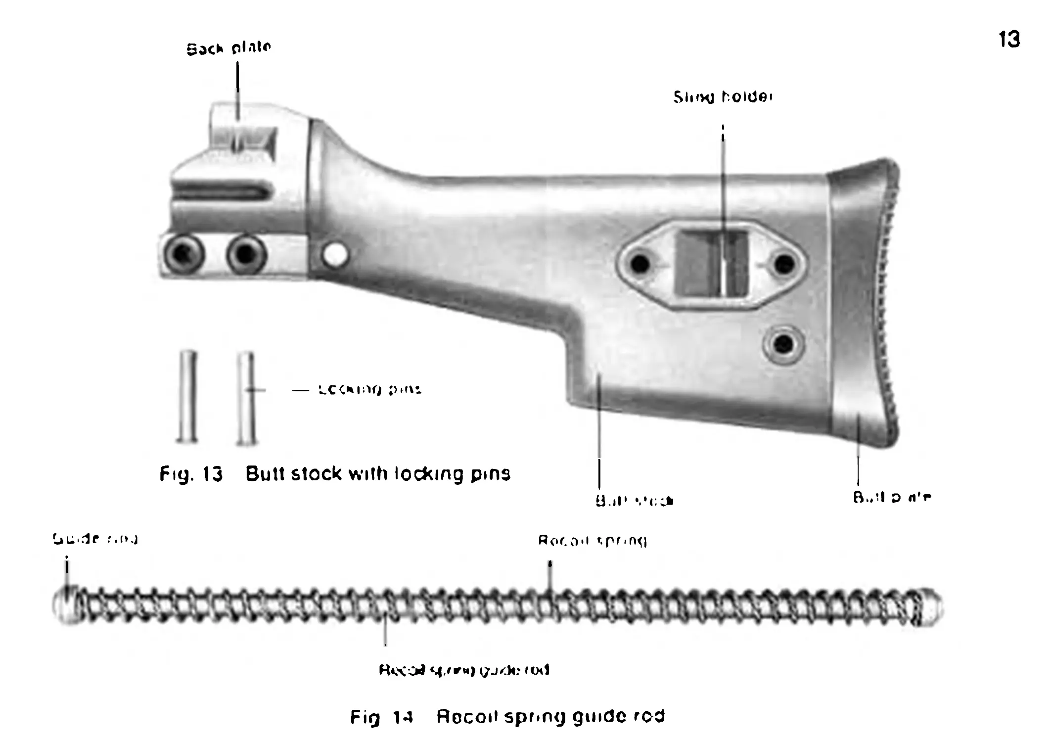
Group 4: Butt Stock with Locking Pins
The butt stock with back plate (Fig. 13) closes the rear of the receiver.
It is connected to the receiver by means of two locking pins. The back
plate contains or holds the recoil spring guide rod with recoil spring
and the buffer assembly.
Recessed m the left side of the butt stock is a sling holder with two
tubular rivets for holding the locking pins while stripping the machine
gun. The rear of the butt stock is closed with a butt plate whose two
clamp springs engage the tubular rivets, thus securing the butt plate.
Group 5: Recoil Spring Guide Rod
The recoil spring guide rod (Fig. 14) is located In the receiver. The
front of the recoil spring guide rod is mounted in tho bolt head earner,
with the rear being supported against tho back plate.
The guide ring and the recoil spring slide over the recoil spring guide
rod and are retained at both ends by tho slop pins
-de f.oj
13
Sock plnlr
Fig. 13 Bull stock with locking pins
B.Jl D «'
Roco'i rTf'n<l
R*XOi 4 jr«) (od
Fig 14 Recoil spring guide rod
14
Group 6: Barrel Assembly
The barrel assembly (Fig. 15) consists of the hammer-forged section
with chamber, the barrel grip with locking lever and the flash hider.
The barrel grip with locking lever are used for inserting and removing
the barrel and locking it in place.
The cams at the rear of lhe barrel lock the inserted barrel in the barrel
extension.
The flash hider is firmly screwed all the way onto the barrel. The re-
taining spring at lhe rear of the flash hider engages the barrel shoul-
der and prevents the (lash hider from working loose.
15
Oarrol qiip
О-41ГГ!
Fig. 15 Ban«Я assembly
16
Group 7: Magazine Attachment Unit
The magazine attachment unit (Fig. 16) enables lhe shooter to use a magazine.
It is inserted in the receiver and swivel-mounted m the bipod attachment welded
to the receiver by moans of a socket pin.
The catch lever engages in an attachment, welded to the receiver and fixes the
magazine attachment unit
17
Socket p<n
Catch lever
Fig 16 Magazine attachment uml
18
Group 8: Magazine
Tho magazine, made of steel. holds 30 cartridges and consists of:
Magazine housing (Fig. 17)
Follower with follower spring (Fig. 18)
Magazine floor plate (Fig. 19)
Fig 17 Magn/те housing
Fig. 19 Magazine Uoor pJato
19
Fifl. 16 Followor with lollnwnr spiinq
20
Group 9: Accessories (Bipod and Sling)
The bipod (Fig 20) can be used as a front or centre support for the
machine gun. It Is attached by inserting the bipod head into tho front
or centre attachment point on the receiver. The bipod legs can be fol-
ded back against the receiver by means ol the catch lever.
Tho sling is used for carrying the machine gun. It is attached to the
front of the receiver by means of tho carbine hook and to tho butt
stock by means of the spring hook.
Barrel for automatic firing of blank cartridges
The barrel tor firing of blank cartndges (Fig 21) is a training device for fmng
cal 7.62 mm x 51 blank ammunition. This barrel is inserted in the weapon instead
of the standard barrel.
To avoid confusion with the standard barrel, the nozzle body is dull chromium-
plated The barrel grip is made ol red plastic according to RAL 3000
The gas pressure can bo regulated by adjusting the nozzle boll
21
Bipod
Fig. 21 Ekirrel for automatic firing of blank cartridges
22
Belt feed conversion kit
The belt feed conversion kit (Fig 22) comprises the belt feed unit, the bolt and
the recoil spring. For firing belled ammunition these three parts must be ex-
changed for the ongmal parts.
The bell feed unit is replaced by the magazine attachment unit and is in the same
way swivol-mounled in the bipod attachment welded to lhe receiver by means of
a socket pin
The catch engages in the receiver and holds lhe bell feed unit in its operational
position
23
Fig. 22 Bolt food conversion ки
24
Handling and Operation
Safety features
The selective fire lever is located on the left side ol the pistol grip. It
can be set for:
S~ - Safe.
E“ Single fire.
F” Burst
The three letters S. E and F are also marked on the right hand side of
the pistol grip, to enable the shooter to identify the position of the
safety axle from either side (Fig. 23).
How to put at safe
Set selective fire lever at "S“ The trigger mechanism is now blocked.
Cocking'loading operations can be carried out while the weapon Is m
’’safe” position.
Firing
Single fire: Set selective fire lever at *’EM.
Burst: Set selective fire lever at "F~
Sa*e
S>ngle
Single tire
Fig. 23
25
Burst
26
Filling of Magazine (Fig. 24)
Ono hand holds the magazine, the other hand places the cartridge on
lhe magazine lips and presses lhe top cartridge with the thumb under
the lips.
Emptying of Magazine
One hand holds the magazine. The points of the cartridges point to
lhe front The second cartridge is pressed down with a small piece of
wood or a cartridge, whereby the top cartridge falls out by itself.
27
Fig. 24 Filling tho magazine
28
Inserting and Removing of Magazine
Set selective fire lever to “S" safe.
Insert magazine into the magazine well (Fig. 25) until the magazine
catch engages audibly.
To remove magazine, push magazine release lever (Fig. 26).
29
Fig. 25 inserting tho magazine
Fhj 26 Removing the magazine
30
Loading the Machine Gun
Set selective fire lever to : safe.
Pull back cocking lever with your left hand and engage it in the recess
in lhe cocking lever housing.
Insert filled magazine Into the magazine well so that the magazine
catch engages audibly.
Let cocking lover snap forward from its rearmost position.
The weapon is loaded with the safety engaged.
Unloading the weapon
Set selective lire lover to "S“ = safe.
Press magazine release lever and remove magazine. Retract cocking
lever and engage it in the recess of the cocking lever housing. Make
sure that lhe chamber Is clear. Release cocking lever.
Disengage the safety and pull the trigger Engage the safety again.
31
Changing the Barrel
Set selective fire lever to ”S” — Safe.
Pull back cocking lever and engage in lhe recess in the cocking lever
housing. Depress barrel locking lever on lhe barrel grip. Rotate barrel
grip upward and push barrel in the direction of fire.
Swivel barrel out of the receiver to tho right and pull to the rear to re-
move it Irom the barrel guide (Fig. 27).
Replace the barrel in the reverse sequence.
32
Changing the Bipod Position
When changing the position of the bipod, leave the bipod legs swivell-
ed down. Depress leaf spring on tho lower side of the receiver (Fig 28)
and remove bipod.
When changing the bipod from the front to centre position or vice
versa rotate bipod 180 .
Insert bipod in bipod attachment (only from the right side of the ma-
chine gun In the case of the centre position).
For folding up, depress both catch levers on the bipod legs and swivel
bipod against receiver.
33
Ну. 28 Detaching of bipod
34
Functioning of Parte
The machine gun is loaded and cocked, with the safety off. Pulling the
trigger releases the cocked hammer which strikes the firing pin.
The powder gases force the bullet out of the barrel, whilst simultane-
ously pressing against the cartridge case.
The base ol the cartridge case transmits a portion of the gas pressure
via bolt head, locking rollers and locking piece to the bolt head carrier.
Initiating the unlocking and bolt recoil sequence.
35
Fig. 29 Boil locked
36
When the locking rollers have completely entered the bolt nead, the
bolt can continue rearward As the bolt recoils, the hammer is cocked
and the empty cartridge case ejected
The compressed recoil spring drives the bolt forward. The cartridge
located m feeding position is forced out of the magazine and into tho
chamber by the bolt head. The extractor engages the extractor groove
The locking rollers are cammed against the support surfaces In the
barrel extension by the locking piece (Fig 30) and the MG is ready to
fire ogam.
37
F«j 30 Bolt unlocked
38
In somi-automatic operation (Fig. 31) after a round has been fired, the
hammer must be released again by the trigger for the next shot
Fig. 31 Semi-automatic fire
39
As the bolt goes forward during burst fire (Fig. 32) the sear is out of
reach of the hammer notch. The cocked hammer Is disengaged by the
action of the release lever.
Fig. 32 Burst fire
40
Disassembling the Light Machine Gun for Cleaning
Pul the weapon at safe'
Remove magazine.
Unload and check lo make sure that there is no cartridge in the cham-
ber. Move the bolt to its forward position by releasing the cocking levor.
Unsnap shng from eyebolt
Remove both locking pins from back plate and insert them in the tu
bular rivets In the butt stock.
Remove butt slock I Fig. 33) and pistol grip.
Pull back cocking lever to remove boll assembly and recoil spring guide
tube (Fig. 34)
Push cocking lover forward again and remove barrel from receiver.
Swivel down magazine attachment unit
Withdraw socket pin on right side of magazine attachment unit and
remove magazine attachment unit (Fig 35)
Detach bipod
41
Fig. 33 Disassembly of back plate and butt stock
Fig. 3-1 Removal of boll a$fjornt)ly
42
Stripping the Bolt Assembly
Grasp bolt head carrier with one hand. Rotate bolt head counter-clock-
wise with the other hand and remove from locking piece Remove
locking piece, tiring pin and firing pm spring from bolt head earner
Reassembling the Bolt
Insert locking piece, firing pin and firing pin spring in the bolt head
carrier and rotate locking piece until its narrow side is located beneath
the locking lover. Push boll head onto locking piece (Fig. 36) so that
its taperod surface is located beneath the locking lever Rotate bolt
head to the right until the first engagement. In this position, push bolt
head forward as far as it will go and then rotate the bolt head until its
bottom side is even with that of the bolt head carrier
Fig 35 Removing magazine attachment unit
43
Fig 36 Rcusuenibly ol boll
44
Disassembly of Pistol Grip
Uncock hammer, rotate selective fire lever upwards and remove both
selective fire lever and trigger housing Irom pistol grip (Fig. 37)
Further stripping may only bo performed by ordnance personnel.
Reassembly of pistol grip is done by reversing the disassembly proce-
dure.
45
Fig. 37 Disassembly Of pislol grip
46
Reassembling the Light Machine Gun (Fig. 38)
Attach bipod to receiver and insert both barrel and boll assembly with
recoil spring guide rod and place in forwardmost position
insert magazine attachment unit in the receiver and fix it with the
socket pin. Swivel upward magazine attachment unit, until the spring
loaded catch engages audibly {Fig. 39).
Attach pistol grip, making sure that the hammer is cocked. Attach butt stock and
press in locking pins from tho loft side. Snap on sling Check whether the light
machine gun is properly reassembled by pulling back and releasing the cocking
lever several times
Prior to shooting make sure that tho flash hlder Is screwed on lightly Insert
magazine.
Malfunction
Basic rule Put at safe’
Remove magazine, unload light machine gun and determine the cause
of malfunction.
47
Fig Зв Reassembling tho LMG
48
Employment of the HK11 Al as belt fed weapon
Exchange magazine attachment unit, bolt and recoil spring for belt feed conver-
sion kit.
Loading the Machine Gun
Ammunition belt with insertion strap
Loading method 1
Set selective fire lever to “S” - Safe Pull back cocking lever and engage in the
recess m the cocking lever housing. Using the insertion strap, insert belt into the
belt feed unit from the left (Fig. 39). Grasp the Insertion strap with your hand and
pull to the right until the first cartridge is located against the cartridge stop. Re-
lease cocking lever The machine gun is loaded with the safety engaged.
Loading method 2
Set selective fire levor to‘S" Safe Pull back cocking lever and engage in the
recess in the cocking lever housing. Swivel bell unit downward (Fig 40) by press-
ing the catch lever Insert belt so that the first cartridge is located against the car-
tndge stop With the belt in place, swivel belt feed unit upward until the catch lover
engages. Release cocking lovor Tho machine gun is loaded with the safety
engaged
49
F.g, 39 Insertion of boh with insertion strap Fig 40 Swivelling out the bell feed uni I
50
Loading method 3
Set selective fire lever to ’S” =; Safe Pull back cocking lever and engage in the
recess in the cocking lever housing. Swivel bell feed unit downward by pressing
the catch lever. Insert bell so that the first cartridge is located against the car-
tridge stop (41). Swrvel cartridge guide downward until il engages the belt feed
uml Swivel belt feed unit and cartridge guide upward again until the catch lever
engages (Fig 42). Release cocking lover. Tho machine gun is loaded with the
safety engaged
This operation also applies to bells without insertion strap
Unloading the Machine Gun
Set selective fire lever to S'* = Safe.
Swivel downward belt feed unit and remove belt. Pull back cocking lever and en-
gage in the recess in the cocking lever housing. Check to make sure that the
chamber is empty. Release cocking lever and swivel belt feed unit into place
Disengage the safety and pull the trigger Engage the safety.
51
Fig. 41 Insort bolt
Fig 42 Swivel belt food unit and
cartridge guide upward
52
Use of the Belt Box
When using lhe belt box, attach the closed box to the machine gun
Insert belt box under the belt feed unit from the left in such a manner that the at-
tachment nbs engage lhe recesses in lhe bell feed unit (Fig 43).
Open lhe belt box and remove the lead end of the belt
Detaching Ute bell box Unload Ute machine gun, push locking lever downward
and remove belt box (Fig. 44).
53
F»g 43 Attaching of bell box
Fig 44 Push rocking lovor downward
54
Adjusting the Rear Drum Sight
Corrections, if indispensable when zeroing, are accomplished by ad-
justing only the rear drum sight for windage or elevation.
Elevation adjustment
Insert a Phillips screwdriver into the adjusting screw (Fig 45) and ro-
tate in the appropriate direction.
Rotating lhe screw to the right will raise the mean point ol impact
28 mm per click at a range of 100 m. rotating rt to the left will lower lhe
mean point of impact 28 mm per click at a range of 1C0 m
55
Fkj 45 Elevation adjustment
56
Windage adjustment
Set click drum tor a range of 200 m
Correction of left-hand deviation Loosen clamping screw (Fig. 46)
Rotate adjusting screw (Fig. 47) to the left until the required correction
is achieved. Tighten clamping screw again
Correction o? right-hand deviation: Loosen clamping screw (Fig 40).
Rotate adjusting screw (Fig 47) to the right until the required correc-
tion is achieved. Tighten clamping scrow again
Noto: Each revolution of the adjusting screw moves the mean point of
impact 12.7 cm to the left or right at a range of 100 m
After performing the windage adjustment, reset lhe desired elevation.
Rg 46 Loosening of
clamping screw
Fig 47 RoUiliny tlx»
adjusting screw
58
Technical Data HK11 A1, Calibre 7.62 nun \ 51
Calibre 7.62 mm >51 NATO (7.62 mm > 51 NATO)
Length of cartridge case 2.05 in ( 51 mm)
Length of weapon . . . . 40.47 in (1030 mm)
Length of barrel . . . . 17.71 In ( 450 mm)
Length of line of sight . 23.20 m ( 590 mm)
Weight of weapon (with bipod) . 16.98 lbs (7.70 kg)
Weight of barrel . . . 3.75 lbs (1.70 kg)
Weight of bipod . . . 1.32 lbs (0.60 kg)
Muzzle velocity -V - . 2624 f.p.s. (800 m/s)
Muzzie energy -Eg- . . 2170 ft. lb. (300 kpm)
Rate of fire . . 650 r.p.m. (650 SchulVmln.)
Sighting device Diopter Rear Drum
Sight
200 m - 1200 m
with 100 m
increments
59
Table of Contents
Page
General Information................................................ 2
Assembly Groups.................................................... 4
Description of the Assembly Groups................................. 6
Handling and Operation ............................................24
Functioning of Parts...............................................34
Disassembling the Light Machine Gun for Cleaning.................. 40
Reassembling the Light Machine Gun................................ 46
Employment as belt fed weapon .................................... 48
Use of the belt box............................................... 52
Adjusting the Rear Drum Sight......................................54
Technical Data.................................................... 58