/


Tags: weapons
Year: 1977


Text
AD
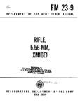
FA-TR-76061
FEASIBILITY STUDY
OF
5.56 MM FOLDED AMMUNITION/WEAPON SYSTEM
0MJ FILE COPY ADA039156
It
by
Reed E. Donnard
Richard R. Rhodes
Thomas J. Hennessy
September 1976
Approved for public release; distribution unlimited.
MAY 10 1977
Munitions Development & Engineering Directorate
U.S. ARMY ARMAMENT COMMAND
FRAN KFORD ARSENAL
PHILADELPHIA, PENNSYLVANIA 19137
DISPOSITION INSTRUCTIONS
Ьеьtroy this report when no longer needed. Do not return it to
Lite originator.
DISCLAIMER
The findings
Department of Lhc
documents.
in this report are not to be eonscru^d as an official
Army position unless so designated by other authorized
UNCLASSIFIED______________________
SECURITY CLASSIFICATION OF THIS PAGE (*h«n Of Bntorod)
REPORT DOCUMENTATION PAGE READ INSTRUCTIONS BEFORE COMPLETING FORM
1. REPORT NUMBER FA-TR-76061"^ 2. GOVT ACCESSION NO. 3. RECIPIENT'S CATALOG NUMBER
-.FEASIBILITY.STUDY OF 5.56 MM FOLDED^ / ^AMMUNITION/WEAPON SYSTEM. / s. type of report a period covered Technical research report-.
e. PERFORMING org. report number
?.-_.*utnor(5) —— "*" Reed E./Donnard Richard R./Rhodes : ... Thomas J./Hennessy B. CONTRACT OR GRANT NUMBER^
B. PERFomnKXromnNIZATION NAME ANO ADDRESS Frankford Arsenal z Attn: SARFA-MDS-S У Philadelphia, PA 19137 10, PROGRAM ELEMENT. PROJECT, TASK AREA & WORK UNIT NUMBERS AMCMS Code: 662603All780011 DA Proj->C1L662603AH78^' <. ' < >
11. CONTROLLING OFFICE NAME ANO ADDRESS ARMCOM IZ^REPORT-OATE JI J Sepfettgbw 1*976 ' i а кймйй1|1.0г_р_1СЕ5;-'‘' "
14. MONITORING AGENCY NAME A ADDRESSfll dlllonnl Iron Conlrolllnd OUIco) 15. srtt'URlTy LLASS. rrt thio report) Unclassified
15л. DECL ASSI Fl CATION/DOWNGRADING SCHEDULE N/A
IS. DISTRIBUTION STATEMENT fol thio Report) Approved for public release; distribution unlimited.
17. DISTRIBUTION STATEMENT fol the «belroct onforod In Block 20, It dltlorenl trom Report)
IB. SUPPLEMENTARY NOTES
Acknowledgement is made to the following personnel who both contributed
to the success of the study and supplied the authors with much of the
information reported herein: (cont'd)
19, KEY WORDS fContlnu* oo глглгвл aide it плслвлвгу and Identify by block number)
Folded ammunition Vehicle space utilization
Ammunition packing volume reduction Increased Cyclic rate s
Ammunition Weight reduction Reduced logistic cost I
Ammunition length reduction £
20. ABSTRACT (Continue an ravecae aide If nacaaaary and Identify by btoch number)
-^Folded Ammunition is a unique concept in ammunition design that re-
locates the propellant charge from the conventional position behind and
coaxial with the projectile to one beside the projectile. For a given
energy output, conventional axially symmetric ammunition cartridges do
not provide the most efficient geometrical shape for a minimum system
parametric profile (system length, weight and bulk). Reconfiguration .-------------
DO , 1473 EDITION OF t NOV (S IS OBSOLETE
,JAMn UNCLASSIFIED
SECURITY CLASSIFICATION OF THIS PAGE (*h*n
UNCLASSIFIED____________________
. IKCURITV CL»mrie»TION or THI« »»O»(Wh«n £>»H »i4»r»<0
18. SUPPLEMENTARY NOTES - Cont'd
Concept Description
Design Analysis
Fabrication Processing
Andrew J. Grandy
James R. Harris
John F. Kloskey
Samuel J. Marziano
Albert Zalcmann
Firing Fixture Design
John A. Duffy
Robert W. Markgraf
2,0. ABSTRACT - Cont'd
of the cartridge using the Folded Ammunition approach makes possible
now what had previously been unattainable in the way of weapon/
ammunition system optimization. This report describes the concept,
outlines its advantages and presents the results of a short-term
analytical and experimental program that successfully demonstrated
the feasibility of Folded Ammunition.
MtESSIQH hr
IIIX wxih tafia
j tia мт mim □
! гукчэояп:? □
._____________________________
- d.-jX/nVAILAeiLITY COOES
' 'л'-'.*.:»'.." tnc/or* yfciii"
fv T
UNCLASSIFIED
SECURITV CLASSIFICATION OF THIS ПАОС(ТЕЬ»п П»г» Knf«r»d)
TABLE OF CONTENTS
Page
INTRODUCTION........................................................ 3
DISCUSSION ......................................................... 9
Design Analysis ............................................... 9
Ballistic Studies ............................................. 19
Case Fabrication............................................... 25
Automatic Firing Test Fixtures ................................ 33
CONCLUSIONS AND RECOMMENDATIONS .................................... 37
APPENDIX A - US Patent No. 3857339.................................. 38
В - Representative Firing Data............................. 58
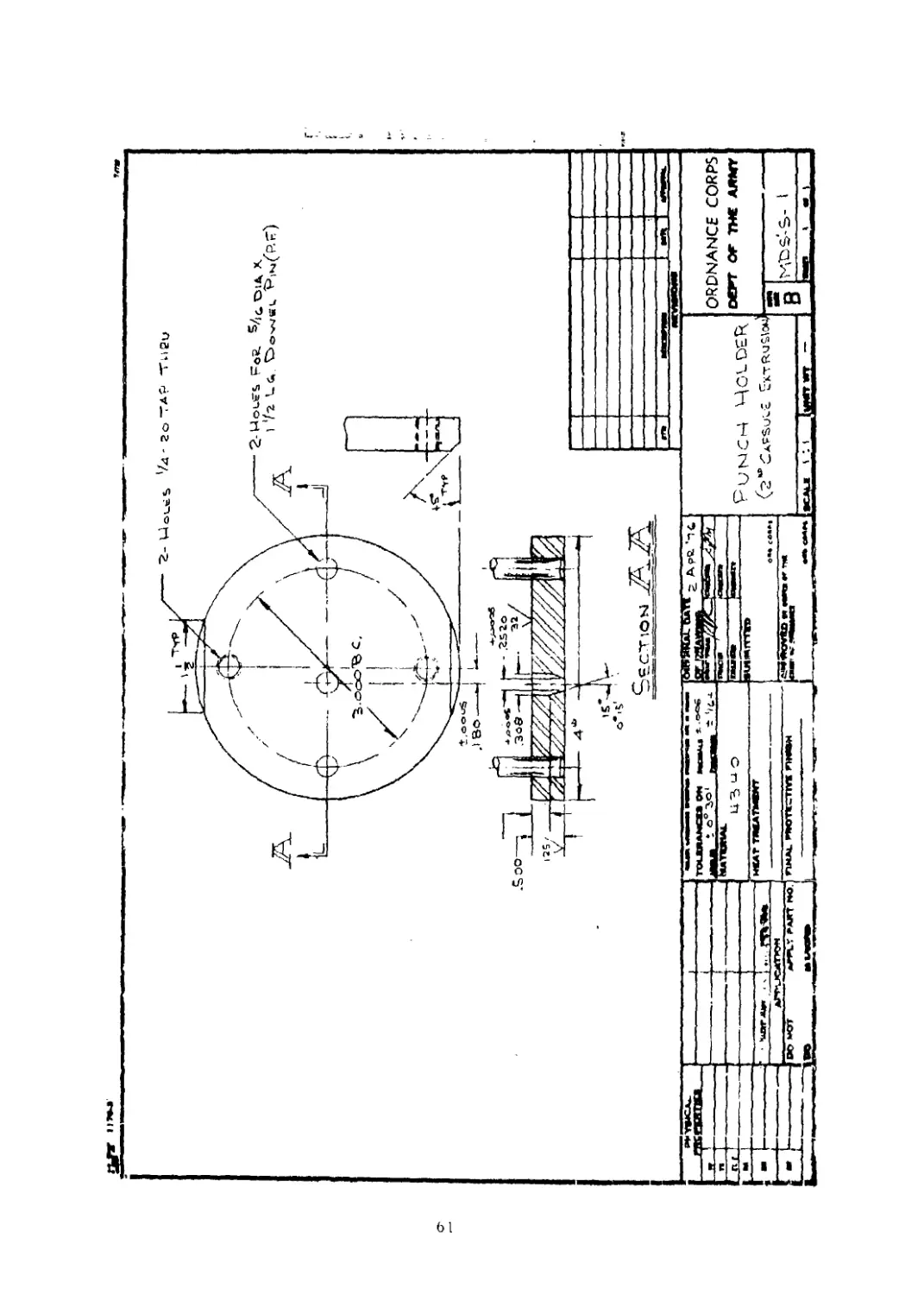
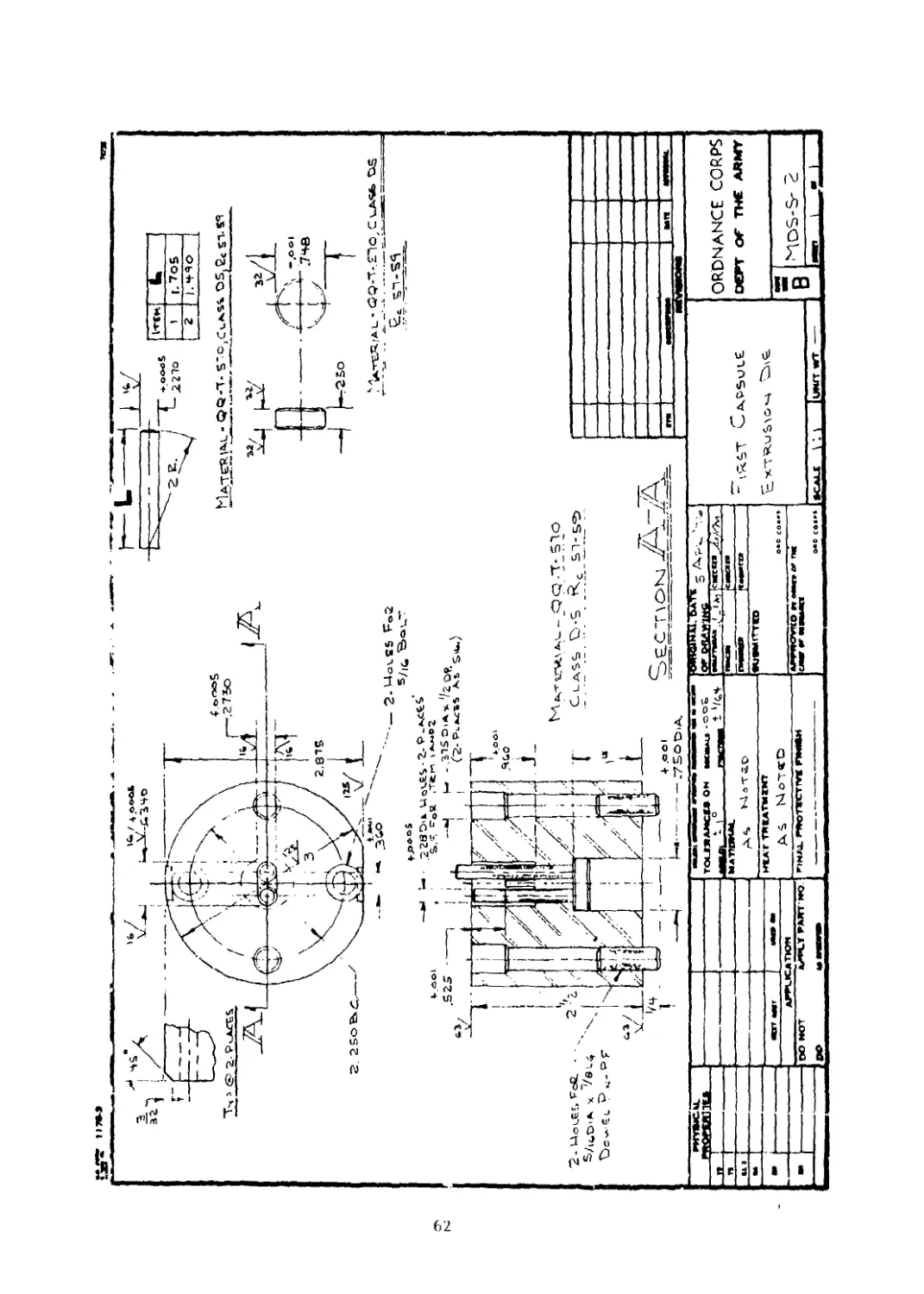
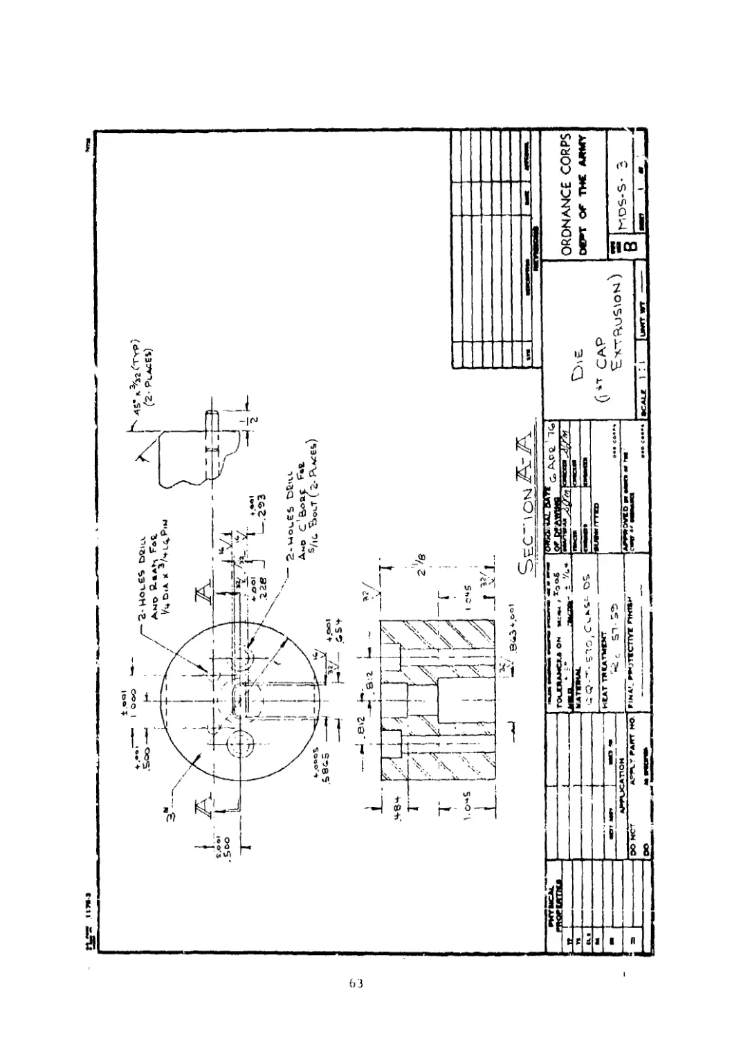
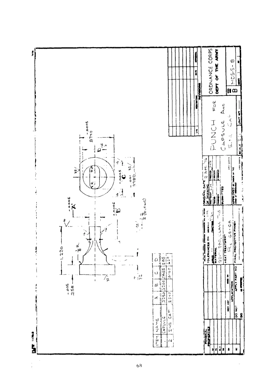
C - Tool Drawings for Case Extrusion Process............... 60
D - Folded Cartridge Details .............................. 70
E - Modified M16A1 Details ................................ 77
F - Modified Belgian LAR Details ........................... 103
DISTRIBUTION........................................................ 144
List of Tables
Table
I. Chamber Deflection at Nodes Located on I.D...................... 18
II. Comparison of Internal Diameter Deflections..................... 19
III. Hardness Readings of Heat-Treated Carburized Cases ............. 28
IV. Hardness Readings of Heat-Treated Uncarburized Cases .... 32
List of Illustrations
Figure
I. Ammunition Concept...................... ..................... 4
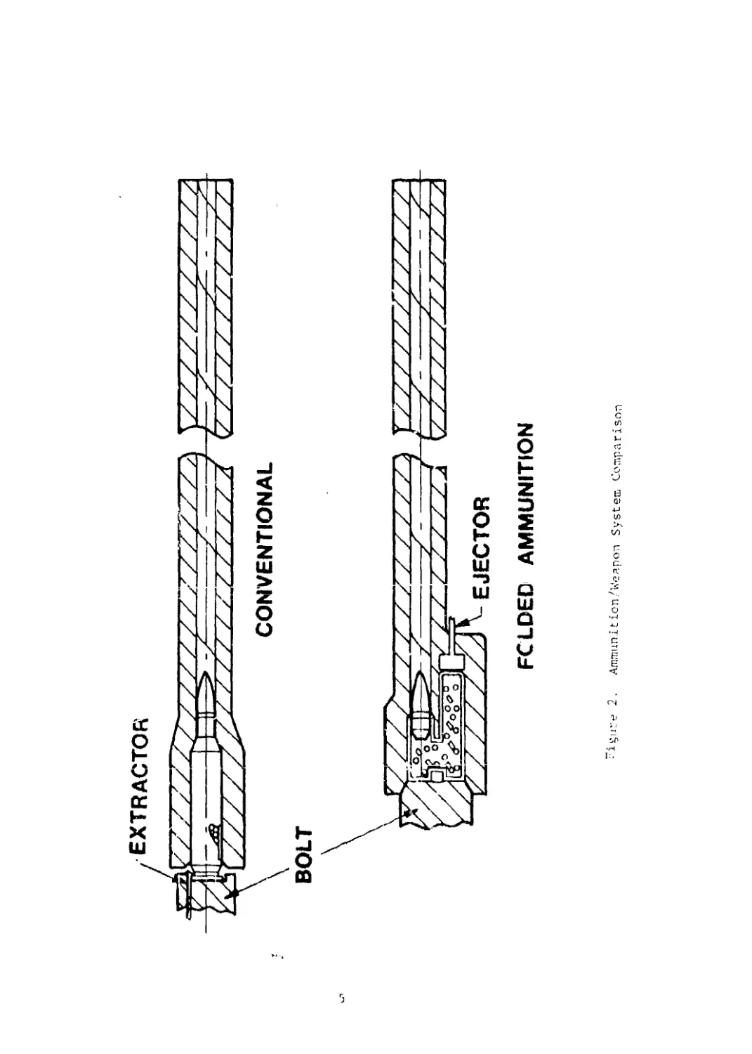
2. Ammunition/Weapon System Comparison .......................... 5
3. Conventional vs Folded Packing Volume Comparisons ............ 6
4. Cartridge Comparisons......................................... 8
List of Illustrations - Cont'd
Figure Pag£
5. Design Analysis.................................................. Ю
6. Folded Chamber Starting Grid (Rear Section)................... 12
7. Folded Chamber Starting Grid (Mid-Section) ................... 13
8. Folded Chamber Stress Plot (Rear Section) ................... 14
9. Folded Chamber Stress Plot (Mid-Section) .................... 15
10. Folded Chamber Distortion Plot (Rear Section)................. 16
11. Folded Chamber Distortion Plot (Mid-Section) ................. 17
12. Ballistic Test Cartridge...................................... 20
13. Gas Flow Control Liner......................................... 21
14. Bolt Cavity Pressure vs Port Position........................... 23
15. Interior Ballistics Comparison.................................. 24
16. Initial Extrusion Process for Folded Cartridge Case........... 26
17. Blank, Cup, and Draw Process for Standard Ammunition .... 27
18. Carburized Microstructure for Folded Cartridge Case........... 29
19. Final Extrusion Process for Folded Cartridge Case............... 30
20. Load and Assembly Process....................................... 31
21. Assembled 5.56 mm Folded Cartridge.............................. 32
22. Automatic Firing Test Fixtures.................................. 34
23. Modified M16A1 Firing Sequence.................................. 35
2
INTRODUCTION
Folded Ammunition is a unique concept in ammunition design that
relocates the propellant charge from the convention position behind
and coaxial with the projectile to one beside the projectile (Figure
1). US Patent 3857339, shown in Appendix A, documents this concept.
For a given energy output, conventional axially symmetric ammunition
cartridges do not provide the most efficient geometrical shape for a
minimum system parametric profile (system length, weight and bulk.).
Reconfiguration of the cartridge using the Folded Ammunition approach
makes possible now what had previously been unattainable in the way of
weapon/ammunition system optimization.
Figure 2 depicts the Weapon/Ammunition systems relationships in
diagramed cross-sectional view. The basis for weight saving in the
Folded Cartridge can be seen as the result of complete support afforded
by the weapon which permits use of a uniformly thin-walled cartridge case.
In addition to the significant savings in cartridge weight, the shortened
cartridge length results in another important system improvement, i.e.,
shortened minimum bolt stroke of the weapon. At least two weapon benefits
arise from this attribute. These are: (1) a greater range in cyclic rate
capability including increased cyclic rate if desired, and (2) reduced
bolt velocity for a given cyclic rate. This latter feature would be a
direct contributing factor to increased weapons parts life.
Perhaps the most far-reaching attribute of the Folded Ammunition
concept is the significant reduction in "packing volume" occupied by the
cartridge in comparison to conventional axisymmetrical l.y shaped ammunition.
Figure 3 reveals the geometrical basis for this statement of fact. The
packing volume occupied by the cartridge is defined as the minimum dimension
rectangular solid encasing the cartridge." The shaded area around the car-
tridge represents dead space which detracts from packing efficiency. In
this illustration, a conventional 5.56 mm FABRL cartridge is shown in
side and end views with appropriate dimensions. The packing volume
of this cartridge is:
Vp = 1 x d2 = 0.323 in3
where:
Vp = packing volume in inches3
1 = cartridge length in incites
d = cartridge case base diameter in Inches
[n contrast, the three views of a 5.56 mm Folded Cartridge represent,
the cartridge s ize tn the fol ded configuration required to house the same
propellant charge and fire the same projectile at the same velocity as
3
Figure 1. Ammunition Concept
extractor
CONVENTIONAL
BOLT
FOLDED AMMUNITION
Ammun1tion/Weapon System Comparison
(2.26)
L —
V_=/d2=.323in3
Г*
Figure '. Conventional vs Folded Packing Volume Comparisons
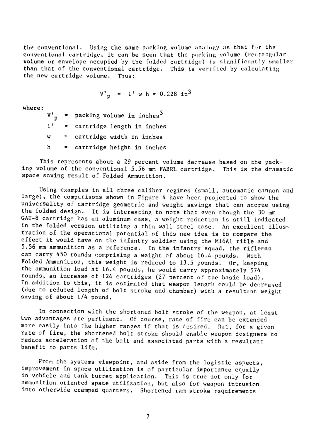
the conventional. Using the same packing volume analogy as that for the
conventional cartridge, it can be seen that the packing volume (rectangular
volume or envelope occupied by the folded cartridge) is significantly smaller
than that of the conventional cartridge. This is verified by calculating
the new cartridge volume. Thus:
V’p = 1' w h = 0.228 in3
where:
V’p = packing volume in inches’’
1' = cartridge length in inches
w = cartridge width in inches
h = cartridge height in inches
This represents about a 29 percent volume decrease based on the pack-
ing volume of the conventional 5.56 mm FABRL cartridge. This is the dramatic
space saving result of Folded Ammunition.
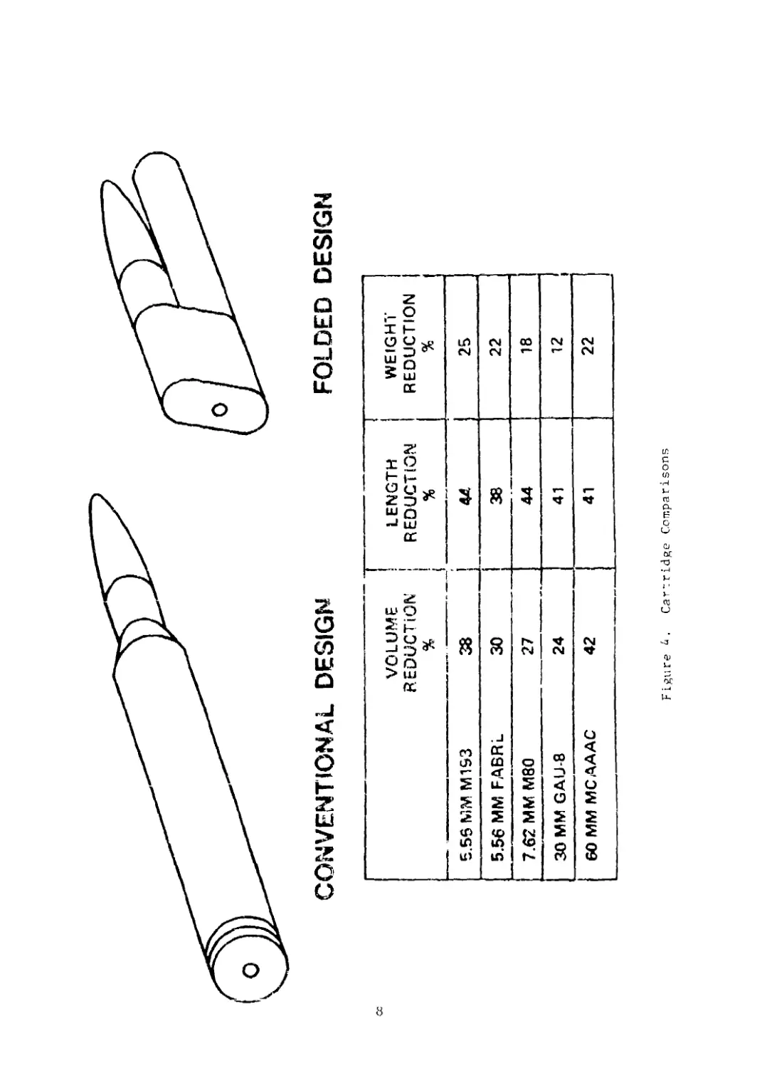
Using examples in all three caliber regimes (small, automatic cannon and
large), the comparisons shown in Figure 4 have been projected to show the
universality of cartridge geometric and weight savings that can accrue using
the folded design. It is interesting to note that even though the 30 mm
GAU-8 cartridge has an aluminum case, a weight reduction is still indicated
in the folded version utilizing a thin wall steel case. An excellent illus-
tration of the operational potential of this new idea is to compare the
effect it would have on the infantry soldier using the M16A1 rifle and
5.56 mm ammunition as a reference. In the infantry squad, the rifleman
can carry 450 rounds comprising a weight of about 16.4 pounds. With
Folded Ammunition, this weight is reduced to 13.5 pounds. Or, keeping
the ammunition load at 16.4 pounds, he would carry approximately 574
rounds, an increase of 124 cartridges (27 percent of the basic load).
In addition to this, it is estimated that weapon length could be decreased
(due to reduced length of bolt stroke and chamber) with a resultant weight
saving of about 1/4 pound.
In connection with the shortened bolt stroke of the weapon, at least
two advantages are pertinent. Of course, rate of fire can be extended
more easily into the higher ranges if that is desired. But, for a given
rate of fire, the shortened bolt stroke should enable weapon designers to
reduce acceleration of the bolt and associated parts with a resultant
benefit to parts life.
From the systems viewpoint, and aside from the logistic aspects,
improvement in space utilization is of particular importance equally
in vehicle and tank turret application. This is true not only for
ammunition oriented space utilization, but also for weapon intrusion
into otherwide cramped quarters. Shortened ram stroke requirements
7
о
CONVENTIONAL DESIGN
FOLDED DESIGN
VOLUME REDUCTION % LENGTH REDUCTION % WEIGHT REDUCTION %
5.56 MM M1S3 38 44. 25
5.56 MM FABRL 30 38 22
7.62 ММ M80 27 44 18
30 MM GAIJ-8 24 41 12
60 MM MCAAAC 42 41 22
Figure i. Cartridge Comparisons
play a significant rcle here. Additionally, the advantages in system
applications to aircr^/t where volume and/or weight savings can be
critical should not be overlooked.
DISCUSSION
Based on the significant potential advantages offered by the concept
of Folded Ammunition, a hardware-orelnted study was undertaken to in-
vestigate the basic feasibility of this new idea and determine the prac-
ticality of adapting it to a working system design. The feasibility in-
vestigation consisted of a series of interrelated activities combining
analytical and hardware phases which served as the basis for the feas-
ibility assessment. These included design analysis, ballistic studies,
case fabrication processes and automatic firing fixture elevation.
Design Analysis
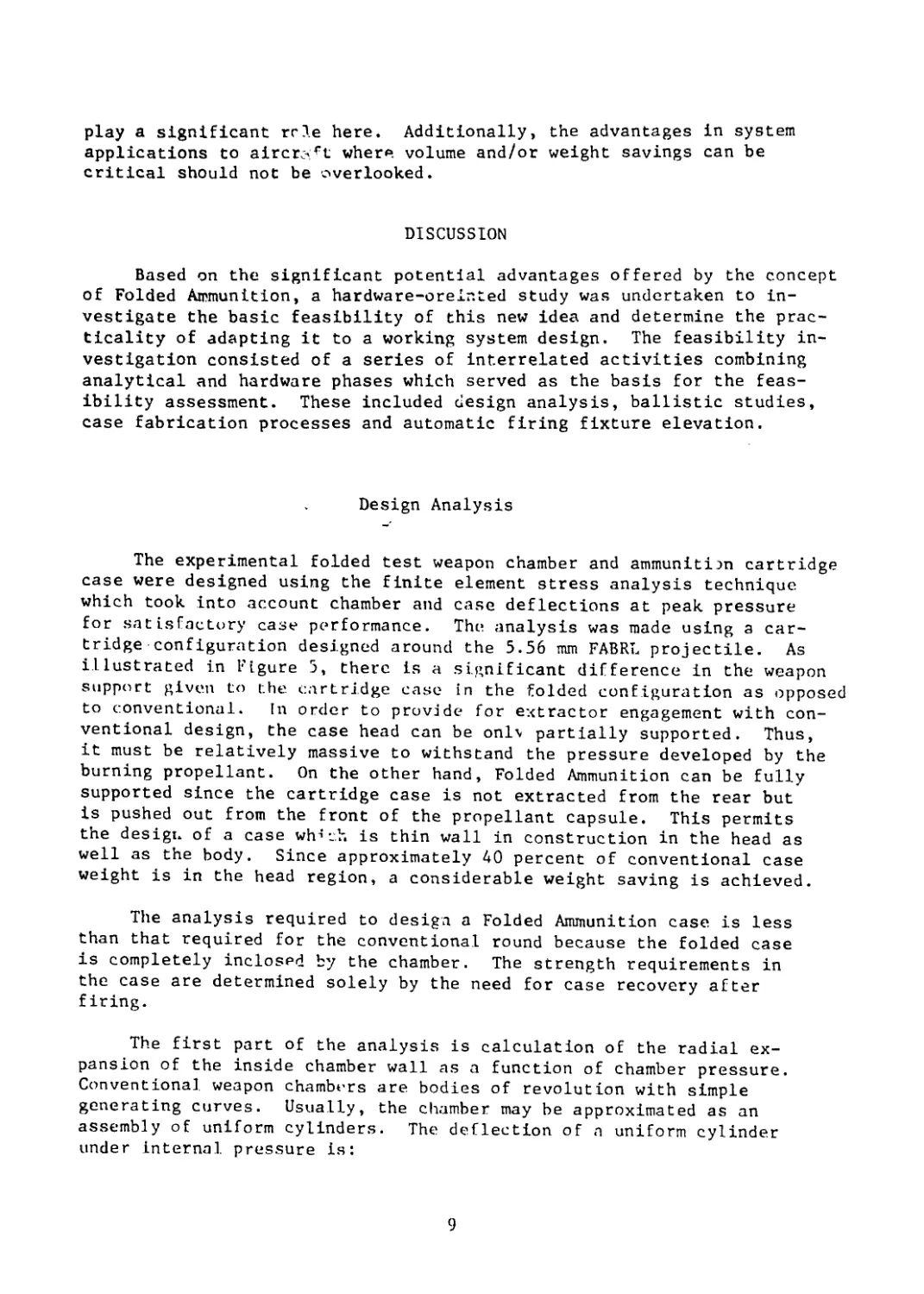
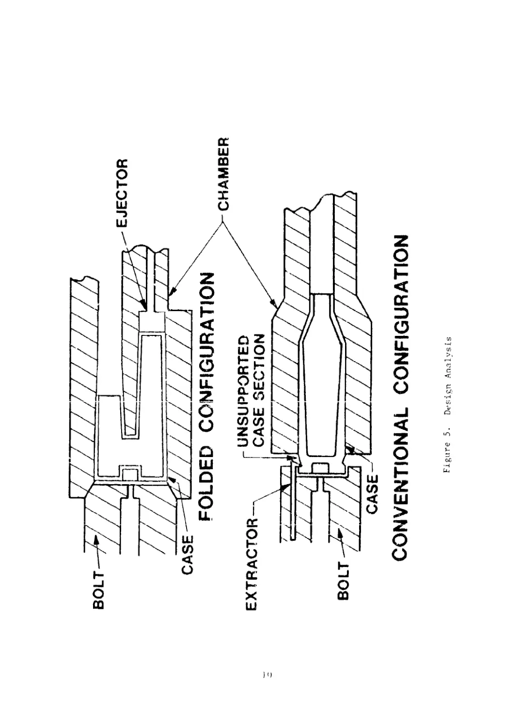
The experimental folded test weapon chamber and ammunition cartridge
case were designed using the finite element stress analysis technique
which took into account chamber and case deflections at peak pressure
for satisfactory case performance. The. analysis was made using a car-
tridge configuration designed around the 5.56 mm FABRL projectile. As
illustrated in Figure 5, there is a significant difference in the weapon
support given to the cartridge case in the folded configuration as opposed
to conventional. In order to provide for extractor engagement with con-
ventional design, the case head can be onlv partially supported. Thus,
it must be relatively massive to withstand the pressure developed by the
burning propellant. On the other hand, Folded Ammunition can be fully
supported since the cartridge case is not extracted from the rear but
is pushed out from the front of the propellant capsule. This permits
the design of a case which is thin wall in construction in the head as
well as the body. Since approximately 40 percent of conventional case
weight is in the head region, a considerable weight saving is achieved.
The analysis required to design a Folded Ammunition case is less
than that required for the conventional round because the folded case
is completely inclosed by the chamber. The strength requirements in
the case are determined solely by the need for case recovery after
firing.
The first part of the analysis is calculation of the radial ex-
pansion of the inside chamber wall as a function of chamber pressure.
Conventional weapon chambers are bodies of revolution with simple
generating curves. Usually, the chamber may be approximated as an
assembly of uniform cylinders. The deflection of a uniform cylinder
under internal pressure is:
9
CONVENTIONAL CONFIGURATION
Figure 5. Design Analysis
Е
1 + (rj/ro)2
1 - <Ч/г0)2
where:
Е и Young’s Modulus of Elasticity
P = Chamber pressure in psi
r£ ~ Inside chamber radius in inches
r0 = Outside chamber radius in inches
о = Deflection of inside chamber radius in inches
у = Poisson’s ratio
The Folded Ammunition case, however, is not a simple body of revolution.
In fact, a complete stress analysis of the chamber or case would require
solution of the three-dimensional Balltrami-Mitchell equations. However,
an approximation of chamber deflection can be obtained by analyzing cross-
sectional slices of the chamber as two-dimensional problems. Using this
approach, considered sufficient for 'this analysis, two sections, one at the
rear and the other at the mid-section of the chamber, were chosen. A finite
element grid was prepared for each section. The starting grids are shown in
Figures 6 and 7, and the results of the analyses are shown in Figures 8 and
9. These plots show lines of constant stress at intervals of 250 psi through-
out each cross section. Figures 10 and 11 show a plot of the deformed geometry
(solid lines) superimposed on a plot of the original grid (dashed lines).
Both sections are assumed to be sections of long regular bodies, i.e., in
plane strain. This means that the axial variation of stress in the weapon
chamber is completely neglected and axial stress is assumed to be zero. This
assumption gives radial chamber deflections that we estimate to be 10 to 20
percent greater than actually occur in the weapon, thus making the analysis
conservative.
Table I presents the x and у components of the deformation vector of
the nodal points on the interior radius of the chamber. The numbers may be
combined vectorially to yield the radial deflection at each point. These,
in turn, are averaged to determine the average radial deflection in the
cross section.
Once the average radial deflections are known, case yield strength
is determined so that the case will recover enough of its original shape
after pressurization to insure extraction. Specifically, the requirement
that case radial recovery be greater than chamber deflection implies
that static extraction force is zero at zero chamber pressure.
I 1
Figure 6. Folded Chamber Starting Grid (Rear Section)
Figure 7. Folded Chamber Starting Grid (Mid-Section)
14
Figure 9. Folded Chamber Stress Plot (Mid-Section)
Figure 10. Folded Chamber Distortion Plot (Rear Section)
Figure IL. Folded Chamber Distortion Plot (Mid-Section)
TABLE 1.
Chamber Deflection at
Nodeg Located on l.D,
Rear Section (Ellipse) Middle Section (2 Holes)
X(x 10-b in.) Y(x 10-6 in.) X(x 10~6 in.) Y(x 10~6 in.)
26 0. 4 -5
2 о 0. 6 -4
2b 0. 7 -2
23 0. 7 -1
21 0. 7 -1
19 0. 7 0
16 0. 7 1
13 0. 7 1
9 0. 5 2
0 0. 0 2
Average radial deflection =
19.7 x IO-6 inches 6. 4 v in~6 inches
1000 psi '3 X 10 1000 psi
Application of thin shell theory to the
Folded Ammunition case permits this criteria
cylindrical portion of the
to be expressed as:
where:
°Yield
- Yield strength
of cartridge case material
This approach in conjunction with the results from Table I gives a
minimum yield strength of 102,000 psi for a chamber pressure of 65,000 psi
Similar calculations carried out for the rear section of the case indicate
a minimum required yield strength of 164,000 psi.
The results of this analysis can be compared with the known solution
[or a thick-walled cylinder. The purpose of the comparison is to see how
much effect increasing the barrel outside diameter has on reducing the
minimum yield strength values required in the case. As the outside
diameter of Lhe thick cylinder increases, the internal deflection
decreases and, in the limit, it approaches Lhe value given by:
j 8
о
Comparison oi both Folded Ammunition chamber sections with the cylinder
equation shows that liLLle. can bo gained by large increases in chamber out-
side diameter. The comparison is made by converting, Lhe Folded Ammunition
to an area-equivalent cylinder and then calculating the limiting value of
internal deflection of that thick cylinder. Results are summarized in
Table 11.
TABLE 11.
Comparison of Internal. Diameter Deflections
Finite Element Value Limiting Value
Section A-A 128 x 10~5 in. 104 x 10~J in
Section B-H 40.9 x 10~5 in. 34.4 x 10 J in
Ballistic Studies
Preliminary ballistic studies of the 5.56 mm Folded Ammunition were
conducted in a heavy walled test weapon instrumented for measurement of
chamber pressure. The weapon was designed to accept reuseable cartridge
cases which were assembled from several components allowing variation of
internal volume and propellant charge distribution. The components of a
representative case are shown in Figure 12. Propellant granulation and
ignition studies were performed with this test hardware to establish the
desired performance level. In addition, a parametric study was conducted
to evaluate the effect on interior ballistics of the 5.56 mm Folded Ammu-
nition of varying the relative locations of the primer and propellant
charge. Also studied was the effect of throttling gas flow from propellant
bed to projectile using flow areas of 1/3, 2/3 and full bore area. A
special breech for the test weapon and special case bases were fabricated
to permit firing with the primer located on the axis of the cylindrical
portion of the case. Also fabricated were liners for the rear portion
of the case which confine the propellant charge to the cylindrical
portion and permit gas bleed-off through areas ol 1/3 and 2/3 bore
area. A representative liner is shown in Figure 13. The cross-
sectional area of the gas bleed-off control slot is shown elevated
for clarity.
19
Figure 12. Ballistic Test Cartridge
CROSS-SECTIONAL AREA OF
GAS BLEED-OFF CONTROL
GAS BLEED-OFF
CONTROL SLOT-
Figure 13. Gas Flow Control Liner
PROPELLANT
CHAMBER
The modified cases were fired in an instrumented test weapon with the
fol.lowing results. The standard case configuration and loading with primer
positioned on the axis of the cylindrical portion produced no detectable
effect on either pressure or velocity. When the 2/3 bore area liner was
inserted and the entire propellant charge confined to the cylinder, average
peak pressure increased by approximately 8 percent and muzzle velocity in-
creased by approximately 2 percent. Using the same configuration as above
but loading propellant in both the cylinder and throat produced a 20 per-
cent increase in average peak pressure. Average velocity was the same as
before but uniformity was substantially degraded. Using the 1/3 bore
area liner and the propellant charge again confined to cylindrical area
of the case, average peak pressure rose 10 percent while velocity de-
creased 10 percent. Here again, ballistic uniformity was poor.
It was concluded from these firings that locating the entire propellant
charge in the cylindrical portion oL' the case in combination with an axially
positioned primer can provide a small increase in performance. However,
the magnitude of this increase is such that other considerations such as
case manufacturing procedures, may render Its adoption impractical or
21
cost-ineffective. Lt was also observed that restriction of gas flow from
the propellant charge to the projectile tends to decrease performance and
greatly degrades ballistic uniformity. However, this study was limited
to the 5.56 mm caliber, and, specifically, the FABRL bullet, which has
a comparatively low sectional density. More extensive studies will be
required to determine whether specific ballistic advantages can be
realized in other systems through variation of primer location,
propellant position or gas bleed-off control.
Based on the preliminary ballistic studies in the test weapon and
results of the design analysis, a prototype cartridge was designed and
fabrication initiated. Concurrent with this, a test barrel was designed
and fabricated to accept this ammunition and permit firing from a universal
test fixture. This barrel, in addition to being instrumented for measure-
ment of chamber pressure, also permitted port pressure measurement to ob-
tain data required for automatic firing fixture operating mechanism design.
In order to obtain a pressure gradient, port pressure taps were provided
at the normal M16A1 petition (6 1/2" from muzzle) and at a position three
inches closer to the bolt face.
Test firings were conducted with pressure gages at the chamber and
both port positions. Results of these tests indicated a pressure at the
normal port position of 9000 psi for rounds fired at the desired performance
level. This translates into a bolt cavity pressure of approximately 750
psi. Since the M16A1 normally operates at a bolt cavity pressure of 1600
to 2400 psi, a relocation of the pressure port was indicated. Figure 14
is a graph of bolt cavity pressure versus port position calculated from
the pressures measured in these test firings. From this curve, a new
port position was selected for the automatic Folded Ammunition firing
fixture. This position is four inches to the rear of the original in
order to produce an estimated average bolt cavity pressure of 1800 psi.
Interior ballistic studies in both the above test weapon and eventually
in the automatic test fixtures resulted in selection of a propellant charge
for the 5.56 mm folded FABRL cartridge that yields velocity and pressure
levels comparable r those obtained with the conventional design. The
data shown in Figure 15 compares interior ballistics of the conventional
and folded designs using the same 5.56 mm FABRL bullet, 18 grains of
propellant WC 680 and the standard FA 41 primer. These curves are derived
from a series of test firings and are representative of these firings.
Performance levels are statistically similar as are calculated efficiencies.
The Folded Ammunition time-pressure curves showed no evidence of unusual
spikes, pressure waves or ignition anomalies. Representative firing data
are shown in Appendix B.
The conclusion can be drawn that the folded design does not appear to
Introduce any negative, effects on ignition or propellant combustion. There
has been some indication in limited studies of a 30 mm system that in the
heavier, larger caliber projectiles improved ballistic efficiencies can
be achieved with the Folded Ammunition design. Studies are being continued
in the 30 mm experimental test fixtures to ascertain the validity of this
preliminary evidence.
22
SOLI CAVITY PRESSURE (PSI)
I'igure Ju. Bo I L Cavily Pressure vs Gas I’oi i l’<>s»I <'->n
23
PRESSURE IKpsll
CONVENTIONAL DESIGN
FOLDED DESIGN
BULLET WT
PROPELLANT
PEAK PRESS.
VELOCITY
BALLISTIC EFF.
PIEZOMETRIC E
37.1 GR
18GRWC 680
46125 PSI
3224 FT/SEC
,lb) 0.337
F.(gp) 0.308
18 GR WC 680
44100 PSI
3150 FT/SEC
0.322
0.3OS
Figure 15. Interior Ballistics Comparison
Case Fabrication
Due to the unusual shape of a folded cartridge case, the ability to
produce this case at a rate and cost comparable to those of a conventional
case was a matter for serious concern in this feasibility study. There-
fore, the establishment of a case fabrication process, that would indicate
a high degree of case producibility, was considered an essential aspect
in demonstrating the feasibility of Folded Ammunition.
Three decisions had to be made at the outset of this feasibility study
with respect to the number of case components, the forming technique and the
case material. A two-piece case was selected in lieu of either a one-piece
or a three-piece case. The one-piece case was considered too difficult tc
mass produce while the three-piece, although easier to fabricate-, was deemed
too complex to meet the stringent requirements of a cartridge case. The
forming technique chosen was an impact extrusion process (Figure 16) as
the first approach in fabricating the unusually-shaped, two-piece folded
case. For comparison, the standard blank cup and draw process used for
fabricating the one-piece 5.56 mm bottleneck case, is shown in Figure 17.
As can be seen, case processing steps have been reduced from 14 for the
conventional to 8 for the folded. Of course, machine production rates
must be taken into consideration as part of any comparative procedure,
among other things, but the impact extrusion process used here enables
a reduction in process steps when compared to conventional case fabrica-
tion. On the other hand, the folded case was fabricated in two parts
and this then increased the number of fabrication steps for the total
case. Even so, a decision was made and carried through which resulted
in a practical experimental method for case fabrication. Steel was
selected as the folded cartridge case material for its cost-savings
potential since it is approximately 40 percent of the cost of brass,
the material from which standard cases are made. Aluminum and plastics
were considered as material candidates but were ruled out at this time
although they could be considered as possible candidates in the future.
Having made these three crucial decisions, it remained to develop
specific tooling and processing operations to fabricate the experimental
Folded Ammunition cases. The tool drawings for the extrusion process
for the 5.56 mm folded cartridge case are shown in Appendix B. Although
many problems surfaced during this development, one of the major hurdles
centered around extruding a steel with a high enough carbon content to
achieve what were considered to be desired case mechanical properties
(approximately 164 kpsi yield strength) through heat treatment. The
lowest carbon steel which can be heat treated to the desired level is
1035, a steel which is not suitable for impact extruding at the degree
of reduction required for the process. Thus, an investigation was
conducted to develop a means for circumventing this problem. The
approach taken utilized a carburizing technique which would be
25
Figure 16. Initial Extrusion Process for Folded Cartridge Case
ANNEAL
STRIP BLANK
STOCK &CUP
ANNEAL
ACLEAN
FIRST
DRAW
A CLEAN
SECOND
DRAW
ANNEAL
ACLEAN
FIRST HEADING
TRIM
HEAD BODY TAPER,PLUG
TURN ANNEAL AFINALTRIM
STRESSRELIEVE,
CLEAN,MOUTHA
NECK ANNEAL
ЯИПК»
5.56mm Ml93 CARTRIDGE
INERT
Figure 17. Blank, Cup, and Draw Process for Standard Ammunition
workable on a thin-walled structure such as the folded cartridge case.
The case, therefore, was extruded from 1008 steel (the lowest carbon
steel (commercially available and extrudable at the required degree
of reduction), carburized to 1035 steel and then heat treated to the
desired property levels. Figure 18 shows the uniformity or homogenity
of such carburized microstructure and Table III lists the hardness
readings obtained on the heat-treated carburized cases.
TABLE III.
Hardness Readings of Heat-Treated Carburized Cases
Hardness - Rc
Case 1 Case
29 32
35 34
39 41
32 33
38 38
36 36
34 34
It was found in subsequent testing that the carburized and heat
treated cases were not sufficiently ductile to preclude splitting during
test firings. In fact, it was found that uncarburized 1008 steel cases
did possess sufficient ductility wherein the as-formed case could be
successfully fired without splitting. This advantageous situation
resulted in a significant simplification of the case process and it
was found that satisfactory case ejection could be obtained in auto-
matic test firing fixtures. The hardness pattern for this case is
shown in Table IV. The final case process, then, is that shown in
Figure 19.
Loading and assembly of the experimental Folded Ammunition was
accomplished in the manner depicted in Figure 20. The process con-
sisted of inserting the projectile in the case to form a closed case
body into which the propellant was loaded. The cap was primed separate-
ly and then joined to the loaded case body. Although this differs from
the <£Я«-2Пtional cartridge assembly, these steps should be amenable to
production processing. Shown in Figure 21 in both external and cutaway
views is the assembled 5.56 mm folded cartridge used in this feasibility
study. Details of cartridge and components are contained in Appendix C.
28
с
Case 1 Case 2
Location A
Location В
Location C
Nol l<: Overall Carbon Content : 0.32/.
Figure 18. Carburized Hi crustrncLure lor bolded Cartridge Case
29
1
Figure 19. Final Extrusion Process for Folded Cartridge Ca=
е
।
CAP INSERT
CAPSULE INSERT LOAD
ASSEMBLED
CARTRIDGE
PROJECTILE PROPELLANT
AND
CRIMP
Figure 20. Load and Assembly Process
Hardness Readings of Heat-Treated Uncarburized Cases
Read ing
Position
Hardness - Re
Case 1 Case 2
B61 B58
368 B74
24 B98
22 22
22 24
22 24
B59 B58
В
Rockwell "B" readings given where Loo low Lo read on "C" scale
BULLE T
CARTRIDGE CAPSULE
FOLDED AMMUNITION
Figure 21. Assembled 5.56 nun Folded Gnrtridg
32
Automatic Firing Test Fixtures
The ability to feed a two-pronged folded cartridge on an auto-
matic basis posed a question that could only be answered by actual
experimentation. In the interest of minimizing cost and taking
maximum advantage of existing hardware, automatic test fixtures
were evolved through modification of standard weapons. Two weapons,
the M16A1 and a Belgian Light Automatic rifle were chosen to provide
latitude to pursue different design approaches based upon two signifi-
cantly different operating mechanisms. In e<>ch case, the weapon was
fitted with a 5.56 mm barrel chambered for the folded 5.56 mm FABRL
cartridge. Magazines were designed for feeding the Folded Ammunition
and appropriate modifications were made to the bolt and belt carrier
to provide the proper feed and mating with the folded desxgn chamber.
In order to make use of the highly desirable front end case ejection
advantages of the folded system approach, ejector systems were fitted
to the weapons and gas operating systems modified to provide satisfactory
cartridge case removal. The modified weapons are shown in Figure 22. De-
tails of the new and modified parts for both weapons are contained in
Appendixes D and E.
Firing tests were conducted in, both weapons to provide empirical
data for refinement of operating mechanisms design resulting in evolution
of fixtures which satisfactorily demonstrated that Folded Ammunition could
be automatically fed, fired and ejected. Figure 23 shows a firing sequence
representing a six-round burst from the modified M16A1 test fixture at a
cyclic rate of 706 s.p.m.
The firing cycle shown starts with the bolt in battery with a round
in the chamber. Propellant gas from the first round fired pressurizes
the bolt carrier. Then in proper sequence, the bolt unlocks and the
expeller lever engages the expeller shaft pushing the fired case out
of the chamber. As the bolt continues rearward, it permits the next
round to enter from the magazine which is located horizontally on the
other side of the weapon. This round pushes the fired case from the
bolt face and into the ejection port as it moves into position for
chambering. The return stroke of the bolt completes the ejection
of the fired case and chambers the next round completing the cycle.
33
Figure 22. Automatic Firing Test Fixtures
Figure 23 a. Modified M16A1 Firing Sequence
CONCLUSIONS ANO RECOMMENDATIONS
The feasibility of the folded ammunition/weapon system has been
demonstrated by automatic test firing of experimental prototype ammuni-
tion in automatic firing fixtures. Pertinent technology has been established
in areas that are essential to the success of this new design approach. These
include: first, capability to match ballistic performance of conventional
ammunition. Secondly, utilization of a two-piece case which performed
satisfactorily in the firing test. Thirdly, the ammunition was fabricated
using statc-of-thc-art impact extrusion machinery. Finally, it was shown
that the folded shape ammunition could be automatically fed, fired and
ejected with indications that this would not offer a stumbling block,
in the development of systems using this principle.
Л.ч a result of the success experienced in the testing of experimental
folded system hardware and the real promise of future system optimization
as indicated by Lhe advantages outlined in the introduction to this report,
it is recommended that the conceptual phase of exploratory development be
completed lo provide combat development agencies with hardware oriented
data to determine operational capabilities, doctrine and specific material
requirements that will provide Army, and very possibly Tri-Service forces
with the improved capabilities that-can accrue from the folded system
design principle. We recommend that Lhe following approach be taken
to achieve this goal.
It is felt that the most cost effective program would be to develop
required hardware oriented data using small caliber as the test vehicle.
In the small caliber Lest vehicle the common cartridge, common fed rifle
ami light machine gun approach would not only supply basic data but would
bi very advantageous in its applicability to the future small arms program.
The utility of one common ammunition package unit suitable for use in the
rifle or light machine gun would be joined to the most advanced projectile
design. In addition Lo the general information that would be gleaned from
a small caliber prog,rain, specific parametric studies should also be con-
ducted in both cannon and large caliber to provide the widest spectrum
ol information.
37
APPENDIX Л
US Patent No. 3857339
38
United States Patent |I9|
Grandy
пн 3,857,339
|45| Dec. 31, 1974
154 ] AMMUNITION and weapon systems
1761 Inventor: Andrew J. Grandy, 2707 Grant
Ave.. North Hills. Pa. 19038
(22| Filed: Mar. 30, 1972
|21] Appl. No : 239,595
| 52 | U.S. Cl............. 102/38, 102/40, 102/43
1511 Int. Cl...........................F42b 5/02
I 581 Field of Search.... 1(12/38, 40, 43. 43 P. 44.
89/35, 35 A. 33
3,369.534 2/1968 Crossman.............. 102/38 X
3.388,633 6/1968 Kershner............... 102/40
3.696,705 10/1972 Hrabovsky................ 89/35 A
FOREIGN PATENTS OR APPLICATIONS
1.537,857 8/1968 France................. 102/38
I'rimary Examiner—Benjamin A. Borchelt
Assistant Examiner—H. J. Tudor
1561 References Cited
UNITED STATES PATENTS
751,519 2/1904 Kilzcr.................. 102/4(1
949.063 2/1910 Dorn .................... 102/38
1.659,625 2/1928 Cowan................. 102/43 R
2.222.812 11/1940 Faulkner................. 89/35 A
2.535.624 12/1950 Burney................... 102/38
2.866.412 12/1958 Meveretal.............. 103/40 X
2.960.031 11/1960 Clift.................. |()2/4(l
3,046,842 7/1962 Sergay ................. 89/35 A
3.046.890 7/1962 Dardick.................. 102/38
3.283,719 11/1966 Grandy................... 102/40
1571 ABSTRACT
A weapon system employing encapsulated ammuni-
tion in which the pressure chamber, located axially
rearward of the projectile, is longitudinally or axially
offset from but in fluid communication with the pro-
pellant capsule chamber. This permits use of ammuni-
tion rounds having reduced length for given character-
istics of prior rounds, resulting in lightest weight and
improved bulk characteristics for the ammunition as
well as associated weapon systems.
This ammunition concept is adaptable to recoilless,
partially recoilless and closed breech ballistic systems
in a variety of arrangements.
102 Claims, 67 Drawing Figures
°7
206J
203KI
2 03
110
204
39
PATENTED DEC31 ШИ
3.857,339
SHEET 01 OF 10
FIG.I4
J25 -----
40
PATENTED DEC 311974
3.857,339
SHEET 02 OF 10
41
PAFENTEDDEC311974
3.857,339
SHEET С 3 OF 10
FIG. 34
< 107
FIG.36
FATENTEDDEC3 т 1974
3.857,339
SHEET CU OF 10
/0Э
43
PATENTED DEC 311974
3,857,339
SHEET 05 Of 10
FIG.43
FIG.44
409
400B- .
400A
403'
405A-
FIG.42
409
‘405A
,403
f»l07
406
405
409
404'
404
409
405
406
405A|
110
4O6.E1G^47
403E
<403 40
"-y408
^411
402
401
402
406 F IG.49
406Ар^^ук^
4О4ДГ
C*
,-403
IO7(
411
-401
40A )405Arl 10
52А-2Г FIG-52
4O4A, —4035
-403
107
-41 I
40'
gg 403
S3K-IQ7
409
404CJII0 у 01
404 402
4035
403
406A '1
406
.07 4^408 4°Э
.07 4
52Л*-, 4Q2
«аистят
- 4.1
FIG. 5lA
Л 403T
409
404
PATENTED ОГСЗ 11974
3.857.339
SHfH Cr0f iO
FIG. 48
42 6
45
PATENTED ОССЗ11974
3,857.339
SHUI 07 OF 10
<26
4<>
PATENTE0DEC3 11974
3,857,339
SHEET 08 OF 10
FIG. 54
47
PATENTE001C311974
3,857.339
SHEE1 09 OF 10
FIG. 57
IIOJ
FIG. 61
48
PATENTED ОЕСЗ11974
3,857,339
SHEET 10 OF 10
FIG 63 FIG. 64
FIG.65
FIG.66
49
3,857,339
I
AMMUNITION AND WEAPON SYSTEMS
I'he invention described herein may he manufac-
tured, used, and licensed by or for lite Government for
governmental purposes without the payment Io nte of
any loyalty thereon,
This invention relates to ammunition and weapon
systems therefor, and more particularly to a variety of
such systems each having the capacity Io utilize cai-
tridge capsule ammunition.
Present day cylindrical ammunition does not repre-
sent the most efficient, over-all cartridge with respect
to bulk and weight
It is an object of the invention to provide weapon ar-
rangements and cartridge capsule ammunition rounds
Г01 use therewith which are of lightness m weight anil
have improved bulk characteristics.
.Another object of the invention is to provide such
ammunition and weapon arrangements that can be ud-
lantageously used as partially recoilless, fully recoilless
or closed breech ballistic systems.
A further object of the invention is to provide such
airangeinents that can be advantageously used in either
fixed projectile or bolt rammed projectile systems.
A further object of the invention is to provide such
arrangements that facilitate an improved manner of re-
moving spent ammunition rounds from the firing cham-
ber of the weapon.
A still further object of the invention is to provide
means lor attaching the cartridges in arrangements that
can be advantageously used in single shol, semi-
automatic and fully automatic weapons
Another object of the invention is to provide specific
capsule cartridge shapes resulting in efficient packag-
ing arrangements which can be advantageously used in
rotary fed and in-line fed single shot, semi-automatic
and fully automatic weapons.
A further object of the invention is to provide both
individual capsule cartridges and multi-cavity, unitized
cartridge arrangements which can be advantageously
used in rotary fed and in-line fed, single shot, semi-
automatic and fully automatic weapons.
These and other objects, features and advantages will
become apparent from th" following description and
accompanying drawings in which:
FIGS. 1-4 arc perspective views of a variety of am-
munition rounds embodying the principles of the inven-
tion
FIG 5 is a longitudinal sectional view of the FIG. 1
round
FIG 6 is a longitudinal sectional view of a portion of
a closed breech weapon system for the FIG. 5 round.
FIG. 7 is a sectional view taken substantially along
lines 7—7 of FIG. 6.
FIG К is an exploded view of certain porlions of the
FIG. 6 arrangement subsequent to firing.
FIGS 9-13 are views, similar to FIGS. 1-5, of a moll-
ified group of ammunition rounds.
FIG 14 is a longitudinal sectional view of a portion
of a recoilless or partially recoilless weapon system for
the FIGS 9-13 rounds.
FIGS 15-19 arc similar views of a modified group of
„mmumlion rounds
.’!<>S 20 and 21 arc longitudinal sectional views of
m,"til>i-ii pontons of weapon svstems associated ivith
ihv round, ol I IGS 15 t<>.
5
III
15
20
2.5
30
3.5
40
45
50
55
60
65
2
FIGS. 22-26 are views, similar to FIGS. 15-19, of a
modified group of ammunition rounds
FIGS. 27 and 28 are longitudinal sectional views of
modified portions of weapon systems associated with
the rounds of FIGS. 22-26,
I IGS. 29-32 are perspective views of a further modi-
fied group of rounds.
FIGS. 33 and 34 are perspective views of clusters of
capsules of the FIG. 30 and FIG. 32 rounds, respec-
tively.
I IGS. 35 and 36 are perspective views of clusters of
capsules of the FIG. 32 and FIG. 31 rounds, respec-
tively.
FIG. 37 is an end view of a modified form of cluster
an angenient.
FIG 38 is a sectional view taken along line 38 -38
of FIG. 37.
FIG. 39 is a perspective view of a modified cluster ar-
i angenient.
FIG 40 is at. exploded persoective view of a linking
clip member and ammunition round used :n the FIG
39 arrangement.
FIGS. 41-44 are end views of integral multiple cavity
containers of cartiidge capsule portions arranged in cy-
lindrical form.
FIG. 45 is a sectional view taken along line 45—45
of FIG. 41.
FIG. 46 is a longitudinal sectional view of a portion
of a closed breech weapon system for the FIGS. 41-44
ammunition.
FIG. 47 is a longitudinal sectional view, partially bro-
ken away, of multi-cavity container modifications for
the FIGS. 41-44 cylinders.
FIG. 48 is a longitudinal sectional view of a portion
of a recoilless or partially recoilless weapon system for
the FIG. 47 ammunition containers.
FIG. 49 is a view, similar to FIG. 47, of further multi-
cavity container modifications for the FIGS. 41-44 am-
munition cylinders.
FIGS. 50 and 51 arc longitudinal section views of
modified portions of weapon systems associated with
the FIG. 49 ammunition containers.
FIG. 52 is a view, similar to FIG. 49, cf further multi-
cavity container modifications for the FIGS. 41-44 am-
munition cylinders, and FIG. 52A is a partial sectional
view taken along line 52A—52A of FIG. 52.
FIGS. 53 and 54 arc longitudinal sectional views of
modified portions of weapon systems associated with
the FIG. 52 ammunition containers.
FIG. 55 is a longitudinal sectional view of a propel-
lant capsule portion of a multi-cavity rectanguiur prism
ammunition cluster.
FIG. 56 is a partial sectional view taken along line
56- 56 of FIG. 55.
FIG. 57 is a sectional view taken along line 57—57
of FIG. 56.
FIG. 5Я is a longitudinal sectional view of a portion
of и closed breech weapon system for the FIG. 55 am-
munition prisms.
FIGS. 59-61 arc views similar to FIG. 55 of modified
uriangements.
FIG. 62 is a longitudinal sectional view of a portion
of a recoilless or partially recoilless weapon system for
the I IG. 59 ammunition prisms.
FIGS. 63 and 64 are longitudinal sectional views of
modified portions of wc;i|Xins systems associated w ith
the FIG. 60 nmmunition prisms.
50
3,857,339
3
EIGS. 65 and 66 are longitudinal sectinnal views of
modified portions of weapon systems associated with
the FIG. 61 ammunition prisms.
The FIG. 1 encapsulated ammunition round shown
generally at 101 includes a thin capsule 102 (MG. 51
of ferrous, non-ferrous or synthetic material of prede-
termined contour Preferably fcriotis, the cartridge
capsule has an elongated substantially cylindrical
chamber 103 anil a propellant chamber 104 integial
therewith but longitudinally offset therefrom. An inter
mediate necked down metering orifice 105 intercon-
nects oi fluidly enmmunic.ncs the propellant chunil’ier
104 with the pressure chuiiihci portion 106 of the cy-
lindrical chamber 103. Л projectile 107 is slidably re-
ceived in the forwaid barrel portion IOS of chamber
103 in longitudinal alignment with the pressure cham-
ber portion 106. An appiopriatc percussion primer 109
is secured in a suitably recessed anil apenured rear wall
portion of the capsule 102. preferably aligned with the
propellant chamber 104 which contains the desilcd
granular, flake, sheet or solid grain propellant 110. The
transverse sections and end walls III of the FIG. I
round propellant chamber are of substantially rectan-
gular configuration The embodiments of FIGS. 2. 3,
and 4 are of substantially the same construction as the
FIG. 1 round, but the transverse sections and corre-
sponding end walls 112, 113, and 114 are of configura-
tions which are substantially square, triangular, and cy-
lindrical. respectively.
The portion of the closed breech weapon system
(MGS. 6-8) includes a substantially cylindrical bitirel
120 having an axially offset capsule chamber 121 inte-
gral therewith, both the barrel and capsule chamber
having a somewhat shortened common wall portion
122 to accommodate the FIG. 1 round prior to firing
i FKi. 6) which function is accomplished after the bar-
rel lug 123 and capsule chamber lug 124 are simulta-
neously engaged by the opposed hook or locking lugs
125, 126 of the rotatable and longitudinally translat-
able breech means or bolts 127. I he closed breech type
holt 1 27 has a firing pin 1 28, biased by spring 129 sui
rounding the Tiring pin rod or stem 130, with its recep-
tive breech opening 131 in operative alignment with
the primer of the round to he fired. The barrel 120 has
a transverse opening I20A and an appropriate conduit
I20C to direct gas energy for further weapon opera-
tion. An ejection rod 134 is slidably mounted in an ap-
ertured forward wall 135 of capsule chamber 121 to
tearwurdly eject a Fired or undesired round when the
bolt 127 has been rotated out of locking engagement
and translated rearward (FIG. 8). Tbe chamber wall
135 is internally recessed to normally seat the ejection
rod head 136. The capsule chamber 121 has a cross-
section ol substantially rectangular configuration to re-
ceive the propellant capsule portion of the FIG. I
round For firing of the FIGS 2, 3, or 4 rounds, this
transverse section configuration is substantially square,
triangular or cylindrical. respectively.
1 he ammunition rounds of FIGS. 9-13 are distin-
guished from the FIGS 1-5 rounds in that the upper
cylindrical portion 103Л of the thin capsule rearward
walls each have a press filled blow out disc 103C or a
pre-formed weakened section as defined by an internal
recess I03F. (FIG 13) in the pressure chamber rear-
ward wall portions The disc or weakened section I03C
operatively aligns with the recoilless or partially recoil-
less weapon nozzle I27A (FIG 14) of the rearwardly
5
io
IS
20
25
30
35
40
45
50
55
60
65
4
enlarging tapered recoil vent I27C provided in the
hreech or bolt 127. The forward internal surface of the
nozzle I27A is formed with a substantially sharp annu-
lai edge to facilitate positive shearing action upon the
operative portion of the weakened section 103C when
sufficient propellant pressure is generated in the pres-
sure chamber portion of cylindrical chamber 103 by
the ignited propellant 110.
I he ammunition rounds of FIGS. 15-19 contain sev-
eral variations fur their operative firings in the fixed
projectile, inscited bolt weapon systems of FIGS 20
,uid 21. The capsule cylindrical chamber 203 has an
open rearward end 206A adjacent its pressure chamber
portion 206, and contains a bottom gas vent 203A
which is substantially in vertical alignment wirh the
blow out disc or pre-formed weakened section 204A
defined by internal recess 204C in the upper wall of
capsule propellant chamber 204. A suitable primei 209
is located in the rearward wall of the propellant cham-
ber which is integrally connected with chamber 203 by
the forwardly opening cavity side and rearward walls
205.
In both the FIG. 20 closed breech and FIG. 21 recoil-
less or partially recoilless weapon systems the common
wall portion 222, for the cylindrical barrel 220 and axi-
ally offset capsule chamber 221, terminates with a rear-
wardly extending tongue 222A that fits into the con-
necting cavity and abuts the cavity rear wall 205 upon
loading of the round, longue 222A has a vertical gas
vent passage 222C that places capsule chambers 203
and 204 in fluid communication upon firing of the
Kiund as the developed pressure gas blows out a por-
tion of the weakened section 204A at the sharp edged
passage 222C and enters the pressure chamber 206 ad-
jacent the concave recess 227E provided in the forward
face of the reduced tip portion 227G on the bolt 227B.
'the bolt 227B is longitudinally translatable in the rota-
tional and longitudinally translatable breech member
227. With bolt lug or pin 227H slidable in longitudinal
slot 227F of member 227, the bolt is withdrawn rear-
wardly prior to operative disengagement and engage-
ment of the hreech hooking or locking lugs 225, 226
with the barrel lug 223 and capsule chamber lug 224.
A iecoillcss or partially i ecoilless weapon nozzle 227A
(FIG. 21) is provided in bolt 227B at the juncture of
the rearwardly enlarging tapered recoil vent 227C and
the concave recess 227E.
The ammunition rounds of FIGS. 22-26 are distin-
guished from the FIGS. 15-19 rounds in that the upper
pin lion of the capsule cylindrical chamber 203 lias a
lengthwise split or slotted wall 203C. A plurality of
camming or dimple means 2O3E arc provided on the
internal surface of the pressure chamber portion 206
adjacent the slotted wall 2O3C and just rearward of
projectile 107. This will facilitate the release and barrel
chambering of the projectile as the longitudinally trans-
latable bolt 250 (FIGS. 27 and 28) cams the dimple
means 203E to spread the inwardly directed substan-
tially annular flange 240 and pushes the projectile to its
final pre-firing position in barrel 260. Cylindrical barrel
260 differs from barrel 220 in that an additional inter-
mediate internal recessed surface 261 is provided rear-
wardly adjacent the rifling 262 to accommodate the
fnrwardmost portion of bolt 250 in its firing position,
while и further recessed surface 263 accommodates the
spread portions of split chamber wall 203. The longitu-
dinal slot 271 of the rotational an longitudinally trans-
51
3,857,339
6
lalable breech member 270 is substnnliully longer than
slot 227F, such that the lug nr pm 227H on halt 250
can be accommodated for its intended lull stroke l he
lot ward end of holt 250 has a (inwardly opening nozzle
surface 253 that mtetsecis with a concave recess 254
piovided on the underside ol tin In 'll, so that the pies
sure chainhci (xiitioii 206 fluidly iomimmicates gas
vent passage 222C with the learwaid end of projectile
107 in both the IIG. 27 closed breech and FIG. 28 re-
coilless or partially recoilless weapon systems, flic
icurwardly enlarging tapered recoil vent 256 (IIG 28 >
m bolt 250 intersects concave iccess 254 at the effec-
tive iceoilless nozzle throat 257.
I'he ammunition rounds of FIGS. 29-32 are each
provided with a longitudinally extending groove 1041.
of dovetail transverse configuration throughout the en-
tire length of a selected propellant capsule chamber
wall portion 104, as well as a rib ot tongue protuber-
ance I04M of substantially similai dovetail configura-
tion along the length of an opposed longitudinally ex-
tending wall portion. Where each substantially similar
round has its coriespondtng tongue and groove sui-
faccs 104M, 104L extending in parallel planes, succes-
sive similar cartridge capsules can be integrally linked
or connected t FIGS 33, 341 in a substantially straight
line cluster pattciu lhe corresponding dovetailed
tongue and groove surfaces of similar rounds can also
be formed or oriented in поп-parallel planes such that
successive sinttlat capsules can be integrally linked or
matingly |omcd to form an arcuate ot circular cluster
pattern or array (I1GS. 35, 36). Tach cluster may be
held in an appropriate feeding and stripping mecha-
nism (not shown) which will enable the corresponding
breech member to longitudinally translate each
stripped round into its weapon position prior to rota-
tional locking motion of the breech member It is con-
templated that each of the previously described rounds
( FIGS. 5, 13, 19, and 26) may be so dovetailed for inte-
giul linking or connecting purposes, and each fired in
their respective weapons which can he slightly alteied
io accommodate the protruding rib or tongue. The
breech locking arrangement on each of the respective
weapons also can be relocated to a position somewhat
rearward to enable the forward portion of the bolt to
have a cross-sectional shape similar oi identical to that
of tin: particular cartridge to be chambered.
A modified cluster airangement (FIG 37) includes
an annular linking member 300 of substantially rear-
wardly opening li-shaped configuration (FIG. 38) hav-
ing a plurality of equally spaced arcuate or concave re
cesses 301 along ns peripheral or outermost surface
302 to accommodate an arcuaic undersurface portion
of the capsule cylindrical chamber 203 on the FIG 17
ammunition rounds The tounds arc slid forward onto
the metal link ring 300 at each recessed surface 301
such that the ring cradles each round at the rearmost
clearance between its propellant chamber 204 and pro-
jectile 107 or its supporting cylinder 203. It is contem-
plated that the ring 300 be formed to cluster similar
rounds from any of the groups associated with FIGS. 5,
13. 19 nr 26 anil that the clustet can lx suitably
mounted and indexed on weapon system cylindrical
stubs of the type to be later described with unitary and
radially arranged ammunition containers or clusters
1 he modified cluster arrangement ( FIG. 39) employs
a plurality of individual clip members 320 (FIG. 40)
which are shown to be joined or linked by insertion ol
respective FIG 1 capsule cartridges 10) into selected
substantially C-shaped wings or clip portions of adja-
cent clips 320. l ach link member 320 is formed Irom
,i pre-slotted blank oi metal member and contains a
у substimtially straight integral nr common portion and
uppet and lower groups of alternately disposed loop
portions 321. 322, 323 and 32IA. 322A. 323A lhe
upjKT loops arc formed to enable simultaneous recep-
tion of the cartridge capsule cylindrical chamber 103
Hi .mil projectile 107 by longitudinally spaced loops 323,
321 of one link and intermediate lixip 322 of an adja-
cent link, while the substantially rectangular propellant
c.ipsule portion 104 is clipped or received by respective
lixip portions 323A, 321A of the one link and middle
IS loop 322A of the adjacent link. The substantially
straight line type of cluster (FIG. 39) so formed can be
uscil in the same manner as the unitary rectangular am-
munition containers or clusters to be later described
Clip members 320 can also cluster separate groups of
20 cartridges of FIGS. 9, 15. 22. The width of the straight
common portion of the C shaped clip portions can be
ieduced such that similar clips can cluster separate
groups of cartridges of FIGS. 2, 10. 16, 23 as well as
FIGS. 4, 12, 18, 25. The clipping or clustering of sepa-
25 i jtc groups of cartridges of FIGS. 3, II, I 7, 24 can be
accomplished where the pre-formed slits of the clip
blank are of sufficient length that the lower loops van
be hcnl or inclined to facilitate insertion of the rounds
I'he integral or unitary multiple cavity containers
•'<» 400A. 400R, 400C, 400D (FIGS. 41-44) are prefera-
bly made of ferrous, non-ferrous or synthetic material
is cylindrical form lo contain a cluster of cartridge cap-
sule portions similar to the respective ammunition
rounds of FIGS 1-4. The annular container 400A has
a central cylindrical opening 401 (FIGS. 41,45) anil in-
cludes a plurality of circumferentially spaced cavities
ihai are defined by integral cartridge capsule portions
402 each having a cylindrical chamber 403 and longitu-
dinally offset propellant chamber 404 which is intc-r-
connected by metering orifice 405 at the icarmost edge
of separating wall 405A Orifice 405 fluidly communi-
cates the propellant chamber 404 with the pressure
chamber portion 406 of chamber 403 whose forward
barrel portion 408 slidably receives projectile 107. A
suitable piimct 409 is secured in an appropriately re-
cessed and apcilured rear wall portion of each car-
nidge capsule portion 402, preferably aligned with pro-
pellant chamber 404 that contains the desired propel
lanl 110. An appropriate substantially annular ring
shaped end wall closure 411 ts suitably secured with ce-
ment or the like to seal the. forward end of each propel-
lant chamber 404 having a rectangular transverse con-
figuration. Containers 400B, 400C, and 4001) will re-
quire similar ring end wall closures that suitably seal
their respective propellant chambers of substantially
squuie, triangular and cylindrical configurations.
lhe central opening 401 of each annular container
400A, 400B, 400C, 400D, is slidingly received on the
M cylindrical stub 420A (FIG 46) that extends rear-
wardly from lhe weapon housing 420B and parallel to
but substantially offset or below the barrel 420 of the
closed breech weapon system for the FIGS. 41-44 cy-
lindrical capsule containers or clusters. Preferably, stub
420A has a tapcred rearward end and is centrally lo-
cated iv-iihin the rearwnrdly opening weapon housing
annul и wall 421 to facilitate the reception of the cylin-
drical or annular containers that can be dchveied by
52
3,857,339
7
the longitudinally translatable breech incans or boll
427 prior tu rotation of the breech to .simultaneously
secure the opposed hook nr locking lugs 425, 426 in
engagement with the weapon housing lugs 423, 424.
After each successive caiIridge capsule portion is sun
ably ihitcscd to a firing position by means not shown,
actuation of spring 429 surrounding the rod or stem
430 ol fifing pin 428 will initiate the aligned printer 44)9
to fire the round. When till of the rounds in the cluster
or container have been lireit, holt 427 is rotated out of
locking engagement and translated rearward to permit
the spent container to be icplaced by another multi
capsule cluster ot container.
The multi-cavity ammunition containers of FIG. 47
are distinguished from the FIG. 45 ammunition cylin
tiers in that the rearward walls of each cartridge cap-
sule portion 402 have a blow out disc or pre-formed
weakened section 403C as defined by internal recess
403E adjacent the pressure chamber portion 406. Each
recess 403F. operatively aligns with the recoilless oi
partially recoilless weapon sharp edged nozzle 427Л
(FIG. 48) of the rearwardly enlarging tapered recoil
vent 427C provided in the breech or bolt 427.
The ammunition containers of FIG. 49, that arc fired
in the fixed projectile, inserted bolt weapon systems of
FIGS 50 and 51, arc distinguished front the FIG 45 cy-
lindrical clusters in that each cartridge capsule portion
402 has its cylindrical chamber 403 defined by a
through bore to provide an open reaiward end 406Л
adjacent its pressure chamber portion 406 lor recep-
tion of reduced tip portion 427G (FIGS. 50, 51) on the
foiward end of the bolt 427B that is longitudinally
translatable in the rotational and longitudinally trans-
latable breech member 427. Preferably, a rearward
upper wall portion of each capsule propellant chamber
404 is internally recessed at 404C to provide a pre-
formed weakened section or blow-out disc 404A in the
full common wall that separates cavities 403 and 404.
When each primer 409 is actuated or initiated, devel-
oped pressure gas blows out the weakened section oi
disc 404A and enters pressure chamber 406 adjacent
the concave recess 427E provided in the forward face
of holt tip 427G. With bolt pin 427H slidable in longitu -
dinal slot 427F of member 427, the holt is withdrawn
substantially simultaneous with indexing of (be associ-
ated ammunition cylinder by means not shown, and
when a replacement ammunition cylinder is required,
bolt withdrawal is followed by operative disengagement
and engagement of the breech or locking lugs 425,426
with the weapon housing lugs 423, 424. A recoilless or
partially recoilless weapon nozzle 427Л (FIG. 51) is
pros tiled in bolt 427B at the juncture of the rearwardly
enlarging tapered recoil vent427C tnd the concave re-
cess 427E
The multi-cavity ammunition containers of FIG. 52
arc distinguished from the FIG. 47 ammunition cylin-
ders in that each cartridge capsule portion 402 has the
upper portion of its cylindrical chamber 403 provided
with a lengthwise split or slotted wall 403S (FIGS. 52,
52A) A plurality of camming or dimple means 403'1'
arc provided on the internal surface id each pressure
chamber portion 406 adjacent the slotted wall 403S
just rearward of each projectile 107. This facilitates the
release and barrel chambering of the projectile as the
longitudinally translatable bolt 450 (FIGS 53 and 54)
cams the dimple means 403 Г tu spread the slotted wall
and pushes the projectile to its final pre-firing position
s
ID
1$
2(1
25
30
35
40
45
50
55
(4)
65
8
in barrel 420. The internal surface of the housing annu-
lar wall 421 is of appropriate dimensions that sufficient
clearance is provided for lateral spreading of the split
cylindrical chimtlrcrs 40.1 during the projectile barrel
chambering operations. The longitudinal slot 471 of
the rotational and longitudinally translatable breed)
rneniher 470 is substantially longer than slot 4271-
(FKIS. 50, 51). such that the pin 427H on holt 450 can
he accommodated for the intended full stroke of the
holt I he forward end of boll 450 has a forwardly open-
ing nozzle surface 453 that intersects with a concave
recess 454 provided on the underside of the holt so that
each pressure chamber portion 406 fluidly communi-
cates developed pressure gas from the respective pro-
pellant chamber 404 with the rearward end of the cor-
responding projectile 107 during ojaeration of both the
F IG, 53 closed breech and FIG. 54 recoilless or par-
tially recoilless weapon systems. The rearwardly en-
larging tapered recoil vent 456 (FIG. 54) in bolt 450
intersects concave recess 454 at the effective recoilless
nozzle throat 457.
The unitary or integral multiple cavity ammunition
cluster 500 (FIGS. 55-57) is a rectangular prism which
is made of materials similar to the aforementioned mul-
ti-cavity cylindrical ammunition containers and in-
cludes a plurality or cluster of cartridge capsule por-
tions 502 that are integrally arranged in laterally
spaced positions across the prism as it is -.uccesMicty
moved or fed tiansvcrsely through the firing chamber
501 (FIG. 58) ।-I a closed breech wcanon system hav-
ing an integral arrangement for the closed breech oi
holt and barrel portions 527 and 520. respectively.
Lach cartridge capsule portion 502 is very similar to
the cartridge capsule portions 402 of the FIG 45 am-
munition cylinder. Preferably, a rectangular shaped or
elongated cover 511 is cemented t<> an appropriate re-
ceptacle- therefor extending across the forwardmost
portions of the successively arranged propellant cham-
bers 404. While each of the propellant cat ities 404 in
the FIG 55 elongated ammunition prisnt has been
formed with a transverse section of substantially rect-
angular configuration, the propellant cavities 404 of
the rectangular prism may also be of substantially
square, triangular and cylindrical configuration, and
the end wall closure or seal 511 would not require mod-
ification.
The type of inulti-cavity ammunition prism 500A
(FIG. 59) are distinguished from the FIG. 55 ammuni-
tion prisms 50(1 in that the rearward walls of each car-
tridge capsule portion 502 for each of the prisms is pro-
vided with u blow out disc or a pre-formed weakened
section 503C as defined by inlemal recess 5O3E adja-
cent the pressure chamber portion 406. Each recess
503F. operatively aligns with the recoilless or partially
recoilless weapon sharp edged nozzle 527A (FIG. 62)
of the rearwardly enlarging tapered recoil vent 527C
provided in the bolt portion 527.
The type of ammunition prism 500B (FIG. 60), that
are fired in the fixed projectile, inserted bolt weapon
systems of FIGS. 63 and 64, are distinguished from the
I IG. 55 ammunition prisms ft)0 tn that each cartridge
capsule portion 502 has its cylindrical chamber 403 de-
fined by a through bore tu provide an open rearward
end 406A udjucent its pressure chamber portion 406
for reception of reduced tip portion S27G (FIGS 63,
64) on the forward end of the bolt 527B that is longitu-
dinally translatable in breech portion 527, A rearward
53
3,857,339
9
upper wall portion of each capsule propellant chamber
404 is internally recessed at 4041' to provide a pre-
formed weakened section or blow out disc 404A in the
lull common wall that sepaiates cavities 403 and 404.
When each primer 409 ь actuated ot initiated, devel
oped pressure gas blows <>ut the weakened section or
disc 404A and enters pressure cliumlx-i 406 adjacent
the concave rev css 527F provided in the forward face
of bolt tip 527G. An appropriate pin and slot connec-
tion I not shown! between boll 527B anil breech por-
tion 527 enables the bolt to be withdrawn suhstaitiiully
simultaneous with indexing or feeding ol 'he associated
ammunition prism through chamber 501 hy means not
shown Bolt 527H is also withdrawn when a replace
inent ammunition prisin is ici|inied Л iccodless oi par-
tially recoilless weapon nozzle 527Д | FIG 64) is pro
s ided in bolt 527В at the pmctni e of the rearwardly ei>
larging tapered recoil vent 527C and the concave re-
cess 527F
fhe tvpe of ammunition prism 500C (FIG 61 i un-
distinguished from the FIG. 60 ammunition prisms in
(hat each cartridge capsule portion 502 has the upper
portion of its cylindrical chamber 403 pioviik-d with a
lengthwise split or slotted wall 403S arid a plurality of
camming or dimple means 403T aie provided on the
internal surface of each pressure chamber portion 406
adjacent the slotted wall 403S just п.-arward of each
projectile 107. This facilitates the idease ami batrcl
chambering of the projectile as the longitudinally trans-
latable bolt 550 (FIGS. 65 and 66) cams the dimple
means 403T to spread the slotted wall and pushes the
projectile to its final pie-firing position in barrel 520.
The internal upper surface of the firing chamber 501 is
suitably dimensioned that sufficient clearance is pro.
sided lor spreading of the slot ted walls A suitable pin
and substantially long slot connection (noi shown) be-
tween holt 550 and breech poitiou 527 will enable full
longitudinal motion of the boh 550 throughout its in-
tended lull stroke The foiwaid end of bolt 550 Illis a
forwardly opening nozzle surface 553 that intersect-,
with a concave recess 554 provided on the underside
of the holt so that each pressure chamber portion 406
Пи idly communicates developed pressure gas from th,.-
respective propellant chamber 404 with the rearward
end of the cm responding projectile 107 during opera-
Iron of both the FIG. 65 closed breech and FIG. 66 rc
coillcss or partially recoilless weapon systems. I he
rearwardly enlarging tapered recoil vent 556 (FIG 66 j
in bolt 550 intersects concave recess 554 at (he effec-
tive recoilless nozzle throat 557.
Various modifications, changes and alterations may-
be resorted to without departing Irom the scope of the
invention as defined hy the appended claims
I claim
I. An ammunition capsule Comprising,
a unitary capsule body has ing an elongated longitiuh
nally extending cylindrical chamber, said chamber
having a forward bai iel portion for slidably receiv-
ing a projectile and a pressure chamber portion
aligned with and rearward of said barrel portion.
a one-piece imperforate propellant capsule chamber
which remains imperforate and is integral with and
la(eiall) offset front said elongated chamber,
s.inl propellant capsule chamber having metering ori
fn.e means for fluidly communicating the propel-
lant c.ipsiild chamber with sard pressure chamber,
and
5
in
15
20
25
30
35
40
45
50
55
60
65
5 A
10
a primer carried by an exterior surface of said ammu-
nition capsule body for igniting a capsule propel-
lant charge.
2. The structure in accordance with claim 1 wherein
said propellant chamber has a transverse section of
substantially rectangular configuration.
3. The structure in accordance with claim 2 wherein
said transverse section is of substantially square config-
uration.
4. The structure in accordance with claim J wherein
said propellant chamber has a transverse section of
-.iihsiantially ti singular configuration
5. The structure in accordance with claim I wherein
said propellant capsule chamber has opposed longitudi-
nally exiending external wall portions, one of said wall
poitions having a longitudinally extending groove and
the other wall portion having a tongue protuberance of
a substantially similar configuration as said groove
6. The structure of claim 5 wherein saivl propellant
chamber has a transverse section of substantially rect-
angular configuration.
7. The structure of claim 6 wherein said transverse
section is of substantially square configuration.
8. The structure of claim 5 wherein said propellant
chamber lias a transverse section of substantially tri-
angular configuration.
9. The structure of claim 5 wherein said groove ex-
tends to the rearward edge of said capsule.
Iff, The structuc of claim 5 wherein said propellant
chamber has a transverse section of polygonal configu-
ration.
11. The structure of claim 5 wherein said propellant
chandler has a transverse section of substantially
square configuration, and said pressure chamber por-
tion has means spaced from said primer for rearwaidly
exhausting operatively developed pressure gas there-
from.
12. The structure of claim 5 wherein said pressure
chamber has means spaced from said primer for rear-
wardly exhausting operatively developed pressure gas
therefrom.
13. 7 he structure in accordance with claim 12
wherein said propellant chamber has a transverse sec-
tion of polygonal configuration.
14. The structure in accordance with chum 5 wherein
a icarward wall of said pressure chamber portion has
a pre-formed weakened section for use with a recoil
vent in breech means of a recoilless system
15. The struehite of claim 14 wherein said propellant
chamber has a transverse section of polygonal configu-
ration.
16. The structure of claim 15 wherein said transverse
sei lion is of substantially triangular configuration.
17. The structure in accordance with claim 15
v.-herein said transverse section is of substantially rect-
angular configuration
IK. The structure of claim 17 wherein said transverse
seclion is of substantially square configuration
19. The structure of claim 14 wherein saivl propellant
chamber has a transverse section of polygonal configu-
ration.
20. The structure in accordance with claim 1 wherein
said propellant chamber has a transverse section of po-
lygonal configuration.
21. The structure in accordance wilh claim 20
wherein и rearward wall of said pressure chamber por-
3,«57,339
II
linn Ims a preluirucd weakened section lor use with <i
recoil vent in breech means of a recoilless system
22. lhe structure of claim 1 wherein said propellant
chamber has a transverse section of substantially
square configuration, and said pressure chamber por-
tion has means spaced front said primer for rearwardly
exhausting operatively developed pressure gas there-
from.
23. The structure of claim 1 wherein said metering
orifice means is a necked down passage interconnect-
ing said capsule propellant chamber and said pressure
chamber
24. The structure of claim 23 wherein said propellant
chamber has a transverse section of substantially
square configuration
25. The structure in accordance with claim I wherein
a rearward wall of said pressure chamber portion has
a pre-formed weakened section for use with a recoil
vent in breech means of a recoilless system.
26. l he structure of claim 25 wherein said propellant
chamber has a transverse section of polygonal configu-
ration
27. lhe structure in accordance with claim 25
wherein said propellant chamber has a transverse sec-
tion of substantially rectangular configuration
28. The structure of claim 27 wherein said transverse
section is of substantially square configuration.
29. The structure of claim 25 wherein said propellant
chamber has a tiansvcrsc section of substantially tri-
angular configuration.
30. The structure in accordance with cairn I wherein
wall portions of said elongated chamber and propellant
capsule chamber are connected by a transversely ex-
tending wall, said chamber wall portions being trans-
versely spaced from each other and having transversely
aligned operative port means defining said metering or-
ifice means.
31. The structure of claim 30 wherein said propellant
chamber has a transverse section of polygonal configu-
ration
32. The structure of claim 30 wherein said propellant
chamber has a transverse section of substantially
square configuration, and said pressure chamber poi
lion has means spaced from said primer for rearwardiv
exhausting operatively developed pressure gas there-
from
33. The structure of claim 30 wherein said propellant
chamber less has longitudinally extending external wall
portions including means for connecting an adjacent
capsule.
34. The structure of claim 30 wherein said pressure
chamber portion has means spaced from said primer
for rearwardly exhausting operatively developed pres-
sure gas therefrom.
35. The structure in accordance with claim 34
wherein said propellant chamber has a transverse sec-
tion of polygonal configuration.
36, The structure of claim 30 wherein said port
means includes a gas vent in said el n>kutc.' chamber
wall portion and a pre-formed w<- !> • m ч :tion in said
propellant capsule chamber wall m.-ta.n
37. The structure of claim 36 wiu icm said propellant
chamber has a transverse section of polygonal configu-
ration
38. The structure of claim 36 wherein said propellant
chamber has a transverse section of substantially
square configuration, and said pressure chamber por-
s
10
15
20
25
30
35
40
45
50
55
60
65
12
lion hii-> means spaced front said primer for rearwardly
exhausting operatively developed pressure gas there-
from.
39. The structure of claim 36 wherein said propellant
chamber has longitudinally extending external wall
portions including means for connecting and adjacent
capsule.
40. The structure of claim 36 wherein said pressure
chamber portion has means spaced from said primer
for rearwardly exhausting operatively developed pres-
sure gas therefrom.
41. The structure of claim 40 wherein said propellant
chamber has a transverse section of polygonal configu-
ration
42. The structure in accordance with claim 30
wherein an upper surface of said propellant chamber
has a pre-formed weakened section.
43. ’I’he structure of claim 42 wherein said propellant
chamber has a transverse section of polygonal configu-
ration.
44. The structure of claim 42 wherein said propellant
chamber has a transverse section of substantially
square configuration, and said pressure chamber por-
tion has means spaced from said primer for rearwardly
exhausting operatively developed pressure gas there-
from.
45. The structure in accordance with claim 42
wherein each propellant chamber has longitudinally ex-
tending external wall portions including means for con-
necting an adjacent capsule.
46. The structure of claim 42 wherein said pressure
chamber portion has means spaced from said primer
for rearwardly exhausting operatively developed pres-
sure gas therefrom.
47. The structure of claim 46 wherein said propellant
chamber has a transverse section of polygonal configu-
ration.
48. The structure in accordance with claim 42
wherein said propellant chamber has a transverse sec-
tarn of substantially rectangular configuration.
49. The structure of claim 48 wherein said transverse
section is of substantially square configuration.
50. The structure of claim 42 wherein said propellant
chamber has a transverse section of substantially tri-
angular configuration.
51. The structure in accordance with claim I wherein
said pressure chamber portion has an open rearward
end
52. The structure of claim 51 wherein said propellant
chamber has a transverse section of polygonal configu-
ration.
53. The structure in accordance with claim 51
wherein said propellant chamber has longitudinally ex-
tending external wall portions including means for con-
necting an adjacent capsule.
54. The structure in accordance with claim 51
wherein said propellant chamber has a transverse sec-
tion of substantially rectangular configuration.
55. The structure of claim 54 wherein said transverse
section is of substantially square configuration.
56. The structure of claim 51 wherein said propellant
chamber has a transverse section of substantially tri-
angular configuration.
57. The structure in accordance with claim 51
wherein said propellant capsule chamber has opposed
longitudinally extending external wall portions, one of
said wall portions having a longitudinally extending
3.857,339
13
groove and the other wall portion having .1 tongue pro
tiibcraiiee о I' a si ibstantially sinulai configuration as
said gio<ive
5X. I he stun thiv <>1 chuiii 57 wheicm said |Uo|K-llant
cl.nmhvi has .i tiansveisc section ol'polygonal coidigii
ration.
59. I he structure of claim 57 wherein said propellant
chamber has a transverse section of substantially rect-
angular conGguration
60. I he structure ol claim 59 wherein said transverse
section is of substantially square conGguration.
61. f ile structure ol claim 57 wherein said propellant
chamber has a transverse section of substantially tii-
angular configuration.
62. Ihe structure in accordance with claini 51
wherein an uppei siuGiee of said propellant chamber
has a pie-formed weakened section.
65. Ihe structiiic in accoidance with claim 62
wherein said propellant chamber has a transvcise sei
lion of substantially rectangular configuration
64. I he stiuctuie of ekiiin 65 w herein said tiansveisc
section is of substantially square conGguration.
65. I he structure of ci.iim 62 w herein said propellant
chamber has a tiansveisc section of substantially tn
angular conGguration.
66. I he structure of claim 62 wherein sard propellant
chamber Inis a transverse section of polygonal curiGgii-
ration
67. Ihe structure of claini 62 wherein each propel
lant chamber has longitudinally extending external wall
portions including means for connecting an adjacent
capsule
68. I he structure ot claini I w herein said propellant
chamber has longitudinally extending extern.il wall
portions including means for connecting an adjacent
capsule
69. Ihe stiucture in accordance with claim 68
wherein said connecting means is partially defined In
a longitudinally exieiuling groove in one of said exter
n.il wall portions, said groove extending to the rearward
edge of said capsule.
70. The structure of claim 69 wherein a rearward
wall of said pressure chamber portion has a pre formed
weakened section lor use wnh a recoil vent in breech
means ol a recoilless system
71. Ihe structure ol cla i in 52 w herein inwardly pi о
trading uimplc me.ms are located on the internal sin
face of s.iid pressure chamber portion
72. I he structure ot claini 71 wherein said propellant
chamber has a transverse section ol polygonal configu
ration
75. Ihe structure in accordance with claini 71
w he i ein each propellant chain her has longitudinally ex-
tending external wall portions including means lor con
iici ting an adjacent capsule
74. The struetuie of claim 75 wherein inwardly di
levied Hauge means .ire provided on the lorward end
ol s.nd h.iirel portion
75. I he struct in c ofc Ijnii 74 wherein said propellant
i h.niil'ci has a transverse section of polygonal configu
r.ltri >11
76. Ihe striiciuic of claini 74 wherein each propel
l.inr chamber has hmgiiinhu.illy extending external wall
portions including means lor connecting an adjacent
capsule
77. I |ц- si i in tn ц- o| t l.i i in 74 who re и i s.nd elongated
ihambci h.r. a hmgitudin.illv slollid w.dl poition
14
78. The structure of claim 77 wherein s.iid propdl ml
chamber has a transverse section ol polygonal conligu
i at uni
79. I he structure of chum 77 wherein said propellant
5 chamber has longitudinally extending external wall
portions including means for connecting an adjacent
capsule.
80. The structure in accordance with claini 77
wherein said propellant chamber has a transverse sec-
1,1 tion of substantially rectangular conGguration.
HI. The structure of claim 80 wherein said transxctse
section is of substantially square configuration
82. The structure of claini 77 wherein said propellant
chamber has a transverse sectinn of substantially tri-
1' angular configuration
85. I he structure of claim 71 wherein said elongated
chamber has a longitudinally slotted wall portion.
84. I lie structure of claini 83 wherein s.nd propellant
chamber has a tiansversc section nf polygonal configu-
Ju
Г.II loll
85. Ihe stiucture of claim 85 wheiein each propel-
iimt chamber has longitudinally extending cxtein.il wall
portions including means for connecting an adjacent
capsule.
86. Ihe structure in accordance with claim 83
wherein saiil propellant capsule chamber has opposed
longitudinally extending external wall portions, one of
said wall portions having a longitudinally extending
ytt pt"ove and the other wall portion having a tongue pro-
tuberance of a substantially similar configuration as
said groove.
87. Ihe structure in accordance with claim 86
wheiein saiil piopellant chamber has ,i tiansversc sec-
ts lion ol |io)ygon.il conligiiiafiou.
88. I he structure of claim 86 wherein said pi opell.int
chamber has a transverse section of subsi.inti.illy rect-
angular configuration
89. flic structure of chum 88 wherein said tr.in-ncisc
40 section is of substantially square configuration.
90. I lie structure of claim 86 wherein said propellant
chambci has a tiansveisc section of substantially tn-
angolai configuration.
9|. Ihe structure in accoi'.unce with cl.inn 8<l
45 wherein an ujiper surface of said piopclkini chamber
li.is a jire-l’ornicd weakened section
92. I he structiii c ot chum 91 wherein said propel).im
chamber has a ti.nisvcrsc section of polvgon.il configu-
I ation.
Stl 93. Ihe stiucture in accordance vvitb claim 91
wherein said propellant chamber has a transverse see
lion of substantially rectangular configuration.
94. I he struetuie of claim 93 wherein said transverse
section is of substantially square conGguration
95. I he structure of claim ! wherein said pressure
chambci portion has means spaced from said primer
lor icaiwardly exhausting operatively developed pres
sine gas therefrom
Ml ' 'lc !,,ruv,l|re in accordance with c hum 83
w hi iein an upper surface of said propellani chambci
has ,i preformed weakened section, and said propel
hint chamber has a transverse section of polygon.il con-
figuration
ns 17. I he struetuie of claim 96 wherein said propellant
capsule chanibei has opjiosed longiludinalli extending
external waff poilions. one ot said vvull portions having
a longitudinal1}’ extending groove and the other wall
56
3,857,339
15
portion having a tongue protuberance of a substantially
similar configuration as said groove
98. I'he structure of claim 96 wherein wall portions
of said elongated chamber and propellant capsule
chamber are connected by a transversely extending
wall, said chamber wall portions Iscing transversely
spaced from each other and having transversely aligned
operative port means defining said metering orifice
means
99. The structure in accordance with claim 96
wherein said propellant cbambci has a transverse sec-
$
in
15
2i I
25
.1!)
35
40
45
50
55
6<i
65
i /
16
tiun of substantially rectangular configuration.
100. The structure of claim 99 wherein said trans-
verse section is of substantially square configuration.
101. The structure of claim 96 wherein said propel-
lant chamber has a transverse section of substantially
triangular configuration.
102. The structure of claim 95 wherein said propel-
lant chamber has a transverse section of polygonal con-
figuration.
APPENDIX В
Representative Firing Data
58
APPENDIX В
Representative Firing Data
Rd No. Weapon Muzzle Velocity (fps) Chamber Pressure (KPSI) Bolt Cavity Pressure (KPSI)
391 Belgian LAR 3007 — N
392 (Modified) 2966 45.0 »l
393 3226 44.5 It
394 3262 50.0 11
395 3134 43.0 11
396 3028 39.5 It
397 3222 43.5 If
v = 3121 P = 44.2
398 Belgian LAR 2972 44.5 N
399 (Modified) 2874 48.0 11
400 3040 41.5 ft
401 ° 2 2 8 41.5 I!
402 3037 44.5 ft
403 3166 44.5 If
404 3046 44.5 11
405 3105 43.0 1!
v = 3059 P = 44.0
406 M-16 Al 3218 N 16.5
407 (Modified) - II 15.0
408 3169 It 11.0
409 3249 II 11.0
410 3211 If 19.5
411 3323 II 19.5
412 3174 II 20.0
413 3271 ♦ 1 19.5
414 - 3213 It 19.5
v = 3228 P - 16.8
N - Not Measured
59
APPENDIX С
Tool Drawings for Case Extrusion Process
00
2 2B D'l WсхЛЛ - 2.-
croft .ТСГ-1
ект VTwtA _____C5 Q .T S Д О
! J атаяпгвхг» _ ' |<X PBAWtwy = r> ' t кяквя^/гх, ~ C.iKt'Sui.C. \£ч'п;ч^^\оч ORDNANCE CORPS DEFT OF THE ARMY
— n««a ff»rn •UWfTTlD o*o саам AWROVfCO •* 0—П О* ТЖ CJW «г ««ММЛ »*0 C4l»i
lim I N4DS-S- 2
•CALX \ ". 1 luWTT WT •n i • 1
U»1
го Гое.
/<<. O.K Г.М
Г^Т
*«тя
IV* мкжпн •Mt MtML
ДИИ1ЯПИ
ORDNANCE CORPS
KAT ТМЛТЖКТ
AmjCATTOW
атагагвач
susaams
Hnt
rtrr II»
\Т» кк«пм ••It «Ж
ютот
с. Г OmCiMAL ьлгт т»*® [своп 0*419 Jti—nj •ишггттто PUNCH ^ог з ХхР № v_t_ £\мъ ORDNANCE CORPS DEPT OF THE ARMY
AITKNDIX I)
Hi 1 did Cartridge lleL.ii Is
70
ПЙ^ПЧТЙ
г KTIU-
- , W*T£RF*?Crn«e, $₽£; Ы L *r»u»CC IN NEC* *"'*
г г Suur £l’»r’ ?>< -'“( *C*CE «EGKPfleo ’0 E«. f **CT "•€ ЭШЛЕ'
• ’"« C*«TN1>GE c*5t SM4^.. *?t 9C less TmKh J* *>,«OS
sptc **'l - с - ♦9*з:
HWT No. I :820579
Bullet anc. capsule
assemble
>-UK---------
0 19200 116205?°
нМВЯ^мГ.!» 5 '.~
I ‘Rao
i<«го5в'
APPENDIX E
Mod’tied М16Л1 Details
SKETCH LIST
SKETCH NO
NO NOMENCLATURE
1 5.56inm Folded Rifle, Assembly JAD-1
2 5.56mtn Folded Rifle, Sectioned Isometric Ass'y JAB-2
3 Barrel (2 Sheets) J AD-3
4 Firing Pin J AD-4
5 Bolt Face J AD-5
6 Bolt Extension J AD-6
7 Bolt Carrier Modification J AD-7
8 Upper Receiver Housing Modification J AD-8
9 Barrel Coupling J AD-9
10 Buffer JAD-10
11 Expel 1 er i.evet JAL1-11
12 Expeller Shaft J‘ "-1 ?
13 Expeller Bearing . Л -! :
14 Magazine Housing J AD-14
15 Lower Housing Modification .’AD' 15
16 Sear, Automatic Modification JAD-10
17 Pins, Lower Housing Assembly J \n ' -
18 Magazine, Assembly , A.- b
19 Magazine, Body r- ' 0
20 Magazine, Spring J AD-20
21 Magazine, Base JAD-21
22 Magazine, Follower JAH-22
23 Chamber, Reamers
*. .........-DfV.......... »иЮ1СТ__./Г<?.4_1У Cxi____t С*/?...........
ГНк© «Г ,. OATt__________________________________ ____________X/. -
____ 5сге£лгж eu^. Ли*. ав'.с.ТлЕ.у.с.
82
MATERIAL: Aliev Steel - Rc 30-35
i ""
►........
<>J-.......
'»
SHEET NO..... OP ...
JOB NO.
МЛГЕК1Л1,: Alloy Slccl, H 38-42
BY,’./1 dATt..... subject X 4 Af.fi// c Mm SHEET NO. OF
q^KD. by// (Лате. s— .,__, .. . .'T'. job no. sJZ?/? — 4
... -......Да7.£../Ж^.О.......-.:......
. -ГОО-'.ОО/ к *TO^rfZ(J
/S' 6 Df,O0Z
MATERIAL: Alloy Steel, |<c 38-Л2
85
Key
seTvks
Modification - Grind a .375 inch wide groove having an .075 inch diameter.
1>Г fee deceive к
87
О)
ф
V)
3
С£
Ы
MATERIAL: Alloy Steel, Rc 32-35
91
.^..e.-ak7A/y.
MATERIAL-. Alloy Steel
!Ч
О о
—______________ /=/чг_ J ^£7- У
G Д^7~/У EL у
9^
ffHMO
.... Z/.fZ
BY...........DATE
CHKD. BY ... DATE
subject /о/-е с/ f?M *4 О ..................
Ri
.......
SHEET NO. OF
JOB NO. 4&P- I?
I
JfrO-Z
9/
MATI’.Rl AL ; Steel/brasa
98
JffiP'lZJ
MATERIAL: Aluminum
100
MATERIAL; Aluminum
8uLJ.gr fgAMSK
10/
APPENDIX F
Mod 11 j cd Belgian 1.ЛК Details
IIJ 1
SKETCH LIST
MKF
Sk.eLc.li No.
1
>
3
4
6
J
8
9
10
1 1
12
] 3
14
15
16
1 7
IS
19
20
21
24
25
26
2 7
28
29
30
31
32
33
34
35
36
37
38
39
Side Cover (.Cocking Lever), Mod 11
Detent, Magazine Catch
Latch, Magazine, Mod II
Sub-Assembly, Magazine, Adaptor
Baek Magazine, Fin-Folded
Body Magazine, Fin-Folded
End, Magazine
Follower, Mod 1J
Spring, Magazine, Mod II
Tobe, Magazine Sub-Assembly, Mod 11
Rod, Piston
Adapter, Gas Cylinder, Mod 11
Pi sLon
Detail of Groove Cylinder, Gas, Mod II
Cylinder, Gas, Mod II
Sleeve, Mod Jl
Socket, Gas Tube, Mod 11
Spring, Expeller Return
extension, i.xpciier. Mod li
l-ixpe 1 let, Mod 1 I
Spring,, Pin, Bo I L
Spring, Rciurn Firing Pin
Pin, Bolt Support, Mod 11
Carrier, Bolt, Mod IL
Firing Pin, Mod Jl
Front Sight Sub-Assembly, Modified L.A.R.
Kicker
Handle, Mod 11
Barrel (Detail), Mod 11
Barrel, Mod II
Receiver, Kicker Slot DeLail, Mod 11
Pawl, Mod 11
Bolt, Mod 11
Magazine Adaptor, Fin 5.5b mm Folded
Sub-Assembly, Gas System
Bo]t, Sub-Assembly
Bullet, Chamber, Reamer
Fore Arm, Mod II
Chamber, Mod II
104
1
/
ЖГ No 1. Side Cover (Cocking Lever, Mod II
MATERIAL: Spring Wire - .0590
MKF No 2. Detent, Magazine Catch
107
MATERIAL: Alloy Steel (Rc 48-50)
MKF No 3. Latch, Magazine, Mod II
ЖР No 4. Sub-Л.
108
ЖЕ No 5. Back Magazine, Fin-Folded
>tKF No 6. Body MagJ
ine, Fin-Folded
MATERIAL: Steel - 1/32" thick
MKF No 7. End, Magazine
MKF No 8. Follower. Mod II
112
CCc’S&>~5£
MATER’.AI.: Spring Wire - .059 dia.
MKF No 9. Spring, Magazine, Mod II
MKF \то 10. Tube, Magazine Sub-Assembly, Mod II
MATERIAL'. Alloy Steel, Re - 60
MKF No 11. Rod, Piston
116
MATERIAL: Alloy Steel, Rc 45-45
MKF No 12. Adapter, Gas Cylinder, Mod II
MATERIAL: Alloy Steel, Rc 58-60
MKF No 13. Piston
118
МКГ No 14. Detail of Groove Cylinder, Gas, Mod II
MATERIAL: Alloy Stool, Rc 45-48
MKF No
Cylinder, Gas, Mod II
NJ
С
MATERIAL: Allov Steel, R 55-60
c
Ж.Е No 16. Sleeve, Mod II
Socket .
Tube. Mod II
MATERIAL: Music Wire
• 0^ Drj
>C<r Хе 1 8 .
Spring, Expell er Return
MATERIAL: Alloy Steel, Rc 53-55
MKF No 19. Extension, Expeller, Mod II
MATERIAL: Alloy Steel, R^ 53-55
MKF No
Expeller, Mod II
- 002
MATERIAL: Music Wire, . 015D
MKF No 21. Spring, Pin, Bolt
4061.
- 002
MATERIAL; Music Wire, .032D
MKF No 22. Spring, Return, Firing Pin
MATERIAL: Alloy Steel, Re 45-48
MKF No 23. Pin, Bolt Support, Mod II
9ZT
MKF No 26. Carrier, Bolt, Mod II
129
MATERIAL: Alloy Sieel, Rc 55-58
MKF No 25. Firing Pin, Mod II
130
MKF No 26. Front Sight Sub-Assembly, Modified L.A.R.
MATERIAL: Music Wire, .059D
MKF No 27. Kicker
MATERIAL: Aluminum
MKF No 28. Handle, Mod II
MKF No 29. Barrel (Detail), Mod II
/ - frfaf-p BSL еНЯГ-
1-421Л5Т З/'бсО^ -fe ~fflqT cffiFT JS
Ab&fojX#. rt>7^trPr- i>£? ^2л)
^o ^>.Hs t^xjs
'..56 ram - 1/9 Twist
>KF No 30. Barrel, Moo II
MKF No 31. Receiver, Kicker Slot Retail, Mod 11
'И I
MATERIAL: Alloy Steel, i
» 32. Pawl, Mod 15
55-60
MATERIAL: Alloy Steel, Rc 58-60
MKF No 33. Bolt, Mod II
...DATE.......... 1 jejte*................................. •MEET но .....
BY______DATE....................................................... JOB MO................
NOTE:
Additional holes added
to reduce weight.
MATERIAL: Steel
MKF No 34. Magazine Adapter, Fin 5.5b mm Folded
MKF No 35. Sub-Assembly, Gas System
H<F No 36. Bolt, Sub-Assembly
"MW* PFMEP
.227^~°
1 ~tC?0‘?'3~
-Z/Jf'Z-
MK.F No 37. Bullet, Chamber, Reamer
(Inside trust be fit to barrel and cylinder)
MKF No 38. Fore Ar~i, Mod II
Г VI
MKF No 39. Chamber, Mod II
DISTRIBUTION
Department of Defense
Director of Defense Research and
Engineering, fir. M. Currie
V» ntagon (Roohi 3F.1006)
Washington, DC 20301
Department of Defense Air
Munitions Requirements and
Development Committee
Washington, DC 20301
Of!ice of the Deputy Chief of
Staff for Research, Development
and Acquisition 1IQDA
Washington, DC 20310
1 Attn: DAMA-ZA (LTG II. Cooksey)
1 Attn: DAMA-WS (BG R. Wing)
Commander
US Army Materiel Development and
Readiness Command
5001 Eisenhower Avenue
Alexandria, VA 22333
1 Attn: DRCCG
1 ALlii; DRCRD, T. Cosgrove
Commander
US Army Aviation Systems Command
12th and Spruce Streets
St. houis, MO 63166
Commander
US Army Armament Research and
Development Command
Attn: DRCSA-RP-GS
Picatinny Arsenal
Dover, NJ 07801
Commander
US Army Test and Evaluation Command
Aberdeen Droving Ground, MD 21005
Commander
US ArmyTRADOC Systems Analysis
Ac t i v i t у
At Ln: ATAA-SA
White Sands Missile Range, NM
88002
Commander
US Army Armaments Command
Rock Island, IL 61201
1 Attn: AMSAR-CG (MG B. Lewis)
1 Attn: AMSAR-RDG (Mr. J. Bllck)
1 Attn; AMSAR-RDT (Dr. Fischer)
1 Attn: AMSAR-RDG (Mr. Artioli)
Command <-• i
Edgewood Arsenal
Aberdeen Proving Ground, MD 21010
1 Attn: SAREA-DE-W, A. Flatau
1 Attn: SAREA-MT-T, D. Katsanis
Commander
Aberdeen Proving Ground
Attn: Technical Library, Bldg 313
Aberdeen Proving Ground, MD 21005
Commander
Picatinny Arsenal
Dover, NJ 07801
1 Attn: Scientific & Technical Info
Branch
1 Attn: SARPA-CO-A, S. Jacobson
Commander
Watervliet Arsenal
Attn: SARWV-RD
Watervliet. NY 121 Rd
144
Commander
US Army - Harry Diamond Laboratory
ATTN: DRXDO-TIB
2800 Powder Nil 1 Road
Adelphla, MD 20783
Commander
Lake City Army Ammunition Plant
Independence, MO 64056
Defense Advanced Research
Projects Agency
1400 Wilson Boulevard
Arlington, VA 22209
Commander
Naval Weapons Center
ATTN: Code 4022
China Lake, CA 93555
Commander
US Naval Ordnance Systems
ATTN: ORD-9132
Washington, DC 20360
Commander
Ruik Island Arsenal
A'1’IN: SARR1-LS
Rack Island, IL 61201
Commander
Hill Air Force. Base
Ogden, L’T 84406
Air Force Materials Laboratory
Air Force Systems Command
Wright-Patterson Air Force Base
Dayton, 011 15433
Commander
US Air Forte Armament Laboratory
ATTN: DLDC, D. Davis
Eglin Air Force Base, FL 32542
Commander
US Army Ballistic Research Laboratory
Attn: Dr. Eichelberger
Aberdeen Proving Ground, MD 21005
Chief, Research & Development
Department of the Army
Attn: CRDSW
Washington, DC 20310
Commander
USATАСОМ
Attn: DRCPM-MCV
Warren, MI 48090
Commander
US Army Materials & Mechanics
Research Center
,tl t Technical Info Division
Watertown, MA 02172
Commander
Us Marine Corps
Attn: AO4F; AX
Washington, DC 20380
Commander
US Army Materiel System Analysis
Agency
Attn: Dr. Sperraza
Aberdeen Proving Ground, MD 21005
Commander
Foreign Science Technology Canter
Attn: AMXST-MCI
Charlottesville, VA 22901
Defense Documentation Center
Cameron Station
Alexandria, VA 22314
Commander
US Army Armament Rscli 6 Dev Command
ATTN: Dr. D. Gyorog, Dep Dir
DRDAR-SC
гlentinny Лгзгпа1
Dover, NJ 07801
145
Commander
Frankford Arsenal
Philadelphia, PA 19137
J ATTN: TD/107-1
1 ATTN: MD/2 20-1
1 ATTN: PD/64-4
1 ATTN: QA/235-3
1 ATTN: AT/228-I
1 ATTN: TS/219-2
1 ATTN: MT/2. -2
1 ATTN; MDS/220-2
1 ATTN : MDS-D/220-2
1 ATTN: MDS-B/220-2
1 ATTN: MDS-E/220-2
20 ATTN: MDS-S/220-2
1 ATTN: MDC-A/219-2
1 ATTN: MDE/220-1
1 ATTN: MDA-A/220
1 ATTN: MDP-R/220-I
1 ATTN: PDM-E/64-4
3 ATTN: TSP-T/51-2
Printing & Reproduction Division
FRANKFORD ARSENAL
Date Printed: 7 March 1977
146