/


Text
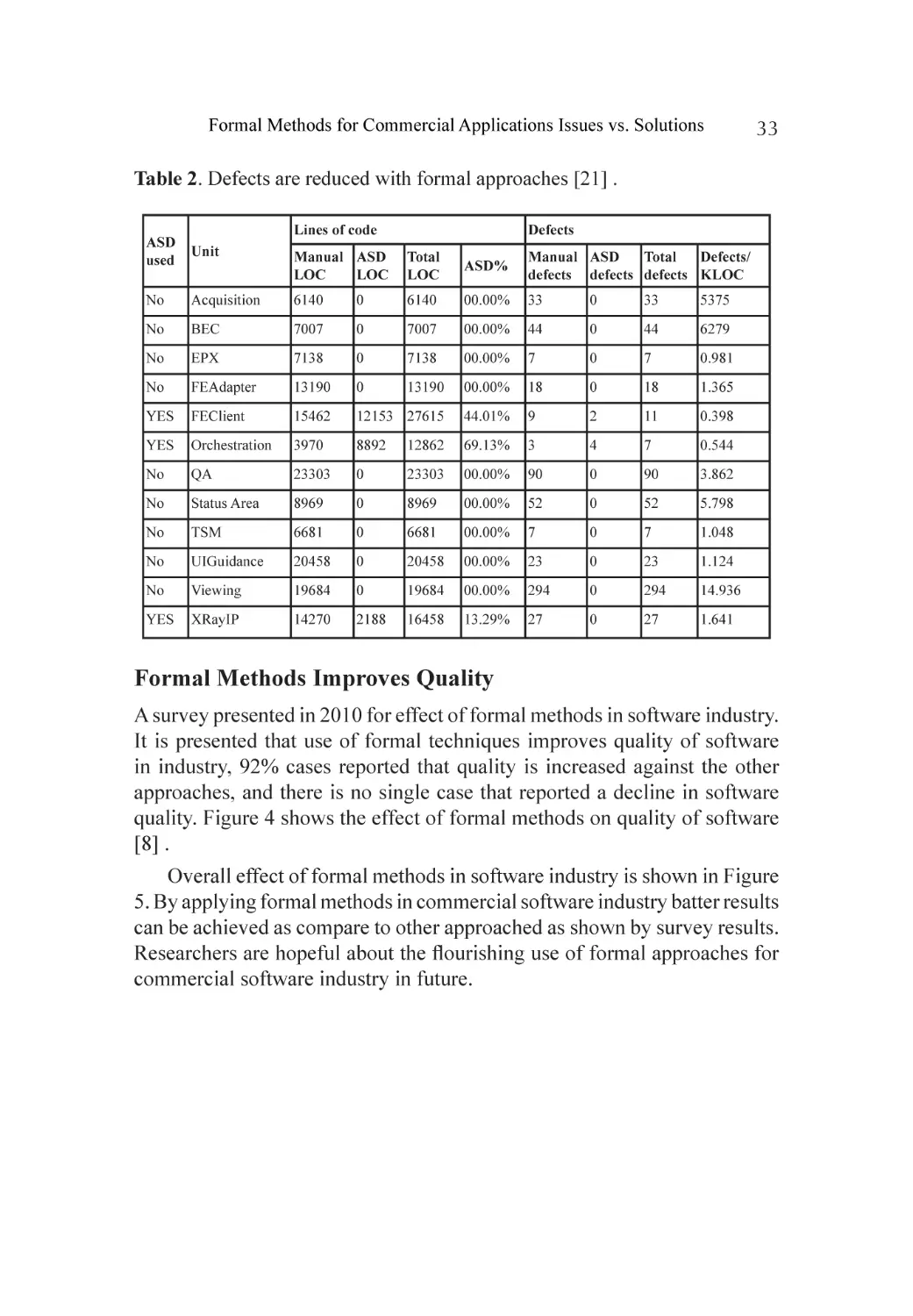
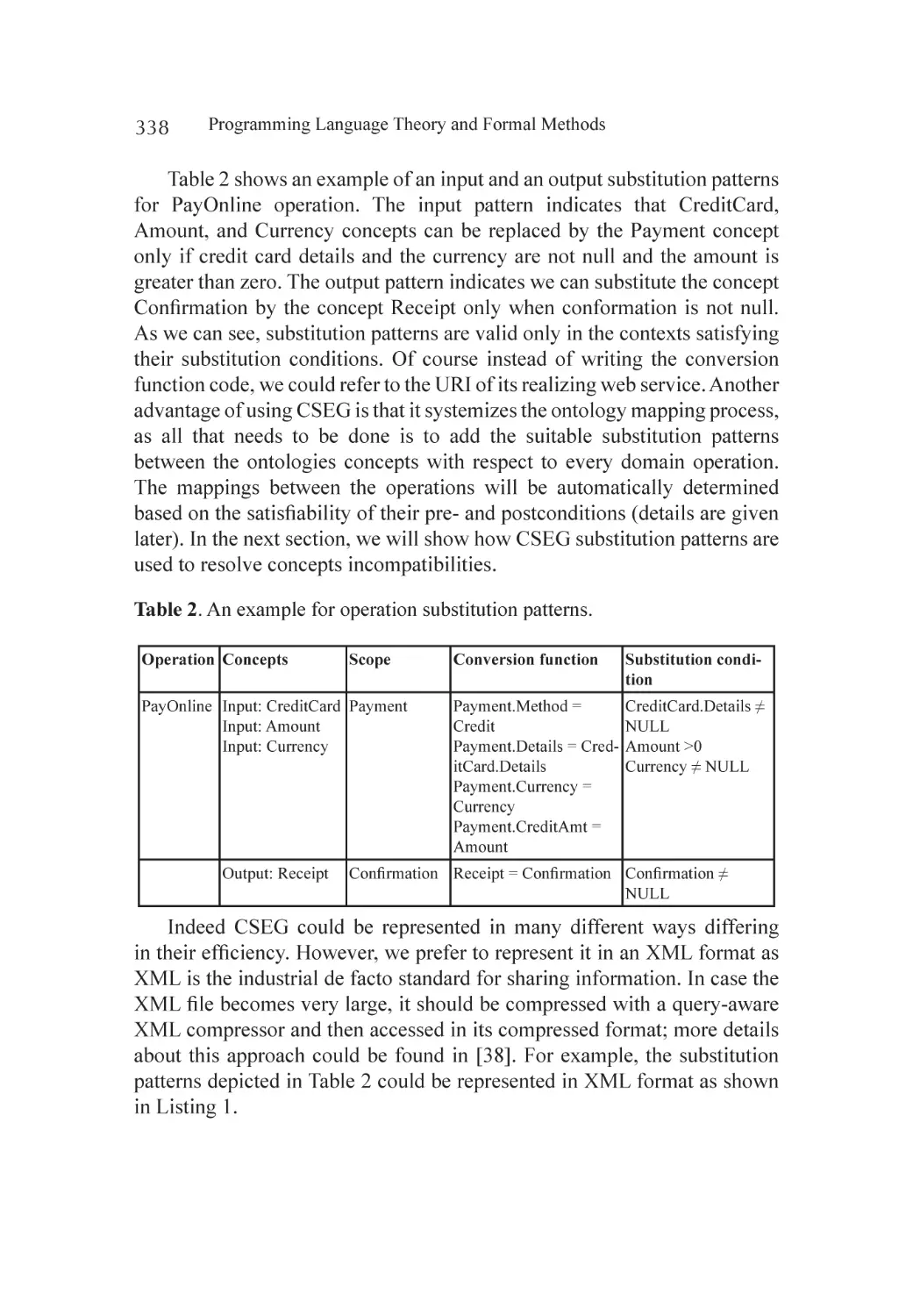
Programming Language Theory
and Formal Methods
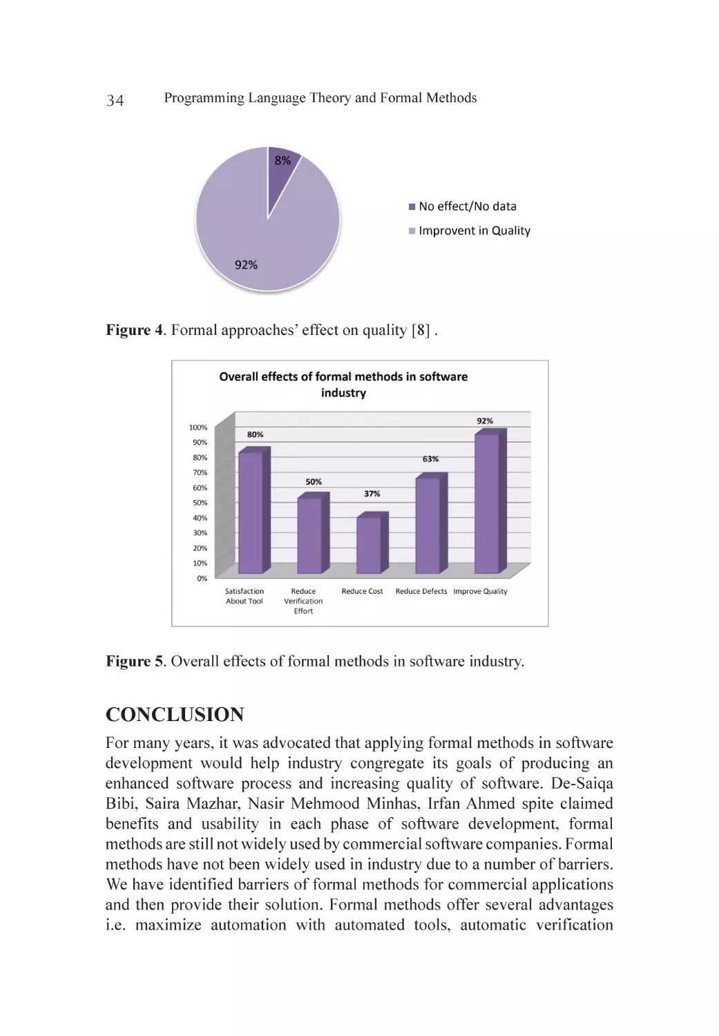
Programming Language Theory
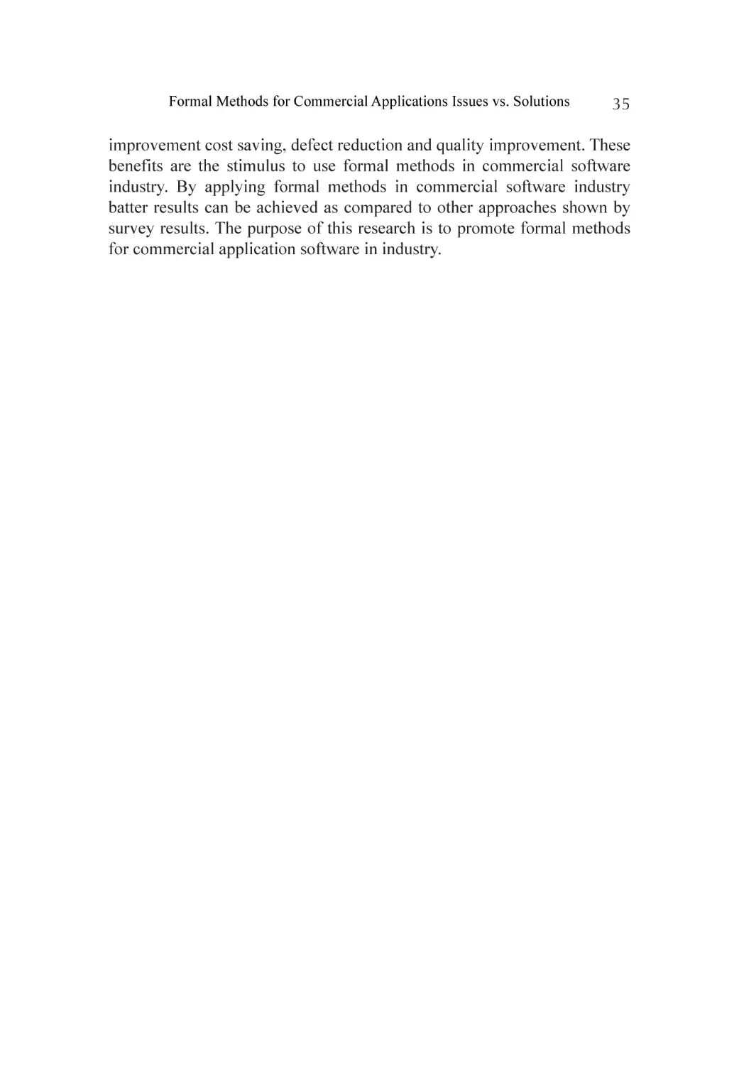
and Formal Methods
Edited by:
Zoran Gacovski
ARCLER
P
r
e
s
s
www.arclerpress.com
Programming Language Theory and Formal Methods
Zoran Gacovski
Arcler Press
224 Shoreacres Road
Burlington, ON L7L 2H2
Canada
www.arclerpress.com
Email: orders@arclereducation.com
e-book Edition 2023
ISBN: 978-1-77469-653-8 (e-book)
This book contains information obtained from highly regarded resources. Reprinted
material sources are indicated. Copyright for individual articles remains with the authors as indicated and published under Creative Commons License. A Wide variety of
references are listed. Reasonable efforts have been made to publish reliable data and
views articulated in the chapters are those of the individual contributors, and not necessarily those of the editors or publishers. Editors or publishers are not responsible for
the accuracy of the information in the published chapters or consequences of their use.
The publisher assumes no responsibility for any damage or grievance to the persons or
property arising out of the use of any materials, instructions, methods or thoughts in the
book. The editors and the publisher have attempted to trace the copyright holders of all
material reproduced in this publication and apologize to copyright holders if permission
has not been obtained. If any copyright holder has not been acknowledged, please write
to us so we may rectify.
Notice: Registered trademark of products or corporate names are used only for explanation and identification without intent of infringement.
© 2023 Arcler Press
ISBN: 978-1-77469-447-3 (Hardcover)
Arcler Press publishes wide variety of books and eBooks. For more information about
Arcler Press and its products, visit our website at www.arclerpress.com
DECLARATION
Some content or chapters in this book are open access copyright free
published research work, which is published under Creative Commons
License and are indicated with the citation. We are thankful to the
publishers and authors of the content and chapters as without them this
book wouldn’t have been possible.
ABOUT THE EDITOR
Dr. Zoran Gacovski’s current position is a full professor at the Faculty of Technical
Sciences, “Mother Tereza” University, Skopje, Macedonia. His teaching subjects
include Software engineering and Intelligent systems, and his areas of research are:
information systems, intelligent control, machine learning, graphical models (Petri,
Neural and Bayesian networks), and human-computer interaction. Prof. Gacovski
has earned his PhD degree at Faculty of Electrical engineering, UKIM, Skopje. In his
career he was awarded by Fulbright postdoctoral fellowship (2002) for research stay at
Rutgers University, USA. He has also earned best-paper award at the Baltic Olympiad
for Automation control (2002), US NSF grant for conducting a specific research in the
field of human-computer interaction at Rutgers University, USA (2003), and DAAD
grant for research stay at University of Bremen, Germany (2008 and 2012). The projects
he took an active participation in, are: “A multimodal human-computer interaction and
modelling of the user behaviour” (for Rutgers University, 2002-2003) - sponsored by
US Army and Ford; “Development and implementation of algorithms for guidance,
navigation and control of mobile objects” (for Military Academy – Skopje, 1999-2002);
“Analytical and non-analytical intelligent systems for deciding and control of uncertain
complex processes” (for Macedonian Ministry of Science, 1995-1998). He is the author
of 3 books (including international edition “Mobile Robots”), 20 journal papers, over 40
Conference papers, and he is also a reviewer/ editor for IEEE journals and Conferences.
TABLE OF CONTENTS
List of Contributors........................................................................................xv
List of Abbreviations..................................................................................... xix
Preface................................................................................................... ....xxiii
Section 1: Formal Methods in Programming
Chapter 1
Integrating Formal Methods in XP—A Conceptual Solution....................... 3
Abstract...................................................................................................... 3
Introduction................................................................................................ 4
Formal Methods in Practice........................................................................ 6
Extreme Programming an Agile Approach................................................... 8
Agile Approaches towards Formal Methods................................................ 9
Formal Methods in XP: A Conceptual Solution.......................................... 11
Evaluation of Proposed Solution............................................................... 15
Discussion and Conclusions..................................................................... 17
Limitations and Future Work..................................................................... 20
References................................................................................................ 21
Chapter 2
Formal Methods for Commercial Applications Issues vs. Solutions.......... 25
Abstract.................................................................................................... 25
Introduction.............................................................................................. 26
Formal Methods: Issues vs. Solutions........................................................ 27
Formal Methods: Motivations for Commercial Applications...................... 30
Conclusion............................................................................................... 34
References................................................................................................ 36
Chapter 3
Why Formal Methods Are Considered for Safety Critical Systems?.......... 39
Abstract.................................................................................................... 39
Introduction.............................................................................................. 40
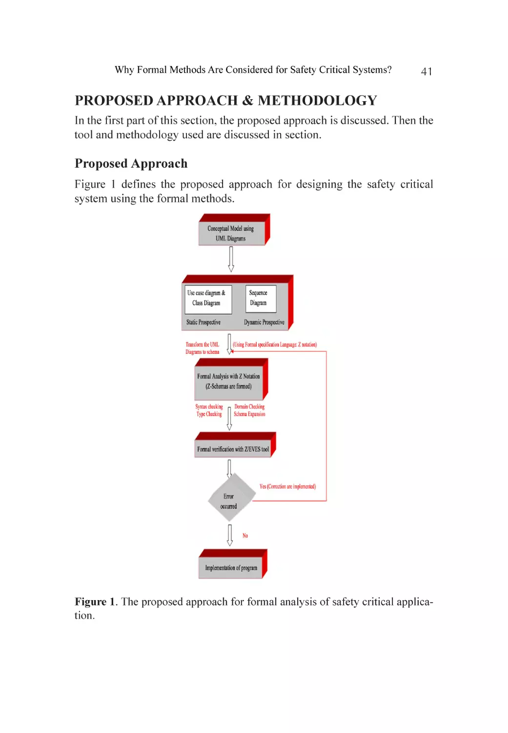
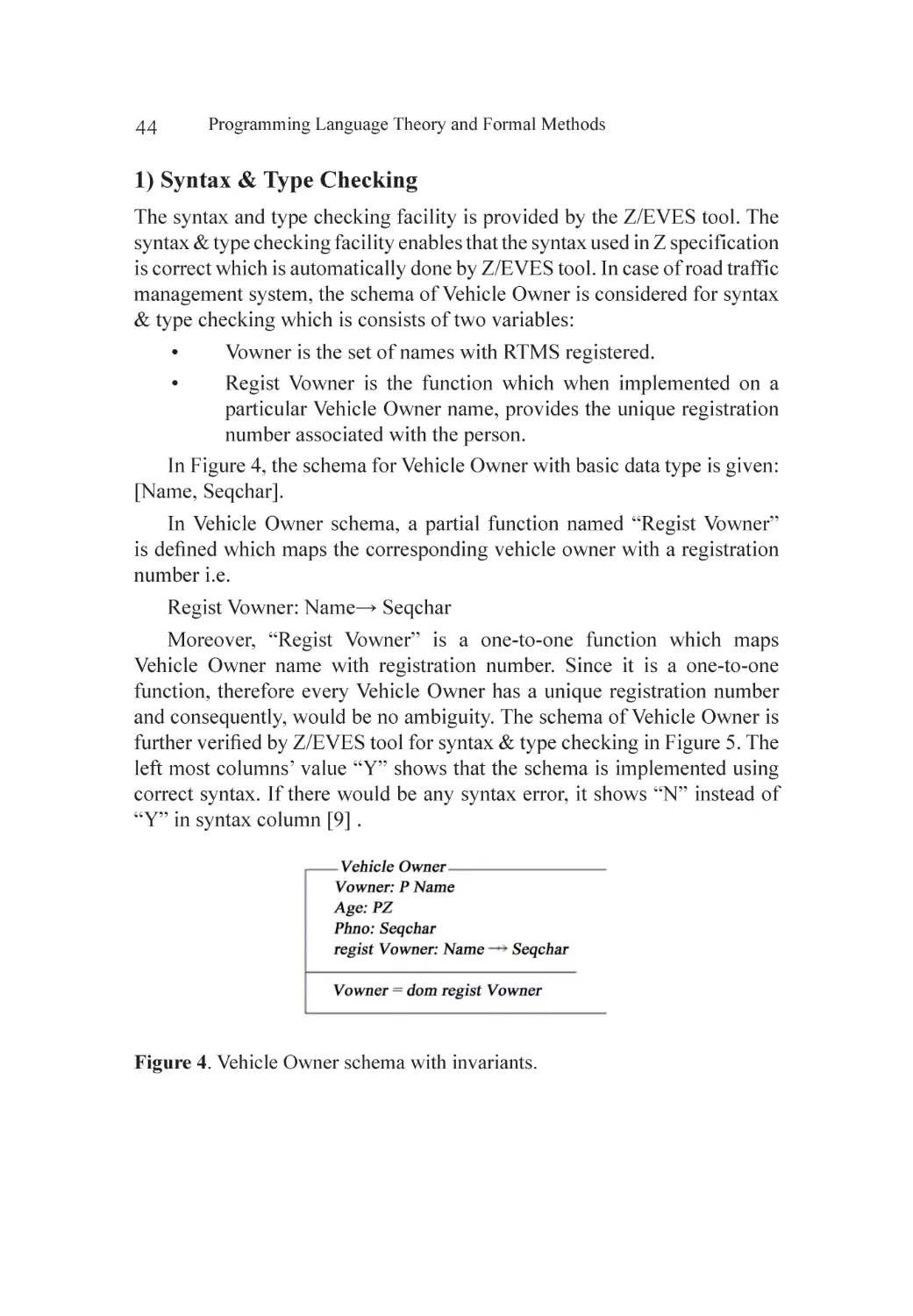
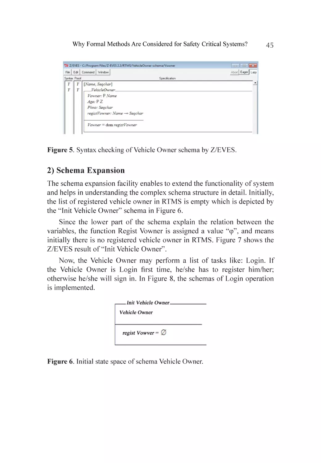
Proposed Approach & Methodology......................................................... 41
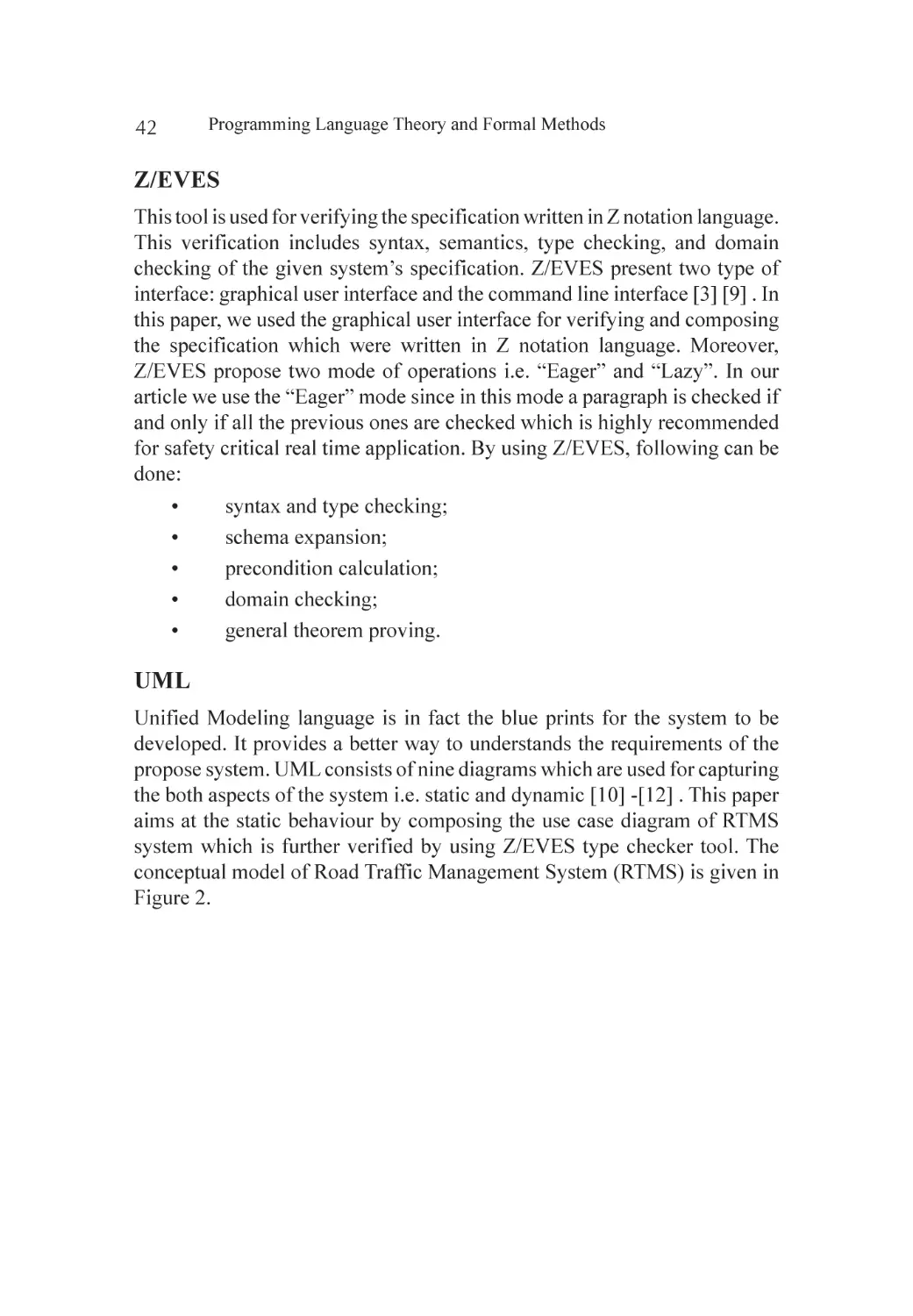
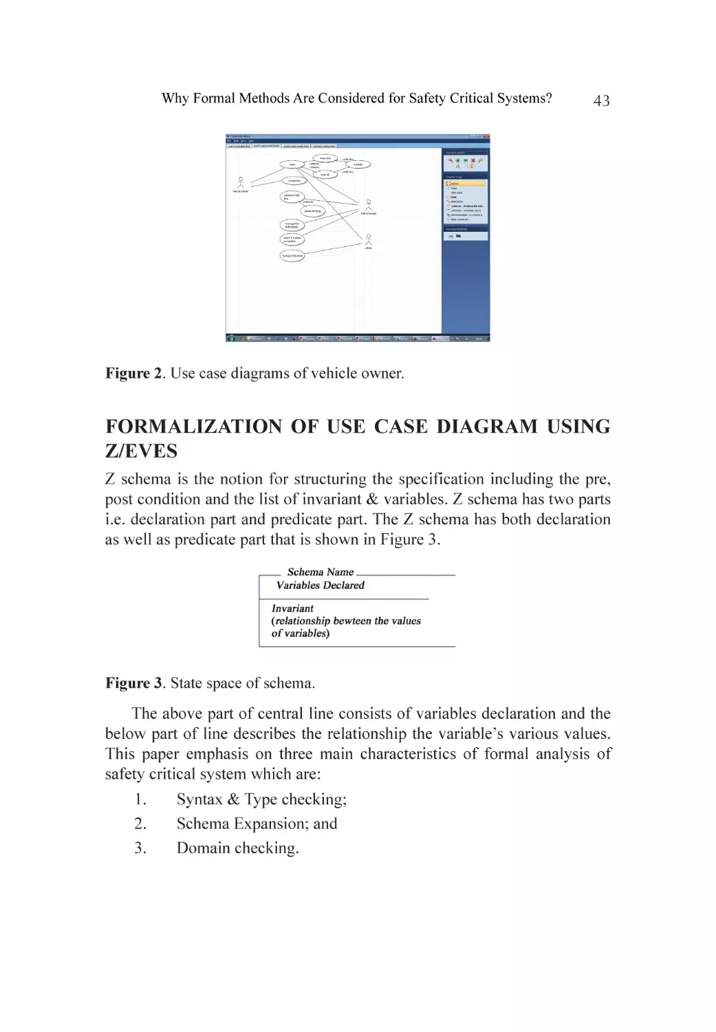
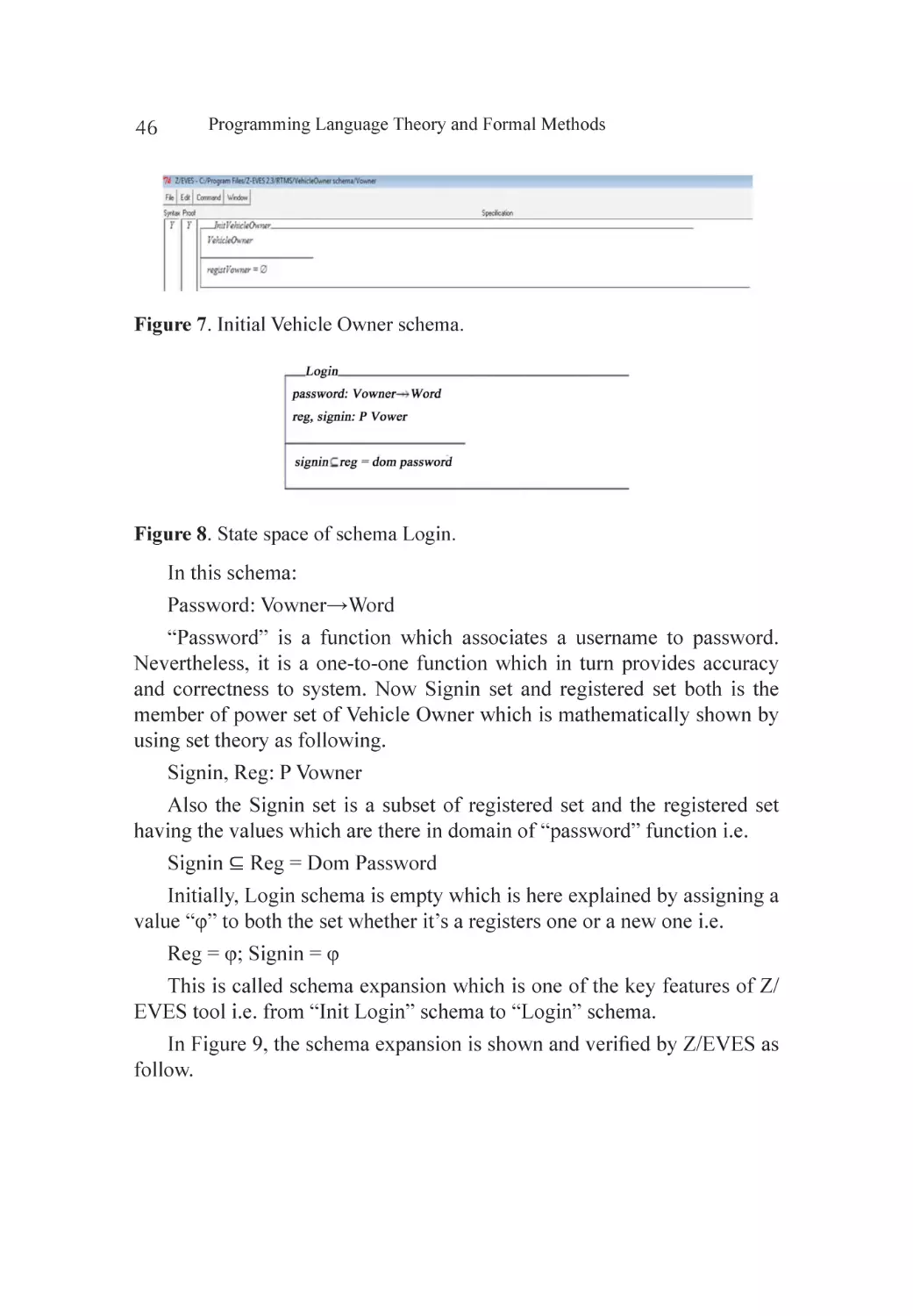
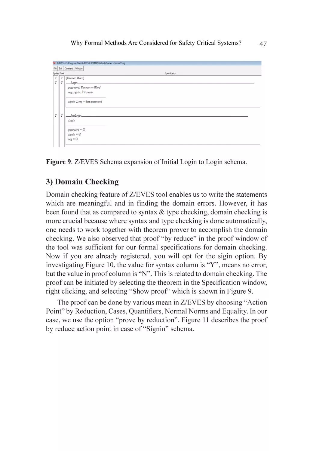
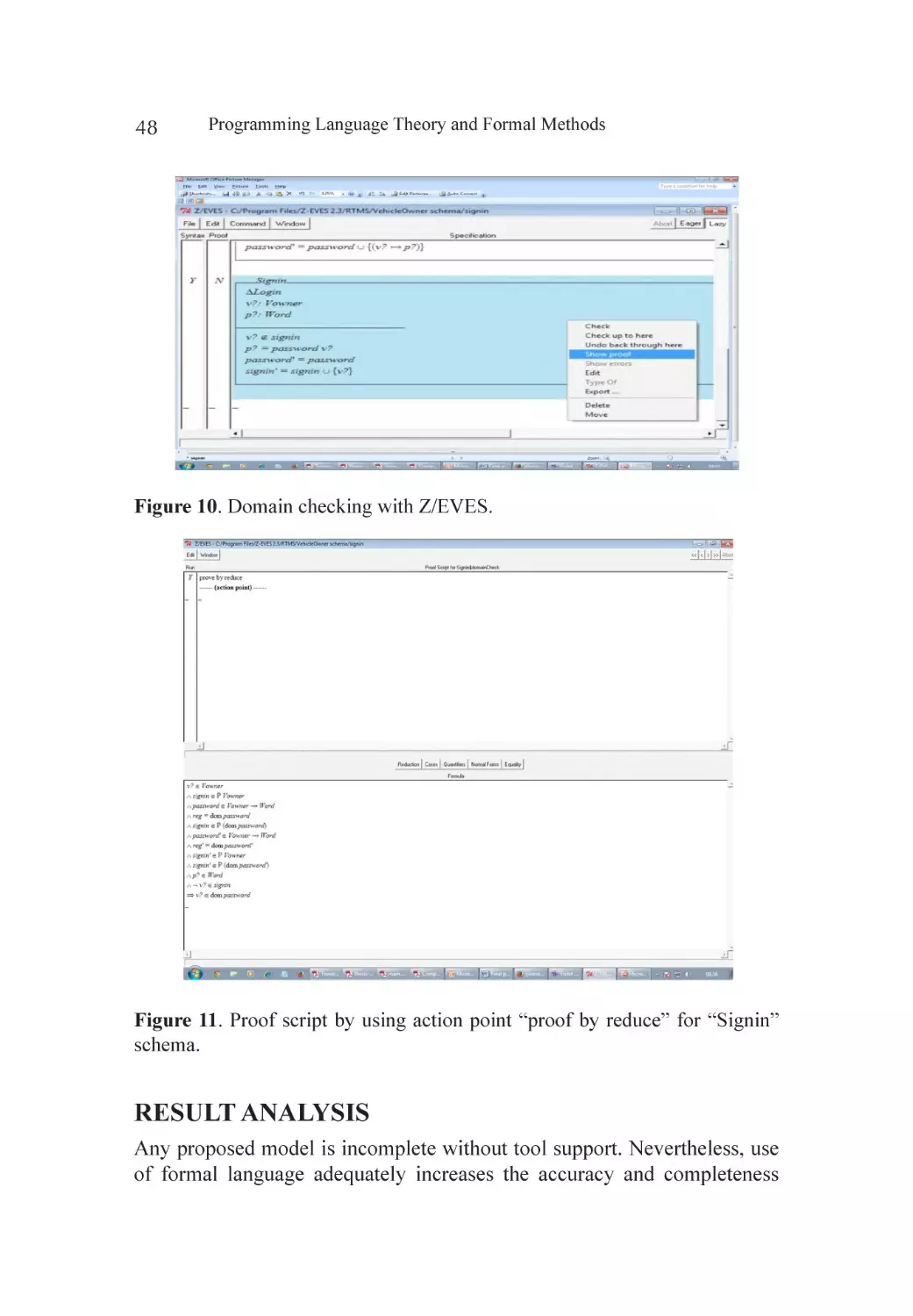
Formalization of Use Case Diagram Using Z/EVES.................................... 43
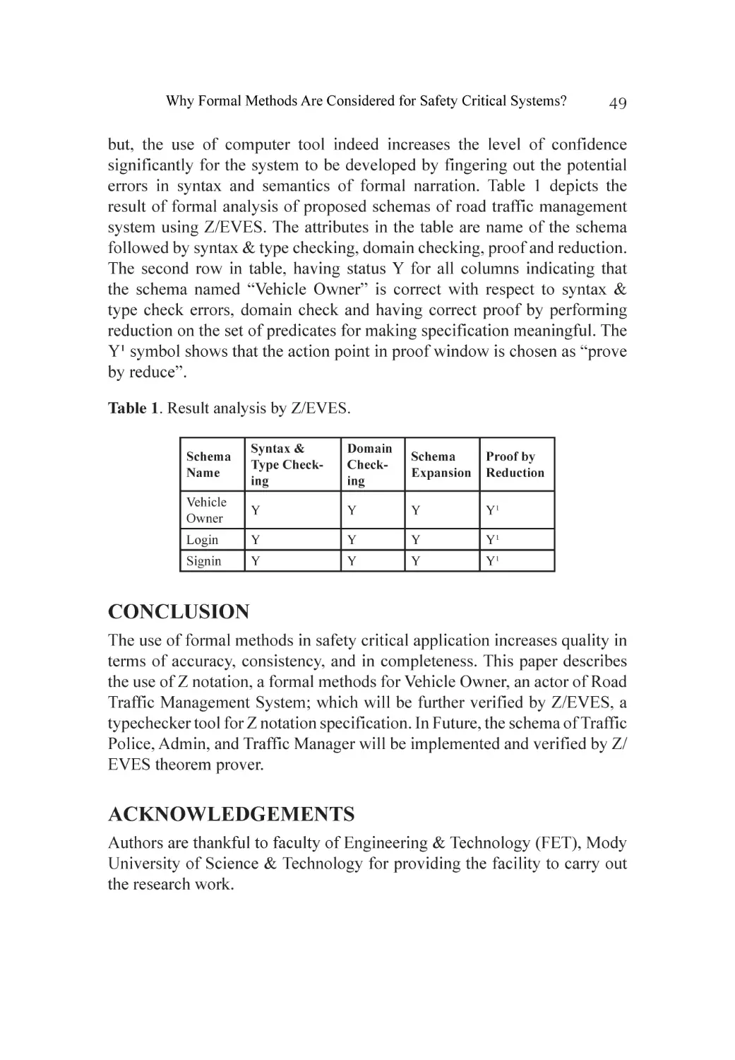
Result Analysis.......................................................................................... 48
Conclusion............................................................................................... 49
Acknowledgements.................................................................................. 49
References................................................................................................ 50
Chapter 4
An Integration of UML Sequence Diagram with Formal Specification
Methods― A Formal Solution Based on Z...................................................... 53
Abstract.................................................................................................... 53
Introduction.............................................................................................. 54
Related Work............................................................................................ 56
Expectations from System Specifications................................................... 57
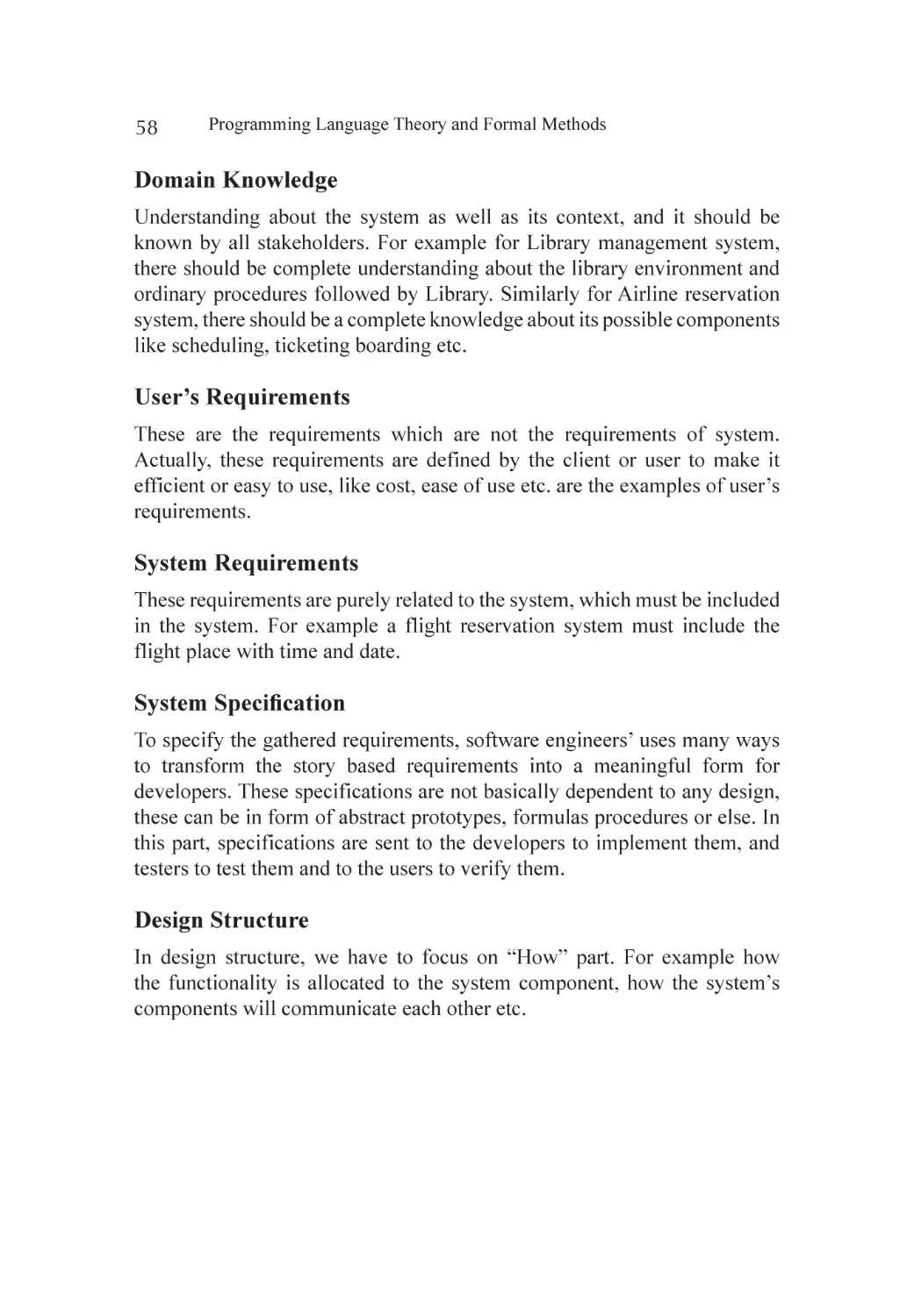
Proposed Solution..................................................................................... 59
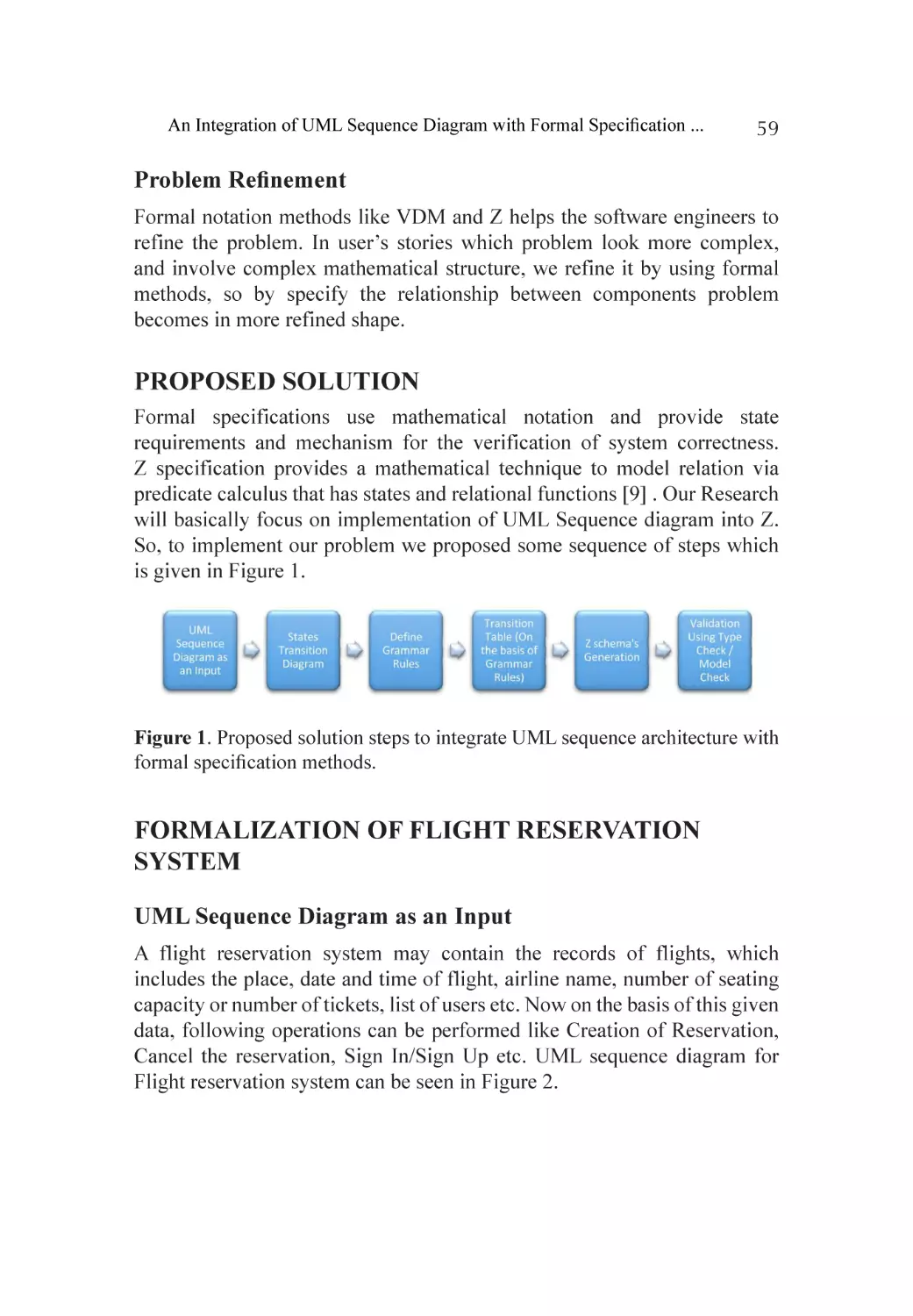
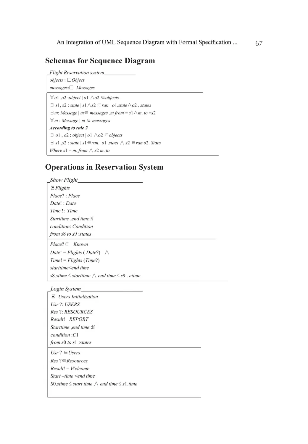
Formalization of Flight Reservation System............................................... 59
Testing and Verification............................................................................. 63
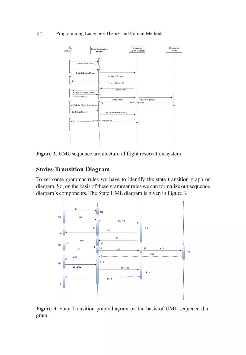
Limitations and Future Work..................................................................... 65
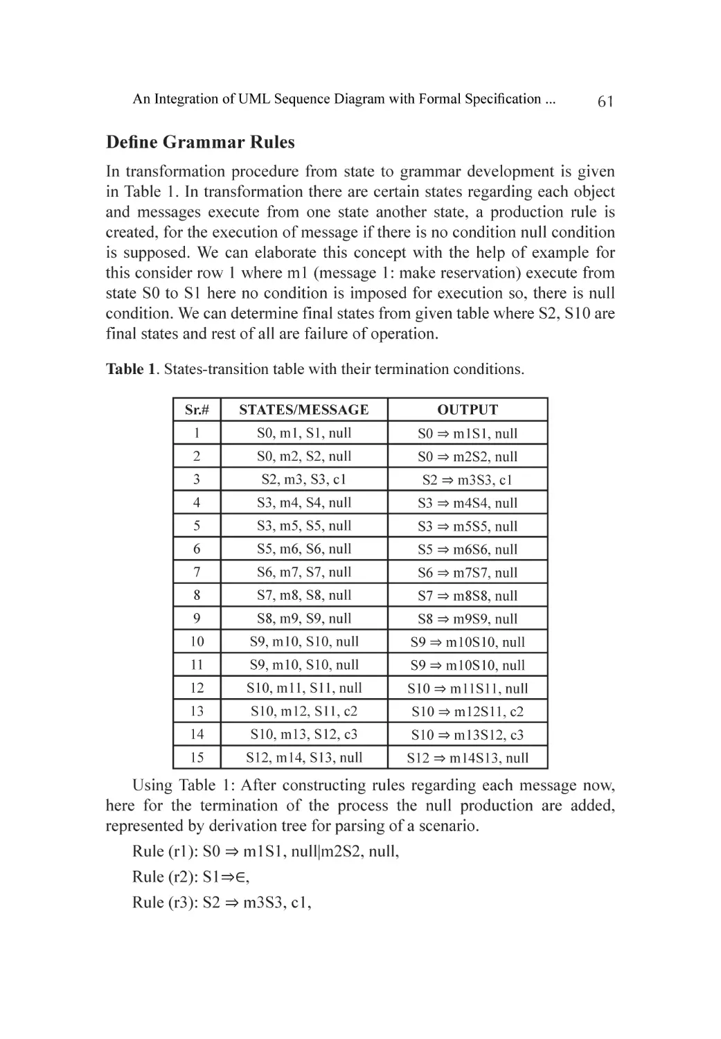
Conclusions.............................................................................................. 65
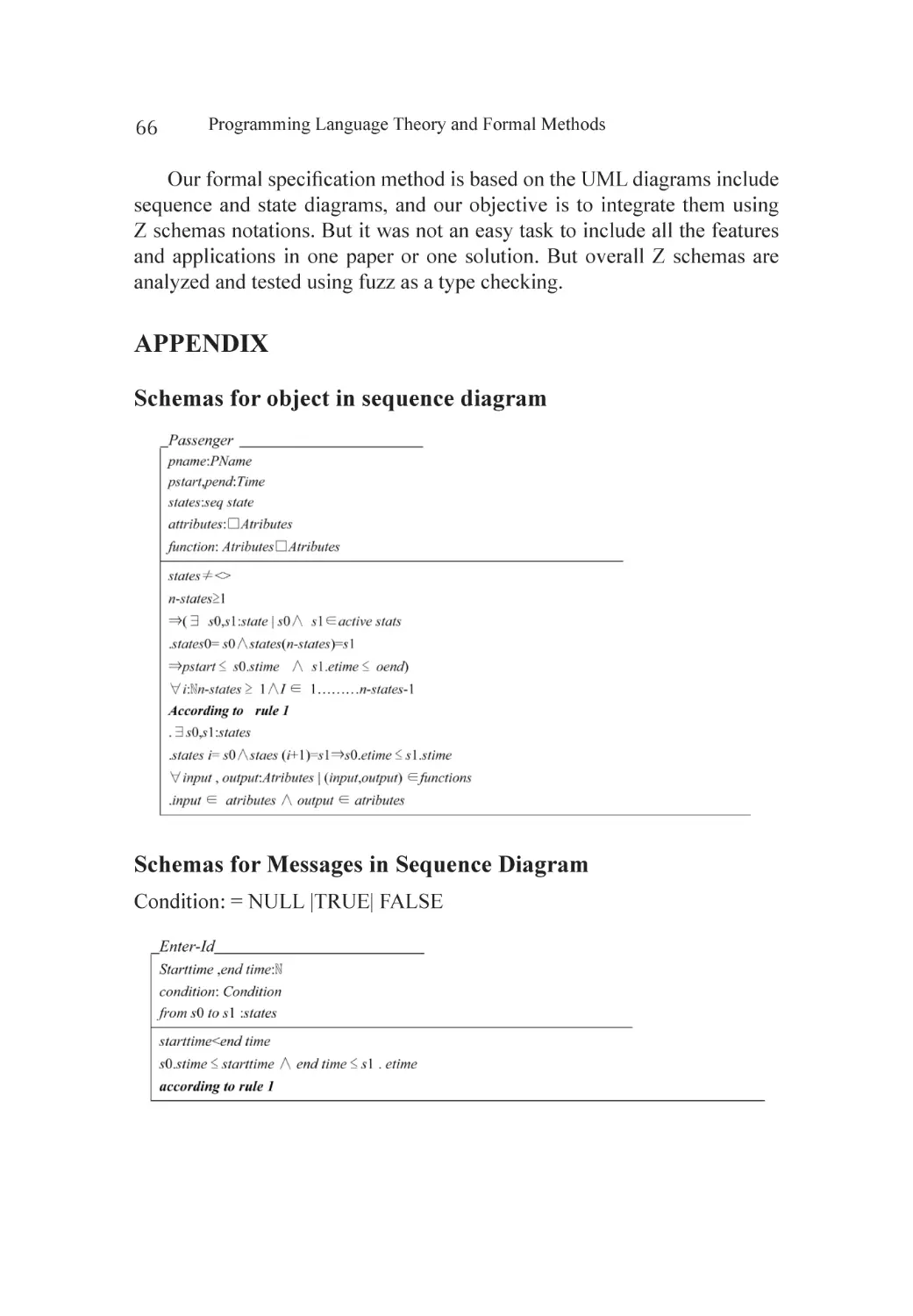
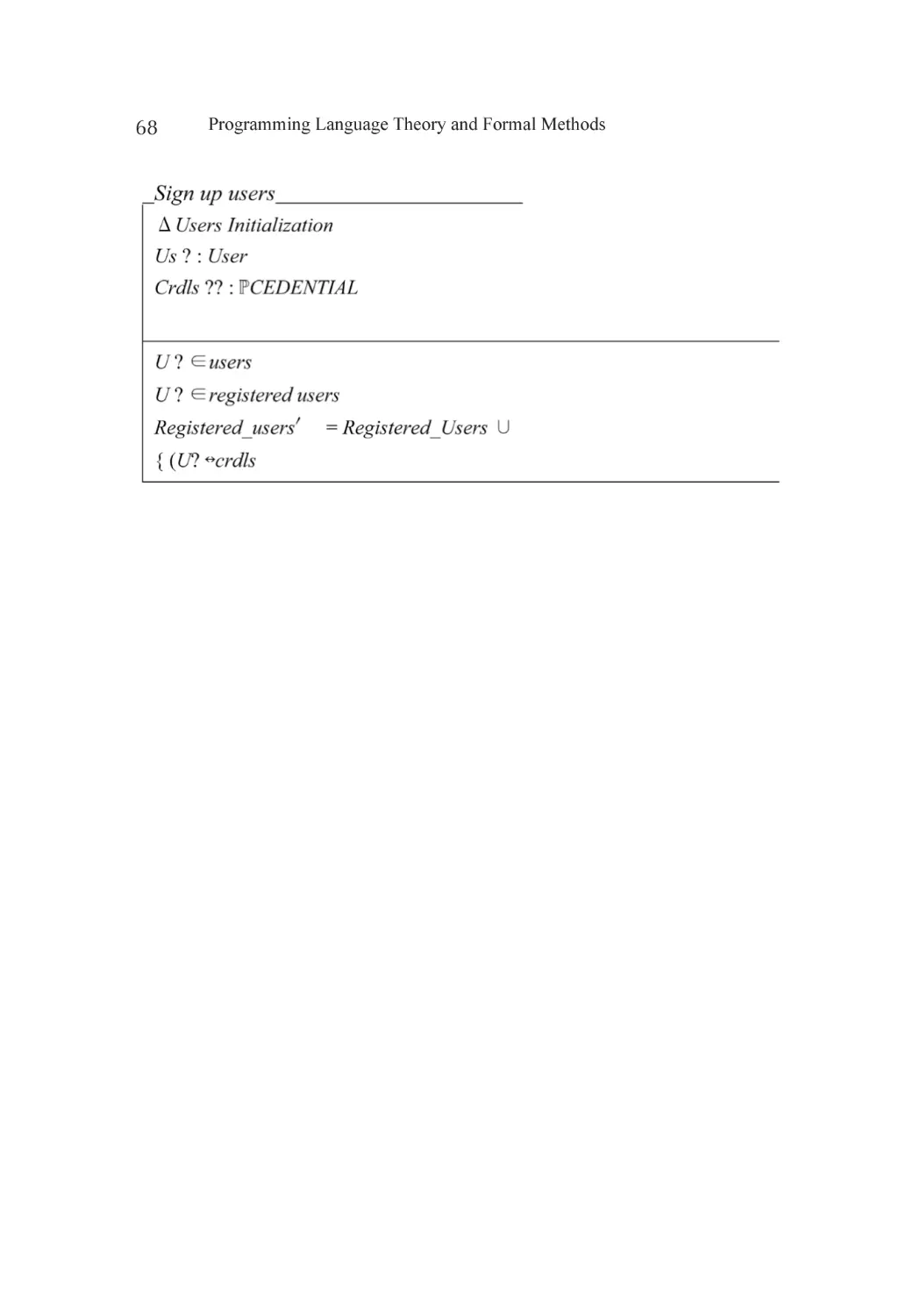
Appendix.................................................................................................. 66
References................................................................................................ 69
Section 2: Programming Languages Semantics
Chapter 5
Declarative Programming with Temporal Constraints,
in the Language CG.................................................................................. 75
Abstract.................................................................................................... 75
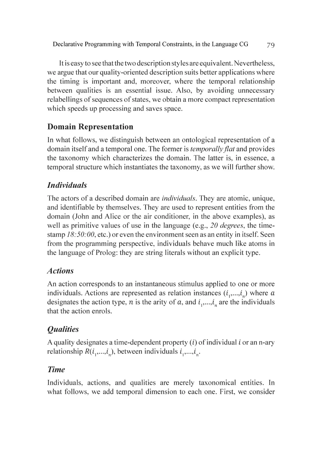
Introduction.............................................................................................. 76
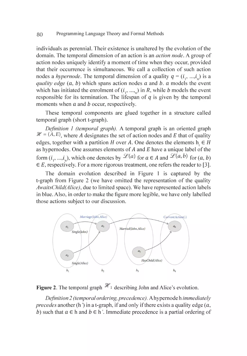
Modeling Evolving Applications................................................................ 77
Asking Temporal Questions: Queries........................................................ 82
Temporal Inference: CG............................................................................ 85
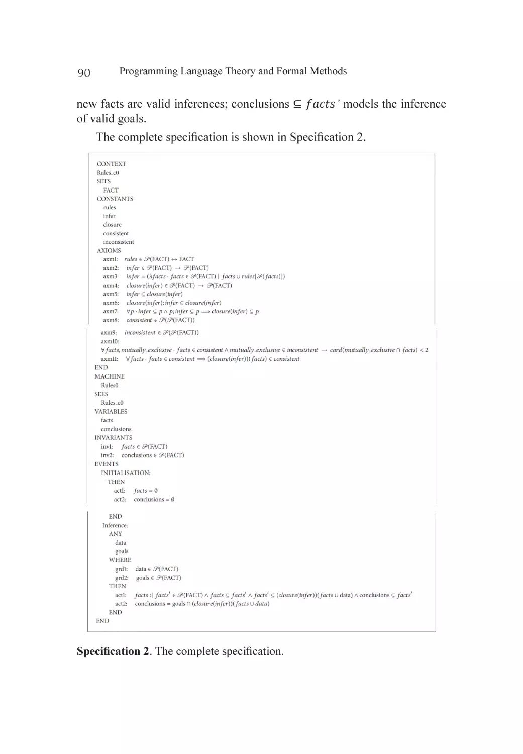
Checking the Correctness of CG Programs................................................ 87
Implementation........................................................................................ 91
Conclusion............................................................................................... 93
Acknowledgment...................................................................................... 94
References................................................................................................ 95
x
Chapter 6
Lolisa: Formal Syntax and Semantics for a Subset of the
Solidity Programming Language in Mathematical Tool Coq..................... 99
Abstract.................................................................................................... 99
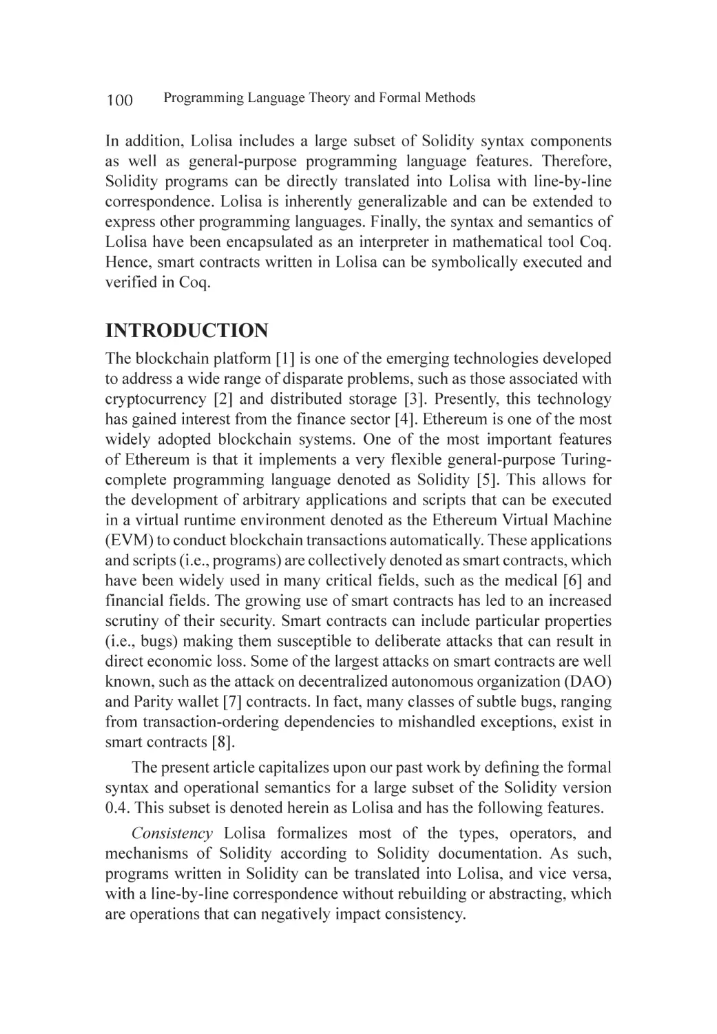
Introduction............................................................................................ 100
Related Work.......................................................................................... 101
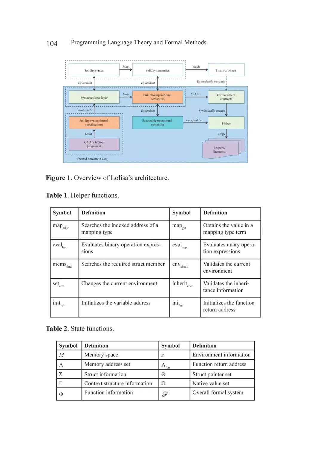
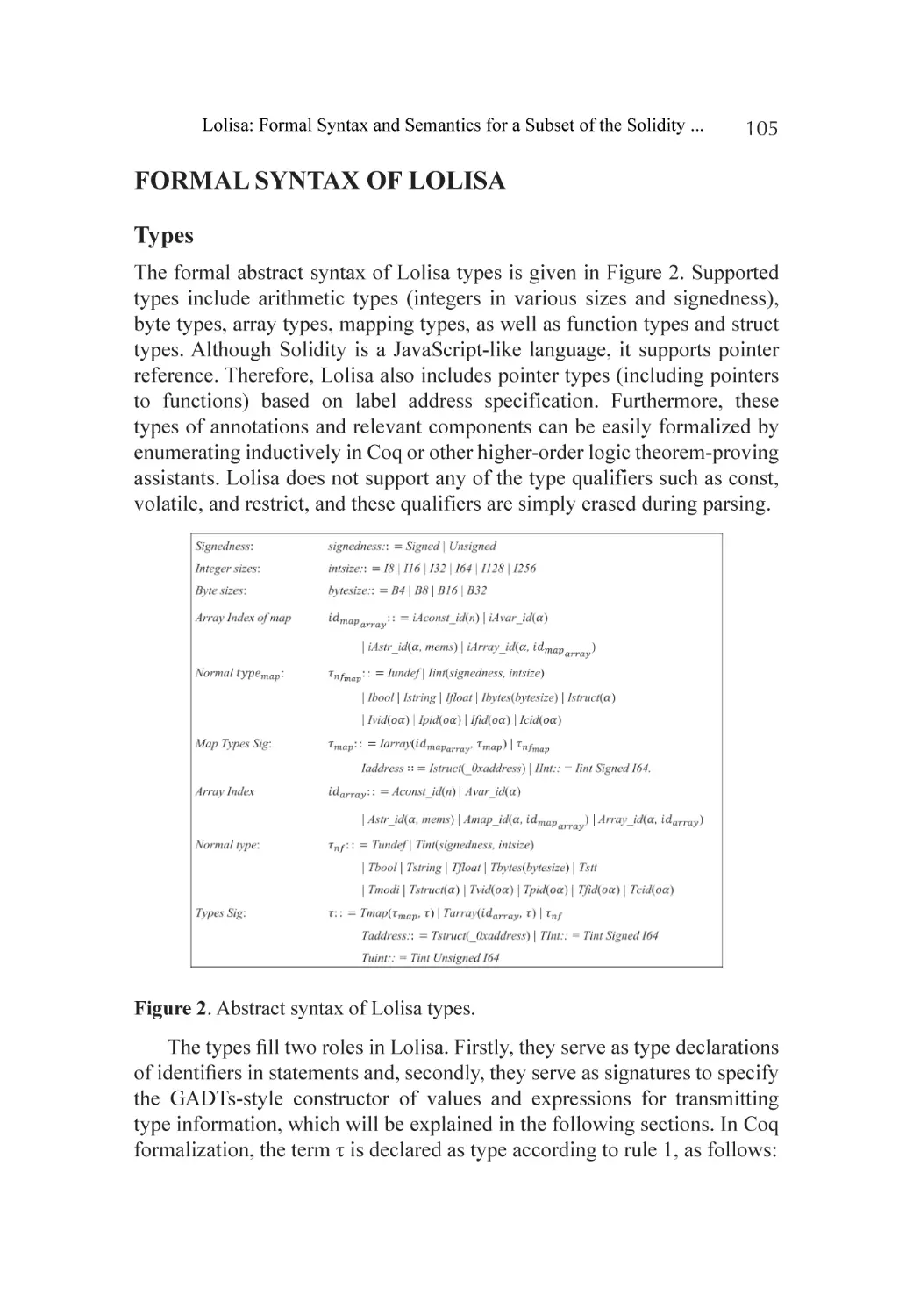
Foundational Concepts........................................................................... 103
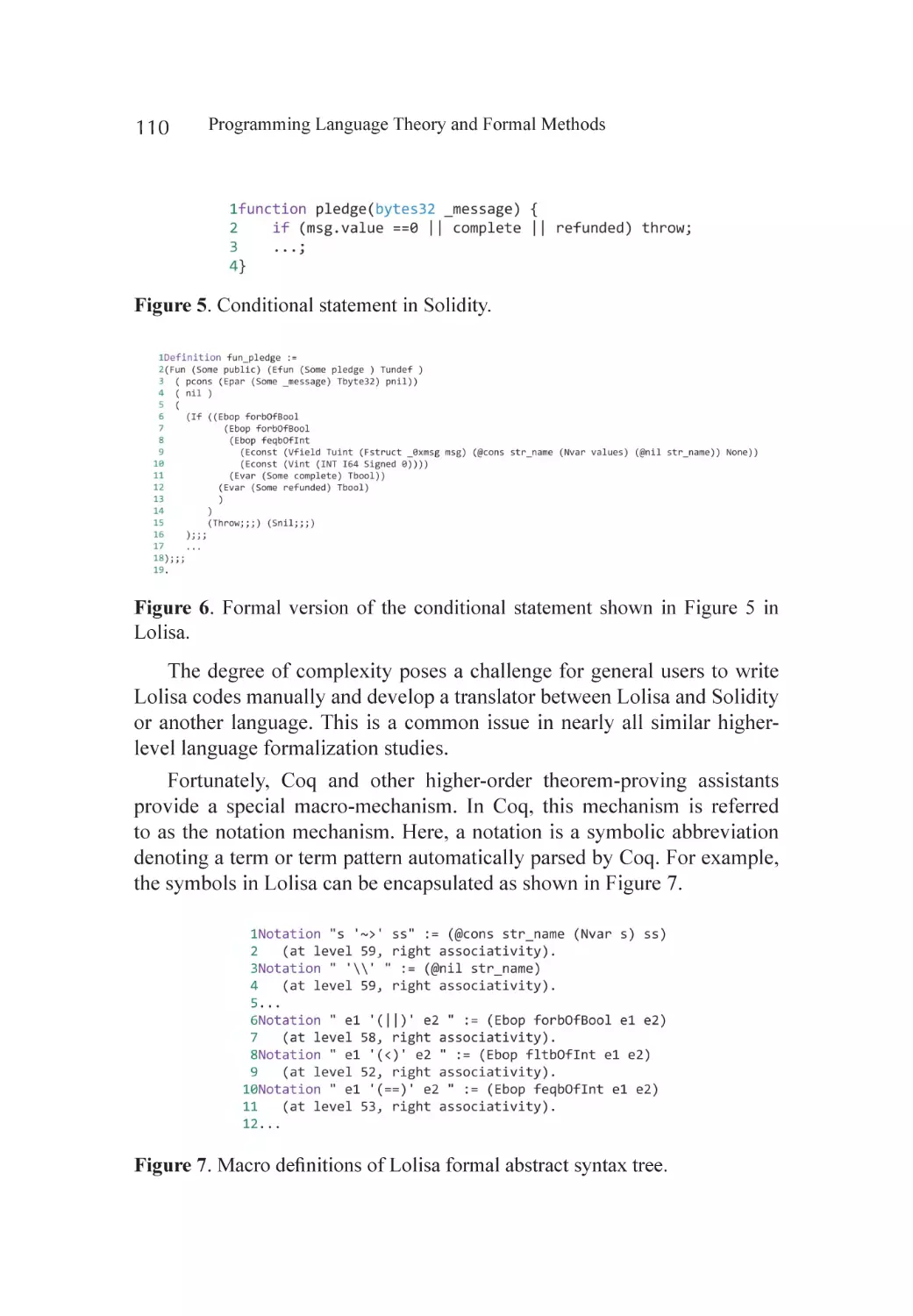
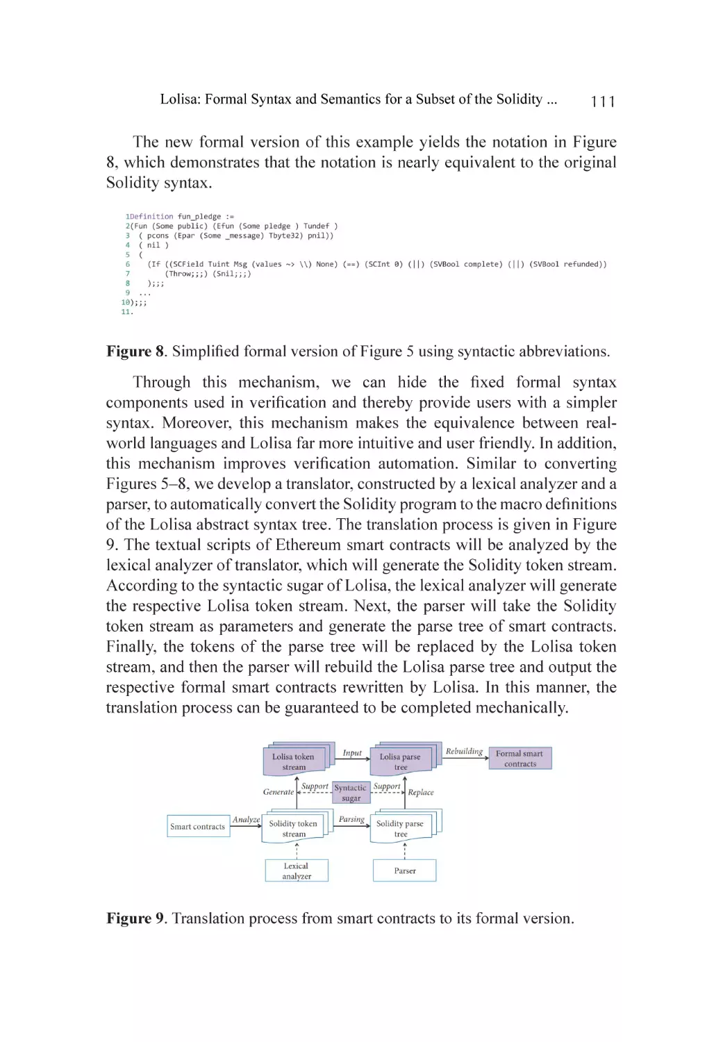
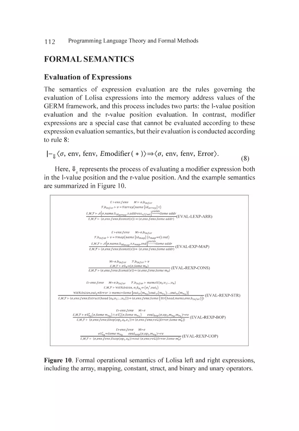
Formal Syntax of Lolisa........................................................................... 105
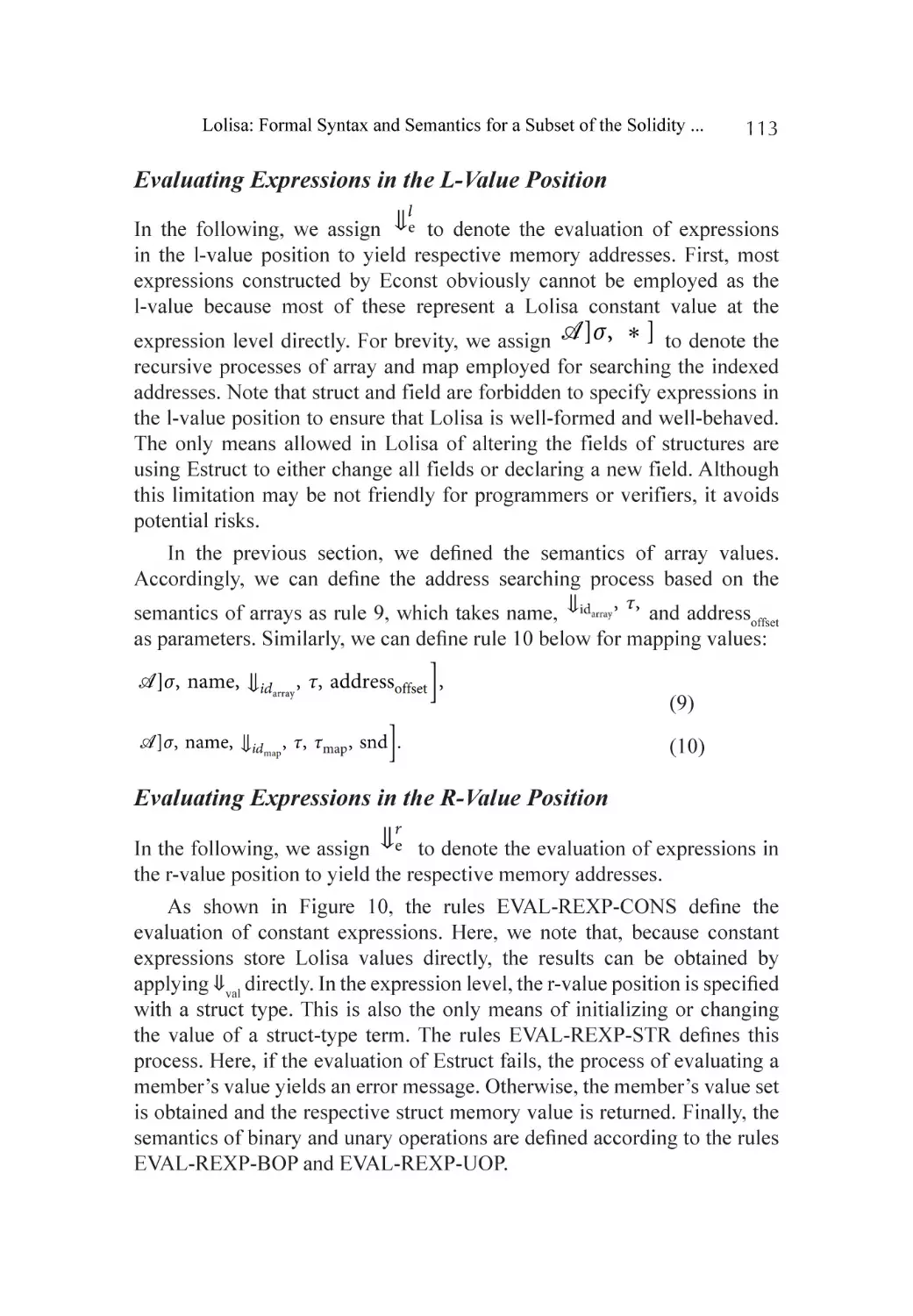
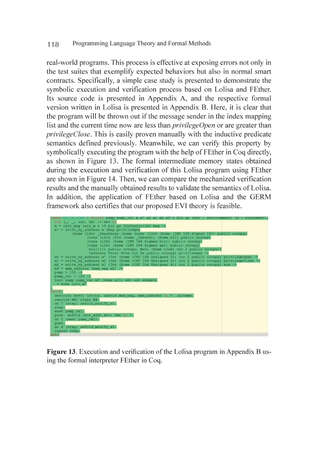
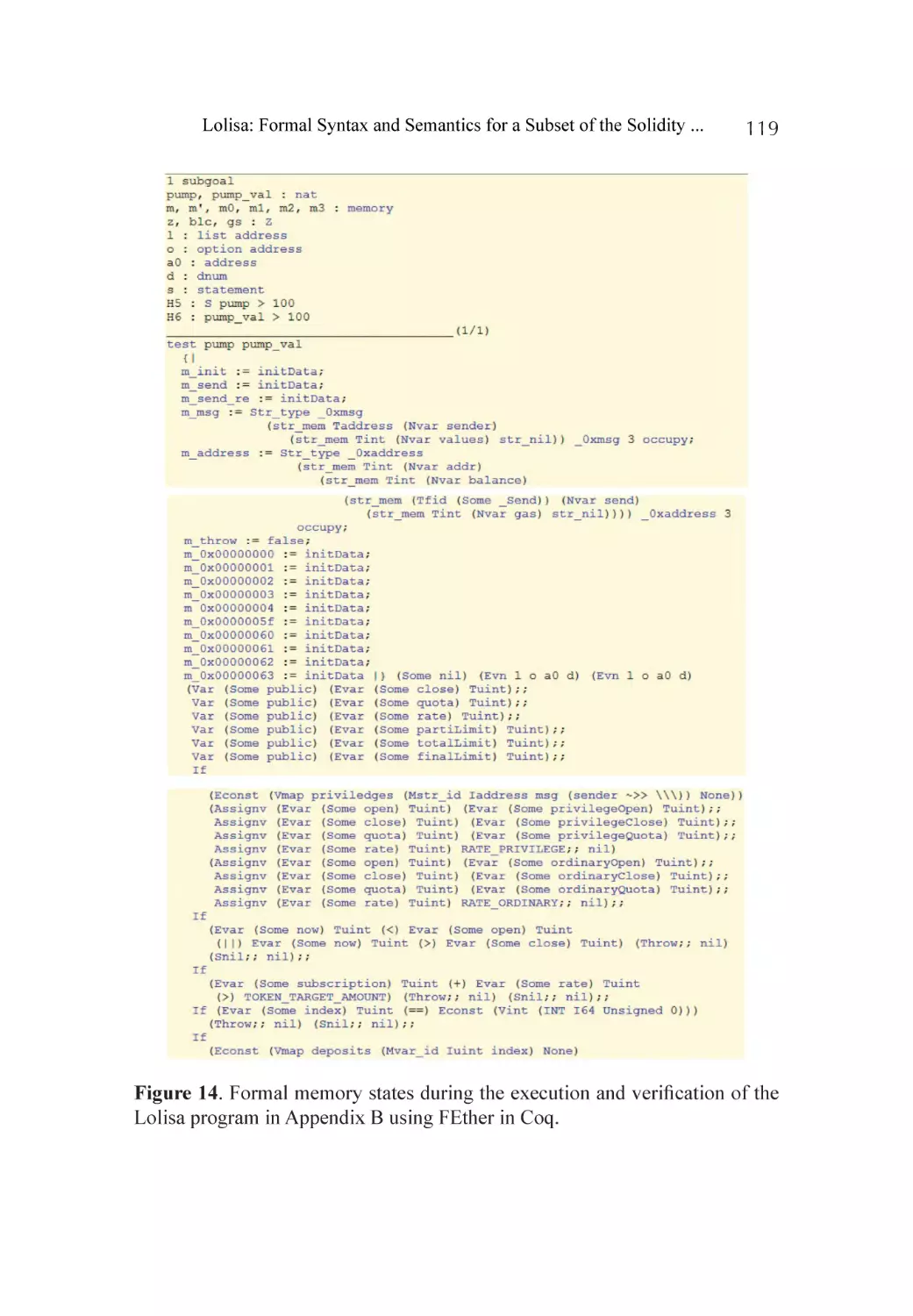
Formal Semantics................................................................................... 112
Formal Verification of Smart Contract Using FEther................................. 117
Discussion.............................................................................................. 120
Conclusion and Future Work.................................................................. 121
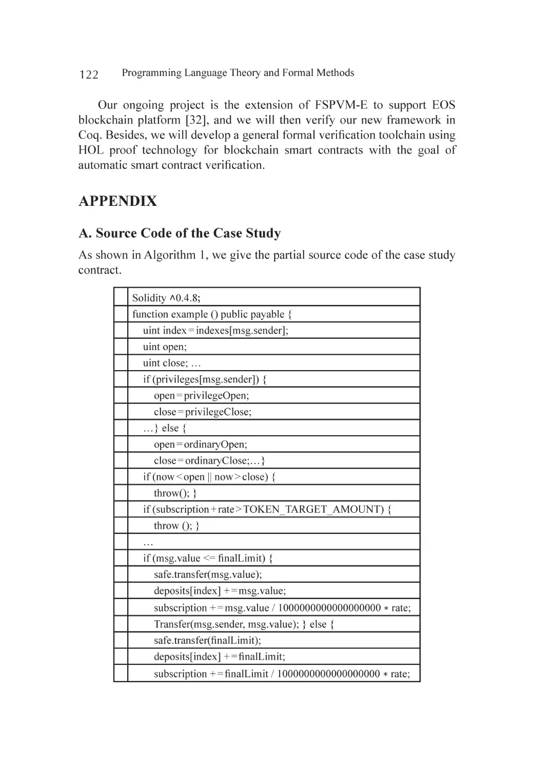
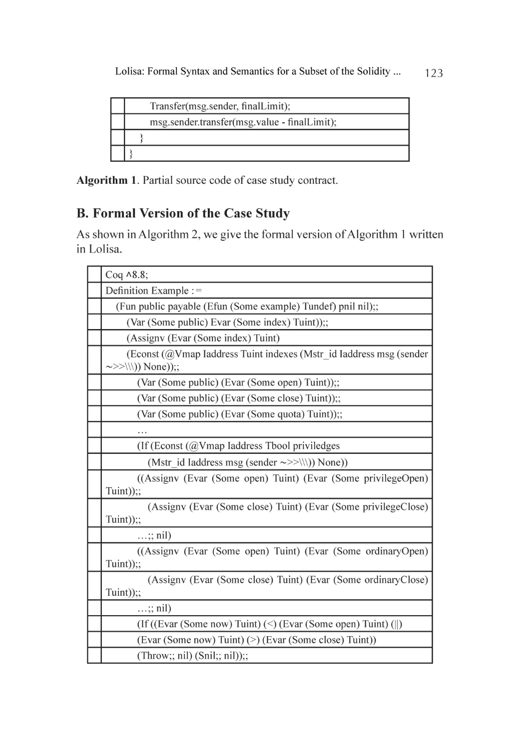
Appendix................................................................................................ 122
References.............................................................................................. 125
Chapter 7
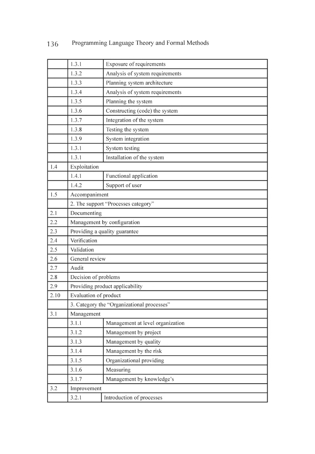
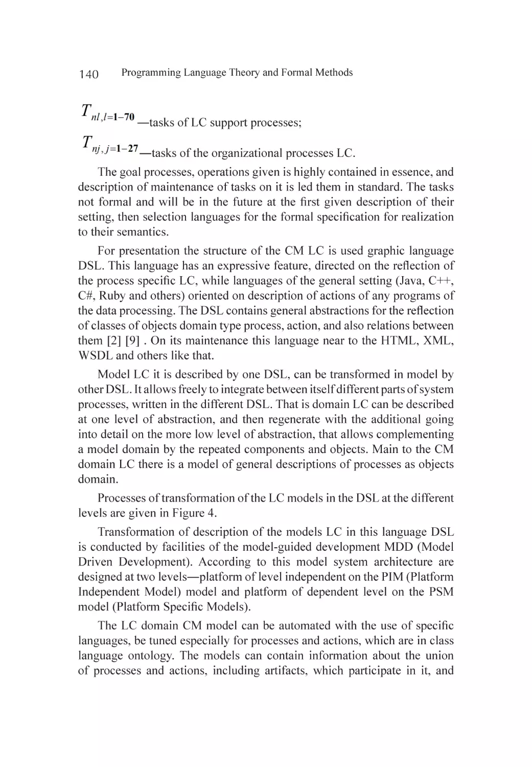
Ontology of Domains. Ontological Description Software
Engineering Domain―The Standard Life Cycle....................................... 129
Abstract.................................................................................................. 129
Introduction............................................................................................ 130
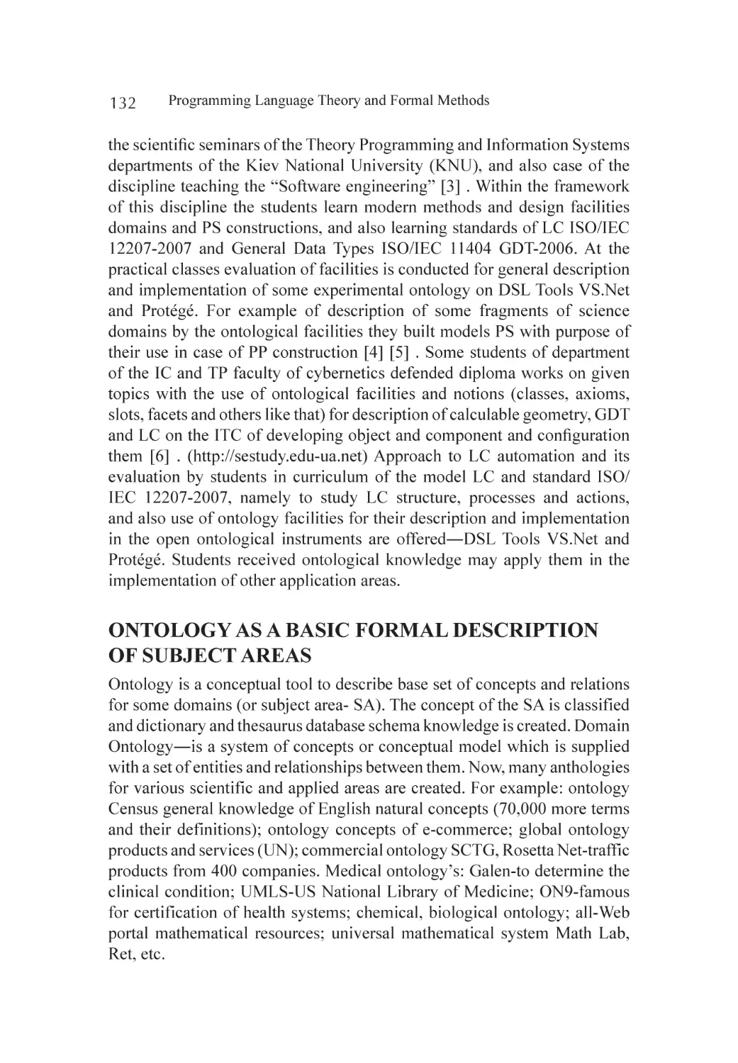
Ontology as a Basiс Formal Description of Subject Areas........................ 132
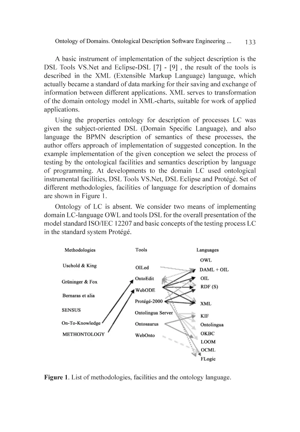
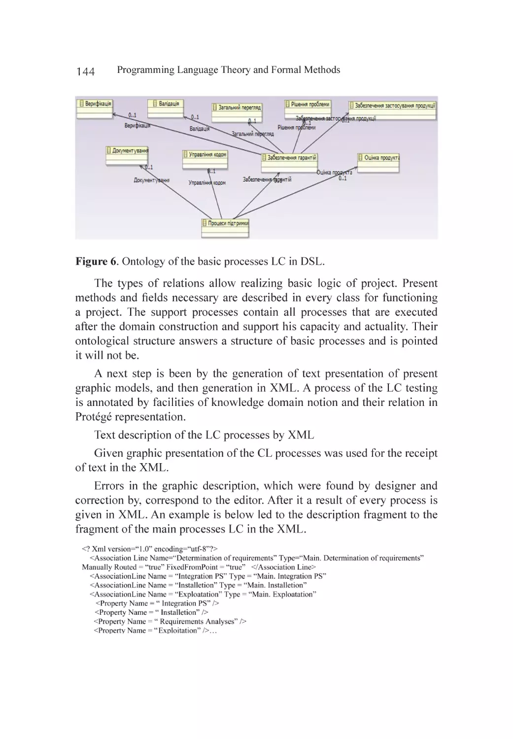
Life Cycles Ontology of Software Systems............................................... 135
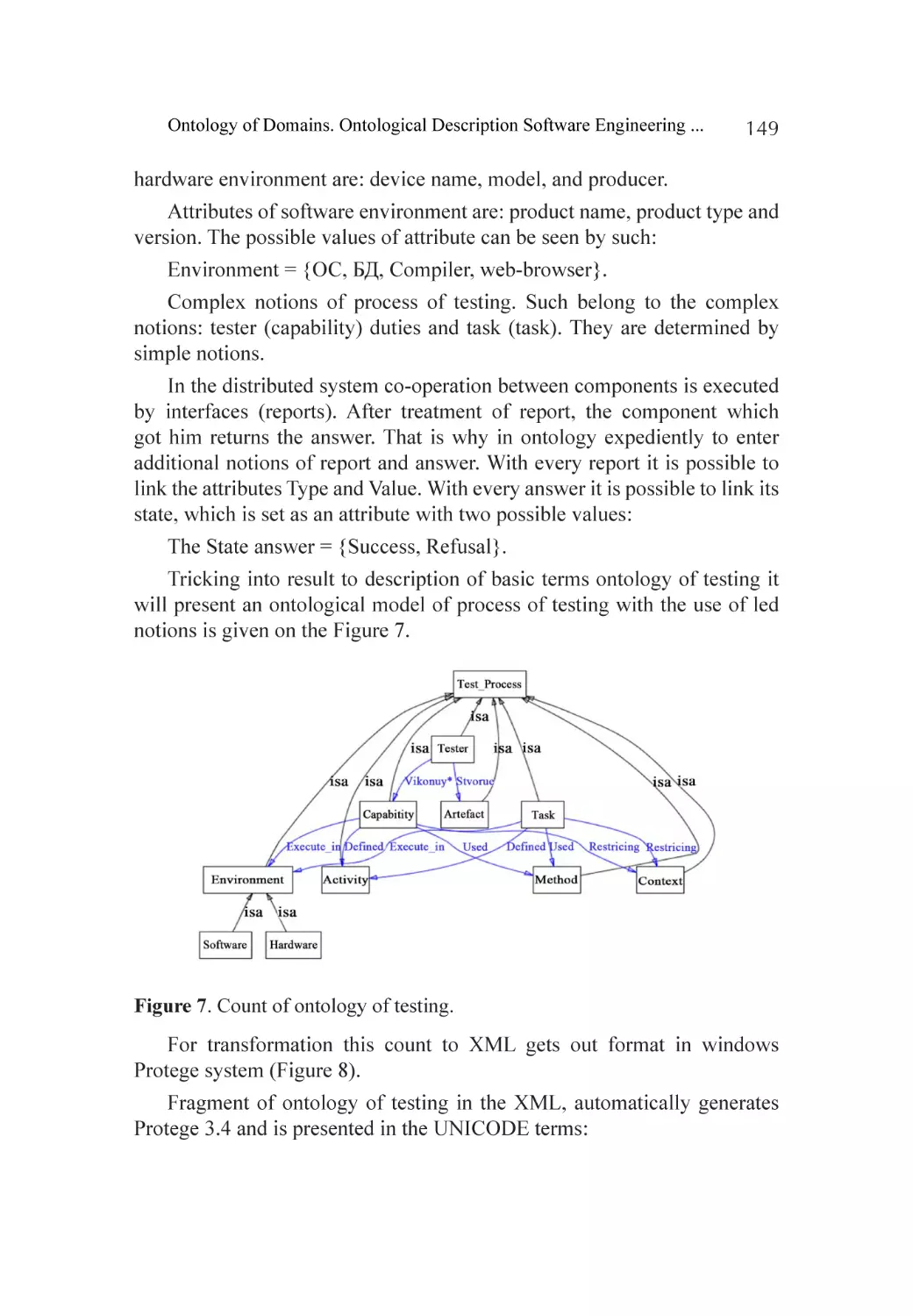
Description of Ontology of Process Testing LC........................................ 145
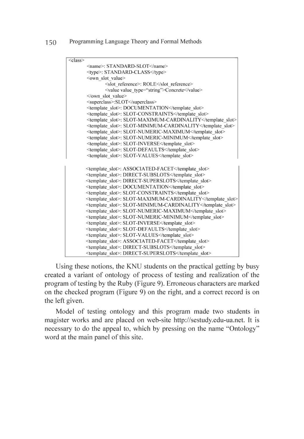
Life Cycle Ontology on Site.................................................................... 151
Conclusions............................................................................................ 152
References.............................................................................................. 154
Chapter 8
Guidelines Based Software Engineering for Developing
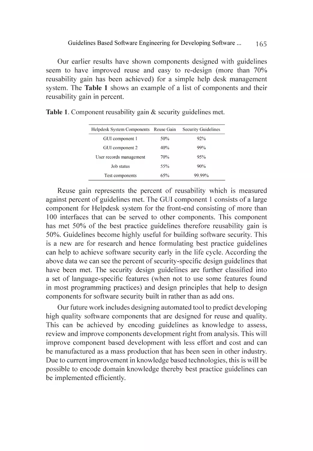
Software Components............................................................................ 157
Abstract.................................................................................................. 157
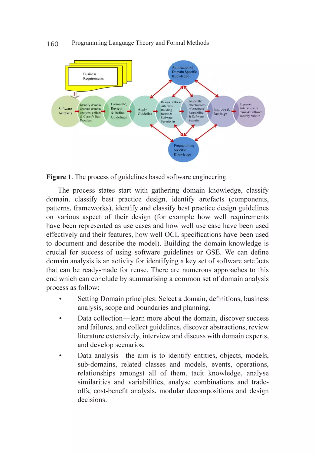
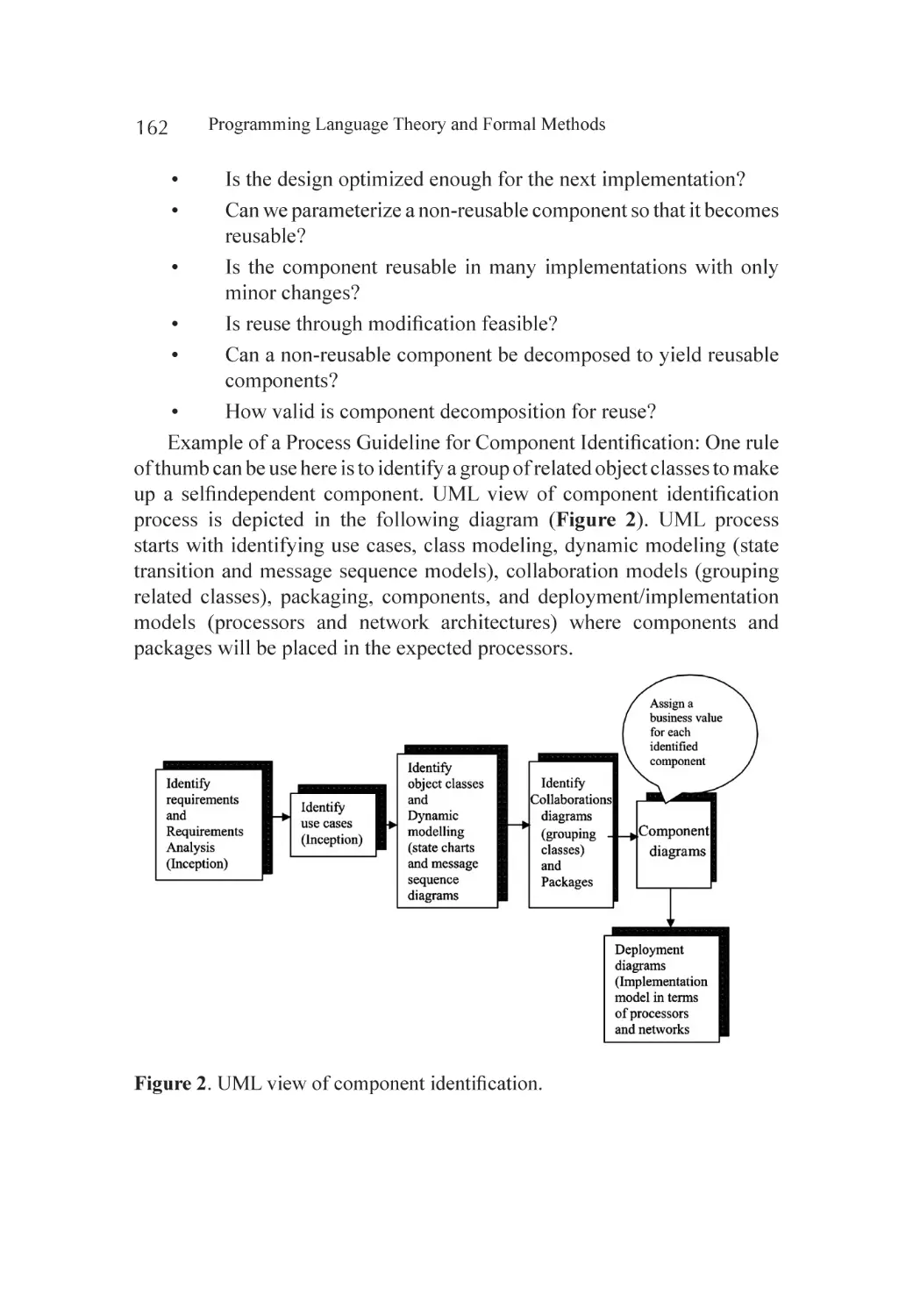
Introduction............................................................................................ 158
Guidelines Based Software Engineering.................................................. 159
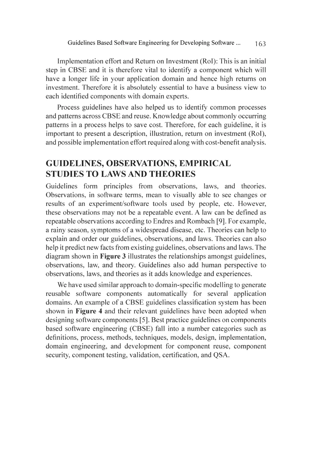
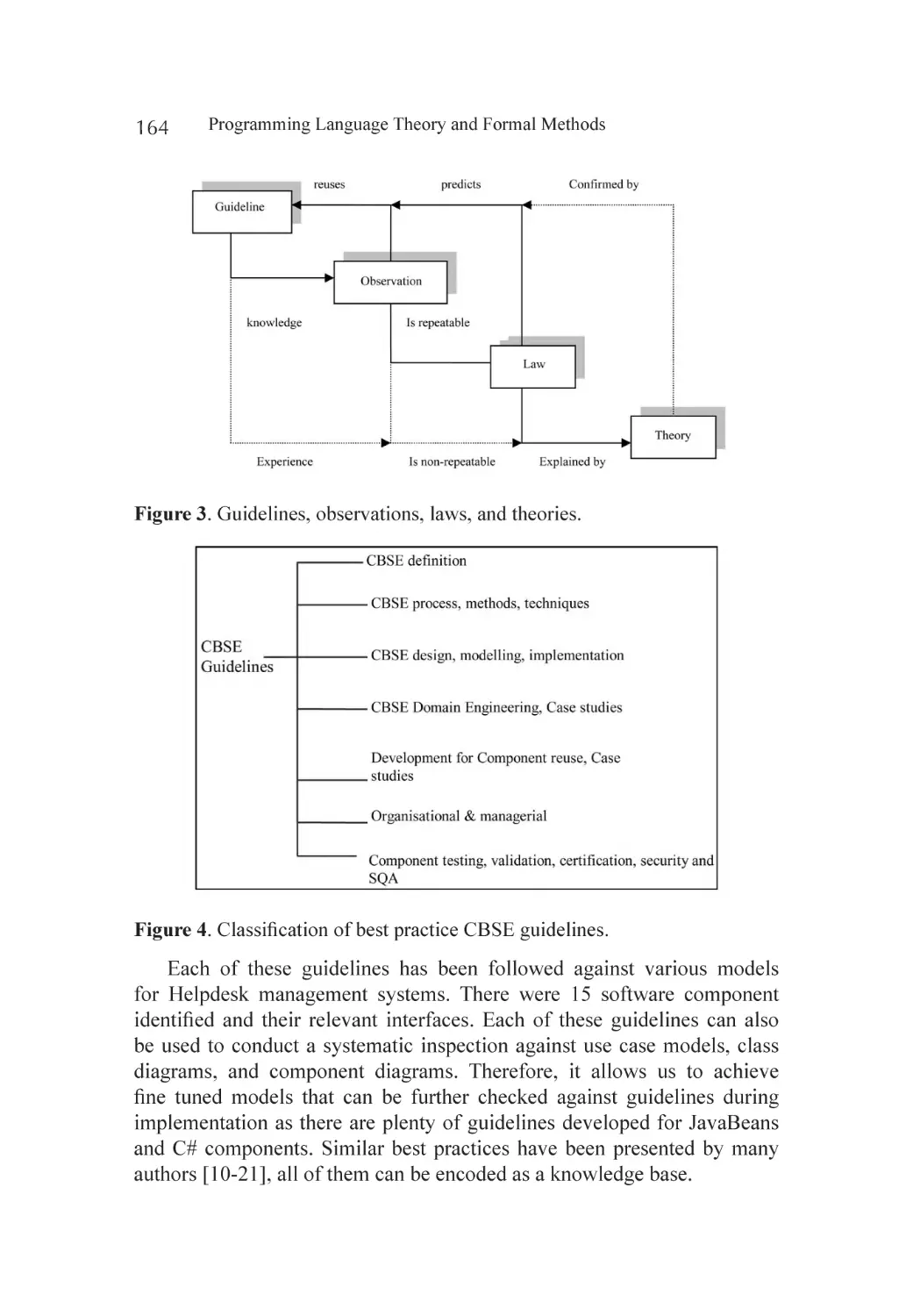
Guidelines, Observations, Empirical Studies to Laws and Theories.......... 163
Conclusion............................................................................................. 166
References.............................................................................................. 167
Chapter 9
Intelligent Agent Based Mapping of Software Requirement
Specification to Design Model............................................................... 169
Abstract.................................................................................................. 169
Introduction............................................................................................ 170
xi
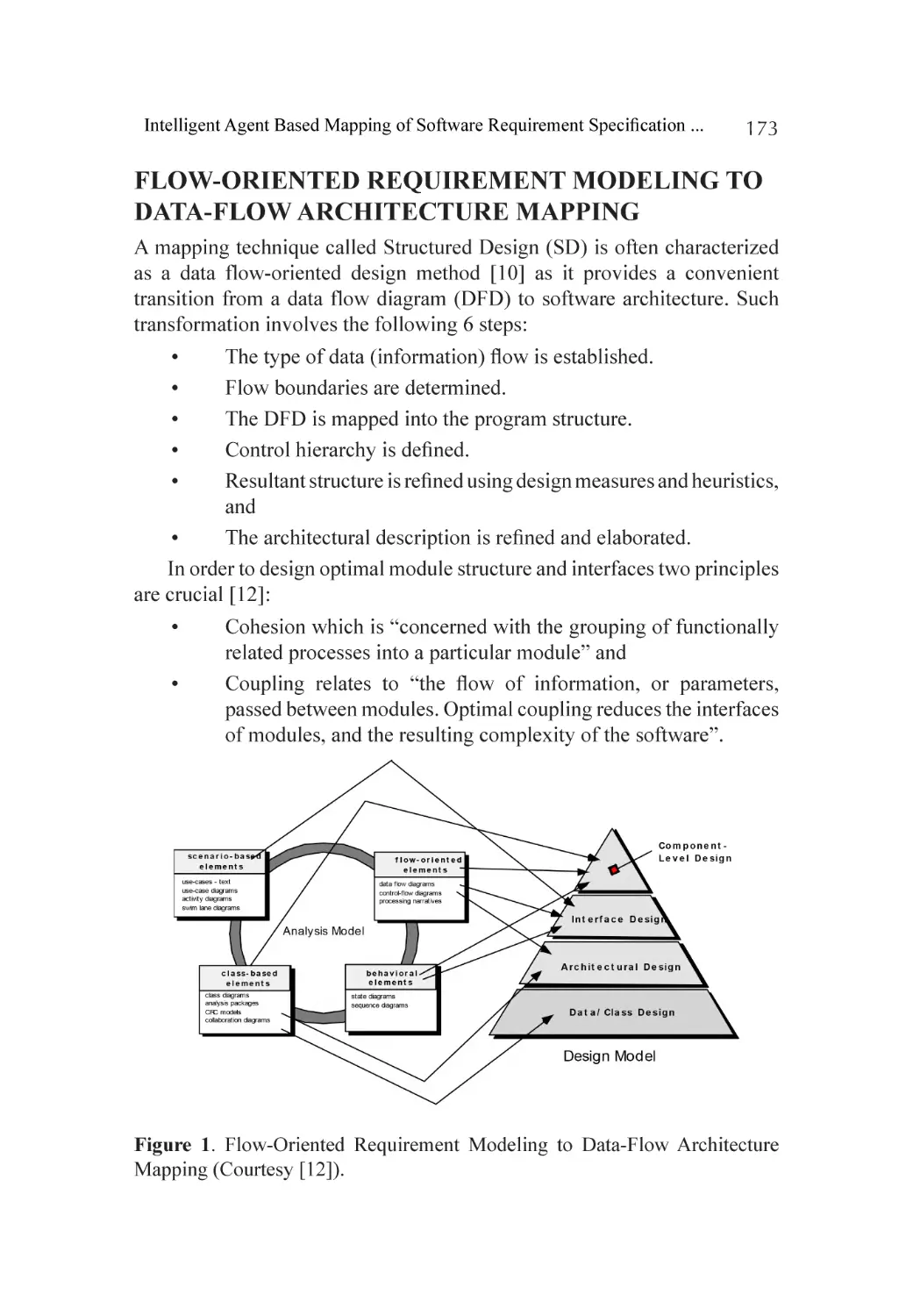
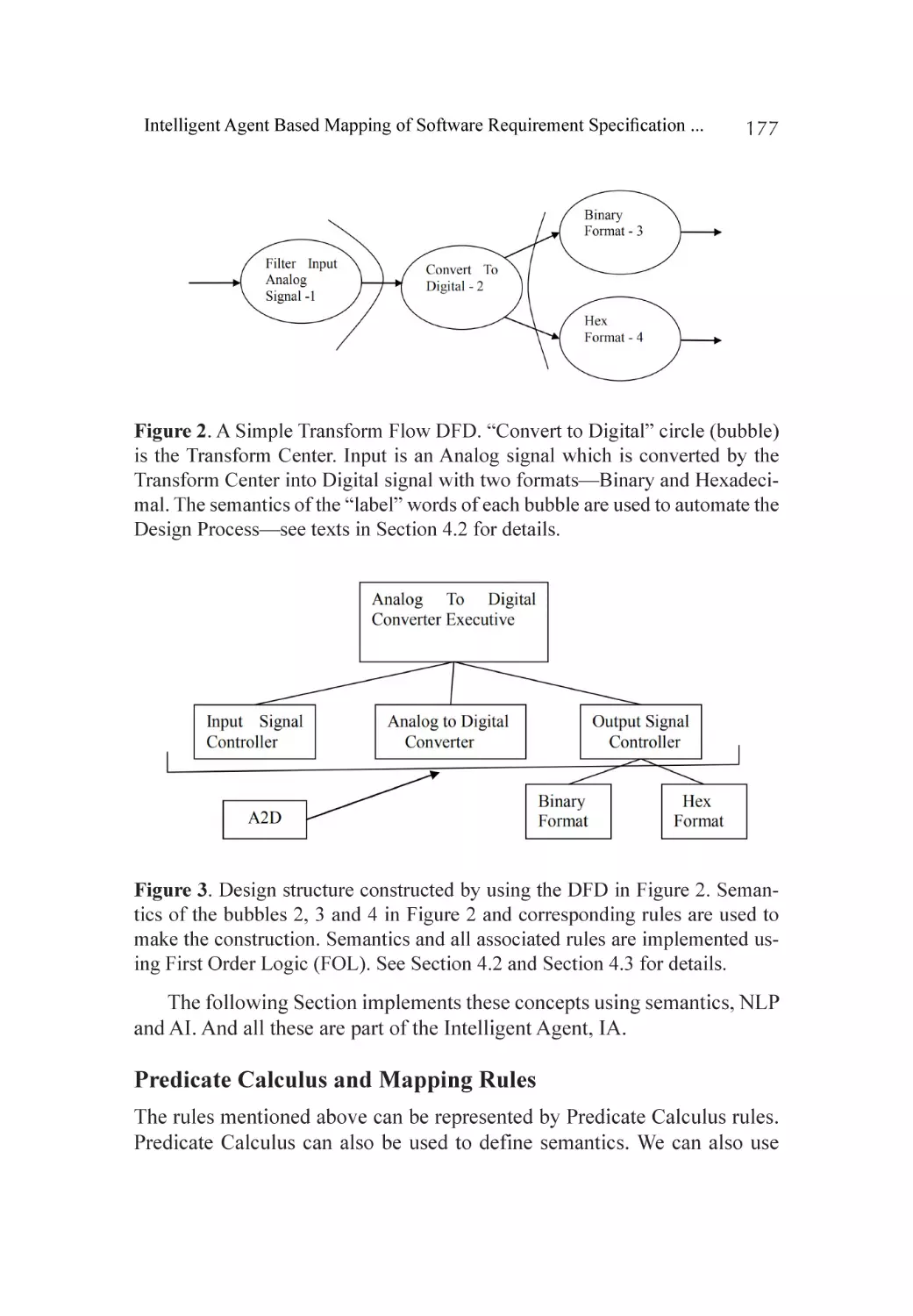
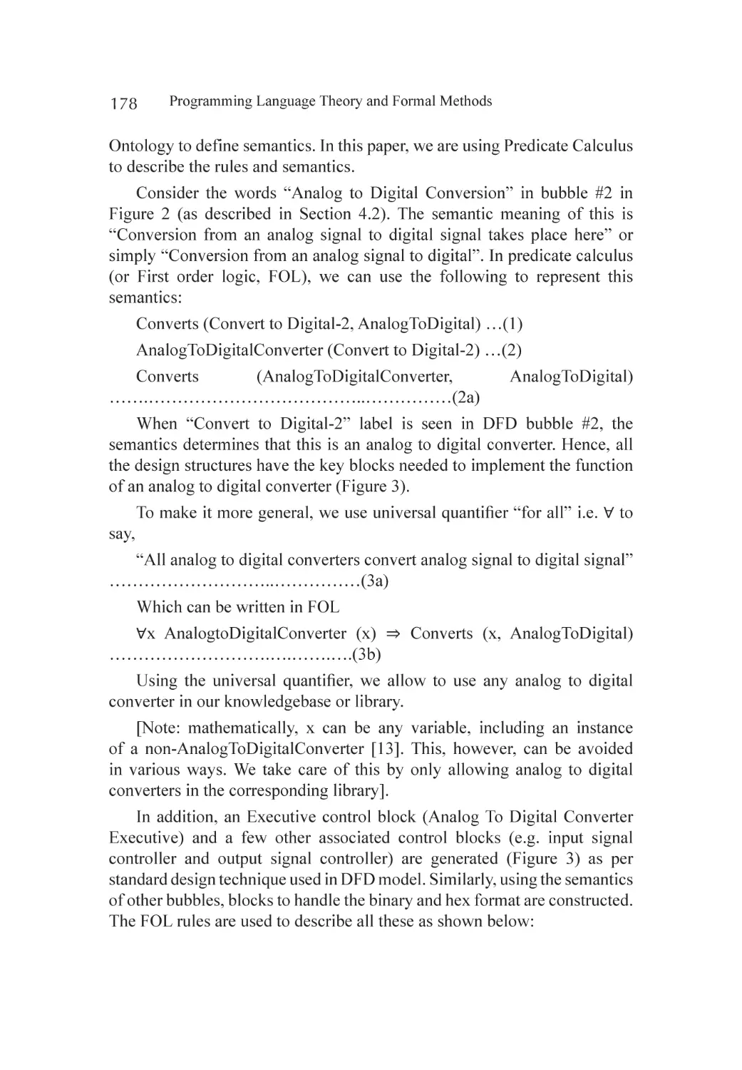
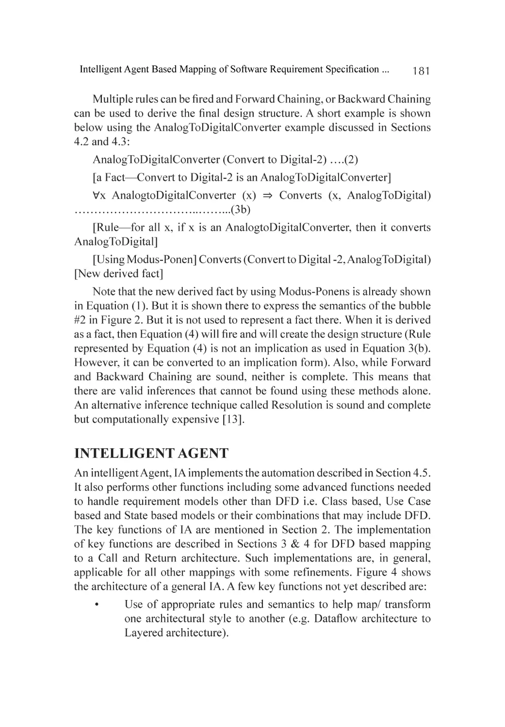
High Level Overview of IRTDM.............................................................. 172
Flow-Oriented Requirement Modeling to Data-Flow
Architecture Mapping................................................................... 173
Automating Flow-Oriented Requirement Modeling to Data-Flow
Architecture Mapping................................................................... 174
Intelligent Agent..................................................................................... 181
Future Works.......................................................................................... 183
Conclusions............................................................................................ 183
References.............................................................................................. 185
Section 3 - Finite Automata
Chapter 10 The Equivalent Conversion between Regular Grammar
and Finite Automata............................................................................... 189
Abstract.................................................................................................. 189
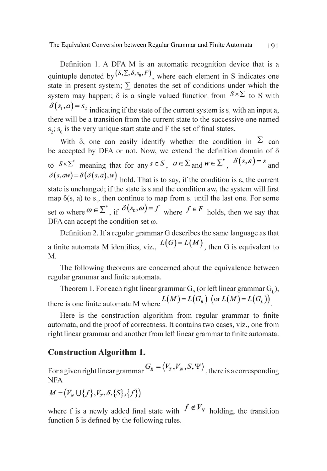
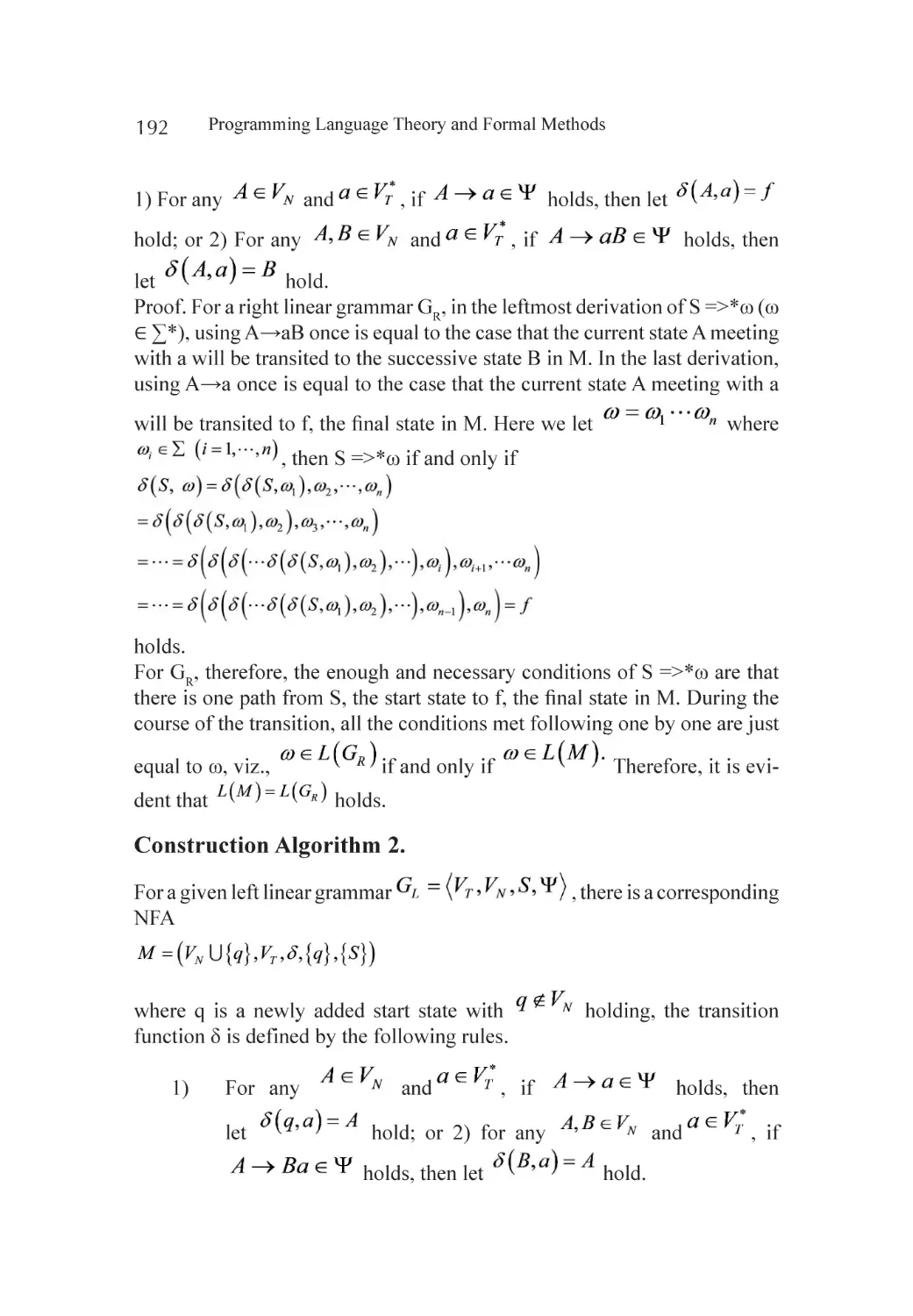
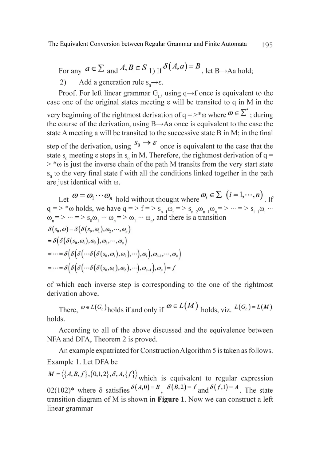
Introduction............................................................................................ 190
Some Equivalent Conversion Algorithms between Regular
Grammar and Finite Automata...................................................... 190
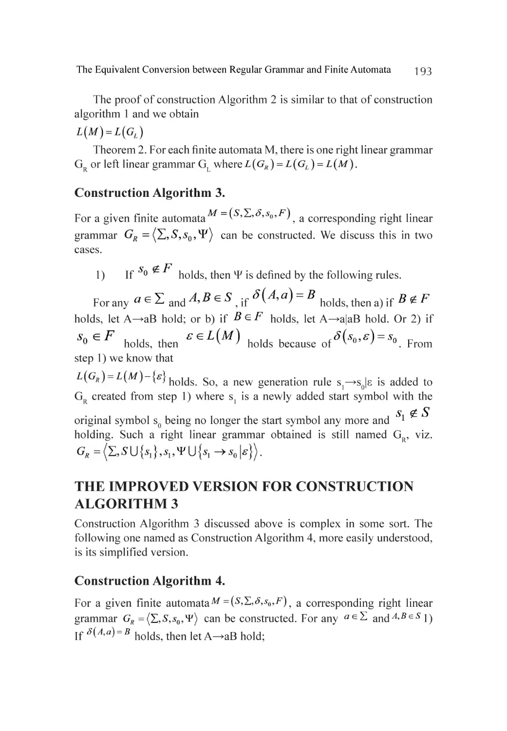
The Improved Version for Construction Algorithm 3................................ 193
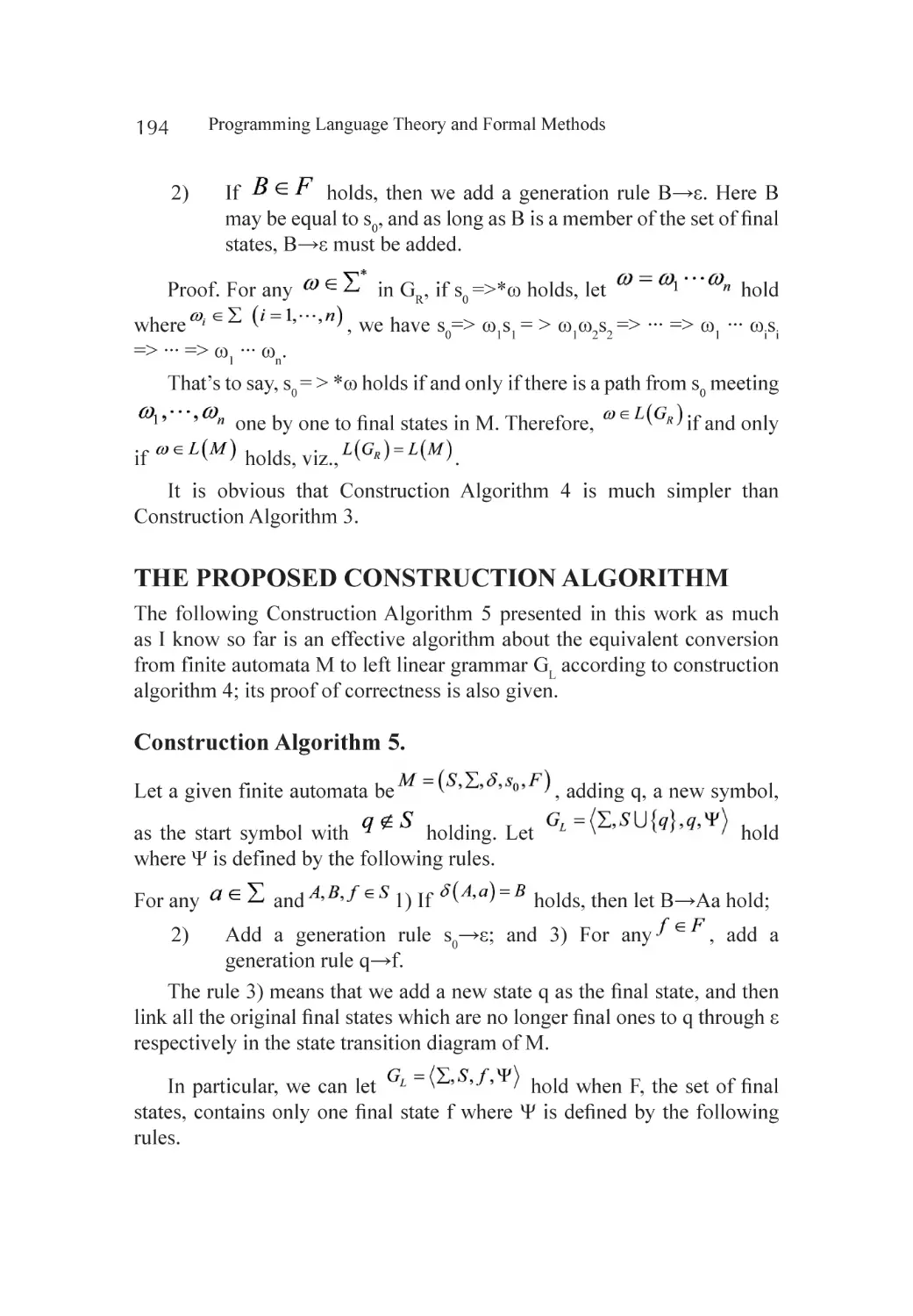
The Proposed Construction Algorithm..................................................... 194
Related Work.......................................................................................... 196
Concluding Remarks............................................................................... 198
Acknowledgements................................................................................ 198
References.............................................................................................. 199
Chapter 11 Controllability, Reachability, and Stabilizability of Finite
Automata: A Controllability Matrix Method........................................... 201
Abstract.................................................................................................. 201
Introduction............................................................................................ 202
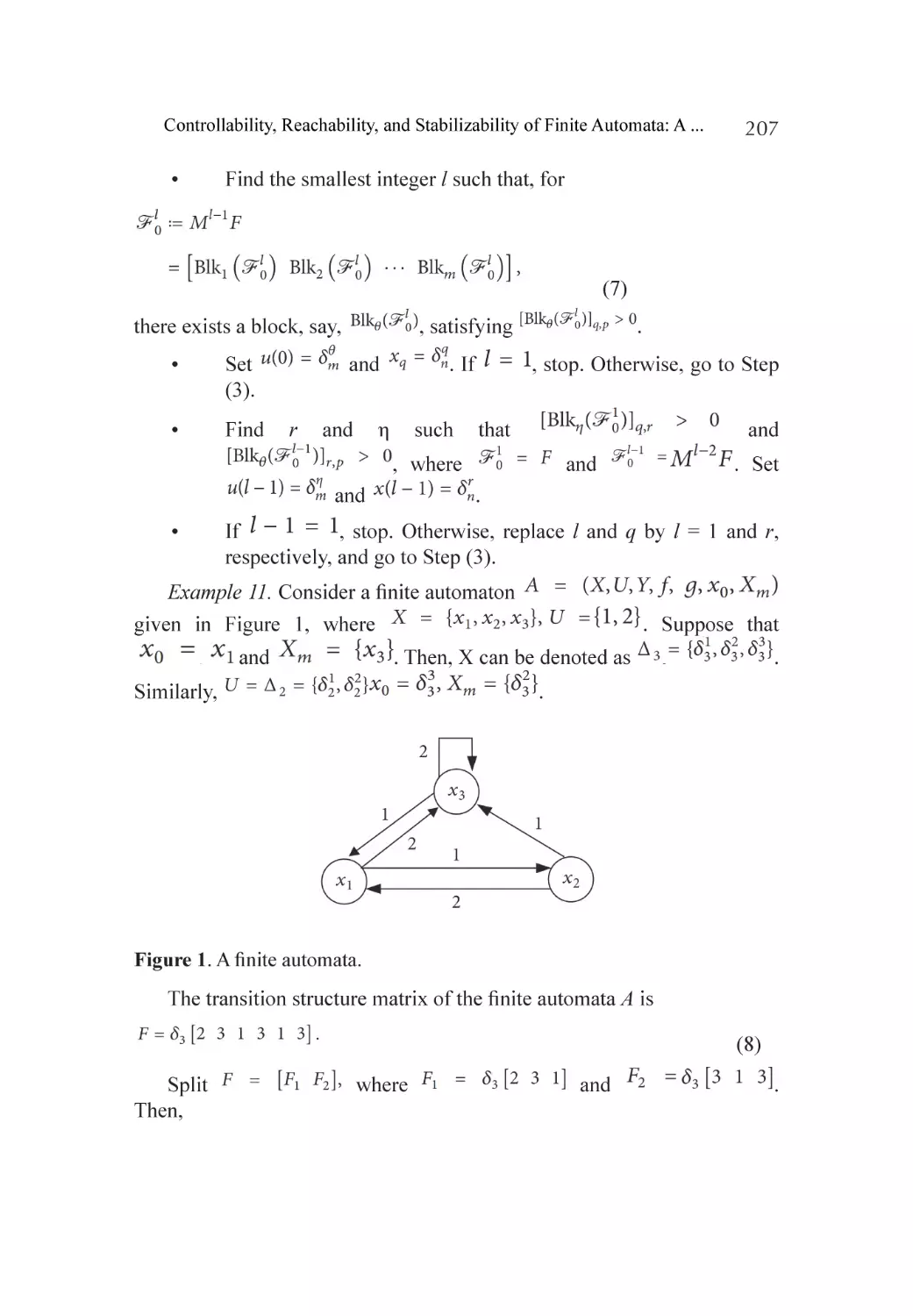
Preliminaries........................................................................................... 203
Main Results........................................................................................... 205
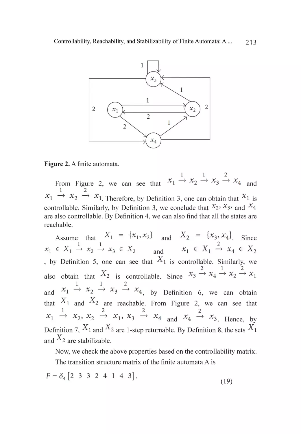
An Illustrative Example........................................................................... 212
Conclusion............................................................................................. 214
Acknowledgments.................................................................................. 215
References.............................................................................................. 216
xii
Chapter 12 Bounded Model Checking of ETL Cooperating with
Finite and Looping Automata Connectives............................................. 221
Abstract.................................................................................................. 221
Introduction............................................................................................ 222
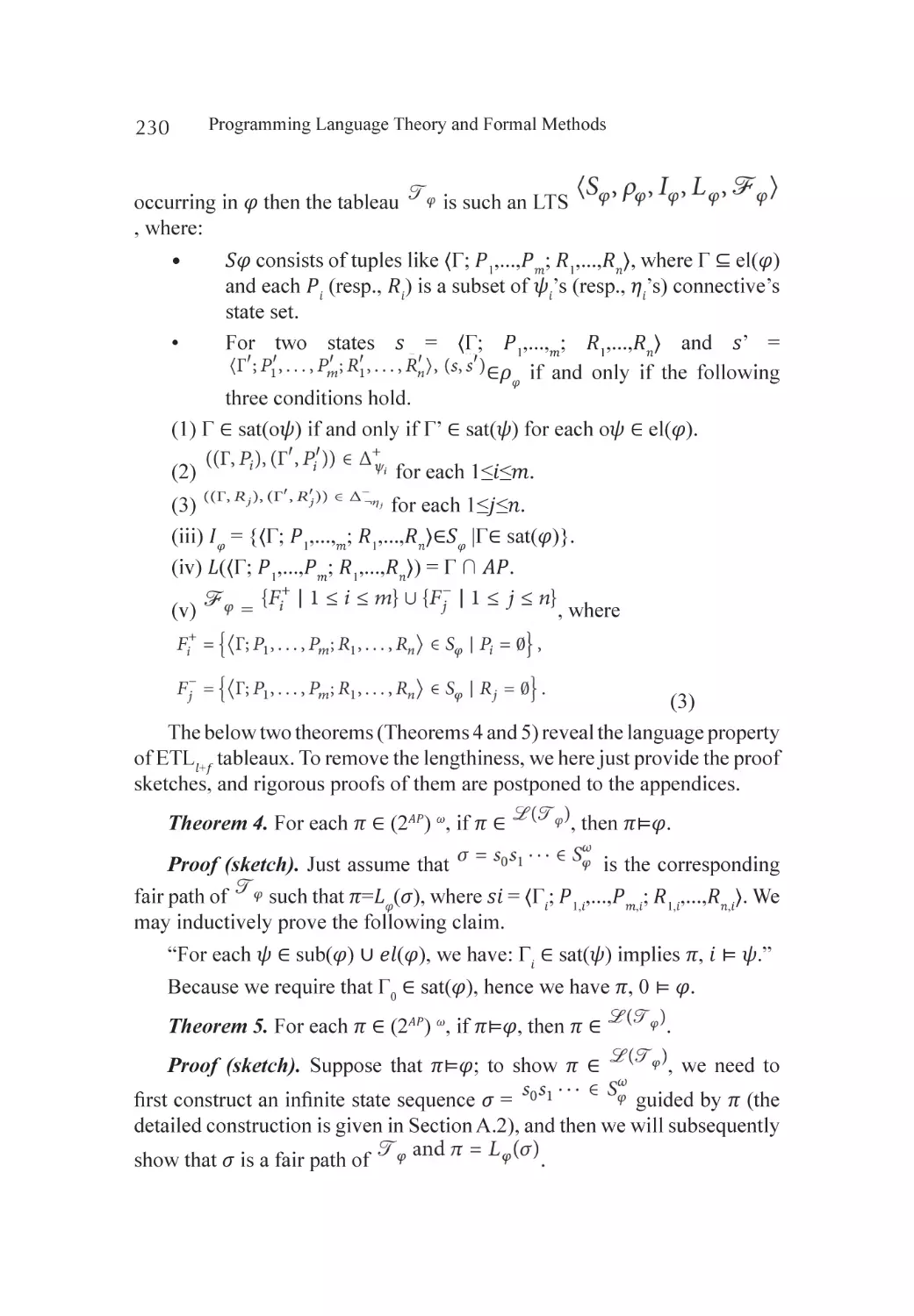
Preliminaries........................................................................................... 224
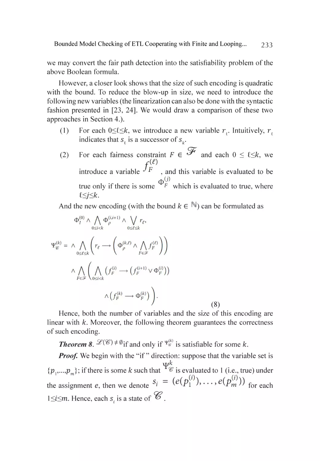
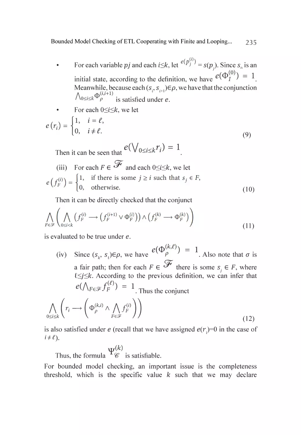
Semantic BMC Encoding for Etl𝑙+F........................................................... 228
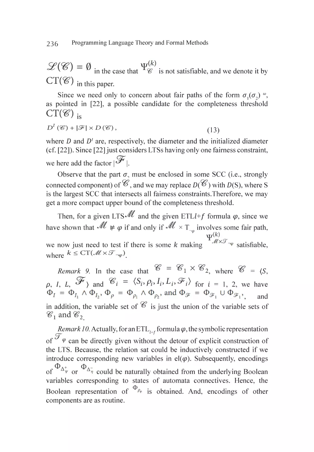
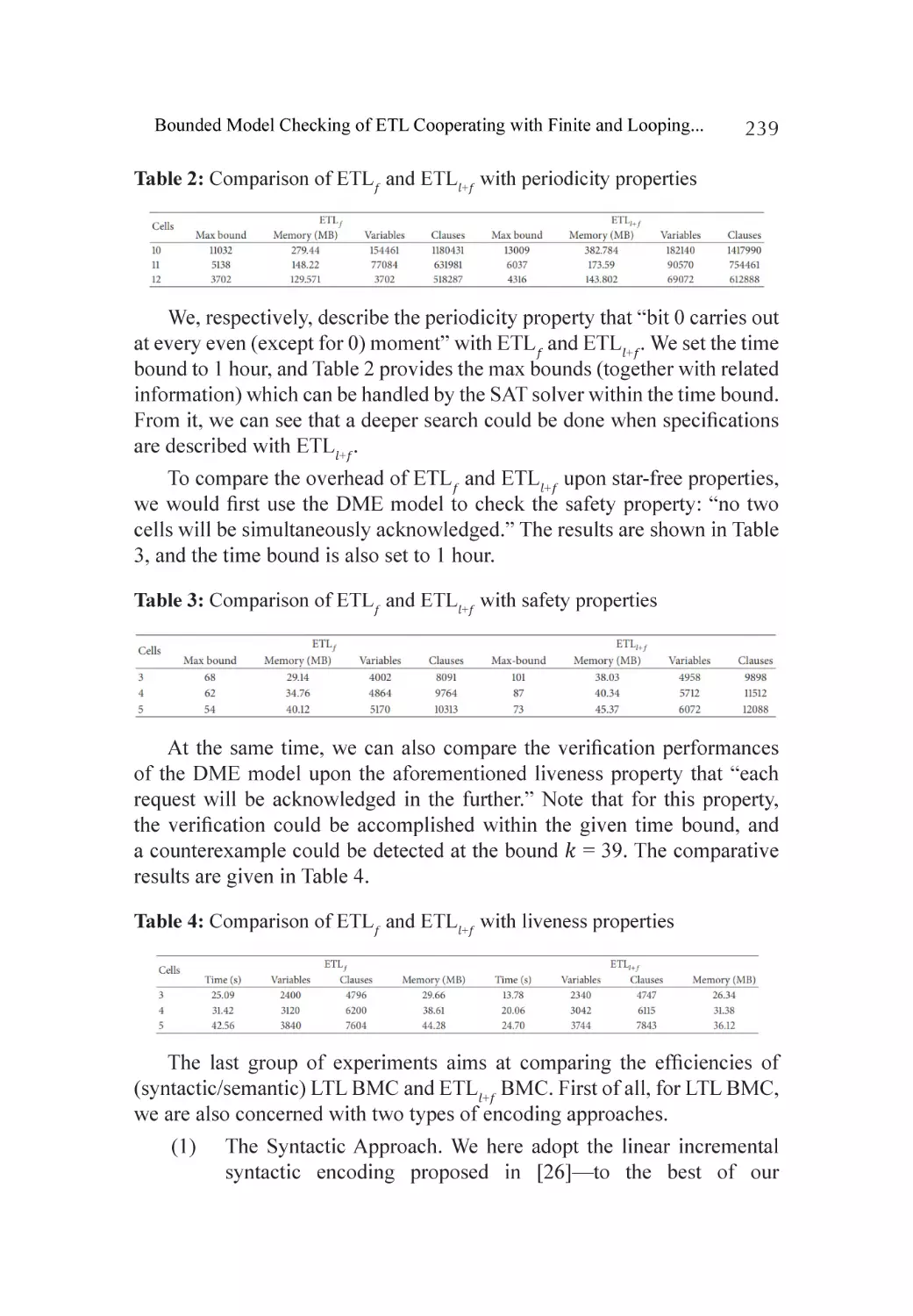
Experimental Results............................................................................... 237
Concluding Remarks............................................................................... 240
References.............................................................................................. 242
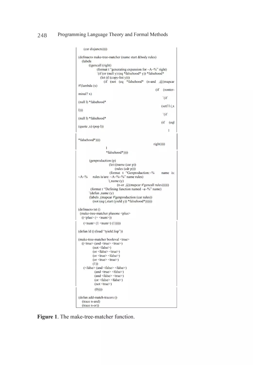
Chapter 13 An Automata-Based Approach to Pattern Matching............................... 245
Abstract.................................................................................................. 245
Introduction............................................................................................ 246
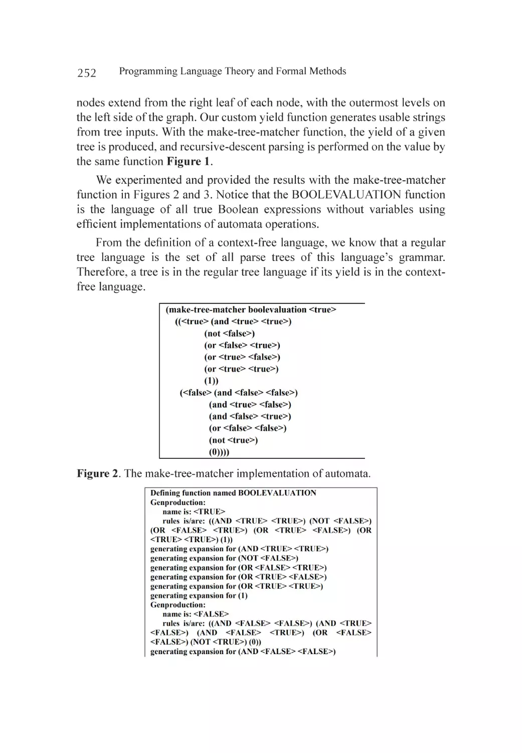
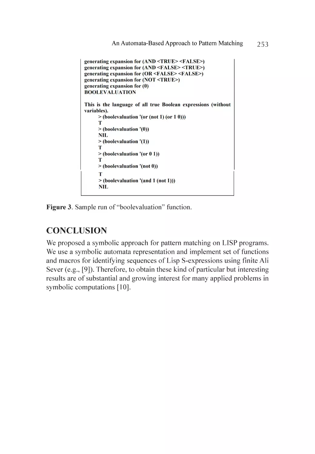
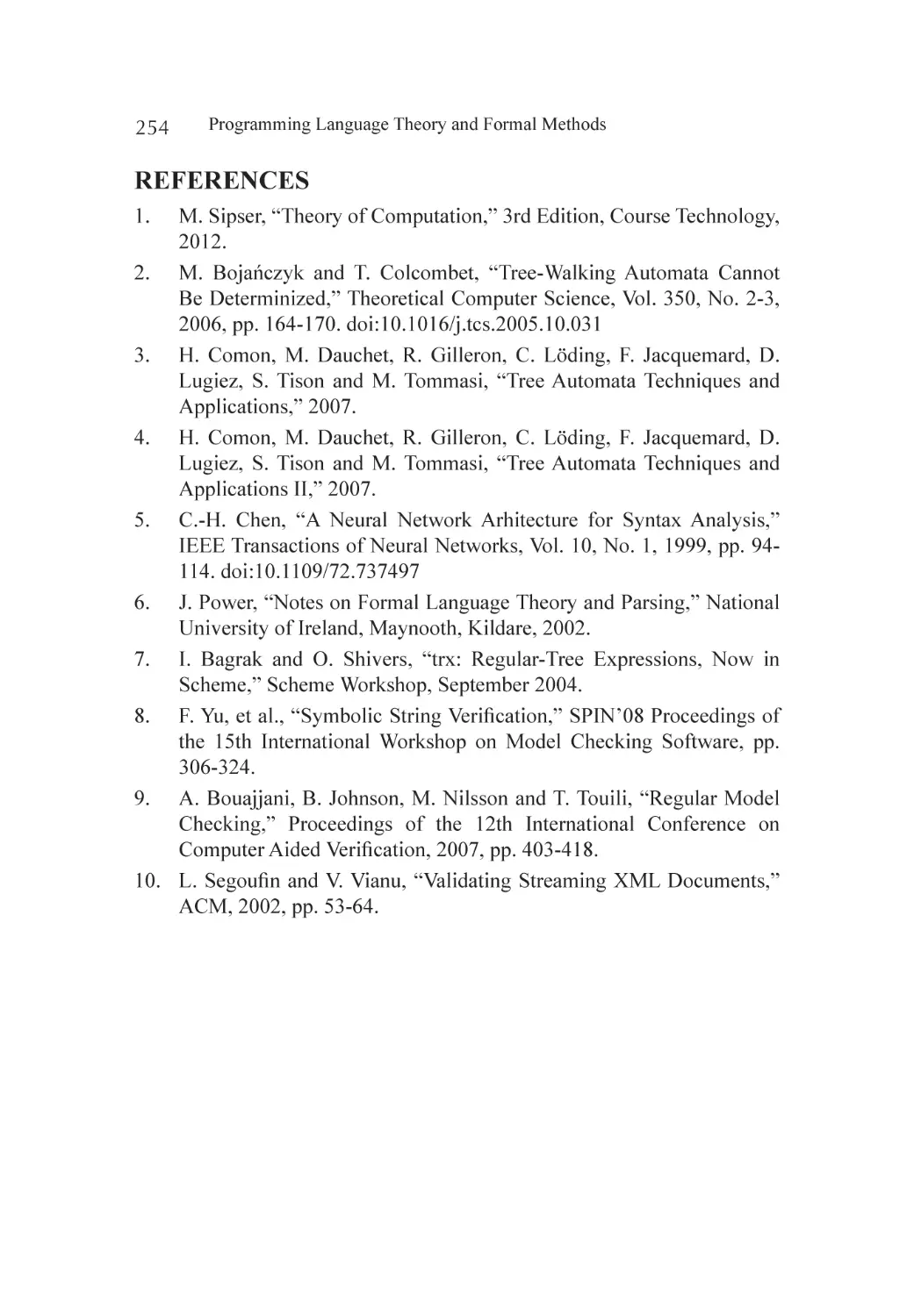
Analysis.................................................................................................. 250
Experiments............................................................................................ 251
Conclusion............................................................................................. 253
References.............................................................................................. 254
Section 4 - Formal methods and Semantics in distributed software
Chapter 14 Building Requirements Semantics for Networked
Software Interoperability....................................................................... 257
Abstract.................................................................................................. 257
Introduction............................................................................................ 258
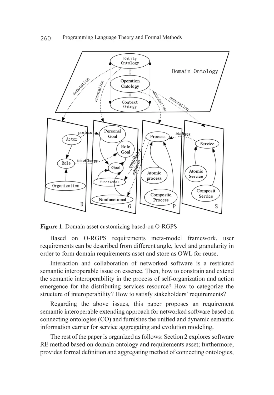
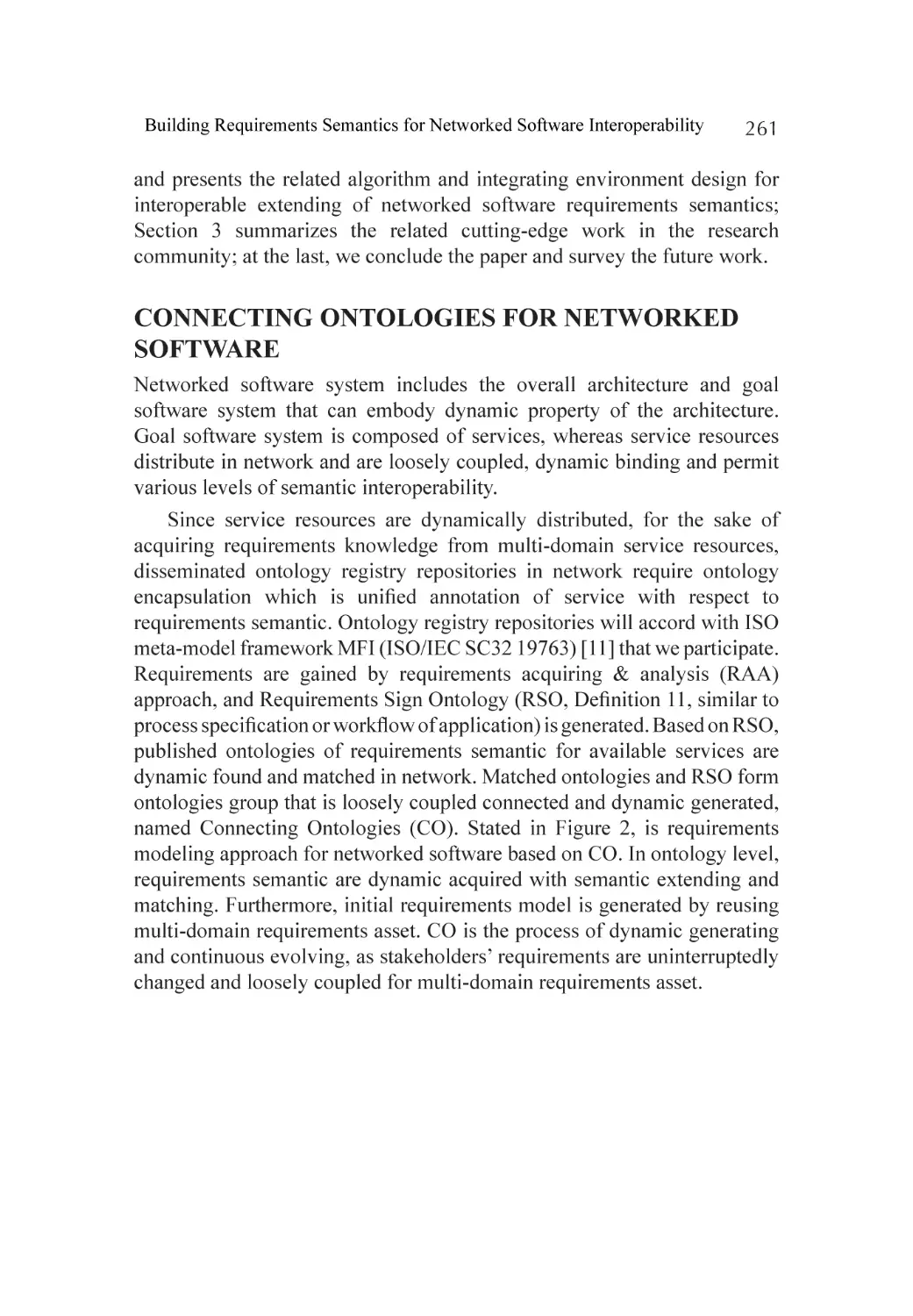
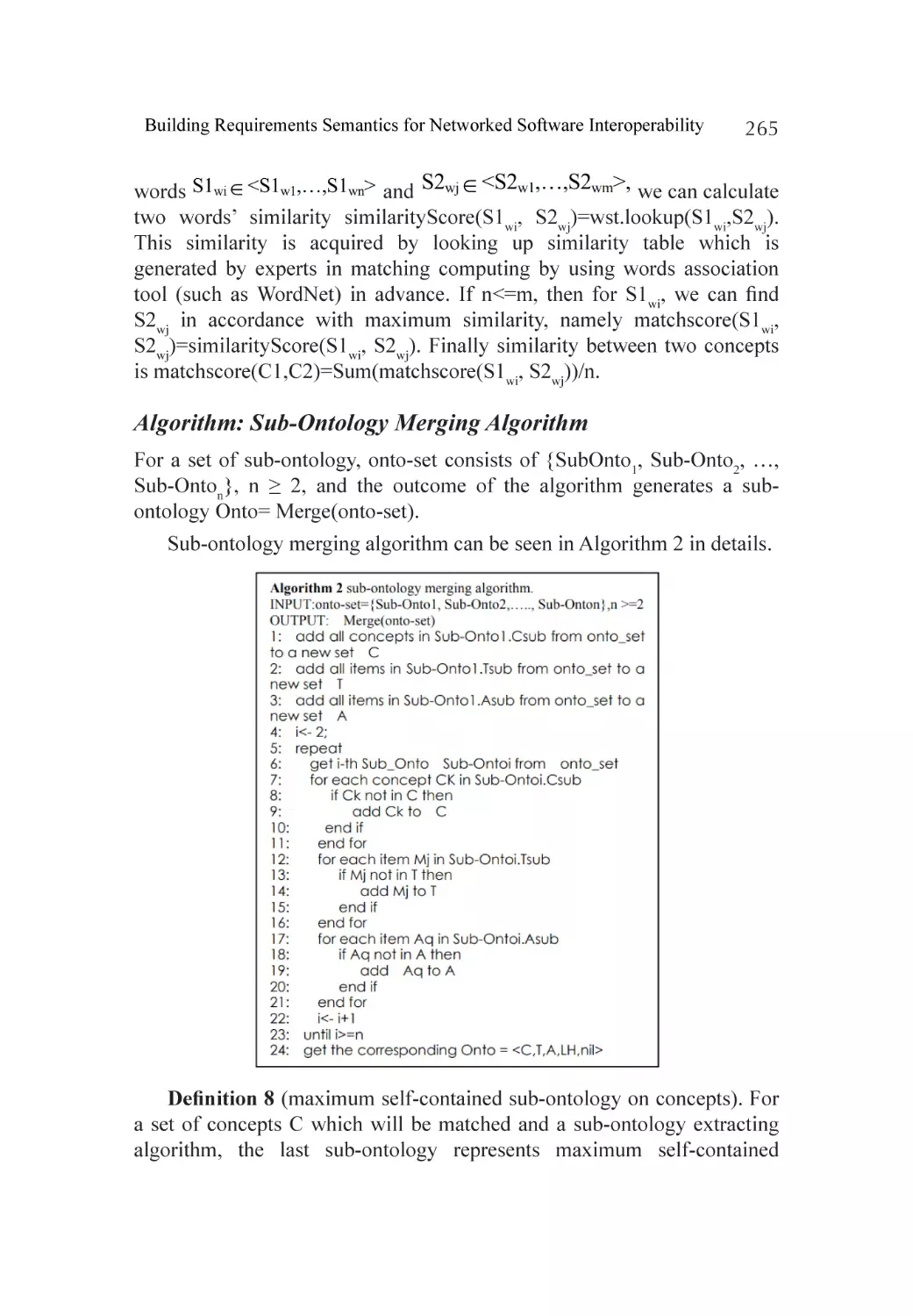
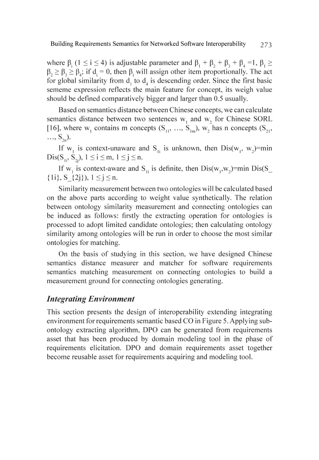
Connecting Ontologies for Networked Software..................................... 261
Related Work.......................................................................................... 275
Conclusions............................................................................................ 276
Acknowledgments.................................................................................. 277
References.............................................................................................. 278
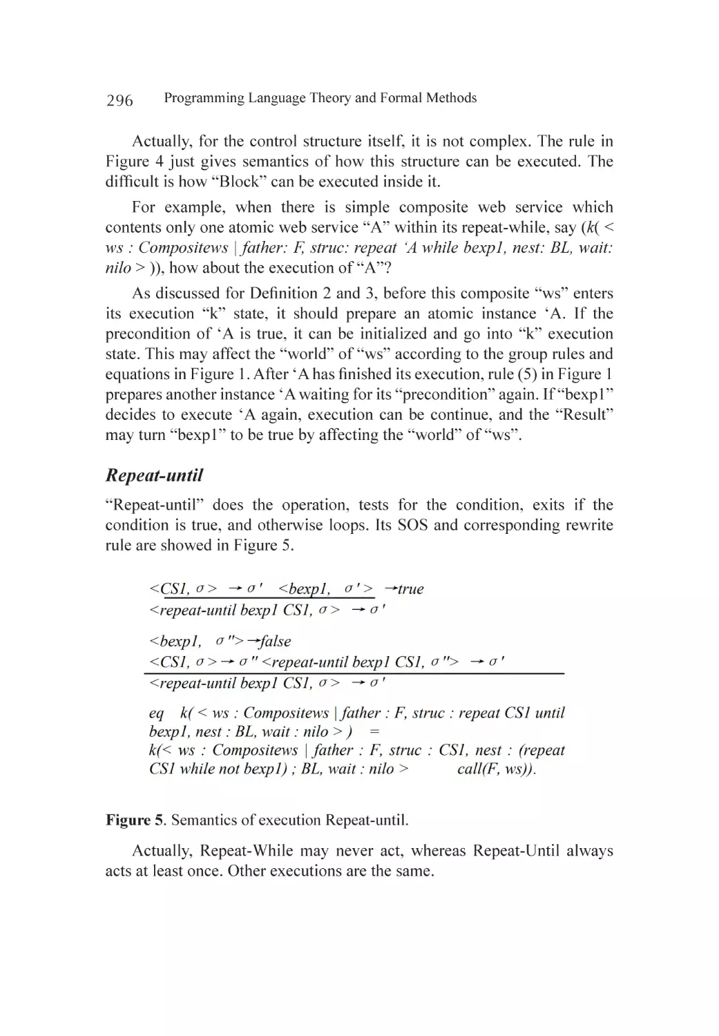
Chapter 15 Formal Semantics of OWL-S with Rewrite Logic.................................... 281
Abstract.................................................................................................. 281
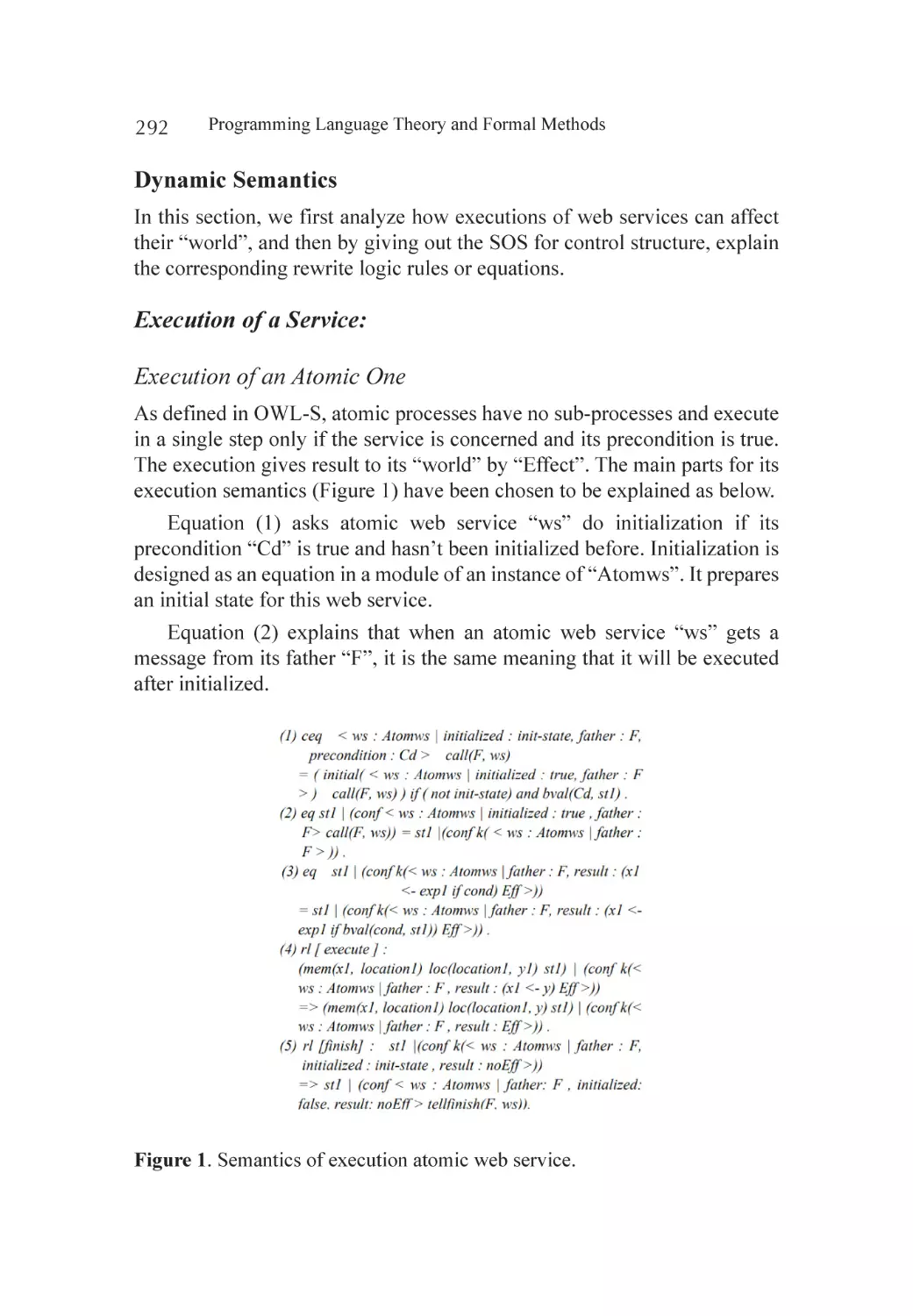
Introduction............................................................................................ 282
Related Works........................................................................................ 283
Background............................................................................................ 284
Abstraction of the Model........................................................................ 286
Dynamic Semantics in Maude................................................................ 291
xiii
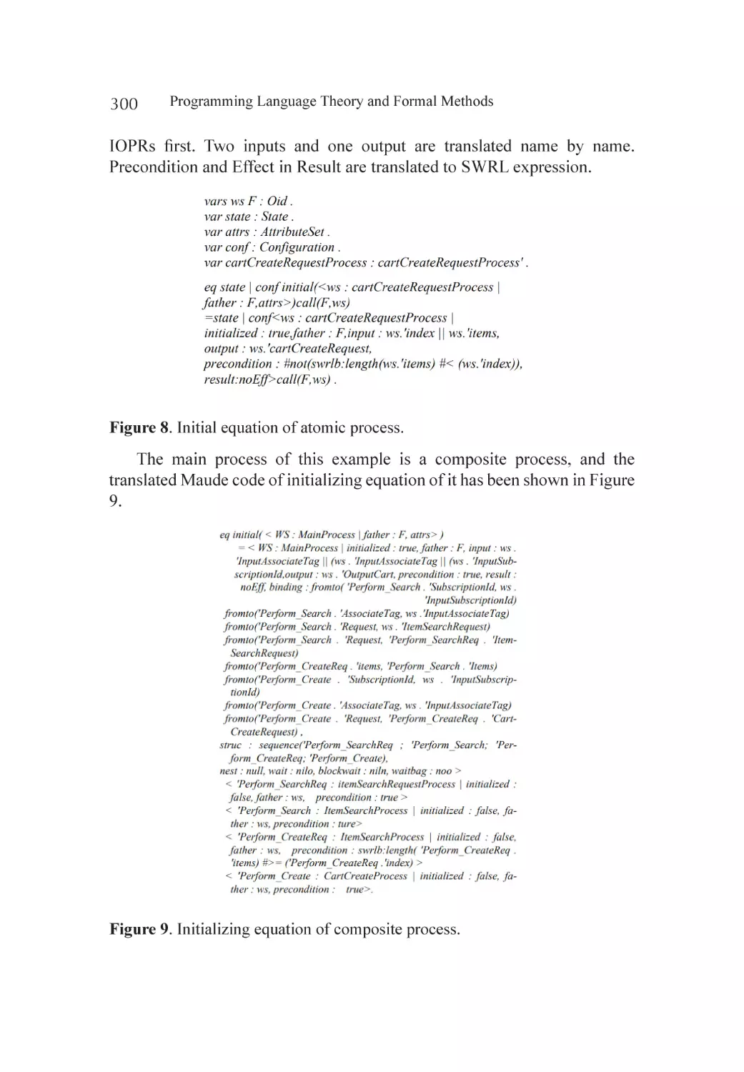
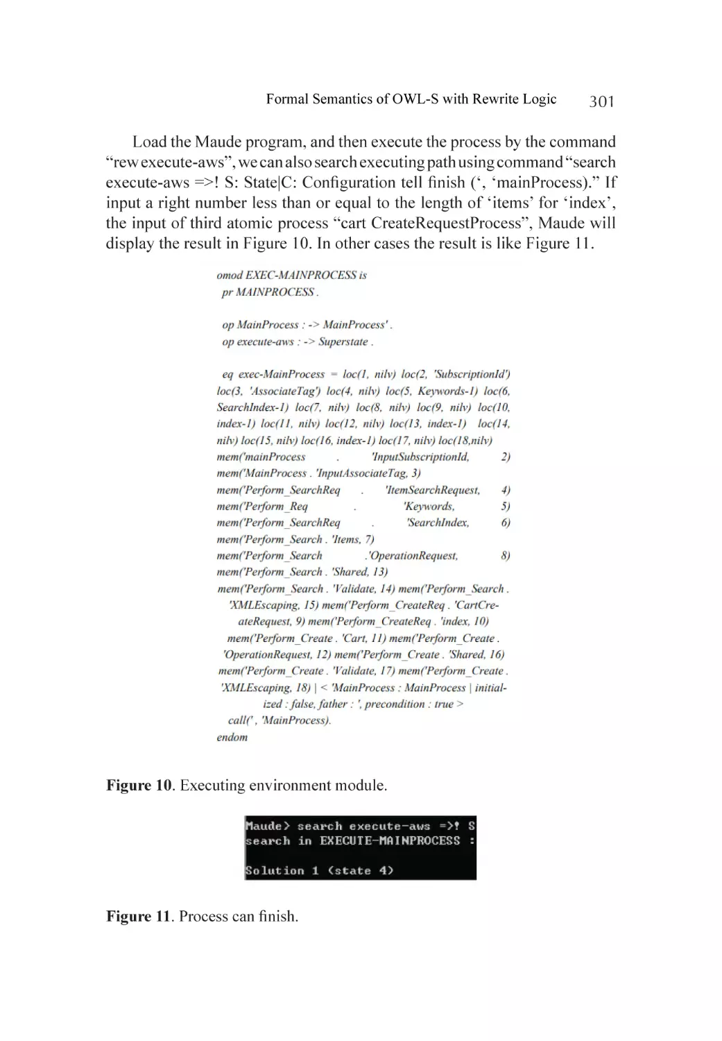
Case Study.............................................................................................. 298
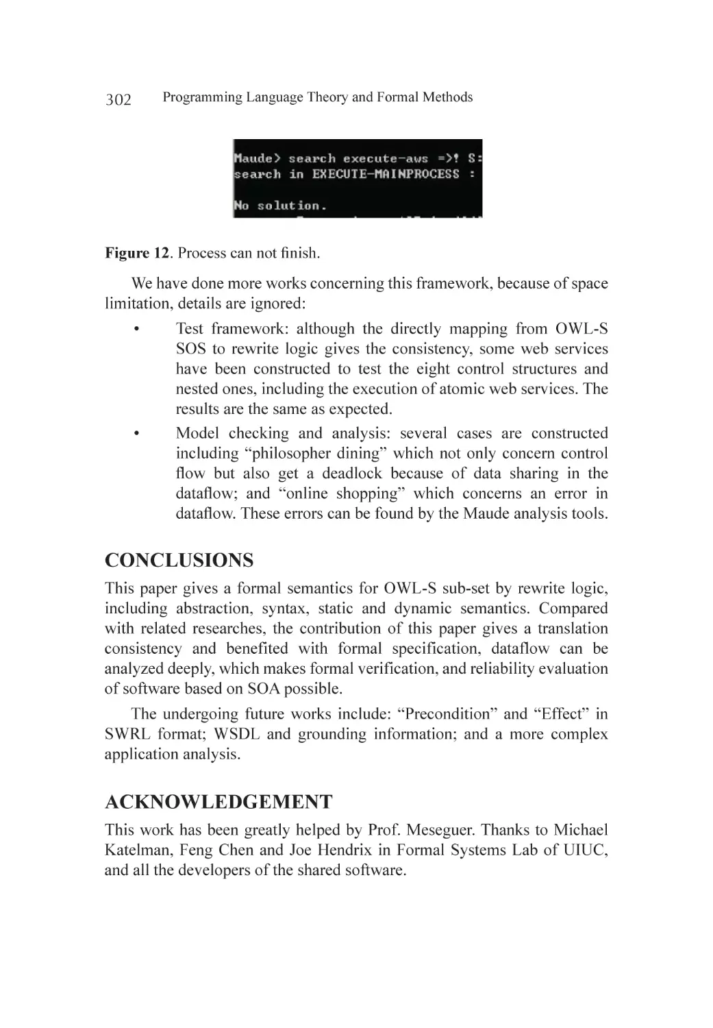
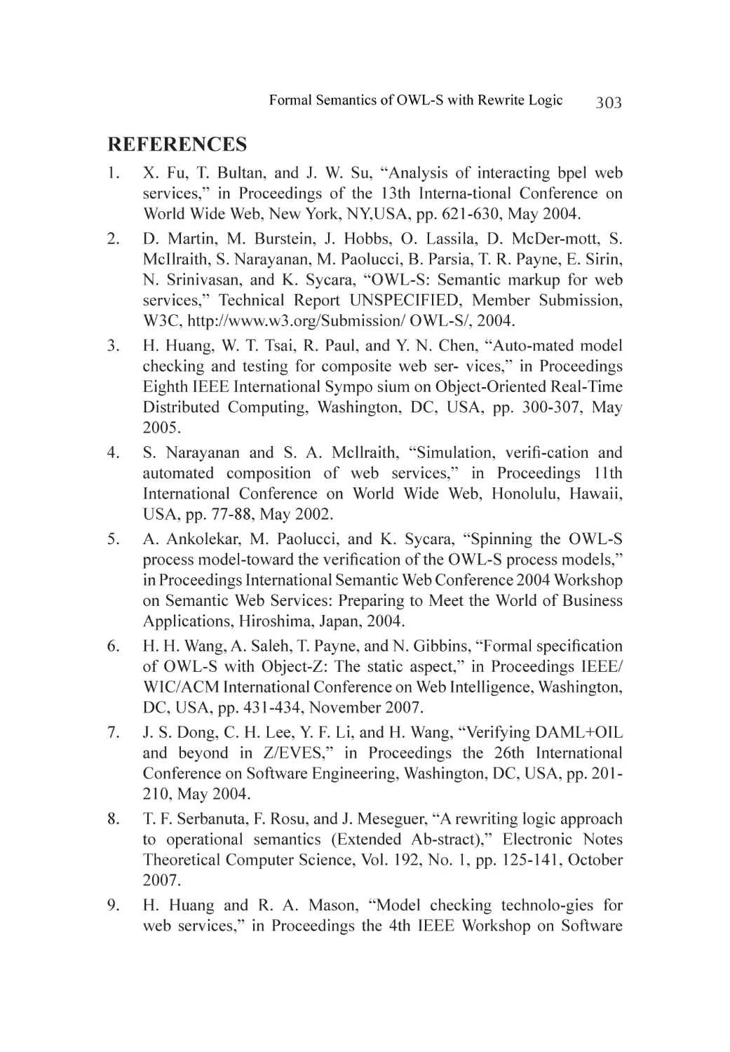
Conclusions............................................................................................ 302
Acknowledgement.................................................................................. 302
References.............................................................................................. 303
Chapter 16 Web Semantic and Ontology................................................................. 305
Abstract.................................................................................................. 305
What Do We Represent in an Ontology?................................................ 306
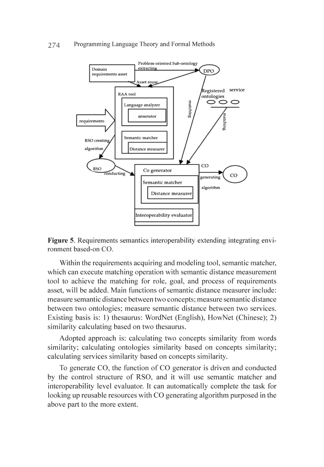
The Web Ontology Language Owl.......................................................... 307
Ontology Language Processors............................................................... 312
Conclusion............................................................................................. 315
References.............................................................................................. 316
Chapter 17 Web Services Conversation Adaptation Using
Conditional Substitution Semantics of Application
Domain Concepts................................................................................... 319
Abstract.................................................................................................. 319
Introduction............................................................................................ 320
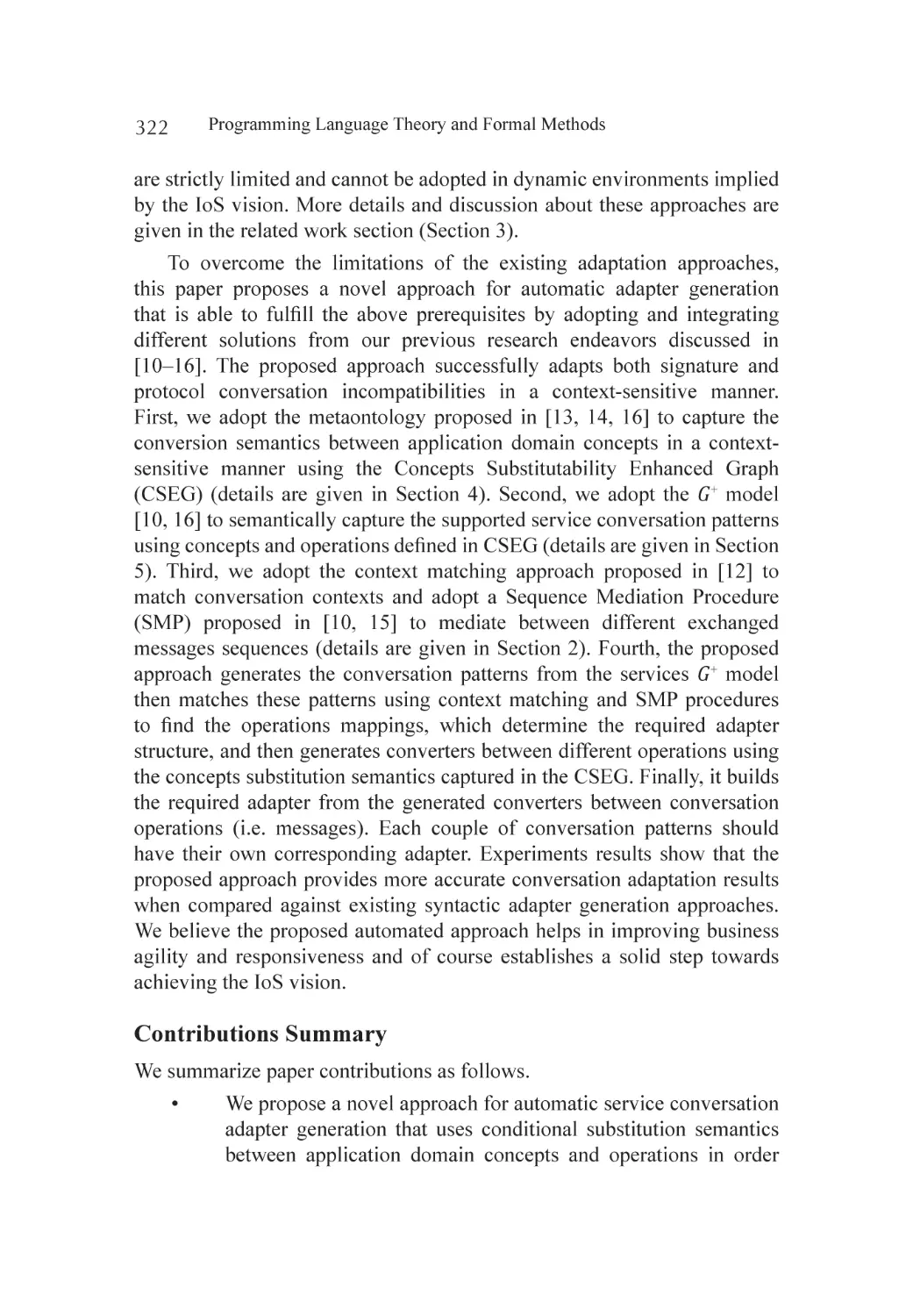
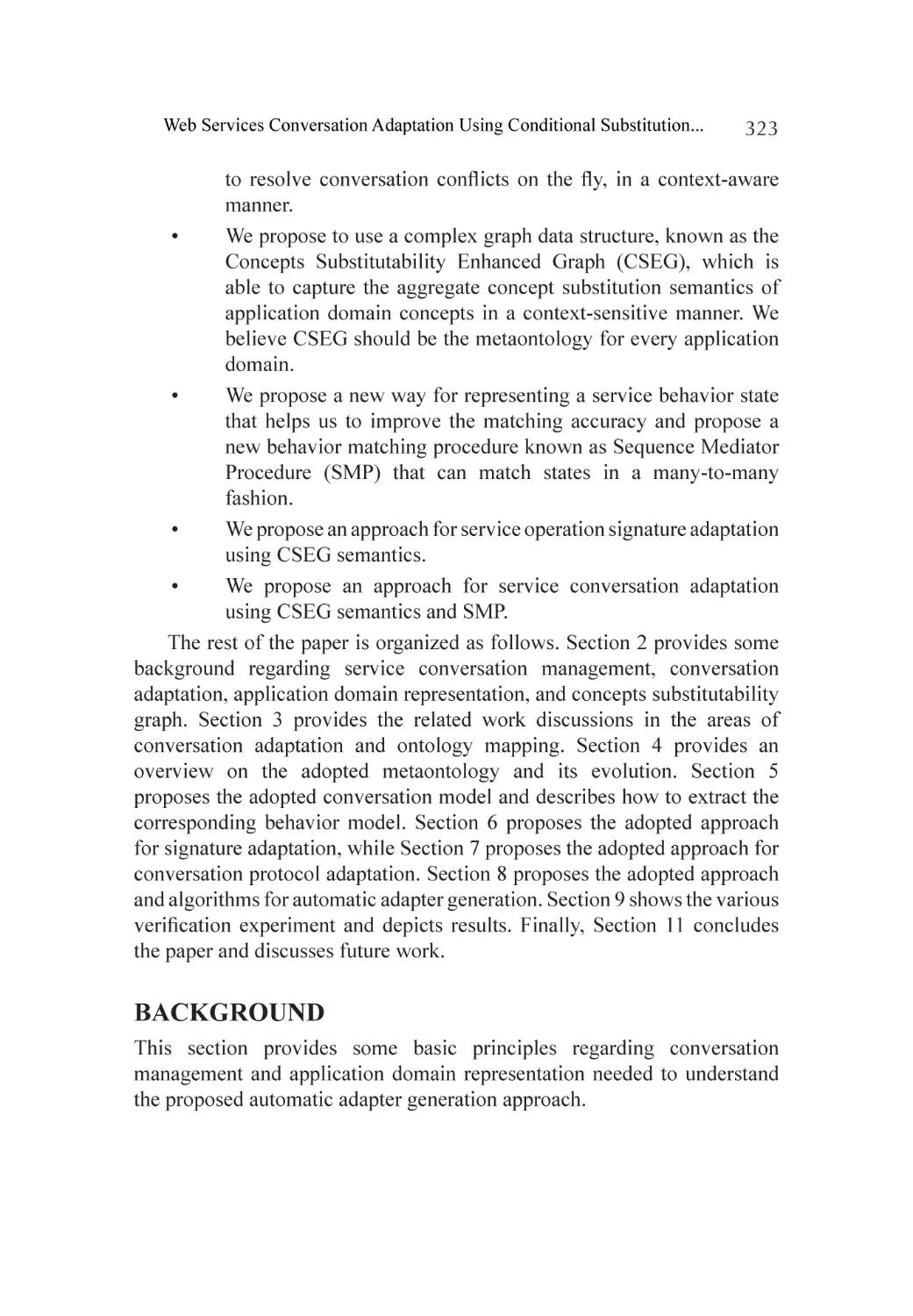
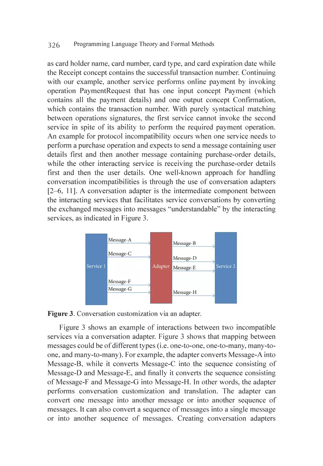
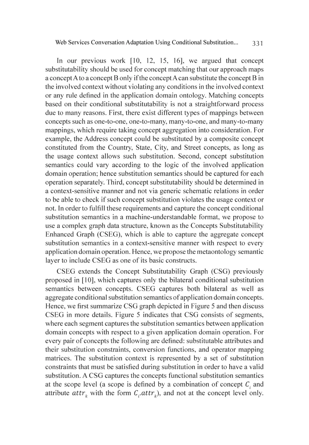
Background............................................................................................ 323
Related Work.......................................................................................... 333
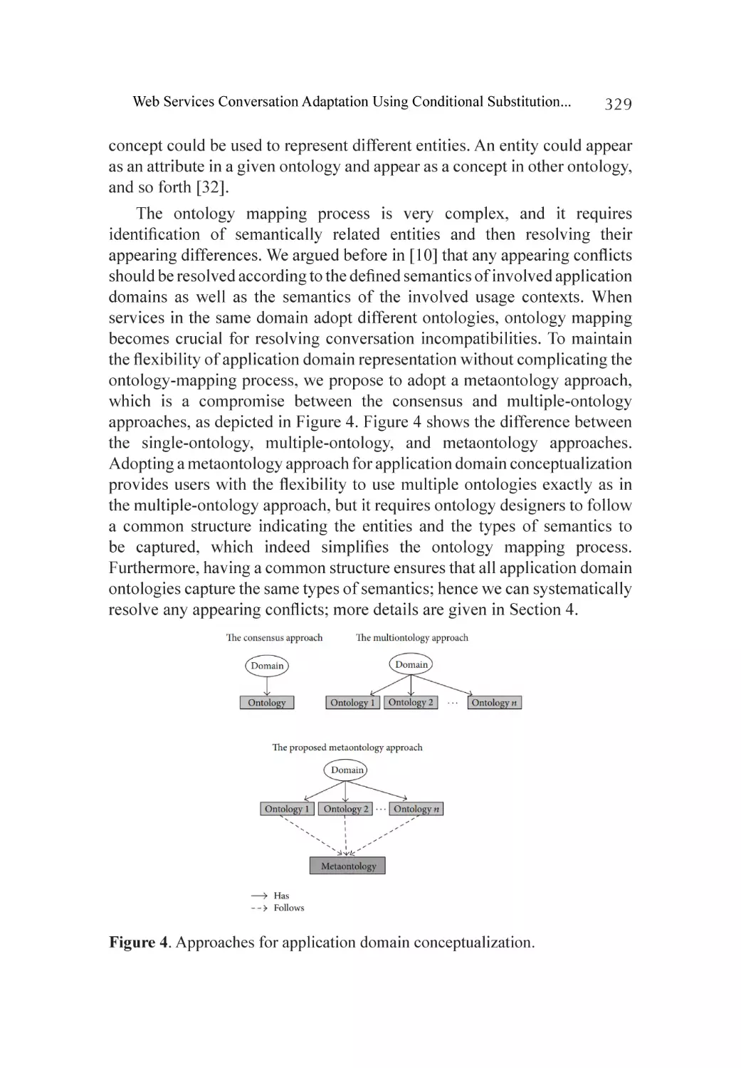
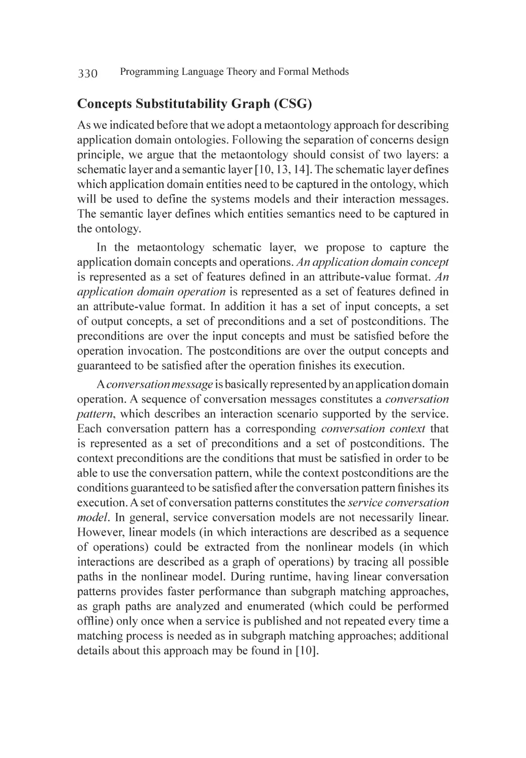
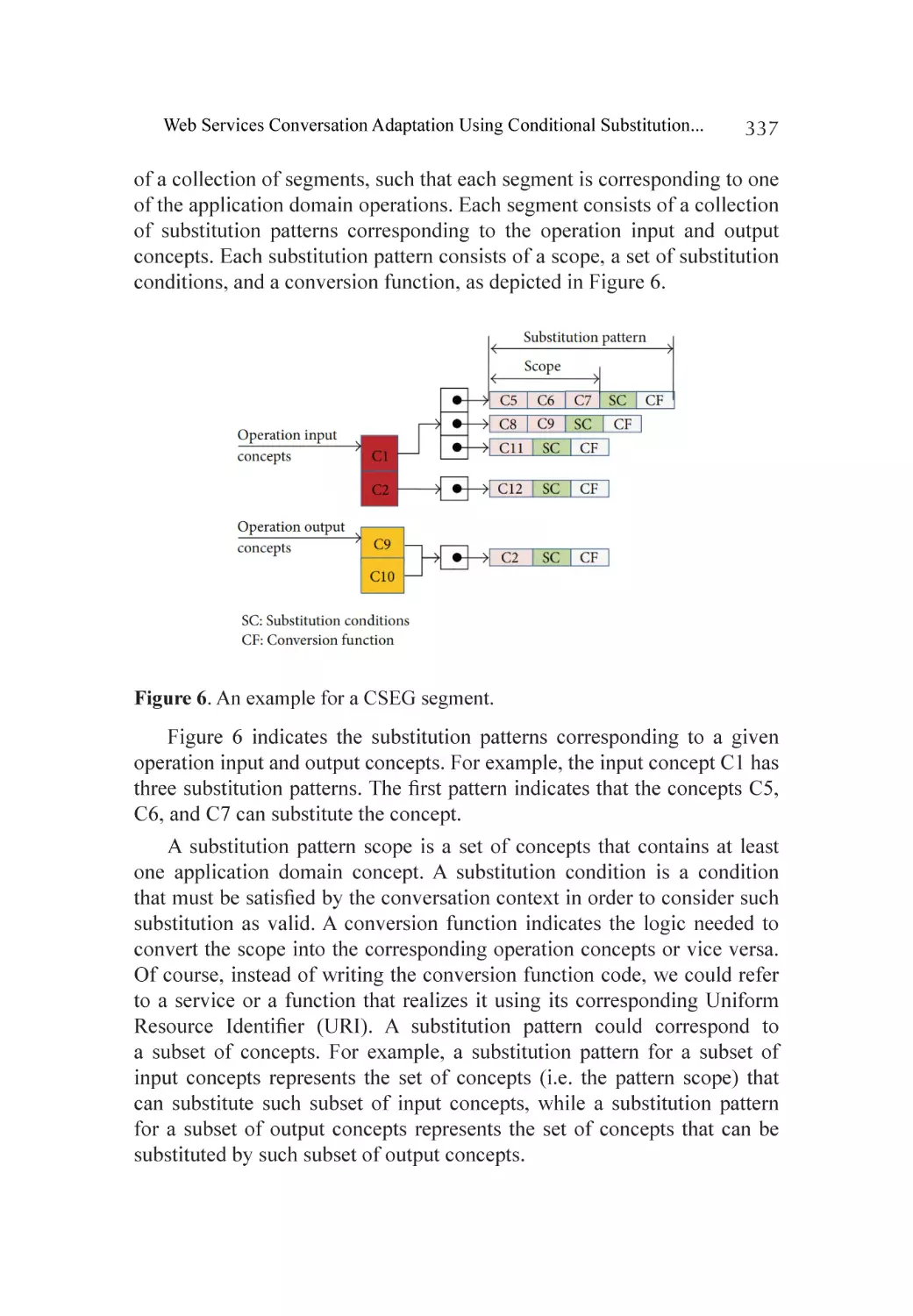
A Context-Sensitive Metaontology for Applications Domains.................. 336
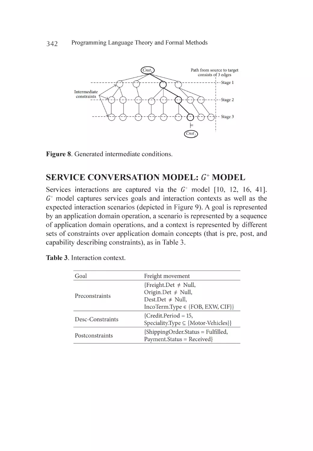
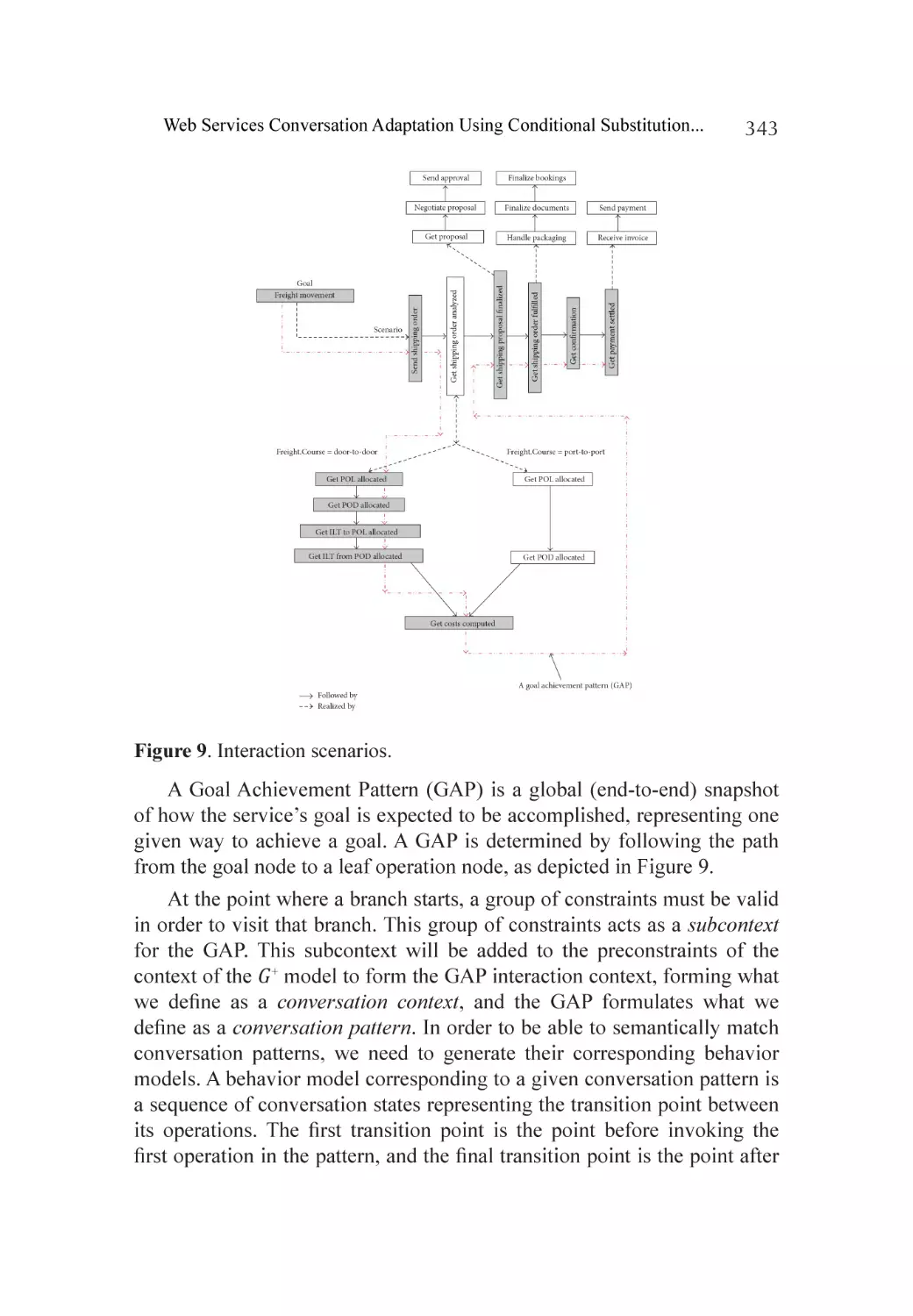
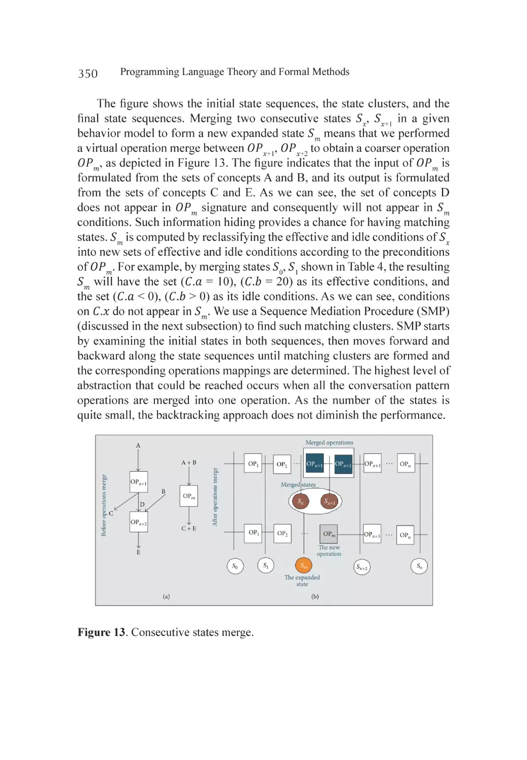
Service Conversation Model: 𝐺+ Model................................................... 342
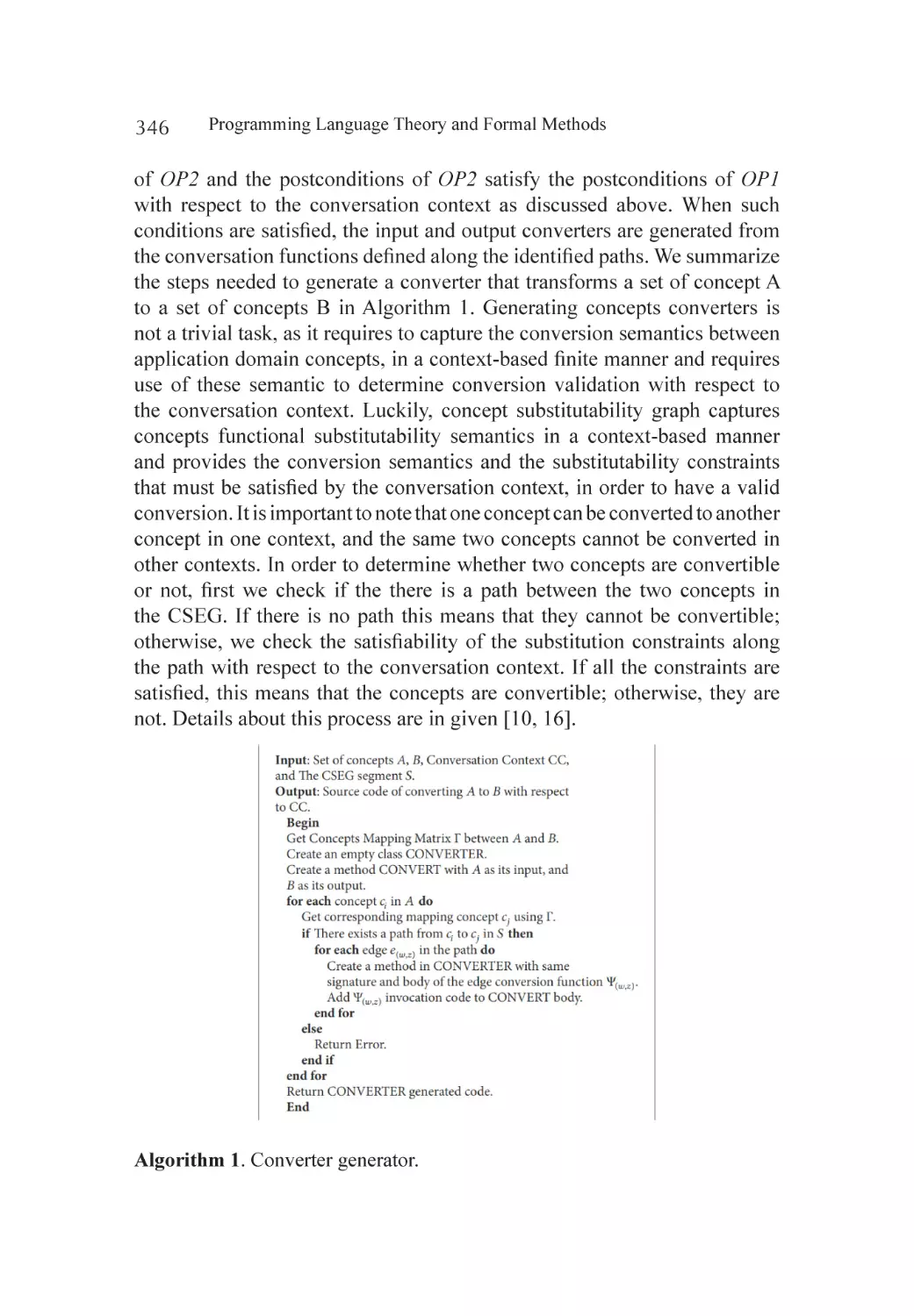
Signature Adaptation.............................................................................. 345
Conversation Protocol Adaptation........................................................... 348
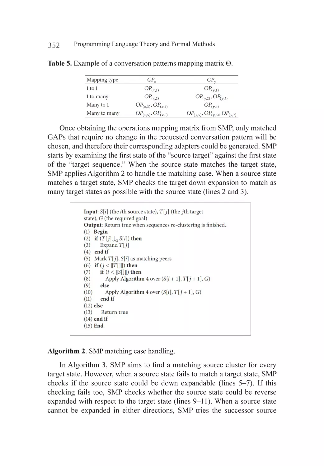
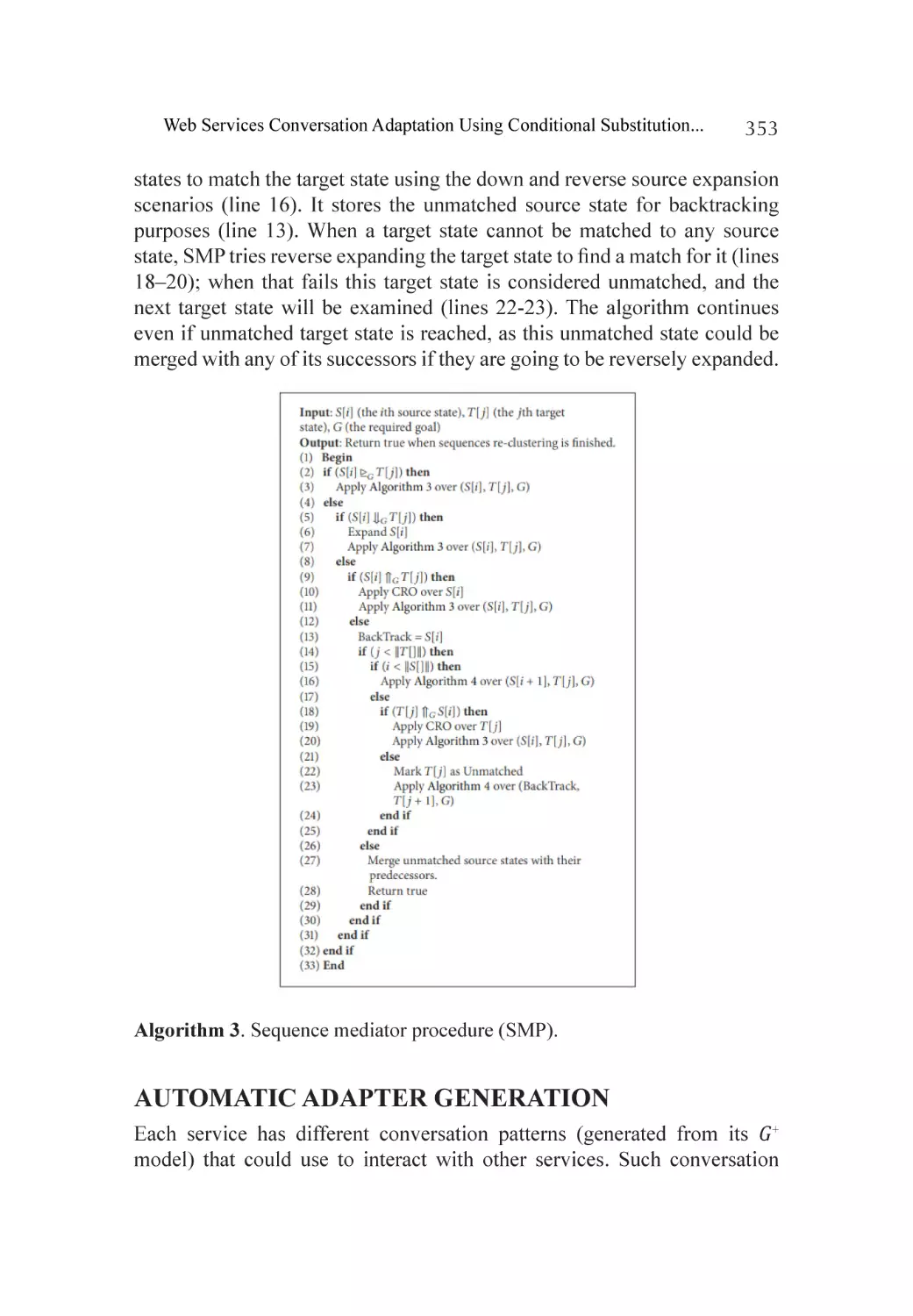
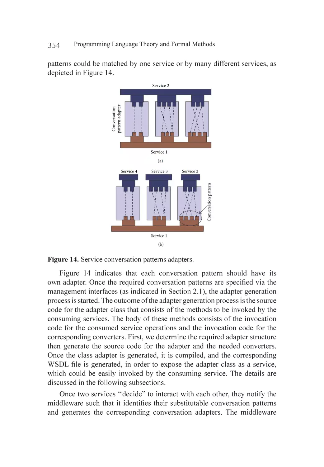
Automatic Adapter Generation............................................................... 353
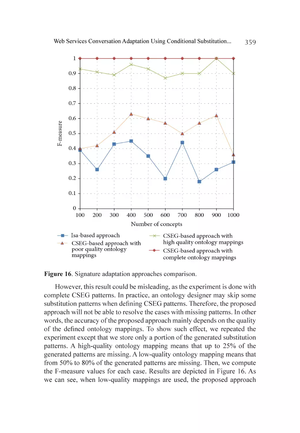
Experiments............................................................................................ 357
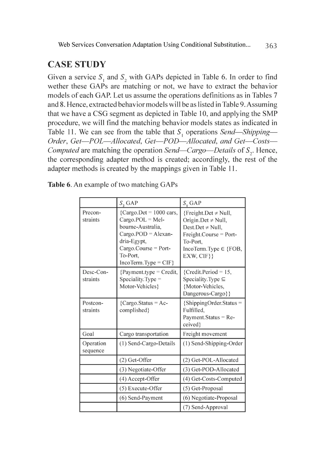
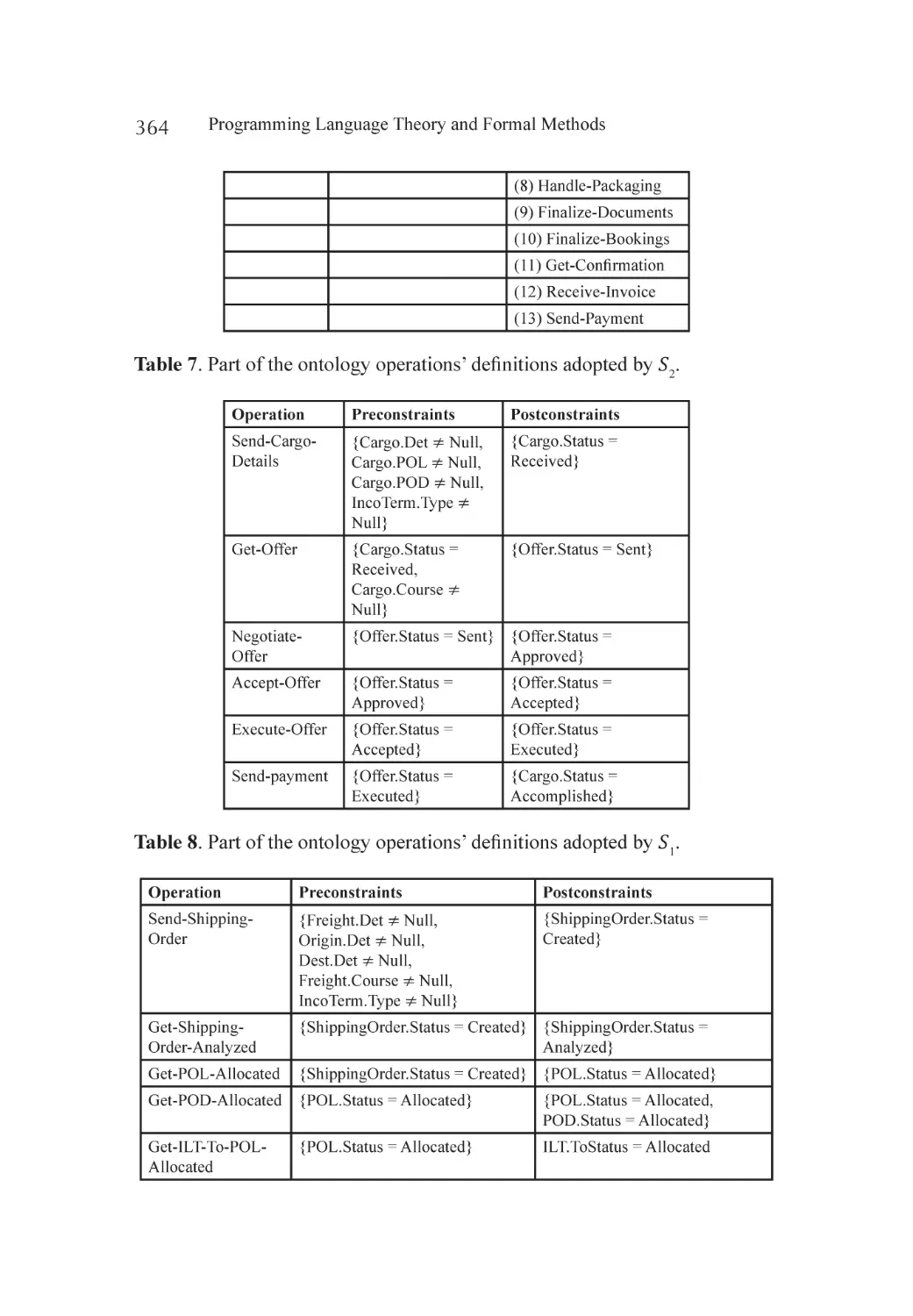
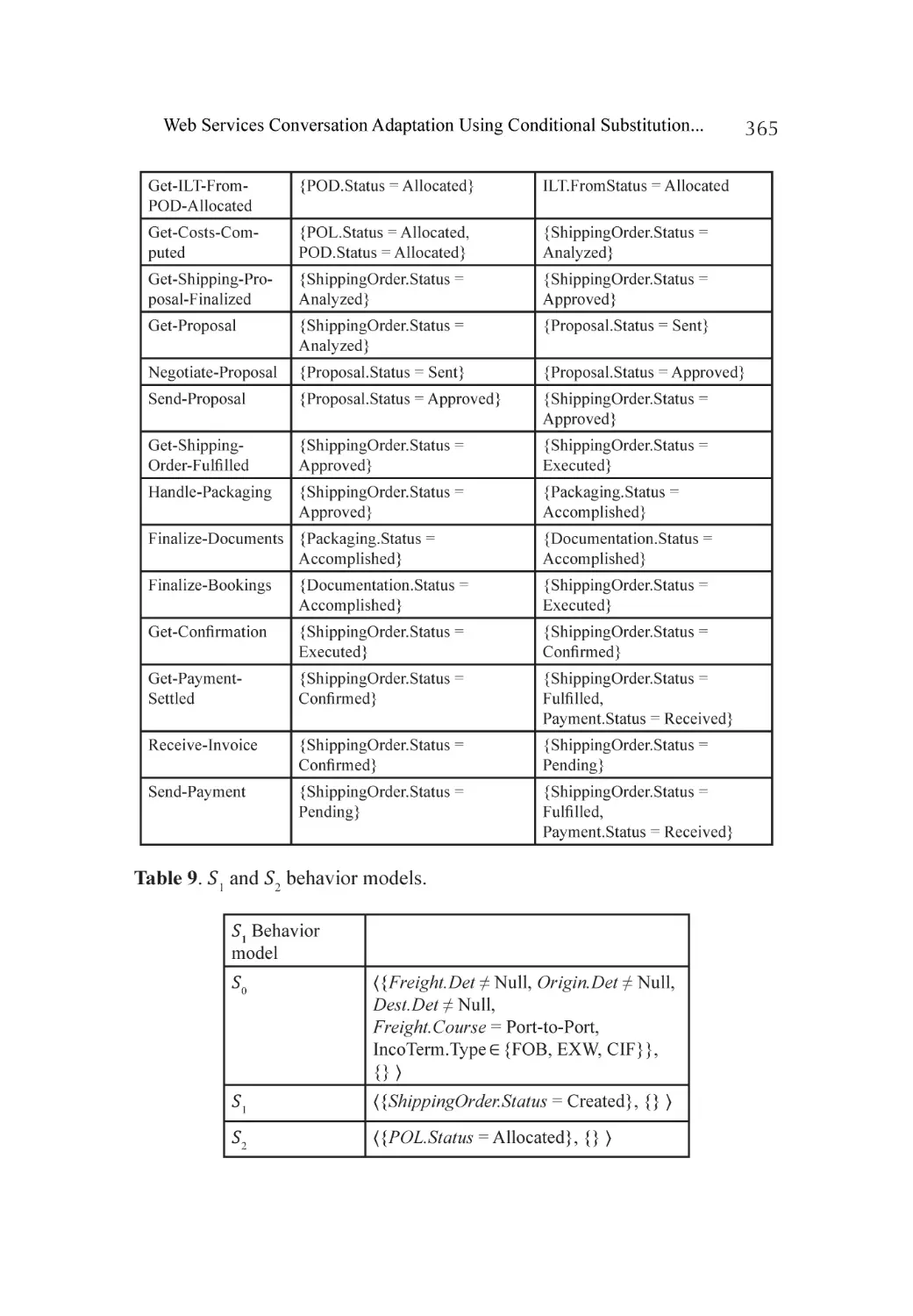
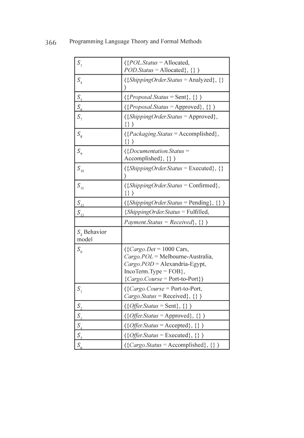
Case Study.............................................................................................. 363
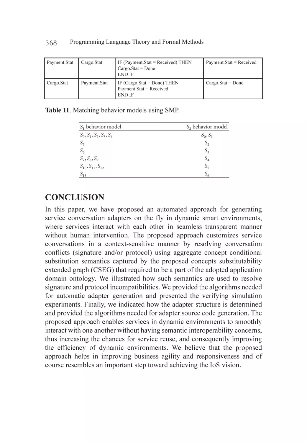
Conclusion............................................................................................. 368
References.............................................................................................. 369
Index...................................................................................................... 373
xiv
LIST OF CONTRIBUTORS
Shagufta Shafiq
UIIT-PMAS Arid Agriculture University, Rawalpindi, Pakistan
Nasir Mehmood Minhas
UIIT-PMAS Arid Agriculture University, Rawalpindi, Pakistan
Saiqa Bibi
UIIT-PMAS Arid Agriculture University, Rawalpindi, Pakistan
Saira Mazhar
UIIT-PMAS Arid Agriculture University, Rawalpindi, Pakistan
Nasir Mehmood Minhas
UIIT-PMAS Arid Agriculture University, Rawalpindi, Pakistan
Irfan Ahmed
UIIT-PMAS Arid Agriculture University, Rawalpindi, Pakistan
Monika Singh
Faculty of Engineering & Technology (FET), Mody University of Science & Technology,
Sikar, India
Ashok Kumar Sharma
Faculty of Engineering & Technology (FET), Mody University of Science & Technology,
Sikar, India
Ruhi Saxena
Computer Science & Engineering, Thapar University, Patiala, India
Nasir Mehmood Minhas
University Institute of Information Technology, PMAS-University Institute of
Information Technology, Rawalpindi, Pakistan
Asad Masood Qazi
University Institute of Information Technology, PMAS-University Institute of
Information Technology, Rawalpindi, Pakistan
Sidra Shahzadi
University Institute of Information Technology, PMAS-University Institute of
Information Technology, Rawalpindi, Pakistan
Shumaila Ghafoor
University Institute of Information Technology, PMAS-University Institute of
Information Technology, Rawalpindi, Pakistan
Lorina Negreanu
POLITEHNICA University of Bucharest, Splaiul Independentei 303, 060042 Bucharest,
Romania
Zheng Yang
School of Information and Software Engineering, University of Electronic Science and
Technology of China, No.4 Section 2 North Jianshe Road, Chengdu 610054, China
Hang Lei
School of Information and Software Engineering, University of Electronic Science and
Technology of China, No.4 Section 2 North Jianshe Road, Chengdu 610054, China
Ekaterina M. Lavrischeva
Moscow Physics-Technical Institute, Dolgoprudnuy, Russia
Muthu Ramachandran
Faculty of Arts, Environment and Technology, School of Computing and Creative
Technologies, Leeds Metropolitan University, Leeds, UK.
Emdad Khan
College of Computer and Information Sciences, Al-Imam Muhammad Ibn Saud Islamic
University, Riyadh, KSA.
Mohammed Alawairdhi
College of Computer and Information Sciences, Al-Imam Muhammad Ibn Saud Islamic
University, Riyadh, KSA.
Jielan Zhang
Department of Information Technology, Yingtan Vocational and Technical College,
Yingtan, China
Zhongsheng Qian
School of Information Technology, Jiangxi University of Finance and Economics,
Nanchang, China.
xvi
Yalu Li
School of Mathematics and Statistics, Shandong Normal University, Jinan 250014,
China
Wenhui Dou
School of Mathematics and Statistics, Shandong Normal University, Jinan 250014,
China
Haitao Li
School of Mathematics and Statistics, Shandong Normal University, Jinan 250014,
China
Institute of Data Science and Technology, Shandong Normal University, Jinan 250014,
China
Xin Liu
School of Mathematics and Statistics, Shandong Normal University, Jinan 250014,
China
Rui Wang
College of Computer Science, National University of Defense Technology, Changsha,
Hunan 410073, China
Wanwei Liu
College of Computer Science, National University of Defense Technology, Changsha,
Hunan 410073, China
Tun Li
College of Computer Science, National University of Defense Technology, Changsha,
Hunan 410073, China
Xiaoguang Mao
College of Computer Science, National University of Defense Technology, Changsha,
Hunan 410073, China
Ji Wang
College of Computer Science, National University of Defense Technology, Changsha,
Hunan 410073, China
Ali Sever
Pfeiffer University, Misenheimer, USA
Bin Wen
State Key Lab of Software Engineering, Wuhan University, Wuhan, China.
xvii
Keqing He
State Key Lab of Software Engineering, Wuhan University, Wuhan, China.
Jian Wang
State Key Lab of Software Engineering, Wuhan University, Wuhan, China.
Ning Huang
Beihang University, Beijing, China
Xiao Juan Wang
Beihang University, Beijing, China
Camilo Rocha
University of Illinois at Champaign Urbana, USA
Elodie Marie Gontier
Professor of French and History, Paris, France
Islam Elgedawy
Computer Engineering Department, Middle East Technical University, Northern Cyprus
Campus, Guzelyurt, Mersin 10, Turkey
xviii
LIST OF ABBREVIATIONS
ABox Assertion Box
ADLs
Architectural Description Languages
AI Artificial Intelligence
BMC
Bounded Model Checking
BOP
Base of the Pyramid People
CBSE
Components Based Software Engineering
`
CM Conceptual Model
CO Connecting Ontologies
CSEG
Concepts Substitutability Enhanced Graph
CSG
Concept Substitutability Graph
DAO Decentralized Autonomous Organization
DFA Deterministic Finite Automata
DFD
Data Flow Diagram
DLs Description Logics
DPO
Domain Problem Ontology
DSL
Domain Specific Language
DSSA Domain-Specific Software Architectures
EVM Ethereum Virtual Machine
FODA Feature-Oriented Domain Analysis
FOL
First Order Logic
GADTs Generalized Algebraic Datatypes
GAP Goal Achievement Pattern
GDP
Gross Domestic Products
GSE
Guidelines Based Software Engineering
IA Intelligent Agent
ICT
Information and Communication Technologies
IFDS
Integrated Formal Development Support
IoS
Internet of Services
ITP Inductive Theorem Prover
KB Knowledgebase
MBPN
Modeling Biasness Process Notation
MDD
Model Driven Development
NFA Non-deterministic Finite Automata
NLP
Natural Language Processing
NLU
Natural Language Understanding
ODM
Organizational Domain Modeling
ODSD
Ontology-Driven Software Development
OWL
Web Ontology Language
OWL-S
Web Ontology Language for Services
PIM
Platform Independent Model
PP Program Products
PS Program Systems
PSM
Platform Specific Models
QoE
Quality of Experience
RAA
Requirements Acquiring & Analysis
RE Requirements Engineering
RML
Requirement Modeling Language
RoI
Return on Investment
SA Structured Analysis
SAAS
Software as a Service
SAWSDL
Semantic Annotations for Web Services Description
Language
SD Structured Design
SEBLA
Semantic Engine using Brain-Like Approach
SMP
Sequence Mediation Procedure
SOA Service Oriented Architecture
SQL
Structured Query Language
STP Semitensor Product
TBox Terminology Box
URI
Uniform Resource Identifier
W3C
World Wide Web Consortium
WS Web Service
xx
WS-BPEL
Web Services Business Process Execution Language
WSCI
Web Services Choreography Interface
WSMO
Web Services Modelling Ontology
XFM
Extreme Formal Modeling
XML
Extensible Markup Language
xxi
PREFACE
In informatics, particularly in software and hardware engineering, formal methods
are a special type of mathematically-defined techniques that perform specification,
development and verification of software and hardware systems. The use of formal
methods for software and hardware design is motivated by the expectation that, as
in other engineering disciplines, performing appropriate mathematical analysis can
contribute to the reliability and robustness of the design.
Formal methods can be described as an application of a fairly wide range of theoretical
informatics fundamentals, especially: logical methods, formal languages, automata
theory, dynamic system of discrete events and program semantics, but also type systems
and algebraic data types on software and hardware specification and verification
problems. Formal methods provide the basic methods of symbolic logic in the
application of software development, both classical and modern.
They define the elements of syntax and semantics of classical court calculus, and
methods of automatic deduction, based on the rule of resolution for court calculus and
its modifications (semantic resolution, linear resolution, hyper-resolution), or the DavisPutnam method. The adopted formal language for reasoning with its subsystems (Horn
logic) and supersystems (quantified court accounts), as well as automatic deduction
methods developed for them - can serve as a means of modeling and solving a range
of problems: artificial intelligence planning, strategic modeling problems (chess),
combinatorial (e.g. “four in a row” games), and propositional information and expert
systems.
Formal specification and verification methods are widely used during software systems
development. Theoretical background for these methods include: process algebras, Petri
nets and temporal logic, and finite discrete automata. Formal models of communication
between processes are used during the model verification, testing and verification of
reactive competing systems. Practical application of formal methods is for language for
specification, testing and verification. On the market - there are many model verification
tools and software testing tools.
This edition covers different topics from: formal grammars in programming,
programming languages semantics, finite automata, and formal methods and semantics
in distributed software.
Section 1 focuses on formal methods in programming, describing integrating formal
methods in XP (extreme programming) - a conceptual solution, formal methods for
commercial, applications issues vs. solutions, why formal methods are considered
for safety critical systems, and integration of UML sequence diagram with formal
specification methods-a formal solution based on Z.
Section 2 focuses on programming languages semantics, describing declarative
programming with temporal constraints, in the language CG, Lolisa: formal syntax
and semantics for a subset of the solidity programming language in mathematical tool
coq, ontology of domains. ontological description software engineering domain - the
standard life cycle, guidelines based software engineering for developing software
components, intelligent agent based mapping of software requirement specification to
design model.
Section 3 focuses on finite automata, describing the equivalent conversion between
regular grammar and finite automata, controllability, reachability, and stabilizability
of finite automata: a controllability matrix method, bounded model checking of ETL
cooperating with finite and looping automata connectives, an automata-based approach
to pattern matching, tree automata for extracting consensus from partial replicas of a
structured document.
Section 4 focuses on formal methods and semantics in distributed software, describing
building requirements semantics for networked software interoperability, formal
semantics of OWL-s with rewrite logic, web semantic and ontology, web services
conversation adaptation using conditional substitution semantics of application domain
concepts.
xxiv
SECTION 1: FORMAL METHODS IN
PROGRAMMING
Chapter
INTEGRATING FORMAL
METHODS IN XP—A
CONCEPTUAL SOLUTION
1
Shagufta Shafiq and Nasir Mehmood Minhas
UIIT-PMAS Arid Agriculture University, Rawalpindi, Pakistan
ABSTRACT
Formal methods can be used at any stage of product development process
to improve the software quality and efficiency using mathematical models
for analysis and verification. From last decade, researchers and practitioners
are trying to establish successful transfer of practices of formal methods
into industrial process development. In the last couple of years, numerous
analysis approaches and formal methods have been applied in different
settings to improve software quality. In today’s highly competitive software
development industry, companies are striving to deliver fast with low cost
and improve quality solutions and agile methodologies have proved their
Citation: Shafiq, S. and Minhas, N. (2014), “Integrating Formal Methods in XP (Extreme Programming) - A Conceptual Solution”. Journal of Software Engineering and
Applications, 7, 299-310. doi: 10.4236/jsea.2014.74029.
Copyright: © 2014 by authors and Scientific Research Publishing Inc. This work is
licensed under the Creative Commons Attribution International License (CC BY).
http://creativecommons.org/licenses/by/4.0
4
Programming Language Theory and Formal Methods
efficiency in acquiring these. Here, we will present an integration of formal
methods, specifications and verification practices in the most renowned
process development methodology of agile i.e. extreme programming with
a conceptual solution. That leads towards the development of a complete
formalized XP process in future. This will help the practitioners to
understand the effectiveness of formal methods using in agile methods that
can be helpful in utilizing the benefits of formal methods in industry.
Keywords: Formal Methods, Specification, Verification, Agile, Extreme
Programming
INTRODUCTION
Formal methods have proved as a powerful technique to ensure the correctness
of software. The growth in their use has been slow but steady and FMs are
typically applied in safety critical systems. Use of formal methods requires
both expertise and efforts, but this is rewarded if they are applied wisely. It
must be seen as good prudently news that Microsoft products increasingly
use formal methods in key parts of their software development, particularly
checking the interoperability of third-party software with Windows. We
believe formal methods are here to stay and will gain further traction in the
future [1] .
Formal methods are used for developing software/hardware systems
by employing mathematical analysis and verification techniques and
often supported by the tools [2] . Mathematical model’s steadiness
enables developers to analyse and verify these models in any phase of the
development process i.e., requirements engineering, specification, design
and architecture, implementation, testing and maintenance [2] .
Since their inception and use in the domain of real-time, critical systems,
now these methods are finding their way to other widens area of industrial
applications especially developing high quality software products [2] .
Traditional software development process can be categorised into
three phases: 1) requirement gathering. Sometime, specifications are also
incorporating in requirement to get more precise and accurate requirements;
2) phase of design, modelling and implementation; 3) the late phase involves
verification and validation process activities.
It can be suggest that formal methods can be effectively used in traditional
software development process to get accurate system specifications using
Integrating Formal Methods in XP—A Conceptual Solution
5
the formal specification methods like ASM, B, Z and VDM even these can
be effectively used for representation and management of complex system
specifications. Formal methods can also be used in software system design
by defining formal models to refine the data, abstract function to represent
system functionality [2] and to implement. Formal methods can be used for
automated code generation and verification from formal models [2] .
Formal methods are always perceived as highly mathematical based
processes and can only be used by mathematicians and specialist software
experts. This inclination leads towards the limited usage in industry-based
software development processes. To change this misconception, a much
wider industrial research has to be performed to get the true benefits of
formal methods in industry [3] .
In today’s fast growing software industries, software industries make
every effort to produce fast delivery, with better quality and low cost
software solutions [2] . With Lightweight iterative approach with the focus
on communication between client and developing team, family of agile
methods has turned out as solution to achieve all these goals. Agile methods
have a wide range of approaches from development process methods like
extreme programming to complete project management process like scrum
[4] . These methods have been effectively used in the software industry to
develop systems on time and within budget with improved software quality
and customer satisfaction [3].
A main reason of not using agile approaches for the development of
safety critical systems is the lack of more formal evaluation techniques
in agile methods where as safety critical systems require more rigorous
development and evaluation techniques to ensure quality products [3] .
As agile approaches less focus on documentation over processes with
informal techniques which are often insufficient in determining the quality
of safety critical systems [3] , agile methods are still not effectively used
to create systems which require more formal development and testing
techniques for development [3] .
It has been observed in literature that combination of agile and formal
methods can bring best features of both the worlds [5] which can lead
towards a better software development solution. In [6] , authors present
an evaluation of agile manifesto and agile development principles to show
that how formal and agile approaches can be integrated and identify the
challenges and issues in doing so. In [3] , authors suggest that agile software
development can used light weight formal analysis techniques effectively
6
Programming Language Theory and Formal Methods
to bring potential difference in creating system, with formally verified
techniques, on time and within budget.
Motivation
It has been observed through literature that application of formal techniques
in early phases of software development improves the quality of software
artefacts and as a result ensure precise and error free requirement details to
the later phases of the development process. As a result the overall cost of a
software project is significantly lower because of the minimized error rate.
After that formal specifications transformed into concrete models to verify
its consistency with the specification that lead towards the implementation.
Till date formal methods couldn’t be effectively used in industry based
product engineering but it has potential of widespread effectiveness for
application development in different domains, whereas agile approaches
lack precise techniques for planning and evaluation. A combination of formal
methods and agile development processes can significantly encourage the
use of formal techniques in industry base software development solutions
[3] .
Here in this article, in Section 2 we first describe the use of formal
specification and verification techniques with frequently used formal
specification languages. We then present an overview of extreme
programming in Section 3. Section 4 contains the related research work
which shows the integration of formal methods with traditional software
development and agile methodologies to support our main concept and the
reason of choosing agile process method for our proposed approach. Section
V describes our proposed approach.
FORMAL METHODS IN PRACTICE
Formal methods can be generally categorized into two basic techniques and
practices i.e. formal specifications and verification [7] .
Formal Specifications can be described as the technique that uses a set
of notations derived from formal logic to explicitly specify the requirements
that the system is to achieve with the design to accomplish those requirements
and also the context of the stated requirements with assumptions and
constraints to specify system functions and desired behaviour explicitly [7] .
Integrating Formal Methods in XP—A Conceptual Solution
7
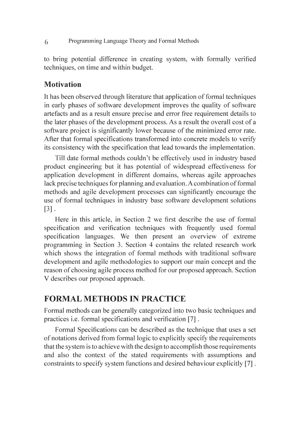
In design specifications, a set of hierarchical specifications with a
high-level abstract representation of the system to detailed implementation
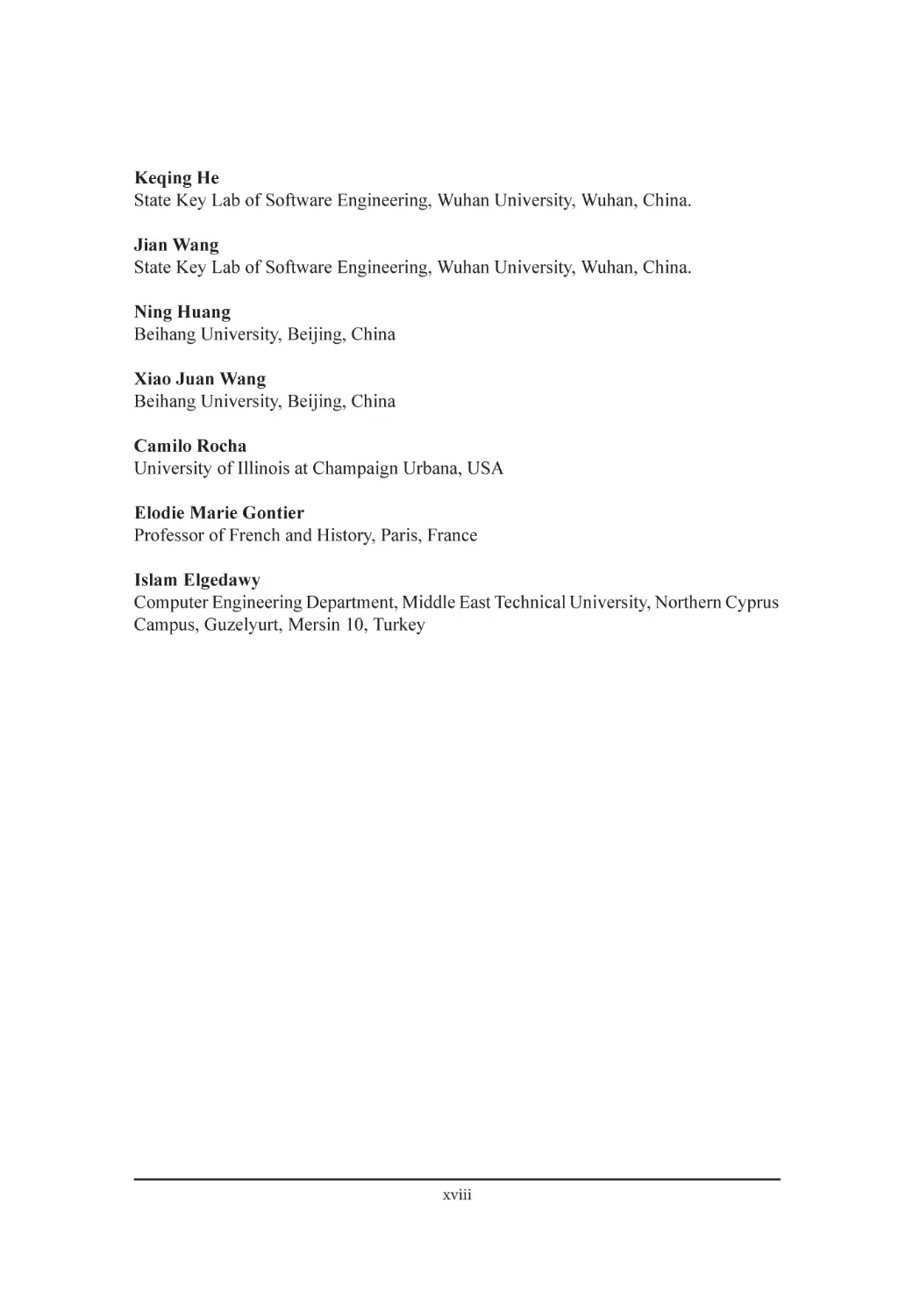
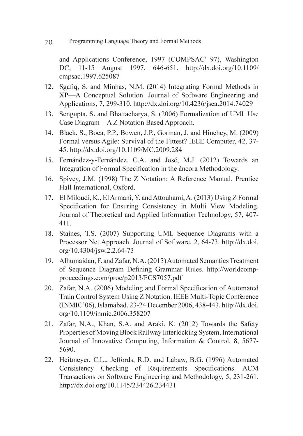
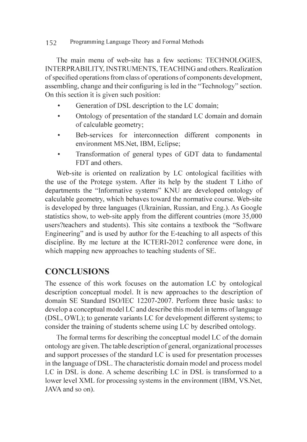
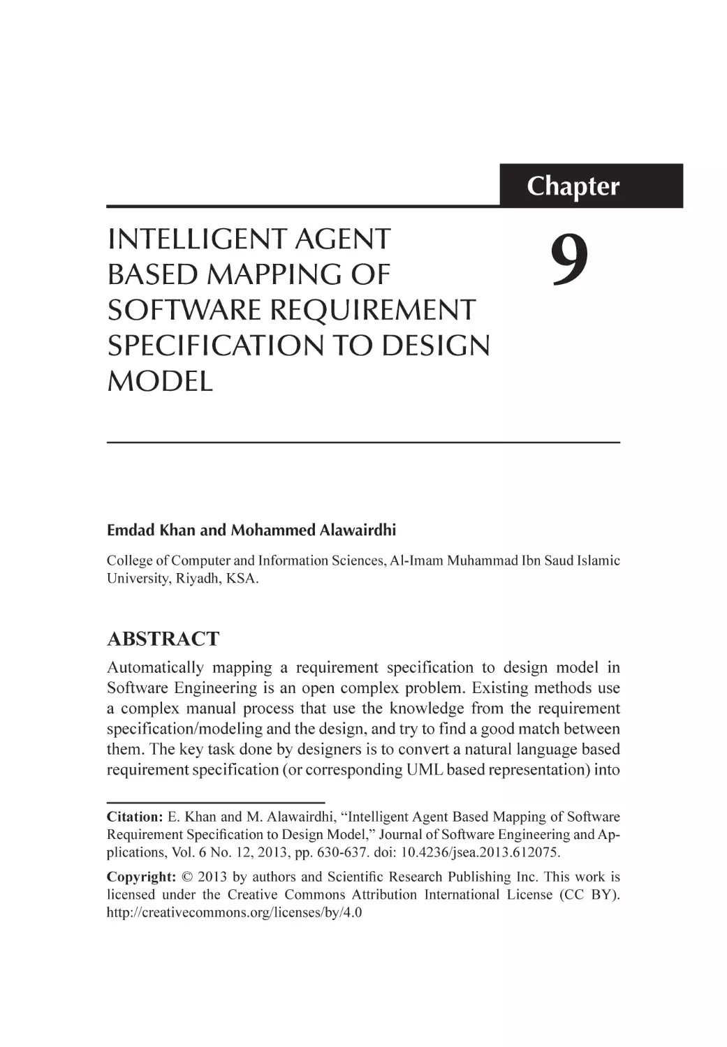
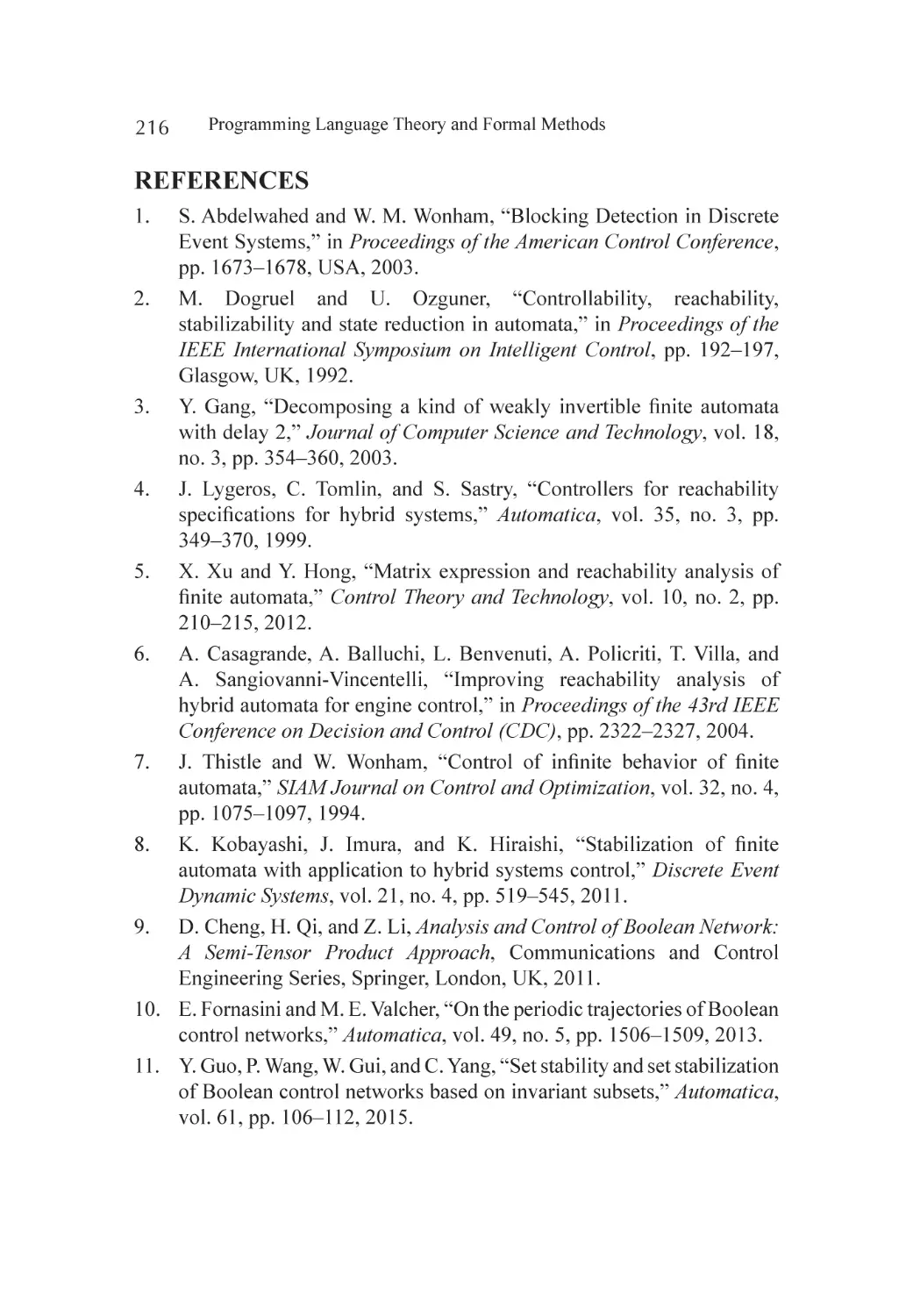
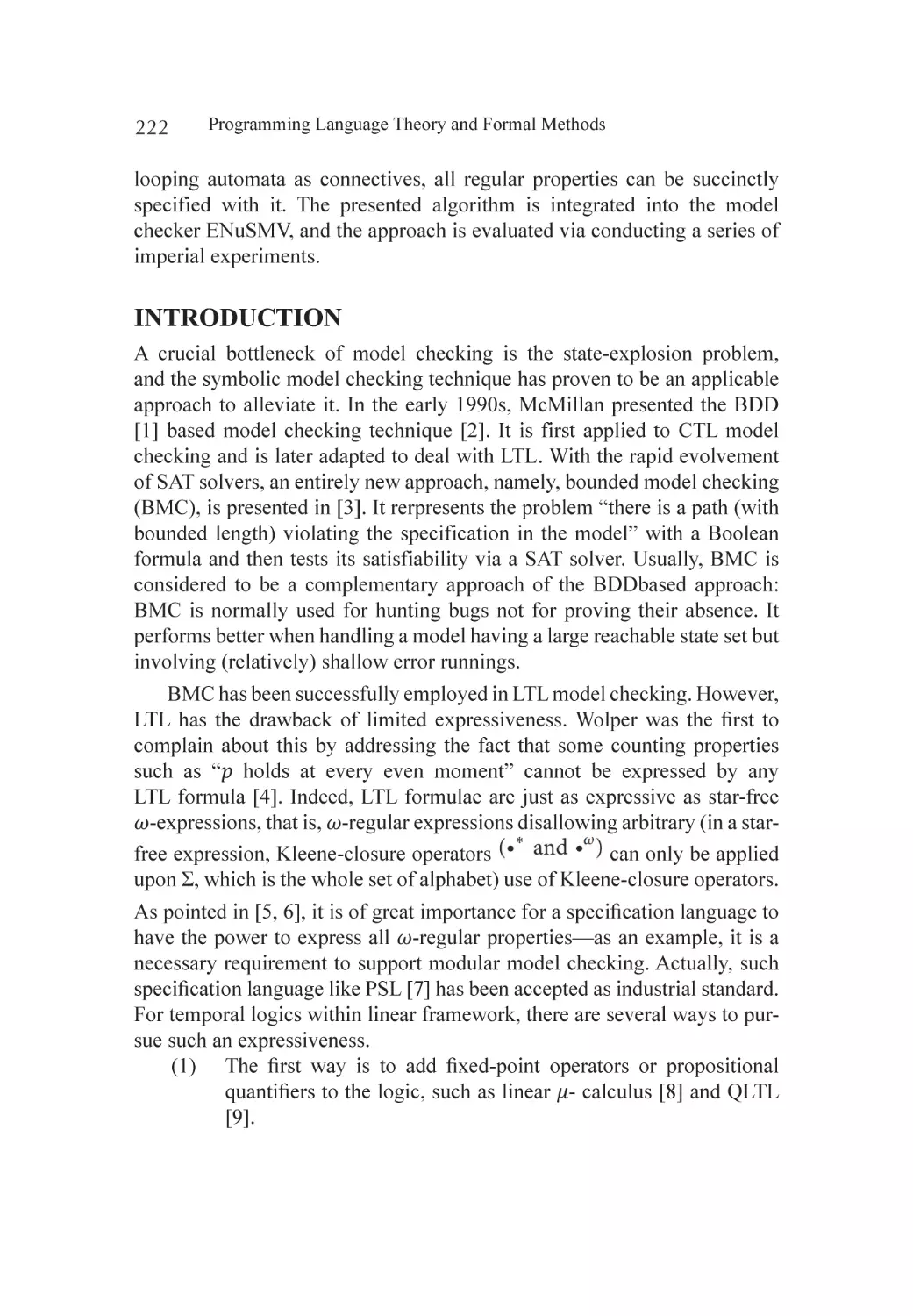
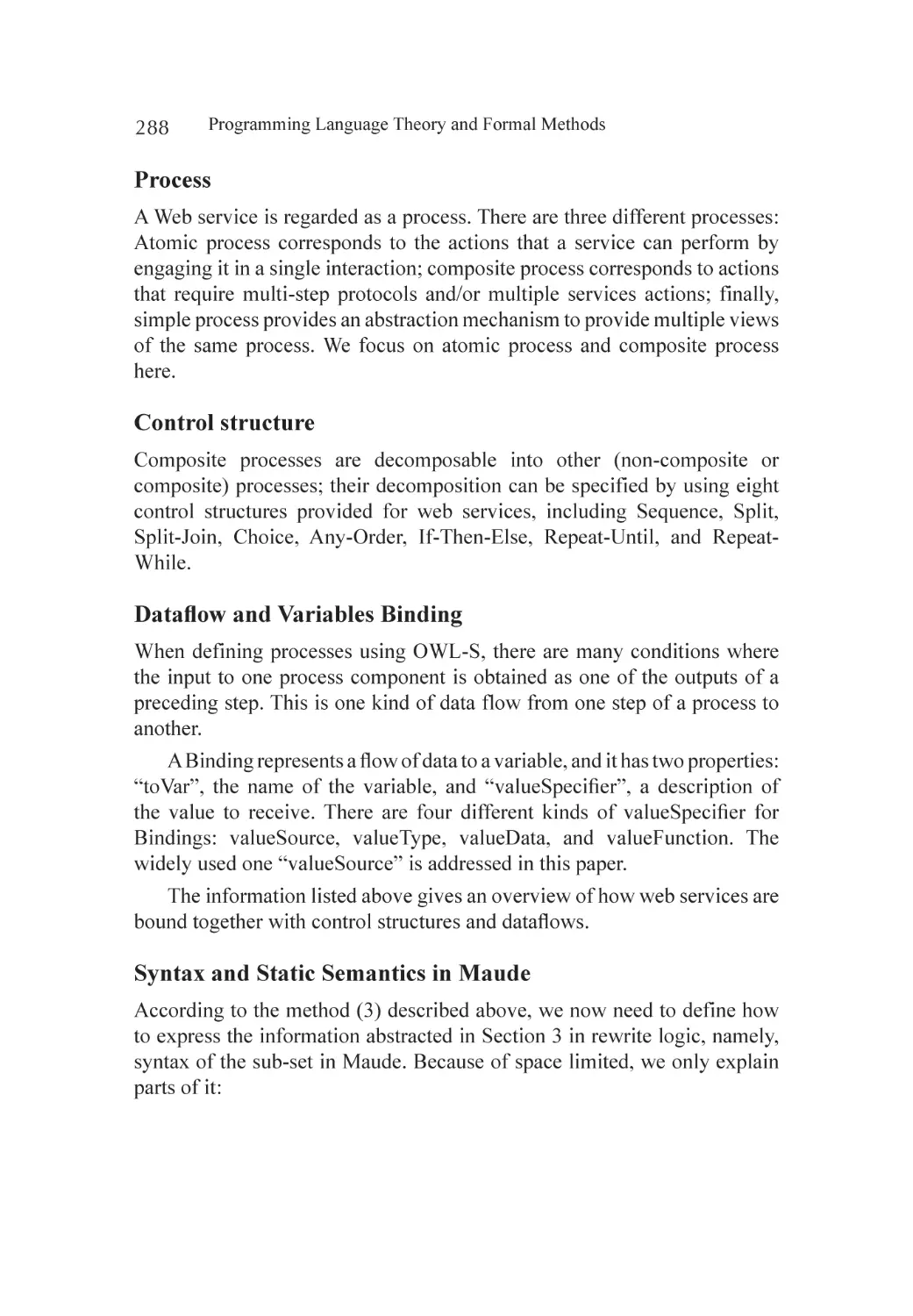
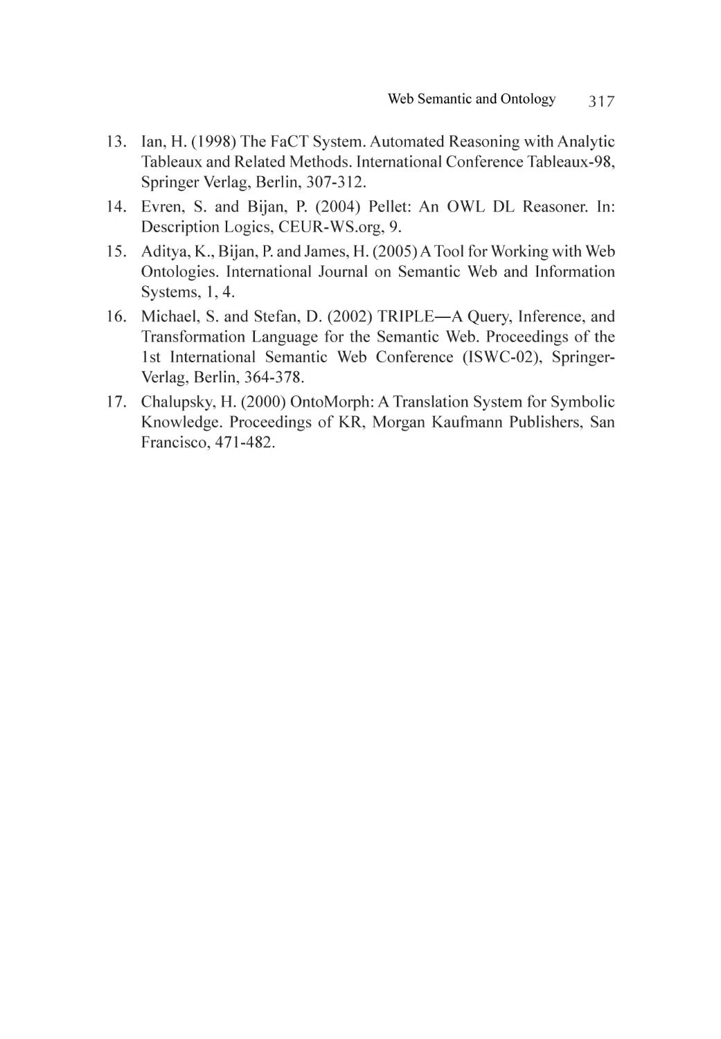
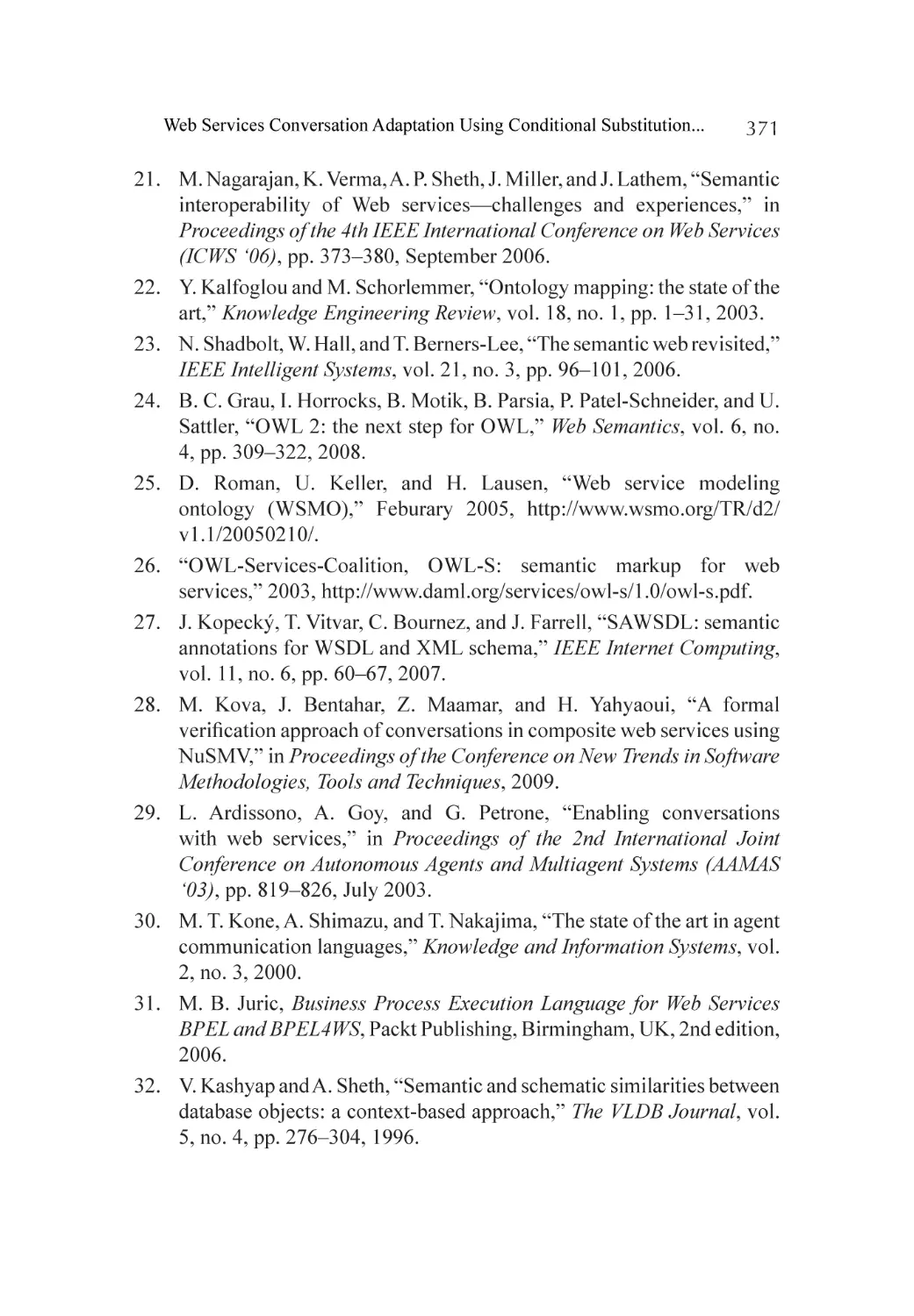
specifications are designed, Figure 1 shows that hierarchy of specification
levels [7] .
Formal Verification is the use of verification methods from formal logic
to examine the specifications for required consistency and completeness
to ensure that the design will satisfy the requirements, assumptions and
constraints that system required [7] .
There are several techniques available for formal specifications with
automated tool support. These automated tools can perform rigorous
verification that can be a tedious step in formal methods [7] .
There are many different types of formal methods techniques used
in different settings; following are the most commonly used examples of
formal specifications, i.e. VDM, B and Z [3] .
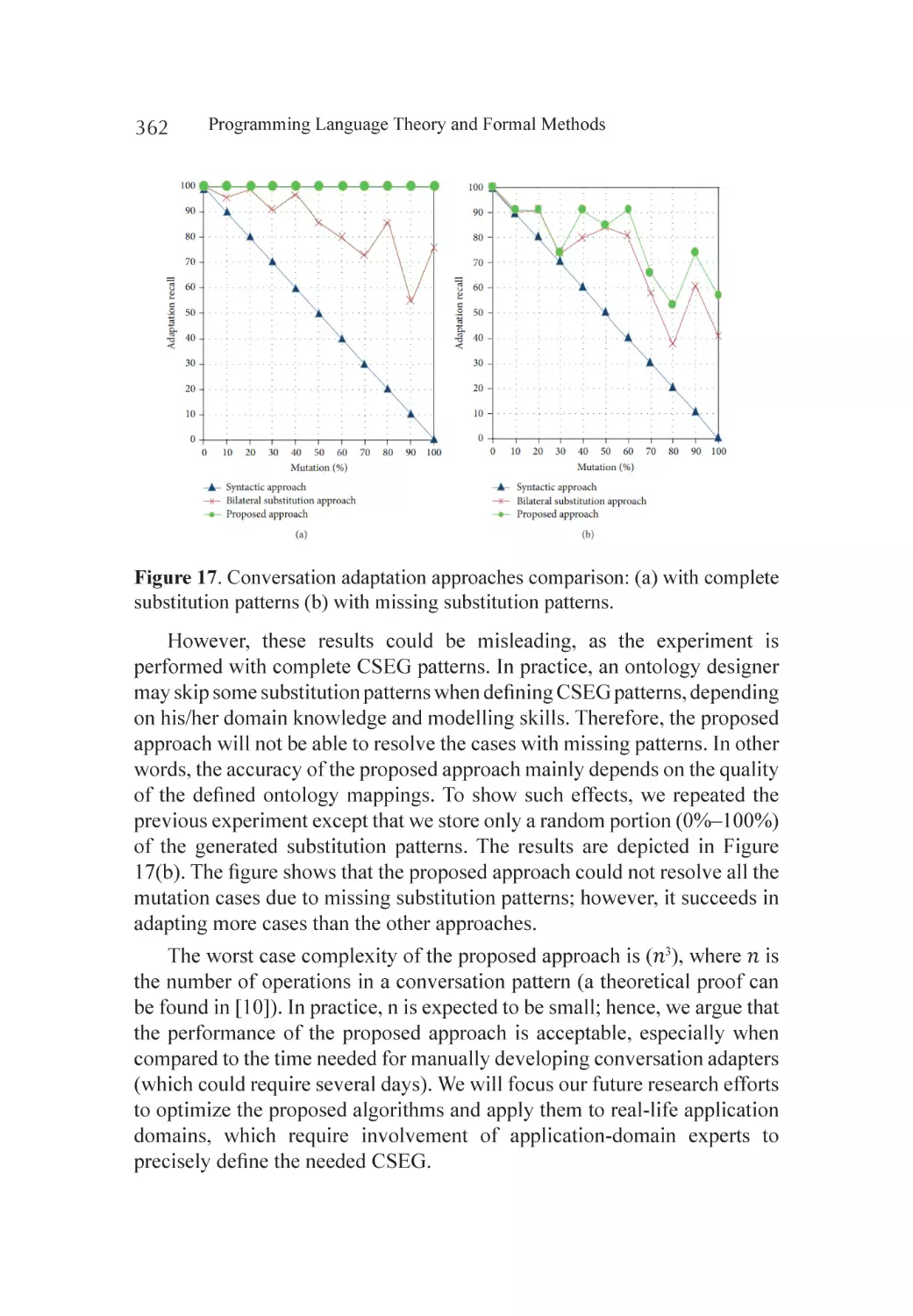
Figure 1. Hierarchy of formal specifications [7] .
VDM
VDM stands for “The Vienna Development Method” and consider as one
of the oldest formal methods. VDM is a collection of practices for the
formal specification and computational development [8] . It consists of a
specification language called VDM-SL. Specifications in VDM-SL based
on the mathematical models develop through simple data types like sets,
lists and mappings, and the operations, causes the state change in the model
[8] .
8
Programming Language Theory and Formal Methods
B-Methods
B-method is another formal specification method consists of abstract
notations and uses set theory for system modelling, and mathematical proof
for consistency verification between the different refinement phases [7] .
Z
Another most commonly used formal specification language for critical
system development, using mathematical notations and schemas to provide
exact descriptions of a system. System is described in a number of small
Z modules called schemas which can cross refer each other as well as per
system required. Each module is expected to have some descriptive informal
language text to help users to understand it.
The selection of formal specification language made on the basis of
developer’s past experience with the selected method or the suitability of
any model with respect to the system under develop and its application
domain [3] .
EXTREME PROGRAMMING AN AGILE APPROACH
An agile development methodology extreme programming can be define
as light weight iterative approach for small and medium size development
teams having incomplete or continuously changing requirements. XP works
in small iterations with simple practices which focus on close collaboration,
simple design to produce high quality products with continuous testing.
Extreme programming created by K. Beck in 1990’s, is a set of twelve
key practices [9] applied with four core values including communication,
simplicity, courage and feedback.
Extreme programming [9] provides a complete solution for product
development process and widely accepted for development of industry based
and as well as object oriented software systems [10] . With the principles
of agile methodology XP proves as novel approach in the family of agile
methods that significantly increase productivity that produce high quality
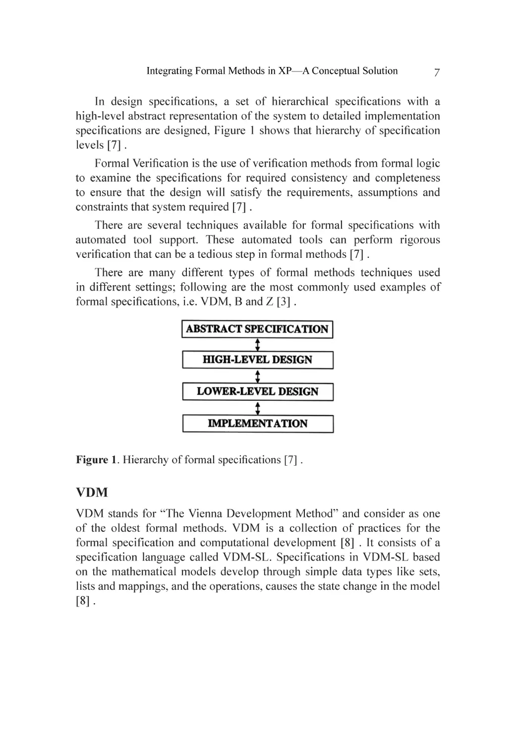
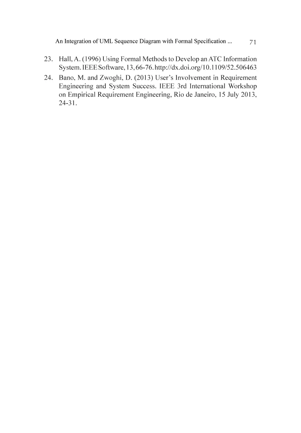
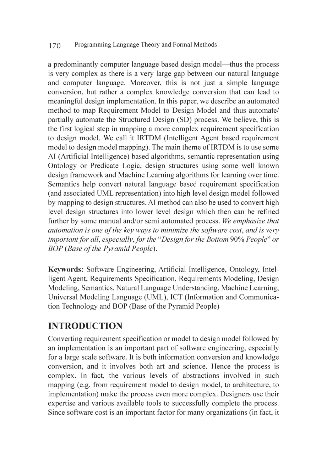
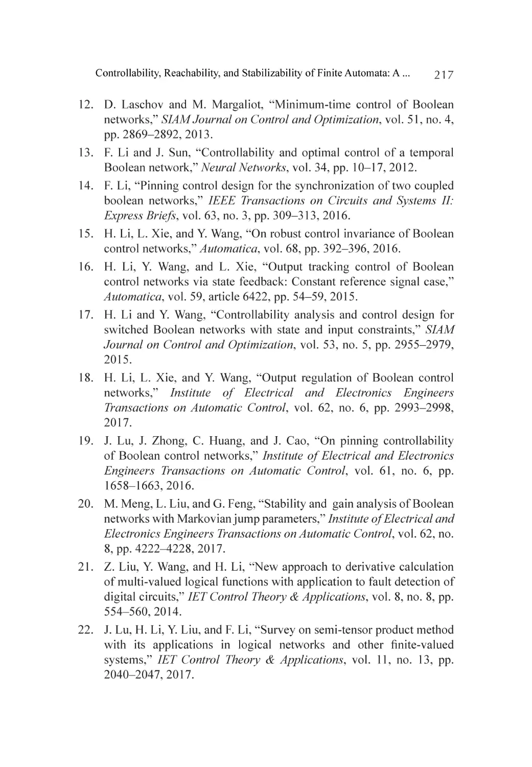
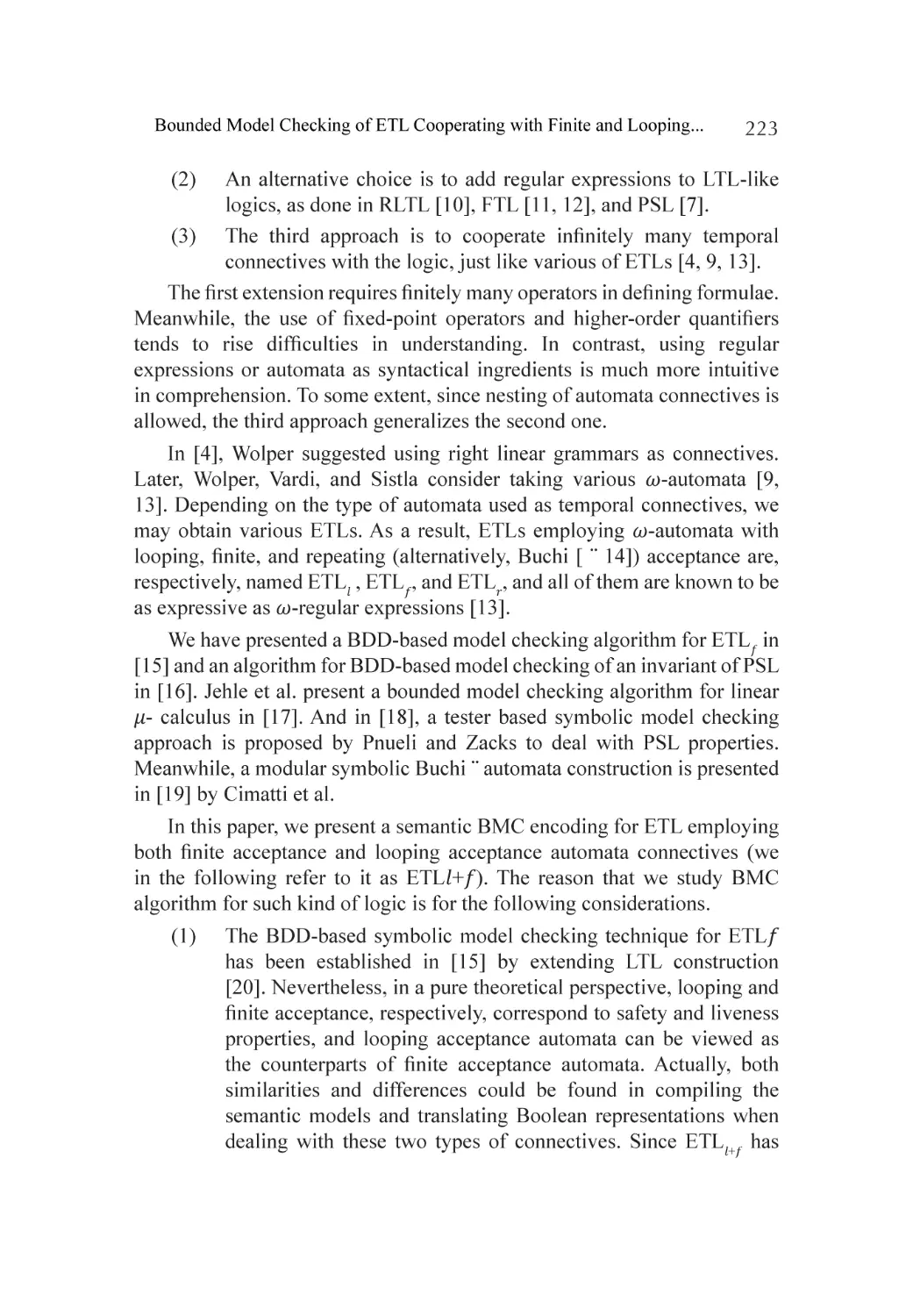
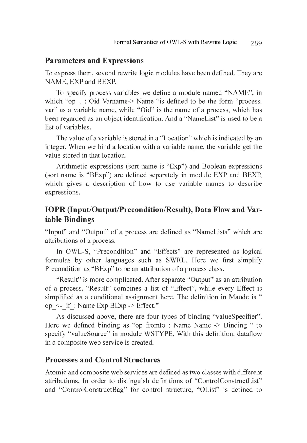
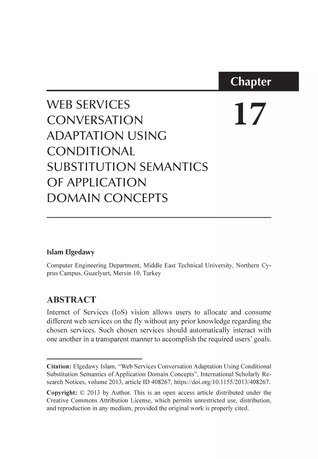
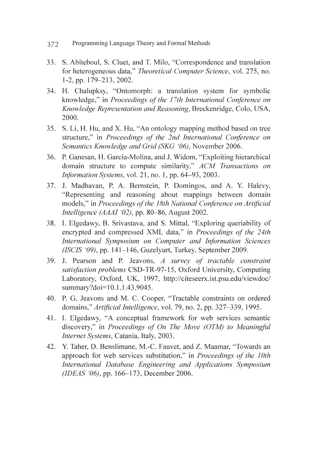
error free code [10] -[12] . Figure 2 shows the complete XP development
process in traditional settings.
Extreme programming is a Test driven approach. In TDD each user
story converted to a test and at the time of release code developed during
iteration will be verified though these pre develop tests. This regression
Integrating Formal Methods in XP—A Conceptual Solution
9
testing technique provides a better test coverage at every phase of software
development which involves writing of unit tests for each individual task in
the system domain [11] .
Figure 2. Extreme programming development process. [11]
AGILE APPROACHES TOWARDS FORMAL
METHODS
Many efforts have been made to integrate the rapidly growing agile
practices, having wide industrial acceptance for producing quality products,
with the formal methods having limited industrial acceptance but with
strong background, distinctive features and benefits. Table 1 shows the
categorization of formal and agile methods.
Richard Kemmerer has made first attempt to investigate the integration
approach for conventional development process using formal methods [15]
. Kemmerer’s work was related to the addition of formal techniques into the
different stages of conventional waterfall model, our work is a step towards
the integration of formal specification and verification within the agile
software development process i.e. extreme programming.
Another study [16] proposed an integration approach for agile formal
development approach with the name of XFun, proposed integration of
formal notation using X-machine within the unified process.
In [17] author suggests an agile approach, combines the agile practice
of tests driven development with formal approach design by contract within
XP [17] .
10
Programming Language Theory and Formal Methods
There is another study [18] that proposes the integration of formal
method techniques into the traditional Vmodel for refinement of critical
aspects of system [18] . The V-model representing the structure of activities
providing guideline for software engineers to follow during the process
development, while our study focuses on suggesting a complete solution
as software development methodology which can be used by the system
developers effectively.
In another study [19] authors have made an effort to develop a light
weight approach using formal methods with the industry development
standards, SOFL [19] . They have used a more graphical notation instead of
pure mathematical syntax to define the high level architecture of the system.
Later on author refine his proposed approach by developing agile based
SOFL method [20] .
Table 1. Agile and formal methods.
Characterizations of Formal and Agile Methods
Agile Methods
Formal Methods
Validation
Verification
Pleasantness
Correctness
Refactoring
Refinement
Concrete
Abstract
Particular
General
Tests
Roofs
Design evolve with code
upfront design
Cowboy coding
Analysis paralysis
Team
Programmer
Beck [9] [10]
Dijkstra [13] [14]
In [21] , authors proposed an extreme Formal Modeling (XFM) (agile
formal methodology) to design the specifications from an informal description
into a more formal language uses extreme programming approach.
Integrating Formal Methods in XP—A Conceptual Solution
11
Recently [3] presented an integration approach of formal specification
and agile. Suggest a theoretical agile approach using scrum methodology
and integrating formal specifications for safety-critical systems. In the
proposed method formal specifications are applied within iteration phase
and having a developing team that consists of both conventional as well as
formal modelling engineers [3] .
Most industrially accepted agile methods i.e. extreme programming
[9] and scrum [22] have been used as emergent trends in dealing with
core challenges and issues in software development process [23] such as:
increase time, with low quality and increase cost at delivery time. [24] .
although, it has been observed that agile software development practices are
also effectively applied in different development settings for safety critical
systems as well [25] [26] . In [26] author argued that Plan driven approaches
are better suited for these types of systems. Whereas further studies suggested
that the integration of agile approaches with the company’s existing plan
driven software development activities can be more effective and beneficial
for producing safety critical systems [26] -[28] . Another study [29] suggests
that integration of agile and CMMI can produce significant difference in
developing quality softwares systems.
FORMAL METHODS IN XP: A CONCEPTUAL
SOLUTION
Formal methods are set of practices for specification and verification but are
not constrained with any specific software development methodology. Mostly
published reports focusing on improving the formal techniques for different
domain and application development and lacks a complete methodology that
can be followed for developing object oriented systems more effectively.
Here in this account of literature we are suggesting a conceptual solution
for software development industry with the integration of formal techniques
into the extreme programming development methodology. Through this,
companies will be able to get benefited aspects of both the integrated
domains to develop high quality software systems.
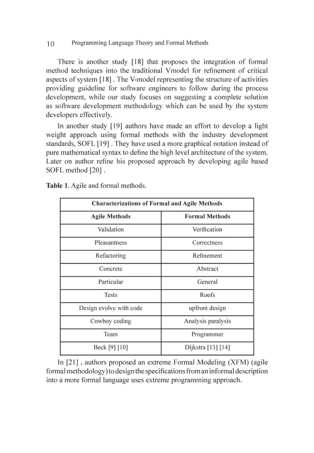
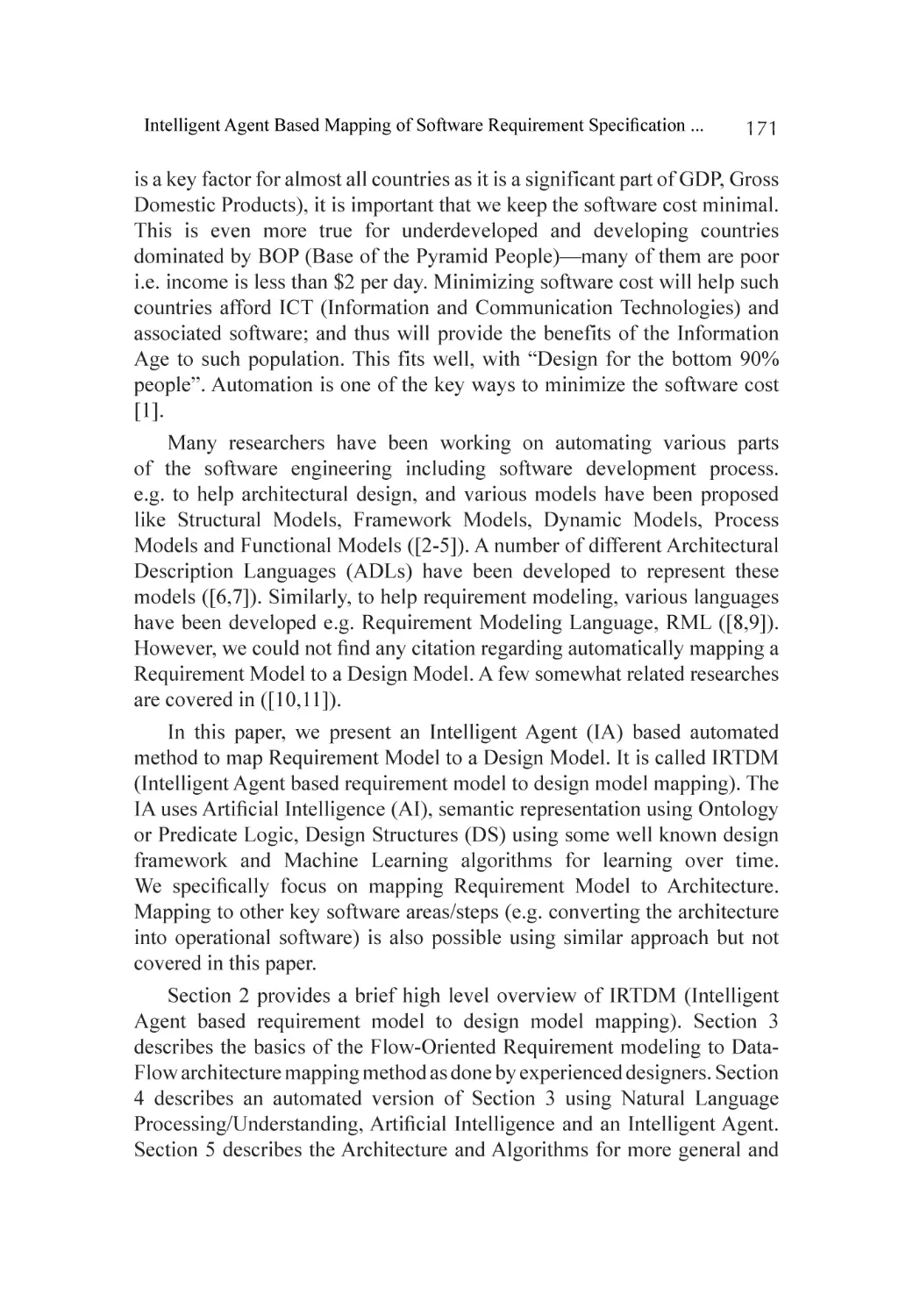
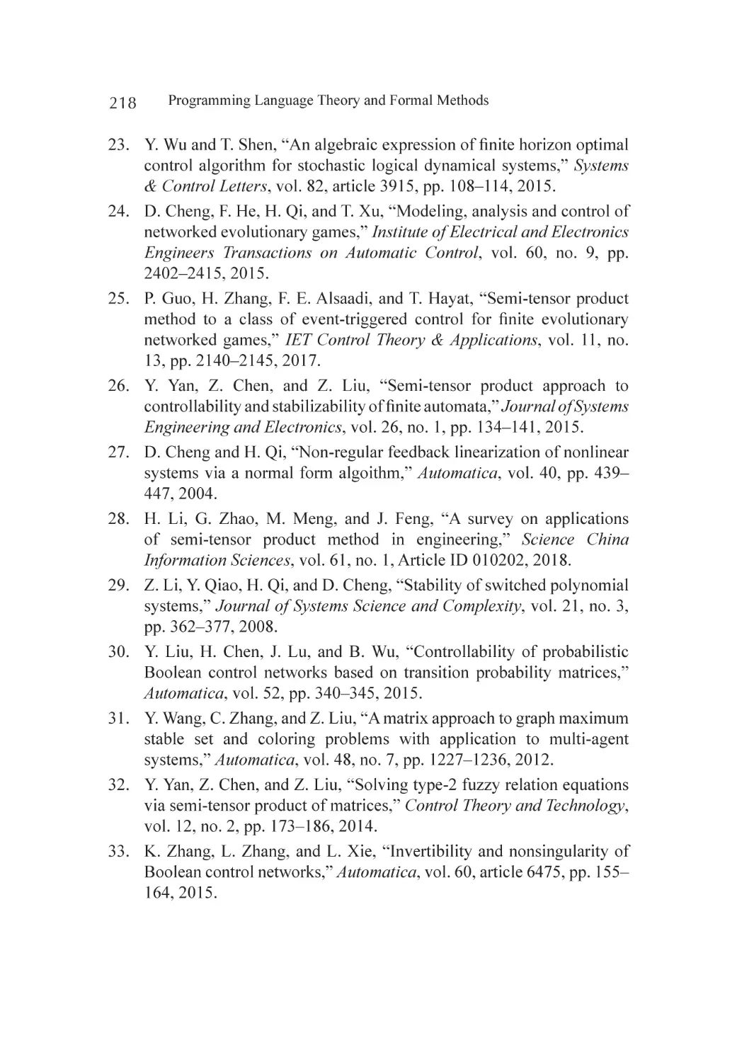
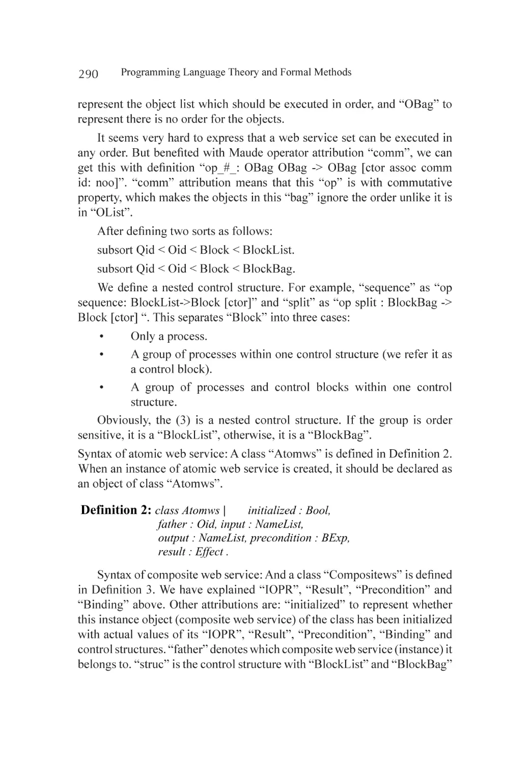
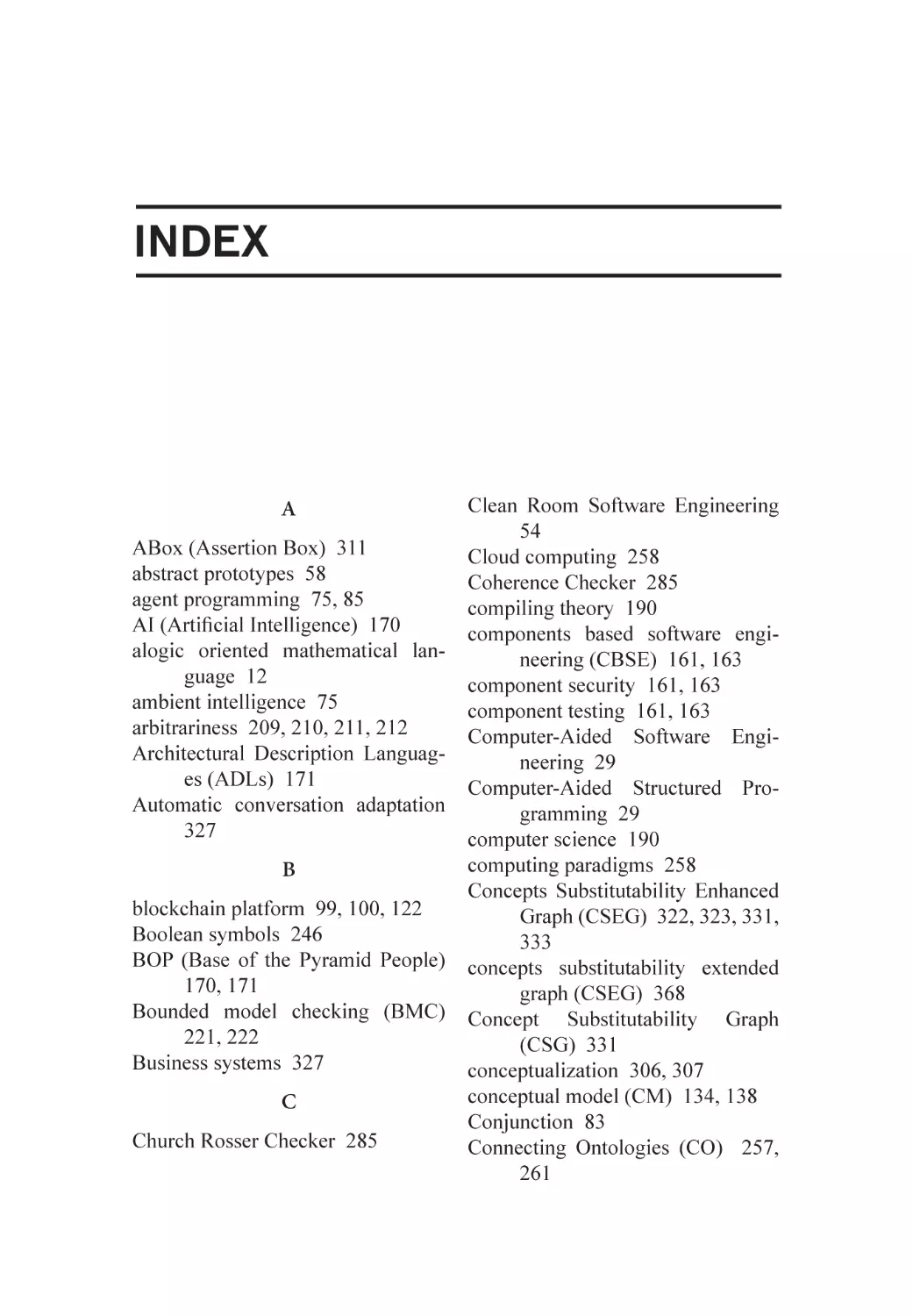
Figure 3 shows our proposed approach for development process of
XP with the integration of formal methods. Here we have suggesting a
conceptual solution.
12
Programming Language Theory and Formal Methods
Figure 3. Proposed approach.
User Stories
User stories in XP serves as the basis for defining the functions of the system
needs to perform, and to facilitate requirements managements described
in an informal manner. In safety circle system use of formal specification
techniques consider as the primary intention so the generated requirements
can be error free hence using user stories in xp available in informal way
needs to be describing through the formal specification techniques to make
them more accurate and precise. And serve as the input for the release
planning including system metaphor.
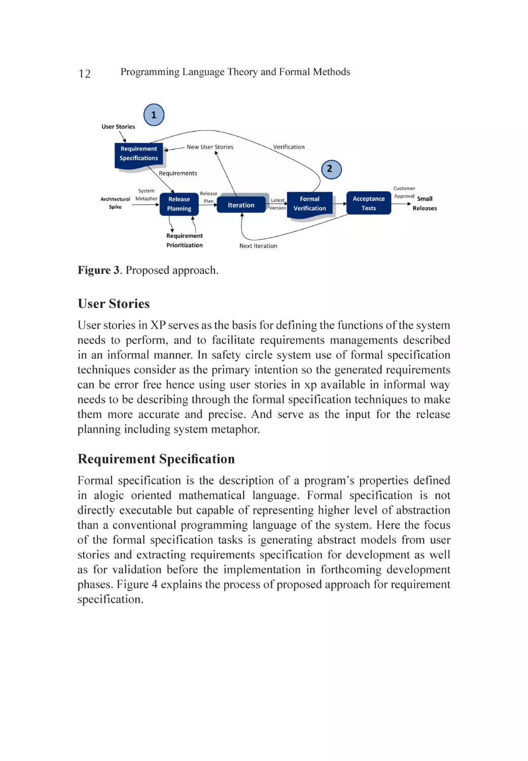
Requirement Specification
Formal specification is the description of a program’s properties defined
in alogic oriented mathematical language. Formal specification is not
directly executable but capable of representing higher level of abstraction
than a conventional programming language of the system. Here the focus
of the formal specification tasks is generating abstract models from user
stories and extracting requirements specification for development as well
as for validation before the implementation in forthcoming development
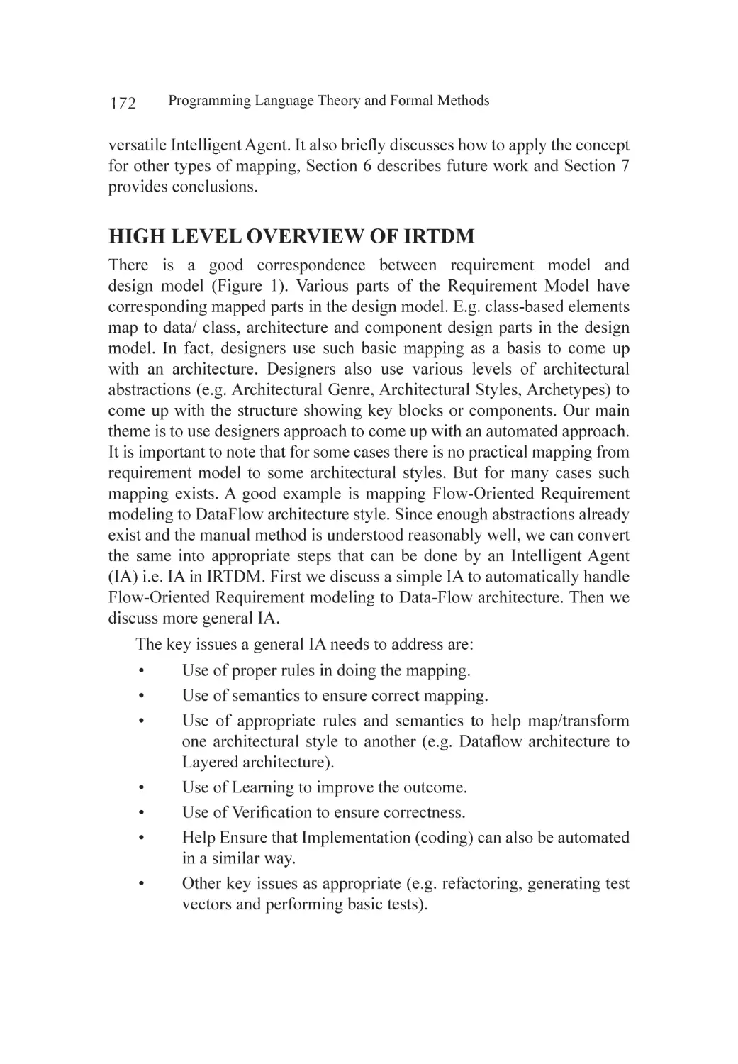
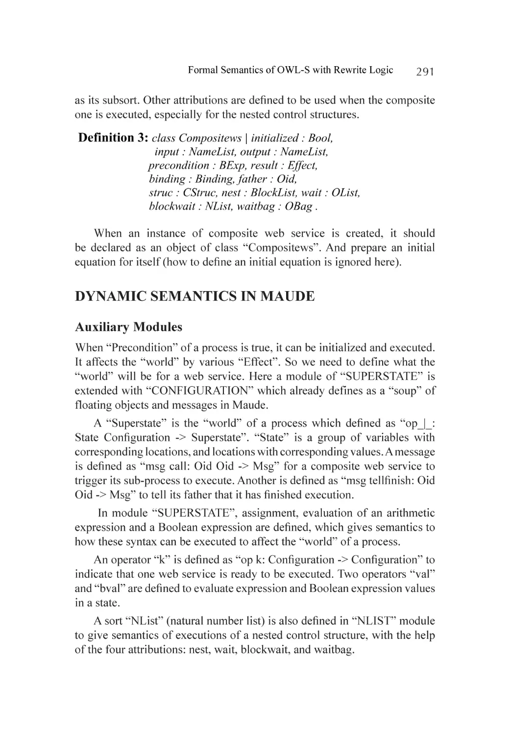
phases. Figure 4 explains the process of proposed approach for requirement
specification.
Integrating Formal Methods in XP—A Conceptual Solution
13
Figure 4. Formal specification in proposed approach.
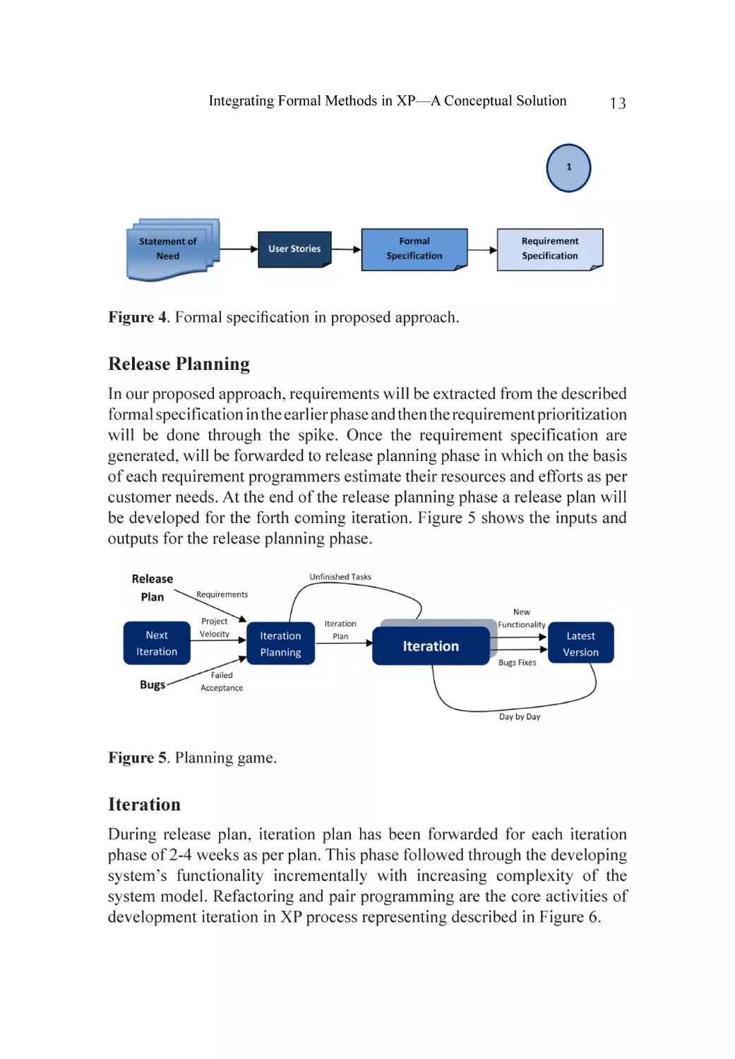
Release Planning
In our proposed approach, requirements will be extracted from the described
formal specification in the earlier phase and then the requirement prioritization
will be done through the spike. Once the requirement specification are
generated, will be forwarded to release planning phase in which on the basis
of each requirement programmers estimate their resources and efforts as per
customer needs. At the end of the release planning phase a release plan will
be developed for the forth coming iteration. Figure 5 shows the inputs and
outputs for the release planning phase.
Figure 5. Planning game.
Iteration
During release plan, iteration plan has been forwarded for each iteration
phase of 2-4 weeks as per plan. This phase followed through the developing
system’s functionality incrementally with increasing complexity of the
system model. Refactoring and pair programming are the core activities of
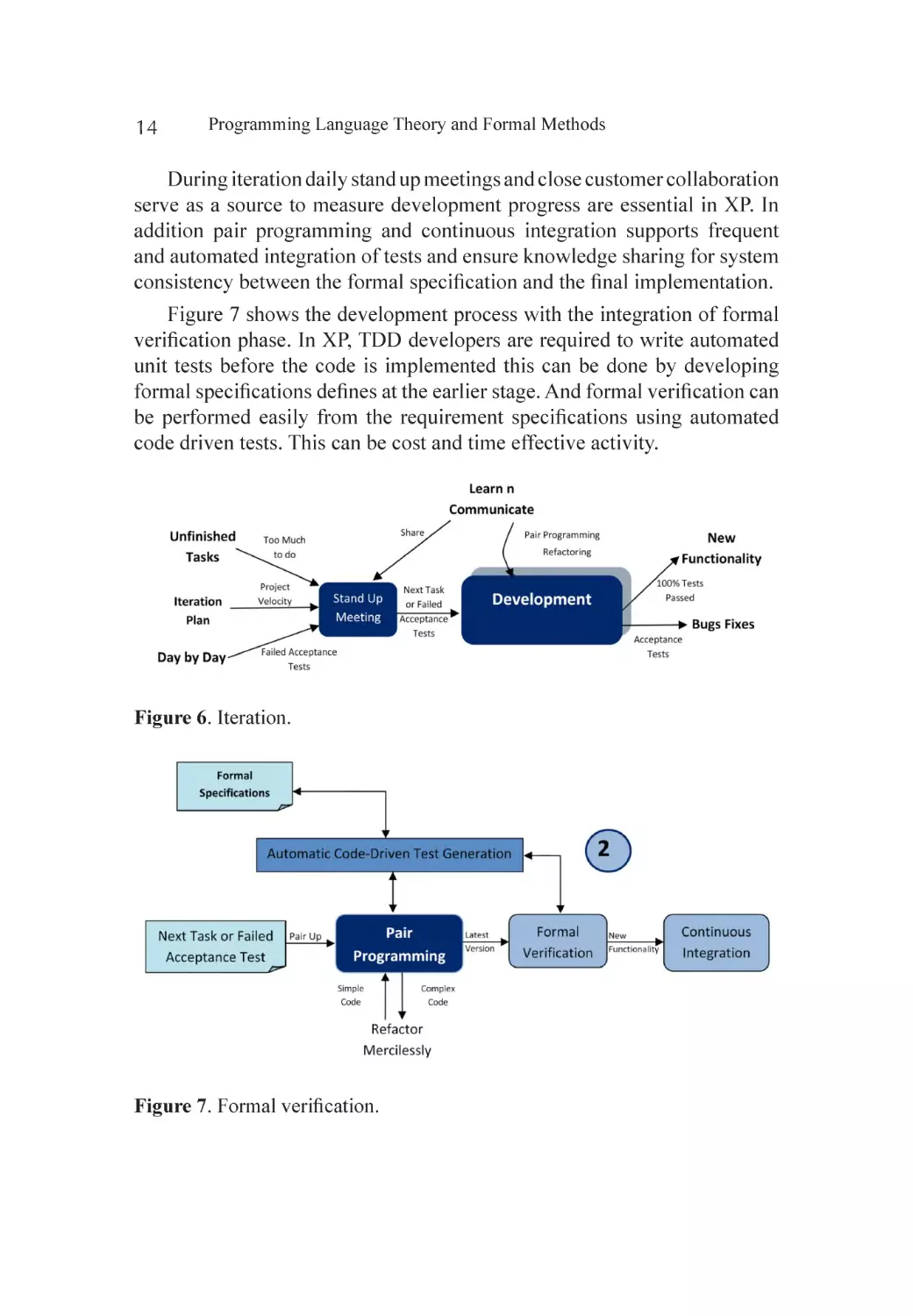
development iteration in XP process representing described in Figure 6.
14
Programming Language Theory and Formal Methods
During iteration daily stand up meetings and close customer collaboration
serve as a source to measure development progress are essential in XP. In
addition pair programming and continuous integration supports frequent
and automated integration of tests and ensure knowledge sharing for system
consistency between the formal specification and the final implementation.
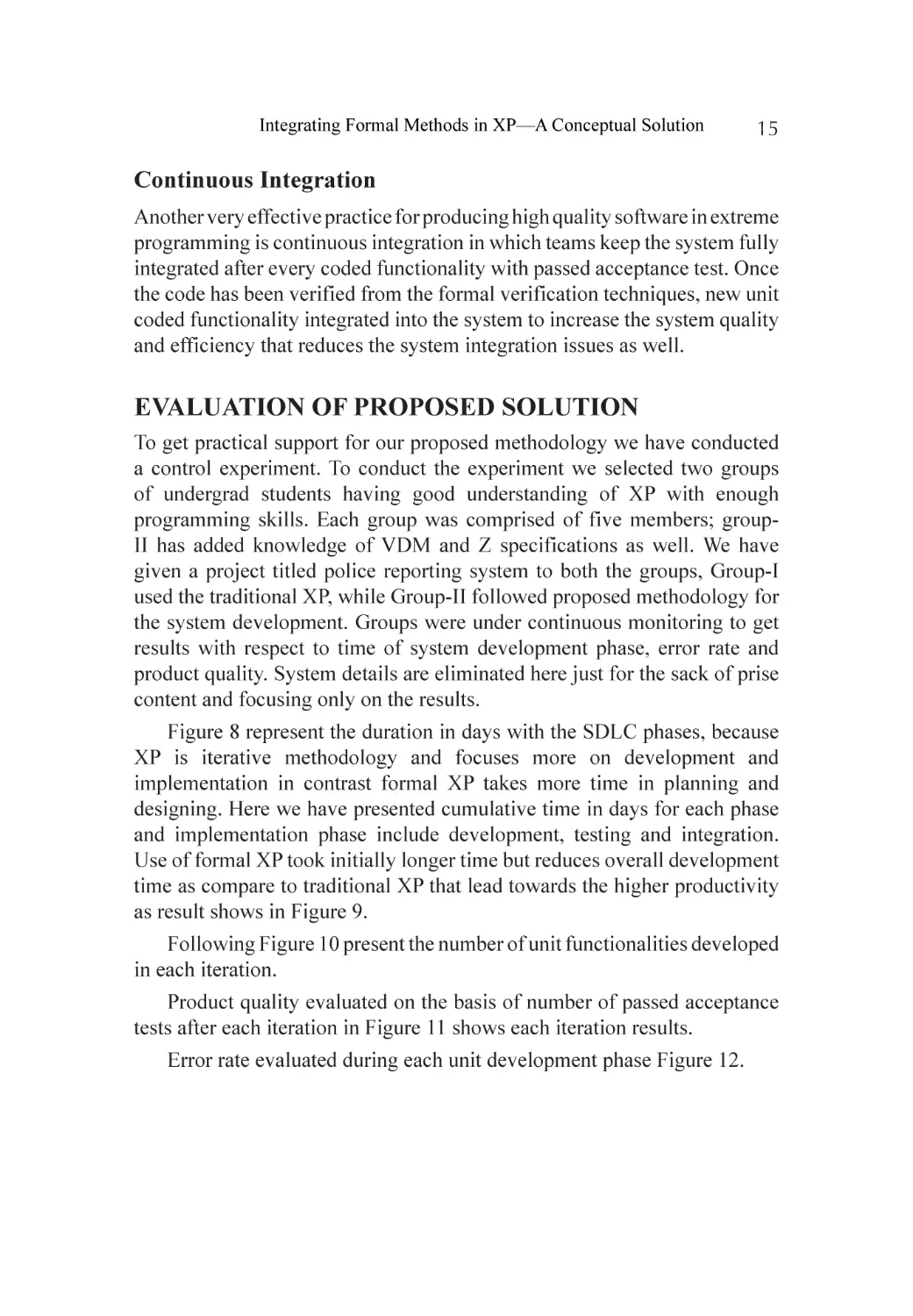
Figure 7 shows the development process with the integration of formal
verification phase. In XP, TDD developers are required to write automated
unit tests before the code is implemented this can be done by developing
formal specifications defines at the earlier stage. And formal verification can
be performed easily from the requirement specifications using automated
code driven tests. This can be cost and time effective activity.
Figure 6. Iteration.
Figure 7. Formal verification.
Integrating Formal Methods in XP—A Conceptual Solution
15
Continuous Integration
Another very effective practice for producing high quality software in extreme
programming is continuous integration in which teams keep the system fully
integrated after every coded functionality with passed acceptance test. Once
the code has been verified from the formal verification techniques, new unit
coded functionality integrated into the system to increase the system quality
and efficiency that reduces the system integration issues as well.
EVALUATION OF PROPOSED SOLUTION
To get practical support for our proposed methodology we have conducted
a control experiment. To conduct the experiment we selected two groups
of undergrad students having good understanding of XP with enough
programming skills. Each group was comprised of five members; groupII has added knowledge of VDM and Z specifications as well. We have
given a project titled police reporting system to both the groups, Group-I
used the traditional XP, while Group-II followed proposed methodology for
the system development. Groups were under continuous monitoring to get
results with respect to time of system development phase, error rate and
product quality. System details are eliminated here just for the sack of prise
content and focusing only on the results.
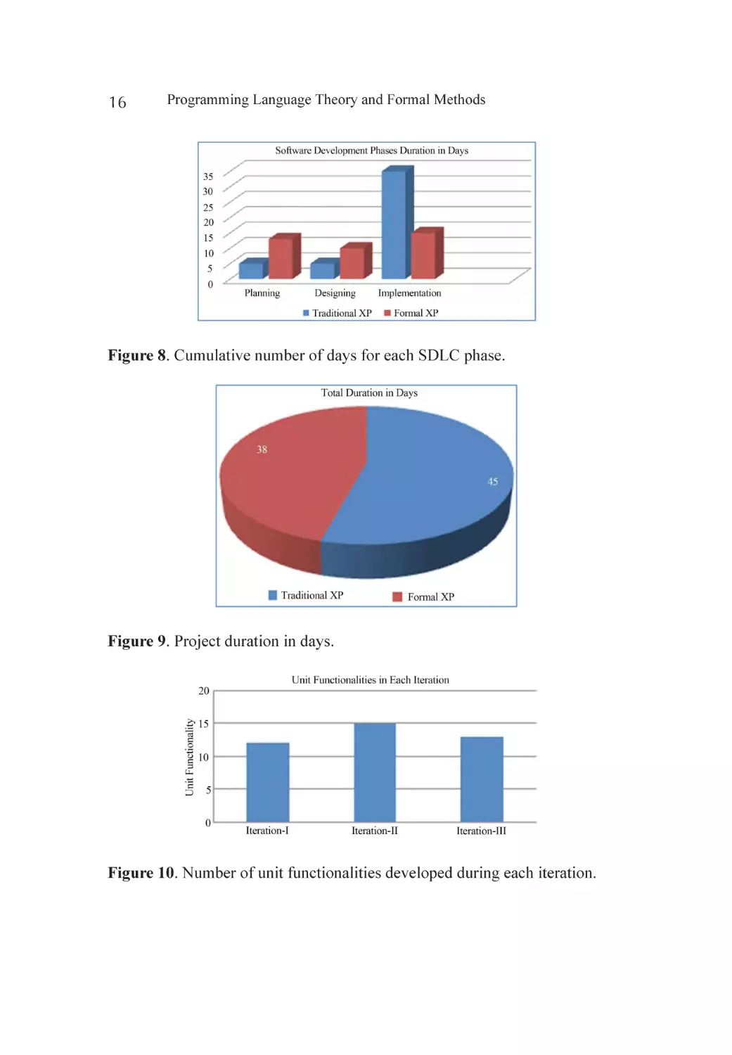
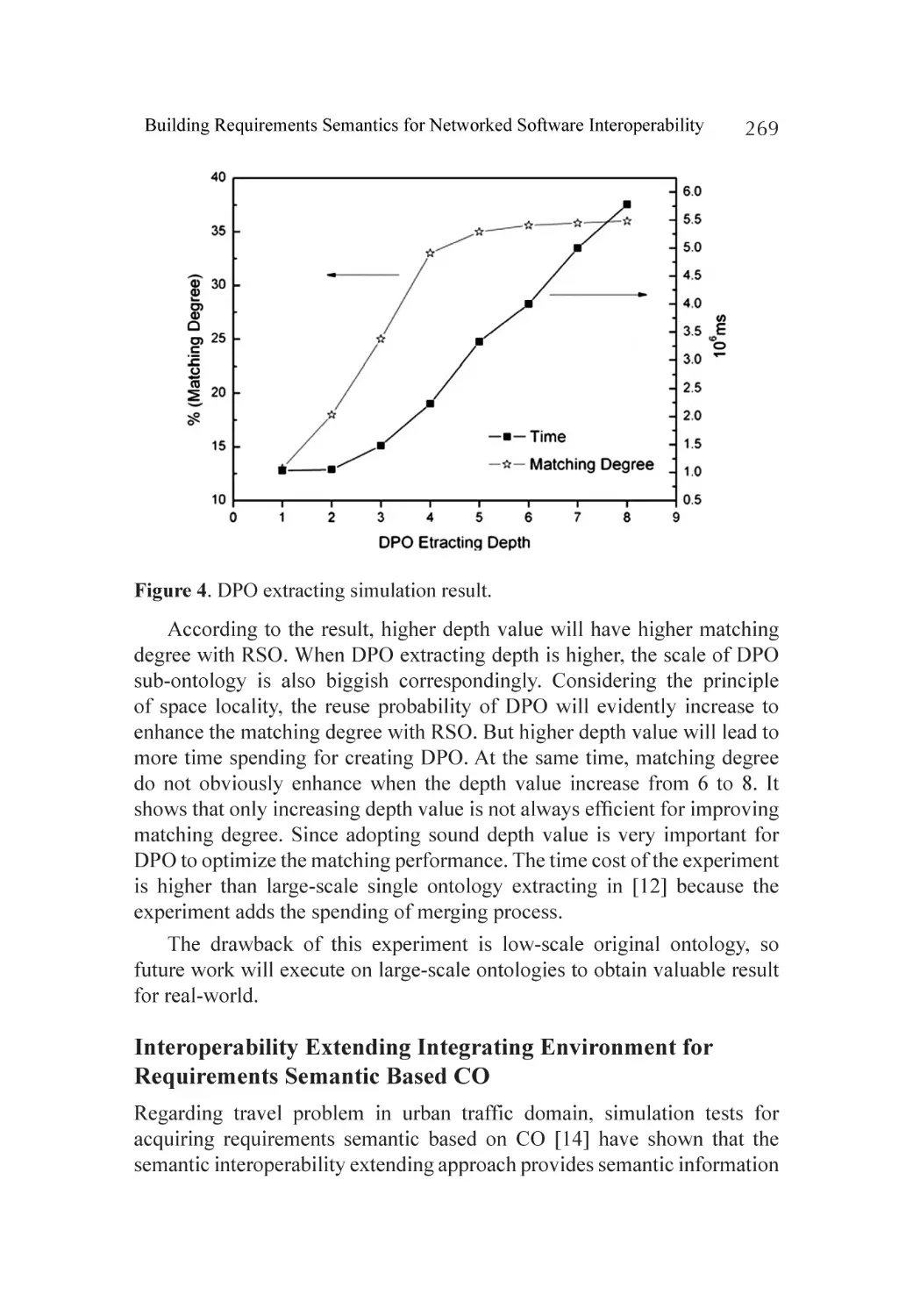
Figure 8 represent the duration in days with the SDLC phases, because
XP is iterative methodology and focuses more on development and
implementation in contrast formal XP takes more time in planning and
designing. Here we have presented cumulative time in days for each phase
and implementation phase include development, testing and integration.
Use of formal XP took initially longer time but reduces overall development
time as compare to traditional XP that lead towards the higher productivity
as result shows in Figure 9.
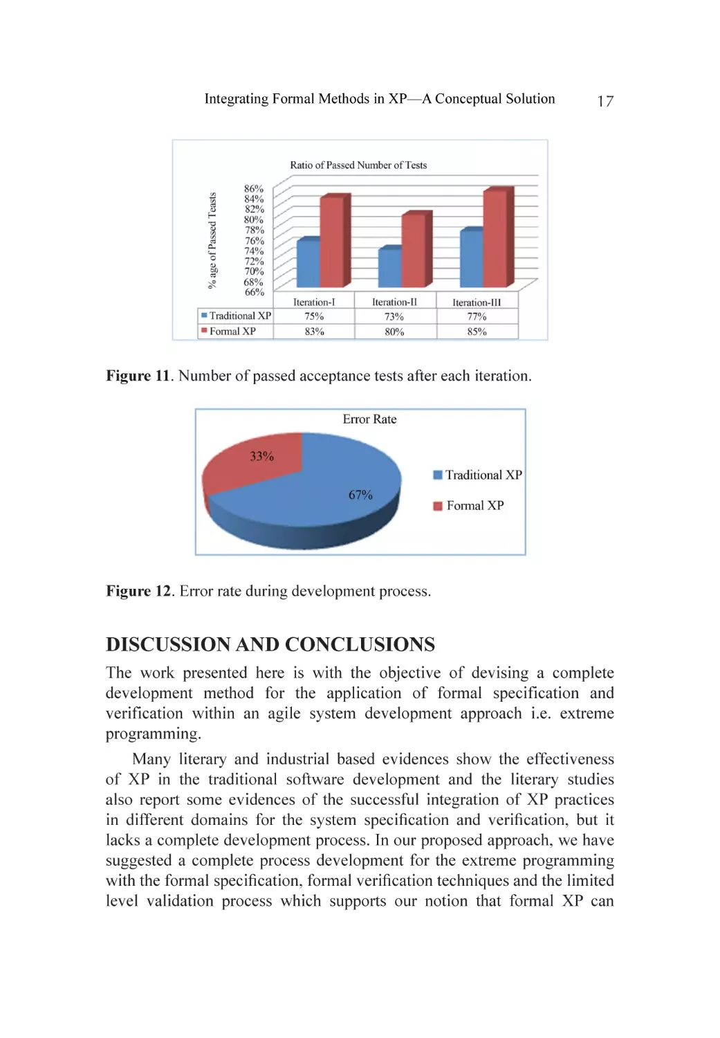
Following Figure 10 present the number of unit functionalities developed
in each iteration.
Product quality evaluated on the basis of number of passed acceptance
tests after each iteration in Figure 11 shows each iteration results.
Error rate evaluated during each unit development phase Figure 12.
16
Programming Language Theory and Formal Methods
Figure 8. Cumulative number of days for each SDLC phase.
Figure 9. Project duration in days.
Figure 10. Number of unit functionalities developed during each iteration.
Integrating Formal Methods in XP—A Conceptual Solution
17
Figure 11. Number of passed acceptance tests after each iteration.
Figure 12. Error rate during development process.
DISCUSSION AND CONCLUSIONS
The work presented here is with the objective of devising a complete
development method for the application of formal specification and
verification within an agile system development approach i.e. extreme
programming.
Many literary and industrial based evidences show the effectiveness
of XP in the traditional software development and the literary studies
also report some evidences of the successful integration of XP practices
in different domains for the system specification and verification, but it
lacks a complete development process. In our proposed approach, we have
suggested a complete process development for the extreme programming
with the formal specification, formal verification techniques and the limited
level validation process which supports our notion that formal XP can
18
Programming Language Theory and Formal Methods
lead to a higher quality product with reduced error rate and improved time
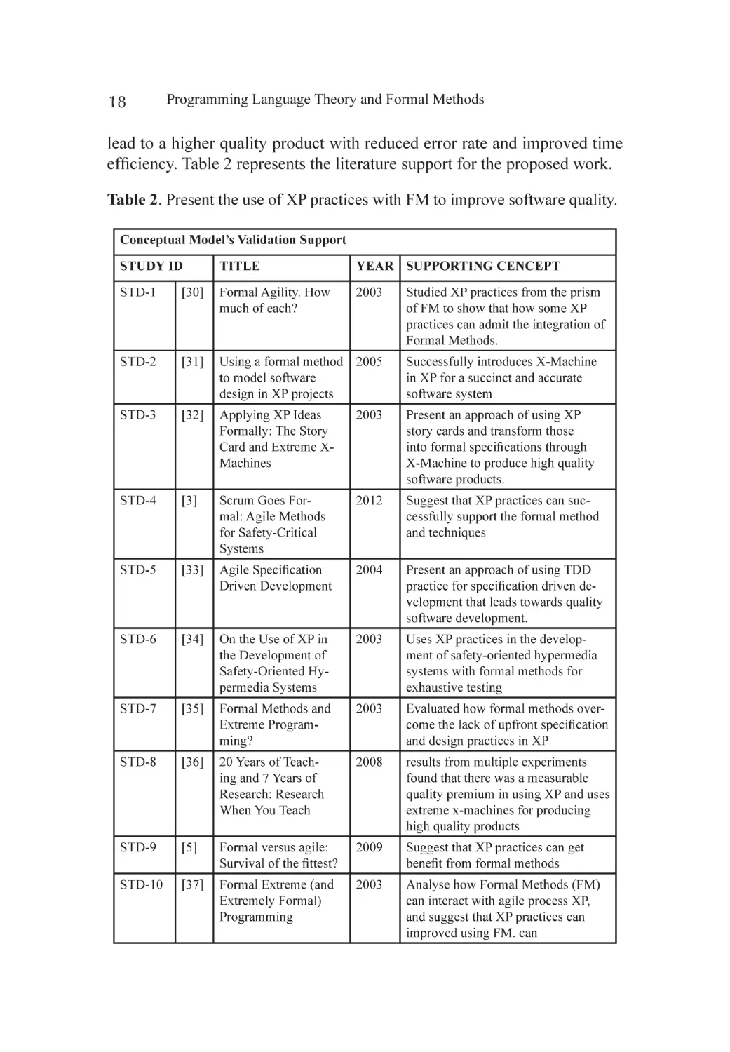
efficiency. Table 2 represents the literature support for the proposed work.
Table 2. Present the use of XP practices with FM to improve software quality.
Conceptual Model’s Validation Support
STUDY ID
TITLE
YEAR SUPPORTING CENCEPT
STD-1
[30]
Formal Agility. How
much of each?
2003
STD-2
[31]
Using a formal method 2005
to model software
design in XP projects
Successfully introduces X-Machine
in XP for a succinct and accurate
software system
STD-3
[32]
Applying XP Ideas
Formally: The Story
Card and Extreme XMachines
2003
Present an approach of using XP
story cards and transform those
into formal specifications through
X-Machine to produce high quality
software products.
STD-4
[3]
Scrum Goes Formal: Agile Methods
for Safety-Critical
Systems
2012
Suggest that XP practices can successfully support the formal method
and techniques
STD-5
[33]
Agile Specification
Driven Development
2004
Present an approach of using TDD
practice for specification driven development that leads towards quality
software development.
STD-6
[34]
On the Use of XP in
the Development of
Safety-Oriented Hypermedia Systems
2003
Uses XP practices in the development of safety-oriented hypermedia
systems with formal methods for
exhaustive testing
STD-7
[35]
Formal Methods and
Extreme Programming?
2003
Evaluated how formal methods overcome the lack of upfront specification
and design practices in XP
STD-8
[36]
20 Years of Teaching and 7 Years of
Research: Research
When You Teach
2008
results from multiple experiments
found that there was a measurable
quality premium in using XP and uses
extreme x-machines for producing
high quality products
STD-9
[5]
Formal versus agile:
Survival of the fittest?
2009
Suggest that XP practices can get
benefit from formal methods
STD-10
[37]
Formal Extreme (and
Extremely Formal)
Programming
2003
Analyse how Formal Methods (FM)
can interact with agile process XP,
and suggest that XP practices can
improved using FM. can
Studied XP practices from the prism
of FM to show that how some XP
practices can admit the integration of
Formal Methods.
Integrating Formal Methods in XP—A Conceptual Solution
19
Application of formal methods is believed as it improves system
reliability at the cost of lower productivity whereas XP focuses on more
productivity, So, in principle, using process development activities of
FM and XP can improve its efficiency like pair programming, daily code
development and integration, the simple design or metaphor and iterative
development process. On the other hand, one criticism to XP is that it lacks
formal or even semi-formal practices. So here in this paper we have tried to
devise a XP process utilizing the formal method techniques and the result
shows that the appropriate combination results in a more efficient and higher
quality development method because each can be able to minimize others’
issues.
Informal specification can have ambiguity and irrelevant details and selfcontradictory and incomplete abstractions which cannot be handled easily in
traditional XP. By defining the requirement specification through the process
of formal specification, these issues can be effectively minimized.
The role of manager in XP is to synchronize and manages the work
of all team members, with the application of the formal specification and
verification. It is required that all managers, trackers and coaches have the
implementation knowledge of formal models and their synchronization in
the software development process. To make this possible, developer’s focus
should be on the improvement of the formal specification technique which
is easier to be read and understood by the people who don’t have the strong
mathematical background like the graphical notations used in SOFL or the
more familiar C-like syntax for VDM.
The process of formal verification in our proposed approach can be
successfully used in minimizing the manual unit tests and regression testing
process in traditional XP and reduces the programmer’s efforts of continuous
testing with efficient time utilization. As suggested in the solution, formal
requirement specifications at first step can be easily transformed into
automated code driven test generation which leads towards the error free
code generation of requirements. There are also many tools available for the
system verification developed through formal specifications.
The method suggested in this paper can provide effective guidelines for
companies looking for an effective development methodology for formal
methods and applying formal specification and/or verification techniques
for software development.
20
Programming Language Theory and Formal Methods
LIMITATIONS AND FUTURE WORK
Shagufta Shafiq, Nasir Mehmood Minhas Here we have presented a
theoretical model with a very limited evaluation process. But for the
industrial applications, it should be verified from the industry. In future, we
will try to develop complete specification process that includes how the user
stories will be transformed into requirement specifications. In addition to the
evaluation of the proposed conceptual solution, several things are needed
in order to ensure higher acceptance of formal methods with industry and
industrial practices.
Integrating Formal Methods in XP—A Conceptual Solution
21
REFERENCES
1.
2.
3.
4.
5.
6.
7.
8.
9.
10.
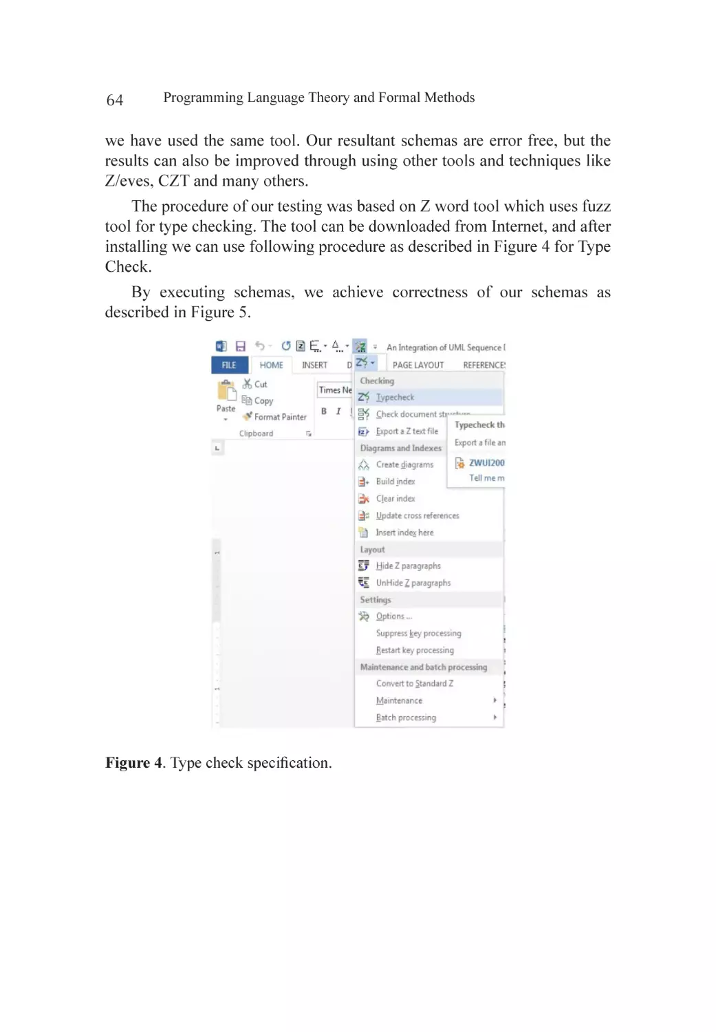
11.
12.
13.
Boca, P., Bowen, J.P. and Siddiqi, J.I. (2010) Formal Methods: State of
the Art and New Directions. Springer-Verlag London Limited, Berlin.
http://dx.doi.org/10.1007/978-1-84882-736-3
Woodcock, J., Larsen, P.G., Bicarregui, J. and Fitzgerald, J. (2009)
Formal Methods: Practice and Experience. ACM Computing Surveys,
41, 1-36. http://dx.doi.org/10.1145/1592434.1592436
Wolff, S. (2012) Scrum Goes Formal: Agile Methods for Safety-Critical
System. 2012 Formal Methods in Software Engineering: Rigorous and
Agile Approaches (FormSERA), Zurich, 2 June 2012, 23-29. http://
dx.doi.org/10.1109/MC.2009.284
Schwaber, K. (2004) Agile Project Management with Scrum. Prentice
Hall, Upper Saddle River.
Black, S., Boca, P.P., Bowen, J.P., Gorman, J. and Hinchey, M. (2009)
Formal versus Agile: Survival of the Fittest? IEEE Computer, 42, 3745.
Larsen, P.G., Fitzgerald, J. and Wolff, S. (2010) Are Formal Methods
Ready for Agility? A Reality Check. 2nd International Workshop on
Formal Methods and Agile Methods, Pisa, 17 September 2010, 13
Pages.
Johnson, S.C. and Butler, R.W. (2001) Formal Methods. CRC Press
LLC, Boca Raton.
Grunerand, S. and Rumpe, B. (2010) GI-Edition. Lecture Notes in
Informatics. 2nd International Workshop on Formal Methods and
Agile Methods, Vol. 179, 13-25.
Beck, K. (1999) Extreme Programming Explained. Addison-Wesley,
Boston.
Beck, K. (2003) Test-Driven Development. Addison-Wesley, Boston.
(2013) Extreme Programming: A Gentle Introduction. http://www.
extremeprogramming.org/.
Wood, W.A. and Kleb, W.L. (2003 Exploring XP for Scientific
Research. IEEE Software, 20, 30-36.
Dijkstra, E.W. (1972) Notes on Structured Programming, Structured
Programming. In: Dahl, O.-J., Hoare, C.A.R. and Dijkstra, E.W., Eds.,
Structured Programming, Academic Press, London, 1-82.
22
Programming Language Theory and Formal Methods
14. Dijkstra, E.W. (1968) A Constructive Approach to the Problem of
Program Correctness. BIT Numerical Mathematics, 8, 174-186. http://
dx.doi.org/10.1007/BF01933419
15. Kemmerer, R.A. (1990) Integrating Formal Methods into the
Development Process. IEEE Software, 7, 37-50. http://dx.doi.
org/10.1109/52.57891
16. Eleftherakis, G. and Cowling, A.J. (2003) An Agile Formal Development
Methodology. Proceedings of 1st South-East European Workshop on
Formal Methods, SEEFM’03, Thessaloniki, 20 November 2003, 3647.
17. Ostroff, J.S., Makalsky, D. and Paige, R.F. (2004) Agile SpecificationDriven Development. Lecture Notes in Computer Science, 3092, 104112.
18. Broy, M. and Slotosch, O. (1998) Enriching the Software Development
Process by Formal Methods. Lecture Notes in Computer Science,
1641, 44-61.
19. Liu, S. and Sun, Y. (1995) Structured Methodology + Object-Oriented
Methodology + Formal Methods: Methodology of SOFL. Proceedings
of First IEEE International Conference on Engineering of Complex
Computer Systems, Ft. Landerdale, 6-10 November 1995, 137-144.
20. Liu, S. (2009) An Approach to Applying SOFL for Agile Process
and Its Application in Developing a Test Support Tool. Innovations
in Systems and Software Engineering, 6, 137-143. http://dx.doi.
org/10.1007/s11334-009-0114-3
21. Suhaib, S.M., Mathaikutty, D.A., Shukla, S.K. and Berner, D. (2005)
XFM: An Incremental Methodology for Developing Formal Models.
ACM Transactions on Design Automation of Electronic Systems, 10,
589-609. http://dx.doi.org/10.1145/1109118.1109120
22. Schwaber, K. and Beedle, M. (2002) Agile Software Development
with Scrum. Prentice-Hall, Upper Saddle River.
23. Karlström, D. (2002) Introducing Extreme Programming—An
Experience Report. Proceedings 3rd International Conference on
Extreme Programming and Agile Processes in Software Engineering,
Alghero.
24. Holström, H., Fixgerald, B., Agerfalk, P.J. and Conchuir, E.O. (2006)
Agile Practices Reduce Distance in Global Software Development.
Integrating Formal Methods in XP—A Conceptual Solution
25.
26.
27.
28.
29.
30.
31.
32.
33.
34.
35.
23
Information and Systems Management, 23, 7-18. http://dx.doi.org/10.
1201/1078.10580530/46108.23.3.20060601/93703.2
ISO TC 22 SC3 WG16 Functional Safety, Convenor Ch. Jung.
Introduction in ISO WD26262 (EUROFORM-Seminar, April 2007).
Drobka, J., Noftzd, D. and Raghu, R. (2004) Piloting XP on Four
Mission Critical Projects. IEEE Software, 21, 70-75. http://dx.doi.
org/10.1109/MS.2004.47
Wils, A., Baelen, S., Holvoet, T. and De Vlamincs, K. (2006) Agility in
the Avionics Software World. 7th International Conference, XP 2006,
Oulu, 17-22 June 2006, 123-132.
Boehm, B. and Turner, R. (2003) Balancing Agility and Discipline.
Addison Wesley, Boston.
Pikkarainen, M. and Mäntyniemi, A. (2006) An Approach for Using
CMMI in Agile Software Development Assessments: Experiences of
Three Case Studies. 6th International SPICE Conference, Luxembourg,
4-5 May 2006, 1-11.
Herranz, Á. and Moreno-Navarro, J.J. (2003) Formal Agility, How
Much of Each? Taller de Metodologías Ágiles en el Desar-Rollo del
Software, VIII Jornadas de Ingeniería del Software Bases de Datos
(JISBD 2003), Grupo ISSI, 47-51.
Thomson, C. and Holcombe, M. (2005) Using a Formal Method to
Model Software Design in XP Projects. Annals of Mathematics,
Computing and Tele-Informatics, 1, 44-53.
Thomson, C. and Holcombe, W. (2003) Applying XP Ideas Formally:
The Story Card and Extreme X-Machines. 1st South-East European
Workshop on Formal Methods, Thessaloniki, 21-23 November 2003,
57-71.
Ostroff, J.S., Makalsky, D. and Paige, R.F. (2004) Agile SpecificationDriven Development. Lecture Notes in Computer Science, 3092, 104112.
Canos, J., Jaen, J., Carsi, J. and Penades, M. (2003) On the Use of
XP in the Development of Safety-Oriented Hypermedia Systems.
Proceedings of XP 2003, Genova, 25-29 May 2003, 201-203.
Baumeister, H. (2002) Formal Methods and Extreme Programming.
Proceedings of Workshop on Evolutionary Formal Software
Development, in Conjunction with FME, Copenhagen, 189-193, 1-2.
24
Programming Language Theory and Formal Methods
36. Holcombe, M. and Thomson, C. (2007) 20 Years of Teaching and 7
Years of Research: Research When You Teach. Proceedings of the 3rd
South-East European Workshop on Formal Methods, Thessaloniki, 30
November-1 December 2007, 1-13.
37. Herranz, A. and Moreno-Navarro, J.J. (2003) Formal Extreme (and
Extremely Formal) Programming. In: Marchesi, M. and Succi, G.,
Eds., 4th International Conference on Extreme Programming and
Agile Processes in Software Engineering, XP 2003, LNCS, No. 2675,
Genova, 88-96.
Chapter
FORMAL METHODS
FOR COMMERCIAL
APPLICATIONS ISSUES VS.
SOLUTIONS
2
Saiqa Bibi, Saira Mazhar, Nasir Mehmood Minhas, and Irfan Ahmed
UIIT-PMAS Arid Agriculture University, Rawalpindi, Pakistan
ABSTRACT
It was advocated that in 21st century, most of software will be developed
with benefits of formal methods. The benefits include faults found in earlier
stage of software development, automating, checking the certain properties
and minimizing rework. In spite of their recognition in academic world
and these claimed advantages, formal methods are still not widely used by
commercial software industry. The purpose of this research is to promote
formal methods for commercial software industry. In this paper we have
identified issues in use of formal methods for commercial applications
and devised strategies to overcome these difficulties which will provide
motivations to use formal methods for commercial applications.
Citation: Bibi, S. , Mazhar, S. , Minhas, N. and Ahmed, I. (2014), “Formal Methods for
Commercial Applications Issues vs. Solutions”. Journal of Software Engineering and
Applications, 7, 679-685. doi: 10.4236/jsea.2014.78062.
Copyright: © 2014 by authors and Scientific Research Publishing Inc. This work is
licensed under the Creative Commons Attribution International License (CC BY).
http://creativecommons.org/licenses/by/4.0
26
Programming Language Theory and Formal Methods
Keywords: Formal Methods, Commercial Applications, Issues of Formal
Methods
INTRODUCTION
Formal languages are the languages in which syntax and semantics are
properly defined by using mathematical notations. Formal languages are of
mathematical nature so; they raise the assurance on the system by reducing
uncertainty in the specification of system [1] . Commercial application
softwares are designed for vending to serve a commercial need or on the
demand of customer. These applications are larger in size.
Formal methods are actually precise techniques; tools support is provided
for development of software as well as hardware systems. Mathematical
techniques of formal methods enable developer to examine and prove models
at any stage of the software development life-cycle: gathering requirements,
specification, architecture, design, implementation, testing, maintenance,
and development [2] .
The purpose behind the promotion of formal approaches was the
detonation in software entanglement that began in the 1960s. Around
then, software systems were rapidly getting to be more complex, however
advance in devices and systems for improvement completed does not keep
pace. Accordingly, there was a clear need for new techniques that might
permit engineers to understand this complication. Formal methods made
this practical by giving a mathematical framework for investigating projects
[3] .
Formal methods are used in software requirement specification:
preparing an accurate report of what the software needs to do, and avoiding
conditions on how it is to be attained [2] .
Use of formal methods at the stage of formal specification can create very
useful documentation [4] . A specification is a practical agreement between
vendor and customer to offer them equally with a general acceptance of
the software requirement. Absolute system specifications are essential
because a design and implementation of system originate their quality in
detail from the requirements specification. Modern research is representing
the obvious advantages of formal and mathematical techniques for software
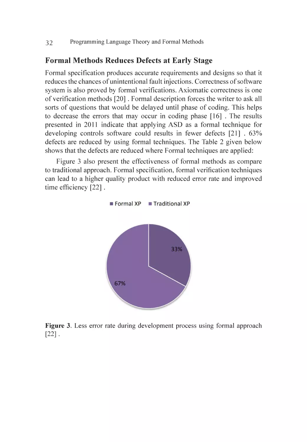
requirements detain and design. Methods used for such mathematical
technique to software requirements capture and design approach are jointly
called formal methods for specification of software [5] .
Formal Methods for Commercial Applications Issues vs. Solutions
27
At the implementation stage, the use of formal methods is utilized for
checking code of software. Each system particular match totally states an
accuracy hypothesis that, if most conditions are fulfilled, the project will
attain the impact depicted by documentation. Confirmation of code is the
endeavour to demonstrate this theorem, or in any event to figure out the reason
of theorem ignorance to hold. The inductive statement strategy for project
confirmation was imagined by Floyd and Hoare and involves explaining the
system with scientific declarations, which are associations that are between
the variables of system and the beginning principles; each one time control,
achieves a specific focus of the system. Coding can additionally be produced
immediately from models provided by formal methods [3] .
For many years, it was advocated that applying formal methods in
software development would help industry congregate its goals of produce
an enhanced software process and increase quality of software. The benefits
that have been cited include finding defects in earlier stage of software
development, automating checking of certain properties, and minimizing
rework; despite these claimed benefits and usability in each phase of software
development i.e. requirements specification, software architecture, software
design, implementation, maintenance, testing, and evolution. In spite of its
claimed benefits formal methods are still not widely used by commercial
software companies. In this paper we have described the challenges in
the use of formal methods for commercial applications industry, devised
strategies to overcome these difficulties which will provide motivations to
use formal methods for commercial applications. We have divided our work
into two sections. In the first section we have identified barriers of formal
methods for commercial applications and devised strategies to overcome
these barriers and in the second section we draw motivations for the use of
formal methods in commercial applications.
FORMAL METHODS: ISSUES VS. SOLUTIONS
Formal methods are still not seen widely in use for commercial applications
due to a number of issues:
Issue-1: Lack of Skilled Persons with Mathematical
Background
Formal methods for commercial applications development are not often
commonly used or it does not well understood by many of the software
engineers because implementation of formal methods demands the
28
Programming Language Theory and Formal Methods
unambiguous concepts of discrete mathematics [6] . Formal verification
needs mathematical skills not only due to the complex interactions between
program subcomponents, but also for the deficiencies in current verification
interfaces. These skill barriers economically resist the verification process
by avoiding the selection of less skilled persons [7] .
Solution: Tutorials & Trainings Help to Build Mathematical
Knowledge
To build knowledge for formal methods in software development
organizations on their own, a high quality tutorials and self-learning
materials can help. Self-training materials allow independent developers to
become familiar more easily with formal methods on their behalf [3] .
Issue-2: Expensive
Business managers have faith that formal methods can enhance the software
quality, but formal methods are not widely used because these methods are
considered costly and unfeasible [8] .
The most considerable doubt in formal methods, mostly from a
perspective of management, is that these methods are expensive because
implementing successful formal methods in an organization also need to
purchase the tools for supporting these methods, training of engineers and
designers, and effort and time to incorporate formal methods in the existing
software development process, with other expenditure [5] .
Solution: Ramp-Up Cost for Formal Methods Pay off over
Many Projects
The ramp-up cost plays significant role for the implementation of formal
methods. The vast number of software development tools and methodologies
place their focus on long term cost savings. There is considerable support
in the literature that formal methods provide real benefits in this area,
increasing system reliability, and thereby decreasing long-term support and
maintenance costs, while simultaneously maintaining or even decreasing
initial development costs. So while formal methods may not be appropriate
or cost effective for one-time use on a particular project, the evidence
suggests that the initial investment can pay off over many projects [3] .
Formal Methods for Commercial Applications Issues vs. Solutions
29
Issue-3: The Inadequate Tool Support
In United States a fact for formal methods indicates lack of tool support as
a barrier. They also highlighted it the key reason for the lack of appreciation
of real world considerations to be the part of formal method community and
therefore they are still not used in commercial industry [9] [10] .
Solution: Formal Methods Supported by Variety of Tools
There are many tools available that provide support to formal methods
such as Finite State Machines, VDM, Z, and OBJ. These tools are used to
increase the productivity and accuracy in all the phases of a system. These
tools possess different type of characteristics and used in industry according
to the nature or requirement of the systems [11] .
In early 80s, tools for Computer-Aided Software Engineering and
Computer-Aided Structured Programming were seen as the mean of
increasing programmer’s productivity and for reducing programming
“bugs”. Now the Tool support can see as a source of increasing productivity
and accuracy for formal developments [12] .
It is our expectation that in near future more focus will be paid to
Integrated Formal Development Support (IFDS) Environments that will
be helpful in support of many of the phases of formal development. These
toolkits will provide Integrated Programming Support Environments that
will be support in configuration management and version control and
facilitate all of the process activities and large scale developments more
harmoniously.
Issue-4: Increase in Development Cycle
Although many established advantages of formal methods, these are badly
accepted by industrial professionals. Many causes have been submitted for
this situation one of them is that they increase the software development
cycle [13] .
Solution: Early Error Detection Helps in Reduce Development
Time
It reduces the development time by applying testing techniques in earlier
phases of the lifecycle [14] . In the seventies, was reporting that over half
the software development time was devoted to testing activities. Formal
30
Programming Language Theory and Formal Methods
methods offer new possibilities for verification i.e. model checking. It
enables us in more effective identification of software defects which allows
reducing verification time [7] . The use of a formal methods or model
removes ambiguities in specification and thus reduces the chance of errors
being introduced during software development. Thus this reduces the testing
effort and time [15] .
FORMAL METHODS: MOTIVATIONS FOR
COMMERCIAL APPLICATIONS
Formal Method Maximize Automation with Automated Tools
Automated tools allow producing models for verification promptly and in a
convenient way directly from the design of models [16] . Modern progress in
analysis tools of formal methods have made it realistic to verify significant
properties formally to provide guarantee that design faults are identified and
approved correctly in early stage of software development lifecycle [17] .
A survey was presented in 2010 for effect of formal methods in software
industry. The satisfaction level with automated tools is greater than 80%
shown in Figure 1 [8] .
Figure 1. Satisfaction level with automated tools [8] .
Automatic Verification Improvement
By using the formal verification approach better verification quality can
be achieved with 70 percent less time and effort [18] as compare to other
approaches. Only 30% effort is required by using formal techniques. Formal
verification results in 2007-2010 survey are shown in the Table1
Formal Methods for Commercial Applications Issues vs. Solutions
31
Table 1. Formal verification vs. simulation [18] .
Subtasks
Simulation
Formal verification
Preparation
Simulation script is generated by
register tool
Properties are generated by
register tool
Execution
3 days of simulation time
1.5 days for automatic set-up of
31 register block set-up and exhaustive verification of 12,600
properties
Analysis effort
60,000 entries to be analysed
No additional effort
Quality of analysis Not-exhaustive, semi-automatic,
error prone
Exhaustive, automatic, fail-safe
Total effort
1.5 days compute time (70%
less than simulation)
3 days compute time + 2 days
manual effort
Formal Methods Reduce Cost
From formal specification, we can thoroughly gain effective test cases
directly from the requirement. Test cases generation is a cost effective way
[19] . Effects of Formal Methods on cost are presented in a survey in 2010
shown in Figure 2.
Figure 2. Formal approaches’ effect on cost [8] .
32
Programming Language Theory and Formal Methods
Formal Methods Reduces Defects at Early Stage
Formal specification produces accurate requirements and designs so that it
reduces the chances of unintentional fault injections. Correctness of software
system is also proved by formal verifications. Axiomatic correctness is one
of verification methods [20] . Formal description forces the writer to ask all
sorts of questions that would be delayed until phase of coding. This helps
to decrease the errors that may occur in coding phase [16] . The results
presented in 2011 indicate that applying ASD as a formal technique for
developing controls software could results in fewer defects [21] . 63%
defects are reduced by using formal techniques. The Table 2 given below
shows that the defects are reduced where Formal techniques are applied:
Figure 3 also present the effectiveness of formal methods as compare
to traditional approach. Formal specification, formal verification techniques
can lead to a higher quality product with reduced error rate and improved
time efficiency [22] .
Figure 3. Less error rate during development process using formal approach
[22] .
Formal Methods for Commercial Applications Issues vs. Solutions
33
Table 2. Defects are reduced with formal approaches [21] .
Lines of code
Defects
ASD
used
Unit
Manual ASD
LOC
LOC
Total
LOC
ASD%
Manual ASD
Total
Defects/
defects defects defects KLOC
No
Acquisition
6140
0
6140
00.00%
33
0
33
5375
No
BEC
7007
0
7007
00.00%
44
0
44
6279
No
EPX
7138
0
7138
00.00%
7
0
7
0.981
No
FEAdapter
13190
0
13190
00.00%
18
0
18
1.365
YES
FEClient
15462
12153 27615
44.01%
9
2
11
0.398
YES
Orchestration
3970
8892
12862
69.13%
3
4
7
0.544
No
QA
23303
0
23303
00.00%
90
0
90
3.862
No
Status Area
8969
0
8969
00.00%
52
0
52
5.798
No
TSM
6681
0
6681
00.00%
7
0
7
1.048
No
UIGuidance
20458
0
20458
00.00%
23
0
23
1.124
No
Viewing
19684
0
19684
00.00%
294
0
294
14.936
YES
XRayIP
14270
2188
16458
13.29%
27
0
27
1.641
Formal Methods Improves Quality
A survey presented in 2010 for effect of formal methods in software industry.
It is presented that use of formal techniques improves quality of software
in industry, 92% cases reported that quality is increased against the other
approaches, and there is no single case that reported a decline in software
quality. Figure 4 shows the effect of formal methods on quality of software
[8] .
Overall effect of formal methods in software industry is shown in Figure
5. By applying formal methods in commercial software industry batter results
can be achieved as compare to other approached as shown by survey results.
Researchers are hopeful about the flourishing use of formal approaches for
commercial software industry in future.
34
Programming Language Theory and Formal Methods
Figure 4. Formal approaches’ effect on quality [8] .
Figure 5. Overall effects of formal methods in software industry.
CONCLUSION
For many years, it was advocated that applying formal methods in software
development would help industry congregate its goals of producing an
enhanced software process and increasing quality of software. De-Saiqa
Bibi, Saira Mazhar, Nasir Mehmood Minhas, Irfan Ahmed spite claimed
benefits and usability in each phase of software development, formal
methods are still not widely used by commercial software companies. Formal
methods have not been widely used in industry due to a number of barriers.
We have identified barriers of formal methods for commercial applications
and then provide their solution. Formal methods offer several advantages
i.e. maximize automation with automated tools, automatic verification
Formal Methods for Commercial Applications Issues vs. Solutions
35
improvement cost saving, defect reduction and quality improvement. These
benefits are the stimulus to use formal methods in commercial software
industry. By applying formal methods in commercial software industry
batter results can be achieved as compared to other approaches shown by
survey results. The purpose of this research is to promote formal methods
for commercial application software in industry.
36
Programming Language Theory and Formal Methods
REFERENCES
1.
2.
3.
4.
5.
6.
7.
8.
9.
10.
11.
12.
13.
14.
Sammi, R., Rubab, I. and Qureshi, M.A. (2010) Formal Specification
Languages for Real-Time Systems. 2010 International Symposium in
Information Technology (ITSim), Kuala Lumpur, 15-17 June 2010,
1642-1647. http://dx.doi.org/10.1109/ITSIM.2010.5561643
Woodcock, J.I.M. and Bicarregui, J. (2009) Formal Methods: Practice
and Experience Engineering College of Aarhus. ACM Computing
Surveys, 41, 1-40.
Geer, P.A. (2011) Formal Methods in Practice: Analysis and Application
of Formal Modeling to Information System.
Bowen, J.P. and Hinchey, M.G. (2006) Ten Commandments of Formal
Methods... Ten Years Later. Computer, 39, 40-48.
Sommerville, L. (2009) Chapter 27 Formal Specification.
Stidolph, D.C. and Whitehead, J. (2003) Managerial Issues for the
Consideration and Use of Formal Methods. Lecture Notes in Computer
Science, 2805, 170-186.
Schiller, T.W. and Ernst, M.D. (2012) Reducing the Barriers to Writing
Verified Specifications. ACM SIGPLAN Notices, 47, 95-112.
Fulara, J. and Jakubczyk, K. (2010) Practically Applicable Formal
Methods. Lecture Notes in Computer Science, 5901, 407-418.
Stidolph, D.C. (2003) When Should Formal Methods Be Used?
Jhala, R. and Majumdar, R. (2009) Software Model
Checking. ACM Computing Surveys, 41, 1-54. http://dx.doi.
org/10.1145/1592434.1592438
Kefalas, P., Eleftherakis, G. and Sotiriadou, A. (2003) Developing
Tools for Formal Methods.
Bowen, J.P. and Hinchey, M.G. (1994) Seven More Myths of Formal
Methods?: Dispelling Industrial Prejudices. Lecture Notes in Computer
Science, 873, 105-117.
Knight, J.C., Dejong, C.L., Gibble, M.S. and Nakano, L.G. (1998)
Why Are Formal Methods Not Used More Widely?
Hierons, R.M., Bogdanov, K., Bowen, J.P., Cleaveland, R., Derrick, J.,
Dick, J., et al. (2002) Using Formal Specifications to Support Testing.
ACM Computing Surveys, 41, Article No. 9.
Formal Methods for Commercial Applications Issues vs. Solutions
37
15. Singh, M. (2013) Formal Methods: A Complementary Support for
Testing. International Journal of Advanced Research in Computer
Science and Software Engineering, 3, 320-322.
16. Cofer, D., Whalen, M. and Miller, S. (2008) Model-Based Development.
1-8.
17. Whalen, M., Cofer, D., Miller, S., Krogh, B.H. and Storm, W.
(2008) Integration of Formal Analysis into a Model-Based Software
Development Process. Lecture Notes in Computer Science, 4916, 6884.
18. Knablein, B.J. and Sahm, H. (2010) Contributed Article Automated
Formal Method Verifies Highly-Configurable HW /SW Interface. 1-7.
19. Batra, M., Malik, A. and Dave, M. (2013) Formal Methods?: Benefits,
Challenges and Future Direction. Journal of Global Research in
Computer Science, 4, 2-6.
20. Alves, M.C.B., Dantas, C.C. and Silva, R.B. (2007) A Topological
Formal Treatment for Scenario-Based Software Specification of
Concurrent Real-Time Systems. 1-7.
21. Groote, J.F., Osaiweran, A.A.H. and Wesselius, J.H. (2011) Benefits of
Applying Formal Methods to Industrial Control Software. 1-10.
22. Shafiq, S. and Minhas, N.M. (2014) Integrating Formal Methods in
XP—A Conceptual Solution. Journal of Software Engineering and
Applications, 7, 299-310.
Chapter
WHY FORMAL METHODS
ARE CONSIDERED FOR
SAFETY CRITICAL
SYSTEMS?
3
Monika Singh1, Ashok Kumar Sharma1, and Ruhi Saxena2
Faculty of Engineering & Technology (FET), Mody University of Science & Technology, Sikar, India
2
Computer Science & Engineering, Thapar University, Patiala, India
1
ABSTRACT
Formal methods are the mathematically techniques and tools which are
used at early stages of software development lifecycle processes. The utter
need of using formal methods in safety critical system leads to accuracy,
consistency and correctness in proposed system. In safety critical real time
application, requirements should be unambiguous and very accurate which
can be achieved by using mathematical theorems. There is utter need to
focus on the requirement phase which is the most critical phase of SDLC.
This paper focuses on the use of Z notation for incorporating the accuracy,
Citation: Singh, M. , Sharma, A. and Saxena, R. (2015), “Why Formal Methods Are
Considered for Safety Critical Systems?”, Journal of Software Engineering and Applications, 8, 531-538. doi: 10.4236/jsea.2015.810050.
Copyright: © 2015 by authors and Scientific Research Publishing Inc. This work is
licensed under the Creative Commons Attribution International License (CC BY).
http://creativecommons.org/licenses/by/4.0.
40
Programming Language Theory and Formal Methods
consistency, and eliminates ambiguity in safety critical system: Road Traffic
Management System as a case study. The syntax, semantics, type checking
and domain checking are further verified by using Z/EVES: a Z notation
type checker tool.
Keywords: Formal Methods, Safety Critical System, Z Notation, Z/EVES,
Syntax & Type Checking, Domain Checking
INTRODUCTION
Formal specification languages are mathematically based on languages
which are adequately used for construction of accurate, consistent and
unambiguous systems and software. As formal methods are equipped with
tool, which can be used for both the prospective i.e. describing a system and
later on for analyzing their functionalities. The major obstacles behind formal
methods to be used in practices frequently are the time spent on specification
[1] [2] . Nevertheless, formal methods do not guarantee correctness, but their
use emphasize to increase the understanding of a system by divulging errors
or facets of incompleteness that may be expensive to correct them at any
later point of time. However, formal methods play a critical role in safety
critical system as they focus on refinement of requirements in the early
stage of development which consequently increase the system’s accuracy
and consistency. Various formal languages are used for this purpose like
VDM, B-Methods, Petri Net, and Z notation etc. Z notation is a model based
on formal specification language which uses the set theory and first order
predicates [3] .
A lot of work has been done in this area of formal analysis of UML
diagrams with formal approaches [4] -[8] . In article 8, UML based framework
is presented to develop web applications. [5] represents the verification
properties by HOL theorem prover. A formalization approach is developed
for UML class diagrams in [6] . The paper [7] advocates how the formal
methods can be used for safety properties of real time critical application
such as railways. [8] explains an integrated approach of Z notation and
Pertinet for analysis of safety critical properties.
In this article, Z notation is used for formal analysis of safety critical
system i.e. Road Traffic Management System which is further verified by
using the Z/EVES tool.
Why Formal Methods Are Considered for Safety Critical Systems?
41
PROPOSED APPROACH & METHODOLOGY
In the first part of this section, the proposed approach is discussed. Then the
tool and methodology used are discussed in section.
Proposed Approach
Figure 1 defines the proposed approach for designing the safety critical
system using the formal methods.
Figure 1. The proposed approach for formal analysis of safety critical application.
Programming Language Theory and Formal Methods
42
Z/EVES
This tool is used for verifying the specification written in Z notation language.
This verification includes syntax, semantics, type checking, and domain
checking of the given system’s specification. Z/EVES present two type of
interface: graphical user interface and the command line interface [3] [9] . In
this paper, we used the graphical user interface for verifying and composing
the specification which were written in Z notation language. Moreover,
Z/EVES propose two mode of operations i.e. “Eager” and “Lazy”. In our
article we use the “Eager” mode since in this mode a paragraph is checked if
and only if all the previous ones are checked which is highly recommended
for safety critical real time application. By using Z/EVES, following can be
done:
•
•
•
•
•
syntax and type checking;
schema expansion;
precondition calculation;
domain checking;
general theorem proving.
UML
Unified Modeling language is in fact the blue prints for the system to be
developed. It provides a better way to understands the requirements of the
propose system. UML consists of nine diagrams which are used for capturing
the both aspects of the system i.e. static and dynamic [10] -[12] . This paper
aims at the static behaviour by composing the use case diagram of RTMS
system which is further verified by using Z/EVES type checker tool. The
conceptual model of Road Traffic Management System (RTMS) is given in
Figure 2.
Why Formal Methods Are Considered for Safety Critical Systems?
43
Figure 2. Use case diagrams of vehicle owner.
FORMALIZATION OF USE CASE DIAGRAM USING
Z/EVES
Z schema is the notion for structuring the specification including the pre,
post condition and the list of invariant & variables. Z schema has two parts
i.e. declaration part and predicate part. The Z schema has both declaration
as well as predicate part that is shown in Figure 3.
Figure 3. State space of schema.
The above part of central line consists of variables declaration and the
below part of line describes the relationship the variable’s various values.
This paper emphasis on three main characteristics of formal analysis of
safety critical system which are:
1.
2.
3.
Syntax & Type checking;
Schema Expansion; and
Domain checking.
Programming Language Theory and Formal Methods
44
1) Syntax & Type Checking
The syntax and type checking facility is provided by the Z/EVES tool. The
syntax & type checking facility enables that the syntax used in Z specification
is correct which is automatically done by Z/EVES tool. In case of road traffic
management system, the schema of Vehicle Owner is considered for syntax
& type checking which is consists of two variables:
•
•
Vowner is the set of names with RTMS registered.
Regist Vowner is the function which when implemented on a
particular Vehicle Owner name, provides the unique registration
number associated with the person.
In Figure 4, the schema for Vehicle Owner with basic data type is given:
[Name, Seqchar].
In Vehicle Owner schema, a partial function named “Regist Vowner”
is defined which maps the corresponding vehicle owner with a registration
number i.e.
Regist Vowner: Name→ Seqchar
Moreover, “Regist Vowner” is a one-to-one function which maps
Vehicle Owner name with registration number. Since it is a one-to-one
function, therefore every Vehicle Owner has a unique registration number
and consequently, would be no ambiguity. The schema of Vehicle Owner is
further verified by Z/EVES tool for syntax & type checking in Figure 5. The
left most columns’ value “Y” shows that the schema is implemented using
correct syntax. If there would be any syntax error, it shows “N” instead of
“Y” in syntax column [9] .
Figure 4. Vehicle Owner schema with invariants.
Why Formal Methods Are Considered for Safety Critical Systems?
45
Figure 5. Syntax checking of Vehicle Owner schema by Z/EVES.
2) Schema Expansion
The schema expansion facility enables to extend the functionality of system
and helps in understanding the complex schema structure in detail. Initially,
the list of registered vehicle owner in RTMS is empty which is depicted by
the “Init Vehicle Owner” schema in Figure 6.
Since the lower part of the schema explain the relation between the
variables, the function Regist Vowner is assigned a value “φ”, and means
initially there is no registered vehicle owner in RTMS. Figure 7 shows the
Z/EVES result of “Init Vehicle Owner”.
Now, the Vehicle Owner may perform a list of tasks like: Login. If
the Vehicle Owner is Login first time, he/she has to register him/her;
otherwise he/she will sign in. In Figure 8, the schemas of Login operation
is implemented.
Figure 6. Initial state space of schema Vehicle Owner.
46
Programming Language Theory and Formal Methods
Figure 7. Initial Vehicle Owner schema.
Figure 8. State space of schema Login.
In this schema:
Password: Vowner→Word
“Password” is a function which associates a username to password.
Nevertheless, it is a one-to-one function which in turn provides accuracy
and correctness to system. Now Signin set and registered set both is the
member of power set of Vehicle Owner which is mathematically shown by
using set theory as following.
Signin, Reg: ℙ Vowner
Also the Signin set is a subset of registered set and the registered set
having the values which are there in domain of “password” function i.e.
Signin ⊆ Reg = Dom Password
Initially, Login schema is empty which is here explained by assigning a
value “φ” to both the set whether it’s a registers one or a new one i.e.
Reg = φ; Signin = φ
This is called schema expansion which is one of the key features of Z/
EVES tool i.e. from “Init Login” schema to “Login” schema.
In Figure 9, the schema expansion is shown and verified by Z/EVES as
follow.
Why Formal Methods Are Considered for Safety Critical Systems?
47
Figure 9. Z/EVES Schema expansion of Initial Login to Login schema.
3) Domain Checking
Domain checking feature of Z/EVES tool enables us to write the statements
which are meaningful and in finding the domain errors. However, it has
been found that as compared to syntax & type checking, domain checking is
more crucial because where syntax and type checking is done automatically,
one needs to work together with theorem prover to accomplish the domain
checking. We also observed that proof “by reduce” in the proof window of
the tool was sufficient for our formal specifications for domain checking.
Now if you are already registered, you will opt for the sigin option. By
investigating Figure 10, the value for syntax column is “Y”, means no error,
but the value in proof column is “N”. This is related to domain checking. The
proof can be initiated by selecting the theorem in the Specification window,
right clicking, and selecting “Show proof” which is shown in Figure 9.
The proof can be done by various mean in Z/EVES by choosing “Action
Point” by Reduction, Cases, Quantifiers, Normal Norms and Equality. In our
case, we use the option “prove by reduction”. Figure 11 describes the proof
by reduce action point in case of “Signin” schema.
48
Programming Language Theory and Formal Methods
Figure 10. Domain checking with Z/EVES.
Figure 11. Proof script by using action point “proof by reduce” for “Signin”
schema.
RESULT ANALYSIS
Any proposed model is incomplete without tool support. Nevertheless, use
of formal language adequately increases the accuracy and completeness
Why Formal Methods Are Considered for Safety Critical Systems?
49
but, the use of computer tool indeed increases the level of confidence
significantly for the system to be developed by fingering out the potential
errors in syntax and semantics of formal narration. Table 1 depicts the
result of formal analysis of proposed schemas of road traffic management
system using Z/EVES. The attributes in the table are name of the schema
followed by syntax & type checking, domain checking, proof and reduction.
The second row in table, having status Y for all columns indicating that
the schema named “Vehicle Owner” is correct with respect to syntax &
type check errors, domain check and having correct proof by performing
reduction on the set of predicates for making specification meaningful. The
Y¹ symbol shows that the action point in proof window is chosen as “prove
by reduce”.
Table 1. Result analysis by Z/EVES.
Schema
Name
Syntax &
Type Checking
Domain
Checking
Schema
Expansion
Proof by
Reduction
Vehicle
Owner
Y
Y
Y
Y¹
Login
Y
Y
Y
Y¹
Signin
Y
Y
Y
Y¹
CONCLUSION
The use of formal methods in safety critical application increases quality in
terms of accuracy, consistency, and in completeness. This paper describes
the use of Z notation, a formal methods for Vehicle Owner, an actor of Road
Traffic Management System; which will be further verified by Z/EVES, a
typechecker tool for Z notation specification. In Future, the schema of Traffic
Police, Admin, and Traffic Manager will be implemented and verified by Z/
EVES theorem prover.
ACKNOWLEDGEMENTS
Authors are thankful to faculty of Engineering & Technology (FET), Mody
University of Science & Technology for providing the facility to carry out
the research work.
50
Programming Language Theory and Formal Methods
REFERENCES
1.
Woodcock, J.C.P. (1989) Structuring Specifications in Z. IEE/BCS
Software Engineering Journal, 4, 51-66. http://dx.doi.org/10.1049/
sej.1989.0007
2. Hall, A. (2002) Correctness by Construction: Integrating Formality
into a Commercial Development Process. Proceedings of International
Symposium of Formal Methods Europe, 2391, 139-157. http://dx.doi.
org/10.1007/3-540-45614-7_13
3. Spivey, J.M. (1989) The Z Notation: A Reference Manual. PrenticeHall, Englewood Cliffs.
4. Hamdy, K.E., Elsoud, M.A. and El-Halawany, A.M. (2011) UMLBased Web Engineering Framework for Modeling Web Application.
Journal of Software Engineering, 5, 49-63. http://dx.doi.org/10.3923/
jse.2011.49.63
5. Hasan, O. and Tahar, S. (2007) Verification of Probabilistic Properties
in the HOL Theorem Prover. Proceedings of the Integrated Formal
Methods, 4591, 333-352. http://dx.doi.org/10.1007/978-3-540-732105_18
6. He, X. (2000) Formalizing UML Class Diagrams: A Hierarchical
Predicate Transition Net Approach. Proceedings of 24th Annual
International Computer Software and Applications Conference, Taipei,
25-28 October 2000, 217-222.
7. Zafar, N.A., Khan, S.A. and Araki, K. (2012) Towards the Safety
Properties of Moving Block Railway Interlocking System. International
Journal of Innovative Computing, Information and Control (ICIC
International), 5677-5690.
8. Heiner, M. and Heisel, M. (1999) Modeling Safety Critical Systems
with Z and Petri-Nets. Proceedings of International Conference on
Computer Safety, Reliability and Security, London, 26-28 October
1999, 361-374. http://dx.doi.org/10.1007/3-540-48249-0_31
9. The Z/EVES 2.0 User’s Guide: Mark Saaltink. October 1999 ORA
Canada.
10. Mostafa, A.M., Manal, A.I., Hatem, E.B. and Saad, E.M. (2007)
Toward a Formalization of UML2.0 Meta-Model Using Z
Specifications. Proceedings of 8th ACIS International Conference
Why Formal Methods Are Considered for Safety Critical Systems?
51
on Software Engineering, Artificial Intelligence, Networking and
Parallel/Distributed Computing, 3, 694-701. http://dx.doi.org/10.1109/
SNPD.2007.508
11. Jacobson, R.I. and Booch, G. (2006) The Unified Modeling Language
Reference Manual. 2nd Edition.
12. Selic, B. and Rumbaugh, J. (1998) UML for Modeling Complex RealTime Systems. Technical Report, Object Time.
Chapter
AN INTEGRATION OF
UML SEQUENCE
DIAGRAM WITH FORMAL
SPECIFICATION
METHODS― A FORMAL
SOLUTION BASED ON Z
4
Nasir Mehmood Minhas, Asad Masood Qazi, Sidra Shahzadi, and Shumaila Ghafoor
University Institute of Information Technology, PMAS-University Institute of Information Technology, Rawalpindi, Pakistan
ABSTRACT
UML Diagrams are considered as a main component in requirement
engineering process and these become an industry standard in many
organizations. UML diagrams are useful to show an interaction, behavior
and structure of the system. Similarly, in requirement engineering, formal
specification methods are also being used in crucial systems where precise
Citation: Minhas, N. , Qazi, A. , Shahzadi, S. and Ghafoor, S. (2015), “An Integration of UML Sequence Diagram with Formal Specification Methods-A Formal Solution Based on Z”. Journal of Software Engineering and Applications, 8, 372-383. doi:
10.4236/jsea.2015.88037.
Copyright: © 2015 by authors and Scientific Research Publishing Inc. This work is
licensed under the Creative Commons Attribution International License (CC BY).
http://creativecommons.org/licenses/by/4.0
54
Programming Language Theory and Formal Methods
information is required. It is necessary to integrate System Models with
such formal methods to overcome the requirements errors i.e. contradiction,
ambiguities, vagueness, incompleteness and mixed values of abstraction.
Our objective is to integrate the Formal Specification Language (Z) with
UML Sequence diagram, as sequence diagram is an interaction diagram
which shows the interaction and proper sequence of components (Methods,
procedures etc.) of the system. In this paper, we focus on components of
UML Sequence diagram and then implement these components in formal
specification language Z. And the results of this research papers are
complete integrated components of Sequence diagram with Z schemas,
which are verified by using tools and model based testing technique of
Formal Specifications. Results can be more improved by integrating
remaining components of Sequence and other UML diagrams into Formal
Specification Language.
Keywords: Formal Specifications, Software Requirement Specifications,
Formal Notations
INTRODUCTION
Formal Methods are based on mathematical techniques, which can be
used in any phase of Project life cycle, especially in an initial stage. When
requirements are gathered from clients, project team has to know about the
system. There are many techniques of formal methods, like Model based
Languages, Process Oriented and Algebraic Specifications.
In Software Engineering, formal specifications and UML Diagrams are
very useful to understand the requirements and specifications of the system.
Formal specifications and UML are used since many years in Software
Engineering, and UML diagrams are considered as a standard tool in many
organizations. There is a complete method in Software Engineering named
as “Clean Room Software Engineering” [1] basically based on formal
specifications. The idea behind the Clean Room SE is “Do it Right, at first
Time”. It is composed of gathering requirements, and then transforms them
into statistical methods, so there will no need of unit testing.
UML diagrams are important to understand the complexity of system.
UML describes the behavior and structure of a program. Also, they describe
the interaction of components with the system. These include Use Case, Class,
Activity and many other diagrams. UML diagrams are easy to understand by
An Integration of UML Sequence Diagram with Formal Specification ...
55
the users, developers and domain experts whereas the formal methods are
difficult to understand by the users, domain experts and developers as well.
Before go forward, we also need to know that where the specification
part lies actually in the Requirement engineering process. A brief detail of
requirement engineering process is given below:
Software requirement engineering involves requirements elicitation,
requirements specification, requirements validation and requirements
management [2] [3] . Requirements elicitation involves the ways of gathering
the requirements which include many traditional, cognitive, model based
techniques etc.
Whereas, the requirements Specification (where analysis and negotiation
of requirements are performed), requirements of users are specify to make
them understandable and meaningful for developers. Specifications can be
formal as well as non-formal [4] . Formal techniques include the set of tools
and techniques based on mathematical models whereas informal techniques
are based on modeling the requirements in diagrams or making architecture
of system. There are many techniques in both types of specification. Like in
formal techniques of specifications, we have different formal specification
languages like Z, VDM etc. and in in-formal or non-formal techniques,
we have UML diagrams which include use-cases, sequence diagrams,
collaboration and interaction diagrams etc.
In Requirements validation, the completeness of the requirements being
checked which means either gathered requirements are correct, complete
or not. The main objective to analyze the validation and verification of
RE process to identify and resolve the problems and highly risk factors
of software in early stages to make strengthen the development cycle [5]
. Finally, in Requirements management phase, issues and conflicts of users
are resolved. According to Andriole [6] , the requirement management is a
political game. It is basically applied in such cases where we have to control
the expectations of stakeholders from software, and put the requirements
rather than in well-meaning by customers but meaning full by developers, so
they can examine that, they actually full fill the user’s requirements.
Authors of [7] include the Requirement change management under
the Requirement Engineering process. RCM is a term which is used as the
history or previous development of the similar software product (s). On the
basis of historical development, we investigate the need of RCM or not.
Programming Language Theory and Formal Methods
56
Unique Features of Sequence Diagrams
There are some unique features of Sequence diagrams and also reasons for
choosing sequence diagrams for this research purpose, which are:
•
Sequence Diagrams are used to show the priorities of steps/
modules of system, Lower step denotes to the later.
•
Reverse Engineering of UML sequence diagrams are used to
support reverse engineering in software development process [8]
.
•
It shows a dynamic behavior of system and considered as good
system architecture design approach [9] .
•
Sequence diagrams include the Life line of the objects, and it can
be easily integrated because of Time dimension [10] .
•
We can use messages to make it understandable by all stakeholders.
•
We can also use loops, alternatives, break, parallelism between
complex components of system and many more [10] .
Our Idea is to work on integration of UML Sequence Diagram’s attributes
with formal specification methods like Z notations to bridge a gap between
both (formal and informal) methods. So, once we make a sketch of any
system in to Sequence diagram to show its sequence of steps, requirement
priorities, time bar information and others, then we will transform these
attributes into Z schemas. So it will be an easy for developers, to develop
system if they had requirements in proper mathematical forms. Also, there
was a research gap of properly integration of Sequence diagrams with formal
specifications.
RELATED WORK
The Integration of formal and in formal methods of specification is not a
new area, it is being used by many software industries as well as there is a
complete area of research in Software engineering to tackle the limitations
of both techniques and transform them into an intermediately solution. Many
studies are there which are helpful to integrate the Z notations with Scrum,
requirement elicitation and many other areas.
In [11] , authors represents a conceptual solution to formalize the Class
Diagrams, in which they formalize the class diagrams through steps including
representing classes in Z, representing associations in Z representing
aggregation in Z and then represent generalization of classes in Z.
An Integration of UML Sequence Diagram with Formal Specification ...
57
Similarly, in [12] researchers represent a conceptual solution to
integrate XP methodology with Z. They work on user stories phase, where
user stories will be verified through Formal Verification techniques. It
can also be observed from [13] in which integration of the Z notations
into Use case Diagram, because use case diagrams are very common in
software development companies, as these are easy to understand by all
stakeholders, so they apply Z on them, to bridge a gap between formal and
informal techniques. It has been observed from [14] , which is study on an
Integration of formal methods into agile methodology that formal methods
can lead towards a better software development solution. In [15] , they
apply formalization in the requirement specification phase of Requirement
Engineering Process. They describe an analyzing phase, in which they will
focus on such a specification which is being analyzed early.
Concept of making Z schemas of UML class and sequence diagrams on
the basis of some semantic rules can also be found in the [16] [17] . Firstly,
a Video on Demand case study is been taken in this study, then authors draw
its class structure diagram to shows the hierarchy of the classes, and then
Z schemas are defined. Secondly, sequence diagram is generated on same
case study, furthermore its objects are defined in a complete way using Z
schemas.
Tony Spiteri [18] takes a case study, transform it into UML diagrams,
and then implement the specifications into formal method languages, then
apply optimization methods to minimize the computing resources; total time
and total cost. in [19] -[21] z notations based schemas are applied in some
real life examples and case studies, furthermore, the authors also uses z/
eves tool for formal model check as well as z schemas verification. In [11] ,
very important concept can be found related to this study, in which sequence
diagram is analyzed through the states of the system and their relationship
according to the message using state transitions graphs.
EXPECTATIONS FROM SYSTEM SPECIFICATIONS
In any system development, we gather the requirements from users and
then we try to understand “What” should be done, but formal specification
methods also specify “Why” should be done. For moving from analysis to
implementation we have to identify these (and many else) variables from
[22] -[24] .
58
Programming Language Theory and Formal Methods
Domain Knowledge
Understanding about the system as well as its context, and it should be
known by all stakeholders. For example for Library management system,
there should be complete understanding about the library environment and
ordinary procedures followed by Library. Similarly for Airline reservation
system, there should be a complete knowledge about its possible components
like scheduling, ticketing boarding etc.
User’s Requirements
These are the requirements which are not the requirements of system.
Actually, these requirements are defined by the client or user to make it
efficient or easy to use, like cost, ease of use etc. are the examples of user’s
requirements.
System Requirements
These requirements are purely related to the system, which must be included
in the system. For example a flight reservation system must include the
flight place with time and date.
System Specification
To specify the gathered requirements, software engineers’ uses many ways
to transform the story based requirements into a meaningful form for
developers. These specifications are not basically dependent to any design,
these can be in form of abstract prototypes, formulas procedures or else. In
this part, specifications are sent to the developers to implement them, and
testers to test them and to the users to verify them.
Design Structure
In design structure, we have to focus on “How” part. For example how
the functionality is allocated to the system component, how the system’s
components will communicate each other etc.
An Integration of UML Sequence Diagram with Formal Specification ...
59
Problem Refinement
Formal notation methods like VDM and Z helps the software engineers to
refine the problem. In user’s stories which problem look more complex,
and involve complex mathematical structure, we refine it by using formal
methods, so by specify the relationship between components problem
becomes in more refined shape.
PROPOSED SOLUTION
Formal specifications use mathematical notation and provide state
requirements and mechanism for the verification of system correctness.
Z specification provides a mathematical technique to model relation via
predicate calculus that has states and relational functions [9] . Our Research
will basically focus on implementation of UML Sequence diagram into Z.
So, to implement our problem we proposed some sequence of steps which
is given in Figure 1.
Figure 1. Proposed solution steps to integrate UML sequence architecture with
formal specification methods.
FORMALIZATION OF FLIGHT RESERVATION
SYSTEM
UML Sequence Diagram as an Input
A flight reservation system may contain the records of flights, which
includes the place, date and time of flight, airline name, number of seating
capacity or number of tickets, list of users etc. Now on the basis of this given
data, following operations can be performed like Creation of Reservation,
Cancel the reservation, Sign In/Sign Up etc. UML sequence diagram for
Flight reservation system can be seen in Figure 2.
60
Programming Language Theory and Formal Methods
Figure 2. UML sequence architecture of flight reservation system.
States-Transition Diagram
To set some grammar rules we have to identify the state transition graph or
diagram. So, on the basis of these grammar rules we can formalize our sequence
diagram’s components. The State UML diagram is given in Figure 3.
Figure 3. State Transition graph/diagram on the basis of UML sequence diagram.
An Integration of UML Sequence Diagram with Formal Specification ...
61
Define Grammar Rules
In transformation procedure from state to grammar development is given
in Table 1. In transformation there are certain states regarding each object
and messages execute from one state another state, a production rule is
created, for the execution of message if there is no condition null condition
is supposed. We can elaborate this concept with the help of example for
this consider row 1 where m1 (message 1: make reservation) execute from
state S0 to S1 here no condition is imposed for execution so, there is null
condition. We can determine final states from given table where S2, S10 are
final states and rest of all are failure of operation.
Table 1. States-transition table with their termination conditions.
Sr.#
STATES/MESSAGE
OUTPUT
1
S0, m1, S1, null
2
S0, m2, S2, null
3
S2, m3, S3, c1
S0 ⇒ m1S1, null
4
S3, m4, S4, null
5
S3, m5, S5, null
6
S5, m6, S6, null
7
S6, m7, S7, null
8
S7, m8, S8, null
9
S8, m9, S9, null
10
S9, m10, S10, null
11
S9, m10, S10, null
12
S10, m11, S11, null
13
S10, m12, S11, c2
14
S10, m13, S12, c3
15
S12, m14, S13, null
S0 ⇒ m2S2, null
S2 ⇒ m3S3, c1
S3 ⇒ m4S4, null
S3 ⇒ m5S5, null
S5 ⇒ m6S6, null
S6 ⇒ m7S7, null
S7 ⇒ m8S8, null
S8 ⇒ m9S9, null
S9 ⇒ m10S10, null
S9 ⇒ m10S10, null
S10 ⇒ m11S11, null
S10 ⇒ m12S11, c2
S10 ⇒ m13S12, c3
S12 ⇒ m14S13, null
Using Table 1: After constructing rules regarding each message now,
here for the termination of the process the null production are added,
represented by derivation tree for parsing of a scenario.
Rule (r1): S0 ⇒ m1S1, null|m2S2, null,
Rule (r2): S1⇒∈,
Rule (r3): S2 ⇒ m3S3, c1,
62
Programming Language Theory and Formal Methods
Rule (r4): S3 ⇒ m4S4, null|m5S5, null,
Rule (r5): S4⇒∈,
Rule (r6): S5 ⇒ m6S6, null,
Rule (r7): S6 ⇒ m7S7, null,
Rule (r8): S7 ⇒ m8S8, null,
Rule (r9): S8 ⇒ m9S9, null,
Rule (r10): S9 ⇒ m10S10, null|m10S10, null,
Rule (r11): S10 ⇒ m11S11, null|m12S11, c2.
To check validation we can derive by above diagram which we have
constructed in grammar rules, here is only the validation for S0, we can
check for all states like this way:
According to r1 S0 ⇒ m2S2, now if we apply r3 we get m3S
S0 ⇒m2S2
(By applying r3 on S2 we get m3S3)
⇒m2m3S3
(By applying r4 on S3 we get m5S5)
⇒m2m3m5S5
(By applying r6 on S5 we get m6S6)
⇒m2m3m5m6S6
(By applying r7 on S6 we get m7S7)
⇒m2m3m5m6m7S7
(By applying r8 on S7 we get m8S8)
⇒m2m3m5m6m7m8S8
(By applying r9 on S8 we get m9S9)
⇒m2m3m5m6m7m8m9S9
(By applying r10 on S9 we get m10S10)
⇒m2m3m5m6m7m8m9m10S10
(By applying r11 on S10 we get m11S11)
⇒m2m3m5m6m7m8m9m11S11
An Integration of UML Sequence Diagram with Formal Specification ...
63
State-Transition Table
Rules for Constructing Z Schemas:
Rule 1:
S0 4˄ S1 € states, if current (state) = i then new (state) = i+1, condition c =
null for the execution, message = m1 will move from S0 to S1. Creation and
termination time of object (passenger) is between start and end time of S0,
S1, and same in the case of message m2.
Rule 2:
S2 ˄ S3 € states, if current (state) = i then new (state) = i+1, condition c =
c1 for the execution, message = m3 will move from S2 toS3 regarding objects
flight reservation system and reservation system manager. Termination and
creation time of these objects (o1, o2) must not be greater than the time
require for the start and end of states S2, S3.
Rule 3:
S3 ˄ S4 € states, if current (state) = i then new (state) = i+1, condition
c = null for the execution, message = m4 will move from S3 toS4 regarding
objects flight reservation system and reservation system manager.
Termination and creation time of these objects (o2 to o1) must not be greater
than the time require for the start and end of states S3, S4.
Rule 4:
S8 ˄ S9 € states, message m9 execute by fulfilling condition c9.
Termination and creation time of these objects (o3 to o4) must not be greater
than the time require for the start and end of states.
Z Schemas Generation
In schema generation, we are using Z as formal specification language.
The schema’s mentioned below are the schemas of the sequence diagram
of flight reservation system, which are based on the set of grammar rules,
which we define earlier. Schemas are defined at the Appendix.
TESTING AND VERIFICATION
We have taken a small case study to work on this particular area, so we
can test and validate our schemas and model efficiently. Our Z schemas
are written in Z word tool, in which there is an option for type checking Z
schemas using tool fuzz. Our grammar rules are semantic based solutions,
which can be clearly seen in our state transition diagram. For model check
64
Programming Language Theory and Formal Methods
we have used the same tool. Our resultant schemas are error free, but the
results can also be improved through using other tools and techniques like
Z/eves, CZT and many others.
The procedure of our testing was based on Z word tool which uses fuzz
tool for type checking. The tool can be downloaded from Internet, and after
installing we can use following procedure as described in Figure 4 for Type
Check.
By executing schemas, we achieve correctness of our schemas as
described in Figure 5.
Figure 4. Type check specification.
An Integration of UML Sequence Diagram with Formal Specification ...
65
Figure 5. On Execution of Schemas the correctness is shown.
LIMITATIONS AND FUTURE WORK
The case study, which we take as a reference is a simple study, and does
not cover all the features of Z, also this integration make the system more
complex for understandable to normal stake holders like Users. Although
a sequence diagram is decomposed into parts, which means modules, sub
modules, their relations etc. are extracted but overall cost of system in terms
of time and money can be increased, that is why, formal specifications were
not cordial welcomed by software industry. But now in this study and related
previous (referenced) studies a gap between formal and informal methods of
requirement engineering and specifications are bridged.
Furthermore, there are many other informal techniques which are needed
to be formalized like many development models, requirement elicitation
techniques which are typically based on user stories etc. Also we can
improve the results by using other formal and mathematical techniques and
algorithms to optimize the results and decrease the overall cost of system.
CONCLUSIONS
In this paper, we have focused on the integration of UML sequence diagram
into using Z specification language. For this we take a system “the Flight
Reservation System” by following all procedure as described in our
methodology, we formalize our system into Z specification as well as we
try to accommodate maximum features of UML diagrams into our proposed
solution by applying some grammar rules, which are used in our semantic
based solution.
66
Programming Language Theory and Formal Methods
Our formal specification method is based on the UML diagrams include
sequence and state diagrams, and our objective is to integrate them using
Z schemas notations. But it was not an easy task to include all the features
and applications in one paper or one solution. But overall Z schemas are
analyzed and tested using fuzz as a type checking.
APPENDIX
Schemas for object in sequence diagram
Schemas for Messages in Sequence Diagram
Condition: = NULL |TRUE| FALSE
An Integration of UML Sequence Diagram with Formal Specification ...
Schemas for Sequence Diagram
Operations in Reservation System
67
68
Programming Language Theory and Formal Methods
An Integration of UML Sequence Diagram with Formal Specification ...
69
REFERENCES
1.
Selby, R.W., Basili, V.R. and Baker, F.T. (2006) Cleanroom Software
Development: An Empirical Evaluation. IEEE Transactions on
Software Engineering, SE-13, 1027-1037.
2. Chikh, A. (2011) A Knowledge Management Framework in Software
Requirements Engineering Based on SECI Model. Journal of Software
Engineering and Applications, 4, 718-728. http://www.SciRP.org/
journal/jsea http://dx.doi.org/10.4236/jsea.2011.412084
3. Flores, F., Mora, M., álvarez, F., et al. (2010) Towards a Systematic
Service Oriented Requirement Engineering Process (S-SoRE).
Proceedings of the International Conference, CENTERIS 2010,
Viana do Castelo, 20-22 October 2010, 111-120. http://dx.doi.
org/10.1007/978-3-642-16402-6_12
4. Batra, M., Malik, A. and Dave, M. (2013) Formal Methods: Benefits,
Challenges and Future Direction. Journal of Global Research in
Computer Science, 4.
5. Boehm, B.W. (1984) Verifying and Validating Software Requirements
and Design Specifications. IEEE Software Journal, 1, 75-88.
6. Andriole, S. and Safeguard Sci. Inc. (1998) The Politics of
Requirements Management. IEEE Software Journal, 15, 82-84. http://
dx.doi.org/10.1109/52.730850
7. Flores, F., Mora, M., álvarez, F., O’Connor, R. and Macias, J. (2008)
Handbook of Research on Modern Systems Analysis and Design
Technologies and Applications. In: Global, I.G.I., Ed., Chapter VI:
Requirements Engineering: A Review of Processes and Techniques,
Minnesota State University; Mankato, 96-111.
8. Rountev, A. and Connell, B.H. (2005) Object Naming Analysis
for Reverse-Engineered Sequence Diagrams. Proceedings of the
International Conference on Software Engineering, St. Louis, 15-21
May 2005, 254-263.
9. Zafar, N.A. and Alhumaidan, F. (2013) Scenarios Verification in
Sequence Diagram. The Journal of American Science, 9, 287-293.
http://www.jofamericanscience.org
10. UML Basics: The Sequence Diagram. http://www.ibm.com/
developerworks/rational/library/3101.html
11. Shroff, M. and France, R.B. (1997) Towards a Formalization of UML
Class Structures in Z. The 21st Annual International Computer Software
70
12.
13.
14.
15.
16.
17.
18.
19.
20.
21.
22.
Programming Language Theory and Formal Methods
and Applications Conference, 1997 (COMPSAC’ 97), Washington
DC, 11-15 August 1997, 646-651. http://dx.doi.org/10.1109/
cmpsac.1997.625087
Sgafiq, S. and Minhas, N.M. (2014) Integrating Formal Methods in
XP—A Conceptual Solution. Journal of Software Engineering and
Applications, 7, 299-310. http://dx.doi.org/10.4236/jsea.2014.74029
Sengupta, S. and Bhattacharya, S. (2006) Formalization of UML Use
Case Diagram—A Z Notation Based Approach.
Black, S., Boca, P.P., Bowen, J.P., Gorman, J. and Hinchey, M. (2009)
Formal versus Agile: Survival of the Fittest? IEEE Computer, 42, 3745. http://dx.doi.org/10.1109/MC.2009.284
Fernández-y-Fernández, C.A. and José, M.J. (2012) Towards an
Integration of Formal Specification in the áncora Methodology.
Spivey, J.M. (1998) The Z Notation: A Reference Manual. Prentice
Hall International, Oxford.
El Miloudi, K., El Armani, Y. and Attouhami, A. (2013) Using Z Formal
Specification for Ensuring Consistency in Multi View Modeling.
Journal of Theoretical and Applied Information Technology, 57, 407411.
Staines, T.S. (2007) Supporting UML Sequence Diagrams with a
Processor Net Approach. Journal of Software, 2, 64-73. http://dx.doi.
org/10.4304/jsw.2.2.64-73
Alhumaidan, F. and Zafar, N.A. (2013) Automated Semantics Treatment
of Sequence Diagram Defining Grammar Rules. http://worldcompproceedings.com/proc/p2013/FCS7057.pdf
Zafar, N.A. (2006) Modeling and Formal Specification of Automated
Train Control System Using Z Notation. IEEE Multi-Topic Conference
(INMIC’06), Islamabad, 23-24 December 2006, 438-443. http://dx.doi.
org/10.1109/inmic.2006.358207
Zafar, N.A., Khan, S.A. and Araki, K. (2012) Towards the Safety
Properties of Moving Block Railway Interlocking System. International
Journal of Innovative Computing, Information & Control, 8, 56775690.
Heitmeyer, C.L., Jeffords, R.D. and Labaw, B.G. (1996) Automated
Consistency Checking of Requirements Specifications. ACM
Transactions on Software Engineering and Methodology, 5, 231-261.
http://dx.doi.org/10.1145/234426.234431
An Integration of UML Sequence Diagram with Formal Specification ...
71
23. Hall, A. (1996) Using Formal Methods to Develop an ATC Information
System. IEEE Software, 13, 66-76. http://dx.doi.org/10.1109/52.506463
24. Bano, M. and Zwoghi, D. (2013) User’s Involvement in Requirement
Engineering and System Success. IEEE 3rd International Workshop
on Empirical Requirement Engineering, Rio de Janeiro, 15 July 2013,
24-31.
SECTION 2: PROGRAMMING LANGUAGES
SEMANTICS
Chapter
DECLARATIVE
PROGRAMMING WITH
TEMPORAL CONSTRAINTS,
IN THE LANGUAGE CG
5
Lorina Negreanu
POLITEHNICA University of Bucharest, Splaiul Independentei 303, 060042 Bucharest, Romania
ABSTRACT
Specifying and interpreting temporal constraints are key elements of
knowledge representation and reasoning, with applications in temporal
databases, agent programming, and ambient intelligence. We present and
formally characterize the language CG, which tackles this issue. In CG, users
are able to develop time-dependent programs, in a flexible and straightforward
manner. Such programs can, in turn, be coupled with evolving environments,
Citation: Lorina Negreanu, “Declarative Programming with Temporal Constraints,
in the Language CG”, The Scientific World Journal, volume 2015, article ID 540854,
https://doi.org/10.1155/2015/540854.
Copyright: © 2015 by Author. This is an open access article distributed under the
Creative Commons Attribution License, which permits unrestricted use, distribution,
and reproduction in any medium, provided the original work is properly cited.
76
Programming Language Theory and Formal Methods
thus empowering users to control the environment’s evolution. CG relies
on a structure for storing temporal information, together with a dedicated
query mechanism. Hence, we explore the computational complexity of our
query satisfaction problem. We discuss previous implementation attempts
of CG and introduce a novel prototype which relies on logic programming.
Finally, we address the issue of consistency and correctness of CG program
execution, using the Event-B modeling approach.
INTRODUCTION
Specifying and reasoning about phenomena that evolve in time are essential
traits of any intelligent system. Their key components are usually identified
as (i) representing the temporal behaviour of a system and (ii) extracting
information which is otherwise implicit in the system representation. In
the traditional line of research, temporal representation and reasoning are
deployed for (program) verification [1]. Thus, the entire system behaviour
is encoded by some form of labelled transition graph (Kripke Structure), and
temporal logic is used for expressing specific properties of the underlying
system. Finally, model checking [2] is employed for verifying whether the
property is entailed by the system at hand. Unlike the traditional approach,
we focus on capturing nonnecessarily deterministic evolutions of a system.
Thus, instead of characterizing all possible behaviours, by unfolding, for
example, a transition system and examining all paths, we look at a single
“evolution path.” We consider that our approach has interesting advantages
with respect to the traditional line of research based on temporal logics such
as LTL, CTL (for a more detailed motivation see, e.g., [3]). We are less
interested in eventuality (e.g., fairness constraints) or maintenance (e.g.,
safety constraints) of properties, which are typical for model checking [4–7]
and for deductive reasoning [8–11] in temporal logics. Instead, we would
like to identify temporal relations in the occurrence of properties, in the spirit
of Allen’s Interval Algebra [12]. As an example, consider identifying “those
individuals which were married at least twice.” This amounts to finding
those properties “married” which occur one after the other and which enrol
the same individual.
Our framework consists of (i) a representation of an evolution path of
a system, one which is specifically tailored for capturing temporal relations
between the system properties, (ii) a temporal language which we employ
for expressing complex temporal constraints between properties, as shown
in the above example, and (iii) a rule-based programming language, CG,
Declarative Programming with Temporal Constraints, in the Language CG
77
which allows the programmer to specify time-dependent programming.
Rule-based programming languages operate on a working memory of factual
information: they check rule applicability against the working memory and
subsequently modify the latter, by effectively applying the rules. CG follows
the same principle; only here the working memory has a temporal structure,
which is precisely (i). Specifying when a rule is applicable is done using (ii).
Applying the rule means executing actions which are aimed at coercing the
system evolution according to the programmer’s intentions.
CG can be highly effective in specifying intelligent device behaviour in
intelligent houses, as illustrated in [13–16]. Also, CG has been employed for
temporal data mining [3]; finally, (i) and (ii) were also used as a means for
representing game outcomes of multiagent systems [17].
The aim of this paper is to (a) build an all-encompassing view of our
approach, (b) present our already established main theoretical results, (c)
introduce a novel implementation based on Prolog, and, finally, (d) examine
aspects pertaining to correctness of our approach. (a) has already been
discussed in different variants, in [3, 13–17]; (b) has been the subject of [3,
14, 17]. (c) and (d) however are new contributions which, to our knowledge,
have not been considered yet.
The rest of the paper is structured as follows. In Section 2, we introduce
the main primitives of our modeling approach. In Section 3, we review
the temporal language
and its computational properties. In Section
4 we illustrate the rule-based language CG and in Section 5 we examine
aspects pertaining to its correctness. In Section 6 we illustrate a lightweight
implementation for CG and finally, in Section 7, we conclude.
MODELING EVOLVING APPLICATIONS
Our approach relies on describing the state of the modelled domain as
a set of relationships between the actors of the domain, relationships
called qualities in what follows: quality relation instances of the form
𝑅(𝑖1,...,𝑖𝑛) where 𝑅 designates the property at hand, 𝑛 is the arity of 𝑅,
and 𝑖1,...,𝑖𝑛 are the individuals enrolled in the relationship. For instance,
the quality Married(John,Alice) designates a binary relationship between
two individuals, while On(ac) designates a property of the device ac (air
conditioner).
A state, as seen in the conventional approach, is unpacked into a set of
qualities, which portrays the status of the domain over a finite time interval,
78
Programming Language Theory and Formal Methods
given that no changes are present during the interval at hand. A state
transition corresponds to a change in the domain: the commencement of new
qualities or the termination of existing ones. Such a change is triggered by
actions. An action is also an instance of the form (𝑖1,...,𝑖𝑛), which designates
an instantaneous event of type 𝑎, which enrols individuals 𝑖1,...,𝑖𝑛. For
instance, Marries(John,Alice) is an action which changes the status of John
and Alice: having been initially single, they now become married. Similarly,
TurnOn(ac) is an action which changes the status of the air conditioner.
State unpacking is illustrated in Figure 1. Above, a conventional
transition system is used to describe the evolution of a domain: John and
Alice are initially single, they become married, and Alice awaits a child that
also comes later on. Below, we use a quality-oriented description: the focus
shifts from states labelled with certain properties to qualities introduced and
terminated by actions. In the former approach, the lifespan of properties is
implicit: one must examine the sequence of states on which the property
continuously holds. For example, Married(John,Alice) holds from 𝑠2 to 𝑠4.
In our approach, the lifespan of qualities is represented explicitly, by their
initiating and terminating actions. For instance, Married(John,Alice) holds
from the moment 𝑎3 was executed until 𝑎6 was executed. We assume 𝑎3
designates the marriage action while 𝑎6 is a special action belonging to the
current moment. We have not labelled actions to avoid cluttering the figure.
Figure 1. Unpacking states.
Declarative Programming with Temporal Constraints, in the Language CG
79
It is easy to see that the two description styles are equivalent. Nevertheless,
we argue that our quality-oriented description suits better applications where
the timing is important and, moreover, where the temporal relationship
between qualities is an essential issue. Also, by avoiding unnecessary
relabellings of sequences of states, we obtain a more compact representation
which speeds up processing and saves space.
Domain Representation
In what follows, we distinguish between an ontological representation of a
domain itself and a temporal one. The former is temporally flat and provides
the taxonomy which characterizes the domain. The latter is, in essence, a
temporal structure which instantiates the taxonomy, as we will further show.
Individuals
The actors of a described domain are individuals. They are atomic, unique,
and identifiable by themselves. They are used to represent entities from the
domain (John and Alice or the air conditioner, in the above examples), as
well as primitive values of use in the language (e.g., 20 degrees, the timestamp 18:50:00, etc.) or even the environment seen as an entity in itself. Seen
from the programming perspective, individuals behave much like atoms in
the language of Prolog: they are string literals without an explicit type.
Actions
An action corresponds to an instantaneous stimulus applied to one or more
individuals. Actions are represented as relation instances (𝑖1,...,𝑖𝑛) where 𝑎
designates the action type, 𝑛 is the arity of 𝑎, and 𝑖1,...,𝑖𝑛 are the individuals
that the action enrols.
Qualities
A quality designates a time-dependent property (𝑖) of individual 𝑖 or an n-ary
relationship 𝑅(𝑖1,...,𝑖𝑛), between individuals 𝑖1,...,𝑖𝑛.
Time
Individuals, actions, and qualities are merely taxonomical entities. In
what follows, we add temporal dimension to each one. First, we consider
80
Programming Language Theory and Formal Methods
individuals as perennial. Their existence is unaltered by the evolution of the
domain. The temporal dimension of an action is an action node. A group of
action nodes uniquely identify a moment of time when they occur, provided
that their occurrence is simultaneous. We call a collection of such action
nodes a hypernode. The temporal dimension of a quality 𝑞 = (𝑖1, ...,𝑖𝑛) is a
quality edge (𝑎, 𝑏) which spans action nodes 𝑎 and 𝑏. 𝑎 models the event
which has initiated the enrolment of (𝑖1, ...,𝑛) in 𝑅, while 𝑏 models the event
responsible for its termination. The lifespan of 𝑞 is given by the temporal
moments when 𝑎 and 𝑏 occur, respectively.
These temporal components are glued together in a structure called
temporal graph (short t-graph).
Definition 1 (temporal graph). A temporal graph is an oriented graph
, where 𝐴 designates the set of action nodes and 𝐸 that of quality
edges, together with a partition 𝐻 over 𝐴. One denotes the elements ℎ𝑖 ∈ 𝐻
as hypernodes. One assumes elements of 𝐴 and 𝐸 have a unique label of the
form (𝑖1, ...,𝑖𝑛), which one denotes by
for 𝑎 ∈ 𝐴 and
for (𝑎, 𝑏)
∈ 𝐸, respectively. For a more rigorous treatment, one refers the reader to [3].
The domain evolution described in Figure 1 is captured by the
t-graph from Figure 2 (we have omitted the representation of the quality
AwaitsChild(Alice), due to limited space). We have represented action labels
in blue. Also, in order to make the figure more legible, we have only labelled
those actions subject to our discussion.
Figure 2. The temporal graph
describing John and Alice’s evolution.
Definition 2 (temporal ordering, precedence). A hypernode ℎ immediately
precedes another (ℎ’) in a t-graph, if and only if there exists a quality edge (𝑎,
𝑏) such that 𝑎 ∈ ℎ and 𝑏 ∈ ℎ’. Immediate precedence is a partial ordering of
Declarative Programming with Temporal Constraints, in the Language CG
81
hypernodes, as illustrated in Figure 2. For instance, ℎ1 immediately precedes
ℎ2 and ℎ3 immediately precedes ℎ4; however the same cannot be said about
ℎ2 and ℎ3. Although represented in sequence in Figure 2, ℎ2 and ℎ3 need not
occur in this particular order. Thus, it might be the case that Alice has a
child prior to the marriage to John or that the child comes after the marriage.
Such information is absent from
and neither conclusion could be made.
However, in Figure 3, the ambiguity is lifted by the presence of the quality
(𝑎3, 𝑎5), labelled AwaitChild(John,Alice).
We denote by ≻ the transitive closure of the immediate precedence
relationship, described previously. If ℎ ≻ ℎ’, we say ℎ precedes ℎ’.
ℎ’.
An action node 𝑎 ∈ ℎ (immediately) precedes 𝑎’ ∈ ℎ’ if and only if ℎ ≻
Figure 3. The temporal graph
and Alice.
describing a more precise evolution of John
Let 𝑞 = (𝑎, 𝑏) and 𝑞’ = (𝑎’, 𝑏’) be two quality edges. 𝑞 occurs before
(after) 𝑞’ if and only if 𝑏 precedes 𝑎’ (𝑏’ precedes 𝑎); 𝑞 occurs just before
(just after) 𝑞’ if and only if 𝑎 precedes 𝑎’ and 𝑎’ precedes 𝑏 (𝑎’ precedes
𝑎 and 𝑎 precedes 𝑏’); 𝑞 overlaps with 𝑞’ if and only if 𝑎, 𝑎’ and 𝑏, 𝑏’ are
simultaneous, respectively; 𝑞 meets 𝑞’ if and only if 𝑏, 𝑎’ are simultaneous
or coincide; 𝑞 contains 𝑞’ if and only if 𝑎 precedes 𝑎’ and 𝑏 precedes 𝑏’.
The relationships between quality edges are inspired from Allen’s Interval
Algebra [12].
82
Programming Language Theory and Formal Methods
For instance, in Figure 2, (𝑎1, 𝑎3) meets with (𝑎3, 𝑎6). Similarly, in Figure 3,
(𝑎1, 𝑎3) is before (𝑎5, 𝑎6). The same does not hold in Figure 2.
ASKING TEMPORAL QUESTIONS: QUERIES
The Language
Temporal graphs store time-dependent information. They act as a temporal
knowledge base for an ever changing domain. In what follows, we present a
means for interrogating the knowledge base, the language
.
Consider a possible query such as Married(John,Alice). Intuitively, the
question intended here is whether John is married to Alice. Judged with
respect to time, the question becomes as follows: “Is it the case that John
was married to Alice, at any point in the evolution of the domain?” The
answer to such a query formulated with respect to a temporal graph
will
return all the quality edges which satisfy it, that is, all quality edges (𝑎, 𝑏)
from
such that
.
Next, consider the query Married(X,Alice). Here, 𝑋 is a variable. We
use the Prolog-style convention and denote variables by capitals. The query
encodes the following question: “Was Alice ever married to someone?” The
answer will produce a possibly empty set of records. If the set is nonempty,
then each record is a (different) witness that the answer to the above question
is yes. In our case, each record will contain a substitution 𝑋 = (e.g., 𝑋 = 𝐽𝑜ℎ𝑛)
as well as the quality edge (𝑎, 𝑏) such that
.
Further on, consider the query Married(X,Y) after Married(Y,John). The
query will identify all marriages of some individual 𝑋 to 𝑌 which precede
those of 𝑌 to John. In this case, each record will store the individual values
for 𝑋 and 𝑌, together with the quality edges labelled accordingly.
Also, we have
Declarative Programming with Temporal Constraints, in the Language CG
83
The evaluation of query (a) (in
) will produce two records, each
containing the quality edge which satisfies the label. The evaluation of query
(b) (in
) will produce one record of two qualities, one for each label
which occurs in the formula. The evaluation of query (c) will produce no
record, while that of query (d) will produce one record of three qualities.
Each record implicitly contains a mapping function between each satisfied
label and its corresponding quality. Since such a function is not vital for the
discussion of our approach in this paper, we have chosen to omit it.
Definition 3 (the language
). Let 𝕍ars designate a set of variables. A
term, denoted by 𝑡, is either a variable or an individual. The syntax of
is
recursively defined as follows:
(1)
where ∝ designates any temporal precedence relations between quality
edges specified in Definition 2, 𝑅 is some quality type of arity 𝑛, and 𝑡1,...,𝑡𝑛
are terms.
We denote by
the set of records which satisfy the query 𝜑 in the
temporal graph
constitutes the semantics of
, which we will
not discuss in detail. Instead, we refer the reader to [3].
Negation and conjunction require some clarifications. The formula ¬𝜑,
interpreted in a t-graph
, should be interpreted as 𝜑 is not true in
;
hence
. Hence, a (sub)formula of the type ¬𝜑 will not generate
a record, when satisfied.
Conjunction is used to express multiple temporal constraints over the
same quality. For instance, the formula Single(X) before hasChild(X) ∧
Single(X) meets Married(X,John) expresses two constraints on the quality
84
Programming Language Theory and Formal Methods
Single(X), which must be simultaneously satisfied by each quality edge from
the record of Single(X).
Complexity
Proposition 4 (see [3, 18]). Let
Checking
is NP-complete.
be a t-graph and 𝜑 a formula of
.
Sketch. We prove hardness only. For membership, see [3, 18]. As a
reduction, we use the conjunctive query problem [19]: given a structure 𝑆
and a sentence of the form
(2)
where each 𝐶𝑖 is an atomic formula containing no free variables, the problem
asks if 𝑆 makes the formula true. From 𝜑𝑐 we build an
formula as
follows: for each 𝐶𝑖 we build the
formula (gadget): 𝐶𝑖 𝑜v𝑒𝑟𝑙𝑎𝑝𝑠 𝐹𝑖(𝑒).
𝜑 is the conjunction of such gadgets. Next, from the structure 𝑆, we build
a t-graph
: (i) we create a quality edge 𝑞 = (𝑎, 𝑏) labelled Fix(e); (ii)
for each relation instance
in 𝑆, we build the quality edge 𝑞𝑖 = (𝑎𝑖, 𝑏𝑖)
labelled
, such that 𝑞𝑖 overlaps with 𝑞.
(⇒). Assume 𝑆 makes 𝜑𝑐 true. In particular, 𝑆 makes ∃𝑥1 ⋅ ⋅ ⋅ ∃𝑥𝑛. 𝐶𝑖
true, for each 𝐶𝑖. Hence, there exists a quality edge in
which satisfies the
query 𝐶𝑖 𝑜v𝑒𝑟𝑙𝑎𝑝𝑠 𝐹𝑖(𝑒), for each 𝐶𝑖. Thus,
is nonempty.
(⇐). Assume
is nonempty and let 𝑟 be some record of
.𝑟
must contain, for each
subformula 𝐶𝑖 𝑜v𝑒𝑟𝑙𝑎𝑝𝑠 𝐹𝑖(𝑒), a quality edge
(𝑎𝑖, 𝑏𝑖) which satisfies it; hence one labelled
, which is also a relation
instance of 𝑆. Therefore, for all
, are evidence that the conjunctive
query 𝜑𝑐 is true in 𝑆.
The computational complexity of the query satisfaction problem may
seem discouraging at first sight. However, the source of complexity can be
found in the maximal arity of the underlying qualities. For instance, given
a formula Q(X,Y,Z), substitution would require building 𝑛3 possible labels
Q(i,j,k), where 𝑛 is the total number of individuals. For formulae where
the arity is an unbounded 𝑚, the possible labels become exponential: 𝑛𝑚.
However, in practice, it is less likely that queries will be formulated with
Declarative Programming with Temporal Constraints, in the Language CG
85
qualities of arity larger than 4. Thus, under this assumption, the computational
complexity of satisfying queries becomes manageable.
TEMPORAL INFERENCE: CG
Updating Temporal Graphs
As illustrated up to this point, the language
is a means for investigating
the evolution of a domain described as a temporal graph. The latter acts as a
structured log and offers no means of interfering with the domain’s current
and future evolution. In this section we make a step forward and describe a
means of achieving this. We introduce yet another language, which we call
CG, which can be used to make changes to a domain. Unlike
, CG is not
a logical/temporal language, but a programming language, operating on a
knowledge base which constitutes a temporal graph. The basic programming
unit of CG is the rule. A rule consists of (i) a set of preconditions, (ii) an
action, and (iii) a set of effects. An example is given below (in what follows,
we abandon our “John and Alice” example theme for a more practical one,
related to the field of application of CG, namely, that of agent programming):
Each precondition is given as an
-formula, where qualities can be
named for later use (e.g., On(X) as q). The action (ii) specifies a stimulus
under which the rule-at-hand is activated. In our example, turnOff is the
respective action. Once a rule is activated, each precondition must be
evaluated, in order to establish whether the rule should be applied or not.
Let 𝜑1 ⋅⋅⋅𝜑𝑛 be the preconditions of a rule. By evaluating 𝜑1 we obtain the
set
, which contains a list of records. Each such record 𝑟 will contain
the qualities which have satisfied 𝜑1, together with a substitution for each
variable occurring in 𝜑1. The evaluation of the next precondition (𝜑2) will be
achieved with respect to the substitution in each 𝑟. When evaluating the last
precondition with respect to all previous records, we will obtain complete
substitutions of all variables occurring in the preconditions. Each such
86
Programming Language Theory and Formal Methods
substitution, together with the matched qualities, is an activation record.
If at least one activation record exists for a rule, we say it is applicable,
which means the effects (iii) can be enforced on the temporal graph. The effects of a rule consist in adding new qualities to the temporal graph or terminating existing ones. Both initiation and termination are relative to existing
qualities from the temporal graph and to the current moment. For instance,
terminate q in a will have the effect of terminating the matched quality q,
in the action node corresponding to a. Similarly, create Off(x) from a will
create a new quality edge labelled Off(x), which spans 𝑎 and a special current action, belonging to the current moment of time and which implicitly
terminates all qualities which are known to hold at the current moment.
Rules such as r1 model ontological knowledge. They maintain temporal
graphs by making implicit information explicit. In the previous example, the
occurrence of a signal turnOff(a) will produce the disconnection of the device a, provided that it is controlled by the application (OperatesUnderCG(a)
is true). The rule explicitly states this, by adding the Off(a) quality, starting
from the exact time when turnOff(a) is executed. Such rules are reactive to
actions only.
We also allow programmers to execute their own actions and thus steer
the evolution of the domain in the desired way. For instance, the very simple
rule
will turn off all air conditioners, whenever the window is opened.
In what follows we provide a grammar for the language CG:
We have denoted by pl and el precondition list and effect list. Act and
qual designate the action and quality tokens, while eff designates an effect.
Declarative Programming with Temporal Constraints, in the Language CG
87
id is a program identifier used to denominate rules, matched qualities, and/
or actions.
CHECKING THE CORRECTNESS OF CG PROGRAMS
Rule-based programs are usually validated by submitting some sample
results to human experts. While it can be helpful it obviously does not
provide enough coverage. A formal specification provides an independent
standard of accuracy that can be used to check the program output. Our
goal is to develop a formal specification for CG programs. We have avoided
defining new action logics based on
—in the spirit of PDI (propositional
dynamic logics) [20] or situation calculus [21]—for specifying rules, their
preconditions, and effects and opted for existing methods. To this end we
will use Event-B specification method [22] and the Rodin platform [23].
A rule-based program has two components: a database of rules and a
rule interpreter. The correctness of the rule-based program involves the
correctness of the database and the correctness of the interpreter. A correct
database of rules is a database where the rules do not contradict. A correct
rule interpreter infers all the pertinent conclusions entailed by its facts and
rules and does not infer any conclusions that are not justified by them. In
order to fit into the Event-B modeling framework, in this section, we have
opted for viewing preconditions, actions, and effects as facts, thus ignoring
the differences between them. This abstraction does not affect the generality
of our results and merely serves to make our model more legible.
Event-B Modeling of Facts and Rules
We model the facts by the abstract set FACT. Rules associate a set of facts—
the premises—with another fact—the conclusion. If the premises all hold,
the conclusion will also hold. In our model we represent the rule database as
a relation from the set of facts to facts:
(3)
New facts are generated by examining the whole set of facts, applying
all the applicable rules, and adding all the new facts to the set. The whole
process is repeated until no new facts appear. We model this process as an
application of the function infer:
(4)
Programming Language Theory and Formal Methods
88
having as domain the initial set of facts and codomain the final set of facts.
While the initial set of facts also appears in the final set, infer may add new
facts:
(5)
The expression
is the set of all the conclusions of
all the rules whose premises match some combination of the initial set of
facts, where
is the set of all combinations of the initial facts. The
expression rules
use the relational image brackets [⋅] in order to
get the set of conclusions of all the pairs in the relation rules whose premises
appear in the set
.
The function infer should be applied until no more conclusions can
be inferred. We model the repetitive application of infer by the function
𝑐𝑙𝑜𝑠𝑢𝑟𝑒, the transitive closure of infer, defined by the following axioms:
(6)
that specify the characteristic properties of the irreflexive transitive closure.
Given a relation 𝑟 from a set 𝑆 to itself, the irreflexive transitive closure of
𝑟, denoted by 𝑐𝑙𝑜𝑠𝑢𝑟(𝑟), is also a relation from 𝑆 to 𝑆. The characteristic
properties of 𝑐𝑙𝑜𝑠𝑢𝑟(𝑟) are as follows:
(i)
(ii)
(iii)
relation 𝑟 is included in 𝑐𝑙𝑜𝑠𝑢𝑟𝑒(𝑟);
the forward composition of 𝑐𝑙𝑜𝑠𝑢𝑟𝑒(𝑟) with 𝑟 is included in
𝑐𝑙𝑜𝑠𝑢𝑟𝑒(𝑟);
relation 𝑐𝑙𝑜𝑠𝑢𝑟𝑒(𝑟) is the smallest relation dealing with (i) and
(ii).
Rule Consistency
We assume that rules are consistent if, starting from a consistent set of
facts, there is no way to infer inconsistent facts. In order to model the
inconsistency of facts we use the set 𝑖𝑛𝑐𝑜𝑛𝑠𝑖𝑠𝑡𝑒𝑛𝑡 containing mutually
exclusive categories, that is, sets of facts that we know are inconsistent:
Declarative Programming with Temporal Constraints, in the Language CG
89
(7)
A consistent set of facts contains no more than one element from each
set of mutually exclusive categories:
(8)
where 𝑓𝑎𝑐𝑡𝑠 ranges over all sets of consistent facts and 𝑚𝑢𝑡𝑢𝑎𝑙𝑙𝑦 𝑒𝑥𝑐𝑙𝑢𝑠𝑖v𝑒
ranges over all sets of inconsistent facts.
Specification of Rule-Based Programs
A rule-based program infers conclusions relevant to some goal based on
some data. We model the inference process by the event 𝐼𝑛𝑓𝑒𝑟𝑒𝑛𝑐𝑒 (see
Specification 1).
Specification 1. Specification of the inference process.
The variables 𝑓𝑎𝑐𝑡𝑠 and 𝑓𝑎𝑐𝑡𝑠’ represent the state of the system before
and after the execution of the 𝐼𝑛𝑓𝑒𝑟𝑒𝑛𝑐𝑒 event. The nondeterministic
assignment operator :| expresses that a modification is possible using a
before-after-predicate (expressed in the above specification immediately
after the first occurrence of :|, from the act1 action). The data are the new
facts that are introduced, and conclusions are the facts that are inferred.
The expression (𝑐𝑙𝑜𝑠𝑢𝑟(𝑖𝑛𝑓𝑒𝑟))(𝑓𝑎𝑐𝑡𝑠 ∪ data) denotes the set of valid
facts that can be inferred from the initial set of facts and the new data;
𝑓𝑎𝑐𝑡𝑠 ⊆ 𝑓𝑎𝑐𝑡𝑠’ models the assumption that the program never retracts any
conclusions;𝑓𝑎𝑐𝑡𝑠’ ⊆ (𝑐𝑙𝑜𝑠𝑢𝑟𝑒(𝑖𝑛𝑓𝑒𝑟))(𝑓𝑎𝑐𝑡𝑠∪data) expresses that all
90
Programming Language Theory and Formal Methods
new facts are valid inferences; conclusions ⊆ 𝑓𝑎𝑐𝑡𝑠’ models the inference
of valid goals.
The complete specification is shown in Specification 2.
Specification 2. The complete specification.
Declarative Programming with Temporal Constraints, in the Language CG
91
Our model is an abstract one that can be further refined by refining the
𝐼𝑛𝑓𝑒𝑟𝑒𝑛𝑐𝑒 event, by explicitly specifying control methods (e.g., backward/
forward chaining), which explicitly specify how new facts are deduced.
Model Validation
The model has been specified and validated using Rodin, an Eclipse-based
IDE for Event-B that provides support for refinement and mathematical
proofs [23]. The model is validated by discharging proof obligations.
The state of development is described in Table 1 with the required proof
obligations.
Table 1
IMPLEMENTATION
Our previous implementation efforts were either (i) driven by the application
context [15, 16, 24, 25] or (ii) attempted to follow closely the algorithm
description, in order to highlight correctness [3, 14, 18]. There are lessons
to be learned from either approach. For instance, approaches such as [16,
25] are highly dependent on the web service (WS) architecture which is
vital for communicating with intelligent devices. Although proficient for
the envisaged scenario, (i) lacks portability as well as scalability. While the
WS approach has its well-known advantages [26], the author believes WS
development can occasionally be hardened by the platform, IDE, and other
application constraints. On the other hand, approaches such as [18] which
is split between two implementations in two different languages (Haskell/
Frege [27] and CLIPS [28]) and is not application-dependent may lack
usability. We believe (ii) to be highly dependent on the implementations
of the two languages (the former, Frege, a rather experimental language, is
known to have unintuitive dissimilarities from Haskell).
Thus, we take a step back and opt for a new approach, one which
preserves the application independence of (ii) but which is more userfriendly, easy to use, and reliant on a unique programming environment.
The reader may have noticed some similarities between Prolog and CG. One
92
Programming Language Theory and Formal Methods
common feature is the query (/clause) matching process which, essentially,
is the same for both languages.
Actually, CG can be seen as a temporal layer on top Prolog: the flat
knowledge base is replaced by a temporal one (a temporal graph). Each
CG rule can be seen as a collection of Prolog clauses. Goal (re)satisfaction
corresponds to rule execution for each found activation record.
In order to represent temporal graphs in Prolog, we use the following 5
metapredicates:
The factual knowledge node(A) indicates that A is an action node, while
action(A,a) assigns the label a to A. Similarly, edge(A,B). indicates that
(𝐴, 𝐵) is a quality edge, while quality(A,B,q) assigns the label q to (𝐴, 𝐵).
Both a and q are arbitrary Prolog predicates. Finally, in(H,A) indicates that
H is the hypernode to which action node A belongs. Hypernodes are not
prespecified by another predicates, since this would be superfluous. Thus,
the set of hypernodes can be identified as the entities H satisfying the goal
in(H,_).
The challenge when transforming a CG rule to a set of Prolog sequences
is expressing temporal constraints between qualities. To achieve this, we
compute the transitive closure of the appropriate direct precedence relation,
introduced in Definition 2.
We illustrate this by a simple example, given by the following query:
Such a query is transformed into a clause of the following form:
Declarative Programming with Temporal Constraints, in the Language CG
93
Thus, in order to identify the quality edge(s) satisfying the above query,
one must find a quality edge labelled r(X) whose initiating action node C
must be preceded by B. Precedence is computed as the transitive closure of
the edge and simultaneous relations:
Note that we have used !(cuts), in order to avoid unnecessary
explorations of the knowledge base, once precedence has been established.
The simultaneous clause is defined as follows:
And it is satisfied if the two action nodes X and Y belong to the same
hypernode.
Specifying more complicated queries is achieved compositionally,
following the scheme presented above. Executing the effects of a rule
reduces to enriching the metarelations defined at the beginning of this
section, in a transactional manner, in the spirit of [14]. This means, in short,
that all effects resulting from rules which are applicable at the same moment
of time are added to the knowledge base in a manner which is perceived as
simultaneous by the programmer. This implies that the effects of one rule
cannot invalidate another, if both rules have been applicable at the same
moment.
CONCLUSION
Temporal graphs coupled with
in CG are a powerful method for
performing temporal reasoning and for enforcing time-dependent behaviour
within intelligent systems. One major advantage of CG is that time is not
encoded explicitly in other program-dependent structures. Time is a language
primitive in itself, and this design choice makes program development
94
Programming Language Theory and Formal Methods
straightforward, even for the inexperienced programmer. Besides being easy
to read, declarative programs can also be easy to verify, as illustrated in
Section 5. The prototype described in Section 6 relies on the cost-expensive
resolution of Prolog; however more efficient implementations are possible.
We leave such an endeavour for future work.
ACKNOWLEDGMENT
The author wishes to acknowledge the help and support from Professor
Cristian Giumale, who was the first to think about temporal graphs and
whose guidance patroned the work presented in this paper.
Declarative Programming with Temporal Constraints, in the Language CG
95
REFERENCES
M. Y. Vardi, “From church and prior to PSL,” in 25 Years of Model
Checking, vol. 5000 of Lecture Notes in Computer Science, pp. 150–
171, Springer, Berlin, Germany, 2008.
2. E. M. Clarke Jr., O. Grumberg, and D. A. Peled, Model Checking, The
MIT Press, 1999.
3. M. Popovici, “Using evolution graphs for describing topology-aware
prediction models in large clusters,” in Computational Logic in
Multi-Agent Systems, M. Fisher, L. van der Torre, M. Dastani, and G.
Governatori, Eds., vol. 7486 of Lecture Notes in Computer Science, pp.
94–109, Springer, Berlin, Germany, 2012.
4. E. M. Clarke, E. A. Emerson, and A. P. Sistla, “Automatic verification
of finite state concurrent systems using temporal logic specifications:
a practical approach,” in Proceedings of the Conference Record of
the 10th Annual ACM Symposium on Principles of Programming
Languages, pp. 117–126, Austin, Tex, USA, January 1983.
5. A. P. Sistla, “On characterization of safety and liveness properties in
temporal logic,” in Proceedings of the 4th Annual ACM Symposium
on Principles of Distributed Computing, pp. 39–48, Ontario, Canada,
August 1985.
6. A. Biere, C. Artho, and V. Schuppan, “Liveness checking as safety
checking,” Electronic Notes in Theoretical Computer Science, vol. 66,
no. 2, pp. 160–177, 2002.
7. O. Kupferman and M. Y. Vardi, “Model checking of safety properties,”
Formal Methods in System Design, vol. 19, no. 3, pp. 291–314, 2001.
8. L. Zhang, U. Hustadt, and C. Dixon, “A resolution calculus for
the branching-time temporal logic CTL,” ACM Transactions on
Computational Logic, vol. 15, no. 1, article 10, 2014.
9. J. Gaintzarain and P. Lucio, “Logical foundations for more expressive
declarative temporal logic programming languages,” ACM Transactions
on Computational Logic, vol. 14, no. 4, p. 28, 2013.
10. J. Gaintzarain, M. Hermo, P. Lucio, M. Navarro, and F. Orejas,
“Invariant-free clausal temporal resolution,” Journal of Automated
Reasoning, vol. 50, no. 1, pp. 1–49, 2013.
11. M. Fisher, C. Dixon, and M. Peim, “Clausal temporal resolution,” ACM
Transactions on Computational Logic, vol. 2, no. 1, pp. 12–56, 2001.
1.
96
Programming Language Theory and Formal Methods
12. J. F. Allen, “Planning as temporal reasoning,” in Principles of
Knowledge Representation and Reasoning, J. F. Allen, R. H. Fikes, and
E. Sandewall, Eds., pp. 3–14, Morgan Kaufmann, San Mateo, Calif,
USA, 1991.
13. C. Giumale, L. Negreanu, M. Muraru, M. Popovici, A. Agache, and
C. Dobre, “Modeling with fluid qualities,” in Proceedings of the 18th
International Conference on Control Systems and Computer Science
(CSCS ‘11), 2011.
14. M. Popovici, M. Muraru, A. Agache, C. Giumale, L. Negreanu, and
C. Dobre, “A modeling method and declarative language for temporal
reasoni ng based on fluid qualities,” in Proceedings of the 19th
International Conference on Conceptual Structures for Discovering
Knowledge (ICCS ‘11), pp. 215–228, Springer, Berlin, Heidelberg,
2011.
15. C. Giumale, L. Negreanu, M. Muraru, and M. Popovici, “Modeling
ontologies for time-dependent applications,” in Proceedings of the 12th
International Symposium on Symbolic and Numeric Algorithms for
Scientific Computing, pp. 202–208, Timisoara, Romania, September
2010.
16. M. Popovici, M. Muraru, A. Agache, L. Negreanu, C. Giumale, and C.
Dobre, “Integration of a declarative language based on fluid qualities
in a service-oriented environment,” in Proceedings of the 14th IASTED
International Conference on Artificial Intelligence and Soft Computing,
Crete, Greece, June 2011.
17. M. Popovici and L. Negreanu, “Strategic behaviour in multi-agent
systems able to perform temporal reasoning,” in Intelligent Distributed
Computing, pp. 211–216, 2013.
18. M. Popovici, A logical language for temporal knowledge representation
and reasoning [Ph.D. thesis], 2012.
19. A. K. Chandra and P. M. Merlin, “Optimal implementation of
conjunctive queries in relational data bases,” in Proceedings of the 9th
Annual ACM Symposium on Theory of Computing (STOC ‘77), pp.
77–90, New York, NY, USA, 1977.
20. R. S. Streett, “Propositional dynamic logic of looping and converse,”
in Proceedings of the 13th Annual ACM Symposium on Theory of
Computing (STOC ‘81), pp. 375–383, New York, NY, USA, 1981.
Declarative Programming with Temporal Constraints, in the Language CG
97
21. G. Lakemeyer, “The situation calculus: a case for modal logic,” Journal
of Logic, Language and Information, vol. 19, no. 4, pp. 431–450, 2010.
22. J.-R. Abrial, Modeling in Event-B: System and Software Engineering,
Cambridge University Press, New York, NY, USA, 1st edition, 2010.
23. Rodin platform, 2014, http://wiki.event-b.org/.
24. M. Popovici, C. Dobre, M. Muraru, and A. Agache, “Modeling of
standards and the open world assumption,” in Proceedings of the
Future Business Technology (FUBUTEC ‘11), pp. 5–17, April 2011.
25. M. Popovici, M. Muraru, A. Agache, L. Negreanu, C. Giumale, and C.
Dobre, “An ontology-based dynamic service composition framework
for intelligent houses,” in Proceedings of the 10th International
Symposium on Autonomous Decentralized Systems (ISADS ‘11), pp.
177–184, Tokyo, Japan, March 2011.
26. M. P. Papazoglou and D. Georgakopoulos, “Introduction: serviceoriented computing,” Communications of the ACM, vol. 46, no. 10, pp.
24–28, 2003.
27. “The frege programming language,” 2014, https://github.com/Frege/
frege.
28. J. C. Giarratano and G. D. Riley, Expert Systems: Principles and
Programming, Brooks/Cole, Pacific Grove, Calif, USA, 2005.
Chapter
LOLISA: FORMAL SYNTAX
AND SEMANTICS FOR
A SUBSET OF THE
SOLIDITY PROGRAMMING
LANGUAGE IN MATHEMATICAL TOOL COQ
6
Zheng Yang and Hang Lei
School of Information and Software Engineering, University of Electronic Science and
Technology of China, No.4 Section 2 North Jianshe Road, Chengdu 610054, China
ABSTRACT
The security of blockchain smart contracts is one of the most emerging issues
of the greatest interest for researchers. This article presents an intermediate
specification language for the formal verification of Ethereum-based
smart contract in Coq, denoted as Lolisa. The formal syntax and semantics
of Lolisa contain a large subset of the Solidity programming language
developed for the Ethereum blockchain platform. To enhance type safety,
the formal syntax of Lolisa adopts a stronger static type system than Solidity.
Citation: Zheng Yang and Hang Lei, “Lolisa: Formal Syntax and Semantics for a
Subset of the Solidity Programming Language in Mathematical Tool Coq”, Mathematical Problems in Engineering, volume 2020, article ID 6191537, https://doi.
org/10.1155/2020/6191537.
Copyright: © 2020 by Authors. This is an open access article distributed under the
Creative Commons Attribution License, which permits unrestricted use, distribution,
and reproduction in any medium, provided the original work is properly cited.
100
Programming Language Theory and Formal Methods
In addition, Lolisa includes a large subset of Solidity syntax components
as well as general-purpose programming language features. Therefore,
Solidity programs can be directly translated into Lolisa with line-by-line
correspondence. Lolisa is inherently generalizable and can be extended to
express other programming languages. Finally, the syntax and semantics of
Lolisa have been encapsulated as an interpreter in mathematical tool Coq.
Hence, smart contracts written in Lolisa can be symbolically executed and
verified in Coq.
INTRODUCTION
The blockchain platform [1] is one of the emerging technologies developed
to address a wide range of disparate problems, such as those associated with
cryptocurrency [2] and distributed storage [3]. Presently, this technology
has gained interest from the finance sector [4]. Ethereum is one of the most
widely adopted blockchain systems. One of the most important features
of Ethereum is that it implements a very flexible general-purpose Turingcomplete programming language denoted as Solidity [5]. This allows for
the development of arbitrary applications and scripts that can be executed
in a virtual runtime environment denoted as the Ethereum Virtual Machine
(EVM) to conduct blockchain transactions automatically. These applications
and scripts (i.e., programs) are collectively denoted as smart contracts, which
have been widely used in many critical fields, such as the medical [6] and
financial fields. The growing use of smart contracts has led to an increased
scrutiny of their security. Smart contracts can include particular properties
(i.e., bugs) making them susceptible to deliberate attacks that can result in
direct economic loss. Some of the largest attacks on smart contracts are well
known, such as the attack on decentralized autonomous organization (DAO)
and Parity wallet [7] contracts. In fact, many classes of subtle bugs, ranging
from transaction-ordering dependencies to mishandled exceptions, exist in
smart contracts [8].
The present article capitalizes upon our past work by defining the formal
syntax and operational semantics for a large subset of the Solidity version
0.4. This subset is denoted herein as Lolisa and has the following features.
Consistency Lolisa formalizes most of the types, operators, and
mechanisms of Solidity according to Solidity documentation. As such,
programs written in Solidity can be translated into Lolisa, and vice versa,
with a line-by-line correspondence without rebuilding or abstracting, which
are operations that can negatively impact consistency.
Lolisa: Formal Syntax and Semantics for a Subset of the Solidity ...
101
Static Type System The formal syntax in Lolisa is defined using
generalized algebraic datatypes (GADTs) [9], which impart static type
annotation to all the values and expressions of Lolisa. In this way, Lolisa
has a stronger static type system than Solidity for checking the construction
of programs.
Executable and Provable In contrast to similar efforts focused on building
formal syntax and semantics for high-level programming languages, the
formal semantics of Lolisa are defined based on the GERM framework in
conjunction with EVI. Therefore, it is theoretically possible for ethereumbased smart contracts written in Lolisa to be symbolically executed and have
their properties simultaneously verified automatically in higher-order logic
theorem-proving assistants directly when conducted in conjunction with a
formal interpreter developed based on GERM framework.
Mechanized and Validated The syntax and semantics of Lolisa are
mechanized using the Coq proof assistant [10]. We also develop a formal
verified interpreter in Coq to validate whether Lolisa satisfies the above
Executable and Provable feature and the meta-properties of the semantics.
The details regarding the implementation of our formal interpreter have
been presented in another paper [11].
The remainder of this paper is structured as follows. Section 2 introduces
related work regarding the programming language formalization. Section 3
introduces the overall structure of the specification language framework and
provides predefinitions of Lolisa syntax and semantics. Section 4 elaborates
on the formal abstract syntax of Lolisa and compares this with the formal
abstract syntax of Solidity. Section 5 presents the formal dynamic semantics
of Lolisa, including the program execution semantics and the formal
standard library for the built-in data structures and functions of EVM.
Section 6 describes the integration of the Lolisa programming language
and its semantics within the formal verified interpreter FEther. Section 7
discusses the contributions and limitations of our current work. Finally,
Section 8 presents the conclusions of our work.
RELATED WORK
Software engineering techniques employing such static and dynamic
analysis tools as Manticore [12] and Mythril [13] have not yet been proven
to be effective at increasing the reliability of smart contracts.
102
Programming Language Theory and Formal Methods
KEVM [14] is a formal semantics for the EVM written using the
K-framework, like the formalization conducted in Lem [15]. KEVM
is executable, and therefore can run the validation test suite provided by
the Ethereum foundation. The symbolic reasoning conducted for KEVM
programs involves specifying properties in Reachability Logic and verifying
them with a separate analysis tool. While these represent currently available
mechanized formalizations of operational semantics, axiomatic semantics,
and formal low-level programming verification tools for EVM and Solidity
bytecode [16], they are not well-suited for high-level programming languages,
such as Solidity. In response, the Ethereum community has placed open calls
for formal verification proposals [17] as part of a concerted effort to develop
formal verification strategies [18]. Fuzzing testing is an efficient and effective
testing technique. Presently, numerous projects develop fuzzing in smart
contracts to analyze vulnerabilities, such as ReGuard [19]. Securify [20] is
a type of Ethereum-based smart contracts security analyzer based on static
analysis. It verifies the behavior of target smart contracts based on the given
security properties at the Ethereum virtual machine bytecode level. Securify
provides a kind of domain-specific language which can write security
properties according to the attack reports and the basic practices. MadMax
[21] is a static program analysis framework that takes the Ethereum bytecode
as analysis source code and automatically analyzes common vulnerabilities
such as the integer and memory overflows vulnerabilities. Besides, it is
the first tool that allows for loop specifications to be defined by a dynamic
property. In this manner, this tool can avoid loop explosion during the
verification process. Similarly to OYENTE, Ehtir [22] is also a type of rulebased static analyzer for the bytecode of Ethereum smart contracts. This tool
can produce control flow graphs and includes the whole possible execution
addresses. VeriSolid [23] is a formal verification framework which can be
accessed through the web directly. Its foundational concept is FSolidM
[24]. In brief, the VeriSolid presents a formal verification framework which
provides an approach for semiautomatically developing the correct formal
specifications of smart contracts. A new approach is presented in Abdellatif
and Brousmiche [25] which can model the execution behaviors of target
smart contracts based on a formal model checking language. This technique
can be applied to verify the execution behavior and authority of target smart
contracts by using model checking methods.
In other fields of computer science, a number of interesting studies
have focused on developing mechanized formalizations of operational
semantics for different high-level programming languages. The Park
Lolisa: Formal Syntax and Semantics for a Subset of the Solidity ...
103
project [26] presents completely formalized denotational semantics and the
corresponding syntax in the JavaScript language. The CompCert project
[27] is another influential verification work for C and GCC that developed a
formal semantics for a subset of C denoted as Clight. This work formed the
basis for VST [28] and CompCertX [29]. In addition, a number of interesting
formal verification studies have been conducted for operating systems based
on the CompCert project. In addition, the operational semantics of JavaScipt
also have been investigated [30], which is of particular importance to the
present study because Solidity is a programming language like JavaScipt.
However, few of the frameworks defined in these related works can be
symbolically executed or analyzed in higher-order logic theorem-proving
assistants directly.
FOUNDATIONAL CONCEPTS
The overall architecture of Lolisa is shown in Figure 1. Table 1 summarizes
the helper functions used in the dynamic semantic definitions. Table 2
lists the state functions used to calculate commonly needed values from
the current state of the program. All of these state that functions will be
encountered in the following discussion. Components of specific states will
be denoted using the appropriate Greek letter subscripted by the state of
interest. As shown in Table 2, the context of the formal memory space is
denoted as M, where σ is employed to denote a specific memory state; the
context of the execution environment is represented as ε; and we assign Λ to
denote a set of memory addresses, where the meta-variable α is employed
to represent an arbitrary address. Similarly, we define the function return
address Λfun. In addition, struct is an important data structure in Lolisa.
Therefore, we adopt Σ to represent the Lolisa struct information context,
and Θ is employed to represent the set of pointers of the struct types. Also,
the following type of assignments may include variables, so our types will
include references to variable-typing contexts, which we will denote as Γ,
Γ1, etc. Such contexts are finite mappings from variable names to types.
Because programs may also contain references to the declared functions of
a Solidity program, another mapping is needed from function identifiers to
types. This mapping will be succinctly denoted as Φ, Φ1, etc. Furthermore,
we assign Ω as the native value set of the basic logic system. For brevity in
the following discussion, we will assign
to represent the overall formal
system combination of Σ, Γ, Θ, Ω, Φ, and Λ. Due to limitation of length, the
details of Lolisa’s formalization have been presented in our online report
(https://arxiv.org/abs/1803.09885).
Programming Language Theory and Formal Methods
104
Figure 1. Overview of Lolisa’s architecture.
Table 1. Helper functions.
Symbol
Definition
Symbol
Definition
mapaddr
Searches the indexed address of a
mapping type
mapget
Obtains the value in a
mapping type term
evalbop
Evaluates binary operation expressions
evaluop
Evaluates unary operation expressions
memsfind
Searches the required struct member
envcheck
Validates the current
environment
setenv
Changes the current environment
inheritchec
Validates the inheritance information
initvar
Initializes the variable address
initre
Initializes the function
return address
Table 2. State functions.
Symbol
Definition
Symbol
Definition
M
Memory space
ε
Environment information
Λ
Memory address set
Λfun
Function return address
Σ
Struct information
Θ
Struct pointer set
Γ
Context structure information
Ω
Native value set
Φ
Function information
Overall formal system
Lolisa: Formal Syntax and Semantics for a Subset of the Solidity ...
105
FORMAL SYNTAX OF LOLISA
Types
The formal abstract syntax of Lolisa types is given in Figure 2. Supported
types include arithmetic types (integers in various sizes and signedness),
byte types, array types, mapping types, as well as function types and struct
types. Although Solidity is a JavaScript-like language, it supports pointer
reference. Therefore, Lolisa also includes pointer types (including pointers
to functions) based on label address specification. Furthermore, these
types of annotations and relevant components can be easily formalized by
enumerating inductively in Coq or other higher-order logic theorem-proving
assistants. Lolisa does not support any of the type qualifiers such as const,
volatile, and restrict, and these qualifiers are simply erased during parsing.
Figure 2. Abstract syntax of Lolisa types.
The types fill two roles in Lolisa. Firstly, they serve as type declarations
of identifiers in statements and, secondly, they serve as signatures to specify
the GADTs-style constructor of values and expressions for transmitting
type information, which will be explained in the following sections. In Coq
formalization, the term τ is declared as type according to rule 1, as follows:
106
Programming Language Theory and Formal Methods
(1)
Note that many types are defined in Figure 2 as parameterized types
recursively. In this way, a specific type is dependent on the specified
parameters and can abstract and express many different Solidity types.
One of the most important data types of Solidity is mapping types.
In Solidity documentation [4], mapping types are declared as mapping
(KeyType⇒ValueType). Here, _KeyType can be nearly any type except for
a mapping, a dynamically sized array, a contract, and a struct. As shown in
Figure 2, _KeyType is defined as Tmap (τmap, τ), where τmap represents the
_KeyType and τ represents the _ValueType. The best way to keep the terms
in Lolisa well-typed and to ensure type safety is to maintain type isolation
rather than adding corollary conditions. Therefore, we define a coordinate
type typemap for _KeyType employed in mapping. In particular, the address
types in Lolisa are treated as a special struct type, so that _KeyType is
allowed to be a struct type in Lolisa. In Coq formalization, typemap shares
the same constructor with that of type except for Tmap, and a term with type
typemap is recorded as τmap according to rule 2, as follows:.
(2)
In Solidity, array types, which are defined according to an array index
idarray as Tarray (idarray, τ) in Coq, can be classified as fixed-size arrays and
dynamic-size arrays. For fixed-size arrays, the size and index number are
allowed to be declared by different data structures including constants,
variables, struct, mapping, and field access values. These are respectively
formalized as Array Index in Figure 2. Because the size of array types in
Solidity can be dynamic, the dynamic-size array type in Lolisa is treated as
a special mapping type of τmap (Iint Signed I64).
As shown in Figure 3, (n)-dimensional mapping types, as well as array
types, are widely defined in smart contracts. Due to the recursive inductive
definition, Lolisa can express n-dimensional array types and n-dimensional
mapping types easily, which is illustrated below by rules 3 and 4, respectively:
(3)
(4)
Lolisa: Formal Syntax and Semantics for a Subset of the Solidity ...
107
Figure 3. A simple example of mapping types in Solidity.
We classify τ and τmap into normal form types and nonnormal form types.
The normal form types refer to types whose typing rules disallow recursive
definition, whereas recursive definition is allowed for nonnormal form types.
For example, the normal form of Tarray(idarray, Tbool) should be Tbool. In
Figure 2, the normal types are defined separately as Normal type.
Expressions
Having formally specified all the possible forms of values that may be declared
and manipulated in Solidity programs, we now discuss the expressions
used in programs to encapsulate values. As introduced in Section 4.1, all
expressions and their subexpressions are defined with GADTs, which are
annotated by two types of signatures according to rule 5, as follows:
(5)
Here, τ0 refers to the current expression type and τ1 refers to the normal
form type after evaluation. For instance, we would define the type of an
integer variable expression e as
. In this way, the formal syntax
of expressions becomes clearer and abstract, and allows the type safety
of Lolisa expressions to be maintained strictly. In addition, employing the
combination of the two types of annotations facilitates the definition of a very
large number of different expressions based on equivalent constructors. Of
course, the use of τ0 and τ1 may be subject to different limitations depending
on the situation.
Constant expressions are used to denote the native values of the basic
formal system, which are transformed from the respective Lolisa values.
Therefore, τ0 and τ1 should satisfy rule 6 given below:
108
Programming Language Theory and Formal Methods
(6)
To satisfy the limitation TYPE-FORM, the array types and mapping
types should be analyzed and simplified according to the type definitions
given by Figure 2 into τfinal ∈ τnf, which can be formulated as ΣΘ ← τ ⟶ τ′
⟶ · · · ⟶ τnΛτn ∈ τnf. We denote this process as ⇓τ.
In addition, as mentioned previously, the type information of the value
level is successfully transmitted into a constant expression. For example, a
value v has type val τ1, and the constant expression Econst has type ∀(τ :
type), val τ ⟶ expr ⇓τ⇓τ. Therefore, τ in Econst (v) is determined by τ1. For
example, Econst(Vbool(b)) has type expr Tbool Tbool, where τ is specified
by the Tbool of Vbool(b). The type information of the expression level can
also be transmitted to the statement level in the same way, which will be
described specifically in the next section.
For operator expressions, Lolisa supports nearly all binary and unary
operators and we adopt opclass(operator) to simplify the formal abstract
syntax. In Coq formalization, binary and unary operators are abstracted as
an inductive type op that is also defined by GADTs, and specific operators
serve as their constructors. In this way, operator expressions are made more
clear and concise, and can be extended more easily than when employing a
weaker static-type system. The binary and unary operators are annotated by
two type signatures, as respectively given in rule 7, as follows:
(7)
Statements
Figure 4 defines the syntax of Lolisa statements. Here, nearly all the
structured control statements of Solidity (i.e., conditional statements, loops,
structure declarations, modifier definitions, contracts, returns, multivalue
returns, and function calls) are supported, but Lolisa does not support
unstructured statements such as goto and unstructured switches like the
infamous “Duff’s device”. Besides, anonymous functions are forbidden in
Lolisa because all functions must have a binding identifier to ensure that
they are well formed. As previously discussed, the assignment e1 = e2 of a
right-value (r-value) e2 to a left-value (l-value) e1, and modifier declarations,
as well as function calls and structure declarations are treated as statements.
Lolisa: Formal Syntax and Semantics for a Subset of the Solidity ...
109
In addition, statements are also classified according to normal form and
nonnormal form categories, where the normal form statement, given as
sttnf, represents a statement that halts after being evaluated. Actually, while
Solidity is a Turing-complete language, smart contract programs written in
Solidity have no existing halting problems because program execution is
limited by gas, which we have defined in ε for Lolisa.
Figure 4. Abstract syntax of Lolisa statements.
As defined in Figure 4, we still inductively classify statement definitions
into a normal form sttnf, whose typing assignments must be conducted
without recursive definition, and non-normal form statements. The normal
form statements of Lolisa are defined as sttnf. The remaining statements are
nonnormal form statements.
Macro Definition of Formal Abstract Syntax
The Lolisa formal syntax is too complex to be adopted by general users.
Lolisa syntax includes the same components as those employed in Solidity;
however, it has stricter formal typing rules. Therefore, Lolisa syntax must
include some additional components not supported in Solidity, such as type
annotations and a monad-type option. Moreover, Lolisa syntax is formally
defined in Coq formalization as inductive predicates. Thus, a Lolisa code
looks much more complicated than the corresponding Solidity code, even
though both the codes demonstrate line-by-line correspondence. An example
of this difficulty is illustrated in the code segments shown in Figures 5 and
6. The formal Lolisa version of the conditional statement in the pledge
function in Figure 6 is much more complicated than that in the original
Solidity version in Figure 5.
110
Programming Language Theory and Formal Methods
Figure 5. Conditional statement in Solidity.
Figure 6. Formal version of the conditional statement shown in Figure 5 in
Lolisa.
The degree of complexity poses a challenge for general users to write
Lolisa codes manually and develop a translator between Lolisa and Solidity
or another language. This is a common issue in nearly all similar higherlevel language formalization studies.
Fortunately, Coq and other higher-order theorem-proving assistants
provide a special macro-mechanism. In Coq, this mechanism is referred
to as the notation mechanism. Here, a notation is a symbolic abbreviation
denoting a term or term pattern automatically parsed by Coq. For example,
the symbols in Lolisa can be encapsulated as shown in Figure 7.
Figure 7. Macro definitions of Lolisa formal abstract syntax tree.
Lolisa: Formal Syntax and Semantics for a Subset of the Solidity ...
111
The new formal version of this example yields the notation in Figure
8, which demonstrates that the notation is nearly equivalent to the original
Solidity syntax.
Figure 8. Simplified formal version of Figure 5 using syntactic abbreviations.
Through this mechanism, we can hide the fixed formal syntax
components used in verification and thereby provide users with a simpler
syntax. Moreover, this mechanism makes the equivalence between realworld languages and Lolisa far more intuitive and user friendly. In addition,
this mechanism improves verification automation. Similar to converting
Figures 5–8, we develop a translator, constructed by a lexical analyzer and a
parser, to automatically convert the Solidity program to the macro definitions
of the Lolisa abstract syntax tree. The translation process is given in Figure
9. The textual scripts of Ethereum smart contracts will be analyzed by the
lexical analyzer of translator, which will generate the Solidity token stream.
According to the syntactic sugar of Lolisa, the lexical analyzer will generate
the respective Lolisa token stream. Next, the parser will take the Solidity
token stream as parameters and generate the parse tree of smart contracts.
Finally, the tokens of the parse tree will be replaced by the Lolisa token
stream, and then the parser will rebuild the Lolisa parse tree and output the
respective formal smart contracts rewritten by Lolisa. In this manner, the
translation process can be guaranteed to be completed mechanically.
Figure 9. Translation process from smart contracts to its formal version.
112
Programming Language Theory and Formal Methods
FORMAL SEMANTICS
Evaluation of Expressions
The semantics of expression evaluation are the rules governing the
evaluation of Lolisa expressions into the memory address values of the
GERM framework, and this process includes two parts: the l-value position
evaluation and the r-value position evaluation. In contrast, modifier
expressions are a special case that cannot be evaluated according to these
expression evaluation semantics, but their evaluation is conducted according
to rule 8:
(8)
Here, ⇓e represents the process of evaluating a modifier expression both
in the l-value position and the r-value position. And the example semantics
are summarized in Figure 10.
Figure 10. Formal operational semantics of Lolisa left and right expressions,
including the array, mapping, constant, struct, and binary and unary operators.
Lolisa: Formal Syntax and Semantics for a Subset of the Solidity ...
113
Evaluating Expressions in the L-Value Position
In the following, we assign
to denote the evaluation of expressions
in the l-value position to yield respective memory addresses. First, most
expressions constructed by Econst obviously cannot be employed as the
l-value because most of these represent a Lolisa constant value at the
expression level directly. For brevity, we assign
to denote the
recursive processes of array and map employed for searching the indexed
addresses. Note that struct and field are forbidden to specify expressions in
the l-value position to ensure that Lolisa is well-formed and well-behaved.
The only means allowed in Lolisa of altering the fields of structures are
using Estruct to either change all fields or declaring a new field. Although
this limitation may be not friendly for programmers or verifiers, it avoids
potential risks.
In the previous section, we defined the semantics of array values.
Accordingly, we can define the address searching process based on the
semantics of arrays as rule 9, which takes name,
and addressoffset
as parameters. Similarly, we can define rule 10 below for mapping values:
(9)
(10)
Evaluating Expressions in the R-Value Position
In the following, we assign
to denote the evaluation of expressions in
the r-value position to yield the respective memory addresses.
As shown in Figure 10, the rules EVAL-REXP-CONS define the
evaluation of constant expressions. Here, we note that, because constant
expressions store Lolisa values directly, the results can be obtained by
applying ⇓val directly. In the expression level, the r-value position is specified
with a struct type. This is also the only means of initializing or changing
the value of a struct-type term. The rules EVAL-REXP-STR defines this
process. Here, if the evaluation of Estruct fails, the process of evaluating a
member’s value yields an error message. Otherwise, the member’s value set
is obtained and the respective struct memory value is returned. Finally, the
semantics of binary and unary operations are defined according to the rules
EVAL-REXP-BOP and EVAL-REXP-UOP.
114
Programming Language Theory and Formal Methods
Due to the static type limitations in the formal abstract syntax definition
based on GADTs, the expressions, subexpressions, and operations are all
guaranteed to be well-formed, and the type dependence relations need not be
checked using, e.g., informal assistant functions, as required by other formal
semantics such as Clight. The functions evalbop and evaluop take the results of
expression evaluations and required operations as arguments, and combine
them together to generate new memory values.
Evaluation of Statements
In the following, we assign ⇓stt to denote the evaluation process of
statements, and parts of the necessary operational semantics are summarized
in Figure 11. Most evaluations employ the helper functions envcheck and
setgas. The helper function envcheck takes the current environment env and the
super-environment fenv as arguments, and checks conditions such as gas
limitations and the congruence of execution levels. Contract declarations
are one of the most important statements of Solidity. In Lolisa, contract
declaration involves two operations. First, the consistency of inheritance
information is checked using the helper function inheritcheck, which takes the
inheritance relations in module context
and the source code as arguments.
Second, the initial contract information, including all member identifiers, is
written into a designated memory block. As defined in Figure 11, the formal
semantics of contract declaration are defined as EVAL-STT-CON below.
Figure 11. Part of formal statement semantics of Lolisa, including environment
and gas checking, contract, struct, modifier, and function call statements.
Lolisa: Formal Syntax and Semantics for a Subset of the Solidity ...
115
As rule EVAL-STT-STRUCT, the address is the new struct type identifier,
and the struct-type information is written into the respective memory block
directly.
In Lolisa, a function call statement is used to apply the function body
indexed by the call statement. The process of applying an indexed function
is defined by the rules EVAL-STT-FUN-CALL below.
Modifier declarations are a kind of special function declaration that
requires three steps, and includes a single limitation. The parameter values
are set by the setpar predicate. As defined by the rule EVAL-STT-MODI in
Figure 11, the first step (denoted as ①) initializes and sets the parameters.
The second step (denoted as ②) stores the modifier body into the respective
memory block. The third step (denoted as ③) attempts to initialize the return
address Λfun. Due to the multiple return values, initre takes a return type list as
an argument. Particularly, the modifier body can only yield an initial memory
state, and therefore cannot change memory states. The difference between
modifier semantics and function semantics is that function semantics include
checking the modifier limitations restricting the function. Specifically,
taking EVAL-STT-FUN as an example, before invoking a function, the
modifier restricting the function will be executed. If the result of a modifier
evaluation is σinit, it means that the limitations checking of the modifier fails
and the function invocation will be thrown out. Otherwise, the function will
be executed.
Development of Standard Library and Evaluation of Programs
As discussed previously, we have developed a small standard library in
Lolisa that incorporates the built-in data structures and functions of EVM to
facilitate execution and verification of Solidity programs rewritten in Lolisa
using higher-order logic theorem-proving assistants. Here, we discuss the
standard library in detail. Then, based on the syntax, semantics, and standard
library formalization, we define the semantics governing the evaluation (i.e.,
execution) of programs written in Lolisa.
Development of the Standard Library and Evaluation of
Programs
Note that we assume the built-in data structures and functions of EVM are
correct. This is reasonable because, first, the present focus is on verification
of high-level smart contract applications rather than the correctness of EVM.
Second, Lolisa is sufficiently powerful to implement any data structure or
116
Programming Language Theory and Formal Methods
function employed by EVM. Thus, we only need to implement the logic of
these built-in EVM features using Lolisa based on the Solidity documentation
[4] to ensure that these features are well formed. For example, an address
is a special compound type in Solidity that has the balance, send, and call
members. However, we can treat an address as a special struct type in Lolisa
and define it using the Lolisa syntax, as shown in Figure 12. All other builtin data structures and functions of EVM are defined in a similar manner.
Typically, requires is a special standard function that does not need a special
address and, according to the Solidity documentation, is defined in Lolisa
as rule 11:
(11)
Figure 12. Address type declaration in Solidity and its equivalent as a special
struct type in Lolisa syntax.
Next, we pack these data structures and functions together as a standard
library in Lolisa, which is executed prior to executing user programs. Thus,
all built-in functions and data structures of EVM can be formalized in Lolisa,
which allows the low-level behavior of EVM to be effectively simulated
rather than building a formal EVM. Currently, this standard library is a small
subset that only includes msg, address, block, send, call, and requires.
Program Evaluation
The semantics governing the execution of a Lolisa program (denoted as
P(stt)) is defined by rules 12 and 13, where ∞ refers to infinite execution
and T represents the set of termination conditions for finite execution.
Lolisa: Formal Syntax and Semantics for a Subset of the Solidity ...
117
(12)
(13)
These rules represent two conditions of P(stt) execution. Under the first
condition governed by rule 12, P(stt) terminates after a finite number of
steps owing to a returned stop, exit, or error. Under the second condition
governed by rule 13, P(stt) cannot terminate via its internal logic and would
undergo an infinite number of steps. Therefore, P(stt) is deliberately stopped
via the gas limitation checking mechanism. Here, opars represents a list
of optional arguments. In addition, as discussed in Section 5.1, the initial
environment env and super-environment fenv are equivalent, except for
their gas values, which are initialized by the helper function initenv, and the
initial gas value of env is set by setgas. Finally, the initial memory state is set
by initmem, considering P(stt) and the standard library lib as arguments.
FORMAL VERIFICATION OF SMART CONTRACT
USING FETHER
As introduced in Section 1, we have implemented a formal verified interpreter
in Coq for Lolisa, denoted as FEther [11], which incorporates about 7000
lines of Coq code (not including proofs and comments). This interpreter
is developed strictly following the formal syntax and semantics of Lolisa
based on the GERM framework. To be specific, FEther is implemented
by computational functions (considered as the mechanized computational
semantics), which are equivalent to the natural semantics of Lolisa given
in this paper. The implementation is conducted following the details
presented in our previous study [11] using Gallina, which is the functional
programming language provided by Coq. Accordingly, FEther can parse the
syntax of Lolisa to symbolically execute formal programs written in Lolisa.
While efforts are ongoing to prove the consistency between the semantics
of FEther and Lolisa, FEther can be employed to prove the properties of
118
Programming Language Theory and Formal Methods
real-world programs. This process is effective at exposing errors not only in
the test suites that exemplify expected behaviors but also in normal smart
contracts. Specifically, a simple case study is presented to demonstrate the
symbolic execution and verification process based on Lolisa and FEther.
Its source code is presented in Appendix A, and the respective formal
version written in Lolisa is presented in Appendix B. Here, it is clear that
the program will be thrown out if the message sender in the index mapping
list and the current time now are less than privilegeOpen or are greater than
privilegeClose. This is easily proven manually with the inductive predicate
semantics defined previously. Meanwhile, we can verify this property by
symbolically executing the program with the help of FEther in Coq directly,
as shown in Figure 13. The formal intermediate memory states obtained
during the execution and verification of this Lolisa program using FEther
are shown in Figure 14. Then, we can compare the mechanized verification
results and the manually obtained results to validate the semantics of Lolisa.
In addition, the application of FEther based on Lolisa and the GERM
framework also certifies that our proposed EVI theory is feasible.
Figure 13. Execution and verification of the Lolisa program in Appendix B using the formal interpreter FEther in Coq.
Lolisa: Formal Syntax and Semantics for a Subset of the Solidity ...
119
Figure 14. Formal memory states during the execution and verification of the
Lolisa program in Appendix B using FEther in Coq.
120
Programming Language Theory and Formal Methods
DISCUSSION
Contributions
First, Lolisa formalizes most of the types, operators, and mechanisms of
Solidity, and it includes most of the Solidity syntax. In addition, a standard
library was built based on Lolisa to represent the built-in data structures and
functions of EVM, such as msg, block, and send. As such, programs written
in Solidity can be translated into Lolisa, and vice versa, with a line-by-line
correspondence without rebuilding or abstracting, which are operations that
can negatively impact consistency.
Second, the formal syntax in Lolisa is defined using generalized
algebraic datatypes, which impart static type annotation to all the values
and expressions of Lolisa. In this way, Lolisa has a stronger static type
system than Solidity for checking the construction of programs. As such,
it is impossible to construct ill-typed terms in Lolisa, which also assists in
discovering ill-typed terms in Solidity source code. Moreover, the formal
syntax ensures that all expressions and values in Lolisa are deterministic.
Finally, the syntax and semantics of Lolisa are mechanized using the Coq
proof assistant. Besides, a formal verified interpreter FEther is developed in
Coq to validate whether Lolisa satisfies the above Executable and Provable
feature and the meta-properties of the semantics. In contrast to similar
efforts focused on building formal syntax and semantics for high-level
programming languages, the formal semantics of Lolisa are defined based
on the FSPVM-E framework. As such, it is possible for programs written in
Lolisa to be symbolically executed and have their properties simultaneously
verified automatically in Coq proof assistant directly as program execution
in the real world when conducted in conjunction with FEther.
Limitations
Although the novel features in the current version of Lolisa specification
language confer a number of advantages, some limitations remain.
First, because the Lolisa is large subset of Solidity, some of Solidity
characteristics, such as inline assembly, have been omitted in Lolisa. Hence,
some complicated Ethereum smart contracts are not supported by the
current version of Lolisa current. These characteristics will be supported in
the updated version of Lolisa.
Lolisa: Formal Syntax and Semantics for a Subset of the Solidity ...
121
Second, the Lolisa is formalized at the Solidity source-code level.
Although it will analyze vulnerabilities before the compiling process, it
cannot guarantee the correctness of the corresponding bytecode when the
compiler is untrusted. One possible solution is developing a low-level
version of Lolisa, which executes the bytecode generated by the compiler,
then proving the equivalence between Solidity execution results and the
respective execution results of the bytecode.
Finally, although the current version of Lolisa can be verified in FEther
symbolically, this process is not yet fully automated. In occasional situations,
programmers must analyze the current proof goal and choose suitable
verification tactics. Fortunately, this goal can be achieved by optimizing the
design of the tactic evaluation strategies.
CONCLUSION AND FUTURE WORK
In this paper, we defined the formal syntax and semantics for a large subset
of Solidity, which we denoted as Lolisa. The formal syntax of Lolisa is
strongly typed according to GADTs. The syntax of Lolisa includes nearly
all the syntax in Solidity, and the two languages are therefore equivalent
with each other. As such, Solidity programs can be translated to Lolisa
line-by-line without rebuilding or abstracting, which are operations that are
too complex to be conducted by general programmers, and may introduce
inconsistencies. Moreover, we have mechanized Lolisa in Coq completely,
and have developed a formal interpreter FEther in mathematical tool Coq
based on Lolisa, which was employed to validate the semantics of Lolisa.
By basing the formal semantics of Lolisa on our FSPVM-E framework
[31], programs written in Lolisa can be symbolically and automatically
executed in Coq, and thereby verify the corresponding Solidity programs
simultaneously. As a result of the present work, we can now directly verify
smart contracts written in Solidity using Lolisa.
The source files containing the formalization of Lolisa abstract syntax
tree are accessible at https://gitee.com/UESTC_EOS_FV/LolisaAST/tree/
master/SPEC
Presently, we are working toward verifying the correctness of FEther,
and developing a proof of the equivalence between computable semantics
and inductive semantics. Subsequently, we will implement our proposed
preliminary scheme based on the notation mechanism of Coq to extend
Lolisa along two important avenues.
122
Programming Language Theory and Formal Methods
Our ongoing project is the extension of FSPVM-E to support EOS
blockchain platform [32], and we will then verify our new framework in
Coq. Besides, we will develop a general formal verification toolchain using
HOL proof technology for blockchain smart contracts with the goal of
automatic smart contract verification.
APPENDIX
A. Source Code of the Case Study
As shown in Algorithm 1, we give the partial source code of the case study
contract.
Solidity ˄0.4.8;
function example () public payable {
uint index = indexes[msg.sender];
uint open;
uint close; …
if (privileges[msg.sender]) {
open = privilegeOpen;
close = privilegeClose;
…} else {
open = ordinaryOpen;
close = ordinaryClose;…}
if (now < open || now > close) {
throw(); }
if (subscription + rate > TOKEN_TARGET_AMOUNT) {
throw (); }
…
if (msg.value <= finalLimit) {
safe.transfer(msg.value);
deposits[index] + = msg.value;
subscription + = msg.value / 1000000000000000000 ∗ rate;
Transfer(msg.sender, msg.value); } else {
safe.transfer(finalLimit);
deposits[index] + = finalLimit;
subscription + = finalLimit / 1000000000000000000 ∗ rate;
Lolisa: Formal Syntax and Semantics for a Subset of the Solidity ...
123
Transfer(msg.sender, finalLimit);
msg.sender.transfer(msg.value - finalLimit);
}
}
Algorithm 1. Partial source code of case study contract.
B. Formal Version of the Case Study
As shown in Algorithm 2, we give the formal version of Algorithm 1 written
in Lolisa.
Coq ˄8.8;
Definition Example : =
(Fun public payable (Efun (Some example) Tundef) pnil nil);;
(Var (Some public) Evar (Some index) Tuint));;
(Assignv (Evar (Some index) Tuint)
(Econst (@Vmap Iaddress Tuint indexes (Mstr_id Iaddress msg (sender
∼>>\\\)) None));;
(Var (Some public) (Evar (Some open) Tuint));;
(Var (Some public) (Evar (Some close) Tuint));;
(Var (Some public) (Evar (Some quota) Tuint));;
…
(If (Econst (@Vmap Iaddress Tbool priviledges
(Mstr_id Iaddress msg (sender ∼>>\\\)) None))
((Assignv (Evar (Some open) Tuint) (Evar (Some privilegeOpen)
Tuint));;
(Assignv (Evar (Some close) Tuint) (Evar (Some privilegeClose)
Tuint));;
…;; nil)
((Assignv (Evar (Some open) Tuint) (Evar (Some ordinaryOpen)
Tuint));;
(Assignv (Evar (Some close) Tuint) (Evar (Some ordinaryClose)
Tuint));;
…;; nil)
(If ((Evar (Some now) Tuint) (<) (Evar (Some open) Tuint) (||)
(Evar (Some now) Tuint) (>) (Evar (Some close) Tuint))
(Throw;; nil) (Snil;; nil));;
124
Programming Language Theory and Formal Methods
(If ((Evar (Some subscription) Tuint) (+) (Evar (Some rate) Tuint) (>)
TOKEN_TARGET_AMOUNT)
(Throw;; nil) (Snil;; nil));;
…
(If ((Econst (Vfield Tuint (Fstruct _0xmsg msg) (values ∼> \\) None))
(<=) (Evar (Some finalLimit) Tuint))
((Fun_call (Econst (Vfield (Tfid (Some safe)) (Fstruct _0xaddress safe)
(send ∼> \\) None))
(pccons (Econst (Vfield Tuint (Fstruct _0xmsg msg) (values ∼> \\)
None)) pcnil));;
(Assignv (Econst (@Vmap Iuint Tuint deposits (Mvar_id Iuint index) None))
((Econst (Vfield Tuint (Fstruct _0xmsg msg) (values ∼> \\) None))
(+)
((Econst (@Vmap Iuint Tuint deposits (Mar_id Iuint index)
None))));;
(Assignv (Evar (Some subscription) Tuint) ((Econst Vfield Tuint
(Fstruct _0xmsg msg)
(values ∼> \\) None)) (+) (Evar (Some finalLimit) Tuint) (/)
(Econst (Vint (INT I64 Unsigned 1000 000 000 000 000 000))) (x)
(Evar (Some rate) Tuint))));; nil) …;; nil);; nil.
Algorithm 2. Formal version of Algorithm A written in Lolisa.
Lolisa: Formal Syntax and Semantics for a Subset of the Solidity ...
125
REFERENCES
1.
2.
3.
4.
5.
6.
7.
8.
9.
10.
11.
12.
13.
S. B. Nakamoto, “A peer-to-peer electronic cash system,” 2020, https://
bitcoin.org/bitcoin.pdf.
A. Narayanan, J. Bonneau, E. Felten, A. Miller, and S. Goldfede, Bitcoin
and Cryptocurrency Technologies: A Comprehensive Introduction,
Princeton University Press, Princeton, NJ, USA, 1 edition, 2016.
V. E. Buterin, “A next-generation smart contract and decentralized
application platform,” 2020, https://github.com/ethereum/wiki/wiki/
White-Paper.
S. Demirkan, I. Demirkan, and A. McKee, “Blockchain technology
in the future of business cyber security and accounting,” Journal of
Management Analytics, vol. 7, no. 2, pp. 189–208, 2020.
2020, Ethereum solidity documentation. https://Solidity.readthedocs.
io/en/develop/.
J. McKee, J. Cheng, N. Xiong, L. Zhan, and Y. Zhang, “A distributed
privacy preservation approach for big data in public health emergencies
using smart contract and SGX,” Computers Materials & Continua, vol.
65, no. 1, pp. 723–741, 2020.
2020, The D. A. O. Attacked: Code issue leads to $60 million ether
theft. https://www.coindesk. com/dao-attacked-code-issue-leads-60million-ether-theft/.
L. Luu, D. H. Chu, H. Olickel, P. Saxena, and A. Hobor, “Making smart
contracts smarter,” in Proceedings of ACM Conference on Computer
and Communications Security, pp. 24–28, Vienna, Austria, October
2016.
H. Xi, C. Chen, and G. Chen, “Guarded recursive datatype constructors,”
in Proceedings of SIGPLAN-SIGACT Symposium on Principles of
Programming Languages, pp. 224–235, New Orleans, LA, USA,
January 2003.
2020, The Coq proof assistant reference manual. https://coq.inria.fr/
distrib/current/refman/.
Z. Yang and H. Lei, “FEther: an extensible definitional interpreter for
smart-contract verifications in Coq,” IEEE Access, vol. 7, pp. 37770–
37791, 2019.
T. M. Bits, 2020, https://github.com/trailofbits/manticore.
B. M. Mueller, 2020, https://github.com/b-mueller/mythril/.
126
Programming Language Theory and Formal Methods
14. E. Hildenbrandt, M. Saxena, X. Zhu, N. Rodrigues, and P. Daian,
“KEVM: a complete semantics of the ethereum virtual machine,” in
Proceedings of IEEE Computer Security Foundations Symposium, pp.
204–217, Oxford, UK, July 2018.
15. Y. Hirai, “Defining the Ethereum Virtual Machine for interactive
theorem provers,” in Proceedings of Financial Cryptography and
Data Security, pp. 35–47, Sliema, Malta, April 2017.
16. S. Amani, M. Bégel, and M. Bortin, “Towards verifying ethereum
smart contract bytecode in Isabelle/HOL,” in Proceedings of Acm
Sigplan International Conference on Certified Programs, pp. 66–77,
Los Angeles, CA, USA, January 2018.
17. C. Reitwiessner, “Dev update: formal methods,” 2020, https://
ethereum.org/2016/09/01/formal-methods-roadmap/.
18. P. Rizzo, “Ethereum seeks smart contract certainty,” 2020, http://www.
coindesk.com/ethereum-formal-verification-smart-contracts/.
19. C. Liu, H. Liu, Z. Cao, Z. Chen, B. Chen, and B. Roscoe, “Reguard:
finding reentrancy bugs in smart contracts,” in Proceedings of IEEE/
ACM International Conference on Software Engineering: Companion,
pp. 65–68, Gothenburg, Sweden, May 2018.
20. P. Tsankov, A. M. Dan, D. Drachsler-Cohen, A. Gervais, F. Bünzli,
and M. T. Vechev, “Securify: practical security analysis of smart
contracts,” in Proceedings of ACM SIGSAC Conference on Computer
and Communications Security, pp. 67–82, Toronto, ON, Canada,
October 2018.
21. N. Grech, M. Kong, A. Jurisevic, L. Brent, B. Scholz, and Y.
Smaragdakis, “Madmax: surviving out-of-gas conditions in ethereum
smart contracts,” in Proceedings of the ACM on Programming
Languages, pp. 1–27, Philadelphia, PA, USA, November 2018.
22. E. Albert, P. Gordillo, B. Livshits, A. Rubio, and I. E. Sergey,
“A framework for high-level analysis of ethereum bytecode,” in
Proceedings of Automated Technology for Verification and Analysis,
pp. 513–520, Los Angeles, CA, USA, October 2018.
23. A. Mavridou, A. Laszka, E. Stachtiari, and A. Dubey, “Verisolid:
correct-by-design smart contracts for ethereum,” in Proceedings of
Financial Cryptography and Data Security, pp. 446–465, Frigate Bay,
St. Kitts and Nevis, February 2019.
Lolisa: Formal Syntax and Semantics for a Subset of the Solidity ...
127
24. A. Mavridou and A. Laszka, “Tool demonstration: fsolidm for designing
secure ethereum smart contracts,” Lecture Notes in Computer Science,
Springer, Cham, Switzerland, pp. 270–277, 2018.
25. T. Abdellatif and K. Brousmiche, “Formal verification of smart contracts
based on users and blockchain behaviors models,” in Proceedings of
International Conference on New Technologies, Mobility and Security,
pp. 1–5, Paris, France, February 2018.
26. D. Park, A. Stefănescu, and G. Roşu, “KJS: a complete formal semantics
of JavaScript,” Acm Sigplan Notices, vol. 50, no. 6, pp. 346–356, 2015.
27. X. Leroy, S. Blazy, D. Kästner, B. Schommer, and M. Pister,
“Compcert-a formally verified optimizing compiler,” in Proceedings
of European Congress on Embedded Real Time Software and Systems,
pp. 35–62, Toulouse, France, January 2016.
28. A. W. Appel, Verified Software Toolchain, Springer Press, Berlin,
Germany, 1 edition, 2011.
29. R. H. Gu, Z. Shao, H. Chen et al., “CertiKOS: an extensible architecture
for building cerified concurrent OS kernels,” in Proceedings of the
USENIX Symposium on Operating Systems Design and Implementation,
pp. 653–669, Savannah, GA, USA, November 2016.
30. S. Maffeis, J. C. Mitchell, and A. Taly, “An operational semantics for
JavaScript,” in Proceedings of Asian Symposium on Programming
Languages and Systems, pp. 307–325, Bangalore, India, December
2008.
31. Z. Yang, H. Lei, and W. Qian, “A hybrid formal verification system in
Coq for ensuring the reliability and security of ethereum-based service
smart contracts,” IEEE Access, vol. 8, pp. 21411–21436, 2020.
32. 2020, EOS blockchain documentation. https://eos.io/.
Chapter
ONTOLOGY OF DOMAINS.
ONTOLOGICAL DESCRIPTION
SOFTWARE ENGINEERING
DOMAIN―THE STANDARD LIFE
CYCLE
7
Ekaterina M. Lavrischeva
Moscow Physics-Technical Institute, Dolgoprudnuy, Russia
ABSTRACT
Basic concepts and notions of ontological description of domains are
implemented in the conceptual model being understandable to ordinary
users of this domain. Ontological approach is used for the presentation of
software engineering domain―Life Cycle (LC) ISO/IEC 12207 with the
aim to automate LC processes and to generate different variants of LC for
development systems. And the second aim of Conceptual Model must teach
Citation: Lavrischeva, E. (2015), “Ontology of Domains. Ontological Description
Software Engineering Domain - The Standard Life Cycle”. Journal of Software Engineering and Applications, 8, 324-338. doi: 10.4236/jsea.2015.87033.
Copyright: © 2015 by authors and Scientific Research Publishing Inc. This work is
licensed under the Creative Commons Attribution International License (CC BY).
http://creativecommons.org/licenses/by/4.0
130
Programming Language Theory and Formal Methods
the student to standard process LC, which includes general, organizational
and supported processes. These processes are presented in graphical terms
of DSL, which are transformed to XML for processing systems in the
modern environment (IBM, VS.Net, JAVA and so on). The testing process
is given in ontology terms of Protégé systems, and semantics of tasks of this
process is implemented in Ruby. Domain ontology LC is displayed by the
several students of MIPT Russia and Kiev National University as laboratory
practicum course “Software Engineering”.
Keywords: Ontology, Life Cycle, Models, Processes, Actions, Tasks, Testing, DSL, XML, Protégé
INTRODUCTION
At the given work, new conception of automation in general processes of LC
and generation of variants specialized are offered for their use in the modern
programs, information systems and technologies and implementations in the
distributed environments of Grid and Clouds processing, highly productive
cluster systems and in web-semantic to the Internet.
This conception is formulated by the author for the students of MIPT
and Kiev National University (KNU) at the basic course lections of
“Software Engineering” (2010-2013). Standard LC ISO/IEC 12207-2007
is a general mechanism of construction of various program systems (PS)
and program products (PP). The 17 processes enter into his composition,
74 under processes (actions) and 232 technological tasks. The automation
of LC is a very thorny and heavy problem. Variants of the standard LC will
be implemented by many companies in case of development of the different
application systems. A submachine gun is absent. Offered by our conception
of LC automation through the formal conceptual model LC is an attempt in
development of the Case commons instruments for support LC to the future
industry PP [1] - [5] .
In addition, for implementation of this conception we use new
languages of description in conceptual models of knowledge: OWL (Web
Ontology Language), ODSD (Ontology-Driven Software Development),
XML (Extensible Markup Language), MBPN (Modeling Biasness Process
Notation) and others like that. There are systems of design of domains―
ODM (Organizational Domain Modeling), FODA (Feature-Oriented Domain
Analysis), DSSA (Domain-Specific Software Architectures), DSL (Domain
Specific Language) Tools VS.Net, Eclipse-DSL, Protégé and others like that.
Ontology of Domains. Ontological Description Software Engineering ...
131
That is terms are used for the formal specification of the LC processes and
design from them of different PP. The ontological approach ODSD allows
getting descriptions of classes from notions to the domain. Unlike previous,
models to the domain can be used not only for the generation of code, but
also can be “executable” artifacts.
An important aspect of design in different domains is the notion base and
system of notions, by which all problems are formulated to the domain. The
notion base is given by terminology, substantial relations between notions
and their interpretations.
Among the relations the main are [1] :
•
Concretization, as an union of notions in the new notion, the
substantial signs of which can be a sum of signs of notions or
substantially new;
•
Association, that approves a presence of communication between
notions without clarification of dependence of them from
maintenance and volumes;
•
Aggregation of terminology, notions, characters for their relations
and paradigms of their interpretations in scopes to the domain is
accepted to name the ontology of domain knowledge.
In the same general case, ontology is an agreement about the general use
of notions, which includes facilities of subject knowledge and agreement
about methods of reasoning representation.
The ontology appears by the semantic networks, knots of which are been
by domain notion, and by arcs―copulas or relation, associations between
them. On the given time the ontological approaches got the wide distribution
in the decision of problems of knowledge, semantic integration of informative
resources, informative searches and others like that representation. They
allow getting descriptions of classes of objects domain, which are specific
at notion and knowledge about them. Some ontology domains are given by
knowledge, dictionaries of notions, concepts and relations between them.
So, the XML become a standard language for marking of various data
domains for their saving and exchange between different domains. It is a
mean of automatic transformation of descriptions of model domains in the
modern ontological languages to the charts, which are suitable for work in
the different applied applications.
Offered conception ontology was considered in the different models of
LC (spiral, interaction, incremental and so on) on student lections and on
132
Programming Language Theory and Formal Methods
the scientific seminars of the Theory Programming and Information Systems
departments of the Kiev National University (KNU), and also case of the
discipline teaching the “Software engineering” [3] . Within the framework
of this discipline the students learn modern methods and design facilities
domains and PS constructions, and also learning standards of LC ISO/IEC
12207-2007 and General Data Types ISO/IEC 11404 GDT-2006. At the
practical classes evaluation of facilities is conducted for general description
and implementation of some experimental ontology on DSL Tools VS.Net
and Protégé. For example of description of some fragments of science
domains by the ontological facilities they built models PS with purpose of
their use in case of PP construction [4] [5] . Some students of department
of the ІС and ТР faculty of cybernetics defended diploma works on given
topics with the use of ontological facilities and notions (classes, axioms,
slots, facets and others like that) for description of calculable geometry, GDT
and LC on the ITC of developing object and component and configuration
them [6] . (http://sestudy.edu-ua.net) Approach to LC automation and its
evaluation by students in curriculum of the model LC and standard ISO/
IEC 12207-2007, namely to study LC structure, processes and actions,
and also use of ontology facilities for their description and implementation
in the open ontological instruments are offered―DSL Tools VS.Net and
Protégé. Students received ontological knowledge may apply them in the
implementation of other application areas.
ONTOLOGY AS A BASIС FORMAL DESCRIPTION
OF SUBJECT AREAS
Ontology is a conceptual tool to describe base set of concepts and relations
for some domains (or subject area- SA). The concept of the SA is classified
and dictionary and thesaurus database schema knowledge is created. Domain
Ontology―is a system of concepts or conceptual model which is supplied
with a set of entities and relationships between them. Now, many anthologies
for various scientific and applied areas are created. For example: ontology
Census general knowledge of English natural concepts (70,000 more terms
and their definitions); ontology concepts of e-commerce; global ontology
products and services (UN); commercial ontology SCTG, Rosetta Net-traffic
products from 400 companies. Medical ontology’s: Galen-to determine the
clinical condition; UMLS-US National Library of Medicine; ON9-famous
for certification of health systems; chemical, biological ontology; all-Web
portal mathematical resources; universal mathematical system Math Lab,
Ret, etc.
Ontology of Domains. Ontological Description Software Engineering ...
133
A basic instrument of implementation of the subject description is the
DSL Tools VS.Net and Eclipse-DSL [7] - [9] , the result of the tools is
described in the XML (Extensible Markup Language) language, which
actually became a standard of data marking for their saving and exchange of
information between different applications. XML serves to transformation
of the domain ontology model in XML-charts, suitable for work of applied
applications.
Using the properties ontology for description of processes LC was
given the subject-oriented DSL (Domain Specific Language), and also
language the BPMN description of semantics of these processes, the
author offers approach of implementation of suggested conception. In the
example implementation of the given conception we select the process of
testing by the ontological facilities and semantics description by language
of programming. At developments to the domain LC used ontological
instrumental facilities, DSL Tools VS.Net, DSL Eclipse and Protégé. Set of
different methodologies, facilities of language for description of domains
are shown in Figure 1.
Ontology of LC is absent. We consider two means of implementing
domain LC-language OWL and tools DSL for the overall presentation of the
model standard ISO/IEC 12207 and basic concepts of the testing process LC
in the standard system Protégé.
Figure 1. List of methodologies, facilities and the ontology language.
134
Programming Language Theory and Formal Methods
Ontology Means
The form of representation of ontology is a conceptual model (CM) on the
reflecting system concepts with common properties (attributes), attitude and
behavior rules. CM serves as a communication (between people, between
computer systems), storage of information in a computer environment and
the recycling of finished objects stored in libraries and repositories. To
describe the use of ontology language OWL (Web Ontology Language)
with a range of languages and markup languages RDF is to access and
exchange ontological knowledge in the Internet. Description in ontology
language OWL is a sequence of axioms and facts, information about classes,
properties and resources for ID documents and Web imported URI in the
form: :: = (see Figure 2).
Figure 2. Languages definition of ontology.
Axiom class is a set of more general classes and restrictions on local
properties of objects.
The class or a subset of the intersection of more general classes of
constraints may be equivalent.
Axiom class in OWL is a set of specifications that can be in the form of
generalized classes, restrictions, sets of resources, Boolean combinations of
descriptions and more.
As ontology editor was used Protégé 3.4. It seems ontology classes,
slots, facets and axioms. (http://protege.stanford.edu/)
Classes describe concepts of, and slots―properties (attributes) classes.
Facets describe the properties of slots (specific types and ranges of
possible values).
The axioms define additional constraints (rules).
Classes can be abstract or concrete.
Abstract classes are classes and concrete containers may contain abstract
attributes (which do not contain specific values).
Ontology of Domains. Ontological Description Software Engineering ...
135
Attributes of concepts in a domain called Protégé slots. Specific classes
contain specific slots, which can be assigned a value (a copy attributes). To
determine the types and limits on the value (like the rules of XML- Schema)
used facets.
Protégé supports multiple inheritances but a class can have more than
one superclass.
LIFE CYCLES ONTOLOGY OF SOFTWARE SYSTEMS
LC received evolution from the beginning of programming, from simplified
life cycle for each application models to spiral, iterative and so on. They
formed a separation in group development of various types PS. As the result
the standard ISO/IEC 1996 (first edition) was introduced, and in 2007 the
second edition of its life cycle appeared, which reflects the overall structure
of processes that may be involved in the development of the different PS.
These standards should be studied by students who will participate in the
joint development of various applications and commercial systems [3] .
Presentation of Formal Specification of the LC Standard ISO/
IEC-12207
The LC processes are given in standard by three categories (see Table 1).
In the each process it defines types of activity (actions-activity), tasks,
aggregate of results (going out) of activity and decision of tasks design,
testing, assembly and others, and also tracing some specific requirements.
A list of works for the basic, organizational and support processes is led in
standard, but method of their implementation and form of presentation not
available. Next, we give a general description of the basic, organizational
and support processes.
Table 1. The process is of standard life cycle.
№ п/п
Process (subprocess)
1. Category the “Basic processes”
1.1
Order (agreement)
1.1.1
Preparation of order, choice of supplier
1.1.2
Monitoring supplier activity, acceptance by user
1.2
Delivery (acquisition)
1.3
Development
136
1.4
1.5
Programming Language Theory and Formal Methods
1.3.1
Exposure of requirements
1.3.2
Analysis of system requirements
1.3.3
Planning system architecture
1.3.4
Analysis of system requirements
1.3.5
Planning the system
1.3.6
Constructing (code) the system
1.3.7
Integration of the system
1.3.8
Testing the system
1.3.9
System integration
1.3.1
System testing
1.3.1
Installation of the system
Exploitation
1.4.1
Functional application
1.4.2
Support of user
Accompaniment
2. The support “Processes category”
2.1
Documenting
2.2
Management by configuration
2.3
Providing a quality guarantee
2.4
Verification
2.5
Validation
2.6
General review
2.7
Audit
2.8
Decision of problems
2.9
Providing product applicability
2.10
Evaluation of product
3. Category the “Organizational processes”
3.1
3.2
Management
3.1.1
Management at level organization
3.1.2
Management by project
3.1.3
Management by quality
3.1.4
Management by the risk
3.1.5
Organizational providing
3.1.6
Measuring
3.1.7
Management by knowledge’s
Improvement
3.2.1
Introduction of processes
Ontology of Domains. Ontological Description Software Engineering ...
3.2.2
Evaluation of processes
3.2.3
Improvement of processes
137
To the basic processes belong:
•
Acquisition process determines actions of buyer at automated
system or service. Actions are initiation and preparation of query,
legalization of contract; monitoring and acceptance;
•
Delivery process determines actions from the transmission of
product or service to the buyer. It has preparation of suggestions,
legalization of contract, planning, implementation and control of
product, and also its estimation and delivery;
•
Development process determines the processes and actions
(development of requirements, planning, encoding, integration,
testing, the system testing, and installation) for development of
PP;
•
Exploitation process (introduction, support of user, testing
functions, exploitation of the system) determines actions of
operator from maintenance of processes the system during its
exploitation by users;
•
Maintenance process (management by modifications, support
of current status and functional fitness, PP in- stallation in the
operating environment, accompaniment and modification,
development of system modification plans, PP migrations on other
and others like that), which determines actions of organization,
that development PP.
The LC standard contains description of the ancillary proceeding, that
regulate the additional actions from verification of product, management by
project and his quality.
The support process contains: documenting, management by versions,
verification and validation, revisions, audits, evaluation of product and
etch. To the organizational processes belong: management by project
(development management) and perfection of processes.
The management process includes the processes of management
by configuration, project, quality, risks, changes and others like that.
The perfection process includes introduction, project estimation and his
perfection.
138
2.
Programming Language Theory and Formal Methods
Quantity of processes, actions and LC standard tasks are shown in Table
Table 2. Processes, under processes tasks and LC actions.
Classes
Process
Action
Task
Basic processes
5
35
135
Support processes
10
25
70
Organizational processes
2
14
27
All
17
74
232
Depending on the purpose of concrete project the main developer and
project manager choose the processes, actions and tasks, line up the LC chart
for application in the concrete project. Description of semantics of processes
and methods of their implementation (objective, component, service and so
on) written in kernel of SWEBOK knowledge and [3] . (www.swebok.com)
Theoretical, applied methods, quality standards, general and fundamental
types of data (ISO/IEC 15404, ISO/IEC 9126, ISO/IEC 11404 and others),
and also recommendations and methods of this standards are used at every
technology of the PS programming with the use of the LC standard.
Task of automation of standard LC arose up in the students groups MIPT
and KNU of course Software Engineering. Taking into account this task, the
author discussed with the students the features of standards and machineries
of their presentation in the modern operating environments. On the practical
lessons the students learned LC processes and gave their description for DSL
Tools VS.Net. The students executed LC ontology description in graphic
(Figure 3) and the XML kinds within this framework. Then they used DSL
Eclipse and Protégé.
XML description of general, support and organization processes are
given on web-site ITC.
Formal Presentation of Conceptual Model Domain LC
Starting from Table 2, we give description to the conceptual model (CM)
domain LC standard, described highly from terms: Р―processes, A―
actions and T―tasks.
Ontology of Domains. Ontological Description Software Engineering ...
139
Figure 3. Graphical representation of the basic life cycle processes.
The LC model has such kind:
where
category,
―basic processes of the LC first
―processes of LC support of the second category;
―organizational processes of the LC second category;
where
―action on the basic processes LC,
―Action on the LC support processes,
―action on the processes LC;
where
―tasks of the basic processes LC;
140
Programming Language Theory and Formal Methods
―tasks of LC support processes;
―tasks of the organizational processes LC.
The goal processes, operations given is highly contained in essence, and
description of maintenance of tasks on it is led them in standard. The tasks
not formal and will be in the future at the first given description of their
setting, then selection languages for the formal specification for realization
to their semantics.
For presentation the structure of the CM LC is used graphic language
DSL. This language has an expressive feature, directed on the reflection of
the process specific LC, while languages of the general setting (Java, C++,
C#, Ruby and others) oriented on description of actions of any programs of
the data processing. The DSL contains general abstractions for the reflection
of classes of objects domain type process, action, and also relations between
them [2] [9] . On its maintenance this language near to the HTML, XML,
WSDL and others like that.
Model LC it is described by one DSL, can be transformed in model by
other DSL. It allows freely to integrate between itself different parts of system
processes, written in the different DSL. That is domain LC can be described
at one level of abstraction, and then regenerate with the additional going
into detail on the more low level of abstraction, that allows complementing
a model domain by the repeated components and objects. Main to the CM
domain LC there is a model of general descriptions of processes as objects
domain.
Processes of transformation of the LC models in the DSL at the different
levels are given in Figure 4.
Transformation of description of the models LC in this language DSL
is conducted by facilities of the model-guided development MDD (Model
Driven Development). According to this model system architecture are
designed at two levels―platform of level independent on the PIM (Platform
Independent Model) model and platform of dependent level on the PSM
model (Platform Specific Models).
The LC domain CM model can be automated with the use of specific
languages, be tuned especially for processes and actions, which are in class
language ontology. The models can contain information about the union
of processes and actions, including artifacts, which participate in it, and
Ontology of Domains. Ontological Description Software Engineering ...
141
also their dependence between itself. They can also contain information
about the configuration structure of the programs of treatment of processes,
vehicle and program resources, necessary in case of implementation of the
programs of automation of processes and their development.
Figure 4. Transformation of description of models LC in DSL.
Ontology of Domain Characteristic Model
DSL development pre-condition is made by the detailed analysis and
structured to the domain. Among the existent methodologies of domain
analysis most knowing such: ODM (Organization Domain Modeling),
FODA (Feature-Oriented Domain Analysis), characteristic analysis to the
domain and DSSA (Domain-Specific Software Architectures) [9] - [11] .
In case of analysis to the domain is created a model of characteristics.
This model secures generalization and disagreements of the PS domain
processes by the indication of general characteristic for all processes and
excellent characteristic each of the LC processes.
A model of characteristic is given by diagrams of characteristic with
description of relations between them. Conception of diagrams is inherited
from the FODA method, which gives possibility briefly to describe all
possible configurations of processes within the limits of different categories
of the LC processes, which are considered as instances, selecting general
and alternative characteristics, which can be excellent for each configuration
of the LC processes.
For the given time notation of characteristic diagram is executed by
the DSL language under the FDL (Feature Definition Language) name,
as languages of description of characteristic of notions to the domain and
formal definite operations for treatment of FDL expressions.
The diagrams of characteristic is given system characteristic the
different domains. In case of creation of automated instruments, intended
Programming Language Theory and Formal Methods
142
for construction of diagrams of characteristic and their treatment, text
presentation is necessary. It inflicts all information, which exists in
the graphic diagram. The determination consists of great number of
characteristic (feature definitions), names of characteristic and expression
(feature expression), that includes:
•
•
Atomic characteristics;
Composition characteristics: names of which determination
elsewhere;
•
Optional characteristics (optional) of expression, is it completed
by the “character”?
•
Obligatory characteristics (mandatory) of expressions, what
reserved in construction of all ();
•
Alternative characteristic (exclusive-choice): у expression of
one-of ();
•
Exceptional set of descriptions (“or-features”) from the list of
characteristic expressions of more-of () and their combination;
•
Value of characteristic by default (default)―atomic to description;
•
Other (indefinite) characteristic in the form of “.”.
The specification of FDL characteristic gives formals for determination
of syntax, which it is possible to compare to the BNF (P.Naur) form for
conducting a lexical and semantic analysis of described characteristic of
model domain, which is used for creation of the different variants PS.
About Machineries of Dependence of Characteristic
Offered approach is contained on principle of inherences characteristic with
such terms:
•
•
•
•
•
Every characteristic answers class;
Associations (copulas) between classes are noticed to so call ,
which marks a type of characteristic dependence:
Obligatory (mandatory) dependence between aggregations in
classes;
Optional (optional) dependence between association and range
of cardinal numbers (by power of great number or quantity of
elements of great number) from 0 до1;
Obligatory list of one-of and more-of in specified class each of
alternatives.
Ontology of Domains. Ontological Description Software Engineering ...
143
The result of translation of description of characteristic in FDL can
be given by the XMI language, as a format of exchange by information
of Meta data (the XML Meta data Information Exchange format). The
XML?documents can be imported in the UML design instruments, such
as Rational and UML, and also for the generation of the Java classes.
After creation of the DSL language to the domain it is necessary to use
the FDL language. Approach to description of model of domain it is used
for developed the LC processes of variants PS by configuring different
processes for automation the PS. On the given model LC are solved the task
of providing a generation of special variants from necessary processes for
realization of the set PS. Every variant will be addition of semantics of some
tasks for included processes. For the receipt of the working variant LC PS a
use of Java facilities is planned [6] [7] .
Standard Life Cycle Ontology in DSL Eclipse
For description of ontology of domains there is other approach of Eclipse
DSL [3] [6] . This development environment is used for presentation of the
graphic models LC because it has effective instruments for description the
object of this domain. On beginning it is necessary to develop a visual model
of domain LC. Than it make description of classes of sections processes LC
domain and relations between them (Figure 5 and Figure 6).
Figure 5. Structure organization process LC in DSL.
144
Programming Language Theory and Formal Methods
Figure 6. Ontology of the basic processes LC in DSL.
The types of relations allow realizing basic logic of project. Present
methods and fields necessary are described in every class for functioning
a project. The support processes contain all processes that are executed
after the domain construction and support his capacity and actuality. Their
ontological structure answers a structure of basic processes and is pointed
it will not be.
A next step is been by the generation of text presentation of present
graphic models, and then generation in XML. A process of the LC testing
is annotated by facilities of knowledge domain notion and their relation in
Protégé representation.
Text description of the LC processes by XML
Given graphic presentation of the CL processes was used for the receipt
of text in the XML.
Errors in the graphic description, which were found by designer and
correction by, correspond to the editor. After it a result of every process is
given in XML. An example is below led to the description fragment to the
fragment of the main processes LC in the XML.
Ontology of Domains. Ontological Description Software Engineering ...
145
For receipt descriptions of the LC processes in XML is given their
semantic description. Annotating is executed on example of the LC testing
processes by Protégé facilities [10] [11] .
Facilities of the Protégé for Description Ontology
To the basic facilities of the Protégé for description of ontology belong:
•
classes (or notion);
•
relation (or properties, attributes);
•
functions;
•
axioms,
•
copies (or individuals).
Classes―it is abstract groups, collections or sets of objects. They can
include the copies, other classes, or halving both that and second. The
relations give a type to co-operation between notions domain. Functions―it
is the special case of relations, in which an n-element of relation is simply
determined by the n-1 previous elements. Axioms are used for determination
of complex limitations on the value of attributes, arguments of relations, for
verification of information correctness, or for inference of new information.
By these facilities Protégé forming an ontological model to the LC
domain is conducted.
The classes answer the types of artifacts, which, in same queue, answer
the roles of program components in system and in the functional properties
product/Classes are reflected in Protégé as an inheritance (inheritance
hierarchy) hierarchy, which is disposed in to the window navigator of classes
(Class Browser). By root of tree of classes in Protégé, by default, appointed
class THING (thing, something). All created classes are to be inherited
immediately or mediocre.
The protégé will be use for presentation CL testing processes.
It are a new type of description LC and testing processes, which are
very necessary for e-learning students for practice preparing some tests for
testing the programs [3] [5] [11] .
DESCRIPTION OF ONTOLOGY OF PROCESS
TESTING LC
The conceptual model of process testing of the PS has a kind [4] [5] [7] [8] :
146
Programming Language Theory and Formal Methods
where TM―subprocess of management by testing;
TD and TA―subprocesses of testing accordingly domains and
applications;
PS.
Env―conceptual and informative environment of testing process of the
To all three subprocesses will give the compatible formal presentation:
where Task―tasks of correspond under process;
En―conceptual and informative environment of correspond under process;
CM―under model of co-ordination of operations of correspond under
process.
Environment composition is determined by expression:
where TG and SG―test active voices and prepared programs;
T and P―tests and application for testing;
RG and RP―reports about implementation of the tests of programs.
Ontological description of testing process. For description of this process
used ontological system Protégé. In her knowledge about the process model
are given by classes, slots, facets and axioms. Similar possibility give
also and other instruments. For example, diagrams of classes in the UML
Rational Rose, which can translate in the program code of a few languages
of programming.
For presentation of testing ontology use two groups of notions: simple
and complex.
Testing―simple notions. It such: Tester (Tester), Context (Context),
Action (Activity), Method (Method), Artifact and Environment.
Ontology of Domains. Ontological Description Software Engineering ...
147
Can have simple notion attributes. In quality attributes such are selectable
under notions, which characterize base (paternal) notion and can accept the
concrete values. Will give short maintenance of basic concepts.
Tester―the subject or object, which executes testing determines. The
group of testing has a leader, which is a notion attribute, and him name―
by the value of attribute. Attributes are been by name, type, duties. Tester
attribute-duties-describes, that can do a tester in the process of testing.
Notion duties?complex notion, which is determined on the basic of simple
notions. For this notion it is possible to select next attributes: tester name,
tester type, duties. Tester attribute-duties-describes actions, which can be
done by tester in the process of testing.
Example to the tester XML-fragment:
Context determines the proper levels, methods of testing, entrances and
going out tasks of testing. In ontology this notion determines one attribute:
Context type (Level of testing) on form
Level of testing = {module, integration, system, regressive}.
Action consists of notions, that go into detail the steps of process of
testing: planning testing, development (generation) of tests, implementation
of tests, estimation of results, measuring test coverage, generation of
reports and others like that. For this notion one attribute is inflicted-type of
action (Activity type) with the possible values: type of action = {planning,
development of tests, implementation of tests, and verification of results,
coverage estimation, and preparation of report}.
Method―this notion, which is answered by a few methods of testing.
For example, the module testing―methods of the structural and functional
testing. Every method in relation to the initial code can be classified as a
“white small box”, “black small box” or based on specification of testing
(specification-based). Fragment of method notion XML?chart:
148
Programming Language Theory and Formal Methods
The methods based on coda subdivide on: structural; over seeding of
errors; mutational. The structural methods subdivide on: testing a stream of
management and testing a data flow. The methods of testing a management
(control-flow methods) stream include coverage of operators, coverage of
branches and different criteria of coverage of ways. This concrete methods
testing is copies of different class of methods of testing.
By the similar rank methods of “black small box” are classified or based
on specification: functional; on supposition about the errors; heuristic and
so on.
From other side, in relation to process of search of errors and refusals,
it is possible to divide all methods into systematic (search of errors) and
stochastic (statistical)?exposure of refusals.
Thus, for description of method of testing will enter next attributes:
•
Name (method name), “laying out on category”;
•
Method type (structural, based on the errors);
•
Approach, based on code, on specifications, statistical.
Such lying out of methods allows simply classifying every method of
testing and extending ontology.
Artifacts. Every action from testing can include a few artifacts, such as
an object of testing, intermediate data, results of testing, plans, sets of tests,
scripts and others like that. Name them “test active voices”. The objects
of testing can be different types: initial code, the HTML files, the XML
files, built-in images, sound, video, documents and so on. All this artifacts
mapping in ontology. Every artifacts is also associated with place of its
saving, data, history of creation and revision (for example, creator, upgrade
time, version number and others like that).
Environment. Program environments, where testing is executed, as a rule
notion such given: name, type and product version. Given notion is broken
up on two under notion: vehicle and program with attributes. Attributes of
Ontology of Domains. Ontological Description Software Engineering ...
149
hardware environment are: device name, model, and producer.
Attributes of software environment are: product name, product type and
version. The possible values of attribute can be seen by such:
Environment = {ОС, БД, Compiler, web-browser}.
Complex notions of process of testing. Such belong to the complex
notions: tester (capability) duties and task (task). They are determined by
simple notions.
In the distributed system co-operation between components is executed
by interfaces (reports). After treatment of report, the component which
got him returns the answer. That is why in ontology expediently to enter
additional notions of report and answer. With every report it is possible to
link the attributes Type and Value. With every answer it is possible to link its
state, which is set as an attribute with two possible values:
The State answer = {Success, Refusal}.
Tricking into result to description of basic terms ontology of testing it
will present an ontological model of process of testing with the use of led
notions is given on the Figure 7.
Figure 7. Count of ontology of testing.
For transformation this count to XML gets out format in windows
Protege system (Figure 8).
Fragment of ontology of testing in the XML, automatically generates
Protege 3.4 and is presented in the UNICODE terms:
150
Programming Language Theory and Formal Methods
Using these notions, the KNU students on the practical getting by busy
created a variant of ontology of process of testing and realization of the
program of testing by the Ruby (Figure 9). Erroneous characters are marked
on the checked program (Figure 9) on the right, and a correct record is on
the left given.
Model of testing ontology and this program made two students in
magister works and are placed on web-site http://sestudy.edu-ua.net. It is
necessary to do the appeal to, which by pressing on the name “Ontology”
word at the main panel of this site.
Ontology of Domains. Ontological Description Software Engineering ...
151
Figure 8. Saving ontology in the XML format.
Figure 9. Testing program with the marked errors in it.
LIFE CYCLE ONTOLOGY ON SITE
Complex technology that includes a spectrum of technologies, facilities,
instruments of planning and reuses specification is realized in ITK of website [6] . (http://sestudy.edu-ua.net)
This site is based on standard systems (Eclipse, Protégé, CORBA,
MS.Net and others), systems of support of co-operation of the programs,
systems and environments between itself VS.Net “Eclipse” Java [6] [11]
-[15] .
Programming Language Theory and Formal Methods
152
The main menu of web-site has a few sections: TECHNOLOGIES,
INTERPRABILITY, INSTRUMENTS, TEACHING and others. Realization
of specified operations from class of operations of components development,
assembling, change and their configuring is led in the “Technology” section.
On this section it is given such position:
•
•
Generation of DSL description to the LC domain;
Ontology of presentation of the standard LC domain and domain
of calculable geometry;
•
Вeb-services for interconnection different components in
environment MS.Net, IBM, Eclipse;
•
Transformation of general types of GDT data to fundamental
FDT and others.
Web-site is oriented on realization by LC ontological facilities with
the use of the Protege system. After its help by the student Т Litho of
departments the “Informative systems” KNU are developed ontology of
calculable geometry, which behaves toward the normative course. Web-site
is developed by three languages (Ukrainian, Russian, and Eng.). As Google
statistics show, to web-site apply from the different countries (more 35,000
users?teachers and students). This site contains a textbook the “Software
Engineering” and is used by author for the E-teaching to all aspects of this
discipline. By me lecture at the ICTERI-2012 conference were done, in
which mapping new approaches to teaching students of SE.
CONCLUSIONS
The essence of this work focuses on the automation LC by ontological
description conceptual model. It is new approaches to the description of
domain SE Standard ISO/IEC 12207-2007. Perform three basic tasks: to
develop a conceptual model LC and describe this model in terms of language
(DSL, OWL); to generate variants LC for development different systems; to
consider the training of students scheme using LC by described ontology.
The formal terms for describing the conceptual model LC of the domain
ontology are given. The table description of general, organizational processes
and support processes of the standard LC is used for presentation processes
in the language of DSL. The characteristic domain model and process model
LC in DSL is done. A scheme describing LC in DSL is transformed to a
lower level XML for processing systems in the environment (IBM, VS.Net,
JAVA and so on).
Ontology of Domains. Ontological Description Software Engineering ...
153
Submission LC processes graphically DSL Tool VS.Net, and in the
language XML is described. Conception of automation of the LC and
realization testing process is discussed. As a practical implementation
process is selected by process testing. A formal description of the conceptual
model testing in terms of Protégé systems and algorithm testing in the
language Ruby is realized.
It is noted that the ontological model of LC and computational geometry
is implemented by the MIPT, KNU students. Technology of work with
that ontology is presented on the website, which gives an access to realize
ontology. (http://sestudy.edu-ua.net)
154
Programming Language Theory and Formal Methods
REFERENCES
1.
Gomes-Perez, A., Fernandez-Lopez, M. and Corcho, O. (2004)
Ontological Engineering. Springer-Verlag, London, 403 p.
2. Mernik, M., Heering, J. and Sloane, A.M. (2006) When and How tо
Develop Domain—Specific Languages. ACM Computing Surveys, 37,
316-344.
3. Lavrischeva, E.M. (2014) Software Engineering Computer Systems.
Paradigms, Technologies, CASE-Tools Programming. Nauk, Dumka,
284 p. (In Russian)
4. Lavrischeva, E.M. (2013) Ontological Representation for the Total
Life Cycle of AC Line Production of Software Product. Proceedings
Conf.TAAPSD’2012, Theoretical and Applied Aspects of Building
Software Systems, Yalta, 25 May-2 June 2013, 81-90.
5. Lavrischeva, E.M. (2013) The Approach to the Formal Submission of
Ontology Life Cycle of Software Systems, Vesnik KNU, a Series of
Physical and Math. Sciences, 4, 140-149.
6. Lavrischeva, E.M., Zinkovich, V., Kolesnik, A., et al. (2012)
Instrumental and Technological Complex for Development and
Learning Design Patterns of Software Systems. State Intellectual
Property Service of Ukraine, Copyright Registration Certificate No.
45292, 103 p. (In Ukrainian)
7. Korotun, T.M. and Lavrischeva, E.M. (2002) Construction of the
Testing Process of Software Systems. Problems of Programming, 2,
272-281. (In Ukrainian)
8. Korotun, T.M. (2005) Models and Methods Testing Engineering
Programs Systems in Resource-Limited Settings. Autoref Dissertation,
Kiev, 23 p. (In Ukrainian)
9. (2005) Walkthrough. Domain–Specific Language (DSL) Tools.
10. Protégé—Frames User’s Guide. http://protege.stanford.edu/doc/index.
php/PrF_UG
11. Mens, C., Van Gorp, P. and Czarnecki, K.A. Taxonomy of Model
Transformation. http://drops.dagstuhl.de/2–5/11
12. Lavrischeva, E.M. (2013) Generative and Composition Programming:
Aspects of Developing Software System Families. Cybernetics and
Systems Analysis, 49, 110-123.
Ontology of Domains. Ontological Description Software Engineering ...
155
13. Lavrischeva, E.M. and Ostrovski, A. (2013) New Theoretical Aspects
of Software Engineering for Development Application and E-Learning.
Journal of Software Engineering and Application, 6, 34-40. http://
www.crirp.org/journal/jsea
14. Lavrischeva, E.M., Stenyashin, A. and Kolesnyk, A. (2014) ObjectComponent Development of Application and Systems. Theory and
Practice. Journal of Software Engineering and Applications, 7, 14.
http://www.scirp.org/journal/jsea
15. Lavrischeva, E.M. (2013) Conception of Programs Factory for
Presentating and E-Learning Disciplines Software Engineering. 10th
International Conference on ICT in Education, Research and Industrial
Applications, Ukraine, 16 June 2013, 15. http://senldogo0039.springersbm.com/ocs/
16. Lavrischeva, E., Ostrovski, A. and Radetskyi, I. (2012) Approach
to E-Learning Fundamental Aspects of Software Engineering. 8th
international Conf. ICTERI—ICT in Education, Research and
Industrial Applications, Kherson, 6-10 June 2012. http://ceur-ws.org/
Vol-848/ICTERI-2012-CEUR-WS-p-176-187
Chapter
GUIDELINES BASED
SOFTWARE ENGINEERING
FOR DEVELOPING
SOFTWARE COMPONENTS
8
Muthu Ramachandran
Faculty of Arts, Environment and Technology, School of Computing and Creative
Technologies, Leeds Metropolitan University, Leeds, UK.
ABSTRACT
Software guidelines have been with us in many forms within Software
Engineering community such as knowledge, experiences, domain expertise,
laws, software design principles, rules, design heuristics, hypothesis,
experimental results, programming rules, best practices, observations, skills,
algorithms have played major role in software development. This paper
presents a new discipline known as Guidelines Based Software Engineering
Citation: M. Ramachandran, “Guidelines Based Software Engineering for Developing
Software Components,” Journal of Software Engineering and Applications, Vol. 5 No.
1, 2012, pp. 1-6. doi: 10.4236/jsea.2012.51001.
Copyright: © 2012 by authors and Scientific Research Publishing Inc. This work is
licensed under the Creative Commons Attribution International License (CC BY).
http://creativecommons.org/licenses/by/4.0
Programming Language Theory and Formal Methods
158
where the aim is to learn from well-known best practices and documenting
newly developed and successful best practices as a knowledge based (could
be part of the overall KM strategies) when developing software systems
across the life cycle. Thereby it allows reuse of knowledge and experiences.
Keywords: Software Reuse, Software Guidelines, Software Design Knowledge, CBSE, GSE
INTRODUCTION
The term Software Engineering was coined by F. L. Bauer the chairman of
1968 NATO Software Engineering conference held in Garmisch, Germany
to promote a disciplined approach to developing software. The term
Software is meant a list of machine instructions where as the Engineering is
meant the use of disciplined approaches and laws when building software
systems. This paper would argue that the term Software should include best
practices which are the laws due to the nature and the age of software as
a science compared with Science and Engineering where the laws have
been proved and established. In the world of software our principles are out
current practices and are continue to emerge as we speak. Later, the term
algorithm has emerged to provide a structured step by step programmable
instructions/solution to a software problem. Best practices provide a step by
step instructions/solution to software problem across the life cycle and are
based on the successful use in real world.
Guidelines provide a precise set of steps based on underlying software
design principles which help us to follow any course of disciplined set of
activities. The term guidelines are defined in the dictionary as follow:
•
•
•
•
•
•
A recommended approach, parameter, etc. for conducting an
activity or task, utilizing a product, etc.;
A statement of desired, good or best practice;
Advice about how to design an interface;
A document used to communicate the recommended procedures,
processes, or usage of a particular business practice;
A recommendation that leads or directs a course of action to
achieve a certain goal;
A written statement or outline of a policy, practice or conduct.
Guidelines may propose options to enable a user to satisfy
provisions of a code, standard, regulation or recommendation.
Guidelines Based Software Engineering for Developing Software ...
159
Software Engineering is a set of disciplined activities that are based on
well defines standards and procedures. In Software Design we use guidelines
that help us to identify a suitable design criterion when faced with design
decisions. Therefore software guidelines summarises expert knowledge as a
collection of design judgements, rationales, and principles. This can be used
by students/ engineers when learning about new principles with examples
and experts alike.
GUIDELINES BASED SOFTWARE ENGINEERING
The very definition of Software Engineering deals with best practices,
disciplined & systematic approaches to software development and
management. These best practices have been found throughout software
development life cycle. Starts from good program design by Parnas [1],
Algorithms design by Dijkstra [2], concurrent programs by Hoare and they
all have provided good design guidelines which are applicable until now.
The term best practices should support knowledge and wisdom that has
emerged from many years of successful use across several projects, products,
programs, and portfolios. Software as a profession, we must also include
a list of recommended conduct and ethical activities when developing
software product or research. Once we accept the term Software Guidelines
as a new discipline that provide well established principles and rules that are
successful in practice and thus also provide knowledge and wisdom. This
way we can also tell the world proudly, we are Engineers since we follow
principles strictly and ethically. Where do we start?
In practice we are not sure of the process by which to apply those principles.
Therefore, our work on software guidelines have started on specifically
on software components [3-5], extended to concurrency, software process
improvement, agile methods, and software product line based development
(aimed on good practice requirements guidelines). Therefore, we prefer to
call Guidelines Based Software Engineering (GSE) which aimed to collect
best practices and experiences as guidelines from many years of wealth of
knowledge and wisdom in Software Engineering and apply them wherever
possible across all artefacts of software development. Guidelines provide
rationale for making a solution that has worked well and successfully in
previous applications, environment, and in people. Figure 1 shows the
process view of guidelines based software engineering.
Programming Language Theory and Formal Methods
160
Figure 1. The process of guidelines based software engineering.
The process states start with gathering domain knowledge, classify
domain, classify best practice design, identify artefacts (components,
patterns, frameworks), identify and classify best practice design guidelines
on various aspect of their design (for example how well requirements
have been represented as use cases and how well use case have been used
effectively and their features, how well OCL specifications have been used
to document and describe the model). Building the domain knowledge is
crucial for success of using software guidelines or GSE. We can define
domain analysis is an activity for identifying a key set of software artefacts
that can be ready-made for reuse. There are numerous approaches to this
end which can conclude by summarising a common set of domain analysis
process as follow:
•
•
•
Setting Domain principles: Select a domain, definitions, business
analysis, scope and boundaries and planning.
Data collection—learn more about the domain, discover success
and failures, and collect guidelines, discover abstractions, review
literature extensively, interview and discuss with domain experts,
and develop scenarios.
Data analysis—the aim is to identify entities, objects, models,
sub-domains, related classes and models, events, operations,
relationships amongst all of them, tacit knowledge, analyse
similarities and variabilities, analyse combinations and tradeoffs, cost-benefit analysis, modular decompositions and design
decisions.
Guidelines Based Software Engineering for Developing Software ...
161
•
Classification—the aim during this phase is to describe domain
classes, models, and components, conduct cluster analysis and
HIPO chart, describe artefacts, classify models and components,
generalize artefacts descriptions, conduct domain vocabulary.
•
Evaluation of domain models—the aim in the last phase is
to evaluate the findings systematically—use expert meeting,
reviews, discussions, and review interviews.
In case if the artefacts are represented in any programming language,
then identify and classify best design constructs that can be used for
expressing various design factors such as reuse, flexibility, security, and so
on. Guidelines fall into several categories such as good practice guidelines
on requirements engineering (Sommerville and Sawyer [6]), RE methodsspecific guidelines such on UML, Use Case driven modelling, design (OO,
generic design principles), quality and SQA procedures and best practices,
software development (good program design and language-specific
guidelines), and good test process guidelines, and guidelines on software
process improvement. The first step in building guidelines based SE is to
devise a classification system/mechanism for collating guidelines which
the useful for finding an appropriate guideline. A number of guidelines,
best practices, projects, and knowledge engineering support for software
development life cycles are presented by Ramachandran [7].
Best practice guidelines on components based software engineering
(CBSE) fall into a number categories such as definitions, process, methods,
techniques, models, design, implementation, domain engineering, and
development for component reuse, component security, component testing,
validation, certification, and QSA. Identifying software components
from your application models is a human intensive activity. This comes
from domain expertise. However, Pressman [8] has identified a few selfassessment questions to identify components from your design abstracts as
given below:
•
•
•
•
•
•
Is component functionality required on future implementations?
How common is the component’s function within the domain?
Is there duplication of the component’s function within the
domain?
Is the component hardware-dependent?
Does the hardware remain unchanged between implementations?
Can the hardware specifics be removed to another component?
Programming Language Theory and Formal Methods
162
•
•
Is the design optimized enough for the next implementation?
Can we parameterize a non-reusable component so that it becomes
reusable?
•
Is the component reusable in many implementations with only
minor changes?
•
Is reuse through modification feasible?
•
Can a non-reusable component be decomposed to yield reusable
components?
•
How valid is component decomposition for reuse?
Example of a Process Guideline for Component Identification: One rule
of thumb can be use here is to identify a group of related object classes to make
up a selfindependent component. UML view of component identification
process is depicted in the following diagram (Figure 2). UML process
starts with identifying use cases, class modeling, dynamic modeling (state
transition and message sequence models), collaboration models (grouping
related classes), packaging, components, and deployment/implementation
models (processors and network architectures) where components and
packages will be placed in the expected processors.
Figure 2. UML view of component identification.
Guidelines Based Software Engineering for Developing Software ...
163
Implementation effort and Return on Investment (RoI): This is an initial
step in CBSE and it is therefore vital to identify a component which will
have a longer life in your application domain and hence high returns on
investment. Therefore it is absolutely essential to have a business view to
each identified components with domain experts.
Process guidelines have also helped us to identify common processes
and patterns across CBSE and reuse. Knowledge about commonly occurring
patterns in a process helps to save cost. Therefore, for each guideline, it is
important to present a description, illustration, return on investment (RoI),
and possible implementation effort required along with cost-benefit analysis.
GUIDELINES, OBSERVATIONS, EMPIRICAL
STUDIES TO LAWS AND THEORIES
Guidelines form principles from observations, laws, and theories.
Observations, in software terms, mean to visually able to see changes or
results of an experiment/software tools used by people, etc. However,
these observations may not be a repeatable event. A law can be defined as
repeatable observations according to Endres and Rombach [9]. For example,
a rainy season, symptoms of a widespread disease, etc. Theories can help to
explain and order our guidelines, observations, and laws. Theories can also
help it predict new facts from existing guidelines, observations and laws. The
diagram shown in Figure 3 illustrates the relationships amongst guidelines,
observations, law, and theory. Guidelines also add human perspective to
observations, laws, and theories as it adds knowledge and experiences.
We have used similar approach to domain-specific modelling to generate
reusable software components automatically for several application
domains. An example of a CBSE guidelines classification system has been
shown in Figure 4 and their relevant guidelines have been adopted when
designing software components [5]. Best practice guidelines on components
based software engineering (CBSE) fall into a number categories such as
definitions, process, methods, techniques, models, design, implementation,
domain engineering, and development for component reuse, component
security, component testing, validation, certification, and QSA.
164
Programming Language Theory and Formal Methods
Figure 3. Guidelines, observations, laws, and theories.
Figure 4. Classification of best practice CBSE guidelines.
Each of these guidelines has been followed against various models
for Helpdesk management systems. There were 15 software component
identified and their relevant interfaces. Each of these guidelines can also
be used to conduct a systematic inspection against use case models, class
diagrams, and component diagrams. Therefore, it allows us to achieve
fine tuned models that can be further checked against guidelines during
implementation as there are plenty of guidelines developed for JavaBeans
and C# components. Similar best practices have been presented by many
authors [10-21], all of them can be encoded as a knowledge base.
Guidelines Based Software Engineering for Developing Software ...
165
Our earlier results have shown components designed with guidelines
seem to have improved reuse and easy to re-design (more than 70%
reusability gain has been achieved) for a simple help desk management
system. The Table 1 shows an example of a list of components and their
reusability gain in percent.
Table 1. Component reusability gain & security guidelines met.
Reuse gain represents the percent of reusability which is measured
against percent of guidelines met. The GUI component 1 consists of a large
component for Helpdesk system for the front-end consisting of more than
100 interfaces that can be served to other components. This component
has met 50% of the best practice guidelines therefore reusability gain is
50%. Guidelines become highly useful for building software security. This
is a new are for research and hence formulating best practice guidelines
can help to achieve software security early in the life cycle. According the
above data we can see the percent of security-specific design guidelines that
have been met. The security design guidelines are further classified into
a set of language-specific features (when not to use some features found
in most programming practices) and design principles that help to design
components for software security built in rather than as add ons.
Our future work includes designing automated tool to predict developing
high quality software components that are designed for reuse and quality.
This can be achieved by encoding guidelines as knowledge to assess,
review and improve components development right from analysis. This will
improve component based development with less effort and cost and can
be manufactured as a mass production that has been seen in other industry.
Due to current improvement in knowledge based technologies, this is will be
possible to encode domain knowledge thereby best practice guidelines can
be implemented efficiently.
166
Programming Language Theory and Formal Methods
CONCLUSION
Muthu Ramachandran Guidelines based SE can create best practices as
guidelines to be followed when developing software artefacts. Guidelines
provide knowledge and wisdom that has emerged from several years of best
practice and experiences in previous projects successfully. This can save
time, cost, and effort with quality that we all seek. Our work has shown
increase in reuse gains to the maximum of 70%. The security factor can be
achieved up to 99%. Thus, we believe, attributes such as reuse and security
factors can be improved significantly which results in achieving high quality
of the software systems and reducing software development costs.
Guidelines Based Software Engineering for Developing Software ...
167
REFERENCES
1.
2.
3.
4.
5.
6.
7.
8.
9.
10.
11.
12.
13.
14.
15.
16.
L. Parnas, “Good Program Design,” Prentice-Hall, Upper Saddle
River, 1979.
E. W. Dijkstra, “Selected Writings on Computing: A Personal
Perspective,” ACM Classic Books Series, 1982.
T. Hoare, “Concurrent Programs,” Prentice-Hall, Upper Saddle River,
1979.
M. Ramachandran and Sommerville, “Software Reuse Assessment,”
First International Workshop on Software Reuse, Germany, 1992.
M. Ramachandran, “Software Components: Guidelines and
Applications,” Nova Publishers, New York, 2008. https://www.
novapublishers.com/catalog/product_info.php?products_id=7577
I. Sommerville and P. Sawyer, “Requirements Engineering: Good
Practice Guide,” Addison Wesley, Boston, 1999.
M. Ramachandran, “Knowledge Engineering for Software Development
Life Cycle,” IGI Global, Hershey, 2011. doi:10.4018/978-1-60960509-4
Pressman, “Software Engineering,” 6th Edition, McGraw Hill, New
York, 2005.
A. Endres and D. Rombach, “A Handbook of Software and Systems
Engineering,” Addison Wesley, Boston, 2003.
W. A. Brown and K. C. Wallnau, “The Current State of CBSE,” The
Current State of CBSE, IEEE Software, Vol. 15, No. 5, 1998.
M. Broy, et al., “What Characterizes a Software Component?”
Software—Concepts and Tools, Vol. 19, No. 1, 1998, pp. 49-56.
doi:10.1007/s003780050007
J. Cheesman and J. Daniels, “UML Components,” Addison Wesley,
Boston, 2000.
D’Souza and Wills, “Objects, Components and Frameworks with
UML,” Addison Wesley, Boston, 1999.
G. Eddon and H. Eddon, “Inside Distributed COM,” Microsoft Press,
Washington, 1998.
G. T. Heineman and W. T. Councill, “Component-Based Software
Engineering,” Addison Wesley, Boston, 2001.
IEEE SW, “Special Issue on Software Components,” IEEE Software,
Vol. 15, No. 5, 1998.
168
Programming Language Theory and Formal Methods
17. I. Jacobson, et al., “Software Reuse: Architecture, Process and
Organisation for Business Success,” Addison Wesley, Boston, 1997.
18. K.-K. Lau and Z. Wang, “A Taxonomy of Software Component
Models,” Proceedings of the 31st EUROMICRO Conference on
Software Engineering and Advanced Applications, 2005.
19. O. Rob Van, et al., “The Koala Component Model for Consumer
Electronics Software,” IEEE Computer, 2000.
20. R. Sessions, “COM and DCOM,” Wiley, New York, 1998.
21. C. Szyperski, “Component Software,” Addison Wesley, Boston, 1998.
Chapter
INTELLIGENT AGENT
BASED MAPPING OF
SOFTWARE REQUIREMENT
SPECIFICATION TO DESIGN
MODEL
9
Emdad Khan and Mohammed Alawairdhi
College of Computer and Information Sciences, Al-Imam Muhammad Ibn Saud Islamic
University, Riyadh, KSA.
ABSTRACT
Automatically mapping a requirement specification to design model in
Software Engineering is an open complex problem. Existing methods use
a complex manual process that use the knowledge from the requirement
specification/modeling and the design, and try to find a good match between
them. The key task done by designers is to convert a natural language based
requirement specification (or corresponding UML based representation) into
Citation: E. Khan and M. Alawairdhi, “Intelligent Agent Based Mapping of Software
Requirement Specification to Design Model,” Journal of Software Engineering and Applications, Vol. 6 No. 12, 2013, pp. 630-637. doi: 10.4236/jsea.2013.612075.
Copyright: © 2013 by authors and Scientific Research Publishing Inc. This work is
licensed under the Creative Commons Attribution International License (CC BY).
http://creativecommons.org/licenses/by/4.0
170
Programming Language Theory and Formal Methods
a predominantly computer language based design model—thus the process
is very complex as there is a very large gap between our natural language
and computer language. Moreover, this is not just a simple language
conversion, but rather a complex knowledge conversion that can lead to
meaningful design implementation. In this paper, we describe an automated
method to map Requirement Model to Design Model and thus automate/
partially automate the Structured Design (SD) process. We believe, this is
the first logical step in mapping a more complex requirement specification
to design model. We call it IRTDM (Intelligent Agent based requirement
model to design model mapping). The main theme of IRTDM is to use some
AI (Artificial Intelligence) based algorithms, semantic representation using
Ontology or Predicate Logic, design structures using some well known
design framework and Machine Learning algorithms for learning over time.
Semantics help convert natural language based requirement specification
(and associated UML representation) into high level design model followed
by mapping to design structures. AI method can also be used to convert high
level design structures into lower level design which then can be refined
further by some manual and/or semi automated process. We emphasize that
automation is one of the key ways to minimize the software cost, and is very
important for all, especially, for the “Design for the Bottom 90% People” or
BOP (Base of the Pyramid People).
Keywords: Software Engineering, Artificial Intelligence, Ontology, Intelligent Agent, Requirements Specification, Requirements Modeling, Design
Modeling, Semantics, Natural Language Understanding, Machine Learning,
Universal Modeling Language (UML), ICT (Information and Communication Technology and BOP (Base of the Pyramid People)
INTRODUCTION
Converting requirement specification or model to design model followed by
an implementation is an important part of software engineering, especially
for a large scale software. It is both information conversion and knowledge
conversion, and it involves both art and science. Hence the process is
complex. In fact, the various levels of abstractions involved in such
mapping (e.g. from requirement model to design model, to architecture, to
implementation) make the process even more complex. Designers use their
expertise and various available tools to successfully complete the process.
Since software cost is an important factor for many organizations (in fact, it
Intelligent Agent Based Mapping of Software Requirement Specification ...
171
is a key factor for almost all countries as it is a significant part of GDP, Gross
Domestic Products), it is important that we keep the software cost minimal.
This is even more true for underdeveloped and developing countries
dominated by BOP (Base of the Pyramid People)—many of them are poor
i.e. income is less than $2 per day. Minimizing software cost will help such
countries afford ICT (Information and Communication Technologies) and
associated software; and thus will provide the benefits of the Information
Age to such population. This fits well, with “Design for the bottom 90%
people”. Automation is one of the key ways to minimize the software cost
[1].
Many researchers have been working on automating various parts
of the software engineering including software development process.
e.g. to help architectural design, and various models have been proposed
like Structural Models, Framework Models, Dynamic Models, Process
Models and Functional Models ([2-5]). A number of different Architectural
Description Languages (ADLs) have been developed to represent these
models ([6,7]). Similarly, to help requirement modeling, various languages
have been developed e.g. Requirement Modeling Language, RML ([8,9]).
However, we could not find any citation regarding automatically mapping a
Requirement Model to a Design Model. A few somewhat related researches
are covered in ([10,11]).
In this paper, we present an Intelligent Agent (IA) based automated
method to map Requirement Model to a Design Model. It is called IRTDM
(Intelligent Agent based requirement model to design model mapping). The
IA uses Artificial Intelligence (AI), semantic representation using Ontology
or Predicate Logic, Design Structures (DS) using some well known design
framework and Machine Learning algorithms for learning over time.
We specifically focus on mapping Requirement Model to Architecture.
Mapping to other key software areas/steps (e.g. converting the architecture
into operational software) is also possible using similar approach but not
covered in this paper.
Section 2 provides a brief high level overview of IRTDM (Intelligent
Agent based requirement model to design model mapping). Section 3
describes the basics of the Flow-Oriented Requirement modeling to DataFlow architecture mapping method as done by experienced designers. Section
4 describes an automated version of Section 3 using Natural Language
Processing/Understanding, Artificial Intelligence and an Intelligent Agent.
Section 5 describes the Architecture and Algorithms for more general and
Programming Language Theory and Formal Methods
172
versatile Intelligent Agent. It also briefly discusses how to apply the concept
for other types of mapping, Section 6 describes future work and Section 7
provides conclusions.
HIGH LEVEL OVERVIEW OF IRTDM
There is a good correspondence between requirement model and
design model (Figure 1). Various parts of the Requirement Model have
corresponding mapped parts in the design model. E.g. class-based elements
map to data/ class, architecture and component design parts in the design
model. In fact, designers use such basic mapping as a basis to come up
with an architecture. Designers also use various levels of architectural
abstractions (e.g. Architectural Genre, Architectural Styles, Archetypes) to
come up with the structure showing key blocks or components. Our main
theme is to use designers approach to come up with an automated approach.
It is important to note that for some cases there is no practical mapping from
requirement model to some architectural styles. But for many cases such
mapping exists. A good example is mapping Flow-Oriented Requirement
modeling to DataFlow architecture style. Since enough abstractions already
exist and the manual method is understood reasonably well, we can convert
the same into appropriate steps that can be done by an Intelligent Agent
(IA) i.e. IA in IRTDM. First we discuss a simple IA to automatically handle
Flow-Oriented Requirement modeling to Data-Flow architecture. Then we
discuss more general IA.
The key issues a general IA needs to address are:
•
•
•
•
•
•
•
Use of proper rules in doing the mapping.
Use of semantics to ensure correct mapping.
Use of appropriate rules and semantics to help map/transform
one architectural style to another (e.g. Dataflow architecture to
Layered architecture).
Use of Learning to improve the outcome.
Use of Verification to ensure correctness.
Help Ensure that Implementation (coding) can also be automated
in a similar way.
Other key issues as appropriate (e.g. refactoring, generating test
vectors and performing basic tests).
Intelligent Agent Based Mapping of Software Requirement Specification ...
173
FLOW-ORIENTED REQUIREMENT MODELING TO
DATA-FLOW ARCHITECTURE MAPPING
A mapping technique called Structured Design (SD) is often characterized
as a data flow-oriented design method [10] as it provides a convenient
transition from a data flow diagram (DFD) to software architecture. Such
transformation involves the following 6 steps:
•
•
•
•
•
The type of data (information) flow is established.
Flow boundaries are determined.
The DFD is mapped into the program structure.
Control hierarchy is defined.
Resultant structure is refined using design measures and heuristics,
and
•
The architectural description is refined and elaborated.
In order to design optimal module structure and interfaces two principles
are crucial [12]:
•
•
Cohesion which is “concerned with the grouping of functionally
related processes into a particular module” and
Coupling relates to “the flow of information, or parameters,
passed between modules. Optimal coupling reduces the interfaces
of modules, and the resulting complexity of the software”.
Figure 1. Flow-Oriented Requirement Modeling to Data-Flow Architecture
Mapping (Courtesy [12]).
174
Programming Language Theory and Formal Methods
[Note: In general, Structured Design (SD) and Structured Analysis
(SA) are methods for analyzing and converting business requirements into
specifications and ultimately, computer programs, hardware configurations
and related manual procedures. SA includes Context Diagram, Data
Dictionary, DFD, Structure Chart, Structured Design and Structured Query
Language (SQL)].
One form of information mapping is called Transform mapping where
incoming data is transformed into an internal form by a transform center.
The transformed data then flows to external world using outgoing flow.
Another form of information mapping is called Transaction mapping in
which a single data item triggers one or a number of information flows that
effect a function implied by the triggering data item. The data item is called
a transaction.
The above mentioned steps are done by designers (all types of designers
including database and data warehouse designers and system architects)
using the Requirement Model (in this case the Flow-oriented model) and the
design structures including Design Genre, Design Styles (in this case data
flow architecture), set of archetypes (e.g. Controller, Detector, Indicators,
Node), basic classes (some of which are described in the Requirement
Model) and some basic design guidelines. Refer to “Software Engineering:
A Practitioner’s Approach” by Roger Pressman [12] for a detailed example.
We basically automate these steps using NLU, AI and an Intelligent Agent
as described below in Sections 4 and 5.
AUTOMATING FLOW-ORIENTED REQUIREMENT
MODELING TO DATA-FLOW ARCHITECTURE
MAPPING
Converting Flow-Oriented Requirement Modeling to Data-Flow
Architecture is a good start because of its simplicity. In this case there is
a direct correspondence between the requirement modeling steps and
architectural mapping steps as both use the same DFD.
Basic Ideas
Use the requirement modeling flow information and match it using AI
rules to the corresponding Data-Flow Architecture. Since there is 1-1
correspondence (refer to Figure 1), Flow-Oriented elements have 1-1
correspondence with the Design Model blocks like Architectural Design),
Intelligent Agent Based Mapping of Software Requirement Specification ...
175
developing such rules are straight forward (refer to Sections 4.2, 4.3 and
the example in Section 5). The rules are needed mainly to map DFD to the
program structure, determine control hierarchy, complete refinement and
elaboration.
Referring to Figure 1, there is a 1-1 correspondence from the DFD
Requirement Model to Architectural Design, Interface Design and
Component Level Design. Thus, we need appropriate rules to map to all
such design levels. Cohesion and coupling are appropriately used to ensure
optimal design module structures and interfaces. Any standard automatic/
semi-automatic technique can be used to determine the optimal design
module structures and interfaces. All these key steps can be iterated during
the refinement process (steps #e and #f in Section 3).
Requirement Modeling and Natural Language Processing
(NLP)
Requirement Modeling methods usually use natural language words or
equivalent methods. For example, in a Use Case diagram, the concept is
expressed using natural language type concept. Class based, Behavioral
based and DFD approaches also use natural language type concept. Thus,
it is important to use Natural Language semantics and Natural Language
Processing (NLP) in automating the mapping of Requirement Modeling to
Design process. In case of DFD based modeling (as already mentioned),
we would need semantics and NLP to map DFD to the program structure,
determine control hierarchy, complete refinement and elaboration.
Besides, in a typical design,
•
The software must be placed into context i.e. the design should
define the external entities (other systems, devices, people) that
the software interacts with and the nature of the interaction.
•
A set of architectural archetypes should be identified—an
archetype is an abstraction (similar to a class) that represents one
element of system behavior.
•
The designer specifies the structure of the system by defining and
refining software components that implement each archetype.
NLP becomes handy in automating all these activities. Let’s use an
example to demonstrate the use of semantics and NLP:
Refer to Figure 2—it shows a simple DFD with reasonable details (i.e.
say level 3 DFD). An analog signal is input to an Analog to Digital conversion
Programming Language Theory and Formal Methods
176
unit (the Transform center circle or bubble #2) after doing some filtering
operation by circle #1. The transform center outputs the digital signal in two
format—binary (bubble #3) and hexadecimal (bubble #4). All bubbles are
labeled with words that are easily understandable to human being as these
are natural language words. Our goal is to use the semantic meaning of these
words to come up with a design structure as designers usually do.
Consider the words “Analog to Digital Conversion” in bubble #2. The
semantic meaning of this is “Conversion from an analog signal to digital
signal takes place here” (see Section 4.3 below how such semantics is
derived/ programmed). Once the program knows this semantics, it can
determine the corresponding design archetypes and top level design box
using AI rules which are based on the domain knowledge, semantics, and
the DFD itself. Figure 3 shows the corresponding design structure. Such as
structure is achieved using the following concept (the corresponding rules
are given in Section 4.3):
•
•
•
•
•
•
The boundaries shown in Figure 2 are used to focus on the design
of bubble #2. This is as per standard DFD based design process
as outlined in Section 3.
Such boundaries can easily be done by representing the DFD
using a Graph which can be implemented using netlist.
Since bubble #2 is taking one input and producing 2 outputs of
different data formats, bubble #2 is doing a “Transform flow”.
The outputs of the transform flow are detailed out in the DFD
itself. So, corresponding design blocks can easily be constructed
(Figure 3 shows this using DFD based mapping to a Call and
Return architecture).
As bubble #2 is doing a transform operation, it needs to do a
“control function” in addition to do the main “transform function”.
This again is part of the standard design process that de signers
use in a Structured Design.
Netlist of the DFD is used to move and identify the new boundaries
(by the automation software i.e. IA), find the new transform center
and complete the design for new transform center, e.g. Binary
Format-3 bubble and Hex Format bubble (Figure 3).
Intelligent Agent Based Mapping of Software Requirement Specification ...
177
Figure 2. A Simple Transform Flow DFD. “Convert to Digital” circle (bubble)
is the Transform Center. Input is an Analog signal which is converted by the
Transform Center into Digital signal with two formats—Binary and Hexadecimal. The semantics of the “label” words of each bubble are used to automate the
Design Process—see texts in Section 4.2 for details.
Figure 3. Design structure constructed by using the DFD in Figure 2. Semantics of the bubbles 2, 3 and 4 in Figure 2 and corresponding rules are used to
make the construction. Semantics and all associated rules are implemented using First Order Logic (FOL). See Section 4.2 and Section 4.3 for details.
The following Section implements these concepts using semantics, NLP
and AI. And all these are part of the Intelligent Agent, IA.
Predicate Calculus and Mapping Rules
The rules mentioned above can be represented by Predicate Calculus rules.
Predicate Calculus can also be used to define semantics. We can also use
178
Programming Language Theory and Formal Methods
Ontology to define semantics. In this paper, we are using Predicate Calculus
to describe the rules and semantics.
Consider the words “Analog to Digital Conversion” in bubble #2 in
Figure 2 (as described in Section 4.2). The semantic meaning of this is
“Conversion from an analog signal to digital signal takes place here” or
simply “Conversion from an analog signal to digital”. In predicate calculus
(or First order logic, FOL), we can use the following to represent this
semantics:
Converts (Convert to Digital-2, AnalogToDigital) …(1)
AnalogToDigitalConverter (Convert to Digital-2) …(2)
Converts
(AnalogToDigitalConverter,
…….………………………………..……………(2a)
AnalogToDigital)
When “Convert to Digital-2” label is seen in DFD bubble #2, the
semantics determines that this is an analog to digital converter. Hence, all
the design structures have the key blocks needed to implement the function
of an analog to digital converter (Figure 3).
say,
To make it more general, we use universal quantifier “for all” i.e. ∀ to
“All analog to digital converters convert analog signal to digital signal”
………………………..……………(3a)
Which can be written in FOL
∀x AnalogtoDigitalConverter (x) ⇒ Converts (x, AnalogToDigital)
……………………….….…….….(3b)
Using the universal quantifier, we allow to use any analog to digital
converter in our knowledgebase or library.
[Note: mathematically, x can be any variable, including an instance
of a non-AnalogToDigitalConverter [13]. This, however, can be avoided
in various ways. We take care of this by only allowing analog to digital
converters in the corresponding library].
In addition, an Executive control block (Analog To Digital Converter
Executive) and a few other associated control blocks (e.g. input signal
controller and output signal controller) are generated (Figure 3) as per
standard design technique used in DFD model. Similarly, using the semantics
of other bubbles, blocks to handle the binary and hex format are constructed.
The FOL rules are used to describe all these as shown below:
Intelligent Agent Based Mapping of Software Requirement Specification ...
179
If x is AnalogToDigitalConverter then Blocks are
“Analog To Digital Converter Executive”
AND “Analog To Digital Converter”
AND “Input Signal Controller”
AND “Output Signal Controller” ……………..…...(4)
If x is Binary Format then Blocks are “Binary Format”
…………………...……………………….….….(5)
If x is Hex Format then Blocks are
...…………………………………………….......(6)
“Hex
Format”
The actual blocks for the analog to digital converter can have more than
one block and also multi-level blocks as appropriate. But the whole thing
can be labeled in the knowledge base as one block (e.g. A2D as shown in
Figure 3) so that it is placed properly when such a rule (i.e. Equation (4)) is
fired (see Section 4.3 for more details). The same is true for all other blocks
and associated rules (e.g. Binary and Hex format blocks in Figure 3). Note,
in a rule (e.g. Equation (4)), the semantics that it is an Analog To Digital
Converter is derived using Equations (1) and (2) [see Section 4.4 for more
details].
It may seem trivial that we could just use the label directly to construct
the design structure using appropriate blocks. Yes, it is true for simple cases.
But label may be more complex (can have more words and mean multiple
operations), the format and words may vary considerably and the like.
Use of NLP & FOL can define the meaning in a more flexible and reliable
way, especially for complex cases. NLP & FOL become more important
for refining the resultant structure (step #e in Section 3), and when the
architectural description is refined and elaborated (step #f in Section 3). See
Section 5 and Section 6 for more details.
Design Structures
In order to properly execute steps (#c to #f) in Section 3, namely,
c)
d)
e)
f)
The DFD is mapped into the program structure.
Control hierarchy is defined.
Resultant structure is refined using design measures and heuristics,
and
The architectural description is refined and elaborated.
Programming Language Theory and Formal Methods
180
Designers follow various policies and processes. An architectural
genre (e.g. Operating System or Artificial Intelligence), architectural style
(e.g. Data-centric or Call and Return) and a set of Archetypes (e.g. Nodes,
Detector, Indicator, Controller) need to be selected/defined. These are heavily
influenced by designer’s experience and knowledge. Such knowledge and
experience need to be put in the knowledgebase using appropriate rules and
predefined structures and blocks. Here, the designers have the option to
make the automated system very efficient. Such structures and blocks need
to be refined on a regular basis for continuous improvement.
To make the design modeling & construction of the design structure
flexible and efficient, and to better support refinement and elaborations,
design structures/ blocks needs to be configurable via some parameters.
This scheme will better support the flexibility in the A2D implementation as
mentioned in Section 4.3.
The Automation Process
The automation process involves the following key steps:
1)
Create a good knowledgebase (KB) that has key information that
designers follow in converting a requirement model to design
model or structure. Designers use various policies and processes.
Such a knowledgebase need to include all architectural genre,
architectural styles, and set of archetypes.
2)
The KB also would need to include all rules to convert a DFD
(other representations used for Requirement Modeling) to design
structures and blocks.
3)
Design library needs to have all the key structures, blocks,
components with appropriate parameterization.
4)
Establish mechanism to continuously improve the library and the
design process based on learning from previous design structures.
This part can be automated using separate rules and semantics.
Once the above keys steps are completed, the IA (see Section 5), can
take a DFD directly and produce a design structure as shown in Figure
3. IA accomplishes this by taking the DFD netlist and implementing (i.e.
converting) each bubbles using the semantics of the bubbles and the rules.
The facts and the rules are combined using an inference mechanism, like
Modus-Ponens.
Intelligent Agent Based Mapping of Software Requirement Specification ...
181
Multiple rules can be fired and Forward Chaining, or Backward Chaining
can be used to derive the final design structure. A short example is shown
below using the AnalogToDigitalConverter example discussed in Sections
4.2 and 4.3:
AnalogToDigitalConverter (Convert to Digital-2) ….(2)
[a Fact—Convert to Digital-2 is an AnalogToDigitalConverter]
∀x AnalogtoDigitalConverter (x) ⇒ Converts (x, AnalogToDigital)
…………………………..……...(3b)
[Rule—for all x, if x is an AnalogtoDigitalConverter, then it converts
AnalogToDigital]
[Using Modus-Ponen] Converts (Convert to Digital -2, AnalogToDigital)
[New derived fact]
Note that the new derived fact by using Modus-Ponens is already shown
in Equation (1). But it is shown there to express the semantics of the bubble
#2 in Figure 2. But it is not used to represent a fact there. When it is derived
as a fact, then Equation (4) will fire and will create the design structure (Rule
represented by Equation (4) is not an implication as used in Equation 3(b).
However, it can be converted to an implication form). Also, while Forward
and Backward Chaining are sound, neither is complete. This means that
there are valid inferences that cannot be found using these methods alone.
An alternative inference technique called Resolution is sound and complete
but computationally expensive [13].
INTELLIGENT AGENT
An intelligent Agent, IA implements the automation described in Section 4.5.
It also performs other functions including some advanced functions needed
to handle requirement models other than DFD i.e. Class based, Use Case
based and State based models or their combinations that may include DFD.
The key functions of IA are mentioned in Section 2. The implementation
of key functions are described in Sections 3 & 4 for DFD based mapping
to a Call and Return architecture. Such implementations are, in general,
applicable for all other mappings with some refinements. Figure 4 shows
the architecture of a general IA. A few key functions not yet described are:
•
Use of appropriate rules and semantics to help map/ transform
one architectural style to another (e.g. Dataflow architecture to
Layered architecture).
182
Programming Language Theory and Formal Methods
•
Use of Learning to improve the outcome.
•
Use of Verification to ensure correctness.
Architectures for which direct mapping does not exists, the mapping
process becomes complex. The designers approach the translation of
requirements to design for such cases using their knowledge, more analyses
and considering more architectural tradeoffs. Although there is no simple
steps like steps #a to steps #f as mentioned in Section 2 for DFD based
mapping, the designer’s approach can be captured into similar flow and
steps but with more natural language descriptions. Thus, for such cases, the
issue of using NLP becomes more important and semantics & rules become
more complex.
The learning over time can be implemented using any standard good
learning algorithms. The verification process can be implemented by allowing
performing some basic tests on the constructed system. Each component
will have netlist or behavioral model representation which can take input
vectors and verify the outputs with some predefined expected outputs (in
compliance with the specification). In some cases, formal verification can be
done using formal mathematical specification of the software.
Figure 4. IRTDM—Intelligent Agent for requirement model to design model
mapping. Shows all the key blocks. The KB and Design Library can reside
outside. Input is mainly the requirement model and output is mainly the design
structure and blocks.
Intelligent Agent Based Mapping of Software Requirement Specification ...
183
FUTURE WORKS
The semantics represented by FOL and other similar techniques are good but
they work satisfactorily mainly for small domain. As shown in Section 4.3,
we need to define semantics for almost everything i.e. existing schemes do
not allow to automatically derive new semantics from semantics of existing
words. In ([14,15]) we have mentioned that while traditional approaches to
Natural Language Understanding (NLU) have been applied over the past 50
years and have had some good successes mainly in a small domain, results
show insignificant advancement, in general, and NLU remains a complex
open problem. NLU complexity is mainly related to semantics: abstraction,
representation, real meaning, and computational complexity. We argued
that while existing approaches are great in solving some specific problems,
they do not seem to address key Natural Language problems in a practical
and natural way. In [16], we proposed a Semantic Engine using Brain-Like
approach (SEBLA) that uses Brain-Like algorithms to solve the key NLU
problem (i.e. the semantic problem) as well as its sub-problems.
SEBLA can calculate semantics of sentences using the semantics of
words and the semantics of a paragraph using the semantics of the sentences.
Enhanced semantics capability is needed to handle complex mapping cases
mentioned in Section 5. We plan to use SEBLA for such cases.
We also plan to use SEBLA to automate/partially automate the
implementation of the architecture into final software form (i.e. converting
the architecture into operational software). Note that the automation
presented in this paper is not the implementation in final software form;
it is rather automating the mapping to design structure or architecture or
blueprint of the desired system.
CONCLUSIONS
IRTDM (Intelligent Agent based requirement model to design model
mapping) will significantly help today’s large software development
process. It takes long time to manually map the requirement model to a
design model. As the software size gets bigger and bigger (a common trend
in the industry), this process will become much more complex, and need for
an automation of this process will become mandatory. In fact, automation
is already mandatory to handle existing software design/development if we
focus on the design for the bottom 90% people (the so-called Base of the
pyramid people, BOP).
184
Programming Language Theory and Formal Methods
IRTDM will also increase the reliability and correctness of the said
mapping and associated software. Moreover, with Natural Language
Processing/Understanding and Artificial Intelligence (AI), the IA (Intelligent
Agent) can map the design model to high level design components, thus
further providing significant help in already very complex software
engineering process.
Thus, our IRTDM will save significant cost for software which is a key
component of the total yearly expense of most countries. Lower software
cost implies lower price for buying new software; thus allowing many more
people in the world to enjoy the benefits of the Information Age.
We have emphasized the need for enhanced Natural Language
Processing/Understanding to better handle semantics, especially, for the
complex software development cases. Use of natural semantics (e.g. SEBLA
[16]) is the key to achieve this which we plan to do next.
Intelligent Agent Based Mapping of Software Requirement Specification ...
185
REFERENCES
1.
2.
3.
4.
5.
6.
7.
8.
9.
10.
11.
12.
13.
E. Khan, “Internet for Everyone: Reshaping the Glob-al Economy by
Bridging the Digital Divide,” 2011.
G. Abowd et al., “Structural Modeling: An Application Framework and
Development Process for Flight Simulators,” CMU Technical Report
CMU/SEI-93-TR-014, 1993.
Structured Analysis. http://en.wikipedia.org/wiki/Structured_analysis
D. Garlan and M. Shaw, “An Introduction to Software Architecture,”
Advances in Software Engineering and Knowledge Engineering, Vol.
I, World Scientific Publishing Company, 1995.
F. Buschmann, et al., “Pattern-Oriented Software Architecture, A
System of Patterns,” Wiley, 2007.
“Architecture Analysis and Design Language, Software (AADL),”
Engineering Institute, Carnegie-Mellon University, 2004.
P. Clements, “A Survey of Architectural Description Languages,” Paul
C. Clements, Software Architecture, Software Engineering Institute,
1996.
S. Greenspan, et al., “A Requirements Modeling Language and Its
Logic,” Information Systems, Vol. 11, No. 1, 1986, pp. 9-23. http://
dx.doi.org/10.1016/0306-4379(86)90020-7
J. Rumbaugh, et al., “The Unified Modeling Language Reference
Manual,” 2nd Edition, Addison-Wesley, 2004.
“Process Model Requirements Gap Analyzer,” 2012. http://www.
accenture.com/SiteCollection
Documents/PDF/Accenture-ProcessModel-Requirements-Gap-Analyzer.pdf
H. E. Okud, et al., “Experimental Development Based on Mapping
Rule between Requirements Analysis Model and Web Framework
Specific Design Model,” SpringerPlus Journal, Vol. 2, 2013, p. 123.
http://dx.doi.org/10.1186/2193-1801-2-123
R. Pressman, “Software Engineering: A Practitioner’s Approach,”
McGrawHill, 2010.
D. Jurafsky, et al., “Speech and Language Processing: An Introduction
to Natural Language Processing, Computational Linguistics and
Speech Recognition,” Pearson/ Prentice Hall, 2009.
186
Programming Language Theory and Formal Methods
14. E. Khan, “Natural Language Based Human Computer Interaction: A
Necessity for Mobile Devices,” International Journal of Computers
and Communications, 2012.
15. E. Khan, “Addressing Big Data Problems using Semantics and Natural
Language Understanding,” 12th Wseas International Conference
on Telecommunications and Informatics (Tele-Info ‘13), Baltimore,
September 17-19, 2013.
16. E. Khan, “Natural Language Understanding Using Brain-Like
Approach: Word Objects and Word Semantics Based Approaches help
Sentence Level Understanding,” Applied to US Patent Office, 2012.
SECTION 3 - FINITE AUTOMATA
Chapter
THE EQUIVALENT
CONVERSION BETWEEN
REGULAR GRAMMAR AND
FINITE AUTOMATA
10
Jielan Zhang1 and Zhongsheng Qian2
Department of Information Technology, Yingtan Vocational and Technical College,
Yingtan, China
1
School of Information Technology, Jiangxi University of Finance and Economics,
Nanchang, China.
2
ABSTRACT
The equivalence exists between regular grammar and finite automata in
accepting languages. Some complicated conversion algorithms have also
been in existence. The simplified forms of the algorithms and their proofs are
given. And the construction algorithm 5 of the equivalent conversion from
Citation: J. Zhang and Z. Qian, “The Equivalent Conversion between Regular Grammar and Finite Automata,” Journal of Software Engineering and Applications, Vol. 6
No. 1, 2013, pp. 33-37. doi: 10.4236/jsea.2013.61005.
Copyright: © 2013 by authors and Scientific Research Publishing Inc. This work is
licensed under the Creative Commons Attribution International License (CC BY).
http://creativecommons.org/licenses/by/4.0
190
Programming Language Theory and Formal Methods
finite automata to left linear grammar is presented as well as its correctness
proof. Additionally, a relevant example is expounded.
Keywords: Regular Grammar, Finite Automata, NFA, DFA
INTRODUCTION
A rapid development in formal languages has made a profound influence
on computer science, especially played a greater role in the design of
programming languages, compiling theory and computational complexity
since formal language system was established by Chomsky in 1956.
Chomsky’s Conversion Generative Grammar was classified into phase
grammar, context-sensitive grammar, context-free grammar and linear
grammar (or regular grammar) that includes left linear grammar and right
linear grammar. All these are just a simple introduction to grammar, and
automata theory, which plays an important role in compiling theory and
technology, has another far-reaching impact on computer science.
A regular grammar G, applied to formal representation and theoretical
research on regular language, is the formal description of regular language,
mainly describes symbolic letters and often identifies words in compiler.
A finite automata M including NFA (Non-deterministic Finite Automata)
and DFA (Deterministic Finite Automata), applied to the formal model
representation and research on digital computer, image recognition,
information coding and neural process etc., is the formal model of discrete
and dynamic system that have finite memory, and is applied to word
identification and the model representation and realization of generation
process during the course of word analysis in compiler. As far as language
representation is concerned, the equivalence exists between the language
regular grammar G describes and that finite automata M identifies.
SOME EQUIVALENT CONVERSION ALGORITHMS
BETWEEN REGULAR GRAMMAR AND FINITE
AUTOMATA
The definition of DFA where some notations in the remainder of this paper
are shown is given first. The definition of NFA and regular grammar as well
as the subset-based construction algorithm from NFA to DFA can be easily
found in [1-4].
The Equivalent Conversion between Regular Grammar and Finite Automata
191
Definition 1. A DFA M is an automatic recognition device that is a
quintuple denoted by
, where each element in S indicates one
state in present system; ∑ denotes the set of conditions under which the
system may happen; δ is a single valued function from
to S with
indicating if the state of the current system is s1 with an input a,
there will be a transition from the current state to the successive one named
s2; s0 is the very unique start state and F the set of final states.
With δ, one can easily identify whether the condition in
can
be accepted by DFA or not. Now, we extend the definition domain of δ
to
meaning that for any
,
and
,
and
hold. That is to say, if the condition is ε, the current
state is unchanged; if the state is s and the condition aw, the system will first
map δ(s, a) to s1, then continue to map from s1 until the last one. For some
set ω where
, if
where
DFA can accept the condition set ω.
holds, then we say that
Definition 2. If a regular grammar G describes the same language as that
a finite automata M identifies, viz.,
M.
, then G is equivalent to
The following theorems are concerned about the equivalence between
regular grammar and finite automata.
Theorem 1. For each right linear grammar GR (or left linear grammar GL),
there is one finite automata M where
.
Here is the construction algorithm from regular grammar to finite
automata, and the proof of correctness. It contains two cases, viz., one from
right linear grammar and another from left linear grammar to finite automata.
Construction Algorithm 1.
For a given right linear grammar
NFA
where f is a newly added final state with
function δ is defined by the following rules.
, there is a corresponding
holding, the transition
Programming Language Theory and Formal Methods
192
1) For any
and
, if
hold; or 2) For any
holds, then let
and
, if
holds, then
let
hold.
Proof. For a right linear grammar GR, in the leftmost derivation of S =>*ω (ω
∈ ∑*), using A→aB once is equal to the case that the current state A meeting
with a will be transited to the successive state B in M. In the last derivation,
using A→a once is equal to the case that the current state A meeting with a
will be transited to f, the final state in M. Here we let
where
, then S =>*ω if and only if
holds.
For GR, therefore, the enough and necessary conditions of S =>*ω are that
there is one path from S, the start state to f, the final state in M. During the
course of the transition, all the conditions met following one by one are just
equal to ω, viz.,
dent that
if and only if
Therefore, it is evi-
holds.
Construction Algorithm 2.
For a given left linear grammar
NFA
, there is a corresponding
where q is a newly added start state with
function δ is defined by the following rules.
1)
For any
let
and
holding, the transition
, if
holds, then
hold; or 2) for any
holds, then let
and
hold.
, if
The Equivalent Conversion between Regular Grammar and Finite Automata
193
The proof of construction Algorithm 2 is similar to that of construction
algorithm 1 and we obtain
Theorem 2. For each finite automata M, there is one right linear grammar
GR or left linear grammar GL where
.
Construction Algorithm 3.
For a given finite automata
grammar
cases.
1)
If
, a corresponding right linear
can be constructed. We discuss this in two
holds, then Ψ is defined by the following rules.
For any
and
, if
holds, let A→aB hold; or b) if
holds, then
step 1) we know that
holds, then a) if
holds, let A→a|aB hold. Or 2) if
holds because of
. From
holds. So, a new generation rule s1→s0|ε is added to
GR created from step 1) where s1 is a newly added start symbol with the
original symbol s0 being no longer the start symbol any more and
holding. Such a right linear grammar obtained is still named GR, viz.
.
THE IMPROVED VERSION FOR CONSTRUCTION
ALGORITHM 3
Construction Algorithm 3 discussed above is complex in some sort. The
following one named as Construction Algorithm 4, more easily understood,
is its simplified version.
Construction Algorithm 4.
For a given finite automata
, a corresponding right linear
grammar
can be constructed. For any
and
1)
If
holds, then let A→aB hold;
Programming Language Theory and Formal Methods
194
2)
If
holds, then we add a generation rule B→ε. Here B
may be equal to s0, and as long as B is a member of the set of final
states, B→ε must be added.
Proof. For any
where
=> ∙∙∙ => ω1 ∙∙∙ ωn.
in GR, if s0 =>*ω holds, let
hold
, we have s0=> ω1s1 = > ω1ω2s2 => ∙∙∙ => ω1 ∙∙∙ ωisi
That’s to say, s0 = > *ω holds if and only if there is a path from s0 meeting
one by one to final states in M. Therefore,
if
holds, viz.,
if and only
.
It is obvious that Construction Algorithm 4 is much simpler than
Construction Algorithm 3.
THE PROPOSED CONSTRUCTION ALGORITHM
The following Construction Algorithm 5 presented in this work as much
as I know so far is an effective algorithm about the equivalent conversion
from finite automata M to left linear grammar GL according to construction
algorithm 4; its proof of correctness is also given.
Construction Algorithm 5.
Let a given finite automata be
as the start symbol with
holding. Let
where Ψ is defined by the following rules.
For any
and
1) If
, adding q, a new symbol,
hold
holds, then let B→Aa hold;
2)
Add a generation rule s0→ε; and 3) For any
, add a
generation rule q→f.
The rule 3) means that we add a new state q as the final state, and then
link all the original final states which are no longer final ones to q through ε
respectively in the state transition diagram of M.
In particular, we can let
hold when F, the set of final
states, contains only one final state f where Ψ is defined by the following
rules.
The Equivalent Conversion between Regular Grammar and Finite Automata
For any
and
1) If
195
, let B→Aa hold;
2)
Add a generation rule s0→ε.
Proof. For left linear grammar GL, using q→f once is equivalent to the
case one of the original states meeting ε will be transited to q in M in the
very beginning of the rightmost derivation of q = >*ω where
; during
the course of the derivation, using B→Aa once is equivalent to the case the
state A meeting a will be transited to the successive state B in M; in the final
step of the derivation, using
once is equivalent to the case that the
state s0 meeting ε stops in s0 in M. Therefore, the rightmost derivation of q =
> *ω is just the inverse chain of the path M transits from the very start state
s0 to the very final state f with all the conditions linked together in the path
are just identical with ω.
Let
hold without thought where
. If
q = > *ω holds, we have q = > f = > sn−1ωn = > sn−2ωn−1ωn = > ∙∙∙ = > si−1ωi ∙∙∙
ωn = > ∙∙∙ = > s0ω1 ∙∙∙ ωn = > ω1 ∙∙∙ ωn, and there is a transition
of which each inverse step is corresponding to the one of the rightmost
derivation above.
There,
holds.
holds if and only if
holds, viz.
According to all of the above discussed and the equivalence between
NFA and DFA, Theorem 2 is proved.
An example expatriated for Construction Algorithm 5 is taken as follows.
Example 1. Let DFA be
which is equivalent to regular expression
02(102)* where δ satisfies
,
and
. The state
transition diagram of M is shown in Figure 1. Now we can construct a left
linear grammar
196
Programming Language Theory and Formal Methods
equivalent to M where
holds.
Figure 1. The state transition diagram of M.
In Figure 1, we can reduce GL to
because of
only one final state f here where
holds. Furthermore, we can also get rid of ε from A→ε for A is not a start
symbol in GL, and then
is obtained.
RELATED WORK
The known proofs that the equivalence and containment problems for regular
expressions, regular grammars and nondeterministic finite automata are
PSPACE-complete that depends upon consideration of highly unambiguous
expressions, grammars and automata. R. E. Stearns and H. B. Hunt III [5]
proved that such dependence is inherent. Deterministic polynomial-time
algorithms are presented for the equivalence and containment problems
for unambiguous regular expressions, unambiguous regular grammars and
unambiguous finite automata. The algorithms are then extended to ambiguity
bounded by a fixed k. Their algorithms depend upon several elementary
observations on the solutions of systems of homogeneous linear difference
equations with constant coefficients and their relationship with the number
of derivations of strings of a given length n by a regular grammar.
V. Laurikari [6] proposed a conservative extension to traditional
nondeterministic finite automata (NFAs) to keep track of the positions in
the input string for the last uses of selected transitions, by adding “tags”
The Equivalent Conversion between Regular Grammar and Finite Automata
197
to transitions. The resulting automata are reminiscent of nondeterministic
Mealy machines. A formal semantics of auto- mata with tagged transitions
is given. An algorithm is given to convert these augmented automata to the
corresponding deterministic automata, which can be used to process strings
efficiently. The application to regular expressions is discussed, explaining
how the algorithms can be used to implement, for example, substring
addressing and a look ahead operator, and an informal comparison to other
widely-used algorithms is made.
Cyril Allauzen, et al. [7] presented a general weighted grammar software
library, the GRM Library, that can be used in a variety of applications in
text, speech, and biosequence processing. The underlying algorithms were
designed to support a wide variety of semirings and the representation and
use of very large grammars and automata of several hundred million rules
or transitions. They described several algorithms and utilities of this library
and pointed out in each case their application to several text and speech
processing tasks.
Several observations were presented on the computational complexity
of regular expression problems [8]. The equivalence and containment
problems were shown to require more than linear time on any multiple
tape deterministic Turing machine. The complexity of the equivalence and
containment problems was shown to be “essentially” independent of the
structure of the languages represented. Subclasses of the regular grammars,
that generated all regular sets but for which equivalence and containment
were provably decidable deterministically in polynomial time, were also
presented. As corollaries several program scheme problems studied in the
literature were shown to be decidable deterministically in polynomial time.
Anne Brüggemann-Klein [9] showed that the Glushkov automaton can
be constructed in a time quadratic in the size of the expression, and that
this is worst-case optimal. For deterministic expressions, their algorithm has
even linear run time. This improves on the cubic time methods.
Motivated by Li and Pedrycz’s work on fuzzy finite automata and fuzzy
regular expressions with membership values in lattice-ordered monoids
and inspired by the close relationship between the automata theory and the
theory of formal grammars, Xiuhong Guo [10] established a fundamental
framework of L-valued grammar. It was shown that the set of L-valued
regular languages coincides with the set of L-languages recognized by
nondeterministic L-fuzzy finite automata and every L-language recognized
by a deterministic L-fuzzy finite automaton is an L-valued regular language.
198
Programming Language Theory and Formal Methods
Formal construction of deterministic finite automata (DFA) based
on regular expression was presented [11] as a part of lexical analyzer. At
first, syntax tree is described based on the augmented regular expression.
Then formal description of important operators, checking nullability and
computing first and last positions of internal nodes of the tree is described.
Next, the transition diagram is described from the follow positions and
converted into deterministic finite automata by defining a relationship
among syntax tree, transition diagram and DFA. Formal specification of
the procedure is described using Z notation and model analysis is provided
using Z/Eves toolset.
Sanjay Bhargava, et al. [12] described a method for constructing a
minimal deterministic finite automaton (DFA) from a regular expression.
It is based on a set of graph grammar rules for combining many graphs
(DFA) to obtain another desired graph (DFA). The graph grammar rules
are presented in the form of a parsing algorithm that converts a regular
expression R into a minimal deterministic finite automaton M such that the
language accepted by DFA M is same as the language described by regular
expression R.
CONCLUDING REMARKS
The conversion algorithm can be realized from regular grammar to finite
automata for the equivalence exists between the language regular grammar
G describes and that finite automata M identifies and vice versa. In fact, the
conversion between them is the very conversion between generation rules
of grammar and mapping function of finite automata. The simplified forms
of the conversion algorithms which are a little complicated and their proofs
are given. And an algorithm about the equivalent conversion from finite
automata to left linear grammar is presented as well as its correctness proof.
Additionally, a relevant example is expounded.
ACKNOWLEDGEMENTS
Jielan Zhang, Zhongsheng Qian (NSFC) under grant No. 61262010 and the
Jiangxi Provincial Natural Science Foundation of China under Grant No.
2010GQS 0048.
The Equivalent Conversion between Regular Grammar and Finite Automata
199
REFERENCES
1.
H. W. Chen, C. L. Liu, Q. P. Tang, K. J. Zhao and Y. Liu, “Programming
Language: Compiling Principle,” 3rd Edition, National Defense
Industry Press, Beijing, 2009, pp. 51-53.
2. A. V. Aho, M. S. Lam, R. Sethi and J. D. Ullman, “Compilers:
Principles, Techniques, and Tools,” 2nd Edition, Addison-Wesley,
New York, 2007.
3. J. E. Hopcroft, R. Motwani and J. D. Ullman, “Introduction to Automata
Theory, Languages, and Computation,” Addison-Wesley, New York,
2007.
4. P. Linz, “An Introduction to Formal Languages and Automata,” 5th
Edition, Jones and Bartlett Publishers, Inc., Burlington, 2011.
5. R. E. Stearns and H. B. Hunt III, “On the Equivalence and Containment
Problems for Unambiguous Regular Expressions, Regular Grammars
and Finite Automata,” SIAM Journal on Computing, Vol. 14, No. 3,
1985, pp. 598-611. doi:10.1137/0214044
6. V. Laurikari, “NFAs with Tagged Transitions, Their Conversion to
Deterministic Automata and Application to Regular Expressions,”
Proceedings of the 7th International Symposium on String Processing
Information Retrieval, IEEE CS Press, New York, 2000, pp. 181-187.
7. C. Allauzen, M. Mohri and B. Roark, “A General Weighted Grammar
Library,” Implementation and Application of Automata, LNCS 3317,
2005, pp. 23-34. doi:10.1007/978-3-540-30500-2_3
8. H.B. Hunt III, “Observations on the Complexity of Regular Expression
Problems,” Journal of Computer and System Sciences, Vol. 19, No. 3,
1979, pp. 222-236. doi:10.1016/0022-0000(79)90002-3
9. A. Brüggemann-Klein, “Regular Expressions into Finite Automata,”
Theoretical Computer Science, Vol. 120, No. 2, 1993, pp. 197-213.
doi:10.1016/0304-3975(93)90287-4
10. X. H. Guo, “Grammar Theory Based on Lattice-ordered Monoid,”
Fuzzy Sets and Systems, Vol. 160, No. 8, 2009, pp. 1152-1161.
doi:10.1016/j.fss.2008.07.009
11. N. A. Zafar and F. Alsaade, “Syntax-Tree Regular Expression Based
DFA Formal Construction,” Intelligent Information Management, Vol.
4, No. 4, 2012, pp. 138- 146. doi:10.4236/iim.2012.44021
200
Programming Language Theory and Formal Methods
12. S. Bhargava and G. N. Purohit, “Construction of a Minimal Deterministic
Finite Automaton from a Regular Expression,” International Journal of
Computer Applications, Vol. 15, No. 4, 2011, pp. 16-27.
Chapter
CONTROLLABILITY,
REACHABILITY, AND
STABILIZABILITY OF FINITE
AUTOMATA: A CONTROLLABILITY MATRIX METHOD
11
Yalu Li,1 Wenhui Dou,1 Haitao Li,1,2 and Xin Liu1
School of Mathematics and Statistics, Shandong Normal University, Jinan 250014,
China
2
Institute of Data Science and Technology, Shandong Normal University, Jinan 250014,
China
1
ABSTRACT
This paper investigates the controllability, reachability, and stabilizability
of finite automata by using the semitensor product of matrices. Firstly, by
expressing the states, inputs, and outputs as vector forms, an algebraic form
is obtained for finite automata. Secondly, based on the algebraic form, a
Citation: Yalu Li, Wenhui Dou, Haitao Li, Xin Liu, “Controllability, Reachability, and
Stabilizability of Finite Automata: A Controllability Matrix Method”, Mathematical
Problems in Engineering, vol. 2018, Article ID 6719319, 6 pages, 2018. https://doi.
org/10.1155/2018/6719319.
Copyright: © 2018 by Authors. This is an open access article distributed under the
Creative Commons Attribution License, which permits unrestricted use, distribution,
and reproduction in any medium, provided the original work is properly cited.
202
Programming Language Theory and Formal Methods
controllability matrix is constructed for finite automata. Thirdly, some
necessary and sufficient conditions are presented for the controllability,
reachability, and stabilizability of finite automata by using the controllability
matrix. Finally, an illustrative example is given to support the obtained new
results.
INTRODUCTION
In the research field of theoretical computer science, finite automaton is one
of the simplest models of computation. Finite automaton is a device whose
states take values from a finite set. It receives a discrete sequence of inputs
from the outside world and changes its state according to the inputs. The
study of finite automata has received many scholars’ research interest in
the last century [1–5] due to its wide applications in engineering, computer
science, and so on.
As we all know, controllability and stabilizability analysis of finite
automata are fundamental topics, which are important and necessary to the
solvability of many related problems [1, 4, 6]. The concepts of controllability,
reachability, and stabilizability of finite automata were defined in [2] by
resorting to the classic control theory. The controllability of a deterministic
Rabin automaton was studied in [7] by defining the “controllability subset.”
Kobayashi et al. [8] investigated the state feedback stabilization of a
deterministic finite automaton and presented some new results.
Recently, a new matrix product, namely, the semitensor product (STP)
of matrices, has been proposed by Cheng et al. [9]. Up to now, STP has been
successfully applied to many research fields related to finite-valued systems
like Boolean networks [10–20], multivalued logical networks [21–23], game
theory [24, 25], finite automata [5, 26], and so on [27–35]. The main feature
of STP is to convert a finite-valued system into an equivalent algebraic form
[22]. Thus, STP provides a convenient way for the construction and analysis
of finite automata [5, 26]. Xu and Hong [5] provided a matrix-based algebraic
approach for the reachability analysis of finite automata with the help of
STP. Yan et al. [26] studied the controllability and stabilizability analysis
of finite automata based on STP and presented some novel results. It should
be pointed out that although the concepts of controllability, reachability,
and stabilizability of finite automata come from classic control theory, there
exist fewer results on the construction of controllability matrix for finite
automata.
Controllability, Reachability, and Stabilizability of Finite Automata: A ...
203
In this paper, we investigate the controllability, reachability, and
stabilizability of deterministic finite automata by using STP. The main
contribution of this paper is to construct a controllability matrix for finite
automata based on the algebraic form. Using the controllability matrix, we
present some necessary and sufficient conditions for the controllability,
reachability, and stabilizability of finite automata. Compared with the
existing results [5, 26], our results are more easily verified via MATLAB.
The rest of this paper is organized as follows. Section 2 contains some
necessary preliminaries on the semitensor product of matrices and finite
automata. Section 3 studies the controllability, reachability, and stabilizability
of finite automata and presents the main results of this paper. In Section 4, an
illustrative example is given to support our new results, which is followed
by a brief conclusion in Section 5.
Notations.
denote the set of real numbers, the
set of natural numbers, and the set of positive integers, respectively.
, where
denotes the kth column of
the n × n identity matrix In. An n × t matrix M is called a logical
matrix, if
, which is briefly denoted by
. The set of n × t logical matrices is denoted by
. Given a real matrix A, Coli(A), Rowj(A), , and
denote the ith
column, the jth row, and the (i, j)th element of , respectively. A > 0 if and
only if
× mn matrix A.
denote the ith block of an n
holds for any
PRELIMINARIES
Semitensor Product of Matrices
In this part, we recall some necessary preliminaries on STP. For details,
please refer to [9].
Definition 1. Given two matrices
semitensor product of A and B is defined as
and
(1)
, the
Programming Language Theory and Formal Methods
204
where
is the least common multiple of n and p and ⊗ is the
Kronecker product of matrices.
Lemma 2. STP has the following properties:
•
•
Let
be a column vector and
. Then
(2)
and
be two column vectors. Then
Let
(3)
where
is called the swap matrix.
Finite Automata
In this subsection, we recall some definitions of finite automata.
A finite automaton is a seven-tuple
, in which
X, U, and Y are finite sets of states, input symbols, and outputs, respectively;
x0 and
are the initial state and the set of accepted states; f and
g are transition and output functions, which are defined as f :
and
, where 2X and 2Y denote the power set of X and Y,
respectively; that is,
represents the finite string
set on U, which does not include the empty transition. Given an initial state
and an input symbol
the function f uniquely determines the
next subset of states, that is,
, while the function g uniquely
determines the next subset of outputs; that is,
.
Throughout this paper, we only consider the deterministic finite automata;
that is,
holds for any
and
. In addition, we
only investigate the controllability, reachability, and stabilizability of
deterministic finite automata, and thus we do not use Y and g in the seventuple
.
In the following, we recall the definitions of controllability, reachability,
and stabilizability for deterministic finite automata.
Definition 3. (i) A state
there exists a control sequence
(ii) A state
any state
is said to be controllable to
such that
is said to be controllable, if
.
, if
.
is controllable to
Controllability, Reachability, and Stabilizability of Finite Automata: A ...
Definition 4. (i) A state
there exists a control sequence
(ii)
A state
from any state
is said to be reachable from
such that
.
is said to be reachable, if
.
205
, if
is reachable
Given two nonempty sets
and
satisfying
and
, we have the following definitions.
Definition 5. A nonempty set of state
if, for any state
, there exist an
such that
.
Definition 6. A nonempty set of state
for any state
, there exist an
such that
.
is said to be controllable,
and a control sequence
is said to be reachable, if,
and a control sequence
Definition 7. A nonempty set of state
is said to be 1-step
returnable, if, for any state
, there exists an input
such
that
.
Definition 8. A nonempty set of state
is reachable and 1-step returnable.
is said to be stabilizable, if
MAIN RESULTS
In this section, we investigate the controllability, reachability, and
stabilizability of deterministic finite automata by constructing a controllability
matrix.
Controllability Matrix
For a deterministic finite automaton
and
and call
, where
, we identify xi as
the vector form of xi. Then, X can be denoted as
. Similarly, for U, we identify uj with
the vector form of uj. Then,
; that is,
and call
.
Using the vector form of elements in X and U, Yan et al. [26] construct
the transition structure matrix (TSM) of
as
206
Programming Language Theory and Formal Methods
. One can see that if there exists a control
moves state
to state
which
, then
(4)
In this case,
. Otherwise,
. Thus, setting
(5)
then one can use M to judge whether or not state xp is controllable to state
xq in one step. Precisely, state xp is controllable to state xq in one step, if and
only if
.
Now, we show that, for any
, state xp is controllable to state xq at
the tth step, if and only if
. We prove it by induction. Obviously,
when t = 1, the conclusion holds. Assume that the conclusion holds for some
. Then, for the case of t + 1, state xp is controllable to state at the (t
+ 1)th step, if and only if there exists some state
such that state xp is
controllable to state xr at the tth step and state xr is controllable to state xq in
one step. Hence,
(6)
By induction, for any
, state xp is controllable to state xq at the tth
step, if and only if
. Thus,
contains all the controllability
information of the finite automata. Noticing that M is an n × n square matrix,
by Cayley-Hamilton theorem, we only need to consider
. Then, we
define the controllability matrix for finite automata as follows.
Definition 9. Set
finite automata is
.
. The controllability matrix of
Based on the controllability matrix, we have the following result.
Algorithm 10. Consider the finite automata
.
Then, the controls which force xp to xq in the shortest time can be designed
by the following steps:
Controllability, Reachability, and Stabilizability of Finite Automata: A ...
•
Find the smallest integer l such that, for
there exists a block, say,
•
Set
(3).
•
Find
and
r
(7)
, satisfying
and
. If
η
such
.
, stop. Otherwise, go to Step
that
and
, where
and
•
207
and
. Set
.
If
, stop. Otherwise, replace l and q by l = 1 and r,
respectively, and go to Step (3).
Example 11. Consider a finite automaton
given in Figure 1, where
and
. Suppose that
. Then, X can be denoted as
Similarly,
.
.
Figure 1. A finite automata.
The transition structure matrix of the finite automata A is
(8)
Split
Then,
where
and
.
208
Programming Language Theory and Formal Methods
(9)
Thus, the controllability matrix is
(10)
By Algorithm 10, one can obtain that
and
one can find
. Setting
and
and
. Let
Hence, state x3 is controllable to state x2 at the 2nd step.
such that
and
.
Controllability, Reachability, and Stabilizability
In this part, we study the controllability, reachability, and stabilizability of
deterministic finite automata based on the controllability matrix.
According to the meaning of controllability matrix, we have the
following results.
Theorem 12. The state
is controllable, if and only if
(11)
Proof.
Necessity. Suppose that the state
is controllable to any state
is controllable. By Definition 3,
. Based on (4), one can see that there exists
a control sequence
satisfying
that
. Thus,
which implies
(12)
Controllability, Reachability, and Stabilizability of Finite Automata: A ...
From the arbitrariness of q, we have
209
.
Sufficiency. Suppose that
holds. Then, for any state
, one can find some
. Therefore, under the
control sequence
, the state
controllable to
controllable.
. From the arbitrariness of q, the state
Theorem 13. The state
is
is
is reachable, if and only if
(13)
Proof.
Necessity. Suppose that the state
is reachable. By Definition 4,
is reachable to any state
. One can obtain from (4) that there
exists a control sequence
satisfying
. Thus,
, which shows that
(14)
From the arbitrariness of p, one can conclude that
Sufficiency. Suppose that
, there exists some
.
. Then, for any state
. Hence, under the control sequence
, the state
By Definition 4, the state
is reachable to
is reachable.
Given two nonempty sets
, where
and
and
, define
(15)
.
Programming Language Theory and Formal Methods
210
Based on Theorems 12 and 13, we have the following result.
Theorem 14. (i) The nonempty set
if
is controllable, if and only
.
(ii) The nonempty set
Proof.
(i)
is reachable, if and only if
.
Necessity. Suppose that the nonempty set
is
controllable. By Definition 5, for any state
, there exist a
and a control sequence
such that
13, for
at least
. Based on Theorems 12 and
a fixed
one of
the
following
. Therefore, for a fixed
cases
, one can
Sufficiency.
Suppose
.
(16)
that
Then,
for
any
have
. It means that, for any state
there exist a
and a control sequence
controllable.
true:
, one can conclude that
. From the arbitrariness of
see that
is
. By Definition 5, the nonempty set
we
such that
is
Controllability, Reachability, and Stabilizability of Finite Automata: A ...
(ii)
211
Necessity. Suppose that the nonempty set
is
reachable. By Definition 6, for any state
exist a
, there
and a control sequence
such that
. Based on Theorems 12 and 13, for a fixed
at least one of the following cases
is true:
. Therefore, for a fixed
, one can see that
. From the arbitrariness of
have
, we
(17)
Sufficiency.
Suppose
that
. Then, for any
, we have
any state
. It means that, for
, there exist a
such that
set
and a control sequence
. By Definition 6, the nonempty
is reachable.
Finally, we study the stabilizability of deterministic finite automata.
For
and
, define
(18)
212
Programming Language Theory and Formal Methods
Theorem 15. The nonempty set
if
is 1-step returnable, if and only
.
Proof. By Definition 7, one can see that the nonempty set
1-step returnable, if and only if, for any state
and some
is
, there exist an input
such that
, that is, for
a fixed
at least one of the following
cases is true:
. Hence,
. From the arbitrariness of
one can obtain that
,
.
Based on Theorems 14 and 15, we have the following result.
Corollary 16. The nonempty set
and
is stabilizable, if and only if
.
Proof. By Definition 8,
is stabilizable, if and only if
is reachable and 1-step returnable. Based on Theorems 14 and 15, the
conclusion follows.
Remark 17. Compared with the existing results on the controllability and
stabilizability of deterministic finite automata [5, 26], the main advantage of
our results is to propose a unified tool, that is, controllability matrix, for the
study of deterministic finite automata. The new conditions are more easily
verified via MATLAB.
AN ILLUSTRATIVE EXAMPLE
Consider the finite automata
2, where
given in Figure
and
.
Controllability, Reachability, and Stabilizability of Finite Automata: A ...
213
Figure 2. A finite automata.
From Figure 2, we can see that
and
. Therefore, by Definition 3, one can obtain that
is
controllable. Similarly, by Definition 3, we conclude that
and
are also controllable. By Definition 4, we can also find that all the states are
reachable.
Assume
that
and
.
Since
and
, by Definition 5, one can see that
also obtain that
is controllable. Since
and
that
is controllable. Similarly, we
, by Definition 6, we can obtain
and
are reachable. From Figure 2, we can see that
and
Definition 7,
and
and
. Hence, by
are 1-step returnable. By Definition 8, the sets
are stabilizable.
Now, we check the above properties based on the controllability matrix.
The transition structure matrix of the finite automata A is
(19)
214
Programming Language Theory and Formal Methods
Split
, where
and
. Then,
(20)
Thus, the controllability matrix is
(21)
Since all rows and columns of C are positive, by Theorems 12 and 13,
any state
A
is controllable and reachable, i = 1, 2, 3, 4.
simple
calculation
gives
and
. By Theorems 14 and 15 and Corollary 16,
and
are
controllable, reachable, 1-step returnable, and stabilizable, respectively.
CONCLUSION
In this paper, we have investigated the controllability, reachability, and
stabilizability of deterministic finite automata by using the semitensor
product of matrices. We have obtained the algebraic form of finite automata
by expressing the states, inputs, and outputs as vector forms. Based on the
algebraic form, we have defined the controllability matrix for deterministic
finite automata. In addition, using the controllability matrix, we have
presented several necessary and sufficient conditions for the controllability,
reachability, and stabilizability of finite automata. The study of an illustrative
example has shown that the obtained new results are effective.
Controllability, Reachability, and Stabilizability of Finite Automata: A ...
215
ACKNOWLEDGMENTS
The research was supported by the National Natural Science Foundation of
China under Grants 61374065 and 61503225, the Natural Science Foundation
of Shandong Province under Grant ZR2015FQ003, and the Natural Science
Fund for Distinguished Young Scholars of Shandong Province under Grant
JQ201613.
216
Programming Language Theory and Formal Methods
REFERENCES
1.
S. Abdelwahed and W. M. Wonham, “Blocking Detection in Discrete
Event Systems,” in Proceedings of the American Control Conference,
pp. 1673–1678, USA, 2003.
2. M. Dogruel and U. Ozguner, “Controllability, reachability,
stabilizability and state reduction in automata,” in Proceedings of the
IEEE International Symposium on Intelligent Control, pp. 192–197,
Glasgow, UK, 1992.
3. Y. Gang, “Decomposing a kind of weakly invertible finite automata
with delay 2,” Journal of Computer Science and Technology, vol. 18,
no. 3, pp. 354–360, 2003.
4. J. Lygeros, C. Tomlin, and S. Sastry, “Controllers for reachability
specifications for hybrid systems,” Automatica, vol. 35, no. 3, pp.
349–370, 1999.
5. X. Xu and Y. Hong, “Matrix expression and reachability analysis of
finite automata,” Control Theory and Technology, vol. 10, no. 2, pp.
210–215, 2012.
6. A. Casagrande, A. Balluchi, L. Benvenuti, A. Policriti, T. Villa, and
A. Sangiovanni-Vincentelli, “Improving reachability analysis of
hybrid automata for engine control,” in Proceedings of the 43rd IEEE
Conference on Decision and Control (CDC), pp. 2322–2327, 2004.
7. J. Thistle and W. Wonham, “Control of infinite behavior of finite
automata,” SIAM Journal on Control and Optimization, vol. 32, no. 4,
pp. 1075–1097, 1994.
8. K. Kobayashi, J. Imura, and K. Hiraishi, “Stabilization of finite
automata with application to hybrid systems control,” Discrete Event
Dynamic Systems, vol. 21, no. 4, pp. 519–545, 2011.
9. D. Cheng, H. Qi, and Z. Li, Analysis and Control of Boolean Network:
A Semi-Tensor Product Approach, Communications and Control
Engineering Series, Springer, London, UK, 2011.
10. E. Fornasini and M. E. Valcher, “On the periodic trajectories of Boolean
control networks,” Automatica, vol. 49, no. 5, pp. 1506–1509, 2013.
11. Y. Guo, P. Wang, W. Gui, and C. Yang, “Set stability and set stabilization
of Boolean control networks based on invariant subsets,” Automatica,
vol. 61, pp. 106–112, 2015.
Controllability, Reachability, and Stabilizability of Finite Automata: A ...
217
12. D. Laschov and M. Margaliot, “Minimum-time control of Boolean
networks,” SIAM Journal on Control and Optimization, vol. 51, no. 4,
pp. 2869–2892, 2013.
13. F. Li and J. Sun, “Controllability and optimal control of a temporal
Boolean network,” Neural Networks, vol. 34, pp. 10–17, 2012.
14. F. Li, “Pinning control design for the synchronization of two coupled
boolean networks,” IEEE Transactions on Circuits and Systems II:
Express Briefs, vol. 63, no. 3, pp. 309–313, 2016.
15. H. Li, L. Xie, and Y. Wang, “On robust control invariance of Boolean
control networks,” Automatica, vol. 68, pp. 392–396, 2016.
16. H. Li, Y. Wang, and L. Xie, “Output tracking control of Boolean
control networks via state feedback: Constant reference signal case,”
Automatica, vol. 59, article 6422, pp. 54–59, 2015.
17. H. Li and Y. Wang, “Controllability analysis and control design for
switched Boolean networks with state and input constraints,” SIAM
Journal on Control and Optimization, vol. 53, no. 5, pp. 2955–2979,
2015.
18. H. Li, L. Xie, and Y. Wang, “Output regulation of Boolean control
networks,” Institute of Electrical and Electronics Engineers
Transactions on Automatic Control, vol. 62, no. 6, pp. 2993–2998,
2017.
19. J. Lu, J. Zhong, C. Huang, and J. Cao, “On pinning controllability
of Boolean control networks,” Institute of Electrical and Electronics
Engineers Transactions on Automatic Control, vol. 61, no. 6, pp.
1658–1663, 2016.
20. M. Meng, L. Liu, and G. Feng, “Stability and gain analysis of Boolean
networks with Markovian jump parameters,” Institute of Electrical and
Electronics Engineers Transactions on Automatic Control, vol. 62, no.
8, pp. 4222–4228, 2017.
21. Z. Liu, Y. Wang, and H. Li, “New approach to derivative calculation
of multi-valued logical functions with application to fault detection of
digital circuits,” IET Control Theory & Applications, vol. 8, no. 8, pp.
554–560, 2014.
22. J. Lu, H. Li, Y. Liu, and F. Li, “Survey on semi-tensor product method
with its applications in logical networks and other finite-valued
systems,” IET Control Theory & Applications, vol. 11, no. 13, pp.
2040–2047, 2017.
218
Programming Language Theory and Formal Methods
23. Y. Wu and T. Shen, “An algebraic expression of finite horizon optimal
control algorithm for stochastic logical dynamical systems,” Systems
& Control Letters, vol. 82, article 3915, pp. 108–114, 2015.
24. D. Cheng, F. He, H. Qi, and T. Xu, “Modeling, analysis and control of
networked evolutionary games,” Institute of Electrical and Electronics
Engineers Transactions on Automatic Control, vol. 60, no. 9, pp.
2402–2415, 2015.
25. P. Guo, H. Zhang, F. E. Alsaadi, and T. Hayat, “Semi-tensor product
method to a class of event-triggered control for finite evolutionary
networked games,” IET Control Theory & Applications, vol. 11, no.
13, pp. 2140–2145, 2017.
26. Y. Yan, Z. Chen, and Z. Liu, “Semi-tensor product approach to
controllability and stabilizability of finite automata,” Journal of Systems
Engineering and Electronics, vol. 26, no. 1, pp. 134–141, 2015.
27. D. Cheng and H. Qi, “Non-regular feedback linearization of nonlinear
systems via a normal form algoithm,” Automatica, vol. 40, pp. 439–
447, 2004.
28. H. Li, G. Zhao, M. Meng, and J. Feng, “A survey on applications
of semi-tensor product method in engineering,” Science China
Information Sciences, vol. 61, no. 1, Article ID 010202, 2018.
29. Z. Li, Y. Qiao, H. Qi, and D. Cheng, “Stability of switched polynomial
systems,” Journal of Systems Science and Complexity, vol. 21, no. 3,
pp. 362–377, 2008.
30. Y. Liu, H. Chen, J. Lu, and B. Wu, “Controllability of probabilistic
Boolean control networks based on transition probability matrices,”
Automatica, vol. 52, pp. 340–345, 2015.
31. Y. Wang, C. Zhang, and Z. Liu, “A matrix approach to graph maximum
stable set and coloring problems with application to multi-agent
systems,” Automatica, vol. 48, no. 7, pp. 1227–1236, 2012.
32. Y. Yan, Z. Chen, and Z. Liu, “Solving type-2 fuzzy relation equations
via semi-tensor product of matrices,” Control Theory and Technology,
vol. 12, no. 2, pp. 173–186, 2014.
33. K. Zhang, L. Zhang, and L. Xie, “Invertibility and nonsingularity of
Boolean control networks,” Automatica, vol. 60, article 6475, pp. 155–
164, 2015.
Controllability, Reachability, and Stabilizability of Finite Automata: A ...
219
34. J. Zhong, J. Lu, Y. Liu, and J. Cao, “Synchronization in an array of
output-coupled boolean networks with time delay,” IEEE Transactions
on Neural Networks and Learning Systems, vol. 25, no. 12, pp. 2288–
2294, 2014.
35. Y. Zou and J. Zhu, “System decomposition with respect to inputs for
Boolean control networks,” Automatica, vol. 50, no. 4, pp. 1304–1309,
2014.
Chapter
BOUNDED MODEL
CHECKING OF ETL
COOPERATING WITH
FINITE AND LOOPING
AUTOMATA CONNECTIVES
12
Rui Wang, Wanwei Liu, Tun Li, Xiaoguang Mao, and Ji Wang
College of Computer Science, National University of Defense Technology, Changsha,
Hunan 410073, China
ABSTRACT
As a complementary technique of the BDD-based approach, bounded model
checking (BMC) has been successfully applied to LTL symbolic model
checking. However, the expressiveness of LTL is rather limited, and some
important properties cannot be captured by such logic. In this paper, we
present a semantic BMC encoding approach to deal with the mixture of
ETL𝑓 and ETL . Since such kind of temporal logic involves both finite and
Citation: Rui Wang, Wanwei Liu, Tun Li, Xiaoguang Mao, Ji Wang, “Bounded Model
Checking of ETL Cooperating with Finite and Looping Automata Connectives”, Journal of Applied Mathematics, vol. 2013, Article ID 462532, 12 pages, 2013. https://doi.
org/10.1155/2013/462532.
Copyright: © 2013 by Authors. This is an open access article distributed under the
Creative Commons Attribution License, which permits unrestricted use, distribution,
and reproduction in any medium, provided the original work is properly cited.
222
Programming Language Theory and Formal Methods
looping automata as connectives, all regular properties can be succinctly
specified with it. The presented algorithm is integrated into the model
checker ENuSMV, and the approach is evaluated via conducting a series of
imperial experiments.
INTRODUCTION
A crucial bottleneck of model checking is the state-explosion problem,
and the symbolic model checking technique has proven to be an applicable
approach to alleviate it. In the early 1990s, McMillan presented the BDD
[1] based model checking technique [2]. It is first applied to CTL model
checking and is later adapted to deal with LTL. With the rapid evolvement
of SAT solvers, an entirely new approach, namely, bounded model checking
(BMC), is presented in [3]. It rerpresents the problem “there is a path (with
bounded length) violating the specification in the model” with a Boolean
formula and then tests its satisfiability via a SAT solver. Usually, BMC is
considered to be a complementary approach of the BDDbased approach:
BMC is normally used for hunting bugs not for proving their absence. It
performs better when handling a model having a large reachable state set but
involving (relatively) shallow error runnings.
BMC has been successfully employed in LTL model checking. However,
LTL has the drawback of limited expressiveness. Wolper was the first to
complain about this by addressing the fact that some counting properties
such as “𝑝 holds at every even moment” cannot be expressed by any
LTL formula [4]. Indeed, LTL formulae are just as expressive as star-free
𝜔-expressions, that is, 𝜔-regular expressions disallowing arbitrary (in a starfree expression, Kleene-closure operators
can only be applied
upon Σ, which is the whole set of alphabet) use of Kleene-closure operators.
As pointed in [5, 6], it is of great importance for a specification language to
have the power to express all 𝜔-regular properties—as an example, it is a
necessary requirement to support modular model checking. Actually, such
specification language like PSL [7] has been accepted as industrial standard.
For temporal logics within linear framework, there are several ways to pursue such an expressiveness.
(1) The first way is to add fixed-point operators or propositional
quantifiers to the logic, such as linear 𝜇- calculus [8] and QLTL
[9].
Bounded Model Checking of ETL Cooperating with Finite and Looping...
223
(2)
An alternative choice is to add regular expressions to LTL-like
logics, as done in RLTL [10], FTL [11, 12], and PSL [7].
(3) The third approach is to cooperate infinitely many temporal
connectives with the logic, just like various of ETLs [4, 9, 13].
The first extension requires finitely many operators in defining formulae.
Meanwhile, the use of fixed-point operators and higher-order quantifiers
tends to rise difficulties in understanding. In contrast, using regular
expressions or automata as syntactical ingredients is much more intuitive
in comprehension. To some extent, since nesting of automata connectives is
allowed, the third approach generalizes the second one.
In [4], Wolper suggested using right linear grammars as connectives.
Later, Wolper, Vardi, and Sistla consider taking various 𝜔-automata [9,
13]. Depending on the type of automata used as temporal connectives, we
may obtain various ETLs. As a result, ETLs employing 𝜔-automata with
looping, finite, and repeating (alternatively, Buchi [ ¨ 14]) acceptance are,
respectively, named ETL𝑙 , ETL𝑓, and ETL𝑟, and all of them are known to be
as expressive as 𝜔-regular expressions [13].
We have presented a BDD-based model checking algorithm for ETL𝑓 in
[15] and an algorithm for BDD-based model checking of an invariant of PSL
in [16]. Jehle et al. present a bounded model checking algorithm for linear
𝜇- calculus in [17]. And in [18], a tester based symbolic model checking
approach is proposed by Pnueli and Zacks to deal with PSL properties.
Meanwhile, a modular symbolic Buchi ¨ automata construction is presented
in [19] by Cimatti et al.
In this paper, we present a semantic BMC encoding for ETL employing
both finite acceptance and looping acceptance automata connectives (we
in the following refer to it as ETL𝑙+𝑓). The reason that we study BMC
algorithm for such kind of logic is for the following considerations.
(1)
The BDD-based symbolic model checking technique for ETL𝑓
has been established in [15] by extending LTL construction
[20]. Nevertheless, in a pure theoretical perspective, looping and
finite acceptance, respectively, correspond to safety and liveness
properties, and looping acceptance automata can be viewed as
the counterparts of finite acceptance automata. Actually, both
similarities and differences could be found in compiling the
semantic models and translating Boolean representations when
dealing with these two types of connectives. Since ETL𝑙+𝑓 has
Programming Language Theory and Formal Methods
224
a rich set of fragments, such as LTL, it is hopeful to develop a
unified semantic BMC framework of such logics.
(2) Practically, things would usually be much more succinct when
employing both types of automata connectives, in comparison
to merely using finite or looping ones. As an example, there is
no direct encoding for the temporal operator G just with finite
acceptance automata—to do this with ETL𝑓, we need to use a
two-state and two-letter connective to represent the operator F
and then to dualize it. In contrast, with looping automata, we just
need to define a one-state and one-letter connective. It would save
much space overhead in building tableaux.
(3) Lastly, unlike syntactic BMC encodings (such kind of encodings
give inductive Boolean translations with the formulae’s structure,
cf. [21, 22] for a survey), the semantic fashion [22] yields a
natural completeness threshold computation approach, and it
describes the fair path finding problem over the product model
with Boolean formulae. In this paper, we give a linear semantic
encoding approach (opposing to the original quadratic semantic
encoding) for ETL𝑙+𝑓. Moreover, the technique can also be tailored
to semantic LTL BMC.
We have implemented the presented algorithm with our model checker
ENuSMV (Ver. 1.2), and this tool allows end users to customize temporal
connectives by defining automata. We have also justified the algorithm by
conducting a series of comparative experiments.
The paper is structured as follows: Section 2 briefly revisits basic
notions. Section 3 introduces semantic BMC encoding technique for ETL𝑙+𝑓.
In Section 4, experimental results of ETL𝑙+𝑓 BMC are given. Finally, we
conclude the whole paper with Section 5.
PRELIMINARIES
An infinite word 𝑤 over the alphabet Σ is a mapping from to Σ; hence
we may use (𝑖) to denote the 𝑖th letter of 𝑤. For the sake of simplicity, we
usually write 𝑤 as the sequence (0)𝑤(1) ⋅ ⋅ ⋅ . A finite prefix of 𝑤 with length
𝑛 is a restriction of 𝑤 to the domain {0, . . . , 𝑛 − 1}, denoted by 𝑤[𝑛].
A (nondeterministic) automaton is a tuple
•
Σ is a finite alphabet,
= ⟨Σ, 𝑄, 𝛿, 𝑞, 𝐹⟩, where:
Bounded Model Checking of ETL Cooperating with Finite and Looping...
•
•
•
•
225
𝑄 is a finite set of states,
𝛿:𝑄×Σ → 2𝑄 is a transition function,
𝑞∈𝑄 is an initial state, and
𝐹⊆𝑄 is a set of accepting states.
An infinite run of
= ⟨Σ, 𝑄, 𝛿, 𝑞, 𝐹⟩ over an infinite word 𝑤 is an
infinite sequence 𝜎=𝑞0𝑞1 ⋅⋅⋅ ∈ 𝑄𝜔, where 𝑞0 = 𝑞 and 𝑞𝑖+1 ∈ (𝑞𝑖, 𝑤(𝑖)) for each
𝑖. In addition, we say that each prefix 𝑞0 ⋅⋅⋅𝑞𝑛+1 is a finite run over [𝑛].
In this paper, we are concerned with two acceptance types for 𝜔-automata.
Looping. An infinite word 𝑤 is accepted if it has an infinite run over 𝑤.
Finite. An infinite word 𝑤 is accepted if it has a finite prefix 𝑤[𝑛], over
which there is a finite run 𝑞0 ⋅⋅⋅𝑞𝑛+1 and 𝑞𝑛+1 is an accepting state (call such a
prefix accepting prefix).
In both cases, we denote by
the set of infinite words accepted by
.
Given an automaton
= ⟨Σ, 𝑄, 𝛿, 𝑞, 𝐹⟩ and a state 𝑟∈𝑄, we denote by
the automaton ⟨Σ, 𝑄, 𝛿, 𝑟, 𝐹⟩. That is,
is almost identical to
except for that its initial state is replaced by 𝑟. Hence,
same.
and
,
are the
Given a set of atomic propositions 𝐴𝑃, the class of ETL𝑙+𝑓 formulae can
be inductively defined as follows.
•
•
•
•
Both ⊤ and ⊥ are ETL𝑙+𝑓 formulae.
Each proposition 𝑝 ∈ 𝐴𝑃 is an ETL𝑙+𝑓 formula.
If 𝜑 is an ETL𝑙+𝑓 formula, then o𝜑 and I𝜑 are ETL𝑙+𝑓 formulae.
If 𝜑1, 𝜑2 are ETL𝑙+𝑓 formulae, then both 𝜑1 ∧ 𝜑2 and 𝜑1 ∨ 𝜑2 are
ETL𝑙+𝑓 formulae.
•
If A is an automaton with the alphabet Σ = {𝑎1, ...,𝑛} and 𝜑1,...,𝜑𝑛
are ETL𝑙+𝑓 formulae, then A(𝜑1,...,𝜑𝑛) is also an ETL𝑙+𝑓 formula.
Remark 1. In the original definition of various ETLs (say ETL , ETL𝑓,
and ETL𝑟), the “next operator” (o) is not explicitly declared. However, this
operator is extremely important in building the semantic BMC encodings
for ETL𝑙+𝑓. Hence, we explicitly use this operator in our definition, and it
would not change the expressiveness of the logic.
Programming Language Theory and Formal Methods
226
Remark 2. Since we employ both finite and looping acceptance automata
connectives, our logic is a mixture of ETL𝑙 and ETL𝑓. On the one hand,
ETL𝑙+𝑓 generalizes both of these two logics; on the other hand, it can be
embedded into ETL𝑟; hence this logic is also as expressive as omega-regular
expressions.
The satisfaction relation of an ETL𝑙+𝑓 formula 𝜑 with respect to an infinite
word 𝜋 ∈ (2𝐴𝑃) 𝜔 and a position 𝑖 ∈
•
•
•
•
•
•
•
𝜋, 𝑖 ⊨ ⊤ and 𝜋, 𝑖 ⊭⊥.
𝜋, 𝑖 ⊨ 𝑝 if and only if 𝑝 ∈ (𝑖).
𝜋, 𝑖 ⊨ ¬𝜑 if and only if 𝜋, 𝑖 ⊭𝜑.
𝜋, 𝑖 ⊨ I𝜑 if and only if 𝜋, 𝑖 + 1 ⊨ 𝜑.
𝜋, 𝑖 ⊨ 𝜑1 ∧ 𝜑2 if and only if 𝜋, 𝑖 ⊨ 𝜑1 and 𝜋, 𝑖 ⊨ 𝜑2.
𝜋, 𝑖 ⊨ 𝜑1 ∨ 𝜑2 if and only if 𝜋, 𝑖 ⊨ 𝜑1 or 𝜋, 𝑖 ⊨ 𝜑2.
If
is a looping acceptance automaton with the alphabet
{𝑎1,...,𝑎𝑛}, then 𝜋, 𝑖 ⊨
•
is inductively given as follows.
infinite word 𝑤 ∈
𝜋, 𝑖 + 𝑗 ⊨ 𝜑𝑘.
If
(𝜑1,...,𝜑𝑛) if and only if: there is an
, and, for each 𝑗 ∈
, 𝑤(𝑗) = 𝑎𝑘 implies
is a finite acceptance automaton with the alphabet {𝑎1,...,𝑎𝑛},
then 𝜋, 𝑖 ⊨
(𝜑1,...,𝜑𝑛) if and only if: there is an infinite word
𝑤∈
with an accepting prefix 𝑤[𝑛], such that, for each 𝑗
As usual, we directly use 𝜋⊨𝜑 in place of 𝜋, 0 ⊨ 𝜑.
To make a better understanding of ETL𝑙+𝑓 formulas, we here give some
examples of the use of automata connectives.
(1)
(2)
Considering the LTL formula 𝜑1U𝜑2, it can be described with an
ETL𝑙+𝑓 formula
(𝜑1, 𝜑2), where
is the finite acceptance
automaton ⟨{𝑎1, 𝑎2}, {𝑞1, 𝑞2}, 𝛿U, 𝑞1, {𝑞2}⟩, and we let 𝛿U(𝑞1, 𝑎1)
= {𝑞1}, 𝛿U(𝑞1, 𝑎2) = {𝑞2}, and 𝛿U(𝑞2, 𝑎1)=𝛿U(𝑞2, 𝑎2)=0.
The LTL formula G𝜑 is equivalent to the ETL𝑙+𝑓 formula
(𝜑), where
= ⟨{𝑎}, {𝑞}, 𝛿G, 𝑞, 0⟩ is a looping acceptance
automaton and 𝛿G(𝑞, 𝑎) = {𝑞}.
Remark 3. The order of letters is important in defining automata
connectives. Hence, the alphabet should be considered as a vector, rather
than a set.
Bounded Model Checking of ETL Cooperating with Finite and Looping...
227
We use sub(𝜑)to denote the set of subformulae of 𝜑. A formula 𝜑 is in
negation normal form (NNF) if all negations in 𝜑 are adjacent to atomic
propositions or automata connectives. One can achieve this by repeatedly
using De Morgan’s law and the schemas of ¬o𝜑 ≡ o¬𝜑 and ¬¬𝜑 ≡ 𝜑. In
addition, we call a formula 𝜑 being of the form
formula.
(𝜑1,...,𝑛) an automaton
Given a formula 𝜑 (in NNF), we use a two-letter-acronym to designate
the type of an automaton subformula of 𝜑: the first letter is either “P” or
“N,” which means “positive” or “negative”; and the second letter can be “F”
or “L,” which describes the acceptance type. For example, NL-subformulae
stand for “negative automata formulae with looping automata connectives,”
such as ¬
(𝜑1, 𝜑2), where
is a two-letter looping automaton.
A model or interchangeably a labeled transition system (LTS) is a tuple
, where:
•
•
•
•
•
𝑆 is a finite set of states,
𝜌⊆𝑆×𝑆 is a transition relation (usually, we require 𝜌 to be total;
that is, for each 𝑠∈𝑆, there is some 𝑠’ ∈ 𝑆 having (𝑠, 𝑠’ )∈𝜌),
𝐼⊆𝑆 is the set of initial states,
𝐿:𝑆 → 2𝐴𝑃 is the labeling function, and
F ⊆ 2𝑆 is a set of fairness constraints.
A path of
is an infinite sequence 𝜎=𝑠0𝑠1 ⋅⋅⋅ ∈ 𝑆𝜔, where 𝑠0 ∈ 𝐼 and
(𝑠𝑖, 𝑠𝑖+1)∈𝜌 for each 𝑖 ∈ . In addition, 𝜎 is a fair path if 𝜎 visits each 𝐹 ∈
infinitely often. Formally, 𝜎 is a fair path if inf(𝜎) ∩ 𝐹
for each 𝐹 ∈
, where inf(𝜎) denotes the set of states occurring infinitely many times
in 𝜎.
An infinite word 𝜋=𝑎0𝑎1 ⋅⋅⋅ is derived from a path 𝜎 of
𝜋 = (𝜎)) if 𝑎𝑖 = 𝐿(𝑠𝑖) for each 𝑖 ∈ N. We use
infinite words derived from fair paths of
(denoted by
to denote the set of
.
Given an ETL𝑙+𝑓 formula 𝜑 and an LTS
, we denote by
⊨ 𝜑 if
𝜋⊨𝜑 for each 𝜋 ∈
. The model checking problem of ETL𝑙+𝑓 is just to
verify if
𝜑.
⊨ 𝜑 holds for the given LTS
and the given ETL𝑙+𝑓 formula
Programming Language Theory and Formal Methods
228
SEMANTIC BMC ENCODING FOR ETL𝑙+F
In this section, we will give a detailed description of the semantic BMC
encoding for ETL𝑙+𝑓. Firstly, we show how to extend the tableau construction
of LTL [20] to that of ETL𝑙+𝑓, and hence a product model can also be
constructed. Subsequently, we interpret the fairness path finding problem
(upon the product model) into SAT, and the size blow-up of this encoding is
linear with the bound.
For the sake of convenience, in this section, we always assume that the
given ETL𝑙+𝑓 formulae have been normalized into NNF.
The Tableaux of ETL𝑙+𝑓 Formulae
Given an ETL𝑙+𝑓 formula 𝜑, we first inductively define its elementary
formula set el(𝜑) as follows.
•
•
•
•
•
el(⊤) = el(⊥) = 0.
el(𝑝) = el(¬𝑝) = {𝑝} for each 𝑝 ∈ 𝐴𝑃.
el(𝜑1 ∧ 𝜑2) = el(𝜑1 ∨ 𝜑2) = el(𝜑1) ∪ el(𝜑2).
el(o𝜑) = el(𝜑) ∪ {o𝜑}.
If 𝜑 =
(𝜑1,...,𝜑𝑛) or 𝜑=¬
of
is 𝑄, then
(𝜑1,...,𝜑𝑛) and the states set
(1)
Hence, if 𝜓 ∈ el(𝜑), then 𝜓 is either an atomic proposition or a formula
rooted at the next operator.
Subsequently, we define the function sat, which maps each subformula
𝜓 of 𝜑 to a set of members in 2el(𝜑). Inductively the following hold.
•
•
•
•
•
(1)
sat(⊤) = 2el(𝜑); sat(⊥) = 0.
sat(𝑝) = {Γ ⊆ el(𝜑) | 𝑝 ∈ Γ} and sat(¬𝑝) = {Γ ⊆ el(𝜑) | 𝑝 ∉ Γ}.
sat(o𝜓) = {Γ ⊆ el(𝜑) | I𝜓 ∈ Γ}.
sat(𝜑1 ∧ 𝜑2) = sat(𝜑1) ∩ sat(𝜑2) and sat(𝜑1 ∨ 𝜑2) = sat(𝜑1) ∪
sat(𝜑2).
Suppose that A = ⟨{𝑎1,...,𝑎𝑛}, 𝑄, 𝛿, 𝑞, 𝐹⟩.
If
is a looping acceptance automaton or a finite acceptance
automaton and 𝑞∉𝐹, then
Bounded Model Checking of ETL Cooperating with Finite and Looping...
(2)
229
(2)
If
is a finite acceptance automaton and 𝑞∈𝐹, then sat(
(𝜑1,...,𝜑𝑛)) = 2el(𝜑).
(vi) sat(¬
(𝜑1,...,𝜑𝑛)) = 2el(𝜑) \ sat(
(𝜑1,...,𝜑𝑛)).
Recall the tableau construction for LTL [20], an “until subformula”
would generate a fairness constraint to the tableau. Indeed, such a subformula
corresponds to a “leastfixpoint subformula” if we translate the specification
into a logic employing higher-order quantifiers, such as 𝜇-calculus. Similarly,
for ETL𝑙+𝑓, the PF- and NL-subformulae also impose fairness constraints.
For this reason, we need to define the following two auxiliary relations
before giving the tableau construction.
For a PF-subformula 𝜓 =
𝑄, 𝛿, 𝑞, 𝐹⟩, we define a relation
suppose that
only if the following hold.
•
•
(𝜑1,...,𝜑𝑛) of 𝜑, where
= ⟨{𝑎1,...,𝑎𝑛},
⊆ (2el(𝜑)×2𝑄)× (2el(𝜑)×2𝑄) as follows:
if and
When
, then, for each 𝑞 ∈ 𝑃\𝐹, there exists some 1≤𝑘≤𝑛 such
that Γ ∈ sat(𝜑𝑘) and 𝑃’ ∩ 𝛿(𝑞, 𝑎𝑘)
.
When 𝑃=0, then 𝑞∈𝑃’ if and only if Γ’ ∈ sat(
each 𝑞∈𝑄.
(𝜑1, ...,𝜑𝑛)) for
Likewise, for each NL-subformula 𝜓=¬
(𝜑1,...,𝑛) of 𝜑, we also define
a relation Δ− 𝜓 ⊆ (2el(𝜑) × 2𝑄) × (2el(𝜑) × 2𝑄). In detail, for any Γ, Γ’ ⊆ el(𝜑)
and 𝑃, 𝑃’ ⊆ 𝑄, we have ((Γ, 𝑃), (Γ’ , 𝑃’ )) ∈
hold.
•
•
if and only if the following
When
, then, for each 𝑞∈𝑃 and 1≤𝑘≤𝑛, we have: Γ ∈ sat(𝜑𝑘)
implies 𝛿(𝑞, 𝑎𝑘)⊆𝑃’ .
When 𝑃=0, then 𝑞∈𝑃’ if and only if Γ’ ∉ sat(
(𝜑1,...,𝜑𝑛)), for
each 𝑞∈𝑄.
We now describe the tableau construction for 𝜑. Suppose that 𝜓1,...,𝜓𝑚 and
¬𝜂1, . . . , ¬𝜂𝑛 are, respectively, all the PFsubformulae and NL-subformulae
Programming Language Theory and Formal Methods
230
occurring in 𝜑 then the tableau
, where:
is such an LTS
𝑆𝜑 consists of tuples like ⟨Γ; 𝑃1,...,𝑃𝑚; 𝑅1,...,𝑅𝑛⟩, where Γ ⊆ el(𝜑)
and each 𝑃𝑖 (resp., 𝑅𝑖) is a subset of 𝜓𝑖’s (resp., 𝜂𝑖’s) connective’s
state set.
•
For two states 𝑠 = ⟨Γ; 𝑃1,...,𝑚; 𝑅1,...,𝑅𝑛⟩ and 𝑠’ =
∈𝜌𝜑 if and only if the following
three conditions hold.
(1) Γ ∈ sat(o𝜓) if and only if Γ’ ∈ sat(𝜓) for each o𝜓 ∈ el(𝜑).
•
(2)
for each 1≤𝑖≤𝑚.
(3)
for each 1≤𝑗≤𝑛.
(iii) 𝐼𝜑 = {⟨Γ; 𝑃1,...,𝑚; 𝑅1,...,𝑅𝑛⟩∈𝑆𝜑 |Γ∈ sat(𝜑)}.
(iv) 𝐿(⟨Γ; 𝑃1,...,𝑃𝑚; 𝑅1,...,𝑅𝑛⟩) = Γ ∩ 𝐴𝑃.
(v)
=
, where
(3)
The below two theorems (Theorems 4 and 5) reveal the language property
of ETL𝑙+𝑓 tableaux. To remove the lengthiness, we here just provide the proof
sketches, and rigorous proofs of them are postponed to the appendices.
Theorem 4. For each 𝜋 ∈ (2𝐴𝑃) 𝜔, if 𝜋 ∈
, then 𝜋⊨𝜑.
Proof (sketch). Just assume that
is the corresponding
fair path of
such that 𝜋=𝐿𝜑(𝜎), where 𝑠𝑖 = ⟨Γ𝑖; 𝑃1,𝑖,...,𝑃𝑚,𝑖; 𝑅1,𝑖,...,𝑅𝑛,𝑖⟩. We
may inductively prove the following claim.
“For each 𝜓 ∈ sub(𝜑) ∪ 𝑒𝑙(𝜑), we have: Γ𝑖 ∈ sat(𝜓) implies 𝜋, 𝑖 ⊨ 𝜓.”
Because we require that Γ0 ∈ sat(𝜑), hence we have 𝜋, 0 ⊨ 𝜑.
Theorem 5. For each 𝜋 ∈ (2𝐴𝑃) 𝜔, if 𝜋⊨𝜑, then 𝜋 ∈
Proof (sketch). Suppose that 𝜋⊨𝜑; to show 𝜋 ∈
.
, we need to
first construct an infinite state sequence 𝜎 =
guided by 𝜋 (the
detailed construction is given in Section A.2), and then we will subsequently
show that 𝜎 is a fair path of
.
Bounded Model Checking of ETL Cooperating with Finite and Looping...
231
The following theorem is immediate from Theorems 4 and 5.
if
Theorem 6. The model M violates the ETL𝑙+𝑓 property 𝜑 if and only
, equivalently; there exists some fair path in
.
Theorem 7. For an ETL𝑙+𝑓 formula 𝜑, its tableau
states.
has at most 4|el(𝜑)|
Proof. Observe that a state should be of the form ⟨Γ; 𝑃1,...,
𝑃𝑚; 𝑅1,...,𝑅𝑛⟩. For Γ, there are 2|el(𝜑)| possible choices. Suppose that
and
set of
each 𝑞∈𝑄𝑗 (resp.,
the
state
. According to the construction,
) corresponds to a unique elementary formula
, and such a mapping is an
injection. Hence we have
Note that
(4)
, and hence we have
.
The Linear Semantic Encoding
Practically, a model’s state space is determined by the evaluation of a set
of variables. Further, we may assume that each of them is a “Boolean
variable” (which corresponds to a proposition belonging to 𝐴𝑃), because
every variable over finite domain could be encoded with several Boolean
variables.
Let
be an arbitrary LTS, and we also assume
that the corresponding variable set is 𝑉 = {𝑝1, ...,𝑛}; then each state 𝑠∈𝑆
uniquely corresponds to an assignment of such 𝑝𝑖s.
If we use (𝑝𝑖) to denote the value of 𝑝𝑖 at 𝑠, then each subset 𝑍⊆𝑆 can be
represented by a Boolean formula Φ𝑍 over 𝑉. In detail, it fulfills
232
Programming Language Theory and Formal Methods
(5)
where 𝑠⊩Φ𝑍 means that Φ𝑍 is evaluated to be true if we assign each 𝑝𝑖 with
the value 𝑠(𝑝𝑖).
Let
, and each binary relation 𝜆 ⊆ 𝑆× 𝑆 also has a
Boolean representation Φ𝜆 over the variable set 𝑉∪𝑉’ . That is,
(6)
where (𝑠1, 𝑠2)⊩Φ𝜆 means that Φ𝜆 is evaluated to be true if we assign each 𝑝𝑖
with 𝑠1(𝑝𝑖) and assign each
with 𝑠2(𝑝𝑖).
Hence, all components of
can be encoded: 𝐼 and 𝜌 can be represented
by two Boolean formulae Φ𝐼 and Φ𝜌, respectively; we subsequently create
a Boolean formula Φ𝐹 for each 𝐹 ∈
; note that the labeling function 𝐿 is
not concerned any longer, because the sates labeled with 𝑝 can be captured
by the Boolean formula 𝑝.
For example, from Theorem 7, we have that the symbolic representation
of
requires 2×|el(𝜑) \ 𝐴𝑃| new Boolean variables—because variables in
el(𝜑) ∩ 𝐴𝑃 can be shared with the encoding of the original model.
A canonical Boolean encoding of fair path existence detection upon
LTSs is presented in [22]: given a model
and a
bound 𝑘 ∈ , one may use the formula
where
(7)
are, respectively, the Boolean formulae obtained
from Φ𝐼 and Φ𝐹 by replacing each variable 𝑝 with a new copy 𝑝(𝑗), and
is obtained from Φ𝜌 by replacing each 𝑝 with 𝑝(𝑖) and replacing each 𝑝’ with
𝑝(𝑗).
It can be seen that this formula is satisfiable if and only if
involves a
fair path of the form 𝑠0𝑠1 ⋅⋅⋅𝑠ℓ−1(𝑠ℓ ⋅⋅⋅𝑠𝑘) 𝜔 (call it is of the lasso shape). Since
that
if and only if
contains some lasso fair path (note that
from each fair path we may derive another fair path of lasso shape), hence
Bounded Model Checking of ETL Cooperating with Finite and Looping...
233
we may convert the fair path detection into the satisfiability problem of the
above Boolean formula.
However, a closer look shows that the size of such encoding is quadratic
with the bound. To reduce the blow-up in size, we need to introduce the
following new variables (the linearization can also be done with the syntactic
fashion presented in [23, 24]. We would draw a comparison of these two
approaches in Section 4.).
(1)
(2)
For each 0≤ℓ≤𝑘, we introduce a new variable 𝑟ℓ. Intuitively, 𝑟ℓ
indicates that 𝑠ℓ is a successor of 𝑠𝑘.
For each fairness constraint 𝐹 ∈
introduce a variable
and each 0 ≤ ℓ≤𝑘, we
, and this variable is evaluated to be
true only if there is some
which is evaluated to true, where
ℓ≤𝑗≤𝑘.
And the new encoding (with the bound 𝑘 ∈ ) can be formulated as
(8)
Hence, both the number of variables and the size of this encoding are
linear with 𝑘. Moreover, the following theorem guarantees the correctness
of such encoding.
Theorem 8.
if and only if
is satisfiable for some 𝑘.
Proof. We begin with the “if ” direction: suppose that the variable set is
{𝑝1,...,𝑝𝑚}; if there is some 𝑘 such that
the assignment 𝑒, then we denote
1≤𝑖≤𝑚. Hence, each 𝑠𝑖 is a state of
is evaluated to 1 (i.e., true) under
for each
.
Programming Language Theory and Formal Methods
234
•
Since the truth value of
; this implies that 𝑠0 ∈ 𝐼.
is 1 under 𝑒, then we have 𝑠0 ⊩
•
For each 0≤𝑖<𝑘, we have
•
Because we have the conjunct
, then there is some 0≤ℓ≤𝑘
such that 𝑒(𝑟ℓ)=1. In the following, we fix this specific value ℓ for
the discussion.
•
According to the constraint
the following.
(1)
(2)
(v)
For each 𝐹 ∈
, and thus (𝑠𝑖, 𝑠𝑖+1)∈𝜌.
, we have
, which indicates that (𝑠𝑘, 𝑠ℓ)∈𝜌.
, we have
.
For each fairness constraint 𝐹 ∈
and 0≤𝑖≤𝑘, we now
inductively show that “
implies
(alternatively, 𝑠𝑗 ∈ 𝐹) for some 𝑖≤𝑗≤𝑘.” First of all, it holds in
the case of 𝑖=𝑘, because we have the constraint
. In
addition, the fact of “when 𝑖=𝑐, it holds” can be immediately
inferred from the hypothesis “when 𝑖 = 𝑐+1, it holds,” according
to the conjunct
. Since we have shown
that
, we can conclude that there exists some ℓ≤𝑗≤𝑘
such that 𝑠𝑗 ∈ 𝐹.
The above shows that
hence
.
is a fair path of
, and
Conversely, for the “only if ” direction, it suffices to find some 𝑘 and
some assignment 𝑒 evaluating
to be true. Since
exist some fair path of lasso shape in
, there must
. Without loss of generality, assume
that 𝜎 =
is such a path; just let 𝑘 be this value, and
we now illustrate how the assignment 𝑒 is constructed.
Bounded Model Checking of ETL Cooperating with Finite and Looping...
•
•
For each variable 𝑝𝑗 and each 𝑖≤𝑘, let
235
= 𝑠(𝑝𝑗). Since 𝑠0 is an
initial state, according to the definition, we have
.
Meanwhile, because each (𝑠𝑖, 𝑠𝑖+1)∈𝜌, we have that the conjunction
is satisfied under 𝑒.
For each 0≤𝑖≤𝑘, we let
(9)
Then it can be seen that
(iii)
For each 𝐹 ∈
.
and each 0≤𝑖≤𝑘, we let
(10)
Then it can be directly checked that the conjunct
(11)
is evaluated to be true under 𝑒.
(iv)
Since (𝑠𝑘, 𝑠ℓ)∈𝜌, we have
. Also note that 𝜎 is
a fair path; then for each 𝐹 ∈
there is some 𝑠𝑗 ∈ 𝐹, where
ℓ≤𝑗≤𝑘. According to the previous definition, we can infer that
. Thus the conjunct
(12)
is also satisfied under 𝑒 (recall that we have assigned 𝑒(𝑟𝑖)=0 in the case of
).
Thus, the formula
is satisfiable.
For bounded model checking, an important issue is the completeness
threshold, which is the specific value 𝑘 such that we may declare
236
Programming Language Theory and Formal Methods
in the case that
is not satisfiable, and we denote it by
in this paper.
Since we need only to concern about fair paths of the form 𝜎1(𝜎2) 𝜔,
as pointed in [22], a possible candidate for the completeness threshold
is
(13)
where 𝐷 and 𝐷𝐼 are, respectively, the diameter and the initialized diameter
(cf. [22]). Since [22] just considers LTSs having only one fairness constraint,
we here add the factor |
|.
Observe that the part 𝜎2 must be enclosed in some SCC (i.e., strongly
connected component) of , and we may replace 𝐷( ) with 𝐷(S), where S
is the largest SCC that intersects all fairness constraints.Therefore, we may
get a more compact upper bound of the completeness threshold.
Then, for a given LTS
have shown that
and the given ETL𝑙+𝑓 formula 𝜑, since we
⊭ 𝜑 if and only if
× T¬𝜑 involves some fair path,
we now just need to test if there is some 𝑘 making
where
.
Remark 9. In the case that
⟩ and
𝜌, 𝐼, 𝐿,
in addition, the variable set of
satisfiable,
, where
= ⟨𝑆,
for 𝑖 = 1, 2, we have
,
and
is just the union of the variable sets of
.
Remark 10. Actually, for an ETL𝑙+𝑓 formula 𝜑, the symbolic representation
of
can be directly given without the detour of explicit construction of
the LTS. Because, the relation sat could be inductively constructed if we
introduce corresponding new variables in el(𝜑). Subsequently, encodings
of
or
could be naturally obtained from the underlying Boolean
variables corresponding to states of automata connectives. Hence, the
Boolean representation of
is obtained. And, encodings of other
components are as routine.
Bounded Model Checking of ETL Cooperating with Finite and Looping...
237
Figure 1: An automata connective declaration in ENuSMV.
Table 1: Comparative results of BDD-based and BMC approaches
EXPERIMENTAL RESULTS
To justify our idea, we have integrated (the tool is available at https://
sourceforge.net/projects/enusmv12/) the ETL𝑙+𝑓 BMC algorithm into
ENuSMV (Ver. 1.2). This tool is completely compatible with NuSMV [25],
and it allows end-users to customize new temporal connectives by defining
automata.
For example, Figure 1 illustrates how to declare a finite acceptance
automata connective (to define a looping acceptance automata connective,
just replace the keyword FINwith LOOP), namely, A. Since it has three
states q1, q2, and q3 (where q1 is the initial state and q3 is an accepting
state), then A[q1], A[q2], and A[q3] are also connectives—for example,
A[q2] just replaces the initial state with q2. Subsequently, one may define
ETL𝑙+𝑓 specifications; for example,
is a proper declaration.
Programming Language Theory and Formal Methods
238
In this redistribution, both BDD-based and bounded model checkings
for ETL𝑙+𝑓 are supported. To perform (semantic encoding based) BMC, we
need to use the command option bmc tab.
We have conducted some experiments to test the correctness and
efficiency of our algorithm. In this paper, we are especially concerned with
the following issues.
(1)
The comparison of BDD-based symbolic model checking and
bounded model checking.
(2) The overhead contrast in verifications of ETL𝑓 and ETL𝑙+𝑓 upon
both star-free and nonstar-free properties.
(3) The comparison of performances with syntactic/semantic BMC
of LTL and semantic BMC of ETL𝑙+𝑓.
To compare the efficiencies between BDD-based MC and BMC, we
chose the (distributed mutual exclusion) DME circuit as the model (which
involves a buggy design), as described in [3]. It consists of 𝑛 cells for 𝑛
users that want to have exclusive access to a shared resource. We conducted
the experiment by describing the liveness property that “a request for using
the resource will eventually be acknowledged” (with ETL𝑙+𝑓 formula). The
max bound are set to 100, and the comparative results are shown in Table 1,
where “C.L.” stands for the length of counterexample.
As a previous work, we have implemented the symbolic model checking
algorithm for ETL𝑓 in ENuSMV 1.0. To justify that in general ETL𝑙+𝑓 could
be more effectively checked, we would make a comparison of BMC for ETL𝑓
and ETL𝑙+𝑓. To draw the comparison upon non-start-free regular properties,
we use a “mod 2𝑛 counter” as the model. The model consists of 𝑛 “cells” bit
0,...,bit n-1. Each cell is a (mod 2) counter having an input carry in and an
output signal carry out. These cells are connected in a serial manner; that is,
bit 0’s carry in is set to 1, and bit i’s carry in is connected to bit i−1’s carry
out as described in Figure 2.
Figure 2: The circuit of MOD 2𝑛 counter.
Bounded Model Checking of ETL Cooperating with Finite and Looping...
239
Table 2: Comparison of ETL𝑓 and ETL𝑙+𝑓 with periodicity properties
We, respectively, describe the periodicity property that “bit 0 carries out
at every even (except for 0) moment” with ETL𝑓 and ETL𝑙+𝑓. We set the time
bound to 1 hour, and Table 2 provides the max bounds (together with related
information) which can be handled by the SAT solver within the time bound.
From it, we can see that a deeper search could be done when specifications
are described with ETL𝑙+𝑓.
To compare the overhead of ETL𝑓 and ETL𝑙+𝑓 upon star-free properties,
we would first use the DME model to check the safety property: “no two
cells will be simultaneously acknowledged.” The results are shown in Table
3, and the time bound is also set to 1 hour.
Table 3: Comparison of ETL𝑓 and ETL𝑙+𝑓 with safety properties
At the same time, we can also compare the verification performances
of the DME model upon the aforementioned liveness property that “each
request will be acknowledged in the further.” Note that for this property,
the verification could be accomplished within the given time bound, and
a counterexample could be detected at the bound 𝑘 = 39. The comparative
results are given in Table 4.
Table 4: Comparison of ETL𝑓 and ETL𝑙+𝑓 with liveness properties
The last group of experiments aims at comparing the efficiencies of
(syntactic/semantic) LTL BMC and ETL𝑙+𝑓 BMC. First of all, for LTL BMC,
we are also concerned with two types of encoding approaches.
(1)
The Syntactic Approach. We here adopt the linear incremental
syntactic encoding proposed in [26]—to the best of our
240
Programming Language Theory and Formal Methods
knowledge, this is the most effective syntactic encoding for full
LTL.
(2) The Semantic Approach. ENuSMV 1.2 also supports semantic
encoding for LTL—this is tailored from our linear encoding
presented in Section 3.2.
We still use the DME circuit as the model and the liveness property
as specification; Table 5 provides the experimental results on LTL BMC
based on syntactic and semantic encodings. From that, we can see that, with
semantic encoding, it tends to generate less clauses and tends to terminate
earlier than that with the syntactic encoding, whereas the latter requires
fewer variables.
Meanwhile, we can also make a comparison between Tables 4 and 5;
we may find that the variable numbers of semantic ETL BMC and LTL
BMC are almost at a fixed ratio—for this experiment, the ratio is 1.09
(approximately).
Table 5: Comparison of syntactic/semantic LTL BMC with liveness properties
Cells
Syntactic LTL BMC encoding
Semantic LTL BMC encoding
Time (s) Variables Clauses Memory Time (s) Variables Clauses Memory
(MB)
(MB)
3
9.34
2052
5474
32.66
8.59
2128
4291
24.79
4
16.71
2736
6806
35.74
10.87
2812
5623
28.44
5
24.06
3420
8138
37.02
15.90
3469
6955
32.28
CONCLUDING REMARKS
The logic ETL𝑙+𝑓 is a variant of extended temporal logic, it employs both
finite and looping acceptance automata connectives, and it can be considered
a mixture of ETL𝑙 and ETL𝑓. Thus, any omega-regular properties can be
succinctly described with this kind of logic, particularly for safety and
liveness properties.
We have presented the semantic bounded model checking algorithm
for ETL𝑙+𝑓. The central part of this approach is the tableau construction.
Meanwhile, we also illustrate how to give a linear BMC encoding for it. To
justify it, we have implemented the presented algorithm (in ENuSMV 1.2).
Experimental results show that ETL𝑙+𝑓 could be more efficiently verified via
BMC (in comparison to our previous implementation for ETL𝑙+𝑓).
Bounded Model Checking of ETL Cooperating with Finite and Looping...
241
In this paper, verification of ETL𝑟, namely, extended temporal logic
using Buchi (alternatively, repeating) automata ¨ as connectives, has not
been studied. This is partly because of the inherited difficulties of Buchi
complementation ¨ [27]. Indeed, we may mimic the ranking complementing
technique of Buchi automata [ ¨ 28–30]. However, this would cause an
asymptotically quadratic blow-up of variable number in building the
tableaux. Hence, a further work is about to study the semantic BMC
encodings of ETL𝑟.
Acknowledgments
The authors thank the anonymous reviewers for their helpful comments
on a previous version of this paper. This work is supported by the NSFC
in China under grant number 61103012, 61272335, 61133007, 91118007,
61120106006, the 863 Program 2011AA010106, 2012AA011201, and the
Program for New Century Excellent Talents in University.
242
Programming Language Theory and Formal Methods
REFERENCES
1.
R. E. Bryant, “Graph-based algorithms for Boolean function
manipulation,” IEEE Transactions on Computers C, vol. 35, no. 8, pp.
677–691, 1986.
2. K. L. McMillan, Symbolic model checking, an approach to the state
explosion problem [Ph.D. thesis], Carnegie Mellon University,
Pittsburgh, Pa, USA; Kluwer Academic, Boston, Mass, USA, 1993.
3. A. Biere, A. Cimatti, E. M. Clarke, and Y. Zhu, “Symbolic model
checking without BDDs,” in Proceedings of the 5th International
Conference on Tools and Algorithms for the Construction and Analysis
of Systems (TACAS ‘99), vol. 1579 of Lecture Notes in Computer
Science, pp. 193–207, Springe, Berlin, Germany, 1999.
4. P. Wolper, “Temporal logic can be more expressive,” Information and
Control, vol. 56, no. 1-2, pp. 72–99, 1983.
5. A. Pnueli, “Linear and branching structures in the semantics and
logics of reactive systems,” in International Colloquium on Automata,
Language and Programming, W. Brauer, Ed., vol. 194 of Lecture Notes
in Computer Science, pp. 15–32, Springer, Berlin, Germany, 1985.
6. O. Lichtenstein, A. Pnueli, and L. Zuck, “The glory of the past,” in
Proceedings of the Workshop on Logics of Programs, vol. 193 of
Lecture Notes in Computer Science, pp. 97–107, Springer, Brooklyn,
NY, USA, 1985.
7. Accellera, “Accellera property languages reference manual,” June
2004, http://www.eda.org/vfv/docs/PSL-v1.1.pdf.
8. B. Banieqbal and H. Barringer, “Temporal logic with fixed points,” in
Temporal Logic in Specification, vol. 398 of Lecture Notes in Computer
Science, pp. 62–74, Springer, Berlin, Germany, 1987.
9. A. P. Sistla, M. Y. Vardi, and P. Wolper, “The complementation problem
for Büchi automata with applications to temporal logic,” Theoretical
Computer Science, vol. 49, no. 2-3, pp. 217–237, 1987.
10. M. Leucker and C. Sanchez, “Regular linear temporal logic,” in
Proceedings of the 4th International Conference on Theoretical Aspects
of Computing, vol. 4711 of Lecture Notes in Computer Science, pp.
291–305, Springer, Berlin, Germany, 2007.
11. R. Armoni, L. Fix, A. Flaisher et al., “The ForSpec temporal logic: a
new temporal property-specification language,” in Proceedings of the
International Conference on Tools and Algorithms for Construction
Bounded Model Checking of ETL Cooperating with Finite and Looping...
12.
13.
14.
15.
16.
17.
18.
19.
20.
21.
22.
243
and Analysis of Systems (TACAS ‘02), vol. 2280 of Lecture Notes in
Computer Science, pp. 296–311, Springer, Berlin, Germany, 2002.
I. Beer, S. Ben-David, C. Eisner, D. Fisman, A. Gringauze, and
Y. Rodeh, “The temporal logic sugar,” in Proceedings of the 13th
International Conference on Computer Aided Verification, G. Berry, H.
Comon, and A. Frinkel, Eds., vol. 2102 of Lecture Notes in Computer
Science, pp. 363–367, Springer, London, UK, 2001.
M. Y. Vardi and P. Wolper, “Reasoning about infinite computations,”
Information and Computation, vol. 115, no. 1, pp. 1–37, 1994.
J. R. Büchi, “On a decision method in restricted second order
arithmetic,” in Proceedings of the International Congresses in Logic,
Methodology and Philosophy of Science 1960, pp. 1–12, Stanford
University Press, Palo Alto, Calif, USA, 1962.
W. Liu, J. Wang, and Z. Wang, “Symbolic model checking of ETL,”
Journal of Software, vol. 20, no. 8, pp. 2015–2025, 2009.
W. Liu, J. Wang, H. Chen, X. Ma, and Z. Wang, “Symbolic model
checking APSL,” Frontiers of Computer Science in China, vol. 3, no.
1, pp. 130–141, 2009.
M. Jehle, J. Johannsen, M. Lange, and N. Rachinsky, “Bounded model
checking for all regular properties,” Electronic Notes in Theoretical
Computer Science, vol. 144, no. 1, pp. 3–18, 2006.
A. Pnueli and A. Zaks, “PSL model checking and run-time verification
via testers,” Formal Methods, Springer, Berlin, Germany, vol. 4085,
pp. 573–586, 2006.
A. Cimatti, M. Roveri, S. Semprini, and S. Tonetta, “From PSL to
NBA: a modular symbolic encoding,” in Formal Methods in Computer
Aided Design (FMCAD ‘06), Lecture Notes in Computer Science, pp.
125–133, Springer, 2006.
E. M. Clarke, O. Grumberg, and K. Hamaguchi, “Another look at LTL
model checking,” in Computer Aided Verification, 6th International
Conference (CAV ‘94), vol. 818 of Lecture Notes in Computer Science,
pp. 415–427, Springer, Berlin, Germany, 1994.
A. Biere, K. Heljanko, T. Junttila, T. Latvala, and V. Schuppan, “Linear
encodings of bounded LTL model checking,” Logical Methods in
Computer Science, vol. 2, no. 5, article 5, 2006.
E. Clarke, D. Kroening, J. Ouaknine, and O. Strichman, “Completeness
and complexity of bounded model checking,” in Verification, Model
244
23.
24.
25.
26.
27.
28.
29.
30.
Programming Language Theory and Formal Methods
Checking, and Abstract Interpretation (VMCAI ‘04), vol. 2937 of
Lecutre Notes in Computer Science, pp. 85–96, Springer, Berlin,
Germany, 2004.
T. Latvala, A. Biere, K. Heljanko, and T. Junttila, “Simple bounded
LTL model checking,” in Formal Methods in Computer-Aided Design
(FMCAD ‘04), A. Hu and A. Martin, Eds., vol. 3312 of Lecture Notes
in Computer Science, pp. 186–200, Springer, Berlin, Germany, 2004.
T. Latvala, A. Biere, K. Heljanko, and T. Junttila, “Simple is better:
efficient bounded model checking for past LTL,” in Verification,
Model Checking, and Abstract Interpretation (VMCAI ‘05), vol. 3385
of Lecture Notes in Computer Science, pp. 380–395, Springer, Berlin,
Germany, 2005.
R. Cavada, A. Cimatti, C. A. Jochim et al., “NuSMV 2. 5 user manual,”
April 2010, http://nusmv.fbk.eu/NuSMV/userman/v25/nusmv.pdf.
K. Heljanko, T. Junttila, and T. Latvala, “Incremental and complete
bounded model checking for full PLTL,” in Proceedings of the 17th
International Conference of Computer Aided Verification (CAV ‘05),
K. Etessami and S. K. Rajamani, Eds., vol. 3576 of Lecture Notes in
Computer Science, pp. 98–111, Springer, Berlin, Germany, 2005.
Q. Yan, “Lower bounds for complementation of ω-automata via the
full automata technique,” Journal of Logical Methods in Computer
Science, vol. 4, no. 1, article 5, 2008.
O. Kupferman and M. Y. Vardi, “Weak alternating automata are not
that weak,” ACM Transactions on Computational Logic, vol. 2, no. 3,
pp. 408–429, 2001.
E. Friedgut, O. Kupferman, and M. Y. Vardi, “Büchi complementation
made tighter,” in Automated Technology for Verification and Analysis
(ATVA ‘06), vol. 3299 of Lecture Notes in Computer Science, pp. 64–
78, Springer, Berlin, Germany, 2004.
S. Schewe, “Büchi complementation made tight,” in STACS 2009: 26th
International Symposium on Theoretical Aspects of Computer Science,
vol. 3, pp. 661–672, IBFI, 2009.
Chapter
AN AUTOMATA-BASED
APPROACH TO PATTERN
MATCHING
13
Ali Sever
Pfeiffer University, Misenheimer, USA
ABSTRACT
Due to its importance in security, syntax analysis has found usage in many
high-level programming languages. The Lisp language has its share of
operations for evaluating regular expressions, but native parsing of Lisp
code in this way is unsupported. Matching on lists requires a significantly
more complicated model, with a different programmatic approach than that
of string matching. This work presents a new automata-based approach
centered on a set of functions and macros for identifying sequences of Lisp
S-expressions using finite tree automata. The objective is to test that a given
Citation: A. Sever, “An Automata-Based Approach to Pattern Matching,” Intelligent
Control and Automation, Vol. 4 No. 3, 2013, pp. 309-312. doi: 10.4236/ica.2013.43036.
Copyright: © 2013 by authors and Scientific Research Publishing Inc. This work is
licensed under the Creative Commons Attribution International License (CC BY).
http://creativecommons.org/licenses/by/4.0
246
Programming Language Theory and Formal Methods
list is an element of a given tree language. We use a macro that takes a
grammar and generates a function that reads off the leaves of a tree and
tries to parse them as a string in a context-free language. The experimental
results indicate that this approach is a viable tool for parsing Lisp lists and
expressions in the abstract interpretation framework.
Keywords: Computation and Automata Theory, Pattern Matching, Regular
Languages
INTRODUCTION
There have been many studies on how to generate a tree parser over Lisp
lists, so that the existence of a list as an element of a regular language
can be determined through equality checks [1]. Matching on lists using
Automatebased approach requires a significantly more complicated model,
with a different programmatic approach than that of string matching which
is studied in [2]. We present that one must abandon the use of regular
expressions, for list pattern matching, in favor of tree parsers. Regular
expressions are convenient in string matching because of the relative
simplicity and predictability of string structures and their straightforward
representation [3,4]. In the realm of trees, the closest we come to this is in
comparisons at tree nodes. Rather, to conclude that a tree is a member of a
regular tree language, we must represent it in a useful format for our purposes
or else require each “cons” cell in the tree to have its own production.
Another requirement of this approach is to provide a certain malleability
in the interface—the ability for a programmer to define his or her own
transition rules (or rewrite rules) on-the-fly—in the make-tree-matcher
Figure 1 function call, for example. We made sure the code would run on
Common Lisp as well as on different Lisp implementations. This required
some bending of the constraints of Lisp, like redefinition of Boolean symbols
out of utility, and working around the organization of nested lists.
An Automata-Based Approach to Pattern Matching
247
248
Programming Language Theory and Formal Methods
Figure 1. The make-tree-matcher function.
An Automata-Based Approach to Pattern Matching
249
The inability to use regular expressions in a simple format was perhaps
the biggest hurdle. We will use standard definitions, but we give some of
these for convenience of the reader.
•
•
•
•
•
•
•
•
•
•
•
•
•
•
Analytic grammar—A set of rules for parsing and returning of
truth values confirming a string as either consistent or inconsistent
with the rules of a formal language.
Context-free grammar—A set of rules over an alphabet, defined
by a quad-tuple G = (Vt, Vn, P, S), where P is a set of production
rules;
Vn is a set of non-terminals;
Vt is a set of terminals; and S is a starting non-terminal and an
element of Vn.
Context-free language—All strings which can be generated by
a context-free grammar.
Finite automaton—A set of states and transitions, commonly
expressed in a flow diagram. Also called a finite state machine.
Finite state machine: a model of computation composed of
states, a transition function, and an input alphabet.
Transition function: describes a condition that would need to be
fulfilled to enable the transition.
input alphabet: input recognized by the finite state machine
Formal grammar—A description of a set of rules for a given
alphabet over which a set of finite strings can be defined.
Kleene closure/Kleene star—The set of all possible combinations
of non-terminals of a regular language. Specifically, the superset
of a set of strings containing the empty string ε and closed on the
string concatenation function. Every string that is part of a regular
language can be found in its Kleene expansion.
Parse tree—A description of the syntax of a string within a
formal grammar.
Parser—A method or algorithm or its implementation which
examines the application of a given string within an analytic
grammar.
Regular tree language—The set of trees accepted by a finite tree
automaton.
Programming Language Theory and Formal Methods
250
•
•
•
Terminal—A constant, indivisible value that cannot be further
reduced to a more simplified form within its own grammar.
Tree automaton—While finite automata typically act on strings,
tree automata are used for tree expressions.
Yield—The string pattern formed from a tree’s leaves as
encountered in an ordered traversal.
ANALYSIS
Finite tree automata are much more difficult to implement than finite
automata, and regular tree languages do not have a nice compact notation
like regular (string) languages do. Instead of reading only one next symbol,
finite state machines that are used to recognize regular expressions can read
any finite number of next symbols. Each of these next symbols can have
any finite number of next states. Since parse trees are not generally unique,
we do not know anything about the structure of the tree when we decide it’s
a member of the regular tree language by parsing its yield. We know it’s a
parse tree for a string in the grammar, but there can be more than one, and
we don’t know which it is.
Although our initial vision involved the usage of regular expressions,
which would be appropriate for normal strings [5,6], the nested form of
S-expressions required a more iterative and comprehensive method.
Traversing a Lisp list involves the usage of a parse tree. Through this
application, one can back trace the sequence of an expression through the
parent nodes that generated each step [7].
Generalized nondeterministic finite automata can be defined as the
5-tuple (S, Σ, δ, s, a), where:
S = A complete set of states;
Σ = A finite alphabet;
δ = A transition function (δ: (S − {a}) × (S − {s}) → R);
s = A start state; and a = A accept state;
where R is the set of all regular expressions over Σ (“Automata”).
This can be similarly migrated to tree parsing. Recognizing trees as
elements of a regular language only allows us to say that the input is part of
the language, or set of all possible elements of the regular grammar. This is
done through Boolean comparisons in a top-down tree automaton context.
Such automata can be represented with the four-tuple (Q, F, Qf, Δ), where:
An Automata-Based Approach to Pattern Matching
251
Q = A set of states;
F = A ranked alphabet;
Qf = A subset of terminal states in Q; and
Δ = A set of transition rules [8,9].
As our implementation uses a nondeterministic pushdown approach, we
can only test for the presence of a list in a regular tree language. As the
language can have any number of similarly organized tree structures, we
cannot tell with our algorithm which one of them has been found—only that
the pattern in question is present in the language.
Using a finite tree automaton to match a Lisp list would require every
cons cell in the pattern to have its own production, all labeled “cons”.
Theorem 1. A regular tree language is the set of parse trees for a contextfree grammar [10].
We parse the yield of the tree to show that it’s a member of the contextfree language, and use the theorem 1 to conclude that it’s a member of the
regular tree language. This does not provide us any information about the
structure of the original tree, but we do know whether it is a member of the
tree language we defined. If it is a member, then we know that it matches the
pattern we are looking for.
EXPERIMENTS
Parsing the string allowed us to test whether it was a member of a given
string language. A language is a set of sentences (strings and trees are
“sentences” in the sense that we use them in formal language theory). A
contextfree language is the set of all strings that can be generated by its
grammar. We also know because of the theorem that there is a regular tree
language composed of all its parse trees.
We test whether that tree is in the regular tree language by testing
whether the string is a parse tree of the context-free language.
Our tree pattern matching implementation allows for parsing of a tree
structure as a string for subsequent comparison. By seeing that a given list
is a parse tree accepted by a finite tree automaton, we know, by the general
theorem which states “A regular tree language is the set of parse trees for a
context-free grammar”. That means the list in question is a member of the
regular language tested by the automaton. The use of tree yield functions
simplified this step. Conceptually, trees consist of parent nodes, where child
252
Programming Language Theory and Formal Methods
nodes extend from the right leaf of each node, with the outermost levels on
the left side of the graph. Our custom yield function generates usable strings
from tree inputs. With the make-tree-matcher function, the yield of a given
tree is produced, and recursive-descent parsing is performed on the value by
the same function Figure 1.
We experimented and provided the results with the make-tree-matcher
function in Figures 2 and 3. Notice that the BOOLEVALUATION function
is the language of all true Boolean expressions without variables using
efficient implementations of automata operations.
From the definition of a context-free language, we know that a regular
tree language is the set of all parse trees of this language’s grammar.
Therefore, a tree is in the regular tree language if its yield is in the contextfree language.
Figure 2. The make-tree-matcher implementation of automata.
An Automata-Based Approach to Pattern Matching
253
Figure 3. Sample run of “boolevaluation” function.
CONCLUSION
We proposed a symbolic approach for pattern matching on LISP programs.
We use a symbolic automata representation and implement set of functions
and macros for identifying sequences of Lisp S-expressions using finite Ali
Sever (e.g., [9]). Therefore, to obtain these kind of particular but interesting
results are of substantial and growing interest for many applied problems in
symbolic computations [10].
254
Programming Language Theory and Formal Methods
REFERENCES
1.
M. Sipser, “Theory of Computation,” 3rd Edition, Course Technology,
2012.
2. M. Bojańczyk and T. Colcombet, “Tree-Walking Automata Cannot
Be Determinized,” Theoretical Computer Science, Vol. 350, No. 2-3,
2006, pp. 164-170. doi:10.1016/j.tcs.2005.10.031
3. H. Comon, M. Dauchet, R. Gilleron, C. Löding, F. Jacquemard, D.
Lugiez, S. Tison and M. Tommasi, “Tree Automata Techniques and
Applications,” 2007.
4. H. Comon, M. Dauchet, R. Gilleron, C. Löding, F. Jacquemard, D.
Lugiez, S. Tison and M. Tommasi, “Tree Automata Techniques and
Applications II,” 2007.
5. C.-H. Chen, “A Neural Network Arhitecture for Syntax Analysis,”
IEEE Transactions of Neural Networks, Vol. 10, No. 1, 1999, pp. 94114. doi:10.1109/72.737497
6. J. Power, “Notes on Formal Language Theory and Parsing,” National
University of Ireland, Maynooth, Kildare, 2002.
7. I. Bagrak and O. Shivers, “trx: Regular-Tree Expressions, Now in
Scheme,” Scheme Workshop, September 2004.
8. F. Yu, et al., “Symbolic String Verification,” SPIN’08 Proceedings of
the 15th International Workshop on Model Checking Software, pp.
306-324.
9. A. Bouajjani, B. Johnson, M. Nilsson and T. Touili, “Regular Model
Checking,” Proceedings of the 12th International Conference on
Computer Aided Verification, 2007, pp. 403-418.
10. L. Segoufin and V. Vianu, “Validating Streaming XML Documents,”
ACM, 2002, pp. 53-64.
SECTION 4 - FORMAL METHODS AND SEMANTICS IN DISTRIBUTED SOFTWARE
Chapter
BUILDING REQUIREMENTS
SEMANTICS FOR
NETWORKED SOFTWARE
INTEROPERABILITY
14
Bin Wen, Keqing He, and Jian Wang
State Key Lab of Software Engineering, Wuhan University, Wuhan, China.
ABSTRACT
Naturally, like the web, integrated software systems in Internet will have
to be distributed and heterogeneous. To im-prove the interoperability of
services for SAAS, it is crucial to build requirements semantics that will
cross the entire lifecycle of services especially on requirements stage. In
this paper, a requirements semantics interoperability extend-ing approach
called Connecting Ontologies (CO) that will act as semantics information
carrier designing to facilitate the requirements identification and services
Citation: B. Wen, K. He and J. Wang, “Building Requirements Semantics for Networked Software Interoperability,” Journal of Software Engineering and Applications,
Vol. 3 No. 2, 2010, pp. 125-133. doi: 10.4236/jsea.2010.32016.
Copyright: © 2010 by authors and Scientific Research Publishing Inc. This work is
licensed under the Creative Commons Attribution International License (CC BY).
http://creativecommons.org/licenses/by/4.0
258
Programming Language Theory and Formal Methods
composition is proposed. Semantic measurement of Chinese scenario is
explored. By adopting the approach, a series of tools support for transport
domain are developed and applied based on CO and DPO (Domain Problem
Ontology) to enforce requirements engineering of networked software
efficiently.
Keywords: Networked Software, Requirements Semantics, Requirements
Engineering, Connecting Ontologies
INTRODUCTION
Ideally, users can access services based on their requirements without
regard to where the services are hosted or how they are delivered. Various
computing paradigms have promised to deliver IT as services including grid
computing, P2P computing, and more recently Cloud computing. The latter
term denotes the infrastructure as “Cloud” from which businesses and users
are able to access application from anywhere in the world on demand. Thus,
the computing world is rapidly transforming towards developing software
for millions of consume as a service, rather than to run on their individual
computers [1].
The development of networked software has emerged varied forms and
definitions. One is pervasive computing, such as grid computing, e-science,
and transparent computing, which focus on resource sharing. Another
category is cloud computing based on SAAS (software as a service) and
related studies include SOA, Web Service, Semantic Web Service etc. SAAS
and virtualization of hardware and software are two main features for Cloud
computing. Networked software that this paper refers to [2] belongs to the
second sort that is complex information system based on Internet towards
service computing. Distribution, autonomy, opening and heterogeneity are
its basic features and stakeholders to be faced having various sorts and
interests. Typically, supporting diversified, personalized and dependable
services to improve user QoE (Quality of Experience) is the highest goal.
Requirements engineering (RE) is crucial to the success of software
engineering, especially for networked software, and considering issues
mainly include dynamic elicitation and analysis, evolution modeling,
requirements management and model verification of user requirements
Building Requirements Semantics for Networked Software Interoperability
259
and so on. Requirements modeling methods mostly are classified as
structural requirements modeling and object-oriented requirements
modeling according to paradigm, and both of them can deal with functional
and nonfunctional requirements analysis. Now the typical software RE
approaches are goal-oriented, ontologyoriented, scenario-based, problem
framework, prerequirements analysis based on domain modeling, document
driving and aspect-oriented method [3].
The most widely significant approaches for networked software RE
are goal-oriented and pre-requirements analysis based on domain ontology
approach. Goal-oriented approach concentrates on analysis and modeling of
early requirements so as to help developer understand the motivation and
expectation for various roles, and involves the identification and analysis of
functional and nonfunctional requirements goal. At present software RE is
switching from object-oriented to goal-oriented [4,5], whereas goal-oriented
approach has produced commercial products for tool supporting, for instance
Cediti goal analyzer: Objectiver. Accordingly goal-oriented requirements
analysis has become the hot spot of the studying of RE.
Virtually, pre-requirements analysis based on domain modeling [6,7]
is the process of requirements analysis based on domain-level ontology
knowledge. The issue of ODE method based ontology [8] only acquires
domain conceptual knowledge especially, but it ignores the modeling for
task and functional knowledge.
All the above-mentioned requirements modeling methods consider only
for object-orient development. The applicability and feasibility of those
approaches for service-oriented computing must be reconsidered. Regarding
the features for service computing, role, goal, process and service, the four
fundamental elements can be used to modeling for the users’ truly intentions
of networked software. A meta-modeling framework containing the four
fundamental elements, namely RGPS [9], is presented for conducting
synergy and ordered structure requirements specification from disordered
requirements information. Furthermore, choosing ontology metamodeling
[10] and encapsulating domain reusable core services asset, O-RGPS
(Ontology-RGPS) meta-model proposal [2] is also put forward (see Figure
1).
260
Programming Language Theory and Formal Methods
Figure 1. Domain asset customizing based-on O-RGPS
Based on O-RGPS requirements meta-model framework, user
requirements can be described from different angle, level and granularity in
order to form domain requirements asset and store as OWL for reuse.
Interaction and collaboration of networked software is a restricted
semantic interoperable issue on essence. Then, how to constrain and extend
the semantic interoperability in the process of self-organization and action
emergence for the distributing services resource? How to categorize the
structure of interoperability? How to satisfy stakeholders’ requirements?
Regarding the above issues, this paper proposes an requirement
semantic interoperable extending approach for networked software based on
connecting ontologies (CO) and furnishes the unified and dynamic semantic
information carrier for service aggregating and evolution modeling.
The rest of the paper is organized as follows: Section 2 explores software
RE method based on domain ontology and requirements asset; furthermore,
provides formal definition and aggregating method of connecting ontologies,
Building Requirements Semantics for Networked Software Interoperability
261
and presents the related algorithm and integrating environment design for
interoperable extending of networked software requirements semantics;
Section 3 summarizes the related cutting-edge work in the research
community; at the last, we conclude the paper and survey the future work.
CONNECTING ONTOLOGIES FOR NETWORKED
SOFTWARE
Networked software system includes the overall architecture and goal
software system that can embody dynamic property of the architecture.
Goal software system is composed of services, whereas service resources
distribute in network and are loosely coupled, dynamic binding and permit
various levels of semantic interoperability.
Since service resources are dynamically distributed, for the sake of
acquiring requirements knowledge from multi-domain service resources,
disseminated ontology registry repositories in network require ontology
encapsulation which is unified annotation of service with respect to
requirements semantic. Ontology registry repositories will accord with ISO
meta-model framework MFI (ISO/IEC SC32 19763) [11] that we participate.
Requirements are gained by requirements acquiring & analysis (RAA)
approach, and Requirements Sign Ontology (RSO, Definition 11, similar to
process specification or workflow of application) is generated. Based on RSO,
published ontologies of requirements semantic for available services are
dynamic found and matched in network. Matched ontologies and RSO form
ontologies group that is loosely coupled connected and dynamic generated,
named Connecting Ontologies (CO). Stated in Figure 2, is requirements
modeling approach for networked software based on CO. In ontology level,
requirements semantic are dynamic acquired with semantic extending and
matching. Furthermore, initial requirements model is generated by reusing
multi-domain requirements asset. CO is the process of dynamic generating
and continuous evolving, as stakeholders’ requirements are uninterruptedly
changed and loosely coupled for multi-domain requirements asset.
262
Programming Language Theory and Formal Methods
Figure 2. Requirements modeling for networked software based-on connecting
ontologies.
Domain Ontology Based on Description Logic
In the line of computer, ontology is explicit representation and description
of conceptualization objects. Ontology can also be used for software RE as
requirements representation and carrier. At the same time, since reusability
of broad-spectrum ontology is relatively hard, the principal application
direction of ontology for software requirements should be domain-oriented
and problem-oriented.
Firstly, this section gives the definition of domain ontology based on
description logic and other related definitions. Next section will apply these
definitions. Then requirements elicitation based on domain ontology and
requirements asset is designed and implemented.
Definition 1 (Domain Ontology based on description logic). Domain
Ontology is expressed as DO=<D, C, T, A, LH>, where D represents domain;
C represents a set of concepts; T represents TBox; A represents ABox; and
LH represents lattice hierarchy of concepts.
Definition 2 (Relation Triple among concepts). For domain ontology
DO=<D, C, T, A, LH> with
and relation
if
Building Requirements Semantics for Networked Software Interoperability
cp and cq satisfy (1)
(2).
(3).
concepts inclusion relation, then
between cp and cq.
263
and
is
represents relation triple
Definition 3 (Semantic Association). For two relations
and
association between
and
denotes semantic
where
.
Definition 4 (semantic association path). For a set of relations
and
relation
triples
if
, for
then DO have a semantic association path
in X from
cqd.
to
where semantic associations
and
exist, namely semantic association path between concept cqs and
Definition 5 (concept semantic depth, Depth). Apart form the class for
itself, the meaning of ontology concept is also described by the associated
classes, namely concept semantic depth. To calculate semantic depth, let the
Depth of ontology root concept is zero, if the Depth of concept c, Depth(c),
is I, then the Depth of its father concept (if existed) is I-1 and the Depth of
its child concept (if existed) is I+1.
Connecting Ontologies
Connecting ontologies based on semantic matching of multi-domain
requirements asset only utilize local or part of ontologies registry repositories
for services. Modularization is an important technique of ontology reuse
for services. Different researchers have different definitions or designations
including segment, module, view or subontology etc. The paper adopts
sub-ontology [12] notion. Some definitions and algorithms are presented as
follows.
Definition 6 (sub-ontology). For domain ontology DO=<D,C,T,A,LH>,
a sub-ontology sub-Onto consists of 5 elements <Csub, Tsub, Asub, LHsub, I>
,where Csub represents the set of sub-Onto concepts which denotes the
context of sub-ontology;
; there exist semantic association or
semantic association path in Csub; Tsub ⊆ T, Asub ⊆ A represent sub-Onto’s
264
Programming Language Theory and Formal Methods
local knowledge base for Tsub, Asub; LHsub represents lattice hierarchy of
concepts; and I represents index pointer towards DO. If sub-ontology=DO
or sub-ontology have nondeterministic domain, then I is nil.
Definition 7 (sub-ontology space in same source). For
DO=<D,C,T,A,LH>, sub-ontology space in same source Space represents
{<sub-Ontob, B, DO|∀ sub-Ontob.I=DO, B ∈ Index>}
Algorithm: Sub-Ontology Extracting Algorithm
For DO=<D,C,T,A,LH>, <CON,n,DO> is the input of sub-ontology
extracting, where CON={con1, con2, …, conk} represents a set of concepts
which will be matched; DO represents father ontology; n represents the depth
of travel. Based on [12], we can get sub-ontology extracting algorithm. The
outcome of the algorithm is a sub-ontology sub-Onto.
Sub-ontology extracting algorithm can be seen from Algorithm 1.
Attentively, semantic similarity matching can be described in details:
for any two concepts C1 and C2, assuming string S1 and S2 is the name
of C1 and C2 respectively. Firstly, lexical analysis that preposition,
conjunction, pronoun and interjection are cancelled is carried out for two
strings, whereas continuous and meaning words are reserved. Strings S1 and
S2 will be transferred to
. For any
Building Requirements Semantics for Networked Software Interoperability
265
words
and
we can calculate
two words’ similarity similarityScore(S1wi, S2wj)=wst.lookup(S1wi,S2wj).
This similarity is acquired by looking up similarity table which is
generated by experts in matching computing by using words association
tool (such as WordNet) in advance. If n<=m, then for S1wi, we can find
S2wj in accordance with maximum similarity, namely matchscore(S1wi,
S2wj)=similarityScore(S1wi, S2wj). Finally similarity between two concepts
is matchscore(C1,C2)=Sum(matchscore(S1wi, S2wj))/n.
Algorithm: Sub-Ontology Merging Algorithm
For a set of sub-ontology, onto-set consists of {SubOnto1, Sub-Onto2, …,
Sub-Onton}, n ≥ 2, and the outcome of the algorithm generates a subontology Onto= Merge(onto-set).
Sub-ontology merging algorithm can be seen in Algorithm 2 in details.
Definition 8 (maximum self-contained sub-ontology on concepts). For
a set of concepts C which will be matched and a sub-ontology extracting
algorithm, the last sub-ontology represents maximum self-contained
266
Programming Language Theory and Formal Methods
subontology on concepts C, where the set of concepts in the extracted subontology unable to increase along with addition of travel depths to cease the
extracting process.
Definition 9 (domain requirements ontology). For convenient
requirements acquisition and matching, domain requirements ontology is
a special DO which only have two concepts with semantic depth Depth=1
in the sets of concepts: Operation denotes requirements verb concept and
Entity denotes requirements noun concepts. Maximum self-contained subontology of the set of operation is called operation ontology and maximum
selfcontained sub-ontology of the set of entity is called entity ontology for
domain requirements ontology.
Definition 10 (Domain Problem Ontology, DPO). Domain Problem
Ontology (DPO) represents as Merge (⋃asseti∈RGPS(Extracting (P,
Dep,asseti),indexi)), where P represents a set of problem’s concepts; Dep
refers to travel depth; RGPS represents domain-customized asset based
RGPS; indexi represents source ontology index with respect to matched
problem concepts of RGPS asset.
Note that the Problem is a specific application context, for example
travel is a Problem for traffic domain.
Definition 11 (Requirements sign ontology, RSO). Requirements
sign ontology RSO consists of 3 elements <DSorl, Concept, Control>,
where DSorl represents input in domain requirements service language; C
represents the set of extracting concepts from DSorl; Concept ⊇ DPO.C;
Control represents control structure among matched service ontologies
mainly including sequence, choice, split-union, any order, cycle.
CO are a sub-ontologies set with different sources in which involve
dynamic finding and matching ontologies of published services, and RSO
serves as mediator and conducts the process of generating CO for serviceoriented requirements.
Definition 12 (connecting ontologies, CO).Connecting ontologies
(CO) consists of <RSO, DPO, Mapping-OntoSet>, where RSO represents
requirements sign ontology; DPO represents problem-oriented domain
problem ontology; Mapping-Onto-Set represents matched sub- ontology set
of different source.
Based on sub-ontology extracting algorithm and the direction of RSO,
requirements semantic of CO firstly execute the matching for DPO. The rest
of unabsorbed parts by DPO for CO run ontologies finding and matching
Building Requirements Semantics for Networked Software Interoperability
267
from multi-domain services in network to satisfy requirements semantic
for stakeholders. General speaking, the matched ontologies always denote
some subontologies of ontologies with respect to multi-domain services,
and they are semantically matching with RSO, namely Oi (i=1~n). Then, as
seen in Figure 3, connecting sub-ontology O0 of DPO and sub-ontologies Oi
of ontologies for multi-domain services according to RSO that acts as the
center will dynamically generate CO. Accordingly, dynamically generated
CO not only contain O0 which is domain-oriented and tightly couple with
DPO, but also do it include some services ontologies Oi for different domain
i and loosely coupling with RSO. A few of unmatched services based CO
will be solved by customizing manufacture.
Figure 3. Connecting ontologies.
Domain Problem Ontology
According to Definition 10, Domain Problem Ontology (DPO) is really a
composite sub-ontology in terms of problem by extracting from Domain
Ontology and RGPS requirements assets that express as OWL format. DPO
is very important in the creating process of CO and acts as problem vision
for CO. Creating CO firstly need adopting and matching with DPO, so the
quality of DPO is crucial for the success of appropriate and preferred match
268
Programming Language Theory and Formal Methods
regarding the contract ontology (i.e. CO ) of all circles for software web
clustering.
We believe that: 1) semantic distance is only necessary and fundamental
measure method for semantic interoperability capability; 2) for semantic
interoperability measurement, semantic distance is not sufficient condition;
3) not only do semantic interoperability capability relate to similarity but
also tightly associate with the contracted standard (i.e. CO) for both sides
and really CO is sufficient condition for interoperability.
Generating DPO can adopt two fashions: semi-automated method
directed by domain experts and fully automated method. We have realized
the first fashion in our domain modeling tool designing to acquiring RGPS
assets and automated fashion is now designing and optimizing. For automated
fashion, we considered problem as follows: 1) the relation between DPO
extracting depth (traverse depth) and CO matching degree with RSO; 2) the
relation between DPO extracting depth (traverse depth) and extracting time
cost.
For the above issues, we work out an experiment for evaluating these
relations.
Experiment Design
Regarding low-scale Transport ontology (concepts number below 200)
and OWL formatted R, G and P, experiment will evaluate the capability
between DPO extracting depth associated with CO matching degree and
time spending. Firstly, using Algorithm 1, 4 ontologies including Transport
ontology, R, G and P [9], will be executed in accordance with the word
“travel” and its synonym and outcome will be merged to generate DPO by
Algorithm 2. RSO can be obtained by requirements acquiring tool [13] that
we have implemented. Matching degree is manually achieved by domain
experts between RSO and DPO.
Result Evaluation and Discussion
In the simulate experiment, the initial value of DPO extracting depth is 1.
Through changeable extracting depth, we can get different matching degree
and time cost for different depth value in order to analysis the influence of
depth for entire CO generating process. Figure 4 is the result for different
depth value.
Building Requirements Semantics for Networked Software Interoperability
269
Figure 4. DPO extracting simulation result.
According to the result, higher depth value will have higher matching
degree with RSO. When DPO extracting depth is higher, the scale of DPO
sub-ontology is also biggish correspondingly. Considering the principle
of space locality, the reuse probability of DPO will evidently increase to
enhance the matching degree with RSO. But higher depth value will lead to
more time spending for creating DPO. At the same time, matching degree
do not obviously enhance when the depth value increase from 6 to 8. It
shows that only increasing depth value is not always efficient for improving
matching degree. Since adopting sound depth value is very important for
DPO to optimize the matching performance. The time cost of the experiment
is higher than large-scale single ontology extracting in [12] because the
experiment adds the spending of merging process.
The drawback of this experiment is low-scale original ontology, so
future work will execute on large-scale ontologies to obtain valuable result
for real-world.
Interoperability Extending Integrating Environment for
Requirements Semantic Based CO
Regarding travel problem in urban traffic domain, simulation tests for
acquiring requirements semantic based on CO [14] have shown that the
semantic interoperability extending approach provides semantic information
270
Programming Language Theory and Formal Methods
carrier for networked software and furnishes semantic goal for on-demand
service aggregating. But now both RSO perfection and CO dynamic
generating mainly rely on manually participating and customizing by
requirements analyzers frequently, and quantitative measurement is absent
for denoting semantic distance and interoperability level. Farther studies are
listed as follows: 1) interoperability extending integrating environment for
requirements semantic; 2) measurement system for requirements semantic
interoperability.
Requirements Semantics Distance for Chinese Context
Now, software requirements semantics mainly adopts ontology encapsulation
style, and requirements matching will reduce to similarity comparing among
entities. Basic elements of entity include concept, relation and instance.
Main measurement feature of concept are: concept name (no semantics,
only consider linguistic and literal similarity, such as some distance formula
[15]), concept semantics similarity, concept structure. Main measurement
feature in relation involve property name, domain and range. Instance is
auxiliary measurement for concept.
Semantics distance refers to a measurement of semantics similarity
or association between two semantic entities. Semantic entities involving
this paper are key words of documents. In general, semantics distance is
a real number in [0,∞). Semantics distance has tight association with
word similarity. Between two words, the bigger semantics distance is, the
lower semantics similarity is and vice versa. They can be built a simple
correspondence that need satisfy some conditions as follows: 1) similarity is
1 when semantics distance is 0 between two words; 2) similarity is 0 when
semantics distance is infinity between two words; 3) between two words, the
bigger semantics distance is, the lower semantics similarity is (monotony
descend).
For two words w1 and w2, similarity expressed as Sim(w1,w2), semantics
distance is Dis(w1,w2), then one can define a simple transfer relation that
satisfy the above conditions:
(1)
α is a adjustable parameter that embody the words’ distance value when
similarity is 0.5. In the most cases, directly computing the words’ similarity
Building Requirements Semantics for Networked Software Interoperability
271
is difficult, so distance measurement can be calculated in advance and then
transfer the similarity for words.
In general, thesaurus is the basis of the semantics distance measurement
throughout computing MSCA (the Most Specific Common Abstraction) to
acquire. To calculate semantics distance, one must use a comprehensive
and exact structural semantic resource repository. Hownet (http://www.
keenage.com) that involves more complete semantics knowledge content
and is referred in some Chinese information processing is suitable for this
studying.
Hownet includes two main definitions: concept and sememe. Concept is
a description for vocabulary’s semantics and every word can be expressed
several concepts. Concept applies a knowledge representation language that
uses sememe as vocabulary to describe.
Differentiated from the other thesaurus (e.g. Wordnet), Hownet don’t
reduce concept to a tree-like hierarchical architecture and that try to depict
every concept using a series of sememes. Hownet adopts 1500 sememes
which are divided into some categories as follows:
1) Event; 2) entity; 3) attribute; 4) aValue; 5) quantity; 6) qValue; 7)
SecondaryFeature; 8) syntax; 9) EventRole; 10) EventFeatures.
For these sememes, they can be reduced to 3 groups: group 1 is called
basic sememe to describe semantics feature for single concept containing
sememes from category 1 to category 7; syntactic sememe only include
category 8 to describe syntactic feature for words; group 3 contain category
9 and 10 called relation sememe to denote relation between concepts (similar
to lattice relation from lattice syntax).
Semantics distance d1(p1,p2) between two sememes p1 and p2 is the path
length from p1 to p2 in the sememe hierarchy structure.
For concept S1 and S2 which they have only one sememe in Hownet,
semantics distance d1(S1,S2) is called the first basic sememe; except from the
first basic sememe expression, for concept S1 and S2 which their semantics in
Hownet is a set of basic sememes, d2(S1,S2) is defined as this part’s semantic
distance.
Corresponding to relation sememe description, its value is a feature
structure. Considering every feature for the feature structure, its attribute is
a relation sememe and its value is a basic sememe or a concrete word. This
part of semantics distance for two concept S1 and S2 denote as d3(S1,S2).
272
Programming Language Theory and Formal Methods
For every feature of the above feature structure, if its value is a set in
which the element of the set is a basic sememe or a concrete word, d4(S1,S2)
can be designed to describe the part of relation signal sememe’s semantics
distance for concept S1 and S2.
Naturally, for the first basic sememe d1(S1,S2), S1(S2) have a elementsememe p1(p2) in Hownet, then d1(S1,S2) = d1(p1,p2).
For the other basic sememes, if S1 includes m sememes, S2 includes n
sememes, then
(2)
where p1i is the sememe of S1, p2j is the sememe of S2. The following is
a java program for calculating relation sememe:
Similarly, we can also get the java program for calculating relation
signal sememe’s semantics distance.
Considering the above-mentioned factors, for two concepts S1 and S2,
semantics distance is defined as [15]:
(3)
Building Requirements Semantics for Networked Software Interoperability
273
where βi (1 ≤ i ≤ 4) is adjustable parameter and β1 + β2 + β3 + β4 =1, β1 ≥
β2 ≥ β3 ≥ β4; if di = 0, then βi will assign other item proportionally. The act
for global similarity from d1 to d4 is descending order. Since the first basic
sememe expression reflects the main feature for concept, its weigh value
should be defined comparatively bigger and larger than 0.5 usually.
Based on semantics distance between Chinese concepts, we can calculate
semantics distance between two sentences w1 and w2 for Chinese SORL
[16], where w1 contains m concepts (S11, …, S1m), w2 has n concepts (S21,
…, S2n).
If w1 is context-unaware and S1i is unknown, then Dis(w1, w2)=min
Dis(S1i, S2j), 1 ≤ i ≤ m, 1 ≤ j ≤ n.
If w1 is context-aware and S1i is definite, then Dis(w1,w2)=min Dis(S_
{1i}, S_{2j}), 1 ≤ j ≤ n.
Similarity measurement between two ontologies will be calculated based
on the above parts according to weight value synthetically. The relation
between ontology similarity measurement and connecting ontologies can
be induced as follows: firstly the extracting operation for ontologies is
processed to adopt limited candidate ontologies; then calculating ontology
similarity among ontologies will be run in order to choose the most similar
ontologies for matching.
On the basis of studying in this section, we have designed Chinese
semantics distance measurer and matcher for software requirements
semantics matching measurement on connecting ontologies to build a
measurement ground for connecting ontologies generating.
Integrating Environment
This section presents the design of interoperability extending integrating
environment for requirements semantic based CO in Figure 5. Applying subontology extracting algorithm, DPO can be generated from requirements
asset that has been produced by domain modeling tool in the phase of
requirements elicitation. DPO and domain requirements asset together
become reusable asset for requirements acquiring and modeling tool.
274
Programming Language Theory and Formal Methods
Figure 5. Requirements semantics interoperability extending integrating environment based-on CO.
Within the requirements acquiring and modeling tool, semantic matcher,
which can execute matching operation with semantic distance measurement
tool to achieve the matching for role, goal, and process of requirements
asset, will be added. Main functions of semantic distance measurer include:
measure semantic distance between two concepts; measure semantic distance
between two ontologies; measure semantic distance between two services.
Existing basis is: 1) thesaurus: WordNet (English), HowNet (Chinese); 2)
similarity calculating based on two thesaurus.
Adopted approach is: calculating two concepts similarity from words
similarity; calculating ontologies similarity based on concepts similarity;
calculating services similarity based on concepts similarity.
To generate CO, the function of CO generator is driven and conducted
by the control structure of RSO, and it will use semantic matcher and
interoperability level evaluator. It can automatically complete the task for
looking up reusable resources with CO generating algorithm purposed in the
above part to the more extent.
Building Requirements Semantics for Networked Software Interoperability
275
After received CO, interoperability level evaluator, which will evaluate
semantic interoperability level, able to decide the preference grade for
candidate services and forecast the QoE of users.
We have designed and implemented a series of tools for supporting service
identifying and composition based on CO and DPO. Relative prototype and
validation of the proposed approach have also partly achieved. Experiment
has demonstrated that the proposed approach is useful for service finding
and integrating. The snapshot of primary tools and Prototype system for
context of traffic travel problem domain can see from Figure 6.
Figure 6. Prototype context and tools of traffic travel problem domain.
RELATED WORK
Application of ontology in RE starts from domain engineering. As reusable
core resources in product line, domain requirements [17] mainly solve
requirements modeling issue for component-oriented software system.
276
Programming Language Theory and Formal Methods
Dr. Jerome Euzenat from INRIA Grenoble RhoneAlpes in France has
studied semantic interoperability issues based ontology mapping [18,19]
and acts as principal in NeOn project of EU FP6 plan. In June 2008, In
formatics of EU startup semantic interoperability central plan for Europe
and set up first session in Brussels aiming at realizing semantic data
interoperability for E-government in Europe. Open source SILIME project
of MITSemantic Interoperability of Metadata and Information in unLike
Environments attempts to semantic interoperability for data resources (such
as data library).
The studying of connecting ontologies is new direction in the world.
Initial investigation studies original domain-level ontology for heterogeneity
and explores how to create new ontology for covering original ontology
with collaboration and consistence, and also containing ontology grouping
technology (for example ontology mapping, ontology aligning, ontology
merging etc.). In 2007, the paper by Shuaib Karim [20] presented a CO
application framework that need not cover original ontology and focus
on studying transfer principle and intermediate concept among original
ontologies. Cregan Anne [21] proposes to build semantic interoperability
by CO and gives some CO examples of gene ontology in 2008. However, in
Cregan Anne’s paper, connecting manners of CO, incentive of connecting,
method and critical content of building semantic interoperability are absent.
We also notice that Linked Open Data [22] initiative has become the existing
foundation for federal Web of Data.
Now, together with CO and RE, the investigation of requirements
semantic interoperability extending for networked software with respect
to service-oriented computing just begins to proceed, and a great deal of
theoretical and technological issues will require to solve.
CONCLUSIONS
This paper explores ontology-based RE, for interoperability extending of
requirements semantics; we present CO approach to improve requirements
modeling under the condition of distributed services aggregation with
loosely coupling and different domain. Some formal definition and
generating algorithm of CO are given. With the novel approach, a integrating
environment and measurement system based on CO is designed and
implemented.
Further work can be classified as follows: studying partial meaning of
semantic interoperability for networked software requirements; build CO
Building Requirements Semantics for Networked Software Interoperability
277
based on Linked Open Data infrastructure; empirical testing for integrating
environment with multi-domain, such as financial risk assessment,
environment protection and so on.
ACKNOWLEDGMENTS
This research has been partly supported by the National Basic Research
Program of China (Grant No. 2007CB310801) and the National Natural
Science Foundation of China under Grant No.60970017 and 60903034.
278
Programming Language Theory and Formal Methods
REFERENCES
1.
Rajkumar Buyyaa, Chee Shin Yeoa, Srikumar Venu- gopala, James
Broberg, and Ivona Brandic, “Cloud com-puting and emerging it
platforms: Vision, hype, and real-ity for delivering computing as the
5th utility,” Future Generation Computer Systems, Vol. 25, No. 6, pp.
599–616, June 2009.
2. K. Q. He, R. Peng, W. Liu, et al. “Networked Software,” Science Press,
Beijing, 2008.
3. Z. Jin, L. Liu, and Y. Jin, “Software Requirements Engi-neering:
Principles and Method,” Science Press, Beijing, 2008.
4. J. Mylopoulos, L. Chung, and E. Yu, “From object-oriented to goaloriented requirements analysis,” Communications of ACM, Vol. 42,
No. 1, pp. 31–37, January 1999.
5. A. V. Lamsweerde and E. Letier, “From object orienta-tion to goal
orientation: A paradigm shift for requirements engineering,” Radical
Innovations of Software and Sys-tem Engineering in the Future, pp.
325–340, 2004.
6. R. Q. Lu, Z. Jin, and G. Chen, “Ontology-oriented re-quirements
analysis,” Journal of Software, Vol. 11, No. 8, pp. 1009–1017, August
2000.
7. Z. Jin, “Ontology-based requirements elicitation,” Chi-nese Journal of
Computers, Vol. 23, No. 5, pp. 486–492, May 2000.
8. R. A. Falbo, G. Guizzardi, and K. C. Duarte, “An onto-logical approach
to domain engineering,” In Proceedings of the International Conference
on Software Engineering and Knowledge Engineering (SEKE02),
Ischia, Italy, pp. 351–358, 2002.
9. J. Wang, K. He, P. Gong, et al. “RGPS: A unified re-quirements metamodeling frame for networked soft-ware,” In Proceedings of Third
International Workshop on Advances and Applications of Problem
Frames (IWAAPF’08) at 30th International Conference on Soft-ware
Engineering (ICSE’08), Leipzig, Germany, pp. 29–35, May 2008.
10. K. Q. He, F. He, and B. Li, “Research on service oriented ontology meta
modeling theory and methodology,” Chi-nese Journal of Computers,
Vol. 28, No. 4, pp. 524–533, April 2005.
11. K. Q. He, Y. F. He, and C. Wang, “International standard: Information
technology-metamodel framework for inter-operability (mfi)-3:
metamodel for ontology registration,” (ISO/IEC19763–3), online at:
Building Requirements Semantics for Networked Software Interoperability
12.
13.
14.
15.
16.
17.
18.
19.
20.
21.
22.
279
http://www.iso.org/iso/iso_ catlogue/catalogue_tc/catalogue_detail.
htm?csnumber=3863 7. ISO, 2007.
Y. Mao, Z. Wu, and H. Chen, “Sub-ontology based re-source management
for web-based e-learning,” doi: http://doi.ieeecomputersocirty.
org/10.1109/TKDE.2008.127, 2008
B. Hu, K. Q. He, H. F. Chen, and J. Wang, “Require-ments driven
web service composition based on RGPS domain assets: Approach and
realization,” Journal of Chi-nese Computer System, Vol. 30, No. 5, pp.
859–862, May 2009.
K. Q. He, “Semantic interoperability refining and clus-tering theory
and its application in on demand service ag-gregation,” Science in
China, F: Information Science (un-published).
L. Lin, “Text clustering research based on semantic dis-tance,” Master’s
thesis, Xiamen University, April 2007.
W. Liu, “Research on services-oriented software re-quirements
elicitation and analysis,” PhD thesis, Wuhan University, June 2008.
M. Mikyeong and Y. Keunhyuk, “An approach to devel-oping domain
requirements as a core asset based on commonality and variability
analysis in a product line,” IEEE Software Engineering (unpublished),
Vol. 31, No. 7, pp. 551–569, July 2005.
J. Euzenat, “An api for ontology alignment,” In Proceed-ings of 3rd
International Semantic Web Conference (ISWC), Hiroshima, Japan,
Lecture Notes in Computer Science, Vol. 3298, pp. 698–712, 2004.
J. Euzenat and P. Shvaiko, “Ontology matching springer,” Heidelberg,
Germany, 2007.
Shuaib Karim, Khalid Latif1, and A. Min Tjoa1, “Pro-viding universal
accessibility using connecting ontologies: A holistic approach,” Lecture
Notes in Computer Science 4556, pringer-Verlag, Berlin Heidelberg,
Vol. 3, pp. 637–646, S 2007.
Cregan Anne, “W3c semantic web ontology languages: Owl and rdf
tutorial,” Technical Report, ISO/IEC JTC1 SC32 11th Open Forum on
Metadata Registries, Sydney, Australia, May 2008. Tutorial.ppt.
C. Bizer, T. Heath, and T. Berners-Lee, “Linked data: The story so far,”
International Journal on Semantic Web and Information Systems, Vol.
5, No. 3, pp. 1–22, 2009.
Chapter
FORMAL SEMANTICS OF
OWL-S WITH REWRITE
LOGIC
15
Ning Huang1, Xiao Juan Wang1, and Camilo Rocha2
Beihang University, Beijing, China
University of Illinois at Champaign Urbana, USA
1
2
ABSTRACT
SOA is built upon and evolving from older concepts of distributed computing
and modular programming, OWL-S plays a key role in describing behaviors
of web services, which are the essential of the SOA software. Although
OWL-S has given semantics to concepts by ontology technology, it gives
no semantics to control-flow and data-flow. This paper presents a formal
semantics framework for OWL-S sub-set, including its abstraction, syntax,
Citation: N. Huang, X. Wang and C. Rocha, “Formal Semantics of OWL-S with Rewrite Logic,” Journal of Software Engineering and Applications, Vol. 2 No. 1, 2009, pp.
25-33. doi: 10.4236/jsea.2009.21004.
Copyright: © 2009 by authors and Scientific Research Publishing Inc. This work is
licensed under the Creative Commons Attribution International License (CC BY).
http://creativecommons.org/licenses/by/4.0
282
Programming Language Theory and Formal Methods
static and dynamic seman-tics by rewrite logic. Details of a consistent
transformation from OWL-S SOS of control-flow to corresponding rules
and equations, and dataflow semantics including “Precondition”, “Result”
and “Binding” etc. are explained. This paper provides a possibility for formal
verification and reliability evaluation of software based on SOA.
Keywords: SOA, Web Services, OWL-S, Formal Semantics, Rewrite Logic, Consistent Transformation, Reliability Evaluation
INTRODUCTION
Service Oriented Architecture (SOA) adopts the Web services standards and
technologies and is rapidly becoming a standard approach for enterprise
information systems. We believe that there will be a heavy demand of
reliability evaluation for the SOA software in the early development phase.
Web services are the essential of the SOA software, because SOA offers
one such architecture, it unifies business processes by structuring large
applications as an ad hoc collection of smaller modules called “services”,
Services-orientation aims at a loose coupling of services with operating
systems, programming languages and other technologies which underlie
applications. There are many higher level standards such as BPEL [1], WSCI,
BPML, DAML-S (the predecessor of OWL-S), etc. OWL-S (Web Ontology
Language for services) is a well-established language for the description of
Web services based on ontology, it has been recommended by Web-ontology
Working Group at the World Wide Web Consortium [2].
In order to undergo more accurate reliability evaluation and prediction
of software based on SOA in the early phase, we should give software
architecture the description semantics for gaining more components
information, according to this motivation, we plan to use OWL-S to describe
the software architecture, and then use formal method to construct a welldefined mathematical model of the system described by OWL-S, once we
have this formal model, we will compute the reliability of the software based
on the formal model. Here, as a meta-language of rewrite logic, Maude has
been chosen as a language to give OWL-S formal semantics in a framework
in static and dynamic aspects. With this framework in hand, an OWL-S
specification can be transformed into an easy-understand formal one only
concerning syntax, and this transformation makes a critical contribution for
the formal verification and reliability evaluation of OWL-S model using the
Maude language.
Formal Semantics of OWL-S with Rewrite Logic
283
The rest of this paper is organized as follows. We will give an overview
of related works in Section 2, the background of our method will be
presented in Section 3 by an overview of OWL-S, rewrite logic and Maude,
section 4 presents the abstraction of the model to introduce what we should
abstract from the model. How to give OWL-S model the formal semantics
using Maude in static and dynamic aspects will be presented respectively in
Section 5 and Section 6. Finally, we will give a conclusion in Section 7 and
an acknowledgement in Section 8.
RELATED WORKS
Most of previous related works focus on model checking instead of
providing a precise formal semantics for the specification. For example,
[3] converts OWL-S Process Model using a C-Like code specification
language and then uses BLAST to validate it by the test cases automatically
generated in the model checking process. [4] proposes a Petri Net-based
operational semantics, which models the control flow of DAML-S (the
former of OWL-S) Process Model, but lack of dataflow. Based on the work
of [4,5] extends it to translate OWL-S Process Model using Promela, a SPIN
specification language, and uses SPIN to do model checking. [6] presents a
formal denotational model of OWL-S using the Object-Z(OZ) specification
language, but it focuses on the formal model for the syntax and static
semantics of OWL-S, and does not discuss the dynamic semantics.
These researches give good examples of formal specification of OWL-S
and applications, but there are some problems:
•
•
Some semantics is undefined: Because OWL-S is not a traditional
language, so some properties can’t be expressed directly. Some
papers didn’t claim this problem explicitly, but some do so, for
example, in [5], “Precondition” and “Effect” can’t be expressed
in Promela and so ignored. In this paper, these properties are
declared as important ones for processes and defined clearly.
Transforming consistency: The structural operational semantics
(SOS) of OWL-S hasn’t been mapped to the specification
language directly in related researches. This gives less
consistency assurance for the transformation. But for rewrite
logic, the mapping is rather clear. On the other hand, the later
transformation for OWL-S specification only concerns syntax.
Programming Language Theory and Formal Methods
284
•
Lack of analysis of dataflow: Among the above researches, only
[5] explicitly stated the dataflow, it simplifies “Input” and “Output”
as “Integer” and connects them to “channel”. On the other hand,
rewrite logic used in this paper is much more appropriate and
efficient for properties deal not only with causality of events but
also with data types or recursive constructs.
[6] and [7] use an algebra specification language Z. But the former
focuses on the analysis of ontology, including some properties verification
and reasoning without analysis of control flow and dataflow. The latter gives
a good explanation for static semantics of OWL-S but without dynamic
semantics.
BACKGROUND
Introduction of OWL-S
OWL-S is an OWL-based (Recommendation produced by the WebOntology Working Group at the World Wide Web Consortium) Web service
ontology, which supplies Web service providers with a core set of constructs
for describing the properties and capabilities of their Web services in
unambiguous, computer interpretable form. OWL-S markup of Web services
will facilitate the automation of Web service tasks, including automated Web
service discovery, execution, composition and interoperation.
It is the first well-researched Web Services Ontology, which has
numerous users from industry and academe, and is still undergoing. Details
of the latest version of OWL-S submission document can be referred to [7].
Rewrite Logic and Maude
Rewriting logic is a computational logic that can be efficiently implemented
and that has good properties as a general and flexible logical and semantic
framework, in which a wide range of logics and models of computation can
be faithfully represented [8].
Definition 1: A rewrite theory R is a triple R = (∑, E, R), with:
•
•
(∑,E) a membership equational theory, and
R a set of labeled rewrite rules of the form: “ l :t → t’ ⇐ cond”,
with “l” as a label, t, t′ ∈ TΣ (X)k for some kind k, and “cond” is a
condition (involving the same variables X).
Formal Semantics of OWL-S with Rewrite Logic
285
In general, a rule in rewrite logic is like:
Maude is a formal programming language based on the mathematical
theory of rewriting logic. With Maude system’s support, this kind of language
specifications can be executed and model can be checked, what is more, its
mathematic semantics can be obtained. A program in Maude is just a rewrite
logic theory, and Maude offers a comprehensive toolkit for the analysis of
specifications, such as LTL model checker, Inductive Theorem Prover (ITP),
Maude Termination Tool, Church Rosser Checker, Coherence Checker, etc.
In Maude, object-oriented systems are specified by object-oriented
modules, defined by the keyword “omod ... endom”, in which classes and
subclasses are declared. A class declaration has the form class C|a1: S1, ..., an:
Sn ,where C is the name of the class, the ai are attribute identifiers, and the Si
are the sorts of the corresponding attributes. An object of a class C is defined
as:< O : C | a1 : v1, ... , an : vn >, where O is the object’s name, and the vi are
the corresponding values of object’s attributes, for i=1 . . . n. Objects can
interact in a number of different ways such as messages passing, messages
between objects can be defined by the keyword “msg”. Details of Maude
can be referred to [9].
The main reasons why we choose rewrite logic to give the OWL-S
specification the formal semantics are listed as follows, and more detail
advantages can be referred to [10]:
•
•
Consistency in transforming: Rewrite logic is a flexible and
expressive one that unifies algebraic denotational semantics and
structural operational semantics (SOS) in a novel way, which can
be seamlessly transformed from OWL-S SOS into rewrite rules/
equations [8], and suitable for describing data types and their
relationships. On the other hand, the latter transforming from an
OWL-S specification model into an algebraic one only concerns
syntax.
Suitable for many logic formula expressions in OWL-S: In
[11], it is argued that rewriting logic is suitable both as a logical
framework in which many other logics can be represented, and as
a semantic framework.
Programming Language Theory and Formal Methods
286
•
•
Efficiency implementation: Maude is a high performance
rewriting logic implementations [12]. It is demonstrated that the
performance of the Maude model checker “is comparable to that
of current explicit-state model checkers” such as SPIN [11].
Analyzing tools: It has been well established now that a rewrite
logic specification can be benefited for comprehensive toolsupported formal verification [13].
ABSTRACTION OF THE MODEL
There are three methods to transform an OWL-S specification into a rewrite
logic one:
•
Translate every lines in OWL-S specification into corresponding
rewrite logic ones directly. The translating is the same as giving
semantics to OWL-S specification.
•
Give OWL-S (the language) rewrite logic semantics for every
parts of its syntax. Then the OWL-S specification itself is a
rewrite logic one with semantics. None transformation is needed.
•
Abstract the main parts of OWL-S (the language), define syntax
in rewrite logic for the sub-set and give semantics for the syntax.
And then translate the OWL-S specification into a rewrite logic
one by abstracting it into the syntax in rewrite logic.
Method (1) is direct, but difficult to ensure the consistency. Method
(2) is a complete one. For example, a service is modeled by a process in
OWL-S, some tags such as < process: CompositeProcess rdf:ID=”CP”>,
<process: hasInput rdf:resource=”#inputownright1”/> are used to give a
detailed perspective within a composite web service. All tags should have
semantics (here the tags are “process: CompositeProcess rdf: ID” and
“process: hasInput rdf: resource”).
In this paper, method (3) is accepted. One reason to do so is that
abstraction can reduce the complexity of analyzing a model; another reason
is that we can go to the most difficult and challenge problems quickly.
In the following section, we will explain what has been abstracted from
OWL-S, including control flow and data flow. This abstraction becomes a
sub-set of OWL-S.
Formal Semantics of OWL-S with Rewrite Logic
287
Parameters and Expressions
Parameters are the basis of representing expressions, conditions, formulas
and the state of an execution. In OWL-S, parameters are distinguished as
“ProcessVar”, “Variables” and “ResultVar”, etc. They can even be identified
as variables in SWRL. Our abstraction in this paper doesn’t distinguish
these, but refer them all as parameters.
Expressions can be treated as literals in OWL-S, either string literals or
XML literals. The later case is used for languages whose standard encoding
is in XML, such as SWRL or RDF. In this paper, expressions are separated
into Arithmetic and Boolean expressions.
Precondition
If a process’s precondition is false, the consequences of performing or
initiating the process are undefined. Otherwise, the result described in
OWL-S for the process will affect its “world”.
Input
Inputs specify the information that the process requires for its execution. It
is not contradictive with the definition of messages between web services,
because a message can bundle as many inputs as required, and the bundling
is specified by the grounding of the process model.
Result and Output
The performance of a process may result in changes of the state of the world
(effects), and the acquisition of information by the client agent performing it
(returned to it as outputs). In OWL-S, the term “Result” is used to refer to a
coupled output and effect. Having declared a result, a process model can then
describe it in terms of four properties, in which, the “inCondition” property
specifies the condition under which this result occurs, the “withOutput”
and “hasEffect” properties then state what ensures when the condition is
true. The “hasResultVar” property declares variables that are bound in the
“inCondition”.
Precondition and Result are represented as logical formulas in OWL-S,
but when they are abstracted, Boolean expression and assignment are used
separately in this paper.
288
Programming Language Theory and Formal Methods
Process
A Web service is regarded as a process. There are three different processes:
Atomic process corresponds to the actions that a service can perform by
engaging it in a single interaction; composite process corresponds to actions
that require multi-step protocols and/or multiple services actions; finally,
simple process provides an abstraction mechanism to provide multiple views
of the same process. We focus on atomic process and composite process
here.
Control structure
Composite processes are decomposable into other (non-composite or
composite) processes; their decomposition can be specified by using eight
control structures provided for web services, including Sequence, Split,
Split-Join, Choice, Any-Order, If-Then-Else, Repeat-Until, and RepeatWhile.
Dataflow and Variables Binding
When defining processes using OWL-S, there are many conditions where
the input to one process component is obtained as one of the outputs of a
preceding step. This is one kind of data flow from one step of a process to
another.
A Binding represents a flow of data to a variable, and it has two properties:
“toVar”, the name of the variable, and “valueSpecifier”, a description of
the value to receive. There are four different kinds of valueSpecifier for
Bindings: valueSource, valueType, valueData, and valueFunction. The
widely used one “valueSource” is addressed in this paper.
The information listed above gives an overview of how web services are
bound together with control structures and dataflows.
Syntax and Static Semantics in Maude
According to the method (3) described above, we now need to define how
to express the information abstracted in Section 3 in rewrite logic, namely,
syntax of the sub-set in Maude. Because of space limited, we only explain
parts of it:
Formal Semantics of OWL-S with Rewrite Logic
289
Parameters and Expressions
To express them, several rewrite logic modules have been defined. They are
NAME, EXP and BEXP.
To specify process variables we define a module named “NAME”, in
which “op_._: Oid Varname-> Name “is defined to be the form “process.
var” as a variable name, while “Oid” is the name of a process, which has
been regarded as an object identification. And a “NameList” is used to be a
list of variables.
The value of a variable is stored in a “Location” which is indicated by an
integer. When we bind a location with a variable name, the variable get the
value stored in that location.
Arithmetic expressions (sort name is “Exp”) and Boolean expressions
(sort name is “BExp”) are defined separately in module EXP and BEXP,
which gives a description of how to use variable names to describe
expressions.
IOPR (Input/Output/Precondition/Result), Data Flow and Variable Bindings
“Input” and “Output” of a process are defined as “NameLists” which are
attributions of a process.
In OWL-S, “Precondition” and “Effects” are represented as logical
formulas by other languages such as SWRL. Here we first simplify
Precondition as “BExp” to be an attribution of a process class.
“Result” is more complicated. After separate “Output” as an attribution
of a process, “Result” combines a list of “Effect”, while every Effect is
simplified as a conditional assignment here. The definition in Maude is “
op_<-_if_: Name Exp BExp -> Effect.”
As discussed above, there are four types of binding “valueSpecifier”.
Here we defined binding as “op fromto : Name Name -> Binding “ to
specify “valueSource” in module WSTYPE. With this definition, dataflow
in a composite web service is created.
Processes and Control Structures
Atomic and composite web services are defined as two classes with different
attributions. In order to distinguish definitions of “ControlConstructList”
and “ControlConstructBag” for control structure, “OList” is defined to
Programming Language Theory and Formal Methods
290
represent the object list which should be executed in order, and “OBag” to
represent there is no order for the objects.
It seems very hard to express that a web service set can be executed in
any order. But benefited with Maude operator attribution “comm”, we can
get this with definition “op_#_: OBag OBag -> OBag [ctor assoc comm
id: noo]”. “comm” attribution means that this “op” is with commutative
property, which makes the objects in this “bag” ignore the order unlike it is
in “OList”.
After defining two sorts as follows:
subsort Qid < Oid < Block < BlockList.
subsort Qid < Oid < Block < BlockBag.
We define a nested control structure. For example, “sequence” as “op
sequence: BlockList->Block [ctor]” and “split” as “op split : BlockBag ->
Block [ctor] “. This separates “Block” into three cases:
•
•
Only a process.
A group of processes within one control structure (we refer it as
a control block).
•
A group of processes and control blocks within one control
structure.
Obviously, the (3) is a nested control structure. If the group is order
sensitive, it is a “BlockList”, otherwise, it is a “BlockBag”.
Syntax of atomic web service: A class “Atomws” is defined in Definition 2.
When an instance of atomic web service is created, it should be declared as
an object of class “Atomws”.
Syntax of composite web service: And a class “Compositews” is defined
in Definition 3. We have explained “IOPR”, “Result”, “Precondition” and
“Binding” above. Other attributions are: “initialized” to represent whether
this instance object (composite web service) of the class has been initialized
with actual values of its “IOPR”, “Result”, “Precondition”, “Binding” and
control structures. “father” denotes which composite web service (instance) it
belongs to. “struc” is the control structure with “BlockList” and “BlockBag”
Formal Semantics of OWL-S with Rewrite Logic
291
as its subsort. Other attributions are defined to be used when the composite
one is executed, especially for the nested control structures.
When an instance of composite web service is created, it should
be declared as an object of class “Compositews”. And prepare an initial
equation for itself (how to define an initial equation is ignored here).
DYNAMIC SEMANTICS IN MAUDE
Auxiliary Modules
When “Precondition” of a process is true, it can be initialized and executed.
It affects the “world” by various “Effect”. So we need to define what the
“world” will be for a web service. Here a module of “SUPERSTATE” is
extended with “CONFIGURATION” which already defines as a “soup” of
floating objects and messages in Maude.
A “Superstate” is the “world” of a process which defined as “op_|_:
State Configuration -> Superstate”. “State” is a group of variables with
corresponding locations, and locations with corresponding values. A message
is defined as “msg call: Oid Oid -> Msg” for a composite web service to
trigger its sub-process to execute. Another is defined as “msg tellfinish: Oid
Oid -> Msg” to tell its father that it has finished execution.
In module “SUPERSTATE”, assignment, evaluation of an arithmetic
expression and a Boolean expression are defined, which gives semantics to
how these syntax can be executed to affect the “world” of a process.
An operator “k” is defined as “op k: Configuration -> Configuration” to
indicate that one web service is ready to be executed. Two operators “val”
and “bval” are defined to evaluate expression and Boolean expression values
in a state.
A sort “NList” (natural number list) is also defined in “NLIST” module
to give semantics of executions of a nested control structure, with the help
of the four attributions: nest, wait, blockwait, and waitbag.
292
Programming Language Theory and Formal Methods
Dynamic Semantics
In this section, we first analyze how executions of web services can affect
their “world”, and then by giving out the SOS for control structure, explain
the corresponding rewrite logic rules or equations.
Execution of a Service:
Execution of an Atomic One
As defined in OWL-S, atomic processes have no sub-processes and execute
in a single step only if the service is concerned and its precondition is true.
The execution gives result to its “world” by “Effect”. The main parts for its
execution semantics (Figure 1) have been chosen to be explained as below.
Equation (1) asks atomic web service “ws” do initialization if its
precondition “Cd” is true and hasn’t been initialized before. Initialization is
designed as an equation in a module of an instance of “Atomws”. It prepares
an initial state for this web service.
Equation (2) explains that when an atomic web service “ws” gets a
message from its father “F”, it is the same meaning that it will be executed
after initialized.
Figure 1. Semantics of execution atomic web service.
Formal Semantics of OWL-S with Rewrite Logic
293
Equation (3) explains that how to execute a condition inside an “Effect”.
Of course there are rules that explain how to evaluate expression inside an
“Effect” (ignored here).
The forth rule (4) simulates state changes by one “Effect”. And rule (5)
ensure that only after all the “Effect” of this web service has been executed
it tells its father it has finished, and prepares a same instance waiting for its
“Precondition” to be true to be initialized to execute again.
Execution of a composite process
Composite web service changes its “world” by executing its sub-processes
according to its control structures.
Different from atomic web service, before a composite one is going to
be executed, it should prepare “binding” information. A rule below is used
to explain how to do that. After that, “sourcedata” should be defined to affect
the “world” by other rules.
After that, composite web service will be executed when its precondition
is true like the atomic one. The difference is that the sub-processes grouped
in control structures should be executed according to semantics of control.
How to execute these structures will be explained below.
Sequence
The SOS of “sequence” and the corresponding rewrite logic rule are showed
in Figure 2. “BLK” is a “Block” and “BL” is a “BlockList”. Obviously,
attribution “nest” here is used to separate the “BlockList”, leaves the first
one in “struc” to be executed first.
The question is how to ensure the first control block be executed firstly?
Especially when it is a nested control structure-because when the most inner
to be executed, the decomposing difference (order sensitive of BlockList
and opposite BlockBag) should be recorded.
As discussed above in Section 4, a “Block” has three cases. But all of
them should ensure that this “Block” be executed before “BL” is going to
be executed for “sequence”. To ensure this, two attributions “wait” and
“blockwait” are defined. “wait” is a “OList (object list)” to ensure that
294
Programming Language Theory and Formal Methods
only after the list of objects are all finished that this service “ws” can be
executed. “blockwait” is defined as “NList (nature number list)”. When an
order sensitive control block (here is sequence) is separated, it definitely
asks the “Block” left in “struc” (here is BLK) should be finished before
other “Block” left in “nest” are going to be executed. So we add natural
number “1” into the “NList” (here is BW). Otherwise, “0” is added for no
order sensitive one, such as for control structure “Split”. And “2” will be
added when the outer control structure asks order but this one doesn’t.
Figure 2. Semantics of execution sequence.
After separating a control structure, there are three cases waited to be
explained of how to execute BLK.
Case 1: BLK is a process
In this case, if it is a composite one, it can be separated recursively. If it is
an atomic one (here is “A”), different rules should be matched according
to “blockwait” (here is BW). The value of head of “BW” is “1” means “A”
should be completely finished before “ws” continues, showed as Figure
3 rule (1). So “A” is put into “wait”, and “1” is added to “BW” of “ws”
to indicate that this an order sensitive block. And then two messages are
released to trigger “A” and “ws”. Of course, there should be a corresponding
rule when “A” completes its execution (Figure 3 rule (2)).
If head(BW)==0 and sum(BW) > 0 (rule (3)), then “2” is added to “BW”
and “A” is added to “waitbag” (here is OO), this indicates that “A” need not
to be executed firstly in this level of the control structure, but it need to be
so in outer control structure. The corresponding rule to release the blocking
is showed as rule (4).
Similarly if head (BW) == 0 and sum(BW) == 0, “0” is added to “BW”
to indicate there is no need for “A” to be executed firstly.
Formal Semantics of OWL-S with Rewrite Logic
295
Figure 3. Semantics of execution nested control Block.
Case 2 and Case 3: are similar with case1, but with recursive definition.
Because of space limited, we will not discuss them here
Repeat-while
“Repeat-While” tests the condition, exits if it is false and does the operation
if the condition is true, then loops. Its SOS and corresponding rewrite rule
are showed in Figure 4.
Figure 4. Semantics of execution Repeat-while.
296
Programming Language Theory and Formal Methods
Actually, for the control structure itself, it is not complex. The rule in
Figure 4 just gives semantics of how this structure can be executed. The
difficult is how “Block” can be executed inside it.
For example, when there is simple composite web service which
contents only one atomic web service “A” within its repeat-while, say (k( <
ws : Compositews | father: F, struc: repeat ‘A while bexp1, nest: BL, wait:
nilo > )), how about the execution of “A”?
As discussed for Definition 2 and 3, before this composite “ws” enters
its execution “k” state, it should prepare an atomic instance ‘A. If the
precondition of ‘A is true, it can be initialized and go into “k” execution
state. This may affect the “world” of “ws” according to the group rules and
equations in Figure 1. After ‘A has finished its execution, rule (5) in Figure 1
prepares another instance ‘A waiting for its “precondition” again. If “bexp1”
decides to execute ‘A again, execution can be continue, and the “Result”
may turn “bexp1” to be true by affecting the “world” of “ws”.
Repeat-until
“Repeat-until” does the operation, tests for the condition, exits if the
condition is true, and otherwise loops. Its SOS and corresponding rewrite
rule are showed in Figure 5.
Figure 5. Semantics of execution Repeat-until.
Actually, Repeat-While may never act, whereas Repeat-Until always
acts at least once. Other executions are the same.
Formal Semantics of OWL-S with Rewrite Logic
297
Split
The components of a “Split” process are a bag of process components to
be executed concurrently. Split completes as soon as all of its component
processes have been scheduled for execution. The rule below creates “Block”
without order (because of split definition). At last these “Block”s produce
atomic web services and messages into the “world” of “ws”. Benefitted
with objects concurrent execution in Maude, all web services that meet its
precondition can be executed concurrently.
Split-join
Here the process consists of concurrent execution of a bunch of process
components with barrier synchronization. That is, “Split-Join” completes
when all of its components processes have completed. To do this, a special
object named “split-join” is defined, and then control structure “splitjoin(BB)” is equal to “sequence (split(BB) ; ‘split-join)”.
Choice
“Choice” calls for the execution of a single control construct from a given
bag of control constructs. Any of the given control constructs may be chosen
for execution. As discussed above, any “Block” inside the control bag may
be chosen to match BLK@BB, because of commutative property. This gives
a choice to the control bag. And then “0” is added to “BW” means there is
no need waiting for this “BLK”.
Anyorder
“Anyorder” allows the process components (specified as a bag) to be
executed in some unspecified order but not concurrently. Execution and
298
Programming Language Theory and Formal Methods
completion of all components is required. The execution of processes in
an Any-Order construct cannot overlap, i.e. atomic processes cannot be
executed concurrently and composite processes cannot be interleaved.
All components must be executed. As with Split+Join, completion of all
components is required.
If-then-else
The “If-Then-Else” class is a control construct that has a property ifCondition,
then and else holding different aspects of the If-Then-Else. Its semantics is
intended to be “Test If-condition; if True do Then, if False do Else”. Its SOS
and corresponding rewrite rule are showed in Figure 6.
Figure 6. Execution of if-then-else.
As discussed above, the rewrite logic rules are obviously consistent
with the definition of SOS benefited from the great expressing capability of
rewrite logic.
CASE STUDY
Through the modules discussed above, we get a “semantics-OWL-S.maude”
rewrite logic theory for semantics of the sub-set OWL-S. With this theory
in hand, a software requirement or design in OWL-S can be abstracted into
a rewrite logic theory with the syntax described above by extending this
Formal Semantics of OWL-S with Rewrite Logic
299
frame. Different from other translating methods directly mapping an OWL-S
model into another specification language, this way avoids explaining
the semantics in an actual model, translating work only concerns syntax
mapping while semantics have been given in “semantics-OWL-S. maude”.
For verifying the rewrite logic theory, we give an example to translate
the process model to a Maude program, and undergo simple verifications
[14] on it.
This example presented by OWL-S in Figure 7 is a web service based
on Amazon E-Commerce Web Services. The process is to search books on
Amazon by inputted keyword and create a cart with selected items, it is
composed of four atomic processes through a sequence control construct.
Figure 7. Structure of the web service process.
Through the rewrite theory discussed above, we get a complete Maude
program. Here we only display the main parts of the Maude program. Figure
8 is the initializing equation for the third atomic process “cartCreateRequest
Process”. In this module, we should build attributes to express process’s
300
Programming Language Theory and Formal Methods
IOPRs first. Two inputs and one output are translated name by name.
Precondition and Effect in Result are translated to SWRL expression.
Figure 8. Initial equation of atomic process.
The main process of this example is a composite process, and the
translated Maude code of initializing equation of it has been shown in Figure
9.
Figure 9. Initializing equation of composite process.
Formal Semantics of OWL-S with Rewrite Logic
301
Load the Maude program, and then execute the process by the command
“rew execute-aws”, we can also search executing path using command “search
execute-aws =>! S: State|C: Configuration tell finish (‘, ‘mainProcess).” If
input a right number less than or equal to the length of ‘items’ for ‘index’,
the input of third atomic process “cart CreateRequestProcess”, Maude will
display the result in Figure 10. In other cases the result is like Figure 11.
Figure 10. Executing environment module.
Figure 11. Process can finish.
Programming Language Theory and Formal Methods
302
Figure 12. Process can not finish.
We have done more works concerning this framework, because of space
limitation, details are ignored:
•
•
Test framework: although the directly mapping from OWL-S
SOS to rewrite logic gives the consistency, some web services
have been constructed to test the eight control structures and
nested ones, including the execution of atomic web services. The
results are the same as expected.
Model checking and analysis: several cases are constructed
including “philosopher dining” which not only concern control
flow but also get a deadlock because of data sharing in the
dataflow; and “online shopping” which concerns an error in
dataflow. These errors can be found by the Maude analysis tools.
CONCLUSIONS
This paper gives a formal semantics for OWL-S sub-set by rewrite logic,
including abstraction, syntax, static and dynamic semantics. Compared
with related researches, the contribution of this paper gives a translation
consistency and benefited with formal specification, dataflow can be
analyzed deeply, which makes formal verification, and reliability evaluation
of software based on SOA possible.
The undergoing future works include: “Precondition” and “Effect” in
SWRL format; WSDL and grounding information; and a more complex
application analysis.
ACKNOWLEDGEMENT
This work has been greatly helped by Prof. Meseguer. Thanks to Michael
Katelman, Feng Chen and Joe Hendrix in Formal Systems Lab of UIUC,
and all the developers of the shared software.
Formal Semantics of OWL-S with Rewrite Logic
303
REFERENCES
1.
2.
3.
4.
5.
6.
7.
8.
9.
X. Fu, T. Bultan, and J. W. Su, “Analysis of interacting bpel web
services,” in Proceedings of the 13th Interna-tional Conference on
World Wide Web, New York, NY,USA, pp. 621-630, May 2004.
D. Martin, M. Burstein, J. Hobbs, O. Lassila, D. McDer-mott, S.
McIlraith, S. Narayanan, M. Paolucci, B. Parsia, T. R. Payne, E. Sirin,
N. Srinivasan, and K. Sycara, “OWL-S: Semantic markup for web
services,” Technical Report UNSPECIFIED, Member Submission,
W3C, http://www.w3.org/Submission/ OWL-S/, 2004.
H. Huang, W. T. Tsai, R. Paul, and Y. N. Chen, “Auto-mated model
checking and testing for composite web ser- vices,” in Proceedings
Eighth IEEE International Sympo sium on Object-Oriented Real-Time
Distributed Computing, Washington, DC, USA, pp. 300-307, May
2005.
S. Narayanan and S. A. Mcllraith, “Simulation, verifi-cation and
automated composition of web services,” in Proceedings 11th
International Conference on World Wide Web, Honolulu, Hawaii,
USA, pp. 77-88, May 2002.
A. Ankolekar, M. Paolucci, and K. Sycara, “Spinning the OWL-S
process model-toward the verification of the OWL-S process models,”
in Proceedings International Semantic Web Conference 2004 Workshop
on Semantic Web Services: Preparing to Meet the World of Business
Applications, Hiroshima, Japan, 2004.
H. H. Wang, A. Saleh, T. Payne, and N. Gibbins, “Formal specification
of OWL-S with Object-Z: The static aspect,” in Proceedings IEEE/
WIC/ACM International Conference on Web Intelligence, Washington,
DC, USA, pp. 431-434, November 2007.
J. S. Dong, C. H. Lee, Y. F. Li, and H. Wang, “Verifying DAML+OIL
and beyond in Z/EVES,” in Proceedings the 26th International
Conference on Software Engineering, Washington, DC, USA, pp. 201210, May 2004.
T. F. Serbanuta, F. Rosu, and J. Meseguer, “A rewriting logic approach
to operational semantics (Extended Ab-stract),” Electronic Notes
Theoretical Computer Science, Vol. 192, No. 1, pp. 125-141, October
2007.
H. Huang and R. A. Mason, “Model checking technolo-gies for
web services,” in Proceedings the 4th IEEE Workshop on Software
304
10.
11.
12.
13.
14.
Programming Language Theory and Formal Methods
Technologies for Future Embed-ded and Ubiquitous Systems, and
the Second International Workshop on Collaborative Computing,
Integration, and Assurance, Wanshington, DC, USA, pp. 217-224,
April 2006.
A. Verdejo and N. Marti-Oliet, “Executable structural operational
semantics in maude,” Journal of Logic and Algebraic Programming,
Vol. 67, No. 1-No. 2, pp. 226-293, April-May 2006.
M. Birna van Riemsdijk, Frank S. de Boer, M. Dastani, and John-Jules
Meyer, “Prototyping 3APL in the maude term rewriting language,” in
Proceedings of the fifth in-ternational joint conference on Autonomous
agents and multiagent systems, Hakodate, Hokkaido, Japan, pp. 12791281, May 2006.
M. Clavel, F. Duran, S. Eker, P. Lincoln, N. M. Oliet, J. Meseguer, and
C. Talcott, “All about maude-A high-per-formance logical framework,”
Springer-Verlag New York, Inc., 2007.
J. Meseguer and G. Rou, “The rewriting logic semantics project,”
Theoretical Computer Science, Vol. 373, No. 3, pp. 213-237, April
2007.
M. Clavel, F. Duran, etc., “Maude mannual,” Department of Computer
Science University of Illinois at Urbana- Champaign, 2007, http://
maude.cs.uiuc.edu
Chapter
WEB SEMANTIC AND
ONTOLOGY
16
Elodie Marie Gontier
Professor of French and History, Paris, France
ABSTRACT
Ontologies have become a popular research topic in many communities. In
fact, ontology is a main component of this research; therefore, the definition,
structure and the main operations and applications of ontology are provided.
Web content consists mainly of distributed hypertext and hypermedia, and
is accessed via a combination of keyword based search and link navigation.
Hence, the ontology can provide a common vocabulary, and a grammar for
publishing data, and can supply a semantic description of data which can
be used to preserve the ontologies and keep them ready for inference. This
Citation: Gontier, E. (2015), “Web Semantic and Ontology”. Advances in Internet of
Things, 5, 15-20. doi: 10.4236/ait.2015.52003.
Copyright: © 2010 by authors and Scientific Research Publishing Inc. This work is
licensed under the Creative Commons Attribution International License (CC BY).
http://creativecommons.org/licenses/by/4.0
Programming Language Theory and Formal Methods
306
paper provides basic concepts of semantic web, and defines the structure
and the main applications of ontology.
Keywords: Ontology, Semantic Web, Language OWL
WHAT DO WE REPRESENT IN AN ONTOLOGY?
In the context of Semantic Web, ontologies describe domain theories for the
explicit representation of the semantics of the data. In other words, ontology
should be seen as a right answer to provide a formal conceptualization.
Indeed, ontology must translate an explicit consensus and develop a certain
level of division. It has two essential aspects to allow the operation of the
resources of web by various applications or software agents. The ontologies
serve then:
•
•
For the vocabulary, the structuring and the operation of metadatas;
As representation pivot for the integration of springs of
heterogeneous data;
•
To describe the web departments, and generally, everywhere it
is going to be necessary to press software modules on semantic
representations requiring certain consensus.
Ontology (def. 1): all the objects recognized as existing in the domain.
To build an ontology, it is also to decide on the way of being and to exist
objects. To continue towards a definition of ontology, it seems to us essential
to remind that the works on the ontologies are developed in an IT context that
is the case, for instance, for Engineering of knowledge, Artificial intelligence
or, more specifically here, the context of Semantics Web where the final goal
is to specify an IT artefact. In this context, the ontology becomes then a
model of the existing objects which makes a reference to it through concepts
of the domain.
The developments are a free performance of the reasons adduced for
the works of Guarino and Giaretta [1] . They aim at progressing towards a
definition reporting an evolutionary process of construction.
Ontology (def. 2): an ontology involves or includes a certain worldview
compared with a given domain. This sight is often conceived as a set of
concept―e.g. entities, attributes, and process―their definitions and their
interrelations. We call it a “conceptualization”. An ontology can take
various forms, but it will include inevitably a vocabulary of terms and
specification of their meaning. So, it is a specification partially reporting
Web Semantic and Ontology
307
a conceptualization. This second definition proposes another point of view
compared with the first one, coherent with her but more precise, in terms of
specification and compared with web operation.
Ontology is good at conceptualization, like said Thomas Gruber “it’s an
explicit specification of conceptualization”:
•
Afterward, it must be used in an IT artefact, but we have to specify
it more later. Ontology will also have to be a logical theory for
which we shall specify the manipulated vocabulary;
•
Finally, the conceptualization is sometimes specified in a very
precise way. That’s why a logical theory cannot always report
it in an exact way: she can accept the interpretative wealth of
the domain conceptualized in an ontology and make it thus
only partially. This gap between the conceptualization and the
formal specification is described by Guarino as the ontological
commitment which the designer has to accept in the passage of
the one to the other one.
The ontology is a theory on the representation of the knowledge. As
indicated in 2000, the ontology “defines the kinds of things that exist in
the application domain”. It is by this theory that it unifies in the domain of
the computing. The ontology “is a formal, explicit specification of a shared
conceptualization” (Gruber, 1993). For the IT specialist of semantic web,
the ontology is a consensual model, because the conceptualization is shared
and brings then to build a linguistic specification with the vocabulary RDF/
RDFS and the language OWL. In the semiotic perspective, conceptualization
according to Gruber relates to the domain of the speech because it is
the abstraction. The domain of the speech takes place of the referent. In
semiotics, we shall say that the ontology symbolizes the conceptualization,
the terms, the notions and the relations which are conceptualized.
THE WEB ONTOLOGY LANGUAGE OWL
The rapid evolution of semantic web ontology languages was enabled
by learning from the experiences in developing existing knowledge
representation formalisms and database conceptual models, and by
inheriting and extending some of their useful features. In particular, the
semantic web significantly improves visibility and extensibility aspects of
knowledge sharing in comparison with the previous approaches [2] . Its
308
Programming Language Theory and Formal Methods
URI-based vocabulary and XML-based grammar are key enablers to web
scale knowledge management and sharing.
One of the strong results of semantic web on the ontologies is the
normalization of their expression. This point, essential if we want that the
ontologies can be shared, exactly seems to find a solution in the context
of semantic web: the definition of the language OWL (Web Ontologies
Language) at various levels of complexity (capacity of complexity of the
descriptions versus calculability) is the best example.
Although already recognisable as an ontology language, the capabilities
of RDF are rather limited: they do not, for example, include the ability to
describe cardinality constraints (such as Hogwarts Students having at most
one pet), a feature found in most conceptual modelling languages, or to
describe even a simple conjunction of classes.
The need for a more expressive ontology language was widely recognised
within the nascent semantic web research community, and resulted in
several proposals for “web ontology languages”, including SHOE, OIL and
DAML + OIL. The architecture of the web depends on agreed standards
and, recognising that an ontology language standard would be a prerequisite
for the development of the semantic web, the World Wide Web Consortium
(W3C) set up a standardisation working group to develop a standard for a
web ontology language. The result of this activity was the OWL ontology
language standard [3] . OWL exploited the earlier work on OIL and DAML
+ OIL, and also tightened the integration of these languages with RDF. The
integration of OWL with RDF includes the provision of a RDF based syntax.
This has the advantage of making OWL ontologies directly accessible to
web based applications, but the syntax is rather verbose and not easy to
read. For example, the description of the above mentioned class of Student
Wizards would be written in RDF/XML as:
In the remainder of this paper, I will instead use an informal \human readable”
syntax based on the one used in the Protege 4 ontology development tool
[4] . A key feature of OWL is its basis in Description Logics (DLs), a family
of logic-based knowledge representation formalisms that are descendants
Web Semantic and Ontology
309
of Semantic Networks and KLONE, but that have a formal semantics
based on rstorder logic [5] . These formalisms all adopt an objectoriented
model, similar to the one used by Plato and Aristotle, in which the domain
is described in terms of individuals, concepts (called classes in RDF), and
roles (called properties in RDF). Individuals, e.g., “Hedwig”, are the basic
elements of the domain; concepts, e.g., “Owl”, describe sets of individuals
having similar characteristics; and roles, e.g., “hasPet”, describe relationships
between pairs of individuals, such as “HarryPotter hasPet Hedwig”.
In order to avoid confusion, I will keep to the already introduced RDF
terminology and from now on refer to these basic language components
as individuals, classes and properties. As well as atomic class names such
as Wizard and Owl, DLs also allow for class descriptions to be composed
from atomic classes and properties. A given DL is characterised by the set
of constructors provided for building class descriptions. OWL is based on
a very expressive DL called SHOIN (D) a sort of acronym derived from
the various features of the language [6] . The class constructors available
in OWL include the Booleans and, or and not, which in OWL are called
intersectionOf, unionOf and complement Of, as well as restricted forms of
existential and universal quantication, which in OWL are called, respectively,
“some Values From” and “all Values From” restrictions. OWL also allows
for properties to be declared to be transitive| if has Ancestor is a transitive
property, then Enoch has Ancestor Cain and Cain has Ancestor Eve implies
that Enoch has Ancestor Eve. The S in SHOIN (D) stands for this basic set
of features.
In OWL, some values from restrictions are used to describe classes
whose instances are related, via a given property, to instances of some other
class. For example, Wizard and hasPet some Owl describes those Wizards
having pet Owls. Note that such a description is itself a class, the instances
of which are just those individuals that satisfy the description; in this case,
those individuals that are instances of Wizard and that are related via the
hasPet property to an individual that is an instance of Owl. If an individual is
asserted to be a member of this class, then we know that they must have a pet
Owl, although we may not be able to identify the Owl in question, i.e., some
values from restrictions specify the existence of a relationship. In contrast,
all values from restrictions constrain the possible objects of a given property
and are typically used as a kind of localised range restriction.
For example, we might want to state that Hogwarts students can have
only Owls, Cats or Toads as pets without placing a global range restriction on
310
Programming Language Theory and Formal Methods
the hasPet property (because other kinds of pet may be possible in general).
We can do this in OWL as follows:
Wizard and hasPet some Owl describes those Wizards having pet Owls.
Note that such a description is itself a class, the instances of which are just
those individuals that satisfy the description; in this case, those individuals
that are instances of Wizard and that are related via the hasPet property
to an individual that is an instance of Owl. If an individual is asserted to
be a member of this class, then we know that they must have a pet Owl,
although we may not be able to identify the Owl in question, i.e., some
values from restrictions specify the existence of a relationship. In contrast,
all values from restrictions constrain the possible objects of a given property
and are typically used as a kind of localised range restriction. For example,
we might want to state that Hogwarts students can have only Owls, Cats
or Toads as pets without placing a global range restriction on the has Pet
property (because other kinds of pet may be possible in general). We can do
this in OWL as follows:
Class: HogwartsStudent
SubClassOf: hasPet only (Owl or Cat or Toad)
In addition to the above mentioned features, OWL also allows for
property hierarchies (the H in SHOIN (D)), extensionally denied classes
using the one of constructor (O), inverse properties using the inverse of
property constructor (I), cardinality restrictions using the minCardinality,
maxCardinality and cardinality constructors (N), and the use of XML
Schema datatypes and values (D) [7] . For example, we could additionally
state that the instances of Hogwarts House are exactly Gryndor, Slytherin,
Ravenclaw and Huepu, that Hogwarts students have an email address (which
is a string) and at most one pet, that isPetOf is the inverse of hasPet and that
a Phoenix can only be the pet of a Wizard:
Class: HogwartsHouse
EquivalentTo: {Gryffindor, Slytherin
Ravenclaw, Hufflepuff}
Class: HogwartsStudent
SubClassOf: hasEmail some string
SubClassOf: hasPet max 1
Web Semantic and Ontology
311
ObjectProperty: hasPet
Inverses: isPetOf
Class: Phoenix
SubClassOf: isPetOf only Wizard
An OWL ontology consists of a set of axioms. As in RDF, subClassOf
and subPropertyOf axioms can be used to dene a hierarchy of classes and
properties. In OWL, an equivalent Class axiom can also be used as an
abbreviation for a symmetrical pair of subClassOf axioms. An equivalentClass
axiom can be thought of as an “if and only if” condition: given the axiom C
equivalentClass D, then an individual is an instance of C if and only if it is
an instance of D. Combining subClassOf and equivalentClass axioms with
class descriptions allows for easy extension of the vocabulary by introducing
new names as abbreviations for descriptions. For example, the following
axiom:
Class: HogwartsStudent
EquivalentTo: Student and attendsSchool
value Hogwarts
introduces the class name HogwartsStudent, and asserts that its instances
are just those Students that attend Hogwarts. Axioms can also be used to
state that a set of classes is disjoint, and to describe additional characteristics
of properties: as well as being Transitive, a property can be Symmetric,
Functional or Inverse Functional. For example, the axioms:
DisjointClasses: Owl Cat Toad
Property: isPetOf
Characteristics: Functional
state that Owl, Cat and Toad are disjoint (i.e., that they have no instances
in common), and that isPetOf is Functional (i.e., pets can have at most one
owner). The above mentioned axioms describe constraints on the structure
of the domain, and play a similar role to the conceptual schema in a database
setting; in DLs such a set of axioms is called a TBox (Terminology Box).
OWL also allows for axioms asserting facts about some concrete situation,
similar to data in a database setting; in DLs such a set of axioms is called an
ABox (Assertion Box). These might, for example, include the facts:
312
Programming Language Theory and Formal Methods
Individual: HarryPotter
Types: HogwartsStudent
Individual: Fawkes
Types: Phoenix
Facts: isPetOf Dumbledore
Basic facts (i.e., those using only atomic classes) correspond directly
to RDF triples|the above facts, for example, correspond to the following
triples:
HarryPotter rdf:type, HogwartsStudent
Fawkes rdf:type Phoenix
Fawkes isPetOf Dumbledore
The term ontology is often used to refer just to a conceptual schema or
TBox, but in OWL an ontology can consist of a mixture of both TBox and
ABox axioms; in DLs, this combination is known as a Knowledge Base.
Description Logics are fully edged logics and so have a formal semantics.
DLs can, in fact, be seen as decidable subsets of rst-order logic, with
individuals being equivalent to constants, concepts to unary predicates and
roles to binary predicates. As well as giving a precise and unambiguous
meaning to descriptions of the domain, this also allows for the development
of reasoning algorithms that can provide correct answers to arbitrarily
complex queries about the domain. An important aspect of DL research has
been the design of such algorithms, and their implementation in (highly
optimised) reasoning systems that can be used by applications to help them
“understand” the knowledge captured in a DL based ontology.
ONTOLOGY LANGUAGE PROCESSORS
As we can see, ontologies are like taxonomies but with more semantic
relationships between concepts and attributes; they also contain strict rules
used to represent concepts and relationships. An ontology is a hierarchically
structured set of terms for describing a domain that can be used as a skeletal
foundation for a knowledge base. According to this definition, the same
ontology can be used for building several knowledge bases.
Indeed, an ontology construct conveys descriptive semantics, and
its actionable semantics is enforced by inference. Hence, effective tools,
such as parsers, validators, and inference engines, are needed to fulfill the
inferenceablity objective:
Web Semantic and Ontology
313
1. OWLJessKB is the descendent of DAMLJessKB and is based on
the Jess Rete inference engine [7] .
2. Java Theorem Prover (JTP) developed at Stanford university [8]
supports both forward and backward chaining inference using RDF/
RDFS and OWL semantics.
3. Jena (http://jena.sourceforge.net/), developed at HP Labs at Bristol, is a popular open-source project. It provides sound and almost
complete (except for blank node types) inference support for RDFS.
Current version of Jena also partially supports OWL inference and
allows users to create customized rule engines [9]
4. F-OWL developed at UMBC, is an inference engine which is based
on Flora-218 [10] .
5. FaCT ++ uses the established FaCT algorithms, but with a different
internal architecture. Additionally, FaCT ++ is implementated using
C ++ in order to create a more efficient software tool, and to maximise portability [11] .
6. Racer (https://www.ifis.uni-luebeck.de/index.php?id=385) is a description logic based reasoner. It supports inference over RDFS/
DAML/OWL ontologies through rules explicitly specified by the
user [12] .
7. Pellet
(http://www.w3.org/2004/04/13-swdd/SwoopDevDay04.
pdf), developed at the University of Maryland, is a “hybrid” DL
reasoner that can deal both TBox reasoning as well as non-empty
ABox reasoning [13] . It is used as the underlying OWL reasoner
for SWOOP ontology editor [14] and provides in-depth ontology
consis- tency analysis.
8. TRIPLE developed by Sintek and Decker into Proceedings of the
1st International Semantic Web Con- ference [15] , is a Horn Logic
based reasoning engine (and a language) and uses many features
from F-logic. Unlike F-logic, it does not have fixed semantics for
classes and objects. This reasoner can be used by translating the
Description Logics based OWL into a language (named TRIPLE)
handled by the reasoner. Extensions of Description Logics that cannot be handled by Horn logic can be supported by incorporating
other reasoners, such as FaCT, to create a hybrid reasoning system.
9. SweetRules (http://sweetrules.projects.semwebcentral.org/) is a
rule toolkit for RuleML. RuleML is a highly expressive language
based on courteous logic programs, and provides additional built-in
semantics to OWL, including prioritized conflict handling and pro-
Programming Language Theory and Formal Methods
314
cedural attachments. The SweetRules engine also provides semantics preserving translation between a various other rule languages
and ontologies (implicit axioms).
The semantics conveyed by ontologies can be as simple as a database
schema or as complex as the back- ground knowledge in a knowledge base.
By using ontologies in the semantic web, users can leverage the ad- vantages
of the following two features:
•
•
Data are published using common vocabulary and grammar;
The semantic description of data is preserved in ontologies and
ready for inference.
Ontology transformation [16] is the process used to develop a new
ontology to cope with new requirements made by an existing one for a
new purpose, by using a transformation function t. In this operation, many
changes are possible, including changes in the semantics of the ontology
and changes in the representation formalism. Ontology Translation is the
function of translating the representation formalism of an ontology while
keeping the same semantic. In other words, it is the process of change or
modification of the structure of an ontology in order to make it suitable for
purposes other than the original one.
There are two types of translation. The first is translation from one formal
language to another, for example from RDFS to OWL, called syntactic
translation. The second is translation of vocabularies, called semantic
translation [17] . The translation problem arises when two Web-based agents
attempt to exchange information, describing it using different ontologies.
The goal of an ontology is to achieve a common and shared knowledge
that can be transmitted between people and between application systems.
Thus, ontologies play an important role in achieving interoperability across
organizations and on the semantic web, because they aim to capture domain
knowledge and their role is to create semantics explicitly in a generic way,
providing the basis for agreement within a domain. Thus, ontologies have
become a popular research topic in many communities. In fact, ontology is a
main component of this research; therefore, the definition, structure and the
main operations and applications of ontology are provided.
Web Semantic and Ontology
315
CONCLUSION
Elodie Marie Gontier Ontologies play an important role in achieving
interoperability across organizations and on the semantic web, because
they aim to capture domain knowledge and their role is to create semantics
explicitly in a generic way, providing the basis for agreement within a domain.
In other words, the current web is transformed from being machine-readable
to machine-understandable. So, ontology is a key technique with which to
annotate semantics and provide a common, comprehensible foundation for
resources on the semantic web.
316
Programming Language Theory and Formal Methods
REFERENCES
1.
Guarino, N. and Giaretta, P. (1995) Ontologies and Knowledge Bases.
In: Towards Very Large Knowledge Bases, IOS Press, Amsterdam, 1-2.
2. Web Ontology Language (OWL) Offers Additional Knowledge Base
Oriented Ontology Constructs and Axioms. http://www.w3.org/2002/
Talks/04-sweb/slide12-0.html
3. Ian Horrocks, Ontologies and the Semantic Web, Oxford University
Computing Laboratory.
4. http://protege.stanford.edu/
5. Baader, F., Calvanese, D., McGuinness, D., Nardi, D. and PatelSchneider, P.F., Eds. (2003) The Description Logic Handbook: Theory,
Implementation and Applications. Cambridge University Press,
Cambridge.
6. Horrocks, I. and Sattler, U. (2007) A Tableau Decision Procedure for
SHOIQ. Journal of Automated Reasoning, 39, 249-276.
7. Joseph, K. and William, R. (2003) DAMLJessKB: A Tool for Reasoning
with the Semantic Web. IEEE Intelligent Systems, 18, 74-77.
8. Joseph, K. And William, R. (2003) DAMLJessKB: A Tool for Reasoning
with the Semantic Web. IEEE Intelligent Systems, 18, 74-77.
9. Richard, F., Jessica, J. and Gleb, F. (2003) JTP: A System Architecture
and Component Library for Hybrid Reasoning. Stanford University,
Stanford.
10. Carroll, J.J, Ian, D., Chris, D., Dave, R., Andy, S. and Kevin, W. (2004)
Jena: Implementing the Semantic Web Recommendations. Proceedings
of the 13th International World Wide Web Conference on Alternate
Track Papers & Posters, 2004, 74-83. ISBN:1-58113-912-8.
11. Zou, Y.Y., Finin, T. and Chen, H. (2004) F-OWL: An Inference Engine
for the Semantic Web. Formal Approaches to Agent-Based Systems.
Vol. 3228 of Lecture Notes in Computer Science. Springer-Verlag,
Berlin. Proceedings of the Third International Workshop (FAABS),
16-18 April 2004.
12. Dmitry, T. and Ian, H. (2003) Implementing New Reasoner with
Datatypes Support. Wonder Web: Ontology In- frastructure for the
Semantic Web Deliverable.
Web Semantic and Ontology
317
13. Ian, H. (1998) The FaCT System. Automated Reasoning with Analytic
Tableaux and Related Methods. International Conference Tableaux-98,
Springer Verlag, Berlin, 307-312.
14. Evren, S. and Bijan, P. (2004) Pellet: An OWL DL Reasoner. In:
Description Logics, CEUR-WS.org, 9.
15. Aditya, K., Bijan, P. and James, H. (2005) A Tool for Working with Web
Ontologies. International Journal on Semantic Web and Information
Systems, 1, 4.
16. Michael, S. and Stefan, D. (2002) TRIPLE―A Query, Inference, and
Transformation Language for the Semantic Web. Proceedings of the
1st International Semantic Web Conference (ISWC-02), SpringerVerlag, Berlin, 364-378.
17. Chalupsky, H. (2000) OntoMorph: A Translation System for Symbolic
Knowledge. Proceedings of KR, Morgan Kaufmann Publishers, San
Francisco, 471-482.
Chapter
WEB SERVICES
CONVERSATION
ADAPTATION USING
CONDITIONAL
SUBSTITUTION SEMANTICS
OF APPLICATION
DOMAIN CONCEPTS
17
Islam Elgedawy
Computer Engineering Department, Middle East Technical University, Northern Cyprus Campus, Guzelyurt, Mersin 10, Turkey
ABSTRACT
Internet of Services (IoS) vision allows users to allocate and consume
different web services on the fly without any prior knowledge regarding the
chosen services. Such chosen services should automatically interact with
one another in a transparent manner to accomplish the required users’ goals.
Citation: Elgedawy Islam, “Web Services Conversation Adaptation Using Conditional
Substitution Semantics of Application Domain Concepts”, International Scholarly Research Notices, volume 2013, article ID 408267, https://doi.org/10.1155/2013/408267.
Copyright: © 2013 by Author. This is an open access article distributed under the
Creative Commons Attribution License, which permits unrestricted use, distribution,
and reproduction in any medium, provided the original work is properly cited.
320
Programming Language Theory and Formal Methods
As services are chosen on the fly, service conversations are not necessarily
compatible due to incompatibilities between services signatures and/
or conversation protocols, creating obstacles for realizing the IoS vision.
One approach for overcoming this problem is to use conversation adapters.
However, such conversion adapters must be automatically created on the
fly as chosen services are only known at run time. Existing approaches
for automatic adapter generation are syntactic and very limited; hence
they cannot be adopted in such dynamic environments. To overcome such
limitation, this paper proposes a novel approach for automatic adapter
generation that uses conditional substitution semantics between application
domain concepts and operations to automatically generate the adapter
conversion functions. Such conditional substitution semantics are captured
using a concepts substitutability enhanced graph required to be part of
application domain ontologies. Experiments results show that the proposed
approach provides more accurate conversation adaptation results when
compared against existing syntactic adapter generation approaches.
INTRODUCTION
Internet of Services (IoS) vision enables users (i.e. people, businesses,
and systems) to allocate and consume the required computing services
whenever and wherever they want in a context-aware seamless transparent
manner. Hence, chosen services automatically interact with one another in
a transparent manner to accomplish the required users’ goals. Middleware
software plays an essential role in supporting such interactions, as it hides
services heterogeneity and ensures their interoperability. Middleware enables
services to locate one another without a priori knowledge of their existences
and enables them to interact with one another even though they are running
on different devices and platforms [1]. Services interactions are conducted
via exchanging messages. A conversation message indicates the operation to
be performed by the service receiving the message. A sequence of messages
exchanged between services to achieve a common goal constitutes what is
known by a conversation pattern. A set of conversation patterns is referred
to as a service conversation. However, services may use different concepts,
vocabularies, and semantics to generate their conversation messages,
raising the possibility for having conversation incompatibilities. Such
incompatibilities must be automatically resolved in order to enable services
conversations on the fly. This should be handled by a conversation adapter
created on the fly by the middleware, please refer to Section 2.2 for more
Web Services Conversation Adaptation Using Conditional Substitution...
321
information about conversation adapters.
In general, in order to create a conversation adapter, first we have to
identify the possible conversation incompatibilities and then try to resolve
the incompatibilities using the available conversation semantics, which
are constituted from service semantics (such as service external behavior,
encapsulated business logic, and adopted vocabulary) and application domain
semantics (such as concepts relations and domain rules). If solutions are
found, the adapter can be created; otherwise the conversations are labelled
as unadaptable, and the corresponding services cannot work together. Hence,
we argue that in order to automatically generate conversation adapters the
following prerequisites must be fulfilled.
•
First, we require substitution semantics of application domain
concepts and operations to be captured in application domain
ontologies in a context-sensitive manner, as such semantics differ
from one context to another in the same application domain, for
example, the concepts Hotel and Resort could be substitutable in
some contexts and not substitutable in others. Hence, capturing
substitution semantics and its corresponding conversion semantics
in a finite context-sensitive manner is mandatory to guarantee the
adapter functional correctness, as these conversion semantics
provide the basic building blocks for generating converters
needed for building the required adapters.
•
Second, we require services descriptions to provide details
about the supported conversation patterns (that is the exchanged
messages sequences), such as the conversation context, the
supported operations, and the supported invocation sequences.
Such information must be captured in a machine-understandable
format and must be based on the adopted application-domain
ontology vocabulary.
•
Finally, as different conversation patterns could be used to
accomplish the same business objective, different types of
mappings between the conversation patterns operations must be
automatically determined (whether it is many-to-many, or oneto-one, and etc). Such operations mappings are essential for
determining the required adapter structure.
Unfortunately, existing approaches for adapter generation (such as the
ones discussed in [2–9]) do not fulfill the mentioned prerequisites; hence they
Programming Language Theory and Formal Methods
322
are strictly limited and cannot be adopted in dynamic environments implied
by the IoS vision. More details and discussion about these approaches are
given in the related work section (Section 3).
To overcome the limitations of the existing adaptation approaches,
this paper proposes a novel approach for automatic adapter generation
that is able to fulfill the above prerequisites by adopting and integrating
different solutions from our previous research endeavors discussed in
[10–16]. The proposed approach successfully adapts both signature and
protocol conversation incompatibilities in a context-sensitive manner.
First, we adopt the metaontology proposed in [13, 14, 16] to capture the
conversion semantics between application domain concepts in a contextsensitive manner using the Concepts Substitutability Enhanced Graph
(CSEG) (details are given in Section 4). Second, we adopt the 𝐺+ model
[10, 16] to semantically capture the supported service conversation patterns
using concepts and operations defined in CSEG (details are given in Section
5). Third, we adopt the context matching approach proposed in [12] to
match conversation contexts and adopt a Sequence Mediation Procedure
(SMP) proposed in [10, 15] to mediate between different exchanged
messages sequences (details are given in Section 2). Fourth, the proposed
approach generates the conversation patterns from the services 𝐺+ model
then matches these patterns using context matching and SMP procedures
to find the operations mappings, which determine the required adapter
structure, and then generates converters between different operations using
the concepts substitution semantics captured in the CSEG. Finally, it builds
the required adapter from the generated converters between conversation
operations (i.e. messages). Each couple of conversation patterns should
have their own corresponding adapter. Experiments results show that the
proposed approach provides more accurate conversation adaptation results
when compared against existing syntactic adapter generation approaches.
We believe the proposed automated approach helps in improving business
agility and responsiveness and of course establishes a solid step towards
achieving the IoS vision.
Contributions Summary
We summarize paper contributions as follows.
•
We propose a novel approach for automatic service conversation
adapter generation that uses conditional substitution semantics
between application domain concepts and operations in order
Web Services Conversation Adaptation Using Conditional Substitution...
323
to resolve conversation conflicts on the fly, in a context-aware
manner.
•
We propose to use a complex graph data structure, known as the
Concepts Substitutability Enhanced Graph (CSEG), which is
able to capture the aggregate concept substitution semantics of
application domain concepts in a context-sensitive manner. We
believe CSEG should be the metaontology for every application
domain.
•
We propose a new way for representing a service behavior state
that helps us to improve the matching accuracy and propose a
new behavior matching procedure known as Sequence Mediator
Procedure (SMP) that can match states in a many-to-many
fashion.
•
We propose an approach for service operation signature adaptation
using CSEG semantics.
•
We propose an approach for service conversation adaptation
using CSEG semantics and SMP.
The rest of the paper is organized as follows. Section 2 provides some
background regarding service conversation management, conversation
adaptation, application domain representation, and concepts substitutability
graph. Section 3 provides the related work discussions in the areas of
conversation adaptation and ontology mapping. Section 4 provides an
overview on the adopted metaontology and its evolution. Section 5
proposes the adopted conversation model and describes how to extract the
corresponding behavior model. Section 6 proposes the adopted approach
for signature adaptation, while Section 7 proposes the adopted approach for
conversation protocol adaptation. Section 8 proposes the adopted approach
and algorithms for automatic adapter generation. Section 9 shows the various
verification experiment and depicts results. Finally, Section 11 concludes
the paper and discusses future work.
BACKGROUND
This section provides some basic principles regarding conversation
management and application domain representation needed to understand
the proposed automatic adapter generation approach.
324
Programming Language Theory and Formal Methods
Service Conversation Management
Basically, we require each web service to have two types of interfaces: a
functional interface and a management interface [17, 18]. The functional
interface provides the operations others services can invoke to accomplish
different business objectives, while the management interface provides
operations to other services in order to get some information about the
service internal state that enables other services to synchronize their
conversations with the service, such as operations for conversation start
and end, supported conversation patterns, and supported application
domain ontologies. However, to generate the right adapters, we need first
to know which conversation patterns will be used before the conversation
started. Therefore, we require from the consuming service to specify
which conversation pattern it will use and which conversation pattern
required from the consumed service before starting the conversation. This
information is provided to the consuming service via the matchmaker or
the service discovery agent, as depicted in Figure 1. Figure 1 indicates
consuming services call conversation adapters to accomplish the required
operations, and in turn the adapter invokes the corresponding operations
from the service providers side and does the suitable conversions between
exchanged messages.
Figure 1. Service-Oriented Architecture with Adapters.
Once the consuming service knows which conversation patterns are
required, it needs to communicate this information with the consumed service
in order to build the suitable adapter. This could be achieved by invoking the
conversation management operations defined in the management interface
of the consumed service, as depicted in Figure 2. The figure indicates that
the consuming service calls the consumed service management interface to
specify the required conversation pattern; once it gets the confirmation, it
Web Services Conversation Adaptation Using Conditional Substitution...
325
starts the conversation and performs the conversation interactions via the
conversation adapter. The adapter in turn will invoke the needed operations
from the functional interface of the consumed service. This forms what we
define as the conversation management architecture, in which each service is
capable of monitoring and controling its conversations and can synchronize
with other services via management interfaces.
Figure 2. Conversation Management Architecture.
Specifying the required conversation patterns in advance has another
benefit that services could determine the correctness of the interactions during
the conversation and that if a service received any operation invocation
request not in the specified conversation pattern or even in the wrong order,
it could reject the request and reset the conversation. It is important to
note that management interfaces should be created according to a common
standard such as Web Services Choreography Interface (WSCI) [19].
Conversation Adaptation
Conversations incompatibilities are classified into signature incompatibilities
and protocol incompatibilities [20, 21]. Signature incompatibilities arise
when the operation to be performed by the receiving service is either not
supported or not described using the required messaging schema (such as using
a different number of input and output concepts, different concepts names,
and different concepts types). On the other hand, protocol incompatibilities
arise when interacting services expect a different ordering for the exchanged
message sequences. An example for signature incompatibility occurs when
one service needs to perform an online payment via operation PayOnline
that has input concepts CreditCard, Amount, and Currency, and the output
concept Receipt. The CreditCard concept contains the card information such
326
Programming Language Theory and Formal Methods
as card holder name, card number, card type, and card expiration date while
the Receipt concept contains the successful transaction number. Continuing
with our example, another service performs online payment by invoking
operation PaymentRequest that has one input concept Payment (which
contains all the payment details) and one output concept Confirmation,
which contains the transaction number. With purely syntactical matching
between operations signatures, the first service cannot invoke the second
service in spite of its ability to perform the required payment operation.
An example for protocol incompatibility occurs when one service needs to
perform a purchase operation and expects to send a message containing user
details first and then another message containing purchase-order details,
while the other interacting service is receiving the purchase-order details
first and then the user details. One well-known approach for handling
conversation incompatibilities is through the use of conversation adapters
[2–6, 11]. A conversation adapter is the intermediate component between
the interacting services that facilitates service conversations by converting
the exchanged messages into messages “understandable” by the interacting
services, as indicated in Figure 3.
Figure 3. Conversation customization via an adapter.
Figure 3 shows an example of interactions between two incompatible
services via a conversation adapter. Figure 3 shows that mapping between
messages could be of different types (i.e. one-to-one, one-to-many, many-toone, and many-to-many). For example, the adapter converts Message-A into
Message-B, while it converts Message-C into the sequence consisting of
Message-D and Message-E, and finally it converts the sequence consisting
of Message-F and Message-G into Message-H. In other words, the adapter
performs conversation customization and translation. The adapter can
convert one message into another message or into another sequence of
messages. It can also convert a sequence of messages into a single message
or into another sequence of messages. Creating conversation adapters
Web Services Conversation Adaptation Using Conditional Substitution...
327
manually is a very time-consuming and costly process, especially when
business frequently changes its consumed services, as in the IoS vision.
This creates a need for automatic generation for web services conversations
adapters, in order to increase business agility and responsiveness, as most of
the business services will be discovered on the fly.
Automatic conversation adaptation is a very challenging task, as it
requires understanding of many types of semantics including user semantics,
service semantics, and application-domain semantics. All of these types
of semantics should be captured in a machine-understandable format so
that the middleware can use them to generate the required conversation
adapters. One way of capturing different types of semantics in a machineunderstandable format is using ontologies. Ontologies represent the semantic
web architecture layer concerned with domain conceptualization. They are
created to provide a common shared understanding of a given application
domain that can be communicated across people, applications, and systems
[10]. Ontologies play a very important role in automatic adapter generation,
as they provide the common reference for resolving any appearing semantic
conflicts. Therefore, we argue that the adopted application domain ontologies
must be rich enough to capture different types of semantics in order to be
able to resolve different conversation conflicts in a context-aware semantic
manner. We argued in our previous work [10, 12, 13] that ontologies
defined as a taxonomy style are not rich enough to capture complex types
of semantics; hence more complex ontology models must be adopted.
Therefore, we proposed in [10, 13, 14] to capture relationships between
application domain concepts as a multidimensional hypergraph rather than a
simple taxonomy; more details will be given in Section 4.
Application Domain Representation
Business systems use application domain ontologies in their modelling
and design in order to standardize their models and to facilitate systems
interaction, integration, evolution, and development. This is because
application domain ontologies provide a common shared understanding of
application domains that can be communicated across people, applications,
and systems. Ontologies represent the semantic web architecture layer
concerned with domain conceptualization; hence application domain
ontology should include descriptions of the domain entities and their
semantics, as well as specify any attributes of domain entities and their
corresponding values. An ontology can range from a simple taxonomy to
a thesaurus (words and synonyms), to a conceptual model (where more
328
Programming Language Theory and Formal Methods
complex relations are defined), or to a logical theory (where formal axioms,
rules, theorems, and theories are defined) [22, 23].
It is important to note the difference between application-domain
ontologies and service modelling ontologies. In Application-domain
ontologies the vocabulary are needed for describing the domain concepts,
operations, rules, and so forth. Application-domain ontologies could be
represented by existing semantic web standards, such as Web Ontology
Language (OWL 2.0) [24]. On the other hand, service modelling ontologies
provide constructs to build the service model in a machine-understandable
format; such constructs are based on the vocabulary provided by the adopted
application domain ontologies. Web Services Modelling Ontology (WSMO)
[25], Web Ontology Language for Services (OWL-S) [26], and Semantic
Annotations for Web Services Description Language (SAWSDL) [27]
are examples of existing service modelling ontologies. The conversation
modelling problem has attracted many research efforts in the areas of SOC
and agent communication (such as in [28–30]). Additionally, there are
some industrial standards for representing service conversations, such as
Web Services Choreography Interface (WSCI) [19] for modelling service
choreography and Web Services Business Process execution Language (WSBPEL) [31] for modelling service orchestration. In this paper, we preferred
to conceptually describe our conversation and applications-domain models
without being restricted to any existing standards. However, any existing
standard that is sufficiently rich to capture the information explained
below will be suitable to represent our models. In general, there are two
approaches that can be adopted for application domain conceptualization:
the single-ontology approach and the multiple-ontology approach. The
single-ontology approach requires every application domain to be described
using only one single ontology, and everyone in the world has to follow this
ontology. The multiple-ontology approach allows the application domain to
be described by different ontologies such that everyone can use a different
preferred ontology. As we can see both approaches have serious practicality
concerns if adopted, the single-ontology approach requires reaching world
consensus for every application domain conceptualization, which is far
from feasible. On the other hand, the multiple-ontology approach requires
determining the mappings between different ontologies in order to be able
to resolve any appearing incompatibilities, which is not feasible approach
when the number of ontologies describing a given application domain is
big. Ontologies incompatibilities result due to many reasons. For example,
two different concepts could be used to describe the same entity, or the same
Web Services Conversation Adaptation Using Conditional Substitution...
329
concept could be used to represent different entities. An entity could appear
as an attribute in a given ontology and appear as a concept in other ontology,
and so forth [32].
The ontology mapping process is very complex, and it requires
identification of semantically related entities and then resolving their
appearing differences. We argued before in [10] that any appearing conflicts
should be resolved according to the defined semantics of involved application
domains as well as the semantics of the involved usage contexts. When
services in the same domain adopt different ontologies, ontology mapping
becomes crucial for resolving conversation incompatibilities. To maintain
the flexibility of application domain representation without complicating the
ontology-mapping process, we propose to adopt a metaontology approach,
which is a compromise between the consensus and multiple-ontology
approaches, as depicted in Figure 4. Figure 4 shows the difference between
the single-ontology, multiple-ontology, and metaontology approaches.
Adopting a metaontology approach for application domain conceptualization
provides users with the flexibility to use multiple ontologies exactly as in
the multiple-ontology approach, but it requires ontology designers to follow
a common structure indicating the entities and the types of semantics to
be captured, which indeed simplifies the ontology mapping process.
Furthermore, having a common structure ensures that all application domain
ontologies capture the same types of semantics; hence we can systematically
resolve any appearing conflicts; more details are given in Section 4.
Figure 4. Approaches for application domain conceptualization.
330
Programming Language Theory and Formal Methods
Concepts Substitutability Graph (CSG)
As we indicated before that we adopt a metaontology approach for describing
application domain ontologies. Following the separation of concerns design
principle, we argue that the metaontology should consist of two layers: a
schematic layer and a semantic layer [10, 13, 14]. The schematic layer defines
which application domain entities need to be captured in the ontology, which
will be used to define the systems models and their interaction messages.
The semantic layer defines which entities semantics need to be captured in
the ontology.
In the metaontology schematic layer, we propose to capture the
application domain concepts and operations. An application domain concept
is represented as a set of features defined in an attribute-value format. An
application domain operation is represented as a set of features defined in
an attribute-value format. In addition it has a set of input concepts, a set
of output concepts, a set of preconditions and a set of postconditions. The
preconditions are over the input concepts and must be satisfied before the
operation invocation. The postconditions are over the output concepts and
guaranteed to be satisfied after the operation finishes its execution.
A conversation message is basically represented by an application domain
operation. A sequence of conversation messages constitutes a conversation
pattern, which describes an interaction scenario supported by the service.
Each conversation pattern has a corresponding conversation context that
is represented as a set of preconditions and a set of postconditions. The
context preconditions are the conditions that must be satisfied in order to be
able to use the conversation pattern, while the context postconditions are the
conditions guaranteed to be satisfied after the conversation pattern finishes its
execution. A set of conversation patterns constitutes the service conversation
model. In general, service conversation models are not necessarily linear.
However, linear models (in which interactions are described as a sequence
of operations) could be extracted from the nonlinear models (in which
interactions are described as a graph of operations) by tracing all possible
paths in the nonlinear model. During runtime, having linear conversation
patterns provides faster performance than subgraph matching approaches,
as graph paths are analyzed and enumerated (which could be performed
offline) only once when a service is published and not repeated every time a
matching process is needed as in subgraph matching approaches; additional
details about this approach may be found in [10].
Web Services Conversation Adaptation Using Conditional Substitution...
331
In our previous work [10, 12, 15, 16], we argued that concept
substitutability should be used for concept matching that our approach maps
a concept A to a concept B only if the concept A can substitute the concept B in
the involved context without violating any conditions in the involved context
or any rule defined in the application domain ontology. Matching concepts
based on their conditional substitutability is not a straightforward process
due to many reasons. First, there exist different types of mappings between
concepts such as one-to-one, one-to-many, many-to-one, and many-to-many
mappings, which require taking concept aggregation into consideration. For
example, the Address concept could be substituted by a composite concept
constituted from the Country, State, City, and Street concepts, as long as
the usage context allows such substitution. Second, concept substitution
semantics could vary according to the logic of the involved application
domain operation; hence substitution semantics should be captured for each
operation separately. Third, concept substitutability should be determined in
a context-sensitive manner and not via generic schematic relations in order
to be able to check if such concept substitution violates the usage context or
not. In order to fulfill these requirements and capture the concept conditional
substitution semantics in a machine-understandable format, we propose to
use a complex graph data structure, known as the Concepts Substitutability
Enhanced Graph (CSEG), which is able to capture the aggregate concept
substitution semantics in a context-sensitive manner with respect to every
application domain operation. Hence, we propose the metaontology semantic
layer to include CSEG as one of its basic constructs.
CSEG extends the Concept Substitutability Graph (CSG) previously
proposed in [10], which captures only the bilateral conditional substitution
semantics between concepts. CSEG captures both bilateral as well as
aggregate conditional substitution semantics of application domain concepts.
Hence, we first summarize CSG graph depicted in Figure 5 and then discuss
CSEG in more details. Figure 5 indicates that CSG consists of segments,
where each segment captures the substitution semantics between application
domain concepts with respect to a given application domain operation. For
every pair of concepts the following are defined: substitutable attributes and
their substitution constraints, conversion functions, and operator mapping
matrices. The substitution context is represented by a set of substitution
constraints that must be satisfied during substitution in order to have a valid
substitution. A CSG captures the concepts functional substitution semantics
at the scope level (a scope is defined by a combination of concept 𝐶𝑖 and
attribute 𝑎𝑡𝑡𝑟𝑘 with the form 𝐶𝑖.𝑎𝑡𝑡𝑟𝑘), and not at the concept level only.
This is needed because attributes with similar names could have different
semantics when they are used to describe different concepts.
Figure 5. Concepts substitutability graph.
The proposed concept matching approach maps a concept A to a concept
B only if the concept A can substitute the concept B in the involved context
without violating any conditions in the involved context or any rule defined
in the application domain ontology. This is done by defining the conditional
substitution semantics of application domain concepts in application domain
ontologies and then using such conditional semantics to resolve appearing
incompatibilities by checking if the conditions representing the involved
context satisfy the required substitution conditions between concepts before
performing any concepts substitutions. In other words, concept mapping is
conditional and not generic that concept mapping will be only valid in the
contexts satisfying the required substitution conditions. Table 1 shows an
example of a segment of a CSG in the logistics application domain that
corresponds to the CargoTransportation operation. A row represents an
edge in a segment in the substitutability graph. For example, the first row
indicates the existence of an edge in the CSG going from the scope Cargo.
Det (the cargo details) into the scope Freight.Det (the freight details). This
edge has also the corresponding substitution constraint as well as conversion
function. Substitutability semantics defined in CSG can be seen as conditional
conversion semantics, as it allows conversion only when the substitution
constraints are valid. Also it provides the details of how to perform such
conversion via conversion functions and operator mapping matrices.
Web Services Conversation Adaptation Using Conditional Substitution...
333
Table 1. A Part of CSG segment for CargoTransportation operation, adapted
from [10].
From scope
To scope
Conversion function
Substitution constraints
Cargo.Det
Freight.Det
Freight.Det = Cargo.Det
Freight.Det
Cargo.Det
Cargo.Det = Freight.Det
Credit.Period
Payment.Type
IF (Credit.Period > 0)
THEN
Payment.Type = Credit
ELSE
Payment.Type = Cash
END IF
Credit.Period ≥ 0
Payment.Type
Credit.Period
IF (Payment.Type = Credit)
THEN
Credit.Period ∈ {15, 30,
45, 60}
ELSE
Credit.Period = 0
END IF
Payment.Type ∈
{Credit, Cash}
CSG managed to provide a conditional ontology mapping approach that
is able to resolve appearing concepts incompatibilities in a context-sensitive
manner (more details will be given later in Section 4.1). Unfortunately, this
approach cannot resolve cases requiring concept aggregation, in which one
concept can substitute for a group of concepts and vice versa. For example,
in the signature incompatibilities example given before, this proposed
approach can resolve the conflict between the Confirmation and Receipt
concepts but it cannot resolve the conflict between the input concepts, as the
CreditCard, Amount, and Currency concepts need to be aggregated in order
to substitute the Payment concept. To overcome such a limitation, our work
in [13, 14] extended CSG graph to capture aggregate conditional substitution
semantics of application domain concepts. The new graph is known as the
Concepts Substitutability Enhanced Graph (CSEG). CSEG uses the notion
of substitution patterns that indicate the mapping types (such as one-toone, one-to-many, many-to-one, and many-to-many) between application
domain concepts with respect to every application domain operation. More
details about CSEG are given in Section 4.
RELATED WORK
This section discusses two main related areas for our work. First, we discuss
related work in the area of conversation adaptation and then discuss the
334
Programming Language Theory and Formal Methods
related work in the area of ontology mapping that shows different approaches
for resolving conflicts.
Conversation Adaptation
The problem of synthesizing adapters for incompatible conversations has
been studied by many researchers in the area of SOC such as the work
described in [2–8, 11] and earlier in the area of component-based software
engineering such as the work described in [9]. We can broadly classify
these efforts into three categories: manual such as work in [2, 3, 7, 8],
semiautomated such as work in [4, 9], and fully automated solutions such as
work in [5, 6, 11].
The manual approaches provide users with guidelines to identify
conversation incompatibilities and propose templates to resolve identified
mismatches. for example, work in [7] tries to mediate between services
based on signatures without taking into consideration services behavior,
while work in [8] requires adapter specification to be defined manually. On
the other hand, work in [3] proposes a method for creating adapters based on
mismatch patterns in service composition; however they adopt a syntactic
approach for comparing patterns operations, which of course cannot work
if different operations sequences or different operation signatures are used.
The semiautomated approaches generate the adapters after receiving
some inputs from the users regarding conversation incompatibilities
resolution. The fully automated approaches generate the adapters without
human intervention provided that conversation models are created
according to some restrictions to avoid having signature incompatibilities
and protocol deadlocks. Manual and semiautomated approaches are not
suitable for dynamic environments due to the following reasons. First, they
require experts to analyze the conversation models and to design solutions
for incompatibilities resolution, resulting in high financial costs and time
barriers for adapter development. This creates obstacles for achieving
on-demand customizations and minimizes users’ flexibility and agility,
especially when users tend to use services for a short term and to change
services frequently. Second, the number of services and users in dynamic
environments is rapidly growing, which diminishes any chances for having
predefined manual customizations policies. Therefore, to have on-demand
conversation customizations, adapters should be created automatically. To
achieve such a vision, we argue that the middleware should be enabled to
automatically create such adapters to avoid any human intervention and to
Web Services Conversation Adaptation Using Conditional Substitution...
335
ensure smooth services interoperability. Unfortunately, existing automatic
adapter generation approaches are strictly limited [11, 20] as they require
no mismatch at the services interface level; otherwise the conversations
are considered unadaptable. We argue that such syntactic approaches are
not suitable for dynamic environments as service heterogeneity is totally
expected in dynamic environments. Hence, conversation incompatibilities
should be semantically resolved without any human intervention. Therefore,
in this paper, we capture both service conversations and application
domain semantics in a machine-understandable format such that we can
automatically resolve appearing conflicts without human intervention; more
details are given in Sections 5, 6, 7, and 8.
Ontology Mapping
Concepts incompatibilities arise when business systems adopt different
application domain ontologies during their interactions. One approach
for resolving such incompatibilities is using an intermediate ontology
mapping approach that transforms the exchanged concepts into concepts
understandable by the interacting systems. Unfortunately, existing
approaches for ontology mapping are known for having limited accuracy.
This is because such approaches are basically based on generic schematic
relations (such as Is-a and Part-of) and ignore the involved usage context as
well as the logic of the involved operation.
We argue that the ontology mapping process could be tolerated if the
number of ontologies representing a given application domain is small
and if there exists a systematic straightforward approach in finding the
mappings between semantically related entities. Indeed, in real life, we
are expecting the number of ontologies describing a given application
domain to be small, as people tend to cluster and unify their understanding.
Of course, we are not expecting them to cluster into one group that uses
a single ontology; however it is more likely they will cluster into few
groups using different ontologies. To fulfil the second requirement, many
research efforts have been proposed to provide systematic straightforward
approaches for ontology mapping such as [33–37]. A good survey about
existing ontology mapping approaches could be found in [22]. For example,
work in [33] proposed a language for specifying correspondence rules
between data elements adopting a general structure consisting of general
ordered labelled trees. Work in [34] developed a translation system for
symbolic knowledge. It provides a language to represent complex syntactic
transformations and uses syntactic rewriting (via pattern-directed rewrite
336
Programming Language Theory and Formal Methods
rules) and semantic rewriting (via partial semantic models and some
supported logical inferences) to translate different statements. Its inferences
are based on generic taxonomic relationships. Work in [35] provides an
ontology mapping approach based on tree structure grammar. They try to
combine between internal concept structure information and rules provided
by similarity languages. Work in [36] proposed a metric for determining
objects similarity using hierarchical domain structure (i.e. Is-a relations) in
order to produce more intuitive similarity scores. work in [37] determines
the mapping between different models without translating the models into
a common language. Such mapping is defined as a set of relationships
between expressions over the given model, where syntactical inferences
are used to find matching elements. As we can see, existing ontology
mapping approaches try to provide a general translation model that can fit
in all contexts using generic schematic relations (such as Is-a and Part-of
relations), or depending on linguistic similarities to resolve conflicts. We
argue that such approaches cannot guarantee high accuracy mapping results
in all contexts [10]. Simply because such generic relations and linguistic
rules could be sources of ambiguities, which are resulting from the actual
domain semantics themselves. For example, the concept Islam could be a
name of a religion or a name of a person and could be applied for both
males and females. Another example, the Resort concept could be related
to the Hotel concept using the Is-a relation, however, we cannot substitute
the concept Resort by the concept Hotel in all context. Such ambiguities can
be resolved only by taking the involved contexts into consideration. Hence,
we argue that in order to guarantee the correctness of the mapping results,
ontology mappings should be determined in a customized manner according
to the usage context as well as the logic of the involved application domain
operation (i.e. the transaction needs to be accomplished by interacting
systems or users). Next section provides our approach for fulfilling these
requirements.
A CONTEXT-SENSITIVE METAONTOLOGY FOR
APPLICATIONS DOMAINS
Unlike CSG only capturing bilateral substitution semantics between
application domain concepts, CSEG is able to capture the aggregate concept
conditional substitution semantics in a context-sensitive manner to allow
a concept to be substituted by a group of concepts and vice versa. This is
achieved by introducing the notion of substitution patterns. CSEG consists
Web Services Conversation Adaptation Using Conditional Substitution...
337
of a collection of segments, such that each segment is corresponding to one
of the application domain operations. Each segment consists of a collection
of substitution patterns corresponding to the operation input and output
concepts. Each substitution pattern consists of a scope, a set of substitution
conditions, and a conversion function, as depicted in Figure 6.
Figure 6. An example for a CSEG segment.
Figure 6 indicates the substitution patterns corresponding to a given
operation input and output concepts. For example, the input concept C1 has
three substitution patterns. The first pattern indicates that the concepts C5,
C6, and C7 can substitute the concept.
A substitution pattern scope is a set of concepts that contains at least
one application domain concept. A substitution condition is a condition
that must be satisfied by the conversation context in order to consider such
substitution as valid. A conversion function indicates the logic needed to
convert the scope into the corresponding operation concepts or vice versa.
Of course, instead of writing the conversion function code, we could refer
to a service or a function that realizes it using its corresponding Uniform
Resource Identifier (URI). A substitution pattern could correspond to
a subset of concepts. For example, a substitution pattern for a subset of
input concepts represents the set of concepts (i.e. the pattern scope) that
can substitute such subset of input concepts, while a substitution pattern
for a subset of output concepts represents the set of concepts that can be
substituted by such subset of output concepts.
338
Programming Language Theory and Formal Methods
Table 2 shows an example of an input and an output substitution patterns
for PayOnline operation. The input pattern indicates that CreditCard,
Amount, and Currency concepts can be replaced by the Payment concept
only if credit card details and the currency are not null and the amount is
greater than zero. The output pattern indicates we can substitute the concept
Confirmation by the concept Receipt only when conformation is not null.
As we can see, substitution patterns are valid only in the contexts satisfying
their substitution conditions. Of course instead of writing the conversion
function code, we could refer to the URI of its realizing web service. Another
advantage of using CSEG is that it systemizes the ontology mapping process,
as all that needs to be done is to add the suitable substitution patterns
between the ontologies concepts with respect to every domain operation.
The mappings between the operations will be automatically determined
based on the satisfiability of their pre- and postconditions (details are given
later). In the next section, we will show how CSEG substitution patterns are
used to resolve concepts incompatibilities.
Table 2. An example for operation substitution patterns.
Operation Concepts
Scope
PayOnline Input: CreditCard Payment
Input: Amount
Input: Currency
Output: Receipt
Conversion function
Substitution condition
Payment.Method =
Credit
Payment.Details = CreditCard.Details
Payment.Currency =
Currency
Payment.CreditAmt =
Amount
CreditCard.Details ≠
NULL
Amount >0
Currency ≠ NULL
Confirmation Receipt = Confirmation Confirmation ≠
NULL
Indeed CSEG could be represented in many different ways differing
in their efficiency. However, we prefer to represent it in an XML format as
XML is the industrial de facto standard for sharing information. In case the
XML file becomes very large, it should be compressed with a query-aware
XML compressor and then accessed in its compressed format; more details
about this approach could be found in [38]. For example, the substitution
patterns depicted in Table 2 could be represented in XML format as shown
in Listing 1.
Web Services Conversation Adaptation Using Conditional Substitution...
<Root>
<Operation name = “PayOnline”>
<Inputs>
<Concepts names = {“CreditCard, Amount, Currency”}>
<SubstitutionPattern>
<Scope>
<Concepts names = {“Payment”}/>
</Scope>
<Condition>
(CreditCard.Details ≠ NULL) and (Amount >0)
and (Currency ≠ NULL)
</Condition>
<ConversionFunction>
“http://example.org/URI/path/convert1.java”
</ConversionFunction>
</SubstitutionPattern>
</Concepts>
</Inputs>
<Outputs>
<Concepts names = {“Receipt”}>
<SubstitutionPattern>
<Scope>
<Concepts names = {“Confirmation”}/>
</Scope>
<Condition>
(Confirmation ≠ NULL)
</Condition>
<ConversionFunction>
“http://example.org/URI/path/convert2.java”
</ConversionFunction>
</SubstitutionPattern>
</Concepts>
</Outputs>
</Operation>
339
340
Programming Language Theory and Formal Methods
</Root>
Listing 1. An XML representation for a CSEG segment.
Resolving Concepts Conflicts via Substitutability Semantics
CSEG contains the information indicating which concepts are substitutable
with respect to every application domain and also indicates the corresponding
conversion functions. Hence, concepts mapping is determined by checking
if there exists a sequence of transformations (i.e. substitution patterns)
that can be carried out to transform a given concept or a group of concepts
into another concept or group of concepts. This is done by checking if
there exists a path between the different concepts in the CSEG segment
corresponding to the involved application domain operation. Having no
path indicates there is no mapping between such concepts according to the
logic of the involved operation. We identify the concepts as reachable if
such path is found. However, in order to consider reachable concepts as
substitutable, we have to make sure that the usage context is not violated
by such transformations. This is done by checking if the conditions of the
usage context satisfy the substitution conditions defined along the identified
path between the concepts. The concepts are considered substitutable only
when the usage context satisfies such substitution conditions. Determining
condition satisfiability is a tricky process, as conditions could have different
scopes (i.e. concepts appearing in the conditions) and yet could be satisfiable;
for example, the condition (Capital.Name = Cairo) satisfies the condition
(Country.Name = Egypt) in spite of having a different scope. Unfortunately,
such cases cannot be resolved by existing condition satisfiability approaches
[39, 40] as they are syntactic and require the conditions to have the same
scope in order to be examined.
To handle such cases, first we differentiate between the two cases as
follows. When satisfiable conditions have the same scope, we identify this
case as ‘‘condition direct satisfiability” which should be determined using
existing condition satisfiability approaches. When satisfiable conditions have
different scopes, we identify such case as ‘‘condition indirect satisfiability”
which should be determined via generation of intermediate condition, as
Web Services Conversation Adaptation Using Conditional Substitution...
341
depicted in Figure 7. The figure indicates that conditions indirect satisfiability
implies transforming the first condition into another intermediate condition
via a transformation (T) such that the intermediate condition directly satisfies
the second condition. Transformation (T) must not violate any condition in
the usage context. We determine conditions indirect satisfiability between
two different conditions as follows. First, we check if the conditions scopes
are reachable. Second, if the scopes are reachable, we use the conversion
functions defined along the path to convert the first scope into the second
scope and use the obtained values to generate another intermediate
condition with the same scope of the second condition. Third, we check
if the intermediate condition satisfies the second condition using existing
syntactic condition satisfiability approaches. Finally, if the intermediate
condition satisfies the second condition, we check if the conditions of the
usage context satisfy the substitution conditions defined along the path to
accept such transformation. More theoretical details and proofs regarding
indirect satisfiability could be found in [10]. As a conversion function could
have multiple finite output values, the first condition could be transformed
into a finite number of intermediate constraints at a given stage (i.e., a path
edge). This forms a finite tree of the possible intermediate constraints that
can be obtained from the first condition using the defined finite conversion
function. When one of the intermediate constraints of the final stage directly
satisfies the second condition, this implies that the first condition can
indirectly satisfy the second condition, as indicated in Figure 8. More details
about the condition indirect satisfiability approach and the techniques for
intermediate conditions generation as well as the corresponding theoretical
proofs could be found in [10].
Figure 7. Direct versus indirect condition satisfiability.
342
Programming Language Theory and Formal Methods
Figure 8. Generated intermediate conditions.
SERVICE CONVERSATION MODEL: 𝐺+ MODEL
Services interactions are captured via the 𝐺+ model [10, 12, 16, 41].
𝐺+ model captures services goals and interaction contexts as well as the
expected interaction scenarios (depicted in Figure 9). A goal is represented
by an application domain operation, a scenario is represented by a sequence
of application domain operations, and a context is represented by different
sets of constraints over application domain concepts (that is pre, post, and
capability describing constraints), as in Table 3.
Table 3. Interaction context.
Web Services Conversation Adaptation Using Conditional Substitution...
343
Figure 9. Interaction scenarios.
A Goal Achievement Pattern (GAP) is a global (end-to-end) snapshot
of how the service’s goal is expected to be accomplished, representing one
given way to achieve a goal. A GAP is determined by following the path
from the goal node to a leaf operation node, as depicted in Figure 9.
At the point where a branch starts, a group of constraints must be valid
in order to visit that branch. This group of constraints acts as a subcontext
for the GAP. This subcontext will be added to the preconstraints of the
context of the 𝐺+ model to form the GAP interaction context, forming what
we define as a conversation context, and the GAP formulates what we
define as a conversation pattern. In order to be able to semantically match
conversation patterns, we need to generate their corresponding behavior
models. A behavior model corresponding to a given conversation pattern is
a sequence of conversation states representing the transition point between
its operations. The first transition point is the point before invoking the
first operation in the pattern, and the final transition point is the point after
344
Programming Language Theory and Formal Methods
finishing the execution of the last operation in the pattern. Intermediate
transition points are the points located between each pair of consecutive
operation. A conversation state is represented by a set of conditions that
are guaranteed to be satisfied at the corresponding transition point. For
example, the conditions at the first transition point are the preconditions of
the conversation context, while the conditions at a given transition point x
are the ones constituted from the postconditions of the preceding operations
as well as the preconditions of the conversation context that are still satisfied
at x. Table 4 shows a simplified example for a sequence of operations and
its corresponding state sequence. We propose a new way for representing
a behavior state that helps us to improve the matching accuracy. Instead
of representing the state as a set of conditions or constraints holding at a
given transition point, we differentiate between these constraints based on
their effect on the next operation to be executed. As we can see in Table
4, we classify state conditions in two classes: effective conditions and idle
conditions. Effective conditions are the minimal subset of the state conditions
that satisfies the preconditions of the following operation, while the idle
conditions are the maximal subset of the state conditions that are independent
from the preconditions of the following operation. This differentiation is
important as states will be matched according to their effective conditions
only, as including idle conditions in the state matching process just adds
unnecessary restrictions as idle conditions have no effect on the invocation
of the following operation [10].
Table 4. An example of a conversation pattern and its corresponding state sequence.
The first row in Table 4 contains the conversation context. The
preconditions of the conversation context are divided into an effective
condition (𝐶.𝑎 = 10) and an idle condition (𝐶.𝑏 = 20) to form the first
Web Services Conversation Adaptation Using Conditional Substitution...
345
state 𝑆0, as only the condition (𝐶.𝑎 = 10) is satisfying the pre-condition of
operation OP1. After OP1 finishes its execution, three conditions are still
satisfied (𝐶.𝑏 = 20), (𝐶.𝑥 = 5), and (𝐶.𝑎 < 0), which in turn are divided
into effective and idle conditions according to the preconditions of OP2
to form the state 𝑆1. The process is repeated at every transition point to
compute the corresponding state. We consider all the conditions of the final
state as effective. Such behavior models could be constructed offline as well
as on the fly, and they will be used to determine the mappings between
conversation patterns to create the conversation adapter.
SIGNATURE ADAPTATION
This section discusses the proposed approach for signature adaptation. It is
based on the context-sensitive conditional concept substitutability approach
discussed before to resolve concepts conflicts using CSEG semantics. As
a conversation message is formulated according to the vocabulary of the
sending service, a chance for signature incompatibility may arise if such a
vocabulary is not supported by the receiving service or the receiving service
is adopting a different messaging schema. It is fortuitous that a signature
incompatibility may be resolved using converters if the operations are
substitutable with respect to the involved conversation context [10].
Operations mapping is determined based on their substitutability status.
Operations substitutability is determined according to the satisfiability
status between their pre- and postconditions, respectively, that an operation
OP1 can be substituted by an operation OP2 when the preconditions
of OP1 satisfy the preconditions of OP2 and the postconditions of OP2
satisfy the postconditions of OP1, as indicated in Figure 10. The figure
shows that operation OP2 can substitute operation OP1 with respect to a
given conversation context. OP2 is adapted to OP1 by generating an input
converter (which converts OP1 inputs to OP2 inputs) and an output converter
(which converts OP2 outputs to OP1 outputs). Converters consist of a set of
conversion functions determined according to the mapping types between
involved concepts. Operations substitutability is determined according to
the satisfiability status between their pre- and postconditions, respectively.
An operation OP1 can be substituted by an operation OP2 when the
preconditions of OP1 satisfy the preconditions of OP2 and the postconditions
of OP2 satisfy the postconditions of OP1. Operations substitutability is not
necessarily bidirectional, as it depends on the satisfiability directions between
their conditions. When we have two operations OP1 and OP2 with different
signatures, we check if the preconditions of OP1 satisfy the preconditions
346
Programming Language Theory and Formal Methods
of OP2 and the postconditions of OP2 satisfy the postconditions of OP1
with respect to the conversation context as discussed above. When such
conditions are satisfied, the input and output converters are generated from
the conversation functions defined along the identified paths. We summarize
the steps needed to generate a converter that transforms a set of concept A
to a set of concepts B in Algorithm 1. Generating concepts converters is
not a trivial task, as it requires to capture the conversion semantics between
application domain concepts, in a context-based finite manner and requires
use of these semantic to determine conversion validation with respect to
the conversation context. Luckily, concept substitutability graph captures
concepts functional substitutability semantics in a context-based manner
and provides the conversion semantics and the substitutability constraints
that must be satisfied by the conversation context, in order to have a valid
conversion. It is important to note that one concept can be converted to another
concept in one context, and the same two concepts cannot be converted in
other contexts. In order to determine whether two concepts are convertible
or not, first we check if the there is a path between the two concepts in
the CSEG. If there is no path this means that they cannot be convertible;
otherwise, we check the satisfiability of the substitution constraints along
the path with respect to the conversation context. If all the constraints are
satisfied, this means that the concepts are convertible; otherwise, they are
not. Details about this process are in given [10, 16].
Algorithm 1. Converter generator.
Web Services Conversation Adaptation Using Conditional Substitution...
347
Figure 10. Signature adaptation.
To convert a list of concepts to another list, first we construct a concepts
mapping matrix (Γ) between the two lists (one list is represented by the
columns, and the other is represented by the rows). A matrix cell has the
value 1 if the corresponding concepts are convertible in the direction needed
otherwise the cell will have the value 0. When concepts are convertible,
we perform the conversion process by invoking the conversion functions
defined along with the edges of the path between them. So the invocation
code of such conversion functions forms the source code of the needed
converter. Steps of generating such converter are indicated in Algorithm 1.
The converter class will have a CONVERT method to be invoked to
perform the conversion process. Of course conversion functions along
the path are cascaded, so there is no need for adaptation. The converter is
represented as a class with different methods corresponding to conversion
functions to be invoked. Algorithm 1 requires the converter class to
have a CONVERT method, which is invoked to apply the conversions.
The algorithm indicates that each element in B should be reachable to a
subset of A (i.e., the subset appeared as a scope in a given substitution
pattern) and also indicates that the conversation context should satisfy all
the substitution conditions defined along the identified path; otherwise
such concept substitution is considered invalid and cannot be used. Once
substitutions validity is confirmed, the determined concepts mappings are
accepted, and the converter is generated. Figure 11 shows an example for
a converter consisting of six conversion functions resulting from different
types of concept mappings. For example, the conversion function CF4 is
348
Programming Language Theory and Formal Methods
responsible for converting the concepts C6 and C7 into the concept C8. In
the next section, we show how the substitutability between two different
sequences of operations (conversation patterns) is determined. More details
about adapter generation will be given later.
Figure 11. Converter structure.
CONVERSATION PROTOCOL ADAPTATION
One approach for semantically resolving conversation incompatibilities
involves the use of the substitutability rule [10, 42] in which two conversation
patterns are considered compatible when one pattern can substitute for the
other without violating any condition in the corresponding conversation
context. In order to determine the substitutability between two conversation
patterns, we must check the substitutability of their messages (representing
the operations to be performed), which in turn requires checking the
substitutability of their input and output concepts. Hence, the first step
needed to resolve conversation incompatibilities involves the ability to
automatically determine concepts substitutability, as indicated before.
Every service supports a specific number of conversation patterns
and requires other services to follow the supported patterns during their
interactions. However, protocol incompatibilities could arise when the
interacting services expect different ordering for the exchanged message
sequences. Protocol incompatibilities may be resolved if there exists a
mapping pattern between the operations appeared in the conversation
patterns [10]. Conversation adapter structure is decided according to the
Web Services Conversation Adaptation Using Conditional Substitution...
349
determined operations mappings, as they specify which messages should be
generated by the adapter when a given message or a sequence of messages is
received. Operations mappings could be of different types such as one-to-one,
one-to-many, many-to-one, and many-to-many mappings and guaranteed
to exist if the conversation patterns are substitutable with respect to the
conversation context [10]. Hence, to resolve protocol incompatibilities, first
we must check the substitutability of the involved conversation patterns, and
then find their corresponding operations mappings. Conversation patterns
substitutability is determined according to the satisfiability status between
their pre and postconditions corresponding to the pre and postconditions
of their contexts, respectively, that a conversation pattern CP1 can be
substituted by a conversation pattern CP2 when the preconditions of CP1
satisfy the preconditions of CP2 and the postconditions of CP2 satisfy
the postconditions of CP1. Conversation patterns substitutability is not
necessarily bidirectional, as it depends on the satisfiability directions
between their conditions. To find the operation mappings between two
substitutable conversation patterns, we must analyze their corresponding
behavior models as operations are matched semantically not syntactically.
To find the operation mappings between two substitutable conversation
patterns, we must find the mappings between their corresponding behavior
states by grouping adjacent states in both models into matching clusters. A
state 𝑆𝑥 matches a state 𝑆𝑦 only when the effective conditions of 𝑆𝑥 satisfy
the effective conditions of 𝑆𝑦. A cluster 𝐶𝐿𝑥 matches another cluster 𝐶𝐿𝑦
when the state resulting from merging 𝐶𝐿𝑥 states matches the state resulting
from merging 𝐶𝐿𝑦 states, as depicted in Figure 12.
Figure 12. State clustering effect.
350
Programming Language Theory and Formal Methods
The figure shows the initial state sequences, the state clusters, and the
final state sequences. Merging two consecutive states 𝑆𝑥, 𝑆𝑥+1 in a given
behavior model to form a new expanded state 𝑆𝑚 means that we performed
a virtual operation merge between 𝑂𝑃𝑥+1, 𝑂𝑃𝑥+2 to obtain a coarser operation
𝑂𝑃𝑚, as depicted in Figure 13. The figure indicates that the input of 𝑂𝑃𝑚 is
formulated from the sets of concepts A and B, and its output is formulated
from the sets of concepts C and E. As we can see, the set of concepts D
does not appear in 𝑂𝑃𝑚 signature and consequently will not appear in 𝑆𝑚
conditions. Such information hiding provides a chance for having matching
states. 𝑆𝑚 is computed by reclassifying the effective and idle conditions of 𝑆𝑥
into new sets of effective and idle conditions according to the preconditions
of 𝑂𝑃𝑚. For example, by merging states 𝑆0, 𝑆1 shown in Table 4, the resulting
𝑆𝑚 will have the set (𝐶.𝑎 = 10), (𝐶.𝑏 = 20) as its effective conditions, and
the set (𝐶.𝑎 < 0), (𝐶.𝑏 > 0) as its idle conditions. As we can see, conditions
on 𝐶.𝑥 do not appear in 𝑆𝑚. We use a Sequence Mediation Procedure (SMP)
(discussed in the next subsection) to find such matching clusters. SMP starts
by examining the initial states in both sequences, then moves forward and
backward along the state sequences until matching clusters are formed and
the corresponding operations mappings are determined. The highest level of
abstraction that could be reached occurs when all the conversation pattern
operations are merged into one operation. As the number of the states is
quite small, the backtracking approach does not diminish the performance.
Figure 13. Consecutive states merge.
Web Services Conversation Adaptation Using Conditional Substitution...
351
Conversation Pattern Matching
Sequence Mediator Procedure (SMP) is a procedure used to match different
state sequences. Such state sequences are generated from the GAPs
(conversation patterns) to be matched. Each transition point 𝑥 between two
consecutive operations 𝑂𝑝𝑥 and 𝑂𝑝𝑥+1 in a given GAP is represented by a
behavior state. Such state is captured via constraints active at this transition
point 𝑥. A constraint at a transition point 𝑥 is considered effective if it needs
to be true in order to invoke 𝑂𝑝𝑥+1. A state 𝑆𝑥 matches a state 𝑆𝑦 when its
effective constraints subsume the effective constraints of 𝑆𝑦 (theoretical
models and proofs could be found in [10]). SMP does not require the state
sequences to have the same number of states in order to be matched; however,
it applies different state expansion operations to reach to a matching case
if possible. When a state is expanded, it could be merged with either its
successor states (known as Down Expansion and denoted as ⇓𝐺) or its
predecessor states (known as Reverse Expansion and denoted as ⇑𝐺), where
𝐺 is the conversation goal, setting the conversation context. SMP uses these
different types of state expansions to recluster unmatched state sequences
to reach a matching case. This reclustering operation could happen on both
state sequences, as indicated in Figure 12. Merging two consecutive states
in a given state sequence means that their successor operations are merged
to form a new operation, as depicted in Figure 13.
Figure 13 shows that the states 𝑆𝑥 and 𝑆𝑥+1 are merged forming a new
state 𝑆𝑚, which is computed as if there is a new operation 𝑂𝑝𝑚 in the sequence
replacing the operations 𝑂𝑝𝑥+1 and 𝑂𝑝𝑥+2. The input of 𝑂𝑝𝑚 is the union
between the sets of concepts A and B, its output is the union between the sets
of concepts C and E, while the set of concepts D will not appear neither in
𝑂𝑝𝑚 input nor in 𝑂𝑝𝑚 output.
SMP tries to recluster both state sequences until it reached into an
organization that has both sequences matched; if such organization is
reached, SMP announces that it found a match and provides the mappings
between the resulting clusters. Such mappings are provided in the form of an
Operations Mapping Matrix (denoted as Θ) that indicated which operations
in a source sequence are mapped to which operations in a target sequence,
as indicated in Table 5.
352
Programming Language Theory and Formal Methods
Table 5. Example of a conversation patterns mapping matrix Θ.
Once obtaining the operations mapping matrix from SMP, only matched
GAPs that require no change in the requested conversation pattern will be
chosen, and therefore their corresponding adapters could be generated. SMP
starts by examining the first state of the “source target” against the first state
of the “target sequence.” When the source state matches the target state,
SMP applies Algorithm 2 to handle the matching case. When a source state
matches a target state, SMP checks the target down expansion to match as
many target states as possible with the source state (lines 2 and 3).
Algorithm 2. SMP matching case handling.
In Algorithm 3, SMP aims to find a matching source cluster for every
target state. However, when a source state fails to match a target state, SMP
checks if the source state could be down expandable (lines 5–7). If this
checking fails too, SMP checks whether the source state could be reverse
expanded with respect to the target state (lines 9–11). When a source state
cannot be expanded in either directions, SMP tries the successor source
Web Services Conversation Adaptation Using Conditional Substitution...
353
states to match the target state using the down and reverse source expansion
scenarios (line 16). It stores the unmatched source state for backtracking
purposes (line 13). When a target state cannot be matched to any source
state, SMP tries reverse expanding the target state to find a match for it (lines
18–20); when that fails this target state is considered unmatched, and the
next target state will be examined (lines 22-23). The algorithm continues
even if unmatched target state is reached, as this unmatched state could be
merged with any of its successors if they are going to be reversely expanded.
Algorithm 3. Sequence mediator procedure (SMP).
AUTOMATIC ADAPTER GENERATION
Each service has different conversation patterns (generated from its 𝐺+
model) that could use to interact with other services. Such conversation
354
Programming Language Theory and Formal Methods
patterns could be matched by one service or by many different services, as
depicted in Figure 14.
Figure 14. Service conversation patterns adapters.
Figure 14 indicates that each conversation pattern should have its
own adapter. Once the required conversation patterns are specified via the
management interfaces (as indicated in Section 2.1), the adapter generation
process is started. The outcome of the adapter generation process is the source
code for the adapter class that consists of the methods to be invoked by the
consuming services. The body of these methods consists of the invocation
code for the consumed service operations and the invocation code for the
corresponding converters. First, we determine the required adapter structure
then generate the source code for the adapter and the needed converters.
Once the class adapter is generated, it is compiled, and the corresponding
WSDL file is generated, in order to expose the adapter class as a service,
which could be easily invoked by the consuming service. The details are
discussed in the following subsections.
Once two services ‘‘decide” to interact with each other, they notify the
middleware such that it identifies their substitutable conversation patterns
and generates the corresponding conversation adapters. The middleware
Web Services Conversation Adaptation Using Conditional Substitution...
355
notifies back the services with the identified substitutable patterns such that
each service knows which patterns should be used during the conversation
[11]. Once a conversation pattern 𝐶𝑃𝑥 is identified as substitutable with
a conversation pattern 𝐶𝑃𝑦, the middleware performs the following steps
(similar to Algorithm 1) to generate their corresponding conversation
adapter, which transforms 𝐶𝑃𝑥 incoming messages into 𝐶𝑃𝑦 outgoing
messages. First, it generates an adapter class with methods corresponding
to 𝐶𝑃𝑥 operations (incoming messages), such that each method consists of a
signature (similar to the signature of the corresponding incoming message)
and an empty body (which will be later containining the code for generating
the corresponding 𝐶𝑃𝑦 outgoing messages). Second, it determines the
operations mappings between 𝐶𝑃𝑥 and 𝐶𝑃𝑦 and then uses these mappings to
construct the generation code for the outgoing message. Table 5 provides an
example for a 𝐶𝑃𝑥 conversation pattern that is substituted by a conversation
pattern 𝐶𝑃𝑦, showing the corresponding operations mappings.
Figure 15 shows the corresponding adapter structure. Signature
incompatibilities are handled by generating the suitable input and output
converters. The outgoing message generation code is constructed as follows.
Figure 15. Conversation adapter structure for patterns in Table 5.
In one-to-one operations mappings, one 𝐶𝑃𝑥 operation matches one
𝐶𝑃𝑦 operation. The input converter is created between the inputs of the 𝐶𝑃𝑥
operation and the inputs of 𝐶𝑃𝑦 operation. The output converter is created
between the outputs of the 𝐶𝑃𝑦 operation and the outputs of 𝐶𝑃𝑥 operation.
The outgoing message generation code consists of the invocation code for
356
Programming Language Theory and Formal Methods
the input converter, the 𝐶𝑃𝑦 operation, and the output converter, as depicted
for 𝑂𝑝𝑥+1 in Figure 15.
In one-to-many operations mappings, one 𝐶𝑃𝑥 operation matches
subsequence of 𝐶𝑃𝑦 operations. An input converter is created between the
inputs of the 𝐶𝑃𝑥 operation and the inputs of the 𝑂𝑃𝑚𝑦 operation (resulting
from merging the 𝐶𝑃𝑦 subsequence). An output converter is created between
the outputs of the 𝑂𝑃𝑚𝑦 operation and the outputs of the 𝐶𝑃𝑥 operation. The
outgoing message generation code consists of the invocation code for the
input converter, the 𝐶𝑃𝑦 subsequence (multiple messages), and the output
converter, as depicted for (𝑥,2) in Figure 15.
In many-to-one operation mapping, a subsequence of 𝐶𝑃𝑥 operations
matches one 𝐶𝑃𝑦 operation. The outgoing message cannot be generated
unless all the operations of the 𝐶𝑃𝑥 subsequence are received. Hence,
before generating the outgoing message, all the incoming messages should
be buffered until the last message is received. This is achieved by using a
message buffer handler. An input converter is created between the inputs
of 𝑂𝑃𝑚𝑥 (resulting from merging the 𝐶𝑃𝑥 subsequence) and the inputs of
the 𝐶𝑃𝑥 operation. An output converter is created between the outputs of
𝐶𝑃𝑦 operation and the outputs of the 𝑂𝑃𝑚𝑥 operation. The outgoing message
generation code consists of the invocation code for the input converter, the
𝐶𝑃𝑦 operation, and the output converter, as depicted for (𝑥,3), 𝑂𝑃(𝑥,4) in Figure
15.
In many-to-many operation mapping, a subsequence of 𝐶𝑃𝑥 operations
matches a subsequence of 𝐶𝑃𝑦 operations. Incoming messages are buffered
as indicated earlier. An input converter is created between the inputs of 𝑂𝑃𝑚𝑥
and the inputs of 𝑂𝑃𝑚𝑦. An output converter is created between the outputs
of 𝑂𝑃𝑚𝑦 and the outputs of 𝑂𝑃𝑚𝑥. The outgoing message generation code
consists of the invocation code for the input converter, the 𝐶𝑃𝑦 subsequence
(multiple messages), and the output converter, as depicted for (𝑥,5), 𝑂𝑃(𝑥,6) in
Figure 15.
Once the adapter class is successfully generated, the middleware can
reroute the conversation messages to the adapter service (corresponding to
the generated class) to perform the needed conversation customizations.
Invoking operations from existing services is a straightforward simple task,
however generating the inputs and outputs converters is not, as we need to
find the mappings between the concepts and their conversion functions. Steps
of generating such adapter class are indicated in Algorithm 4. Algorithm 4
simply starts by creating an empty class then adds methods to this class
Web Services Conversation Adaptation Using Conditional Substitution...
357
with the same signatures of the consuming service conversation pattern. For
each created method, it gets the sequence of operations realizing the method
with the help of the operation mapping matrix (Θ). Then, it creates the
concepts converters by calling the ConverterGenerator function (depicted
in Algorithm 1) with the proper parameters. Finally, it adds the converter
generated code to the adapter if no error resulted during the generation.
Algorithm 4. Adapter automatic generator.
In case the algorithm returns error, this means conversation adaptation
cannot be performed; therefore, these services cannot talk to each other on
the fly, and a manual adapter needs to be created to enable such conversation.
EXPERIMENTS
This section provides simulation experiments used for verifying the proposed
approaches. First, we start by the verifying experiments for the proposed
signature adaptation approach; then we introduce the verifying experiments
for the proposed conversation adaptation approach.
358
Programming Language Theory and Formal Methods
Signature Adaptation
To verify the proposed signature adaptation using conditional ontology
mapping approach, we use a simulation approach to compare between the
proposed approach and the generic mapping approach that adopts only Is-a
relations to match signature concepts (both input and output concepts). The
used comparison metric is the F-measure metric.
F-measure metric combines between the retrieval precision and recall
metrics and is used as an indicator for accuracy that approaches with higher
values which means that they are more accurate. F-measure is computed
as (2 ∗𝑃𝑟𝑒𝑐𝑖𝑠𝑖𝑜𝑛 ∗ 𝑅𝑒𝑐𝑎𝑙𝑙)/(𝑅𝑒𝑐𝑎𝑙𝑙 + 𝑃𝑟𝑒𝑐𝑖𝑠𝑖𝑜𝑛). The experiment starts
by generating two random sets of independent concepts (representing two
different ontologies). One set will be used as the original dataset, and the
second one will be used as a query set. For each concept in the query set, we
randomly generate an Is-a relation to a corresponding concept in the original
dataset (i.e., mapping using Is-a relation). For each pair of concepts having an
Is-a relation, we generate a corresponding substitution pattern in the CSEG.
For simplicity, the substitution pattern is generated as follows. The scope is
equal to the original dataset concept. The substitution condition is generated
as greater than condition with a randomly generated integer number (e.g.,
C1 > 10). The conversion function is just an equality function (e.g., C1 =
C2). From the generated set of concepts, we generate a random signature
(i.e., a random operation) by randomly choosing a set of input concept and
a set of output concepts. For each generated signature in the query set, we
generate a corresponding context. For simplicity, the context will consist of
one equality condition with a randomly generated integer number (e.g., C1
= 20). Hence, not all the substitution patterns defined in the CSEG will be
valid according to the generated contexts. We submit the query set to the two
approaches to find matches in the original dataset, and based on the retrieved
concepts the F-measure is computed. Figure 16 depicts the results. As we
can see, the generic approach ignores the contexts and retrieves the whole
original dataset as answers, which results in low F-measure values, while
the proposed approach succeed to reach 100%.
Web Services Conversation Adaptation Using Conditional Substitution...
359
Figure 16. Signature adaptation approaches comparison.
However, this result could be misleading, as the experiment is done with
complete CSEG patterns. In practice, an ontology designer may skip some
substitution patterns when defining CSEG patterns. Therefore, the proposed
approach will not be able to resolve the cases with missing patterns. In other
words, the accuracy of the proposed approach mainly depends on the quality
of the defined ontology mappings. To show such effect, we repeated the
experiment except that we store only a portion of the generated substitution
patterns. A high-quality ontology mapping means that up to 25% of the
generated patterns are missing. A low-quality ontology mapping means that
from 50% to 80% of the generated patterns are missing. Then, we compute
the F-measure values for each case. Results are depicted in Figure 16. As
we can see, when low-quality mappings are used, the proposed approach
360
Programming Language Theory and Formal Methods
accuracy is negatively affected. The worst case complexity of the proposed
approach is 𝑂(𝑛 ∗𝑚‖𝑝‖), where 𝑛 is the average number of substitution
patterns of domain operations, 𝑚 is average number of possible outputs
generated from conversion functions, and ‖𝑝‖ is the length of the path 𝑝
linking between mapped concepts (details could be found in [10]). The
factor 𝑚‖𝑝‖ is the cost endured to find a sequence of generated intermediate
conditions to indirectly match two conditions. However, in practice, 𝑛, 𝑚,
and 𝑝 are expected to be small; hence, we argue that the performance of the
proposed approach is acceptable.
Conversation Adaptation
Currently, there is no standard datasets for service conversations. Hence, to
verify the proposed approach for automated adapter generation, we follow a
simulation approach similar to the one used in [10]. The proposed simulation
approach compares three approaches for automated adapter generation. The
first approach is a syntactic approach that requires no changes at the services
interface level of the operations. It cannot resolve any semantic differences.
We use this approach as a benchmark for our works. The second approach
is our approach proposed in [11] that uses bilateral concept substitution to
resolve signatures incompatibilities. We use this approach to show the effect
of not supporting concept aggregation. The third approach is the approach
proposed in this paper that uses aggregate concept conditional substitution
semantics to resolve signature incompatibilities. The used comparison metric
is the adaptation recall metric. It is similar to the retrieval recall metric and is
computed as the percentage of the number of adapted conversation patterns
(i.e., the ones that have a successfully generated conversation adapter) with
respect to the actual number of the adaptable conversation patterns in the
dataset.
The experiment starts by generating a random set of independent
conversation patterns, for which each pattern has a unique operation, and
each operation has different input and output concepts. A query set is
generated as a copy of the original set. The query set is submitted to the
three adaptation approaches in order to generate the adapters between the
Web Services Conversation Adaptation Using Conditional Substitution...
361
query set patterns and the original set patterns. As the two sets are identical
and the conversation patterns are independent, each pattern in the query set
will have only one substitutable pattern in the original set (i.e., its copy). The
second phase of the experiment involves the gradual mutation of the query
set and submission of the mutated query set to the three approaches, and then
we check the number of adapters generated by each approach to compute
the adaptation recall metric. The mutation process starts by mutating 10% of
the query set and then continues increasing the percentage by 10% until the
query set is completely mutated. The value of 10% is an arbitrary percentage
chosen to show the effect of semantic mutations on the approach. At each
step, the adaptation recall metric is computed for the three approaches. The
mutation process is performed by changing the signatures of the operations
with completely new ones. Then the corresponding substitution patterns are
added between the old concepts and the new concepts in the CSEG. The
number of concepts in a substitution pattern is randomly chosen between 1
(to ensure having cases of bilateral substitution) and 5 (an arbitrary number
for concept aggregation). For simplicity, conversion functions are generated
by assigning the old values of the concepts to the new values of the concepts,
and the substitution conditions are generated as not null conditions.
The experiment results are depicted in Figure 17(a). The figure shows
that the syntactic approach could not handle any mutated cases, as it cannot
resolve signature incompatibilities. Hence, its corresponding adaptation
recall values drops proportionally to the mutation percentage. The bilateral
substitution approach only solved the cases with substitution patterns
having one concept in their scopes, while it could not solve the cases with
substitution patterns having more than one concept in their scopes (i.e., cases
representing concept aggregation). Hence, its corresponding adaptation
recall values are higher than the values of the syntactic approach (as it
solved bilateral substitution cases) and lower than the values of the proposed
approach (as it could not resolve cases require concept aggregation). On the
other hand, the proposed approach managed to generate adapters for all the
mutated cases, providing a stable adaptation recall value of one.
362
Programming Language Theory and Formal Methods
Figure 17. Conversation adaptation approaches comparison: (a) with complete
substitution patterns (b) with missing substitution patterns.
However, these results could be misleading, as the experiment is
performed with complete CSEG patterns. In practice, an ontology designer
may skip some substitution patterns when defining CSEG patterns, depending
on his/her domain knowledge and modelling skills. Therefore, the proposed
approach will not be able to resolve the cases with missing patterns. In other
words, the accuracy of the proposed approach mainly depends on the quality
of the defined ontology mappings. To show such effects, we repeated the
previous experiment except that we store only a random portion (0%–100%)
of the generated substitution patterns. The results are depicted in Figure
17(b). The figure shows that the proposed approach could not resolve all the
mutation cases due to missing substitution patterns; however, it succeeds in
adapting more cases than the other approaches.
The worst case complexity of the proposed approach is (𝑛3), where 𝑛 is
the number of operations in a conversation pattern (a theoretical proof can
be found in [10]). In practice, n is expected to be small; hence, we argue that
the performance of the proposed approach is acceptable, especially when
compared to the time needed for manually developing conversation adapters
(which could require several days). We will focus our future research efforts
to optimize the proposed algorithms and apply them to real-life application
domains, which require involvement of application-domain experts to
precisely define the needed CSEG.
Web Services Conversation Adaptation Using Conditional Substitution...
363
CASE STUDY
Given a service 𝑆1 and 𝑆2 with GAPs depicted in Table 6. In order to find
wether these GAPs are matching or not, we have to extract the behavior
models of each GAP. Let us assume the operations definitions as in Tables 7
and 8. Hence, extracted behavior models will be as listed in Table 9. Assuming
that we have a CSG segment as depicted in Table 10, and applying the SMP
procedure, we will find the matching behavior models states as indicated in
Table 11. We can see from the table that 𝑆1 operations Send—Shipping—
Order, Get—POL—Allocated, Get—POD—Allocated, and Get—Costs—
Computed are matching the operation Send—Cargo—Details of 𝑆2. Hence,
the corresponding adapter method is created; accordingly, the rest of the
adapter methods is created by the mappings given in Table 11.
Table 6. An example of two matching GAPs
Preconstraints
𝑆2 GAP
{Cargo.Det = 1000 cars,
Cargo.POL = Melbourne-Australia,
Cargo.POD = Alexandria-Egypt,
Cargo.Course = PortTo-Port,
IncoTerm.Type = CIF}
𝑆1 GAP
{Freight.Det ≠ Null,
Origin.Det ≠ Null,
Dest.Det ≠ Null,
Freight.Course = PortTo-Port,
IncoTerm.Type ∈ {FOB,
EXW, CIF}}
Desc-Constraints
{Payment.type = Credit, {Credit.Period = 15,
Speciality.Type =
Speciality.Type ⊆
Motor-Vehicles}
{Motor-Vehicles,
Dangerous-Cargo}}
Postconstraints
{Cargo.Status = Accomplished}
{ShippingOrder.Status =
Fulfilled,
Payment.Status = Received}
Goal
Cargo transportation
Freight movement
Operation
sequence
(1) Send-Cargo-Details
(1) Send-Shipping-Order
(2) Get-Offer
(2) Get-POL-Allocated
(3) Negotiate-Offer
(3) Get-POD-Allocated
(4) Accept-Offer
(4) Get-Costs-Computed
(5) Execute-Offer
(5) Get-Proposal
(6) Send-Payment
(6) Negotiate-Proposal
(7) Send-Approval
364
Programming Language Theory and Formal Methods
(8) Handle-Packaging
(9) Finalize-Documents
(10) Finalize-Bookings
(11) Get-Confirmation
(12) Receive-Invoice
(13) Send-Payment
Table 7. Part of the ontology operations’ definitions adopted by 𝑆2.
Operation
Preconstraints
Postconstraints
Send-CargoDetails
{Cargo.Det ≠ Null,
Cargo.POL ≠ Null,
Cargo.POD ≠ Null,
IncoTerm.Type ≠
Null}
{Cargo.Status =
Received}
Get-Offer
{Cargo.Status =
Received,
Cargo.Course ≠
Null}
{Offer.Status = Sent}
Accept-Offer
{Offer.Status =
Approved}
{Offer.Status =
Accepted}
Execute-Offer
{Offer.Status =
Accepted}
{Offer.Status =
Executed}
Send-payment
{Offer.Status =
Executed}
{Cargo.Status =
Accomplished}
NegotiateOffer
{Offer.Status = Sent} {Offer.Status =
Approved}
Table 8. Part of the ontology operations’ definitions adopted by 𝑆1.
Operation
Preconstraints
Postconstraints
Send-ShippingOrder
{Freight.Det ≠ Null,
Origin.Det ≠ Null,
Dest.Det ≠ Null,
Freight.Course ≠ Null,
IncoTerm.Type ≠ Null}
{ShippingOrder.Status =
Created}
Get-ShippingOrder-Analyzed
Get-POL-Allocated
{ShippingOrder.Status = Created} {ShippingOrder.Status =
Analyzed}
{ShippingOrder.Status = Created} {POL.Status = Allocated}
Get-POD-Allocated {POL.Status = Allocated}
{POL.Status = Allocated,
POD.Status = Allocated}
Get-ILT-To-POLAllocated
ILT.ToStatus = Allocated
{POL.Status = Allocated}
Web Services Conversation Adaptation Using Conditional Substitution...
365
Get-ILT-FromPOD-Allocated
{POD.Status = Allocated}
ILT.FromStatus = Allocated
Get-Costs-Computed
{POL.Status = Allocated,
POD.Status = Allocated}
{ShippingOrder.Status =
Analyzed}
Get-Shipping-Proposal-Finalized
{ShippingOrder.Status =
Analyzed}
{ShippingOrder.Status =
Approved}
Get-Proposal
{ShippingOrder.Status =
Analyzed}
{Proposal.Status = Sent}
Negotiate-Proposal
{Proposal.Status = Sent}
{Proposal.Status = Approved}
Send-Proposal
{Proposal.Status = Approved}
{ShippingOrder.Status =
Approved}
Get-ShippingOrder-Fulfilled
{ShippingOrder.Status =
Approved}
{ShippingOrder.Status =
Executed}
Handle-Packaging
{ShippingOrder.Status =
Approved}
{Packaging.Status =
Accomplished}
Finalize-Documents {Packaging.Status =
Accomplished}
{Documentation.Status =
Accomplished}
Finalize-Bookings
{Documentation.Status =
Accomplished}
{ShippingOrder.Status =
Executed}
Get-Confirmation
{ShippingOrder.Status =
Executed}
{ShippingOrder.Status =
Confirmed}
Get-PaymentSettled
{ShippingOrder.Status =
Confirmed}
{ShippingOrder.Status =
Fulfilled,
Payment.Status = Received}
Receive-Invoice
{ShippingOrder.Status =
Confirmed}
{ShippingOrder.Status =
Pending}
Send-Payment
{ShippingOrder.Status =
Pending}
{ShippingOrder.Status =
Fulfilled,
Payment.Status = Received}
Table 9. 𝑆1 and 𝑆2 behavior models.
𝑆1 Behavior
model
𝑆0
𝑆1
𝑆2
⟨{Freight.Det ≠ Null, Origin.Det ≠ Null,
Dest.Det ≠ Null,
Freight.Course = Port-to-Port,
IncoTerm.Type ∈ {FOB, EXW, CIF}},
{} ⟩
⟨{ShippingOrder.Status = Created}, {} ⟩
⟨{POL.Status = Allocated}, {} ⟩
366
Programming Language Theory and Formal Methods
𝑆3
⟨{POL.Status = Allocated,
POD.Status = Allocated}, {} ⟩
𝑆5
⟨{Proposal.Status = Sent}, {} ⟩
𝑆4
𝑆6
𝑆7
𝑆8
𝑆9
𝑆10
𝑆11
𝑆12
𝑆13
𝑆2 Behavior
model
⟨{ShippingOrder.Status = Analyzed}, {}
⟩
⟨{Proposal.Status = Approved}, {} ⟩
⟨{ShippingOrder.Status = Approved},
{} ⟩
⟨{Packaging.Status = Accomplished},
{} ⟩
⟨{Documentation.Status =
Accomplished}, {} ⟩
⟨{ShippingOrder.Status = Executed}, {}
⟩
⟨{ShippingOrder.Status = Confirmed},
{} ⟩
⟨{ShippingOrder.Status = Pending}, {} ⟩
{ShippingOrder.Status = Fulfilled,
Payment.Status = Received}, {} ⟩
𝑆0
⟨{Cargo.Det = 1000 Cars,
Cargo.POL = Melbourne-Australia,
Cargo.POD = Alexandria-Egypt,
IncoTerm.Type = FOB},
{Cargo.Course = Port-to-Port}⟩
𝑆1
⟨{Cargo.Course = Port-to-Port,
Cargo.Status = Received}, {} ⟩
𝑆2
𝑆3
𝑆4
𝑆5
𝑆6
⟨{Offer.Status = Sent}, {} ⟩
⟨{Offer.Status = Approved}, {} ⟩
⟨{Offer.Status = Accepted}, {} ⟩
⟨{Offer.Status = Executed}, {} ⟩
⟨{Cargo.Status = Accomplished}, {} ⟩
Web Services Conversation Adaptation Using Conditional Substitution...
367
Table 10. CSG segment for CargoTransportation operation.
Source
Destination
Conversion Fn
Cargo.Det
Freight.Det
Freight.Det = Cargo.Det
Substitution Cond.
Freight.Det
Cargo.Det
Cargo.Det = Freight.Det
Cargo.POL
Origin.Det
Origin.Det = Cargo.POL
Origin.Det
Cargo.POL
Cargo.POL = Origin.Det
Cargo.POD
Dest.Det
Dest.Det = Cargo.POD
Dest.Det
Cargo.POD
Cargo.POD = Dest.Det
Cargo.Type
Freight.Type
Freight.Type = Cargo.Type
Freight.Type
Cargo.Type
Cargo.Type = Freight.Type
Credit.Period
Payment.Type
IF (Credit.Period > 0) THEN
Payment.Type = Credit
ELSE
Payment.Type = Cash
END IF
Credit.Period ≥ 0
Payment.Type
Credit.Period
IF (Payment.Type = Credit) THEN
Credit.Period ∈ {15, 30, 45, 60}
ELSE
Credit.Period = 0
END IF
Payment.Type ∈ {Credit,
Cash}
Order.Stat
Cargo.Stat
SWITCH (Order.Stat)
CASE Fulfilled: Cargo.Stat = Done
CASE Created: Cargo.Stat = Received
END CASE
Order.Stat ∈ {Fulfilled,
Created}
Cargo.Stat
Order.Stat
SWITCH (Cargo.Stat)
CASE Done: Order.Stat = Fulfilled
CASE Received: Order.Stat = Created
END CASE
Cargo.Stat ∈ {Done,
Received}
Proposal.Stat
Offer.Stat
Offer.Stat = Proposal.Stat
Offer.Stat
Proposal.Stat
Proposal.Stat = Offer.Stat
Proposal.Stat ∈
{Sent,Approved}
Order.Stat
Offer.Stat
IF (Order.Stat = Approved) THEN
Offer.Stat = Accepted
ELSE
Offer.Stat = Executed
END IF
Offer.Stat
Order.Stat
IF (Offer.Stat = Accepted) THEN
Order.Stat = Approved
ELSE
Order.Stat = Executed
END IF
Offer.Stat ∈ {Sent, Approved}
Order.Stat ∈ {Approved,
Executed}
Offer.Stat ∈ {Accepted,
Executed}
368
Programming Language Theory and Formal Methods
Payment.Stat
Cargo.Stat
IF (Payment.Stat = Received) THEN
Cargo.Stat = Done
END IF
Payment.Stat = Received
Cargo.Stat
Payment.Stat
IF (Cargo.Stat = Done) THEN
Payment.Stat = Received
END IF
Cargo.Stat = Done
Table 11. Matching behavior models using SMP.
CONCLUSION
In this paper, we have proposed an automated approach for generating
service conversation adapters on the fly in dynamic smart environments,
where services interact with each other in seamless transparent manner
without human intervention. The proposed approach customizes service
conversations in a context-sensitive manner by resolving conversation
conflicts (signature and/or protocol) using aggregate concept conditional
substitution semantics captured by the proposed concepts substitutability
extended graph (CSEG) that required to be a part of the adopted application
domain ontology. We illustrated how such semantics are used to resolve
signature and protocol incompatibilities. We provided the algorithms needed
for automatic adapter generation and presented the verifying simulation
experiments. Finally, we indicated how the adapter structure is determined
and provided the algorithms needed for adapter source code generation. The
proposed approach enables services in dynamic environments to smoothly
interact with one another without having semantic interoperability concerns,
thus increasing the chances for service reuse, and consequently improving
the efficiency of dynamic environments. We believe that the proposed
approach helps in improving business agility and responsiveness and of
course resembles an important step toward achieving the IoS vision.
Web Services Conversation Adaptation Using Conditional Substitution...
369
REFERENCES
1.
M. Papazoglou and D. Georgakopoulos, “Service oriented computing,”
Communications of the ACM, vol. 46, no. 10, pp. 24–28, 2003.
2. M. Dumas, M. Spork, and K. Wang, “Adapt or perish: algebra and
visual notation for service interface adaptation,” in Business Process
Management, vol. 4102 of Lecture Notes in Computer Science, pp.
65–80, 2006.
3. B. Benatallah, F. Casati, D. Grigori, H. R. Motahari Nezhad, and
F. Toumani, “Developing adapters for web services integration,”
in Proceedings of the 17th International Conference on Advanced
Information Systems Engineering (CAiSE ‘05), pp. 415–429, June
2005.
4. H. R. Motahari Nezhad, B. Benatallah, A. Martens, F. Curbera, and
F. Casati, “Semi-automated adaptation of service interactions,” in
Proceedings of the 16th International World Wide Web Conference
(WWW ‘07), pp. 993–1002, May 2007.
5. R. Mateescu, P. Poizat, and G. Salaün, “Behavioral adaptation of
component compositions based on process algebra encodings,” in
Proceedings of the 22nd IEEE/ACM International Conference on
Automated Software Engineering (ASE ‘07), pp. 385–388, November
2007.
6. A. Brogi and R. Popescu, “Automated generation of BPEL adapters,”
in Proceedings of the 4th International Conference on Service-Oriented
Computing (ICSOC ‘06), vol. 4294 of Lecture Notes in Computer
Science, pp. 27–39, 2006.
7. J. Hau, W. Lee, and S. Newhouse, “The ICENI semantic service
adaptation framework,” in UK e-Science All Hands Meeting, pp. 79–
86, 2003.
8. A. Brogi and R. Popescu, “Service adaptation through trace
inspection,” International Journal of Business Process Integration and
Management, vol. 2, no. 1, pp. 9–16, 2007.
9. D. M. Yellin and R. E. Strom, “Protocol specifications and component
adaptors,” ACM Transactions on Programming Languages and
Systems, vol. 19, no. 2, pp. 292–333, 1997.
10. I. Elgedawy, Z. Tari, and J. A. Thom, “Correctness-aware high-level
functional matching approaches for semantic Web services,” ACM
Transactions on the Web, vol. 2, no. 2, article 12, 2008.
370
Programming Language Theory and Formal Methods
11. I. Elgedawy, “Automatic generation for web services conversations
adapters,” in Proceedings of the 24th International Symposium
on Computer and Information Sciences (ISCIS ‘09), pp. 616–621,
Guzelyurt, Turkey, September 2009.
12. I. Elgedawy, Z. Tari, and M. Winikoff, “Exact functional context
matching for Web services,” in Proceedings of the Second International
Conference on Service Oriented Computing (ICSOC ‘04), pp. 143–
152, New York, NY, USA, November 2004.
13. I. Elgedawy, “A context-sensitive approach for ontology mapping
using concepts substitution semantics,” in Proceedings of the 25th
International Symposium on Computer and Information Sciences
(ISCIS ‘10), vol. 62 of Lecture Notes in Electrical Engineering, pp.
323–328, London, UK, 2010.
14. I. Elgedawy, “Conditional ontology mapping,” in Proceedings of
the 36th IEEE International Conference on Computer Software and
Applications (COMPSAC ‘12), the 7th IEEE International Workshop
on Engineering Semantic Agent Systems (ESAS ‘12), Izmir, Turkey,
2012.
15. I. Elgedawy, Z. Tari, and M. Winikoff, “Scenario matching using
functional substitutability in web services,” in Proceedings of the 5th
International Conference on Web Information Systems Engineering
(WISE ‘04), Brisbane, Australia, 2004.
16. I. Elgedawy, Z. Tari, and M. Winikoff, “Exact functional context
matching for Web services,” in Proceedings of the 2nd International
Conference on Service Oriented Computing (ICSOC ‘04), pp. 143–
152, Amsterdam, Netherlands, November 2004.
17. F. Casati, E. Shan, U. Dayal, and M.-C. Shan, “Business—oriented
management of Web services,” Communications of the ACM, vol. 46,
no. 10, pp. 55–60, 2003.
18. M. P. Papazoglou and W.-J. van den Heuvel, “Web services management:
a survey,” IEEE Internet Computing, vol. 9, no. 6, pp. 58–64, 2005.
19. W3C, “Web service choreography interface,” 2002, http://www.
w3.org/TR/wsci/.
20. M. Dumas, B. Benatallah, and H. R. M. Nezhad, “Web service
protocols: compatibility and adaptation,” IEEE Data Engineering
Bulletin, vol. 31, no. 3, pp. 40–44, 2008.
Web Services Conversation Adaptation Using Conditional Substitution...
371
21. M. Nagarajan, K. Verma, A. P. Sheth, J. Miller, and J. Lathem, “Semantic
interoperability of Web services—challenges and experiences,” in
Proceedings of the 4th IEEE International Conference on Web Services
(ICWS ‘06), pp. 373–380, September 2006.
22. Y. Kalfoglou and M. Schorlemmer, “Ontology mapping: the state of the
art,” Knowledge Engineering Review, vol. 18, no. 1, pp. 1–31, 2003.
23. N. Shadbolt, W. Hall, and T. Berners-Lee, “The semantic web revisited,”
IEEE Intelligent Systems, vol. 21, no. 3, pp. 96–101, 2006.
24. B. C. Grau, I. Horrocks, B. Motik, B. Parsia, P. Patel-Schneider, and U.
Sattler, “OWL 2: the next step for OWL,” Web Semantics, vol. 6, no.
4, pp. 309–322, 2008.
25. D. Roman, U. Keller, and H. Lausen, “Web service modeling
ontology (WSMO),” Feburary 2005, http://www.wsmo.org/TR/d2/
v1.1/20050210/.
26. “OWL-Services-Coalition, OWL-S: semantic markup for web
services,” 2003, http://www.daml.org/services/owl-s/1.0/owl-s.pdf.
27. J. Kopecký, T. Vitvar, C. Bournez, and J. Farrell, “SAWSDL: semantic
annotations for WSDL and XML schema,” IEEE Internet Computing,
vol. 11, no. 6, pp. 60–67, 2007.
28. M. Kova, J. Bentahar, Z. Maamar, and H. Yahyaoui, “A formal
verification approach of conversations in composite web services using
NuSMV,” in Proceedings of the Conference on New Trends in Software
Methodologies, Tools and Techniques, 2009.
29. L. Ardissono, A. Goy, and G. Petrone, “Enabling conversations
with web services,” in Proceedings of the 2nd International Joint
Conference on Autonomous Agents and Multiagent Systems (AAMAS
‘03), pp. 819–826, July 2003.
30. M. T. Kone, A. Shimazu, and T. Nakajima, “The state of the art in agent
communication languages,” Knowledge and Information Systems, vol.
2, no. 3, 2000.
31. M. B. Juric, Business Process Execution Language for Web Services
BPEL and BPEL4WS, Packt Publishing, Birmingham, UK, 2nd edition,
2006.
32. V. Kashyap and A. Sheth, “Semantic and schematic similarities between
database objects: a context-based approach,” The VLDB Journal, vol.
5, no. 4, pp. 276–304, 1996.
372
Programming Language Theory and Formal Methods
33. S. Abiteboul, S. Cluet, and T. Milo, “Correspondence and translation
for heterogeneous data,” Theoretical Computer Science, vol. 275, no.
1-2, pp. 179–213, 2002.
34. H. Chalupksy, “Ontomorph: a translation system for symbolic
knowledge,” in Proceedings of the 17th International Conference on
Knowledge Representation and Reasoning, Breckenridge, Colo, USA,
2000.
35. S. Li, H. Hu, and X. Hu, “An ontology mapping method based on tree
structure,” in Proceedings of the 2nd International Conference on
Semantics Knowledge and Grid (SKG ‘06), November 2006.
36. P. Ganesan, H. Garcia-Molina, and J. Widom, “Exploiting hierarchical
domain structure to compute similarity,” ACM Transactions on
Information Systems, vol. 21, no. 1, pp. 64–93, 2003.
37. J. Madhavan, P. A. Bernstein, P. Domingos, and A. Y. Halevy,
“Representing and reasoning about mappings between domain
models,” in Proceedings of the 18th National Conference on Artificial
Intelligence (AAAI ‘02), pp. 80–86, August 2002.
38. I. Elgedawy, B. Srivastava, and S. Mittal, “Exploring queriability of
encrypted and compressed XML data,” in Proceedings of the 24th
International Symposium on Computer and Information Sciences
(ISCIS ‘09), pp. 141–146, Guzelyurt, Turkey, September 2009.
39. J. Pearson and P. Jeavons, A survey of tractable constraint
satisfaction problems CSD-TR-97-15, Oxford University, Computing
Laboratory, Oxford, UK, 1997, http://citeseerx.ist.psu.edu/viewdoc/
summary?doi=10.1.1.43.9045.
40. P. G. Jeavons and M. C. Cooper, “Tractable constraints on ordered
domains,” Artificial Intelligence, vol. 79, no. 2, pp. 327–339, 1995.
41. I. Elgedawy, “A conceptual framework for web services semantic
discovery,” in Proceedings of On The Move (OTM) to Meaningful
Internet Systems, Catania, Italy, 2003.
42. Y. Taher, D. Benslimane, M.-C. Fauvet, and Z. Maamar, “Towards an
approach for web services substitution,” in Proceedings of the 10th
International Database Engineering and Applications Symposium
(IDEAS ‘06), pp. 166–173, December 2006.
INDEX
A
ABox (Assertion Box) 311
abstract prototypes 58
agent programming 75, 85
AI (Artificial Intelligence) 170
alogic oriented mathematical language 12
ambient intelligence 75
arbitrariness 209, 210, 211, 212
Architectural Description Languages (ADLs) 171
Automatic conversation adaptation
327
B
blockchain platform 99, 100, 122
Boolean symbols 246
BOP (Base of the Pyramid People)
170, 171
Bounded model checking (BMC)
221, 222
Business systems 327
C
Church Rosser Checker 285
Clean Room Software Engineering
54
Cloud computing 258
Coherence Checker 285
compiling theory 190
components based software engineering (CBSE) 161, 163
component security 161, 163
component testing 161, 163
Computer-Aided Software Engineering 29
Computer-Aided Structured Programming 29
computer science 190
computing paradigms 258
Concepts Substitutability Enhanced
Graph (CSEG) 322, 323, 331,
333
concepts substitutability extended
graph (CSEG) 368
Concept Substitutability Graph
(CSG) 331
conceptualization 306, 307
conceptual model (CM) 134, 138
Conjunction 83
Connecting Ontologies (CO) 257,
261
374
Programming Language Theory and Formal Methods
consistency 39, 40, 49
Context Diagram 174
controllability matrix 202, 203, 205,
206, 208, 212, 213, 214
conventional programming language 12
conversation patterns 320, 321, 322,
324, 325, 330, 343, 345, 348,
351, 352, 353, 354, 360
D
Data analysis 160
Data collection 160
Data Dictionary 174
data flow diagram (DFD) 173
decentralized autonomous organization (DAO) 100
Description Logics (DLs) 308
DFA (Deterministic Finite Automata) 190
digital computer 190
distributed hypertext 305
domain knowledge 131
Domain Problem Ontology (DPO)
266, 267
DPO (Domain Problem Ontology)
258
DSL (Domain Specific Language)
130, 133
DSSA (Domain-Specific Software
Architectures) 130, 141
Dynamic Models 171
E
Ethereum community 102
Ethereum Virtual Machine (EVM)
100
extreme Formal Modeling (XFM)
10
Extreme programming 8, 9
F
finite automata 201, 202, 203, 204,
205, 206, 207, 208, 211, 212,
213, 214, 216, 218
finite state machines 250
Finite tree automata 250
First Order Logic (FOL) 177
Flight reservation system 59
FODA (Feature-Oriented Domain
Analysis) 130, 141
formal language theory 251
Formal specification 12, 13
Formal specification languages 40
Formal Verification 7
Framework Models 171
Functional Models 171
G
Generalized algebraic datatypes
(GADTs) 101
Generalized nondeterministic finite
automata 250
Goal Achievement Pattern (GAP)
343
grid computing 258
Guidelines Based Software Engineering (GSE) 159
H
Helpdesk management systems 164
heterogeneous data 306
high-level programming languages
101, 102, 120
hypermedia 305
Hypernodes 92
Index
I
ICT (Information and Communication Technologies) 171
image recognition 190
Inductive Theorem Prover (ITP)
285
information coding 190
Integrated Formal Development
Support (IFDS) 29
Integrated Programming Support
Environments 29
integrated software systems 257
Intelligent Agent (IA) 171, 172
intelligent system 76
Internet of Services (IoS) 319, 320
IRTDM (Intelligent Agent based
requirement model to design
model mapping) 170, 171,
183
J
JavaScript-like language 105
K
knowledgebase (KB) 180
L
Library management system 58
Lisp code 245
Lolisa formal syntax 109
M
Maude Termination Tool 285
MBPN (Modeling Biasness Process
Notation) 130
MDD (Model Driven Development)
140
metaontology schematic layer 330
375
multiagent systems 77
multidimensional hypergraph 327
N
Natural Language Processing (NLP)
175
Natural Language Understanding
(NLU) 183
NFA (Non-deterministic Finite Automata) 190
O
object oriented systems 11
ODM (Organizational Domain
Modeling) 130
ODM (Organization Domain Modeling) 141
ODSD (Ontology-Driven Software
Development) 130
Ontology 129, 130, 132, 133, 134,
135, 141, 143, 144, 145, 150,
151, 152, 154
ontology domains 131
operating systems 282
OWL-S (Web Ontology Language
for services) 282
OWL (Web Ontology Language)
130, 134
P
P2P computing 258
PIM (Platform Independent Model)
140
Process Models 171
programming languages 282
program products (PP) 130
program systems (PS) 130
project management 5
376
Programming Language Theory and Formal Methods
PSM model (Platform Specific Models) 140
Q
QoE (Quality of Experience) 258
R
regular language 246, 249, 250, 251
regular tree languages 250
Requirement Modeling Language,
RML 171
requirements acquiring & analysis
(RAA) 261
Requirements engineering (RE) 258
Return on Investment (RoI) 163
Road Traffic Management System
40, 42, 49
Rule-based programming languages
77
S
SAAS (software as a service) 258
safety critical system 39, 40, 41, 43
Semantic Annotations for Web Services Description Language
(SAWSDL) 328
Semantic Engine using Brain-Like
approach (SEBLA) 183
semantic networks 131
semantics 99, 100, 101, 102, 112,
113, 114, 115, 116, 117, 120,
121, 126, 127
semitensor product (STP) 202
Sequence
Mediator
Procedure
(SMP) 323, 351
service conversations 320, 326, 328,
335, 360, 368
Service
Oriented
Architecture
(SOA) 282
Services interactions 320, 342
software architecture 27
software design 27
software development 25, 26, 27,
28, 29, 30, 34
Software Engineering 53, 54, 69, 70
Software Engineering community
157
Software guidelines 157
software quality 28, 33
Solidity 99, 100, 101, 102, 103,
105, 106, 107, 108, 109, 110,
111, 114, 115, 116, 120, 121,
122, 125
standard library formalization 115
State unpacking 78
Structural Models 171
Structure Chart 174
Structured Analysis (SA) 174
Structured Design (SD) 170, 173,
174
Structured Query Language (SQL)
174
syntax 99, 100, 101, 103, 105, 107,
108, 109, 110, 111, 114, 115,
116, 117, 120, 121
T
TBox (Terminology Box) 311
transition structure matrix 205, 207,
213
U
Unified Modeling language 42
Uniform Resource Identifier (URI)
337
Index
W
Web Ontology Language for Services (OWL-S) 328
Web Ontology Language (OWL 2.0)
328
Web-ontology Working Group 282
Web Services Business Process execution Language (WS-BPEL)
328
Web Services Choreography Interface (WSCI) 325, 328
377
Web Services Modelling Ontology
(WSMO) 328
web service (WS) architecture 91
World Wide Web Consortium (W3C)
308
X
XML (Extensible Markup Language) 130, 133
Z
Z notation 39, 40, 42, 49
z schemas verification 57