/


Author: O'Regan G.
Tags: programming software computer technology software engineering
ISBN: 978-3-031-07816-3
Year: 2022
Similar


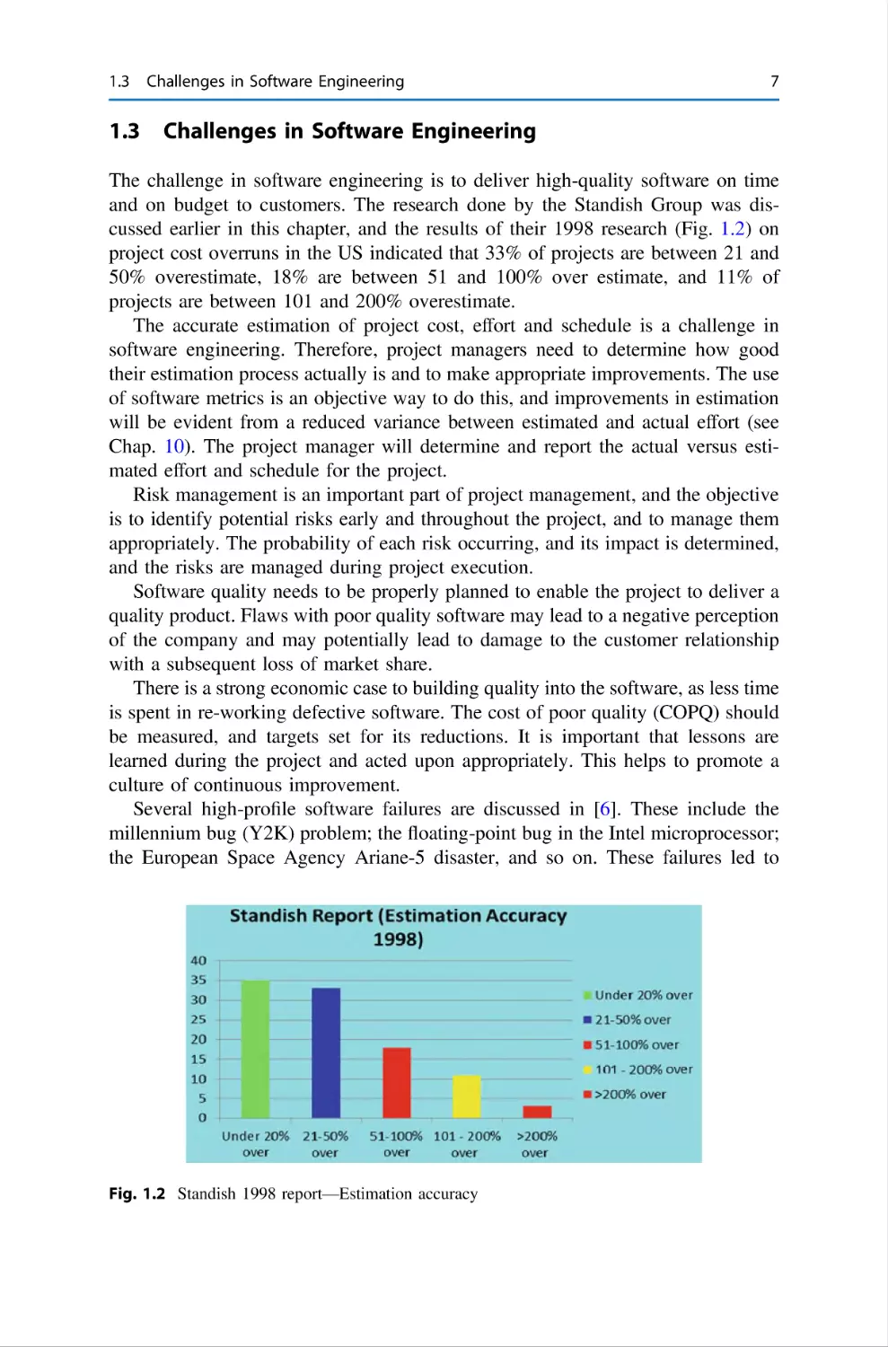
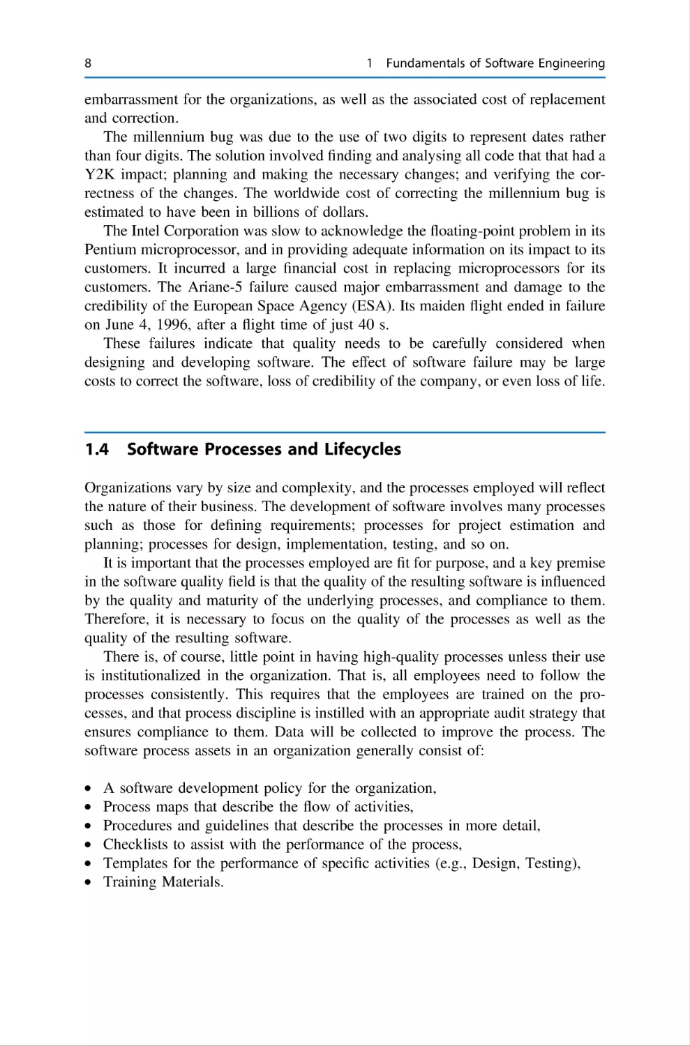
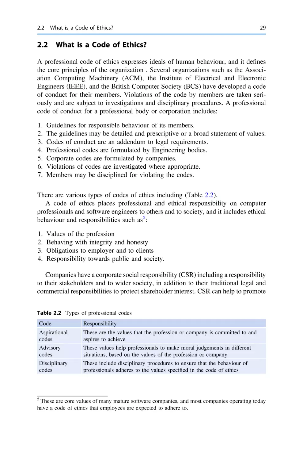
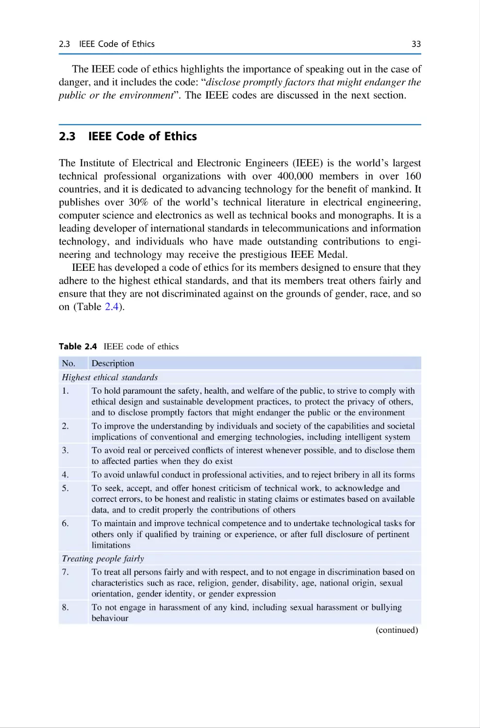
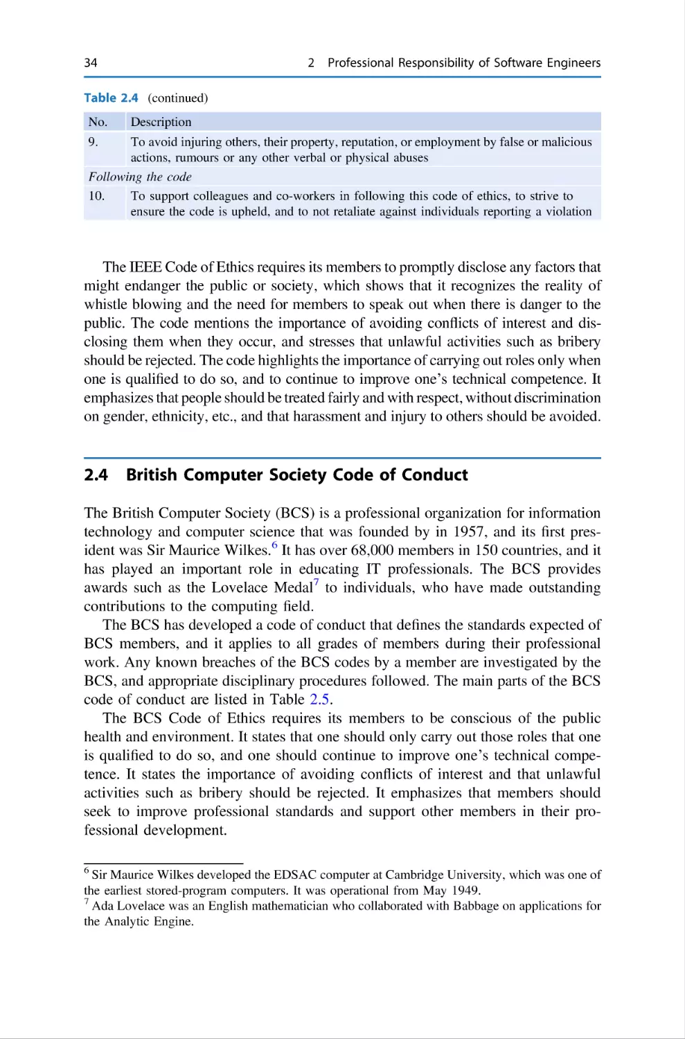
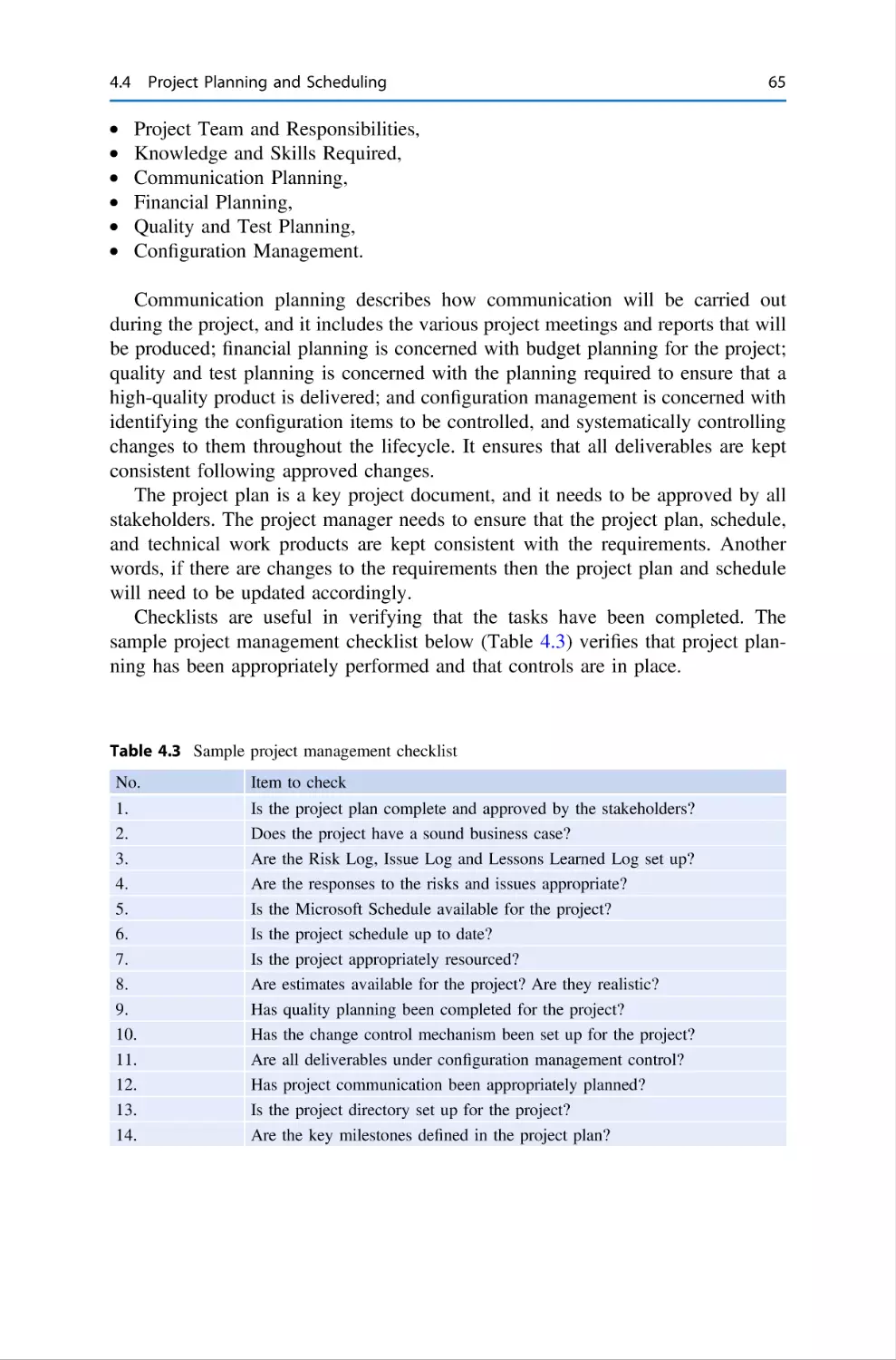
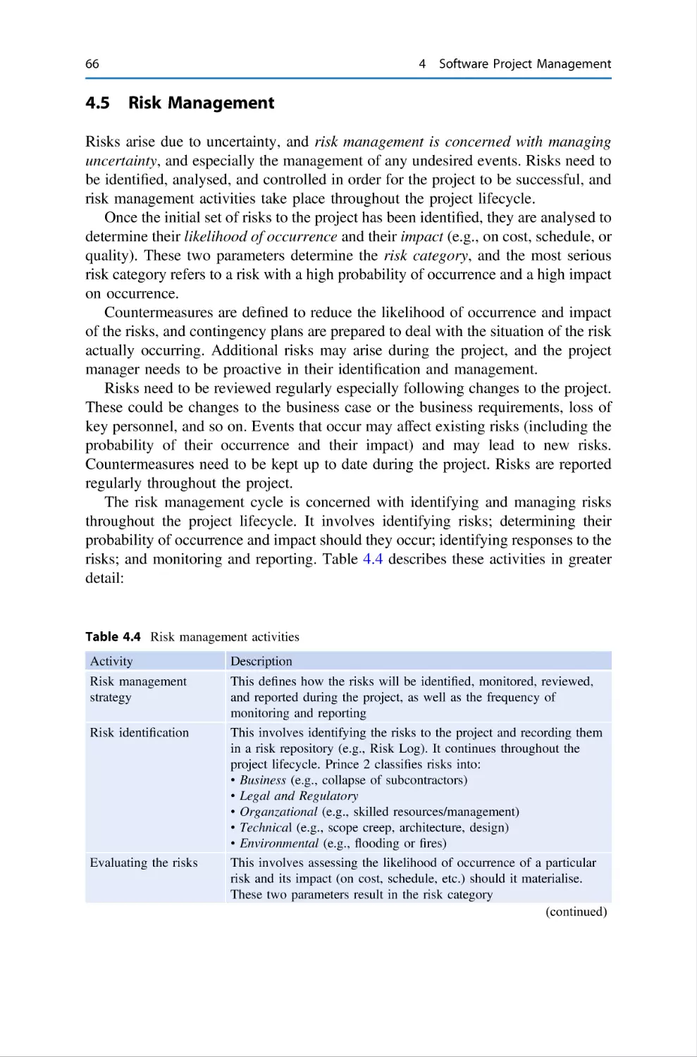
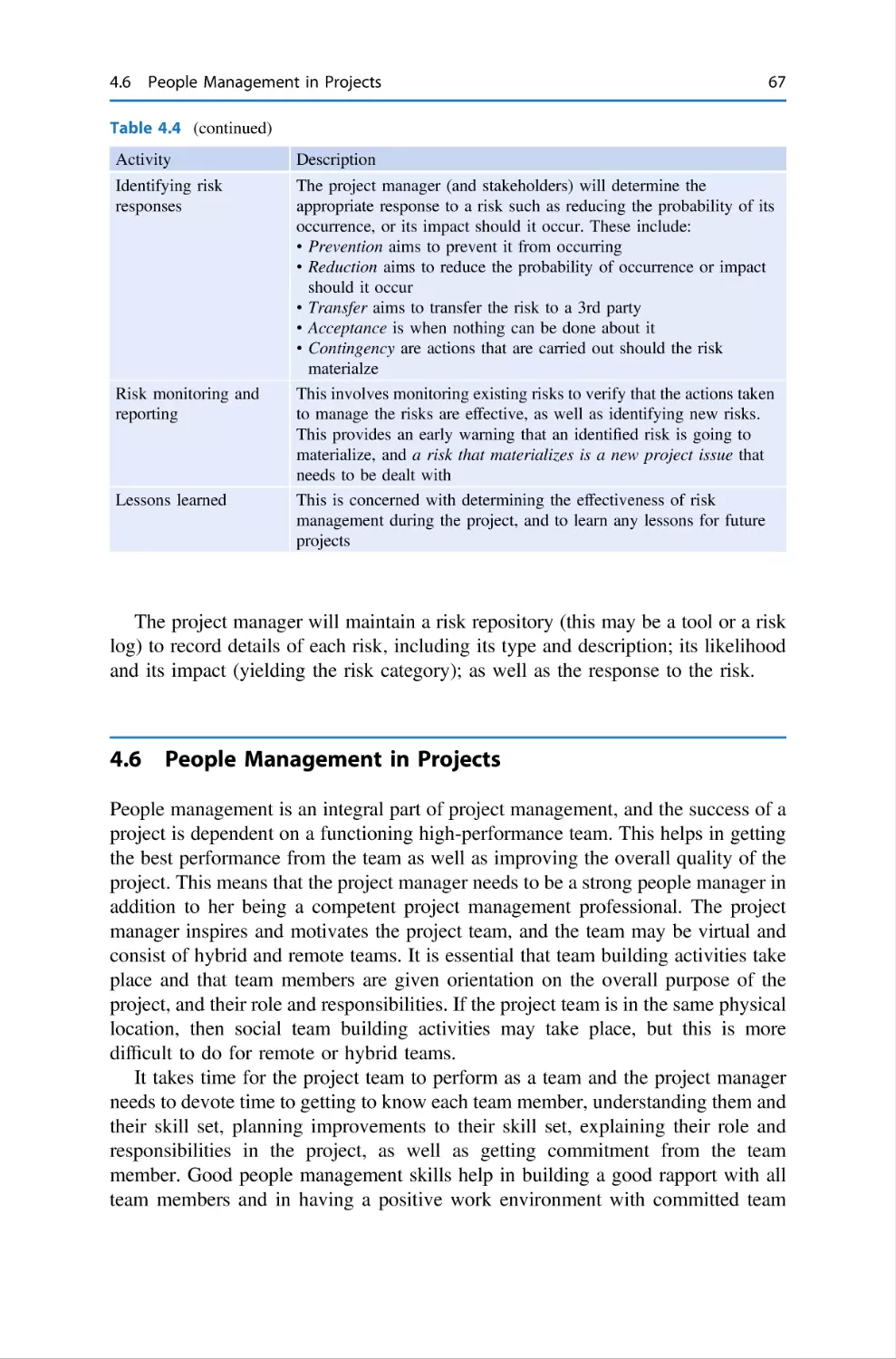
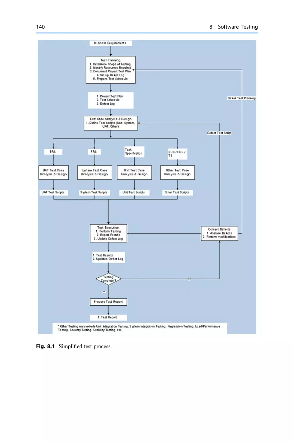
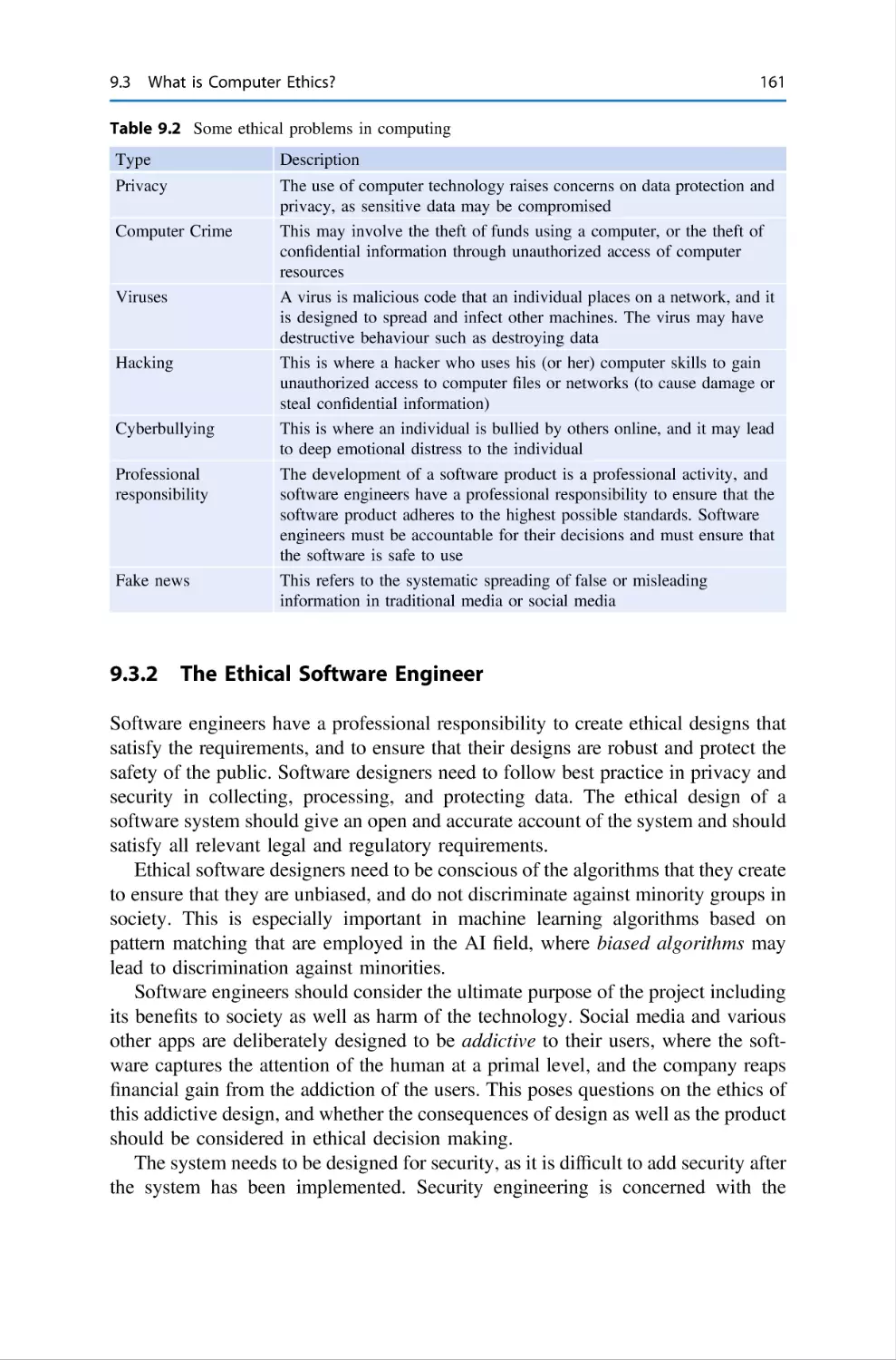
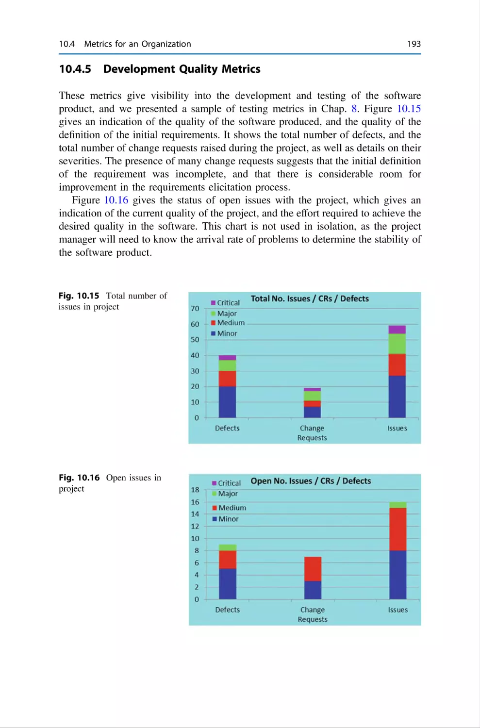
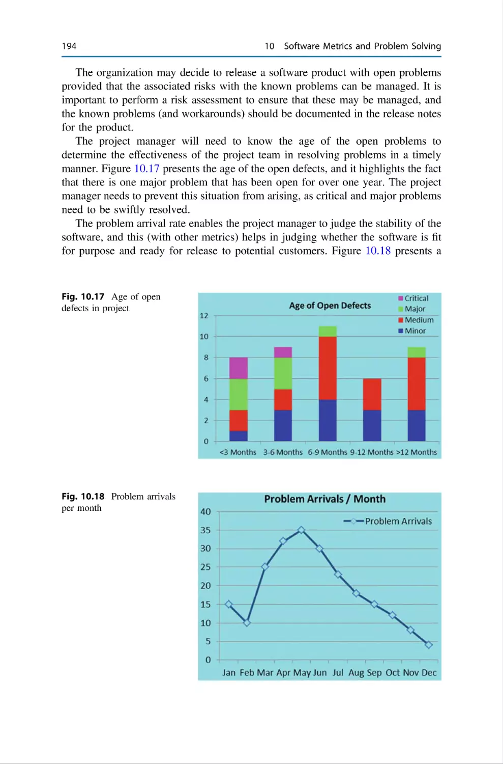
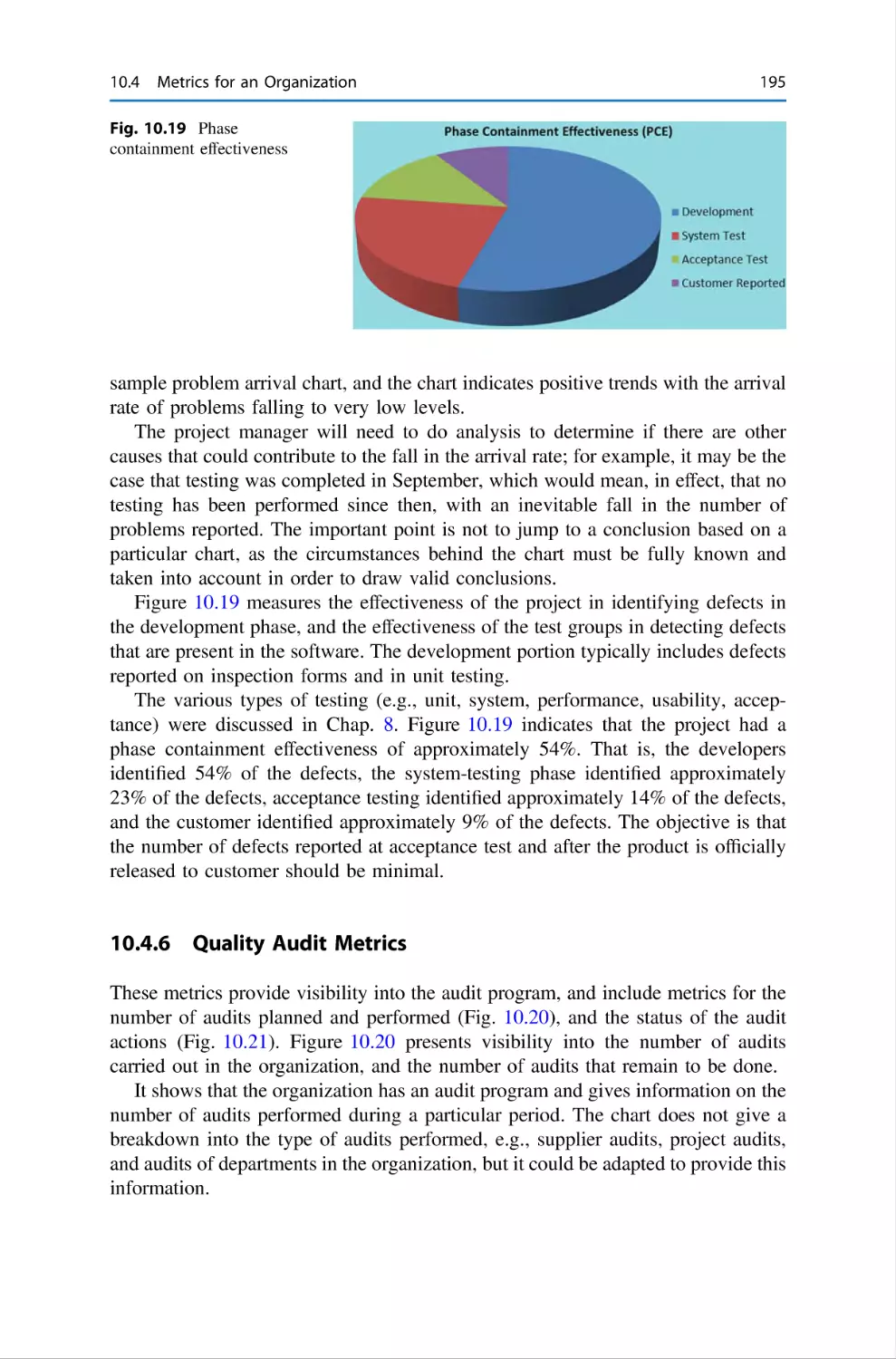
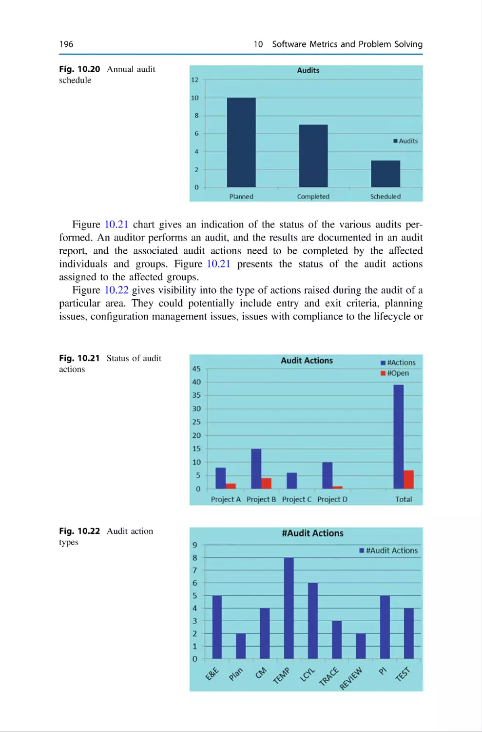
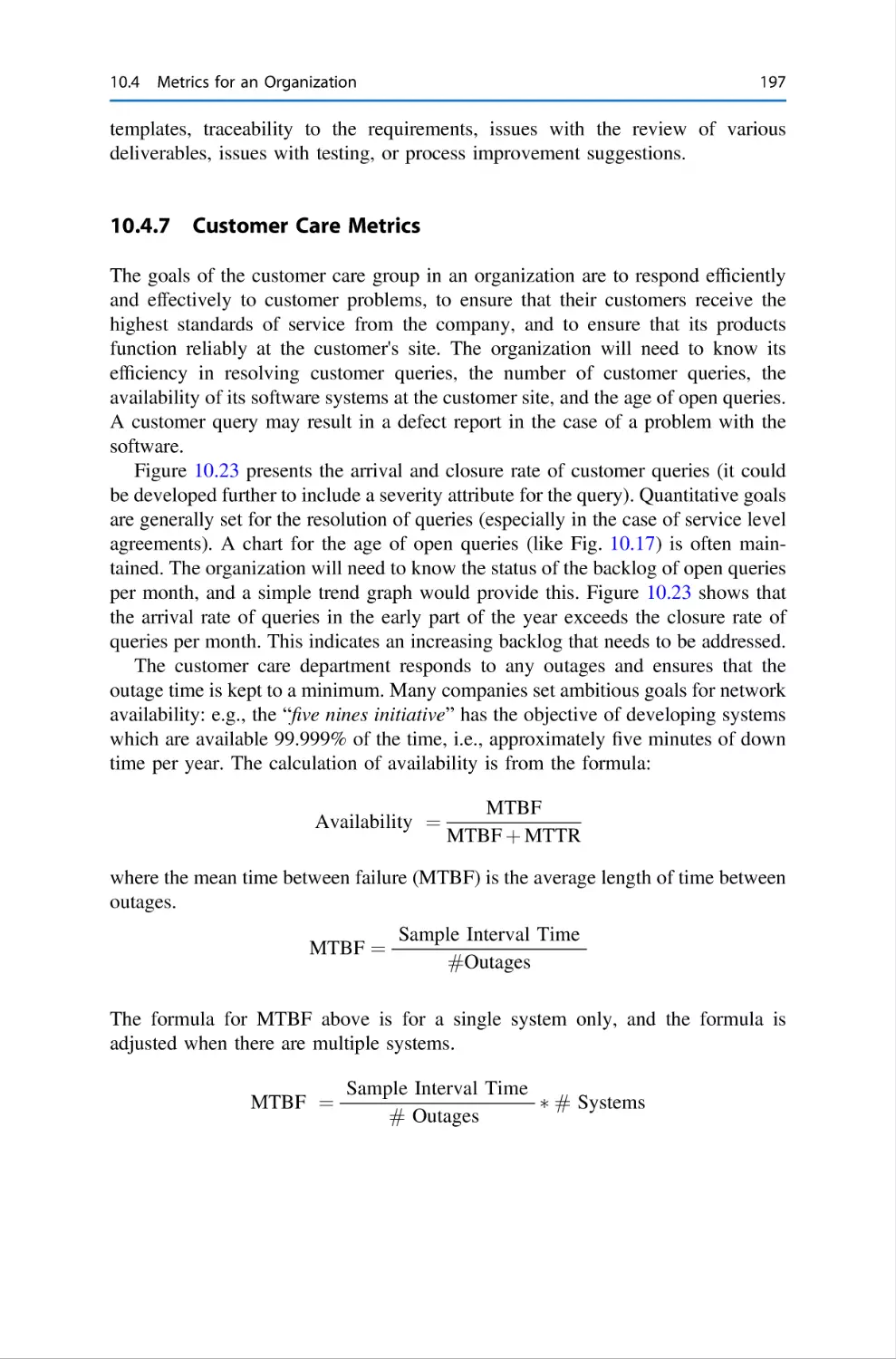
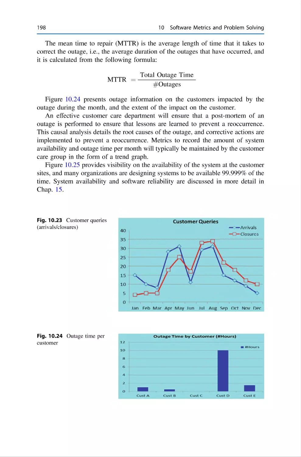
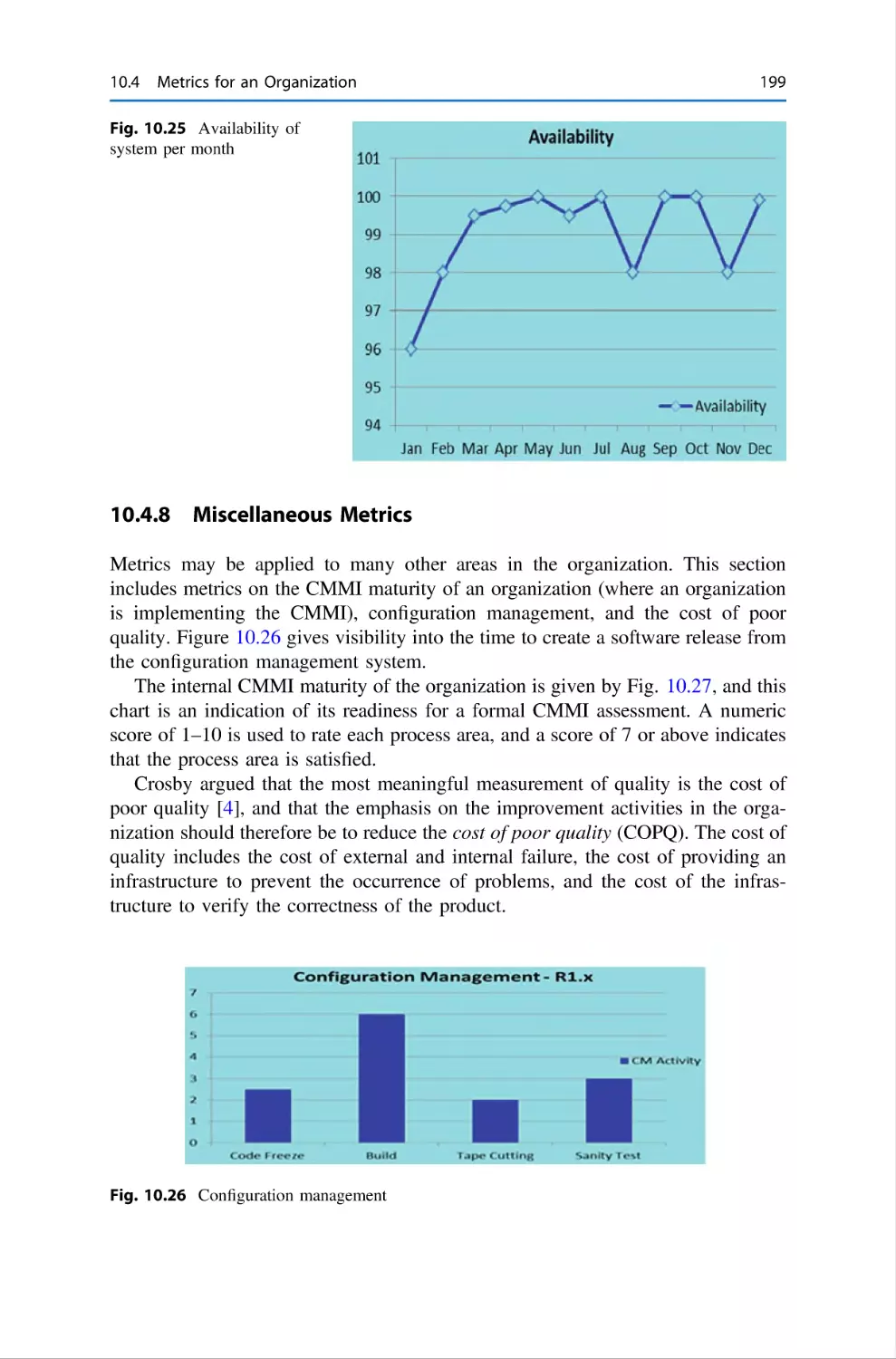
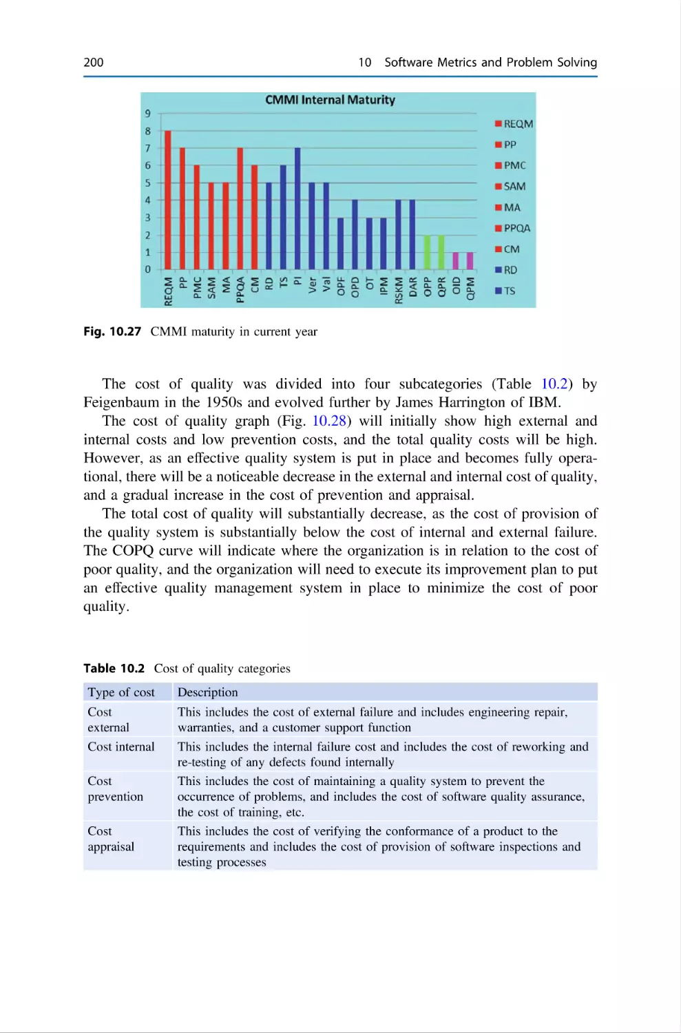
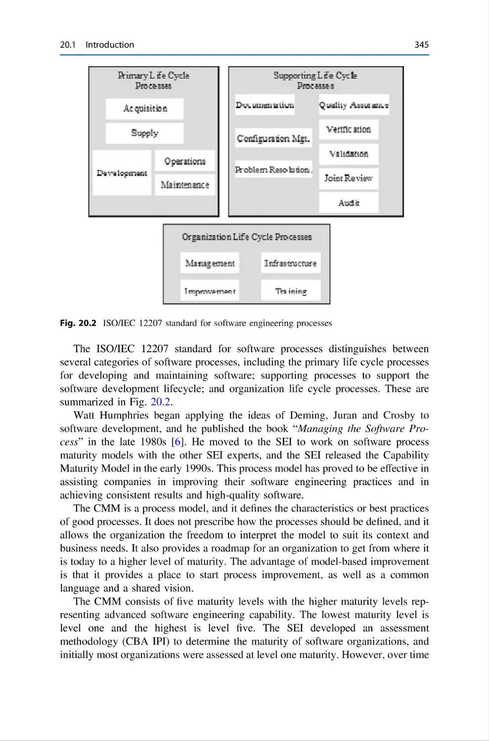
Text
Undergraduate Topics in Computer Science
Gerard O’Regan
Concise Guide
to Software
Engineering
From Fundamentals
to Application Methods
Second Edition
Undergraduate Topics in Computer
Science
Series Editor
Ian Mackie, University of Sussex, Brighton, UK
Advisory Editors
Samson Abramsky
Oxford, UK
Chris Hankin
, Department of Computer Science, University of Oxford,
, Department of Computing, Imperial College London, London, UK
Mike Hinchey , Lero – The Irish Software Research Centre, University of
Limerick, Limerick, Ireland
Joseph Migga Kizza, The University of Tennessee–Chattanooga, College of
Engineering and Computer Science, Chattanooga, Tennessee, USA
Dexter C. Kozen, Department of Computer Science, Cornell University, Ithaca,
NY, USA
Andrew Pitts , Department of Computer Science and Technology, University of
Cambridge, Cambridge, UK
Hanne Riis Nielson , Department of Applied Mathematics and Computer Science,
Technical University of Denmark, Kongens Lyngby, Denmark
Steven S. Skiena, Department of Computer Science, Stony Brook University, Stony
Brook, NY, USA
Iain Stewart
UK
, Department of Computer Science, Durham University, Durham,
‘Undergraduate Topics in Computer Science’ (UTiCS) delivers high-quality
instructional content for undergraduates studying in all areas of computing and
information science. From core foundational and theoretical material to final-year
topics and applications, UTiCS books take a fresh, concise, and modern approach
and are ideal for self-study or for a one- or two-semester course. The texts are all
authored by established experts in their fields, reviewed by an international advisory
board, and contain numerous examples and problems, many of which include fully
worked solutions.
The UTiCS concept relies on high-quality, concise books in softback format, and
generally a maximum of 275–300 pages. For undergraduate textbooks that are
likely to be longer, more expository, Springer continues to offer the highly regarded
Texts in Computer Science series, to which we refer potential authors.
Gerard O’Regan
Concise Guide to Software
Engineering
From Fundamentals to Application
Methods
Second Edition
123
Gerard O’Regan
University of Central Asia
Naryn, Kyrgyzstan
ISSN 1863-7310
ISSN 2197-1781 (electronic)
Undergraduate Topics in Computer Science
ISBN 978-3-031-07815-6
ISBN 978-3-031-07816-3 (eBook)
https://doi.org/10.1007/978-3-031-07816-3
1st edition: © Springer International Publishing AG 2017
2nd edition: © Springer Nature Switzerland AG 2022
This work is subject to copyright. All rights are reserved by the Publisher, whether the whole or part
of the material is concerned, specifically the rights of translation, reprinting, reuse of illustrations,
recitation, broadcasting, reproduction on microfilms or in any other physical way, and transmission
or information storage and retrieval, electronic adaptation, computer software, or by similar or dissimilar
methodology now known or hereafter developed.
The use of general descriptive names, registered names, trademarks, service marks, etc. in this
publication does not imply, even in the absence of a specific statement, that such names are exempt from
the relevant protective laws and regulations and therefore free for general use.
The publisher, the authors, and the editors are safe to assume that the advice and information in this
book are believed to be true and accurate at the date of publication. Neither the publisher nor the
authors or the editors give a warranty, expressed or implied, with respect to the material contained
herein or for any errors or omissions that may have been made. The publisher remains neutral with regard
to jurisdictional claims in published maps and institutional affiliations.
This Springer imprint is published by the registered company Springer Nature Switzerland AG
The registered company address is: Gewerbestrasse 11, 6330 Cham, Switzerland
To
Past and present members of the Formal
Methods Group (Foundations and Methods
Group) at Trinity College Dublin, Ireland.
Preface
Overview
The objective of this book is to provide a concise introduction to the software
engineering field to students and practitioners. The principles of software engineering are discussed, and the goal is to give the reader a grasp of the fundamentals
of the software engineering field, as well as guidance on how to apply the theory in
an industrial environment.
Organization and Features
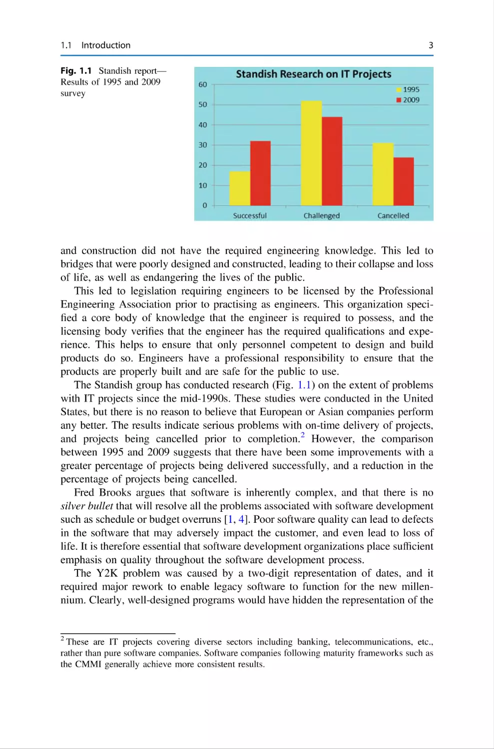
Chapter 1 presents a broad overview of software engineering and discusses various
software lifecycles and the activities in software development. We discuss
requirements gathering and specification, software design, implementation, testing
and maintenance. The lightweight Agile methodology is introduced, and it has
become very popular in industry.
Chapter 2 discusses the professional responsibilities of software engineers.
Engineers have a responsibility to ensure that the products that they design and
develop are built to the highest possible standards and are safe for the public to use.
Engineers must behave ethically in their dealings with their clients, and they need to
adhere to the code of ethics of the professional engineering body.
Chapter 3 discusses ethical software engineering where the ethical software
engineer needs to examine both the technical and the ethical dimensions of decisions that affect wider society. We discuss the Volkswagen emissions scandal
where engineers installed a “defeat device” to enable cars to pass an emissions test.
Chapter 4 introduces project management for traditional software engineering,
and we discuss project estimation, project planning and scheduling, project monitoring and control, risk management, managing communication and change, and
managing project quality.
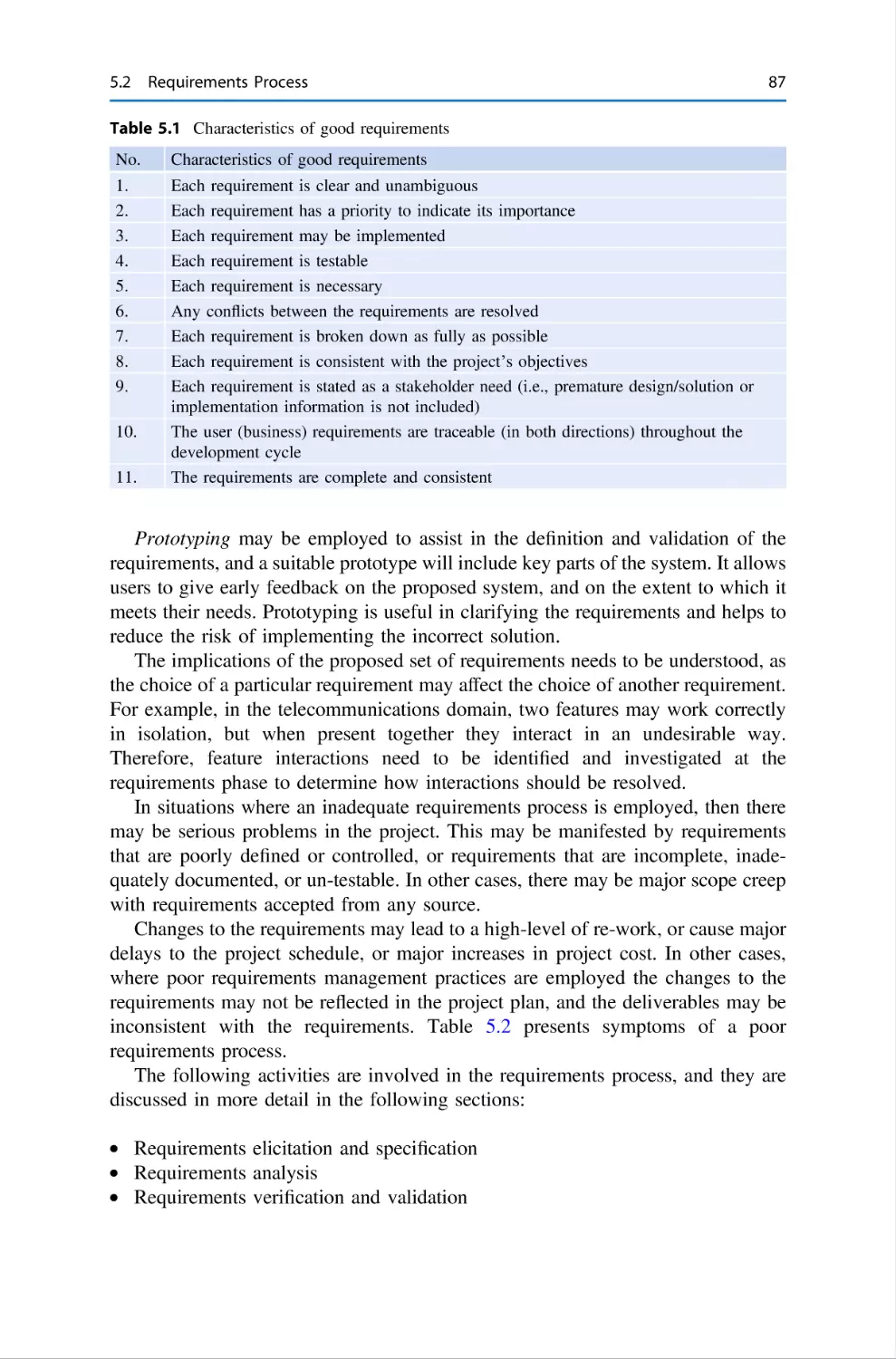
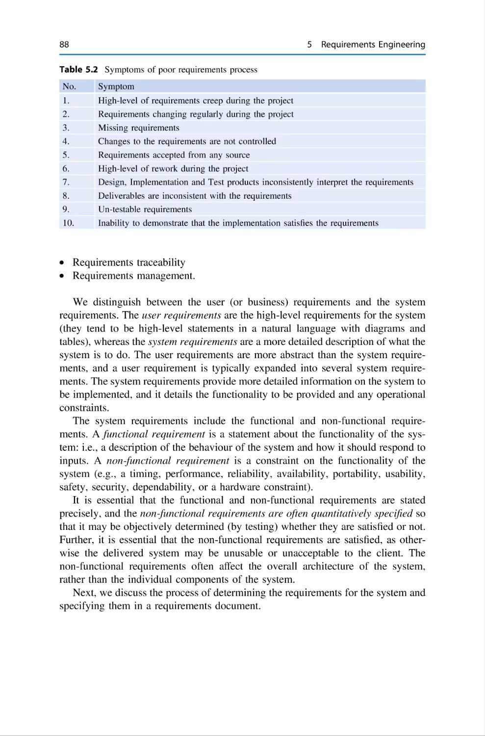
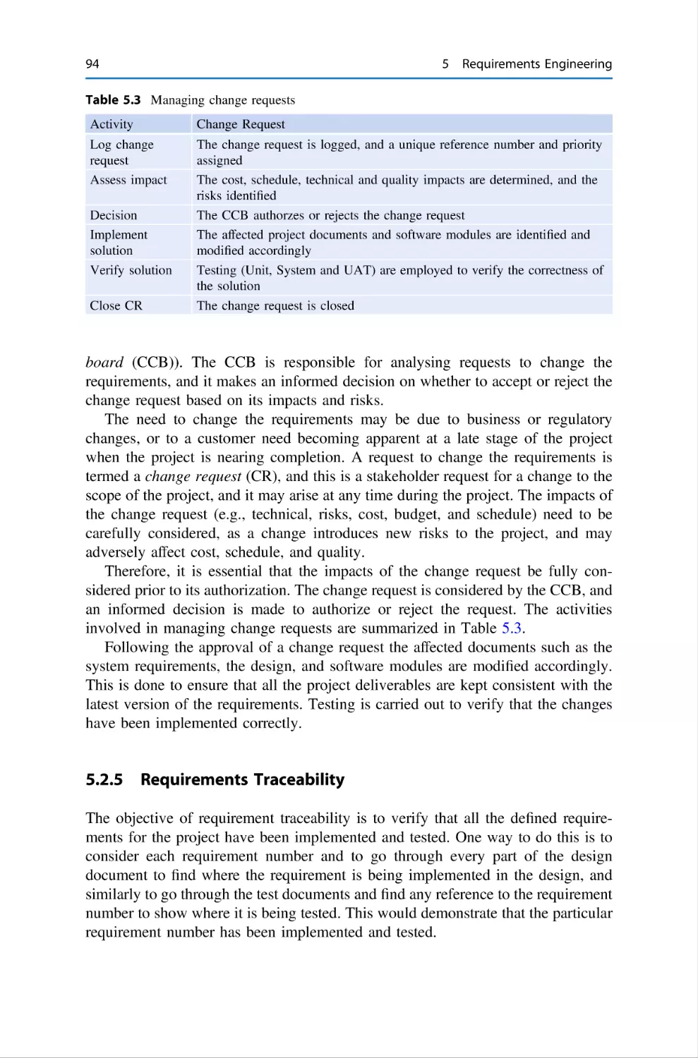
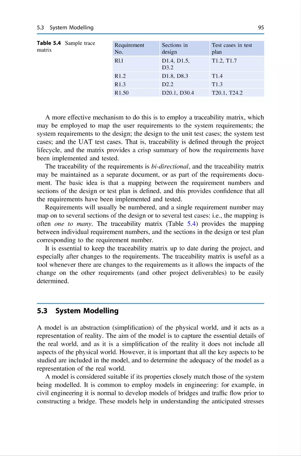
Chapter 5 discusses requirements engineering and discusses activities such as
requirements gathering, requirements elicitation, requirements analysis, requirements management, and requirements verification and validation.
vii
viii
Preface
Chapter 6 discusses software design and development, where software design is
the blueprint of the solution to be developed. It is concerned with the high-level
architecture of the system, as well as the detailed design that describes the algorithms and functionality of the individual programs. The detailed design is then
implemented in a programming language such as C++ or Java. We discuss software
development topics such as software reuse, customized-off-the-shelf software
(COTS), and open-source software development.
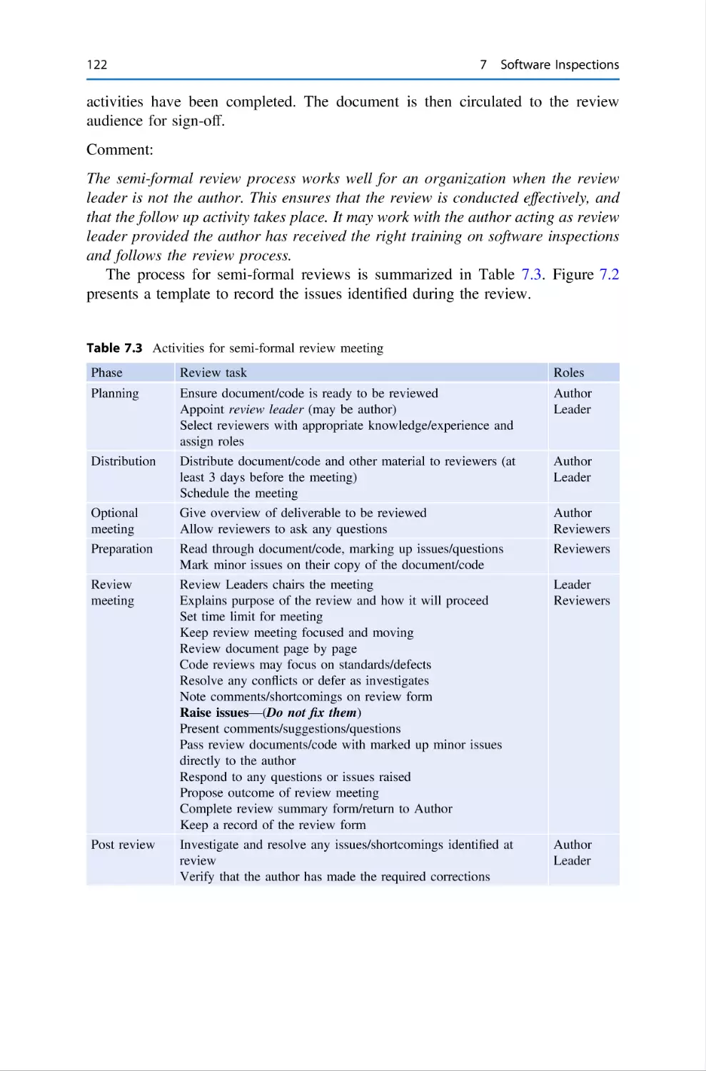
Chapter 7 discusses software inspections, which play an important role in
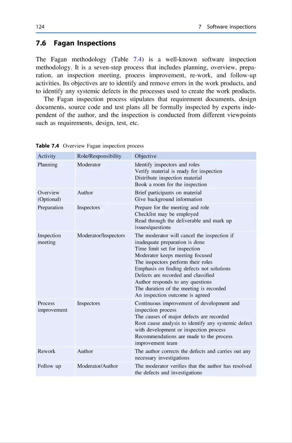
building quality into a product. The well-known Fagan inspection process that was
developed at IBM in the 1970s is discussed, as well as lighter review and walkthrough methodologies.
Chapter 8 is concerned with software testing and discusses the various types of
testing that may be carried out during the project. We discuss test planning, test case
definition, test environment set-up, test execution, test tracking, test metrics, test
reporting, and testing in an e-commerce environment.
Chapter 9 discusses ethics and privacy where professional ethics are a code of
conduct that governs how members of a profession deal with each other and with
third parties. It expresses ideals of human behaviour, and the fundamental values
of the organization, and is an indication of its professionalism. Privacy is defined as
“the right to be left alone,” and specifies there should be no intrusion upon
seclusion, and no public disclosure of private facts or false information.
Chapter 10 is concerned with metrics and problem-solving, and this includes a
discussion of the balanced score card which assists in identifying appropriate
metrics for the organization. The goal, question, metrics (GQM) approach is discussed, and this allows appropriate metrics related to the organization goals to be
defined. A selection of sample metrics for an organization is presented, and
problem-solving tools such as fishbone diagrams, Pareto charts, trend charts are
discussed.
Chapter 11 is concerned with the selection and management of a software
supplier. It discusses how candidate suppliers may be identified, formally evaluated
against defined selection criteria, and how the appropriate supplier is selected. We
discuss how the selected supplier is managed during the project.
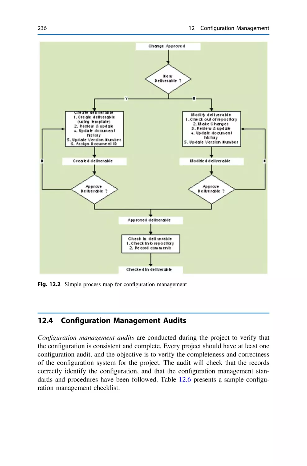
Chapter 12 discusses software configuration management and discusses the
fundamental concept of a baseline. Configuration management is concerned with
identifying those deliverables that must be subject to change control and controlling
changes to them.
Chapter 13 discusses software quality assurance and the importance of process
quality. It is a premise in the quality field that good processes and conformance to
them is essential for the delivery of high-quality product, and this chapter discusses
audits, and describes how they are carried out.
Chapter 14 discusses the Agile methodology which is a popular lightweight
approach to software development. Agile provides opportunities to assess the
direction of a project throughout the development lifecycle and ongoing changes to
requirements are considered normal in the Agile world. It has a strong collaborative
style of working, and it advocates adaptive planning and evolutionary development.
Preface
ix
Chapter 15 discusses software reliability and dependability and covers topics such as
software reliability and software reliability models; the cleanroom methodology, system availability; safety and security critical systems; and dependability engineering.
Chapter 16 discusses formal methods, which consist of a set of mathematical
techniques to specify and derive a program from its specification. Formal methods
may be employed to rigorously state the requirements of the proposed system. They
may be employed to derive a program from its mathematical specification, and they
may be used to provide a rigorous proof that the implemented program satisfies its
specification. They have been mainly applied to the safety critical field.
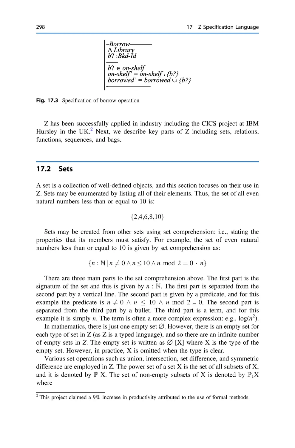
Chapter 17 presents the Z specification language, which is one of the more
popular formal methods. It was developed at the Programming Research Group at
Oxford University in the early 1980s. Z specifications are mathematical, and the use
of mathematics ensures precision and allows inconsistencies and gaps in the
specification to be identified. Theorem provers may be employed to demonstrate
that the software implementation meets its specification.
Chapter 18 presents the unified modelling language (UML), which is a visual
modelling language for software systems, and I used to present several views of the
system architecture. It was developed at Rational Corporation as a notation for
modelling object-oriented systems. We present various UML diagrams such as use
case diagrams, sequence diagrams, and activity diagrams.
Chapter 19 discusses software process improvement. It begins with a discussion
of a software process and discusses the benefits that may be gained from a software
process improvement initiative. Various models that support software process
improvement are discussed, and these include the Capability Maturity Model
Integration (CMMI), ISO 9000, Personal Software Process (PSP), and Team
Software Process (TSP).
Chapter 20 gives an overview of the CMMI model and discusses its five
maturity levels and their constituent process areas. We discuss both the staged and
continuous representations of the CMMI and SCAMPI appraisals that indicate the
extent to which the CMMI has been implemented in the organization, as well as
identifying opportunities for improvement.
Chapter 21 discusses various tools to support the various software engineering
activities. The focus is first to define the process, and then to find tools to support
the process. Tools to support project management are discussed as well as tools to
support requirements engineering, configuration management, design and development activities, and software testing.
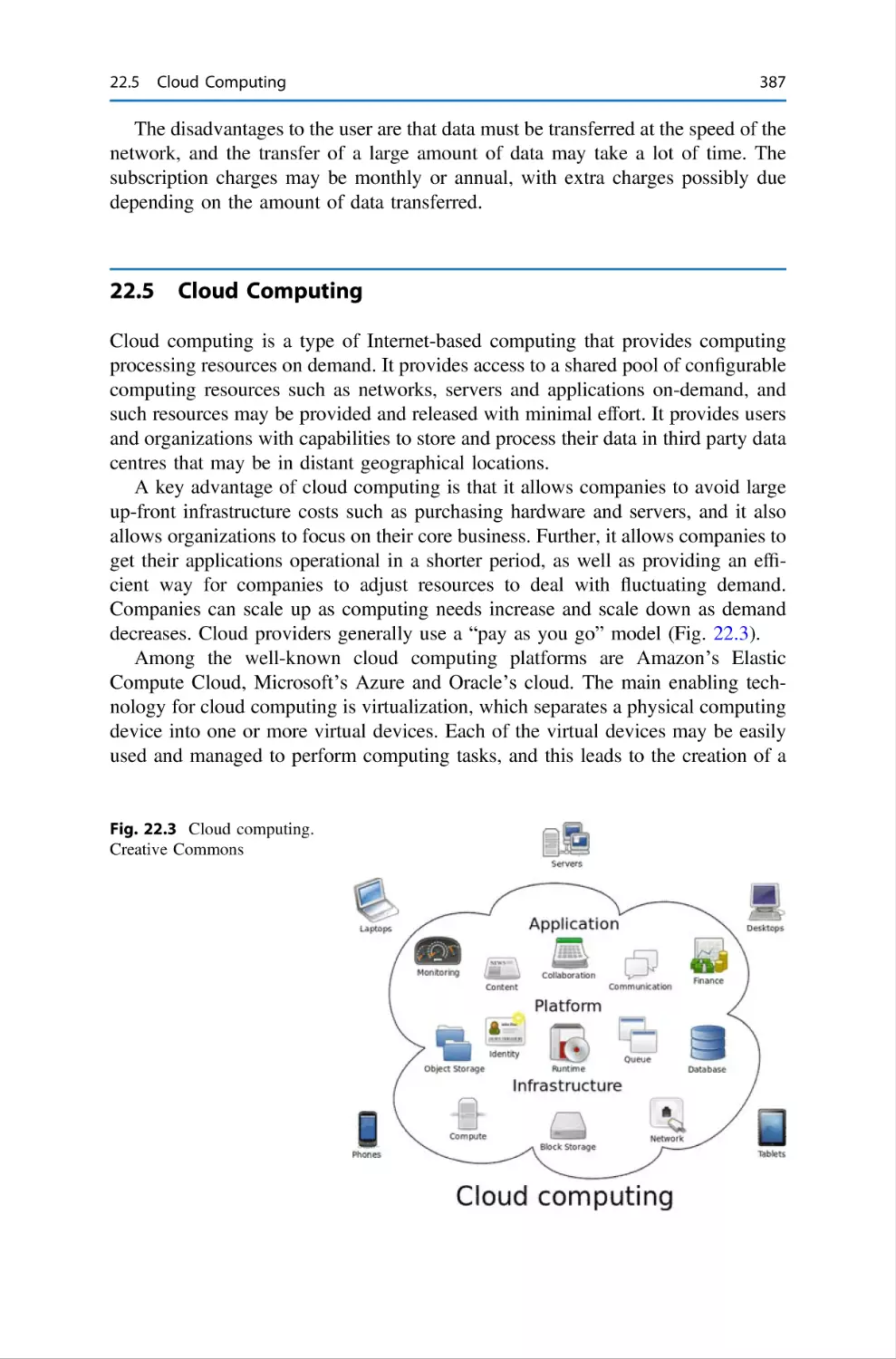
Chapter 22 discusses innovation in the software field including miscellaneous
topics such as distributed systems, service-oriented architecture, software as a
service, cloud computing and embedded systems. We discuss the need for innovation in software engineering and discuss some recent innovations such as
aspect-oriented software engineering.
Chapter 23 is concerned with the application of the legal system to the computing field. This includes the protection of intellectual property such as patents,
copyright, trademarks and trade secrets, and the resolution of disputes between
parties.
x
Preface
Chapter 24 discusses cybersecurity and cybercrime. Cybercrime is a crime that
involves a computer and a network. The computer may be the vehicle by which the
crime was conducted, or it may be the target of the crime. Cybersecurity is concerned with the ability of a computer system to protect itself from attacks, and there
are several characteristics of security such as confidentiality, integrity, and
availability.
Chapter 25 is the concluding chapter in which we summarize the journey that we
have travelled in this book.
Audience
The main audience of this book is computer science students who are interested in
learning about software engineering and in learning on how to build high-quality
and reliable software on time and on budget. It will also be of interest to industrialists including software engineers, quality professionals and software managers,
as well as the motivated general reader.
Acknowledgments
I am deeply indebted to family and friends who supported my efforts in this
endeavour, and my thanks, as always, to the team at Springer. This book is dedicated to present and past members of the Formal Methods Group (Foundations and
Methods Group) at Trinity College Dublin where the author spent several happy
years. I would especially like to thank Dr. Mícheál Mac An Airchinnigh,
Dr. Andrew Butterfield, Dr. Hugh Gibbons, Dr. Arthur Hughes, Alexis Donnelly,
Dara Gallagher, Eoin McDonnell, Gradamir Starovic, and Glenn Strong.
Cork, Ireland
Gerard O’Regan
Contents
1
Fundamentals of Software Engineering . . . . . . . . .
1.1
Introduction . . . . . . . . . . . . . . . . . . . . . . . .
1.2
What is Software Engineering? . . . . . . . . . .
1.3
Challenges in Software Engineering . . . . . . .
1.4
Software Processes and Lifecycles . . . . . . . .
1.4.1
Waterfall Lifecycle . . . . . . . . . . . .
1.4.2
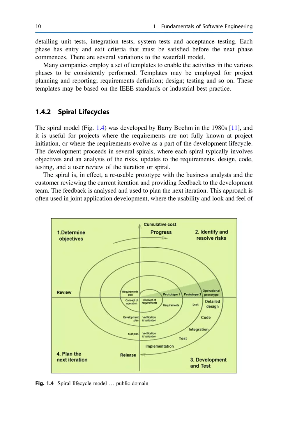
Spiral Lifecycles . . . . . . . . . . . . . .
1.4.3
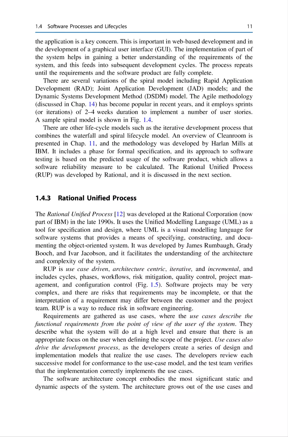
Rational Unified Process . . . . . . . .
1.4.4
Agile Development . . . . . . . . . . . .
1.4.5
Continuous Software Development
1.5
Activities in Software Development . . . . . . .
1.5.1
Requirements Definition . . . . . . . .
1.5.2
Design . . . . . . . . . . . . . . . . . . . . .
1.5.3
Implementation . . . . . . . . . . . . . . .
1.5.4
Software Testing . . . . . . . . . . . . . .
1.5.5
Support and Maintenance . . . . . . .
1.6
Software Inspections . . . . . . . . . . . . . . . . . .
1.7
Software Project Management . . . . . . . . . . .
1.8
CMMI Maturity Model . . . . . . . . . . . . . . . .
1.9
Formal Methods . . . . . . . . . . . . . . . . . . . . .
1.10 Review Questions . . . . . . . . . . . . . . . . . . . .
1.11 Summary . . . . . . . . . . . . . . . . . . . . . . . . . .
References . . . . . . . . . . . . . . . . . . . . . . . . . . . . . . .
.
.
.
.
.
.
.
.
.
.
.
.
.
.
.
.
.
.
.
.
.
.
.
.
.
.
.
.
.
.
.
.
.
.
.
.
.
.
.
.
.
.
.
.
.
.
.
.
.
.
.
.
.
.
.
.
.
.
.
.
.
.
.
.
.
.
.
.
.
.
.
.
.
.
.
.
.
.
.
.
.
.
.
.
.
.
.
.
.
.
.
.
.
.
.
.
.
.
.
.
.
.
.
.
.
.
.
.
.
.
.
.
.
.
.
.
.
.
.
.
.
.
.
.
.
.
.
.
.
.
.
.
.
.
.
.
.
.
.
.
.
.
.
.
.
.
.
.
.
.
.
.
.
.
.
.
.
.
.
.
.
.
.
.
.
.
.
.
.
.
.
.
.
.
.
.
.
.
.
.
.
.
.
.
.
.
.
.
.
.
.
.
.
.
.
.
.
.
.
.
.
.
.
.
.
.
.
.
.
.
.
.
.
.
.
.
.
.
.
.
.
.
.
.
.
.
.
.
.
.
.
.
.
.
.
.
.
.
.
.
.
.
.
.
.
.
.
.
.
.
.
.
.
.
.
.
.
.
.
.
.
.
.
.
.
.
.
.
.
.
.
.
.
.
.
.
1
1
4
7
8
9
10
11
12
14
15
15
17
18
19
20
21
21
22
23
24
24
25
2
Professional Responsibility of Software Engineers . .
2.1
Introduction . . . . . . . . . . . . . . . . . . . . . . . . . .
2.2
What is a Code of Ethics? . . . . . . . . . . . . . . . .
2.2.1
Role of a Whistle Blower . . . . . . . . .
2.3
IEEE Code of Ethics . . . . . . . . . . . . . . . . . . . .
2.4
British Computer Society Code of Conduct . . .
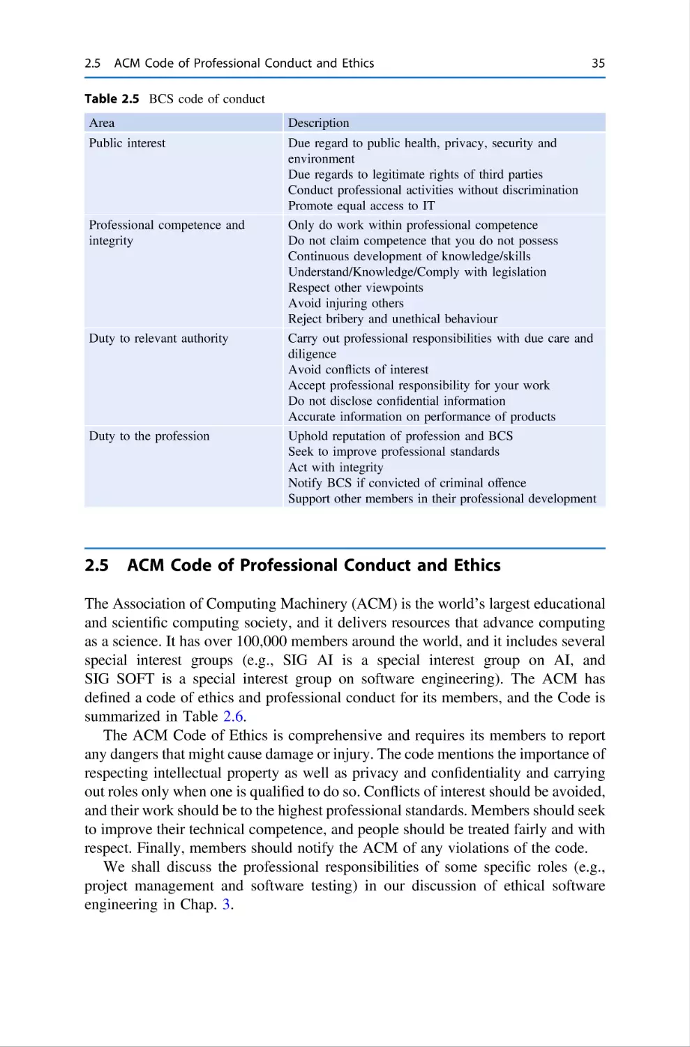
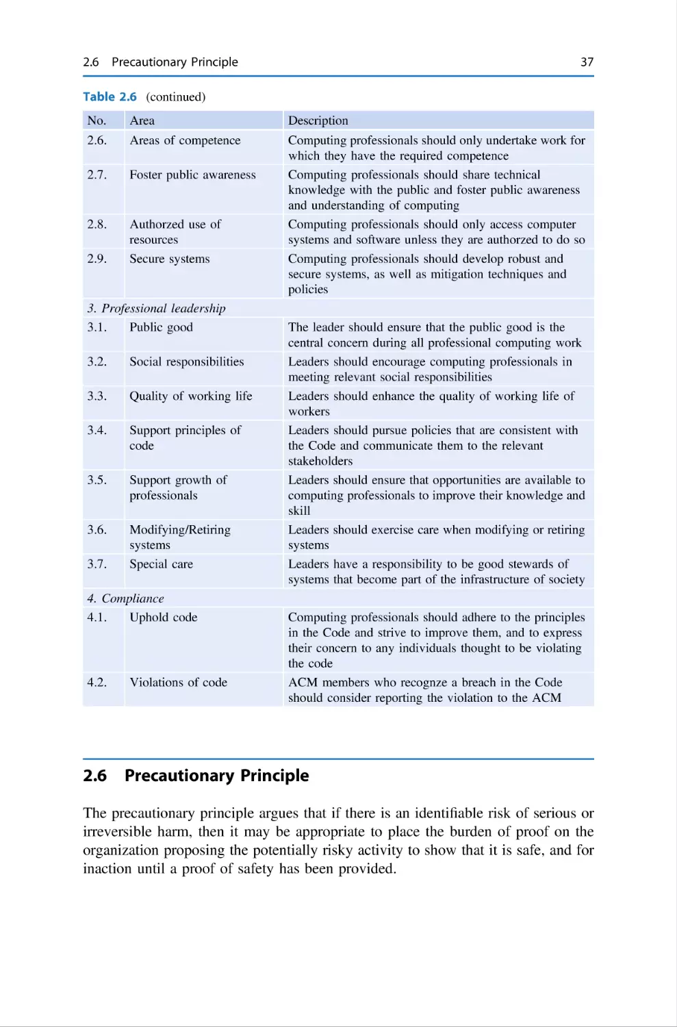
2.5
ACM Code of Professional Conduct and Ethics
2.6
Precautionary Principle . . . . . . . . . . . . . . . . . .
.
.
.
.
.
.
.
.
.
.
.
.
.
.
.
.
.
.
.
.
.
.
.
.
.
.
.
.
.
.
.
.
.
.
.
.
.
.
.
.
.
.
.
.
.
.
.
.
.
.
.
.
.
.
.
.
.
.
.
.
.
.
.
.
.
.
.
.
.
.
.
.
.
.
.
.
.
.
.
.
.
.
.
.
.
.
.
.
27
27
29
31
33
34
35
37
.
.
.
.
.
.
.
.
.
.
.
.
.
.
.
.
.
.
.
.
.
.
.
xi
xii
Contents
2.7
2.8
Review Questions . . . . . . . . . . . . . . . . . . . . . . . . . . . . . . . . .
Summary . . . . . . . . . . . . . . . . . . . . . . . . . . . . . . . . . . . . . . .
38
38
3
Ethical Software Engineering . . . . . . . . . . . . . . .
3.1
Introduction . . . . . . . . . . . . . . . . . . . . . . .
3.2
Safety and Ethics . . . . . . . . . . . . . . . . . . .
3.2.1
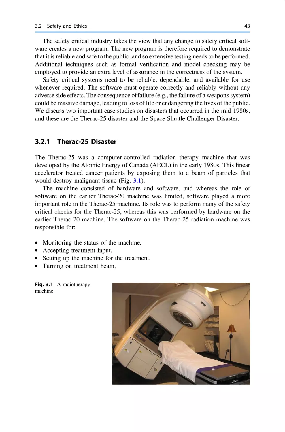
Therac-25 Disaster . . . . . . . . . . .
3.2.2
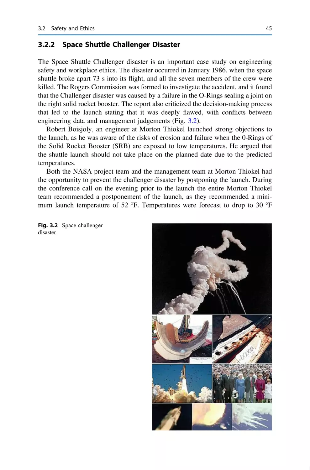
Space Shuttle Challenger Disaster
3.3
Ethical Project Management . . . . . . . . . . . .
3.4
Ethical Software Design and Development .
3.4.1
Volkswagen Emissions Scandal . .
3.5
Ethical Software Testing . . . . . . . . . . . . . .
3.6
Review Questions . . . . . . . . . . . . . . . . . . .
3.7
Summary . . . . . . . . . . . . . . . . . . . . . . . . .
.
.
.
.
.
.
.
.
.
.
.
.
.
.
.
.
.
.
.
.
.
.
.
.
.
.
.
.
.
.
.
.
.
.
.
.
.
.
.
.
.
.
.
.
.
.
.
.
.
.
.
.
.
.
.
.
.
.
.
.
.
.
.
.
.
.
.
.
.
.
.
.
.
.
.
.
.
.
.
.
.
.
.
.
.
.
.
.
.
.
.
.
.
.
.
.
.
.
.
.
.
.
.
.
.
.
.
.
.
.
.
.
.
.
.
.
.
.
.
.
.
.
.
.
.
.
.
.
.
.
.
.
.
.
.
.
.
.
.
.
.
.
.
.
.
.
.
.
.
.
.
.
.
.
41
41
42
43
45
46
48
52
53
54
55
4
Software Project Management . . . . . . . . . . . .
4.1
Introduction . . . . . . . . . . . . . . . . . . . . .
4.2
Project Start Up and Initiation . . . . . . . .
4.3
Estimation . . . . . . . . . . . . . . . . . . . . . .
4.3.1
Estimation Techniques . . . . . .
4.3.2
Work Breakdown Structure . . .
4.4
Project Planning and Scheduling . . . . . .
4.5
Risk Management . . . . . . . . . . . . . . . . .
4.6
People Management in Projects . . . . . . .
4.7
Quality Management in Projects . . . . . . .
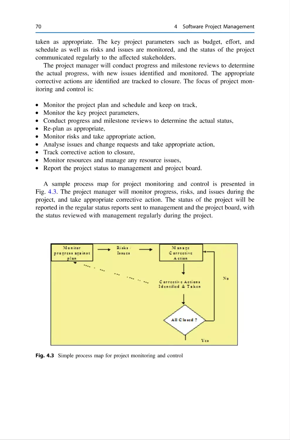
4.8
Project Monitoring and Control . . . . . . .
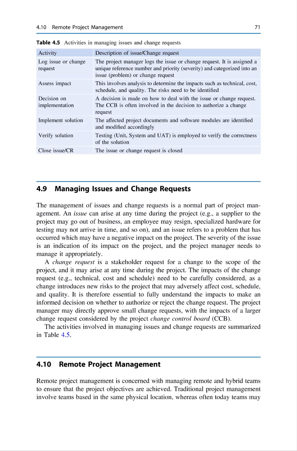
4.9
Managing Issues and Change Requests . .
4.10 Remote Project Management . . . . . . . . .
4.11 Outsourcing . . . . . . . . . . . . . . . . . . . . .
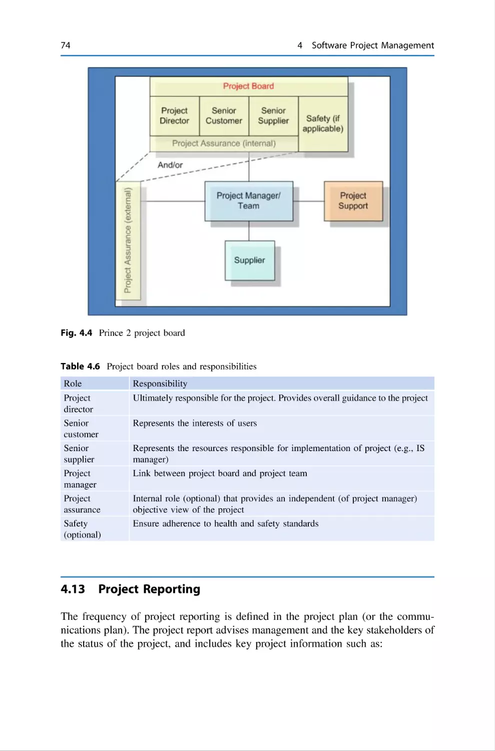
4.12 Project Board and Governance . . . . . . . .
4.13 Project Reporting . . . . . . . . . . . . . . . . .
4.14 Project Closure . . . . . . . . . . . . . . . . . . .
4.15 Prince 2 Methodology . . . . . . . . . . . . . .
4.16 Project Manager Professional . . . . . . . . .
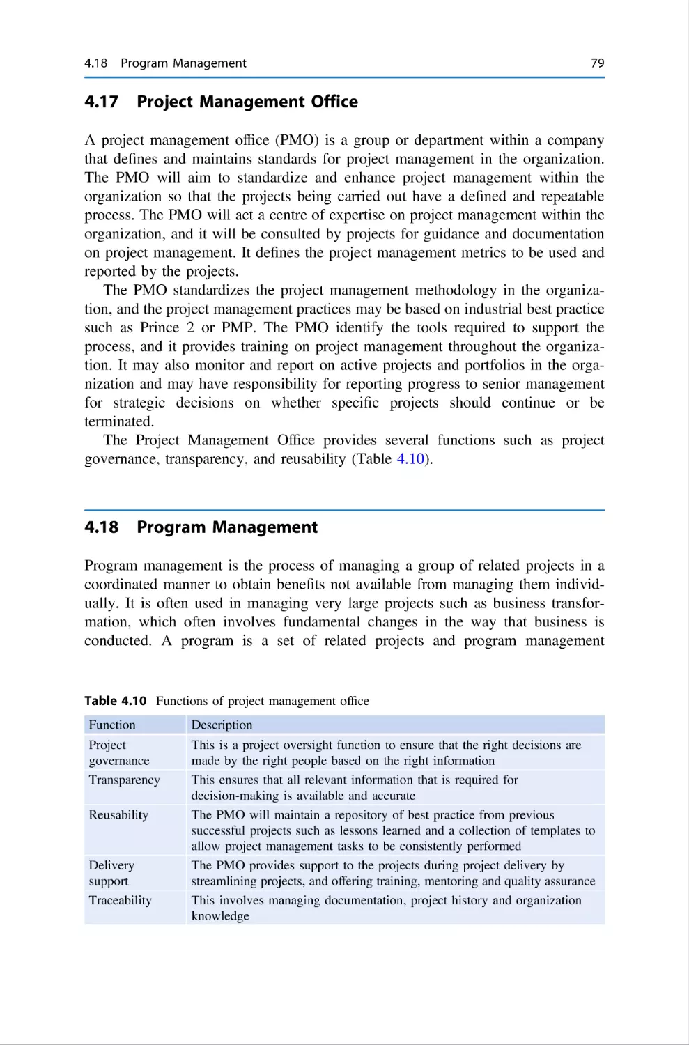
4.17 Project Management Office . . . . . . . . . .
4.18 Program Management . . . . . . . . . . . . . .
4.19 Project Portfolio Management . . . . . . . .
4.20 Project Management in the Agile World .
4.21 Review Questions . . . . . . . . . . . . . . . . .
4.22 Summary . . . . . . . . . . . . . . . . . . . . . . .
References . . . . . . . . . . . . . . . . . . . . . . . . . . . .
.
.
.
.
.
.
.
.
.
.
.
.
.
.
.
.
.
.
.
.
.
.
.
.
.
.
.
.
.
.
.
.
.
.
.
.
.
.
.
.
.
.
.
.
.
.
.
.
.
.
.
.
.
.
.
.
.
.
.
.
.
.
.
.
.
.
.
.
.
.
.
.
.
.
.
.
.
.
.
.
.
.
.
.
.
.
.
.
.
.
.
.
.
.
.
.
.
.
.
.
.
.
.
.
.
.
.
.
.
.
.
.
.
.
.
.
.
.
.
.
.
.
.
.
.
.
.
.
.
.
.
.
.
.
.
.
.
.
.
.
.
.
.
.
.
.
.
.
.
.
.
.
.
.
.
.
.
.
.
.
.
.
.
.
.
.
.
.
.
.
.
.
.
.
.
.
.
.
.
.
.
.
.
.
.
.
.
.
.
.
.
.
.
.
.
.
.
.
.
.
.
.
.
.
.
.
.
.
.
.
.
.
.
.
.
.
.
.
.
.
.
.
.
.
.
.
.
.
.
.
.
.
.
.
.
.
.
.
.
.
.
.
.
.
.
.
.
.
.
.
.
.
.
.
.
.
.
.
.
.
.
.
.
.
.
.
.
.
.
.
.
.
.
.
.
.
.
.
.
.
.
.
.
.
.
.
.
.
.
.
.
.
.
.
.
.
.
.
.
.
.
.
.
.
.
.
.
.
.
.
.
.
.
.
.
.
.
.
.
.
.
.
.
.
.
.
.
.
.
.
.
.
.
.
.
.
.
.
.
.
.
.
.
.
.
.
.
.
.
.
.
.
.
.
.
.
.
.
.
.
.
.
.
.
57
57
59
60
61
61
63
66
67
68
69
71
71
72
73
74
75
76
76
79
79
80
81
82
82
83
.
.
.
.
.
.
.
.
.
.
.
.
.
.
.
.
.
.
.
.
.
.
.
.
.
.
.
.
.
.
.
.
.
.
.
.
.
.
.
.
.
.
.
.
.
.
.
.
.
.
.
.
Contents
xiii
5
Requirements Engineering . . . . . . . . . . . . . . . . . . . . . . .
5.1
Introduction . . . . . . . . . . . . . . . . . . . . . . . . . . . . .
5.2
Requirements Process . . . . . . . . . . . . . . . . . . . . . .
5.2.1
Requirements Elicitation and Specification
5.2.2
Requirements Analysis . . . . . . . . . . . . . .
5.2.3
Requirements Verification and Validation .
5.2.4
Requirements Management . . . . . . . . . . .
5.2.5
Requirements Traceability . . . . . . . . . . . .
5.3
System Modelling . . . . . . . . . . . . . . . . . . . . . . . . .
5.4
Requirements Definition in the Agile World . . . . . .
5.5
Review Questions . . . . . . . . . . . . . . . . . . . . . . . . .
5.6
Summary . . . . . . . . . . . . . . . . . . . . . . . . . . . . . . .
References . . . . . . . . . . . . . . . . . . . . . . . . . . . . . . . . . . . .
.
.
.
.
.
.
.
.
.
.
.
.
.
.
.
.
.
.
.
.
.
.
.
.
.
.
.
.
.
.
.
.
.
.
.
.
.
.
.
.
.
.
.
.
.
.
.
.
.
.
.
.
.
.
.
.
.
.
.
.
.
.
.
.
.
.
.
.
.
.
.
.
.
.
.
.
.
.
.
.
.
.
.
.
.
.
.
.
.
.
.
85
85
86
89
92
92
93
94
95
97
97
98
99
6
Software Design and Development . . . . . . . . . . . . . . . . . . .
6.1
Introduction . . . . . . . . . . . . . . . . . . . . . . . . . . . . . . .
6.2
Architecture Design . . . . . . . . . . . . . . . . . . . . . . . . . .
6.3
Low-Level Design and Development . . . . . . . . . . . . .
6.3.1
Function-Oriented Design . . . . . . . . . . . . . .
6.3.2
Object-Oriented Design . . . . . . . . . . . . . . . .
6.3.3
User-Interface Design . . . . . . . . . . . . . . . . .
6.3.4
Open-Source Development . . . . . . . . . . . . .
6.3.5
Customized-off-the-Shelf Software . . . . . . . .
6.3.6
Software Reuse . . . . . . . . . . . . . . . . . . . . . .
6.3.7
Design Patterns . . . . . . . . . . . . . . . . . . . . . .
6.3.8
Object-Oriented Programming . . . . . . . . . . .
6.4
Software Maintenance and Evolution . . . . . . . . . . . . .
6.5
Software Design and Development in the Agile World
6.6
Review Questions . . . . . . . . . . . . . . . . . . . . . . . . . . .
6.7
Summary . . . . . . . . . . . . . . . . . . . . . . . . . . . . . . . . .
References . . . . . . . . . . . . . . . . . . . . . . . . . . . . . . . . . . . . . .
.
.
.
.
.
.
.
.
.
.
.
.
.
.
.
.
.
.
.
.
.
.
.
.
.
.
.
.
.
.
.
.
.
.
.
.
.
.
.
.
.
.
.
.
.
.
.
.
.
.
.
.
.
.
.
.
.
.
.
.
.
.
.
.
.
.
.
.
.
.
.
.
.
.
.
.
.
.
.
.
.
.
.
.
.
.
.
.
.
.
.
.
.
.
.
.
.
.
.
.
.
.
101
101
102
106
107
107
109
109
110
110
111
111
112
113
114
114
115
7
Software Inspections . . . . . . . . . . . . . . . . . . . . . .
7.1
Introduction . . . . . . . . . . . . . . . . . . . . . . .
7.2
Economic Benefits of Software Inspections .
7.3
Informal Reviews . . . . . . . . . . . . . . . . . . .
7.4
Structured Walkthrough . . . . . . . . . . . . . . .
7.5
Semi-formal Review Meeting . . . . . . . . . . .
7.6
Fagan Inspections . . . . . . . . . . . . . . . . . . .
7.6.1
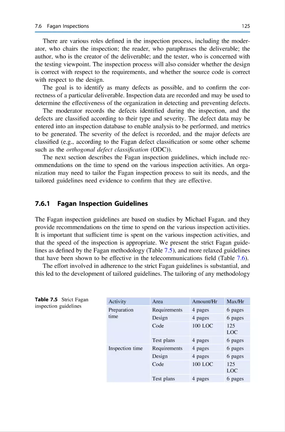
Fagan Inspection Guidelines . . . .
7.6.2
Inspectors and Roles . . . . . . . . . .
7.6.3
Inspection Entry Criteria . . . . . . .
7.6.4
Preparation . . . . . . . . . . . . . . . . .
7.6.5
The Inspection Meeting . . . . . . . .
.
.
.
.
.
.
.
.
.
.
.
.
.
.
.
.
.
.
.
.
.
.
.
.
.
.
.
.
.
.
.
.
.
.
.
.
.
.
.
.
.
.
.
.
.
.
.
.
.
.
.
.
.
.
.
.
.
.
.
.
.
.
.
.
.
.
.
.
.
.
.
.
117
117
119
120
120
121
124
125
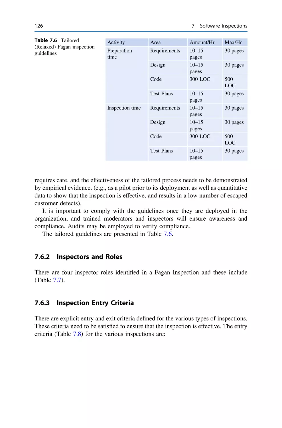
126
126
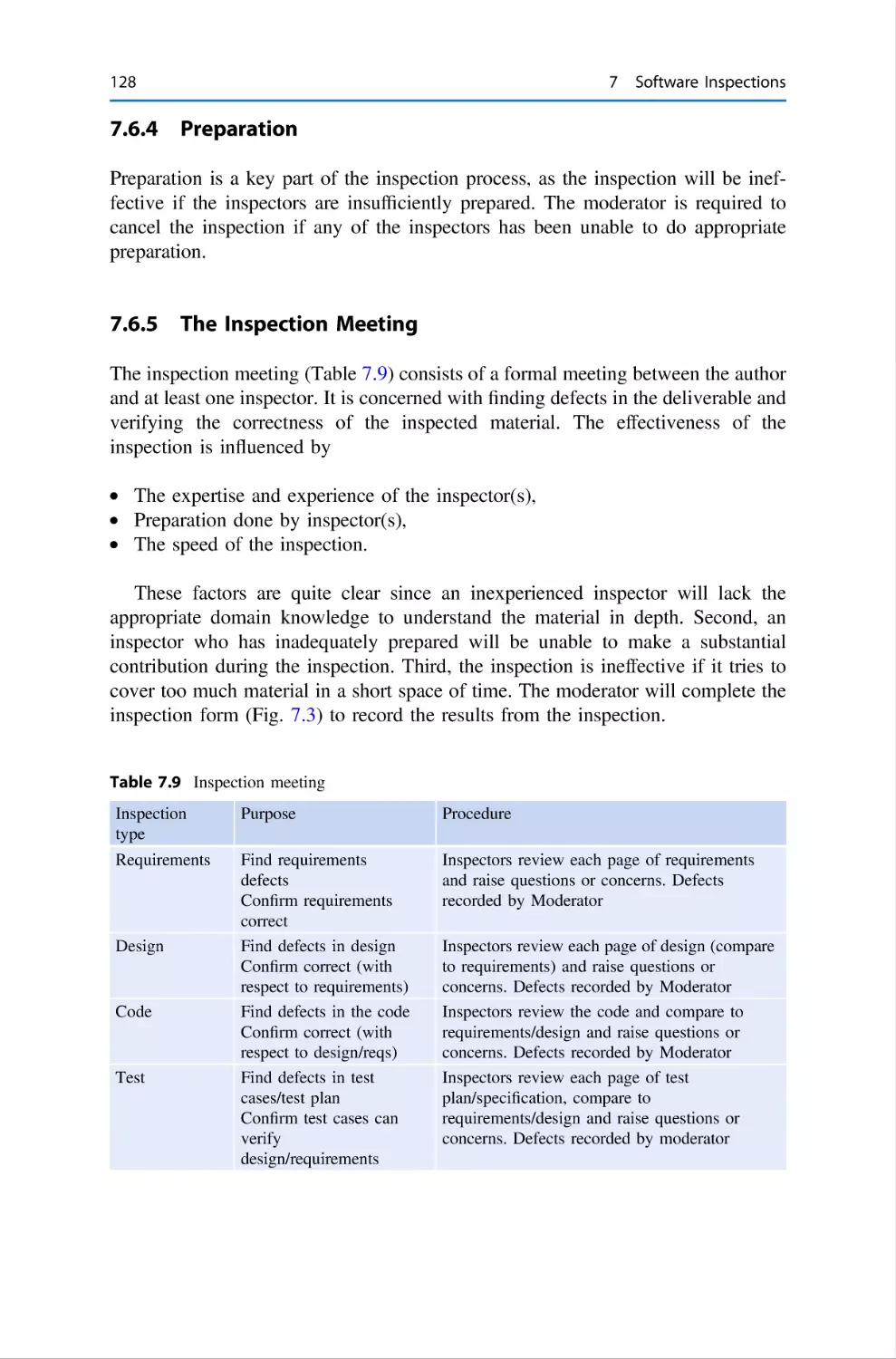
128
128
.
.
.
.
.
.
.
.
.
.
.
.
.
.
.
.
.
.
.
.
.
.
.
.
.
.
.
.
.
.
.
.
.
.
.
.
.
.
.
.
.
.
.
.
.
.
.
.
.
.
.
.
.
.
.
.
.
.
.
.
.
.
.
.
.
.
.
.
.
.
.
.
.
.
.
.
.
.
.
.
.
.
.
.
.
.
.
.
.
.
.
.
.
.
.
.
.
.
.
.
.
.
.
.
.
.
.
.
.
xiv
Contents
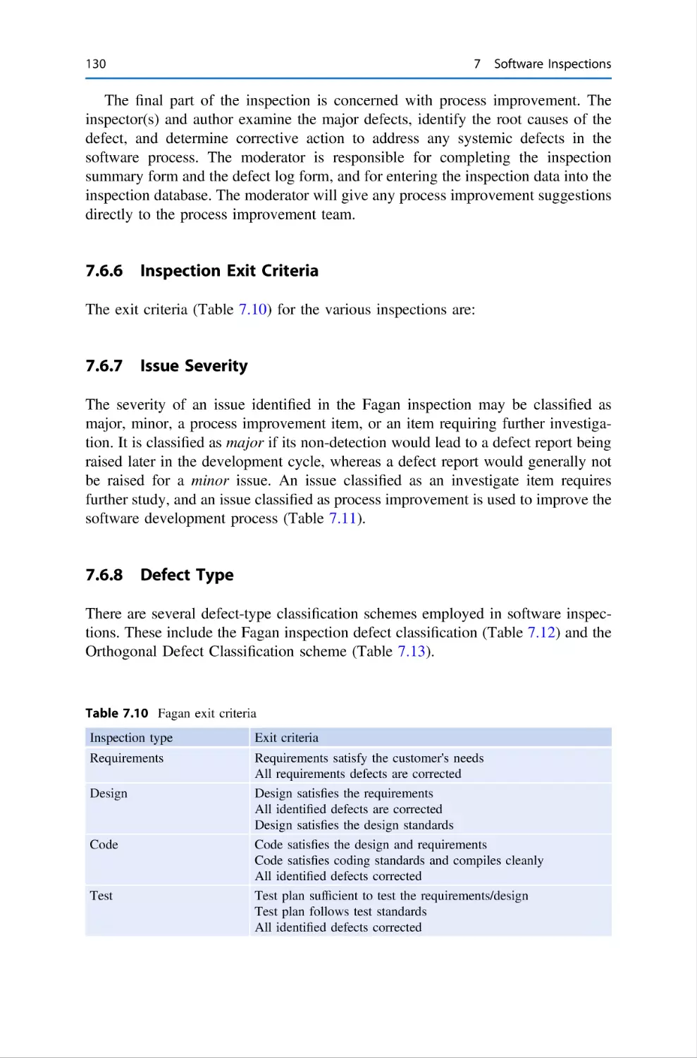
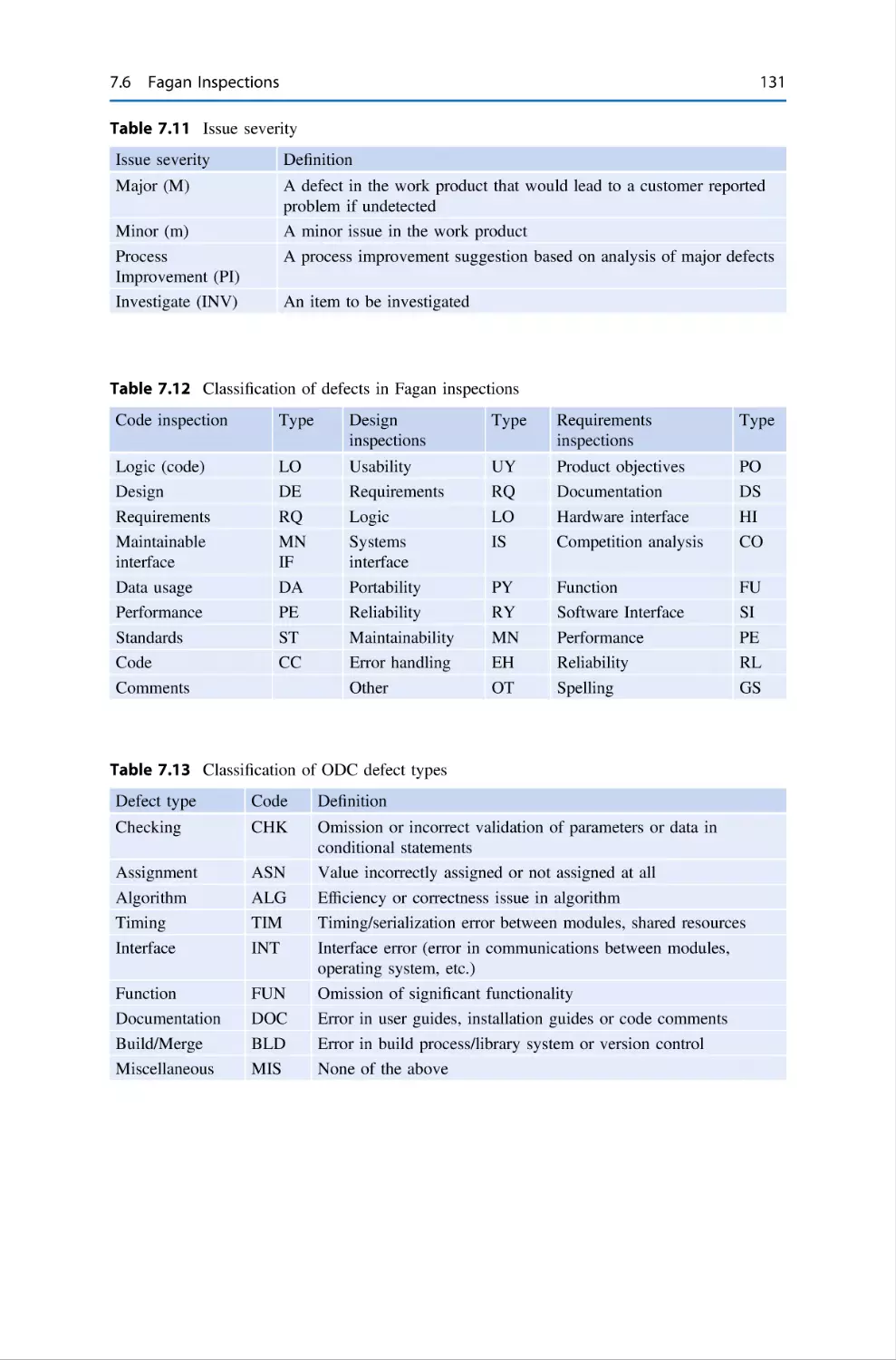
7.6.6
Inspection Exit Criteria
7.6.7
Issue Severity . . . . . . .
7.6.8
Defect Type . . . . . . . .
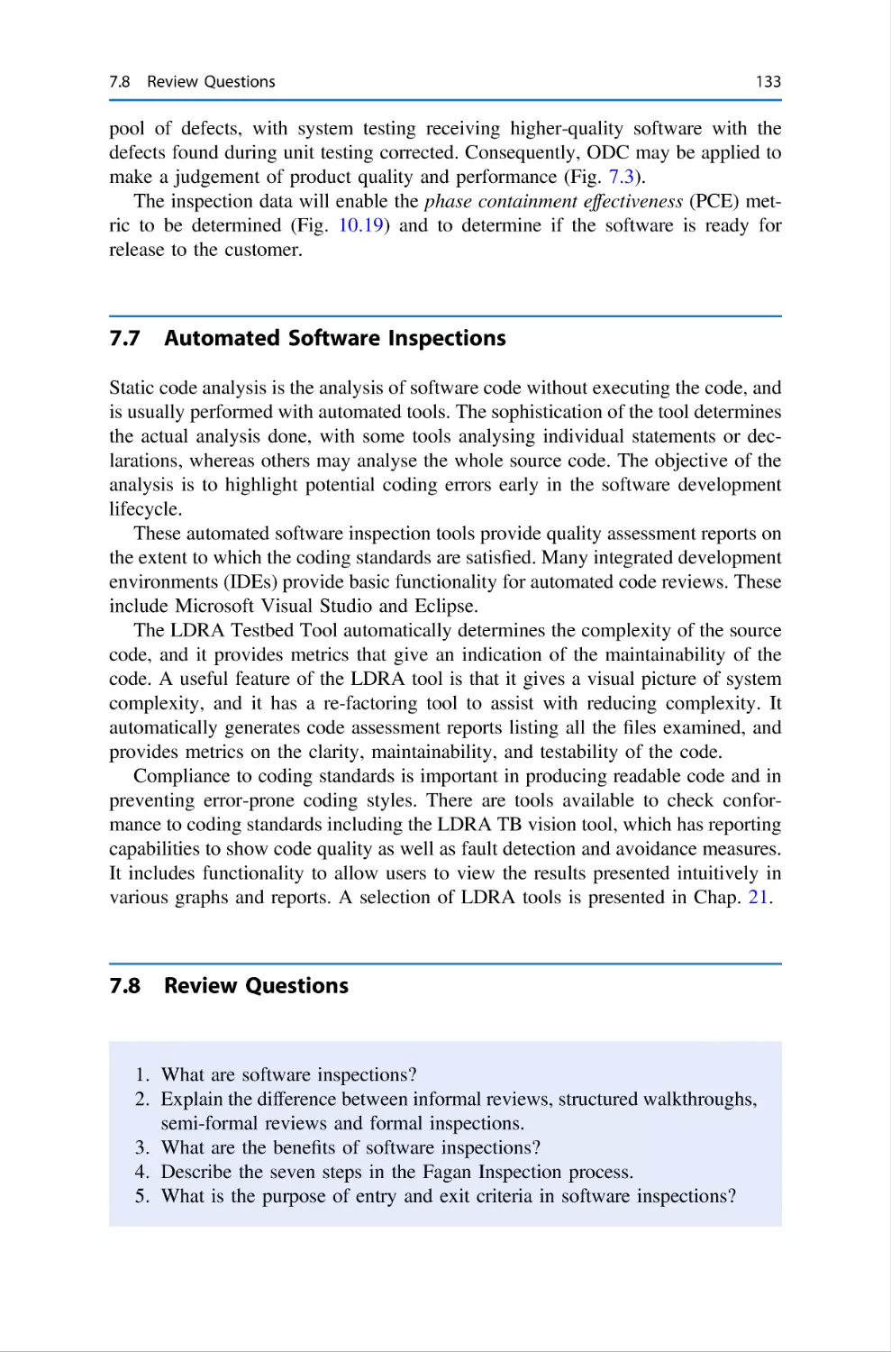
7.7
Automated Software Inspections
7.8
Review Questions . . . . . . . . . . .
7.9
Summary . . . . . . . . . . . . . . . . .
References . . . . . . . . . . . . . . . . . . . . . .
.
.
.
.
.
.
.
.
.
.
.
.
.
.
.
.
.
.
.
.
.
.
.
.
.
.
.
.
.
.
.
.
.
.
.
.
.
.
.
.
.
.
.
.
.
.
.
.
.
.
.
.
.
.
.
.
.
.
.
.
.
.
.
.
.
.
.
.
.
.
.
.
.
.
.
.
.
.
.
.
.
.
.
.
.
.
.
.
.
.
.
.
.
.
.
.
.
.
.
.
.
.
.
.
.
.
.
.
.
.
.
.
.
.
.
.
.
.
.
.
.
.
.
.
.
.
.
.
.
.
.
.
.
.
.
.
.
.
.
.
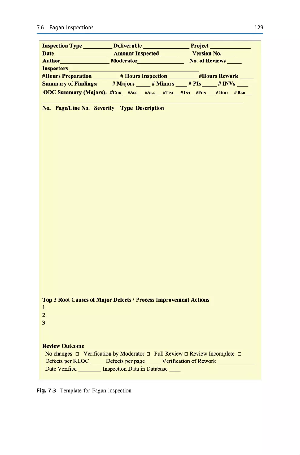
130
130
130
133
133
134
135
8
Software Testing . . . . . . . . . . . . . . . . . . . .
8.1
Introduction . . . . . . . . . . . . . . . . . .
8.2
Test Process . . . . . . . . . . . . . . . . . .
8.3
Test Planning . . . . . . . . . . . . . . . . .
8.4
Test Case Design and Definition . . .
8.5
Test Execution . . . . . . . . . . . . . . . .
8.6
Test Reporting and Project Sign-Off .
8.7
Testing and Quality Improvement . .
8.8
Traceability of Requirements . . . . . .
8.9
Test Tools . . . . . . . . . . . . . . . . . . .
8.10 E-Commerce Testing . . . . . . . . . . . .
8.11 Testing in the Agile World . . . . . . .
8.12 Review Questions . . . . . . . . . . . . . .
8.13 Summary . . . . . . . . . . . . . . . . . . . .
.
.
.
.
.
.
.
.
.
.
.
.
.
.
.
.
.
.
.
.
.
.
.
.
.
.
.
.
.
.
.
.
.
.
.
.
.
.
.
.
.
.
.
.
.
.
.
.
.
.
.
.
.
.
.
.
.
.
.
.
.
.
.
.
.
.
.
.
.
.
.
.
.
.
.
.
.
.
.
.
.
.
.
.
.
.
.
.
.
.
.
.
.
.
.
.
.
.
.
.
.
.
.
.
.
.
.
.
.
.
.
.
.
.
.
.
.
.
.
.
.
.
.
.
.
.
.
.
.
.
.
.
.
.
.
.
.
.
.
.
.
.
.
.
.
.
.
.
.
.
.
.
.
.
.
.
.
.
.
.
.
.
.
.
.
.
.
.
.
.
.
.
.
.
.
.
.
.
.
.
.
.
.
.
.
.
.
.
.
.
.
.
.
.
.
.
.
.
.
.
.
.
.
.
.
.
.
.
.
.
.
.
.
.
.
.
.
.
.
.
.
.
.
.
.
.
.
.
.
.
.
.
.
.
.
.
.
.
.
.
.
.
.
.
.
.
.
.
.
.
.
.
.
.
.
.
.
.
.
.
.
.
.
.
.
.
137
137
139
143
144
145
146
147
148
148
150
151
152
152
9
Ethics
9.1
9.2
9.3
and Privacy . . . . . . . . . . . . . . . . . . . . .
Introduction . . . . . . . . . . . . . . . . . . . . .
Business Ethics . . . . . . . . . . . . . . . . . . .
What is Computer Ethics? . . . . . . . . . . .
9.3.1
Ethical Problems in Computing
9.3.2
The Ethical Software Engineer
9.3.3
Ethics in Data Science . . . . . .
9.4
Privacy . . . . . . . . . . . . . . . . . . . . . . . . .
9.4.1
Social Media . . . . . . . . . . . . .
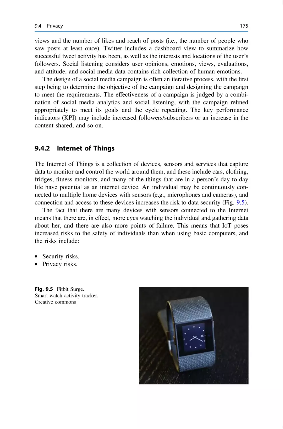
9.4.2
Internet of Things . . . . . . . . . .
9.4.3
AI and Facial Recognition . . . .
9.4.4
Privacy and the Law . . . . . . . .
9.4.5
EU GDPR Privacy Law . . . . .
9.5
Review Questions . . . . . . . . . . . . . . . . .
9.6
Summary . . . . . . . . . . . . . . . . . . . . . . .
References . . . . . . . . . . . . . . . . . . . . . . . . . . . .
.
.
.
.
.
.
.
.
.
.
.
.
.
.
.
.
.
.
.
.
.
.
.
.
.
.
.
.
.
.
.
.
.
.
.
.
.
.
.
.
.
.
.
.
.
.
.
.
.
.
.
.
.
.
.
.
.
.
.
.
.
.
.
.
.
.
.
.
.
.
.
.
.
.
.
.
.
.
.
.
.
.
.
.
.
.
.
.
.
.
.
.
.
.
.
.
.
.
.
.
.
.
.
.
.
.
.
.
.
.
.
.
.
.
.
.
.
.
.
.
.
.
.
.
.
.
.
.
.
.
.
.
.
.
.
.
.
.
.
.
.
.
.
.
.
.
.
.
.
.
.
.
.
.
.
.
.
.
.
.
.
.
.
.
.
.
.
.
.
.
.
.
.
.
.
.
.
.
.
.
.
.
.
.
.
.
.
.
.
.
.
.
.
.
.
.
.
.
.
.
.
.
.
.
.
.
.
.
.
.
.
.
.
.
.
.
.
.
.
.
.
.
.
.
.
.
.
.
.
.
.
.
.
.
.
.
.
.
.
.
.
.
.
.
.
.
.
.
.
.
.
.
.
.
.
.
155
155
157
159
160
161
162
166
172
175
176
177
178
179
180
180
.
.
.
.
.
.
.
.
.
.
.
.
.
.
.
.
.
.
.
.
.
.
.
.
.
.
.
.
.
.
.
.
.
.
.
.
.
.
.
.
.
.
.
.
.
.
.
.
.
.
.
.
.
.
.
.
.
.
.
.
.
.
.
.
181
181
182
184
.
.
.
.
.
.
.
.
.
.
.
.
.
.
10 Software Metrics and Problem Solving . . .
10.1 Introduction . . . . . . . . . . . . . . . . . .
10.2 The Goal Question Metric Paradigm
10.3 The Balanced Scorecard . . . . . . . . .
.
.
.
.
.
.
.
.
.
.
.
.
Contents
xv
10.4
Metrics for an Organization . . . . . . . . . . . . . . . . .
10.4.1 Customer Satisfaction Metrics . . . . . . . .
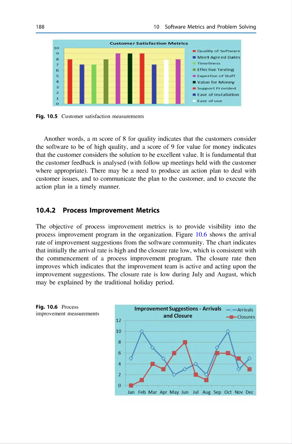
10.4.2 Process Improvement Metrics . . . . . . . .
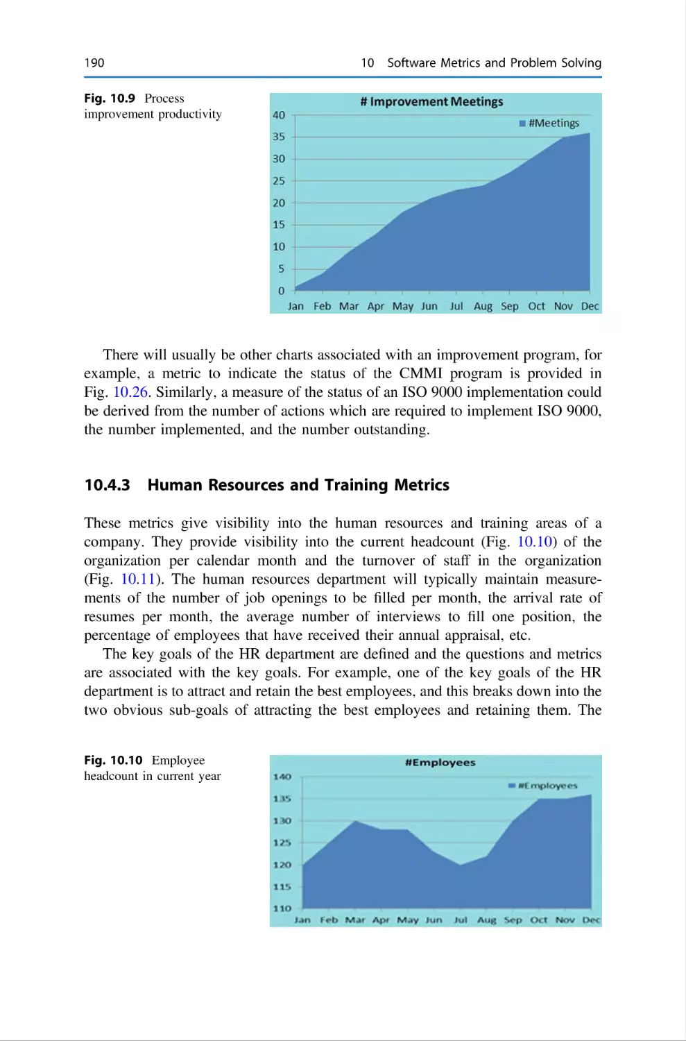
10.4.3 Human Resources and Training Metrics .
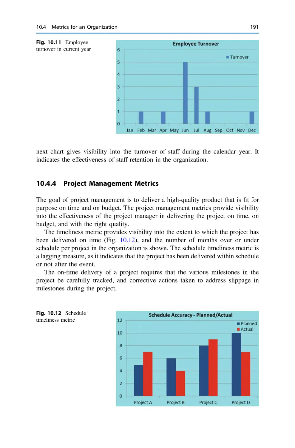
10.4.4 Project Management Metrics . . . . . . . . .
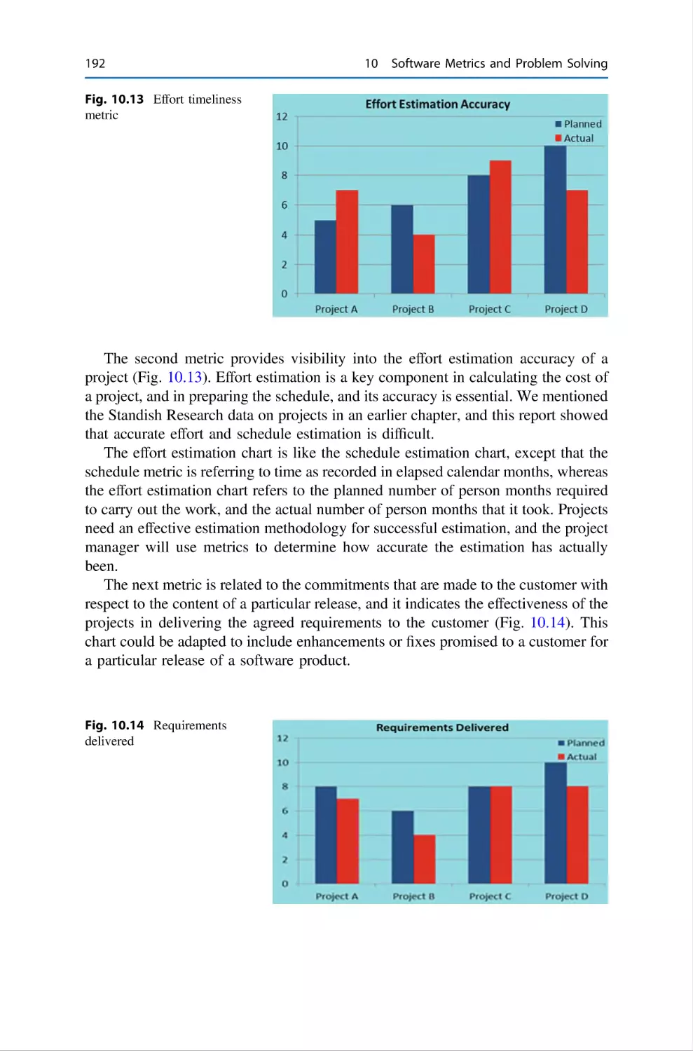
10.4.5 Development Quality Metrics . . . . . . . .
10.4.6 Quality Audit Metrics . . . . . . . . . . . . . .
10.4.7 Customer Care Metrics . . . . . . . . . . . . .
10.4.8 Miscellaneous Metrics . . . . . . . . . . . . . .
10.5 Implementing a Metrics Program . . . . . . . . . . . . .
10.5.1 Data Gathering for Metrics . . . . . . . . . .
10.6 Problem-Solving Techniques . . . . . . . . . . . . . . . .
10.6.1 Fishbone Diagram . . . . . . . . . . . . . . . . .
10.6.2 Histograms . . . . . . . . . . . . . . . . . . . . . .
10.6.3 Pareto Chart . . . . . . . . . . . . . . . . . . . . .
10.6.4 Trend Graphs . . . . . . . . . . . . . . . . . . . .
10.6.5 Scatter Graphs . . . . . . . . . . . . . . . . . . .
10.6.6 Metrics and Statistical Process Control . .
10.7 Review Questions . . . . . . . . . . . . . . . . . . . . . . . .
10.8 Summary . . . . . . . . . . . . . . . . . . . . . . . . . . . . . .
References . . . . . . . . . . . . . . . . . . . . . . . . . . . . . . . . . . .
.
.
.
.
.
.
.
.
.
.
.
.
.
.
.
.
.
.
.
.
.
.
.
.
.
.
.
.
.
.
.
.
.
.
.
.
.
.
.
.
.
.
.
.
.
.
.
.
.
.
.
.
.
.
.
.
.
.
.
.
.
.
.
.
.
.
.
.
.
.
.
.
.
.
.
.
.
.
.
.
.
.
.
.
.
.
.
.
.
.
.
.
.
.
.
.
.
.
.
.
.
.
.
.
.
.
.
.
.
.
.
.
.
.
.
.
.
.
.
.
.
.
.
.
.
.
.
.
.
.
.
.
.
.
.
.
.
.
.
.
.
.
.
.
.
.
.
.
.
.
.
.
.
.
.
.
.
.
.
.
.
.
.
.
.
.
.
.
.
.
.
.
.
.
.
.
.
.
.
.
.
.
.
.
.
.
.
.
.
187
187
188
190
191
193
195
197
199
201
202
203
205
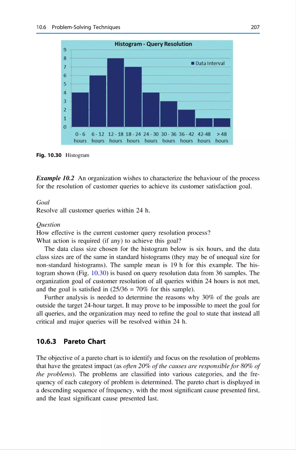
206
207
209
209
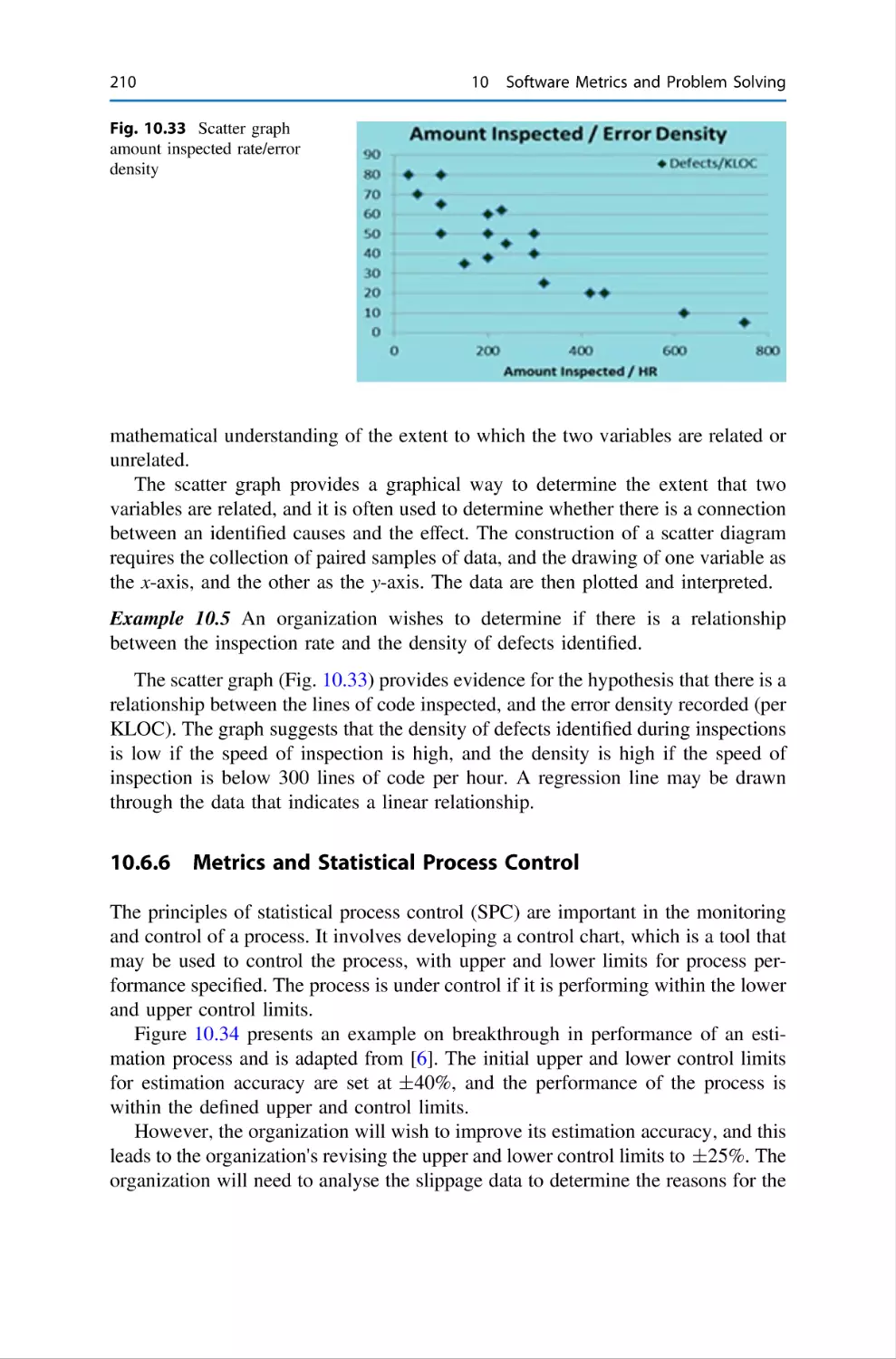
210
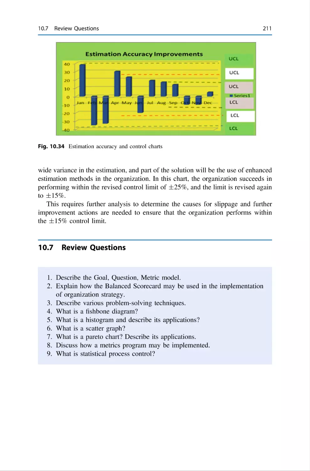
211
212
212
.
.
.
.
.
.
.
.
.
.
.
.
.
.
.
.
.
.
.
.
.
.
.
.
.
.
.
.
.
.
.
.
.
.
.
.
.
.
.
.
.
.
.
.
.
.
.
.
.
.
.
.
.
.
.
.
.
.
.
.
.
.
.
.
.
.
.
.
.
.
.
.
.
.
.
.
.
.
.
.
.
.
.
.
.
.
.
.
.
.
.
.
.
.
.
.
.
.
.
.
.
.
.
.
.
.
.
.
.
.
.
.
.
.
.
.
.
.
.
.
.
.
.
.
.
.
.
.
.
.
.
.
.
.
.
.
.
.
.
.
.
.
.
.
.
.
.
.
.
.
.
.
.
.
.
.
.
.
.
.
.
.
.
.
.
.
.
.
.
.
.
.
.
.
.
.
.
.
.
.
.
.
.
.
.
.
.
.
.
.
.
.
.
.
.
.
213
213
216
216
217
217
218
219
220
220
220
222
224
225
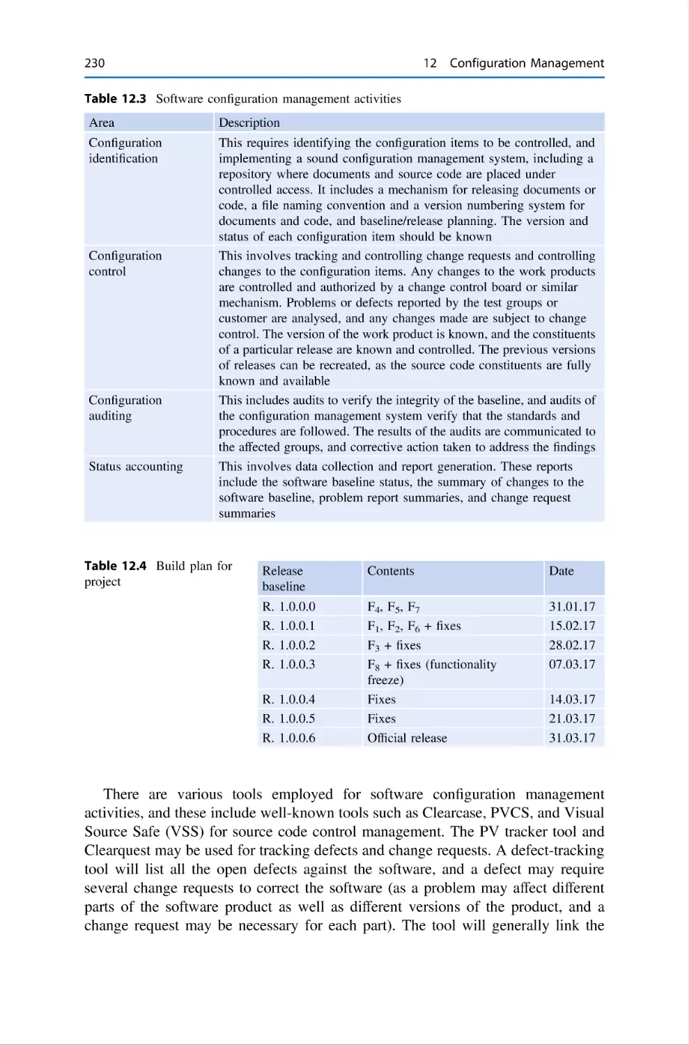
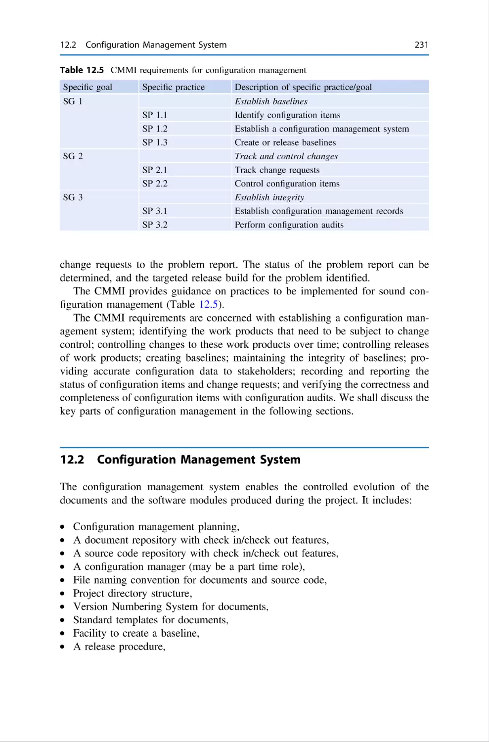
12 Configuration Management . . . . . . . . . . . . . . . . . .
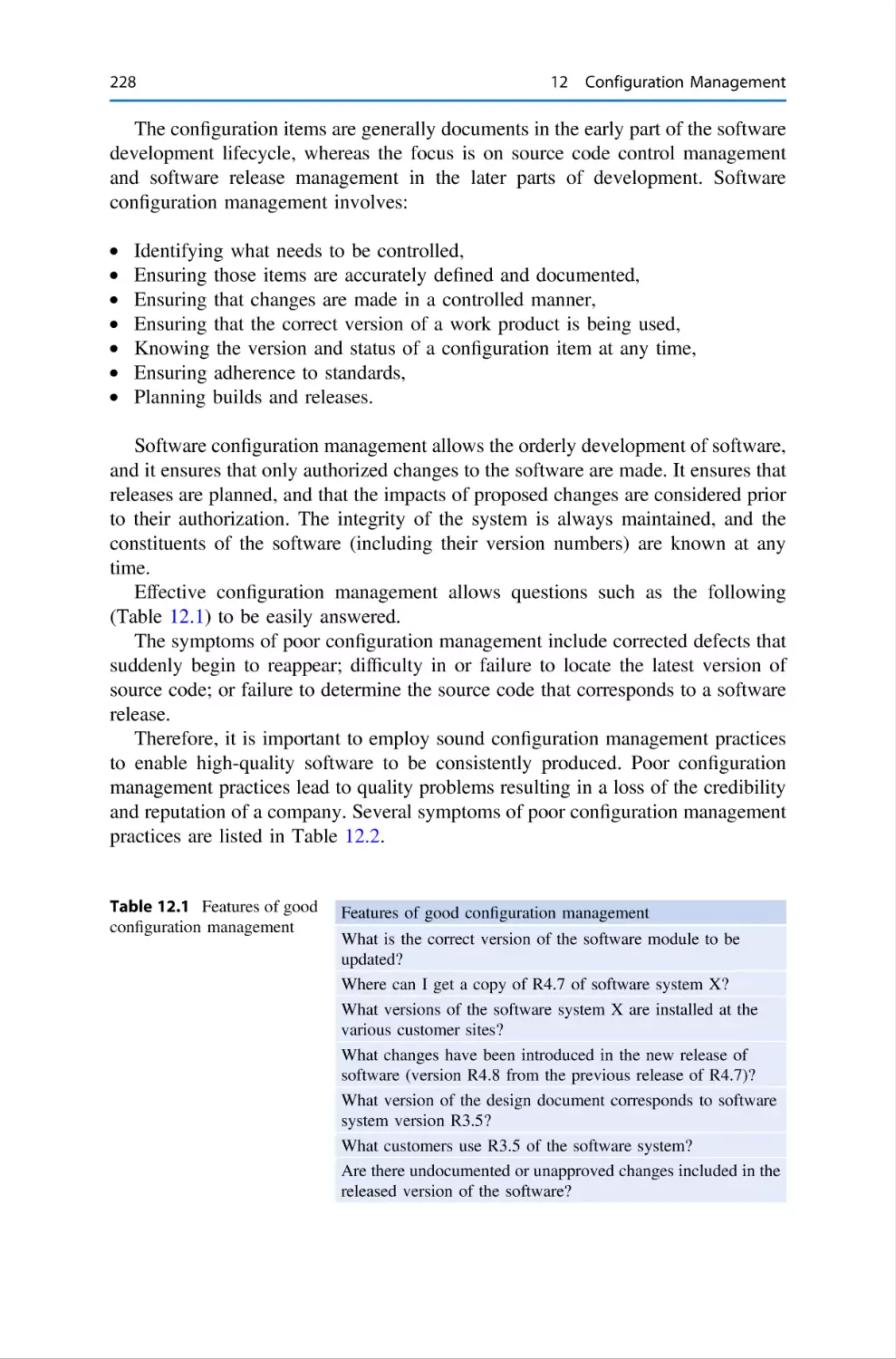
12.1 Introduction . . . . . . . . . . . . . . . . . . . . . . . .
12.2 Configuration Management System . . . . . . .
12.2.1 Identify Configuration Items . . . . .
12.2.2 Document Control Management . .
12.2.3 Source Code Control Management .
12.2.4 Configuration Management Plan . .
.
.
.
.
.
.
.
.
.
.
.
.
.
.
.
.
.
.
.
.
.
.
.
.
.
.
.
.
.
.
.
.
.
.
.
.
.
.
.
.
.
.
.
.
.
.
.
.
.
.
.
.
.
.
.
.
.
.
.
.
.
.
.
.
.
.
.
.
.
.
.
.
.
.
.
.
.
.
.
.
.
.
.
.
.
.
.
.
.
.
.
227
227
231
232
232
233
233
11 Supplier Selection and Management . . . . . . .
11.1 Introduction . . . . . . . . . . . . . . . . . . . .
11.2 Planning and Requirements . . . . . . . . .
11.3 Identifying Suppliers . . . . . . . . . . . . . .
11.4 Prepare and Issue RFP . . . . . . . . . . . .
11.5 Evaluate Proposals and Select Supplier .
11.6 Formal Agreement . . . . . . . . . . . . . . .
11.7 Managing the Supplier . . . . . . . . . . . .
11.8 Acceptance of Software . . . . . . . . . . . .
11.9 Rollout and Customer Support . . . . . . .
11.10 Ethical Software Outsourcing . . . . . . . .
11.11 Legal Breach of Contact . . . . . . . . . . .
11.12 Review Questions . . . . . . . . . . . . . . . .
11.13 Summary . . . . . . . . . . . . . . . . . . . . . .
.
.
.
.
.
.
.
.
.
.
.
.
.
.
.
.
.
.
.
.
.
.
.
.
.
.
.
.
.
.
.
.
.
.
.
.
.
.
.
.
.
.
xvi
Contents
12.3
12.4
12.5
12.6
Change Control . . . . . . . . . . . . . . .
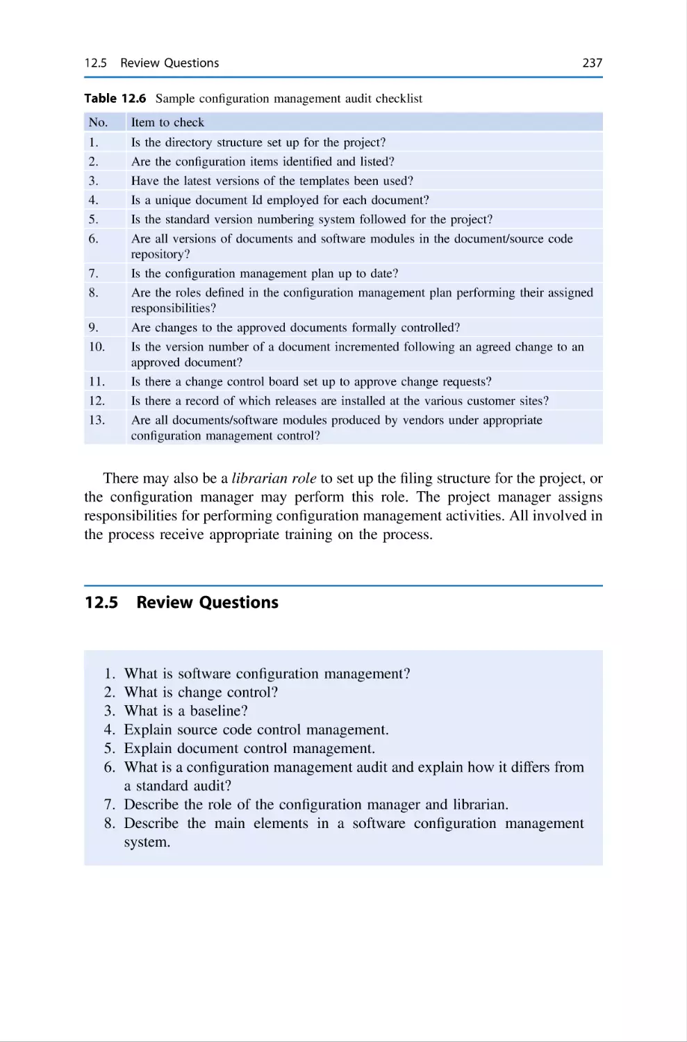
Configuration Management Audits .
Review Questions . . . . . . . . . . . . .
Summary . . . . . . . . . . . . . . . . . . .
.
.
.
.
.
.
.
.
.
.
.
.
.
.
.
.
.
.
.
.
.
.
.
.
.
.
.
.
.
.
.
.
.
.
.
.
.
.
.
.
.
.
.
.
.
.
.
.
.
.
.
.
.
.
.
.
.
.
.
.
.
.
.
.
.
.
.
.
.
.
.
.
.
.
.
.
.
.
.
.
234
236
237
238
13 Software Quality Assurance . . . .
13.1 Introduction . . . . . . . . . . .
13.2 Audit Planning . . . . . . . . .
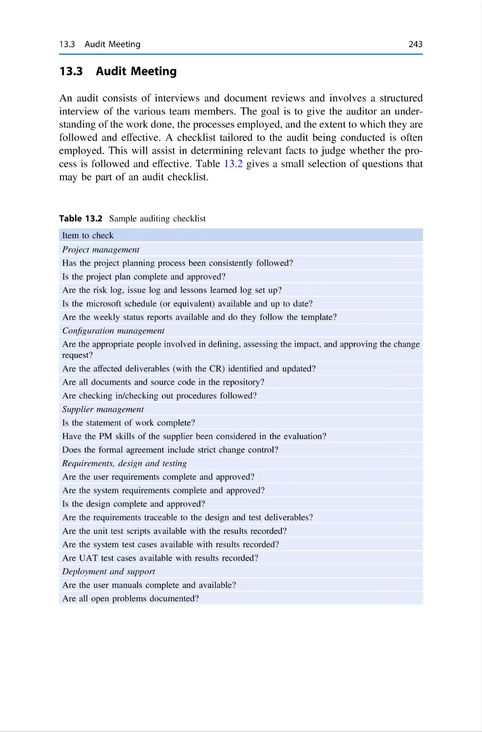
13.3 Audit Meeting . . . . . . . . .
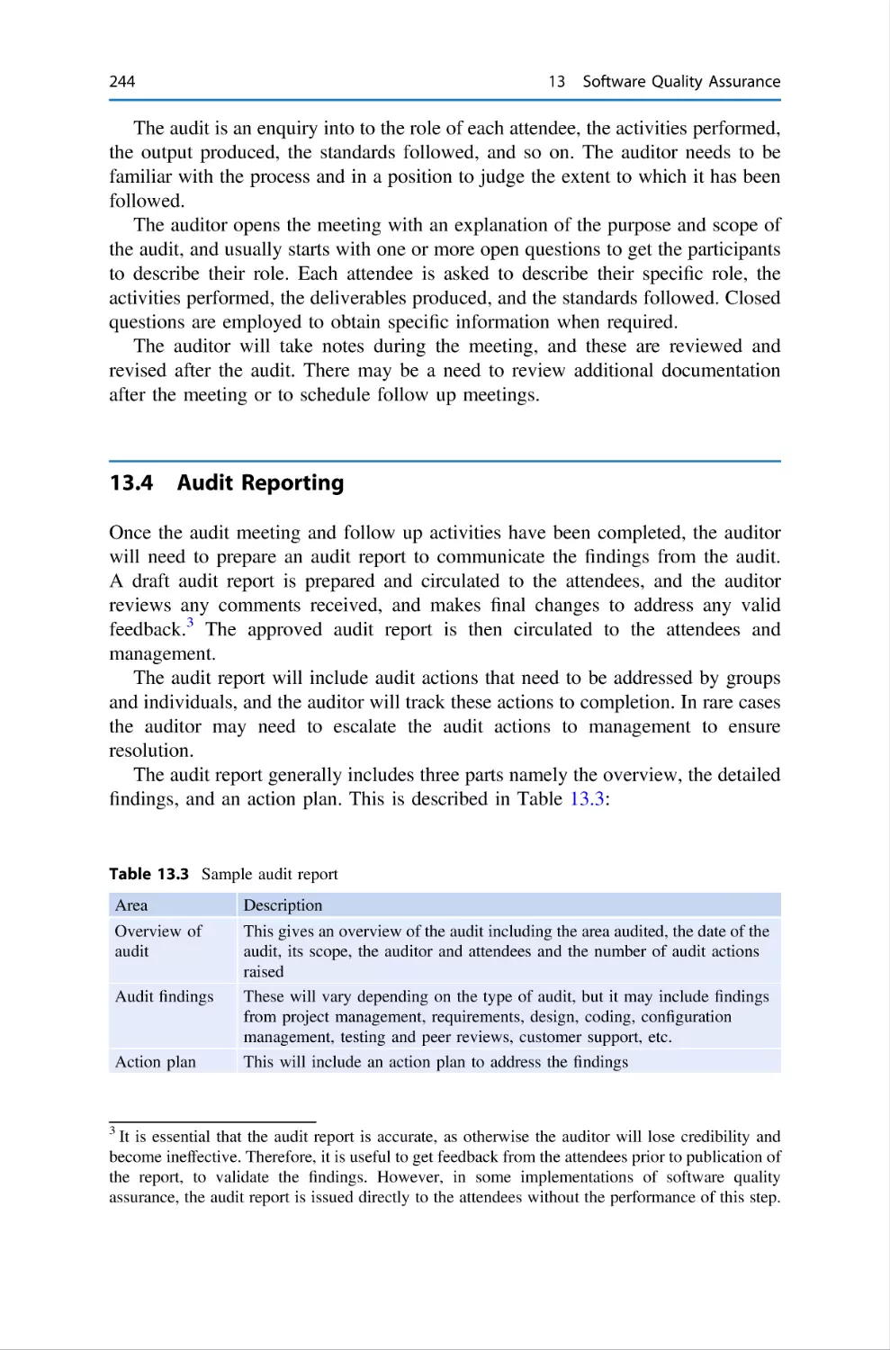
13.4 Audit Reporting . . . . . . . .
13.5 Follow Up Activity . . . . . .
13.6 Audit Escalation . . . . . . . .
13.7 Review of Audit Activities
13.8 Other Audits . . . . . . . . . . .
13.9 Review Questions . . . . . . .
13.10 Summary . . . . . . . . . . . . .
.
.
.
.
.
.
.
.
.
.
.
.
.
.
.
.
.
.
.
.
.
.
.
.
.
.
.
.
.
.
.
.
.
.
.
.
.
.
.
.
.
.
.
.
.
.
.
.
.
.
.
.
.
.
.
.
.
.
.
.
.
.
.
.
.
.
.
.
.
.
.
.
.
.
.
.
.
.
.
.
.
.
.
.
.
.
.
.
.
.
.
.
.
.
.
.
.
.
.
.
.
.
.
.
.
.
.
.
.
.
.
.
.
.
.
.
.
.
.
.
.
.
.
.
.
.
.
.
.
.
.
.
.
.
.
.
.
.
.
.
.
.
.
.
.
.
.
.
.
.
.
.
.
.
.
.
.
.
.
.
.
.
.
.
.
.
.
.
.
.
.
.
.
.
.
.
.
.
.
.
.
.
.
.
.
.
.
.
.
.
.
.
.
.
.
.
.
.
.
.
.
.
.
.
.
.
.
.
.
.
.
.
.
.
.
.
.
.
.
.
.
.
.
.
.
.
.
.
.
.
.
.
.
.
.
.
.
.
.
.
.
.
.
.
.
.
.
.
.
.
.
.
.
.
.
.
.
.
.
.
.
.
.
.
.
.
.
.
.
.
.
.
.
.
.
.
.
.
.
.
.
.
.
.
.
.
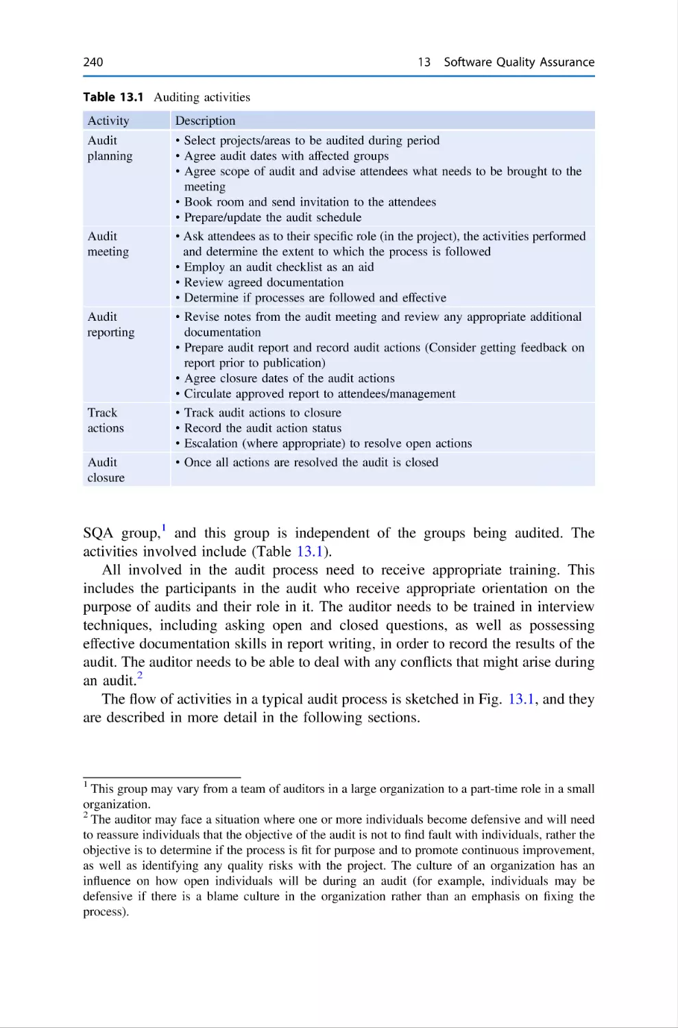
239
239
242
243
244
245
245
245
245
246
246
14 Agile Methodology . . . . . . . . . .
14.1 Introduction . . . . . . . . . .
14.2 Scrum Methodology . . . .
14.3 User Stories . . . . . . . . . .
14.4 Estimation in Agile . . . . .
14.5 Test Driven Development
14.6 Pair Programming . . . . . .
14.7 Review Questions . . . . . .
14.8 Summary . . . . . . . . . . . .
Reference . . . . . . . . . . . . . . . . . .
.
.
.
.
.
.
.
.
.
.
.
.
.
.
.
.
.
.
.
.
.
.
.
.
.
.
.
.
.
.
.
.
.
.
.
.
.
.
.
.
.
.
.
.
.
.
.
.
.
.
.
.
.
.
.
.
.
.
.
.
.
.
.
.
.
.
.
.
.
.
.
.
.
.
.
.
.
.
.
.
.
.
.
.
.
.
.
.
.
.
.
.
.
.
.
.
.
.
.
.
.
.
.
.
.
.
.
.
.
.
.
.
.
.
.
.
.
.
.
.
.
.
.
.
.
.
.
.
.
.
.
.
.
.
.
.
.
.
.
.
.
.
.
.
.
.
.
.
.
.
.
.
.
.
.
.
.
.
.
.
.
.
.
.
.
.
.
.
.
.
.
.
.
.
.
.
.
.
.
.
.
.
.
.
.
.
.
.
.
.
.
.
.
.
.
.
.
.
.
.
.
.
.
.
.
.
.
.
.
.
.
.
.
.
.
.
.
.
.
.
.
.
.
.
.
.
.
.
.
.
.
.
.
.
.
.
.
.
.
.
.
.
.
.
.
.
.
.
.
.
.
.
.
.
.
.
.
.
.
.
247
247
250
251
252
252
253
254
254
255
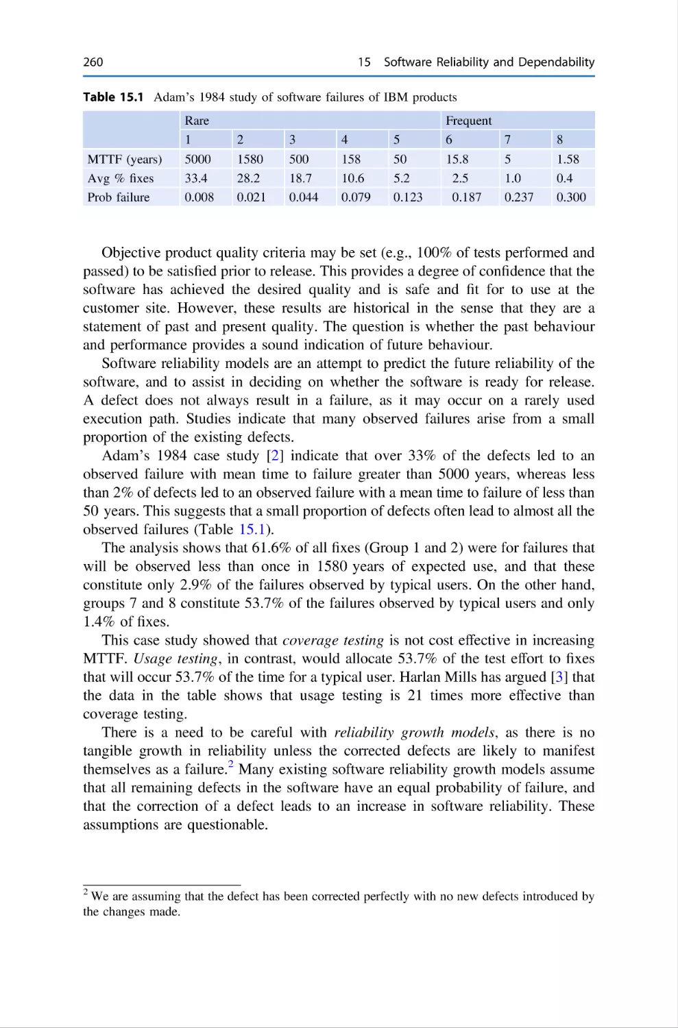
15 Software Reliability and Dependability . . . . . . .
15.1 Introduction . . . . . . . . . . . . . . . . . . . . . .
15.2 Software Reliability . . . . . . . . . . . . . . . . .
15.2.1 Software Reliability and Defects
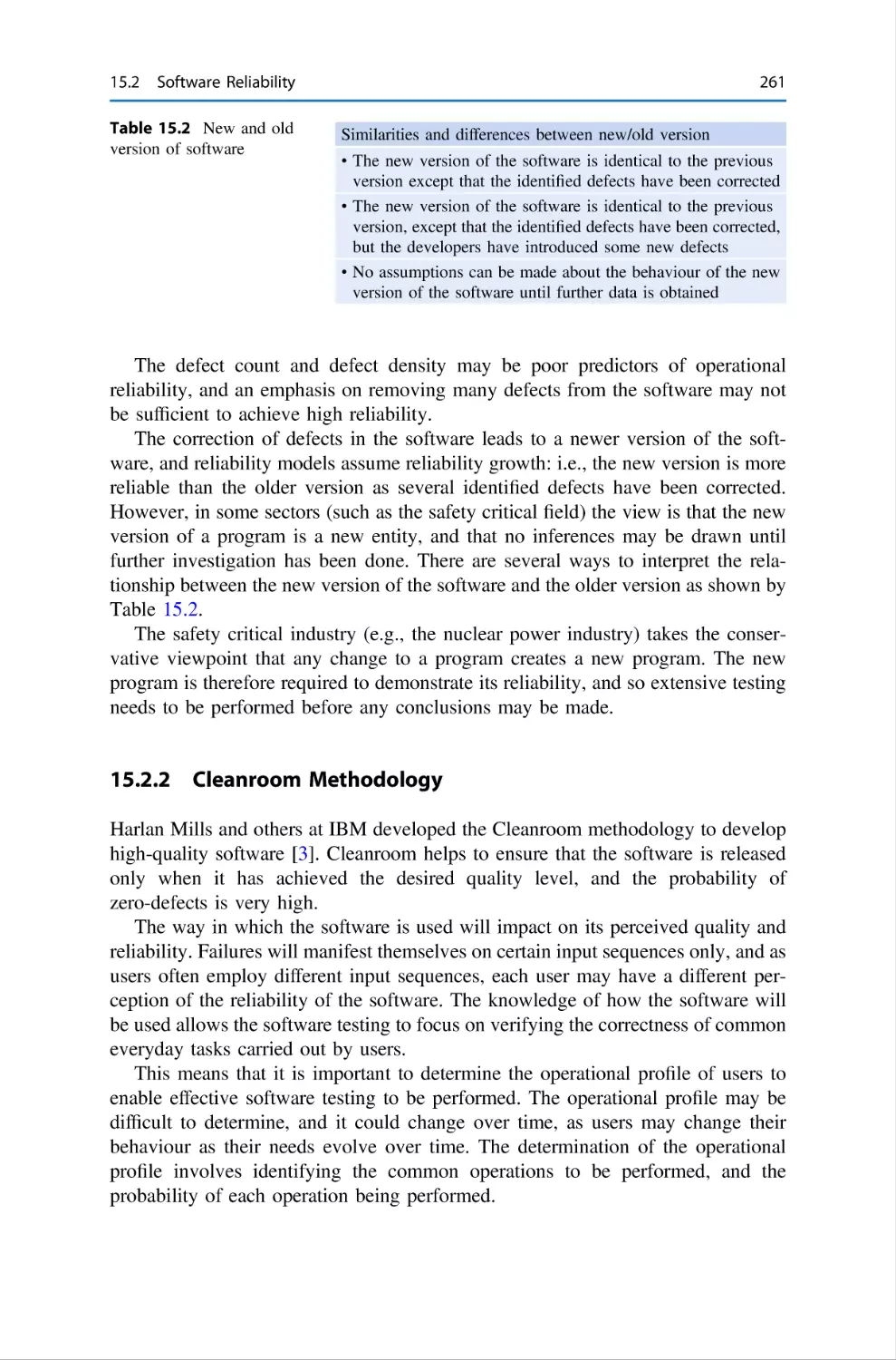
15.2.2 Cleanroom Methodology . . . . . .
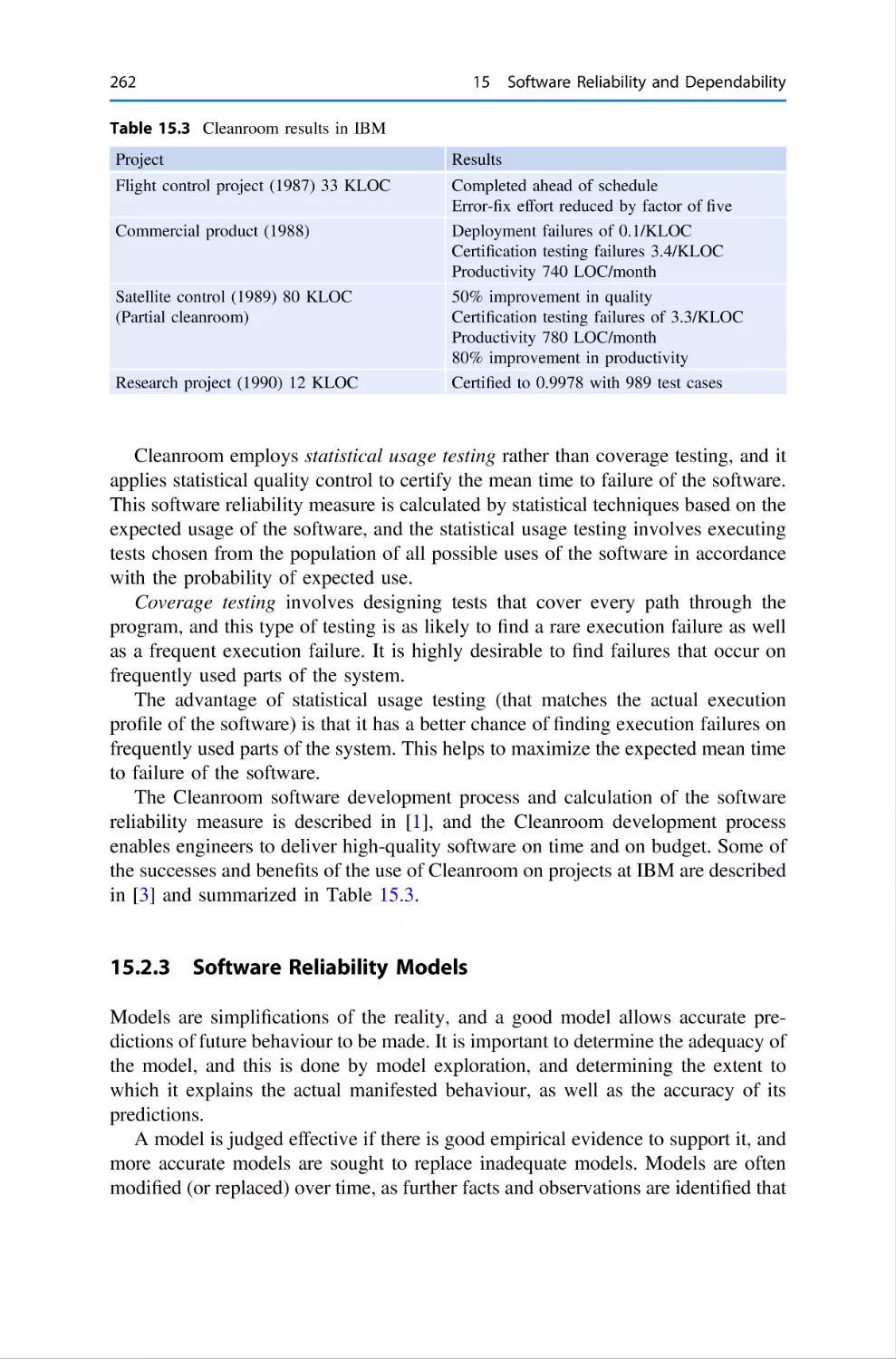
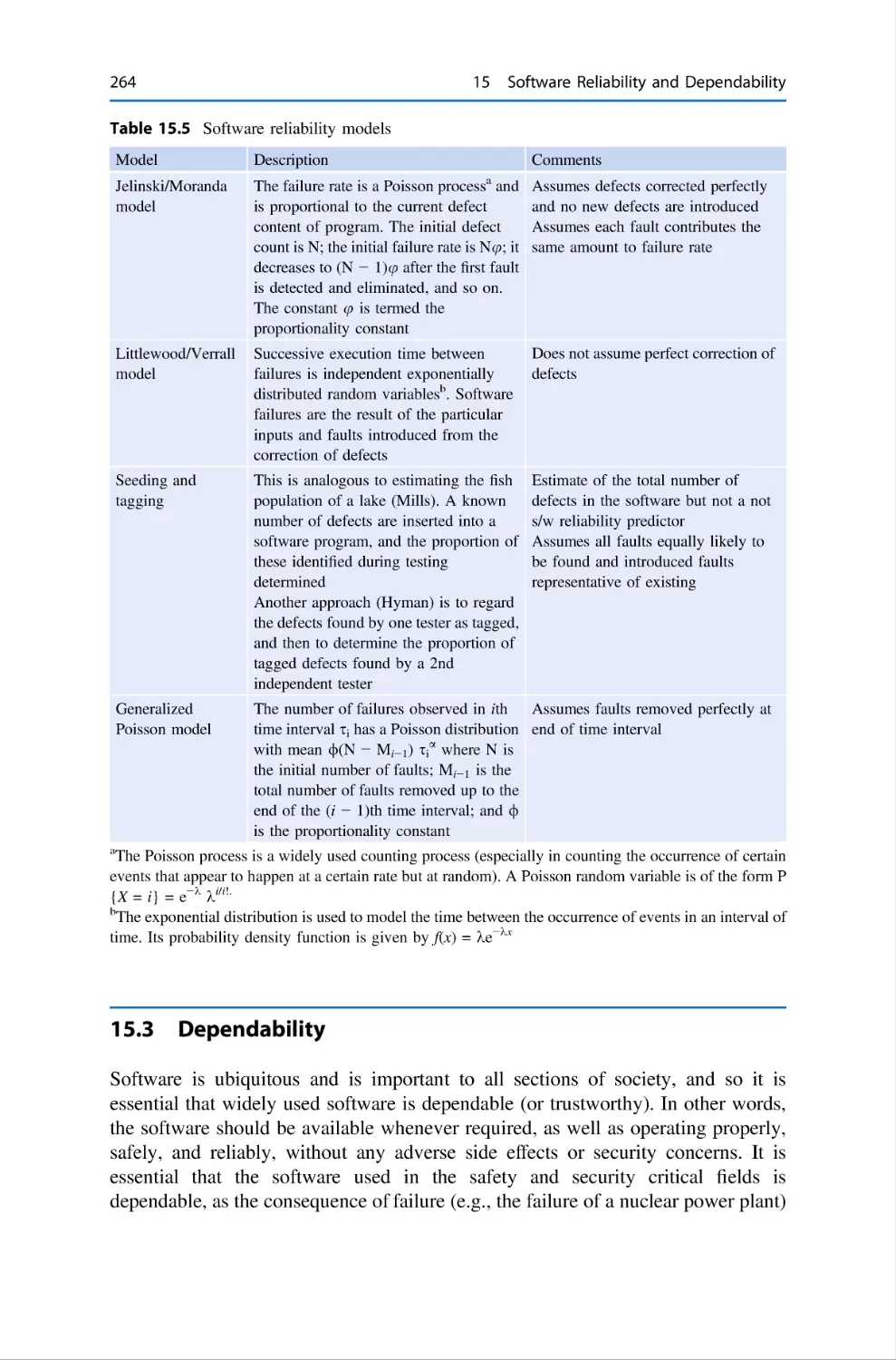
15.2.3 Software Reliability Models . . .
15.3 Dependability . . . . . . . . . . . . . . . . . . . . .
15.4 Computer Security . . . . . . . . . . . . . . . . .
15.5 System Availability . . . . . . . . . . . . . . . . .
15.6 Safety Critical Systems . . . . . . . . . . . . . .
15.7 Review Questions . . . . . . . . . . . . . . . . . .
15.8 Summary . . . . . . . . . . . . . . . . . . . . . . . .
References . . . . . . . . . . . . . . . . . . . . . . . . . . . . .
.
.
.
.
.
.
.
.
.
.
.
.
.
.
.
.
.
.
.
.
.
.
.
.
.
.
.
.
.
.
.
.
.
.
.
.
.
.
.
.
.
.
.
.
.
.
.
.
.
.
.
.
.
.
.
.
.
.
.
.
.
.
.
.
.
.
.
.
.
.
.
.
.
.
.
.
.
.
.
.
.
.
.
.
.
.
.
.
.
.
.
.
.
.
.
.
.
.
.
.
.
.
.
.
.
.
.
.
.
.
.
.
.
.
.
.
.
.
.
.
.
.
.
.
.
.
.
.
.
.
.
.
.
.
.
.
.
.
.
.
.
.
.
.
.
.
.
.
.
.
.
.
.
.
.
.
.
.
.
.
.
.
.
.
.
.
.
.
.
.
.
.
.
.
.
.
.
.
.
.
.
.
.
.
.
.
.
.
.
.
.
.
.
.
.
257
257
258
259
261
262
264
266
267
268
269
269
270
.
.
.
.
.
.
.
.
.
.
16 Formal Methods . . . . . . . . . . . . . . . . . . . . . . . . . . . . . . . . . . . . . . . 271
16.1 Introduction . . . . . . . . . . . . . . . . . . . . . . . . . . . . . . . . . . . . . 271
16.2 Why Should We Use Formal Methods? . . . . . . . . . . . . . . . . . 274
Contents
xvii
16.3
16.4
16.5
Applications of Formal Methods . . . . . . . . . . . . . . .
Tools for Formal Methods . . . . . . . . . . . . . . . . . . . .
Approaches to Formal Methods . . . . . . . . . . . . . . . .
16.5.1 Model-Oriented Approach . . . . . . . . . . . . .
16.5.2 Axiomatic Approach . . . . . . . . . . . . . . . . .
16.6 Proof and Formal Methods . . . . . . . . . . . . . . . . . . .
16.7 The Future of Formal Methods . . . . . . . . . . . . . . . .
16.8 The Vienna Development Method . . . . . . . . . . . . . .
16.9 VDM♣, the Irish School of VDM . . . . . . . . . . . . . .
16.10 The Z Specification Language . . . . . . . . . . . . . . . . .
16.11 The B Method . . . . . . . . . . . . . . . . . . . . . . . . . . . .
16.12 Predicate Transformers and Weakest Preconditions . .
16.13 The Process Calculii . . . . . . . . . . . . . . . . . . . . . . . .
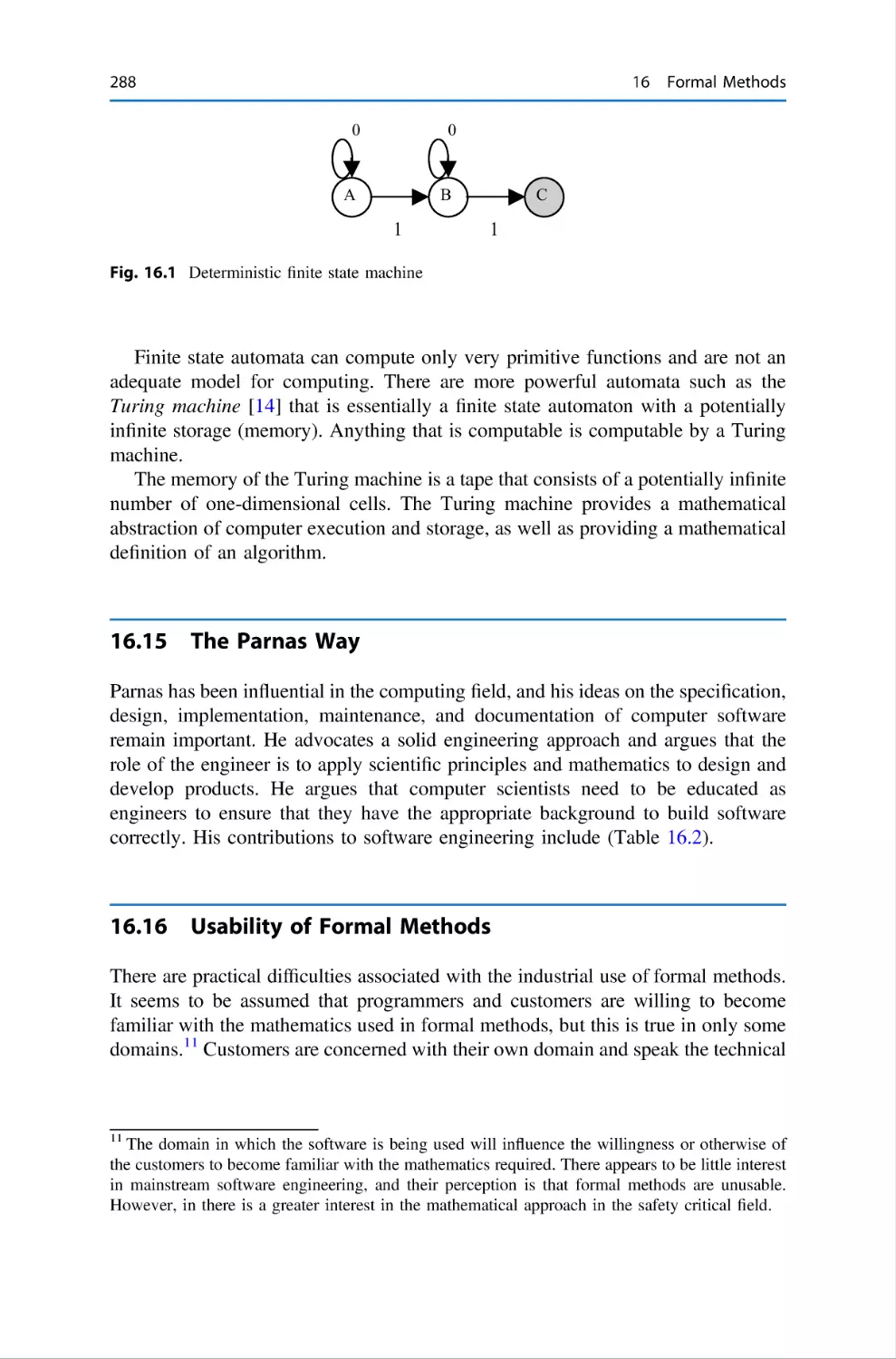
16.14 Finite State Machines . . . . . . . . . . . . . . . . . . . . . . .
16.15 The Parnas Way . . . . . . . . . . . . . . . . . . . . . . . . . . .
16.16 Usability of Formal Methods . . . . . . . . . . . . . . . . . .
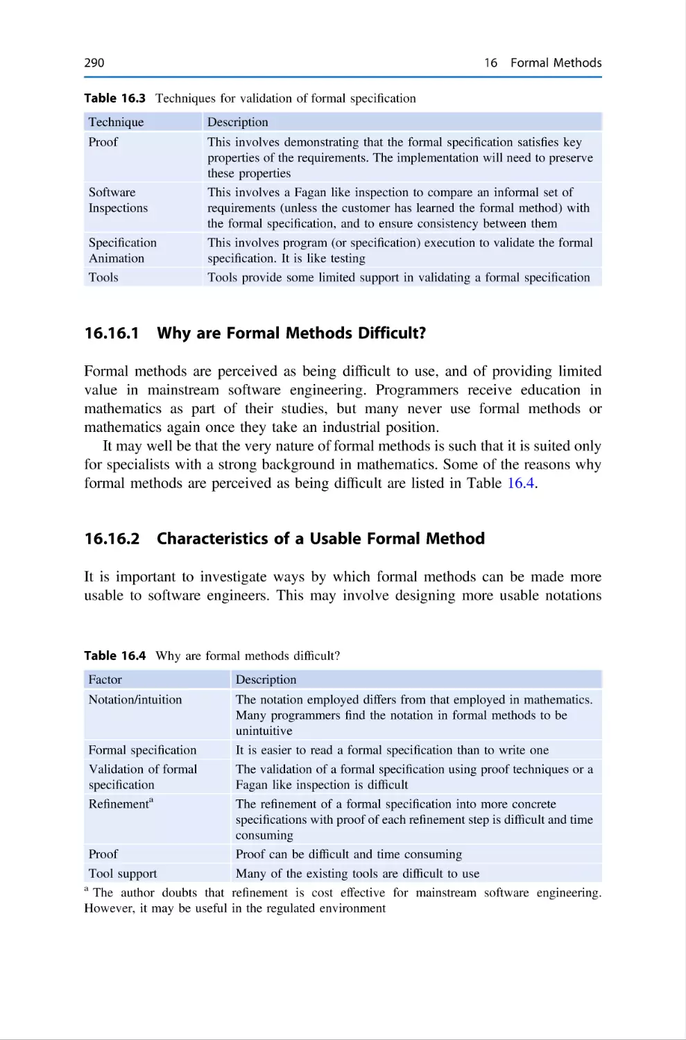
16.16.1 Why are Formal Methods Difficult? . . . . . .
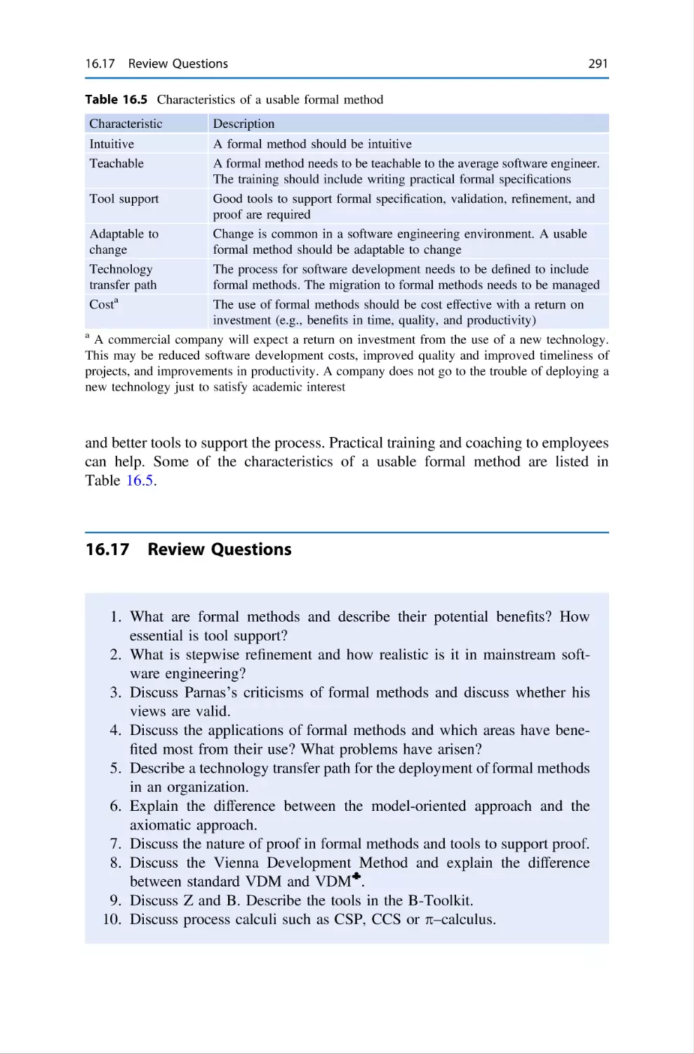
16.16.2 Characteristics of a Usable Formal Method
16.17 Review Questions . . . . . . . . . . . . . . . . . . . . . . . . . .
16.18 Summary . . . . . . . . . . . . . . . . . . . . . . . . . . . . . . . .
References . . . . . . . . . . . . . . . . . . . . . . . . . . . . . . . . . . . . .
.
.
.
.
.
.
.
.
.
.
.
.
.
.
.
.
.
.
.
.
.
.
.
.
.
.
.
.
.
.
.
.
.
.
.
.
.
.
.
.
.
.
.
.
.
.
.
.
.
.
.
.
.
.
.
.
.
.
.
.
.
.
.
.
.
.
.
.
.
.
.
.
.
.
.
.
.
.
.
.
.
.
.
.
.
.
.
.
.
.
.
.
.
.
.
.
.
.
.
.
.
.
.
.
.
.
.
.
.
.
.
.
.
.
.
.
.
.
.
.
.
.
.
.
.
.
.
.
.
.
.
.
.
.
.
.
.
.
.
.
.
.
.
.
.
.
.
275
276
277
277
279
279
280
281
282
283
284
285
286
287
288
288
290
290
291
292
292
17 Z Specification Language . . . . . . . . . . . .
17.1 Introduction . . . . . . . . . . . . . . . . .
17.2 Sets . . . . . . . . . . . . . . . . . . . . . . .
17.3 Relations . . . . . . . . . . . . . . . . . . .
17.4 Functions . . . . . . . . . . . . . . . . . . .
17.5 Sequences . . . . . . . . . . . . . . . . . . .
17.6 Bags . . . . . . . . . . . . . . . . . . . . . . .
17.7 Schemas and Schema Composition
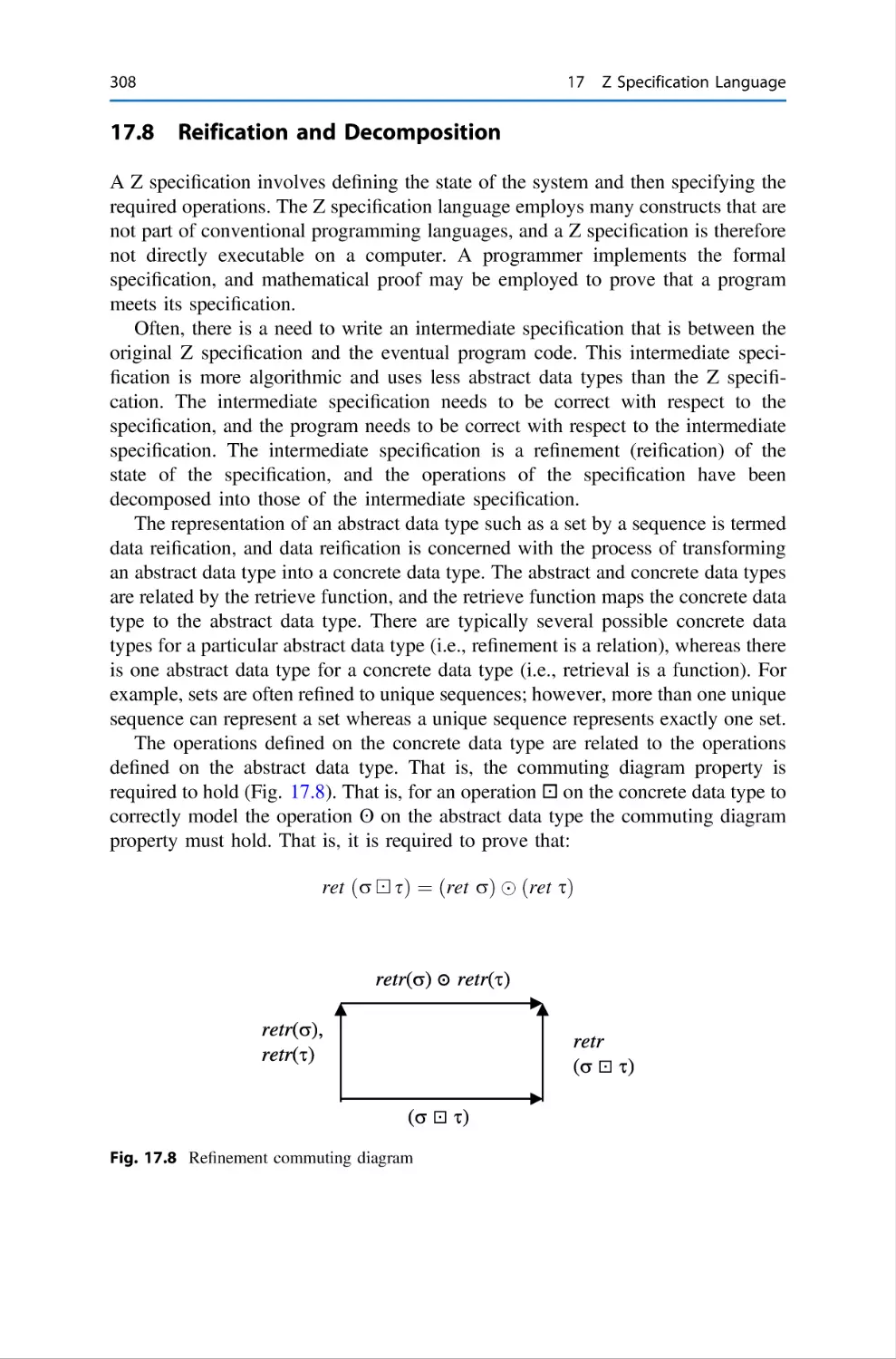
17.8 Reification and Decomposition . . . .
17.9 Proof in Z . . . . . . . . . . . . . . . . . .
17.10 Review Questions . . . . . . . . . . . . .
17.11 Summary . . . . . . . . . . . . . . . . . . .
References . . . . . . . . . . . . . . . . . . . . . . . .
.
.
.
.
.
.
.
.
.
.
.
.
.
.
.
.
.
.
.
.
.
.
.
.
.
.
.
.
.
.
.
.
.
.
.
.
.
.
.
.
.
.
.
.
.
.
.
.
.
.
.
.
.
.
.
.
.
.
.
.
.
.
.
.
.
.
.
.
.
.
.
.
.
.
.
.
.
.
.
.
.
.
.
.
.
.
.
.
.
.
.
.
.
.
.
.
.
.
.
.
.
.
.
.
.
.
.
.
.
.
.
.
.
.
.
.
.
.
.
.
.
.
.
.
.
.
.
.
.
.
.
.
.
.
.
.
.
.
.
.
.
.
.
.
.
.
.
.
.
.
.
.
.
.
.
.
.
.
.
.
.
.
.
.
.
.
.
.
.
.
.
.
.
.
.
.
.
.
.
.
.
.
.
.
.
.
.
.
.
.
.
.
.
.
.
.
.
.
.
.
.
.
.
.
.
.
.
.
.
.
.
.
.
.
.
.
.
.
.
.
.
.
.
.
.
.
.
.
.
.
.
.
.
.
.
.
.
.
.
.
.
.
.
.
.
.
.
.
.
.
.
.
.
.
.
.
.
.
.
.
295
295
298
299
301
302
303
305
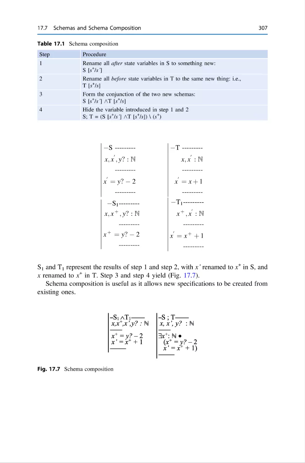
308
309
309
310
311
18 Unified Modelling Language . . . . .
18.1 Introduction . . . . . . . . . . . .
18.2 Overview of UML . . . . . . .
18.3 UML Diagrams . . . . . . . . . .
18.4 Object Constraint Language .
18.5 Tools for UML . . . . . . . . . .
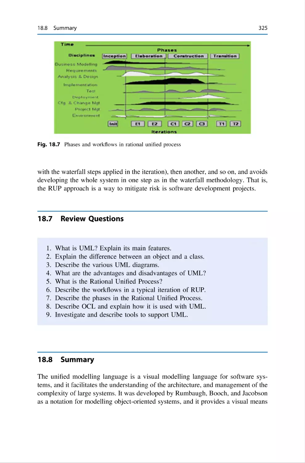
18.6 Rational Unified Process . . .
18.7 Review Questions . . . . . . . .
.
.
.
.
.
.
.
.
.
.
.
.
.
.
.
.
.
.
.
.
.
.
.
.
.
.
.
.
.
.
.
.
.
.
.
.
.
.
.
.
.
.
.
.
.
.
.
.
.
.
.
.
.
.
.
.
.
.
.
.
.
.
.
.
.
.
.
.
.
.
.
.
.
.
.
.
.
.
.
.
.
.
.
.
.
.
.
.
.
.
.
.
.
.
.
.
.
.
.
.
.
.
.
.
.
.
.
.
.
.
.
.
.
.
.
.
.
.
.
.
.
.
.
.
.
.
.
.
.
.
.
.
.
.
.
.
.
.
.
.
.
.
.
.
.
.
.
.
.
.
.
.
.
.
.
.
.
.
.
.
313
313
314
316
322
322
323
325
.
.
.
.
.
.
.
.
.
.
.
.
.
.
.
.
.
.
.
.
.
.
.
.
.
.
.
.
.
.
.
.
.
.
.
.
.
.
.
.
xviii
Contents
18.8 Summary . . . . . . . . . . . . . . . . . . . . . . . . . . . . . . . . . . . . . . . 325
References . . . . . . . . . . . . . . . . . . . . . . . . . . . . . . . . . . . . . . . . . . . . 326
19 Software Process Improvement . . . . . . . . . . . . .
19.1 Introduction . . . . . . . . . . . . . . . . . . . . . .
19.2 What is a Software Process? . . . . . . . . . .
19.3 What is Software Process Improvement? .
19.4 Benefits of Software Process Improvement
19.5 Software Process Improvement Models . .
19.6 Process Mapping . . . . . . . . . . . . . . . . . . .
19.7 Process Improvement Initiatives . . . . . . . .
19.8 Barriers to Success . . . . . . . . . . . . . . . . .
19.9 Setting Up an Improvement Initiative . . . .
19.10 Appraisals . . . . . . . . . . . . . . . . . . . . . . . .
19.11 Review Questions . . . . . . . . . . . . . . . . . .
19.12 Summary . . . . . . . . . . . . . . . . . . . . . . . .
References . . . . . . . . . . . . . . . . . . . . . . . . . . . . .
.
.
.
.
.
.
.
.
.
.
.
.
.
.
.
.
.
.
.
.
.
.
.
.
.
.
.
.
.
.
.
.
.
.
.
.
.
.
.
.
.
.
.
.
.
.
.
.
.
.
.
.
.
.
.
.
.
.
.
.
.
.
.
.
.
.
.
.
.
.
.
.
.
.
.
.
.
.
.
.
.
.
.
.
.
.
.
.
.
.
.
.
.
.
.
.
.
.
.
.
.
.
.
.
.
.
.
.
.
.
.
.
.
.
.
.
.
.
.
.
.
.
.
.
.
.
.
.
.
.
.
.
.
.
.
.
.
.
.
.
.
.
.
.
.
.
.
.
.
.
.
.
.
.
.
.
.
.
.
.
.
.
.
.
.
.
.
.
.
.
.
.
.
.
.
.
.
.
.
.
.
.
.
.
.
.
.
.
.
.
.
.
.
.
.
.
.
.
.
.
.
.
.
.
.
.
.
.
.
.
327
327
328
330
331
332
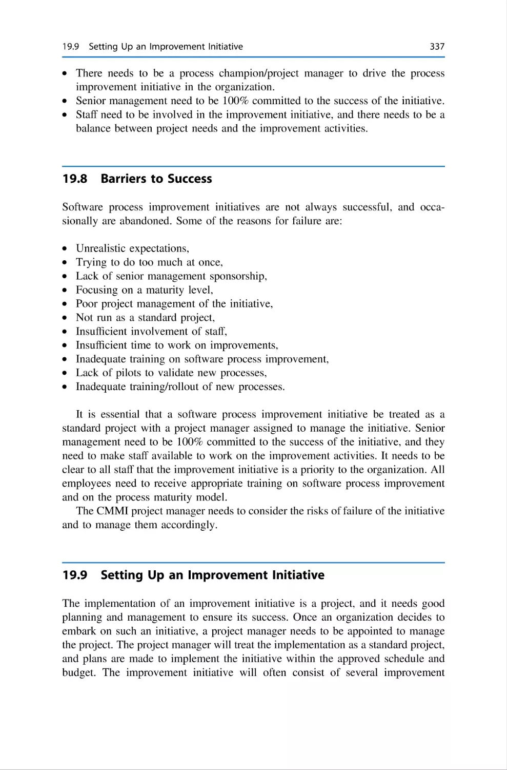
335
336
337
337
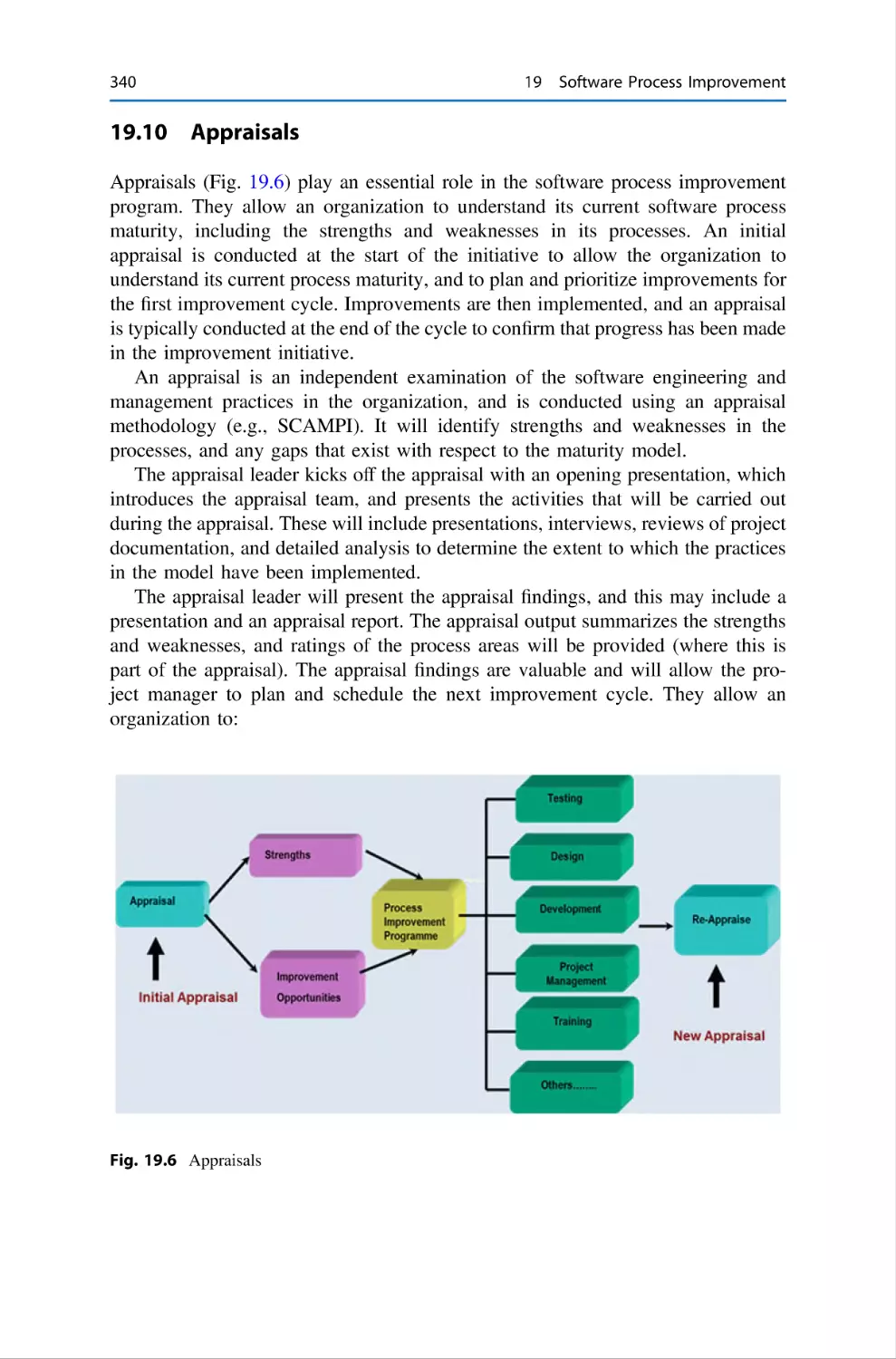
340
341
341
342
20 Capability Maturity Model Integration . . . .
20.1 Introduction . . . . . . . . . . . . . . . . . . .
20.2 The CMMI . . . . . . . . . . . . . . . . . . . .
20.3 CMMI Maturity Levels . . . . . . . . . . .
20.3.1 CMMI Representations . . . .
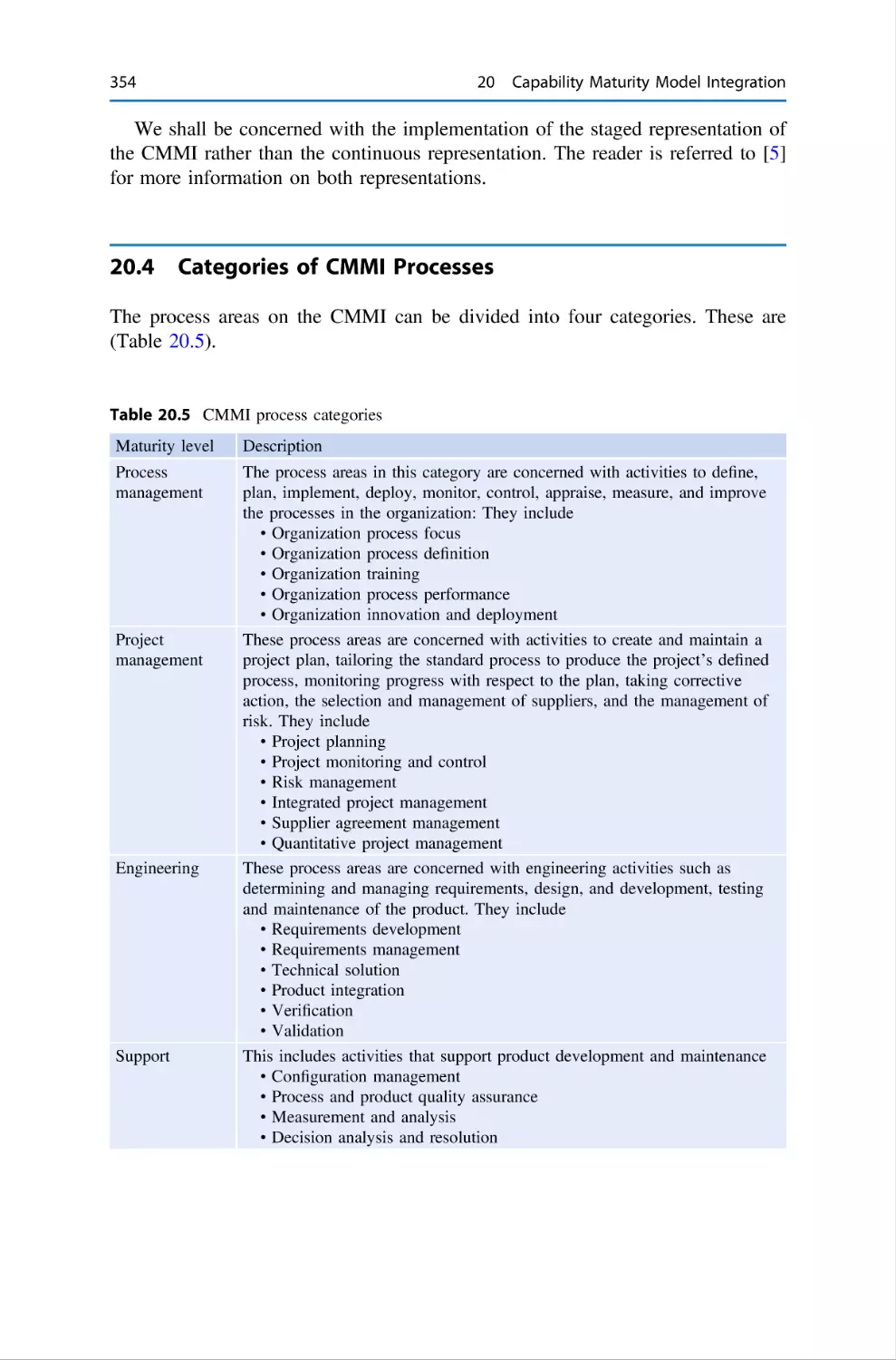
20.4 Categories of CMMI Processes . . . . .
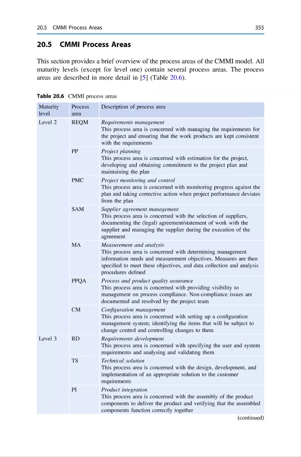
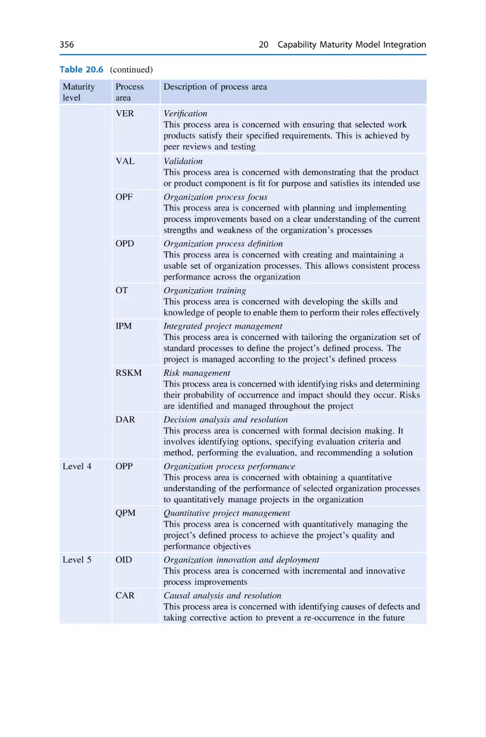
20.5 CMMI Process Areas . . . . . . . . . . . .
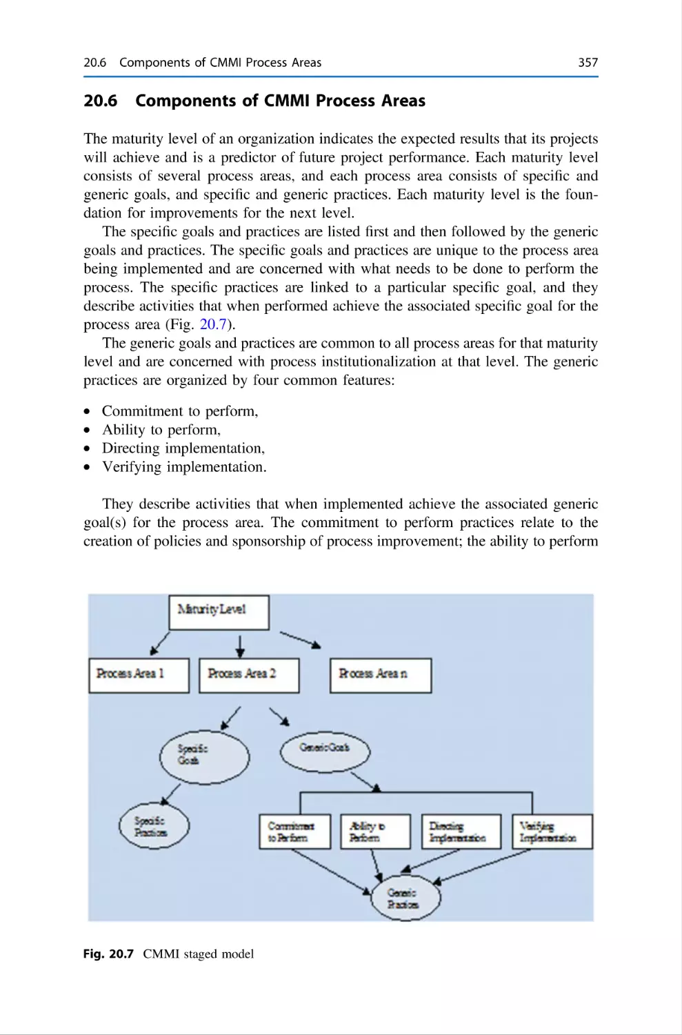
20.6 Components of CMMI Process Areas .
20.7 SCAMPI Appraisals . . . . . . . . . . . . .
20.8 Review Questions . . . . . . . . . . . . . . .
20.9 Summary . . . . . . . . . . . . . . . . . . . . .
References . . . . . . . . . . . . . . . . . . . . . . . . . .
.
.
.
.
.
.
.
.
.
.
.
.
.
.
.
.
.
.
.
.
.
.
.
.
.
.
.
.
.
.
.
.
.
.
.
.
.
.
.
.
.
.
.
.
.
.
.
.
.
.
.
.
.
.
.
.
.
.
.
.
.
.
.
.
.
.
.
.
.
.
.
.
.
.
.
.
.
.
.
.
.
.
.
.
.
.
.
.
.
.
.
.
.
.
.
.
.
.
.
.
.
.
.
.
.
.
.
.
.
.
.
.
.
.
.
.
.
.
.
.
.
.
.
.
.
.
.
.
.
.
.
.
.
.
.
.
.
.
.
.
.
.
.
.
.
.
.
.
.
.
.
.
.
.
.
.
.
.
.
.
.
.
.
.
.
.
.
.
.
.
.
.
.
.
.
.
.
.
.
.
343
343
346
349
352
354
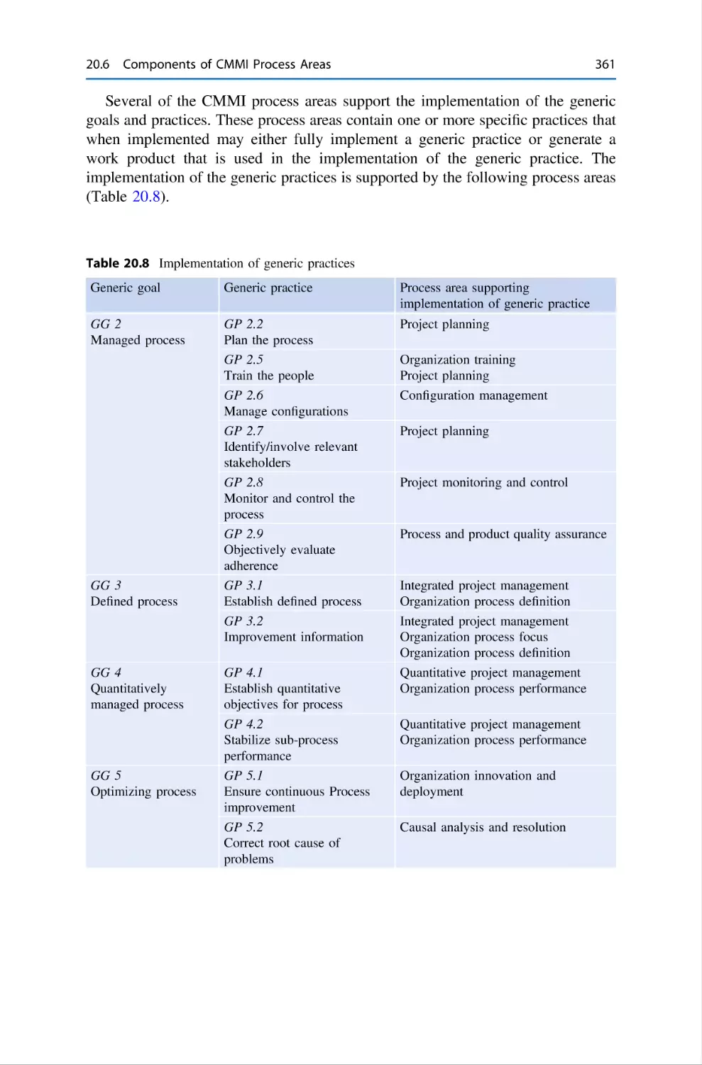
355
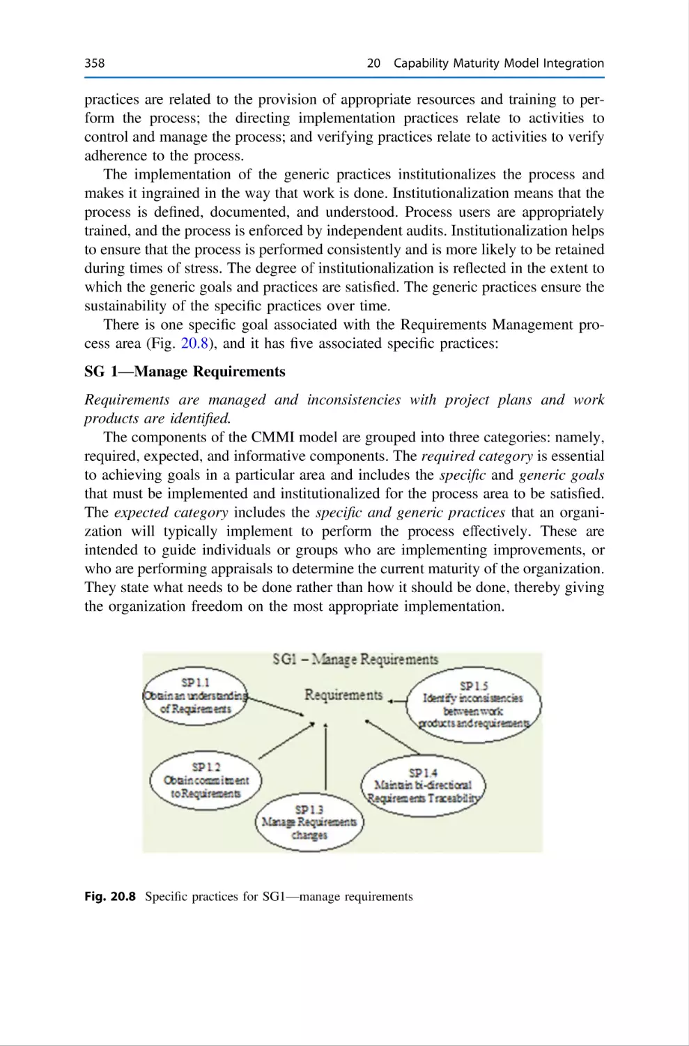
357
362
362
363
363
21 Software Engineering Tools . . . . . . . . . . . . . . . . . . . . . . . . . . .
21.1 Introduction . . . . . . . . . . . . . . . . . . . . . . . . . . . . . . . . . .
21.2 Tools for Project Management . . . . . . . . . . . . . . . . . . . . .
21.3 Tools for Requirements . . . . . . . . . . . . . . . . . . . . . . . . . .
21.4 Tools for Design and Development . . . . . . . . . . . . . . . . .
21.5 Tools for Agile Development . . . . . . . . . . . . . . . . . . . . . .
21.6 Tools for Configuration Management and Change Control .
21.7 Tools for Code Analysis and Code Inspections . . . . . . . . .
21.8 Tools for Testing . . . . . . . . . . . . . . . . . . . . . . . . . . . . . .
21.9 Review Questions . . . . . . . . . . . . . . . . . . . . . . . . . . . . . .
21.10 Summary . . . . . . . . . . . . . . . . . . . . . . . . . . . . . . . . . . . .
References . . . . . . . . . . . . . . . . . . . . . . . . . . . . . . . . . . . . . . . . .
.
.
.
.
.
.
.
.
.
.
.
.
.
.
.
.
.
.
.
.
.
.
.
.
.
.
.
.
.
.
.
.
.
.
.
.
365
365
366
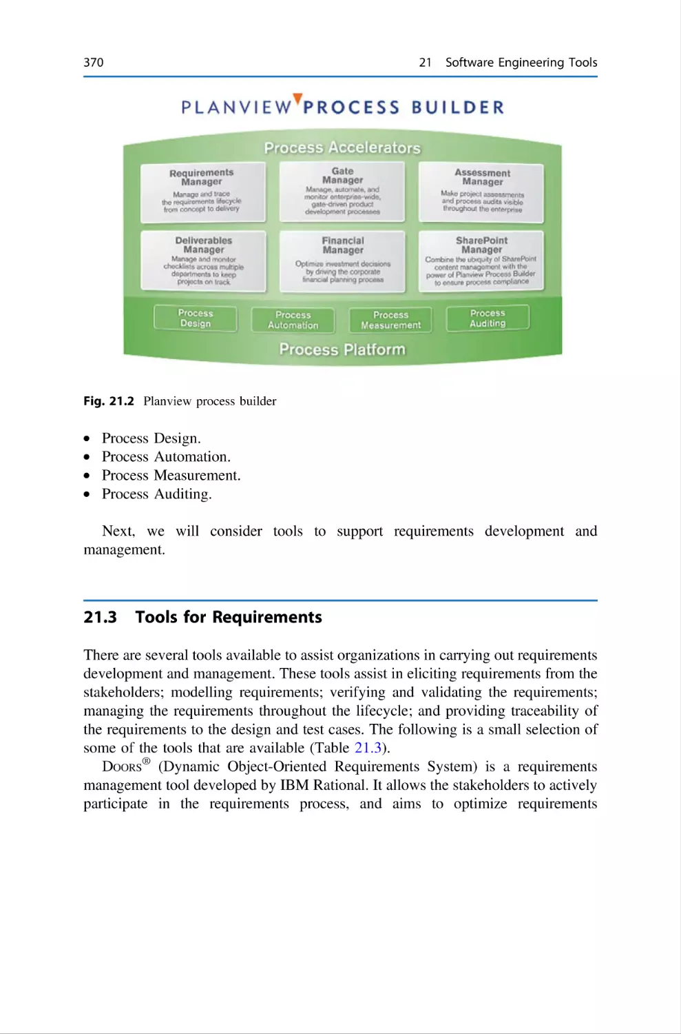
370
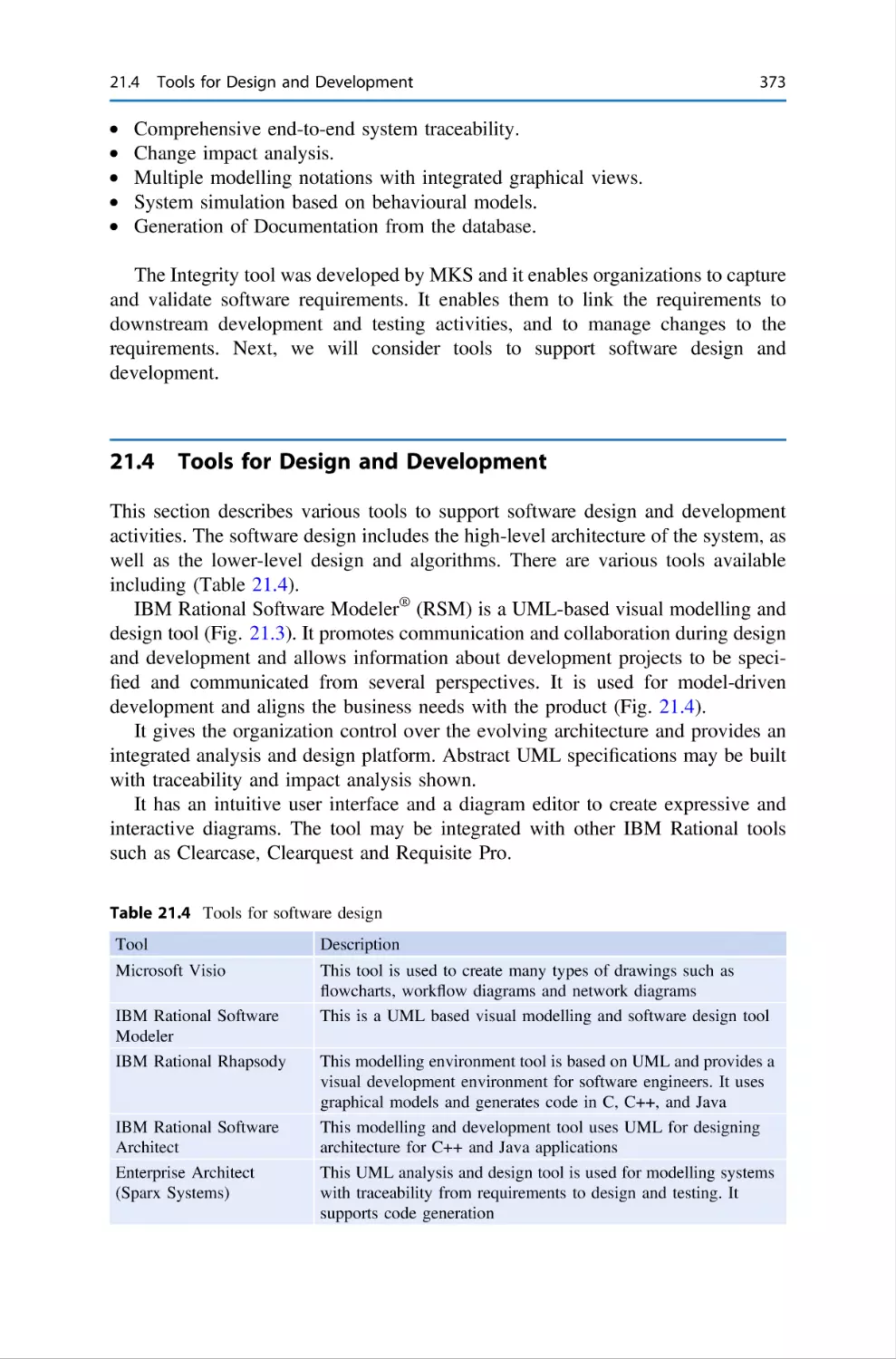
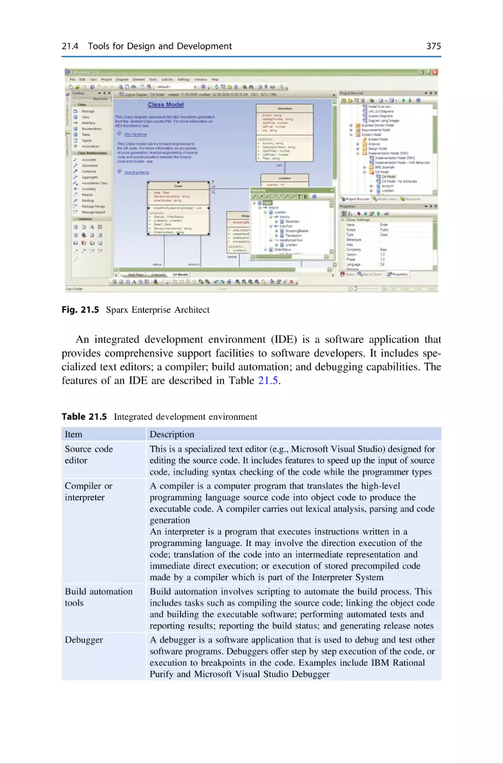
373
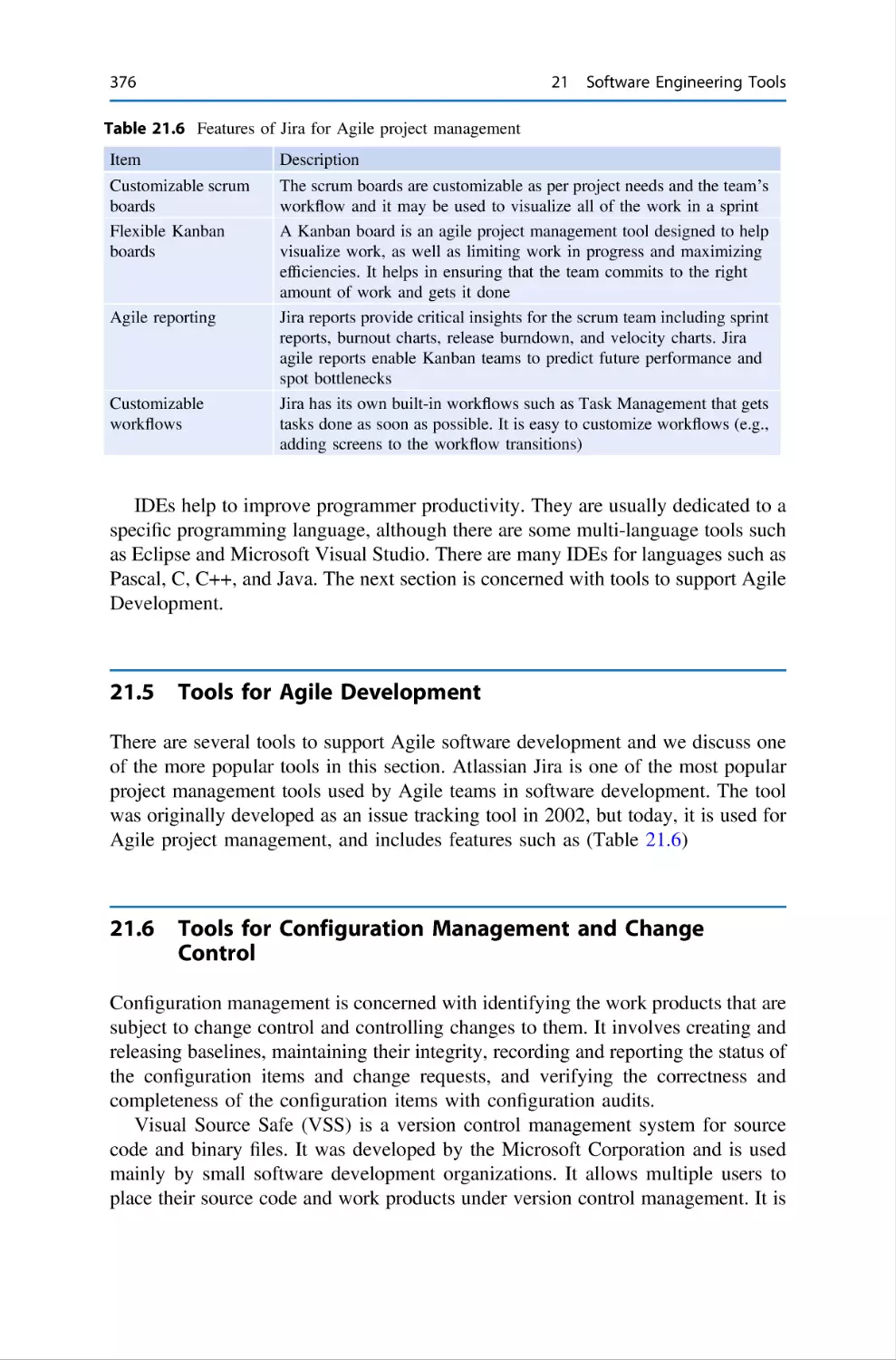
376
376
377
379
380
381
382
.
.
.
.
.
.
.
.
.
.
.
.
.
.
.
.
.
.
.
.
.
.
.
.
.
.
.
.
.
.
.
.
.
.
.
.
Contents
xix
22 A Miscellany of Innovation . . . . . . . . . . . . . . . . . . . . .
22.1 Introduction . . . . . . . . . . . . . . . . . . . . . . . . . . .
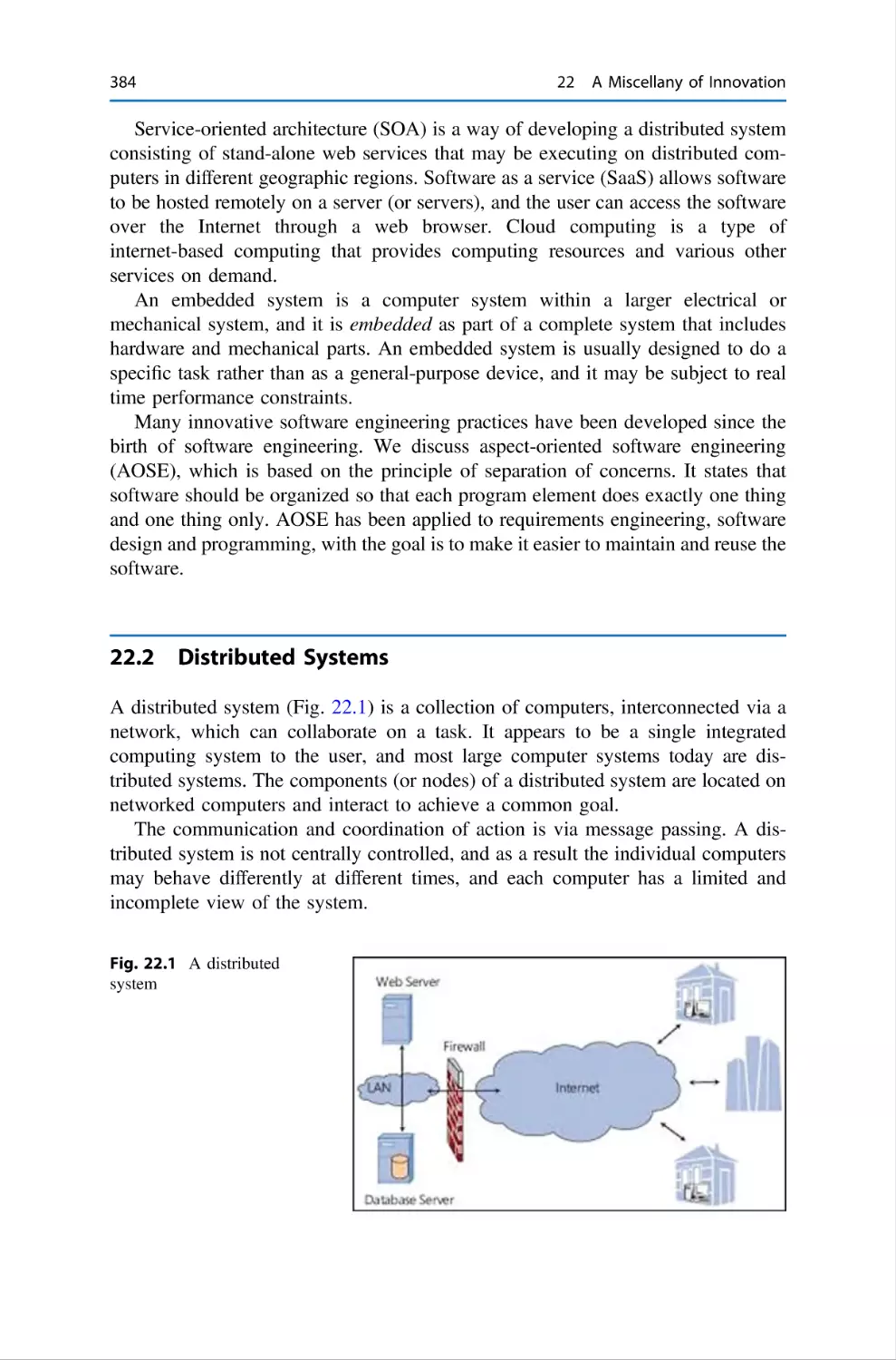
22.2 Distributed Systems . . . . . . . . . . . . . . . . . . . . . .
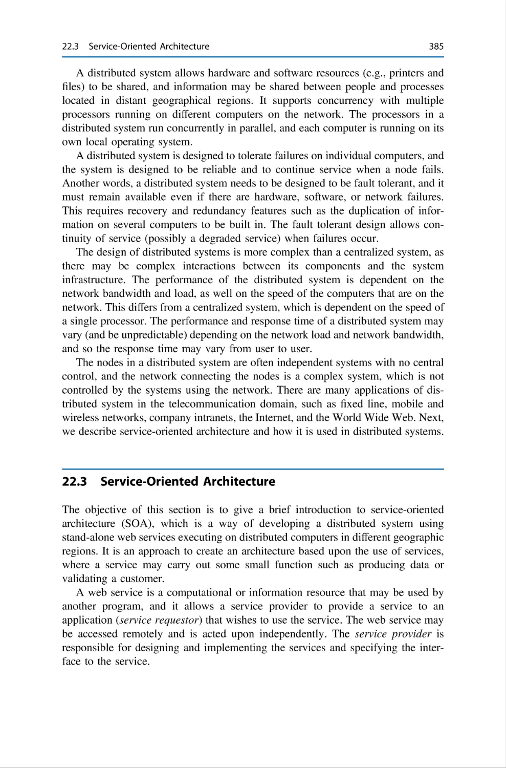
22.3 Service-Oriented Architecture . . . . . . . . . . . . . .
22.4 Software as a Service . . . . . . . . . . . . . . . . . . . .
22.5 Cloud Computing . . . . . . . . . . . . . . . . . . . . . . .
22.6 Embedded Systems . . . . . . . . . . . . . . . . . . . . . .
22.7 Software Engineering and Innovation . . . . . . . . .
22.7.1 Aspect-Oriented Software Engineering .
22.8 Review Questions . . . . . . . . . . . . . . . . . . . . . . .
22.9 Summary . . . . . . . . . . . . . . . . . . . . . . . . . . . . .
References . . . . . . . . . . . . . . . . . . . . . . . . . . . . . . . . . .
.
.
.
.
.
.
.
.
.
.
.
.
.
.
.
.
.
.
.
.
.
.
.
.
.
.
.
.
.
.
.
.
.
.
.
.
.
.
.
.
.
.
.
.
.
.
.
.
.
.
.
.
.
.
.
.
.
.
.
.
.
.
.
.
.
.
.
.
.
.
.
.
.
.
.
.
.
.
.
.
.
.
.
.
.
.
.
.
.
.
.
.
.
.
.
.
.
.
.
.
.
.
.
.
.
.
.
.
.
.
.
.
.
.
.
.
.
.
.
.
383
383
384
385
386
387
388
389
389
390
390
391
23 Legal Aspects of Software Engineering . . . . . .
23.1 Introduction . . . . . . . . . . . . . . . . . . . . .
23.2 Intellectual Property . . . . . . . . . . . . . . .
23.2.1 Patents . . . . . . . . . . . . . . . . . .
23.2.2 Copyright . . . . . . . . . . . . . . . .
23.2.3 Copyright of Software . . . . . . .
23.2.4 Software Licensing . . . . . . . . .
23.3 Lawsuits . . . . . . . . . . . . . . . . . . . . . . . .
23.3.1 Tort in Software Engineering . .
23.3.2 Software Licenses and Failure .
23.3.3 Legal Aspects of Outsourcing .
23.4 Computer Crime . . . . . . . . . . . . . . . . . .
23.5 Review Questions . . . . . . . . . . . . . . . . .
23.6 Summary . . . . . . . . . . . . . . . . . . . . . . .
Reference . . . . . . . . . . . . . . . . . . . . . . . . . . . . .
.
.
.
.
.
.
.
.
.
.
.
.
.
.
.
.
.
.
.
.
.
.
.
.
.
.
.
.
.
.
.
.
.
.
.
.
.
.
.
.
.
.
.
.
.
.
.
.
.
.
.
.
.
.
.
.
.
.
.
.
.
.
.
.
.
.
.
.
.
.
.
.
.
.
.
.
.
.
.
.
.
.
.
.
.
.
.
.
.
.
.
.
.
.
.
.
.
.
.
.
.
.
.
.
.
.
.
.
.
.
.
.
.
.
.
.
.
.
.
.
.
.
.
.
.
.
.
.
.
.
.
.
.
.
.
.
.
.
.
.
.
.
.
.
.
.
.
.
.
.
.
.
.
.
.
.
.
.
.
.
.
.
.
.
.
.
.
.
.
.
.
.
.
.
.
.
.
.
.
.
.
.
.
.
.
.
.
.
.
.
.
.
.
.
.
.
.
.
.
.
.
.
.
.
.
.
.
.
.
.
.
.
.
.
.
.
.
.
.
.
.
.
.
.
.
.
.
.
.
.
.
.
.
.
.
.
.
.
.
.
393
393
395
396
399
402
404
405
406
407
408
410
412
412
413
24 Cybersecurity and Cybercrime . . .
24.1 Introduction . . . . . . . . . . . .
24.1.1 Scams . . . . . . . . .
24.1.2 Malware . . . . . . . .
24.1.3 Cyberextortion and
24.2 Hacking . . . . . . . . . . . . . . .
24.3 Cybersecurity . . . . . . . . . . .
24.4 Review Questions . . . . . . . .
24.5 Summary . . . . . . . . . . . . . .
References . . . . . . . . . . . . . . . . . . .
.
.
.
.
.
.
.
.
.
.
.
.
.
.
.
.
.
.
.
.
.
.
.
.
.
.
.
.
.
.
.
.
.
.
.
.
.
.
.
.
.
.
.
.
.
.
.
.
.
.
.
.
.
.
.
.
.
.
.
.
.
.
.
.
.
.
.
.
.
.
.
.
.
.
.
.
.
.
.
.
.
.
.
.
.
.
.
.
.
.
.
.
.
.
.
.
.
.
.
.
.
.
.
.
.
.
.
.
.
.
.
.
.
.
.
.
.
.
.
.
.
.
.
.
.
.
.
.
.
.
.
.
.
.
.
.
.
.
.
.
.
.
.
.
.
.
.
.
.
.
.
.
.
.
415
415
418
419
419
421
423
429
429
430
.
.
.
.
.
.
.
.
.
.
.
.
.
.
.
.
.
.
.
.
.
.
.
.
.
.
.
.
.
.
.
.
.
.
.
.
Ransomware
.
.
.
.
.
.
.
.
.
.
.
.
.
.
.
.
.
.
.
.
.
.
.
.
.
.
.
.
.
.
.
.
.
.
.
.
.
.
.
.
.
.
.
.
.
.
.
.
.
.
25 Epilogue . . . . . . . . . . . . . . . . . . . . . . . . . . . . . . . . . . . . . . . . . . . . . 431
25.1 The Future of Software Engineering . . . . . . . . . . . . . . . . . . . . 434
Glossary . . . . . . . . . . . . . . . . . . . . . . . . . . . . . . . . . . . . . . . . . . . . . . . . . . . . 435
Index . . . . . . . . . . . . . . . . . . . . . . . . . . . . . . . . . . . . . . . . . . . . . . . . . . . . . . 441
List of Figures
Fig.
Fig.
Fig.
Fig.
Fig.
Fig.
Fig.
Fig.
Fig.
Fig.
1.1
1.2
1.3
1.4
1.5
2.1
3.1
3.2
3.3
3.4
Fig.
Fig.
Fig.
Fig.
Fig.
Fig.
Fig.
Fig.
Fig.
Fig.
Fig.
Fig.
Fig.
Fig.
Fig.
Fig.
Fig.
Fig.
Fig.
Fig.
Fig.
3.5
4.1
4.2
4.3
4.4
4.5
4.6
5.1
6.1
6.2
7.1
7.2
7.3
7.4
8.1
8.2
8.3
9.1
9.2
9.3
9.4
Standish report—Results of 1995 and 2009 survey . . . . . . . .
Standish 1998 report—Estimation accuracy . . . . . . . . . . . . .
Waterfall V lifecycle model . . . . . . . . . . . . . . . . . . . . . . . . .
Spiral lifecycle model … public domain . . . . . . . . . . . . . . . .
Rational unified process . . . . . . . . . . . . . . . . . . . . . . . . . . . .
Whistle blower . . . . . . . . . . . . . . . . . . . . . . . . . . . . . . . . . . .
A radiotherapy machine . . . . . . . . . . . . . . . . . . . . . . . . . . . .
Space challenger disaster . . . . . . . . . . . . . . . . . . . . . . . . . . .
Bridge over the River Kwaii in Kanchanburi, Thailand . . . .
Balancing an ethical life against a feather in Egyptian
religion . . . . . . . . . . . . . . . . . . . . . . . . . . . . . . . . . . . . . . . . .
Volkswagen Beetle Type 82E . . . . . . . . . . . . . . . . . . . . . . . .
Simple process map for project planning . . . . . . . . . . . . . . .
Sample microsoft project schedule . . . . . . . . . . . . . . . . . . . .
Simple process map for project monitoring and control . . . .
Prince 2 project board . . . . . . . . . . . . . . . . . . . . . . . . . . . . . .
Project management triangle . . . . . . . . . . . . . . . . . . . . . . . . .
Prince 2 processes . . . . . . . . . . . . . . . . . . . . . . . . . . . . . . . . .
Requirements process . . . . . . . . . . . . . . . . . . . . . . . . . . . . . .
C.A.R Hoare. (Public domain) . . . . . . . . . . . . . . . . . . . . . . .
David Parnas . . . . . . . . . . . . . . . . . . . . . . . . . . . . . . . . . . . . .
Michael Fagan . . . . . . . . . . . . . . . . . . . . . . . . . . . . . . . . . . .
Template for semi-formal review . . . . . . . . . . . . . . . . . . . . .
Template for Fagan inspection . . . . . . . . . . . . . . . . . . . . . . .
Sample-defect types in a project (ODC) . . . . . . . . . . . . . . . .
Simplified test process . . . . . . . . . . . . . . . . . . . . . . . . . . . . .
Sample test status . . . . . . . . . . . . . . . . . . . . . . . . . . . . . . . . .
Cumulative defects . . . . . . . . . . . . . . . . . . . . . . . . . . . . . . . .
Corrupt legislation. 1896. Public domain . . . . . . . . . . . . . . .
Bentham’s panopticon prison . . . . . . . . . . . . . . . . . . . . . . . .
Cardinals eavesdropping in the Vatican . . . . . . . . . . . . . . . .
Young peoples on smart phones and social media.
Public domain . . . . . . . . . . . . . . . . . . . . . . . . . . . . . . . . . . . .
.
.
.
.
.
.
.
.
.
.
.
.
.
.
.
.
.
.
3
7
9
10
12
30
43
45
49
.
.
.
.
.
.
.
.
.
.
.
.
.
.
.
.
.
.
.
.
.
.
.
.
.
.
.
.
.
.
.
.
.
.
.
.
.
.
.
.
.
.
50
52
63
64
70
74
76
77
90
104
105
118
123
129
132
140
142
146
157
167
170
. . 173
xxi
xxii
List of Figures
Fig. 9.5
Fig.
Fig.
Fig.
Fig.
Fig.
Fig.
Fig.
Fig.
Fig.
Fig.
Fig.
Fig.
Fig.
Fig.
Fig.
Fig.
Fig.
Fig.
Fig.
Fig.
Fig.
Fig.
Fig.
Fig.
Fig.
Fig.
Fig.
Fig.
Fig.
Fig.
Fig.
Fig.
Fig.
Fig.
Fig.
Fig.
Fig.
Fig.
Fig.
Fig.
Fig.
Fig.
9.6
10.1
10.2
10.3
10.4
10.5
10.6
10.7
10.8
10.9
10.10
10.11
10.12
10.13
10.14
10.15
10.16
10.17
10.18
10.19
10.20
10.21
10.22
10.23
10.24
10.25
10.26
10.27
10.28
10.29
10.30
10.31
10.32
10.33
10.34
11.1
12.1
12.2
13.1
16.1
17.1
17.2
Fitbit Surge. Smart-watch activity tracker. Creative
commons . . . . . . . . . . . . . . . . . . . . . . . . . . . . . . . . . .
EU GDPR 2016/679 . . . . . . . . . . . . . . . . . . . . . . . . . .
GQM example . . . . . . . . . . . . . . . . . . . . . . . . . . . . . .
The balanced scorecard . . . . . . . . . . . . . . . . . . . . . . . .
Balanced score card and implementing strategy . . . . .
Customer survey arrivals . . . . . . . . . . . . . . . . . . . . . . .
Customer satisfaction measurements . . . . . . . . . . . . . .
Process improvement measurements . . . . . . . . . . . . . .
Status of process improvement suggestions. . . . . . . . .
Age of open process improvement suggestions . . . . . .
Process improvement productivity . . . . . . . . . . . . . . .
Employee headcount in current year . . . . . . . . . . . . . .
Employee turnover in current year . . . . . . . . . . . . . . .
Schedule timeliness metric . . . . . . . . . . . . . . . . . . . . .
Effort timeliness metric . . . . . . . . . . . . . . . . . . . . . . . .
Requirements delivered . . . . . . . . . . . . . . . . . . . . . . . .
Total number of issues in project . . . . . . . . . . . . . . . .
Open issues in project . . . . . . . . . . . . . . . . . . . . . . . . .
Age of open defects in project . . . . . . . . . . . . . . . . . .
Problem arrivals per month . . . . . . . . . . . . . . . . . . . . .
Phase containment effectiveness . . . . . . . . . . . . . . . . .
Annual audit schedule . . . . . . . . . . . . . . . . . . . . . . . . .
Status of audit actions . . . . . . . . . . . . . . . . . . . . . . . . .
Audit action types . . . . . . . . . . . . . . . . . . . . . . . . . . . .
Customer queries (arrivals/closures) . . . . . . . . . . . . . .
Outage time per customer . . . . . . . . . . . . . . . . . . . . . .
Availability of system per month . . . . . . . . . . . . . . . .
Configuration management . . . . . . . . . . . . . . . . . . . . .
CMMI maturity in current year . . . . . . . . . . . . . . . . . .
Cost of poor quality (COPQ) . . . . . . . . . . . . . . . . . . .
Fishbone cause-and-effect diagram . . . . . . . . . . . . . . .
Histogram . . . . . . . . . . . . . . . . . . . . . . . . . . . . . . . . . .
Pareto chart outages . . . . . . . . . . . . . . . . . . . . . . . . . .
Trend chart estimation accuracy . . . . . . . . . . . . . . . . .
Scatter graph amount inspected rate/error density . . . .
Estimation accuracy and control charts . . . . . . . . . . . .
Legal contract . . . . . . . . . . . . . . . . . . . . . . . . . . . . . . .
Simple process map for change requests . . . . . . . . . . .
Simple process map for configuration management . .
Sample audit process . . . . . . . . . . . . . . . . . . . . . . . . .
Deterministic finite state machine . . . . . . . . . . . . . . . .
Specification of positive square root . . . . . . . . . . . . . .
Specification of a library system . . . . . . . . . . . . . . . . .
.
.
.
.
.
.
.
.
.
.
.
.
.
.
.
.
.
.
.
.
.
.
.
.
.
.
.
.
.
.
.
.
.
.
.
.
.
.
.
.
.
.
.
.
.
.
.
.
.
.
.
.
.
.
.
.
.
.
.
.
.
.
.
.
.
.
.
.
.
.
.
.
.
.
.
.
.
.
.
.
.
.
.
.
.
.
.
.
.
.
.
.
.
.
.
.
.
.
.
.
.
.
.
.
.
.
.
.
.
.
.
.
.
.
.
.
.
.
.
.
.
.
.
.
.
.
.
.
.
.
.
.
.
.
.
.
.
.
.
.
.
.
.
.
.
.
.
.
.
.
.
.
.
.
.
.
.
.
.
.
.
.
.
.
.
.
.
.
.
.
.
.
.
.
.
.
.
.
.
.
.
.
.
.
.
.
.
.
.
.
.
.
.
.
.
.
.
.
.
.
.
.
.
.
.
.
.
.
.
.
.
.
.
.
.
.
.
.
.
.
.
.
.
.
.
.
.
.
.
.
.
.
.
.
.
.
.
.
.
.
.
.
.
.
.
.
.
.
.
.
.
.
.
.
.
.
.
.
.
.
.
.
.
.
.
.
.
.
.
.
.
.
.
.
.
.
.
.
.
.
.
.
.
.
.
.
.
.
.
.
.
.
.
.
.
.
.
.
.
.
.
175
179
183
185
185
187
188
188
189
189
190
190
191
191
192
192
193
193
194
194
195
196
196
196
198
198
199
199
200
201
205
207
208
209
210
211
218
235
236
241
288
296
297
List of Figures
Fig.
Fig.
Fig.
Fig.
Fig.
Fig.
Fig.
Fig.
Fig.
Fig.
Fig.
Fig.
Fig.
Fig.
Fig.
Fig.
Fig.
Fig.
Fig.
Fig.
Fig.
17.3
17.4
17.5
17.6
17.7
17.8
18.1
18.2
18.3
18.4
18.5
18.6
18.7
19.1
19.2
19.3
19.4
19.5
19.6
20.1
20.2
Fig.
Fig.
Fig.
Fig.
Fig.
Fig.
Fig.
Fig.
Fig.
Fig.
Fig.
Fig.
Fig.
Fig.
Fig.
Fig.
Fig.
Fig.
Fig.
Fig.
Fig.
20.3
20.4
20.5
20.6
20.7
20.8
21.1
21.2
21.3
21.4
21.5
21.6
21.7
22.1
22.2
22.3
22.4
23.1
23.2
23.3
23.4
xxiii
Specification of borrow operation . . . . . . . . . . . . . . . .
Specification of vending machine using bags . . . . . . .
Schema inclusion . . . . . . . . . . . . . . . . . . . . . . . . . . . .
Merging schemas (S1 _ S2) . . . . . . . . . . . . . . . . . . . .
Schema composition . . . . . . . . . . . . . . . . . . . . . . . . . .
Refinement commuting diagram . . . . . . . . . . . . . . . . .
Simple object diagram . . . . . . . . . . . . . . . . . . . . . . . .
Use-case diagram of ATM machine . . . . . . . . . . . . . .
UML sequence diagram for balance enquiry . . . . . . . .
UML activity diagram. . . . . . . . . . . . . . . . . . . . . . . . .
UML state diagram . . . . . . . . . . . . . . . . . . . . . . . . . . .
Iteration in rational unified process . . . . . . . . . . . . . . .
Phases and workflows in rational unified process . . . .
Process as glue for people, procedures and tools . . . .
Sample process map . . . . . . . . . . . . . . . . . . . . . . . . . .
Steps in process improvement . . . . . . . . . . . . . . . . . . .
ISO 9001 quality management system . . . . . . . . . . . .
Continuous improvement cycle . . . . . . . . . . . . . . . . . .
Appraisals . . . . . . . . . . . . . . . . . . . . . . . . . . . . . . . . . .
Process as glue for people, procedures and tools . . . .
ISO/IEC 12207 standard for software engineering
processes . . . . . . . . . . . . . . . . . . . . . . . . . . . . . . . . . . .
CMMI worldwide maturity 2013 . . . . . . . . . . . . . . . .
CMMI maturity levels. . . . . . . . . . . . . . . . . . . . . . . . .
CMMI capability levels . . . . . . . . . . . . . . . . . . . . . . .
CMMI—continuous representation . . . . . . . . . . . . . . .
CMMI staged model . . . . . . . . . . . . . . . . . . . . . . . . . .
Specific practices for SG1—manage requirements . . .
Dashboard views in Planview Enterprise . . . . . . . . . .
Planview process builder. . . . . . . . . . . . . . . . . . . . . . .
IBM Rational DOORS tool . . . . . . . . . . . . . . . . . . . . . .
IBM Rational Software Modeler . . . . . . . . . . . . . . . . .
Sparx Enterprise Architect . . . . . . . . . . . . . . . . . . . . .
LDRA code coverage analysis report . . . . . . . . . . . . .
HP Quality Center . . . . . . . . . . . . . . . . . . . . . . . . . . .
A distributed system . . . . . . . . . . . . . . . . . . . . . . . . . .
Service-oriented architecture . . . . . . . . . . . . . . . . . . . .
Cloud computing. Creative Commons. . . . . . . . . . . . .
Example of an embedded system . . . . . . . . . . . . . . . .
Patent for an invention . . . . . . . . . . . . . . . . . . . . . . . .
St. Colomba’s Cathach . . . . . . . . . . . . . . . . . . . . . . . .
Legal contract. Creative Commons . . . . . . . . . . . . . . .
Dandy Pickpockets (1818) . . . . . . . . . . . . . . . . . . . . .
.
.
.
.
.
.
.
.
.
.
.
.
.
.
.
.
.
.
.
.
.
.
.
.
.
.
.
.
.
.
.
.
.
.
.
.
.
.
.
.
.
.
.
.
.
.
.
.
.
.
.
.
.
.
.
.
.
.
.
.
.
.
.
.
.
.
.
.
.
.
.
.
.
.
.
.
.
.
.
.
.
.
.
.
.
.
.
.
.
.
.
.
.
.
.
.
.
.
.
.
.
.
.
.
.
.
.
.
.
.
.
.
.
.
.
.
.
.
.
.
.
.
.
.
.
.
.
.
.
.
.
.
.
.
.
.
.
.
.
.
298
304
305
305
307
308
318
319
320
321
321
324
325
329
330
331
334
338
340
344
.
.
.
.
.
.
.
.
.
.
.
.
.
.
.
.
.
.
.
.
.
.
.
.
.
.
.
.
.
.
.
.
.
.
.
.
.
.
.
.
.
.
.
.
.
.
.
.
.
.
.
.
.
.
.
.
.
.
.
.
.
.
.
.
.
.
.
.
.
.
.
.
.
.
.
.
.
.
.
.
.
.
.
.
.
.
.
.
.
.
.
.
.
.
.
.
.
.
.
.
.
.
.
.
.
.
.
.
.
.
.
.
.
.
.
.
.
.
.
.
.
.
.
.
.
.
.
.
.
.
.
.
.
.
.
.
.
.
.
.
.
.
.
.
.
.
.
.
.
.
.
.
.
.
345
348
349
352
352
357
358
369
370
372
374
375
378
380
384
386
387
388
397
400
409
411
xxiv
Fig. 24.1
Fig. 24.2
Fig. 24.3
List of Figures
Trojan horse at Troy . . . . . . . . . . . . . . . . . . . . . . . . . . . . . . . . . 420
Hacker at work on blacklit keyboard. Creative Commons . . . . 421
Sun Tzu Wu . . . . . . . . . . . . . . . . . . . . . . . . . . . . . . . . . . . . . . . 427
List of Tables
Table 2.1
Table
Table
Table
Table
Table
Table
Table
Table
Table
Table
Table
Table
Table
Table
Table
Table
Table
Table
Table
Table
Table
Table
Table
Table
Table
Table
Table
Table
Table
Table
Table
Table
2.2
2.3
2.4
2.5
2.6
4.1
4.2
4.3
4.4
4.5
4.6
4.7
4.8
4.9
4.10
5.1
5.2
5.3
5.4
6.1
6.2
7.1
7.2
7.3
7.4
7.5
7.6
7.7
7.8
7.9
7.10
7.11
Professional responsibilities of software engineers
and testers . . . . . . . . . . . . . . . . . . . . . . . . . . . . . . . . .
Types of professional codes . . . . . . . . . . . . . . . . . . . .
Steps in whistle blowing . . . . . . . . . . . . . . . . . . . . . .
IEEE code of ethics . . . . . . . . . . . . . . . . . . . . . . . . . .
BCS code of conduct . . . . . . . . . . . . . . . . . . . . . . . . .
ACM code of conduct . . . . . . . . . . . . . . . . . . . . . . . .
Estimation techniques . . . . . . . . . . . . . . . . . . . . . . . . .
Example work-breakdown structure . . . . . . . . . . . . . .
Sample project management checklist . . . . . . . . . . . .
Risk management activities . . . . . . . . . . . . . . . . . . . .
Activities in managing issues and change requests . . .
Project board roles and responsibilities. . . . . . . . . . . .
Key processes in Prince 2 . . . . . . . . . . . . . . . . . . . . .
PMBOK process groups . . . . . . . . . . . . . . . . . . . . . . .
PMBOK knowledge areas . . . . . . . . . . . . . . . . . . . . .
Functions of project management office . . . . . . . . . . .
Characteristics of good requirements . . . . . . . . . . . . .
Symptoms of poor requirements process . . . . . . . . . .
Managing change requests . . . . . . . . . . . . . . . . . . . . .
Sample trace matrix . . . . . . . . . . . . . . . . . . . . . . . . . .
Views of system architecture . . . . . . . . . . . . . . . . . . .
Object-oriented paradigm . . . . . . . . . . . . . . . . . . . . . .
Informal review . . . . . . . . . . . . . . . . . . . . . . . . . . . . .
Structured walkthroughs . . . . . . . . . . . . . . . . . . . . . . .
Activities for semi-formal review meeting . . . . . . . . .
Overview Fagan inspection process . . . . . . . . . . . . . .
Strict Fagan inspection guidelines . . . . . . . . . . . . . . .
Tailored (Relaxed) Fagan inspection guidelines . . . . .
Inspector roles . . . . . . . . . . . . . . . . . . . . . . . . . . . . . .
Fagan entry criteria . . . . . . . . . . . . . . . . . . . . . . . . . .
Inspection meeting . . . . . . . . . . . . . . . . . . . . . . . . . . .
Fagan exit criteria . . . . . . . . . . . . . . . . . . . . . . . . . . .
Issue severity . . . . . . . . . . . . . . . . . . . . . . . . . . . . . . .
.
.
.
.
.
.
.
.
.
.
.
.
.
.
.
.
.
.
.
.
.
.
.
.
.
.
.
.
.
.
.
.
.
.
.
.
.
.
.
.
.
.
.
.
.
.
.
.
.
.
.
.
.
.
.
.
.
.
.
.
.
.
.
.
.
.
.
.
.
.
.
.
.
.
.
.
.
.
.
.
.
.
.
.
.
.
.
.
.
.
.
.
.
.
.
.
.
.
.
.
.
.
.
.
.
.
.
.
.
.
.
.
.
.
.
.
.
.
.
.
.
.
.
.
.
.
.
.
.
.
.
.
.
.
.
.
.
.
.
.
.
.
.
.
.
.
.
.
.
.
.
.
.
.
.
.
.
.
.
.
.
.
.
.
.
.
.
.
.
.
.
.
.
.
.
.
.
.
.
.
.
.
.
.
.
.
.
.
.
.
.
.
.
.
.
.
.
.
.
.
.
.
.
.
.
.
.
.
.
.
.
.
.
.
.
.
.
.
.
.
.
.
.
.
.
.
.
.
.
.
.
28
29
32
33
35
36
62
62
65
66
71
74
77
78
78
79
87
88
94
95
103
108
120
121
122
124
125
126
127
127
128
130
131
xxv
xxvi
Table
Table
Table
Table
Table
Table
Table
Table
Table
Table
Table
Table
Table
Table
Table
Table
Table
Table
Table
Table
Table
Table
Table
Table
Table
Table
Table
Table
Table
Table
Table
Table
Table
Table
Table
Table
Table
Table
Table
Table
Table
Table
Table
Table
List of Tables
7.12
7.13
8.1
8.2
9.1
9.2
9.3
10.1
10.2
10.3
10.4
10.5
11.1
11.2
12.1
12.2
12.3
12.4
12.5
12.6
13.1
13.2
13.3
15.1
15.2
15.3
15.4
15.5
15.6
16.1
16.2
16.3
16.4
16.5
17.1
18.1
18.2
18.3
18.4
18.5
18.6
19.1
19.2
19.3
Classification of defects in Fagan inspections. . . . . . . . . . . .
Classification of ODC defect types. . . . . . . . . . . . . . . . . . . .
Types of testing . . . . . . . . . . . . . . . . . . . . . . . . . . . . . . . . . .
Simple test schedule . . . . . . . . . . . . . . . . . . . . . . . . . . . . . . .
Ten commandments on computer ethics . . . . . . . . . . . . . . . .
Some ethical problems in computing . . . . . . . . . . . . . . . . . .
Sources of information . . . . . . . . . . . . . . . . . . . . . . . . . . . . .
BSC objectives and measures for IT service organization . .
Cost of quality categories . . . . . . . . . . . . . . . . . . . . . . . . . . .
Implementing metrics . . . . . . . . . . . . . . . . . . . . . . . . . . . . . .
Goals and questions . . . . . . . . . . . . . . . . . . . . . . . . . . . . . . .
Phase containment effectiveness . . . . . . . . . . . . . . . . . . . . . .
Supplier selection and management . . . . . . . . . . . . . . . . . . .
Possible breaches of contract . . . . . . . . . . . . . . . . . . . . . . . .
Features of good configuration management . . . . . . . . . . . .
Symptoms of poor configuration management . . . . . . . . . . .
Software configuration management activities . . . . . . . . . . .
Build plan for project . . . . . . . . . . . . . . . . . . . . . . . . . . . . . .
CMMI requirements for configuration management . . . . . . .
Sample configuration management audit checklist . . . . . . . .
Auditing activities . . . . . . . . . . . . . . . . . . . . . . . . . . . . . . . .
Sample auditing checklist . . . . . . . . . . . . . . . . . . . . . . . . . . .
Sample audit report . . . . . . . . . . . . . . . . . . . . . . . . . . . . . . .
Adam’s 1984 study of software failures of IBM products . .
New and old version of software . . . . . . . . . . . . . . . . . . . . .
Cleanroom results in IBM . . . . . . . . . . . . . . . . . . . . . . . . . .
Characteristics of good software reliability model . . . . . . . .
Software reliability models . . . . . . . . . . . . . . . . . . . . . . . . . .
Dimensions of dependability . . . . . . . . . . . . . . . . . . . . . . . .
Criticisms of formal methods . . . . . . . . . . . . . . . . . . . . . . . .
Parnas’s contributions to software engineering . . . . . . . . . . .
Techniques for validation of formal specification . . . . . . . . .
Why are formal methods difficult? . . . . . . . . . . . . . . . . . . . .
Characteristics of a usable formal method . . . . . . . . . . . . . .
Schema composition. . . . . . . . . . . . . . . . . . . . . . . . . . . . . . .
Classification of UML things . . . . . . . . . . . . . . . . . . . . . . . .
UML diagrams . . . . . . . . . . . . . . . . . . . . . . . . . . . . . . . . . . .
Simple class diagram . . . . . . . . . . . . . . . . . . . . . . . . . . . . . .
Advantages of UML . . . . . . . . . . . . . . . . . . . . . . . . . . . . . .
OCL constraints . . . . . . . . . . . . . . . . . . . . . . . . . . . . . . . . . .
UML tools . . . . . . . . . . . . . . . . . . . . . . . . . . . . . . . . . . . . . .
Benefits of software process improvement (CMMI) . . . . . . .
Continuous improvement cycle . . . . . . . . . . . . . . . . . . . . . .
Teams in improvement program . . . . . . . . . . . . . . . . . . . . . .
.
.
.
.
.
.
.
.
.
.
.
.
.
.
.
.
.
.
.
.
.
.
.
.
.
.
.
.
.
.
.
.
.
.
.
.
.
.
.
.
.
.
.
.
.
.
.
.
.
.
.
.
.
.
.
.
.
.
.
.
.
.
.
.
.
.
.
.
.
.
.
.
.
.
.
.
.
.
.
.
.
.
.
.
.
.
.
.
131
131
141
144
159
161
168
186
200
201
202
202
215
224
228
229
230
230
231
237
240
243
244
260
261
262
263
264
265
273
289
290
290
291
307
315
316
317
322
323
323
332
339
339
List of Tables
Table
Table
Table
Table
Table
Table
Table
Table
Table
Table
Table
Table
Table
Table
Table
Table
Table
Table
19.4
20.1
20.2
20.3
20.4
20.5
20.6
20.7
20.8
21.1
21.2
21.3
21.4
21.5
21.6
23.1
23.2
24.1
xxvii
Phases in an appraisal . . . . . . . . . . . . . . . . . . . . . . . . . . . . .
Motivation for CMMI implementation . . . . . . . . . . . . . . . . .
Benefits of CMMI implementation . . . . . . . . . . . . . . . . . . . .
CMMI maturity levels . . . . . . . . . . . . . . . . . . . . . . . . . . . . .
CMMI capability levels for continuous representation . . . . .
CMMI process categories . . . . . . . . . . . . . . . . . . . . . . . . . . .
CMMI process areas . . . . . . . . . . . . . . . . . . . . . . . . . . . . . .
CMMI generic practices . . . . . . . . . . . . . . . . . . . . . . . . . . . .
Implementation of generic practices . . . . . . . . . . . . . . . . . . .
Tool evaluation table . . . . . . . . . . . . . . . . . . . . . . . . . . . . . .
Key capabilities of Planview Enterprise . . . . . . . . . . . . . . . .
Tools for requirements development and management . . . . .
Tools for software design . . . . . . . . . . . . . . . . . . . . . . . . . . .
Integrated development environment . . . . . . . . . . . . . . . . . .
Features of Jira for Agile project management . . . . . . . . . . .
Process for obtaining a patent . . . . . . . . . . . . . . . . . . . . . . .
Types of lawsuits . . . . . . . . . . . . . . . . . . . . . . . . . . . . . . . . .
Computer crimes . . . . . . . . . . . . . . . . . . . . . . . . . . . . . . . . .
.
.
.
.
.
.
.
.
.
.
.
.
.
.
.
.
.
.
.
.
.
.
.
.
.
.
.
.
.
.
.
.
.
.
.
.
341
347
349
350
353
354
355
359
361
366
369
371
373
375
376
398
406
417
1
Fundamentals of Software
Engineering
Abstract
This chapter presents a broad overview of software engineering and discusses
various software lifecycles and the phases in software development. We discuss
requirements gathering and specification, software design, implementation,
testing and maintenance. The lightweight Agile methodology is introduced, and
it has become very popular in industry. Mathematics may potentially assist
software engineers in delivering high-quality software products that are safe to
use, and the extent to which mathematics should be employed remains a topic of
active debate.
Keywords
•
•
•
Standish chaos report Software lifecycles Waterfall model Spiral model
Rational unified process Agile development Software inspections
Software testing Project management
•
1.1
•
•
•
•
Introduction
The approach to software development in the 1950s and 1960s has been described
as the “Mongolian Hordes Approach” by Fred Brooks [1].1 The “method” or lack
of method was applied to projects that were running late, and it involved adding
many inexperienced programmers to the project, with the expectation that this
The “Mongolian Hordes” management myth is the belief that adding more programmers to a
software project that is running late will allow catch-up. In fact, as Brooks says adding people to a
late software project makes it later.
1
© Springer Nature Switzerland AG 2022
G. O’Regan, Concise Guide to Software Engineering,
Undergraduate Topics in Computer Science,
https://doi.org/10.1007/978-3-031-07816-3_1
1
2
1
Fundamentals of Software Engineering
would allow the project schedule to be recovered. However, this approach was
deeply flawed as it led to programmers with inadequate knowledge of the project
attempting to solve problems, and they inevitably required significant time from the
other project team members.
This resulted in the project being delivered even later, as well as subsequent
problems with quality (i.e., the approach of throwing people at a problem does not
work). The philosophy of software development back in the 1950/60s was characterized by:
The completed code will always be full of defects.
The coding should be finished quickly to correct these defects.
Design as you code approach.
This philosophy accepted defeat in software development, and suggested that
irrespective of a solid engineering approach, that the completed software would
always contain lots of defects, and that it therefore made sense to code as quickly as
possible, and to then identify the defects that were present, and to correct them as
quickly as possible to solve a problem.
In the late 1960s it was clear that the existing approaches to software development were deeply flawed, and that there was an urgent need for change.
The NATO Science Committee organized two famous conferences to discuss
critical issues in software development [2]. The first conference was held at Garmisch, Germany, in 1968, and it was followed by a second conference in Rome in
1969. Over fifty people from eleven countries attended the Garmisch conference,
including Edsger Dijkstra, who did important theoretical work on formal specification and verification. The NATO conferences highlighted problems that existed in
the software sector in the late 1960s, and the term “software crisis” was coined to
refer to these. There were problems with budget and schedule overruns, as well as
the quality and reliability of the delivered software.
The conference led to the birth of software engineering as a discipline in its own
right, and the realization that programming is quite distinct from science and
mathematics. Programmers are like engineers in that they build software products,
and they therefore need education in traditional engineering as well as the latest
technologies. The education of a classical engineer includes product design and
mathematics. However, often computer science education places an emphasis on
the latest technologies, rather than on the important engineering foundations of
designing and building high-quality products that are safe for the public to use.
Programmers therefore need to learn the key engineering skills to enable them to
build products that are safe for the public to use. This includes a solid foundation on
design and on the mathematics required for building safe software products.
Mathematics plays a key role in classical engineering, and in some situations, it
may also assist software engineers in the delivery of high-quality software products.
Several mathematical approaches to assist software engineers are described in [3].
There are parallels between the software crisis in the late 1960s, and serious
problems with bridge construction in the nineteenth century. Several bridges collapsed, or were delivered late or over-budget, since people involved in their design
1.1 Introduction
3
Fig. 1.1 Standish report—
Results of 1995 and 2009
survey
and construction did not have the required engineering knowledge. This led to
bridges that were poorly designed and constructed, leading to their collapse and loss
of life, as well as endangering the lives of the public.
This led to legislation requiring engineers to be licensed by the Professional
Engineering Association prior to practising as engineers. This organization specified a core body of knowledge that the engineer is required to possess, and the
licensing body verifies that the engineer has the required qualifications and experience. This helps to ensure that only personnel competent to design and build
products do so. Engineers have a professional responsibility to ensure that the
products are properly built and are safe for the public to use.
The Standish group has conducted research (Fig. 1.1) on the extent of problems
with IT projects since the mid-1990s. These studies were conducted in the United
States, but there is no reason to believe that European or Asian companies perform
any better. The results indicate serious problems with on-time delivery of projects,
and projects being cancelled prior to completion.2 However, the comparison
between 1995 and 2009 suggests that there have been some improvements with a
greater percentage of projects being delivered successfully, and a reduction in the
percentage of projects being cancelled.
Fred Brooks argues that software is inherently complex, and that there is no
silver bullet that will resolve all the problems associated with software development
such as schedule or budget overruns [1, 4]. Poor software quality can lead to defects
in the software that may adversely impact the customer, and even lead to loss of
life. It is therefore essential that software development organizations place sufficient
emphasis on quality throughout the software development process.
The Y2K problem was caused by a two-digit representation of dates, and it
required major rework to enable legacy software to function for the new millennium. Clearly, well-designed programs would have hidden the representation of the
2
These are IT projects covering diverse sectors including banking, telecommunications, etc.,
rather than pure software companies. Software companies following maturity frameworks such as
the CMMI generally achieve more consistent results.
4
1
Fundamentals of Software Engineering
date, which would have required minimal changes for year 2000 compliance.
Instead, companies spent vast sums of money to rectify the problem.
The quality of software produced by some companies is impressive.3 These
companies employ mature software processes and are committed to continuous
improvement. There is a lot of industrial interest in software process maturity
models for software organizations, and various approaches to assess and mature
software companies are described in [5, 6].4 These models focus on improving the
effectiveness of the management, engineering and organization practices related to
software engineering, and in introducing best practice in software engineering. The
disciplined use of the mature software processes by the software engineers enables
high-quality software to be consistently produced.
1.2
What is Software Engineering?
Software engineering involves the multi-person construction of multi-version programs. The IEEE 610.12 definition of Software Engineering is:
Software engineering is the application of a systematic, disciplined, quantifiable approach
to the development, operation, and maintenance of software; that is, the application of
engineering to software, and the study of such approaches.
Software engineering includes:
1. Methodologies to design, develop, and test software to meet customers’ needs.
2. Software is engineered. That is, the software products are properly designed,
developed, and tested in accordance with engineering principles.
3. Quality and safety are properly addressed.
4. Mathematics may be employed to assist with the design and verification of
software products. The level of mathematics employed will depend on the safety
critical nature of the product. Systematic peer reviews and rigorous testing will
often be sufficient to build quality into the software, with heavy mathematical
techniques reserved for safety and security critical software.
5. Sound project management and quality management practices are employed.
6. Support and maintenance of the software is properly addressed.
3
I recall projects at Motorola that regularly achieved 5.6r-quality in a L4 CMM environment (i.e.,
approx. 20 defects per million lines of code. This represents very high quality).
4
Approaches such as the CMM or SPICE (ISO 15504) focus mainly on the management and
organizational practices required in software engineering. The emphasis is on defining software
processes that are fit for purpose and consistently following them. The process maturity models
focus on what needs to be done rather how it should be done. This gives the organization the
freedom to choose the appropriate implementation to meet its needs. The models provide useful
information on practices to consider in the implementation.
1.2 What is Software Engineering?
5
Software engineering is not just programming. It requires the engineer to state
precisely the requirements that the software product is to satisfy, and then to produce designs that will meet these requirements. The project needs to be planned and
delivered on time and budget. The requirements must provide a precise description
of the problem to be solved: i.e., it should be evident from the requirements what is
and what is not required.
The requirements need to be rigorously reviewed to ensure that they are stated
clearly and unambiguously and reflect the customer’s needs. The next step is then
to create the design that will solve the problem, and it is essential to validate the
correctness of the design. Next, the software code to implement the design is
written, and peer reviews and software testing are employed to verify and validate
the correctness of the software.
The verification and validation of the design is rigorously performed for safety
critical systems, and it is sometimes appropriate to employ mathematical techniques
for these systems. However, it will usually be sufficient to employ peer reviews or
software inspections as these methodologies provide a high degree of rigour. This
may include approaches such as Fagan inspections [7], Gilb inspections [8], or
Prince 2’s approach to quality reviews [9].
The term “engineer” is a title that is awarded on merit in classical engineering. It
is generally applied only to people who have attained the necessary education and
competence to be called engineers, and who base their practice on classical engineering principles. The title places responsibilities on its holder to behave professionally and ethically. Often in computer science the term “software engineer” is
employed loosely to refer to anyone who builds things, rather than to an individual
with a core set of knowledge, experience, and competence.
Several computer scientists (such as Parnas5) have argued that computer scientists should be educated as engineers to enable them to apply appropriate scientific principles to their work. They argue that computer scientists should receive a
solid foundation in mathematics and design, to enable them to have the professional
competence to perform as engineers in building high-quality products that are safe
for the public to use. The use of mathematics is an integral part of the engineer’s
work in other engineering disciplines, and so the software engineer should be able
to use mathematics to assist in the modelling or understanding of the behaviour or
properties of the proposed software system.
Software engineers need education6 on specification, design, turning designs
into programs, software inspections, and testing. The education should enable the
software engineer to produce well-structured programs that are fit for purpose.
5
Parnas has made important contributions to computer science. He advocates a solid engineering
approach with the extensive use of classical mathematical techniques in software development. He
also introduced information hiding in the 1970s, which is now a part of object-oriented design.
6
Software Companies that are following approaches such as the CMM or ISO 9001 consider the
education and qualification of staff prior to assigning staff to performing specific tasks. The
appropriate qualifications and experience for the specific role are considered prior to appointing a
person to carry out the role. Many companies are committed to the education and continuous
6
1
Fundamentals of Software Engineering
Parnas has argued that software engineers have responsibilities as professional
engineers.7 They are responsible for designing and implementing high-quality and
reliable software that is safe to use. They are also accountable for their decisions
and actions,8 and have a responsibility to object to decisions that violate professional standards. Engineers are required to behave professionally and ethically with
their clients. The membership of the professional engineering body requires the
member to adhere to the code of ethics9 of the profession. Engineers in other
professions are licensed, and therefore Parnas argues that a similar licensing
approach be adopted for professional software engineers10 to provide confidence
that they are competent for the assignment. Professional software engineers are
required to follow best practice in software engineering and the defined software
processes.11
Many software companies invest heavily in training, as the education and
knowledge of its staff are essential to delivering high-quality products and services.
Employees receive professional training related to the roles that they are performing, such as project management, software design and development, software
testing, and service management. The fact that the employees are professionally
qualified increases confidence in the ability of the company to deliver high-quality
products and services. A company that pays little attention to the competence and
continuous development of its staff will obtain poor results and suffer a loss of
reputation and market share.
development of their staff, and on introducing best practice in software engineering into their
organization.
7
The ancient Babylonians used the concept of accountability, and they employed a code of laws
(known as the Hammurabi Code) c. 1750 B.C. It included a law that stated that if a house
collapsed and killed the owner then the builder of the house would be executed.
8
However, it is unlikely that an individual programmer would be subject to litigation in the case of
a flaw in a program causing damage or loss of life. A comprehensive disclaimer of responsibility
for problems rather than a guarantee of quality accompanies most software products. Software
engineering is a team-based activity involving many engineers in various parts of the project, and it
would be potentially difficult for an outside party to prove that the cause of a particular problem is
due to the professional negligence of a particular software engineer, as there are many others
involved in the process such as reviewers of documentation and code and the various test groups.
Companies are more likely to be subject to litigation, as a company is legally responsible for the
actions of their employees in the workplace, and a company is a wealthier entity than one of its
employees. The legal aspects of licensing software may protect software companies from
litigation. However, greater legal protection for the customer can be built into the contract between
the supplier and the customer for bespoke-software development.
9
Many software companies have a defined code of ethics that employees are expected to adhere.
Larger companies will wish to project a good corporate image and to be respected worldwide.
10
The British Computer Society (BCS) has introduced a qualification system for computer science
professionals that it used to show that professionals are properly qualified. The most important of
these is the BCS Information Systems Examination Board (ISEB) which allows IT professionals to
be qualified in service management, project management, software testing, and so on.
11
Software companies that are following the CMMI or ISO 9001 standards will employ audits to
verify that the processes and procedures have been followed. Auditors report their findings to
management and the findings are addressed appropriately by the project team and affected
individuals.
1.3 Challenges in Software Engineering
1.3
7
Challenges in Software Engineering
The challenge in software engineering is to deliver high-quality software on time
and on budget to customers. The research done by the Standish Group was discussed earlier in this chapter, and the results of their 1998 research (Fig. 1.2) on
project cost overruns in the US indicated that 33% of projects are between 21 and
50% overestimate, 18% are between 51 and 100% over estimate, and 11% of
projects are between 101 and 200% overestimate.
The accurate estimation of project cost, effort and schedule is a challenge in
software engineering. Therefore, project managers need to determine how good
their estimation process actually is and to make appropriate improvements. The use
of software metrics is an objective way to do this, and improvements in estimation
will be evident from a reduced variance between estimated and actual effort (see
Chap. 10). The project manager will determine and report the actual versus estimated effort and schedule for the project.
Risk management is an important part of project management, and the objective
is to identify potential risks early and throughout the project, and to manage them
appropriately. The probability of each risk occurring, and its impact is determined,
and the risks are managed during project execution.
Software quality needs to be properly planned to enable the project to deliver a
quality product. Flaws with poor quality software may lead to a negative perception
of the company and may potentially lead to damage to the customer relationship
with a subsequent loss of market share.
There is a strong economic case to building quality into the software, as less time
is spent in re-working defective software. The cost of poor quality (COPQ) should
be measured, and targets set for its reductions. It is important that lessons are
learned during the project and acted upon appropriately. This helps to promote a
culture of continuous improvement.
Several high-profile software failures are discussed in [6]. These include the
millennium bug (Y2K) problem; the floating-point bug in the Intel microprocessor;
the European Space Agency Ariane-5 disaster, and so on. These failures led to
Fig. 1.2 Standish 1998 report—Estimation accuracy
8
1
Fundamentals of Software Engineering
embarrassment for the organizations, as well as the associated cost of replacement
and correction.
The millennium bug was due to the use of two digits to represent dates rather
than four digits. The solution involved finding and analysing all code that that had a
Y2K impact; planning and making the necessary changes; and verifying the correctness of the changes. The worldwide cost of correcting the millennium bug is
estimated to have been in billions of dollars.
The Intel Corporation was slow to acknowledge the floating-point problem in its
Pentium microprocessor, and in providing adequate information on its impact to its
customers. It incurred a large financial cost in replacing microprocessors for its
customers. The Ariane-5 failure caused major embarrassment and damage to the
credibility of the European Space Agency (ESA). Its maiden flight ended in failure
on June 4, 1996, after a flight time of just 40 s.
These failures indicate that quality needs to be carefully considered when
designing and developing software. The effect of software failure may be large
costs to correct the software, loss of credibility of the company, or even loss of life.
1.4
Software Processes and Lifecycles
Organizations vary by size and complexity, and the processes employed will reflect
the nature of their business. The development of software involves many processes
such as those for defining requirements; processes for project estimation and
planning; processes for design, implementation, testing, and so on.
It is important that the processes employed are fit for purpose, and a key premise
in the software quality field is that the quality of the resulting software is influenced
by the quality and maturity of the underlying processes, and compliance to them.
Therefore, it is necessary to focus on the quality of the processes as well as the
quality of the resulting software.
There is, of course, little point in having high-quality processes unless their use
is institutionalized in the organization. That is, all employees need to follow the
processes consistently. This requires that the employees are trained on the processes, and that process discipline is instilled with an appropriate audit strategy that
ensures compliance to them. Data will be collected to improve the process. The
software process assets in an organization generally consist of:
•
•
•
•
•
•
A software development policy for the organization,
Process maps that describe the flow of activities,
Procedures and guidelines that describe the processes in more detail,
Checklists to assist with the performance of the process,
Templates for the performance of specific activities (e.g., Design, Testing),
Training Materials.
1.4 Software Processes and Lifecycles
9
The processes employed to develop high-quality software generally include:
•
•
•
•
•
•
•
•
•
•
•
•
Project Management Process,
Requirements process,
Design Process,
Coding Process,
Peer Review Process,
Testing Process,
Supplier Selection and Management processes,
Configuration Management process,
Audit process,
Measurement Process,
Improvement Process,
Customer Support and Maintenance processes.
The software development process has an associated lifecycle that consists of
various phases. There are several well-known lifecycles employed such as the
waterfall model [10]; the spiral model [11], the Rational Unified Process [12] and
the Agile methodology [13] which has become popular in recent years. The choice
of a particular software development lifecycle is determined from the needs of the
specific project. The various lifecycles are described in more detail in the following
sections.
1.4.1 Waterfall Lifecycle
The waterfall model (Fig. 1.3) starts with requirements gathering and definition. It
is followed by the system specification (with the functional and non-functional
requirements), the design and implementation of the software, and comprehensive
testing. The testing generally includes unit, system, and user acceptance testing.
The waterfall model is employed for projects where the requirements can be
identified early in the project lifecycle or are known in advance. We are treating the
waterfall model as the “V” life cycle model, with the left-hand side of the “V”
detailing requirements, specification, design, and coding and the right-hand side
Fig. 1.3 Waterfall V
lifecycle model
10
1
Fundamentals of Software Engineering
detailing unit tests, integration tests, system tests and acceptance testing. Each
phase has entry and exit criteria that must be satisfied before the next phase
commences. There are several variations to the waterfall model.
Many companies employ a set of templates to enable the activities in the various
phases to be consistently performed. Templates may be employed for project
planning and reporting; requirements definition; design; testing and so on. These
templates may be based on the IEEE standards or industrial best practice.
1.4.2 Spiral Lifecycles
The spiral model (Fig. 1.4) was developed by Barry Boehm in the 1980s [11], and
it is useful for projects where the requirements are not fully known at project
initiation, or where the requirements evolve as a part of the development lifecycle.
The development proceeds in several spirals, where each spiral typically involves
objectives and an analysis of the risks, updates to the requirements, design, code,
testing, and a user review of the iteration or spiral.
The spiral is, in effect, a re-usable prototype with the business analysts and the
customer reviewing the current iteration and providing feedback to the development
team. The feedback is analysed and used to plan the next iteration. This approach is
often used in joint application development, where the usability and look and feel of
Fig. 1.4 Spiral lifecycle model … public domain
1.4 Software Processes and Lifecycles
11
the application is a key concern. This is important in web-based development and in
the development of a graphical user interface (GUI). The implementation of part of
the system helps in gaining a better understanding of the requirements of the
system, and this feeds into subsequent development cycles. The process repeats
until the requirements and the software product are fully complete.
There are several variations of the spiral model including Rapid Application
Development (RAD); Joint Application Development (JAD) models; and the
Dynamic Systems Development Method (DSDM) model. The Agile methodology
(discussed in Chap. 14) has become popular in recent years, and it employs sprints
(or iterations) of 2–4 weeks duration to implement a number of user stories.
A sample spiral model is shown in Fig. 1.4.
There are other life-cycle models such as the iterative development process that
combines the waterfall and spiral lifecycle model. An overview of Cleanroom is
presented in Chap. 11, and the methodology was developed by Harlan Mills at
IBM. It includes a phase for formal specification, and its approach to software
testing is based on the predicted usage of the software product, which allows a
software reliability measure to be calculated. The Rational Unified Process
(RUP) was developed by Rational, and it is discussed in the next section.
1.4.3 Rational Unified Process
The Rational Unified Process [12] was developed at the Rational Corporation (now
part of IBM) in the late 1990s. It uses the Unified Modelling Language (UML) as a
tool for specification and design, where UML is a visual modelling language for
software systems that provides a means of specifying, constructing, and documenting the object-oriented system. It was developed by James Rumbaugh, Grady
Booch, and Ivar Jacobson, and it facilitates the understanding of the architecture
and complexity of the system.
RUP is use case driven, architecture centric, iterative, and incremental, and
includes cycles, phases, workflows, risk mitigation, quality control, project management, and configuration control (Fig. 1.5). Software projects may be very
complex, and there are risks that requirements may be incomplete, or that the
interpretation of a requirement may differ between the customer and the project
team. RUP is a way to reduce risk in software engineering.
Requirements are gathered as use cases, where the use cases describe the
functional requirements from the point of view of the user of the system. They
describe what the system will do at a high level and ensure that there is an
appropriate focus on the user when defining the scope of the project. Use cases also
drive the development process, as the developers create a series of design and
implementation models that realize the use cases. The developers review each
successive model for conformance to the use-case model, and the test team verifies
that the implementation correctly implements the use cases.
The software architecture concept embodies the most significant static and
dynamic aspects of the system. The architecture grows out of the use cases and
12
1
Fundamentals of Software Engineering
Fig. 1.5 Rational unified process
factors such as the platform that the software is to run on, deployment considerations, legacy systems, and the non-functional requirements.
RUP decomposes the work of a large project into smaller slices or mini-projects,
and each mini-project is an iteration that results in an increment to the product.
The iteration consists of one or more steps in the workflow, and generally leads to
the growth of the product. If there is a need to repeat an iteration, then all that is lost
is the misdirected effort of one iteration, rather that the entire product. Another
words, RUP is a way to mitigate risk in software engineering.
1.4.4 Agile Development
There has been a massive growth of popularity among software developers in
lightweight methodologies such as Agile. This is a software development
methodology that is more responsive to customer needs than traditional methods
such as the waterfall model. The waterfall development model is similar to a wide
and slow-moving value stream, and halfway through the project 100% of the
requirements are typically 50% done. However, for agile development 50% of
requirements are typically 100% done halfway through the project.
This methodology has a strong collaborative style of working and its approach
includes:
•
•
•
•
•
•
•
Aims to achieve a narrow fast flowing value stream,
Feedback and adaptation employed in decision making,
User Stories and sprints are employed,
Stories are either done are not done (no such thing as 50% done),
Iterative and Incremental development is employed,
A project is divided into iterations,
An iteration has a fixed length (i.e., Time boxing is employed),
1.4 Software Processes and Lifecycles
13
• Entire software development lifecycle is employed for the implementation of
each story,
• Change is accepted as a normal part of life in the Agile world,
• Delivery is made as early as possible,
• Maintenance is seen as part of the development process,
• Refactoring and Evolutionary Design Employed,
• Continuous Integration is employed,
• Short Cycle Times,
• Emphasis on Quality,
• Stand Up Meetings,
• Plan regularly,
• Direct interaction preferred over documentation,
• Rapid conversion of requirements into working functionality,
• Demonstrate value early,
• Early decision making.
Ongoing changes to requirements are considered normal in the Agile world, and
it is believed to be more realistic to change requirements regularly throughout the
project rather than attempting to define all the requirements at the start of the
project. The methodology includes controls to manage changes to the requirements,
and good communication and early regular feedback is an essential part of the
process.
A story may be a new feature or a modification to an existing feature. It is
reduced to the minimum scope that can deliver business value, and a feature may
give rise to several stories. Stories often build upon other stories and the entire
software development lifecycle is employed for the implementation of each story.
Stories are either done or not done—i.e., there is such thing as a story being 80%
done. The story is complete only when it passes its acceptance tests. Stories are
prioritized based on a number of factors including:
• Business Value of Story,
• Mitigation of risk,
• Dependencies on other stories.
The Scrum approach is an Agile method for managing iterative development,
and it consists of an outline planning phase for the project followed by a set of
sprint cycles (where each cycle develops an increment). Sprint planning is performed before the start of the iteration, and stories are assigned to the iteration to fill
the available time. Each scrum sprint is of a fixed length (usually 2–4 weeks), and it
develops an increment of the system. The estimates for each story and their priority
are determined, and the prioritized stories are assigned to the iteration. A short
morning stand-up meeting is held daily during the iteration, and attended by the
14
1
Fundamentals of Software Engineering
scrum master, the project manager12 and the project team. It discusses the progress
made the previous day, problem reporting and tracking, and the work planned for
the day ahead. A separate meeting is held for issues that require more detailed
discussion.
Once the iteration is complete the latest product increment is demonstrated to an
audience including the product owner. This is to receive feedback and to identify
new requirements. The team also conducts a retrospective meeting to identify what
went well and what went poorly during the iteration. This is for continuous
improvement of future iterations. Planning for the next sprint then commences. The
scrum master is a facilitator who arranges the daily meetings and ensures that the
scrum process is followed. The role involves removing roadblocks so that the team
can achieve their goals and communicating with other stakeholders.
Agile employs pair programming and a collaborative style of working with the
philosophy that two heads are better than one. This allows multiple perspectives in
decision making and a broader understanding of the issues.
Software testing is very important and Agile generally employs automated
testing for unit, acceptance, performance, and integration testing. Tests are run
frequently with the goal of catching programming errors early. They are generally
run on a separate build server to ensure that all dependencies are checked. Tests are
re-run before making a release. Agile employs test driven development with tests
written before the code. The developers write code to make a test pass with ideally
developers only coding against failing tests. This approach forces the developer to
write testable code.
Refactoring is employed in Agile as a design and coding practice. The objective
is to change how the software is written without changing what it does. Refactoring
is a tool for evolutionary design where the design is regularly evaluated, and
improvements are implemented as they are identified. It helps in improving the
maintainability and readability of the code and in reducing complexity. The automated test suite is essential in showing that the integrity of the software is maintained following refactoring.
Continuous integration allows the system to be built with every change. Early
and regular integration allows early feedback to be provided. It also allows all of the
automated tests to be run thereby identifying problems earlier. Agile is discussed in
more detail in Chap. 14.
1.4.5 Continuous Software Development
Continuous software development is in a sense the successor to Agile, and involves
activities such as continuous integration, continuous delivery, continuous testing,
and continuous deployment of the software. Its objective is to enable technology
companies to accelerate the delivery of their products to their customers, thereby
12
Agile teams are self-organizing, and the project manager role is generally not employed for
small projects (<20 staff).
1.5 Activities in Software Development
15
delivering faster business benefits as well as reshaping relationships with their
customers.
Continuous integration is a coding philosophy with an associated set of practices
where each developer submits their work as soon as it is finished, and several builds
may take place during the day in response to the addition of significant change. The
build has an associated set of unit and integration tests that are automated and are
used to verify the integrity of the build, and this ensures that the addition of the new
code is of a high-quality. Continuous integration ensures that the developers receive
immediate feedback on the software that they are working on.
Continuous delivery builds on the activities in continuous integration, where
each code that is added to the build has automated unit and system tests conducted.
Automated functional tests, regression tests and possibly acceptance tests will be
conducted, and once the automated tests pass the software is sent to a staging
environment for deployment.
Continuous testing allows the test group to continuously test the most up to date
version of the software, and it includes manual testing as well as user acceptance
testing. It differs from conventional testing as the software is expected to change
over time.
Continuous deployment allows changes to be delivered to end users quickly
without human intervention, and it requires the completion of the automated
delivery tests prior to deployment to production.
1.5
Activities in Software Development
There are various activities involved in software development including:
•
•
•
•
•
Requirements Definition,
Design,
Implementation,
Software Testing,
Support and Maintenance.
These activities are discussed in the following sections and cover both traditional
software engineering and Agile.
1.5.1 Requirements Definition
The user (business) requirements specify what the customer wants and define what
the software system is required to do (as distinct from how this is to be done). The
requirements are the foundation for the system, and if they are incorrect, then
the implemented system will be incorrect. Prototyping may be employed to assist in
the definition and validation of the requirements. The process of determining the
16
1
Fundamentals of Software Engineering
requirements, analysing, and validating them and managing them throughout the
project lifecycle is termed requirements engineering.
The user requirements are determined from discussions with the customer to
determine their actual needs, and they are then refined into the system requirements,
which state the functional and non-functional requirements of the system. The
specification of the user requirements needs to be unambiguous to ensure that all
parties involved in the development of the system share a common understanding
of what is to be developed and tested.
There is no requirements document as such in Agile, and the product backlog
(i.e., the prioritized list of functionality of the product to be developed) is the closest
to the idea of a requirements document in a traditional project. However, the written
part of a user story in Agile is incomplete until the discussion of that story takes
place. It is often useful to think of the written part of a story as a pointer to the real
requirement, such as a diagram showing a workflow or the formula for a calculation. The Agile software development methodology argues that as requirements
change so quickly that a requirements document is unnecessary, since such a
document would be out of date as soon as it was written.
Requirements gathering in traditional software engineering involve meetings
with the stakeholders to gather all relevant information for the proposed product.
The stakeholders are interviewed, and requirements workshops conducted to elicit
the requirements from them. An early working system (prototype) is often used to
identify gaps and misunderstandings between developers and users. The prototype
may serve as a basis for writing the specification.
The requirements workshops are used to discuss and prioritize the requirements,
as well as identifying and resolving any conflicting requirements. The collected
information is consolidated into a coherent set of requirements. Changes to the
requirements may occur during the project, and these need to be controlled. It is
essential to understand the impacts (e.g., schedule, budget and technical) of a
proposed change to the requirements prior to its approval.
Requirements verification is concerned with ensuring that the requirements are
properly implemented (i.e., building it right) in the design and implementation.
Requirements validation is concerned with ensuring that the right requirements are
defined (building the right system), and that they are precise, complete, and reflect
the actual needs of the customer.
The requirements are validated by the stakeholders to ensure that they are those
desired, and to establish their feasibility. This may involve several reviews of the
requirements until all stakeholders are ready to approve the requirements document.
Other validation activities include reviews of the prototype and the design, and user
acceptance testing.
The requirements for a system are generally documented in a natural language
such as “English”. Other notations that are employed include the visual modelling
language UML [14], and formal specification languages such as VDM or Z for the
safety critical field.
The specification of the system requirements of the product is essentially a
statement of what the software development organization will provide to meet the
1.5 Activities in Software Development
17
business (user) requirements. That is, the detailed business requirements are a
statement of what the customer wants, whereas the specification of the system
requirements is a statement of what will be delivered by the software development
organization.
It is essential that the system requirements are valid with respect to the user
requirements, and they are reviewed by the stakeholders to ensure their validity.
Traceability may be employed to show that the business requirements are addressed
by the system requirements.
There are two categories of system requirements: namely, functional and
non-functional requirements. The functional requirements define the functionality
that is required of the system, and it may include screen shots, report layouts or
desired functionality specified as use cases. The non-functional requirements will
generally include security, reliability, availability, performance, and portability
requirements, as well as usability and maintainability requirements.
1.5.2 Design
The design of the system consists of engineering activities to describe the architecture or structure of the system, as well as activities to describe the algorithms and
functions required to implement the system requirements. It is a creative process
concerned with how the system will be implemented, and its activities include
architecture design, interface design, and data structure design. There are often
several possible design solutions for a particular system, and the designer will need
to decide on the most appropriate solution.
Refactoring is employed in Agile as a design and coding practice. The objective
is to change how the software is written without changing what it does. Refactoring
is a tool for evolutionary design where the design is regularly evaluated, and
improvements are implemented as they are identified. It helps in improving the
maintainability and readability of the code and in reducing complexity. The automated test suite is essential in demonstrating that the integrity of the software is
maintained following refactoring.
The design may be specified in various ways such as graphical notations that
display the relationships between the components making up the design. The
notation may include flow charts, or various UML diagrams such as sequence
diagrams, state charts, and so on. Program description languages or pseudo code
may be employed to define the algorithms and data structures that are the basis for
implementation.
Function-oriented design is historical, and it involves starting with a high-level
view of the system and refining it into a more detailed design. The system state is
centralized and shared between the functions operating on that state.
Object-oriented design is based on the concept of information hiding developed
by Parnas [15]. The system is viewed as a collection of objects rather than functions, with each object managing its own state information. The system state is
decentralized, and an object is a member of a class. The definition of a class
18
1
Fundamentals of Software Engineering
includes attributes and operations on class members, and these may be inherited
from super classes. Objects communicate by exchanging messages.
It is essential to verify and validate the design with respect to the system
requirements, and this may be done by traceability of the design to the system
requirements and design reviews.
1.5.3 Implementation
This phase is concerned with implementing the design in the target language and
environment (e.g., C++ or Java), and it involves writing or generating the actual
code. The development team divides up the work to be done, with each programmer
responsible for one or more modules. The coding activities often include code
reviews or walkthroughs to ensure that quality code is produced, and to verify its
correctness. The code reviews will verify that the source code conforms to the
coding standards and that maintainability issues are addressed. They will also verify
that the code produced is a valid implementation of the software design.
The development of a new feature in Agile begins with writing a suite of test
cases based on the requirements for the feature. The tests fail initially, and so the
first step is to write some code that enables the new test cases to pass. This new
code may be imperfect (it will be improved later). The next step is to ensure that the
new feature works with the existing features, and this involves executing all new
and existing test cases.
This may involve modification of the source code to enable all of the tests to
pass, and to ensure that all features work correctly together. The final step is
refactoring the code, and this involves cleaning up and restructuring the code, and
improving its structure and readability. The test cases are re-run during the refactoring to ensure that the functionality is not altered in any way. The process repeats
with the addition of each new feature.
Software reuse provides a way to speed up the development process. Components or objects that may be reused need to be identified and handled accordingly.
The implemented code may use software components that have either being
developed internally or purchased off the shelf. Open-source software has become
popular in recent years, and it allows software developed by others to be used
(under an open-source license) in the development of applications.
The benefits of software reuse include increased productivity and a faster time to
market. There are inherent risks with customized-off-the shelf (COTS) software, as
the supplier may decide to no longer support the software, or there is no guarantee
that software that has worked successfully in one domain will work correctly in a
different domain. It is therefore important to consider the risks as well as the
benefits of software reuse and open-source software.
1.5 Activities in Software Development
19
1.5.4 Software Testing
Software testing is employed to verify that the requirements have been correctly
implemented, and that the software is fit for purpose, as well as identifying defects
present in the software. There are various types of testing that may be conducted
including unit testing, integration testing, system testing, performance testing and
user acceptance testing. These are described below:
Unit and Integration Testing
Unit testing is performed by the programmer on the completed unit (or module),
and prior to its integration with other modules. The programmer writes these tests,
and the objective is to show that the code satisfies the design. The unit test case is
generally documented, and it should include the test objective and the expected
results.
Code coverage and branch coverage metrics are often generated to give an
indication of how comprehensive the unit testing has been. These metrics provide
visibility into the number of lines of code executed, as well as the branches covered
during unit testing. The developer executes the unit tests; records the results; corrects any identified defects, and re-tests the software.
Test driven development (TDD) is employed in the Agile world, and this
involves writing the unit test cases (and possibly other test cases) before the code,
and the code is then written to pass the defined test cases. These tests are automated
in the Agile world and are run with every build.
Integration testing is performed on the integrated system once all of the individual units work correctly in isolation. The objective is to verify that all of the
modules and their interfaces work correctly together, and to identify and resolve
any issues. Modules that work correctly in isolation may fail when integrated with
other modules. The developers generally perform this type of testing. These tests
are automated in the Agile world.
System and Performance Testing
The purpose of system testing is to verify that the implementation is valid with
respect to the system requirements. It involves the specification of system test cases,
and the execution of the test cases will verify that the system requirements have
been correctly implemented. An independent test group generally conducts this type
of testing, and the system tests are traceable to the system requirements.
The purpose of performance testing is to ensure that the performance of the
system satisfies the non-functional requirements. It may include load performance
testing, where the system is subjected to heavy loads over a long period of time, and
stress testing, where the system is subjected to heavy loads during a short time
interval. Performance testing often involves the simulation of many users using the
system and involves measuring the response times for various activities.
Any system requirements that have been incorrectly implemented will be
identified, and defects logged and reported to the developers. System testing may
20
1
Fundamentals of Software Engineering
also include security and usability testing. The preparation of the test environment
may involve ordering special hardware and tools, and needs to be set up early in the
project.
User Acceptance Testing
UAT testing is usually performed under controlled conditions at the customer site,
and its operation will closely resemble the real-life behaviour of the system. The
customer will see the product in operation and will judge whether the system is fit
for purpose. The objective is to demonstrate that the product satisfies the business
requirements and meets the customer expectations. Upon its successful completion
the customer is happy to accept the product.
1.5.5 Support and Maintenance
Software systems often have a long lifetime, and the software needs to be continuously enhanced over its lifetime to meet the evolving needs of the customers.
This may involve regular new releases with new functionality and corrections to
known defects.
Any problems that the customer identifies with the software are reported as per
the customer support and maintenance agreement. The support issues will require
investigation, and the issue may be a defect in the software, an enhancement to the
software, or due to a misunderstanding. An appropriate solution is implemented to
resolve, and testing is conducted to verify that the solution is correct, and that the
changes made have not adversely affected other parts of the system. A post-mortem
may be conducted to learn lessons from the defect,13 and to take corrective action to
prevent a re-occurrence.
The goal of building a correct and reliable software product the first time is
difficult to achieve, and the customer is always likely to find some issues with the
released software product. It is accepted today that quality needs to be built into
each step in the development process, with the role of software inspections and
testing to identify as many defects as possible prior to release and minimize the risk
that serious defects will be found post-release.
The effective in-phase inspections of the deliverables will influence the quality
of the resulting software, and lead to a corresponding reduction in the number of
defects. The testing group plays a key role in verifying that the system is correct,
and in providing confidence that the software is fit for purpose and ready to be
released. The approach to software correctness involves testing and re-testing, until
13
This is essential for serious defects that have caused significant inconvenience to customers
(e.g., a major telecom outage). The software development organization will wish to learn lessons to
determine what went wrong in its processes that prevented the defect from been identified during
peer reviews and testing. Actions to prevent a reoccurrence will be identified and implemented.
1.7 Software Project Management
21
the testing group believe that all defects have been eliminated. Dijkstra [16]
comments on testing are well-known:
Testing a program demonstrates that it contains errors, never that it is correct.
That is, irrespective of the amount of time spent testing, it can never be said with
absolute confidence that all defects have been found in the software. Testing provides increased confidence that the program is correct, and statistical techniques
may be employed to give a measure of the software reliability.
Some mature organizations have a quality objective of three defects per million
lines of code, which was introduced by Motorola as part of its six-sigma (6r)
program. It was originally applied it to its manufacturing businesses and subsequently applied to its software organizations. The goal is to reduce variability in
manufacturing processes and to ensure that the processes performed within strict
process control limits.
1.6
Software Inspections
Software inspections are used to build quality into software products. There are a
number of well-known approaches such as the Fagan Methodology [7]; Gilb’s
approach [8]; and Prince 2’s approach.
Fagan inspections were developed by Michael Fagan of IBM It is a seven-step
process that identifies and removes errors in work products. The process mandates
that requirement documents, design documents, source code, and test plans are all
formally inspected by experts independent of the author of the deliverable to ensure
quality.
There are various roles defined in the process including the moderator who
chairs the inspection. The reader’s responsibility is to read or paraphrase the
deliverable, and the author is the creator of the deliverable and has a special interest
in ensuring that it is correct. The tester role is concerned with the test viewpoint.
The inspection process will consider whether the design is correct with respect to
the requirements, and whether the source code is correct with respect to the design.
Software inspections play an important role in building quality into software, and in
reducing the cost of poor quality in the organization.
1.7
Software Project Management
The timely delivery of quality software requires good management and engineering
processes. Software projects have a history of being delivered late or over budget,
and good project management practices include the following activities:
22
•
•
•
•
•
•
•
•
•
•
•
1
Fundamentals of Software Engineering
Estimation of cost, effort and schedule for the project,
Identifying and managing risks,
Preparing the project plan,
Preparing the initial project schedule and key milestones,
Obtaining approval for the project plan and schedule,
Staffing the project,
Monitoring progress, budget, schedule, effort, risks, issues, change requests and
quality,
Taking corrective action,
Re-planning and re-scheduling,
Communicating progress to affected stakeholders,
Preparing status reports and presentations.
The project plan will contain or reference several other plans such as the project
quality plan; the communication plan; the configuration management plan; and the
test plan.
Project estimation and scheduling are difficult as often software projects are
breaking new ground and may differ from previous projects. That is, previous
estimates may often not be a good basis for estimation for the current project. Often,
unanticipated problems can arise for technically advanced projects, and the estimates may often be optimistic. Gantt charts are often employed for project
scheduling, and these show the work breakdown for the project, as well as task
dependencies and allocation of staff to the various tasks.
The effective management of risk during a project is essential to project success.
Risks arise due to uncertainty and the risk management cycle involves14 risk
identification; risk analysis and evaluation; identifying responses to risks; selecting
and planning a response to the risk; and risk monitoring. The risks are logged, and
the likelihood of each risk arising, and its impact is then determined. The risk is
assigned an owner and an appropriate response to the risk determined. Project
management is discussed in more detail in Chap. 4.
1.8
CMMI Maturity Model
The CMMI is a framework to assist an organization in the implementation of best
practice in software and systems engineering. It is an internationally recognized
model for software process improvement and assessment and is used world-wide by
thousands of organizations. It provides a solid engineering approach to the development of software, and it supports the definition of high-quality processes for the
various software engineering and management activities.
14
These are the risk management activities in the Prince2 methodology.
1.9 Formal Methods
23
It was developed by the Software Engineering Institute (SEI) who adapted the
process improvement principles used in the manufacturing field to the software
field. They developed the original CMM model and its successor the CMMI.
The CMMI states what the organization needs to do to mature its processes rather
than how this should be done.
The CMMI consists of five maturity levels with each maturity level consisting of
several process areas. Each process area consists of a set of goals, and these goals
are implemented by practices related to that process area. Level two is focused on
management practices; level three is focused on engineering and organization
practices; level four is concerned with ensuring that key processes are performing
within strict quantitative limits; and level five is concerned with continuous process
improvement. Maturity levels may not be skipped in the staged representation of
the CMMI, as each maturity level is the foundation for the next level. The CMMI
and Agile are compatible, and CMMI v1.3 supports Agile software development.
The CMMI allows organizations to benchmark themselves against other organizations. This is done by a formal SCAMPI appraisal conducted by an authorized
lead appraiser. The results of the appraisal are generally reported back to the SEI,
and there is a strict qualification process to become an authorized lead appraiser.
An appraisal is useful in verifying that an organization has improved, and it enables
the organization to prioritize improvements for the next improvement cycle.
The CMMI is discussed in more detail in Chap. 20.
1.9
Formal Methods
Dijkstra and Hoare have argued that the way to develop correct software is to derive
the program from its specifications using mathematics, and to employ mathematical
proof to demonstrate its correctness with respect to the specification. This offers a
rigorous framework to develop programs adhering to the highest quality constraints.
However, in practice mathematical techniques have proved to be cumbersome to
use, and their widespread use in industry is unlikely at this time.
The safety–critical area is one domain to which mathematical techniques have
been successfully applied. There is a need for extra rigour in the safety and security
critical fields, and mathematical techniques can demonstrate the presence or
absence of certain desirable or undesirable properties (e.g., “when a train is in a
level crossing, then the gate is closed”).
Spivey [17] defines a “formal specification” as the use of mathematical notation
to describe in a precise way the properties which an information system must have,
without unduly constraining the way in which these properties are achieved. It
describes what the system must do, as distinct from how it is to be done. This
abstraction away from implementation enables questions about what the system
does to be answered, independently of the detailed code. Further, the unambiguous
nature of mathematical notation avoids the problem of ambiguity in an imprecisely
worded natural language description of a system.
24
1
Fundamentals of Software Engineering
The formal specification thus becomes the key reference point for the different
parties concerned with the construction of the system and is a useful way of
promoting a common understanding for all those concerned with the system. The
term “formal methods” is used to describe a formal specification language, and a
method for the design and implementation of computer systems.
The specification is written precisely in a mathematical language. The derivation
of an implementation from the specification may be achieved via stepwise refinement. Each refinement step makes the specification more concrete and closer to the
actual implementation. There is an associated proof obligation that the refinement
be valid, and that the concrete state preserves the properties of the more abstract
state. Thus, assuming the original specification is correct and the proofs of correctness of each refinement step are valid, then there is a very high degree of
confidence in the correctness of the implemented software.
Formal methods have been applied to a diverse range of applications, including
circuit design, artificial intelligence, specification of standards, specification and
verification of programs, etc. They are described in more detail in Chap. 16.
1.10
Review Questions
1. Discuss the research results of the Standish Group the current state of IT
project delivery?
2. What are the main challenges in software engineering?
3. Describe various software lifecycles such as the waterfall model and the
spiral model.
4. Discuss the benefits of Agile over conventional approaches. List any risks
and disadvantages?
5. Describe the purpose of the CMMI? What are the benefits?
6. Describe the main activities in software inspections.
7. Describe the main activities in software testing.
8. Describe the main activities in project management?
9. What are the advantages and disadvantages of formal methods?
1.11
Summary
The birth of software engineering was at the NATO conference held in 1968 in
Germany. This conference highlighted the problems that existed in the software
sector in the late 1960s, and the term “software crisis” was coined to refer to these.
The conference led to the realization that programming is quite distinct from
References
25
science and mathematics, and that software engineers need to be properly trained to
enable them to build high-quality products that are safe to use.
The Standish group conducts research on the extent of problems with the
delivery of projects on time and budget. Their research indicates that it remains a
challenge to deliver projects on time, on budget and with the right quality.
Programmers are like engineers in the sense that they build products. Therefore,
programmers need to receive an appropriate education in engineering as part of
their training. The education of traditional engineers includes training on product
design, and an appropriate level of mathematics.
Software engineering involves multi-person construction of multi-version programs. It is a systematic approach to the development and maintenance of the
software, and it requires a precise statement of the requirements of the software
product, and then the design and development of a solution to meet these
requirements. It includes methodologies to design, develop, implement and test
software as well as sound project management, quality management and configuration management practices. Support and maintenance of the software needs to be
properly addressed.
Software process maturity models such as the CMMI have become popular in
recent years. They place an emphasis on understanding and improving the software
process to enable software engineers to be more effective in their work.
References
1. F. Brooks, The Mythical Man Month (Addison Wesley, 1975)
2. Petrocelli, Software engineering, in Report on two NATO Conferences held in Garmisch,
Germany (October1968) and Rome, Italy, Oct 1969, ed. by P. Naur, B. Randell (Buxton,
1975)
3. G. O’Regan, Mathematical Approaches to Software Quality (Springer, London, 2006)
4. F. Brooks, No silver bullet. Essence and accidents of software engineering, in Information
Processing (Elsevier, Amsterdam, 1986)
5. G. O’Regan, Introduction to Software Process Improvement (Springer, London, 2010)
6. G. O’Regan, Introduction to Software Quality (Springer, 2014)
7. M. Fagan, Design and code inspections to reduce errors in software development. IBM Syst.
J. 15(3) (1976)
8. T. Gilb, D. Graham (1994) Software Inspections (Addison Wesley, 1994)
9. Managing Successful Projects with PRINCE2 (Office of Government Commerce, 2004)
10. W. Royce, The software lifecycle model (waterfall model), in Proceedings of WESTCON,
Aug 1970
11. B. Boehm, A spiral model for software development and enhancement. Computer (1988)
12. J. Rumbaugh et al., The Unified Software Development Process (Addison Wesley, 1999)
13. K. Beck, Extreme Programming Explained. Embrace Change (Addison Wesley, 2000)
14. I.J.G. Booch, J. Rumbaugh, The Unified Software Modelling Language User Guide
(Addison-Wesley, 1999)
26
1
Fundamentals of Software Engineering
15. D. Parnas, On the criteria to be used in decomposing systems into modules. Commun. ACM
15(12) (1972)
16. E.W. Dijkstra, Structured Programming (Academic Press, 1972)
17. J.M. Spivey, The Z Notation. A Reference Manual (Prentice Hall International Series in
Computer Science, 1992)
2
Professional Responsibility
of Software Engineers
Abstract
This chapter discusses the professional responsibilities of software engineers.
Engineers have a professional responsibility to build products properly and to
ensure that they are safe for the public to use. They are required to behave
ethically with their clients and to adhere to the code of ethics of the engineering
profession.
Keywords
•
IEEE code of ethics BCS code of ethics
Whistle blower Precautionary principle
•
2.1
• ACM code of ethics •
Introduction
Software engineering involves multi-person construction of multi-version programs. It requires the engineer to state precisely the requirements that the software
product is to satisfy, and to produce designs that will meet these requirements. It
involves starting with a precise description of the problem to be solved; producing a
design and validating the correctness of the design; finally, the implementation and
testing are performed.
Parnas has argued that computer scientists need the right education to apply
scientific and mathematical principles in their work. Software engineers need
education on specification, design, turning designs into programs, software
inspections and testing. This should enable the software engineer to produce
well-structured programs using module decomposition and information hiding. He
© Springer Nature Switzerland AG 2022
G. O’Regan, Concise Guide to Software Engineering,
Undergraduate Topics in Computer Science,
https://doi.org/10.1007/978-3-031-07816-3_2
27
28
2
Professional Responsibility of Software Engineers
Table 2.1 Professional responsibilities of software engineers and testers
No.
Responsibility
1.
2.
3.
Honesty and fairness in dealings with Clients
Responsibility for actions
Continuous learning to ensure appropriate knowledge to serve the client effectively
argues that “software engineers have individual responsibilities as professionals”.1
They are responsible for designing and implementing high-quality and reliable
software that is safe to use. They are also accountable for their own decisions and
actions,2 and have a responsibility to object to decisions that violate professional
standards.
Professional engineers have a duty to their clients to ensure that they are solving
the real problem of the client. They need to precisely state the problem before
working on its solution. Engineers need to be honest about current capabilities
when asked to work on problems that have no appropriate technical solution, rather
than accepting a contract for something that cannot be done.3
The licensing of a professional engineer provides confidence that the engineer
has the right education, experience to build safe and reliable products. Otherwise,
the profession gets a bad name because of poor work carried out by unqualified
people. Professional engineers are required to follow rules of good practice and to
object when rules are violated. The licensing of an engineer requires that the
engineer completes an accepted engineering course and understands the professional responsibility of an engineer. The professional body is responsible for
enforcing standards and certification. The term ‘engineer’ is a title that is awarded
on merit, but it also places responsibilities on its holder.
Engineers have a professional responsibility and are required to behave ethically
with their clients. The membership of the professional engineering body requires
the member to adhere to the code of ethics of the profession. The code of ethics4
will detail the ethical behaviour and responsibilities including (Table 2.1).
1
The concept of accountability for actions dates back thousands of years. The ancient Babylonians
employed a code of laws c. 1750 B.C. known as ‘The Hammarabi Code’. This included a law that
if a house collapsed and killed the owner then the builder of the house would be executed.
2
However, it is unlikely that an individual programmer would be subject to litigation in the case of
a flaw in a program causing damage or loss of life, and instead it would be their employer that
could potentially be sued. However, many software products are accompanied by a comprehensive
disclaimer of responsibility for problems, rather than a guarantee of quality.
3
Parnas applied this professional responsibility faithfully when he argued against the Strategic
Defence Initiative (SDI), as he believed that the public (i.e., taxpayers) were being misled and that
the goals of the project were not achievable.
4
These are core values of most mature software companies, and many companies today have a
code of ethics that employees are required to adhere to.
2.2 What is a Code of Ethics?
2.2
29
What is a Code of Ethics?
A professional code of ethics expresses ideals of human behaviour, and it defines
the core principles of the organization . Several organizations such as the Association Computing Machinery (ACM), the Institute of Electrical and Electronic
Engineers (IEEE), and the British Computer Society (BCS) have developed a code
of conduct for their members. Violations of the code by members are taken seriously and are subject to investigations and disciplinary procedures. A professional
code of conduct for a professional body or corporation includes:
1.
2.
3.
4.
5.
6.
7.
Guidelines for responsible behaviour of its members.
The guidelines may be detailed and prescriptive or a broad statement of values.
Codes of conduct are an addendum to legal requirements.
Professional codes are formulated by Engineering bodies.
Corporate codes are formulated by companies.
Violations of codes are investigated where appropriate.
Members may be disciplined for violating the codes.
There are various types of codes of ethics including (Table 2.2).
A code of ethics places professional and ethical responsibility on computer
professionals and software engineers to others and to society, and it includes ethical
behaviour and responsibilities such as5:
1.
2.
3.
4.
Values of the profession
Behaving with integrity and honesty
Obligations to employer and to clients
Responsibility towards public and society.
Companies have a corporate social responsibility (CSR) including a responsibility
to their stakeholders and to wider society, in addition to their traditional legal and
commercial responsibilities to protect shareholder interest. CSR can help to promote
Table 2.2 Types of professional codes
Code
Responsibility
Aspirational
codes
Advisory
codes
Disciplinary
codes
These are the values that the profession or company is committed to and
aspires to achieve
These values help professionals to make moral judgements in different
situations, based on the values of the profession or company
These include disciplinary procedures to ensure that the behaviour of
professionals adheres to the values specified in the code of ethics
5
These are core values of many mature software companies, and most companies operating today
have a code of ethics that employees are expected to adhere to.
30
2
Professional Responsibility of Software Engineers
the corporation in the community where it operates, and to be seen as a socially
responsible citizen in the community. It plays a role in ensuring that the corporation
behaves ethically within society and has a positive impact on the environment.
Codes of conduct are values that members of a professional body or employees
of a company are expected to adhere to, but may not be legally enforced as such.
However, members of a particular profession or employees of a company that
violate the codes may be subject to disciplinary procedures by the professional body
or their employer. An effective code of ethics helps the corporation to achieve its
corporate social responsibilities.
Unfortunately, codes of conduct may sometimes be just window dressing, where
the aspirations expressed in the code of ethics does not reflect the reality on the
ground. The code may give the appearance that work is carried out a certain way
(e.g., emissions below certain thresholds), and that the engineers are ethical in their
day-to-day work. However, the reality on the ground may be quite different with
unethical work practices taking place but covered up. Further, codes of conduct
have been criticized as being vague and contradictory, and this may create uncertainty for the employee or member of the professional as to what is the right action
or behaviour is for a given situation.
Moral judgements and ethical decisions occur in various situations in a work
environment, and so it would not be feasible for a code of ethics to cover all
scenarios. In practice, a code of ethics expresses the moral principles of an organization, and so an employee or software professional needs a moral compass, and
to recognize situations where ethical decisions need to be made to apply their
ethical judgement to a particular case.
There may be conflicts between the loyalty that a person has to their employer
and their duty to do the right thing such as protecting the public. No employee
desires to be placed in a situation where there is a conflict between what is morally
right and their loyalty to their employer, and it is important that organizations
establish structures, where serious problems can be reported, discussed openly, and
dealt with appropriately. In rare situations, an employee may have no choice but to
become a whistle-blower to protect the public, where the organization is intent or
proceeding with a very risky approach that potentially endangers life or the environment. However, every effort should be made to avoid this situation as it places
the employee in a very difficult position with consequences to their career if he or
she speaks out (Fig. 2.1).
Fig. 2.1 Whistle blower
2.2 What is a Code of Ethics?
31
An employee may have a conflict of interest that could affect her professional
judgement in a certain situation. For example, suppose that an employee has
responsibility for selecting a new software package, and her husband runs one of
the firms tendering for the work. Then an ethical employee would inform management of the conflict of interest and remove herself from the selection process to
remove any possibility of bias in the selection process.
That is, a conflict of interest is an interest which if pursued interferes or conflicts
with the obligation of the employee to his/her employer or client. The conflict of
interest may corrupt or interfere with the employee’s professional judgement and
could potentially lead to inappropriate or immoral behaviour. It potentially destroys
the trustworthiness of an individual, and so it is important to disclose a potential
conflict of interest as soon as it arises.
Bribery and corruption are endemic to some countries, and as these are illegal
activities in most countries the employee needs to report such activities when they
arise. For example, an employee such as a purchasing manager is in a position of
influence in an organization and could potentially be offered a bribe by another
individual or company to influence his/her decision-making. Often, individuals or
companies may be subtle in their attempt to gain influence on decision makers, with
gifts or invitations to all-expenses paid events such as golf outings used to build up
relationships with decision makers.
It is important to be cautious with respect to corporate entertainment, and many
companies have policies that prohibit or restrict gifts to employees from external
organizations or individuals. This helps to prevent employees being inappropriately
influenced by others in their decision-making.
2.2.1 Role of a Whistle Blower
The whistle-blower is a person who speaks out and informs the public on potentially unsafe or criminal acts in an organization. However, speaking out should be
the very last step in the process as it could have serious consequences on the
employee and her career. The first steps are to establish the facts to determine the
extent of the danger and its potential impact on the public, communicating the
perceived danger and evidence for the danger within the organization, and
exhausting all internal procedures prior to acting by speaking out. The whistle
blower should only speak out when:
1. The organization will do serious harm to the public.
2. The whistle blower has identified the threat, reported it to management, and
concluded that management will not act.
3. The whistle blower has exhausted all internal procedures.
4. The whistle blower has convincing evidence that the threat is real.
5. The whistle blower believes that revealing the threat will prevent harm.
32
2
Professional Responsibility of Software Engineers
Table 2.3 describes the typical steps in whistle blowing.
Speaking out may be the ethical thing to do but often it comes at a serious cost to
the employee, as he or she may be portrayed as being disloyal to the organization.
Further, as the organization will wish to protect itself it may attempt to discredit the
employee, and it may even terminate the employment of the employee. The
organization may portray the issue as a disgruntled employee whose employment
was terminated due to performance issues with the employee’s work.
Whistle blowing can also place a lot of emotional strain on the employee, and
even if the employee is not fired it may result in career termination in the organization, with zero prospects of further promotion in the company. It is important
that the employee protects himself by gathering all evidence on the existence of
danger, as this will be needed at a later stage. It may be prudent for the whistle
blower to consider the consequences of speaking out and doing the right thing, both
on themselves and on others, to ensure that they fully understand the implications of
the serious steps that they are taking and can manage the difficult circumstances in
the aftermath of speaking out.
It may seem reasonable to suggest that an employee is fulfilling his moral duty if
he informs management of the danger, as management are the decision makers with
all the pertinent facts and are thus best to make the final decision. However, such an
approach can sometimes lead to loss of life, as with the Space Shuttle Challenger
disaster back in 1986, which is discussed in Chap. 3. Robert Boisjoly, an engineer
at Morton Thiokel was aware of the risks of erosion and failure when the 0-Rings of
the Solid Rocket Booster (SRB) are exposed to low temperatures. He argued that
the shuttle launch should not take place on the planned date due to the predicted
temperatures and advised management of the situation. However, NASA placed
pressure on Morton Thiokel to proceed with the launch, and it gave their go ahead
to continue with the launch, which resulted in the death of the crew of the space
shuttle.
Table 2.3 Steps in whistle blowing
No.
Responsibility
1.
Establish the facts and double (or triple check) to ensure that you are factually correct
with respect to the danger and gather appropriate solid evidence that will convince any
reasonable person of the danger
Report the matter and present the factual information to your immediate superior and
determine what action (if any) management will take
In the case of inaction escalate as appropriate within the organization (organizations
vary size/hierarchical structure and so escalation mechanism will differ) until all internal
procedures are exhausted
In the absence of a reasonable resolution to the situation, or the organization fails to act
or find an appropriate solution there may be no alternative but to speak out
The whistle blower reflects on the situation, weighs up the evidence and options, and
decides that the only way to prevent harm is to speak out and reveal the danger to the
public
2.
3.
4.
5.
2.3 IEEE Code of Ethics
33
The IEEE code of ethics highlights the importance of speaking out in the case of
danger, and it includes the code: “disclose promptly factors that might endanger the
public or the environment”. The IEEE codes are discussed in the next section.
2.3
IEEE Code of Ethics
The Institute of Electrical and Electronic Engineers (IEEE) is the world’s largest
technical professional organizations with over 400,000 members in over 160
countries, and it is dedicated to advancing technology for the benefit of mankind. It
publishes over 30% of the world’s technical literature in electrical engineering,
computer science and electronics as well as technical books and monographs. It is a
leading developer of international standards in telecommunications and information
technology, and individuals who have made outstanding contributions to engineering and technology may receive the prestigious IEEE Medal.
IEEE has developed a code of ethics for its members designed to ensure that they
adhere to the highest ethical standards, and that its members treat others fairly and
ensure that they are not discriminated against on the grounds of gender, race, and so
on (Table 2.4).
Table 2.4 IEEE code of ethics
No.
Description
Highest ethical standards
1.
To hold paramount the safety, health, and welfare of the public, to strive to comply with
ethical design and sustainable development practices, to protect the privacy of others,
and to disclose promptly factors that might endanger the public or the environment
2.
To improve the understanding by individuals and society of the capabilities and societal
implications of conventional and emerging technologies, including intelligent system
3.
To avoid real or perceived conflicts of interest whenever possible, and to disclose them
to affected parties when they do exist
4.
To avoid unlawful conduct in professional activities, and to reject bribery in all its forms
5.
To seek, accept, and offer honest criticism of technical work, to acknowledge and
correct errors, to be honest and realistic in stating claims or estimates based on available
data, and to credit properly the contributions of others
6.
To maintain and improve technical competence and to undertake technological tasks for
others only if qualified by training or experience, or after full disclosure of pertinent
limitations
Treating people fairly
7.
To treat all persons fairly and with respect, and to not engage in discrimination based on
characteristics such as race, religion, gender, disability, age, national origin, sexual
orientation, gender identity, or gender expression
8.
To not engage in harassment of any kind, including sexual harassment or bullying
behaviour
(continued)
34
2
Professional Responsibility of Software Engineers
Table 2.4 (continued)
No.
Description
To avoid injuring others, their property, reputation, or employment by false or malicious
actions, rumours or any other verbal or physical abuses
Following the code
10.
To support colleagues and co-workers in following this code of ethics, to strive to
ensure the code is upheld, and to not retaliate against individuals reporting a violation
9.
The IEEE Code of Ethics requires its members to promptly disclose any factors that
might endanger the public or society, which shows that it recognizes the reality of
whistle blowing and the need for members to speak out when there is danger to the
public. The code mentions the importance of avoiding conflicts of interest and disclosing them when they occur, and stresses that unlawful activities such as bribery
should be rejected. The code highlights the importance of carrying out roles only when
one is qualified to do so, and to continue to improve one’s technical competence. It
emphasizes that people should be treated fairly and with respect, without discrimination
on gender, ethnicity, etc., and that harassment and injury to others should be avoided.
2.4
British Computer Society Code of Conduct
The British Computer Society (BCS) is a professional organization for information
technology and computer science that was founded by in 1957, and its first president was Sir Maurice Wilkes.6 It has over 68,000 members in 150 countries, and it
has played an important role in educating IT professionals. The BCS provides
awards such as the Lovelace Medal7 to individuals, who have made outstanding
contributions to the computing field.
The BCS has developed a code of conduct that defines the standards expected of
BCS members, and it applies to all grades of members during their professional
work. Any known breaches of the BCS codes by a member are investigated by the
BCS, and appropriate disciplinary procedures followed. The main parts of the BCS
code of conduct are listed in Table 2.5.
The BCS Code of Ethics requires its members to be conscious of the public
health and environment. It states that one should only carry out those roles that one
is qualified to do so, and one should continue to improve one’s technical competence. It states the importance of avoiding conflicts of interest and that unlawful
activities such as bribery should be rejected. It emphasizes that members should
seek to improve professional standards and support other members in their professional development.
6
Sir Maurice Wilkes developed the EDSAC computer at Cambridge University, which was one of
the earliest stored-program computers. It was operational from May 1949.
7
Ada Lovelace was an English mathematician who collaborated with Babbage on applications for
the Analytic Engine.
2.5 ACM Code of Professional Conduct and Ethics
35
Table 2.5 BCS code of conduct
Area
Description
Public interest
Due regard to public health, privacy, security and
environment
Due regards to legitimate rights of third parties
Conduct professional activities without discrimination
Promote equal access to IT
Only do work within professional competence
Do not claim competence that you do not possess
Continuous development of knowledge/skills
Understand/Knowledge/Comply with legislation
Respect other viewpoints
Avoid injuring others
Reject bribery and unethical behaviour
Carry out professional responsibilities with due care and
diligence
Avoid conflicts of interest
Accept professional responsibility for your work
Do not disclose confidential information
Accurate information on performance of products
Uphold reputation of profession and BCS
Seek to improve professional standards
Act with integrity
Notify BCS if convicted of criminal offence
Support other members in their professional development
Professional competence and
integrity
Duty to relevant authority
Duty to the profession
2.5
ACM Code of Professional Conduct and Ethics
The Association of Computing Machinery (ACM) is the world’s largest educational
and scientific computing society, and it delivers resources that advance computing
as a science. It has over 100,000 members around the world, and it includes several
special interest groups (e.g., SIG AI is a special interest group on AI, and
SIG SOFT is a special interest group on software engineering). The ACM has
defined a code of ethics and professional conduct for its members, and the Code is
summarized in Table 2.6.
The ACM Code of Ethics is comprehensive and requires its members to report
any dangers that might cause damage or injury. The code mentions the importance of
respecting intellectual property as well as privacy and confidentiality and carrying
out roles only when one is qualified to do so. Conflicts of interest should be avoided,
and their work should be to the highest professional standards. Members should seek
to improve their technical competence, and people should be treated fairly and with
respect. Finally, members should notify the ACM of any violations of the code.
We shall discuss the professional responsibilities of some specific roles (e.g.,
project management and software testing) in our discussion of ethical software
engineering in Chap. 3.
36
2
Professional Responsibility of Software Engineers
Table 2.6 ACM code of conduct
No.
Area
1. General principles
1.1.
Contribute to society and
human well-being
1.2.
Avoid harm to others
1.3.
Be honest and trustworthy
1.4.
Be fair and act not to
discriminate
1.5.
Respect property
rights/intellectual
property
1.6.
Respect the privacy of
others
1.7.
Respect confidentiality
2. Professional responsibility
2.1.
Quality of
processes/Product
2.2.
Maintain high standards
2.3.
Respect rules
2.4.
Professional review
2.5.
Comprehensive
evaluations
Description
Computer professionals must strive to develop computer
systems that will be used in socially responsible ways
with minimal negative consequences
Computer professionals must follow best practice to
ensure that they develop high-quality systems that are
safe for the public. The professional has a responsibility
to report any signs of danger in the workplace that could
result in serious damage or injury
The computer professional will give an honest account of
their qualifications and any conflicts of interest. The
professional will make accurate statement on the system
and the system design and will exercise care in
representing ACM
Computer professionals are required to ensure that there
is no discrimination in the use of computer resources, and
that equality, tolerance and respect for others are
respected
The professional must not violate copyright or patent
law, and only authorized copies of software should be
made. The integrity of intellectual property must be
protected, and credit for another person’s ideas or work
must not be taken
The professional must ensure that any personal
information gathered for a specific purpose is not used
for another purpose without the consent of the
individuals. User data observed during normal system
operation must be treated with the strictest confidentiality
The professional will respect all confidentiality
obligations to employers, clients, and users
Computing professionals should strive to achieve the
highest quality work throughout the process
It is essential to maintain high standards of technical
knowledge and competence, and to upgrade skills on an
ongoing basis
Computing professionals must adhere to rules including
national and international laws and regulations
Peer reviews play an important role in building quality
into a work product, and computing professions should
seek reviews of their work as well as participating in
reviews
Computing professionals are required to be thorough and
comprehensive in their evaluation of computer systems
including analysis and management of risk
(continued)
2.6 Precautionary Principle
37
Table 2.6 (continued)
No.
Area
Description
2.6.
Areas of competence
2.7.
Foster public awareness
2.8.
Authorzed use of
resources
Secure systems
Computing professionals should only undertake work for
which they have the required competence
Computing professionals should share technical
knowledge with the public and foster public awareness
and understanding of computing
Computing professionals should only access computer
systems and software unless they are authorzed to do so
Computing professionals should develop robust and
secure systems, as well as mitigation techniques and
policies
2.9.
3. Professional leadership
3.1.
Public good
3.2.
Social responsibilities
3.3.
Quality of working life
3.4.
Support principles of
code
3.5.
Support growth of
professionals
3.6.
Modifying/Retiring
systems
Special care
3.7.
4. Compliance
4.1.
Uphold code
4.2.
2.6
Violations of code
The leader should ensure that the public good is the
central concern during all professional computing work
Leaders should encourage computing professionals in
meeting relevant social responsibilities
Leaders should enhance the quality of working life of
workers
Leaders should pursue policies that are consistent with
the Code and communicate them to the relevant
stakeholders
Leaders should ensure that opportunities are available to
computing professionals to improve their knowledge and
skill
Leaders should exercise care when modifying or retiring
systems
Leaders have a responsibility to be good stewards of
systems that become part of the infrastructure of society
Computing professionals should adhere to the principles
in the Code and strive to improve them, and to express
their concern to any individuals thought to be violating
the code
ACM members who recognze a breach in the Code
should consider reporting the violation to the ACM
Precautionary Principle
The precautionary principle argues that if there is an identifiable risk of serious or
irreversible harm, then it may be appropriate to place the burden of proof on the
organization proposing the potentially risky activity to show that it is safe, and for
inaction until a proof of safety has been provided.
38
2
Professional Responsibility of Software Engineers
The main problem with the precautionary principle is that it potentially forbids
too much, and opponents have argued that several innovations used today would
not have been implemented if the precautionary principle had been adhered to.
Further, its opponents argue that its demands for incontrovertible proof of no
damage or harm is impractical, and that it is more sensible to demand that there are
reasonable grounds for believing that there is no harm.
The precautionary principle may also be applied to unknown threats, where the
principle permits preventive measures to be taken prior to fully knowing the seriousness of the threat. That is,
1.
2.
3.
4.
There is a threat,
The threat is uncertain,
Action is required,
Action is taken.
2.7
1.
2.
3.
4.
5.
6.
7.
8.
2.8
Review Questions
Explain professional responsibility and accountability?
What is a code of ethics?
Describe the main features of the IEEE code of conduct.
Describe the main features of the BCS code of conduct.
Describe the main features of the ACM code of conduct.
What is the role of a whistle blower?
Give examples of conflicts of interest that could arise in the work place.
What is the precautionary principle?
Summary
Software engineers have responsibilities as computer professionals in that they are
responsible for designing and implementing high-quality and reliable software that
is safe for the public to use. They are also accountable for their own decisions and
actions and have a responsibility to object to decisions that violate professional
standards.
Professional engineers have a duty to their clients to ensure that they are solving
the real problem of the client. They need to precisely state the problem before
working on its solution. Engineers need to be honest about current capabilities
when asked to work on problems that have no appropriate technical solution, rather
than accepting a contract for something that cannot be done.
2.8 Summary
39
Professional engineers are required to follow rules of good practice and to object
when rules are violated. The licensing of an engineer requires that the engineer
completes an accepted engineering course and understands the professional
responsibility of an engineer. The professional body is responsible for enforcing
standards and certification. That is, the term ‘engineer’ is award only to those that
have achieved a certain minimum level of competence, and the term places
responsibilities on its holder.
Several professional organizations such as the British Computer Society, IEEE
and ACM have developed a code of ethics for their members to adhere to. These
codes provide guidelines for the responsible behaviour of their members, and
members may be disciplined for violating the code of ethics. A code of ethics places
professional and ethical responsibilities on software engineers.
A whistle blower is a person who speaks out and informs the public on
potentially unsafe or criminal acts in an organization. Speaking out may be the
ethical thing to do but it often comes at a serious cost to the employee.
3
Ethical Software Engineering
Abstract
This chapter discusses ethical software engineering where the ethical software
engineer needs to examine both the technical and the ethical dimensions of
decisions that affect wider society. We discuss several case studies including the
Volkswagen emissions scandal where engineers installed a “defeat device” to
cheat on the emissions test, and we also discuss the infamous case of the
Therac-25 radiation machine whose malfunction led to the deaths of several
patients.
Keywords
•
•
•
•
•
Safety and ethics Therac-25 Space shuttle disaster Volkswagen scandal
Ethical project management Ethical software testing Ethical design and
development
3.1
•
Introduction
Software engineering is a discipline that is concerned with the development of
software, and it includes activities such as requirements gathering and definition,
software design and development, and software testing to verify the correctness of
the software. It is a team-based activity with several roles involved such as project
managers, system analysts, developers, and testers. Software engineering is much
more than programming, and it involves rigorous engineering practices to define the
right requirements, and to design and implement an appropriate solution that is fit
for purpose and satisfies the requirements.
© Springer Nature Switzerland AG 2022
G. O’Regan, Concise Guide to Software Engineering,
Undergraduate Topics in Computer Science,
https://doi.org/10.1007/978-3-031-07816-3_3
41
42
3
Ethical Software Engineering
Technical decisions need to be made in software engineering, and often these
decisions affect people’s lives, with potential harmful impacts on others and society.
This means that the ethical impacts of technical decisions need to be considered as
part of the software engineering process, and so the ethical software engineer needs
to examine both the technical and the ethical dimensions of decisions that affect
wider society. At a minimum ethical, software engineers should:
• Do no harm,
• Do not take bribes,
• Be fair to others.
A fundamental principle of ethics is based on the Hippocratic Oath “Do no
harm”, which may be seen to be breached where there are violations of ethics. For
example, the Volkswagen emissions scandal led to the deception of the public and
harm to society, the company, and its employees. The actions of Volkswagen were
unethical and illegal.
We discussed the professional responsibilities of software engineers in Chap. 2,
as well as the code of ethics/conduct of several professional bodies such as IEEE,
ACM and BCS. The codes of ethics provide guidance on the interaction of technology and values, and software engineers need to be aware of their ethical
responsibilities throughout the software development process, and to act when
ethical standards are in danger of being violated.
3.2
Safety and Ethics
The release of an unreliable software product may result in damage to property or
injury (including loss of life) to a third party. Consequently, companies need to be
confident that their software products are fit for purpose prior to their release. It is
essential that software that is widely used is dependable, which means that the
software is available whenever required, and that it operates safely and reliably
without any adverse side effects.
Today, billions of devices and computers are connected to the Internet, and this
has led to a growth in attacks on computers. It is essential that computer security is
carefully considered, and that developers are aware of the threats facing a system,
and techniques to eliminate them. The software developers need to be able to
develop secure dependable systems that can deal with and recover from external
attacks.
A safety critical system is a system whose failure could result in significant
economic damage or loss of life. There are many examples of safety critical systems
such as aircraft flight control systems, nuclear power stations and missile systems. It
is essential to employ rigorous processes in the design and development of safety
critical systems, and software testing alone is usually insufficient in verifying the
correctness of these systems.
3.2 Safety and Ethics
43
The safety critical industry takes the view that any change to safety critical software creates a new program. The new program is therefore required to demonstrate
that it is reliable and safe to the public, and so extensive testing needs to be performed.
Additional techniques such as formal verification and model checking may be
employed to provide an extra level of assurance in the correctness of the system.
Safety critical systems need to be reliable, dependable, and available for use
whenever required. The software must operate correctly and reliably without any
adverse side effects. The consequence of failure (e.g., the failure of a weapons system)
could be massive damage, leading to loss of life or endangering the lives of the public.
We discuss two important case studies on disasters that occurred in the mid-1980s,
and these are the Therac-25 disaster and the Space Shuttle Challenger Disaster.
3.2.1 Therac-25 Disaster
The Therac-25 was a computer-controlled radiation therapy machine that was
developed by the Atomic Energy of Canada (AECL) in the early 1980s. This linear
accelerator treated cancer patients by exposing them to a beam of particles that
would destroy malignant tissue (Fig. 3.1).
The machine consisted of hardware and software, and whereas the role of
software on the earlier Therac-20 machine was limited, software played a more
important role in the Therac-25 machine. Its role was to perform many of the safety
critical checks for the Therac-25, whereas this was performed by hardware on the
earlier Therac-20 machine. The software on the Therac-25 radiation machine was
responsible for:
•
•
•
•
Monitoring the status of the machine,
Accepting treatment input,
Setting up the machine for the treatment,
Turning on treatment beam,
Fig. 3.1 A radiotherapy
machine
44
3
Ethical Software Engineering
• Turning off treatment beam,
• Detecting hardware malfunction.
There were six major accidents with the machine in the mid-1980s (1985–1987),
where patients were given massive overdoses of radiation. The machine malfunctioned, and several patients received doses that were hundreds of times more than
the appropriate dose, resulting in the death of three people and serious injuries to
three others.
The machine continued in use for over 18 months after the first accident, with
AECL believing that an accident was impossible with the machine, and it took no
action with respect to the first accident. The second accident occurred a month later,
and AECL sent an engineer on site to investigate the incident. He was unable to
reproduce the problem, but AECL made some hardware and software changes and
claimed that this solved the problem, as well as increasing the reliability of the
machine a multiple of times.
AECL’s response to the third action was denial of the problem, where they stated
that the malfunction could not have been caused by the Therac-25 machine. They
claimed that the 4th accident was as the result of a wiring problem. Finally, because
of the 5th accident, and FDA investigations into the operation of the Therac-25
machine, AECL finally launched a thorough investigation. The FDA ruled that the
Therac-25 machines were defective, and advised AECL to prepare a corrective
action plan, and to advise their customers of the problems with the machine.
The corrective action plan was prepared by AECL and presented to the FDA. It
led to serious concerns in the FDA with respect to the software engineering practices employed in AECL, and the risks that these posed to the delivery of a
high-quality product that was safe for the public. There was a lack of software
engineering and testing documentation for the software development, and the
testing of the software was inadequate. The FDA directed AECL to do extensive
testing on the system each time a small software change was made to ensure the
safety of the software. The main reasons for the Therac-25 disaster include:
•
•
•
•
•
•
Initial failure to believe end users,
Overconfidence of engineers in its correctness,
Poor software design and development,
Software errors,
Poor resolution of software defects,
Inadequate testing.
The Therac-25 disaster led to the deaths of three people and serious injury to three
others. Software engineering practices were immature in the 1980s, but this is no
excuse for what happened. It is basic common sense that a proper investigation should
have been done after the first accident, and that all existing machines should have been
judged unsafe until proved otherwise. That is, all Therac-25 machines should have
been removed from operational use until the cause of the problem had been correctly
identified, and appropriate solutions implemented to prevent a reoccurrence.
3.2 Safety and Ethics
45
3.2.2 Space Shuttle Challenger Disaster
The Space Shuttle Challenger disaster is an important case study on engineering
safety and workplace ethics. The disaster occurred in January 1986, when the space
shuttle broke apart 73 s into its flight, and all the seven members of the crew were
killed. The Rogers Commission was formed to investigate the accident, and it found
that the Challenger disaster was caused by a failure in the O-Rings sealing a joint on
the right solid rocket booster. The report also criticized the decision-making process
that led to the launch stating that it was deeply flawed, with conflicts between
engineering data and management judgements (Fig. 3.2).
Robert Boisjoly, an engineer at Morton Thiokel launched strong objections to
the launch, as he was aware of the risks of erosion and failure when the 0-Rings of
the Solid Rocket Booster (SRB) are exposed to low temperatures. He argued that
the shuttle launch should not take place on the planned date due to the predicted
temperatures.
Both the NASA project team and the management team at Morton Thiokel had
the opportunity to prevent the challenger disaster by postponing the launch. During
the conference call on the evening prior to the launch the entire Morton Thiokel
team recommended a postponement of the launch, as they recommended a minimum launch temperature of 52 °F. Temperatures were forecast to drop to 30 °F
Fig. 3.2 Space challenger
disaster
46
3
Ethical Software Engineering
overnight which was likely to compromise the safety of the launch. They had
expected NASA to rubber stamp the decision, but they were wrong, and NASA
stated that the Morton Thiokel briefing was based on emotion rather than factual
data. NASA requested Morton Thiokel to review their data again to determine if the
data showed that it was unsafe to proceed, and the conference call was re-scheduled
to later in the evening.
For a launch to take place all sub-contractors must sign-off on going ahead, and
NASA seems to have encouraged (perhaps pressurized) Morton Thiokel to recommend the launch unless they could prove that it was unsafe to do so. The
conference call had been delayed allowing Morton Thiokel management to consider
all of the data, and the result of the Morton Thiokel management meeting (which
excluded participation from Boisjoly) was to proceed with the launch. Morton
Thiokel stated that its data was inconclusive at the conference call with NASA, and
all sub-contractors agreed to proceed with the launch. Boisjoly later called the
Morton Thiokel decision to go ahead to be unethical.
Separatism is the idea that scientists and engineers provide the technical input
and advice to management concerning a particular engineering situation, and
management decide how best to proceed. That is, managers act as the decision
maker taking all inputs into account to make a value judgement on the best way to
proceed. This approach generally works fine in engineering, but problems arise
when managers are trying to balance conflicting values such as achieving a strict
delivery constraint and the safety of an operation, and where management believes
(or encourages their subordinates to support their belief) that there is a small but
manageable risk. It is essential to have openness and transparency in
decision-making, where decisions are made on the objective facts and data, and
risks are kept to an absolute minimum and are manageable.
The precautionary principle was discussed in Chap. 2 and requires that a particular course of action be demonstrated to be safe prior to being conducted. This
was the normal modus operandi of NASA, but NASA changed the burden of proof
the night before the launch to demand that Morton Thiokel prove to NASA management that it was unsafe to proceed with launch. However, once Morton Thiokel
gave their approval and ignored the input of Robert Boisjoly, it could be argued that
Boisjoly had a moral responsibility to be a whistle blower given the likelihood that
safety would be compromised due to the forecasted low temperatures for the
launch. Boisjoly may have taken the position that he had advised management of
the dangers with launch (following the principle of separatism), and that it was the
responsibility of management to act by postponing the launch.
3.3
Ethical Project Management
Software projects have a history of being delivered late or over budget, and software project management is concerned with the effective management of software
projects to ensure the successful delivery of a high-quality product, on time and on
3.3 Ethical Project Management
47
budget, to the customer. A project is a temporary group activity designed to
accomplish a specific goal such as the delivery of a product to a customer. It has a
clearly defined beginning and end in time.
Project management involves good project planning and estimation; the management of resources; the management of issues and change requests that arise
during the project; managing quality; managing risks; managing the budget;
monitoring progress; taking appropriate action when progress deviates from
expectations; communicating progress to the various stakeholders; and delivering a
high-quality product to the customer.
Project managers are professionals, and they must always behave professionally
and ethically during the project. The Project Management Institute (PMI) has
defined a code of ethics and professional behaviour for project management, which
defines the expectations of the behaviour of project management professionals.
These core values include:
•
•
•
•
Professional responsibility,
Respect,
Fairness,
Honesty.
Project management professionals have a responsibility for the decisions that
they make (or fail to make), and the actions that they take (or fail to take). They
should accept only those assignments for which they have the required competence,
and commitments made should be fulfilled. Errors or omissions should be corrected
promptly, and any proprietary information provided should be protected. Further,
any unethical or illegal conduct should be reported to management, and project
management professions should be aware of regulations and laws that govern their
work.
Project managers have a duty to show respect to others including sensitivity of
behaviour in working with others from different cultural backgrounds. This
involves always behaving professionally, listening to others’ point of view, and
seeking to understand them, and working through conflicts and disagreements with
others.
Project managers have a duty to be fair in decision making with decisions made
objectively and impartially, and they refrain from participating in decision-making
where there is a potential conflict of interest. Further, favouritism and discrimination are not allowed.
Finally, it is the duty of project managers to act in a truthful and honest manner
in their communication and conduct, and not to engage in or condone behaviour
that attempts to deceive others (e.g., making misleading or false statements).
The project manager is accountable for the success of the project, and larger
projects have more opportunities for ethics being compromised than smaller projects. Project managers endeavour to balance budget, schedule, effort, and quality,
which may potentially lead to ethical dilemmas when the project manager is
tempted to cut corners to enable the project to be delivered on time and on budget.
48
3
Ethical Software Engineering
This could potentially result in quality being compromised, health and safety being
compromised, privacy being compromised, and so on.
The selection of a subcontractor could pose a conflict of interest to the project
manager, where the project manager knows one of the candidate subcontractors
from a previous working relationship or family relationships. It is therefore
important that in such a situation that the project manager excludes herself from the
supplier selection to ensure that there is no conflict of interest.
Project management involves ethical decision-making, and good project governance is a good enabler of ethical project management. It enables the key project
stakeholders to be kept informed of the key project status and the key decisions
being made regularly during the project.
3.4
Ethical Software Design and Development
Ethical software design and development is concerned with ethical issues that may
arise during technology development, such as questions as to how the technology
will be used, and whether it could lead to harm to individuals and society. The
design of a technology determines how it will be used, and this means that there
needs to be an ethical dimension to the design process, where ethical values are
considered as well as the desired functionality.
David Lean1 directed the movie “The Bridge on the River Kwai” in 1957, and
the film was based on the historical construction of the Thailand-Burma railway that
took place during the Japanese occupation of Burma in the Second World War.
British prisoners of war are ordered to construct the bridge, and initially the British
and their leader, Colonel Nicholson, resisted participation in its construction.
However, Colonel Nicholson later becomes obsessed with designing and building a
proper bridge that will last well beyond the war, and that will be a tribute to the skill
and ingenuity of British engineers (Fig. 3.3).
They build a solid bridge over the river and on the day that it is due to open with
the first train due to pass over Nicholson finally realizes the gravity of what he has
done (i.e., collaborating with the enemy and contributing to their plans for further
aggression). He blows up the bridge sending the train into the river. That is, the
purpose of the technology (i.e., the completed bridge) needed to be considered, as a
completed bridge would cause harm to others in that it would have facilitated an
expansion of Japanese aggression to other countries. Further, it was unethical for
Nicholson to collaborate with his enemy who wished to harm him and his country,
and his collaboration conflicted with his duties to the British army.
Software design is the process where certain functions are translated into a
blueprint for a system that can fulfil these functions. There are often several design
choices for a particular technology, and different designs may vary in the extent to
David Lean was an influential film director who directed well-known movies such as Lawrence
of Arabia, Doctor Zhivago and Ryan’s Daughter.
1
3.4 Ethical Software Design and Development
49
Fig. 3.3 Bridge over the River Kwaii in Kanchanburi, Thailand
which they deal with individual ethical values. The goal is to choose the design that
best meets the most important ethical values and technology considerations, and
this means that responsible choices must be made in the selection of the most
appropriate design. Software design is a systematic process that uses technical and
scientific knowledge, and there may need for trade-offs with conflicting ethical
values in the different designs. It involves activities such as:
•
•
•
•
•
•
•
Problem analysis,
Requirements analysis and definition (may include prototyping),
Architectural Design (may include design options and decision),
Low Level Design,
Implementation,
Testing,
Maintenance.
Value centred design is an approach to design that involves taking human values
into account during the design process and solving value conflicts through engineering design and technological innovation. It involves investigating and determining the values that are relevant to the project and understanding conflicts to
make trade-offs. There is a need to analyse designs to determine the extent to which
they meet individual values, and to develop innovative designs to meet particularly
relevant moral values. Valued centred design involves:
•
•
•
•
Reasoning/clarifying values underlying conflicting design requirements,
Social cost benefit analysis (including monetary costs for safety),
Evaluation criteria (including value criteria, weightings may be employed),
Thresholds for what is acceptable for each criterion,
50
3
Ethical Software Engineering
• Evaluation of options,
• Selected option.
There may be conflicts between ethical values when choosing between two or
more design options, and where the different designs score well on different criteria.
This is where designers are unable to do justice to all ethical values simultaneously,
and often the resolution of these moral dilemmas require a trade off or balancing
between competing values. A trade off decision is where a choice needs to be made
between at least two options, in which at least two moral values are relevant as
choice criteria, and so finding the right balance in the trade off decisions may be a
challenge (Fig. 3.4).
Software designers have a responsibility to create ethical designs that satisfy the
requirements, and to ensure that their designs are robust and protect the safety of the
public. Ethics is an important design concern that should be considered, and. this
will determine how well the product fits within the ethical boundaries. There may
be several ethical values that may be relevant, including safety, accessibility,
usability, accessibility, sustainability, privacy, security, honesty, fairness, and
loyalty. The evaluation of each design option should rate the extent to which the
relevant moral values are addressed by that option as well as the technical criteria.
Data management is an important part of ethical software engineering, where
personal data ownership as well as data rights, access rights, privacy and security
rights need to be considered and protected. Software designers need to follow best
practice in privacy and security principles in collecting, processing, and protecting
data. An ethical system needs to be accessible, and its design should consider its
accessibility for different categories of users, such as those with visual or hearing
impairments, or those with different levels of language ability or education.
Fig. 3.4 Balancing an ethical life against a feather in Egyptian religion
3.4 Ethical Software Design and Development
51
The ethical design of a software system should give an open and accurate
account of the system and should satisfy all relevant legal and regulatory requirements. We discuss the Volkswagen diesel gate emissions scandal in the next section, where the unethical conduct of the company and its management involved
tasking software designers to develop a “defeat device” to cheat the emissions tests.
Ethical software designers need to be conscious of the algorithms that they create
to ensure that they are unbiased, and do not discriminate against minority groups in
society. This is especially important in machine learning algorithms based on
pattern matching that are employed in the AI field, where biased algorithms may
lead to discrimination such as in controversies including the Amazon hiring algorithm which discriminated against females, and predictive policing algorithm which
led to racial profiling and discrimination against minorities.
Software designers should consider the ultimate purpose of the project including
its benefits to society as well as harm of the technology. We discussed the purpose
of the bridge over the river Kwai and argued that its design led to harm for society.
Social media and various other apps are deliberately designed to be addictive to
their users, where the software captures the attention of the human at a primal level,
and the company reaps financial gain from the addiction of the users. Humans have
become addicted to their smartphones, and check their phone hundreds of times a
day, and their addiction has been caused by addictive software design. This poses
questions on the ethics of this addictive design, and whether the consequences of
design as well as the end product should be considered in ethical decision making.
The system needs to be designed for security, as it is difficult to add security after
the system has been implemented. Security engineering is concerned with the
development of systems that can prevent malicious attacks and recover from them.
Software developers need to be aware of the threats facing a system and develop
solutions to manage them. Security loopholes may be introduced in the development of the system, and so care needs to be taken to prevent these as well as
preventing hackers from exploiting security vulnerabilities.
There is a need to conduct a risk assessment of the security threats facing a
system early in the software development process, and this will lead to several
security requirements for the system. That is, the requirements of the system should
specify security and privacy requirements, and the software design and development must implement them to ensure that security and privacy are not breached.
Security testing (including penetration testing) is carried out to identify any flaws in
the security mechanisms of the computer system, and to verify that the security
requirements such as confidentiality, availability, integrity, etc., are satisfied.
However, the successful completion of security testing does not guarantee that there
are no security vulnerabilities in the system. Hackers will still attempt to steal
confidential data and to disrupt the services being offered by a system.
52
3
Ethical Software Engineering
3.4.1 Volkswagen Emissions Scandal
The Volkswagen Diesel gate scandal arose as a result of the German company
deliberately programming its turbocharged direct injection (TDI) diesel engines to
activate their emissions controls only during laboratory emissions tests. This meant
that the vehicles NOx emissions passed the US regulatory requirements during
laboratory tests, whereas the actual emissions were over 40 times higher in
real-world driving (Fig. 3.5).
Volkswagen deployed this software in over 11 million vehicles worldwide
including roughly half a million vehicles in the United States from 2009 to 2015. It
became evident in 2014 that there were discrepancies in emissions between
European and US models, and regulators in several countries launched an investigation into Volkswagen. Several senior executives resigned or were suspended,
and Volkswagen spent billions in recalling the affected vehicles and rectifying the
issues with the emissions.
Volkswagen pleaded guilty to criminal charges in 2017, and they admitted to
developing a “defeat device” to enable diesel models to pass US emission tests and
deliberately concealing its use. Volkswagen was fined $2.8 billion for rigging the
vehicles to cheat on the emission tests. The scandal had cost Volkswagen $33
billion in fines, penalties, financial settlements, and buyback costs by mid-2020.
Martin Winterkorn resigned his position of the CEO of Volkswagen in 2015, and he
was charged with fraud and conspiracy in the United States in 2018.
The scandal highlighted how software-controlled machinery is prone to cheating, and it has opened a debate on whether there is a need for a mechanism to
independently verify software that is employed to satisfy legal or regulatory
requirements. That is, should all such software code be published for scrutiny by
independent regulators and/or independently certified?
Fig. 3.5 Volkswagen Beetle
Type 82E
3.5 Ethical Software Testing
53
The Volkswagen scandal is deeply concerning as it demonstrates the failure of
corporate business ethics to act as a barrier to the pursuit of business self-interest.
Volkswagen is a prestigious German company, and it is extraordinary that the
professionalism that Germany is renowned for could be tarnished in this way.
Unfortunately, sometimes the code of ethics of an organization are just window
dressing for the public, rather than being embraced and engrained in the day-to-day
work practices of corporate life. Why did engineers fail to consider their ethical
responsibilities? Why did they fail to question the implementation of this device?
Why were there no whistle blowers to speak out against these unethical practices?
Was there a lack of moral courage among the engineers? Were there appropriate
structures in place for whistle-blowers to discuss ethical concerns? Volkswagen’s
actions were illegal and deeply unethical, and its good name has been tarnished.
A corporate environment is generally focused on the business and product
implementation rather than on critical reflection on the wider implications of the
technology. Engineers are often busy with their lives outside the office while trying
to build a career within the office and speaking out may not be viewed as career
advancing. Further, a hierarchical work environment does not actively encourage
speaking out on issues outside of product development, with corporate enterprises
often command driven operations, with power assigned within the hierarchy, and
subordinates may fear the consequences of speaking out.
Engineers are often focused on getting the software to perform correctly to meet
its specification, and so often may not consider the wide societal impacts of the
technology. However, it is in the interest of both corporations and their employees
to consider the bigger picture, and to actively consider ethical issues in the design
process. Otherwise, they could well pay the price for their inaction later with
significant damage to the reputation of the corporation and financial loss.
3.5
Ethical Software Testing
Software testers are professionals and need to always behave ethically during
testing. The ISTQB Code of Ethics for test professionals is based on the IEEE and
ACM code of ethics and it states that:
•
•
•
•
•
•
•
•
Certified software testers shall act consistently in the public interest.
They act in the best interests of their client and employer.
They ensure that their deliverables meet the highest professional standards.
They maintain independence and integrity in professional judgements.
They shall promote an ethical approach to the management of software testing.
They shall advance the integrity and reputation of the profession.
They shall be supportive of colleagues and cooperate with software developers.
They shall participate in lifelong learning and promote ethics in their profession.
54
3
Ethical Software Engineering
Comprehensive testing reduces the risk of serious quality problems with the
software, but it is impossible to test everything due to time constraints. This means
that the testers need to focus their testing on the areas of greatest risk with the
software, and on the parts of the system that the users are most likely to be using. It
is essential that the testers have the appropriate expertise, that the right test environment is set up, that they have prepared test plans and test specification to test the
software, and that they have all the required tools in place.
Ethical issues may arise during testing if the project is behind schedule, and
when there is pressure applied to the test team to stay with the original project
delivery schedule. It may be that the available time for testing is insufficient to
verify the correctness of the software, or the limited time could lead to testers
missing serious defects. This could lead to the quality of the released software being
compromised, and the test manager needs to resist any pressure that poses risks to
quality and needs to raise concerns at senior level where appropriate.
It is essential that the customer be informed of all quality problems with the
software to ensure that they can manage any associated risks. The final test report
should summarize the testing that has been done, the results of the testing, the open
problems, the problem arrival rate, and known risks with the software. The final test
report generally includes a recommendation from the test manager to release the
software, and such a recommendation should be based on the key facts with a clear
statement that all risks can be managed.
There may be conflicts when the project manager wishes to release the software
on schedule, and where the test manager has concerns or believes that it is unsafe to
do so based on the key testing status and risks. It is essential in such situations that
the decision made is based on the facts and risks, and objective data should support
the decision that is made.
3.6
1.
2.
3.
4.
5.
6.
7.
8.
9.
Review Questions
What is ethical software engineering?
Explain how the Therac-25 disaster occurred.
Explain how the challenger disaster occurred.
What is ethical software design?
What is value centred design?
What is ethical software testing?
What is ethical project management?
Explain the concept of separatism?
What are the ethical considerations in the development of safety critical
systems?
3.7 Summary
3.7
55
Summary
Ethical software engineering is concerned with ethical issues that may arise during
software development, such as questions as to how the technology will be used, and
whether it could lead to harm to individuals and society.
Ethics and professional responsibility apply to many areas in software engineering. There is a need for ethical project management where project managers
have a responsibility for the decisions that they make (or fail to make), and the
actions that they take (or fail to take). Further, they should be aware of regulations
and laws that govern their work.
There is an ethical dimension to the design process, where ethical values need to
be considered as well as the desired functionality. Ethical issues may arise during
testing if the project is behind schedule, and when there is pressure applied to the
test team to stay with the original project delivery schedule.
The space shuttle challenger disaster in the mid-1980s is an important case study
in on engineering safety and workplace ethics. The disaster was caused by a failure
in the O-Rings sealing, and the decision making that led to the launch was deeply
flawed.
The Volkwagen dieselgate emissions scandal involved the German company
deliberately programming a “defeat device” to enable diesel models to pass US
emission tests and concealing its use.
4
Software Project Management
Abstract
This chapter provides an introduction to project management for traditional
software engineering, and we discuss project estimation, project planning and
scheduling, project monitoring and control, risk management, managing
communication and change, and managing project quality.
Keywords
•
•
•
•
•
Business case Estimation Scheduling Risk management Project board and
project governance People management Project reports Project metrics
Remote project management Outsourcing Quality management Prince 2
PMP and PMBOK
4.1
•
•
•
•
•
•
•
Introduction
Software projects have a history of being delivered late or over budget, and software project management is concerned with the effective management of software
projects to ensure the successful delivery of a high-quality product, on time and on
budget, to the customer. A project is a temporary group activity designed to
accomplish a specific goal such as the delivery of a product to a customer. It has a
clearly defined beginning and end in time.
Project management involves good project planning and estimation; the management of resources; the management of issues and change requests that arise
during the project; managing quality; managing risks; managing the budget;
monitoring progress; taking appropriate action when progress deviates from
expectations; communicating progress to the various stakeholders; and delivering a
high-quality product to the customer. It involves:
© Springer Nature Switzerland AG 2022
G. O’Regan, Concise Guide to Software Engineering,
Undergraduate Topics in Computer Science,
https://doi.org/10.1007/978-3-031-07816-3_4
57
58
•
•
•
•
•
•
•
•
•
•
•
•
•
•
•
•
•
•
4 Software Project Management
Defining the business case for the project,
Defining the scope of the project and what it is to achieve,
Estimation of the cost, effort, and schedule,
Determining the start and end dates for the project,
Determining the resources required,
Assigning resources to the various tasks and activities,
Determining the project lifecycle and phases of the project,
Staffing the project,
Preparing the project plan,
Scheduling the various tasks and activities in the schedule,
Preparing the initial project schedule and key milestones,
Obtaining approval for the project plan and schedule,
Identifying and managing risks,
Monitoring progress, budget, schedule, effort, risks, issues, change requests and
quality,
Taking corrective action,
Re-planning and re-scheduling,
Communicating progress to affected stakeholders,
Preparing status reports and presentations.
The scope of the project needs to be determined, and the estimated effort for the
various tasks and activities established. The project plan and schedule will then be
developed and approved by the stakeholders, and these are maintained during the
project. The project plan will contain or reference several other plans such as the
project quality plan; the communication plan; the configuration management plan;
and the test plan.
Project estimation and scheduling are difficult as software projects are often
breaking new ground and differ from previous projects. That is, historical estimates
may often not be a good basis for estimation for the current project. Often, unanticipated problems may arise for technically advanced projects, and the estimates
may be overly optimistic.
Gantt charts are generally employed for project scheduling, and these show the
work breakdown for the project as well as task dependencies and allocation of staff
to the various tasks.
The effective management of risk during a project is essential to project success.
Risks arise due to uncertainty and the risk management cycle involves1 risk
identification; risk analysis and evaluation; identifying responses to risks; selecting
and planning a response to the risk; and risk monitoring.
Once the risks have been identified they are logged (e.g., in the Risk Log). The
likelihood of each risk arising, and its impact is then determined. The risk is
assigned an owner and an appropriate response to the risk determined.
1
These are the risk management activities in the Prince 2 methodology.
4.2 Project Start Up and Initiation
59
Once the planning is complete the project execution commences, and the focus
moves to monitoring progress, managing risks and issues, re-planning as appropriate, providing regular progress reports to the project board, and so on.
Two popular project management methodologies are the Prince 2 methodology,
which was developed in the U.K., and Project Management Professional (PMP)
and its associated project management body of knowledge (PMBOK) from the
Project Management Institute (PMI) in the United States.
4.2
Project Start Up and Initiation
There are many ways in which a project may arise, but it is always essential that
there is a clear rationale (business case) for the project. A telecoms company may
wish to develop a new version of its software with attractive features to gain market
share. An internal IT department may receive a request from its business users to
alter its business software to satisfy new legal or regulatory requirements. A software development company may be contacted by a business to develop a bespoke
solution to meet its needs, and so on.
All parties must be clear on what the project is to achieve, and how it will be
achieved. It is fundamental that there is a business case for the project (this is the
reason for the project), as it clearly does not make sense for the organization to
spend a large amount of money without a sound rationale for the project. In other
words, the project must make business sense (e.g., it may have a financial return on
the investment or it may be to satisfy some business or regulatory requirement).
At the project start up the initial scope and costing for the project are determined,
and the feasibility of the project is determined.2 The project is authorized,3 and a
project board is set up for project governance. The project board verifies that there
is a sound business case for the project, and a project manager is appointed to
manage the project.
The project board (or steering group) includes the key stakeholders and is
accountable for the success of the project. The project manager provides regular
status reports to the project board during the project, and the project board is
consulted when key project decisions need to be made.
The project manager is responsible for the day-to-day management of the project, and good planning is essential to its success. The approach to the project is
decided,4 and the project manager kicks off the project and mobilizes the project
team. The detailed requirements and estimates for the project are determined, the
schedule of activities and tasks established, and resources are assigned for the
This refers to whether the project is technically and financially feasible.
Organizations have limited resources, and as many projects may be proposed it will not be
possible to authorize every project, and so several projects with weak business cases may be
rejected.
4
For example, it may be decided to outsource the development to a third-party provider, purchase
an off-the-shelf solution, or develop the solution internally.
2
3
60
4 Software Project Management
various tasks and activities.5 The project manager prepares the project plan, which
is subject to the approval of the key stakeholders. The initial risks are identified and
managed, and a risk log (or repository) is set up for the project. Once the planning is
complete project execution commences.
4.3
Estimation
Estimation is an important part of project management, and the accurate estimates
of effort, cost and schedule are essential to delivering a project the on time and on
budget, and with the right quality.6 Estimation is employed in the planning process
to determine the resources and effort required, and it feeds into the scheduling of the
project. The problems with over or under-estimation of projects are well known,
and good estimates allow:
•
•
•
•
Accurate calculation of the project cost and its feasibility,
Accurate scheduling of the project,
Measurement of progress and costs against the estimates,
Determining the resources required for the project.
Poor estimation leads to:
• Projects being over or under-estimated,
• Projects being over or under-resourced (impacting staff morale),
• Negative impression of the project manager.
Consequently, estimation needs to be rigorous, and there are several well-known
techniques available (e.g., work-breakdown structures, function points, and so on).
Estimation applies to both the early and later parts of the project, with the later
phases of the project refining the initial estimates, as a more detailed understanding
of the project activities is then available. The new estimates are used to re-schedule
and to predict the eventual effort, delivery date and cost of the project. The following are guidelines for estimation:
•
•
•
•
Sufficient time needs to be allowed to do estimation,
Estimates are produced for each phase of software development,
The initial estimates are high-level,
The estimates for the next phase should be solid whereas estimates for the later
phases may be high-level,
• The estimates should be conservative rather than optimistic,
5
The project scheduling is usually done with the Microsoft Project tool.
The consequences of underestimating a project include the project being delivered late, with the
project team working late nights and weekends to recover the schedule, quality being
compromised with steps in the process omitted, and so on.
6
4.3 Estimation
•
•
•
•
61
Estimates will usually include contingency,
Estimates should be reviewed to ensure their adequacy,
Estimates from independent experts may be useful,
It may be useful to prepare estimates using various methods and to compare.
Project metrics may be employed to measure the accuracy of the estimates.
These metrics are reported during the project and include:
• Effort Estimation Accuracy,
• Budget Estimation Accuracy,
• Schedule Estimation Accuracy.
Next, we discuss various estimation techniques including the work-breakdown
structure, the analogy method, and the Delphi method.
4.3.1 Estimation Techniques
Estimates need to be produced consistently, and it would be inappropriate to have
an estimation procedure such as “Go ask Fred”,7 as this clearly relies on an individual and is not a repeatable process. The estimates may be based on a
work-breakdown structure, function points, or another appropriate methodology.
There are several approaches to project estimation (Table 4.1) including.
4.3.2 Work Breakdown Structure
This is a popular approach to project estimation (it is also known as decomposition)
and involves the following:
• Identify the project deliverables to be produced during the project,
• Estimate the size of each deliverable (in pages or LOC),
• Estimate the effort (number of days) required to complete the deliverable based
on its complexity and size, and experience of team,
• Estimate the cost of the completed deliverable,
• The estimate for the project is the sum of the individual estimates.
The approach often uses productivity data that is available from previously
completed projects. The effort required for a complex deliverable is higher than that
of a simple deliverable (where both are of the same size). The project planning
section in the project plan (or a separate estimation plan) will include the lifecycle
phases, and the deliverables/tasks to be carried out in each phase. It may include a
table along the following lines (Table 4.2).
Unless “Go Ask Fred” is the name of the estimation methodology, or the estimation tool
employed.
7
62
4 Software Project Management
Table 4.1 Estimation techniques
Technique
Description
Work breakdown
structure
Identify the project deliverables to be produced during the project.
Estimate the size of each deliverable (in pages or LOC). Estimate the
effort (number of days) required to complete the deliverable based on its
size and complexity. Estimate the cost of the completed deliverable
This involves comparing the proposed project to a previously
completed project (that is like the proposed project). The historical data
and metrics for schedule, effort and budget estimation accuracy are
considered, as well as similarities and differences between the projects
to provide effort, schedule, and budget estimates
This involves consultation with experienced personnel to derive the
estimate. The expert(s) can factor in differences between past project
experiences, knowledge of existing systems as well as the specific
requirements of the project
The Delphi Method is a consensus method used to produce accurate
schedules and estimates. It was developed by the Rand Corporation and
improved by Barry Boehm and others. It provides extra confidence in
the project estimates by using experts independent of the project
manager or third-party supplier
These include various cost prediction models such as Cocomo and Slim.
The Costar tool supports Cocomo, and the Qsm tool supports Slim
Function Points were developed by Allan Albrecht at IBM in the late
1970s and involve analysing each functional requirement and assigning
a number of function points based on its size and complexity. This total
number of function points is a measure of the estimate for the project
Analogy method
Expert judgement
Delphi method
Cost predictor
models
Function points
Table 4.2 Example work-breakdown structure
Lifecycle phase
Project deliverable or task
description
Est. size
Est.
effort
Est.
cost
Planning and
requirements
Project plan
Project schedule
Business requirements
Test plan
Issue/Risk log
Lessons learned log
System requirements
Technical/DB design
Source code
40
20
20
15
3
1
15
30
5000
(LOC)
200
30
10 days
5 days
10 days
5 days
2 days
1 day
5 days
10 days
10 days
$5000
$2500
$5000
$2500
$1000
$500
$2500
$5000
$5000
2 days
10 days
10 days
10 days
10 days
$1000
$5000
$5000
$5000
$5000
(continued)
Design
Coding
Testing
Unit tests/results
ST specs
System testing
UAT specs
UAT testing
30
4.4 Project Planning and Scheduling
63
Table 4.2 (continued)
Lifecycle phase
Project deliverable or task
description
Est. size
Est.
effort
Est.
cost
Deployment
Release notes/Procedures
User manuals
Support procedures
Training plan
End project report
Lessons learned report
10%
20
50
15
25
10
5
5 days
10 days
10 days
5 days
2 days
2 days
13.4
147.4
$2500
$5000
$5000
$2500
$1000
$1000
$6700
$73,700
Project closure
Contingency
Total
4.4
Project Planning and Scheduling
A well-managed project has an increased chance of success, and good planning is
an essential part of project management. There is the well-known adage that states,
“Fail to plan, plan to fail”.8 The project manager and the relevant stakeholders will
consider the appropriate approach for the project and determine whether a solution
should be purchased off the shelf, whether to outsource the software development to
a third party supplier, or whether to develop the solution internally. A simple
process map for project planning is presented in Fig. 4.1.
Fig. 4.1 Simple process map for project planning
8
This quotation is adapted from Benjamin Franklin (an inventor and signatory to the American
declaration of independence).
64
4 Software Project Management
Estimation is a key part of project planning, and the effort estimates are used for
scheduling of the tasks and activities in a project-scheduling tool such as Microsoft
Project (Fig. 4.2).
The schedule will detail the phases in the project, the key project milestones, the
activities and tasks to be performed in each phase as well as their associated
timescales, and the resources required to carry out each task. The project manager
will update the project schedule regularly during the project.
Projects vary in size and complexity and the formality of the software development process employed needs to reflect this. The project plan defines how the
project will be carried out, and it generally includes sections such as:
•
•
•
•
•
•
Business Case,
Project Scope,
Project Goals and Objectives,
Key Milestones,
Project Planning and Estimates,
Key Stakeholders,
Fig. 4.2 Sample microsoft project schedule
4.4 Project Planning and Scheduling
•
•
•
•
•
•
65
Project Team and Responsibilities,
Knowledge and Skills Required,
Communication Planning,
Financial Planning,
Quality and Test Planning,
Configuration Management.
Communication planning describes how communication will be carried out
during the project, and it includes the various project meetings and reports that will
be produced; financial planning is concerned with budget planning for the project;
quality and test planning is concerned with the planning required to ensure that a
high-quality product is delivered; and configuration management is concerned with
identifying the configuration items to be controlled, and systematically controlling
changes to them throughout the lifecycle. It ensures that all deliverables are kept
consistent following approved changes.
The project plan is a key project document, and it needs to be approved by all
stakeholders. The project manager needs to ensure that the project plan, schedule,
and technical work products are kept consistent with the requirements. Another
words, if there are changes to the requirements then the project plan and schedule
will need to be updated accordingly.
Checklists are useful in verifying that the tasks have been completed. The
sample project management checklist below (Table 4.3) verifies that project planning has been appropriately performed and that controls are in place.
Table 4.3 Sample project management checklist
No.
Item to check
1.
2.
3.
4.
5.
6.
7.
8.
9.
10.
11.
12.
13.
14.
Is the project plan complete and approved by the stakeholders?
Does the project have a sound business case?
Are the Risk Log, Issue Log and Lessons Learned Log set up?
Are the responses to the risks and issues appropriate?
Is the Microsoft Schedule available for the project?
Is the project schedule up to date?
Is the project appropriately resourced?
Are estimates available for the project? Are they realistic?
Has quality planning been completed for the project?
Has the change control mechanism been set up for the project?
Are all deliverables under configuration management control?
Has project communication been appropriately planned?
Is the project directory set up for the project?
Are the key milestones defined in the project plan?
66
4.5
4 Software Project Management
Risk Management
Risks arise due to uncertainty, and risk management is concerned with managing
uncertainty, and especially the management of any undesired events. Risks need to
be identified, analysed, and controlled in order for the project to be successful, and
risk management activities take place throughout the project lifecycle.
Once the initial set of risks to the project has been identified, they are analysed to
determine their likelihood of occurrence and their impact (e.g., on cost, schedule, or
quality). These two parameters determine the risk category, and the most serious
risk category refers to a risk with a high probability of occurrence and a high impact
on occurrence.
Countermeasures are defined to reduce the likelihood of occurrence and impact
of the risks, and contingency plans are prepared to deal with the situation of the risk
actually occurring. Additional risks may arise during the project, and the project
manager needs to be proactive in their identification and management.
Risks need to be reviewed regularly especially following changes to the project.
These could be changes to the business case or the business requirements, loss of
key personnel, and so on. Events that occur may affect existing risks (including the
probability of their occurrence and their impact) and may lead to new risks.
Countermeasures need to be kept up to date during the project. Risks are reported
regularly throughout the project.
The risk management cycle is concerned with identifying and managing risks
throughout the project lifecycle. It involves identifying risks; determining their
probability of occurrence and impact should they occur; identifying responses to the
risks; and monitoring and reporting. Table 4.4 describes these activities in greater
detail:
Table 4.4 Risk management activities
Activity
Description
Risk management
strategy
This defines how the risks will be identified, monitored, reviewed,
and reported during the project, as well as the frequency of
monitoring and reporting
This involves identifying the risks to the project and recording them
in a risk repository (e.g., Risk Log). It continues throughout the
project lifecycle. Prince 2 classifies risks into:
• Business (e.g., collapse of subcontractors)
• Legal and Regulatory
• Organzational (e.g., skilled resources/management)
• Technical (e.g., scope creep, architecture, design)
• Environmental (e.g., flooding or fires)
This involves assessing the likelihood of occurrence of a particular
risk and its impact (on cost, schedule, etc.) should it materialise.
These two parameters result in the risk category
(continued)
Risk identification
Evaluating the risks
4.6 People Management in Projects
67
Table 4.4 (continued)
Activity
Description
Identifying risk
responses
The project manager (and stakeholders) will determine the
appropriate response to a risk such as reducing the probability of its
occurrence, or its impact should it occur. These include:
• Prevention aims to prevent it from occurring
• Reduction aims to reduce the probability of occurrence or impact
should it occur
• Transfer aims to transfer the risk to a 3rd party
• Acceptance is when nothing can be done about it
• Contingency are actions that are carried out should the risk
materialze
This involves monitoring existing risks to verify that the actions taken
to manage the risks are effective, as well as identifying new risks.
This provides an early warning that an identified risk is going to
materialize, and a risk that materializes is a new project issue that
needs to be dealt with
This is concerned with determining the effectiveness of risk
management during the project, and to learn any lessons for future
projects
Risk monitoring and
reporting
Lessons learned
The project manager will maintain a risk repository (this may be a tool or a risk
log) to record details of each risk, including its type and description; its likelihood
and its impact (yielding the risk category); as well as the response to the risk.
4.6
People Management in Projects
People management is an integral part of project management, and the success of a
project is dependent on a functioning high-performance team. This helps in getting
the best performance from the team as well as improving the overall quality of the
project. This means that the project manager needs to be a strong people manager in
addition to her being a competent project management professional. The project
manager inspires and motivates the project team, and the team may be virtual and
consist of hybrid and remote teams. It is essential that team building activities take
place and that team members are given orientation on the overall purpose of the
project, and their role and responsibilities. If the project team is in the same physical
location, then social team building activities may take place, but this is more
difficult to do for remote or hybrid teams.
It takes time for the project team to perform as a team and the project manager
needs to devote time to getting to know each team member, understanding them and
their skill set, planning improvements to their skill set, explaining their role and
responsibilities in the project, as well as getting commitment from the team
member. Good people management skills help in building a good rapport with all
team members and in having a positive work environment with committed team
68
4 Software Project Management
members working in harmony together to complete the project activities. A good
work environment helps in improving productivity, as team members are working
in harmony together to achieve the project goals. The project team development
phases often include:
•
•
•
•
Forming,
Storming,
Norming,
Performing.
The project manager needs to be active in motivating team members and
addressing natural drops in project commitment levels that may arise during the
project. It is essential that team members feel a part of the project and that they feel
that their contribution is important and recognized, as this will help in maintaining
their commitment to the project. Conflicts may arise between team members during
a project, and the project manager needs to play a role in resolving such situations.
The project manager needs to manage people issues such as:
•
•
•
•
Communication issues,
Clash of personalities,
Unrealistic expectations,
Workplace culture.
The project manager must be proactive in monitoring completion of the deliverables of team members, ensuring that the project is kept on schedule, and giving
feedback on performance to team members.
4.7
Quality Management in Projects
There are various definitions of “quality” such as Juran’s definition that quality is
“fitness for purpose”, and Crosby definition of quality as “conformance to the
requirements”. The Crosby definition is useful when asking whether we are
building it right, whereas the Juran definition is useful when asking whether we are
building the right system. Crosby’s definition is useful in requirements verification,
where software inspections and testing verify that the requirements have been
correctly implemented. Juran’s definition is useful in requirements validation.
It is a fundamental premise in the quality field that it is more cost effective to
build quality into the product, rather than adding it later during the testing phase.
Therefore, quality needs to be considered at every step during the project, and every
deliverable needs to be reviewed to ensure its fitness for purpose. The review may
be like a software inspection, a structured walkthrough or another appropriate
methodology.
4.8 Project Monitoring and Control
69
The project plan will include a section on quality planning for the project (this
may be a reference to a separate plan). The quality plan will define how the project
plans to deliver a high-quality project, as well as the quality controls and quality
assurance activities that will take place during project execution. The quality
planning for the project needs to ensure that the customer’s quality expectations
will be achieved.
The project manager has overall responsibility for project quality, and the quality
department (if one exists) will assign a quality engineer to the project, and the
quality engineer will promote quality and its importance to the project team, as well
as facilitating quality improvement. The project manager needs to ensure that sound
software engineering processes are employed, as well as ensuring that the defined
standards and templates are followed.
It is an accepted principle in the quality field that good processes and conformance to them is essential for the delivery of a high-quality product. The quality
engineer will conduct process audits to ensure that the processes and standards are
followed consistently during the project. An audit report is published, and any audit
actions are tracked to closure.
Software Testing is conducted to verify that the software correctly implements
the requirements, and a separate project test plan will define the various types of
testing to be performed during the project. These will typically include unit, integration, system, performance and acceptance testing, and the results from the
various test activities enables the fitness for purpose of the software to be determined, as well as judging whether it is ready to be released or not.
The project manager will report the various project metrics (including the quality
metrics) in the regular project status reports, and the quality metrics provide an
objective indication of the quality of the product at that moment in time.
The cost of poor quality may be determined at the end of the project, and this
may require a time recording system for the various project activities. The effort
involved in detecting and correcting defects may be recorded, and a COPQ chart
like Fig. 10.28 presented.
Poor quality may arise due to several reasons. For example, it may be caused by
inadequate reviews or testing of the software; inadequate skills or experience of the
project team; or poorly defined or understood requirements.
The project manager will conduct a lessons-learned meeting at the end of the
project to identify and record all the lessons learned from the project. These are then
published as a lessons-learned report and shared with relevant stakeholders as part
of continuous improvement.
4.8
Project Monitoring and Control
Project monitoring and control is concerned with monitoring project execution and
taking corrective action when project performance deviates from expectations. The
progress of the project should be monitored against the plan, and corrective actions
70
4 Software Project Management
taken as appropriate. The key project parameters such as budget, effort, and
schedule as well as risks and issues are monitored, and the status of the project
communicated regularly to the affected stakeholders.
The project manager will conduct progress and milestone reviews to determine
the actual progress, with new issues identified and monitored. The appropriate
corrective actions are identified are tracked to closure. The focus of project monitoring and control is:
•
•
•
•
•
•
•
•
•
Monitor the project plan and schedule and keep on track,
Monitor the key project parameters,
Conduct progress and milestone reviews to determine the actual status,
Re-plan as appropriate,
Monitor risks and take appropriate action,
Analyse issues and change requests and take appropriate action,
Track corrective action to closure,
Monitor resources and manage any resource issues,
Report the project status to management and project board.
A sample process map for project monitoring and control is presented in
Fig. 4.3. The project manager will monitor progress, risks, and issues during the
project, and take appropriate corrective action. The status of the project will be
reported in the regular status reports sent to management and the project board, with
the status reviewed with management regularly during the project.
Fig. 4.3 Simple process map for project monitoring and control
4.10
Remote Project Management
71
Table 4.5 Activities in managing issues and change requests
Activity
Description of issue/Change request
Log issue or change
request
The project manager logs the issue or change request. It is assigned a
unique reference number and priority (severity) and categorized into an
issue (problem) or change request
This involves analysis to determine the impacts such as technical, cost,
schedule, and quality. The risks need to be identified
A decision is made on how to deal with the issue or change request.
The CCB is often involved in the decision to authorize a change
request
The affected project documents and software modules are identified
and modified accordingly
Testing (Unit, System and UAT) is employed to verify the correctness
of the solution
The issue or change request is closed
Assess impact
Decision on
implementation
Implement solution
Verify solution
Close issue/CR
4.9
Managing Issues and Change Requests
The management of issues and change requests is a normal part of project management. An issue can arise at any time during the project (e.g., a supplier to the
project may go out of business, an employee may resign, specialized hardware for
testing may not arrive in time, and so on), and an issue refers to a problem that has
occurred which may have a negative impact on the project. The severity of the issue
is an indication of its impact on the project, and the project manager needs to
manage it appropriately.
A change request is a stakeholder request for a change to the scope of the
project, and it may arise at any time during the project. The impacts of the change
request (e.g., technical, cost and schedule) need to be carefully considered, as a
change introduces new risks to the project that may adversely affect cost, schedule,
and quality. It is therefore essential to fully understand the impacts to make an
informed decision on whether to authorize or reject the change request. The project
manager may directly approve small change requests, with the impacts of a larger
change request considered by the project change control board (CCB).
The activities involved in managing issues and change requests are summarized
in Table 4.5.
4.10
Remote Project Management
Remote project management is concerned with managing remote and hybrid teams
to ensure that the project objectives are achieved. Traditional project management
involve teams based in the same physical location, whereas often today teams may
72
4 Software Project Management
operate in hybrid mode with some employees working in the office and other
employees and teams working remotely in different physical locations. This means
that today remote employees play important roles in the success of projects, and
remote project management has become more important in managing hybrid and
remote teams. A hybrid team is a flexible work structure with some employees
working remotely and others working from the office.
The management of remote teams requires modern communication including
video conferencing, shared files, and documents, as well as team communication
and messaging apps. It is more challenging to build a team culture with remote
teams, and while creating the team is the easy part the team building is more
difficult. This is since it is much more difficult to build up a team bond and trust
among team members who are not in the same physical location. The project
manager will stay engaged with the team throughout the project with virtual
meetings, and remote project management is like traditional project management
except that the project is executed remotely. It is a flexible methodology that can
support various approaches such as traditional software engineering and Agile.
The first step in assembling a remote team is to determine the remote structure
that is required, and then to find the people with the appropriate technical and soft
skills that are required to carry out the project. The project manager needs to
communicate clear expectations to the team members at project initiation, including
the process to be followed, work hours, project goals, their responsibilities, the tools
that will be employed for collaboration, and so on. The project manager will keep
the team engaged through regular virtual team meetings, and the team members will
check in daily with the project manager to advise on progress made and this could
take the form of a virtual stand-up meeting.
4.11
Outsourcing
Outsourcing is a common business practice where a company contracts out business
functions such as manufacturing, software development, and call centres to third
party providers. The outsourcing of a business function to a distant country is
termed offshoring, whereas outsourcing may also be done domestically, and
nearshoring is where the outsourcing is to a nearby country. The main benefits are
outsourcing include:
• Cost savings due to reduction in business expenses,
• Availability of expertise not available in house,
• Staff augmentation of skilled personnel (usually offshore based) to supplement
in-house staff for specific projects,
• Allows company to focus on core business activities,
• Makes business more flexible,
• Increased efficiencies.
4.12
Project Board and Governance
73
Outsourcing involves handing control of various business functions over to a
third party, and this leads to business risks such as the quality of the service may be
below expectations, or the third party may go out of business, or that there may be
risks to confidentiality and security. There are several disadvantages associated with
outsourcing such as:
•
•
•
•
Managing the day-to-day relationship with offshore team,
Differences in times zones,
Risks to quality, confidentiality, and security,
Differences in culture and language.
Many large projects involve total or partial outsourcing of the software development, and it is therefore essential to select a supplier that can deliver high-quality
and reliable software on time and on budget. We discuss the selection and management of a supplier in more detail in Chap. 11.
4.12
Project Board and Governance
The project board9 (or steering group) is responsible for directing the project, and it
is directly accountable for the success of the project. It consists of senior managers
and staff in the organization who have the authority to make resources available, to
remove roadblocks, and to get things done.
It is consulted whenever key project decisions need to be made, and it plays a
key role in project governance. The project board ensures that there is a clear
business case for the project, and that the capital funding for the project is adequate
and well spent. The project board may cancel the project at any stage during project
execution should there cease to be a business case or should project spending
exceed tolerance and go out of control.10
The project manager reports to the project board and sends regular status reports
to highlight progress made as well as key project risks and issues. The project board
meets at an appropriate frequency during the project (with extra sessions held
should serious project issues arise) (Fig. 4.4)
There are several roles on the project board (an individual could perform more
than one role) and their responsibilities include (Table 4.6).
9
The project board in the Prince 2 methodology includes roles such as the project executive, senior
supplier, senior user, project assurance, and the project manager. These roles have distinct
responsibilities.
10
The project plan will usually specify a tolerance level for schedule and spending, where the
project may spend (perhaps less than 10%) more than the allocated capital for the project before
seeking authorization for further capital funding for the project.
74
4 Software Project Management
Fig. 4.4 Prince 2 project board
Table 4.6 Project board roles and responsibilities
Role
Responsibility
Project
director
Senior
customer
Senior
supplier
Project
manager
Project
assurance
Safety
(optional)
Ultimately responsible for the project. Provides overall guidance to the project
4.13
Represents the interests of users
Represents the resources responsible for implementation of project (e.g., IS
manager)
Link between project board and project team
Internal role (optional) that provides an independent (of project manager)
objective view of the project
Ensure adherence to health and safety standards
Project Reporting
The frequency of project reporting is defined in the project plan (or the communications plan). The project report advises management and the key stakeholders of
the status of the project, and includes key project information such as:
4.14
•
•
•
•
•
•
•
Project Closure
75
Completed Deliverables (during period),
New risks and issues,
Schedule, Effort and Budget Status (e.g., RAG metrics11),
Quality and Test Status,
Key Risks and Issues,
Milestone Status,
Deliverables planned (next period).
The project manager discusses the project report with management and the
project board and presents the status of the project as well as the key risks and
issues. The project manager will present a recovery plan (exception report) to deal
with the situation where the project has fallen significantly outside the defined
project tolerance (i.e., it is significantly behind schedule or over budget).
The key risks and issues will be discussed, and the project manager will explain
how the key issues are being dealt with, and how the key risks will be managed.
The new risks and issues will also be discussed, and the project board will carefully
consider how the project manager plans to deal with these and will provide
appropriate support.
The project board will carefully consider the status of the project as well as the
input from the project manager before deciding on the appropriate course of action
(which could include the immediate termination of the project if there is no longer a
business case for it).
4.14
Project Closure
A project is a temporary activity, and once the project goals have been achieved and
the product handed over to the customer and support group, it is ready to be closed.
The project manager will prepare an end of project report detailing the extent to
which the project achieved its targeted objectives. The report will include a summary of key project metrics including key quality metrics and the budget and
timeliness metrics.
The success of the project is judged on the extent to which the defined objectives
have been achieved, and on the extent to which the project has delivered the agreed
functionality on schedule, on budget and with the right quality. This is often
referred to as the project management triangle (Fig. 4.5).
The project manager presents the end project report to the project board,
including any factors (e.g., change requests) that may have affected the timely
delivery of the project or the allocated budget. The project is then officially closed.
The project manager then schedules a meeting with the team review the lessons
learned from the project. The team records the lessons learned during the project
(typically in a lessons-learned log), and the key lessons learned are summarized in
Often, a colour coding mechanism is employed with a red flag indicating a serious issue; amber
highlighting a potentially serious issue; and green indicating that everything is ok.
11
76
4 Software Project Management
Fig. 4.5 Project management
triangle
the lessons-learned report. Any actions identified are assigned to individuals and
followed through to closure, and the lessons-learned report is made available to
other projects (with the goal of learning from experience). The project team is
disbanded, and the project team members are assigned to other duties.
4.15
Prince 2 Methodology
Prince 2 (Projects in controlled environments) is a popular project management
methodology that is widely used in the U.K. and Europe. It is a structured, process
driven approach to project management, with processes for project start up, initiating a project, controlling a stage, managing stage boundaries, closing a project,
managing product delivery, planning, and directing a project (Fig. 4.6). It has
procedures to coordinate people and activities in a project, as well as procedures to
monitor and control project activities.
These key processes are summarized in Table 4.7, and more detailed information
on Prince 2 is in [1].
4.16
Project Manager Professional
Project Manager Professional (PMP) is an internationally recognized project
management qualification offered by the Project Management Institute (PMI). It
involves an exam based on PMI’s project management body of knowledge
(PMBOK).
The project management body of knowledge is a body of knowledge for project
management, and the PMBOK guide is a subset of the project management body of
knowledge. It was first published by the PMI in 1996, and the 6th edition provides
support for Agile [2].
4.16
Project Manager Professional
77
Fig. 4.6 Prince 2 processes
Table 4.7 Key processes in Prince 2
Process
Description
Start-up
Project Manager and project board appointed, project approach and
project brief defined
Project and quality plan complete, business case and risks refined,
project files set up, and project authorized
Stage plan prepared, quality and risks/issues managed, progress
reviewed and reported
Stage status reviewed and next stage planned, actual products produced
vs. original stage plan compared, stage or exception report produced
Orderly closure of project with project board, end project report and
lessons learned report
Covers product creation by the team or a 3rd party supplier. Ensure that
the planned deliverables meet quality criteria
Prince 2 employs product-based planning which involves identifying
the products required, and the activities and resources to provide them
The project board consists of senior management, and it controls the
project. It has the authority to authorize and define what is required
from the project, commitment of resources and funds, and management
direction
Initiating
Controlling a stage
Managing stage
Boundary
Closing a project
Managing product
delivery
Planning
Directing a project
78
4 Software Project Management
It is process based with the work performed as processes, and it provides
guidelines for managing projects, and it describes the project management lifecycle
and its related processes. It has five process groups, and these are (Table 4.8).
PMBOK has ten knowledge areas on project management, and these are
described in Table 4.9.
Table 4.8 PMBOK process groups
Process
Description
Initiating
Planning
Define a new project and obtain authorization to start the project
This involves establishing the scope of the project and defining the plan
to achieve the project’s objectives
This involves executing the activities defined in the project plan
This involves tracking progress and performance of the project and taking
corrective action where appropriate
These processes perform an orderly closure of the project
Executing
Monitoring and
Control
Closing a project
Table 4.9 PMBOK knowledge areas
Knowledge area
Description
Project integration
management
Project scope
management
Project schedule
management
Project cost management
The processes to identify and coordinate the various processes and
project management activities
The processes to ensure that the project includes all the work
required to complete the project (and only that)
The processes to manage the timely completion of the project
Project quality
management
Project resource
management
Project communications
management
Project risk management
Project procurement
management
Project stakeholder
management
The processes involved in planning, estimating, budgeting, and
controlling costs so that the project can be completed within the
approved budget
The processes and activities of the organization that determine the
quality policies, objectives, and responsibilities so that the project
satisfies the quality expectations
The processes to organize, manage, and lead the project team
The processes involved in determining the information needs of
those involved in the project and fulfilling them
The processes involved in analysing, response planning, and
controlling risk in a project
The processes concerned with the purchase of products or services
external to the project team
This involves identifying all stakeholders affected by the project
and analysing/managing their expectations
4.18
Program Management
4.17
79
Project Management Office
A project management office (PMO) is a group or department within a company
that defines and maintains standards for project management in the organization.
The PMO will aim to standardize and enhance project management within the
organization so that the projects being carried out have a defined and repeatable
process. The PMO will act a centre of expertise on project management within the
organization, and it will be consulted by projects for guidance and documentation
on project management. It defines the project management metrics to be used and
reported by the projects.
The PMO standardizes the project management methodology in the organization, and the project management practices may be based on industrial best practice
such as Prince 2 or PMP. The PMO identify the tools required to support the
process, and it provides training on project management throughout the organization. It may also monitor and report on active projects and portfolios in the organization and may have responsibility for reporting progress to senior management
for strategic decisions on whether specific projects should continue or be
terminated.
The Project Management Office provides several functions such as project
governance, transparency, and reusability (Table 4.10).
4.18
Program Management
Program management is the process of managing a group of related projects in a
coordinated manner to obtain benefits not available from managing them individually. It is often used in managing very large projects such as business transformation, which often involves fundamental changes in the way that business is
conducted. A program is a set of related projects and program management
Table 4.10 Functions of project management office
Function
Description
Project
governance
Transparency
This is a project oversight function to ensure that the right decisions are
made by the right people based on the right information
This ensures that all relevant information that is required for
decision-making is available and accurate
The PMO will maintain a repository of best practice from previous
successful projects such as lessons learned and a collection of templates to
allow project management tasks to be consistently performed
The PMO provides support to the projects during project delivery by
streamlining projects, and offering training, mentoring and quality assurance
This involves managing documentation, project history and organization
knowledge
Reusability
Delivery
support
Traceability
80
4 Software Project Management
coordinates their planning and execution. A project manager is responsible for the
planning and execution of a single project, and for ensuring that their project is
successfully delivered on time and budget, whereas the program manager is
responsible for the success of the entire program.
Program management provides an environment where the projects may be run
successfully, and it provides a layer above the management of projects. The program manager has oversight of the importance and status of all the projects in the
program and supports project-level activity to ensure that the program goals are
achieved.
The program manager is responsible for the program and does not micro-manage
projects, as this is a project manager’s responsibility. The program manager needs
to coordinate and prioritize the resources across the projects, and needs to deal with
issues, roadblocks, links, and interdependencies between the projects, as well as
managing the overall risks and cost of the program.
4.19
Project Portfolio Management
A portfolio is a collection of projects and programs that will deliver business benefit
or operational efficiencies in an organization. Project portfolio management
(PPM) is focused on doing the right projects at the right time, and so it is the
process of selecting the right projects and programs to do, the right time to do them,
and managing them effectively.
PPM differs from program and project management that are focused on execution and delivery (i.e., doing the projects and programs right), whereas PPM
focuses on ensuring that it does the right projects that deliver business value.
Organizations have limited resources and it is not possible to do all projects, and so
only the best projects that deliver real business benefit should be done. This means
that rigorous project selection should be employed to ensure that only those projects
that are aligned to the organization’s strategic direction and deliver the greatest
business benefit should be selected.
PPM ensures that project execution is aligned with the organization strategy with
each selected project playing a role in carrying out its strategy. This ensures that the
benefits provided from the execution of the projects provide the greatest financial
return on the investment made. It ensures that the portfolio is balanced with pet
projects that have a limited business return avoided, and it avoids a focus on
short-term results.
PPM must ensure that there is a balance between the implementation of change
initiatives and maintaining business as usual.
4.20
4.20
Project Management in the Agile World
81
Project Management in the Agile World
Scrum is a framework for managing an Agile software development project. It is
not a prescriptive methodology as such, and it relies on a self-organizing,
cross-functional team to take the feature from idea to implementation. The crossteam includes the product owner who represents the interest of the users; the scrum
master who is the coach for the team, and helps the team to understand the Scrum
process and to perform at the highest level, as well as performing some light project
management activities such as project tracking; and the team itself who decide on
which person should work on which tasks and so on.
The Scrum methodology breaks the software development for the project into a
series of sprints, where each sprint is of fixed time duration of 2–4 weeks. There is a
planning meeting at the start of the sprint where the team members determine the
number of items/tasks that they can commit to, and then create a sprint backlog (to
do list) of the tasks to be performed during the sprint. The Scrum team takes a small
set of features from idea to coded and tested functionality that is integrated into the
evolving product.
The team attends a daily stand-up meeting (usually of 15 min duration) where
the progress of the previous day is discussed, as well as any obstacles to progress.
The new functionality is demonstrated to the product owner and any other relevant
stakeholders at the end of the sprint, and this may result in changes to the delivered
functionality or the addition of new items to the product backlog. There is a sprint
retrospective meeting to reflect on the sprint and to identify improvement
opportunities.
The main deliverable produced using the Scrum framework is the product itself,
and Scrum expects to build a properly tested product increment (in a shippable
state) at the end of each sprint. The product backlog is another deliverable, and it is
maintained and prioritized by the product owner. There is also the sprint backlog
which is the list of the functionality to be implemented in the sprint.
The Scrum Master is the expert on the Agile process and acts as a coach to the
team thereby helping the team to achieve a high level of performance. The role
differs from that of a project manager, as the Scrum Master does not assign tasks to
individuals or provide day-to-day direction to the team. However, the scrum master
typically performs some light project management tasks.
Many of the traditional project manager responsibilities such as task assignment
and day-to-day project decisions revert to the team, and the responsibility for the
scope and schedule trade-off goes to the product owner. The product owner creates
and communicates a solid vision of the product and shares the vision through the
product backlog. Larger Agile projects (team size > 20) will often have a dedicated
project manager role.
82
4 Software Project Management
4.21
1.
2.
3.
4.
5.
6.
7.
8.
9.
10.
4.22
Review Questions
What is a project? What is project management?
Describe various approaches to estimation.
What activities take place at project start-up and initiation?
What skills are required to be a good project manager?
What is the purpose of the project board and explain project governance.
What is the purpose of risk management? How are risks managed?
Describe the main activities in project management.
What is the difference between a risk and an issue?
What is the purpose of project reporting?
How is quality managed in a project?
Summary
Project management is concerned with the effective management of projects, and
the goal is to deliver a high-quality product, on time and on budget, to the customer.
It involves good project planning and estimation; managing resources; managing
changes and issues that arise; managing quality; managing risks; managing the
budget; monitoring progress and taking corrective action; communicating progress;
and delivering a high-quality product to the customer.
The scope of the project needs to be determined, and estimates established. The
project plan is developed and approved by the stakeholders, and it will contain or
reference several other plans. It needs to be maintained during the project. Project
estimation and scheduling are difficult as often software projects are quite different
from previous projects. Gantt charts are often employed for project scheduling, and
these show the work breakdown for the project, as well as task dependencies and
the assignment of staff to the various tasks.
The effective management of risk during a project is essential to project success.
Risks arise due to uncertainty and the risk management cycle involves risk identification; risk analysis and evaluation; identifying responses to risks; selecting and
planning a response to the risk; and risk monitoring.
Once the planning is complete the project execution commences, and the focus
moves to monitoring progress, re-planning as appropriate, managing risks and
issues, re-planning as appropriate, providing regular progress reports to the project
board, and so on. Finally, there is an orderly close of the project.
References
83
References
1. Managing Successful Projects with PRINCE 2 (Office of Government Commerce, 2004)
2. A Guide to the Project Management Body of Knowledge. PMBOK Guide, 6th edn. (Project
Management Institute, 2017)
5
Requirements Engineering
Abstract
This chapter discusses requirements engineering and discusses activities such as
requirements gathering, requirements elicitation, requirements analysis, requirements management, and requirements verification and validation.
Keywords
•
•
User requirements System requirements Functional and non-functional
requirements Requirements elicitation Requirements analysis
Requirements verification and validation Requirements management
Requirements traceability
•
5.1
•
•
•
•
Introduction
The user requirements specify what the customer wants and define what the software system is required to do, as distinct from how this is to be done. The
requirements are the foundation for the system, and if they are incorrect then
irrespective of the best software development processes in the world, the implemented system will be incorrect. The process of determining the requirements,
analysing, and validating them and managing them throughout the project lifecycle
is termed requirements engineering.
Often, the initial requirements for a project arise due to a particular problem that
the business or customer needs to solve. This leads to a project to implement an
appropriate solution, and the first step is to determine the scope of work and the
actual requirements for the project, and whether the project is feasible from the cost,
time, and technical considerations.
© Springer Nature Switzerland AG 2022
G. O’Regan, Concise Guide to Software Engineering,
Undergraduate Topics in Computer Science,
https://doi.org/10.1007/978-3-031-07816-3_5
85
86
5 Requirements Engineering
The user requirements are determined from discussions with the customer to
determine their actual needs, and they are then refined into the system requirements,
which state the functional and non-functional requirements of the system.
The requirements must be precise and unambiguous to ensure that all stakeholders are clear on what is (and what is not) to be delivered, and prototyping may
be employed to clarify the requirements and to assist in their definition.
Requirements verification is concerned with ensuring that the requirements are
properly implemented (i.e., building it right). Another words, it is concerned with
ensuring that the requirements are properly addressed in the design and implementation, and a traceability matrix and testing are often employed as part of the
verification activities.
Requirements validation (i.e., building the right system) is concerned with
ensuring that the right requirements are defined, and that they are precise, complete,
consistent, realizable and reflect the actual needs of the customer. The validation of
the requirements is done by the stakeholders, and it involves several reviews of the
requirements (and prototype), reviews of the design, and user acceptance testing.
The Agile software development methodology (discussed in more detail in
Chap. 14) has become very popular, and its lightweight approach is to be contrasted
with the traditional waterfall model. It argues that requirements change so quickly
that a requirements document is unnecessary, since such a document would be out
of date as soon as it was written.
This chapter will focus on requirements engineering as it is in traditional software engineering, and the reader may consult Chap. 14 and the various texts on
Agile to understand its approach to requirements engineering.
5.2
Requirements Process
The process of determining the requirements for a proposed system involves discussions with the relevant stakeholders to determine their needs, and to explicitly
define what functionality the system should provide, as well as any hardware and
performance constraints.
The specification of the requirements needs to be precise and unambiguous to
ensure that all parties involved share a common understanding of the system, and
fully agree on what is to be developed and tested. A feasibility study may be needed
to demonstrate that the requirements are feasible and may be implemented within
the defined schedule and cost constraints.
The requirements are the foundation for the system, and project planning is
based on the defined requirements. It is therefore essential that the requirements are
complete (all services required by the user are defined), consistent (requirements
should not contradict one another) and unambiguous (the requirements are clear and
definite in meaning). Table 5.1 presents characteristics of good requirements.
5.2 Requirements Process
87
Table 5.1 Characteristics of good requirements
No.
Characteristics of good requirements
1.
2.
3.
4.
5.
6.
7.
8.
9.
Each requirement is clear and unambiguous
Each requirement has a priority to indicate its importance
Each requirement may be implemented
Each requirement is testable
Each requirement is necessary
Any conflicts between the requirements are resolved
Each requirement is broken down as fully as possible
Each requirement is consistent with the project’s objectives
Each requirement is stated as a stakeholder need (i.e., premature design/solution or
implementation information is not included)
The user (business) requirements are traceable (in both directions) throughout the
development cycle
The requirements are complete and consistent
10.
11.
Prototyping may be employed to assist in the definition and validation of the
requirements, and a suitable prototype will include key parts of the system. It allows
users to give early feedback on the proposed system, and on the extent to which it
meets their needs. Prototyping is useful in clarifying the requirements and helps to
reduce the risk of implementing the incorrect solution.
The implications of the proposed set of requirements needs to be understood, as
the choice of a particular requirement may affect the choice of another requirement.
For example, in the telecommunications domain, two features may work correctly
in isolation, but when present together they interact in an undesirable way.
Therefore, feature interactions need to be identified and investigated at the
requirements phase to determine how interactions should be resolved.
In situations where an inadequate requirements process is employed, then there
may be serious problems in the project. This may be manifested by requirements
that are poorly defined or controlled, or requirements that are incomplete, inadequately documented, or un-testable. In other cases, there may be major scope creep
with requirements accepted from any source.
Changes to the requirements may lead to a high-level of re-work, or cause major
delays to the project schedule, or major increases in project cost. In other cases,
where poor requirements management practices are employed the changes to the
requirements may not be reflected in the project plan, and the deliverables may be
inconsistent with the requirements. Table 5.2 presents symptoms of a poor
requirements process.
The following activities are involved in the requirements process, and they are
discussed in more detail in the following sections:
• Requirements elicitation and specification
• Requirements analysis
• Requirements verification and validation
88
5 Requirements Engineering
Table 5.2 Symptoms of poor requirements process
No.
Symptom
1.
2.
3.
4.
5.
6.
7.
8.
9.
10.
High-level of requirements creep during the project
Requirements changing regularly during the project
Missing requirements
Changes to the requirements are not controlled
Requirements accepted from any source
High-level of rework during the project
Design, Implementation and Test products inconsistently interpret the requirements
Deliverables are inconsistent with the requirements
Un-testable requirements
Inability to demonstrate that the implementation satisfies the requirements
• Requirements traceability
• Requirements management.
We distinguish between the user (or business) requirements and the system
requirements. The user requirements are the high-level requirements for the system
(they tend to be high-level statements in a natural language with diagrams and
tables), whereas the system requirements are a more detailed description of what the
system is to do. The user requirements are more abstract than the system requirements, and a user requirement is typically expanded into several system requirements. The system requirements provide more detailed information on the system to
be implemented, and it details the functionality to be provided and any operational
constraints.
The system requirements include the functional and non-functional requirements. A functional requirement is a statement about the functionality of the system: i.e., a description of the behaviour of the system and how it should respond to
inputs. A non-functional requirement is a constraint on the functionality of the
system (e.g., a timing, performance, reliability, availability, portability, usability,
safety, security, dependability, or a hardware constraint).
It is essential that the functional and non-functional requirements are stated
precisely, and the non-functional requirements are often quantitatively specified so
that it may be objectively determined (by testing) whether they are satisfied or not.
Further, it is essential that the non-functional requirements are satisfied, as otherwise the delivered system may be unusable or unacceptable to the client. The
non-functional requirements often affect the overall architecture of the system,
rather than the individual components of the system.
Next, we discuss the process of determining the requirements for the system and
specifying them in a requirements document.
5.2 Requirements Process
89
5.2.1 Requirements Elicitation and Specification
Requirements elicitation is the process of determining the requirements for the
proposed system, and it involves discussions with the relevant stakeholders to
determine their needs, and to explicitly define what functionality the system should
provide, as well as any operational and performance constraints. The process of
eliciting the requirements from the stakeholders is difficult as
• Stakeholders often do not know what they want from the system.
• Stakeholders often do not know what is or what is not technically feasible and
may have unrealistic expectations.
• Stakeholders express the requirements in the language of their domain, which
may differ from the language of the business analysts.
• Different stakeholders may want different things from the system resulting in
conflicts that need to be resolved.
The project manager/business analyst and the relevant stakeholders will conduct
a brainstorming session to define the high-level requirements for the proposed
system (or modification to an existing system). The requirements gathering may
involve interviews with the stakeholders to allow them to talk about how they
currently perform their work, and to determine their requirements for the proposed
system. It may also include observation session where the business analyst observes
the users to see how the work is currently performed (Fig. 5.1).
Further requirements workshops will review and analyse the draft user and
system requirements documents and identify all other relevant information for the
proposed system. There will typically be two requirements documents produced,
and these are the user (sometimes called business) requirements specification (URS
or BRS) and the system requirements specification (SRS). These two documents
could be combined into one document.
The user requirements document is usually written in a natural language such as
English (it may include diagrams and tables), and it describes the external behaviour of the system, and specifies the functional and non-functional requirements in
non-technical language. The systems requirements document will be an expanded
version of the user requirements, and it provides the detail as to how the user
requirements will be provided in the system. It is a detailed specification of the
entire system, with the aim of describing the external behaviour of the system and
excluding (as far as possible) design information.1 The system requirements
specification may be written in:
1
It is desirable that the user or system requirements describe what is to be provided rather than
how it is to be provided. That is, in theory, design or implementation information should be
excluded in the specification. However, in practice it is sometimes difficult to exclude all design
information (e.g., consider the case where a system needs to work with an existing system).
90
5 Requirements Engineering
Fig. 5.1 Requirements
process
Brainstorm
Draft high-level
Create System Reqs
Draft SRS
user requirements
Requirements Elicitation
Draft URS
System Reqs Analysis
/ Validation
Approved SRS
Requirements Analysis / Validation
Approved URS
• A natural language
• A graphical language
• Formal specification language.
The system specification is generally written in a natural language such as
“English” (with diagrams and tables included). Natural language is inherently
ambiguous, and therefore care is required to ensure that the definition is precise and
unambiguous, and the specification needs to be carefully reviewed to ensure that
any ambiguities are identified and removed.
The specification may be written in a graphical specification language such as
UML, which is often employed in defining the functional requirements of a system
using use case diagrams, state diagrams and sequence diagrams. Finally, extra
precision is needed for the specification of the requirements in the safety critical and
security critical fields, and a formal mathematical specification language (such as
VDM or Z) is often used in these domains.
Prototyping may be employed, and it helps in identifying gaps and misunderstandings in the definition of the requirements. The prototype is an early working
version of the system, and it is used to give the users a flavour of what the working
system will look like, and its evaluation by the stakeholders helps in clarifying the
requirements. The prototype may be thrown away at the end of prototyping, or it
may be re-used in the development of the system. Prototyping involves:
•
•
•
•
Define prototype objectives
Decide which functional requirements will be prototyped
Develop the prototype
Evaluate the prototype.
The project manager (or a business analyst) will facilitate the requirements
workshops, and the initial workshop is an interview and brainstorming session2
2
It may involve getting end users to talk about how they currently do a certain task and
brainstorming on better ways in which the proposed system can do the same task.
5.2 Requirements Process
91
focused on requirements discovery. This involves identifying and gathering the
requirements from the various stakeholders, analysing, and prioritizing them,
resolving conflicts between them, and consolidating them into a coherent set of user
requirements.
This leads to the first draft of the user requirements, which is prepared by the
project manager/business analyst, and the draft document is circulated to the
stakeholders for review and comments. Further requirements workshops are then
held to discuss and analyse the current draft of the user requirements, to ensure that
they meet the needs of the stakeholders, as well as identifying new requirements
and resolving any conflicts.3 This process continues until all stakeholders agree
with the user requirements and are prepared to approve them. In some cases, the
user requirements may already be defined and documented by the customer.
The project manager/business analyst may employ a checklist as an aid to
determine that the requirements process has been followed, and to verify that the
user requirements have been fully specified, and that every requirement specified is
necessary. The final version of the user requirements document is circulated to all
participants for their final review and approval.
Once the user requirements have been approved by all stakeholders the work on
the system requirements commences, and the business analyst expands the user
requirements into more specific and detailed system requirements. Several
workshops/reviews of the system requirement specification take place with the
stakeholders, with the goal of ensuring that the system requirements are valid with
respect to the user requirements, and that they meet stakeholders’ needs and are fit
for purpose. Finally, the stakeholders approve the system requirements specification.
Scenarios are useful in adding detail to the requirements, with each scenario
covering a small number of possible interactions with the system. Use cases are
often used to identify the actors involved in the interactions, and they provide a
useful way to elicit the requirements from the stakeholders who interact directly
with the system.
The ambiguity of natural language has led to interest in more precise notations to
express requirements unambiguously. We mentioned the graphical unified modelling language (UML) [1], which has become popular in recent years. Its use case
diagram is often used for requirements elicitation, with the use cases (Fig 18.2)
describing the functional requirements of the system graphically. The use cases
describe the scenarios (or sequences of actions) in the system from the user’s
viewpoint (actor). It shows how the actor interacts with the system, where an actor
represents the set of roles that a user can play, and the actor may be human or an
automated system. Use cases diagrams and various UML diagrams are discussed in
Chap. 18.
Formal specification notations such as Z or VDM that are often employed in the
safety critical or security critical fields. The advantage of these mathematical languages is that they are precise and amenable to proof, and mathematical analysis
3
Conflicts are inevitable as stakeholders will have different needs, and so discussion and
negotiation are required to resolve these conflicts and achieve consensus.
92
5 Requirements Engineering
may be employed in a sense to debug4 the requirements. This provides increased
confidence in the correctness and validity of the requirements. However, these
notations are perceived as being difficult to use by industrialists, and they are not
widely employed in mainstream software engineering. Formal methods are discussed in more detail in Chap. 16.
5.2.2 Requirements Analysis
The requirements analysis activities are conducted as part of requirements elicitation, and the requirements are analysed to ensure that they are those that are
required; that they are precisely and unambiguously stated; that they are complete
and consistent; that they are categorized and prioritized; and that any conflicts
between them are identified and resolved. There may be an initial feasibility study
prior to the commencement of the project to ensure that the proposed system is
technically feasible, and achievable within the defined budget and time constraints.
The resolution of any conflicts is through discussion and negotiations with the
stakeholders. The requirements are generally prioritized to define the importance of
each requirement, and several development models (e.g., the Rational Unified
Process) implement the most important requirements first. Requirements analysis is
an iterative process with feedback going back to the stakeholders in the requirements elicitation process.
The requirements workshops will verify that the system requirements are valid
with respect to the user requirements, and technical workshops will need to be
conducted to determine the appropriate approach to their implementation.
5.2.3 Requirements Verification and Validation
The difference between requirements validation and verification is illustrated by the
phrase “Building the right thing” versus “building it right”. In other words, validation is concerned with ensuring that the correct requirements are being implemented, whereas verification is concerned with ensuring that the defined
requirements are being implemented correctly.
The stakeholders validate the requirements to ensure that they are the right set of
requirements, and that their implementation will result in a system that is fit for
purpose. It is essential to validate the requirements, as the cost of correction of a
requirements defect increases the later that the defect is discovered. Therefore, it is
essential to identify such defects as early as possible, as otherwise there may be
major cost and time involved in its correction, especially if the defect is discovered
late in the software development lifecycle.
4
Essentially, the mathematical language provides the facility to prove that certain properties are
true of the specification, and that certain undesirable properties are false in the specification.
5.2 Requirements Process
93
The validation activities may involve checks that the requirements are complete,
consistent, feasible, testable, and are fit for purpose. The validation may involve
prototyping, several reviews (and updates) of the requirements (and prototype) by
the stakeholders, until all stakeholders are ready to approve the requirements of the
system.
The validation of the requirements will ensure that the requirements are complete and consistent, as well as reflecting the needs of the customer. The final
validation step is the user acceptance testing, and this is performed by the customer
to confirm that the completed system is fit for purpose and satisfies customer
expectations. The lifecycle model employed determines the verification and validation activities to be conducted during the project, with models such as joint
application development (JAD) and Agile involving a high-level of customer
involvement throughout the lifecycle.
Requirements verification is concerned with ensuring that the system as built
(from design, to implementation, to testing and deployment) properly implements
the defined requirements. A traceability matrix (Table 5.4) shows how the
requirements are implemented and tested, and it may be employed as part of
requirements verification.
It shows how the user requirements have been addressed in the system
requirements, and how they have been implemented in the design of the system, as
well as showing how the test cases have verified that the implementation has
implemented the requirements correctly.
5.2.4 Requirements Management
Requirements management is concerned with managing changes to the requirements, and in ensuring that the project maintains an up to date approved set of
requirements throughout the project lifecycle. It is essential that the project deliverables are kept consistent with the latest version of the requirements, and that when
the requirements document changes then all other project deliverables such as the
design document, software modules and test specifications are kept consistent with
the new version of the requirements.
It is an important area to get right as all project activities are planned from the
approved set of requirements. Requirements management is concerned with
managing changes to the requirements of the project, and in identifying inconsistencies between the requirements and the project plans and work products. Its focus
is on the activities for managing changes to the requirements, as distinct from the
activities in gathering and defining the requirements.
It is important that changes to the requirements are controlled, and that the
impacts of the changes are fully understood prior to authorization. Once the system
requirements have been approved, any proposed changes to the requirements are
subject to formal change control. The project will set up a group that is responsible
for authorizing changes to the requirements (usually called the change control
94
5 Requirements Engineering
Table 5.3 Managing change requests
Activity
Change Request
Log change
request
Assess impact
The change request is logged, and a unique reference number and priority
assigned
The cost, schedule, technical and quality impacts are determined, and the
risks identified
The CCB authorzes or rejects the change request
The affected project documents and software modules are identified and
modified accordingly
Testing (Unit, System and UAT) are employed to verify the correctness of
the solution
The change request is closed
Decision
Implement
solution
Verify solution
Close CR
board (CCB)). The CCB is responsible for analysing requests to change the
requirements, and it makes an informed decision on whether to accept or reject the
change request based on its impacts and risks.
The need to change the requirements may be due to business or regulatory
changes, or to a customer need becoming apparent at a late stage of the project
when the project is nearing completion. A request to change the requirements is
termed a change request (CR), and this is a stakeholder request for a change to the
scope of the project, and it may arise at any time during the project. The impacts of
the change request (e.g., technical, risks, cost, budget, and schedule) need to be
carefully considered, as a change introduces new risks to the project, and may
adversely affect cost, schedule, and quality.
Therefore, it is essential that the impacts of the change request be fully considered prior to its authorization. The change request is considered by the CCB, and
an informed decision is made to authorize or reject the request. The activities
involved in managing change requests are summarized in Table 5.3.
Following the approval of a change request the affected documents such as the
system requirements, the design, and software modules are modified accordingly.
This is done to ensure that all the project deliverables are kept consistent with the
latest version of the requirements. Testing is carried out to verify that the changes
have been implemented correctly.
5.2.5 Requirements Traceability
The objective of requirement traceability is to verify that all the defined requirements for the project have been implemented and tested. One way to do this is to
consider each requirement number and to go through every part of the design
document to find where the requirement is being implemented in the design, and
similarly to go through the test documents and find any reference to the requirement
number to show where it is being tested. This would demonstrate that the particular
requirement number has been implemented and tested.
5.3 System Modelling
Table 5.4 Sample trace
matrix
95
Requirement
No.
Sections in
design
Test cases in test
plan
Rl.l
D1.4, D1.5,
D3.2
D1.8, D8.3
D2.2
D20.1, D30.4
T1.2, T1.7
R1.2
R1.3
R1.50
T1.4
T1.3
T20.1, T24.2
A more effective mechanism to do this is to employ a traceability matrix, which
may be employed to map the user requirements to the system requirements; the
system requirements to the design; the design to the unit test cases; the system test
cases; and the UAT test cases. That is, traceability is defined through the project
lifecycle, and the matrix provides a crisp summary of how the requirements have
been implemented and tested.
The traceability of the requirements is bi-directional, and the traceability matrix
may be maintained as a separate document, or as part of the requirements document. The basic idea is that a mapping between the requirement numbers and
sections of the design or test plan is defined, and this provides confidence that all
the requirements have been implemented and tested.
Requirements will usually be numbered, and a single requirement number may
map on to several sections of the design or to several test cases: i.e., the mapping is
often one to many. The traceability matrix (Table 5.4) provides the mapping
between individual requirement numbers, and the sections in the design or test plan
corresponding to the requirement number.
It is essential to keep the traceability matrix up to date during the project, and
especially after changes to the requirements. The traceability matrix is useful as a
tool whenever there are changes to the requirements as it allows the impacts of the
change on the other requirements (and other project deliverables) to be easily
determined.
5.3
System Modelling
A model is an abstraction (simplification) of the physical world, and it acts as a
representation of reality. The aim of the model is to capture the essential details of
the real world, and as it is a simplification of the reality it does not include all
aspects of the physical world. However, it is important that all the key aspects to be
studied are included in the model, and to determine the adequacy of the model as a
representation of the real world.
A model is considered suitable if its properties closely match those of the system
being modelled. It is common to employ models in engineering: for example, in
civil engineering it is normal to develop models of bridges and traffic flow prior to
constructing a bridge. These models help in understanding the anticipated stresses
96
5 Requirements Engineering
on the bridge and play an important role in the design of a bridge that is safe to use.
It is important that the models are an adequate representation of the reality, as
otherwise there is the potential for serious consequences. For example, the model of
the Tacoma Narrows Bridge did not include aerodynamic forces, and this proved to
be a major factor in its subsequent collapse [2].
A good model will allow predictions of future behaviour to be made, and the
adequacy of the model is determined from model exploration. This involves asking
questions and determining the extent to which the model provides accurate answers
to the questions. Inadequate models are replaced over time with better models that
provide a better explanation of the reality. For example, the Ptolemaic cosmological
model was replaced by the Copernican model, and Newtonian mechanics was
replaced the theory of relativity when dealing with velocities that are close to the
speed of light [3].
The adequacy of the model will determine its acceptability as a representation of
the physical world. Models that are ineffective will be replaced with models that
offer a better explanation of the manifested physical behaviour.
The principle of Occam’s Razor5 (‘principle of parsimony’) is a key principle
employed in modelling [4]. It states that the number of entities employed to explain
the reality should be kept to a minimum, with every entity used required for the
explanation. Another words, the simplest model should be chosen with the least
number of assumptions, and all superfluous concepts that are not required to explain
the phenomena should be removed. This results in a crisp and simpler model.
System modelling is an abstraction of the existing and proposed system, and it
helps in clarifying what the existing system does, and in communicating and
clarifying requirements of the proposed system. The model is a simplification of the
system, and it may be explored to identify strengths and weaknesses in the existing
system. This leads to requirements for the new system.
Models of the new system may be used to communicate the proposed requirements to the other stakeholders, and more than one model (e.g., using several UML
diagrams) may be employed to represent the system from several different viewpoints (e.g., environment, behaviour, structural, or behaviour). The use of the
graphical UML diagrams to represent the software system is a useful type of system
modelling.
Another important approach (used mainly in the safety and security critical field)
is the use of mathematical models that provide abstract mathematical models of the
proposed software system.
Model-driven engineering is concerned with the generation of the programs from
the models, and the Rational/IBM tools allow programs to be generated from the
UML diagrams.
5
This principle is named after the medieval philosopher, William of Ockham.
5.5 Review Questions
5.4
97
Requirements Definition in the Agile World
Every aspect of Agile development such as requirements and design is continuously
revisited during the development, and the direction of the project is regularly
evaluated. Agile has a strong collaborative style of working, and ongoing changes
to requirements are considered normal in the agile world. It argues that it is more
realistic to change requirements regularly throughout the project, rather than
attempting to define all the requirements at the start of the project (as in the
waterfall methodology).
Agile includes controls to manage changes to the requirements, and good
communication and early regular feedback is an essential part of the process. A user
story may be a new feature or a modification to an existing feature. The feature is
reduced to the minimum scope that can deliver business value, and a feature may
give rise to several stories. Stories often build upon other stories and the entire
software development lifecycle is employed for the implementation of each story.
Stories are either done or not done (i.e., there is no such thing as 50% done), and the
story is complete only when it passes its acceptance tests. Stories are prioritized
based on several factors including the business value of story, mitigation of risk and
dependencies on other stories.
The product backlog is maintained and prioritized by the product owner. It is a
complete list of the functionality (user stories) to be added to the product. Once the
iteration is complete the latest product increment is demonstrated to a review
audience including the product owner. This is to receive feedback and to identify
new requirements. The team also conducts a retrospective meeting to identify what
went well and what went poorly during the iteration, as part of continuous
improvement for future iterations.
5.5
Review Questions
1. What is the difference between a functional and non-functional requirement?
2. What is the difference between requirements verification and validation?
3. What is requirements engineering? How are requirements elicited from
the customer?
4. Explain the difference between a user requirement and a system
requirement?
5. How are changes to the requirements managed? Why is it important to
keep project deliverables consistent with the requirements?
6. What is the purpose of requirements traceability?
98
5 Requirements Engineering
7. Explain the
requirements
8. Explain the
requirements
5.6
advantages and disadvantages of specifying the system
in a natural language. Describe other approaches.
purpose of a model and how models may be used in
engineering.
Summary
The user requirements specify what the customer wants and define what the software system is required to do, as distinct from how this is to be done. The
requirements are the foundation for the system, and so if they are incorrect then the
implemented system will be incorrect. The process of determining the requirements,
analysing and validating them and managing them throughout the project lifecycle
is termed requirements engineering.
The user requirements are determined from discussions with the customer to
determine their actual needs, and they are then refined into the system requirements,
which state the functional and non-functional requirements of the system. The
requirements must be precise and unambiguous to ensure that all stakeholders are
clear on what is (and what is not) to be delivered.
Prototyping may be employed to assist in the definition of the requirements.
Requirements verification is concerned with ensuring that the requirements are
properly implemented, and it is concerned with ensuring that the requirements are
properly addressed in the design and implementation. A traceability matrix and
testing are often employed as part of the verification activities.
Requirements validation is concerned with ensuring that the right requirements
are defined, and that they are complete, consistent, and reflect the actual needs of
the customer. The validation of the requirements is done by the stakeholders, and it
involves several reviews of the requirements (and prototype), reviews of the design,
and user acceptance testing.
Requirements management is concerned with managing changes to the
requirements, and in ensuring that the project maintains an up to date approved set
of requirements throughout the project lifecycle. It ensures that the project deliverables are kept consistent with the latest version of the requirements, and when the
requirements document changes then all other project deliverables need to be kept
consistent with the new version of the requirements.
The objective of requirement traceability is to verify that all the defined
requirements for the project have been implemented and tested. The traceability
matrix provides a crisp summary of how the requirements have been implemented
and tested, and it provides a bi-directional mapping of the requirements to the
design and test cases.
References
99
References
1. I.J.G. Booch, J. Rumbaugh, The Unified Software Modelling Language User Guide
(Addison-Wesley, 1999)
2. G. O’Regan, A Practical Approach to Software Quality (Springer Verlag, New York, 2002)
3. T. Kuhn, The Structure of Scientific Revolutions (University of Chicago Press, 1970)
4. M.M. An Airchinnigh, Conceptual Models and Computing. PhD Thesis. Department of
Computer Science, University of Dublin, Trinity College, Dublin, 1990
6
Software Design and Development
Abstract
This chapter discusses design and development, and software design is the
blueprint of the solution to be developed. It is concerned with the high-level
architecture of the system, as well as the detailed design that describes the
algorithms and functionality of the individual programs. The detailed design is
then implemented in a programming language such as C++ or Java. We discuss
software development topics such as software reuse, customized-off-the-shelf
software (COTS), and open-source software development.
Keywords
•
•
•
Architectural design Detailed design Function-oriented design
Object-oriented design Object-oriented development User-interface design
Open-source development
Customized off the shelf software (COTS)
Software reuse Software maintenance and evolution
•
6.1
•
•
•
•
•
Introduction
The user requirements specify what the customer wants and define what the software system is required to do, as distinct from how this is to be done. The user
requirements are determined from discussions with the stakeholders to determine
their actual needs, and they are then refined into the system requirements, which
state the functional and non-functional requirements of the system.
The software design of the system is a blueprint of the solution of the system to
be developed. It is concerned with the high-level architecture of the system, as well
as the detailed design that describes the algorithms and functionality of the
© Springer Nature Switzerland AG 2022
G. O’Regan, Concise Guide to Software Engineering,
Undergraduate Topics in Computer Science,
https://doi.org/10.1007/978-3-031-07816-3_6
101
102
6
Software Design and Development
individual programs. The detailed design is then implemented in a programming
language such as C++ or Java.
Software design is a creative process that is concerned with how the system will
be organized and implemented. It consists of the high-level system architecture and
the low-level detailed design. The system architecture may include hardware such
as personal computers and servers, as well as the definition of the subsystems with
the various software modules and their interfaces. The choice of the architecture of
the system is a key design decision, as it affects the performance and maintainability
of the system.
The architecture is often modelled with block diagrams that give a high-level
picture of the system structure, where each diagram represents a sub-system (or
component) with arrows indicating the flow of data or control. The architecture
facilitates discussion of the system design, as well as recording the design decisions. Architecture in the small is concerned with the architecture of individual
programs, whereas architecture in the large is concerned with the architecture of
large complex systems that may include other systems.
The system architecture is analogous to the architecture of a building, and it
describes how the system is organized as a set of communicating structures (or
sub-systems). It presents the high-level design of the system, and there may be
several views of the architecture (e.g., Kruchten’s 4+1 model), which describe the
system from different viewpoints (e.g., end-users and managers). The views (e.g.,
logical, development, process and physical) may be presented using various UML
diagrams (e.g., class, activity, and state diagrams).
The choice of the architectural design will determine the extent to which key
non-functional requirements such as performance, reliability and availability are
satisfied. Further, the architecture of the system is costly and difficult to modify, and
so it is essential that the right architecture be chosen first time (issues such as
scalability may also need to be considered). Detailed (Low-level) design is concerned with the specification of the design of the modules or individual programs.
The software development is concerned with the actual implementation of the
design, and it is implemented is in some programming language such as C++ or
Java. The software may be developed internally, or it may be outsourced to another
company; existing open-source software may be employed or modified accordingly; or a solution may be purchased off-the-shelf (COTS). It is essential that the
design is valid with respect to the requirements, and that the implemented system is
valid with respect to the design.
6.2
Architecture Design
The design of the system consists of engineering activities to describe the architecture model or structure of the system that will satisfy the functional and
non-functional requirements, as well as the design of the individual programs to
describe the algorithms and functionality required to implement the system
requirements.
6.2 Architecture Design
103
The design is concerned with how the system will be organized, and the
architecture design is often presented as a set of interacting components. The design
activities include architecture design, interface design, component design, algorithm
design, and data structure design. There are often several possible design solutions
for a particular system, and the designer will need to choose the most appropriate
design of the system.
The architectural model of the system is an abstract visual representation of the
structure of the system, and it is often presented as a set of boxes or block diagrams.
It shows the major components of the system (i.e., the subsystems) and their
interactions, and each box represents a component with the architecture showing all
of the components and their connections. A box within a box represents a
sub-component, and arrows are used to represent the flow of data between the
components. This abstract description of the system provides a high-level view of
the system and is an effective way to facilitate discussion about the system design
with the relevant stakeholders.
There is often a need to present multiple views of the system architecture such as
how the system is decomposed into modules, how the run-time processes interact,
how the hardware is distributed across the processors in the system. These views
may include Krutchen’s 4+1 model (Table 6.1) [1].
The process view may be described by data-flow diagrams (part of the SSADM
method), which show the flow of data through a system. UML is a popular design
method that gives several views of the architecture of the system.
The interface design defines the interfaces between the system components, and
this allows a component to be used without knowing how it is implemented. Once
the interface designs have been specified the components may be designed and
developed concurrently. The component design defines how each component will
operate, and the database design defines the data structures that are required. It is
essential to validate the design with respect to the system requirements, and to
ensure that the architecture will satisfy the functional and non-functional
requirements.
Table. 6.1 Views of system architecture
View
Description
Logical
This view shows the key abstractions in the system as objects or object
classes
This view shows how the system is composed of interacting processes at
run-time
This view shows how the software is decomposed into modules/components
for development
This view shows the system hardware and how the software components are
distributed across the processors in the system
Process view
Development
view
Physical view
104
6
Software Design and Development
Fig. 6.1 C.A.R Hoare.
(Public domain)
Architectural design patterns are popular and date back to the mid-1990s. These
act as a reusable solution that may be used in many situations. There are many
examples of design patterns such as the client server pattern which includes servers
and clients with services delivered from the servers.
The views of C.A.R. Hoare (Fig. 6.1) on software design are interesting. He
states that there are two ways of constructing a software design.
One way is to make it so simple that there are obviously no deficiencies.
The other way is to make it so complex that there are no obvious deficiencies.
He argues that the first method is far more difficult to achieve, and that it requires
skill and insight. The starting point in design is always the problem domain, and it
is essential that the problem to be solved be understood from several different
viewpoints. Several potential solutions may then be identified, and each potential
solution is evaluated. This leads to the chosen solution that may, for example, be the
simplest and least costly.
Design is an iterative process, and the goal is to describe the system architecture
that will satisfy the functional and non-functional requirements. It involves
describing the system at several different levels of abstraction, with the designer
starting off with an informal picture of the design that is then refined by adding
more information.
Parnas’s ideas on architecture and design have been quite influential, and he
recognized that the structure of a software system matters and getting the structure
right is important. His 1972 paper “On the criteria to be used in decomposing
systems into modules” [2] is a classic in software engineering. He introduced the
revolutionary information hiding principle, which allows software to be designed in
a way to deal with change (Fig. 6.2).
A module is characterized by its knowledge of a design decision (secret) that it
hides from all other modules. Every information-hiding module has an interface
that provides the only means to access the services provided by the modules. The
interface hides the module’s implementation. Information hiding is a fundamental
6.2 Architecture Design
105
Fig. 6.2 David Parnas
principle that is used in object-oriented programming, and Parnas argues in his
1972 paper that:
It is almost always incorrect to begin the decomposition of a system into modules on the
basis of a flowchart. We propose instead that one begins with a list of difficult design
decisions or design decisions which are likely to change. Each module is then designed to
hide such a decision from the others
The design may be specified in various ways such as graphical notations that
display the relationships between the various components making up the design.
The notation may include block diagrams, flow charts, or various UML diagrams
such as sequence diagrams, state charts, and so on.
The design of programs may employ pseudo code to specify the algorithms, as
well as the data structures that are the basis for implementation. Natural language is
often used to express information that cannot be expressed formally, but it is
essential that the natural language description is precise and unambiguous. The
design activities include:
•
•
•
•
•
•
Architecture design of system (with all sub-systems)
Abstract specification of each sub-system
Interface design (for each subsystem)
Component design
Data structure design
Algorithm design.
The quality of the software architecture directly impacts the robustness, performance, and maintainability of the system. The software architecture needs to
manage the inherent complexity of the system, and it must be sufficiently robust to
ensure that the system performance is within the bounds specified in the
non-functional requirements, with safety, security, availability, and maintainability
requirements properly addressed.
106
6
Software Design and Development
There is a need to understand the relationship between the software to be
designed and its external environment. This may involve using UML to develop
models such as a system context model that shows the other systems in its environment, and an interaction model that shows the interaction between the system
and its environment.
6.3
Low-Level Design and Development
The design of the system consists of engineering activities to describe the components of the system, as well as the algorithms and functions required to implement the system requirements. Design and development are concerned with
developing an executable software system.
Function-oriented design involves starting with a high-level view of the system
and refining it into a more detailed design. The system state is centralized and
shared between the functions operating on that state. Functional design has been
overtaken by object-oriented design, and so it is mainly of historic interest today.
Object-oriented design (OOD) is popular, and it is based on the concept of
information hiding developed by Parnas. The system is viewed as a collection of
objects rather than functions, with each object managing its own state information.
The system state is decentralized, and an object is a member of an object class. The
definition of a class includes attributes and operations on class members, and these
may be inherited from super classes. Objects communicate by exchanging messages, and messages are the only way to access an object. The internal details of the
object are kept private.
Software design and development are closely linked, and often proceed in parallel. Software design is the creative process that identifies the software components
and their relationships, whereas software development is concerned with the
implementation of the design in some programming language. The choice of language reflects the problem domain, and it may be an object-oriented language such as
C++ or Java, or a procedural language such as C or FORTRAN. It is important that the
software code is subject to a peer review to ensure that it is of high quality, and that it
is a valid implementation of the requirements and design. The coding standards for
the language need to be followed, as this helps with the maintainability of the code.
Software reuse has become important during software development. Its advantages are that it improves software productivity, and potentially provides higher
quality software. Customized off-the-shelf software (COTS) provides specific
functionality that may be purchased and tailored for use in the software development. It may be possible to buy the entire system off-the-shelf, and so one of the
earliest design decisions is whether to buy or build the application.
Open-source software development has become popular, and the idea is that the
source code is not proprietary but is freely available (under an open-source license)
for software developers to use and modify as they wish. It offers a way to speed up
software development, as well as potentially providing a high-quality cost-effective
solution.
6.3 Low-Level Design and Development
107
6.3.1 Function-Oriented Design
Function-oriented design is one of the older design methodologies, and it involves
starting with a high-level view of the system and refining it into a more detailed
design. The system is a set of modules with clearly defined behaviour, and which
interact with each other in a defined manner to produce some system behaviour.
Function-oriented design views the software design as a set of functions that
share state, and the functions transform the inputs to the desired outputs. The
system state is centralized and shared between the functions operating on the state,
and at the end of the phase all the major modules (as well as their interactions) and
all the main data structures of the system have been defined.
The system design (top level design) first determines which modules are needed
for the system, and the low-level design expands on the system design and is
focused on the internal design and specification of the modules. The detailed design
is concerned with how the modules are interconnected and implemented.
The functional design is a refinement of the architectural design in that the
architectural design has identified the key components, and the functional design
then in a sense then determines the module structure for each component (the
modules created need to be consistent with the architecture). Functional design is
mainly of historic interest, as it has been overtaken by object-oriented design.
6.3.2 Object-Oriented Design
Object-oriented design (OOD) is a design method that models the system as a set of
cooperating objects (rather than as a set of functions), and where the individual
objects are viewed as instances of a class. Object-oriented design is concerned with
the object-oriented decomposition of the system, and it involves defining the
required objects and their interactions to solve the problem. The system state is
decentralized with each object managing its own state information. The objects
have a collection of attributes that define their state, and operations that act on the
state. The data in the object is hidden, and the only access to the data is with the
operations.
The difference between a class and an object may be seen from the example that
walls and windows are classes, whereas individual doors and windows are objects.
A class is a set of objects (rather than an individual object), and all members of the
class share the same attributes, operations, and relationships. A class may represent
a software thing or a hardware thing.
A class may inherit its behaviour from one or more super-classes, with the class
definition setting out the differences between the class and its super-classes. The
communication between objects is done by exchanging messages (in practice, an
object calls a procedure associated with another object).
An object is a “black box” that sends and receives messages. A black box
consists of code (computer instructions) and data (information which these
instructions operate on). The traditional way of programming kept code and data
108
6
Software Design and Development
separate. For example, functions and data structures in the C programming language are not connected. However, in the object-oriented world code and data are
merged into a single indivisible thing called an object.
The reason that an object is called a black box is that the user of an object never
needs to look inside the box, since all communication to it is done via messages.
Messages define the interface to the object. Everything an object can do is represented by its message interface. Therefore, there is no need to know anything about
what is in the black box (or object) to use it. The access to an object is only through
its messages, while keeping the internal details private. This is called information
hiding and is due to work by Parnas in the early 1970s.
The main features of the object-oriented paradigm are described in Table 6.2.
The architectural design shows the major components of the system and their
interactions. The UML diagrams help in identifying the objects and operations in
the system, and the various UML models (e.g., sequence diagrams and state diagrams) show the relationships between the objects. UML may be used to develop an
Table 6.2 Object-oriented paradigm
Feature
Description
Class
A class defines the abstract characteristics of a thing, including its
attributes (or properties), and its behaviours (or methods). The
members of a class are termed objects
An object is a particular instance of a class with its own set of
attributes. The set of values of the attributes of a particular object is
called its state
The methods associated with a class represent the behaviours of
the objects in the class
Message passing is the process by which an object sends data to
another object or asks the other object to invoke a method
A class may have sub-classes (or children classes) that are more
specialized versions of the class. A subclass inherits the attributes
and methods of the parent class. This allows the programmer to
create new classes from existing classes. The derived classes
inherit the methods and data structures of the parent class
One fundamental principle of the object-oriented world is
encapsulation (or information hiding). The internals of an object
are kept private to the object and may not be accessed from outside
the object. That is, encapsulation hides the details of how a
particular class works, and it requires a clearly specified interface
around the services provided
Abstraction simplifies complexity by modelling classes and
removing all un-necessary detail. All essential detail is represented,
and non-essential information is ignored
Polymorphism is behaviour that varies depending on the class in
which the behaviour is invoked. Two or more classes may react
differently to the same message. The same name is given to
methods in different subclasses: i.e., one interface, and multiple
methods
Object
Method
Message passing
Inheritance
Encapsulation
(Information Hiding)
Abstraction
Polymorphism
6.3 Low-Level Design and Development
109
interaction model that shows the interaction between the system and its environment. The various UML diagrams are described in more detail in Chap. 18.
Design patterns (best practice of solutions to common problems that may be
reused) are often employed in object-oriented design.
6.3.3 User-Interface Design
User interface design is concerned with the design of the user interface for machines
and software. The user interface is the boundary between the user and the system,
and the usability of the system (as well as the user experience) will be determined
by the quality of the user interface design. The user interface needs to consider the
knowledge and experience of the user, and the user interactions with the system
should be as simple and efficient as possible.
User interface design requires a good understanding of user needs, as well as
how the user will interact with the system. It may involve prototyping of the
interface, and usability testing of the prototypes to judge its fitness for use. There
are usability standards (e.g., ISO 9241 and ISO 16982:2002) that provide guidance
on usability.
Today’s graphical user interfaces (GUI) have become ubiquitous for applications
on personal computers, and a GUI is characterized by:
•
•
•
•
Multiple windows on the screen
Use of icon to represent information
Command selection via menus
Use of a mouse.
The advantages of GUIs are that they are easy to learn and use, with users with
limited computing experience able to learn the user interface quite quickly.
6.3.4 Open-Source Development
Open-source development is a modern approach to software development in which
the source code is published, and thousands of volunteer software developers from
around the world participate in developing and improving the software. The idea is
that the source code is not proprietary, and that it is freely available for software
developers to use and modify as they wish. One useful benefit is that it may
potentially speed up development time thereby shortening time to market.
The roots of open-source development are in the Free Software Foundation
(FSF). This is a non-profit organization founded by Richard Stallman [3] to promote the free software movement, and it has developed a legal framework for the
free software movement.
The Linux operating system is a well-known open-source product, and other
products include mySQL, Firefox and Apache HTTP server. The quality of
110
6
Software Design and Development
software produced by the open-source movement is generally good, and defects are
generally identified and fixed faster than with proprietary software development.
A company needs to decide whether the product to be developed should use an
open-source approach, as well as determining the risks and benefits associated with
this approach. It is essential that there are no security or quality risks associated
with the software. The type of open-source license required needs to be identified
and obtained.
6.3.5 Customized-off-the-Shelf Software
Customized-off-the-shelf software (COTS) is software (or a system) that is ready
made, and may be purchased off-the-shelf, and adapted to the user’s requirements.
A COTS product typically needs to be configured for the specific use required, and
the tailoring is within the parameters of the commercial software, and so custom
development is usually not required.
The use of COTS components may shorten the time to market and help to reduce
software development costs, as the components may be purchased from a
third-party vendor rather than developed internally. Further, there is greater confidence in the quality and reliability of the COTS software (compared to custom
built software), as its reliability has already been shown through its use with other
organizations.
The disadvantages of COTS are that it could lead to dependency on a particular
vendor, or the risk that the COTS product could become obsolete with the vendor
no longer supporting it. Further, there may also be security risks if the COTS
software contains security vulnerabilities (this is even more serious if the COTS
software is integrated with other software products to create larger systems). For
this reason, the product development strategy needs to be clearly thought through,
with all risks carefully considered.
6.3.6 Software Reuse
Software reuse is the systematic reuse of existing software technology to build
software. It involves the reuse of software deliverables produced during the software development lifecycle (e.g., designs, code, and test suites), and its successful
implementation may shorten the time to market, as well as reducing software costs
and improving software quality and productivity.
The successful introduction of reuse in an organization requires an infrastructure
to support reuse. It is a lot more than creating a repository of software assets, where
software engineers add software items to the depository, with the hope that other
software engineers will use the contents of the repository.1
1
I recall Parnas making a joke many years ago that we have developed all this reusable software
that nobody reuses.
6.3 Low-Level Design and Development
111
The reuse process involves activities to manage the reuse infrastructure and
establishing the reuse goals and the roles involved. It includes activities to create
reusable assets which involves understanding the domain in which the software will
be used, and designing the software for use in multiple products, as well as identifying, collecting, and representing the required software assets.
Finally, it involves activities to classify and retrieve the assets in the reuse library,
and activities to search and retrieve the required software assets from the library.
6.3.7 Design Patterns
A design pattern is a design problem that has been solved by others in the past and
its solution may be reused to speed up the software development process. It is an
abstract description of best practice that has worked successfully in different systems and environments, and it acts as a reusable solution that may be used in many
situations. It is more a description or template on how to solve the problem within a
particular context, rather than a finished solution. There are many examples of
design patterns (e.g., the client server pattern includes servers and clients with
services delivered from the servers).
6.3.8 Object-Oriented Programming
Object-oriented programming has become popular in large-scale software development, and it became the dominant paradigm in programming from the early
1990s. Its proponents argue that it is easier to learn, and simpler to develop and
maintain such programs, and its growth in popularity was helped by the rise in
popularity of Graphical User Interfaces (GUI), which are well suited to
object-oriented programming. The C++ programming language has become popular, and it is an object-oriented extension of the C programming language.
The traditional view of programming is that a program is a collection of functions, or a list of instructions to be performed on the computer. Object-oriented
programming is a paradigm shift in programming, where a computer program is
viewed as a collection of objects that act on each other. Each object may send and
receive messages and process data. That is, each object may be viewed as an
independent entity or actor with a distinct role or responsibility.
The origins of object-oriented programming go back to the invention of Simula
67 at the Norwegian Computing Research Centre2 in the late 1960s. It introduced
the notion of a class and instances of a class.3 Simula 67 influenced later languages
such as the Smalltalk object-oriented language developed at Xerox PARC in the
mid-1970s.
2
The inventors of Simula-67 were Ole-Johan Dahl and Kristen Nygaard.
Dahl and Nygaard were working on ship simulations and were attempting to address the huge
number of combinations of different attributes from different types of ships. Their insight was to
group the different types of ships into different classes of objects, with each class of objects being
responsible for defining its own data and behaviour.
3
112
6
Software Design and Development
Xerox introduced the term ‘Object-oriented programming’ for the use of objects
and messages as the basis for computation. Most modern programming languages
support object-oriented programming, and object-oriented features have been added
to many existing languages such as BASIC, FORTRAN and Ada.
C++ and Java
Bjarne Stroustrup developed the C++ programming language in 1983 as an
object-oriented extension of the C programming language. It was designed to use
the power of object-oriented programming, and to maintain the speed and portability of C. It provides a significant extension of C’s capabilities, but it does not
force the programmer to use the object-oriented features of the language.
A key difference between C++ and C is the concept of a class. A class is an
extension to the C concept of a structure. The main difference is that while a C data
structure can hold only data, a C++ class may hold both data and functions. An
object is an instantiation of a class: i.e., the class is essentially the type, whereas the
object is essentially a variable of that type. Classes are defined in C++ by using the
keyword class.
Java is an object-oriented programming language developed by James Gosling
and others at Sun Microsystems in the early 1990s. C and C++ influenced the
syntax of the language, and the language was designed with portability in mind.
The objective is for a program to be written once and executed anywhere. Platform
independence is achieved by compiling the Java code into Java bytecode, which are
simplified machine instructions specific to the Java platform.
This code is then run on a Java Virtual Machine (JVM) that interprets and
executes the Java bytecode. The JVM is specific to the native code on the host
hardware. The problem with interpreting bytecode is that it is slow compared to
traditional compilation. However, Java has a few techniques to address this
including just in time compilation and dynamic recompilation. Java also provides
automatic garbage collection. This is a very useful feature as it protects programmers who forget to deallocate memory (thereby causing memory leaks).
The reader is referred to [4] for a more detailed explanation of the design and
development activities.
6.4
Software Maintenance and Evolution
Software maintenance is the process of changing a system after it has been delivered to the customer, and it involves correcting any defects that are present in the
software and enhancing the system to meet the evolving needs of the customer. The
defects may be due to coding, design, or requirements errors, with coding defects
the cheapest to fix and requirements defects the most expensive to correct. The
resolution to the defects involves identifying the affected software components and
modifying them and verifying that the solution is correct and that no new problems
have been introduced.
6.5 Software Design and Development in the Agile World
113
Software systems often have a long lifetime (e.g., some systems have a lifetime
of 20–30 years), and so the software needs to be continuously enhanced over its
lifetime to meet the evolving needs of the customer. Software evolution is concerned with the continued development and maintenance of the software after its
initial release, with new releases of the software prepared each year. Each new
release includes new functionality and corrections to the known defects.
6.5
Software Design and Development in the Agile World
Pair programming is an agile technique where two programmers work together at
one computer. The author of the code is termed the driver, and the other programmer is termed the observer (or navigator) and is responsible for reviewing
each line of written code. The observer also considers the strategic direction of the
coding and proposes improvement suggestions and potential problems that may
need to be ad-dressed. The driver can focus on the implementation of the current
task and use the observer as a safety net. The two programmers switch roles
regularly during the development of the new functionality.
Pair programming requires more programming effort to develop code compared
to programmers working individually. However, the resulting code is of higher
quality, with fewer defects and a reduction in the cost of maintenance. Further, pair
programming enables a better design solution to be created as more design alternatives are considered.
This is since two programmers are bringing different experiences to the problem,
and they may have different ways of solving the problem. This leads them to
explore a larger number of ways of solving the problem than an individual programmer. Finally, pair programming is good for knowledge sharing and learning,
and it allows knowledge to be shared on programming practice and design and
al-lows knowledge about the system to be shared throughout the team.
Refactoring is employed in Agile as a design and coding practice. The objective
is to change how the software is written without changing what it does.
Re-factoring is a tool for evolutionary design where the design is regularly evaluated, and improvements are implemented as they are identified. It helps in
improving the maintainability and readability of the code and in reducing complexity. The auto-mated test suite is essential in demonstrating that the integrity of
the software is maintained following refactoring.
Continuous integration allows the system to be built with every change. Early
and regular integration allows early feedback to be provided, and it also al-lows all
the automated tests to be run thereby identifying problems earlier.
114
6.6
6
Software Design and Development
Review Questions
1. What is the difference between requirements and design?
2. Explain the difference between architectural design and detailed design.
3. Explain the difference between functional oriented design and
object-oriented design.
4. What are the advantages and disadvantages of COTS software?
5. What is object-oriented programming?
6. What is software reuse and how is it accomplished?
7. Explain the differences between COTS, software reuse, and open source
software.
8. Explain the difference between software maintenance and evolution.
6.7
Summary
The success of business is highly influenced by software, and companies may
develop their own software internally, or they may acquire software solutions
off-the-shelf or from bespoke software development.
The user requirements specify what the customer wants and define what the
software system is required to do, as distinct from how this is to be done. The
requirements are the foundation for the system, and it is essential that they are
correct and reflect the needs of the customer.
The software design of the system is a blueprint of the system to be developed. It
is concerned with the high-level architecture of the system, as well as the detailed
design that describes the algorithms and functionality of the individual programs.
Software design is a creative process that is concerned with how the system will be
organized and implemented.
The system architecture may include hardware such as computers and servers, as
well as the definition of the subsystems with the various software modules and their
interfaces. The choice of the architecture of the system is a key design decision, as it
affects the performance and maintainability of the system.
The detailed software design of the system is concerned with activities to
describe the algorithms and functions required to implement the system requirements. It may include hardware as well as the various software modules and their
interfaces. Design and development are concerned with developing an executable
software system.
The software development is concerned with the actual implementation of the
design in some programming language such as C++ or Java. The software may be
developed internally, or it may be outsourced to another company, or a solution
References
115
may be purchased off-the-shelf. It is essential that the design is valid with respect to
the requirements, and that the implemented system is valid with respect to the
design.
References
1. P. Kruchten, Architectural blueprints—The “4+1” view model of software architecture. IEEE
Softw. 12(6), 42–50 (1995)
2. D. Parnas, On the criteria to be used in decomposing systems into modules. Commun. ACM 15
(12) (1972)
3. G. O’Regan, Giants of Computing (Springer, 2013)
4. I. Sommerville, Software Engineering, 9th edn. (Pearson, 2011)
7
Software Inspections
Abstract
This chapter discusses software inspections, which play an important role in
building quality into a product. The well-known Fagan inspection process that
was developed at IBM in the 1970s is discussed, as well as lighter review and
walkthrough methodologies.
Keywords
•
•
•
Informal review Structured walkthrough Fagan inspection Gilb inspections
Economic benefits of inspections Inspection guides Entry and exit criteria
Automated software inspections
7.1
•
•
•
•
Introduction
The objective of software inspections is to build quality into the software product,
rather than adding quality later. There is clear evidence that the cost of correction of
a defect increases the later that it is detected, and it is therefore more cost effective
to build quality in rather than adding it later in the development cycle. Software
inspections are an effective way of doing this.
There are several approaches to software inspections, and these vary in the
formality of the process. An informal review consists of a walkthrough of the
document or code by an individual other than the author. The meeting usually takes
place at the author's desk (or in a meeting room), and the reviewer and author
discuss the document or code informally.
There are formal software inspection methodologies such as the well-known
Fagan inspection methodology [1] and the Gilb methodology [2]. These methodologies include pre-inspection activity, an inspection meeting, and post-inspection
© Springer Nature Switzerland AG 2022
G. O’Regan, Concise Guide to Software Engineering,
Undergraduate Topics in Computer Science,
https://doi.org/10.1007/978-3-031-07816-3_7
117
118
7 Software Inspections
activity. Several inspection roles are typically employed, including an author role,
an inspector role, a tester role, and a moderator role.
The Fagan inspection methodology was developed by Michael Fagan (Fig. 7.1)
at IBM in the mid-1970s, and Tom Gilb developed Gilb’s approach in the early
1990s. The formality of the software inspection methodology employed is influenced by the impacts of software failure on the customer’s business, as a failure
may have a major negative impact on the customer. For example, an incorrect
one-line change to telecommunications software could lead to failure resulting in a
major telecommunications outage, and significant disruption to customers.
Further, there may be financial impacts, as the service level agreement details the
service level that will be provided, and the compensation given for service disruption. Consequently, a telecommunications company needs to ensure that its
software is fit for purpose, and a formal software inspection process tends to be
employed to ensure that quality is built in. This means that requirement documents,
high-level and detailed design documents, and software code are all inspected, and
generally inspections are explicitly planned in the project schedule.
Another words, an organization needs to define an inspection process that is
appropriate to its business, and it may adopt a rigorous approach such as the Fagan
or Gilb methodology, or a less formal process where the impact of failure is less
severe. It may not be possible to have all the participants present in a room, and
participation by conference call or video link may need to be employed. A formal
process may not suit some organizations, and a structured walkthrough may be the
adopted approach.
Software inspections play an important role in building quality into the software,
and in ensuring that the quality of the delivered product is good. The quality of the
delivered software product is only as good as the quality at the end each phase, and
therefore a phase should be exited only when the desired quality has been achieved.
The effectiveness of an inspection is influenced by the expertise of the inspectors, adequate preparation, the speed of the inspection, and compliance to the
inspection process. The inspection methodology provides guidelines on the
inspection and preparation rates for an inspection, and guidelines on the entry and
exit criteria for an inspection.
Fig. 7.1 Michael Fagan
7.2 Economic Benefits of Software Inspections
119
There are typically at least two roles in the inspection methodology. These
include the author role and the inspector role. The moderator, tester, and the reader
roles may also be present in the methodology.
The next section describes the benefits of software inspections, and this is followed by a discussion of a simple review methodology where the reviewers send
comments directly to the author. Then, a structured walkthrough and a semi-formal
review process are described, and finally the Fagan inspection process is described
in detail.
7.2
Economic Benefits of Software Inspections
There is clear evidence that a software inspection program provides a return on
investment, and has tangible benefits in terms of quality, productivity, time to
market, and customer satisfaction. For example, IBM Houston employed software
inspections for the Space Shuttle missions: 85% of the defects were found by
inspections and 15% were found by testing. There were no defects found on the
space missions, and about 2 million lines of computer software were inspected.
IBM, North Harbour in the UK quoted a 9% increase in productivity with 93% of
defects found by software inspections.
Software inspections are useful for educating new employees on the product, and
on the standards and procedures used in the organization. They ensure that
knowledge is shared among the employees, rather than understood by just one
individual. Inspections improve software productivity, as less time is spent in
correcting defective software.
The cost of correction of a defect increases the later that it is identified in the
lifecycle. Boehm [3] states that the cost of correction of a requirements defect
identified in the field is over 40 times more expensive than if it were detected at the
requirements phase, and so it is most economical to detect and fix the defect in
phase. The cost of correction of a requirements defect identified at the customer site
includes the cost of correcting the requirements, the cost of design, coding, unit
testing, system testing, and regression testing. It may be necessary to send an
engineer on site to fix the problem, and there may be hidden costs in the negative
perception of the company with a subsequent loss of sales.
There is a powerful argument to identify defects as early as possible, and software inspections are a cost-effective way of doing this. There are various estimates
of the cost of poor quality (COPQ) in an organization (Fig. 10.28), and some
estimates suggest that it could be as high as 20–40% of sales. The exact calculation
may be determined by a time sheet accountancy system, which details the cost of
internal and external failure, and the cost of appraisal and prevention.
The return on investment from the introduction of software inspections may be
calculated, and the evidence is that it leads to reductions in the cost of poor quality.
Inspections provide a cost-effective way of improving quality and productivity.
120
7 Software Inspections
Table 7.1 Informal review
Step
Description
1.
The author circulates the deliverable (either physically or electronically) to the review
audience
The author advises the review audience of the due date for comments
The due date for comments is typically one week or longer
The author checks that all comments have been received by the due date
The author contacts any reviewers who have not provided feedback, and requests
comments
The author analyses all comments received and implements the appropriate changes
The deliverable is circulated to the review audience for sign-off
The reviewers sign off (with any final comments) indicating that the document has been
correctly amended by the author
The author/project leader stores the comments received
2.
3.
4.
5.
6.
7.
8.
9.
7.3
Informal Reviews
This type of review involves reviewers sending comments directly to the author
(e.g., email or written), and there is no actual review meeting. It is not as effective as
the Fagan inspection process, but it helps in identifying some defects in the work
products.
The author is responsible for making sure that the review happens, and advises
the participants that comments are due by a certain date. The author analyses the
comments received, makes the required changes, and circulates the document for
approval. The activities are described in Table 7.1.
Comment:
The informal review process may help to improve quality in an organization. It is
dependent on the participants adequately reviewing the deliverable and sending
comments to the author. The author can only request the reviewer to send comments. There is no independent monitoring of the author to ensure that the review
happens and is effective, and that comments are requested, received, and
implemented.
7.4
Structured Walkthrough
A structured walkthrough is a peer review in which the author of a deliverable (e.g., a
project document or actual code) brings one or more reviewers through the deliverable. The objective is to get feedback from the reviewers on the quality of the
document or code, and to familiarize the review audience with the author’s work. The
walkthrough includes several roles namely the review leader (usually the author), the
author, the scribe (may be the author) and the review audience (Table 7.2).
7.5 Semi-formal Review Meeting
121
Table 7.2 Structured walkthroughs
Step
Description
1.
The author circulates the deliverable (either physically or electronically) to the review
audience
The author schedules a meeting with the reviewers
The reviewers familiarize themselves with the deliverable
The review leader (usually the author) chairs the meeting
The author brings the review audience through the deliverable, explaining what each
section is aiming to achieve, and requesting comments from them as to its correctness
The scribe (usually the author) records errors, decisions, and any action items
A meeting outcome is agreed, and the author addresses all agreed items. If the meeting
outcome is that a second review should be held then go to step 1
The deliverable is circulated to reviewers for signoff and the reviewers sign off (with
any final comments) indicating that the deliverable has been correctly amended by the
author
The author/project leader stores the comments and sign-offs
2.
3.
4.
5.
6.
7.
8.
9.
7.5
Semi-formal Review Meeting
A semi-formal review (a simplified version of the Fagan inspection) is a moderated
review meeting chaired by the review leader. The author selects the reviewers and
appoints a review leader (who may be the author). The review leader chairs the
meeting and verifies that the follow-up activity has been completed. The author
distributes the deliverable to be reviewed and provides a brief overview as
appropriate. The material in this section is adapted from O’Hara [4].
The review leader schedules the review meeting with the reviewers (with possible participation via a conference call). The review leader chairs the meeting and
is responsible for keeping the meeting focused and running smoothly, resolving any
conflicts, recording actions, and completing the review form.
The review leader checks that all participants, including conference call participants are present, and that all have done adequate preparation. Each reviewer is
invited to give general comments, as this will determine whether the deliverable is
ready to be reviewed, and whether the review should take place. Participants who
are unable to attend are required to send their comments to the review leader prior
to the review, and the review leader will present these comments at the meeting.
The material is typically reviewed page per page for a document review, and
each reviewer is invited to comment on the current page. Code reviews may focus
on coding standards, or on both coding standards and on finding defects in the
software code. The issues noted during the review are recorded, and these may
include items requiring further investigation.
The review outcome is decided at the end of the review (i.e., whether the
deliverable needs a second review). The author then carries out the necessary
corrections and investigation, and the review leader verifies that the follow up
122
7 Software Inspections
activities have been completed. The document is then circulated to the review
audience for sign-off.
Comment:
The semi-formal review process works well for an organization when the review
leader is not the author. This ensures that the review is conducted effectively, and
that the follow up activity takes place. It may work with the author acting as review
leader provided the author has received the right training on software inspections
and follows the review process.
The process for semi-formal reviews is summarized in Table 7.3. Figure 7.2
presents a template to record the issues identified during the review.
Table 7.3 Activities for semi-formal review meeting
Phase
Review task
Roles
Planning
Ensure document/code is ready to be reviewed
Appoint review leader (may be author)
Select reviewers with appropriate knowledge/experience and
assign roles
Distribute document/code and other material to reviewers (at
least 3 days before the meeting)
Schedule the meeting
Give overview of deliverable to be reviewed
Allow reviewers to ask any questions
Read through document/code, marking up issues/questions
Mark minor issues on their copy of the document/code
Review Leaders chairs the meeting
Explains purpose of the review and how it will proceed
Set time limit for meeting
Keep review meeting focused and moving
Review document page by page
Code reviews may focus on standards/defects
Resolve any conflicts or defer as investigates
Note comments/shortcomings on review form
Raise issues—(Do not fix them)
Present comments/suggestions/questions
Pass review documents/code with marked up minor issues
directly to the author
Respond to any questions or issues raised
Propose outcome of review meeting
Complete review summary form/return to Author
Keep a record of the review form
Investigate and resolve any issues/shortcomings identified at
review
Verify that the author has made the required corrections
Author
Leader
Distribution
Optional
meeting
Preparation
Review
meeting
Post review
Author
Leader
Author
Reviewers
Reviewers
Leader
Reviewers
Author
Leader
7.5 Semi-formal Review Meeting
Fig. 7.2 Template for semi-formal review
123
124
7.6
7 Software Inspections
Fagan Inspections
The Fagan methodology (Table 7.4) is a well-known software inspection
methodology. It is a seven-step process that includes planning, overview, preparation, an inspection meeting, process improvement, re-work, and follow-up
activities. Its objectives are to identify and remove errors in the work products, and
to identify any systemic defects in the processes used to create the work products.
The Fagan inspection process stipulates that requirement documents, design
documents, source code and test plans all be formally inspected by experts independent of the author, and the inspection is conducted from different viewpoints
such as requirements, design, test, etc.
Table 7.4 Overview Fagan inspection process
Activity
Role/Responsibility
Objective
Planning
Moderator
Overview
(Optional)
Preparation
Author
Inspection
meeting
Moderator/Inspectors
Process
improvement
Inspectors
Rework
Author
Follow up
Moderator/Author
Identify inspectors and roles
Verify material is ready for inspection
Distribute inspection material
Book a room for the inspection
Brief participants on material
Give background information
Prepare for the meeting and role
Checklist may be employed
Read through the deliverable and mark up
issues/questions
The moderator will cancel the inspection if
inadequate preparation is done
Time limit set for inspection
Moderator keeps meeting focused
The inspectors perform their roles
Emphasis on finding defects not solutions
Defects are recorded and classified
Author responds to any questions
The duration of the meeting is recorded
An inspection outcome is agreed
Continuous improvement of development and
inspection process
The causes of major defects are recorded
Root cause analysis to identify any systemic defect
with development or inspection process
Recommendations are made to the process
improvement team
The author corrects the defects and carries out any
necessary investigations
The moderator verifies that the author has resolved
the defects and investigations
Inspectors
7.6 Fagan Inspections
125
There are various roles defined in the inspection process, including the moderator, who chairs the inspection; the reader, who paraphrases the deliverable; the
author, who is the creator of the deliverable; and the tester, who is concerned with
the testing viewpoint. The inspection process will also consider whether the design
is correct with respect to the requirements, and whether the source code is correct
with respect to the design.
The goal is to identify as many defects as possible, and to confirm the correctness of a particular deliverable. Inspection data are recorded and may be used to
determine the effectiveness of the organization in detecting and preventing defects.
The moderator records the defects identified during the inspection, and the
defects are classified according to their type and severity. The defect data may be
entered into an inspection database to enable analysis to be performed, and metrics
to be generated. The severity of the defect is recorded, and the major defects are
classified (e.g., according to the Fagan defect classification or some other scheme
such as the orthogonal defect classification (ODC)).
The next section describes the Fagan inspection guidelines, which include recommendations on the time to spend on the various inspection activities. An organization may need to tailor the Fagan inspection process to suit its needs, and the
tailored guidelines need evidence to confirm that they are effective.
7.6.1 Fagan Inspection Guidelines
The Fagan inspection guidelines are based on studies by Michael Fagan, and they
provide recommendations on the time to spend on the various inspection activities.
It is important that sufficient time is spent on the various inspection activities, and
that the speed of the inspection is appropriate. We present the strict Fagan guidelines as defined by the Fagan methodology (Table 7.5), and more relaxed guidelines
that have been shown to be effective in the telecommunications field (Table 7.6).
The effort involved in adherence to the strict Fagan guidelines is substantial, and
this led to the development of tailored guidelines. The tailoring of any methodology
Table 7.5 Strict Fagan
inspection guidelines
Activity
Area
Amount/Hr
Max/Hr
Preparation
time
Requirements
Design
Code
4 pages
4 pages
100 LOC
Test plans
Requirements
Design
Code
4 pages
4 pages
4 pages
100 LOC
Test plans
4 pages
6 pages
6 pages
125
LOC
6 pages
6 pages
6 pages
125
LOC
6 pages
Inspection time
126
Table 7.6 Tailored
(Relaxed) Fagan inspection
guidelines
7 Software Inspections
Activity
Area
Amount/Hr
Max/Hr
Preparation
time
Requirements
10–15
pages
10–15
pages
300 LOC
30 pages
Design
Code
Test Plans
Inspection time
Requirements
Design
Code
Test Plans
10–15
pages
10–15
pages
10–15
pages
300 LOC
10–15
pages
30 pages
500
LOC
30 pages
30 pages
30 pages
500
LOC
30 pages
requires care, and the effectiveness of the tailored process needs to be demonstrated
by empirical evidence. (e.g., as a pilot prior to its deployment as well as quantitative
data to show that the inspection is effective, and results in a low number of escaped
customer defects).
It is important to comply with the guidelines once they are deployed in the
organization, and trained moderators and inspectors will ensure awareness and
compliance. Audits may be employed to verify compliance.
The tailored guidelines are presented in Table 7.6.
7.6.2 Inspectors and Roles
There are four inspector roles identified in a Fagan Inspection and these include
(Table 7.7).
7.6.3 Inspection Entry Criteria
There are explicit entry and exit criteria defined for the various types of inspections.
These criteria need to be satisfied to ensure that the inspection is effective. The entry
criteria (Table 7.8) for the various inspections are:
7.6 Fagan Inspections
127
Table 7.7 Inspector roles
Role
Responsibilities
Moderator
Manages the inspection process and ensures compliance to the process
Plans the inspection and chairs the meeting
Keeps the meeting focused and resolves any conflicts
Keeps to the inspection guidelines
Verifies that the deliverables are ready to be inspected
Verifies that the inspectors have done adequate preparation
Records the defects on the inspection sheet
Verifies that the agreed follow-up work has been completed
Skilled in the inspection process and appropriately trained
Skilful, diplomatic, and occasionally forceful
Paraphrases the deliverable and gives an independent view of it
Actively participates in the inspection
Creator of the work product being inspected
Has an interest in finding all defects present in the deliverable
Ensures that the work product is ready to be inspected
Gives an overview to inspectors (if required)
Participates actively during inspection and answers all questions
Resolves all identified defects and carries out any required investigation
Role is focused on how the product would be tested
Role often employed in requirements inspection / test plan inspection
The tester participates actively in the inspection
Reader
Author
Tester
Table 7.8 Fagan entry criteria
Inspection type
Entry criteria
Roles
Requirements
Inspector(s) with sufficient expertise available
Preparation done by inspectors
Correct requirements template used
Requirements inspected and signed off
Correct design template used to produce
design
Inspector(s) have sufficient domain
knowledge
Preparation done by inspectors
Requirements/Design inspected and signed off
Overview provided
Preparation done by inspectors
Code Listing available
Clean compile of source code
Coding standards satisfied
Inspector(s) have sufficient domain
knowledge
Requirements/Design inspected and signed off
Preparation done by inspectors
Inspector(s) have sufficient domain
knowledge
Correct Test Plan template employed
Moderator/Inspectors
Design inspection
Code inspection
Test plan
inspection
Moderator/Inspectors
Moderator/Inspectors
Moderator/Inspectors
128
7 Software Inspections
7.6.4 Preparation
Preparation is a key part of the inspection process, as the inspection will be ineffective if the inspectors are insufficiently prepared. The moderator is required to
cancel the inspection if any of the inspectors has been unable to do appropriate
preparation.
7.6.5 The Inspection Meeting
The inspection meeting (Table 7.9) consists of a formal meeting between the author
and at least one inspector. It is concerned with finding defects in the deliverable and
verifying the correctness of the inspected material. The effectiveness of the
inspection is influenced by
• The expertise and experience of the inspector(s),
• Preparation done by inspector(s),
• The speed of the inspection.
These factors are quite clear since an inexperienced inspector will lack the
appropriate domain knowledge to understand the material in depth. Second, an
inspector who has inadequately prepared will be unable to make a substantial
contribution during the inspection. Third, the inspection is ineffective if it tries to
cover too much material in a short space of time. The moderator will complete the
inspection form (Fig. 7.3) to record the results from the inspection.
Table 7.9 Inspection meeting
Inspection
type
Purpose
Procedure
Requirements
Find requirements
defects
Confirm requirements
correct
Find defects in design
Confirm correct (with
respect to requirements)
Find defects in the code
Confirm correct (with
respect to design/reqs)
Find defects in test
cases/test plan
Confirm test cases can
verify
design/requirements
Inspectors review each page of requirements
and raise questions or concerns. Defects
recorded by Moderator
Design
Code
Test
Inspectors review each page of design (compare
to requirements) and raise questions or
concerns. Defects recorded by Moderator
Inspectors review the code and compare to
requirements/design and raise questions or
concerns. Defects recorded by Moderator
Inspectors review each page of test
plan/specification, compare to
requirements/design and raise questions or
concerns. Defects recorded by moderator
7.6 Fagan Inspections
Fig. 7.3 Template for Fagan inspection
129
130
7 Software Inspections
The final part of the inspection is concerned with process improvement. The
inspector(s) and author examine the major defects, identify the root causes of the
defect, and determine corrective action to address any systemic defects in the
software process. The moderator is responsible for completing the inspection
summary form and the defect log form, and for entering the inspection data into the
inspection database. The moderator will give any process improvement suggestions
directly to the process improvement team.
7.6.6 Inspection Exit Criteria
The exit criteria (Table 7.10) for the various inspections are:
7.6.7 Issue Severity
The severity of an issue identified in the Fagan inspection may be classified as
major, minor, a process improvement item, or an item requiring further investigation. It is classified as major if its non-detection would lead to a defect report being
raised later in the development cycle, whereas a defect report would generally not
be raised for a minor issue. An issue classified as an investigate item requires
further study, and an issue classified as process improvement is used to improve the
software development process (Table 7.11).
7.6.8 Defect Type
There are several defect-type classification schemes employed in software inspections. These include the Fagan inspection defect classification (Table 7.12) and the
Orthogonal Defect Classification scheme (Table 7.13).
Table 7.10 Fagan exit criteria
Inspection type
Exit criteria
Requirements
Requirements satisfy the customer's needs
All requirements defects are corrected
Design satisfies the requirements
All identified defects are corrected
Design satisfies the design standards
Code satisfies the design and requirements
Code satisfies coding standards and compiles cleanly
All identified defects corrected
Test plan sufficient to test the requirements/design
Test plan follows test standards
All identified defects corrected
Design
Code
Test
7.6 Fagan Inspections
131
Table 7.11 Issue severity
Issue severity
Definition
Major (M)
A defect in the work product that would lead to a customer reported
problem if undetected
A minor issue in the work product
A process improvement suggestion based on analysis of major defects
Minor (m)
Process
Improvement (PI)
Investigate (INV)
An item to be investigated
Table 7.12 Classification of defects in Fagan inspections
Code inspection
Type
Design
inspections
Type
Requirements
inspections
Type
Logic (code)
Design
Requirements
Maintainable
interface
Data usage
Performance
Standards
Code
Comments
LO
DE
RQ
MN
IF
DA
PE
ST
CC
Usability
Requirements
Logic
Systems
interface
Portability
Reliability
Maintainability
Error handling
Other
UY
RQ
LO
IS
Product objectives
Documentation
Hardware interface
Competition analysis
PO
DS
HI
CO
PY
RY
MN
EH
OT
Function
Software Interface
Performance
Reliability
Spelling
FU
SI
PE
RL
GS
Table 7.13 Classification of ODC defect types
Defect type
Code
Definition
Checking
CHK
Assignment
Algorithm
Timing
Interface
ASN
ALG
TIM
INT
Function
Documentation
Build/Merge
Miscellaneous
FUN
DOC
BLD
MIS
Omission or incorrect validation of parameters or data in
conditional statements
Value incorrectly assigned or not assigned at all
Efficiency or correctness issue in algorithm
Timing/serialization error between modules, shared resources
Interface error (error in communications between modules,
operating system, etc.)
Omission of significant functionality
Error in user guides, installation guides or code comments
Error in build process/library system or version control
None of the above
132
7 Software Inspections
The Orthogonal Defect Classification (ODC) scheme was developed at IBM [5],
and a defect is classified according to three (orthogonal) viewpoints. Thee defect
trigger is the catalyst that led the defect to manifest itself; the defect type indicates
the change required for correction; and the defect impact indicates the impact of the
defect at the phase in which it was identified. The ODC classification yields a rich
pool of information about the defect, but effort is required to record this information. The defect type classification is described in Table 7.13.
The defect impact provides a mechanism to relate the impact of the software
defect to customer satisfaction. The impact of a defect identified pre-release is
viewed as the impact of it being detected by an end-user, and for a customerreported defect its impact is the actual information reported by the customer.
The inspection data is typically recorded in an inspection database, which allows
analysis to be performed on the most common types of defects, and the preparation
of action plans to minimize reoccurrence (Fig. 7.4). The frequency of defects per
category is identified, and causal analysis is employed to identify preventive
actions. Often, the most problematic areas are targeted first (as identified in a pareto
chart), and an investigation into the category is conducted. The action plans will
identify actions to be carried out to improve the existing processes.
The ODC classification scheme may be used to give early warning on the quality
and reliability of the software, as its use leads to an expected profile of defects for
the various lifecycle phases. The actual profile may then be compared to the
expected profile, and the presence of significant differences between these may
indicate risks to quality.
For example, if the actual defect profile at the system test phase resembles the
defect profile of the unit-testing phase, then it is likely that there are quality
problems. This is clear since the unit-testing phase is expected to yield a certain
Fig. 7.4 Sample-defect types in a project (ODC)
7.8 Review Questions
133
pool of defects, with system testing receiving higher-quality software with the
defects found during unit testing corrected. Consequently, ODC may be applied to
make a judgement of product quality and performance (Fig. 7.3).
The inspection data will enable the phase containment effectiveness (PCE) metric to be determined (Fig. 10.19) and to determine if the software is ready for
release to the customer.
7.7
Automated Software Inspections
Static code analysis is the analysis of software code without executing the code, and
is usually performed with automated tools. The sophistication of the tool determines
the actual analysis done, with some tools analysing individual statements or declarations, whereas others may analyse the whole source code. The objective of the
analysis is to highlight potential coding errors early in the software development
lifecycle.
These automated software inspection tools provide quality assessment reports on
the extent to which the coding standards are satisfied. Many integrated development
environments (IDEs) provide basic functionality for automated code reviews. These
include Microsoft Visual Studio and Eclipse.
The LDRA Testbed Tool automatically determines the complexity of the source
code, and it provides metrics that give an indication of the maintainability of the
code. A useful feature of the LDRA tool is that it gives a visual picture of system
complexity, and it has a re-factoring tool to assist with reducing complexity. It
automatically generates code assessment reports listing all the files examined, and
provides metrics on the clarity, maintainability, and testability of the code.
Compliance to coding standards is important in producing readable code and in
preventing error-prone coding styles. There are tools available to check conformance to coding standards including the LDRA TB vision tool, which has reporting
capabilities to show code quality as well as fault detection and avoidance measures.
It includes functionality to allow users to view the results presented intuitively in
various graphs and reports. A selection of LDRA tools is presented in Chap. 21.
7.8
Review Questions
1. What are software inspections?
2. Explain the difference between informal reviews, structured walkthroughs,
semi-formal reviews and formal inspections.
3. What are the benefits of software inspections?
4. Describe the seven steps in the Fagan Inspection process.
5. What is the purpose of entry and exit criteria in software inspections?
134
7 Software Inspections
6. What factors influence the effectiveness of a software inspection?
7. Describe the roles involved in a Fagan inspection.
8. Describe the benefits of automated inspections.
7.9
Summary
The objective of software inspections is to build quality into the software product,
and there is clear evidence that the cost of correction of a defect increases the later
in the software development cycle in which it is detected. Consequently, there is an
economic argument to employing software inspections, as it is more cost effective
to build quality in rather than adding it later in the development cycle.
There are several approaches to software inspections, and these vary in the level
of formality employed. A simple approach consists of a walkthrough of the document or code by an individual other than the author. The meeting is informal and
usually takes place at the author’s desk or in a meeting room, and the reviewer and
author discuss the document or code informally.
There are formal software inspection methodologies such as the well-known
Fagan inspection methodology. This approach includes pre-inspection activity, an
inspection meeting, and post-inspection activity. Several inspection roles are typically employed, including an author role, an inspector role, a tester role, and a
moderator role.
An organization will need to devise an inspection process that is suitable for its
needs. The level of formality is influenced by its business, its culture, and the
potential impact of a software defect on its customers. It may not be possible to
have all the participants present in a room, and participation by conference call may
be employed.
Software inspections play an important role in building quality into each phase,
and in ensuring that the quality of the delivered product is good. The quality of the
delivered software product is only as good as the quality at the end each phase, and
therefore a phase should be exited only when the desired quality has been achieved.
The effectiveness of an inspection is influenced by the expertise of the inspectors, adequate preparation, and speed of the inspection, and compliance to the
inspection process. The inspection methodology provides guidelines on the
inspection and preparation rates for an inspection, and guidelines on the entry and
exit criteria for an inspection.
References
135
References
1. M. Fagan, Design and code inspections to reduce errors in software development. IBM Syst.
J. 15(3) (1976)
2. T. Gilb, D. Graham, Software Inspections (Addison Wesley, 1994)
3. B. Boehm, Software Engineering Economics (Prentice Hall, New Jersey, 1981)
4. F. O’Hara, Peer Reviews—The Key to Cost Effective Quality (European SEPG, Amsterdam,
1998)
5. I. Bhandari, A case study of software process improvement during development. IEEE Trans.
Softw. Eng. 19(12) (1993)
8
Software Testing
Abstract
This chapter is concerned with software testing and discusses the various types
of testing that may be carried out during the project. We discuss test planning,
test case definition, test environment set-up, test execution, test tracking, test
metrics, test reporting, and testing in an e-commerce environment.
Keywords
•
•
•
•
Test planning Test case design Unit testing System testing Performance
testing E-commerce testing Acceptance Testing White box testing Black
box testing Test tools Test Environment Test Reporting
•
8.1
•
•
•
•
•
•
Introduction
Testing plays a key role in verifying the correctness of software and confirming that
the requirements have been correctly implemented. It is a constructive and
destructive activity in that while on the one hand it aims to verify the correctness of
the software, on the other hand it aims to find as many defects as possible in the
software. The majority of defects (e.g., 80%) may be detected by software
inspections in a mature software organization, with the remainder detected by the
various types of testing carried out during the project.
Software testing provides confidence that the product is ready for release to
potential customers, and the recommendation of the testing department is crucial in
the decision as to whether the software product should be released or not. The test
manager highlights any risks associated with the product, and these are considered
prior to its release. The test manager and test department can be influential in an
organization by providing strategic advice on product quality, and in encouraging
© Springer Nature Switzerland AG 2022
G. O’Regan, Concise Guide to Software Engineering,
Undergraduate Topics in Computer Science,
https://doi.org/10.1007/978-3-031-07816-3_8
137
138
8 Software Testing
organization change to improve the quality of the software product using best
practice in software engineering.
The testers need a detailed understanding of the software requirements to enable
them to develop appropriate test cases to verify the correctness of the software. Test
planning commences at the early stages of the project, and testers play a role in
building quality into the software product as well as verifying its correctness. The
testers generally participate in the review of the requirements, and the testing
viewpoint is important during the review to ensure that the requirements are correct
and are testable.
The test plan for the project is documented (this could be part of the project plan
or a separate document), and it includes the personnel involved, the resources and
effort required, the definition of the testing environment to enable effective testing
to take place, any special hardware and test tools required, and the planned
schedule. There is a separate test specification plan for the various types of testing,
and it records the test cases, including the purpose of the test case, the inputs and
expected outputs, and the test procedure for the test case.
Various types of testing are performed during the project, including unit, integration, system, regression, performance, and user acceptance testing. The software
developers perform the unit testing, and the objective is to verify the correctness of
a module. This type of testing is termed “white box” testing and is based on
knowledge of the internals of the software module. White box testing typically
involves checking that every path in a module has been tested, and it involves
defining and executing test cases to ensure code and branch coverage. The objective
of “black box” testing is to verify the functionality of a module (or feature or the
complete system itself), and knowledge of the internals of the software module is
not required.
Test reporting is an important part of the project, and it ensures that all project
participants understand the current quality of the software, as well as understanding
what needs to be done to ensure that the product achieves the required quality
criteria. The test status is reported regularly during the project, and once the tester
discovers a defect, a problem report is opened, and the problem is analysed and
corrected by the software developers. The problem may indicate a genuine defect, a
misunderstanding by the tester, or a request for an enhancement.
An independent test group is generally more effective than a test group that is
directly reporting to the development manager. The independence of the test group
helps to ensure that quality is not compromised when the project is under pressure
to make its committed delivery dates. A good test group will play a proactive role in
quality improvement, and this may involve participation in the analysis of the
defects identified during testing phase at the end of the project, with the goal of
prevention or minimization of the reoccurrence of the defects.
Real world issues such as the late delivery of the software from the developers
often complicate the software testing. Software development is challenging and
deadline-driven and missed developer deadlines may lead to compression of the
testing schedule, as the project manager may wish to stay with the original
schedule. There are risks associated with shortening the test cycle, as the testers
8.2 Test Process
139
may be unable to complete the planned test activities. This means that insufficient
data is available to make an informed judgement as to whether the software is ready
for release, leading to risks that a defect-laden product may be shipped to the
customer.
Test departments may be understaffed, as management may consider additional
testers to be expensive and may wish to minimize costs. The test manager needs to
be assertive in presenting the test status of the project, stating the known quality and
risks, and the recommendation of the test manager needs to be carefully considered
by the project manager and other stakeholders.
8.2
Test Process
The quality of the testing is dependent on the maturity of the test process, and a
good test process will include test planning, test case analysis and design, test
execution and test reporting. A simplified test process is sketched in Fig. 8.1, and
the test process will include:
•
•
•
•
•
•
•
•
•
•
Test planning and risk management.
Dedicated test environment and test tools.
Test case definition.
Test automation.
Test execution.
Formality in handover to test department.
Test result analysis.
Test reporting.
Measurements of test effectiveness.
Lessons learned and test process improvement.
Test planning consists of a documented plan defining the scope of testing and the
various types of testing to be performed, the definition of the test environment, the
required hardware or software for the test environment, the estimation of effort and
resources for the various activities, risk management, the deliverables to be produced, the key test milestones, and the test schedule.
The test plan is reviewed to ensure its fitness for purpose, and to obtain commitment to the plan, as well as ensuring that all involved understand and agree to
their responsibilities. The test plan may be revised in a controlled manner during the
project. It is described in more detail in Sect. 7.3.
The test environment varies according to the type of business and project
requirements. Large organizations may employ dedicated test laboratories, whereas
a single workstation may be sufficient in a small organization. A dedicated test
environment may require significant capital investment, but it will pay for itself in
reducing the cost of poor quality, by identifying defects, and verifying that the
software is fit for purpose.
140
Fig. 8.1 Simplified test process
8 Software Testing
8.2 Test Process
141
The test environment includes the hardware and software needed to verify the
correctness of the software. It is defined early in the project so that any required
hardware or software may be ordered in time. It may include simulation tools,
automated regression, and performance test tools, as well as tools for defect
reporting and tracking.
The software developers produce a software build under configuration management control, and the build is verified for integrity to ensure that testing may
commence. There is generally a formal or informal handover of the software to the
test department, and a formal handover includes criteria that must be satisfied for
the handover to take place. The test department must be ready for testing with the
test cases and test environment prepared.
The various types of testing employed to verify the correctness of the software
are described in Table 8.1. They may include.
The effectiveness of the testing is dependent on the definition of good test cases,
which need to be complete in the sense that their successful execution will provide
confidence in the correctness of the software. Hence, the test cases must relate or
cover the software requirements, and we discussed the concept of a traceability
Table 8.1 Types of testing
Test type
Description
Unit testing
This testing is performed by the software developers, and it verifies the
correctness of the software modules
This testing is used to verify the correctness of software components, to
ensure that the component is correct and may be reused
This testing is (usually) carried out by an independent test group to verify
the correctness of the complete system
This testing is (usually) carried out by an independent test group to ensure
that the performance of the system is within the defined parameters. It may
require tools to simulate clients and heavy loads, and precise
measurements of performance are made
This testing is used to verify that the system performance is within the
defined limits for heavy system loads over long or short periods of time
This testing is specific to web-based applications and verifies that the web
site functions correctly with the supported browsers
This testing verifies that the software is easy to use, and that the look and
feel of the application is good
This testing verifies that the confidentiality, integrity, and availability
requirements are satisfied
This testing verifies that the core functionality is preserved following
changes or corrections to the software. Test automation may be employed
to increase its productivity and efficiency
This testing simulates part of the system where the real system currently
does not exist, or where the real live situation is hard to replicate
This testing carried out by the customer to verify that the software matches
the customer's expectations prior to acceptance
Component
testing
System testing
Performance
testing
Load/stress
testing
Browser
compatibility
Usability testing
Security testing
Regression
testing
Test simulation
Acceptance
testing
142
8 Software Testing
matrix (that maps the requirements to the design and test cases) in Chap. 5
(Table 5.4). The traceability matrix provides confidence that each requirement has a
corresponding test case for verification. The test cases will be of the form:
•
•
•
•
•
Purpose of the test case.
Set-up required to execute the test case.
Inputs to the test case.
The test procedure.
Expected outputs or results.
The test execution will follow the procedure defined in the test cases, and the
tester will compare the actual results obtained with the expected results. The test
completion status will be passed, failed, or blocked (if unable to run at this time).
The test results summary will indicate which test cases could be executed, which
passed, which failed and which test cases could not be executed.
The tester documents the test results including detailed information on the
passed and failed tests. This will assist the software developers in identifying the
precise causes of failure and the appropriate corrective actions. The developers and
tester will agree to open a defect report in the defect tracking system to track the
successful correction of the defect.
The test status (Fig. 8.2) consists of the number of tests planned, the number of
test cases run, the number that have passed, and the number of failed and blocked
tests. The test status is reported regularly to management during the testing cycle.
The test status and test results are analysed, and extra resources provided where
necessary to ensure that the product is of high quality with all defects corrected
prior to the acceptance of the product.
Test tools and test automation are used to support the test process, and lead to
improvements in quality, reduced cycle time, and productivity. Tool selection needs
to be performed in a controlled manner, and it is best to identify the requirements
for the tool first, and then to examine a selection of tools to determine which best
meets the requirements. Tools may be applied to test management and reporting,
test results management, defect management, and to the various types of testing.
Fig. 8.2 Sample test status
8.3 Test Planning
143
A good test process will maintain measurements to determine its effectiveness,
and an end of testing review is conducted at the end of testing to identify any
lessons that need to be learned for continual improvement. The test metrics
employed will answer questions such as:
•
•
•
•
•
•
•
•
•
What is the current quality of the software?
How stable is the product?
Is the product ready to be released at this time?
What are the key risks and are they all managed?
How good was the quality of the software that was handed over?
How does the product quality compare to other products?
How effective was the testing performed on the software?
How many open problems are there and how serious are they?
How much testing remains to be done?
8.3
Test Planning
Testing is a sub-project of a project and needs to be managed as such, and so good
project planning and monitoring and control is required. The IEEE 829 standard
includes a template for test planning, and test planning involves defining the scope
of the testing to be performed; defining the test environment; estimating the effort
required to define the test cases and to perform the testing; identifying the resources
needed (including people, hardware, software, and tools); assigning the resources to
the tasks; defining the schedule; and identifying any risks to the testing and
managing them.
The monitoring and control of the testing involves tracking progress and taking
corrective action; re-planning as appropriate where the scope of the testing has
changed; providing test reports to give visibility of the test status to the project team
(including the number of tests planned, executed, passed, blocked and failed);
re-testing corrections to the failed or blocked test cases; taking corrective action to
ensure quality and schedule are achieved; managing risks; and providing a final test
report with a recommendation to go to acceptance testing. Test management
involves:
•
•
•
•
•
•
•
•
•
Identify the scope of testing to be done.
Determine types of testing to be performed.
Estimates of time, resources, people, hardware, software and tools.
Determine how test progress and results will be communicated.
Define how test defects will be logged and reported.
Provide resources needed.
Definition of test environment.
Assignment of people to tasks.
Define the schedule.
144
8 Software Testing
Table 8.2 Simple test schedule
Activity
Resource name
(s)
Start date
End/re-plan
date
Comments
Review requirements
Project test plan and
review
System test plan/review
Performance test
plan/review
Regression plan/review
Set up test environment
System testing
Test Team
J.DiNatale
15.02.2017
15.02.2017
16.02.2017
28.02.2017
Complete
Complete
P.Cuitino
L.Padilla
01.03.2017
15.03.2017
22.03.2017
31.03.2017
Complete
Complete
P.Cuitino
P.Cuitino
P.Cuitino
01.03.2017
15.03.2017
01.04.2017
15.03.2017
31.03.2017
31.05.2017
Performance testing
L.Padilla
15.04.2017
07.05.2017
Regression testing
L.Padilla
07.05.2017
31.05.2017
Test reporting
J.DiNatale
01.04.2017
31.05.2017
Complete
Complete
In
progress
In
progress
In
progress
In
progress
•
•
•
•
•
Identify and manage risks.
Track progress and take corrective action.
Provide regular test status of passed, blocked, failed tests.
Re-plan if scope of the project changes.
Conduct post-mortem to learn any lessons.
Table 8.2 presents a simple test schedule for a small project, and the test
manager will often employ Microsoft Project (or a similar scheduling tool) for
planning and tracking of larger projects (e.g., Fig. 4.2). The activities in the test
schedule are tracked and updated accordingly to record the tasks that have been
completed, and dates are re-scheduled as appropriate. Testing is a key sub-project
of the main project, and the project manager will track the key test milestones and
will maintain close contact with the test manager.
It is prudent to consider risk management early in test planning, and to identify
risks that could potentially arise during the testing, and to estimate the probability of
occurrence of the risk and its impact should it occur, and to identify (as far as is
practical) actions to mitigate the risk or a contingency plan to address the risk if it
materializes.
8.4
Test Case Design and Definition
Several types of testing that may be performed during the project were described in
Table 8.1, and there is often a separate test plan for Unit, System and UAT testing.
The unit tests are based on the software design; the system tests are based on the
8.5 Test Execution
145
system requirements, and the UAT tests are based on the business (or user)
requirements.
Each of these test plans contains test scripts (e.g., the Unit Test Plan contains the
Unit Test scripts and so on), and the test scripts are traceable to the design (for the
Unit Tests), and for the system requirements (for the System Test scripts). The unit
tests are more focused on white box testing whereas the system test and UAT tests
are focused on black box testing.
Each test script contains the objective of the test script and the procedure by
which the test is carried out. Each test script includes:
•
•
•
•
•
•
•
Test Case ID
Test Type (e.g., Unit, System, UAT)
Objective/Description
Test Script Steps
Expected Results
Actual Results
Tested By
Regression testing involves carrying out a subset of the defined tests to verify
that the core functionality of the software remains in place following changes to the
system.
8.5
Test Execution
The software developers will carry out the unit and integration testing as part of the
normal software development activities. The developers will correct any identified
defects, and the development continues until all unit and integration tests pass, and
the software is fit to be released to the test group.
The test group will usually be independent (i.e., it has an independent reporting
channel), and it will usually perform the system testing, performance testing,
usability testing, and so on. There is usually a formal handover from development
to the test group prior to the commencement of testing, and the handover criteria
needs to be satisfied for the software to be accepted for testing by the test group.
The handover criteria will generally require that all unit and integration tests
have been run and passed, that all known risks have been identified, that the test
environment is ready for independent testing, and that the system, performance and
all other relevant test scripts are available, and that all required resources required
for testing are available.
Test execution then commences, and the testers run the system tests and other
tests, log any defects in the defect-tracking tool, and communicate progress to the
test manager. The test status is communicated to the project team, and the developers correct the identified defects, and produce new releases. The test group retests
146
8 Software Testing
the failed and blocked tests and performs regression testing to ensure that the core
functionality remains in place. This continues until the quality goals for the project
have been achieved.
8.6
Test Reporting and Project Sign-Off
The test manager will report progress regularly during the project. The report
provides the status of testing for the project and includes:
•
•
•
•
Quality Status (including tests run, passed, and blocked).
Risks and issues.
Status of Test Schedule.
Deliverables planned (next period).
The test manager discusses the test status with management and highlights the
key risks and issues to be dealt with. The test manager may require management
support to deal with these.
The test status is important in judging whether the software is ready to be
released to the customer. Various quality metrics may be employed to measure the
quality of the software, and the key risks and issues are considered. The test
manager will make a recommendation to release or not based on the actual test
status. One useful metric (one of many) is the cumulative arrival rate (Fig. 8.3) that
gives an indication of the stability of the product.
The slope of the curve is initially steep as testing commences and defects are
detected. As testing continues and defects are corrected and retested, the slope of
the curve levels off, and over time the indications are that the software has stabilized, and is potentially ready to be released to the customer.
However, it is important not to rush to conclusions based on an individual
measurement. For example, the above chart could possibly indicate that testing
halted on May 13th with no testing since then, and that would explain why the
defect arrival rate per week is zero. Careful investigation and analysis must be done
before the interpretation of a measurement is made, and usually several measurements rather than one are employed to make a sound decision.
Fig. 8.3 Cumulative defects
8.7 Testing and Quality Improvement
8.7
147
Testing and Quality Improvement
Testing is an essential part of the software development process, and the recommendation of the test manager is carefully considered in the decision to release the
software product. Decision-making is based on objective facts, and measurements
are employed to assess the quality of the software. The open-problem status
(Figs. 10.16 and 10.17), the problem arrival rate (Fig. 10.18) and the cumulative
problem arrival rate (Fig. 8.3) give an indication of the quality and stability of the
software and may be used in conjunction with other measures to decide on whether
it is appropriate to release the software, or whether further testing should be
performed.
Test defects are valuable in the sense that they provide the organization the
opportunity to improve its software development process to prevent the defects
from reoccurring in the future. A mature development organization will perform
internal reviews of requirements, design, and code prior to testing. The effectiveness of the internal review process and the test process may be seen in the phase
containment metric (PCE), which is discussed in Chap. 10.
Figure 10.19 indicates that the project had a phase containment effectiveness of
approximately 54%. That is, the developers identified 54% of the defects, the
system-testing phase identified approximately 23% of the defects, acceptance
testing identified approximately 14% of the defects, and the customer identified
approximately 9% of the defects. Many organizations set goals with respect to the
phase containment effectiveness of their software. For example, a mature organization might aim for their software development department to have a phase containment effectiveness goal of 80%. This means that 80% of the defects should be
found by software inspections.
The improvement trends in phase containment effectiveness may be tracked over
time. There is no point in setting a goal for a particular group or area unless there is
a clear mechanism to achieve the goal. Thus, to achieve a goal of 80% phase
containment effectiveness the organization will need to implement a formal software inspection methodology as described in Chap. 6. Training on inspections will
be required, and the effectiveness of software inspections monitored and improved.
A mature organization will aim to have 0% of defects reported by the customer,
and this goal requires improvements in its software inspection methodology and its
software testing methodology. Measurements provide a way to verify that the
improvements have been successful. Each defect is potentially valuable as it, in
effect, enables the organization to identify weaknesses in the software process and
to target improvements.
Escaped customer defects offer an opportunity to improve the testing process, as
it indicates a weakness in the test process. The defects are categorized, causal
analysis is performed, and corrective actions are identified to improve the testing
process. This helps to prevent a reoccurrence of the defects. Thus, software testing
plays an important role in quality improvement.
148
8.8
8 Software Testing
Traceability of Requirements
The objective of requirements traceability (as discussed in Chap. 5) is to verify that
all the requirements have been implemented and tested. One way to do this would
be to examine each requirement number and to go through every part of the design
document to find any reference to the requirement number, and similarly to go
through the test plan and find any reference to the requirement number. This would
demonstrate that the requirement number has been implemented and tested.
A more effective mechanism to do this is with a traceability matrix (Table 5.4).
This may be a separate document or part of the test documents. The idea is that a
mapping between the requirement numbers and the associated test cases is defined,
and this provides confidence that all the requirements have been implemented and
tested.
A requirement number may map on to several test cases, i.e., the mapping may
be one to many with several test cases employed to verify the correctness of a
particular requirement. Traceability provides confidence that each requirement
number has been implemented in the software design and tested via the test plan.
8.9
Test Tools
Test tools are employed to support the test process, and are used to enhance quality,
reduce cycle time, and increase productivity. Tool selection needs to be planned,
and the evaluation and selection of a particular tool involves defining the
requirements for the proposed tool and identifying candidate tools to evaluate
against the requirements. Each tool is then evaluated to yield an evaluation profile,
and the results are analysed to enable an informed decision to be made. Tools to
support the various software engineering activities (including testing) are described
in Chap. 21.
There are various tools to support testing such as test planning and management
tools; defect tracking tools; regression test automation tools; performance tools; and
so on. There are tools available from various vendors such as Compuware, Software
Research, Inc., HP, LDRA, McCabe and Associates, and IBM Rational.
Test Management Tools
There are various test management tools available (e.g., the Quality Center tool
from HP), and the main features of such a tool are:
•
•
•
•
•
Management of entire testing process.
Test planning.
Support for building and recording test scripts.
Test status and reporting.
Graphs for presentation.
8.9 Test Tools
•
•
•
•
•
•
149
Defect control system.
Support for many testers.
Support for large volume of test data.
Audit trail proof that testing has been done.
Test automation.
Support for various types of testing.
The Quality Center™ tool standardizes and manages the entire test and quality
process, and it is a web-based system for automated software quality management
and testing. It employs dashboard technology to give visibility into the process.
It provides a consistent repeatable process for gathering requirements; planning
and scheduling tests; analysing results; and managing defects. It supports a high-level
of collaboration and communication between the stakeholders. It allows the business
analysts to define the application requirements and testing objectives. The test
managers and testers may then design test plans, test cases and automated scripts. The
testers then run the manual and automated tests, report results and log the defects.
The developers review and correct the logged defects. Project and test managers
can create status reports and manage test resources. Test and product managers
decide objectively whether the application is ready to be released.
Miscellaneous Testing Tools
There is a wide collection of test tools to support activities such as static testing,
unit testing, system testing, performance testing, and regression testing.
Code coverage tools are useful for unit testing, and, for example, the LDRA
Testbed can analyse source files to report on areas of code that were not executed at
run time, thereby facilitating the identification of missing test data. Code coverage
tools are useful in identifying the sources of errors, as they will typically show the
code areas that were executed through textual or graphic reports.
Regression testing involves re-running existing test cases to verify that the
software remains correct following the changes made. It is often automated with
capture and playback tools, and the Winrunner tool1 that was developed by Mercury (now part of HP) captures, verifies, and replays user interactions, and allows
regression testing to be automated. Effort is required to set up the tests for
automation, but the payback is improvements in quality and productivity.
The purpose of performance testing is to verify that system performance is
within the defined limits, and it requires measures on the server side, network side,
and client side disc, It includes load testing and stress testing tools. Mercury’s
LoadRunner (now called HP Loadrunner) tool allows the software application to be
tested with hundreds or thousands of concurrent users to determine its performance
under heavy loads. It allows the scalability of the software system to be tested, to
determine if can support the predicted growth.
1
The Winrunner tool has been replaced by HP Unified Functional Testing Software.
150
8 Software Testing
The decision on whether to automate and what to automate often involves a test
process improvement team. It tends to be difficult for a small organization to make a
major investment in test tools (especially if the projects are small). However, larger
organizations will require a more sophisticated testing process to ensure that
high-quality software is consistently produced.
8.10
E-Commerce Testing
There has been an explosive growth in electronic commerce, and web site quality
and performance is a key concern. A web site is a software application and so
standard software engineering principles are employed to verify the quality of a
web site. E-commerce applications are characterized by:
•
•
•
•
•
•
•
•
•
•
Distributed system with millions of servers and billions of participants.
High availability requirements (24 * 7 * 365).
Look and feel of the web site is highly important.
Browsers may be unknown.
Performance may be un-predictable.
Users may be unknown.
Security threats may be from anywhere.
Often rapid application development is required.
Design a little, implement a little, and test a little.
Rapidly changing technologies.
The standard waterfall lifecycle model is rarely employed for the front end of a
web application, and instead RAD/JAD/Agile models are employed. The use of
lightweight development methodologies does not mean that anything goes in
software development, and similar project documentation should be produced
(except that the chronological sequence of delivery of the documentation is more
flexible). Joint application development allows early user feedback to be received
on the look and feel and correctness of the application, and the method of design a
little, implement a little, and test a little is valid for web development. The various
types of web testing include:
•
•
•
•
•
•
•
•
•
Static testing.
Unit testing.
Functional Testing.
Browser compatibility testing.
Usability testing.
Security testing.
Load/performance/stress testing.
Availability testing.
Post deployment testing.
8.11
Testing in the Agile World
151
Static testing generally involves inspections and reviews of documentation. The
purpose of static testing of web sites is to check the content of the web pages for
accuracy, consistency, correctness, and usability, and to identify any syntax errors
or anomalies in the HTML. There are tools available (e.g., NetMechanic) for
statically checking the HTML for syntax correctness.
The purpose of unit testing is to verify that the content of the web pages corresponds to the design, that the content is correct, that all the links are valid, and
that the web navigation operates correctly.
The purpose of functional testing is to verify that the functional requirements are
satisfied. It may be quite complex as e-commerce applications may involve product
catalogue searches, order processing, credit checking and payment processing, and
the application may liaise with legacy systems. Also, testing of cookies, whether
enabled or disabled, needs to be considered.
The purpose of browser compatibility testing is to verify that the web browsers
that are to be supported are supported. The purpose of usability testing is to verify
that the look and feel of the application is good, and that web performance (loading
web pages, graphics, etc.) is good. There are automated browsing tools which go
through all the links on a page, attempt to load each link, and produce a report
including the timing for loading an object or page. Usability needs to be considered
early in design and is important in GUI applications.
The purpose of security testing is to ensure that the web site is secure. The
purpose of load, performance and stress testing is to ensure that the performance of
the system is within the defined parameters.
The purpose of post-deployment testing is to ensure that web site performance
remains good, and this may be done as part of a service level agreement (SLA).
The SLA generally includes a penalty clause if the availability of the system or its
performance falls outside the defined parameters. Consequently, it is important to
identify performance and availability issues early before they become a problem.
Post-deployment testing includes monitoring of web site availability, performance,
and security, and taking corrective action. E-commerce sites operate 24 h a day for
365 days a year, and major financial loss is incurred in the case of a major outage.
8.11
Testing in the Agile World
Test-driven development (TDD) was developed by Kent Beck and others as part of
extreme programming, and it is employed in Agile software development. It
ensures that test cases are written early with the software code written to pass the
test cases. It is a paradigm shift from traditional software engineering, where unit
tests are written and executed after the code has been written.
The set of test cases is derived from the requirements, and the software is then
written to pass the test cases. Another words, the test-driven development of a new
feature begins with writing a suite of test cases based on the requirements for the
feature, and the code for the feature is then written to pass the test cases.
152
8 Software Testing
Initially all tests fail as no code has been written, and so the first step is to write
some code that enables the new test cases to pass. This new code may be imperfect
(it will be improved later), but this is initially acceptable as the only purpose is to
pass the new test cases. The next step is to ensure that the new feature works with
the existing features, and this involves executing all new and existing test cases.
This may involve modification of the source code to enable all the tests to pass,
and to ensure that all features work correctly together. The final step is refactoring
the code, and this involves cleaning up and restructuring the code. The test cases are
re-run during the refactoring to ensure that the functionality is not altered in any
way. The process repeats with the addition of each new feature. Agile software
development is described in more detail in Chap. 14.
8.12
1.
2.
3.
4.
5.
6.
7.
8.
9.
8.13
Review Questions
Describe the main activities in test planning.
What does the test environment consist of? When should it be set up?
Explain the traceability of the requirements to the test cases?
Describe the various types of testing that may be performed.
Investigate available test tools to support testing? What areas of testing do
they support and what are their benefits?
Describe an effective way to evaluate and select a test tool.
What are the characteristics of e-commerce testing that make it unique
from other domains.
Discuss test reporting and the influence of the test manager in project
sign-off.
Explain test driven development.
Summary
This chapter discussed software testing and how testing may be used to verify that
the software is of a high quality and fit to be released to potential customers. Testing
is both a constructive and destructive activity, in that while on the one hand it aims
to verify the correctness of the software, on the other hand it aims to find as many
defects as possible.
Various test activities were discussed including test planning, setting up the test
environment, test case definition, test execution, defect reporting, and test management and reporting.
8.13
Summary
153
We discussed black and white box testing, unit and integration testing, system
testing, performance testing, security and usability testing. Testing in an
e-commerce environment was considered.
Test reporting enables all project participants to understand the current quality of
the software, and to understand what needs to be done to ensure that the product
meets the required quality criteria.
Various tools to support the testing process were discussed, and a methodology
to assist in the selection and evaluation of tools is essential. Metrics are useful in
providing visibility into test progress and into the quality of the software. The role
of testing in promoting quality improvement was discussed.
Testing is often complicated by the late delivery of the software from the
developers, and this may lead to the compression of the testing schedule. The
recommendation of the test manager on whether to release the product needs to be
carefully considered.
9
Ethics and Privacy
Abstract
This chapter discusses ethics and privacy where professional ethics are a code of
conduct that governs how members of a profession deal with each other and with
third parties. It expresses ideals of human behaviour, and the fundamental values
of the organization, and is an indication of its professionalism. Privacy is defined
as “the right to be left alone”, and specifies there should be no intrusion upon
seclusion, and no public disclosure of private facts or false information.
Keywords
•
•
Business ethics Computer ethics Privacy and the law
AI Internet of things Social media
•
9.1
•
• GDPR • Security •
Introduction
Ethics is a practical branch of philosophy that deals with moral questions such as
the nature of what is right or wrong, as well as how a person should behave in a
particular situation in a complex world. Ethics explore what actions are right or
wrong within a specific context or within a certain society and seek to find satisfactory answers to moral questions. It is a search for moral principles to guide the
behaviour of individuals or groups, and ethical issues occur when a conflict arises
between an individual’s moral compass, and the values or moral principles held by
the society that the individual belongs to. The origin of the word “ethics” is from
the Greek word ἠhijó1, which means habit or custom.
There are various schools of ethics such as the relativist position (as defined by
Protagoras), which argues that each person decides on what is right or wrong for
them; cultural relativism argues that the particular society determines what is right
© Springer Nature Switzerland AG 2022
G. O’Regan, Concise Guide to Software Engineering,
Undergraduate Topics in Computer Science,
https://doi.org/10.1007/978-3-031-07816-3_9
155
156
9 Ethics and Privacy
or wrong based upon its cultural values; deontological ethics (as defined by Kant)
argues that there are moral laws to guide people in deciding what is right or wrong;
and utilitarianism which argues that an action is right if its overall effect is to
produce more happiness than unhappiness in society.
Professional ethics are a code of conduct that governs how members of a profession deal with each other and with third parties. A professional code of ethics
expresses ideals of human behaviour, and it defines the fundamental principles of
the organization, and is an indication of its professionalism. Several organizations
such as the Association Computing Machinery (ACM), the Institute of Electrical
and Electronic Engineers (IEEE) and the British Computer Society (BCS) have
developed a code of conduct for their members, and violations of the code by
members are taken seriously and are subject to investigations and disciplinary
procedures (see Chap. 2).
Business ethics define the core values of the business and are used to guide
employee behaviour. Should an employee accept gifts from a supplier to a company
as this could lead to a conflict of interest? A company may face ethical questions on
the use of technology. For example, should the use of a new technology be
restricted because people can use it for illegal or harmful actions as well as beneficial ones? How can we balance the rights of a business to sell products that
benefit society and the rights of citizens to be protected from harm from any
unintended consequences of the technology?
Consider mobile phone technology, which has transformed communication
between people, and thus is highly beneficial to society. What about mobile phones
with cameras? On the one hand, they provide useful functionality in combining a
phone and a camera. On the other hand, they may be employed to take indiscreet
photos without permission of others, which may then be placed on inappropriate
sites. In other words, how can citizens be protected from inappropriate use of such
technology?
Professional responsibility in the computing and software engineering fields
refer to the responsibility of computer professionals to carry out their work professionally to the highest standards, and to use sound judgement in the exercise of
their duties. Engineers are accountable to themselves and others for their actions,
and they must be willing to accept professional responsibility when performance
does not meet professional standards.
Professional engineers have a duty to their clients to ensure that they are solving
the real problem of the client. They need to precisely state the problem before
working on its solution. Engineers need to be honest about current capabilities
when asked to work on problems that have no appropriate technical solution, rather
than accepting a contract for something that cannot be done. That is, engineers have
a professional responsibility and are required to behave ethically with their clients.
The membership of the professional engineering body requires the member to
adhere to the code of ethics of the profession.
9.2 Business Ethics
9.2
157
Business Ethics
Business ethics (also called corporate ethics) is concerned with ethical principles
and moral problems that arise in a business environment (Fig. 9.1). They refer to
the core principles and values of the organization and apply throughout the organization. They guide individual employees in carrying out their roles, and ethical
issues include the rights and duties of a company, its employees, customers, and
suppliers.
Many corporation and professional organizations have a written “code of ethics”
that defines the professional standards expected of all employees in the company.
Unfortunately, sometimes the code of ethics of an organization are window
dressing, where they give the impression that these are the core values of the
organization, whereas in reality they have not been properly implemented on the
ground or are not being followed rigorously by employees in their day-to-day work
practices and are not ingrained in the organization culture.
All employees are expected to adhere to the core values in the code whenever
they represent the company. The human resource function in a company plays an
important role in promoting ethics, and in putting internal HR policies in place
relating to the ethical conduct of the employees, as well as addressing discrimination, sexual harassment and ensuring that employees are treated appropriately
(including cultural sensitivities in a multi-cultural business environment). HR has a
responsibility to provide training and awareness to staff on its core values.
Fig. 9.1 Corrupt legislation. 1896. Public domain
158
9 Ethics and Privacy
Companies are expected to behave ethically and not to exploit its workers. There
was a case of employee exploitation at the Foxconn plant (an Apple supplier of the
iPhone) in Shenzhen in China in 2006, where conditions at the plant were so
dreadful (long hours, low pay, unreasonable workload, and crammed accommodation) that several employees committed suicide. The scandal raised questions on
the extent to which a large corporation such as Apple should protect the safety and
health of the factory workers of its suppliers. Further, given the profits that Apple
makes from the iPhone, is it ethical for Apple to allow such workers to be
exploited?
Today, the area of corporate social responsibility (CSR) has become applicable
to the corporate world, and it requires the corporation to be an ethical and
responsible citizen in the communities in which it operates (even at a cost to its
profits). It is therefore reasonable to expect a responsible corporation to pay its fair
share of tax, and to refrain from using tax loopholes to avoid paying billions in
taxes on international sales. Today, environment ethics has become topical, and it is
concerned with the responsibility of business in protecting the environment in
which it operates. It is reasonable to expect a responsible corporation to make
protection of the environment and sustainability part of its business practices, even
if this has an impact on its profitability.
Unethical business practices refer to those business actions that don’t meet the
standard of acceptable business operations, and they give the company a bad
reputation. It may be that the entire business culture is corrupt, or it may be result of
the unethical actions of an employee. It is important that such practices be exposed,
and this may place an employee in an ethical dilemma (i.e., the loyalty of the
employee to the employer versus doing the right thing such as becoming a
whistle-blower and exposing the unethical or unsafe business practices). There are
dangers that a whistle-blower could suffer career suicide following her exposure of
unethical practices, and organizations need to create an effective structure or
mechanism, where employees can raise serious ethical issues so that these may be
resolved without fear of negative consequences to their career.
Some accepted business practices in the workplace might cause ethical concerns.
For example, in many companies it is normal for the employer to monitor email and
Internet use to ensure that employees do not abuse it, and so there may be grounds
for privacy concerns. On the one hand, the employer is paying the employee’s
salary, and has a reasonable expectation that the employee does not abuse email and
the Internet. On the other hand, the employee has reasonable rights of privacy
provided that the computer resources are not abused.
The nature of privacy is relevant in the business models of several technology
companies. For example, Google specializes in Internet based services and products, and its many products include Google Search (the world’s largest search
engine); Gmail for email; and Google Maps (a web mapping application that offers
satellite images and street views). Google’s products gather a lot of personal data,
and create revealing profiles of the users, which can then be used for commercial
purposes.
9.3 What is Computer Ethics?
159
A Google search leaves traces on both the computer and in records kept by
Google, which has raised privacy concerns as such information may be obtained by
a forensic examination of the computer, or in records obtained from Google or the
Internet Service Providers (ISP). Gmail automatically scans the contents of emails
to add context sensitive advertisements to them and to filter spam, which raises
privacy concerns, as it means that all emails sent or received are scanned and read
by some computer. Google has argued that the automated scanning of emails is
done to enhance the user experience, as it provides customized search results,
tailored advertisements, and the prevention of spam and viruses. Google maps
provides location information which may be used for targeted advertisements, and
smartphones with Google maps may be used for the surveillance of users by
tracking the places that they visit as well as the times and duration that they visit.
9.3
What is Computer Ethics?
Computer ethics is a set of principles that guide the behaviour of individuals when
using computer resources. Several ethical issues that may arise include intellectual
property rights, privacy concerns, as well as the impacts of computer technology on
wider society.
The Computer Ethics Institute (CEI) is an American organization that examines
ethical issues that arise in the information technology field. It published the ten
commandments on computer ethics (Table 9.1) in the early 1990s [1], which
attempted to outline principles and standards of behaviour to guide people in the
ethical use of computers.
Table 9.1 Ten commandments on computer ethics
No.
Description
1
2
3
4
5
6
7
Thou shalt not use a computer to harm other people
Thou shalt not interfere with other people’s computer work
Thou shalt not snoop around in other people's computer files
Thou shalt not use a computer to steal
Thou shalt not use a computer to bear false witness
Thou shalt not copy or use proprietary software for which you have not paid
Thou shalt not use other people's computer resources without authorization or proper
compensation
Thou shalt not appropriate other people's intellectual output
Thou shalt think about the social consequences of the program you are writing or the
system you are designing
Thou shalt always use a computer in ways that ensure consideration and respect for your
fellow humans
8
9
10
160
9 Ethics and Privacy
The first commandment says that it is unethical to use a computer to harm
another user (e.g., destroy their files or steal their personal data), or to write a
program that on execution does so. That is, activities such as spamming, malware,
spyware, phishing, ransomware, and cyberbullying are unethical. The second
commandment is related and may be interpreted that malicious software and viruses
that disrupt the functioning of computer systems are unethical. The third commandment says that it is unethical (with some exceptions such as dealing with
cybercrime and international terrorism) to read another person’s emails, files, and
personal data, as this is an invasion of their privacy.
The fourth commandment argues that the theft or leaking of confidential electronic personal information is unethical (computer technology has made it easier to
commit fraud from the theft of personal information). The fifth commandment
states that it is unethical to spread false or incorrect information (e.g., fake news or
misinformation spread via email or social media). The sixth commandment states
that it is unethical to obtain illegal copies of copyrighted software, as software is
considered an artistic or literary work that is subject to copyright or license. All
copies should be obtained legally.
The seventh commandment states that it is unethical to break into a computer
system with another user’s id and password (without their permission), or to gain
unauthorized access to the data on another computer by hacking into the computer
system. The eight commandment states that it is unethical to claim ownership of an
intellectual creation that does not belong to you (e.g., to claim ownership of a
program that was written by another, or to use an invention that is protected by a
patent without proper authorization).
The ninth commandment states that it is important for companies and individuals
to think about the social impacts of the software that is being created, and to create
software only if it is beneficial to society (i.e., it is unethical to create malicious
software or addictive software). That is, individual and companies need to consider
the common good as well as profitability. The tenth commandment states that
communication over computers and the Internet should be courteous and users
should show courtesy and respect for others (e.g., there should be no use of abusive
language or spreading of false information).
9.3.1 Ethical Problems in Computing
The ten commandments of computer ethics outline various principles to guide
ethical behaviour in the information technology field. The computing field has
introduced a unique set of ethical problems such as the unauthorized use of computer resources, the problem of hacking and theft of personal data, the problem of
computer viruses, the professional responsibility of computer professionals in their
work, the protection of personal data and privacy, and computer crime. Some
ethical problems that arise in the computing field are summarized in Table 9.2.
9.3 What is Computer Ethics?
161
Table 9.2 Some ethical problems in computing
Type
Description
Privacy
The use of computer technology raises concerns on data protection and
privacy, as sensitive data may be compromised
This may involve the theft of funds using a computer, or the theft of
confidential information through unauthorized access of computer
resources
A virus is malicious code that an individual places on a network, and it
is designed to spread and infect other machines. The virus may have
destructive behaviour such as destroying data
This is where a hacker who uses his (or her) computer skills to gain
unauthorized access to computer files or networks (to cause damage or
steal confidential information)
This is where an individual is bullied by others online, and it may lead
to deep emotional distress to the individual
The development of a software product is a professional activity, and
software engineers have a professional responsibility to ensure that the
software product adheres to the highest possible standards. Software
engineers must be accountable for their decisions and must ensure that
the software is safe to use
This refers to the systematic spreading of false or misleading
information in traditional media or social media
Computer Crime
Viruses
Hacking
Cyberbullying
Professional
responsibility
Fake news
9.3.2 The Ethical Software Engineer
Software engineers have a professional responsibility to create ethical designs that
satisfy the requirements, and to ensure that their designs are robust and protect the
safety of the public. Software designers need to follow best practice in privacy and
security in collecting, processing, and protecting data. The ethical design of a
software system should give an open and accurate account of the system and should
satisfy all relevant legal and regulatory requirements.
Ethical software designers need to be conscious of the algorithms that they create
to ensure that they are unbiased, and do not discriminate against minority groups in
society. This is especially important in machine learning algorithms based on
pattern matching that are employed in the AI field, where biased algorithms may
lead to discrimination against minorities.
Software engineers should consider the ultimate purpose of the project including
its benefits to society as well as harm of the technology. Social media and various
other apps are deliberately designed to be addictive to their users, where the software captures the attention of the human at a primal level, and the company reaps
financial gain from the addiction of the users. This poses questions on the ethics of
this addictive design, and whether the consequences of design as well as the product
should be considered in ethical decision making.
The system needs to be designed for security, as it is difficult to add security after
the system has been implemented. Security engineering is concerned with the
162
9 Ethics and Privacy
development of systems that can prevent malicious attacks and recover from them.
Software developers need to be aware of the threats facing a system and develop
solutions to manage them. Security loopholes may be introduced in the development of the system, and so care needs to be taken to prevent these as well as
preventing hackers from exploiting security vulnerabilities.
Software testers need to always behave ethically during the development and
testing of the software. The ISTQB Code of Ethics for test professionals is based on
the IEEE and ACM code of ethics, and it states that software testers should act in
the public interest and in the best interest of their client and employer. They ensure
that their deliverables meet the highest standards, and they are independent in their
professional judgements. They are required to be ethical and to be supportive of
their colleagues, and to work closely with software developers. Software testers
need to keep their knowledge up to date with lifelong learning.
Ethical issues may arise during testing if the project is behind schedule, and
when there is pressure applied to the test team to stay with the original project
delivery schedule. This could lead to the quality of the released software being
compromised, and the test manager needs to resist any pressure that poses risks to
quality.
9.3.3 Ethics in Data Science
Information is power in the digital age, and the collection, processing and use of
information needs to be regulated. Data science is a multi-disciplinary field that
extracts knowledge from data sets that consist of structured and unstructured data,
and large data sets (big data1) may be analysed to extract useful information. The
field has great power to harm and to help, and data scientists have a responsibility to
use this power wisely. Data science may be regarded as a branch of statistics as it
uses many concepts from the field, and it is essential that both the data and models
are valid to prevent errors occurring during data analysis.
Personal data is collected about individuals from their use of computer resources
such as their use of email, their Google searches, their Internet, and Social media
use to build up revealing profiles of the user that may be targeted to advertisers.
Modern technology has allowed governments to conduct mass surveillance on its
citizens, with face recognition software allowing citizens to be recognized at
demonstrations or other mass assemblies.
Further, smartphones provide location data that allows the location of the user to
be tracked. It is important that such technologies are regulated and not abused by
the state. Privacy has become more important in the information age, and it is the
way in which we separate ourselves from other people and is the right to be left
alone. The European GDPR law has become an important protector of privacy and
personal data, and both European and other countries have adapted it.
1
Big data involves combining data from lots of sources such as bar codes, cctv, shopping data,
drivers license, and so on.
9.3 What is Computer Ethics?
163
Companies collect lots of personal data about individuals, and so the question is
how should a company respond to a request for personal information on users?
Does it have a policy to deal with that situation? What happens to the personal data
that a bankrupt company has gathered? Is the personal data part of the assets of the
bankrupt company and sold on with the remainder of the company? How does this
affect privacy agreements and compliance to them or does the agreement cease on
termination of business activities?
The consequence of an error in data collection or processing could result in harm
to an individual, and so the data collection and processing needs to be accurate.
Decisions may be made based on public and private data, and often individuals are
unaware as to what data was collected about them, whether the data is accurate, and
whether it is possible to correct errors in the data.
Further, the conclusions from the analysis may be invalid due to errors in
incorrect or biased algorithms, and so a reasonable question is how to keep algorithmically driven systems from harming people? Data scientists have a responsibility to ensure that the algorithm is fit for purpose and uses the right training data,
and as far as practical to detect and eliminate unintentional discrimination in
algorithms against individuals or groups.
That is, problems may arise when the algorithm uses criteria tuned to fit the
majority, as this may be unfair to minorities. Another words, the results are correct,
but presented in an over simplistic manner. This could involve presenting the
correct aggregate outcome but ignoring the differences within the population, and
so leading to the suppression of diversity, and discriminating against the minority
group. Another example is where the data may be correct but presented in a
misleading way (e.g., the scales of the axis may be used to present the results
visually in an exaggerated way).
The ownership of personal data is important, for example, if I take a picture of
another individual does the picture belong to me (as owner of the camera and the
collector of the data)? Or does it belong to the individual who is the subject of the
image? Most reasonable people would say that the image is my property, and if so
what responsibilities or obligations do I have (if any) to the other individual?
That is, although I may technically be the owner of the image, the fact that it
contains the personal data (or image) of another should indicate that I have an
ethical responsibility or obligation to ensure that the image (or personal data) is not
misused in any way to harm that individual. Further, if I misuse the image in any
way then I may be open to a lawsuit from the individual.
Ethical rules are shared values that are followed voluntarily to make the world a
better place, whereas legal rules are used to enforce social values. Often, the
benefits of following the rules outweigh the costs of following them. For example,
following the defined rules of the road leads to safe and predictable travel, whereas
the cost of obeying the rules is that an individual must drive under the speed limit
on the correct side of the road.
There has been a phenomenal growth in the use of digital data in information
technology, with vast amounts of data collected, processed, and used, and so the
ethics of data science has become important. There are social consequences to the
164
9 Ethics and Privacy
use of data, and the ethics of data science aims to investigate what is fair and ethical
in data science, and what should or should not be done with data.
A fundamental principle of ethics in data science refers to informed consent, and
this has its origins in the ethics of medical experiments on individuals. The concept
of informed consent in medical ethics is where the individual is informed about the
experiment and gives their consent voluntarily. The individual has the right to
withdraw consent at any time during the experiment. Such experiments are generally conducted to benefit society, and often there is a board that approves the
study and oversees it to ensure that all participants have given their informed
consent and attempts to balance the benefits to society with any potential harm to
individuals. Once individuals have given their informed consent data may be collected about them.
The principle of informed consent is part of information technology, in the sense
that individuals accept the terms and conditions before they may use software
applications, and these terms state that data may be collected, processed, and
shared. However, it is important to note that generally users do not give informed
consent in the sense of medical experiments, as the details of the data collection and
processing is hidden in the small print of the terms and condition, and this is
generally a long and largely unreadable document. Further, the consent is not given
voluntarily, in the sense that if a user wishes to use the software, then he or she has
no choice but to click acceptance of the terms and conditions of use for the site.
Otherwise, they are unable to access the site, and so for many software applications
(apps) consent is essentially coerced rather than freely given.
There was some early research done on user behaviour by Facebook in 2012,
where they conducted an experiment to determine if they could influence the mood
of users by posing happy or sad stories to their news feed. The experiment was done
without the consent of the users, and while the study indicated that happy or sad
stories did influence the user’s mood and postings, it led to controversy and major
dissatisfaction with Facebook when users became aware that they were the subject
of a psychological experiment without their consent.
The dating site OKCupid uses an algorithm to find compatibility matches for its
users based on their profiles, and two people are assigned a match rating based on
the extent to which the algorithm judges them to be compatible. OKCupid also
conducted psychological experiments on its users without their knowledge, with the
first experiment being a “love is blind” day where all images were removed from
the site, and so compatibilities were determined without the use of images.
Another experiment was controversial and unethical, as the site lied to the users
on their match ratings (e.g., two people with a compatibility rating of 90% were
given a rating of 30%, and vice versa). The site was trying to determine the extent
that two people would get along irrespective of the rating that they were given, and
it showed that two people talked more when falsely told that the algorithm matched
them, and vice versa. The controversy arose once users became aware of the
deception by the company, and it provides a case study on the socially unacceptable manipulation of user data by an Internet company.
9.3 What is Computer Ethics?
165
Data collection is not a new phenomenon as devices such as cameras and
telephones have been around for some time. People have reasonable expectations
on privacy, and do not expect their phone calls to be monitored and eavesdropped
by others, or they do not expect to be recorded in a changing room or in their home.
Individuals will wish to avoid the harm that could occur due to data about them
being collected, processed, and shared. The question is whether reasonable rules
can be defined and agreed, and whether trade-offs may be made to balance the
conflicting rights and to protect the individual as far as is possible.
The consequence of an error in the data analysis or with the analysis method
could result in harm to the individual. There are many sources of error such as the
sample chosen, which may not be representative of the entire population. Other
problems arise with knowledge acquisition by machine learning, where the learning
algorithm has used incomplete training data for pattern (or other knowledge)
recognition. Training data may also be incomplete if the future population differs
from the past population.
The data collection needs to decide on the data and attributes to be collected, and
often the attributes chosen are limited to what is available, and the data scientist will
also need to decide what to do with missing attributes. Often errors arise in data
processing tasks such as analysing text information or recognizing faces from
photos. There may be human errors in the data (e.g., spelling errors or where the
data field was misunderstood), and errors may lead to poor results and possible
harm to the user. The problem with such errors is that often decisions are made
based on public and private data, and often individuals are unaware as to what data
was collected and whether there is a method to correct it.
Even with perfect data the conclusions from the analysis may be invalid due to
errors in the model, and there are many ways in which the model may be incorrect.
Many machine-learning algorithms just estimate parameters to fit a pre-determined
model, without knowing whether the model is appropriate or not (e.g., the model
may be attempting to fit a linear model to a non-linear reality). This becomes
problematic when estimating (or extrapolating) values outside of the given data
unless there is confidence in the correctness of the model.
Further, care is required before assigning results to an individual from an
analysis of group data, as there may be other explanations (e.g., Simpson’s paradox
in probability/statistics is where a trend that appears in several groups of data
disappears or reverses when these groups are combined). It is important to think
about the population that you are studying, and to make sure that you are collecting
data on the right population, and whether to segment it into population groups, as
well as how best to do the segmentation.
It may seem reasonable to assume that data-driven analysis is fair and neutral,
but unfortunately the problem is that humans may unintentionally introduce bias, as
they set the boundary conditions. The bias may be through their choice of the
model, the use of training data that may not be representative of the population, or
the past population may not be representative of the future population, and so on.
This may potentially lead to algorithmic decisions that are unfair (e.g., the Amazon
hiring algorithm discriminated against female applicants, and so the question is how
166
9 Ethics and Privacy
to be confident that the algorithms are fair and unbiased. Data scientists have a
responsibility to ensure that the algorithm is fit for purpose and uses the right
training data, and as far as practical to detect and eliminate unintentional discrimination (individual or target group).
Another problem that may arise is data that is correct but presented in a misleading way. One simple way to do this is to manipulate the scales of the axis to
present the results visually in an exaggerated way. Another example is where the
results are correct, but presented in an over simplistic manner (e.g., there may be
two or more groups in the population with distinct behaviour where one group is the
dominant), where the correct aggregate outcome is presented but this is misleading
due to the differences within the population, and by suppressing diversity there may
be discrimination against the minority group. In other words, the algorithm may use
criteria tuned to fit the majority and may be unfair to minorities.
Exploration is the first phase in data analysis, and a hypothesis may be devised to
fit the observed data (this is the opposite of traditional approaches where the starting
point is the hypothesis, and the data is used to confirm or reject the hypothesis
based on the data from the control and target groups, and so this approach needs to
be used carefully to ensure the validity of the results).
9.4
Privacy
Privacy is a fundamental concept in modern society, and it has become an important
area in the computing field. In Greek mythology there was a giant called Argus
Panoptes, who was an all-seeing giant with one hundred eyes looking in every
direction, and he would always have some eyes open even when asleep. That is, he
was always watching and monitoring the world around him, and so was the perfect
guardian. He was later slain by Hermes (the messenger of the gods).
Jeremy Bentham designed a circular prison in the eighteenth century termed the
Panopticon, where a single guard in the centre of the complex could observe all the
prisoners. His idea was that although individual prisoners did not know if they were
being watched or not at a given time instant (as this depended on the direction that
the guard was facing), that they would behave as if they were being watched, and so
they would behave all the time (Fig. 9.2).
The modern version of the Panopticon is a set of security cameras that is
watching people, or websites that are monitoring the behaviour of individuals who
are visiting the site, or the entire Internet, which is working out everything that we
are doing by watching us. The question is whether we as individuals should be
concerned about this, and whether it matters if we as individuals are doing nothing
wrong. Some have argued that everyone would be completely honest due to zero
privacy, and where everyone could know what everyone else is doing. Others
respond by saying that privacy is a basic human right, and that it is needed for
freedoms to be exercised in society.
9.4 Privacy
167
Fig. 9.2 Bentham’s
panopticon prison
The “Right to have privacy” was an influential legal article written by Louis
Brandeis and Samuel Warren and published in the Harvard Law Review in 1890
[2]. The article advocates for privacy as “the right to be left alone”. William Prosser
wrote an article in the Californian Law Review in 1960 in which he outlined four
types of privacy torts [3]:
•
•
•
•
Intrusion upon seclusion
Public disclosure of private facts
Publishing objectionable, false information
Misappropriation of name or likeness.
There has traditionally been a difference between rural and urban living, where
in a small-town people know everything about every other person in the town, and
there is essentially very little privacy from all the gossip (pueblo pequeño infierno
grande). In a larger city, people are anonymous, and nobody knows or cares about
what others are doing, and so there is a greater sense of privacy. Further, an
individual living in a small town has a choice of moving to a new town for a fresh
start or waiting in the town for the community to forget a particular event, whereas
in a large city this problem is a lot less relevant due to the anonymous nature of city
living.
There are some parallels of the Internet being like the small village, except that
the relationship is asymmetric. Another words, in a small town everyone knows as
much about another as vice versa (i.e., it is a symmetric relationship), whereas the
relationship is asymmetric for the Internet. This makes it a very unequal
168
9 Ethics and Privacy
relationship, with one party gathering lots of information and building up a profile
about all other parties and using that information for commercial purposes. The
other parties are not actively gathering information and have a very limited picture
of what is going on with all the data that is gathered.
Further, while events and information may be forgotten in a village over time
this does not happen with the Internet: i.e., it is very difficult to forget things on the
Internet with web pages surviving forever in some archive even if taken down.
Another issue is that once a page is put up many copies of it are made, and even if
page is taken down there may still be many copies remaining elsewhere, and so
there is no way of really deleting something once it has been published on the web.
This could create major problems for individuals who pose indiscreet content
online, as that content may be there in perpetuity.
People need an understanding of how their personal information and data is
collected, shared, and used across the many computer platforms that they use, and
the extent to which they have control over their personal information. New technology has led to major changes in the way in which privacy is experienced by
society, and so it is important to understand the nature of privacy, and to consider
the problems and risks that exist, as well as privacy laws and rules that are available
to protect individuals from its abuse. The main sources of personal data that are
collected include (Table 9.3).
These sources of information can collect vast amounts of data, and the collected
data may potentially result in harm to an individual. The collected data is commercially valuable, especially when data about individuals are linked from several
Table 9.3 Sources of information
Source
Answers
Data collected by merchants
and service providers
This includes personal data entered for the purchase of
products and services such as name, address, date of birth,
products and services purchased, etc.
This involves monitoring the user’s activity on the site (or
app), and recording the user’s searches, and the products
browsed and purchased
It may involve recording the user’s interests, their activities,
and their interactions and communications with others on
the site
The history of a person’s searches over a period of time on a
search engine such as Google reveals information about the
individual and their interests
There are many sensors in the world around us such as
personal devices as part of the Internet of Things that may
record information such as health data or what the
individual is eating
Third party devices such as security cameras may be
conducting public or private surveillance
GPS technology on smart phones may be tracking the user’s
location
Activity tracking
Search Profile
Sensors from devices
9.4 Privacy
169
sources. Data brokers are companies that aggregate and link information from
multiple sources to create more complete and valuable information products (i.e.,
profiles of individuals) that may then be sold on to interested parties. Meta data (i.e.,
data about the data such as the time of a phone call or who the call is made to) also
provides useful information that may be collected and shared.
For example, suppose that the probability of an individual buying a pair of
hiking boots is very low (say 1 in 5000 probability). Next, that individual starts
scanning a website (say Amazon) for boots then that individual is now viewed as
being more likely to buy a pair of hiking boots (say a 1 in 100 probability). This
large increase in probability will mean that the individual is now of interest to
advertisers and sellers, and various targeted (popup) advertisements will appear
advertising different hiking boots to the individual. This may become quite tedious
and annoying to the user, who may have been just browsing, and is now subject to
an invasion of advertisements, but many apps are free and often the source of their
revenue is from advertisements, and so they gather data about the user that is then
sold on to advertisers.
De-identification is the removal of identifiable information from data and
includes the removal of fields (or attributes) such as name, address, and phone
number so that no personally identifiable attributes remain in the dataset. This
means that the identity of the person is not immediately identifiable, and so it
provides some safeguards to the individual. However, it is possible that the individual’s identity may be determined from the other retained fields, and this means
that care must be taken if public records are to be released. That is, it may still be
possible even if de-identification has taken place to identity individuals. Anonymity
is limited or virtually impossible given the extent of public and private information
that is available about individuals, and facial recognition technology allows the
rapid identification of individuals from the images of their faces.
Privacy is important, and individuals should be able to express themselves
without worrying about who may be watching. Individuals naturally desire rights
such as the right to be left alone, for secret or intimate information to be kept secure
from others, and for control over personal information where individuals can
decide what information will be shared, when it will be shared, and how it will be
communicated and shared with others (Fig. 9.3).
That is, users should be in control of how their data is used, and most user
agreements are “all-or-nothing” in the sense that a user must give up control of their
data to use the application, and so essentially the user has no control. That is, a user
must click acceptance of the terms and conditions to use the services of a web
application. Clearly, users would be happier and feel that they are in control if they
were offered graduated choices by the vendor, to allow them to make trade-offs, and
to choose a level of privacy that they are comfortable with.
Privacy has become quite topical with recent developments in the information
age, and especially with the rise of social media, the Internet of Things and Artificial Intelligence. However, privacy concerns are not a new phenomenon, and they
initially grew out of the development of early technologies such as the first cameras,
microphones and telephones, where indiscreet or unauthorized images or recordings
170
9 Ethics and Privacy
Fig. 9.3 Cardinals eavesdropping in the Vatican
could be made leading to concerns of an invasion of privacy by a prying media or
others.
The early concerns over privacy were often with maintaining the security and
confidentiality of a message, and so this led to some people and groups to communicate with each other using ciphers. For example, Julius Caesar communicated
important messages using an alphabetic cipher during his campaign in Gaul in the
first century B.C., and the emperor Augustus used a similar approach for communication. Further, some of the leaders during the American War of Independence
used codes and pseudonyms to protect their identity during sensitive
communication.
Societies vary in terms of their political systems, with democracies offering a
peaceful way of replacing an unpopular government, whereas totalitarian states are
often ruthless in their control of the population. Some autocratic societies run by
dictators employ a culture of surveillance on the population, and this may include
identifying individuals who pose a potential threat to the regime and removing such
individuals from society either by imprisonment or political assassination. Often,
these societies are characterized by mass surveillance of individuals, police searches
and seizure of private property, police brutality, and so on. In democratic societies
there are usually laws to protect the citizen against unreasonable police searches and
behaviour.
The importance of privacy in the information technology field became apparent
in the early 1970s with the introduction of databases. These could hold private
information about individuals, and there was a need for a set of rules to protect how
information should be collected and used. This led to the development of a set of
9.4 Privacy
171
fair information processing principles (FIPPs) that was concerned with the way that
data is used, collected and privacy. This was developed by the US Secretary’s
Advisory Committee on Automated Personal Data Systems, and published in their
1973 report on Records, Computers, and the Rights of Citizens [4]. This led to the
Privacy Act in 1974, and this act remains the basis on which data collection is
governed in the United States. The report outlined several principles such as:
•
•
•
•
•
Transparency of collection and storage of information,
Accessibility of personal information,
Purpose limitations (consent),
Correction of personal data,
Personal data safeguards and accountability.
That is, the organization that is collecting personal data must be doing so openly
(i.e., it is not secretly or covertly collecting data), and an individual must be able to
access any data that the organization has about her. There must be a way for an
individual to prevent information that was gathered for one purpose to be used for
another purpose without their consent. Further, there must be a way for an individual to correct or amend information about him. Finally, any organization that is
creating, maintaining, or disseminating personal must ensure the reliability of the
data for the identified use, and take reasonable precautions to prevent against any
misuse of the data.
Computing technology has evolved in a major way from the mainframes and
databases of the early 1970s, and today modern society has embraced a plethora of
leading-edge technologies such as smart phones, social media, the Internet of
Things, and Artificial Intelligence. It is reasonable to ask what privacy means in the
modern digital world and whether there is privacy anymore? Users of social media
share large parts of their lives with a massive on-line audience as well as with large
corporations, and social media companies gather lots of data about its users that
may be used to determine patterns, and to generate profiles that may be targeted to
advertisers. So much data is being collected about individuals, and the question is
where does it go? Who controls it? Are companies adequately managing risks of
data breaches? What happens when data privacy is breached or data is not secured
properly? Is there transparency? Is user data encrypted? Is confidentiality and
authenticity maintained?
The Internet of Things (IoT) is not a single technology as such, and instead it is a
collection of devices, sensors and services that capture data to monitor and control
the world around them. It refers to interconnected technology that is now an integral
part of modern society, where computation and data communication are embedded
in the environment. It allows everyday devices to connect to other devices or people
over the Internet, and this may include smart phone to smart phone communication,
vehicle to vehicle communication, connected cameras, GPS tracking, the smart
grid, and so on. It allows a vast amount of data to be gathered and transmitted to
and processed by companies. It means that information processing is now an
integral part of people’s lives, and IoT connects many devices to the Internet.
172
9 Ethics and Privacy
The level of interconnectivity and data gathered with IoT means that security and
privacy have become important concerns, and it is essential to control both the
devices and the data. For example, control could be lost if someone hacks into the
smart phone, as the smart phone often links to bank accounts, email accounts and
even household appliances. A lot of user data is potentially gathered painting a
profile of individual users through their online activities as well as their searches,
and the data gathered is used to improve the user experience, and the profile of users
may be sold on to advertisers. Data should only be gathered with user consent, and
there are risks of hacking or eavesdropping.
There has been a major growth in AI technology in recent years, and AI has been
applied to self-driving cars, facial recognition, machine translation and so on. Facial
recognition technology may be used to unlock phones to authenticate identity, and
it has also been applied to read facial expression during job interviews, as well as
following the movement of individuals.
A vehicle may contain several on-board computers for processing various
vehicle controls as well as for entertainment systems. Vehicles that connect to the
Internet are potentially at risk of being hacked, where a hacker may potentially
commandeer vehicle controls such as steering and the brakes.
It is often unclear who is collecting personal information, the type of information
that they are collecting, what is being done with the data, and who the data is being
shared with. Information privacy refers to control over information and is a value
that in a sense protects from certain kinds of harm. For example, if others have
information about a particular individual, they may be able to use it against the
individual. For example, if the individual has been the victim of phishing or identity
theft where their personal financial information such as credit cards are stolen, then
the perpetrators have power over the individual since they have personal and
sensitive information about the individual.
9.4.1 Social Media
Social media involves the use of computer technology for the creation and
exchange of user-generated content. These web-based technologies allow users to
discuss and modify the created content, and it has led to major changes in communication between individuals, communities, and organizations (Fig. 9.4).
Social media is designed to have the individual share as much information as
possible, and to continue to do so while they are on the site, and with every
disclosure (or post) the individual reveals a little bit more about himself or herself.
It is very easy to post photos and information on social media sites such as
Facebook or Twitter, and social media is designed in such a way that it is addictive
and poses risks to the privacy of an individual.
There is a danger that both social media companies and other users could harm
the individual’s privacy. The harm from other users may arise when a piece of the
user’s information is shared with the wrong audience, and this later leads to
problems for the user. There are two distinct audiences for the individual’s
9.4 Privacy
173
Fig. 9.4 Young peoples on
smart phones and social
media. Public domain
information namely other users and the platform itself. The social media platform
maintains a vast quantity of electronic information consisting of immense databases, which can collect a vast amount of data on the individual and other users.
There is a power imbalance between the platform and the user, with the platform
designed to have the individual share as much as possible, and people may
potentially pose risks in social interaction. An individual’s information may be
viewed by friends, family, employer, work colleagues and nameless others, and so
everyone in the individual’s network as well as others could be an unwanted
audience.
Users often may not realize the full extent of their audience when they post, and
the people who are authorized in an individual’s network may not be the desired
recipients of certain posts (disclosures). It is difficult to delete online messages, and
destructive posts may last long after an incident. Therefore, it is very much in the
interests of users to keep their Social Media posts discreet, as both friends and
outsiders of their social media network pose risks to their privacy.
Another words, it is difficult for an individual to protect herself from the risks of
social media, and there are several threats such as:
•
•
•
•
•
Manufactured disclosures
Extracting consent
Overexposure
Faithless friends
Online harassment
Manufactured disclosures refer to how a social media site gets people to disclose
more and more information, and this is similar in a way to surveillance. Traditional
surveillance involves watching people to learn something about them, whereas
modern surveillance as in social media has less to do with this, and it generally
involves getting people to disclose something more about themselves and so in
effect to learn something new about the person.
174
9 Ethics and Privacy
Extracting consent refers to how a social media site obtains consent from its
users on the various practices employed on the site. A user must click acceptance of
the associated terms and conditions to use the site, and often this involves accepting
invasive practices described in a long, dense, and largely unreadable terms of use
document. The social media site may also request access to the camera, location,
and address book of the individual. Often, users just accept the terms and conditions
and permission requests because they are so worn down with so many requests
from different apps, and they have no choice but to accept the terms of use and
invasive practices so that they may use the site.
Social media sites constantly introduce new features to make user data more
visible, more searchable, and more complete to others and may result in over
exposure of their information. Faithless friends refer to when information that has
been shared in the individual’s network is shared more widely by one of the
“friends” of the individual. This may lead to embarrassment or harm to the individual. Finally, online harassment is where repeated insults or bullying of an
individual takes place online, which may even include threats of violence, posting
of indiscreet images or even revenge porn.
9.4.1.1 Data Analytics for Social Media
Data analytics provides a quantitative insight into human behaviour on a social
media website and is a way to understand users and how to communicate with them
better. It enables the business to understand its audience better, to improve the user
experience, and to create content that will be of interest to them. Data analytics
consist of a collection of data that says something about the social media conversation, and it involves the collection, monitoring, analysis, summarization, and a
graph to visualize insight into the behaviour of users.
Another words, data analytics involves learning to read a social media community through data, and the interpretations of the quantifiable data (or metrics)
gives information on the activities, events, and conversations. This includes what
users like when they are online, but other important information such as their
opinions and emotions need to be gathered through social listening. Social listening
involves monitoring keywords and mentions in social media conversations in the
target audience and industry, to understand and analyse what the audience is saying
about the business and allows the business to engage with its audience.
Social media companies use data analytics to gain an insight into customers, and
elementary data such as the number of likes, the number of followers, the number of
times a video is played on YouTube, and so on are gathered to obtain a quantified
understanding of a conversation. This data is valuable in judging the effectiveness
of a social media campaign, where the focus is to determine how effective the
campaign has been in meeting its goals. The goals may be to increase the number of
users or to build a brand, and data analytics combined with social listening help in
understanding how people are interacting, as well as what they are interacting about
and how successful the interactions has been.
Facebook and Twitter maintain a comprehensive set of measurements for data
analytics, with Facebook maintaining several metrics such as the number of page
9.4 Privacy
175
views and the number of likes and reach of posts (i.e., the number of people who
saw posts at least once). Twitter includes a dashboard view to summarize how
successful tweet activity has been, as well as the interests and locations of the user’s
followers. Social listening considers user opinions, emotions, views, evaluations,
and attitude, and social media data contains rich collection of human emotions.
The design of a social media campaign is often an iterative process, with the first
step being to determine the objective of the campaign and designing the campaign
to meet the requirements. The effectiveness of a campaign is judged by a combination of social media analytics and social listening, with the campaign refined
appropriately to meet its goals and the cycle repeating. The key performance
indicators (KPI) may include increased followers/subscribers or an increase in the
content shared, and so on.
9.4.2 Internet of Things
The Internet of Things is a collection of devices, sensors and services that capture
data to monitor and control the world around them, and these include cars, clothing,
fridges, fitness monitors, and many of the things that are in a person’s day to day
life have potential as an internet device. An individual may be continuously connected to multiple home devices with sensors (e.g., microphones and cameras), and
connection and access to these devices increases the risk to data security (Fig. 9.5).
The fact that there are many devices with sensors connected to the Internet
means that there are, in effect, more eyes watching the individual and gathering data
about her, and there are also more points of failure. This means that IoT poses
increased risks to the safety of individuals than when using basic computers, and
the risks include:
• Security risks,
• Privacy risks.
Fig. 9.5 Fitbit Surge.
Smart-watch activity tracker.
Creative commons
176
9 Ethics and Privacy
The fact that these devices consist of both hardware and software means that
there are now two points of failure: i.e., hardware failure and software failure.
Hardware is generally more reliable than software, and hardware failures tend to be
because of components wearing out over time. Software failures are often due to
design issues, and software often requires regular updates to correct problems or to
deal with security vulnerabilities. The fact that these devices are connected to the
Internet means that software upgrades are possible but being connected to the
Internet means that the device may be targeted by hackers in a similar way to which
a computer is hacked.
Further, these Internet devices contain sensors that gather a lot of personal data
about the individual, and they collect, use, and share this data, and so the IoT
devices pose similar data security risks as laptops or smart phones. Many IoT
devices are inexpensive and have serious security vulnerabilities, with some
Internet devices failing to encrypt data when transmitting data or images to the
cloud. This means that that an eavesdropper could intercept this Internet traffic, and
cause harm to the individual.
IoT has serious implications for privacy in that the IoT devices can produce
granular personal data such as when the individual is at home, what the individual
eats, and so on. They gather a lot of personal data the individual, and the data may
be shared with other devices or platforms thereby posing risks to the privacy of the
individual.
9.4.3 AI and Facial Recognition
There has been a major growth in the AI field in recent years, and facial recognition
is a new AI technology that offers the ability to unlock phones to authenticate
identity, and so it may be used to protect the individual. Facial recognition has
advanced in sophistication to allow individuals to be recognized at demonstrations
and street protests, and this means that some authoritarian governments could
potentially use facial recognition technology as a tool for authoritarian control. That
is, surveillance combined with facial recognition could be oppressive to individuals
and society and lead to a totalitarian state.
A society that adopts a paradigm of constant surveillance, where individuals are
living in a world with technology monitoring their activities, learning to recognize
patterns, and drawing inferences is moving towards totalitarianism. Facial recognition is a potentially dangerous technology that may challenge civil liberties, and it
could severely impact marginalized groups in society.
•
•
•
•
Faces are hard to hide,
Faces are central to identity,
Existing face and name databases,
Facial recognition is widespread.
9.4 Privacy
177
Facial recognition is a biometric technology that analyses visual data from social
media and other sources, and they can detect facial features and to essentially
reduce each face to a mathematical equation using factors such as the distance
between the individual’s eyes, the width of the nose, and so on, and the patterns in
the visual data are compared to patterns in facial recognition databases to confirm
identity.
Some companies have applied facial recognition technology to read facial
expression during job interviews, and this provides a mechanism for the company
to obtain data that they may not otherwise receive. Deep fakes are an AI technology
that allows convincing images and videos to be created of individuals doing things
that they never did or said, and this disruptive technology has been applied to
misrepresent individuals in a variety of ways. An individual may be seen to make
false or even preposterous claims, and this is achieved from content taken from
social media and other media that is then manipulated and edited in various ways to
achieve the desire effect. This technology could potentially show an individual
committing a crime or present the individual in a very negative way. The technology has at this time mainly been applied to humour as in political satire, but as
the technology improves it may become difficult to distinguish the real from the
fake with serious consequences for society.
9.4.4 Privacy and the Law
Data collection laws focus on how data is collected, used, and shared, and data
protection includes the right to information self-determination. The web is full of
privacy policies that specify what type of personal data will be collected, how it will
be processed and used, how it is shared, and what can be done about it. Further,
individuals may take a lawsuit against another for a tort, for example, when
someone pries or stalks them, or publishes a defamatory article, or violates their
privacy. There are three main areas that impact upon an individual’s privacy
namely:
• The Media,
• Surveillance,
• Personal Data.
Media laws protect an individual against intrusion, where another party may be
held liable for the invasion of the individual’s privacy (e.g., phone tapping,
snooping, examining a person’s bank account, and so on). The tort of the public
disclosure of private facts is part of the legal system in many states, and its goal is to
prevent the public disclosure of private facts concerning the private life of an
individual, where the matter is not of legitimate concern to the public. That is,
others are prevented from widely spreading private facts such as the individual’s
face or identity for their own benefit, and there are slander and libel laws to protect
an individual’s good name and reputation, and to prevent defamation of character.
178
9 Ethics and Privacy
There are laws and rights to regulate surveillance with search warrants required
in most countries to search the home of a private individual, as well as the right to
seize personal property. Warrants are generally required to obtain personal electronic records held by telecommunication companies (e.g., the calls made and
received as well as meta data such as geo-location data), and warrants may be
required to obtain records held by Internet technology companies (e.g., emails, web
sites visited, searches, and other electronic messages).
Countries vary in their laws for the protection of security and privacy, but many
countries recognize that the security and privacy commitments made by a company
in their policies should be fully implemented. Further, companies should be held
accountable for any security breaches that occur that lead to data security or privacy
being compromised, and the company may be liable for any losses suffered by
individuals resulting from the breach.
Further, people must not be misled about the functionality of a website or mobile
app that places their security or privacy at risk, and users must give their consent to
any changes to the privacy policy that would allow for the collection of additional
personal data, and users must be informed about the extensiveness of tracking and
data collection. The collection and use of personal information of Facebook2 users
by Cambridge Analytica was a factor in the victory of Donald Trump over Hilary
Clinton in the 2016 presidential election in the United States.
9.4.5 EU GDPR Privacy Law
Europe has been active in the development of data protection regulation, and the
European General Data Protection Regulation (EU GDPR 2016/679) is a comprehensive data protection framework that became operational in 2018. The
importance of both privacy and data protection has been recognized in Europe, and
these are regarded as fundamental human rights in the EU. The goal is to give
individuals control over their personal data, and it has had a huge impact on privacy
laws of other countries around the world, with other countries using it to develop
similar laws (e.g., Japan and the state of California in the US). GDPR also addresses
the transfer of personal data outside of the EU, and it prohibits the transfer of
personal data outside of the EU to countries that do not provide an equivalent or
adequate data protection framework as GDPR (Fig. 9.6).
GDPR consists of a data governance framework that attempts to place privacy
on a par with other laws. It creates protections that follow the data, and it places
responsibilities on companies in managing privacy and information. GDPR applies
whenever personal data is processed, and it starts from the presumption that the
processing of the personal data is illegitimate. This means that companies carry the
burden of legitimizing their actions, and they must be able to show that they have a
legitimate basis for processing data. That is, they must be able to show that they
Facebook was fined $5 billion in 2019 for deceptive and unfair trade practices related to
Facebook’s user interface.
2
9.5 Review Questions
179
Fig. 9.6 EU GDPR
2016/679
have the consent of the data subject, or that the processing is necessary because of
the contract that exists between them and the data subject, or where they have a
legitimate interest, and where the interest of the data controller prevails over that of
the data subject. The company must be able to demonstrate adherence to the fair
information practice below:
•
•
•
•
Standards for data quality
Standards for transparency
Special protections for sensitive data
Standards of enforcement.
This means that data must be obtained legitimately and is used in the manner of
the purpose for which it was acquired, and there must be openness and transparency
so that individuals will know how their data will be used. There should be special
protections for sensitive data with the ability to opt in for consent (e.g., race, sexual
orientation, political beliefs), and there must be standards for enforcement to ensure
compliance to the standards. The Data Privacy Impact Assessment (DPIA) is
mentioned in GDPR, and it is needed if the processing of personal information is
likely to result in a high risk to the rights and freedoms of individuals. This
assessment helps to ensure that companies are complying with privacy requirements.
The standard for informed consent is very high which means that it is freely given
and informed. GDPR also gives very strong data subject rights, including the right to
access data, data portability, the right to rectify data, the right to erase data, the right
to object to processing, and the right to restrict processing. These rights provide a
powerful tool for data subjects to exercise control over their personal information.
9.5
Review Questions
1. What is data science?
2. What is the role of the data scientist?
3. What is privacy? Why is it important?
180
9 Ethics and Privacy
4. What are the main sources of personal data collected on line?
5. What are the main risks to an individual using social media?
6. What are the main risks to an individual using a fitness device (as part of
the Internet of Things)?
7. What are the main risks with AI facial recognition technology?
8. Explain the importance of the EU GDPR law.
9. What is a digital privacy impact assessment?
9.6
Summary
Ethics is a practical branch of philosophy that deals with moral questions such as
the nature of what is right or wrong, as well as how a person should behave in a
particular situation in a complex world. Computer ethics is a set of principles that
guide the behaviour of individuals when using computer resources. Business ethics
(also called corporate ethics) is concerned with ethical principles and moral problems that arise in a business environment. Ethics guide individual employees in
carrying out their roles, and ethical issues include the rights and duties of a company, its employees, customers, and suppliers. Several ethical issues that may arise
include intellectual property rights, privacy concerns, as well as the impacts of
computer technology on wider society.
Companies collect lots of personal data about individuals from their use of
computer resources such as email, search engines, their Internet and Social media
use, and the data is processed to build up revealing profiles of the user that may be
targeted to advertisers. Modern technology allows mass surveillance to be conducted by governments on its citizens, with face recognition software allowing
citizens to be recognized at demonstrations or other mass assemblies.
Privacy is important in the information age, and it is the way in which we
separate ourselves from other people and is the right to be left alone. The European GDPR law has become an important protector of privacy and personal data,
and both European and other countries have adapted it.
References
1. R.C. Barquin, In Pursuit of a ‘ten commandments’ for computer ethics. Computer Ethics
Institute (1992)
2. L. Brandeis, S. Warren, BrW:90 the right to have privacy. Harvard Law Rev., (1890)
3. W. Prosser, Privacy. Californian Law Rev., (1960)
4. Records, Computers and the Rights of Citizens, US Secretary’s Advisory Committee on
Automated Personal Data Systems (1973). https://aspe.hhs.gov/report/records-computers-andrights-citizens
10
Software Metrics and Problem Solving
Abstract
This chapter is concerned with metrics and problem solving, and this includes a
discussion of the balanced score card which assists in identifying appropriate
metrics for the organization. The Goal, Question, Metrics (GQM) approach is
discussed, and this allows metrics related to the organization goals to be defined.
A selection of sample metrics for an organization is presented, and
problem-solving tools such as fishbone diagrams, pareto charts, trend charts
are discussed.
Key words
•
•
•
•
•
Measurement Goal, question, metric Balanced scorecard Problem solving
Data gathering Fishbone diagram Histogram Pareto chart Trend graph
Scatter graph Statistical process control
10.1
•
•
•
•
•
Introduction
Measurement is an essential part of mathematics and the physical sciences, and it
has been successfully applied to the software engineering field. The purpose of a
measurement program is to establish and use quantitative measurements to manage
the software development processes and software quality in an organization; to
assist the organization in understanding its current software engineering capability;
and to provide an objective indication that software process improvements have
been successful.
Measurements provide visibility into the various functional areas in the organization, and the quantitative data allow trends to be seen over time. The analysis of the
measurements allows action plans to be produced for continuous improvement.
Measurements may be employed to track the quality, timeliness, cost, schedule, and
© Springer Nature Switzerland AG 2022
G. O’Regan, Concise Guide to Software Engineering,
Undergraduate Topics in Computer Science,
https://doi.org/10.1007/978-3-031-07816-3_10
181
182
10
Software Metrics and Problem Solving
effort of software projects. The term “metric” and “measurement” are used interchangeably in this book. The formal definition of measurement given by Fenton [1] is:
Measurement is the process by which numbers or symbols are assigned to attributes or
entities in the real world in such a way as to describe them according to clearly defined rules.
Measurement plays a key role in the physical sciences and everyday life: for
example, calculating the distance to the planets and stars; determining the mass of
objects; computing the speed of mechanical vehicles; calculating the electric current
flowing through a wire; computing the rate of inflation; estimating the unemployment rate, and so on. Measurement provides a more precise understanding of the
entity under study.
Often several measurements are used to provide a detailed understanding of the
entity under study. For example, the cockpit of an aeroplane contains measurements
of altitude, speed, temperature, fuel, latitude, longitude, and various devices
essential to modern navigation and flight, and clearly an airline offering to fly
passengers using just the altitude measurement would not be taken seriously.
Metrics play a key role in problem solving, and various problem-solving techniques will be discussed later in this chapter. Measurement data are essential in
quantifying how serious a particular problem is, and they provide a precise quantitative measure of the extent of the problem. For example, a telecommunications
outage is measured as the elapsed time between the down time and the subsequent
up time, and the longer the outage lasts the more serious it is. It is essential to
minimize outages and their impact should one occur, and measurement data are
invaluable in proving an objective account of the extent of the problem. Measurement data may be used to perform analysis on the root cause of a particular
problem, e.g., of a telecommunications outage, and to verify that the actions taken
to correct the problem have been effective.
Metrics provide an internal view of the quality of the software product, but care is
needed before deducing the behaviour that a product will exhibit externally from the
various internal measurements of the product. A leading measure is a software
measure that usually precedes the attribute that is under examination; for example,
the arrival rate of software problems is a leading indicator of the maintenance effort.
Leading measures provide an indication of the likely behaviour of the product in the
field and need to be examined closely. A lagging indicator is a software measure that
is likely to follow the attribute being studied; for example, escaped customer defects
are an indicator of the quality and reliability of the software. It is important to learn
from lagging indicators even if the data can have little impact on the current project.
10.2
The Goal Question Metric Paradigm
Many software metrics programs have failed because they had poorly defined, or
non-existent goals and objectives, with the metrics defined unrelated to the
achievement of the business goals. The Goal Question Metric (GQM) paradigm
was developed by Victor Basili and others of the University of Maryland [2]. It is a
10.2
The Goal Question Metric Paradigm
183
rigorous goal-oriented approach to measurement, in which goals, questions, and
measurements are closely integrated.
The business goals are first defined, and then questions that relate to the
achievement of the goal are identified. For each question a metric that gives an
objective answer to the question is defined. The statement of the business goal is
precise, and it is related to individuals or groups. The GQM approach is a simple
one, and managers and engineers proceed according to the following three stages:
• Set goals specific to needs in terms of purpose, perspective and environment.
• Refine the goals into quantifiable questions.
• Deduce the metrics and data to be collected (and the means for collecting them)
to answer the questions.
GQM has been applied to several domains, and so we consider an example from
the software field. Consider the goal of determining the effectiveness of a new
programming language L. There are several valid questions that may be asked at
this stage, including who are the programmers that use L?, and what is their level of
experience? What is the quality of software code produced with language L? What
is the productivity of language L? This leads naturally to the quality and productivity metrics as detailed in Fig. 10.1.
Goal
The focus on improvements should be closely related to the business goals, and the
first step is to identify the key goals that are essential for business success (or to the
success of an improvement program). The business goals are related to the strategic
direction of the organization and the problems that it is currently facing. There is
little sense in directing improvement activities to areas that do not require
improvement, or for which there is no business need to improve, or from which
there will be a minimal return to the organization.
Goal—Determine Effectiveness of
Programming Language L
Question—Who uses
Programming
Language L
Metric—% of
Developers #
years Experience
Fig. 10.1 GQM example
Question—
What is the
Quality of
Language L code
Metric—#
Defects per
KLOC
Question—What
is the code
productivity of
Language L
Metric—# Lines
code per month
184
10
Software Metrics and Problem Solving
Question
These are the key questions that determine the extent to which the goal is being
satisfied, and for each business goal the set of pertinent questions need to be
identified. The information that is required to determine the status of the goal is
determined, and this naturally leads to the set of questions that must be answered to
provide this information. Each question is analysed to determine the best approach
to obtain an objective answer, and to define the metrics that are needed, and the data
that needs to be gathered to answer the question objectively.
Metrics
These are measurements that give a quantitative answer to the particular question,
and they are closely related to the achievement of the goals. They provide an
objective picture of the extent to which the goal is currently satisfied. Measurement
improves the understanding of a specific process or product, and the GQM
approach leads to measurements that are closely related to the goal, rather than
measurement for the sake of measurement.
GQM helps to ensure that the defined measurements will be relevant and used by
the organizations to understand its current performance, and to improve and satisfy
the business goals more effectively. Successful improvement is impossible without
clear improvement goals that are related to the business goals. GQM is a rigorous
approach to software measurement, and the measures may be from various viewpoints, e.g., manager viewpoint, project team viewpoint, etc. The idea is always first
to identify the goals, and once the goals have been decided common-sense questions and measurement are employed.
There are two key approaches to software process improvement: i.e., top-down,
or bottom-up improvement. Top-down approaches are based on process improvement models and appraisals: e.g., models such as the CMMI, ISO 15504, and ISO
9000, whereas GQM is a bottom-up approach to software process improvement and
is focused on improvements related to certain specific goals. The top down and
bottom-up approaches are often combined in practice.
10.3
The Balanced Scorecard
The balanced scorecard (BSC) (Fig. 10.2) is a management tool that is used to
clarify and translate the organization vision and strategy into action. It was
developed by Kaplan and Norton [3], and has been applied to many organizations.
The European Software Institute (ESI) developed a tailored version of the BSC for
the IT sector (the IT Balanced Scorecard).
The BSC assists in selecting appropriate measurements to indicate the success or
failure of the organization's strategy. There are four perspectives in the scorecard:
customer, financial, internal process, and learning and growth. Each perspective
10.3
The Balanced Scorecard
185
Fig. 10.2 The balanced
scorecard
Fig. 10.3 Balanced score
card and implementing
strategy
includes objectives to be accomplished for the strategy to succeed, measures to
indicate the extent to which the objectives are being met, targets to be achieved in
the perspective, and initiatives to achieve the targets. The balanced scorecard
includes financial and non-financial measures.
The BSC is useful in selecting the key processes that the organization should
focus its process improvement efforts on to achieve its strategy (Fig. 10.3). Traditional improvement is based on improving quality; reducing costs; and improving
productivity, whereas the balanced scorecard takes the future needs of the organization into account and identifies the processes that the organization needs to excel at
in future to achieve its strategy. This results in focused process improvement, and the
intention is to yield the greatest business benefit from the improvement program.
The starting point is for the organization to define its vision and strategy for the
future. This often involves strategy meetings with the senior management to clarify the
vision, and to achieve consensus on the strategic direction for the organization among
the senior management team. The vision and strategy are then translated into objectives for the organization or business unit. The next step is communication, and the
186
10
Software Metrics and Problem Solving
vision and strategy and objectives are communicated to all employees. These critical
objectives must be achieved for the strategy to succeed, and so all employees (with
management support) will need to determine their own local objectives to support the
organization strategy. Goals are set and rewards are linked to performance measures.
The financial and customer objectives are first determined from the strategy, and
the key business processes to be improved are then identified. These are the key
processes that will lead to a breakthrough in performance for customers and
shareholders of the company. It may require new processes with re-training of
employees on the new processes necessary, and the balanced scorecard is very
effective in driving organization change. The financial objectives require targets to
be set for customer, internal business process, and the learning and growth perspective. The learning and growth perspective will examine competencies and
capabilities of employees and the level of employee satisfaction. Figure 10.3
describes how the balanced scorecard may be used for implementing the organization vision and strategy.
Table 10.1 presents sample objectives and measures for the four perspectives in
the BSC for an IT service organization.
Table 10.1 BSC objectives and measures for IT service organization
Financial
Cost of provision of services
Cost of hardware/software
Increase revenue
Reduce costs
Timeliness of solution
99.999% network availability
24 × 7 customer support
Internal business process
Requirements definition
Software design
Implementation
Testing
Maintenance
Customer support
Security/proprietary information
Disaster prevention and recovery
Customer
Quality service
Reliability of solution
Rapid response time
Accurate information
Timeliness of solution
99.999% network availability
24 × 7 customer support
Learning and growth
Expertise of staff
Software development capability
Project management
Customer support
Staff development career structure
Objectives for staff
Employee satisfaction
Leadership
10.4
10.4
Metrics for an Organization
187
Metrics for an Organization
The objective of this section is to present a set of metrics to provide visibility into
various areas in the organization, and to show how metrics can facilitate
improvement. The metrics presented may be applied or tailored to individual
organizations, and the objective is to show how metrics may be employed for
effective management. Many organizations have monthly quality or operation
reviews in which the presentation of metrics plays an important part.
We present sample metrics for the various functional areas in a software
development organization, including human resources, customer satisfaction, supplier quality, internal audit, project management, requirements and development,
testing, and process improvement. These metrics are typically presented at a
monthly management review, and performance trends observed. The main output
from a management review is a series of improvement actions.
10.4.1 Customer Satisfaction Metrics
Figure 10.4 shows the customer survey arrival rate per customer per month, and it
indicates that there is a customer satisfaction process in place in the organization,
that the customers are surveyed, and the extent to which they are surveyed. It does
not provide any information as to whether the customers are satisfied, whether any
follow-up activity from the survey is required, or whether the frequency of surveys
is sufficient (or excessive) for the organization.
Figure 10.5 gives the customer satisfaction measurements in several categories
including quality, the ability of the company to meet the committed dates and to
deliver the agreed content, the ease of use of the software, the expertise of the staff
and the value for money. Figure 10.5 is interpreted as follows:
8–10
7
5–6
0–4
Fig. 10.4 Customer survey
arrivals
Exceeds expectations
Meets expectations
Fair
Below expectations
188
10
Software Metrics and Problem Solving
Fig. 10.5 Customer satisfaction measurements
Another words, a m score of 8 for quality indicates that the customers consider
the software to be of high quality, and a score of 9 for value for money indicates
that the customer considers the solution to be excellent value. It is fundamental that
the customer feedback is analysed (with follow up meetings held with the customer
where appropriate). There may be a need to produce an action plan to deal with
customer issues, and to communicate the plan to the customer, and to execute the
action plan in a timely manner.
10.4.2 Process Improvement Metrics
The objective of process improvement metrics is to provide visibility into the
process improvement program in the organization. Figure 10.6 shows the arrival
rate of improvement suggestions from the software community. The chart indicates
that initially the arrival rate is high and the closure rate low, which is consistent with
the commencement of a process improvement program. The closure rate then
improves which indicates that the improvement team is active and acting upon the
improvement suggestions. The closure rate is low during July and August, which
may be explained by the traditional holiday period.
Fig. 10.6 Process
improvement measurements
10.4
Metrics for an Organization
189
Fig. 10.7 Status of process
improvement suggestions
Fig. 10.8 Age of open
process improvement
suggestions
The chart does not indicate the effectiveness of the process improvement suggestions and the overall impact the suggestion has on quality, cycle time, or productivity. There are no measurements of the cost of performing improvements, and
this is important for a cost benefit analysis of the benefits of the improvements
obtained versus the cost of the improvements.
Figure 10.7 provides visibility into the status of the improvement suggestions,
and the number of raised, open, and closed suggestions per month. The chart
indicates that gradual progress has been made in the improvement program with a
gradual increase in the number of suggestions that are closed.
Figure 10.8 provides visibility into the age of the improvement suggestions, and
this is a measure of the productivity of the improvement team and its ability to do
its assigned work.
Figure 10.9 gives an indication of the productivity of the improvement program, and
it shows how often the team meets to discuss the improvement suggestions and to act
upon them. This chart is slightly naive as it just tracks the number of improvement
meetings that have taken place during the year, and it has no information on the actual
productivity of the meeting. The chart could be considered with Figs. 10.6, 10.7, and
10.8, to get more accurate information on the productivity of the team.
190
10
Software Metrics and Problem Solving
Fig. 10.9 Process
improvement productivity
There will usually be other charts associated with an improvement program, for
example, a metric to indicate the status of the CMMI program is provided in
Fig. 10.26. Similarly, a measure of the status of an ISO 9000 implementation could
be derived from the number of actions which are required to implement ISO 9000,
the number implemented, and the number outstanding.
10.4.3 Human Resources and Training Metrics
These metrics give visibility into the human resources and training areas of a
company. They provide visibility into the current headcount (Fig. 10.10) of the
organization per calendar month and the turnover of staff in the organization
(Fig. 10.11). The human resources department will typically maintain measurements of the number of job openings to be filled per month, the arrival rate of
resumes per month, the average number of interviews to fill one position, the
percentage of employees that have received their annual appraisal, etc.
The key goals of the HR department are defined and the questions and metrics
are associated with the key goals. For example, one of the key goals of the HR
department is to attract and retain the best employees, and this breaks down into the
two obvious sub-goals of attracting the best employees and retaining them. The
Fig. 10.10 Employee
headcount in current year
10.4
Metrics for an Organization
191
Fig. 10.11 Employee
turnover in current year
next chart gives visibility into the turnover of staff during the calendar year. It
indicates the effectiveness of staff retention in the organization.
10.4.4 Project Management Metrics
The goal of project management is to deliver a high-quality product that is fit for
purpose on time and on budget. The project management metrics provide visibility
into the effectiveness of the project manager in delivering the project on time, on
budget, and with the right quality.
The timeliness metric provides visibility into the extent to which the project has
been delivered on time (Fig. 10.12), and the number of months over or under
schedule per project in the organization is shown. The schedule timeliness metric is
a lagging measure, as it indicates that the project has been delivered within schedule
or not after the event.
The on-time delivery of a project requires that the various milestones in the
project be carefully tracked, and corrective actions taken to address slippage in
milestones during the project.
Fig. 10.12 Schedule
timeliness metric
192
10
Software Metrics and Problem Solving
Fig. 10.13 Effort timeliness
metric
The second metric provides visibility into the effort estimation accuracy of a
project (Fig. 10.13). Effort estimation is a key component in calculating the cost of
a project, and in preparing the schedule, and its accuracy is essential. We mentioned
the Standish Research data on projects in an earlier chapter, and this report showed
that accurate effort and schedule estimation is difficult.
The effort estimation chart is like the schedule estimation chart, except that the
schedule metric is referring to time as recorded in elapsed calendar months, whereas
the effort estimation chart refers to the planned number of person months required
to carry out the work, and the actual number of person months that it took. Projects
need an effective estimation methodology for successful estimation, and the project
manager will use metrics to determine how accurate the estimation has actually
been.
The next metric is related to the commitments that are made to the customer with
respect to the content of a particular release, and it indicates the effectiveness of the
projects in delivering the agreed requirements to the customer (Fig. 10.14). This
chart could be adapted to include enhancements or fixes promised to a customer for
a particular release of a software product.
Fig. 10.14 Requirements
delivered
10.4
Metrics for an Organization
193
10.4.5 Development Quality Metrics
These metrics give visibility into the development and testing of the software
product, and we presented a sample of testing metrics in Chap. 8. Figure 10.15
gives an indication of the quality of the software produced, and the quality of the
definition of the initial requirements. It shows the total number of defects, and the
total number of change requests raised during the project, as well as details on their
severities. The presence of many change requests suggests that the initial definition
of the requirement was incomplete, and that there is considerable room for
improvement in the requirements elicitation process.
Figure 10.16 gives the status of open issues with the project, which gives an
indication of the current quality of the project, and the effort required to achieve the
desired quality in the software. This chart is not used in isolation, as the project
manager will need to know the arrival rate of problems to determine the stability of
the software product.
Fig. 10.15 Total number of
issues in project
Fig. 10.16 Open issues in
project
194
10
Software Metrics and Problem Solving
The organization may decide to release a software product with open problems
provided that the associated risks with the known problems can be managed. It is
important to perform a risk assessment to ensure that these may be managed, and
the known problems (and workarounds) should be documented in the release notes
for the product.
The project manager will need to know the age of the open problems to
determine the effectiveness of the project team in resolving problems in a timely
manner. Figure 10.17 presents the age of the open defects, and it highlights the fact
that there is one major problem that has been open for over one year. The project
manager needs to prevent this situation from arising, as critical and major problems
need to be swiftly resolved.
The problem arrival rate enables the project manager to judge the stability of the
software, and this (with other metrics) helps in judging whether the software is fit
for purpose and ready for release to potential customers. Figure 10.18 presents a
Fig. 10.17 Age of open
defects in project
Fig. 10.18 Problem arrivals
per month
10.4
Metrics for an Organization
195
Fig. 10.19 Phase
containment effectiveness
sample problem arrival chart, and the chart indicates positive trends with the arrival
rate of problems falling to very low levels.
The project manager will need to do analysis to determine if there are other
causes that could contribute to the fall in the arrival rate; for example, it may be the
case that testing was completed in September, which would mean, in effect, that no
testing has been performed since then, with an inevitable fall in the number of
problems reported. The important point is not to jump to a conclusion based on a
particular chart, as the circumstances behind the chart must be fully known and
taken into account in order to draw valid conclusions.
Figure 10.19 measures the effectiveness of the project in identifying defects in
the development phase, and the effectiveness of the test groups in detecting defects
that are present in the software. The development portion typically includes defects
reported on inspection forms and in unit testing.
The various types of testing (e.g., unit, system, performance, usability, acceptance) were discussed in Chap. 8. Figure 10.19 indicates that the project had a
phase containment effectiveness of approximately 54%. That is, the developers
identified 54% of the defects, the system-testing phase identified approximately
23% of the defects, acceptance testing identified approximately 14% of the defects,
and the customer identified approximately 9% of the defects. The objective is that
the number of defects reported at acceptance test and after the product is officially
released to customer should be minimal.
10.4.6 Quality Audit Metrics
These metrics provide visibility into the audit program, and include metrics for the
number of audits planned and performed (Fig. 10.20), and the status of the audit
actions (Fig. 10.21). Figure 10.20 presents visibility into the number of audits
carried out in the organization, and the number of audits that remain to be done.
It shows that the organization has an audit program and gives information on the
number of audits performed during a particular period. The chart does not give a
breakdown into the type of audits performed, e.g., supplier audits, project audits,
and audits of departments in the organization, but it could be adapted to provide this
information.
196
10
Software Metrics and Problem Solving
Fig. 10.20 Annual audit
schedule
Figure 10.21 chart gives an indication of the status of the various audits performed. An auditor performs an audit, and the results are documented in an audit
report, and the associated audit actions need to be completed by the affected
individuals and groups. Figure 10.21 presents the status of the audit actions
assigned to the affected groups.
Figure 10.22 gives visibility into the type of actions raised during the audit of a
particular area. They could potentially include entry and exit criteria, planning
issues, configuration management issues, issues with compliance to the lifecycle or
Fig. 10.21 Status of audit
actions
Fig. 10.22 Audit action
types
10.4
Metrics for an Organization
197
templates, traceability to the requirements, issues with the review of various
deliverables, issues with testing, or process improvement suggestions.
10.4.7 Customer Care Metrics
The goals of the customer care group in an organization are to respond efficiently
and effectively to customer problems, to ensure that their customers receive the
highest standards of service from the company, and to ensure that its products
function reliably at the customer's site. The organization will need to know its
efficiency in resolving customer queries, the number of customer queries, the
availability of its software systems at the customer site, and the age of open queries.
A customer query may result in a defect report in the case of a problem with the
software.
Figure 10.23 presents the arrival and closure rate of customer queries (it could
be developed further to include a severity attribute for the query). Quantitative goals
are generally set for the resolution of queries (especially in the case of service level
agreements). A chart for the age of open queries (like Fig. 10.17) is often maintained. The organization will need to know the status of the backlog of open queries
per month, and a simple trend graph would provide this. Figure 10.23 shows that
the arrival rate of queries in the early part of the year exceeds the closure rate of
queries per month. This indicates an increasing backlog that needs to be addressed.
The customer care department responds to any outages and ensures that the
outage time is kept to a minimum. Many companies set ambitious goals for network
availability: e.g., the “five nines initiative” has the objective of developing systems
which are available 99.999% of the time, i.e., approximately five minutes of down
time per year. The calculation of availability is from the formula:
Availability ¼
MTBF
MTBF þ MTTR
where the mean time between failure (MTBF) is the average length of time between
outages.
MTBF ¼
Sample Interval Time
#Outages
The formula for MTBF above is for a single system only, and the formula is
adjusted when there are multiple systems.
MTBF ¼
Sample Interval Time
* # Systems
# Outages
198
10
Software Metrics and Problem Solving
The mean time to repair (MTTR) is the average length of time that it takes to
correct the outage, i.e., the average duration of the outages that have occurred, and
it is calculated from the following formula:
MTTR ¼
Total Outage Time
#Outages
Figure 10.24 presents outage information on the customers impacted by the
outage during the month, and the extent of the impact on the customer.
An effective customer care department will ensure that a post-mortem of an
outage is performed to ensure that lessons are learned to prevent a reoccurrence.
This causal analysis details the root causes of the outage, and corrective actions are
implemented to prevent a reoccurrence. Metrics to record the amount of system
availability and outage time per month will typically be maintained by the customer
care group in the form of a trend graph.
Figure 10.25 provides visibility on the availability of the system at the customer
sites, and many organizations are designing systems to be available 99.999% of the
time. System availability and software reliability are discussed in more detail in
Chap. 15.
Fig. 10.23 Customer queries
(arrivals/closures)
Fig. 10.24 Outage time per
customer
10.4
Metrics for an Organization
199
Fig. 10.25 Availability of
system per month
10.4.8 Miscellaneous Metrics
Metrics may be applied to many other areas in the organization. This section
includes metrics on the CMMI maturity of an organization (where an organization
is implementing the CMMI), configuration management, and the cost of poor
quality. Figure 10.26 gives visibility into the time to create a software release from
the configuration management system.
The internal CMMI maturity of the organization is given by Fig. 10.27, and this
chart is an indication of its readiness for a formal CMMI assessment. A numeric
score of 1–10 is used to rate each process area, and a score of 7 or above indicates
that the process area is satisfied.
Crosby argued that the most meaningful measurement of quality is the cost of
poor quality [4], and that the emphasis on the improvement activities in the organization should therefore be to reduce the cost of poor quality (COPQ). The cost of
quality includes the cost of external and internal failure, the cost of providing an
infrastructure to prevent the occurrence of problems, and the cost of the infrastructure to verify the correctness of the product.
Fig. 10.26 Configuration management
200
10
Software Metrics and Problem Solving
Fig. 10.27 CMMI maturity in current year
The cost of quality was divided into four subcategories (Table 10.2) by
Feigenbaum in the 1950s and evolved further by James Harrington of IBM.
The cost of quality graph (Fig. 10.28) will initially show high external and
internal costs and low prevention costs, and the total quality costs will be high.
However, as an effective quality system is put in place and becomes fully operational, there will be a noticeable decrease in the external and internal cost of quality,
and a gradual increase in the cost of prevention and appraisal.
The total cost of quality will substantially decrease, as the cost of provision of
the quality system is substantially below the cost of internal and external failure.
The COPQ curve will indicate where the organization is in relation to the cost of
poor quality, and the organization will need to execute its improvement plan to put
an effective quality management system in place to minimize the cost of poor
quality.
Table 10.2 Cost of quality categories
Type of cost
Description
Cost
external
Cost internal
This includes the cost of external failure and includes engineering repair,
warranties, and a customer support function
This includes the internal failure cost and includes the cost of reworking and
re-testing of any defects found internally
This includes the cost of maintaining a quality system to prevent the
occurrence of problems, and includes the cost of software quality assurance,
the cost of training, etc.
This includes the cost of verifying the conformance of a product to the
requirements and includes the cost of provision of software inspections and
testing processes
Cost
prevention
Cost
appraisal
10.5
Implementing a Metrics Program
201
Fig. 10.28 Cost of poor quality (COPQ)
10.5
Implementing a Metrics Program
The metrics discussed in this chapter may be adapted and tailored to meet the needs
of organizations. The metrics are only as good as the underlying data, and good data
gathering is essential. The following are typical steps in the implementation of a
metrics program (Table 10.3):
The business goals are the starting point in the implementation of a metrics
program, as there is no sense in measurement for the sake of measurement, and so
metrics must be closely related to the business goals. The next step is to identify the
relevant questions to determine the extent to which the business goal is being
satisfied, and to define metrics that provide an objective answer to the questions.
The organization defines its business goals, and each department develops
specific goals to meet the organization's goals. Measurement will indicate the extent
to which specific goals are being achieved, and good data gathering, and recording
are essential. First, the organization will need to determine which data need to be
Table 10.3 Implementing metrics
Implementing metrics in organization
Define the business goals
Determine the pertinent questions
Define the metrics
Identify tools to (semi-) automate metrics
Determine data that needs to be gathered
Identify and provide needed resources
Gather data and prepare metrics
Communicate the metrics/review monthly
Provide training
202
10
Software Metrics and Problem Solving
gathered, and to determine methods by which the data may be recorded. The
information that is needed to answer the questions related to the goals will determine the precise data to be recorded. A small organization may decide to record the
data manually, but often automated or semi-automated tools will be employed. It is
essential that the data collection and extraction is efficient, as otherwise the metrics
program is likely to fail.
The roles and responsibilities of staff with respect to the implementation and
day-to-day operation of the metrics program need to be defined. Training is needed
to enable staff to perform their roles effectively. Finally, a regular management
review is needed, where the metrics and trends are presented, and actions identified
and carried out to ensure that the business goals are achieved.
10.5.1 Data Gathering for Metrics
Metrics are only as good as the underlying data, and so data gathering is a key
activity in a metrics program. The data to be recorded will be closely related to the
questions, and the data are used to give an objective answer to the questions. The
business goals are often expressed quantitatively for extra precision, and Table 10.4
presents an example of how the questions related to a particular goal are identified.
Table 10.5 is designed to determine the effectiveness of the software development process, and to enable the above questions to be answered. It includes a
column for inspection data that records the number of defects recorded at the
Table 10.4 Goals and questions
Goal
Questions
Reduce escaped defects from each lifecycle phases by 10%
How many defects are identified within each lifecycle phase?
How many defects are identified after each lifecycle phase is exited?
What % of defects escaped from each lifecycle phase?
Table 10.5 Phase containment effectiveness
Phase of origin
Phase
Inspect
defects
Reqs
Design
Code
Unit test
System
test
Accept
test
Reqs Design Code Accept
test
4
3
20
2
2
1
1
2
2
10
5
In-phase
defects
Other
defects
%
PCE
4
3
20
6
4
15
40%
42%
57%
10.6
Problem-Solving Techniques
203
various inspections. The defects include the phase where the defect originated; for
example, a defect identified in the coding phase may have originated in the
requirements or design phase. This data is typically maintained in a spreadsheet,
e.g., Excel (or a dedicated tool), and it needs to be kept up to date. It enables the
phase containment effectiveness (PCE) to be calculated for the various phases.
We will distinguish between a defect that is detected in-phase versus a defect that
is detected out-of-phase. An in-phase defect is a problem that is detected in the phase
in which it is created (e.g., usually by a software inspection). An out-of-phase defect
is detected in a later phase (e.g., a problem with the requirements may be discovered
in the design phase, which is a later phase from the phrase in which it was created).
The effectiveness of the requirements phase in Table 10.5 is judged by its
success in identifying defects as early as possible, as the cost of correction of a
requirements defect increases the later in the cycle that it is identified. The
requirements PCE is calculated to be 40%, i.e., the total number of requirements
defects identified in phase divided by the total number of requirements defects
identified. There were four defects identified at the inspection of the requirements,
and six defects were identified outside of the requirements phase: one in the design
phase, one in the coding phase, two in the unit testing phase, and two at the system
testing phase: i.e., 4/10 = 40%. Similarly, the code PCE is calculated to be 57%.
The overall PCE for the project is calculated to be the total number of defects
detected in phase in the project divided by the total number of defects, i.e.,
27/52 = 52%. Table 10.4 is a summary of the collected data, and its construction
consists of:
• Maintain inspection data of requirements, design, and code inspections.
• Identify defects in each phase and determine their phase of origin.
• Record the number of defects in each phase per phase of origin.
The staff who perform inspections need to record the problems identified,
whether it is a defect, and its phase of origin. Staff will need to be appropriately
trained to do this consistently.
The above is just one example of data gathering, and in practice the organization
will need to collect various data to enable it to give an objective answer to the
extent that the goal is being satisfied.
10.6
Problem-Solving Techniques
Problem solving is a key part of quality improvement, and a quality circle (or
problem-solving team) is a group of employees who do similar work and volunteer
to come together on company time to identify and analyse work-related problems.
Quality circles were first proposed by Ishikawa in Japan in the 1960s.
204
10
Software Metrics and Problem Solving
Various tools that assist problem solving include process mapping, trend charts,
bar charts, scatter diagrams, fishbone diagrams, histograms, control charts, and
pareto charts [5]. These provide visibility into the problem and help to quantify the
extent of the problem. The main features of a problem-solving team include:
•
•
•
•
•
•
Group of employees who do similar work.
Voluntarily meet regularly on company time.
Supervisor as leader.
Identify and analyse work-related problems.
Recommend solutions to management.
Implement solution where possible.
The facilitator of the quality circle coordinates the activities, ensures that the
team leaders and teams members receive sufficient training, and obtains specialist
help where required. The facilitator has the following responsibilities:
•
•
•
•
•
Focal point of quality circle activities.
Train circle leaders/members.
Coordinate activities of all the circle groups.
Assist in inter-circle investigations.
Obtain specialist help when required.
The circle leaders receive training in problem-solving techniques and are
responsible for training the team members. The leader needs to keep the meeting
focused and requires skills in team building. The steps in problem solving include:
•
•
•
•
•
•
•
Select the problem.
State and restate the problem.
Collect the facts.
Brainstorm.
Choose course of action.
Present to management.
Measurement of success.
The benefits of a successful problem-solving culture in the organization include:
•
•
•
•
Savings of time and money.
Increased productivity.
Reduced defects.
Fire prevention culture.
Various problem-solving tools are discussed in the following sections.
10.6
Problem-Solving Techniques
205
10.6.1 Fishbone Diagram
This well-known problem-solving tool consists of a cause-and-effect diagram that is
in the shape of the backbone of a fish. The objective is to identify the various causes
of some problem, and then these causes are broken down into several sub-causes.
The various causes and sub-causes are analysed to determine the root cause of the
problem, and actions to address the root cause are then defined to prevent a reoccurrence of the manifested effect. There are various categories of causes, and these
may include people, methods and tools, and training.
The great advantage of the fishbone diagram is that it offers a crisp mechanism to
summarize the collective knowledge that a team has about a particular problem, as
it focuses on the causes of the problem, and facilitates the detailed exploration of
the causes.
The construction of a fishbone diagram involves a clear statement of the particular effect, and the effect is placed at the right-hand side of the diagram. The
major categories of cause are drawn on the backbone of the fishbone diagram;
brainstorming is used to identify causes; and these are then placed in the appropriate
category. For each cause identified the various sub-causes may be identified by
asking the question “Why does this happen?” This leads to a more detailed
understanding of the causes and sub-causes of a particular problem.
Example 10.1 An organization wishes to determine the causes of a high number of
reported defects from the customer. There are various categories that may be
employed such as people, training, methods, tools, and environment. In practice,
the fishbone diagram in Fig. 10.29 would be more detailed than that presented, as
sub-causes would also be identified by a detailed examination of the identified
causes. The root cause(s) are determined from detailed analysis.
This example suggests that the organization has significant work to do in several
areas, and that an improvement program is required. The improvements needed
include the implementation of a software development process and a software test
Fig. 10.29 Fishbone cause-and-effect diagram
206
10
Software Metrics and Problem Solving
process; the provision of training to enable staff to do their jobs more effectively;
and the implementation of better management practices to motivate staff and to
provide a supportive environment for software development.
The causes identified may be symptoms rather than actual root causes: for
example, high staff turnover may be the result of poor morale and a “blame culture”, rather than a cause in itself of poor-quality software. The fishbone diagram
gives a better understanding of the possible causes of the high number of customer
reported defects. A small subset of these causes is then identified as the root cause
(s) of the problem following further discussion and analysis.
The root causes are then addressed by appropriate corrective actions (e.g., an
appropriate software development process and test process are defined and providing training to all development staff on the new processes). The management
attitude and organization culture will need to be corrected to enable a supportive
software development environment to be put in place.
10.6.2 Histograms
A histogram is a way of representing data in bar chart format, and it shows the
relative frequency of various data values or ranges of data values. It is typically
employed when there are many data values, and it gives a very crisp picture of the
spread of the data values, and the centring and variance from the mean.
The histogram has an associated shape, e.g., it may be a normal distribution, a
bimodal or multi-modal distribution, or be positively or negatively skewed. The
variation and centring refer to the spread of data, and the relation of the centre of the
histogram to the customer requirements. The spread of the data is important as it
indicates whether the process is too variable, or whether it is performing within the
requirements. The histogram is termed process centred if its centre coincides with
the customer requirements; otherwise, the process is too high or too low. A histogram enables predictions of future performance to be made if the future will
resemble the past.
The construction of a histogram first requires that a frequency table be constructed, and this requires that the range of data values be determined. The data are
divided into several data buckets, where a bucket is a particular range of data
values, and the relative frequency of each bucket is displayed in bar format. The
number of class intervals or buckets is determined, and the class intervals are
defined. The class intervals are mutually disjoint and span the range of the data
values. Each data value belongs to exactly one class interval and the frequency of
each class interval is determined.
The histogram is a well-known statistical tool, and its construction is made more
concrete with the following example.
10.6
Problem-Solving Techniques
207
Fig. 10.30 Histogram
Example 10.2 An organization wishes to characterize the behaviour of the process
for the resolution of customer queries to achieve its customer satisfaction goal.
Goal
Resolve all customer queries within 24 h.
Question
How effective is the current customer query resolution process?
What action is required (if any) to achieve this goal?
The data class size chosen for the histogram below is six hours, and the data
class sizes are of the same in standard histograms (they may be of unequal size for
non-standard histograms). The sample mean is 19 h for this example. The histogram shown (Fig. 10.30) is based on query resolution data from 36 samples. The
organization goal of customer resolution of all queries within 24 hours is not met,
and the goal is satisfied in (25/36 = 70% for this sample).
Further analysis is needed to determine the reasons why 30% of the goals are
outside the target 24-hour target. It may prove to be impossible to meet the goal for
all queries, and the organization may need to refine the goal to state that instead all
critical and major queries will be resolved within 24 h.
10.6.3 Pareto Chart
The objective of a pareto chart is to identify and focus on the resolution of problems
that have the greatest impact (as often 20% of the causes are responsible for 80% of
the problems). The problems are classified into various categories, and the frequency of each category of problem is determined. The pareto chart is displayed in
a descending sequence of frequency, with the most significant cause presented first,
and the least significant cause presented last.
208
10
Software Metrics and Problem Solving
The pareto chart is a key problem-solving tool, and a properly constructed chart
will enable the organization to resolve the key causes of problems, and to verify
their resolution. The effectiveness of the improvements may be judged at a later
stage from the analysis of new problems and the creation of a new pareto chart. The
results should show tangible improvements, with less problems arising in the category that was the major source of problems.
The construction of a pareto chart requires the organization to decide on the
problem to be investigated; to identify the causes of the problem via brainstorming;
to analyse the historical or real time data; to compute the frequency of each cause;
and finally, to display the frequency in descending order for each cause category.
Example 10.3 An organization wishes to understand the various causes of outages,
and to minimize their occurrence.
The pareto chart (Fig. 10.31) below includes data from an analysis of outages,
where each outage is classified into a particular cause. The six causal categories
identified are: hardware, software, operator error, power failure, an act of nature,
and unknown. The three main causes of outages are hardware, software, and
operator error, and analysis is needed to identify appropriate actions to address
these. The hardware category may indicate that there are problems with the reliability of the system hardware, and that existing hardware systems may need
improvement or replacement. There may be a need to address availability and
reliability concerns with more robust hardware solutions.
The software category may be due to the release of poor-quality software, or to
usability issues in the software, and this requires further investigation. Finally,
operator issues may be due to lack of knowledge or inadequate training of the
operators. An improvement plan needs to be prepared and implemented, and its
effectiveness will be judged by a reduction in outages, and reductions of problems
in the targeted category.
Fig. 10.31 Pareto chart
outages
10.6
Problem-Solving Techniques
209
10.6.4 Trend Graphs
A trend graph monitors the performance of a variable over time, and it allows trends
in performance to be identified, as well as allowing predictions of future trends to be
made (if the future resembles the past). Its construction involves deciding on the
variable to measure, and to gather the data points to plot the data.
Example 10.4 An organization plans to deploy an enhanced estimation process and
wishes to determine if estimation is actually improving with the new process.
The estimation accuracy determines the extent to which the actual effort differs
from the estimated effort. A reading of 25% indicates that the project effort was
25% more than estimated, whereas a reading of −10% indicates that the actual effort
was 10% less than estimated.
The trend chart (Fig. 10.32) indicates that initially that estimation accuracy is
very poor, but then there is a gradual improvement coinciding with the implementation of the new estimation process.
It is important to analyse the performance trends in the chart. For example, the
estimation accuracy for August (17% in the chart) needs to be investigated to
determine the reasons why it occurred. It could potentially indicate that a project is
using the old estimation process, or that a new project manager received no training
on the new process). A trend graph is useful for noting positive or negative trends in
performance, with negative trends analysed and actions identified to correct
performance.
10.6.5 Scatter Graphs
The scatter diagram is used to determine whether there is a relationship or correlation between two variables, and where there is to measure the relationship
between them. The results may be a positive correlation, negative correlation, or no
correlation. Correlation has a precise statistical definition, and it provides a precise
Fig. 10.32 Trend chart
estimation accuracy
210
10
Software Metrics and Problem Solving
Fig. 10.33 Scatter graph
amount inspected rate/error
density
mathematical understanding of the extent to which the two variables are related or
unrelated.
The scatter graph provides a graphical way to determine the extent that two
variables are related, and it is often used to determine whether there is a connection
between an identified causes and the effect. The construction of a scatter diagram
requires the collection of paired samples of data, and the drawing of one variable as
the x-axis, and the other as the y-axis. The data are then plotted and interpreted.
Example 10.5 An organization wishes to determine if there is a relationship
between the inspection rate and the density of defects identified.
The scatter graph (Fig. 10.33) provides evidence for the hypothesis that there is a
relationship between the lines of code inspected, and the error density recorded (per
KLOC). The graph suggests that the density of defects identified during inspections
is low if the speed of inspection is high, and the density is high if the speed of
inspection is below 300 lines of code per hour. A regression line may be drawn
through the data that indicates a linear relationship.
10.6.6 Metrics and Statistical Process Control
The principles of statistical process control (SPC) are important in the monitoring
and control of a process. It involves developing a control chart, which is a tool that
may be used to control the process, with upper and lower limits for process performance specified. The process is under control if it is performing within the lower
and upper control limits.
Figure 10.34 presents an example on breakthrough in performance of an estimation process and is adapted from [6]. The initial upper and lower control limits
for estimation accuracy are set at ±40%, and the performance of the process is
within the defined upper and control limits.
However, the organization will wish to improve its estimation accuracy, and this
leads to the organization's revising the upper and lower control limits to ±25%. The
organization will need to analyse the slippage data to determine the reasons for the
10.7
Review Questions
211
Fig. 10.34 Estimation accuracy and control charts
wide variance in the estimation, and part of the solution will be the use of enhanced
estimation methods in the organization. In this chart, the organization succeeds in
performing within the revised control limit of ±25%, and the limit is revised again
to ±15%.
This requires further analysis to determine the causes for slippage and further
improvement actions are needed to ensure that the organization performs within
the ±15% control limit.
10.7
Review Questions
1. Describe the Goal, Question, Metric model.
2. Explain how the Balanced Scorecard may be used in the implementation
of organization strategy.
3. Describe various problem-solving techniques.
4. What is a fishbone diagram?
5. What is a histogram and describe its applications?
6. What is a scatter graph?
7. What is a pareto chart? Describe its applications.
8. Discuss how a metrics program may be implemented.
9. What is statistical process control?
212
10.8
10
Software Metrics and Problem Solving
Summary
Measurement is an essential part of mathematics and the physical sciences, and it
has been successfully applied to the software engineering field. The purpose of a
software measurement program is to establish and use quantitative measurements to
manage the software development processes in the organization, and to assist the
organization in understanding its current software capability and to confirm that
improvements have been successful.
This chapter included a collection of sample metrics to give visibility into the
various functional areas in the organization, including customer satisfaction metrics, process improvement metrics, project management metrics, HR metrics,
development and quality metrics, and customer care metrics.
The balanced scorecard assists the organization in selecting appropriate measurements to indicate the success or failure of the organization's strategy. Each of the four
scorecard perspectives includes objectives that need to be achieved for the strategy to
succeed, and measurements indicate the extent to which the objectives are being met.
The Goal, Question, Metric paradigm is a rigorous, goal-oriented approach to
measurement in which goals, questions, and measurements are closely integrated.
The business goals are first defined, and then questions that relate to the achievement of the goal are identified, and for each question a metric that gives an
objective answer to the question is defined.
Metrics play a key role in problem solving, and various problem-solving techniques were discussed. These include histograms, pareto charts, trend charts and
scatter graphs. The measurement data are used to assist the analysis and to determine
the root cause of a particular problem, and to verify that the actions taken to correct
the problem have been effective. Trends may be seen over time, and the analysis of
the trends allows action plans to be prepared for continuous improvement.
Metrics may be employed to track the quality, timeliness, cost, schedule, and
effort of software projects. They provide an internal view of the quality of the
software product, but care is needed before deducing the behaviour that a product
will exhibit externally.
References
1. N. Fenton, Software Metrics: A Rigorous Approach (Thompson Computer Press, 1995)
2. V. Basili, H. Rombach, The TAME project. Towards improvement-oriented software
environments. IEEE Trans. Softw. Eng. 14(6) (1988)
3. R.S. Kaplan, D.P. Norton, The Balanced Scorecard, Translating Strategy into Action (Harvard
Business School Press, 1996)
4. P. Crosby, Quality Is Free, The Art of Making Quality Certain (McGraw Hill, 1979)
5. M. Brassard, D. Ritter, The Memory Jogger. A Pocket Guide of Tools for Continuous
Improvement and Effective Planning (Goal/QPC. Methuen, MA, 1994)
6. G. Keeni et al., The evolution of quality processes at Tate Consulting Services. IEEE Softw. 17
(4) (2000)
11
Supplier Selection and Management
Abstract
This chapter is concerned with the selection and management of a software
supplier. It discusses how candidate suppliers may be identified, formally
evaluated against defined selection criteria, and how the appropriate supplier is
selected. We discuss how the selected supplier is managed during the project.
Keywords
•
•
•
Request for proposal Supplier evaluation Formal agreement Statement of
work Managing supplier Service level agreement Escrow Breach of
contract Acceptance of software
•
11.1
•
•
•
•
Introduction
Outsourcing is a common business practice where a company contracts out business
functions such as manufacturing, software development, and call centres to third
party providers. The outsourcing of a business function to a distant country is
termed offshoring, whereas outsourcing may also be done domestically, and
nearshoring is where the outsourcing is to a nearby country. The main benefits are
outsourcing include:
•
•
•
•
Cost savings due to reduction in business expenses.
Availability of expertise not available in house.
Allows company to focus on core business activities.
Increased efficiencies.
© Springer Nature Switzerland AG 2022
G. O’Regan, Concise Guide to Software Engineering,
Undergraduate Topics in Computer Science,
https://doi.org/10.1007/978-3-031-07816-3_11
213
214
11
Supplier Selection and Management
Outsourcing involves handing control of various business functions over to a
third party, and this leads to business risks such as the quality of the service may be
below expectations, or the third party may go out of business, or that there may be
risks to confidentiality and security. Outsourcing involves managing the day-to-day
relationship with the offshore/onshore team in possibly different time zones, and
there may be differences in language and culture.
Many large projects involve total or partial outsourcing of the software development, and it is therefore essential to select a supplier that can deliver high-quality
and reliable software on time and on budget. Supplier selection and management is
concerned with the selection and management of a third-party software supplier.
Many large projects involve total or partial outsourcing of the software development, and it is therefore essential to select a supplier that can deliver high-quality
and reliable software on time and on budget.
This means that the process for the selection of the supplier needs to be rigorous,
and that the capability of the supplier is clearly understood, and the associated risks
are known prior to selection. The selection is based on objective criteria such as
cost, the approach, the ability of the supplier to deliver the required solution, the
supplier capability, and while cost is an important criterion, it is just one among
several other important factors.
Once the selection of the supplier is finalized a legal agreement is drawn up
between the contractor and supplier, which states the terms and condition of the
contract, as well as the statement of work. The statement of work details the work to
be carried out, the deliverables to be produced, when they will be produced, the
personnel involved their roles and responsibilities, any training to be provided, and
the standards to be followed.
The supplier then commences the defined work and is appropriately managed for
the duration of the contract. This will involve regular progress reviews, and
acceptance testing is carried out prior to accepting the software from the supplier.
The following activities are generally employed for supplier selection and management (Table 11.1).
Remote project management is concerned with managing remote and hybrid
teams to ensure that the project objectives are achieved. Traditional project management involve teams based in the same physical location, whereas often today
teams may operate in hybrid mode with some employees working in the office and
other employees and teams working remotely in different physical locations. This
means that remote employees often play important roles in the success of projects,
and remote project management has become more important in managing hybrid
and remote teams.
The management of remote teams requires modern communication including
video conferencing, shared files, and documents, as well as team communication
and messaging apps. The creation of the team is the easy part as it is more challenging to build a team culture with remote teams. The project manager will stay
engaged with the team throughout the project with virtual meetings, and remote
11.1
Introduction
215
Table 11.1 Supplier selection and management
Activity
Description
Planning and
requirements
This involves defining the approach to the procurement. It involves
• Defining the procurement requirements
• Forming the evaluation team to rate each supplier against objective
criteria
This involves identifying suppliers and may involve research,
recommendations from colleagues or previous working relationships.
Usually, three to five potential suppliers will be identified
This involves the preparation and issuing of the request for proposal
(RFP) to potential suppliers. The RFP may include the evaluation
criteria and a preliminary legal agreement
The received proposals are evaluated, and a short-list produced. The
short-listed suppliers are invited to make a presentation of their
proposed solution
Each supplier makes a presentation followed by a Q&A session. The
evaluation criteria are completed for each supplier and reference sites
checked (as appropriate). The decision on the preferred supplier is made
A formal agreement is made with the preferred supplier. This may
include
• Negotiations with the supplier/involvement with legal department
• Agreement may vary (statement of work, service level agreement,
Escrow, etc.)
• Formal agreement signed by both parties
• Unsuccessful parties informed
• Purchase order raised
This is concerned with monitoring progress, project risks, milestones
and issues, and taking action when progress deviates from expectations
This is concerned with the acceptance of the software and involves
acceptance testing to ensure that the supplied software is fit for purpose
This is concerned with the deployment of the software and
support/maintenance activities
Identify suppliers
Prepare and issue
RFP
Evaluate proposals
Select supplier
Define supplier
agreement
Managing the
supplier
Acceptance
Rollout
project management is like traditional project management except that the project is
executed remotely. It is a flexible methodology that can support various approaches
such as traditional software engineering and Agile.
The project manager needs to determine the remote structure that is required, and
then to find the people with the appropriate skills to carry out the project. The
project expectations need to be communicated clearly to the team members at
project initiation, including the process to be followed, work hours, project goals,
their responsibilities, the tools that will be employed for collaboration, and so on.
Regular virtual team meetings will be conducted by the project manager, and the
team members will check in daily with the project manager to advise on progress
made.
216
11.2
11
Supplier Selection and Management
Planning and Requirements
The potential acquisition of software arises as part of a make-or-buy analysis at
project initiation. The decision is whether the project team should (or has the
competence to) develop a particular software system (or component of it), or
whether there is a need to outsource (or purchase off-the-shelf) the required software. The supplied software may be the complete solution to the project’s
requirements, or it may need to be integrated with other software produced for the
project. The following tasks are involved:
• The requirements are defined (these may be a subset of the overall business
requirements).
• The solution may be available as an off-the-shelf software package (with configuration needed to meet the requirements).
• The solution may be to outsource all or part of the software development.
• The solution may be a combination of the above.
Once the decision has been made to outsource or purchase an off-the-shelf
solution an evaluation team is formed to identify potential suppliers, and evaluation
criteria is defined to enable each supplier’s solution to be objectively rated.
A plan will be prepared by the project manager detailing the approach to the
procurement, defining how the evaluation will be conducted, defining the members
of the evaluation team and their roles and responsibilities, and preparing a schedule
of the procurement activities to be carried out.
The remainder of this chapter is focused on the selection of a supplier for the
outsourcing of all (or part) of the software development, but it could be easily
adapted to deal with the selection of an off-the-shelf software package.
11.3
Identifying Suppliers
A list of potential suppliers may be determined in various ways including:
•
•
•
•
Previous working relationship with suppliers.
Research via the Internet/Gartner.
Recommendations from colleagues or another company.
Advertisements/other.
A previous working relationship with a supplier provides useful information on
the capability of the supplier, and whether it would be a suitable candidate for the
work to be done. Further, a supplier that is ISO 9001 certified for quality and ISO
27001 certified for Information Security has independent indications of reasonable
capability. Companies will often maintain a list of preferred suppliers, and these are
the suppliers that have worked previously with the company, and whose capability
11.5
Evaluate Proposals and Select Supplier
217
is known. The risks associated with a supplier on the preferred supplier list are
known and are generally less than those of an unknown supplier. If the experience
of working with the supplier is poor, then the supplier may be removed from the
preferred supplier list.
There may be additional requirements for public procurement to ensure fairness
in the procurement process, and often-public contracts need to be more widely
advertised to allow all interested parties the opportunity to make a proposal to
provide the product or service.
The list of candidate suppliers may potentially be quite large, and so short listing
may be employed to reduce the list to a more manageable size of around five
candidate suppliers.
11.4
Prepare and Issue RFP
The Request for Proposal (RFP) is prepared and issued to potential suppliers, and
the suppliers are required to complete a proposal detailing the solution that they will
provide, as well as the associated costs, by the closing date. The proposal will need
to detail the specifics of the supplier’s solution, and it needs to show how the
supplier plans to implement the requirements.
The RFP details the requirements for the software and must contain sufficient
information to allow the candidate supplier to provide a complete and accurate
response. The completed proposal will include technical and financial information,
which allows a rigorous evaluation of each received proposal to be carried out.
The RFP may include the criteria defined to evaluate the supplier, and often
weightings are employed to reflect the importance of individual criteria. The
evaluation criteria may include several categories such as:
•
•
•
•
•
Functional (related to business requirements).
Technology (related to the technologies/non-functional requirements).
Supplier capability and maturity.
Delivery approach.
Overall Cost.
Once the proposals have been received further short listing may take place to
limit the formal evaluation to around 3–5 suppliers.
11.5
Evaluate Proposals and Select Supplier
The evaluation team will evaluate all received proposals using an evaluation
spreadsheet (or similar mechanism), and the results of the evaluation yield a short
list of around three suppliers. The short-listed suppliers are then invited to make a
218
11
Supplier Selection and Management
presentation to the evaluation team, and this allows the team to question each
supplier in detail to gain a better understanding of the solution that they are offering,
and any risks associated with the supplier and their proposed solution.
Following the presentations and Q&A sessions the evaluation team will follow
up with checks on reference sites for each supplier. The evaluation spread sheet is
updated with all the information gained from the presentations, the reference site
checks, and the risks associated with individual suppliers.
Finally, an evaluation report is prepared to give a summary of the evaluation,
and this includes the recommendation of the preferred supplier. The project board
then makes a decision to accept the recommendation; select an alternate supplier; or
restart the procurement process.
11.6
Formal Agreement
The preferred supplier is informed on the outcome of the evaluation, and negotiations on a formal legal agreement commences. The agreement will need to be
signed by both parties, and may (depending on the type of agreement) include
(Fig. 11.1):
•
•
•
•
•
•
•
•
•
Legal Contract.
Statement of Work.
Implementation Plan.
Training Plan.
User Guides and Manuals.
Customer Support to be Provided.
Service Level Agreement.
Escrow Agreement.
Warranty Period.
Fig. 11.1 Legal contract
11.7
Managing the Supplier
219
The statement of work (SOW) is employed in bespoke software development,
and it details the work to be carried out, the activities involved, the deliverables to
be produced, the personnel involved and their roles and responsibilities.
A service level agreement (SLA) is an agreement between the customer and
service provider which specifies the service that the customer will receive as well as
the response time to customer issues and problems. It will also detail the penalties
should the service performance fall below the defined levels.
An Escrow agreement is an agreement made between two parties where an
independent trusted third-party acts as an intermediary between both parties. The
intermediary receives money from one party and sends it to the other party when
contractual obligations are satisfied. Under an Escrow agreement the trusted third
party may also hold documents and source code.
11.7
Managing the Supplier
The activities involved in the management of the supplier are like the standard
project management activities discussed in Chap. 4. The supplier may be based in a
different physical location (possibly in another country or it may consist of hybrid
teams), and so regular communication is essential for the duration of the contract.
The project manager is responsible for managing the supplier and will typically
communicate with the supplier daily. The supplier will send regular status reports
detailing progress made as well as any risks and issues. The activities involved
include:
•
•
•
•
•
•
•
•
•
•
•
Monitoring progress.
Managing schedule, effort, and budget.
Managing risks and issues.
Managing changes to the scope of the project.
Obtaining weekly progress reports from the supplier.
Managing project milestones.
Managing quality.
Reviewing the supplier’s work.
Performing audits of the project.
Monitoring test results and correction of defects.
Acceptance testing of the delivered software.
The project manager will maintain daily/weekly contact with the supplier, and
will monitor progress, milestones, risks, and issues. The risks associated with the
supplier include the supplier delivering late or delivering poor quality, and all risks
need to be managed.
220
11.8
11
Supplier Selection and Management
Acceptance of Software
Acceptance testing is carried out to ensure that the software developed by the
supplier is fit for purpose. The supplied software may just be a part of the overall
system, and it may need to be integrated with other software. The acceptance testing
involves:
•
•
•
•
•
•
•
•
Preparation of acceptance test cases (this is the acceptance criteria).
Planning and scheduling of acceptance testing.
Setting up the Test Environment.
Execution of test cases (UAT testing) to verify acceptance criteria is satisfied.
Test Reporting.
Communication of defects to supplier.
Correction of the defects by supplier.
Re-testing and Acceptance of software.
The project manager will communicate any defects with the software to the
supplier, and the supplier makes the required corrections and modifications to the
software. Re-testing then takes place and once all acceptance tests have successfully
passed the software is accepted.
11.9
Rollout and Customer Support
This activity is concerned with the rollout of the software at the customer site, and
the handover to the support and maintenance team. It involves:
•
•
•
•
•
Deployment of the software at customer site.
Provision of training to staff.
Handover to the Support and Maintenance Team.
On-going customer support.
On-going maintenance.
11.10
Ethical Software Outsourcing
Software outsourcing is a way for a business to hire a third-party subcontractor to
develop all or part of a software development project, rather than carrying out the
project in-house. It has become popular for western companies to outsource software
developments to countries in Asia and Eastern Europe, with India now a major player
for software outsourcing, and Poland and the Ukraine1 have also become popular.
1
This was before Putin’s Russia invaded Ukraine in 2022.
11.10
Ethical Software Outsourcing
221
There are various motivations for outsourcing such as the desire to reduce the
cost of software development, or it may be that the company may wish to focus on
its core business and to outsource non-core activities, or it may that the company
lacks the expertise or capacity to implement the project internally. There are various
models of outsourcing including where a company may partner with a third party
supplier as a way to obtain extra IT resources for a company project, or it might
outsource all or parts of the project to a third party supplier under the company’s
supervision, or it may outsource with the subcontractor having full responsibility
for the work from the start to the end with minimal supervision.
The costs of outsourcing may be significantly cheaper than developing the software internally, but there are risks that it could be work out more expensive where
there are delays or significant rework due to poor quality. There are risks of disruption
of business activities depending on the political climate of the country where the
subcontractor is based. Further, there may be risks of pandemics, natural disasters, or
the subcontractor becoming bankrupt. It is essential that contractors are qualified for
the work that they are to perform, and all associated risks must be managed.
The area of corporate social responsibility (CSR) has become important in recent
years, and companies have a responsibility to be good corporate citizens and to
consider wider society in their actions and their impact on the world. That is,
corporations are expected to behave ethically, and to be conscious of their carbon
footprint and the sustainability of their business in the countries in which they are
operating (even at the expense of profits).
There are several ethical issues with outsourcing such as the fact that outsourcing
may lead to loss of jobs in the home country of the company when it decides to
outsource its software development to a cheaper country. It would seem reasonable
to expect an ethical corporation to protect jobs in the countries where it is operating.
Ethical corporations have a responsibility to ensure that there are reasonable
work practices in place at the subcontractor company, and that workers receive a
fair salary, have reasonable conditions of employment, and are not exploited by the
subcontractor. Globalization and the outsourcing of manufacturing operations led to
many sweatshops in Asia, and there is the infamous case of Foxconn, an Apple
supplier of the iPhone based in Shenzhen in China. Several Foxconn employees
committed suicide due to their working conditions and their exploitation by the
company, and this raised important questions on the responsibilities of Apple for
the welfare of the employees of one of its key suppliers. It is reasonable to expect a
company as profitable as Apple to ensure that the staff of its suppliers are not
exploited.
Advanced economies have many laws and regulations to protect the environment, and the health and safety of employees. However, the laws and regulations in
Asia or wherever the subcontractor is based may not be as stringent. An ethical
corporate citizen has responsibilities to the environment, and it is not sufficient for
the corporation to say that it is complying fully with the laws of every country it is
222
11
Supplier Selection and Management
operating, where these laws are not fit for purpose. The corporation has ethical
responsibilities for the health and safety of the subcontractor staff that are working
on their projects.
There may be significant cultural differences between the country where the
country where the corporation is based and the country where the subcontractor is
based, and potentially very different values between both countries. There may be
problems with the political system in the country where the subcontractor is based,
where an authoritarian government may maintain a strong control over the state and
its citizens. There may be problems with corruption, where bribes are paid to
officials and others to get things done, and to remove roadblocks. There may be
unethical practices over price fixing, and there may be cultural differences in the
understanding of the importance and protection of proprietary information, intellectual property, and compliance to security and privacy standards. It is important
to be explicit in the software outsourcing so that there is no room for
misunderstanding.
An ethical corporation will wish to seek the cheapest offering, but it is also
important to consider the ethical implications of outsourcing. An ethical corporation
will need to check ethical behaviour of the subcontractor on a regular basis
including salary and working conditions, and one way to do this is to perform audits
of suppliers. Audits provide visibility into the technical software development work
being done to verify its compliance to standards and all appropriate laws and
regulations, and special ethical audits could be conducted to provide insight into
any work practices that could create ethical difficulties.
It is generally inappropriate to award the contract to a subcontractor just on price
alone, and while price is an important criterion it is just one among many criteria,
and ethical criteria should also be considered. It is best to build a stable relationship
with suppliers, where there is a deep understanding of each supplier and any
associated risks.
11.11
Legal Breach of Contact
The legal agreement between the company and the subcontractor specifies the terms
to be satisfied and the obligations on both parties for the duration of the contract.
These include the deliverables to be produced, the timelines, the responsibilities of
both parties, and the financial payments to be made at agreed milestones. A contract
is legally binding on both parties with both having defined obligations and should
one party fail to deliver according to the terms of the agreement then they are in
breach of the contract.2
2
It is also possible that two parties make a verbal contract that is legally enforceable.
11.11
Legal Breach of Contact
223
A material breach is where one party does not fulfil their obligations under the
contract or delivers a significantly different result from that defined in the contract.
An anticipatory breach is where one party has indicated that they will not be
fulfilling their obligations under the contract, and while an actual breach has not yet
occurred there is an intention to be in breach of the contract. Both parties will
generally discuss and attempt to resolve any such breaches, and it is generally easy
to resolve minor breaches. However, if both parties are unable to resolve their
dispute over a material breach in the contract, then one party may decide to sue the
other party for being in breach of contract. However, legal disputes tend to be
expensive and time consuming, and it is often more economical and in the best
interest of both parties to come to a resolution of their dispute without the
involvement of their lawyers.
The plaintiff will bring the lawsuit to court claiming a material breach in the
contract, and the plaintiff will need to show that there was a legally binding contract
between the two parties, that the plaintiff fulfilled all of his obligations under the
contract (unless there was a legitimate reason not to), that the defendant failed to
honour the terms of the legal agreement, and that the defendant’s actions led to loss
being suffered by the plaintiff. That is, the breach of contract claim involves proving
that:
•
•
•
•
Existence of contract.
Plaintiff honoured contract.
Defendant did not fulfil conditions of contract.
Plaintiff suffered loss or damages.
The court will need to decide if there was a material breach of the contract and
will consider the arguments made by the plaintiff and the defendant. The defence
may argue that misunderstandings, misinterpretations, and errors in the terms of the
contract agreed by both the plaintiff and defendant led to the breach of contract, and
the judge will need to weigh up and consider all of the evidence and issue a
judgement. The judgement is based on the facts of the case and the details of the
contract, and it may be in favour of the defendant or the plaintiff depending on the
circumstances of the case. For example, if the judge decides in favour of the
plaintiff the remedy may be restitution and could potentially include:
• Award of financial compensation for the breach of contract.
• Punitive damages to punish the wrongdoer.
There are many possible breaches that could occur such as (Table 11.2).
224
11
Supplier Selection and Management
Table. 11.2 Possible breaches of contract
Breach
Description
Missing deliverables
This is where the supplier has failed to deliver one or more
deliverables, or where they have been delivered late
This is where one or more deliverables do not satisfy the
requirements, or they may fail to adhere to the defined standards
or be unusable
This is where the agreed human resources for the contract have
not been provided
This is where the resources provided lack the skills and
experience to perform their roles effectively
This is where the software engineering environment provided is
not fit for purpose for developing and testing the software
This is where the intellectual property (e.g., patents and
copyright) has not been properly protected
This is where the confidentiality of proprietary information
provided to the subcontractor has not been protected
This is where there are serious quality problems in testing or with
the software produced, and where the software does not perform
correctly under real world conditions
This is where the support provided has been below the level
agreed between the parties. It may be that the resolution of
problems has not achieved the targets in the service level
agreement
This is where the supplier has become bankrupt and is unable to
fulfil their obligations
Deliverables not fit for
purpose
Missing personnel
Unskilled resources
Inadequate development
environment
Intellectual property not
protected
Proprietary information
not protected
Quality problems
Inadequate support
(SLA)
Bankrupt supplier
11.12
Review Questions
1. What are the main activities in supplier selection and management?
2. What factors would lead an organization to seek a supplier rather than
developing a software solution in-house?
3. What are the benefits of out-sourcing?
4. Describe how a supplier should be selected.
5. Describe how a supplier should be managed.
6. What is a service level agreement?
7. Describe the purpose of a statement of work?
8. What is an Escrow agreement?
9. What is ethical outsourcing?
10. What is a breach of contract and how should it be managed?
11.13
Summary
11.13
225
Summary
Supplier selection and management is concerned with the selection and management of a third-party software supplier. Many large projects often involve total or
partial outsourcing of the software development, and it is therefore essential to
select a supplier who can deliver high-quality and reliable software on time and on
budget.
The process for the selection of the supplier needs to be rigorous, and the
capability of the supplier including the associated risks needs to be clearly understood. The selection is based on objective criteria, and the evaluation team will rate
each supplier against the criteria and recommend their preferred supplier.
Once the selection is finalized a legal agreement is drawn up (which usually
includes the terms and condition of the contract as well as a statement of work). The
supplier then commences the defined work and is appropriately managed for the
duration of the contract.
The project manager is responsible for managing the supplier, and this involves
communicating with the supplier daily and managing issues and risks. The software
is subject to acceptance testing before it is accepted from the supplier.
12
Configuration Management
Abstract
This chapter discusses configuration management and discusses the fundamental
concept of a baseline. Configuration management is concerned with identifying
those deliverables that must be subject to change control and controlling changes
to them.
Keywords
•
•
•
•
Configuration management system
Configuration items
Baseline
File
naming conventions Version control Change control Change control board
Configuration management audits
•
12.1
•
•
Introduction
Software configuration management (SCM) is concerned with tracking and controlling changes to the software and project deliverables, and it provides full
traceability of the changes made during the project. It provides a record of what has
been changed, as well as who changed it. SCM involves identifying the configuration items of the system; controlling changes to them; and maintaining integrity
and traceability.
The origins of software configuration management go back to the early days of
computing when the principles of configuration management used in the hardware
design and development field were applied to software development in the 1950s. It
has evolved over time to a set of procedures and tools to manage changes to the
software.
© Springer Nature Switzerland AG 2022
G. O’Regan, Concise Guide to Software Engineering,
Undergraduate Topics in Computer Science,
https://doi.org/10.1007/978-3-031-07816-3_12
227
228
12
Configuration Management
The configuration items are generally documents in the early part of the software
development lifecycle, whereas the focus is on source code control management
and software release management in the later parts of development. Software
configuration management involves:
•
•
•
•
•
•
•
Identifying what needs to be controlled,
Ensuring those items are accurately defined and documented,
Ensuring that changes are made in a controlled manner,
Ensuring that the correct version of a work product is being used,
Knowing the version and status of a configuration item at any time,
Ensuring adherence to standards,
Planning builds and releases.
Software configuration management allows the orderly development of software,
and it ensures that only authorized changes to the software are made. It ensures that
releases are planned, and that the impacts of proposed changes are considered prior
to their authorization. The integrity of the system is always maintained, and the
constituents of the software (including their version numbers) are known at any
time.
Effective configuration management allows questions such as the following
(Table 12.1) to be easily answered.
The symptoms of poor configuration management include corrected defects that
suddenly begin to reappear; difficulty in or failure to locate the latest version of
source code; or failure to determine the source code that corresponds to a software
release.
Therefore, it is important to employ sound configuration management practices
to enable high-quality software to be consistently produced. Poor configuration
management practices lead to quality problems resulting in a loss of the credibility
and reputation of a company. Several symptoms of poor configuration management
practices are listed in Table 12.2.
Table 12.1 Features of good
configuration management
Features of good configuration management
What is the correct version of the software module to be
updated?
Where can I get a copy of R4.7 of software system X?
What versions of the software system X are installed at the
various customer sites?
What changes have been introduced in the new release of
software (version R4.8 from the previous release of R4.7)?
What version of the design document corresponds to software
system version R3.5?
What customers use R3.5 of the software system?
Are there undocumented or unapproved changes included in the
released version of the software?
12.1
Introduction
Table 12.2 Symptoms of
poor configuration
management
229
Symptoms of poor configuration management
Defects corrected suddenly begin to re-appear
Cannot find the latest version of the source code
Unable to match the source code and object code
Wrong version of software sent to the customer
Wrong code tested
Cannot replicate previously released code
Simultaneous changes to same source component by multiple
developers with some changes lost
Configuration management involves identifying the configuration items to be
controlled, and systematically controlling change to them, to maintain the integrity
and traceability of the configuration throughout the software development lifecycle.
There is a need to manage and control changes to documents and source code,
including the project plan, the requirements document, design documents, code, and
test plans.
A key concept in configuration management is that of a “baseline”, which is a
set of work products that have been formally reviewed and agreed upon and serves
as the foundation for future development work.
A baseline can only be changed through formal change control procedures,
which leads to a new baseline. It provides a stable basis for the continuing evolution
of the configuration items, and all approved changes move forward from the current
baseline leading to the creation of a new baseline. The change control board
(CCB) or a similar mechanism authorizes the release of baselines, and the content
of each baseline is documented. All configuration items must be approved before
they are entered into the released baselines.
Therefore, it is necessary to identify the configuration items that need to be
placed under formal change control, and to maintain a history of the changes made
to the baseline. There are four key parts to software configuration management
(Table 12.3).
A typical set of software releases (e.g., in the telecommunications domain)
consists of incremental development, where the software to be released consists of
several release builds with the early builds consisting of new functionality, and the
later builds consisting of fix releases.
Software configuration management is planned for the project, and each project
will typically have a configuration management plan which will detail the planned
delivery of functionality and fix release for the project (Table 12.4).
Each of the R.1.0.O. k baselines are termed release builds, and they consist of
new functionality and fixes to the identified problems. The content of each release
build is known, i.e., the project team and manager will target specific functionality
and fixes for each build, and the actual content of the particular release baseline is
documented. Each release build can be replicated, as the version of source code to
create the build is known, and the source code is under control management.
230
12
Configuration Management
Table 12.3 Software configuration management activities
Area
Description
Configuration
identification
This requires identifying the configuration items to be controlled, and
implementing a sound configuration management system, including a
repository where documents and source code are placed under
controlled access. It includes a mechanism for releasing documents or
code, a file naming convention and a version numbering system for
documents and code, and baseline/release planning. The version and
status of each configuration item should be known
This involves tracking and controlling change requests and controlling
changes to the configuration items. Any changes to the work products
are controlled and authorized by a change control board or similar
mechanism. Problems or defects reported by the test groups or
customer are analysed, and any changes made are subject to change
control. The version of the work product is known, and the constituents
of a particular release are known and controlled. The previous versions
of releases can be recreated, as the source code constituents are fully
known and available
This includes audits to verify the integrity of the baseline, and audits of
the configuration management system verify that the standards and
procedures are followed. The results of the audits are communicated to
the affected groups, and corrective action taken to address the findings
This involves data collection and report generation. These reports
include the software baseline status, the summary of changes to the
software baseline, problem report summaries, and change request
summaries
Configuration
control
Configuration
auditing
Status accounting
Table 12.4 Build plan for
project
Release
baseline
Contents
Date
R.
R.
R.
R.
F4, F5, F7
F1, F2, F6 + fixes
F3 + fixes
F8 + fixes (functionality
freeze)
Fixes
Fixes
Official release
31.01.17
15.02.17
28.02.17
07.03.17
1.0.0.0
1.0.0.1
1.0.0.2
1.0.0.3
R. 1.0.0.4
R. 1.0.0.5
R. 1.0.0.6
14.03.17
21.03.17
31.03.17
There are various tools employed for software configuration management
activities, and these include well-known tools such as Clearcase, PVCS, and Visual
Source Safe (VSS) for source code control management. The PV tracker tool and
Clearquest may be used for tracking defects and change requests. A defect-tracking
tool will list all the open defects against the software, and a defect may require
several change requests to correct the software (as a problem may affect different
parts of the software product as well as different versions of the product, and a
change request may be necessary for each part). The tool will generally link the
12.2
Configuration Management System
231
Table 12.5 CMMI requirements for configuration management
Specific goal
Specific practice
SG 1
SP 1.1
SP 1.2
SP 1.3
SG 2
SP 2.1
SP 2.2
SG 3
SP 3.1
SP 3.2
Description of specific practice/goal
Establish baselines
Identify configuration items
Establish a configuration management system
Create or release baselines
Track and control changes
Track change requests
Control configuration items
Establish integrity
Establish configuration management records
Perform configuration audits
change requests to the problem report. The status of the problem report can be
determined, and the targeted release build for the problem identified.
The CMMI provides guidance on practices to be implemented for sound configuration management (Table 12.5).
The CMMI requirements are concerned with establishing a configuration management system; identifying the work products that need to be subject to change
control; controlling changes to these work products over time; controlling releases
of work products; creating baselines; maintaining the integrity of baselines; providing accurate configuration data to stakeholders; recording and reporting the
status of configuration items and change requests; and verifying the correctness and
completeness of configuration items with configuration audits. We shall discuss the
key parts of configuration management in the following sections.
12.2
Configuration Management System
The configuration management system enables the controlled evolution of the
documents and the software modules produced during the project. It includes:
•
•
•
•
•
•
•
•
•
•
Configuration management planning,
A document repository with check in/check out features,
A source code repository with check in/check out features,
A configuration manager (may be a part time role),
File naming convention for documents and source code,
Project directory structure,
Version Numbering System for documents,
Standard templates for documents,
Facility to create a baseline,
A release procedure,
232
12
Configuration Management
• A group (change control board) to approve changes to baseline,
• A change control procedure,
• Configuration management audits to verify integrity of baseline.
12.2.1 Identify Configuration Items
The configuration items are the work products to be placed under configuration
management control, and they include project documents, source code and data
files. They may also include compilers as well as any supporting tools employed in
the project.
The project documentation will typically include project plans; the user
requirements specification; the system requirements specification; the architecture
and technical design documents; the test plans, etc.
The items to be placed under configuration management control are identified
and documented early in the project lifecycle. Each configuration item needs to be
uniquely identified and controlled. This may be done with a naming convention for
the project deliverables and source code and applying it consistently. For example,
a simple approach is to employ mnemonics labels and version numbers to uniquely
identify project deliverables. A user requirements specification for project 005 in
the Finance business area may be represented simply by:
FIN 005 URS
12.2.2 Document Control Management
The project documents are stored in a document repository using a configuration
management tool such as PVCS or VSS. For consistency, a standard directory
structure is often employed for projects, as this makes it easier to locate particular
configuration items. A single repository may be employed for both documents and
software code (or a separate repository for each).
Clearly, it is undesirable for two individuals to modify the same document at the
same time, and the document repository will include check in/check out procedures.
The document must be checked out prior to its modification, and once it is checked
out, another user may not modify it until it has been checked back in. An audit trail
of all modifications made to a particular document is maintained, including details
of the person who made the change, the date that the change was made, and the
rationale for the change.
Version Numbering of Documents
A simple version numbering system may be employed to record the versions of
documents: e.g., v0.1, v0.2, v0.3 is often used for draft documents, with version
v1.0 being the first approved version of the document. Each time a document is
12.2
Configuration Management System
233
modified its version number is incremented, and the document history records the
reasons for modification.
•
•
•
•
•
•
V0.1 Initial draft of document
V0.x Revised draft (x > 0)
V1.0 Approved baseline version
V1.x Approved minor revision (x > 0)
Vn.0 Approved major revision (n > 1)
Vn.x Approved minor revision (x > 0, n > 1).
The document will provide information on whether it is a draft or approved, as
well as the date of last modification, the person who made the modification, and the
rationale for the modification. The configuration management system will provide
records of the configuration management activities, as well as the status of the
configuration items and the status of the change requests. The revision history of the
configuration items will be maintained.
12.2.3 Source Code Control Management
The source code and data files are stored in a source code repository using a tool
such as PVCS, VSS or Clearcase, and the repository provides an audit trail of all the
changes made to the source code. An item must first be checked out for modification, the changes are made, and it is then checked back into the repository. The
source code management system provides security and control of the configuration
items, and the procedures include:
•
•
•
•
•
Access controls,
Checking in/out configuration items,
Merging and Branching,
Labels (labelling releases),
Reporting.
The source code configuration management tool ensures the integrity of the
source code and prevents more than one person from altering the software code at
the same time.
12.2.4 Configuration Management Plan
A software configuration management plan (it may be part of the project plan or a
separate plan) is prepared early in the project, and it defines the configuration
management activities for the project. It will detail the items to be placed under
configuration management control, the standards for naming configuration items,
234
12
Configuration Management
the version numbering system, as well as version control and release management.1
The CM plan is placed under configuration management control.
The content of each software release is documented as well as installation and
rollback instructions. The content includes the requirements and change requests
implemented, as well as the defects corrected and the version of the new release.
A list is maintained of the customer sites of where the release has been installed. All
software releases are tested prior to their approval. The CM plan will include:
•
•
•
•
•
Roles and responsibilities,
Configuration Items,
Naming Conventions,
Version Control,
Filing Structure for project.
The stakeholders and roles involved are identified and documented in the CM
plan. Often, the role of a software configuration manager is employed, and this may
be a full time or part time role.2 The CM manager ensures that the configuration
management activities are carried out correctly and will conduct and report the
results of the CM audits.
12.3
Change Control
A change request (CR) database3 is set up to record change requests made during
the project. The change requests are documented and considered by the change
control board (CCB). The CCB may just consist of the project manager and the
system owner for small projects, or a management and technical team for larger
projects.
The impacts and risks of the proposed change need to be considered, and an
informed decision made on whether to reject or approve the CR. The proposed
change may have technical impacts, as well as introducing new project risks, and
may adversely affect the schedule and budget. It is important to keep change to a
minimum at the later stages of the project to reduce risks to quality.
Figure 12.1 describes a simple process for raising a change request; performing
an impact assessment; deciding on whether to approve or reject the change request;
and proceeding with implementation (where applicable).
The results of the CCB review of each change request (including the rationale of
the decision made) will be recorded. Change requests and problem reports for all
configuration items are recorded and analysed, reviewed, approved (or rejected) and
tracked to closure.
1
These may be defined in a Configuration Management procedure and referenced in the CM plan.
This depends on the size of the organization and projects. The project manager may perform the
CM manager role for small projects.
3
This may just be a simple Excel spread sheet or a sophisticated tool.
2
12.3
Change Control
235
Fig. 12.1 Simple process map for change requests
A sample configuration management process map is detailed in Fig. 12.2, and it
shows the process for updates to configuration information following an approved
change request. The deliverable is checked out of the repository; modifications are
made, and the changes approved; configuration information is updated, and the
deliverable is checked back into the repository.
236
12
Configuration Management
Fig. 12.2 Simple process map for configuration management
12.4
Configuration Management Audits
Configuration management audits are conducted during the project to verify that
the configuration is consistent and complete. Every project should have at least one
configuration audit, and the objective is to verify the completeness and correctness
of the configuration system for the project. The audit will check that the records
correctly identify the configuration, and that the configuration management standards and procedures have been followed. Table 12.6 presents a sample configuration management checklist.
12.5
Review Questions
237
Table 12.6 Sample configuration management audit checklist
No.
Item to check
1.
2.
3.
4.
5.
6.
Is the directory structure set up for the project?
Are the configuration items identified and listed?
Have the latest versions of the templates been used?
Is a unique document Id employed for each document?
Is the standard version numbering system followed for the project?
Are all versions of documents and software modules in the document/source code
repository?
Is the configuration management plan up to date?
Are the roles defined in the configuration management plan performing their assigned
responsibilities?
Are changes to the approved documents formally controlled?
Is the version number of a document incremented following an agreed change to an
approved document?
Is there a change control board set up to approve change requests?
Is there a record of which releases are installed at the various customer sites?
Are all documents/software modules produced by vendors under appropriate
configuration management control?
7.
8.
9.
10.
11.
12.
13.
There may also be a librarian role to set up the filing structure for the project, or
the configuration manager may perform this role. The project manager assigns
responsibilities for performing configuration management activities. All involved in
the process receive appropriate training on the process.
12.5
1.
2.
3.
4.
5.
6.
Review Questions
What is software configuration management?
What is change control?
What is a baseline?
Explain source code control management.
Explain document control management.
What is a configuration management audit and explain how it differs from
a standard audit?
7. Describe the role of the configuration manager and librarian.
8. Describe the main elements in a software configuration management
system.
238
12.6
12
Configuration Management
Summary
Software configuration management is concerned with the orderly development and
evolution of the software. It is concerned with tracking and controlling changes to
the software and project deliverables, and it provides full traceability of the changes
made during the project.
It involves identifying the configuration items that are subject to change control,
controlling changes to them, and maintaining integrity and traceability throughout
the software development lifecycle. The configuration items are generally documents in the early part of the development lifecycle, whereas the focus is on source
code control management and software release management in the later parts of the
development lifecycle.
The company standards need to be adhered to, and the correct version of a work
product should be always known. There is a need for a document and source code
repository, which has access controls, checking in and checking out procedures;
and labelling of releases.
A project will have a configuration management plan, and the configuration
manager role is responsible for ensuring that the configuration management
activities are carried out correctly.
Configuration management ensures that the impacts of proposed changes are
considered prior to authorization. It ensures that releases are planned and that only
authorized changes to the software are made. The integrity of the system is
maintained, and the constituents of the software system and their version numbers
are always known. Configuration audits will be conducted to verify that the CM
activities have been carried out correctly.
13
Software Quality Assurance
Abstract
This chapter discusses software quality assurance and the importance of process
quality. It is a premise in the quality field that good processes and conformance
to them is essential for the delivery of high quality product, and this chapter
discusses audits, and describes how they are carried out.
Keywords
•
•
•
•
•
Auditor Independence of auditor SQA team Audit planning Audit meeting
Audit reporting Audit actions Tracking actions Audit escalation Training
13.1
•
•
•
•
Introduction
The purpose of software quality assurance is to provide visibility to management on
the processes being followed and the work products being produced in the organization. It is a systematic enquiry into the way that things are done in the organization, and involves conducting audits of projects, suppliers, and departments. It
provides:
•
•
•
•
Visibility
Visibility
Visibility
Visibility
into
into
into
into
the
the
the
the
extent of compliance to the defined processes and standards.
processes and standards in use in the organization.
effectiveness of the defined processes.
fitness for use of the work products produced.
Software quality assurance involves planning and conducting audits; reporting
the results to the affected groups; tracking the assigned audit actions to completion;
and conducting follow up audits, as appropriate. It is generally conducted by the
© Springer Nature Switzerland AG 2022
G. O’Regan, Concise Guide to Software Engineering,
Undergraduate Topics in Computer Science,
https://doi.org/10.1007/978-3-031-07816-3_13
239
240
13
Software Quality Assurance
Table 13.1 Auditing activities
Activity
Description
Audit
planning
• Select projects/areas to be audited during period
• Agree audit dates with affected groups
• Agree scope of audit and advise attendees what needs to be brought to the
meeting
• Book room and send invitation to the attendees
• Prepare/update the audit schedule
• Ask attendees as to their specific role (in the project), the activities performed
and determine the extent to which the process is followed
• Employ an audit checklist as an aid
• Review agreed documentation
• Determine if processes are followed and effective
• Revise notes from the audit meeting and review any appropriate additional
documentation
• Prepare audit report and record audit actions (Consider getting feedback on
report prior to publication)
• Agree closure dates of the audit actions
• Circulate approved report to attendees/management
• Track audit actions to closure
• Record the audit action status
• Escalation (where appropriate) to resolve open actions
• Once all actions are resolved the audit is closed
Audit
meeting
Audit
reporting
Track
actions
Audit
closure
SQA group,1 and this group is independent of the groups being audited. The
activities involved include (Table 13.1).
All involved in the audit process need to receive appropriate training. This
includes the participants in the audit who receive appropriate orientation on the
purpose of audits and their role in it. The auditor needs to be trained in interview
techniques, including asking open and closed questions, as well as possessing
effective documentation skills in report writing, in order to record the results of the
audit. The auditor needs to be able to deal with any conflicts that might arise during
an audit.2
The flow of activities in a typical audit process is sketched in Fig. 13.1, and they
are described in more detail in the following sections.
1
This group may vary from a team of auditors in a large organization to a part-time role in a small
organization.
2
The auditor may face a situation where one or more individuals become defensive and will need
to reassure individuals that the objective of the audit is not to find fault with individuals, rather the
objective is to determine if the process is fit for purpose and to promote continuous improvement,
as well as identifying any quality risks with the project. The culture of an organization has an
influence on how open individuals will be during an audit (for example, individuals may be
defensive if there is a blame culture in the organization rather than an emphasis on fixing the
process).
13.1
Introduction
Fig. 13.1 Sample audit process
241
242
13.2
13
Software Quality Assurance
Audit Planning
Organizations vary in size and complexity and so the planning required for audits
will vary. In a large organization the quality manager or auditor is responsible for
planning and scheduling the audits. In a small organization the quality assurance
activities may be performed by a part time auditor who plans and schedules the
audits.
A representative sample of projects/areas in the organization will be audited, and
the number and types of audits conducted will depend on the current maturity of the
organization. Mature organizations with a strong process culture will require fewer
audits, whereas immature organizations may need a larger number of audits to
ensure that the process is ingrained in the way that work is done.
It is essential that the auditor is independent of the area being audited. That is,
the auditor should not be reporting to the manager whose area is being audited, as
otherwise important findings in the audit could be omitted from the report. The
independence of the auditor helps to ensure that the findings are fair and objective,
as the auditor may state the facts as they are without fear of negative consequences.
The auditor needs to be familiar with the process, and in a position to judge the
extent to which the standards have been followed. The audit report needs to be
accurate, as incorrect statements made in the report will damage the credibility of
the auditor. The planning and scheduling activities will include:
•
•
•
•
•
•
•
Project/Area to be audited,
Planned Date of Audit,
Scope of Audit,
Checklist to be used,
Documentation required,
Auditor,
Attendees.
The auditor may receive orientation on the project/area to be audited prior to the
meeting and may review relevant documentation in advance. A checklist may be
employed by the auditor as an aid to structure the interview.
The role requires good verbal and documentation skills, as well as the ability to
deal with any conflicts that may arise during the audit. The auditor needs to be fair
and objective, and audit criteria will be employed to establish the facts in a
non-judgmental manner.
Software quality assurance requires that an independent group (e.g., the SQA
group) be set up. This may be a part time group of one person in a small organization or a team of auditors in a large organization. The auditors must be appropriately trained to carry out their roles. The individuals being audited need to
receive orientation on the purpose of audits and their role in the audit.
13.3
13.3
Audit Meeting
243
Audit Meeting
An audit consists of interviews and document reviews and involves a structured
interview of the various team members. The goal is to give the auditor an understanding of the work done, the processes employed, and the extent to which they are
followed and effective. A checklist tailored to the audit being conducted is often
employed. This will assist in determining relevant facts to judge whether the process is followed and effective. Table 13.2 gives a small selection of questions that
may be part of an audit checklist.
Table 13.2 Sample auditing checklist
Item to check
Project management
Has the project planning process been consistently followed?
Is the project plan complete and approved?
Are the risk log, issue log and lessons learned log set up?
Is the microsoft schedule (or equivalent) available and up to date?
Are the weekly status reports available and do they follow the template?
Configuration management
Are the appropriate people involved in defining, assessing the impact, and approving the change
request?
Are the affected deliverables (with the CR) identified and updated?
Are all documents and source code in the repository?
Are checking in/checking out procedures followed?
Supplier management
Is the statement of work complete?
Have the PM skills of the supplier been considered in the evaluation?
Does the formal agreement include strict change control?
Requirements, design and testing
Are the user requirements complete and approved?
Are the system requirements complete and approved?
Is the design complete and approved?
Are the requirements traceable to the design and test deliverables?
Are the unit test scripts available with the results recorded?
Are the system test cases available with results recorded?
Are UAT test cases available with results recorded?
Deployment and support
Are the user manuals complete and available?
Are all open problems documented?
244
13
Software Quality Assurance
The audit is an enquiry into to the role of each attendee, the activities performed,
the output produced, the standards followed, and so on. The auditor needs to be
familiar with the process and in a position to judge the extent to which it has been
followed.
The auditor opens the meeting with an explanation of the purpose and scope of
the audit, and usually starts with one or more open questions to get the participants
to describe their role. Each attendee is asked to describe their specific role, the
activities performed, the deliverables produced, and the standards followed. Closed
questions are employed to obtain specific information when required.
The auditor will take notes during the meeting, and these are reviewed and
revised after the audit. There may be a need to review additional documentation
after the meeting or to schedule follow up meetings.
13.4
Audit Reporting
Once the audit meeting and follow up activities have been completed, the auditor
will need to prepare an audit report to communicate the findings from the audit.
A draft audit report is prepared and circulated to the attendees, and the auditor
reviews any comments received, and makes final changes to address any valid
feedback.3 The approved audit report is then circulated to the attendees and
management.
The audit report will include audit actions that need to be addressed by groups
and individuals, and the auditor will track these actions to completion. In rare cases
the auditor may need to escalate the audit actions to management to ensure
resolution.
The audit report generally includes three parts namely the overview, the detailed
findings, and an action plan. This is described in Table 13.3:
Table 13.3 Sample audit report
Area
Description
Overview of
audit
This gives an overview of the audit including the area audited, the date of the
audit, its scope, the auditor and attendees and the number of audit actions
raised
These will vary depending on the type of audit, but it may include findings
from project management, requirements, design, coding, configuration
management, testing and peer reviews, customer support, etc.
This will include an action plan to address the findings
Audit findings
Action plan
3
It is essential that the audit report is accurate, as otherwise the auditor will lose credibility and
become ineffective. Therefore, it is useful to get feedback from the attendees prior to publication of
the report, to validate the findings. However, in some implementations of software quality
assurance, the audit report is issued directly to the attendees without the performance of this step.
13.8
13.5
Other Audits
245
Follow Up Activity
Once the auditor has circulated the audit report to the affected groups, the focus then
moves to closure of the assigned audit actions. The auditor will follow up with the
affected individuals to monitor closure of the actions by the agreed date, and where
appropriate a time extension may be granted. The auditor will update the status of
an audit action to closed once it has been completed correctly. In rare cases the
auditor may need to escalate the audit action to management for resolution. This
may happen when an assigned action has not been dealt with despite one or
more-time extensions. Once all audit actions have been closed the audit is closed.
13.6
Audit Escalation
In rare cases the auditor may encounter resistance from one or more individuals in
completing the agreed audit actions. The auditor will remind the individual(s) of the
audit process and their responsibilities in the process. In rare cases, where the individual(s) fail to address their assigned action(s) in a reasonable time frame, the auditor
will escalate the non-compliance to management. The escalation may involve:
• Escalation of actions to Middle Management,
• Escalation to Senior Management.
Escalation is generally a rare occurrence, especially if good software engineering
practices are embedded in the organization.
13.7
Review of Audit Activities
The results of the audit activities will be reviewed with management on a periodic
basis. Audits provide important information to management on the processes being
used in the organization; the extent to which they are followed; and the extent to
which they are effective.
An independent audit (usually a third party or separate internal audit function) of
SQA activities may be conducted to ensure that the SQA function is effective. Any
non-compliance issues identified and assigned to the auditor and quality manager
for resolution.
13.8
Other Audits
The audit process that we discussed has been focused on process audits conducted
during a project. Other audits that may be conducted include supplier audits, where
the auditor visits the supplier to determine the extent to which they are following
the agreed processes and standards for the outsourced work.
246
13
Software Quality Assurance
The SQA team is often the point of contact to facilitate customer audits, where
an audit team from the customer visits the organization to determine the extent to
which they are following processes and standards.
13.9
1.
2.
3.
4.
5.
6.
7.
Review Questions
What is the purpose of an audit?
What planning is done prior to the audit?
Explain why the auditor needs to be independent?
Describe the activities in the audit process.
What happens at an audit meeting?
What happens after an audit meeting?
How will the auditor deal with a situation where the audit actions are still
open after the due date?
13.10
Summary
The purpose of software quality assurance is to provide visibility to management on
the processes being followed and the work products being produced in the organization. It is a systematic enquiry into the way that things are done in the organization, and it involves conducting audits of projects, suppliers, and departments.
It provides visibility into the processes and standards in use, their effectiveness,
and the extent of compliance to them. It involves planning and conducting audits;
reporting the results to the affected groups; tracking the assigned audit actions to
completion; and conducting follow up audits, as appropriate. It is generally conducted by the SQA group, and this group is independent of the groups being
audited.
The audit planning is concerned with selecting projects/areas to be audited,
determining who needs to be involved and dealing with the logistics. The audit
meeting is a formal meeting with the audit participants to discuss their specific
responsibilities in the project, the processes followed, and so on.
The audit report details the findings from the audit and includes audit actions that
need to be resolved. Once the audit report has been published the auditor will track
the assigned audit actions to completion, and once all actions have been addressed
the audit may then be closed.
14
Agile Methodology
Abstract
This chapter discusses the Agile methodology which is a popular lightweight
approach to software development. Agile provides opportunities to assess the
direction of a project throughout the development lifecycle, and ongoing
changes to requirements are considered normal in the Agile world. It has a strong
collaborative style of working, and it advocates adaptive planning and
evolutionary development.
Keywords
•
•
•
•
•
Sprints Stand-up meeting Scrum Stories Refactoring Pair programming
Test driven development Continuous integration
14.1
•
•
Introduction
Agile is a popular lightweight software development methodology that provides
opportunities to assess the direction of a project throughout the development lifecycle. There has been a growth in interest in lightweight software development
methodologies since the 1990s, and these include approaches such as rapid application development (RAD), dynamic systems development method (DSDM), and
extreme programming (XP). These approaches are referred to collectively as agile
methods.
Every aspect of Agile development such as requirements and design is continuously revisited during the development, and the direction of the project is regularly
evaluated. Agile focuses on rapid and frequent delivery of partial solutions
developed in an iterative and incremental manner. Each partial solution is evaluated
by the product owner, and the feedback is used to determine the next steps for the
© Springer Nature Switzerland AG 2022
G. O’Regan, Concise Guide to Software Engineering,
Undergraduate Topics in Computer Science,
https://doi.org/10.1007/978-3-031-07816-3_14
247
248
14
Agile Methodology
project. Agile claims to be more responsive to customer needs than traditional
methods such as the waterfall model, and its adherents believe that it results in:
•
•
•
•
higher quality,
higher productivity,
faster time to market,
improved customer satisfaction.
It advocates adaptive planning, evolutionary development, early development,
continuous improvement, and a rapid response to change. The term ‘agile’ was
coined by Kent Beck and others in the Agile Manifesto in 2001 [1]. The traditional
waterfall model is similar to a wide and slow-moving value stream, and halfway
through the project 100% of the requirements are typically 50% done. However,
50% of the requirements are typically 100% done halfway through an agile project.
Agile has a strong collaborative style of working, and ongoing changes to
requirements are considered normal in the agile world. It argues that it is more
realistic to change requirements regularly throughout the project, rather than
attempting to define all the requirements at the start of the project (as in the
waterfall methodology). Agile includes controls to manage changes to the
requirements, and good communication and early regular feedback is an essential
part of the process.
A user story may be a new feature or a modification to an existing feature. The
feature is reduced to the minimum scope that can deliver business value, and a
feature may give rise to several stories. Stories often build upon other stories and
the entire software development lifecycle is employed for the implementation of
each story. Stories are either done or not done (i.e., there is no such thing as 50%
done), and the story is complete only when it passes its acceptance tests.
Scrum is an Agile method for managing iterative development, and it consists of
an outline planning phase for the project, followed by a set of sprint cycles (where
each cycle develops an increment). Sprint planning is performed before the start of
the iteration, and stories are assigned to the iteration to fill the available time. Each
scrum sprint is of a fixed length (usually 2–4 weeks), and it develops an increment
of the system.
The estimates for each story and their priority are determined, and the prioritized
stories are assigned to the iteration. A short (usually 15 min) morning stand up
meeting is held daily during the iteration, and it is attended by the scrum master, the
project manager1 and the project team. It discusses the progress made the previous
day, problem reporting and tracking, and the work planned for the day ahead.
A separate meeting is held for issues that require more detailed discussion.
Once the iteration is complete the latest product increment is demonstrated to a
review audience including the product owner. This is to receive feedback and to
identify new requirements. The team also conducts a retrospective meeting to
1
Agile teams are self-organizing and small teams (team size < 20 people) do not usually have a
project manager role, and the scrum master performs some light project management tasks.
14.1
Introduction
249
identify what went well and what went poorly during the iteration, as part of
continuous improvement for future iterations.
The planning for the next sprint then commences. The scrum master is a
facilitator who arranges the daily meetings and ensures that the scrum process is
followed. The role involves removing roadblocks so that the team can achieve their
goals and communicating with other stakeholders. Agile employs pair programming and a collaborative style of working with the philosophy that two heads are
better than one. This allows multiple perspectives in decision making which provides a broader understanding of the issues.
Software testing is very important in verifying that the software is fit for purpose,
and Agile generally employs automated testing for unit, acceptance, performance,
and integration testing. Agile employs test driven development with tests written
before the code. The developers write code to make a test pass with ideally
developers only coding against failing tests. This approach forces the developer to
write testable code, as well as ensuring that the requirements are testable. Tests are
run frequently with the goal of catching programming errors early. They are generally run on a separate build server to ensure that all the dependencies are checked.
Tests are re-run before making a release.
Refactoring is employed in Agile as a design and coding practice. The objective
is to change how the software is written without changing what it does. Refactoring
is a tool for evolutionary design where the design is regularly evaluated, and
improvements are implemented as they are identified. It helps in improving the
maintainability and readability of the code and in reducing complexity. The automated test suite is essential in demonstrating that the integrity of the software is
maintained following refactoring.
Continuous integration allows the system to be built with every change. Early
and regular integration allows early feedback to be provided, and it also allows all
the automated tests to be run thereby identifying problems earlier. The main philosophy and features of Agile are:
•
•
•
•
•
•
•
•
•
•
•
Working software is more useful than presenting documents,
Direct interaction preferred over documentation,
Change is accepted as a normal part of life in the Agile world,
Customer involved throughout the project,
Demonstrate value early,
Feedback and adaptation employed in decision making,
Aims is to achieve a narrow fast flowing value stream,
User Stories and sprints are employed,
A project is divided into iterations,
An iteration has a fixed length (i.e., Time boxing is employed),
Entire software development lifecycle is employed for implementation of the
story,
• Stories are either done are not done (no such thing as 50% done),
• Iterative and Incremental development is employed,
• Emphasis on Quality,
250
•
•
•
•
•
•
•
•
•
14
Agile Methodology
Stand Up Meetings held daily,
Rapid conversion of requirements into working functionality,
Delivery is made as early as possible,
Maintenance is seen as part of the development process,
Refactoring and Evolutionary Design Employed,
Continuous Integration is employed,
Short Cycle Times,
Plan regularly,
Early decision making.
Stories are prioritized based on several factors including:
• Business Value of Story,
• Mitigation of risk,
• Dependencies on other stories.
14.2
Scrum Methodology
Scrum is a framework for managing an Agile software development project. It is
not a prescriptive methodology as such, and it relies on a self-organizing,
cross-functional team to take the feature from idea to implementation. The
cross-functional team includes the product owner who represents the interest of the
users and ensures that the right product is built; the scrum master who is the coach
for the team, and helps the team to understand the Scrum process and to perform at
the highest level, as well as performing some light project management activities
such as project tracking; and the team itself who decide on which person should
work on which tasks and so on.
The Scrum methodology breaks the software development for the project into a
series of sprints, where each sprint is of fixed time duration of 2–4 weeks. There is a
planning meeting at the start of the sprint where the team members determine the
number of items/tasks that they can commit to, and then create a sprint backlog (to
do list) of the tasks to be performed during the sprint. The Scrum team takes a small
set of features from idea to coded and tested functionality that is integrated into the
evolving product.
The team attends a daily stand-up meeting (usually of 15 min duration) where
the progress of the previous day is discussed, as well as any obstacles to progress.
The new functionality is demonstrated to the product owner and any other relevant
stakeholders at the end of the sprint, and this may result in changes to the delivered
functionality or the addition of new items to the product backlog. There is a sprint
retrospective meeting to reflect on the sprint and to identify improvement
opportunities.
14.3
User Stories
251
The main deliverable produced using the Scrum framework is the product itself,
and Scrum expects to build a properly tested product increment (in a shippable
state) at the end of each sprint. The product backlog is another deliverable, and it is
maintained and prioritized by the product owner. It is a complete list of the functionality (user stories) to be added to the product, and there is also the sprint
backlog which is the list of the functionality to be implemented in the sprint. Other
deliverables are the sprint burnout and release burnout charts, which show the
amount of work remaining in a sprint or release and indicate the extent to which the
sprint or release is on schedule.
The Scrum Master is the expert on the Agile process and acts as a coach to the
team thereby helping the team to achieve a high level of performance. The role
differs from that of a project manager, as the Scrum Master does not assign tasks to
individuals or provide day-to-day direction to the team. However, the scrum master
typically performs some light project management tasks.
Many of the traditional project manager responsibilities such as task assignment
and day-to-day project decisions revert to the team, and the responsibility for the
scope and schedule trade-off goes to the product owner. The product owner creates
and communicates a solid vision of the product and shares the vision through the
product backlog. Larger Agile projects (team size > 20) will often have a dedicated
project manager role.
14.3
User Stories
A user story is a short simple description of a feature written from the viewpoint of
the user of the system. They are often written on index cards or sticky notes and
arranged on walls or tables to facilitate discussion. This approach facilitates the
discussion of the functionality rather than the written text.
A user story can be written at varying levels of detail, and a large, detailed user
story is known as an epic. An epic story is often too large to be implemented in one
sprint, and such a story is often split into several smaller user stories.
It is the product owner’s responsibility to ensure that a product backlog of user
stories exist, but the product owner is not required to write all stories. In fact,
anyone can write a user story, and each team member usually writes a user story
during an Agile project. User stories are written throughout an Agile project, with a
user story-writing workshop held at the beginning of the project. This leads to the
product backlog that describes the functionality to be added during the project.
Some of these will be epics, and these will need to be decomposed into smaller
stories that will fit into the timeboxed sprint. New user stories may be written at any
time and added to the product backlog.
There is no requirements document as such in Agile, and the product backlog
(i.e., the prioritized list of the functionality of the product to be developed) is closest
to the idea of a requirements document for a traditional project. However, the
written part of a user story in Agile is incomplete until the discussion of that story
252
14
Agile Methodology
takes place. It is often useful to think of the written part of a story as a pointer to the
real requirement, such as a diagram showing a workflow or the formula for a
calculation.
14.4
Estimation in Agile
Planning poker is a popular consensus-based estimation technique often used in
Agile, and it is used to estimate the effort required to implement a user story. The
planning session starts with the product owner reading the user story or describing a
feature to the estimators.
Each estimator holds a deck of planning poker cards with values like 0, 1, 2, 3, 5,
8, 13, 20, 40 and 100, where the values represent the units in which the team
estimates. The estimators discuss the feature with the product owner, and when the
discussion is fully complete and all questions answered, each estimator privately
selects a card to reflect his or her estimate.
All cards are then revealed and if all values are the same then that value is
chosen as the estimate. Otherwise, the estimators discuss their estimates with the
rationale for the highest and lowest discussed in detail. Each estimator then reselects an estimate card, and the process continues until consensus is achieved, or if
consensus cannot be achieved the estimation of the item is deferred until more
information is available.
The initial estimation session usually takes place after the initial product backlog
is written. This session may take several days, and it is used to create the initial
estimates of the size and scope of the project. Further estimation and planning
sessions take place regularly during the project as user stories are added to the
product backlog, and these will typically take place towards the end of the current
sprint.
The advantage of the estimation process employed is that it brings multiple
expert opinions from the cross-functional team together, and the experts justify their
estimates in the detailed discussion. This helps to improve the estimation accuracy
in the project.
14.5
Test Driven Development
Test-driven development (TDD) is a software development process often employed
in Agile. It was developed by Kent Beck and others as part of extreme programming, and the developers focus on testing the requirements before writing the code.
The application is written with testability in mind, and the developers must consider
how to test the application in advance. Further, it ensures that test cases for every
feature are written and writing tests early help in gaining a deeper understanding of
the requirements.
14.6
Pair Programming
253
TDD is based on the transition of the requirements into a set of test cases, and
the software is then written to pass the test cases. Another words, the test-driven
development of a new feature begins with writing a suite of test cases based on the
requirements for the feature, and the code for the feature is written to pass the test
cases. This is a paradigm shift from traditional software engineering where the unit
tests are written and executed after the code is written.
The tests are written for the new feature, and initially all tests fail as no code has
been written, and so the first step is to write some code that enables the new test
cases to pass. This new code may be imperfect (it will be improved later), but this is
acceptable at this time as the only purpose is to pass the new test cases. The next
step is to ensure that the new feature works with the existing features, and this
involves executing all new and existing test cases.
This may involve modification of the source code to enable all the tests to pass,
and to ensure that all features work correctly together. The final step is refactoring
the code, and this involves cleaning up and restructuring the code, and improving
its structure and readability. The test cases are re-run during the refactoring to
ensure that the functionality is not altered in any way. The process repeats with the
addition of each new feature.
Continuous integration allows the system to be built with every change, and this
allows early feedback to be provided. It also allows all the automated tests to be run,
thereby ensuring that the new feature works with the existing functionality and
identifying problems earlier.
14.6
Pair Programming
Pair programming is an agile technique where two programmers work together at
one computer. The author of the code is termed the driver, and the other programmer is termed the observer (or navigator) and is responsible for reviewing
each line of written code. The observer also considers the strategic direction of the
coding and proposes improvement suggestions and potential problems that may
need to be addressed. The driver can focus on the implementation of the current
task and use the observer as a safety net. The two programmers switch roles
regularly during the development of the new functionality.
Pair programming requires more programming effort to develop code compared
to programmers working individually. However, the resulting code is of higher
quality, with fewer defects and a reduction in the cost of maintenance. Further, pair
programming enables a better design solution to be created as more design alternatives are considered.
This is since two programmers are bringing different experiences to the problem,
and they may have different ways of solving the problem. This leads them to
explore a larger number of ways of solving the problem than an individual programmer. Finally, pair programming is good for knowledge sharing and learning,
and it allows knowledge to be shared on programming practice and design and
allows knowledge about the system to be shared throughout the team.
254
14.7
1.
2.
3.
4.
5.
6.
7.
14.8
14
Agile Methodology
Review Questions
What is Agile?
How does Agile differ from the waterfall model?
What is a user story?
Explain how estimation is done in Agile
What is test-driven development?
Describe the scrum methodology and the role of the Scrum Master
Explain pair programming and describe its advantages
Summary
This chapter gave a brief introduction to Agile, which is a popular lightweight
software development methodology. Agile advocates adaptive planning, evolutionary development, early development, continuous improvement, and a rapid
response to change. The traditional waterfall model is similar to a wide and
slow-moving value stream, and halfway through the project 100% of the requirements are typically 50% done. However, 50% of the requirements are typically
100% done halfway through an agile project.
Agile has a strong collaborative style of working, and ongoing changes to
requirements are considered normal in the Agile world. It includes controls to
manage changes to the requirements, and good communication and early regular
feedback is an essential part of the process.
A story may be a new feature or a modification to an existing feature. It is
reduced to the minimum scope that can deliver business value, and a feature may
give rise to several stories. Stories often build upon other stories and the entire
software development lifecycle is employed for the implementation of each story.
Stories are either done or not done and the story is complete only when it passes its
acceptance tests.
The Scrum approach is an Agile method for managing iterative development,
and it consists of an outline planning phase for the project followed by a set of
sprint cycles (where each cycle develops an increment). Each scrum sprint is of a
fixed length (usually 2–4 weeks), and it develops an increment of the system.
The estimates for each story and their priority are determined, and the prioritized
stories are assigned to the iteration. A short (usually 15 min) morning stand up
meeting is held daily during the iteration and attended by the project manager and
the project team. It discusses the progress made the previous day, problem reporting
and tracking, and the work planned for the day ahead.
Reference
255
Once the iteration is complete the latest product increment is demonstrated to a
review audience including the product owner. This is to receive feedback and to
identify new requirements. The team also conducts a retrospective meeting to
identify what went well and what went poorly during the iteration, as part of
continuous improvement for future sprints.
Reference
1. K. Beck et al., Manifesto for Agile Software Development (Agile Alliance, 2001). http://
agilemanifesto.org/
15
Software Reliability and Dependability
Abstract
This chapter discusses software reliability and dependability, and covers topics
such as software reliability and software reliability models, the Cleanroom
methodology, system availability, safety and security critical systems, and
dependability engineering.
Keywords
•
•
Software reliability
Software reliability models
System availability
Dependability Computer security Safety critical systems Cleanroom
•
15.1
•
•
•
Introduction
This chapter introduces the important area of software reliability and dependability,
and it introduces important topics in software engineering such as software reliability and availability; software reliability models; the Cleanroom methodology;
dependability and its various dimensions; security engineering; and safety critical
systems.
Software reliability is the probability that the program works without failure for
a period of time, and it is usually expressed as the mean time to failure. It is
different from hardware reliability, in that hardware is characterized by components
that physically wear out, whereas software is intangible and software failures are
due to design and implementation errors. Another words, software is either correct
or incorrect when it is designed and developed, and it does not physically deteriorate over time.
© Springer Nature Switzerland AG 2022
G. O’Regan, Concise Guide to Software Engineering,
Undergraduate Topics in Computer Science,
https://doi.org/10.1007/978-3-031-07816-3_15
257
258
15 Software Reliability and Dependability
Harlan Mills and others at IBM developed the Cleanroom approach to software
development, and the process is described in [1]. It involves the application of
statistical techniques to calculate a software reliability measure based on the
expected usage of the software.1 This involves executing tests chosen from the
population of all possible uses of the software in accordance with the probability of
its expected use. Statistical usage testing is more effective at finding defects that
lead to failure than coverage testing.
Models are simplifications of the reality, and a good model allows accurate
predictions of future behaviour to be made. A model is judged effective if there is
good empirical evidence to support it, and a good software reliability model will
have good theoretical foundations and realistic assumptions. The extent to which
the software reliability model can be trusted depends on the accuracy of its predictions, and empirical data will need to be gathered to judge its accuracy.
It is essential that software that is widely used is dependable, which means that
the software is available whenever required, and that it operates safely and reliably
without any adverse side effects. Today, billions of computers are connected to the
Internet, and this has led to a growth in attacks on computers. It is essential that
computer security is carefully considered, and that developers are aware of the
threats facing a system, and techniques to eliminate them. The developers need to
be able to develop secure dependable systems that can deal with and recover from
external attacks.
15.2
Software Reliability
The design and development of high-quality software has become increasingly
important for society. The hardware field has been very successful in developing
sound reliability models, which allow useful predictions of how long a hardware
component (or product) will function reliably. This has led to a growing interest in
the software field in the development of a sound software reliability model. An
effective software reliability model would provide a sound mechanism to predict the
reliability of the software prior to its deployment at the customer site, as well as
confidence that the software is fit for purpose and safe to use.
Definition 15.1 (Software Reliability)
Software reliability is the probability that the program works without failure for a
specified length of time, and it is a statement of the future behaviour of the software.
It is generally expressed in terms of the mean-time-to-failure (MTTF) or the
mean-time-between-failure (MTBF).
1
The expected usage of the software (or operational profile) is a quantitative characterization
(usually based on probability) of how the system will be used.
15.2
Software Reliability
259
Statistical sampling techniques are often employed to predict the reliability of
hardware, as it is not feasible to test all items in a production environment. The
quality of the sample is then used to make inferences on the quality of the entire
population, and this approach is effective in manufacturing environments where
variations in the manufacturing process often lead to defects in the physical
products.
There are similarities and differences between hardware and software reliability.
A hardware failure generally arises due to a component wearing out due to its age,
and often a replacement component is required. Many hardware components are
expected to last for a certain period, and the variation in the failure rate of a
hardware component is often due to variations in the manufacturing process, or to
the operating environment of the component. Good hardware reliability predictors
have been developed, and each hardware component has an expected mean time to
failure. The reliability of a product may be determined from the reliability of the
individual components of the hardware.
Software is an intellectual undertaking involving a team of designers and programmers. It does not physically wear out as such, and software failures manifest
themselves from user inputs. Each copy of the software code is identical, and the
software code is either correct or incorrect. That is, software failures are due to
design and implementation errors, rather than to the software physically wearing
out over time. Several software reliability models (e.g., the software reliability
growth models) have been developed, but the software engineering community has
not yet developed a sound software reliability predictor model that can be trusted.
The software population to be sampled consists of all possible execution paths of
the software, and since this is potentially infinite it is generally not possible to
perform exhaustive testing. The way in which the software is used (i.e., the inputs
entered by the users) will impact upon its perceived reliability. Let If represent the
fault set of inputs (i.e., if 2 If if and only if the input of if by the user leads to failure).
The randomness of the time to software failure is due to the unpredictability in the
selection of an input if 2 If. It may be that the elements in If are inputs that are rarely
used, and therefore the software will be perceived as being reliable.
Statistical usage testing may be used to make predictions on the future performance and reliability of the software. This requires an understanding of the
expected usage profile of the system, as well as the population of all possible usages
of the software. The sampling is done in accordance with the expected usage
profile, and a software reliability measure calculated.
15.2.1 Software Reliability and Defects
The release of an unreliable software product may result in damage to property or
injury (including loss of life) to a third party. Consequently, companies need to be
confident that their software products are fit for purpose prior to their release. The
project team needs to conduct extensive inspections and testing of the software, as
well as considering all associated risks prior to its release.
260
15 Software Reliability and Dependability
Table 15.1 Adam’s 1984 study of software failures of IBM products
MTTF (years)
Avg % fixes
Prob failure
Rare
1
2
3
4
5
Frequent
6
7
8
5000
33.4
0.008
1580
28.2
0.021
500
18.7
0.044
158
10.6
0.079
50
5.2
0.123
15.8
2.5
0.187
1.58
0.4
0.300
5
1.0
0.237
Objective product quality criteria may be set (e.g., 100% of tests performed and
passed) to be satisfied prior to release. This provides a degree of confidence that the
software has achieved the desired quality and is safe and fit for to use at the
customer site. However, these results are historical in the sense that they are a
statement of past and present quality. The question is whether the past behaviour
and performance provides a sound indication of future behaviour.
Software reliability models are an attempt to predict the future reliability of the
software, and to assist in deciding on whether the software is ready for release.
A defect does not always result in a failure, as it may occur on a rarely used
execution path. Studies indicate that many observed failures arise from a small
proportion of the existing defects.
Adam’s 1984 case study [2] indicate that over 33% of the defects led to an
observed failure with mean time to failure greater than 5000 years, whereas less
than 2% of defects led to an observed failure with a mean time to failure of less than
50 years. This suggests that a small proportion of defects often lead to almost all the
observed failures (Table 15.1).
The analysis shows that 61.6% of all fixes (Group 1 and 2) were for failures that
will be observed less than once in 1580 years of expected use, and that these
constitute only 2.9% of the failures observed by typical users. On the other hand,
groups 7 and 8 constitute 53.7% of the failures observed by typical users and only
1.4% of fixes.
This case study showed that coverage testing is not cost effective in increasing
MTTF. Usage testing, in contrast, would allocate 53.7% of the test effort to fixes
that will occur 53.7% of the time for a typical user. Harlan Mills has argued [3] that
the data in the table shows that usage testing is 21 times more effective than
coverage testing.
There is a need to be careful with reliability growth models, as there is no
tangible growth in reliability unless the corrected defects are likely to manifest
themselves as a failure.2 Many existing software reliability growth models assume
that all remaining defects in the software have an equal probability of failure, and
that the correction of a defect leads to an increase in software reliability. These
assumptions are questionable.
2
We are assuming that the defect has been corrected perfectly with no new defects introduced by
the changes made.
15.2
Software Reliability
Table 15.2 New and old
version of software
261
Similarities and differences between new/old version
• The new version of the software is identical to the previous
version except that the identified defects have been corrected
• The new version of the software is identical to the previous
version, except that the identified defects have been corrected,
but the developers have introduced some new defects
• No assumptions can be made about the behaviour of the new
version of the software until further data is obtained
The defect count and defect density may be poor predictors of operational
reliability, and an emphasis on removing many defects from the software may not
be sufficient to achieve high reliability.
The correction of defects in the software leads to a newer version of the software, and reliability models assume reliability growth: i.e., the new version is more
reliable than the older version as several identified defects have been corrected.
However, in some sectors (such as the safety critical field) the view is that the new
version of a program is a new entity, and that no inferences may be drawn until
further investigation has been done. There are several ways to interpret the relationship between the new version of the software and the older version as shown by
Table 15.2.
The safety critical industry (e.g., the nuclear power industry) takes the conservative viewpoint that any change to a program creates a new program. The new
program is therefore required to demonstrate its reliability, and so extensive testing
needs to be performed before any conclusions may be made.
15.2.2 Cleanroom Methodology
Harlan Mills and others at IBM developed the Cleanroom methodology to develop
high-quality software [3]. Cleanroom helps to ensure that the software is released
only when it has achieved the desired quality level, and the probability of
zero-defects is very high.
The way in which the software is used will impact on its perceived quality and
reliability. Failures will manifest themselves on certain input sequences only, and as
users often employ different input sequences, each user may have a different perception of the reliability of the software. The knowledge of how the software will
be used allows the software testing to focus on verifying the correctness of common
everyday tasks carried out by users.
This means that it is important to determine the operational profile of users to
enable effective software testing to be performed. The operational profile may be
difficult to determine, and it could change over time, as users may change their
behaviour as their needs evolve over time. The determination of the operational
profile involves identifying the common operations to be performed, and the
probability of each operation being performed.
262
15 Software Reliability and Dependability
Table 15.3 Cleanroom results in IBM
Project
Results
Flight control project (1987) 33 KLOC
Completed ahead of schedule
Error-fix effort reduced by factor of five
Deployment failures of 0.1/KLOC
Certification testing failures 3.4/KLOC
Productivity 740 LOC/month
50% improvement in quality
Certification testing failures of 3.3/KLOC
Productivity 780 LOC/month
80% improvement in productivity
Certified to 0.9978 with 989 test cases
Commercial product (1988)
Satellite control (1989) 80 KLOC
(Partial cleanroom)
Research project (1990) 12 KLOC
Cleanroom employs statistical usage testing rather than coverage testing, and it
applies statistical quality control to certify the mean time to failure of the software.
This software reliability measure is calculated by statistical techniques based on the
expected usage of the software, and the statistical usage testing involves executing
tests chosen from the population of all possible uses of the software in accordance
with the probability of expected use.
Coverage testing involves designing tests that cover every path through the
program, and this type of testing is as likely to find a rare execution failure as well
as a frequent execution failure. It is highly desirable to find failures that occur on
frequently used parts of the system.
The advantage of statistical usage testing (that matches the actual execution
profile of the software) is that it has a better chance of finding execution failures on
frequently used parts of the system. This helps to maximize the expected mean time
to failure of the software.
The Cleanroom software development process and calculation of the software
reliability measure is described in [1], and the Cleanroom development process
enables engineers to deliver high-quality software on time and on budget. Some of
the successes and benefits of the use of Cleanroom on projects at IBM are described
in [3] and summarized in Table 15.3.
15.2.3 Software Reliability Models
Models are simplifications of the reality, and a good model allows accurate predictions of future behaviour to be made. It is important to determine the adequacy of
the model, and this is done by model exploration, and determining the extent to
which it explains the actual manifested behaviour, as well as the accuracy of its
predictions.
A model is judged effective if there is good empirical evidence to support it, and
more accurate models are sought to replace inadequate models. Models are often
modified (or replaced) over time, as further facts and observations are identified that
15.2
Software Reliability
Table 15.4 Characteristics
of good software reliability
model
263
Characteristics of good software reliability model
Good theoretical foundation
Realistic assumptions
Good empirical support
As simple as possible (Ockham’s Razor)
Trustworthy and accurate
cannot be explained with the current model. A good software reliability model will
have the following characteristics (Table 15.4).
There are several software reliability predictor models employed (Table 15.5)
with varying degrees of success. Some of them just compute defect counts rather
than estimating software reliability in terms of mean time to failure. They may be
categorized into:
• Size and Complexity Metrics
These are used to predict the number of defects that a system will reveal in
operation or testing.
• Operational Usage Profile
These predict failure rates based on the expected operational usage profile of the
system. The number of failures encountered is determined and the software
reliability predicted (e.g., Cleanroom and its prediction of the MTTF).
• Quality of the Development Process
These predict failure rates based on the process maturity of the software development process in the organization (e.g., CMMI maturity).
The extent to which the software reliability model can be trusted depends on the
accuracy of its predictions, and empirical data will need to be gathered to make a
judgement. It may be acceptable to have a little inaccuracy during the early stages
of prediction, provided the predictions of operational reliability are close to the
observations. A model that gives overly optimistic results is termed ‘optimistic’,
whereas a model that gives overly pessimistic results is termed ‘pessimistic’.
The assumptions in the reliability model need to be examined to determine
whether they are realistic. Several software reliability models have questionable
assumptions such as:
•
•
•
•
All defects are corrected perfectly
Defects are independent of one another
Failure rate decreases as defects are corrected.
Each fault contributes the same amount to the failure rate.
264
15 Software Reliability and Dependability
Table 15.5 Software reliability models
Model
Description
Comments
Jelinski/Moranda
model
The failure rate is a Poisson processa and
is proportional to the current defect
content of program. The initial defect
count is N; the initial failure rate is Nu; it
decreases to (N − 1)u after the first fault
is detected and eliminated, and so on.
The constant u is termed the
proportionality constant
Assumes defects corrected perfectly
and no new defects are introduced
Assumes each fault contributes the
same amount to failure rate
Littlewood/Verrall
model
Successive execution time between
failures is independent exponentially
distributed random variablesb. Software
failures are the result of the particular
inputs and faults introduced from the
correction of defects
Does not assume perfect correction of
defects
Seeding and
tagging
This is analogous to estimating the fish
population of a lake (Mills). A known
number of defects are inserted into a
software program, and the proportion of
these identified during testing
determined
Another approach (Hyman) is to regard
the defects found by one tester as tagged,
and then to determine the proportion of
tagged defects found by a 2nd
independent tester
Estimate of the total number of
defects in the software but not a not
s/w reliability predictor
Assumes all faults equally likely to
be found and introduced faults
representative of existing
Generalized
Poisson model
The number of failures observed in ith Assumes faults removed perfectly at
time interval si has a Poisson distribution end of time interval
with mean /(N − Mi−1) sia where N is
the initial number of faults; Mi−1 is the
total number of faults removed up to the
end of the (i − 1)th time interval; and /
is the proportionality constant
a
The Poisson process is a widely used counting process (especially in counting the occurrence of certain
events that appear to happen at a certain rate but at random). A Poisson random variable is of the form P
{X = i} = e−k ki/i!.
b
The exponential distribution is used to model the time between the occurrence of events in an interval of
time. Its probability density function is given by f(x) = ke−kx
15.3
Dependability
Software is ubiquitous and is important to all sections of society, and so it is
essential that widely used software is dependable (or trustworthy). In other words,
the software should be available whenever required, as well as operating properly,
safely, and reliably, without any adverse side effects or security concerns. It is
essential that the software used in the safety and security critical fields is
dependable, as the consequence of failure (e.g., the failure of a nuclear power plant)
15.3
Dependability
265
Table 15.6 Dimensions of dependability
Dimension
Description
Availability
Reliability
Safety
The system is available for use at any time
The system operates correctly and is trustworthy
The system operates safely and does not injure people or damage the
environment
The system is secure and prevents unauthorized intrusions
Security
could be massive damage leading to loss of life or endangering the lives of the
public.
Dependability engineering is concerned with techniques to improve the
dependability of systems, and it involves the use of a rigorous design and development process to minimize the number of defects in the software. A dependable
system is generally designed for fault tolerance, where the system can deal with
(and recover from) faults that occur during software execution. Such a system needs
to be secure, and able to protect itself from accidental or deliberate external attacks.
Table 15.6 lists several dimensions to dependability.
Modern software systems are subject to attack by malicious software such as
viruses that may change its behaviour, or corrupt data causing the system to become
unreliable. Other malicious attacks include a denial-of-service attack that negatively
impacts the system’s availability.
The design and development of dependable software needs to include protection
measures to prevent against such external attacks that compromise the availability
and security of the system. Further, a dependable system needs to include recovery
mechanisms to enable normal service to be restored as quickly as possible following an attack.
Dependability engineering is concerned with techniques to improve the
dependability of systems, and in designing dependable systems. A dependable
system will generally be developed using an explicitly defined repeatable process,
and it may employ redundancy (spare capacity) and diversity (different types) to
achieve reliability.
There is a trade-off between dependability and performance of the system, as
dependable systems will need to carry out extra checks to monitor themselves and
to check for erroneous states, and to recover from faults before failure occurs. This
inevitably leads to increased costs in the design and development of dependable
systems.
Software availability is the percentage of the time that the software system is
running and is a measure of the uptime/downtime of the software during a particular
time period. The downtime refers to a period of time when the software is
unavailable for use (including planned and unplanned outages), and many companies aim to develop software that is available for use 99.999% of the time in the
year (i.e., an annual downtime of less than 5 min per annum). This goal is known as
five nines, and it is a common goal in the telecommunications sector. We discussed
availability metrics in Chap. 10.
266
15 Software Reliability and Dependability
Safety-critical systems are systems where it is essential that the system is safe for
the public, and that people or the environment are not harmed in the event of system
failure. These include aircraft control systems and process control systems for
chemical and nuclear power plants. The failure of a safety critical system could in
some situations lead to loss of life or serious economic damage.
Formal methods are discussed in Chap. 16, and they provide a precise way of
specifying the requirements and demonstrating (using mathematics) that key
properties are satisfied in the formal specification. Further, they may be used to
show that the implemented program satisfies its specification. The use of formal
methods leads to increased confidence in the correctness of safety critical and
security critical systems.
The security of the system refers to its ability to protect itself from accidental or
deliberate external attacks, which are common today since most computers are
networked and connected to the Internet. There are various security threats in any
networked system including threats to the confidentiality and integrity of the system
and its data, and threats to the availability of the system.
Therefore, controls are required to enhance security and to ensure that attacks are
unsuccessful. Encryption is one way to reduce system vulnerability, as encrypted
data is unreadable to the attacker. There may be controls that detect and repel
attacks, and these controls are used monitor the system and to take action to shut
down parts of the system or restrict access in the event of an attack. There may be
controls that limit exposure (e.g., insurance policies and automated backup strategies) that allow recovery from the problems introduced.
It is important to have a reasonable level of security as otherwise all the other
dimensions of dependability (reliability, availability, and safety) are compromised.
Security loopholes may be introduced in the development of the system, and so care
needs to be taken to prevent hackers from exploiting security vulnerabilities.
Risk analysis plays a key role in the specification of security and dependability
requirements, and this involves identifying risks that can result in serious incidents.
This leads to the generation of specific security requirements as part of the system
requirements to ensure that these risks do not materialize, or if they do materialize
then serious incidents will not materialize.
15.4
Computer Security
The introduction of the Internet in the early 1990s has transformed the world of
computing, and it has led inexorably to more and more computers being connected
to the Internet. This has subsequently led to an explosive growth in attacks on
computers and systems, as hackers and malicious software seek to exploit known
security vulnerabilities. It is therefore essential to develop secure systems that can
deal with and recover from such external attacks.
Hackers will often attempt to steal confidential data and to disrupt the services
being offered by a system. Security engineering is concerned with the development
of systems that can prevent such malicious attacks and recover from them. It has
15.5
System Availability
267
become an important part of software and system engineering, and software
developers need to be aware of the threats facing a system and develop solutions to
eliminate them.
Hackers may probe parts of the system for weaknesses, and system vulnerabilities may lead to attackers gaining unauthorized access to the system. There is a
need to conduct a risk assessment of the security threats facing a system early in the
software development process, and this will lead to several security requirements
for the system.
The system needs to be designed for security, as it is difficult to add security after
it has been implemented. Security loopholes may be introduced in the development
of the system, and so care needs to be taken to prevent these as well as preventing
hackers from exploiting security vulnerabilities. Encryption is one way to reduce
system vulnerability, as encrypted data is unreadable to the attacker. There may be
controls that detect and repel attacks, and these controls are used monitor the system
and to take action to shut down parts of the system or restrict access in the event of
an attack.
The choice of architecture and how the system is organized is fundamental to the
security of the system, and different types of systems will require different technical
solutions to provide an acceptable level of security to its users. The following
guidelines for designing secure systems are described in [4]:
•
•
•
•
•
•
•
•
Security decisions should be based on the security policy,
A security critical system should fail securely,
A secure system should be designed for recoverability,
A balance is needed between security and usability,
A single point of failure should be avoided,
A log of user actions should be maintained,
Redundancy and diversity should be employed,
Organization information in system into compartments.
It is important to have a reasonable level of security, as otherwise all the other
dimensions of dependability (reliability, availability and safety) are compromised.
15.5
System Availability
System availability is the percentage of time that the software system is running
without downtime, and robust systems will generally aim to achieve 5-nines
availability (i.e., 99.999% availability). This is equivalent to approximately 5 min
of down time (including planned/unplanned outages) per year. The availability of a
system is measured by its performance when a subsystem fails, and its ability to
resume service in a state close to the original state. A fault tolerant system continues
to operate correctly (possibly at a reduced level) after some part of the system fails,
and it aims to achieve 100% availability.
268
15 Software Reliability and Dependability
System availability and software reliability are related, with availability measuring the percentage of time that the system is operational, and reliability measuring the probability of failure free operation over a period of time. The
consequence of a system failure may be to freeze or crash the system, and system
availability is measured by how long it takes to recover and restart after a failure.
A system may be unreliable and yet have good availability metrics (fast restart after
failure), or it may be highly reliable with poor availability metrics (taking a long
time to recover after a failure).
Software that satisfies strict availability constraints is usually reliable. The
downtime generally includes the time needed for activities such as re-booting a
machine, upgrading to a new version of software, planned and unplanned outages.
It is theoretically possible for software to be highly unreliable but to be highly
available. Consider, for example, software that fails consistently for 0.5 s every
day. Then the total failure time is 183 s or approximately 3 min, and such a system
would satisfy 5-nines availability. However, this scenario is highly unlikely for
almost all systems, and the satisfaction of strict availability constraints usually
means that the software is also highly reliable.
It is also theoretically possible that software that is highly reliable may satisfy
poor availability metrics. Consider the upgrade of the version of software at a
customer site to a new version, where the upgrade path is complex or poorly
designed (e.g., taking 2 days). Then the availability measure is very poor even
though the product may be highly reliable. Further, the time that system unavailability occurs is relevant, as a system that is unavailable at 03:00 in the morning
may have minimal impacts on users. Consequently, care is required before drawing
conclusions between software reliability and software availability metrics.
15.6
Safety Critical Systems
A safety critical system is a system whose failure could result in significant economic damage or loss of life. There are many examples of safety critical systems
including aircraft flight control systems and missile system, and it is therefore
essential to employ rigorous processes in their design and development Software
testing alone is usually insufficient in verifying the correctness of these systems.
The safety critical industry takes the view that any change to safety critical
software creates a new program. The new program is therefore required to
demonstrate that it is reliable and safe to the public, and so extensive testing needs
to be performed. Other techniques such as formal verification and model checking
may be employed to provide an extra level of assurance in the correctness of the
safety critical system.
Safety critical systems need to be dependable and available for use whenever
required. Safety critical software must operate correctly and reliably without any
adverse side effects. The consequence of failure (e.g., the failure of a weapons
system) could be massive damage, leading to loss of life or endangering the lives of
the public.
15.8
Summary
269
The development of a safety critical system needs to be rigorous, and subject to
strict quality assurance to ensure that the system is safe to use and that the public
will not be in danger. This involves rigorous design and development processes to
minimize the number of defects in the software, as well as comprehensive testing to
verify its correctness.
Formal methods consist of a set of mathematical techniques to rigorously state the
requirements of the proposed system. They may be employed to derive a program
from its mathematical specification, and they may be used to provide a rigorous
proof that the implemented program satisfies its specification. Formal methods
provide the facility to prove that certain properties are true of the specification, and
this is valuable, especially in safety critical and security critical applications. The
advantage of a mathematical specification is that it is not subject to the ambiguities
inherent in a natural language description of a system, and it may be subjected to a
rigorous analysis to demonstrate the presence or absence of key properties.
Safety critical systems are generally designed for fault tolerance, where the
system can deal with (and recover from) faults that occur during execution. Fault
tolerance is achieved by anticipating exceptional events, and in designing the system
to handle them. A fault tolerant system is designed to fail safely, and programs are
designed to continue working (possibly at a reduced level of performance) rather
than crashing after the occurrence of an error or exception. Many fault tolerant
systems mirror all operations, where each operation is performed on two or more
duplicate systems, and so if one fails then the other system can take over.
15.7
Review Questions
1. Explain the difference between software reliability and system availability.
2. What is software dependability?
3. Explain the significance of Adam’s 1984 study of software defects at
IBM.
4. Describe the Cleanroom methodology.
5. Describe the characteristics of a good software reliability model.
6. Explain the relevance of security engineering.
7. What is a safety critical system?
15.8
Summary
This chapter introduced some important topics in software engineering including
software reliability and the Cleanroom methodology; dependability; availability;
security; and safety critical systems.
270
15 Software Reliability and Dependability
Software reliability is the probability that the program works without failure for
a period of time, and it is usually expressed as the mean time to failure. Cleanroom
involves the application of statistical techniques to calculate software reliability,
and it is based on the expected usage of the software.
It is essential that software that software used in the safety and security critical
fields is dependable, with the software available when required, as well as operating
safely and reliably without any adverse side effects. Many of these systems are fault
tolerant and are designed to deal with (and recover) from faults that occur during
execution.
Such a system needs to be secure and able to protect itself from external attacks
and needs to include recovery mechanisms to enable normal service to be restored
as quickly as possible. Another words, it is essential that if the system fails then it
fails safely.
Today, billions of computers are connected to the Internet, and this has led to a
growth in attacks on computers. It is essential that developers are aware of the
threats facing a system and are familiar with techniques to eliminate them.
References
1. G. O’ Regan, Mathematical Approaches to Software Quality (Springer, London, 2006)
2. E. Adams, Optimizing preventive service of software products. IBM Res. J. 28(1), 2–14 (1984)
3. R.H. Cobband, H.D. Mills, Engineering Software under Statistical Quality Control (IEEE
Software 1990)
4. I. Sommerville,Software Engineering, 9th edn. (Pearson. 2011)
16
Formal Methods
Abstract
This chapter discusses formal methods, which consist of a set of mathematic
techniques that provide an extra level of confidence in the correctness of the
software. They consist of a formal specification language, and employ a
collection of tools to support the syntax checking of the specification, as well as
the proof of properties of the specification. They allow questions to be asked
about what the system does independently of the implementation, and they may
be employed to formally state the requirements of the proposed system, and to
derive a program from its mathematical specification. They may be employed to
provide a rigorous proof that the implemented program satisfies its specification,
and they have been applied mainly to the safety critical field.
Keywords
•
•
Formal specification Vienna development method Z specification language
B Method Model-oriented approach Axiomatic approach Process calculus
Refinement Finite state machines Usability of formal methods
•
16.1
•
•
•
•
•
•
Introduction
The term “formal methods” refer to various mathematical techniques used for the
formal specification and development of software. They consist of a formal specification language and employ a collection of tools to support the syntax checking of the
specification, as well as the proof of properties of the specification. They allow questions to be asked about what the system does independently of the implementation.
The use of mathematical notation avoids speculation about the meaning of
phrases in an imprecisely worded natural language description of a system. Natural
language is inherently ambiguous, whereas mathematics employs a precise rigorous
notation. Spivey [1] defines formal specification as:
© Springer Nature Switzerland AG 2022
G. O’Regan, Concise Guide to Software Engineering,
Undergraduate Topics in Computer Science,
https://doi.org/10.1007/978-3-031-07816-3_16
271
272
16
Formal Methods
Definition 16.1 (Formal Specification)
Formal specification is the use of mathematical notation to describe in a precise way
the properties that an information system must have, without unduly constraining
the way in which these properties are achieved.
The formal specification thus becomes the key reference point for the different
parties involved in the construction of the system. It may be used as the reference
point for the requirements; program implementation; testing and program documentation. It promotes a common understanding for all those concerned with the
system. The term “formal methods” is used to describe a formal specification
language and a method for the design and implementation of a computer system.
Formal methods may be employed at several levels:
• Formal specification only (program developed informally),
• Formal specification, refinement, and verification (some proofs),
• Formal specification, refinement, and verification (with extensive theorem
proving).
The specification is written in a mathematical language, and the implementation
may be derived from the specification via stepwise refinement.1 The refinement step
makes the specification more concrete and closer to the actual implementation.
There is an associated proof obligation to demonstrate that the refinement is valid,
and that the concrete state preserves the properties of the abstract state. Thus,
assuming that the original specification is correct and the proofs of correctness of
each refinement step are valid, then there is a very high degree of confidence in the
correctness of the implemented software.
Stepwise refinement is illustrated as follows: the initial specification S is the
initial model M0; it is then refined into the more concrete model M1, and M1 is then
refined into M2, and so on until the eventual implementation Mn = E is produced.
S ¼ M0 YM1 YM2 YM3 Y. . .. . .. . .YMn ¼ E
Requirements are the foundation of the system to be built, and irrespective of the
best design and development practices, the product will be incorrect if the
requirements are incorrect. The objective of requirements validation is to ensure
that the requirements reflect what is required by the customer (to build the right
system). Formal methods may be employed to model the requirements, and the
model exploration yields further desirable or undesirable properties.
1
It is questionable whether stepwise refinement is cost effective in mainstream software
engineering, as it involves re-writing a specification ad nauseum. It is time-consuming to proceed
in refinement steps with significant time also required to prove that the refinement step is valid. It is
more relevant to the safety–critical field. Others in the formal methods field may disagree with this
position.
16.1
Introduction
273
Formal methods provide the facility to prove that certain properties are true of
the specification, and this is valuable, especially in safety critical and security
critical applications. The properties are a logical consequence of the mathematical
requirements, and the requirements may be amended where appropriate. Thus,
formal methods may be employed in a sense to debug the requirements during
requirements validation.
The use of formal methods generally leads to more robust software and to
increased confidence in its correctness. Formal methods may be employed at different levels (e.g., it may just be used for specification with the program developed
informally). The challenges involved in the deployment of formal methods in an
organization include the education of staff in formal specification, as the use of
these mathematical techniques may be a culture shock to many staff.
Formal methods have been applied to a diverse range of applications, including
the safety and security critical fields to develop dependable software. The applications include the railway sector, microprocessor verification, the specification of
standards, and the specification and verification of programs. Parnas and others
have criticized formal methods on the following grounds (Table 16.1).
Table 16.1 Criticisms of formal methods
No
Criticism
Often the formal specification is as difficult to read as the programa
Many formal specifications are wrongb
Formal methods are strong on syntax but provide little assistance in deciding on what
technical information should be recorded using the syntaxc
4
Formal specifications provide a model of the proposed system. However, a precise
unambiguous mathematical statement of the requirements is what is neededd
5
Stepwise refinement is unrealistic.e It is like, for example, deriving a bridge from the
description of a river and the expected traffic on the bridge. There is always a need for
the creative step in design
6
Much unnecessary mathematical formalisms have been developed rather than using the
available classical mathematicsf
a
Of course, others might reply by saying that some of Parnas’s tables are not exactly intuitive, and
that the notation he employs in some of his tables is quite unfriendly. The usability of all the
mathematical approaches needs to be enhanced if they are to be taken seriously by industrialists
b
Obviously, the formal specification must be analysed using mathematical reasoning and tools to
provide confidence in its correctness. The validation of a formal specification can be carried out
using mathematical proof of key properties of the specification; software inspections; or
specification animation
c
Approaches such as VDM include a method for software development as well as the specification
language
d
Models are extremely valuable as they allow simplification of the reality. A mathematical study of
the model demonstrates whether it is a suitable representation of the system. Models allow
properties of the proposed requirements to be studied prior to implementation
e
Stepwise refinement involves rewriting a specification with each refinement step producing a more
concrete specification (that includes code and formal specification) until eventually the detailed
code is produced. It is difficult and time consuming but, tool support may make refinement easier
f
Approaches such as VDM or Z are useful in that they add greater rigour to the software
development process. They are reasonably easy to learn, and there have been some good results
obtained by their use. Classical mathematics is familiar to students and therefore it is desirable that
new formalisms are introduced only where necessary
1
2
3
274
16
Formal Methods
However, formal methods are potentially quite useful and reasonably easy to
use. The use of a formal method such as Z or VDM forces the software engineer to
be precise and helps to avoid ambiguities present in natural language. Clearly, a
formal specification should be subject to peer review to provide confidence in its
correctness. New formalisms need to be intuitive to be usable by practitioners, and
the advantage of classical mathematics is that it is familiar to students.
16.2
Why Should We Use Formal Methods?
There is a strong motivation to use best practice in software engineering to produce
software adhering to high quality standards. Quality problems with software may
cause minor irritations or major damage to a customer's business including loss of
life. Formal methods are a leading-edge technology that may be of benefit to
companies in reducing the occurrence of defects in software products. Brown [2]
argues that for the safety critical field that:
Comment 16.1 (Missile Safety) Missile systems must be presumed dangerous
until shown to be safe, and that the absence of evidence for the existence of
dangerous errors does not amount to evidence for the absence of danger.
This suggests that companies in the safety critical field will need to demonstrate
that every reasonable practice was taken to prevent the occurrence of defects. One
such practice is the use of formal methods, and its exclusion may need to be
justified in some domains. It is quite possible that a software company may be sued
for software which injures a third party, and this suggests that companies will need
a rigorous quality assurance system to prevent the occurrence of defects.
There is some evidence to suggest that the use of formal methods provides
savings in the cost of the project. For example, a 9% cost saving is attributed to the
use of formal methods during the CICS project, and the T800 project attributed a
12-month reduction in testing time to the use of formal methods. These are discussed in more detail in chapter one of [3].
The use of formal methods is mandatory in certain circumstances. The Ministry
of Defence (MOD) in the United Kingdom issued two safety–critical standards2 in
the early 1990s related to the use of formal methods in the software development
lifecycle.
The first was Defence Standard 00-55, “The Procurement of safety critical
software in defense equipment” [4] which made it mandatory to employ formal
methods in the development of safety–critical software in the UK. The standard
mandates the use of formal proof that the most crucial programs correctly implement their specifications.
2
The U.K. Defence Standards 0055 and 0056 were later revised to be less prescriptive on the use
of formal methods.
16.3
Applications of Formal Methods
275
The other was Def. Stan 00-56 “Hazard analysis and safety classification of the
computer and programmable electronic system elements of defense equipment” [5].
The objective of this standard is to provide guidance to identify which systems or
parts of systems being developed are safety-critical and thereby require the use of
formal methods. This proposed system is subject to an initial hazard analysis to
determine whether there are safety-critical parts.
The reaction to these defence standards 00-55 and 00-56 was quite hostile
initially, as most suppliers were unlikely to meet the technical and organization
requirements of the standard. This is described in [6].
16.3
Applications of Formal Methods
Formal methods have been employed to verify the correctness of software in
several domains such as the safety and security critical fields. This includes
applications to the nuclear power industry, the aerospace industry, the security
technology area, and the railroad domain. These sectors are subject to stringent
regulatory controls to ensure that safety and security are properly addressed.
Several organizations have piloted formal methods in their organizations (with
varying degrees of success). IBM developed the VDM specification language at its
laboratory in Vienna, and it piloted the Z formal specification language on the CICS
(Customer Information Control System) project at its plant in Hursley, England
(with a 9% cost saving).
The mathematical techniques developed by Parnas (i.e., his requirements model
and tabular expressions) have been employed to specify the requirements of the A-7
aircraft as part of a research project for the US Navy.3 Tabular expressions were
also employed for the software inspection of the automated shutdown software of
the Darlington Nuclear power plant in Canada.4 These were two successful uses of
mathematical techniques in software engineering.
There are examples of the use of formal methods in the railway domain, with
GEC Alsthom and RATP using B for the formal specification and verification of
the computerized signalling system on the Paris Metro. Several examples dealing
with the modelling and verification of a railroad gate controller and railway signalling are described in [3]. Clearly, it is essential to verify safety critical properties such as “when the train goes through the level crossing then the gate is
closed”.
3
However, the resulting software was never actually deployed on the A-7 aircraft.
This was an impressive use of mathematical techniques, and it has been acknowledged that
formal methods must play an important role in future developments at Darlington. However, given
the time and cost involved in the software inspection of the shutdown software some managers
have less enthusiasm in shifting from hardware to software controllers [7].
4
276
16
Formal Methods
PVS is a mechanized environment for formal specification and verification, and
it was developed at SRI in California. It includes a specification language integrated
with support tools and an interactive theorem prover. The specification language is
based on higher-order logic, and the theorem prover is guided by the user in
conducting proof. It has been applied to the verification of hardware and software,
and PVS has been used for the formal specification and partial verification of the
micro-code of the AAMP5 microprocessor.
Formal methods has been applied to the specification of services [8], and a
selection of applications of formal methods to industry is presented in [9].
16.4
Tools for Formal Methods
Formal methods have been criticized for the limited availability of tools to support
the software engineer in writing the formal specification and in conducting proof.
Many of the early tools were criticized as not being of industrial strength. However,
in recent years more advanced tools have become available to support the software
engineer’s work in formal specification and formal proof, and this is likely to
continue in the coming years.
The tools include syntax checkers that determine whether the specification is
syntactically correct; specialized editors which ensure that the written specification
is syntactically correct; tools to support refinement; automated code generators that
generate a high-level language corresponding to the specification; theorem provers
to demonstrate the correctness of refinement steps, and to identify and resolve proof
obligations, as well as proving the presence or absence of key properties; and
specification animation tools where the execution of the specification can be
simulated.
The B-Toolkit5 from B-Core is an integrated set of tools that supports the BMethod. It provides functionality for syntax and type checking, specification animation, proof obligation generator, an auto-prover, a proof assistor, and code
generation. This, in theory, allows the complete formal development from the initial
specification to the final implementation, with every proof obligation justified,
leading to a provably correct program. There is also the Atelier B tool to support
formal specification and development in B.
The IFAD Toolbox6 is a support tool for the VDM-SL specification language,
and it provides support for syntax and type checking, an interpreter and debugger to
execute and debug the specification, and a code generator to convert from VDM-SL
to C++. The Overture Integrated Development Environment (IDE) is an
open-source tool for formal modelling and analysis of VDM-SL specifications.
5
The source code for the B-Toolkit is now available.
The IFAD Toolbox has been renamed to VDMTools as IFAD sold the VDM Tools to CSK in
Japan. The CSK VDM tools are available for worldwide use.
6
16.5
Approaches to Formal Methods
277
There are various tools for model checking including Spin, Bandera, SMV, and
UppAal. These tools perform a systematic check on property P in all states and are
applicable if the system generates a finite behavioural model. Spin is an
open-source tool, and it checks finite state systems with properties specified by
linear temporal logic. It generates a counterexample trace if determines that a
property is violated.
There are tools to support theorem provers, and the Boyer-Moore Theorem prover (NQTHM) was developed at the University of Texas in the late 1970s. It
is far more automated than many other interactive theorem provers, but it requires
detailed human guidance (with suggested lemmas) for difficult proofs. The user
therefore needs to understand the proof being sought and the internals of the theorem prover. Many mathematical theorems have been proved including Gödel’s
incompleteness theorem.
The HOL system was developed at the University of Cambridge, and it is an
environment for interactive theorem proving in a higher-order logic. It requires
skilled human guidance and has been used for the verification of microprocessor
design. It is one of the most widely used theorem provers.
16.5
Approaches to Formal Methods
There are two key approaches to formal methods: namely the model-oriented
approach of VDM or Z, and the algebraic or axiomatic approach of the process
calculi such as the calculus communicating systems (CCS) or communicating
sequential processes (CSP).
16.5.1 Model-Oriented Approach
The model-oriented approach to specification is based on mathematical models,
where a model is a simplification or abstraction of the real world that contains only
the essential details. For example, the model of an aircraft will not include the
colour of the aircraft, and the objective would be to model the aerodynamics of the
aircraft. There are many models employed in the physical world, such as meteorological models that allow weather forecasts to be given.
The importance of models is that they serve to explain the behaviour of a
particular entity and may also be used to predict future behaviour. Models may vary
in their ability to explain aspects of the entity under study. One model may be good
at explaining some aspects of the behaviour, whereas another model might be good
at explaining other aspects. The adequacy of a model is a key concept in modelling,
and it is determined by the effectiveness of the model in representing the underlying
behaviour, and in its ability to predict future behaviour. Model exploration consists
of asking questions and determining the extent to which the model can give an
effective answer to the particular question. A good model is chosen as a
278
16
Formal Methods
representation of the real world and is referred to whenever there are questions in
relation to the aspect of the real world.
It is fundamental to explore the model to determine its adequacy, and to
determine the extent to which it explains the underlying physical behaviour and
allows accurate predictions of future behaviour to be made. There may be more than
one possible model of a particular entity: for example, the Ptolemaic model and the
Copernican model are different models of the solar system. This leads to the
question as to which is the best or most appropriate model to use, and on the criteria
to use to determine which is more suitable. The ability of the model to explain the
behaviour, its simplicity, and its elegance will be part of the criteria. The principle
of “Ockham’s Razor” (law of parsimony) is often used in modelling, and it suggests
that the simplest model with the least number of assumptions required should be
selected.
The adequacy of the model will determine its acceptability as a representation of
the physical world. Models that are ineffective will be replaced with models that
offer a better explanation of the manifested physical behaviour. There are many
examples in science of the replacement of one theory by a newer one. For example,
the Copernican model of the universe replaced the older Ptolemaic model, and
Newtonian physics was replaced by Einstein’s theories of relativity. The structure
of the revolutions that take place in science are described in [10].
Modelling can play a key role in computer science, as computer systems tend to
be highly complex, whereas a model allows simplification or an abstraction of the
underlying complexity, and it enables a richer understanding of the underlying
reality to be gained. We discussed system modelling in Chap. 5, and it provides an
abstraction of the existing and proposed system, and it helps in clarifying what the
existing system does, and in communicating and clarifying the requirements of the
proposed system.
The model-oriented approach to software development involves defining an
abstract model of the proposed software system, and the model is then explored to
determine its suitability as a representation of the system. This takes the form of
model interrogation, i.e., asking questions, and determining the extent to which the
model can answer the questions. The modelling in formal methods is typically
performed via elementary discrete mathematics, including set theory, sequences,
functions, and relations.
Various models have been applied to assist with the complexities in software
development. These include the Capability Maturity Model (CMM), which is
employed as a framework to enhance the capability of the organization in software
development; UML, which has various graphical diagrams that are employed to
model the requirements and design; and mathematical models that are employed for
formal specification.
VDM and Z are model-oriented approaches to formal methods. VDM arose from
work done at the IBM laboratory in Vienna in formalizing the semantics for the
PL/1 compiler in the early 1970s, and it was later applied to the specification of
software systems. The origin of the Z specification language is in work done at
Oxford University in the early 1980s.
16.6
Proof and Formal Methods
279
16.5.2 Axiomatic Approach
The axiomatic approach focuses on the properties that the proposed system is to
satisfy, and there is no intention to produce an abstract model of the system. The
required properties and behaviour of the system are stated in mathematical notation.
The difference between the axiomatic specification and a model-based approach
may be seen in the example of a stack.
The stack includes operators for pushing an element onto the stack and popping
an element from the stack. The properties of pop and push are explicitly defined in
the axiomatic approach. The model-oriented approach constructs an explicit model
of the stack, and the operations are defined in terms of the effect that they have on
the model. The axiomatic specification of the pop operation on a stack is given by
properties, for example, pop(push(s, x)) = s.
Comment 16.2 (Axiomatic Approach) The property-oriented approach has the
advantage that the implementer is not constrained to a particular choice of
implementation, and the only constraint is that the implementation must satisfy the
stipulated properties.
The emphasis is on specifying the required properties of the system, and
implementation issues are avoided. The properties are typically stated using
mathematical logic (or higher-order logics). Mechanized theorem-proving techniques may be employed to prove results.
One potential problem with the axiomatic approach is that the properties specified may not be realized in any implementation. Thus, whenever a “formal axiomatic theory” is developed a corresponding “model” of the theory must be
identified, to ensure that the properties may be realized in practice. That is, when
proposing a system that is to satisfy some set of properties, there is a need to prove
that there is at least one system that will satisfy the set of properties.
16.6
Proof and Formal Methods
A mathematical proof typically includes natural language and mathematical symbols, and often many of the tedious details of the proof are omitted. The proof may
employ a “divide and conquer” technique, i.e., breaking the conjecture down into
sub-goals and then attempting to prove each of the sub-goals.
Many proofs in formal methods are concerned with crosschecking the details of
the specification, or in checking the validity of the refinement steps, or checking
that certain properties are satisfied by the specification. There are often many
tedious lemmas to be proved, and theorem provers7 are essential in dealing with
these. Machine proof is explicit and reliance on some brilliant insight is avoided.
7
Many existing theorem provers are difficult to use and are for specialist use only. There is a need
to improve the usability of theorem provers.
280
16
Formal Methods
Proofs by hand are notorious for containing errors or jumps in reasoning, while
machine proofs are explicit but are often extremely lengthy and unreadable. The
infamous machine proof of the correctness of the VIPER microprocessor8 consisted
of several million formulae [6].
A formal mathematical proof consists of a sequence of formulae, where each
element is either an axiom or derived from a previous element in the series by
applying a fixed set of mechanical rules.
The application of formal methods in an industrial environment requires the use
of machine-assisted proof, since thousands of proof obligations arise from a formal
specification, and theorem provers are essential in resolving these efficiently.
Automated theorem proving is difficult, as often mathematicians prove a theorem
with an initial intuitive feeling that the theorem is true. Human intervention to
provide guidance or intuition improves the effectiveness of the theorem prover.
The proof of various properties about a program increases confidence in its
correctness. However, an absolute proof of correctness9 is unlikely except for the
most trivial of programs. A program may consist of legacy software that is assumed
to work; a compiler that is assumed to work correctly creates it. Theorem provers
are programs that are assumed to function correctly. The best that formal methods
can claim is increased confidence in correctness of the software, rather than an
absolute proof of correctness.
16.7
The Future of Formal Methods
The debate concerning the level of use of mathematics in software engineering is
still ongoing. Many practitioners are against the use of mathematics and avoid its
use. They tend to employ methodologies such as software inspections and testing
(or more recently the Agile approach has become popular) to improve confidence in
the correctness of the software. They argue that in the current competitive industrial
environment, where time to market is a key driver, that the use of such formal
mathematical techniques would seriously impact the market opportunity. Industrialists often need to balance conflicting needs such as quality, cost, and delivering on
time head of competitors. They argue that the commercial realities require
methodologies and techniques that allow them to achieve their business goals
effectively.
8
This verification was controversial with RSRE and Charter overselling VIPER as a chip design
that conforms to its formal specification.
9
This position is controversial with others arguing that if correctness is defined mathematically
then the mathematical definition (i.e., formal specification) is a theorem, and the task is to prove
that the program satisfies the theorem. They argue that the proofs for non-trivial programs exist,
and that the reason why there are not many examples of such proofs is due to a lack of
mathematical specifications.
16.8
The Vienna Development Method
281
The other camp argues that the use of mathematics is essential in the delivery of
high-quality and reliable software, and that if a company does not place sufficient
emphasis on quality, then it will pay the price in terms of poor quality and the loss
of its reputation in the marketplace.
It is generally accepted that mathematics and formal methods must play a role in
the safety critical and security critical fields. Apart from that the extent of the use of
mathematics is a hotly disputed topic. The pace of change in the world is
extraordinary, and companies face significant competitive forces in a global marketplace. It is unrealistic to expect companies to deploy formal methods unless they
have clear evidence that it will support them in delivering commercial products to
the marketplace ahead of their competition, at the right price and with the right
quality. Formal methods need to prove that it can do this if it wishes to be taken
seriously in mainstream software engineering. The issue of technology transfer of
formal methods to industry is discussed in [11].
16.8
The Vienna Development Method
VDM dates from work done by the IBM research laboratory in Vienna. This group
was specifying the semantics of the PL/1 programming language using an operational semantic approach. That is, the semantics of the language were defined in
terms of a hypothetical machine which interprets the programs of that language [12,
13]. Later work led to the Vienna Development Method (VDM) with its specification language, Meta IV. This was used to give the denotational semantics of
programming languages, i.e., a mathematical object (set, function, etc.) is associated
with each phrase of the language [13]. The mathematical object is termed the
denotation of the phrase.
VDM is a model-oriented approach and this means that an explicit model of the
state of an abstract machine is given, and operations are defined in terms of the
state. Operations may act on the system state, taking inputs, and producing outputs
as well as a new system state. Operations are defined in a precondition and
post-condition style. Each operation has an associated proof obligation to ensure
that if the precondition is true, then the operation preserves the system invariant.
The initial state itself is, of course, required to satisfy the system invariant.
VDM uses keywords to distinguish different parts of the specification, e.g.,
preconditions, post-conditions, as introduced by the keywords pre and post
respectively. In keeping with the philosophy that formal methods specify what a
system does as distinct from how, VDM employs post-conditions to stipulate the
effect of the operation on the state. The previous state is then distinguished by
employing hooked variables, e.g., v¬, and the post-condition specifies the new state
which is defined by a logical predicate relating the pre-state to the post-state.
VDM is more than its specification language VDM-SL, and is, in fact, a software
development method, with rules to verify the steps of development. The rules
enable the executable specification, i.e., the detailed code, to be obtained from the
282
16
Formal Methods
initial specification via refinement steps. Thus, we have a sequence S = S0, S1, …,
Sn = E of specifications, where S is the initial specification, and E is the final
(executable) specification.
Retrieval functions enable a return from a more concrete specification to the
more abstract specification. The initial specification consists of an initial state, a
system state, and a set of operations. The system state is a particular domain, where
a domain is built out of primitive domains such as the set of natural numbers,
integers, etc., or constructed from primitive domains using domain constructors
such as Cartesian product, disjoint union, etc. A domain-invariant predicate may
further constrain the domain, and a type in VDM reflects a domain obtained in this
way. Thus, a type in VDM is more specific than the signature of the type, and thus
represents values in the domain defined by the signature, which satisfy the domain
invariant. Another words, VDM types may not be “statically type checked”.
VDM specifications are structured into modules, with a module containing the
module name, parameters, types, operations, etc. Partial functions occur frequently
in computer science as many functions, may be undefined, or fail to terminate for
some arguments in their domain. VDM addresses partial functions by employing
non-standard logical operators, namely the logic of partial functions (LPFs), which
is discussed in [14].
VDM has been used in industrial projects, and its tool support includes the IFAD
Toolbox.10 VDM is described in more detail in [11]. There are several variants of
VDM, including VDM++, the object-oriented extension of VDM, and the Irish
school of the VDM, which is discussed in the next section.
16.9
VDM♣, the Irish School of VDM
The Irish School of VDM is a variant of standard VDM, and is characterized by its
constructive approach, classical mathematical style, and its terse notation [15]. This
method aims to combine the what and how of formal methods in that its terse
specification style stipulates in concise form what the system should do; furthermore, the fact that its specifications are constructive (or functional) means that the
how is included with the what.
However, it is important to qualify this by stating that the how as presented by
VDM♣ is not directly executable, as several of its mathematical data types have no
corresponding structure in high-level or functional programming languages. Thus, a
conversion or reification of the specification into a functional or high-level language
must take place to ensure a successful execution. Further, the fact that a specification is constructive is no guarantee that it is a good implementation strategy, if the
construction itself is naive.
10
The VDM Tools are now available from the CSK Group in Japan.
16.10
The Z Specification Language
283
The Irish school follows a similar development methodology to standard VDM,
and it is a model-oriented approach. The initial specification is presented, with the
initial state and operations defined. The operations are presented with preconditions; however, no post-condition is necessary as the operation is “functionally”
(i.e., explicitly) constructed.
There are proof obligations to demonstrate that the operations preserve the
invariant. That is, if the precondition for the operation is true, and the operation is
performed, then the system invariant remains true after the operation. The philosophy is to exhibit existence constructively rather than providing a theoretical proof
of existence that demonstrates the existence of a solution without presenting an
algorithm to construct the solution.
The school avoids the existential quantifier of predicate calculus, and reliance on
logic in proof is kept to a minimum, with emphasis instead placed on equational
reasoning. Structures with nice algebraic properties are sought, and one nice
algebraic structure employed is the monoid, which has closure, associative, and a
unit element. The concept of isomorphism is powerful, reflecting that the two
structures are essentially identical, and thus we may choose to work with either,
depending on which is more convenient for the task in hand.
The school has been influenced by the work of Polya and Lakatos. The former
[16] advocated a style of problem solving characterized by first considering an
easier sub-problem and considering several examples. This generally leads to a
clearer insight into solving the main problem. Lakatos’s approach to mathematical
discovery [17] is characterized by heuristic methods. A primitive conjecture is
proposed and if global counterexamples to the statement of the conjecture are
discovered, then the corresponding hidden lemma for which this global counterexample is a local counter example is identified and added to the statement of the
primitive conjecture. The process repeats, until no more global counterexamples are
found. A sceptical view of absolute truth or certainty is inherent in this.
Partial functions are the norm in VDM♣, and as in standard VDM, the problem
is that functions may be undefined, or fail to terminate for several of the arguments
in their domain. The logic of partial functions (LPFs) is avoided, and instead care is
taken with recursive definitions to ensure termination is achieved for each argument. Academic and industrial projects have been conducted using the method of
the Irish school, but tool support is limited.
16.10
The Z Specification Language
Z is a formal specification language founded on Zermelo set theory, and it was
developed by Abrial at Oxford University in the early 1980s. It is used for the
formal specification of software and is a model-oriented approach. An explicit
model of the state of an abstract machine is given, and the operations are defined in
terms of the effect on the state. It includes a mathematical notation that is like VDM
and the visually striking schema calculus. The latter consists essentially of boxes (or
284
16
Formal Methods
schemas), and these are used to describe operations and states. The schema calculus
enables schemas to be used as building blocks and combined with other schemas.
The Z specification language was published as an ISO standard (ISO/IEC
13,568:2002) in 2002.
The schema calculus is a powerful means of decomposing a specification into
smaller pieces or schemas. This helps to make Z specification highly readable, as
each individual schema is small and self-contained. Exception handling is done by
defining schemas for the exception cases, and these are then combined with the
original operation schema. Mathematical data types are used to model the data in a
system and these data types obey mathematical laws. These laws enable simplification of expressions and are useful with proofs.
Operations are defined in a precondition/post-condition style. However, the
precondition is implicitly defined within the operation, i.e., it is not separated out as
in standard VDM. Each operation has an associated proof obligation to ensure that
if the precondition is true, then the operation preserves the system invariant. The
initial state itself is, of course, required to satisfy the system invariant.
Post-conditions employ a logical predicate which relates the pre-state to the
post-state, and the post-state of a variable v is given by priming, e.g., v′. Various
conventions are employed, e.g., v? indicates that v is an input variable and v!
indicates that v is an output variable. The symbol N Op operation indicates that this
operation does not affect the state, whereas D Op indicates that this operation affects
the state.
Many data types employed in Z have no counterpart in standard programming
languages. It is therefore important to identify and describe the concrete data
structures that will ultimately represent the abstract mathematical structures. The
operations on the abstract data structures may need to be refined to yield operations
on the concrete data structure that yield equivalent results. For simple systems,
direct refinement (i.e., one step from abstract specification to implementation) may
be possible; in more complex systems, deferred refinement is employed, where a
sequence of increasingly concrete specifications are produced to eventually yield
the executable specification.
Z has been successfully applied in industry, and one of its well-known successes
is the CICS project at IBM Hursley in England. Z is described in more detail in
Chap. 17.
16.11
The B Method
The B-Technologies [18] consist of three components: a method for software
development, namely the B-Method; a supporting set of tools, namely, the
B-Toolkit; and a generic program for symbol manipulation, namely, the B-Tool
(from which the B-Toolkit is derived). The B-Method is a model-oriented approach
and is closely related to the Z specification language. Abrial developed the
16.12
Predicate Transformers and Weakest Preconditions
285
B specification language, and every construct in the language has a set theoretic
counterpart, and the method is founded on Zermelo set theory. Each operation has
an explicit precondition.
A key role of the abstract machine in the B-Method is to provide encapsulation
of variables representing the state of the machine and operations that manipulate the
state. Machines may refer to other machines, and a machine may be introduced as a
refinement of another machine. The abstract machines are specification machines,
refinement machines, or implementable machines. The B-Method adopts a layered
approach to design where the design is gradually made more concrete by a
sequence of design layers. Each design layer is a refinement that involves a more
detailed implementation in terms of the abstract machines of the previous layer. The
design refinement ends when the final layer is implemented purely in terms of
library machines. Any refinement of a machine by another has associated proof
obligations, and proof is required to verify the validity of the refinement step.
Specification animation of the Abstract Machine Notation (AMN) specification
is possible with the B-Toolkit, and this enables typical usage scenarios to be
explored for requirements validation. This is, in effect, an early form of testing, and
it may be used to demonstrate the presence or absence of desirable or undesirable
behaviour. Verification takes the form of a proof to demonstrate that the invariant is
preserved when the operation is executed within its precondition, and this is performed on the AMN specification with the B-Toolkit.
The B-Toolkit provides several tools that support the B-Method, and these
include syntax and type checking, specification animation, proof obligation generator, auto prover, proof assistor, and code generation. Thus, in theory, a complete
formal development from initial specification to final implementation may be
achieved, with every proof obligation justified, leading to a provably correct
program.
The B-Method and toolkit have been successfully applied in industrial applications, including the CICS project at IBM Hursley in the United Kingdom [19].
The automated support provided has been cited as a major benefit of the application
of the B-Method and the B-Toolkit.
16.12
Predicate Transformers and Weakest Preconditions
The precondition of a program S is a predicate, i.e., a statement that may be true or
false, and it is usually required to prove that if the precondition Q is true then
execution of S is guaranteed to terminate in a finite amount of time in a state
satisfying R. This is written as {Q} S {R}.
The weakest precondition of a command S with respect to a post-condition
R [20] represents the set of all states such that if execution begins in any one of
these states, then execution will terminate in a finite amount of time in a state
with R true. These set of states may be represented by a predicate Q′, so that
wp(S,R) = wpS (R) = Q′, and so wpS is a predicate transformer: i.e., it may be
286
16
Formal Methods
regarded as a function on predicates. The weakest precondition is the precondition
that places the fewest constraints on the state than all of the other preconditions of
(S,R). That is, all the other preconditions are stronger than the weakest precondition.
The notation Q{S}R is used to denote partial correctness, and indicates that if
execution of S commences in any state satisfying Q, and if execution terminates,
then the final state will satisfy R. Often, a predicate Q which is stronger than the
weakest precondition wp(S,R) is employed, especially where the calculation of the
weakest precondition is nontrivial. Thus, a stronger predicate Q such that Q ! wp
(S,R) is often employed.
There are many properties associated with the weakest preconditions, and these
may be used to simplify expressions involving weakest preconditions, and in
determining the weakest preconditions of various program commands such as
assignments, iterations, etc. Weakest preconditions may be used in developing a
proof of correctness of a program in parallel with its development [21].
An imperative program F may be regarded as a predicate transformer. This is
since a predicate P characterizes the set of states in which the predicate P is true,
and an imperative program may be regarded as a binary relation on states, which,
leads to the Hoare triple P{F}Q. That is, the program F acts as a predicate transformer with the predicate P regarded as an input assertion, i.e., a Boolean
expression that must be true before the program F is executed, and the predicate
Q is the output assertion, which is true if the program F terminates (where
F commenced in a state satisfying P).
16.13
The Process Calculii
The objectives of the process calculi [22] are to provide mathematical models which
provide insight into the diverse issues involved in the specification, design, and
implementation of computer systems which continuously act and interact with their
environment. These systems may be decomposed into sub-systems that interact
with each other and their environment.
The basic building block is the process, which is a mathematical abstraction of
the interactions between a system and its environment. A process that lasts indefinitely may be specified recursively. Processes may be assembled into systems; they
may execute concurrently or communicate with each other. Process communication
may be synchronized, and this takes the form of one process outputting a message
simultaneously to another process inputting a message. Resources may be shared
among several processes. Process calculi such as CSP [22] and CCS [23] have been
developed and they enrich the understanding of communication and concurrency,
and they obey several mathematical laws.
The expression (a ? P) in CSP describes a process which first engages in event a,
and then behaves as process P. A recursive definition is written as (lX) • F(X) and
an example of a simple chocolate vending machine is:
16.14
Finite State Machines
287
VMS ¼ lX:fcoin; chocg • ðcoin?ðchoc?XÞÞ
The simple vending machine has an alphabet of two symbols, namely, coin and
choc. The behaviour of the machine is that a coin is entered into the machine, and
then a chocolate selected and provided, and the machine is ready for further use.
CSP processes use channels to communicate values with their environment, and
input on channel c is denoted by (c?.x Px). This describes a process that accepts any
value x on channel c, and then behaves as process Px. In contrast, (c!e P) defines a
process which outputs the expression e on channel c and then behaves as process P.
The p-calculus is a process calculus based on names. Communication between
processes takes place between known channels, and the name of a channel may be
passed over a channel. There is no distinction between channel names and data
values in the p-calculus. The output of a value v on channel a is given by āv; i.e.,
output is a negative prefix. Input on a channel a is given by a(x) and is a positive
prefix. Private links or restrictions are denoted by (x)P.
16.14
Finite State Machines
Warren McCulloch and Walter Pitts published early work on finite state automata in
1943. They were interested in modelling the thought process for humans and
machines. Moore and Mealy developed this work further, and these machines are
referred to as the “Moore machine” and the “Mealy machine”. The Mealy machine
determines its outputs through the current state and the input, whereas the output of
Moore’s machine is based upon the current state alone.
Definition 16.2 (Finite State Machine)
A finite state machine (FSM) is an abstract mathematical machine that consists of a
finite number of states. It includes a start state q0 in which the machine is in
initially; a finite set of states Q; an input alphabet R; a state transition function
d; and a set of final accepting states F (where F ⊆, Q).
The state transition function takes the current state and an input and returns the next
state. That is, the transition function is of the form:
d:Q×R!Q
The transition function provides rules that define the action of the machine for
each input, and it may be extended to provide output as well as a state transition.
State diagrams are used to represent finite state machines, and each state accepts a
finite number of inputs. A finite state machine may be deterministic or
non-deterministic, and a deterministic machine (Fig. 16.1) changes to exactly one
state for each input transition, whereas a non-deterministic machine may have a
choice of states to move to for a particular input.
288
16
0
0
A
B
1
Formal Methods
C
1
Fig. 16.1 Deterministic finite state machine
Finite state automata can compute only very primitive functions and are not an
adequate model for computing. There are more powerful automata such as the
Turing machine [14] that is essentially a finite state automaton with a potentially
infinite storage (memory). Anything that is computable is computable by a Turing
machine.
The memory of the Turing machine is a tape that consists of a potentially infinite
number of one-dimensional cells. The Turing machine provides a mathematical
abstraction of computer execution and storage, as well as providing a mathematical
definition of an algorithm.
16.15
The Parnas Way
Parnas has been influential in the computing field, and his ideas on the specification,
design, implementation, maintenance, and documentation of computer software
remain important. He advocates a solid engineering approach and argues that the
role of the engineer is to apply scientific principles and mathematics to design and
develop products. He argues that computer scientists need to be educated as
engineers to ensure that they have the appropriate background to build software
correctly. His contributions to software engineering include (Table 16.2).
16.16
Usability of Formal Methods
There are practical difficulties associated with the industrial use of formal methods.
It seems to be assumed that programmers and customers are willing to become
familiar with the mathematics used in formal methods, but this is true in only some
domains.11 Customers are concerned with their own domain and speak the technical
11
The domain in which the software is being used will influence the willingness or otherwise of
the customers to become familiar with the mathematics required. There appears to be little interest
in mainstream software engineering, and their perception is that formal methods are unusable.
However, in there is a greater interest in the mathematical approach in the safety critical field.
16.16
Usability of Formal Methods
289
Table 16.2 Parnas’s contributions to software engineering
Area
Contribution
Tabular expressions
These are mathematical tables for specifying requirements and enable
complex predicate logic expressions to be represented in a simpler
form
Mathematical
He advocates the use of precise mathematical documentation for
documentation
requirements and design
Requirements
He advocates the use of mathematical relations to specify the
specification
requirements precisely
Software design
He developed information hiding that is used in object-oriented
designa, and allows software to be designed for change. Every
information-hiding module has an interface that provides the only
means to access the services provided by the modules. The interface
hides the module’s implementation
Software inspections
His approach requires the reviewers to take an active part in the
inspection. They are provided with a list of questions by the author and
their analysis involves the production of mathematical table to justify
the answers
Predicate logic
He developed an extension of the predicate calculus to deal with
partial functions, and it preserves the classical two-valued logic when
dealing with undefined values
a
It is surprising that many in the object-oriented world seem unaware that information hiding goes
back to the early 1970s and many have never heard of Parnas
language of that domain.12 Often, the use of mathematics is an alien activity that
bears little resemblance to their normal work. Programmers are interested in programming rather than in mathematics and are generally not interested in becoming
mathematicians.13
However, the mathematics involved in most formal methods is reasonably elementary, and, in theory, if both customers and programmers are willing to learn the
formal mathematical notation, then a rigorous validation of the formal specification
can take place to verify its correctness. It is usually possible to get a developer to
learn a formal method, as a programmer has some experience of mathematics and
logic; however, in practice, it is more difficult to get a customer to learn a formal
method.
This often means that often a formal specification of the requirements and an
informal definition of the requirements using a natural language are maintained. It is
essential that both are consistent and that there is a rigorous validation of the formal
specification. Otherwise, if the programmer proves the correctness of the code with
respect to the formal specification, and the formal specification is incorrect, then the
formal development of the software is incorrect. There are several techniques to validate a formal specification (Table 16.3) and these are described in more detail in [24].
12
Most customers have a very limited interest and even less willingness to use mathematics. There
are exceptions to this especially in the regulated sector.
13
Mathematics that is potentially useful to software engineers is discussed in [14].
290
16
Formal Methods
Table 16.3 Techniques for validation of formal specification
Technique
Description
Proof
This involves demonstrating that the formal specification satisfies key
properties of the requirements. The implementation will need to preserve
these properties
This involves a Fagan like inspection to compare an informal set of
requirements (unless the customer has learned the formal method) with
the formal specification, and to ensure consistency between them
This involves program (or specification) execution to validate the formal
specification. It is like testing
Tools provide some limited support in validating a formal specification
Software
Inspections
Specification
Animation
Tools
16.16.1 Why are Formal Methods Difficult?
Formal methods are perceived as being difficult to use, and of providing limited
value in mainstream software engineering. Programmers receive education in
mathematics as part of their studies, but many never use formal methods or
mathematics again once they take an industrial position.
It may well be that the very nature of formal methods is such that it is suited only
for specialists with a strong background in mathematics. Some of the reasons why
formal methods are perceived as being difficult are listed in Table 16.4.
16.16.2 Characteristics of a Usable Formal Method
It is important to investigate ways by which formal methods can be made more
usable to software engineers. This may involve designing more usable notations
Table 16.4 Why are formal methods difficult?
Factor
Notation/intuition
Description
The notation employed differs from that employed in mathematics.
Many programmers find the notation in formal methods to be
unintuitive
Formal specification
It is easier to read a formal specification than to write one
Validation of formal
The validation of a formal specification using proof techniques or a
specification
Fagan like inspection is difficult
The refinement of a formal specification into more concrete
Refinementa
specifications with proof of each refinement step is difficult and time
consuming
Proof
Proof can be difficult and time consuming
Tool support
Many of the existing tools are difficult to use
a
The author doubts that refinement is cost effective for mainstream software engineering.
However, it may be useful in the regulated environment
16.17
Review Questions
291
Table 16.5 Characteristics of a usable formal method
Characteristic
Description
Intuitive
Teachable
A formal method should be intuitive
A formal method needs to be teachable to the average software engineer.
The training should include writing practical formal specifications
Tool support
Good tools to support formal specification, validation, refinement, and
proof are required
Adaptable to
Change is common in a software engineering environment. A usable
formal method should be adaptable to change
change
Technology
The process for software development needs to be defined to include
transfer path
formal methods. The migration to formal methods needs to be managed
The use of formal methods should be cost effective with a return on
Costa
investment (e.g., benefits in time, quality, and productivity)
a
A commercial company will expect a return on investment from the use of a new technology.
This may be reduced software development costs, improved quality and improved timeliness of
projects, and improvements in productivity. A company does not go to the trouble of deploying a
new technology just to satisfy academic interest
and better tools to support the process. Practical training and coaching to employees
can help. Some of the characteristics of a usable formal method are listed in
Table 16.5.
16.17
Review Questions
1. What are formal methods and describe their potential benefits? How
essential is tool support?
2. What is stepwise refinement and how realistic is it in mainstream software engineering?
3. Discuss Parnas’s criticisms of formal methods and discuss whether his
views are valid.
4. Discuss the applications of formal methods and which areas have benefited most from their use? What problems have arisen?
5. Describe a technology transfer path for the deployment of formal methods
in an organization.
6. Explain the difference between the model-oriented approach and the
axiomatic approach.
7. Discuss the nature of proof in formal methods and tools to support proof.
8. Discuss the Vienna Development Method and explain the difference
between standard VDM and VDM♣.
9. Discuss Z and B. Describe the tools in the B-Toolkit.
10. Discuss process calculi such as CSP, CCS or p–calculus.
292
16.18
16
Formal Methods
Summary
This chapter discussed formal methods which offers a mathematical approach to the
development of high-quality software. Formal methods employ mathematical
techniques for the specification and development of software and are useful in the
safety critical field. They consist of a formal specification language; a methodology
for formal software development; and a set of tools to support the syntax checking
of the specification, as well as the proof of properties of the specification.
The model-oriented approach includes formal methods such as VDM, Z and B,
whereas the axiomatic approach includes the process calculi such as CSP, CCS and
the p calculus. VDM was developed at the IBM lab in Vienna, and it has been used
in academia and industry. CSP was developed by C.A.R Hoare, and CCS by Robin
Milner.
Formal methods allow questions to be asked and answered about what the
system does independently of the implementation. They offer a way to debug the
requirements, and to show that certain desirable properties are true of the specification, whereas certain undesirable properties are absent.
The use of formal methods generally leads to more robust software and to
increased confidence in its correctness. There are challenges involved in the
deployment of formal methods, as the use of these mathematical techniques may be
a culture shock to many staff.
The usability of existing formal methods was considered, and reasons for their
perceived difficulty considered. The characteristics of a usable formal method was
explored.
There are various tools to support formal methods including syntax checkers;
specialized editors; tools to support refinement; automated code generators that
generate a high-level language corresponding to the specification; theorem provers;
and specification animation tools where the execution of the specification can be
simulated.
References
1. J.M. Spivey, The Z Notation. A Reference Manual (Prentice Hall International Series in
Computer Science, 1992)
2. M.J.D. Brown, Rational for the development of the U.K. Defence Standards for Safety
Critical software, in Compass Conference (1990)
3. M. Hinchey, J. Bowen, Applications of Formal Methods (Prentice Hall International Series in
Computer Science, 1995)
4. 00-55 (PART 1) I Issue 1, The Procurement of Safety Critical software in Defence
Equipment, PART 1: Requirements. Ministry of Defence, Interim Defence Standard, U.K.,
1991
5. 00-55 (PART 2) I Issue 1, The Procurement of Safety Critical software in Defence
Equipment, PART 2: Guidance. Ministry of De fence, Interim Defence Standard, U.K., 1991
6. M. Tierney, The Evolution of Def Stan 00-55 and 00-56: An Intensification of the “Formal
Methods debate” in the UK (Research Centre for Social Sciences, University of Edinburgh,
1991)
References
293
7. S. Gerhart, D. Craighen, T. Ralston, Experience with Formal Methods in Critical Systems
(IEEE Software, 1994, January)
8. M.M.A. Airchinnigh, D. Belsnes, G. O’Regan, Formal Methods and Service Specification, in
International Conference on Intelligence in Services and Networks (Springer, Berlin, 1994),
pp. 563–572
9. J. Woodcock, P.G. Larsen, J. Bicarregui, J. Fitzgerald, Formal Methods: Practice and
Experience (ACM Computer Surveys, 2009)
10. T. Kuhn, The Structure of Scientific Revolutions (University of Chicago Press, 1970)
11. G. O’Regan, Concise Guide to Formal Methods (Springer, Berlin, 2017)
12. D. Bjorner, C. Jones, The Vienna Development Method. The meta language. Lecture Notes in
Computer Science, vol. 61 (Springe, Berlin, 1978)
13. D. Bjorner, C. Jones, Formal Specification and software Development (Prentice Hall
International Series in Computer Science, 1982)
14. G. O’ Regan, Guide to Discrete Mathematics (Springer, Berlin, 2016)
15. M.M.A. Airchinnigh, PhD thesis. Conceptual Models and Computing. Department of
Computer Science. University of Dublin. Trinity College. Dublin, 1990
16. G. Polya, How to Solve It. A New Aspect of Mathematical Method (Princeton University
Press, 1957)
17. I. Lakatos, Proof and Refutations. The Logic of Mathematical Discovery (Cambridge
University Press, 1976)
18. E. McDonnell, MSc thesis. Department of Computer Science. Trinity College, Dublin, 1994
19. J.P. Hoare, Application of the B-method to CICS, in Applications of Formal Method,. ed by
M. Hinchey, J.P. Bowen (Prentice Hall International Series in Computer)
20. D. Gries, The Science of Programming (Springer, Berlin, 1981)
21. G. O’ Regan, Mathematical Approaches to Software Quality (Springer, Berlin, 2006)
22. C.A.R. Hoare, Communicating Sequential Processes (Prentice Hall International Series in
Computer Science, 1985)
23. R. Milner et al., A Calculus of Mobile Processes (Part 1). LFCS Report Series.
ECS-LFCS-89-85. (Department of Computer Science, University of Edinburgh, 1989)
24. B.A. Wickmann, A Personal View of Formal Methods (National Physical Laboratory, 2000,
March)
17
Z Specification Language
Abstract
This chapter presents the Z specification language, which is one of the most
widely used formal methods. Z is a formal specification language based on
Zermelo set theory. It was developed at the Programming Research Group at
Oxford University in the early 1980s. Z specifications are mathematical and
employ a classical two-valued logic. The use of mathematics ensures precision
and allows inconsistencies and gaps in the specification to be identified.
Theorem provers may be employed to demonstrate that the software implementation meets its specification.
Keywords
•
•
•
•
Sets, relations and functions Bags and sequences Precondition Postcondition
Invariant Data reification Refinement Schema calculus Proof in Z
•
17.1
•
•
•
Introduction
Z is a formal specification language based on Zermelo set theory. It was developed
at the Programming Research Group at Oxford University in the early 1980s [1] and
became an ISO standard in 2002. Z specifications are mathematical and employ a
classical two-valued logic. The use of mathematics ensures precision and allows
inconsistencies and gaps in the specification to be identified. Theorem provers may
be employed to prove properties of the specification, and to demonstrate that the
software implementation meets its specification.
Z is a ‘model oriented’ approach with an explicit model of the state of an abstract
machine given, and operations are defined in terms of this state. Its mathematical
notation is used for formal specification, and its schema calculus is used to structure
© Springer Nature Switzerland AG 2022
G. O’Regan, Concise Guide to Software Engineering,
Undergraduate Topics in Computer Science,
https://doi.org/10.1007/978-3-031-07816-3_17
295
296
17 Z Specification Language
the specification. The schema calculus is visually striking, and consists essentially
of boxes, with these boxes or schemas used to describe operations and states. The
schemas may be used as building blocks and combined with other schemas. The
simple schema below (Fig. 17.1) is the specification of the positive square root of a
real number.
The schema calculus is a powerful means of decomposing a specification into
smaller pieces or schemas. This helps to make Z specifications highly readable, as
each individual schema is small and self-contained. Exception handling is
addressed by defining schemas for the exception cases. These are then combined
with the original operation schema. Mathematical data types are used to model the
data in a system, and these data types obey mathematical laws. These laws enable
simplification of expressions and are useful with proofs.
Operations are defined in a precondition/postcondition style. A precondition
must be true before the operation is executed, and the postcondition must be true
after the operation has executed. The precondition is implicitly defined within the
operation. Each operation has an associated proof obligation to ensure that if the
precondition is true, then the operation preserves the system invariant. The system
invariant is a property of the system that must be always true. The initial state itself
is, of course, required to satisfy the system invariant.
The precondition for the specification of the square root function above is that
num? ≥ 0; i.e., the function SqRoot may be applied to positive real numbers only.
The postcondition for the square root function is root!2 = num? and root! ≥ 0.
That is, the square root of a number is positive, and its square gives the number.
Postconditions employ a logical predicate which relates the pre-state to the
post-state, with the post-state of a variable being distinguished by priming the
variable, e.g., v'.
Z is a typed language and whenever a variable is introduced its type must be
given. A type is simply a collection of objects, and there are several standard types
in Z. These include the natural numbers ℕ, the integers ℤ and the real numbers ℝ.
The declaration of a variable x of type X is written x : X. It is also possible to create
your own types in Z.
Various conventions are employed within Z specification: for example, v?
indicates that v is an input variable, and v! indicates that v is an output variable. The
variable num? is an input variable and root! is an output variable in the square root
Fig. 17.1 Specification of positive square root
17.1
Introduction
297
Fig. 17.2 Specification of a library system
schema above. The notation N Op in a schema indicates that the operation Op does
not affect the state, whereas the notation Δ Op in the schema indicates that Op is an
operation that affects the state.
Many of the data types employed in Z have no counterpart in standard programming languages. It is therefore important to identify and describe the concrete
data structures that ultimately will represent the abstract mathematical structures. As
the concrete structures may differ from the abstract, the operations on the abstract
data structures may need to be refined to yield operations on the concrete data that
yield equivalent results. For simple systems, direct refinement (i.e., one step from
abstract specification to implementation) may be possible; in more complex systems, deferred refinement1 is employed, where a sequence of increasingly concrete
specifications are produced to yield the executable specification. There is a calculus
for combining schemas to make larger specifications, and this is discussed later in
the chapter.
Example 17.1 The following is a Z specification to borrow a book from a library
system. The library is made up of books that are on the shelf; books that are
borrowed; and books that are missing. The specification models a library with sets
representing books on the shelf, on loan or missing. These are three mutually
disjoint subsets of the set of books Bkd-Id. The system state is defined in the
Library schema (Fig. 17.2), and operations such as Borrow and Return affect the
state. The Borrow operation is specified in Fig. 17.3.
The notation ℙBkd-Id is used to represent the power set of Bkd-Id (i.e., the set of
all subsets of Bkd-Id). The disjointness condition for the library is expressed by the
requirement that the pair wise intersection of the subsets on-shelf, borrowed,
missing is the empty set.
The precondition for the Borrow operation is that the book must be available on
the shelf to borrow. The postcondition is that the borrowed book is added to the set
of borrowed books and is removed from the books on the shelf.
1
Stepwise refinement involves producing a sequence of increasingly more concrete specifications
until eventually the executable code is produced. Each refinement step has associated proof
obligations to prove that the refinement step is valid.
298
17 Z Specification Language
Fig. 17.3 Specification of borrow operation
Z has been successfully applied in industry including the CICS project at IBM
Hursley in the UK.2 Next, we describe key parts of Z including sets, relations,
functions, sequences, and bags.
17.2
Sets
A set is a collection of well-defined objects, and this section focuses on their use in
Z. Sets may be enumerated by listing all of their elements. Thus, the set of all even
natural numbers less than or equal to 10 is:
f2;4;6;8;10g
Sets may be created from other sets using set comprehension: i.e., stating the
properties that its members must satisfy. For example, the set of even natural
numbers less than or equal to 10 is given by set comprehension as:
fn : N j n 6¼ 0 ^ n ≤ 10 ^ n mod 2 ¼ 0 • ng
There are three main parts to the set comprehension above. The first part is the
signature of the set and this is given by n : ℕ. The first part is separated from the
second part by a vertical line. The second part is given by a predicate, and for this
example the predicate is n 6¼ 0 ^ n ≤ 10 ^ n mod 2 = 0. The second part is
separated from the third part by a bullet. The third part is a term, and for this
example it is simply n. The term is often a more complex expression: e.g., log(n2).
In mathematics, there is just one empty set ∅. However, there is an empty set for
each type of set in Z (as Z is a typed language), and so there are an infinite number
of empty sets in Z. The empty set is written as ∅ [X] where X is the type of the
empty set. However, in practice, X is omitted when the type is clear.
Various set operations such as union, intersection, set difference, and symmetric
difference are employed in Z. The power set of a set X is the set of all subsets of X,
and it is denoted by ℙ X. The set of non-empty subsets of X is denoted by ℙ1X
where
2
This project claimed a 9% increase in productivity attributed to the use of formal methods.
17.3
Relations
299
P1 X ¼¼ fU : P X j U 6¼ £ ½X]g
A finite set of elements of type X (denoted by F X) is a subset of X that cannot
be put into a one-to-one correspondence with a proper subset of itself. That is:
F X ¼¼ fU : P X j :9 V : PU • V 6¼ U ^ ð9f : V ↣UÞg
The expression f: V ↣ U denotes that f is a bijection from U to V, and injective,
surjective, and bijective functions are discussed in [2].
The fact that Z is a typed language means that whenever a variable is introduced
(e.g., in quantification with 8 and 9) it is first declared. For example, 8j:J • P ! Q.
There is also the unique existential quantifier 91 j: J | P which states that there is
exactly one j of type J that has property P.
17.3
Relations
Relations are used extensively in Z and a relation R between X and Y is any subset
of the Cartesian product of X and Y, i.e., R ⊆ (X × Y). A relation in Z is denoted
by R: X $ Y, and the notation x ↦ y indicates that the pair (x,y) 2 R.
Consider, the relation home_owner: Person $ Home that exists between people
and their homes. An entry daphne ↦ mandalay 2 home_owner if daphne is the
owner of mandalay. It is possible for a person to own more than one home:
rebecca 7! nirvana 2 home owner
rebecca 7! tivoli 2 home owner
It is possible for two people to share ownership of a home:
rebecca 7! nirvana 2 home owner
lawrence 7! nirvana 2 home owner
There may be some people who do not own a home, and there is no entry for
these people in the relation home_owner. The type Person includes every possible
person, and the type of Home includes every possible home. The domain of the
relation home_owner is given by:
x 2 dom home owner , 9h : Home • x 7! h 2 home owner:
The range of the relation home_owner is given by:
h 2 ran home owner , 9x : Person • x 7! h 2 home owner:
300
17 Z Specification Language
The composition of two relations home_owner: Person $ Home and home_value: Home $ Value yields the relation owner_wealth: Person $ Value and is
given by the relational composition home_owner; home_value where:
p 7! v 2 home owner ; home value ,
ð9h : Home • p 7! h 2 home value ^ h 7! v 2 homevalue Þ
The relational composition may also be expressed as:
owner wealth ¼ home value ∘ home owner
The union of two relations often arises in practice. Suppose a new entry aisling ↦
muckross is to be added. Then this is given by.
home owner’ ¼ home owner [ faisling 7! muckross g
Suppose that we are interested in knowing all females who are house owners.
Then we restrict the relation home_owner so that the first element of all ordered
pairs must be female. Consider female: ℙ Person with {aisling, rebecca} ⊆ female.
home owner ¼ faisling 7! muckross; rebecca 7! nirvana;
lawrence 7! nirvanag
female / home owner ¼ faisling 7! muckross; rebecca 7! nirvanag
That is, female / home_owner is a relation that is a subset of home_owner, such
that the first element of each ordered pair in the relation is female. The operation /
is termed domain restriction and its fundamental property is:
x 7! y 2 U / R , ðx 2 U ^ x 7! y 2 Rg
where R: X $ Y and U: ℙ X.
There is also a domain anti-restriction (subtraction) operation, and its fundamental property is:
where R: X $ Y and U: ℙX.
There are also range restriction (the / operator) and the range anti-restriction
operator (the operator). These are discussed in [1].
17.4
17.4
Functions
301
Functions
A function is an association between objects of some type X and objects of another
type Y such that given an object of type X, there exists only one object in Y associated with that object [1]. A function is a set of ordered pairs where the first
element of the ordered pair has at most one element associated with it. A function is
therefore a special type of relation, and a function may be total or partial.
A total function has exactly one element in Y associated with each element of X,
whereas a partial function has at most one element of Y associated with each
element of X (there may be elements of X that have no element of Y associated with
them). A partial function from X to Y (f: X 9Y) is a relation f: X $ Y such that:
8x: X; y; z: Y • ðx 7! y 2 f ^ x 7! z 2 f ) y ¼ zÞ
The association between x and y is denoted by f(x) = y, and this indicates that the
value of the partial function f at x is y. A total function from X to Y (denoted f: X ! Y) is
a partial function such that every element in X is associated with some value of Y.
f : X ! Y , f : X 9 Y ^ dom f ¼ X
Clearly, every total function is a partial function but not vice versa.
|
| - TempMap-------|
| CityList : P City
|
|
| temp : City 9 Z
|
| -----|
|
| dom temp ¼ CityList
|
| -----------------One operation that arises quite frequently in specifications is the function
override operation. Consider the specification of a temperature map above and an
example temperature map given by temp = {Cork ↦ 17, Dublin ↦ 19, London ↦
15}. Then consider the problem of updating the temperature map if a new temperature reading is made in Cork: e.g., {Cork ↦ 18}. Then the new temperature
chart is obtained from the old temperature chart by function override to yield {Cork
↦ 18, Dublin ↦ 19, London ↦ 15}. This is written as:
temp’ ¼ temp ⊕ fCork 7! 18g
The function override operation combines two functions of the same type to give
a new function of the same type. The effect of the override operation is that the
entry {Cork ↦ 17} is removed from the temperature chart and replaced with the
entry {Cork ↦ 18}.
302
17 Z Specification Language
Suppose f, g: X 9Y are partial functions then f ⊕ g is defined and indicates that
f is overridden by g. It is defined as follows:
ðf ⊕ gÞðxÞ ¼ gðxÞ where x 2 dom g
ðf ⊕ gÞðxÞ ¼ f ðxÞ where x 62 dom g ^ x 2 dom f
This may also be expressed (using domain anti-restriction) as:
There is notation in Z for injective, surjective and bijective functions. An injective
function is one to one: i.e.,
f ðxÞ ¼ f ðyÞ ) x ¼ y
A surjective function is onto i.e.,
Given y 2 Y; 9 x 2 X such that f ðxÞ ¼ y
A bijective function is one to one and onto, and it indicates that the sets X and
Y can be put into one-to-one correspondence with one another. Z includes lambda
calculus notation (k-calculus is discussed in [2]) to define functions. For example,
the function cube = kx:N • x * x * x. Function composition f; g is similar to
relational composition.
17.5
Sequences
The type of all sequences of elements drawn from a set X is denoted by seq
X. Sequences are written as hx1, x2, …. xni and the empty sequence is denoted by hi.
Sequences may be used to specify the changing state of a variable over time, with
each element of the sequence representing the value of the variable at a discrete time
instance.
Sequences are functions and a sequence of elements drawn from a set X is a
finite function from the set of natural numbers to X. A finite partial function f from
X to Y is denoted by
A finite sequence of elements of X is given by
, and the domain of the
function consists of all numbers between 1 and # f (where #f is the cardinality of f).
It is defined formally as:
17.6
Bags
303
The sequence hx1 ; x2 ; . . .: xn i above is given by:
f1 7! x1 ; 2 7! x2 ; . . .. . .. . . n 7! xn g
There are various functions to manipulate sequences. These include the sequence
concatenation operation. Suppose r = hx1 ; x2 ; . . .: xn i and s = hy1 ; y2 ; . . .: ym i then:
r \ s ¼ hx1 ; x2 ; . . .:xn ; y1 ; y2 ; . . .: ym i
The head of a non-empty sequence gives the first element of the sequence.
head r ¼ head hx1 ; x2 ; . . .: xn i ¼ x1
The tail of a non-empty sequence is the same sequence except that the first element
of the sequence is removed.
tail r ¼ tailhx1 ; x2 ; . . .: xn i ¼ hx2 ; . . .: xn i
Suppose f: X ! Y and a sequence r: seq X then the function map applies f to each
element of r:
map f r ¼ map f hx1 ; x2 ; . . .: xn i ¼ hf ðx1 Þ; f ðx2 Þ; . . .: f ðxn Þi
The map function may also be expressed via function composition as:
map f r ¼ r ; f
The reverse order of a sequence is given by the rev function:
rev r ¼ revhx1 ; x2 ; . . .: xn i ¼ hxn ; . . .: x2 ; x1 i
17.6
Bags
A bag is like a set except that there may be multiple occurrences of each element in
the bag. A bag of elements of type X is defined as a partial function from the type of
the elements of the bag to positive whole numbers. The definition of a bag of type
X is:
bag X ¼ X 9N1 :
304
17 Z Specification Language
For example, a bag of marbles may contain 3 blue marbles, 2 red marbles, and 1
green marble. This is denoted by B = [׀b, b, b, g, r, r]. The bag of marbles is thus
denoted by:
bag Marble ¼ Marble 9N1 :
The function count determines the number of occurrences of an element in a bag.
For the example above, count Marble b = 3, and count Marble y = 0 since there are
no yellow marbles in the bag. This is defined formally as:
count bag Xy ¼ 0
y 62 bag X
count bag Xy ¼ ðbag XÞðyÞ
y 2 bag X
An element y is in bag X if and only if y is in the domain of bag X.
y in bag X , y 2 domðbag XÞ
The union of two bags of marbles B1 = [׀b, b, b, g, r, r] and B2 = [ ׀b, g, r, y] is
given by B1 ⊎ B2 = [ ׀b, b, b, b, g, g, r, r, r, y]. It is defined formally as:
ðB1 ] B2 ÞðyÞ ¼ B2 ðyÞ
y 62 dom B1 ^ y 2 dom B2
ðB1 ] B2 ÞðyÞ ¼ B1 ðyÞ
ðB1 ] B2 ÞðyÞ ¼ B1 ðyÞ þ B2 ðyÞ
y 2 dom B1 ^ y 62 dom B2
y 2 dom1 ^ y 2 dom B2
A bag may be used to record the number of occurrences of each product in a
warehouse as part of an inventory system. It may model the number of items
remaining for each product in a vending machine (Fig. 17.4).
The operation of a vending machine would require other operations such as identifying the set of acceptable coins, checking that the customer has entered sufficient
coins to cover the cost of the good, returning change to the customer, and updating the
quantity on hand of each good after a purchase. A detailed account is in [1].
Fig. 17.4 Specification of vending machine using bags
17.7
17.7
Schemas and Schema Composition
305
Schemas and Schema Composition
The Z specification is presented in visually striking boxes called schemas. These are
used for specifying states and state transitions, and they employ notation to represent
the before and after state (e.g., s and s’ where s’ represents the after state of s). They
group all relevant information that belongs to a state description.
There are several useful schema operations such as schema inclusion, schema
composition, and the use of propositional connectives to link schemas together. The
Δ convention indicates that the operation affects the state, whereas the N convention
indicates that the state is not affected. These conventions allow complex operations
to be specified concisely and assist with the readability of the specification. Schema
composition is analogous to relational composition and allows new schemas to be
derived from existing schemas.
A schema name S1 may be included in the declaration part of another schema S2.
The effect of the inclusion is that the declarations in S1 are now part of S2 and the
predicates of S1 are S2 are joined together by conjunction. If the same variable is
defined in both S1 and S2, then it must be of the same type in both.
|
| - S1
|
|
| x; y : N
|
| ----|
|
|xþy[2
|
| -----
|
| - S2 ----|
|
| S1 ; z : N
|
| ----|
|
|z ¼ xþy
|
| -----
The result is that S2 includes the declarations and predicates of S1 (Fig. 17.5).
Two schemas may be linked by propositional connectives such as S1 ^ S2, S1 _
S2, S1 ) S2, and S1 , S2. The schema S1 _ S2 is formed by merging the
declaration parts of S1 and S2, and then combining their predicates by the logical _
operator. For example, S = S1 _ S2 yields (Fig. 17.6).
Fig. 17.5 Schema inclusion
Fig. 17.6 Merging schemas (S1 _ S2)
306
17 Z Specification Language
Schema inclusion and the linking of schemas use normalization to convert
sub-types to maximal types, and predicates are employed to restrict the maximal
type to the sub-type. This involves replacing declarations of variables (e.g., u: 1..35
with u : Z, and adding the predicate u > 0 and u < 36 to the predicate part). The Δ
and N conventions are used extensively, with the notation Δ TempMap is used in
the specification of schemas that involve a change of state.
D TempMap ¼ TempMap ^ TempMap’
The longer form of Δ TempMap is written as:
|
| - D TempMap---------|
| CityList; CityList’ : P City
|
|
| temp; temp’ : City 9 Z
|
| dom temp ¼ CityList
|
|
| dom temp ¼ CityList’
|
| -----------------The notation N TempMap is used in the specification of operations that do not
involve a change to the state.
|
| - N TempMap---------|
| DTempMap
|
|
| -----|
| CityList ¼ CityList’
|
|
| temp ¼ temp’
|
| -----------------Schema composition is analogous to relational composition, and it allows new
specifications to be built from existing ones. It allows the after-state variables of one
schema to be related with the before variables of another schema. The composition
of two schemas S and T (S; T) is described in detail in [1], and involves 4 steps
(Table 17.1).
The example below should make schema composition clearer. Consider the
composition of S and T where S and T are defined as follows:
17.7
Schemas and Schema Composition
307
Table 17.1 Schema composition
Step
Procedure
1
Rename all after state variables in S to something new:
S [s+/s’]
Rename all before state variables in T to the same new thing: i.e.,
T [s+/s]
Form the conjunction of the two new schemas:
S [s+/s’] ^T [s+/s]
Hide the variable introduced in step 1 and 2
S; T = (S [s+/s’] ^T [s+/s]) \ (s+)
2
3
4
|
|
| -S --------|
| x; x0 ; y? : N
|
|
--------|
| 0
| x ¼ y? - 2
|
|
|
--------|
| -S1 --------|
|
| x; x þ ; y? : N
|
|
--------|
| þ
| x ¼ y? - 2
|
|
---------
|
| -T --------|
|
0
|
x; x : N
|
|
--------|
| 0
| x ¼ xþ1
|
|
|
--------|
| -T1 --------|
|
| x þ ; x0 : N
|
|
--------|
|
| x0 ¼ x þ þ 1
|
|
|
---------
S1 and T1 represent the results of step 1 and step 2, with x’ renamed to x+ in S, and
x renamed to x+ in T. Step 3 and step 4 yield (Fig. 17.7).
Schema composition is useful as it allows new specifications to be created from
existing ones.
Fig. 17.7 Schema composition
308
17.8
17 Z Specification Language
Reification and Decomposition
A Z specification involves defining the state of the system and then specifying the
required operations. The Z specification language employs many constructs that are
not part of conventional programming languages, and a Z specification is therefore
not directly executable on a computer. A programmer implements the formal
specification, and mathematical proof may be employed to prove that a program
meets its specification.
Often, there is a need to write an intermediate specification that is between the
original Z specification and the eventual program code. This intermediate specification is more algorithmic and uses less abstract data types than the Z specification. The intermediate specification needs to be correct with respect to the
specification, and the program needs to be correct with respect to the intermediate
specification. The intermediate specification is a refinement (reification) of the
state of the specification, and the operations of the specification have been
decomposed into those of the intermediate specification.
The representation of an abstract data type such as a set by a sequence is termed
data reification, and data reification is concerned with the process of transforming
an abstract data type into a concrete data type. The abstract and concrete data types
are related by the retrieve function, and the retrieve function maps the concrete data
type to the abstract data type. There are typically several possible concrete data
types for a particular abstract data type (i.e., refinement is a relation), whereas there
is one abstract data type for a concrete data type (i.e., retrieval is a function). For
example, sets are often refined to unique sequences; however, more than one unique
sequence can represent a set whereas a unique sequence represents exactly one set.
The operations defined on the concrete data type are related to the operations
defined on the abstract data type. That is, the commuting diagram property is
required to hold (Fig. 17.8). That is, for an operation ⊡ on the concrete data type to
correctly model the operation ʘ on the abstract data type the commuting diagram
property must hold. That is, it is required to prove that:
ret ðr ⊡ sÞ ¼ ðret rÞ ⨀ ðret sÞ
Fig. 17.8 Refinement commuting diagram
17.10
Review Questions
309
In Z, the refinement and decomposition is done with schemas. It is required to
prove that the concrete schema is a valid refinement of the abstract schema, and this
gives rise to several proof obligations. It needs to be proved that the initial states
correspond to one another, and that each operation in the concrete schema is correct
with respect to the operation in the abstract schema, and that it is applicable (i.e.,
whenever the abstract operation may be performed the concrete operation may also
be performed).
17.9
Proof in Z
Mathematicians perform rigorous proof of theorems using technical and natural
language. Logicians employ formal proofs to prove theorems using propositional
and predicate calculus. Formal proofs generally involve a long chain of reasoning
with every step of the proof justified. Rigorous proofs involve precise reasoning
using a mixture of natural and mathematical language. Rigorous proofs [1] have
been described as analogous to high level programming languages, with formal
proofs analogous to machine language.
A mathematical proof includes natural language and mathematical symbols, and
often many of the tedious details of the proof are omitted. Many proofs in formal
methods such as Z are concerned with crosschecking on the details of the specification, or on the validity of the refinement step, or proofs that certain properties
are satisfied by the specification. There are often many tedious lemmas to be
proved, and tool support is essential as proof by hand often contain errors or jumps
in reasoning. Machine proofs are lengthy and largely unreadable; however, they
provide extra confidence as every step in the proof is justified. The proof of various
properties about the programs increases confidence in its correctness.
17.10
1.
2.
3.
4.
5.
Review Questions
Describe the main features of the Z specification language.
Explain the difference between ℙ1 X, ℙ X and FX.
Explain the three main parts of set comprehension in Z. Give examples.
Discuss the applications of Z. What problems have arisen?
Give examples to illustrate the use of domain and range restriction
operators and domain and range anti-restriction operators with relations
in Z.
6. Give examples to illustrate relational composition.
7. Explain the difference between a partial and total function, and give
examples to illustrate function override.
310
17 Z Specification Language
8. Give examples to illustrate the various operations on sequences including
concatenation, head, tail, map and reverse operations.
9. Give examples to illustrate the various operations on bags.
10. Discuss the nature of proof in Z and tools to support proof.
11. Explain the process of refining an abstract schema to a more concrete
representation, the proof obligations, and the commuting diagram
property.
17.11
Summary
Z is a formal specification language that was developed in the early 1980s at Oxford
University in England. It has been employed in both industry and academia, and it
was used successfully on the IBM’s CICS project at Hursley. Its specifications are
mathematical, and this allows properties to be proved about the specification, and
any gaps or inconsistencies in the specification may be identified.
Z is a model oriented’ approach and an explicit model of the state of an abstract
machine is given, and the operations are defined in terms of their effect on the state.
Its main features include a mathematical notation that is similar to VDM, and the
schema calculus. The latter consists essentially of boxes that are used to describe
operations and states.
The schemas are used as building blocks to form larger specifications, and they
are a powerful means of decomposing a specification into smaller pieces. This helps
with the readability of Z specifications, since each schema is small in size and
self-contained.
Z is a highly expressive specification language, and it includes notation for sets,
functions, relations, bags, sequences, predicate calculus, and schema calculus.
Z specifications are not directly executable, as many of its data types and constructs
are not part of modern programming languages. A programmer implements the
formal specification, and mathematical proof may be employed to prove that a
program meets its specification.
Often, there is a need to write an intermediate specification that is between the
original Z specification and the eventual program code. This intermediate specification is more algorithmic and uses less abstract data types than the Z specification.
The intermediate specification needs to be correct with respect to the specification,
and the program needs to be correct with respect to the intermediate specification.
The intermediate specification is a refinement (reification) of the state of the
specification, and the operations of the specification have been decomposed into
those of the intermediate specification.
References
311
Therefore, there is a need to refine the Z specification into a more concrete
representation and prove that the refinement is valid. The refinement and decomposition is done with schemas, and it is required to prove that the concrete schema
is a valid refinement of the abstract schema. This gives rise to several proof obligations, and it needs to be shown that each operation in the concrete schema is
correct with respect to the operation in the abstract schema.
References
1. A. Diller, Z. An Introduction to Formal Methods (Wiley, England, 1990)
2. G. O’ Regan, Guide to Discrete Mathematics (Springer, Berlin, 2016)
18
Unified Modelling Language
Abstract
This chapter presents the Unified Modelling Language (UML), which is a visual
modelling language for software systems, and it is used to present several views
of the system architecture. It was developed at Rational Corporation as a
notation for modelling object-oriented systems. We present various UML
diagrams such as use case diagrams, sequence diagrams and activity diagrams.
Keywords
•
•
•
Use case diagrams Classes and objects Sequence diagrams
Activity diagrams State diagrams Collaboration diagrams
Object constraint language Rational unified process
18.1
•
•
•
•
Introduction
The unified modelling language (UML) is a visual modelling language for software
systems. It was developed by Rumbaugh et al. [1] at Rational Corporation (now
part of IBM), as a notation for modelling object-oriented systems. It provides a
visual means of specifying, constructing, and documenting object-oriented systems,
and it facilitates the understanding of the architecture of the system, and in
managing the complexity of a large system.
The language was strongly influenced by three existing methods: the Object
Modelling Technique (OMT) developed by Rumbaught; the Booch Method
developed by Booch; and Object-Oriented Software Engineering (OOSE) developed by Jacobson. UML unifies and improves upon these methods, and it has
become a popular formal approach to modelling software systems.
© Springer Nature Switzerland AG 2022
G. O’Regan, Concise Guide to Software Engineering,
Undergraduate Topics in Computer Science,
https://doi.org/10.1007/978-3-031-07816-3_18
313
314
18
Unified Modelling Language
Models provide a better understanding of the system to be developed, and a
UML model allows the system to be visualized prior to its implementation, and it
simplifies the underlying reality. Large complex systems are difficult to understand
in their entirety, and the use of a UML model is an aid to abstracting and simplifying complexity. The choice of the model is fundamental, and a good model will
provide a good insight into the system. Models need to be explored and tested to
ensure their adequacy as a representation of the system. Models simplify the reality,
but it is important to ensure that the simplification does not exclude any important
details. The chosen model affects the view of the system, and different roles require
different viewpoints of the proposed system.
An architect will design a house prior to its construction, and the blueprints will
contain details of the plan of each room, as well as plans for electricity and
plumbing. That is, the plans for a house include floor plans, electrical plans, and
plumping plans. These plans provide different viewpoints of the house to be constructed and are used to provide estimates of the time and materials required to
construct it.
A database developer will often focus on entity-relationship models, whereas a
systems analyst may focus on algorithmic models. An object-oriented developer
will focus on classes and on the interactions of classes. Often, there is a need to
view the system at different levels of detail, and no single model is sufficient for
this. This leads to the development of a small number of interrelated models.
UML provides a formal model the system, and it allows the same information to
be presented in several ways, and at different levels of detail. The requirements of
the system are expressed in terms of use cases; the design view captures the
problem space and solution space; the process view models the systems processes;
the implementation view addresses the implementation of the system; and the
deployment view models the physical deployment of the system.
There are several UML diagrams providing different viewpoints of the system,
and these provide the blueprint of the software.
18.2
Overview of UML
UML is an expressive graphical modelling language for visualizing, specifying,
constructing, and documenting a software system. It provides several views of the
software’s architecture, and it has a clearly defined syntax and semantics. Each
stakeholder (e.g., project manager, developers, and testers) has a different perspective, and looks at the system in different ways at different times during the
project. UML is a way to model the software system before implementing it in a
programming language.
A UML specification consists of precise, complete, and unambiguous models.
The models may be employed to generate code in a programming language such as
Java or C++. The reverse is also possible, and so it is possible to work with either
the graphical notation of UML, or the textual notation of a programming language.
18.2
Overview of UML
315
UML expresses things that are best expressed graphically, whereas a programming
language expresses things that are best expressed textually, and tools are employed
to keep both views consistent. UML may be employed to document the software
system, and it has been employed in several domains including the banking sector,
defence, and telecommunications.
The use of UML requires an understanding of its basic building blocks, the rules
for combining the building blocks, and the common mechanisms that apply
throughout the language. There are three kinds of building blocks employed:
• Things,
• Relationships,
• Diagrams.
Things are the object-oriented building blocks of the UML. They include
structural things, behavioural things, grouping things and annotational things
(Table 18.1). Structural things are the nouns of the UML models; behavioural
things are the dynamic parts and represent behaviour and their interactions over
time; grouping things are the organization parts of UML; and annotation things are
the explanatory parts. Things, relationships, and diagrams are all described
graphically and are discussed in detail in [1].
Table 18.1 Classification of UML things
Thing
Kind
Description
Structural
Class
A class is a description of a set of objects that share the same
attributes and operations
An interface is a collection of operations that specify a
service of a class or component. It specifies externally visible
behaviour of the element
A collaboration defines an interaction between software
objects
A use case is a set of actions that define the interaction
between an actor and the system to achieve a particular goal
An active class is used to describe concurrent behaviour of a
system
A component is used to represent any part of a system for
which UML diagrams are made
A node is used to represent a physical part of the system
(e.g., server, network, etc.)
These comprise interactions (message exchange between
components) expressed as sequence diagrams or
collaboration diagrams
A state machine is used to describe different states of system
components
These are the organization parts of UML models. A package
organizes elements into groups and is a way to organize a
UML model
These are the explanatory parts (notes) of UML
Interface
Collaboration
Use case
Active class
Component
Node
Behavioural
Interaction
Grouping
State
machine
Packages
Annotation
316
18
Unified Modelling Language
There are four kinds of relationship in UML:
•
•
•
•
Dependency,
Association,
Generalization,
Extensibility.
Dependency is used to represent a relationship between two elements of a system, in which a change to one thing affects the other thing (dependent thing).
Association describes how elements in the UML diagram are associated and
describes a set of connections among elements in a system. Aggregation is an
association that represents a structural relationship between a whole and its parts.
A generalization is a parent/child relationship in which the objects of the specialized element (child) are substituted for objects of the generalized element (the
parent). Extensibility refers to a mechanism to extend the power of the language to
represent extra behaviour of the system. Next, we describe the key UML diagrams.
18.3
UML Diagrams
The UML diagrams provide a graphical visualization of the system from different
viewpoints, and we present several key UML diagrams in Table 18.2.
Table 18.2 UML diagrams
Diagram
Description
Class
A class is a key building block of any object-oriented system. The class
diagram shows the classes, their attributes and operations, and the
relationships between them
This shows a set of objects and their relationships. An object diagram is an
instance of a class diagram
These show the actors in the system, and the different functions that they
require from the system
These diagrams show how objects interact with each other, and the order in
which the interactions occur
This is an interaction diagram that emphasizes the structural organization of
objects that send and receive messages
These describe the behaviour of objects that act differently according to the
state that they are in
This diagram is used to illustrate the flow of control in a system (it is like a
flow chart)
This diagram shows the structural relationship of components of a software
system, and their relationships/interfaces
This diagram is used for visualizing the deployment view of a system and
shows the hardware of the system and the software on the hardware
Object
Use Case
Sequence
Collaboration
State chart
Activity
Component
Deployment
18.3
UML Diagrams
317
The concept of class and objects are taken from object-oriented design, and
classes are the most important building block of any object-oriented system. A class
is a set of objects that share the same attributes, operations, relationships, and
semantics [1]. Classes may represent software things and hardware things. For
example, walls, doors, and windows are all classes, whereas individual doors and
windows are objects. A class represents a set of objects rather than an individual
object.
Automated bank teller machines (ATMs) include two key classes: customers and
accounts. The class definition includes both the data structure for customers and
accounts, and the operations on customers and accounts. These include operations
to add or remove a customer, operations to debit or credit an account, or to transfer
from one account to another. There are several instances of customers and accounts,
and these are the actual customers of the bank and their accounts.
Every class has a name (e.g., Customer and Account) to distinguish it from other
classes. There will generally be several objects associated with the class. The class
diagram describes the name of the class, its attributes, and its operations. An
attribute represents some property of the class that is shared by all objects; for
example, the attributes of the class ‘Customer’ are name and address. Attributes are
listed below the class name, and the operations are listed below the attributes. The
operations may be applied to any object in the class. The responsibilities of a class
may also be included in the definition (Table 18.3).
Class diagrams typically include various relationships between classes. In
practice, very few classes are stand alone, and most collaborate with others in
various ways. The relationship between classes needs to be considered, and these
provide different ways of combining classes to form new classes. The relationships
include dependencies (a change to one thing affects the dependent thing); generalizations (these link generalized classes to their specializations in a
subclass/superclass relationship); and associations (these represent structural relationships among objects).
A dependency is a relationship that states that a change in the specification of
one thing affects the dependent thing. It is indicated by a dashed line (––>).
Generalizations allow a child class to be created from one or more parent classes
(single or multiple inheritance). A class that has no parents is termed a base class
(e.g., consider the base class Shape with three children: Rectangle, Circle and
Polygon, and where Rectangle has one child namely Square). Generalization is
indicated by a solid directed line that points to the parent (—►). Association is a
Table 18.3 Simple class
diagram
Customer
Account
Name: String
Address: String
Add()
Remove()
Balance:Real
Type:String
Debit()
Credit()
CheckBal()
Transfer()
318
18
Unified Modelling Language
Fig. 18.1 Simple object diagram
structural relationship that specifies that objects of one thing are connected to
objects of another thing. It is indicated by a solid line connecting the same or
different classes.
The object diagram (Fig. 18.1) shows a set of objects and their relationships at a
point of time. It is related to the class diagram in that the object is an instance of the
class. The ATM example above had two classes (customers and accounts), and the
objects of these classes are the actual customers and their corresponding accounts.
Each customer may have several accounts, and the names and addresses of the
customers are detailed as well as the corresponding balance in the customer’s
accounts. There is one instance of the customer class and two instances of the
account class in this example.
An object has a state that has a given value at each time instance. Operations on
the object will often (except for query operations) change its state. An object
diagram contains objects and links to other objects and gives a snapshot of the
system at a particular moment of time.
A use case diagram models the dynamic aspects of the system, and it shows a set
of use cases and actors and their relationships. It describes scenarios (or sequences
of actions) in the system from the user’s viewpoint (actor) and shows how the actor
interacts with the system. An actor represents the set of roles that a user can play,
and the actor may be human or an automated system. Actors are connected to use
cases by association, and they may communicate by sending and receiving
messages.
A use case diagram shows a set of use cases, with each use case representing a
functional requirement. Use cases are employed to model the visible services that
the system provides within the context of its environment, and for specifying the
requirements of the system as a black box. Each use case carries out some work that
is of value to the actor, and the behaviour of the use case is described by the flow of
events in text. The description includes the main flow of events for the use case and
the exceptional flow of events. These flows may also be represented graphically.
There may also be alternate flows as well as the main flow of the use case. Each
sequence is termed a scenario, and a scenario is one instance of a use case.
18.3
UML Diagrams
319
Use cases provide a way for the end users and developers to share a common
understanding of the system. They may be applied to all or part of the system
(subsystem), and the use cases are the basis for development and testing. A use case
is represented graphically by an ellipse. The benefits of use cases include:
• Enables the stakeholders (e.g., domain experts, developers, testers, and end
users) to share a common understanding of the functional requirements.
• Models the requirements (specifies what the system should do).
• Models the context of a system (identifies actors and their roles).
• May be used for development and testing.
Figure 18.2 presents a simple example of the definition of the use cases for an
ATM application. The typical user operations at an ATM machine include the
balance inquiry operation, cash withdrawal, and the transfer of funds from one
account to another. The actors for the system include ‘customer’ and ‘admin’, and
these actors have different needs and expectations of the system.
The behaviour from the user’s viewpoint is described, and the use-cases include
“withdraw cash”, “balance enquiry”, “transfer” and “maintain/reports”. The use
case view includes the actors who are performing the sequence of actions.
The next UML diagram considered is the sequence diagram which models the
dynamic aspects of the system and shows the interaction between objects/classes in
the system for each use case. The interactions model the flow of control that
characterizes the behaviour of the system, and the objects that play a role in the
interaction are identified. A sequence diagram emphasizes the time ordering of
messages, and the interactions may include messages that are dispatched from
object to object, with the messages ordered in sequence by time.
The example in Fig. 18.3 considers the sequences of interactions between
objects for the “Balance Enquiry” use case. This sequence diagram is specific to the
case of a valid balance enquiry, and a sequence diagram is also needed to handle the
exception cases.
Fig. 18.2 Use-case diagram of ATM machine
320
18
Unified Modelling Language
Fig. 18.3 UML sequence diagram for balance enquiry
The behaviour of the “balance enquiry” operation is evident from the diagram.
The customer inserts the card into the ATM machine and the PIN number is
requested by the ATM. The customer then enters the number, and the ATM
machine contacts the bank for verification of the number. The bank confirms the
validity of the number, and the customer then selects the balance enquiry operation.
The ATM contacts the bank to request the balance of the account, and the bank
sends the details to the ATM machine. The balance is displayed on the screen of the
ATM machine. The customer then withdraws the card. The actual sequence of
interactions is evident from the sequence diagram.
The example has four objects (Customer, ATM, Bank and Account) and these
are laid out from left to right at the top of the sequence diagram. Collaboration
diagrams are interaction diagrams that consist of objects and their relationships.
However, while sequence diagrams emphasize the time ordering of messages, a
collaboration diagram emphasizes the structural organization of the objects that
send and receive messages. Sequence diagrams and collaboration diagrams may be
converted to the other without loss of information. Collaboration diagrams are
described in more detail in [1].
The activity diagram is considered in Fig. 18.4, and this diagram is essentially a
flow chart showing the flow of control from one activity to another. It is used to
model the dynamic aspects of a system, and this involves modelling the sequential
and possibly concurrent steps in a computational process. It is different from a
sequence diagram in that it shows the flow from activity to activity, whereas a
sequence diagram shows the flow from object to object.
State diagrams (also known as state machine diagrams or state charts) show the
dynamic behaviour of a class, and how an object behaves differently depending on
the state that it is in. There is an initial state and a final state, and the operation
generally results in a change of state, with the operations resulting in different states
being entered and exited. A state diagram is an enhanced version of a finite state
machine (as discussed in Chap. 16) (Fig. 18.5).
18.3
UML Diagrams
321
Fig. 18.4 UML activity diagram
Process
withdrawal
Insert card
Validation
Welcome
valid
end
withdraw
Display
menu
invalid
Return card
balance
Error
end
Display
balance
Card removed
Fig. 18.5 UML state diagram
There are several other UML diagrams including component and deployment
diagrams. The reader is referred to [1].
Advantages of UML
UML offers a rich notation to model software systems, and to understand the
proposed system from different viewpoints. Its main advantages are (Table 18.4).
322
18
Table 18.4 Advantages of
UML
18.4
Unified Modelling Language
Advantages of UML
Visual modelling language with a rich expressive notation
Mechanism to manage complexity of a large system
Enables the proposed system to be studied before
implementation
Visualization of architecture design of the system
It provides different views of the system
Visualization of system from different viewpoints
Use cases allow the description of typical user behaviour
Better understanding of implications of user behaviour
Use cases provide a mechanism to communicate the proposed
behaviour of the software system
Use cases are the basis of development and testing
Object Constraint Language
The object constraint language (OCL) is a declarative language that provides a
precise way of describing rules (or expressing constraints) on the UML models.
OCL was originally developed as a business modelling language by Jos Warmer at
IBM, and it was developed further by the Object Management Group (OMG), as
part of a formal specification language extension to UML. It was initially used as
part of UML, but it is now used independently of UML.
OCL is a pure expression language: i.e., there are no side-effects as in imperative
programming languages, and the OCL expressions can be used in various places in
the UML model including:
• Specify the initial value of an attribute.
• Specify the body of an operation.
• Specify a condition.
There are several types of OCL constraints including (Table 18.5).
There are various tools available to support OCL, and these include OCL
compilers (or checkers) that provide syntax and consistency checking of the OCL
constraints, and the USE specification environment is based on UML/OCL.
18.5
Tools for UML
There are many tools that support UML (mainly developed by IBM/Rational), and a
small selection is listed in Table 18.6.
18.6
Rational Unified Process
323
Table 18.5 OCL constraints
OCL
constraint
Description
Invariant
A condition that must always be true. An invariant may be placed on an
attribute in a class, and this has the effect of restricting the value of the
attribute. All instances of the class are required to satisfy the invariant. An
invariant is a predicate, and is introduced after the keyword inv
A condition that must be true before the operation is executed. A precondition
is a predicate and is introduced after the keyword pre
A condition that must be true when the operation has just completed
execution. A postcondition is a predicate and is introduced after the keyword
post
A condition that must be true before the state transition occurs
Precondition
Postcondition
Guard
Table 18.6 UML tools
Tool
Description
Requisite Pro
Requirements and use case management tool. It provides
requirements management and traceability
RSM is a visual modelling and design tool that is used by systems
architects/systems analysts to communicate processes, flows, and
designs
RSA is a tool that is used by software architects to enable a good
architectures to be created
These are configuration management/change control tools that are
used to manage change in the project
Rational Software
Modeler (RSM)
Rational Software
Architect (RSA)
Clearcase/Clearquest
18.6
Rational Unified Process
Software projects need a well-structured software development process to achieve
their objectives, and the Rational Unified Development Software Process (RUP) [2]
is a way to mitigate risk in software development projects. RUP and UML are often
used together, and RUP is:
• Use case driven,
• Architecture centric,
• Iterative and incremental.
It includes iterations, phases, workflows, risk mitigation, quality control, project
management, and configuration control. Software projects may be complex, and
there are risks that requirements may be missed in the process, or that the interpretation of a requirement may differ between the customer and developer. RUP
gathers requirements as use cases, which describe the functional requirements from
the point of view of the users of the system.
324
18
Unified Modelling Language
The use case model describes what the system will do at a high-level, and there
is a focus on the users in defining the scope the project. Use cases drive the
development process, and the developers create a series of design and implementation models that realize the use cases. The developers review each successive
model for conformance to the use-case model. The testers verify that the implementation model correctly implements the use cases.
The software architecture concept embodies the most significant static and
dynamic aspects of the system. The architecture grows out of the use cases and
factors such as the platform that the software is to run on, deployment considerations, legacy systems, and non-functional requirements.
A commercial software product is a large undertaking, and the work is
decomposed into smaller slices or mini-projects, where each mini-project is a
manageable chunk. Each mini project is an iteration that results in an increment to
the product (Fig. 18.6).
Iterations refer to the steps in the workflow, and an increment leads to the growth
of the product. If the developers need to repeat the iteration, then the organization
loses only the misdirected effort of a single iteration, rather than the entire product.
Therefore, the unified process is a way to reduce risk in software engineering. The
early iterations implement the areas of greatest risk to the project.
RUP consists of four phases, and these are inception, elaboration, construction,
and transition (Fig. 18.7). Each phase consists of one or more iterations, where each
iteration consists of several workflows. The workflows may be requirements,
analysis, design, implementation, and test. Each phase terminates in a milestone
with one or more project deliverables.
The inception identifies and prioritizes the most important project risks, and it is
concerned with initial project planning, cost estimation and early work on the
architecture and functional requirements for the product. The elaboration phase
specifies most of the use cases in detail. The construction phase is concerned with
building the product and implements all agreed use cases. The transition phase
covers the period during which the product moves into the customer site and
includes activities such as training customer personnel, providing help-line assistance and correcting defects found after delivery.
The waterfall lifecycle has the disadvantage that the risk is greater towards the
end of the project, where it is costly to undo mistakes from earlier phases. The
iterative process develops an increment (i.e., a subset of the system functionality
Fig. 18.6 Iteration in rational unified process
18.8
Summary
325
Fig. 18.7 Phases and workflows in rational unified process
with the waterfall steps applied in the iteration), then another, and so on, and avoids
developing the whole system in one step as in the waterfall methodology. That is,
the RUP approach is a way to mitigate risk is software development projects.
18.7
1.
2.
3.
4.
5.
6.
7.
8.
9.
18.8
Review Questions
What is UML? Explain its main features.
Explain the difference between an object and a class.
Describe the various UML diagrams.
What are the advantages and disadvantages of UML?
What is the Rational Unified Process?
Describe the workflows in a typical iteration of RUP.
Describe the phases in the Rational Unified Process.
Describe OCL and explain how it is used with UML.
Investigate and describe tools to support UML.
Summary
The unified modelling language is a visual modelling language for software systems, and it facilitates the understanding of the architecture, and management of the
complexity of large systems. It was developed by Rumbaugh, Booch, and Jacobson
as a notation for modelling object-oriented systems, and it provides a visual means
326
18
Unified Modelling Language
of specifying, constructing, and documenting such systems. It facilitates the
understanding of the architecture of the system, and in managing its complexity.
UML allows the same information to be presented in several different ways and
at different levels of detail. The requirements of the system are expressed in use
cases; and other views include the design view that captures the problem space and
solution space; the process view which models the systems processes; the implementation view and the deployment view.
The UML diagrams provide different viewpoints of the system and provide the
blueprint of the software. These include class and object diagrams, use case diagrams, sequence diagrams, collaboration diagrams, activity diagrams, state charts,
collaboration diagrams, and deployment diagrams.
The object constraint language (OCL) is an expression language, and the OCL
expressions may be used in various places in a UML model to specify the initial
value of an attribute, the body of an operation or a condition.
RUP consists of four phases, and these are inception, elaboration, construction,
and transition. Each phase consists of one or more iterations, and the iteration
consists of several workflows. The workflows may be requirements, analysis,
design, implementation, and test. Each phase terminates in a milestone with one or
more project deliverables. The RUP approach is a way to mitigate risk is software
development projects.
References
1. I. Jacobson, G. Booch, J. Rumbaugh, The Unified Software Modelling Language User Guide
(Addison-Wesley, 1999)
2. J. Rumbaugh et al., The Unified Software Development Process (Addison Wesley, 1999)
19
Software Process Improvement
Abstract
This chapter discusses software process improvement. It begins with a
discussion of a software process, and discusses the benefits that may be gained
from a software process improvement initiative. Various models that support
software process improvement are discussed, and these include the Capability
Maturity Model Integration (CMMI), ISO 9000, Personal Software Process
(PSP) and Team Software Process (TSP).
Keywords
•
•
•
Software process Software process improvement Process mapping Benefits
of software process improvement CMMI ISO/IEC 15504 (SPICE) ISO
9000 PSP and TSP Root cause analysis Six sigma
•
19.1
•
•
•
•
•
Introduction
The success of business today is highly influenced by the functionality and quality
of the software that it uses. It is essential that the software is safe, reliable, of a high
quality and fit for purpose. Companies may develop their own software internally,
or they may acquire software solutions off-the-shelf or from bespoke software
development. Software development companies need to deliver high-quality and
reliable software consistently on time to their customers.
Cost is a key driver in most organizations, and it is essential that software is
produced as cheaply and efficiently as possible, and that waste is reduced or
eliminated in the software development process. In a nutshell, companies need to
produce software that is better, faster, and cheaper than their competitors in order
to survive in the marketplace. Another words, companies need to continuously
© Springer Nature Switzerland AG 2022
G. O’Regan, Concise Guide to Software Engineering,
Undergraduate Topics in Computer Science,
https://doi.org/10.1007/978-3-031-07816-3_19
327
328
19
Software Process Improvement
work smarter to improve their businesses, and to deliver superior solutions to their
customers.
Software process improvement initiatives are aligned to business goals and play
a key role in helping companies achieve their strategic goals. It is invaluable in the
implementation of best practice in organizations and allows companies to focus on
fire prevention rather than firefighting. It allows companies to problem solve key
issues to eliminate quality problems, and to critically examine their current processes to determine the extent to which they meet its needs, as well as identifying
how the processes may be improved, and identifying where waste can be minimized
or eliminated.
It allows companies to identify the root causes of problems (e.g., using the five
why tool), and to determine appropriate solutions to the problems. The benefits of
successful process improvement include the consistent delivery of high-quality
software, improved financial results and increased customer satisfaction.
Software process improvement initiatives lead to a focus on the process and on
ways to improve it. Many problems are caused by a defective process rather than
people, and a focus on the process helps to avoid the blame culture that arises when
blame is apportioned to individuals rather than the process. The focus on the
process leads to a culture of openness in discussing problems and their solutions,
and in instilling process ownership among the process practitioners.
Software process improvement (SPI) allows companies to mature their software
engineering processes, and to achieve their business goals more effectively. It helps
software companies to improve performance and to deliver high-quality software on
time and on budget, as well, reducing the cost of development, and improving
customer satisfaction. It has become an indispensable tool for software engineers
and managers to achieve their goals, and it provides a return on investment to the
organization.
19.2
What is a Software Process?
A software development process is the process used by software engineers to design
and develop computer software. It may be an undocumented ad hoc process as
devised by the team for a particular project, or it may be a standardized and
documented process used by various teams on similar projects. The process is seen
as the glue that ties people, technology, and procedures coherently together.
The processes employed in software development include processes to determine the requirements; processes for the design and development of the software;
processes to verify that the software is fit for purpose; and processes to maintain the
software.
A software process is a set of activities, methods, practices, and transformations
that people use to develop and maintain software and the associated work products.
19.2
What is a Software Process?
329
Definition 19.1 (Software Process)
A process is a set of practices or tasks performed to achieve a given purpose. It may
include tools, methods, material, and people.
An organization will typically have many processes in place for doing its work,
and the object of process improvement is to improve these to meet business goals
more effectively.
The Software Engineering Institute (SEI) believes that there is a close relationship between the quality of the delivered software and the quality and maturity
of the underlying processes employed to create the software. The SEI adopted and
applied the principles of process improvement used in the manufacturing field to
develop process maturity models such as the CMM and its successor the CMMI.
These maturity models are invaluable in maturing the software processes in software intensive organizations.
The process is an abstraction of the way in which work is done in the organization, and it is seen as the glue that ties people, procedures, and tools together
(Fig. 19.1).
A process is often represented by a process map which details the flow of
activities and tasks. The process map will typically include the inputs to each
activity as well as the output from an activity. Often, the output from one activity
will become an input to the next activity. A simple example of a process map for
creating the system requirements specification is described in Fig. 19.2. The input
to the activity to create the systems requirements specification will typically be the
business (user) requirements, whereas the output is the systems requirements
specification document itself.
As a process matures it is defined in more detail and documented. It will have
clearly defined entry and exit criteria, inputs and outputs, an explicit description of
the tasks, verification of the process and consistent implementation throughout the
organization.
Fig. 19.1 Process as glue for
people, procedures and tools
330
19
Business
Requirements
Create System
Requirements
Software Process Improvement
System
Requirements
Specification
Fig. 19.2 Sample process map
19.3
What is Software Process Improvement?
The origins of the software process improvement field go back to Walter Shewhart’s work on statistical process control in the 1930s. Shewhart’s work was later
refined by Deming and Juran, who argued that high-quality processes are essential
to the delivery of a high-quality product. They argued that the quality of the end
product is largely determined by the processes used to produce and support it, and
that therefore there needs to be an emphasis on the process as well as on the
product.
These quality gurus argued that product quality will improve as variability in
process performance is reduced [1], and their approach was effective in transforming manufacturing companies with quality problems to companies that would
consistently deliver high-quality products. Further, the improvements to quality led
to cost reductions and higher productivity, as less time was spent in reworking
defective products.
The ideas of Deming and Juran was later applied to the software quality field by
Watt Humphries and others at the Software Engineering Institute (SEI) leading to
the birth of the software process improvement field. Software process improvement
is concerned with practical action to improve the software processes in the organization to improve performance, and to ensure that business goals are achieved
more effectively. For example, the business goals may be to deliver projects faster
and with higher quality.
Definition 19.2 (Software Process Improvement)
A program of activities designed to improve the performance and maturity of the
organization’s software processes and the results of such a program.
Software process improvement initiatives (Fig. 19.3) support the organization in
achieving its key business goals more effectively, where the business goals could be
delivering software faster to the market, improving quality, and reducing or eliminating waste. The objective is to work smarter and to build software better, faster,
and cheaper than competitors. Software process improvement makes business
sense, and it provides a return on investment.
There are international standards and models available to support software
process improvement. These include the CMMI Model, the ISO 90001 standard,
and ISO 15504 (popularly known as SPICE). The SEI developed the CMMI model,
and it includes best practice for processes in software and systems engineering.
19.4
Benefits of Software Process Improvement
331
Fig. 19.3 Steps in process improvement
The ISO 9001 standard is a quality management system that may be employed in
hardware, software development or service companies. The ISO 15504 standard is
an international standard for software process improvement and process assessment,
and it is popular in the automotive sector.
Software process improvement is concerned with defining the right processes
and following them consistently. It involves training all staff on the new processes,
refining the processes, and continuously improving the processes. The need for a
process improvement initiative often arises due to the realization that the organization is weak in some areas in software engineering, and that it needs to improve to
achieve its business goals more effectively. The starting point of any improvement
initiative is an examination of the business needs of the organization, and these may
include goals such as delivering high-quality products on time or delivering
products faster to the market.
19.4
Benefits of Software Process Improvement
It is a challenge to deliver high-quality software consistently on time and on-budget.
There are problems with budget and schedule overruns, late delivery of the software, spiralling costs, quality problems with the delivered software, customer
complaints, and staff morale.
Software process improvement can assist in dealing with these problems. There
are costs involved but it provides a return on the investment made. Specifically, the
benefits from software process improvement include:
332
19
Table 19.1 Benefits of
software process
improvement (CMMI)
•
•
•
•
•
•
•
•
Software Process Improvement
Improvements
Median
#Data
points
Low
High
Cost
Schedule
Productivity
Quality
Customer
satisfaction
ROI
20%
37%
62%
50%
14%
21
19
17
20
6
3%
2%
9%
7%
−4%
87%
90%
255%
132%
55%
4.7:1
16
2:1
27:1
Improvements to quality,
Reductions in the cost of poor quality,
Improvements in productivity,
Reductions to the cost of software development,
Improvements in on-time delivery,
Improved consistency in budget and schedule delivery,
Improvements to customer satisfaction,
Improvements to employee morale.
The Software Engineering Institute maintains data on the benefits that organizations have achieved from using the CMMI. These include improvements in
several categories such as cost, schedule, productivity, quality, customer satisfaction, and the return on investment.
Table 19.1 presents results in software process improvement collaborations of
twenty-five organizations taken from conference presentations, published papers
and individual [2].
For example, Northrop Grumman Defense Systems met every milestone (25 in a
row) with high-quality and customer satisfaction; Lockheed Martin reported an 80%
increase in software productivity over a five-year period when it achieved CMM
level 5, and obtained further increases in productivity as it moved to CMMI level 5.
Siemens (India) reported an improved defect removal rate from over 50% before
testing to over 70% before testing, and a post- release defect rate of 0.35 defects per
KLOC. Accenture reported a 5:1 return on investment from software process
improvement activities.
19.5
Software Process Improvement Models
A process model1 such as the CMMI defines best practice for software processes in
an organization. It describes what the processes should do rather than how they
should be done, and this allows the organization to use its professional judgement in
1
There is the well-known adage “All models are wrong, some are useful”.
19.5
Software Process Improvement Models
333
the implementation of processes to meet its needs. The process model will need to
be interpreted and tailored to the organization.
A process model provides a place to start an improvement initiative, and it
provides a common language and shared vision for improvement. It provides a
framework to prioritize actions, and it allows the benefits of the experience of other
organizations to be shared. The popular process models used in software process
improvement include:
•
•
•
•
•
•
•
Capability Maturity Model Integration (CMMI),
ISO 9001 Standard,
ISO 15504,
PSP and TSP,
Six sigma,
Root cause analysis (RCA),
Balanced Scorecard.
The CMMI was developed by the Software Engineering Institute, and it is the
successor to the older software CMM which was released in the early 1990s. The
latter is specific to the software field, and it was influenced by Watt Humphrey’s
work at IBM [3]. The CMMI is a suite of products used for improving processes,
and it includes models, appraisal methods and training material. The CMMI models
address three areas of interest:
• CMMI for development (CMMI-DEV),
• CMMI for services (CMMI-SVC),
• CMMI for scquisition (CMMI-ACQ).
The CMMI Development Model is discussed in Chap. 20, and it provides a
structured approach to improvement, which allows the organization to set its
improvement goals and priorities. The CMMI framework allows organizations to
improve their maturity by improvements to their underlying processes. It provides a
clearly defined roadmap for improvement, and it allows the organization to improve
at its own pace. Its approach is evolutionary rather than revolutionary, and it
recognizes that a balance is required between project needs and process improvement needs. It allows the processes to evolve from ad hoc immature activities to
disciplined mature processes.
The CMMI practices may be used for the development, acquisition and maintenance of products and services. A SCAMPI appraisal determines the actual
process maturity of an organization, and a SCAMPI class A appraisal allows the
organization to benchmark itself against other organizations.
ISO 9001 is an internationally recognized quality management standard
(Fig. 19.4), and it is customer and process focused. It applies to the processes that
an organization uses to create and control products and services, and it emphasizes
334
19
Software Process Improvement
Fig. 19.4 ISO 9001 quality
management system
continuous improvement.2 The standard is designed to apply to any product or
service that the organization supplies.
The implementation of ISO 9001 involves understanding the requirements of the
standard, and how the standard applies to the organization. It requires the organization to identify its quality objectives, define a quality policy, produce documented
procedures, and carry out independent audits to ensure that the processes and
procedures are followed. An organization may be certified against the ISO 9001
standard to gain recognition on its commitment to quality and continuous
improvement. The certification involves an independent assessment of the organization to verify that it has implemented the ISO 9001 requirements properly, and
that the quality management system is effective. It will also verify that the processes
and procedures defined are consistently followed, and that appropriate records are
maintained. The ISO 9004 standard provides guidance for continuous
improvement.
The ISO/IEC 15504 standard (popularly known as ISO SPICE) is an international standard for process assessment. It includes guidance for process improvement and for process capability determination, as well as guidance for performing
an assessment. It uses the international standard for software and systems lifecycle
processes (ISO/IEC 12207) as its process model.
The ISO 12207 standard distinguishes between several categories of software
processes including the primary life cycle processes for developing and maintaining
software; supporting processes to support the software development lifecycle; and
organization life cycle processes. There is a version of SPICE termed “Automotive
SPICE” that is popular in the automotive sector. ISO/IEC 15504 can be used in a
similar way to the CMMI, and its process model (i.e., ISO 12207) may be employed
to implement best practice in the definition of processes. Assessments may be
performed to identify strengths and opportunities for improvement.
2
The ISO 9004 standard provides guidance on continuous improvement.
19.6
Process Mapping
335
The Personal Software Process (PSP) is a disciplined data driven software
development process that is designed to help software engineers understand and to
improve their personal software process performance. It was developed by Watt
Humphrey at the SEI, and it helps engineers to improve their estimation and
planning skills, and to reduce the number of defects in their work. This enables
them to make commitments that they can keep and to manage the quality of their
projects.
The Team Software Process (TSP) was developed by Watt Humphries at the
SEI, and is a structured approach designed to help software teams understand and
improve their quality and productivity. Its focus is on building an effective software
development team, and it involves establishing team goals, assigning team roles as
well as other teamwork activities. Team members must already be familiar with the
PSP.
Six Sigma (6r) was developed by Motorola to improve quality and reduce
waste. Its approach is to identify and remove the causes of defects in processes by
reducing process variability. It uses quality management techniques and tools such
as the five whys, business process mapping, statistical techniques, and the DMAIC
and DMADV methodologies. There are several roles involved in six sigma initiatives such as Champions, Black Belts and Green Belts, and each role requires
knowledge and experience, and is awarded on merit subject to training and certification. Sponsorship and leadership is required from top management to ensure the
success of a 6r initiative, and 6r was influenced by earlier quality management
techniques developed by Shewhart, Deming and Juran. A 6r project follows a
defined sequence of steps and has quantified targets (e.g., financial, quality, customer satisfaction, and cycle time reduction).
19.6
Process Mapping
The starting point for improving a process is first to understand the process as it is
currently performed, and to determine the extent to which it is effective. The
process stakeholders reach a common understanding of how the process is performed, and the process (as currently performed) is then sketched pictorially, with
the activities and their inputs and outputs recorded graphically. This graphical
representation is termed a “process map” and is an abstract description of the
process “as is”.
The process map is an abstraction of the way that work is done, and it may be
critically examined to determine how effective it really is, and to identify weaknesses and potential improvements. This critical examination by the process
practitioners leads to modifications to its definition, and the proposed definition is
sketched in a new process map to yield the process “to be”.
Each activity has an input and an output, and these are recorded in the process
map. Once the team has agreed the definition of new process, the supporting
templates required become clear from an examination of the input and output of the
336
19
Software Process Improvement
various activities. There may be a need for standards to support the process (e.g.,
procedures and templates), and the procedures or guidelines will be documented to
provide the details on how the process is to be carried out, and they will detail the
tasks and activities, and the roles required to perform them.
19.7
Process Improvement Initiatives
The need for a software process improvement initiative often arises from the
realization that the organization is weak in some areas in software engineering, and
that it needs to improve to achieve its business goals more effectively. The starting
point of any improvement initiative is an examination of the business goals of the
organization, and these may include:
•
•
•
•
Delivering high-quality products on time,
Delivering products faster to the market,
Reducing the cost of software development,
Improving software quality.
There is more than one approach to the implementation of an improvement
program. A small organization has fewer resources available and team members
involved in the initiative will typically be working part time. Larger organizations
may be able to assign people full time on the improvement activities. The software
process improvement initiative is designed to enable the organization to achieve its
business goals more effectively.
Once the organization goals have been defined the improvement initiative
commences. This involves conducting an appraisal (Fig. 19.6) to determine the
current strengths and weaknesses of the processes; analysing the results to formulate a process improvement plan; implementing the plan; piloting the improved
processes and verifying that they are effective; training staff and rolling out the new
processes. The improvements are monitored for effectiveness and the cycle repeats.
The software process improvement philosophy is:
• The improvement initiative is based on business needs.
• Improvements should be planned based on the strengths and weaknesses of the
processes in the organization.
• The CMMI Model (or an alternate model) is the vehicle for improvement.
• The improvements are prioritized (it is not possible to do everything at once).
• The improvement initiative needs to be planned and managed as a project.
• The results achieved need to be reviewed at the end of the period, and a new
improvement cycle started for continuous improvement.
• Software process improvement requires people to change their behaviour, and so
organization culture (and training) needs to be considered.
19.9
Setting Up an Improvement Initiative
337
• There needs to be a process champion/project manager to drive the process
improvement initiative in the organization.
• Senior management need to be 100% committed to the success of the initiative.
• Staff need to be involved in the improvement initiative, and there needs to be a
balance between project needs and the improvement activities.
19.8
Barriers to Success
Software process improvement initiatives are not always successful, and occasionally are abandoned. Some of the reasons for failure are:
•
•
•
•
•
•
•
•
•
•
•
Unrealistic expectations,
Trying to do too much at once,
Lack of senior management sponsorship,
Focusing on a maturity level,
Poor project management of the initiative,
Not run as a standard project,
Insufficient involvement of staff,
Insufficient time to work on improvements,
Inadequate training on software process improvement,
Lack of pilots to validate new processes,
Inadequate training/rollout of new processes.
It is essential that a software process improvement initiative be treated as a
standard project with a project manager assigned to manage the initiative. Senior
management need to be 100% committed to the success of the initiative, and they
need to make staff available to work on the improvement activities. It needs to be
clear to all staff that the improvement initiative is a priority to the organization. All
employees need to receive appropriate training on software process improvement
and on the process maturity model.
The CMMI project manager needs to consider the risks of failure of the initiative
and to manage them accordingly.
19.9
Setting Up an Improvement Initiative
The implementation of an improvement initiative is a project, and it needs good
planning and management to ensure its success. Once an organization decides to
embark on such an initiative, a project manager needs to be appointed to manage
the project. The project manager will treat the implementation as a standard project,
and plans are made to implement the initiative within the approved schedule and
budget. The improvement initiative will often consist of several improvement
338
19
Software Process Improvement
cycles, with each improvement cycle implementing one or more process areas.
Small improvement cycles may be employed to implement findings from an
appraisal or improvement suggestions from staff.
One of the earliest activities carried out on any improvement initiative is to
determine the current maturity of the organization with respect to the model. This
will usually involve an appraisal conducted by one or more experienced appraisers.
The findings will indicate the current strengths and weaknesses of the processes, as
well as gaps with respect to the practices in the model. This initial appraisal is
important, as it allows management in the organization to understand its current
maturity with respect to the model, and to communicate where it wants to be, as
well as how it plans to get there. The initial appraisal assists in prioritizing
improvements for the first improvement cycle.
The project manager will then prepare a project plan and schedule. The plan will
detail the scope of the initiative, the budget, the process areas to be implemented,
the teams and resources required, the initial risks identified, the key milestones, the
quality and communication plan, and so on. The project schedule will detail the
deliverables to be produced, the resources required and the associated timeline for
delivery. Project management was discussed in Chap. 4.
The software process improvement initiative is designed to support the organization in achieving its business goals more effectively. The steps include examining
organization needs; conducting an appraisal to determine the current strengths and
weaknesses; and analysing the results to formulate an improvement plan. The
improvement plan is then implemented; the improvements monitored and confirmed as being effective; and the improvement cycle repeats. The continuous
improvement cycle is described in Fig. 19.5 and Table 19.2.
The teams involved in implementation are discussed in Table 19.3.
Fig. 19.5 Continuous improvement cycle
19.9
Setting Up an Improvement Initiative
339
Table 19.2 Continuous improvement cycle
Activity
Description
Identify improvements to The improvements to be made during an improvement cycle come from several
be made
sources:
• Improvement suggestions from staff
• Lessons learned by projects
• Periodic process reviews
• Recommendations from appraisals
Plan improvements
A project plan and schedule are prepared for a large improvement cycle
(involving the implementation of several process areas). An action plan (with
owners and target completion dates) is sufficient for small improvement
initiatives
Implement improvements The improvements will consist of new processes, standards, templates,
procedures, guidelines checklists, and tools (where appropriate) to support the
process
Pilots/refine
Selected new processes and standards will often be piloteda prior to their
deployment to ensure that they are fit for purpose
Deploy
• Staff are trained on the new processes and standards
• Staff receive support during the deployment
• Audits are conducted
Do it all again
Improvement is continuous and as soon as an improvement cycle is complete its
effectiveness is considered, and a new improvement cycle is ready to commence
a
The result from the pilot may be that the new process is not suitable to be deployed in the organization or that it
needs to be significantly revised prior to deployment
Table 19.3 Teams in improvement program
Role/team
Members
Responsibility
Project
manager
Project manager
Project manage the improvement project
Provides leadership on process improvement
Steering
group
(project
board)
Senior manager(s)/project Provides management sponsorship of initiative
manager
Provides resources and funding for the initiative
Uses influence to remove any roadblocks that arise with the
improvement activities
SEPG team
Managers, technical and
PROJECT manager
Coordinate day-to-day improvement activities
Provides direction and support to improvement terms
Review and approve new processes & coordinate pilots,
training, and rollout of new processes
Improvement
teams
Process users/project
manager
Focus on specific process area(s)
Review the current process “as is” and define the new process
“to be”
Obtain feedback on new process, conduct pilots, refine process,
provide training, and conduct rollout of new process
Staff
All affected staff
Participate in improvement teams
Participate in pilots
Participate in training on new processes
Adhere to new processes
External
consultancy
External consultant
Conduct appraisal to determine initial maturity and assist in
planning of first improvement cycle
Provide expertise/training on the maturity model
Conduct periodic process reviews
Conduct appraisal at end of each improvement cycle
340
19.10
19
Software Process Improvement
Appraisals
Appraisals (Fig. 19.6) play an essential role in the software process improvement
program. They allow an organization to understand its current software process
maturity, including the strengths and weaknesses in its processes. An initial
appraisal is conducted at the start of the initiative to allow the organization to
understand its current process maturity, and to plan and prioritize improvements for
the first improvement cycle. Improvements are then implemented, and an appraisal
is typically conducted at the end of the cycle to confirm that progress has been made
in the improvement initiative.
An appraisal is an independent examination of the software engineering and
management practices in the organization, and is conducted using an appraisal
methodology (e.g., SCAMPI). It will identify strengths and weaknesses in the
processes, and any gaps that exist with respect to the maturity model.
The appraisal leader kicks off the appraisal with an opening presentation, which
introduces the appraisal team, and presents the activities that will be carried out
during the appraisal. These will include presentations, interviews, reviews of project
documentation, and detailed analysis to determine the extent to which the practices
in the model have been implemented.
The appraisal leader will present the appraisal findings, and this may include a
presentation and an appraisal report. The appraisal output summarizes the strengths
and weaknesses, and ratings of the process areas will be provided (where this is
part of the appraisal). The appraisal findings are valuable and will allow the project manager to plan and schedule the next improvement cycle. They allow an
organization to:
Fig. 19.6 Appraisals
19.12
Summary
341
Table 19.4 Phases in an appraisal
Phase
Description
Planning and
preparation
Conducting the
appraisal
Reporting the
results
This involves identifying the sponsor’s objectives and the requirements
for the appraisal. A good appraisal plan is essential to its success
The appraisal team interviews the participants and examines data to
judge the extent to which the CMMI is implemented in the organization
The findings (including a presentation and an appraisal report).are
reported to the sponsor
•
•
•
•
Understand its current process maturity (including strengths and weaknesses),
Relate its strengths and weaknesses to the improvement model,
Prioritize its improvements for the next improvement cycle,
Benchmark itself against other organizations.
There are three phases in an appraisal (Table 19.4).
19.11
Review Questions
1.
2.
3.
4.
5.
6.
7.
What is a software process?
What is software process improvement?
What are the benefits of software process improvement?
Describe the various models available for software process improvement?
Draw the process map for the process of cooking your favourite meal.
Describe how a process improvement initiative may be run?
What are the main barriers to successful software process improvement
initiatives and how can they be overcome?
8. Describe the three phases in an appraisal.
19.12
Summary
The success of business is highly influenced by software, and companies may
develop their own software internally, or they may acquire software solutions
off-the-shelf or from bespoke software development.
Software process improvement plays a key role in helping companies to improve
their software engineering capability, and to achieve their strategic goals. It enables
organizations to implement best practice in software engineering, and to achieve
improved results. It allows companies to focus on fire prevention rather than
342
19
Software Process Improvement
firefighting, by critically examine their processes to determine the extent to which
they are fit for purpose. It helps in identifying how the process may be improved
and how waste may be eliminated.
Software process improvement initiatives lead to a focus on the process, which is
important since many problems are caused by defective processes rather than by
people. This leads to a culture of openness in discussing problems and instils
process ownership among the process practitioners.
Software process improvement helps software companies to deliver the agreed
software on-time and on-budget, as well as improving the quality of the delivered
software, reducing the cost of development, and improving customer satisfaction.
It has become an indispensable tool for software engineers and managers to
achieve their goals, and it provides a return on investment to the organization. The
next chapter introduces the Capability Maturity Model Integration (CMMI), which
has become a useful framework in maturing software engineering processes.
References
1. W. Edwards Deming, Out of Crisis (M.I.T. Press, 1986)
2. Software Engineering Institute, in CMMI Executive Overview (Presentation by the SEI, 2006)
3. W. Humphry. Managing the Software Process (Addison Wesley, 1989)
20
Capability Maturity Model Integration
Abstract
This chapter gives an overview of the CMMI model and discusses its five
maturity levels and their constituent process areas. We discuss both the staged
and continuous representations of the CMMI, and SCAMPI appraisals that
indicate the extent to which the CMMI has been implemented in the
organization, as well as identifying opportunities for improvement.
Keywords
•
•
CMMI maturity levels CMMI capability levels CMMI staged representation
CMMI continuous representation CMMI process areas Appraisals
20.1
•
•
•
Introduction
The Software Engineering Institute1 developed the Capability Maturity Model
(CMM) in the early 1990s as a framework to help software organizations improve
their software process maturity. The CMMI is the successor to the older CMM, and
its implementation brings best practice in software and systems engineering into the
1
The SEI was founded by the US Congress in 1984 and has worked successfully in advancing
software engineering practices in the US and worldwide. It performs research to find solutions to
key software engineering problems, and its proposed solutions are validated through pilots. These
solutions are then disseminated to the wider software engineering community through its training
program. The SEI’s research and maturity models have played an important role in helping
companies to deliver high-quality software consistently on time and on budget.
© Springer Nature Switzerland AG 2022
G. O’Regan, Concise Guide to Software Engineering,
Undergraduate Topics in Computer Science,
https://doi.org/10.1007/978-3-031-07816-3_20
343
344
20
Capability Maturity Model Integration
organization. The SEI and many other quality experts believe that there is a close
relationship between the maturity of software processes and the quality of the
delivered software product.
The CMM built upon the work of quality gurus such as Edwards Deming [1],
Juran [2] and Crosby [3]. These quality gurus were effective in transforming
struggling manufacturing companies with quality problem to companies that could
consistently produce high quality products. Their success was due to the focus on
improving the manufacturing process and in reducing variability in the process. The
work of these quality experts is discussed in [4].
Similarly, software companies need to have quality software processes to deliver
high-quality software to their customers. The SEI has collected empirical data to
suggest that there is a close relationship between software process maturity and the
quality of the delivered software. Therefore, there is a need to focus on the software
process as well as on the product.
The CMM was released in 1991 and its successor, the CMMI® model, was
released in 2002 [5]. The CMMI is a framework to assist an organization in the
implementation of best practice in software and systems engineering. It is an
internationally recognized model for process improvement and is used world-wide
by thousands of organizations.
The focus of the CMMI is on improvements to the software process to ensure
that they meet business needs more effectively. A process is a set of practices or
tasks performed to achieve a given purpose. It may include tools, methods, material,
and people. An organization will typically have many processes in place for doing
its work, and the object of process improvement is to improve these to meet
business goals more effectively.
The process is an abstraction of the way in which work is done in the organization and is seen as the glue (Fig. 20.1) that ties people, procedures, and tools
together.
It may be described by a process map which details the flow of activities and
tasks. The process map will include the input to each activity and the output from
each activity. Often, the output from one activity will become the input to the next
activity. A simple example of a process map for creating the system requirements
specification was described in Fig. 19.2.
Fig. 20.1 Process as glue for people, procedures and tools
20.1
Introduction
345
Fig. 20.2 ISO/IEC 12207 standard for software engineering processes
The ISO/IEC 12207 standard for software processes distinguishes between
several categories of software processes, including the primary life cycle processes
for developing and maintaining software; supporting processes to support the
software development lifecycle; and organization life cycle processes. These are
summarized in Fig. 20.2.
Watt Humphries began applying the ideas of Deming, Juran and Crosby to
software development, and he published the book “Managing the Software Process” in the late 1980s [6]. He moved to the SEI to work on software process
maturity models with the other SEI experts, and the SEI released the Capability
Maturity Model in the early 1990s. This process model has proved to be effective in
assisting companies in improving their software engineering practices and in
achieving consistent results and high-quality software.
The CMM is a process model, and it defines the characteristics or best practices
of good processes. It does not prescribe how the processes should be defined, and it
allows the organization the freedom to interpret the model to suit its context and
business needs. It also provides a roadmap for an organization to get from where it
is today to a higher level of maturity. The advantage of model-based improvement
is that it provides a place to start process improvement, as well as a common
language and a shared vision.
The CMM consists of five maturity levels with the higher maturity levels representing advanced software engineering capability. The lowest maturity level is
level one and the highest is level five. The SEI developed an assessment
methodology (CBA IPI) to determine the maturity of software organizations, and
initially most organizations were assessed at level one maturity. However, over time
346
20
Capability Maturity Model Integration
companies embarked on improvement initiatives, and matured their software processes, and today many companies are performing at the higher maturity levels.
The first company to be assessed at CMM level 52 was the Motorola plant in
Bangalore in India. The success of the software CMM led to the development of
other process maturity models such as the systems engineering capability maturity
mode (CMM/SE) which is concerned with maturing systems engineering practices,
and the people capability maturity model (P-CMM) which is concerned with
improving the ability of the software organizations to attract, develop, and retain
talented software engineering professionals.
The SEI commenced work on the CMMI® [5] in the late 1990s. This is a
replacement for the older CMM model, and its development involved merging the
software CMM and the systems CMM and ensuring that the new model was
compatible with ISO 15504 standard.3 The CMMI is described in the next section.
20.2
The CMMI
The CMMI consists of five maturity levels (Fig. 20.4) with each maturity level
(except level one) consisting of several process areas. Each process area consists of
a set of goals, and these must be implemented by a set of related practices for the
process area to be satisfied. The practices specify what is to be done rather than how
it should be done. Processes are activities associated with carrying out certain tasks,
and they need to be defined and documented. The users of the process need to
receive appropriate training to enable them to carry out the process, and process
discipline need to be enforced by independent audits. Process performance needs to
be monitored and improvements made to ineffective processes.
The emphasis for level two of the CMMI is on maturing management practices
such as project management, requirements management, configuration management, and so on. The emphasis on level three of the CMMI is on maturing engineering and organization practices. Maturity level three is concerned with defining
standard organization processes, and it also includes process areas for the various
engineering activities needed to design and develop the software. Level four is
concerned with ensuring that key processes are performing within strict quantitative
limits, and adjusting processes, where necessary, to perform within these limits.
Level five is concerned with continuous process improvement. Maturity levels may
not be skipped in the staged implementation of the CMMI, as each maturity level is
the foundation for work on the next level.
2
Of course, the fact that a company has been appraised at a certain CMM or CMMI rating is no
guarantee that it is performing effectively as a commercial organization. For example, the Motorola
plant in India was appraised at CMM level 5 in the late 1990s while Motorola lost business
opportunities in the GSM market.
3
ISO 15504 (popularly known as SPICE) is an international standard for software process
assessment.
20.2
The CMMI
347
Table 20.1 Motivation for CMMI implementation
Motivation for CMMI implementation
Enhances the credibility of the company
Marketing benefit of CMMI maturity level
Implementation of best practice in software and systems engineering
Clearly defined roadmap for improvement
It increases the capability and maturity of an organization
It improves the management of subcontractors
It provides improved technical and management practices
It leads to higher quality of software
It leads to increased timeliness of projects
It reduces the cost of maintenance and incidence of defects
It allows the measurement of processes and products
It allows projects/products to be quantitatively managed
It allows innovative technologies to be rigorously evaluated to enhance process performance
It improves customer satisfaction
It changes the culture from firefighting to fire prevention
It leads to a culture of improvement
It leads to higher morale in company
There is also a continuous representation4 of the CMMI (like ISO 15504) that
allows the organization to focus its improvements on the key processes that are
closely related to its business goals. This allows it the freedom to choose an
approach that should result in the greatest business benefit rather than proceeding
with the standard improvement roadmap of the staged approach. However, in
practice it is often necessary to implement several of the level two process areas
before serious work can be done on maturing a process to a higher capability level.
Table 20.1 presents motivations for the implementation of the CMMI.
The CMMI model covers both the software engineering and systems engineering
disciplines. Systems engineering is concerned with the development of systems that
may or may not include software, whereas software engineering is concerned with
the development of software systems. The model contains extra information relevant to a particular discipline, and this is done by discipline amplification.5
The CMMI has been updated in recent years to provide support for the Agile
methodology.
4
Our focus is on the implementation of the staged representation of the CMMI rather than the
continuous representation. This provides a clearly defined roadmap to improvement, and it also
allows benchmarking of organizations. Appraisals against the staged representation are useful
since a CMMI maturity level rating is awarded to the organization, and the company may use this
to publicize its software engineering capability.
5
Discipline amplification is a specialized piece of information that is relevant to a particular
discipline. It is introduced in the model by text such as “For Systems Engineering”.
348
20
Capability Maturity Model Integration
Fig. 20.3 CMMI worldwide maturity 2013
The CMMI allows organizations to benchmark themselves against similar
organizations (Fig. 20.3). This is generally done by a formal SEI SCAMPI Class A
appraisal6 conducted by an authorized SCAMPI lead appraiser. The results will
generally be reported back to the SEI, and there is a strict qualification process to
become an authorized lead appraiser. The qualification process helps to ensure that
the appraisals are conducted fairly and objectively and that the results are consistent. An appraisal verifies that an organization has improved, and it enables the
organization to prioritize improvements for the next improvement cycle. Small
organizations will often prefer a SCAMPI Class B or C appraisal, as these are less
expensive and time consuming.7
The time required to implement the CMMI in an organization depends on its size
and current maturity. It generally takes one to two years to implement maturity level
two, and a further one to two years to implement level 3. The implementation of the
CMMI needs to be balanced against the day-to-day needs of the organization in
delivering products and services to its customers (Fig. 20.4).
The SEI has gathered empirical data (Table 20.2) on the benefits gained from the
implementation of the CMMI [7]. The table shows the median results reported to
the SEI.
6
A SCAMPI Class A appraisal is a systematic examination of the processes in an organization to
determine the maturity of the organization with respect to the CMMI. An appraisal team consists
of a SCAMPI lead appraiser, one or more external appraisers, and usually one internal appraiser. It
consists of interviews with senior and middle management and reviews with project managers and
project teams. The appraisers will review documentation and determine the extent to which the
processes defined are effective, as well as the extent to which they are institutionalized in the
organization. Data will be gathered and reviewed by the appraisers, ratings produced, and the
findings presented.
7
Small organizations may not have the budget for a formal SCAMPI Class A appraisal. They may
be more interested in an independent SCAMPI Class B or C appraisal, which is used to provide
feedback on their strengths and opportunities for improvement. Feedback allows the organization
to focus its improvement efforts for the next improvement cycle.
20.3
CMMI Maturity Levels
349
Fig. 20.4 CMMI maturity
levels
Table 20.2 Benefits of
CMMI implementation
Benefit
Actual saving
Cost
Schedule
Productivity
Quality
Customer satisfaction
Return on investment
34%
50%
61%
48%
14%
4:1
The processes implemented during a CMMI initiative will generally include:
•
•
•
•
•
•
•
•
•
Developing and Managing Requirements,
Design and Development,
Project Management,
Selecting and managing Subcontractors,
Managing change and Configurations,
Peer reviews,
Risk Management and Decision Analysis,
Testing,
Audits.
20.3
CMMI Maturity Levels
The CMMI is divided into five maturity levels (Table 20.3) with each maturity level
(except level one) consisting of several process areas. The maturity level is a
predictor of the results that will be obtained from following the software process,
350
20
Capability Maturity Model Integration
Table 20.3 CMMI maturity levels
Maturity level
Description
Initial
Processes are often ad hoc or chaotic with performance often
unpredictable. Success is often due to the heroics of people rather than
having high-quality processes in place. The defined process is often
abandoned in times of crisis, and there are no audits to enforce the
process
It is difficult to repeat previous success since success is due to heroic
efforts of its people rather than processes. These organizations often
over-commit, as they often lack an appropriate estimation process on
which to base project commitments
Firefighting is a way of life in these organizations. High-quality software
might be produced, but at a cost including long hours, high level of
rework, over budget and schedule and unhappy staff and customers.
Projects do not perform consistently as their success is dependent on the
people involved
They may have few processes defined and poor change control, poor
estimation and project planning, and weak enforcement of standards
A level two organization has good project management practices in place
and planning and managing new projects is based on experience with
similar previous projects
The process is planned, performed, and controlled. A level two
organization is disciplined in following processes, and the process is
enforced with independent audits
The status of the work products produced by the process is visible to
management at major milestones, and changes to work products are
controlled. The work products are placed under appropriate configuration
management control
The requirements for a project are managed and changes to the
requirements are controlled. Project management practices are in place to
manage the project, and a set of measures are defined for budget,
schedule, and effort variance. Subcontractors are managed
Independent audits are conducted to enforce the process. The processes in
a level two organization are defined at the project level
A maturity level three organization has standard processes defined that
support the whole organization
These standard processes ensure consistency in the way that projects are
conducted across the organization. There are guidelines defined that allow
the organization process to be tailored and applied to each project
There are standards in place for design and development and procedures
defined for effective risk management and decision analysis
Level 3 processes are generally defined more rigorously than level 2
processes, and the definition includes the purpose of the process, inputs,
entry criteria, activities, roles, measures, verification steps, exit criteria
and output. There is also an organization wide training program and
improvement data is collected
A level 4 organization sets quantitative goals for the performance of key
processes, and these processes are controlled using statistical techniques
Processes are stable and perform within narrowly defined limits. Software
process and product quality goals are set and managed
(continued)
Managed
Defined
Quantitatively
managed
20.3
CMMI Maturity Levels
351
Table 20.3 (continued)
Maturity level
Optimizing
Description
A level 4 organization has predictable process performance, with
variation in process performance identified and the causes of variation
corrected
A level 5 organization has a continuous process improvement culture in
place, and processes are improved based on a quantitative understanding
of variation
Defect prevention activities are an integral part of the development
lifecycle. New technologies are evaluated and introduced (where
appropriate) into the organization. Processes may be improved
incrementally or through innovative process and technology
improvements
and the higher the maturity level of the organization, the more capable it is and the
more predictable its results. The current maturity level acts as the foundation for the
improvements to be made in the move to the next maturity level.
The maturity levels provide a roadmap for improvements in the organization,
and maturity levels are not skipped in the staged implementation. A particular
maturity level is achieved only when all process areas belonging to that maturity
level (and all process areas belonging to lower maturity levels) have been successfully implemented and institutionalized8 in the organization.
The implementation of the CMMI generally starts with improvements to processes at the project level. The focus at level two is on improvements to managing
projects and suppliers, and improving project management, supplier selection and
management practices, and so on.
The improvements at level 3 involve a shift from the focus on projects to the
organization. It involves defining standard processes for the organization, and projects may then tailor the standard process (using tailoring guidelines) to produce the
project’s software process. Projects are not required to do everything in the same
way as the tailoring of the process allows the project’s defined software process to
reflect the unique characteristics of the project: i.e., a degree of variation is allowed
as per the tailoring guidelines to reflect the unique characteristics of the project.
The implementation of level three involves defining procedures and standards
for engineering activities such as design, coding, and testing. Procedures are
defined for peer reviews, testing, risk management and decision analysis.
The implementation of level four involves achieving process performance within
defined quantitative limits. This involves the use of metrics and setting quantitative
goals for project and process performance and managing process performance. The
implementation of level 5 is concerned with achieving a culture of continuous
8
Institutionalization is a technical term and means that the process is ingrained in the way in which
work is performed in the organization. An institutionalized process is defined, documented, and
followed in the organization. All employees have been appropriately trained in its use and process
discipline is enforced via audits. It is illustrated by the phrase “That’s the way we do things around
here”.
352
20
Capability Maturity Model Integration
improvement in the company. The causes of defects are identified, and resolution
actions implemented to prevent a reoccurrence.
20.3.1 CMMI Representations
The CMMI is available in the staged and continuous representations. Both representations use the same process areas as well as the same specific and generic goals
and practices.
The staged representation was described in Fig. 20.4, and it follows the
well-known improvement roadmap from maturity level one through improvement
cycles until the organization has achieved its desired level of maturity. The staged
approach is concerned with organization maturity, and it allows statements of
organization maturity to be made, whereas the continuous representation is concerned with individual process capability.
The continuous representation is illustrated in Fig. 20.5, and it has been influenced by ISO 15504 (the standard for software process assessment). It is concerned
with improving the capability of those selected processes, and it gives the organization the freedom to choose the order of improvements that best meet its business needs (Fig. 20.6). The continuous representation allows statements of
Fig. 20.5 CMMI capability levels
Fig. 20.6 CMMI—continuous representation
20.3
CMMI Maturity Levels
353
Table 20.4 CMMI capability levels for continuous representation
Capability level
Description
Incomplete (0)
The process does not implement all the capability level one generic and
specific practices. The process is either not performed or partially
performed
A process that performs all the specific practices and satisfies its
specific goals. Performance may not be stable
A process at this level has infrastructure to support the process. It is
managed: i.e., planned and executed in accordance with policy, its
users are trained; it is monitored and controlled and audited for
adherence to its process description
A process at this level has a defined process: i.e., a managed process
that is tailored from the organization’s set of standard processes. It
contributes work products, measures, and other process improvement
information to the organization’s process assets
A process at this level is a quantitatively managed process: i.e., a
defined process that is controlled by statistical techniques. Quantitative
objectives for quality and process performance are established and used
to control the process
A process at this level is an optimizing process: i.e., a quantitatively
managed process that is continually improved through incremental and
innovative improvements
Performed (1)
Managed (2)
Defined (3)
Quantitatively
managed (4)
Optimizing (5)
individual process capability to be made. It employs six capability levels, and a
process is rated at a particular capability level.
Each capability level consists of a set of specific and generic goals and practices,
and the capability levels provide a path for process improvement within the process
area. Process improvement is achieved by the evolution of a process from its current
capability level to a higher capability level. For example, a company may wish to
mature its project planning process from its current process rating of capability level
2 to a rating of capability level 3. This requires the implementation of practices to
define a standard project planning process as well as collecting improvement data.
The capability levels are shown in Table 20.4.
An incomplete process is a process that is either partially performed or not performed
at all. A performed process carries out the expected practices and work products.
However, such a process may not be adequately planned or enforced. A managed
process is planned and executed with appropriately skilled and trained personnel. The
process is monitored and controlled and periodically enforced via audits.
A defined process is a managed process that is tailored from the standard process
in the organization using tailoring guidelines. A quantitatively managed process is a
defined process that is controlled using quantitative techniques. An optimizing
process is a quantitatively managed process that is continuously improved through
incremental and innovative improvements.
The process is rated at a particular capability level provided it satisfies all the
specific and generic goals of that capability level, and it also satisfies the specific
and generic goals of all lower capability levels.
354
20
Capability Maturity Model Integration
We shall be concerned with the implementation of the staged representation of
the CMMI rather than the continuous representation. The reader is referred to [5]
for more information on both representations.
20.4
Categories of CMMI Processes
The process areas on the CMMI can be divided into four categories. These are
(Table 20.5).
Table 20.5 CMMI process categories
Maturity level
Description
Process
management
The process areas in this category are concerned with activities to define,
plan, implement, deploy, monitor, control, appraise, measure, and improve
the processes in the organization: They include
• Organization process focus
• Organization process definition
• Organization training
• Organization process performance
• Organization innovation and deployment
These process areas are concerned with activities to create and maintain a
project plan, tailoring the standard process to produce the project’s defined
process, monitoring progress with respect to the plan, taking corrective
action, the selection and management of suppliers, and the management of
risk. They include
• Project planning
• Project monitoring and control
• Risk management
• Integrated project management
• Supplier agreement management
• Quantitative project management
These process areas are concerned with engineering activities such as
determining and managing requirements, design, and development, testing
and maintenance of the product. They include
• Requirements development
• Requirements management
• Technical solution
• Product integration
• Verification
• Validation
This includes activities that support product development and maintenance
• Configuration management
• Process and product quality assurance
• Measurement and analysis
• Decision analysis and resolution
Project
management
Engineering
Support
20.5
CMMI Process Areas
20.5
355
CMMI Process Areas
This section provides a brief overview of the process areas of the CMMI model. All
maturity levels (except for level one) contain several process areas. The process
areas are described in more detail in [5] (Table 20.6).
Table 20.6 CMMI process areas
Maturity
level
Process
area
Description of process area
Level 2
REQM
Requirements management
This process area is concerned with managing the requirements for
the project and ensuring that the work products are kept consistent
with the requirements
Project planning
This process area is concerned with estimation for the project,
developing and obtaining commitment to the project plan and
maintaining the plan
Project monitoring and control
This process area is concerned with monitoring progress against the
plan and taking corrective action when project performance deviates
from the plan
Supplier agreement management
This process area is concerned with the selection of suppliers,
documenting the (legal) agreement/statement of work with the
supplier and managing the supplier during the execution of the
agreement
Measurement and analysis
This process area is concerned with determining management
information needs and measurement objectives. Measures are then
specified to meet these objectives, and data collection and analysis
procedures defined
Process and product quality assurance
This process area is concerned with providing visibility to
management on process compliance. Non-compliance issues are
documented and resolved by the project team
Configuration management
This process area is concerned with setting up a configuration
management system; identifying the items that will be subject to
change control and controlling changes to them
Requirements development
This process area is concerned with specifying the user and system
requirements and analysing and validating them
Technical solution
This process area is concerned with the design, development, and
implementation of an appropriate solution to the customer
requirements
Product integration
This process area is concerned with the assembly of the product
components to deliver the product and verifying that the assembled
components function correctly together
(continued)
PP
PMC
SAM
MA
PPQA
CM
Level 3
RD
TS
PI
356
20
Capability Maturity Model Integration
Table 20.6 (continued)
Maturity
level
Process
area
Description of process area
VER
Verification
This process area is concerned with ensuring that selected work
products satisfy their specified requirements. This is achieved by
peer reviews and testing
VAL
Validation
This process area is concerned with demonstrating that the product
or product component is fit for purpose and satisfies its intended use
Organization process focus
This process area is concerned with planning and implementing
process improvements based on a clear understanding of the current
strengths and weakness of the organization’s processes
Organization process definition
This process area is concerned with creating and maintaining a
usable set of organization processes. This allows consistent process
performance across the organization
Organization training
This process area is concerned with developing the skills and
knowledge of people to enable them to perform their roles effectively
Integrated project management
This process area is concerned with tailoring the organization set of
standard processes to define the project’s defined process. The
project is managed according to the project’s defined process
Risk management
This process area is concerned with identifying risks and determining
their probability of occurrence and impact should they occur. Risks
are identified and managed throughout the project
Decision analysis and resolution
This process area is concerned with formal decision making. It
involves identifying options, specifying evaluation criteria and
method, performing the evaluation, and recommending a solution
Organization process performance
This process area is concerned with obtaining a quantitative
understanding of the performance of selected organization processes
to quantitatively manage projects in the organization
Quantitative project management
This process area is concerned with quantitatively managing the
project’s defined process to achieve the project’s quality and
performance objectives
Organization innovation and deployment
This process area is concerned with incremental and innovative
process improvements
Causal analysis and resolution
This process area is concerned with identifying causes of defects and
taking corrective action to prevent a re-occurrence in the future
OPF
OPD
OT
IPM
RSKM
DAR
Level 4
OPP
QPM
Level 5
OID
CAR
20.6
20.6
Components of CMMI Process Areas
357
Components of CMMI Process Areas
The maturity level of an organization indicates the expected results that its projects
will achieve and is a predictor of future project performance. Each maturity level
consists of several process areas, and each process area consists of specific and
generic goals, and specific and generic practices. Each maturity level is the foundation for improvements for the next level.
The specific goals and practices are listed first and then followed by the generic
goals and practices. The specific goals and practices are unique to the process area
being implemented and are concerned with what needs to be done to perform the
process. The specific practices are linked to a particular specific goal, and they
describe activities that when performed achieve the associated specific goal for the
process area (Fig. 20.7).
The generic goals and practices are common to all process areas for that maturity
level and are concerned with process institutionalization at that level. The generic
practices are organized by four common features:
•
•
•
•
Commitment to perform,
Ability to perform,
Directing implementation,
Verifying implementation.
They describe activities that when implemented achieve the associated generic
goal(s) for the process area. The commitment to perform practices relate to the
creation of policies and sponsorship of process improvement; the ability to perform
Fig. 20.7 CMMI staged model
358
20
Capability Maturity Model Integration
practices are related to the provision of appropriate resources and training to perform the process; the directing implementation practices relate to activities to
control and manage the process; and verifying practices relate to activities to verify
adherence to the process.
The implementation of the generic practices institutionalizes the process and
makes it ingrained in the way that work is done. Institutionalization means that the
process is defined, documented, and understood. Process users are appropriately
trained, and the process is enforced by independent audits. Institutionalization helps
to ensure that the process is performed consistently and is more likely to be retained
during times of stress. The degree of institutionalization is reflected in the extent to
which the generic goals and practices are satisfied. The generic practices ensure the
sustainability of the specific practices over time.
There is one specific goal associated with the Requirements Management process area (Fig. 20.8), and it has five associated specific practices:
SG 1—Manage Requirements
Requirements are managed and inconsistencies with project plans and work
products are identified.
The components of the CMMI model are grouped into three categories: namely,
required, expected, and informative components. The required category is essential
to achieving goals in a particular area and includes the specific and generic goals
that must be implemented and institutionalized for the process area to be satisfied.
The expected category includes the specific and generic practices that an organization will typically implement to perform the process effectively. These are
intended to guide individuals or groups who are implementing improvements, or
who are performing appraisals to determine the current maturity of the organization.
They state what needs to be done rather than how it should be done, thereby giving
the organization freedom on the most appropriate implementation.
Fig. 20.8 Specific practices for SG1—manage requirements
20.6
Components of CMMI Process Areas
359
The informative category includes information to guide the implementer on how
best to approach the implementation of the specific and generic goals and practices.
These include sub-practices, typical work products, discipline amplifications, and
so on. This information assists with the implementation of the process area.
The implementation and institutionalization of a process area involves the
implementation of the specific and generic practices. The specific practices are
concerned with process implementation and are described in detail in [8]. The
generic practices are concerned with process institutionalization and are summarized in Table 20.7.
Table 20.7 CMMI generic practices
Generic goal
Generic
practice
Description of generic practice
GG 1
Performed process
GP 1.1
GG 2
Managed process
GP 2.1
Perform base practices
The purpose of this generic practice is to produce the work
products and services associated with the process (i.e., as
detailed in the specific practices). These practices may be
done informally without following a documented process
description and success may be dependent on the
individuals performing the work. That is, the basic process
is performed but it may be immature
Organization policy
The organization policy is established by senior
management and defines the management expectations of
the organization
Plan the process
A plan is prepared to perform the process and it will assign
responsibilities and document the resources needed to
perform the process as well as any training requirements.
The plan is revised as appropriate
Provide resources
This is concerned with ensuring that the resources required
to perform the process (as specified in the plan) are
available when required
Assign responsibility
The purpose of this generic practice is to assign
responsibility for performing the process
Train people
This generic practice is concerned with ensuring that
people receive the appropriate training to enable them to
perform and support the process
Manage configurations
This generic practice is concerned with identifying the
work products created by the process that will be subject
to configuration management control
Identify and involve relevant stakeholders
This is concerned with ensuring that the stakeholders are
identified (as described in the plan) and involved
appropriately during the execution of the process
(continued)
GP 2.2
GP 2.3
GP 2.4
GP 2.5
GP 2.6
GP 2.7
360
20
Capability Maturity Model Integration
Table 20.7 (continued)
Generic goal
Generic
practice
Description of generic practice
GP 2.8
Monitor and control the process
This generic practice is concerned with monitoring process
performance and taking corrective action
GP 2.9
Objectively evaluate adherence
This is concerned with conducting audits to verify that
process execution adheres to the process description
Review status with higher level management
This is concerned with providing higher level management
with appropriate visibility into the process
Establish a defined process
This is concerned with tailoring the organization set of
standard processes to produce the project’s defined
process
Collect improvement information
This generic practice is concerned with collecting
improvement information and work products to support
future improvement of the processes
Establish quantitative objectives
This is concerned with agreeing quantitative objectives
(e.g., quality/performance) for the process with the
stakeholders
Stabilize sub-process performance
This generic practice is concerned with stabilizing the
performance of one or more key sub-processes of the
process using statistical techniques. This enables the
process to achieve its objectives
Ensure continuous process improvement
This generic practice is concerned with systematically
improving selected processes to meet quality and
process-performance targets
Correct root cause of problems
This generic practice is concerned with analysing defects
encountered to correct the root cause of these problems
and to prevent re-occurrence
GP 2.10
GG 3
Defined process
GP 3.1
GP 3.2
GG 4
Quantitatively
managed process
GP 4.1
GP 4.2
GG 5
Optimizing
process
GP 5.1
GP 5.2
The generic goals support an evolution of process maturity, and the implementation of each generic goal provides a foundation for further process
improvements. That is, a process rated at a particular maturity level has all the
maturity of a process at the lower levels and the additional maturity of its rated
level. In other words, a defined process is a managed process; a quantitatively
managed process is a defined process, and so on.
20.6
Components of CMMI Process Areas
361
Several of the CMMI process areas support the implementation of the generic
goals and practices. These process areas contain one or more specific practices that
when implemented may either fully implement a generic practice or generate a
work product that is used in the implementation of the generic practice. The
implementation of the generic practices is supported by the following process areas
(Table 20.8).
Table 20.8 Implementation of generic practices
Generic goal
Generic practice
Process area supporting
implementation of generic practice
GG 2
Managed process
GP 2.2
Plan the process
GP 2.5
Train the people
GP 2.6
Manage configurations
GP 2.7
Identify/involve relevant
stakeholders
GP 2.8
Monitor and control the
process
GP 2.9
Objectively evaluate
adherence
GP 3.1
Establish defined process
GP 3.2
Improvement information
Project planning
GG 3
Defined process
GG 4
Quantitatively
managed process
GG 5
Optimizing process
GP 4.1
Establish quantitative
objectives for process
GP 4.2
Stabilize sub-process
performance
GP 5.1
Ensure continuous Process
improvement
GP 5.2
Correct root cause of
problems
Organization training
Project planning
Configuration management
Project planning
Project monitoring and control
Process and product quality assurance
Integrated project management
Organization process definition
Integrated project management
Organization process focus
Organization process definition
Quantitative project management
Organization process performance
Quantitative project management
Organization process performance
Organization innovation and
deployment
Causal analysis and resolution
362
20.7
20
Capability Maturity Model Integration
SCAMPI Appraisals
SCAMPI appraisals are conducted to enable an organization to understand its
current software process maturity, and to prioritize future improvements [9]. The
appraisal is an independent examination of the processes used in the organization
against the CMMI model, and its objective is to identify strengths and weaknesses
in the processes, which are then used to prioritize improvements in the next
improvement cycle.
The SCAMPI methodology is the appraisal methodology used with the CMMI,
and there are three distinct classes of appraisal (SCAMPI Class A, B, and C) [10]
These classes vary in formality, the cost, effort, and timescales involved, the rating
of the processes, and the reporting of results.
The scope of the appraisal includes the process areas to be examined, and the
projects and organization unit to be examined. It may be limited to the level 2
process areas, or the level 2 and level 3 process areas, and so on. The scope depends
on how active the organization has been in process improvement.
The appraisal will identify any gaps that exist with respect to the implementation
of the CMMI practices for each process area within the scope of the appraisal. The
appraisal team will conduct interviews and review project documentation, and they
will examine the extent to which the practices are implemented.
The appraisal findings are presented and are used to plan and prioritize the next
improvement cycle. SCAMPI appraisals are discussed in more detail in [4].
20.8
Review Questions
1. Describe the CMMI Model.
2. Describe the staged and continuous representations of the CMMI.
3. What are the advantages and disadvantages of each CMMI
representation?
4. Describe the CMMI maturity levels and the process areas in each level.
5. What is the purpose of the CMMI specific and generic practices?
6. Describe how the generic practices are implemented?
7. What is the difference between implementation and institutionalization?
8. What is the purpose of SCAMPI appraisals?
9. How do appraisals fit into the software process improvement cycle?
References
20.9
363
Summary
The Capability Maturity Model Integration is a framework to assist an organization
in the implementation of best practice in software and systems engineering. It was
developed at the Software Engineering Institute and is used by many organizations
around the world.
The SEI and other quality experts believe that there is a close relationship
between the quality of the delivered software, and the maturity of the processes
used to create the software. Therefore, there needs to be a focus on the process as
well as on the product, and the CMMI contains best practice in software and
systems engineering to assist in the creation of high-quality processes.
The process is seen as the glue that ties people, technology, and procedures
coherently together. Processes are activities associated with carrying out certain
tasks, and they need to be defined and documented. The users of the process need to
receive appropriate training on their use, and process discipline need to be enforced
with independent audits. Process performance needs to be monitored and
improvements made to ineffective processes.
The CMMI consists of five maturity levels with each maturity level (except level
one) consisting of several process areas. Each maturity level acts as a foundation for
improvement for the next improvement level, and each increase in maturity level
represents more advanced software engineering capability. The higher the maturity
level of the organization, the more capable it is, and the more predictable its results.
The lowest level of maturity is maturity level 1, and the highest level is maturity
level 5.
Each process area consists of a set of specific and generic goals, and these must
be implemented by an associated set of specific and generic practices. The practices
specify what is to be done rather than how it should be done, and the organization is
given freedom in choosing the most appropriate implementation to meet its needs.
The SCAMPI appraisal methodology is used to determine the maturity of
software organizations. It is a systematic examination of the processes used in the
organization against the CMMI model, and it includes interviews and reviews of
documentation. A successful SCAMPI Class A appraisal allows the organization to
report its maturity rating to the SEI and to benchmark itself against other companies. Appraisals are a part of the improvement cycle, and improvement plans are
prepared after the appraisal to address the findings and to prioritize improvements.
References
1.
2.
3.
4.
W. Edwards Deming, Out of Crisis (M.I.T. Press, 1986)
J. Juran, Juran’s Quality Handbook (McGraw Hill 1951)
P. Crosby, Quality is Free. The Art of Making Quality Certain (McGraw Hill, 1979)
G. O’ Regan, Introduction to Software Quality (Springer, 2014)
364
20
Capability Maturity Model Integration
5. M.B. Chrissis, M. Conrad, S. Shrum, CMMI for Development. Guidelines for Process
Integration and Product Improvement, 3rd edn. SEI Series in Software Engineering (Addison
Wesley, 2011)
6. W. Humphry, Managing the Software Process (Addison58 Wesley, 1989)
7. CMMI Impact. Presentation by Anita Carleton (Software Engineering Institute, 2009)
8. G. O’Regan, Introduction to Software Process Improvement (Springer, London, 2010)
9. Standard CMMI Appraisal Method for Process Improvement. CMU/SEI-2006-HB-002. V1.2
(2006)
10. Appraisal Requirements for CMMI V1.2. (ARC V1.2). SCAMPI Upgrade Team. TR
CMU/SEI-2006-TR-011 (2006)
21
Software Engineering Tools
Abstract
This chapter discusses various tools to support the various software engineering
activities. The focus is first to define the process, and then to find tools to support
the process. Tools to support project management are discussed as well as tools
to support requirements engineering, configuration management, design and
development activities and software testing.
Keywords
.
.
.
Microsoft project COCOMO Planview Enterprise IBM Rational DOORS
Rational Software Modeler LDRA Testbed Integrated development
environment Sparx Enterprise Architect HP Quality Center Jira
.
21.1
.
.
.
.
.
Introduction
The goal of this chapter is to give a flavour of a selection of tools1 that can support
the performance of the various software engineering activities. Tools for project
management, requirements management, configuration management, design and
The list of tools discussed in this chapter is intended to give a flavour of what tools are available,
and the inclusion of a particular tool is not intended as a recommendation of that tool. Similarly,
the omission of a particular tool should not be interpreted as disapproval of that tool.
1
© Springer Nature Switzerland AG 2022
G. O’Regan, Concise Guide to Software Engineering,
Undergraduate Topics in Computer Science,
https://doi.org/10.1007/978-3-031-07816-3_21
365
366
21
Table 21.1 Tool evaluation
table
Tool 1
Requirement 1
Requirement 2
…
…
Requirement n
Total
Software Engineering Tools
Tool 2
8
4
7
6
3
35
6
38
…
Tool k
9
8
…
8
45
development, testing, and so on are considered. The approach is generally to choose
tools to support the process, rather than choosing a process to support the tool.2
Mature organizations will employ a structured approach to the introduction of
new tools. First, the requirements for a new tool are specified, and the options to
satisfy the requirements are considered. These may include developing a tool
internally; outsourcing the development of a tool to a third-party supplier; or purchasing an off the shelf solution from a vendor.
The sample tool evaluation process (Table 21.1) lists all the requirements vertically that the test tool is to satisfy, and the candidate tools that are to be evaluated and
rated against each requirement are listed horizontally. Various rating schemes may be
employed, and a simple numeric mechanism is employed for the example below. The
tool evaluation criteria are used to rate the effectiveness of each candidate tool, and to
indicate the extent to which the tool satisfies the defined requirements. The chosen
tool in this example is Tool k as it is the most highly rated of the evaluated tools.
Several candidate tools will be identified and considered prior to selection, and
each candidate tool will be evaluated to determine the extent to which it satisfies the
specified requirements. An informed decision is then made, and the proposed tool
will be piloted prior to its deployment. The pilot provides feedback on its suitability, and the feedback will be considered prior to a decision on full deployment,
and whether any customization is required prior to roll out.
Finally, the users are trained on the tool, and the tool is rolled out throughout the
organization. Support is provided for a period post deployment. First, we consider a
selection of tools for project management.
21.2
Tools for Project Management
There are several tools to support the various project management activities such as
estimation and cost prediction, planning and scheduling, monitoring risks and
issues, and managing a portfolio of projects. These include tools such as Microsoft
Project, which is a powerful project planning and scheduling tool that is widely
used in industry. Small projects may employ a simpler tool such as Microsoft Excel
for their project scheduling activities.
2
That is, the process normally comes first then the tool rather than the other way around.
21.2
Tools for Project Management
367
The Constructive Cost Model (COCOMO) is a cost prediction model developed by
Boehm [1], and it is used to estimate effort, schedule, and cost for small and
medium projects. It is based on an effort estimation equation that calculates the
software development effort in person-months from the estimated project size. The
effort estimation calculation is based on the estimate of a project’s size in thousands
of source lines of code (SLOC3). The accuracy of the tool is limited, as there is a
great deal of variation among teams due to differences in the expertise and experience of the personnel in the project team.
There are several commercial variants of the tool including the COCOMO Basic,
Intermediate and Advanced Models. The Intermediate Model includes several cost
drivers to model the project environment, and each cost driver is rated. There are
over fifteen cost drivers used, and these include product complexity, reliability, and
experience of personnel as well as programming language experience. The COCOMO
parameters need to be calibrated to reflect the actual project development environment. The effort equation used in COCOMO is given by:
Effort ¼ 2:94 * EAF * ðKSLOCÞE
ð21:1Þ
In this equation, EAF refers to the effort adjustment factor that is derived from
the cost drivers, and E is the exponent that is derived from the five scale drivers.4
The Costar tool is a commercial tool that implements the COCOMO Mode, and it may
be used on small or large projects. It needs to be calibrated to reflect the software
engineering environment, and this will enable more accurate estimates to be
produced.
Microsoft Project (Fig. 4.2) is a project management tool that is used for
planning, scheduling, and charting project information. It enables a realistic project
schedule to be created, and the schedule is updated regularly during the project to
reflect the actual progress made, and the project is re-planned as appropriate. We
discussed project management in Chap. 4.
A project is defined as a series of steps or tasks to achieve a specific goal. The
amount of time that it takes to complete a task is termed its duration, and tasks are
performed in a sequence determined by the nature of the project. Resources such as
people and equipment are required to perform a task. A project will typically consist
of several phases such as planning and requirements; design; implementation;
testing and closing the project.
The project schedule (Fig. 4.2) shows the tasks and activities to be carried out
during the project; the effort and duration of each task and activity; the percentage
complete of each task, and the resources needed to carry out the various tasks. The
schedule shows how the project will be delivered within the key project parameters
such as time, cost, and functionality without compromising quality in any way.
3
SLOC includes delivered source lines of code created by project staff (excluding automated code
generated and code comments).
4
The five scale drivers are factors contributing to duration and cost and they determine the
exponent used in the Effort equation. Examples include team cohesion and process maturity.
368
21
Software Engineering Tools
The project manager is responsible for managing the schedule and will take
corrective action when project performance deviates from expectations. The project
schedule will be updated regularly to reflect actual progress made, and the project
re-planned appropriately.
The project manager may employ tools for recording and managing risks and
issues, and this may be as simple as using an excel spreadsheet. The project
manager may maintain a lessons-learned log to record the lessons learned during a
project, and these will be analysed towards the end of a project and the lessons
learned report prepared. The project reporting may be done with a tool or with a
standard Microsoft word report.
Project portfolio management (PPM) is concerned with managing a portfolio of
projects, and it allows the organization to choose the mix and sequencing of its
projects to yield the greatest business benefit to the organization.
PPM tools analyse the project’s total expected cost, the resources required, the
schedule, the benefits that will be realized as well as interdependencies with other
projects in the portfolio. This allows project investment decisions to be made
methodically to deliver the greatest benefit to the organization. The approach moves
away from the normal once off analysis of an individual project proposal, to the
analysis of a portfolio of projects. PPM tools aim to manage the continuous flow of
projects from concept all the way to completion.
There are several commercial portfolio management tools available from various
vendors. These include Clarity PPM from Computer Associates; Change Point from
Compuware; RPM from IBM Rational; PPM Center from HP; and Planview
Enterprise from Planview. We limit our discussion in this section to the Planview
Enterprise tool.
Planview Enterprise Portfolio Management allows organizations to manage
projects and resources across the enterprise, and to align their initiatives for maximum business benefit. It provides visibility into and control of project portfolios
and allows the organization to prioritize and manage its projects and resources. This
allows it to make better investment decisions, and to balance its business strategy
against its available resources. Planview helps an organization to optimize its
business through eight key capabilities (Table 21.2).
Planview allows key project performance indicators to be closely tracked, and
these include dashboard views of variances of cost, effort, and schedule, which are
used for analysis and reporting (Fig. 21.1).
Planview includes Process Builder (Fig. 21.2), which allows modelling and
management of enterprise-wide processes. It provides tracking, control, and audit
capabilities in key process areas such as requirements management and product
development, as well as satisfying key regulatory requirements.
The organization may define and model its processes in Process Builder, and this
includes process adoption, compliance, and continuous improvement. The functionality includes:
21.2
Tools for Project Management
369
Table 21.2 Key capabilities of Planview Enterprise
Capability
Description
Strategic planning
Define mission, objectives, and strategies
Allocate funding/staffing for chosen strategy
Automate and manage strategic process
Investment analysis
Devise strategic long-term plans
Identify key criteria to evaluate initiatives
Optimze strategic and project investments to maximize business benefit
Capacity management Balance resources with business demands
Ensure capacity supports business strategy
Align top down and bottom-up planning
Forecast resource capacity
Demand management Request work & Check status
Review lifecycles
Project management Scope, schedule, and execution of work
Track/report time worked against projects
Track and manage risks and issues
Track/display performance & trend analysis
Financial
Collaborate to better forecast cost
management
Monitor spending
Resource
Balance portfolios/assign people efficiently
management
Improve forecasting
Keep staff productive
Change management Determine impact of change on schedule/cost
Effectively manage change
Fig. 21.1 Dashboard views in Planview Enterprise
370
21
Software Engineering Tools
Fig. 21.2 Planview process builder
•
•
•
•
Process
Process
Process
Process
Design.
Automation.
Measurement.
Auditing.
Next, we will consider tools to support requirements development and
management.
21.3
Tools for Requirements
There are several tools available to assist organizations in carrying out requirements
development and management. These tools assist in eliciting requirements from the
stakeholders; modelling requirements; verifying and validating the requirements;
managing the requirements throughout the lifecycle; and providing traceability of
the requirements to the design and test cases. The following is a small selection of
some of the tools that are available (Table 21.3).
DOORS® (Dynamic Object-Oriented Requirements System) is a requirements
management tool developed by IBM Rational. It allows the stakeholders to actively
participate in the requirements process, and aims to optimize requirements
21.3
Tools for Requirements
371
Table 21.3 Tools for requirements development and management
Tool
Description
DOORS (IBM/Rational)
This is a Requirements Management tool developed by Telelogic
(which is now part of IBM/Rational)
This is a Requirements Management and Use Case management
tool developed by IBM/Rational
This is a UML analysis and design tool that covers requirements
gathering, analysis and design, and testing and maintenance. It
was developed by Sparx Systems and integrates requirements
management with the other software development activities
This is a requirements tool developed by Vitech, which may be
used for modelling and simulation
This tool was developed by MKS and enables organizations to
capture and validate software requirements, and to link them to
downstream development and testing activities
Requisite Pro
(IBM/Rational)
Enterprise Architect
(Sparx Systems)
CORE (Vitech)
Integrity (MKS)
communication, collaboration, and verification. High-quality requirements help the
organization in reducing costs,5 and in meeting their business objectives.
The tool can capture, link, trace, analyse, and manage changes to the requirements. It enhances communication and collaboration to ensure that the project
conforms to the customer requirements, as well as compliance to regulations and
standards.
Requirements are documented in a way that is easy to interpret and navigate. It is
easy to locate information within the database, and the user requirements are
recorded in a document style showing each individual requirement. It provides
views of the list with assigned identifiers and an Explorer-like navigation tree.
The tool employs links to support traceability of the requirements, and these are
traversed with a simple click of the mouse to the corresponding object. The links
are easy to create by dragging and dropping, e.g., a new link from the user
requirements to the system requirements is created in this way. The tool provides
dynamic reporting on traceability, and filters may be employed to ensure that
traceability is complete. Traceability is essential in demonstrating that the
requirements have been implemented and tested.
The management of change is an important part of the requirements process. The
DOORS tool supports changes to requirements and allows an impact analysis of the
proposed changes to be performed. It allows changes that could impact other
requirements or design items and test cases to be tagged. The DOORS® tool
(Fig. 21.3) provides:
5
A good requirements process will enable high-quality requirements to be consistently produced,
and the cost of poor quality is reduced as wastage and rework is minimized. The requirements are
the foundation of the system and if they are incorrect then the delivered system will not be fit for
purpose.
372
21
Software Engineering Tools
Fig. 21.3 IBM Rational DOORS tool
•
•
•
•
•
•
•
A comprehensive requirements management environment.
Web browser access to the requirements database.
Manages changes to requirements.
Scalable solution for managing project scope and cost
Traceability to design items, test plans and test cases.
Active engagement from stakeholders.
Integrates with other IBM Rational tools.
There are several other IBM Rational tools that may be integrated with DOORS®.
These include the IBM Rational System Architect, Requirements Composer,
Rhapsody, and Quality Manager.
IBM Rational RequisitePro is a requirements management tool that allows
requirements to be documented with familiar document-based methods, and it
provides capabilities such as requirements traceability and impact analysis.
Requirements are managed throughout the lifecycle, and changes to the requirements controlled.
The CORE product suite was developed by Vitech, and it has functionality for
requirements management, modelling and simulation, and verification and validation. It supports UML activity and sequence diagrams, which are used to describe
the desired behaviour and flow of control, as well as allowing analysis to be carried
out. The tool provides:
21.4
•
•
•
•
•
Tools for Design and Development
373
Comprehensive end-to-end system traceability.
Change impact analysis.
Multiple modelling notations with integrated graphical views.
System simulation based on behavioural models.
Generation of Documentation from the database.
The Integrity tool was developed by MKS and it enables organizations to capture
and validate software requirements. It enables them to link the requirements to
downstream development and testing activities, and to manage changes to the
requirements. Next, we will consider tools to support software design and
development.
21.4
Tools for Design and Development
This section describes various tools to support software design and development
activities. The software design includes the high-level architecture of the system, as
well as the lower-level design and algorithms. There are various tools available
including (Table 21.4).
IBM Rational Software Modeler® (RSM) is a UML-based visual modelling and
design tool (Fig. 21.3). It promotes communication and collaboration during design
and development and allows information about development projects to be specified and communicated from several perspectives. It is used for model-driven
development and aligns the business needs with the product (Fig. 21.4).
It gives the organization control over the evolving architecture and provides an
integrated analysis and design platform. Abstract UML specifications may be built
with traceability and impact analysis shown.
It has an intuitive user interface and a diagram editor to create expressive and
interactive diagrams. The tool may be integrated with other IBM Rational tools
such as Clearcase, Clearquest and Requisite Pro.
Table 21.4 Tools for software design
Tool
Description
Microsoft Visio
This tool is used to create many types of drawings such as
flowcharts, workflow diagrams and network diagrams
This is a UML based visual modelling and software design tool
IBM Rational Software
Modeler
IBM Rational Rhapsody
IBM Rational Software
Architect
Enterprise Architect
(Sparx Systems)
This modelling environment tool is based on UML and provides a
visual development environment for software engineers. It uses
graphical models and generates code in C, C++, and Java
This modelling and development tool uses UML for designing
architecture for C++ and Java applications
This UML analysis and design tool is used for modelling systems
with traceability from requirements to design and testing. It
supports code generation
374
21
Software Engineering Tools
Fig. 21.4 IBM Rational Software Modeler
IBM Rational Rhapsody® is a visual development environment used in real-time
or embedded systems. It helps teams collaborate to understand and elaborate
requirements; abstract complexity using modelling languages such as UML; validate functionality early in development; and automate code generation to speed up
the development process.
Sparx Enterprise Architect (Fig. 21.5) is a UML analysis and design tool used
for modelling business and IT systems. It was developed by the Australian company, Sparx Systems, and it covers the full product development lifecycle,
including business modelling, requirements management, software design, code
generation, and testing. It supports automated document generation, code generation and reverse engineering of source code. Its reverse engineering feature allows a
visual representation of the software application to be provided.
It is a multi-user graphical tool with built in reporting and documentation. It can
model, manage and trace requirements to the design, test cases and deployment, and
it can trace the implementation of the system requirements to model elements. It can
search and report on requirements and perform an impact analysis on proposed
changes to the requirements.
The tool allows deployments scripts to be built, debugged, and tested and
executed from within its development environment. UML and modelling are
integrated into the development process and debugging capabilities are provided.
This includes run time examination of the executing code for several programming
languages, and NUnit and JUnit test classes (used as part of test-driven development) may be generated and integrated directly into the test process.
21.4
Tools for Design and Development
375
Fig. 21.5 Sparx Enterprise Architect
An integrated development environment (IDE) is a software application that
provides comprehensive support facilities to software developers. It includes specialized text editors; a compiler; build automation; and debugging capabilities. The
features of an IDE are described in Table 21.5.
Table 21.5 Integrated development environment
Item
Description
Source code
editor
This is a specialized text editor (e.g., Microsoft Visual Studio) designed for
editing the source code. It includes features to speed up the input of source
code, including syntax checking of the code while the programmer types
A compiler is a computer program that translates the high-level
programming language source code into object code to produce the
executable code. A compiler carries out lexical analysis, parsing and code
generation
An interpreter is a program that executes instructions written in a
programming language. It may involve the direction execution of the
code; translation of the code into an intermediate representation and
immediate direct execution; or execution of stored precompiled code
made by a compiler which is part of the Interpreter System
Build automation involves scripting to automate the build process. This
includes tasks such as compiling the source code; linking the object code
and building the executable software; performing automated tests and
reporting results; reporting the build status; and generating release notes
A debugger is a software application that is used to debug and test other
software programs. Debuggers offer step by step execution of the code, or
execution to breakpoints in the code. Examples include IBM Rational
Purify and Microsoft Visual Studio Debugger
Compiler or
interpreter
Build automation
tools
Debugger
376
21
Software Engineering Tools
Table 21.6 Features of Jira for Agile project management
Item
Description
Customizable scrum
boards
Flexible Kanban
boards
The scrum boards are customizable as per project needs and the team’s
workflow and it may be used to visualize all of the work in a sprint
A Kanban board is an agile project management tool designed to help
visualize work, as well as limiting work in progress and maximizing
efficiencies. It helps in ensuring that the team commits to the right
amount of work and gets it done
Jira reports provide critical insights for the scrum team including sprint
reports, burnout charts, release burndown, and velocity charts. Jira
agile reports enable Kanban teams to predict future performance and
spot bottlenecks
Jira has its own built-in workflows such as Task Management that gets
tasks done as soon as possible. It is easy to customize workflows (e.g.,
adding screens to the workflow transitions)
Agile reporting
Customizable
workflows
IDEs help to improve programmer productivity. They are usually dedicated to a
specific programming language, although there are some multi-language tools such
as Eclipse and Microsoft Visual Studio. There are many IDEs for languages such as
Pascal, C, C++, and Java. The next section is concerned with tools to support Agile
Development.
21.5
Tools for Agile Development
There are several tools to support Agile software development and we discuss one
of the more popular tools in this section. Atlassian Jira is one of the most popular
project management tools used by Agile teams in software development. The tool
was originally developed as an issue tracking tool in 2002, but today, it is used for
Agile project management, and includes features such as (Table 21.6)
21.6
Tools for Configuration Management and Change
Control
Configuration management is concerned with identifying the work products that are
subject to change control and controlling changes to them. It involves creating and
releasing baselines, maintaining their integrity, recording and reporting the status of
the configuration items and change requests, and verifying the correctness and
completeness of the configuration items with configuration audits.
Visual Source Safe (VSS) is a version control management system for source
code and binary files. It was developed by the Microsoft Corporation and is used
mainly by small software development organizations. It allows multiple users to
place their source code and work products under version control management. It is
21.7
Tools for Code Analysis and Code Inspections
377
easy to use and may be integrated with the Microsoft Visual Studio tool. Microsoft
has replaced VSS with its Visual Studio Team System tool.
Polytron Version Control System (PVCS) is a version control system for software code and binary files. It was developed by Serena Software Inc. and is suitable
for use by large or small teams. It allows multiple users to place their source code
and project deliverables under version control management and it allows files to be
checked in and checked out; baselines to be controlled; roll-back of code; and
tracking of check-ins. It includes functionality for branching, merging, and labelling. It includes the PV Tracker tool for tracking defects, and the PV Builder tool
for performing builds and releases.
The PV Tracker tool automates the capture and communication of issues and
change requests. This is done throughout the software development lifecycle for
project teams, and the tool allows the developers to link the affected source code
files with issues and changes. It allows managers to determine and report on team
progress, and to prioritize tasks. PV Builder maintains an audit trail of the files
included in the build as well as their versions.
IBM Rational Clearcase and Clearquest are popular configuration management
tools with a rich feature set. Clearcase allows software code and other software
deliverables to be placed under version control management, and it may be
employed in large or medium projects. It can handle many files and supports
standard configuration management tasks such as checking in and checking out of
the software assets as well as labelling and branching. Objects are stored in
repositories called VOBs.
Clearquest may be linked to Clearcase as well as to other IBM Rational tools. It
allows the defects in a project to be tracked, and it allows the versions of source
code modules that were changed to be linked to a defect number in Clearquest.
21.7
Tools for Code Analysis and Code Inspections
Static code analysis is the analysis of software code without the actual execution of
the code. It is usually performed with automated tools and the analysis performed
depends on the sophistication of the tools. Some tools may analyse individual
statements or declarations, whereas others may analyse the whole source code. The
objective of the analysis is to highlight potential coding errors early in the development lifecycle.
The LDRA Tools automatically determine the complexity of the source code and
provide metrics that give an indication of the maintainability of the code. A useful
feature of LDRA is that it gives a visual picture of system complexity, and it has a
re-factoring tool to assist with its reduction. It generates code assessment reports
listing all the files examined, and providing metrics of the clarity, maintainability
and testability of the code. Other LDRA tools may be used for code coverage
analysis (Fig. 21.6).
378
21
Software Engineering Tools
Fig. 21.6 LDRA code coverage analysis report
Compliance to coding standards is important in producing readable code and in
preventing error-prone coding styles. There are several tools available to check
conformance to coding standards including the LDRA TBvision tool, which has
reporting capabilities to show code quality as well as fault detection and avoidance
measures. It provides intuitive functionality to view the results in various graphs
and reports.
Some static code analysis tools (e.g., tools for formal methods) aim to prove
properties about a particular program. This may include reasoning about program
correctness or that of a program meeting its specification. These tools often provide
support for assertions, and a precondition is the assertion placed before the code
fragment, and this predicate is true before execution of the code. The post-condition
is the assertion placed after the code fragment, and this predicate is true after the
execution of the code.
There are several open-source tools available for static code analysis, and these
include the RATS tools which provide multi-language support for C, C++, Perl and
PHP, and the PMD tool for Java. There are several commercial tools available, and
these include the LDRA Testbed tool which provides support for C, C++ and Java;
The Fortify tool helps developers to identify security vulnerabilities in C, C++ and
Java; and the Parasoft tool helps developers to identify coding issues that lead to
security, reliability, performance, and maintainability issues later.
21.8
21.8
Tools for Testing
379
Tools for Testing
Testing plays a key role in verifying that the software system satisfies the
requirements and is fit for purpose. There are various tools to support testing such
as test management tools; defect tracking tools; regression test automation tools;
performance tools; and so on [2]. The tools considered in this section include:
• Test Director (HP Quality Center).
• Winrunner.
• Load Runner.
Test Director (now called HP Quality Center) is a web-based test management
tool developed by HP Mercury.6 It provides a consistent repeatable process for
gathering requirements; planning and scheduling tests; analysing results; and
managing defects. It consists of four modules namely:
•
•
•
•
Requirements.
Test Plan.
Test Lab.
Defect Management.
The Requirements module supports requirements management and traceability
of the test cases to the requirements. The Test Plan module supports the creation
and update of test cases. The Test Lab module supports execution of the test cases
defined in the Test Plan module. The Defect Management module supports the
logging of defects, and these defects can be linked back to the test cases that failed.
HP Quality Center supports a high-level of collaboration and communication
between the stakeholders. It allows the business analysts to define the application
requirements and testing objectives. The test managers and testers may then design
test plans, test cases and automated scripts. The testers then run the manual and
automated tests, report results and log the defects. The developers review and
correct the logged defects. Project and test managers can create status reports
and manage test resources. Test and product managers decide objectively whether
the application is ready to be released.
The HP Quality Center™ tool (Fig. 21.7) standardizes and manages the entire
test and quality process and is a web-based system for automated software quality
management and testing. It employs dashboard technology to give visibility into the
process.
Mercury developed the Winrunner tool that automatically captures, verifies, and
replays user interactions. It is used mainly used to automate regression testing,
which improves productivity and allows defects to be identified in a timely manner.
6
Mercury is now part of HP.
380
21
Software Engineering Tools
Fig. 21.7 HP Quality Center
This provides confidence that enhancements to the software have had no negative
impact on the integrity of the system. The Winrunner tool has been replaced by HP
Unified Functional Testing Software, which includes HP Quick Test Professional
and HP Service Test.
Mercury developed the LoadRunner performance testing tool, which allows a
software application to be tested with thousands of concurrent users to determine its
performance under heavy loads. It allows the scalability of the software system to
be determined, and whether it can support future predicted growth.
21.9
1.
2.
3.
4.
5.
Review Questions
Why are tools used in software engineering?
How should a tool be selected?
What is the relationship between the process and the tool?
What tools would you recommend for project management?
Describe how you would go about selecting a tool for requirements
development.
21.10
Summary
381
6. Describe various tools that are available for design and development.
7. What tools would you recommend for testing?
8. What tools would you recommend for configuration management?
21.10
Summary
The objective of this chapter was to give a flavour of various tools available to
support the organization in engineering software. These included tools for project
management, configuration management, design and development, test management, and so on. The tools are chosen to support the process.
The project management tools included a discussion of the COCOMO Cost Model,
which may be employed to estimate the cost and effort for a project; and the
Microsoft Project tool, which is used extensively by project managers to schedule
and track their projects. The Planview Portolio Management Tool was also discussed, and this tool allows an organization to manage a portfolio of projects.
The tools to support requirements development and management included IBM
Rational DOORS, Requisite Pro and CORE. The DOORS tool allows all stakeholders to
actively participate in the requirements process, and aims to optimize requirements
communication, collaboration and verification.
The tools to support design and development included the IBM Rational Software Modeler tool, the Sparx Enterprise Architect tool and Integrated Developer
Environments to support software developers. The Rational Software Modeler®
(RSM) is a UML-based visual modelling and design tool. Enterprise Architect is a
UML analysis and design tool, and provides traceability from requirements to
design, testing and deployment. The tools discussed to support configuration
management included PVCS and Clearcase.
The tools to support testing included Quality Center™, Winrunner and Loadrunner tools. HP Quality Center™ standardizes and manages the entire test process.
It has modules for requirements management, test planning, test lab and defect
management.
Tool selection is done in a controlled manner. First, the organization needs to
determine its requirements for the tool. Various candidate tools are evaluated and a
decision on the proposed tool is made. Next, the tool is piloted to ensure that it
meets the needs of the organization, and feedback from the pilot may lead to
changes or customizations of the tool. Finally, the end users are trained on the use
of the tool and it is rolled out throughout the organization.
382
21
Software Engineering Tools
References
1. B. Boehm, Software Engineering Economics (Prentice Hall, New Jersey, 1981)
2. G. O’Regan, Concise Guide to Software Testing (Springer, 2019)
22
A Miscellany of Innovation
Abstract
This chapter discusses innovation in the software field including miscellaneous
topics such as distributed systems, service-oriented architecture, software as a
service, cloud computing and embedded systems. We discuss the need for
innovation in software engineering and discuss some recent innovations
including aspect-oriented software engineering.
Keywords
•
•
Distributed systems Service-oriented architecture Software as a service
Cloud computing Aspect-oriented software engineering Embedded systems
Innovation in software engineering
•
22.1
•
•
•
Introduction
The objective of this chapter is to give a flavour of several topics that have become
relevant to the software engineering field in recent times. The software field is
highly innovative and continually evolving, and this has led to the development of
many new technologies and systems. This includes distributed systems,
service-oriented architecture (SOA), software as a service (SaaS), cloud computing,
embedded systems, and many more. Software engineering needs to continually
respond to the emerging technology trends with innovative solutions and
methodologies to support the latest developments.
A distributed system is a collection of computers that appears to be a single
system, and many large computer systems used today are distributed systems.
A distributed system allows hardware and software resources to be shared, and it
supports concurrency with multiple processors running on different computers on
the network.
© Springer Nature Switzerland AG 2022
G. O’Regan, Concise Guide to Software Engineering,
Undergraduate Topics in Computer Science,
https://doi.org/10.1007/978-3-031-07816-3_22
383
384
22
A Miscellany of Innovation
Service-oriented architecture (SOA) is a way of developing a distributed system
consisting of stand-alone web services that may be executing on distributed computers in different geographic regions. Software as a service (SaaS) allows software
to be hosted remotely on a server (or servers), and the user can access the software
over the Internet through a web browser. Cloud computing is a type of
internet-based computing that provides computing resources and various other
services on demand.
An embedded system is a computer system within a larger electrical or
mechanical system, and it is embedded as part of a complete system that includes
hardware and mechanical parts. An embedded system is usually designed to do a
specific task rather than as a general-purpose device, and it may be subject to real
time performance constraints.
Many innovative software engineering practices have been developed since the
birth of software engineering. We discuss aspect-oriented software engineering
(AOSE), which is based on the principle of separation of concerns. It states that
software should be organized so that each program element does exactly one thing
and one thing only. AOSE has been applied to requirements engineering, software
design and programming, with the goal is to make it easier to maintain and reuse the
software.
22.2
Distributed Systems
A distributed system (Fig. 22.1) is a collection of computers, interconnected via a
network, which can collaborate on a task. It appears to be a single integrated
computing system to the user, and most large computer systems today are distributed systems. The components (or nodes) of a distributed system are located on
networked computers and interact to achieve a common goal.
The communication and coordination of action is via message passing. A distributed system is not centrally controlled, and as a result the individual computers
may behave differently at different times, and each computer has a limited and
incomplete view of the system.
Fig. 22.1 A distributed
system
22.3
Service-Oriented Architecture
385
A distributed system allows hardware and software resources (e.g., printers and
files) to be shared, and information may be shared between people and processes
located in distant geographical regions. It supports concurrency with multiple
processors running on different computers on the network. The processors in a
distributed system run concurrently in parallel, and each computer is running on its
own local operating system.
A distributed system is designed to tolerate failures on individual computers, and
the system is designed to be reliable and to continue service when a node fails.
Another words, a distributed system needs to be designed to be fault tolerant, and it
must remain available even if there are hardware, software, or network failures.
This requires recovery and redundancy features such as the duplication of information on several computers to be built in. The fault tolerant design allows continuity of service (possibly a degraded service) when failures occur.
The design of distributed systems is more complex than a centralized system, as
there may be complex interactions between its components and the system
infrastructure. The performance of the distributed system is dependent on the
network bandwidth and load, as well on the speed of the computers that are on the
network. This differs from a centralized system, which is dependent on the speed of
a single processor. The performance and response time of a distributed system may
vary (and be unpredictable) depending on the network load and network bandwidth,
and so the response time may vary from user to user.
The nodes in a distributed system are often independent systems with no central
control, and the network connecting the nodes is a complex system, which is not
controlled by the systems using the network. There are many applications of distributed system in the telecommunication domain, such as fixed line, mobile and
wireless networks, company intranets, the Internet, and the World Wide Web. Next,
we describe service-oriented architecture and how it is used in distributed systems.
22.3
Service-Oriented Architecture
The objective of this section is to give a brief introduction to service-oriented
architecture (SOA), which is a way of developing a distributed system using
stand-alone web services executing on distributed computers in different geographic
regions. It is an approach to create an architecture based upon the use of services,
where a service may carry out some small function such as producing data or
validating a customer.
A web service is a computational or information resource that may be used by
another program, and it allows a service provider to provide a service to an
application (service requestor) that wishes to use the service. The web service may
be accessed remotely and is acted upon independently. The service provider is
responsible for designing and implementing the services and specifying the interface to the service.
386
22
Fig. 22.2 Service-oriented
architecture
A Miscellany of Innovation
Service
Registry
publish
find
Service
Requestor
bind
Service
Provider
service
The service is platform and implementation language independent, and it is
designed and implemented by the service provider with the interface to the service
specified. Information about the service is published in an accessible registry, and
service clients (requestor) can locate the service provider and link their application
with the specific service and communicate with it. The idea of a SOA is illustrated
in Fig. 22.2.
There are several standards that support communication between services, as
well as standards for service interface definition. These are discussed in [1].
22.4
Software as a Service
The idea of software as a service (SaaS) is that the software may be hosted remotely
on a server (or servers), and access provided to it over the Internet through a web
browser. The functionality is provided at the remote server with client access
provided through the web browser.
The cost model for traditional software is made up of an up-front cost for a
perpetual license and optional on-going support fees. SaaS is a software licensing
and delivery model where the software is licensed to the user on a subscription
basis. The software provider owns and provides the service, whereas the software
organization that is using the service will pay a subscription for its use. Occasionally, the software is free to use with funding for the service provided using
advertisements, or there may be a free basic service provided with charges applied
for the more advanced version.
A key benefit of SaaS is that the cost of hosting and management of the service
is transferred to the service provider, with the provider responsible for resolving
defects and installing upgrades of the software. Consequently, the initial set up
costs for users is significantly less than for traditional software.
22.5
Cloud Computing
387
The disadvantages to the user are that data must be transferred at the speed of the
network, and the transfer of a large amount of data may take a lot of time. The
subscription charges may be monthly or annual, with extra charges possibly due
depending on the amount of data transferred.
22.5
Cloud Computing
Cloud computing is a type of Internet-based computing that provides computing
processing resources on demand. It provides access to a shared pool of configurable
computing resources such as networks, servers and applications on-demand, and
such resources may be provided and released with minimal effort. It provides users
and organizations with capabilities to store and process their data in third party data
centres that may be in distant geographical locations.
A key advantage of cloud computing is that it allows companies to avoid large
up-front infrastructure costs such as purchasing hardware and servers, and it also
allows organizations to focus on their core business. Further, it allows companies to
get their applications operational in a shorter period, as well as providing an efficient way for companies to adjust resources to deal with fluctuating demand.
Companies can scale up as computing needs increase and scale down as demand
decreases. Cloud providers generally use a “pay as you go” model (Fig. 22.3).
Among the well-known cloud computing platforms are Amazon’s Elastic
Compute Cloud, Microsoft’s Azure and Oracle’s cloud. The main enabling technology for cloud computing is virtualization, which separates a physical computing
device into one or more virtual devices. Each of the virtual devices may be easily
used and managed to perform computing tasks, and this leads to the creation of a
Fig. 22.3 Cloud computing.
Creative Commons
388
22
A Miscellany of Innovation
scalable system of multiple independent computing devices that allows the idle
physical resources to be allocated and used more effectively.
Cloud computing providers offer their services according to different models.
These include infrastructure as a service (IaaS) where computing infrastructure such
as virtual machines and other resources are provided as a service to subscribers.
Platform as a service (Paas) provides capability to the consumer to deploy infrastructure related or application related that are supported by the provider onto the
cloud. PaaS vendors offer a development platform to application developers.
Software as a service (SaaS) provides capability to the consumer to use the provider’s applications running on a cloud infrastructure through a web browser or a
program interface. Cloud providers manage the infrastructure and platforms that run
the applications.
22.6
Embedded Systems
An embedded system is a computer system within a larger electrical or mechanical
system that is usually subject to real time constraints. The computer system is
embedded as part of a complete system that includes hardware and mechanical
parts. Embedded systems vary from personal devices such as MP3 players and
mobile phones, to household devices such as dishwashers and cookers, to the
automotive sector, and to traffic lights. An embedded system is usually designed to
do a specific task rather than as a general-purpose device, and it may be subject to
real time performance constraints (Fig. 22.4).
Some embedded systems are termed reactive systems as they react to events that
occur in their environment, and so their design is often based on a stimulus–
response model. An event (or condition) that occurs in the system environment that
causes the system to respond in some way is termed a stimulus, and a response is a
signal sent by the software to its environment. For example, in the automotive
Fig. 22.4 Example of an
embedded system
22.7
Software Engineering and Innovation
389
sector there are sensors in a car that detect when the temperature in the engine goes
too high, and the response may be an audio alarm and visual warning to the driver.
One of the earliest embedded system was the guidance computer developed for
the Minuteman II missile [2] in the mid-1960s. Embedded systems are ubiquitous
today, and they control many devices that are in common use such as microwave
ovens, washing machines, coffee makers, clocks, DVD players, mobile phones and
televisions.
Embedded systems became more popular following the introduction of the
microprocessor in the early 1970s, as cheap microprocessors were able to fulfil the
same role as many components. Most microprocessors produced today are used as
components of embedded systems.
22.7
Software Engineering and Innovation
The software field is highly innovative, and many new technologies and systems
have been developed. We have discussed a sample of these innovations in this
chapter, and the software engineering field needs to continually respond to these
emerging technology trends with innovative solutions and methodologies to support the latest developments.
There have been many innovations in software engineering since its birth in the
late 1960s. These include the waterfall and spiral lifecycle models, the Rational
Unified Process, and iterative development; the Agile methodology; software
inspections and reviews; software testing and test-driven development; information
hiding, object-oriented design and development; formal methods and UML; software process improvement, the CMM, CMMI and ISO SPICE.
There is also the need to focus on best practice in software engineering, as well
as emerging technologies from various research programs. Piloting or technology
transfer of innovative technology is an important part of continuous improvement.
We discuss aspect-oriented software engineering to illustrate innovation in software
engineering.
22.7.1 Aspect-Oriented Software Engineering
The objective of this section is to give a brief introduction to aspect-oriented
software engineering (AOSE), which is an innovation in software engineering
based on the principle of separation of concerns. This principle states that software
should be organized so that each program element does exactly one thing and one
thing only. It is an important way to think about and structure software systems and
makes it easier to maintain and reuse the software. Aspect-oriented software
engineering may be applied to requirements engineering, software design and
programming.
390
22
A Miscellany of Innovation
Concerns reflect system requirements and examples of concerns are specific
functionality, performance requirements, security requirements, and so on. In most
systems, the mapping between the requirements (concerns) and components is not
one to one, and this means that the implementation of a change to the requirements
may involve changes to more than one component. AOSE is an approach that aims
to address this problem, and it is based on the idea of an aspect, which is a program
abstraction that encapsulates functionality based on the separation of concerns.
Programs that have been designed with the principle of separation of concerns have
clear traceability to the requirements.
The principle of separation of concerns is a key principle in software engineering
and requires that the software be organized in such a way that each element in the
program (e.g., class, procedure) does exactly one thing. Another words, it is a
design principle that separates a computer program into distinct sections such that
each section addresses a separate concern.
A modular program implements the principle of separation of concerns through
information hiding, where access to the module is through a well-defined interface
with the information inside the module hidden. The value of the principle of separation of concerns is that individual sections of programs may be reused or
modified independently without needing to be familiar with or modifying other
sections of the program.
22.8
1.
2.
3.
4.
5.
6.
7.
22.9
Review Questions
What is a distributed system?
What is service-oriented architecture?
What is software as a service?
What is cloud computing?
What is embedded software engineering?
Describe the various models that are used in cloud computing.
What is aspect-oriented software engineering?
Summary
This chapter gave a brief introduction to distributed systems, service-oriented
architecture, software as a service, cloud computing, embedded systems, and
aspect-oriented software engineering.
References
391
A distributed system is a collection of interconnected computers that appears to
be a single system. Service-oriented architecture is a way of developing a distributed system consisting of stand-alone web service executing on distributed
computers in different geographic regions. Software as a service allows software to
be hosted remotely on a server (or servers), and access is provided to it over the
Internet through a web browser. Cloud computing is a type of internet-based
computing that provides computing resources and various other services on
demand.
An embedded system is a computer system within a larger electrical or
mechanical system, and it is usually designed to do a specific task rather than as a
general-purpose device, and it may be subject to real time performance constraints.
Aspect-oriented software engineering is based on the principle of separation of
concerns, and it has been applied to requirements engineering, software design and
programming, with the goal is to make it easier to maintain and reuse the software.
References
1. I. Sommerville, Software Engineering, 9th edn. (Pearson, 2011)
2. G. O’Regan, Introduction to the History of Computing (Springer, 2016)
Legal Aspects of Software Engineering
23
Abstract
This chapter is concerned with the application of the legal system to the
computing field. This includes the protection of intellectual property such as
patents, copyright, trademarks and trade secrets, and the resolution of disputes
between parties.
Keywords
.
.
.
Law of tort Lawsuits Professional responsibility
Outsourcing Software licenses
23.1
. Professional negligence .
Introduction
The legal system consists of a set of laws and rules that guides human behaviour by
permitting some actions and forbidding others. Laws are made by the state, and a
particular act is either permitted or not. There are consequences (enforced by the
state) for those who do not follow the rules. A good law is generally moral, but law
has no necessary basis in morality, and immoral laws could be part of the legal
system.
There are two broad classes of the legal system namely criminal law and civil
law. Criminal law refers to the laws governing crimes against the state, whereas
civil law is used to resolve disputes that arise between two parties.
Morality does not directly tell us what we should or shouldn’t do, and it is in a
sense a set of standards to evaluate good or bad behaviour. An individual needs to
be conscious of ethical concerns in situations that arise in human existence, and to
use their moral compass and values to do what he or she believes to be the right
thing. Moral standards are important for the proper functioning of society.
© Springer Nature Switzerland AG 2022
G. O’Regan, Concise Guide to Software Engineering,
Undergraduate Topics in Computer Science,
https://doi.org/10.1007/978-3-031-07816-3_23
393
394
23
Legal Aspects of Software Engineering
Modern society is governed by various rules of behaviour such as rules of
etiquette, rules from religion, rules of membership of an organization, and laws
(legal rules) of behaviour. Laws are made by the legislature of the state and may be
enforced by the various organs of the state with fines or imprisonment.
The origin of civil law is from the Roman world, and this is a codified system
that specifies the rules and regulations for the purpose of providing civil order in a
society. They specify what may be brought to court as well as the applicable
procedures and punishment. These laws are generally produced by legislation in
parliaments, and judges interpret the law and the intentions of parliament. They
may interpret the law literally or modify the interpretation (e.g., extending the
definition in a statue or considering what problem the legislators were attempting to
solve) to prevent absurd results. The role of the judge is to establish the facts and to
apply the applicable code.
English common law developed in England from the twelfth century, when King
Henry II developed a single system of justice for the entire country that would be
under the control of the king. Judges play an important role in making the law in
that their decisions establish legal principles, and the system operates on the
principle of binding precedent where the judge in a particular case must follow the
decision of judges in previous similar cases.
Legal aspects of computing are concerned with the application of the legal
system to the computing field. This includes the protection of intellectual property
such as patents, copyright, trademarks and trade secrets, and the resolution of
disputes between parties. Patents provide legal protection for intellectual ideas such
as inventions; copyright law protects the expression of an idea such as the software
code; and trademarks provide legal protection of names or symbols (e.g., Apple or
Amazon).
There are potential legal consequences to an organization that has developed
software that has had serious quality problems causing harm or damages to others,
and where the software has been inadequately developed and tested, or where the
development and testing practices are deemed to be inadequate or negligent.
The use of software is generally subject to a license, where a software license is a
legal agreement between the copyright owner and the licensee that governs the use
or distribution of software to the user. The two most common categories of software
licenses that may be granted under copyright law are those for proprietary software
and those for free open-source software. The software license agreement provides
limited warranties on the quality of the software, and limited remedies when the
software is defective.
There are potential legal implications on both parties during bespoke software
development and test outsourcing, where a legal contract is prepared between the
supplier and the customer. This will generally include a statement of work that
stipulates the deliverables to be produced, and it may also include a service level
agreement and an Escrow agreement. Such contracts specify what will be delivered
and when as well as quality expectations, and the milestone payments are generally
linked to the completion of the agreed deliverables and acceptance of them at key
23.2
Intellectual Property
395
project milestones. Such agreements often provide greater legal remedy than software that has been provided under license, as there is a clear contract between both
parties.
Computer crime includes the unauthorized access of computer resources, the
theft of personal information, cyber extortion, and denial of service attacks. The
problem of hacking is where a hacker uses his (or her) computer skills to gain
unauthorized access to a computer system. We distinguish between ethical white
hat hackers and malicious black hat hackers, where white hat hackers play a role in
improving system security, whereas black hat hackers seek to exploit vulnerabilities
for financial or malicious gain.
Electronic commerce includes transactions to place an order, the acknowledgement of the order, the acceptance of the order where a legal contract now exists
between both parties, and order fulfilment. The contract specifies the terms and
places responsibilities on both parties, and such contracts generally have a cooling
off period, where the buyer may cancel the contract without penalty (but the buyer
would be subject to the costs involved in returning the goods in the case of
cancellation).
23.2
Intellectual Property
Intellectual property law deals with the rules that apply in protecting inventions,
designs, and artistic work, and in enforcing such rights. Intangible assets such as
software designs or inventions may be protected in a similar way to the protection
of private property, and the inventor is generally granted exclusive rights to the
invention for a defined period. This gives the inventor the incentive to develop
creative works that may benefit society, as it allows the owner of the invention to
profit from their work without fear of misappropriation by others.
The main forms of intellectual property are patents, copyright, and trademarks.
Patents give inventors exclusive rights to their invention for a specified period
(possibly up to 20 years), or to profit from the invention by transferring the right to
another party. A patent protects innovative ideas and concepts, and the invention
itself must be novel and more than an obvious next step from existing technology.
The patent needs to be filed at the Patent Office, and the patent gives the inventor
protection against patent infringement in a specific country or region of the world.
A copyright applies to original writing, music, motion pictures and other original
intellectual and artistic expressions. It does not protect the underlying idea as such,
and what is protected is the expression of the idea. Copyrights are exclusive rights
to making copies of the expression, where the ways of expressing ideas is copyrightable. Copyright law protects computer software source code from being copied
by third parties without obtaining the required permission. The term “fair use”
refers to the permitted limited use of copyrightable material without acquiring
permission from the copyright owner.
396
23
Legal Aspects of Software Engineering
A trademark protects names or symbols that are used to identify goods or
services, and their purpose is to avoid confusion and to help customers to distinguish one brand from another.
A trade secret is information that provides competitive advantage over others,
and it is of value only if it is kept secret. It applies in the computer sector where
programs may use algorithms that are unknown to others.1
23.2.1 Patents
Patents are the strongest part of intellectual property, and they provide much
stronger protection than copyright or trademarks. They protect the implementation
of innovative ideas and inventions for a period (often up to 20 years), but the time
interval of protection is much shorter than with copyrights (70 years after the life of
the author) or trademarks (often indefinite). They are expensive to apply for and
costly to obtain/defend, but they in effect give the inventor a monopoly (or
exclusive rights) to exploit the invention during the lifetime of the patent, and all
others need the permission of the patent holder to use the invention. At the end of
the lifetime of the patent the invention becomes public domain with unrestrictive
use.
A patent may be for an innovative idea for a product or a process for making
something in a new way. There are several types of patents such as utility patents
that are patents for a novel, useful and functional invention. These are the most
common type of patent and are the most useful and profitable. There is a variation
termed the utility model for small useful functional innovations. These patents are
narrow in focus and so do not merit a utility patent as such, and they often refer to
something small in the manufacturing process. These tend to be inexpensive and
fast to obtain, and they are often called petty or minor patents. Design patents
protect the beauty or design of a manufactured product, and so it is essentially like
the copyright of the design of the manufactured product. It protects the appearance
of the product but not its functionality (Fig. 23.1).
A utility patent protects the idea or function (the way it works) of something
useful such as the invention of a product or a process, whereas a design pattern
protects the expression of the idea such as the appearance of the product. For
example, the iPhone has over 2000 utility patents protecting how various parts of
the phone work, but it only has a small number of design patents that protect its
appearance. Often utility patents apply to sub-elements of the product rather than to
the product itself, and so instead many functions of the product are patented, as the
product itself is too big to patent.
The benefits of patents to society are that they encourage investment and the
development of useful products and foster a culture of innovation in the state as the
inventor and wider society benefits from the exploitation of the invention. Trade
secrets were a common way to protect inventions prior to the widespread use of
1
It is not illegal to use reverse engineering to try to discover the trade secret.
23.2
Intellectual Property
397
Fig. 23.1 Patent for an
invention
patents, but their disadvantage is that other companies were unaware of the latest
developments. The granting of exclusive rights to the inventor for a temporary time
period (the lifetime of the patent) fosters the publication of inventions and
encourages their commercial exploitation as the inventor has exclusive (or monopoly rights) for a period of time. This is especially important in situations where
there are large costs and major risks involved in bringing a product to market such
as in the pharmaceutical sector. Further, the invention or technology may be
licensed (for a fee) to other companies during the lifetime of the patent. For
example, there are many patents on mobile phones, and companies may license
their patents to the manufacturers that make the phones.
The disadvantage of patents is that they may impact competition as they act as a
barrier to market entry. A market participant may be reluctant to enter the market
due to the high charges incurred for each licensed patent, and existing participants
may be discouraged and depart the market. It may also lead to higher charges for
consumers, as there are significant legal costs involved in both lodging and
defending patents, and this means that the cost of the product is higher than it would
otherwise be due to the legal overhead.
398
23
Legal Aspects of Software Engineering
Table 23.1 Process for obtaining a patent
Step
Description
Obtaining a
provisional patent
This starts the clock on the patent application, as the date of first
application is extremely relevant in patent law, as priority is given to
the party that is first to file. The provisional patent is easy to obtain
and gives the right to the inventor to say: “patent pending”
The formal patent application may be filed up to one year from the
provisional application, and it requires a lot of technical detail, and is
expensive (up to $100 k) and time consuming. Most patents filed will
be rejected
The third step involves working through the patent review and appeal
process (average 2.5 years) at the patent office
Once a patent is granted there may be a need to go to court to defend
it (e.g., a party might dispute the validity of the patent) anytime
during its lifetime, or to take legal action against a party for patent
infringement (e.g., where a party uses a patent without permission)
Formal application
Review and appeal
Defending patent
Patents are difficult and expensive to apply for, and it is time consuming for both
companies and the government patent office. Further, lawsuits are expensive in both
taking a lawsuit for patent infringement and in defending a lawsuit alleging patent
violation. And so, the question is sometimes asked as to whether the benefits of the
patent process are worth the costs, with some computer scientists such as Richard
Stallman arguing against intellectual property law [1]. The process for obtaining a
utility patent involves (Table 23.1).
The patent application must show that the invention is novel2 (i.e., the invention
is new, and the inventor is the first to discover it). Next, it must be more than an
obvious next step from existing technology (i.e., the invention is not obvious and is
a significant advance over the existing prior art3). Further, the invention must have
utility, and so it must be useful and of practical benefit to the public and society.
That is, the requirements for a patent on an invention are that it is:
• Novel,
• Utility,
• Not obvious.
The process for obtaining a design patent is easy and quick to get as it is just
protecting appearance, and all that it required is to show that it is new or original,
that the person who is filing the patent is its creator and has not copied it from
someone else, and that it is ornamental. The process for obtaining a utility model
patent is short and quick, but it is not as strong as a utility patent.
2
The invention must not have been publicly disclosed to the public (e.g., described in a
publication or presented at a conference).
3
Prior art refers to the existing state of knowledge of a field.
23.2
Intellectual Property
399
The general rule is one patent one country, and the patent can only be enforced
in the country or jurisdiction where it was issued. Another words, a patent issued in
Malaysia is not valid in the United States and vice versa, and so there is a need for
the company or individual to apply for a patent in every country that is important.
Further, if the patent is issued to a company or individual in Malaysia then it can be
only enforced with a lawsuit in Malaysia, and the courts will not consider patents
from other countries.
Patent litigation is where the patent owner takes a lawsuit against another party
for infringing the exclusive rights that the patent holder has with respect to the
invention. The defendant may be as selling a technology that uses the patented
invention, and the plaintiff will need to show that:
•
•
•
•
•
•
It has a patent for the invention
The patent has not expired
The patent is valid in the country where the infringement took place
The defendant used the invention
The defendant did not have a license to use the invention
The defendant’s actions led to loss to the plaintiff.
Often, the parties will reach a settle (e.g., licensing) rather than going through the
expense of the legal process.
23.2.2 Copyright
Copyrights apply to original writing and to original intellectual and artistic
expressions, and it protects the expression of the idea rather than facts or the idea
itself. Copyright law protects literary, musical, and artistic works such as poetry,
songs, books, painting, dance, movies, music, information in news media and
computer software. It provides exclusive rights to making copies of the expression
(subject to copyright law and fair use), where the ways of expressing ideas is
copyrightable.
One of the earliest disputes in copyright law occurred during early Irish
Christianity in the late sixth century A.D., where there is a story of a dispute
between St. Columba and St. Finnian over the right to copy part of the bible. St.
Jerome had created a Latin copy of the bible called the Vulgate, and St. Jerome’s
Psalter refers to the Book of Psalms in the bible. St. Columba had borrowed the
Psalter from St. Finnian and made a copy that he called the Cathach. St. Finnian
disputed St. Columba’s right to make a copy, and he claimed ownership of the
copy. King Diarmuid Mac Cerbhaill intervened to resolve the dispute, and he ruled
that “To every cow belongs her calf, therefore to every book belongs its copy”, and
so established the principle of copyright law in early Christian Ireland (Fig. 23.2).
A copyright gives the copyright owner rights to exclude others from using or
copying the finished work, and most copyrights are generally valid for the creator’s
lifetime plus 70 years (the exact period depends on the jurisdiction as copyright
400
23
Legal Aspects of Software Engineering
Fig. 23.2 St. Colomba’s
Cathach
laws vary between countries). The original reason why copyright developed was to
motivate artists to produce more artistic work thereby encouraging creative art, and
so artists are rewarded for creating more music, art, and so on. Over time, the period
for protection has increased in a major way, and today the purpose of copyright is
more about protecting the artistic creations of business and large corporations.
The creator of an original work may obtain a copyright, and the work needs to be
recorded (e.g., on paper, art, laptops, and mobile phones). Copyright is automatic in
most countries although a small number of countries require registration. Registration gives extra benefits as often it allows the copyright owner to sue for a larger
amount, and so it may be useful to get registered. Copyrights are
•
•
•
•
Original
Recorded
Registration is useful
Mainly corporate owned.
23.2
Intellectual Property
401
Copyrights do not protect ideas or concepts, as copyrights protect expression and
not the idea itself. Sometimes in a copyright dispute one party may be alleging that
the expression protected in the copyright was violated, with the other party arguing
that it was the idea that was used to create a derivative work and that no copyright
violation took place. Names and common phrases may not be protected, and
similarly with facts and data. Methods of operation or equipment maintenance
instructions are excluded under copyright law, as are most manufactured goods
(exceptions include books and DVDs). Useful things are not protected by copyright
as patents protect most of these, but there are some exceptions such as dictionaries
and software where expression is protected.
The copyright holder has several rights including the right to prevent others from
making copies of the work, as well as the rights to stop others from making a
derivative work, i.e., something that is based upon the work. The copyright owners
have the right to distribute the work, and to display the work anywhere and anytime
they like. The owners of a copy have limited rights and may display the copy in one
location only. The original copyright owner has performance rights, and the right
to exclude others from performing the work. The performance right is limited in the
case of music, where others have the right to perform the music in public in return
for a royalty payment to the original author of the song.
There are several limitations of copyright and the most important of these is “fair
use” (or right to copy), which refers to the permitted limited use of copyrighted
material without obtaining permission from the copyright owner. Fair use is not a
right as such: rather, it is more of a defence that the defendant makes to the judge,
and it is the rationale for why the use of the copyrighted material is viewed as fair
by the defendant. Fair use is a little subjective and there are several factors that the
judge will need to consider in coming to an informed and balanced view on whether
it is reasonable to apply fair use in the case. These factors include:
•
•
•
•
Purpose of use
Amount used
Nature of work
Commercial impact.
The purpose of use is the reason why the material has been used, and it is easier
to justify fair use for non-profit purposes such as educational use (especially in
face-to-face education rather than on-line education). Other areas that are used to
justify fair use include literature, criticism, parody, and news reporting. The amount
or proportion of material used is important, as it is easier to justify the use of a small
portion of the work, or a small proportion of the amount used to the whole of the
copyrighted work. There may be complications if the amount used is the core part
of the copyrighted material.
The nature of the work is important as some types are better protected than
others, and so if the work is mainly facts and data, it may not be so well protected,
whereas if it is a good story about a wizard called “Harry Potter” it will be well
protected. The commercial impact involves determining the financial costs and the
402
23
Legal Aspects of Software Engineering
effect on the market or the commercial value from using the material, and if the
costs are minimal, it is easier to justify fair use. The defendant bears the burden of
proving fair use in any litigation on copyright infringement.
A copyright infringement is where the rights of the copyright owner have been
violated, and where there may be grounds to sue another party for infringing the
rights. An indirect infringement is where a person indirectly and illegally uses
copyrighted work (without being aware of it), as in the unconscious plagiarism of
the song “He’s so fine” that was written by Ronnie Mack and recorded by the
Chiffons in 1963, by George Harrison in his 1970 song “My Sweet Lord”. A direct
infringement is where a person distributes, displays, or performs copyrighted work,
or prepares a derivative work without permission. A contributory infringement is
where a person has contributed in some material way to the copyright infringement.
The copyright owner will need to convince the judge that a copyright
infringement has occurred, and the plaintiff must first show that it is the copyright
owner of the original work. Often, there may be no direct evidence of infringement,
and so the judge often considers circumstantial evidence, as this may assist in
determining on the balance of probability that it is more likely than not that an
infringement took place. The judge will consider whether copying took place, and if
so, whether that copying was legal (e.g., fair use, ideas, public domain) or not.
Further, the more the works differ, the higher the standard of proof required to show
infringement. The damages claimed could include the economic damage such as
loss of sales and profit, or the plaintiff may be looking for statutory damages which
are a high fixed amount as defined in law, or in the case of a blatant violation of
copyright the damages sought could include personal liability including major costs
for the individual or even that of a criminal offence.
It is permitted to create a derivative work if permission has been obtained from
the author of the original work, and the agreement will often include a financial
settlement or licensing to create the derivative work (e.g., creating a movie based
upon a book will generally include a payment to the author). In many countries the
translation of a book creates a derivative work, and so it requires the permission of
the copyright holder, and similarly for audio books (China is an exception as it
considers translation as transformative fair use). The recording of sheet music is a
derivative work and needs permission, as are arrangements of a work.
23.2.3 Copyright of Software
Software code is protected automatically without copyright registration in most
countries, and software copyright law is part of global copyright law. A copyright
protects expression (i.e., the way in which something is said), and a registered
copyright is inexpensive and easy to get, although court cases for copyright violation are expensive. Software patents protect function (not the expression of the
function) and provide stronger protection, but they are costly, time consuming and
difficult to obtain.
23.2
Intellectual Property
403
The same function may be expressed in multiple ways by different programs, but
if the function is protected (as in a software patent) then nobody else can do that
thing without permission or licensing from the patent holder. That is, copyright law
protects one expression of the function, and as a different program could implement
the same function in a different way, the function itself is not protected. Another
words, copyright law protects just the expression of the function, whereas patent
law protects the function itself.
Computer software source code was granted protection by copyright law from
the mid-1970s, which means that the reproduction of the computer software created
by software developers and software companies is protected. This protection
includes that of the deliverables created as part of the software development process
(e.g., the specification, design, code, testing and other artefacts). The work of an
employee automatically belongs to the company (i.e., the company owns the creative work of its employees), and if an employee moves to a new company, then the
intellectual creations of the employee’s previous employment belong to the previous employer and should not be disclosed to the new employer. The employee
may have signed a non-disclosure agreement with the previous employer, and so
the employee must respect any confidential information from previous employment.
Further, if a software contractor produces the software code for a company, then
this generally belongs to the company (there is usually a signed legal agreement to
that effect). All such work is protected by copyright, which means that if a software
contractor is implementing the same function in another company and uses the
same software code that he/she previously developed for a former client, then the
contractor and the new company would be in breach of copyright law, unless
permission has been obtained for its use.
The copyright grants the author the right to exclude others from making copies,
and the owners of the copies have the right to make additional copies (for archival
purposes) without the authorization of the copyright owner. Further, owners of
copies have the right to sell their copies.
This has led the software sector to move towards licensing their software rather
than selling it. There is some software code that is freely available, and this includes
software created by the free software movement (which began in the mid-1980s),
the open-source initiative (which began in the late 1990s as a move that wished to
highlight the benefits of freely available source code), or software that is in the
public domain and that is therefore not subject to copyright. Open-source software
(OSS) is software that is freely available under an open-source license to study,
change and distribute to anyone for any purpose.
The 1998 US Digital Millennium Copyright Act (DMCA) is an extension of
copyright law for the United States, and one of its motivations was a response to the
rise of e-commerce in the late 1990s, and the desire of lawmakers to protect and
support the digital economy, and to enhance protections for US copyright law.
There are three main areas of protection in the act:
404
23
Legal Aspects of Software Engineering
• Safe harbour
• Digital Rights Management (DRM)
• Prohibit Copy Protection Circumvention.
DMCA provides safe harbour protections to Internet Service businesses in the
US, and in it does this by adding extra provisions to makes fair use far wider for
these businesses. It is designed to protect online service providers (OSP) from
copyright claims from conduct of their end users that copyright holders claim is
infringing their copyright. The EU has rejected the safe harbour provisions in
DMCA.
Digital Rights Management (DRM) refers to using digital coding to enact rights
like fair trial version or limited version or restrictions on use, and it essentially
involves the use of digital code to assign digital assess rights to users. That is, users
are stopped from doing certain things using digital code, and DMCA is a legal tool
to make DRM stronger in its protections of these rights, and it makes violation of
these rights a criminal offence.
Finally, the prohibition of copy protection circumvention makes it a criminal
offence to break encryption algorithms to gain access and does not provide a fair
use exception. DMCA remains unique to the United States, but any individual or
company around the world that breaks encryption could be sued and even jailed in
the United States. That is, DMCA poses risks to international companies, and while
copyright violations are mainly civil lawsuits DMCA creates criminal liability for
violations.
23.2.4 Software Licensing
A software license is a legal agreement between the copyright owner and the
licensee, which governs the use or distribution of software to the user (licensee).
Computer software code is protected under copyright law in most countries, and a
typical software license grants the user permission to make one or more copies of
the software, where the copyright owner retains exclusive rights to the software
under copyright law.
The two most common categories of software licenses that may be granted under
copyright law are those for proprietary software, and those for free open-source
software (FOSS). The rights granted to the licensee are quite different for each of
these categories, where the user has the right to copy, modify and distribute (under
the same license) software that has been supplied under an open-source license,
whereas proprietary software typically does not grant these rights to the user.
The licensing of proprietary software typically gives the owner of a copy of the
software the right to use it (including the rights to make copies for archival purposes). The software may be accompanied with an end-user license agreement
(EULA) that may place further restrictions on the rights of the user. There may be
restrictions on the ownership of the copies made, and on the number of installations
allowed under the term of the distribution. The ownership of the copy of the
23.3
Lawsuits
405
software often remains with the copyright owner, and the end user must accept the
license agreement to use the software.
The most common licensing model is per single user, and the customer may
purchase a certain number of licenses over a fixed period. Another model employed
is the license per server model (for a site license), or a license per dongle model,
which allows the owner of the dongle use the software on any computer. A license
may be perpetual (it lasts forever), or it may be for a fixed period (typically one year).
The software license often includes maintenance for a period (typically one
year), and the maintenance agreement generally includes updates to the software
during that time and it may also cover a limited amount of technical support. The
two parties may sign a service level agreement (SLA), which stipulates the service
that will be provided by the service provider. This will generally include timelines
for the resolution of serious problems, as well as financial penalties that will be
applicable where the customer service performance does not meet the levels defined
in the SLA.
Free and open-source licenses are often divided into two categories depending
on the rights to be granted in distribution of the modified software. The first
category aims to give users unlimited freedom to use, study and modify the software, and if the user adheres to the terms of an open-source license such as GNU or
General Public License (GPL), the freedom to distribute the software and any
changes made to it. The second category of open-source licenses give the user
permission to use, study and modify the software, but not the right to distribute it
freely under an open source license (it could be distributed as part of a proprietary
software license).
23.3
Lawsuits
A lawsuit is a proceeding taken by one party (or several parties) against another
party in a civil court. The basic principles of litigation are where the plaintiff sues
another person(s) for being negligent, where the negligence of the defendant caused
injury or damage to the property of the plaintiff, and the plaintiff is seeking compensation for her loss. It involves proving in a court of law that:
• The defendant had a duty of care
• The defendant breached this duty of care
• The breach caused harm to the plaintiff or the property of the plaintiff.
The plaintiff is entitled to compensation of the full value of the injury or the
damage to the property if the case is successfully proved. Further, if there is clear
evidence that the defendant acted maliciously, or fraudulently then punitive damages may be awarded to the plaintiff to punish the defendant. Punitive damages are
generally awarded in a small percentage of lawsuits, and they may be appealed to a
higher court.
406
23
Legal Aspects of Software Engineering
Table 23.2 Types of lawsuits
Type
Description
Criminal
This type of lawsuit is brought by the state against the software
company or individuals (e.g., developers or testers) for committing
a criminal act (e.g., tampering with a computer or loading a virus
onto a computer)
This type of lawsuit is brought by an individual(s) against a
company or individual(s) (e.g., developers or testers) for
committing some wrong to him or his computer (e.g., releasing a
virus onto his computer)
The company has a duty of care to take all reasonable measures to
make the product safe, so that the public may not suffer personal
injuries or damage or loss of their property. The company could be
judged to be negligence if it employed inadequate software
development and testing practices
This is where the quality of service is judged against a professional
standard and deemed to be negligent, with mistakes made in the
delivery of the service that would not be made by an ordinary
professional in the field
A product defect caused a personal injury or damage to property,
and the burden of proof required is to demonstrate that the program
was defective and that the defect caused the accident (e.g., the
failure of the program controlling the breaks in the car led to the car
crash)
The company made a statement of fact to you when it knew that the
statement was false, and where you relied on the statement to make
an economic decision such as buying a defective product
The regulatory sector (e.g., FDA) places requirements on how
software should be developed and tested so that it is safe for the
public to use
A software contract specifies the obligations that both parties have
to each other (as well as implied terms such as implied warranty)
This type of litigation is where one party takes civil action against
another for copyright or patent infringement
Tort
Negligence
Malpractice
Strict Liability
Fraud
Regulatory
Breach of contract
Intellectual property
infringement
There are several types of lawsuits that may be brought against a software
company (the defendant) including (Table 23.2).
23.3.1 Tort in Software Engineering
The law of tort refers to a civil wrong where one party (the defendant) is held
accountable for their actions (by the plaintiff). There are several actions that the
defendant could be held accountable: e.g., negligence, trespass, misstatement,
product liability, defamation, and so on. For example, the defendant may be
accused of negligence and a breach of his duty of care, where damage that was
reasonably foreseeable was caused by his negligence.
23.3
Lawsuits
407
The impact of a flaw in software may be catastrophic, and so a software
development organization must take all reasonable precautions to prevent the
occurrence of defects (as otherwise it could be sued for negligence). This is
especially true in the safety critical domain, where defects could cause major
damage or even loss of life among the public. This requires reasonable precautions
such as having appropriate software engineering practices in place to allow the
organization to consistently produce high quality software, and for stringent processes to validate the requirements and to verify that the implementation satisfies
the specification.
A quality management system indicates that the organization takes software
quality seriously, and that it has a sound software development process in place that
serves the needs of the organization and its customers. Modem quality assurance
systems include processes for software inspections, testing, quality audits, customer
satisfaction, software development, project planning, etc.
The organization will need to provide evidence that it took all reasonable steps in
the design, development and testing of the software to ensure that a quality product
was produced. This will generally include records of the various quality assurance
activities that took place during the project and showing that there is a sound quality
management system in place, and that it is appropriate and fully operational within
the organization.
It is important to maintain records and an audit trail of the various quality
assurance activities for a period after the project, so that the organization may
defend itself should a customer decide to take legal action for negligence against it
following a serious problem in the software at the customer site. The records will
allow the organization to prepare a legal defence to show that it took all reasonable
steps during the software development and testing, and that its behaviour was
always professional.
That is, the presence of records may be used to demonstrate that all reasonable
steps were taken, and the records typically include lists of all the deliverables in the
project; minutes of project meetings; records of risk and issue logs, records of
reviews of requirements, design, and software code, records of test plans and test
results; and so on.
23.3.2 Software Licenses and Failure
Software developers and testers often employ dedicated tools for various parts of
software development and testing process, and the use of tools is generally subject
to a licensing agreement. The tools may be developed in-house, but it is more
common to employ proprietary tools or open-source tools.
A software license is a legal agreement between the copyright owner and the
licensee, which governs the use or distribution of software to the user (licensee).
The license may cover the entire site, several users, or a single user. The organization must satisfy the licensing agreement and must have sufficient licenses for the
deployed version of the tool on site.
408
23
Legal Aspects of Software Engineering
Computer software code is protected under copyright law in most countries, and
a typical software license grants the user permission to make one or more copies of
the software, where the copyright owner retains exclusive rights to the software
under copyright law. We discussed licensing in more detail in Sect. 23.2.4.
Software license agreements generally include limited warranties on the quality
of the licensed software, and they often provide limited remedies to the customer
when the software is defective. The software vendor typically promises that the
software will conform to the software documentation for a specified period (the
warranty period), and the software warranty generally excludes problems that are
not caused by the software, or problems that are beyond the software vendor’s
control.
The customers are generally provided with limited remedies in the case of
defective software. For example, the remedy provided may be an offer to replace the
defective software with a corrected version, or termination of the user’s right to use
the defective software and a partial refund of the license fee. There is generally no
financial compensation for loss or damage, and this is generally excluded in the
software licensing agreement.
Software licensing agreements are generally accompanied by a comprehensive
disclaimer that protects the software vendor from any liability (however remote)
that might result from the use of the software. It may include statements such as
“the software is provided ‘as is’, and that the customers use the software at their
own risk”.
A limited warranty and disclaimer limit the customer’s rights and remedies if the
licensed software is defective, and so the customer may need to consider how best
to manage the associated risks. Table 23.2 discussed various lawsuits that could
potentially be launched against a software provider.
23.3.3 Legal Aspects of Outsourcing
The bespoke development or testing of software has become popular in the software
engineering field. This may involve the outsourcing of the complete project (including development and testing), or perhaps just the outsourcing of the software
testing to an independent external organization. Bespoke (or custom) software is
software that is developed for a specific customer or organization, and it needs to
satisfy the defined customer requirements.
The organization will need to be rigorous in its selection of the appropriate
supplier, as it is essential that the supplier selected has the capability of delivering
high-quality and reliable software on time and on budget. The contract should not
be awarded on costs alone, as this is just one criterion among several other
important criteria.
This means that the capability of the supplier is clearly understood, and the
associated risks with the supplier are known prior to selection. The selection is
based on objective criteria such as cost, previous working experience (if any) with
the supplier, the planned approach to develop the solution, the ability of the supplier
23.3
Lawsuits
409
Fig. 23.3 Legal contract. Creative Commons
to deliver the required solution, and the supplier capability. Although, cost is an
important factor in the selection, it is just one among several other important factors
to consider. Often, weightings will be employed to reflect the relative importance of
the criteria.
Once the selection of the supplier is finalized a legal agreement is drawn up
between the contractor and supplier, which states the terms and condition of the
contract, as well as the statement of work (Fig. 23.3). The statement of work
(SOW) details the work to be carried out, the deliverables to be produced, when
they will be produced, the personnel involved, their roles and responsibilities, any
training to be provided, and the standards to be followed. The agreement will need
to be signed by both parties, and may (depending on the type of agreement) include
a warranty period, a service level agreement, training, user guides and manuals,
customer support, and an escrow agreement.
Sometimes, it will be just the testing part of a project that is outsourced, and so
this is concerned with the selection and management of an appropriate supplier to
perform the testing. It is essential that the selected test organization can carry out
the required testing to the defined quality standard, as well as being capable of
completing the testing within the budget and schedule constraints.
The legal contract specifies the obligations on both the supplier and the organization and should either party fail to honour their commitments they may well be
in breach of contract. For example, the contract places obligations on the supplier to
deliver various deliverables at various times during the project, and that they will
need to satisfy certain quality standards. Further, the contract will detail milestone
410
23
Legal Aspects of Software Engineering
payments to be made by the organization to the supplier provided defined deliverables have been produced to the right standard by a certain date.
It may be that one or more parties does not honour their agreement or there may
be a dispute as to whether what is defined in the contract has been honoured or not.
The organization may claim that the binding agreement has not been honoured, and
there may be a need to seek legal remedy if a material breach of the contract has
occurred, and the supplier may counter-claim that the organization is in breach of
contract for failing to make the specified milestone payments.
The first step is dialogue between both parties with the objective of finding a
reasonable resolution, but if both parties are unable to agree a way forward the first
party may seek a legal remedy in a civil court. We discussed the legal breach of a
contract for outsourcing in Chap. 11.
23.4
Computer Crime
Computer crime (or cybercrime) is a crime that involves a computer and a network.
The computer may be the vehicle by which the crime was conducted, or it may be
the target of the crime. Today, more and more individuals and companies are
online, and networking systems and computers have become quite complex. There
has been a major growth in attacks on businesses and individuals, and so it is
essential to consider computer and network security. The introduction of the World
Wide Web in the early 1990s transformed the world of computing, and it later led to
an explosive growth in attacks on computers and systems. The Internet was
developed based on trust with security features added later as a response to various
types of attacks, as hackers and malicious software sought to exploit known
security vulnerabilities. It is therefore essential to develop secure systems that can
deal with and recover from such external attacks.
One of the earliest Internet attacks was back in 1988 when a graduate student
from Carnegie Mellon University released a program on the Internet (an Internet
Worm) that exploited security vulnerability in the mail software to automatically
replicate itself locally and on remote machines. It affected lots of machines and
effectively shut down the Internet for 1–2 days.
Humans face danger on some streets or neighbourhoods in urban areas, and such
dangers need to be managed (Fig. 23.4). Similarly, the Internet has dangers with
hackers, scammers, and web predators lurking in the shadows, and ready to pounce
on those who are not well prepared or defended. There are several threats associated
with network connectivity such as unauthorized access (a break-in by an unauthorized person), disclosure of sensitive information to people who should not have
access to the information, and denial of service (DoS), where there is a degradation
of service that makes it impossible to access the web site and perform productive
work. The threats facing a user include:
23.4
Computer Crime
411
Fig. 23.4 Dandy
Pickpockets (1818)
•
•
•
•
•
•
•
•
•
•
•
Unauthorized access
Disclosure of sensitive information
Denial of service
Theft of credit card data
Bank fraud
Defacement of web sites
Phishing emails
Virus
Cyberextortion
Ransomware
Various Internet scams.
A hacker may be accessing a computer resource without authorization with the
intention of committing an unlawful act. The hacker’s activities may be limited to
eavesdropping (listening to a conversation), or it may be an active
man-in-the-middle attack, where the hacker may possibly alter the conversation
between two parties.
There may be attacks that lead to defacement of the web sites, bank fraud, theft
of credit card numbers, hoax (scam) letters, phishing emails that appear to come
from legitimate parties but contain links to a site that is different from the one that
the user expects to go to, intercepting of packets and password sniffing. Phishing is
an attempt to obtain sensitive information such as usernames, passwords, and credit
card details with the intention of committing fraud.
A computer virus is a self-replicating computer program that is installed on the
user’s computer without consent. It is malicious software in that when it is executed it
replicates itself and infects other computer programs by modifying them. A virus
often performs some type of harmful activity on the infected computers such as
accessing private information, spamming email contacts, or corrupting data. It is not a
crime per se to write a computer virus or malicious software. However, if that software
or other malware spreads to other computers, then it could be considered a crime.
412
23
Legal Aspects of Software Engineering
Cyberextortion is a crime that involves an attack, or threat of an attack,
accompanied by a demand for money to stop the attack. They are often initiated
through malware in an email attachment. These may include denial of service
attacks or ransomware attacks that encrypts the victim’s data. The victim is then
offered the private key to resolve the encryption in return for payment. Companies
need to manage the risks associated with cyberextortion, and to ensure that end
users are properly educated on malware and phishing.
Another form of computer crime is Internet fraud where one party is intent on
deceiving another. Among these are hoax email scams, which are designed to
deceive, and fraud the email recipient. These may include the Nigeria 419 scams,
where the email recipient is offered a share of a large amount of money trapped in
their country, if the recipient will help in getting the money out of the country. The
recipient may be asked for their bank account details to help them to transfer the
money (this information will later be used by them to steal funds), or the request
may be to pay fees or taxes to release payment with further fees requested. Of
course, the money will never arrive, and if a recipient receives a message that
sounds too good to be true then in all probability it is a scam.
The unauthorized access to a computer system and the theft of confidential data
and disruption of its services is unlawful and may be subject to prosecution and the
full rigour of the law.
23.5
Review Questions
1. What is intellectual property law?
2. Describe the behaviours of the ethical software tester.
3. How can a software company demonstrate that it took all reasonable steps
to deliver a high-quality software product, and that the testing was fit for
purpose.
4. Explain the different types of software licensing.
5. Explain the legal aspects of bespoke software development.
6. What happens when one party in a test-outsourcing project believes that a
material breach of the contract has occurred?
7. What types of lawsuits could be brought against a software company?
8. Explain the difference between ethical and malicious hackers.
23.6
Summary
Legal aspects of computing are concerned with the application of the legal system
to the computing field. It includes intellectual property law including patents,
copyright, trademarks, and trade secrets; bespoke software development; test
Reference
413
outsourcing; licensing of software; professional negligence in the development and
testing of software; and computer crime.
A lawsuit is a proceeding by a party against another party in a civil court where
the plaintiff sues another person for being negligent, where the negligence of the
defendant caused injury or damage to the property of the plaintiff
Bespoke software (or custom software) is software that is developed for a
specific customer or organization and needs to satisfy specific customer requirements. The legal contract specifies the obligations of the supplier, and should the
supplier fail to honour its commitments it may well be in breach of contract. This
may result in the first party seeking a legal remedy in a civil court.
A software license is a legal agreement between the copyright owner and the
licensee, which governs the use or distribution of software to the user (licensee).
Computer software code is protected under copyright law, and the license grants the
user permission to make one or more copies of the software. Software license
agreements generally provide limited remedies to the customer when the software
defective. However, there may be legal implications if the software has been
inadequately developed and tested.
A hacker is a person who uses his (or her) computer skills to gain unauthorized
access to computer files or networks. Hackers may probe parts of the system for
weaknesses, and system vulnerabilities may lead to attackers gaining unauthorized
access to the system.
Reference
1. G. O’ Regan, Giants of Computing (Springer, 2013)
24
Cybersecurity and Cybercrime
Abstract
This chapter discusses cybersecurity and cybercrime. Computer crime (or
cybercrime) is a crime that involves a computer and a network. The computer
may be the vehicle by which the crime was conducted, or it may be the target of
the crime. Cybersecurity is the protection of information through good security
practices, including the protection of confidentiality, integrity, and availability of
data. It is achieved through policies that ensure consistency in employee
behaviour in the use of computer resources, as well as training and awareness of
security in the workplace.
Keywords
•
•
•
•
•
Computer crime Scam Malware Hacking Cyberextortion Cybersecurity
Phishing Trojan horse
•
24.1
•
Introduction
Computer crime (or cybercrime) is a crime that involves a computer and a network.
The computer may be the vehicle by which the crime was conducted, or it may be
the target of the crime. It is common in the major urban areas to encounter dangers
in some streets or neighbourhoods, and such dangers need to be managed. Similarly, the Internet has dangers with hackers, scammers, and web predators lurking in
the shadows. A hacker may be accessing a computer resource without authorization
with the intention of committing an unlawful act. The hacker’s activities may be
limited to eavesdropping (listening to a conversation), or it may be an active
man-in-the-middle attack, where the hacker may possibly alter the conversation
between two parties.
© Springer Nature Switzerland AG 2022
G. O’Regan, Concise Guide to Software Engineering,
Undergraduate Topics in Computer Science,
https://doi.org/10.1007/978-3-031-07816-3_24
415
416
24
Cybersecurity and Cybercrime
One of the earliest computer crimes that occurred in the United States was in the
late 1950s, and this was a financial crime that involved the alteration of bank
records to embezzle cents from the interest earned on long-term accounts. The trial
took place several years later in 1966, and this was the first prosecuted computer
crime case in the US. One of the earliest Internet attacks was in 1988, when a
graduate student from Carnegie Mellon University released a program on the
Internet (an Internet Worm), which exploited security vulnerability in the mail
software to automatically replicate itself locally and on remote machines. It affected
lots of machines and effectively shut down the Internet for 1–2 days.
The legal system evolves as technology evolves and an accepted legal principle
is that a person cannot or should not face criminal punishment for an act that was
not a criminal offence before he or she committed the act (nullum crimen sine lege).
Another words, the principle says that there is no punishment without law, and this
protects the perpetrators from punishment outside of the law. That is, there was very
little law dealing with computer crime in the early days of computing, and so there
was minimal punishment of offenders, as the probability of conviction in the
absence of law was very low. Prosecutors attempted to use the existing law to bring
perpetrators to justice, but often there were loopholes that could be exploited by the
defence.
The number of computers and computer users in the early days of computing
was extremely small, and the introduction of time-sharing systems in the 1960s was
a way to share scarce computer resources among several users. This led to an
increase in the number of computer users, but most of the population had no access
to computer technology. Most computer crimes that occurred involved some form
of theft, with unauthorized access regarded more as an abuse of computer resources
rather than a crime. This was since computer resources were still quite rare at that
time, and so unauthorized access to computer resources was more socially
acceptable that it is today, as in the modern age computer resources are everywhere,
and it is not acceptable for others to gain unauthorized access to computer
resources.
Most developed countries introduced laws criminalizing computer crime from
the early 1970s, and these laws have evolved as technology evolves. Often new
problems arise from the introduction of new technology that need to be addressed
by the legal system. For example, the introduction of the Internet and World Wide
Web has transformed computer crime to the global stage, with billions of users
accessing web sites around the world, and this has created a whole new set of
problems and challenges for the legal system to deal with.
Today, more and more individuals and companies are online, and networking
systems and computers have become quite complex. There has been a major growth
in attacks on businesses and individuals, and so it is essential to consider computer
and network security. The Internet was developed based on trust with security
features added as a response to different types of attacks.
There are several threats associated with network connectivity such as unauthorized access (a break-in by an unauthorized person), disclosure of sensitive
information to people who should not have access to the information, and denial of
24.1
Introduction
417
service (DoS), where there is a degradation of service that makes it impossible to
access the web site and perform productive work. Table 24.1 presents several
examples of computer crimes:
There are many possible computer crimes varying from attacks that lead to
defacement of the web sites, to bank fraud and the theft of credit card numbers, the
sending of hoax (scam) letters and phishing emails that appear to come from
Table 24.1 Computer crimes
Crime
Description
Intellectual
property
Infringements of intellectual property are usually civil matters rather than
criminal, but the deliberate violation of intellectual property for
commercial gain may be a criminal matter
This is where unsolicited messages are sent to many people usually for
commercial purposes such as in advertisements for products, but possibly
for fraudulent purposes such as phishing
Phishing is the fraudulent activity that aims to obtain sensitive personal
information such as user-ids and passwords, bank account and credit card
information, etc., by deceiving users that communication is coming from
legitimate parties
This is where someone obtains and deliberately uses another person’s
personal information (e.g., bank account or credit card information) to
commit fraud
A scam is an illegal or dishonest scheme designed to steal or commit
fraud, where the scheme is designed to get the victim part with her money.
The scam may appear very convincing to the victim
This is a crime that involves an attack, or threat of an attack, accompanied
by a demand for money to stop the attack
This cyberextortion attack encrypts the victim’s data and threatens to
perpetually block access to the data unless a ransom is paid
Cyberbullying (or online bullying) is a form of bullying or harassment by
electronic means, where someone harasses another over the Internet
(especially on social media sites)
Fraud is intentional deception with the intention of gaining financial gain
at the expense of the victim. The fraud may be a civil or a criminal matter
Malware is malicious software that is designed to create harm or cause
damage to a computer or network, and they include viruses and Trojan
horses
This is where information that is stored on corporate databases or servers
is stolen and may occur because of an employee’s account being
compromised or due to an unsecured network
This attack essentially shuts down a machine or network or where there is
a degradation of service that makes it inaccessible to its users or prevents
them from performing productive work
Unauthorized access is where someone gains access to a website or server
without permission. It may be due to a security breach, where someone
gained access by using another person’s account, or through guessing
their password
Spam
Phishing
Identity theft
Scams
Cyberextortion
Ransomware
Cyberbullying
Fraud
Malware
Theft of
corporate data
Denial of service
Unauthorized
access
418
24
Cybersecurity and Cybercrime
legitimate parties but contain links to a site that is different from the one that the
user expects to go to and so attempt to steal from the use. Other crimes include the
interception of packets and password sniffing. Next, we discuss some of the
cybercrimes in more detail.
24.1.1 Scams
A scam is a scheme where one party is intent on deceiving another for financial
gain, and it generally involves persuading the victim to part with his/her money.
The scam may be extremely convincing, and the communication may appear to
come from a legitimate source. A scam is often sent by a hoax email that is
designed to deceive, and fraud the email recipient.
For example, the victim may receive an email from a party that appears to be her
bank that advises her that she is overdrawn on her current account, or that there is a
suspicious transaction on her account. She is requested to login with the link
provided in the email, and once she has clicked on the link and provided her
financial details to what appears to be her bank, she suffers immediate financial loss.
Phishing is an attempt to obtain sensitive information such as usernames,
passwords, and credit card details with the intention of committing fraud. The scam
may take the form of a phishing email designed to persuade the victim to reveal
personal information such as name, address, date of birth, phone number, financial
details, login details, passwords for identity theft, and the goal may be to use the
information gained to access bank accounts, or to sell on the personal information
to other criminal groups.
The cold call scam is where somebody claiming to be from the technical
department of a computer company contacts the recipient and advises her that their
computer is infected with a virus or hacked. They offer to remotely connect to the
computer to solve the problem for a fee, and as the victim may be in a state of shock
or fear they may well agree to a remote connection. The scammer may simulate a
virus on the remote machine and just take the fee, or their actions may be more
sinister where they encrypt all the data on the machine, and demand payment for
resolution.
The infamous Nigeria 419 scam is where the email recipient is offered a share of
a large amount of money trapped in the sender’s country, if the recipient will help in
getting the money out of the country. The recipient may be asked for their bank
account details to help them to transfer the money (this information will later be
used by them to steal funds), or the request may be to pay fees or taxes to release
payment, with further fees requested as time goes on. Of course, the money will
never arrive, and if an email looks like it really is too good to be true then it has a
high probability of being a scam.
24.1
Introduction
419
24.1.2 Malware
Malware is malicious software that is designed to negatively impact the victim’s
computer, and it may delete files, change user settings, spy on the user, and open the
computer to attacks. It installs itself on the victim’s computer without their consent,
and it may install itself without the victim’s knowledge by exploiting vulnerabilities
in operating systems or browsers, or it may install itself after a user downloads and
runs an infected program.
A computer virus is a self-replicating computer program that is installed on the
user’s computer without their consent. This malicious program replicates itself on
execution and infects other computer programs by modifying them. A virus often
performs some type of harmful activity on the infected computers such as accessing
private information, spamming email contacts, or corrupting data. It is not a crime
per se to write a computer virus or malicious software. However, if that software or
other malware spreads to other computers, then it could be considered a crime.
A Trojan horse is a type of malware that is disguised as legitimate software, and it
misleads the user on its true intent. Hackers often use this type of software to gain
access to the victim’s computer system. The origin of the term is from the deceptive
Trojan horse that led to the fall of Troy during the Trojan War. The wooden horse
contained Odysseus and several other Greeks, and it was left as a victory gift for the
Trojans when the Greeks sailed away. The Trojans brought the horse inside their
city, and Odysseus and the Greeks later opened the gates of Troy for the returning
Greeks, leading to the slaughter of the citizens of Troy and their exodus led to the
founding of the city of Rome, as described in Virgil’s Aeneid. This well-known
event in Greek mythology led to the well-known aphorism “Beware of Greeks
bearing gifts” (Fig. 24.1).
24.1.3 Cyberextortion and Ransomware
Cyberextortion is a crime that involves an attack, or threat of an attack, accompanied by a demand for money to stop the attack. It may involve an individual or
group sending a threatening email to a company advising them that they are able to
seriously harm them, and that they will exploit security vulnerabilities or breaches
to launch an immediate attack on the company unless they receive a payment to
prevent the attack. The attack could be to threaten to expose private personal
information of customers obtained because of a security breach, or it could be a
direct attack on the data and information held on databases and servers.
A ransomware attack is an even more sinister form of extortion that involves
encrypting the victim’s files and making them inaccessible, and a ransom payment
is demanded to decrypt the victim’s data. The victim is unable to recover the files
without the decryption key as decryption is an intractable problem, and so the only
way to recover the files is to make the payment and pay the ransom. The victim will
420
24
Cybersecurity and Cybercrime
Fig. 24.1 Trojan horse at Troy
usually be required to make payment with Bitcoin or another digital currency, and
so tracing the perpetrator of the attack is extremely difficult. Once payment is made
the victim will be provided with the decryption key and will be able to access the
files.
Ransomware attacks are often initiated through malware in an email attachment,
which contains a Trojan horse that looks like a legitimate file, and the victim
unwittingly opens it. Care is always required when opening an attachment even if it
appears to be from a legitimate source.
The denial-of-service attack is when a web site is overloaded by a malicious
attack, and where users are therefore unable to access the web site for an extended
period. That is, this attack is where the perpetrator attempts to make a computer or
network unavailable for use by disrupting the services of a host connected to the
Internet. It is achieved by flooding the target computer or server with requests with
the goal of overloading the system and preventing normal operation. The attack
may be conducted to blackmail the victim for a financial payment, or it may be
carried out as an act of revenge.
There are other forms of extortion such as sextortion, where the victim is
blackmailed into providing sexual favours to the perpetrator, where the latter has
obtained indiscreet images of her that he is threatening to share on social media.
This type of coercion involves the abuse of the power that the perpetrator has over
the victim.
24.2
24.2
Hacking
421
Hacking
A hacker is a person who uses his (or her) computer skills to gain unauthorized
access to computer files or networks. A hacker may enjoy experimenting with
computer technology (the original meaning of the term), but some hackers enjoy
breaking into systems and causing damage (the modern meaning of the word).
Ethical (white hat) hackers are former hackers who play an important role in the
security industry in testing network security, and in helping to create secure
products and services. Malicious (black hat) hackers (also called crackers) are
generally motivated by personal gain, and they exploit security and system vulnerabilities to steal, exploit or sell data (Fig. 24.2).
Many computer systems in use today have vulnerabilities that may be exploited
by a determined hacker to gain unauthorized entry to the system, and access to
unauthorized information. It is vital that best practice in software and system
engineering is employed to develop safe and secure systems, and that known
vulnerabilities in system security are addressed promptly by updates to the system
software. Further, it is essential to educate staff on security, and to define (and
follow) the appropriate procedures to prevent security breaches.
The early hackers were mainly young students without malicious intent who
were exploring the university computer systems. These included students at Massachusetts Institute of Technology in the late 1950s who were interested in
exploring the IBM 704 computer, and they would enter areas of the system without
authorization and gain access to privileged resources.
They were motivated by knowledge and wished to have a deeper understanding
of the systems that they had access to. The idea of a hacker ethic was formulated in
a book by Steven Levy in the mid-1980s [1], and he outlined several ethical
principles including free access to computers and information and improvement to
quality of life. His six key tenets are:
Fig. 24.2 Hacker at work on blacklit keyboard. Creative Commons
422
24
Cybersecurity and Cybercrime
•
•
•
•
Access to computers should be unlimited and total,
All information should be free,
Mistrust authority,
Hackers should be judged by their hacking and not by bogus criteria such as race
and religion,
• Art and beauty can be created on a computer,
• Computers can change your life for the better.
The free software movement arose in the early 1980s from followers of the
hacker ethic, with Richard Stallman (its founder) often referred to as “the last true
hacker” [2]. Today, ethical hackers need to obtain permission prior to acting, as
their actions may potentially cause major disruption to an organization. Responsible
(white hat) hackers can provide useful information on security vulnerabilities and
may assist by testing and improving computer security.
Hackers will often attempt to steal confidential data and to disrupt the services
being offered by a system. Security engineering is concerned with the development
of systems that can prevent such malicious attacks and recover from them. It has
become an important part of software and system engineering, and software
developers need to be aware of the threats facing a system and develop solutions to
manage them.
Hackers may probe parts of the system for weaknesses, and system vulnerabilities may lead to attackers gaining unauthorized access to the system. The
security of the system refers to its ability to protect itself from accidental or
deliberate external attacks, which are common today since most computers are
networked and connected to the Internet. The introduction of the world wide web in
the early 1990s transformed the world of computing, but it led to an explosive
growth in attacks on computers and systems, as hackers and malicious software
sought to exploit known security vulnerabilities. It is therefore essential to develop
secure systems that can deal with and recover from such external attacks.
There are various security threats in any networked system including threats to
the confidentiality and integrity of the system and its data, and threats to the
availability of the system. Therefore, controls are required to enhance security and
to ensure that attacks are unsuccessful. There is a need to conduct a risk assessment
of the security threats facing a system early in the software development process,
and this will lead to several security requirements for the system. The system needs
to be designed for security, as it is difficult to add security after the system has been
implemented. Security loopholes may be introduced in the development of the
system, and so care needs to be taken to prevent these as well as preventing hackers
from exploiting security vulnerabilities.
Encryption is one way to reduce system vulnerability, as encrypted data is
unreadable to the attacker. There may be controls that detect and repel attacks, and
these controls may be used to monitor the system and to take appropriate action to
shut down parts of the system or restrict access in the event of an attack. There may
be controls that limit exposure (e.g., insurance policies and automated backup
strategies) that allow recovery from the problems introduced.
24.3
Cybersecurity
423
The choice of architecture and how the system is organized is fundamental to the
security of the system, and different types of systems will require different technical
solutions to provide an acceptable level of security to its users. The following
guidelines for designing secure systems are described in [3]:
•
•
•
•
•
•
•
•
Security decisions should be based on the security policy,
A security critical system should fail securely,
A secure system should be designed for recoverability,
A balance is needed between security and usability,
A single point of failure should be avoided,
A log of user actions should be maintained,
Redundancy and diversity should be employed,
Organization of information in system into compartments.
Security testing of the software is important, and it is essential to identify
security vulnerabilities and any flaws in the security mechanisms of the computer
system, and to verify that the security requirements such as confidentiality, availability, and integrity are satisfied. However, the successful completion of security
testing does not guarantee that there are no remaining security vulnerabilities in the
system, and it is important to remain vigilant. Further, it is important that users be
educated on security, and their role in preventing breaches of security to minimize
the risks of becoming victims of computer crime.
The unauthorized access to a computer system and the theft of confidential data
and disruption of its services is unlawful and may be subject to prosecution and the
full rigour of criminal law.
24.3
Cybersecurity
The introduction of the Internet led to a major growth in attacks on businesses and
individuals. The Internet was developed based on trust with security features added
as a response to different types of attacks. Today, good cybersecurity is an essential
part of modern electronic systems. The consequences of poor security are potentially very serious including the theft of personal information and credit cards of
customers, resulting in a loss of trust and damage to the reputation and credibility of
the company. The security of the system refers to its ability to protect itself from
attacks, and there are several characteristics of security such as:
• Confidentiality,
• Integrity,
• Availability.
Confidentiality means that the information may be viewed and accessed only by
those authorized, and encryption may be employed to ensure that the unauthorized
access of information is meaningless to anyone other than the intended parties.
424
24
Cybersecurity and Cybercrime
Other approaches include access controls where only those with the appropriate
access privileges may access the data. Integrity means that the data may only be
modified by those authorized to do so, and availability refers to the fact that the
system and its data are always available for use (i.e., it is not subject to a
denial-of-service attack).
Security is holistic and it is essential to identify any security vulnerabilities and
to correct them. There may be vulnerabilities with respect to the security of the
subcontractors of a company, and it is important that their access privileges to the
company’s computer network be limited. It is important to be able to limit the
access that malicious software may have within the company’s network. There may
be controls that detect and repel attacks such that parts of the system are shut down
or access restricted to prevent the malicious software from moving around the
network. Hackers may use phishing emails to install malicious software to get
credentials and steal passwords. They are often motivated by personal gain, and
they exploit security and system vulnerabilities to steal, exploit or sell data or
intellectual property. Attacks may be from internal or external to the company and
the attacks may lead to:
• Unauthorized data access and usage,
• Unauthorized data theft and deletion,
• Unauthorized data manipulation.
The system needs to be designed for security, as it is difficult to add security after
the system has been implemented. Examples of best practice for the implementation
of good security includes:
•
•
•
•
Apply need to know principle (only those that need to know have access),
Apply minimal user rights principle (level of access restricted to task),
Update systems regularly,
Design systems with security and privacy in mind.
Security loopholes may be introduced in the development of the system, and so
care needs to be taken to prevent these as well as preventing hackers from
exploiting security vulnerabilities. Early risk analysis is conducted to determine
what needs to be protected, and the threats and vulnerabilities of the current system
are analysed as well as their probability and impacts, which leads to a risk profile of
the system. The high-risk areas lead to the security requirements including the
required security measures and supporting technologies. There is a trade-off
between security risks and the cost of security measures, and this is a continuous
process due to continued changes in technology. A comprehensive security system
requires a range of measures such as:
• Preventive measures,
• Detective measures,
• Administrative measures.
24.3
Cybersecurity
425
Preventive measures are used to stop unauthorized attacks from occurring before
they succeed and do any harm, detective measures are used to discover any
unauthorized attacks that may be on-going or completed, and administrative
measures which are used to clarify processes, rules, and standards within an
organization. Organizational and administrative measures are as important as
technical measures in securing a system.
The administrative measures include identifying the technical measures, actions
and enforcement mechanisms that are needed, and defining the responsibilities for
carrying out the measures. The policies and procedures as defined in the Information Security Management System of ISO/IEC 27001 provide guidance on what
should be implemented in security management.
Preventive measures often involve the use of encryption for communication and
stored data, and these measures mean that the data is meaningless to anyone who is
not authorized to see it. The encryption and decryption are performed with keys,
where the same secret key is used for symmetric cryptography and different keys
(public and private) are used for asymmetric cryptography with digital certificates
used to verify the authenticity of the key owner.
Preventive measures also include access control mechanisms for authentication
to verify if the person is who she claims to be, and a range of measures such as user
id and password, smart card and biometric data may be used for verification. The
next step is to ensure that those authenticated have the appropriate level of authorization to access the data, and an authorization matrix may be used to specify
the roles and the level of access for each role.
The goal of detective measures is to monitor whether a system is secure, and to
detect attacks. Security audits may be conducted to verify that the planned security
measures have been implemented, for example, which recommended measures
have been implemented, as well as verifying that all planned measures have been
implemented. Penetration testing are a way to find and remove security weaknesses,
and it involves experts (e.g., white hat hackers) playing the role of attackers trying
to find vulnerabilities in a system, and improvement actions are then taken to
improve any identified weakness in the system.
The system needs to be designed for security, and the protection of privacy in the
electronic age requires good security practices to be in place. Security is holistic and
it is essential to identify any security vulnerabilities and to correct them. It is
important to be able to limit the access that malicious software may have within the
company’s network, and this may include controls that detect and repel attacks such
as shutting down parts of the system or restricting access thereby preventing the
malicious software from moving around the network.
Cybersecurity is the protection of information through good security practices,
and it protects the confidentiality, integrity and availability of data. It is achieved
through policies that ensure consistency in employee behaviour in the use of
computer resources, as well as training and awareness of security in the workplace.
Technology (e.g., firewalls) plays an important role in the implementation of
security. The implementation of security is achieved through:
426
•
•
•
•
24
Cybersecurity and Cybercrime
Policy,
Training,
Awareness,
Technology.
The cybersecurity policy regulates the behaviour of employees to ensure consistency
in what they can or cannot do to prevent the misuse of computer resources, or damage or
destruction of information. It is essential to develop, implement and manage the cyber
security policy, and there may be specific policies for particular systems as well as an
organization wide security policy. The policy defines the vision, sets the direction and
scope of security, and provides detailed instructions for its conduct.
The implementation of the security policy leads to an effective intrusion
detection and prevention system, and includes the day-to-day operations risk
management, monitoring of security problems, incidence management to handle
incidents, disaster recovery management, and business continuity planning.
Training and awareness programs are concerned with teaching employees and
raising awareness on the good use of information assets, and on how to use technology responsibly in the workplace. Training helps in improving employee
behaviour and in ensuring compliance with the security policy.
Technology plays an important role in the implementation of security policy,
with the use of technology often invisible to the user as it is implemented by IT
staff. Users will be familiar with technology that enforces periodic changing of
passwords and the security of passwords. The technology may include firewalls that
are computer hardware or software that act as a gatekeeper to keep unwanted data
out and prevents unwanted data such as malware from reaching inside the trusted
network. That is, firewalls control the flow of information between the outside
world (un-trusted network) to the inside world (trusted network). There is a need to
employ up to date versions of anti-virus software to protect computers from viruses.
Encryption is a way to protect information by enciphering it so that it is
unreadable to others who do not possess a security key to decipher it. A virtual
private network (VPN) uses encryption technology to create a secured connection
between two points. Other technical controls include access controls with authentication and authorization, where the identity of the user is authenticated by password, and a user is assigned a level of access corresponding to her role. Audit logs
are maintained to record who and when accessed various parts of the system.
Sun Tzu Wu’s description of warfare in “The Art of War” c. 500 B.C. is
analogous to security (Fig. 24.3).
• He who knows the enemy and himself will not be in danger in 100 battles,
• He who knows himself but not the enemy will win some and lose some battles,
• He who neither knows himself or the enemy will be in danger in all battles.
Computer security began with the development of early computers, and security
for these large expensive machines was physical where access to sensitive locations
was protected. The threats in the early days of computing were theft of equipment,
24.3
Cybersecurity
427
Fig. 24.3 Sun Tzu Wu
espionage, and sabotage. The development of the ARPANET network of computers
in the late 1960s led to new security challenges, as there were security problems
with ARPANET. These included insufficient controls and safeguards to protect data
from unauthorized remote users.
The weaknesses in ARPANET security included the poor structure of passwords, the lack of security protocols for phone-based phone connections, and the
lack of user based identification and authentication methods. This meant that
hackers had easy access to ARPANET due to the network insecurity. TCP/IP
became the protocol for ARPANET in the early-1980s.
ARPANET evolved into the Internet during the 1980s and virtually all computers could now be interconnected by phone line and modem, and the Internet
became pervasive in all corners of globe. The Internet consists of the interconnection of millions of networks and billions of computers. Early Internet deployment treated security as a low priority, and many security problems today are due to
this lack of security (e.g., email). The Internet brings millions of unsecured computer networks and billions of unsecured computers into continuous communication
with each other.
The security of information of a particular computer is dependent on the security
of every other computer that it is connected to, or another words there is a clear and
present danger from others when connected online. This means that there is a need
to be conscious of cybersecurity, and to improve security practices to prevent
428
24
Cybersecurity and Cybercrime
cyber-attacks. The goal is to avoid being the victim of information warfare, which
could arise if one is undefended. A security breach may be an intentional act by a
hostile party, or it could occur accidentally because of clicking a link in an email.
There may be cybersecurity attacks such as phishing and ransomware attacks
that may impact public and private system users. The software on a web site runs on
the web server, and it may store personal customer data in a database on the hard
drive of a server or in the cloud. Hackers will exploit any vulnerabilities to gain
access, and the unauthorized activities may include an attack on the data either
damaging or compromising information. The goal may be to steal personal customer data such as credit card information.
The modern world is digital and there has been a transformation in technology
and communication, with technologies such as the Internet of Things, social media,
and AI. There have been privacy and security breaches with digital technology
allowing personal and confidential data to be compromised.
Poor security may lead to cybercrime, theft of confidential data such as credit
cards or personal data, identity theft with the goal of financial fraud, financial loss,
ransomware attacks, disruption due to a virus attack or where the user is unable to
access their data. There may be legal and privacy violations and negative publicity.
Human error is the major cause of cybersecurity breaches, and so education needs
to be provided to employees and the public to ensure their awareness of
cybersecurity.
Users should choose strong passwords and change them regularly. They should
think carefully before clicking on a link or opening an attachment, and to beware of
phishing emails that encourage them to give out personal information such as login
information for banks.
The World Wide Web consists of unknown users and suppliers with
un-predictable behaviour operating in unknown countries around the world. These
users and web sites may be friendly or hostile and the issue of trust arises:
•
•
•
•
Is the other person whom they claim to be?
Can the other person be relied upon to deliver the goods on-payment?
Can the other person be trusted not to inflict malicious damage?
Is financial information kept confidential on the server?
Hostility may manifest itself in various acts of destruction. For example, malicious software may attempt to format the hard disc of the local machine, and if
successful all local data will be deleted. Other malicious software may attempt to
steal confidential data from the local machine including bank account or credit card
details.
The display of web pages on the local client machine may involve the downloading of programs from the server and running the program on the client machine.
Standard HTML allows the static presentation of a web page, whereas many web
pages include active content. There is a danger that a Trojan horse may be activated
during the execution of active content.
24.5
Summary
429
Security threats may be from anywhere (e.g., client side, server side, transmission) in an e-commerce environment, and therefore a holistic approach to security is
required. Internal and external security measures need to be considered, with
internal security generally implemented with good processes and procedures and
assigning appropriate access privileges.
It is essential that the user is confident in the security provided as otherwise they
will be reluctant to pass credit card details over the web for purchases. Technologies
such as secure-socket layer (SSL) and secure HTTP (S-HTTP) help to ensure
security.
There is a need for care with wifi as it may not be possible to determine its
security, and it may not even be the desired network as it could be an evil twin.
There is a need to apply security patches whenever they become available.
24.4
Review Questions
1.
2.
3.
4.
5.
6.
7.
8.
9.
What is cybercrime?
What are the main computer crimes?
What is a scam?
What is identity theft?
What is malware?
Explain the difference between cyberextortion and ransomware.
What is a hacker?
What is cybersecurity?
Explain the analogy between Sun Wu’s description of warfare and
cybersecurity.
10. Explain the difference between “white hat” and “black hat” hackers.
24.5
Summary
Computer crime is a crime that involves a computer and a network. The computer
may be the vehicle by which the crime was conducted, or it may be the target of the
crime. The Internet has dangers with hackers, scammers, and web predators lurking
in the shadows. A hacker may be accessing a computer resource without authorization with the intention of committing an unlawful act including to eavesdropping, or it may be an active man-in-the-middle attack, where the hacker may
possibly alter the conversation between two parties.
430
24
Cybersecurity and Cybercrime
Many developed countries introduced laws criminalizing computer crime from
the early 1970s, and new laws have been introduced as technology evolves. The
introduction of the Internet and World Wide Web has transformed computer crime
to the global stage, with billions of users accessing web sites around the world, and
this has created a whole new set of problems and challenges for the legal system to
deal with.
Today, more and more individuals and companies are online, and networking
systems and computers have become quite complex. There has been a major growth
in attacks on businesses and individuals, and so it is essential to consider computer
and network security.
References
1. S. Levy, Hackers: Heroes of the Computer Revolution (O’Reilly Media, 1984)
2. G. O’Regan, Pillars of Computing (Springer, 2015)
3. I. Sommerville, Software Engineering, 9th edn. (Pearson, 2011)
Epilogue
25
Abstract
This chapter is the concluding chapter in which we summarize the journey that
we have travelled in this book.
We embarked on a long journey is this book and set ourselves the objective of
providing a concise introduction to the software engineering field to students and
practitioners. The book was based on the author’s experience at leading industrial
companies, and it covered both theory and practice. The objective was to give the
reader a grasp of the fundamentals of the software engineering field, as well as
guidance on how to apply the theory in an industrial environment.
Customers today have very high expectations on quality and expect high-quality
software to be consistently delivered on time and on budget. The focus on quality
requires that sound software engineering practices be employed to enable quality
software to be consistently produced. Further, it is an accepted view in the software
quality field that the quality of the delivered software is closely related to the quality
of the underlying processes used to build the software, and on adherence to them.
Many processes are employed in the design and development of software, and
companies need to determine the extent to which the underlying processes used to
design, develop, test, and manage software projects are fit for purpose. The process
will need to be continuously improved, and often model-based improvement using
a framework such as the CMMI is employed. There is also the need to focus on best
practice in software engineering, as well as emerging technologies from various
research programs. Piloting or technology transfer of innovative technology is an
important part of continuous improvement. Companies need to focus on customer
satisfaction and software quality, and they need to ensure that the desired quality is
built into the software product.
We discussed project planning and tracking, software lifecycles, software
inspections and testing, configuration management, software quality assurance, etc.
The capability maturity model integrated was discussed, and it provides a
© Springer Nature Switzerland AG 2022
G. O’Regan, Concise Guide to Software Engineering,
Undergraduate Topics in Computer Science,
https://doi.org/10.1007/978-3-031-07816-3_25
431
432
25
Epilogue
framework that assists organizations in software process improvement. The
appraisal of an organization against the CMMI allows the organization to determine
the current capability or maturity of selected software processes and to prioritize
improvements.
We discussed the professional responsibility of software engineers, where
engineers have a professional responsibility to behave ethically with their clients.
The professional engineering body requires its member to adhere to the code of
ethics of the profession.
We discussed ethical software engineering including the ethical impacts of
technical decisions as part of the software engineering process. The ethical software
engineer needs to examine both the technical and the ethical dimensions of decisions that affect wider society.
We introduced project management, and discussed project estimation; project
planning and scheduling, project monitoring and control, risk management, and
managing project quality.
We discussed requirements engineering including activities such as requirements
gathering, requirements elicitation, requirements analysis, requirements management, and requirements verification and validation.
We then discussed design and development, including the high-level architectural design, the low-level design of individual programs, and software development and reuse. The views of Hoare and Parnas on software design were discussed,
and we discussed the historical function-oriented design and object-oriented design.
We discussed software development topics such as software reuse,
customized-off-the-shelf software, and open-source software development.
We discussed software inspections including Fagan inspections, as well as the
less formal review and walkthrough methodologies. Software testing was then
discussed, including the various types of testing that may be carried out, and we
discussed test planning, test case definition, test tracking, test metrics, test reporting,
and testing in an e-commerce environment.
We then discussed ethics and privacy where professional ethics are a code of
conduct that governs how members of a profession deal with each other and with
third parties. It expresses ideals of human behaviour, and the fundamental principles of the organization, and is an indication of its professionalism. Privacy is
defined as “the right to be left alone”, and specifies there should be no intrusion
upon seclusion, and no public disclosure of private facts or false information.
We then discussed metrics and problem solving, including the balanced score
card and GQM, as well as presenting a collection of sample metrics for an
organization.
We then discussed outsourcing including the selection and management of a
software supplier, and we described how candidate suppliers may be formally
evaluated, selected, and managed during the project.
We then discussed software configuration management including the concept of
a baseline. Configuration management is concerned with identifying those deliverables that are subject to change control and controlling changes to them.
25
Epilogue
433
We discussed software quality assurance and the importance of process quality,
and the discussion included audits and described how they are carried out.
We discussed the Agile methodology which is has become the dominant paradigm in software engineering. It is a popular lightweight approach to software
development that has a strong collaborative style of working. It advocates adaptive
planning and evolutionary development.
We then discussed software reliability and dependability, and covered topics
such as software reliability and software reliability models; the Cleanroom
methodology; system availability; safety and security critical systems, and dependency engineering.
We discussed formal methods, which are often employed in the safety critical
and security critical fields. These consist of a set of mathematical techniques to
specify and derive a program from its specification. Formal methods may be
employed to rigorously state the requirements of the proposed system; they may be
employed to derive a program from its mathematical specification; and they provide
a rigorous proof that the implemented program satisfies its specification.
We discussed the Z specification language, which was developed at the Programming Research Group at Oxford University in the early 1980s. Z specifications
are mathematical, and the use of mathematics ensures precision, and allows
inconsistencies and gaps in the specification to be identified. Theorem provers may
be employed to demonstrate that the software implementation meets its
specification.
We then discussed the unified modelling language, which is a visual modelling
language for software systems, and it is used to present several views of the system
architecture. We presented various UML diagrams such as use case diagrams,
sequence diagrams and activity diagrams.
We then discussed the important field of software process improvement, and
discussed the idea of a software process, and discussed the benefits that may be
gained from software process improvement.
We gave an overview of the CMMI model and discussed its five maturity levels
and their constituent process areas. We discussed both the staged and continuous
representations of the CMMI.
We then discussed a selection of tools to support various software engineering
activities, including tools to support project management, requirements engineering, configuration management, design and development activities and software
testing.
We then discussed some innovative developments in the computer field, such as
distributed systems, service-oriented architecture, software as a service, cloud
computing and embedded systems. This led to a discussion of the many innovations
in the software engineering, and the need for continuous innovation.
We then discussed legal aspects of computing including the application of the
legal system to the computing field. This includes the protection of intellectual
property such as patents, copyright, trademarks and trade secrets, and the resolution
of disputes between parties.
434
25
Epilogue
Finally, we discussed cybersecurity and cybercrime. Computer crime (or
cybercrime) is a crime that involves a computer and a network. The computer may
be the vehicle by which the crime was conducted, or it may be the target of the
crime. Cybersecurity is the protection of information through good security practices, including the protection of confidentiality, integrity, and availability of data. It
is achieved through policies that ensure consistency in employee behaviour in the
use of computer resources, as well as training and awareness of security in the
workplace.
25.1
The Future of Software Engineering
Software engineering has come a long way since the 1950s and 1960s, when it was
accepted that the completed software would always contain lots of defects, and that
the coding should be done as quickly as possible, to enable these defects to be
quickly identified and corrected.
The software crisis in the late 1960s highlighted problems with budget and
schedule overruns, as well as problems with the quality and reliability of the
delivered software. This led to the birth of software engineering as a discipline, and
the realization that programming is quite distinct from science and mathematics.
The software engineering field is highly innovative, and many new technologies
and systems have been developed over the decades. These include object-oriented
design and development; formal methods and UML; the waterfall and spiral
models; software inspections and software testing; software process improvement
and the CMMI; and the Agile methodology.
Software engineering will continue to be fundamental to the success of projects.
There is not a one size that fits all: some companies (e.g., in the safety critical or
security critical fields) are likely to focus on formal methods and software process
maturity models such as the CMMI. For other areas, the lightweight Agile
methodology may be the appropriate software development methodology.
Companies are likely to measure the cost of poor quality in future, as driving
down the cost of poor quality will become more important. Software components
and the verification of software components is likely to become important, to speed
up software development and to shorten time to market. Software reuse and
open-source software development is likely to grow in popularity, and continuous
innovation will continue in the software engineering field.
Glossary
ACM Association of Computing Machinery
AECL Atomic Energy of Canada Ltd.
AMN Abstract Machine Notation
AOSE Aspect Oriented Software Engineering
ATM Automated Teller Machine
BCS British Computer Society
BRS Business Requirements Specification
BSC Balanced Score Card
CAR Causal Analysis and Resolution
CBA IPI CMM Based Assessment Internal Process Improvement
CCB Change Control Board
CCS Calculus Communicating Systems
CICS Customer Information Control System
CM Configuration Management
CMM® Capability Maturity Model
CMMI® Capability Maturity Model Integration
COCOMO Constructive Cost Model
COPQ Cost of Poor Quality
COTS Customized Off the Shelf
CR Change Request
CSP Communicating Sequential Processes
CSR Corporate Social Responsibility
© Springer Nature Switzerland AG 2022
G. O’Regan, Concise Guide to Software Engineering,
Undergraduate Topics in Computer Science,
https://doi.org/10.1007/978-3-031-07816-3
435
436
DAR Decision Analysis and Resolution
DMAIC Define, Measure, Analyse, Improve, Control
DMADV Define, Measure, Analyse, Design, Verify
DMCA Digital Millennium Copyright Act
DOORS Dynamic Object-Oriented Requirements System
DPIA Data Protection Impact Assessment
DRM Digital Rights Management
DSDM Dynamic Systems Development Method
EAF Effort Adjustment Factor
EDSAC Electronic Delay Storage Automatic Calculator
ESA European Space Agency
ESI European Software Institute
EULA End User License Agreement
FDA Food and Drug Administration
FIPPs Fair Information Practice Principles
FOSS Free Open-Source Software
FSF Free Software Foundation
FSM Finite State Machine
GDPR General Data Protection Regulation
GG Generic Goal
GNU GNU’s Not Unix15
GP Generic Practice
GPL General Public License
GQM Goal, Question, Metric
GUI Graphical User Interface
HP Hewlett Packard
HR Human Resources
HTML Hyper Text Mark-up Language
HTTP Hypertext Transfer Protocol
IaaS Infrastructure as a Service
Glossary
Glossary
IBM International Business Machines
IDE Integrated Development Environment
IEC International Electro technical Commission
IEEE Institute of Electrical and Electronic Engineers
IoT Internet of Things
IP Internet Protocol
IPM Integrated Project Management
ISEB Information System Examination Board
ISO International Standards Organization
ISP Internet Service Provider
ISTQB International Software Testing Qualifications Board
JAD Joint Application Development
JVM Java Virtual Machine
KLOC Thousand Lines of Code
LCL Lower Control Limit
LDRA Liverpool Data Research Associates
LPF Logic of Partial Functions
LOC Lines of Code
MA Measurement and Analysis
MOD Ministry of Defence
MTBF Mean Time Between Failure
MTTF Mean Time to Failure
MTTR Mean Time to Repair
NATO North Atlantic Treaty Organization
OCL Object Constraint Language
ODC Orthogonal Defect Classification
OID Organization Innovation and Deployment
OMG Object Management Group
OMT Object Modelling Technique
OOD Object-Oriented Design
437
438
OOSE Object-Oriented Software Engineering
OPD Organization Process Definition
OPF Organization Process Focus
OPP Organization Process Performance
OSP Online Service Provider
OSS Open-Source Software
OT Organization Training
PaaS Platform as a Service
PCE Phase Containment Effectiveness
P-CMM People Capability Maturity Model
PI Product Integration
PL/1 Programming Language
PMBOK Project Management Book of Knowledge
PMI Project Management Institute
PMC Project Monitoring and Control
PMO Project Management Office
PMP Project Management Professional
PP Project Planning
PPM Project Portfolio Management
PPQA Process and Product Quality Assurance
Prince Projects In a Controlled Environment
PSP Personal Software Process
PVCS Polytron Version Control System
QPM Quantitative Project Management
RAD Rapid Application Development
RAG Red, Amber, Green
RCA Root Cause Analysis
RD Requirements Development
REQM Requirements Management
RFP Request for Proposal
Glossary
Glossary
ROI Return on Investment
RPM Rational Portfolio Manager
RSM Rational Software Modeler
RSKM Risk Management
RUP Rational Unified Process
SaaS Software as a Service
SAM Supplier Agreement Management
SCAMPI Standard CMMI Appraisal Method for Process Improvement
SCM Software Configuration Management
SDI Strategic Defence Initiative
SEI Software Engineering Institute
SEPG Software Engineering Process Group
SG Specific Goal
SIG Special Interest Group
SIG AI AI Special Interest Group
SIG SOFT Software Engineering Special Interest Group
SLA Service Level Agreement
SLOC Source lines of code
SOA Service Oriented Architecture
SOW Statement of Work
SP Specific Practice
SPC Statistical Process Control
SPI Software Process Improvement
SPICE Software Process Improvement Capability dEtermination
SQA Software Quality Assurance
SRB Solid Rocket Booster
SRS System Requirements Specification
SSADM Structured Systems Analysis and Design Method
SSL Secure Socket Layer
TCP Transport Control Protocol
439
440
TDD Test Driven Development
TDI Turbo Charged Direction Injection
TS Technical Solution
TSP Team Software Process
UAT User Acceptance Testing
UCL Upper Control Limit
UK United Kingdom
UML Unified Modelling Language
URS User Requirements Specification
VAL Validation
VDM Vienna Development Method
VDM♣ Irish School of VDM
VER Verification
VOB Version Object Base
VPN Virtual Private Network
VSS Visual Source Safe
XP Extreme Programming
Y2K Year 2000
Glossary
Index
A
Agile development, 12, 14
AI and Facial Recognition, 176
Analogy Method, 62
Architecture design, 102
Ariane 5 disaster, 7
Atlassian Jira, 376
Audit escalation, 245
Audit meeting, 243
Audit planning, 242
Audit reporting, 244
Automated software inspections, 133
Axiomatic approach, 279
B
Bags, 303
Balanced scorecard, 184
Barriers to success, 337, 340
Baseline, 229
BCS code of conduct, 33
Bespoke software, 408
B Method, 284
Booch method, 313
Business case, 59
Business ethics, 157
C
C++, 112
Calculus Communicating Systems (CCS), 286
Capability maturity model integration, 343,
363, 435
Categories of CMMI processes, 354
Change control, 234
Change control board, 71
Change request, 71
Clarity PPM, 368
Class diagrams, 317
Cleanroom methodology, 261
Clearcase, 230
Clearquest, 230
Cloud computing, 387
CMMI, 346
CMMI maturity levels, 349
CMMI process areas, 355
CMMI representations, 352
Cocomo, 367
Commuting diagram property, 308
Computer crime, 410
Computer ethics, 159
Computer security, 266
Configuration control, 230
Configuration identification, 230
Configuration management, 227
Configuration management audits, 236
Configuration management plan, 233
Continuous representation, 352
Copyright of software, 402
Copyrights, 399
Corporate social responsibility, 158
Cost of poor quality, 119, 199
Cost predictor models, 62
Communicating Sequential Processes (CSP),
286
Customer care metrics, 197
Customer Information Control System
(CICS), 275
Customer satisfaction metrics, 187
Customized-off-the-shelf software, 110
Cyberextortion, 419
Cybersecurity, 423
D
Darlington Nuclear power plant, 275
Data gathering for metrics, 202
Data reification, 308
David Lean, 48
Decomposition, 308
Def Stan 00-55, 275
© Springer Nature Switzerland AG 2022
G. O’Regan, Concise Guide to Software Engineering,
Undergraduate Topics in Computer Science,
https://doi.org/10.1007/978-3-031-07816-3
441
442
Dependability, 257, 264
Development quality metrics, 193
Distributed systems, 384
Document control management, 232
Dynamic Object-Oriented Requirements
System (DOORS), 370
E
E-commerce testing, 150
Embedded systems, 388
Enterprise Architect, 374
Escrow agreement, 219
Estimation, 60
Estimation in agile, 252
Ethical outsourcing, 220
Ethical project management, 46
Ethical software engineer, 161
Ethical software testing, 53
Ethics, 155, 180
Ethics in data science, 162
EU GDPR, 178
European Space Agency, 8
Expert judgment, 62
F
Fagan inspection guidelines, 125
Fagan inspections, 5, 21, 124
Finite state machines, 287
Fishbone diagram, 205
Formal methods, 23
Formal specification, 272
Functional requirement, 88
Function-oriented design, 107
Function points, 62
G
Generic goals, 357
Generic practices, 358
Goal question metric, 182
H
Hacker, 421
Hacking, 421
Hippocratic oath, 42
Histograms, 206
Human resources and training metrics, 190
I
IEEE code of ethics, 27, 33, 34
IEEE standards, 10
Information hiding, 104, 289
Inspection meeting, 128
Integrated development environment, 375
Intellectual property, 395
Index
Internet of Things, 175
ISO 9001, 333
J
Java, 112
L
Law of Tort, 406
Lawsuits, 405
LDRA tool, 133, 377
Legal aspects of outsourcing, 408
Legal breach of contact, 222
M
Malware, 419
Mathematical proof, 279, 309
Measurement, 181
Method, 284
Microsoft Project, 367
Model, 9
Model-oriented approach, 278
Mongolian Hordes Approach, 1
N
Non-functional requirement, 88
O
Object diagram, 318
Object modeling technique, 313
Object-oriented design, 107
Object-oriented programming, 111
Object-oriented software engineering, 313
Open source development, 109
Outsourcing, 72, 73, 213, 214
Overture Integrated Development
Environment, 276
P
Pair programming, 253
Pareto chart, 207
Parnas, 5, 6, 17, 27, 106, 288
Partial correctness, 286
Partial function, 301
Patents, 396
People management, 67
Performance testing, 19
Personal Software Process, 335
Phase containment effectiveness, 133
Planview, 368
Planview Enterprise, 368
Polytron Version Control System (PVCS),
230, 377
Postcondition, 284
Precautionary Principle, 37
Index
Precondition, 284, 285
Predicate transformer, 286
Prince 2, 5, 21, 59, 76
Privacy, 166
Privacy and the Law, 177
Problem-solving techniques, 203
Process calculi, 286
Process improvement metrics, 188
Process mapping, 335
Process maturity models, 22
Process model, 332
Professional Engineering Association, 3
Professional engineers, 6, 28, 39
Professional ethics, 156
Professional responsibility, vii, 27, 28, 156,
432
Program management, 79
Project, 47, 57
Project board, 59, 73
Project closure, 75
Project management, 21, 47, 57
Project Management Book of Knowledge
(PMBOK), 59, 76, 438
Project Management Institute, 76
Project management metrics, 191
Project Management Office, 79
Project Manager, 59
Project Manager Professional, 76
Project monitoring and control, 69
Project portfolio management, 80, 81
Project reporting, 74
Proof in Z, 309
Prototyping, 15, 87
Q
Quality audit metrics, 195
Quality Center, 149, 379
Quality management, 68
R
Rational Software Modeler, 373
Rational Unified Process, 9, 11, 324, 439
Refinement, 272
Reification, 308
Remote project management, 71
Request for Proposal, 217
Requirements analysis, 92
Requirements elicitation, 89
Requirements managements, 93
Requirements process, 86
Requirements validation, 92, 272
Requirements verification, 93
Requirement traceability, 94, 98
RequisitePro, 372
443
Risk management, 66
S
Safety and ethics, 42
Safety critical systems, 42, 268
SCAMPI Appraisals, 362
Scams, 418
Scatter graphs, 209
Schema calculus, 283
Schema composition, 305, 306
Schema inclusion, 305
Schemas, 305
Scientific revolutions, 278
Scrum methodology, 250
Security, 422, 423
Sequence diagram, 319, 320
Sequences, 302
Service-oriented architecture, 385
Simula 67, 111
Six sigma, 21, 335
Social media, 172, 174
Software as a service, 386
Software crisis, 2, 24
Software design, viii, 101, 114
Software engineering, 2, 4, 7, 434
Software engineering tools, 365
Software failures, 7
Software inspections, 117
Software licensing, 404, 407
Software metrics, 181
Software process, 328
Software process improvement, 327, 330
Software quality assurance, 239
Software reliability, 257, 258, 260
Software reliability and defects, 259
Software reliability models, 262
Software reuse, 18, 110
Software testing, 19, 137
Source code control management, 233
Space Shuttle Challenger Disaster, 45
Specific goals, 357
Specific practices, 357
Spiral model, 10
Sprint planning, 13, 248
Standish group, 3, 25
State diagrams, 320
Statement of work, 219
Statistical process control, 210
Statistical usage testing, 262
Steering group, 339
Story, 13, 248, 254
Structured walkthrough, 120
Supplier selection, 214
System availability, 267
444
System modelling, 95, 97
System testing, 19
T
Team software process, 335
Test case design, 144
Test cases, 141
Test director, 379
Test driven development, 19, 151, 252
Test environment, 139
Test execution, 145
Test planning, 139, 143
Test process, 139
Test reporting, 146
Test tools, 142, 148
Therac-25 disaster, 43
Traceability, 17, 243, 371, 372
Trojan horse, 428
U
UAT testing, 20
UML activity diagram, 321
UML diagrams, 316
Unified modeling language, 313, 325
Unit testing, 19
Use-case diagram, 319
User-interface design, 109
User requirements, 85, 98, 101
User stories, 251
Index
V
Value centred design, 49
VDM, 273, 281
VDM♣, 283
Victor Basili, 182
VIPER, 280
Visual source safe, 230, 376
Volkswagen Emissions Scandal, 52
W
Walter Shewhart, 330
Waterfall model, 9
Watt Humphries, 345
Weakest precondition, 285
Whistle blower, 31
Work breakdown structure, 62
Y
Y2K, 3, 7, 8
Y2K bug, 8
Z
Z, 273
Zermelo set theory, 285
Z specification, 284, 296
Z specification language, 284