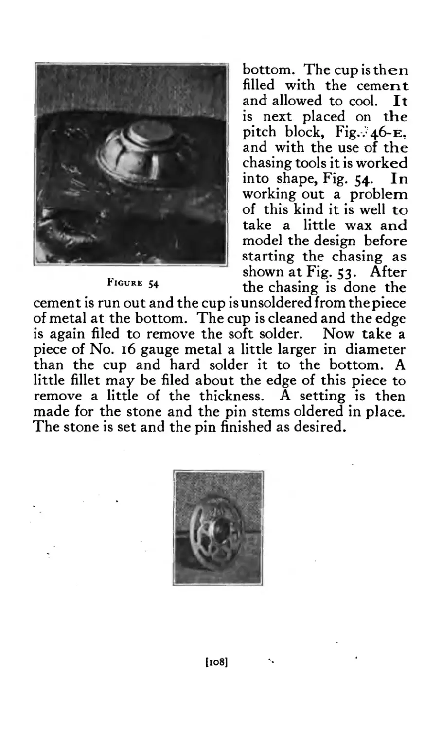
/


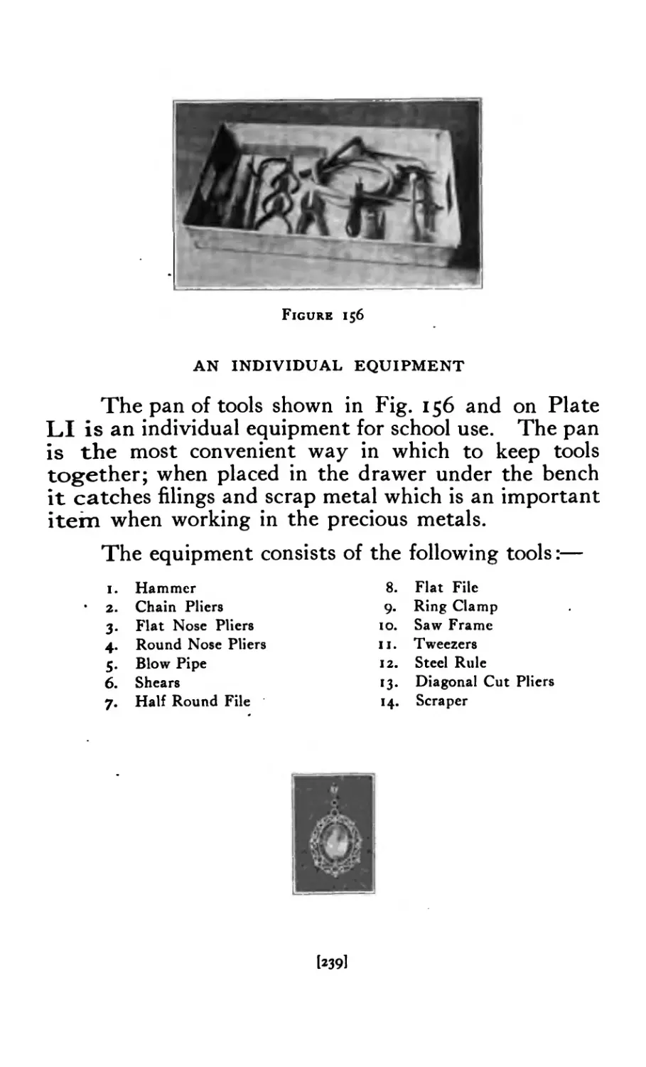

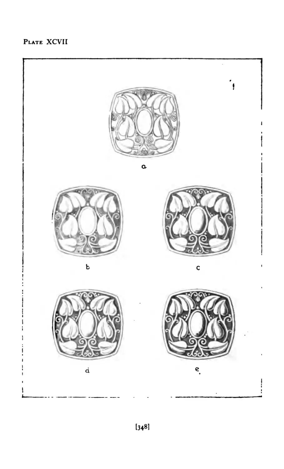


Text
Augustus F. Rose Antonio Cirino
Jewelry Malang
and
- jt\VELRY
Pvt/A-tviNG and DESIGN
An illustrated text book
•«•'.Teachers, Students of Design, and
Craft Workers in Jewelry
BY
AUGUSTUS F. ROSE
Author of “Copper Work”
Head of the Departments of Jewelry and Silversmith!ng,
and Normal Art, Rhode Island School of Design
and
ANTONIO CIRINO, B. S.
Assistant in Departments of Jewelry and Silversmithing,
and Normal Art, Rhode Island School of Design
Metal Crafts Publishing Co.
Providence, R. I.
Copyright 1917
By Augustus F. Rose
Printed by
The Davis Press, Inc.
Worcester, Mass.
TABLE OF CONTENTS
Book I. Jewelry Making
CHAPTER PAGE
I Stones ......... II
Stone Cutting ........ 22
Gold, Silver, and Weights ...... 31
TV ?rocesses Involved in Jewelry Making 47
V brooches Pierced without Stones . . 49
VI Brooches with Stones ....... 59
VII Brooches with Wire Edges ..... 73
VIII Brooches Carved and Ornaments Applied 77
IX Brooches made of Wire ...... 86
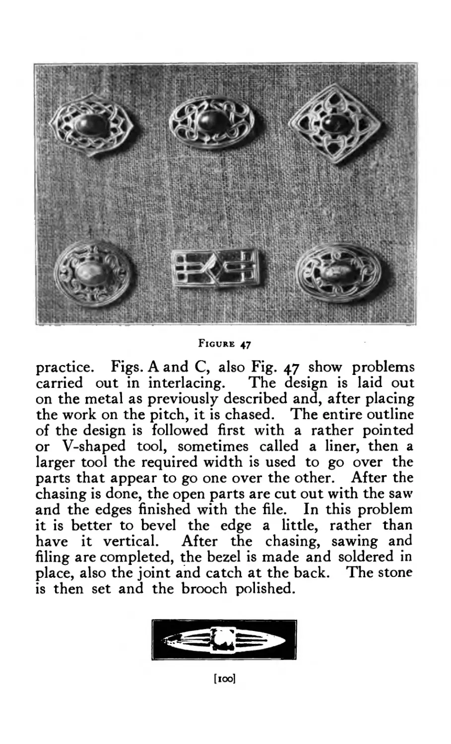
x Brooches Chased and in RepoussS .... 97
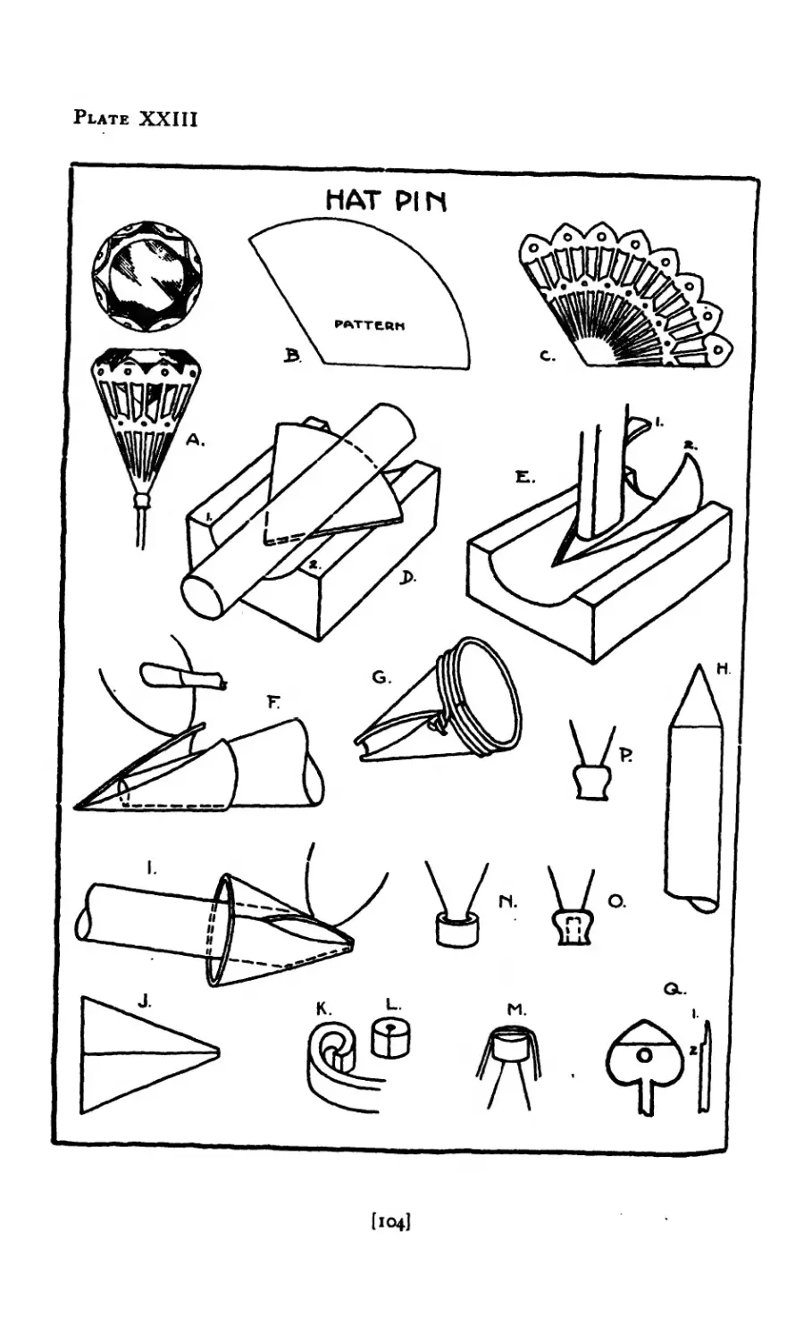
XI The Hat Pin ........ 103
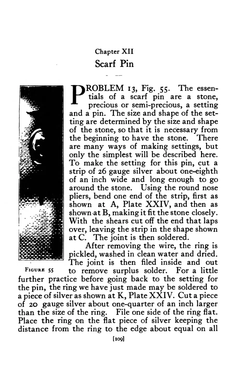
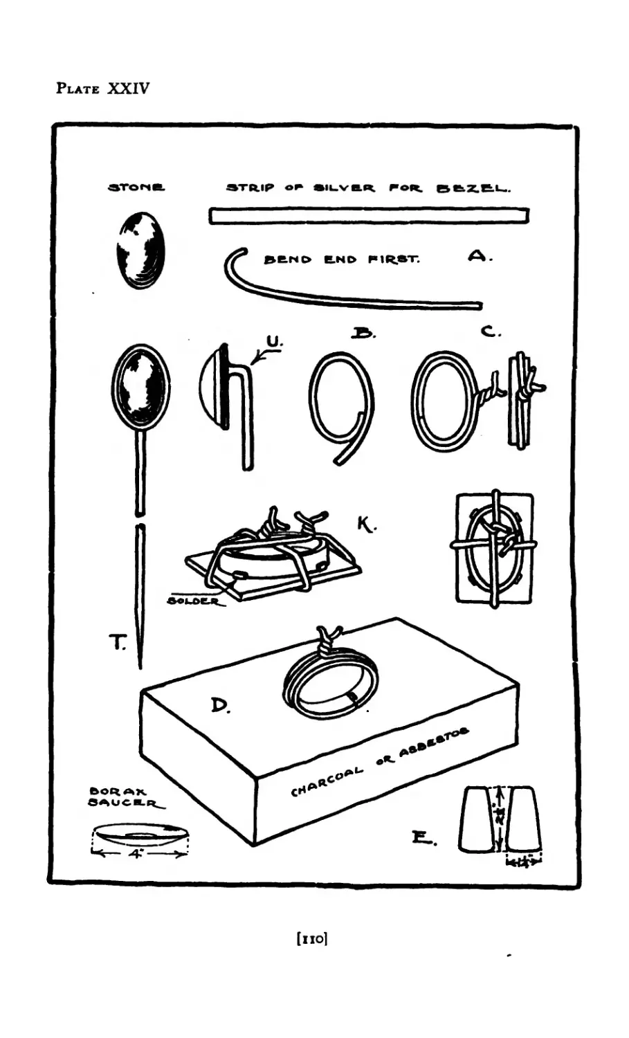
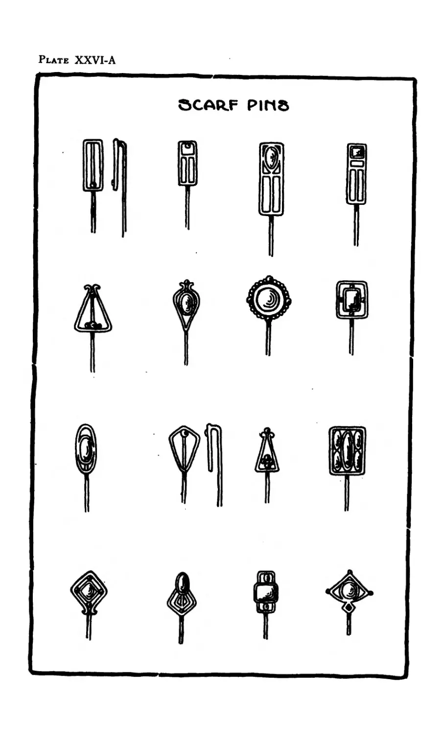
XII Scarf Pin ......... 109
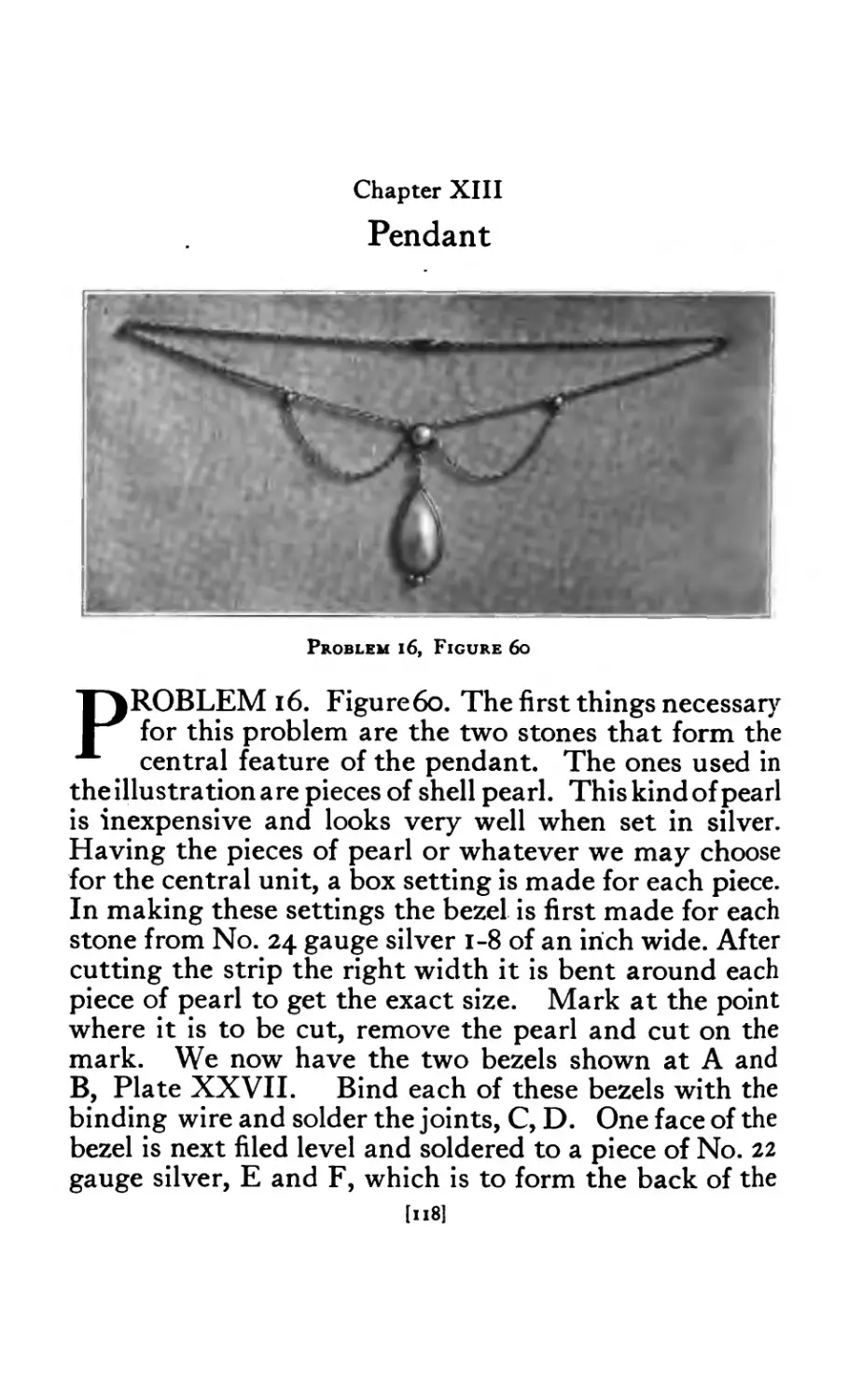
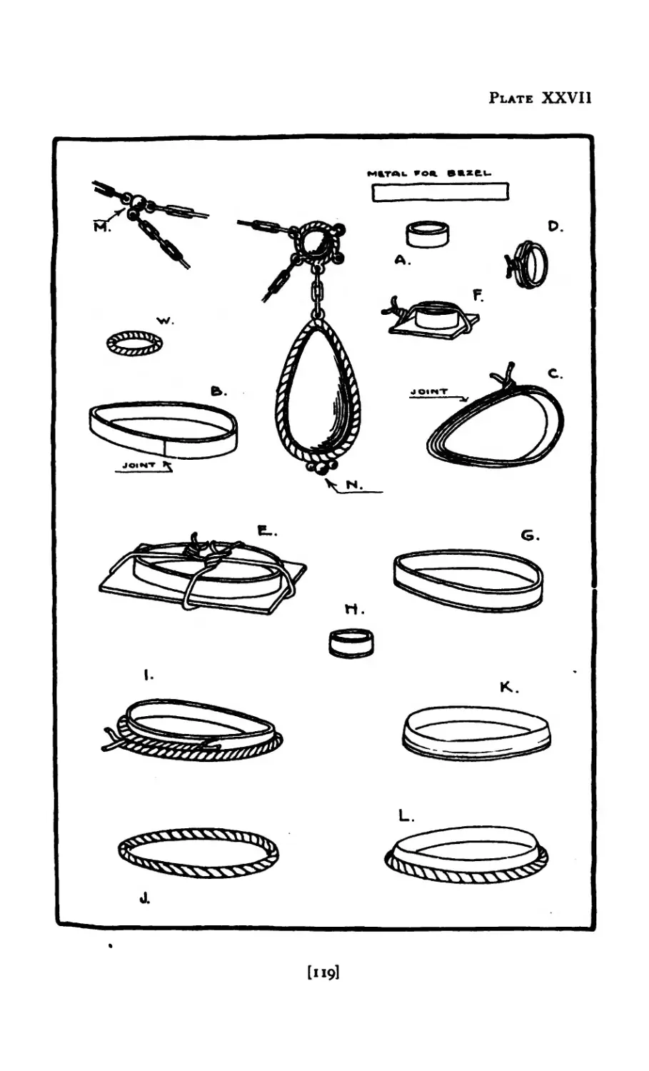
XIII Pendant . . . . ... 118
XIV Finger Ring ........ 142
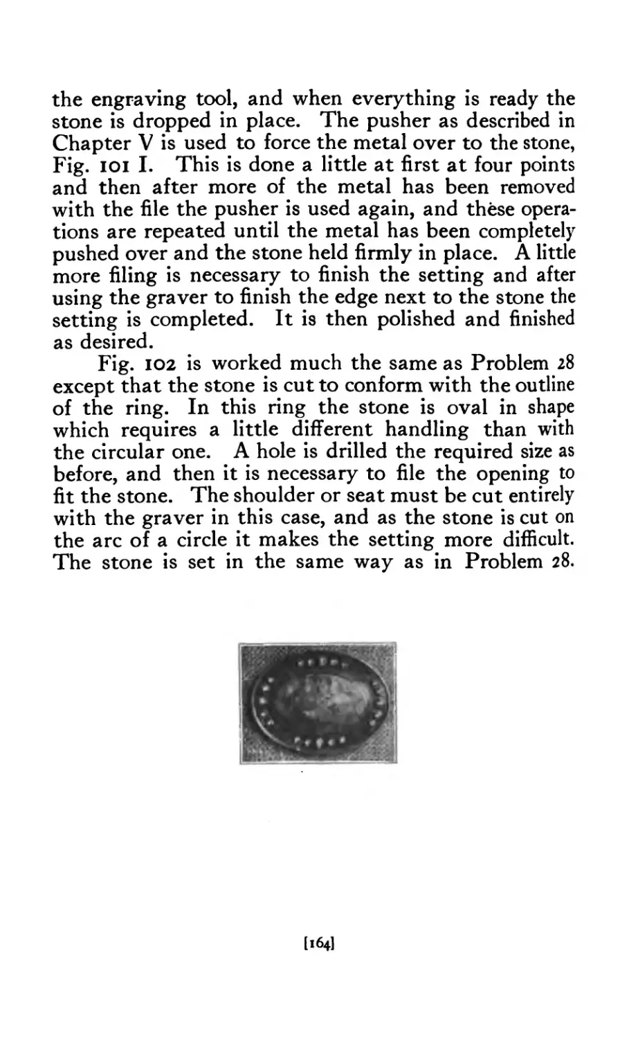
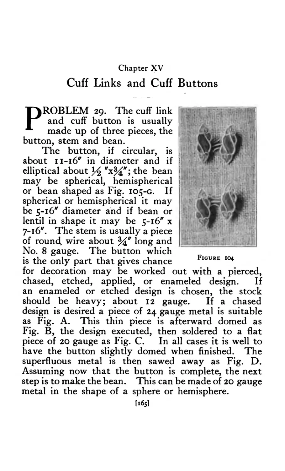
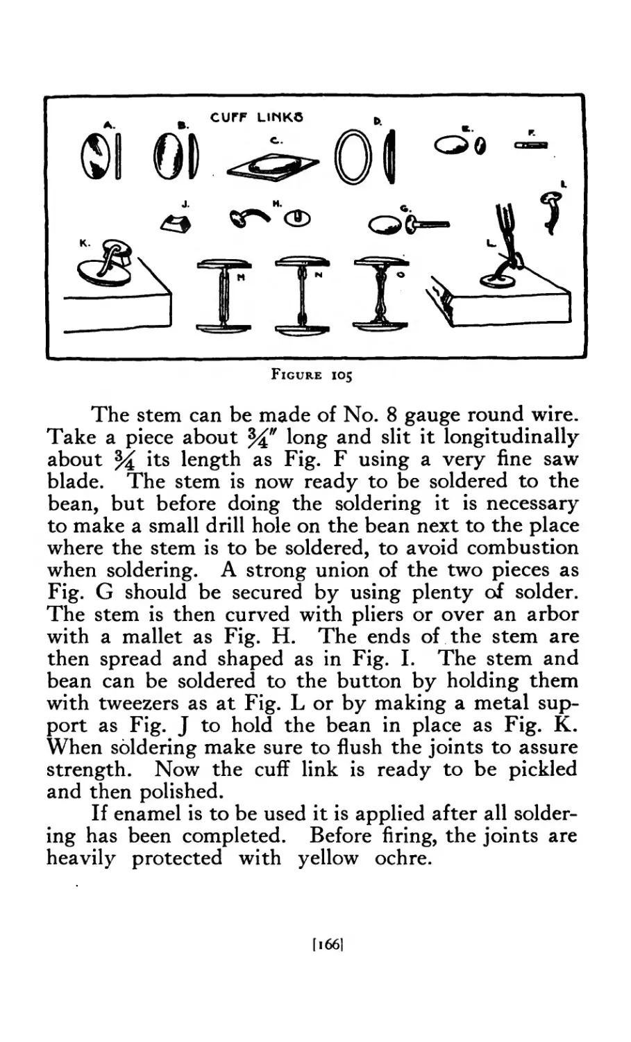
XV Cuff Links and Cuff Buttons ..... 165
XVI Fobs and Chains ....... 169
XVII Enameling ........ 181
XVIII Modeling and Casting ....... 198
XIX Hub and Die Cutting ....... 214
XX Equipment ........ 234
Book IL Jewelry Design
CHAPTER PAGE
XXI Introduction to Jewelry Design ..... 257
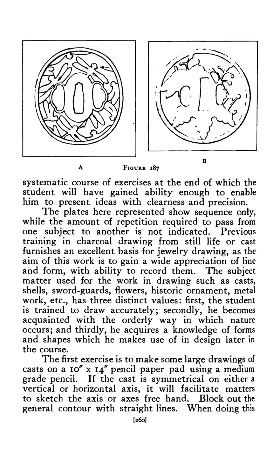
XXII Jewelry Drawing . * . 259
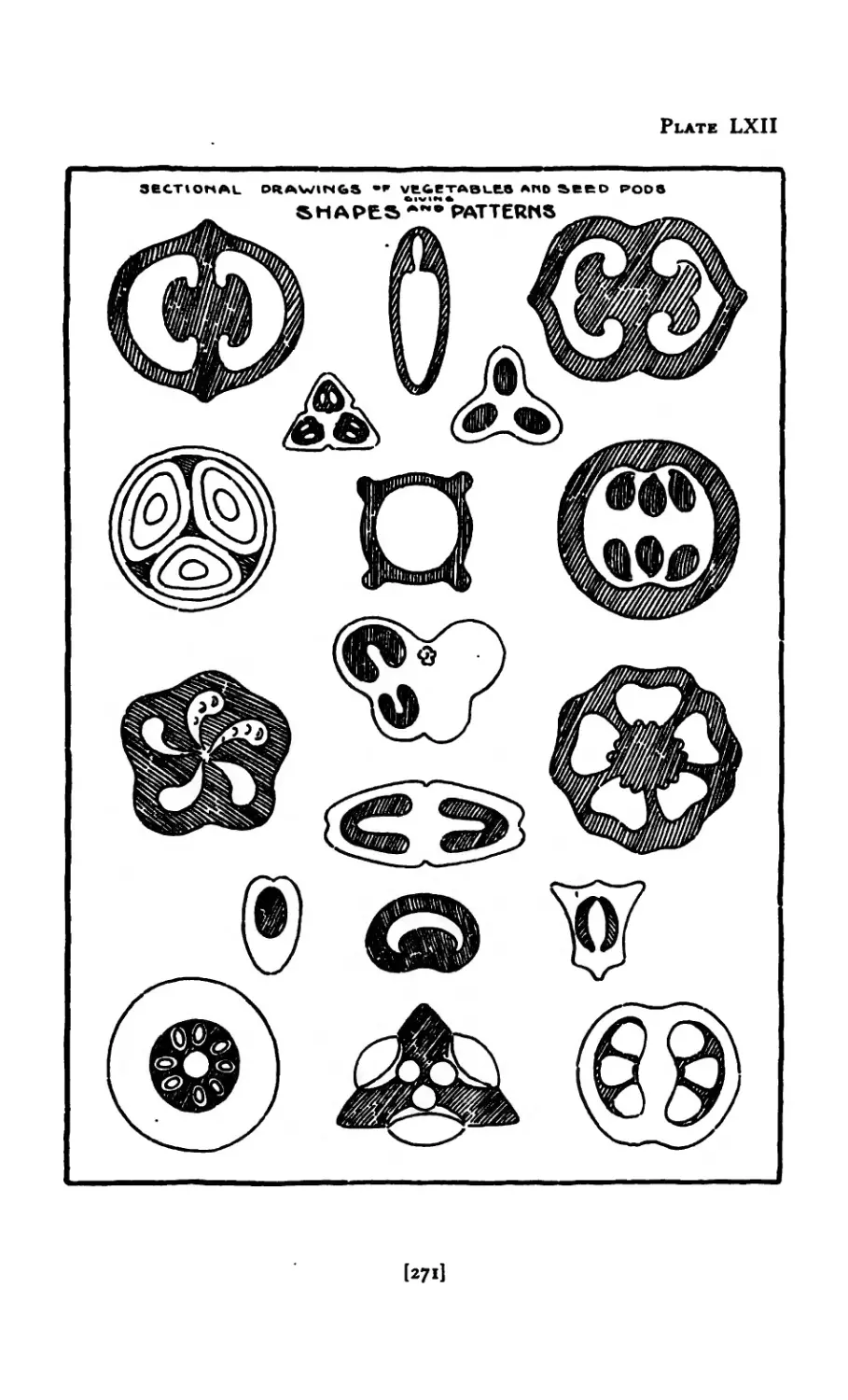
XXIII Nature Drawing ....... 265
XXIV Historic Ornament ....... 286
XXV Principles of Jewelry Design ..... 293
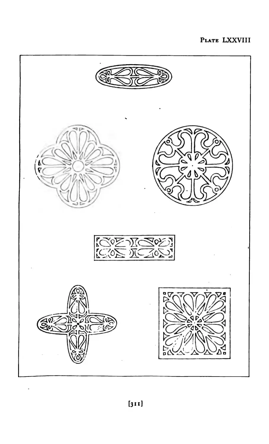
XXVI The Beginning of Design (Variations) .... 305
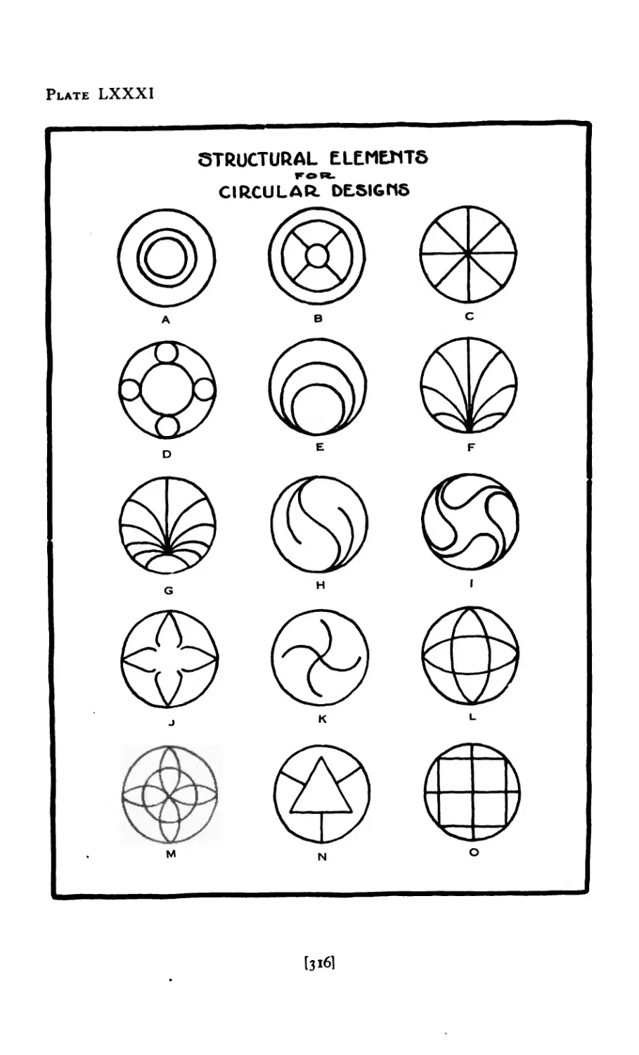
XXVII Structural Elements of the Circle .... 315
XXVIII The Evolution of Design ...... 319
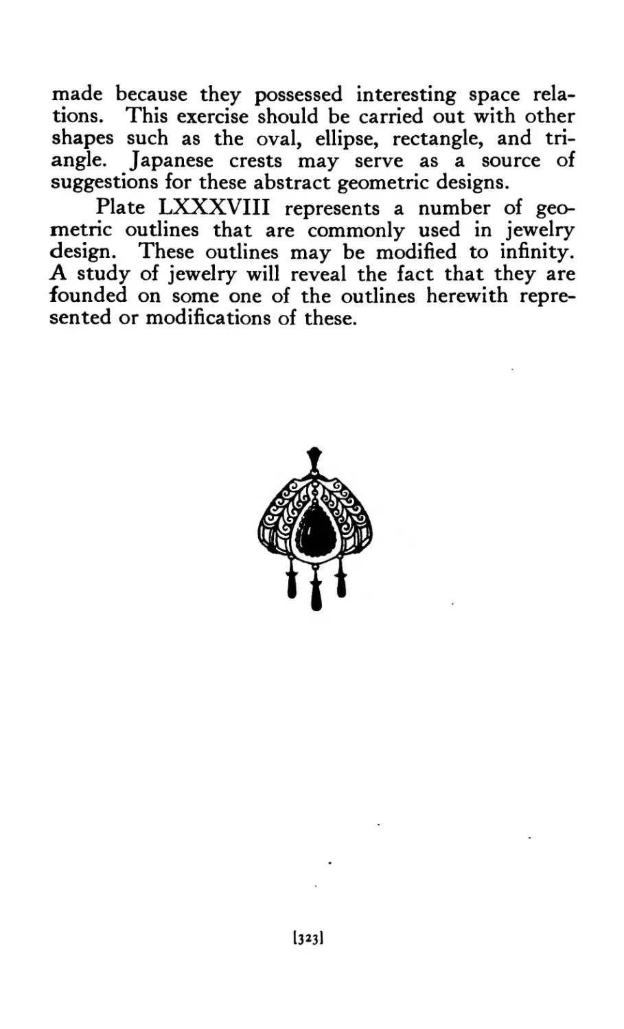
XXIX Geometric Designs ....... 322
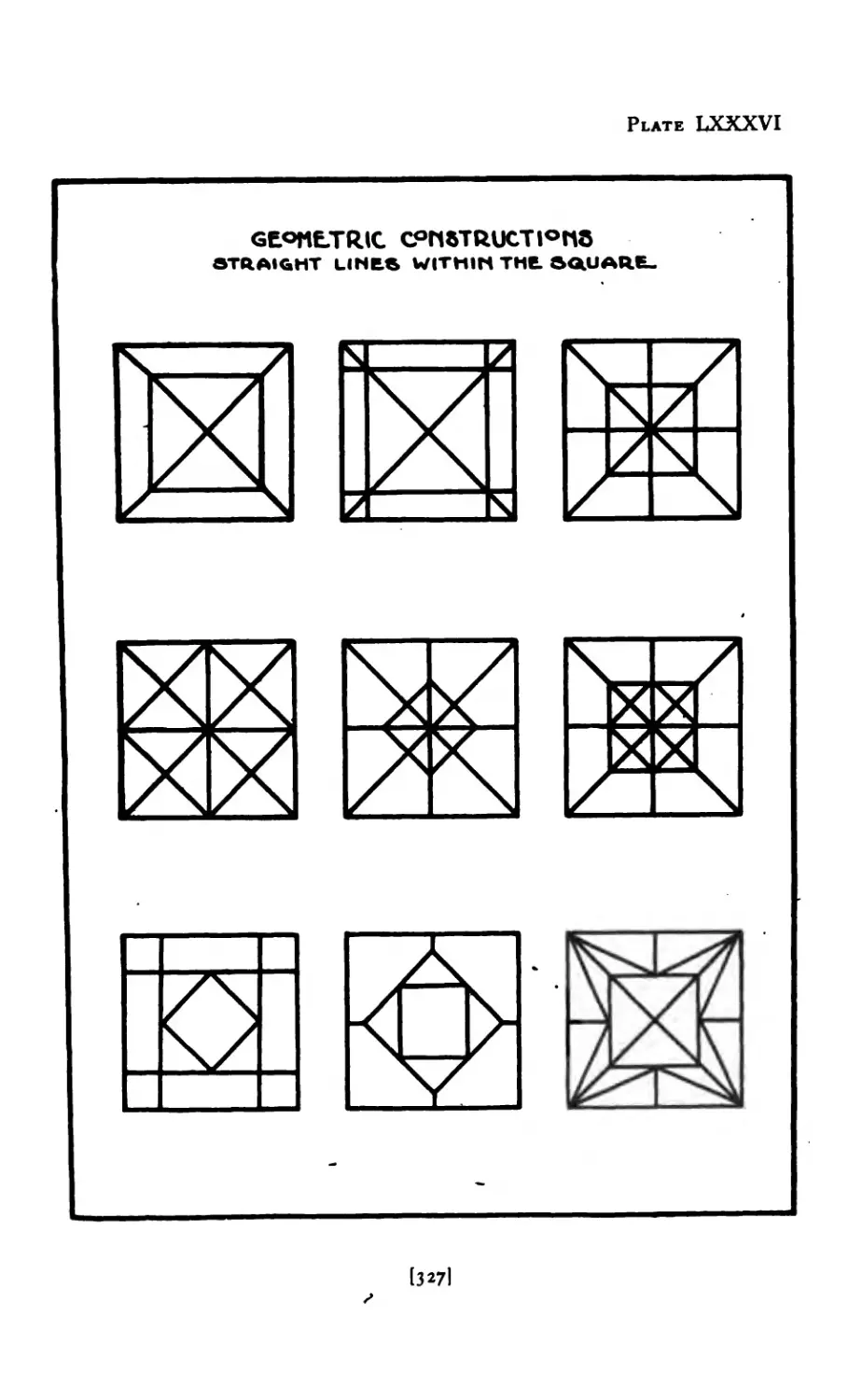
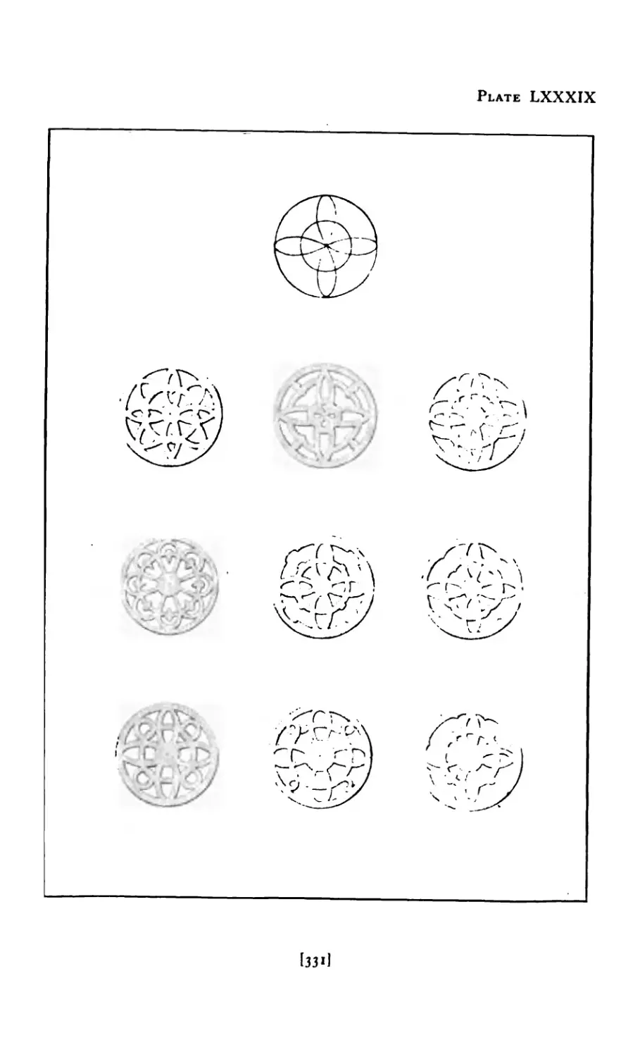
XXX The First Problems in Design . • . 330
XXXI Rendering in Pencil ....... 336
[iiij
CHAPTER PACE
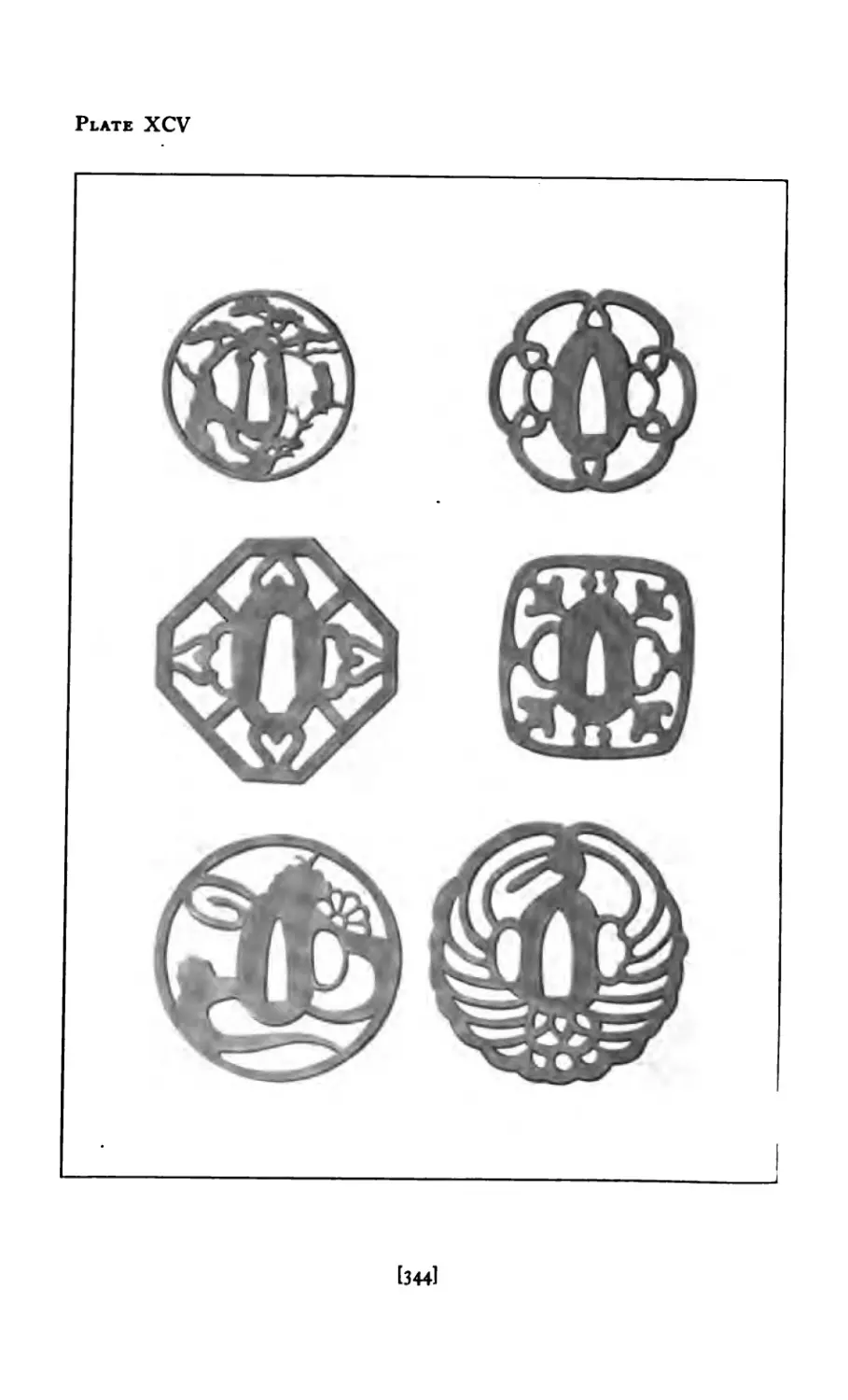
XXXII Rendering with Brush ...... 3 43
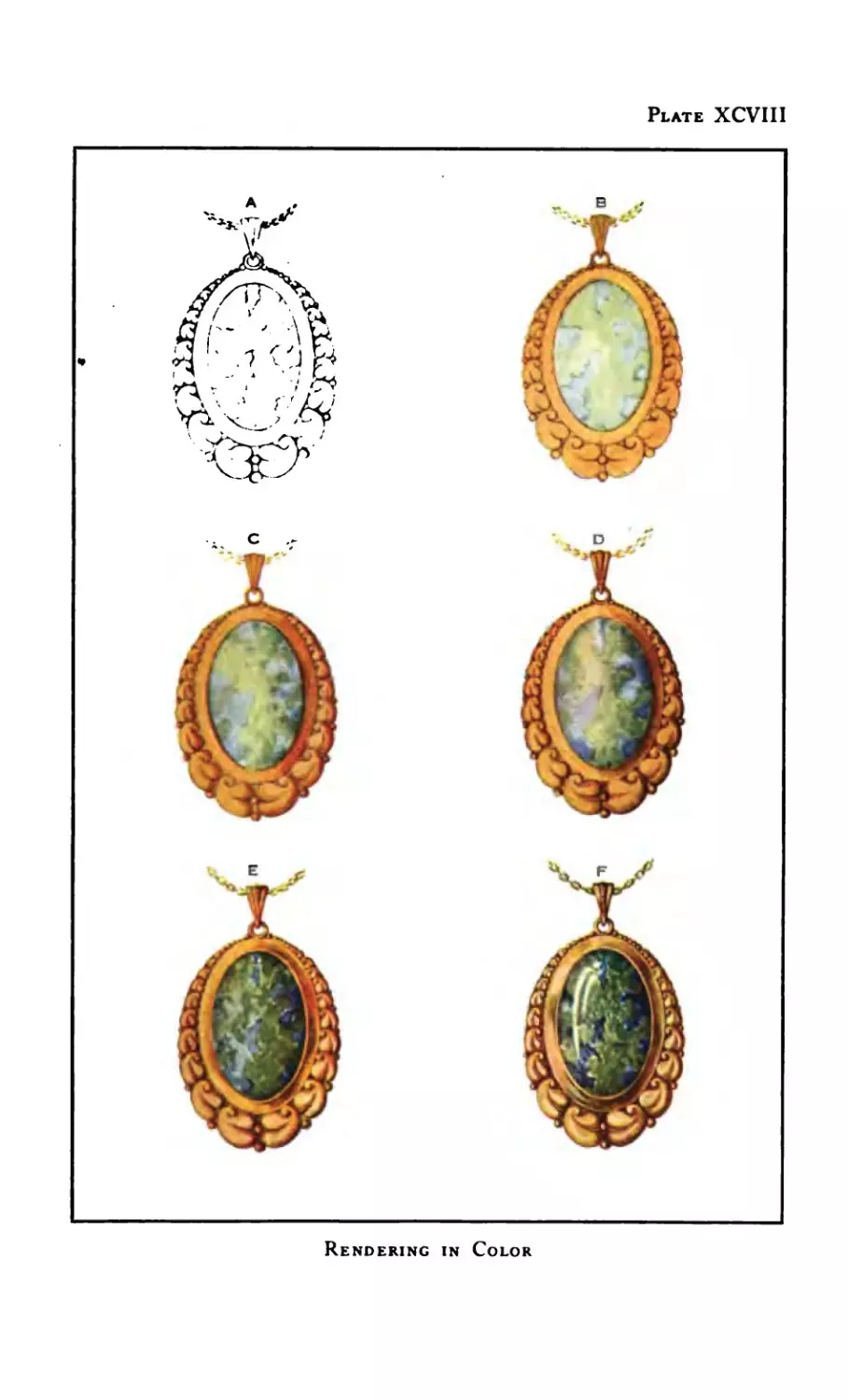
XXXIII Rendering in Color ....... 35°
XXXIV Rendering Stones ... 352
XXXV The Vital Curves 3 5<>
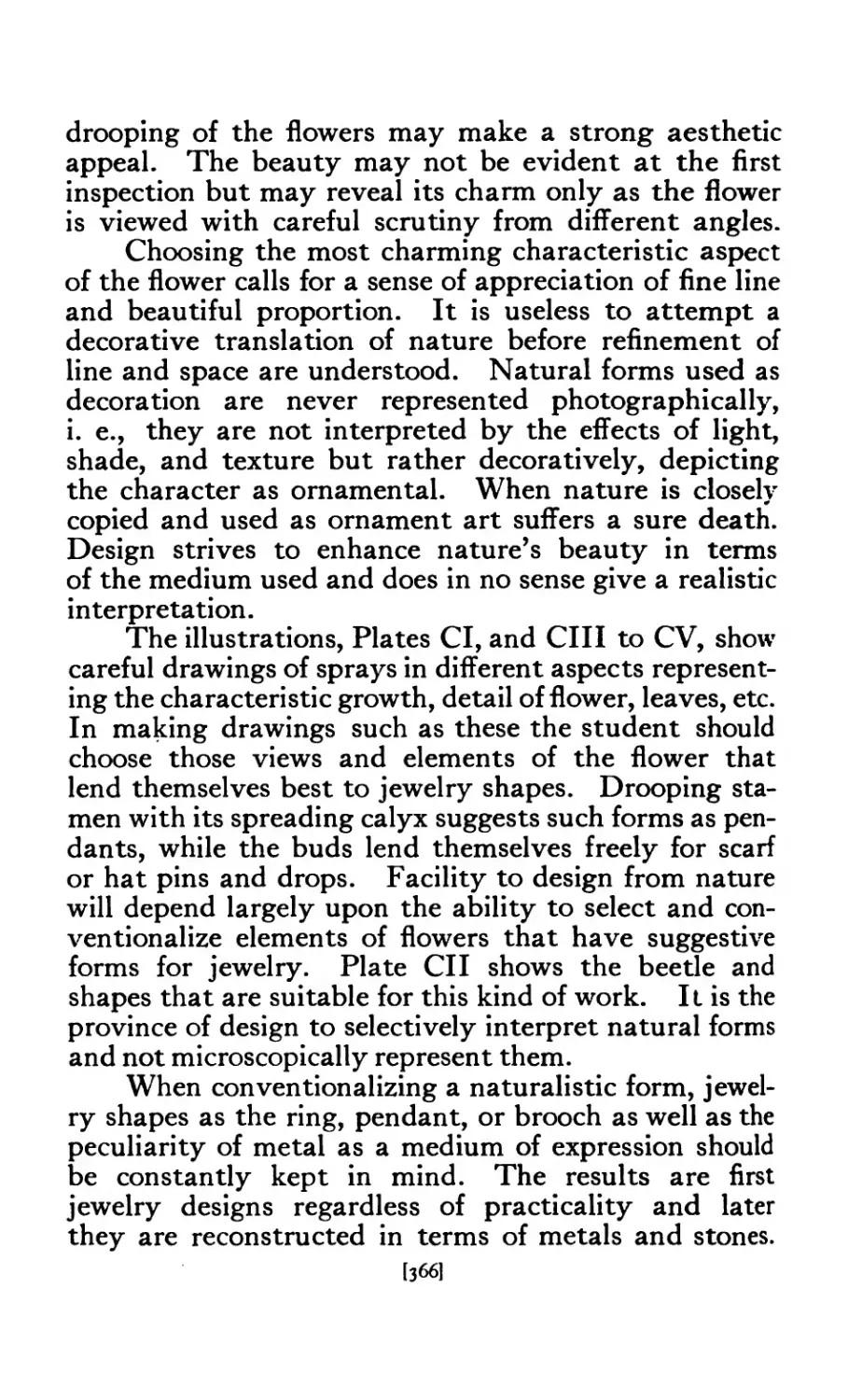
XXXVI How to Choose Material for Jewelry 36^’
XXXVII Designs Derived from Nature ... 3О4
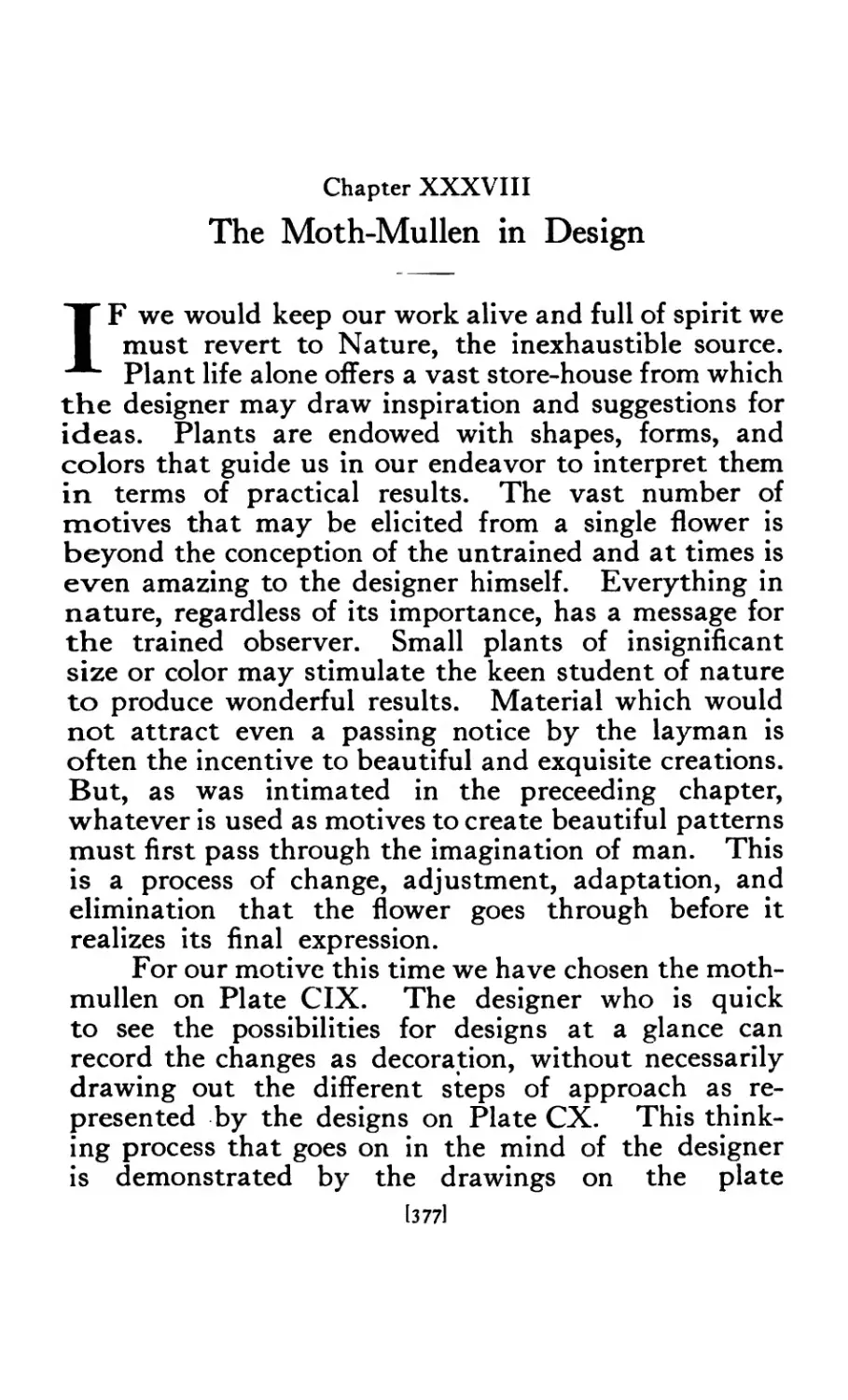
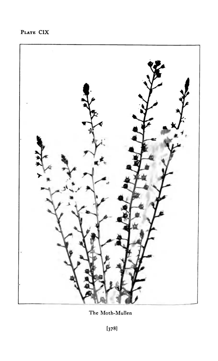
XXXVIII The Moth-Mullen in Design ..... 4 У 7*
XXXIX The Snow Crystal in Design ..... 3*4
XL The Sea Horse in Design ...... з
XLI The Butterfly in Design ...... 396
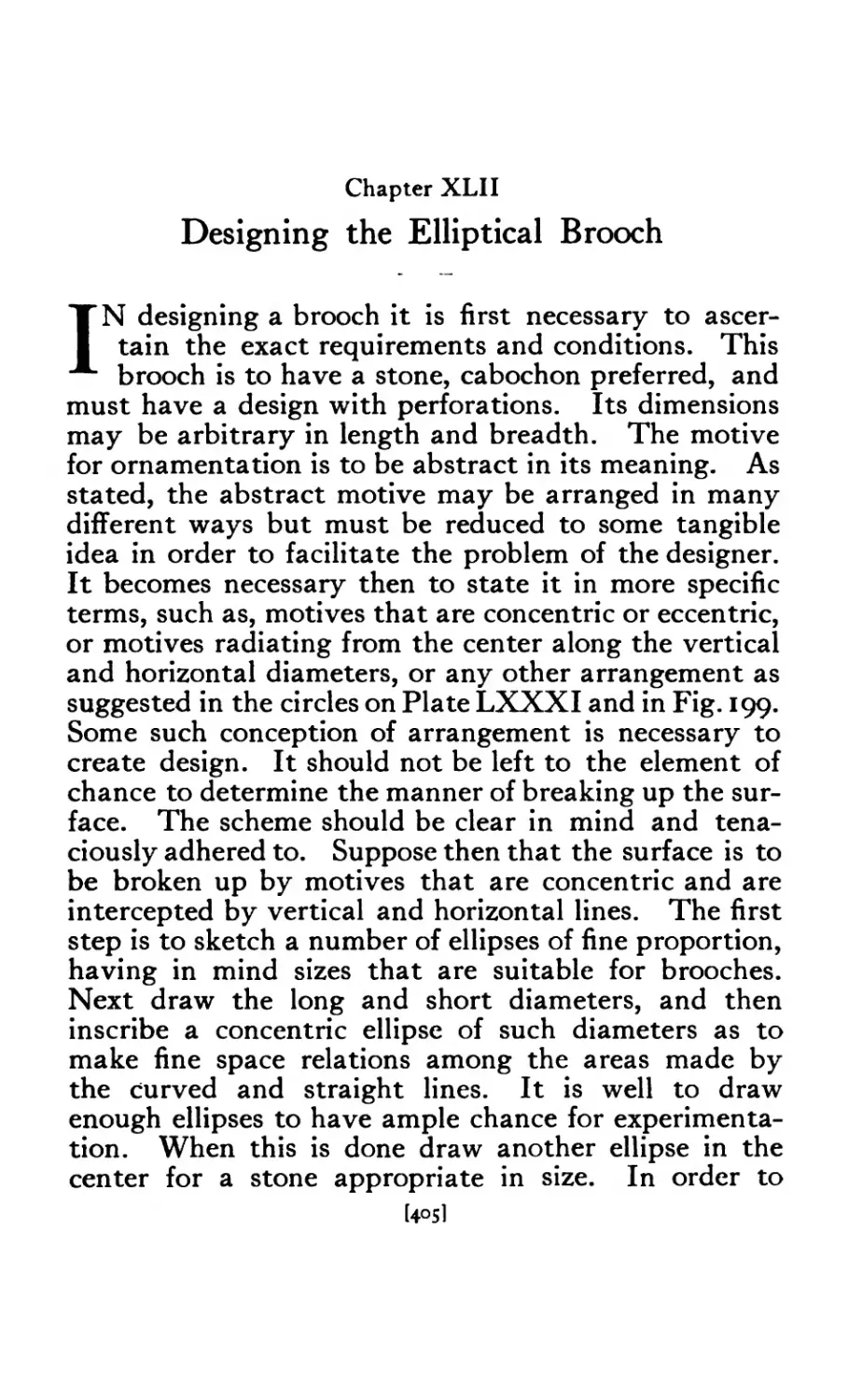
XLII Designing the Elliptical Brooch ..... 4°5
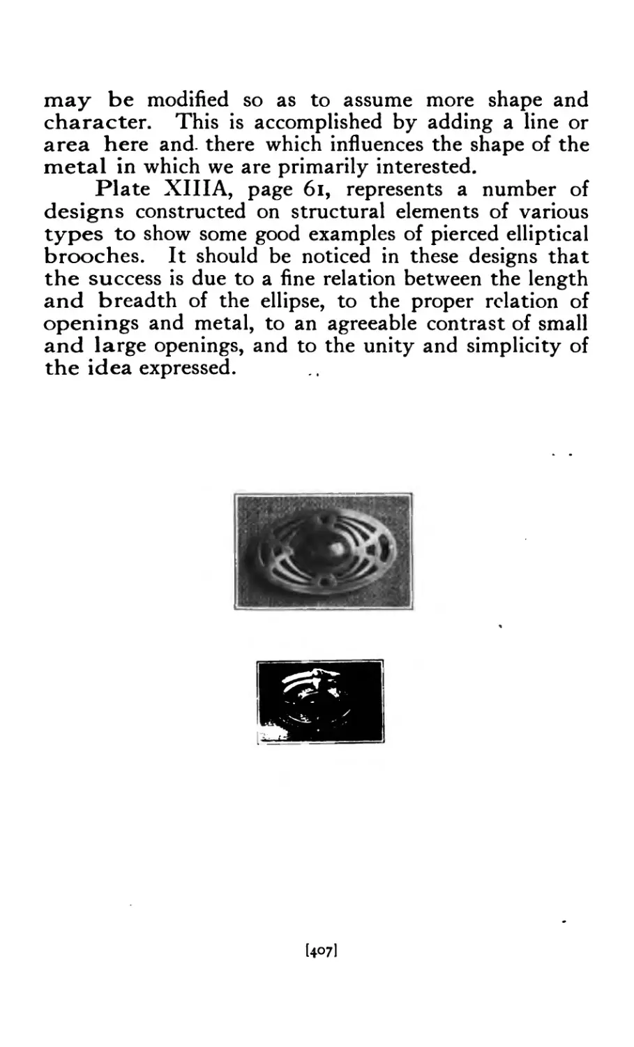
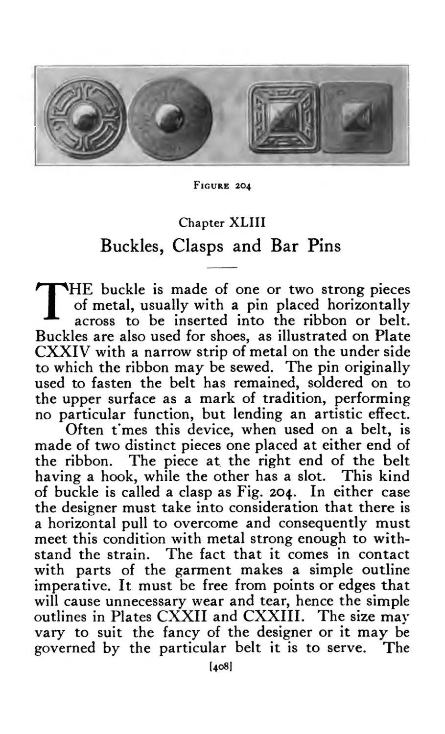
XLIII Buckles, Clasps, and Bar Pins ..... 40S
XLIV Pendants, Lavalliere, and Necklace .... 413
XLV The Watch Fob ........ 421
XLVI The Hat Pin ........ 426
XLVII The Cuff Link and Cuff Button ..... 430
XLVI 11 The Finger Ring. ....... 43 5
XLIX The Scarf Pin ....... 438
L Chains, Pendant Slides, and Pendant Connections . 441
LI Keeping Freshness in One’s Work. .... 450
L1I The Note Book ........ 452
LIH Equipment for Jewelry Drawing and Design . 457
LIV Jewelry Coloring ....... 461
OF ILLUSTRATIONS
i
и
HI
IV
V
VI
\ II
\ III
VIII-A
IX
X
XI
XII
XIII
Xlll-A
XIV
XV
XVI
XVII
XVIII
XIX
XXI
XXII
XXIII
XXIV
XXV
XXVI
XXVl-Л
XXVII
XXVIII
XXIX
XXX
XXXI
XXXII
Вос. I. Jewelry Making
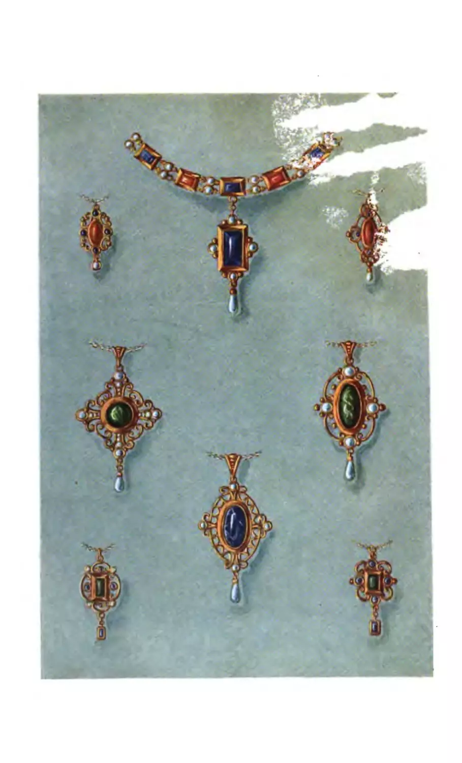
Per ants in Color .....
Diamond Mine, South Africa
Stones in Color ......
Stones in Color ......
Rana of Dolphur, “Prince of Pearls” .
Pearling Fleet, Ceylon ....
Australian Opals .....
Slitting and Faceting Stones
Opal Jewelry ......
Pierced Brooches in Color ....
Pierced Brooches, (Designs)
Pierced Brooches .....
Class in Jewelry Making ....
Pierced Brooches .....
Designs for Circular Brooches
Designs for Elliptical Brooches
Brooches .......
Stone Setting ......
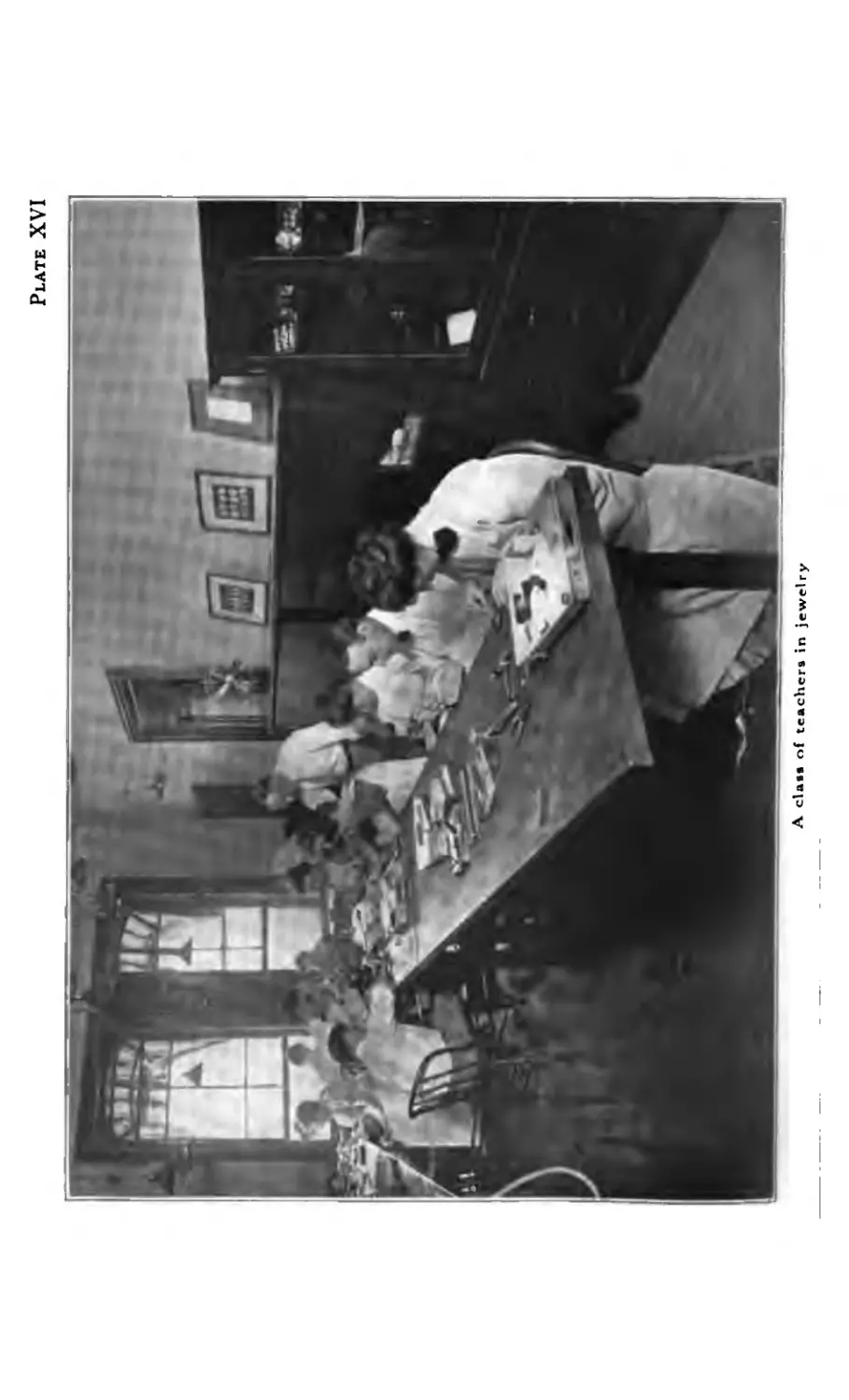
Class of Teachers in Jewelry'
Brooches .......
Brooches ..... • .
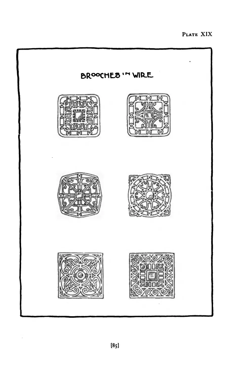
Designs for Wire Brooches ....
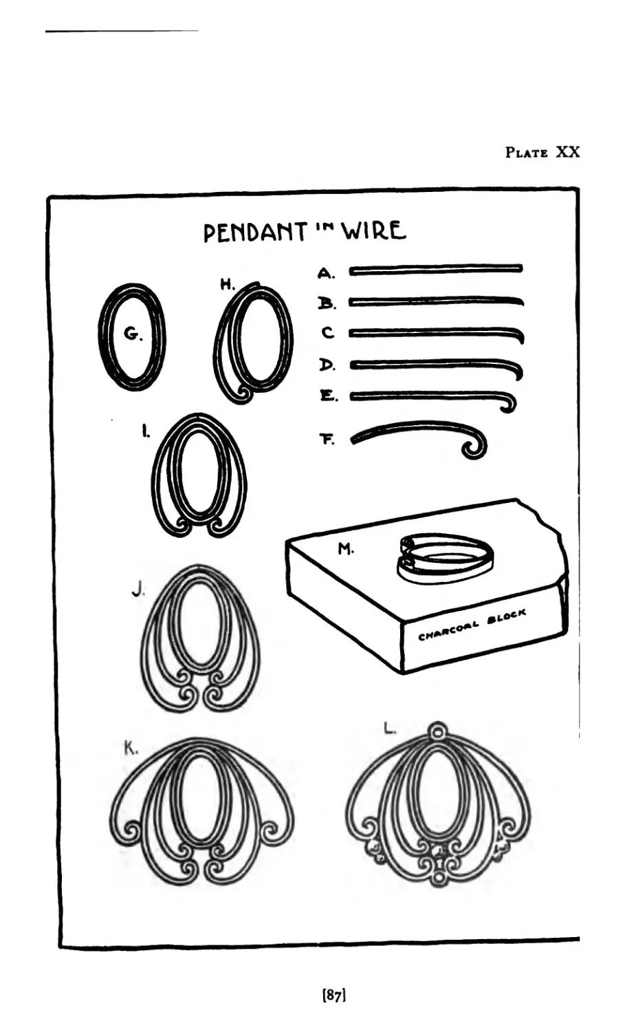
Pendant in Wire
Brooches ..... . .
Circular Brooches in Wire ....
Hat Pin .......
Scarf Pin .......
Scarf Pin ......
Scarf Pin .......
Scarf Pi ns ......
Pendant .......
Pendant .......
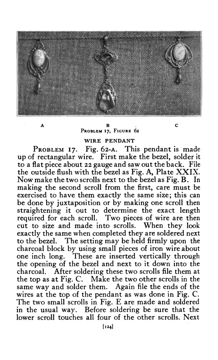
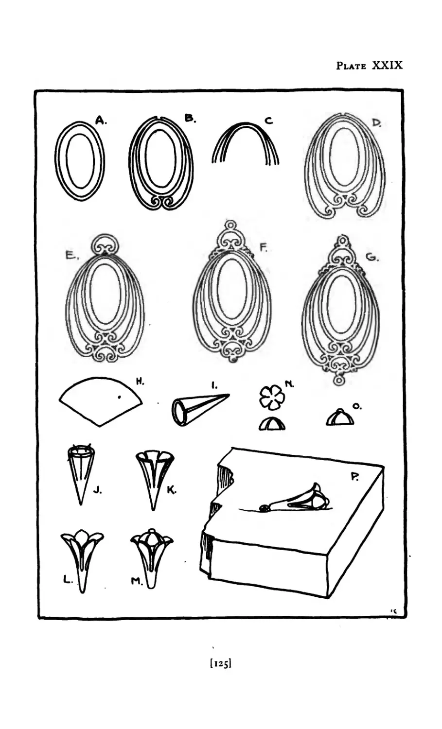
Wire Pendant ......
Designs for Wire Pendants
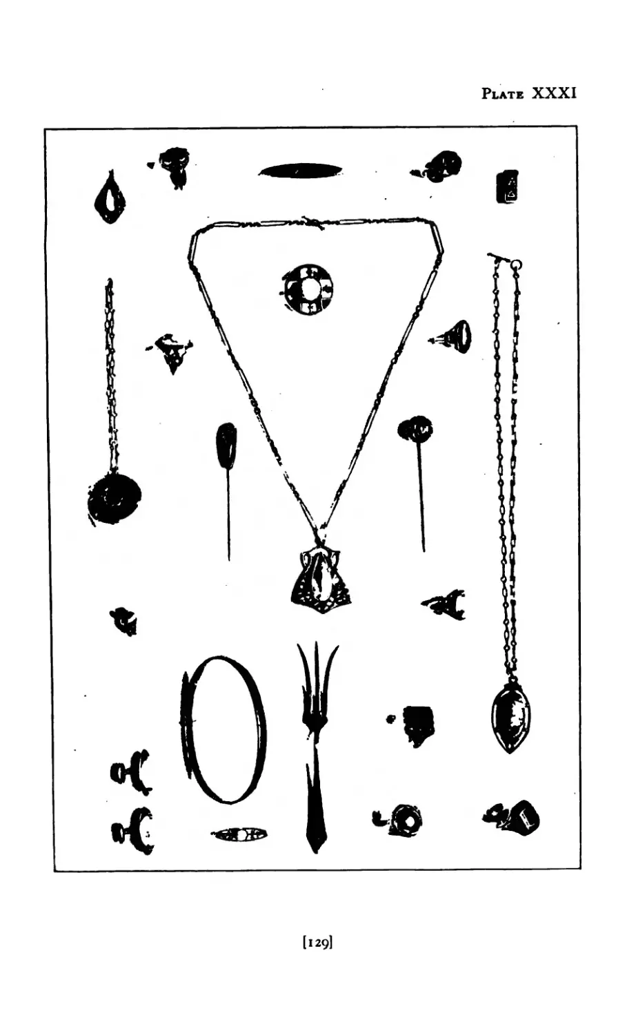
Miscellaneous Jewelry ....
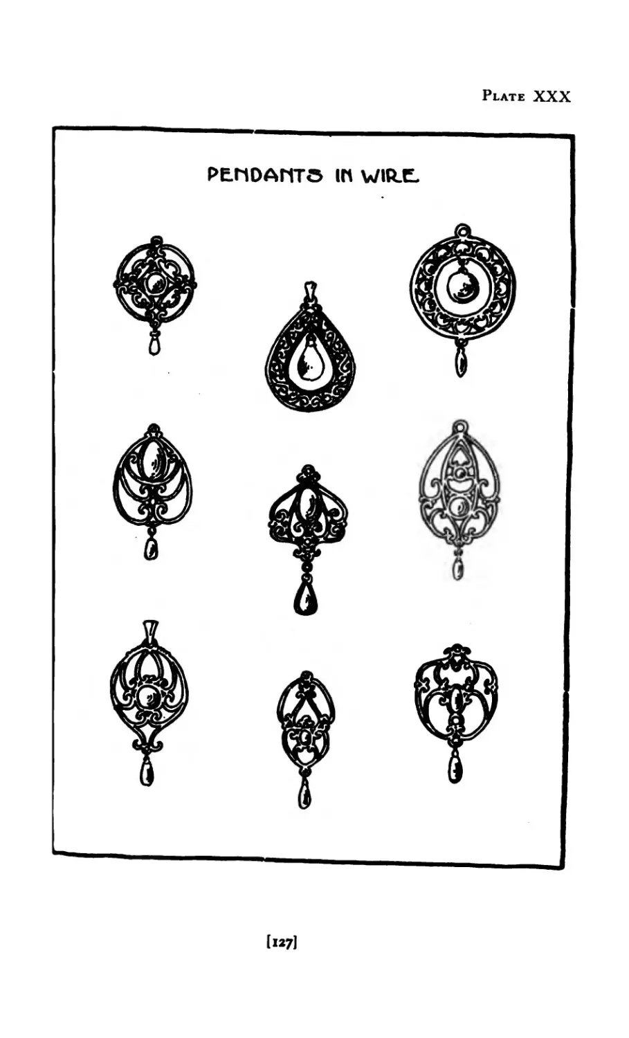
Pendants in Wire .....
PAGE
Frontispiece
12
17
19
23
24
30
48
50
51
54
58
61
66
71
76
81
82
85
87
90
93
104
110
112
i И
116
119
121
125
127
129
131
PLATE
XXXIII Pendant ......
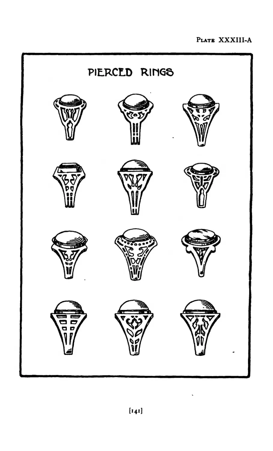
XXXIII-A Designs for Pierced Rings .
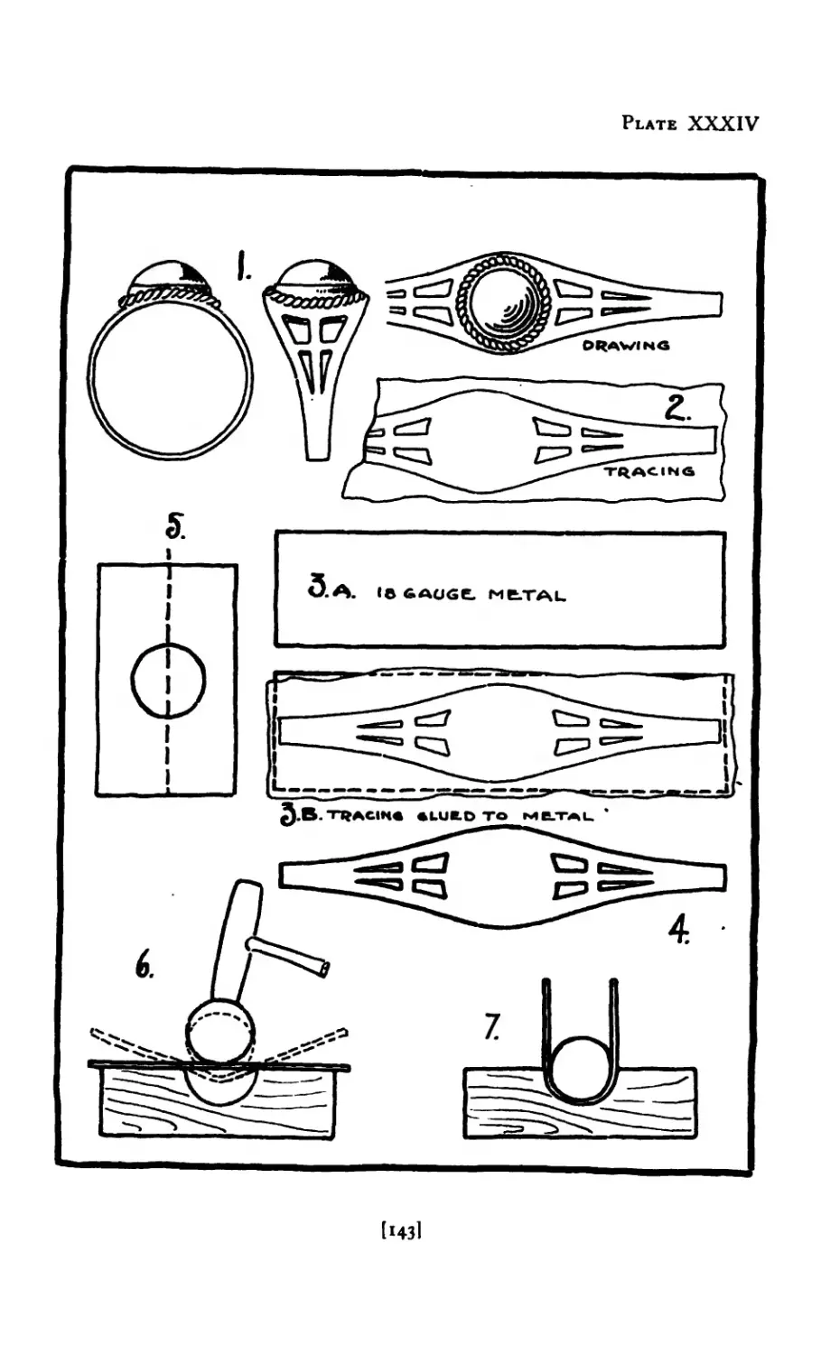
XXXIV Pierced Ring .....
XXXV Pierced Ring .....
XXXVI XXXVII XXXVIII Wire Ring .... Ring with Leaves Carved Cuff Links ....
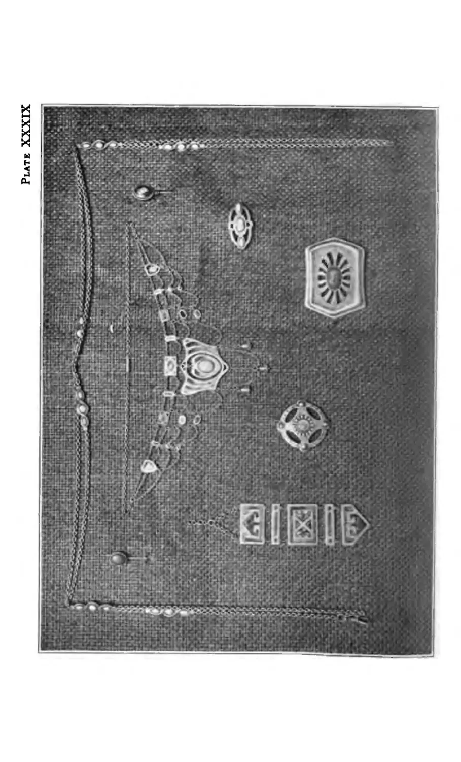
XXXIX Jewelry (Miscellaneous)
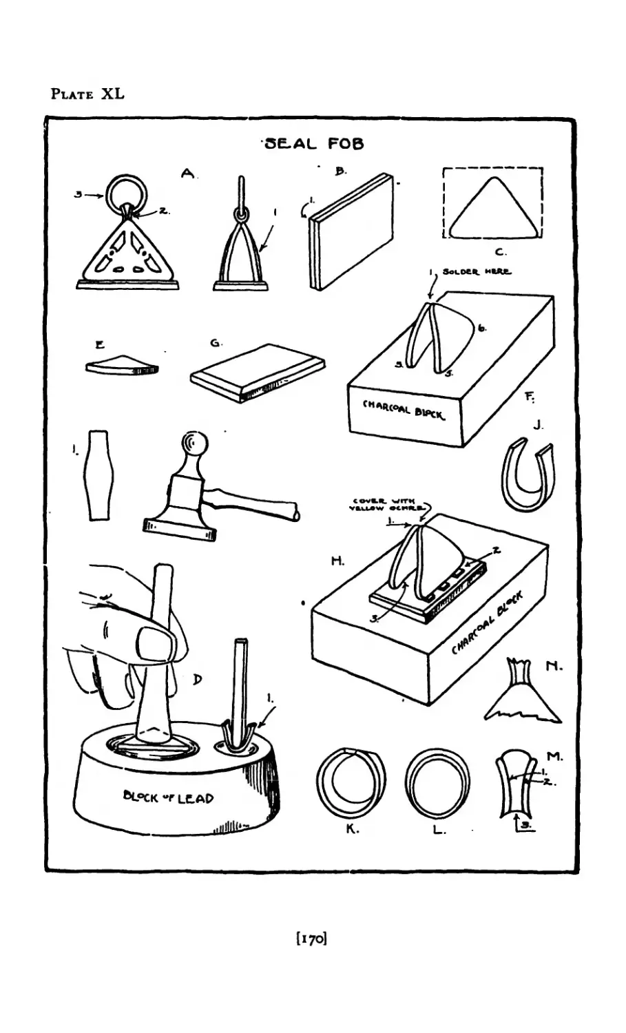
XL Seal Fob ......
XLI Seal Fob .....
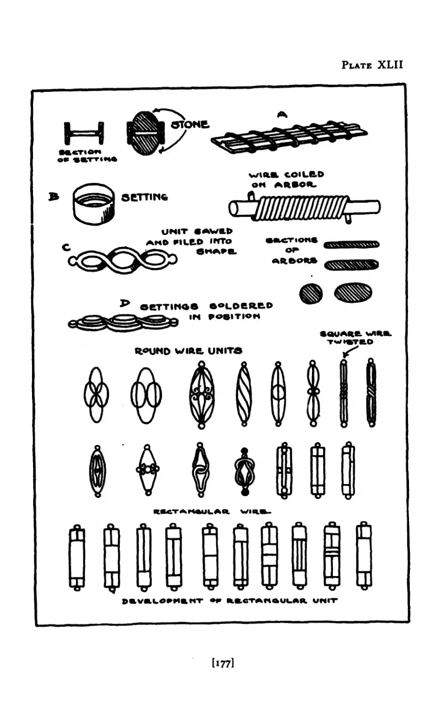
XLII Units for Chains ....
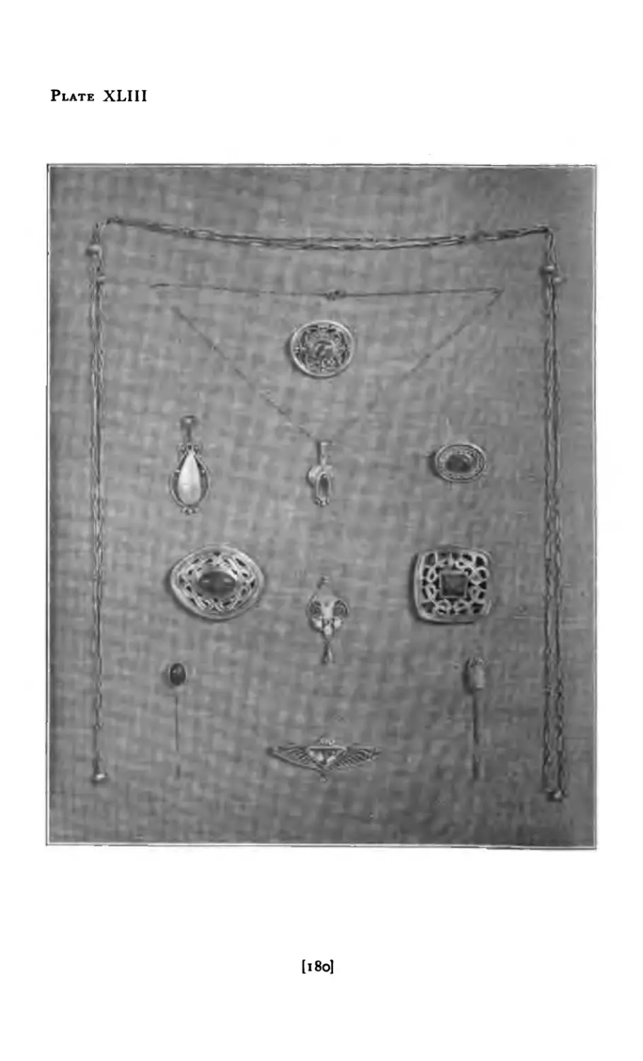
XLIII Jewelry (Miscellaneous)
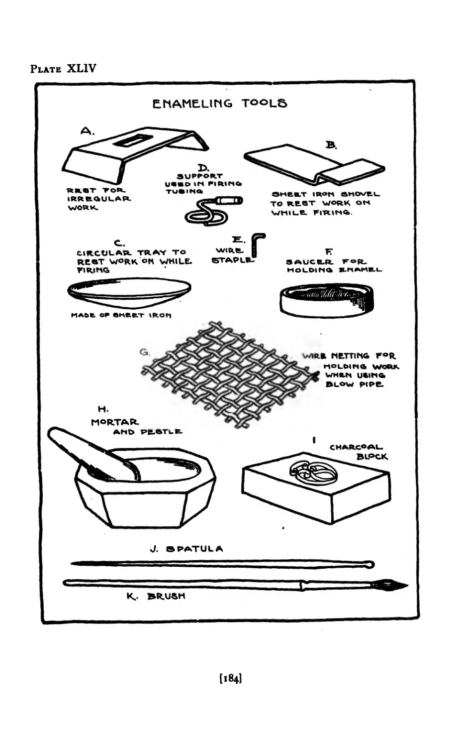
XLIV Enameling Tools ....
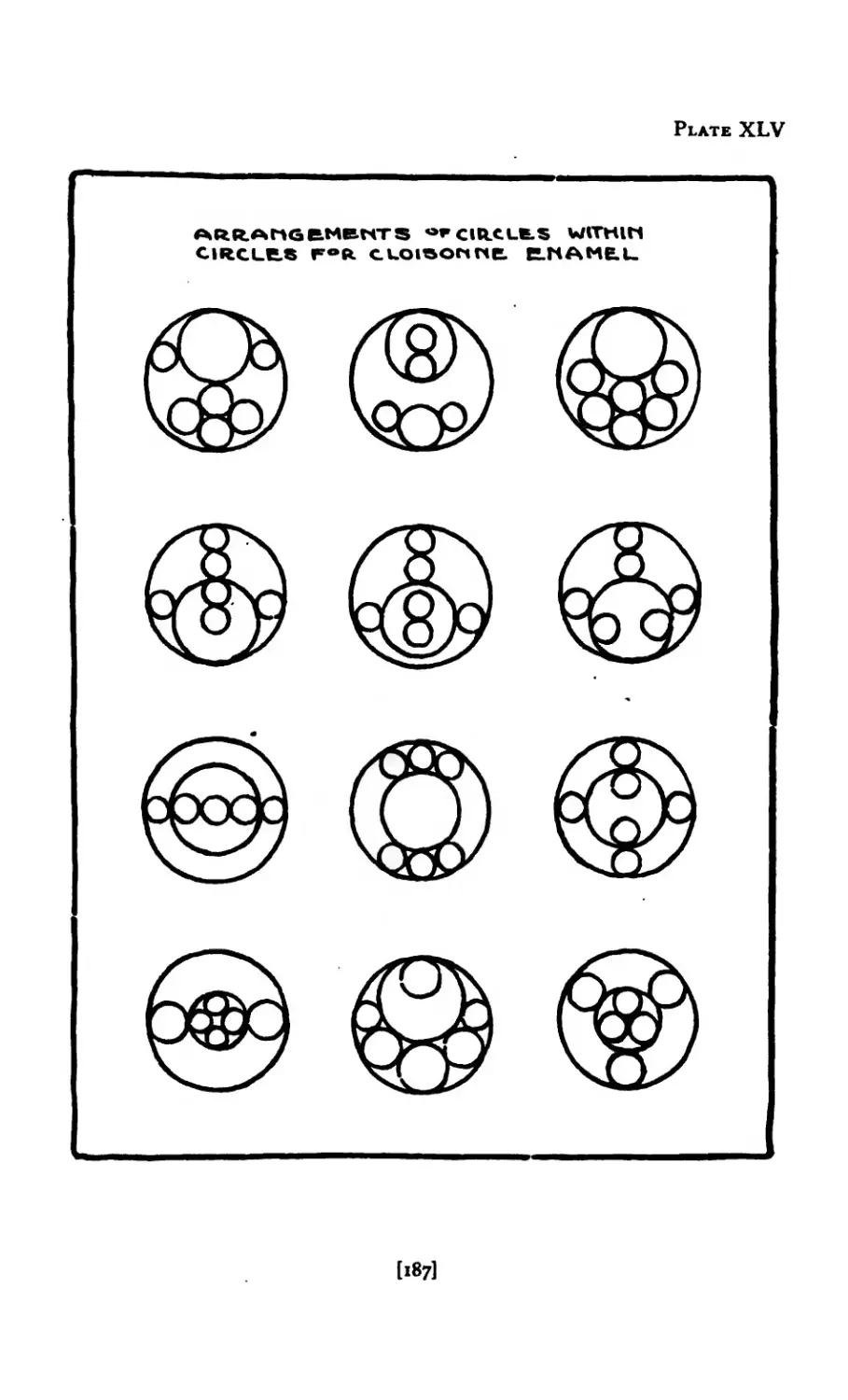
XLV Designs for Cloisonne Enamel
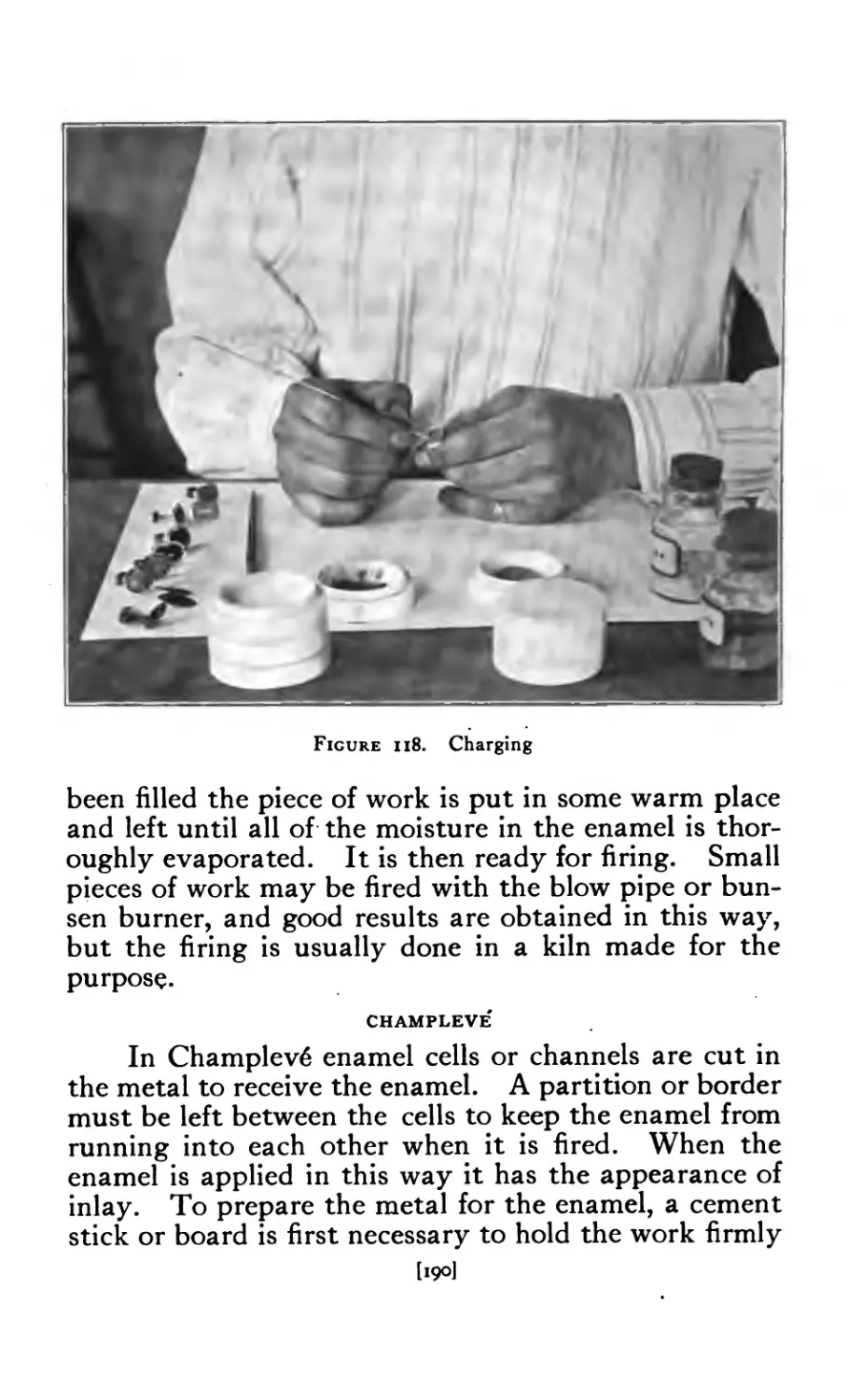
XLVI Designs for Fobs in Enamel
XLVI-A Enameled Brooches in Color
XLV1I Modeling and Cast Work .
XLVIII Casting (Opening Mould) .
XLIX Cuttie Fish Casting ....
L Melting and Pouring ....
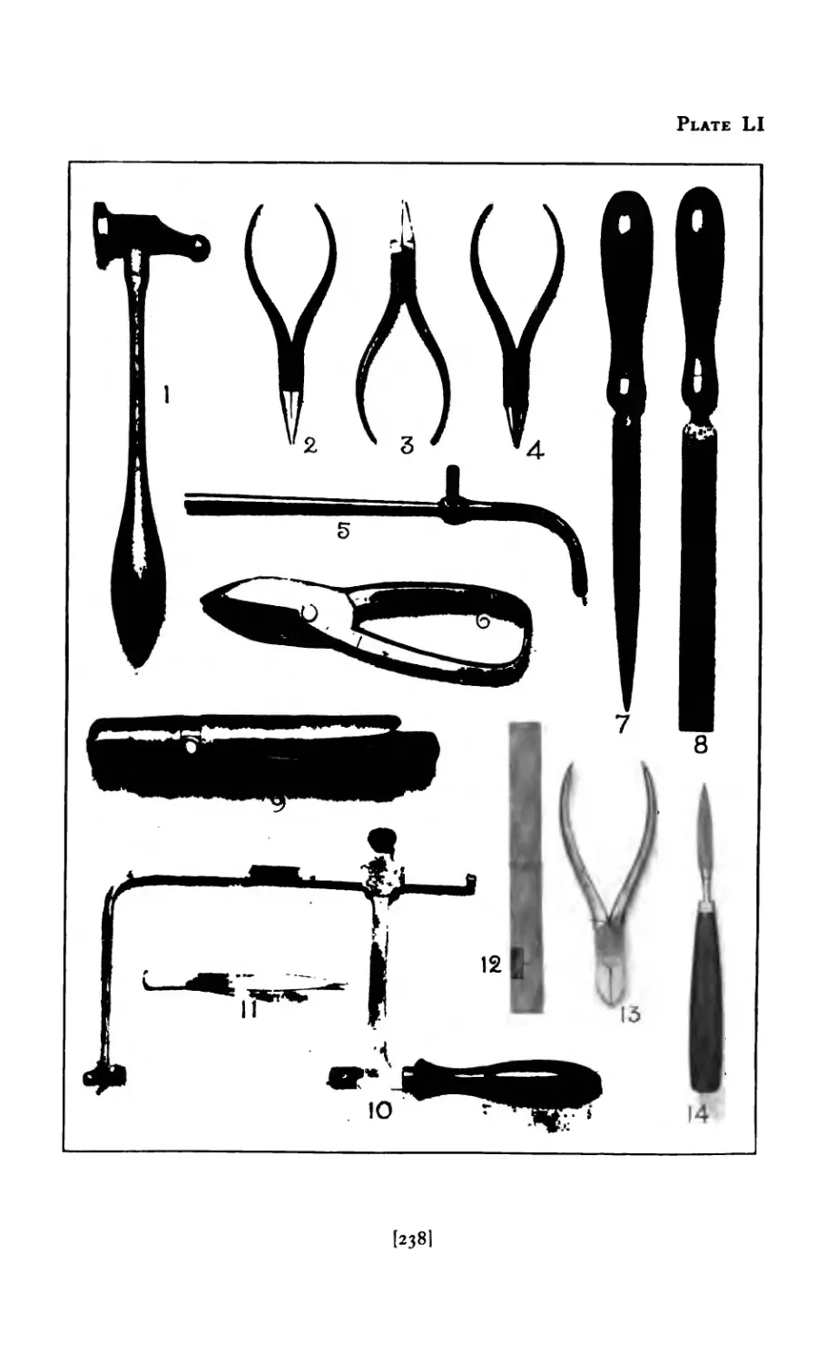
LI Tools for Jew’elry Making .
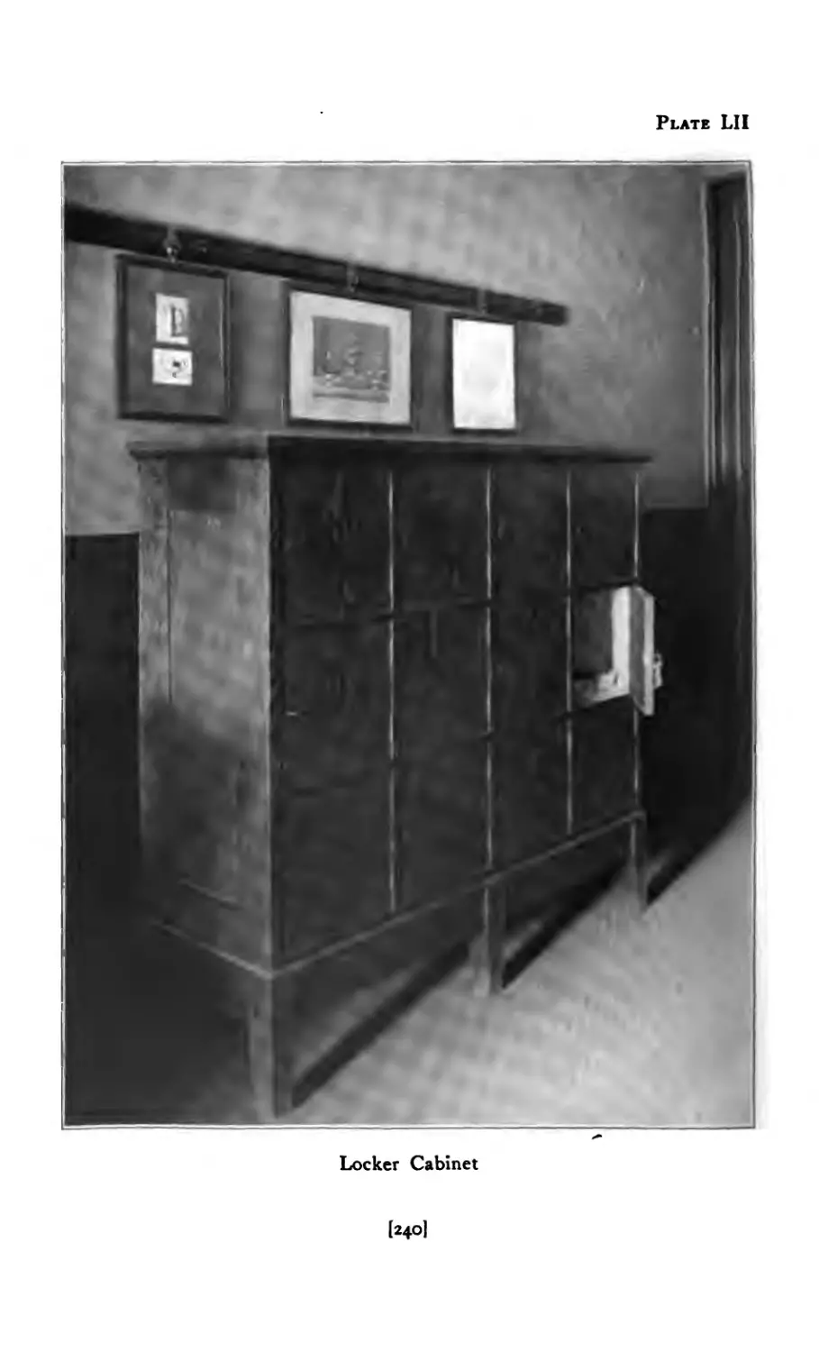
Lil Locker Cabinet ....
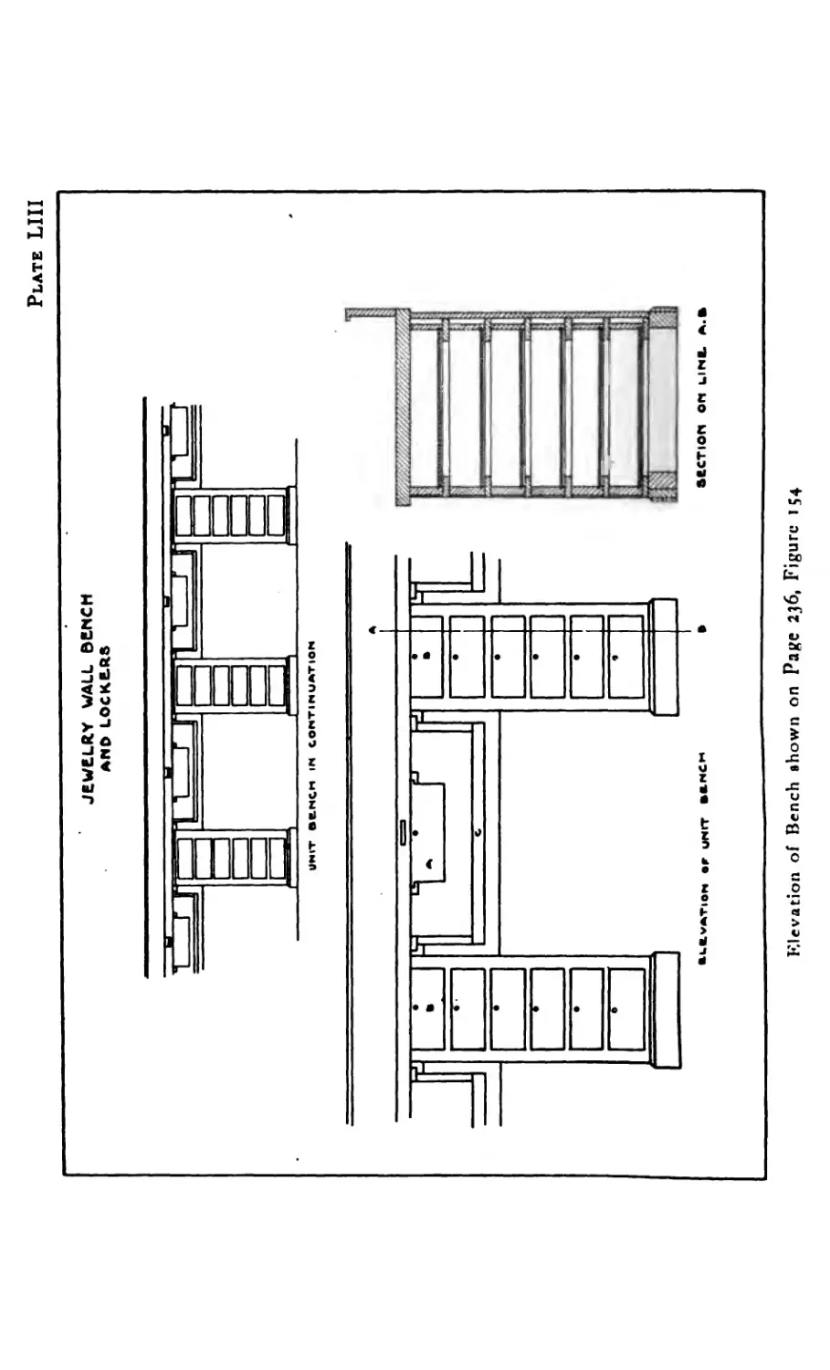
LIII Bench for Jewelry Making .
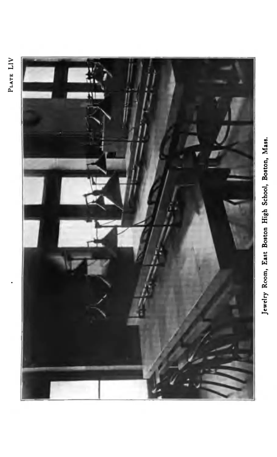
LIV Jewelry Room (East Boston High School)
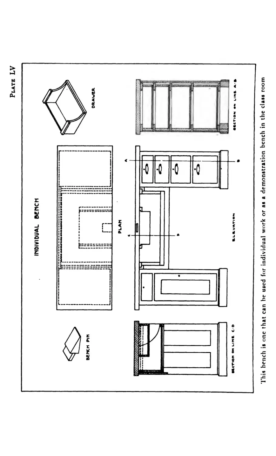
LV Demonstration Bench
*7'
«7-
177
180
184
187
191
200
207
21 I
213
238
24O
244
245
246
FIGURE
I Stone Slitting ....
2 Faceting .....
3 Roughing out the stone
4 Cutting stone to size . .
5 Polishing stone ....
6 Rough and polished stone .
7 Gold bars ....
8 California miners panning gold .
9 Shaft mining (early method)
io Pierced brooches without stones .
ii Placing the saw through work
12 Fastening end of saw in frame
13 Method of holding w’ork while sawing
14 Method of holding work while sawing
15 Method of holding work while sawing
16 Filing .....
17 Brooches with stones
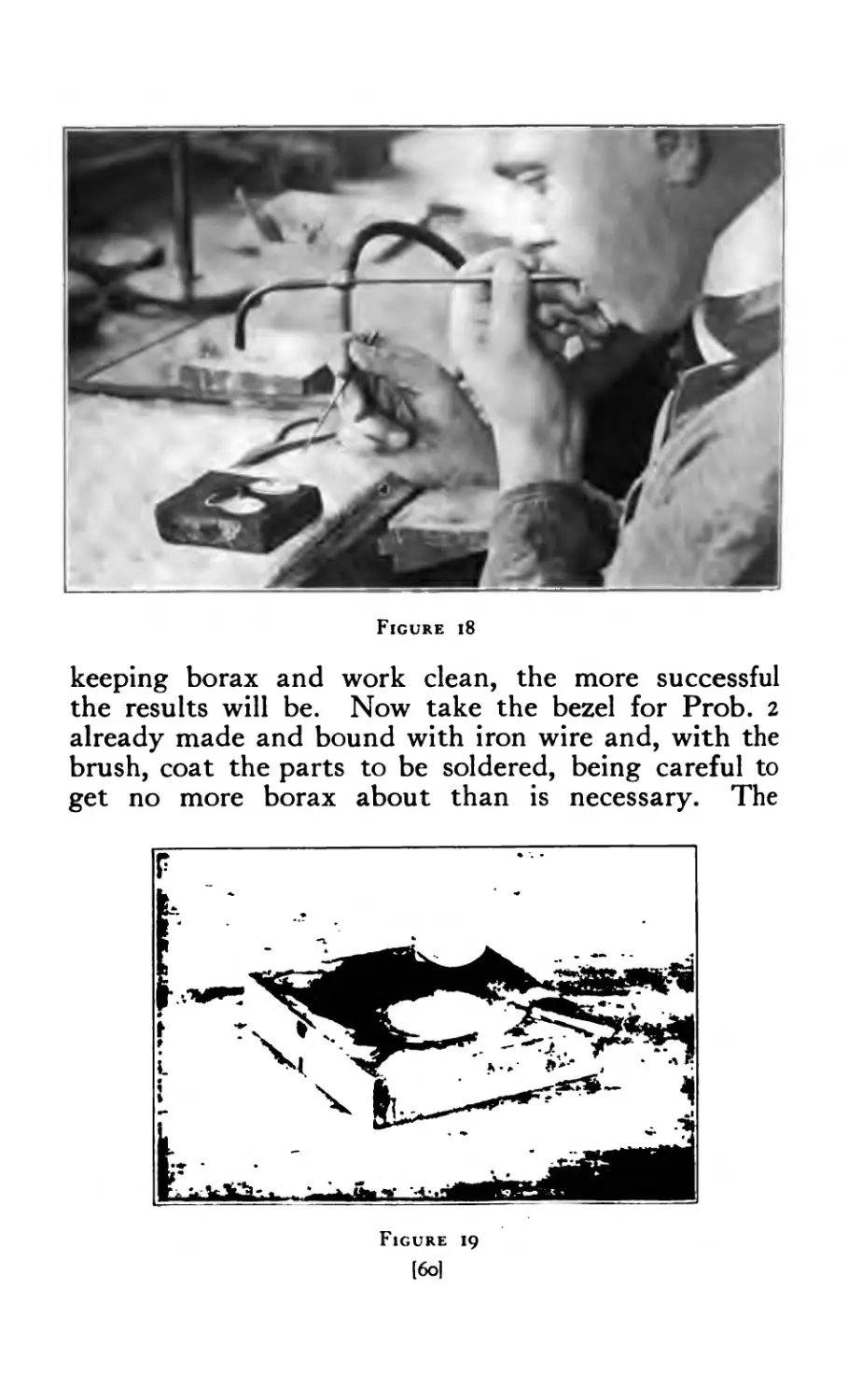
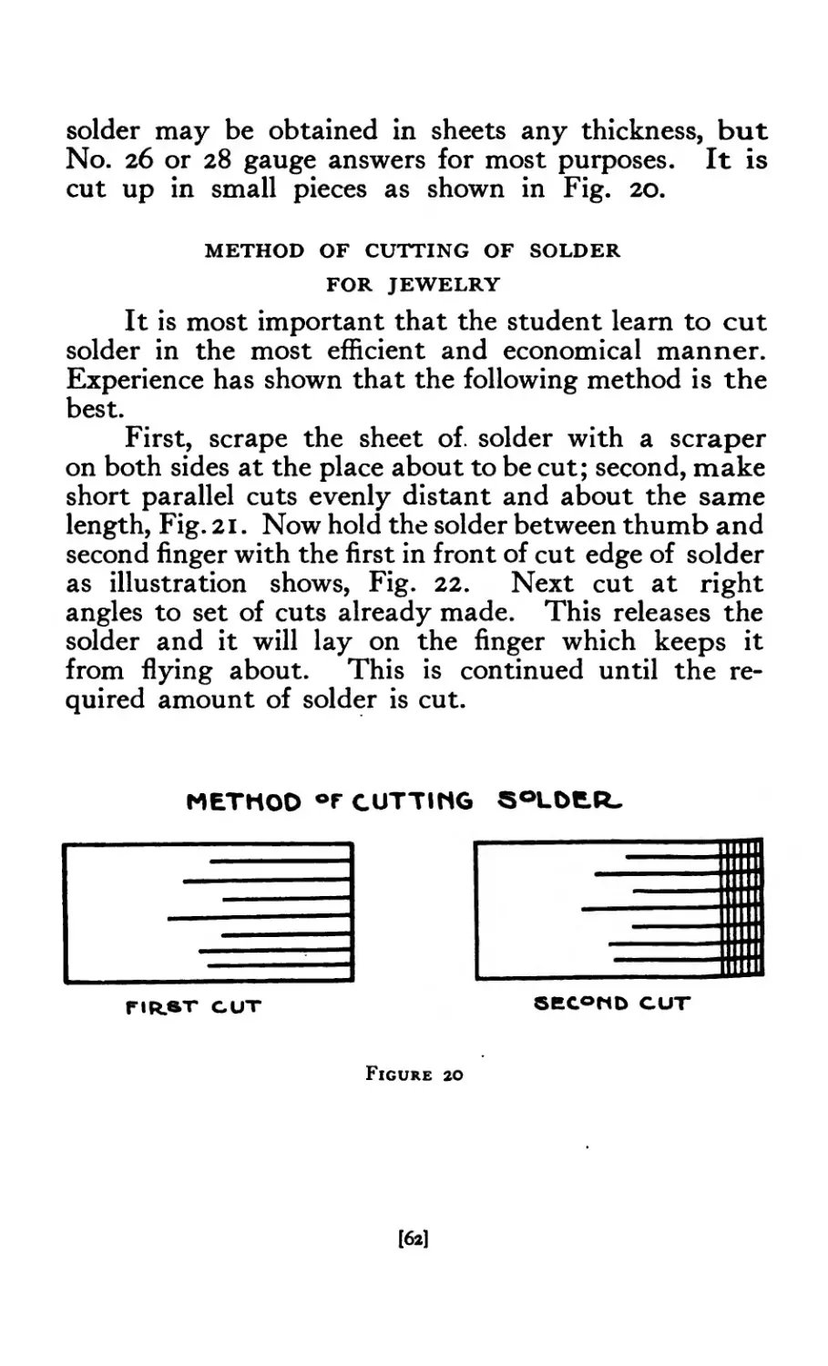
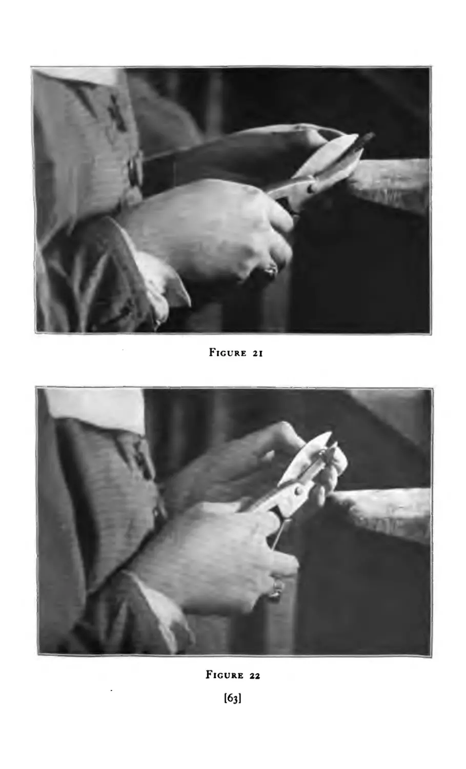
18 Soldering .....
PAGE
24
24
26
26
28
28
34
35
36
49
52
53
53
55
55
55
59
60
[vi]
PAGE
6o
62
cut) ....... 63
1 cut) ...... 63
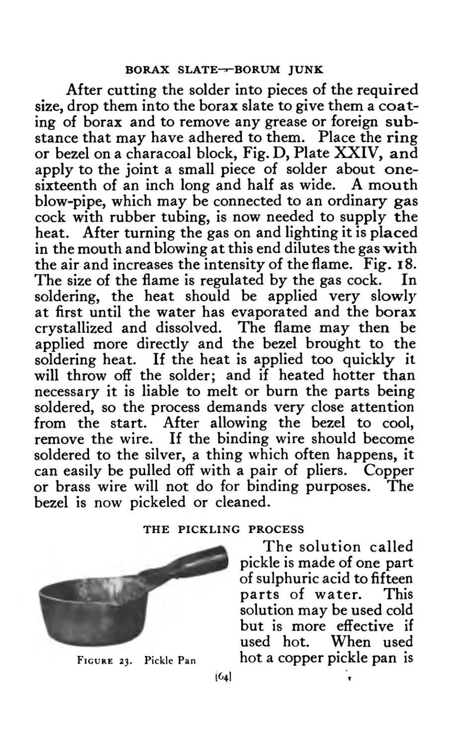
................64
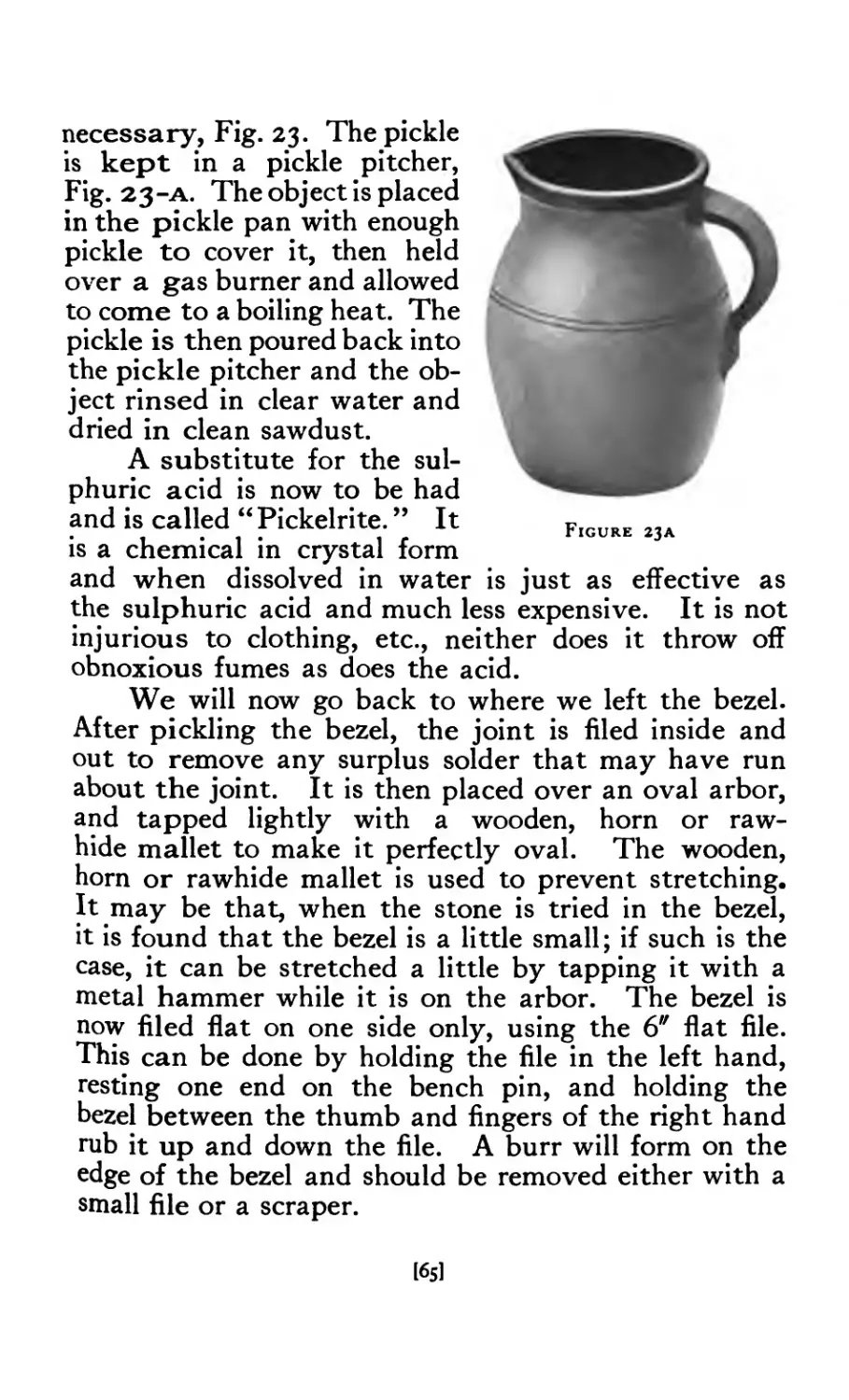
..................................6s
. lead block ....... 67
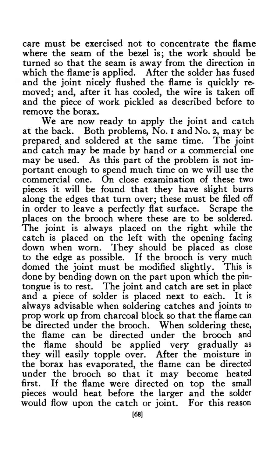
2.4 a ig tools ........ 69
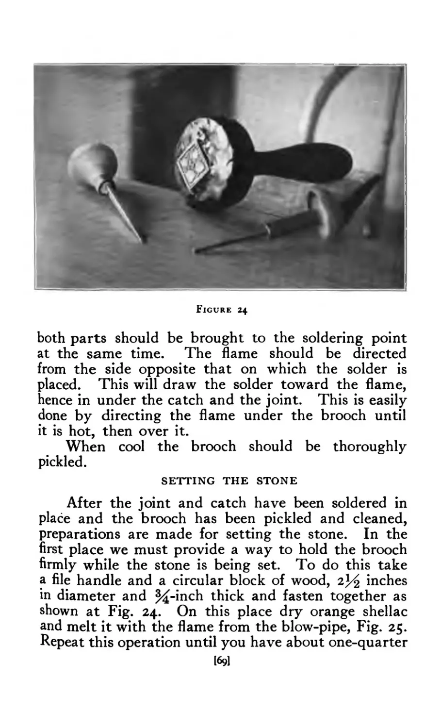
25 Shen*........... 70
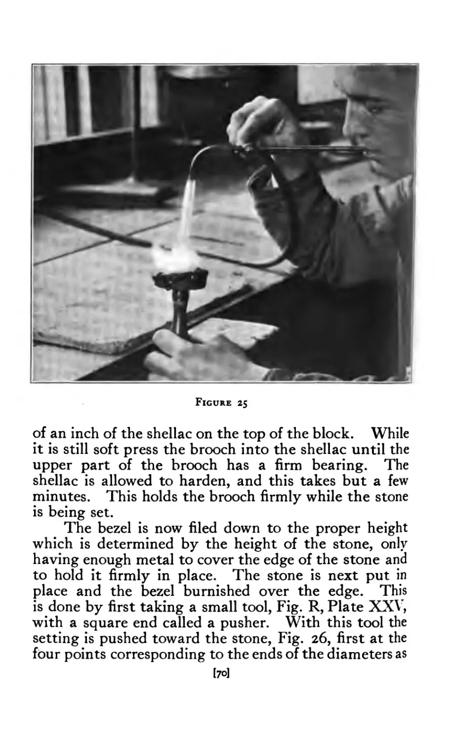
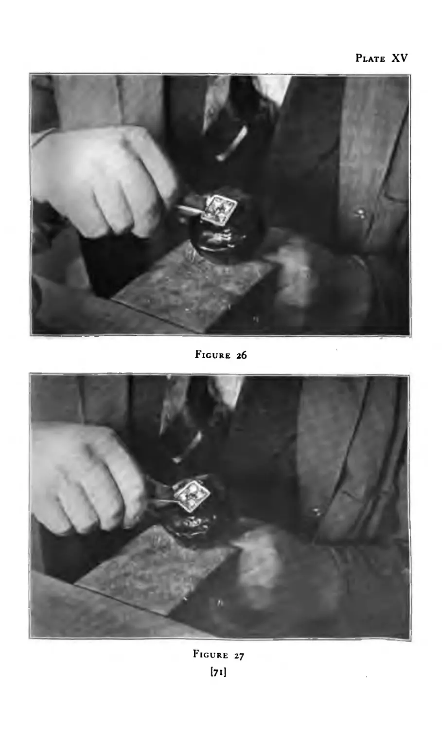
26 Setting the stone .... .... 71
27 T timing bezel. .... .... 71
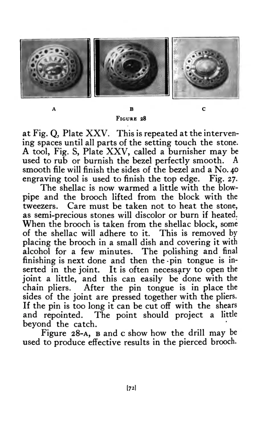
28 Drilled Brooches ........ 72
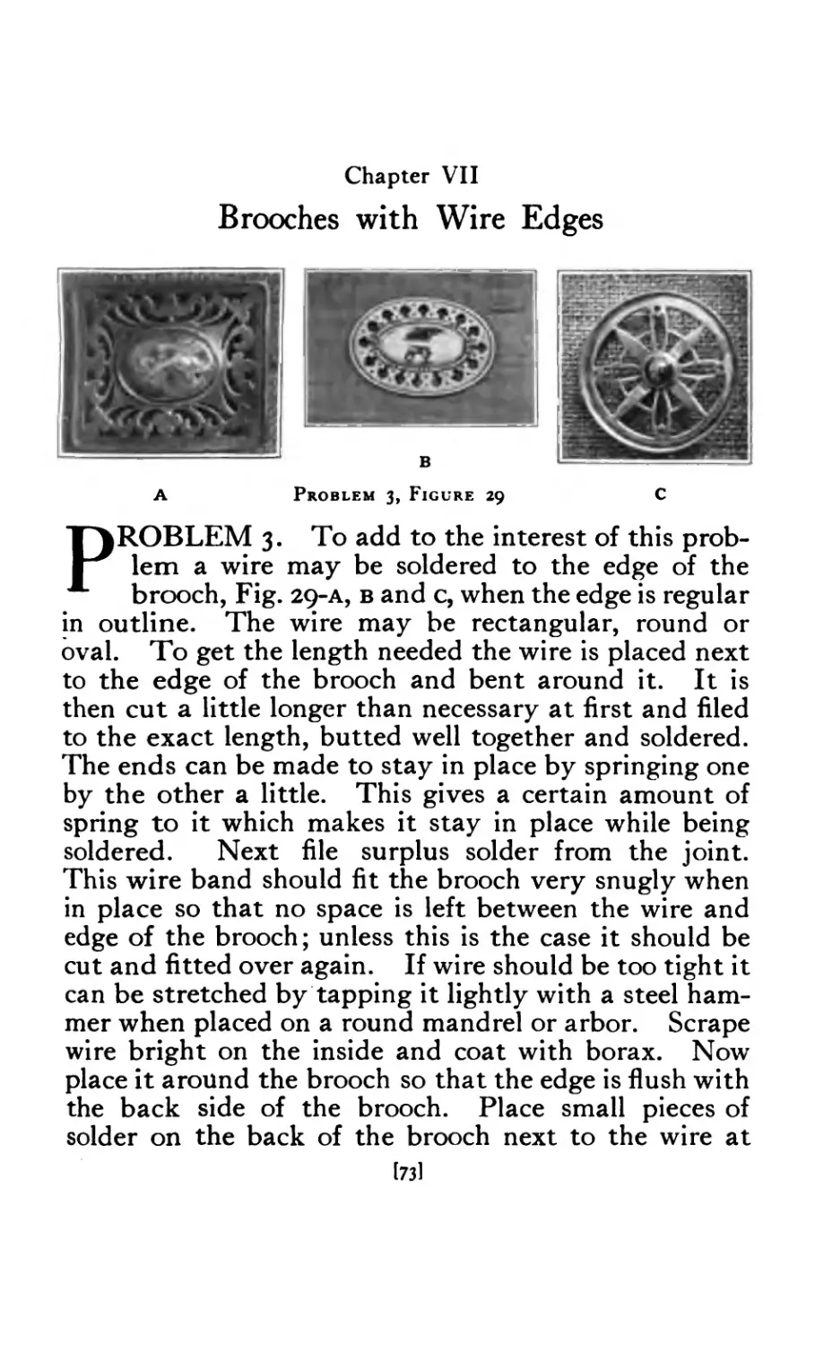
29 Brooches with wire edges ....... 73
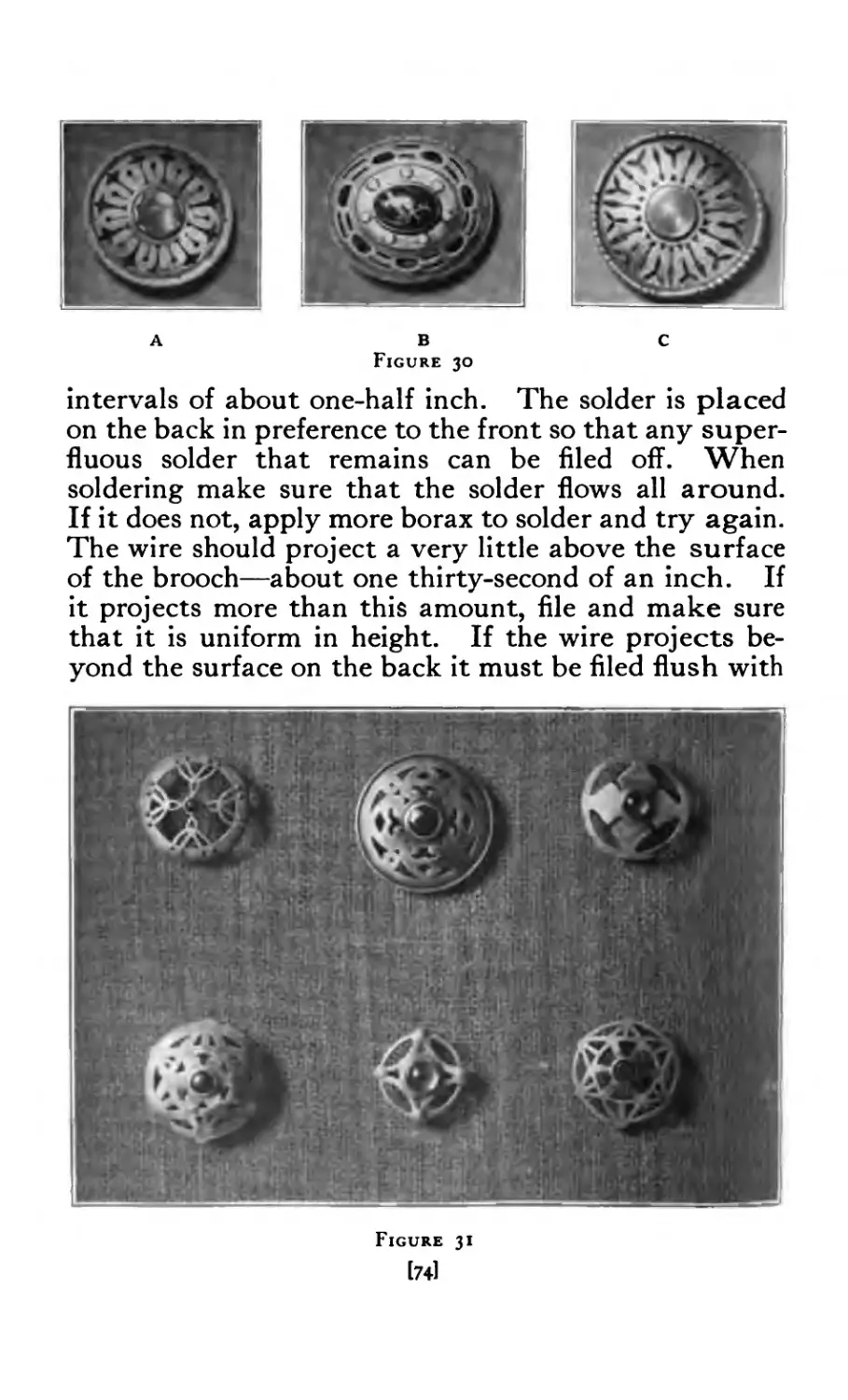
30 Brooches with wire edges ....... 74
31 Pierced Brooches ........ 74
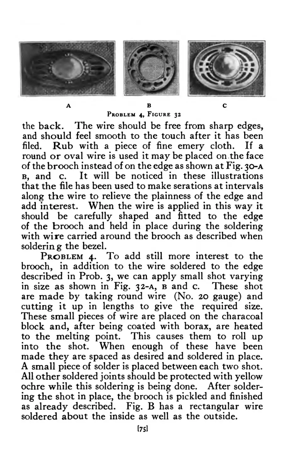
32 Brooches with shot ........ 75
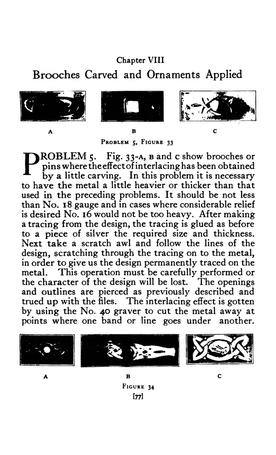
33 Carved Brooches .... .... 77
34 Carved Brooches ........ 77
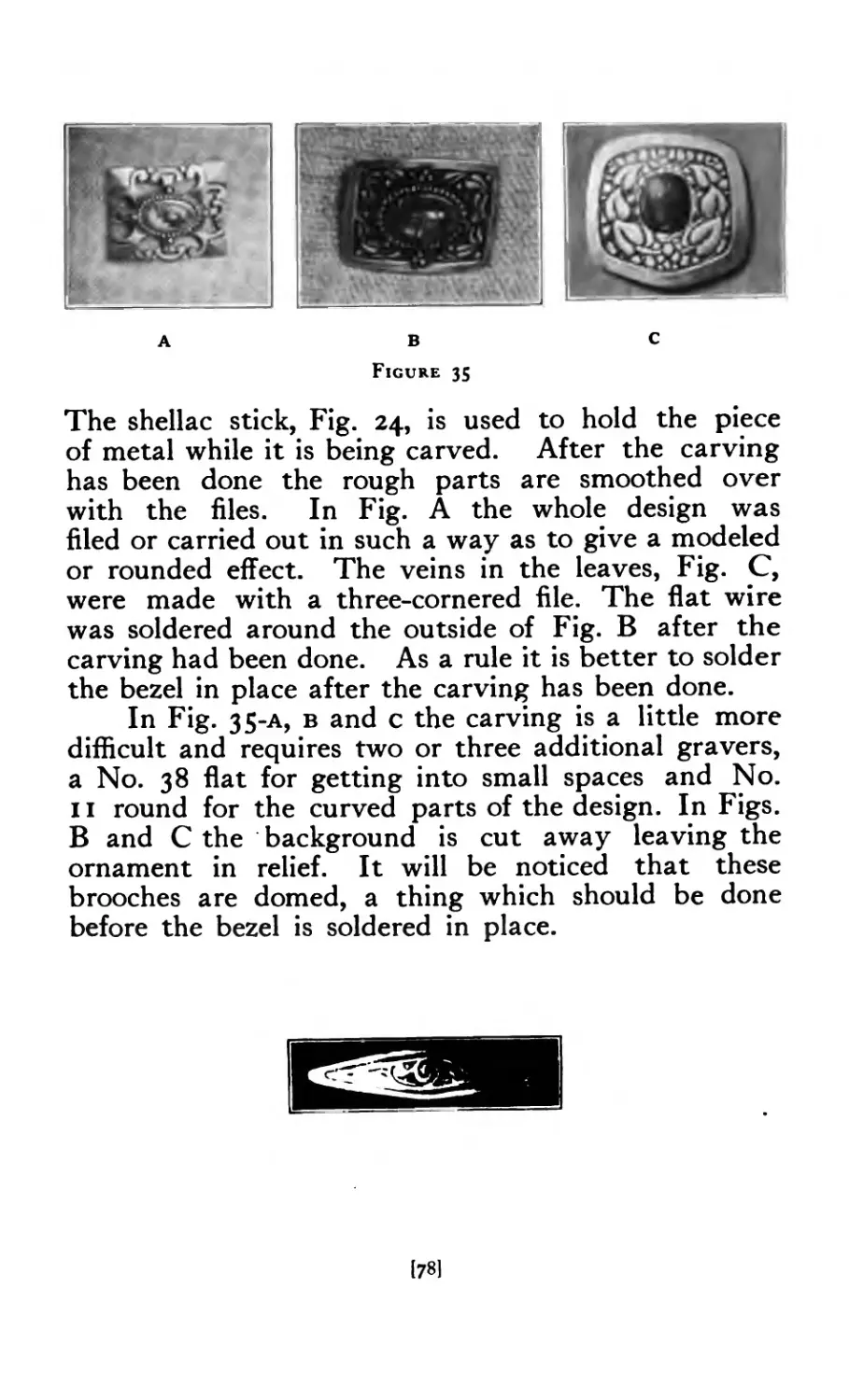
35 Carved Brooches ........ 78
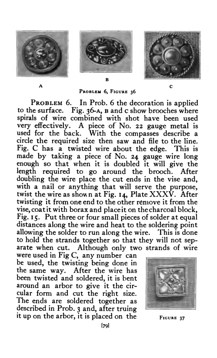
36 Brooches with applied decoration ..... 79
37 Square Brooch set with moonstones ..... 79
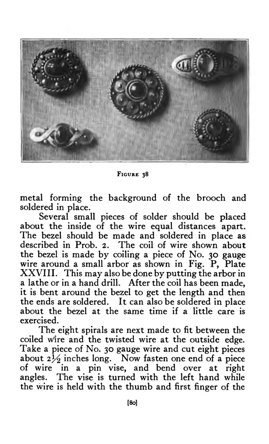
38 Brooches .......... 80
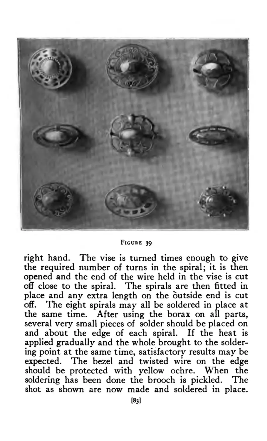
39 Brooches (miscellaneous) ....... 83
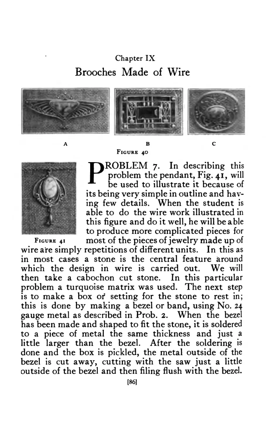
40 Wire Brooches ......... 68
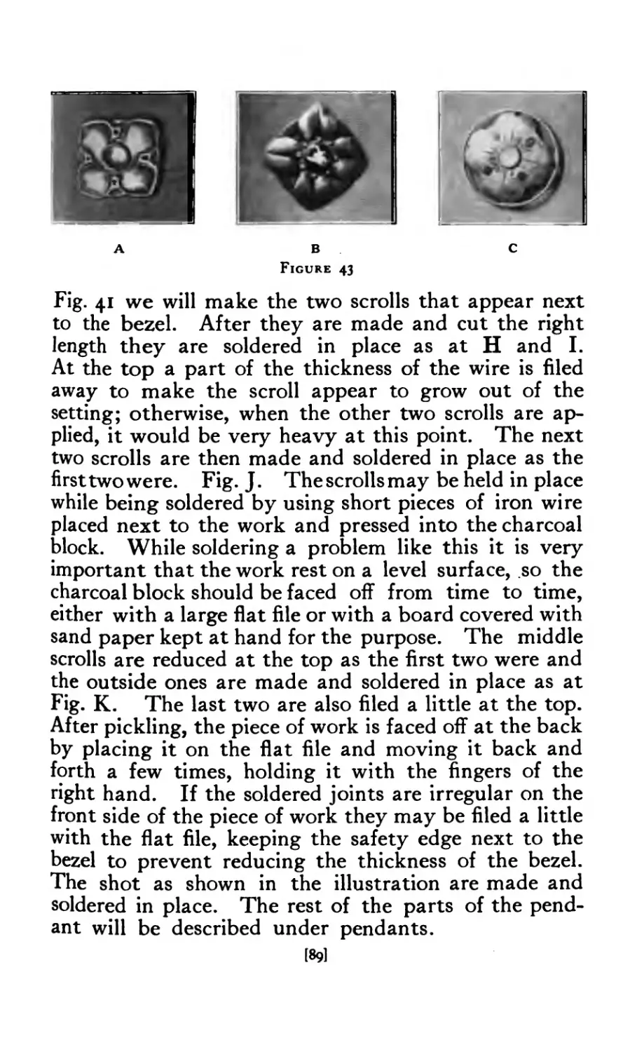
41 Wire Pendant ......... 86
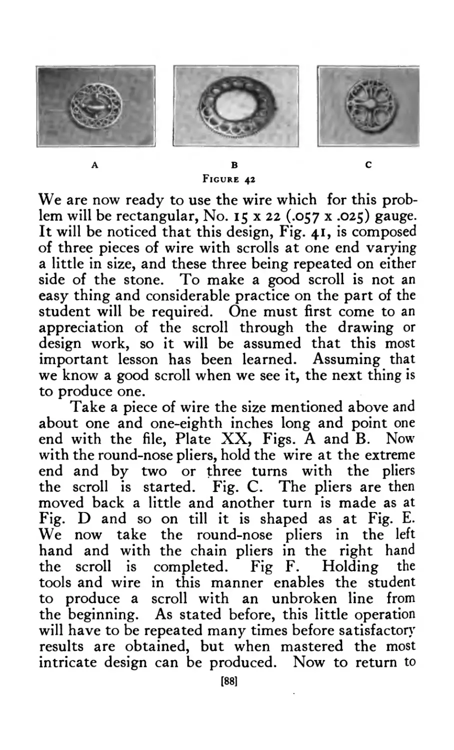
42 Wire Brooches ......... 88
43 Brooches in repouss4 ........ 89
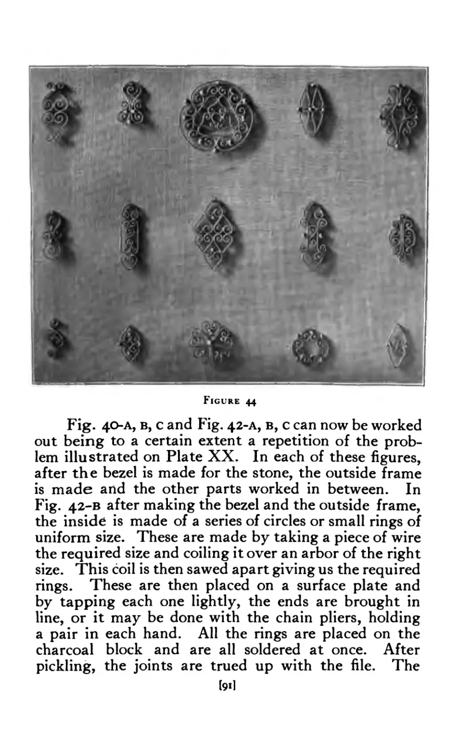
44 Problems in wire bending ....... 91
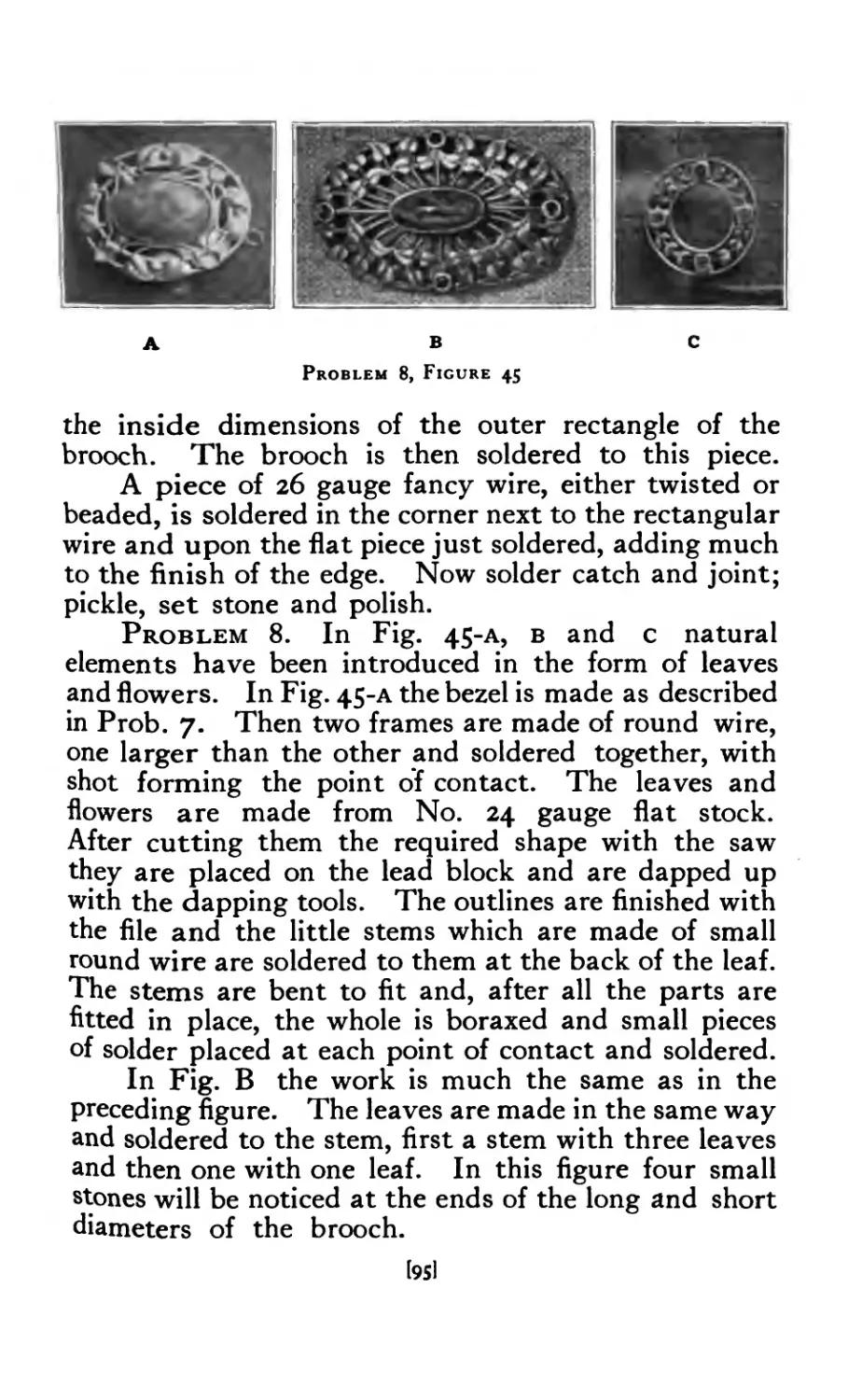
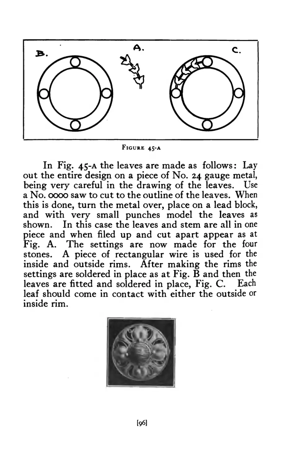
45 Brooches made up of natural elements .... 95
45-A Layout of design for circular brooch . . . 96
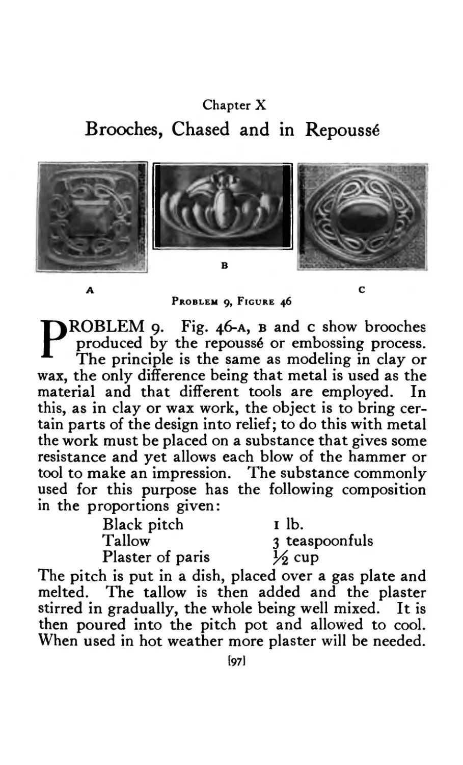
46 Brooches chased and in repouss4 ..... 97
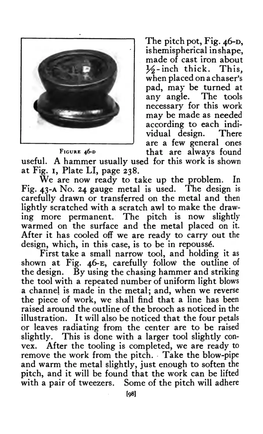
46-D Pitch Pot ......... 98
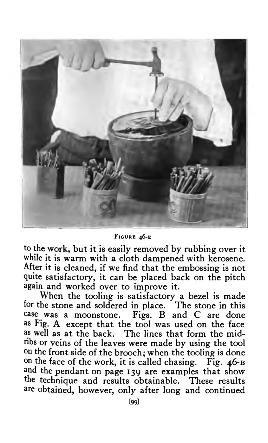
46-E Chasing .......... 99
47 Chased Brooches . . . 100
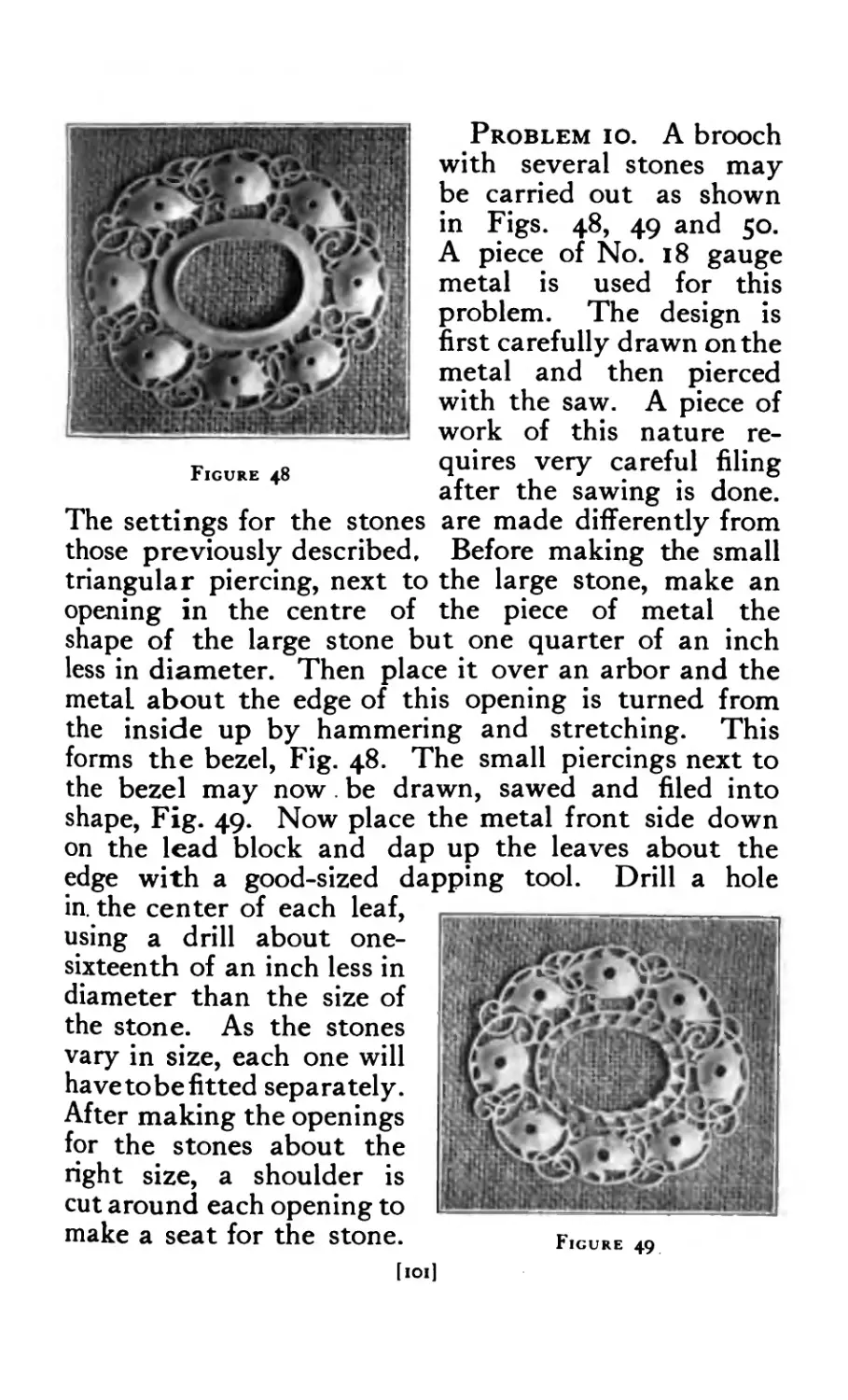
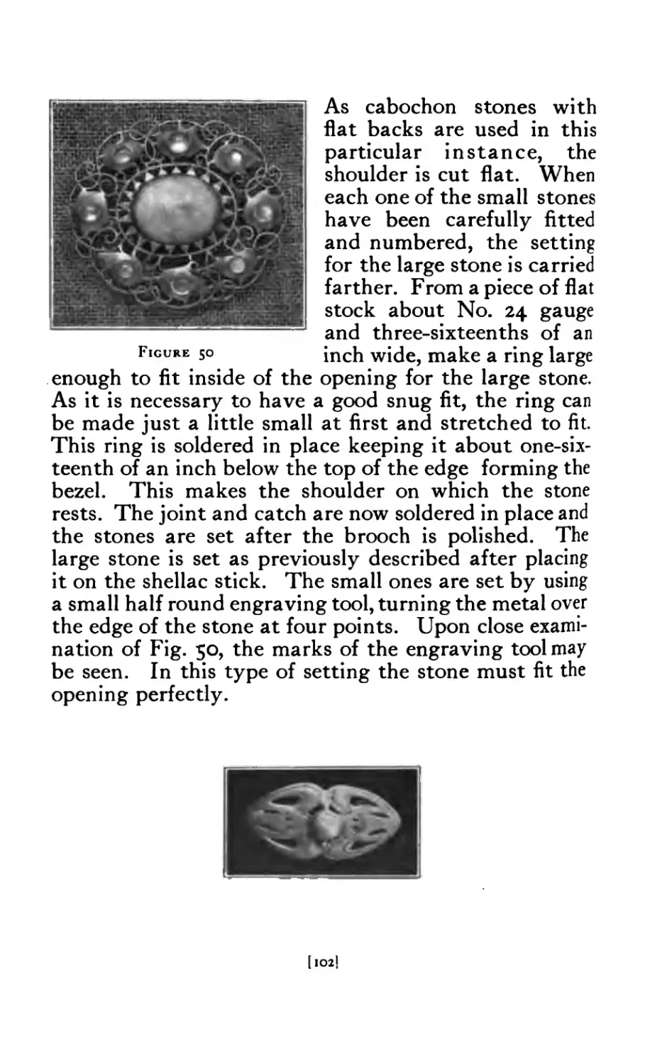
48 Pierced Brooch with stones . . . 101
49 Pierced Brooch with stones . . . . 101
50 Pierced Brooch with stones set . . . 102
51 Hat Pin (pierced) ........ 103
52 Hat Pin (chased) . . . . . . . 107
53 Model for chased hat pin ....... 107
54 Hat Pin Head on pitch block . 108
55 Scarf Pin .......... 109
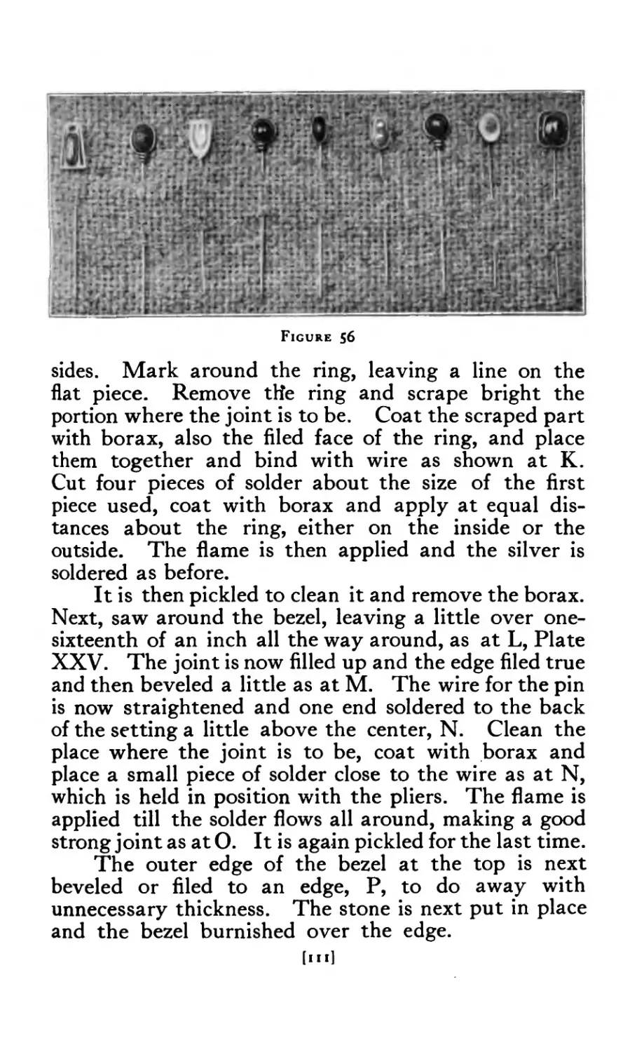
56 Scarf Pins (miscellaneous) . • 111
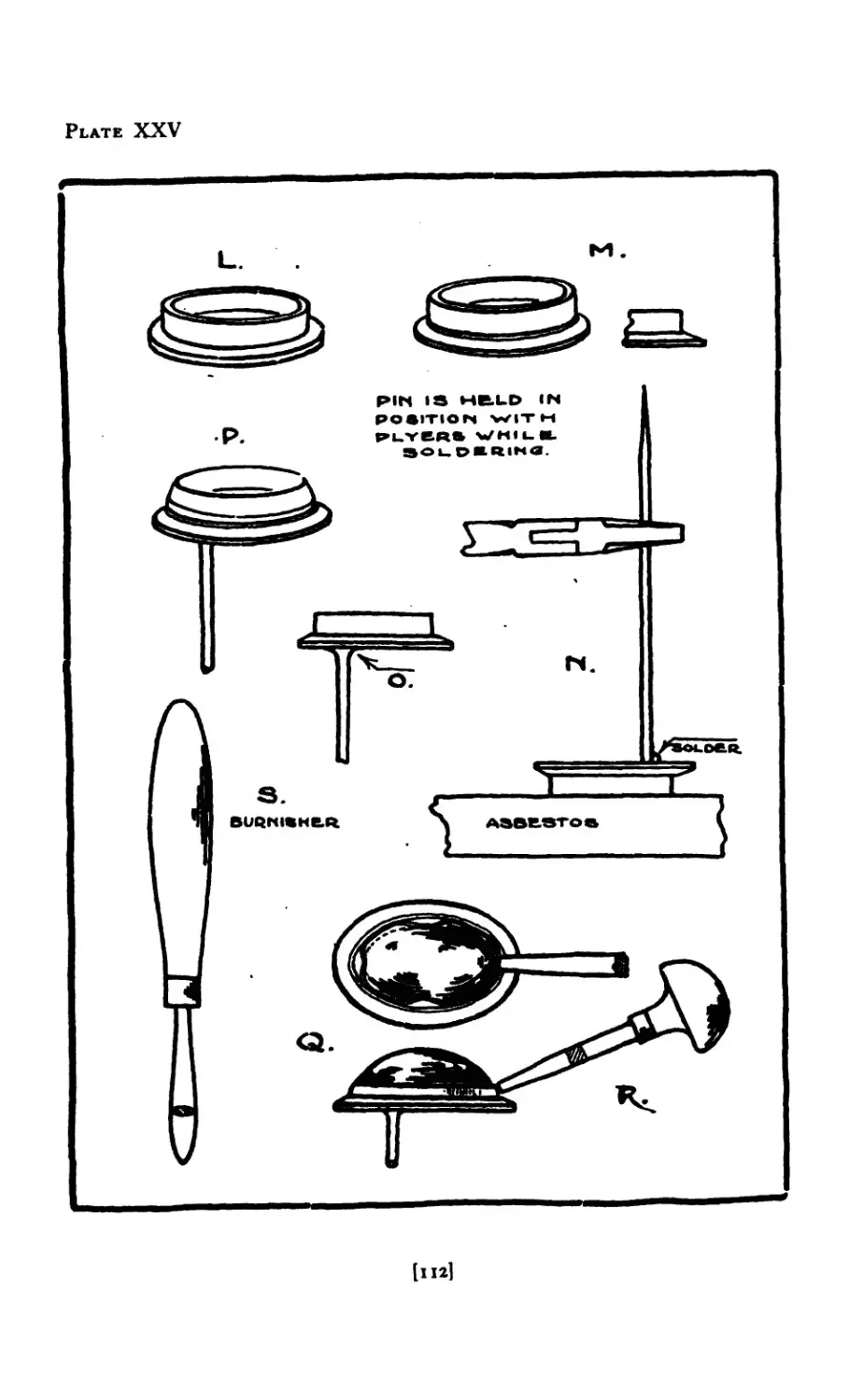
58 Scarf Pin set with scarab . . • 113
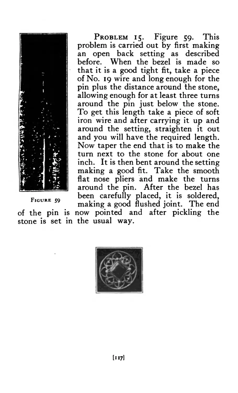
59 Scarf Pin with wire setting . . . • 117
[vii]
FIGURE
PAGE
6о
6i
62
63
64
65
66
67
68
69
70
7i
72
73
74
75
76
77
78
79
80
81
82
83
84
85
86
86-А
87
88
89
90
9i
91-А
92
93
94
95
96
97
98
99
ioo
101
102
Pendant set with pearl . 118
Pendants .......... 122
Wire Pendants . 124
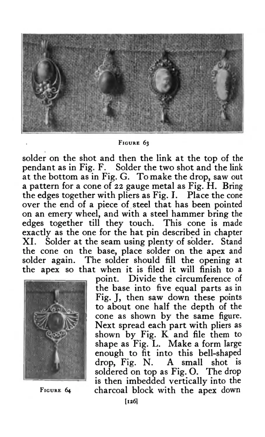
Wire Pendants . . . . . . 126
Wire Pendant . . . . . • . 126
Wire Pendant set with chrysacola . . . . 128
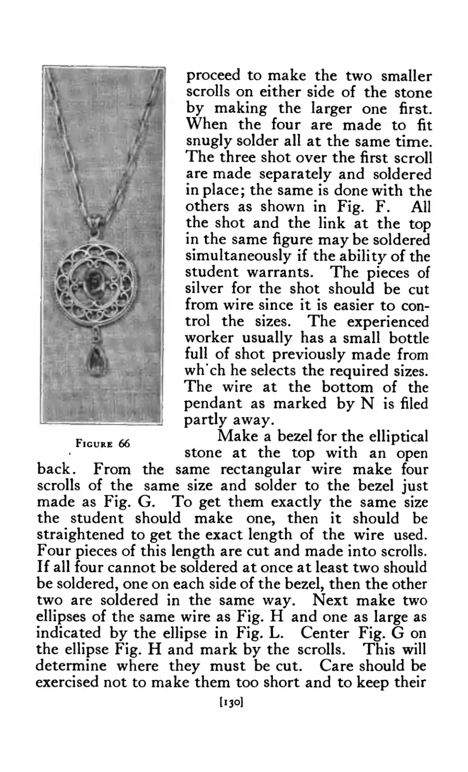
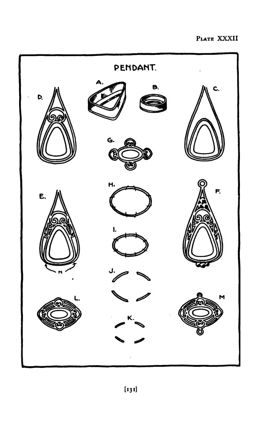
Wire Pendant . . . . . . 130
Wire Pendant set with garnets and pearls . . . 132
Pendant set with pearl blister . . . . . 132
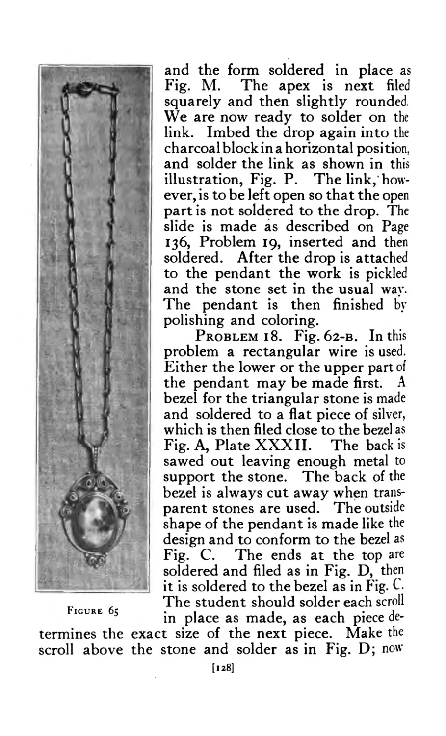
Wire Pendant and chain . . 134
Details of pendant ......... 135
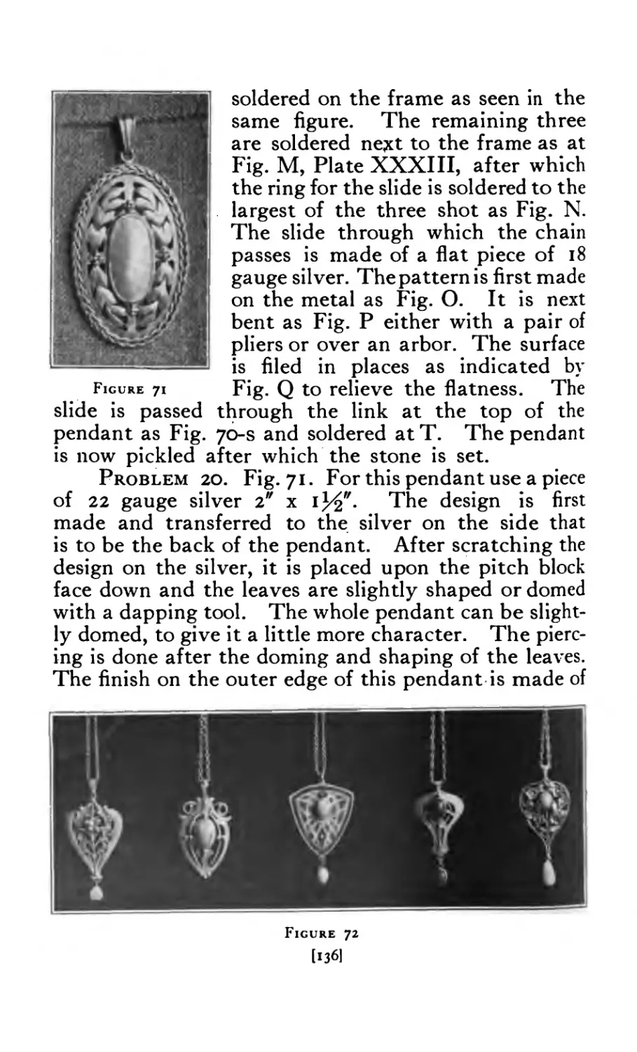
Pendant with leaves and twisted wire . . . . . 136
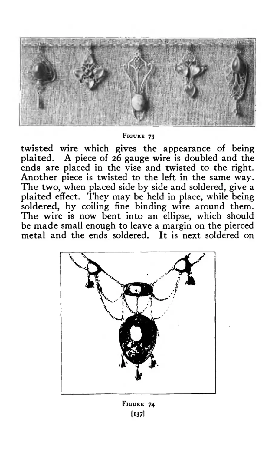
Pendants (miscellaneous) . . . . 136
Pendants (miscellaneous) ....... 137
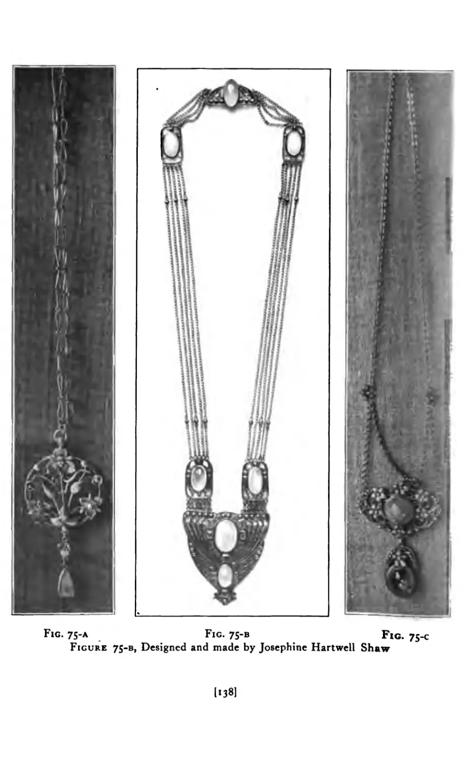
Wire Pendant with bell drops . . . . . 137
Pendants (miscellaneous) . . . . . 138
Pendant and chain units chased . . . . . . 139
Pendant on pitch . . . . . . . 139
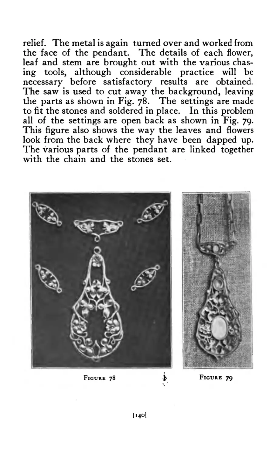
Pendant and units sawed to outline ..... 140
Back of pendant . . . . 140
Pierced finger ring . . . - . 142
Pierced rings . . . . . . . 144
Rings (miscellaneous) ....... 146
Wire Ring . . . 147
Wire Ring with leaves and shot ...... 149
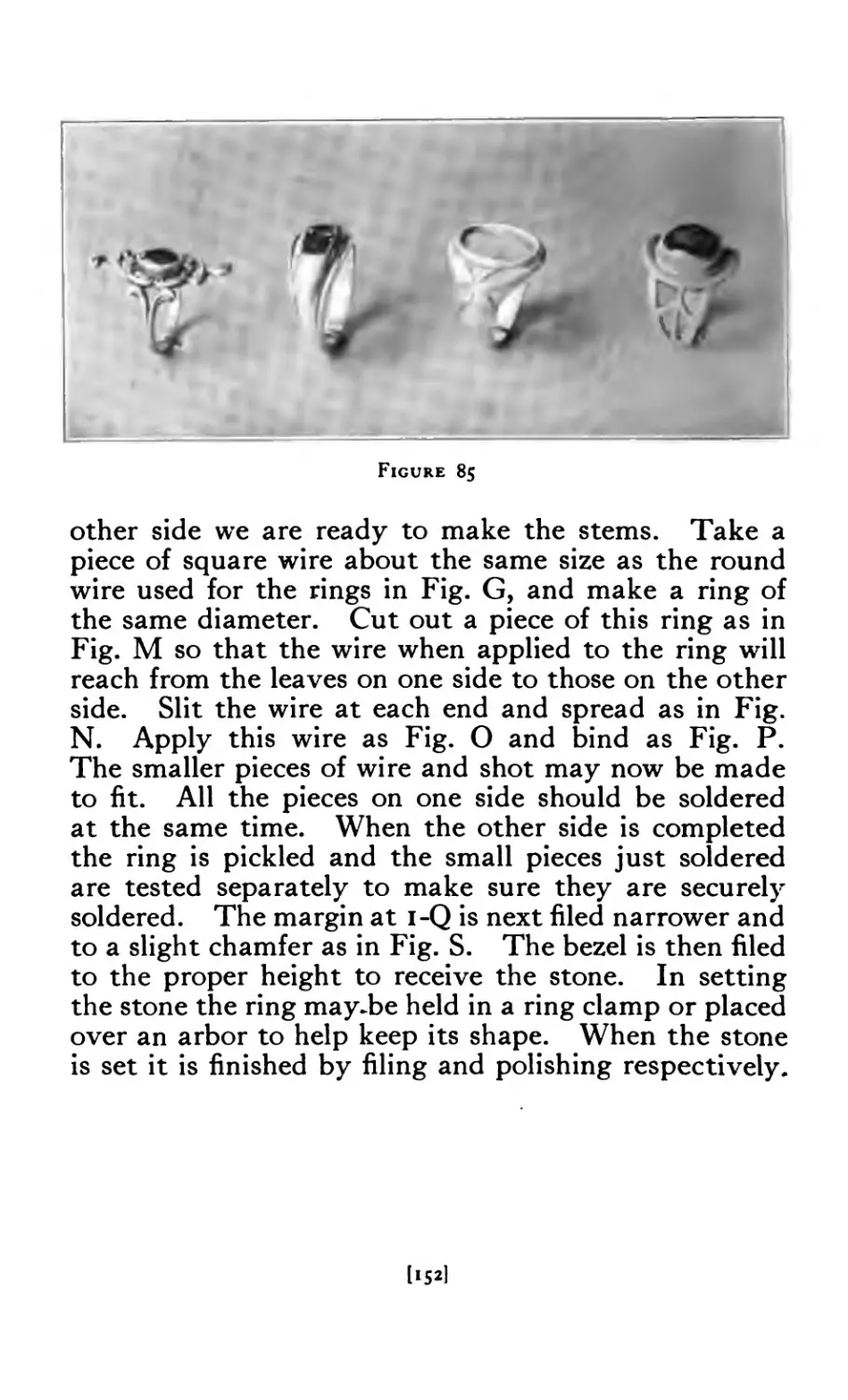
Rings (miscellaneous) . . . . . . 152
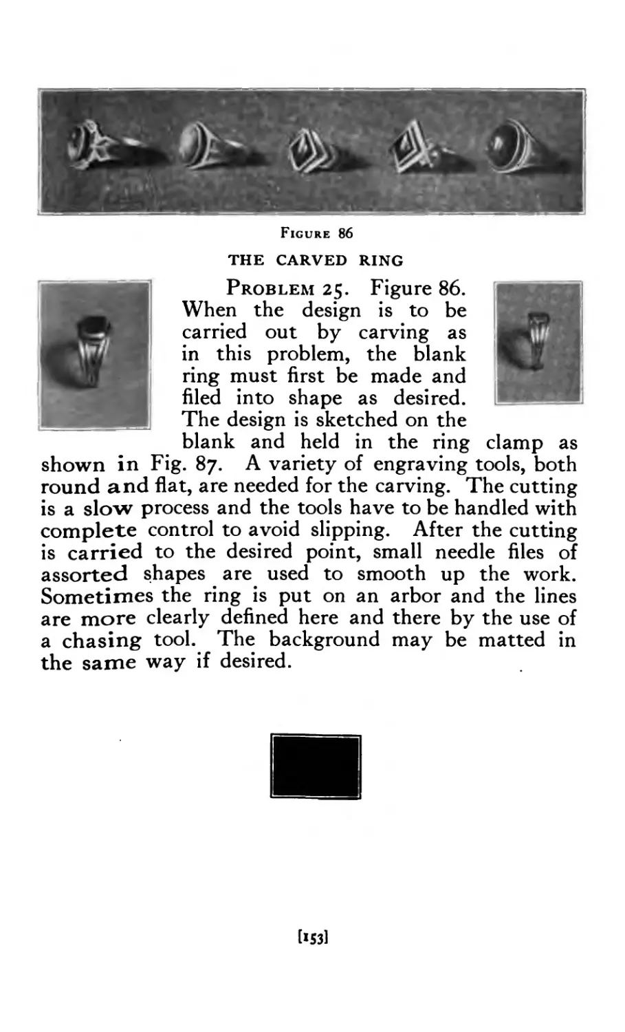
Carved Rings . . . . . . 153
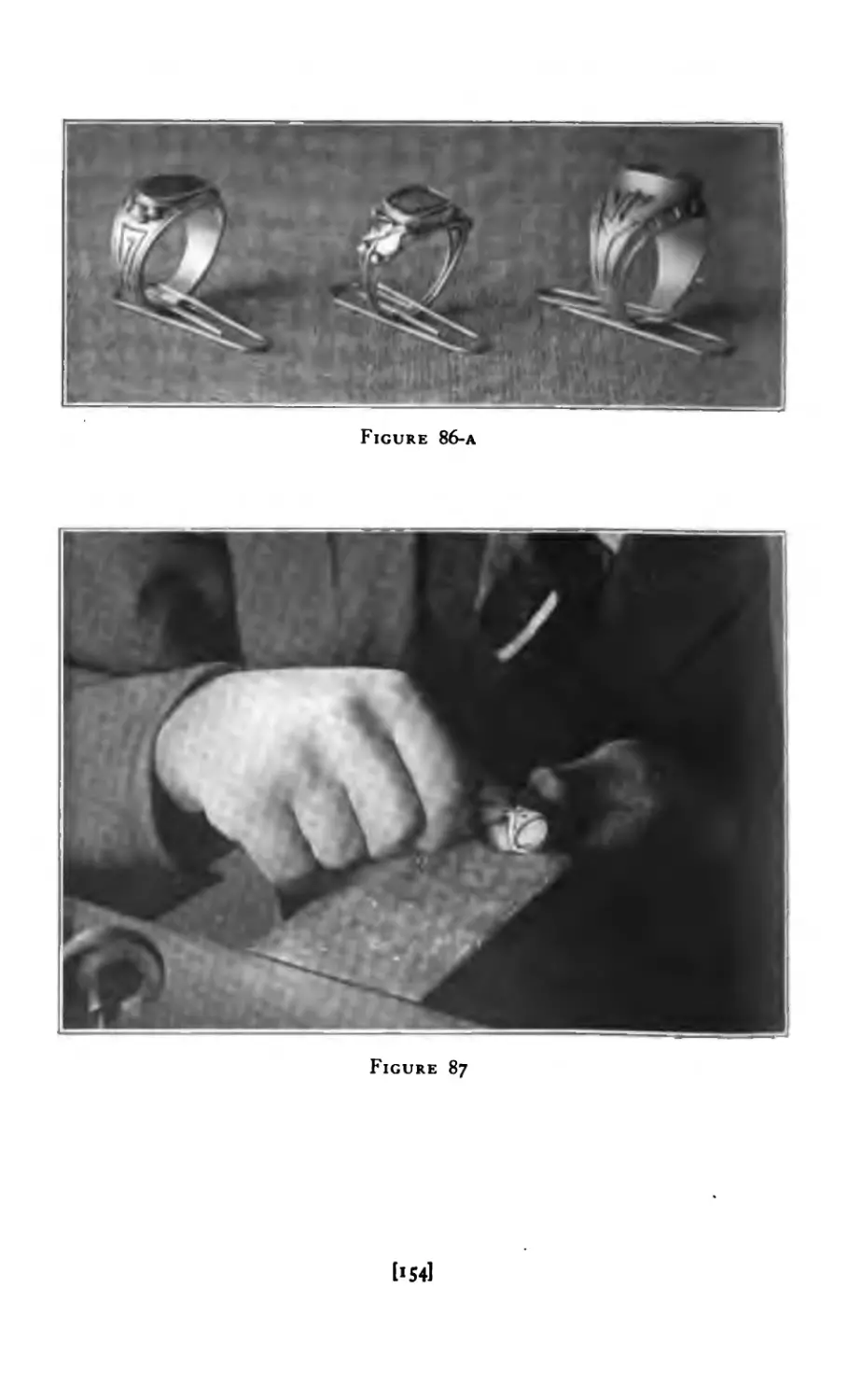
Rings (miscellaneous) ....... 154
Carving Ring . . . . . . . . . 154
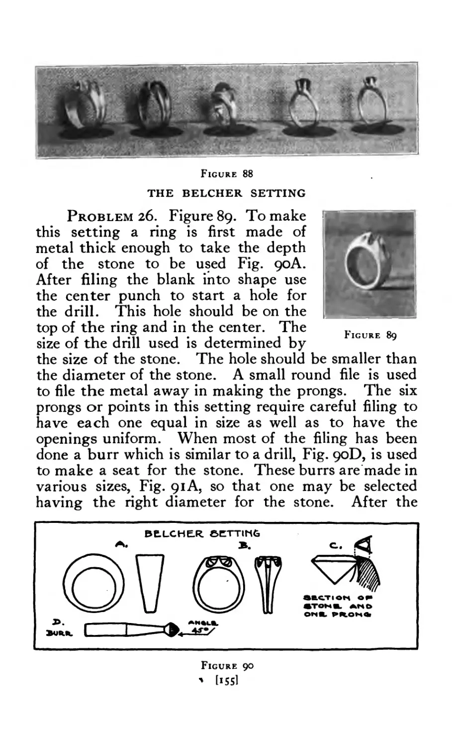
Rings (miscellaneous) ....... 155
Belcher Ring . . . . . . 153
Belcher Setting (details) ....... 155
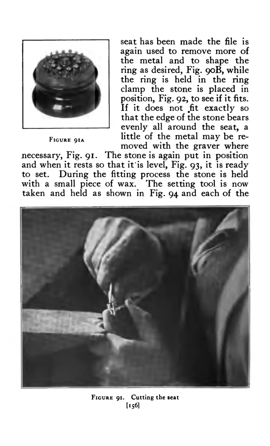
Belcher Setting (cutting seat) . . . . . . 156
Ring burrs ......... 156
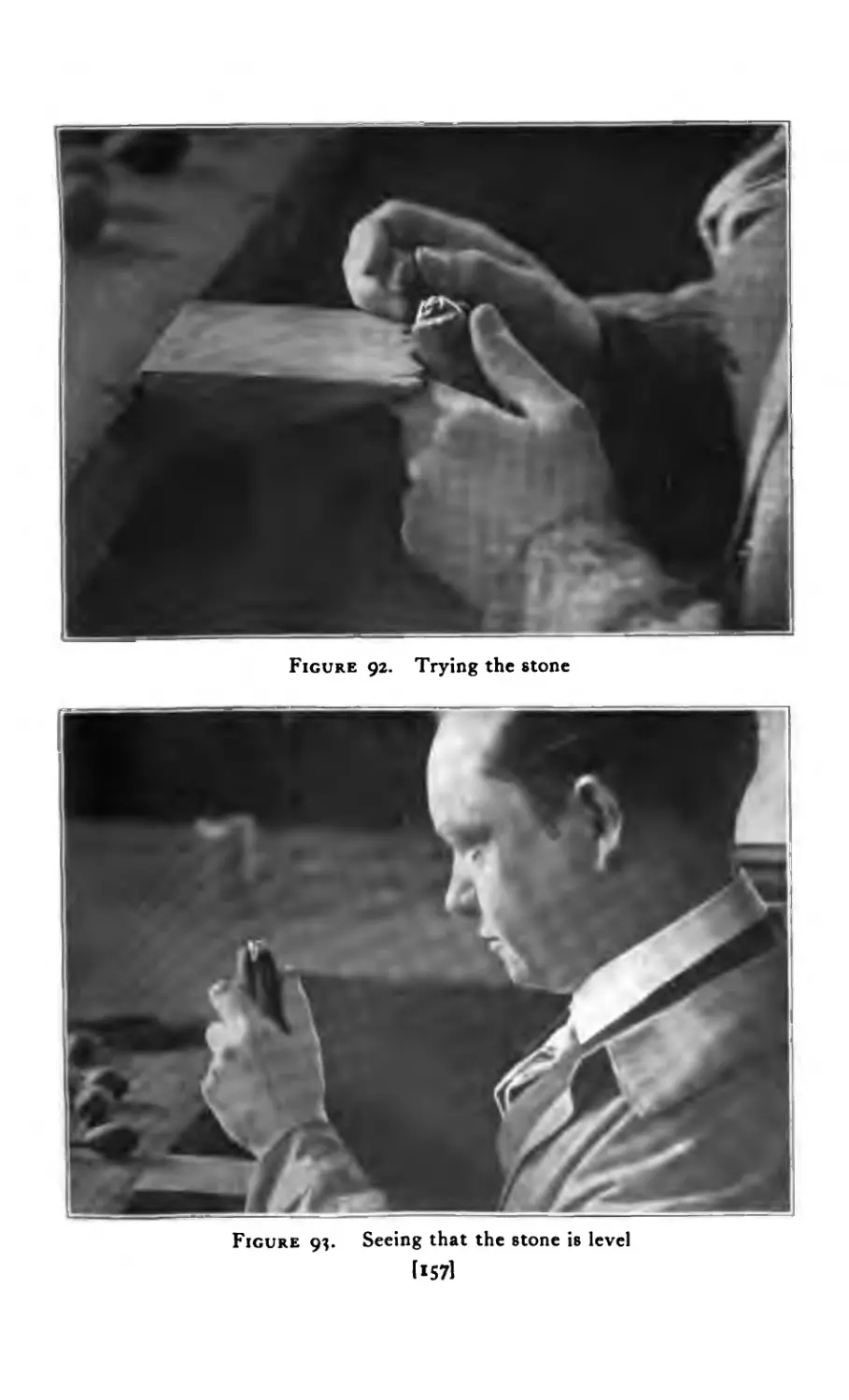
Belcher Setting (trying the stone) . . . . 157
” ” (leveling the stone) . . . 157
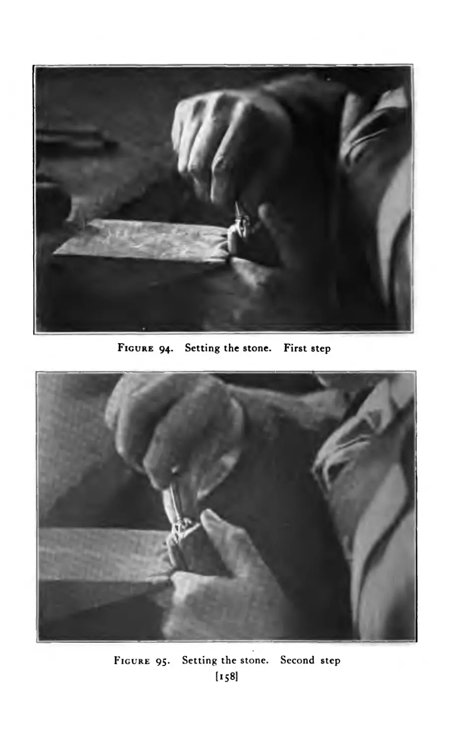
* ’ (setting the stone, first step) . . . 158
” ” (setting the stone, second step) . . . 158
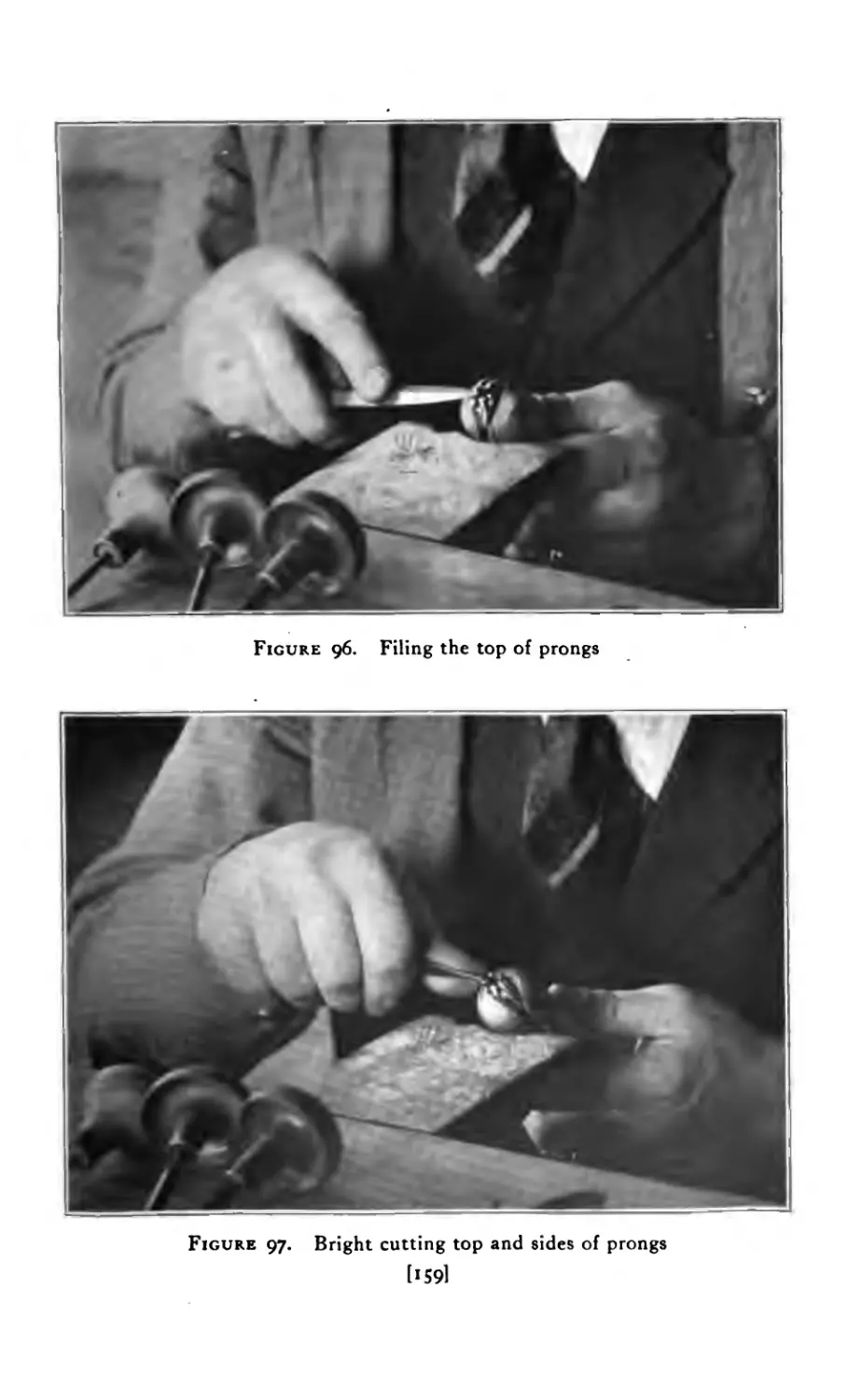
” (filing the prongs) ..... 159
” (bright cutting) ...... 159
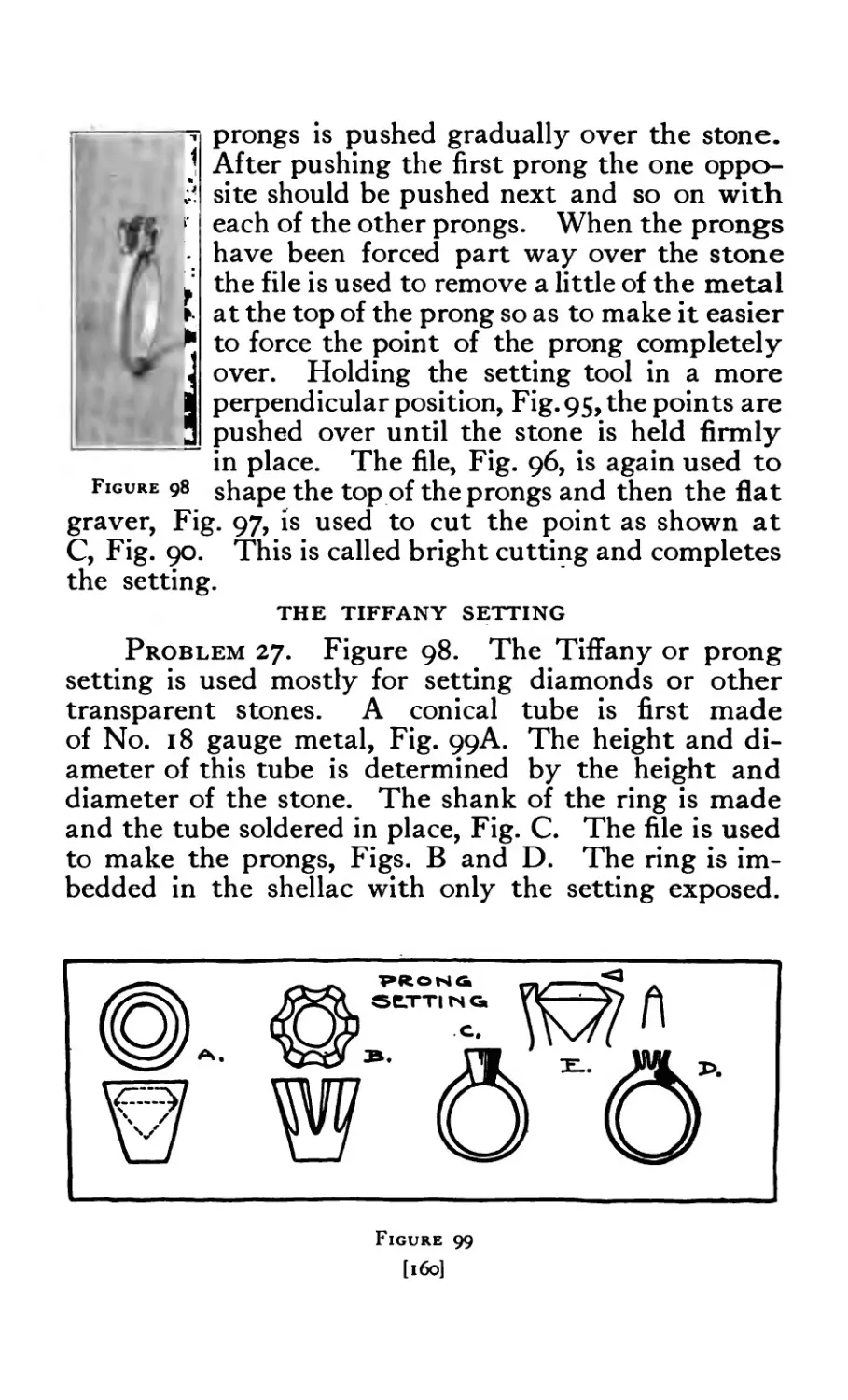
Tiffany Setting . . . . • • . 160
Tiffany Setting (details) . . . . • . . 160
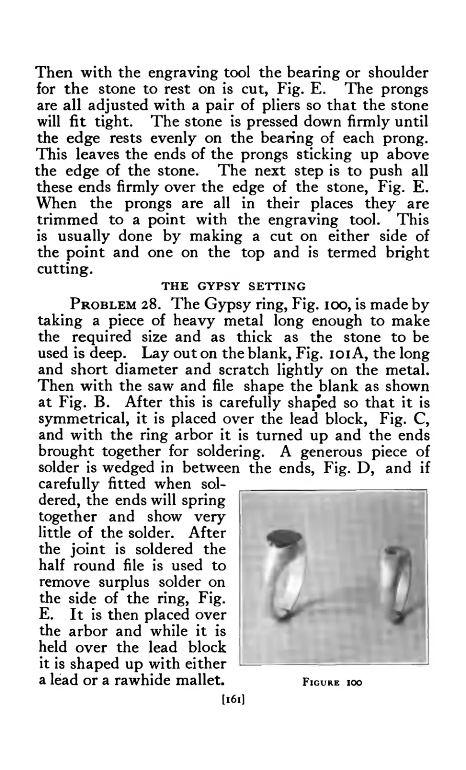
Gypsy Setting . . . . • • • • • 161
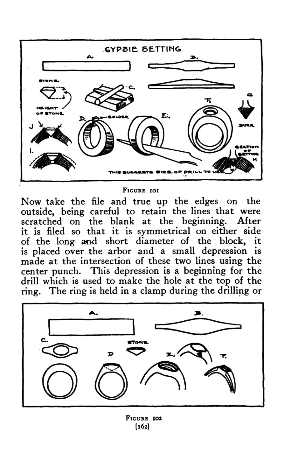
Gypsy Setting (details) ....... 162
Gypsy Setting (details) ....... 162
[viii]
FIGURE PAGE
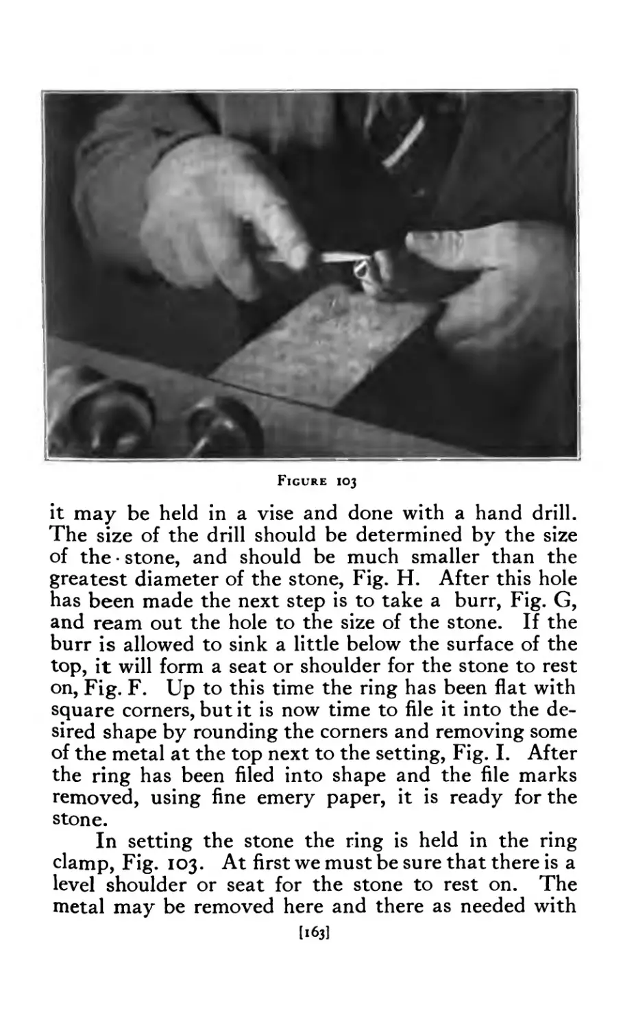
103 Gypsy Setting (finishing top) 163
104 Enameled Cuff Links .... 165
105 Cuff links (details) ..... 166
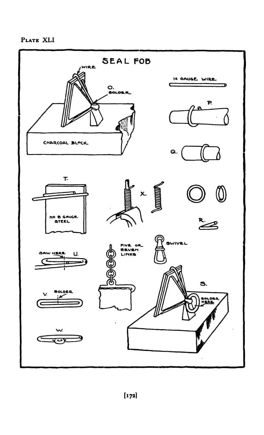
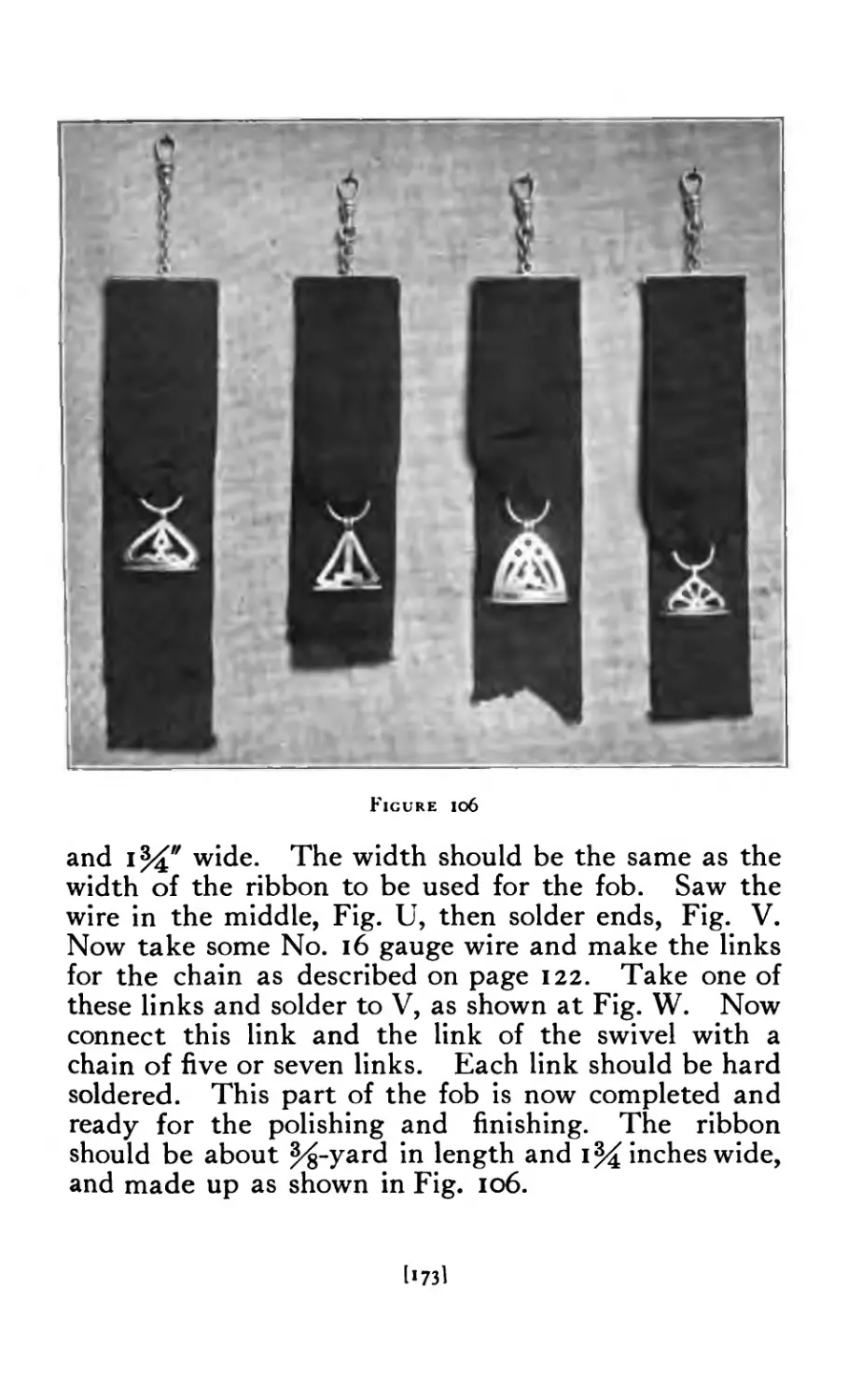
106 Seal Fobs ...... 173
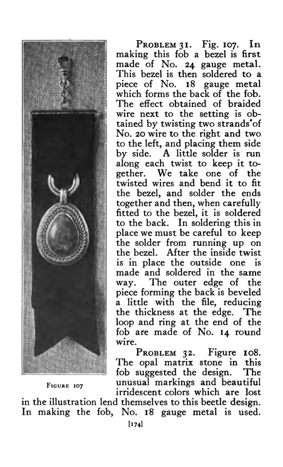
107 Fob set with chrysacola .... 174
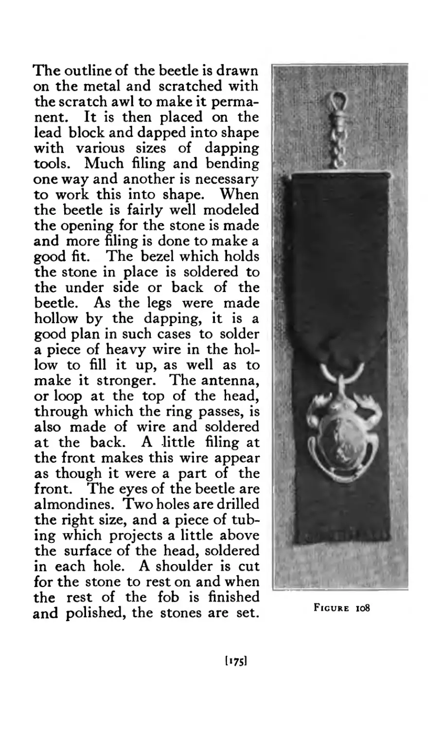
108 Fob (beetle design) ..... 175
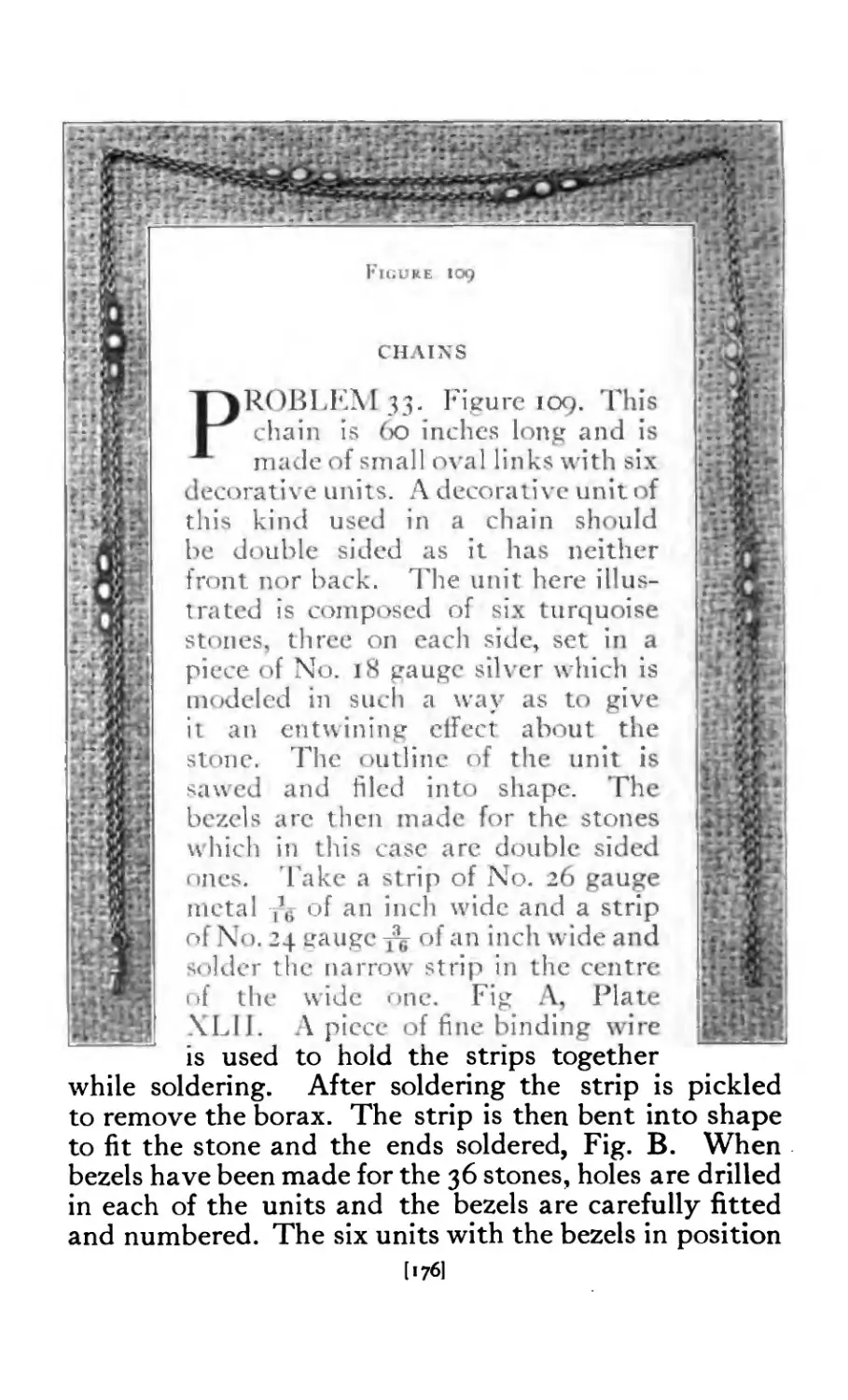
109 Muff chain set with turquoise 176
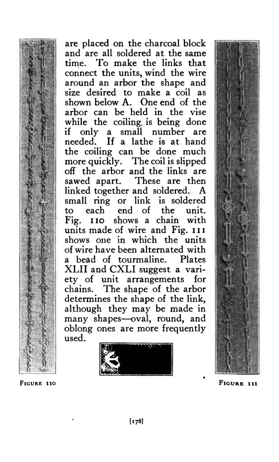
110 Chain made of wire units .... 178
in Chain with moonstone beads and wire units 178
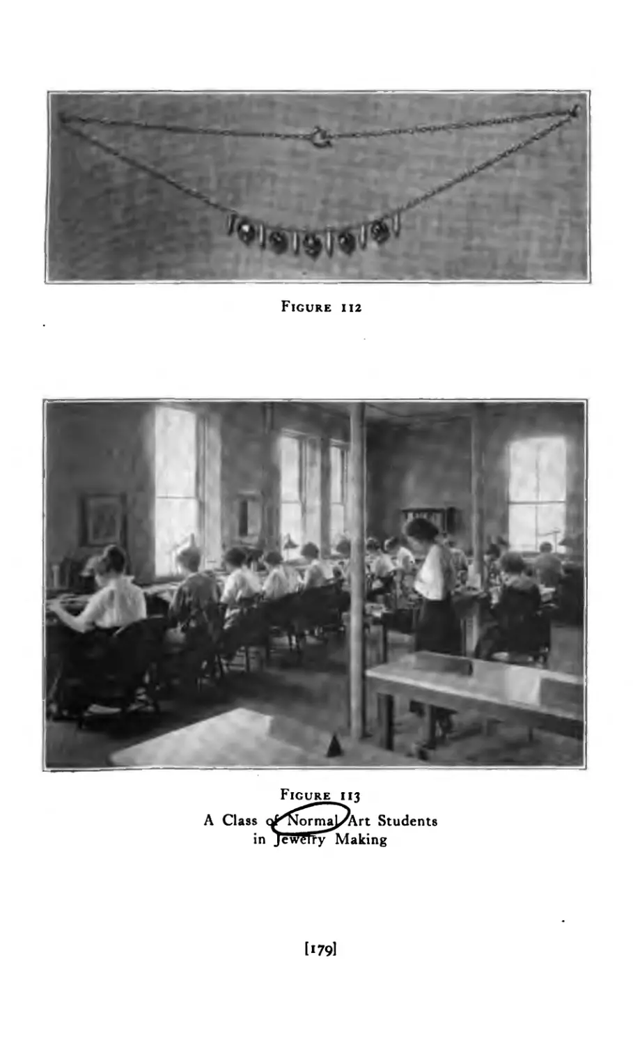
112 Neck chain with garnets .... 179
113 Jewelry making (class) .... 179
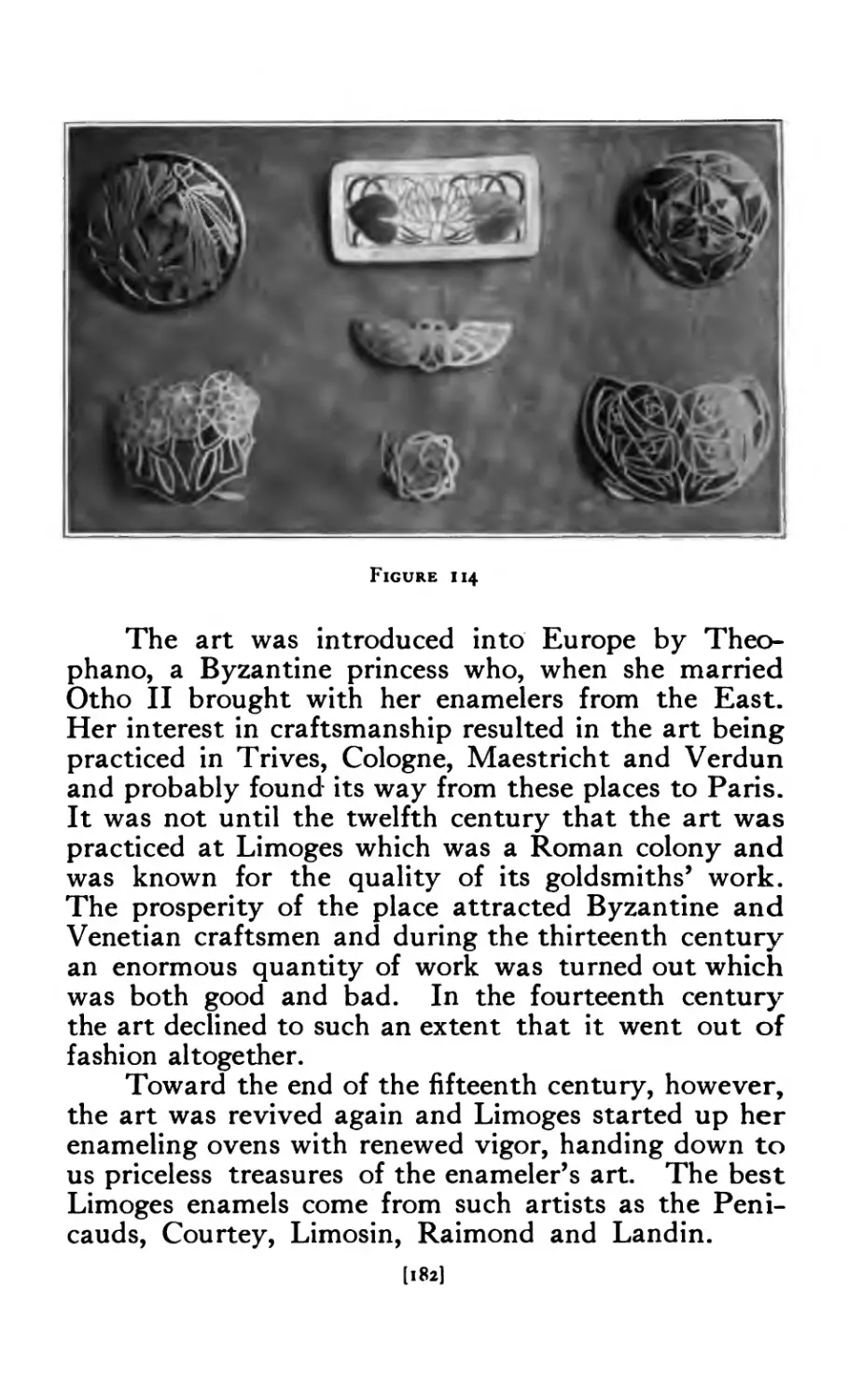
114 Enameled Jewelry ..... 182
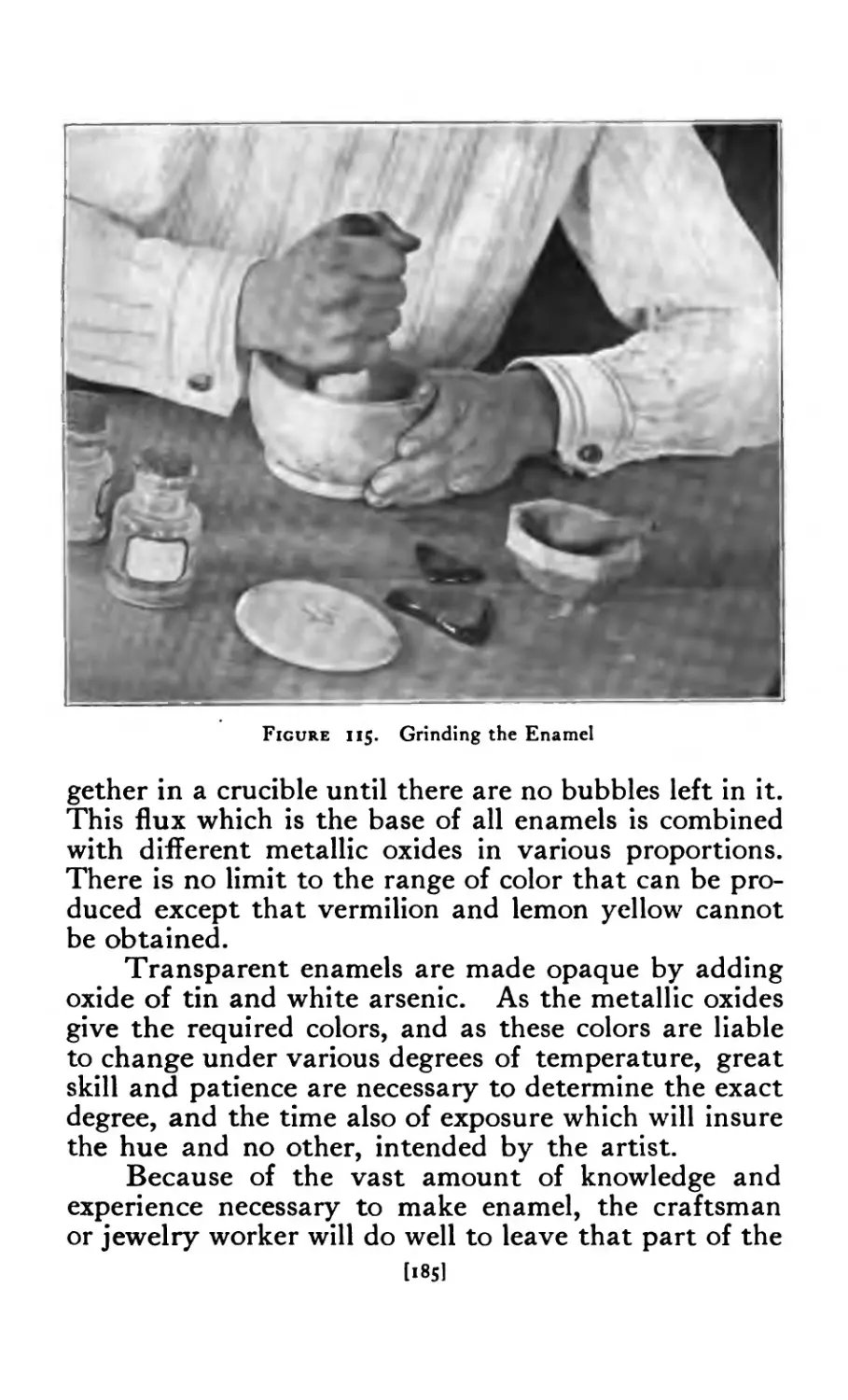
115 Grinding enamel ..... 185
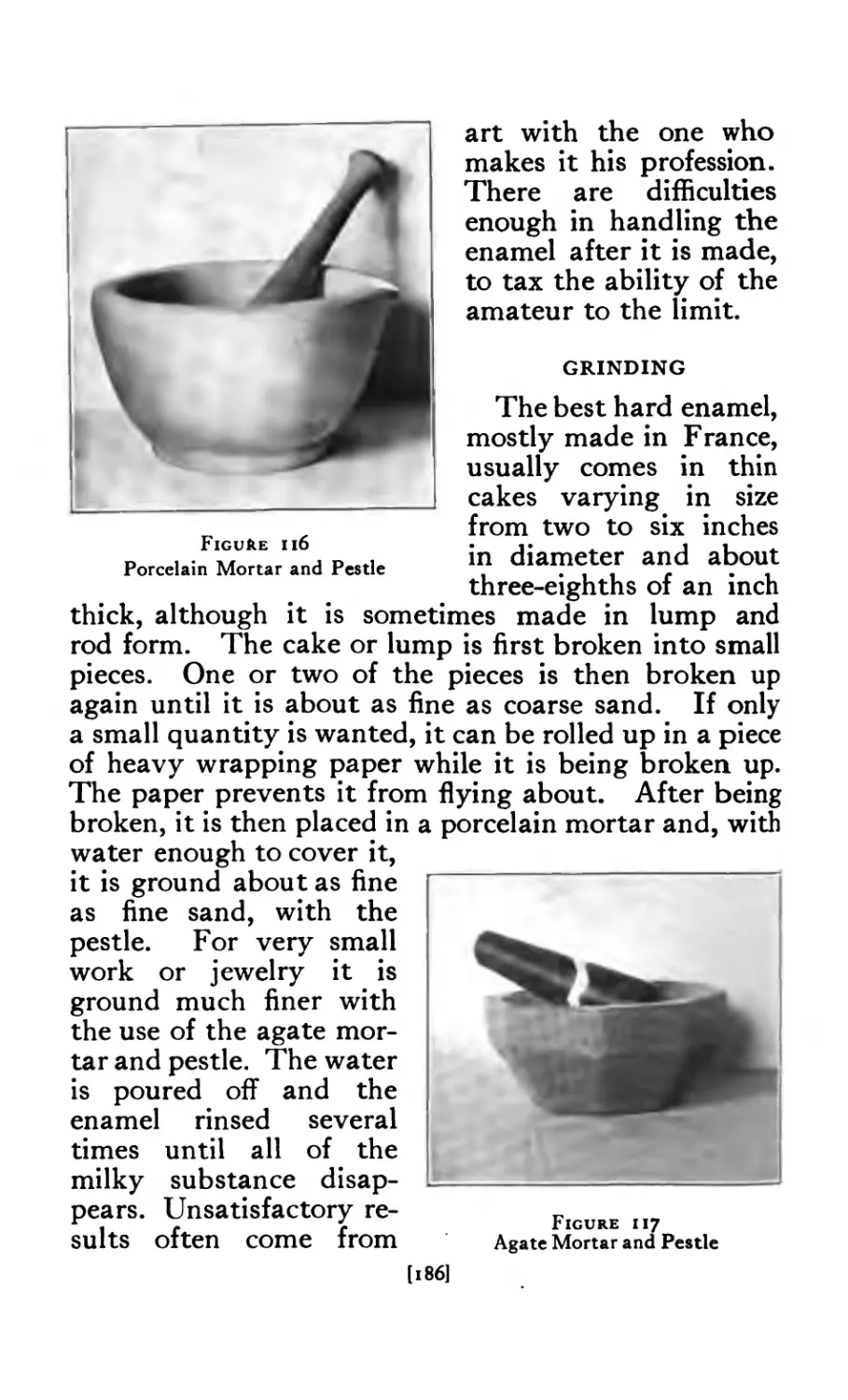
116 Porcelain mortar and pestle 186
117 Agate mortar and pestle .... 186
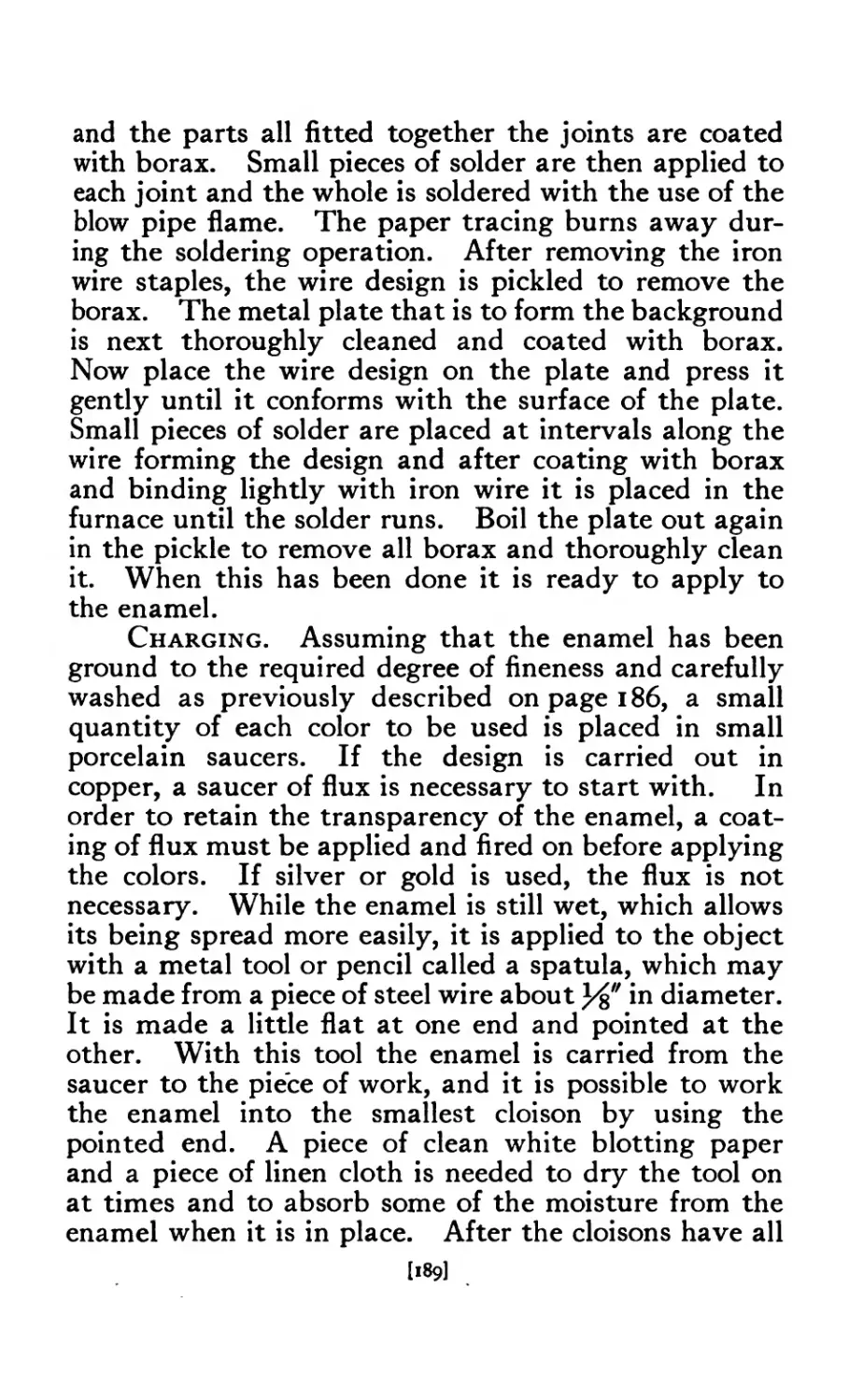
118 Charging enamel ..... 190
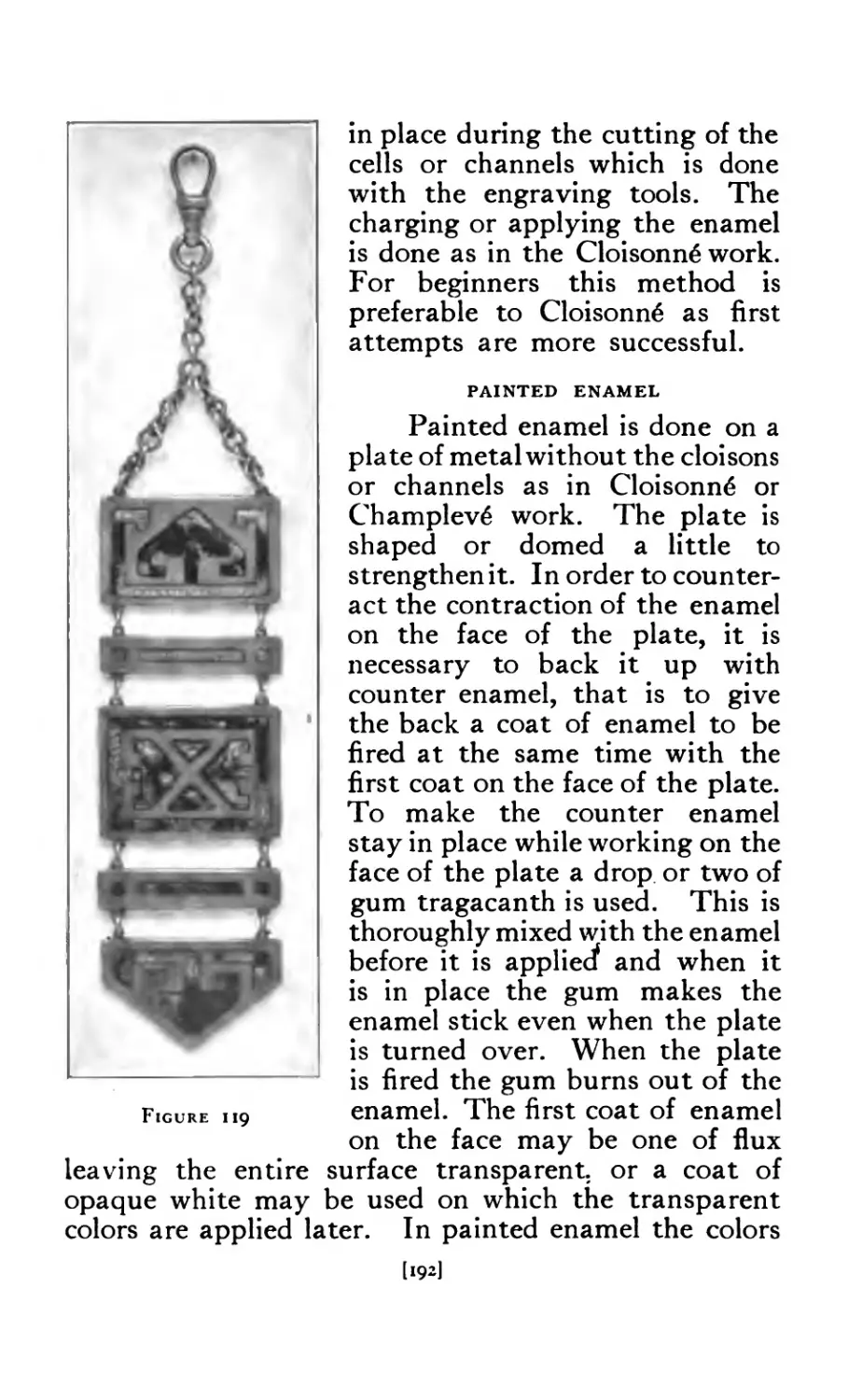
119 Enameled Fob ...... 192
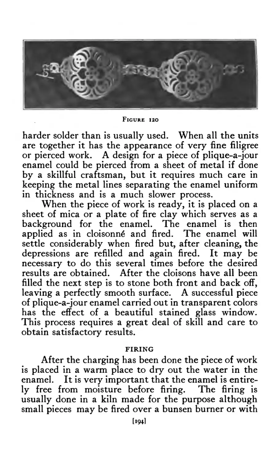
120 Enameled Bracelet ..... >94
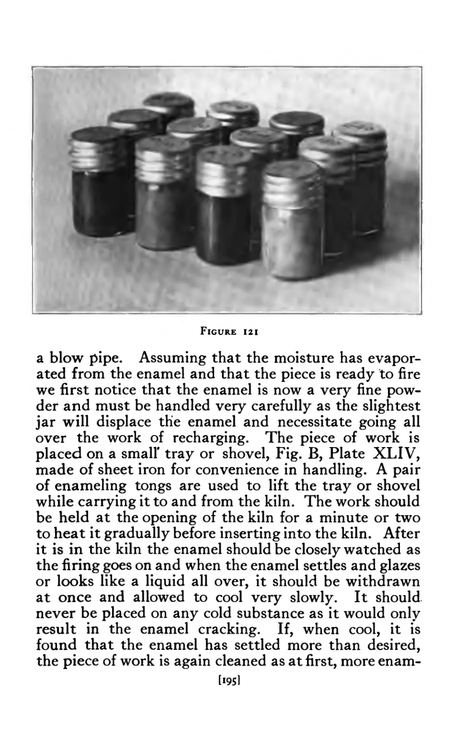
121 Set of Enamels (12 colors) .... 195
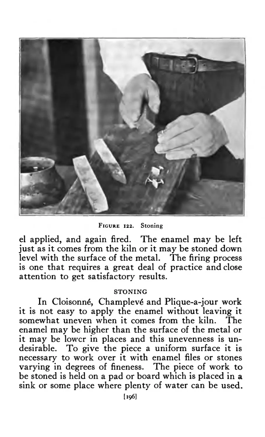
122 Stoning enamel ..... 196
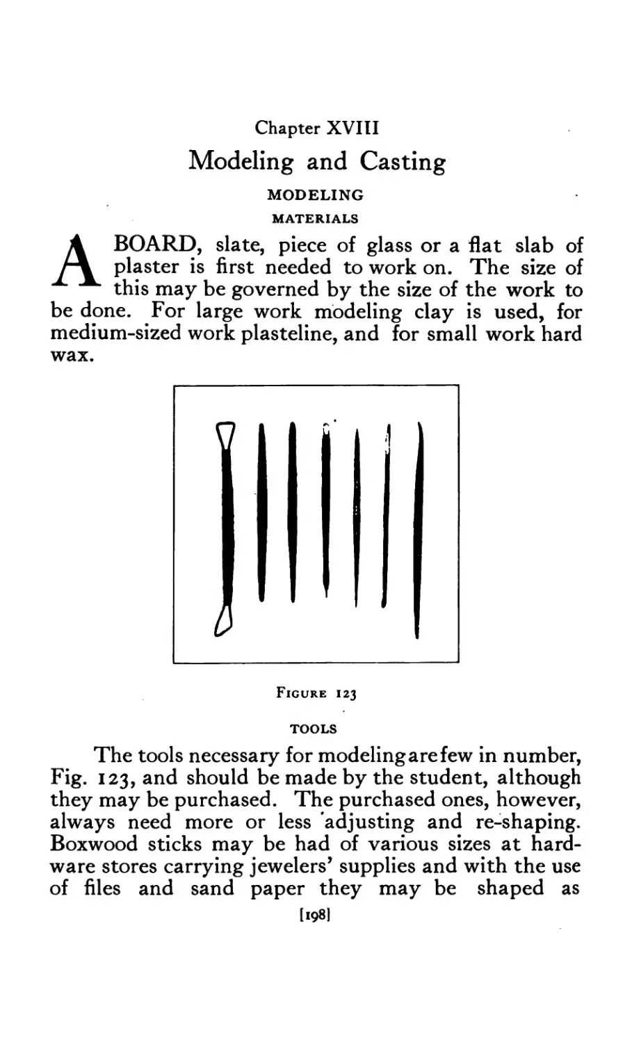
123 Modeling Tools ..... 198
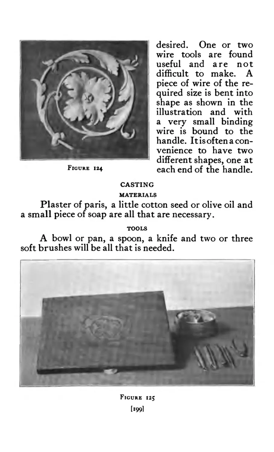
124 Scroll (modeled) ..... 199
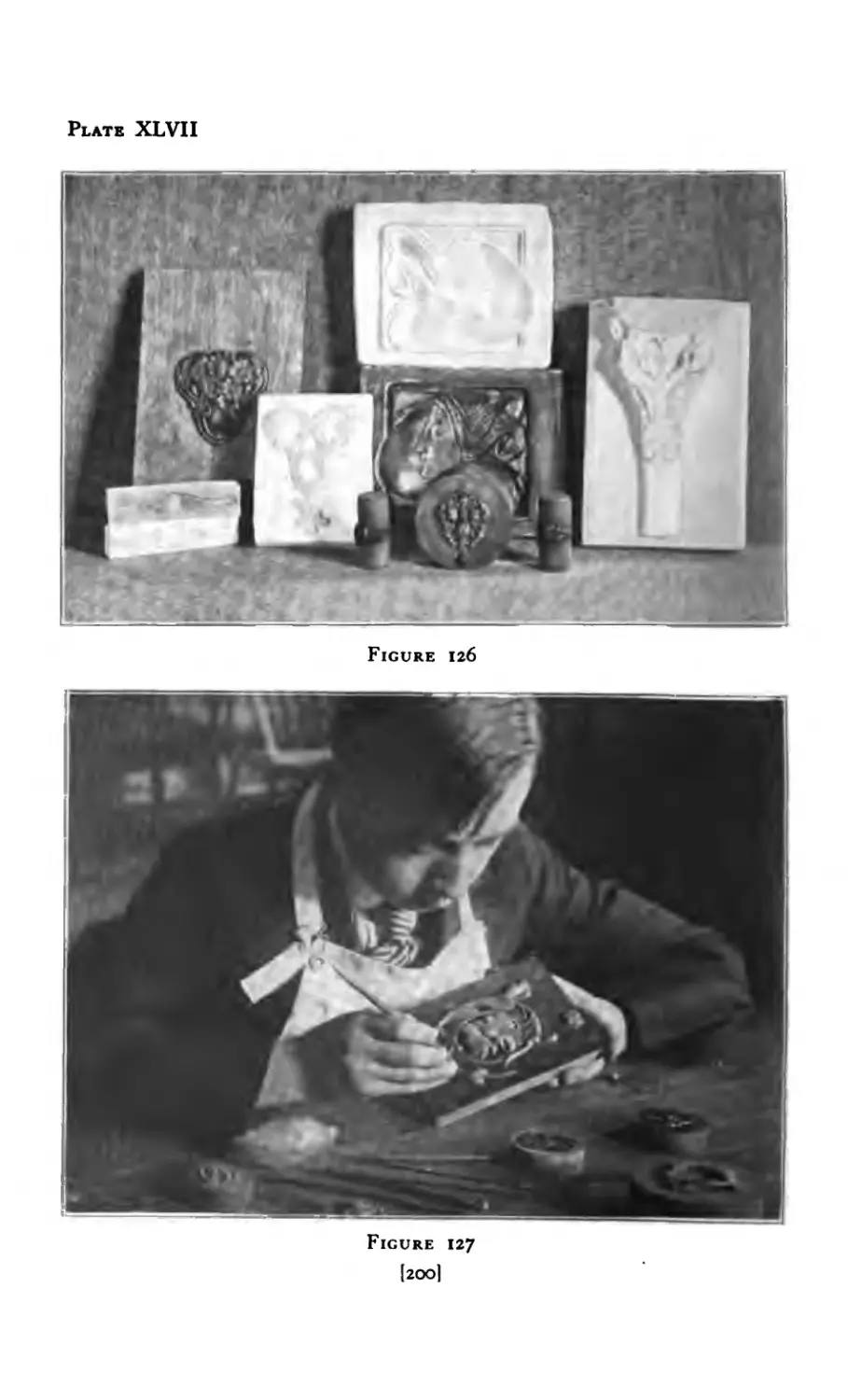
125 Scroll (first step) ..... 199
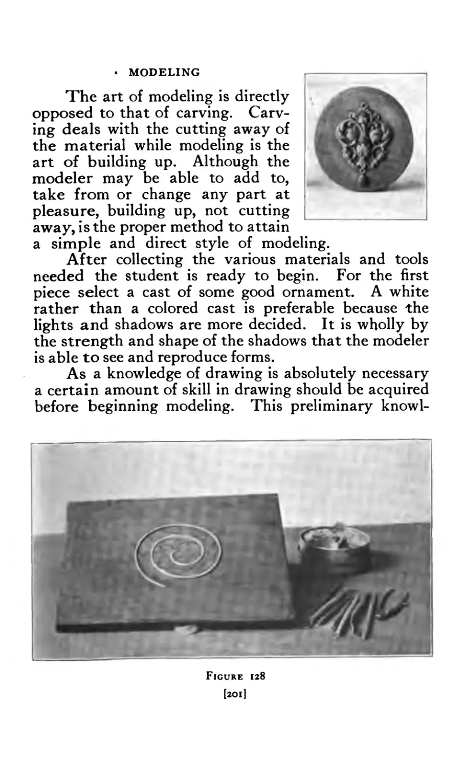
126 Modeling and Casts ..... 200
127 Modeling Scroll. ..... 200
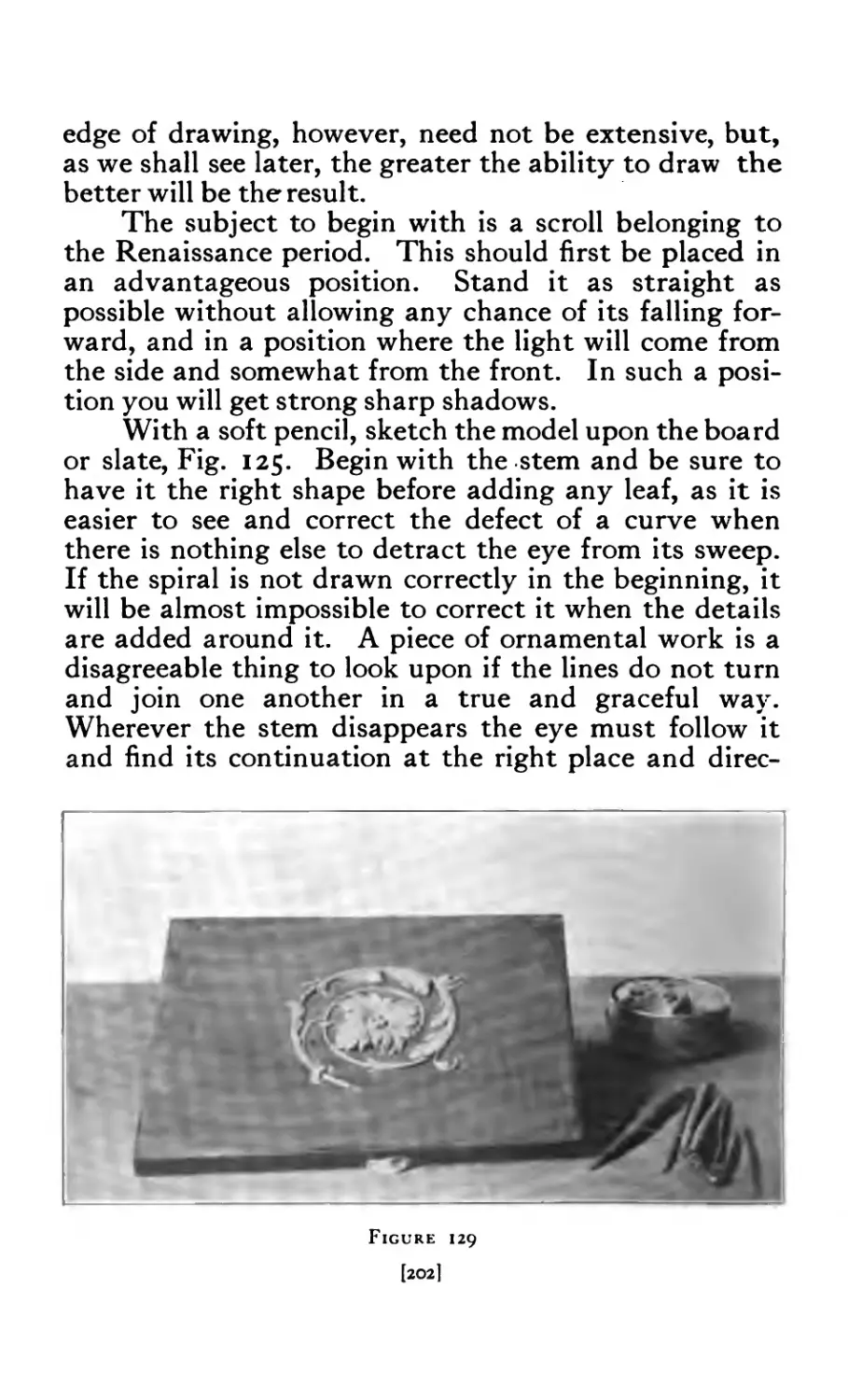
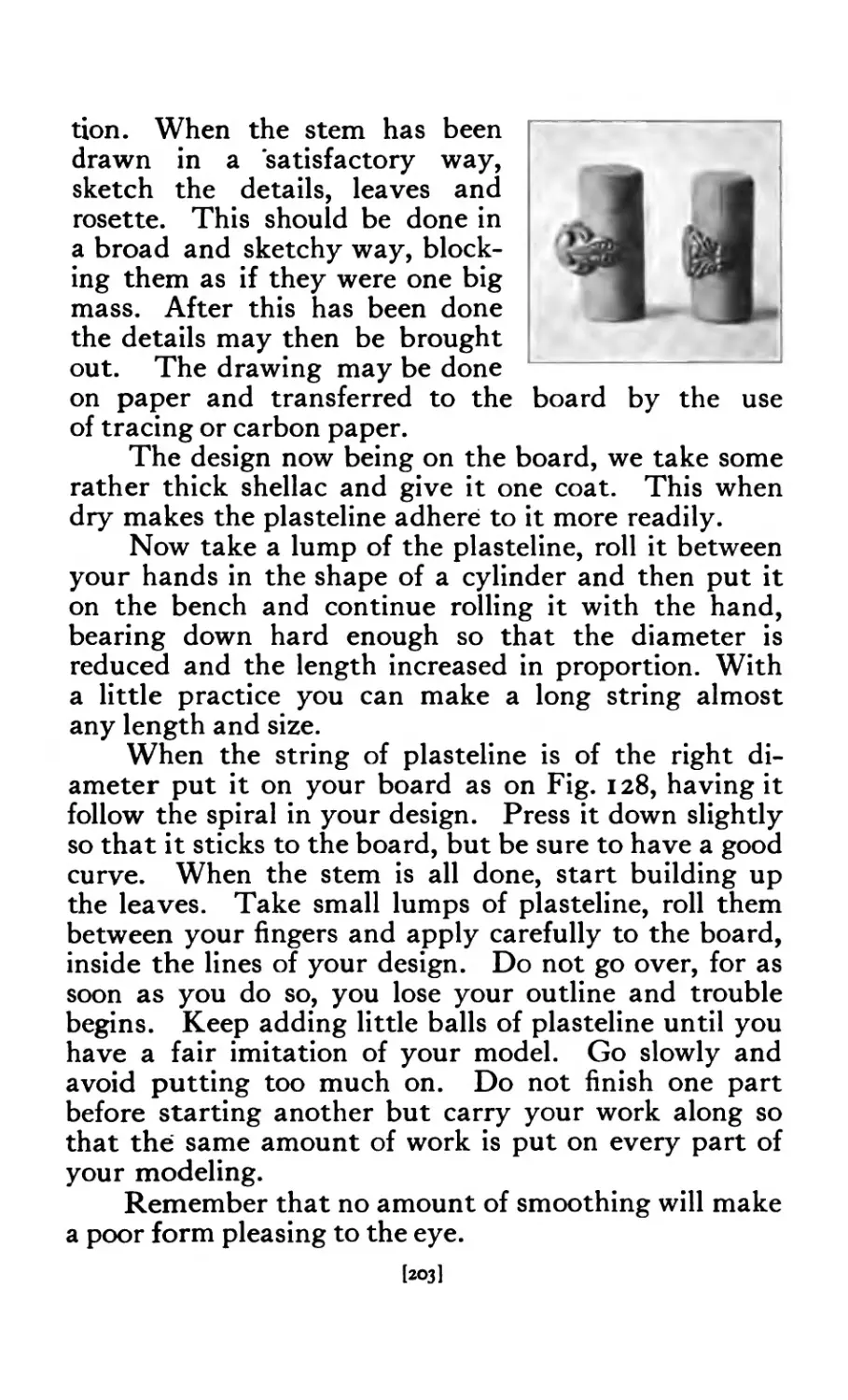
128 Scroll (second step) ..... 201
129 Scroll (third step) ..... 202
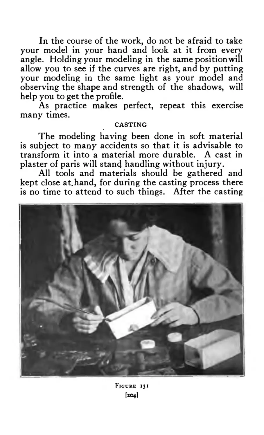
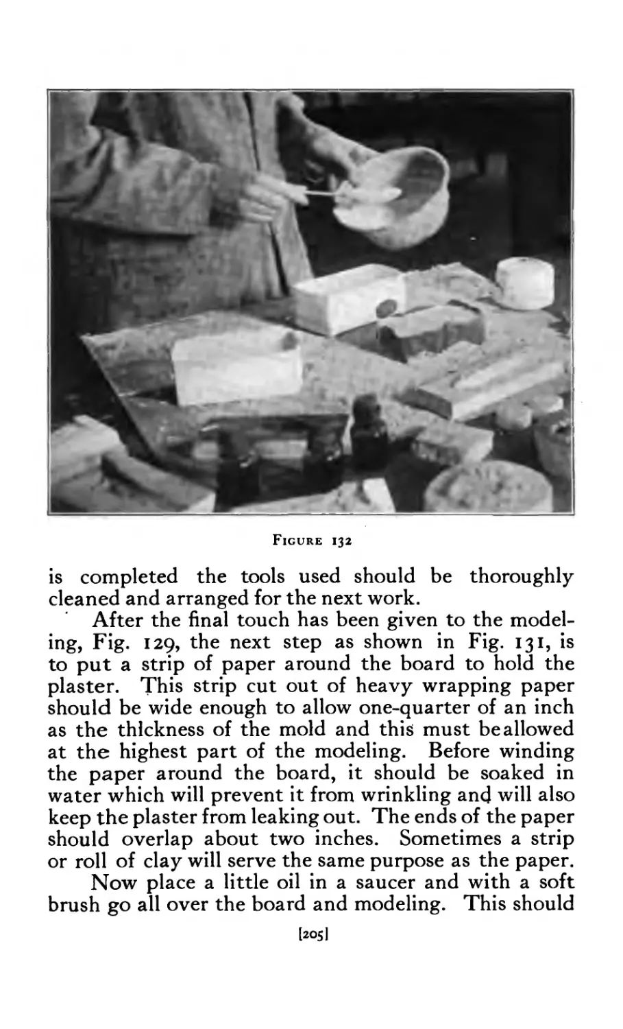
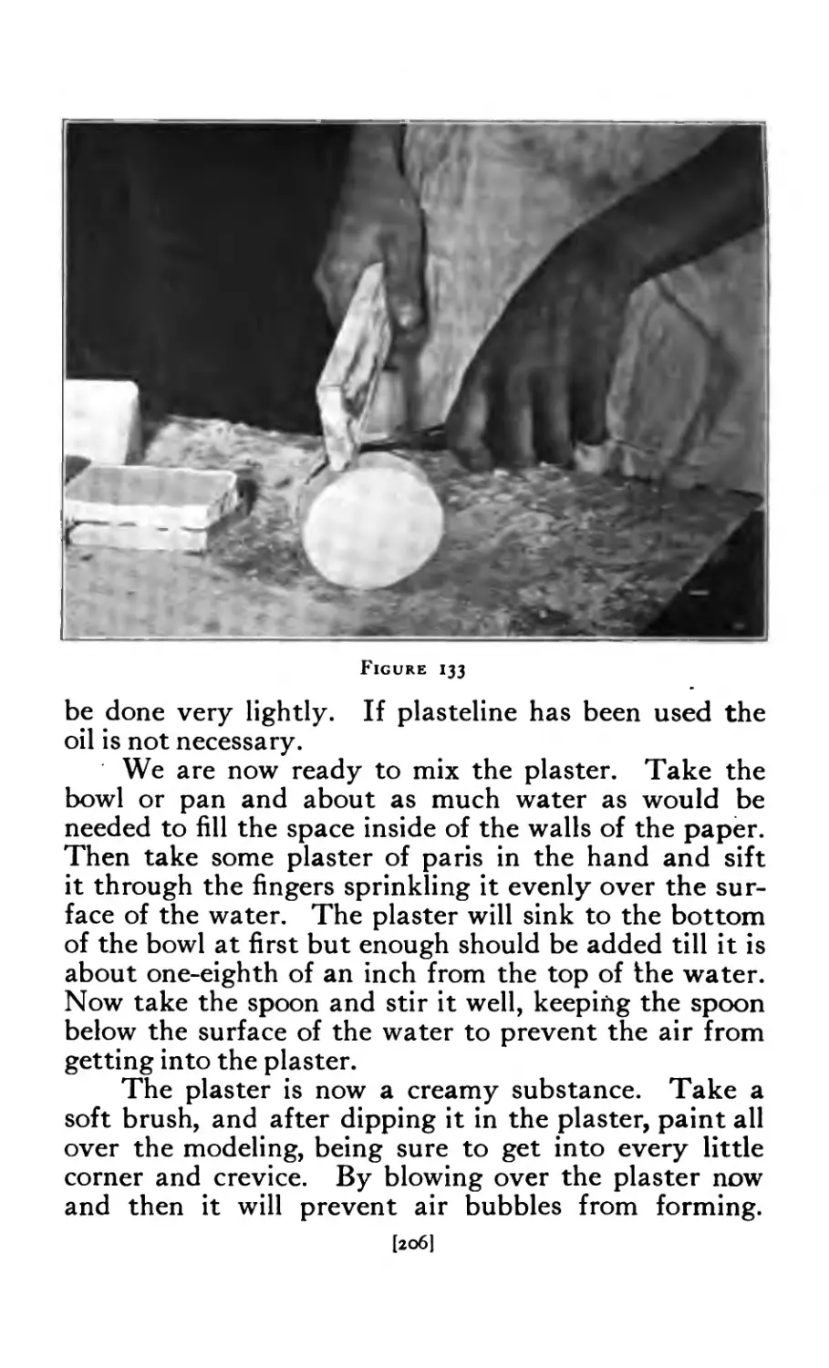
131 Casting (preparing the mould) 204
132 Casting (pouring) ..... 20$
133 Casting (separating the mould) . 206
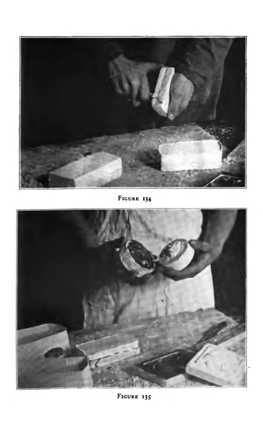
134 Casting (trimming the mould) 207
135 Cast and mould separated .... 207
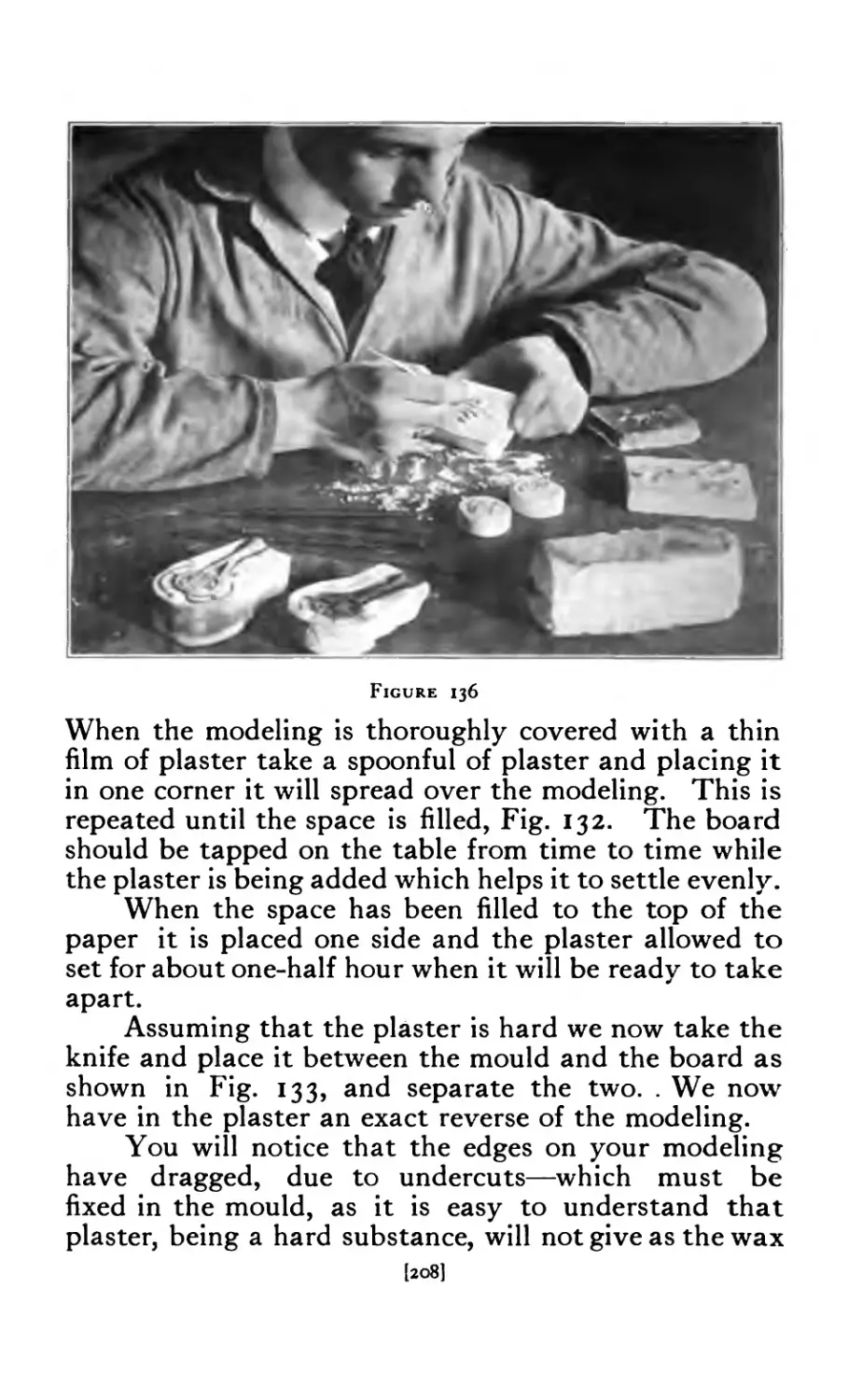
136 Touching up cast ..... 208
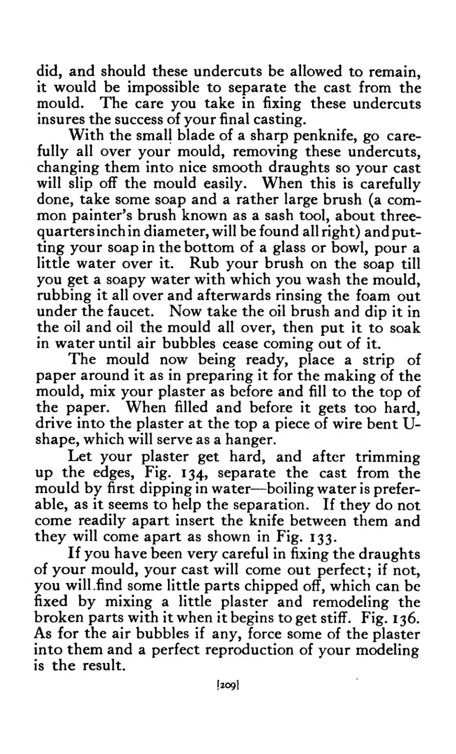
137 Cuttie Fish casting ..... 210
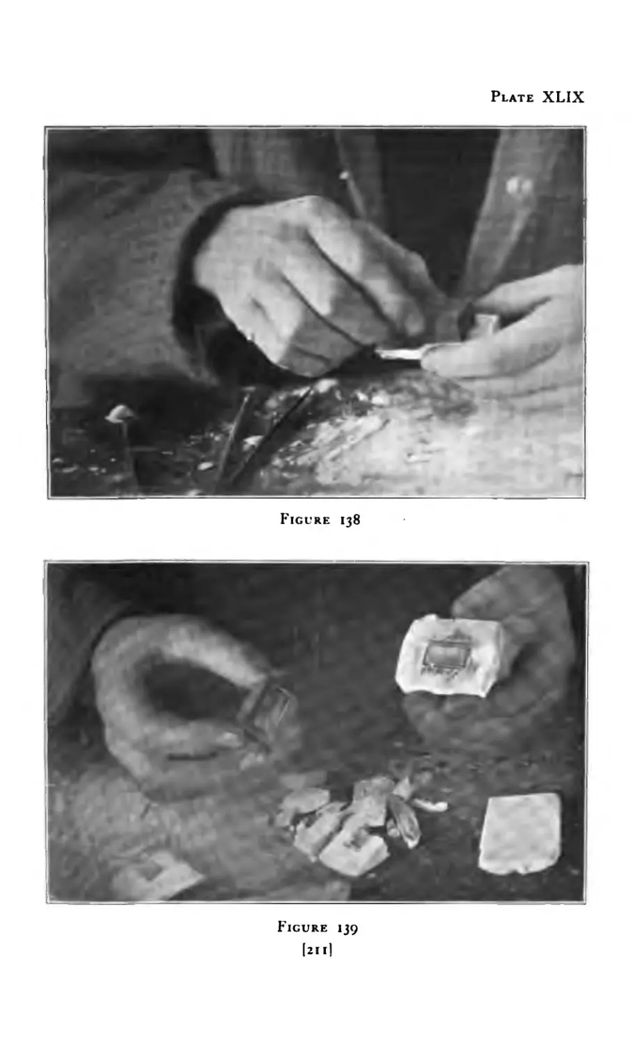
138 Lifting pattern from cuttie fish 211
139 Depression in cuttie fish .... 211
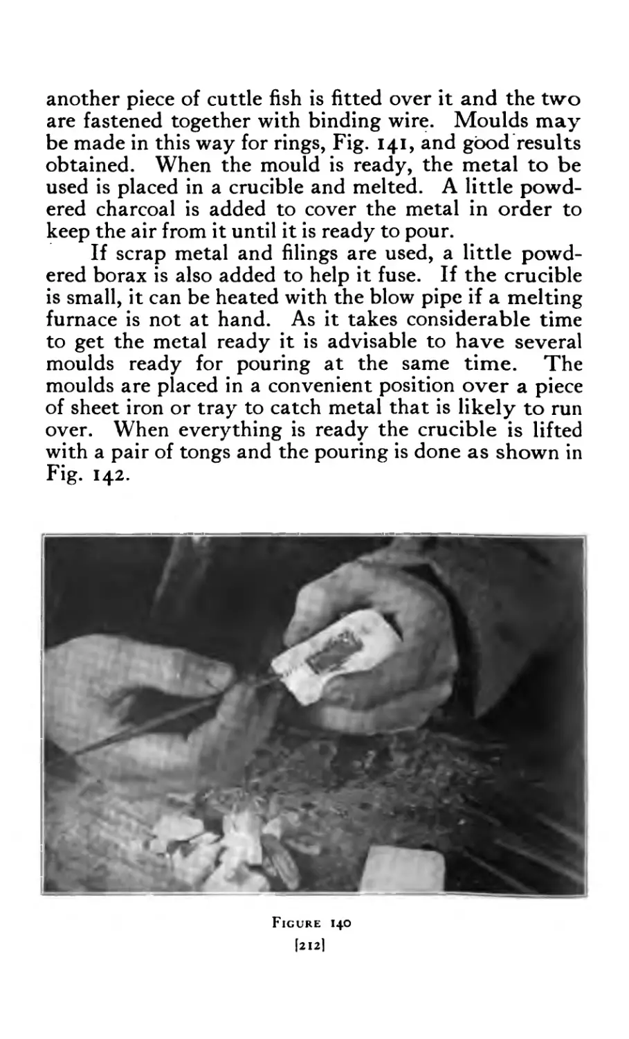
140 Opening for metal ..... 212
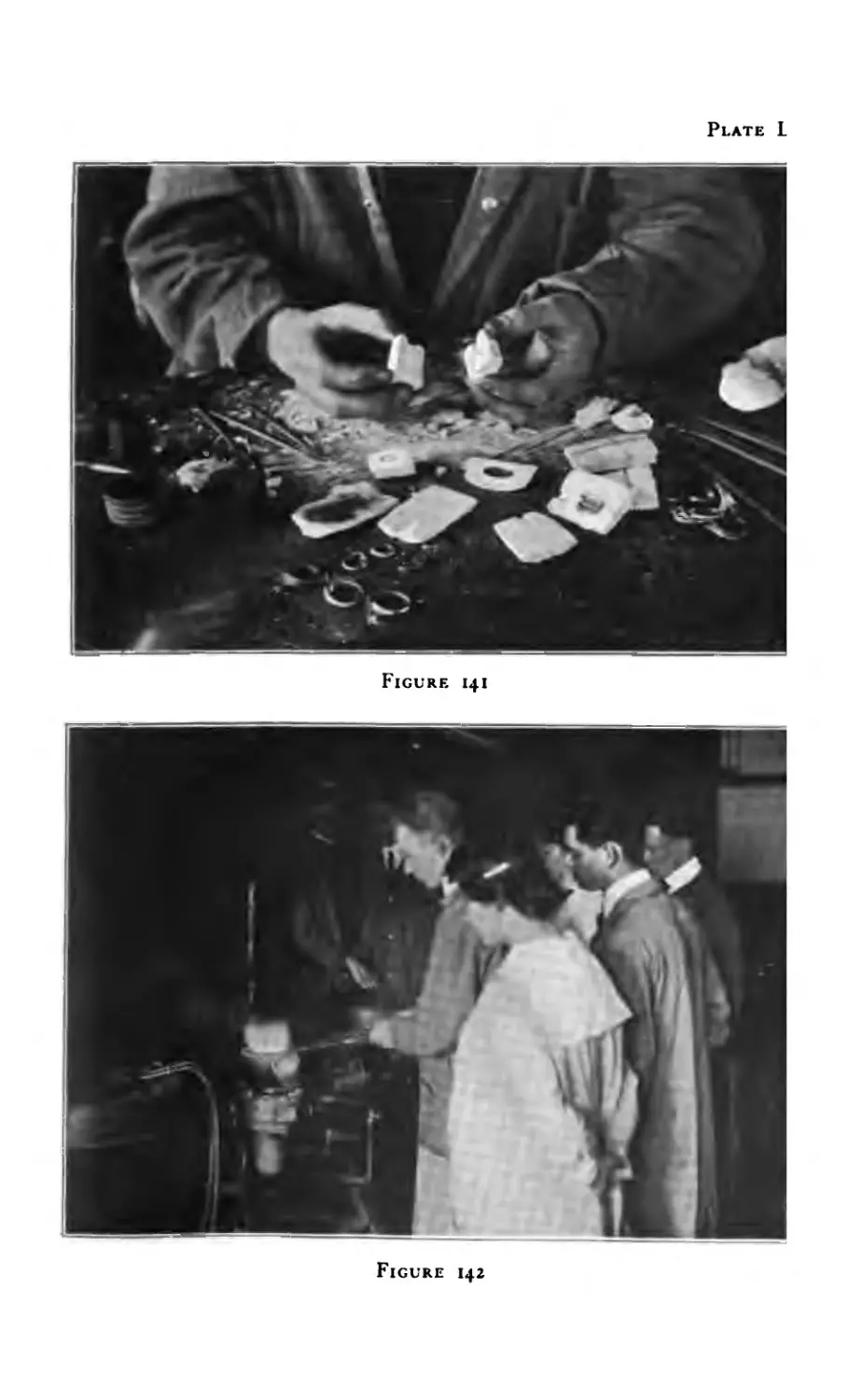
141 Cuttie Fish casting (rings) .... 213
142 Melting and Pouring .... 213
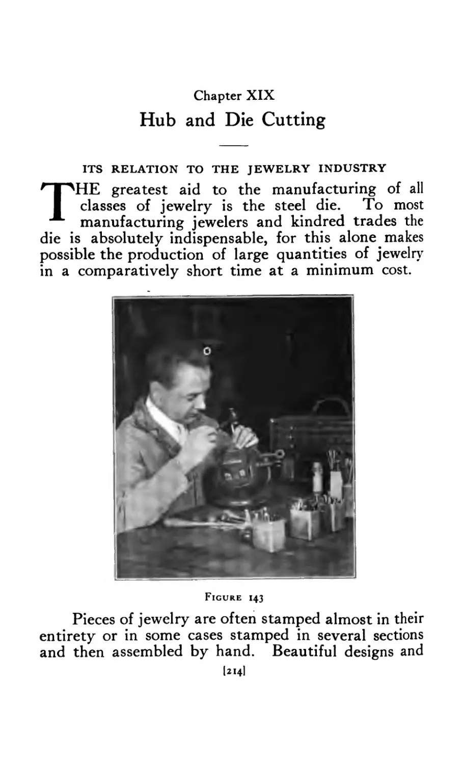
143 Hub and Die Cutting .... 214
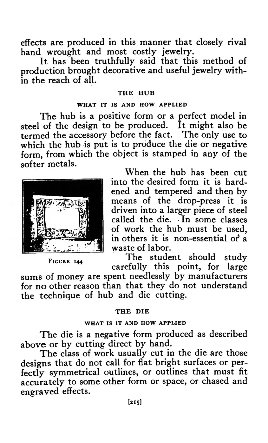
144 Hub ....... 215
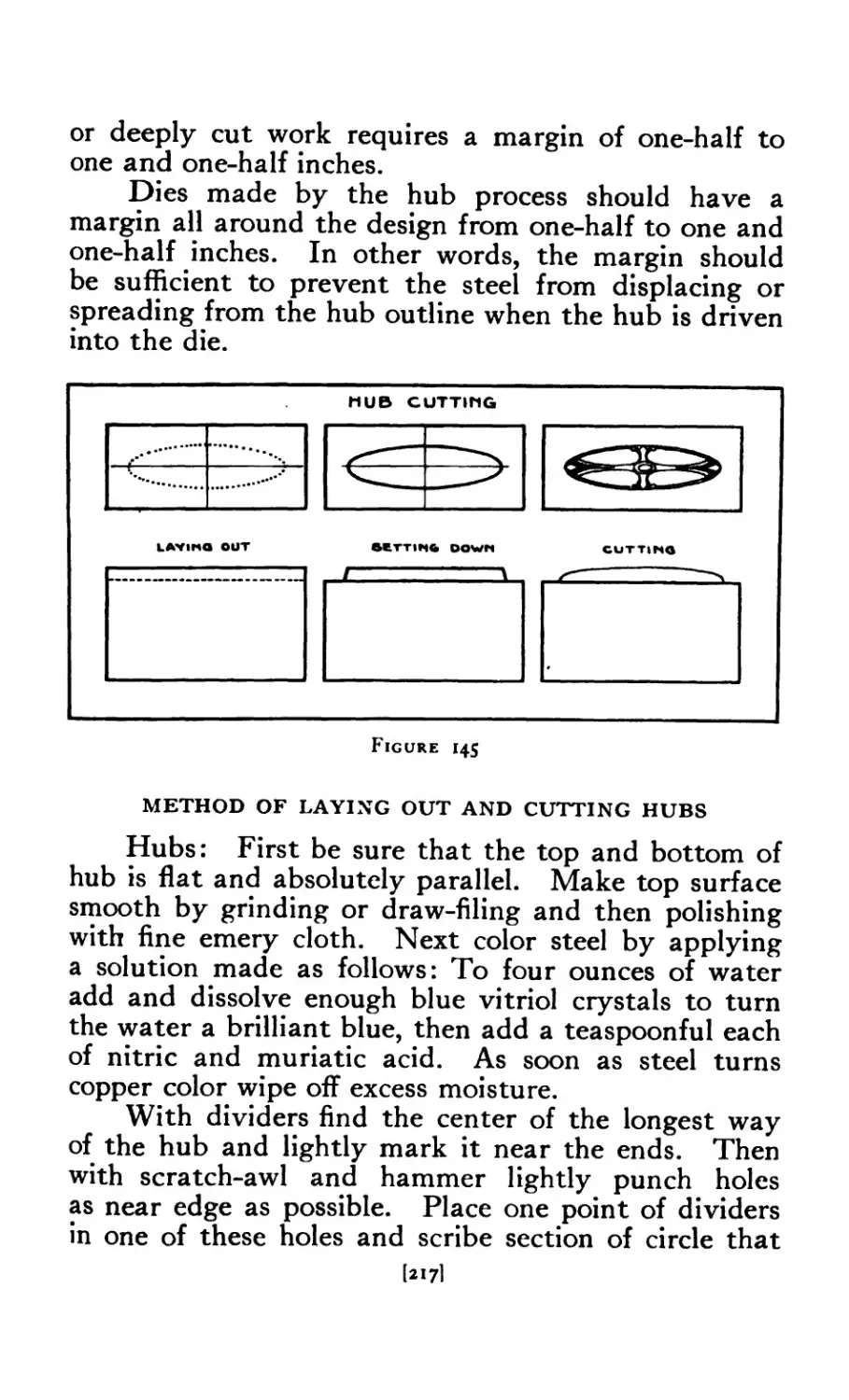
145 Method of laying out and cutting hubs 217
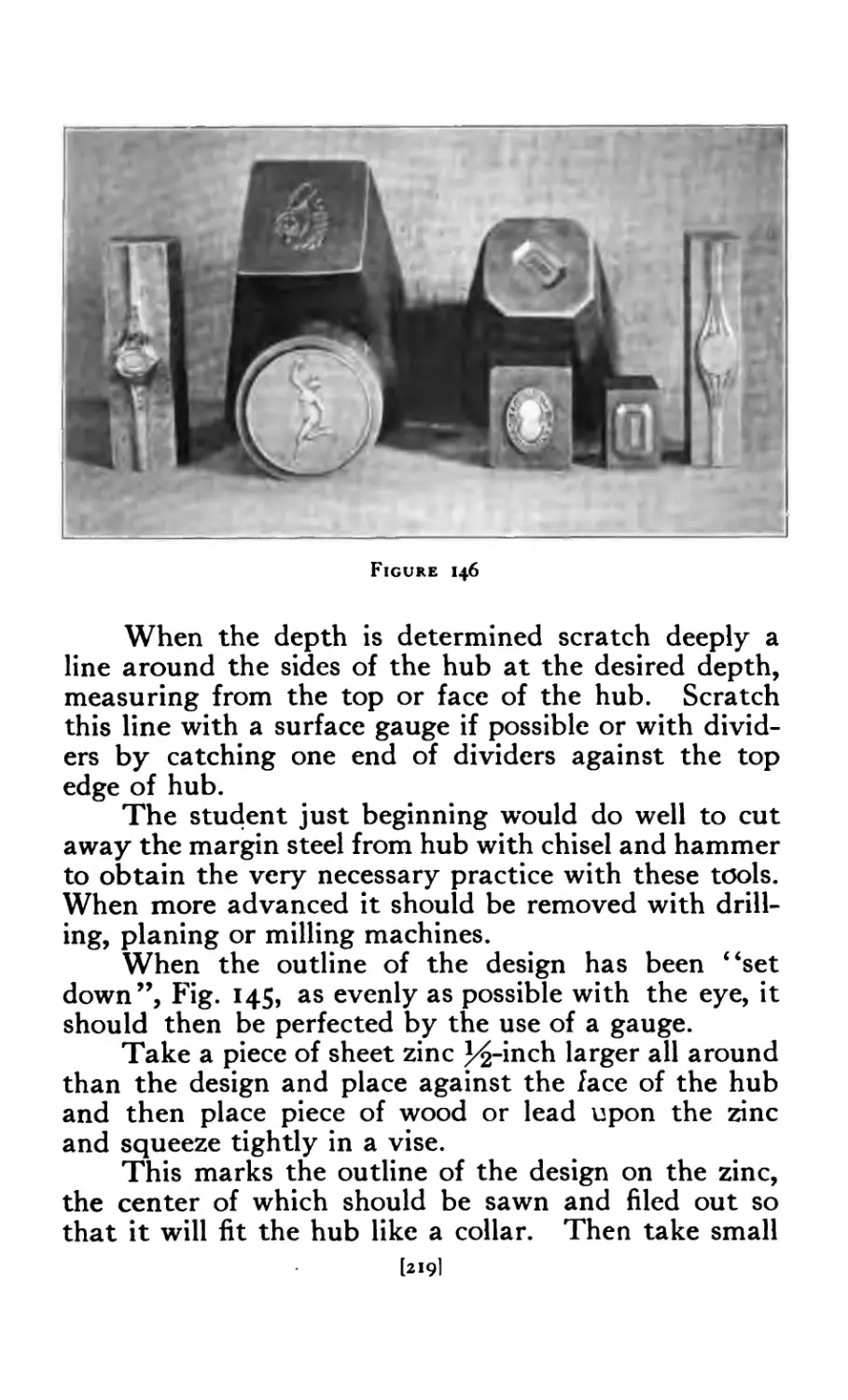
146 Hubs and Dies ...... 219
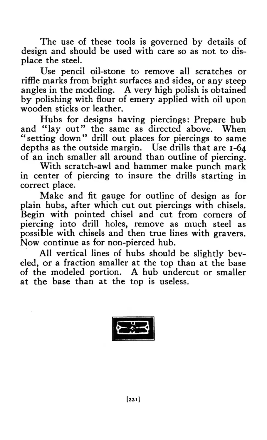
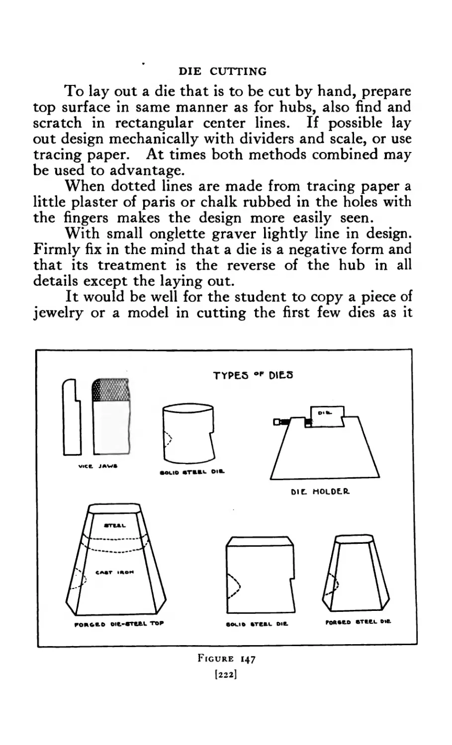
147 Types of Dies ...... 222
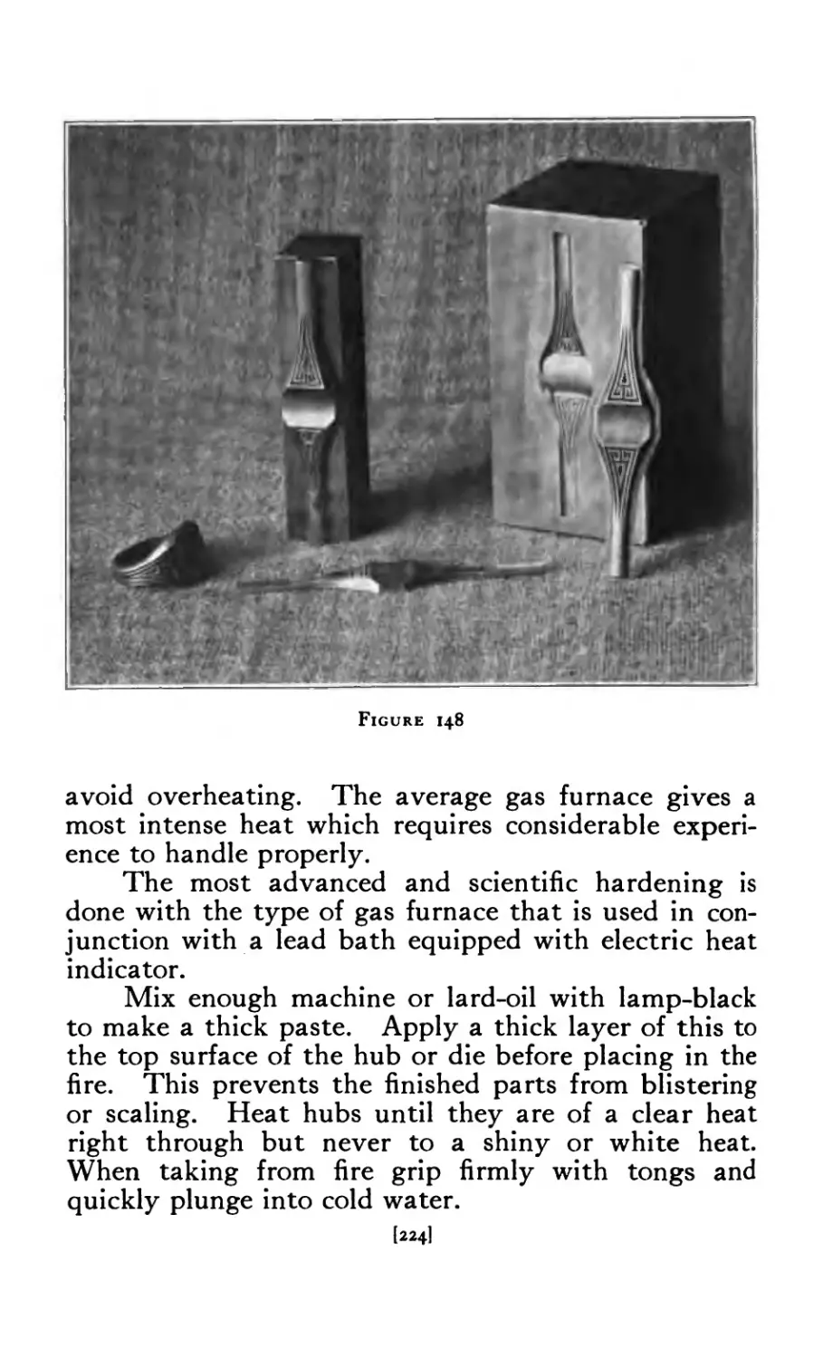
148 Hub and Die of ring ..... 224
[ix]
FIGURE PAGE
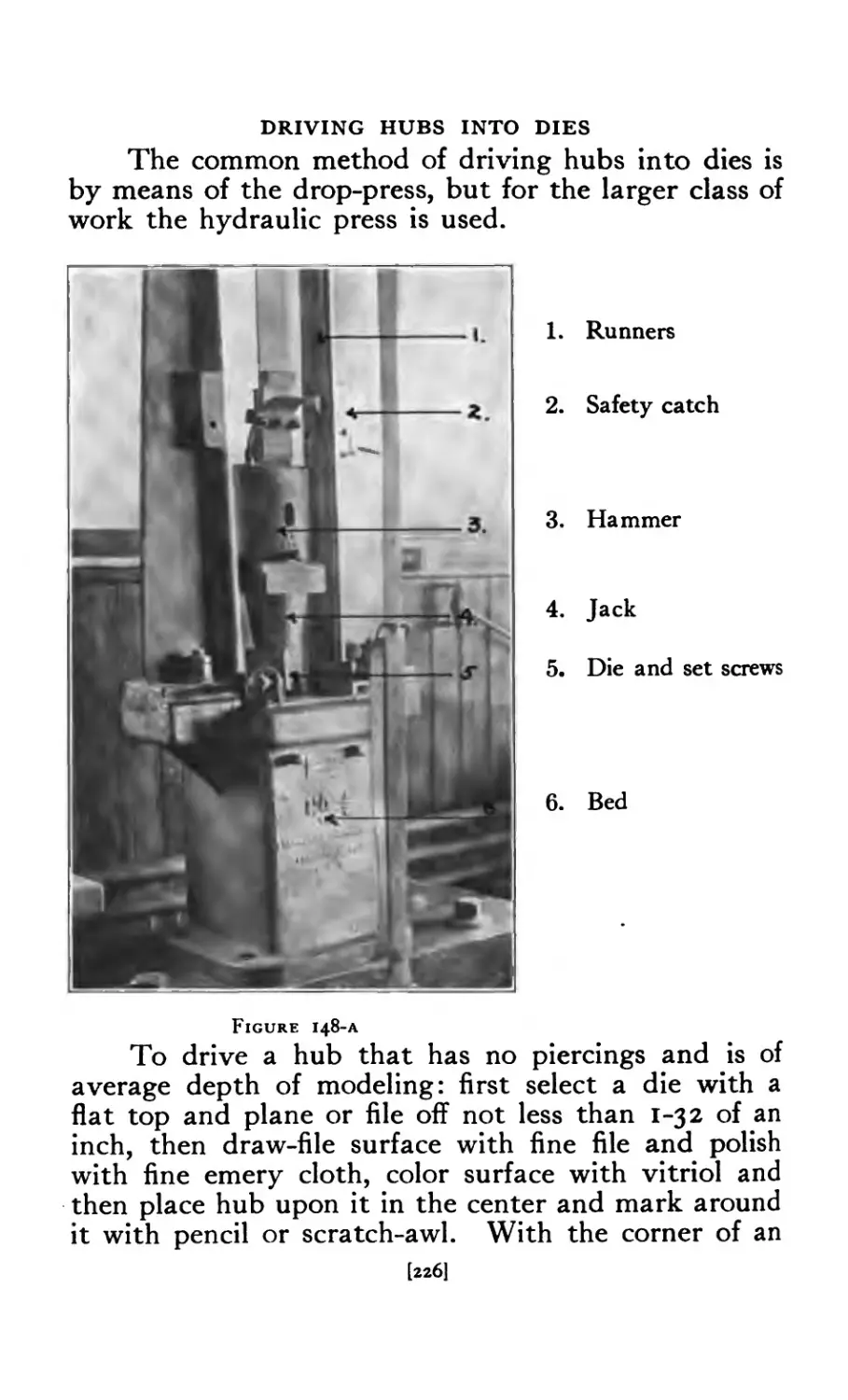
148-A Drop-press ......... 226
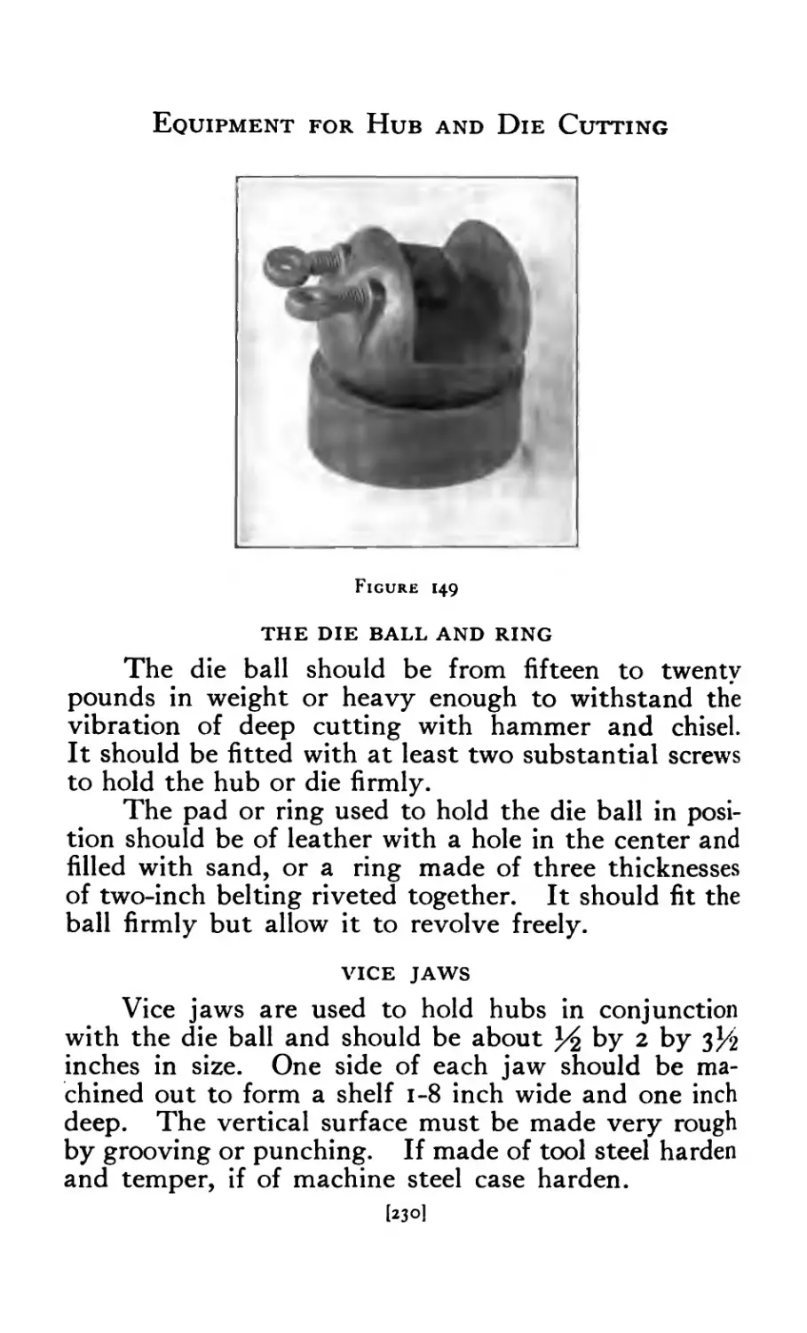
149 Die Ball ......... 230
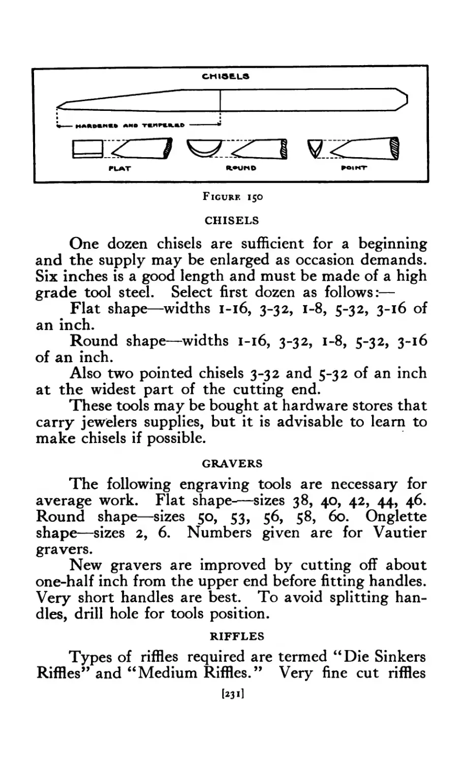
150 Chisels .......... 231
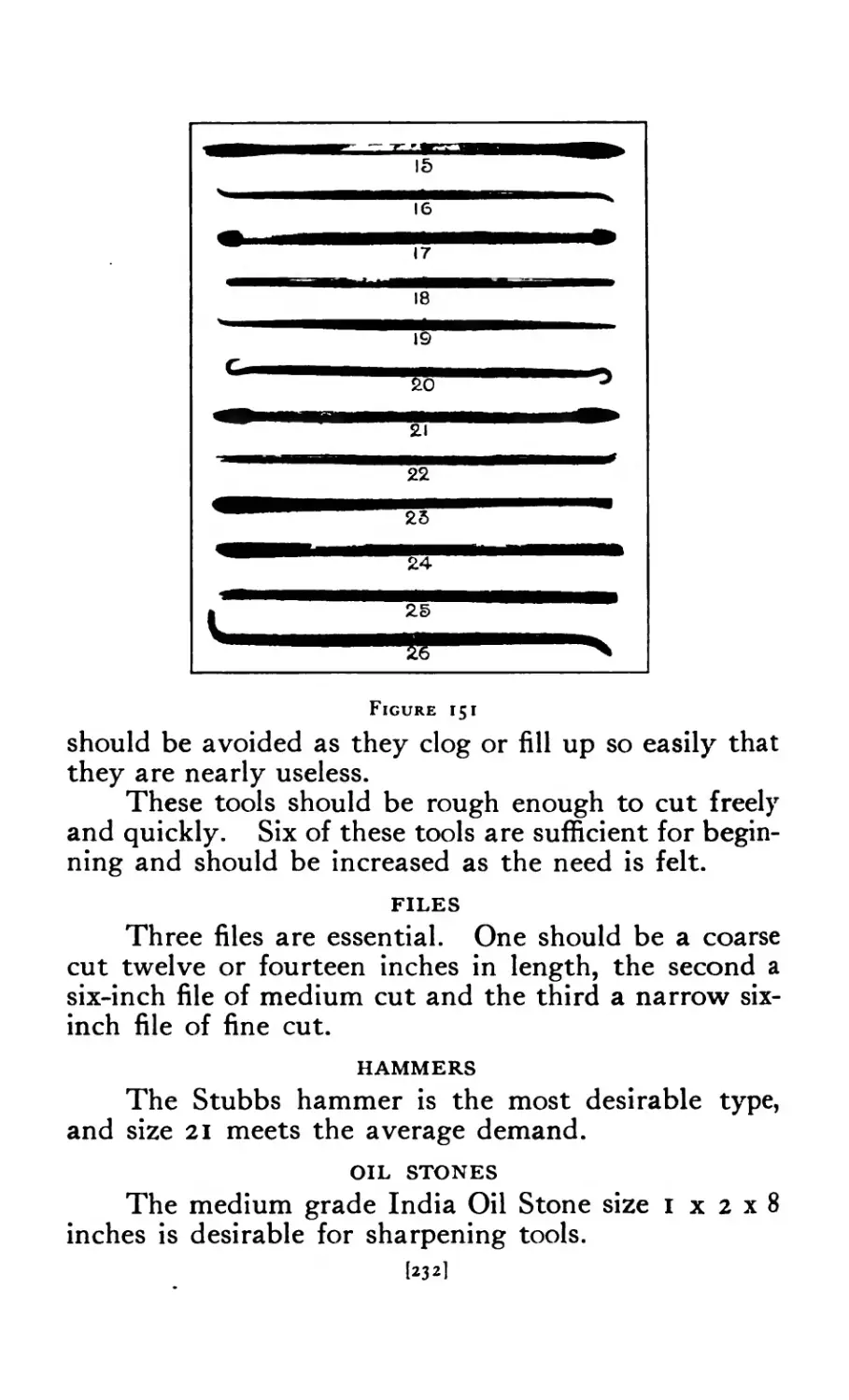
151 Riffles.............232
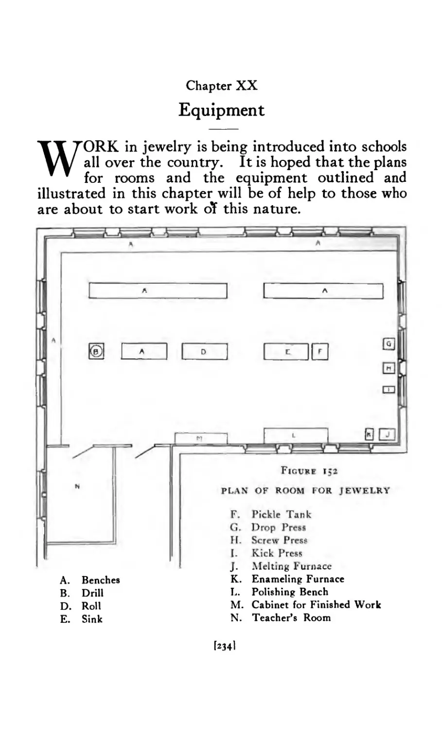
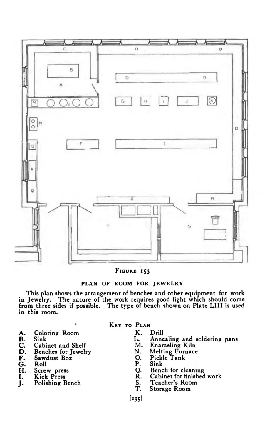
152 Plan of room for jewelry ....... 234
153 Plan of room for jewelry ....... 235
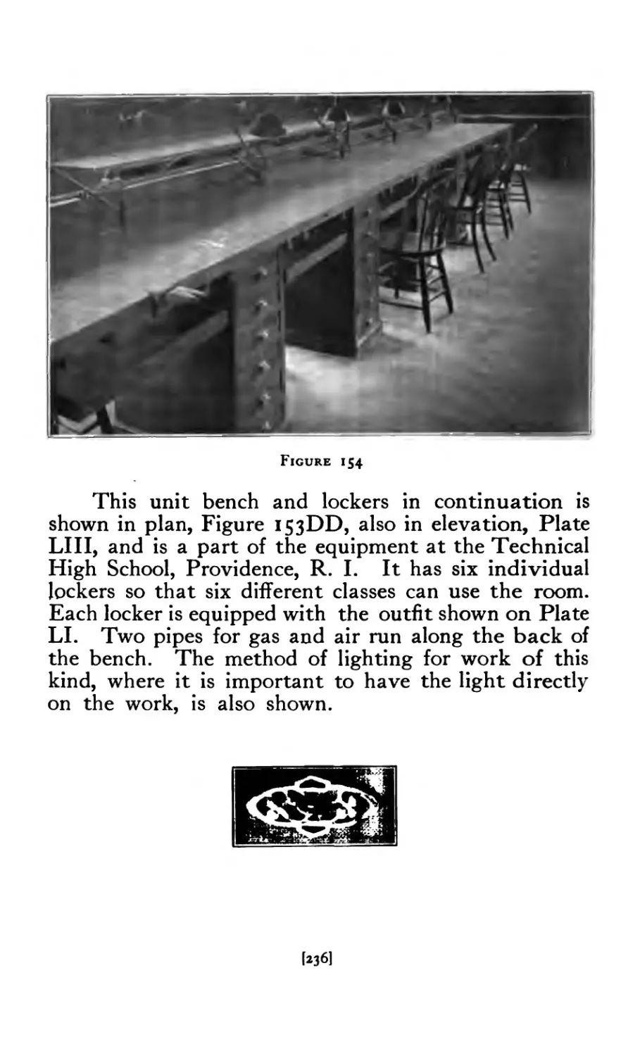
154 Benches for jewelry ........ 236
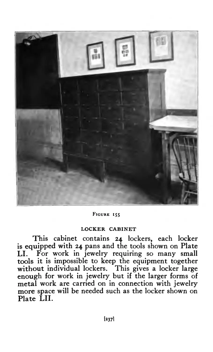
155 Locker Cabinet . . 237
156 Individual Equipment ....... 239
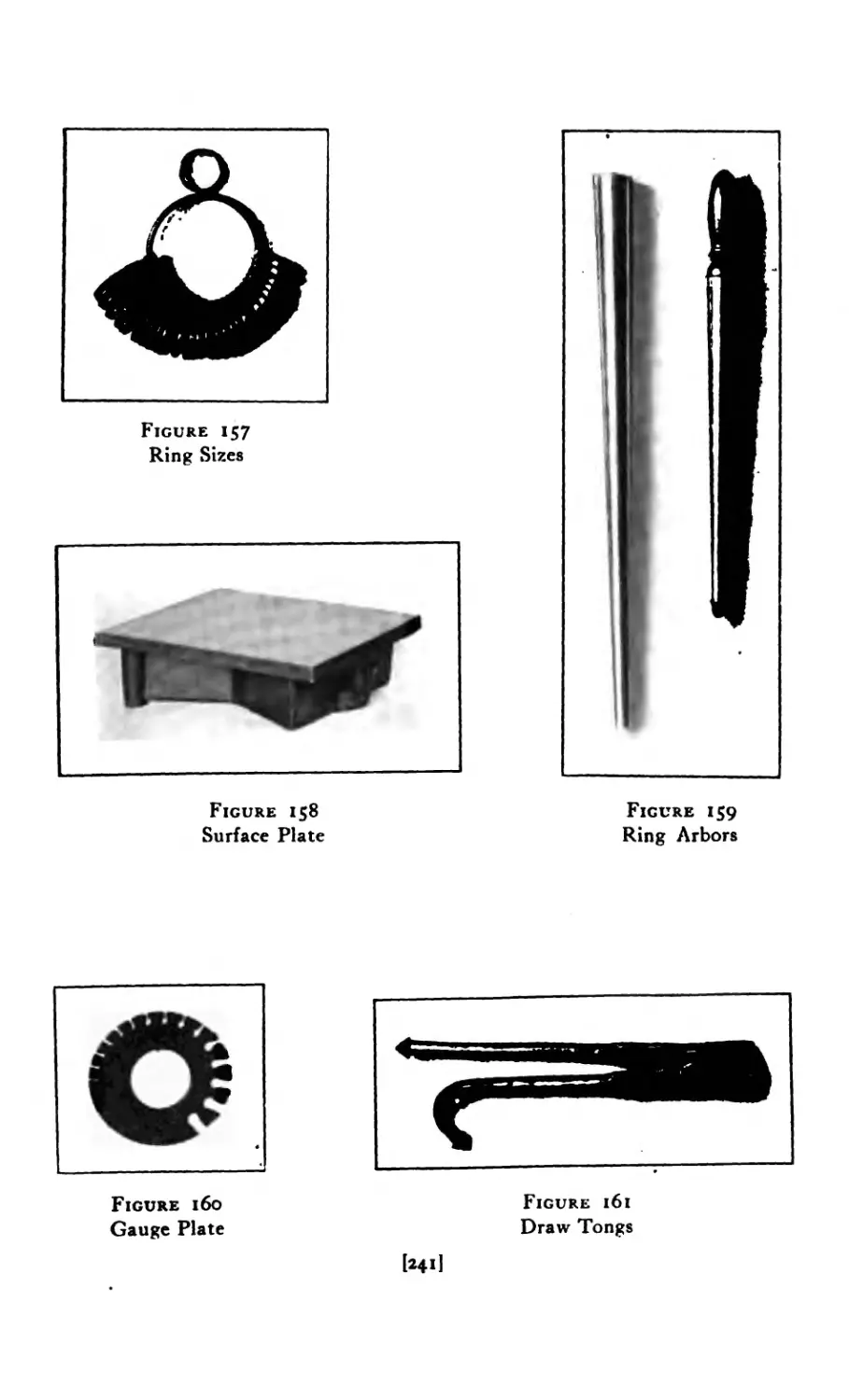
157 Ring Sizes . . . . . 241
158 Surface Plate . . . 241
159 Ring Arbors ......... 241
160 Gauge Plate ......... 241
161 Draw Tongs ......... 241
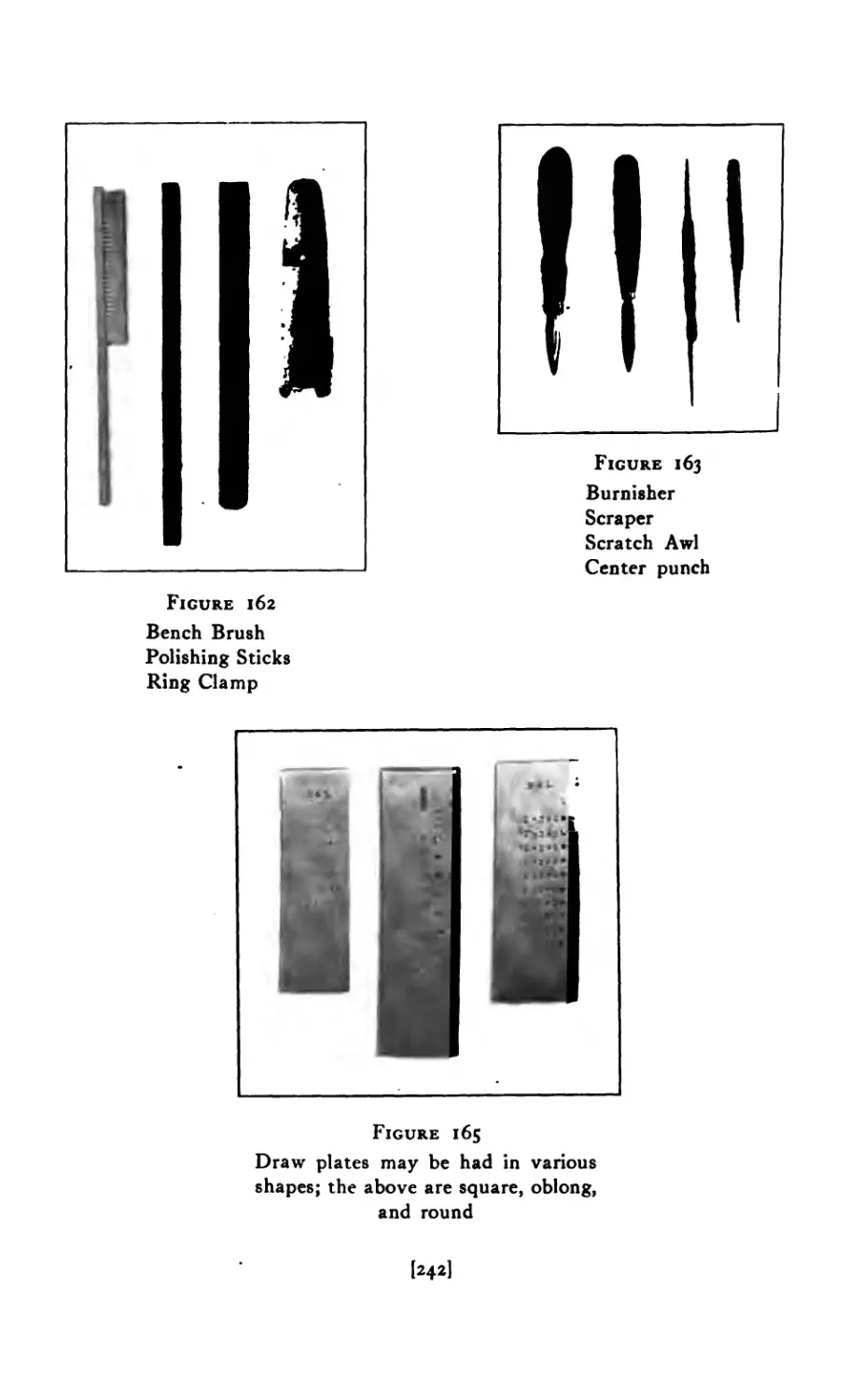
162 Bench Brush, Polishing Sticks, Ring Clamp 242
163 Burnisher, Scraper, Scratch-awl, Punch .... 242
165 Draw Plates ......... 242
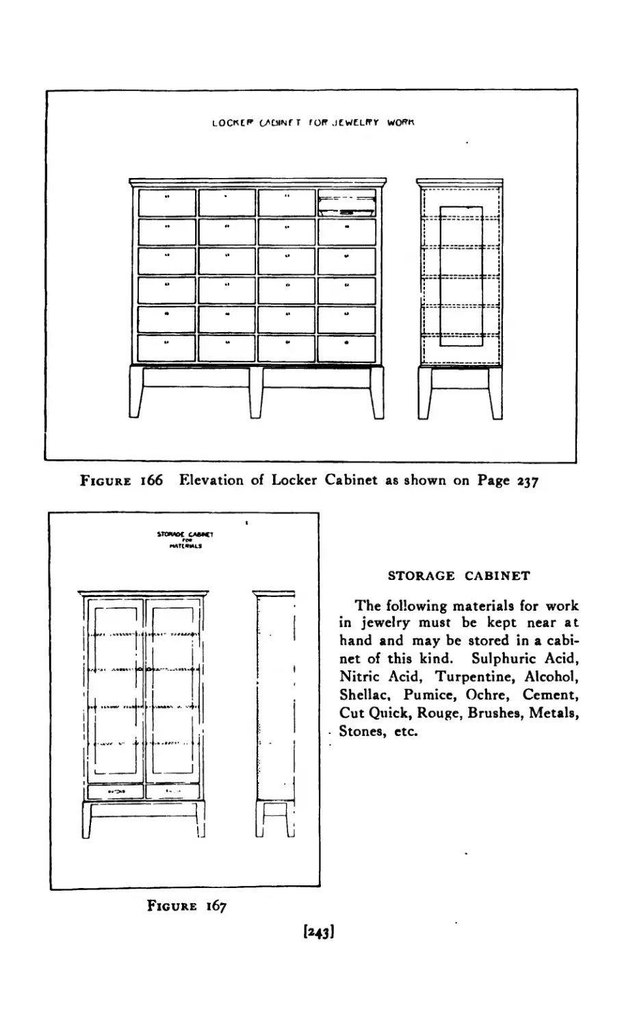
166 Elevation of Locker Cabinet ...... 243
167 Storage Cabinet ........ 243
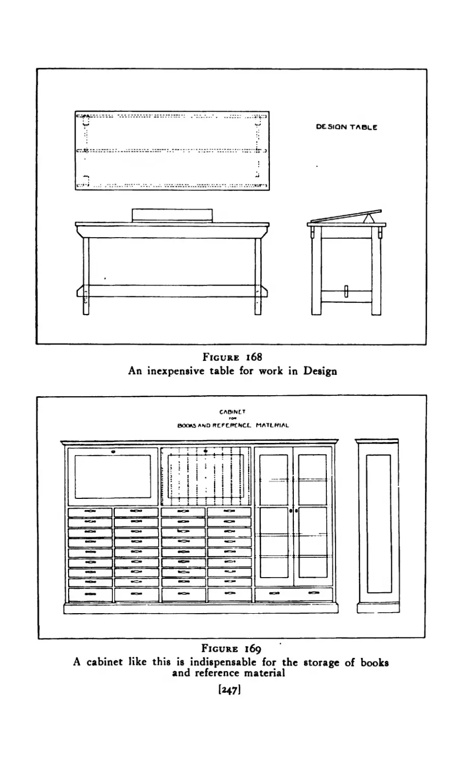
168 Design Table ......... 247
169 Storage Cabinet (Books and Plates) ..... 247
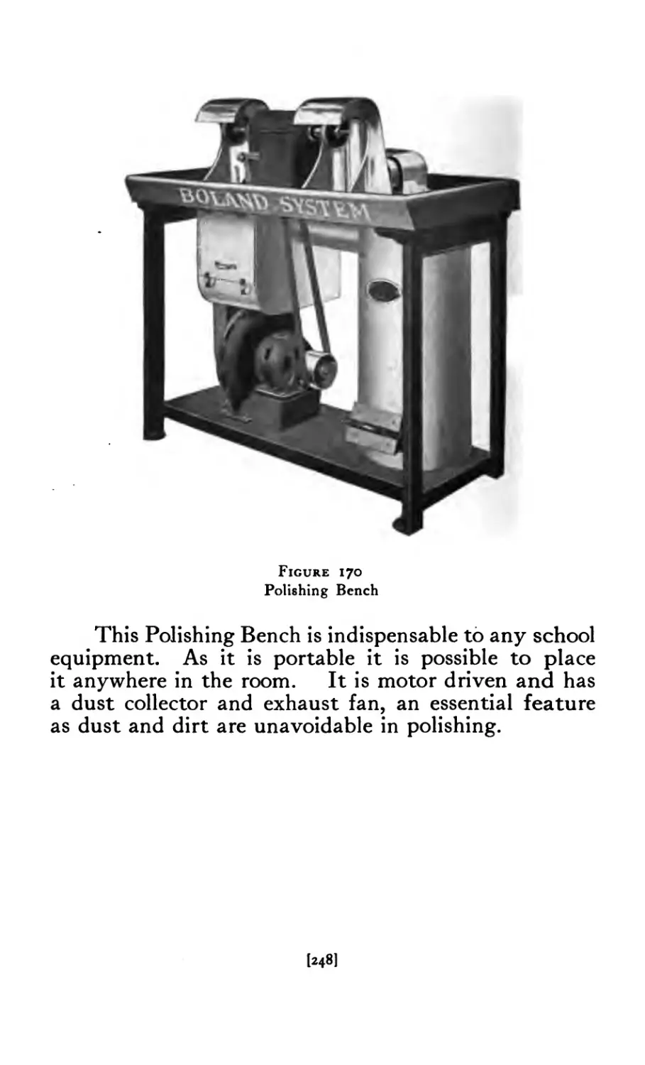
170 Polishing Bench ........ 248
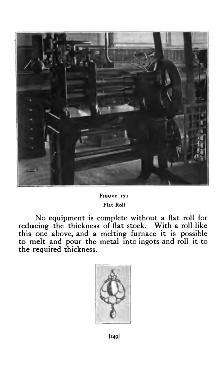
171 Flat Roll.............................249
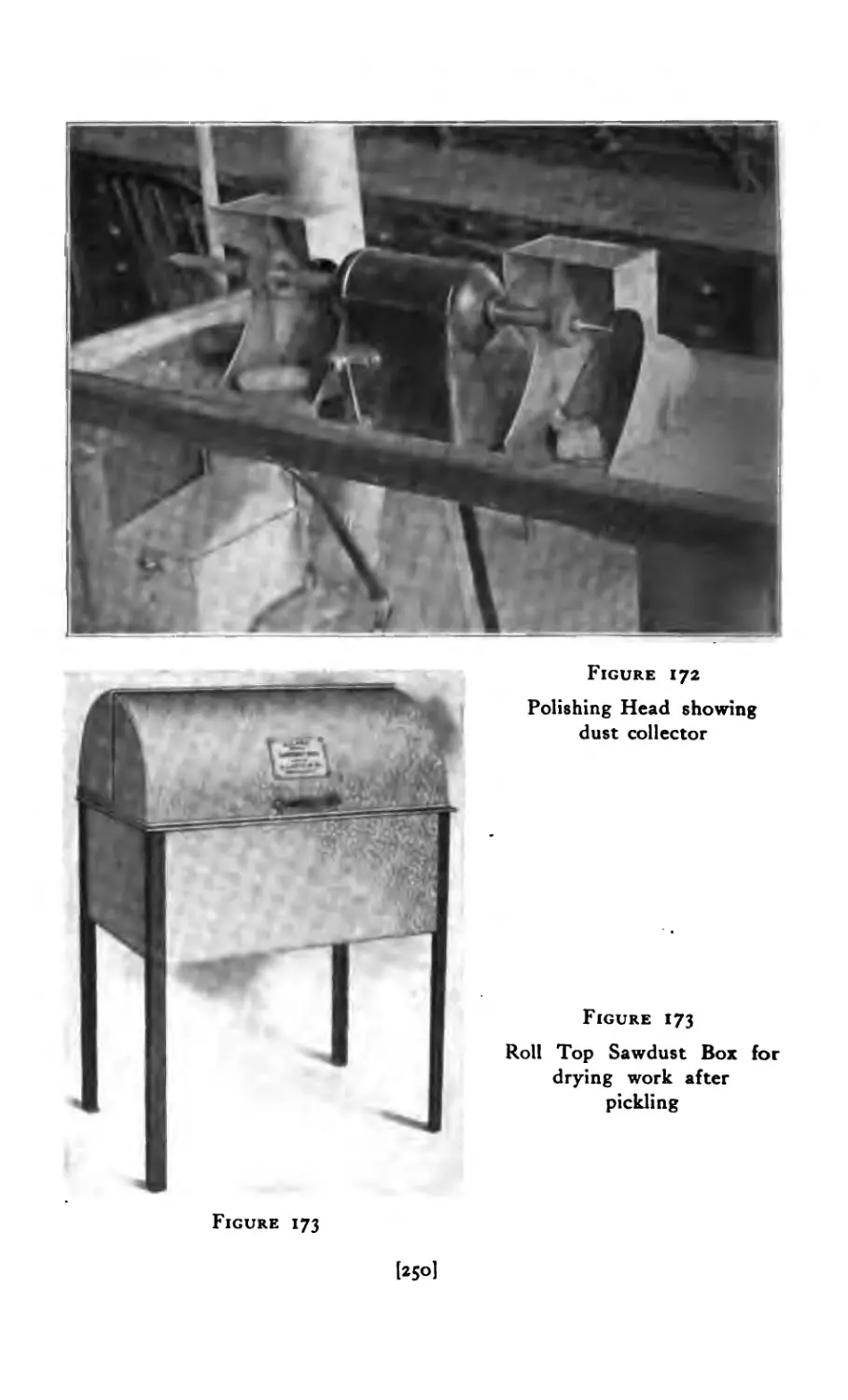
172 Polishing Head ........ 250
173 Sawdust Box ......... 250
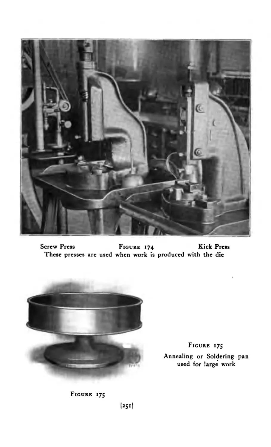
174 Screw Press, Kick Press . . . .251
175 Annealing and Soldering Pan . . 251
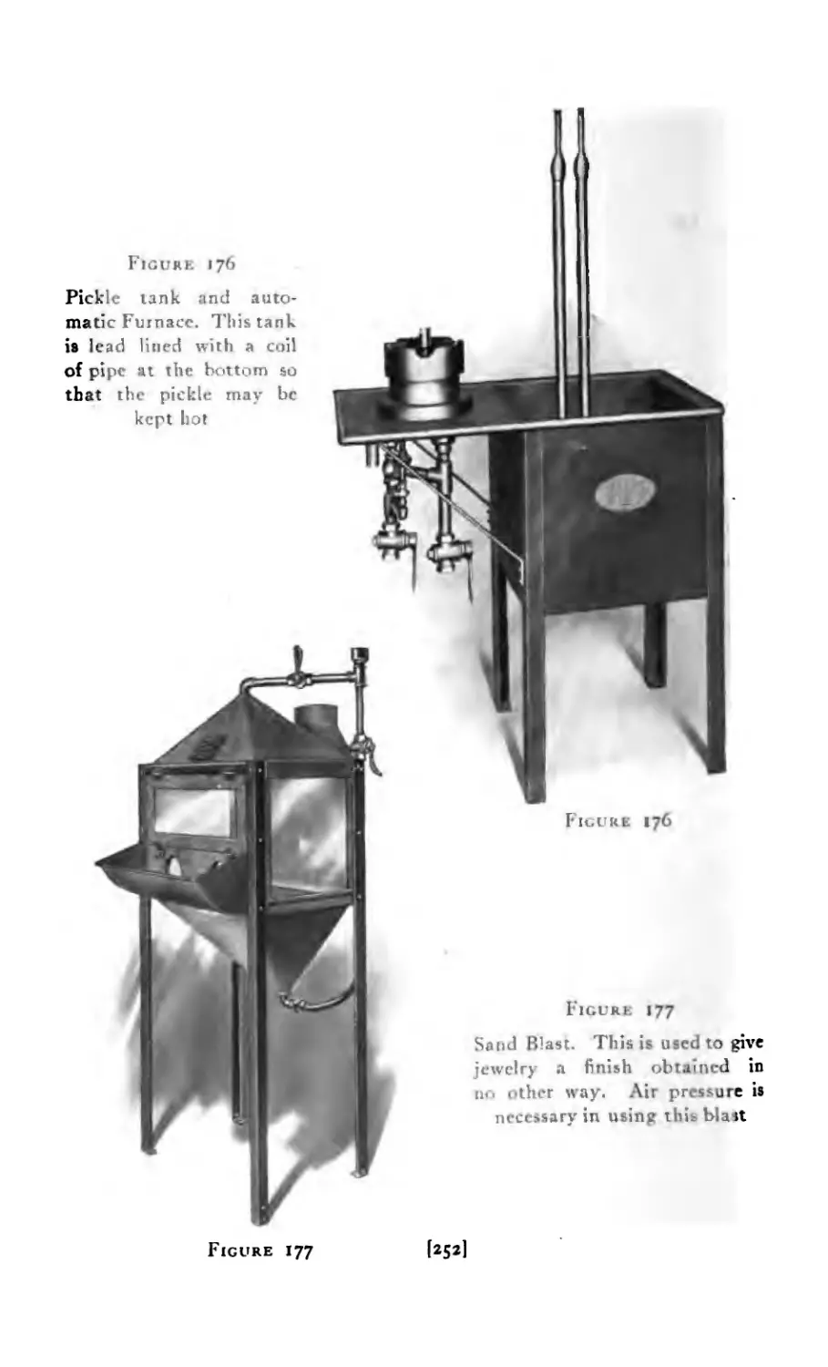
176 Pickle Tank ......... 252
177 Sand Blast ......... 252
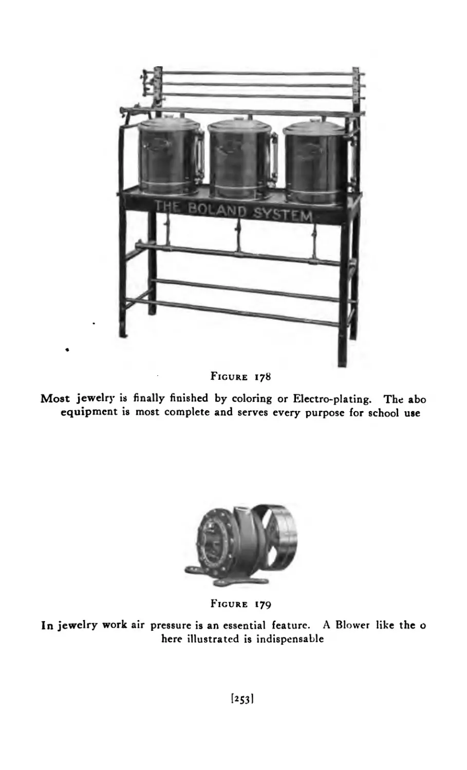
178 Coloring Outfit ........ 253
179 Blower .......... 253
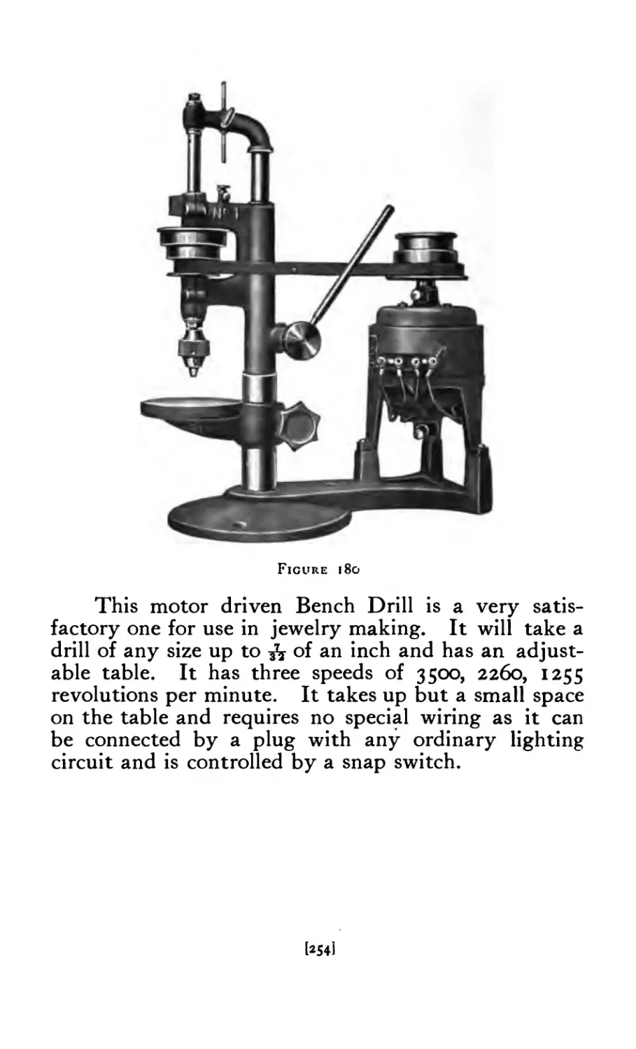
180 Electric Drill ......... 254
Book II. Jewelry Design
PLATE PAGE
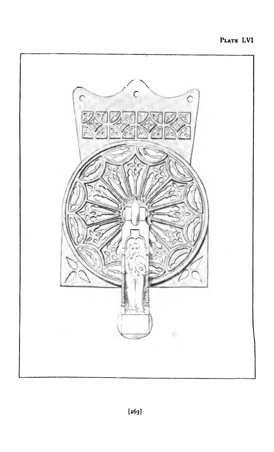
LVI Copy of Door-Knocker ...... 263
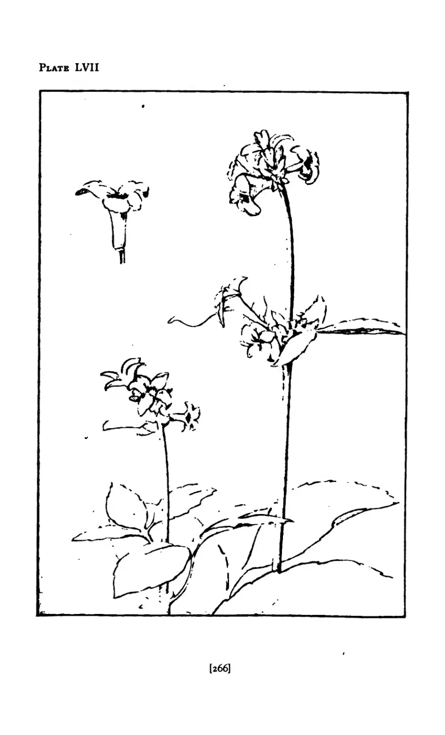
LV1I Flower Spray ........ 266
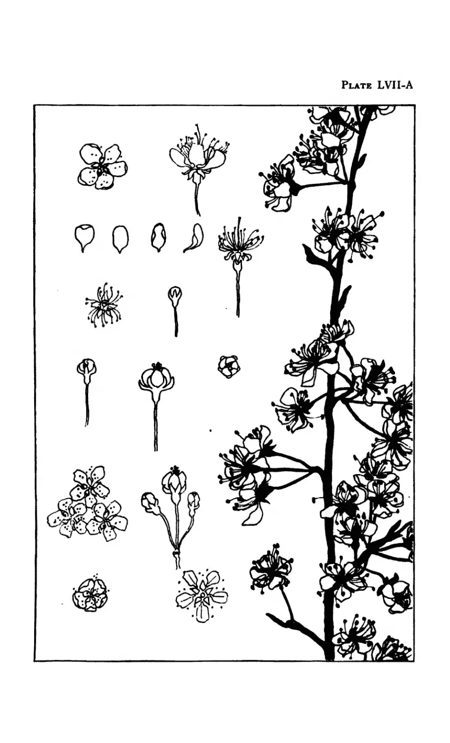
LVII-A Study of Apple Blossoms ......
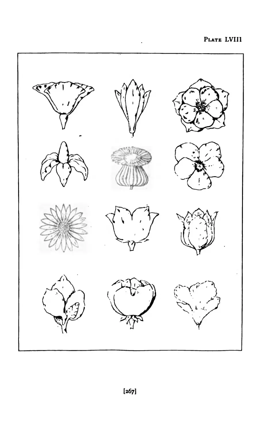
LVIII Bud Forms ........ 267
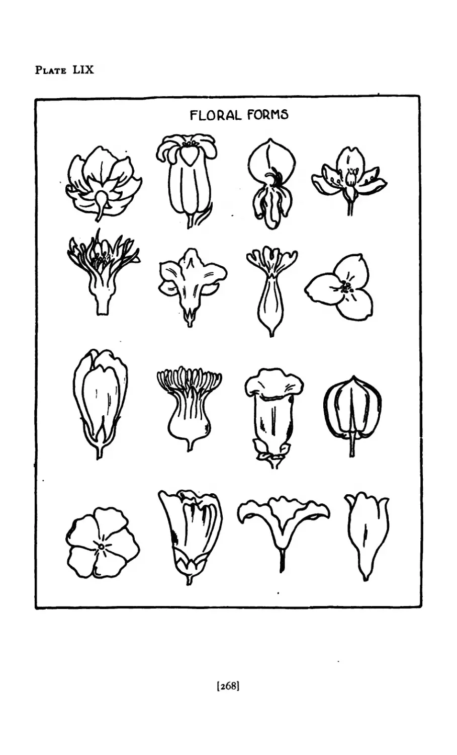
LIX Bud Forms ........ 268
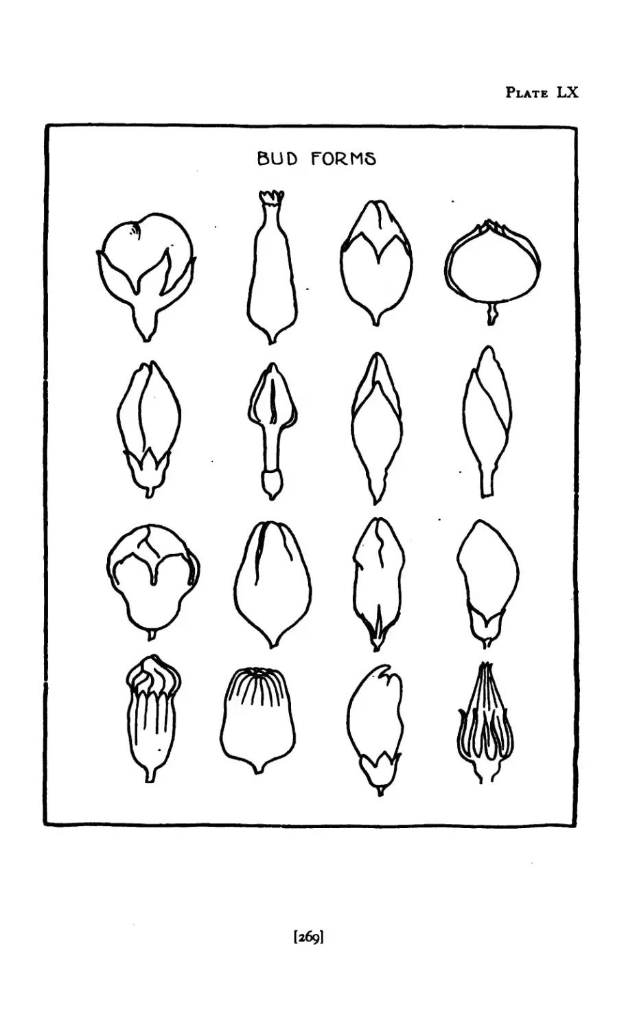
LX Bud Forms ........ 269
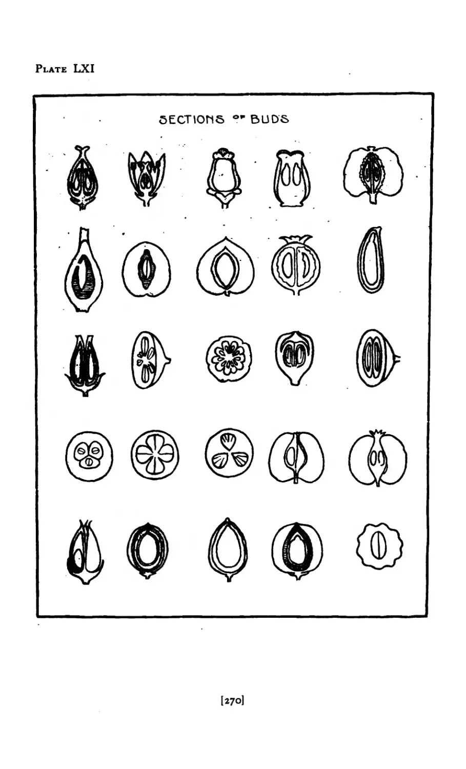
LX I Bud Sections ........ 270
LX1I Sections of Seed Pods . . . . . .271
lx]
PLATE PAGE
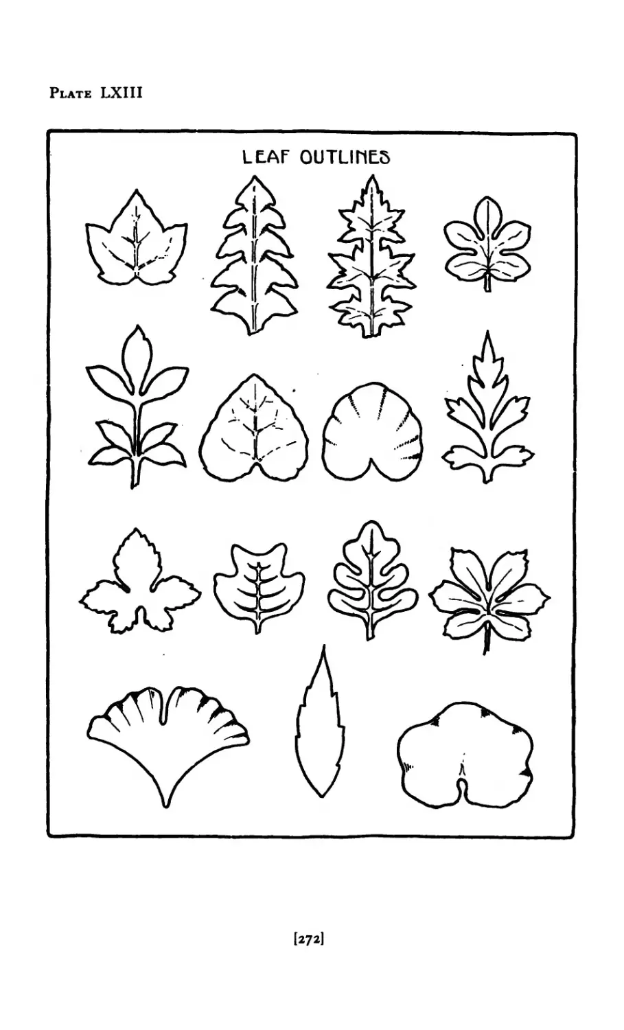
LXIII Leaf Outlines 272
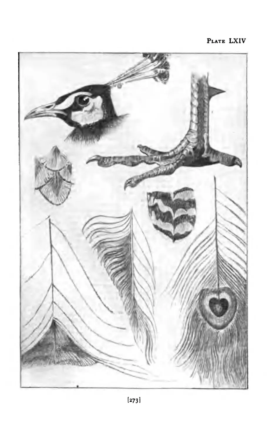
LXIV Studies from Peacock ..... 273
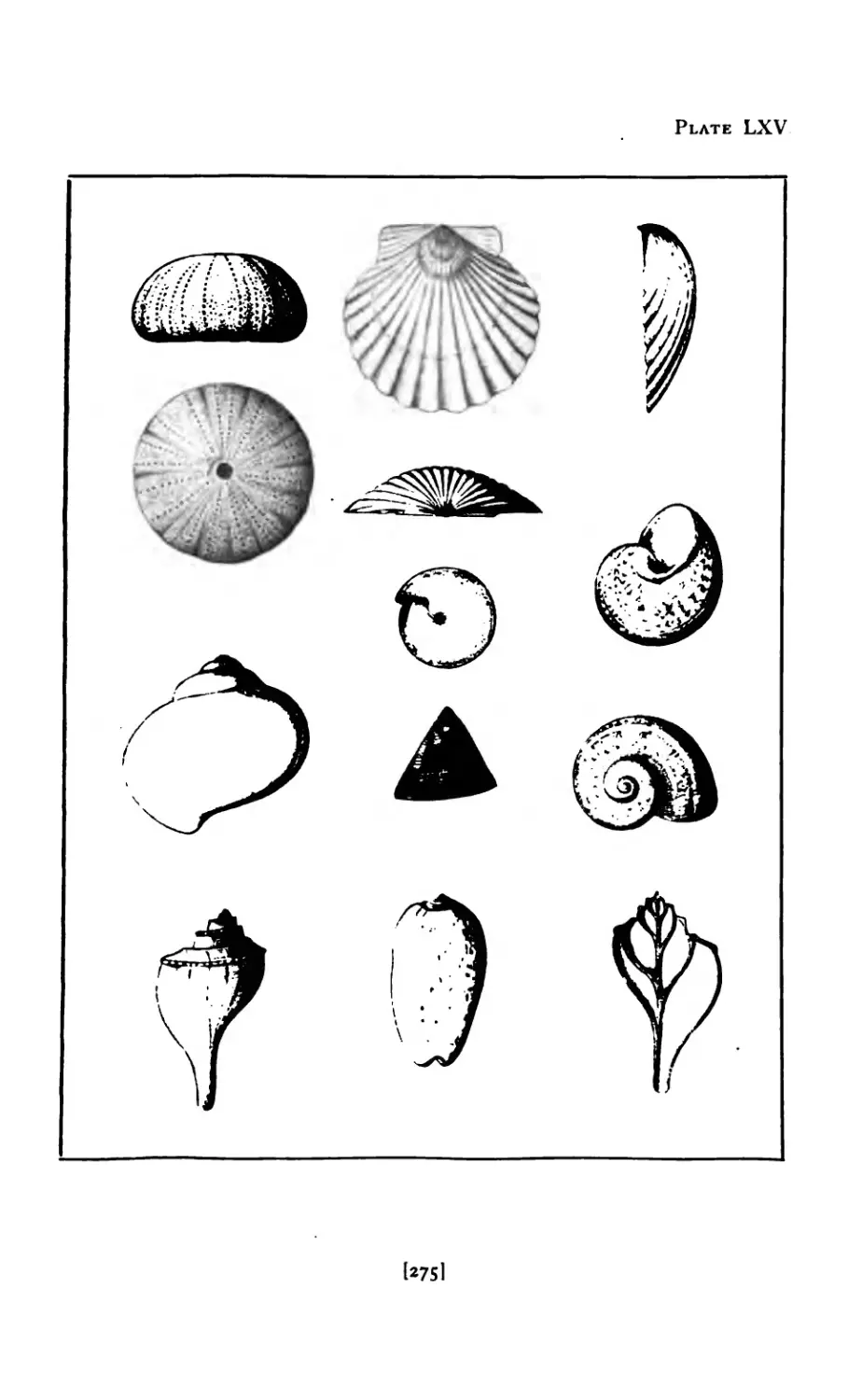
LXV Shells . ....... 275
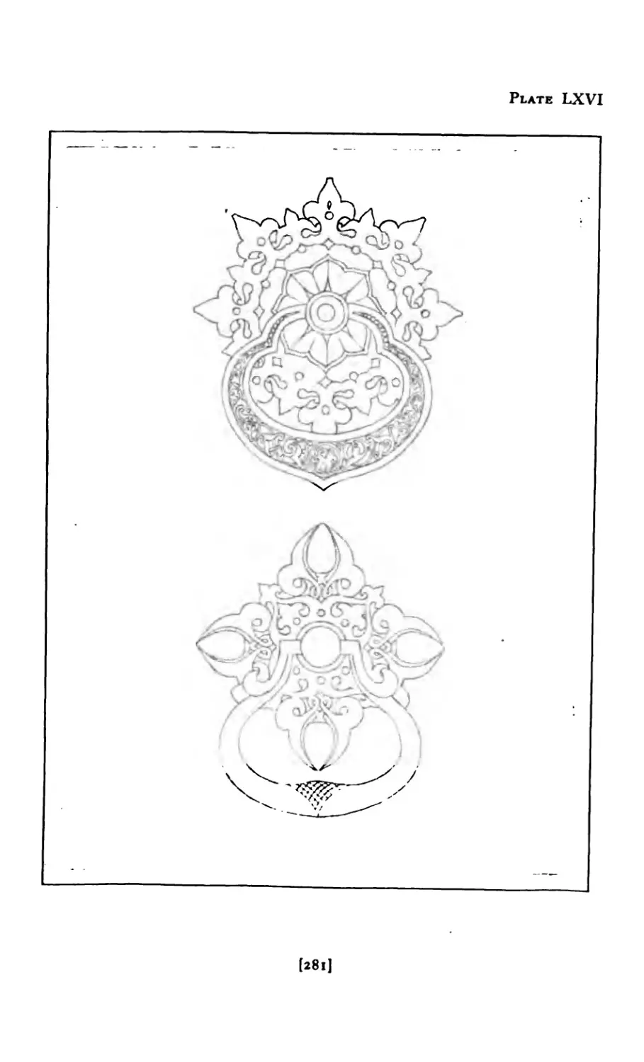
LXV1 Arabic Door-Knockers ..... 28l
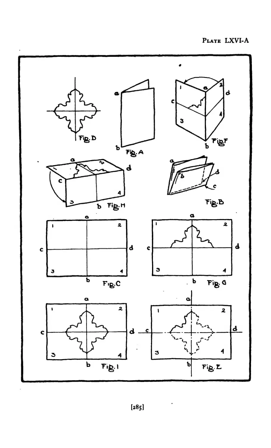
LXVI-A Steps in Tracing ...... 285
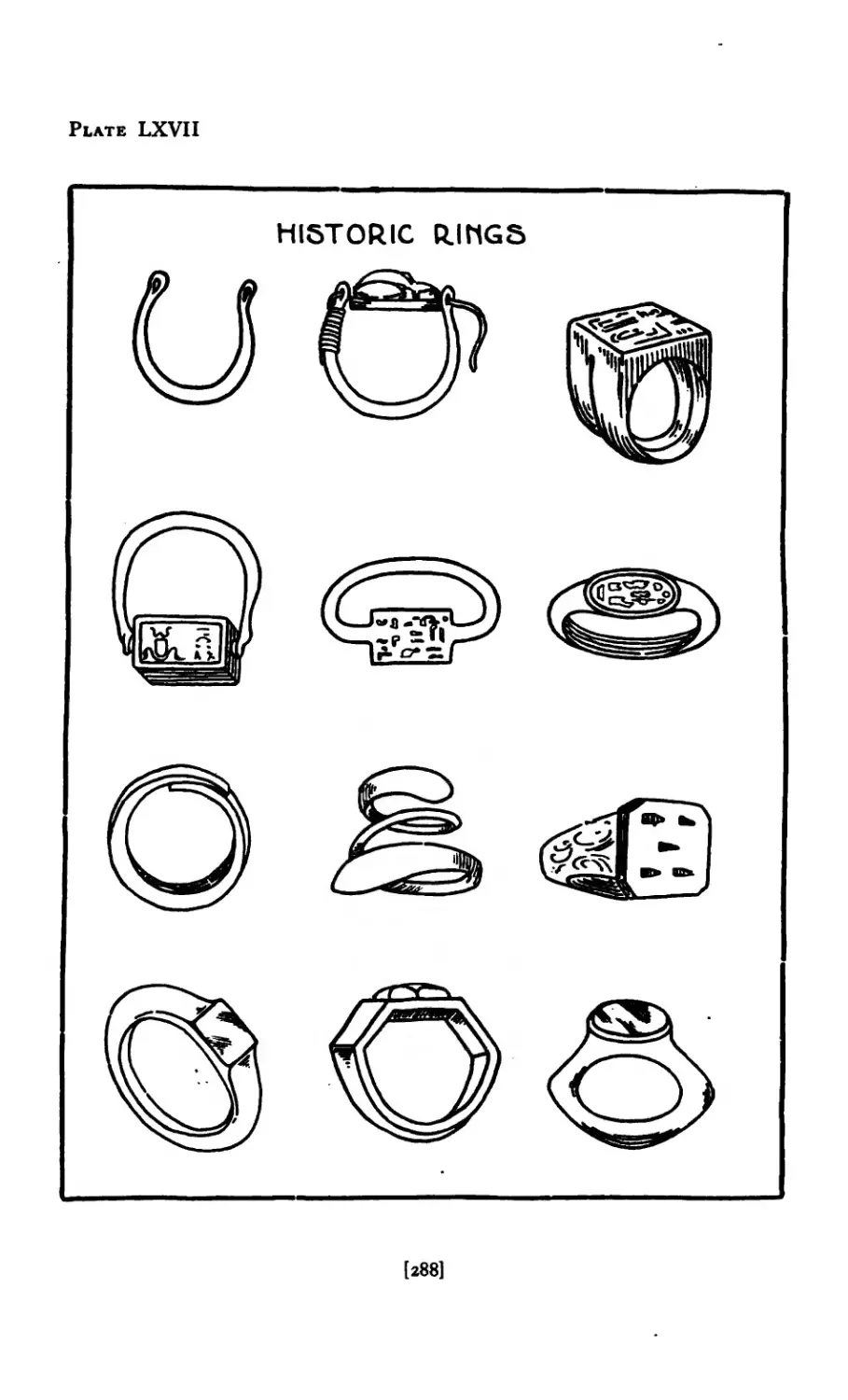
LXVII Historc Rings ....... 288
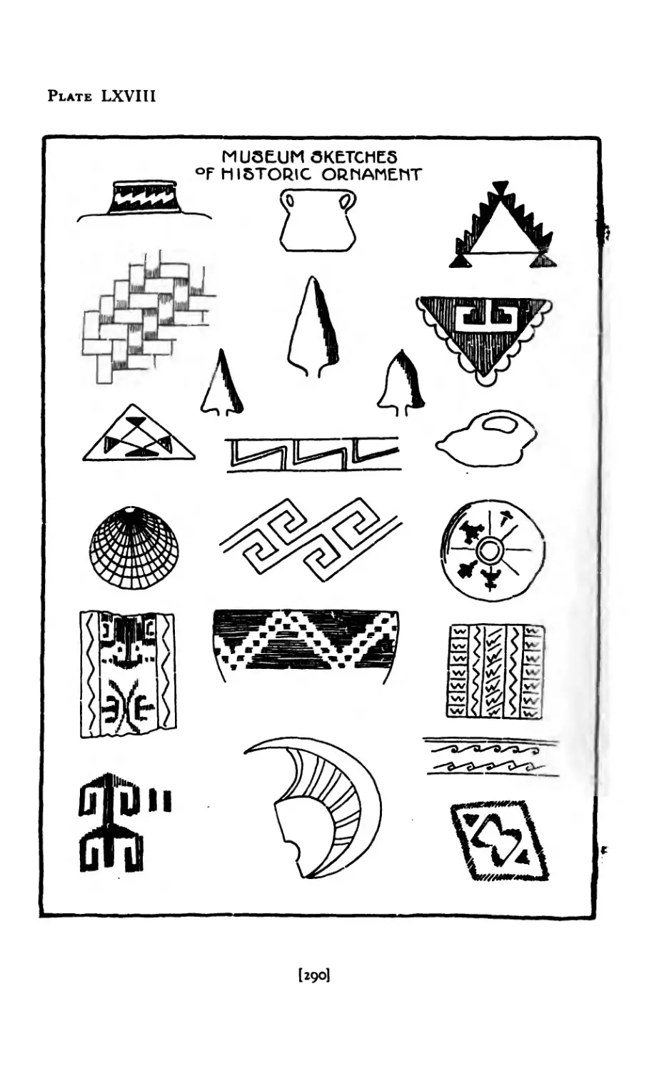
I.XVIII Historic Ornament ...... 29O
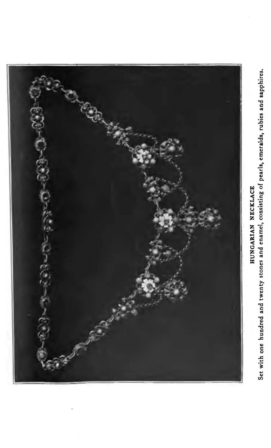
LXIX Hungarian Necklace ..... 291
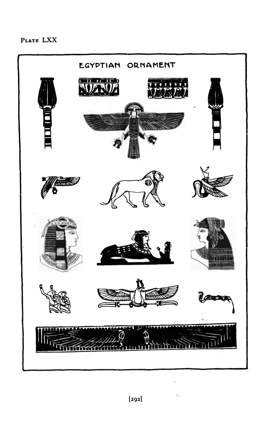
LXX Historic Ornament ...... 292
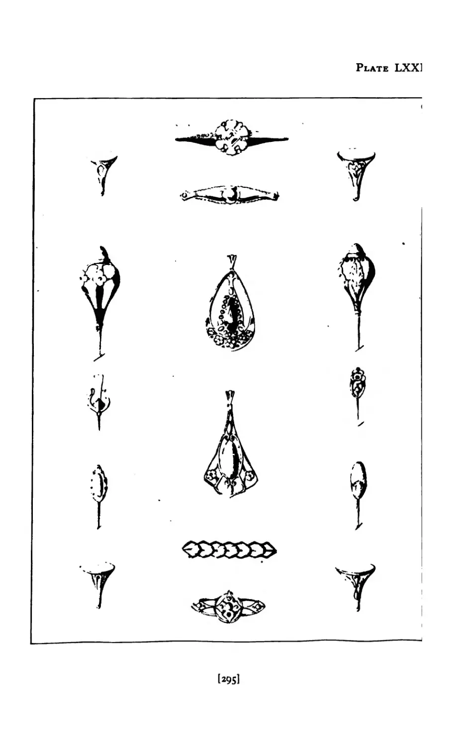
LXXI Designs Derived from Nature 295
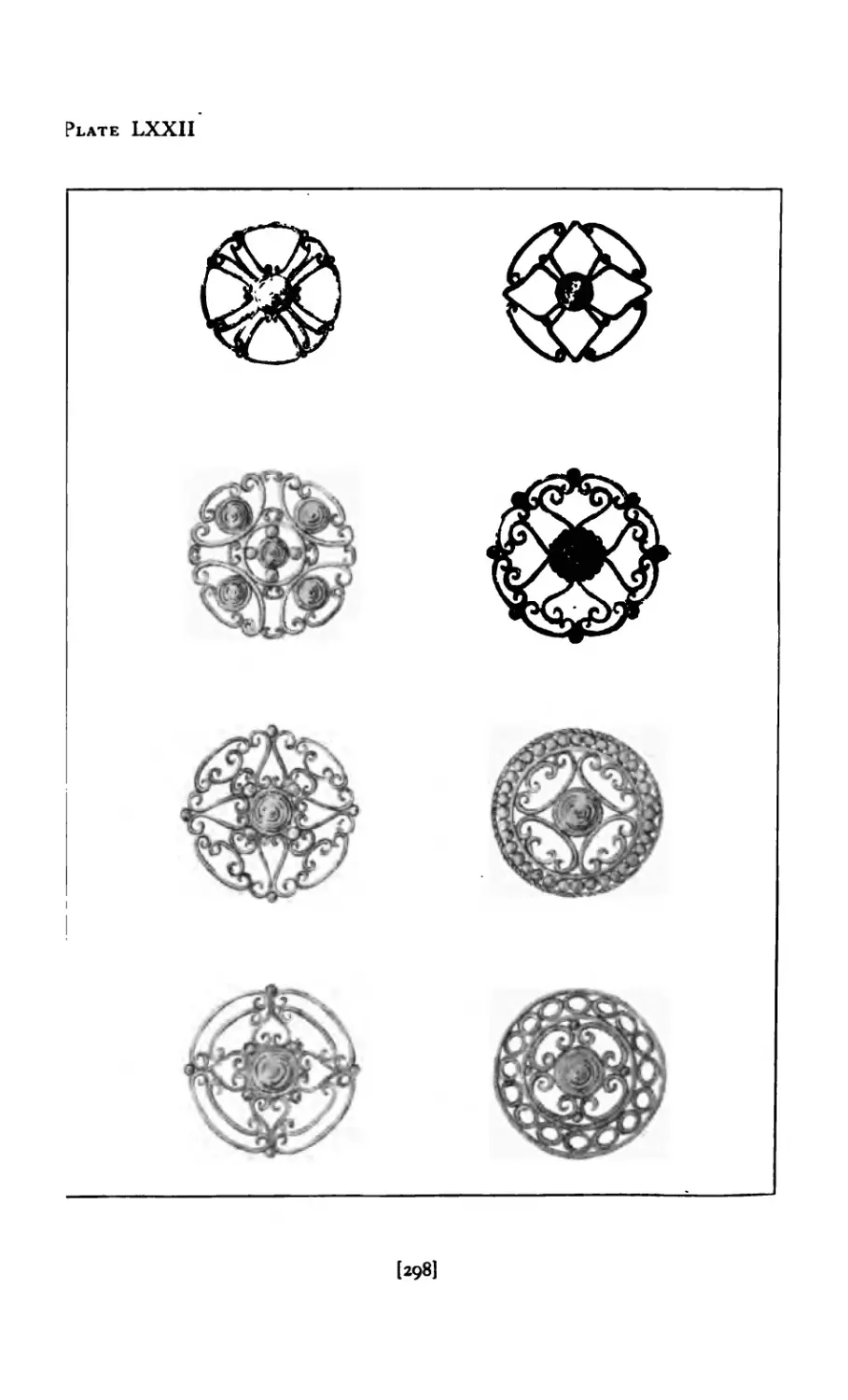
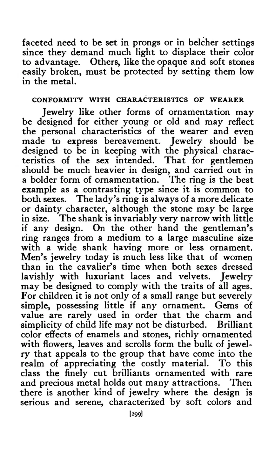
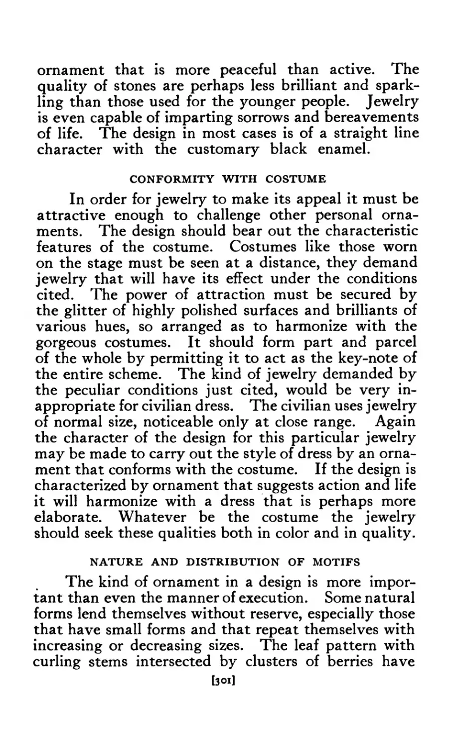
LXXII Brooches in Wire ...... 298
lxxiii Brooches in Wire ...... 300
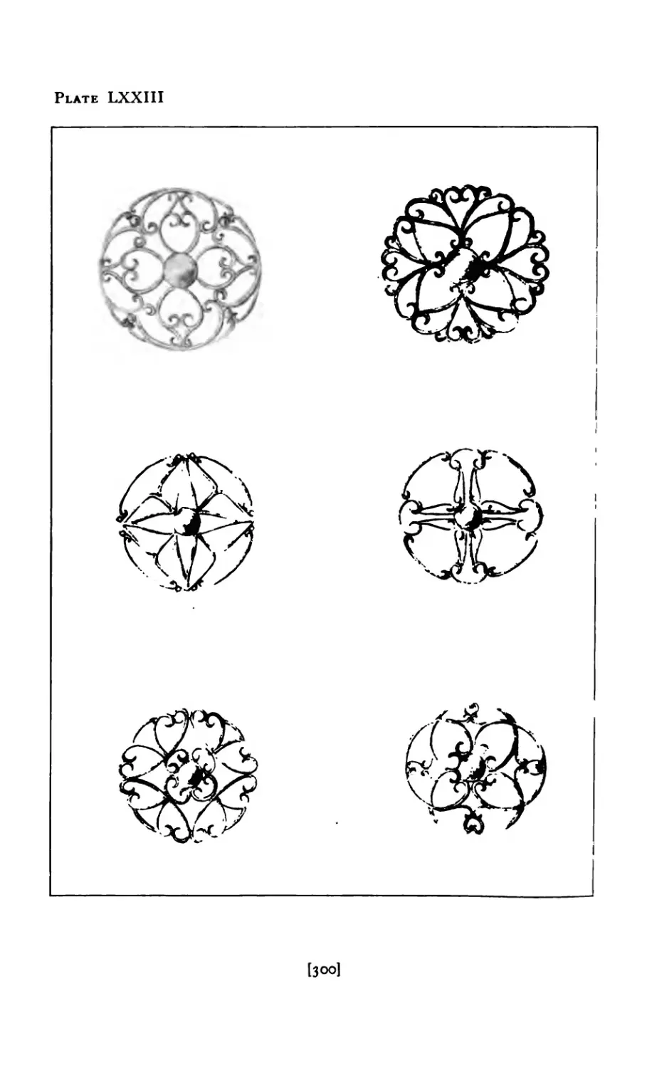
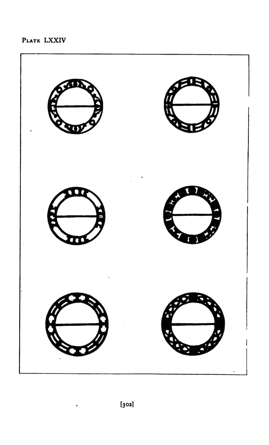
LXX IV Circular Brooches ...... 302
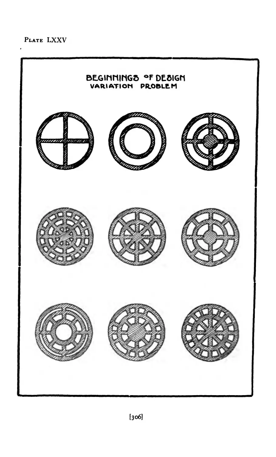
LXXV Beginnings of Design ..... 306
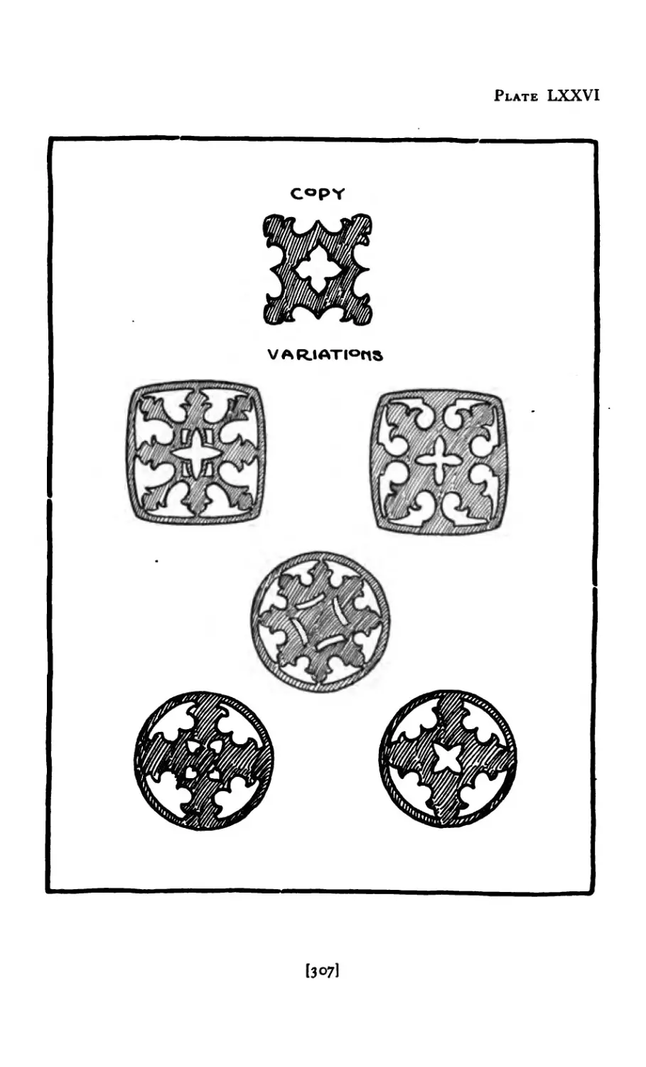
LXXVI Variations ....... 307
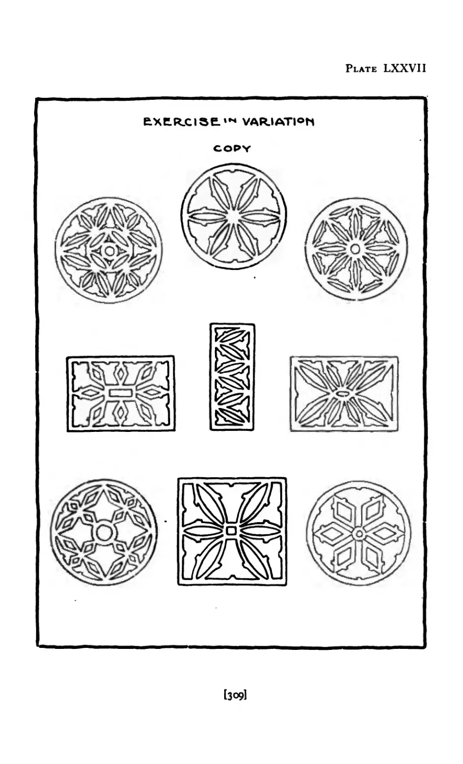
LXXVII Variations of Gothic Motive .... 309
LXXVIII Variations ....... 3H
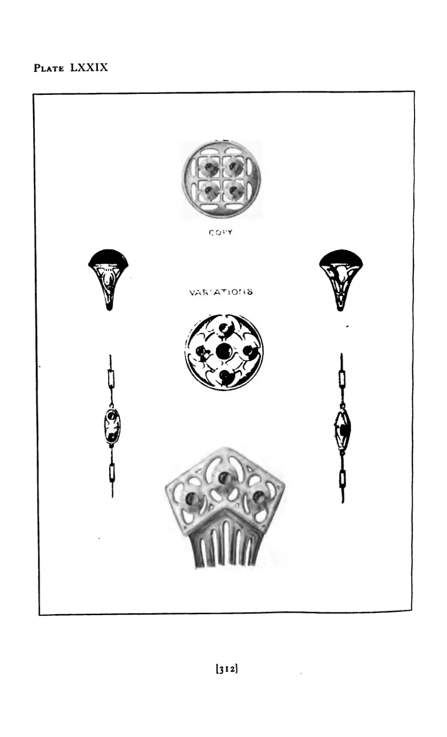
LXXIX Variations ....... 312
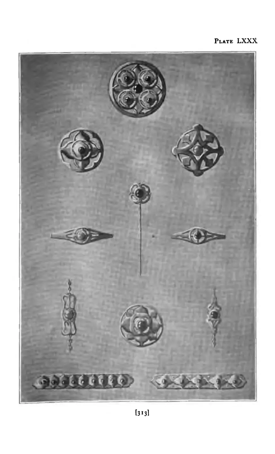
LXXX Variations ....... 313
LXXXI Structural Elements of Circle .... 3l6
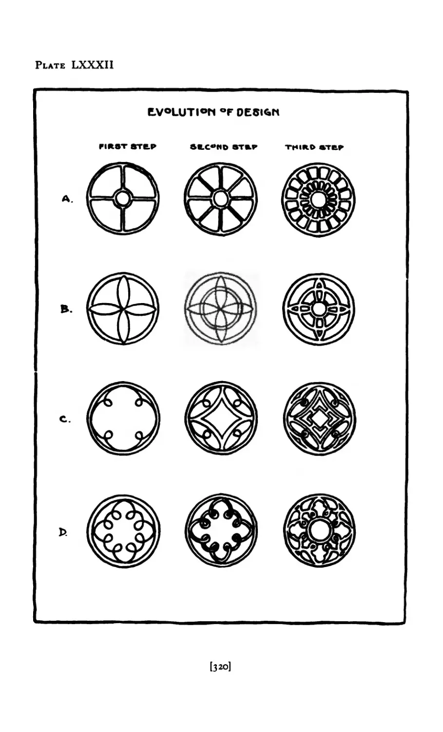
LXXXII Evolution of Design ...... 320
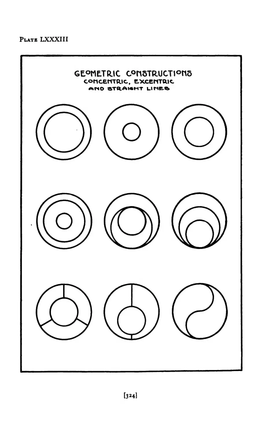
LXXXIII Geometric Constructions .... 324
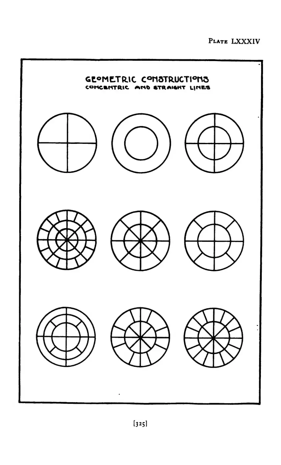
LXXXIV Geometric Constructions ..... 325
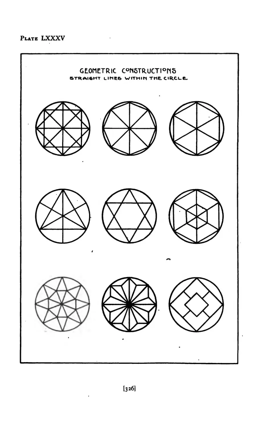
LXXXV Geometric Constructions ..... 326
LXXXVI Geometric Constructions ..... 327
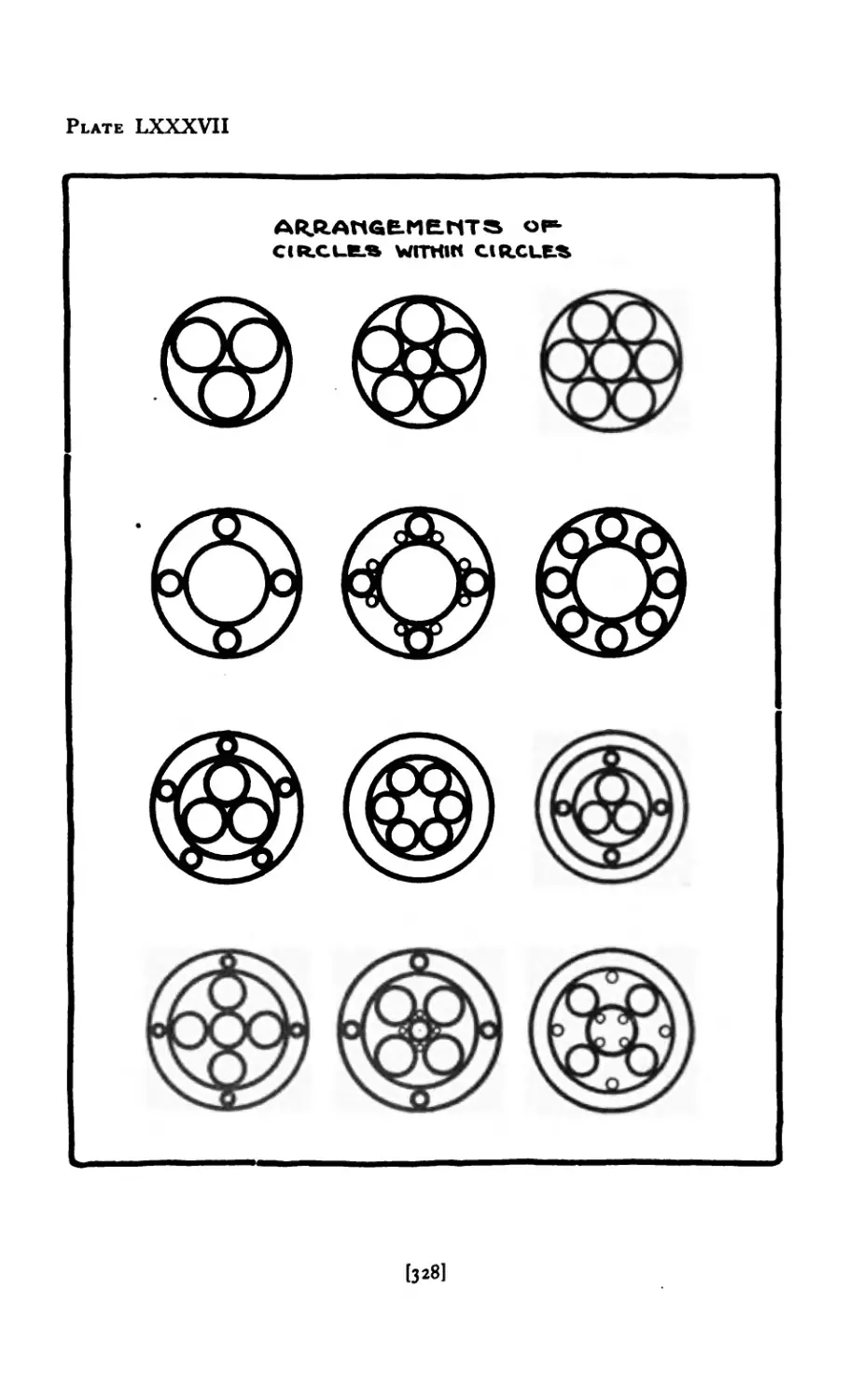
LXXXVII Arrangements of Circles ..... 328
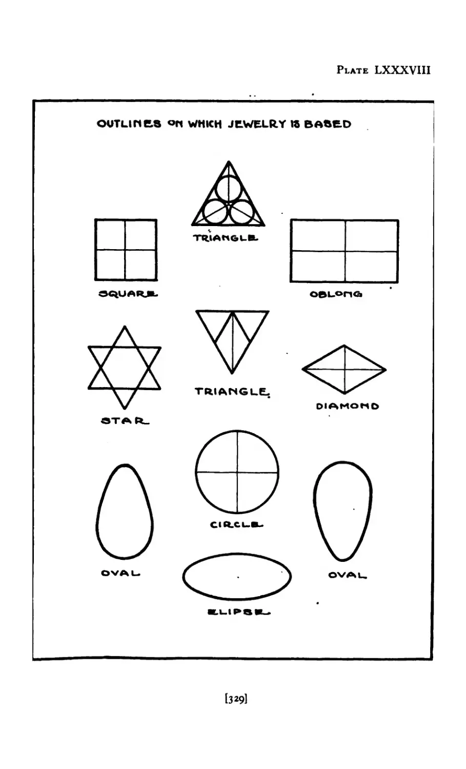
LXXXVIII Outlines on which Jewelry is based 329
LXXXIX Circular Designs ...... 331
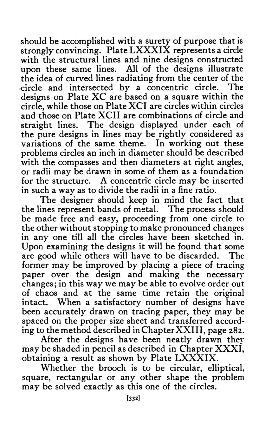
XC Circular Designs ...... 333
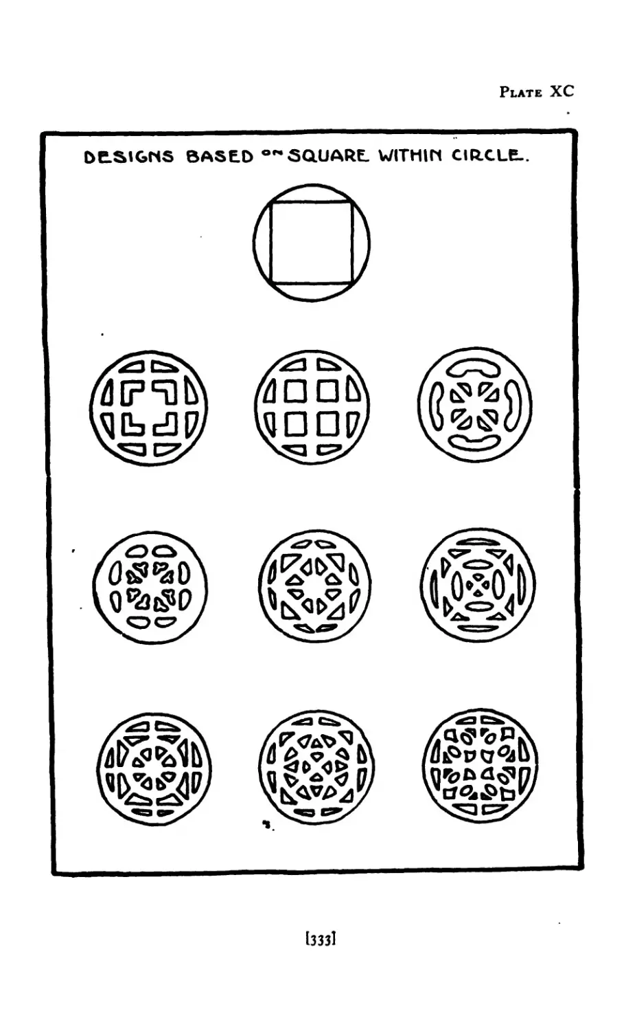
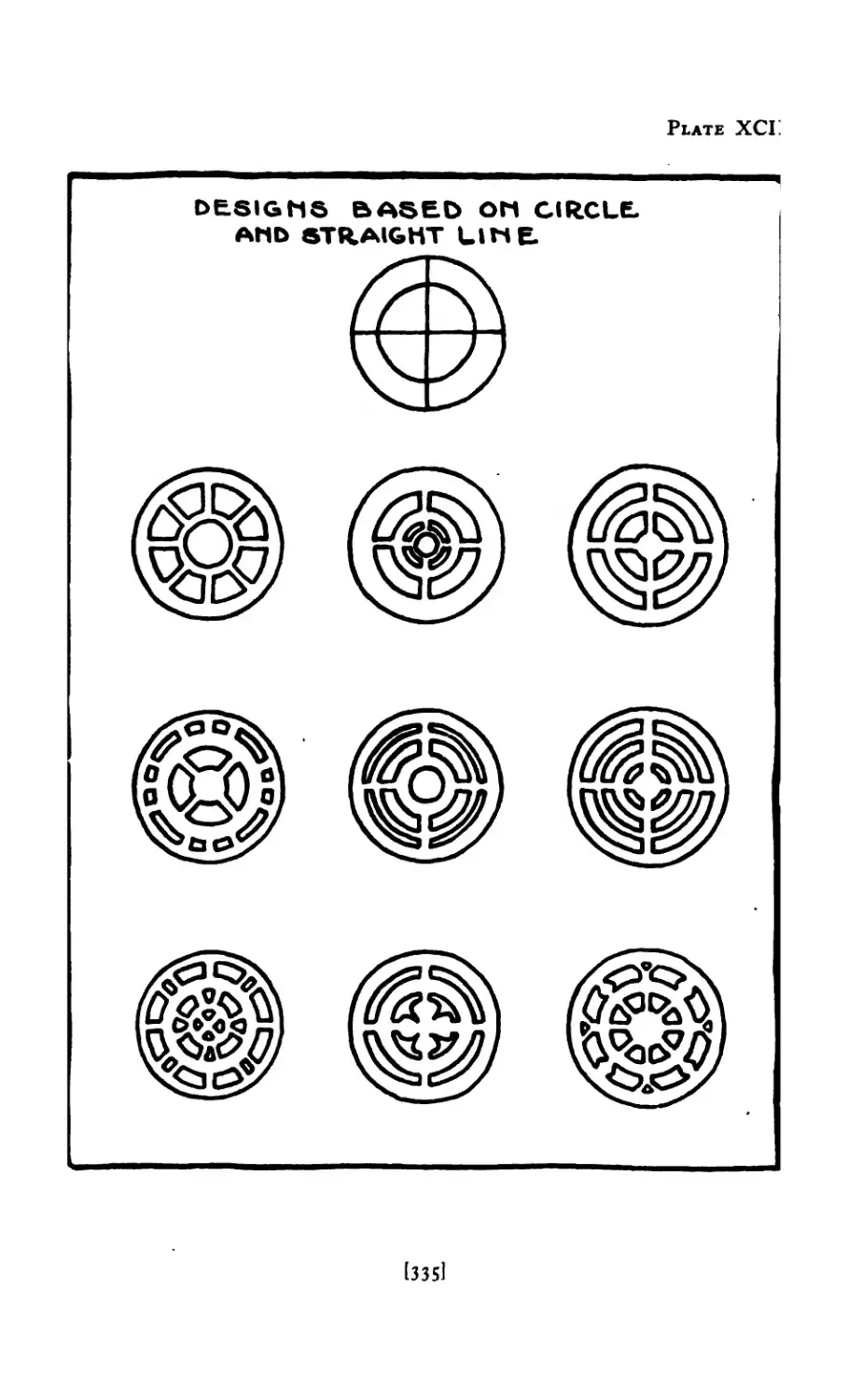
XCI Circular Designs ...... 334
XCII Circular Designs ...... 335
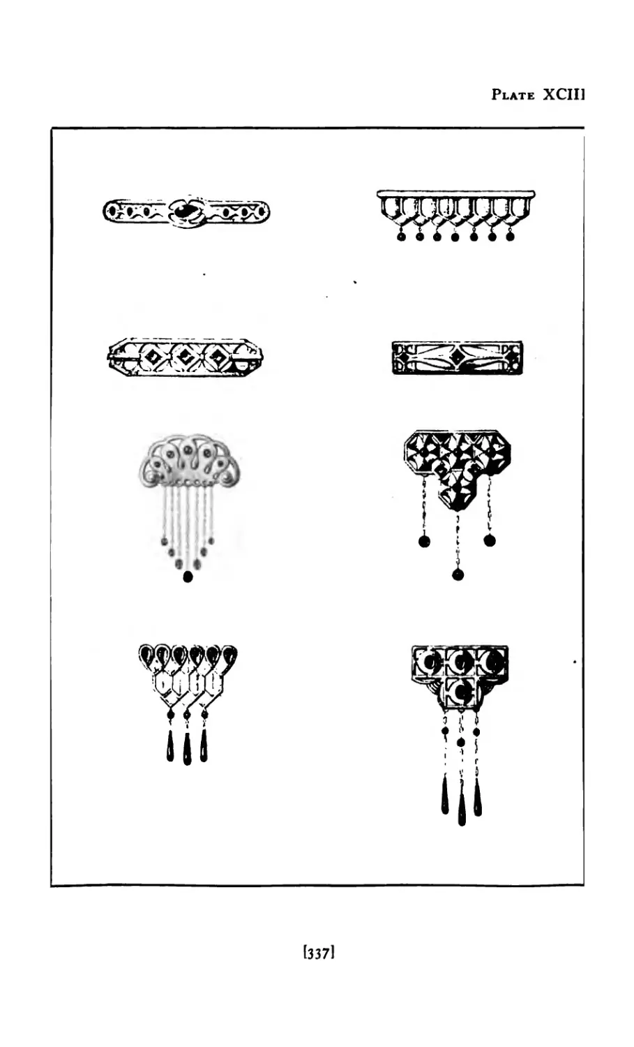
хеш Copies from Photographs .... 337
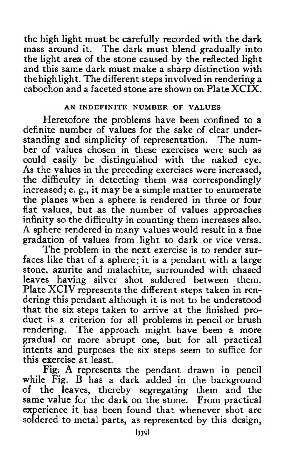
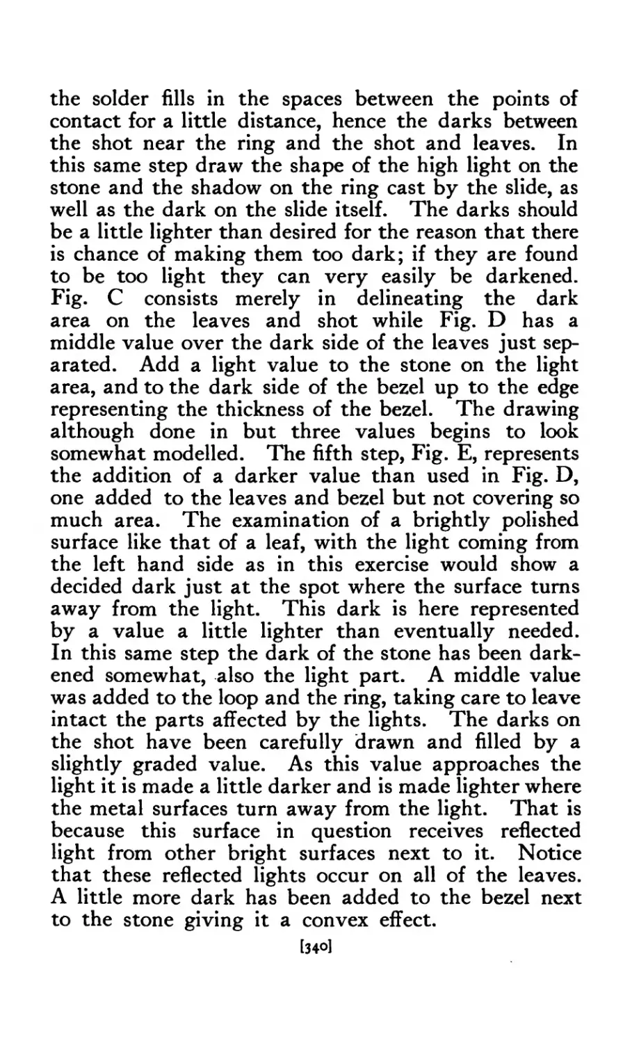
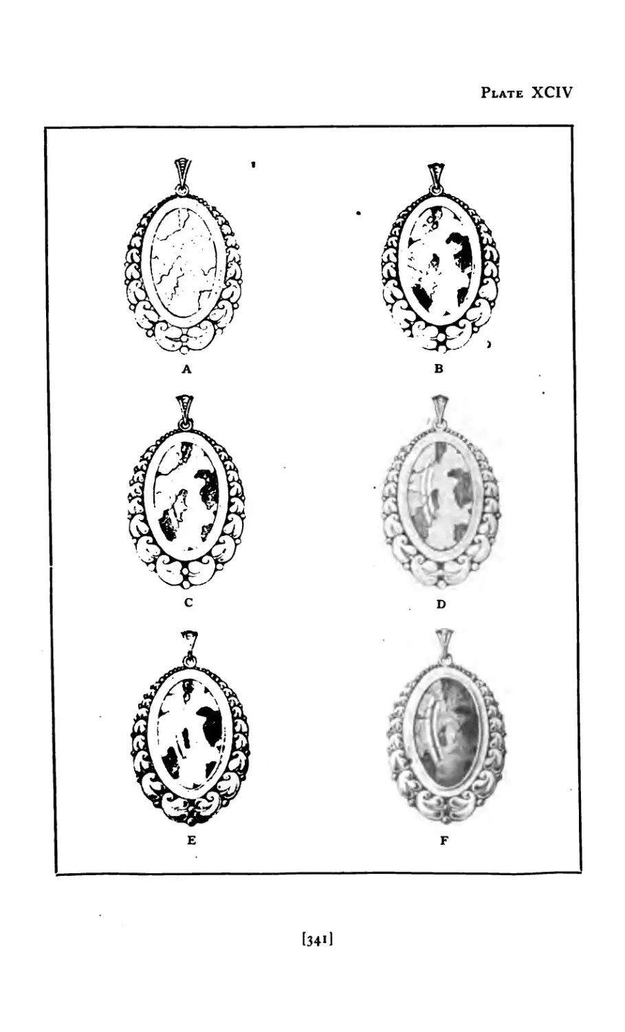
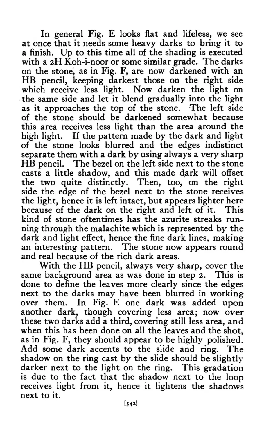
XCIV Method of Rendering ..... 341
xcv Rendering in Two Values ..... 344
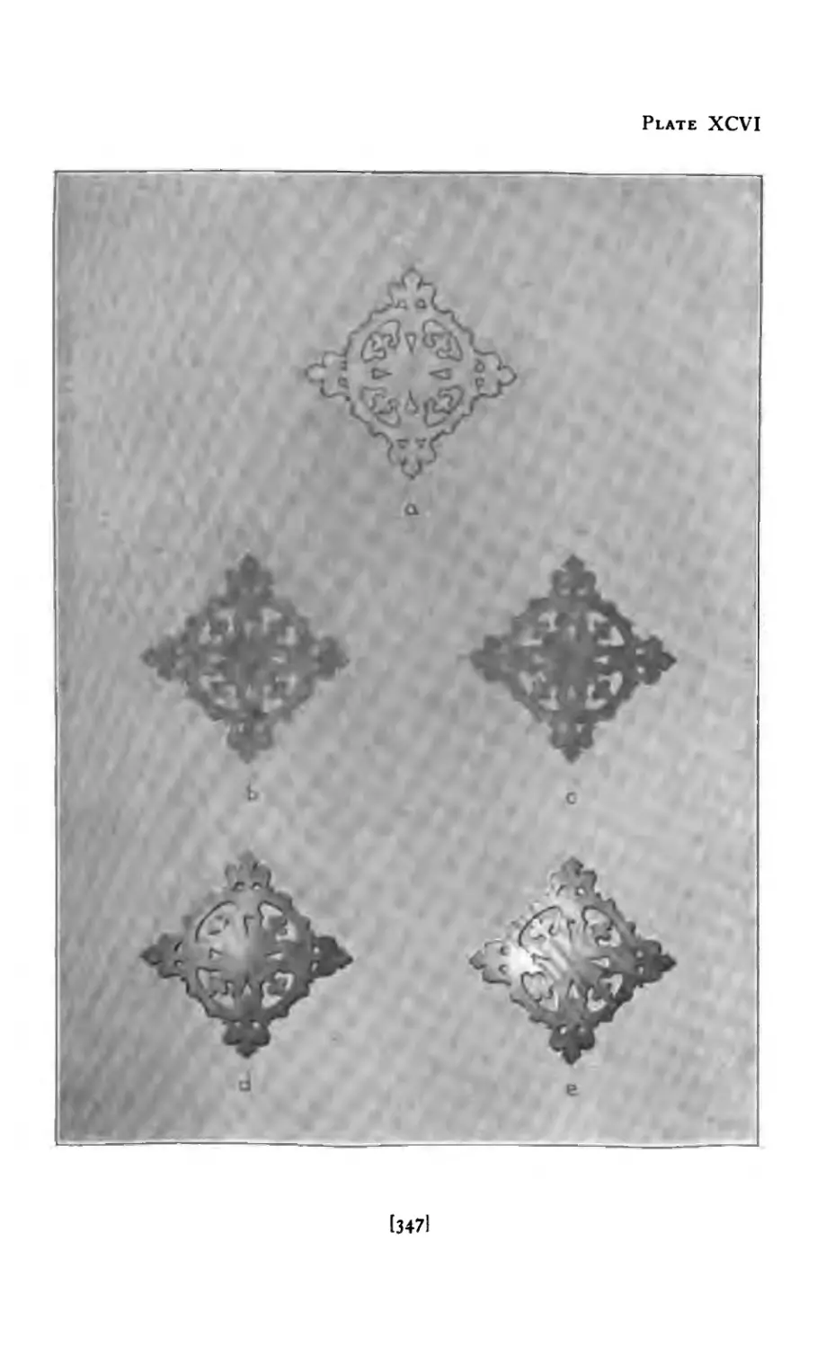
XCVI Rendering in Four Values on Gray Paper . 347
XCVII Rendering in Four Values on Gray Paper . 348
XCVIII Rendering in Color (Many Values)
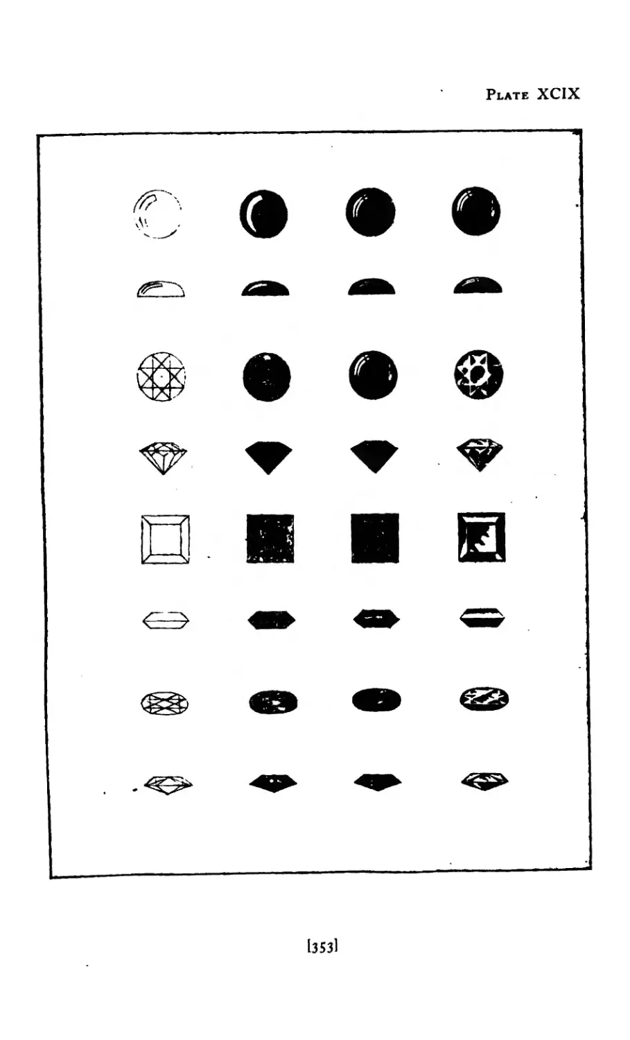
XCIX Rendering Stones ...... 353
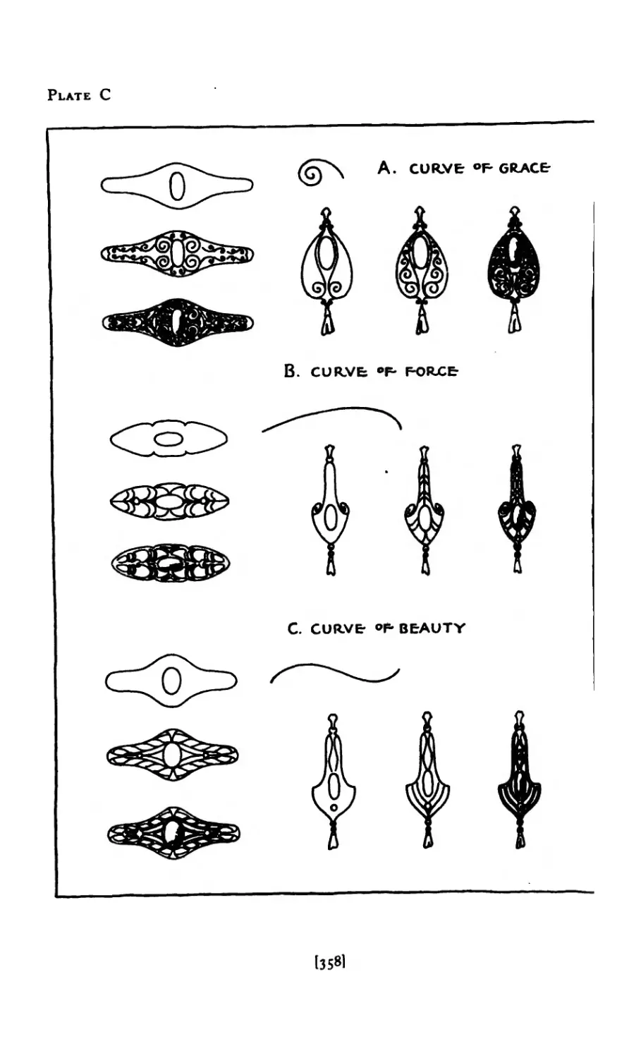
c Designs showing Vital Curves .... 358
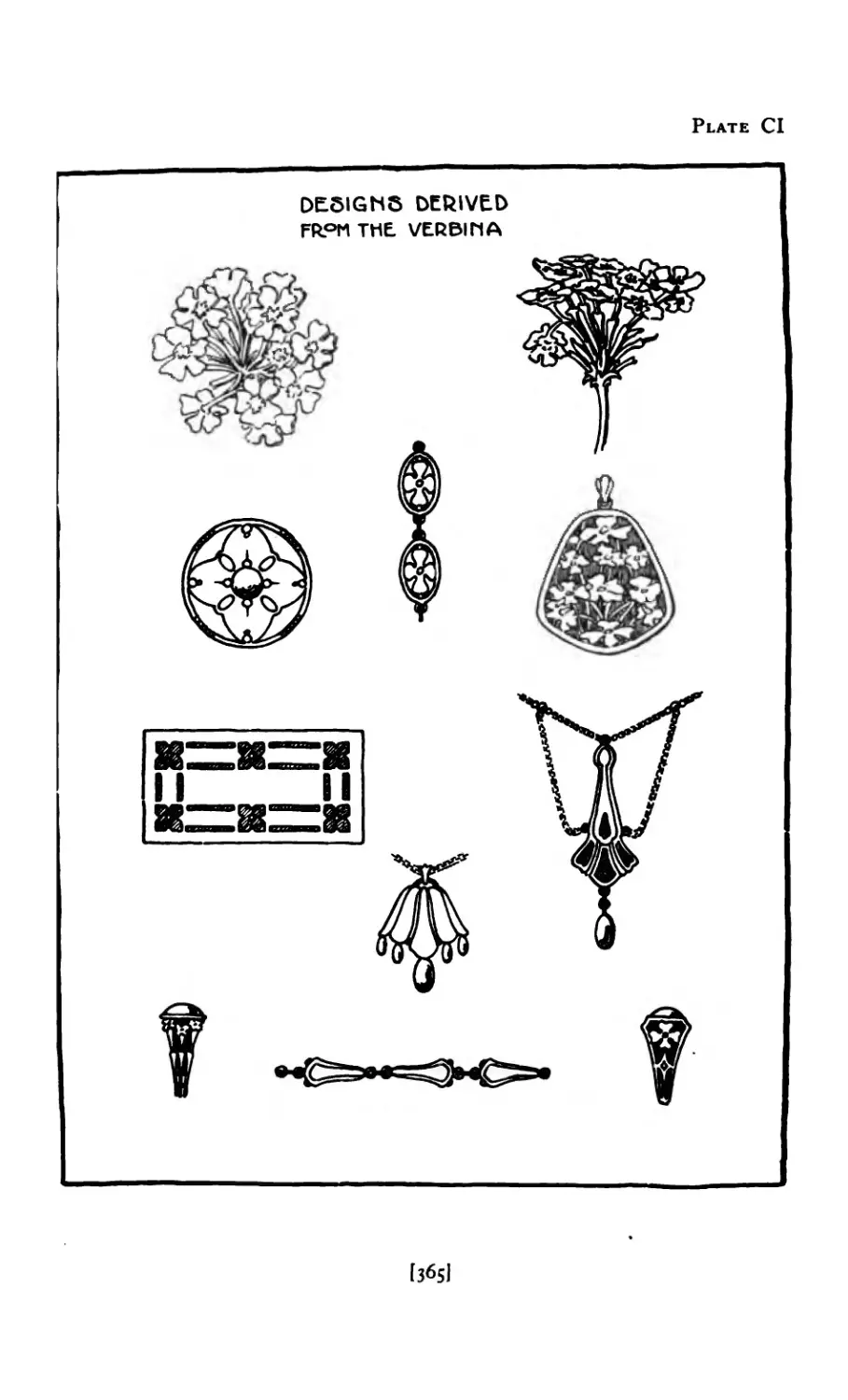
Cl Designs derived from Verbena .... 365
Cll Suggestive Forms, from Beetle .... 367
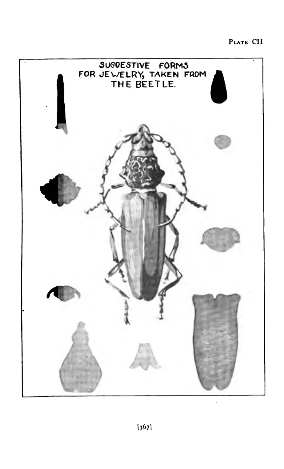
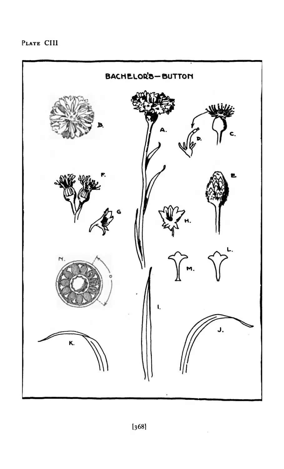
CIII Study of Bachelor’s Button .... 368
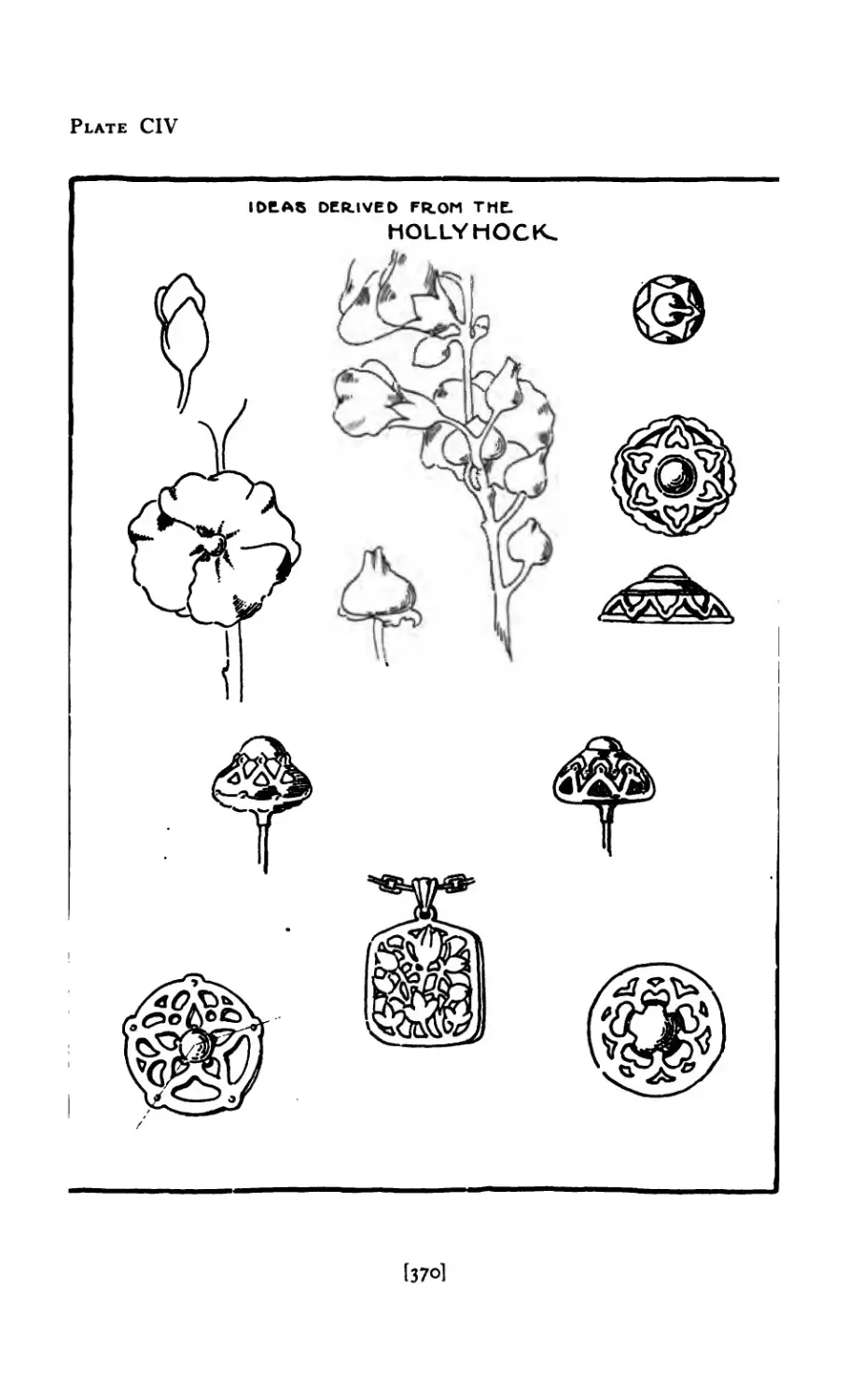
CIV Idea derived from Hollyhock .... 370
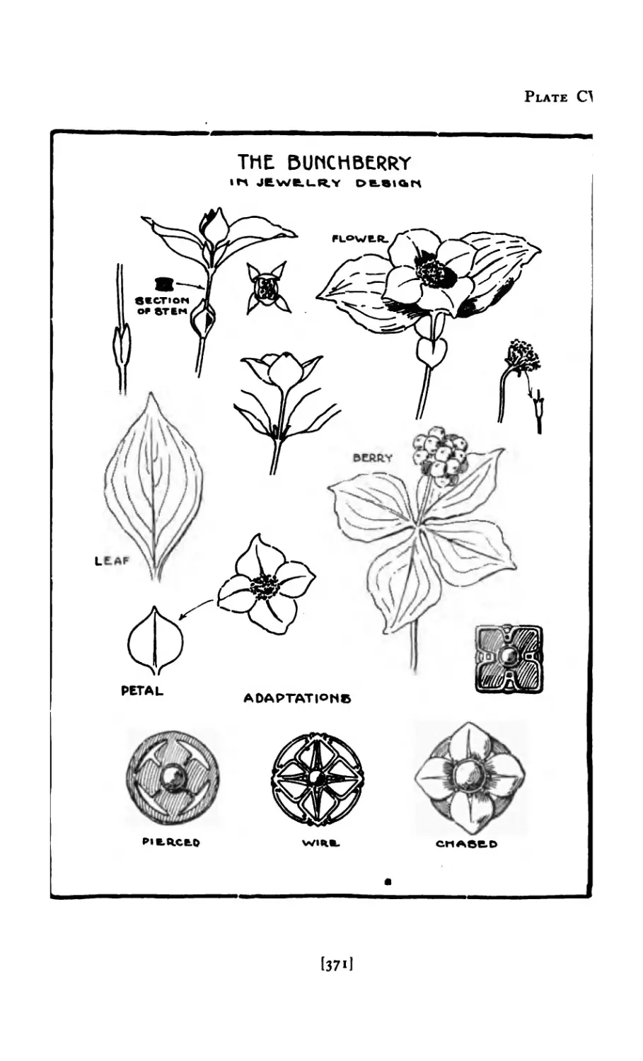
cv The Bunchberry in Design .... 371
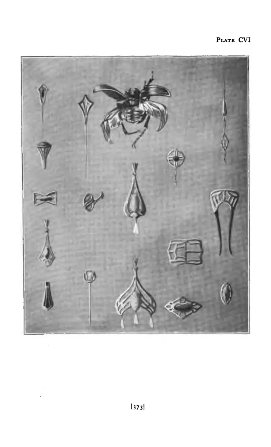
CVI Designs derived from Insect .... 373
[xi]
PLATE PAGE
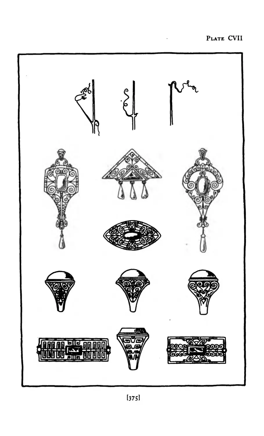
CVII Designs derived from Tendril .... 375
C.V1II Gold Pendant set with Turquoise and Pearl Drop
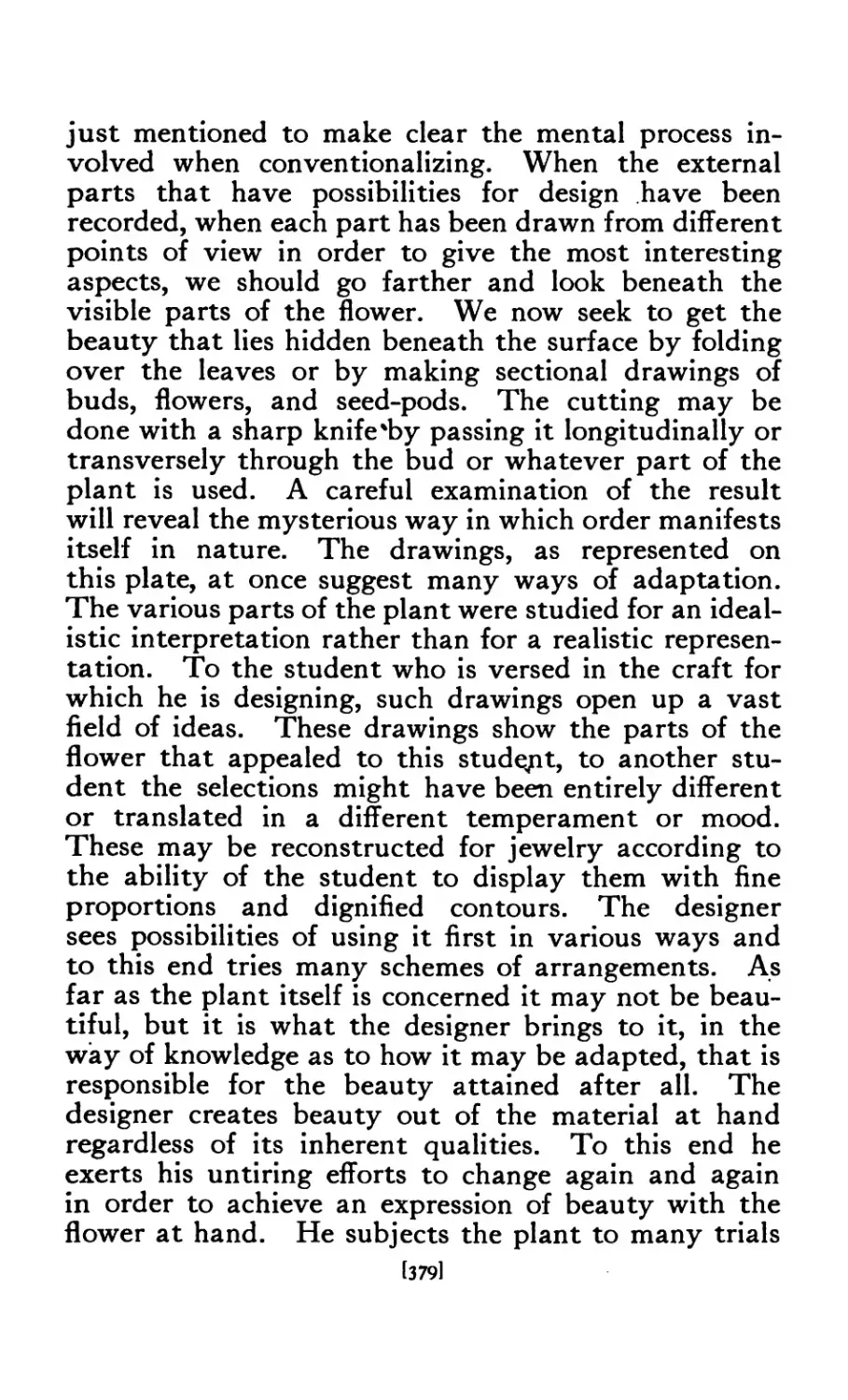
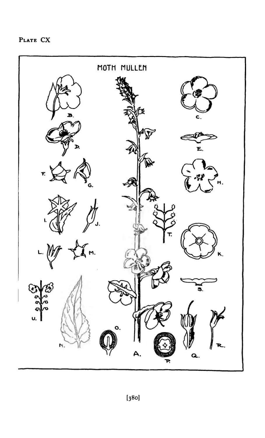
CIX Photograph of Moth-Mullen Spray 378
ex Moth-Mullen in Design ..... 380
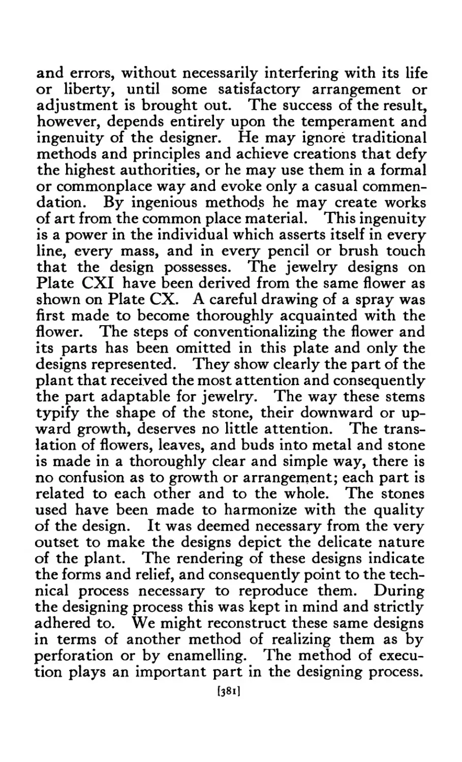
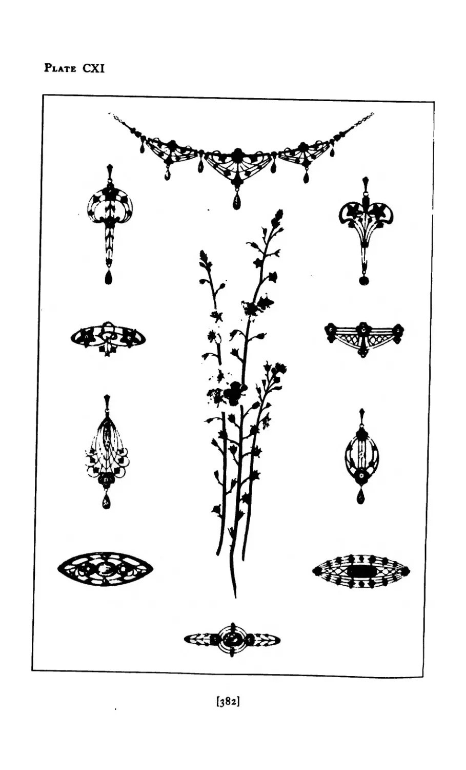
CXI Designs derived from Moth-Mulle 382
CXI I Designs derived from Snow-Crystal
CXIII Snow-Crystal Patterns ..... 38<>
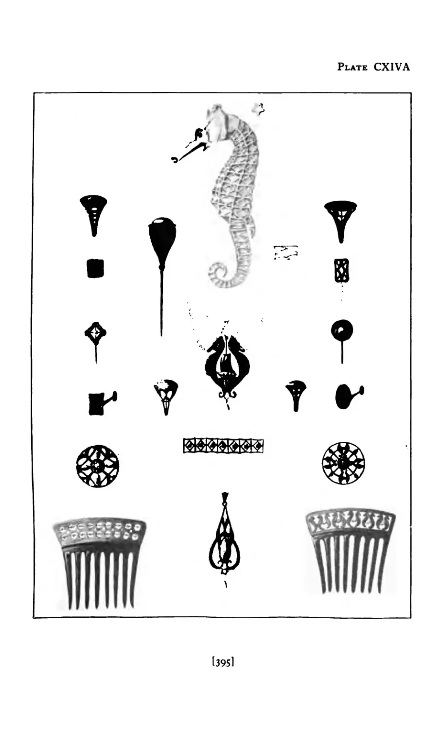
CXIV Designs derived from Sea Horse 393
CXIV-A Designs derived from Sea Horse 395
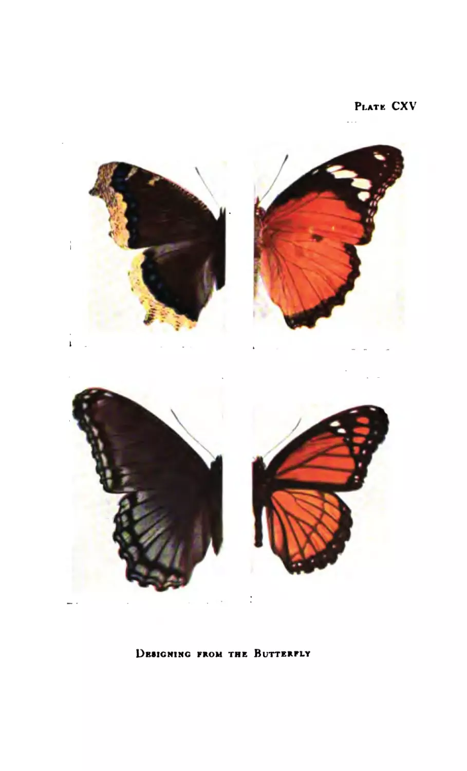
cxv Butterflies .......
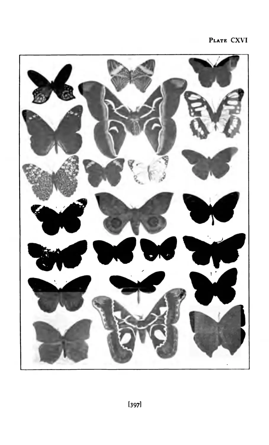
CXVI Collection of Butterflies ..... 397
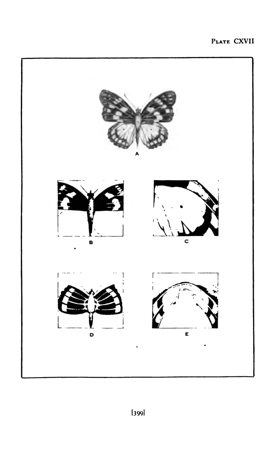
CXVI1 Method of Designing, from Butterfly . 399
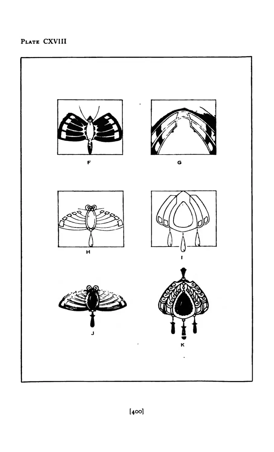
CX VIII Method of Designing, from Butterfly . 400
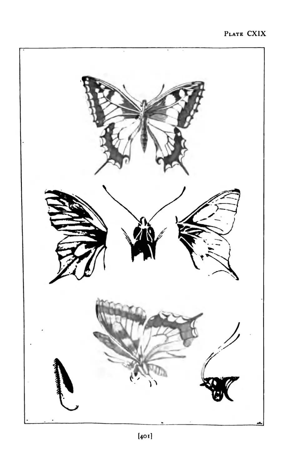
CXIX Studies from Butterfly ..... 4c 1
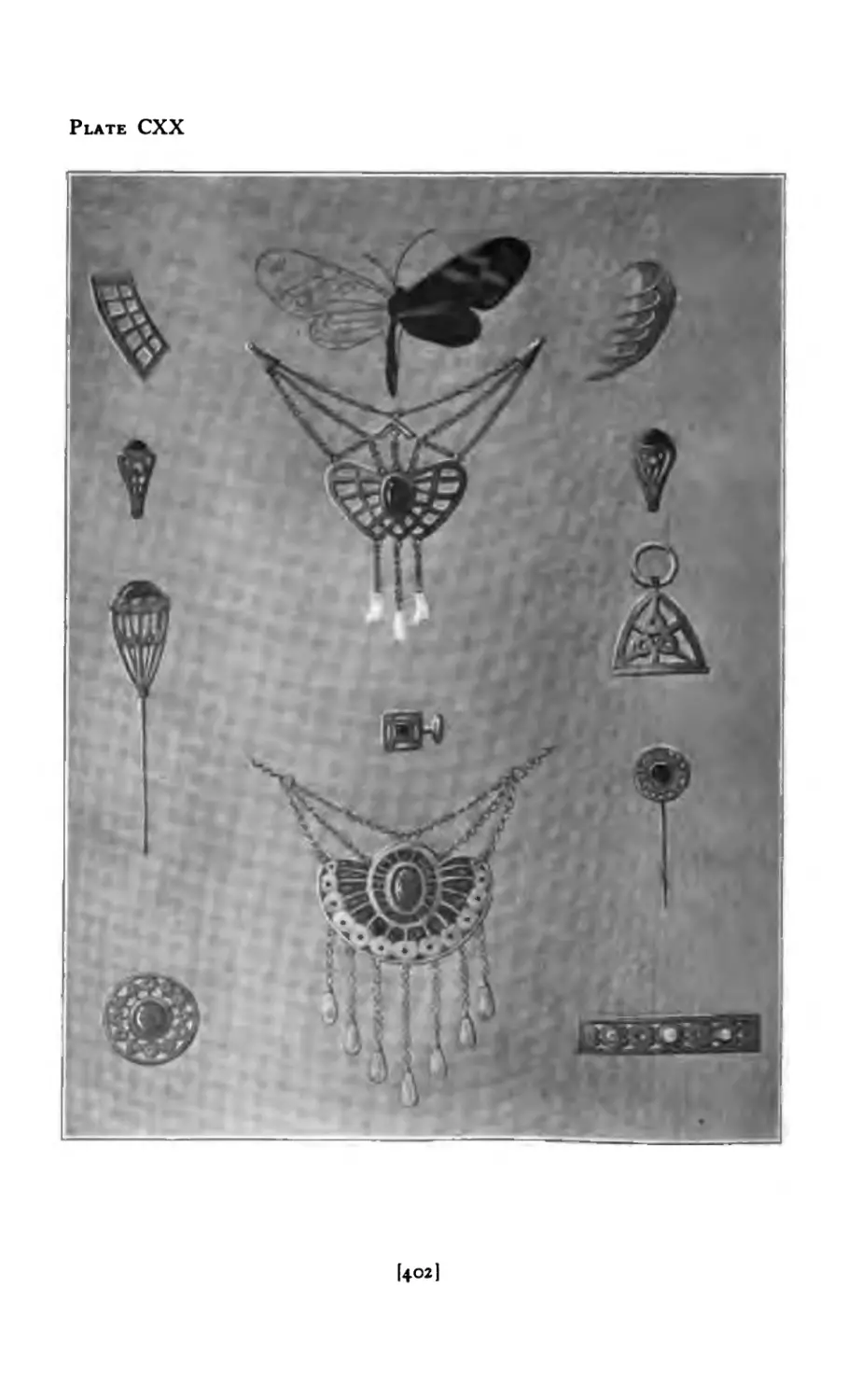
exx Designs derived from Butterfly .... 402
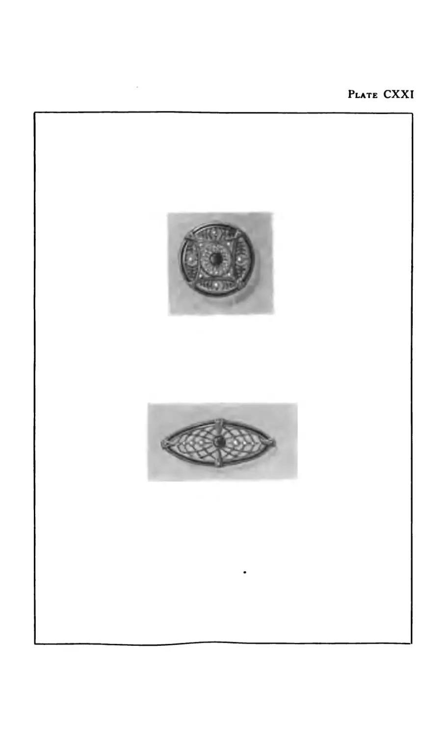
CXXI Brooches in Gold and Enamel ....
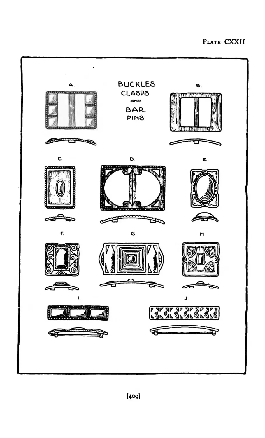
CXXI1 Buckles, Clasps, Bar Pins ..... 409
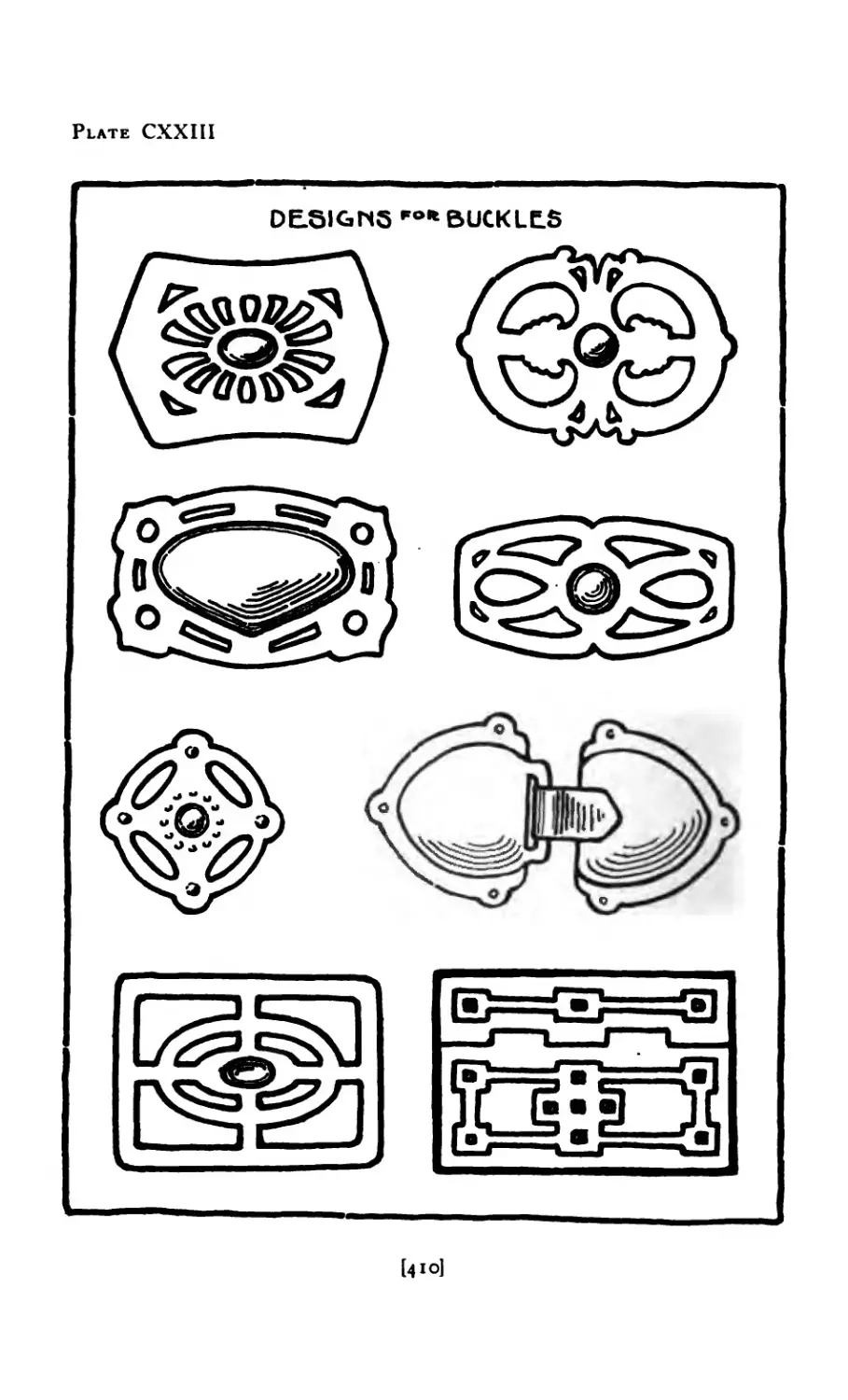
CXXI1I Designs for Buckles ... 410
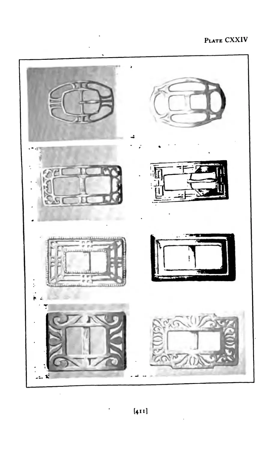
CXXIV Shoe Buckles ....... 411
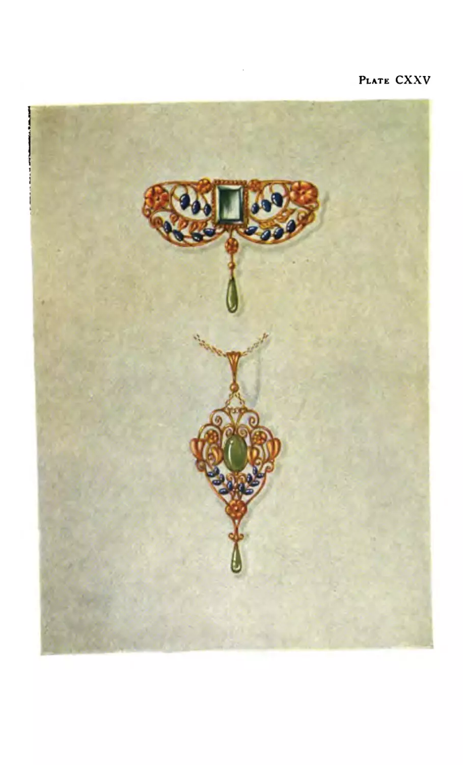
exxv Brooch and Pendant in Gold ....
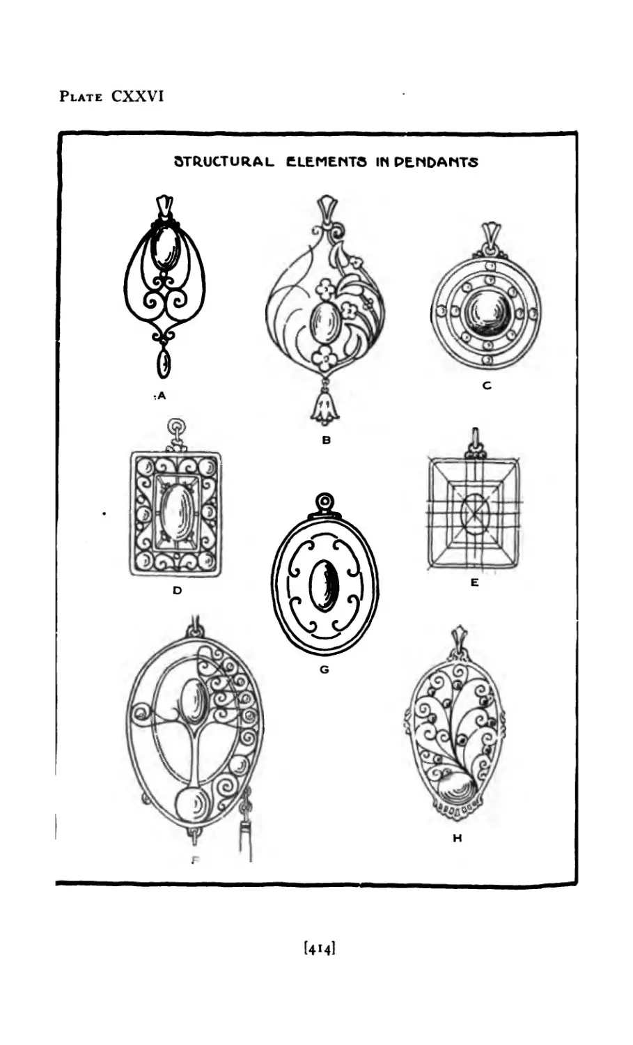
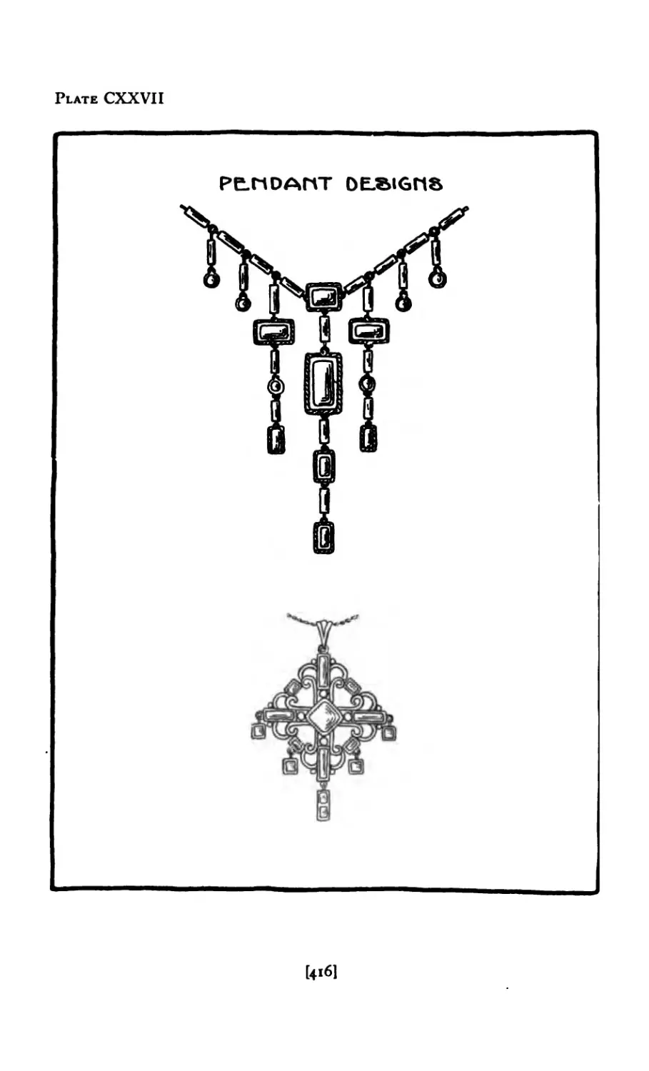
CXXV1 Structural Elements in Pendants 414
CXX VII Pendant Designs ...... 416
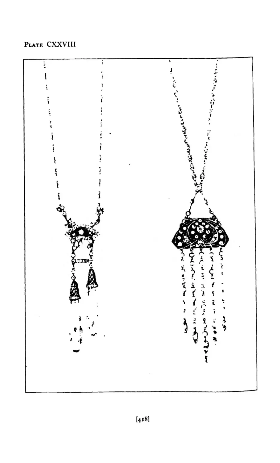
CXXVIII Pendants in Platinum ..... 418
CXXIX Designs for Seal Fobs ..... 422
exxx Fob in Enamel ...... 423
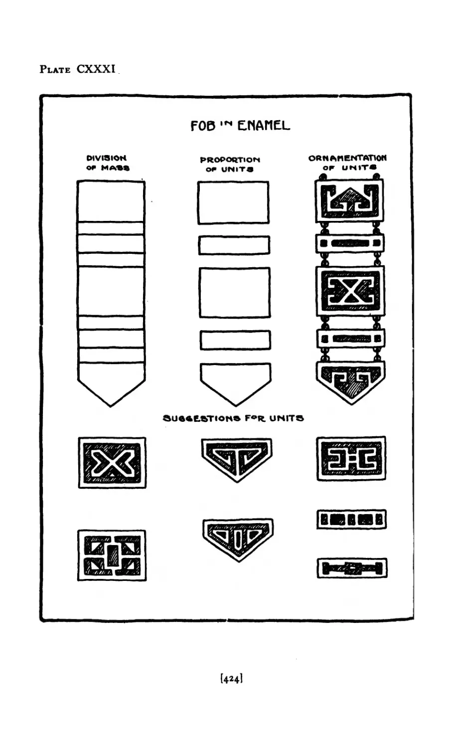
CXXXI Fob in Enamel ...... 424
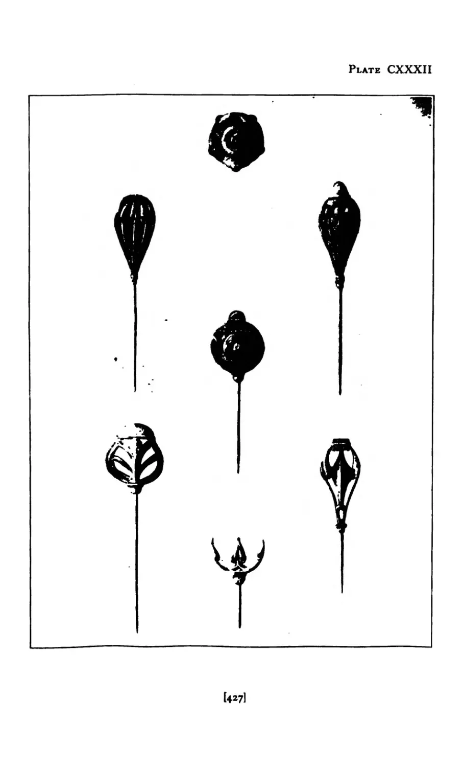
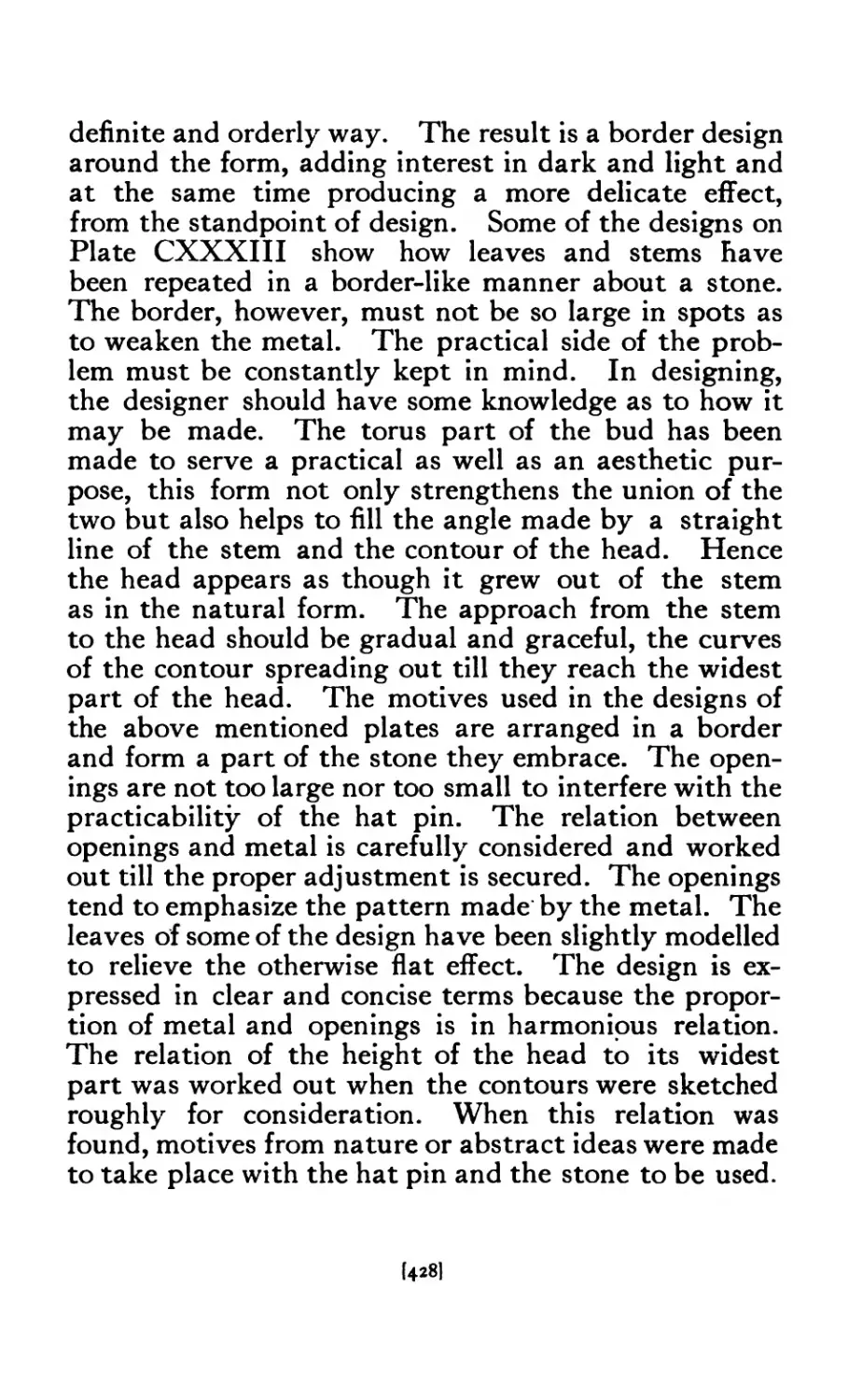
CXXXII Hat Pin Designs ...... 427
CXXXII1 Hat Pin Designs ..... 429
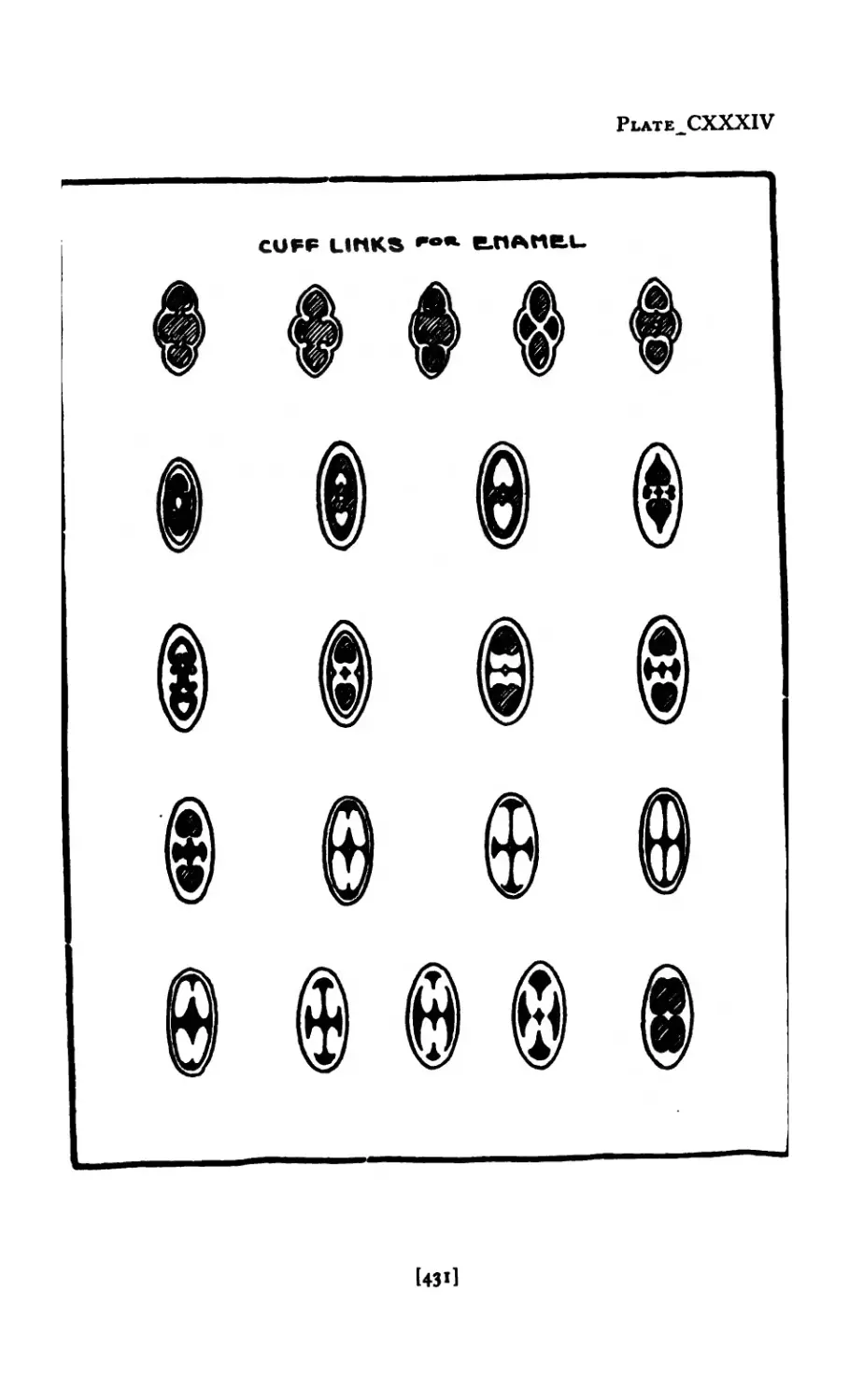
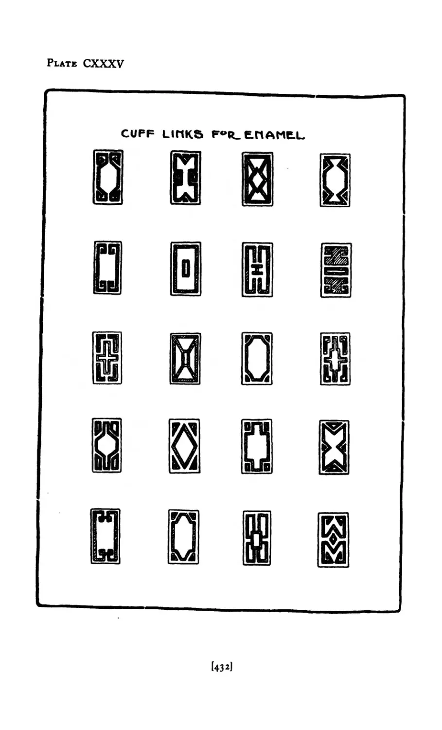
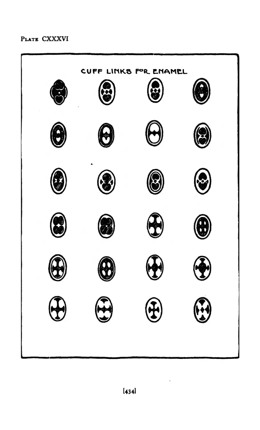
CXXXIV Cuff Links for Enamel ..... 43 i
exxxv Cuff Links for Enamel ..... 432
CXXXVI Cuff Links for Enamel ..... 434
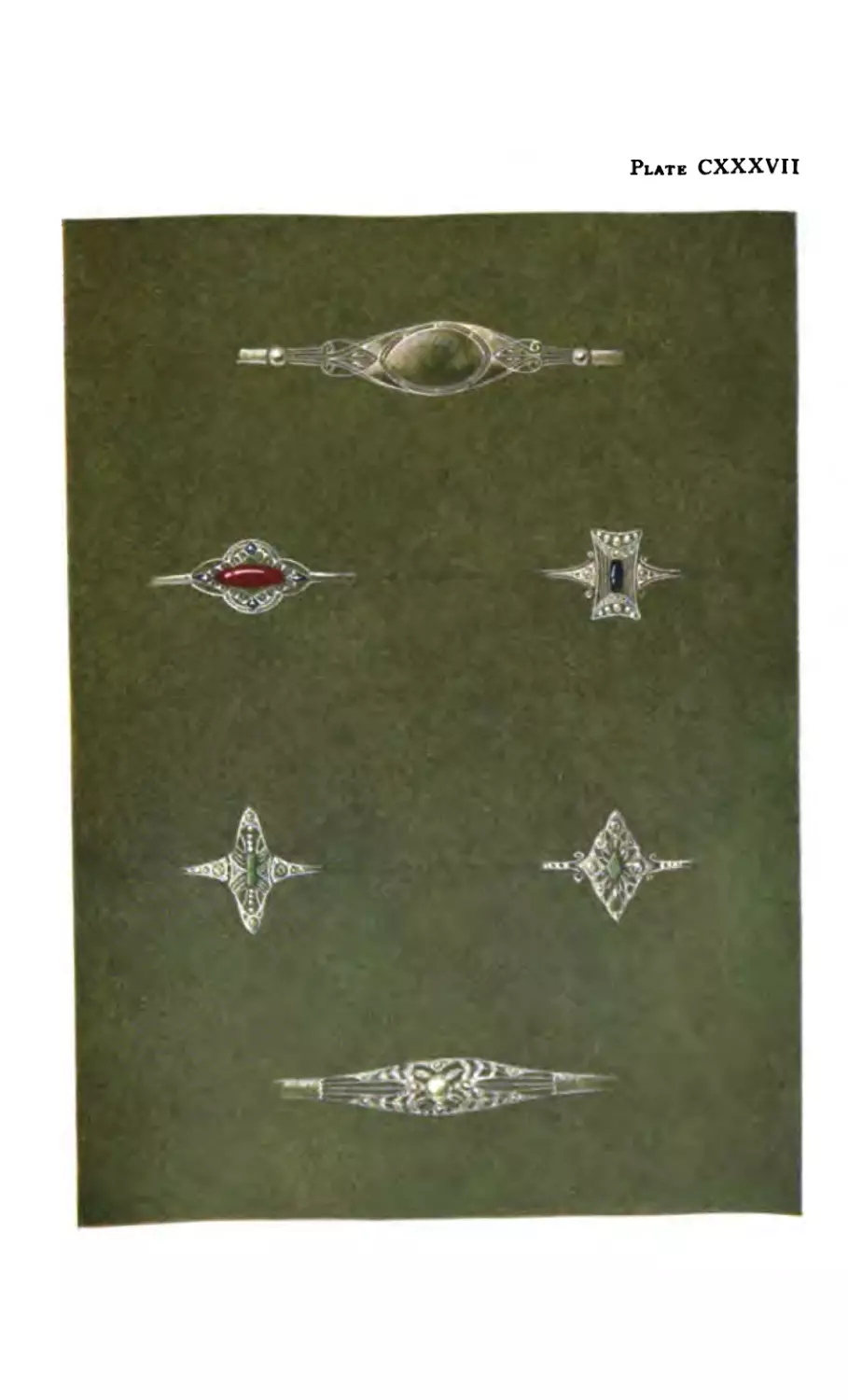
CXXX VII Designs in Platinum .....
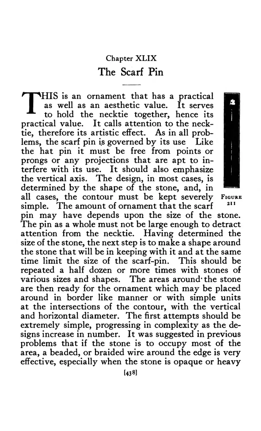
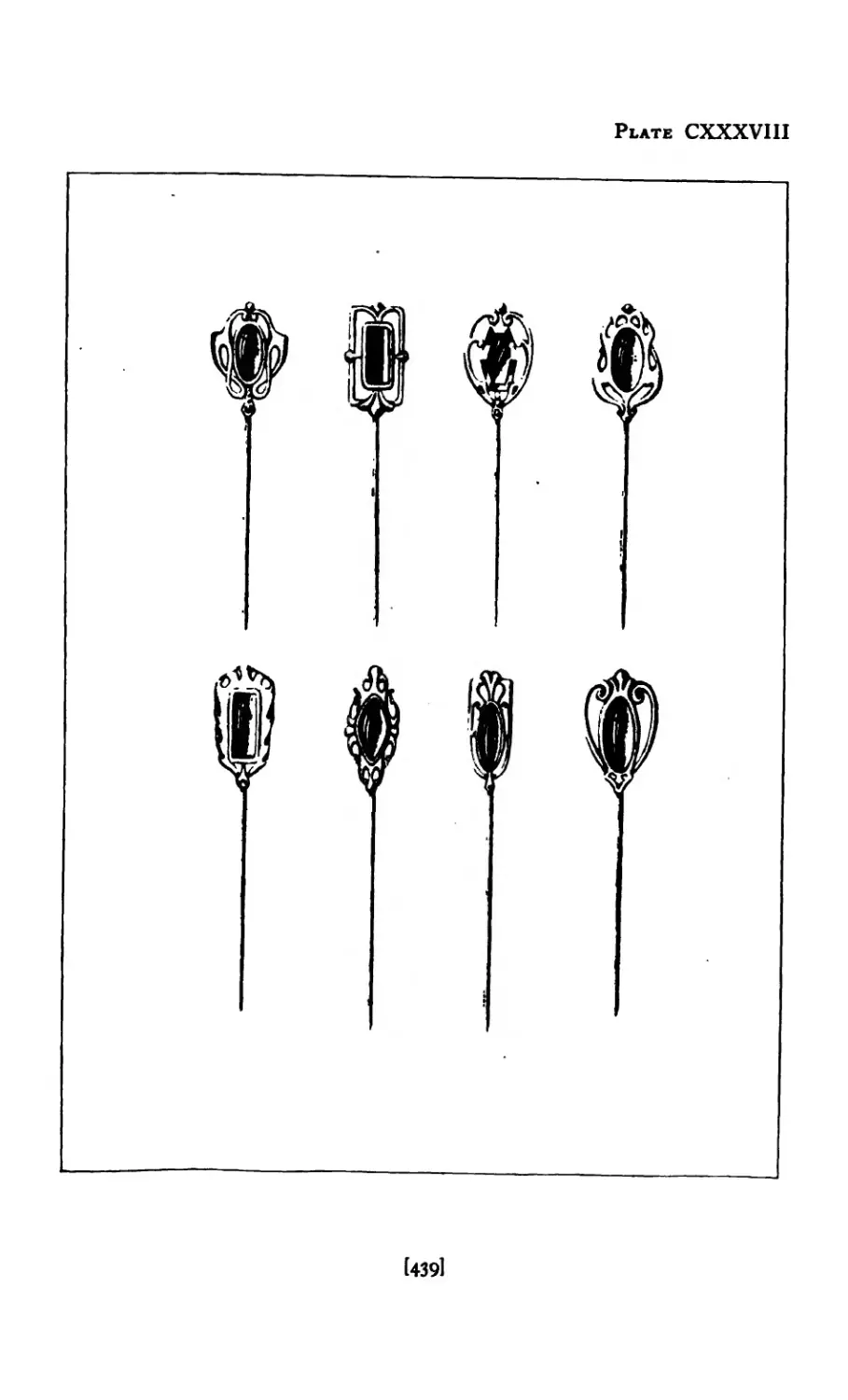
CXXXVI II Scarf Pin Designs ...... 439
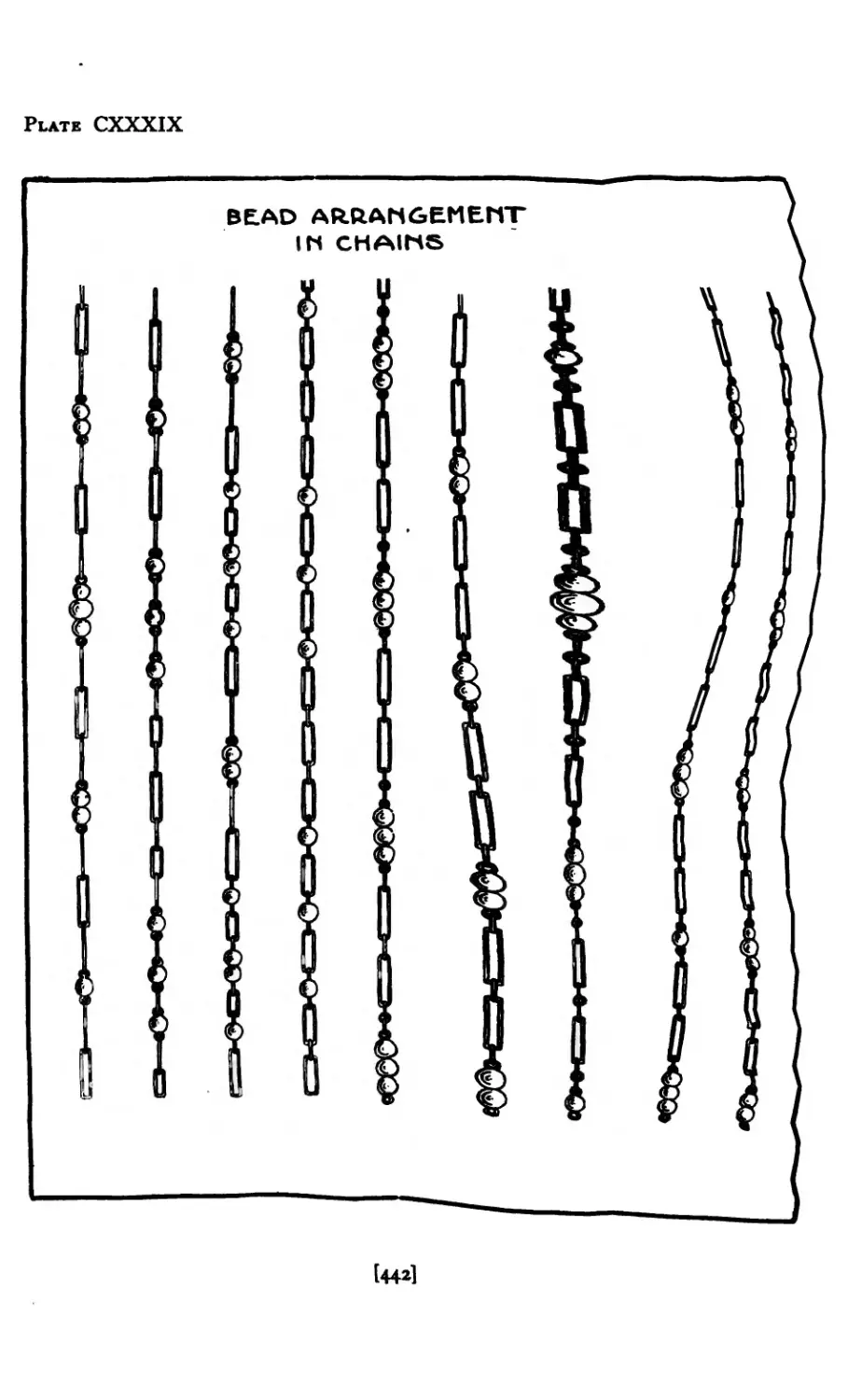
CXXX IX Bead arrangement in Chains .... 442
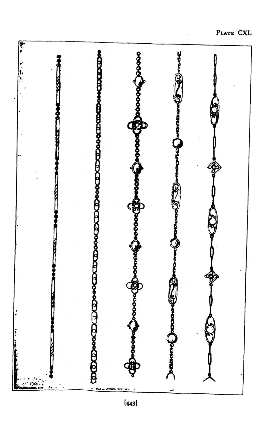
CXL Chain Designs ....... 443
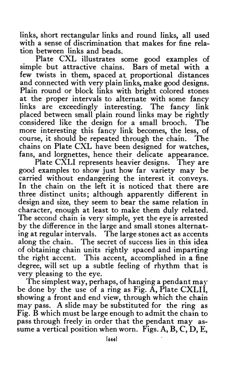
CXLI Chain Designs ....... 445
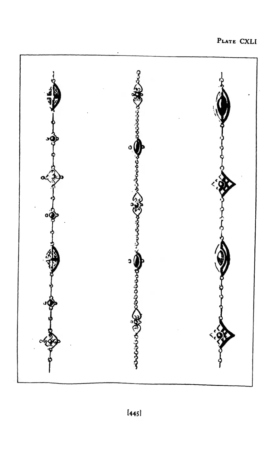
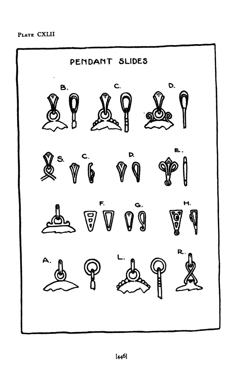
CXLI I Pendant Slides ...... 446
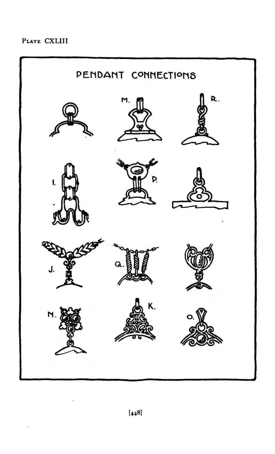
CXLI 11 Pendant Connections ..... 448
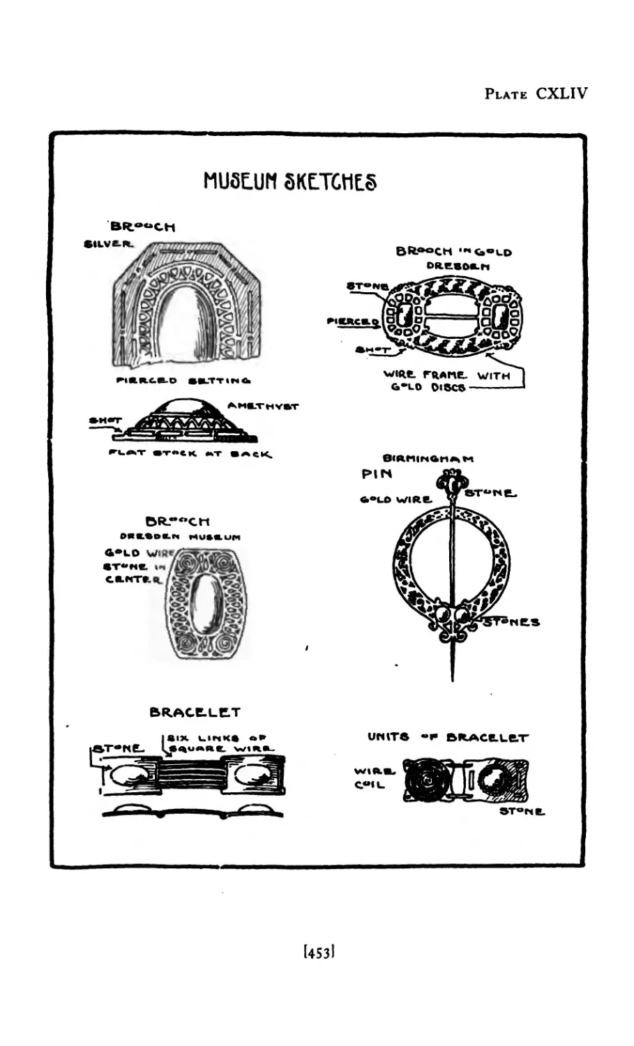
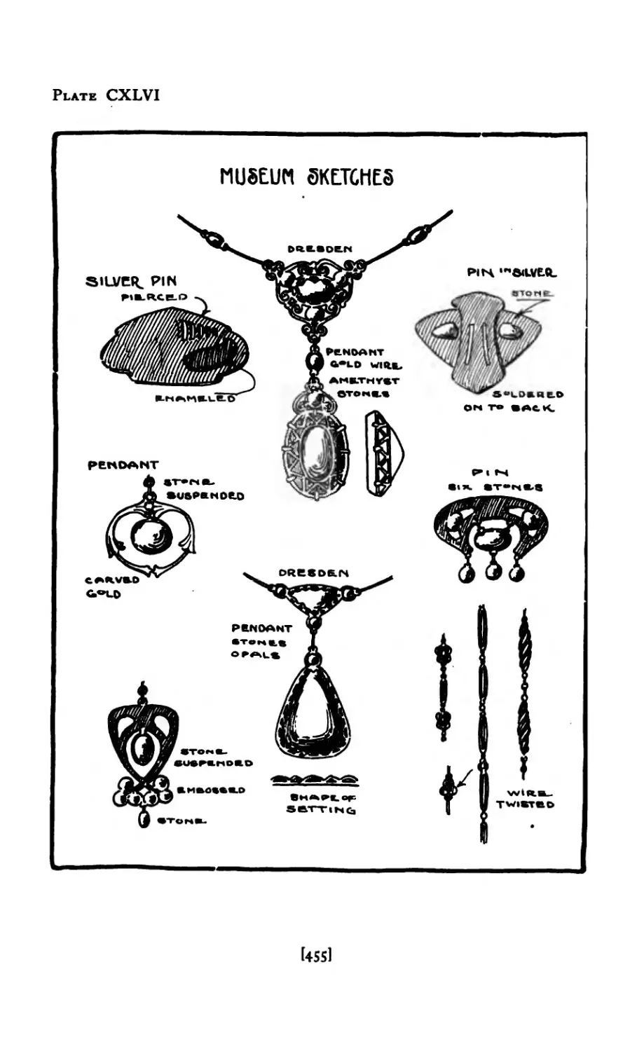
CXLIV Museum Sketches ..... 453
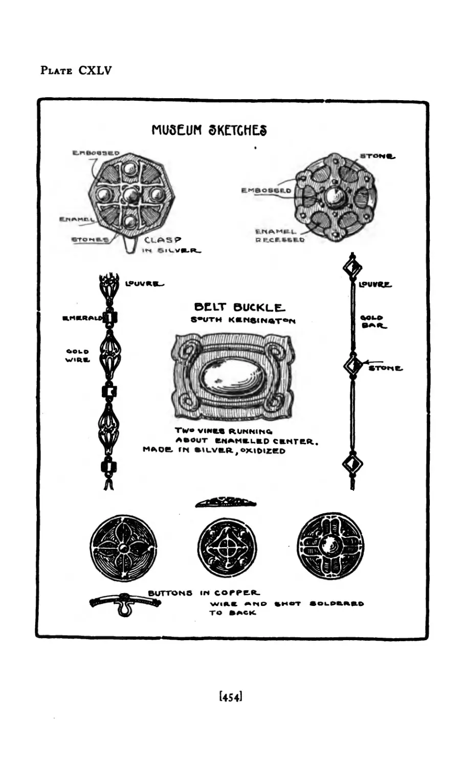
CXLV Museum Sketches ...... 454
CXLVI Museum Sketches ...... 455
[xii]
FIGURE PAGE
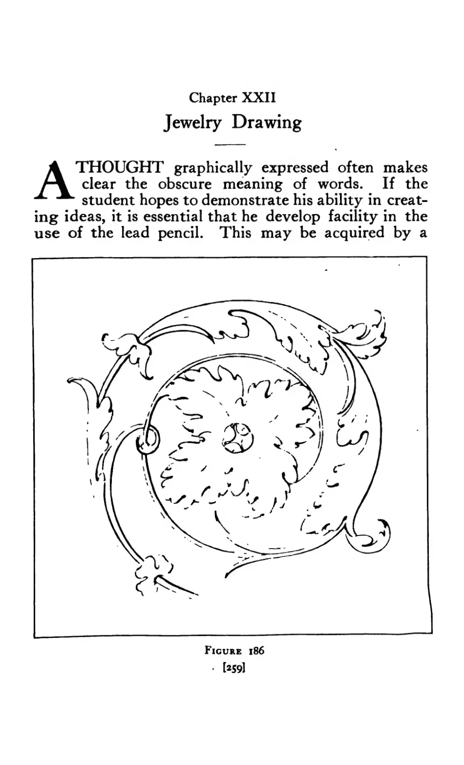
I 86 Renaissance Scroll from Cast ..... 259
187 A, В Copies from Japanese Sword-Guards .... 260
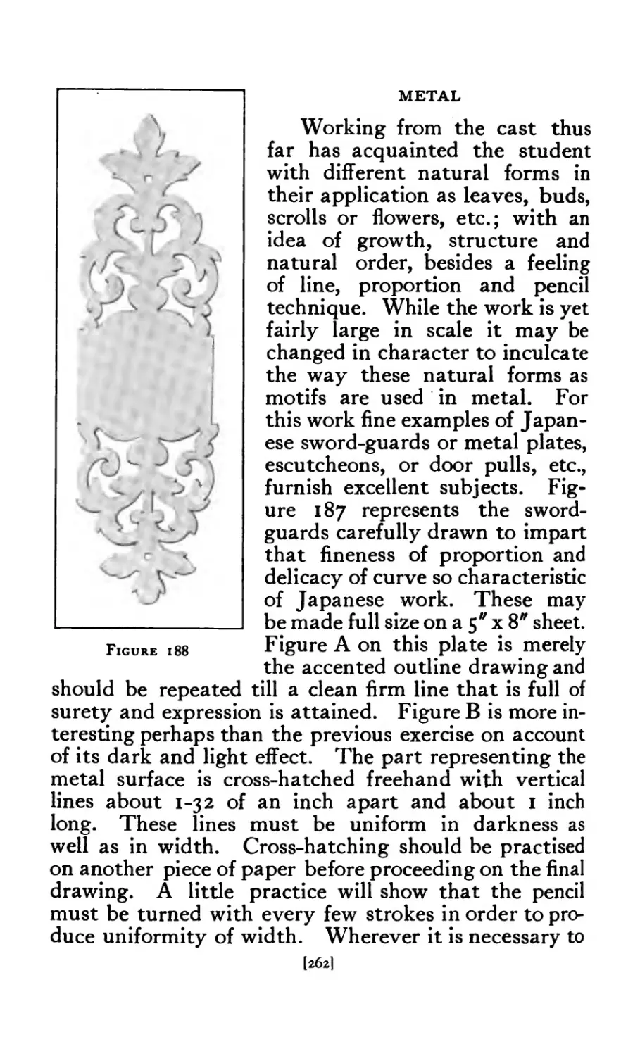
188 Copy of Metal-Plate ....... 262
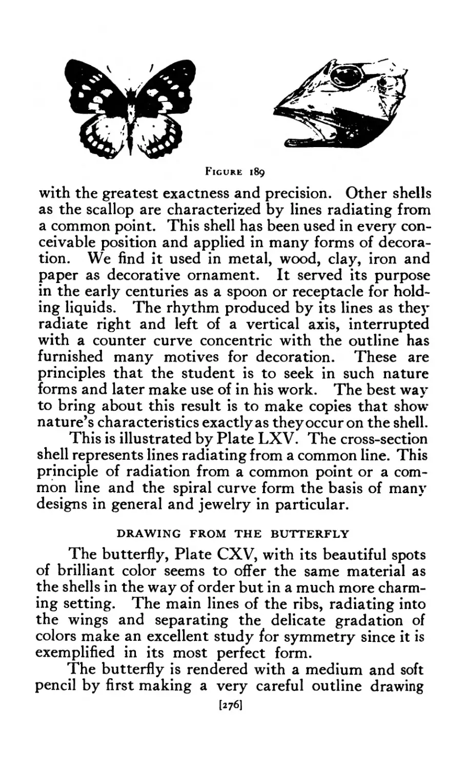
1 89 Butterfly and Ficb ....... 276
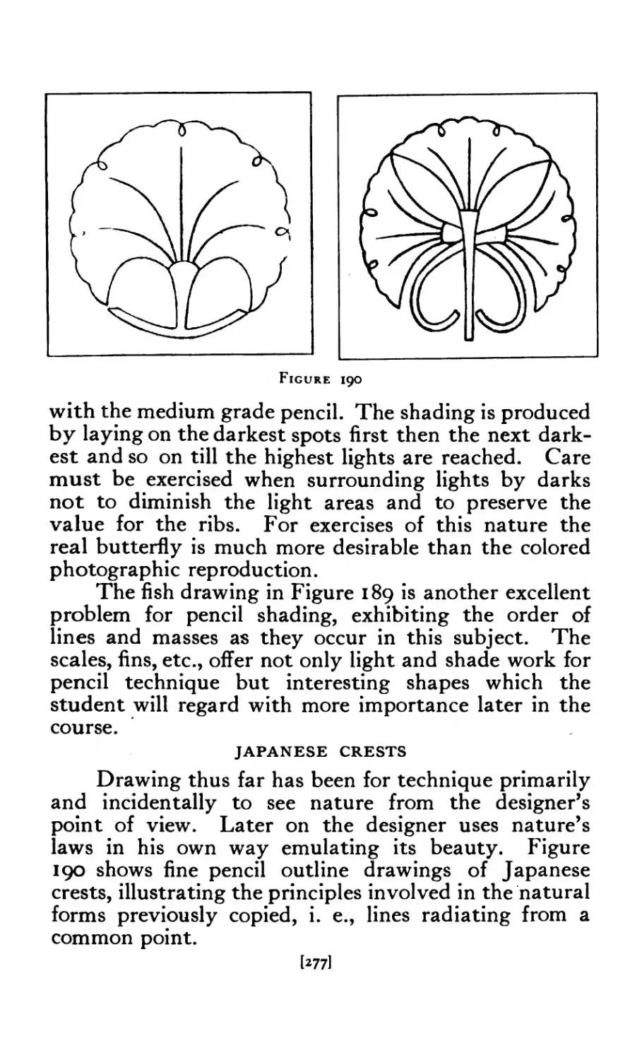
190 Japanese Crests ....... 277
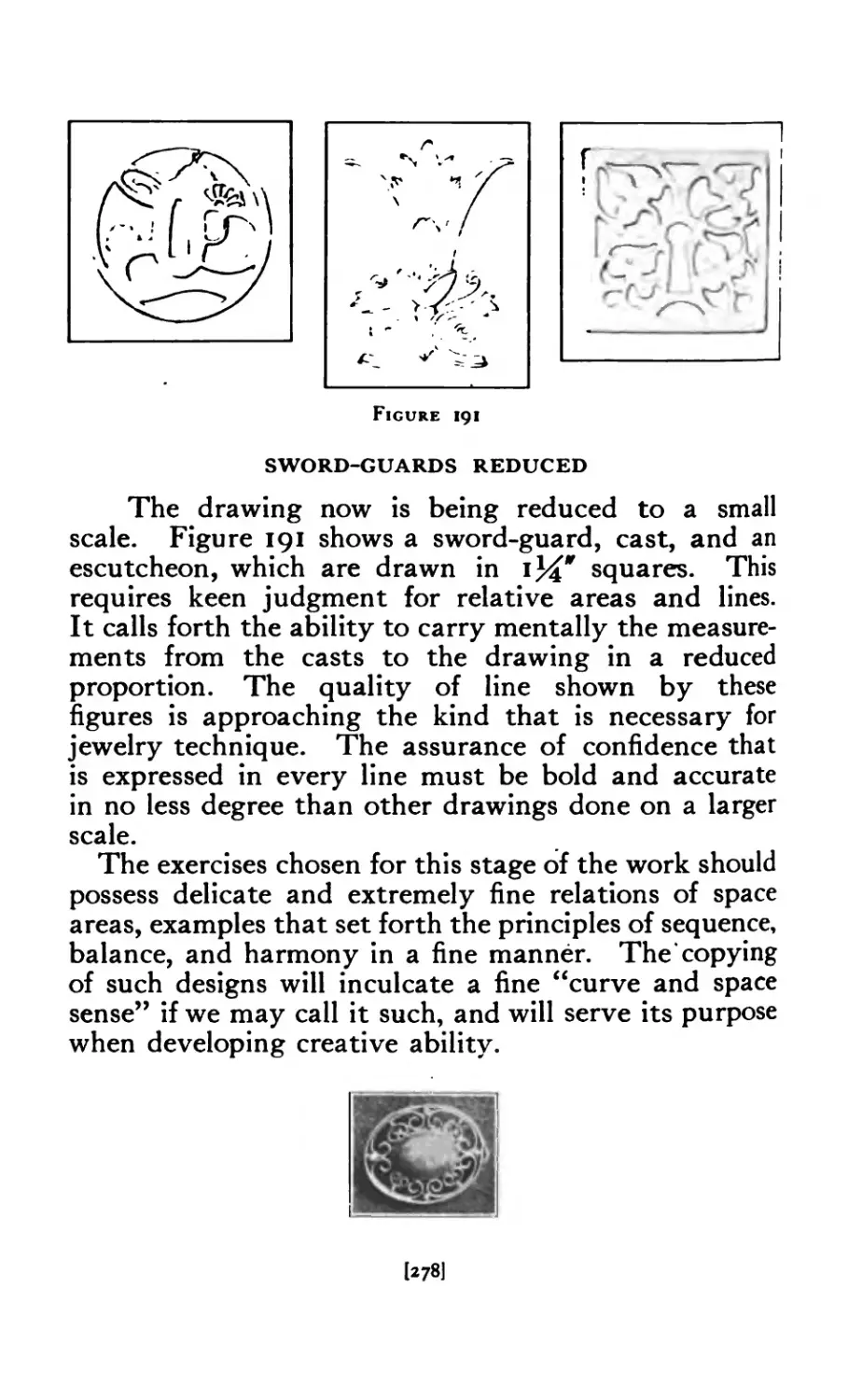
191 Japanese Sword-Guard, Cast, Escutcheon . . . 278
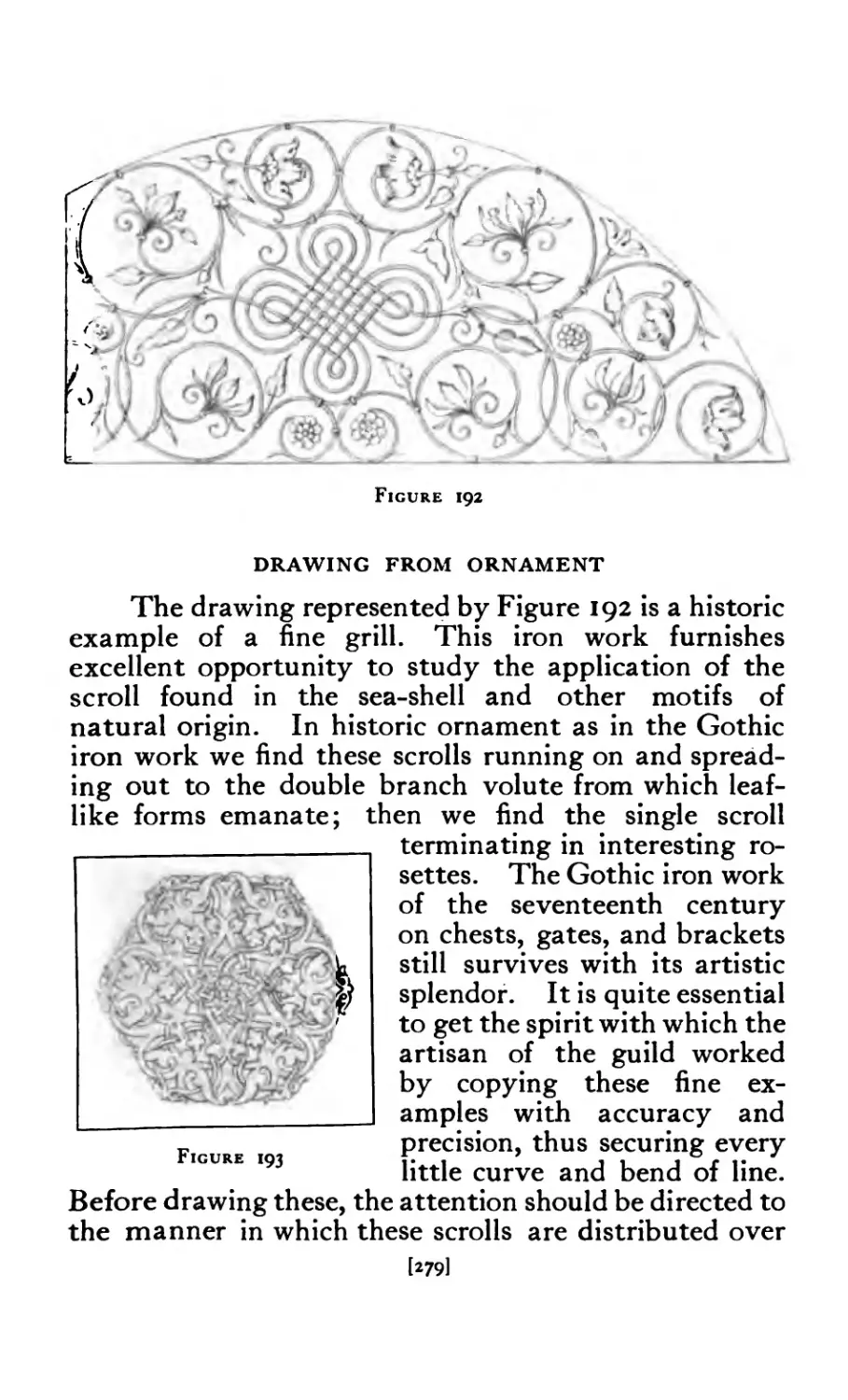
192 Grill 279
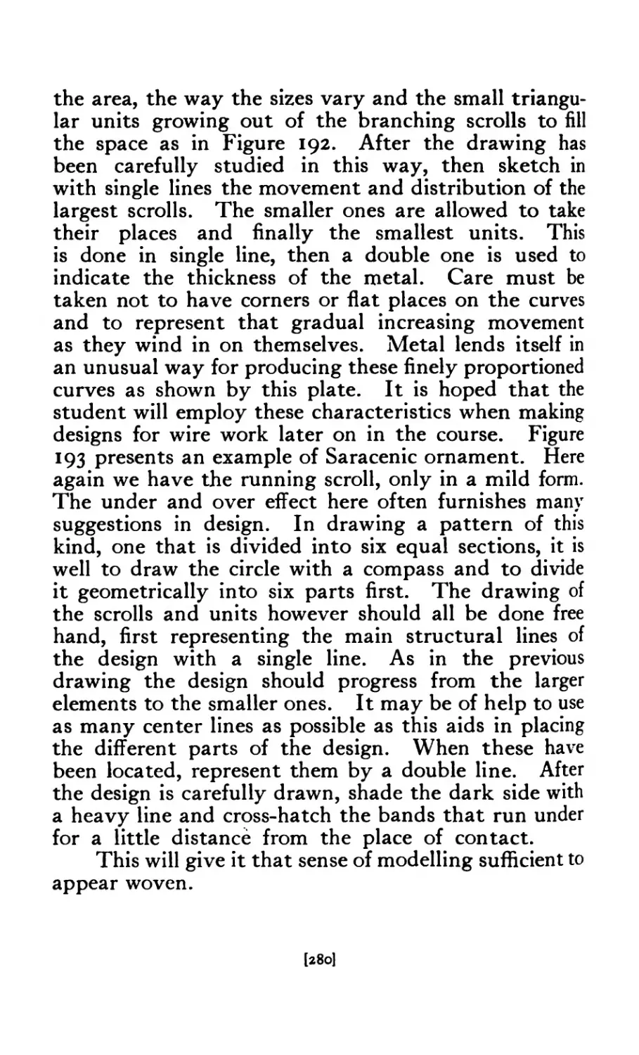
193 Saracenic Ornament ....... 279
194 Scrap- эок ......... 283
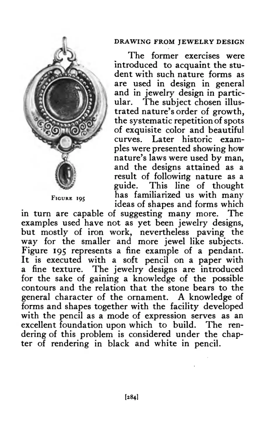
195 Copy Pendant from Deutsche Goldschmiede Zeitung . 284
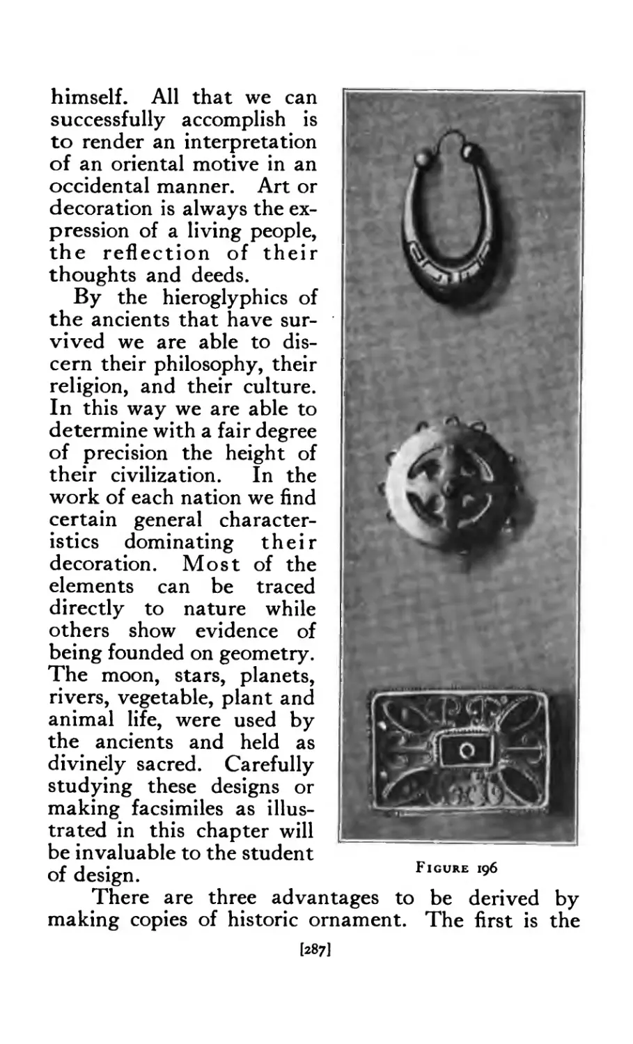
196 Rendering from Copies ....... 287
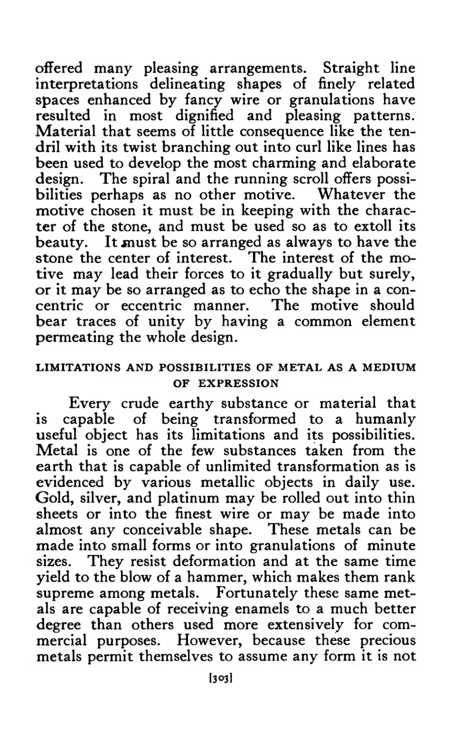
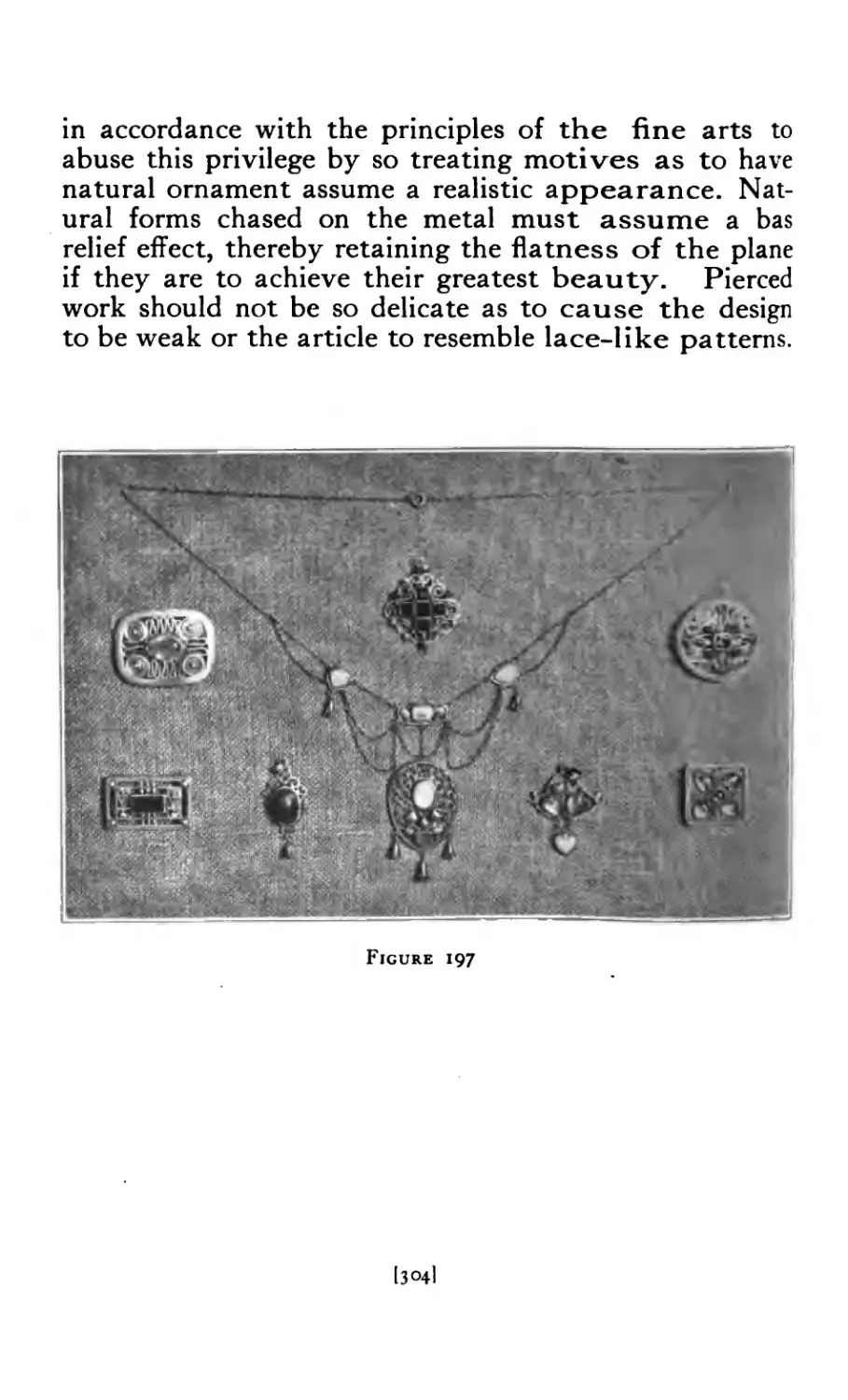
197 Jewelry ......... 304
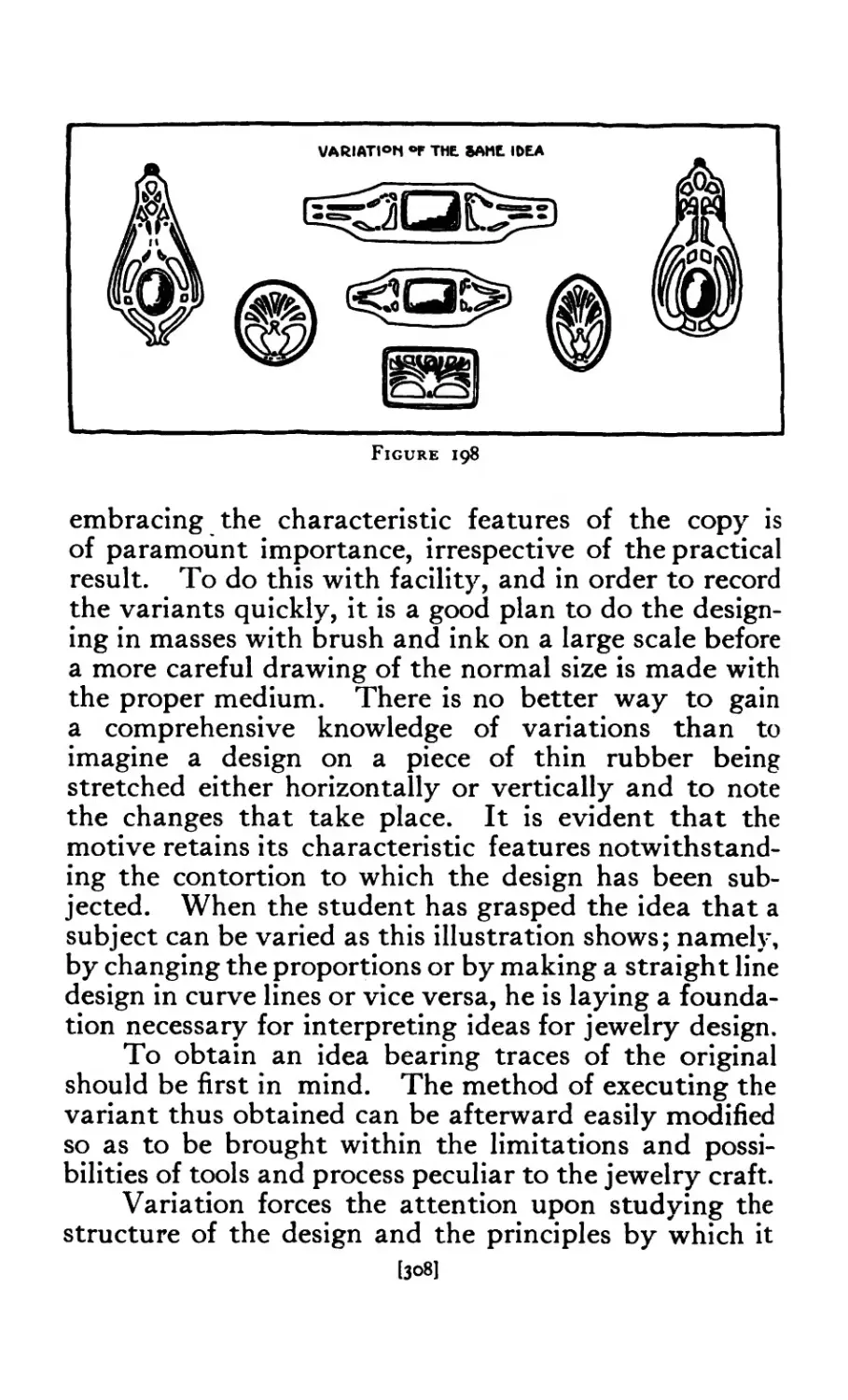
198 Variations of Bird Design ...... 308
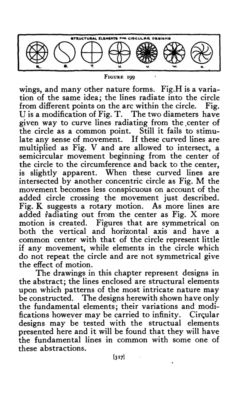
199 Structural Elements of Circle . . . . . 317
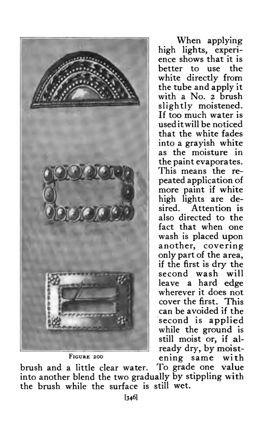
200 Rendering from Photograph on Gray Paper . 346
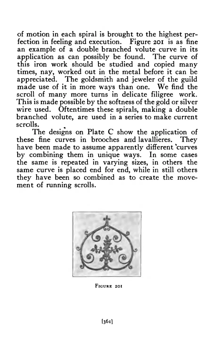
201 Renaissance Iron Ornament ...... 361
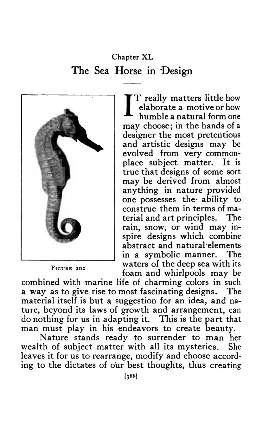
202 Sea Horse .......... 388
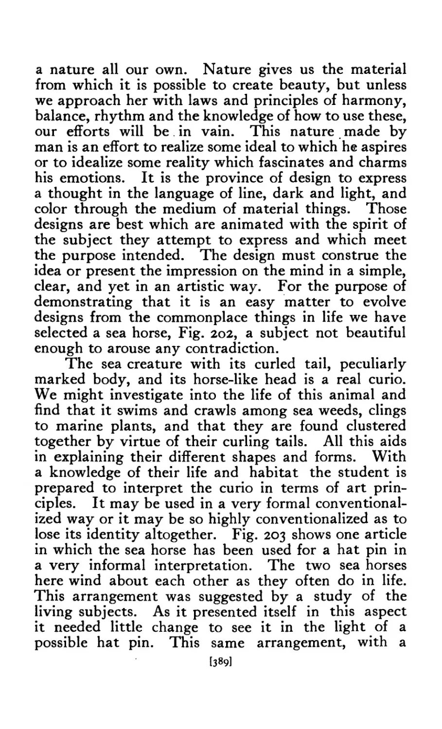
203 Hat Pin with Sea Horse Motive ..... 39°
204 Clasps ......... 408
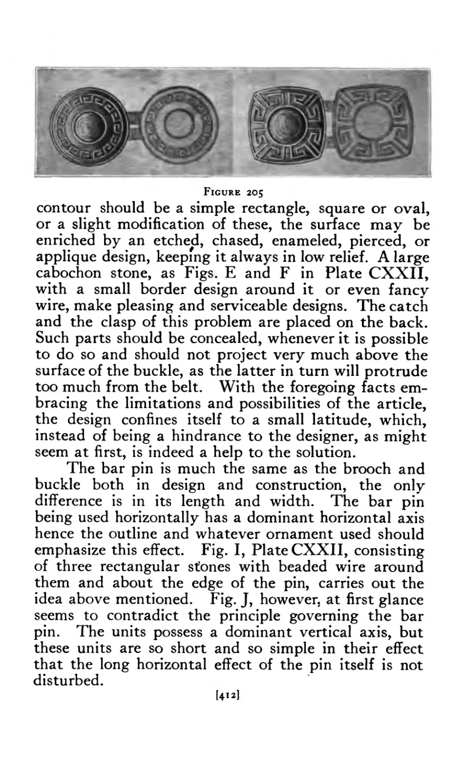
205 Clasps . . . . . . . . 412
206 Wire Pendants . 4J3
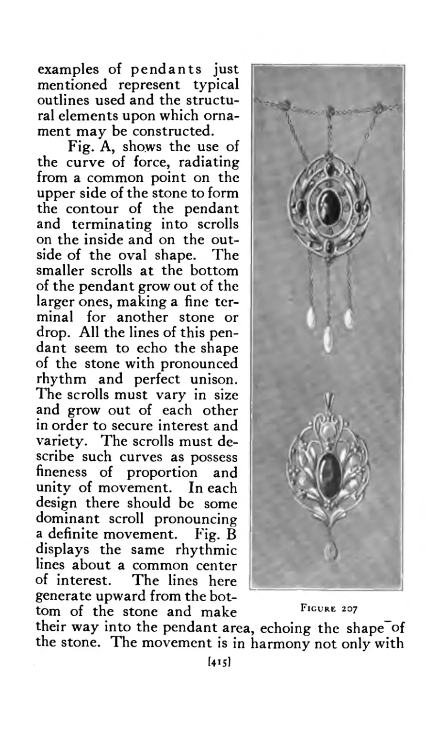
207 Pendant Designs ........ 415
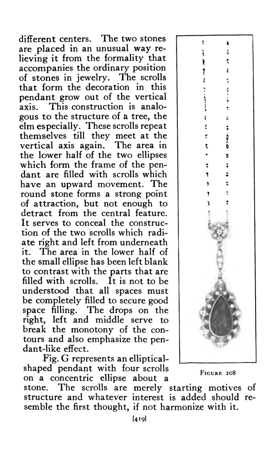
208 Pendant in Platinum . . .4 194
209 Hat Pin in Wire ........ 42^
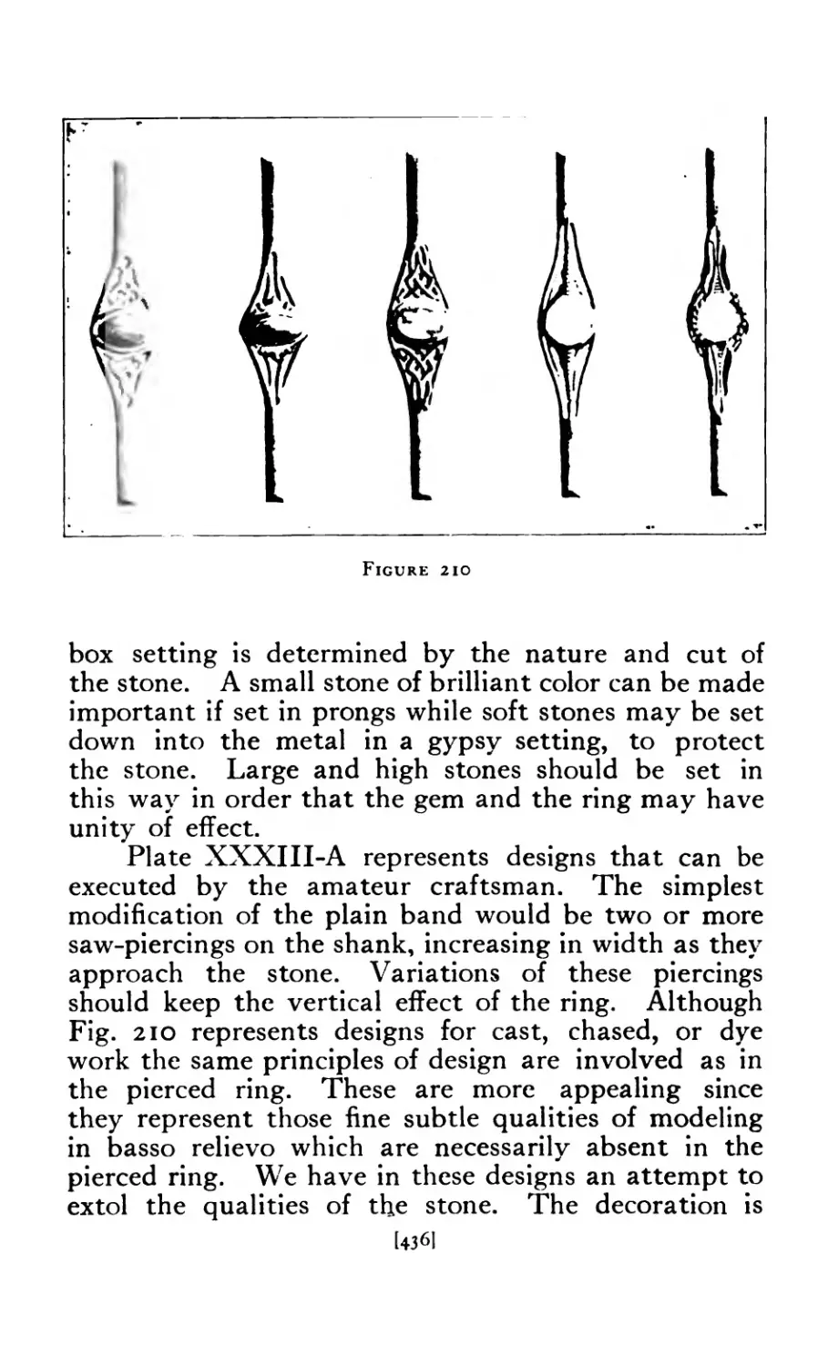
210 Ring Designs ........ 436
211 Scarf Pin ......... 438
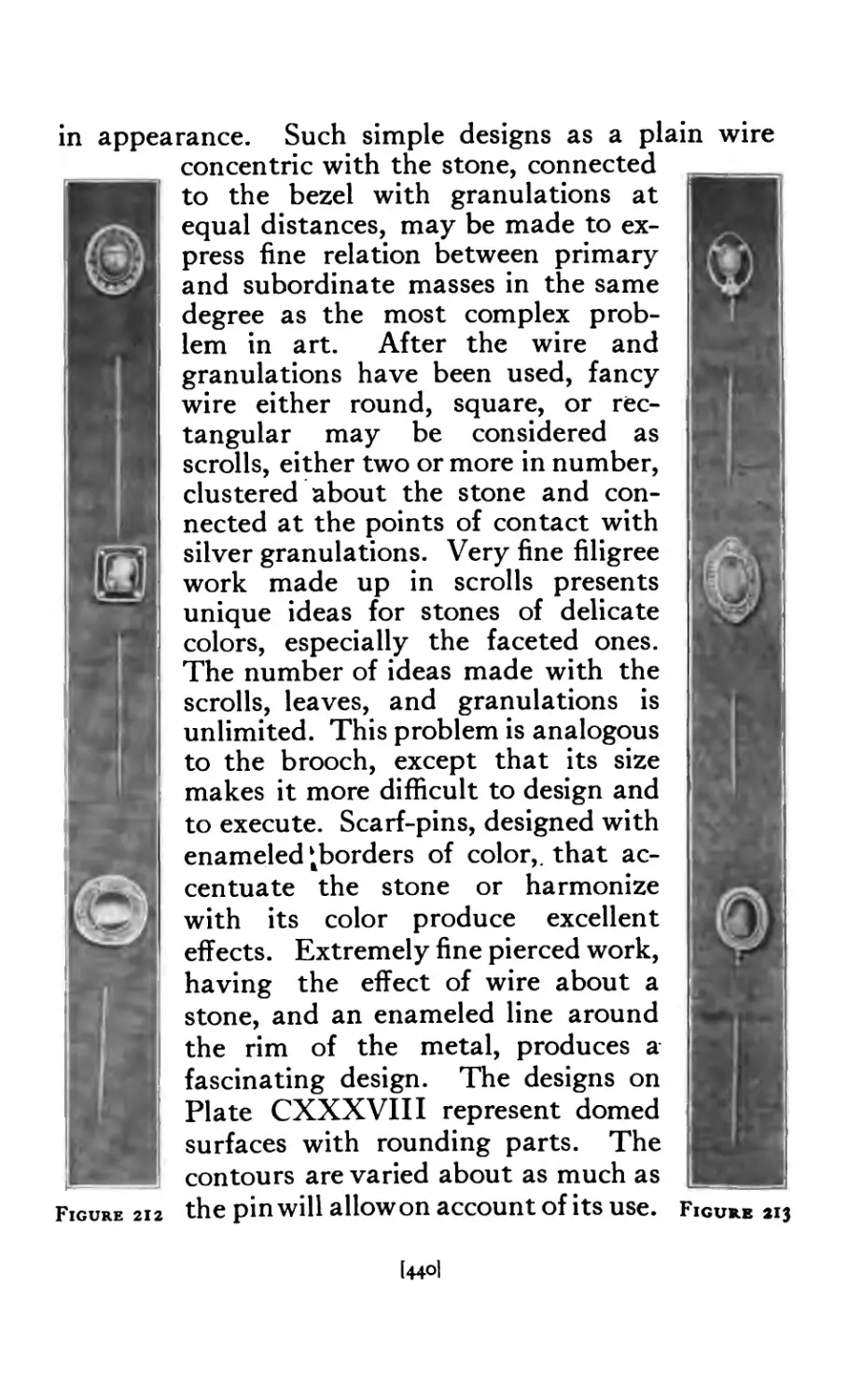
212 Scarf Pins ......... 44°
213 Scarf Pins .. . . . • 44°
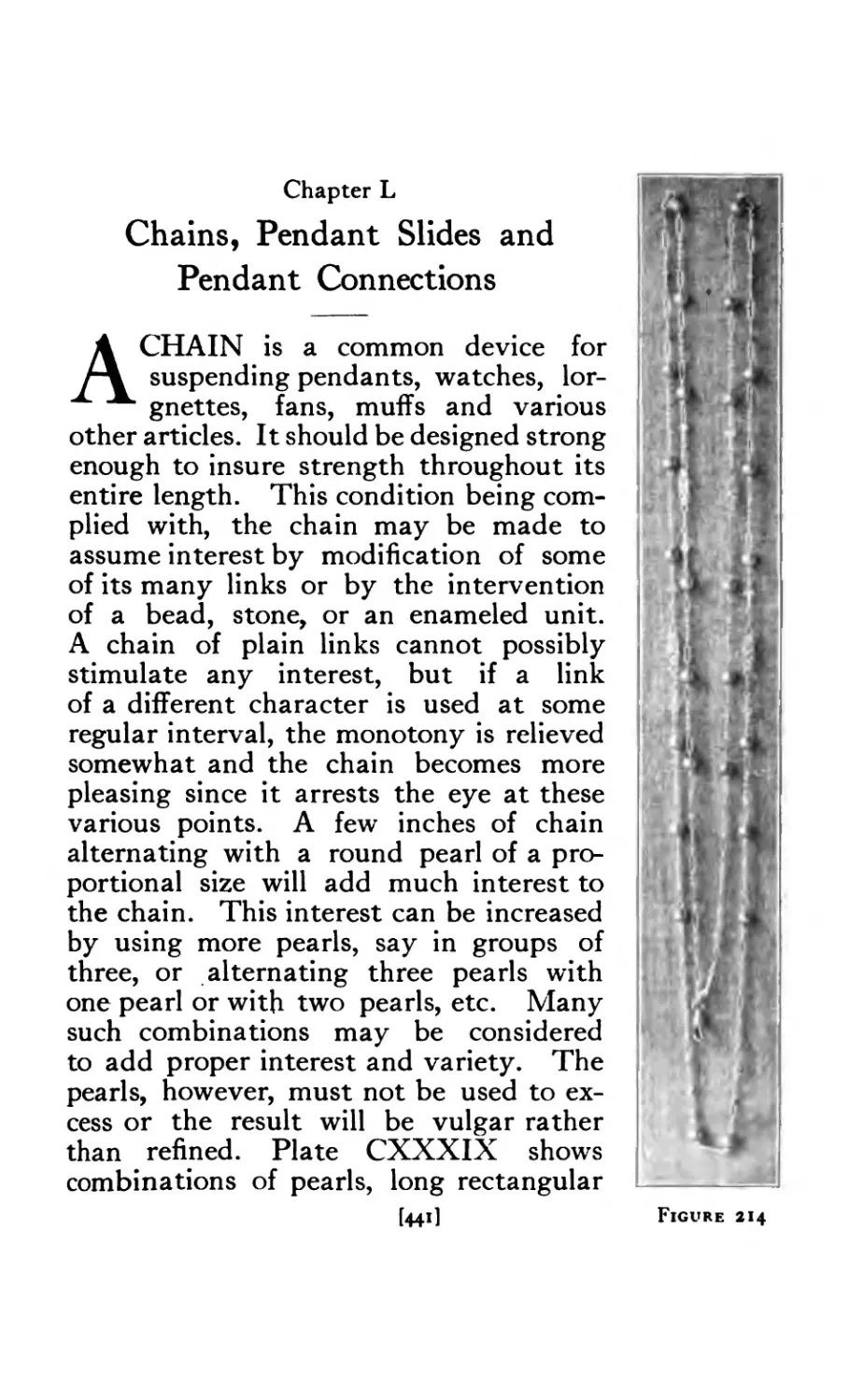
214 Chains and Beads ....... 441
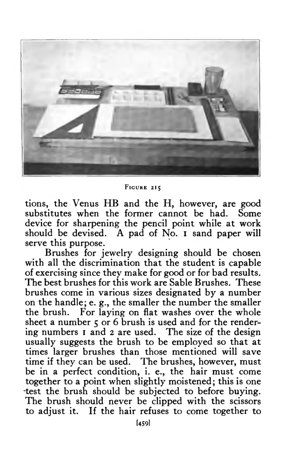
215 Equipment for Drawing and Design .... 459
[xiii]
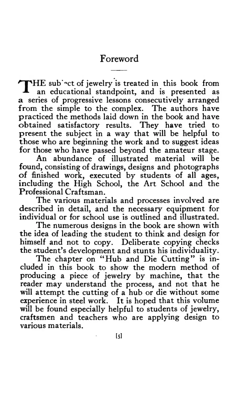
Foreword
г |ЛНЕ sub let of jewelry is treated in this book from
an educational standpoint, and is presented as
a series of progressive lessons consecutively arranged
from the simple to the complex. The authors have
practiced the methods laid down in the book and have
obtained satisfactory results. They have tried to
present the subject in a way that will be helpful to
those who are beginning the work and to suggest ideas
for those who have passed beyond the amateur stage.
An abundance of illustrated material will be
found, consisting of drawings, designs and photographs
of finished work, executed by students of all ages,
including the High School, the Art School and the
Professional Craftsman.
The various materials and processes involved are
described in detail, and the necessary equipment for
individual or for school use is outlined and illustrated.
The numerous designs in the book are shown with
the idea of leading the student to think and design for
himself and not to copy. Deliberate copying checks
the student’s development and stunts his individuality.
The chapter on “Hub and Die Cutting” is in-
cluded in this book to show the modern method of
producing a piece of jewelry by machine, that the
reader may understand the process, and not that he
will attempt the cutting of a hub or die without some
experience in steel work. It is hoped that this volume
will be found especially helpful to students of jewelry,
craftsmen and teachers who are applying design to
various materials.
[51
The author’s thanks are due the following persons
who have assisted in the successful completion of the
book.
To Josephine Beane Rose, for untiring assistance
in correcting the text and reading the proof.
To the Rhode Island School of Design, for the
opportunity of developing the work treated in the book.
To past students whose drawings and designs are
reproduced, especially to Stanley Price, who assisted
in making the mechanical drawings.
To Mr. Frederick Forth, Mr. Walter Saunders,
and Mr. Emil Sweitzer, for valuable information; Mrs.
Josephine Hartwell Shaw for the originals on pages
138 and 433; Ostby & Barton Company of Providence,
for many courtesies; Miss E. B. Hewitt, Margaret
Morrison, Carnegie School, Pittsburgh, Pa., for original
on page 129; Mr. M. E. Heiser, Queensland, Australia,
for the originals on pages 23 and 30; Mr. William A.
Heath, for assistance with the chapter on “Hub and
Die Cutting”; Mr. F. E. Masselin, for assistance with
the chapter on “Modelling and Casting”; Mr. F. P.
Boland, for cuts used on pages 248, 252 and 253;
Espositer & Company of New York, for the original
on page 29; The Jewelers Circular of New York, for
the use of the cut on page 17; Handy & Harmon of
Bridgeport, Connecticut, for the tables on pages 39,
40, 41 and 42; Methuen & Company, Limited, of
London, England, for permission to use the color plates
on pages 12 and 14, and the cuts on page 24; Doubleday,
Page & Company, New York, for permission to use
the color plate on page 396; the Century Company
of New York, for permission to use the illustrations
from “The Book of the Pearl,” pages 19 and 21.
Grateful acknowledgment is also due to the
numerous writers of whose books and magazine articles
I have made free use, to which references are made in
the appropriate places.
16]
Introduction
THE Making of Jewelry is an ancient art, and
may be traced to a very remote period, not only
by examples, of which there are many, but through
ancient writings. Abundant examples of goldsmith’s
work have been found in Egyptian tombs dating as
far back as the fifteenth century, В. C. The Bible
has many references to the use of jewelry.
The goldsmith’s craft, as practiced centuries ago,
has many attractive features that may be adapted or
applied to the craft work of the present time. The
possibilities for the application of design are unlimited.
With no other material can more satisfactory results
be obtained in the finished piece of work than with that
employed by the goldsmith. No other craft calls for
such skill in the handling of the materials used, or so
keen a sense of fine line and proportion in design.
The pieces of jewelry most prized by our museums
to-day are those made centuries ago, where cleverness
in design and workmanship were of much greater
value than the material used.
Many craftsmen design in the material, feeling
their way along without a drawing, but, as Benvenuto
Cellini says, “Though many have practiced the art
without making drawings, those who made their
drawings first did the best work. ”
In school work we have our attention called very
often to the work of architects, sculptors, painters aiyd
engineers, but mention is seldom made of those who
have worked in metal, even though their work repre-
sents some of the finest moments in the history of
mankind. Few know that Tubal Cain was the first
[71
metal worker of whom we have any record, or that
Bezaleel of the Tribe of Judah and Oholiab of the
Tribe of Dan were the goldsmiths who made the sacred
jewels and vessels for the tabernacle. The names of
Mentor, Acrages, Stratonicus, Unichus, and Hecataeus
are unknown to many, but these are the men who pro-
duced the superb Greek specimens in metal, many of
which are now to be seen in our museums. During
the middle ages, it was the custom for each of the kings
of France to have his goldsmith. Gilbert Lorin was
goldsmith to Charles the Seventh, Jehan Gallant to
Charles the Eighth, and Henri to Louis the Twelfth.
Few know that Benvenuto Cellini and Girlandio were
unrivalled goldsmiths of the sixteenth century, or
even that our own honored patriot, Paul Revere, was
a worker in the precious metals.
Jewelry comprises various objects for personal
adornment, rendered precious by their workmanship.
In the form of rings and pendants, jewelry may be
merely decorative, or in the form of brooches and pins,
it may be useful as well. The making of jewelry culti-
vates an appreciation of this ancient art. To acquire
the keenest sense of appreciation for the fine jewelry
of ancient or modern times, one must study the designs
as expressed in the work, and practice the art. The
knowledge derived from actual practice is both cultu-
ral "and practical. It not only helps to develop the
artistic impulse and make the individual sensitive to
the beauty of nature as applied to metal, but it also
arouses interest in the metal industries and the commer-
cial processes allied with the manufacture of jewelry
on a large scale, such as mining, assaying and alloying.
18]
Book I
JEWELRY MAKING
Materials Used in Jewelry Making
Jewelry, generally speaking, is made
up of stones either precious or semi-pre-
cious, and the metal that forms the
setting. Before taking up the making of
jewelry it is necessary that one should
know something of the materials used.
Chapters I and II take up the subject of
stones used in jewelry and their cutting
and polishing. Chapter III deals with
the metals used, their alloys and methods
of weighing.
Chapter I
Stones
“Dumb jewels in their silent hind, more than quick words do move a woman's
mind.99 Shakespeabe
STONES have been worn upon the persons of men
and women since prehistoric times and in most
pieces of jewelry today, stones, because of their
rarity and color, play the principal part, and are usually
the central feature around which is the setting or
ornamentation.
Generally speaking the stones used in jewelry are
divided into two classes—Precious and Semi-Precious.
These terms, however, are used commercially and refer
to their rarity and value. The value of a stone is
merely what it will bring in the open market and its
artistic merits may be only a matter of opinion. Many
people, however, prefer the rare to the beautiful.
These stones are no less than minerals taken from
the earth, and after they have been improved by the
art of man by cutting and polishing, the finest and rarest
of them are what we call gems.
PRECIOUS STONES
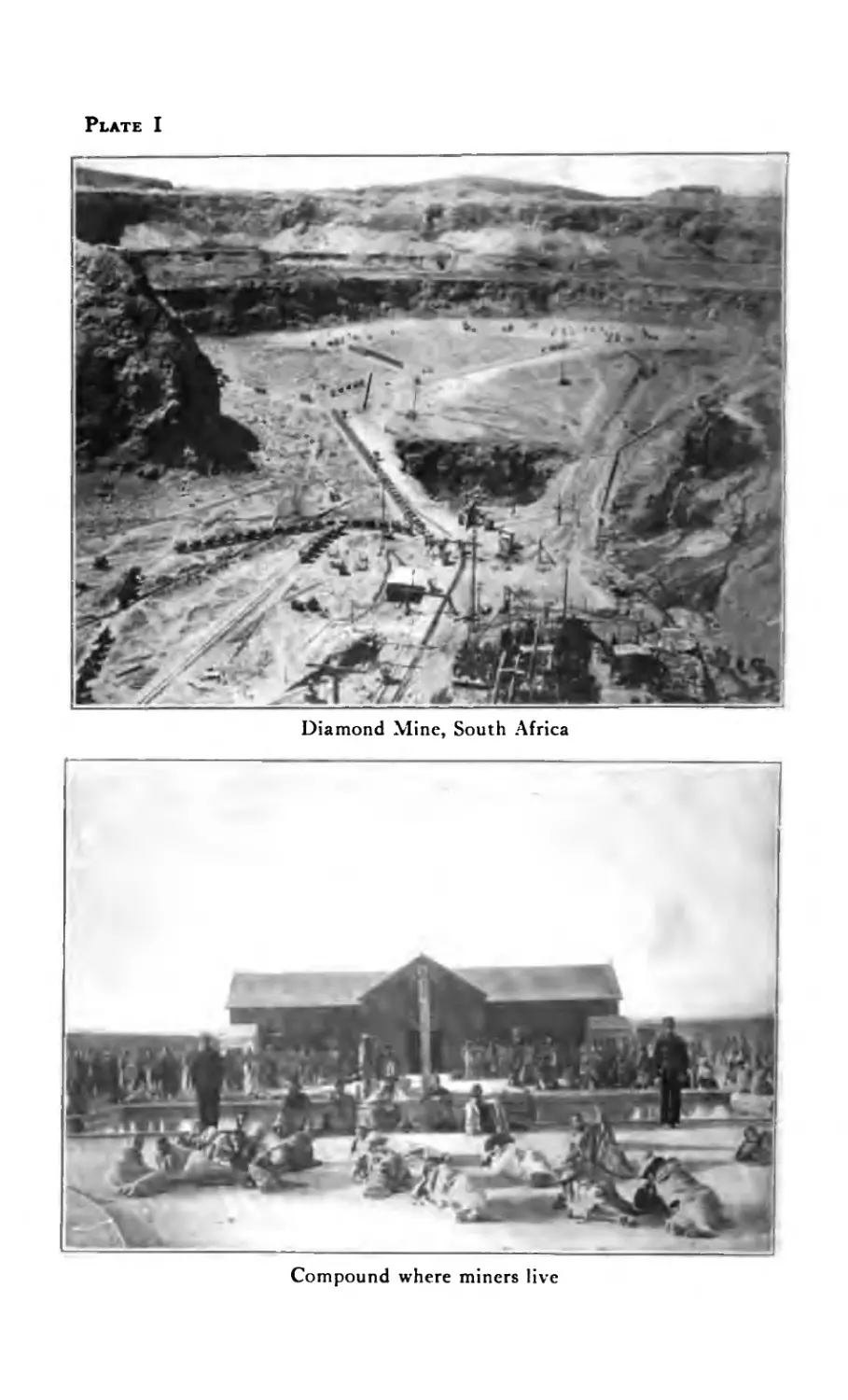
The most precious stones are the diamonds, emer-
alds, rubies and sapphires. The pearl is oftentimes
classed with precious stones. Although strictly speak-
ing while it is not a stone it holds an honored place
in jewelry.
DIAMOND
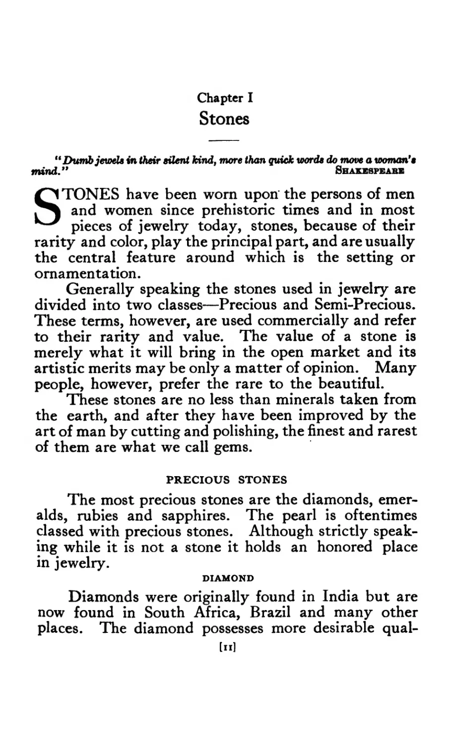
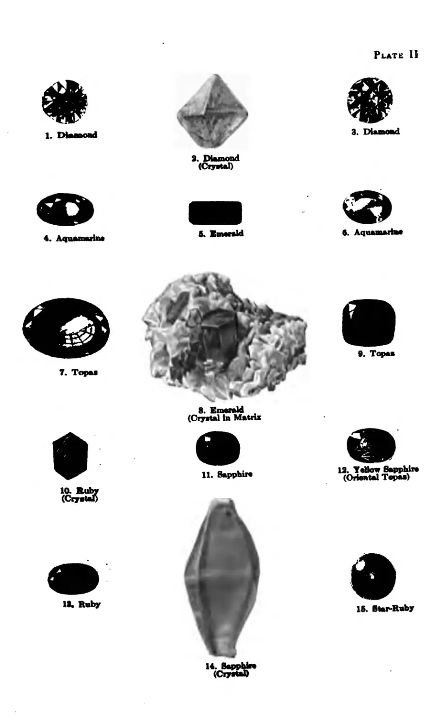
Diamonds were originally found in India but are
now found in South Africa, Brazil and many other
places. The diamond possesses more desirable qual-
[n]
Plate I
Diamond Mine, South Africa
Compound where miners live
Plate IJ
1. Diamond
3. Diamond
9. Diamond
(Cryetal)
ft. Bmeeald
ft. Aquamarine
7. Topae
19. YoUow Sapphire
(Oriental Topes)
1ft. Ruby
1ft. Star-Ruby
ities than any other stone, having greater hardness,
brilliancy, light and refraction, and is found in a variety
of colors, such as white, yellow, brown, blue, green and
in many shades. It is found in deposits of gravel,
sand or clay in river beds and is recovered by the simple
process of washing.
EMERALD
The emerald is probably the rarest of all precious
stones and is considered by some to be even more
valuable than the diamond. Compared with other
precious stones the emerald in its occurrence in nature
is unique, for it is found in the rock in which it was
formed. Unlike diamonds, sapphires and rubies, it
never occurs in gem gravels. The earliest known local-
ity where emeralds were found was in upper Egypt
near the coast of the Red Sea. The best stones, how-
ever, are found in Columbia, South America. Fine
specimens have also been found in the United States
in North Carolina.
While the usual shade of color seen in emeralds
is alluded to as emerald green, there are other shades,
such as grass green, sea green and green slightly tinged
with yellow. The shades most highly valued are those
of an .intense fresh green sometimes compared with
that seen in a meadow in spring.
RUBY
The ruby is the oldest or first known of all precious
stones, dating far back in the early history of Chaldea
and Babylonia. The finest specimens, as well as the
largest quantities, are found in Upper Burma, and at
the present time over one-half of the world’s supply
comes from this locality. The rubies found in Ceylon,
Siam and Australia have not the deep rich color of the
Burmese ruby which is a shade of red slightly inclined
to the purple and is often called “Pigeon Blood Ruby.”
The value of rubies depends upon their color and trans-
parency.
l»31
The ruby is found in limestone deposits on side
hills, but the largest quantity is found in alluvial de-
posits of gravel and clay in river beds. These deposits
are about fifteen to twenty feet below the surface and
from a few inches to five feet in thickness. This ma-
terial called “byon” is mined or removed and put
through a washing process by which the rubies are
recovered.
The genuine ruby is gotten from the mineral known
as corundum. Emery, so much used, is an impure form
of corundum.
The superbly blood-red color of the perfect ruby
is produced by the very tiny portions of impurity in
the substance after they have been crystalized by
Nature’s wonderful processes.
All genuine—that is natural stones, contain cer-
tain tiny flaws and blemishes and characteristic pecu-
liarities. The fewer these flaws the rarer the gem.
Imitation stones get their imperfections during
manufacture, and as the chemists are more careful
than Nature, these imperfections are less noticeable.
By the following differences between the real and
the artificial, you can test your ruby.
A real ruby contains irregularly shaped bubbles;
the imitation ruby contains bubbles that are perfectly
round.
Natural rubies all have a silky sheen, due to a num-
ber of tiny parallel lines going in three definite direc-
tions; imitation stones never have this characteristic.
To examine a ruby, place it in a strong light and
look at it through a microscope. If the stone is in a
setting, then place a drop of oil on its face and hold it
up with the back to the light. When it is held in this
way the stone is illuminated and can be thoroughly
examined through the lens. The drop of oil prevents
reflection that would hinder the eye.
Rubies are over four times heavier than water.
If you take the right quantity of water and dissolve in
[141
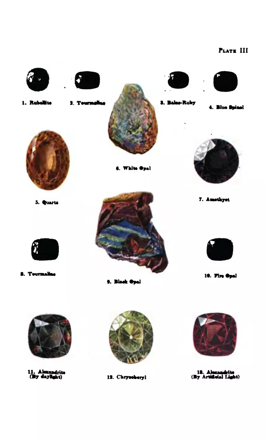
Plats III
•. BlMkftpal
IS. Chrybeijl
IS. AlwaaSrite
(By ArtiSebl Lfebt)
it thallium, silver nitrate, you get a liquid four times
heavier than water. If a ruby sinks in this it is a nor-
mal stone; if not, it is imitation.
SAPPHIRE
The word “sapphire” which means blue, is of the
same form in nearly all the early tongues, thus showing
that they were in use by the ancients. Sapphires are
found in many parts of the world and are usually found
in the same locality as the ruby. The largest number
and finest quality of these stones come from Siam,
and are found and recovered in much the same way as
the ruby.
The sapphire is next to the diamond in hardness
and it is this quality that makes it impervious to wear
and insures its sharp edges and corners against years
of use. Like the ruby the value of the sapphire is
determined by its color. The finest stones are a deep
blue and the deeper the color the more highly it is
prized if its translucency is not impaired. Although
the sapphire with its many shades of blue is con-
sidered the most desirable stone, it is also found in
other colors such as red, green, yellow and pink.
PEARL
“Errors, like straws, upon the surface flow,
He who would search for pearls must dive below”
Dryden.
On account of their natural beauty pearls have
been' considered from the earliest times as among the
most splendid gems.
The people of India and Persia were among the
earliest to collect pearls, because of the rich fisheries of
Ceylon and the Persian Gulf. The Indian and Persian
princes have been enabled to acquire large collections
of pearls which have never been equalled. Some of
these princes have pearls and pearl ornaments worth
millions of dollars.
[isl
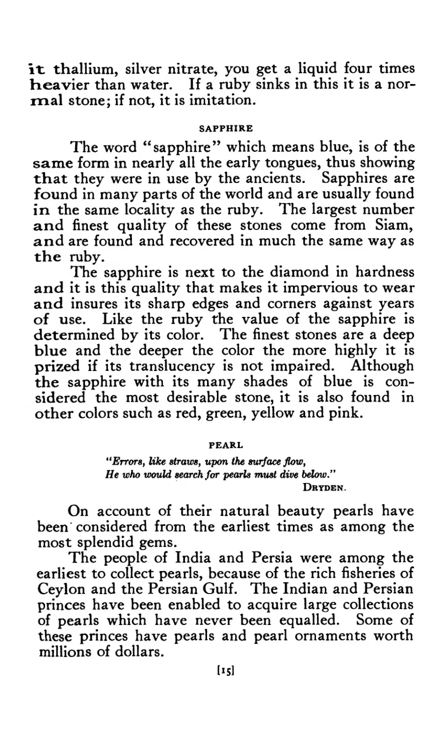
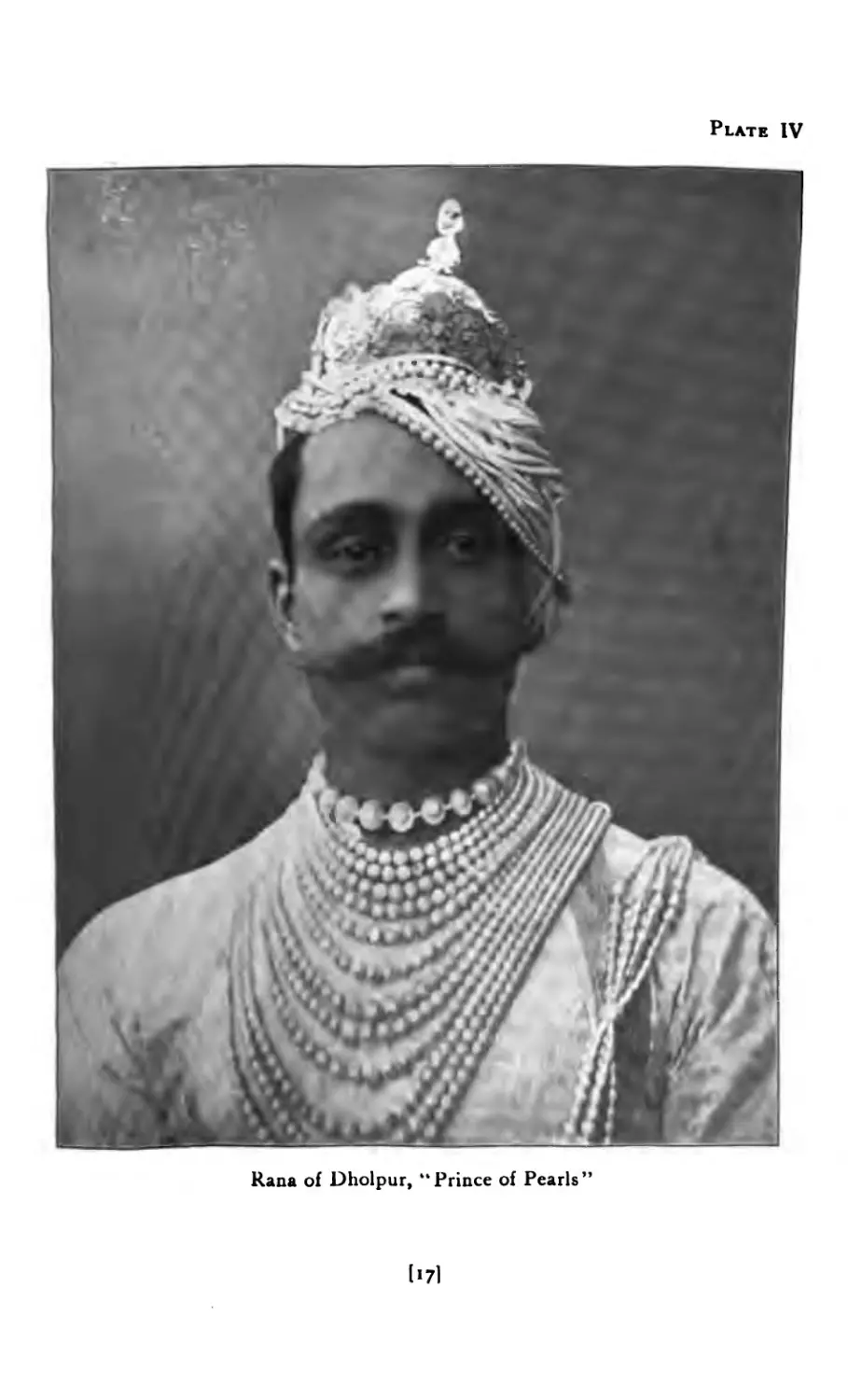
The late Rana of Dholpur, sometimes called the
“ Prince of Pearls,” possessed a collection of pearls un-
rivaled by those of any of the other Indian princes.
The portrait, Plate IV, shows the pearls in about one-
fortieth their actual size and with this fact in mind,
an idea of the value of the jewels may be obtained from
the illustration. It is reported that the Prince had an
offer of $1,000,000 for the string of single pearls which
is shown encircling his neck. These pearls are of un-
usual size and of perfect luster. The offer, it is said,
was not considered, as it is against all tradition for a
native of India to part with jewels of this kind. The
entire collection of this Prince is said by experts to be
valued at over $7,000,000.
The finest quality of pearls are produced by the
pearl mollusk, which inhabits the seas and rivers of
temperate regions. This bivalve mollusk has a shell
from two to eight inches in diameter and is grouped like
the common oyster in colonies.
Pearl fishing has been carried on in Ceylon since
550 В. C., and is conducted much the same today as it
was then. Dr. George F. King in “The Book of the
Pearl,” gives a most interesting description of the pearl
fisheries of Ceylon which is here very briefly described.
These fisheries are under the control of the colonial
government of the British fempire who operate them
on its own account, allowing the fishermen one-fourth
of the oysters taken by them and selling the remaining
three-fourths.
When it has been decided to hold a fishery, public
notice is given by advertisement stating the time of
beginning, the length of time it will last, the reefs to
be fished, the number of boats to be given employ-
ment and an estimate of the number of oysters to be
removed.
The fishery usually begins late in February as the
sea is then relatively calm and there is less danger of
storms. A week before the opening of the season the
[16]
Plate IV
Rana of Dholpur, “Prince of Pearls”
1171
boats begin to arrive from India, Arabia and elsewhere.
Sometimes fifty or more come in a single day, laden
with men, women and children, some with the ma-
terials for their huts. It is only a few days before the
desolate beach becomes populated with thousands of
people. Besides the eight or ten thousand fishermen,
there are pearl merchants, government officials, pro-
vision dealers, pawn dealers, mechanics, clerks and
priests—the whole making up a city of about forty
thousand or more with well planned and lighted streets,
a police court, a jail, a bank, post auction room, hospi-
tal and cemetery, all for a strenuous six weeks of toil
and labor of money getting and gambling.
The fishing fleet consists of several hundred boats
which are examined by the officials and, if found satis-
factory, are registered and numbered. The average
boat carries about thirty-five men. Arising shortly
after midnight they prepare to get under way so as to
reach the reefs about sunrise. There each boat takes its
position assigned for the day and the divers begin work-
ing in pairs. The number of oysters secured on each visit
to the bottom is on an average between fifteen and fifty.
The diving is continued until a signal is given from the
guard vessel when the boats go ashore. After the boats
are run up on the beach the oysters are removed and
placed in the government palisades, which is all done
under close supervision. The oysters are then divided
and after the fisherman receives his share the rest are
auctioned off and bid in by the pearl merchants. The
purchaser then opens the oysters and carefully searches
for the pearl. Machines are now used in recovering the
pearls. After the six weeks of strenuous work the
fishermen fold their tents and silently steal away until
another season comes around. In 1906 in Ceylon and
India, pearls were gathered to the value of $1,300,000.
Pearls are met with in almost every color of the
rainbow, but those with a rich warm tint are most in
demand. The lustre, as it is called, is its. chief char-
lie]
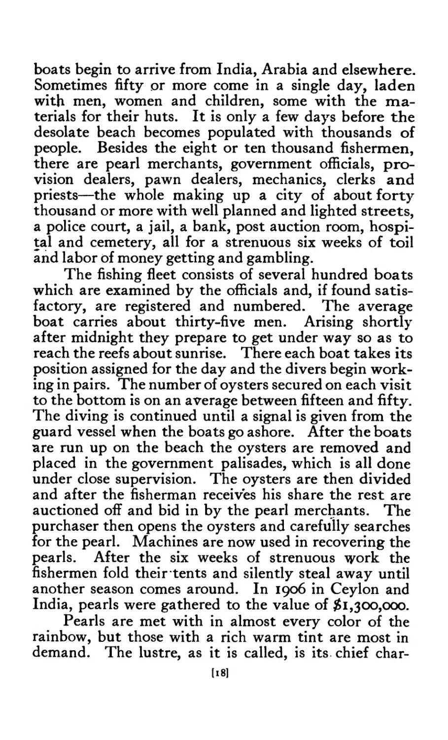
Plate V
The pearling fleet on the shore at Marichchikadde, Ceylon
Unloading oysters from the vessels at Marichchikadde, Ceylon
I >91
acteristic and when combined with the right color,
makes it beautiful and valuable.
Pearls are sold by their weight in grains rather
than by karats, four grains being equal to one karat.
As in the case of precious stones the value of pearls
varies with their size, form and general appearance.
A first-class pearl must have a symmetrical form, a
smooth surface and a perfect lustre.
SEMI-PRECIOUS STONES
A large number of stones used in jewelry are known
as semi-precious; the most follows:— amethyst lapis-lazuli turquoise aquamarine topaz moonstone important ones are as peridot opal tourmaline zircon chrysoberyl alexandrite
Others of less importance although much used are:—
chrysoprase azurite
jade malachite
garnet bloodstone
agate coral
carnelian
and many others. These stones while comparatively
common and inexpensive, are indispensable to the
worker in jewelry. The variety of colors to be had in
these stones make it possible to produce unusual designs
of artistic merit and to adapt them to the personality
and costume of the wearer. For more detailed informa-
tion regarding stones the student is referred to “Gem
Stones” by G. F. Herbert Smith, also “The Curious
Lore of Precious Stones,” by George Frederick Kunz.
[20]
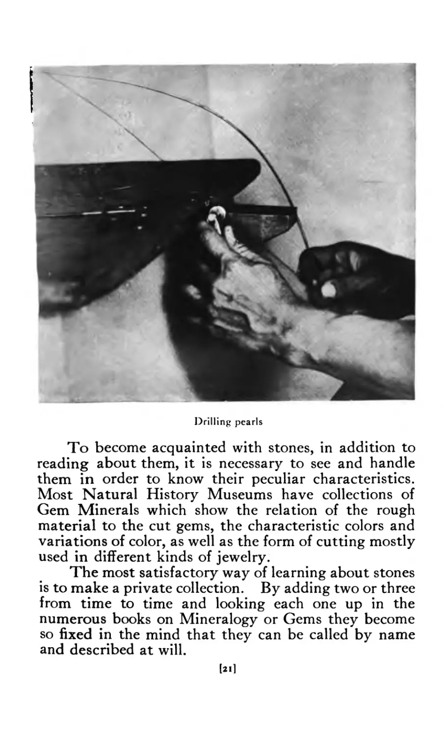
Drilling pearls
To become acquainted with stones, in addition to
reading about them, it is necessary to see and handle
them in order to know their peculiar characteristics.
Most Natural History Museums have collections of
Gem Minerals which show the relation of the rough
material to the cut gems, the characteristic colors and
variations of color, as well as the form of cutting mostly
used in different kinds of jewelry.
The most satisfactory way of learning about stones
is to make a private collection. By adding two or three
from time to time and looking each one up in the
numerous books on Mineralogy or Gems they become
so fixed in the mind that they can be called by name
and described at will.
[2l]
Chapter II
Stone Cutting
WE have no record of the first genius who discov-
eredthat added beauty might be obtained by pol-
ishing, and thus adding lustre to color; nor of
the genius who invented the art of drilling gems, so that
they could be strung. The art of faceting only dated
back to the 15th century when diamonds were intro-
duced as personal ornaments, although in India large
brilliants were polished on their natural facets, but
these only added to the surface lustre, and had no rela-
tion to the laws of the incidence of light which govern
the proportions of a modern diamond, cut scientifically
to attain the maximum brilliancy.
The early stone cutters were organized into guilds,
and records of these show that they existed as early as
1285 in Paris, Nuremburg and Bruges. The earliest
form of cutting was probably nothing more than an
attempt to adapt its outline to the form of setting
designed for it by rounding off its corners and other
irregularities.
Ludwig Van Berguen of Bruges was the first man
to cut diamonds with a symmetrical arrangement of
facets. He tried the experiment of putting two dia-
monds in cement and rubbing one against the other,
and found by doing this that the stones could be
polished and even cut in any way he liked, thus adding
to their brilliancy and value.
CUTTING DIAMONDS
There are four important stages in the cutting of
diamonds—cleaving, slitting, cutting and polishing.
[22]
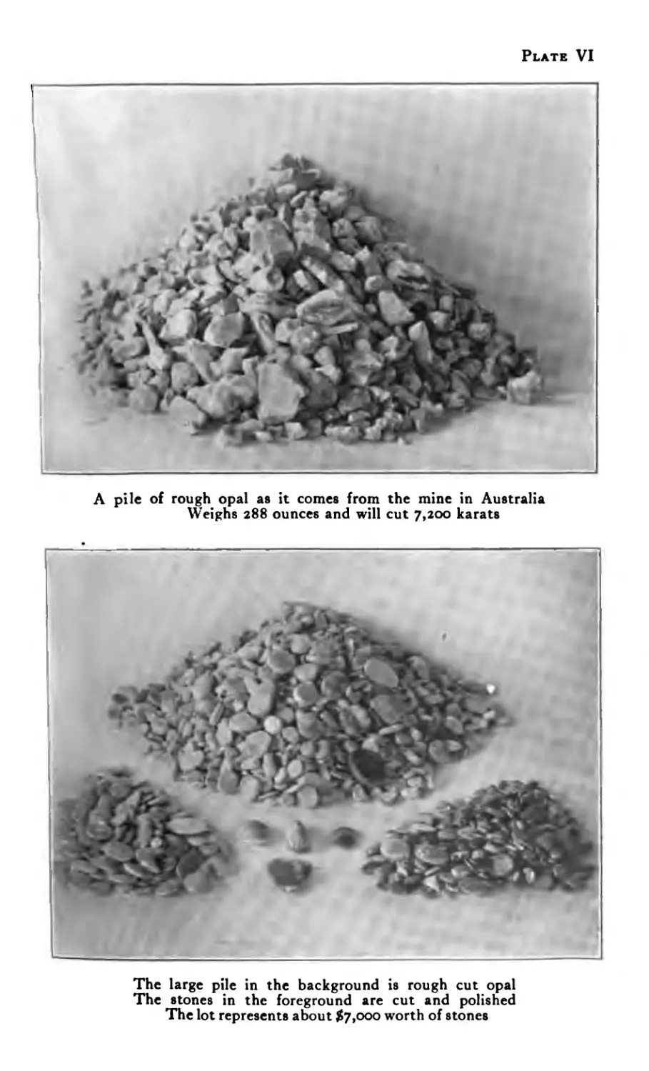
Plate VI
A pile of rough opal as it comes from the mine in Australia
Weighs 288 ounces and will cut 7,200 karats
The large pile in the background is rough cut opal
The stones in the foreground are cut and polished
The lot represents about $7,000 worth of stones
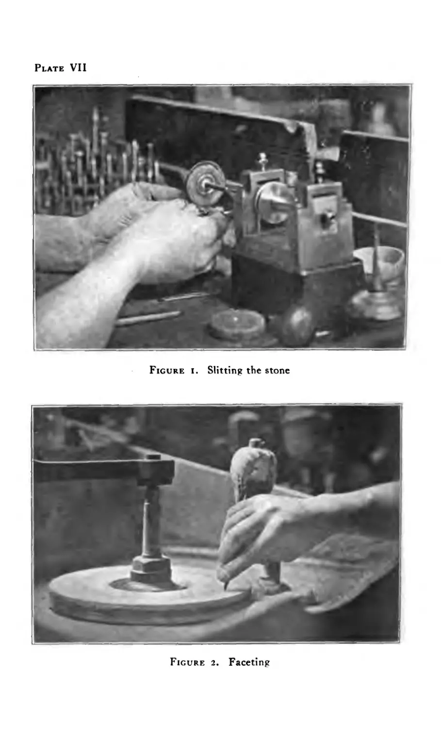
Plate VII
Figure i. Slitting the stone
Figure 2. Faceting
Cleavage in a diamond is what is known in wood
as “grain” and must be carefully studied in cutting
them. The diamond to be cleaved has a small notch
cut into it by the edge of another diamond, into which a
steel blade is inserted and struck a quick blow, which
splits the stpne.
After being roughly formed by breaking off comers
the stone is then cut and polished, which is only a me-
chanical process. The diamond is held next to a wheel
which revolves at a high rate of speed and with the use
of diamond dust and oil, facet after facet is formed.
There are fifty-eight facets on every full cut brilliant
diamond.
Through the courtesy of Mr. Frederick Forth, the
author had the pleasure of spending a half day in the
lapidary of Van Dam & Co., of Amsterdam, the largest
diamond cutting house in the world. Here there were
about three hundred men employed; diamonds were
being cut and handled in large quantities.
The cutting of diamonds is an art by itself and the
lapidary who cuts and polishes diamonds rarely cuts
other stones. In cutting the diamond, brilliancy is the
prime requisite, while in cutting other stones, color is
given precedence.
STYLES IN STONE CUTTING
There are five styles of stone cutting that have been
practiced for a long time which are as follows: Caboch-
on, Table cut, Rose cut, Brilliant cut and Step or Trap
cut.
The oldest of these styles of cutting is the rounded
shape known as cabochon which was used in the cutting
of rubies, emeralds, sapphires and garnets until the
modern methods of cutting came into practice. These
stones as well as all transparent ones are now cut with
facets.
CUTTING SEMI-PRECIOUS STONES
Opaque and semi-opaque stones are now cut caboch-
on, and although the finest cuttings require experiencej
[25]
Figure 3
Figure 4
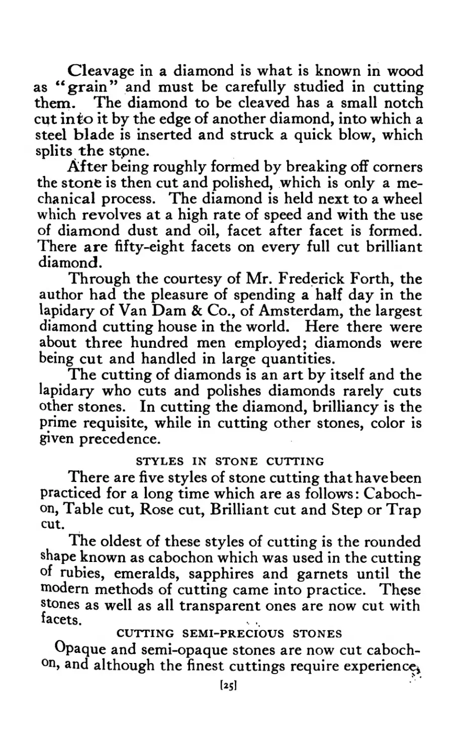
the amateur will be surprised to find that with a very
limited equipment he is able to do creditable cutting.
SLITTING
A piece of rough stone is taken and first closely
examined, to determine the best method of cutting in
order to get the greatest value with the least waste and
loss of weight. Having decided the best method of
cutting it is then put through a process of “slitting,”
Fig. I, if it is a large piece. The rough stone is held
against the edge of a thin metal disc or circular plate
and while it is revolving at a high rate of speed, fine
emery and oil is applied to hasten the process.
ROUGHING
After the large piece has been slit up into pieces of
the required size and thickness, one of the pieces is held
with the fingers against a corundum wheel and roughed
into shape. The face which is to be the front of the
stone is then fastened to the end of a holder (an ordi-
nary pen holder will do) with cement, which is easily
heated over the gas or alcohol lamp.
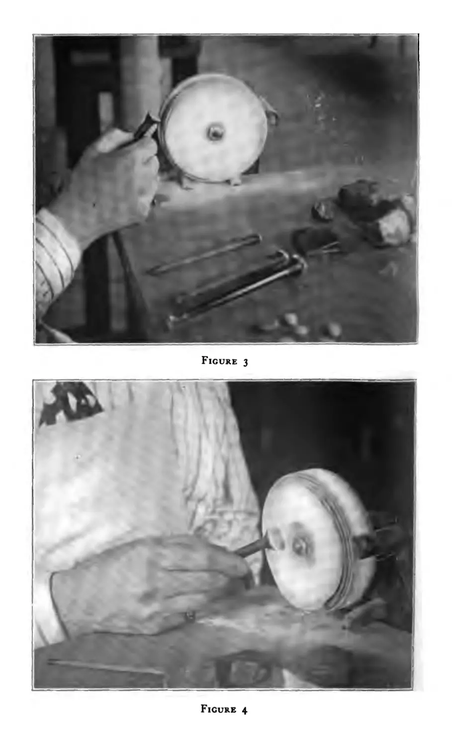
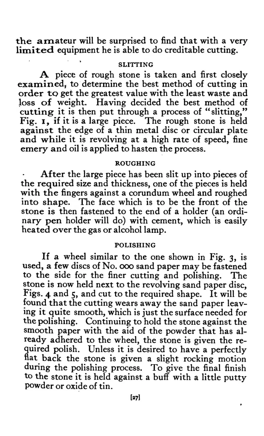
POLISHING
If a wheel similar to the one shown in Fig. 3, is
used, a few discs of No. 000 sand paper may be fastened
to the side for the finer cutting and polishing. The
stone is now held next to the revolving sand paper disc,
Figs. 4 and 5, and cut to the required shape. It will be
found that the cutting wears away the sand paper leav-
ing it quite smooth, which is just the surface needed for
the polishing. Continuing to hold the stone against the
smooth paper with the aid of the powder that has al-
ready adhered to the wheel, the stone is given the re-
quired polish. Unless it is desired to have a perfectly
flat back the stone is given a slight rocking motion
during the polishing process. To give the final finish
to the stone it is held against a buff with a little putty
powder or oxide of tin.
[27]
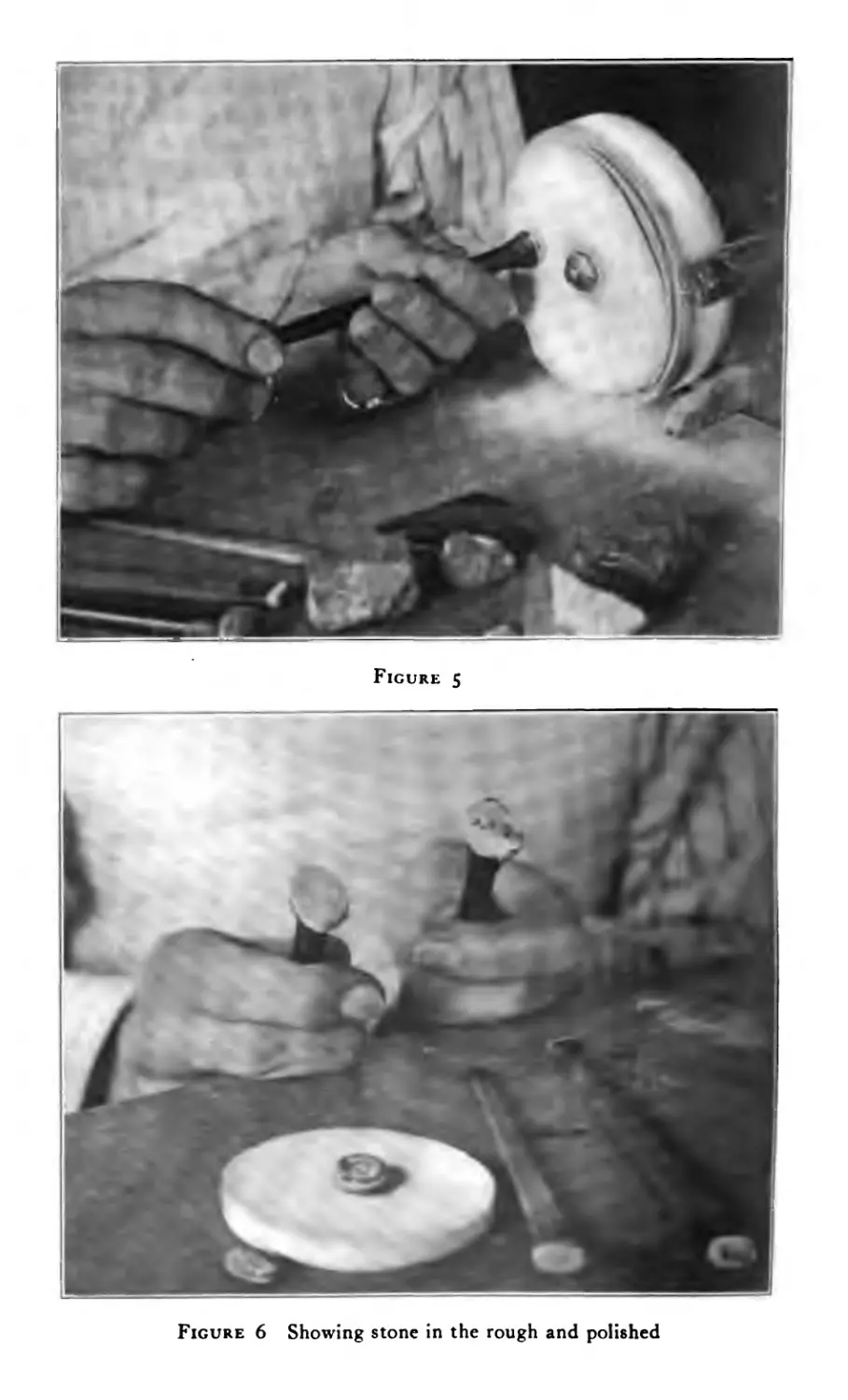
Figure 5
Figure 6 Showing stone in the rough and polished
After the back is completed the stone is removed
from the stick with the blade of a knife, but in doing so
care must be exercised so as not to chip the stone. The
cement is now warmed again and the stone fastened to
it, having the face or front of the stone at the top. The
cutting is done as before except that the front of the
stone is usually rounded more or less which gives it the
cut styled cabochon. An ordinary grindstone may be
used for the rough cutting and where several stones are
to be cut the same size, grooves are made in the grind-
stone for this purpose.
Some of the semi-precious gem minerals may be
obtained for a few cents an ounce and where the crafts-
man can do his own cutting he is able to save money on
his stones, and oftentimes get results that are distinc-
tive in every way.
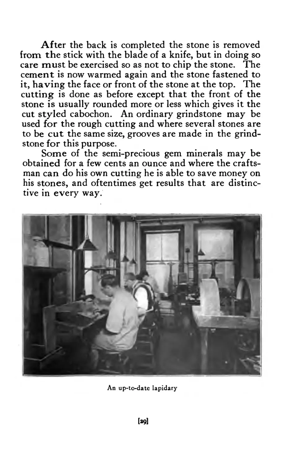
An up-to-date lapidary
[*91
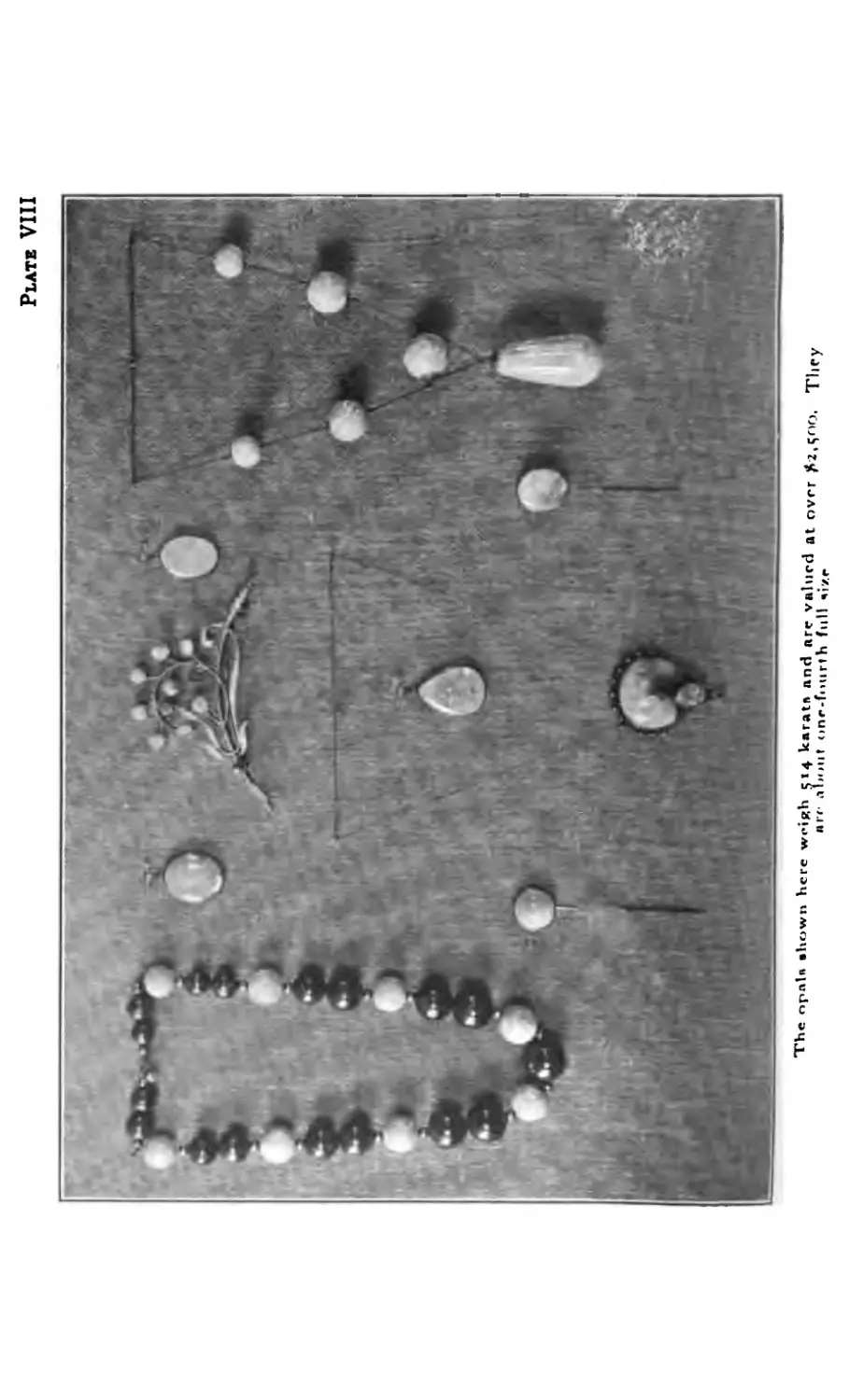
Plate VIII
The opaU Shown here wHRh 514 karats and are valued at over *2 eno
arc- about one-fourth full size
Chapter III
Gold-Silver-Weights, etc.
GOLD
GOLD is one of the metals taken from the earth
and is probably the first metal known to man.
Its first use has been traced back to 3600 В. C.
and was probably originally obtained in Egypt, as
the ancient methods of obtaining gold in Egypt are
illustrated in early rock carvings. It is said in the
book of Genesis that Abraham, in the twentieth century
В. C., when he went out of Egypt, was very rich not
only in cattle but in gold and silver both in dust and
ingots. In Exodus xxv, 29, we read that Moses was
commanded by the Lord to make spoons of gold for
the Tabernacle. In the writings of Homer, Sophocles,
Herodotus, Pliny and others, gold is frequently men-
tioned. >
Gold is widely distributed in nature and is found
in many ways and in all parts of the world. It is found
in water, in the ice of Alaska, in the sand of South
Africa, and in the quartz in Colorado, and is frequently
found native, though usually alloyed with silver or
iron. The purest specimens of native gold have yielded
from 96 to 99 per cent, pure metal.
The unanimity with which all races of mankind
have selected gold as the first and chief representative
of value is remarkable. In the earliest times it was
used as a medium of exchange in the form of bars,
spikes and rings; the rings could be opened and closed
so that a chain could be made for convenience in carry-
ing. Gold was also used at a very early period for the
construction of personal ornaments, as the savage
I31]
found it easy to beat out the pure ore into circlets to
adorn his limbs. The universal use of gold in prefer-
ence to all other metals is due to its many properties;
its color and lustre, its malleability and its indestruc-
tibility. Gold does not tarnish nor can it be destroyed.
It may be reduced to a liquid and the liquid transferred
to a powder, and the powder when melted in a crucible
returns to its natural state. It is the most malleable
of all metals and has been hammered into leaves
1-282,oooth of an inch thick. An ounce of gold may
be drawn out into a wire fifty miles long. The tenacity
of gold is seven tons per square inch.
Pure gold, being too soft for all ordinary purposes,
is generally alloyed with other metals. Silver and
copper are the principal alloys used, although iron is
used in small quantities for different purposes. Pure
silver has a brilliant white color and is the whitest of
all metals; none surpasses it in lustre, and in hardness
it ranges between pure gold and pure copper. It is
more fusible than copper or gold, melting at. a bright
red heat or at 1873° F. It is commonly used for the
purpose of alloying gold in its pure state, but if too
much be added it makes the gold pale. Pure copper
is the only metal that has a reddish appearance. It
is both malleable and ductile, hence it is very useful
as an alloy for gold.
KARAT
Gold is known by karat. The word “karat” is
derived from the seed of the Abyssinian coral tree.
These seeds which are small and equal in size and
weight are said to be the original karat weights of
jewelers. Jewelers and assayers divide the troy pound,
ounce or other weight into twenty-four parts and call
each a karat as a means of stating the proportion of
pure gold contained in any alloy of gold with other
metals. Thus pure gold being considered as 24 karat
fine, if two, six, or ten twenty-fourths of alloy is present
I32]
the gold is said to be 22, 18, or 14 karat fine. This does
not apply to the karat used in weighing diamonds and
other precious stones, as the karat so used has a fixed
weight and is divided into “ karat grains” and fractions
thereof.
To find the number of karats desired take
500 dwt. Gold
200 dwt. Silver
100 dwt. Copper
800 dwt.
This makes a total of 800 dwts. Now multiply the
gold alloy, 500 dwt. x 24 Grains = 12000. Divide 12000
by 800 and it gives 15 Kt. Gold.
Another problem:
300 dwt. Gold
150 dwt. Silver
150 dwt. Copper
600 dwt.
300 x 24 = 7200 divided by 600= 12 Kt.
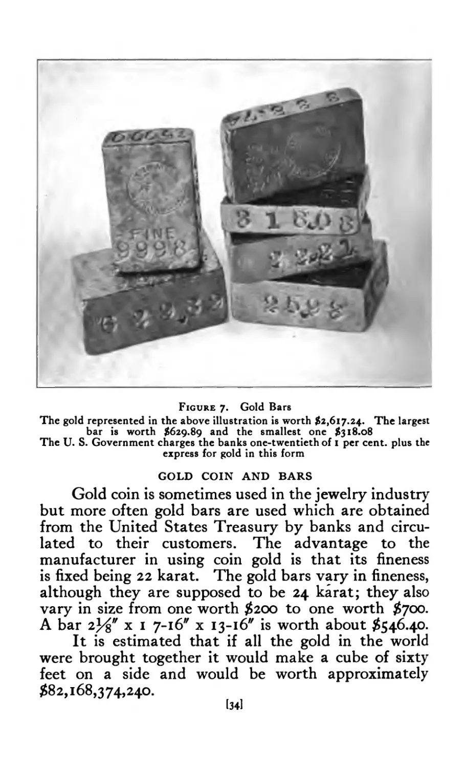
Figure 7. Gold Bars
The gold represented in the above illustration is worth $2,617.24. The largest
bar is worth $629.89 and the smallest one $318.08
The U. S. Government charges the banks one-twentieth of I per cent, plus the
express for gold in this form
GOLD COIN AND BARS
Gold coin is sometimes used in the jewelry industry
but more often gold bars are used which are obtained
from the United States Treasury by banks and circu-
lated to their customers. The advantage to the
manufacturer in using coin gold is that its fineness
is fixed being 22 karat. The gold bars vary in fineness,
although they are supposed to be 24 karat; they also
vary in size from one worth $200 to one worth $700.
A bar 2%" x 1 7-16" x 13-16" is worth about $546.40.
It is estimated that if all the gold in the world
were brought together it would make a cube of sixty
feet on a side and would be worth approximately
$82,168,374,240.
[34]
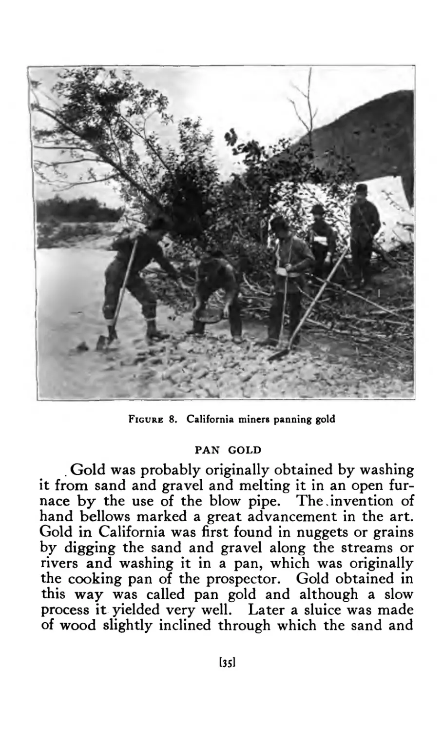
Figure 8. California miners panning gold
PAN GOLD
. Gold was probably originally obtained by washing
it from sand and gravel and melting it in an open fur-
nace by the use of the blow pipe. The.invention of
hand bellows marked a great advancement in the art.
Gold in California was first found in nuggets or grains
by digging the sand and gravel along the streams or
rivers and washing it in a pan, which was originally
the cooking pan of the prospector. Gold obtained in
this way was called pan gold and although a slow
process it yielded very well. Later a sluice was made
of wood slightly inclined through which the sand and
[35I
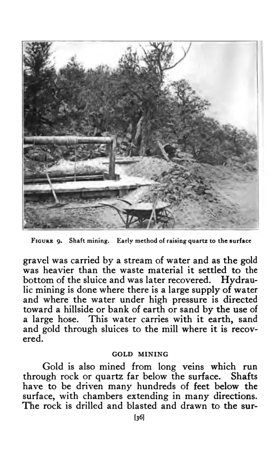
Figure 9- Shaft mining. Early method of raising quartz to the surface
gravel was carried by a stream of water and as the gold
was heavier than the waste material it settled to the
bottom of the sluice and was later recovered. Hydrau-
lic mining is done where there is a large supply of water
and where the water under high pressure is directed
toward a hillside or bank of earth or sand by the use of
a large hose. This water carries with it earth, sand
and gold through sluices to the mill where it is recov-
ered.
GOLD MINING
Gold is also mined from long veins which run
through rock or quartz far below the surface. Shafts
have to be driven many hundreds of feet below the
surface, with chambers extending in many directions.
The rock is drilled and blasted and drawn to the sur-
[36]
face in large buckets or elevators. It is then taken to
the stamp mill or crusher where it is reduced to a pow-
der and spread over tables slightly inclined. A stream
of water is allowed to pass over these tables which
carries off everything but the gold which settles to the
bottom.
SMELTING AND REFINING
After the gold has been recovered in the various
ways mentioned, it is taken to the smelter or refining
mill where all other metals, such as silver and copper
which are usually found with gold, are separated leav-
ing only pure gold. It is then melted and poured into
ingots and shipped to one of the United States Assay
Offices where it is assayed and made into bars of various
sizes. These bars are then sent about the country to
various banks having a call for gold in this form. It
is from these banks that the manufacturing jeweler
gets the bars of gold and he alloys it to suit the grade
of work he manufactures.
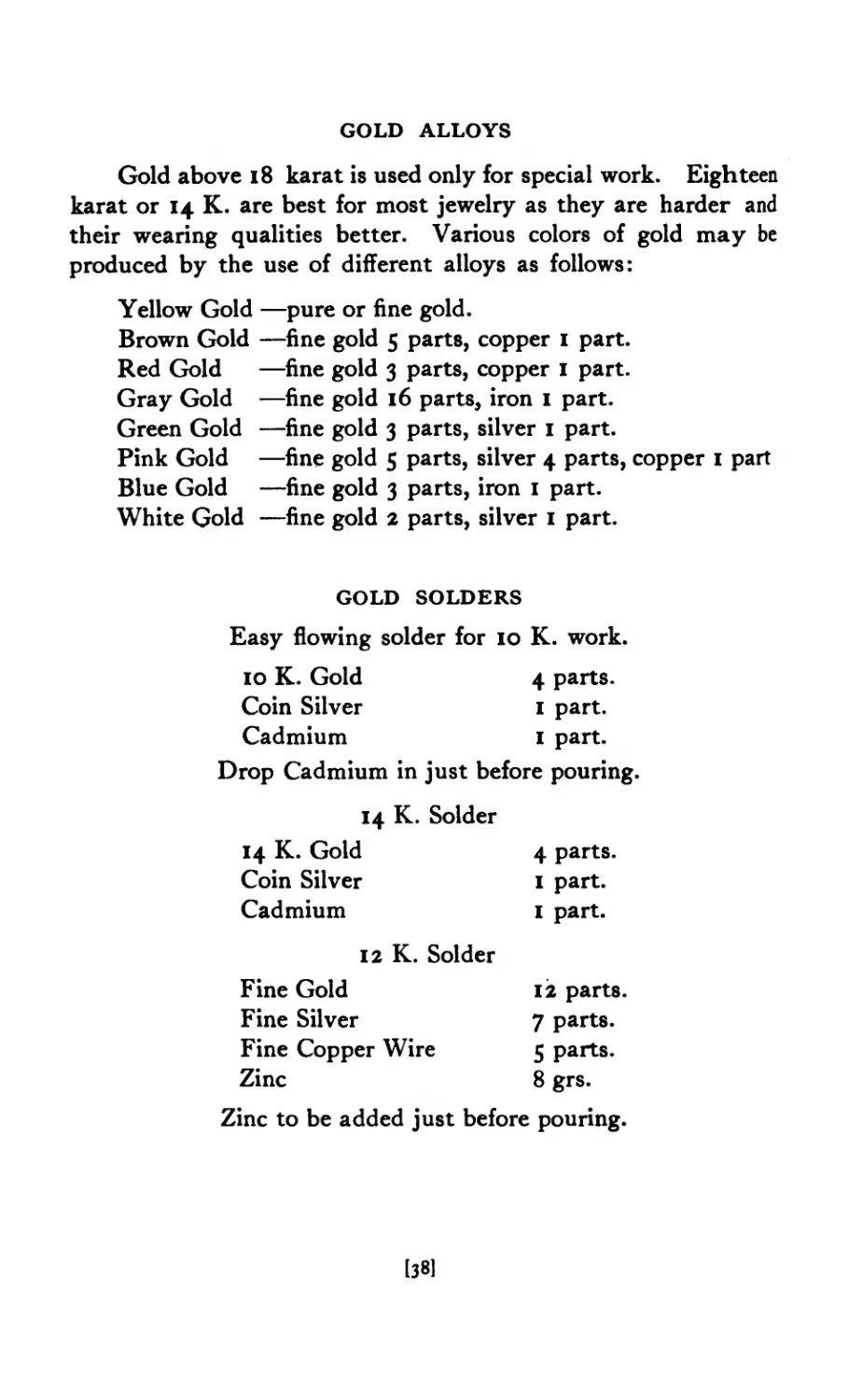
GOLD ALLOYS
Gold above 18 karat is used only for special work. Eighteen
karat or 14 K. are best for most jewelry as they are harder and
their wearing qualities better. Various colors of gold may be
produced by the use of different alloys as follows:
Yellow Gold —pure or fine gold.
Brown Gold —fine gold 5 parts, copper 1 part.
Red Gold —fine gold 3 parts, copper 1 part.
Gray Gold —fine gold 16 parts, iron 1 part.
Green Gold —fine gold 3 parts, silver 1 part.
Pink Gold —fine gold 5 parts, silver 4 parts, copper 1 part
Blue Gold —fine gold 3 parts, iron 1 part.
White Gold —fine gold 2 parts, silver 1 part.
GOLD SOLDERS
Easy flowing solder for 10 K. work.
10 K. Gold 4 parts.
Coin Silver 1 part.
Cadmium 1 part.
Drop Cadmium in just before pouring.
14 K. Solder
14 K. Gold
Coin Silver
Cadmium
12 K. Solder
Fine Gold
Fine Silver
Fine Copper Wire
Zinc
4 parts.
1 part.
1 part.
12 parts
7 parts.
5 parts.
8 grs.
Zinc to be added just before pouring.
[38]
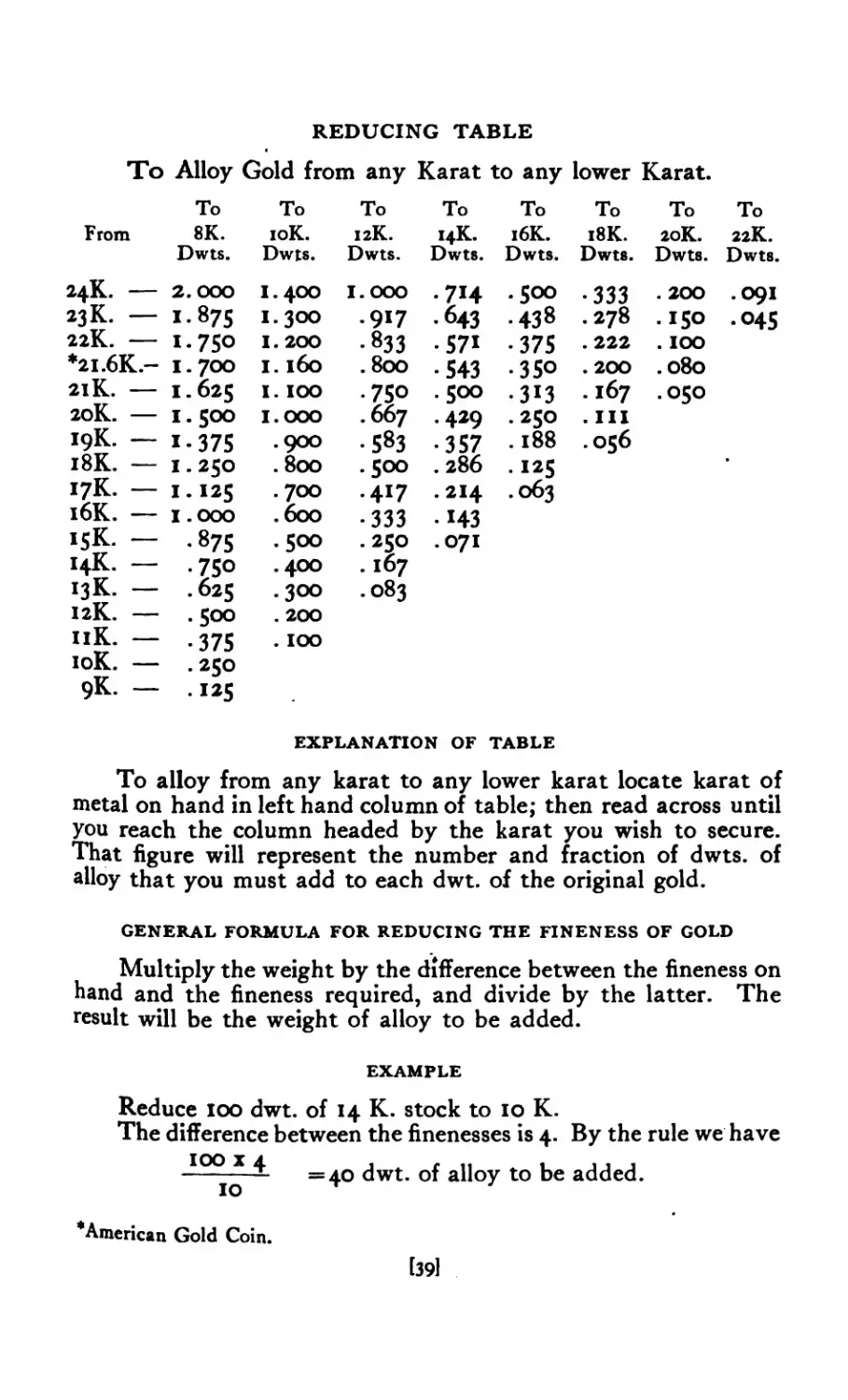
REDUCING TABLE
To Alloy Gold from any Karat to any lower Karat.
To To To To To To To To
From 8K. 10K. 12K. 14K. 16К. 18K. 20K. 22K.
Dwts. Dwts. Dwts. Dwts. Dwts. Dwts. Dwts. Dwts.
24K. — 2.000 I.400 I.000 •74 .500 •333 . 200 .091
23 K. — 1-875 I.300 .917 • 643 • 438 .278 .ISO •045
22K. — I-75O 1.200 • 833 • 571 •375 . 222 . IOO
*21.6K.- 1.700 I. l6o . 8oo •543 •350 . 200 .080
21К. — 1.625 I. IOO •750 .500 •313 . 167 .050
20K. — 1.500 I.000 . 667 .429 . 250 . Ill
19К. — 1-375 .900 •583 •357 .188 056
18К. — 1.250 . 8oo . 500 .286 •125
17К. — 1.125 .700 •417 . 214 063
16К. — 1.000 .600 •333 •43
15К. — •875 .500 .250 .071
14К. — • 75° .400 . 167
13К. — .625 .300 .083
12К. — .500 . 200
11K. — •375 . IOO
10K. — . 250
9K. — .125
EXPLANATION OF TABLE
To alloy from any karat to any lower karat locate karat of
metal on hand in left hand column of table; then read across until
you reach the column headed by the karat you wish to secure.
That figure will represent the number and fraction of dwts. of
alloy that you must add to each dwt. of the original gold.
GENERAL FORMULA FOR REDUCING THE FINENESS OF GOLD
Multiply the weight by the difference between the fineness on
hand and the fineness required, and divide by the latter. The
result will be the weight of alloy to be added.
EXAMPLE
Reduce 100 dwt. of 14 K. stock to 10 K.
The difference between the finenesses is 4. By the rule we have
j^oo x 4 alloy to be added.
‘American Gold Coin.
1391
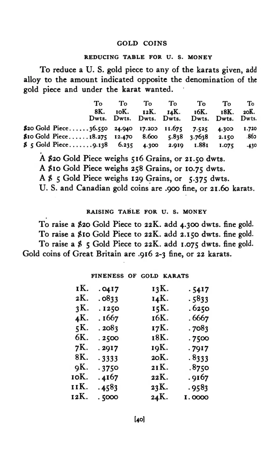
GOLD COINS
REDUCING TABLE FOR U. S. MONEY
To reduce a U. S. gold piece to any of the karats given, add
alloy to the amount indicated opposite the denomination of the
gold piece and under the karat wanted.
To 8K. Dwts. To 10K. Dwts. To 12K. Dwts. To 14K. Dwts. To 16K. Dwts. To 18K. Dwts. To 20K. Dwts.
$20 Gold Piece. .. ...36.550 24.940 17.200 11.675 7-525 4.300 1.720
$10 Gold Piece... ...18.275 12.470 8.600 5-838 37638 2.150 86э
$ 5 Gold Piece... ....9.138 6.235 4.300 2.919 1.881 I-O75 •430
A $2Q Gold Piece weighs 516 Grains, or 21.50 dwts.
A $10 Gold Piece weighs 258 Grains, or 10.75 dwts.
A $ 5 Gold Piece weighs 129 Grains, or 5.375 dwts.
U. S. and Canadian gold coins are .900 fine, or 21.60 karats.
RAISING TABLE FOR U. S. MONEY
To raise a £20 Gold Piece to 22K. add 4.300 dwts. fine gold.
To raise a $10 Gold Piece to 22K. add 2.150 dwts. fine gold.
To raise a $ 5 Gold Piece to 22K. add 1.075 dwts. fine gold.
Gold coins of Great Britain are .916 2-3 fine, or 22 karats.
FINENESS OF GOLD KARATS
iK. •0417 I3K. • 5417
2K. •0833 14K. • 5833
зК- . 1250 15К. .6250
4K. . 1667 16К. .6667
SK. 2083 17К. • 7083
6K. • 2500 18К. •7S°o
7K. • 2917 19К. .7917
8K. •3333 20K. •833З
9K. • 3750 21К. •8750
10K. .4167 22K. .9167
11K. • 4583 23K. •9583
12K. . 5000 24K. 1.0000
[40]
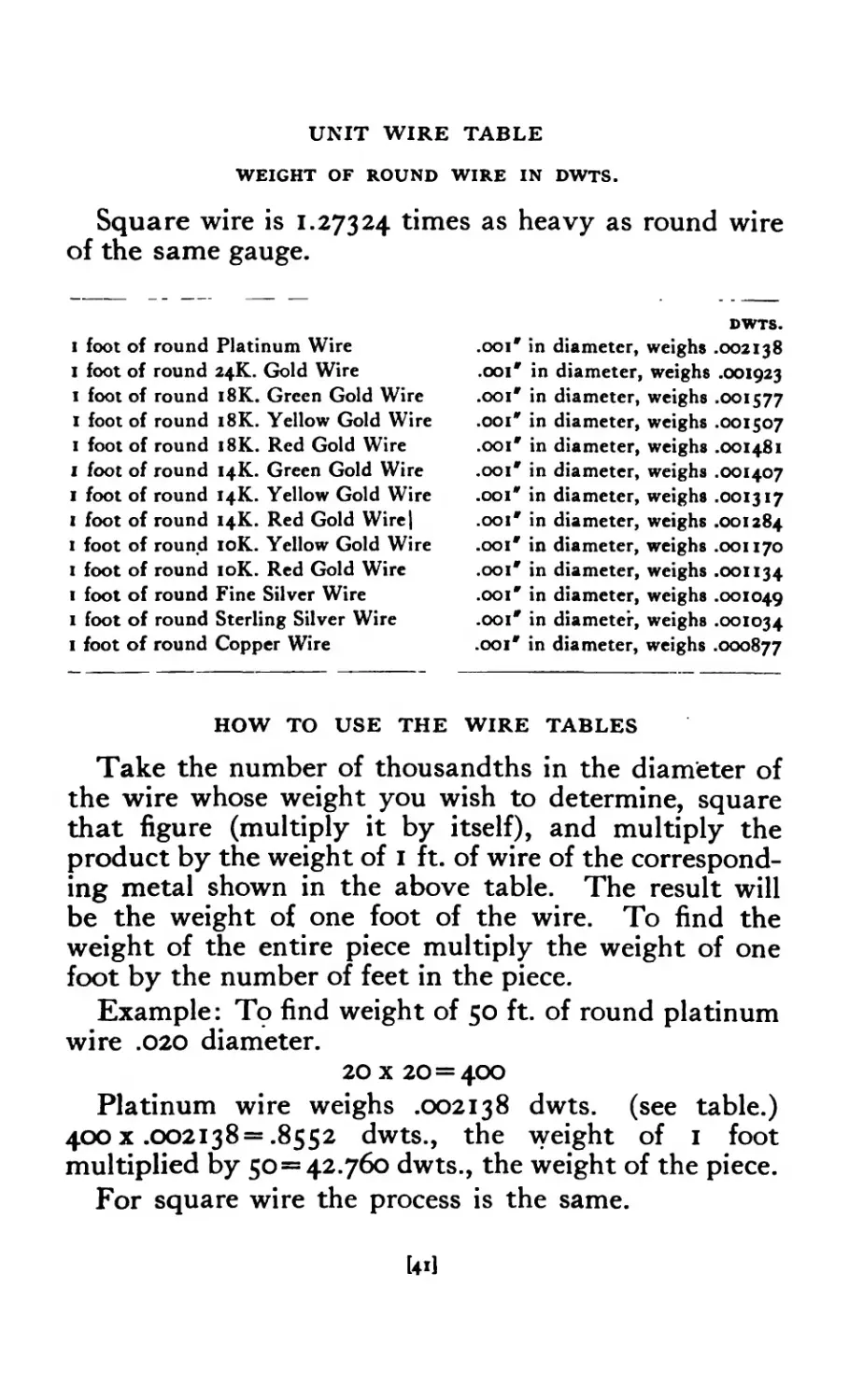
UNIT WIRE TABLE
WEIGHT OF ROUND WIRE IN DWTS.
Square wire is 1.27324 times as heavy as round wire
of the same gauge.
I foot of round Platinum Wire
I foot of round 24K. Gold Wire
1 foot of round 18K. Green Gold Wire
I foot of round 18K. Yellow Gold Wire
1 foot of round 18K. Red Gold Wire
1 foot of round 14K. Green Gold Wire
1 foot of round 14K. Yellow Gold Wire
I foot of round 14K. Red Gold Wire|
1 foot of round 10K. Yellow Gold Wire
1 foot of round 10K. Red Gold Wire
1 foot of round Fine Silver Wire
1 foot of round Sterling Silver Wire
1 foot of round Copper Wire
DWTS.
.ooi* in diameter, weighs .002138
.ooi* in diameter, weighs .001923
.ooi* in diameter, weighs .001577
.001* in diameter, weighs .001507
.ooi* in diameter, weighs .001481
.ooi* in diameter, weighs .001407
.001* in diameter, weighs .001317
.ooi* in diameter, weighs .001284
.ooi* in diameter, weighs .001170
.ooi* in diameter, weighs .001134
.001' in diameter, weighs .001049
.ooi* in diameter, weighs .001034
.ooi* in diameter, weighs .000877
HOW TO USE THE WIRE TABLES
Take the number of thousandths in the diameter of
the wire whose weight you wish to determine, square
that figure (multiply it by itself), and multiply the
product by the weight of I ft. of wire of the correspond-
ing metal shown in the above table. The result will
be the weight of one foot of the wire. To find the
weight of the entire piece multiply the weight of one
foot by the number of feet in the piece.
Example: To find weight of 50 ft. of round platinum
wire .020 diameter.
20 x 20=400
Platinum wire weighs .002138 dwts. (see table.)
400 x .002138= .8552 dwts., the weight of 1 foot
multiplied by 50= 42.760 dwts., the weight of the piece.
For square wire the process is the same.
lol
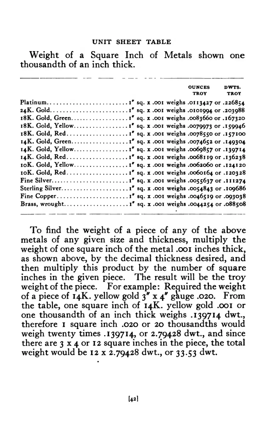
UNIT SHEET TABLE
Weight of a Square Inch of Metals shown one
thousandth of an inch thick.
OUNCES DWTS.
TROY TROY
Platinum..........................I* sq. x .001 weighs .0113427 or .226854
24K. Gold.........................1* sq. x .001 weighs .0101994 or -203988
18K. Gold, Green..................ir sq. x .001 weighs .0083660 or .167320
18K. Gold, Yellow.................ir sq. x .001 weighs .0079973 ог л 5994-6
18K. Gold, Red...................ir sq. x .001 weighs .0078550 or .157100
14K. Gold, Green..................1' sq. x .001 weighs .0074652 or .149304
14K. Gold, Yellow.................1* sq. x .001 weighs .0069857 or .139714
14K. Gold, Red....................1* sq. x .001 weighs .0068119 or «136238
10K. Gold, Yellow................1' sq. x .001 weighs .0062060 or .124120
10K. Gold, Red...................ir sq. x .001 weighs .0060164 or .120328
Fine Silver.......................1* sq. x .001 weighs .0055637 or .II1274
Sterling Silver...................ir sq. x .001 weighs .0054843 or .109686
Fine Copper.......................1* sq. x .001 weighs .0046519 or .093038
Brass, wrought....................ir sq. x .001 weighs .0044254 or .088508
To find the weight of a piece of any of the above
metals of any given size and thickness, multiply the
weight of one square inch of the metal .001 inches thick,
as shown above, by the decimal thickness desired, and
then multiply this product by the number of square
inches in the given piece. The result will be the troy
weight of the piece. For example: Required the weight
of a piece of 14K. yellow gold 3* x 4* gkuge .020. From
the table, one square inch of 14K. yellow gold .001 or
one thousandth of an inch thick weighs .139714 dwt.,
therefore 1 square inch .020 or 20 thousandths would
weigh twenty times .139714, or 2.79428 dwt., and since
there are 3 x 4 or 12 square inches in the piece, the total
weight would be 12 x 2.79428 dwt., or 33.53 dwt.
[42I
SILVER
Silver is widely diffused but is rarely found in the
native state.
Silver is originally as widespread as gold, occurring
in nearly all of the volcanic rocks. Whereas gold
remains unaltered by the action of the elements and
is often carried long distances from its original place
of occurrence, silver on the contrary is only to be found
in the rocks where it originally occurs. When these
rocks are broken down or worn away, the silver is either
driven into new mineral combinations, or more often
dissipated and lost. Silver, therefore, is only to be
obtained by subterranean mining. Shafts are driven
and the ore brought to the surface, and by use of various
processes the silver is extracted, refined and made ready
for commercial purposes.
An old process and one still employed extensively
throughout Mexico where a large quantity of silver
is produced, is to take the ore after it- has been crushed
or reduced to a fine mud or puddle and spread it about
two feet deep over the floor of a large courtyard.
Powdered sulphate of copper is spread over the mass
and then horses or mules are driven around in circles
to tread the sulphate in and mix it thoroughly with
the. ore. After about one day’s treading a quantity
of common salt is added and after two days more
treading quicksilver is added. This mass is trodden
over for a period of about fifteen days, and is then
shoveled into a la ge tank through which a rapid
stream of water is passed. This washes away all but
the silver and quicksilver, which is then poured into
cone-shaped canvas bags. Most of the quicksilver
runs out leaving the silver which is then retorted.
The quicksilver is used over and over again to assist
in recovering the silver.
Pure silver has a beautiful white color and lustre;
it is almost as plastic as pure gold and like it very soft.
[431
Silver does not tarnish in natural air, but when it
comes in contact with sulphur compounds it readily
forms black silver sulphide. The sulphur compounds
which act on silver are found in small quantities in the
air as a result of burning coal and illuminating gas,
while larger amounts occur in vulcanized rubber, wool,
and foods like eggs.
Pure silver is too soft to make durable objects
that require lightness and stability of form. This de-
fect is overcome by alloying it with a little copper.
An alloy of 925 parts fine silver and 75 parts copper
is called 925-1000 fine or what is commonly known as
sterling silver. This alloy is used almost universally
for jewelry and the best silverware.
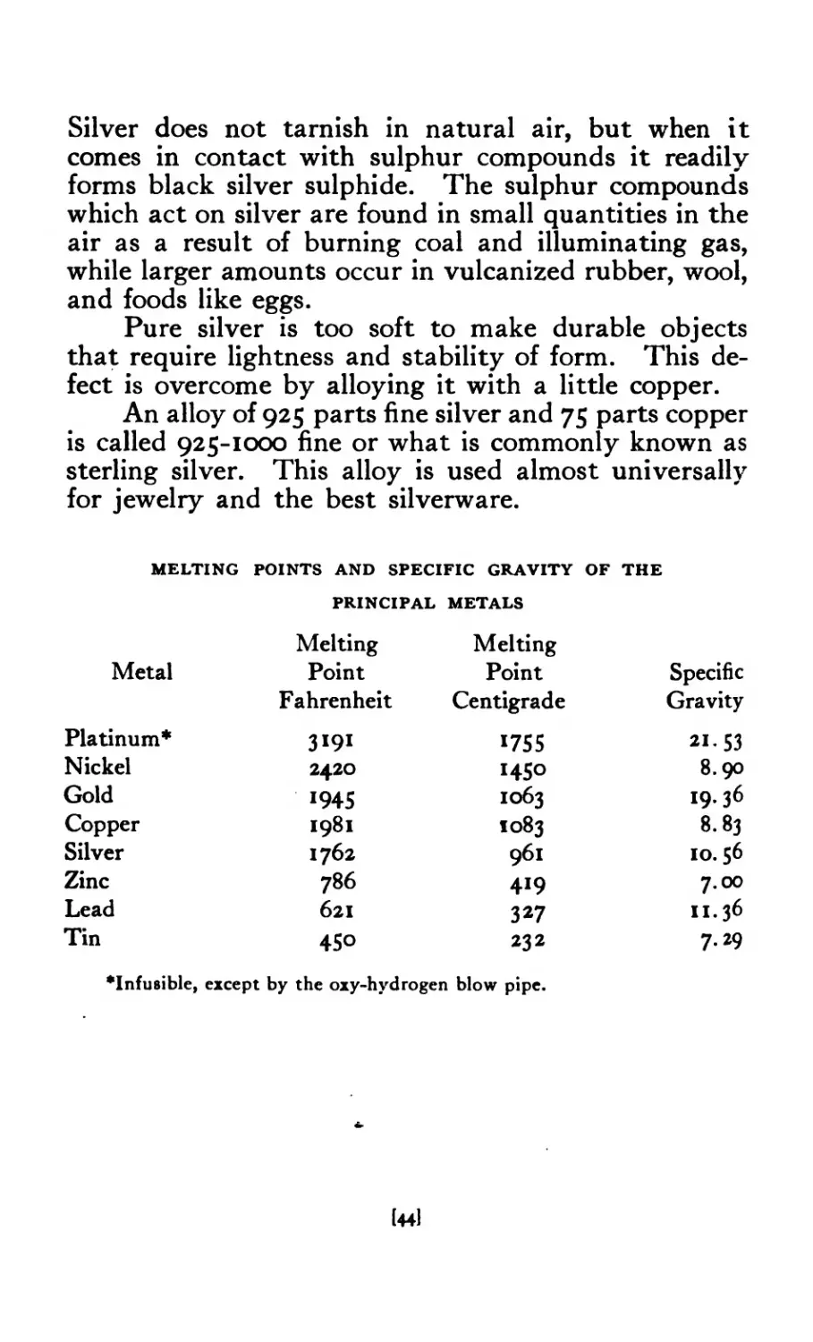
MELTING POINTS AND SPECIFIC GRAVITY OF THE
PRINCIPAL METALS
Metal Melting Point Fahrenheit Melting Point Centigrade Specific Gravity
Platinum* 3191 VS5 21-S3
Nickel 2420 1450 8.90
Gold 1945 1063 19.36
Copper 1981 1083 8.83
Silver 1762 961 10. $6
Zinc 786 419 7.00
Lead 621 327 11.36
Tin 450 232 7.29
•Infusible, except by the oxy-hydrogen blow pipe.
(441
WEIGHTS
THE POUND STERLING
The earliest series of standard weights known were
discovered in the ruins of Nineveh and are now in the
British Museum. The old Saxon pound was the earli-
est standard of England. The pound sterling was de-
termined from this weight in silver. In 1266 Henry II
decreed the following standards: The sterling, or penny
to weigh equal to thirty-two wheat corns, taken from
the middle of the ear; twenty pence, one ounce; twelve
ounces, one pound; eight pounds, one gallon of wine,
which is the eighth part of a quarter. The idea of the
grain was borrowed by the English from the French,
and the Black Prince brought back with him from
France the pound Troye, which was derived from the
commercial town of that name. The use of the Troy
standard was adopted by the druggists and jewelers,
on account of its convenient reduction into grains.
The pound avoirdupois, weighing 7,000 grains Troy
(Fr. Avoir-du-poids, “to have weight”), first appears
in use during the reign of Edward III and it as well as
the Troy pound has been employed without change
ever since.
The unit of weight in the United States is a Troy
pound weight obtained from England, a duplicate of
the original standard. It is a bronze weight of 5,760
grains Troy and is kept in a strong safe at the United
States Mint in Philadelphia. On the second Wednes-
day in February each year, the safe is opened when the
copies or the working weights are compared with the
original upon the most delicately poised balances.
Working standards are supplied by the Secretary of
State to the state governments, which in turn supply
them to the sealers of weights and measures of the
various countries who must compare with the state
standard once a year.
Us]
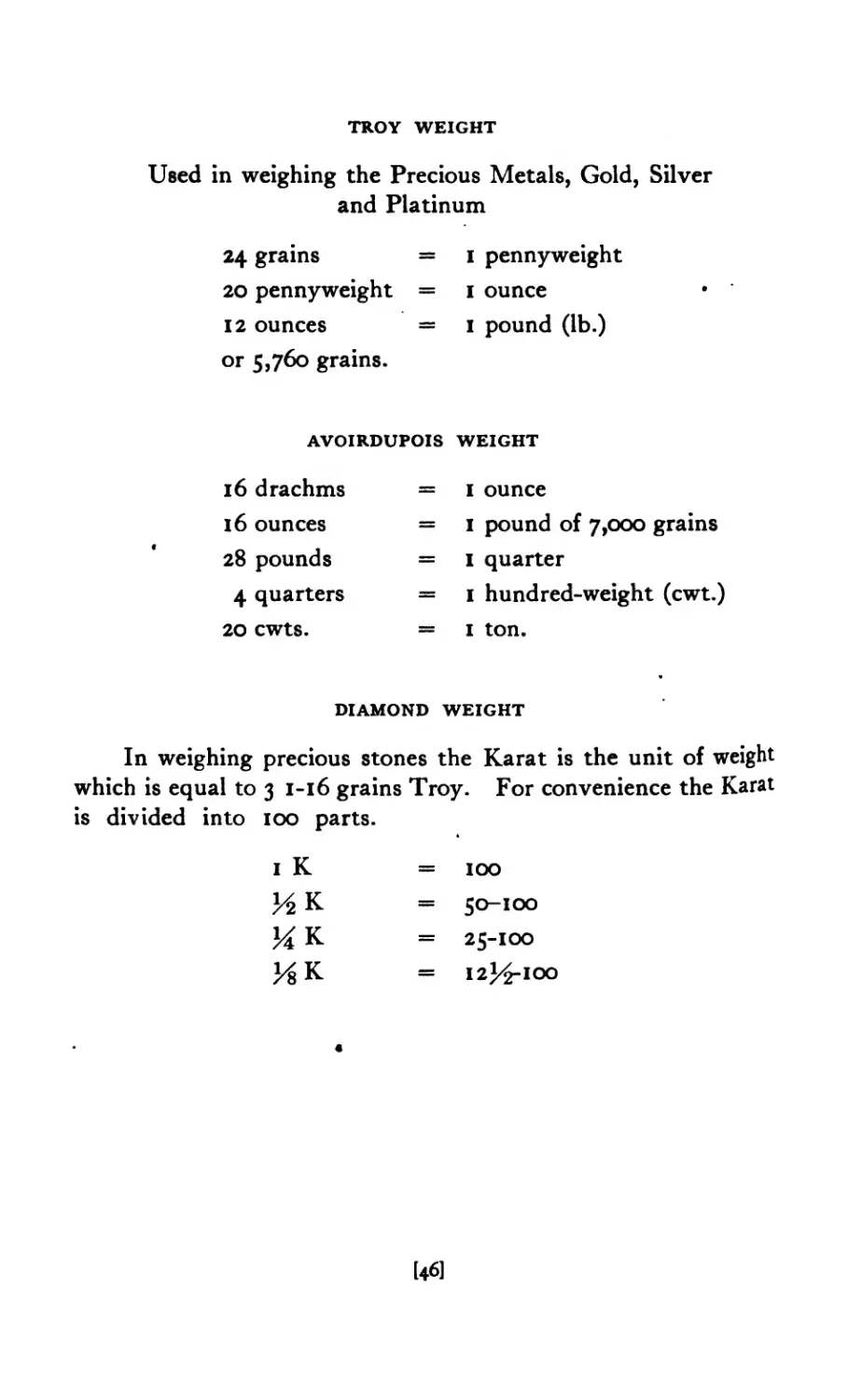
TROY WEIGHT
Used in weighing the Precious Metals, Gold, Silver
and Platinum
24 grains =
20 pennyweight =
12 ounces =
or 5,760 grains.
1 pennyweight
1 ounce
1 pound (lb.)
AVOIRDUPOIS WEIGHT
16 drachms
16 ounces
28 pounds
4 quarters
20 cwts.
= 1 ounce
= 1 pound of 7,000 grains
= 1 quarter
= 1 hundred-weight (cwt.)
= 1 ton.
DIAMOND WEIGHT
In weighing precious stones the Karat is the unit of weight
which is equal to 3 1-16 grains Troy. For convenience the Karat
is divided into 100 parts.
1 К
ИК
ИК
= 100
= 50-100
= 25-100
= 12^-100
[46]
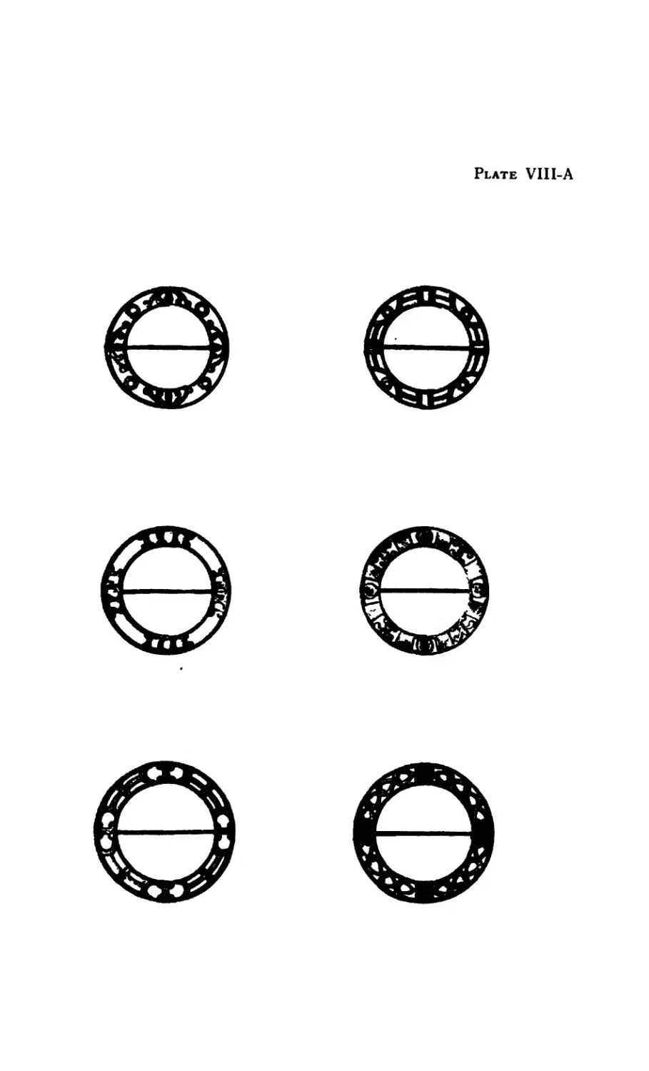
Plate VIII-A
Chapter IV
Processes Involved in Jewelry Making
THERE are different ways of approaching the sub-
ject of jewelry making. Some begin by having
the student or beginner take for the first problem
one that calls for the use of wire bending and soldering.
Others give a problem calling for the introduction of a
variety of processes in one piece. It has been the au-
thor’s experience, however, that the best and most
satisfactory results are obtained both from the stu-
dent’s point of view and the consideration of the finished
product when the student is led to advance from the
simple problem to the more complex by a series of
elementary problems carefully graded. The beginner
has not only to learn the processes involved in the
making of a piece of jewelry but also to master the
various tools used and to learn the limitations of his
material. Although the number of tools used in
jewelry making are few comparatively speaking, it
seems best for the beginner to take them up one or two
at a time and plan his problem accordingly.
The processes involved in jewelry making are as
follows:
Sawing Stone Setting
Filing Polishing
Bending Modeling
Carving Casting
Embossing or rcpoussd Hub and Die Cutting
Soldering Stamping or Pressing
Each of these will be taken up and explained in
the various problems that follow.
[47]
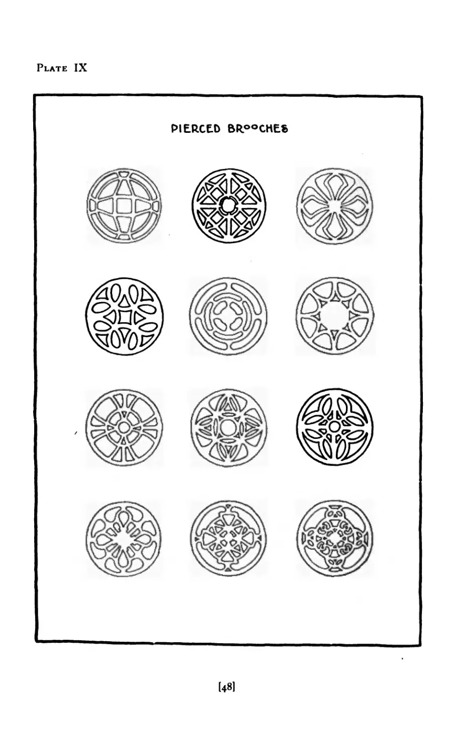
Plate IX
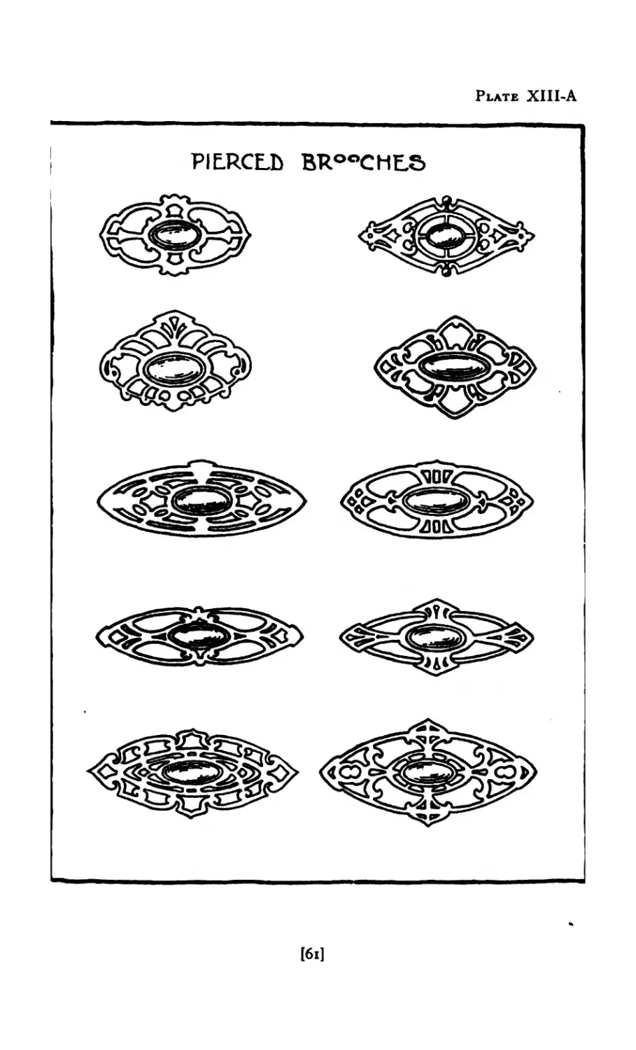
PIERCED BROOCHE«
[48I
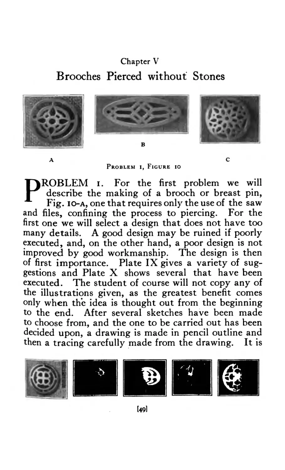
Chapter V
Brooches Pierced without Stones
Problem i, Figure io
C
PROBLEM i. For the first problem we will
describe the making of a brooch or breast pin,
Fig. io-a, one that requires only the use of the saw
and files, confining the process to piercing. For the
first one we will select a design that does not have too
many details. A good design may be ruined if poorly
executed, and, on the other hand, a poor design is not
improved by good workmanship. The design is then
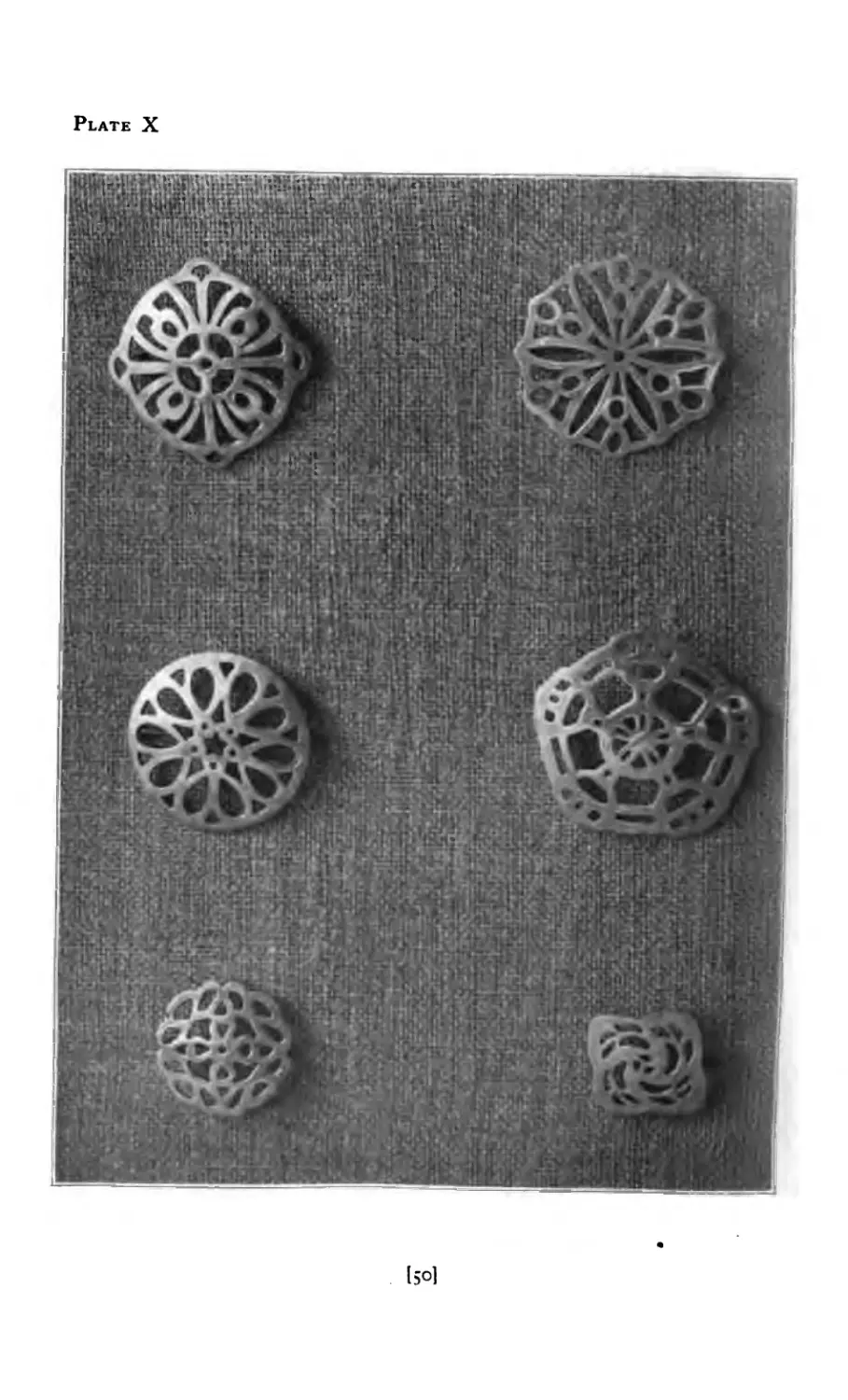
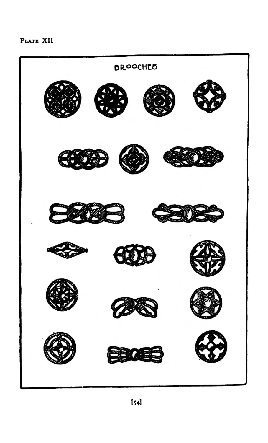
of first importance. Plate IX gives a variety of sug-
gestions and Plate X shows several that have been
executed. The student of course will not copy any of
the illustrations given, as the greatest benefit comes
only when the idea is thought out from the beginning
to the end. After several sketches have been made
to choose from, and the one to be carried out has been
decided upon, a drawing is made in pencil outline and
then a tracing carefully made from the drawing. It is
l49l
Plate X
150]
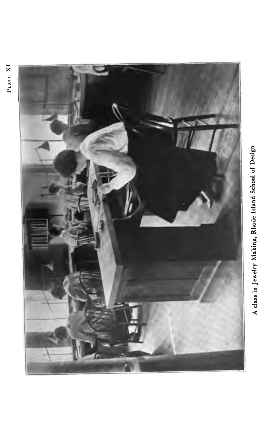
1’1. А И- XI
A class in Jewelry Making, Rhode Island School of Design
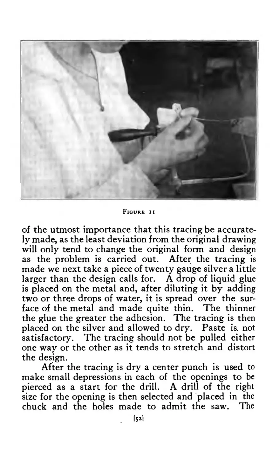
Figure и
of the utmost importance that this tracing be accurate-
ly made, as the least deviation from the original drawing
will only tend to change the original form and design
as the problem is carried out. After the tracing is
made we next take a piece of twenty gauge silver a little
larger than the design calls for. A drop of liquid glue
is placed on the metal and, after diluting it by adding
two or three drops of water, it is spread over the sur-
face of the metal and made quite thin. The thinner
the glue the greater the adhesion. The tracing is then
placed on the silver and allowed to dry. Paste is. not
satisfactory. The tracing should not be pulled either
one way or the other as it tends to stretch and distort
the design.
After the tracing is dry a center punch is used to
make small depressions in each of the openings to be
pierced as a start for the drill. A drill of the right
size for the opening is then selected and placed in the
chuck and the holes made to admit the saw. The
Figure 12
Figure 13
[53)
Plate XII
[541
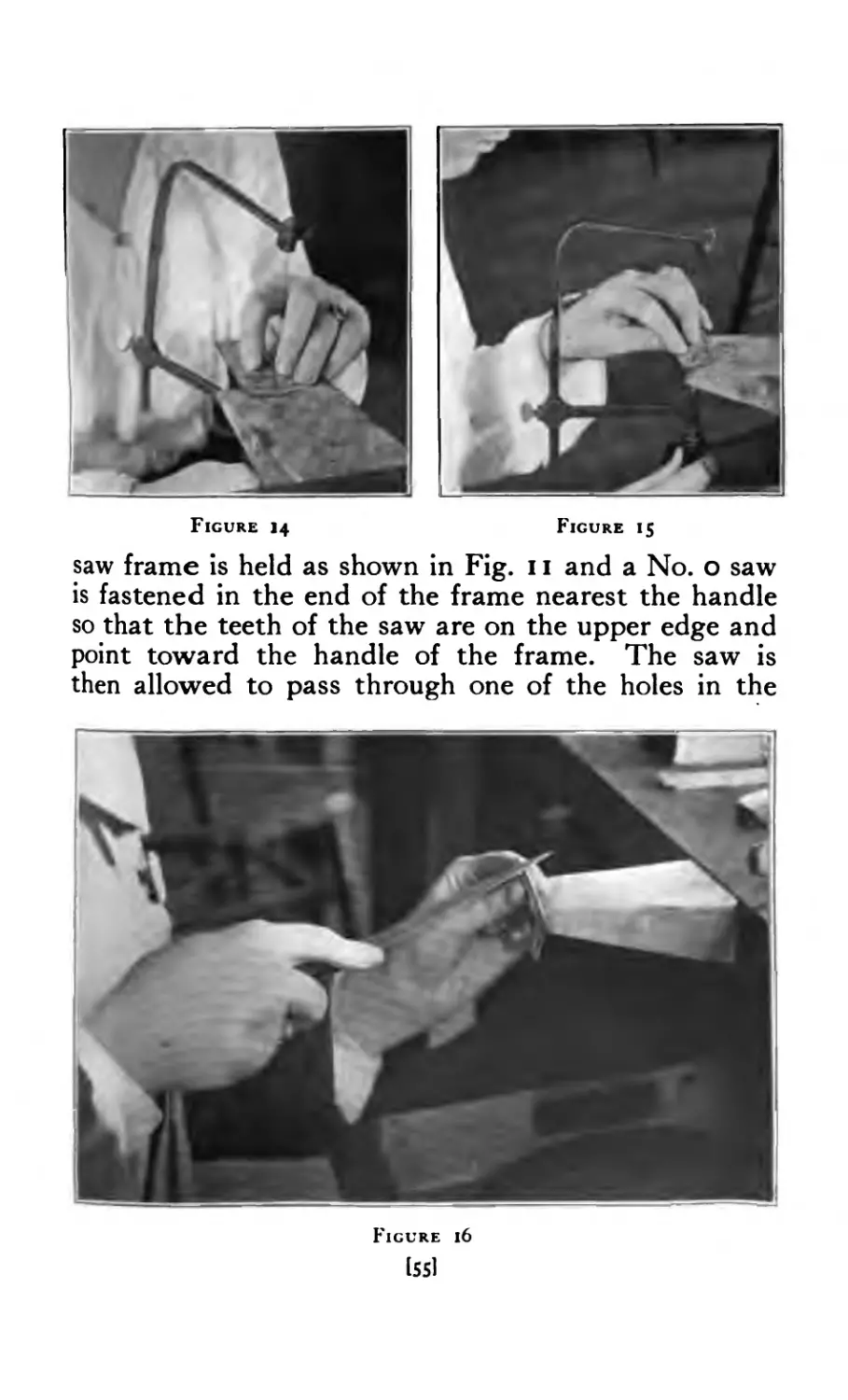
Figure 14 Figure 15
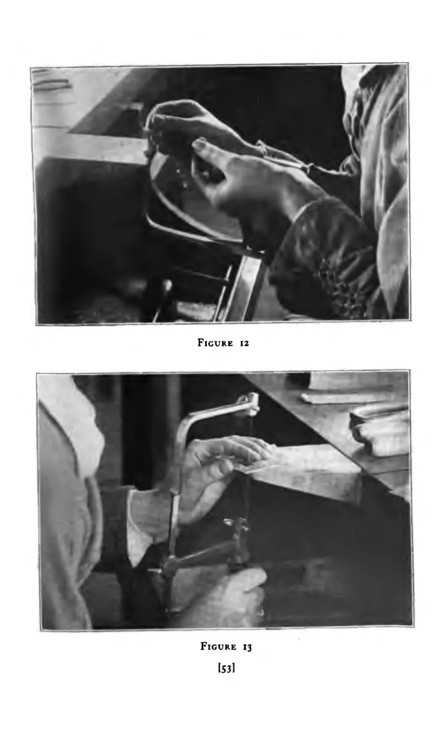
saw frame is held as shown in Fig. 11 and a No. о saw
is fastened in the end of the frame nearest the handle
so that the teeth of the saw are on the upper edge and
point toward the handle of the frame. The saw is
then allowed to pass through one of the holes in the
Figure 16
[55]
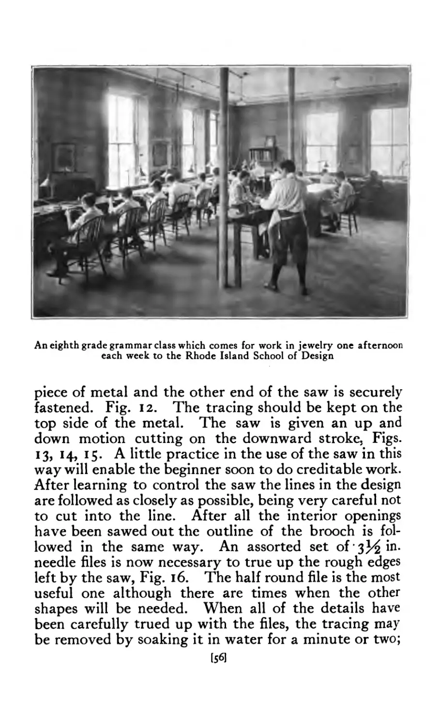
An eighth grade grammar class which comes for work in jewelry one afternoon
each week to the Rhode Island School of Design
piece of metal and the other end of the saw is securely
fastened. Fig. 12. The tracing should be kept on the
top side of the metal. The saw is given an up and
down motion cutting on the downward stroke, Figs.
13, 14, 15. A little practice in the use of the saw in this
way will enable the beginner soon to do creditable work.
After learning to control the saw the lines in the design
are followed as closely as possible, being very careful not
to cut into the line. After all the interior openings
have been sawed out the outline of the brooch is fol-
lowed in the same way. An assorted set of 3^ in.
needle files is now necessary to true up the rough edges
left by the saw, Fig. 16. The half round file is the most
useful one although there are times when the other
shapes will be needed. When all of the details have
been carefully trued up with the files, the tracing may
be removed by soaking it in water for a minute or two;
[56J
and when this has been done the sharp edges of the
openings may be removed by holding the file at an
angle and going over the edges rather lightly. A strip
of very fine emery cloth No. ooo may be used to finish
the piercings. A large flat file is used to true up the
outline of the brooch if it is regular in outline as Fig.
IO-A.
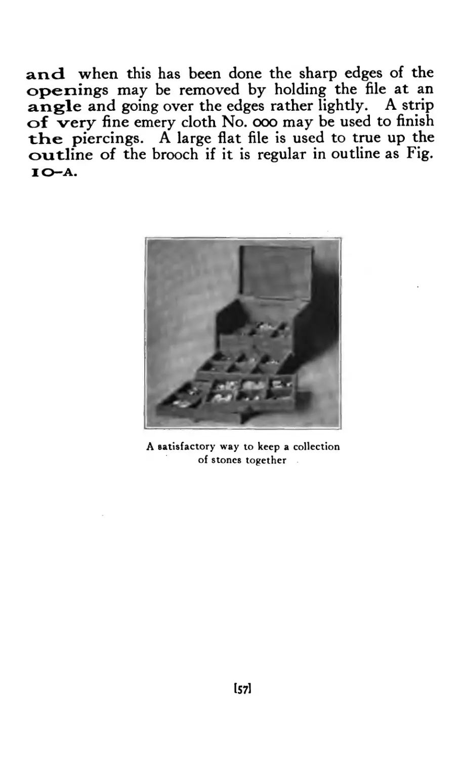
A satisfactory way to keep a collection
of stones together
lS71
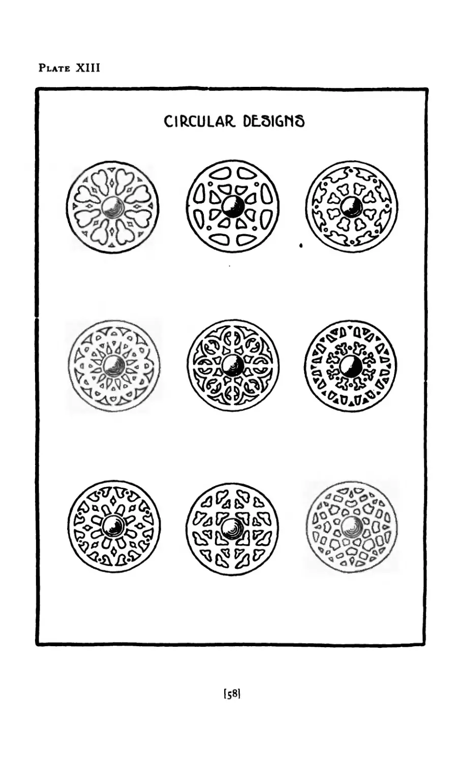
Plate XIII
CIRCULAR. DESIGNS
[58I
Chapter VI
Brooches with Stones
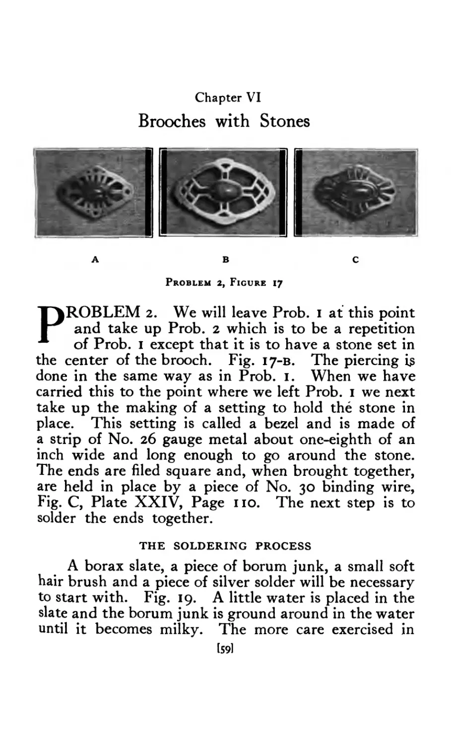
ABC
Problem 2, Figure 17
PROBLEM 2. We will leave Prob. I at this point
and take up Prob. 2 which is to be a repetition
of Prob. I except that it is to have a stone set in
the center of the brooch. Fig. 17-в. The piercing 13
done in the same way as in Prob. 1. When we have
carried this to the point where we left Prob. 1 we next
take up the making of a setting to hold the stone in
place. This setting is called a bezel and is made of
a strip of No. 26 gauge metal about one-eighth of an
inch wide and long enough to go around the stone.
The ends are filed square and, when brought together,
are held in place by a piece of No. 30 binding wire,
Fig. C, Plate XXIV, Page no. The next step is to
solder the ends together.
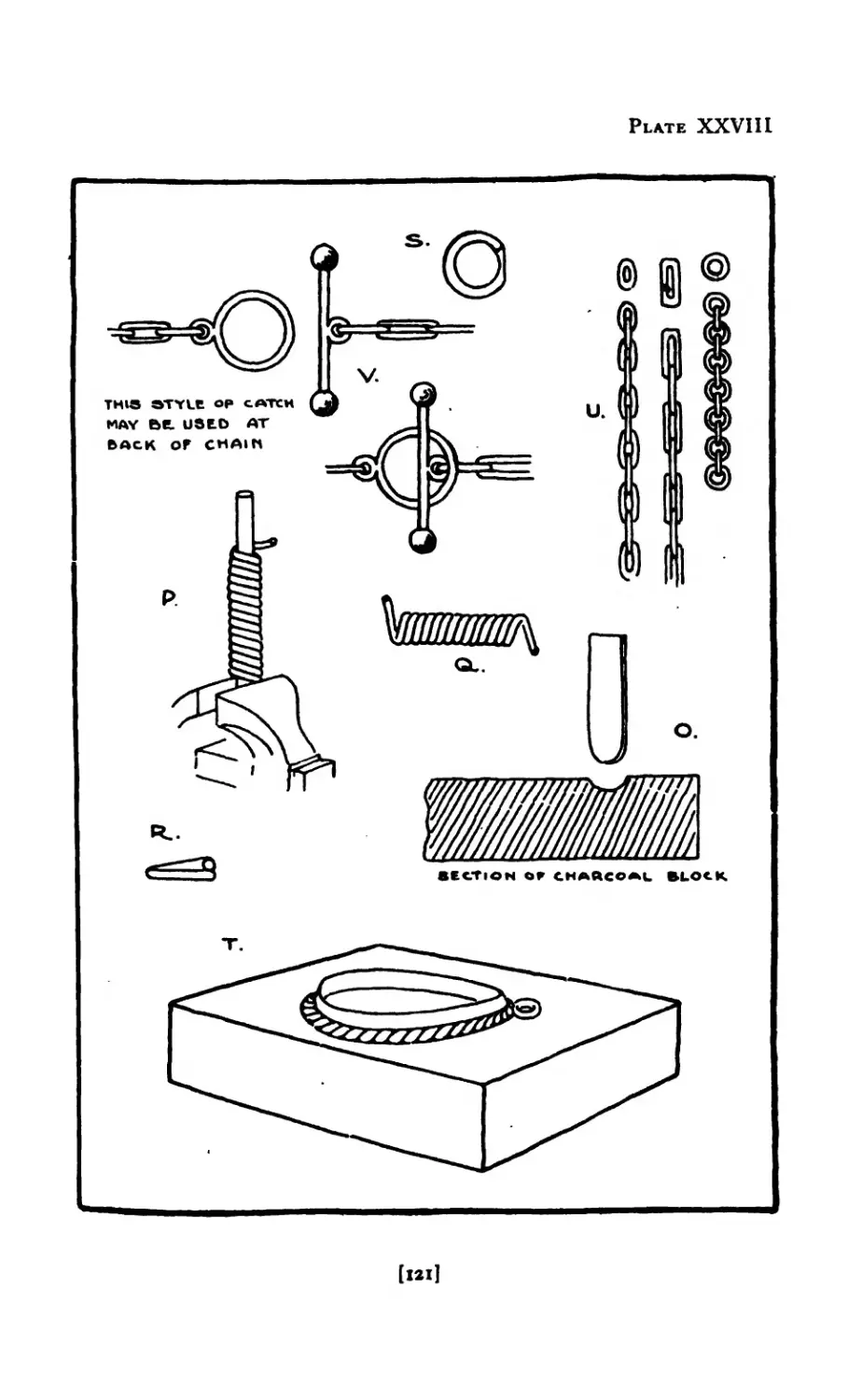
THE SOLDERING PROCESS
A borax slate, a piece of borum junk, a small soft
hair brush and a piece of silver solder will be necessary
to start with. Fig. 19. A little water is placed in the
slate and the borum junk is ground around in the water
until it becomes milky. The more care exercised in
[59]
Figure 18
keeping borax and work clean, the more successful
the results will be. Now take the bezel for Prob. 2
already made and bound with iron wire and, with the
brush, coat the parts to be soldered, being careful to
get no more borax about than is necessary. The
Figure 19
[60]
Plate ХШ-А
PIERCED BR°°CHE&
[61]
solder may be obtained in sheets any thickness, but
No. 26 or 28 gauge answers for most purposes. It is
cut up in small pieces as shown in Fig. 20.
METHOD OF CUTTING OF SOLDER
FOR JEWELRY
It is most important that the student learn to cut
solder in the most efficient and economical manner.
Experience has shown that the following method is the
best.
First, scrape the sheet of. solder with a scraper
on both sides at the place about to be cut; second, make
short parallel cuts evenly distant and about the same
length, Fig. 21. Now hold the solder between thumb and
second finger with the first in front of cut edge of solder
as illustration shows, Fig. 22. Next cut at right
angles to set of cuts already made. This releases the
solder and it will lay on the finger which keeps it
from flying about. This is continued until the re-
quired amount of solder is cut.
Hill
Hill
inn
Hill
Hill
inn
Hill
Hill
Figure 20
[62]
Figure 21
Figure 22
[63]
BORAX SLATE—'~BORUM JUNK
After cutting the solder into pieces of the required
size, drop them into the borax slate to give them a coat-
ing of borax and to remove any grease or foreign sub-
stance that may have adhered to them. Place the ring
or bezel on a characoal block, Fig. D, Plate XXIV, and
apply to the joint a small piece of solder about one-
sixteenth of an inch long and half as wide. A mouth
blow-pipe, which may be connected to an ordinary gas
cock with rubber tubing, is now needed to supply the
heat. After turning the gas on and lighting it is placed
in the mouth and blowing at this end dilutes the gas with
the air and increases the intensity of the flame. Fig. 18.
The size of the flame is regulated by the gas cock. In
soldering, the heat should be applied very slowly
at first until the water has evaporated and the borax
crystallized and dissolved. The flame may then be
applied more directly and the bezel brought to the
soldering heat. If the heat is applied too quickly it
will throw off the solder; and if heated hotter than
necessary it is liable to melt or bum the parts being
soldered, so the process demands very close attention
from the start. After allowing the bezel to cool,
remove the wire. If the binding wire should become
soldered to the silver, a thing which often happens, it
can easily be pulled off with a pair of pliers. Copper
or brass wire will not do for binding purposes. The
bezel is now pickeled or cleaned.
THE PICKLING PROCESS
The solution called
pickle is made of one part
of sulphuric acid to fifteen
parts of water. This
solution may be used cold
but is more effective if
used hot. When used
Figure 23. Pickle Pan hot a copper pickle pan is
iQl r
necessary, Fig. 23. The pickle
is kept in a pickle pitcher,
Fig. 23-A. The object is placed
in the pickle pan with enough
pickle to cover it, then held
over a gas burner and allowed
to come to a boiling heat. The
pickle is then poured back into
the pickle pitcher and the ob-
ject rinsed in clear water and
dried in clean sawdust.
A substitute for the sul-
phuric acid is now to be had
and is called “Pickelrite.” It Figure 23л
is a chemical in crystal form
and when dissolved in water is just as effective as
the sulphuric acid and much less expensive. It is not
injurious to clothing, etc., neither does it throw off
obnoxious fumes as does the acid.
We will now go back to where we left the bezel.
After pickling the bezel, the joint is filed inside and
out to remove any surplus solder that may have run
about the joint. It is then placed over an oval arbor,
and tapped lightly with a wooden, horn or raw-
hide mallet to make it perfectly oval. The wooden,
horn or rawhide mallet is used to prevent stretching.
It may be that, when the stone is tried in the bezel,
it is found that the bezel is a little small; if such is the
case, it can be stretched a little by tapping it with a
metal hammer while it is on the arbor. The bezel is
now filed flat on one side only, using the 6" flat file.
This can be done by holding the file in the left hand,
resting one end on the bench pin, and holding the
bezel between the thumb and fingers of the right hand
rub it up and down the file. A burr will form on the
edge of the bezel and should be removed either with a
small file or a scraper.
I65]
Plate XIV
Figure 23В
We are now ready to solder the bezel to the
brooch; but before soldering to improve the appearance
of the brooch when completed it is modeled or domed
a little. This can be done either on the end grain of a
block of wood or on a sand bag, Fig. 23-в. If the wood
is used a small hollow is made with a gouge. The
brooch is placed in the depression and brought into
shape by striking it with the wooden mallet or a slightly
domed punch. Prob. 1 may be domed at this time
also.
Now place the bezel on the brooch exactly in the
center and mark on the brooch close to the bezel with
a scratch awl or some sharp-pointed tool. Next with
the scraper scrape on the inside of this line, making
a bright surface about 1-16" wide. Borax the edge of
the bezel filed flat and the surface of the metal just
scraped. Center the bezel and bind with wire as in Fig.
K, Plate XXIV, taking care that the bezel is exactly cen-
tered. Place small pieces of solder on the inside of thebezel
and, with the blow-pipe, apply heat as before; although
this time care must be exercised to heat the larger
piece first. When the bottom piece has been heated,
the flame is directed over the work till the solder outside
of the bezel is brought to the fusing point. Again
[67]
care must be exercised not to concentrate the flame
where the seam of the bezel is; the work should be
turned so that the seam is away from the direction in
which the flame-is applied. After the solder has fused
and the joint nicely flushed the flame is quickly re-
moved; and, after it has cooled, the wire is taken off
and the piece of work pickled as described before to
remove the borax.
We are now ready to apply the joint and catch
at the back. Both problems, No. I and No. 2, may be
prepared, and soldered at the same time. The joint
and catch may be made by hand or a commercial one
may be used. As this part of the problem is not im-
portant enough to spend much time on we will use the
commercial one. On close examination of these two
pieces it will be found that they have slight burrs
along the edges that turn over; these must be filed off
in order to leave a perfectly flat surface. Scrape the
places on the brooch where these are to be soldered.
The joint is always placed on the right while the
catch is placed on the left with the opening facing
down when worn. They should be placed as close
to the edge as possible. If the brooch is very much
domed the joint must be modified slightly. This is
done by bending down on the part upon which the pin-
tongue is to rest. The joint and catch are set in place
and a piece of solder is placed next to each. It is
always advisable when soldering catches and joints to
prop work up from charcoal block so that the flame can
be directed under the brooch. When soldering these,
the flame can be directed under the brooch and
the flame should be applied very gradually as
they will easily topple over. After the moisture in
the borax has evaporated, the flame can be directed
under the brooch so that it may become heated
first. If the flame were directed on top the small
pieces would heat before the larger and the solder
would flow upon the catch or joint. For this reason
[68]
Figure 24
both parts should be brought to the soldering point
at the same time. The flame should be directed
from the side opposite that on which the solder is
placed. This will draw the solder toward the flame,
hence in under the catch and the joint. This is easily
done by directing the flame under the brooch until
it is hot, then over it.
When cool the brooch should be thoroughly
pickled.
SETTING THE STONE
After the joint and catch have been soldered in
place and the brooch has been pickled and cleaned,
preparations are made for setting the stone. In the
first place we must provide a way to hold the brooch
firmly while the stone is being set. To do this take
a file handle and a circular block of wood, 2^ inches
in diameter and ^-inch thick and fasten together as
shown at Fig. 24. On this place dry orange shellac
and melt it with the flame from the blow-pipe, Fig. 25.
Repeat this operation until you have about one-quarter
I69I
Figure 25
of an inch of the shellac on the top of the block. While
it is still soft press the brooch into the shellac until the
upper part of the brooch has a firm bearing. The
shellac is allowed to harden, and this takes but a few
minutes. This holds the brooch firmly while the stone
is being set.
The bezel is now filed down to the proper height
which is determined by the height of the stone, only
having enough metal to cover the edge of the stone and
to hold it firmly in place. The stone is next put in
place and the bezel burnished over the edge. This
is done by first taking a small tool, Fig. R, Plate XXV,
with a square end called a pusher. With this tool the
setting is pushed toward the stone, Fig. 26, first at the
four points corresponding to the ends of the diameters as
I70]
Plate XV
Figure 26
Figure 27
[7«]
в
Figure 28
С
at Fig. Q, Plate XXV. This is repeated at the interven-
ing spaces until all parts of the setting touch the stone.
A tool, Fig. S, Plate XXV, called a burnisher may be
used to rub or burnish the bezel perfectly smooth. A
smooth file will finish the sides of the bezel and a No. 40
engraving tool is used to finish the top edge. Fig. 27.
The shellac is now warmed a little with the blow-
pipe and the brooch lifted from the block with the
tweezers. Care must be taken not to heat the stone,
as semi-precious stones will discolor or burn if heated.
When the brooch is taken from the shellac block, some
of the shellac will adhere to it. This is removed by
placing the brooch in a small dish and covering it with
alcohol for a few minutes. The polishing and final
finishing is next done and then the-pin tongue is in-
serted in the joint. It is often necessary to open the
joint a little, and this can easily be done with the
chain pliers. After the pin tongue is in place the
sides of the joint are pressed together with the pliers.
If the pin is too long it can be cut off with the shears
and repointed. The point should project a little
beyond the catch.
Figure 28-A, в and c show how the drill may be
used to produce effective results in the pierced brooch.
I72I
Chapter VII
Brooches with Wire Edges
Problem 3, Figure 29
PROBLEM 3. To add to the interest of this prob-
lem a wire may be soldered to the edge of the
brooch, Fig. 29-A, в and c, when the edge is regular
in outline. The wire may be rectangular, round or
oval. To get the length needed the wire is placed next
to the edge of the brooch and bent around it. It is
then cut a little longer than necessary at first and filed
to the exact length, butted well together and soldered.
The ends can be made to stay in place by springing one
by the other a little. This gives a certain amount of
spring to it which makes it stay in place while being
soldered. Next file surplus solder from the joint.
This wire band should fit the brooch very snugly when
in place so that no space is left between the wire and
edge of the brooch; unless this is the case it should be
cut and fitted over again. If wire should be too tight it
can be stretched by tapping it lightly with a steel ham-
mer when placed on a round mandrel or arbor. Scrape
wire bright on the inside and coat with borax. Now
place it around the brooch so that the edge is flush with
the back side of the brooch. Place small pieces of
solder on the back of the brooch next to the wire at
[73]
в
Figure 30
intervals of about one-half inch. The solder is placed
on the back in preference to the front so that any super-
fluous solder that remains can be filed off. When
soldering make sure that the solder flows all around.
If it does not, apply more borax to solder and try again.
The wire should project a very little above the surface
of the brooch—about one thirty-second of an inch. If
it projects more than this amount, file and make sure
that it is uniform in height. If the wire projects be-
yond the surface on the back it must be filed flush with
Figure 31
[74]
ABC
Problem 4, Figure 32
the back. The wire should be free from sharp edges,
and should feel smooth to the touch after it has been
filed. Rub with a piece of fine emery cloth. If a
round or oval wire is used it may be placed on .the face
of the brooch instead of on the edge as shown at Fig. 30-A
в, and c. It will be noticed in these illustrations
that the file has been used to make serations at intervals
along the wire to relieve the plainness of the edge and
add interest. When the wire is applied in this way it
should be carefully shaped and fitted to the edge
of the brooch and held in place during the soldering
with wire carried around the brooch as described when
soldering the bezel.
Problem 4. To add still more interest to the
brooch, in addition to the wire soldered to the edge
described in Prob. 3, we can apply small shot varying
in size as shown in Fig. 32-A, в and c. These shot
are made by taking round wire (No. 20 gauge) and
cutting it up in lengths to give the required size.
These small pieces of wire are placed on the characoal
block and, after being coated with borax, are heated
to the melting point. This causes them to roll up
into the shot. When enough of these have been
made they are spaced as desired and soldered in place.
A small piece of solder is placed between each two shot.
All other soldered joints should be protected with yellow
ochre while this soldering is being done. After solder-
ing the shot in place, the brooch is pickled and finished
as already described. Fig. В has a rectangular wire
soldered about the inside as well as the outside.
[75I
Plate XVI
A class of teachers in jewelry
Chapter VIII
Brooches Carved and Ornaments Applied
A
В C
Problem 5, Figure 33
PROBLEM 5. Fig. 33-A, в and c show brooches or
pins where theeffectofinterlacing has been obtained
by a little carving. In this problem it is necessary
to have the metal a little heavier or thicker than that
used in the preceding problems. It should be not less
than No. 18 gauge and in cases where considerable relief
is desired No. 16 would not be too heavy. After making
a tracing from the design, the tracing is glued as before
to a piece of silver the required size and thickness.
Next take a scratch awl and follow the lines of the
design, scratching through the tracing on to the metal,
in order to give us the design permanently traced on the
metal. This operation must be carefully performed or
the character of the design will be lost. The openings
and outlines are pierced as previously described and
trued up with the files. The interlacing effect is gotten
by using the No. 40 graver to cut the metal away at
points where one band or line goes under another.
A
В
Figure 34
[77]
ABC
Figure 35
The shellac stick, Fig. 24, is used to hold the piece
of metal while it is being carved. After the carving
has been done the rough parts are smoothed over
with the files. In Fig. A the whole design was
filed or carried out in such a way as to give a modeled
or rounded effect. The veins in the leaves, Fig. C,
were made with a three-cornered file. The flat wire
was soldered around the outside of Fig. В after the
carving had been done. As a rule it is better to solder
the bezel in place after the carving has been done.
In Fig. 35-A, в and c the carving is a little more
difficult and requires two or three additional gravers,
a No. 38 flat for getting into small spaces and No.
11 round for the curved parts of the design. In Figs.
В and C the background is cut away leaving the
ornament in relief. It will be noticed that these
brooches are domed, a thing which should be done
before the bezel is soldered in place.
I78)
A
Problem 6, Figure 36
C
Problem 6. In Prob. 6 the decoration is applied
to the surface. Fig. 36-A, в and c show brooches where
spirals of wire combined with shot have been used
very effectively. A piece of No. 22 gauge metal is
used for the back. With the compasses describe a
circle the required size then saw and file to the line.
Fig. C has a twisted wire about the edge. This is
made by taking a piece of No. 24 gauge wire long
enough so that when it is doubled it will give the
length required to go around the brooch. After
doubling the wire place the cut ends in the vise and,
with a nail or anything that will serve the purpose,
twist the wire as show n at Fig. 14, Plate XXXV. After
twisting it from one end to the other remove it from the
vise, coat it with borax and place it on the charcoal block,
Fig. 15. Put three or four small pieces of solder at equal
distances along the wire and heat to the soldering point
allowing the solder to run along the wire. This is done
to hold the strands together so that they will not sep-
arate when cut. Although only two
were used in Fig C, any number can
be used, the twisting being done in
the same way. After the wire has
been twisted and soldered, it is bent
around an arbor to give it the cir-
cular form and cut the right size.
The ends are soldered together as
described in Prob. 3 and, after truing
it up on the arbor, it is placed on the
strands of wire
Figure 37
[791
Figure 38
metal forming the background of the brooch and
soldered in place.
Several small pieces of solder should be placed
about the inside of the wire equal distances apart.
The bezel should be made and soldered in place as
described in Prob. 2. The coil of wire shown about
the bezel is made by coiling a piece of No. 30 gauge
wire around a small arbor as shown in Fig. P, Plate
XXVIII. This may also be done by putting the arbor in
a lathe or in a hand drill. After the coil has been made,
it is bent around the bezel to get the length and then
the ends are soldered. It can also be soldered in place
about the bezel at the same time if a little care is
exercised.
The eight spirals are next made to fit between the
coiled wire and the twisted wire at the outside edge.
Take a piece of No. 30 gauge wire and cut eight pieces
about 2^ inches long. Now fasten one end of a piece
of wire in a pin vise, and bend over at right
angles. The vise is turned with the left hand while
the wire is held with the thumb and first finger of the
[80]
Plate XVII
[81]
Plate XVIII
1821
The ones forming the center of the spiral are flattened
a little on the bottom. If one works carefully all of
the shot may be soldered at once. The joint and catch
are now soldered at the back and, after the final pick-
ling, the stone is set and the brooch polished.
Fig. 36-A differs.from Fig. 36-c in that a beaded wire
is used next to the bezel and next to the flat wire around
the outside of the brooch, and a small round wire is
soldered on the inside of the beaded wire. The three
wires give an interesting finish to the edge. In using
a combination of wires in this way, much depends on
the relation one wire bears to the other regarding size
and shape. In Fig. 36-в the decoration is obtained by
applying four small pieces of metal in the shape of
leaves, these being connected with a piece of wire in
the form of a stem, and a few shot suggesting berries.
The only thing new in this illustration are the leaves
which are cut out of No. 24 gauge metal and shaped
up from the back with dapping punches on a block of
lead, Fig. 23-в. After they are shaped up they are filed
off flat on the back and then, by using a three-cornered
file, a vein or mid-rib is suggested on the face of the
leaf. In this particular case a square wire was used
for the stems. When the leaves, stems and shot are
all made they are put in place and all soldered at the
same time.
[84]
Figure 39
right hand. The vise is turned times enough to give
the required number of turns in the spiral; it is then
opened and the end of the wire held in the vise is cut
off close to the spiral. The spirals are then fitted in
place and any extra length on the outside end is cut
off. The eight spirals may all be soldered in place at
the same time. After using the borax on all parts,
several very small pieces of solder should be placed on
and about the edge of each spiral. If the heat is
applied gradually and the whole brought to the solder-
ing point at the same time, satisfactory results may be
expected. The bezel and twisted wire on the edge
should be protected with yellow ochre. When the
soldering has been done the brooch is pickled. The
shot as shown are now made and soldered in place.
[83]
Plate XIX
V/IR-E.
[85]
Chapter IX
Brooches Made of Wire
А В C
Figure 40
Figure 41
PROBLEM 7. In describing this
problem the pendant, Fig. 41, will
be used to illustrate it because of
its being very simple in outline and hav-
ing few details. When the student is
able to do the wire work illustrated in
this figure and do it well, he will be able
to produce more complicated pieces for
most of the pieces of jewelry made up of
wire are simply repetitions of different units. In this as
in most cases a stone is the central feature around
which the design in wire is carried out. We will
then take a cabochon cut stone. In this particular
problem a turquoise matrix was used. The next step
is to make a box of setting for the stone to rest in;
this is done by making a bezel or band, using No. 24
gauge metal as described in Prob. 2. When the bezel
has been made and shaped to fit the stone, it is soldered
to a piece of metal the same thickness and just a
little larger than the bezel. After the soldering is
done and the box is pickled, the metal outside of the
bezel is cut away, cutting with the saw just a little
outside of the bezel and then filing flush with the bezel.
[86)
Plate XX
PENDANT WIR.L
(87]
А В С
Figure 43
Fig. 41 we will make the two scrolls that appear next
to the bezel. After they are made and cut the right
length they are soldered in place as at H and I.
At the top a part of the thickness of the wire is filed
away to make the scroll appear to grow out of the
setting; otherwise, when the other two scrolls are ap-
plied, it would be very heavy at this point. The next
two scrolls are then made and soldered in place as the
first two were. Fig. J. The scrolls may be held in place
while being soldered by using short pieces of iron wire
placed next to the work and pressed into the charcoal
block. While soldering a problem like this it is very
important that the work rest on a level surface, so the
charcoal block should be faced off from time to time,
either with a large flat file or with a board covered with
sand paper kept at hand for the purpose. The middle
scrolls are reduced at the top as the first two were and
the outside ones are made and soldered in place as at
Fig. K. The last two are also filed a little at the top.
After pickling, the piece of work is faced off at the back
by placing it on the flat file and moving it back and
forth a few times, holding it with the fingers of the
right hand. If the soldered joints are irregular on the
front side of the piece of work they may be filed a little
with the flat file, keeping the safety edge next to the
bezel to prevent reducing the thickness of the bezel.
The shot as shown in the illustration are made and
soldered in place. The rest of the parts of the pend-
ant will be described under pendants.
[89]
ABC
Figure 42
We are now ready to use the wire which for this prob-
lem will be rectangular, No. 15 x 22 (.057 x .025) gauge.
It will be noticed that this design, Fig. 41, is composed
of three pieces of wire with scrolls at one end varying
a little in size, and these three being repeated on either
side of the stone. To make a good scroll is not an
easy thing and considerable practice on the part of the
student will be required. One must first come to an
appreciation of the scroll through the drawing or
design work, so it will be assumed that this most
important lesson has been learned. Assuming that
we know a good scroll when we see it, the next thing is
to produce one.
Take a piece of wire the size mentioned above and
about one and one-eighth inches long and point one
end with the file, Plate XX, Figs. A and B. Now
with the round-nose pliers, hold the wire at the extreme
end and by two or three turns with the pliers
the scroll is started. Fig. C. The pliers are then
moved back a little and another turn is made as at
Fig. D and so on till it is shaped as at Fig. E.
We now take the round-nose pliers in the left
hand and with the chain pliers in the right hand
the scroll is completed. Fig F. Holding the
tools and wire in this manner enables the student
to produce a scroll with an unbroken line from
the beginning. As stated before, this little operation
will have to be repeated many times before satisfactory
results are obtained, but when mastered the most
intricate design can be produced. Now to return to
[88]
Figure 44
Fig. 40-A, в, c and Fig. 42-A, в, c can now be worked
out being to a certain extent a repetition of the prob-
lem illustrated on Plate XX. In each of these figures,
after the bezel is made for the stone, the outside frame
is made and the other parts worked in between. In
Fig. 42-B after making the bezel and the outside frame,
the inside is made of a series of circles or small rings of
uniform size. These are made by taking a piece of wire
the required size and coiling it over an arbor of the right
size. This coil is then sawed apart giving us the required
rings. These are then placed on a surface plate and
by tapping each one lightly, the ends are brought in
line, or it may be done with the chain pliers, holding
a pair in each hand. All the rings are placed on the
charcoal block and are all soldered at once. After
pickling, the joints are trued up with the file. The
[91I
Plate XXI
[90]
bezel is now placed in the center of the charcoal block
and the frame outside of it. If the rings are made the
right size, they can now be dropped into place and,
after all parts are carefully adjusted and boraxed and
a piece of solder placed over each point of contact,
the whole is soldered. After pickling, the front and
back are faced off, using the flat file. A little more
life may be given this piece by doming it as the pierced
brooch was domed
Fig. 40-в differs from those just described in that
a faceted cut stone is used and in that a large part of
the brooch is made up of straight lines, requiring more
accurate work. At first we must make what is called
a shoulder bezel. Where the stone is transparent and
cut as at Fig. В the back of the setting must be left
open so that the bezel is made with a shoulder on
which the stone rests. To make the bezel in this
way two strips of No. 24 gauge metal are needed
about 3 inches long, one J^-inch wide and the other
J/g-inch wide. These two strips are first soldered
together. Before soldering, the two surfaces coming
together should be cleansed or scraped bright and
then coated with borax; and, after placing one
over the other, they are bound with wire to hold them
in place. Several pieces of solder are then placed at
intervals along the edge and the two are soldered
together. This gives us a strip of metal with a
shoulder from which the bezel is made. Next make
the outside frame, being sure that the opposite
sides are equal and the angles right angles. The
rectangle should be the same proportion as the
stone. The next step is to solder the two bars that
run from end -to end. The ends of these strips should
be filed squarely to make sure of a good joint. Now
solder the vertical set of wires. Care should be taken
always to have right angles and the student should
avoid using too much solder. In working with the
shortest pieces of wire they can be handled by holding
[92!
Plate XXII
BROOCHES ,N WIRE.
them in the flat-nose pliers. The student will save
time in working out this problem if like operations on
like pieces are done at the same time. The short
pieces should all be soldered at the same time. In
placing the wire the student will find it helpful if he
devises some method of holding the brooch firmly
on the charcoal block. Short pieces of wire will serve
the purpose as described in the preceding chapter.
When soldering several pieces at the same time the
student will get good results if a fairly large flame
with a good mixture of air is used; in other words, a
soft flame. When soldering the two strips that hold
the bezel they should be placed so that the bezel will
fit tightly. The bezel should be dropped in place to
make sure of a tight fit before attempting to solder.
Now make two pieces like flower pots as shown
of about 20 gauge metal and solder them in place.
From the same rectangular wire make four scrolls
to fit in place, and solder. Add the two smaller
pieces and solder them. Now solder in the short
vertical piece. This should be filed wedge-shaped
at the bottom end to make a good fit. The four
shots are made and first soldered together upon
the charcoal block and then soldered in place. If
the group of shot does not fit, the vertical wire can
be filed a little until it does fit. The bezel is now put
in place and soldered at each end after which shot are
made to fit next to the bezel at the top and bottom
and at the four corners of the brooch. All the shot
should be soldered at the same time. To avoid un-
soldering joints already soldered it is advisable to
coat them with yellow ochre.
The outside of the brooch now looks very weak
in design. To overcome this the brooch is soldered
to a piece of flat stock of about 20 gauge. This piece
should be larger than the brooch by about 1-16 of an
inch all around. The center is first sawed out so that
the inside dimensions of the rectangle are equal to
(941
А ВС
Problem 8, Figure 45
the inside dimensions of the outer rectangle of the
brooch. The brooch is then soldered to this piece.
A piece of 26 gauge fancy wire, either twisted or
beaded, is soldered in the corner next to the rectangular
wire and upon the flat piece just soldered, adding much
to the finish of the edge. Now solder catch and joint;
pickle, set stone and polish.
Problem 8. In Fig. 45-A, в and c natural
elements have been introduced in the form of leaves
and flowers. In Fig. 45-A the bezel is made as described
in Prob. 7. Then two frames are made of round wire,
one larger than the other and soldered together, with
shot forming the point of contact. The leaves and
flowers are made from No. 24 gauge flat stock.
After cutting them the required shape with the saw
they are placed on the lead block and are dapped up
with the dapping tools. The outlines are finished with
the file and the little stems which are made of small
round wire are soldered to them at the back of the leaf.
The stems are bent to fit and, after all the parts are
fitted in place, the whole is boraxed and small pieces
of solder placed at each point of contact and soldered.
In Fig. В the work is much the same as in the
preceding figure. The leaves are made in the same way
and soldered to the stem, first a stem with three leaves
and then one with one leaf. In this figure four small
stones will be noticed at the ends of the long and short
diameters of the brooch.
[95I
Figure 45-A
In Fig. 45-A the leaves are made as follows: Lay
out the entire design on a piece of No. 24 gauge metal,
being very careful in the drawing of the leaves. Use
a No. 0000 saw to cut to the outline of the leaves. When
this is done, turn the metal over, place on a lead block,
and with very small punches model the leaves as
shown. In this case the leaves and stem are all in one
piece and when filed up and cut apart appear as at
Fig. A. The settings are now made for the four
stones. A piece of rectangular wire is used for the
inside and outside rims. After making the rims the
settings are soldered in place as at Fig. В and then the
leaves are fitted and soldered in place, Fig. C. Each
leaf should come in contact with either the outside or
inside rim.
[96)
Chapter X
Brooches, Chased and in Repouss6
Problem 9, Figure 46
C
PROBLEM 9. Fig. 46-A, в and c show brooches
produced by the repoussd or embossing process.
The principle is the same as modeling in clay or
wax, the only difference being that metal is used as the
material and that different tools are employed. In
this, as in clay or wax work, the object is to bring cer-
tain parts of the design into relief; to do this with metal
the work must be placed on a substance that gives some
resistance and yet allows each blow of the hammer or
tool to make an impression. The substance commonly
used for this purpose has the following composition
in the proportions given:
Black pitch I lb.
Tallow 3 teaspoonfuls
Plaster of paris cup
The pitch is put in a dish, placed over a gas plate and
melted. The tallow is then added and the plaster
stirred in gradually, the whole being well mixed. It is
then poured into the pitch pot and allowed to cool.
When used in hot weather more plaster will be needed.
I97I
The pitch pot, Fig. 46-D,
is hemispherical in shape,
made of cast iron about
^2-inch thick. This,
when placed on a chaser’s
pad, may be turned at
any angle. The tools
necessary for this work
may be made as needed
according to each indi-
vidual design. There
are a few general ones
that are always found
Figure 46-D
useful. A hammer usually used for this work is shown
at Fig. 1, Plate LI, page 238.
We are now ready to take up the problem. In
Fig. 43-A No. 24 gauge metal is used. The design is
carefully drawn or transferred on the metal and then
lightly scratched with a scratch awl to make the draw-
ing more permanent. The pitch is now slightly
warmed on the surface and the metal placed on it.
After it has cooled off we are ready to carry out the
design, which, in this case, is to be in repouss£.
First take a small narrow tool, and holding it as
shown at Fig. 46-E, carefully follow the outline of
the design. By using the chasing hammer and striking
the tool with a repeated number of uniform light blows
a channel is made in the metal; and, when we reverse
the piece of work, we shall find that a line has been
raised around the outline of the brooch as noticed in the
illustration. It will also be noticed that the four petals
or leaves radiating from the center are to be raised
slightly. This is done with a larger tool slightly con-
vex. After the tooling is completed, we are ready to
remove the work from the pitch. Take the blow-pipe
and warm the metal slightly, just enough to soften the
pitch, and it will be found that the work can be lifted
with a pair of tweezers. Some of the pitch will adhere
[98]
Figure 46-Е
to the work, but it is easily removed by rubbing over it
while it is warm with a cloth dampened with kerosene.
After it is cleaned, if we find that the embossing is not
quite satisfactory, it can be placed back on the pitch
again and worked over to improve it.
When the tooling is satisfactory a bezel is made
for the stone and soldered in place. The stone in this
case was a moonstone. Figs. В and C are done
as Fig. A except that the tool was used on the face
as well as at the back. The lines that form the mid-
ribs or veins of the leaves were made by using the tool
on the front side of the brooch; when the tooling is done
on the face of the work, it is called chasing. Fig. 46-в
and the pendant on page 139 are examples that show
the technique and results obtainable. These results
are obtained, however, only after long and continued
[99]
Figure 47
practice. Figs. A and C, also Fig. 47 show problems
carried out in interlacing. The design is laid out
on the metal as previously described and, after placing
the work on the pitch, it is chased. The entire outline
of the design is followed first with a rather pointed
or V-shaped tool, sometimes called a liner, then a
larger tool the required width is used to go over the
parts that appear to go one over the other. After the
chasing is done, the open parts are cut out with the saw
and the edges finished with the file. In this problem
it is better to bevel the edge a little, rather than
have it vertical. After the chasing, sawing and
filing are completed, the bezel is made and soldered in
place, also the joint and catch at the back. The stone
is then set and the brooch polished.
[100]
Problem io. A brooch
with several stones may
be carried out as shown
in Figs. 48, 49 and 50.
A piece of No. 18 gauge
metal is used for this
problem. The design is
first carefully drawn on the
metal and then pierced
with the saw. A piece of
work of this nature re-
Ficuke 48 4uires very careful filing
after the sawing is done.
The settings for the stones are made differently from
those previously described. Before making the small
triangular piercing, next to the large stone, make an
opening in the centre of the piece of metal the
shape of the large stone but one quarter of an inch
less in diameter. Then place it over an arbor and the
metal about the edge of this opening is turned from
the inside up by hammering and stretching. This
forms the bezel, Fig. 48. The small piercings next to
the bezel may now. be drawn, sawed and filed into
shape, Fig. 49. Now place the metal front side down
on the lead block and dap up the leaves about the
edge with a good-sized dapping tool. Drill a hole
in. the center of each leaf,
using a drill about one-
sixteenth of an inch less in
diameter than the size of
the stone. As the stones
vary in size, each one will
havetobefitted separately.
After making the openings
for the stones about the
right size, a shoulder is
cut around each opening to
make a seat for the stone.
Figure 49
[101]
As cabochon stones with
flat backs are used in this
particular instance, the
shoulder is cut flat. When
each one of the small stones
have been carefully fitted
and numbered, the setting
for the large stone is carried
farther. From a piece of flat
stock about No. 24 gauge
and three-sixteenths of an
Figure 50 inch wide, make a ring large
enough to fit inside of the opening for the large stone.
As it is necessary to have a good snug fit, the ring can
be made just a little small at first and stretched to fit.
This ring is soldered in place keeping it about one-six-
teenth of an inch below the top of the edge forming the
bezel. This makes the shoulder on which the stone
rests. The joint and catch are now soldered in place and
the stones are set after the brooch is polished. The
large stone is set as previously described after placing
it on the shellac stick. The small ones are set by using
a small half round engraving tool, turning the metal over
the edge of the stone at four points. Upon close exami-
nation of Fig. 50, the marks of the engraving tool may
be seen. In this type of setting the stone must fit the
opening perfectly.
[ioz|
Chapter XI
The Hat Pin
ROBLEM ii. To make
the hat pin as illustrated,
Fig.51 andonPlateXXIII,
secure a circular stone about
in diameter, either faceted or
cabochon cut. Make several
designs with small perforations
as illustrated at Fig. A. The
small openings are preferable to
the large as the metal is less
likely to break in the bending.
-------- When a satisfactory design has
Figure 51 been made, make a pattern of
the cone as shown at Fig. B. To make
this, first take the slant height of the cone
as a radius and describe a semi-circle. On
this semi-circle lay off the diameter of the
stone three times as a chord. On this
pattern trace the unit of design as shown
by Fig. C. Make a tracing of this pattern
and glue it to a piece of No. 18 gauge silver.
The sawing and filing are now done. After
all of the edges are filed, the metal is ready
to be bent into shape. Take a block
of lead and with a gouge cut a concave
form as shown at Fig. D and indicated by
line 1 at 2. The metal is now placed on the
block and, with a cylindrical mandrel and
mallet, the form is curled up.
Fig. D shows the position of the metal
on the lead block with the mandrel in place.
In all the illustrations where the pattern of
the cone is used the design is not shown as
it is not necessary to the explanation of
the processes. The mandrel is used as
[103]
Plate XXHI
HAT PIH
[104]
much as possible except when
it becomes necessary to resort
to another tool like that in
Fig. E. By tapping the tool
lightly and turning the cone
a little each time, the edges of
the cone at I and 2 come
within about °f an inch
of each other. The form is
now placed over a cone-
shaped mandrel which isfirmly
fastened in a vise, Fig. F, and
the edges are brought still
closer till they touch for about
of an inch or more along
the edges as shown by Fig. G.
The extreme point of the cone
may be cut off at this time.
After the edges have been
scraped and boraxed, bind the
cone with wire as indicated
by the same Fig. G and then
solder. We solder only enough
of the seam to facilitate the
rest of the bending. To do
the rest of the bending it
becomes necessary to make a
tool that will just fit inside
the cone as Fig. H.
To make this tool, take
a cylindrical piece of steel
about %" in diameter and
point one end on an emery
wheel till it fits snugly into
the cone. Fasten this tool
firmly in the vise and place the cone over it. Take the
mallet and bring the edges together as shown by Fig.
I. After the edges butt, as indicated by Fig. J, it is
1105]
ready to be soldered. The seam along
the inside of the cone as well as the
outside is well boraxed and soldered. It
is then pickled and the joint filed into
shape.
Now take a piece of metal about
No. 16 gauge and about 3-16* wide of any
convenient length and with the round-
nose pliers bend as shown at K, then
saw and butt ends at L, and solder.
This form is to help strengthen the hat-
pin stem. It is now wired about the
apex of the cone and soldered as shown
at M. As there is very little surface
to be soldered it is well to flush the
joints as indicated by N.
The dotted lines in О show that the
piece soldered to the apex has been drilled
as far as the hidden lines indicate, and
the drill used was a little larger than the
thickness of the hat pin stem. The'hat
pin stem is of Nickel silver and any
length. The little support is now filed
to shape as shown at P.
Fig. Q is a two-view drawing of one
of the prongs. The end view shows the
part cut away to make a shoulder for the
stone to rest on. This is done with a
three-cornered file and the depth 1-2 is
about —just enough to turn onto the
stone. Having filed each prong to about
half the thickness of the metal the stone
is ready to be set. The filing of the
prongs is best done when the pattern
of the cone is in the flat as Fig. C.
Now holding the cone between the opening of the
bench-pin the stone is inserted and each prong is
pushed over gradually, using the same tool as was used
[106]
before in stone setting. In the setting of
the stone the same precautions must be
taken as in previous problems. Always
push opposite prongs alternately to avoid
throwing the stone to one side. After
the stone has been firmly set and the
points of the prongs pressed well down
with the burnisher, the hat pin stem is
ready to be soldered in place. Soft solder
is used here because the amount of heat
used to melt the hard solder would render
the stem soft and hence impractical. The
end of the stem is scraped and • covered
with the soft soldering fluid. A little of
the fluid is also placed into the hole of the
stem support. The stem is inserted and
soldered. Here again plenty of solder
must be used to secure a firm hold for the
stem. The hat pin is now ready for the
finishing and polishing.
Problem 12, Figure 52. A piece of No.
24 gauge metal 1" in diameter is needed to
make this hat pin head. Place the metal over
the lead block,
Fig. 23-в, and
Figure 5г usjng the Small
end of the chasing hammer
dap it up in a cup-shaped
form. The edge is trued up
with the file and after an-
nealing, the cup is soft .
soldered to a piece of sheet
copper or brass for conven-
ience in handling. As it is
necessary to fill the cup
with chasers’ cement, a hole
must be left in the piece
that is Soft Soldered tO the Figure 53
[107]
bottom. The cup is then
filled with the cement
and allowed to cool. It
is next placed on the
pitch block, Fig.-,';46-E,
and with the use of the
chasing tools it is worked
into shape, Fig. 54. In
working out a problem
of this kind it is well to
take a little wax and
model the design before
starting the chasing as
shown at Fig. 53. After
Figure 54 the chasjng js Jone the
cement is run out and the cup is unsoldered from the piece
of metal at the bottom. The cup is cleaned and the edge
is again filed to remove the soft solder. Now take a
piece of No. 16 gauge metal a little larger in diameter
than the cup and hard solder it to the bottom. A
little fillet may be filed about the edge of this piece to
remove a little of the thickness. A setting is then
made for the stone and the pin stems oldered in place.
The stone is set and the pin finished as desired.
[108]
Chapter XII
Scarf Pin
Figure 55
PROBLEM 13, Fig. 55. The essen-
tials of a scarf pin are a stone,
precious or semi-precious, a setting
and a pin. The size and shape of the set-
ting are determined by the size and shape
of the stone, so that it is necessary from
the beginning to have the stone. There
are many ways of making settings, but
only the simplest will be described here.
To make the setting for this pin, cut a
strip of 26 gauge silver about one-eighth
of an inch wide and long enough to go
around the stone. Using the round nose
pliers, bend one end of the strip, first as
shown at A, Plate XXIV, and then as
shown at B, making it fit the stone closely.
With the shears cut off the end that laps
over, leaving the strip in the shape shown
at C. The joint is then soldered.
After removing the wire, the ring is
pickled, washed in clean water and dried.
The joint is then filed inside and out
to remove surplus solder. For a little
further practice before going back to the setting for
the pin, the ring we have just made may be soldered to
a piece of silver as shown at K, Plate XXIV. Cut a piece
of 20 gauge silver about one-quarter of an inch larger
than the size of the ring. File one side of the ring flat.
Place the ring on the flat piece of silver keeping the
distance from the ring to the edge about equal on all
[109]
Plate XXIV
[iio]
Figure 56
sides. Mark around the ring, leaving a line on the
flat piece. Remove the ring and scrape bright the
portion where the joint is to be. Coat the scraped part
with borax, also the filed face of the ring, and place
them together and bind with wire as shown at K.
Cut four pieces of solder about the size of the first
piece used, coat with borax and apply at equal dis-
tances about the ring, either on the inside or the
outside. The flame is then applied and the silver is
soldered as before.
It is then pickled to clean it and remove the borax.
Next, saw around the bezel, leaving a little over one-
sixteenth of an inch all the way around, as at L, Plate
XXV. The joint is now filled up and the edge filed true
and then beveled a little as at M. The wire for the pin
is now straightened and one end soldered to the back
of the setting a little above the center, N. Clean the
place where the joint is to be, coat with borax and
place a small piece of solder close to the wire as at N,
which is held in position with the pliers. The flame is
applied till the solder flows all around, making a good
strong joint as at 0. It is again pickled for the last time.
The outer edge of the bezel at the top is next
beveled or filed to an edge, P, to do away with
unnecessary thickness. The stone is next put in place
and the bezel burnished over the edge.
[in]
Plate XXV
[ini
Figure 58
Problem 14. Plate XXVI. Make a
bezel for the stone and solder it upon a piece
of No. 22 gauge flat silver as Fig. A. File
to an ellipse to conform to the shape of the
bezel, leaving a full % in. all around the
bezel as Fig. B. Now take a piece of No.
28 gauge round wire and anneal, using a
soft flame. If the wire is coiled there is
less chance for it to melt when annealing.
Straighten out the wire by taking each
end in a pair of pliers and giving it a pull.
With this wire make an ellipse similar to
the shape of the bezel and large enough
to leave 3-32" space around the bezel.
This wire is not to come flush with the
edge of the metal upon which the bezel is
soldered. A margin about 1-32TS left in
order to make a more interesting design. With an ellipse
the correct size we are ready to solder the ends together;
to do this allow the ends to pass as Fig. C, then pull them
apart and let them butt as at Fig. D. The spring in the
wire created by this operation will hold the ends
together. A very small piece of solder is placed at the
joint and a soft flame is applied. The soldering of the
wire must be closely watched or it will burn. Before
soldering the wire to the base see that it is elliptical
and trued up. This can be done by placing it on a
flat surface and tapping it lightly with a wooden mallet
or by pressing it between two charcoal blocks with flat
surfaces while the wire is red hot. Before soldering
the wire to the base, scrape the surface bright. Dip
the wire into the borax and place upon the base. Very
small pieces of solder should be placed around the inside
of the wire at intervals of about 1-4". The student
should exercise care here to keep the wire the same
distance all the way around the bezel as Fig. E. Do
not solder unless the wire is exactly centered. If the
work is propped up and a soft flame used good results
I из)
Plate XXVI
SCARF PIN
G>
[441
ought to follow. To encourage the solder
to flow evenly, the flame should be kept
moving around the base and occasionally
applied to the top.
When selecting the shot the student
must not use too large ones; if he does
they will make it impossible to turn the ______I
bezel in setting the stone because the
bezel may become soldered to the shot. In
soldering a group of shot as those in Fig. G,
it is sometimes made easier if a bit of solder is applied
on the surface of the metal upon which they are
to be soldered, and fused evenly. This gives a
surface of solder so that when the shot are put in
and the flame applied, the solder once more fuses and
the shot are soldered to the surface. When solder-
ing one or two a small piece of solder is placed next to
each shot. After all the shot have been soldered,
pickle the work, then test each shot to make sure all
are soldered. The next step is to solder the stem,
for which a piece of No. 18 gauge wire about 2 1-2"
long is used. First file end square as at Fig. L, then
hold wire in tweezers, and adjust at the place to be
soldered as illustrated by Fig. H. About 1-4" from the
top of the base is a good place. Enough solder should
be used to make a firm joint as Fig. I. Now pickle for
the last time. Set the stone in the usual way. The
pin is then bent by holding the stem part next to the
base in a pair of chain pliers, while the bending is done
with the thumb and the index finger of the other hand.
When bent it should look like Fig. K.
[115I
Plate XXVI-A
SCARP RIHS
Figure 59
Problem 15. Figure 59. This
problem is carried out by first making
an open back setting as described
before. When the bezel is made so
that it is a good tight fit, take a piece
of No. 19 wire and long enough for the
pin plus the distance around the stone,
allowing enough for at least three turns
around the pin just below the stone.
To get this length take a piece of soft
iron wire and after carrying it up and
around the setting, straighten it out
and you will have the required length.
Now taper the end that is to make the
turn next to the stone for about one
inch. It is then bent around the setting
making a good fit. Take the smooth
flat nose pliers and make the turns
around the pin. After the bezel has
been carefully placed, it is soldered,
making a good flushed joint. The end
of the pin is now pointed and after pickling the
stone is set in the usual way.
[117I
Chapter XIII
Pendant
Problem 16, Figure 6o
PROBLEM 16. Figure6o. The first things necessary
for this problem are the two stones that form the
central feature of the pendant. The ones used in
the illustration are pieces of shell pearl. This kind of pearl
is inexpensive and looks very well when set in silver.
Having the pieces of pearl or whatever we may choose
for the central unit, a box setting is made for each piece.
In making these settings the bezel is first made for each
stone from No. 24 gauge silver 1-8 of an inch wide. After
cutting the strip the right width it is bent around each
piece of pearl to get the exact size. Mark at the point
where it is to be cut, remove the pearl and cut on the
mark. We now have the two bezels shown at A and
B, Plate XXVII. Bind each of these bezels with the
binding wire and solder the joints, C, D. One face of the
bezel is next filed level and soldered to a piece of No. 22
gauge silver, E and F, which is to form the back of the
[i 18]
Plate XXVII
[119]
setting. After soldering, the two settings should be
pickled to remove the borax. Next saw around the
bezel within 1-32 of an inch of the soldered joint. The
edges are then filed even with the bezel as shown at
G and H.
As the design calls for a twist about the settings, we
take a piece of No. 24 gauge silver wire twice as long
as the distance around the settings, double it, place
one end in the vise and twist. Plan to have enough
wire to make the twist for both settings at the same
time. After the twist is made and a little solder is
run along the twisted wire, it is bent around each bezel
to get the exact size, before it is cut. The cutting
here should be done with the saw as it will leave
the ends of the wire square and make a better joint
when soldered. After the joints are soldered we have
two rings, Figs. J and W. The top of each bezel is
next filed down to the right height and beveled to an
edge as at K. The twisted rings are now placed over
the bezels as at L and soldered in place. Care should
be taken to have the twist come in line with the back
at all points. If the twist has been made to fit tightly
it will stay in place while being soldered without the
use of wire. In soldering this, several small pieces of
solder should be placed along the twist, for the solder
will not flow along the wire freely as it does not come
in contact with the bezel at all points. The solder will
flow up and around the wire instead of along the joint.
The soldering should be watched quite closely at this
time and the flame kept away as much as possible
from the other soldered joints to prevent their un-
soldering.
We now make the five small balls that are shown
in the design at M and N. To make these balls, first
make a small depression in the top of the charcoal
block about 1-4 of an inch in diameter and about 1-8
of an inch deep, Fig. 0. Take a small piece of copper,
18 or 20 gauge, and file one end semi-circular; hold it
[120]
Plate XXVIП
[wil
Figure 6i
against the charcoal block and with two or three turns
of the hand the depression is made Care should be
taken to give the depression a smooth surface. Now-
take a small piece of the scrap silver that was sawed
from the edge of the bezel and place it on the charcoal
block over the depression; with the blow-pipe, heat the
silver to the melting point and it will roll up into the
depression and take the shape of a ball. A little experi-
menting with different sizes of scrap metal will enable
one to get just the size wanted. After making the five
balls needed we next make the small rings that connect
the chain with the bezels and with two of the balls.
As there are twelve of these rings needed and as they
are the same size, they can all be made at once. Take
a small arbor about 1-16 of an inch in diameter and
fasten one end in the vise together with one end of a
piece of No. 24 gauge silver wire. Holding the other
end of the wire with a pair of pliers, coil it about
the nail or needle until twelve or fifteen turns have
been made, Fig. P. Taking it out of the vise and
slipping the coil from the nail leaves it in the shape
of a small spring, Q. Now with a fine saw the
rings are sawed apart. The rings are now as at
R. Using the pliers the ends are given a slight
twist to bring them in line with each other. The
rings are now soldered to the bezels and the balls.
Before soldering, however, each ring should be filed
a little flat, as at S, where it comes in contact with the
[l»2]
bezel. The filing is done just a little to one side of the
joint which has been left unsoldered so that it can be
opened to receive the chain when ready to put together.
The rings are so small that they should be held with the
pliers while the filing is done. When the rings are
ready, the bezel is placed on the charcoal block, Fig. T,
and the ring put in place. Coat the joint with light
borax and place a small piece of solder over the joint.
The flame from the blowpipe is next applied and the
soldering is completed. The bezel that requires five
rings and the balls with three may all be soldered at the
same time. If the borax used is too thick it will be
difficult to keep the rings in place. The three shot are
now soldered in place at the bottom of the large setting.
When this is done all parts are pickled.
The stones are set as described in Chap. VI, page 59.
The parts are next linked together with the chain. Those
who desire can make the chain in the same way that
the small rings were made. The shape of the link is
determined by the shape of the arbor that the wire is
wound on. This arbor may be round, oval, or rect-
angular, making chains as shown at U. A commercial
catch may be used at the back as shown in the illustra-
tion or one may be made as shown at V. The chain
and settings may be oxidized a little to give them a
gray finish which looks well with the pearl.
[123]
A В С
Problem 17, Figure 62
WIRE PENDANT
Problem 17. Fig. 62-A. This pendant is made
up of rectangular wire. First make the bezel, solder it
to a flat piece about 22 gauge and saw out the back. File
the outside flush with the bezel as Fig. A, Plate XXIX.
Now make the two scrolls next to the bezel as Fig. B. In
making the second scroll from the first, care must be
exercised to have them exactly the same size; this can
be done by juxtaposition or by making one scroll then
straightening it out to determine the exact length
required for each scroll. Two pieces of wire are then
cut to size and made into scrolls. When they look
exactly the same when completed they are soldered next
to the bezel. The setting may be held firmly upon the
charcoal block by using small pieces of iron wire about
one inch long. These are inserted vertically through
the opening of the bezel and next to it down into the
charcoal. After soldering these two scrolls file them at
the top as at Fig. C. Make the two other scrolls in the
same way and solder them. Again file the ends of the
wires at the top of the pendant as was done in Fig. C.
The two small scrolls in Fig. E are made and soldered
in the usual way. Before soldering be sure that the
lower scroll touches all four of the other scrolls. Next
[124]
Plate XXIX
I125I
Figure 63
solder on the shot and then the link at the top of the
pendant as in Fig. F. Solder the two shot and the link
at the bottom as in Fig. G. To make the drop, saw out
a pattern for a cone of 22 gauge metal as Fig. H. Bring
the edges together with pliers as Fig. I. Place the cone
over the end of a piece of steel that has been pointed
on an emery wheel, and with a steel hammer bring the
edges together till they touch. This cone is made
exactly as the one for the hat pin described in chapter
XI. Solder at the seam using plenty of solder. Stand
the cone on the base, place solder on the apex and
solder again. The solder should fill the opening at
the apex so that when it is filed it will finish to a
point. Divide the circumference of
the base into five equal parts as in
Fig. J, then saw down these points
to about one half the depth of the
cone as shown by the same figure.
Next spread each part with pliers as
shown by Fig. К and file them to
shape as Fig. L. Make a form large
enough to fit into this bell-shaped
drop, Fig. N. A small shot is
soldered on top as Fig. O. The drop
is then imbedded vertically into the
Figure 64 charcoal block with the apex down
[126I
and the form soldered in place as
Fig. M. The apex is next filed
squarely and then slightly rounded.
We are now ready to solder on the
link. Imbed the drop again into the
charcoal block in a horizontal position,
and solder the link as shown in this
illustration, Fig. P. The link,' how-
ever, is to be left open so that the open
part is not soldered to the drop. The
slide is made as described on Page
136, Problem 19, inserted and then
soldered. After the drop is attached
to the pendant the work is pickled
and the stone set in the usual way.
The pendant is then finished by
polishing and coloring.
Problem 18. Fig. 62-в. In this
problem a rectangular wire is used.
Either the lower or the upper part of
the pendant may be made first. A
bezel for the triangular stone is made
and soldered to a flat piece of silver,
which is then filed close to the bezel as
Fig. A, Plate XXXII. The back is
sawed out leaving enough metal to
support the stone. The back of the
bezel is always cut away when trans-
parent stones are used. The outside
shape of the pendant is made like the
design and to conform to the bezel as
Fig. C. The ends at the top are
soldered and filed as in Fig. D, then
it is soldered to the bezel as in Fig. C.
The student should solder each scroll
in place as made, as each piece de-
termines the exact size of the next piece. Make the
scroll above the stone and solder as in Fig. D; now
[128]
Plate XXX
(i»7)
Plate XXXI
[129]
e ability of the
The pieces of
proceed to make the two smaller
scrolls on either side of the stone
by making the larger one first.
When the four are made to fit
snugly solder all at the same time.
The three shot over the first scroll
are made separately and soldered
in place; the same is done with the
others as shown in Fig. F. All
the shot and the link at the top
in the same figure may be soldered
simultaneously if 1
student warrants.
silver for the shot should be cut
from wire since it is easier to con-
trol the sizes. The experienced
worker usually has a small bottle
full of shot previously made from
wh’ch he selects the required sizes.
The wire at the bottom of the
pendant as marked by N is filed
partly away.
Figure 66 Make a bezel for the elliptical
stone at the top with an open
back. From the same rectangular wire make four
scrolls of the same size and solder to the bezel just
made as Fig. G. To get them exactly the same size
the student should make one, then it should be
straightened to get the exact length of the wire used.
Four pieces of this length are cut and made into scrolls.
If all four cannot be soldered at once at least two should
be soldered, one on each side of the bezel, then the other
two are soldered in the same way. Next make two
ellipses of the same wire as Fig. H and one as large as
indicated by the ellipse in Fig. L. Center Fig. G on
the ellipse Fig. H and mark by the scrolls. This will
determine where they must be cut. Care should be
exercised not to make them too short and to keep their
[130]
Plate XXXII
(131I
curvature. The same is done with
the smaller ellipse I. The first
four pieces of Fig. J are soldered
in place as at Fig. L, then the
smaller pieces in Fig. K. The
shot and the link which is made of
round wire are then soldered as at
Fig. M. The slide is made in the
usual way; it is soldered when in
place and then the work is pickled.
All parts are carefully examined
to make sure that the pieces are
Figure 67 securely soldered. The bezels are
next prepared for setting the stones. When they
have been set the two parts are connected with a link
made of round wire. The link is closed with the pliers
and left unsoldered.
Problem 19. Fig. 68. Choose a stone of about
the same proportions as the one in the sketch and make
a box setting for it as previously described. Saw out the
back,leaving about i-ib* shoulder for thestone to rest on
as Fig. A, Plate XXXIII. Now take a piece of 20 gauge
flat silver large enough for this problem and draw on
the design as at Fig. B. Place the bezel on this metal and
mark its position as shown by the ellipse in the same
figure. Saw out the design leaving
an opening for the bezel just large
enough to receive it snugly as Fig.
C. Take a piece of rectangular
wire and make a rectangle for the
outside of the pendant as Fig. D.
Connect Figs. C and D by soldering
two metal strips between them as
at Fig. E. These strips should be
made of the same wire as that used
for Fig. D. On a piece of 22 gauge
flat silver draw the shapes of the
flowers. The drawing should be
[132]
Plate XXXIII
1«331
made a little larger than the
flower is actually required as it is
to assume part of a hemispherical
form when finished. Saw out the
flower as Fig. 70-u. Take a dap-
ping tool of the right size and
shape the flowers as Fig. V. The
metal may be placed on pitch, lead
or hard wood while this is being
done. An impression of the general
form of the flower may be made
first in the lead or whatever is used,
then the metal pattern is placed
over it. The square flowers repre-
sented by Fig. Z are done in the same
way. When all the flowers are
shaped they are ready to receive the
shot. There are five shot in each
flower. Make four shot the same
size as Fig. W, place a small piece
of solder on top and apply the flame.
Now place one shot on top of the
four and solder again, Fig. X. Do
likewise for the others. When the
clusters are made pickle them and
solder one group in each flower as in
Fig. Y and Z-3. The flowers are then
adjusted in place as Fig. F, Plate
XXXIII, and soldered. With rectan-
gular wire of the same size as used for
Fig. D make the scrolls as those in Fig.
G. These are soldered in their respec-
tive places. The bezel is then in-
serted and soldered as in Fig. H.
Now take a piece of 20 gauge flat
Figure 69 silver that is larger on all sides than
the part of the pendant already completed. From this
piece of 20 gauge metal, make a frame having an
[>341
Figure 70
opening the size of the inside of the rectangle D as
Fig. I. Solder the pendant already made on top
of this frame keeping the margin even all around.
The two pieces should be bound together with
plenty of wire so that the frame may touch the part
to be soldered at all points. It is not necessary for
the wire to pass completely across the pendant in
binding. This will allow a piece of 20 gauge
copper a little smaller than the opening of the frame
to be placed under the pendant while solderihg.
The piece of metal if covered lightly with yellow ochre
will prevent it from being soldered to other parts. The
purpose of this metal is to keep the flowers and bezel
from sagging. A rectangle similar to D is made of
twisted wire and soldered on the frame as at Fig. 70-
j. Part of this wire, at 1, in Fig. L, is removed with a
graver to make room for the shot. Four shot are then
[«351
soldered on the frame as seen in the
same figure. The remaining three
are soldered next to the frame as at
Fig. M, Plate XXXIII, after which
the ring for the slide is soldered to the
largest of the three shot as Fig. N.
The slide through which the chain
passes is made of a flat piece of 18
gauge silver. The pattern is first made
on the metal as Fig. O. It is next
bent as Fig. P either with a pair of
pliers or over an arbor. The surface
is filed in places as indicated by
Figure 71 Fig. Q to relieve the flatness. The
slide is passed through the link at the top of the
pendant as Fig. 70-s and soldered at T. The pendant
is now pickled after which the stone is set.
Problem 20. Fig. 71. For this pendant use a piece
of 22 gauge silver 2" x 1^*. The design is first
made and transferred to the silver on the side that
is to be the back of the pendant. After scratching the
design on the silver, it is placed upon the pitch block
face down and the leaves are slightly shaped or domed
with a dapping tool. The whole pendant can be slight-
ly domed, to give it a little more character. The pierc-
ing is done after the doming and shaping of the leaves.
The finish on the outer edge of this pendant is made of
Figure 72
[136)
Figure 73
twisted wire which gives the appearance of being
plaited. A piece of 26 gauge wire is doubled and the
ends are placed in the vise and twisted to the right.
Another piece is twisted to the left in the same way.
The two, when placed side by side and soldered, give a
plaited effect. They may be held in place, while being
soldered, by coiling fine binding wire around them.
The wire is now bent into an ellipse, which should
be made small enough to leave a margin on the pierced
metal and the ends soldered. It is next soldered on
l48]
top of the pendant. The solder should be placed at
frequent intervals on the inside of the wire. If the wire
Prob, ai, Figure 76
cannot be made to touch at all points
on the flat piece, solder wherever
it does touch, then press down on the
elevated places when cool and solder
again. The shot and ring at the top
are soldered as in the previous problem
and the slide is made in the usual way.
Problem 21. Fig. 76. No. 20
gauge metal is used for this problem.
The design is drawn on or transferred
to the metal which is then placed on
the pitch block, Fig. 77 and 46. A small
chasing or lining tool is used to trace
the outline of all the parts of the de-
sign. Fig.46-E. Themetai isthentaken
from the pitch and turned face down.
Chasing tools and punches are used
here and there to give the desired
[139]
Figure 77
relief. The metal is again turned over and worked from
the face of the pendant. The details of each flower,
leaf and stem are brought out with the various chas-
ing tools, although considerable practice will be
necessary before satisfactory results are obtained.
The saw is used to cut away the background, leaving
the parts as shown in Fig. 78. The settings are made
to fit the stones and soldered in place. In this problem
all of the settings are open back as shown in Fig. 79.
This figure also shows the way the leaves and flowers
look from the back where they have been dapped up.
The various parts of the pendant are linked together
with the chain and the stones set.
Figure 78
Figure 79
I140I
Plate XXXIII-A
PIERCED RINGS
1'4'1
Chapter XIV
Finger Ring
PIERCED RING
PROBLEM 22. Fig. 80. The size
of the ring must first be deter-
mined. This is found by using
the ring sizes, or by measuring with
a narrow strip of paper around the
finger on which the ring is to be worn.
When this strip of paper is straightened
out it will give the length of the metal
needed for thfe ring. Usually a pre-
cious or semi-precious stone is made figure 8o
the central feature of the ring. As
the size of the stone will determine the width of the
ring at the top, it is necessary to know this at the
beginning. A variety of methods are used in fastening
the stone to the ring, which are called settings. The
simplest form, known as a box setting, is employed in
the ring here illustrated. Not knowing the length of
the metal needed and the size of the stone and the kind
of setting to be used, a drawing of the design on Plate
XXXIV, Fig. i, is necessary. Then make a careful trac-
ing, Fig 2, from the drawing and glue it to the surface
of the metal, Fig. 3, A and B. For the ring here illus-
trated, No. 18 gauge sterling silver is used 2%" long
and 9-16" wide. After the glue is thoroughly dry it
will hold the tracing firmly in place. A small drill,
No. 60, is used to make openings through which the
metal saw is placed. For this problem a No. 00 saw
is needed as the openings are quite small in places.
Saw as closely to the line as possible, being careful not
[142]
Plate XXXIV
(<431
Figure 8i
to cut into it. After the openings are sawed out,
Fig. 4, file them true with the needle files. A square
and a knife edge are needed to finish the small open-
ings. Next cut the metal the required length and file
the ends square. When the filing is completed and
all rough edges are removed it is bent into shape.
To do this bore a hole with a %" bit into a piece of wood
about 2’x 3’ x i" as shown at Fig. 5. Saw through
the middle of the block on the dotted line. Take a
piece of 5-8" dowell or a ring arbor and having placed
the metal over the block as at Fig. 6, strike the upper
part of the dowell or arbor with the mallet, driving the
metal into the form as at Fig. 7. Then striking on the
upturned ends as at Fig. 8, Plate XXXV, first on one
side and then on the other, gradually bring them nearer
together as at Fig. 9, and continue till they touch. Use a
piece of binding wire to hold the ends in contact while
they are being soldered, Fig. 10. After coating the
joint with borax and applying a small piece of solder
at A, place on the charcoal block for soldering.
The bezel is next made from No. 24 gauge silver
and for this ring a strip of metal x /4* is needed,
Fig. 11. After cutting the strip the right width it is
bent to fit the stone, cut the right length, and soldered.
As this bezel is to fit a convex surface, some filing is
necessary to make a good joint, Fig. 12-A. After
fitting the bezel perfectly to the top of the ring, solder
in place as at Fig. 13. The twist shown in the design,
Fig. 1, is next made. Take a piece of No. 24 gauge
[’441
Plate XXXV
I *451
Figure 82
silver wire about 12" long, double it twice and place
one end in the vise; with a nail or anything that will
serve the purpose, twist the wire as shown at Fig. 14.
After twisting it from one end to the other, remove it
from the vise, coat it with borax and place it on the
charcoal block, Fig. 15. Put three or four small pieces
of solder at equal distances along the wire and heat to
the soldering point, allowing the solder to run along
the wire. This is done to hold the different strands
together so that they will not separate when cut.
When this has been done bend the wire about the bezel
to get the required size and then cut and solder the
ends together, making a ring as at Fig. 16. A little
filing may be necessary at the joint to work the ends
together. Now place it over the bezel as shown at
Fig. 1, Plate XXXIV, and solder in place. The ring
is next pickled to clean off the borax about the soldered
joints. The bezel is filed to the right height, the
thickness of the edge reduced and the stone set.
[46]
WIRE RING
Problem 23. Fig. 83. To make the
finger ring in this problem use a circular
stone of about X* diameter and some
No. 14 gauge wire.
First determine the size of the ring as
described in Prob. 22. Take two equal
lengths of the wire as A, B, Plate XXXVI
and bend into cicles, as C, D. Next file
Figure 83
ends flat and solder. Place these two rings on an arbor
and use a rawhide or wooden mallet to make them
circular. Care must be taken not to stretch either
ring as they should be kept the same size. Next
place the rings side by side with soldered joints to-
gether as shown at E and bind with wire at places
indicated by F. While soldering be careful that the
solder does not flow beyond points I and 2.
We are now ready to make the bezel. Take a piece
of bezel silver No. 24 gauge a little longer than the cir-
cumference of the stone and about %? wide as at G,
also a piece of the same length but wide as H.
Scrape one surface on each piece and file the edges of
each strip parallel. Borax the scraped surfaces and
place the strip wide upon the strip wide with
scraped surfaces facing each other, Fig. I. Bind with
wire and make sure that edges 1-2, and 3-4 are parallel.
Now place small pieces of solder along 3-4 and apply
heat from the direction indicated by the arrow in Fig. I
to draw the solder under the top strip. Do not use
too much solder as it will flush the edge upon which the
stone is to rest. The angle ought to be kept a right
angle like J and not like that indicated by curve in K.
The shoulder bezel is now ready to bend around the
stone. The method is the same as in former problems.
Care must be exercised not to make the bezel too small
as any attempt to stretch the metal will result in a piece
of bad workmanship.
1*471
Plats XXXVI
WIRE. RING
[148]
After the bezel is made it is inserted
between the rings. The rings are first
pulled apart until they can receive the
bezel as shown by Fig. L. Do not
push the bezel too far down into the rings;
that indicated by Fig. M is about right.
No binding is necessary as the spring in
the rings will hold the bezel in place
while being soldered. It will be easier
to solder the bezel to the rings if the
whole ring is inverted upon the charcoal
block as shown by Fig. N. The solder is figure
placed at points indicated by arrows;
again the utmost care must be exercised not to hold
the flame too long while the solder comes to the melting
point as the weight of the rings may cause them to fall
even with the top of the bezel.
Having done this part of the work successfully,
we are ready to bring the wire closer together as indi-
cated by arrow at I and 2, Fig. M. Here it becomes
necessary to use the round-nose pliers for part of the
work. As they are apt to mar the surface of the wire
it is well to wrap a piece of cloth or thin leather around
the nose of the pliers. At first, points 1 and 2 of Fig.
M can be brought together part of the way with the
fingers. As a last resort the pliers are used till they
come as close as shown by Fig. O. Now continue the
soldering along the rings as shown by the same figure
and also at the points that the rings touch the bezel.
Next make some silver shot to fit between rings and
bezel, Fig. P. Several shot may be used if desired.
The shot should touch in three places; a small piece of
solder is placed at each point of contact and then sol-
dered. It is advisable to solder one shot at a time, un-
less a cluster is used and then they may be soldered
together first.
Fig. Q shows that the bezel comes below the wire
at 1. This will have to be filed off with the half-round
[»49l
file till it conforms to the ring as represented by Fig. R.
The ring is now ready to be cleaned and pickled. The
stone is set in the usual way except that the work can
be accomplished more easily if the ring is placed over
an arbor as shown by Fig. S. After the stone is set
the ring is polished and oxidized if desired.
FLAT RING WITH LEAVES APPLIED
Problem 24. Plate XXXVII. To make the ring as
illustrated here take a piece of 20 gauge metal and mark
out the pattern in the usual way. Next file to the
drawing as Fig. A and bend as shown in the previous
problem on the ring. When it has been shaped and
soldered at the joint as Fig. B, make the bezel. The
bezel should be made high enough to allow for filing
as Fig. C. It is then filed as Fig. D to conform to the
shape of the ring and then solder'ed as Fig. E. In this
ring the two wires 1,2, in Fig. F along the surface of the
shank are 28 gauge. Two separate rings are made the
size of the largest diameter of the ring as Fig. G and
bent as in Fig. H, to conform to the contour of the
shank. They are adjusted in place as in Fig. F and
soldered all around. If these rings are made to fit
tightly it will require no binding. The leaves are made
of 24 gauge silver; the drawing is first made on the
metal and then it is sawed as Fig. I. They are then
dapped up in a lead block. The leaf is placed so that
the drawing of the mid-rib is next to the lead. After
it is slightly domed as Fig. J, file the surface along the
lines delineating the mid-rib as Fig. K. The metal
may also be removed with a graver. Having made the
mid-rib on all the leaves they are adjusted to the surface
of the ring by bending with pliers or flattening where
needed. Care should be taken that they touch the
surface of the ring at all points. Next place two leaves
on one side of the ring as in Fig. L and apply small
pieces of solder around the leaves. See that they are
soldered at all points. Having done the same with the
[150]
Plate XXXVII
[iSiJ
Figure 85
other side we are ready to make the stems. Take a
piece of square wire about the same size as the round
wire used for the rings in Fig. G, and make a ring of
the same diameter. Cut out a piece of this ring as in
Fig. M so that the wire when applied to the ring will
reach from the leaves on one side to those on the other
side. Slit the wire at each end and spread as in Fig.
N. Apply this wire as Fig. О and bind as Fig. P.
The smaller pieces of wire and shot may now be made
to fit. All the pieces on one side should be soldered
at the same time. When the other side is completed
the ring is pickled and the small pieces just soldered
are tested separately to make sure they are securely
soldered. The margin at i-Q is next filed narrower and
to a slight chamfer as in Fig. S. The bezel is then filed
to the proper height to receive the stone. In setting
the stone the ring may.be held in a ring clamp or placed
over an arbor to help keep its shape. When the stone
is set it is finished by filing and polishing respectively.
I152I
Figure 86
THE CARVED RING
Problem 25. Figure 86.
When the design is to be
carried out by carving as
in this problem, the blank
ring must first be made and
filed into shape as desired.
The design is sketched on the
blank and held in the ring clamp as
shown in Fig. 87. A variety of engraving tools, both
round and flat, are needed for the carving. The cutting
is a slow process and the tools have to be handled with
complete control to avoid slipping. After the cutting
is carried to the desired point, small needle files of
assorted shapes are used to smooth up the work.
Sometimes the ring is put on an arbor and the lines
are more clearly defined here and there by the use of
a chasing tool. The background may be matted in
the same way if desired.
[43]
Figure 86-a
Figure 87
(«541
Figure 88
THE BELCHER SETTING
Problem 26. Figure 89. To make
this setting a ring is first made of
metal thick enough to take the depth
of the stone to be used Fig. 90A.
After filing the blank into shape use
the center punch to start a hole for
the drill. This hole should be on the
top of the ring and in the center. The
size of the drill used is determined by
the size of the stone. The hole should be smaller than
the diameter of the stone. A small round file is used
to file the metal away in making the prongs. The six
prongs or points in this setting require careful filing to
have each one equal in size as well as to have the
openings uniform. When most of the filing has been
done a burr which is similar to a drill, Fig. 90D, is used
to make a seat for the stone. These burrs are made in
various sizes, Fig. 91A, so that one may be selected
having the right diameter for the stone. After the
Figure 90
' [1551
Figure oia
seat has been made the file is
again used to remove more of
the metal and to shape the
ring as desired, Fig. 90B, while
the ring is held in the ring
clamp the stone is placed in
position, Fig. 92, to see if it fits.
If it does not .fit exactly so
that the edge of the stone bears
evenly all around the seat, a
little of the metal may be re-
moved with the graver where
necessary, Fig. 91. The stone is again put in position
and when it rests so that it is level, Fig. 93, it is ready
to set. During the fitting process the stone is held
with a small piece of wax. The setting tool is now
taken and held as shown in Fig. 94 and each of the
Figure 91. Cutting the seat
[156I
Figure 92. Trying the stone
Figure 93. Seeing that the stone is level
[«571
Figure 94. Setting the stone. First step
Figure 95. Setting the stone. Second step
[158]
prongs is pushed gradually over the stone.
After pushing the first prong the one oppo-
site should be pushed next and so on with
each of the other prongs. When the prongs
have been forced part way over the stone
the file is used to remove a little of the metal
at the top of the prong so as to make it easier
to force the point of the prong completely
over. Holding the setting tool in a more
perpendicular position, Fig. 95, the points are
pushed over until the stone is held firmly
in place. The file, Fig. 96, is again used to
Figure 98 shape the top of the prongs and then the flat
graver, Fig. 97, is used to cut the point as shown at
C, Fig. 90. This is called bright cutting and completes
the setting.
THE TIFFANY SETTING
Problem 27. Figure 98. The Tiffany or prong
setting is used mostly for setting diamonds or other
transparent stones. A conical tube is first made
of No. 18 gauge metal, Fig. 99A. The height and di-
ameter of this tube is determined by the height and
diameter of the stone. The shank of the ring is made
and the tube soldered in place, Fig. C. The file is used
to make the prongs, Figs. В and D. The ring is im-
bedded in the shellac with only the setting exposed.
Figure 99
[160]
Figure 96. Filing the top of prongs
Figure 97. Bright cutting top and sides of prongs
[159]
Then with the engraving tool the bearing or shoulder
for the stone to rest on is cut, Fig. E. The prongs
are all adjusted with a pair of pliers so that the stone
will fit tight. The stone is pressed down firmly until
the edge rests evenly on the bearing of each prong.
This leaves the ends of the prongs sticking up above
the edge of the stone. The next step is to push all
these ends firmly over the edge of the stone, Fig. E.
When the prongs are all in their places they are
trimmed to a point with the engraving tool. This
is usually done by making a cut on either side of
the point and one on the top and is termed bright
cutting.
THE GYPSY SETTING
Figure ioo
Problem 28. The Gypsy ring, Fig. 100, is made by
taking a piece of heavy metal long enough to make
the required size and as thick as the stone to be
used is deep. Lay out on the blank, Fig. 101 A, the long
and short diameter and scratch lightly on the metal.
Then with the saw and file shape the blank as shown
at Fig. B. After this is carefully shaped so that it is
symmetrical, it is placed over the lead block, Fig. C,
and with the ring arbor it is turned up and the ends
brought together for soldering. A generous piece of
solder is wedged in between the ends, Fig. D, and if
carefully fitted when sol-
dered, the ends will spring
together and show very
little of the solder. After
the joint is soldered the
half round file is used to
remove surplus solder on
the side of the ring, Fig.
E. It is then placed over
the arbor and while it is
held over the lead block
it is shaped up with either
a lead or a rawhide mallet.
[161)
GYP5IE SE.TTING
Figure ioi
Now take the file and true up the edges on the
outside, being careful to retain the lines that were
scratched on the blank at the beginning. After
it is filed so that it is symmetrical on either side
of the long and short diameter of the block, it
is placed over the arbor and a small depression is
made at the intersection of these two lines using the
center punch. This depression is a beginning for the
drill which is used to make the hole at the top of the
ring. The ring is held in a clamp during the drilling or
Figure 102
[162]
Figure 103
it may be held in a vise and done with a hand drill.
The size of the drill should be determined by the size
of the • stone, and should be much smaller than the
greatest diameter of the stone, Fig. H. After this hole
has been made the next step is to take a burr, Fig. G,
and ream out the hole to the size of the stone. If the
burr is allowed to sink a little below the surface of the
top, it will form a seat or shoulder for the stone to rest
on, Fig. F. Up to this time the ring has been flat with
square corners, but it is now time to file it into the de-
sired shape by rounding the corners and removing some
of the metal at the top next to the setting, Fig. I. After
the ring has been filed into shape and the file marks
removed, using fine emery paper, it is ready for the
stone.
In setting the stone the ring is held in the ring
clamp, Fig. 103. At first we must be sure that there is a
level shoulder or seat for the stone to rest on. The
metal may be removed here and there as needed with
[163]
the engraving tool, and when everything is ready the
stone is dropped in place. The pusher as described in
Chapter V is used to force the metal over to the stone,
Fig. ioi I. This is done a little at first at four points
and then after more of the metal has been removed
with the file the pusher is used again, and these opera-
tions are repeated until the metal has been completely
pushed over and the stone held firmly in place. A little
more filing is necessary to finish the setting and after
using the graver to finish the edge next to the stone the
setting is completed. It is then polished and finished
as desired.
Fig. 102 is worked much the same as Problem 28
except that the stone is cut to conform with the outline
of the ring. In this ring the stone is oval in shape
which requires a little different handling than with
the circular one. A hole is drilled the required size as
before, and then it is necessary to file the opening to
fit the stone. The shoulder or seat must be cut entirely
with the graver in this case, and as the stone is cut on
the arc of a circle it makes the setting more difficult.
The stone is set in the same way as in Problem 28.
[164]
Chapter XV
Cuff Links and Cuff Buttons
PROBLEM 29. The cuff link
and cuff button is usually
made up of three pieces, the
button, stem and bean.
The button, if circular, is
about Il-l6" in diameter and if
elliptical about the bean
may be spherical, hemispherical
or bean shaped as Fig. 105-G. If
spherical or hemispherical it may
be 5-16* diameter and if bean or
lentil in shape it may be 5-16* x
7-16*. The stem is usually a piece
of round, wire about long and
No. 8 gauge. The button which
is the only part that gives chance
Figure 104
for decoration may be worked out with a pierced,
chased, etched, applied, or enameled design. If
an enameled or etched design is chosen, the stock
should be heavy; about 12 gauge. If a chased
design is desired a piece of 24 gauge metal is suitable
as Fig. A. This thin piece is afterward domed as
Fig. B, the design executed, then soldered to a flat
piece of 20 gauge as Fig. C. In all cases it is well to
have the button slightly domed when finished. The
superfluous metal is then sawed away as Fig. D.
Assuming now that the button is complete, the next
step is to make the bean. This can be made of 20 gauge
metal in the shape of a sphere or hemisphere.
[165]
Figure 105
The stem can be made of No. 8 gauge round wire.
Take a piece about long and slit it longitudinally
about its length as Fig. F using a very fine saw
blade. The stem is now ready to be soldered to the
bean, but before doing the soldering it is necessary
to make a small drill hole on the bean next to the place
where the stem is to be soldered, to avoid combustion
when soldering. A strong union of the two pieces as
Fig. G should be secured by using plenty of solder.
The stem is then curved with pliers or over an arbor
with a mallet as Fig. H. The ends of the stem are
then spread and shaped as in Fig. I. The stem and
bean can be soldered to the button by holding them
with tweezers as at Fig. L or by making a metal sup-
port as Fig. J to hold the bean in place as Fig. K.
When soldering make sure to flush the joints to assure
strength. Now the cuff link is ready to be pickled
and then polished.
If enamel is to be used it is applied after all solder-
ing has been completed. Before firing, the joints are
heavily protected with yellow ochre.
(i66|
Plate XXXVIII
Plate XXXIX
Chapter XVI
Fobs and Chains
THE SEAL WATCH FOB
PROBLEM 30. To make the watch-fob as shown
by Fig. A, Plate XL, take two pieces of silver
No. 18 gauge 1x 1^* and solder together with
a very little solder at two corners as at I and 2, Fig.
B. This is done so that both pieces can be pierced at
the same time. Glue the design to the metal and
pierce the small openings first. When this has been
done the outline of the fob may be sawed. This will
give us Fig. C. All edges and openings are now trued
up with the file. Fig. A 1 shows that the sides of
the fob are slightly domed. Take a lead block and
hollow out a place to receive the metal to be domed as
Fig. D. Place the metal in the hollow and with a
punch and hammer shape the metal like Fig. E.
When both pieces have been domed in this way, place
them on the charcoal block as shown by Fig. F. Note
that points at 1 should touch, as they are to be
soldered, and the base lines 3-4 and 5-6 should be
parallel. When soldering at t use plenty of solder.
To make the base take a piece of silver No. 14
gauge 1* x True it up with the file and bevel
the edges as at Fig. G. Now scrape where the sides
are to be soldered to the base and place in position on
the charcoal block as at Fig. H. To prevent the side
pieces from unsoldering at 1, cover the joint with yellow
ochre. Borax the joints to be soldered and place about
three pieces of solder on the outside of each side as
shown at H, 2. When soldering make sure that the sol-
der flows under the joints and comes through to the
[169]
Plate XL
Г"-------
'5tAL FOB
[170]
inside, Fig. H, 3. The piece of work is now pickled
to remove the borax, making it easier to see that a good
joint has been made.
To make the loop, Fig. A 2, take a piece of No. 18
gauge about x 1* and saw to pattern as at Fig. I.
Now make a hollow in the lead block, Fig. D 1, and
shape the metal as shown at Fig. J. The rest of the
bending may be done with the round nose pliers bring-
ing the ends together as shown at K. The ends are
filed, butted and soldered. After the ends are soldered
as at L the outside is filed to look like M. The two
lines, M 1-2 are made by using a three corner file. It
is now filed to fit the point of the fob at the top, Fig. N;
Fig. M 3 shows the part cut away. The loop is now
wired to the top and soldered. Fig. О shows the posi-
tion of the fob on the charcoal block and the arrow
shows where solder is to be placed. Be sure and use
plenty of borax and solder to flush the joint. The fob
should be made to stand as shown by putting a support
under the loop.
To make the ring for the loop, Fig. A 3, take a
piece of No. 14 gauge wire long and bend around
an arbor, Fig. P, Plate XLI. Use the mallet to bring
ends together. Solder after filing the ends flat. Now
place the ring back on the arbor, Fig. Q, and make it
circular by tapping it lightly with the wood or rawhide
mallet. Saw the joint open, but do not disturb the shape
of ring. Open the ends enough to pass ring through loop
as shown at R. After the ring has been passed
through the loop, bring the ends into line again and
solder once more. A piece of wire bound across the
diameter of the ring may be used to make ends touch
if necessary. Fig. S shows position of fob while ring
is being soldered. This part of the fob is complete
and after pickling can be polished and finished.
We next make the top part of the fob. Take a
piece of 14 gauge wire and bend around a piece of steel
as shown by Fig. T. The steel used here was 8 gauge
[171!
Plate XLI
[>7»1
Figure 106
and 1%" wide. The width should be the same as the
width of the ribbon to be used for the fob. Saw the
wire in the middle, Fig. U, then solder ends, Fig. V.
Now take some No. 16 gauge wire and make the links
for the chain as described on page 122. Take one of
these links and solder to V, as shown at Fig. W. Now
connect this link and the link of the swivel with a
chain of five or seven links. Each link should be hard
soldered. This part of the fob is now completed and
ready for the polishing and finishing. The ribbon
should be about ^g-yard in length and 1 % inches wide,
and made up as shown in Fig. 106.
I173I
Figure 107
Problem 31. Fig. 107. In
making this fob a bezel is first
made of No. 24 gauge metal.
This bezel is then soldered to a
piece of No. 18 gauge metal
which forms the back of the fob.
The effect obtained of braided
wire next to the setting is ob-
tained by twisting two strands’of
No. 20 wire to the right and two
to the left, and placing them side
by side. A little solder is run
along each twist to keep it to-
gether. We take one of the
twisted wires and bend it to fit
the bezel, and solder the ends
together and then, when carefully
fitted to the bezel, it is soldered
to the back. In soldering this in
place we must be careful to keep
the solder from running up on
the bezel. After the inside twist
is in place the outside one is
made and soldered in the same
way. The outer edge of the
piece forming the back is beveled
a little with the file, reducing
the thickness at the edge. The
loop and ring at the end of the
fob are made of No. 14 round
wire.
Problem 32. Figure 108.
The opal matrix stone in this
fob suggested the design. The
unusual markings and beautiful
irridescent colors which are lost
in the illustration lend themselves to this beetle design.
In making the fob, No. 18 gauge metal is used.
[«74]
The outline of the beetle is drawn
on the metal and scratched with
the scratch awl to make it perma-
nent. It is then placed on the
lead block and dapped into shape
with various sizes of dapping
tools. Much filing and bending
one way and another is necessary
to work this into shape. When
the beetle is fairly well modeled
the opening for the stone is made
and more filing is done to make a
good fit. The bezel which holds
the stone in place is soldered to
the under side or back of the
beetle. As the legs were made
hollow by the dapping, it is a
good plan in such cases to solder
a piece of heavy wire in the hol-
low to fill it up, as well as to
make it stronger. The antenna,
or loop at the top of the head,
through which the ring passes, is
also made of wire and soldered
at the back. A -little filing at
the front makes this wire appear
as though it were a part of the
front. The eyes of the beetle are
almondines. Two holes are drilled
the right size, and a piece of tub-
ing which projects a little above
the surface of the head, soldered
in each hole. A shoulder is cut
for the stone to rest on and when
the rest of the fob is finished
and polished, the stones are set.
Figure 108
1*751
Figure 109
stone,
sawed
bezels
which
ones,
metal
PROBLEM 33. Figure lot). This
chain is 60 inches long and is
made of small m al links with six
decorative units. A decorative unit of
this kind used in a chain should
be double sided as it has neither
front nor back. The unit here illus-
trated is composed of six turquoise
stones, three on each side, set in a
piece of No. 18 gauge silver which is
modeled in such a way as to give
entwining effect about the
The outline of the unit is
and filed into shape. The
arc then made for the stones
in this case are double sided
Гаке a strip of No. 26 gauge
i’ji of an inch wide and a strip
24 gauge °1 an *nch " ide and
the narrow strip in the centre,
of the wide one. Fig A, Plate
XLI J. A piece of fine binding wire
is used to hold the strips
while soldering. After soldering the strip is pickled
to remove the borax. The strip is then bent into shape
to fit the stone and the ends soldered, Fig. B. When
bezels have been made for the 36 stones, holes are drilled
in each of the units and the bezels are carefully fitted
and numbered. The six units with the bezels in position
[•76!
Plate XLII
v/iat c.otue.D
DavaxormtiT Ш-стАпаииАй, vrtrr
[177]
Figure но
are placed on the charcoal block
and are all soldered at the same
time. To make the links that
connect the units, wind the wire
around an arbor the shape and
size desired to make a coil as
shown below A. One end of the
arbor can be held in the vise
while the coiling, is being done
if only a small number are
needed. If a lathe is at hand
the coiling can be done much
more quickly. The coil is slipped
off the arbor and the links are
sawed apart. These are then
linked together and soldered. A
small ring or link is soldered
to each end of the unit.
Fig. no shows a chain with
units made of wire and Fig. in
shows one in which the units
of wire have been alternated with
a bead of tourmaline. Plates
XLII and CXLI suggest a vari-
ety of unit arrangements for
chains. The shape of the arbor
determines the shape of the link,
although they may be made in
many shapes—oval, round, and
oblong ones are more frequently
Figure hi
I <781
Figure 112
Figure 113
A Class
in
ormaL/Art Students
у Making
[>791
Plate XLIII
* "Т?1
[180]
Chapter XVII
Enameling
THE art of enameling has been prac-
ticed from very early times, dating
far back in history. Probably it is
unknown when the practice commenced.
Many of the early examples now to be
seen in the British Museum date as far
back as the tenth century В. C. Enamel
in its simplest forms was in use among
the Egyptians, Phoenicians, Assyrians,
Greeks, Romans and Etruscians, and is seen at its best
in association with jewelers’ and goldsmiths’ work.
The Egyptians used a fine royal blue glaze on the
small imagesof mummies which were placed in the tombs
to be the servants of the dead in the next world, but its
use upon metal to any great extent is more doubtful.
In the early Greek work it is quite probable that
the glass blowers and jewelers worked together. A
ring in the British Museum with a band of glass about
it gives evidence of this fact. Although there are
many examples in the museums of Europe of work
done up to the fourth century A. D., we know more
about the art of enameling from then on.
It was about this time that the art was practiced
by the Greeks at Byzantium and by the Celts in Ire-
land. The Greeks at Byzantium practiced what was
termed cloisonn6 and the Celts the champlev£ form
of enameling, and for five centuries their work was
unrivaled for its beauty. During the tenth century
the art of the Byzantine enamelers began to decline
and at the same time it sprang up in Western Europe.
About the fourteenth century it was carried from
Constantinople across Asia to China by artificers who
set up workshops on their way. Toward the end of the
sixteenth century the art was carried from China into
India and Japan.
[181]
Figure 114
The art was introduced into Europe by Theo-
phano, a Byzantine princess who, when she married
Otho II brought with her enamelers from the East.
Her interest in craftsmanship resulted in the art being
practiced in Trives, Cologne, Maestricht and Verdun
and probably found its way from these places to Paris.
It was not until the twelfth century that the art was
practiced at Limoges which was a Roman colony and
was known for the quality of its goldsmiths’ work.
The prosperity of the place attracted Byzantine and
Venetian craftsmen and during the thirteenth century
an enormous quantity of work was turned out which
was both good and bad. In the fourteenth century
the art declined to such an extent that it went out of
fashion altogether.
Toward the end of the fifteenth century, however,
the art was revived again and Limoges started up her
enameling ovens with renewed vigor, handing down to
us priceless treasures of the enameler’s art. The best
Limoges enamels come from such artists as the Peni-
cauds, Courtey, Limosin, Raimond and Landin.
[182]
Enameling as a truly fine art again began to die
in the 17th century and was not practiced to any extent
till the middle of the 19th century. The. names of
Herkomer, Fisher, Varley and Stabler are associated
with the best modern work.
ENAMEL POSSIBILITIES
With the use of enamel it is possible to reproduce
the various play of colors in opals, in laboradorite, the
translucency of such stones as the agate and onyx and
a brilliance of transparency equal to that of emeralds
and rubies. It is made to last and if kept out of the
ground and protected from actual rough usage it will
suffer little deterioration at the hand of time. Nothing
but burial in damp earth can impair it.
This peculiar gem-like quality unlike anything
else in art materials, gives it a peculiar charm and when
applied to objects in metal it adds a great deal to their
attractiveness and value. Good judgment, however,
must be exercised in the amount of enamel used. In
some articles such as pieces of jewelry, little enamel
should be used, thereby giving it the character of a
gem. There are many objects to which enamel may
be properly applied, such as scarf pins, cuff links,
brooches, buckles, clasps, pendants, necklaces, hat
pins and fobs.
KINDS OF ENAMEL
There are three kinds of enamel, transparent,
translucent, and opaque. The transparent reflects
the color and surface of the metal, while the opaque
gives color on the surface only. The translucent
admits the light but partially.
COMPOSITION OF ENAMEL
Enamel is composed of a flux combined with
oxides of metals. The flux is composed of silica
(powdered flint or sand) minimum which is red lead,
nitrate or carbonate of soda, or potash, all melted to-
[183]
Plate XL1V
ENAMELING TOOLS
J. SPATULA
K- BS.USH
[184]
Figure 115. Grinding the Enamel
gether in a crucible until there are no bubbles left in it.
This flux which is the base of all enamels is combined
with different metallic oxides in various proportions.
There is no limit to the range of color that can be pro-
duced except that vermilion and lemon yellow cannot
be obtained.
Transparent enamels are made opaque by adding
oxide of tin and white arsenic. As the metallic oxides
give the required colors, and as these colors are liable
to change under various degrees of temperature, great
skill and patience are necessary to determine the exact
degree, and the time also of exposure which will insure
the hue and no other, intended by the artist.
Because of the vast amount of knowledge and
experience necessary to make enamel, the craftsman
or jewelry worker will do well to leave that part of the
1185]
Plate XLV
ARR.AhGtMBNT5 «FCIILCULS WlTHlM
CIRCLES СЛОПОНПЕ. E.NAME.L
[1871
Figure 116
Porcelain Mortar and Pestle
art with the one who
makes it his profession.
There are difficulties
enough in handling the
enamel after it is made,
to tax the ability of the
amateur to the limit.
GRINDING
The best hard enamel,
mostly made in France,
usually comes in thin
cakes varying in size
from two to six inches
in diameter and about
three-eighths of an inch
thick, although it is sometimes made in lump and
rod form. The cake or lump is first broken into small
pieces. One or two of the pieces is then broken up
again until it is about as fine as coarse sand. If only
a small quantity is wanted, it can be rolled up in a piece
of heavy wrapping paper while it is being broken up.
The paper prevents it from flying about. After being
broken, it is then placed in a porcelain mortar and, with
water enough to cover it,
it is ground about as fine
as fine sand, with the
pestle. For very small
work or jewelry it is
ground much finer with
the use of the agate mor-
tar and pestle. The water
is poured off and the
enamel rinsed several
times until all of the
milky substance disap-
pears. Unsatisfactory re-
sults often come from
[i 86]
lack of care in washing the enamel. It is a good
plan to have a dish of some kind to pour the
washings into to save enamel that otherwise would be
wasted. This waste enamel, as it is called, is used for
counter enameling. After being washed, the enamel
is removed from the mortar to a small saucer, by the
use of a palette knife.
PROCESSES USED
There are seven methods or processes used in
enameling, which are as follows: Cloisonn6, Champ-
lev6, Painted, Grissaill6, Bassetaille, Plicque a Jour
and Niello.
THE CLOISONNE
In the Cloisonne method the outline is all-impor-
tant, and as this outline consists solely of the wire which
encloses the various fields of color, it must be simplified
to the last degree.
With its severe limitations it demands at once a
fine sense of color and the most careful drawing.
Cloisonne enamel is produced by setting up cells
or cloisons on the surface of the object or material to
be decorated. This is done by bending flat or rectangu-
lar wire into the shapes called for in the outline of the
design and then soldering these wire units on to the
material which forms the background. The wire thus
forms cells into which the enamel is placed and then
melted or fused in the furnace.
At first a careful tracing is made for the design,
giving all the lines that are to be in wire. This tracing
is then placed on a charcoal block which has been faced
off level with the use of a file. Now using a small pair
of pliers the wire is bent into the shape of the design,
fitting all of the lines on the tracing paper. These
pieces of wire are then held in place by the use of small
staples made of iron wire which are forced through the
tracing into the charcoal block, pinning the cloison
wire to the charcoal. After the design is completed
[188]
and the parts all fitted together the joints are coated
with borax. Small pieces of solder are then applied to
each joint and the whole is soldered with the use of the
blow pipe flame. The paper tracing burns away dur-
ing the soldering operation. After removing the iron
wire staples, the wire design is pickled to remove the
borax. The metal plate that is to form the background
is next thoroughly cleaned and coated with borax.
Now place the wire design on the plate and press it
gently until it conforms with the surface of the plate.
Small pieces of solder are placed at intervals along the
wire forming the design and after coating with borax
and binding lightly with iron wire it is placed in the
furnace until the solder runs. Boil the plate out again
in the pickle to remove all borax and thoroughly clean
it. When this has been done it is ready to apply to
the enamel.
Charging. Assuming that the enamel has been
ground to the required degree of fineness and carefully
washed as previously described on page 186, a small
quantity of each color to be used is placed in small
porcelain saucers. If the design is carried out in
copper, a saucer of flux is necessary to start with. In
order to retain the transparency of the enamel, a coat-
ing of flux must be applied and fired on before applying
the colors. If silver or gold is used, the flux is not
necessary. While the enamel is still wet, which allows
its being spread more easily, it is applied to the object
with a metal tool or pencil called a spatula, which may
be made from a piece of steel wire about in diameter.
It is made a little flat at one end and pointed at the
other. With this tool the enamel is carried from the
saucer to the piece of work, and it is possible to work
the enamel into the smallest cloison by using the
pointed end. A piece of clean white blotting paper
and a piece of linen cloth is needed to dry the tool on
at times and to absorb some of the moisture from the
enamel when it is in place. After the cloisons have all
[189]
Figure 118. Charging
been filled the piece of work is put in some warm place
and left until all of the moisture in the enamel is thor-
oughly evaporated. It is then ready for firing. Small
pieces of work may be fired with the blow pipe or bun-
sen burner, and good results are obtained in this way,
but the firing is usually done in a kiln made for the
purpose.
CHAMPLEVE
In Champlev£ enamel cells or channels are cut in
the metal to receive the enamel. A partition or border
must be left between the cells to keep the enamel from
running into each other when it is fired. When the
enamel is applied in this way it has the appearance of
inlay. To prepare the metal for the enamel, a cement
stick or board is first necessary to hold the work firmly
[190I
Plate XLVI
[i9i]
Figure 119
in place during the cutting of the
cells or channels which is done
with the engraving tools. The
charging or applying the enamel
is done as in the Cloisonne work.
For beginners this method is
preferable to Cloisonne as first
attempts are more successful.
PAINTED ENAMEL
Painted enamel is done on a
plate of metal without the cloisons
or channels as in Cloisonn6 or
Champlevf; work. The plate is
shaped or domed a little to
strengthen it. In order to counter-
act the contraction of the enamel
on the face of the plate, it is
necessary to back it up with
counter enamel, that is to give
the back a coat of enamel to be
fired at the same time with the
first coat on the face of the plate.
To make the counter enamel
stay in place while working on the
face of the plate a drop or two of
gum tragacanth is used. This is
thoroughly mixed with the enamel
before it is appliecf and when it
is in place the gum makes the
enamel stick even when the plate
is turned over. When the plate
is fired the gum burns out of the
enamel. The first coat of enamel
on the face may be one of flux
leaving the entire surface transparent, or a coat of
opaque white may be used on which the transparent
colors are applied later. In painted enamel the colors
[192]
may be used much the same as in
water color where one color is mixed
with another to get the required
effect. In painted enamel a small
sable hair brush is used to apply the
enamel. If, after firing the first time,
the colors do not appear as planned another applica-
tion is made and fired again, and this may be done
several times until the desired effects are obtained.
GRISSAILLE
In grissailk enamel the plate is prepared the same
way as for painted enamel. A coat of counter enamel
is applied at the back and a coat of flux on the face of
the plate. After the first firing the design or decora-
tion is carried out in opaque white. This is applied in
such a way as to give a modeled or relief effect. After
the opaque white has been fired a coat of transparent
enamel is applied using any color desired covering the
entire surface of the plate. The decoration being
carried out in the white with the covering of color gives
a most interesting effect of light and shade.
BASSETAILLE
Bassetaille enamels are made by chasing or engrav-
ing the design or decoration on the plate in relief. The
enamel, which should be either transparent or trans-
lucent is then applied all over the surface. The differ-
ent depths of the color on the modeled or engraved
surface produces different depths of tone in the color
used and gives unusually rich effects.
PLIQUE-A-JOUR
Plique-a-jour is something like
cloisonn£ except that it has no back.
The cloisons or design is carried
out or made in the same way as
cloisonn£. The different units form-
ing the design are soldered with a
I193I
Figure 120
harder solder than is usually used. When all the units
are together it has the appearance of very fine filigree
or pierced work. A design for a piece of plique-a-jour
enamel could be pierced from a sheet of metal if done
by a skillful craftsman, but it requires much care in
keeping the metal lines separating the enamel uniform
in thickness and is a much slower process.
When the piece of work is ready, it is placed on a
sheet of mica or a plate of fire clay which serves as a
background for the enamel. The enamel is then
applied as in cloisonne and fired. The enamel will
settle considerably when fired but, after cleaning, the
depressions are refilled and again fired. It may be
necessary to do this several times before the desired
results are obtained. After the cloisons have all been
filled the next step is to stone both front and back off,
leaving a perfectly smooth surface. A successful piece
of plique-a-jour enamel carried out in transparent colors
has the effect of a beautiful stained glass window'.
This process requires a great deal of skill and care to
obtain satisfactory results.
FIRING
After the charging has been done the piece of work
is placed in a warm place to dry out the water in the
enamel. It is very important that the enamel is entire-
ly free from moisture before firing. The firing is
usually done in a kiln made for the purpose although
small pieces may be fired over a bunsen burner or with
[194]
Figure 121
a blow pipe. Assuming that the moisture has evapor-
ated from the enamel and that the piece is ready to fire
we first notice that the enamel is now a very fine pow-
der and must be handled very carefully as the slightest
jar will displace the enamel and necessitate going all
over the work of recharging. The piece of work is
placed on a small’ tray or shovel, Fig. B, Plate XLIV,
made of sheet iron for convenience in handling. A pair
of enameling tongs are used to lift the tray or shovel
while carrying it to and from the kiln. The work should
be held at the opening of the kiln for a minute or two
to heat it gradually before inserting into the kiln. After
it is in the kiln the enamel should be closely watched as
the firing goes on and when the enamel settles and glazes
or looks like a liquid all over, it should be withdrawn
at once and allowed to cool very slowly. It should
never be placed on any cold substance as it would only
result in the enamel cracking. If, when cool, it is
found that the enamel has settled more than desired,
the piece of work is again cleaned as at first, more enam-
[195)
Figure 122. Stoning
el applied, and again fired. The enamel may be left
just as it comes from the kiln or it may be stoned down
level with the surface of the metal. The firing process
is one that requires a great deal of practice and close
attention to get satisfactory results.
STONING
In Cloisonne, Champlev6 and Plique-a-jour work
it is not easy to apply the enamel without leaving it
somewhat uneven when it comes from the kiln. The
enamel may be higher than the surface of the metal or
it may be lower in places and this unevenness is un-
desirable. To give the piece a uniform surface it is
necessary to work over it with enamel files or stones
varying in degrees of fineness. The piece of work to
be stoned is held on a pad or board which is placed in a
sink or some place where plenty of water can be used.
[196)
The board should slope away from the worker so that
the water which should be freely used will run off.
The stones or files are dipped in the water and then
rubbed over the enamel back and forth until the re-
quired surface is obtained. Sometimes flour of pum-
mice is used with the stones to hasten the process.
A coarse file is used first to rough it down, then one
considerably finer and finally a scotch stone is used to
finish the surface. If transparent enamel is used it is
necessary to fire it again just enough to give it a glazed
surface. In using opaque enamel this is not necessary.
Finally the work is buffed a little to brighten the sur-
face.
Note. The beautiful color effects obtained in the combination of enamel
and metal are completely lost in photographic reproduction, making the
illustrations in this chapter lifeless and unsatisfactory.
(«071
Chapter XVIII
Modeling and Casting
MODELING
MATERIALS
ABOARD, slate, piece of glass or a flat slab of
plaster is first needed to work on. The size of
this may be governed by the size of the work to
be done. For large work modeling clay is used, for
medium-sized work plasteline, and for small work hard
wax.
Figure 123
TOOLS
The tools necessary for modeling are few in number,
Fig. 123, and should be made by the student, although
they may be purchased. The purchased ones, however,
always need more or less adjusting and re-shaping.
Boxwood sticks may be had of various sizes at hard-
ware stores carrying jewelers’ supplies and with the use
of files and sand paper they may be shaped as
[198I
Figure 124
desired. One or two
wire tools are found
useful and are not
difficult to make. A
piece of wire of the re-
quired size is bent into
shape as shown in the
illustration and with
a very small binding
wire is bound to the
handle. It is often a con-
venience to have two
different shapes, one at
each end of the handle.
CASTING
MATERIALS
Plaster of paris, a little cotton seed or olive oil and
a small piece of soap are all that are necessary.
TOOLS
A bowl or pan, a spoon, a knife and two or three
soft brushes will be all that is needed.
Figure 125
II991
Plate XLVII
Figure 126
Figure 127
[200]
• MODELING
The art of modeling is directly
opposed to that of carving. Carv-
ing deals with the cutting away of
the material while modeling is the
art of building up. Although the
modeler may be able to add to,
take from or change any part at
pleasure, building up, not cutting
away, is the proper method to attain
a simple and direct style of modeling.
After collecting the various materials and tools
needed the student is ready to begin. For the first
piece select a cast of some good ornament. A white
rather than a colored cast is preferable because the
lights and shadows are more decided. It is wholly by
the strength and shape of the shadows that the modeler
is able to see and reproduce forms.
As a knowledge of drawing is absolutely necessary
a certain amount of skill in drawing should be acquired
before beginning modeling. This preliminary knowl-
Figure 128
[2011
edge of drawing, however, need not be extensive, but,
as we shall see later, the greater the ability to draw the
better will be the result.
The subject to begin with is a scroll belonging to
the Renaissance period. This should first be placed in
an advantageous position. Stand it as straight as
possible without allowing any chance of its falling for-
ward, and in a position where the light will come from
the side and somewhat from the front. In such a posi-
tion you will get strong sharp shadows.
With a soft pencil, sketch the model upon the board
or slate, Fig. 125. Begin with the stem and be sure to
have it the right shape before adding any leaf, as it is
easier to see and correct the defect of a curve when
there is nothing else to detract the eye from its sweep.
If the spiral is not drawn correctly in the beginning, it
will be almost impossible to correct it when the details
are added around it. A piece of ornamental work is a
disagreeable thing to look upon if the lines do not turn
and join one another in a true and graceful way.
Wherever the stem disappears the eye must follow it
and find its continuation at the right place and direc-
Figure 129
[2021
tion. When the stem has been
drawn in a satisfactory way,
sketch the details, leaves and
rosette. This should be done in
a broad and sketchy way, block-
ing them as if they were one big
mass. After this has been done
the details may then be brought
out. The drawing may be done
on paper and transferred to the board by the use
of tracing or carbon paper.
The design now being on the board, we take some
rather thick shellac and give it one coat. This when
dry makes the plasteline adhere to it more readily.
Now take a lump of the plasteline, roll it between
your hands in the shape of a cylinder and then put it
on the bench and continue rolling it with the hand,
bearing down hard enough so that the diameter is
reduced and the length increased in proportion. With
a little practice you can make a long string almost
any length and size.
When the string of plasteline is of the right di-
ameter put it on your board as on Fig. 128, having it
follow the spiral in your design. Press it down slightly
so that it sticks to the board, but be sure to have a good
curve. When the stem is all done, start building up
the leaves. Take small lumps of plasteline, roll them
between your fingers and apply carefully to the board,
inside the lines of your design. Do not go over, for as
soon as you do so, you lose your outline and trouble
begins. Keep adding little balls of plasteline until you
have a fair imitation of your model. Go slowly and
avoid putting too much on. Do not finish one part
before starting another but carry your work along so
that the same amount of work is put on every part of
your modeling.
Remember that no amount of smoothing will make
a poor form pleasing to the eye.
[203]
In the course of the work, do not be afraid to take
your model in your hand and look at it from every
angle. Holding your modeling in the same position will
allow you to see if the curves are right, and by putting
your modeling in the same light as your model and
observing the shape and strength of the shadows, will
help you to get the profile.
As practice makes perfect, repeat this exercise
many times.
CASTING
The modeling having been done in soft material
is subject to many accidents so that it is advisable to
transform it into a material more durable. A cast in
plaster of paris will stand handling without injury.
All tools and materials should be gathered and
kept close at.hand, for during the casting process there
is no time to attend to such things. After the casting
Figure 13 i
[204]
Figure 132
is completed the tools used should be thoroughly
cleaned and arranged for the next work.
After the final touch has been given to the model-
ing, Fig. 129, the next step as shown in Fig. 131, is
to put a strip of paper around the board to hold the
plaster. This strip cut out of heavy wrapping paper
should be wide enough to allow one-quarter of an inch
as the thickness of the mold and this must be allowed
at the highest part of the modeling. Before winding
the paper around the board, it should be soaked in
water which will prevent it from wrinkling and will also
keep the plaster from leaking out. The ends of the paper
should overlap about two inches. Sometimes a strip
or roll of clay will serve the same purpose as the paper.
Now place a little oil in a saucer and with a soft
brush go all over the board and modeling. This should
[2051
Figure 133
be done very lightly. If plasteline has been used the
oil is not necessary.
We are now ready to mix the plaster. Take the
bowl or pan and about as much water as would be
needed to fill the space inside of the walls of the paper.
Then take some plaster of paris in the hand and sift
it through the fingers sprinkling it evenly over the sur-
face of the water. The plaster will sink to the bottom
of the bowl at first but enough should be added till it is
about one-eighth of an inch from the top of the water.
Now take the spoon and stir it well, keeping the spoon
below the surface of the water to prevent the air from
getting into the plaster.
The plaster is now a creamy substance. Take a
soft brush, and after dipping it in the plaster, paint all
over the modeling, being sure to get into every little
corner and crevice. By blowing over the plaster now
and then it will prevent air bubbles from forming.
[206]
Figure 134
Figure 135
Figure 136
When the modeling is thoroughly covered with a thin
film of plaster take a spoonful of plaster and placing it
in one corner it will spread over the modeling. This is
repeated until the space is filled, Fig. 132. The board
should be tapped on the table from time to time while
the plaster is being added which helps it to settle evenly.
When the space has been filled to the top of the
paper it is placed one side and the plaster allowed to
set for about one-half hour when it will be ready to take
apart.
Assuming that the plaster is hard we now take the
knife and place it between the mould and the board as
shown in Fig. 133, and separate the two. . We now
have in the plaster an exact reverse of the modeling.
You will notice that the edges on your modeling
have dragged, due to undercuts—which must be
fixed in the mould, as it is easy to understand that
plaster, being a hard substance, will not give as the wax
[208]
did, and should these undercuts be allowed to remain,
it would be impossible to separate the cast from the
mould. The care you take in fixing these undercuts
insures the success of your final casting.
With the small blade of a sharp penknife, go care-
fully all over your mould, removing these undercuts,
changing them into nice smooth draughts so your cast
will slip off the mould easily. When this is carefully
done, take some soap and a rather large brush (a com-
mon painter’s brush known as a sash tool, about three-
quarters inch in diameter, will be found all right) and put-
ting your soap in the bottom of a glass or bowl, pour a
little water over it. Rub your brush on the soap till
you get a soapy water with which you wash the mould,
rubbing it all over and afterwards rinsing the foam out
under the faucet. Now take the oil brush and dip it in
the oil and oil the mould all over, then put it to soak
in water until air bubbles cease coming out of it.
The mould now being ready, place a strip of
paper around it as in preparing it for the making of the
mould, mix your plaster as before and fill to the top of
the paper. When filled and before it gets too hard,
drive into the plaster at the top a piece of wire bent U-
shape, which will serve as a hanger.
Let your plaster get hard, and after trimming
up the edges, Fig. 134, separate the cast from the
mould by first dipping in water—boiling water is prefer-
able, as it seems to help the separation. If they do not
come readily apart insert the knife between them and
they will come apart as shown in Fig. 133.
If you have been very careful in fixing the draughts
of your mould, your cast will come out perfect; if not,
you wilLfind some little parts chipped off, which can be
fixed by mixing a little plaster and remodeling the
broken parts with it when it begins to get stiff. Fig. 136.
As for the air bubbles if any, force some of the plaster
into them and a perfect reproduction of your modeling
is the result.
I209I
After trimming the edges and allowing it to dry it is
ready for use.
CUTTLE FISH
Cuttie fish is used in casting special pieces or parts
of jewelry when a metal pattern is available. After
facing off the soft surface of a piece of cuttie fish
with a file, cut it to the required size with the small saw.
As cuttie fish is very brittle it must be handled with
great care. Place the pattern on the piece of cuttie
fish, Fig. 137, and press it carefully until it is embedded.
Lift off the pattern, Fig. 138, and we have a mould
which shows every detail of the pattern. If a little
fine graphite is powdered over the mould and the
pattern again pressed into it better results are obtained,
Fig. 139.
An opening, Fig. 140, into which the metal is
poured, is made with a small knife. A small vent is
made at one side for air. After completing the mould
Figure 137
[2101
Plate XLIX
Figure 138
Figure 139
I211]
another piece of cuttie fish is fitted over it and the two
are fastened together with binding wire. Moulds may
be made in this way for rings, Fig. 141, and good results
obtained. When the mould is ready, the metal to be
used is placed in a crucible and melted. A little powd-
ered charcoal is added to cover the metal in order to
keep the air from it until it is ready to pour.
If scrap metal and filings are used, a little powd-
ered borax is also added to help it fuse. If the crucible
is small, it can be heated with the blow pipe if a melting
furnace is not at hand. As it takes considerable time
to get the metal ready it is advisable to have several
moulds ready for pouring at the same time. The
moulds are placed in a convenient position over a piece
of sheet iron or tray to catch metal that is likely to run
over. When everything is ready the crucible is lifted
with a pair of tongs and the pouring is done as shown in
Fig. 142.
Figure 140
[212)
Plate L
Figure 141
Figure 142
Chapter XIX
Hub and Die Cutting
ITS RELATION TO THE JEWELRY INDUSTRY
THE greatest aid to the manufacturing of all
classes of jewelry is the steel die. To most
manufacturing jewelers and kindred trades the
die is absolutely indispensable, for this alone makes
possible the production of large quantities of jewelry-
in a comparatively short time at a minimum cost.
Figure 143
Pieces of jewelry are often stamped almost in their
entirety or in some cases stamped in several sections
and then assembled by hand. Beautiful designs and
I214I
effects are produced in this manner that closely rival
hand wrought and most costly jewelry.
It has been truthfully said that this method of
production brought decorative and useful jewelry with-
in the reach of all.
THE HUB
WHAT IT IS AND HOW APPLIED
The hub is a positive form or a perfect model in
steel of the design to be produced. It might also be
termed the accessory before the fact. The only use to
which the hub is put is to produce the die or negative
form, from which the object is stamped in any of the
softer metals.
When the hub has been cut
into the desired form it is hard-
ened and tempered and then by
means of the drop-press it is
driven into a larger piece of steel
called the die. In some classes
of work the hub must be used,
in others it is non-essential of a
waste of labor.
The student should study
carefully this point, for large
sums of money are spent needlessly by manufacturers
for no other reason than that they do not understand
the technique of hub and die cutting.
Figure 144
THE DIE
WHAT IS IT AND HOW APPLIED
The die is a negative form produced as described
above or by cutting direct by hand.
The class of work usually cut in the die are those
designs that do not call for flat bright surfaces or per-
fectly symmetrical outlines, or outlines that must fit
accurately to some other form or space, or chased and
engraved effects.
[2«$1
HARDENING CUTTING TOOLS
Heat tools to a “cherry red” in a forge or with a
gas blow pipe and then plunge into cold water. Test,
with a file and if the file will not cut, polish tool with
emery cloth and then temper by drawing tool through
blow pipe flame slowly until steel turns to a light straw
color, then plunge into water.
If the cutting edge will not stand a reasonable
amount of use, but does not break, it is too soft. Re-
harden and temper very lightly. If the cutting edge
breaks or crumbles it is too hard; polish and retemper
lightly. Avoid a “white heat” in hardening as it
burns and spoils the steel.
SHARPENING TOOLS
To sharpen or shape the ends of chisels or engrav-
ing tools grind on a wet grindstone. If an emery wheel
is used great care must be taken to avoid friction heat
that is sufficient to discolor the steel. Should it dis-
color grind off the discolored part or reharden and
temper.
At such times as the tools need only a little sharp-
ening, use a well oiled India stone.
STEEL USED FOR HUBS AND DIES
Jessop’s and “Crescent Special” tool steel are
nearly always used for hubs and dies.
MEASUREMENTS OF STEEL
Hubs: Allow one-eighth of an inch margin all
around the design for average work, but for work hav-
ing large flat surfaces or for designs to be deeply cut
allow one-quarter inch margin.
The depth or thickness of a hub should be about
one inch for small work and one and one-quarter or
one and one-half inches for large work.
Dies: Small dies that are cut by hand require
not less than three-eighths of an inch margin. Large
[2161
or deeply cut work requires a margin of one-half to
one and one-half inches.
Dies made by the hub process should have a
margin all around the design from one-half to one and
one-half inches. In other words, the margin should
be sufficient to prevent the steel from displacing or
spreading from the hub outline when the hub is driven
into the die.
HUB CUTTIHG
LAVINO OUT
Figure 145
METHOD OF LAYING OUT AND CUTTING HUBS
Hubs: First be sure that the top and bottom of
hub is flat and absolutely parallel. Make top surface
smooth by grinding or draw-filing and then polishing
with fine emery cloth. Next color steel by applying
a solution made as follows: To four ounces of water
add and dissolve enough blue vitriol crystals to turn
the water a brilliant blue, then add a teaspoonful each
of nitric and muriatic acid. As soon as steel turns
copper color wipe off excess moisture.
With dividers find the center of the longest way
of the hub and lightly mark it near the ends. Then
with scratch-awl and hammer lightly punch holes
as near edge as possible. Place one point of dividers
in one of these holes and scribe section of circle that
[217!
will mark the middle of the hub at the edge. Then
repeat this action at other end of hub and where these
sections of circles cross, punch with scratch-awl as
before.
Lay scale on hub and with scratch-awl firmly
scratch lines from punch-hole to punch-hole. This
gives center lines across the hub that are at perfect
right angles.
Never scratch center lines by running dividers
along edge of hub.
If design is composed of only straight lines or
circles lay it out on hub mechanically with dividers,
scale and scratch-awl.
Other designs should be laid out in the following
manner: cut piece of tracing paper a little smaller than
top surface of the hub and fold and crease it to form
right-angle lines through the center as on hub; cut small
v at four edges of paper on center creases. Lay tracing
paper over drawing or design and center it, then trace
with sharp soft pencil (according to repeat of design)
one-half or one-quarter of the design; complete the
tracing by folding the tracing paper in such a manner
as to be able to draw the other sections from the first.
Place tracing paper upon hub so that the v’s in
edges of the tracing paper center on scratch lines on
hub and stick down with beeswax. With scratch-awl
and hammer follow the center of pencil lines and punch
a dotted line through tracing paper.
When paper is removed the design is evident in
the form of finely dotted lines. Dot the lines only
heavy enough to be plainly seen.
The hub is then ready for “setting down” or
removing the steel that forms the margin around the
design. The depth that a hub is “set down” is gov-
erned by the depth of the modeling the design requires.
The average hub should be “set down” about 1-32 of
an inch deeper than the modeling or relief of the design.
[218)
Figure 146
When the depth is determined scratch deeply a
line around the sides of the hub at the desired depth,
measuring from the top or face of the hub. Scratch
this line with a surface gauge if possible or with divid-
ers by catching one end of dividers against the top
edge of hub.
The student just beginning would do well to cut
away the margin steel from hub with chisel and hammer
to obtain the very necessary practice with these tools.
When more advanced it should be removed with drill-
ing, planing or milling machines.
When the outline of the design has been “set
down”, Fig. 145, as evenly as possible with the eye, it
should then be perfected by the use of a gauge.
Take a piece of sheet zinc J^-inch larger all around
than the design and place against the face of the hub
and then place piece of wood or lead upon the zinc
and squeeze tightly in a vise.
This marks the outline of the design on the zinc,
the center of which should be sawn and filed out so
that it will fit the hub like a collar. Then take small
[219I
flat punch and hammer and “up set” or tap the zinc
in so that it fits tightly. Now mark one end of hub
and zinc so as to know the first position of the gauge.
Lift off gauge and reverse it on hub. It will be
found that it will not fit very well in this position, so
take file and lightly file places where it binds. Do not
force gauge down but work carefully until it goes down
as it did in first position.
Then turn gauge over and fit in two more posi-
tions as above, that is if design has four equal quarters.
In the last position “up set” gauge with punch as
before and fit again all around. If carefully done this
will give a perfect outline.
The next step is to consider the general form that
the hub is to assume and the depth of modeling.
Re-color the entire top of hub with vitriol and then
with surface gauge or dividers mark depth of modeling
around the sides of part of hub that has been fitted
to gauge.
With chisel or file rough out the general elevations
or planes and leave them fairly smooth. Re-color
and scratch center lines upon modeled section and
from these lines lay out detail of design. Mark out
principal points with dividers and scale, if possible
sketch in balance of design with scratch-awl or use
tracing paper.
With small onglette graver lightly line in details
of design and then model or cut away as much as
possible with chisels.
True and smooth the modeling with engraving tools
and when satisfied no more can be done with these
tools use riffels, Fig. 151, to finish.
Perhaps the use of hardened steel punches made
into several shapes that will fit into details of modeling
may be used to advantage in truing hollow lines or
cuts, or for matting surfaces.
[220]
The use of these tools is governed by details of
design and should be used with care so as not to dis-
place the steel.
Use pencil oil-stone to remove all scratches or
riffle marks from bright surfaces and sides, or any steep
angles in the modeling. A very high polish is obtained
by polishing with flour of emery applied with oil upon
wooden sticks or leather.
Hubs for designs having piercings: Prepare hub
and “lay out” the same as directed above. When
“setting down” drill out places for piercings to same
depths as the outside margin. Use drills that are 1-64
of an inch smaller all around than outline of piercing.
With scratch-awl and hammer make punch mark
in center of piercing to insure the drills starting in
correct place.
Make and fit gauge for outline of design as for
plain hubs, after which cut out piercings with chisels.
Begin with pointed chisel and cut from corners of
piercing into drill holes, remove as much steel as
possible with chisels and then true lines with gravers.
Now continue as for non-pierced hub.
All vertical lines of hubs should be slightly bev-
eled, or a fraction smaller at the top than at the base
of the modeled portion. A hub undercut or smaller
at the base than at the top is useless.
[221]
DIE CUTTING
To lay out a die that is to be cut by hand, prepare
top surface in same manner as for hubs, also find and
scratch in rectangular center lines. If possible lay
out design mechanically with dividers and scale, or use
tracing paper. At times both methods combined may
be used to advantage.
When dotted lines are made from tracing paper a
little plaster of paris or chalk rubbed in the holes with
the fingers makes the design more easily seen.
With small onglette graver lightly line in design.
Firmly fix in the mind that a die is a negative form and
that its treatment is the reverse of the hub in all
details except the laying out.
It would be well for the student to copy a piece of
jewelry or a model in cutting the first few dies as it
will be less confusing. Dies for designs without pierc-
ings should be cut into general form first with chisels,
gravers and riffles. Re-color with vitriol and then lay
out details of design and proceed to cut out deepest
parts with chisels. True and smooth with gravers
and then cut in shallow details with gravers.
Lines or surfaces may also be trued or set with
punches of necessary form. Avoid as far as possible
the displacing of the steel with these tools. Fine riffle
where necessary and then polish as for hubs.
Dies with piercings should be laid out in full detail
of outline in any of the above methods. Cut out steel
with chisels as near to outline as possible without tak-
ing out lines. True to line with gravers and then
proceed as for other dies.
Care should be used to keep the portion of the die
forming piercings on the same level with the margin
of the die. Use the greatest care to avoid undercutting
or rough side surfaces.
The sides or edges of cutting should have enough
bevel and be smooth enough so that when the metal is
stamped into the die it will leave the die freely. Have
small piece of modeling material on block of wood and
use to tap into die to procure impression of cutting.
Before polishing die stamp piece of lead into it
with drop-press, if the depth and details are satisfac-
tory, then polish; after polishing stamp lead in again
to make sure that it will leave the die freely before
hardening.
A general knowledge of other branches of the
jewelry trade, particularly tool-making, will help the
hub and die cutter to work more intelligently.
HARDENING
The charcoal fire in a forge is the usual and most
satisfactory method of hardening hubs and dies. This
heat is easily controlled. The gas furnace may also
be used but the uttermost care should be exercised to
[223I
Figure 148
avoid overheating. The average gas furnace gives a
most intense heat which requires considerable experi-
ence to handle properly.
The most advanced and scientific hardening is
done with the type of gas furnace that is used in con-
junction with a lead bath equipped with electric heat
indicator.
Mix enough machine or lard-oil with lamp-black
to make a thick paste. Apply a thick layer of this to
the top surface of the hub or die before placing in the
fire. This prevents the finished parts from blistering
or scaling. Heat hubs until they are of a clear heat
right through but never to a shiny or white heat.
When taking from fire grip firmly with tongs and
quickly plunge into cold water.
[224]
If hardening in “ still water ” move back and forth
well under surface of water; if in running water, hold
under the inflow. Do not remove from water until
cold.
Place on fire again and heat enough so that water
will boil upon it and then pour muriatic acid upon it
and allow the acid to remain about half a minute, then
wash in water. Test with file and if the file will not
cut it, it is ready to have the top surface polished with
fine emery and oil.
If hardening with charcoal fire, place hub on fire
without wind blast on. Turn hub from time to time
until steel turns to light straw color, then plunge into
water.
If hardening with gas furnace, temper by setting
hub on a larger piece of red hot steel or iron, turn about
until coloring begins and then plunge.
Always place hub or dies face up in the fire. Dies
should always be hardened in running water in a large
pan, bucket or barrel. Heat dies to same heat as for
hubs. When plunging hold face die under inflow of
water until perfectly cold.
Place in fire again until hot enough to boil water
upon it, then apply muriatic acid, test with file and
polish. Place upon fire and turn around occasionally
until it turns a light straw color, then plunge into
water.
Do not try to hurry the tempering, for if a forced
fire is used the die will temper too rapidly on the out-
side and be too hard in the center.
Most manufacturers use one or sometimes two
types of dies; the hub or die cutter must be governed
by this fact in the types of dies he uses.
225]
DRIVING HUBS INTO DIES
The common method of driving hubs into dies is
by means of the drop-press, but for the larger class of
work the hydraulic press is used.
1. Runners
2. Safety catch
3. Hammer
4, Jack
5. Die and set screws
6. Bed
Figure 148-A
To drive a hub that has no piercings and is of
average depth of modeling: first select a die with a
flat top and plane or file off not less than 1-32 of an
inch, then draw-file surface with fine file and polish
with fine emery cloth, color surface with vitriol and
then place hub upon it in the center and mark around
it with pencil or scratch-awl. With the corner of an
[2261
emery wheel cut a nick in one of the edges of the back
of the hub, also on the edge of face of die. These are
called “front marks” and are used to insure the plac-
ing of the hub and die in the same position each time
it is set up in the drop-press.
Screw the die into position in drop-press if of the
tall steel topped type, but if smaller solid steel die is
used set die into die-dish or holder made to fit this
type of die. Then place hub face to face with die in
position marked on die. If the hub is of such shape
that it will set flat upon die it is ready for a blow from
the hammer of drop-press. If the hub is of such shape
that will not set flat, place a thin layer of wax on the
back of the hub and lower the hammer until it rests
upon the hub. When the hammer is raised the hub
sticks to the jack or lower part of the hammer. Raise
hammer about halfway up and let fall, using great care
not to let the hammer rebound or strike more than
once.
This first blow will give an idea as to how hard the
second or other blows may be delivered.
Now stamp lead into the die and compare it with
hub and if it is deep enough and shows all the details
of the hub, file off face of die so that all edges of sunken
part are of same depth, then use oil-stone to polish
rough edges.
The bottom of the die should then be turned off
so that it is parallel with the face or top. About an
inch in the center of the bottom of the die should be
turned 1-32 of an inch deeper than the outer part of
surface. The die is then ready to harden.
To drive a hub having piercings it may be treated
as for plain hub if of shallow modeling, but if deeply
modeled and having many or very small piercings the
top of the die should be domed or rounded on the top.
To drive a hub into a red-hot die, first place die in
position in drop-press, then wax back of hub, and place,
holding hub upon die, lower hammer until it rests firm-
[227]
ly and the hub sticks to jack. Raise hammer enough
to clear die and then center die to hub by adjusting
die with screws of drop-press. Next raise hammer and
make it fast with safety catch, loosen two front screws
of drop-press and remove die and place in fire upside
down. Heat to a dark red and then place die in posi-
tion again and screw up front screws.
Have pan of water near, also a stiff bristle brush;
dip brush into water and then quickly splash and brush
top of die; this removes the scale from die that forms
with the heating.
Raise hammer and let it fall. Hold hammer up
with safety catch and quickly pick up hub and drop it
into pan of water. This keeps the hub cool so that it
may be handled and also keeps the temper from being
drawn from the hub by the heat.
To strike a second or more blows splash water
into die with brush and then place hub into die with
the hand and strike hub again as quickly as possible.
If necessary heat die a second time and continue as
before until hub is driven to desired depth.
If hub should stick in die when driving, strike
with small hammer on side of hub to knock it out.
Allow die to cool slowly.
Clean out die with acid as when hardening and
then face off top of die with file or by turning in lathe
so that edges of sunken part are of even depth. Polish
out die and then lightly strike hub into die again with
drop-press with the die cold.
Draw-file the top of die and stone edges. Turn
off bottom of die and harden and temper.
THE FORCE
The force is a positive form that is fastened to the
jack of the drop-press to help force the gold, silver or
brass into the die.
For nearly all shallow dies the flat force is used.
This in shape follows the outline of die but is about
[228]
1-8 of an inch larger all around and is set down about
1-8 of an inch. The surface is plain and flat.
For very deep dies or when it is desirable to have
the piece of jewelry very thin or light in weight a force
is used that conforms to the die in detail. Such a force
closely resembles a hub, but does not have such finish
as a hub. The force is hardened also.
STAMPING
The die and force are very carefully adjusted in
the drop-press so that the force centers over the die.
The metal that is to be used for stamping is cut into
pieces a little larger than the sunken portion of the die
and this is placed squarely in the center of the die.
The hammer is then allowed to strike one blow.
Small or shallow designs are usually stamped with
one blow; if necessary to strike more than one blow to
get the piece up sharply, the stamping should be
annealed after each blow.
A good general knowledge of all branches of the
jewelry trade will greatly help the hub and die cutter.
Particular attention should be given designing and
modeling.
In addition to the broad field offered to the hub
and die cutter in the jewelry trade there are other very
interesting fields such as offered by the silversmithing
trade, embossing of leather, paper, cloths and silks.
12 29|
Equipment for Hub and Die Cutting
Figure 149
THE DIE BALL AND RING
The die ball should be from fifteen to twenty
pounds in weight or heavy enough to withstand the
vibration of deep cutting with hammer and chisel.
It should be fitted with at least two substantial screws
to hold the hub or die firmly.
The pad or ring used to hold the die ball in posi-
tion should be of leather with a hole in the center and
filled with sand, or a ring made of three thicknesses
of two-inch belting riveted together. It should fit the
ball firmly but allow it to revolve freely.
VICE JAWS
Vice jaws are used to hold hubs in conjunction
with the die ball and should be about ^2 by 2 by 3H
inches in size. One side of each jaw should be ma-
chined out to form a shelf 1-8 inch wide and one inch
deep. The vertical surface must be made very rough
by grooving or punching. If made of tool steel harden
and temper, if of machine steel case harden.
[230]
Figure 150
CHISELS
One dozen chisels are sufficient for a beginning
and the supply may be enlarged as occasion demands.
Six inches is a good length and must be made of a high
grade tool steel. Select first dozen as follows:—
Flat shape—widths 1-16, 3-32, 1-8, 5-32, 3-16 of
an inch.
Round shape—widths 1-16, 3-32, 1-8, 5-32, 3-16
of an inch.
Also two pointed chisels 3-32 and 5-32 of an inch
at the widest part of the cutting end.
These tools may be bought at hardware stores that
carry jewelers supplies, but it is advisable to learn to
make chisels if possible.
GRAVERS
The following engraving tools are necessary for
average work. Flat shape—sizes 38, 40, 42, 44, 46.
Round shape—sizes 50, 53, 56, 58, 60. Onglette
shape—sizes 2, 6. Numbers given are for Vautier
gravers.
New gravers are improved by cutting off about
one-half inch from the upper end before fitting handles.
Very short handles are best. To avoid splitting han-
dles, drill hole for tools position.
RIFFLES
Types of riffles required are termed “Die Sinkers
Riffles” and “Medium Riffles.” Very fine cut riffles
[231]
should be avoided as they clog or fill up so easily that
they are nearly useless.
These tools should be rough enough to cut freely
and quickly. Six of these tools are sufficient for begin-
ning and should be increased as the need is felt.
FILES
Three files are essential. One should be a coarse
cut twelve or fourteen inches in length, the second a
six-inch file of medium cut and the third a narrow six-
inch file of fine cut.
HAMMERS
The Stubbs hammer is the most desirable type,
and size 21 meets the average demand.
OIL STONES
The medium grade India Oil Stone size 1x2x8
inches is desirable for sharpening tools.
[232I
An India and an Arkansas stone X x /4 x 4 inches
in size, also an Arkansas pencil stone should be used in
finishing hubs and dies.
DIVIDERS, STEEL SCALE, SCRATCH-AWL
A pair of steel dividers about three and one-half
inches in length will be found the most handy size.
The steel scale should be thin and flexible, six
inches in length and divided into thirty-seconds and
sixty-fourths of an inch.
A small round file cut off to three and one-half
inches in length and ground to a very sharp point makes
a good scratch-awl, or use one-eighth round steel and
harden and temper point.
1«зз1
Chapter XX
Equipment
WORK in jewelry is being introduced into schools
all over the country. It is hoped that the plans
for rooms and the equipment outlined and
illustrated in this chapter will be of help to those who
are about to start work of this nature.
Figuxf 152
PLAN OF ROOM I OR JEWELRY
A.
B.
D.
E.
Benches
Drill
Roll
Sink
F.
G.
H.
I.
J.
K.
L.
M.
N.
Pickle Tank
Drop Press
Screw Press
Kick Press
Melting Furnace
Enameling Furnace
Polishing Bench
Cabinet for Finished Work
Teacher’s Room
[2341
Figure 153
PLAN OF ROOM FOR JEWELRY
This plan shows the arrangement of benches and other equipment for work
in Jewelry. The nature of the work requires good light which should come
from three sides if possible. The type of bench shown on Plate LIII is used
in this room.
• Key
A. Coloring Room
B. Sink
C. Cabinet and Shelf
D. Benches for Jewelry
F. Sawdust Box
G. Roll
H. Screw press
I. Kick Press
J. Polishing Bench
to Plan
K. Drill
L. Annealing and soldering pans
M. Enameling Kiln
N. Melting Furnace
O. Pickle Tank
P. Sink
Q. Bench for cleaning
R. Cabinet for finished work
S. Teacher’s Room
T. Storage Room
(235]
Figure 154
This unit bench and lockers in continuation is
shown in plan, Figure 153DD, also in elevation, Plate
LIII, and is a part of the equipment at the Technical
High School, Providence, R. I. It has six individual
lockers so that six different classes can use the room.
Each locker is equipped with the outfit shown on Plate
LI. Two pipes for gas and air run along the back of
the bench. The method of lighting for work of this
kind, where it is important to have the light directly
on the work, is also shown.
I236]
Figure 155
LOCKER CABINET
This cabinet contains 24 lockers, each locker
is equipped with 24 pans and the tools shown on Plate
LI. For work in jewelry requiring so many small
tools it is impossible to keep the equipment together
without individual lockers. This gives a locker large
enough for work in jewelry but if the larger forms of
metal work are carried on in connection with jewelry
more space will be needed such as the locker shown on
Plate LIL
b371
Plate LI
[238I
Figure 156
AN INDIVIDUAL EQUIPMENT
The pan of tools shown in Fig. 156 and on Plate
LI is an individual equipment for school use. The pan
is the most convenient way in which to keep tools
together; when placed in the drawer under the bench
it catches filings and scrap metal which is an important
item when working in the precious metals.
The equipment consists of the following tools:—
I. Hammer 8. Flat File
2. Chain Pliers 9. Ring Clamp
3- Flat Nose Pliers 10. Saw Frame
4- Round Nose Pliers 11. Tweezers
5- Blow Pipe 12. Steel Rule
6. Shears 13. Diagonal Cut Pliers
7- Half Round File 14. Scraper
1*39]
Plate LI I
Locker Cabinet
[240]
Figure 160
Gauge Plate
Figure 161
Draw Tongs
[241]
Figure 162
Bench Brush
Polishing Sticks
Ring Clamp
Scraper
Scratch Awl
Center punch
Figure 165
Draw plates may be had in various
shapes; the above are square, oblong,
and round
[242]
LOCKt* C/DiNfT fO^JEWELffr
Figure 166 Elevation of Locker Cabinet as shown on Page 237
Figure 167
STORAGE CABINET
The following materials for work
in jewelry must be kept near at
hand and may be stored in a cabi-
net of this kind. Sulphuric Acid,
Nitric Acid, Turpentine, Alcohol,
Shellac, Pumice, Ochre, Cement,
Cut Quick, Rouge, Brushes, Metals,
Stones, etc.
I243l
Plate LIII
JEWELRY WALL BENCH
ANO LOCKE.RS
Elevation of Bench shown on Page 2j6, Figure 154
Plate LIV
Jewelry Room, East Boston High School, Boston, Mass.
Plate LV
This bench is one that can be used for individual work or as a demonstration bench in the class room
Figure 168
An inexpensive table for work in Design
A cabinet like this is indispensable for the storage of books
and reference material
[247I
Figure 170
Polishing Bench
This Polishing Bench is indispensable to any school
equipment. As it is portable it is possible to place
it anywhere in the room. It is motor driven and has
a dust collector and exhaust fan, an essential feature
as dust and dirt are unavoidable in polishing.
[248]
Figure 171
Flat Roll
No equipment is complete without a flat roll for
reducing the thickness of flat stock. With a roll like
this one above, and a melting furnace it is possible
to melt and pour the metal into ingots and roll it to
the required thickness.
[249]
Figure 173
[z$o]
Screw Press Figure 174 Kick Press
These presses are used when work is produced with the die
Figure 175
Figure 175
Annealing or Soldering pan
used for large work
[251]
Figure 176
Pickle tank and auto-
matic Furnace. This tank
is lead lined with a coil
of pipe at the bottom so
that the pickle may be
kept hot
Figure 176
Figure 177
Sand Blast. This is used to give
jewelry a finish obtained in
tn. < thcr way. Air pressure is
necessary in using this blast
Figure 177
[252]
Figure 178
Most jewelry is finally finished by coloring or Electro-plating. The abo
equipment is most complete and serves every purpose for school use
Figure 179
In jewelry work air pressure is an essential feature. A Blower like the о
here illustrated is indispensable
[2531
Figure 180
This motor driven Bench Drill is a very satis-
factory one for use in jewelry making. It will take a
drill of any size up to -fa of an inch and has an adjust-
able table. It has three speeds of 3500, 2260, 1255
revolutions per minute. It takes up but a small space
on the table and requires no special wiring as it can
be connected by a plug with any ordinary lighting
circuit and is controlled by a snap switch.
Us+i
Book II
JEWELRY DESIGN
Chapter XXI
Introduction to Jewelry Design
IN jewelry design, as in other forms of design, the
problem always begins with certain given conditions
or requirements which must be keptinmind through-
out the designing process. We must first consider its
use, and ask the question, Is it to be a brooch, pen-
dant or ring? Then, as most pieces of jewelry are
nothing more than the setting of some precious or semi-
precious stone, it is necessary to know not only the
kind of stone to be used but its size and shape before
anything can be done, and it would be better if it were
designed expressly for the person who is to wear it.
The purpose in jewelry design is to add interest to
construction, but in doing this the designer must con-
tinually keep in mind the purpose and material. In
designing a finger ring, for example, the object is to
secure or set a stone in a band of metal which is to
encircle the finger. The problem is a ring. The ma-
terials are a stone and the metal, which may be either
silver, gold, or platinum. It is possible to carry out
such a problem in a very simple manner, having no
ornamentation whatever, only a proper relation be-
tween stone and metal; that is, having the right amount
of metal visible in relation to the stone used. There
must be, however, refinement of line in the modeling
of the metal to have it in keeping with the stone. A
precious stone with delicate, transparent coloring
should be treated quite differently from a semi-precious
stone of opaque coloring.
If ornamentation is desired it is still necessary
to keep in mind its purpose and the material used.
[257]
Interest may be added to the construction in various
ways. The surface of the metal may be broken up by
modeling or carving some intricate pattern, giving an
interesting play of dark and light, or the metal may
be treated in a lighter or more open work manner by
piercing or removing as much of the metal as is possible
without affecting the strength of the setting, the
decoration resulting in beauty of line and silhouette.
In this method there are splendid opportunities for
design.
The ring is simply used as an illustration; all other
forms of jewelry may be treated in the same manner.
Before the student of jewelry design can work out any
of the problems he may be called upon to execute, he
must be led to design intelligently for himself so that
he will not be dependent on others for ideas. He must
be led along various lines which will give him the
necessary equipment. First of all he must study na-
ture, but before he can appreciate her exquisite detail,
a knowledge of drawing must be acquired.
[258]
Chapter XXII
Jewelry Drawing
A THOUGHT graphically expressed often makes
clear the obscure meaning of words. If the
student hopes to demonstrate his ability in creat-
ing ideas, it is essential that he develop facility in the
use of the lead pencil. This may be acquired by a
Figure 186
• [259]
в
A Figure 187
systematic course of exercises at the end of which the
student will have gained ability enough to enable
him to present ideas with clearness and precision.
The plates here represented show sequence only,
while the amount of repetition required to pass from
one subject to another is not indicated. Previous
training in charcoal drawing from still life or cast
furnishes an excellent basis for jewelry drawing, as the
aim of this work is to gain a wide appreciation of line
and form, with ability to record them. The subject
matter used for the work in drawing such as casts,
shells, sword-guards, flowers, historic ornament, metal
work, etc., has three distinct values: first, the student
is trained to draw accurately; secondly, he becomes
acquainted with the orderly way in which nature
occurs; and thirdly, he acquires a knowledge of forms
and shapes which he makes use of in design later in
the course.
The first exercise is to make some large drawings of
casts on a io" x 14" pencil paper pad using a medium
grade pencil. If the cast is symmetrical on either a
vertical or horizontal axis, it will facilitate matters
to sketch the axis or axes free hand. Block out the
general contour with straight lines. When doing this
(260]
do not make one half of the drawing on one side of the
center line and then proceed to make its corresponding
half. It is more in accordance with the art of drawing
to carry the two sides together. Whatever is done on
one side of the center line should be done on the other
side almost simultaneously. Points on one side of the
drawing are carried across to the opposite side by light
lines. When the drawing has been roughly sketched
in straight lines, securing the large masses, rub it lightly
with a piece of art gum in one direction only. Rubbing
the drawing in one direction while erasing should be
practised till it becomes a habit. As amateurs are
prone to rub in a back and forward motion they assume
the risk of creasing the paper. Now that the paper is
clean and contains a faint impression of the drawing,
proceed to make the sketch more accurate in detail
and at the same time obtain a more finished line. It
is sometimes necessary to go over the drawing three or
four times before the final line is drawn, the idea being
that after the drawing has been roughly blocked out in
straight lines the largest curves are laid in, then the
smaller curves, and so on down to the smallest detail.
In other words it is proceeding from the whole to the
parts. When the drawing is clean and free from ragged
edges, assume the light falling from the upper left hand
side and accent the shadow side as represented by the
drawing, Fig. 186.
After several of these large drawings have been
made it will be well to reduce the size. Instead of
making one drawing on a sheet io* x 14" make two
by dividing the paper into two rectangles 5* x 8" with
a half-inch margin around the outside of each, and
making one drawing in each rectangle.
[261]
METAL
Working from the cast thus
far has acquainted the student
with different natural forms in
their application as leaves, buds,
scrolls or flowers, etc.; with an
idea of growth, structure and
natural order, besides a feeling
of line, proportion and pencil
technique. While the work is yet
fairly large in scale it may be
changed in character to inculcate
the way these natural forms as
motifs are used in metal. For
this work fine examples of Japan-
ese sword-guards or metal plates,
escutcheons, or door pulls, etc.,
furnish excellent subjects. Fig-
ure 187 represents the sword-
guards carefully drawn to impart
that fineness of proportion and
delicacy of curve so characteristic
of Japanese work. These may
be made full size on a 5" x 8" sheet.
Figure A on this plate is merely
the accented outline drawing and
should be repeated till a clean firm line that is full of
surety and expression is attained. Figure В is more in-
teresting perhaps than the previous exercise on account
of its dark and light effect. The part representing the
metal surface is cross-hatched freehand with vertical
lines about 1-32 of an inch apart and about 1 inch
long. These lines must be uniform in darkness as
well as in width. Cross-hatching should be practised
on another piece of paper before proceeding on the final
drawing. A little practice will show that the pencil
must be turned with every few strokes in order to pro-
duce uniformity of width. Wherever it is necessary to
[262]
Plate LVI
[г631
continue the length, the continued lines should not join
the former but start directly below. If the lines are
joined, a dark streak across the drawing will be the re-
sult. When the metal part is covered, the vertical
lines should apparently blend thus producing a fine
even tone of gray. The dark shadow lines that repre-
sent the thickness may be done before or after the
cross-hatching. The sword-guard exercises, or what-
ever is used as a substitute, should range from large
simple perforations to more complex ones till it is
possible to execute intricate patterns.
This takes us to such examples as represented by
Plate LVI. This design shows an abstract motif in per-
foration. The copying of such a design ought to reveal
the way dark and light masses are arranged for decora-
tion. The technique in this figure and in the succeeding
ones on page 278, Figure 191, is identical in method.
These perforated designs should be selected with the
keenest sense of discrimination for good line and fine
proportion. While the size of the drawings here may
vary, their relative proportions should be identical
with the example chosen. The copy should conform
line for line and should record even what may appear
to be accidents.
[264]
Chapter XXIII
Nature Drawing
DRAWING FROM PLANTS AND FLOWERS
THE boundless field of nature sets before us multi-
tudes of simple forms for study and inspiration.
Plant form in all its phases, the world of insects,
marine, animal, and bird life, are but a few of the
sources for the student to draw from. To the untrained
mind they are limited or entirely hidden, but to the
student of design with a gift for keen and accurate
observation, they offer no end of possibilities. Learn-
ing to see and understand nature comes only after a
careful and enthusiastic search for her more minute
and insignificant productions. The student must
first take the flower, leaf, or fruit; the butterfly or
beetle; the fish, shell, or the crystal, and make careful
systematic drawings, beginning with the whole, studied
from all points of view, then passing to the detail.
Studies thus made when translated into terms of
jewelry will be found to possess endless suggestions of
ideas and an unfolding of nature’s laws, which must be
adhered to by all designers, will be the student’s reward.
If fresh flowers are available make careful pencil
drawings of them. The. aim of this exercise is to get
acquainted with the floral forms that lend themselves
best to jewelry designs, also to gain a knowledge of
growth, structure, and color. Cut out a rectangle
$" x 8" on a sheet of paper and hold it upright before
the spray of flowers. This is called a finder. Move
this about in front of the spray till it seems to fill the
space in a pleasing manner, avoiding similar or equal
distribution of masses. The spray should apparently
fill the area without necessarily covering the space.
[265)
Plate LVII
(266]
Plate LVII-A
Plate LVII1
[267]
Plate LIX
[268]
Plate LX
BUD FORMS
[269]
Plate LXI
SECTIONS ow BUDS
I f 0 8 ®
® ($) s o
О M t
® @ ® (J) (J)
ф о о @ ©
[270]
Plate LXII
[271]
Plate LXIII
[272]
Plate LXIV
[273]
When it has been decided just how the stem is to cut
the area it should be recorded by sketching its position
on the paper; after this has been done a more careful
drawing is made. Like previous line drawings the shad-
ow side is accented to give it a suggestion of form or vol-
ume as Plate LVII. The structure of leaf and stem must
be carefully made note of, the turn of petals, the swell
of calyx, and the spread of stamen, for all this is knowl-
edge that the designer must have ready at all times.
The contour of a single leaf or flower bud as shown by
Plate LVIII, are quite essential as suggestions of shapes.
The color of the spray may be recorded by first inking
the pencil drawing then filling in with color as Plate
LVIIA. Plates LVIII to LXIII are continuations of
this exercise except that the structure and contour
are limited to the flowers and leaves. A thorough
knowledge of the different parts of the flowers is highly
important since this is the most interesting part
of natural motives. The general structure of the
petals on the torus, the shape of each petal, the curl of
the calyx and the contour of the bud should be studied
carefully from different angles, with some suggestion
as to its modelling. The drawings on these plates
have just enough line shading to indicate the form.
Plate LXIV shows a careful study of interesting parts
of the peacock.
DRAWING FROM SHELLS
The sea-shell has much for the student who is
endeavoring to understand the beauty of nature. Plate
LXV shows interesting views. The shell and the spiral so
characteristic of many shells have been used from time
immemorial in design, the shell having a charm that
causes the observer to wonder at nature’s exact work.
Sometimes the motive is quite distinguishable,
while at others it bears slight traces of characteristic
curves with other natural forms introduced. This
spiral possesses a movement that increases its motion
as it seems to wind to the center. It should be copied
[274I
Plate LXV
U75l
Figure 189
with the greatest exactness and precision. Other shells
as the scallop are characterized by lines radiating from
a common point. This shell has been used in every con-
ceivable position and applied in many forms of decora-
tion. We find it used in metal, wood, clay, iron and
paper as decorative ornament. It served its purpose
in the early centuries as a spoon or receptacle for hold-
ing liquids. The rhythm produced by its lines as they
radiate right and left of a vertical axis, interrupted
with a counter curve concentric with the outline has
furnished many motives for decoration. These are
principles that the student is to seek in such nature
forms and later make use of in his work. The best way
to bring about this result is to make copies that show
nature’s characteristics exactly as they occur on the shell.
This is illustrated by Plate LXV. The cross-section
shell represents lines radiating from a common line. This
principle of radiation from a common point or a com-
mon line and the spiral curve form the basis of many
designs in general and jewelry in particular.
DRAWING FROM THE BUTTERFLY
The butterfly, Plate CXV, with its beautiful spots
of brilliant color seems to offer the same material as
the shells in the way of order but in a much more charm-
ing setting. The main lines of the ribs, radiating into
the wings and separating the delicate gradation of
colors make an excellent study for symmetry since it is
exemplified in its most perfect form.
The butterfly is rendered with a medium and soft
pencil by first making a very careful outline drawing
[276]
Figure 190
with the medium grade pencil. The shading is produced
by laying on the darkest spots first then the next dark-
est and so on till the highest lights are reached. Care
must be exercised when surrounding lights by darks
not to diminish the light areas and to preserve the
value for the ribs. For exercises of this nature the
real butterfly is much more desirable than the colored
photographic reproduction.
The fish drawing in Figure 189 is another excellent
problem for pencil shading, exhibiting the order of
lines and masses as they occur in this subject. The
scales, fins, etc., offer not only light and shade work for
pencil technique but interesting shapes which the
student will regard with more importance later in the
course.
JAPANESE CRESTS
Drawing thus far has been for technique primarily
and incidentally to see nature from the designer’s
point of view. Later on the designer uses nature’s
laws in his own way emulating its beauty. Figure
190 shows fine pencil outline drawings of Japanese
crests, illustrating the principles involved in the natural
forms previously copied, i. e., lines radiating from a
common point.
[277I
SWORD-GUARDS REDUCED
The drawing now is being reduced to a small
scale. Figure 191 shows a sword-guard, cast, and an
escutcheon, which are drawn in squares. This
requires keen judgment for relative areas and lines.
It calls forth the ability to carry mentally the measure-
ments from the casts to the drawing in a reduced
proportion. The quality of line shown by these
figures is approaching the kind that is necessary for
jewelry technique. The assurance of confidence that
is expressed in every line must be bold and accurate
in no less degree than other drawings done on a larger
scale.
The exercises chosen for this stage of the work should
possess delicate and extremely fine relations of space
areas, examples that set forth the principles of sequence,
balance, and harmony in a fine manner. The "copying
of such designs will inculcate a fine “curve and space
sense” if we may call it such, and will serve its purpose
when developing creative ability.
[278]
Figure 192
DRAWING FROM ORNAMENT
Figure 193
The drawing represented by Figure 192 is a historic
example of a fine grill. This iron work furnishes
excellent opportunity to study the application of the
scroll found in the sea-shell and other motifs of
natural origin. In historic ornament as in the Gothic
iron work we find these scrolls running on and spread-
ing out to the double branch volute from which leaf-
like forms emanate; then we find the single scroll
terminating in interesting ro-
settes. The Gothic iron work
of the seventeenth century
on chests, gates, and brackets
still survives with its artistic
splendor. It is quite essential
to get the spirit with which the
artisan of the guild worked
by copying these fine ex-
amples with accuracy and
precision, thus securing every
little curve and bend of line.
Before drawing these, the attention should be directed to
the manner in which these scrolls are distributed over
[279I
the area, the way the sizes vary and the small triangu-
lar units growing out of the branching scrolls to fill
the space as in Figure 192. After the drawing has
been carefully studied in this way, then sketch in
with single lines the movement and distribution of the
largest scrolls. The smaller ones are allowed to take
their places and finally the smallest units. This
is done in single line, then a double one is used to
indicate the thickness of the metal. Care must be
taken not to have corners or flat places on the curves
and to represent that gradual increasing movement
as they wind in on themselves. Metal lends itself in
an unusual way for producing these finely proportioned
curves as shown by this plate. It is hoped that the
student will employ these characteristics when making
designs for wire work later on in the course. Figure
193 presents an example of Saracenic ornament. Here
again we have the running scroll, only in a mild form.
The under and over effect here often furnishes many
suggestions in design. In drawing a pattern of this
kind, one that is divided into six equal sections, it is
well to draw the circle with a compass and to divide
it geometrically into six parts first. The drawing of
the scrolls and units however should all be done free
hand, first representing the main structural lines of
the design with a single line. As in the previous
drawing the design should progress from the larger
elements to the smaller ones. It may be of help to use
as many center lines as possible as this aids in placing
the different parts of the design. When these have
been located, represent them by a double line. After
the design is carefully drawn, shade the dark side with
a heavy line and cross-hatch the bands that run under
for a little distance from the place of contact.
This will give it that sense of modelling sufficient to
appear woven.
[280]
Plate LXVI
[281]
TRACING FROM HISTORIC ORNAMENT
Every student should have a scrap-book in which
may be kept such examples as will suggest new ideas
or inspire fresh thoughts. To this book the student may
turn in the future to stimulate the artistic impulse. It
is for economy of time and space that these examples be
made on a strong, thin, transparent paper. Tracing
from designs to add to the scrap-book or making trac-
ings during the process of designing should be done
all the time. Making good tracings with a clear and
steady line, as those on Plate LXVI, is conducive to good
pencil or brush work. The tracing is made by holding
the paper firmly over the model and drawing with a
medium soft pencil well pointed. The book or plate
being used may be protected from abuse by placing
a sheet of pyraline over it. The student should always
be collecting designs, adding them to the scrap-book
which, in a word, is the store house for suggestions
and a great asset to the designer. Figure 194 illustrates
such a scrap-book.
TO MAKE A SYMMETRICAL TRACING
Very frequently it becomes necessary to transfer a
design from one sheet to another and more frequently
it is necessary to make a perfectly accurate drawing of
rough sketches. To make an accurate drawing of a
figure that is symmetrical on either the vertical or
horizontal axis is a tedious process if the pattern is
very intricate, and it is more so when the design is
alike on both axes. Tracing paper will not only save
time but it will assure an accurate result beyond a
question. It is quite important to use a good trans-
parent paper and a fine sharp point on the pencil. To
make a tracing, take a piece of tracing paper that is a
little larger in area than the design. Fold the paper in
halves by making a firm crease as Fig. A, Plate LXVIA;
keeping the paper thus folded, fold again at right angles
to first crease as Fig. B, making absolutely certain that
[282]
the first two half creases just coincide before the
second crease is made. When the paper is unfolded
there will be two creases at right angles as АВ-CD in
Fig. C, and four quarters, namely i, 2, 3,4. Make two
diameters on the design to be traced as in Fig. D;
now place the tracing paper upon it so that the diam-
eters of the tracing paper and those of the drawing
will just coincide. While holding it down firmly trace
on the first quarter as Fig. E. Now fold on AB as
Fig. F, so that the drawing is on the outside of the
tracing paper, then trace the design by drawing on the
second quarter of the tracing paper as Fig. G. Next
fold on the diameter CD as Fig. H and trace the half
already made upon the third and fourth respectively
as Fig. I. The drawings of the four quarters when
complete should be on the same side of the tracing
paper. It will be noticed that the design has really
been traced three times from the original drawing of
the first quarter.
If the work is done accurately with a medium grade
pencil, well pointed, the result will be perfect. Now
that a perfect drawing is obtained it can be transferred
to wherever desired by holding the tracing down, with
the graphite lines next to the paper to which the
transferring is to be made and marking over the same
lines of the drawing. The transferring may also be
done by rubbing over the tracing with a coin in one
direction only, and that is always away from the worker.
Figure 194
[283]
Figure 195
DRAWING FROM JEWELRY DESIGN
The former exercises were
introduced to acquaint the stu-
dent with such nature forms as
are used in design in general
and in jewelry design in partic-
ular. The subject chosen illus-
trated nature’s order of growth,
the systematic repetition of spots
of exquisite color and beautiful
curves. Later historic exam-
ples were presented showing how
nature’s laws were used by man,
and the designs attained as a
result of following nature as a
guide. This line of thought
has familiarized us with many
ideas of shapes and forms which
in turn are capable of suggesting many more. The
examples used have not as yet been jewelry designs,
but mostly of iron work, nevertheless paving the
way for the smaller and more jewel like subjects.
Figure 195 represents a fine example of a pendant.
It is executed with a soft pencil on a paper with
a fine texture. The jewelry designs are introduced
for the sake of gaining a knowledge of the possible
contours and the relation that the stone bears to the
general character of the ornament. A knowledge of
forms and shapes together with the facility developed
with the pencil as a mode of expression serves as an
excellent foundation upon which to build. The ren-
dering of this problem is considered under the chap-
ter of rendering in black and white in pencil.
[284]
Plate LXVI-A
[285]
Chapter XXIV
Historic Ornament
“I do not think any man but one of the highest genius could do anything in
these days without much study of Ancient Art, and even he would be much hindered
if he lacked it.” William Morris
WHEN the character or quality of an ornament
of the past can be identified according to the
methods and motives employed and to the race
or nation that produced the ornament it is called
historic. The three most important styles of historic
ornament are the Egyptian, the Greek, and the
Roman.
A knowledge of the different styles of ornament
forms an excellent basis not only as a means of identify-
ing the work of past generations but also for the ma-
terial it furnishes for new thought. Our predecessors
have handed down to us a vast amount of expressions
in things beautiful. It remains for us, their posterity,
to add to or modify this inheritance in the light of
our own time. When coming into possession of the
social experiences of the past, it is expected that we
contribute our share to its wealth for having made use
of it. The ornament of a past generation may be
translated into a modern language possessing the spirit
of a twentieth century people, but the knowledge
derived should ultimately give birth to a new inspira-
tion, if not quasi new expression. By so doing we
contribute to the wealth accumulated by social ex-
pression. It is not expected of any generation to copy
the people of the past. For the occidental to endeavor
to transfuse the Japanese spirit into his design would
be as impossible as actually to try to be the Japanese
[286]
himself. All that we can
successfully accomplish is
to render an interpretation
of an oriental motive in an
occidental manner. Art or
decoration is always the ex-
pression of a living people,
the reflection of their
thoughts and deeds.
By the hieroglyphics of
the ancients that have sur-
vived we are able to dis-
cern their philosophy, their
religion, and their culture.
In this way we are able to
determine with a fair degree
of precision the height of
their civilization. In the
work of each nation we find
certain general character-
istics dominating their
decoration. Most of the
elements can be traced
directly to nature while
others show evidence of
being founded on geometry.
The moon, stars, planets,
rivers, vegetable, plant and
animal life, were used by
the ancients and held as
divinely sacred. Carefully
studying these designs or
making facsimiles as illus-
trated in this chapter will
be invaluable to the student
of design. F,gure 196
There are three advantages to be derived by
making copies of historic ornament. The first is the
[287]
Рьлтв LXVII
HISTORIC RINGS
[288]
development of appreciation. The principles of con-
centration, subordination, rhythm, balance, harmony
of line and color, and symmetry are revealed as the
ornament is studied and copied line for line. The
changes that the same motive went through as it was
adapted to different purposes clearly sets forth the
principles governing conventionalization. A clear
understanding of the way that these principles and
laws were used develops the sense of appreciation
for art in general and increases the ability to
create new forms. The second benefit derived from
copying is the ability to identify the different styles
of ornament. By choosing examples that are purely
characteristic of the style, a vivid impression is made
on the memory because of having executed the design
in line, dark and light, and perhaps color. The
transition from one style into another is a slow
and subtle one; the line of demarcation is always very
obscure, hence the motives used by one generation
in their design may be so transformed by a succeeding
one that the identity of the former style is entirely
lost. If enough copies are made so that the impression
is permanent the style will be easily recognized in the
future and can even be reproduced at will.
The third benefit, but not the least important,
is. that of using it for modern purposes. Styles, fash-
ions, and ideas of the present are merely revivals of
the past, or at least modifications, conforming with
present institutions and processes. If our decorations
cannot be identified with those of the past they at least
bear traces of resemblances to several periods. We
translate the ornament of the past in terms of modern
expression and conditions. A clear understanding of
each style will enable the student to design intelli-
gently and consistently any particular period. It
enables him to blend with the borrowed forms others
of his own ingenuity or so to vary the motives of the
period chosen as to give rise to a new ornament.
[289]
Plate LXVIII
[290]
HUNGARIAN NECKLACE
Set with one hundred and twenty stones and enamel, consisting of pearls, emeralds, rubies and sapphires.
Plate LXX
EGYPTIAN ORNAMENT
[292]
Chapter XXV
Principles of Jewelry Design
ALTHOUGH there are many principles of jewelry
design the six that are considered here are first in
importance. They are, Fitness to purpose, Unity
between stones and ornament, Conformity with per-
sonal characteristics of the wearer, Conformity with
costume, Nature and distribution of ornament, and
Possibilities and Limitation of metal as a medium of
expression.
FITNESS TO PURPOSE
Every piece of jewelry must be designed to fit its
purpose. Some pieces like the brooch, clasp, buckle,
scarf pin, cuff links, and hat pin, may be designated
as useful since they serve the purpose of a fastening for
clothing. The ring, head ornament, pendant, bracelet,
armlet, earring and la valliere, are used merely for
personal adornment. As the savage used paint and
tattoo to call attention to certain parts of the body, so
people of modern times use decorative jewelry. The
ornament on useful jewelry is secondary to its practical
value while that on decorative jewelry is of primary
importance. Whether the piece of jewelry serves a
useful or aesthetic purpose primarily or secondarily,
it must fit the purpose for which it is used. It must
be of such a nature as to conform to the surrounding
conditions, must be duly related to the parts it is to
adorn and must serve its purpose in an efficient way.
The ring is circular because it is to fit over the
finger. For this reason it must be perfectly smooth
on the inside and, as it is to come in contact with the
other fingers, it must be more or less smooth on the
outside. The stone must not rise abruptly or too
[2931
high above the shank since this would interfere with
the freedom of the hand. The shank on the inside of
the ring must narrow if the fingers are to close com-
fortably. The armlets and anklets, etc., which are for
a similar purpose as the ring, require the same char-
acteristics.
The brooch, which originally was used almost
exclusively for holding together parts of the garment
seems to have a place in the ornamental as well as the
useful jewelry. It often serves the purpose of a but-
ton; for this reason its shape was round originally but
now the contour has assumed various shapes. Since
it is used to hold fabrics it must be free from edges that
would catch and tear. It must be made strong enough
to hold its shape at all times.
The pendant, necklace, and la valliere which are
worn about the neck and hang over the breast are made
up of one or more movable parts suspended on a chain.
The pendant is worn over the waist and must therefore
be of a conspicuous size while the la valliere is a delicate
jewel pendant and worn with a low neck waist. The
gem is usually a small brilliant. It is sometimes used
with a chain just long enough to go around the neck
and to allow it to hang at the throat.
THE NECKLACE
The necklace is composed of jeweled or enameled
units connected by one or more chains; some hang in
festoons making a lace-like pattern on the breast.
The jeweled units are often graded toward the ends
from a pendant hanging in the middle. Necklaces
are very frequently set with precious stones and bright
enamel. The stones, when graded, produce a rhyth-
mic effect of color. The lace effect is produced by a
net work of chain giving a rhythmic movement as it
recedes from the central feature. In any case the areas
enclosed by the chains should receive careful consider-
ation by the designer. The curves, which apparently
[294I
Plate LXX]
1295]
begin and terminate on the main line of support repeat
themselves with decreasing or increasing wave-like
movements as they lead the eye around.
GIRDLES, CLASPS AND BUCKLES
Girdles, clasps and buckles, have a practical rather
than an ornamental use. The clasp is made of two
pieces, one connecting the other by means of a hook.
The buckle was formerly made up of one piece, but is
now made of two, and has taken the place of the clasp.
The buckle as a clasp is made of two pieces, one piece
haying the hook and the other having the space
to receive the hook. It is so designed as to make it
difficult to discern the two separate pieces. As it often
comes in contact with cloth the contour is usually
extremely simple. A very common shape is one that
is wider horizontally than vertically. This shape
carries out the effect of the horizontal pull. It is made
of rather heavy metal enabling it to keep its shape and
form, when subject to strain.
THE SCARF-PIN
The scarf-pin is used to keep the tie in place.
While the head is ornamented and attracts attention
to the tie it also keeps it from coming out because of
the angular bend of the pin from the head down. As
pressure is brought to bear on the pin it must be of
sufficient thickness to withstand bending. Because
it assumes a vertical position its design should be con-
structed to impart an up and down effect. The hat
pin is much like the scarf-pin in principle. The head
which is the ornamented part is usually a knob-like
form and should be free from prongs or points. A
stone is sometimes used as the central feature of the
design.
THE CUFF BUTTON OR CUFF LINK
The cuff button or cuff link is a piece of jewelry
that seems to be a necessity. It is made in various
types; it may be a flat disc on the end of a thick curved
[296]
wire, with a bean on the other end, or it may be made of
two discs connected with links. It is a necessity
inasmuch as men’s shirts are made without buttons
or cuffs. The disc may be circular or elliptical or
even square or rectangular in shape. The outline is
invariably simple as it is to offer no resistance while
it is being adjusted in place. Ornament employed
should be low in relief, enamel sometimes being used.
A stone or brilliant is sometimes set low in the metal or,
if a large stone is used, it is of a low cabochon cut. The
wire connecting the two parts is bent in order to bring
the cuffs together at the opening.
UNITY BETWEEN STONE AND ORNAMENT
Many gems, beautiful in color and accurately cut,
are very frequently ruined by being improperly mount-
ed. The aesthetic value of a stone lies in its color
quality. Some stones possess rich and intense colors
while others are soft and quiet in appearance. The
hardness, transparency or opacity of the stone indicates
the manner in which it should be mounted. Stones
that are soft and breakable must of necessity be mount-
ed so as to avoid wear.
The cabochon cut stones seem to retain more of
the natural qualities, than the faceted so perhaps have
more charm when used with hand-wrought jewelry.
Whether faceted or cabochon this quality should be
carried out in the design. When using stones that are
light in color the student should avoid heavy or clumsy
motives. The spots should be rather light, small and
delicate in appearance. The ornament as a whole
should be $o, Igfepted as to heighten the quality of the
stone, making it not only a part of the whole scheme
but the dominant feature.
The mounting is a very essential element in jewel-
ry. The stone should not appear to rise abruptly out
of the metal but should make its appearance gradually
in gracing the whole design. Some stones like the
[497]
Plate LXXII
[298]
faceted need to be set in prongs or in belcher settings
since they demand much light to displace their color
to advantage. Others, like the opaque and soft stones
easily broken, must be protected by setting them low
in the metal.
CONFORMITY WITH CHARACTERISTICS OF WEARER
Jewelry like other forms of ornamentation may
be designed for either young or old and may reflect
the personal characteristics of the wearer and even
made to express bereavement. Jewelry should be
designed to be in keeping with the physical charac-
teristics of the sex intended. That for gentlemen
should be much heavier in design, and carried out in
a bolder form of ornamentation. The ring is the best
example as a contrasting type since it is common to
both sexes. The lady’s ring is always of a more delicate
or dainty character, although the stone may be large
in size. The shank is invariably very narrow with little
if any design. On the other hand the gentleman’s
ring ranges from a medium to a large masculine size
with a wide shank having more or less ornament.
Men’s jewelry today is much less like that of women
than in the cavalier’s time when both sexes dressed
lavishly with luxuriant laces and velvets. Jewelry
may be designed to comply with the traits of all ages.
For children it is not only of a small range but severely
simple, possessing little if any ornament. Gems of
value are rarely used in order that the charm and
simplicity of child life may not be disturbed. Brilliant
color effects of enamels and stones, richly ornamented
with flowers, leaves and scrolls form the bulk of jewel-
ry that appeals to the group that have come into the
realm of appreciating the costly material. To this
class the finely cut brilliants ornamented with rare
and precious metal holds out many attractions. Then
there is another kind of jewelry where the design is
serious and serene, characterized by soft colors and
[299I
Plate LXXIII
[300]
ornament that is more peaceful than active. The
quality of stones are perhaps less brilliant and spark-
ling than those used for the younger people. Jewelry
is even capable of imparting sorrows and bereavements
of life. The design in most cases is of a straight line
character with the customary black enamel.
CONFORMITY WITH COSTUME
In order for jewelry to make its appeal it must be
attractive enough to challenge other personal orna-
ments. The design should bear out the characteristic
features of the costume. Costumes like those worn
on the stage must be seen at a distance, they demand
jewelry that will have its effect under the conditions
cited. The power of attraction must be secured by
the glitter of highly polished surfaces and brilliants of
various hues, so arranged as to harmonize with the
gorgeous costumes. It should form part and parcel
of the whole by permitting it to act as the key-note of
the entire scheme. The kind of jewelry demanded by
the peculiar conditions just cited, would be very in-
appropriate for civilian dress. The civilian uses jewelry
of normal size, noticeable only at close range. Again
the character of the design for this particular jewelry
may be made to carry out the style of dress by an orna-
ment that conforms with the costume. If the design is
characterized by ornament that suggests action and life
it will harmonize with a dress that is perhaps more
elaborate. Whatever be the costume the jewelry
should seek these qualities both in color and in quality.
NATURE AND DISTRIBUTION OF MOTIFS
The kind of ornament in a design is more impor-
tant than even the manner of execution. Some natural
forms lend themselves without reserve, especially those
that have small forms and that repeat themselves with
increasing or decreasing sizes. The leaf pattern with
curling stems intersected by clusters of berries have
[301]
Plate LXXIV
[302]
offered many pleasing arrangements. Straight line
interpretations delineating shapes of finely related
spaces enhanced by fancy wire or granulations have
resulted in most dignified and pleasing patterns.
Material that seems of little consequence like the ten-
dril with its twist branching out into curl like lines has
been used to develop the most charming and elaborate
design. The spiral and the running scroll offers possi-
bilities perhaps as no other motive. Whatever the
motive chosen it must be in keeping with the charac-
ter of the stone, and must be used so as to extoll its
beauty. It must be so arranged as always to have the
stone the center of interest. The interest of the mo-
tive may lead their forces to it gradually but surely,
or it may be so arranged as to echo the shape in a con-
centric or eccentric manner. The motive should
bear traces of unity by having a common element
permeating the whole design.
LIMITATIONS AND POSSIBILITIES OF METAL AS A MEDIUM
OF EXPRESSION
Every crude earthy substance or material that
is capable of being transformed to a humanly
useful object has its limitations and its possibilities.
Metal is one of the few substances taken from the
earth that is capable of unlimited transformation as is
evidenced by various metallic objects in daily use.
Gold, silver, and platinum may be rolled out into thin
sheets or into the finest wire or may be made into
almost any conceivable shape. These metals can be
made into small forms or into granulations of minute
sizes. They resist deformation and at the same time
yield to the blow of a hammer, which makes them rank
supreme among metals. Fortunately these same met-
als are capable of receiving enamels to a much better
degree than others used more extensively for com-
mercial purposes. However, because these precious
metals permit themselves to assume any form it is not
[303]
in accordance with the principles of the fine arts to
abuse this privilege by so treating motives as to have
natural ornament assume a realistic appearance. Nat-
ural forms chased on the metal must assume a bas
relief effect, thereby retaining the flatness of the plane
if they are to achieve their greatest beauty. Pierced
work should not be so delicate as to cause the design
to be weak or the article to resemble lace-like patterns.
Figure 197
[3041
Chapter XXVI
The Beginning of Design
VARIATIONS
AFTER the student has made several
drawings from various natural forms such
as flowers, shells, beetles, or butterflies and
from these has passed on to making copies of
ironwork and jewelry in order to understand H
the limitations and possibilities of metal, he is
then equipped with material fundamental for
design; but he has not as yet the knowledge
necessary to guide him in his endeavor to use natural
forms in a decorative way. Even with a most complete
and elaborate storehouse of forms and shapes gained
from copying one cannot expect designs to come freely
and easily. It is quite evident that there is a gap which
must be given due and proper consideration. The gap
between copying designs and creating them is wider
than was expected. If this gap is not bridged by
some means by which the student can easily make
his way across from the ability of imitation to that of
creation he will find that his efforts will be unsuccess-
ful at the very outset.
There seems to be no better way of bridging this
space than by the problem of variation, which lies just
between imitation and creation; it takes the work up
where copying ends and carries it across to the point
where creating begins. Every effort should be made
to concentrate the attention on changing the copy even
to the extent of sacrificing the technique, in order to
obtain a variation of the theme. Making something
different from what we already have before us, yet
[305]
Plate LXXV
BEGINhlNGB °F DESIGN
VARIATION PR.OBLE.M
[306)
Plate LXXVI
COPY
VARJATIonS
[307]
Figure 198
embracing the characteristic features of the copy is
of paramount importance, irrespective of the practical
result. To do this with facility, and in order to record
the variants quickly, it is a good plan to do the design-
ing in masses with brush and ink on a large scale before
a more careful drawing of the normal size is made with
the proper medium. There is no better way to gain
a comprehensive knowledge of variations than to
imagine a design on a piece of thin rubber being
stretched either horizontally or vertically and to note
the changes that take place. It is evident that the
motive retains its characteristic features notwithstand-
ing the contortion to which the design has been sub-
jected. When the student has grasped the idea that a
subject can be varied as this illustration shows; namely,
by changing the proportions or by making a straight line
design in curve lines or vice versa, he is laying a founda-
tion necessary for interpreting ideas for jewelry design.
To obtain an idea bearing traces of the original
should be first in mind. The method of executing the
variant thus obtained can be afterward easily modified
so as to be brought within the limitations and possi-
bilities of tools and process peculiar to the jewelry craft.
Variation forces the attention upon studying the
structure of the design and the principles by which it
I308]
Plate LXXVII
EXER.CI3E.‘N VARIATION
COPY
[309]
is put together. It induces the student to look for
something beyond the color of stones or the quality of
finish on the metal. All parts are given the most
careful scrutiny, all elements are composed to harmon-
ize with each other and with the whole. The relation
of motives, the direction they pursue and the interest
they evoke are critically considered. The shape of the
motive and the pattern it generates is of no little
importance. The main structural lines upon which the
design is planned must be discovered in searching for
the secret of its beauty. When the principles that are
responsible for the design are discovered and well
understood, they must be interpreted in a new light;
this is left to the fancy of the designer. Plates in this
chapter show several variations of the same theme. This
process acquaints the student with the general principles
of design and the manner in which others have dis-
played them. Whatever comparisons are made between
the original and the variations they are for the purpose
of making certain that the new design has elements
common with the old. In adapting the old material
in other ways or to new shapes the result may be
thoroughly convincing in its resemblance to the copy or
it may be an entirely new idea.
In working out such problems as those on
Plates LXXVI and LXXVII the copies in metal
design should be smaller and smaller till they are the
size of the larger pieces of jewelry.. Having arrived
at this stage we can focus our attention to jewelry
and make variations as illustrated on Plate LXXIX.
At the beginning it is a good plan to keep the varia-
tion as closely related in character to the copy as is
possible as Fig. 198, that is, not to make a variation
that is too foreign to the motive in the design. Later on,
when the student’s acquaintance is wider in regard to
what the ring or brooch or pendant should be, he can
easily apply the motive in the copy to a ring, pendant
or brooch as the illustrations on Plate LXXX.
[310]
Plate LXXVIH
Bn]
Plate LXXIX
[312)
Plate LXXX
Bi 31
If the student’s mind can be so opened and so
influenced by the forms in nature or other designs, that
whatever he looks at suggests an idea as shape or as
arrangement for his peculiar line of work, then and only
then can we hope that he will design with ease and
enjoyment.
This changing and interpreting a motive in different
terms is only a stepping stone to purely original work.
And yet, roughly speaking, it can be said that nothing
is strictly original, that everything we have has been
suggested by something else, or it may be a modifica-
tion of what went before.
[314]
Chapter XXVII
Structural Elements of the Circle
WHILE areas such as circles, rectangles, squares,
ellipses, etc., may be modified with lines and
masses of an infinite variety the results produced
invariably represent, to a more or less degree, either
motion or rest. Whatever the character of the design
there is certain to appear structural lines which deline-
ate the masses suggesting movement or repose. The
pattern may, therefore, be either static or dynamic.
The circle does not evoke any movement if it is
small enough to be taken in by the eye at a glance, but
if it is so large to cause the eye to follow its circumfer-
ence then it may set up a feeling of movement. Fig. A,
Plate LXXXI, showing the concentric circles, fails to set
up any action, excepting possibly that of convergence.
Fig. C shows lines radiating from the center of the cir-
cle; if a concentric circle is described in it as in Fig.
199R the effect is unchanged. Figs. N, О which con-
sist of a triangle and a square respectively do not im-
part any feeling of movement whatever; they produce
a static effect. Fig. S is divided by a curve which sug-
gests a graceful movement. The eye is lead through
the circle from a point on one side of the circumference
to a point on the other side in a rhythmic manner.
The added lines in Fig. H help to give more movement.
Figs. F and G impart an upward motion from a com-
mon point. The lines radiate from a center on or near
the circumference into the area and eventually back
into the circumference with rhythmic motion. Examples
of lines radiating from a common point abound in
such natural forms as leaves, shells, insects and butterfly
I315]
Plate LXXX1
[316]
STRUCTURAL ELEMENTS *•* CIRCULAR DMI6NS
Figure 199
wings, and many other nature forms. Fig.H is a varia-
tion of the same idea; the lines radiate into the circle
from different points on the arc within the circle. Fig.
U is a modification of Fig. T. The two diameters have
given way to curve lines radiating from the .center of
the circle as a common point. Still it fails to stimu-
late any sense of movement. If these curved lines are
multiplied as Fig. V and are allowed to intersect, a
semicircular movement beginning from the center of
the circle to the circumference and back to the center,
is slightly apparent. When these curved lines are
intersected by another concentric circle as Fig. M the
movement becomes less conspicuous on account of the
added circle crossing the movement just described.
Fig. К suggests a rotary motion. As more lines are
added radiating out from the center as Fig. X more
motion is created. Figures that are symmetrical on
both the vertical and horizontal axis and have a
common center with that of the circle represent little
if any movement, while elements in the circle which
do not repeat the circle and are not symmetrical give
the effect of motion.
The drawings in this chapter represent designs in
the abstract; the lines enclosed are structural elements
upon which patterns of the most intricate nature may
be constructed. The designs herewith shown have only
the fundamental elements; their variations and modi-
fications however may be carried to infinity. Circular
designs may be tested with the structual elements
presented here and it will be found that they will have
the fundamental lines in common with some one of
these abstractions.
[317I
In creating designs in the circle the character of
the structural elements to be used should be con-
spicuously kept in mind and the result should be
consistent with the elements chosen. In jewelry
design, however, such rotary motion as expressed by
Fig. X and K, or similar strong effect of movement
should be discouraged.
The ellipse and oval are variations of the circle. By
virtue of their contours they impart a graceful and
varying movement which is slightly apparent; for this
reason they are preferred to the circle. Curved lines in
such areas that are not concentric or that do not radiate
from the center are apt to stimulate a sense of move-
ment that is very pleasing.
Plates LXXXIII to LXXXVI show the square and
circle similarly treated.
I318I
Chapter XXVIII
The Evolution of Design
PLATE LXXXII attempts to make clear the evolu-
tion of design. The first thought in Fig. A first
step, was the circle and the structural elements.
It designated the contour and limited the area of
the design. Vertical and horizontal lines were then
added. The second step of this same figure has
additional diameters. The third step shows a more
pleasing result by the modification of the area in the
second step made by the straight lines. The succeed-
ing Figures, В, C and D, represent the same method of
developing designs by the use of different elements.
Instead of the circle being intercepted by straight lines
we have curved lines within the circle. It can be seen
by the different steps how the designs begin with a
mere thought in lines, arranged in a circle. In each
step either something more is added or some part
is modified to make the design practical. Plates
LXXXIII to LXXXV, and LXXXVII also show
geometric construction of circular designs. The
figures present elements based on geometry upon
which designs may be constructed. The circles are
capable of unlimited variation. These plates rep-
resent a few ideas which might be varied infinitely
as e, g. Plate LXXXVII shows the variations of one
idea namely, circles within a circle. Plate LXXXVI
shows the square with abstract ideas. Whatever the
contour used, whether the outlines suggested by these
plates or their modifications, all the designs have
structural elements. Every design must begin with
an idea, either abstract as those represented by these
[319]
Plate LXXXI1
EV°LUTI°N °F DESIGN
FIRST 8TE.P StCOfID STB.P THIRD STS?
[320]
plates, or concrete as natural motives. The success
of the design, however, depends on the fine space
relation among all its parts. The proper relation
that must exist between each part and the whole design
cannot be stipulated in words nor reduced to a formula.
This can only be acquired by the study of fine examples.
The surest way of attaining the desired result is by
making many careful copies.
[321]
Chapter XXIX
Geometric Designs
IT is quite important that the student have a knowl-
edge of the use of mechanical drawing instru-
ments in so far as they are used in connection with
jewelry designing. If possible, designing of this kind
should be preceded by a course in elementary mechan-
ical drawing so as to become proficient in the use of
the instruments and to obtain a knowledge of a few
geometric exercises.
The aim of this problem is to obtain geometric
designs without regard to practical ideas. Mechanical
drawing instruments, T square and triangles comprise
the necessary equipment for this exercise. The designs
are begun in a very simple manner, using first circles,
circles and straight lines, and then straight lines alone.
Begin first by making six iH* circles; describe con-
centric circles of various radii in these circles already
made seeking to break up the areas in an interesting
way as represented by Plate LXXXIII. On another
sheet make more circles. This time use straight lines,
striving to obtain a fine relation of areas made by the
lines. Plate LXXXIV represents a number of circles
broken up in the simplest way possible, while Plates
LXXXV and LXXXVII have some designs of a more
interesting combination because they represent some
common figures with which we are familiar. Now
take the square and break it up with straight lines
beginning always with the simplest possible way,
making them more complex as the work progresses
from one square to another. Plate LXXXVI rep-
resents a few squares selected out of many that were
[322I
made because they possessed interesting space rela-
tions. This exercise should be carried out with other
shapes such as the oval, ellipse, rectangle, and tri-
angle. Japanese crests may serve as a source of
suggestions for these abstract geometric designs.
Plate LXXXVIII represents a number of geo-
metric outlines that are commonly used in jewelry
design. These outlines may be modified to infinity.
A study of jewelry will reveal the fact that they are
founded on some one of the outlines herewith repre-
sented or modifications of these.
I323I
Plate LXXXIII
GEOMETRIC СОП8ТЙ.иСТ1°ПЗ
concBMTRjc, txceriTWc
ANO STR.AXHT LINtb
13241
Plate LXXXIV
GE°ME.TR3C С°ПЗТкиСТ1°ПЗ
coHcatvnuc. a«o *tra«*ht цны
[325]
Plate LXXXV
GEOMETRIC CONSTRUCTIONS
STRAWMT Lines WffMIH THE ClUCLb
[326]
Plate LXXXVI
[327I
Plate LXXXVII
AKR-AHGE-MEKT^ Ol~
CIR.CUBJS WITHIN CIRCLED
[328]
Plate LXXXVIII
OUTLIHE-S OH WHICH JEWELRY IS BASED
[3291
Chapter XXX
First Problems in Design
DESIGN always begins with certain conditions and
restrictions. It is of primary importance that the
requirements of the problem are thoroughly un-
derstood and adhered to. It should be known what
purpose the object is to serve as this usually confines it
to certain limitations and possibilities, and is one of the
factors which helps to determine the process of execu-
tion. The method of executing the motives is also
governed by the material in which it is to be realized.
The technical process used to carry out the decoration
serves in aiding the structural composition of the
design. These are conditions by which the problem is
governed and they help toward the solution. The
more definite the requirements for the problem, the
more it is confined to certain boundaries and ultimately
the easier it is to produce a result.
The problem is to design a pierced circular brooch,
without a stone, measuring about one inch in diameter.
The requirements of the problem call for a contour that
is circular. The next point to be determined is the kind
of motive or ornament to be used and the way in which
it is to be carried out. It has already been stated that
it is to be pierced. Motives may be either abstract
or characteristic of natural forms. It is intended here
to use an abstract motive, and to have the design radi-
ally symmetrical. It is to be constructed on the struc-
tural lines as represented in Plate LXXXIX, bearing
out the abstract figure chosen. The simplest possible
design is this figure as selected with plain bands of metal.
Modifications of these bands may be made by changing
slightly the metal parts either in the perforations or in
the metal areas. Variety of spaces, with the proper
adjustment of relative proportions, adds interest and
Ьз°]
Plate LXXXIX
should be accomplished with a surety of purpose that is
strongly convincing. Plate LXXXIX represents a circle
with the structural lines and nine designs constructed
upon these same lines. All of the designs illustrate
the idea of curved lines radiating from the center of the
•circle and intersected by a concentric circle. The
designs on Plate XC are based on a square within the
circle, while those on Plate XCI are circles within circles
and those on Plate XCII are combinations of circle and
straight lines. The design displayed under each of
the pure designs in lines may be rightly considered as
variations of the same theme. In working out these
problems circles an inch in diameter should be described
with the compasses and then diameters at right angles,
or radii may be drawn in some of them as a foundation
for the structure. A concentric circle may be inserted
in such a way as to divide the radii in a fine ratio.
The designer should keep in mind the fact that
the lines represent bands of metal. The process should
be made free and easy, proceeding from one circle to
the other without stopping to make pronounced changes
in any one till all the circles have been sketched in.
Upon examining the designs it will be found that some
are good while others will have to be discarded. The
former may be improved by placing a piece of tracing
paper over the design and making the necessary
changes; in this way we may be able to evolve order out
of chaos and at the same time retain the original
intact. When a satisfactory number of designs have
been accurately drawn on tracing paper, they may be
spaced on the proper size sheet and transferred accord-
ing to the method described in ChapterXXIII, page 282.
After the designs have been neatly drawn they
may be shaded in pencil as described in Chapter XXXI,
obtaining a result as shown by Plate LXXXIX.
Whether the brooch is to be circular, elliptical,
square, rectangular or any other shape the problem
may be solved exactly as this one of the circles.
[332I
Plate XC
DESIGNS BASED SQUARE WITHIN CIRCLE.
13331
Plate XCI
DESIGNS BASED °" CIRCLES WITHIN *• CIRCLE
[334I
Plate XCI
DESIGNS BASED Oh CIRCLE
AMD STRAIGHT LINE
[335]
Chapter XXXI
Rendering in Pencil
TWO VALUES
IT is required to represent a flat metallic surface with
thickness. Make a copy of a perforated design or
take one of the circular designs on Plate XC. Ex-
ecute the drawing with a medium grade pencil. The
drawing must be accurate and light in its lines. On
another sheet of paper practice the exercise of making
lines equally distant and of the same grayness, using a
medium soft pencil. These lines must be drawn uni-
form in width, which may be accomplished by turning
the pencil slightly with every six or seven strokes there-
by preventing a flat place on the lead, also aiding in
keeping a point. The lines may be made about 1-64
of an inch apart or even less. A uniform value will be
the result when even pressure is brought to bear with
every stroke of the pencil. Continue this exercise till
it is possible to produce areas of even flat tones of
different values. Whenever it is necessary to continue
the length of lines or to increase the area of a tone,
care must be exercised not to overlap the ends of the
lines. If the lines are allowed to overlap a dark streak
will appear across the gray tone, which is objectionable
to good results. When this exercise is mastered it will
be noticed that these lines, en masse, blend as one
smooth shade of gray producing the effect of a flat
value, which is the desired result. Cover the metal area
of the design with these vertical shade lines. When this
is done,, imagine that the light on the object falls from
the upper left hand corner. This will make the edges
dark that are not affected by the ray of light. With a me-
dium soft pencil draw the dark edges. This gives the
flat surfaces their proper thickness. The width of
[336I
Plate XCIU
Ь37]
these shadow lines is indicative of the thickness of the
metal. When approaching the light they should be
made to gradually decrease in width. Plate LXXXIX
shows designs rendered in this way.
THREE OR FOUR VALUES
From the previous exercise in line rendering we
find that the closer the lines are made the more is the
effect of a flat smooth tone. By allowing the lines to
touch each other in a lateral position, and with much
practice the student will eventually be able to pro-
duce the desired values.
The exercises on Plate XCIII show the lines drawn
closer than in the previous ones and the line effect is
less conspicuous, which is highly desirable. The
examples here shown are not absolutely flat in charac-
ter but have some rounding surfaces. The high places
affected by the light are left the value of the paper
while the surfaces less affected have a flat middle gray
tone. To render in four values make a number of
copies of good jewelry designs. When a careful outline
is obtained represent the thickness of the metal on
the shadow side by a heavy dark as was done in
Fig. 187A, (the sword-guard). Now introduce a
middle gray on the surfaces that do not catch the
light as in Plate LXXXIX, keeping the lines close
together. Thus far the metallic part of the object
is represented in three distinct values: namely, black,
middle gray and white. In some instances, however,
it is necessary to introduce a value darker than middle
gray to produce more modelling effect. ‘ This value is
half way between middle gray and black.
The cabochon stones and drops are represented
with very dark masses of blacks wherever the light
affects the stone most. Upon examination of a trans-
parent stone it is noticed that a bright high light sur-
rounded by a dark, appears on the side affected by the
light, and, that part of the stone away from the light is
light, due to the ray permeating the stone. The shape of
[338]
the high light must be carefully recorded with the dark
mass around it. The dark must blend gradually into
the light area of the stone caused by the reflected light
and this same dark must make a sharp distinction with
the high light. The different steps involved in rendering a
cabochon and a faceted stone are shown on Plate XCIX.
AN INDEFINITE NUMBER OF VALUES
Heretofore the problems have been confined to a
definite number of values for the sake of clear under-
standing and simplicity of representation. The num-
ber of values chosen in these exercises were such as
could easily be distinguished with the naked eye.
As the values in the preceding exercises were increased,
the difficulty in detecting them was correspondingly
increased; e. g., it may be a simple matter to enumerate
the planes when a sphere is rendered in three or four
flat values, but as the number of values approaches
infinity so the difficulty in counting them increases also.
A sphere rendered in many values would result in a fine
gradation of values from light to dark or vice versa.
The problem in the next exercise is to render sur-
faces like that of a sphere; it is a pendant with a large
stone, azurite and malachite, surrounded with chased
leaves having silver shot soldered between them.
Plate XCIV represents the different steps taken in ren-
dering this pendant although it is not to be understood
that the six steps taken to arrive at the finished pro-
duct is a criterion for all problems in pencil or brush
rendering. The approach might have been a more
gradual or more abrupt one, but for all practical
intents and purposes the six steps seem to suffice for
this exercise at least.
Fig; A represents the pendant drawn in pencil
while Fig. В has a dark added in the background
of the leaves, thereby segregating them and the
same value for the dark on the stone. From practical
experience it has been found that whenever shot are
soldered to metal parts, as represented by this design,
(3391
the solder fills in the spaces between the points of
contact for a little distance, hence the darks between
the shot near the ring and the shot and leaves. In
this same step draw the shape of the high light on the
stone and the shadow on the ring cast by the slide, as
well as the dark on the slide itself. The darks should
be a little lighter than desired for the reason that there
is chance of making them too dark; if they are found
to be too light they can very easily be darkened.
Fig. C consists merely in delineating the dark
area on the leaves and shot while Fig. D has a
middle value over the dark side of the leaves just sep-
arated. Add a light value to the stone on the light
area, and to the dark side of the bezel up to the edge
representing the thickness of the bezel. The drawing
although done in but three values begins to look
somewhat modelled. The fifth step, Fig. E, represents
the addition of a darker value than used in Fig. D,
one added to the leaves and bezel but not covering so
much area. The examination of a brightly polished
surface like that of a leaf, with the light coming from
the left hand side as in this exercise would show a
decided dark just at the spot where the surface turns
away from the light. This dark is here represented
by a value a little lighter than eventually needed.
In this same step the dark of the stone has been dark-
ened somewhat, also the light part. A middle value
was added to the loop and the ring, taking care to leave
intact the parts affected by the lights. The darks on
the shot have been carefully drawn and filled by a
slightly graded value. As this value approaches the
light it is made a little darker and is made lighter where
the metal surfaces turn away from the light. That is
because this surface in question receives reflected
light from other bright surfaces next to it. Notice
that these reflected lights occur on all of the leaves.
A little more dark has been added to the bezel next
to the stone giving it a convex effect.
[340I
Plate XCIV
f34»l
In general Fig. E looks flat and lifeless, we see
at once that it needs some heavy darks to bring it to
a finish. Up to this time all of the shading is executed
with a 2H Koh-i-noor or some similar grade. The darks
on the stone, as in Fig. F, are now darkened with an
HB pencil, keeping darkest those on the right side
which receive less light. Now darken the light on
the same side and let it blend gradually into the light
as it approaches the top of the stone. The left side
of the stone should be darkened somewhat because
this area receives less light than the area around the
high light. If the pattern made by the dark and light
of the stone looks blurred and the edges indistinct
separate them with a dark by using always a very sharp
HB pencil. The bezel on the left side next to the stone
casts a little shadow, and this made dark will offset
the two quite distinctly. Then, too, on the right
side the edge of the bezel next to the stone receives
the light, hence it is left intact, but appears lighter here
because of the dark on the right and left of it. This
kind of stone oftentimes has the azurite streaks run-
ning through the malachite which is represented by the
dark and light effect, hence the fine dark lines, making
an interesting pattern. The stone now appears round
and real because of the rich dark areas.
With the HB pencil, always very sharp, cover the
same background area as was done in step 2. This is
done to define the leaves more clearly since the edges
next to the darks may have been blurred in working
over them. In Fig. E one dark was added upon
another dark, though covering less area; now over
these two darks add a third, covering still less area, and
when this has been done on all the leaves and the shot,
as in Fig. F, they should appear to be highly polished.
Add some dark accents to the slide and ring. The
shadow on the ring cast by the slide should be slightly
darker next to the light on the ring. This gradation
is due to the fact that the shadow next to the loop
receives light from it, hence it lightens the shadows
next to it.
[342I
Chapter XXXII
Rendering with Brush
IN- BLACK AND WHITE
WHEN a discriminating sense for close differences
of values has been developed and the fine
muscles of the fingers have been so trained
that a delicacy of touch results from every pencil
mark, the student is prepared to undertake brush
rendering.
Make several full size drawings of sword-guards on
a sheet of white water-color paper. The models chosen
should be simple in their outline and pattern as those on
Plate XCV. When the drawings are complete rub them
lightly with art gum to reduce the pencil marks to a gray-
ness. Unless this is done, especially when light colored
washes are used, the pencil lines will show through the
color. With a number 3 brush mix some charcoal
gray and water in a tray, to obtain a value half-way
between white and black. More than enough color
to cover the designs should be mixed. The student
should always be generous when mixing paint since it
is very difficult to obtain the same value if the wash
should run short when applying it to the drawings.
With the same brush fairly full of the wash, apply
beginning at the top of the design and working from
left to right till covered, leaving the perforations the
color of the paper. If a puddle of paint forms at the
bottom of the design, first dry the brush on a blotter
and then take up the superfluous wash with the dry
brush. This should be repeated till the painted sur-
face appears as one flat tone. Best results are obtained
if the board is held in a sloping position as this allows
[343I
Plate XCV
1344]
the paint to flow down gradually and evenly. When
the drawings are covered and the paint is dry, mix
charcoal gray with a little water to represent the thick-
ness of the metal. Enough water should be used to
reduce the paint to a consistency that can be applied;
this value should be almost black. Imagine, then,
that the light falls from the upper left hand corner;
wherever the ray of light strikes the edges it will be
light and wherever it does not it will be dark. Apply
this dark paint already mixed for the thickness as
illustrated on Plate XCV.
When applying paint in superposition or juxtaposi-
tion the student should make certain that the first color
is dry unless a moist background is purposely desired.
This exercise should be repeated till a satisfactory
degree of perfection has been attained. The washes
should be smooth and flat,—free from cloudy effects
and hard edges.
The exercise just completed consists of but two
values, viz., black and middle gray, as it is impossible
to show the high light because of the white paper used.
The effect produced is a flat surface with a dark rep-
resenting the thickness of the metal.
The next exercise is done on granite rendering
paper. The design, which may be original or a copy,
should be smaller in area and more intricate in its
pattern than the sword-guard designs, thereby com-
plicating the exercise. The design is to appear as a
domed surface. Plate XCVI represents the steps
taken when rendering in five values. Fig. A shows the
design in pencil outline; Fig. В the result after applying
a gray wash; Fig. C same as Fig. В with the addition
of a darker wash on the right half of the design; Fig. D
a lighter wash than Fig. C with a little Chinese white
added. This value covers less area than half of the
design. In Fig. E the thickness of the metal is repre-
sented by the black edges and the high lights by the
white edges.
[345]
Figure 200
When applying
high lights, experi-
ence shows that it is
better to use the
white directly from
the tube and apply it
with a No. 2 brush
slightly moistened.
If too much water is
used it will be noticed
that the white fades
into a grayish white
as the moisture in
the paint evaporates.
This means the re-
peated application of
more paint if white
high lights are de-
sired. Attention is
also directed to the
fact that when one
wash is placed upon
another, covering
only part of the area,
if the first is dry the
second wash will
leave a hard edge
wherever it does not
cover the first. This
can be avoided if the
second is applied
while the ground is
still moist or, if al-
ready dry, by moist-
ening same with
brush and a little clear water. To grade one value
into another blend the two gradually by stippling with
the brush while the surface is still wet.
[346I
Plate XCVI
l347l
Plate XCVH
[348]
The exercise on Plate XCVII differs from the
previous ones in that the design is not perforated and
has a stone and silver shot. The method of procedure
is the same as before, kept in four simple values. Fig.
A shows the pencil outline drawing; Fig. В one flat
wash for the background and one flat wash for the
stone, a No. 2 brush being used. Fig. C is white mixed
with a little water applied with the same brush and a
dark added to the stone. Fig. D has darks to repre-
sent the shadows cast by the motifs in relief. Fig. E
same as Fig. C with high lights added on top of the
lights added in Fig. C and the high lights on the stone.
It will be seen in Fig. E that the darks for shadows
have been accentuated slightly more than those in
Fig. D. This is due to the fact that the exact value
cannot always be ascertained the first time. The study
of lights on metals will also reveal the fact that they
appear as a sheen when the surface is flat, as represented
on the outside rim of Fig. E. Throughout rendering
the student should make a careful study of lights and
darks and the shapes of shadows, for the shadows give
life and reality to the shapes of the lights. Without
the shadows on the upper left side of the stone cast
by the bezel and the shadow on the light side on the
lower right of the bezel, the stone would appear very
flat and lifeless.
Fig. 200 represents designs rendered from photo-
graphs according to the methods just described.
[349I
Chapter ХХХШ
Rendering in Color
IN method, this exercise is the same as the preced-
ing except that the problem is much more intricate
as it has more than four simple values. Instead of
using black, white, and various tones of grays, we use
yellows, red-oranges and browns representing gold
colors. The colors here used are pale cadmium or
gamboge, Van Dyke brown, vermillion, Chinese white
and black. Since there are many shades of gold, no
attempt is made to give a recipe for any one special
shade. Cobalt blue and various shades of green
graded with its complement or black was used for the
stone.
Fig. A, Plate XCVIII, shows the pencil drawing
slightly rubbed with art gum to gray the blackness of
the pencil marks; Fig. В shows the metal part of the
design covered by a flat gamboge yellow wash, using a
No. 2 brush. The stone is washed in with pale blues
and greens. Fig. C shows the addition of one dark on
the shadow side of the motives in relief, and shadows
cast by the bezel on the stone. For this part of the
work a No. I brush may be easier to handle although
this depends largely on individual ability. Fig. D
shows that some darker values have been added in
places. The dark is the same as that in Fig. C with a
little more Van Dyke brown. It should be noticed,
however, that as the darks are darkened they lose life
and metallic quality unless Alizarian crimson is added.
Fig. D shows the stone worked up more by darkening
the blues and greens and the form of the stone modelled.
Fig. E shows the lights applied, viz., pale cadmium mixed
[35°1
Plate XCVIII
Rendering in Color
with white for that part of the metal that catches the
most light. The darks have been accentuated in
places and the colors of the stone darkened on the dark
side. Fig. F shows the added finishing touches. A
careful study of a highly polished piece of jewelry with
relief work will have some reflected lights due to the
adjoining surfaces. These lights are represented in the
drawing with pale cadmium and a touch of red orange.
The last is added to give the color more warmth since
these reflected lights are not exposed to much light.
The last designs illustrated seem full of light and life.
The metal appears to have a bright polish and the high
places sparkle with much brilliancy. This is obtained
by adding a little more white to the yellow used for
the lights in Fig. E. These light yellows when applied
should cover less area than those in Fig. E. When all
the lights have been gone over by this last yellow, viz.,
pale cadmium and white the high lights are then ready
to be applied. These high lights, which are used
sparingly are made by applying pure white paint from
the tube with the No. i brush slightly moistened. The
high light on the stone is pure white paint.
Chapter XXXIV
Rendering Stones
IN jewelry design it is quite necessary that stones be
given a naturalistic appearance. To obtain the
brilliancy and sparkle with which nature has en-
dowed gem stones is beyond the possibility of pigments.
The most that can be accomplished is a faint impression
of the natural qualities. As a matter of fact the rep-
resentation of some gems, such as the very small bril-
liants, is highly conventional. The effect of light on
stones, especially the transparent cabochon cut, must
be carefully studied. The dark colored ones seem to
emit the light so that they appear light on the dark
side and dark on the light side with the high light where
the rays have full benefit. The opaque cabochon
presents a simple problem of a dark on the shadow
side with a light on the opposite side and the high light
at the place where the light has fullest play. The
shape of the high light on a cabochon stone is of course
curved, the shape of the surface. One end of the high
light may assume the image of the window as a reflec-
tion ; and the other end may vanish gradually into the
dark as it turns away from the light. The stones should
be studied and copied carefully till a thorough under-
standing of their appearance under different lights is
certain.
When the student is thoroughly acquainted with
different stones, the method of representing them on
paper with their respective lights and shadows becomes
highly conventional. To this end Plate XCIX serves
the purpose of making clear one possible way of render-
ing faceted and cabochon stones. These are rendered
[352I
Plate XCIX
1353]
upon a gray sheet, chosen in preference to the white for
this illustration on account of its advantage in showing
high lights. The first lateral row on the left shows the
pencil drawing of the stones with facets and high light
carefully drawn. Each stone is represented by a top
and front view. The light is assumed to be falling
from the upper left hand side. The high lights are
usually made a little larger in order to be sure not to
have them undersize when the rendering is completed.
The second row shows the addition of a'middle gray,
while the third has a dark with lights added. The
fourth row is the finished result with the sparkling high
lights. The sparkling lights are often applied with
paint taken directly from the tube upon a slightly
moistened brush. The white paint on gray paper
often seems to dry out darker than expected after the
first application. This makes it necessary to apply
the paint several times on the same spot. When using
white paper the high lights may be left the color of the
paper, when this is possible. Oftentimes a wash is
put over the entire surface of the stone. In this case
the stone is modelled as usual and a high light of pure
white paint is used.
A quicker method of rendering cabochon stones,
especially the opaque kind, is to first lay on a flat wash
of color, then with a little graphite on the point of a
shading stub darken the shadow side, making it grade
into the light area gradually. While this subdues the
intensity of color somewhat, the effect is nevertheless
satisfactory. The high light is then applied in the
usual way. A careful study of the dark area of a
stone, front and top views respectively, will determine
the shape of the dark and the customary place for the
high light. When the stone is represented in a box
setting, it will have the advantage of the metal around
it, with its light and dark effect, to offset the gem. The
little shadow cast by the thickness of the metal on the
light side of the stone and the light of the bezel on the
[354]
dark side also help to separate it from the surrounding
ornament.
As it is impossible to represent all the facets on
very small diamonds, it is necessary to reduce the
number of the facets to as few as will adequately
explain the gem. Stones not larger than one-eighth
inch fall in this class. A circle is first drawn with a
fairly hard pencil, then two equilateral triangles are
inscribed, one with its apex in line with an imaginary
vertical diameter, and the other with a vertex dia-
metrically opposite the apex of the first triangle, making
a six-pointed star. A light blue wash is then placed on
the entire stone, and when dry, a darker blue is placed on
the central area, the table, the hexagon enclosed by the
lines of the triangle. The lines on the light side are then
represented by white lines, while those on the dark
side are kept in their relative values. A high light
drawn parallel to the direction of the falling ray is also
placed on the table and on the portion away from the
light. A little dark of the same value as was placed
on the table is added in the angles made by the lines
of the triangle. The dark is added only in a few places
especially on the light half of the stone and in those
angles away from the direction of the falling ray. A
touch of pure white is applied on the intersection of the
lines forming the triangles. This should be repeated
till the lights appear to sparkle.
bssl
Chapter XXXV
The Vital Curves
CURVED lines may be graceful, weak, or forceful,
and varying or monotonous. Curves abound in
nature from the humble plant to her most charm-
ing creations. We must select the lines which are
most pleasing and fascinating to the eye.
Human nature delights in variety and is intensely
interested in change, especially when it occurs at vary-
ing intervals. Variety of action, work, and scenery is
what gives buoyancy, and spice to life. Human
nature craves for change; but if it occurs too frequently,
we have a condition of unrest which is even more un-
desirable than monotony. The question arises as to
how much change we can stand without reaching the
point of abusing variety to such an extent that we cease
to appreciate its value. This depends upon the phys-
ical and psychological condition and upon individual
differences. While the interest in a mere line does not
depend on all three of the above conditions it does rely
on the aesthetic turn of mind and on temperament.
A line reaches its supreme beauty when it changes
gradually with a slight increasing or decreasing variety
for a certain length of its course and then makes a
sudden and quick turn to the end. Such a curve is
free, stimulating and graceful; it leads the eye slowly
but surely for a considerable distance along a flat
curve when it hastens the eye to the end with increasing
and varying momentum. The changes in such a line
occur in a geometrical progression.
[3561
THIS IS THE CURVE OF FORCE
The curve of force, Fig. B, Plate C, occurs pro-
fusely in nature as a supporting element. Its seem-
ingly straight part implies strength, it gives the
feeling of being able to give great support. It is
found in many plants, ranging from the blade of
grass to the contour of the tall elms. It is the beautiful
curve that the sky rocket describes as it leaves the
ground in an almost vertical direction, increasing its
curve as it loses momentum, until from lack of force
it quickly takes a downward direction producing the
same curve once again. The eye delights to follow it
as it ascends high into the sky, not only because of the
path it describes, but also because of the varying speed
it generates. This curve is also to be found in the oval
and the ellipse but is absent in the circle. It will readily
be seen that the circle lacks variety because by reason
of its sameness of curvature, any part of its circumfer-
ence can be superimposed on any other part, hence its
monotomy and harmony of curvature. It continually
changes direction; at every point on the circumference
the change is unvarying since it eventually returns into
itself. The curve of the circle is not a free curve as
it is controlled by a center. It is seldom found in
nature except in the cross sections of stems, stalks, and
tree trunks. Ruskin calls it the finite curve, while the
free curve of the oval and the ellipse he designates as
the infinite and immortal curve.
We find the curve of force used by the people of
past generations; the Egyptians recognized it in the lotus
bud, and papyrus, and they found a direct application
in their capitols; the Greeks showed their fondness for
it as is evidenced by the contour of their vases, the
antifix, akroter and in many other sculptural orna-
mentation. It did not escape the keen eye of the
Romans, as we find it used profusely on their painted
vases, their capitals, arches, and even their small
common bronze utensils. The curve of force is capable
13571
Plate С
13581
of so much variation and acquires possibilities that it
would not otherwise possess. The ingenious designer
can easily imagine the reverse curve of this line and
make it readily applicable to many forms and con-
tours. Such a line makes an “S” curve and by chang-
ing its proportions, as is shown by Fig. C, Plate C, it
may assume such a perfection as to make what Hogarth
regards as
THE CURVE OF BEAUTY
We have observed this line in the rolling hills of
the country as they merge one into the other; we
recall it in the upward sweep of active flames and in
the rolling waves of the high seas. We find it in the
back of the female figure when in profile. The artist
in recognizing this line of beautiful movement and fine
proportion has not failed to use it in his own expression
of thoughts and emotions. Master Painters like
Giotto, Michael Angelo, and Titian, not only made
frequent use of it as the main structural lines of their
theme but the composition of a single figure or drapery
was made to echo the movement. Corot made fre-
quent use of it in a horizontal position. His points of
attraction and general massing of darks cause the
eye to move unconsciously in the path of such a curve.
The grandeur of his whole composition is largely due
to his success in making the elements conform to this
exquisite line of beauty. The sensation and joy
stimulated by the subtle movement of such curves
can be likened to the sounds of a great symphony.
It is the province of jewelry design to use any-
thing that is grand and ennobling. Employing the
most precious metals, bits of exquisite colored enamels,
gems and pearls of the rarest specimen, it only seems
compatible with the above to make use of the line of
beauty as a means of unifying metal and stones. Thus
the artisan may express his inner feelings and emotions
in the mediums just mentioned as the artist does with
paints, brushes and canvas. The jewelry craftsman,
[359I
however, cannot use curves of an intricate kind if he
would observe the use to which his product is to be
put. It limits him to simple and restraint lines with a
variety of the most subtle kind. Hence his sensitive-
ness to so fine a curve as herewith considered.
Another vital curve of extreme beauty, found in
many forms of nature, is the spiral or Ionic Volute
curve, often called the
THE CURVE OF GRACE
The curve of grace Fig. A, Plate C, may be made
mechanically, by striking a series of arcs with different
centers, but it can best be produced free-hand with the
sense of feeling as the only guide. Fig. A which typifies
this curve was described as just explained. Nature
has imprinted this curve on many forms; the nautilus
shell is a striking example of wonderful grace. A
careful study of the shell shows how this curve quickens
its movement with increasing momentum as it winds
toward the center. Here again we have exemplified
the arithmetical progression of varying intervals of
motion that please the aesthetic sense. Its grace-
ful movement has been recognized as one possess-
ing a supreme quality of beauty, hence its use in
various applications. The Egyptians used it on their
painted borders, the Greeks made extensive use of it
in their decorations as a running border; the Romans
employed it in their Ionic capitals and it was appre-
ciated to such an extent as to find a happy combination
with the Corinthian capital of the composite style.
The Gothic craftsman of the 16th and 17th century
found its ready application in iron and the precious
metals. The iron grills, the large church door hinges,
consoles in architecture and the metal attachments
on wooden chests are but a few examples where the
spiral found expression. In all the fine examples that
have survived we find the spiral was executed with the
utmost skill and perfection. The delicate acceleration
[360]
of motion in each spiral is brought to the highest per-
fection in feeling and execution. Figure 201 is as fine
an example of a double branched volute curve in its
application as can possibly be found. The curve of
this iron work should be studied and copied many
times, nay, worked out in the metal before it can be
appreciated. The goldsmith and jeweler of the guild
made use of it in more ways than one. We find the
scroll of many more turns in delicate filigree work.
This is made possible by the softness of the gold or silver
wire used. Oftentimes these spirals, making a double
branched volute, are used in a series to make current
scrolls.
The designs on Plate C show the application of
these fine curves in brooches and lavallieres. They
have been made to assume apparently different curves
by combining them in unique ways. In some cases
the same is repeated in varying sizes, in others the
same curve is placed end for end, while in still others
they have been so combined as to create the move-
ment of running scrolls.
Figure 201
(3611
Chapter XXXVI
How to Choose Material
for Jewelry Design
IN the foregoing chapters mention was made of such
natural forms as the shell, beetle, butterfly, flower,
feather, etc., as material which is full of deco-
rative motifs, and particularly because they lend them-
selves to jewelry design very easily.
The sources of design from which may be obtained
suggestions for new ideas are countless to the student
whose mind has been so cultivated as to see ideas in
whole or in the parts of things. It is needless to say
that all things in nature are not suitable for this par-
ticular branch of design, hence the student must use
discretion in his choice of material. From the material
which we have selected we can easily see by a rough
analysis that they have certain principles of order in
common. We find in most of these a certain repetition
of shape, a rhythm of line and shape, symmetry on a
vertical or horizontal axis, and the principle of order
of some kind.
Yet we may look around us and find much in the
world of animal or plant which contains these principles
and yet is not quite suitable for our particular line of
design, simply because it does not lend itself easily
to the character of the jewel. The material chosen
should be made up of small units which, if repeated
in groups, will form a beautiful pattern, and if taken
separately will give fine shapes. This can easily
be seen in such material as has been mentioned above,
also very strikingly in the seed pod or in a bud of a
flower when a section is taken. The material chosen
I362]
should be full of motives which are beautiful in them-
selves and which if placed side by side and repeated
in a circle or a square will make a fine pattern or a
beautiful spotting.
[363]
Chapter XXXVII
Designs Derived from Nature
“ Though we travel the world over to find the beautiful,
we must have it with us or we find it not.”—Emerson.
IN designing jewelry we may use abstract elements
which of themselves have no definite meaning nor
suggest any natural form, or we may go to nature
and use plant, bird, marine, and insect life, for suggestive
motifs. However well the student may know and be
able to represent natural forms he cannot use them as
designs in any material unless he adapts them. Adap-
tation is the key note to applied design. When the
motive is adapted, it forms an integral part of the
material employed and the transition through which
it passes is called conventionalization. This does not
mean that the subject matter is put through a formal-
izing or stiffening process whereby beauty and life
become extinct but that it is interpreted in a decorative
manner, emulating nature’s beauty, growth, and color
in the material employed.
Nature’s source of wealth for motives is vast and
unlimited but the student cannot use them unless he
has learned wherein the beauty lies through the study
of such forms. The flower or other subject matter
should be studied carefully line for line, turning it
first one way and then another, and recording the most
interesting aspects. The relation of lines and masses
should be looked for and recorded when they appear
to proclaim their most characteristic arrangement.
Perhaps the grouping of the petals about a common
center or the relation of stamen and swell of calyx
exemplifies its beauty. The contour of the leaves and
[364]
Plate CI
DESIGNS DERIVED
FR.°M THE VERBINA
[365]
drooping of the flowers may make a strong aesthetic
appeal. The beauty may not be evident at the first
inspection but may reveal its charm only as the flower
is viewed with careful scrutiny from different angles.
Choosing the most charming characteristic aspect
of the flower calls for a sense of appreciation of fine line
and beautiful proportion. It is useless to attempt a
decorative translation of nature before refinement of
line and space are understood. Natural forms used as
decoration are never represented photographically,
i. e., they are not interpreted by the effects of light,
shade, and texture but rather decoratively, depicting
the character as ornamental. When nature is closely
copied and used as ornament art suffers a sure death.
Design strives to enhance nature’s beauty in terms
of the medium used and does in no sense give a realistic
interpretation.
The illustrations, Plates CI, and CIII to CV, show
careful drawings of sprays in different aspects represent-
ing the characteristic growth, detail of flower, leaves, etc.
In making drawings such as these the student should
choose those views and elements of the flower that
lend themselves best to jewelry shapes. Drooping sta-
men with its spreading calyx suggests such forms as pen-
dants, while the buds lend themselves freely for scarf
or hat pins and drops. Facility to design from nature
will depend largely upon the ability to select and con-
ventionalize elements of flowers that have suggestive
forms for jewelry. Plate СП shows the beetle and
shapes that are suitable for this kind of work. It is the
province of design to selectively interpret natural forms
and not microscopically represent them.
When conventionalizing a naturalistic form, jewel-
ry shapes as the ring, pendant, or brooch as well as the
peculiarity of metal as a medium of expression should
be constantly kept in mind. The results are first
jewelry designs regardless of practicality and later
they are reconstructed in terms of metals and stones.
[366]
Plate СП
1367I
Plate CII1
BACH BLOtfe- BOTTOM
[368]
As was stated before there is no virtue in copying
nature and using it bodily for decorative purposes.
If it is desired, however, to maintain the character-
istic features of some particular flower so that its
identity is slightly apparent, the natural growth of
flowers, petals, and detail used should be convention-
alized the same throughout the pattern. Design
demands uniformity of change throughout the scheme.
If the plant form is used only as a suggestive motive
the amount of departure from the naturalistic is arbi-
trary. It may be so highly conventionalized as to
entirely lose the identity of the source, as some of the
designs on Plate CIV. The proportions of the ele-
ments may be changed to suit the idea the designer
may have in mind, e. g., if the unit is long and narrow
and suggestive of a bar pin, it may be made short and
wide through the middle or at one end for a brooch or
pendant. It is quite evident in conventionalizing that
it is not necessary to keep the proportion of the natu-
ralistic form and that it may be modified to suit the
needs of the problem at hand provided it is done in a
fine way. In Plate CXI the manner of growth and con-
tour of the leaves and smaller units with bell shaped
flowers have been arranged to suit the outline of the
pendant and brooches. These same designs in turn may
serve as suggestive ideas for future designs. The illus-
tration, Fig. A, Plate CIII, is a bachelor’s button.
The flower was studied carefully from different angles
observing growth, contour, lines, masses and color of
leaves and flowers. The most interesting aspects were
drawn as Figs. А, В, C, etc. Details showing enlarge-
ment of different elements were carefully recorded, as
D, G, H. For extended study, the petals were turned
down and the flower opened. Drawings were then
made as it appeared from the front and top. Buds were
dissected transversely and longitudinally, as shown
by Fig. F. The knowledge derived in making these
drawings is invaluable when making conventionalized
designs of them; Fig. L is formal interpretation of G, H.
[369]
Plate CIV
IOtAS DER.IVEO FR.OM THE.
HOLLYHOCK.
l37°l
Plate C5
THE BUHCHBERRY
11*1 JtWtLR.Y OE-SIOiK
[371)
Thus far the drawings are mere records of this
particular flower, although there is some slight modi-
fication in the proportion of the elements. In order
to serve the purpose of decoration they must be subject
to more change. They are now ready for adaptation
or conventionalization.
In adapting designs to metal, the student must
ever keep in mind the processes that are involved in
making jewelry. Fig. A represents the flower as made
up of several small units like Fig. G, clustered together
about a common center as in B. This suggests a cir-
cular brooch which may be made by enameling, piercing
or modelling. The unit G or H was simplified as M, L,
the arrangement in the flower suggesting a radical arrange-
ment in the jewelry. Hence a circle representing a
stone as a center of attraction with these units around
it at regular intervals as N. In doing this the aim is
to secure beautiful proportion.
By beautiful proportion is meant a fine space
relation. Two or more spaces may be in good or bad
proportion according to the relation that one bears to
the other. The contrast must not be too great nor
must they be too much the same in area. In good pro-
portion, monotony is absent while variety with unity
reigns supreme. There is no definite ratio regarding space
relation to denote when spaces are well related. Feel-
ing and good judgment are the only guides to fineness
of proportion. Differences of space is not enough to
assure good spacing. There must be a fine adjustment
of one space with another in order to obtain that qual-
ity in design which gives everlasting joy and pleasure.
However, there is no virtue in repeating a unit
over a surface unless we give as much attention to the
background space that is left as to the unit itself. A
fine adjustment of the units and metal left is the deter-
mining factor in securing a pleasant result. One spot
should help the other and the whole should be free from
confusion. If the unit chosen is too broken up and
[372]
Plate CVI
1з7з1
irregular in outline, the metal left will not make a
pleasing pattern specially if the design is to be perfor-
ated. We should not concentrate on the unit or spot
and trust to luck that, when repeated, we will obtain
a beautiful pattern in the metal that is left after pierc-
ing. The pattern made by the motifs and the metal
after the motives are modified according to the process
chosen should be thought of as one.
It will be seen that Fig. N has been modified in
its repetition and a unit added. The unit was im-
proved when it was spread at the smaller end, as
Fig. M. The change modifies the background space
and helps eto create a pleasing pattern in the metal
part. In Fig. N a unit was added because it was felt
that there was too much metal, the design looked
heavy. The additional unit is seen in Fig. N at 0.
The change lightens up the whole pattern, which, as
it is, may be pierced, enameled or chased. What-
ever process is employed at this stage the design has
the appearance of being unfinished around the rim. A
flat wire with nicks to relieve its plain effect or a line
raised from the back will greatly improve the design.
The bezel can also be modified to carry out the floral
idea if it is curved on the edge as in Fig. N.
If this same design is to be chased the motive
should be modelled only slightly above the surface.
This element may be used less conventionalized so that
the identity of the flower is more distinguishable.
The unit may be a little more than the silhouette used
in the pierced design. It may contain the characteristic
turn of the petals and some of the light and dark
effects, and adapted to the flat surface of the metal
in bas relief. It should be remembered in designs of
this kind that the more detail is represented in a single
unit the fewer the times is the unit capable of repeti-
tion, and vice versa. The reason being that the more
attraction it possesses, the fewer times it should be
repeated. Plate CVII represents designs derived from
[374I
Plate CVI1
[3751
a tendril. It will be noticed how the spiral stems
have been used in varying proportions, and modified to
suit certain chosen shapes. This tendril is suggestive
of many beautiful wire pieces of jewelry.
Ь7б|
Chapter XXXVIII
The Moth-Mullen in Design
IF we would keep our work alive and full of spirit we
must revert to Nature, the inexhaustible source.
Plant life alone offers a vast store-house from which
the designer may draw inspiration and suggestions for
ideas. Plants are endowed with shapes, forms, and
colors that guide us in our endeavor to interpret them
in terms of practical results. The vast number of
motives that may be elicited from a single flower is
beyond the conception of the untrained and at times is
even amazing to the designer himself. Everything in
nature, regardless of its importance, has a message for
the trained observer. Small plants of insignificant
size or color may stimulate the keen student of nature
to produce wonderful results. Material which would
not attract even a passing notice by the layman is
often the incentive to beautiful and exquisite creations.
But, as was intimated in the preceeding chapter,
whatever is used as motives to create beautiful patterns
must first pass through the imagination of man. This
is a process of change, adjustment, adaptation, and
elimination that the flower goes through before it
realizes its final expression.
For our motive this time we have chosen the moth-
mullen on Plate CIX. The designer who is quick
to see the possibilities for designs at a glance can
record the changes as decoration, without necessarily
drawing out the different steps of approach as re-
presented by the designs on Plate CX. This think-
ing process that goes on in the mind of the designer
is demonstrated by the drawings on the plate
[377]
Plate C1X
The Moth-Mullen
[378]
just mentioned to make clear the mental process in-
volved when conventionalizing. When the external
parts that have possibilities for design have been
recorded, when each part has been drawn from different
points of view in order to give the most interesting
aspects, we should go farther and look beneath the
visible parts of the flower. We now seek to get the
beauty that lies hidden beneath the surface by folding
over the leaves or by making sectional drawings of
buds, flowers, and seed-pods. The cutting may be
done with a sharp knife'by passing it longitudinally or
transversely through the bud or whatever part of the
plant is used. A careful examination of the result
will reveal the mysterious way in which order manifests
itself in nature. The drawings, as represented on
this plate, at once suggest many ways of adaptation.
The various parts of the plant were studied for an ideal-
istic interpretation rather than for a realistic represen-
tation. To the student who is versed in the craft for
which he is designing, such drawings open up a vast
field of ideas. These drawings show the parts of the
flower that appealed to this student, to another stu-
dent the selections might have been entirely different
or translated in a different temperament or mood.
These may be reconstructed for jewelry according to
the ability of the student to display them with fine
proportions and dignified contours. The designer
sees possibilities of using it first in various ways and
to this end tries many schemes of arrangements. As
far as the plant itself is concerned it may not be beau-
tiful, but it is what the designer brings to it, in the
way of knowledge as to how it may be adapted, that is
responsible for the beauty attained after all. The
designer creates beauty out of the material at hand
regardless of its inherent qualities. To this end he
exerts his untiring efforts to change again and again
in order to achieve an expression of beauty with the
flower at hand. He subjects the plant to many trials
[379]
Plate CX
MOTH HULLEH
[380]
and errors, without necessarily interfering with its life
or liberty, until some satisfactory arrangement or
adjustment is brought out. The success of the result,
however, depends entirely upon the temperament and
ingenuity of the designer. He may ignore traditional
methods and principles and achieve creations that defy
the highest authorities, or he may use them in a formal
or commonplace way and evoke only a casual commen-
dation. By ingenious methods he may create works
of art from the common place material. This ingenuity
is a power in the individual which asserts itself in every
line, every mass, and in every pencil or brush touch
that the design possesses. The jewelry designs on
Plate CXI have been derived from the same flower as
shown on Plate CX. A careful drawing of a spray was
first made to become thoroughly acquainted with the
flower. The steps of conventionalizing the flower and
its parts has been omitted in this plate and only the
designs represented. They show clearly the part of the
plant that received the most attention and consequently
the part adaptable for jewelry. The way these stems
typify the shape of the stone, their downward or up-
ward growth, deserves no little attention. The trans-
lation of flowers, leaves, and buds into metal and stone
is made in a thoroughly clear and simple way, there is
no confusion as to growth or arrangement; each part is
related to each other and to the whole. The stones
used have been made to harmonize with the quality
of the design. It was deemed necessary from the very
outset to make the designs depict the delicate nature
of the plant. The rendering of these designs indicate
the forms and relief, and consequently point to the tech-
nical process necessary to reproduce them. During
the designing process this was kept in mind and strictly
adhered to. We might reconstruct these same designs
in terms of another method of realizing them as by
perforation or by enamelling. The method of execu-
tion plays an important part in the designing process.
[3811
Plate CXI
[382]
The contour of the different designs, however, was
not suggested by the plant or any part of it. They are
simply the results of knowledge of jewelry shapes.
The motive for decoration, however, was taken from
the plant as is evidenced by the character of the designs.
These motives, namely flowers, buds, and leaves, were
adapted to the shapes selected according to the arrange-
ments described in the chapter on structural elements.
The massing and grouping were done according to
principles found in nature as rhythm, balance, sym-
metry, and radiation. Rhythm is quite conspicuous
in the small bud-like forms as they decrease or increase
in size. Their arrangement around the stone accentu-
ates the interest enough to make it the center of
attraction. The lines of the brooches and pendants
show how the stems have been changed from straight
lines to conform to the shape of the jewel desired.
When we have done all we can with the plant we
may turn to the designs just made and make many
variations of them. After having made designs direct
from nature and in turn having made variations of
these designs we may look back with pleasure to the
original source of inspiration, Nature, with a height-
ened feeling of reverence and respect for her humble
objects.
I383I
Chapter XXXIX
The Snow Crystal in Design
A STUDY of the three vast kingdoms of nature,
namely the animal, vegetable, and mineral leads
us to adopt the Platonic theory, that nature
proceeds by geometry. This would convince us if we
were to make careful microscopic examination of some
of her small forms.
In this exercise we have taken the common snow-
flake that is so familiar. We know what beautiful
effects the snow makes in winter as it covers the uni-
verse with its white mantle, but few of us have taken
the trouble to study the minute and perfect geometrical
structure of the evanescent snow crystals. These
crystalline masses depend upon the degree of cold for
the perfection of their geometric forms; the colder the
atmosphere through which they fall, the more per-
fectly defined are their designs. The drawings on
Plate CXIII indicate a few outline patterns from the
handwork of Nature, while the one used in Plate СХП
shows the modelling with detail. It is clear that their
construction varies in design; this variation being due
to a condition of the atmosphere other than that of
temperature. But if the designer is not interested in
the cause of their formation his keen observation must
be arrested by their wonderfully beautiful designs and
by the ideas they may suggest. In no form of nature
that we have studied thus far, do we find shapes that
approximate ready made designs as do the snow crys-
tals. If we were to take them literally and apply a
stone in the center, an edge to give the outline a sim-
pler contour, and proceed to represent it as pierced or
I384I
enameled we would have, in most cases, a pleasing
result. Although there is not much effort spent on
the part of the designer to create beauty it gives us
an appreciation of patterns made by nature. These crys-
tals on Plate CXIII are set in their construction, hence
we call the patterns geometric. They are not so pleas-
ing as figures that are free and have less symmetry
in their composition. But it is not necessary to take
the crystal bodily and use it as was formerly suggested.
We may concentrate on some one part of it and use the
motive in any shape we may have in mind. This is
much more difficult than repeating the same unit
radially several times around, but the result has more
artistic merit. This is clearly seen in the designs of
Plate CXII. The crystal on this page has been partly
rendered, giving its intricate pattern on the surface.
The first idea that this crystal suggests is a hexagonal
brooch, as is indicated by the hexagonal design. Up-
on examination it will be seen how much this brooch
design resembles the natural snow crystal in its com-
position; as some of the units are used bodily, the design
is only informally conventionalized. The pearls filling
in the angular spaces made by the diverging lines show
how the designer is able to overcome unpleasant con-
ditions in the parts that do not permit any change.
It is a matter of bringing in knowledge of the jewelry
craft to aid in improving such places. Note how this
same design has been worked out in the elliptical-
shaped brooch at the bottom of the plate. Here the
same motive has been used, but instead of being iden-
tical in size, it has been varied to suit the shape chosen.
It makes a more pleasing design, because there is more
variety in size among its similar units. The pearls
have not been used in the angles of the contour, since
there are but four in number, using them would create
four disconnected masses holding the eye in fixed
positions. Note in this design how much more attrac-
tion the stone has, with its size increased, than in the
[3851
Plate CX111
SHOW CRYSTALS
SUCGESTING PATTERhE F°R. JEWELRY
[386]
hexagonal one. Note how the design has been greatly-
simplified, although compared in parts it has many
shapes and masses in common with the natural form.
The design in the upper right is suggested by the inner
part of the crystal, by the white lines that cross each
other and enclose dark small masses of various sizes.
This spot appears six times around the crystal while
here it is used but four. A circle was made and then
these lines were drawn to radiate from four diametri-
cally opposite points on the circumference. As the
circle was simply for construction, it was erased and a
four-pointed star, enclosing a circular stone, was made
to take its place. The contour was simplified by adding
metal areas between the four. principal units. This
necessitated the addition of other lines as well as the
pearls. In the design under this one, it will be seen
that the horizontal units at the extreme ends are sim-
ilar to some in the crystals and to those used in the hex-
agonal design, although somewhat modified in their
outlines. The vertical motive can easily be distin-
guished in the hexagonal one and its variation, namely
the elliptical brooch. In this design, however, there
are but two of these used on the vertical axis, the other
parts of the design have been devised to make up a
harmonious result. This design is conventionalized
to a greater degree than those just described. The
design to the left is a variation of the one in the upper
right and has very little in common with the snow
crystal itself. It will be seen that the method of
making ideas from nature becomes more and more
formally conventionalized as we proceed in the evolu-
tion of design.
I387I
Chapter XL
The Sea Horse in 'Design
Figure 202
IT really matters little how
elaborate a motive or how
humble a natural form one
may choose; in the hands of a
designer the most pretentious
and artistic designs may be
evolved from very common-
place subject matter. It is
true that designs of some sort
may be derived from almost
anything in nature provided
one possesses the- ability to
construe them in terms of ma-
terial and art principles. The
rain, snow, or wind may in-
spire designs which combine
abstract and natural elements
in a symbolic manner. The
waters of the deep sea with its
foam and whirlpools may be
combined with marine life of charming colors in such
a way as to give rise to most fascinating designs. The
material itself is but a suggestion for an idea, and na-
ture, beyond its laws of growth and arrangement, can
do nothing for us in adapting it. This is the part that
man must play in his endeavors to create beauty.
Nature stands ready to surrender to man her
wealth of subject matter with all its mysteries. She
leaves it for us to rearrange, modify and choose accord-
ing to the dictates of our best thoughts, thus creating
(388!
a nature all our own. Nature gives us the material
from which it is possible to create beauty, but unless
we approach her with laws and principles of harmony,
balance, rhythm and the knowledge of how to use these,
our efforts will be. in vain. This nature made by
man is an effort to realize some ideal to which he aspires
or to idealize some reality which fascinates and charms
his emotions. It is the province of design to express
a thought in the language of line, dark and light, and
color through the medium of material things. Those
designs are best which are animated with the spirit of
the subject they attempt to express and which meet
the purpose intended. The design must construe the
idea or present the impression on the mind in a simple,
clear, and yet in an artistic way. For the purpose of
demonstrating that it is an easy matter to evolve
designs from the commonplace things in life we have
selected a sea horse, Fig. 202, a subject not beautiful
enough to arouse any contradiction.
The sea creature with its curled tail, peculiarly
marked body, and its horse-like head is a real curio.
We might investigate into the life of this animal and
find that it swims and crawls among sea weeds, clings
to marine plants, and that they are found clustered
together by virtue of their curling tails. All this aids
in explaining their different shapes and forms. With
a knowledge of their life and habitat the student is
prepared to interpret the curio in terms of art prin-
ciples. It may be used in a very formal conventional-
ized way or it may be so highly conventionalized as to
lose its identity altogether. Fig. 203 shows one article
in which the sea horse has been used for a hat pin in
a very informal interpretation. The two sea horses
here wind about each other as they often do in life.
This arrangement was suggested by a study of the
living subjects. As it presented itself in this aspect
it needed little change to see it in the light of a
possible hat pin. This same arrangement, with a
[389]
little stretching of the imagination, may be
adapted to the shank of a ring as is repre-
sented by the cast in Fig. 126. The treatment
is rather naturalistic since there is but little
modification in its form. When they were
designed for the ring they passed through
slight changes in order to conform to the
peculiar shape of the shank of the ring. After
the sea horses were adjusted in place, an
Figure 203 empty Space was created between them that
demanded due consideration. The motive to be used for
such a space should bear some relation to the orna-
ment already employed. The question first asked
was what kind of motive may be used that will be con-
sistent with the idea already expressed and at the same
time fill the space adequately. The naturalistic treat-
ment of the sea horse is well apparent so that what-
ever natural form is used it must also be convention-
alized to the same degree. After much thought and
search for a motive it was deemed wise to select some-
thing from the fish’s natural environment and nothing
seemed more appropriate than a sea weed. This was
carefully studied and drawn in its various positions to
secure the knowledge which is necessary to enter into
the spirit when designing. When it became familiar
it was drawn between the sea horses, allowing it to
come gradually from the shank of the ring as though
it grew out of it and to attain full growth between the
fishes. Thus we have used this humble subject in a
rather informally conventionalized manner, retaining
to a large extent the character of its features and at
the same time we have interpreted them in terms of
metal as a means of decoration for the finger.
But this is not all that is possible. If we can think
of it in its simplest form, merely its contour, and then
simplify it still more we can use it as a motive for repe-
tition in a circle which, when arranged on the right and
left of a stone, makes an attractive bar pin.
[390]
The curl of the tail makes an excellent spiral and
is easily applied to many forms of jewelry. If the spi-
ral tail is accentuated we find it will lend itself to many
forms of jewelry, producing exquisite designs. This
part constructs one of the vital curves that was men-
tioned in chapter XXXV and which is capable of so
many applications. The stones chosen should be sug-
gestive of the enviromnent of the sea horse. *
Careful study of the body discloses many interest-
ing shapes. The rectangular shape figure, in which is
inscribed a diamond, is repeated over the body in
decreasing and increasing measures. Although each
spot resembles the one above and the other one below
yet it varies to such an extent as to suggest a different
idea or motive. The motives seem meaningless at the
first impression to stimulate any aesthetic feeling for
design. However insignificant the motive may seem
it should at least be given a passing consideration; this
becomes a good test for the designer to display his abil-
ity in creating ideas and his ingenuity in adapting
them. In spite of its humble character this motive is
used to demonstrate the possibilities of which it is
capable. In the two rings on Plate CXIV the idea can
easily be traced back to the sea horse and be readily
recognized. On examining this subject again we find
a diamond-shaped unit which apparently has very
few possibilities for decoration. This motive like the
other was not chosen because it seemed highly enriched
with ideas but simply to demonstrate what is possible.
It was not chosen with the hope that it might fit some
jewelry shape, but the motive was adjusted to a par-
ticular article, in this case the elliptical brooch. It
was planned to have the designs in wire with any num-
ber of stones. The diamond shape motive was modi-
fied in order to fit the shape of the brooch chosen.
The motive can easily be recognized in Fig. C, although
there are many of them in an interlacing arrangement.
I391I
In Fig. D the rectangular shape has been modified so
that4 it has assumed the shape of an oval. This can
easily be distinguished at the right and left of the large
elliptical stone. The diamond in the original rectangle
has given way to lines that radiate from the extremities
to the central stones. Half of the original diamond
shape still remains while the other half has been con-
verted into a double-branched volute curve holding a
small circular stone. The circular brooch, Fig. F,
represents the sea horse highly conventionalized and
simplified to such a degree as to retain only the contour.
They have been clustered in pairs about a central facet-
ed stone. As the problem was to be kept very light in
its appearance and executed in round wire the motive
was translated with this in mind, hence the piercing
in the sea horse unit. When placed side by side a
place for a small circular stone was formed between
the heads of the fishes. The student should take ad-
vantage of all these opportunities that arise but should
treat them with judgment and discrimination. When
these units were placed on the vertical and horizontal
axis, they seemed to leave much space between them,
perhaps just enough to allow four more units. As it
was deemed wise not to use these again in order to
avoid monotony, it was necessary therefore to search
for some unit that would fill the empty space and that
would harmonize with the motive already used. Such
a motive might be suggested by or taken from the units
already in the design. The triangular shape unit
selected was suggested by the opening in the sea horse
already conventionalized. It has been made sym-
metrical and the curly endings have given way to
curves that blend into the bezel of the stone. The
finish which appears at both top and bottom of this
triangular unit gives it the appearance of growing out
of the brooch itself. Fig. E is another brooch of wire
that has been evolved from the same motive, although
the conventionalization of the diamond-shape motive
[392]
Plate CXIV
13931
is very formal. Its identity has vanished to such an
extent as to give rise to an apparently new unit.
When the transition from the original motive is so great
it may demand the introduction of other forms to create
the desired result, as it happened with this brooch.
The two lower bar pins, Figs. G and H, show how the
same rectangular motive with the inscribed diamond
figure has assumed a geometric appearance. In Fig. G
the rectangle is quite long, while the diamond is made
to fit the varied proportions. This unit by virtue of
its proportions created a place for a gem stone. A
circular stone was chosen in preference to other shapes,
in order to emphasize the long bar effect of the pin. As
the rim was flat and uninteresting it was enhanced by
cutting away some of the metal, thereby creating a
dark and light effect. These spots are square in shape,
again keeping to the straight line character of the unit
chosen. Fig. H makes a very interesting bar pin.
The diamond shapes have been subjected to such varia-
tion as to create a motive which, when placed side by
side, evolves semicircular shaped figures. The modi-
fied squares have been filled with stones and alternat-
ing spirals thus carrying out the curl of the sea horse.
Interest has also been added by the contrast of stones
of different sizes.
Plate CXIVA represents a number of designs
derived from various parts of the sea horse.
[394I
Plate CX1VA
[39S]
Chapter XLI
The Butterfly in Design
DESIGNING from the butterfly or from any of
the sources of nature involves on the part of the
student not only ability to see motives which the
untrained would not see but also the ability to interpret
such motives in terms of design. Copying from the
different sources of nature in the foregoing problems
was not suggested to the student that he might hope
in the course of time to find ready-made designs. The
subjects chosen were given to inculcate a feeling of
balance, rhythm, beautiful proportion, and harmony of
line and shape, the principles which the student will
learn to use in his production of designs. While copy-
ing, the student should strive to keep these principles
in mind or better to make notes of them as he goes
along; and unless this is done with active attention
and intense interest the copying will be done merely
for its own sake and the vital aim of the problem will
be entirely missed.
When designing from nature the student is asked
to make an exact copy either in pencil or brush as
shown by the illustrations Fig. A, Plate CXVII, and
Plate CXIX, in order to gain a wider appreciation of
its rhythmic lines and shapes, harmonious color, and
balance or symmetry of spots. Butterflies with such
beautiful spots as those on Plate CXV will be found
very suggestive for ideas. The student may prove
himself to be very skilful in this and yet be
utterly unable to make up a design of the crudest
sort even after you have shown examples and illus-
trated plates. The amateur cannot see how this
[396]
Plate CXV
Designing from the Butterfly
Plate CXVI
[397]
insignificant weed or that worthless seed-pod was
enough to suggest so many beautiful designs. Even
though the students be shown where the different
designs came from, which part of the flower suggested
this design and which that, they cannot sit down and
make them unless a more psychological method of
presenting this problem is evolved.
Plates CXVII and CXVIII show just the way the
designer thinks when confronted with this problem.
Fig. A is a very careful pencil drawing of the butterfly
showing all detail. Fig. В shows a unit that ap-
parently has possibilities of suggesting some idea.
Fig. D shows that the unit has been simplified thereby
becoming a formal representation of this part of the
fly. Fig. H in Plate CXVIII still bears the char-
acteristic features of Fig. D, but with much more
formality. The lines representing the ribs of the fly
have been increased in number and the upward rhyth-
mic movement has been accented. The rectangular
spots at the ends of these lines have correspondingly
been increased and modified to carry out the upward
direction of the lines. The upper part of the body of
the fly has given way to a stone while the lower part
has been replaced by a drop. The head conveniently
made way for three circles which might be granulations
while the antennae are curled into involute curves
around the three circles. The design thus far is
in abstract terms, no thought having been given to
the method of execution, the aim being first to
produce an arrangement with no idea as to practical-
ities. Fig. J shows how such a composition of lines
and masses can be reconstructed or interpreted in
terms of metal and some definite process of execution.
The result here attained is for a pierced brooch although
we might have made it for enamel or even for the
героиss6 process.
Fig. C is another part of the same fly. Part of
this was taken and inverted as shown by Fig. E. By
[398]
Plate
a
D e
13991
Plate CXVI II
[400)
Plate CXIX
[401]
Plate CXX
I402]
this simple process of inversion we have created a
series of lines radiating downward to left and right
from a common point. Familiarity with jewelry
suggested a hanging of some kind, a pendant possibly.
Hence Fig. I in Plate CXVIII expresses the same
downward effect of these lines with some modification
of the ends and the spots between the lines. These
lines created an open space and it was taken advantage
of by inserting a stone that echoed its shape. The
three drops were added to emphasize the downward
effect of the pendant. This design as with Fig. H is
merely in abstract terms. It is a cluster of lines
radiating downward from a common point. The
design is now to be interpreted in terms of metal,
stones, and a definite process of execution. Fig. К
shows that it has been interpreted in fine wire. The
spaces between the main lines of the design have been
filled in with scrolls since they looked empty and
unattractive. The other modifications and additions
have been made to create a harmonious whole. The
result is a complete design for a jewel which the
novice marvels at, wondering how unit В or C was the
origin of that beautiful design. A collection of butter-
flies such as Plate CXVI is invaluable for this kind of
work. Plate CXIX shows studies made from a
butterfly in this collection while in Plate CXX we see
a number of designs evolved from the butterfly.
The question may now arise as to whether it is
necessary for the student to have some knowledge of
the making of jewelry in order to design practical
jewelry and do it with facility. Of course it would be
of great help to know how the jewel is put together
but it is not absolutely necessary. When the student
has made many copies from photographed jewelry,
and has some creative ability, he should be able to
produce excellent results.
When the student has grasped the method of
attacking the problem or better the method of inter-
14031
preting units for design, he is beginning to develop
creative power that can evolve designs from almost
anything. Just as soon as the student is able to
look at any part or unit of the butterfly and see in
it endless possibilities in design he will never be ham-
pered for ideas, he will see more possibilities in a single
motif than ever before, and his pencil will not work
fast enough to record these ideas.
If this method of designing is followed the student
will never be wanting in ideas since they are anywhere
and everywhere if he only knows how to interpret
them. Designing from nature will prevent the stu-
dent’s work from becoming monotonous and the
method described will render the designs free from
strain and overlabor; they will look fresh, possess a
feeling that will tell that they were done with freedom
and spontaneity. Furthermore the student will not
feel like many students of design who give it up after
working for a few hours because of a scarcity of ideas.
I404I
Plate CXXI
Chapter XLII
Designing the Elliptical Brooch
IN designing a brooch it is first necessary to ascer-
tain the exact requirements and conditions. This
brooch is to have a stone, cabochon preferred, and
must have a design with perforations. Its dimensions
may be arbitrary in length and breadth. The motive
for ornamentation is to be abstract in its meaning. As
stated, the abstract motive may be arranged in many
different ways but must be reduced to some tangible
idea in order to facilitate the problem of the designer.
It becomes necessary then to state it in more specific
terms, such as, motives that are concentric or eccentric,
or motives radiating from the center along the vertical
and horizontal diameters, or any other arrangement as
suggested in the circles on Plate LXXXI and in Fig. 199.
Some such conception of arrangement is necessary to
create design. It should not be left to the element of
chance to determine the manner of breaking up the sur-
face. The scheme should be clear in mind and tena-
ciously adhered to. Suppose then that the surface is to
be broken up by motives that are concentric and are
intercepted by vertical and horizontal lines. The first
step is to sketch a number of ellipses of fine proportion,
having in mind sizes that are suitable for brooches.
Next draw the long and short diameters, and then
inscribe a concentric ellipse of such diameters as to
make fine space relations among the areas made by
the curved and straight lines. It is well to draw
enough ellipses to have ample chance for experimenta-
tion. When this is done draw another ellipse in the
center for a stone appropriate in size. In order to
[4°sl
make the exercise as profitable as possible, the stones
in each ellipse should vary from a small to a fairly
large size. Up to this time we have been dealing with
pure line, now it behooves us to realize what we have
in terms of metal and stone. Instead of thinking of
them as mere lines, think of them as bands of metal of
various widths and draw them as such. When this is
done it will be quite evident that we have a design,
severely simple, nevertheless one fulfilling the above
requirements. As simple as this may seem, it calls for
judgment and a sense discrimination for fine space areas.
Good spacing will determine the success of these
as well as other problems of more complexity. The
design must display a fine adjustment of one per-
foration with another, of perforations and metal
that embodies them. The intricacy of the pattern
should increase with each design,—instead of a single
metal band radiating right and left, we might double
them, creating more metal and more small spaces.
Each metal band added creates additional light effect
and consequently complicates the solution. But, re-
gardless of the number of spaces- created by the metal,
the problem is one of dark and light, and its charm
consists in its contrast of small and large areas of the
right relationship. It must ever be kept in mind that
the real interest is attained in the metal and that what-
ever perforation is made must ultimately leave a fine
pattern in the metal. These ellipses should be filled
by spontaneous efforts without stopping to erase errors
for modifications. When a result is not satisfactory
begin with a new ellipse or by tracing over the design
making the necessary corrections. Each attempt
should be made with confidence and surety of purpose.
There should be no hesitating efforts; every stroke
should be a direct result and a convincing thought.
The good designs in turn might be elaborated by the
use of tracing paper. This method is advocated so
as- to keep the original design intact. The perforation
[406]
may be modified so as to assume more shape and
character. This is accomplished by adding a line or
area here and. there which influences the shape of the
metal in which we are primarily interested.
Plate XIIIA, page 61, represents a number of
designs constructed on structural elements of various
types to show some good examples of pierced elliptical
brooches. It should be noticed in these designs that
the success is due to a fine relation between the length
and breadth of the ellipse, to the proper relation of
openings and metal, to an agreeable contrast of small
and large openings, and to the unity and simplicity of
the idea expressed.
[407I
Figure 204
Chapter XLIII
Buckles, Clasps and Bar Pins
THE buckle is made of one or two strong pieces
of metal, usually with a pin placed horizontally
across to be inserted into the ribbon or belt.
Buckles are also used for shoes, as illustrated on Plate
CXXIV with a narrow strip of metal on the under side
to which the ribbon may be sewed. The pin originally
used to fasten the belt has remained, soldered on to
the upper surface as a mark of tradition, performing
no particular function, but lending an artistic effect.
Often t’mes this device, when used on a belt, is
made of two distinct pieces one placed at either end of
the ribbon. The piece at. the right end of the belt
having a hook, while the other has a slot. This kind
of buckle is called a clasp as Fig. 204. In either case
the designer must take into consideration that there is
a horizontal pull to overcome and consequently must
meet this condition with metal strong enough to with-
stand the strain. The fact that it comes in contact
with parts of the garment makes a simple outline
imperative. It must be free from points or edges that
will cause unnecessary wear and tear, hence the simple
outlines in Plates CXXII and CXXIII. The size may
vary to suit the fancy of the designer or it may be
governed by the particular belt it is to serve. The
Цо8|
Plate СХХИ
[409I
Plate СХХП1
DESIGNS FO* BUCKLES
[410]
Plate CXXIV
l4"l
Figure 205
contour should be a simple rectangle, square or oval,
or a slight modification of these, the surface may be
enriched by an etched, chased, enameled, pierced, or
applique design, keeping it always in low relief. A large
cabochon stone, as Figs. E and F in Plate CXXII,
with a small border design around it or even fancy
wire, make pleasing and serviceable designs. The catch
and the clasp of this problem are placed on the back.
Such parts should be concealed, whenever it is possible
to do so and should not project very much above the
surface of the buckle, as the latter in turn will protrude
too much from the belt. With the foregoing facts em-
bracing the limitations and possibilities of the article,
the design confines itself to a small latitude, which,
instead of being a hindrance to the designer, as might
seem at first, is indeed a help to the solution.
The bar pin is much the same as the brooch and
buckle both in design and construction, the only
difference is in its length and width. The bar pin
being used horizontally has a dominant horizontal axis
hence the outline and whatever ornament used should
emphasize this effect. Fig. I, Plate CXXII, consisting
of three rectangular stones with beaded wire around
them and about the edge of the pin, carries out the
idea above mentioned. Fig. J, however, at first glance
seems to contradict the principle governing the bar
pin. The units possess a dominant vertical axis, but
these units are so short and so simple in their effect
that the long horizontal effect of the pin itself is not
disturbed.
[4’2]
Plate CXXV
Chapter XLIV
Pendant, Lavalliere and Necklace
THE pendant is an ornament that is
suspended from the neck by a chain.
Its size varies to suit the wearer and
it is invariably worn over the garment.
Another form of pendant smaller and more
delicate in character, is now in vogue, name-
ly the lavalliere. This is worn, almost with-
out exception, with a low neck dress and is
often set with a small brilliant. It is some-
times worn about the throat. Whatever the
Figure 206
distinction, they are both types of pendants and are
governed by the same principles of design.
The pendant may be arbitrary in its size and set
with one or more stones of varying dimensions. The
idea of a pendant must be set forth in a conspicuous way
as the dominant characteristic in the design. This is
done by emphasizing the vertical axis. The ornament
used in conjunction with the stone, whether applied,
carved, pierced, or enameled, should be consistent with
the qualities that the stone or stones possess. A com-
mon shape for a pendant or lavalliere is pear or oval.
The widest part may be above or below the center of
the horizontal axis as examples shown by Figs. A and
H on Plate CXXVI. Other contours used are the ellip-
tical, rectangular, diamond shaped, and circular. What-
ever the shape the stone or stones should form the cen-
ter of interest and should, therefore, assume a con-
spicuous position on the pendant. When one stone
is used, it is often more interesting to place it a little
above or below the central point of the pendant. The
[413I
Plate CXXVI
STRUCTURAL ELEMENTS IN PENDANTS
UmI
examples of pendants just
mentioned represent typical
outlines used and the structu-
ral elements upon which orna-
ment may be constructed.
Fig. A, shows the use of
the curve of force, radiating
from a common point on the
upper side of the stone to form
the contour of the pendant
and terminating into scrolls
on the inside and on the out-
side of the oval shape. The
smaller scrolls at the bottom
of the pendant grow out of the
larger ones, making a fine ter-
minal for another stone or
drop. All the lines of this pen-
dant seem to echo the shape
of the stone with pronounced
rhythm and perfect unison.
The scrolls must vary in size
and grow out of each other
in order to secure interest and
variety. The scrolls must de-
scribe such curves as possess
fineness of proportion and
unity of movement. In each
design there should be some
dominant scroll pronouncing
a definite movement. Fig. В
displays the same rhythmic
lines about a common center
of interest. The lines here
generate upward from the bot-
tom of the stone and make Figure 207
their way into the pendant area, echoing the shape of
the stone. The movement is in harmony not only with
[415I
Plate CXXVII
РЕ.ПОАПТ DE.&IGHS
[416I
the stone but also with the contour of the pendant
itself. The dominating structural lines of the pendant
lead the eye gracefully to the slide and eventually to
the chain. When possible the chain should appear to
grow gracefully and tangentially out of the pendant,
and never abruptly or at right angles to the main curves
of the pendant. The interest of this pendant has been
intensified by allowing the structural lines to terminate
in leaves and flower. The interest of the stone has
not been sacrificed by the addition of these forms since
some of the leaves carry their interest to it, while those
above the stone deliberately move toward the chain,
thereby equalizing the interest. The drop in this pen-
dant has taken the form of a bell-shaped flower, con-
forming to the naturalistic effect of the whole design.
Fig. C is a pendant showing a large stone. Be-
cause of the size and color which this stone possesses
it is deliberately intended to make these qualities the
dominating features of the design. For this reason
very little ornament is ascribed to it, in order to allow
the stone to make the appeal in the interest of the
pendant. Nothing could be more simple than plain
bands of circular wire interrupted at various places
with silver shot to relieve the simplicity.
Fig. D illustrates the way in which it is possible
to adapt elliptical and circular stones to a rectangular
contour. The corners have been rounded to soften
the angularity. The main structural lines here are
concentric with the contour. The small circular stones
find places in the corners and on the horizontal axis.
This pendant needs no additional feature in the nature
of a drop.
Fig. E represents another rectangular pendant
with vertical, horizontal and diagonal lines ready to’
receive the ornament.
Fig. F has, besides the structural lines, one quarter
of the design suggested. Interest has been added by
making the ellipse on the same vertical axis but on
14*71
Plate CXXVIII
I418I
different centers. The two stones
are placed in an unusual way re-
lieving it from the formality that
accompanies the ordinary position
of stones in jewelry. The scrolls
that form the decoration in this
pendant grow out of the vertical
axis. This construction is analo-
gous to the structure of a tree, the
elm especially. These scrolls repeat
themselves till they meet at the
vertical axis again. The area in
the lower half of the two ellipses
which form the frame of the pen-
dant are filled with scrolls which
have an upward movement. The
round stone forms a strong point
of attraction, but not enough to
detract from the central feature.
It serves to conceal the construc-
tion of the two scrolls which radi-
ate right and left from underneath
it. The area in the lower half of
the small ellipse has been left blank
to contrast with the parts that are
filled with scrolls. It is not to be
understood that all spaces must
be completely filled to secure good
space filling. The drops on the
right, left and middle serve to
break the monotony of the con-
tours and also emphasize the pen-
dant-like effect.
Fig. G represents an elliptical-
shaped pendant with four scrolls
on a concentric ellipse about a
stone. The scrolls are merely starting motives of
structure and whatever interest is added should re-
semble the first thought, if not harmonize with it.
[4 >91
Fig. H is similar in contour to Fig. F but the oval
in this case has been filled unsymmetrically. Although
the scrolls radiate right and left into the oval area there
is an occult balance that is pleasing to the eye. The
stone is the center of interest but is not placed in the
center of the pendant. It serves at this, place as a
point from which the scrolls may radiate. The small
end of the pendant below the stone is made more
interesting by working the metal into small ornamental
units thereby relieving the stone from an otherwise
heavy appearance acquired by its location. The
method of distributing the ornament is less conven-
tional than those previously described but much more
interesting.
Plate CXXVII shows pendant designs using square
and rectangular shape stones. The straight line effect
of these designs is in keeping with the angular effect of
the gems.
[420]
Chapter XLV
The Watch Fob
STRICTLY speaking a fob is a small pocket attached
to the waist or belt. The word has been extended
in meaning and made to include the appendage that
hangs from the pocket and connects the watch, hence the
so-called watch fob. The watch fob takes the place of
a watch chain. Ordinarily a plain ribbon one inch to
one and one-quarter inches wide suffices. In order
that the ribbon may keep its shape, some form of
weight is attached to it. This device is designed to
suit the aesthetic idea of the owner and has assumed
an important place in the jewelry industry of today.
The ribbon has often given way to metal parts connect-
ed by links or by hinges, which makes it more durable
and allows more opportunity for aesthetic expression,
as Plate CXXXI. The watch fob is of comparatively
recent origin. For all intents and purposes a plain
flat piece of metal attached to a ribbon with enough
ornament to keep it within the realm of good taste is
sufficient to fulfill the requirements of a watch fob, as
Plate CXXX. The seal-type fob, Fig. 106, adds to the
practicability because of its size, it being easier to take
hold of than the flat one. However, if the flat type is
desired, it is possible to use a large, deep cabochon
stone, mounted on a piece of metal about the width
of the ribbon, thereby securing the necessary weight.
On this type the ornament must be used sparingly and
simply, especially if the stone takes up most of the area.
Fancy wire, such as the twisted, braided or beaded,
makes a very good border effect around stones when
very little ornament is to be used. The pendant-
[421]
Plate CXXIX
DESIGNS re*-SEAL F°B
14^2]
Plate CXXX
[4231
Plate CXXXI
[424I
shaped fob, swinging by a loop or ring, is a good one
and preferred to the square, oval or elliptical. What-
ever shape is used, the fob must be free from rough
edges that cause wear on the clothing. The triangular-
shape, which is a modification of the pendant hanging
as described in Chapter XLIV, can be brought within
the limits of the above restrictions and made to serve
the purpose excellently. These contours admit very
little modification if the outlines are to conform to the
requirements previously stated. The base of the fob
is designed with curved sides to do away with the
angular corners, while the sides are domed to con-
form to the outline of the base. The triangular-
shaped area may be enriched with any of the technical
processes employed in the jewelry craft. The designs
illustrated on Plate CXXIX are pierced. The ele-
ments here are abstract in meaning, although natural
motives might have been used with equal results. The
designs present diverse ideas in practically the same
outline. Whether taken from natural form or geo-
metric figures they may suggest movement, leading
up to the loop or movement radiating to each of the
three corners, or may be purely static.
The Seal Fobs, Fig. 106, suggest the relative pro-
portion of seal to length and width of ribbon, and
also the amount of chain needed. Fig. A, Plate XL,
represents different views, illustrating how the base is
made to conform to the sides. Plate CXXXI shows
the Ribbon Fob designed in metal, with the same rec-
tangular spaces and variants, while the spacings at the
left on the same plate, illustrate the steps taken in
working out pleasing relations of the different parts.
The ornamentation on this fob is produced by enamel-
ing the design with harmonious color. Plate CXXX
represents fobs in enamel with monograms as the
motives.
[425]
Chapter XLVI
The Hat Pin
Figure 209
THE function of the hat pin deter-
mines its design and construction.
As this article of ornament is a fas-
tening which comes in contact with veils
and other material of like nature it must
be made free from objectionable projec-
tions or points. The length of a hat pin
stem is governed by the size of hat' in
vogue. In designing it, the thought must
be kept in mind that it is to be inserted
with the hand. The size of the head should not be
so large as to look conspicuous when on the hat and
not so small as to render it difficult to insert. With
the requirements and limitations thus stated, the
most practical shapes for the head seem to be such
forms as the sphere, hemisphere, cone and their
modifications. The surface enrichment of these may
be either pierced, embossed or built up of many parts.
Nature forms such as buds with perhaps the calyx
turned down suggest many good ideas for hat pin
designs. The natural stem with the bud or open petals
on one end needs little interpretation in terms of metal
and stone to make a suitable hat pin. The upward
growth of leaves, or spreading petals of a flower, are
ideas that lend themselves to this problem as to no other.
In Plate CIV we have a naturalistic drawing of the
hollyhock. The sepals surrounding the bud form have
been used to serve as a setting to hold a stone. As this
setting would look too plain and barren, if used bodily,
it becomes necessary to introduce some opening in a
[426I
Plate CXXXII
U27]
definite and orderly way. The result is a border design
around the form, adding interest in dark and light and
at the same time producing a more delicate effect,
from the standpoint of design. Some of the designs on
Plate CXXXIII show how leaves and stems have
been repeated in a border-like manner about a stone.
The border, however, must not be so large in spots as
to weaken the metal. The practical side of the prob-
lem must be constantly kept in mind. In designing,
the designer should have some knowledge as to how it
may be made. The torus part of the bud has been
made to serve a practical as well as an aesthetic pur-
pose, this form not only strengthens the union of the
two but also helps to fill the angle made by a straight
line of the stem and the contour of the head. Hence
the head appears as though it grew out of the stem
as in the natural form. The approach from the stem
to the head should be gradual and graceful, the curves
of the contour spreading out till they reach the widest
part of the head. The motives used in the designs of
the above mentioned plates are arranged in a border
and form a part of the stone they embrace. The open-
ings are not too large nor too small to interfere with the
practicability of the hat pin. The relation between
openings and metal is carefully considered and worked
out till the proper adjustment is secured. The openings
tend to emphasize the pattern made by the metal. The
leaves of some of the design have been slightly modelled
to relieve the otherwise flat effect. The design is ex-
pressed in clear and concise terms because the propor-
tion of metal and openings is in harmonious relation.
The relation of the height of the head to its widest
part was worked out when the contours were sketched
roughly for consideration. When this relation was
found, motives from nature or abstract ideas were made
to take place with the hat pin and the stone to be used.
(428)
Plate CXXXIII
[429!
Chapter XLVII
The Cuff Link and Cuff Button
AS was mentioned in the chapter on the principles
of jewelry design, the cuff button or cuff link is one
of the pieces of jewelry that may be called useful.
It serves to keep the ends of the cuffs together. Cuff
links may be made on the principle of a link with a
loose disc on either end. Sometimes a button is
duplicated on either end of a stem but it often has a
bean at one end. The stem is curved in order that the
cuff may come together when the button is in place.
The use to which the cuff link is put determines the
nature of its ornament and its contour. In order that
it may be serviceable, it must be easy to insert into the
cuff. This demands that the shape be of a convenient
size and the ornament in low relief. If the button is
used with a bean, it may be spherical or lentil shaped.
The button may be made any shape so long as its out-
line remains unbroken. The shapes preferable for this
purpose are rectangular, circular and elliptical. The
elliptical designs on Plates CXXXIV and CXXXVI are
variations of the same idea. The designs herewith
illustrated are curves which harmonize with the outline
of the button. The design may be executed in a number
of different ways; it may be etched, chased, or enameled.
Those illustrated are designed for enamel as this is an
attractive medium for artistic expression. The rec-
tangular shaped designs on Plate CXXXV are also for
cuff links or cuff buttons. This problem is simply the
breaking up of a rectangular space. Whatever the
problem, the technical process of execution should be
foremost in the designer’s mind, since in many ways
[43 °1
Plate.CXXXIV
CUFF LINKS *•* Е.ПАМЫ.
♦
(43»]
Plate CXXXV
[432]
it determines the nature and the structure of the
design. It will be noted by the surface decoration in
some of these designs that the patterns are impossible
for pierced work, but may do very well for other tech-
nical processes. These illustrated are best adapted to
enamel and are designed to be executed in that medium.
The design is thought of in terms of channels that are
to be cut out of the metal to receive the enamel. These
channels may be of various widths but the pattern is
determined by the outline of the button. The simplest
design would be a repetition concentric with the out-
line. A modification of this may be made by the addi-
tion of another small concentric spot, again repeating
the shape of the outline. Further developments of
the first idea may be made by modifying the outline
to a slight degree.
[43 31
Plate CXXXVI
[434]
Chapter XLVIII
The Finger Ring
AS a personal ornament the ring is the most com-
mon form of jewelry. The design is limited in
shape and area. All rings have a point of attrac-
tion either in the stone or in the ornamentation, the
wedding ring alone being an exception. The ring form
is a device to display a stone which in turn adorns the
finger. This fact makes the stone the main point of
interest in this form of jewelry. Some of the Egyptian
and Roman rings, consisting of plain bands of metal
set with roughly cut stones with extremely little if any
ornament, illustrate this point. As in all forms of
design the ring must comply with the principle of fit-
ness to purpose. The part of the ring that is on the
inside of the finger must be narrow enough to cause no
discomfort to the wearer while the top of the ring may
be light or heavy as desired. The lines forming the
sides of the shank should be simple curves although
they may be slightly modified. When ornament is used
it should be kept subordinate to the stone and all other
interest added as decoration should lead the attention
from the shank up to the stone in a graceful manner
with increasing interest. The stone should be the
center of interest while the decoration on the shank
and around the stone should echo its characteristic
features. If the stone is light and delicate in color the
design of the ring and the decoration should be in har-
mony with these qualities. The stone forms part
and parcel of the metal band and should be thought of
as such in the process of designing. The method of
setting it whether by prongs, gypsy, belcher, or in a
[43 si
Figure 210
box setting is determined by the nature and cut of
the stone. A small stone of brilliant color can be made
important if set in prongs while soft stones may be set
down into the metal in a gypsy setting, to protect
the stone. Large and high stones should be set in
this way in order that the gem and the ring may have
unity of effect.
Plate XXXIII-A represents designs that can be
executed by the amateur craftsman. The simplest
modification of the plain band would be two or more
saw-piercings on the shank, increasing in width as they
approach the stone. Variations of these piercings
should keep the vertical effect of the ring. Although
Fig. 210 represents designs for cast, chased, or dye
work the same principles of design are involved as in
the pierced ring. These are more appealing since
they represent those fine subtle qualities of modeling
in basso relievo which are necessarily absent in the
pierced ring. We have in these designs an attempt to
extol the qualities of the stone. The decoration is
[436I
Plate CXXXVII
restrained and simple, neither overdone nor detracting
from the interest of the gem.
The platinum ring presents a charm that is all
its own. The color, hardness and rarity of platinum
have restricted the workman in its use in a most
judicious manner. Hence instead of the synthetic
method of building on the ornament, or by carving,
it is preferable from the economic standpoint to make
the design apparent by perforation. The very fine
saw-piercings impart the effect of delicate wire work.
When designing for a platinum ring as those illustrated
on Plate CXXXVII it should be considered much the
same as fine wire work. The designs are to be governed
by the same principles as those previously explained.
[437]
Chapter XLIX
The Scarf Pin
Л
THIS is an ornament that has a practical
as well as an aesthetic value. It serves
to hold the necktie together, hence its
practical value. It calls attention to the neck-
tie, therefore its artistic effect. As in all prob-
lems, the scarf pin i.s governed by its use Like
the hat pin it must be free from points or
prongs or any projections that are apt to in-
terfere with its use. It should also emphasize
the vertical axis. The design, in most cases, is
determined by the shape of the stone, and, in
all cases, the contour must be kept severely Figure
simple. The amount of ornament that the scarf 2,1
pin may have depends upon the size of the stone.
The pin as a whole must not be large enough to detract
attention from the necktie. Having determined the
size of the stone, the next step is to make a shape around
the stone that will be in keeping with it and at the same
time limit the size of the scarf-pin. This should be
repeated a half dozen or more times with stones of
various sizes and shapes. The areas around1 the stone
are then ready for the ornament which may be placed
around in border like manner or with simple units
at the intersections of the contour, with the vertical
and horizontal diameter. The first attempts should be
extremely simple, progressing in complexity as the de-
signs increase in number. It was suggested in previous
problems that if the stone is to occupy most of the
area, a beaded, or braided wire around the edge is very
effective, especially when the stone is opaque or heavy
[438]
Plate
[4391
in appearance. Such simple designs as a plain wire
Figure 212
concentric with the stone, connected
to the bezel with granulations at
equal distances, may be made to ex-
press fine relation between primary
and subordinate masses in the same
degree as the most complex prob-
lem in art. After the wire and
granulations have been used, fancy
wire either round, square, or rec-
tangular may be considered as
scrolls, either two or more in number,
clustered about the stone and con-
nected at the points of contact with
silver granulations. Very fine filigree
work made up in scrolls presents
unique ideas for stones of delicate
colors, especially the faceted ones.
The number of ideas made with the
scrolls, leaves, and granulations is
unlimited. This problem is analogous
to the brooch, except that its size
makes it more difficult to design and
to execute. Scarf-pins, designed with
enameled‘^borders of color,, that ac-
centuate the stone or harmonize
with its color produce excellent
effects. Extremely fine pierced work,
having the effect of wire about a
stone, and an enameled line around
the rim of the metal, produces a
fascinating design. The designs on
Plate CXXXVIII represent domed
surfaces with rounding parts. The
contours are varied about as much as
the pin will allowon account of its use.
Figure *13
I440I
Chapter L
Chains, Pendant Slides and
Pendant Connections
A CHAIN is a common device for
suspending pendants, watches, lor-
gnettes, fans, muffs and various
other articles. It should be designed strong
enough to insure strength throughout its
entire length. This condition being com-
plied with, the chain may be made to
assume interest by modification of some
of its many links or by the intervention
of a bead, stone, or an enameled unit.
A chain of plain links cannot possibly
stimulate any interest, but if a link
of a different character is used at some
regular interval, the monotony is relieved
somewhat and the chain becomes more
pleasing since it arrests the eye at these
various points. A few inches of chain
alternating with a round pearl of a pro-
portional size will add much interest to
the chain. This interest can be increased
by using more pearls, say in groups of
three, or alternating three pearls with
one pearl or with two pearls, etc. Many
such combinations may be considered
to add proper interest and variety. The
pearls, however, must not be used to ex-
cess or the result will be vulgar rather
than refined. Plate CXXXIX shows
combinations of pearls, long rectangular
[4411
Figure 214
Platb CXXXIX
BEAD AR.ttANGEMEHT
IM CH AIKS
[442]
Plate CXL
(4431
links, short rectangular links and round links, all used
with a sense of discrimination that makes for fine rela-
tion between links and beads.
Plate CXL illustrates some good examples of
simple but attractive chains. Bars of metal with a
few twists in them, spaced at proportional distances
and connected with very plain links, make good designs.
Plain round or block links with bright colored stones
at the proper intervals to alternate with some fancy
links are exceedingly interesting. The fancy link
placed between small plain round links may be rightly
considered like the design for a small brooch. The
more interesting this fancy link becomes, the less, of
course, it should be repeated through the chain. The
chains on Plate CXL have been designed for watches,
fans, and lorgnettes, hence their delicate appearance.
Plate CXLI represents heavier designs. They are
good examples to show just how far variety may be
carried without endangering the interest it conveys.
In the chain on the left it is noticed that there are
three distinct units; although apparently different in
design and size, they seem to bear the same relation in
character, enough at least to make them duly related.
The second chain is very simple, yet the eye is arrested
by the difference in the large and small stones alternat-
ing at regular intervals. The large stones act as accents
along the chain. The secret of success lies in this idea
of obtaining chain units rightly spaced and imparting
the right accent. This accent, accomplished in a fine
degree, will set up a subtle feeling of rhythm that is
very pleasing to the eye.
The simplest way, perhaps, of hanging a pendant may
be done by the use of a ring as Fig. A, Plate CXLII,
showing a front and end view, through which the chain
may pass. A slide may be substituted for the ring as
Fig. В which must be large enough to admit the chain to
pass through freely in order that the pendant may as-
sume a vertical position when worn. Figs. А, В, C, D, E,
[444I
Plate CXLI
14451
Plate CXLH
PENDANT SLIDES
В. C. D.
14461
F, G and H showing front and side views, are modi-
fications of the same style of slide, offering various
treatment in design. This slide may be so affected by
decoration as to become quite elaborate as Figs. I, J
and K, Plate CXLIII. Oftentimes a small faceted or
cabochon stone is set on the face of the slide when no
other ornament is used as Figs. E and H, Plate CXLII.
The slide may have a link soldered to it which in turn
passes through a link of the pendant proper. The
link of the pendant is often reinforced by granula-
tions of decreasing sizes as they recede from the link
around the pendant as Fig. L.
The three shot on the right and left respectively
not only help to strengthen the union of the ring and
pendant, but serve to simplify the contour.
In a heavy pendant the link may be replaced by a
hinge fastening as Fig. M, Plate CXLIII. Although this
may seem less decorative than the former ones it has
more durable quality than the more ornate kind. Fig. I
is another device for suspending large pendants. The
rings are modified so as to assume a more decorative
effect and their connection with each other is on the
same principle as the hinge, although it is less conspicu-
ous. Figs. J, K, N, and О represent very artistic ways
of solving this problem. In Fig. J the slide has as-
sumed the shape of a “V” fastening on the right
and left of a stone which serves as a center of attraction.
The leaves carry out the direction of the chain pull,
by having it coincide with the lines of the chain.
The main part of the pendant may be attached by a
small chain or simply by a good size double link as
Fig. P. Fig. Q is perhaps a rustic method of connect-
ing the chain with the pendant. It consists of three
wires made into a loop connecting the pendant and
chain, each twisted about itself several times. This
twisted link is shown in a simpler type by Fig. R.
The twist not only adds to the decorative effect by
breaking up what would otherwise be a long and mo-
14471
Plate CXLHI
I448I
notonous line but also helps to strengthen the connect-
ing wire. Oftentimes when the soldering of links is
not possible this method serves as an excellent substi-
tute and the twist relieves it from the severe simplici-
ty. The twist in a loop at the top of a wire pendant
may be modified by this twisted effect as Figs. S and
R. This lends much of the charm that is characteris-
tic of hand-wrought jewelry. Whatever method is used
to unite the chain and pendant, it should be in har-
mony with the character of the whole design.
The clasp or catch of the pendant may be a very
simple device, made up of a bar and a ring, or
it may be made in two hooks. Either of these
is secure and easily constructed. The complexity of
such a device may depend upon the mechanical in-
genuity of the designer. However intricately made,
its mechanical parts should be so treated as to become
decorative features. The decoration which may be
introduced to conceal the mechanical construction,
should not lessen its serviceability as a catch. How-
ever the catch is devised, the fact that it must be made
both secure and easy to manipulate should be kept
in mind, also that it must harmonize with the design
of the pendant.
The ring snap is a commercial product that
offers good service as a means of unifying the
chain. As it has been used for a long time, its merits
are to be gauged by its favorable acceptance as a con-
necting link for pendant chains.
14491
Chapter LI
Keeping Freshness in One’s Work
DESIGN is always the expression of a thought, a feel-
ing, or an emotion, of a personality. Jewelry design
is no exception. Design for jewelry is to realize
an idea in terms of metal and stones. The thought
may be to display some beautiful gem with a metal
that may be so treated as to accentuate the qualities
of the stone and to harmonize with the characteristics
of the wearer. The success of such an attempt depends
largely upon the ability to see these gem stones in their
proper relation to the person; in a word, the designer
must not only know the laws of beauty which make for
artistic expression but also personal characteristics,
that the two may be happily combined. Unless the
designer, then, is a wide awake student of life itself the
expression of his thoughts will become monotonous,
meaningless, and dead expressions. As life changes
it becomes necessary therefore to make designing a
changing conception of these relationships. The pro-
cess becomes one of continual change and adaptation
to life. In making these adaptations the designer must
look to nature for inspiration and use her boundless
resources in new ways. If jewelry is considered as an
expression of individual taste, and as necessary to hap-
piness, it becomes a live subject stimulated by a human
desire. These creations must be as different in their
manifestations as personalities are in their varieties.
In order to assure that the design may vary for each
stone and for each individual the student must forever
regard each problem as peculiar to the conditions at
UsoJ
hand. Nature with its inexhaustible supply of motives
may serve to keep the designs different and at the
same time fresh and full of living qualities. The
student must seek not only new motives for expression
but also new ways of interpreting these motives for the
ideas. New structural arrangements must be in-
vented, informal ways of arranging the stones and new
ways of disseminating the interest of the motives must
be tried at the expense of time and labor. Instead of
the usual conventional method of distributing motives,
instead of the obvious ways of securing balance, the
student should endeavor to strike out new avenues of
approach. The ingenious designer is constantly in-
venting new ways and means of obtaining the desired
result. Instead, for instance, of beginning with the
boundaries of the design and working toward the stone,
the center of interest, the process may be changed,
working in zones from the center out to the confines of
the design. Above all, the designs must be done with
ease and freedom if they are to look crisp and vivacious.
Designs must be a direct result of a thought and what-
ever changes or corrections are desired should be
carried out in a new drawing. The results should look
free, easy and appear spontaneously expressed. If
this method is adhered to the designing will never
become tiring nor will the designs look labored or
strained.
Usd
Chapter LII
The Note Book
MANY times the art student who is open minded
sees things in nature that inspire him to action;
at other times, as he sits by himself dreaming of
things beautiful, fleeting ideas come to him that may
be startling. These moments which are filled with thrill-
ing beauty and that excite the artistic impulse should
be recorded else they be gone never to return. It is
this idea, this inspiration, that comes to us while our
mind is unconsciously at play with the artistic Muse
that later proves to be the incentive to a work of art.
The ideas which are but imaginary in the beginning
should be given visible interpretation. At these par-
ticular moments the notebook is invaluable. There
are many beautiful motives around us that may be help-
ful in our work, but unless they are recorded and
thought of they will mean little or nothing, and we
shall possess only a meagre storehouse of ideas. This
is one of the ways that the student can gain an abun-
dance of material as an asset in designing. The note-
book ought to be the student’s constant companion
since he may have occasion to use it at every waking
hour. Sometimes it may be the little wild flower in
the field, or the line of the creeping vine, or perhaps,
the beautiful shape of the alderberry; and, may be the
beautiful pattern made by the shadow of the big tree
by our house is worth making note of. But let us not
stop here; if we look toward the open sky it may be
the shapes of the little clouds as they appear over the
horizon in rhythmic procession; then the beautiful
I452I
Plate CXLIV
MUStUH 5KE.TCHHS
bR.ACC.LtT
[4531
Plate CXLV
MUSEUM SKETCHES
[454]
Plate CXLVI
(4S51
lines made by the smoke of the old farm house chim-
ney is perhaps interesting with its long sweeping
curves as it dies away. Then too, while our eyes are
still in the heavens, we note the line made by the
swallows as they are soaring side by side. There are
so many things that might be mentioned if the space
only permitted. The winter with its Jack Frost pat-
terns on the window panes as we awake early in the
morning may strike us with awe and wonder. The
drooping icicles from the twigs of the lofty elm after
a cold rain may suggest so much with its rhythmic
curves, or sparkling glassy beads on the frozen buds
may excite the student of jewelry design to practical
ideas.
Then when going to the museum the notebook
fulfills another great service and one which reminds
us in later years of our visit to the Louvre of Paris, the
British Museum in London, or the Metropolitan of
New York. It will enable us to live again the joy we
had in viewing the beautiful works of art, those which
interested us most and arrested our attention to such
a degree that we stopped to make a note here and there.
Perhaps it was the wonderful hand-wrought jewelry
of the Egyptian or of the Greek. All this we find in
our precious notebook. The note may be no more than
ohe quarter of a bilaterally symmetrical design as this
is sufficient to recall the whole. Then with the aid of
words and enlarged details as Plates CXLIV, CXLV,
and CXLVI, the note means still more so that, should we
feel at any time like making a replica, it would be quite
possible to do so. The illustrations show the methods
of recording notes of interesting bits of jewelry.
[456I
Chapter LIII
Equipment for Jewelry Drawing
and Design
TO secure the best results in any kind of work, it is
essential that good material be used. Poor tools
in the hands of a novice are certainly not con-
ducive to good work. This applies so much to jewelry
designing that, from the very beginning, the best
material is recommended.
Drawing materials such as papers, pencils, brushes,
and colors, are so numerous that no attempt will be
made to discuss all the varieties but simply suggest
those that have been found, from experience, to give
excellent satisfaction.
For the beginner for jewelry drawing a ioM x 14"
pad of ordinary drawing paper does well. The advan-
tages of such a pad are economy and the manner in
which the paper is put up. The sheets will always be
flat, free from cracks and wrinkles, which is very
desirable for good results. As the work becomes
smaller and more erasing is necessary, a paper with a
better surface should be used, especially for color work
and pencil shading. The ordinary drawing paper has
not enough body for this work and if erased very much
the surface becomes rough.
Pencil shading requires a paper that has a smooth
surface and more body than common drawing paper.
The smooth surface is very desirable for fine detail
work. A Keuffel & Esser Normal Paper will give
excellent results for pencil shading. A number seven
Strathmore water color paper is generally used for the
brush work although for large work a paper with more
[457]
texture takes the color much better. Colored papers
are often desirable, especially when rendering in black
and white. When a quick result is wanted a colored
paper like the Granit Rendering Paper is excellent.
The colored papers have the advantage of showing off
the gold or silver colors much better and producing
a more harmonious effect. The white papers are often
tinted with a flat wash to obtain colors that will best
harmonize with the design to be rendered when the
colored paper is not suitable. Platinum work may be
rendered on black paper or on celluloid. When using
celluloid, that with a dull finish on one side is preferred
since it holds the color better than the smooth finish.
The advantage of using this material is that the design
may be washed off and the celluloid used again.
Gray mounting board is sometimes preferred to
the other papers because of its color and thickness.
When a design is to be subjected to much handling
a board of this weight preserves the design in an excel-
lent manner. Although the surface does not permit
any erasing it takes the color so well and the harmony
produced is so satisfactory that the effort made to keep
the drawing free from erasures is well worth while.
As tracing paper is used quite extensively in this
work, a good grade will save time and trouble. A
paper that is strong and transparent is recommended
while the use of thin ones coated with a wax film is
discouraged.
Blotters such as are used for commercial purposes
render good service in soaking up color and in drying
brushes. The colorless blotting paper is to be preferred
because oftentimes the colored ones when wet stain
white drawing paper.
The number of drawing pencils on the market is
so numerous that only those suitable for drawing and
designing will be given consideration. The Koh-i-noor
pencils have always had the preference and for this
work the HB and 2H grades are used with few excep-
Г458]
tions, the Venus HB and the H, however, are good
substitutes when the former cannot be had. Some
device for sharpening the pencil point while at work
should be devised. A pad of No. i sand paper will
serve this purpose.
Brushes for jewelry designing should be chosen
with all the discrimination that the student is capable
of exercising since they make for good or for bad results.
The best brushes for this work are Sable Brushes. These
brushes come in various sizes designated by a number
on the handle; e. g., the smaller the number the smaller
the brush. For laying on flat washes over the whole
sheet a number 5 or 6 brush is used and for the render-
ing numbers 1 and 2 are used. The size of the design
usually suggests the brush to be employed so that at
times larger brushes than those mentioned will save
time if they can be used. The brushes, however, must
be in a perfect condition, i. e., the hair must come
together to a point when slightly moistened; this is one
-test the brush should be subjected to before buying.
The brush should never be clipped with the scissors
to adjust it. If the hair refuses to come together to
[459]
a natural point it indicates that the brush is worn and
must be replaced.
The fact that the expensive colors are readily
soluble and fade very little with time makes them the
cheapest in the end. Moist colors in the tubes are
better than those in the cake form, although the
latter have been used with good results. Such colors
as Chinese white, charcoal gray, pale cadmium, gam-
boge, emerald green, cobalt blue, vermilion, alizarin
crimson and veridian would furnish an adequate assort-
ment although more could be added to make up a
more elaborate set. If the cake form is used, such
boxes as Talens No. 7 or with the addition of Chinese
white and pale cadmium in the tubes will make up a
less expensive equipment. The recesses in the water
color boxes, or a nest of cabinet saucers, of a sloping tiel
of five or six divisions will furnish a good pallet for
mixing the paint. Unless the water color box has a
compartment for holding water, an ordinary glass
makes a good receptacle for a mixing medium.
For erasing, the emerald eraser does well for line
work, while art gum is employed for general cleaning.
By virtue of its composition the design is rubbed to
a grayness while all the finger marks are completely
removed and the surface of the paper is left intact.
This is very desirable for color work.
If a whole set of mechanical drawing instruments
cannot be afforded a good steel or boxwood scale and
a small compass will serve their place from time to
time.
Fig. 168, Page 247, illustrates an inexpensive table
which might’ be made at a moderate cost. A more
comfortable but expensive table is one with an adjust-
able top fitted to a cast iron standard.
(460I
Chapter LIV
Jewelry Coloring
DESIGNS rendered in color show the kind of
finish a piece of jewelry is to have, indicating
whether it is to be finished in white, yellow, green
or Roman gold, or matted, sand-blasted, or oxidized
silver. These shades of color are determined by the
designer after a careful study of the color of the stone
which is to be mounted. It is important, therefore,
that the designer have some knowledge of the colors
that can be obtained with chemicals in order that he
may design intelligently.
The natural oxidation of silver is due to the
presence of sulphur in the atmosphere. This very
desirable color may be produced by the use of chemicals
in a very short time, with the following solution:
one ounce of potassium sulphide to one quart of water.
The solution is prepared by bringing the water to a
boil, then dropping the sulphide in and allowing it to
dissolve. The liquid is more effective if applied when
hot to the metal, after it has been thoroughly cleaned.
It is best to use a weak solution so that the oxidiz-
ing may be produced gradually. The piece of work
may be submerged in the solution until the desired
color is produced, but if it has a stone that is com-
paratively soft, it will absorb the solution to such an
extent as to ruin it. It is therefore best to apply the
solution with a brush. When it has dried, sprinkle
a little pumice powder over the piece of work and brush
it with a stiff brush until the desired shade of gray is
obtained. If the color rubs off too easily, it shows that
the solution was too concentrated and if light and dark
[46i]
spots appear with an uneven appearance, it sjiows that
the work was not thoroughly cleaned before the solution
was applied. The color may also be rubbed off the
high places by taking a little moist pumice powder on
the end of the thumb and working over it till the desired
effect is obtained. It is then rinsed and, when dry,
rubbed briskly with a cotton flannel or a chamois cloth.
The high places should have a bright polish and if more
polish than that obtained by the pumice is desired, a
powdered rouge or a hand-buff may be used, or, if a
polishing lathe is at hand, rub stick rouge on the cotton
or felt buff, and polish, being careful not to wear away
the high points in the piece of work. Acid solutions
used for coloring are best kept in enameled or earthen
jars.
Silver jewelry may also be oxidized by using the
following preparation: eighteen parts of graphite and
three parts of powdered blood-stone mixed with either
oil or turpentine. After the piece of work is dry, it
is rubbed with a soft brush which is occasionally drawn
over wax.
A pleasing brown may b’e produced by using the
following: ten parts of sal-ammoniac, ten parts of blue
vitriol and five parts of salt peter mixed together.
A blue-black color may be produced by using
sulphide of ammonium and warming the object slightly
till the desired shade of blue-black appears. It is then
submerged in luke-warm soap water, after which it is
rubbed with a soft brush.
Green oxidation may be produced by applying
the following solution: three parts hydrochloric acid,
one part iodine, one part water. When enough has
been applied, that is when the required color is reached,
it is thoroughly rinsed and well dried. If possible, the
piece of work should be left in the solution till the
desired color is obtained. If the piece of jewelry has
much relief work, the high places may be rubbed and
polished, and then the green oxide may be again applied
[462]
in the low parts only, until a beautiful green color is
the result..
One ounce of liquid platinum, mixed with several
gallons of water, will make a very rich gray for silver
work. Although expensive, it gives a very uniform and
durable finish.
Polishing powder for jewelry may be made by
mixing fifteen parts oxide of iron, eighty-six parts of
carbonate.of magnesia, and twenty parts of washed
American Tripoli.
[463]