/
Tags: weapons military affairs machine gun
Year: 1942
Text
THE BROWNING
HEAVY
MACHINE GUN
Mechanism Made Easy
joo calibre model 1917
(WATER COOLED)
ALDBRSHOT
GALE & POLDEN LIMITED
One Shilling and Sixpence (net)
(By Post, 1/8)
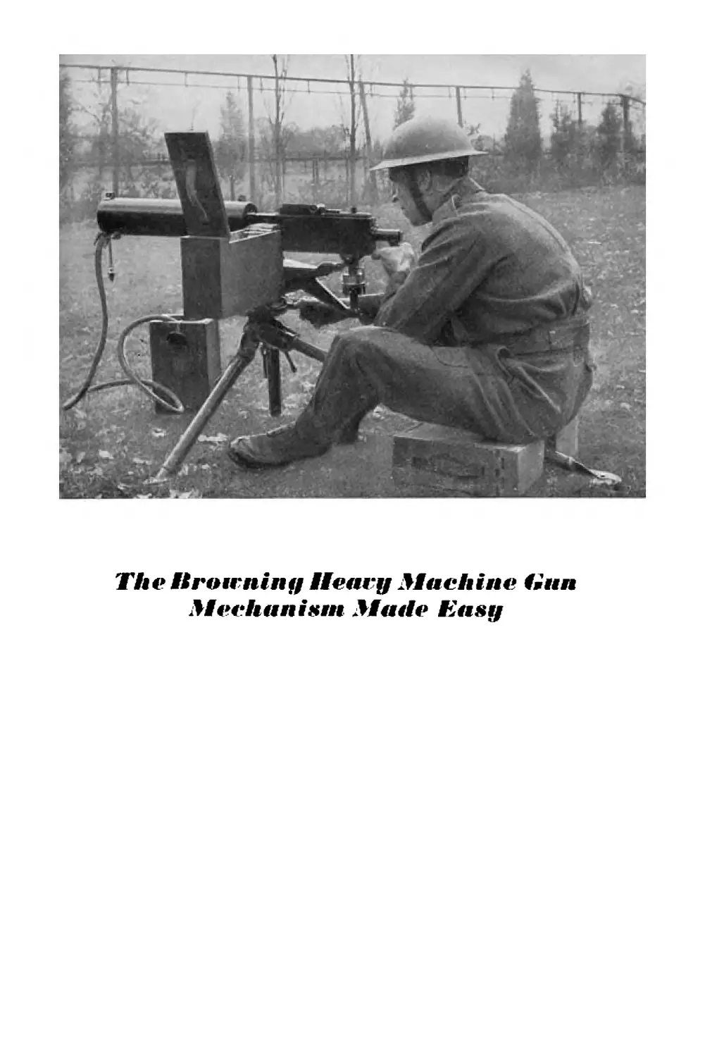
The Urowniny Heavy Machine Hun
Mechanism Made Easy
Contents
PAGE
GENERAL DESCRIPTION ... 5
DATA.........................5
FIELD STRIPPING ..... 7
DETAILED STRIPPING OF GROUPS . 9
HEAD SPACE ADJUSTMENT ... 13
MECHANISM....................16
TRIPOD MOUNTING ..... 21
SIGHTS......................24
FIRING......................26
STOPPAGES ...................29
USEFUL NOTES .... .31
Printed «n Great Britain by
Gate & Polden Lid,, Aldershot
1942
P96 7
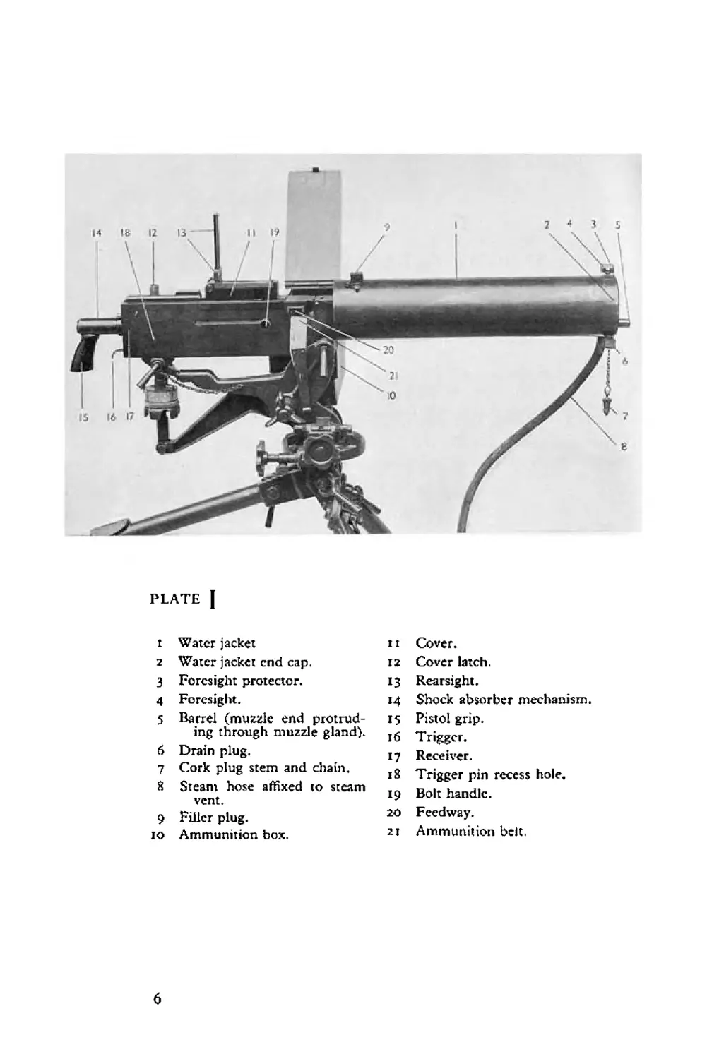
PLATE J
r Water jacket
2 Water jacket end cap.
3 Foresight protector.
4 Foresight.
5 Barrel (muzzle end protrud-
ing through muzzle gland).
6 Drain plug,
7 Cork plug stem and chain,
8 Steam hose affixed to steam
vent.
9 Filler plug.
io Ammunition box.
11 Cover.
12 Cover latch.
13 Rearsight.
14 Shock absorber mechanism.
15 Pistol grip.
16 Trigger.
17 Receiver.
18 Trigger pin recess hole.
19 Bolt handle.
20 Feedway.
21 Ammunition belt.
6
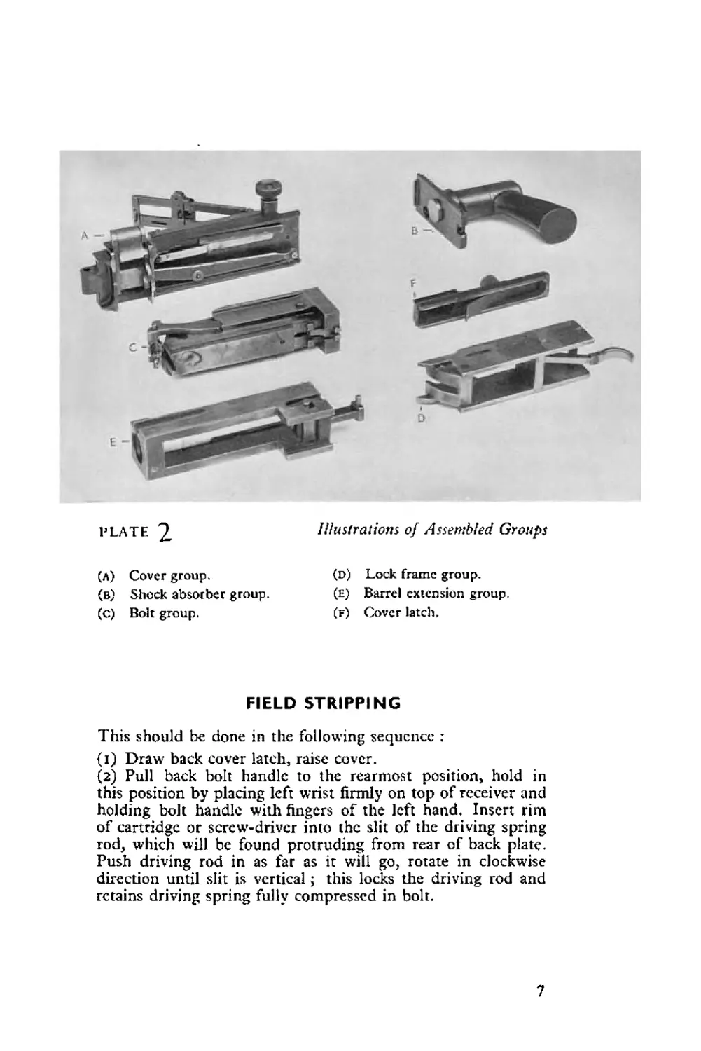
PLATE 2
(A) Cover group.
(в) Shock absorber group.
(c) Bolt group.
Illustrations of Assembled Groups
(d) Lock frame group.
(e) Barrel extension group.
(f) Cover latch.
FIELD STRIPPING
This should be done in the following sequence :
(i) Draw back cover latch, raise cover.
(2) Pull back bolt handle to the rearmost position, hold in
this position by placing left wrist firmly on top of receiver and
holding bolt handle with fingers of the left hand. Insert rim
of cartridge or screw-driver into the slit of the driving spring
rod, which will be found protruding from rear of back plate.
Push driving rod in as far as it will go, rotate in clockwise
direction until slit is vertical; this locks the driving rod and
retains driving spring fully compressed in bolt.
7
(3) Push bolt handle forward a few inches.
(4) Push cover latch forward with left hand. Back plate of
pistol grip may now be lifted up and out of receiver with right
hand.
(5) Pull bolt handle to rearmost position and withdraw bolt
handle from bolt.
(6) Grasp driving spring rod with right hand, withdraw bolt
and support same with left hand. Turn extractor upwards and
remove.
(7) With nose of bullet, push in trigger pin (located in hole on
the right side of receiver). Grasp lock frame spacer with left
thumb and pull rearwards until lower projection of barrel
extension drops down behind bottom plate of receiver.
(8) Grasp lock frame and push forward on tips of accelerator ;
this will separate lock frame from barrel extension.
(9) Draw barrel extension and barrel to rear out of receiver.
(10) Unscrew barrel extension from barrel.
NOTE : The ah eve stripping I-io is what is normally^needed under field
conditions for a temporary stoppage necessitating a change of parts, etc.
(see pp. 29-30, Stoppages).
DETAIL STRIPPING OF GROUPS
(plates 3, 4, 5, 6, 7)
COVER
(1) With point of bullet turn cover pin spring upwards, with-
draw pin, remove cover.
(2) With point of bullet turn feed lever pivot pin spring out-
wards, remove pivot pin, remove feed lever, remove belt feed
slide.
(3) Push out feed pawl pin. Remove iced pawl and feed pawl
spring.
(4) With point of bullet inserted between extractor cam and
extractor spring, prise extractor spring away from extractor cam,
remove extractor spring.
8
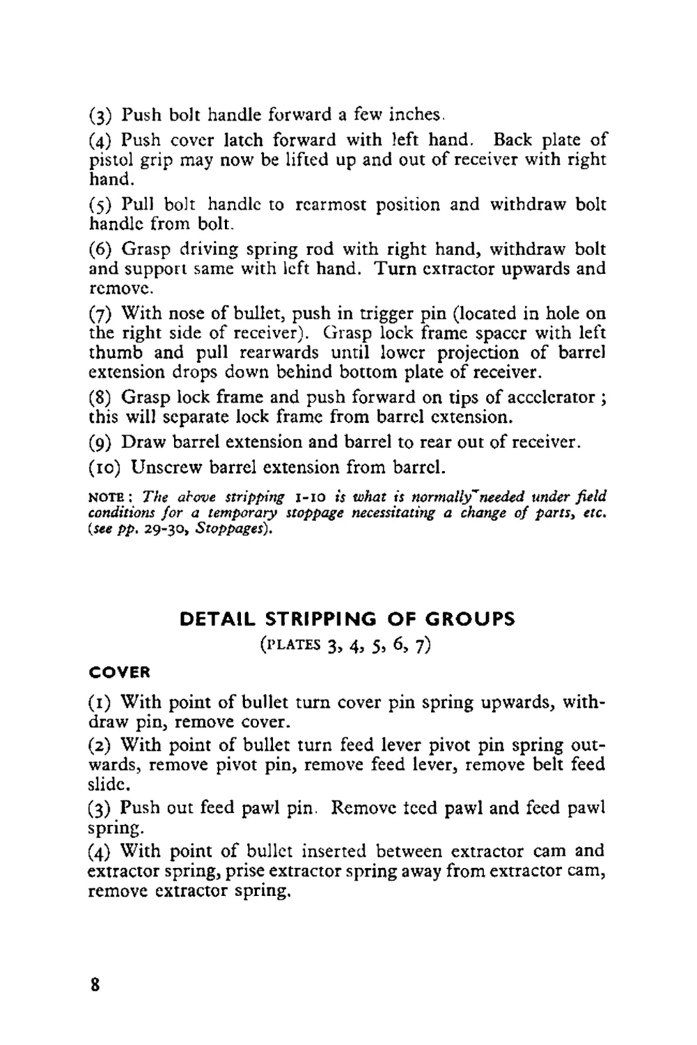
PLATE 3 Cover Group Stripped
ii Cover.
22 Cover extractor cam.
23 Cover extractor spring.
24 Belt feed slide.
25 Belt feed pawl.
26 Belt feed pawl pin.
27 Belt feed pawl spring.
28 Cover pin and spring.
29 Belt feed lever pivot pin and
spring.
30 Belt feed lever.
31 Belt feed lever actuating stud.
9
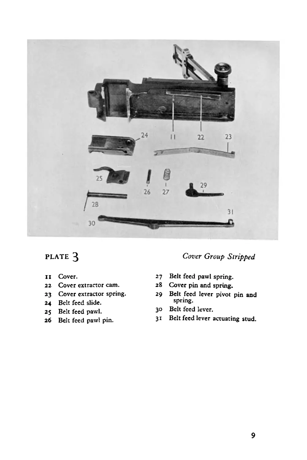
PLATE 4
Bait Group Stripped
19 Bolt handle.
32 Bolt.
33 Extractor.
33a Ejector.
34 Sear spring and pin.
35 Cocking lever.
36 Cocking lever pin.
37 Sear.
38 Striker.
39 Striker spring retaining pin.
40 Striker spring.
41 Driving spring rod.
42 Driving spring.
to
SHOCK ABSORBER GROUP
(Stripping of this group is rarely needed except in case of repair)
(i) Unscrew adjusting screw,
(2) Remove adjusting screw plunger and the adjusting screw
plunger spring,
(3) Remove buffer discs (there are 16 of these), buffer plug,
buffer ring and buffer plate.
BOLT
(1) Remove extractor.
(2) With cocking lever in rearmost position insert point of
bullet into trigger notch of sear. Press sear downwards, releasing
striker.
(3) Push out cocking lever pin.
(4) Remove cocking lever.
(5) With point of bullet push sear spring to left side of bolt,
(6) Remove scar downwards. Replace scar spring in original
position, sear spring and sear spring pin can now be removed
upwards.
(7) Tilt bolt upwards and striker and spring assembly will
fall out.
(8) To remove striker spring, push out striker spring retaining
pin, taking care not to allow spring to fly out.
(9) Remove driving rod and driving spring by turning driving
rod notch to horizontal position and withdrawing spring and
rod under control. (The driving spring is long, and care should
be taken not to kink it. A quick withdrawal of driving rod will
prevent this.)
11
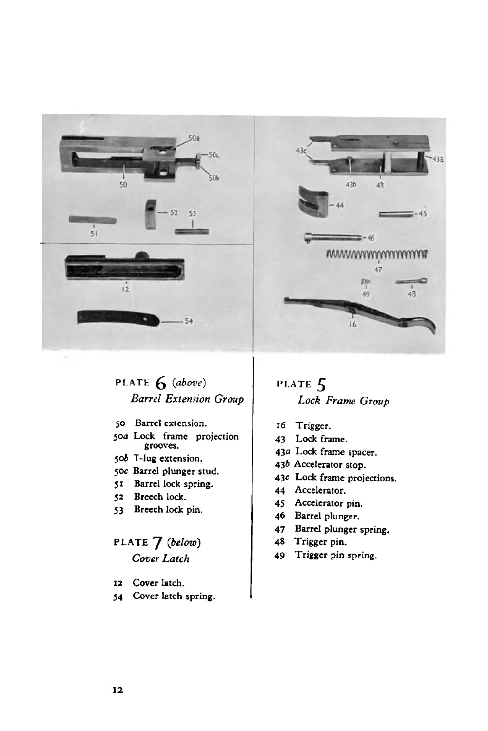
PLATE g {above)
Barrel Extension Group
50 Barrel extension.
50a Lock frame projection
grooves.
50ft T-lug extension.
50c Barrel plunger stud.
51 Barrel lock spring.
52 Breech lock.
53 Breech lock pin.
PLATE 7 {below)
Cover Latch
12 Cover latch.
54 Cover latch spring.
PLATE 5
Lock Frame Group
16 Trigger.
43 Lock frame.
43<* Lock frame spacer.
43& Accelerator stop.
43е Lock frame projections.
44 Accelerator.
45 Accelerator pin.
46 Barrel plunger.
47 Barrel plunger spring.
48 Trigger pin.
49 Trigger pin spring.
12
LOCK FRAME
(i) Push out trigger pin and remove trigger pin spring.
(2) Remove trigger.
(3) Push out accelerator pin, remove accelerator.
(4) Push out barrel plunger head pin from slit in left side plate
of lock frame. (Take care to keep spring under control whilst
doing this.) Barrel plunger and barrel plunger spring may now
be withdrawn.
BARREL EXTENSION
(1) Push out breech lock pin and remove breech lock.
(2) Insert nose of bullet under forward shoulder of barrel lock
spring and prise it forwards and remove it.
COVER LATCH
Pull latch smartly to rear, removing it from its seat, remove
cover latch spring.
TO REASSEMBLE GROUPS
Each group should be reassembled in detail in the reverse
order in which it has been stripped.
HEAD SPACE ADJUSTMENT
This must be done before reassembly. By the term “ head
space ” is meant the distance between the face of the bolt and
the base of the barrel. When correctly adjusted the face of the
bolt should firmly support the base of the cartridge in position
in the chamber when the gun is fired.
TOO MUCH HEAD SPACE (Ле., adjustment is too loose)
The base of the cartridge will not be firmly supported by the
bolt face and when cartridge is discharged a separated case or
a bulged case may result, causing difficult extraction.
TOO LITTLE HEAD SPACE (i.e.s adjustment is too tight)
(This can sometimes be detected by ear when the gun is being
fired, as the bolt on its return to its forward position will give
a dead sound effect.)
13
Binding of certain moving parts and slow rate of fire may
result. It may not be possible for the mechanism to go fully
home to the firing position, when the gun cannot be fired.
Breakage of the barrel extension can result from firing the gun
with head space too tight.
THE CORRECT HEAD SPACE ADJUSTMENT
(a) Partly screw barrel into barrel extension.
(в) Remove extractor from bolt. With barrel and barrel
extension in a horizontal position, place the bolt in its full
forward home position in the barrel extension.
(c) Lock bolt to barrel extension by lifting breech lock up into
its seat; hold it firmly in this position.
(d) Continue screwing barrel into barrel extension until resist-
ance is felt (other than that of the barrel lock spring).
(e) Release breech lock which should now fall of its own weight,
if the head space adjustment is correct.
(f) Remove the bolt.
(g) Note position of barrel lock spring ; if this is in between
two barrel notches, screw barrel up to second notch. If barrel
lock spring is seated in a barrel notch, screw barrel up to next
notch.
It is advisable to mark barrel with this correct head space
adjustment so that quick head space adjustment can always be
made on subsequent stripping and reassembling.
REASSEMBLY OF GROUPS INTO GUN
Screw barrel into barrel extension. Insert the barrel and the
barrel extension (head space adjustment having been made) into
receiver from the rear. Slide the barrel forward carefully with
the left hand until the lower projection of the barrel extension
butts against bottom plate of receiver. Grasp lock frame and
place accelerator claws between rear face of barrel extension and
forward faces of T lug extension, inserting at the same time the
forward projections of the lock frame into their corresponding
grooves in the barrel extension. Push forward on the lock frame,
which will tip back accelerator claws and will compress barrel
plunger spring, thus locking lock frame to barrel extension.
(During this operation the trigger bar must pass between the
two accelerator claws, otherwise it will interfere with the
И
accelerator tips and prevent them proceeding rearwards.)
Ensure the lock frame is securely locked to the barrel extension ;
raise and push forward into the receiver the assembled barrel,
barrel extension and lock frame ; push in trigger pin, when the
whole assembly can be pushed fully forward home, making sure
of this by seeing trigger pin reseats itself in its recess in the right
side of receiver. Test that everything is home by pulling on the
lock frame spacer rearwards. Insert bolt, making sure extractor
is in position, and that cocking lever is in fully forward position.
Insert bolt handle. Push forward cover latch, replace pistol
grip and back plate. Pull cover latch to rear, locking back
plate in position. Pull bolt handle to rearmost position and,
with it so held, insert screw-driver or base of bullet into slit
of driving rod, push in and turn anti-clockwise to horizontal
position, thus releasing driving spring. Allow bolt to return
to forward position.
FINAL TEST OF HEAD SPACE ADJUSTMENT
Finally, test that the head space adjustment is correct as
follows :—
Raise cover.
Raise extractor.
With mechanism in its fully forward position, take hold of
bolt handle and withdraw it to rear J inch; there should be
no independent movement of bolt rearwards from base of
barrel—/.e., barrel and bolt should move together to the rear.
If there is any such movement of bolt independent of barrel,
head space adjustment is too loose.
To rectify, insert combination tool or point of bullet between
right side of receiver and barrel notches, and screw up barrel
one notch.
To test for too tight head space adjustment, work cocking
mechanism backwards and forwards by means of bolt handle.
If head space is too tight moving parts will not work smoothly ;
the breech will bind as it is locked. The mechanism may not
go fully home, when the trigger cannot be pulled to release
striker.
To rectify too tight head space adjustment, insert combina-
tion tool or point of bullet between left side of receiver and
barrel notches and unscrew barrel one notch.
Any such head space adjustment carried out must be tested.
15
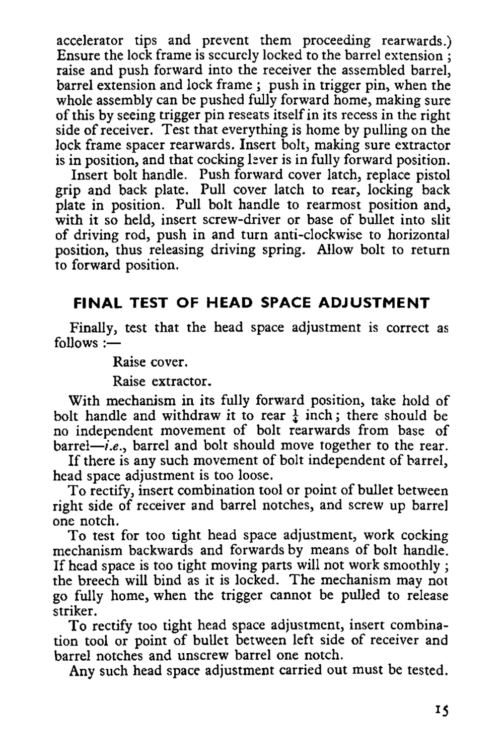
PLATE 3 Internal Mechanism in Forward Position
Bolt (32) forward in firing position.
Extractor (33) gripping succeeding round (in belt, not shown).
Cocking lever (35) in rearmost position.
Breech lock (52) forced up (by breech lock cam, not shown).
Breech lock pin projections (53) clear of lock frame projections (43c).
Accelerator claws (44) tipped forward.
Barrel plunger and spring (46 and 47) released, having pushed home on
barrel plunger stud on T-lug of barrel extension.
BACKWARD MOVEMENT OF MECHANISM
BARREL
BARREL EXTENSION
BOLT
ACCELERATOR MOVEMENTS
When a cartridge is fired, the force of the explosion drives the
bolt (which is locked to the barrel by the breech lock in the
barrel extension), barrel and barrel extension to the rear
approximately f inch, when the breech lock clears the breech
lock cam situated on the bottom plate of the receiver. The
breech lock is now free to drop, and is assisted by the projections
of the breech lock pin striking the inclined forward surfaces of
the lock frame projections. The bolt is thus free to continue to
the rear. The rear of the barrel extension strikes the forward
curved surfaces of the accelerator claws, tipping them backwards
until the accelerator abuts the accelerator stop ; the accelerator
locks in this position, locking at the same time the barrel
plunger and spring which have meanwhile been compressed by
the rearward motion of the barrel plunger stud. The barrel and
barrel extension are thus locked in this position, and cannot con-
tinue further to the rear. During the tipping backwards of the
accelerator claws above described, the accelerator tips are in
16
S3 324 32 35
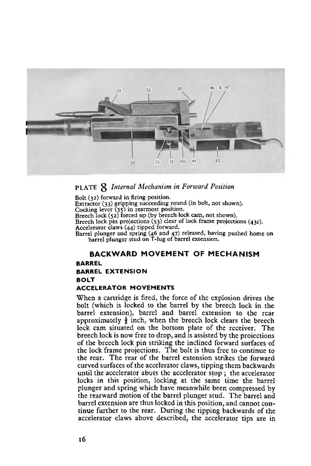
PLATE Internal Mechanism in Backward Position
(32a) Feed lever actuating stud cam groove»
(33) Extractor in position to guide grooved rim of cartridge into T cut
of bolt»
Barrel extension (50) stopped from proceeding rearward by lock frame (43).
The inclined faces of the lock frame projections (43c) have struck the
projections of the breech lock pin (53), forcing them down and
unlocking bolt.
Accelerator claws (44) have been tipped backward and the barrel
plunger (46) driven rearward, compressing barrel plunger spring (47).
Cocking lever (35) has been forced forward, thus cocking striker.
contact with the forward faces of the bottom extensions of the
bolt. The accelerator acting as an increasing lever assists and
accelerates the bolt to the rear. During the rearward movement
of the bolt, the tip of the cocking lever located in its socket in
the top plate of receiver is forced forward, thus withdrawing
striker to rear, compressing striker pin spring and engaging
bent with sear.
During the above rearward movements of the mechanism
the driving spring is compressed. Any remaining rearward
motion of the bolt which has not been overcome in compressing
the driving spring is absorbed by the buffer recoil mechanism.
EXTRACTOR
FEEDING OF SUCCEEDING ROUND
During the backward movement of the mechanism, the
extractor withdraws the succeeding cartridge from the belt;
as the extractor reaches its rearmost position it is forced down
by the extractor cam in the cover, ready to position the succeed-
ing round in the T cut of the bolt head,
17
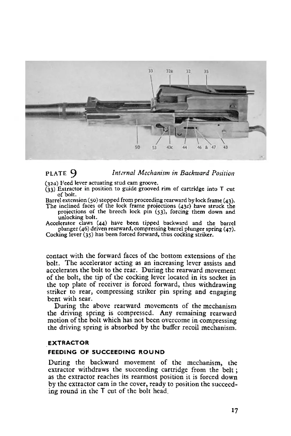
Bottom Illustration :
Shows bolt proceeding rear-
wards, and the extractor
withdrawing the succeeding
round from the belt.
Top Illustration : Shows
bah in fully forward posi-
tion. Cover raised to show
the belt feed arm actuating
stud) having been driven to
the left when located in
cam groove of bolt. Thus
the forward end of the belt
feed arm has driven belt
feed pawl to right, thus
positioning succeeding round
against cartridge stops in
feed way. The extractor is
gripping succeeding round.
FEEDING OF BELT
FEED LEVER
BELT STOP PAWL OPERATIONS
During the backward movement of the mechanism, the feed
lever actuating stud is located in the cam groove in the top of
the bolt; thereby its forward end engaged in the belt feed slide
is driven to the left. The belt feed pawl is permitted by its
spring to ride up and over the next cartridge. The belt is
prevented from being carried in the same direction by the
belt stop pawl.
The backward movement of the mechanism has thus achieved
the following ;—
(a) The spent case of the fired round has been extracted from
the chamber.
(в) The succeeding round has been extracted from the feed
belt ready to be positioned into the T cut of the bolt head for
feeding into the chamber.
(c) The striker has been cocked.
(d) The feed mechanism is in position ready to feed another
round into the feed way.
(e) The recoiling springs have been compressed ready to reassert
themselves to drive mechanism forward again.
THE FORWARD MOVEMENT OFTHE MECHANISM
The forward movement of the mechanism (described in detail
below) provides the following :—
(a) The succeeding round is positioned into the T cut of the
bolt and is fed into the chamber.
(в) The ejector ejects the spent case.
(c) The bolt closes and the breech is locked.
(d) The trigger bar engages the sear slot ready to release striker
on trigger being pulled.
(e) The next cartridge in belt is fed into position in the feedway,
and is gripped by the extractor, ready to be withdrawn from
belt on the next rearward movement of the mechanism.
BOLT
ACCELERATOR
BARREL EXTENSION
BARREL
The compressed driving spring reasserts itself, driving the bolt
forward. The succeeding round is positioned by the extractor
into the T cut of the bolt head and is carried forward into
chamber.
19
The bottom projections of the bolt strike the tips of the
accelerator claws, tipping them forward and unlocking the barrel
plunger ; the barrel plunger spring reasserts itself, driving for-
ward the barrel extension and barrel. The breech lock rides up
the breech lock cam to lock bolt to barrel extension and barrel.
The sear notches engage the trigger bar. The tip of the cocking
lever is returned to its fully backward position. (It should be
noted that, should the mechanism not go fully forward home,
the cocking lever will not be right back, thus preventing the
striker from striking the cap of the cartridge.)
BELT FEED
FEED LEVER
FEED PAWL
CARTRIDGE STOPS
The feed lever actuating stud riding in its cam groove in the bolt
is driven to the left, thus its forward end carries the feed slide to
the right, carrying with it the belt feed pawl, belt, and succeed-
ing round until the latter abutts the front and back cartridge
stops in the feedway. The succeeding round is now in position
for the extractor to extract it.
EXTRACTOR
During the first part of the bolt’s travel forward the extractor
feed cam, situated on the left plate of receiver, strikes the
extractor plunger and guides the extractor downwards, finally
positioning the base of the succeeding round in T cut of bolt,
and nose of bullet into chamber.
The ejector (at the bottom of the extractor) strikes the spent
case (if it has not already fallen out), which has been withdrawn
from the chamber (the rim of spent case being in T cut of bolt
head), and ejects the spent case through the ejector port opening
in the base of the receiver.
When the bolt has nearly closed, the extractor is forced up
by a steeply inclined cam on the left plate of receiver, thus
releasing its grip of the cartridge, which has been fed well
into the chamber. The extractor rides upwards and over
the base of the next cartridge in the belt in the feedway. The
extractor spring in the cover forces the extractor down and
on to this cartridge, thus gripping it securely ready to withdraw
it on the next rearward movement of the mechanism.
20
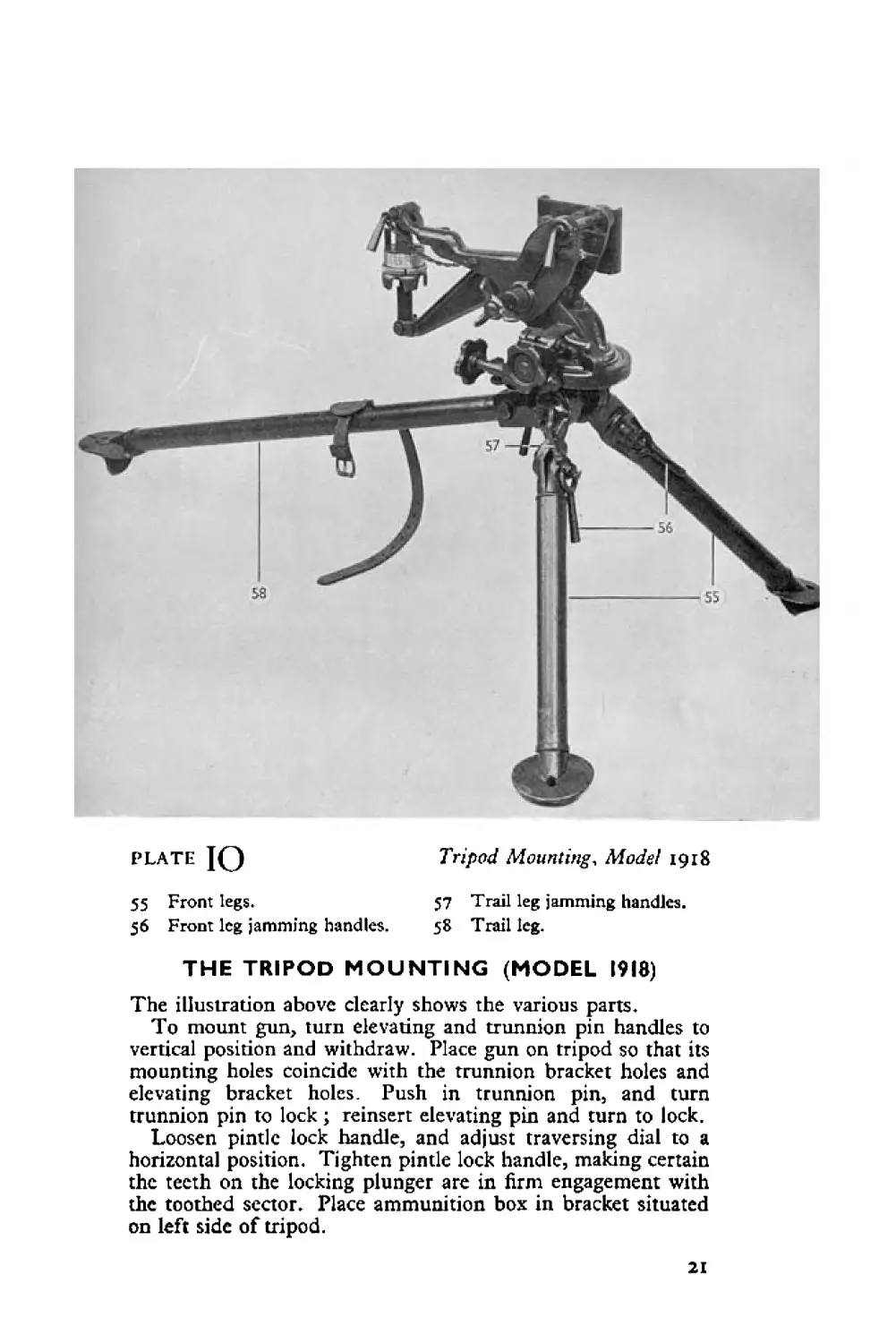
PLATE JQ Tripod Mounting, Model 1918
55 Front legs» 57 Trail leg jamming handles.
56 Front leg jamming handles. 58 Trail leg.
THE TRIPOD MOUNTING (MODEL 1918)
The illustration above clearly shows the various parts.
To mount gun, turn elevating and trunnion pin handles to
vertical position and withdraw. Place gun on tripod so that its
mounting holes coincide with the trunnion bracket holes and
elevating bracket holes. Push in trunnion pin, and turn
trunnion pin to lock; reinsert elevating pin and turn to lock.
Loosen pintle lock handle, and adjust traversing dial to a
horizontal position. Tighten pintle lock handle, making certain
the teeth on the locking plunger are in firm engagement with
the toothed sector. Place ammunition box in bracket situated
on left side of tripod.
21
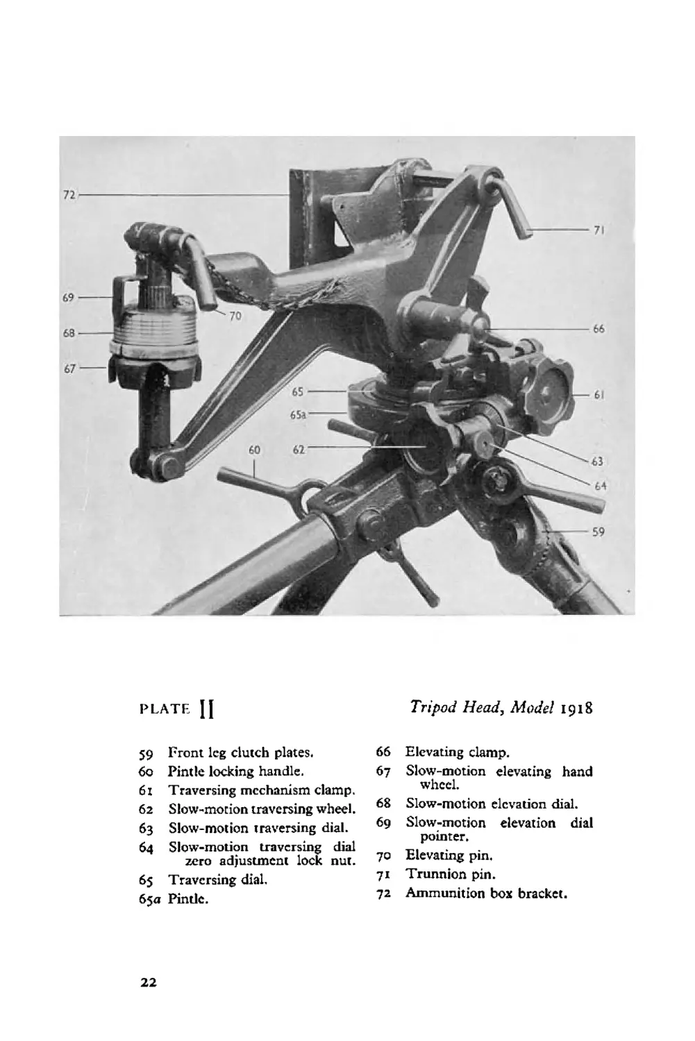
PLATE {J
Tripod Head, Model 1918
59 Front leg clutch plates.
60 Pintle locking handle.
61 Traversing mechanism clamp.
62 Slow-motion traversing wheel.
63 Slow-motion traversing dial.
64 Slow-motion traversing dial
zero adjustment lock nut.
65 Traversing dial.
65a Pintle.
66 Elevating clamp.
67 Slow-motion elevating hand
wheel.
68 Slow-motion elevation dial.
69 Slow-motion elevation dial
pointer.
70 Elevating pin,
71 Trunnion pin.
72 Ammunition box bracket.
22
ELEVATING MECHANISM
A slow-motion elevating hand wheel is provided with a mil
clicking device. Turned in a forward direction (i.e., forwards
away from gunner) raises gun, and turned in the reverse direction
lowers gun. Each click represents i mil alteration.
Larger alteration in angles of elevation than that provided by
the slow-motion elevating hand wheel may be accomplished by
loosening elevating clamp and raising or lowering gun.
TRAVERSING MECHANISM
A slow-motion mil clicking traversing gear is provided. With
the traversing gear clamp screwed up so that the teeth of the
traversing gear are engaged, the traversing handle when rotated
in a clockwise direction traverses gun to left, and when rotated in
an anti-clockwise direction traverses gun to right. Each click
represents x mil traverse.
With the traversing gear clamp unscrewed so that the
traversing gear teeth are disengaged, the gun is free to be
traversed by hand.
Small angles of traverse can be read off from the small dial
on the traversing hand wheel. Zero setting can be established
by loosening dial lock nut and tightening at desired setting.
Larger alterations in angles of traverse than that provided by
the slow-motion traversing wheel may be accomplished by
loosening traversing clamp and traversing gun by hand. Angles
of traverse may be read off from traversing dial which is pro-
vided with an adjustable zero setting that can be turned by
hand.
23
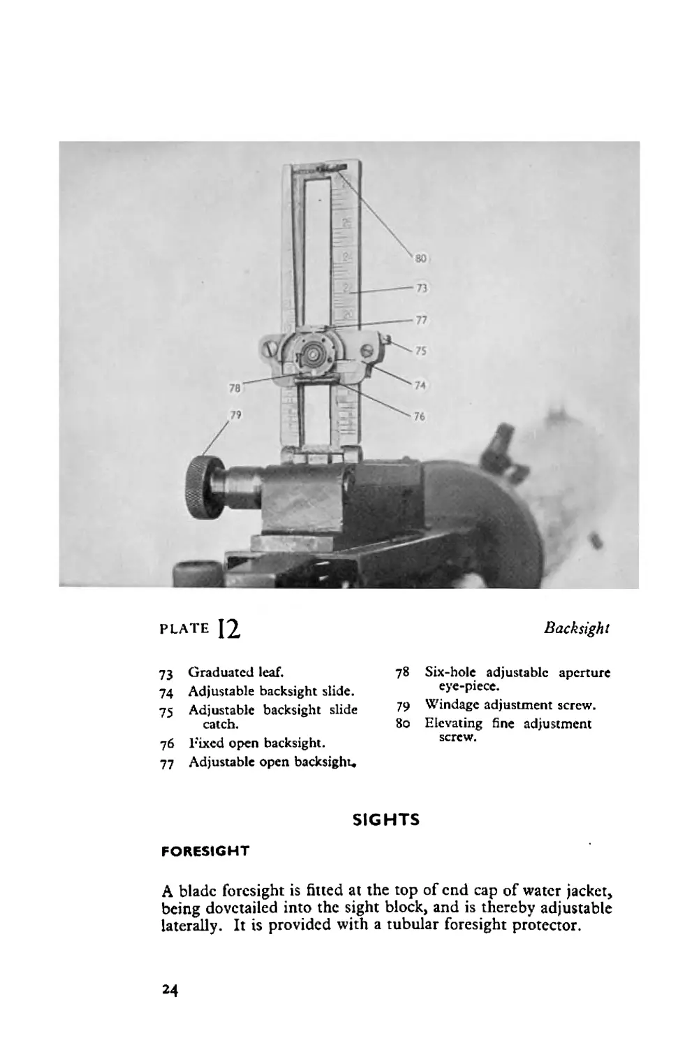
PLATE 12
Backsight
73 Graduated leaf.
74 Adjustable backsight slide.
75 Adjustable backsight slide
catch.
76 Fixed open backsight.
77 Adjustable open backsight.
78 Six-hole adjustable aperture
eye-piece.
79 Windage adjustment screw.
80 Elevating fine adjustment
screw.
SIGHTS
FORESIGHT
A blade foresight is fitted at the top of end cap of water jacket,
being dovetailed into the sight block, and is thereby adjustable
laterally. It is provided with a tubular foresight protector.
24
BACKSIGHT
In Plate 12 is illustrated the backsight described in detail below.
It is to be noted that guns may be fitted with different types of
backsights to the one described. The description that follows
should enable other types of backsights to be easily understood
and used. It consists of a leaf. In its lowered position an open
U backsight is in position, which is sighted for 500 metres. When
leaf is raised graduations on the leaf are used by which the slide
is set to the range required. For large variations in elevation the
catch on the right side of the slide is depressed and the slide
raised or lowered to range selected. For small and fine adjust-
ments of elevation the elevating notched wheel at the top of the
slide is used. The slide carries an adjustable plate containing
five different sized apertures so as to enable the gunner to select
the one most suitable to the shooting conditions.
To set for the aperture required, push in with the tip of a
finger on the serrated circle on the aperture plate and turn until
the aperture required is at the bottom. Make sure aperture plate
is correctly fixed by seeing that the corresponding notch on
the periphery of the sight plate is engaged with the key at the
top of the slide.
The aperture is set to the range marked on the leaf that
coincides with the bottom face of the window (e.g., illustration
shows aperture sight set for 1,500 metres). In addition to the
aperture there is an open U backsight at the top of the slide.
This open sight is set to the range marked on the leaf that
coincides with the top edges of the shoulders of this sight (e.g.>
illustration shows open adjustable backsight set for 1,950 metres).
It will be noticed from the illustration that the grooves in the
leaf in which the slide moves up and down incline to the left,
so that as the slide is raised the aperture is automatically moved
to the left. This movement is made to counteract the drift of
the bullet.
The leaf sight is mounted on a base which is adjustable for
windage ; this adjustment is accomplished by means of the
milled-headed screw situated to the left of the sight base. This
windage adjustment screw, when rotated backwards towards
gunner, moves sight to left to counteract for wind blowing
from left to right, and when rotated forward (?.<?., away from
gunner) the sight is moved to the right to counteract wind blow-
ing from the right.
25
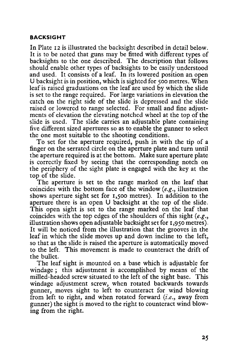
PLATE [3 The Firing Position (Gun mounted on 1918 Tripod)
BEFORE FIRING
PREREQUISITES
(1) Ammunition loaded into belts.
(2) Ammunition boxes.
(3) Water condenser filled with water
(4) Combination tool,
(5) Cleaning rod.
(6) Separated case extractor.
(7) Sparc parts.
note : 4, 5, 6 and 7 are essential far passible stoppages,
(a) All mechanism must be clean, free from dust, dirt and
fluff, and thoroughly oiled.
(в) When assembled, rear barrel packing should provide a
smooth watertight fit in trunnion block; copious oiling or
greasing remedies slight water leak here.
26
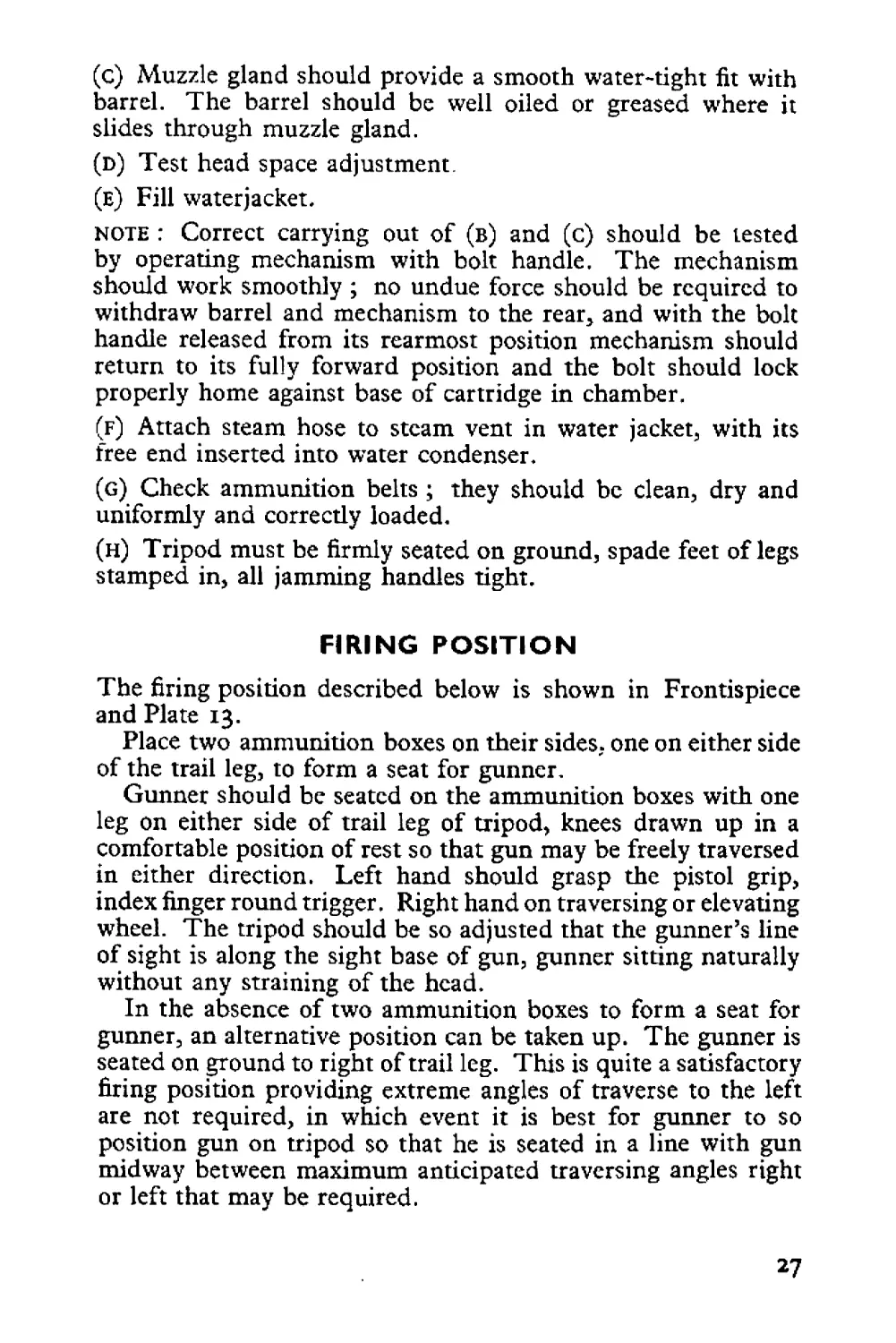
(c) Muzzle gland should provide a smooth water-tight fit with
barrel. The barrel should be well oiled or greased where it
slides through muzzle gland.
(d) Test head space adjustment.
(E) Fill waterjacket,
note : Correct carrying out of (в) and (c) should be tested
by operating mechanism with bolt handle. The mechanism
should work smoothly ; no undue force should be required to
withdraw barrel and mechanism to the rear, and with the bolt
handle released from its rearmost position mechanism should
return to its fully forward position and the bolt should lock
properly home against base of cartridge in chamber.
(f) Attach steam hose to steam vent in water jacket., with its
free end inserted into water condenser.
(g) Check ammunition belts ; they should be clean, dry and
uniformly and correctly loaded.
(h) Tripod must be firmly seated on ground, spade feet of legs
stamped in, all jamming handles tight.
FIRING POSITION
The firing position described below is shown in Frontispiece
and Plate 13.
Place two ammunition boxes on their sides, one on either side
of the trail leg, to form a seat for gunner.
Gunner should be seated on the ammunition boxes with one
leg on either side of trail leg of tripod, knees drawn up in a
comfortable position of rest so that gun may be freely traversed
in either direction. Left hand should grasp the pistol grip,
index finger round trigger. Right hand on traversing or elevating
wheel. The tripod should be so adjusted that the gunner’s line
of sight is along the sight base of gun, gunner sitting naturally
without any straining of the head.
In the absence of two ammunition boxes to form a seat for
gunner, an alternative position can be taken up. The gunner is
seated on ground to right of trail leg. This is quite a satisfactory
firing position providing extreme angles of traverse to the left
are not required, in which event it is best for gunner to so
position gun on tripod so that he is seated in a line with gun
midway between maximum anticipated traversing angles right
or left that may be required.
27
FIRING
Set sights to range required.
Release elevating and traversing mechanism clamps ; align
sights on target.
See that elevating hand wheel and traversing dial and slow-
motion traversing dials are at zero.
Tighten elevating and traversing clamps.
Check alignment of sights on target by elevating wheel and
slow-motion traversing wheel.
Insert loaded ammunition belt in feedway, ammunition box
having been placed in its bracket on tripod (illustration
page 18).
Cock gun by withdrawing bolt handle to rear and allowing
it to fly forward. Repeat once.
Push safety catch to right; this locks trigger at safe position.
TO FIRE
Release safety catch by pushing it to left, confirm aim, press
trigger, and keep trigger pressed for required number of rounds
desired to be fired in burst. Release trigger. Repeat for subse-
quent bursts of fire, relaying aim between bursts.
important : Gunner should allow gun to vibrate normally
on tripod. No attempt should be made to hold the gun firmly
with either hand to counteract vibration. No weight should
be placed on tripod, either by gunner sitting on trail leg or by
riding front tripod legs with his feet.
DURING FIRING
Gun should be watched for water leaks, sluggish action, and
excessive vibration on tripod.
Slight water leaks may be remedied as previously described
in paras (в) and (c) pp. 26-27. Serious water leaks will neces-
sitate adjustment of packing glands.
If sluggish action is apparent, the following remedies should
be tried, and the gun fired as each is carried out until sluggish-
ness is remedied :—
(1) Test head space adjustment.
(2) Oil muzzle gland.
28
(3) Clean chamber (if dirt, dust or grit particles are present,
evidence of such will be given by longitudinal scratches on
ejected cases).
(4) Oil mechanism plentifully.
(5) Tighten buffer recoil mechanism.
STOPPAGES REMEDIED BY IMMEDIATE ACTION
(I) GUN FAILS TO FIRE
Gunner takes hold of ammunition belt protruding to the right
of gun from feedway and gives it a sharp jerk to the right.
Cock gun. Relay aim. Continue firing.
(2) GUN STILL FAILS TO FIRE
Gunner raises cover. Pull bolt handle to rear, meanwhile left
hand is placed under ejection port at bottom of receiver to
catch ejected round.
If a separated case is cause of stoppage, either a live round will
be ejected with the front portion of a separated case adhering
to it or the separated case will be left in the chamber. In this
event, call for clearing plug (of the cartridge type) which is
placed in feedway against the cartridge stops and gripped by
the extractor, holding down on the extractor, load the clearing
plug slowly and smoothly into the chamber so that it will not
strike and so burr the edge of the chamber. Strike forward on
the bolt handle to ensure that the clearing plug is seated in
ruptured case. Pull bolt handle to rear when clearing plug
and separated case will be ejected. The separated case should
be removed from the clearing plug so that it is ready for
further use.
Tighten head space adjustment one click.
Cock gun. Relay aim. Continue firing.
If live round is ejected, inspect cap ; if struck, reject round.
Continue firing.
If cap has not been struck by striker—
Replace bolt with spare completely assembled bolt.
Adjust head space.
Continue firing.
29
If no round is ejected—
Inspect chamber. If round in chamber—
Remove it by passing cleaning rod through barrel from
muzzle end and pushing it out of chamber. (Too much force
should not be exercised as base of round may be driven forcibly
against T cut in bolt, thereby injuring T cut, or base of round
may become jammed in T cut.)
If no round is ejected and there is no round in chamber—
Raise extractor and inspect for round in T cut of bolt. If
there is a round in T cut and there is room to insert end of com-
bination tool through bolt handle slot and beneath round,
prise round upwards out of T cut. Otherwise tap round down
through T cut until it drops through ejection port.
If no round is ejected, no round in chamber or in T cut—
Inspect first round ; if a short round a round which
has had the bullet pushed back into case) discard it and continue
firing.
If the first round has a definite nick in the rim where the
extractor has struck it, the belt feed lever should be replaced,
as this indicates the belt feed lever actuating stud is worn.
If gun still fails to fire—
Raise cover.
Inspect feed mechanism, belt feed lever, belt feed and stop
pawls, extractor cover spring and replace defective parts.
RUNAWAY GUN
If gun still continues to fire when trigger is released, raise
cover immediately; this will stop feed mechanism from
functioning. Remove belt. This fault is caused by the trigger
bar being bent down at its forward end. To rectify remove
trigger bar and bend front end upwards slightly.
ASSISTANT GUNNER
note : During immediate action assistant gunner should carry
out the following :—
Whenever cover is raised, remove first round from belt
and hold ready for inspection; reposition belt in feedway.
Have handy all spare parts, cleaning rod, separated case
extractor and combination tool.
Hand to gunner any spare part or tool called for by him.
Carry out any instructions gunner directs.
30
AFTER FIRING
Strip gun.
Clean barrel as for rifle. [Note the hot water in jacket can be
used for cleaning bore of barrel as follows : Make a plug with
a piece of flannelette round a cartridge case of a size to fit into
muzzle gland tightly. Tilt muzzle towards ground. As gunner
withdraws barrel, assistant gunner plugs muzzle gland. The
barrel withdrawn from mechanism, can now be inserted, muzzle
first, into and in front of muzzle gland (first withdrawing plug)
and the hot water from jacket allowed to flow through barrel.]
Drain water jacket; thoroughly grease outside of barrel as
well as the bore.
Clean and oil thoroughly all parts.
It is advisable to remove driving spring and rod to clean and
oil, as during damp weather there is a likelihood of these
becoming rusty unseen in the bolt.
Examine mechanism for any wear or burred parts ; replace
those necessary.
Reassemble gun.
Check spare parts and accessories.
Thoroughly clean tripod and oil working parts and threads.
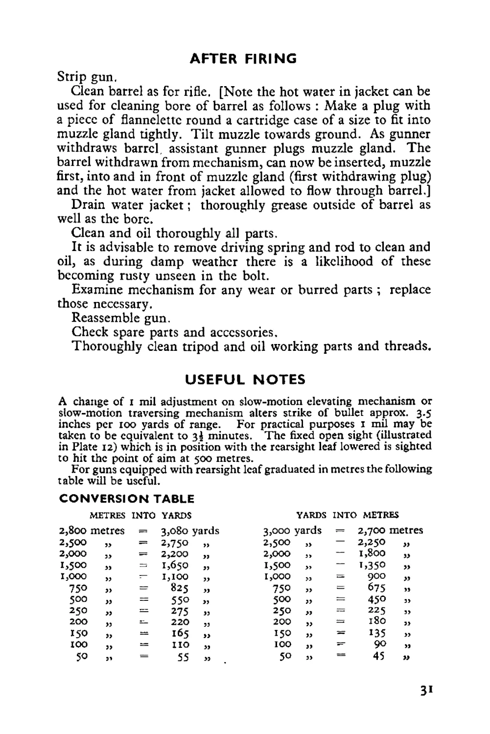
USEFUL NOTES
A change of I mil adjustment on slow-motion elevating mechanism or
slow-motion traversing mechanism alters strike of bullet approx. 3.5
inches per 100 yards of range. For practical purposes 1 mil may be
taken to be equivalent to 34 minutes. The fixed open sight (illustrated
in Plate 12) which is in position with the rearsight leaf lowered is sighted
to hit the point of aim at 500 metres.
For guns equipped with rearsight leaf graduated in metres the following
table will be useful.
CONVERSION TABLE
METRES INTO YARDS
YARDS INTO METRES
2,800 metres — 3,080 yards 3,000 yards — 2,700 metres
2,500 2,750 ,3 2,500 ,, — 2,250 >3
2,000 33 = 2,200 33 2,000 ,, — 1,800 33
1,500 >3 1,650 33 1,500 — t,35O 33
1,000 33 — 1,100 1,000 >5 = 900 ,,
750 T- 825 ,3 750 ,, = 675 33
500 >3 z = 550 3, 500 ,, — 450 33
250 » = 275 33 250 3, = 225 35
200 >3 — 220 ,, 200 33 = 180 33
150 3> 165 33 150 33 = 135 55
100 33 no ,, IOO 33 — 90 33
50 — 55 ,3 50 35 = 45
31
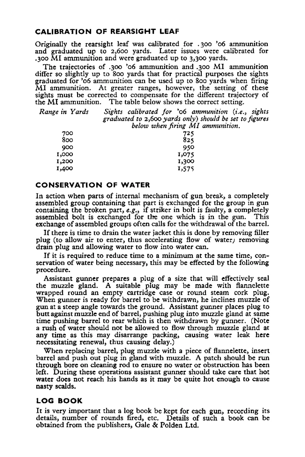
CALIBRATION OF REARSIGHT LEAF
Originally the rearsight leaf was calibrated for .300 ’об ammunition
and graduated up to 2,600 yards. Later issues were calibrated for
.300 MI ammunition and were graduated up to 3,300 yards.
The trajectories of .300 *06 ammunition and .300 MI ammunition
differ so slightly up to 800 yards that for practical purposes the sights
graduated for ’06 ammunition can be used up to 800 yards when firing
MI ammunition. At greater ranges, however, the setting of these
sights must be corrected to compensate for the different trajectory of
the MI ammunition. The table below shows the correct setting.
Range in Yards Sights calibrated for ’06 ammunition (fe., sights
graduated to 2,600 yards only) should be set to figures
below when firing MI ammunition.
725
825
950
i>O75
1,300
1,575
700
Soo
900
1,000
1,200
1,400
CONSERVATION OF WATER
In action when parts of internal mechanism of gun break, a completely
assembled group containing that part is exchanged for the group in gun
containing the broken part, e.g.3 if striker in bolt is faulty, a completely
assembled bolt is exchanged for the one which is in the gun. This
exchange of assembled groups often calls for the withdrawal of the barret
If there is time to drain the water jacket this is done by removing filler
plug (to allow air to enter, thus accelerating flow of water; removing
drain plug and allowing water to flow into water can.
If it is required to reduce time to a minimum at the same time, con-
servation of water being necessary, this may be effected by the following
procedure.
Assistant gunner prepares a plug of a size that will effectively seal
the muzzle gland. A suitable plug may be made with flannelette
wrapped round an empty cartridge case or round steam cork plug.
When gunner is ready for barrel to be withdrawn, he inclines muzzle of
gun at a steep angle towards the ground. Assistant gunner places plug to
butt against muzzle end of barrel, pushing plug into muzzle gland at same
time pushing barrel to rear which is then withdrawn by gunner. (Note
a rush of water should not be allowed to flow through muzzle gland at
any time as this may disarrange packing, causing water leak here
necessitating renewal, thus causing delay.)
When replacing barrel, plug muzzle with a piece of flannelette, insert
barrel and push out plug in gland with muzzle. A patch should be run
through bore on cleaning rod to ensure no water or obstruction has been
left. During these operations assistant gunner should take care that hot
water does not reach his hands as it may be quite hot enough to cause
nasty scalds.
LOG BOOK
It is very important that a log book be kept for each gun, recording its
details, number of rounds fired, etc. Details of such a book can be
obtained from the publishers, Gale 6c Polden Ltd.