/


Text
BROWNING MACHINE GUN
.30 Calibre
Air cooled
FABRIQUE NATIONALE D'ARMES DE GUERRE, S. A., HERSTAL-BELGIQUE
FOREWORD
The F, N. Browning Machine Gun col. 30 is produced in
various types.
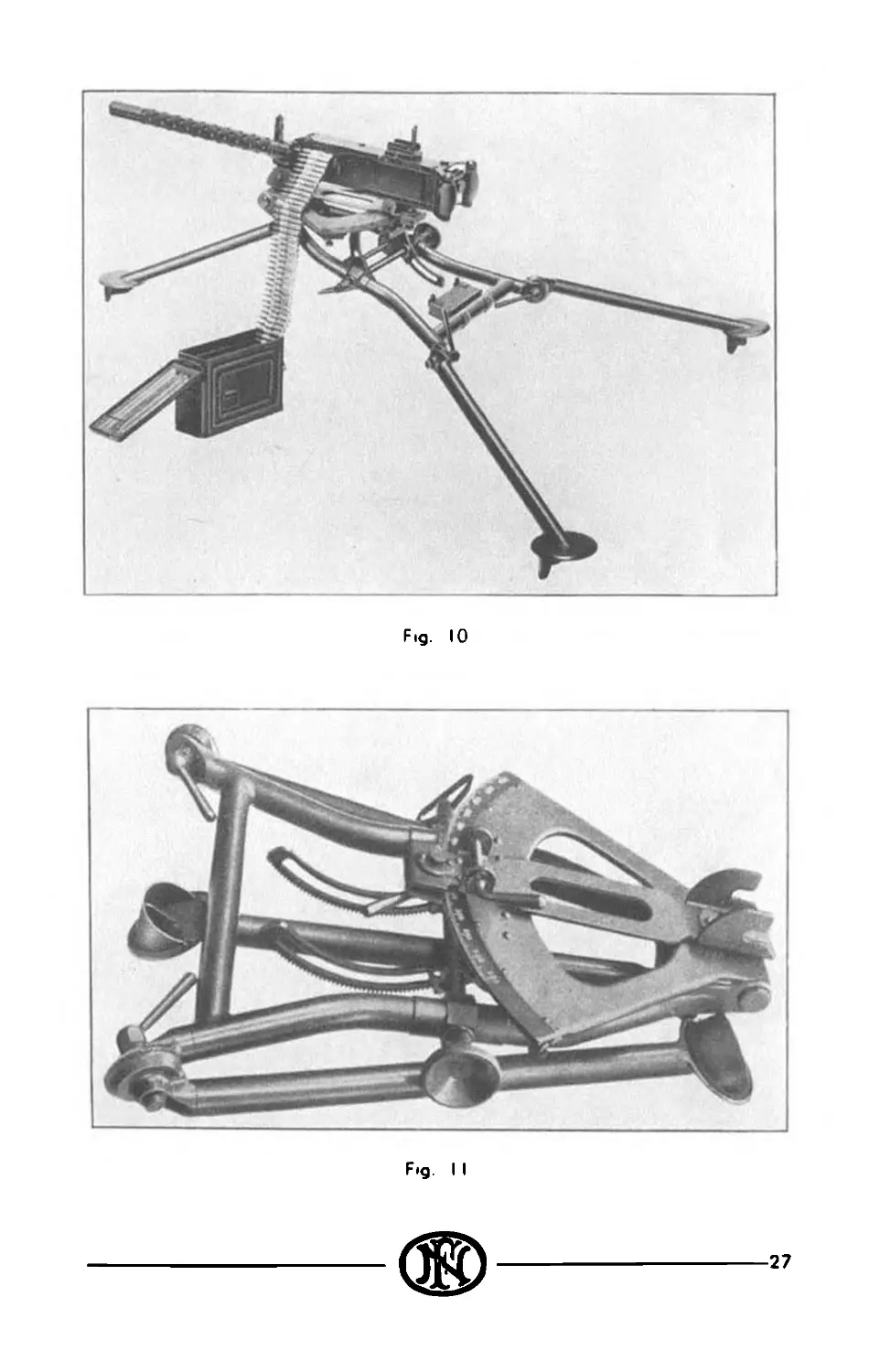
The ground type is either air-cooled or water-cooled, it may
be used os well for anti-aircraft or anti-tank firing as for mount-
ing in tanks. For the ground use, the cyclic rote of fire on the
gun is about 600 rounds per minute. Fitted with a light barrel,
1he air-cooled type is used os on aircraft weapon of the fixed or
af the flexible type.
The cyclic rate of fire of the F. N. 30 col. Aircraft gun is
above 1.600 rounds per minute.
All these types of guns were successfully used during and
after World War II by the U. S. A. Forces and their ollies. They
all work on the some principle and there ore only few differences
of design between the various types.
Single left hand feed is standard but on request alternate
feed con be supplied by changing ports of the feeding mechanism.
3
PRINCIPLE OF OPERATION
In this gun the force of the recoil is utilized to operate and
fire the gun automatically as long as ammunition is supplied and
the action on the trigger is maintained. Each time a cartridge
is fired the recoil carries the barrel a short distance backward.
This motion unlocks the bolt from the barrel extension and
throws the bait to the rear against the action of a spring. As
the bolt goes back it extracts the empty case from the chamber
and at the some time drows о cartridge from the belt. The
spring then returns the bolt ond barrel to the forward position,
loads о cartridge into the barrel, ejects the empty cose through
the bottom of the gun, locks the bolt to the barrel through the
barrel extension and fires the cartridge.
DETAILED FUNCTIONING
Each time a cartridge is fired, the mechanical action within
the gun involves many parts moving simultaneously or in their
proper order. The action of these ports and their relationship
one to the other con be explained more clearly if each cycle of
operation is divided into various phases. These phases will be
explained in the following order:
1. Firing.
2. Recoiling.
3. Counterrecoiling
4. Cocking.
5. Automatic Firing.
6. Feeding.
7. Extracting and Ejecting.
1. Firing. — When the gun has been loaded and the firing pin
has been cocked and the firing pin spring compressed by
hand charging, the gun is ready to fire.
When the trigger is pressed, it raises the rear end of
the trigger bar. The trigger bar pivots on the trigger bar
pin, causing the front end to press down on the top of the
sear. The sear is forced downward until the notch in the
sear is disengaged from the shoulder of the firing pin. The
firing pin is driven forward by the firing pin spring to fire the
cartridge.
2. Recoiling. — The complete cycle of the recoiling parts of the
gun, which takes place as each cartridge is fired, consists of
the recoil stroke when certain parts move rearward and the
counterrecoil stroke when the some ports move forward. At
the instant of firing, the barrel, barrel extension, and the
bolt, known as the recoiling ports, ore in the forward posi-
tion in the gun.
At this time, the bolt is held securely against the rear
of the cartridge by the breech lock, which extends up from
the barrel extension into a notch in the under side of the
bolt.
After the cartridge explodes and as the bullet travels
out of the barrel, the force of recoil drives the recoiling ports
rearward. During the first 1/2 inch of rearward travel, the
breech lock is pushed off the breech lock cam step. This
permits the breech lock to be forced down out cf the notch
in the bolt by the breech lock depressor of the frome
engaging the breech lock pin. This unlocks the bolt.
As the recoiling parts move toward the rear, the barrel
extension bears against the accelerator and rotates it rear-
ward. The tip of the accelerator strikes the lower projection
on the bolt and accelerates the bolt to'the rear.
The barrel ond barrel extension hove a total rearword
travel of I inch, ot which time they are completely stopped
by the frame body.
During this recoil of 1 inch, the frame spring in the
frome body is compressed by the rearward momentum of
the barrel extension, transmitted through the barrel exten-
sion shank. The spring is lacked in the compressed position
by the clows of the accelerator which ore moved against
the shoulders of the barrel extension shank. The frome
spring assists the frame in bringing the barrel and barrel
extension to rest during the recoil stroke. This cushions
the shock of the barrel ond barrel extension os they ore
stopped.
The bolt travels rearward for о total of 5 1/2 inches.
During this travel, the driving springs are compressed. The
rearward stroke of the bolt is finally stopped as the bolt
strikes the buffer plate in the back plate. Thus, part of the
recoil energy of the bolt is stored in the driving springs, ond
the remainder is absorbed by the buffer disks in the bock
plate.
3. Counterrecoiling. — After completion of the recoil stroke, the
bolt is forced forward by the energy stored in the driving
springs and the compressed buffer disks. When the bolt has
moved forward about 3 inches, the projection on the bottom
of the bolt strikes the tips of the accelerator and rotates it
forward. This rotation moves the claws of the accelerator
away from the shoulder of the barrel extension shonk. This
releases the frome spring. The energy stored in the spring,
supplemented by counterrecoil energy of the bolt transmitted
through the accelerator, forces the barrel ond barrel exten-
sion forward.
As the barrel extension moves forward, the breech lock
engages the breech lock com ond is forced upward. The
bolt, which has been continuing its forward motion since
striking the occelerotor, hos at this instant reached a posi-
tion where the notch on the under side of the bolt is directly
above the breech lock, thus permitting the breech lock to
engage the bolt. The bolt is thereby locked to the barrel
extension just before the recoiling parts reach the firing
position.
4. Cocking. — The oct of cocking the gun begins os the bolt
starts to recoil immediately after firing. As the bolt moves
rearward, the tip of the cocking lever, which is in the V-slot
in the top plate bracket, is forced forward. Since the
cocking lever pivots on the cocking lever pin, the lower end,
which engages in a slot in the firing pin, is forced rearword,
thereby compressing the firing pin spring against the sear
stop pin. The shoulder at the back end of the firing pin
is forced over and slightly beyond the notch of the sear
which is forced upward by the sear spring.
During the forward motion of the bolt, the tip of the
cocking lever again enters the V-slot of the top plate bracket
and this action swings the bottom of the cocking lever for-
ward out of the path of the firing pin and leaves the shoulder
of the firing pin engaged by the sear. The cocking lever
acts os a safety device to prevent firing of the cartridge
before the bolt hos gone forward sufficiently for the breech
lock to be engaged. When the recoiling parts ore approxi-
mately 1/16 inch from the forward position, the gun is
ready to fire. If the sear is not depressed at this instant,
the recoiling portion assumes its forward position and the
gun ceoses to fire.
5. Automatic Firing. — For automatic firing the trigger is
pressed and held down. The sear is depressed as its tip is
carried against the com surface of the depressed trigger bar
by the forward movement of the bolt near the end of the
counterrecoil stroke. The sear releases the firing pin, thus
automatically firing the next cartridge. The gun fires
automatically as long os trigger action is maintained, and
until the ammunition supply is exhausted.
6. Feeding. — The belt feed mechanism is actuated by the bolt.
When the bolt is in the forward position, the belt feed slide
is entirely within the gun. A lug on the rear of the belt
feed lever rides in the diagonal cam groove in the top of the
------------------------------ 7
bolt. The other end of the belt feed lever engages о slot
in the belt feed slide to which the belt feed powl and belt
feed powl arm ore attached.
As the bolt moves rearward during recoil, the belt feed
lever is pivoted about the belt feed lever pivot stud, and the
forward end of the lever moves the belt feed slide out of the
side of the gun over the ammunition belt and the belt feed
pawl pivots so os to ride over the link holding the next car-
tridge in the belt.
At the end of the recoil stroke, the travel of the belt
feed slide is sufficient to permit the belt feed powl to snap
down behind the link holding the next cartridge in order to
pull the belt into the gun.
As the bolt moves forward on the counterrecoil stroke,
the belt is pulled into the gun by the belt feed powl. The
belt holding pawl is forced downward as the belt is pulled
over it. As the cartridge is positioned in the feedwoy, the
belt holding pawl snaps up behind the next cartridge, to
keep the ammunition belt from falling out of the gun.
When the bolt is forward, the belt feed powl has placed a
cartridge directly above the chamber.
7. Extracting and Ejecting. — As recoil starts, a cartridge is
drawn from the ammunition belt by the extractor. The
empty case is withdrawn from the chamber by the T-slot in
the front face of the bolt.
Note. — The empty cose, having been expanded by
the force of explosion, fits the chamber very tightly, and the
possibility exists of tearing the case if the withdrawal is too
rapid. To prevent this, and to insure slow initial withdrawal,
the top front edge of the breech lock and the front side of the
notch in the bolt ore beveled. Thus, before the breech is
completely unlocked, the bolt has moved slightly away from
the breech end of the barrel in a gradual manner.
As the bolt moves to the rear, the cover extractor com
forces the extractor down, causing the cartridge to enter
the T-slot in the bolt.
As the extractor is forced down, о plunger on the left
side of the extractor rides against the top of the com. Near
the end of the rearward movement of the bolt, the plunger
of the extractor rides over the end of the cam.
8 ®--------------------------------------------------------------
On the counterrecoil stroke, the extractor is forced
farther down by the extractor plunger riding under the
com. This pushes the next live cortridge into its correct
position in the T-slot. At the some time, the live cartridge
moving into place expels the empty cartridge cose. The
extractor step pin in the bolt limits the downward travel of
the extractor so that the cortridge, guided by the ejector,
enters the chamber. When the cartridge is nearly cham-
bered, the extractor plunger rides up the extractor com, the
extractor compresses the cover extractor spring, and is forced
down into the extractor groove of the next cortridge in the
belt.
OPERATION
LOADING
Loading may be considered to include two distinct opera-
tions: entering the loaded belt properly into the feedway and then
operating the mechanism of the gun until the action is closed with
a cartridge in the chamber and with a cartridge in the feedway
gripped by the extractor for extraction from the belt on the next
recoil stroke.
The cover should be closed before the first round is fed into
the feedway and should remain closed as long as ammunition is
being fed. If the first round is fed with the cover open, the belt
feed lever moy be bend os the cover is closed, due to the fact that
slight shifting of the belt in the feedway may cause misolinement
of the belt feed lever stud and its cam groove in the bolt.
Always enter the double loop end af the belt from the left through
the feed opening until the first cartridge is beyond the belt
holding pawl (if the gun is equiped for right hand feed enter
the single loop end from the right). Retract the bolt fully by
means of the retracting handle, and allow the bolt to go forward
freely. This places the first cartridge in the belt in position in
the feedway where it is gripped by the extractor
The second operation consists of pulling the bolt once again
completely to the rear and releasing it. This action places a
cartridge in the chamber and the extractor grips the next cart-
ridge in the belt. The gun is now fully loaded and cocked, ready
to fire when the sear is depressed.
UNLOADING
Lift cover, raise extractor, and remove ammunition belt.
Lower extractor, retract the bolt sufficiently to remove the round
in the chamber ond make visual inspection of the feedway, T-slot,
and chamber to make certain thot the gun is unloaded. Release
the bolt and lower the cover
If certain thot the gun is completely unloaded, actuate the
firing mechanism to relieve the pressure on the firing pin spring.
Caution:
Before raising cover, be sure manual trigger safety is placed
m safe position so that gun cannot be fired accidentally. In
case of misfire, wait at least 10 seconds before raising cover.
10
FIRING
When the trigger is pressed, its forword end pushes up the
reor end of the trigger bor. This causes the front end of the
trigger bor to press down upon the top of the seor, forcing the
sear downward ond releasing the notch of the seor from the
shoulder of the firing pin. This permits the firing pin spring to
drive the firing pin forword to fire the cortridge.
PRECAUTIONS
Before firing
1. See thot the borrel is cleor.
2. See thot the working ports of the gun ore oiled.
3. See thot the gun is breeched correctly.
4. Try the gun's oction by pulling fully bock the bolt hondle
ond see thot the mechonism returns freely to the forword
position under the oction cf the driving spring.
5. See thot ommunition belts ore correctly looded.
6. See thot the various clomps of the mount ore tight.
After firing
1. Place manual safety in safety position
2. Unload the gun.
3. See thot the barrel is cleor.
4. Disassemble the gun (field stripping). Cleon and oil
the parts (The barrel has not to be disengaged from
the borrel extension).
5. Using о brush clean ond oil the inside of the receiver
and of the cover.
6. Cleon ond oil the inside of the trunnion block
7. Reassemble ond close the gun.
8. Try a few times the gun's action by pulling fully back
the bolt hondle and let it go forword
9. Remove manual safety.
10 Press the trigger to release the firing pin.
12
STOPPAGES
Stoppoges should be of гоге occurence if proper attention
is paid to care and maintenance.
Most of the stoppages which may occur can be corrected
by immediate action without even looking for the cause of the
stoppage.
I. Pull fully back the cocking handle in order to clear from
rhe mechanism the defective or misplaced round.
2. Release the cocking handle in order to close the mechan-
ism and lood the next cartridge.
3. Resume firing.
Should the stoppage reoccur, look for the cause.
I Open the cover.
2. Remove the ammunition belt.
3. Inspect inside of mechanism.
If the cause of the stoppage does not appear: clear the
barrel and disassemble the gun (field stripping,.
13
FIELD STRIPPING AND REASSEMBLY
Lift up the cover. Remove the bock plate. Pressing on
the end of the driving spring rod release the pin of its head from
hole in the side plate.
Remove the driving spring assembly.
Pull bock the bolt handle to the end. Remove the handle
out of the side of the gun through the hole in the bolt handle slot
of the casing.
Pull the bolt out of the bock of the cosing.
Push in the plunger of the frame in the right side of the
casing and pull the frame straight to the rear. This will drow
out the cosing, the frame, the barrel extension and the barrel.
To disassemble those ports: press the accelerator forward,
this will disengage the clows of the accelerator from the shank
of the barrel extension and separate those assemblies.
Lift barrel locking spring in borrel extension and unscrew the
barrel.
Push out the breech lock axis of the barrel extension, the
breech lock will come out.
Push out accelerator oxis in frame, the accelerator will
come out.
Holding the front end of the frame agoinst a wooden block
with the point of a cartridge push the head of cap of the recoiling
spring out of its groove in the frame plate. Cap and spring
will be projected against the block.
Disassembling of the bolt. — Remove extractor by turning it
to the vertical position and pull it out. Remove cocking
lever pin and cocking lever. Press down the sear ta release
the firing pin. Depress sear, with the thin end of cocking
lever, turn sear stop arm until it comes in the center of the
slot in the bolt. Turn bolt over and push sear stop pin out
of the bolt. Sear and sear spring will come out. Holding
the bolt in vertical position the firing pin will drop out.
(If the bolt has an alternate feed switch, to remove it
depress the switch stud and turn the switch for 90 degrees.)
Reassembling of the bolt. — Replace firing pin in the bolt
(shoulder down) Replace sear spring and sear. Press in
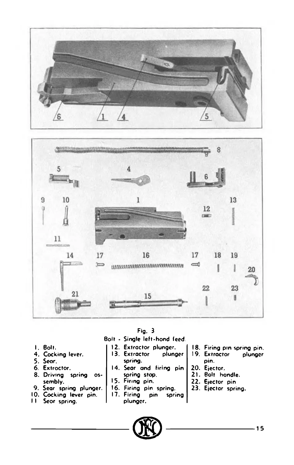
Fig. 3
Bolt - Single left-hond feed.
12. Extractor plunger.
13. Extractor plunger
spring.
14. Sear and tiring pin
spring stop.
15. Firing pin.
16. Firing pin spring.
17. Firing pin spring
plunger.
I. Boh.
4. Cocking lever.
5. Sear.
6. Extractor.
8. Driving spring as-
sembly.
9. Sear spring plunger.
10. Cocking lever pin.
I I Seor spring.
18. Firing pin spring pin.
19. Extractor plunger
pin.
20. Ejector.
21. Bolt hondle.
22. Ejector pin
23. Ejector spring.
15
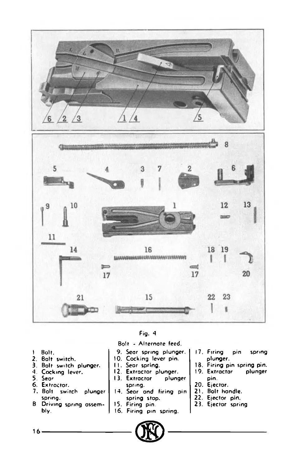
Fig. 4
I Bolt.
2. Bolt switch.
3. Bolt switch plunger.
4. Cocking lever.
5. Seor
6. Extroctor.
7. Bolt switch plunger
spring.
В Driving spring ossem-
bly.
Bolt - Alternote feed.
9. Seor spring plunger.
10. Cocking lever pin.
I I. Seor spring.
12. Extractor plunger.
13. Extractor plunger
spring.
14. Seor ond firing pin
spring stop.
15. Firing pin.
16. Firing pm spring.
17. Firing pin spring
plunger.
18. Firing pin spring pin.
I 9. Extractor plunger
pin.
20. Ejector.
21. Bolt hondle.
22. Ejector pin.
23. Ejector spring
---®----
the seor pin stop os for os possible, turn the orm of the sear
stop to the left in the recess of the bolt. Insert cocking
lever, com surface on the bock, replace cocking lever pin
and push the cocking lever in the forward position. Replace
extractor.
To reassemble the recoil spring end cap on the frame,
take one of the powl pins of the receiver using it os о guide
through the frame and the spring. Compress the spring
and insert the pin of the cop of the spring into the groove
of the left side plote of the frame.
Reassembling of the gun. — Replace accelerator and oxis in the
frame. Replace bolt lock and axis in the barrel extension.
Lift the barrel locking spring of the barrel extension and
screw the barrel in (see "Breeching the cun"). Take in
one hand the barrel extension, the frame in the other. Push
the depressors of the frame into the ouidewoys of the barrel
extension taking core to lift the accelerator behind the bar-
rel extension. At the end of the movement the frame and
the barrel extension are held together as the notches of
the barrel extension shank ore engaged by the claws of the
accelerator. Insert barrel, barrel extension and frame in
the cosing, push in the locating stud of the frame to allow
it to enter in the receiver and drop in the locating hole of
the receiver. Rep'oce the bolt (cocking lever rotated fully
forward’ and push forward in the receiver until the hole for
the bolt handle is in line with the enlarged opening in the
rear of the slot in the side plate and insert the bolt handle.
Push the bolt completely forward. Insert the drivi ng
pin rod assembly in the bolt, push it forward and engage
the driving spring rod retaining oin in its opening in the right
side plate. Replace the bock plate. Clcse down the cover.
Breeching the gun. — Every time the barrel has been unscrewed
it is necessary to readjust the headspoce i.e. the position of
the barrel in accordance with the bolt.
To breech the gun take the bolt (extractor removed),
the barrel extension and the barrel Raise the barrel
locking spring out of the notch in the borrel and slide it to
the side where it can be held disengaged. Then having
unscrewed the barrel about two turns and while holding the
borrel and barrel extension in о vertical position, muzzle
end down, place the bolt in its guides in the borrel exten-
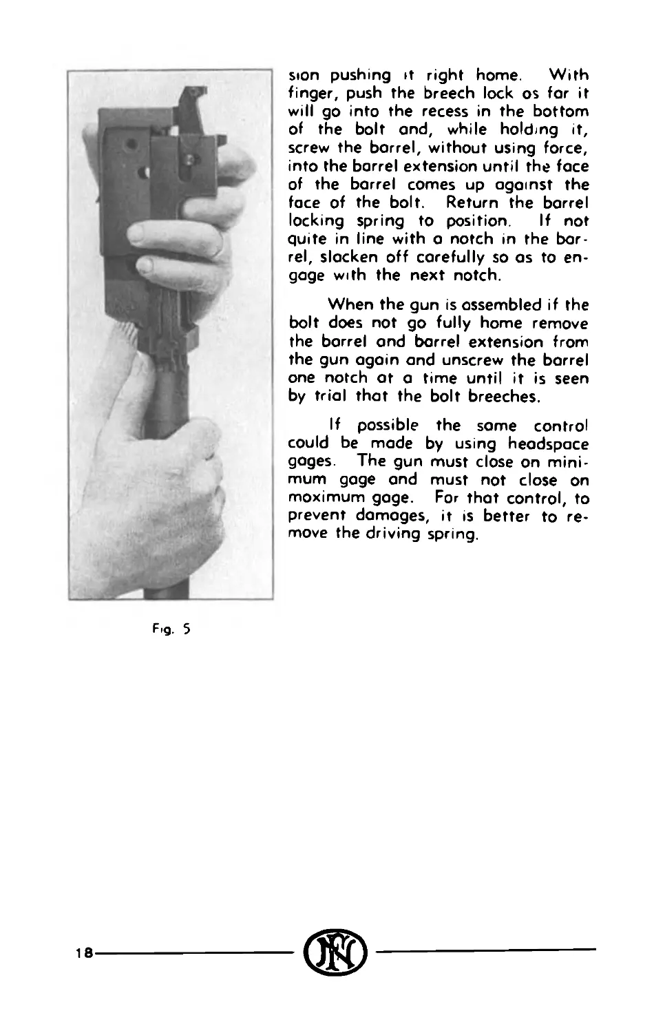
Fig. 5
sion pushing it right home. With
finger, push the breech lock os for it
will go into the recess in the bottom
of the bolt ond, while holding it,
screw the borrel, without using force,
into the barrel extension until the face
of the borrel comes up against the
face of the bolt. Return the borrel
locking spring to position. If not
quite in line with a notch in the bar-
rel, slacken off carefully so os to en-
gage with the next notch.
When the gun is assembled if the
bolt does not go fully home remove
the borrel ond barrel extension from
the gun again and unscrew the borrel
one notch at a time until it is seen
by trial that the bolt breeches.
If possible the some control
could be made by using headspace
gages. The gun must close on mini-
mum gage ond must not close on
maximum gage. For that control, to
prevent damages, it is better to re-
move the driving spring.
18
CHANGING FEED
If the gun has on alternate feeding, in order to change the
gun from left-hond feed to right-hand feed or vice versa repo-
sitioning of the ports must be carried out in the bolt group, belt
feed mechanism, and certain ports of the receiver.
The following describes, in general terms, the change from
left-hand feed to right-hand feed. By reversing the process, the
gun may be changed from right-hand feed to left-hond feed
1. Bolt group
— Remove the bolt assembly from the gun.
— Remove the extractor from the bolt.
— Remove extractor axis pin, change over extractor and
its spring, replace extractor axis pin
— Press in the switch stud to clear the bolt switch
— Turn the switch (180”) until the opposite hole in the
switch comes in front of the stud The com groove in
the bolt switch will then line up tc moke the groove in
the bolt marked "R" Iright) continuous ("L" feed is for
left-hand).
— Replace extractor on the bolt.
2. Belt feed mechanism
— The cover opened, remove belt feed lever Transfer the
belt feed lever plunger and spring from the upper hole
in the belt feed lever to the lower
— Remove the assembled belt feed slide from the cover,
reverse it, reverse the lug closing the slot of the feed
lever, and replace the slide in its way in the cover with
the pawl end of the slide toward the right.
— Replace the belt feed lever and insert the cotter pin
— Push the slide to the right and hold it so thot the belt
feed pawl pin can be pushed out of place and remove
the belt feed pawl, belt feed pawl arm and spring from
the belt feed slide
— Move the belt feed pawl arm from its position ot the
bottom of the pawl (cover in the raised position) and
19
Fig. 6
1. Bolt. 26. Front cortridge stop. 31. Belt feed powl arm.
2. Bolt switch. 27. Belt teed lever spring 32. Belt feed powl.
3. Bolt switch plunger. 6. Extractor. 24. Reor cortridge stop 25. Belt holding powl. 2B. 29 30. plunger. Belt feed lever. Belt feed slide. Belt feed slide cop filling piece. 33. Belt holding powl pm.
20
place it in position on the top of the pawl. The locating
pins will locate the arm in the proper position
— Reassemble the belt feed pawl spring ond arm to tht
belt feed powl by inserting the belt feed pawl pin.
3. Receiver group
— Remove the belt holding pcwl pms from the right and
left hand sides
— Remove the two pins of the front cartridge guide, turn
over the guide ond replace the two pins
— Take out the right hand front cartridge stop ond move
it to the left
— Remove the right hand reor cartridge stop and move it
to the left.
— Remove the belt holding pawl and spring from the left
ond turn them over to the right.
— Reinstal the two belt holding pawl pins
NOTE. — After changing the gun from cne hand feed to the
other ond also before firing the gun should be inspected to deter-
mine that all parts hove been properly assembled.
21
CARE AND MAINTENANCE
Before firing
Following ports ought to be oiled with thin oil of good quo-
lity.
— The outside of the rear of the barrel, bearing in the
trunnion block.
— The belt feed slide in the cover.
— The grooves for feed lever in the bolt.
— The grooves for the bolt ribs in the borrel extension.
— The breech lock in the barrel extension.
— The breech lock com in the receiver.
In general other parts con be very slightly oiled with on oiled
cloth.
The bore and chamber of the barrel should be wiped dry
of oil
After firing
Cleon the barrel by running oily or grease flannel patches,
using cleaning rod, through the bore
The cleaning of the mechanism of the gun has the object
to remove thoroughly the dust and the dirt caused by the non
burned powder grains and the powder residues, the moisture ond
the rust spots.
Cleaning the gun casing is carried out by means of о dry
flannel patch ond a wooden scraper.
The ingredients used for cleaning the gun are: set grease,
light mineral oil, petroleum The use of abrasives such as brick
or emery powder, ought to be strictly descarded. The use of
petroleum makes the cleaning of very dirty ports easy but, in order
to prevent rust, they ought to be carefully wiped before greasing.
If rust spots set in, soak them for о moment with oil, then
rub the rust away by means of an oily patch.
22
The components ought to be wiped with о dry flonnel potch
and by means of an oily rag.
Never scratch the parts with a knife or with a sharp tool.
Moke sure, from time to time, that no metallic fouling hos
formed in the bore. The metallic fouling has no injurious effect
in itself but it frequently recovers the powder residues which cause
the "pitting" of the bord.
The metallic fouling con eventually be removed by using
following solution:
Ammonia persulphate . 1/2 tea spoon
Ammonia carbonate 1/2 tea spoon
Ammonia (28 %) . 0,285 litre
Water 0,142 litre.
In order to be sure thot this solution does not bite the steel,
add some potassium bichromate.
Plug the chamber with a rubber stopper, hold the borrel in
the vertical position ond fill the bore with the solution. Eventually
odd some oil in order to prevent the evaporation of ammonia ond
consequently the rusting of the bore. Leave the borrel standing
for 2 hours. When the solution begins to work bubbles appear
at the surface and the solution turns gradually to a deep blue
color. When the solution ceases to bubble, pour it out of the
borrel. Clean the bore with flonnel patches saturated in a 20 %
soda solution and coat the bore with a thin grease layer.
Replacement of component parts
The replacement of unserviceable parts ought to be carried
out by means of the regular spare parts supplied with the gun, but
the assembling of these ports ought to be carried out without
using force ond without using cutting tools. The spare ports
ought to be new.
The maximum of shots which may be fired from a barrel
depends on the rote ond duration of fire it hos been submitted
during its life. It ought to be discorded when 4 % of the rounds
give key holes on a target at short range.
The wear or the erosion ot the chamber may cause ruptures,
swellings or stickings of cartridge cases which make the extraction
of the cose difficult ond uncertain. Chamber and bore ought to
be inspected periodically.
23
Storing the guns
The guns ought to be stored in dry ond well aerated rooms.
Before storing, clean the guns thoroughly, and using a brush,
coat them with a hot mixture of molten vaseline and ail. In
particular regarding the barrel which is mounted on the gun,
clean it thoroughly, run a flannel patch saturated with grease
through the bore, and stop up the muzzle by means of a grease
plug.
For the guns which are to be stored for a long time proceed
as follows: dip each group of parts (gun casing, bolt, etc.) in a
hot both of molten vaseline and oil and reassemble the guns
before the mixture has solidified
The same care ought to be paid to spare barrels as to the
guns. They ought to be oiled, by rubbing the oil over their
whole surface by means of the finger so that no portion will be
in contact with the external agents.
Periodical cleaning
The guns ought to be carefully examined, cleaned and
greased each month in order to be ready for use.
24
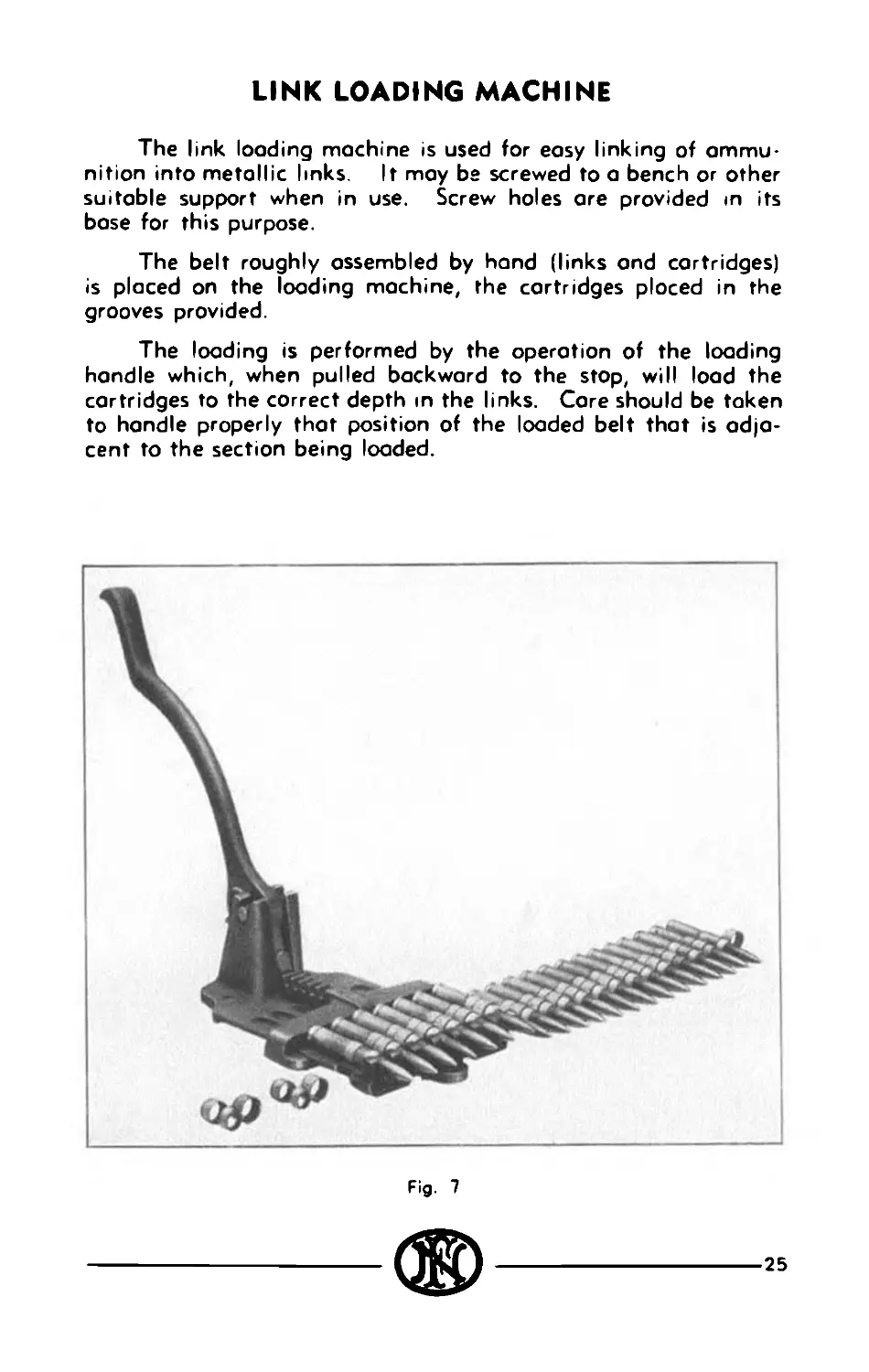
LINK LOADING MACHINE
The link loading machine is used for easy linking of ammu-
nition into metallic links. It may be screwed to a bench or other
suitable support when in use. Screw holes ore provided in its
base for this purpose.
The belt roughly assembled by hand (links ond cartridges)
is placed on the loading machine, the cartridges ploced in the
grooves provided.
The loading is performed by the operation of the loading
hondle which, when pulled backward to the stop, will load the
cartridges to the correct depth in the links. Core should be token
to hondle properly thot position of the loaded belt that is adja-
cent to the section being loaded.
Fig. 7
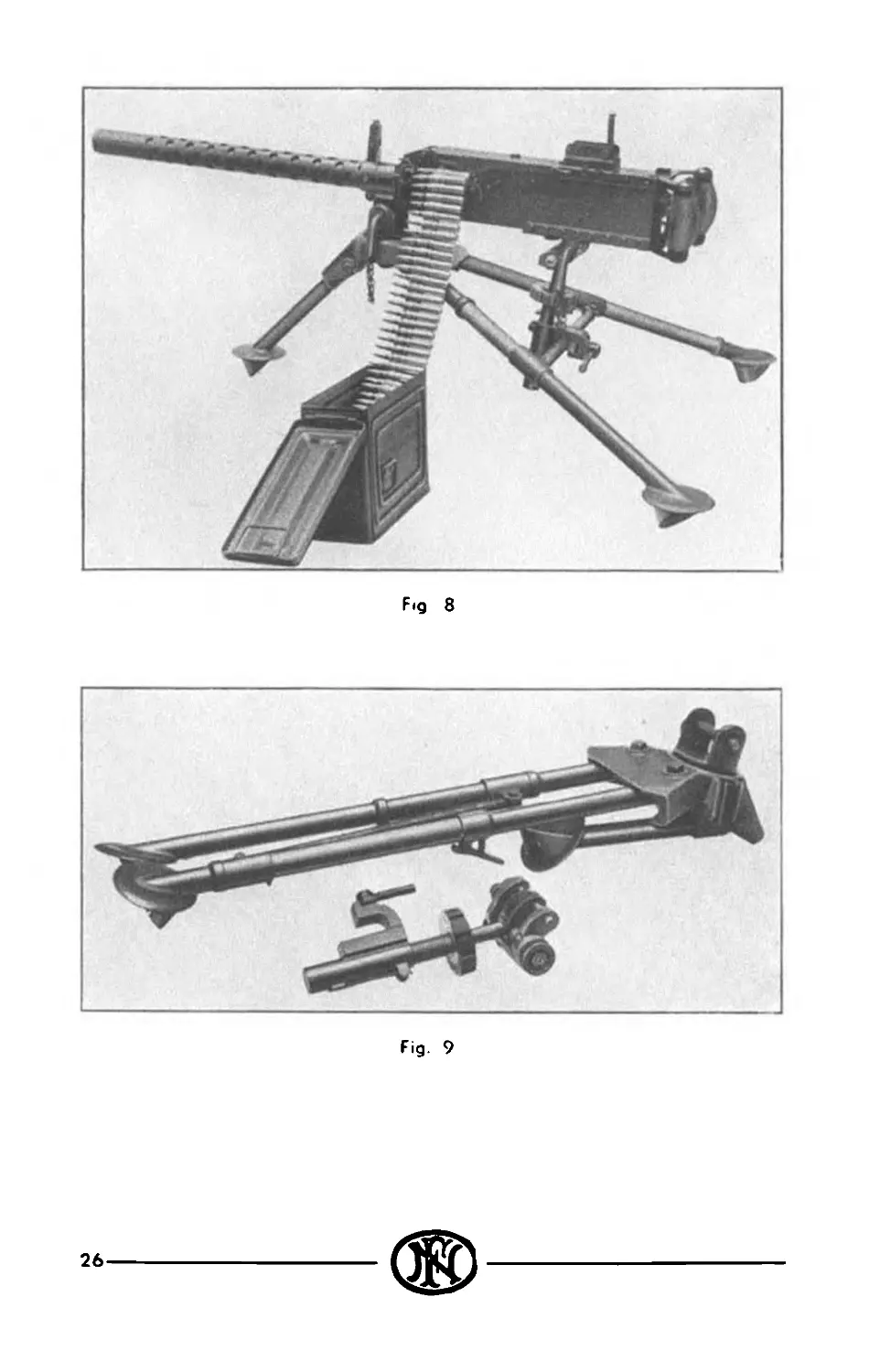
Fig 8
Fig. 9
26
27
GENERAL DATA
of the .30 Colibre F. N. Browning Machine Gun
(Air cooled)
Weight of gun........................Appx: 13.000 kg
Weight of barrel.....................Appx: 3.300 kg
Length of gun (overall).....................1,000 mm
Width of back plate (with double grip) 146 mm
Width of breech casing (with bolt hondle) 100 mm
Length of barrel............................. 609 mm
Length of line of sight...................... 353 mm
Twist of grooves (right)..................... 254 mm
Number of grooves............................. 4
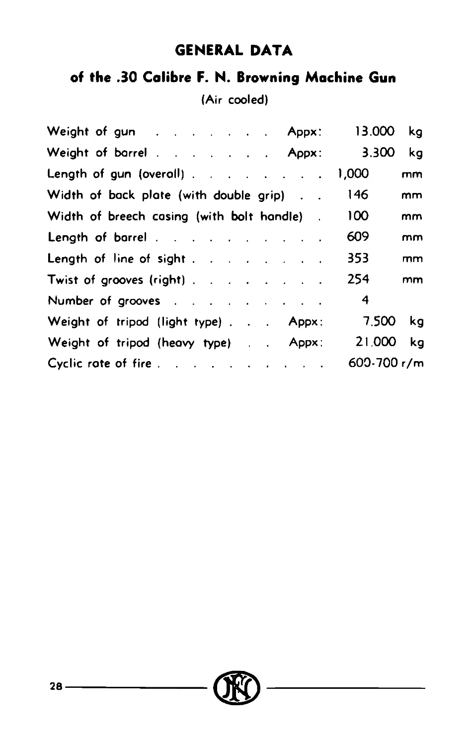
Weight of tripod (light type) . Appx: 7.500 kg
Weight of tripod (heavy type) Appx: 21.000 kg
Cyclic rate of fire.......................... 600-700 r/m
CONTENTS
Foreword..................................................... 3
Principle of operation....................................... 4
Detailed functioning......................................... 5
1. Firing............................................. 5
2. Recoiling.......................................... 5
3. Counterrecoiling................................... 6
4. Cocking............................................ 7
5. Automatic Firing................................... 7
6 Feeding............................................ 7
7. Extracting ond Ejecting............................ 8
Operation................................................... 10
Loading................................................ 10
Unloading.............................................. 10
Firing................................................. 11
Precautions................................................. 12
Before firing.......................................... 12
After firing........................................... 12
Stoppages................................................... 13
Field stripping and reassembly.............................. 14
Disassembling of the Bolt.............................. 14
Reassembling of the Bolt............................... 14
Reassembling of the Gun................................ 17
Breeching the Gun...................................... 17
Changing feed............................................... 19
1. Bolt Group........................................ 19
2. Belt Feed Mechanism............................... 19
3. Receiver Group..................................... 21
Care and maintenance 22
Before firing.......................................... 22
After firing........................................... 22
Replacement of Component Parts......................... 23
Storing the Gun........................................ 24
Periodical Cleaning.................................... 24
Link loading machine........................................ 25
General data................................................ 28