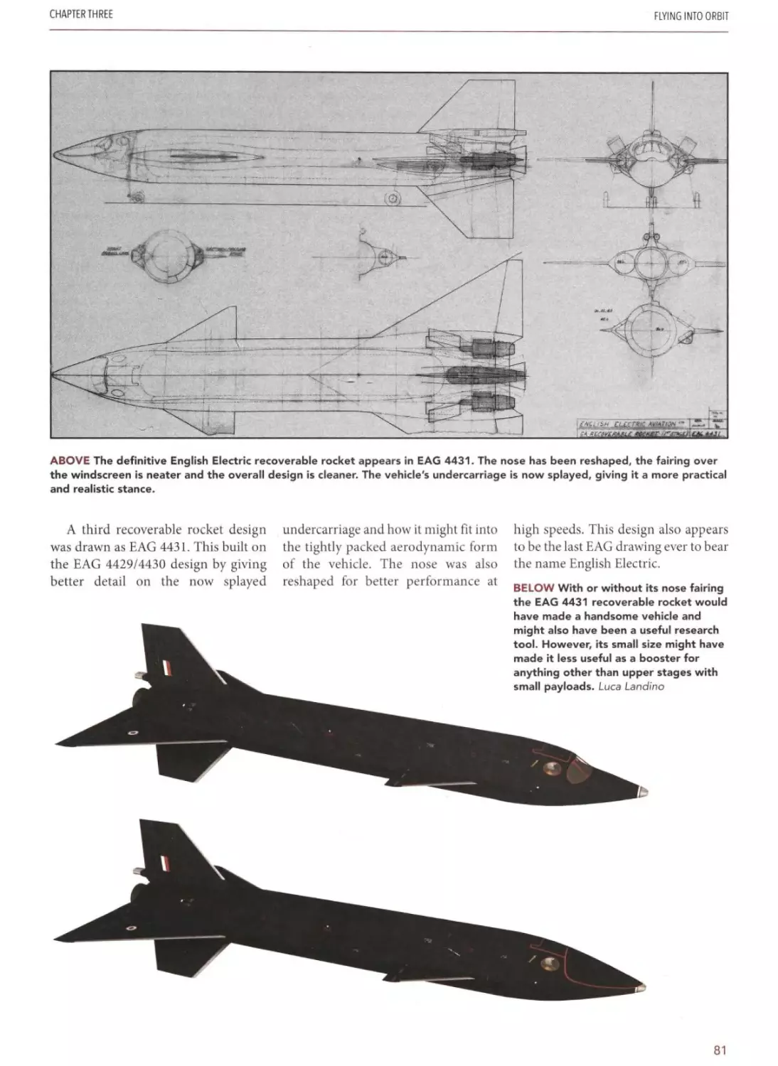
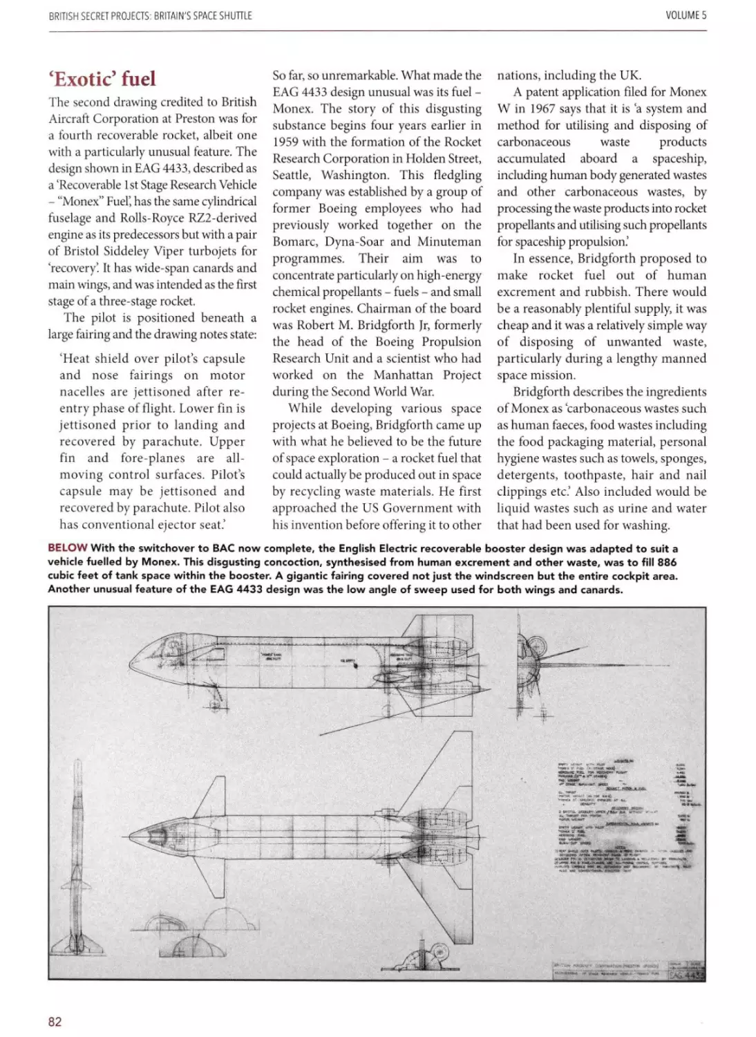
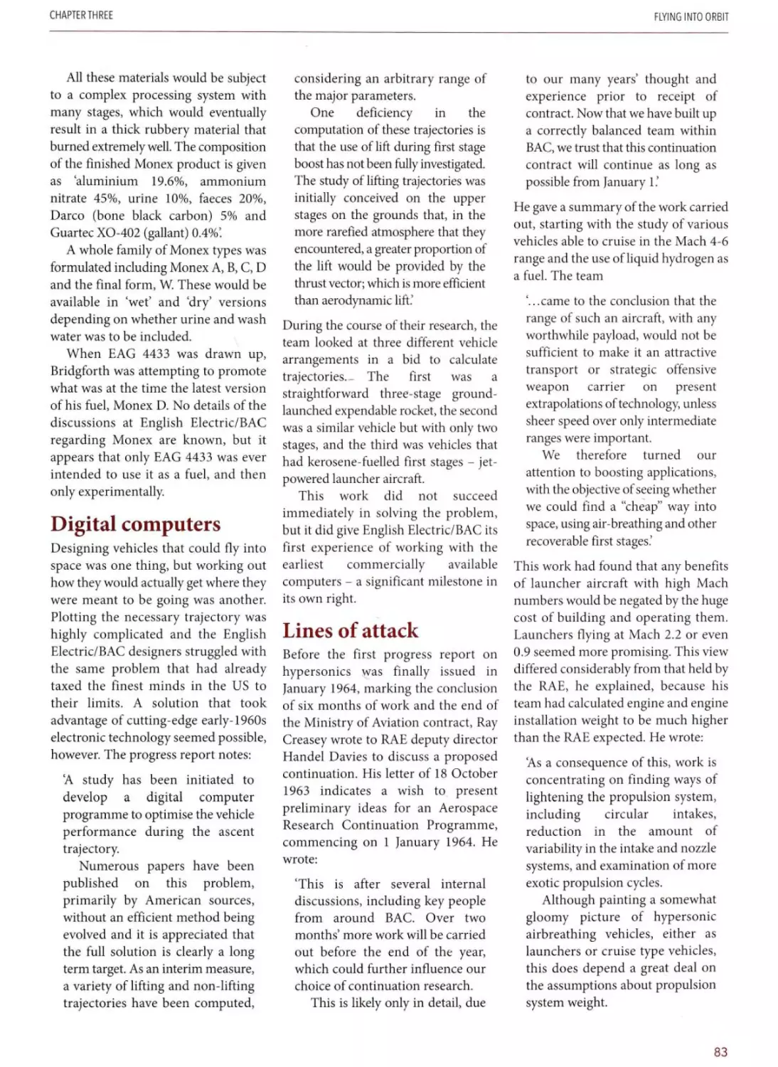
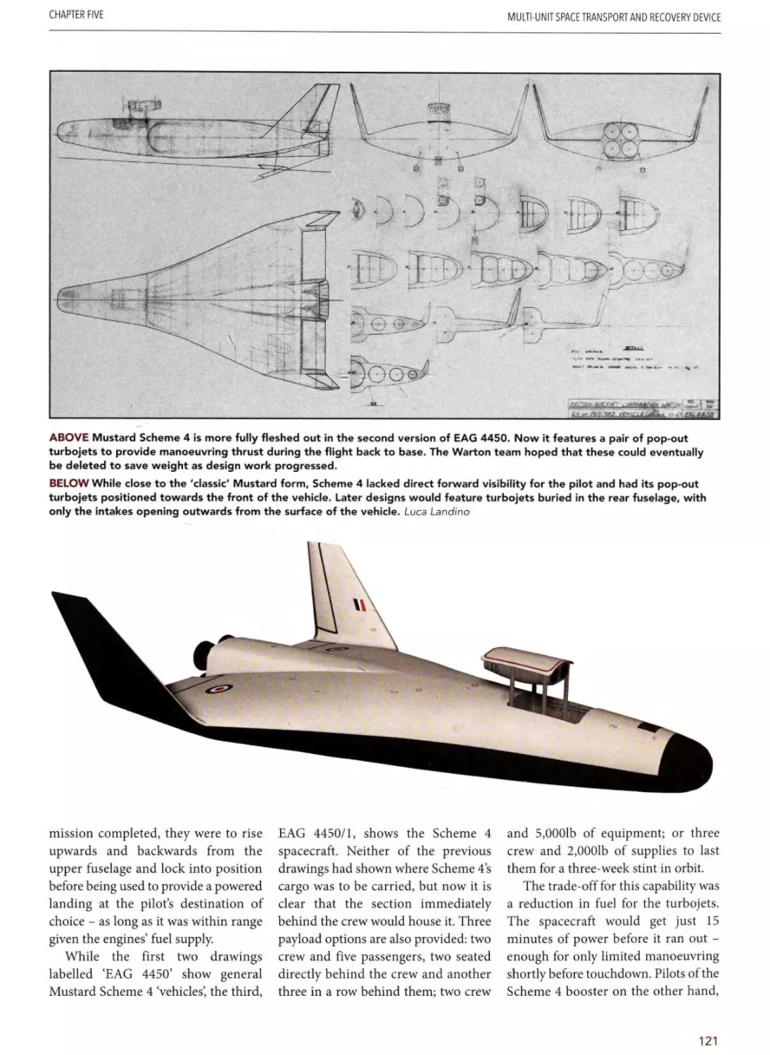
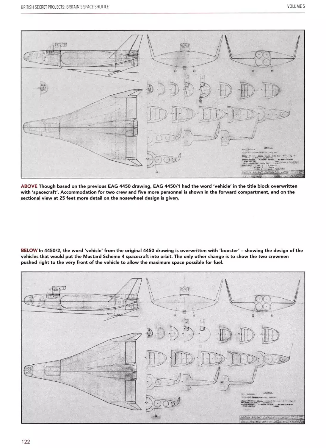
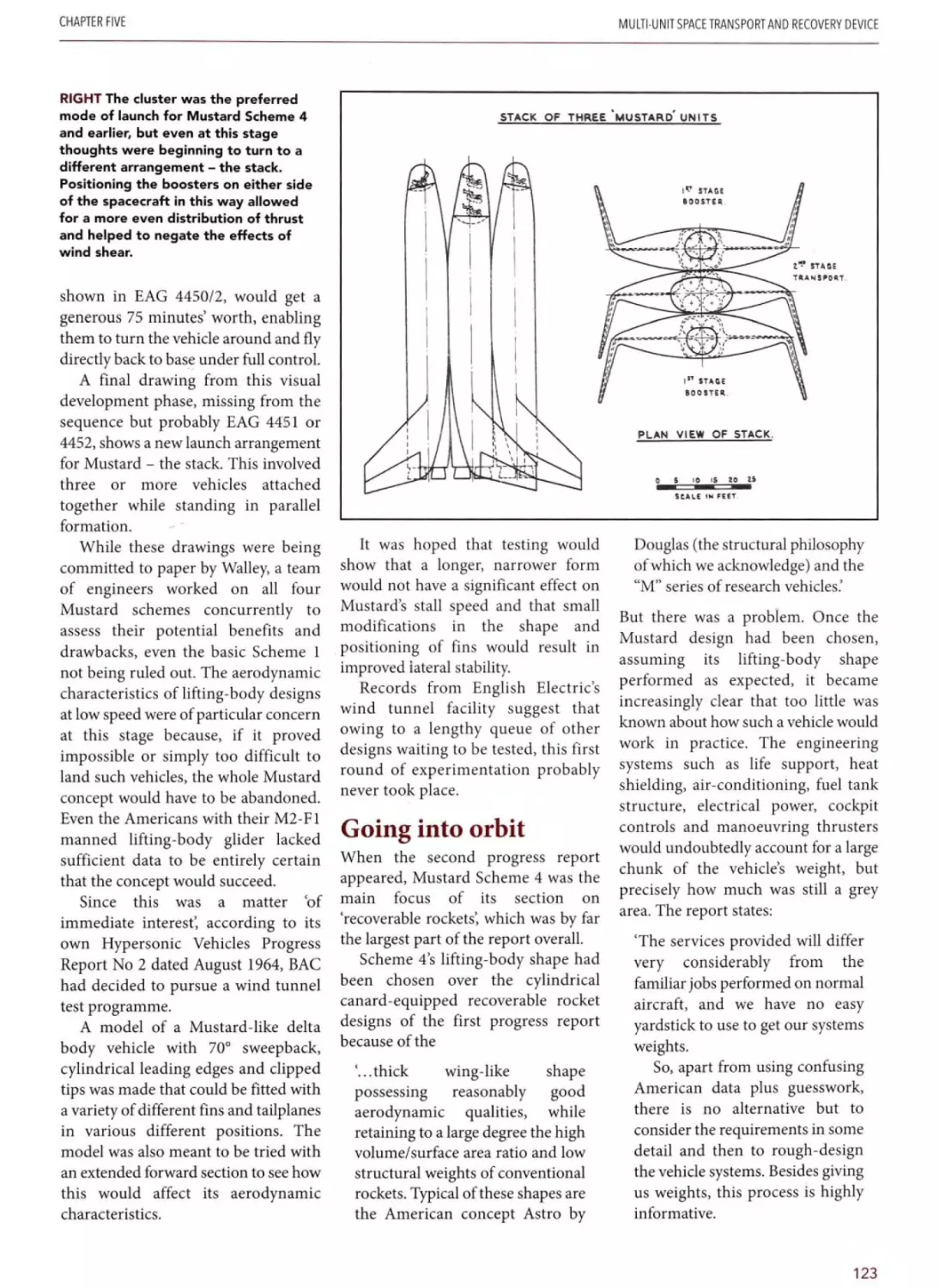
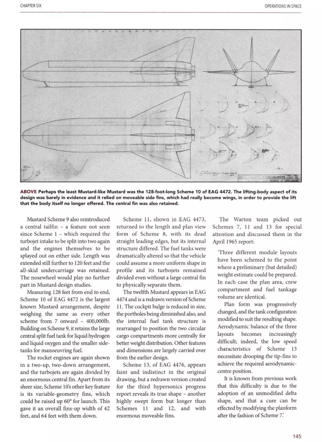
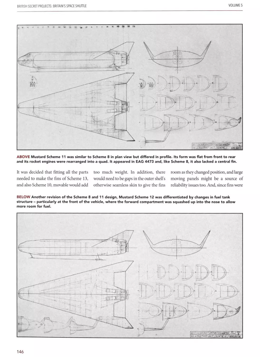
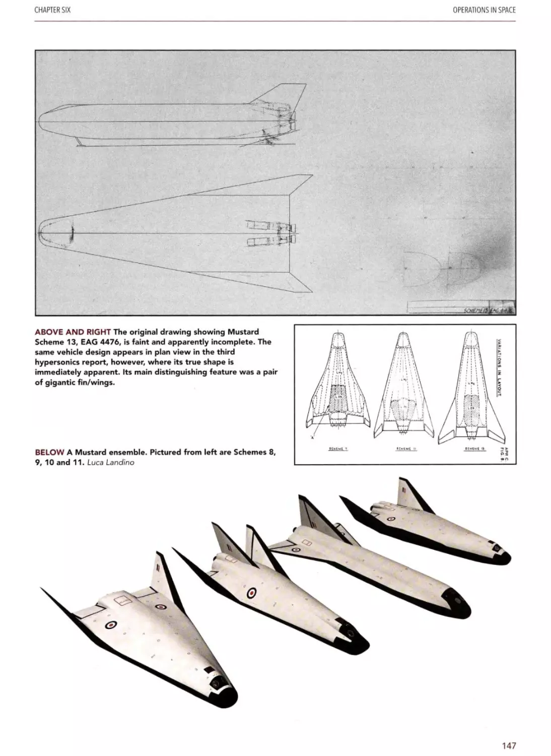
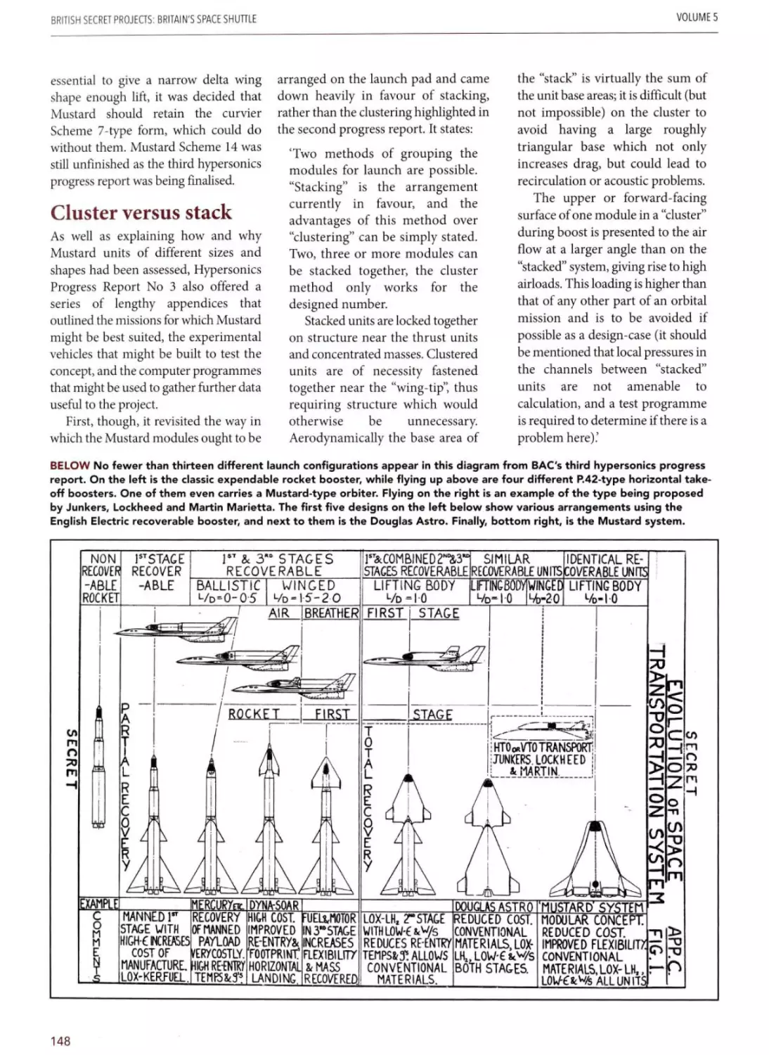
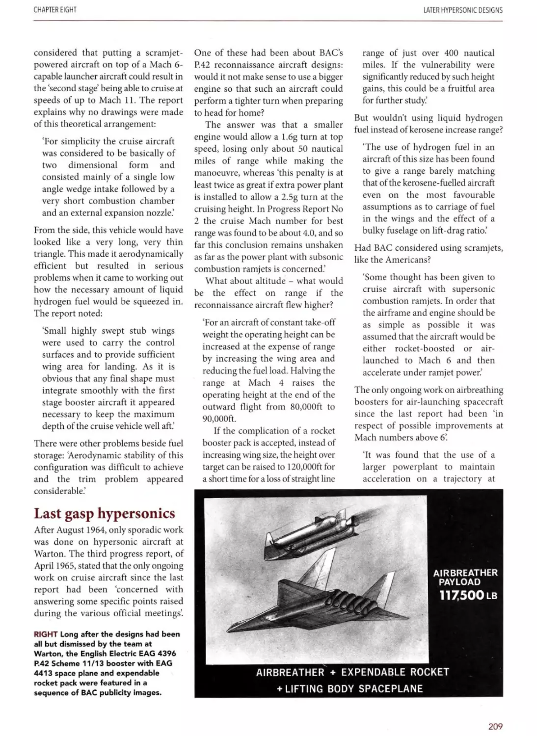
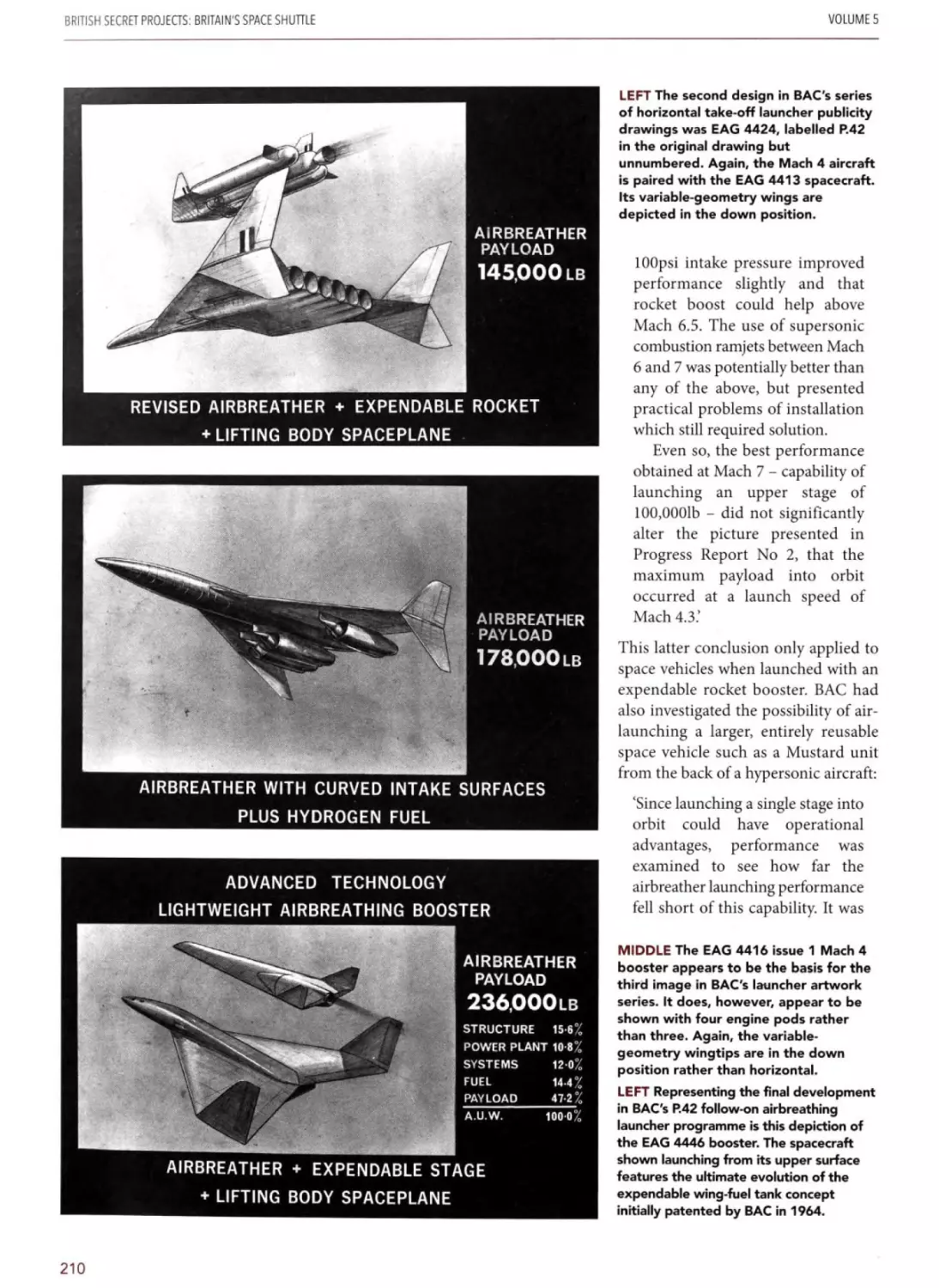
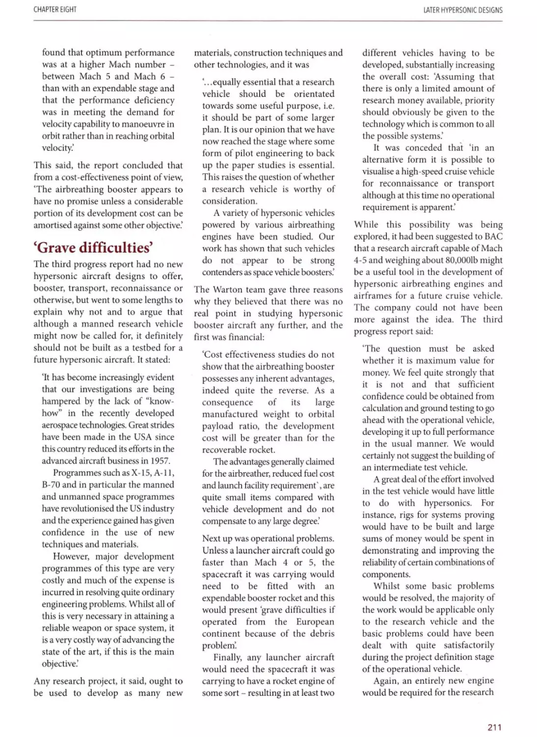
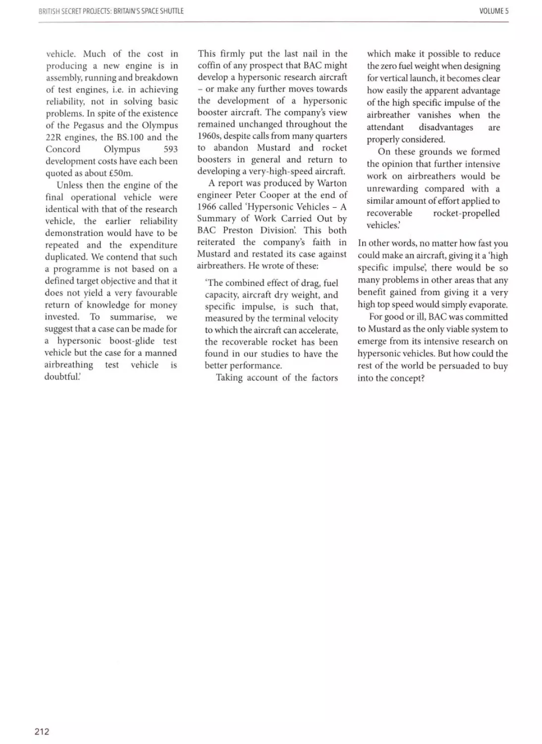
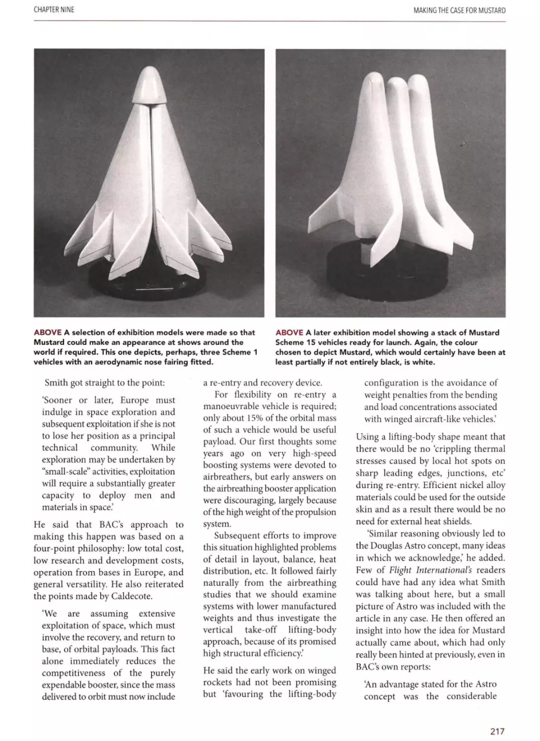
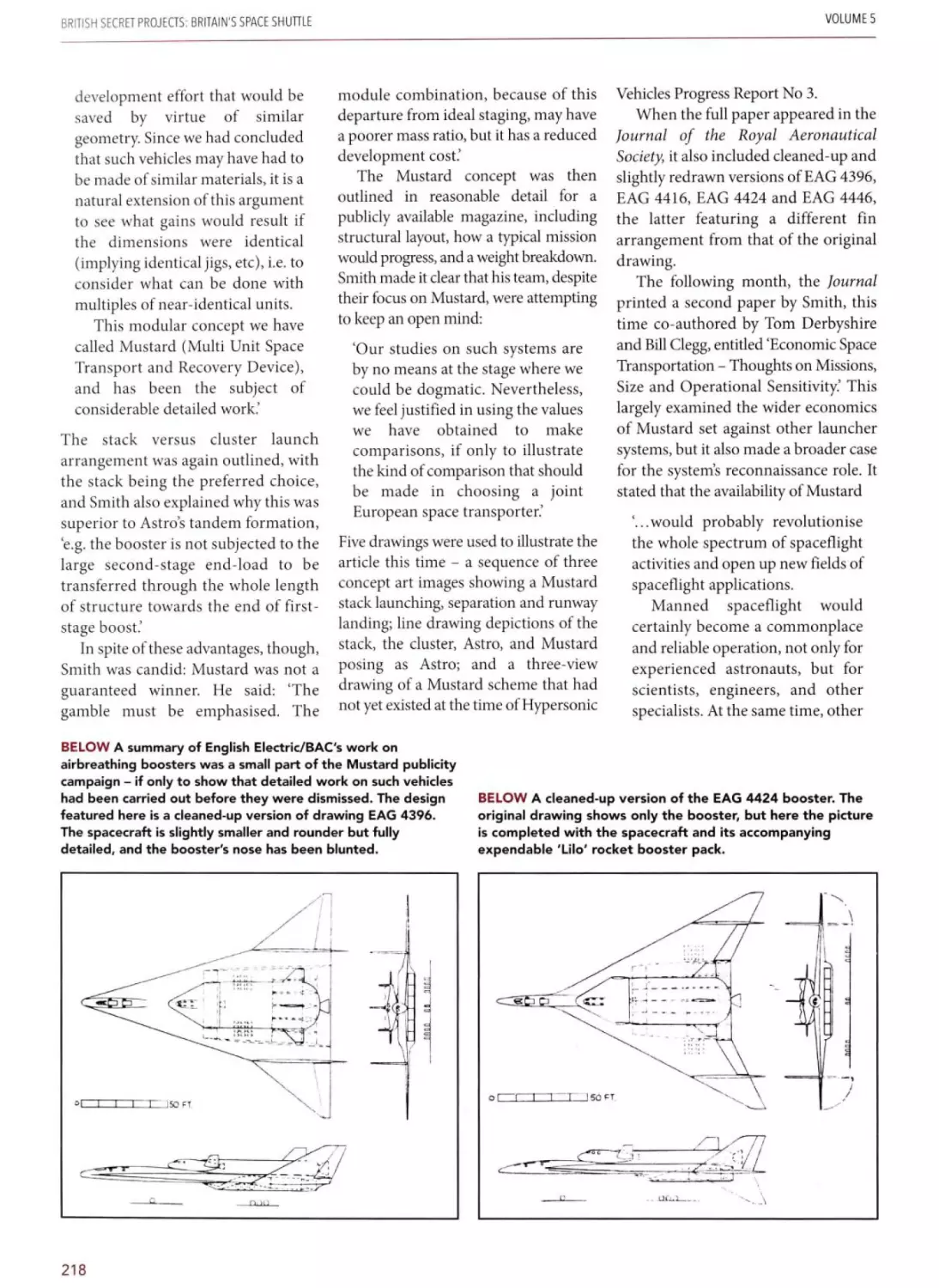
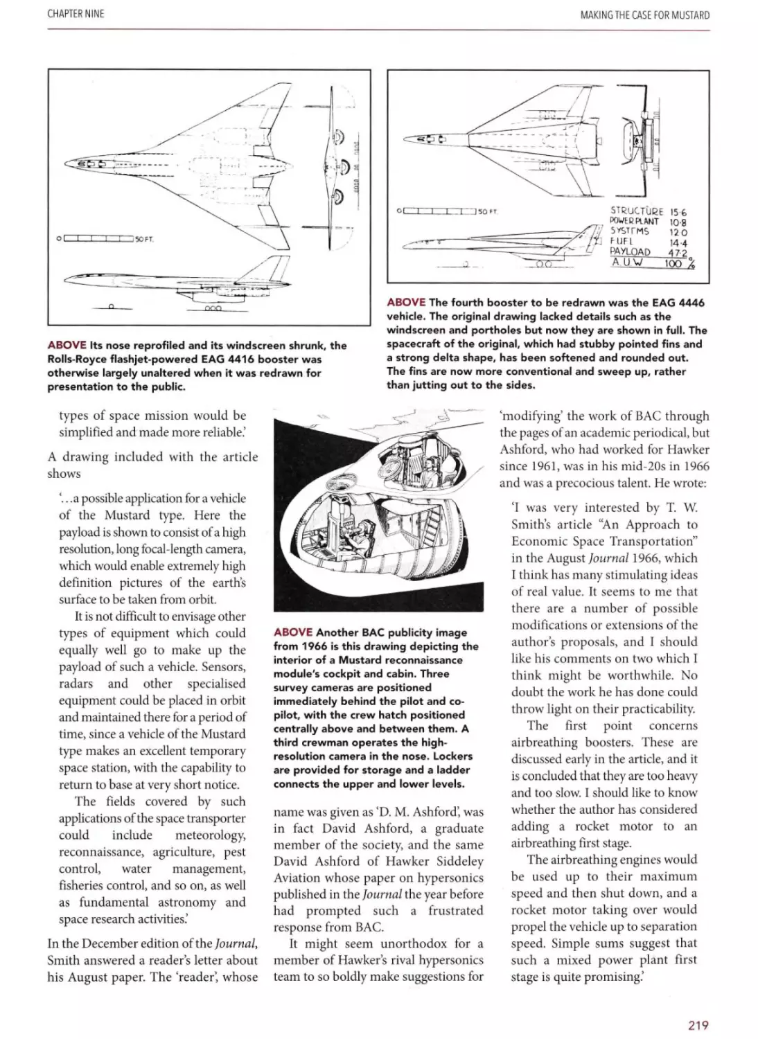
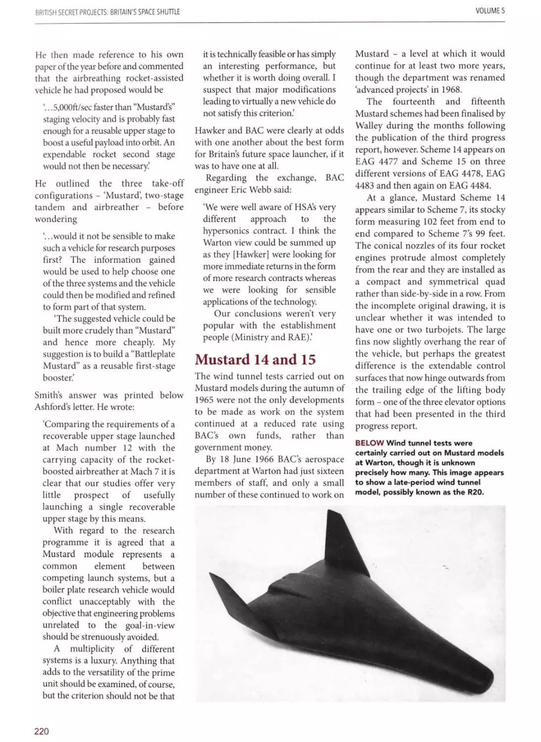
/


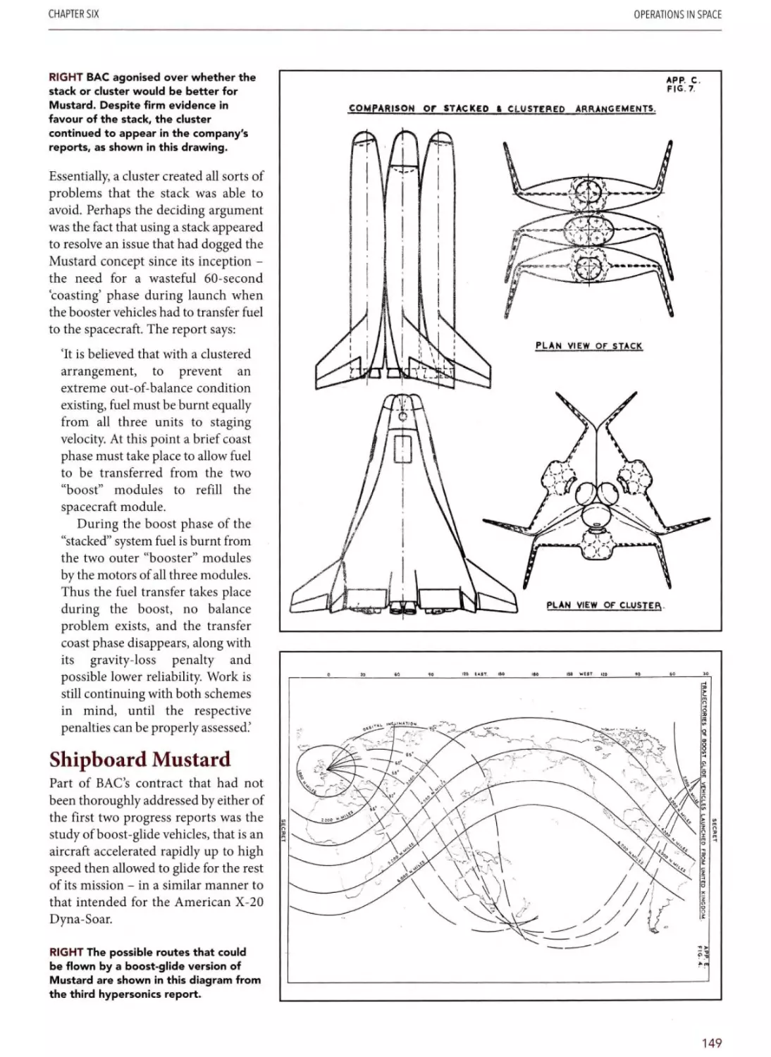
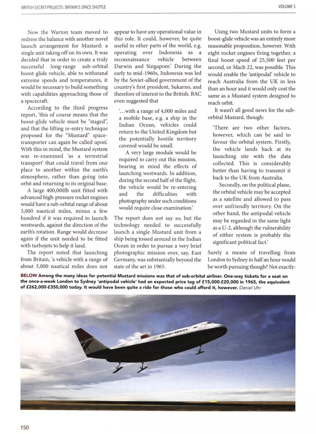
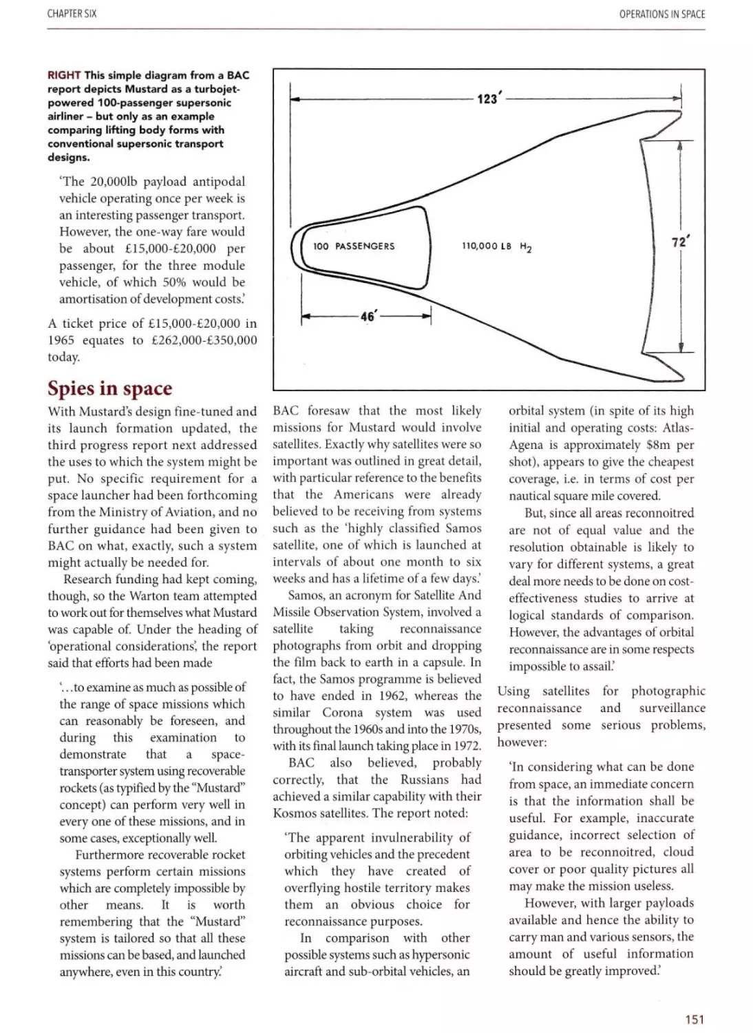
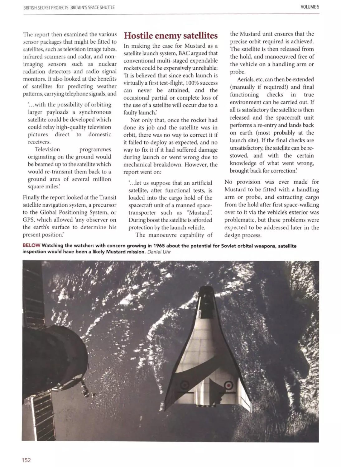


Text
BRITISH SECRET PROJECTS
BRITISH SECRET PROJECTS
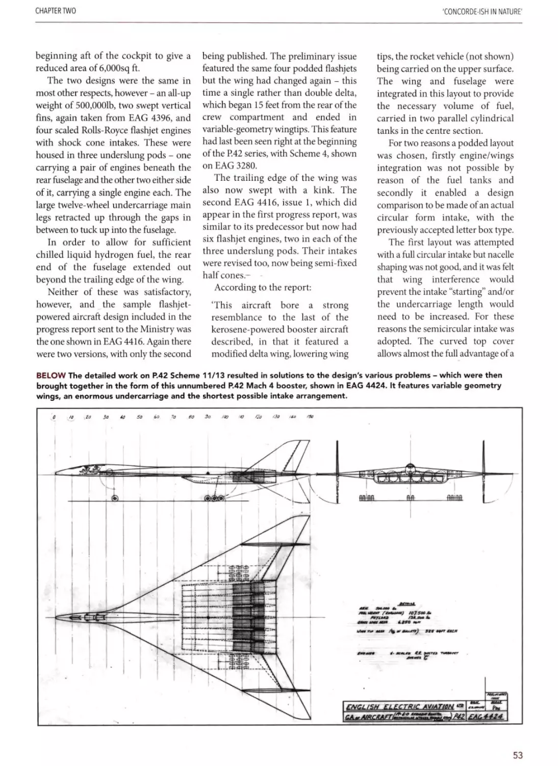
Britain's Space Shuttle
DAN SHARP
Crecy Publishing Ltd
Crecy
www.crecy.co.uk
British Secret Projects Volume 5
Britain's Space Shuttle
Dan Sharp
First published in 2016 by Crecy Publishing
All rights reserved. No part of this book may be
reproduced or transmitted in any form or by any means
electronic or mechanical, including photocopying,
recording or by any information storage without
permission from the Publisher in writing. All enquiries
should be directed to the Publisher.
© Dan Sharp 2016
All images copyright BAE Systems
except where otherwise noted
A CIP record for this book is available from the British
Library
Printed in Malta by Melita Press
ISBN 9781910809020
Crecy Publishing Ltd
la Ringway Trading Estate, Shadowmoss Rd
Manchester M22 5LH
Tel (0044) 161 499 0024
www.crecy.co.uk
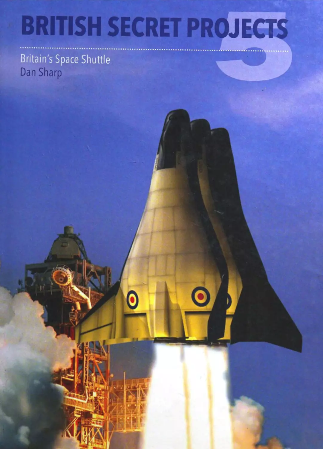
FRONT COVER artwork by Daniel Uhr
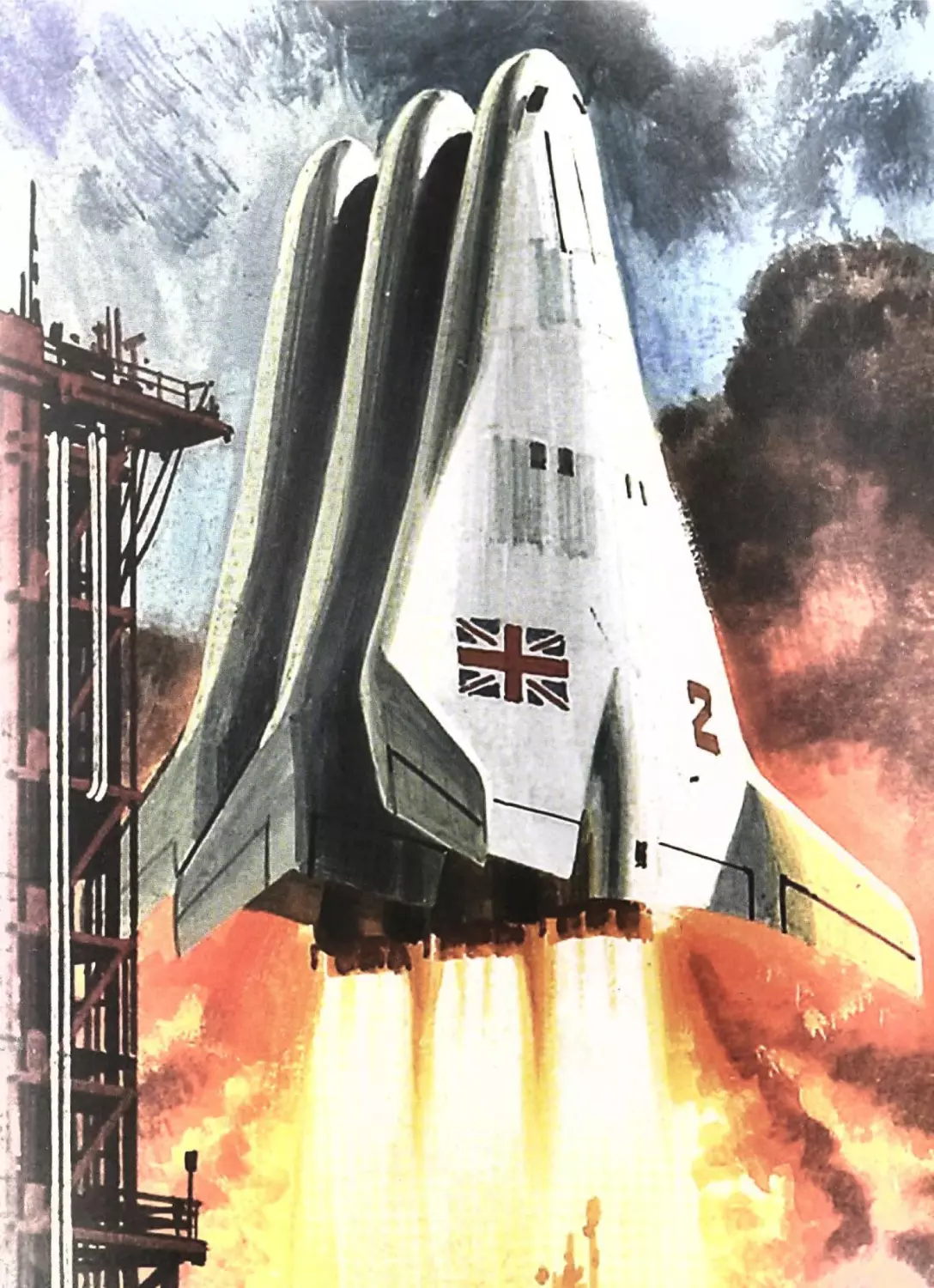
PAGE 2 Wilf Hardy's spectacular painting of the ВАС
Mustard as it appeared in a 1978 Look and Learn
children's book. Look and Learn
REAR COVER
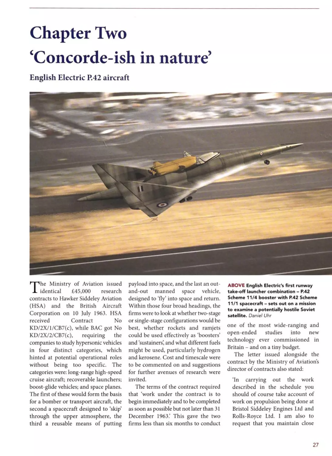
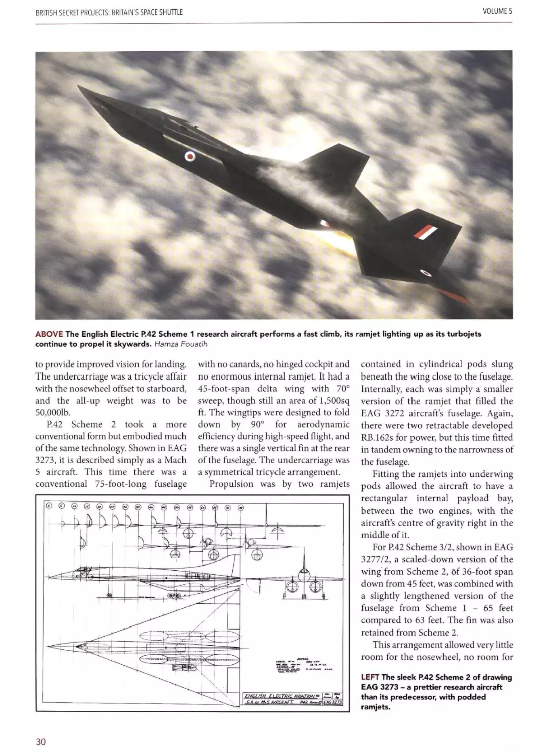
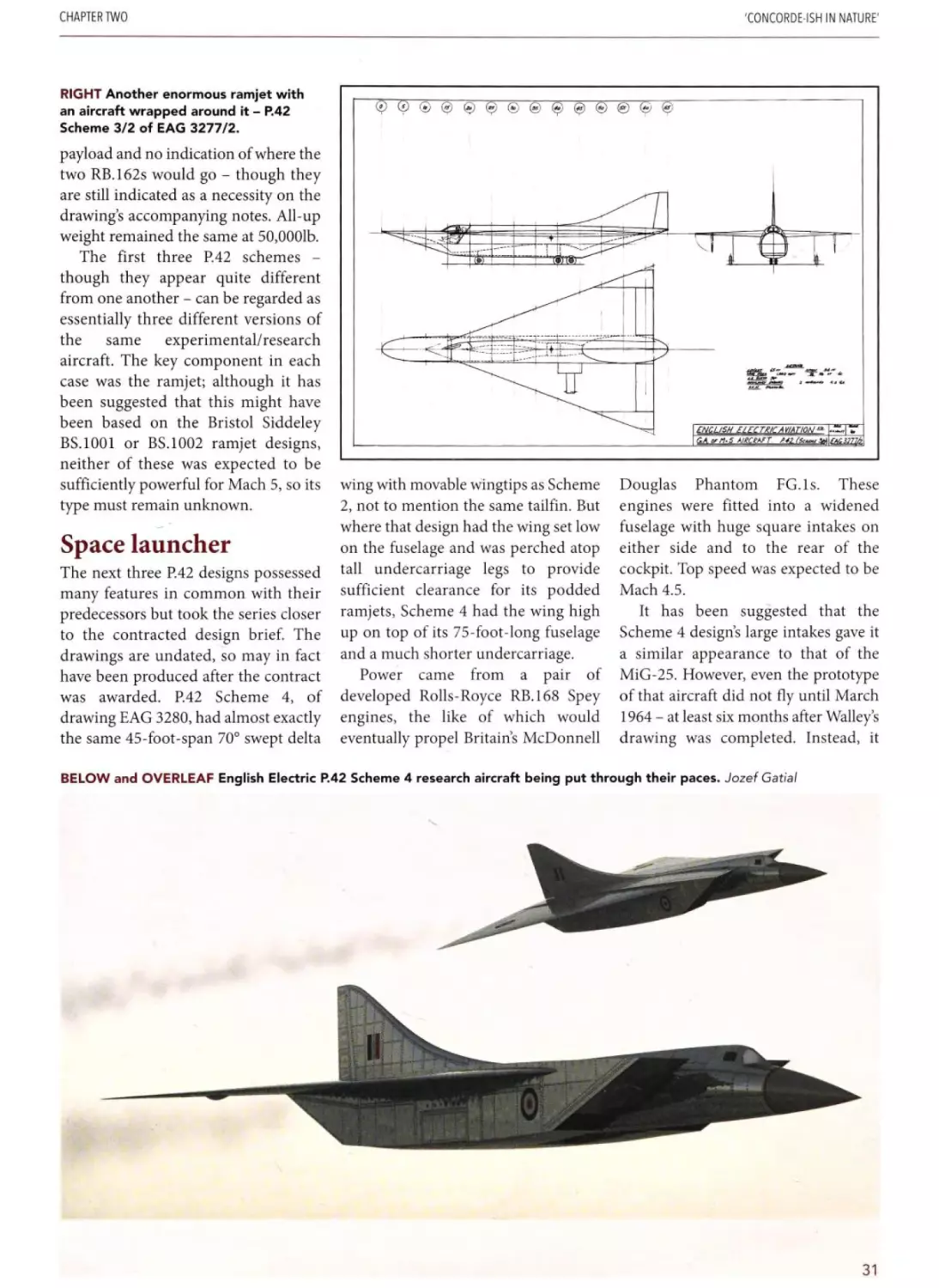
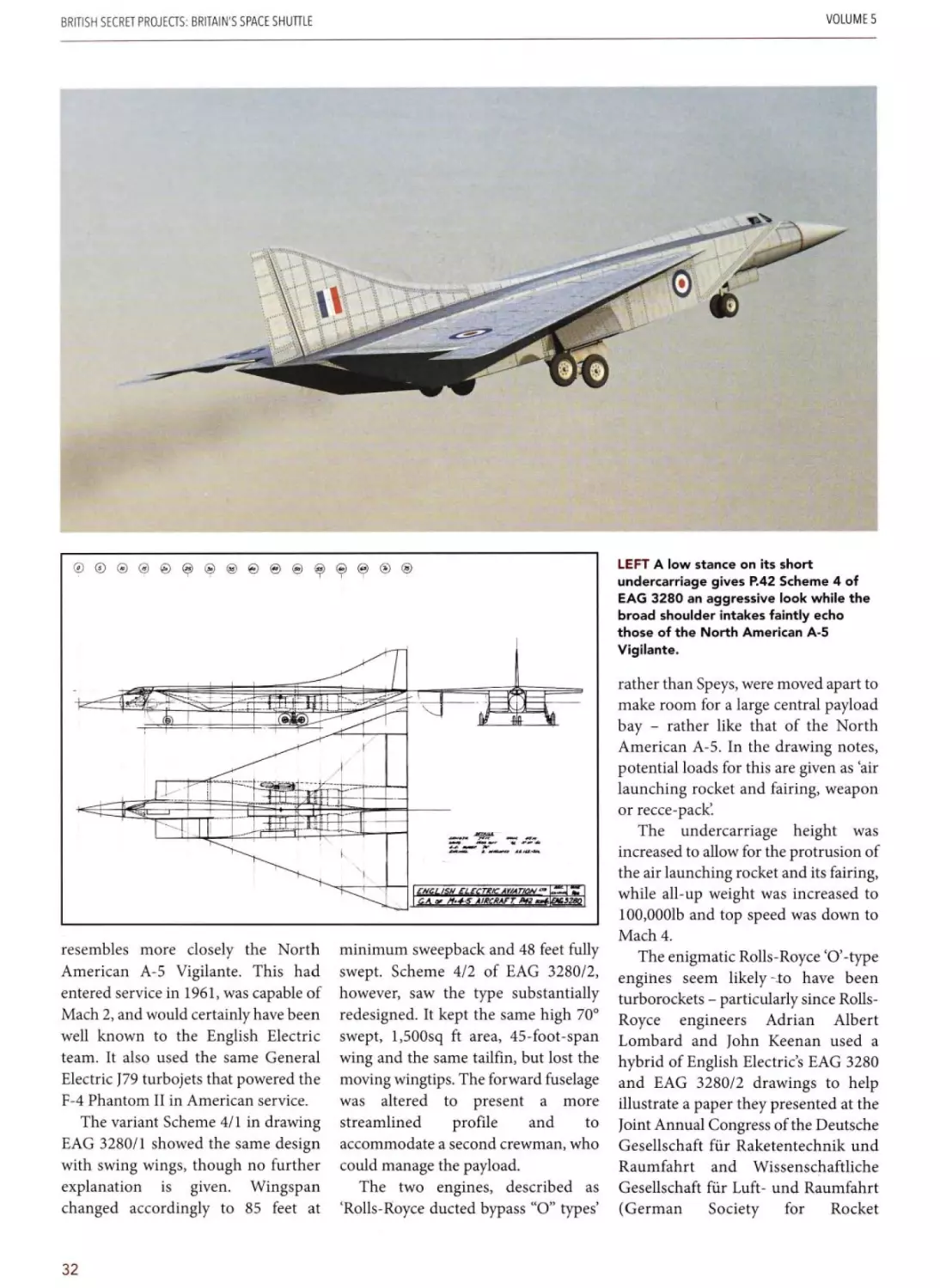
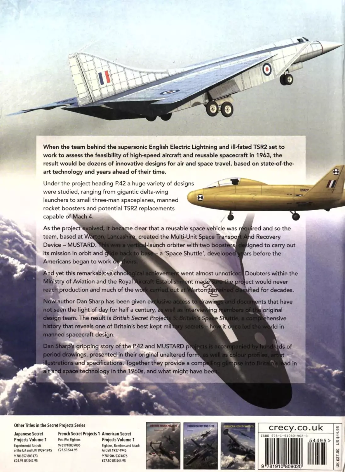
TOP An English Electric P.42 Scheme 4 research
aircraft being put through its paces. Jozef Gatial
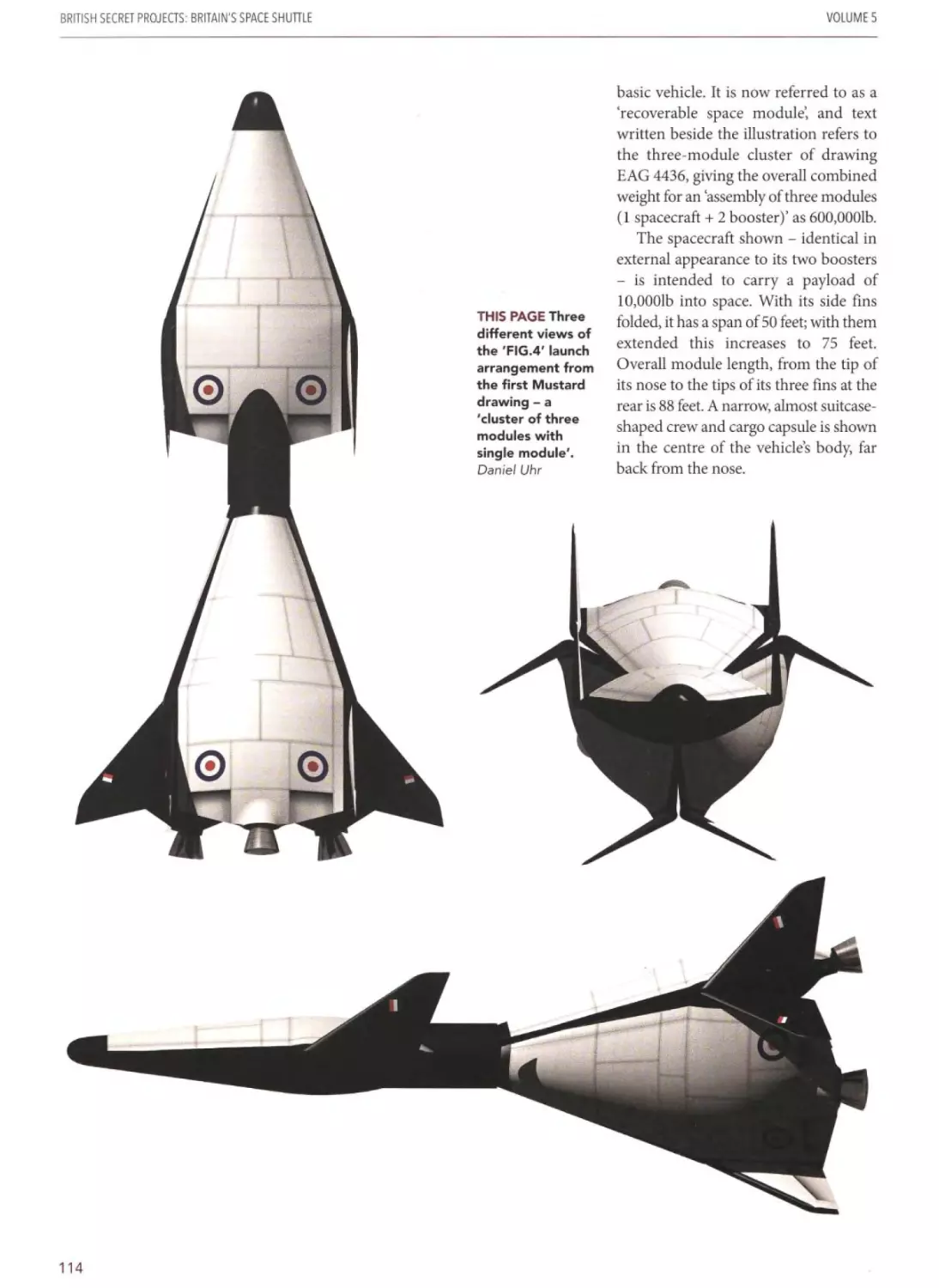
MIDDLE A manned glider version of the ВАС Mustard
was among a whole host of research proposals put
forward. Chris Sandham-Bailey
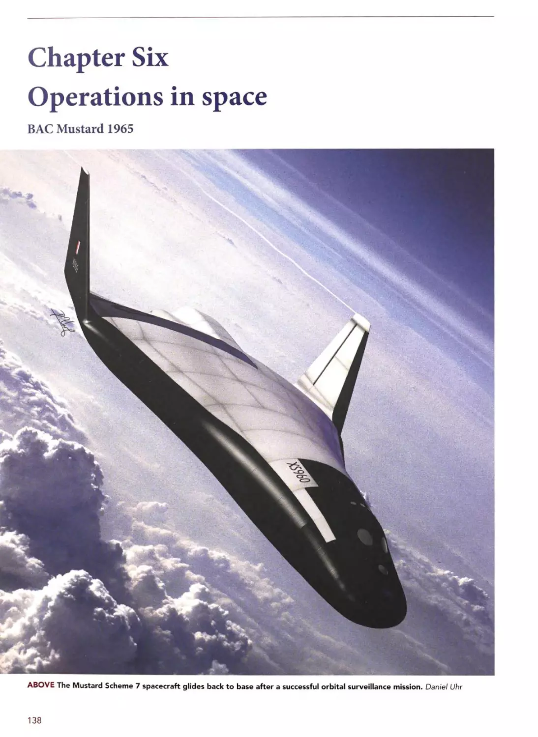
BOTTOM The Mustard Scheme 7 spacecraft glides
back to base after a successful orbital surveillance
mission. Daniel Uhr
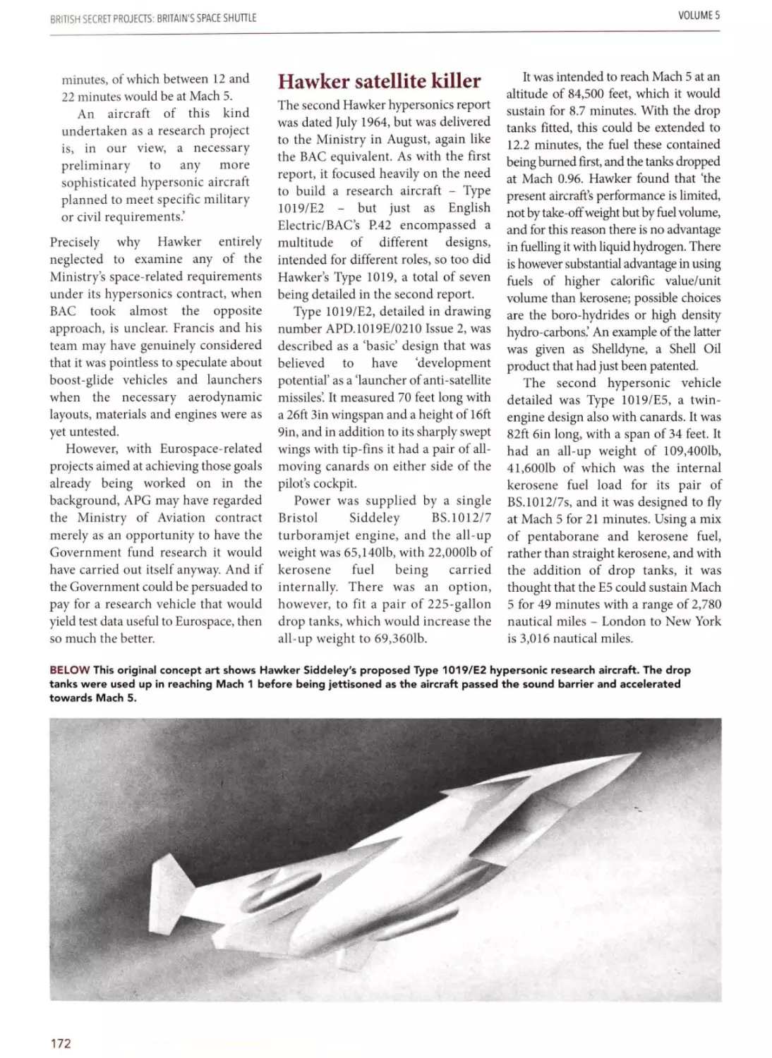
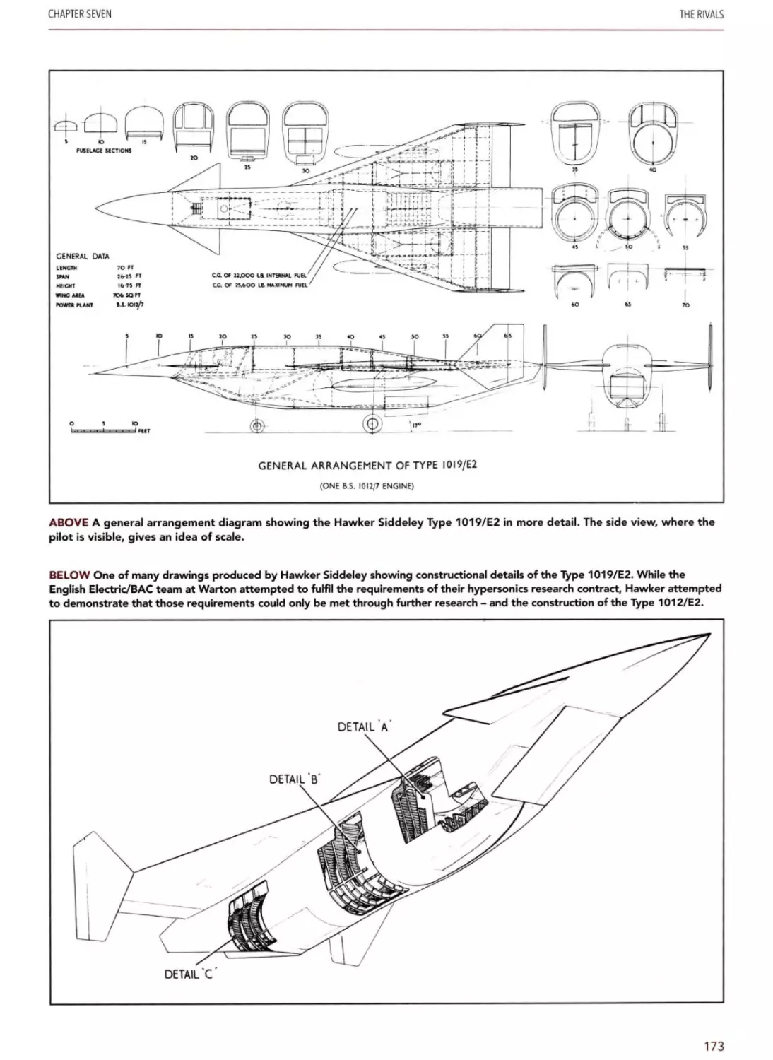
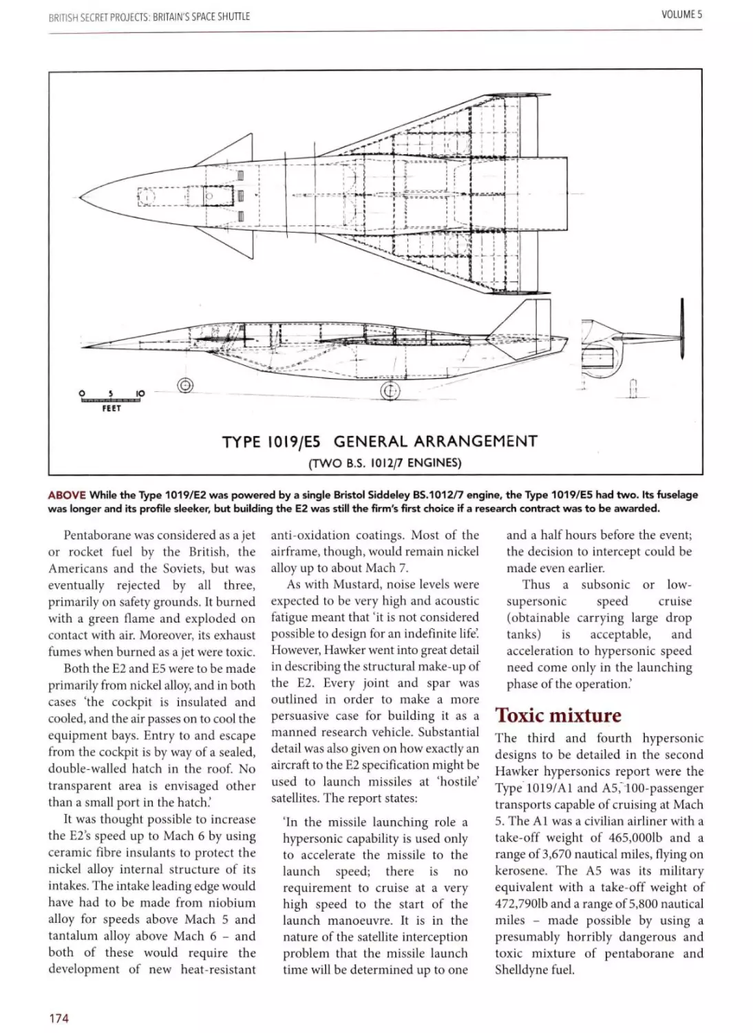
FRONT FLAP This original concept art shows
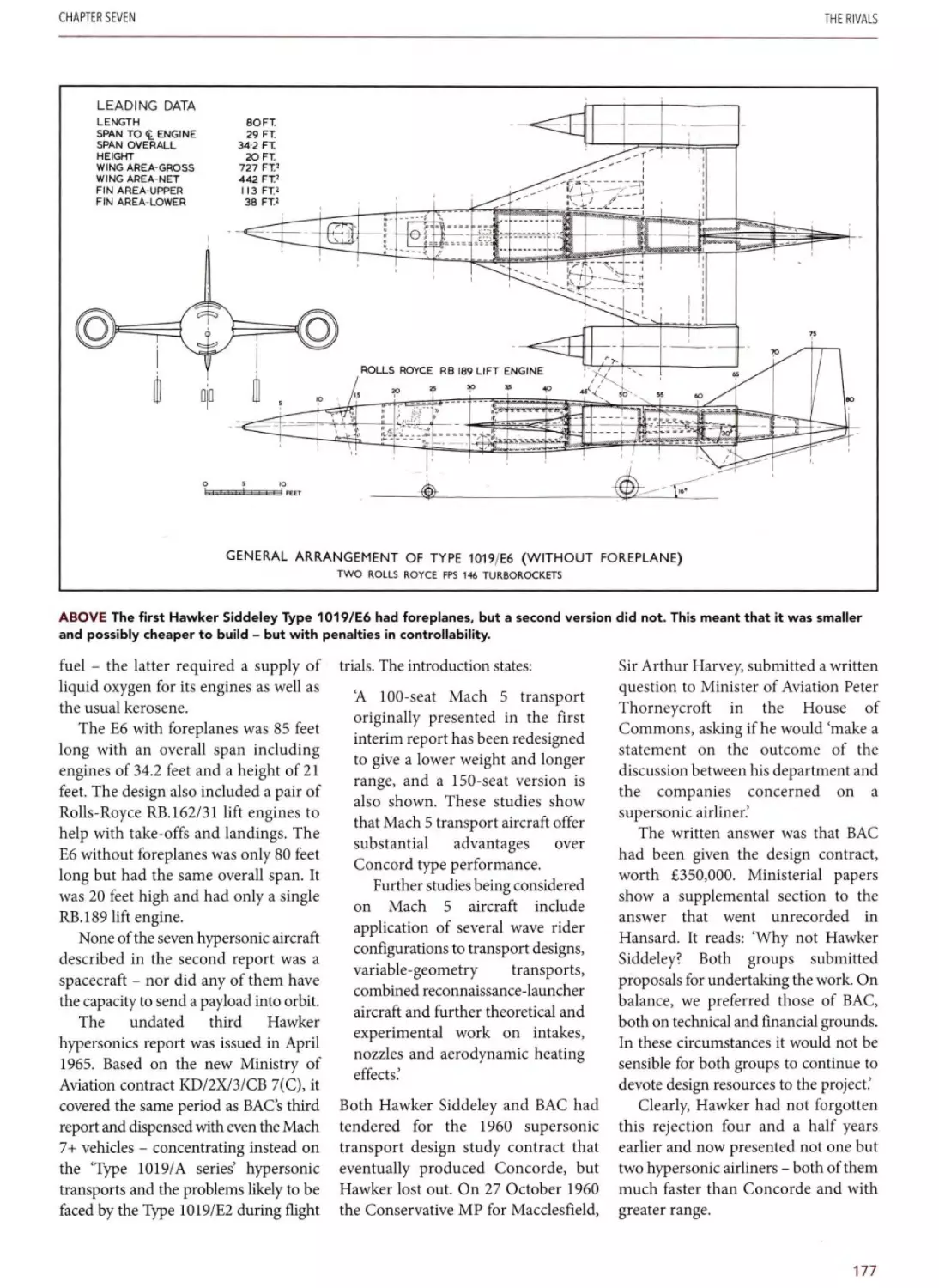
HawkerSiddeley's proposed Type 1019/E2 hypersonic
research aircraft. The drop tanks were used up in
reaching Mach 1 before being jettisoned as the aircraft
passed the sound barrier and accelerated towards
Mach 5.
BACK FLAP
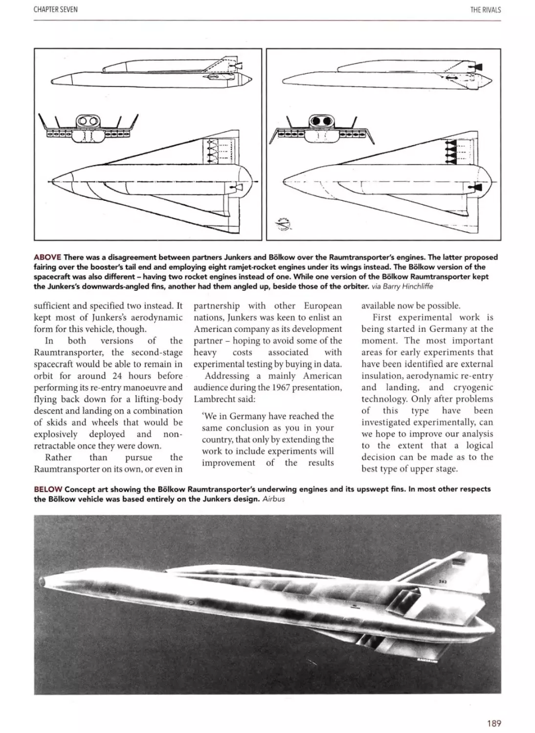
TOP While one version of the Bolkow Raumtransporter
kept the Junkers's downwards-angled fins, this had them
angled up, beside those of the orbiter, via Barry Hinchliffe
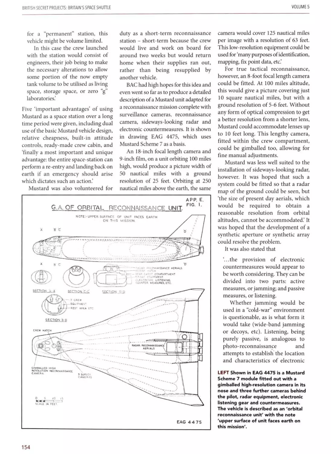
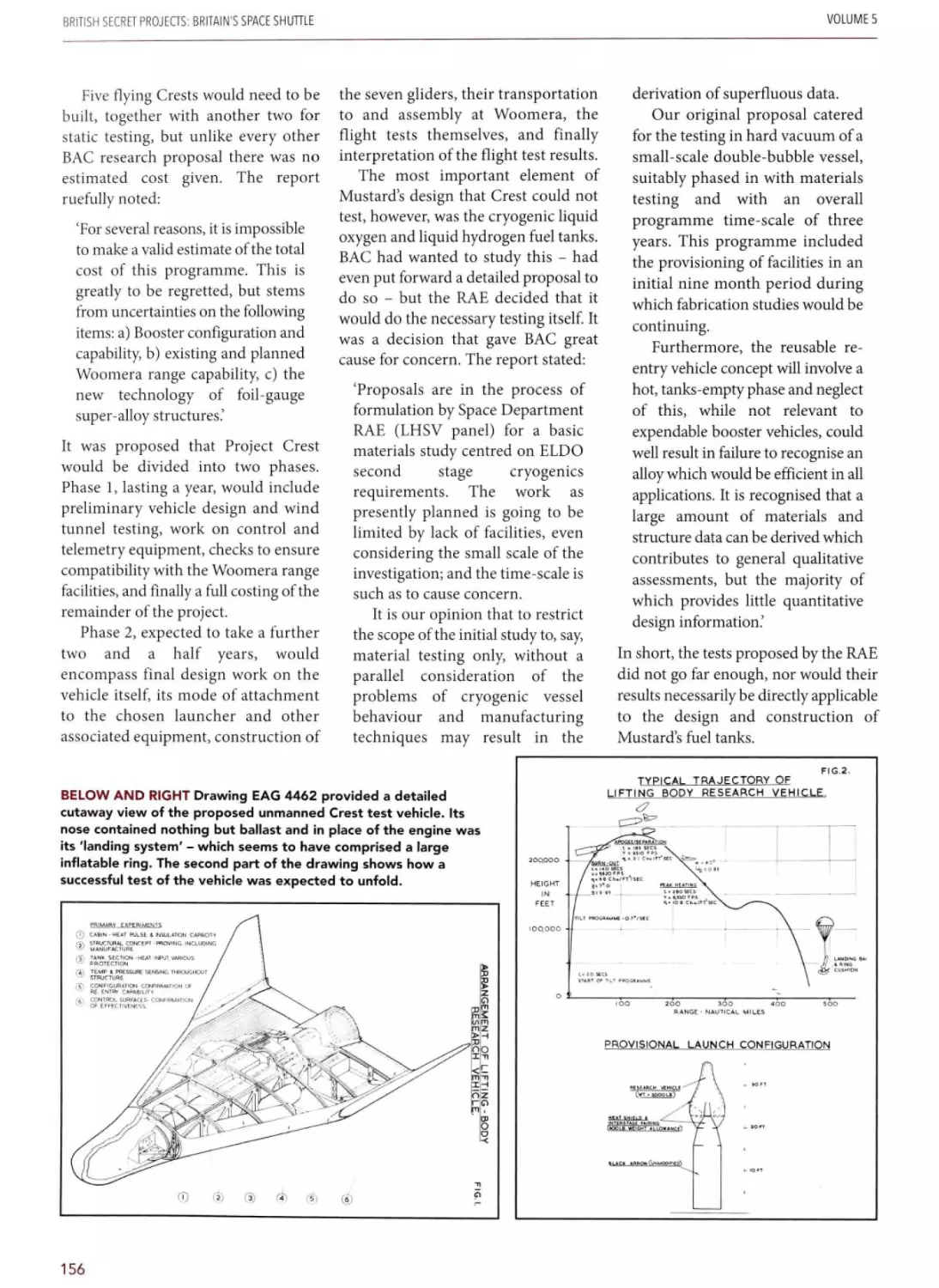
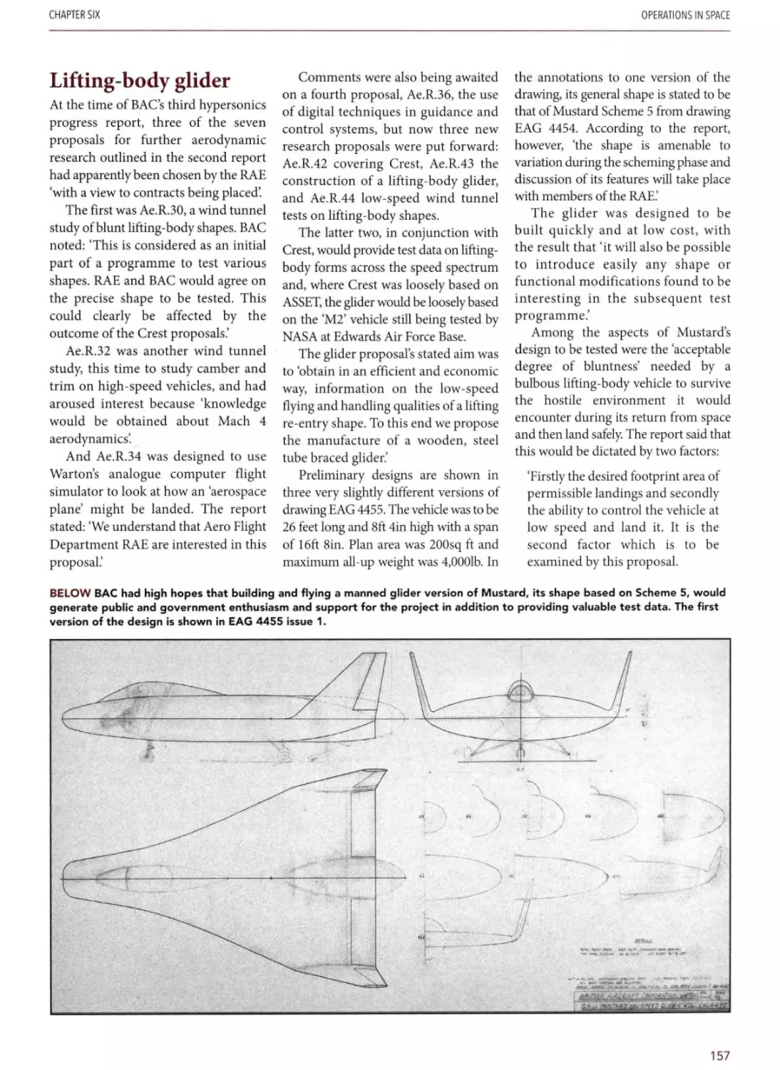
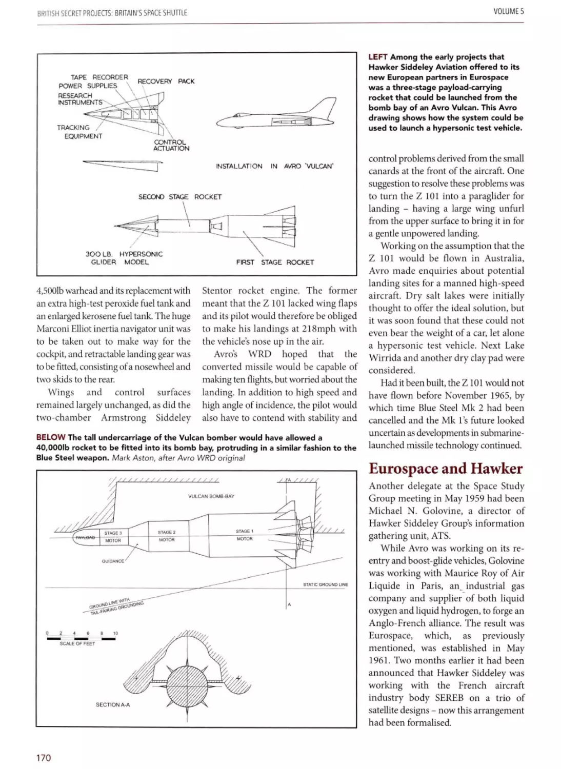
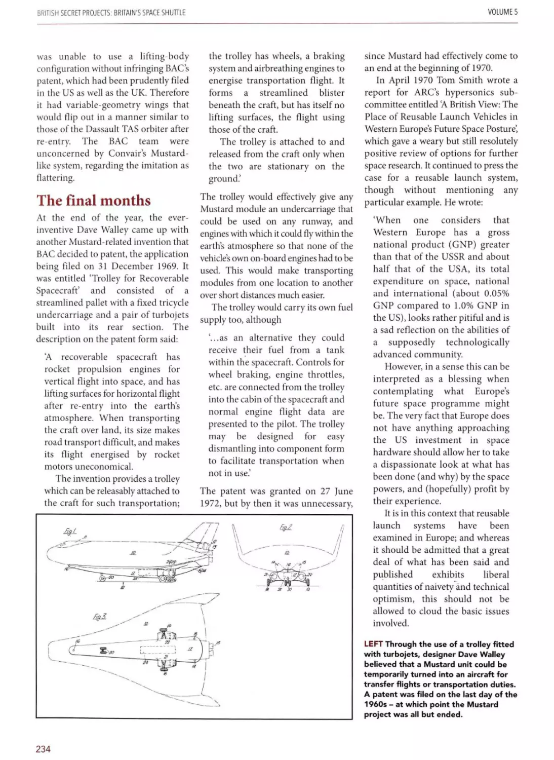
BOTTOM Drawing EAG 4462 provided a detailed
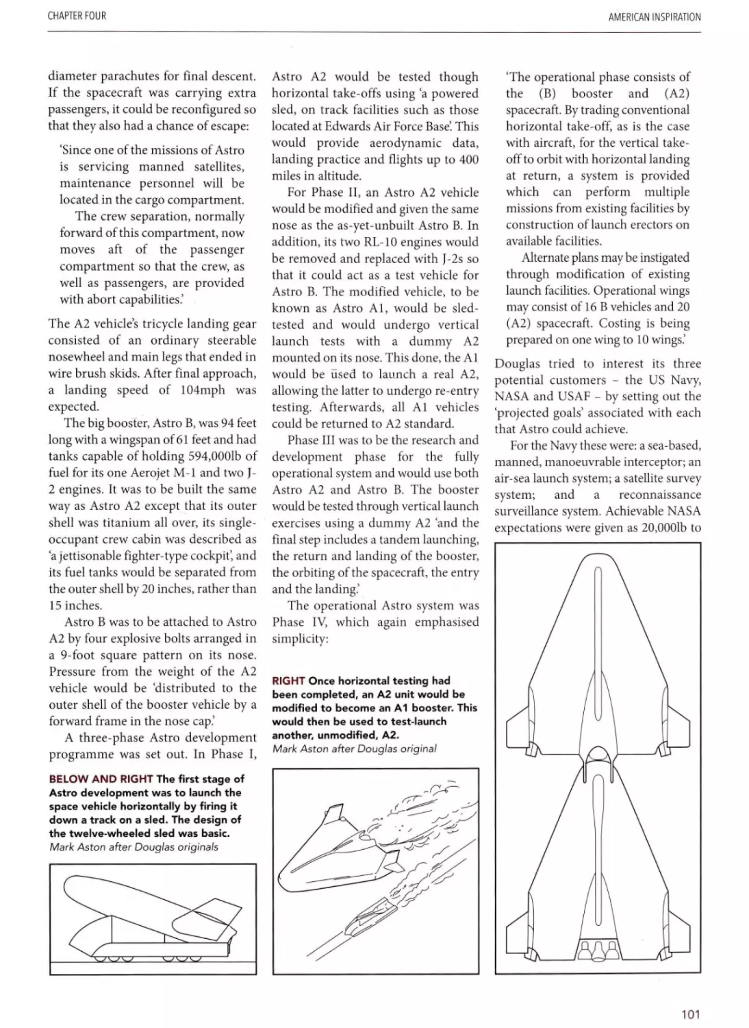
cutaway view of the proposed unmanned Crest test
vehicle. Its nose contained nothing but ballast and in
place of the engine was its 'landing system' - which
seems to have comprised a large inflatable ring.
Research has brought to light many contemporary and
rare documents and images of varying quality. They are
reproduced and have been enhanced as far as possible.
Contents
Introduction...........................................................................6
Acknowledgements.......................................................................7
Chapter 1 The rise of English Electric..............................................8
From the Second World War to Very High Speed Vehicles
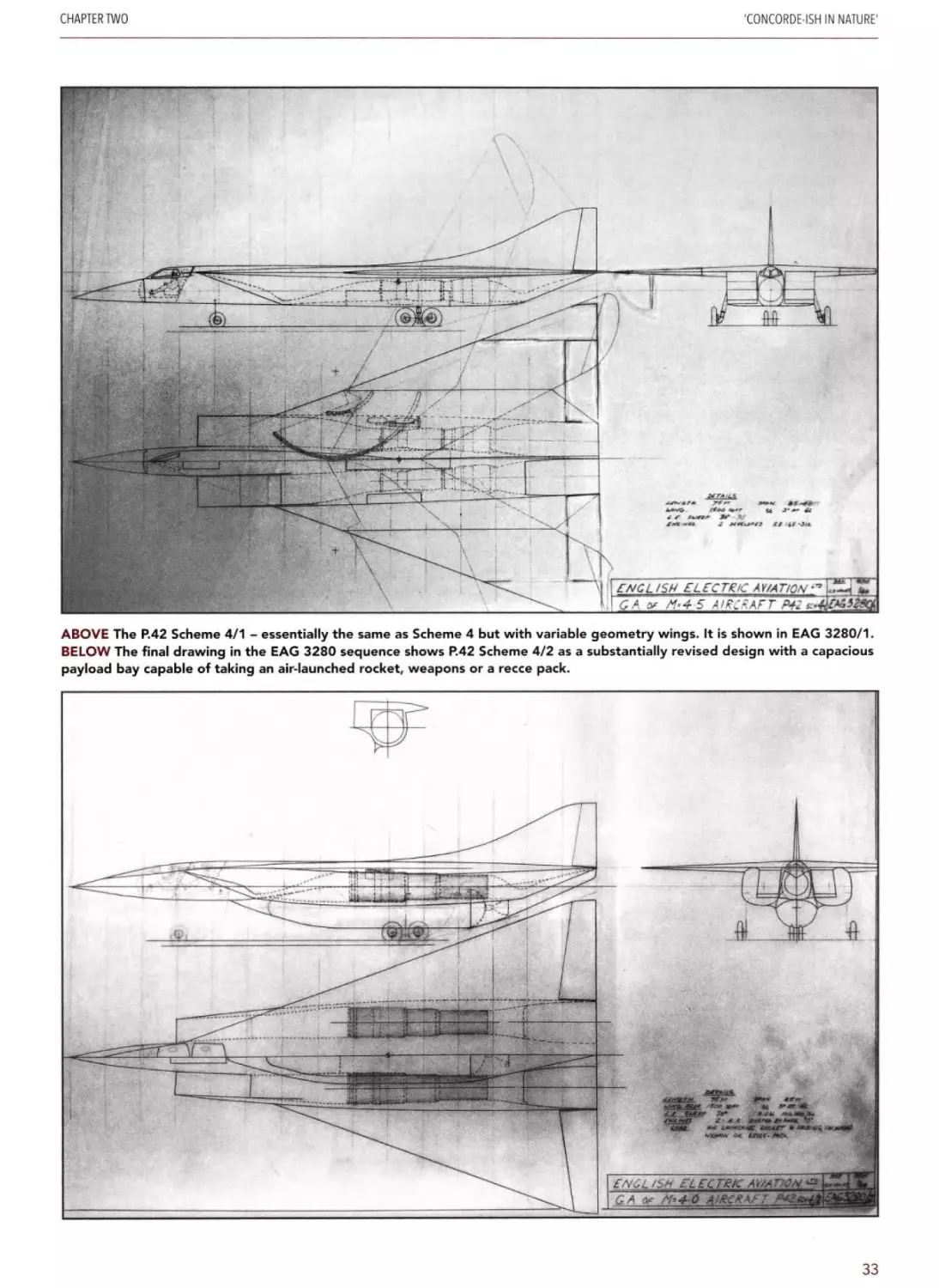
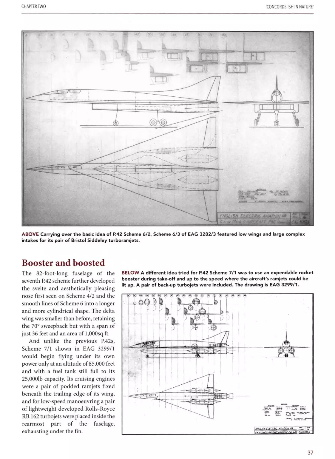
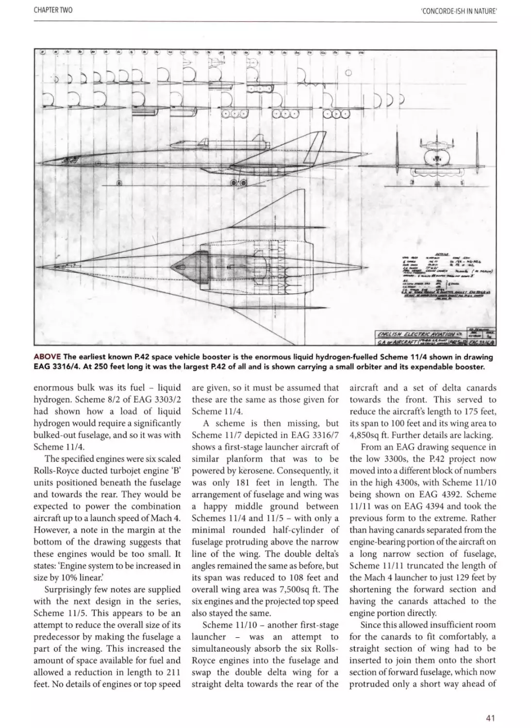
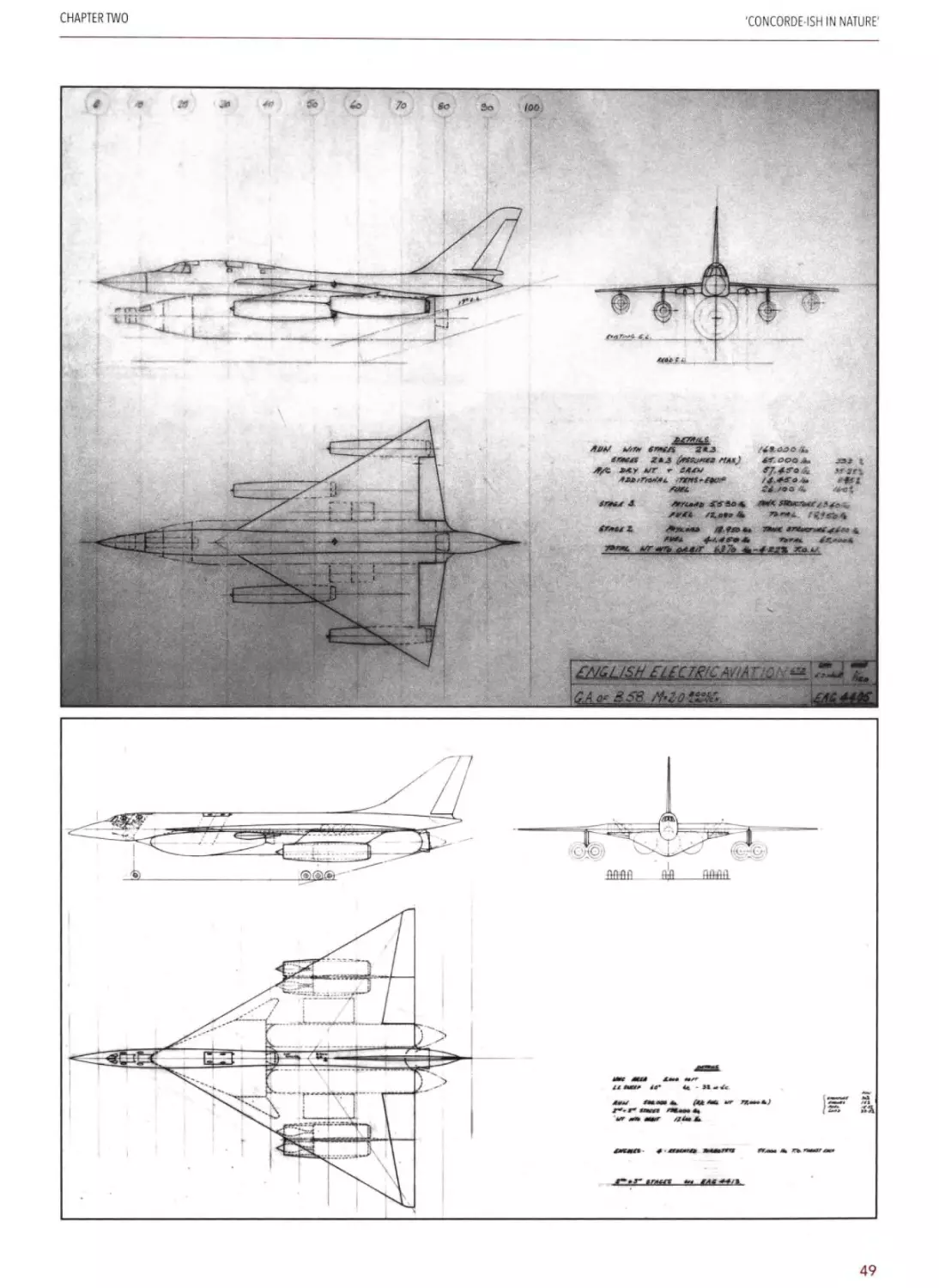
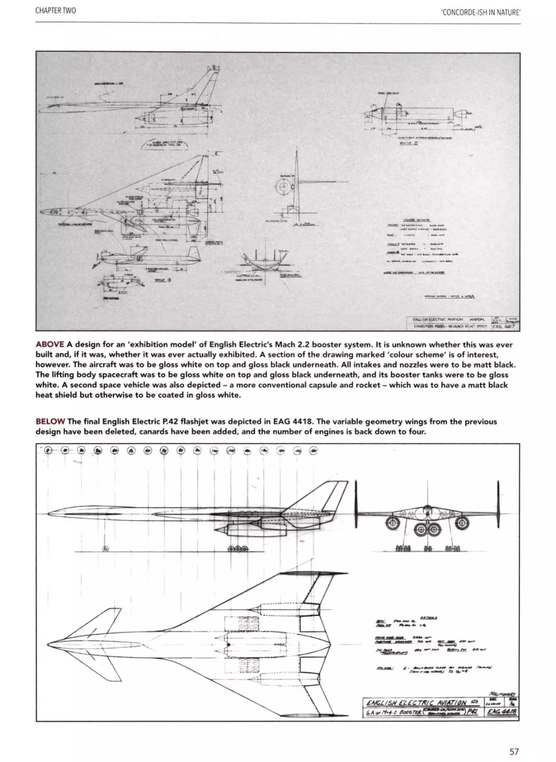
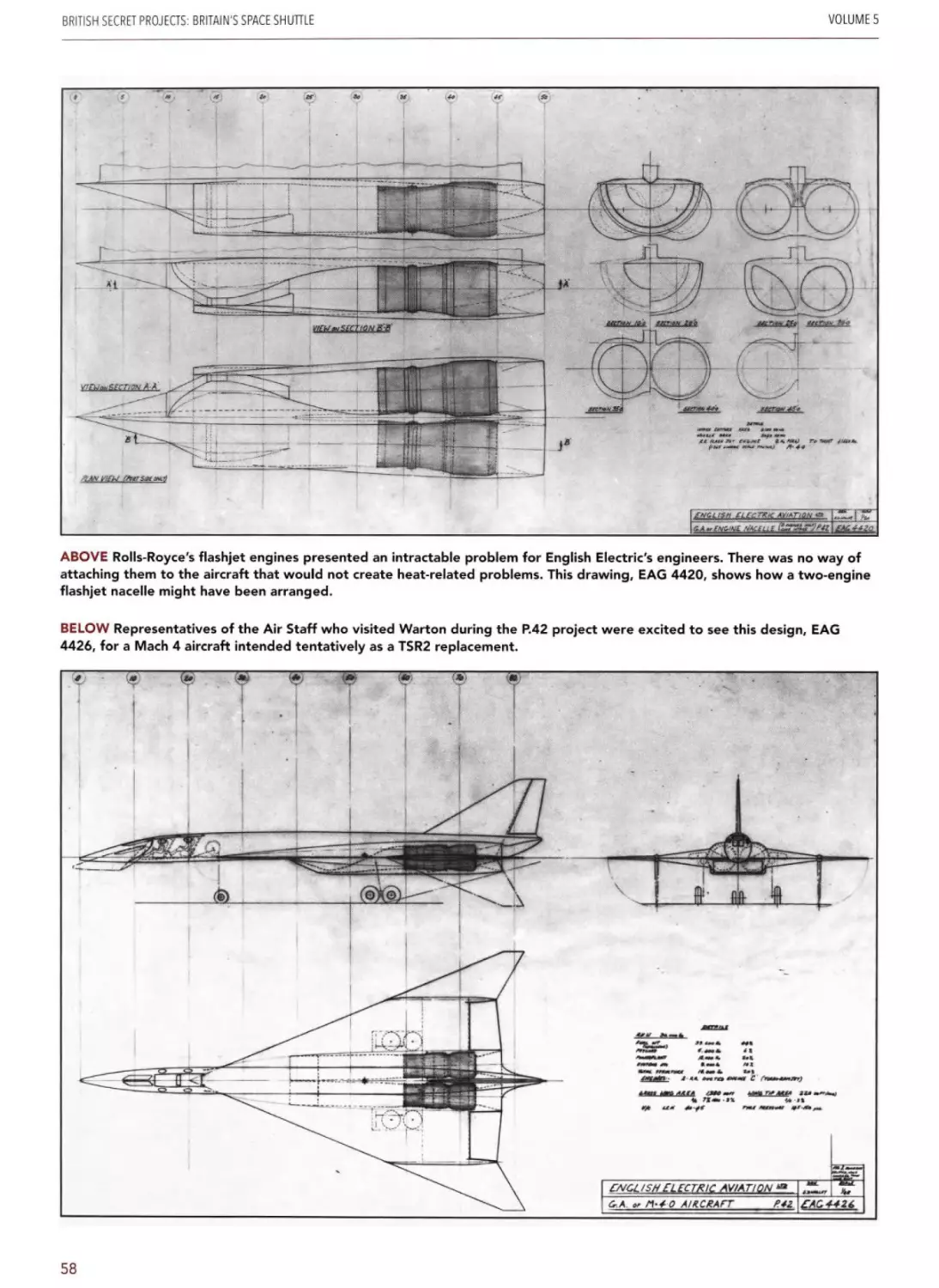
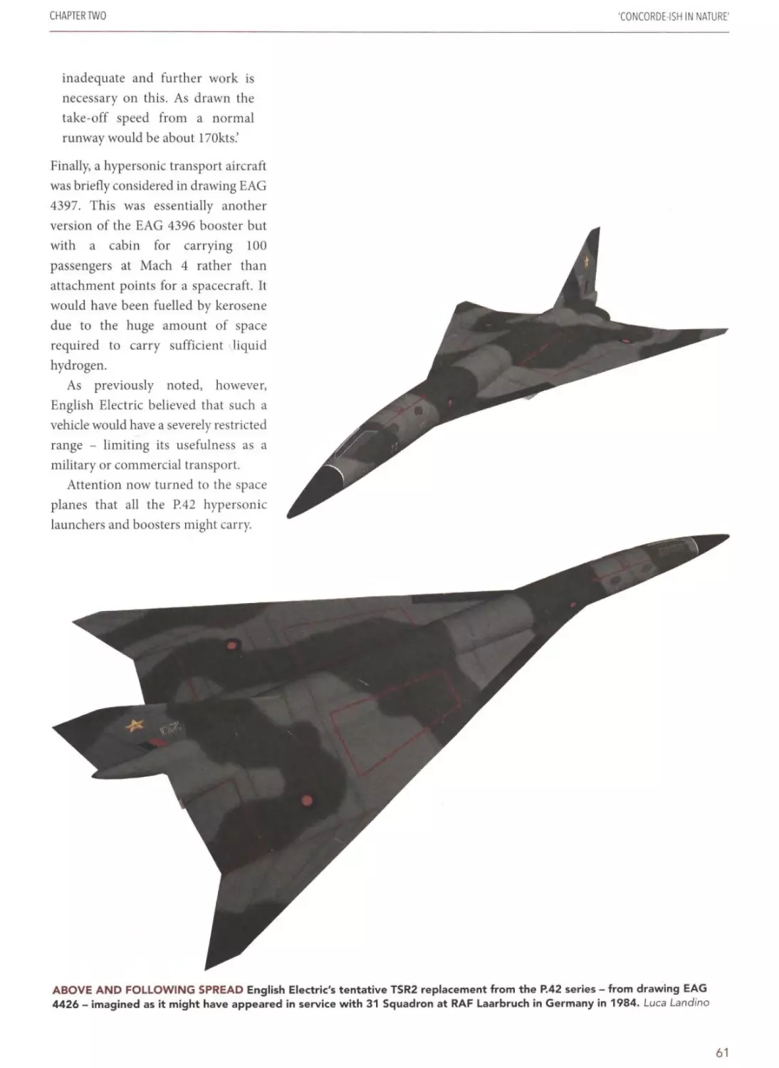
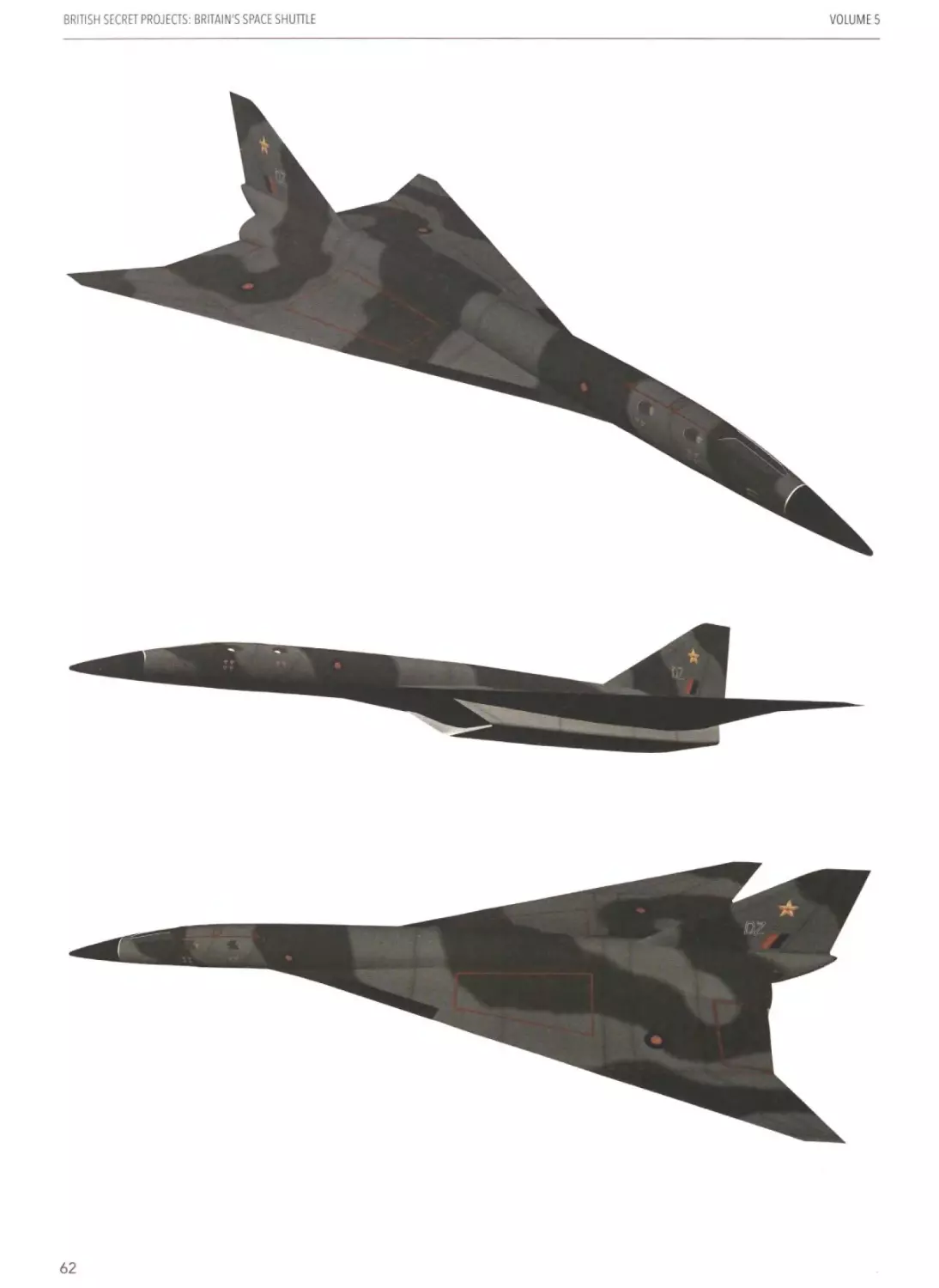
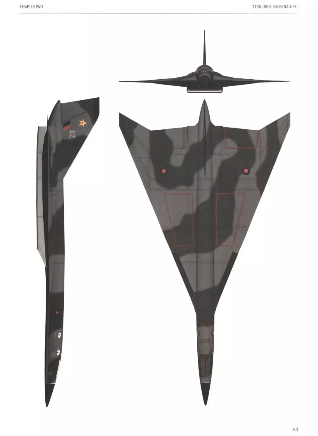
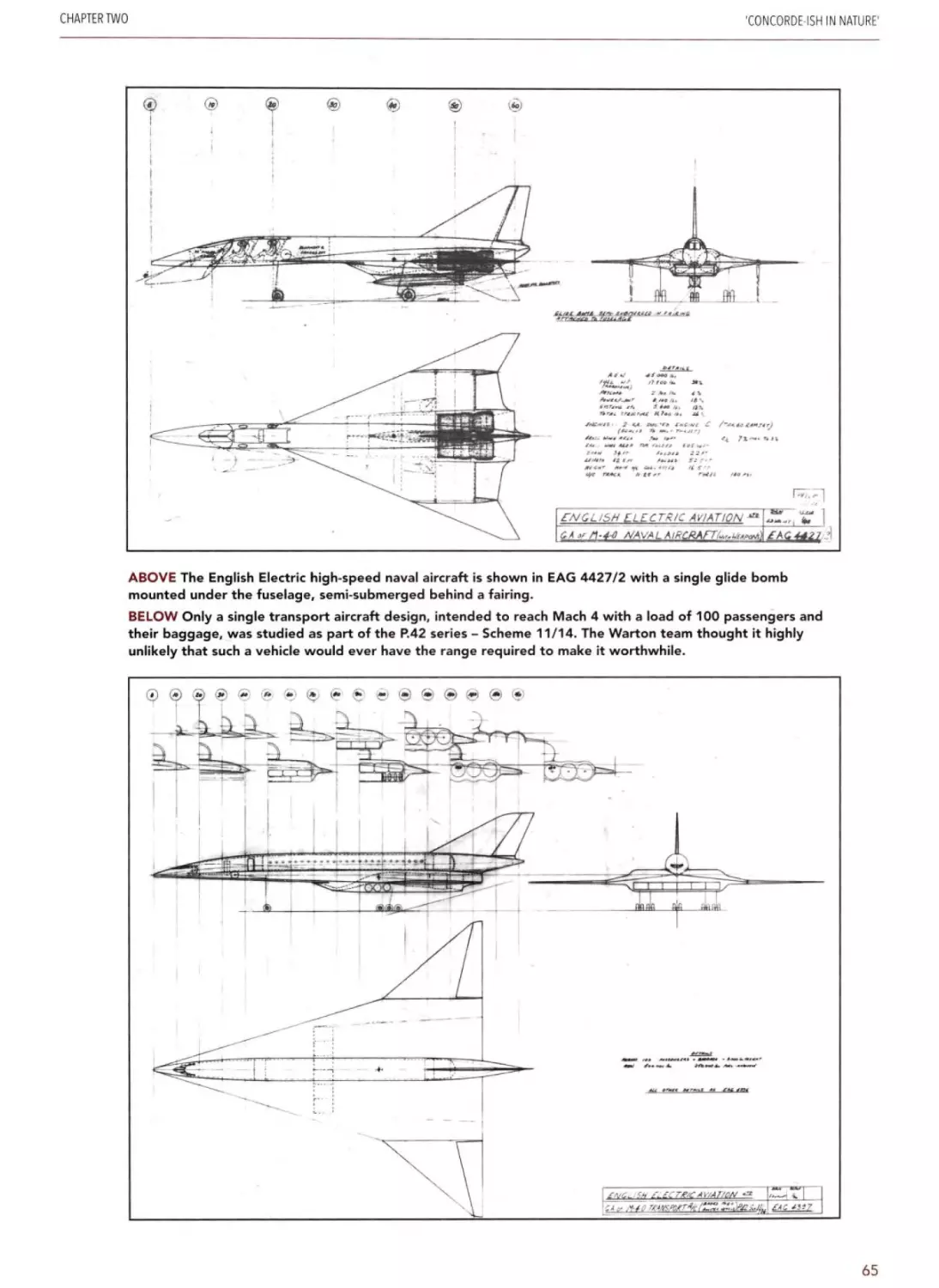
Chapter 2 ‘Concorde-ish in nature’.................................................27
English Electric P.42 aircraft
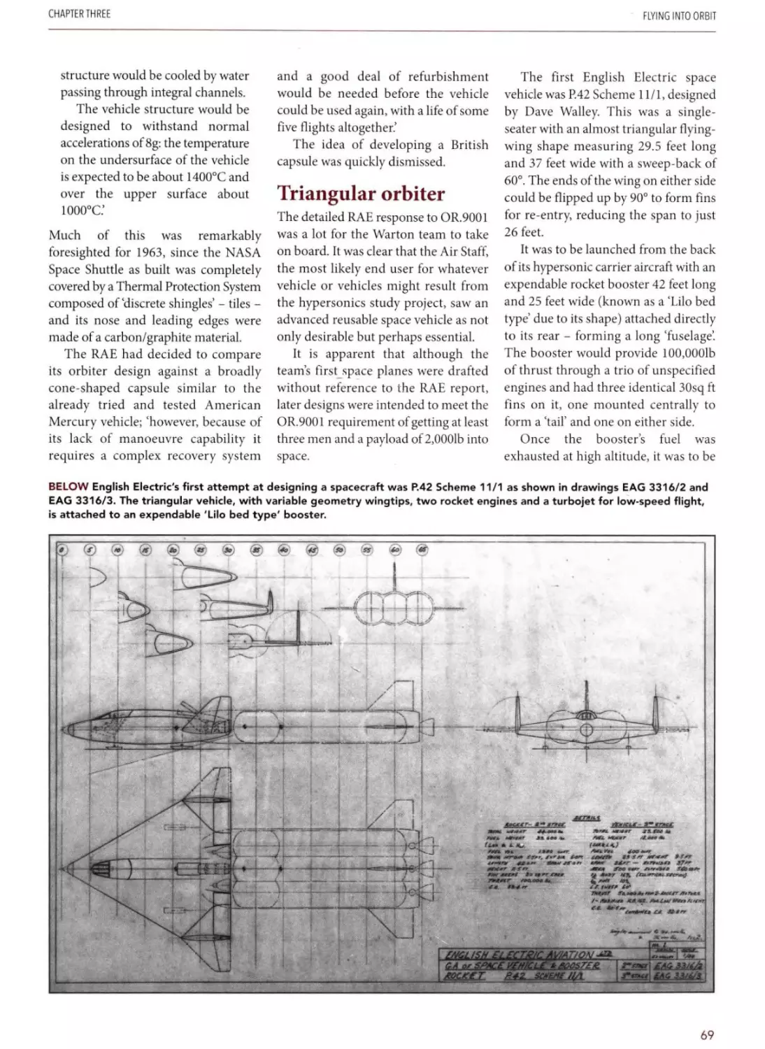
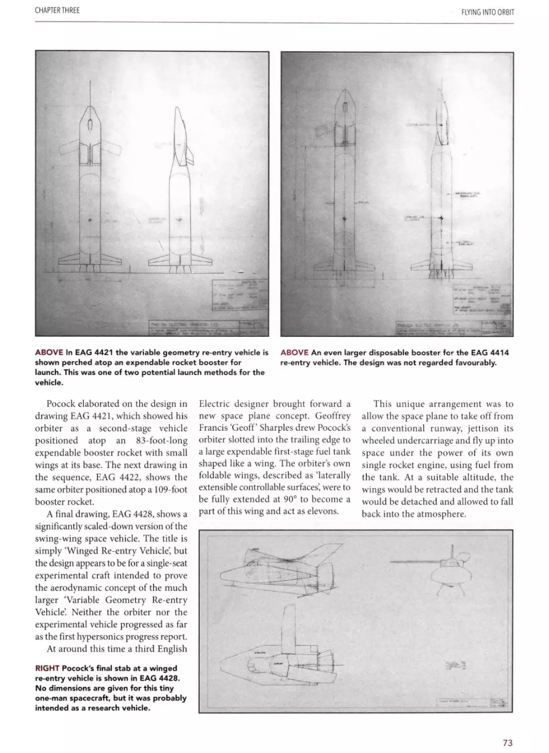
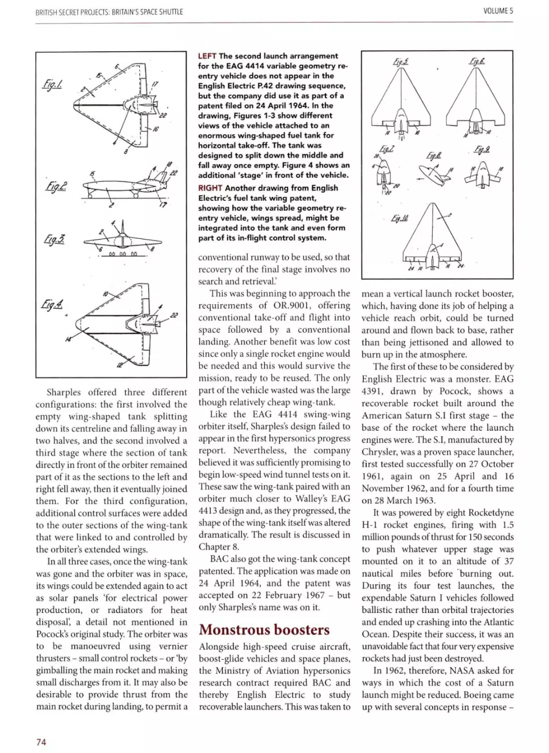
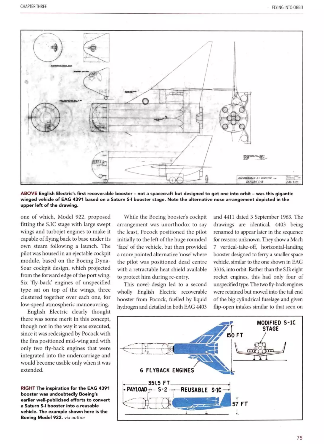
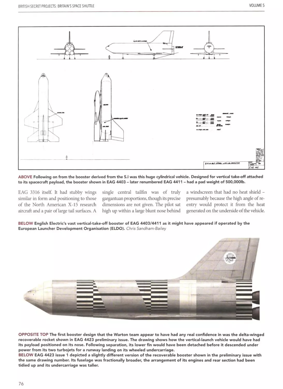
Chapter? Flying into orbit........................................................66
English Electric P.42 space planes
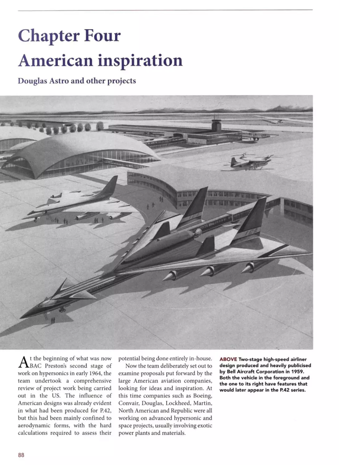
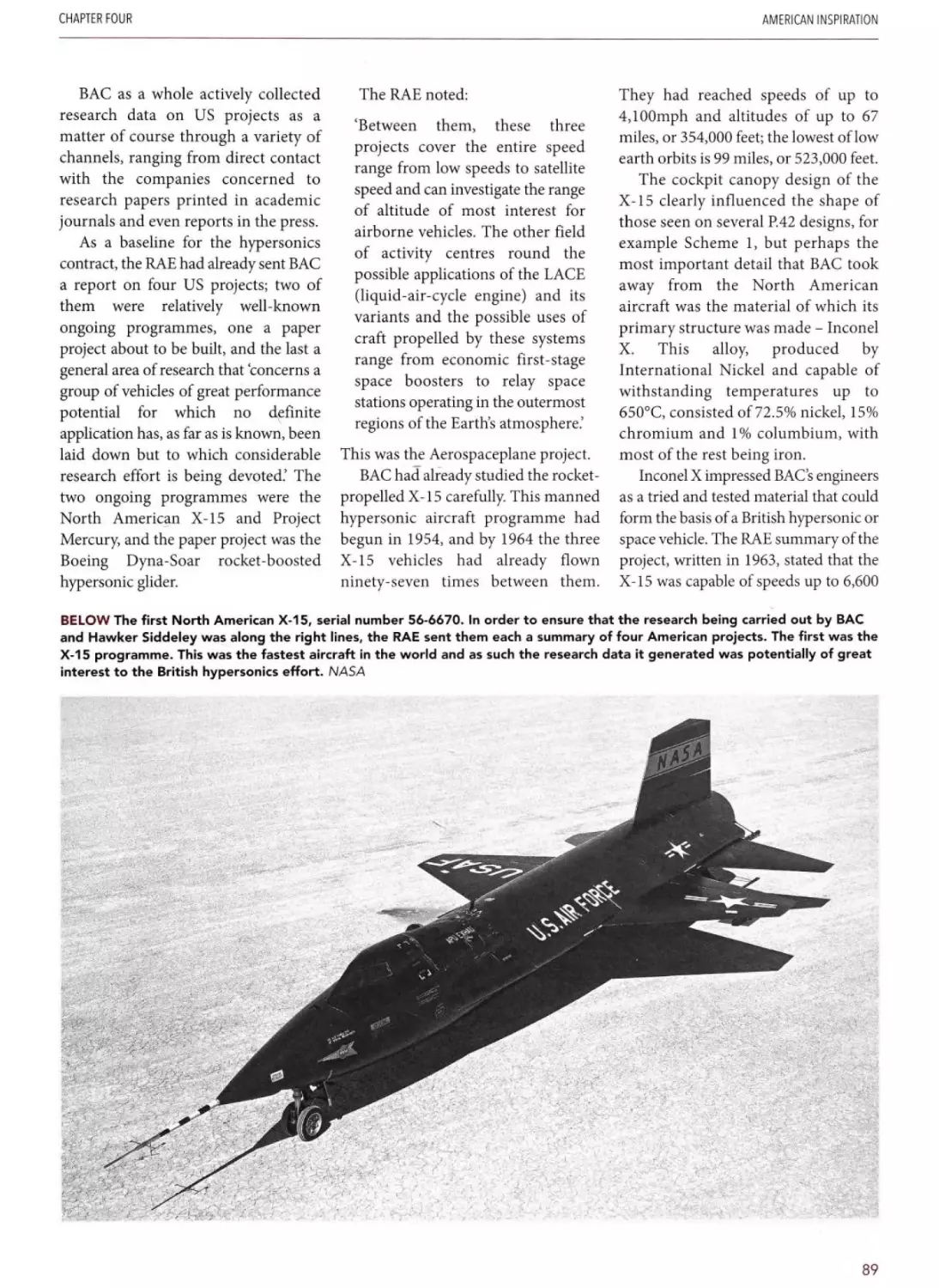
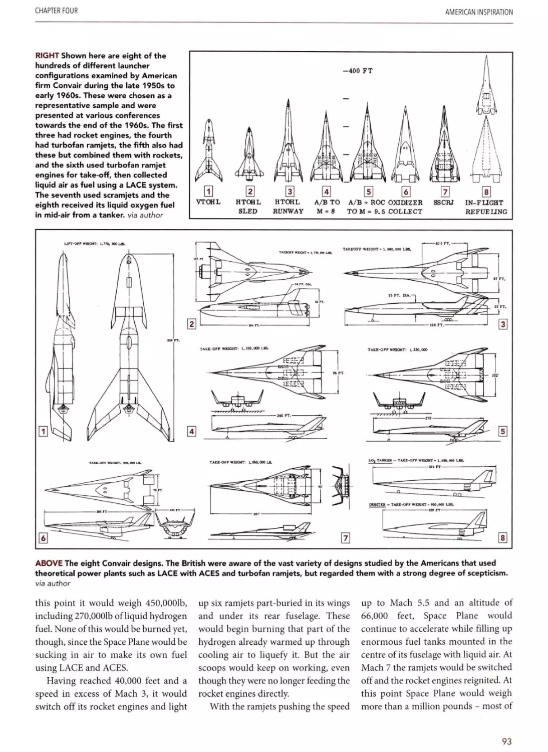
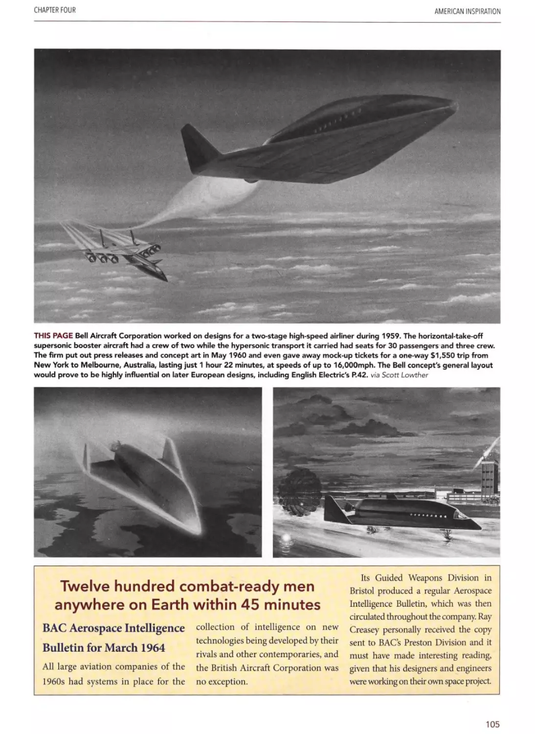
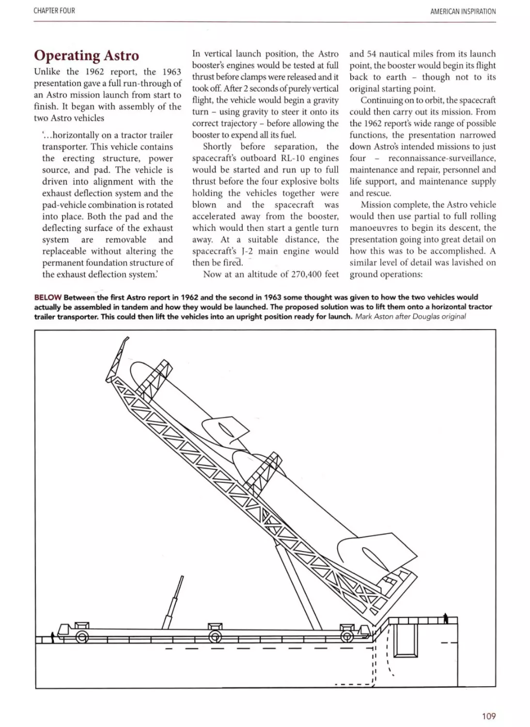
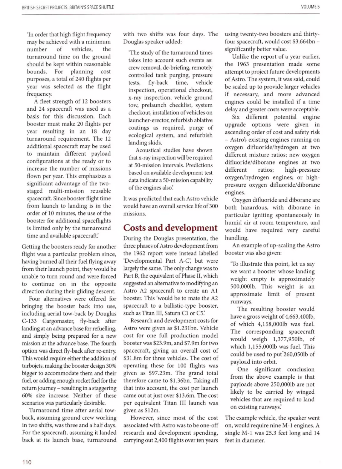
Chapter 4 American inspiration.....................................................88
Douglas Astro and other projects
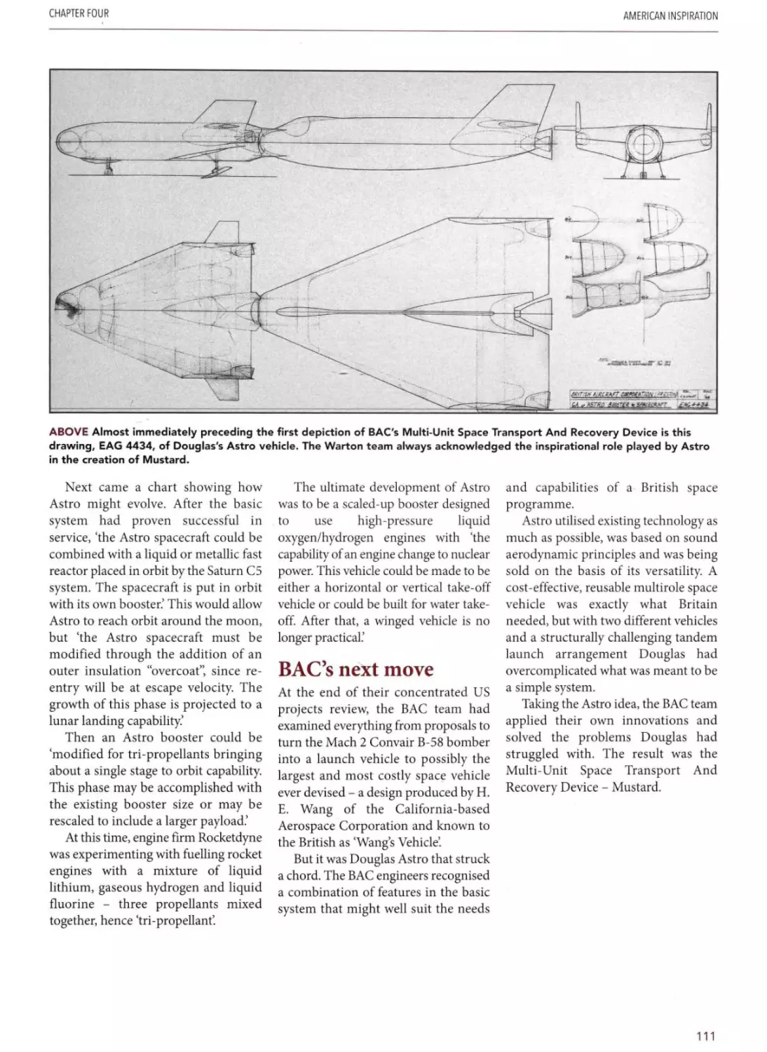
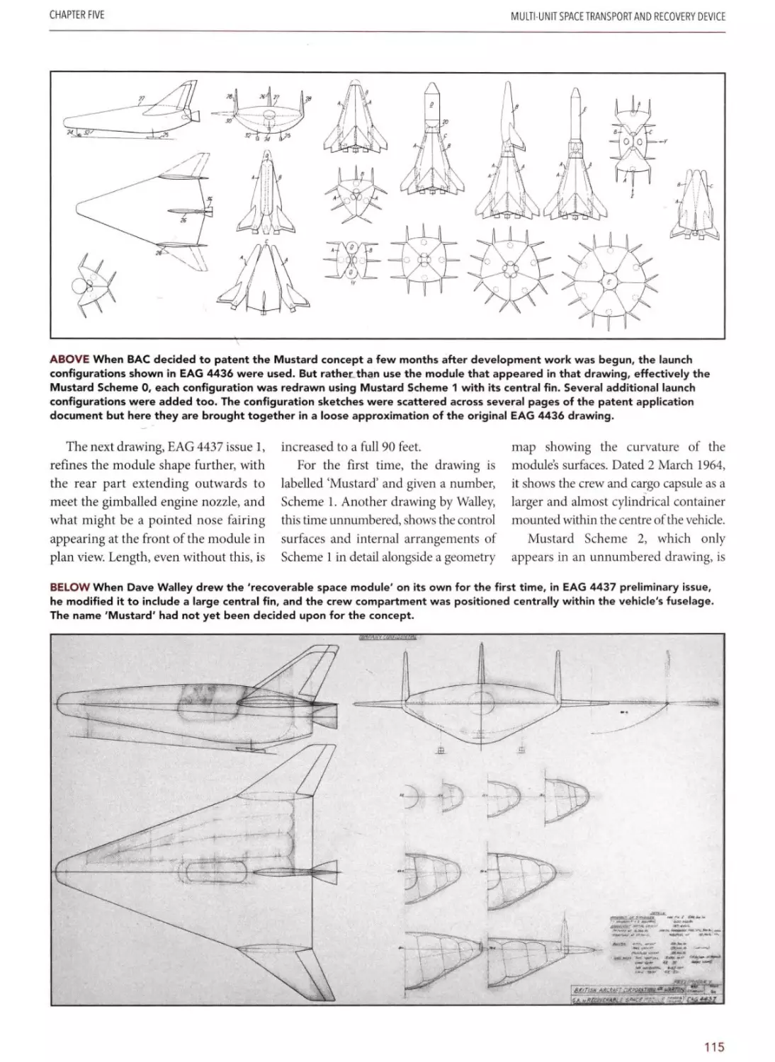
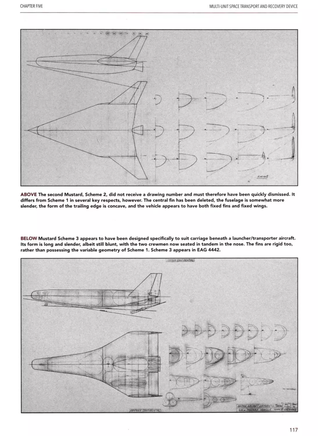
Chapter 5 Multi-Unit Space Transport And Recovery Device..........................112
ВАС Mustard 1964
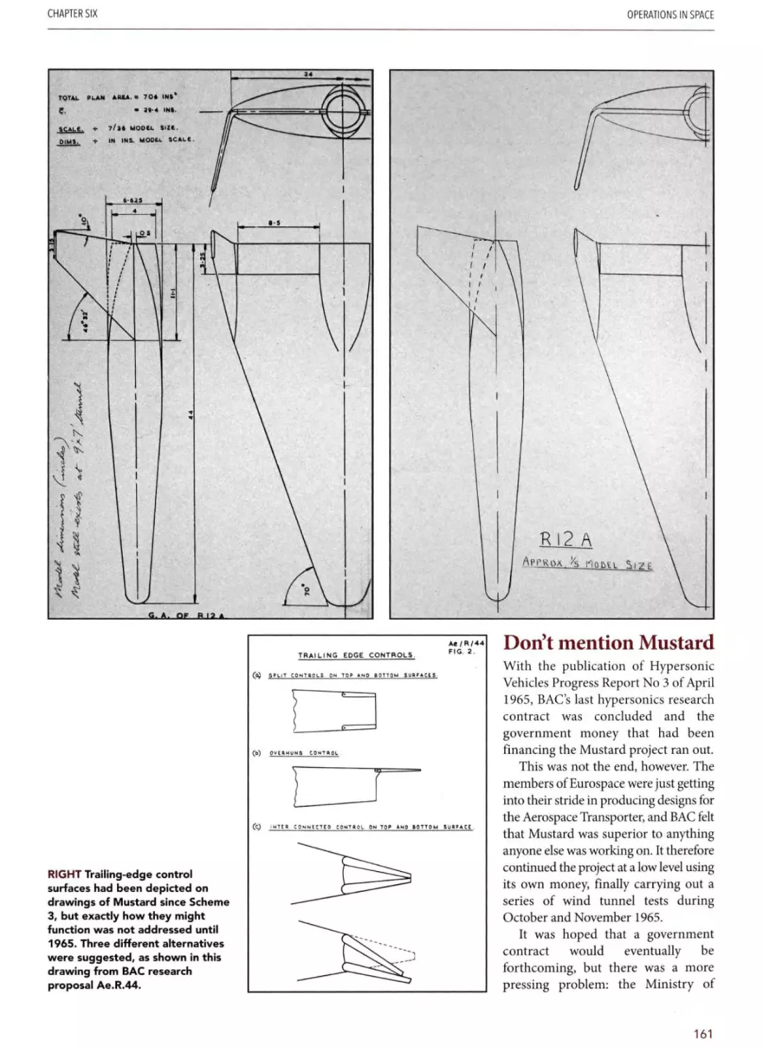
Chapter 6 Operations in space......................................................138
ВАС Mustard 1965
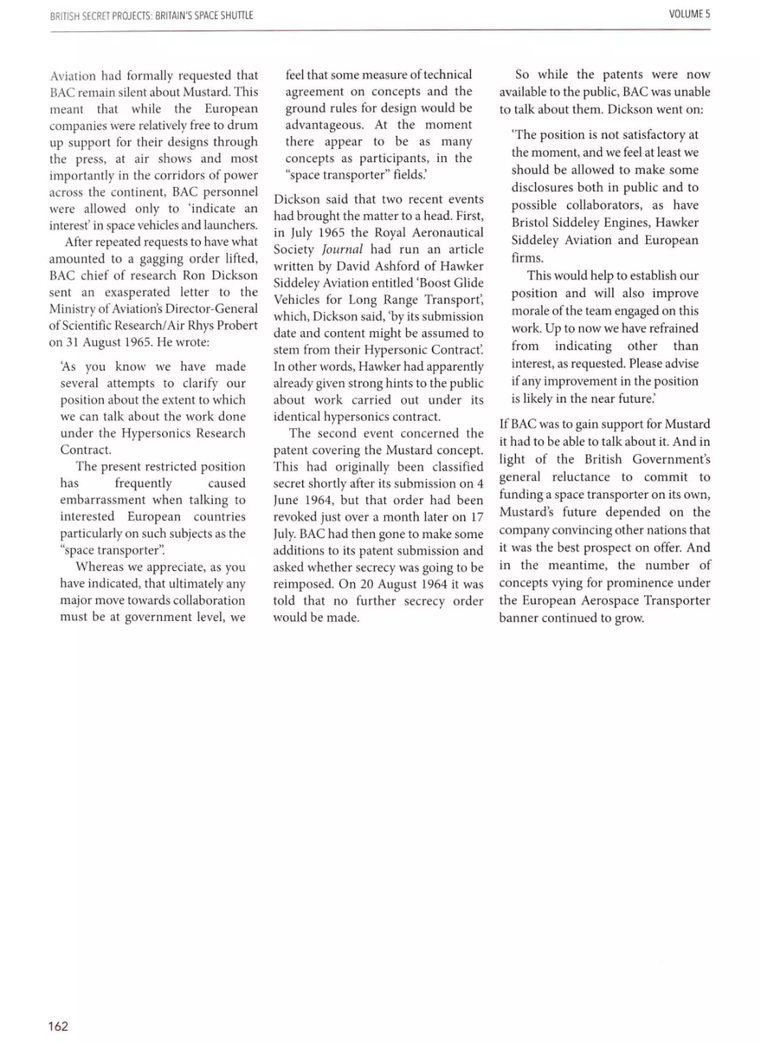
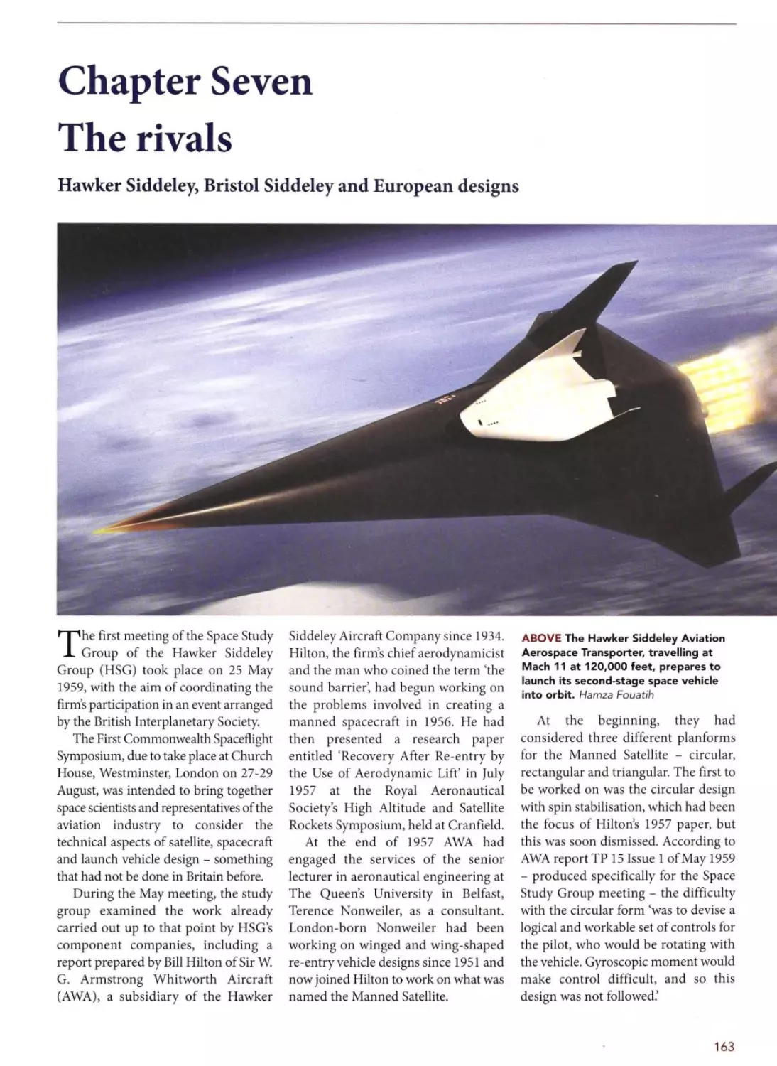
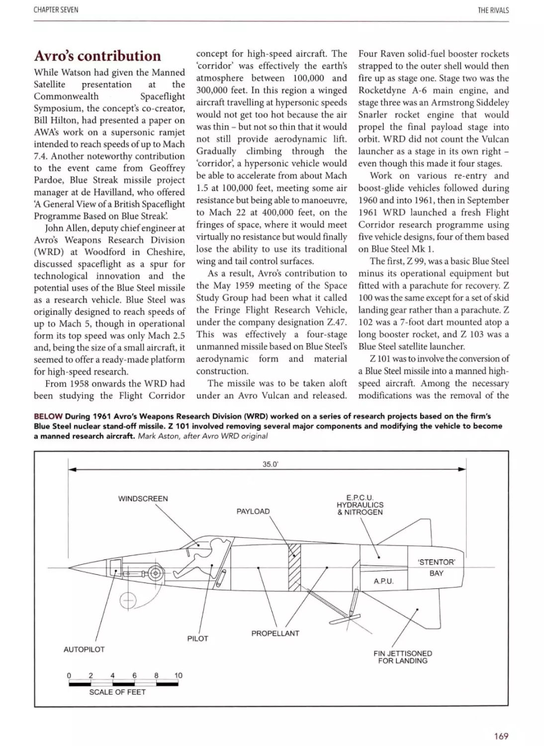
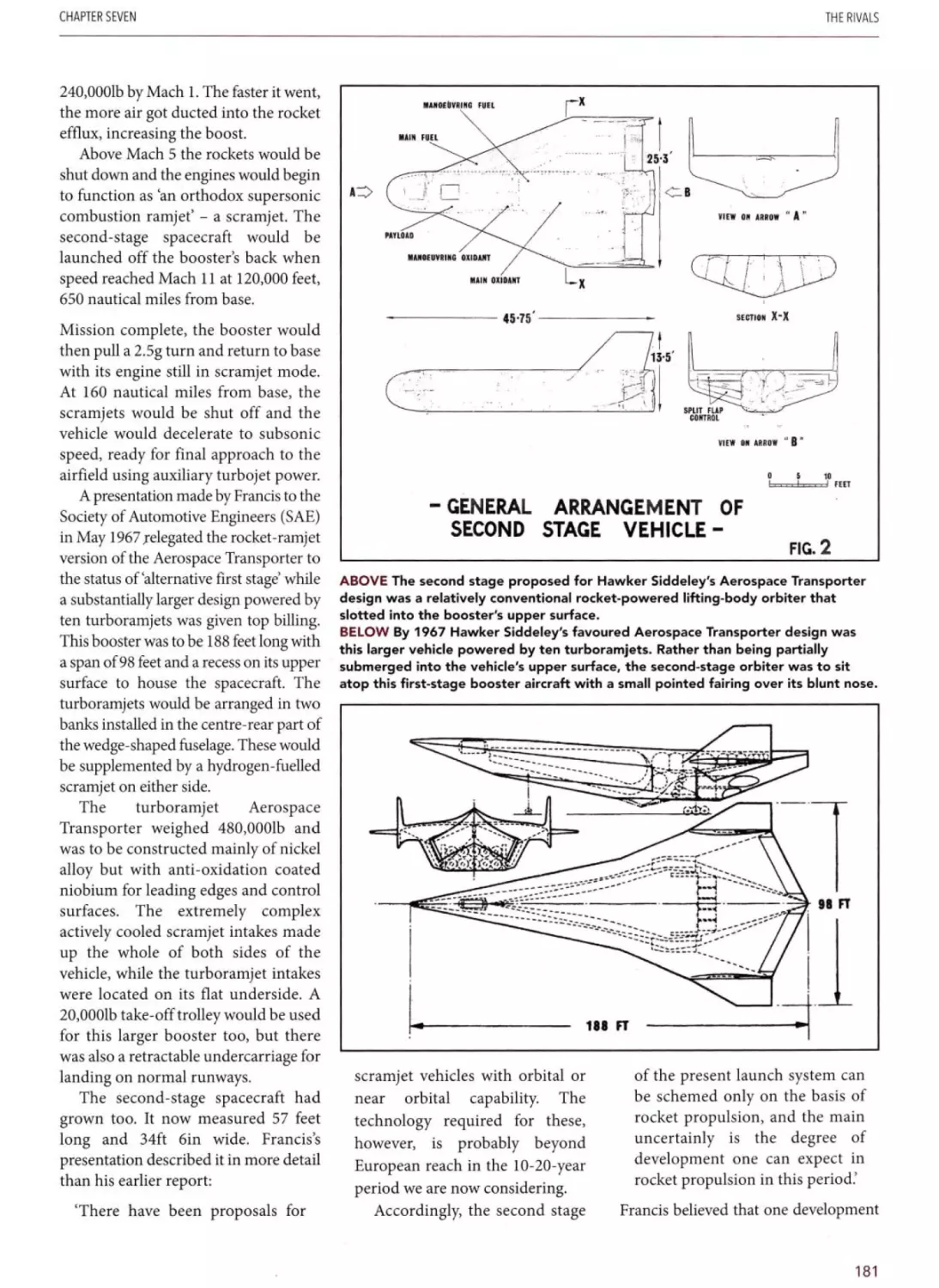
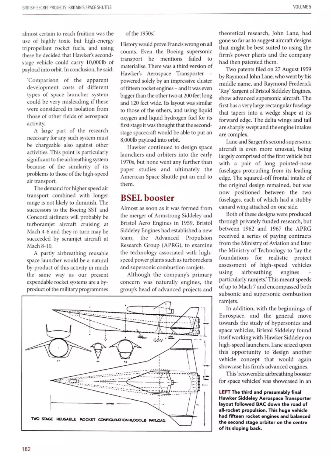
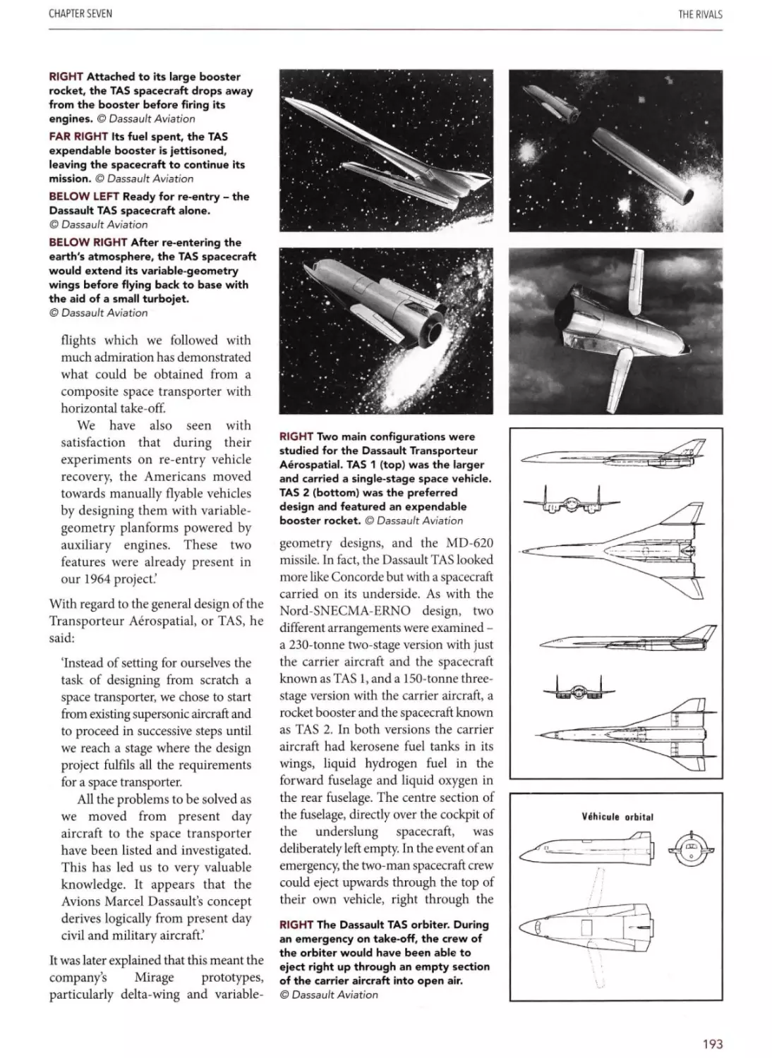
Chapter 7 The rivals...............................................................163
Hawker Siddeley, Bristol Siddeley and European designs
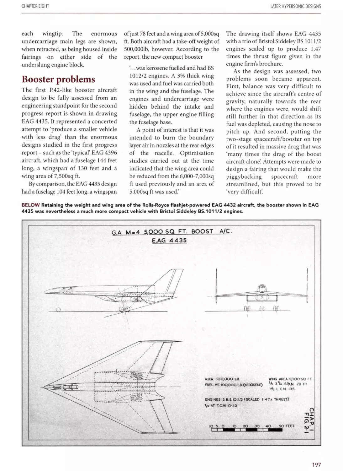
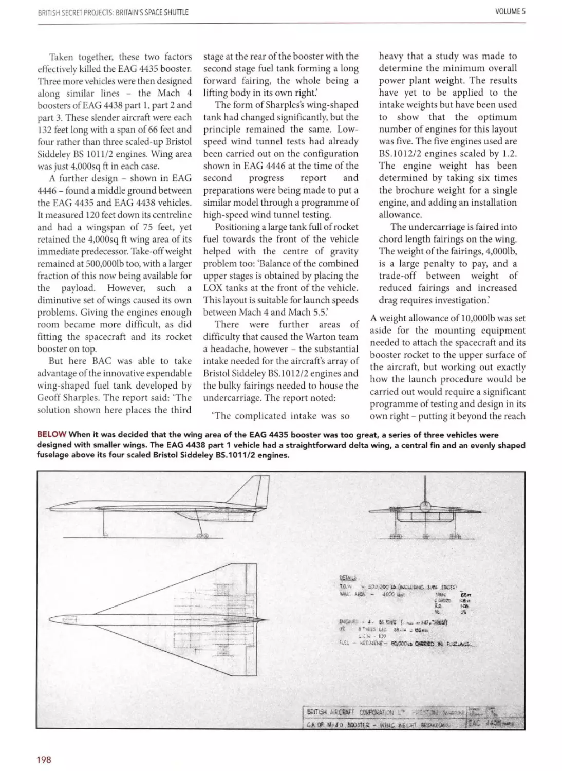
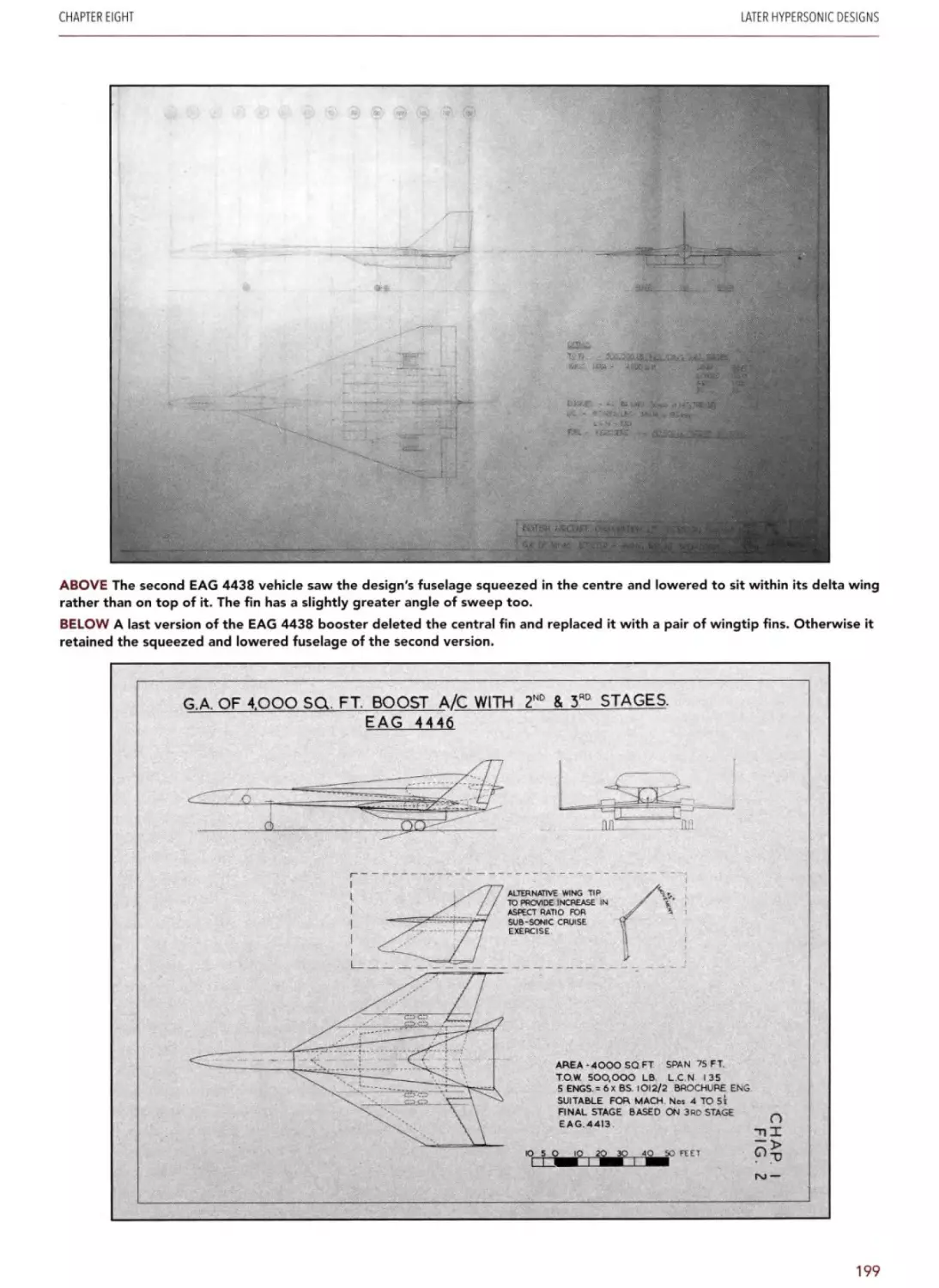
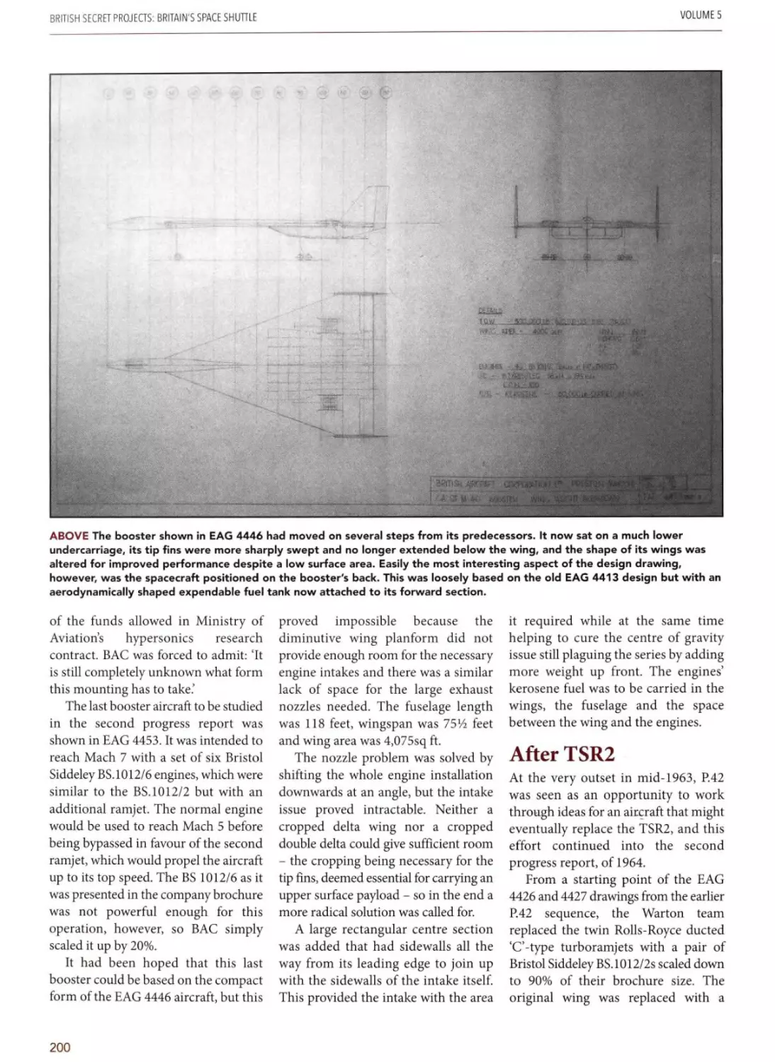
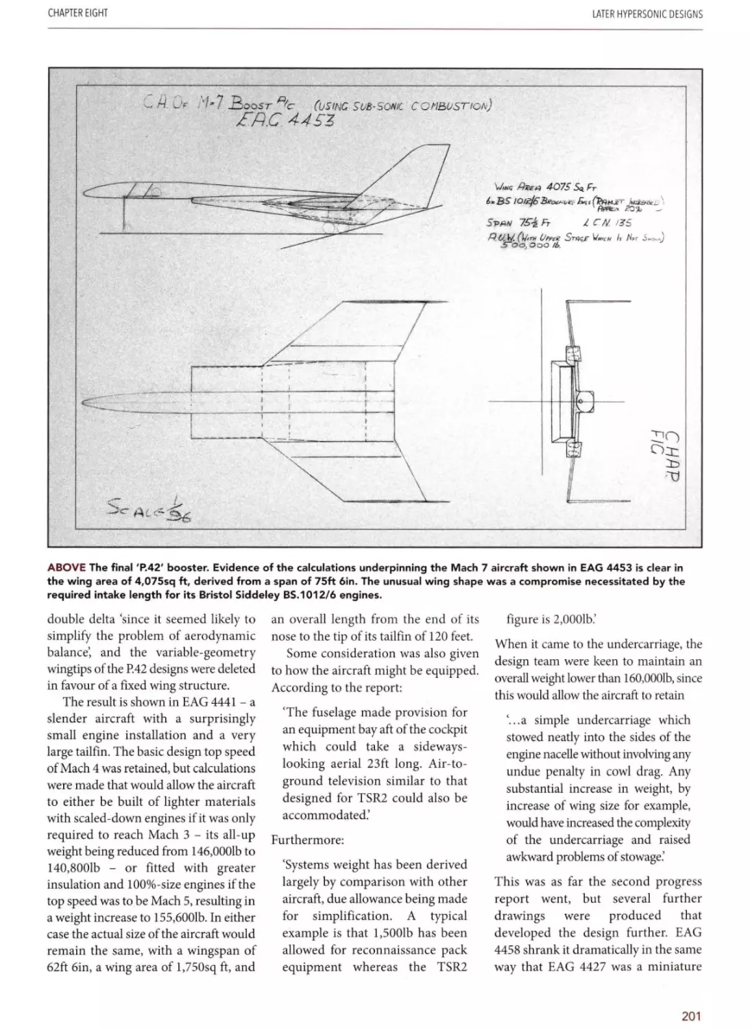
Chapter 8 Later hypersonic designs.................................................195
P.42 under ВАС
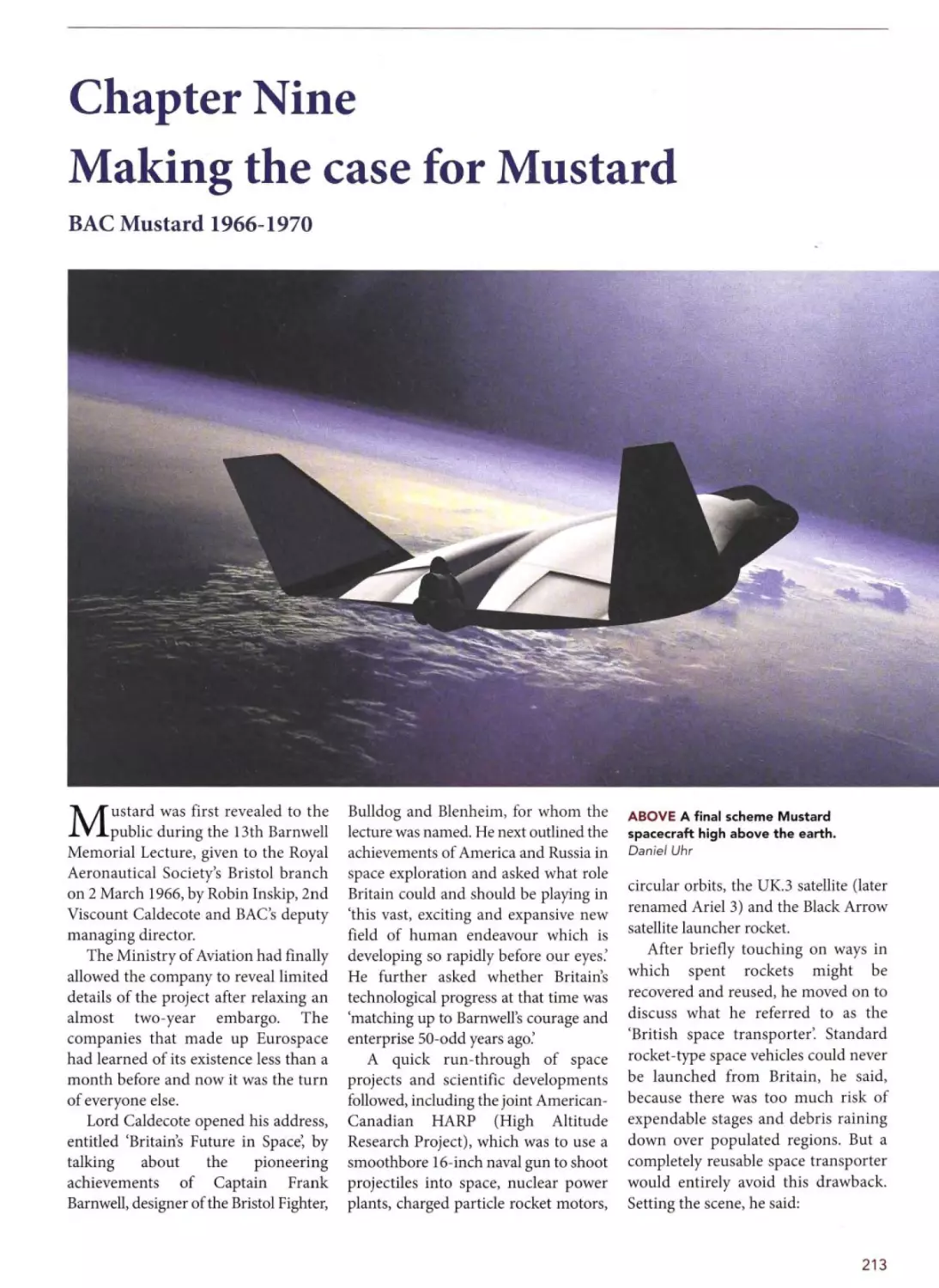
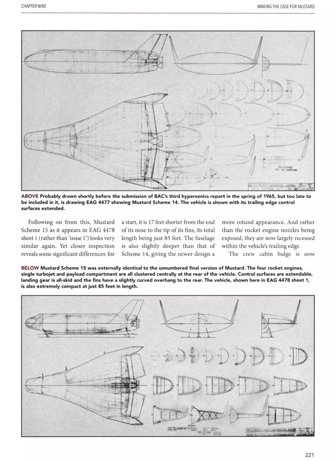
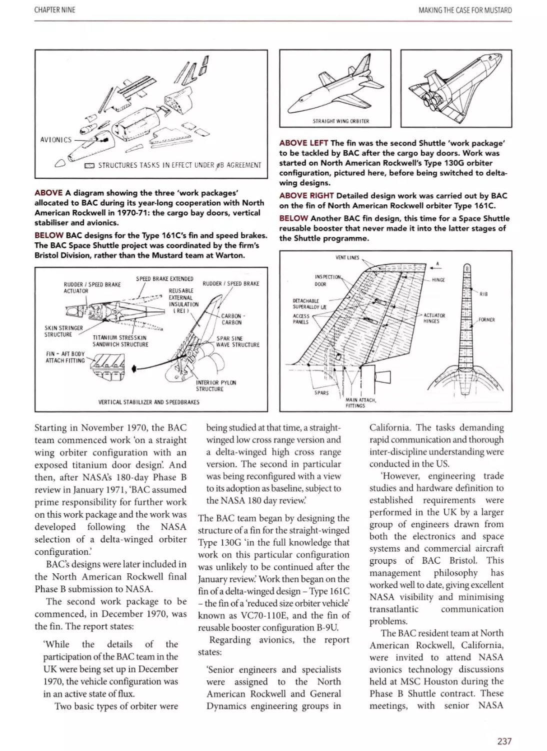
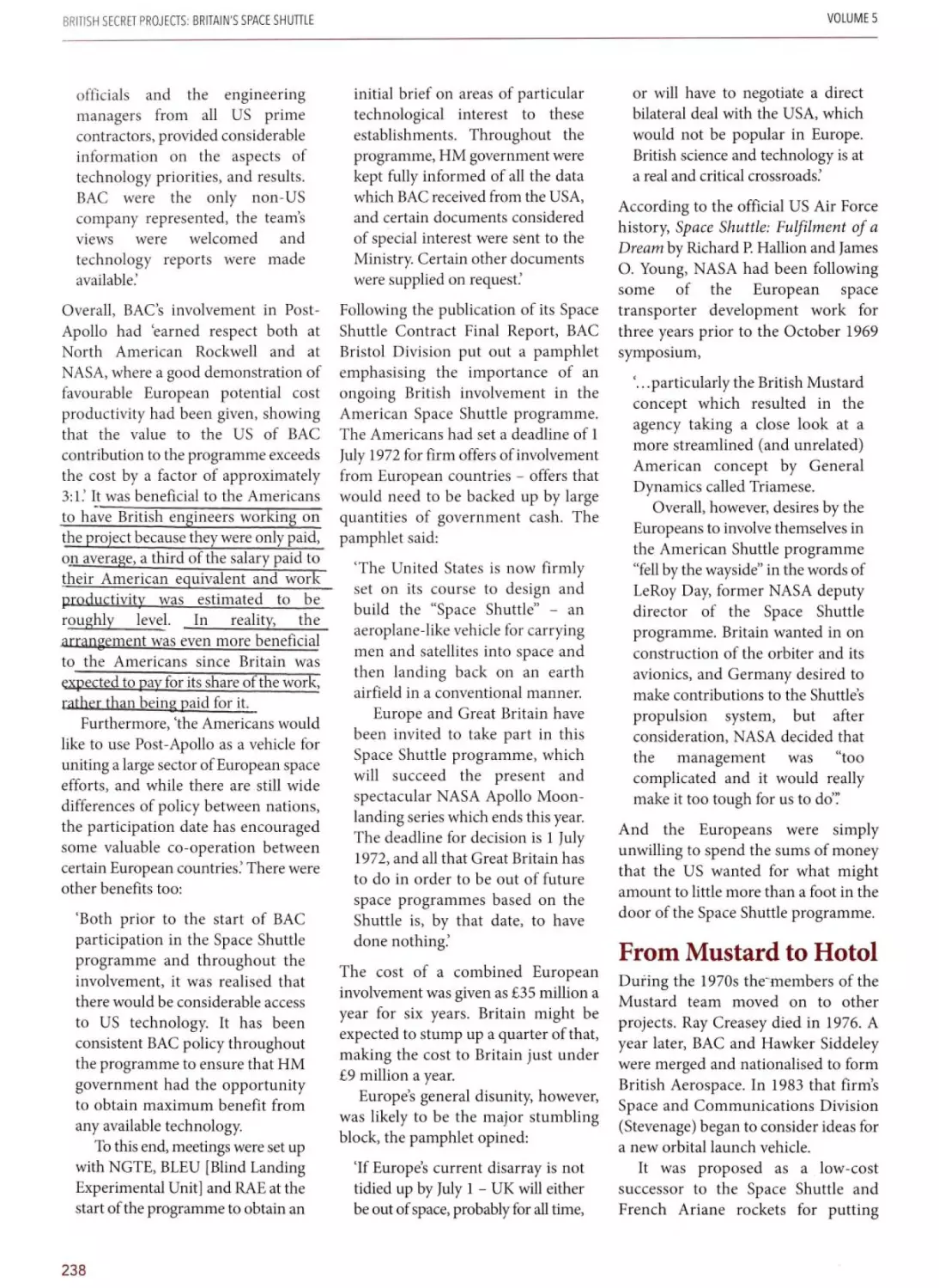
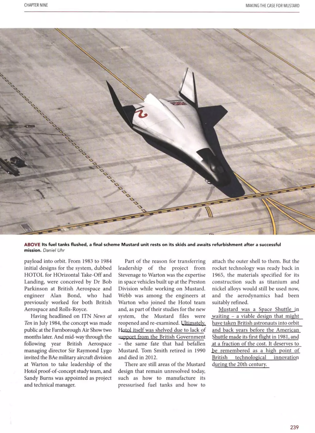
Chapter 9 Making the Case for Mustard..............................................213
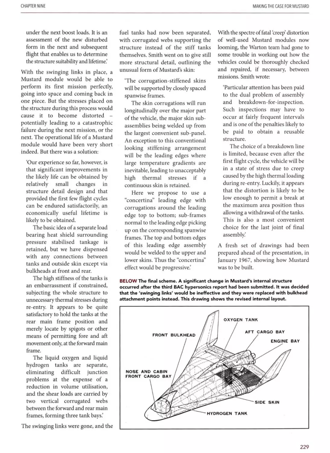
ВАС Mustard 1966-1970
Appendix 1 Europe falls behind........................................................240
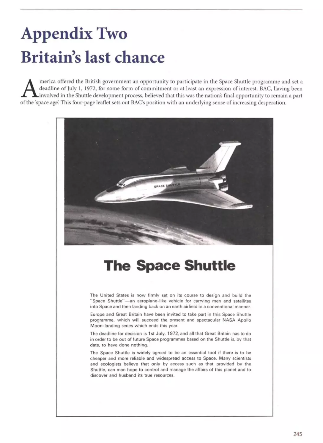
Appendix 2 Britain's last chance......................................................245
Reference Sources and Bibliography....................................................249
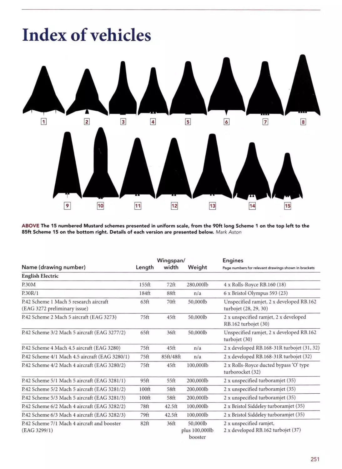
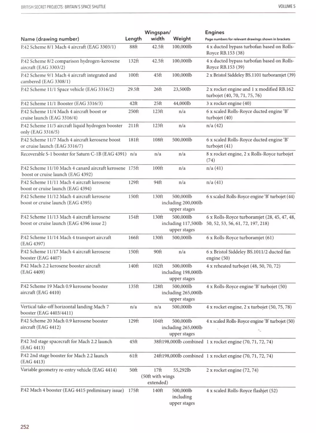
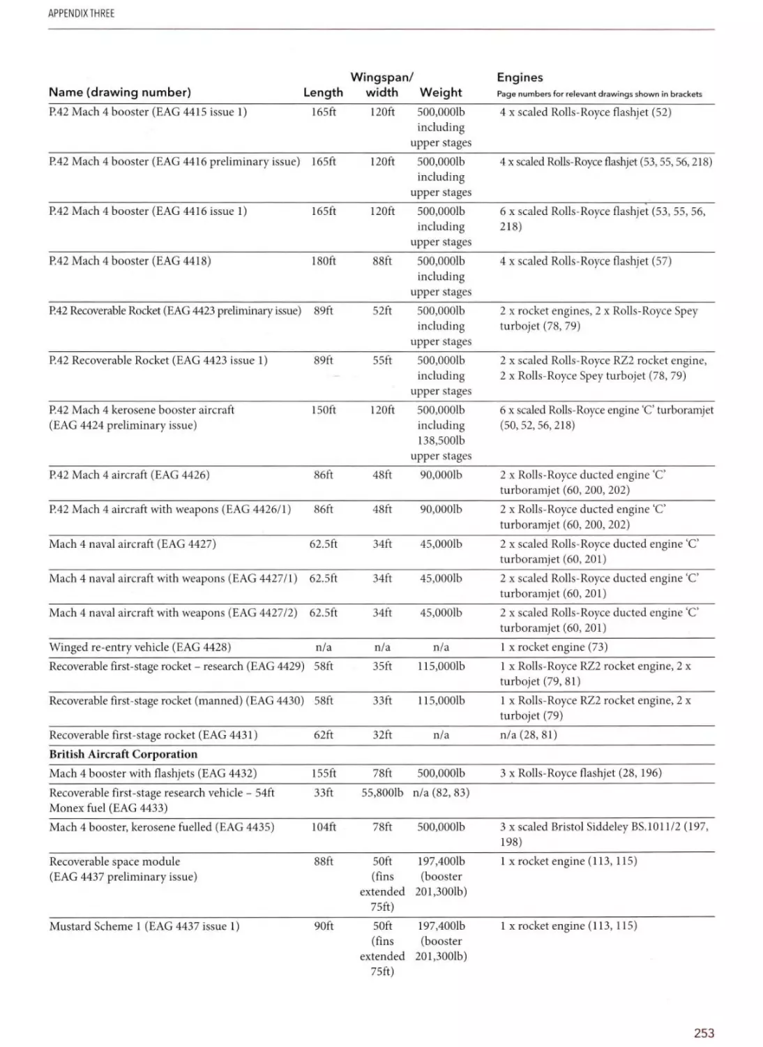
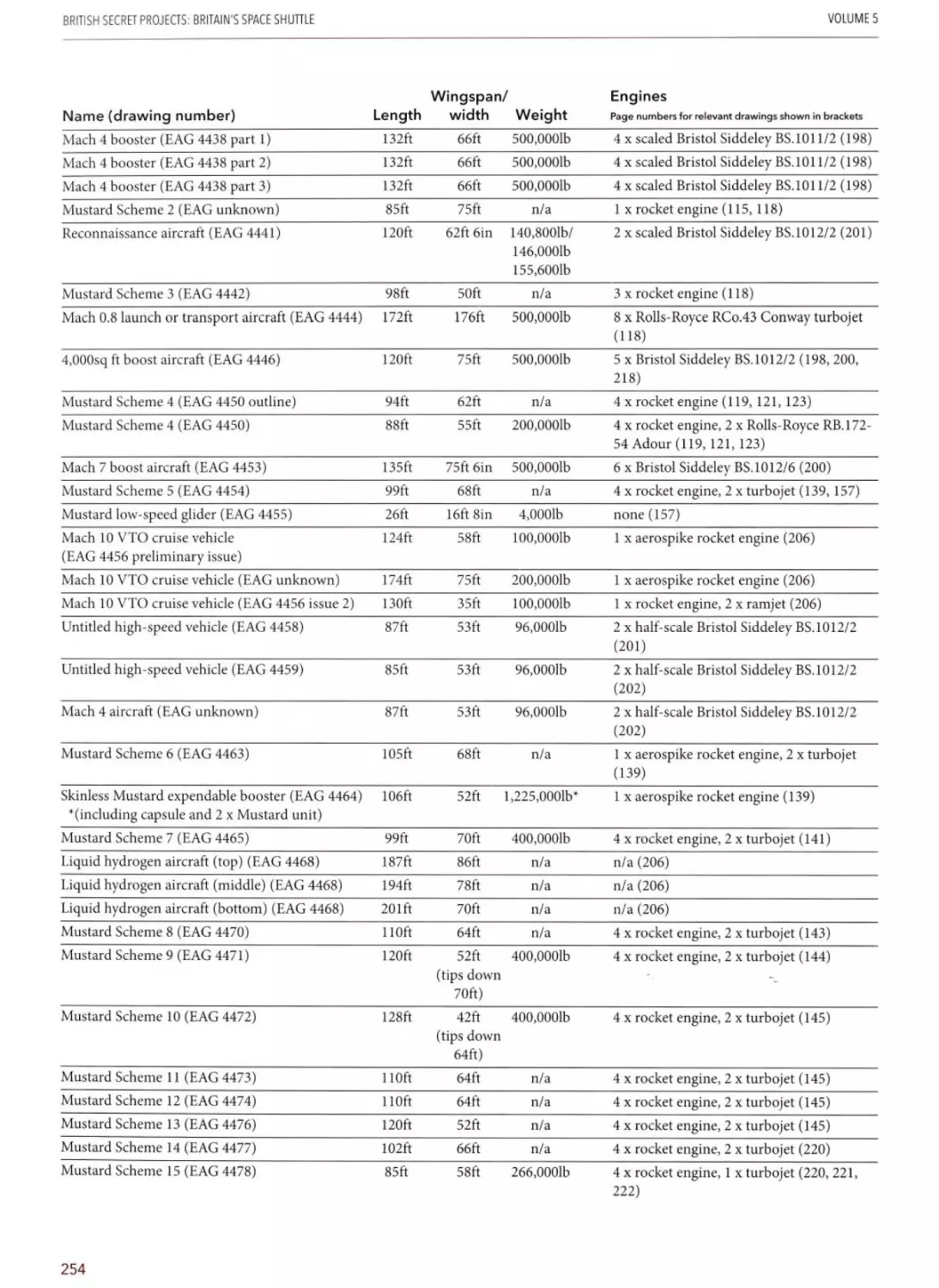
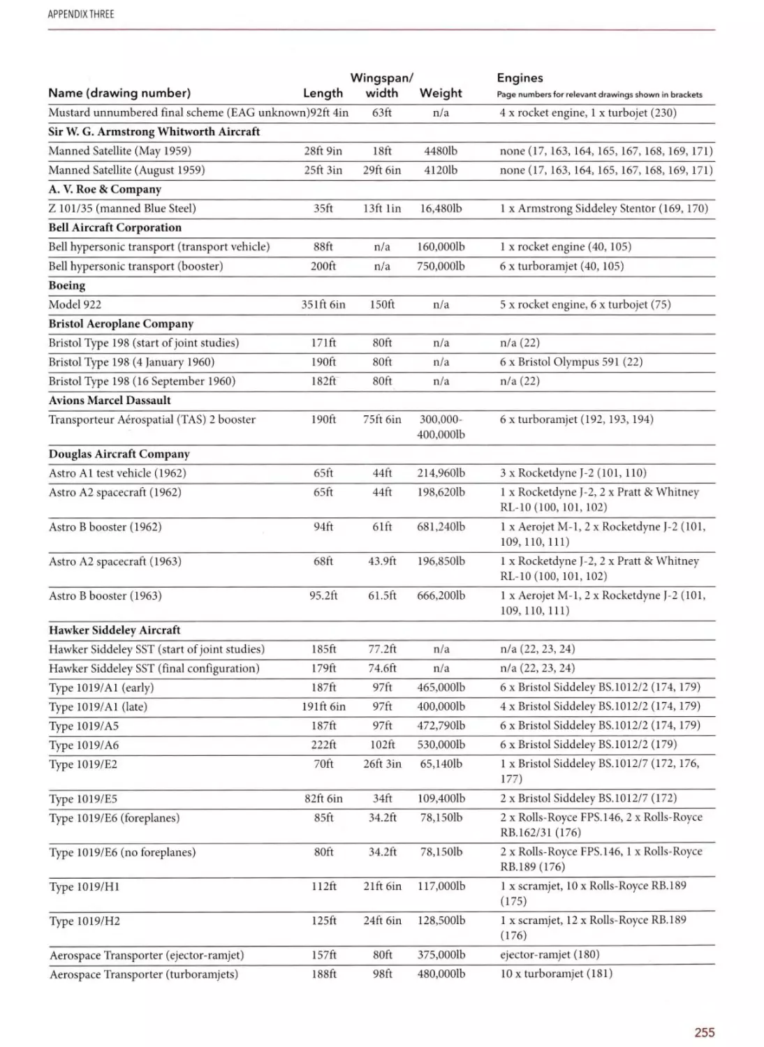
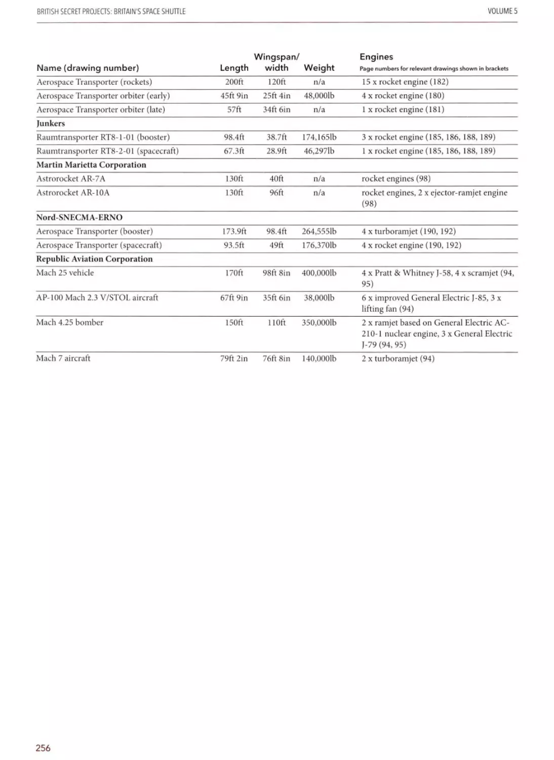
Index of vehicles.....................................................................251
Index.................................................................................257
5
Introduction
This is the story of the British Aircraft Corporations Multi-
Unit Space Transport And Recovery Device, or ‘Mustard’ -
a Space Shuttle before its time.
It might reasonably be wondered, therefore, why so much
of this book is devoted to English Electric Aviation and its
work on P.42, a project primarily intended to produce and
assess designs for high-speed aircraft.
The answer is that P.42 led directly to Mustard. It is worth
noting that by 1963, when P.42 commenced, working on high-
speed aircraft designs was nothing new for English Electric.
The firm had already built Britain’s first supersonic fighter,
the Lightning, had worked on numerous high-speed missile
projects, and had carried out several years of detailed work
on the P.10, a projected Mach 3 ramjet-propelled aircraft.
It had also been studying faster-than-sound passenger
aircraft since joining the Supersonic Transport Aircraft
Committee in 1957, and had been left deeply sceptical about
the practicality and prospects of such designs.
In 1960, English Electric joined the Bristol Aeroplane
Company as a joint senior partner in the new British
Aircraft Corporation (ВАС), which also encompassed
Vickers-Armstrongs and Hunting Aircraft. That same year
Hawker Siddeley, its chief rival and competitor, grew to
encompass both de Havilland Aircraft and Blackburn
Aircraft. It was already the parent of Gloster Whitworth,
Avro and Folland. Both firms were industrial giants at the
cutting edge of defence technology on the world stage.
By July 1963, as the Bristol component of ВАС was
getting to grips with the supersonic airliner project that
would be named Concorde the following year, English
Electric was heavily engaged in work on the TSR2 strike
aircraft - another high-speed design.
It was at this time and against this backdrop that ВАС
received a contract requiring it to study hypersonic vehicles,
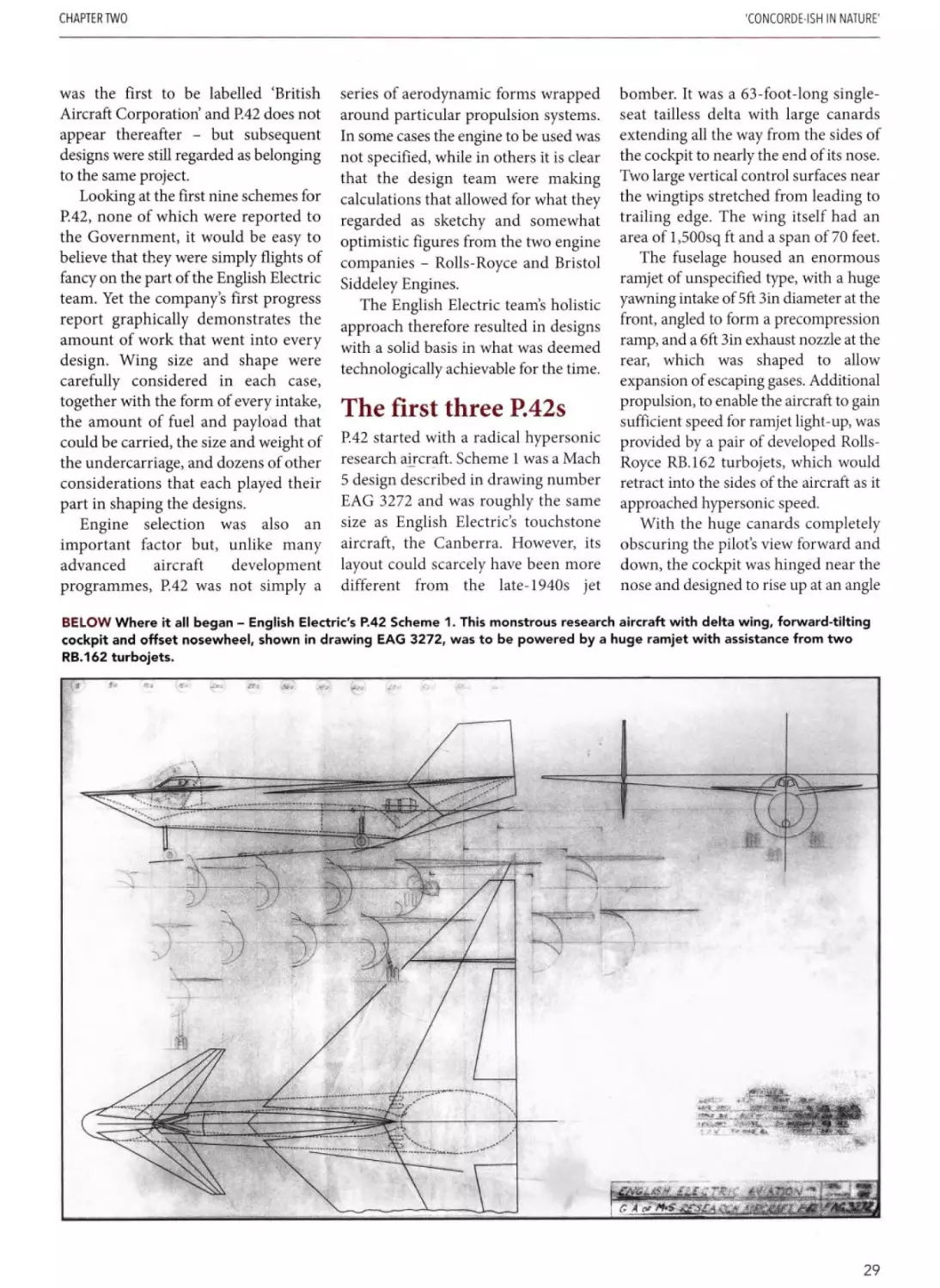
that is aircraft capable of achieving Mach 5 or above. Designs
were needed that could fulfil one or all of four different roles
- long-range cruise aircraft, recoverable space vehicle
launcher, boost-glide vehicle, and space plane.
The work was given to English Electric’s design team at
Warton, near Preston in Lancashire, which was already in
the process of being rebranded as BAC’s Preston Division.
About a month later the team received a report from the
Royal Aircraft Establishment (RAE), Britain’s closest
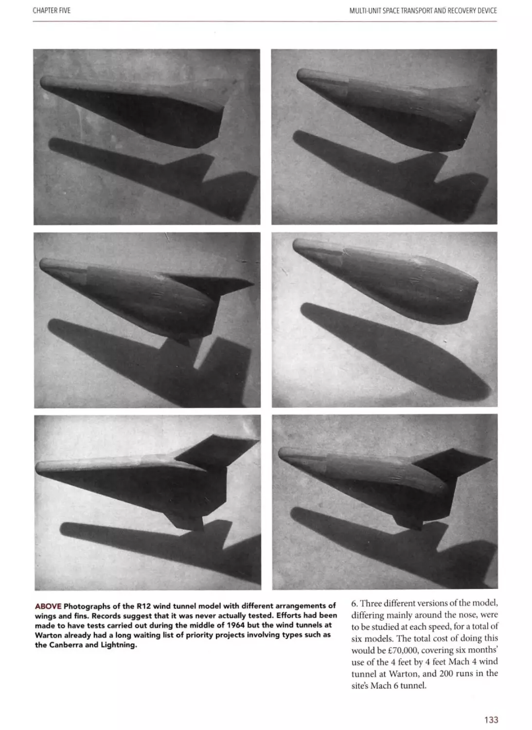
equivalent to NASA, among other roles, indicating that the
contract was more about the pressing need for a cheap and
reusable space vehicle than it was about a long-range cruise
aircraft that could travel from London to Sydney in 2 hours.
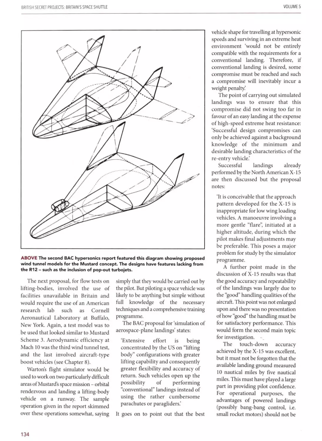
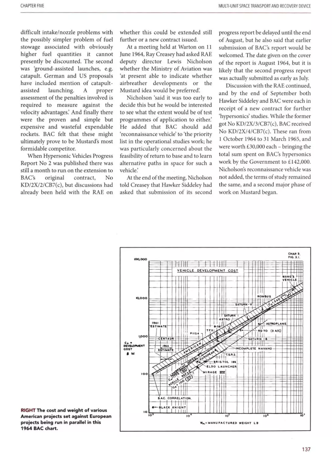
Therefore only cursory work was done on the hypersonic
transport role and the greatest effort was exerted to design an
aircraft capable of launching the maximum possible payload
into space. Pursuing this goal led the team to design a series of
hypersonic aircraft that could carry space vehicles up to high
altitude before releasing them for the final boost into space.
Then the hypersonic aircraft itself was pushed onto the
back burner and the team concentrated instead on a much
more efficient means of achieving the same goal - a vertical -
launch rocket-engined spacecraft that could be used time
and time again to ferry cargo into orbit.
By now English Electric’s naming convention had fallen
by the wayside and the project received an acronym rather
than a number - ‘Mustard’. The name was particularly apt
since the spacecraft and its boosters were hot structure
vehicles; rather than deflecting heat away using a shield like
the later American Space Shuttle, their lightweight skin
simply absorbed it. Hot Mustard indeed!
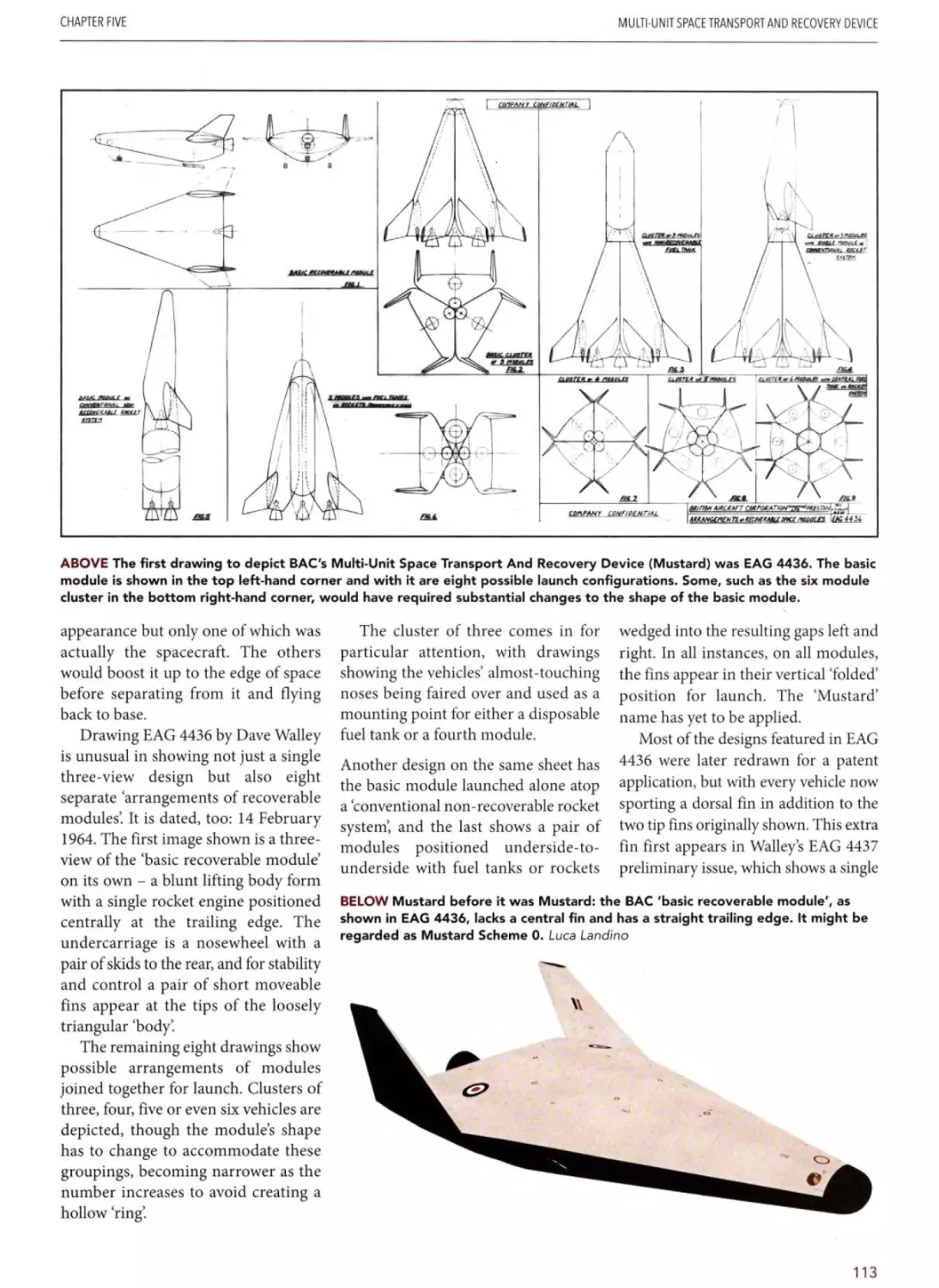
The first drawing depicting this new system was
committed to paper on St Valentine’s Day, 14 February 1964.
But why were the Preston designers so convinced that a
contract to study hypersonic aircraft needed to result in
designs for a rocket-propelled spacecraft? It all came down
to the relative cost and ease of putting satellites in orbit.
The launch of the Soviet Sputnik satellite on 4 October
1957 only confirmed a conclusion reached by the RAE some
months earlier that the most effective form of military
reconnaissance in the future would be satellite-based. It was
decided that Britain should build its own satellites and
would therefore need the means to launch them into space.
The science of rocketry was already well advanced in
Britain and, with doubts growing about the effectiveness and
cost of de Havilland’s Blue Streak medium-range ballistic
missile as a nuclear weapon, it was decided in 1960 that it
should be repurposed as a satellite launcher.
But being a disposable vehicle, it was still hugely
expensive and entirely unsuitable for space missions where
a human crew would be needed. There was a growing fear
that the Soviet Union might use its satellites not only for
spying, but also as platforms for nuclear weaponry aimed at
the West from orbit. If that was the case, Britain would need
a reusable vehicle capable of inspecting or even destroying
potentially hostile satellites, as well as launching its own.
The European Launcher Development Organisation
(ELDO) had been formed in 1962, with Britain as the senior
member, and it was hoped that other member nations would
come together to fund a reusable space transport vehicle for
launching satellites and other space missions.
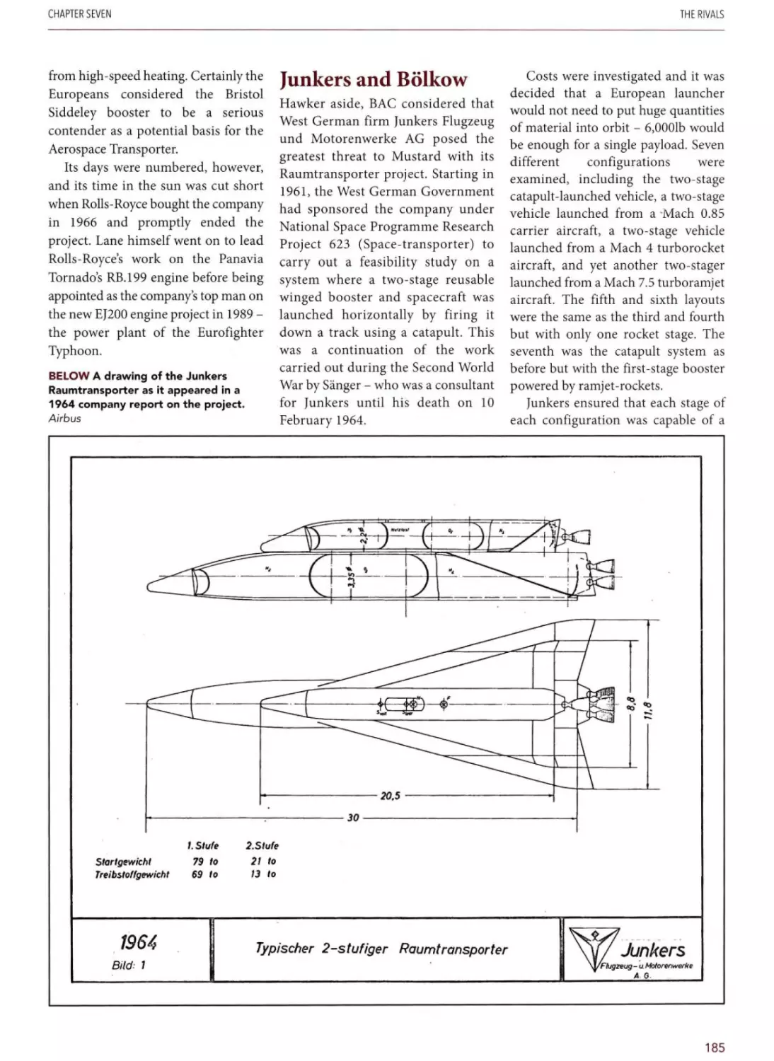
However, rather than joining forces to work towards this
common goal, the British firms and their French and
Germany counterparts each came up with their own rival
projects, and a European space race began to develop. Like
the early work of the Preston team, however, the French
and Germans focused on more expensive horizontal-take-
off launchers.
6
As the race progressed, Hawker Siddeley too came to
favour a horizontal-take-off launcher, leaving ВАС to go it
alone with the simpler, cheaper Mustard.
A significant part of this simplicity was its ‘lifting body’
form, which would enable it to glide back to earth from orbit
without an expensive heat shield. This was inspired by work
carried out in America, particularly a project then being
promoted by the Douglas Aircraft Company called ASTRO
- an acronym whose meaning varied from year to year.
Astro was problematic because it involved a small vehicle
sitting on the nose of a very large vehicle, each of which
would need to be developed separately at great expense. In
addition, the payload it could put into orbit was limited by
the enormous amount of fuel the two vehicles would have
to carry between them.
In this respect, Mustard’s key innovation was the use of
several units that were nearly identical. Three or more
Mustard vehicles would launch together, either in stack’ or
cluster’ formation, all of their engines firing, but with only
one of them actually reaching space. The others would pump
fuel into the orbiter unit so that its tank remained full for
the final stage of the journey into orbit. When their own
tanks were dry, the fuelling units would detach, glide home
and land, ready to be prepared for their next mission.
The American system that eventually became the NASA
Space Shuttle used the same principle, with an external tank
fuelling the orbiter’s engines during launch. But unlike
Britain’s Mustard, the Shuttles external tank was not
reusable. After every launch it simply fell away into the
atmosphere, plummeted to earth, broke up on impact with
the ocean and sank, never to be recovered.
In essence, the Mustard team developed a technology that
the Shuttle would go on to prove was entirely viable. As the
ВАС project’s leader Tom Smith later said: ‘There is nothing
worse than being right at the wrong time.’
It is difficult now to believe that Britain was once a world
leader in spacecraft design, though it is not quite so difficult
to believe that this fact was kept largely hidden under a veil of
secrecy for more than fifty years by the British Government.
While millions were being spent to maintain a space
programme based on unmanned rockets, English
Electric/BAC’s highly advanced and cost-effective proposals
were left on the shelf. The only consolation, perhaps, is that
Mustards contemporary rivals today suffer a similar obscurity.
This book was written to showcase the incredible
achievements of Smith and his team and to ensure that their
work takes its rightful place in the history of British
technological innovation.
Acknowledgements
This book could not exist without the unstinting kindness,
patience and support of Tony Wilson and Eric Webb at
Warton. Both afforded the author every courtesy,
answered every question and explained every nuance of
systems and technology with which few now can claim to
be entirely familiar.
The overwhelming generosity of BAE Systems has been
vital to this book too, and I cannot thank lan Lawrenson and
Howard Mason enough for their help in this regard.
I am also indebted to the following people for their help
and support: Mark Aston, Peter Collins, Alan Ranger, Peter
Barnes and Patrick Hassell at Rolls-Royce, Phillipe Coue
and Luc Berger of Dassault Aviation, Chris Farara at
Brooklands Museum, Hamza Fouatih, Simon Fowler, Jozef
Gatial, Chris Gibson, Barry Hinchliffe, Luca Landino, Scott
Lowther of Aerospaceprojectsreview.com, Paul Martell-
Mead of Secretprojects.co.uk, Ronnie Olsthoorn, Dr Bob
Parkinson, Alexander Power, Gill Richardson, Chris
Sandham-Bailey, Daniel Uhr, Hans-Ulrich Willbold at
Airbus, Gerald Wilson at Warton, and Jessica A. Brown at
The Aerospace Corporation for teaching me a valuable
lesson about Wang’s Vehicle.
7
Chapter One
The rise of English Electric
From the Second World War to Very High Speed Vehicles
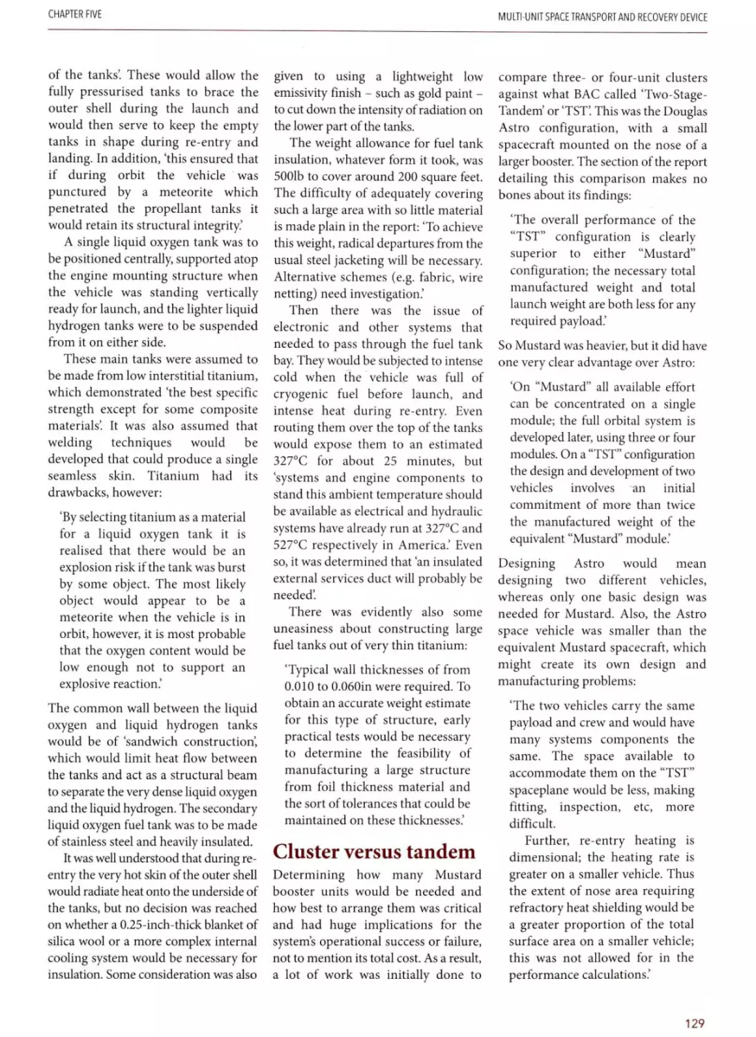
The British Aircraft Corporations
Mustard space vehicle was the
culmination of three strands of
development that became increasingly
interwoven during the eighteen years
between 1945 and 1963.
The first of these was a scientific
interest in the potential of earths
atmosphere and space that had begun in
Britain during the early 1920s. Second
and third were rapid advances in engine
technology and the emergence of
English Electric as a major force in the
aviation industry, both beginning just
after the Second World War.
Modern British space science began
with the discovery of the ionosphere
and a fundamental shift in the way space
was perceived and understood. Edward
Victor Appleton, professor of physics at
Kings College London, demonstrated in
1924 that the ionospheric layers in the
upper atmosphere could be used for the
long-distance transmission of radio
waves - something radio pioneer
Guglielmo Marconi had demonstrated
in 1902 in England without knowing
how or why it worked.
Suddenly space no longer seemed so
remote and its physics so unknowable.
It could be reached and used for the
practical purpose of communicating
over long distances. Scientists began to
wonder what other properties the
atmosphere might have and how they
might be used.
The level of enthusiasm was such that
in Liverpool on 13 October 1933 Phillip
Cleator formed the British Interplanetary
Society (BIS), a group dedicated to
promoting the concept of space travel
and the study of space. Among its early
members were science fiction writer
Arthur C. Clarke, who joined in 1934,
and engineer Arthur Valentine ‘Vai’
Cleaver. Cleaver, who later worked on
sophisticated rocket engines at Rolls-
Royce, wrote of the BIS:
‘It never built rockets, and before
the war it always had less than
100 members, who were largely
regarded as cranks. Some of
them undoubtedly were, but the
allusion is made by the present
writer in no derogatory spirit, if
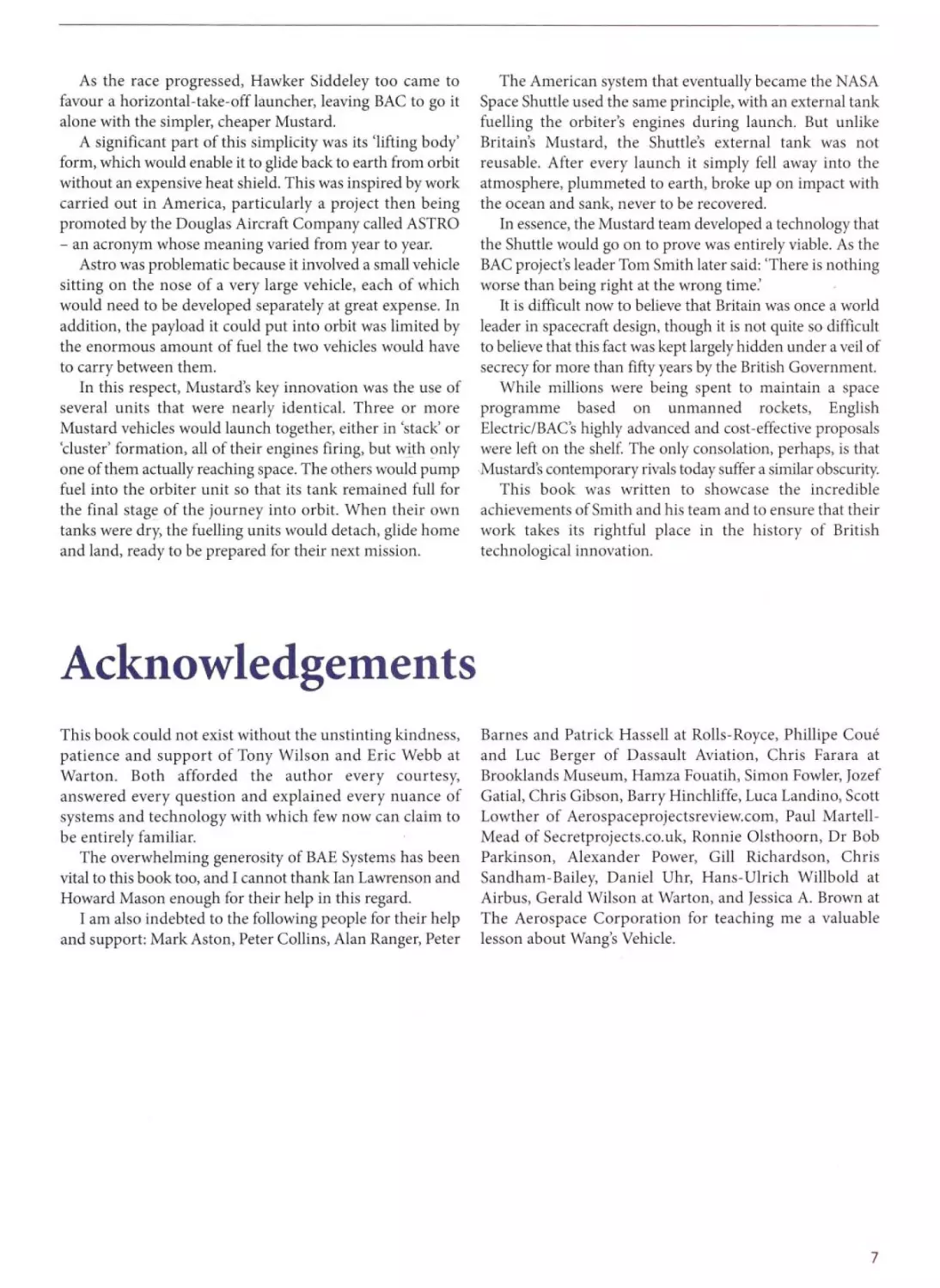
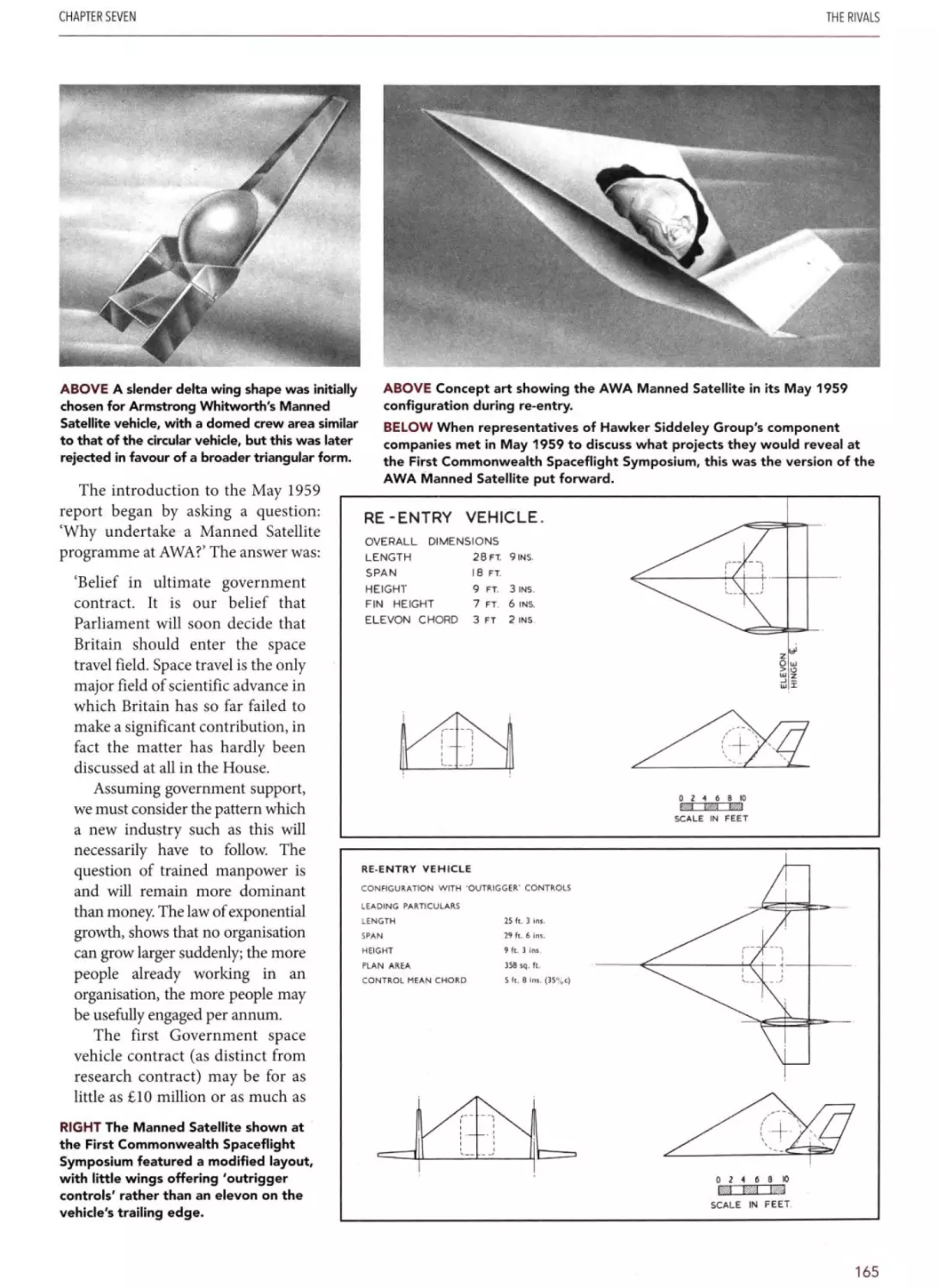
ABOVE British Airways ВАС Concorde
G-BOAC, as it might have looked based
on English Electric's P.30M design,
approaches Mach 1. Hamza Fouatih
for no other reason than because
he became a member himself in
1937?
Low-key atmospheric research was still
under way in Britain when, in 1935, the
Government asked the Royal Arsenal’s
research department at Woolwich to
look at how cordite-fuelled military
rockets could be developed. Some work
had been done on rockets during the
First World War, but their inaccuracy
as a weapon and the difficulties of
storing them safely led to this being
discontinued.
The new interest in rockets came as
a direct result of German military
developments in the field, the British
Government having become aware of a
significant programme of investment
in solid-fuel artillery rockets begun in
1929 at Kummersdorf near Berlin.
8
CHAPTER ONE
THE RISE OF ENGLISH ELECTRIC
Starting in 1936, Alwyn Crow, the
Arsenals director of ballistics research,
led a series of studies including work
on a rocket capable of reaching targets
900 miles away. Any hopes Britain’s
new space scientists might have had
that this would lead to a research
vehicle for atmospheric studies were
dashed in 1939, however, with the
outbreak of the Second World War.
As Crows team turned their
attention to designing solid-fuel anti-
aircraft rockets that could be fired at
German bombers, a small team from
Shell subsidiary the Asiatic Petroleum
Company, led by scientist Isaac
Lubbock, developed a liquid-fuelled
rocket engine at the Fuel Oil Technical
Laboratory in Fulham, London.
This was intended to help heavily
laden aircraft take off, but also to
demonstrate that liquid fuel, in this
case liquid oxygen, and petrol could
work just as well as, or better than, the
solid-fuel equivalent. This engine,
dubbed ‘Lizzie’, was being bench-tested
at the Ministry of Supply Weapons
Research Station at Langhurst, near
Horsham, by 1942.
At around the same time in
Germany, the design of the Aggregat-4
or V-2 rocket was being finalised.
Topped with a warhead containing
2,2001b of Amatol high explosive, this
missile had a surface-to-surface range
of 200 miles and a sophisticated
guidance system. More than 3,000 were
launched at the Allies, but they seldom
succeeded in inflicting strategically
effective damage. As the war drew to its
conclusion amid the ruins of the Third
Reich, the Allies moved in to capture as
much of Germany’s rocket technology
as possible.
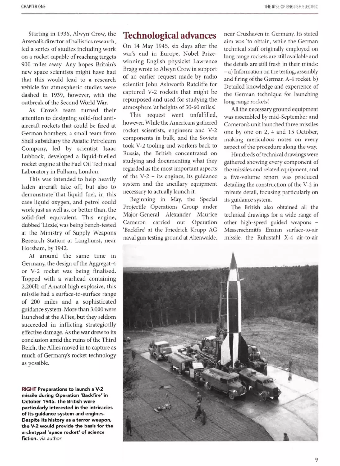
RIGHT Preparations to launch a V-2
missile during Operation 'Backfire' in
October 1945. The British were
particularly interested in the intricacies
of its guidance system and engines.
Despite its history as a terror weapon,
the V-2 would provide the basis for the
archetypal 'space rocket' of science
fiction, via author
Technological advances
On 14 May 1945, six days after the
war’s end in Europe, Nobel Prize-
winning English physicist Lawrence
Bragg wrote to Alwyn Crow in support
of an earlier request made by radio
scientist John Ashworth Ratcliffe for
captured V-2 rockets that might be
repurposed and used for studying the
atmosphere ‘at heights of 50-60 miles’.
This request went unfulfilled,
however. While the Americans gathered
rocket scientists, engineers and V-2
components in bulk, and the Soviets
took V-2 tooling and workers back to
Russia, the British concentrated on
studying and documenting what they
regarded as the most important aspects
of the V-2 - its engines, its guidance
system and the ancillary equipment
necessary to actually launch it.
Beginning in May, the Special
Projectile Operations Group under
Major-General Alexander Maurice
Cameron carried out Operation
‘Backfire at the Friedrich Krupp AG
naval gun testing ground at Altenwalde,
near Cruxhaven in Germany. Its stated
aim was ‘to obtain, while the German
technical staff originally employed on
long range rockets are still available and
the details are still fresh in their minds:
- a) Information on the testing, assembly
and firing of the German A-4 rocket, b)
Detailed knowledge and experience of
the German technique for launching
long range rockets.’
All the necessary ground equipment
was assembled by mid-September and
Cameron’s unit launched three missiles
one by one on 2, 4 and 15 October,
making meticulous notes on every
aspect of the procedure along the way.
Hundreds of technical drawings were
gathered showing every component of
the missiles and related equipment, and
a five-volume report was produced
detailing the construction of the V-2 in
minute detail, focusing particularly on
its guidance system.
The British also obtained all the
technical drawings for a wide range of
other high-speed guided weapons -
Messerschmitt’s Enzian surface-to-air
missile, the Ruhrstahl X-4 air-to-air
9
BRITISH SECRET PROJECTS: BRITAIN'S SPACE SHUTTLE
VOLUMES
missile, Rheinmetall-Borsigs Rheintochter
surface-to-surface missile, and many
more.
The capture of Dr Hellmuth Walter
and his Walter Werke facility at Kiel in
May 1945 also provided a wealth of
information about rocket powerplants
fuelled by high-test peroxide (HTP), such
as the HWK 109-500 rocket-assisted-
take-off engine, the Messerschmitt Me
163Bs HWK 109-509A, and the Me 263’s
dual-chamber HWK 109-509C.
Lengthy interviews were also
conducted with ramjet scientists,
including Austrian Eugen Sanger, Me
163 designer Alexander Lippisch, and
Focke-Wulf s Otto Pabst, with notes
and documents carefully gathered.
Ramjet engines, which can only be
fired up if they are already moving so
fast that air is literally being ‘rammed’
into their intake by the forward
motion, seemed very promising for
high-speed propulsion.
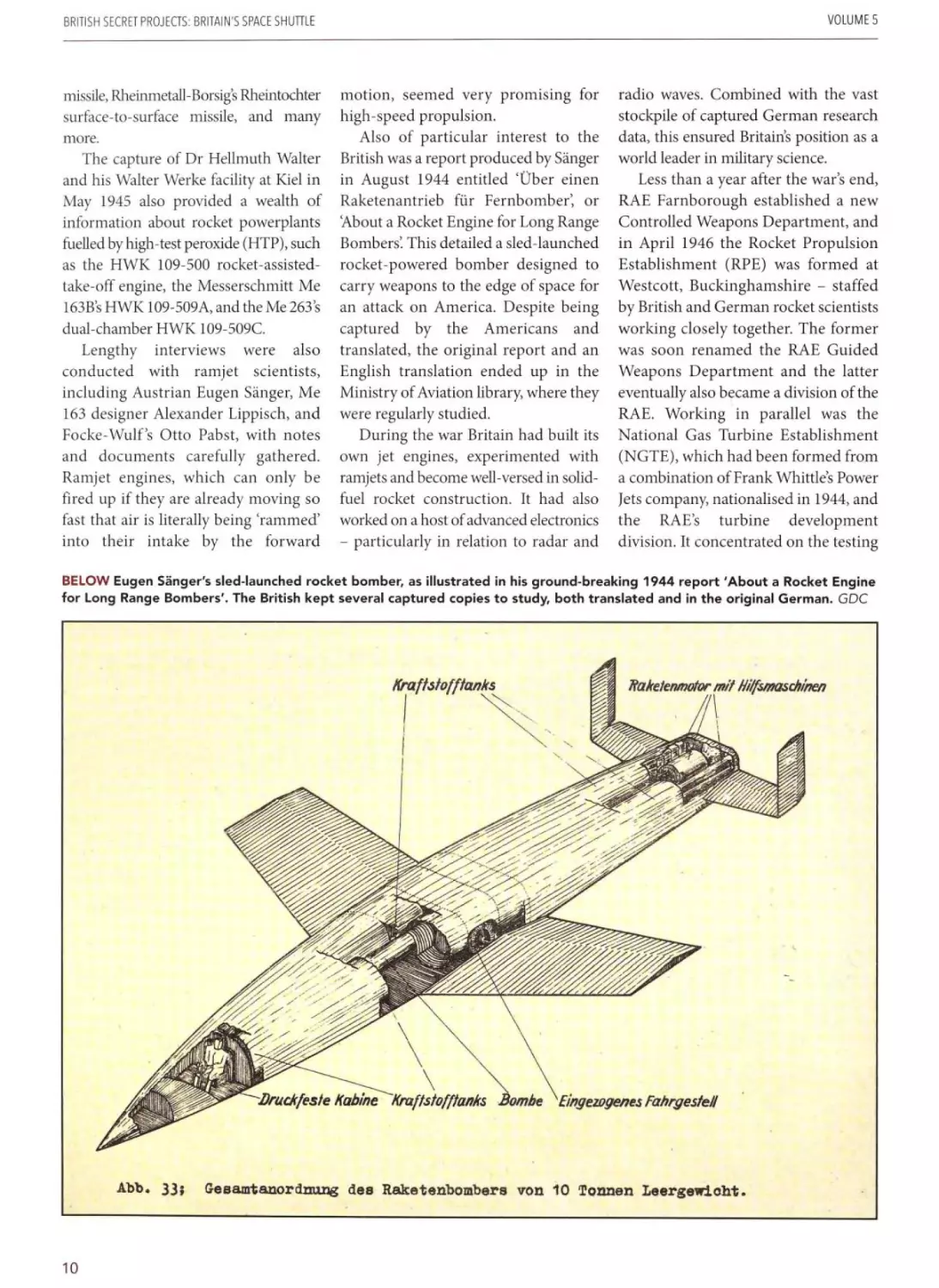
Also of particular interest to the
British was a report produced by Sanger
in August 1944 entitled ‘Uber einen
Raketenantrieb fur Fernbomber’ or
About a Rocket Engine for Long Range
Bombers’. This detailed a sled-launched
rocket-powered bomber designed to
carry weapons to the edge of space for
an attack on America. Despite being
captured by the Americans and
translated, the original report and an
English translation ended up in the
Ministry of Aviation library, where they
were regularly studied.
During the war Britain had built its
own jet engines, experimented with
ramjets and become well-versed in solid-
fuel rocket construction. It had also
worked on a host of advanced electronics
- particularly in relation to radar and
radio waves. Combined with the vast
stockpile of captured German research
data, this ensured Britain’s position as a
world leader in military science.
Less than a year after the wars end,
RAE Farnborough established a new
Controlled Weapons Department, and
in April 1946 the Rocket Propulsion
Establishment (RPE) was formed at
Westcott, Buckinghamshire - staffed
by British and German rocket scientists
working closely together. The former
was soon renamed the RAE Guided
Weapons Department and the latter
eventually also became a division of the
RAE. Working in parallel was the
National Gas Turbine Establishment
(NGTE), which had been formed from
a combination of Frank Whittles Power
Jets company, nationalised in 1944, and
the RAE’s turbine development
division. It concentrated on the testing
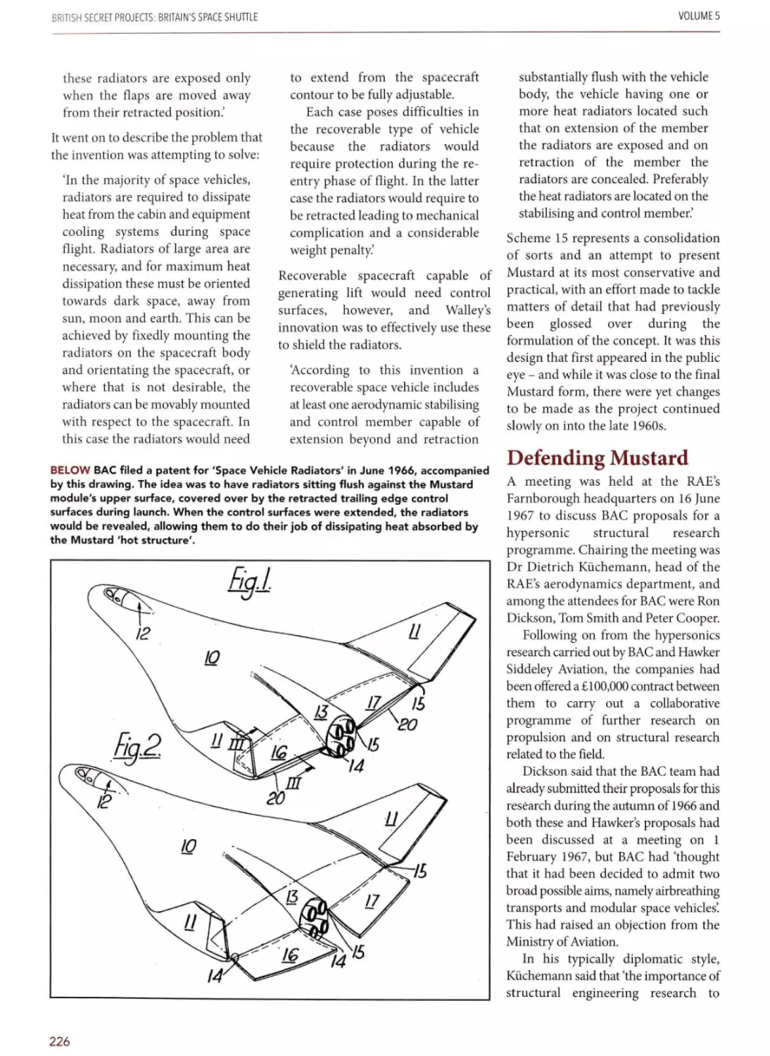
BELOW Eugen Sanger's sled-launched rocket bomber, as illustrated in his ground-breaking 1944 report 'About a Rocket Engine
for Long Range Bombers'. The British kept several captured copies to study, both translated and in the original German. GDC
Abb. 33» Geeamtanordnong dee Raketenbombers von 10 Toanen Leergewioht.
10
CHAPTER ONE
THE RISE OF ENGLISH ELECTRIC
and development of gas turbine
engines, primarily for aircraft. Together
the RAE and the NGTE became the
nucleus around which a large and
technologically advanced weapons and
propulsion research industry
flourished - despite the general
austerity of the post-war years.
English Electric rising
By now the English Electric Company,
a large-scale manufacturer of electrical
equipment, engines and railway
vehicles before the Second World War,
was already establishing itself as a
successful aviation company to rival the
likes of Hawker and Bristol. In 1938 it
had been chosen as a major
subcontractor for what was to become
known as the shadow’ aircraft industry,
building Handley Page Hainpdens at its
workshops in Preston, Lancashire.
Three years later it started
constructing Handley Page Halifaxes
too, and built up a small in-house design
group to work out modifications
necessary for the production line. On 23
December 1942 English Electric
acquired D. Napier & Son, adding aero-
engine manufacturing and development
expertise to its portfolio.
In early 1944 the Ministry of Aircraft
Production chose English Electric as a
potential manufacturer for the advanced
Folland Fo. 117A fighter powered by the
Bristol Centaurus 12, designed to
specification F.6/42, then F. 19/43. Some
design work was to be involved, so the
company decided to expand its team of
designers and engineers, even though
the Folland fighter project was
ultimately abandoned.
At the same time Westland Aircraft
began design work on a new medium
bomber to be powered by a pair of
Metropolitan-Vickers F.2/4 turbojets
under specification number B. 1/44.
This project was led by Westland’s
eccentric but highly intelligent 35-year-
old technical director William Edward
Willoughby ‘Teddy’ Petter, son of the
company’s founder and chairman
Ernest Petter.
On 13 May 1944 English Electric was
notified that it had been chosen to build
the new highly advanced de Havilland
Vampire jet fighter, and the first contract
for 120 aircraft was placed in June.
While preparations for this work were
under way, Petter resigned from
Westland. He felt aggrieved when, upon
returning to work after a period of
absence, he discovered that work on his
bomber had been suspended in favour
of a design that eventually became the
turboprop-powered Wyvern carrier-
borne strike fighter.
Westland’s loss was English
Electrics gain, for shortly thereafter
Petter was hired by the firm as its new
chief engineer. After six successful
years of producing other companies’
designs, the directors of English
Electric had decided that the firm
should begin producing its own. The
highly experienced, well-connected
Petter was the ideal candidate to set
this in motion.
His first task was to expand the
company’s small design team, and he
went about doing this by bringing in
talented engineers from other firms.
Among his key appointments were
Frederick William ‘Freddie’ Page, who
left Hawker to join as chief stressman,
and young engineering graduate
Bernard Oliver ‘Ollie’ Heath.
With the beginnings of his new team
in place, Petter pressed ahead with the
jet bomber he had wanted to build all
along. A new specification was issued
in March 1945, B.3/45, and by the time
the war ended the English Electric
design was taking shape as what would
eventually become the Canberra.
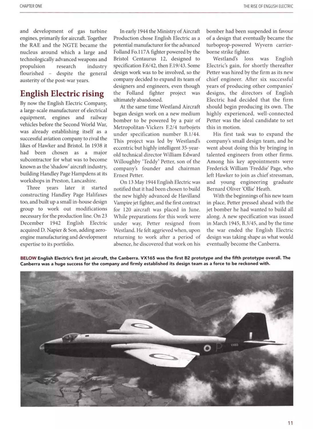
BELOW English Electric's first jet aircraft, the Canberra. VX165 was the first B2 prototype and the fifth prototype overall. The
Canberra was a huge success for the company and firmly established its design team as a force to be reckoned with.
11
BRITISH SECRET PROJECTS: BRITAIN’S SPACE SHUTTLE
VOLUMES
After the war the firm was spared
the worst of the inevitable military
cutbacks since the Vampire it was
building had been chosen to equip the
newly slimmed-down RAE In
addition, the company as a whole
manufactured a diverse range of
successful industrial products, rather
than being entirely dependent on its
aircraft business for survival, and
therefore had money to continue
investing in aviation.
This investment was rewarded when
an order for four prototypes of the new
B.3/45 bomber was placed in January
1946. Petter continued to expand his
team by recruiting Raymond Frederick
‘Ray’ Creasey from Vickers as an
aerodynamicist later that year. Creasey,
born in 1921, had worked for the
company throughout the war and had
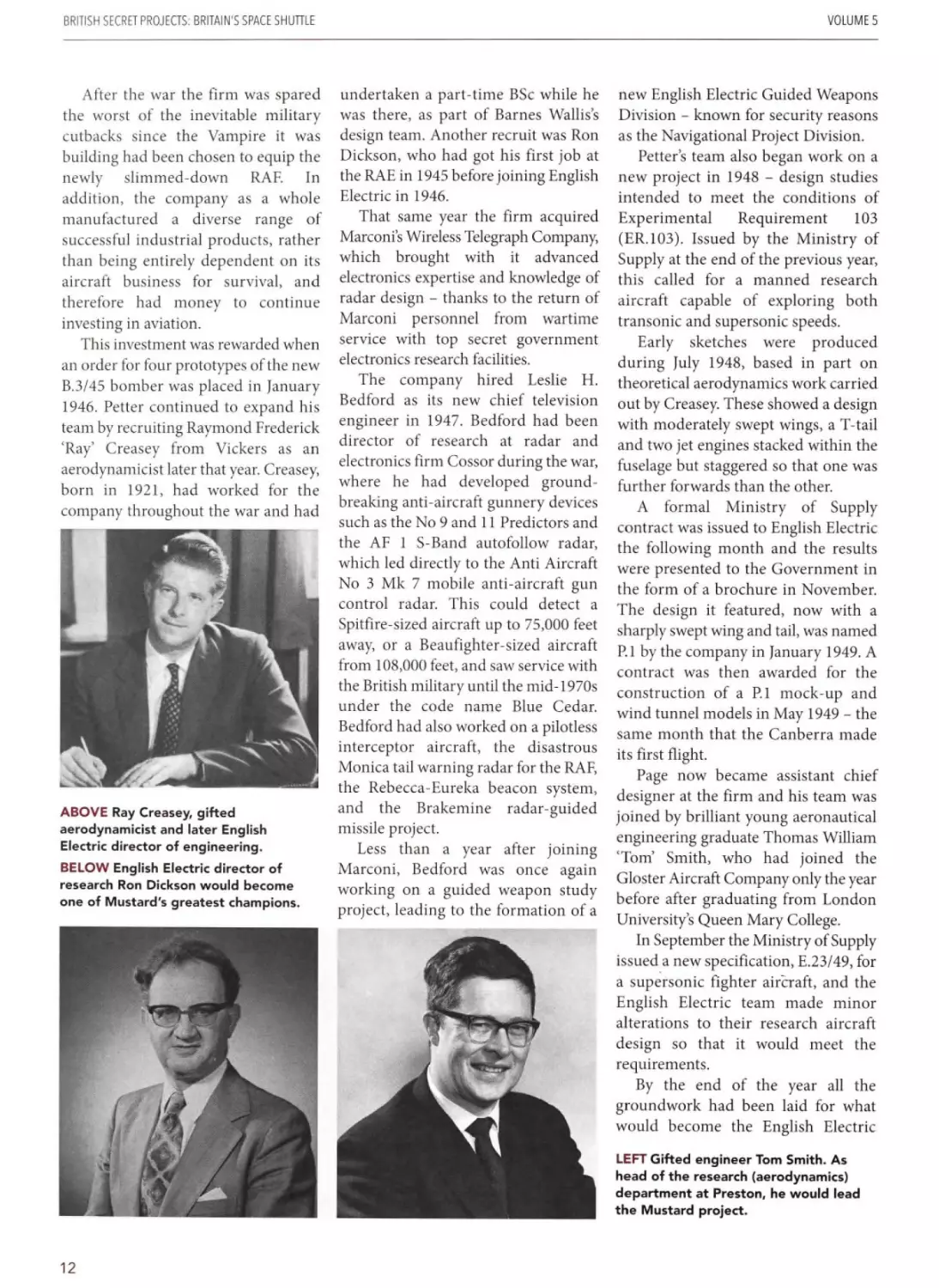
ABOVE Ray Creasey, gifted
aerodynamicist and later English
Electric director of engineering.
BELOW English Electric director of
research Ron Dickson would become
one of Mustard's greatest champions.
undertaken a part-time BSc while he
was there, as part of Barnes Walliss
design team. Another recruit was Ron
Dickson, who had got his first job at
the RAE in 1945 before joining English
Electric in 1946.
That same year the firm acquired
Marconi’s Wireless Telegraph Company,
which brought with it advanced
electronics expertise and knowledge of
radar design - thanks to the return of
Marconi personnel from wartime
service with top secret government
electronics research facilities.
The company hired Leslie H.
Bedford as its new chief television
engineer in 1947. Bedford had been
director of research at radar and
electronics firm Cossor during the war,
where he had developed ground-
breaking anti-aircraft gunnery devices
such as the No 9 and 11 Predictors and
the AF 1 S-Band autofollow radar,
which led directly to the Anti Aircraft
No 3 Mk 7 mobile anti-aircraft gun
control radar. This could detect a
Spitfire-sized aircraft up to 75,000 feet
away, or a Beaufighter-sized aircraft
from 108,000 feet, and saw service with
the British military until the mid-1970s
under the code name Blue Cedar.
Bedford had also worked on a pilotless
interceptor aircraft, the disastrous
Monica tail warning radar for the RAF,
the Rebecca-Eureka beacon system,
and the Brakemine radar-guided
missile project.
Less than a year after joining
Marconi, Bedford was once again
working on a guided weapon study
project, leading to the formation of a
new English Electric Guided Weapons
Division - known for security reasons
as the Navigational Project Division.
Petter’s team also began work on a
new project in 1948 - design studies
intended to meet the conditions of
Experimental Requirement 103
(ER. 103). Issued by the Ministry of
Supply at the end of the previous year,
this called for a manned research
aircraft capable of exploring both
transonic and supersonic speeds.
Early sketches were produced
during July 1948, based in part on
theoretical aerodynamics work carried
out by Creasey. These showed a design
with moderately swept wings, a T-tail
and two jet engines stacked within the
fuselage but staggered so that one was
further forwards than the other.
A formal Ministry of Supply
contract was issued to English Electric
the following month and the results
were presented to the Government in
the form of a brochure in November.
The design it featured, now with a
sharply swept wing and tail, was named
P.l by the company in January 1949. A
contract was then awarded for the
construction of a P.l mock-up and
wind tunnel models in May 1949 - the
same month that the Canberra made
its first flight.
Page now became assistant chief
designer at the firm and his team was
joined by brilliant young aeronautical
engineering graduate Thomas William
‘Tom’ Smith, who had joined the
Gloster Aircraft Company only the year
before after graduating from London
University’s Queen Mary College.
In September the Ministry of Supply
issued a new specification, E.23/49, for
a supersonic fighter aircraft, and the
English Electric team made minor
alterations to their research aircraft
design so that it would meet the
requirements.
By the end of the year all the
groundwork had been laid for what
would become the English Electric
LEFT Gifted engineer Tom Smith. As
head of the research (aerodynamics)
department at Preston, he would lead
the Mustard project.
12
CHAPTER ONE
THE RISE OF ENGLISH ELECTRIC
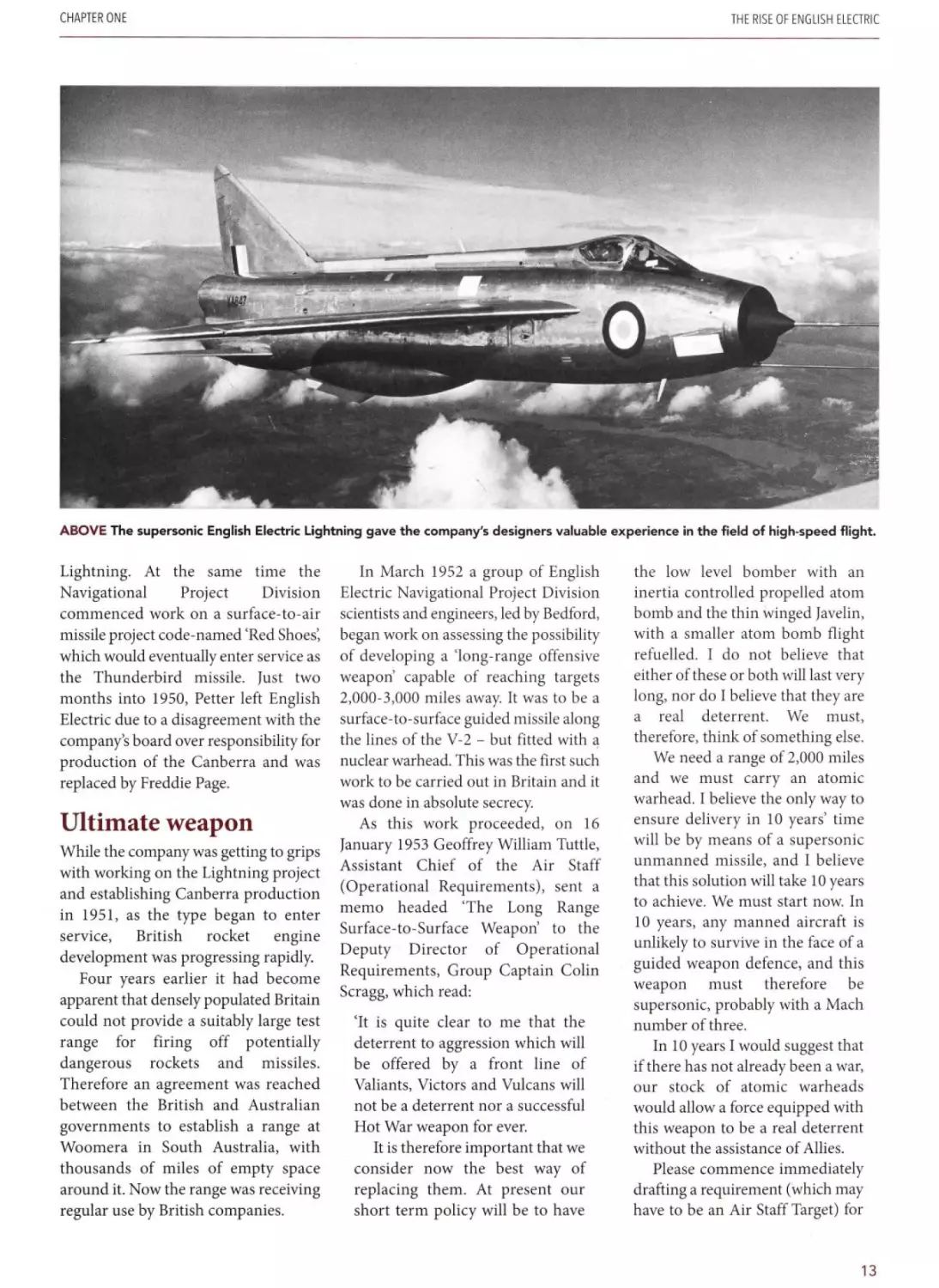
ABOVE The supersonic English Electric Lightning gave the company's designers valuable experience in the field of high-speed flight.
Lightning. At the same time the
Navigational Project Division
commenced work on a surface-to-air
missile project code-named ‘Red Shoes’,
which would eventually enter service as
the Thunderbird missile. Just two
months into 1950, Petter left English
Electric due to a disagreement with the
company’s board over responsibility for
production of the Canberra and was
replaced by Freddie Page.
Ultimate weapon
While the company was getting to grips
with working on the Lightning project
and establishing Canberra production
in 1951, as the type began to enter
service, British rocket engine
development was progressing rapidly.
Four years earlier it had become
apparent that densely populated Britain
could not provide a suitably large test
range for firing off potentially
dangerous rockets and missiles.
Therefore an agreement was reached
between the British and Australian
governments to establish a range at
Woomera in South Australia, with
thousands of miles of empty space
around it. Now the range was receiving
regular use by British companies.
In March 1952 a group of English
Electric Navigational Project Division
scientists and engineers, led by Bedford,
began work on assessing the possibility
of developing a ‘long-range offensive
weapon’ capable of reaching targets
2,000-3,000 miles away. It was to be a
surface-to-surface guided missile along
the lines of the V-2 - but fitted with a
nuclear warhead. This was the first such
work to be carried out in Britain and it
was done in absolute secrecy.
As this work proceeded, on 16
January 1953 Geoffrey William Tuttle,
Assistant Chief of the Air Staff
(Operational Requirements), sent a
memo headed ‘The Long Range
Surface-to-Surface Weapon’ to the
Deputy Director of Operational
Requirements, Group Captain Colin
Scragg, which read:
‘It is quite clear to me that the
deterrent to aggression which will
be offered by a front line of
Valiants, Victors and Vulcans will
not be a deterrent nor a successful
Hot War weapon for ever.
It is therefore important that we
consider now the best way of
replacing them. At present our
short term policy will be to have
the low level bomber with an
inertia controlled propelled atom
bomb and the thin winged Javelin,
with a smaller atom bomb flight
refuelled. I do not believe that
either of these or both will last very
long, nor do I believe that they are
a real deterrent. We must,
therefore, think of something else.
We need a range of 2,000 miles
and we must carry an atomic
warhead. I believe the only way to
ensure delivery in 10 years’ time
will be by means of a supersonic
unmanned missile, and 1 believe
that this solution will take 10 years
to achieve. We must start now. In
10 years, any manned aircraft is
unlikely to survive in the face of a
guided weapon defence, and this
weapon must therefore be
supersonic, probably with a Mach
number of three.
In 10 years I would suggest that
if there has not already been a war,
our stock of atomic warheads
would allow a force equipped with
this weapon to be a real deterrent
without the assistance of Allies.
Please commence immediately
drafting a requirement (which may
have to be an Air Staff Target) for
13
BRITISH SECRET PROJECTS. BRITAIN’S SPACE SHUTTLE
VOLUME 5
such a weapon, and inform the
Ministry of Supply that you are
doing so. While I realise that the
essential requirement is for
terminal guidance, I do not believe
that work on the other parts of the
system, such as propulsion,
navigation, fuzing or materials
should be held up for this.’
It seems likely that Tuttle had received
an interim report from Bedford’s team,
who would not issue their final report
until 30 July 1953.
Two weeks later, on 14 August, a
new Air Staff Target, OR.203 (Issue 2),
was circulated by Scragg. This slated:
‘The Air Staff first raised a
requirement for a long range
surface-to-surface guided weapon
under OR.203 - a long range
expendable bomber - in 1945, and
this was regraded as an Air Staff
Target in January 1952.
It is considered that progress in
this field has been unduly restricted
by envisaging the missile as a
conventional aircraft form, and,
therefore, the Air Staff now wish to
restate this requirement in a
modified form in the light of the
foreseeable development of the
operational situation.’
The requirement’s wording echoed
Tuttles assessment of the future need
for a supersonic long-range surface-to-
surface guided weapon. The required
range was 2,500 nautical miles but ‘it is
highly desirable in the interests of
economy and flexibility that the basic
missile (warhead, guidance/control
system) can be increased in range by
adding stages of fuel/propulsion.’
Under ‘warheads’, the requirement
stated that ‘an atomic warhead only is
required,’ and under ‘accuracy’ it said:
‘Against a precisely known target an
accuracy of 500 yards 50% zone is
required but the Air Staff will be
informed if this degree of accuracy will
impose unacceptably severe penalties.’
On 17 September Scragg invited the
Air Staff - the RAF’s most senior
commanders - to a presentation by
Bedford and his team. He wrote:
‘The visit is designed to introduce a
new concept in which we are likely
to become more closely involved in
the future and which will have
many most difficult and unusual
problems. The presentation will be
unofficial and without prejudice to
any decisions on our part or the
further work which the firm may be
undertaking.’
A copy of Bedfords report was attached
to each invitation and anyone reading
it would quickly realise that the ‘new
concept’ it outlined was truly
horrifying. The document states:
‘Serious consideration was first
devoted to the project of a long
range offensive weapon in March
1952, since which time a great deal
of ground has been covered in an
exploratory manner.
Our investigation leaves us in no
doubt that the long range weapon
is not in the pipe-dream category
but is a practical possibility. This
being so, it is quite certain that the
potential enemy would not fail to
fully exploit our geographical
disadvantage by the use of such a
weapon against us.
Certain forms of the weapon
such as the ballistic rocket are
virtually immune from defensive
counter-measures of any kind. In
this case, the only possible defence
is therefore attack.
From a military point of view
our ability to launch such an
attack, clearly advertised and
substantiated, is probably the only
useful war deterrent.’
The report makes it clear that English
Electric’s study was broad and
examined a wide range of missile types.
It says:
‘These have included ramjet, glide
rocket and ballistic rocket with
emphasis increasing in that order.
Ramjets have received rather scant
attention because the originally
considered long flight time of 75
minutes, for Mach 2.4, was
inconsistent with guidance accuracy.
More recent consideration suggests
the possibility of a ramjet flying at
Mach 3.5. The glide rocket with
Mach greater than six was
considered more fully but, though
an improvement with respect to
guidance accuracy, did not offer an
attractive solution and left serious
problems with regard to
aerodynamic heating.
Gradually our opinion has
hardened in favour of the
(guided) ballistic rocket, this
reducing the time of flight to 16
minutes. This solution almost
disposes of the problem of gyro
drift, for not only is the time of
flight relatively short but the
gyros are in field free space and
hence nominally driftless.
A weapon of this type reaches a
speed of 17,000ft per second
approx, and can probably be
considered invulnerable to
defensive countermeasures for all
time. It is therefore probably the
ultimate form of weapon and the
circumstances appear to us to
justify the bold step of proceeding
straight to the ultimate solution
without going through
intermediate and subsequently
obsolete techniques.’
In 1952-53, earlier than perhaps
anyone else in the world, Bedford and
his team had realised the urgent need
for long-range missiles fitted with
nuclear warheads. Even the Americans
did not give such a weapon top priority
until the following year, though
Convair had been handed a
development contract for a long-range
missile in January 195L
Il was also clear to Bedford that a
huge amount of research and
development work would be required
to build an ‘ultimate weapon’ that
actually worked. There were, he
thought, two main problems: getting
enough thrust, and designing
something that could ‘survive the short
but excessively arduous descent
through the atmosphere’ - in other
words, re-entry.
14
CHAPTER ONE
THE RISE OF ENGLISH ELECTRIC
In this regard, the report states:
‘The temperature troubles only
arise during the final few seconds
of descent through the atmosphere.
In this regime the heat transfer
conditions are somewhat obscure
and only tentative calculations have
been possible.
Two solutions now appear
realisable: 1. The use of sweat
cooled surfaces with water as
coolant. [This] requires
considerable ducting and provision
of rapid change in rate of water
supply. 2. The use of a carbon skin.
Carbon has emerged as the most
suitable material for use as a heat
shield. It is some seven times better
than steel in this respect.’
This may well represent the first British
scientific examination of the heating
problems associated with atmospheric
re-entry. In April 1954 the US
approached the UK with a proposal of
cooperation on the development of
ballistic missiles armed with nuclear
warheads. This resulted in the Wilson-
Sandys Agreement of August 1954,
where the US would work on a long-
range missile and the UK would
develop one for the medium range.
By 8 August 1955 Bedford’s report
had resulted in OR.l 139, which called
for a medium-range ballistic missile
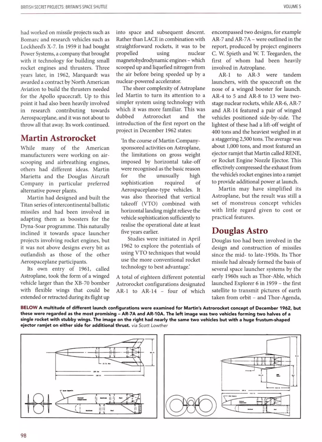
system for the military. The company
chosen to fulfil this requirement was de
Havilland Propellers, with what
became the Blue Streak missile.
Joining the space race
In 1939 the British Interplanetary
Society’s technical committee had
published the design of a spaceship for
taking three men to the moon and
back using a combination of 2,250
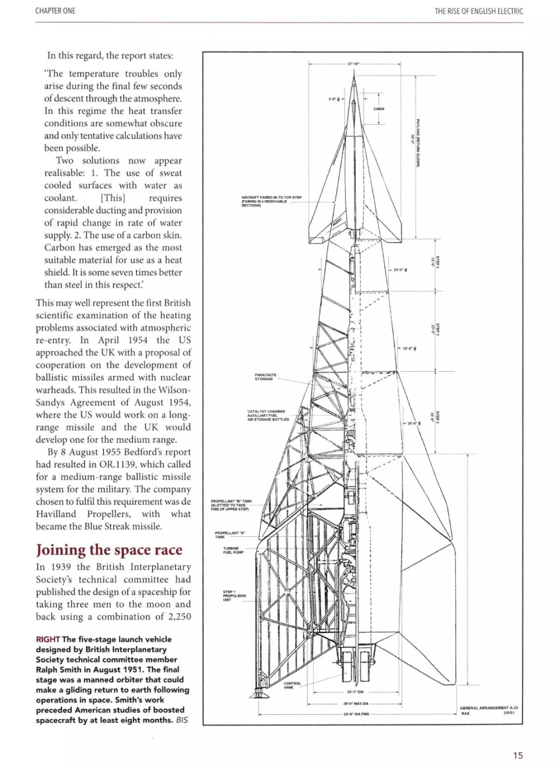
RIGHT The five-stage launch vehicle
designed by British Interplanetary
Society technical committee member
Ralph Smith in August 1951. The final
stage was a manned orbiter that could
make a gliding return to earth following
operations in space. Smith's work
preceded American studies of boosted
spacecraft by at least eight months. BIS
15
BRITISH SECRET PROJECTS: BRITAIN’S SPACE SHUTTLE
VOLUME 5
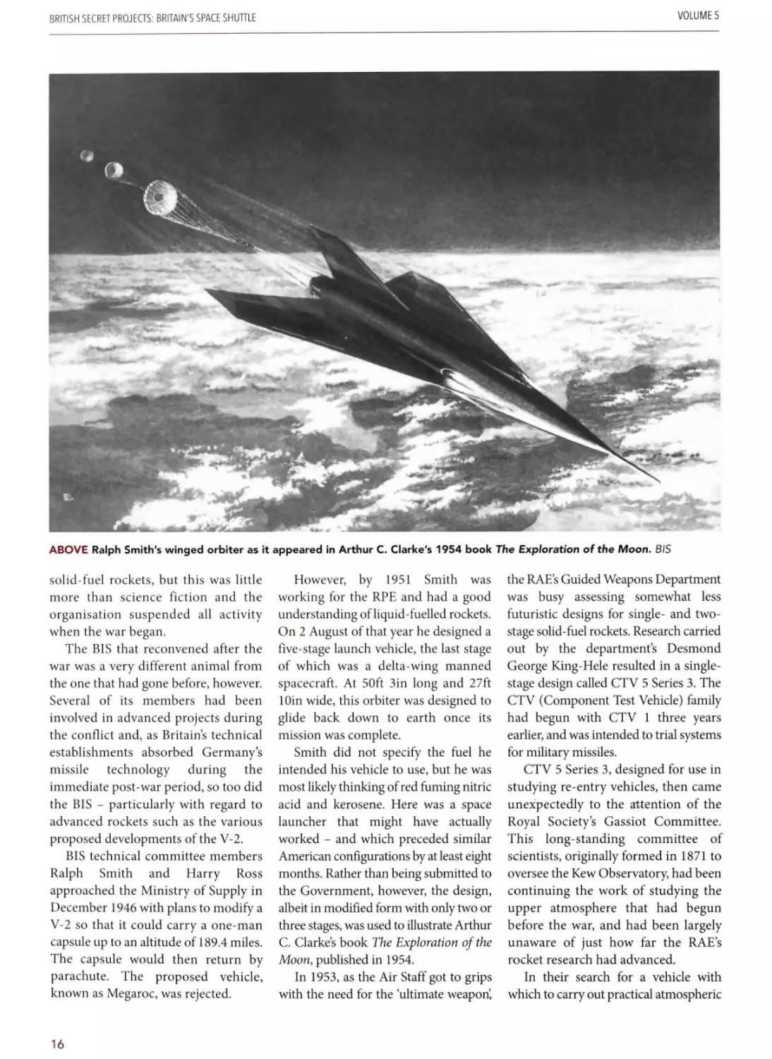
ABOVE Ralph Smith's winged orbiter as it appeared in Arthur C. Clarke's 1954 book The Exploration of the Moon. BIS
solid-fuel rockets» but this was little
more than science fiction and the
organisation suspended all activity
when the war began.
The BIS that reconvened after the
war was a very different animal from
the one that had gone before, however.
Several of its members had been
involved in advanced projects during
the conflict and, as Britain’s technical
establishments absorbed Germany’s
missile technology during the
immediate post-war period, so too did
the BIS - particularly with regard to
advanced rockets such as the various
proposed developments of the V-2.
BIS technical committee members
Ralph Smith and Harry Ross
approached the Ministry of Supply in
December 1946 with plans to modify a
V-2 so that it could carry a one-man
capsule up to an altitude of 189.4 miles.
The capsule would then return by
parachute. The proposed vehicle,
known as Megaroc, was rejected.
However, by 1951 Smith was
working for the RPE and had a good
understanding of liquid-fuelled rockets.
On 2 August of that year he designed a
five-stage launch vehicle, the last stage
of which was a delta-wing manned
spacecraft. At 50ft 3in long and 27ft
lOin wide, this orbiter was designed to
glide back down to earth once its
mission was complete.
Smith did not specify the fuel he
intended his vehicle to use, but he was
most likely thinking of red fuming nitric
acid and kerosene. Here was a space
launcher that might have actually
worked - and which preceded similar
American configurations by at least eight
months. Rather than being submitted to
the Government, however, the design,
albeit in modified form with only two or
three stages, was used to illustrate Arthur
C. Clarke’s book The Exploration of the
Moon, published in 1954.
In 1953, as the Air Staff got to grips
with the need for the ultimate weapon,
the RAEs Guided Weapons Department
was busy assessing somewhat less
futuristic designs for single- and two-
stage solid-fuel rockets. Research carried
out by the departments Desmond
George King-Hele resulted in a single-
stage design called CTV 5 Series 3. The
CTV (Component Test Vehicle) family
had begun with CTV 1 three years
earlier, and was intended to trial systems
for military missiles.
CTV 5 Series 3, designed for use in
studying re-entry vehicles, then came
unexpectedly to the attention of the
Royal Society’s Gassiot Committee.
This long-standing committee of
scientists, originally formed in 1871 to
oversee the Kew Observatory, had been
continuing the work of studying the
upper atmosphere that had begun
before the war, and had been largely
unaware of just how far the RAEs
rocket research had advanced.
In their search for a vehicle with
which to carry out practical atmospheric
16
CHAPTER ONE
THE RISE OF ENGLISH ELECTRIC
experiments, committee members had
even visited the US to learn about
Aerobee sounding rockets - which were
based on the design of captured V-2s. In
fact, the Americans had captured so
many components that they were able to
assemble about sixty working V-2s,
though without guidance systems, and to
continue using them for atmospheric
research alongside the Aerobee until the
last V-2 was fired on 19 September 1952.
It was the US scientific liaison
officer in London, Fred Singer, who
told the Gassiot scientists about the
RAEs rocket research, and specifically
about the CTV 5 Series 3 in 1953. A
few months later the Government, also
realising the suitability of the RAEs
rocket for space research, offered it to
the scientists.
In 1954 the Gassiot Committee
proposed that the CTV 5 Series 3 be
developed into a scientific research
rocket capable of carrying a 1001b
payload to an altitude of around 125
miles.
Coincidentally, at the end of that
year the Defence Research Policy
Committee (DRPC), an influential
group of military technology advisors
who reported directly to the Chiefs of
Staff and the Minister of Defence, set
up a working party to look at how long-
range military reconnaissance might be
improved through new technology.
While this work was under way, in
early 1955, the Americans were
consulted on the CTV 5 Series 3s
design. A delegation from the RAE
visited the New Mexico Joint Guided
Missile Test Range, formerly known as
the White Sands Proving Ground, to
examine the design of the Aerobee for
themselves. From this came the
revelation that the number of stabilising
fins on a rocket should be three - not
two or four - to help it clear the launcher
rails. In September 1956 CTV 5 Series 3
was renamed Skylark, after a suggestion
made in the RAEs in-house magazine.
It was powered by solid-fuel engines
developed by the RPE - initially the
Raven engine, then the Raven and the
Cuckoo when an extra stage was added.
While the civilian Skylark was being
finalised, a military research rocket,
Black Knight, was being devised by
Saunders-Roe to investigate design
problems posed by the development of
Blue Streak.
Meanwhile, the DRPC’s working
group had reached the conclusion that
an orbiting satellite equipped with
cameras would be the best possible
vehicle for carrying out long-range
reconnaissance. King-Hele was then
asked to investigate the design features
of such a satellite. He reported his
findings to the working group in 1956,
noting the difficulties of getting images
back from the satellite and suggesting
that it ought to be solar-powered. He
also suggested that Blue Streak might
make a suitable launch vehicle. After
his evidence had been reviewed by the
Royal Society, it was agreed that an
Artificial Satellite Sub-Committee
should be formed to look more closely
at the possibilities of satellites.
The first Skylark rocket was test-
launched in February 1957, and three
months later the RAE put out another
report making a much more detailed
assessment of how Blue Streak might be
used as a satellite launcher - by
mounting the smaller Black Knight
research vehicle on top of it as a second
stage. Neither vehicle had yet been built.
At this stage there was no government
requirement for a satellite, let alone a
satellite launcher, but the RAE was
convinced that both would be needed, so
continued with its research. Then, on 4
October 1957, the Soviets stunned the
West by successfully launching the
Sputnik 1 satellite into low earth orbit.
Less than a month later, on 3 November,
it was joined by Sputnik 2 with a dog on
board. Skylarks first scientific research
launch took place on 13 November.
These dramatic developments
resulted in a significantly increased
interest in space on the part of the
British Government. The Americans
launched their first satellite, Explorer 1,
on 31 January 1958, and their second,
Vanguard 1, on 17 March of the same
year. The first of twenty-two Saunders-
Roe Black Knight test vehicle launches
took place on 7 September 1958.
In May 1959 Conservative MP
Richard Fort asked Prime Minister
Harold Macmillan whether he was in a
position to make a statement about
space research. Macmillan replied:
‘Design studies are being put in
hand for the adaptation of the
British military rockets which are
now under development. This will
put us in a position, should we
decide to do so, to make an all-
British effort.’
That same month, the first meeting of
Hawker Siddeley Groups Space Study
Group took place. Its main purpose at
that time was to work out what ideas the
groups component firms should present
at the First Commonwealth Spaceflight
Symposium that August. Among them
was Armstrong Whitworth Aircrafts
Manned Satellite - details of which are
given in Chapter 7 - a proposed manned
space vehicle for orbital surveillance. And
before the end of the year Saunders-Roe
produced a brochure for a satellite launch
vehicle it called Black Prince, based on
designs it had already submitted to the
RAE in April. This was an unmanned
rocket, rather than a manned spacecraft.
It was announced in April 1960 that
Blue Streak would be cancelled as a
weapon, but would continue in
development as a satellite launcher.
Saunders-Roe, Bristol Siddeley and the
RAE spent the rest of the year working
out how Blue Streak might be
reconfigured for this new role with the
possible inclusion of Black Knight and
a new third stage.
At the end of the year and into early
1961 attempts were made to interest
the French in a joint satellite launcher
programme. This first resulted in
Eurospace, a private arrangement
between Hawker Siddeley and a group
of French companies to collaborate on
space projects. Then, after protracted
negotiations, the European Launcher
Development Organisation (ELDO)
came into being in March 1962. The
partners were Britain, bearing 38.8% of
the cost, France 23.9%, West Germany
22%, Italy 9.8%, Belgium 2.9%, and the
Netherlands 2.6%.
17
BRITISH SECRET PROJECTS: BRITAIN'S SPACE SHUTTLE
VOLUME 5
After Lightning
Unlike Saunders-Roe and the Hawker-
Siddeley Group firms, English Electric
had no involvement in the early
beginnings of Britain’s space race; its
hands were full with other work.
The P.l research aircraft made its
first flight in August 1954 and the
Lightning fighter into which it was
developed first Hew in April 1957,
entering service in December 1959.
Behind the scenes, the company’s
designers worked on numerous
different versions of the Canberra and
Lightning while also developing
unrelated advanced projects. Of the
project sequence between P.l and P.42,
seven were Canberra variants and
fifteen, including P.1 itself, were
variations on the Lightning theme -
such as P.l5, the photo-reconnaissance
version, and P.l8, the low-altitude
bomber version.
Between 1950 and 1955 other
projects included P.7, a large transport
aircraft powered by a single nose-
mounted Armstrong Siddeley Double
Mamba turboprop, and P.9, a basic jet
trainer aircraft where the instructor
and pupil sat next to one another.
A third major project began in 1955
in the form of P.10. This was English
Electrics first attempt to make use of
the advanced power plants under
development by its sister company, the
engine manufacturer Napier. In 1951
the firm had been contracted by the
NGTE to construct a test vehicle
powered by a large-diameter ramjet -
rival firm Bristol Engines being already
engaged in ramjet work with the RAE.
The result was the Ram Jet Test
Vehicle, or RJTV, and its power plant,
the Napier Ram Jet or NRJ. The vehicle
was a success and Napier then
continued to work on and improve the
design, resulting in the RJTV 2, which
had a ramjet capable of Mach 3-4.
When Operational Requirement
OR.330 with specification R.156T was
issued in January 1955, calling for a radar
reconnaissance aircraft with a top speed
above Mach 2.5, it was clear to English
Electric that Napiers ramjets could offer
a means of meeting that requirement.
Numerous different versions of P. 10 were
drafted, each with a long pointed nose, a
long slender fuselage, a low strongly
swept fin, and foreplanes just aft of the
cockpit. Where they differed most was
in the wings and engines.
One early design drafted by Ollie
Heath in January 1955, possibly the first
P. 10 study, was powered by sixteen Rolls-
Royce RB.121 turbojets, eight housed in
each wing. This had foreplanes like
miniature versions of the Lightnings
wings, and one version of it had vertical
fins just outboard of the engines for
added stability at high speed.
The P.10B of March 1955, however,
had a dozen ramjet burners within its
wings instead; the wing itself had thus
become the propulsion system. Exactly
how it would have been accelerated to
the point where the ramjets could
operate is unclear, however. The P. 10C of
January 1956 had enormous 60-inch-
diameter ramjets on its wingtips and thin
wings. Such huge engines did not yet
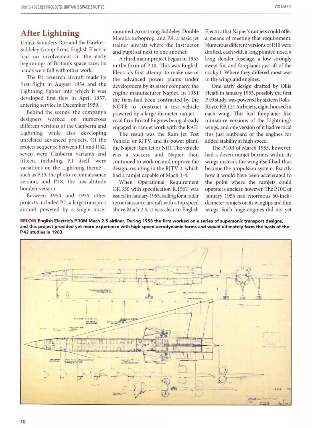
BELOW English Electric's R30M Mach 2.5 airliner. During 1958 the firm worked on a series of supersonic transport designs,
and this project provided yet more experience with high-speed aerodynamic forms and would ultimately form the basis of the
P.42 studies in 1963.
18
CHAPTER ONE
THE RISE OF ENGLISH ELECTRIC
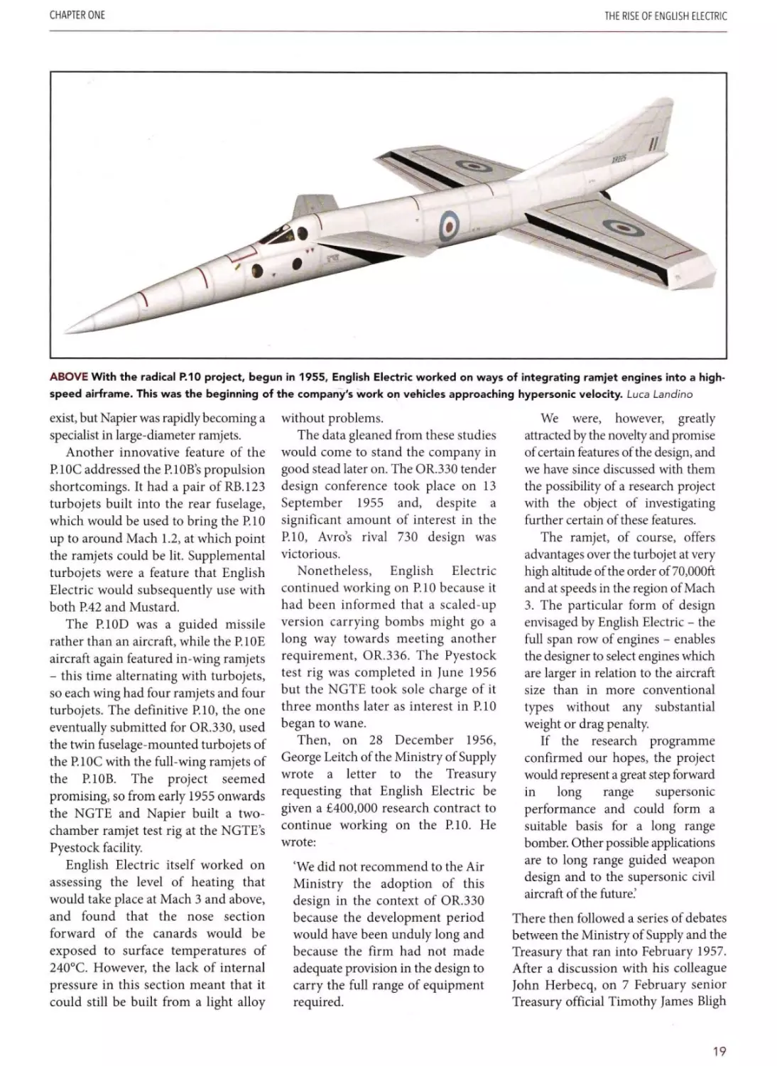
ABOVE With the radical P.1O project, begun in 1955, English Electric worked on ways of integrating ramjet engines into a high-
speed airframe. This was the beginning of the company's work on vehicles approaching hypersonic velocity. Luca Landino
exist, but Napier was rapidly becoming a
specialist in large-diameter ramjets.
Another innovative feature of the
P.10C addressed the P.lOBs propulsion
shortcomings. It had a pair of RB.123
turbojets built into the rear fuselage,
which would be used to bring the P. 10
up to around Mach 1.2, at which point
the ramjets could be lit. Supplemental
turbojets were a feature that English
Electric would subsequently use with
both P.42 and Mustard.
The P.10D was a guided missile
rather than an aircraft, while the P.10E
aircraft again featured in-wing ramjets
- this time alternating with turbojets,
so each wing had four ramjets and four
turbojets. The definitive P.10, the one
eventually submitted for OR.330, used
the twin fuselage-mounted turbojets of
the P.10C with the full-wing ramjets of
the P.10B. The project seemed
promising, so from early 1955 onwards
the NGTE and Napier built a two-
chamber ramjet test rig at the NGTE s
Pyestock facility.
English Electric itself worked on
assessing the level of heating that
would take place at Mach 3 and above,
and found that the nose section
forward of the canards would be
exposed to surface temperatures of
240°C. However, the lack of internal
pressure in this section meant that it
could still be built from a light alloy
without problems.
The data gleaned from these studies
would come to stand the company in
good stead later on. The OR.330 tender
design conference took place on 13
September 1955 and, despite a
significant amount of interest in the
P.10, Avros rival 730 design was
victorious.
Nonetheless, English Electric
continued working on P.10 because it
had been informed that a scaled-up
version carrying bombs might go a
long way towards meeting another
requirement, OR.336. The Pyestock
test rig was completed in June 1956
but the NGTE took sole charge of it
three months later as interest in P.10
began to wane.
Then, on 28 December 1956,
George Leitch of the Ministry of Supply
wrote a letter to the Treasury
requesting that English Electric be
given a £400,000 research contract to
continue working on the P.10. He
wrote:
‘We did not recommend to the Air
Ministry the adoption of this
design in the context of OR.330
because the development period
would have been unduly long and
because the firm had not made
adequate provision in the design to
carry the full range of equipment
required.
We were, however, greatly
attracted by the novelty and promise
of certain features of the design, and
we have since discussed with them
the possibility of a research project
with the object of investigating
further certain of these features.
The ramjet, of course, offers
advantages over the turbojet at very
high altitude of the order of 70,000ft
and at speeds in the region of Mach
3. The particular form of design
envisaged by English Electric - the
full span row of engines - enables
the designer to select engines which
are larger in relation to the aircraft
size than in more conventional
types without any substantial
weight or drag penalty.
If the research programme
confirmed our hopes, the project
would represent a great step forward
in long range supersonic
performance and could form a
suitable basis for a long range
bomber. Other possible applications
are to long range guided weapon
design and to the supersonic civil
aircraft of the future.’
There then followed a series of debates
between the Ministry of Supply and the
Treasury that ran into February 1957.
After a discussion with his colleague
John Herbecq, on 7 February senior
Treasury official Timothy James Bligh
19
BRITISH SECRET PROJECTS: BRITAIN'S SPACE SHUTTLE
VOLUME 5
wrote to their superior David Radford
Serpell, the Treasury undersecretary
with special responsibility for defence:
‘Mr Leitch made it clear that the
Ministry of Supply are interested
in this at the highest level, and he
hoped that we could give them
very early agreement.
1 know it is more difficult to
drown kittens that have their eyes
open, and that there is much to be
said for trying to get this project
stopped at this stage. Nevertheless
the sum involved is relatively
small, and I do not believe we can
hold such a strong view about this
as to be able to prevent Ministry
of Supply going ahead with it
within the shortly-to-be-reduced
(we hope) provision for research
and development expenditure.
Accordingly I come down on the
side of Mr Herbecq’s first
recommendation and would let
this proceed.’
At this point the P.10 was very close to
receiving full funding to be built as a
flying research aircraft. The Ministry of
Supply wanted it and the Treasury, which
held the purse strings, seemingly wanted
it too. English Electric had even offered
to sweeten the deal by paying £100,000
of the £400,000 out of its own pocket.
Serpell, a man later described by
British Rail Chairman Sir Peter Parker
as being as cosy as a razor blade’, wrote
back to Bligh on 11 February:
‘This is clearly one of those cases
where divided opinions are
inevitable. Let us get away from the
idea that “this is only a small one”.
The cost - £400,000 over two years
- would be very substantial in any
field. Even so, what really matters
is the effort involved.
Most of this money must no
doubt be spent, at this stage, on the
time of skilled men and
complicated machines. Can we
really afford this? A great effort is
apparently to be made by the
British aircraft industry as a whole
(or nearly) to develop a British
commercial supersonic aircraft
(which, incidentally, would not be
available until 1970).
Yet, as this weeks Flight points
out, the team lacks representation
from “the only two British firms
with truly supersonic experience -
Fairey and English Electric”. The
first question is, therefore, whether
English Electrics resources might
not be better used in assisting the
development of a commercial
supersonic aircraft, rather than -
as appears to be the case - jumping
ahead to an aircraft development
which, if it takes place at all, will,
presumably, not be for 20 years
from now.
At such a date, it seems unlikely
that there will be bombers, at any
rate in areas where Mach 3
performance would be required,
and if there are no bombers the
need for fighters of that sort of
performance will also have
disappeared. The Ministry of
Supply’s failure to secure a
“defence” view on the value of the
P.10 project must be taken as
evidence of the probable lack of
military interest. But all the same 1
think that such a view should be
sought since the P.10 project would
take up the time of skilled workers
who (the Ministry of Defence
might hold) would be better
employed on aircraft with a less
ambitious performance or on
guided missile development and
production.’
And with that, Serpell finally killed the
P.10 outright. A letter was sent to him
on 19 February by Air Ministry official
Ronald C. Kent saying of the P. 10: ‘The
possible long term applications for
such an advanced project, both in
manned and unmanned vehicles, are
many; and the proposal has the Air
Staff s full support.’ But it was too late.
In a memo dated 8 April 1957, Herbecq
wrote: ‘This project is now a firm
candidate for a trim in aid of the £20m
target.’ This was four days after the
publication of the 1957 Defence White
Paper, which was intended primarily to
save that amount of money by reducing
the number of military projects
undergoing development at that point.
John Rankin Christie of the
Ministry of Supply wrote to Bligh on 1
August 1957 to explain that
‘English Electric agreed to re-
examine the programme and
proposed another approach which
involved a design study stage to
explore the possibilities as a first
step with some exploratory work on
ram jets at Bristols. We are now
satisfied that this will keep progress
on the project at a satisfactory rate.
This stage will last until about
March next year when we shall have
to decide on examination of the
results whether to carry on or not.’
English Electric had apparently agreed
to fund the research itself. The Ministry
of Supply had allocated £45,000 to the
P.10, but this would now be transferred
to Bristol Engines’ ramjet work. Here
the ailing P.10 came to a halt. But
Serpell’s comments about English
Electric’s experience and Britain’s future
commercial supersonic airliner had
been more apt than he knew.
Supersonic transports
While P.10 was drawing its final breath,
English Electric was already preparing to
engage in another cutting-edge project -
P.17. In October 1956, two months
before the resurrection of P.10, English
Electric had begun talks with Handel
Davies, the Ministry of Supply’s newly
appointed Director-General of Scientific
Research (Air), regarding proposals for
a successor to the Canberra.
A set of specifications was being
drafted, which included a speed of
Mach 1.3 and a range of some 800
miles at sea level carrying either a
conventional or nuclear weapons
payload or reconnaissance equipment.
These were solidified into a new
General Operational Requirement in
March 1957, GOR.339. The deadline
for submissions was 31 January 1958,
and the eventual result was that
English Electric’s P.17 became the basis
for the TSR2 strike aircraft. In the
process of winning this major contract,
the company was paired up with
Vickers-Armstrongs, which was given
the project lead.
20
CHAPTER ONE
THE RISE OF ENGLISH ELECTRIC
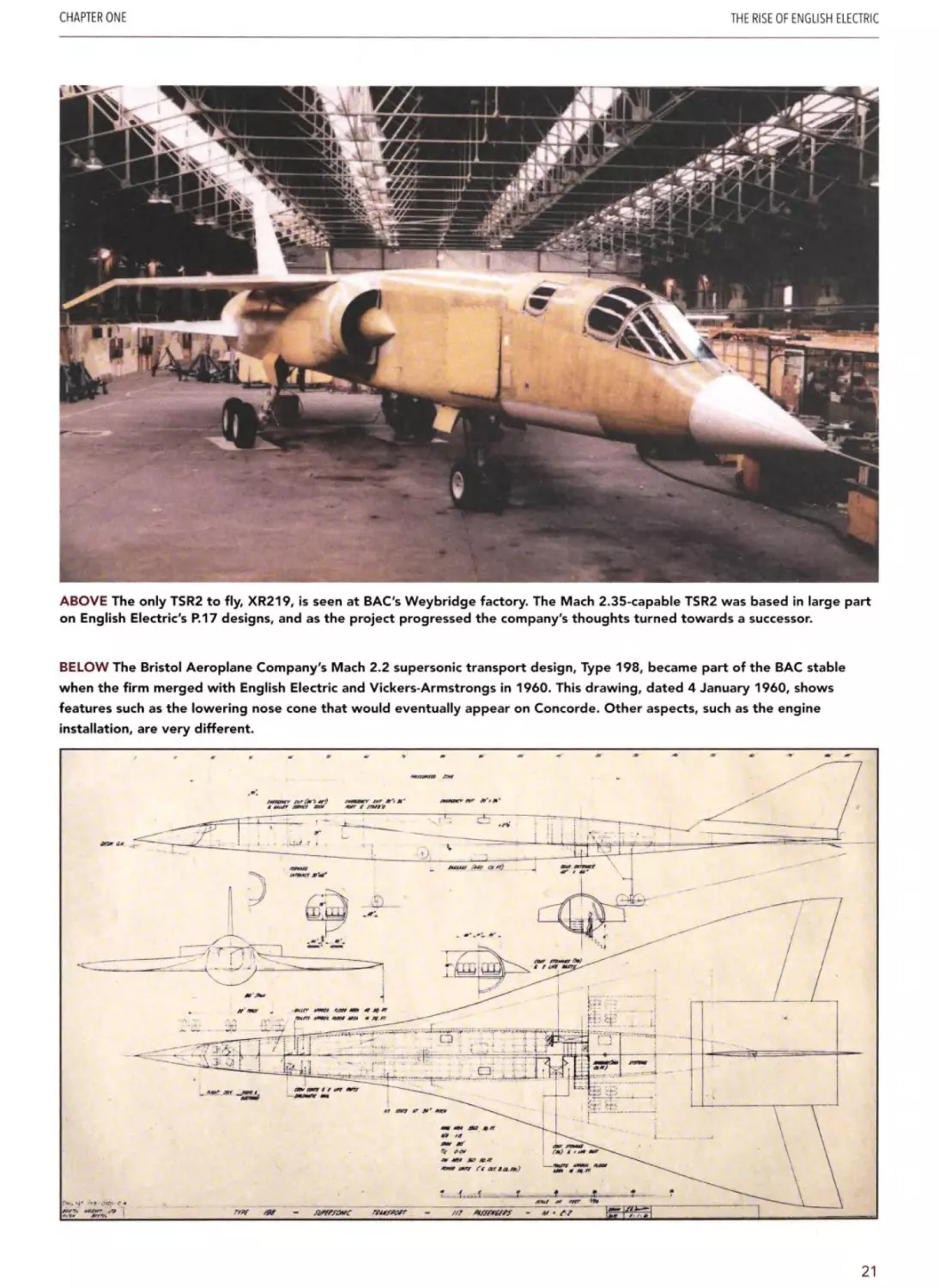
ABOVE The only TSR2 to fly, XR219, is seen at BAC's Weybridge factory. The Mach 2.35-capable TSR2 was based in large part
on English Electric's P.17 designs, and as the project progressed the company's thoughts turned towards a successor.
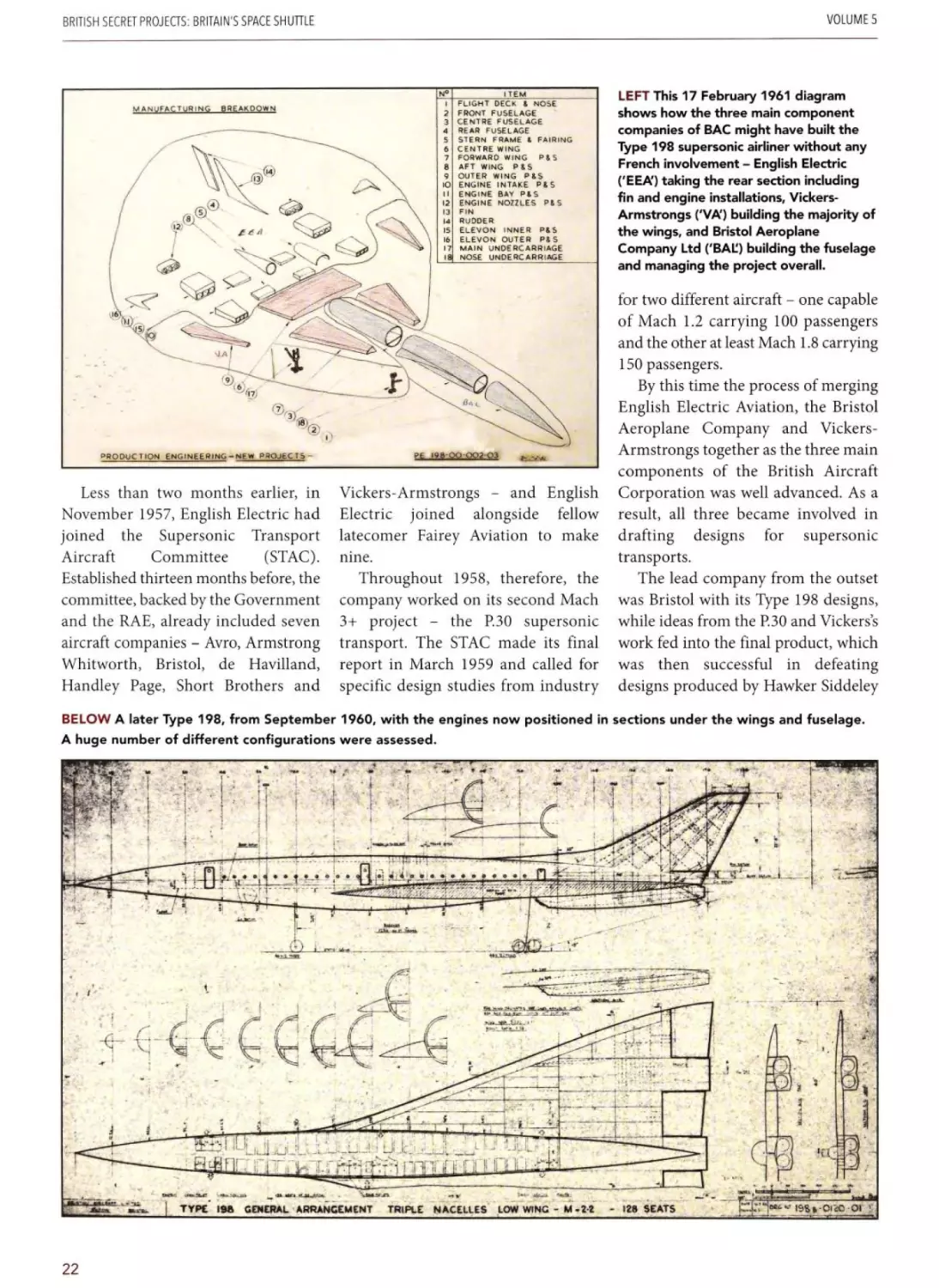
BELOW The Bristol Aeroplane Company's Mach 2.2 supersonic transport design, Type 198, became part of the ВАС stable
when the firm merged with English Electric and Vickers-Armstrongs in 1960. This drawing, dated 4 January 1960, shows
features such as the lowering nose cone that would eventually appear on Concorde. Other aspects, such as the engine
installation, are very different.
21
BRITISH SECRET PROJECTS: BRITAIN'S SPACE SHUTTLE
VOLUMES
Less than two months earlier, in
November 1957, English Electric had
joined the Supersonic Transport
Aircraft Committee (STAC).
Established thirteen months before, the
committee, backed by the Government
and the RAE, already included seven
aircraft companies - Avro, Armstrong
Whitworth, Bristol, de Havilland,
Handley Page, Short Brothers and
Vickers-Armstrongs - and English
Electric joined alongside fellow
latecomer Fairey Aviation to make
nine.
Throughout 1958, therefore, the
company worked on its second Mach
3+ project - the P.30 supersonic
transport. The STAC made its final
report in March 1959 and called for
specific design studies from industry
LEFT This 17 February 1961 diagram
shows how the three main component
companies of ВАС might have built the
Type 198 supersonic airliner without any
French involvement - English Electric
CEE A) taking the rear section including
fin and engine installations, Vickers-
Armstrongs ('VA') building the majority of
the wings, and Bristol Aeroplane
Company Ltd ('BAL) building the fuselage
and managing the project overall.
for two different aircraft - one capable
of Mach 1.2 carrying 100 passengers
and the other at least Mach 1.8 carrying
150 passengers.
By this time the process of merging
English Electric Aviation, the Bristol
Aeroplane Company and Vickers-
Armstrongs together as the three main
components of the British Aircraft
Corporation was well advanced. As a
result, all three became involved in
drafting designs for supersonic
transports.
The lead company from the outset
was Bristol with its Type 198 designs,
while ideas from the P.30 and Vickerss
work fed into the final product, which
was then successful in defeating
designs produced by Hawker Siddeley
BELOW A later Type 198, from September 1960, with the engines now positioned in sections under the wings and fuselage.
A huge number of different configurations were assessed.
22
CHAPTER ONE
THE RISE OF ENGLISH ELECTRIC
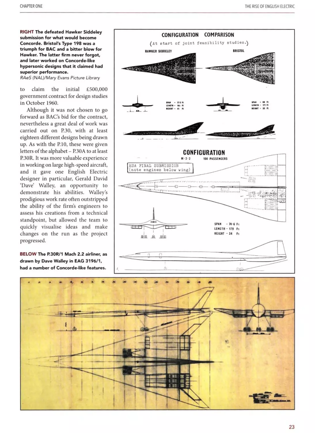
RIGHT The defeated Hawker Siddeley
submission for what would become
Concorde. Bristol's Type 198 was a
triumph for ВАС and a bitter blow for
Hawker. The latter firm never forgot,
and later worked on Concorde-like
hypersonic designs that it claimed had
superior performance.
RAeS (NAL)/Mary Evans Picture Library
to claim the initial £500,000
government contract for design studies
in October 1960.
Although it was not chosen to go
forward as ВАС s bid for the contract,
nevertheless a great deal of work was
carried out on P.30, with at least
eighteen different designs being drawn
up. As with the P.10, these were given
letters of the alphabet - P.30A to at least
P.30R. It was more valuable experience
in working on large high-speed aircraft,
and it gave one English Electric
designer in particular, Gerald David
‘Dave Walley, an opportunity to
demonstrate his abilities. Walleys
prodigious work rate often outstripped
the ability of the firm’s engineers to
assess his creations from a technical
standpoint, but allowed the team to
quickly visualise ideas and make
changes on the run as the project
progressed.
BELOW The P.30R/1 Mach 2.2 airliner, as
drawn by Dave Walley in EAG 3196/1,
had a number of Concorde-like features.
CONFIGURATION COMPARISON
At start of joint feasibility studies.)
23
BRITISH SECRET PROJECTS: BRITAIN'S SPACE SHUHLE
VOLUMES
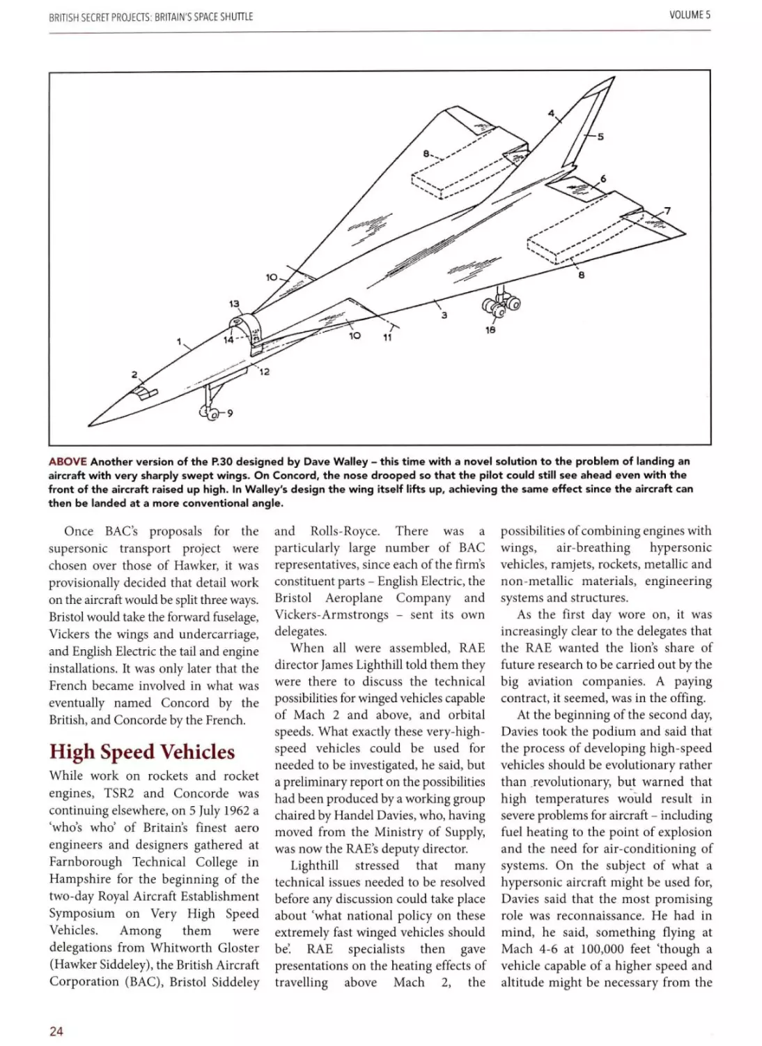
ABOVE Another version of the P.3O designed by Dave Walley - this time with a novel solution to the problem of landing an
aircraft with very sharply swept wings. On Concord, the nose drooped so that the pilot could still see ahead even with the
front of the aircraft raised up high. In Walley's design the wing itself lifts up, achieving the same effect since the aircraft can
then be landed at a more conventional angle.
Once BAC’s proposals for the
supersonic transport project were
chosen over those of Hawker, it was
provisionally decided that detail work
on the aircraft would be split three ways.
Bristol would take the forward fuselage,
Vickers the wings and undercarriage,
and English Electric the tail and engine
installations. It was only later that the
French became involved in what was
eventually named Concord by the
British, and Concorde by the French.
High Speed Vehicles
While work on rockets and rocket
engines, TSR2 and Concorde was
continuing elsewhere, on 5 July 1962 a
‘who’s who’ of Britain’s finest aero
engineers and designers gathered at
Farnborough Technical College in
Hampshire for the beginning of the
two-day Royal Aircraft Establishment
Symposium on Very High Speed
Vehicles. Among them were
delegations from Whitworth Gloster
(Hawker Siddeley), the British Aircraft
Corporation (ВАС), Bristol Siddeley
and Rolls-Royce. There was a
particularly large number of ВАС
representatives, since each of the firm’s
constituent parts - English Electric, the
Bristol Aeroplane Company and
Vickers-Armstrongs - sent its own
delegates.
When all were assembled, RAE
director James Lighthill told them they
were there to discuss the technical
possibilities for winged vehicles capable
of Mach 2 and above, and orbital
speeds. What exactly these very-high-
speed vehicles could be used for
needed to be investigated, he said, but
a preliminary report on the possibilities
had been produced by a working group
chaired by Handel Davies, who, having
moved from the Ministry of Supply,
was now the RAE’s deputy director.
Lighthill stressed that many
technical issues needed to be resolved
before any discussion could take place
about ‘what national policy on these
extremely fast winged vehicles should
be’. RAE specialists then gave
presentations on the heating effects of
travelling above Mach 2, the
possibilities of combining engines with
wings, air-breathing hypersonic
vehicles, ramjets, rockets, metallic and
non-metallic materials, engineering
systems and structures.
As the first day wore on, it was
increasingly clear to the delegates that
the RAE wanted the lion’s share of
future research to be carried out by the
big aviation companies. A paying
contract, it seemed, was in the offing.
At the beginning of the second day,
Davies took the podium and said that
the process of developing high-speed
vehicles should be evolutionary rather
than revolutionary, but warned that
high temperatures would result in
severe problems for aircraft - including
fuel heating to the point of explosion
and the need for air-conditioning of
systems. On the subject of what a
hypersonic aircraft might be used for,
Davies said that the most promising
role was reconnaissance. He had in
mind, he said, something flying at
Mach 4-6 at 100,000 feet ‘though a
vehicle capable of a higher speed and
altitude might be necessary from the
24
CHAPTER ONE
THE RISE OF ENGLISH ELECTRIC
vulnerability aspect*. This aircraft
would have several advantages over a
satellite, he said, including ‘improved
definition, and greater control over its
trajectory. It could also have an
offensive ability.’ Other promising uses
for such a vehicle were as the first stage
of a satellite-launching system and for
long-range transport.
At the end of his speech, Davies
made four recommendations:
‘...that design studies should be
made in industry of a
reconnaissance bomber/transport
vehicle in the Mach 4-6 speed
range; that parametric studies of
vehicles capable of flight in the
Mach 6-12 speed range should be
made, including the possible use of
such an aircraft as a satellite
launcher; the vulnerability of these
types of vehicles should be
investigated; and basic research
over a broad front should
continue.’
Assistant Chief of the Air Staff Air Vice
Marshal Christopher Hartley then
explained the Air Ministry’s position.
He said that he was ‘under pressure to
define the military requirements for
aerospace vehicles’ but was ‘most
encouraged to find so much common
ground’ between the RAE’s thinking
and that of his own staff. He also said
it was unlikely that the UK would be
able to go it alone with hypersonics and
space launcher projects, but that ‘a
great deal has to be done before one
can approach other countries with
proposals for collaboration.’
There were two main reasons, he
said, for ‘extension upwards of the
Mach number and altitude capabilities
of current weapons carriers and
transports’: the risk of losing the ability
to penetrate enemy defences at low
level, and the potential threat posed by
enemy aircraft flying at high altitudes.
He agreed that the most obvious use
for a hypersonic aircraft was for
reconnaissance, but ‘there is also a case
for a transport of medium to short
range which can over-fly countries
without being detected. If such an
aircraft could take off and land using
2,000-yard runways, it would be a very
useful vehicle for transporting key
personnel very quickly.’
He warned that ‘little emphasis
should be put on a strike application at
the present stage, particularly as the
type of defensive weapons likely to exist
in 15 years’ time cannot be clearly
forecast, but obviously one would try to
use a hypersonic vehicle in the strike
role if it existed.’ Using hypersonic
speed for a fighter aircraft also needed
to be investigated.
Next it was delegates’ turn to offer
some of their own experiences with
designing Mach 2+ aircraft.
Dr Robin Jamison, head of Bristol
Siddeley Engines’ newly established
Advanced Propulsion Research Group,
went first. He described a design study
carried out by his firm involving a Mach
7 transport weighing 300,0001b,
carrying a 15,0001b payload, that could
take off and land on 7,000-foot runways.
Three novel engine types had been
considered - a reheated turbojet/ramjet
combination, a turbojet/rocket/ramjet
combination, and a turbo-rocket.
Whichever was used, the intake would
have been a Nonweiler shape, formed
like an inverted ‘V’, and the air flow into
the engine would have been controlled
by a ramp. Initial power would be
provided by the turbojet, with the ramjet
lighting up at Mach 1. By Mach 3, the
turbojet would just be increasing drag,
so it would be powered down and
switched off at some point between
Mach 3 and Mach 4 - with the air being
entirely diverted away from it.
Up to Mach 7, the ramjet provided
all of the power. Jamison said: ‘It was
found that with the turbojet/ramjet
configuration, acceleration at transonic
speeds was poor and fuel consumption
high, but with the addition of rocket
power for acceleration in this region
there was a decrease of total engine-
plus-fuel weight.’
Range without the rocket was 4,400
miles, but with it the aircraft could
reach 4,900 miles. Jamison said that if a
‘pick-a-back configuration’ was
considered - the aircraft effectively
being propelled to altitude by an
expendable rocket or similar - climb
fuel would be saved and a range of up
to 6,900 miles was possible at Mach 7.
In the group discussion that followed,
Rolls-Royce engineer Stephen Bragg
questioned Bristol Siddeley’s fuel
consumption figures and said that
Jamison’s design study demonstrated the
need to study the whole flight trajectory
of any hypersonic vehicle.
Denning Pearson, the managing
director of Rolls-Royce’s aero engine
division, and also chief executive of the
company as a whole, then said he was
not convinced that jet deflection -
diverting the airflow around the inside
of a turbojet/ramjet combination -
would be easy to accomplish in practice
‘as has been assumed by some speakers’.
Ray Creasey, now English Electric’s
director of engineering, made a
presentation describing various project
studies carried out by his firm after the
cancellation of OR.330. One example,
he said, was an aircraft with a capability
of Mach 3 at 100,000 feet, which had a
ducted wing structure with integrated
ramjets. It had been found that there
was ample stowage volume available for
fuel, but the ratio of engine exit
area/inlet area caused problems. He
was referring to the P.10, though he did
not name it as such, and said that in
general ‘once one considers speeds
above Mach 2, and skin temperatures
above 150°C, many difficulties arise
and prospects for civil aircraft with skin
temperatures of 600°C appear remote.’
A second representative of ВАС,
David J. Farrar, from the part of the
corporation that had been the Bristol
Aeroplane Company, said that the
problems he had faced in designing the
Bristol Bloodhound surface-to-air
missile were very similar to those
facing designers working on high-
speed aircraft: ‘For example, the design
of control systems with severe
aerodynamic and thermodynamic
loads, equipment design in an
unfavourable environment, protection
of materials, including thermal shock
and ablation problems.’ Vulnerability
studies had shown that ‘a hypersonic
25
BRITISH SECRET PROJECTS: BRITAIN'S SPACE SHUTTLE
VOLUME 5
cruise aircraft should be invulnerable
to tactical surface-to-air guided
weapons, but not to strategic SAMs
such as Nike-Zeus’
I’he UM-49 Nike Zeus missile was
a development of the MIM-14 Nike
Hercules anti-missile system, designed
to intercept incoming ICBMs in the
upper atmosphere - or even satellites -
and destroy them with a 25-kiloton
W31 nuclear warhead. The huge blast
created by this device was intended to
guarantee a ‘kill’, but strong doubts had
already been raised about its
effectiveness by July 1962. Detonating
a nuclear device in the upper
atmosphere made the air below it
opaque to radar - effectively blinding
Zeus and preventing further
interceptions if a second wave of
missiles was inbound.
Not only that, but the system could
not tell the difference between decoys
fitted with radar reflectors and missiles
carrying live warheads. If the spread of
incoming targets caused some to be
missed by the first Zeus detonation, it
would then be too late for the system to
pick up the stragglers. It was cancelled
the following year.
Farrar then went on to criticise the
RAE report for failing to take into
account the re-entry problems that
would be faced by weapon-carrying
hypersonic aircraft, but conceded that
such an aircraft ‘might be of great
tactical use’.
During the final afternoon of
debates, Alan Clifton of Supermarine,
and now the Vickers-Armstrongs part
of ВАС, who had been one of the
Supermarine Spitfire’s designers, said:
‘The time scale assumed for
producing a hypersonic aircraft
appears to be an in-service date of
1980. We are concerned with
converting research and
development data into ironmongery,
and this is a continuous process. The
evolutionary way, with research
aircraft being regularly designed, is a
cheaper way of proceeding than
aiming to produce one vehicle in the
distant future.’
The Air Ministry’s Morien Morgan,
who was at that time chairing the
Concorde oversight committee,
replied:
‘At the present time record sums
are being spent on research
aircraft. The ministry is not anti
research aircraft, but only a limited
sum of money is available. If a
good case for a research aircraft is
put forward it will be energetically
pursued.’
Lighthill then summed up, but did not
tell delegates that a second working
party had been set up a month earlier
to further investigate hypersonics as
space vehicles. Only when this research
group had all but concluded its
research were a pair of contracts for
further hypersonics studies drawn up
for the two biggest players in the British
aviation industry.
26
Chapter Two
‘Concorde-ish in nature’
English Electric P.42 aircraft
The Ministry of Aviation issued
identical £45,000 research
contracts to Hawker Siddeley Aviation
(HSA) and the British Aircraft
Corporation on 10 July 1963. HSA
received Contract No
KD/2X/l/CB7(c), while ВАС got No
KD/2X/2/CB7(c), requiring the
companies to study hypersonic vehicles
in four distinct categories, which
hinted at potential operational roles
without being too specific. The
categories were: long-range high-speed
cruise aircraft; recoverable launchers;
boost-glide vehicles; and space planes.
The first of these would form the basis
for a bomber or transport aircraft, the
second a spacecraft designed to ‘skip
through the upper atmosphere, the
third a reusable means of putting
payload into space, and the last an out-
and-out manned space vehicle,
designed to ‘fly’ into space and return.
Within those four broad headings, the
firms were to look at whether two-stage
or single-stage configurations would be
best, whether rockets and ramjets
could be used effectively as ‘boosters’
and ‘sustainers’, and what different fuels
might be used, particularly hydrogen
and kerosene. Cost and timescale were
to be commented on and suggestions
for further avenues of research were
invited.
The terms of the contract required
that ‘work under the contract is to
begin immediately and to be completed
as soon as possible but not later than 31
December 1963.’ This gave the two
firms less than six months to conduct
ABOVE English Electric's first runway
take-off launcher combination - P.42
Scheme 11/4 booster with P.42 Scheme
11/1 spacecraft - sets out on a mission
to examine a potentially hostile Soviet
satellite. Daniel Uhr
one of the most wide-ranging and
open-ended studies into new
technology ever commissioned in
Britain - and on a tiny budget.
The letter issued alongside the
contract by the Ministry of Aviation’s
director of contracts also stated:
‘In carrying out the work
described in the schedule you
should of course take account of
work on propulsion being done at
Bristol Siddeley Engines Ltd and
Rolls-Royce Ltd. I am also to
request that you maintain close
27
BRITISH SECRET PROJECTS: BRITAIN'S SPACE SHUTTLE
VOLUME 5
collaboration with the Royal
Aircraft Establishment and with
the National Gas Turbine
Establishment.*
HSAs work on its contract is discussed
in Chapter 7. The English Electric
Aviation team at Warton, near Preston,
Lancashire, were to fulfil BAC’s
contract. English Electric had by now
been part of the corporation for three
years and Warton was rebranded as its
Preston Division during the course of
the work.
The project had already been given
the designation P.42 and was under the
supervision of Ray Creasey and the
head of the research (aerodynamics)
department, Tom Smith, with designer
Dave Walley responsible for most of
the necessary drawings.
What the engine companies offered
Right at the outset English Electric was urged to ‘take account of work on
propulsion being done at Bristol Siddeley Engines Ltd and Rolls-Royce Ltd’.
This amounted to perusing various brochures provided by the two
companies and attempting to work out which was offering the most reliable
set of performance figures - no easy task - and how those figures might change
when the engine was actually installed in a real aircraft.
While Bristol Siddeley supplied only two brochures, first for its BS.1011
turbojet/ramjet, then for a more advanced version of the same thing called
BS.1012, Rolls-Royce gave English Electric four options - its Type ‘B’ turbojets,
‘C’ turboramjets, ‘O’ turborockets, and the ‘flashjef, a version of the latter
fuelled by liquid hydrogen alone.
The first progress report on English Electric’s hypersonics studies has a
whole section devoted to comparing these proposed powerplants. It states:
‘The two engine companies supplied data in somewhat different form. Rolls-
Royce submitted performance data for their engine fitted with a fully variable
intake and a semi-variable ejector nozzle. There was no allowance for pre-
entry drag and the efficiency of the nozzle referred to a “rubber” installation.
On the other hand Bristol Siddeley Engines presented a brochure
containing matched installed performance for their power plant. The
Rolls-Royce engine was matched to a more practical intake and nozzle and
the performance corrected accordingly.
Although the Bristol Siddeley Engines data included allowances for pre-
entry and base drag, these were considered to be optimistic. Therefore, for
performance work the allowances were increased, so that the Bristol Siddeley
Engines and Rolls-Royce designs were compared on the same standard.’
In other words, English Electric took each brochure with a pinch of salt. The
Rolls-Royce figures had to be amended to take real-world installation into
account, and Bristol Siddeley Engines’ figures had to be toned down because
they were deemed to be overly ‘optimistic
Interviewed in 1984, Smith recalled:
‘We started by looking at things which
were Concorde-ish in nature and went
on from there to high-speed aircraft
which would travel at Mach 12.*
When two members of the Air Staff,
deputy directors of requirements
Group Captain A. Hewitt and Wing
Commander G. E. Thirlwall, visited
Warton in December 1963, they
reported on the firm*s design activities
and noted in their report:
‘Studies of hypersonic vehicles began
about May 1962 in preparation for
the Very High Speed Vehicles
Conference of July 1962. The subject
was considered principally in terms
of hypersonic aerodynamics and
about 10 people of Aerodynamics
Research were engaged.
The scale of effort was increased to
about 30 and the scope of the work was
broadened to cover all aspects of
hypersonic flight when work began on
the Ministry of Aviation contract. It
was emphasised that the best designers,
structures engineers and other
specialists in the firm had been brought
together to form the present team.’
Getting started
The English Electric team had chosen to
begin their work, before the Very High
Speed Vehicles event had even taken
place, with a series of general designs for
hypersonic cruise research aircraft. This
made it possible to establish what
difficulties might be faced later and
what aspects of design would need the
greatest consideration.
As usual, the English Electric ‘EAG’
drawing number sequence was used
(although no one now knows what
‘EAG’ actually stood for). A designer
would be allocated a block of numbers
and would then work through them.
P.42 began with drawing number EAG
3272 and can be said to have ended on,
or close in sequence to, EAG 4495.
At first, P.42 was worked on through
a series of numbered ‘schemes’ rather
than alphabetical letters as had been the
case with P.10 and P.30. Many of these
were then subdivided into two or more
different design variations on a
sometimes very loose common theme.
Further subdivision was possible with
‘issues’, which retained the same
drawing number but differed slightly
from one another in detail. For example,
the aircraft featured on EAG 4396 was
the thirteenth variation on Scheme 11 -
making it Scheme 11/13.
EAG 4396 was then further
subdivided into EAG 4396 P.42 Scheme
11/13 issue 1 and issue 2. Other
drawings sometimes also featured a
preliminary issue, which went before
issue 1. This system lasted until Scheme
20, whereupon the ‘schemes’ system was
apparently abandoned and drawings
were simply labelled ‘P.42’. Even this
ceased after drawing number EAG 4431
- the last drawing number to be labelled
‘English Electric Aviation’. EAG 4432
28
CHAPTER TWO
’CONCORDE-ISH IN NATURE'
was the first to be labelled ‘British
Aircraft Corporation and P.42 does not
appear thereafter - but subsequent
designs were still regarded as belonging
to the same project.
Looking at the first nine schemes for
P.42, none of which were reported to
the Government, it would be easy to
believe that they were simply flights of
fancy on the part of the English Electric
team. Yet the company's first progress
report graphically demonstrates the
amount of work that went into every
design. Wing size and shape were
carefully considered in each case,
together with the form of every intake,
the amount of fuel and payload that
could be carried, the size and weight of
the undercarriage, and dozens of other
considerations that each played their
part in shaping the designs.
Engine selection was also an
important factor but, unlike many
advanced aircraft development
programmes, P.42 was not simply a
series of aerodynamic forms wrapped
around particular propulsion systems.
In some cases the engine to be used was
not specified, while in others it is clear
that the design team were making
calculations that allowed for what they
regarded as sketchy and somewhat
optimistic figures from the two engine
companies - Rolls-Royce and Bristol
Siddeley Engines.
The English Electric teams holistic
approach therefore resulted in designs
with a solid basis in what was deemed
technologically achievable for the time.
The first three P.42s
P.42 started with a radical hypersonic
research aircraft. Scheme 1 was a Mach
5 design described in drawing number
EAG 3272 and was roughly the same
size as English Electrics touchstone
aircraft, the Canberra. However, its
layout could scarcely have been more
different from the late-1940s jet
bomber. It was a 63-foot-long single-
seat tailless delta with large canards
extending all the way from the sides of
the cockpit to nearly the end of its nose.
Two large vertical control surfaces near
the wingtips stretched from leading to
trailing edge. The wing itself had an
area of l,500sq ft and a span of 70 feet.
The fuselage housed an enormous
ramjet of unspecified type, with a huge
yawning intake of 5ft 3in diameter at the
front, angled to form a precompression
ramp, and a 6ft 3in exhaust nozzle at the
rear, which was shaped to allow
expansion of escaping gases. Additional
propulsion, to enable the aircraft to gain
sufficient speed for ramjet light-up, was
provided by a pair of developed Rolls-
Royce RB.162 turbojets, which would
retract into the sides of the aircraft as it
approached hypersonic speed.
With the huge canards completely
obscuring the pilot’s view forward and
down, the cockpit was hinged near the
nose and designed to rise up at an angle
BELOW Where it all began - English Electric's P.42 Scheme 1. This monstrous research aircraft with delta wing, forward-tilting
cockpit and offset nosewheel, shown in drawing EAG 3272, was to be powered by a huge ramjet with assistance from two
RB.162 turbojets.
29
BRITISH SECRET PROJECTS: BRITAIN'S SPACE SHUTTLE
VOLUME 5
ABOVE The English Electric P.42 Scheme 1 research aircraft performs a fast climb, its ramjet lighting up as its turbojets
continue to propel it skywards. Hamza Fouatih
to provide improved vision for landing.
The undercarriage was a tricycle affair
with the nosewheel offset to starboard,
and the all-up weight was to be
50,000lb.
P.42 Scheme 2 took a more
conventional form but embodied much
of the same technology. Shown in EAG
3273, it is described simply as a Mach
5 aircraft. This time there was a
conventional 75-foot-long fuselage
with no canards, no hinged cockpit and
no enormous internal ramjet. It had a
45-foot-span delta wing with 70°
sweep, though still an area of l,500sq
ft. The wingtips were designed to fold
down by 90° for aerodynamic
efficiency during high-speed flight, and
there was a single vertical fin at the rear
of the fuselage. The undercarriage was
a symmetrical tricycle arrangement.
Propulsion was by two ramjets
contained in cylindrical pods slung
beneath the wing close to the fuselage.
Internally, each was simply a smaller
version of the ramjet that filled the
EAG 3272 aircraft’s fuselage. Again,
there were two retractable developed
RB.162s for power, but this time fitted
in tandem owning to the narrowness of
the fuselage.
Fitting the ramjets into underwing
pods allowed the aircraft to have a
rectangular internal payload bay,
between the two engines, with the
aircrafts centre of gravity right in the
middle of it.
For P.42 Scheme 3/2, shown in EAG
3277/2, a scaled-down version of the
wing from Scheme 2, of 36-foot span
down from 45 feet, was combined with
a slightly lengthened version of the
fuselage from Scheme 1 - 65 feet
compared to 63 feet. The fin was also
retained from Scheme 2.
This arrangement allowed very little
room for the nosewheel, no room for
LEFT The sleek P.42 Scheme 2 of drawing
EAG 3273 - a prettier research aircraft
than its predecessor, with podded
ramjets.
30
CHAPTER TWO
CONCORDE ISH IN NATURE1
RIGHT Another enormous ramjet with
an aircraft wrapped around it - P.42
Scheme 3/2 of EAG 3277/2.
payload and no indication of where the
two RB.162s would go - though they
are still indicated as a necessity on the
drawings accompanying notes. All-up
weight remained the same at 50,0001b.
The first three P.42 schemes -
though they appear quite different
from one another - can be regarded as
essentially three different versions of
the same experimental/research
aircraft. The key component in each
case was the ramjet; although it has
been suggested that this might have
been based on the Bristol Siddeley
BS.1001 or BS.1002 ramjet designs,
neither of these was expected to be
sufficiently powerful for Mach 5, so its
type must remain unknown.
Space launcher
The next three P.42 designs possessed
many features in common with their
predecessors but took the series closer
to the contracted design brief. The
drawings are undated, so may in fact
have been produced after the contract
was awarded. P.42 Scheme 4, of
drawing EAG 3280, had almost exactly
the same 45-foot-span 70° swept delta
wing with movable wingtips as Scheme
2, not to mention the same tailfin. But
where that design had the wing set low
on the fuselage and was perched atop
tall undercarriage legs to provide
sufficient clearance for its podded
ramjets, Scheme 4 had the wing high
up on top of its 75-foot-long fuselage
and a much shorter undercarriage.
Power came from a pair of
developed Rolls-Royce RB.168 Spey
engines, the like of which would
eventually propel Britain’s McDonnell
Douglas Phantom FG.ls. These
engines were fitted into a widened
fuselage with huge square intakes on
either side and to the rear of the
cockpit. Top speed was expected to be
Mach 4.5.
It has been suggested that the
Scheme 4 designs large intakes gave it
a similar appearance to that of the
MiG-25. However, even the prototype
of that aircraft did not fly until March
1964 - at least six months after Walleys
drawing was completed. Instead, it
BELOW and OVERLEAF English Electric P.42 Scheme 4 research aircraft being put through their paces. Jozef Gatial
31
BRITISH SECRET PROJECTS: BRITAIN'S SPACE SHUTTLE
VOLUMES
resembles more closely the North
American A-5 Vigilante. This had
entered service in 1961, was capable of
Mach 2, and would certainly have been
well known to the English Electric
team. It also used the same General
Electric J79 turbojets that powered the
F-4 Phantom 11 in American service.
The variant Scheme 4/1 in drawing
EAG 3280/1 showed the same design
with swing wings, though no further
explanation is given. Wingspan
changed accordingly to 85 feet at
minimum sweepback and 48 feet fully
swept. Scheme 4/2 of EAG 3280/2,
however, saw the type substantially
redesigned. It kept the same high 70°
swept, l,500sq ft area, 45-foot-span
wing and the same tailfin, but lost the
moving wingtips. The forward fuselage
was altered to present a more
streamlined profile and to
accommodate a second crewman, who
could manage the payload.
The two engines, described as
‘Rolls-Royce ducted bypass “O” types’
LEFT A low stance on its short
undercarriage gives P.42 Scheme 4 of
EAG 3280 an aggressive look while the
broad shoulder intakes faintly echo
those of the North American A-5
Vigilante.
rather than Speys, were moved apart to
make room for a large central payload
bay - rather like that of the North
American A-5. In the drawing notes,
potential loads for this are given as ‘air
launching rocket and fairing, weapon
or recce-pack’.
The undercarriage height was
increased to allow for the protrusion of
the air launching rocket and its fairing,
while all-up weight was increased to
100,0001b and top speed was down to
Mach 4.
The enigmatic Rolls-Royce ‘O’-type
engines seem likely to have been
turborockets - particularly since Rolls-
Royce engineers Adrian Albert
Lombard and John Keenan used a
hybrid of English Electric’s EAG 3280
and EAG 3280/2 drawings to help
illustrate a paper they presented at the
Joint Annual Congress of the Deutsche
Gesellschaft fur Raketentechnik und
Raumfahrt and Wissenschaftliche
Gesellschaft fur Luft- und Raumfahrt
(German Society for Rocket
32
CHAPTER TWO
'CONCORDE ISH IN NATURE'
ABOVE The P.42 Scheme 4/1 - essentially the same as Scheme 4 but with variable geometry wings. It is shown in EAG 3280/1.
BELOW The final drawing in the EAG 3280 sequence shows P.42 Scheme 4/2 as a substantially revised design with a capacious
payload bay capable of taking an air-launched rocket, weapons or a recce pack.
33
BRITISH SECRET PROJECTS: BRITAIN'S SPACE SHUTTLE
VOLUMES
technology and Space Travel, and
Scientific Society for Air- and Space
Travel) at Berlin, West Germany, on
14-18 September 1964.
The paper stated that the
turborocket
*.. .operates by burning oxygen and
fuel in a rocket-type combustion
chamber. The efflux from this
chamber goes through a turbine
which drives a compressor taking
in air from the atmosphere. The
turbine exhaust is mixed with the
air ducted from the compressor
and additional fuel is burned in the
tail pipe. The combustion chamber
is operated fuel rich to reduce
turbine inlet temperature to a level
which allows satisfactory
operation of the turbine blades.’
The idea was to produce an engine that
weighed just a third as much as a
turbojet but which also used three
times less fuel than a rocket. One
potential use for this engine, presented
by Rolls-Royce but probably based on
English Electric’s work, was as part of a
‘space launcher system’.
The papers overview of this system
almost amounts to a description of
English Electric’s P.42 Scheme 4/2
aircraft. It says:
‘It is worth examining a possible
launch vehicle with a recoverable
airbreathing booster system; this is
a winged aircraft propelled by
lightweight airbreathing engines,
and carrying the rocket-propelled
upper stage, or stages.
These are released at a speed
approaching Mach 5 at 80,000-
100,000ft altitude. Because the
booster is a winged aircraft it can
be brought back to base by a
human crew and used for further
launchings. Figure 6 [the
illustration showing the English
Electric-type design] shows a
launching system designed to
place a 5001b instrumented satellite
into a low Earth orbit.
A two-stage solid-fuel rocket,
which weighs 27,0001b, is carried
internally and launched at Mach
4.5 and 74,000ft. The aircraft is
powered by two kerosene-oxygen
turborocket engines and has a
take-off weight of about 100,0001b.’
The Rolls-Royce launcher takes the
forward fuselage of P.42 Scheme 4 and
mates it to the widened fuselage of P.42
Scheme 4/2, while retaining the
undercarriage positioning of the latter.
Carrying the rocket payload internally
no doubt accounted for Rolls-Royce’s
Mach 4.5 speed, compared to the
English Electric-calculated Mach 4,
based on a larger payload causing
greater drag.
It is unknown whether English
Electric/BAC had any involvement in
this development of Rolls-Royce’s
work, but while that company persisted
in using the P.42 Scheme 4 design for
illustrative purposes well into 1964,
English Electric quickly shelved it in
1963 and moved on.
BELOW The first two-seater P.42 was Scheme 5/1. It was longer than any of the previous designs at 95 feet and was powered
by a pair of turboramjets of unspecified make and model.
34
CHAPTER TWO
'CONCORDE ISH IN NATURE'
Further early variants
The next two major P.42 design
subseries, Schemes 5 and 6, were to be
powered by turboramjets - similar in
operation to the turborocket - and
each had two crewmen rather than one.
In layout, they followed the same
pattern established earlier. The four
Scheme 5 designs featured very large
intakes in front of and below their
cockpits and had engines of uncertain
make and model that largely filled the
interior of their fuselages. All were
intended to reach Mach 5. Meanwhile,
the Scheme 6 designs had their
turboramjets, specifically Bristol
Siddeley-designed units, mounted
externally or utilising only the rear
portion of the fuselage, leaving the
nose with a clean aerodynamic shape.
These were all aimed at hitting a top
speed of Mach 4.
The Scheme 5 variants are described
in drawings EAG 3281 to EAG 3281/3
and except for the form of their forward
intakes they were very similar - each
fitted with two vertical control surfaces
extending forwards from the trailing
edge on either side. The shape of these
curved fins was the same as it had been
for every other P.42 design so far.
The first P.42 Scheme 5 was 95 feet
long and 55 feet wide with a sharp V-
shaped nose, the intake openings
appearing on either side of the lower
part of the ‘V*. Slightly larger at 100 feet
long and 58 feet wide, Scheme 5/2
replaced it with a much more complex
form - a T-structure with two-shock
quarter-cone shaped surfaces widening
into the intakes. Scheme 5/3 replaced
the ‘ramp’-shaped nose intake with a
more conventional rounded profile, but
flattened with wide square intakes.
P.42 Scheme 6 also appears to have
had three iterations - Scheme 6/1 to
6/3 in drawings EAG 3282/1 to EAG
3282/3 - but the first of these is lost.
Scheme 6/2 follows on from Scheme
4/2, with its sleek nose and angular
intakes. It was to be 78 feet long with
the usual 70° wing sweep and the usual
single tailfin. All-up weight was
100,0001b too. The positioning of the
delta wing was unusual, however: it
was so high up that it practically sat on
top of the fuselage. Its span was only
42.5 feet, with an anhedral angle of 10°.
While it was powered by a pair of
turboramjets like the Scheme 5 designs,
Scheme 6/2 s engines in the rear half of
the fuselage and their intakes were
positioned to allow room for an
internal payload bay, which was not a
feature of any version of Scheme 5. The
mainwheels of the tricycle
undercarriage tucked up into narrow
apertures on either side of the rearward
section of the intakes.
Scheme 6/3 was very similar to
Scheme 6/2 in plan view, but seen from
the side or the front it looked like a very
different aircraft. Its turboramjets were
housed within a boxy structure set
beneath the straight delta wing. Above
that was the narrow and smoothly
tapering main fuselage and standard
early Р42 fin. Again there was room for
a reasonably capacious payload bay
between the engines, and all three
undercarriage wheels had to fit into
slots in the engine ‘box’.
BELOW Drastic intake revisions are clearly visible on EAG 3281/2, showing P.42 Scheme 5/2. This time the design had grown 5
feet in length to 100 feet and its wingspan was up to 58 feet.
35
BRITISH SECRET PROJECTS: BRITAIN'S SPACE SHUHLE
VOLUMES
ABOVE With more alterations, the P.42 Scheme 5 nose is made rounder and flatter with side intakes for Scheme 5/3 of
drawing EAG 3281/3.
BELOW P.42 Scheme 6/2 was a high-wing design intended to reach only Mach 4, while earlier schemes had aimed for Mach 5.
It is shown in EAG 3282/2.
36
CHAPTER TWO
'CONCORDE ISH IN NATURE’
ABOVE Carrying over the basic idea of P.42 Scheme 6/2, Scheme 6/3 of EAG 3282/3 featured low wings and large complex
intakes for its pair of Bristol Siddeley turboramjets.
Booster and boosted
The 82-foot-long fuselage of the
seventh P.42 scheme further developed
the svelte and aesthetically pleasing
nose first seen on Scheme 4/2 and the
smooth lines of Scheme 6 into a longer
and more cylindrical shape. The delta
wing was smaller than before, retaining
the 70° sweepback but with a span of
just 36 feet and an area of l,000sq ft.
And unlike the previous P.42s,
Scheme 7/1 shown in EAG 3299/1
would begin flying under its own
power only at an altitude of 85,000 feet
and with a fuel tank still full to its
25,0001b capacity. Its cruising engines
were a pair of podded ramjets fixed
beneath the trailing edge of its wing,
and for low-speed manoeuvring a pair
of lightweight developed Rolls-Royce
RB. 162 turbojets were placed inside the
rearmost part of the fuselage,
exhausting under the fin.
BELOW A different idea tried for P.42 Scheme 7/1 was to use an expendable rocket
booster during take-off and up to the speed where the aircraft's ramjets could be
lit up. A pair of back-up turbojets were included. The drawing is EAG 3299/1.
37
BRITISH SECRET PROJECTS: BRITAIN'S SPACE SHUTTLE
VOLUME 5
ABOVE Another view of P.42 Scheme 7/1, this time sitting on its take-off trolley. Full details of how the booster and trolley
were to operated are included as annotations on this drawing, EAG 3302/1.
For take-off, P.42 Scheme 7/1 used a
single 100,0001b 75-foot-long solid-fuel
booster rocket. This was to be fixed
between the two ramjets under the
aircraft and would provide 175,0001b of
thrust.
Another drawing, EAG 3302/1,
elaborates on exactly how this
arrangement could be expected to leave
the runway - with the aid of a trolley.
Written on the drawing is an eight-
point guide to the aircrafts take-off
procedure. First the trolley would be
rolled under the boosterless aircraft
while it sat on the tarmac on its own
undercarriage. Next the trolley ‘arms’
would be raised by just 1 foot, lifting
the aircraft a little so that its
undercarriage could be retracted. Then
the booster rocket would be carefully
slid into position from the rear - the
top of the trolley being fitted with
rollers to ease this process along.
With the booster attached, the
aircraft would then be towed to its
launching position at the end of the
runway. The booster would then be
fired and both trolley and aircraft
would begin to accelerate. At 1 OOmph
the arms’ would start to extend, giving
the aircraft a 5° angle of incidence at
150mph.
The front attachments would then
release and the arms collapse, allowing
the aircraft’s nose to rise up to an angle
of 15°. At 200mph the rear attachments
would also release and the arms
collapse, causing the aircraft to lift off
immediately. All of this was to happen
within 1,500 feet over the course of just
10 seconds. The booster would then
propel the aircraft up to 85,000 feet and
a speed of Mach 2.5, whereupon its
ramjets could be lit up for ongoing
acceleration up to Mach 4.
It was to be the only Scheme 7
design. P.42 Scheme 8/1 retained
Scheme 7/Is fuselage form but
lengthened it by 6 feet to 88 feet. The
usual 70° swept delta wing reverted to
the Scheme 6 span of 42.5 feet. Rather
than relying on a complex trolley and
booster arrangement, however, it is
noted on the drawing, EAG 3303/1,
that Scheme 8/1 was to be ‘self-
accelerating’. To this end it had four
Rolls-Royce RB.153 bypass turbofans
fitted into two double pods beneath its
wings. Top speed at a cruising altitude
of 85,000 feet was to be Mach 4.
Like Scheme 7/1, however, Scheme
8/1 is depicted with a rocket attached
to the centreline of its fuselage,
between its engines. Rather than being
a booster for the aircraft, this was to be
an ‘air-launched rocket’ weighing
38
CHAPTER TWO
'CONCORDE-ISH IN NATURE'
RIGHT P.42 Scheme 8/1 of EAG 3301/1
is the first aircraft design in the series
that could be described as a booster in
its own right, rather than needing one
itself. It was intended to be capable of
carrying an air-launched 2,000lb rocket.
32,000lb that was boosted up to launch
altitude by the aircraft itself.
Not only was Scheme 8/1 a booster
for missiles or space vehicles, it was
also the first P.42 design to have an
internal payload capacity explicitly
mentioned in its drawing notes -
‘20001b approx.’.
Drawing EAG 3303/2 is a modified
copy of EAG 3303/1 showing Scheme
8/2 - how the aircraft might be
redesigned to run its four turbofans on
hydrogen rather than kerosene. The
most striking change was a massively
enlarged fuselage and fin, the former
going from 88 to a whopping 132 feet.
The only other real difference was a
nosewheel that retracted forwards
rather than backwards to allow more
room for fuel.
One of the oddest P.42s, and a
footnote to the early sequence of
designs, was Scheme 9/1 - another
one-of-a-kind, depicted in EAG
3308/1. This time the only feature
retained from previous schemes was
the ubiquitous tailfin. Power for flight
up to Mach 4 came from a pair of
Bristol Siddeley BS.1011 turboramjets,
overall length was 100 feet, and cruise
altitude was 85,000 feet.
Scheme 9/1 was the most Concorde-
ish design of the whole sequence,
recalling the P.30 designs most strongly,
even if its resemblance to the earlier
project was only superficial. The
cambered ogival delta wing was highly
unusual. Very few P.42 designs featured
any sort of curve to the leading edge of
their wings, yet Scheme 9/1 was all
curve. Its span was 45 feet and its area
l,820sq ft. The point of the camber,
which made it look oddly organic, was
for high-speed stability.
The Royal Aircraft Establishment
had done some work on cambered
designs, and it appears that Scheme 9/1
was based on the results. In addition,
English Electric/BAC kept a close eye
ABOVE The enormous fuselage volume required to contain liquid hydrogen rather
than kerosene fuel is graphically illustrated in EAG 3303/2. It depicts P.42 Scheme
8/2, the hydrogen-fuelled version of Scheme 8/1, which is shown against it for
comparison. Studying the potential of different fuels was part of English Electric's
Ministry of Aviation contract.
on developments in the US and
particularly on work carried out by
NASA - perhaps more so than any
other British manufacturer. And at this
time NASA was also working on fixed
swept-wing planforms that might give
improved performance at high speed.
Five NASA employees filed a patent
on a similar cambered wing design
nearly two years after Scheme 9/1 was
committed to paper. Their claim stated:
‘It is the object of the present
invention to provide a new and
novel aircraft having a fixed wing
capable of attaining superior
supersonic flight performance and
adequate low-speed, subsonic take-
off and cruise flight capabilities.
Another object of the present
invention is a novel supersonic
aircraft configuration utilising wing
areas of receding slope to provide
39
BRITISH SECRET PROJECTS: BRITAIN'S SPACE SHUTTLE
VOLUME 5
ABOVE The P.42 design that most strongly recalled English Electric's earlier P.30
work was Scheme 9/1 of EAG 3308/1. The unusually cambered wing and fuselage
was thought to offer greater stability at high speed.
maximum utilisation of the inherent
nacelle-wing airflow interference. A
further object of the present
invention is to provide a new and
improved fixed wing planform in
which a twisted and cambered wing
is utilised for maximising supersonic
flight efficiency.
Yet another object is a new and
novel aircraft configuration in
which the wing fuselage-nacelle
combination is self-trimming and
the drag-due-to-lift is considerably
lower than that of a low-sweep flat
wing configuration of conventional
aircraft’
Whether the wing would have actually
delivered on the promised benefits in
practice remains to be seen. NASA only
rated its cambered wing design up to
Mach 3.5 and, contrary to its claim, it
was hardly novel given English Electrics
earlier use of the aerodynamic form.
Three-stage P.42
Scheme 10 is lost, but from Scheme 11
onwards it seemed as though the P.42
was on more promising ground.
Scheme 11/1, appearing on drawings
EAG 3316/2 and EAG 3316/3, was a
combination third-stage space vehicle
and second-stage booster rocket, and is
detailed in Chapter 3. And Scheme 11/4
of EAG 3316/4 - it would seem that
there were no Schemes 11/2 or 11/3 -
was an enormous first-stage launcher
aircraft designed to carry the space
vehicle and booster fastened to its back.
This piggyback arrangement may
have been inspired by a multitude of
American design studies stemming
from a well-publicised Bell Aircraft
Corporation concept from early 1960
for a hypersonic transport system that
involved a small rocket-propelled high-
altitude vehicle positioned atop a
supersonic booster (see Chapter 4).
Beyond the basic arrangement,
however, the Scheme 11/4 aircraft had
little in common with Bells design. Its
rounded, almost double-cylinder
fuselage was 250 feet long and sat atop
a double delta wing with a span of 123
feet and an area of 10;000sq ft. The
forward section of the wing was swept
back at an angle of 77° and the rearward
section at 60°. Instead of the usual P.42
single tailfin, which would have been
rendered ineffective by the spacecraft
sitting in front of it, two large swept
vertical surfaces were fitted, which
extended all the way from leading to
trailing edges at the point where the
delta wing sweepback angle changed.
The reason for the aircrafts
40
CHAPTER TWO
CONCORDE ISH IN NATURE'
ABOVE The earliest known P.42 space vehicle booster is the enormous liquid hydrogen-fuelled Scheme 11/4 shown in drawing
EAG 3316/4. At 250 feet long it was the largest P.42 of all and is shown carrying a small orbiter and its expendable booster.
enormous bulk was its fuel - liquid
hydrogen. Scheme 8/2 of EAG 3303/2
had shown how a load of liquid
hydrogen would require a significantly
bulked-out fuselage, and so it was with
Scheme 11/4.
The specified engines were six scaled
Rolls-Royce ducted turbojet engine ‘B’
units positioned beneath the fuselage
and towards the rear. They would be
expected to power the combination
aircraft up to a launch speed of Mach 4.
However, a note in the margin at the
bottom of the drawing suggests that
these engines would be too small. It
states: ‘Engine system to be increased in
size by 10% linear.’
Surprisingly few notes are supplied
with the next design in the series,
Scheme 11/5. This appears to be an
attempt to reduce the overall size of its
predecessor by making the fuselage a
part of the wing. This increased the
amount of space available for fuel and
allowed a reduction in length to 211
feet. No details of engines or top speed
are given, so it must be assumed that
these are the same as those given for
Scheme 11/4.
A scheme is then missing, but
Scheme 11/7 depicted in EAG 3316/7
shows a first-stage launcher aircraft of
similar planform that was to be
powered by kerosene. Consequently, it
was only 181 feet in length. The
arrangement of fuselage and wing was
a happy middle ground between
Schemes 11/4 and 11/5 - with only a
minimal rounded half-cylinder of
fuselage protruding above the narrow
line of the wing. The double deltas
angles remained the same as before, but
its span was reduced to 108 feet and
overall wing area was 7,500sq ft. The
six engines and the projected top speed
also stayed the same.
Scheme 11/10 - another first-stage
launcher - was an attempt to
simultaneously absorb the six Rolls-
Royce engines into the fuselage and
swap the double delta wing for a
straight delta towards the rear of the
aircraft and a set of delta canards
towards the front. This served to
reduce the aircrafts length to 175 feet,
its span to 100 feet and its wing area to
4,850sq ft. Further details are lacking.
From an EAG drawing sequence in
the low 3300s, the R42 project now
moved into a different block of numbers
in the high 4300s, with Scheme 11/10
being shown on EAG 4392. Scheme
11/11 was on EAG 4394 and took the
previous form to the extreme. Rather
than having canards separated from the
engine-bearing portion of the aircraft on
a long narrow section of fuselage,
Scheme 11/11 truncated the length of
the Mach 4 launcher to just 129 feet by
shortening the forward section and
having the canards attached to the
engine portion directly.
Since this allowed insufficient room
for the canards to fit comfortably, a
straight section of wing had to be
inserted to join them onto the short
section of forward fuselage, which now
protruded only a short way ahead of
41
BRITISH SECRET PROJECTS: BRITAIN'S SPACE SHUTTLE
VOLUMES
ABOVE The same but different - EAG 3316/5 shows P.42 Scheme 11/5, another hydrogen-fuelled
booster, but this time with a more efficient wing-fuselage arrangement that made it possible to reduce
the vehicle's overall length significantly.
BELOW P.42 Scheme 11/7 was a kerosene-fuelled booster similar to the earlier Scheme 11s but smaller
due to the lower volume of propellant required. It is shown in EAG 3316/7. Note the very small
undercarriage compared to later designs.
42
CHAPTER TWO
CONCORDE ISH IN NATURE'
ABOVE A wide variety of different intake, fuselage, wing and fin designs were investigated during
English Electric's work on P.42. Scheme 11/10 of EAG 4392 was a booster like most of the other Scheme
11s, but with canards sitting almost on top of the fuselage. The aircraft is shown without its space vehicle
payload for clarity.
BELOW P.42 Scheme 11/11 took compactness to extremes - consisting of a huge rectangular intake and
engines with wings and a stubby fuselage attached. It is shown in drawing EAG 4394.
43
BRITISH SECRET PROJECTS: BRITAIN'S SPACE SHUTTLE
VOLUMES
ABOVE The aircraft shown in EAG 4395, R42 Scheme 11/12, was a refinement of earlier booster designs and very close to a
layout English Electric felt was sufficiently viable to study in much greater depth.
the engine intakes. Again, there are no
notes to elaborate further on this
design. The wingspan was 94 feet.
It seems that there was no future in
this layout, however, since Scheme
11/12 of EAG 4395 returned to the
double delta of Scheme 11/7, albeit
with a more integrated engine
arrangement similar to that utilised for
Scheme 11/10. Length was kept down
at 150 feet and the wing sweepbacks
were less extreme than before at 73° for
the front section and 50° for the rear.
The wingspan was 130 feet and the area
7,500sq ft. All-up weight was
300,0001b, excluding the 200,0001b
weight of the third-stage spacecraft and
its rocket attachment.
The first report
Although they embodied many
advanced features and innovative ideas,
the first nine schemes of P.42 were seen
as little more than a warm-up for the
English Electric team. None of them
were individually mentioned in the first
progress report that English
Electric/BAC prepared for the Ministry
of Aviation in late 1963, and which was
published in early January 1964. Its
introduction made it clear that some
areas of the company’s contract had been
covered in more detail than others.
While the contract defined the four
different types of vehicle to be
examined as ‘long range high-speed
cruise aircraft, recoverable launchers,
boost-glide vehicles and space planes’,
English Electric instead defined its
studies as covering ‘airbreathing
boosters, cruise vehicles, rocket vehicles
and orbiting and re-entry vehicles’.
The report states:
‘Over 50 different layouts have
been done of aircraft to operate in
the hypersonic flight regime
between Mach 4 and Mach 5.
Some work has been done on
aircraft above this speed bracket but
has been discontinued partly due to
power plant and structural material
uncertainties, but mainly due to
poor range or booster performance.
In addition to those airbreather
studies, expendable and recoverable
44
CHAPTER TWO
'CONCORDE-ISH IN NATURE'
rocket vehicles for launching
satellites have been looked at in some
detail. A small amount of work has
been done on the orbiting vehicles to
be launched by the above.’
The firm was at pains to point out that
although ‘long range high-speed cruise
aircraft’ had been top of the Ministry of
Aviations research list, there was a good
reason why they had received the least
attention. The report’s author notes:
‘Because of the contract timescale
and financial limitations, it was
thought (justifiably, as it emerged)
that complete coverage could not
be afforded to all these items. In
anticipation that this initial
investigation would show the need
for further work, therefore, it was
decided to concentrate most effort
on a complete study of one major
unknown, the airbreathing
booster, while covering the other
items, and associated specialist
studies, as best the remaining
manpower allowed.’
Earlier work on airbreathing vehicles
had indicated to English Electric that
airframe structure and propulsion
systems were the two areas that were
likely to present the most difficulties.
As the report says:
‘This suggested that the best way of
tackling the real problems was to
operate partly on a project study
basis, investigating a small number
of specific vehicles. It was felt that
this would enable the inevitable
engineering compromises so often
missed or ignored in generalised
parametric studies, to be made as
soon as possible. However, all
requirements of the contract have
been covered in some degree.’
In other words, the company believed it
best to look at specific layouts for specific
vehicles so that particular problems
could be more easily identified.
Furthermore, having looked at the
fuel consumption of vehicles travelling at
Mach 4-5, the firm concluded that range
was unlikely to ever get much better than
3,450 miles - about the distance of a one-
way trip from London to New York.
Such a journey could be accomplished in
less than an hour, but the cost would be
enormous and destinations that were
further away would be unreachable
without a refuelling stop.
This seemed to rule out any realistic
hope of an aircraft based on the
contract’s first required research subject
- a long-range high-speed cruise
aircraft - so more effort was applied to
recoverable launchers, boosters and
space planes instead.
P.42 had effectively become a space
project, focused on getting the
maximum possible payload into orbit.
Looking at the most achievable and
cost-effective top speed for these
vehicles, English Electric concluded that
wing lower surface and intake duct
temperatures rose so dramatically above
Mach 4 that the development difficulties
associated with attempting anything
faster would simply outweigh any
possible advantages. The report says:
‘A major factor in choosing the
upper limit of the speed range to
be investigated was temperature.
Structure weight steadily increases
with Mach number as higher
stagnation temperatures are
encountered, the effect being felt
chiefly in the engine intakes where
radiation relief is slight.
Estimated temperatures for
400kts equivalent air speed were as
follows: Mach 4 wing lower surface
410°C, intake duct 625°C. Mach 5
wing lower surface 550°C, intake
duct l,000°C. Mach 6 wing lower
surface 680°C, intake duct 1,460°C.
Quite clearly at speeds above
Mach 4 we entered a region of
increasing difficulty with present
materials and constructional
methods, and a pronounced
upward trend in the structure
weight fraction seemed inevitable,
especially when intake areas grow
with speed.
A simple parametric
performance study underlined the
dubious advantages of very high
booster speeds.*
A typical airbreather
Work had begun on three-stage boosters
- large aircraft carrying small spacecraft
on their backs - with P.42 Scheme 11/4,
so by the time Scheme 11/13 was
reached the company believed that it was
ready to carry out a more detailed
analysis of a sample layout. This
appeared in drawing EAG 4396.
As already mentioned, by the time
of the January 1964 report the
designation ‘P.42’ had been all but
dropped and the designs are referred to
throughout the document simply by
their drawing numbers.
The report stated that the EAG 4396
aircraft, which was 154 feet long and
had a wingspan of 130 feet, was
‘...typical of the kerosene
airbreathing boosters that have been
studied. Although by no means
regarded as optimum, the layout
was accepted as the basis for the
detailed structural work on which
subsequent assessment was made.
Designed to carry a two stage
liquid-hydrogen powered rocket
vehicle to Mach 4 launch velocity
at 80,000ft to 100,000ft, this
aircraft with load weighs 500,0001b
and is powered by six Rolls-Royce
turboramjets burning kerosene.’
The intake for these was, the author
notes, ‘unfortunately longer than
optimum, due to the necessity of
retracting the undercarriage into the
lower surface of the power unit block.’
Since the intake would be required to
deal with extremely high temperatures,
it was designed as a self-contained ‘hot
structure’ - intended to absorb heat
rather than reflecting it, with the entire
duct being made from the nickel
chromium super alloy Inconel 718.
A separate drawing, EAG 4399, was
included to better explain the complex
internal layout of the EAG 4396’s
intake. Although there was technically
only one, this was initially split into six
sections by vertical dividers and each
section had three wedges for
compression, with boundary layer air
being extracted and collected then
vented across the top surface of the
45
BRITISH SECRET PROJECTS: BRITAIN'S SPACE SHUTTLE
VOLUME 5
ABOVE The P.42 Scheme 11/13 booster was the focus of a major effort on the part of English Electric's engineers. Every
aspect of the design, shown in EAG 4396 issue 2, was assessed in depth and formed a significant part of BAC's first
hypersonics progress report to the Ministry of Aviation.
BELOW Even in bare metal and with minimal markings to keep weight down, P.42 Scheme 11/13 would have made an
impressive sight. Note the fairings over the spacecraft-booster attachment points. Chris Sandham-Bailey
wing through an ejector nozzle. The
angle of ramps within the intake could
be varied depending on the aircraft s
speed, with the mechanism for moving
the ramps housed within the vertical
dividers.
After the ramps, the dividers were
interrupted and the intake became one
again for several feet ‘to provide a
plenum chamber which allows cross
flow to occur in case of engine
mismatch or failure (this feature is not
now thought to be necessary in view of
the ducted nature of the engines but
requires examination). This chamber is
followed by six discrete ducts which
change to circular cross section at the
engine face?
The double delta wing, with an area
of 7,500sq ft, was chosen because it
would be self-trimming at Mach 4 and
the payload - the spacecraft - was to be
carried on the upper surface to avoid
both the high lower surface
temperatures and interference with the
intakes’. This reasoning would appear
to rule out the option of carrying the
spacecraft below the aircraft somehow.
English Electrics detailed analysis
had ‘highlighted specific troubles
inherent in this type of layout, but these
are not so severe as to warrant big
changes in layout or structure. Flutter
46
CHAPTER TWO
CONCORDE ISH IN NATURE'
ABOVE P.42 Scheme 11/134 engine intakes were studied in fine detail. This drawing, EAG 4399, shows the type's proposed
engine bay structure.
involving longitudinal modes only,
appears unlikely. The full problem with
spanwise bending and elevator flapping
modes has not been investigated?
It was determined that the aircraft
would handle normally but there was a
possibility of control reversal above say
5OOOft/sec’. This would depend on the
detail design of the aircraft’s control
surfaces, it was noted.
If the aircraft was intended to
surpass Mach 4 during operations, its
structure would have to be made of
nickel alloy or a light alloy such as
titanium, but with a heat shield. If it
would only have to cope with Mach 4
or below, ‘the primary structure could,
but not necessarily, be made of
titanium alloy throughout (except for
the air intakes). Weight estimates are
based on the assumption that skin
joints are welded and all parts of the
structure designed to the minimum
thickness required for strength or
manufacturing limitations.’
Conventional take-off and landing
from normal airfields was assumed, so
novel forms of lightweight
undercarriage using collapsible metal
shock absorbers or replaceable skids
were not considered, the report notes,
although ‘attempts were made to reduce
bending moments by the use of multiple
landing gear, but these schemes have
been abandoned as impractical and
replaced by a conventional tricycle
undercarriage with oleo shock
absorption.’
Hot and heavy
It may have been arranged
conventionally, but the EAG 4396
aircraft’s undercarriage was anything
but conventional in size and shape.
According to the report:
‘This aircraft, with all-up weight of
500,0001b, is considerably heavier
than any aircraft so far flown in
this country, and careful
consideration was given to the
undercarriage. Study of airfield
information led us to believe that
undue restriction on the number
of airfields capable of operating the
aircraft would be avoided by
designing for an LCN of 60.
At this figure about one third of
the military airfields in this
country would be satisfactory.’
LCN stood for Load Classification
Number, commonly known today as
PCN or Pavement Classification
Number, an arbitrary rating for the
weight of aircraft that a given airfield
can successfully tolerate. This is
matched against ACNs, or Aircraft
Classification Numbers. So if the ACN
is larger than the PCN, the aircraft is
too heavy for the airfield. By way of
comparison with the EAG 4396 of
1963, a modern Boeing 777 has an all-
up weight well in excess of 500,0001b.
The impact of detailed calculations
made during English Electrics design
process is evident here. P.42 Scheme
11/7 with an all-up weight of 500,0001b
had only two wheels per main leg,
whereas the EAG 4396 aircraft needed
twelve wheels per main leg. Each of
these was to be a hefty 38 by 14 inches
with an operating pressure of 130psi.
The report says:
‘This main bogie configuration has
been taken as standard on all
layouts of 500,0001b to enable
realistic stowage comparisons to be
made. It is interesting that each
main bogie may be represented by
a “block” measuring 134 x 94 x
47
BRITISH SECRET PROJECTS: BRITAIN'S SPACE SHUTTLE
VOLUME 5
38in, and that an increase of
allowable LCN to 100 would only
reduce this block by approximately
one sixth in each direction.’
The aircrafts 80,0001b of kerosene fuel
was to be stored in its wing structure,
but this posed another technical
problem: ‘Conventional integral tank
construction is not possible due to the
skin temperature of up to 550°C at the
end of boost, and some form of tankage
separated or insulated from the outside
skin will be needed. Further work is in
progress on this problem.’
English Electric looked carefully at
the types of insulation that might be
required if EAG 4396 was to travel at
hypersonic speeds for any length of
time. The Warton engineers considered
whether the overall design would be a
‘hot structure’, not just the engine
intakes, or an insulated structure
designed to keep the heat out.
In the latter case this comprised
‘...an outer radiation shield,
insulation package and an
aluminium basic structure. The
outer radiation shield was made up
of discrete panels which were
structurally capable of carrying the
local pressure loads applied to
them. The shield was attached to
the basic structure by four local
supports which passed through the
insulation package. The insulation
package was considered to consist
of low density Refrasil wrapped by
a thin stainless steel cover.’
Refrasil is a silica-based textile that is
used today to make heatproof blankets.
The overall ‘hot structure’ concept
was tested and seemed problematic:
‘Investigation into thermal cycling
has been carried out, which showed
that incremental strain could occur
during a cycle of load-heat-cool-
unload, which could lead to
premature collapse of the structure
after a small number of cycles if not
taken into account in design.’
Not only that, but with the whole
structure of the aircraft being heated,
the tolerance of extreme heat areas -
particularly the engine intakes,
themselves a ‘hot structure’ - would be
reduced.
As with the undercarriage size,
calculations relating to EAG 4396’s
weight made it clear that early
assumptions had been overly
optimistic. It had initially been thought
that a payload of 200,0001b could be
carried. However, detail work showed
that the wing needed to be more than
twice as heavy - from an estimate of
23,0001b to a more realistic 50,0001b.
Wing tips went from 7,5001b to
15,0001b and air intakes/power plant
from 92,5001b to 120,0001b. Fuselage,
fins, undercarriage and systems all
remained the same. This was 62,0001b
of extra weight, which, when combined
with the extra fuel required to carry it,
resulted in a payload of just 117,5001b.
And the actual amount of cargo that
could be put into orbit via the
piggybacking spacecraft shrank
accordingly from 23,3001b to 13,7001b.
It is worth noting that while the
engine weight figure used was lifted
directly from the Rolls-Royce brochure,
the systems weight, 60,0001b, had been
finely calculated and ‘consisted of the
fuel system, hydraulics, electrics, flying
controls, protective services, etc, etc, the
extent of these systems not being
known. It also included the penalty
associated with the mounting and
separation systems for the second and
third stages.’
In addition, it was foreseen that ‘such
items as capsule ejection for the crew,
windscreen shielding, insulation,
separate tankage in lieu of integral tanks’
would all be necessary, as well as ‘second
stage mounting and separation systems’
OPPOSITE TOP Working on P.42 Scheme 11/13 in detail gave the Warton team
grave misgivings about the use of high-speed conventional-take-off aircraft as
boosters for space vehicles. They therefore began to consider low-speed launchers,
which seemed to have greater potential. The Convair B-58 Hustler was among the
types examined, shown here in EAG 4405.
BOTTOM Looking more than a little B-58ish, this unnumbered P.42 aircraft (possibly
intended as P.42 Scheme 11/18 or simply Scheme 18) was designed to launch its
spacecraft-booster payload at just Mach 2.2. This drawing, EAG 4409, is notable as
the first appearance of English Electric's initial lifting body orbiter design, tucked
beneath the low-speed booster.
‘Slow’ launchers
If detailed studies of the EAG 4396
aircraft taught English Electric
anything, it was that putting a payload
into space might actually be easier if the
vehicle putting it there did not have to
be an airbreathing aircraft that travelled
at hypersonic speeds.
According to the report
. .a tentative effort was made to use
the Supersonic Transport aircraft as
a Mach 2.2 launcher. This showed
that modification of the existing
aircraft was exceedingly difficult if
not impossible, involving large
increases in propulsion size,
undercarriage mods etc, and a
similar conclusion was reached
about the modification of any other
existing aircraft. Aircraft included
in this study included the VC 10,
Vulcan and B-58.’
The supersonic transport in question
may have been Bristol’s latest Concorde
design, the Type 223, or something
close to it - possibly English Electric’s
own P.30 studies.
With existing types ruled out, the
design team came up with a new Mach
2.2 aircraft form that bore a loose visual
similarity to Convair’s B-58 Hustler - a
speculative launcher version of which
appears in EAG 4405. The report says:
‘This design, shown on EAG 4409,
proved to be capable of launching
a greater weight into orbit than the
Mach 4 aircraft, due to the fact that
the simplification of the launch
aircraft allows the load carried to
be increased, and this increase
more than offsets the reduction in
launch velocity.
48
CHAPTER TWO
CONCORDE ISH IN NATURE'
49
BRITISH SECRET PROJECTS: BRITAIN’S SPACE SHUTTLE
VOLUMES
ABOVE Handsome, if a little Hustler-ish, the P.42 design of EAG 4409 as it might have looked complete with space vehicle and
booster. Chris Sandham-Bailey
Main weight reducing factors
are a reduction in wing area,
because the propulsion system no
longer dictates the wing planform,
a change to light alloy construction,
fixed centre-body intakes, simple
reheated turbojets and a reduced
fuel weight.
In addition, the load may be
carried underneath the aircraft,
which makes separation easier.’
Taking the principle even further, English
Electric redesigned EAG 4409 in the
form of EAG 4410 - not included in the
report to the Ministry - which flew even
slower at a mere Mach 0.9. This 135-foot-
long 128-foot-span design, marked P.42
Scheme 19, had a delta wing with 60°
sweepback and was powered by four
Rolls-Royce ‘B’-type jet engines arranged
in two pods of two under the wings,
outboard of the underslung space plane.
A further development of the Mach
0.9 scheme, shown in EAG 4412, was
included in the report, which stated:
Again the weight put into orbit rose for
the same reason, the aircraft itself was
lighter by reason of having a simple
turbojet installation, and a lower fuel
weight stemming from the higher
subsonic lift/drag.’
Both the Mach 2.2 EAG 4409 and
the 129-foot-long, 104-foot-wide Mach
0.9 EAG 4412 were then re-examined
to see how they might perform with
liquid hydrogen rather than kerosene
fuel. It was found that the latter had
enough fuselage and wing volume to
allow for the necessary hydrogen fuel
tankage - and would therefore have
looked about the same.
A liquid hydrogen EAG 4409,
however, would have required
extensive changes. Wing volume was
nowhere near enough to house the
required pair of large cylindrical
hydrogen tanks, so the fuselage would
have had to be significantly enlarged.
Neither liquid hydrogen aircraft was
drawn, however.
Despite the apparent benefits of low-
speed launchers, English Electric
continued to consider high-speed
designs in parallel. A striking example
of this is the Mach 4 booster shown in
EAG 4407 and marked P.42 Scheme
11/17. This aircraft, drawn at the same
time as the slow vehicles, was to have six
Bristol Siddeley BS. 1011/2 turboramjet
engines of 40,0001b thrust each -
making it anything but slow.
Also of interest is the P.42
numbering sequence at this point.
Drawing EAG 4407 is Scheme 11/17,
EAG 4408 is unrelated, EAG 4409 is an
unnumbered P.42, then EAG 4410 is
P.42 Scheme 19, EAG 4411 is unrelated,
and EAG 4412 is P.42 Scheme 20.
Presuming that the unnumbered P.42
is actually Scheme 18, it would appear
that the Scheme Ils from 11/12
onwards were regarded as P.42 schemes
in their own right - the sequence
running Scheme 11/16, Scheme 11/17,
Scheme 18, Scheme 19 and Scheme 20.
Problems eliminated
Since the EAG 4396 launcher design
had been instrumental in helping to
identify problem areas with
hypersonics, English Electric then went
back to it and redesigned it - now
armed with substantially more data and
new ideas about how to overcome its
issues. The result was EAG 4424. This
was ‘basically the same as the Mach 4
booster described previously, except that
every effort had been made to eliminate
problem areas and save weight.
‘The double delta planform has
been replaced by a modified delta
wing with widely spaced twin fins,
which will increase clearances
during launch of the second stage,
still carried on the upper surface.
The swept trailing edge and
repositioning of the undercarriage
allows the shortest possible engine
system to be used, enabling the wing
area to be reduced from 7,000sq ft
to 6,250sq ft, a major weight saving.
The wing tip extensions are
lowered supersonically to increase
lateral stability and a revision in
the boost launch trajectory has
allowed the fuel load carried to be
reduced.’
OPPOSITE TOP How slow can you go? The aircraft shown on EAG 4410, P.42 Scheme 19, was designed to drop-launch its
spacecraft payload while flying at transonic speed - Mach 0.9.
BOTTOM Reducing the launch speed meant that the booster aircraft necessary to put a payload into space could be reduced in
size too. This relatively small design, P.42 Scheme 20, is almost wrapped over the top of the space vehicle it carries. The
drawing is EAG 4412.
50
CHAPTER TWO
'CONCORDE-ISH IN NATURE'
Weight was saved in the undercarriage and intakes but the results of a considerable investigation into system
DETAILS
WNC 5OQC wn
А1Ж SQO.QQQw 'A Q FUEL WLJCUjOOl»'
EblMS - 4 ROLLS WOE -В T/PE
roc z* .зг ЯКХ ct’MLb ш Ofc LAC 44’5 л ~ч 'b~r*W
AT 409200*
V STKX
h'’ Эи*>- ь»
ENGLISH ELECTRC АУ1АТЮЫ
GA OF M'O-9 кеяо&ш бооэтюАС r^Sui^O
I EAC 4412
51
BRITISH SECRET PROJECTS: BRITAIN'S SPACE SHUTTLE
VOLUMES
ABOVE The sheer compactness of the P.42 Scheme 20 booster is well illustrated in this artful depiction. Chris Sandham-Bailey
and equipment requirements indicated
that 60,0001b was an accurate estimate.
This allowed a payload of 138,5001b, and
the amount of material that could be put
into space was similarly increased, up to
17,5001b. Another version of EAG 4424,
which was identical to the original in
every way except that its Rolls-Royce
turbojets were swapped for the
equivalent, lighter, Bristol Siddeley
models, offered a payload-into-space of
23,0001b. This version was never drawn,
however, and remained nothing more
than a set of calculations.
Flashjet power
Having examined the merits of ramjets,
turboramjets and turborockets for
hypersonic flight, English Electric next
turned its attention to another
innovative power plant being tentatively
offered by Rolls-Royce - the flashjet.
This was fuelled by chilled and
compressed liquid hydrogen that was
passed through a heat exchanger and
heated by around 200°C before being
expanded through a turbine, driving a
frontal compressor. Finally, the
hydrogen was burned aft of the turbine
as a form of reheat.
The first design to feature this novel
engine was the Mach 4 EAG 4415
booster, labelled ‘P.42’ but without a
scheme number. Two different versions
were drafted under the same drawing
number - the preliminary issue, which
was 175 feet long and had a double delta
wing like that of EAG 4396, beginning
at the tip of its nose and extending back
for an overall area of 7,500sq ft - and
issue 1, which was shorter at 165 feet
and had a narrower double delta
BELOW During the early 1960s in Europe it was commonly believed that the best form a space vehicle booster could take was
that of a hypersonic aircraft. English Electric never quite gave up on this concept and continued to study high-speed boosters
such as P.42 Scheme 11/17, seen here in EAG 4407, even as it pursued other vehicle types.
52
CHAPTER TWO
'CONCORDE-ISH IN NATURE'
beginning aft of the cockpit to give a
reduced area of 6,000sq ft.
The two designs were the same in
most other respects, however - an all-up
weight of 500,0001b, two swept vertical
fins, again taken from EAG 4396, and
four scaled Rolls-Royce flashjet engines
with shock cone intakes. These were
housed in three underslung pods - one
carrying a pair of engines beneath the
rear fuselage and the other two either side
of it, carrying a single engine each. The
large twelve-wheel undercarriage main
legs retracted up through the gaps in
between to tuck up into the fuselage.
In order to allow for sufficient
chilled liquid hydrogen fuel, the rear
end of the fuselage extended out
beyond the trailing edge of the wing.
Neither of these was satisfactory,
however, and the sample flashjet-
powered aircraft design included in the
progress report sent to the Ministry was
the one shown in EAG 4416. Again there
were two versions, with only the second
being published. The preliminary issue
featured the same four podded flashjets
but the wing had changed again - this
time a single rather than double delta,
which began 15 feet from the rear of the
crew compartment and ended in
variable-geometry wingtips. This feature
had last been seen right at the beginning
of the P.42 series, with Scheme 4, shown
on EAG 3280.
The trailing edge of the wing was
also now swept with a kink. The
second EAG 4416, issue 1, which did
appear in the first progress report, was
similar to its predecessor but now had
six flashjet engines, two in each of the
three underslung pods. Their intakes
were revised too, now being semi-fixed
half cones.-
According to the report:
‘This aircraft bore a strong
resemblance to the last of the
kerosene-powered booster aircraft
described, in that it featured a
modified delta wing, lowering wing
tips, the rocket vehicle (not shown)
being carried on the upper surface.
The wing and fuselage were
integrated in this layout to provide
the necessary volume of fuel,
carried in two parallel cylindrical
tanks in the centre section.
For two reasons a podded layout
was chosen, firstly engine/wings
integration was not possible by
reason of the fuel tanks and
secondly it enabled a design
comparison to be made of an actual
circular form intake, with the
previously accepted letter box type.
The first layout was attempted
with a full circular intake but nacelle
shaping was not good, and it was felt
that wing interference would
prevent the intake “starting” and/or
the undercarriage length would
need to be increased. For these
reasons the semicircular intake was
adopted. The curved top cover
allows almost the full advantage of a
BELOW The detailed work on P.42 Scheme 11/13 resulted in solutions to the design's various problems - which were then
brought together in the form of this unnumbered P.42 Mach 4 booster, shown in EAG 4424. It features variable geometry
wings, an enormous undercarriage and the shortest possible intake arrangement.
53
BRITISH SECRET PROJECTS: BRITAIN'S SPACE SHUTTLE
VOLUMES
ABOVE Among the advanced power plants offered to English Electric for its hypersonics project
by Rolls-Royce was the flashjet. The first P.42 design to incorporate it was the unnumbered one
shown in EAG 4415 preliminary issue. The four engines were podded in an attempt to keep their
enormous heat away from the vehicle's cryogenic fuel tanks.
BELOW The 'issue T version of drawing EAG 4415 shows changes to the flashjet-driven P.42
aircraft's wing design.
54
CHAPTER TWO
'CONCORDE-ISH IN NATURE'
circular form to be obtained and
nacelle shaping is good.’
However, suspending high-temperature
flashjets under the wing posed a real
problem to which there was no obvious
answer. The report notes:
‘On this type of mounting,
radiation would take place between
the duct and pod skin which would
make the resultant temperature of
these skins of the same order,
eliminating the differential thermal
problem.
Due to the engines being
mounted in such close proximity
to the wing, there would be a
pressure rise between the top of
the pod and the wing which
would produce local temperature
gradients both spanwise and
chordwise on the lower surface of
the wing. These present the main
structural problem to be solved
with this type of engine
installation.’
This overheating was not the worst of
it, however. EAG 4416 had a serious
issue when it came to fuel storage since
keeping all that hypersonic heat away
from tanks containing chilled liquid
hydrogen was not going to be easy.
Anything used to fix the tanks to the
rest of the internal structure would be
just another conduit for the heat.
Nevertheless, English Electric went to
some lengths to find a solution to this
problem:
‘It is not considered practical to
carry the fuel in the conventional
way in integral tanks, due to the
large number of heat shorts into
the tanks via spar and rib webs.
Even if a load-carrying type
super-insulant were developed that
could be attached to the inner
surfaces of the tanks, because of
the surface area ratio to volume
stored the rate of hydrogen boil-off
would still be embarrassing.
One way of nullifying this
effect would be to pressurise the
tanks just prior to take-off and
thus make use of the specific heat
of the fuel instead of allowing the
fuel to boil away. A layer of
insulation would still be required
to stop air freezing to the outside
of the tank.
The weight penalty involved
because of the relatively high
pressures being transmitted by flat
BELOW The P.42 design from EAG 4415 was given variable geometry wings for EAG 4416 preliminary issue.
55
BRITISH SECRET PROJECTS: BRITAIN'S SPACE SHUTTLE
VOLUMES
ABOVE There were more significant changes to English Electric's flashjet P.42 in drawing EAG 4416 issue 1. Two additional
engines were included, raising the total to six, and their intakes were substantially redesigned.
plates leads one to the conclusion
that the only satisfactory method
of storage would be by cylinders
laid in the wing.’
Even this was simply not feasible
because a whole collection of these
cylinders would need to be made in
different lengths and diameters to fit
the aerodynamic form of the aircrafts
delta wing.
Booster mission profile
Just as it said it would in its
introduction, English Electrics first
progress report on its hypersonics work
focused primarily on airbreathing
boosters for rocket-powered space
vehicles. Three main designs were
looked at for this function: the
kerosene-fuelled turbojet-powered
EAG 4396 design, its reworked
successor of EAG 4424, and the flashjet-
propelled EAG 4416 aircraft. These
three vehicles primarily embodied the
firms efforts to establish an optimum
wing area and power plant combination
to give maximum useful payload - the
most amount of material put into space.
Other variables considered in-depth
were weight, intake pressure, fuel type,
liquid air boosting, sophisticated
boundary layer removal systems, the
BELOW The aerodynamic form of English Electric's flashjet P.42 booster reimagined in military service. Although the company
was working on designs for space vehicle launchers, there is little doubt that the RAF would have been the main customer for
any aircraft actually built. Chris Sandham-Bailey
56
CHAPTER TWO
‘CONCORDE-ISH IN NATURE'
ABOVE A design for an 'exhibition model' of English Electric's Mach 2.2 booster system. It is unknown whether this was ever
built and, if it was, whether it was ever actually exhibited. A section of the drawing marked 'colour scheme' is of interest,
however. The aircraft was to be gloss white on top and gloss black underneath. All intakes and nozzles were to be matt black.
The lifting body spacecraft was to be gloss white on top and gloss black underneath, and its booster tanks were to be gloss
white. A second space vehicle was also depicted - a more conventional capsule and rocket - which was to have a matt black
heat shield but otherwise to be coated in gloss white.
BELOW The final English Electric P.42 flashjet was depicted in EAG 4418. The variable geometry wings from the previous
design have been deleted, canards have been added, and the number of engines is back down to four.
57
BRITISH SECRET PROJECTS: BRITAIN'S SPACE SHUTTLE
VOLUME 5
ABOVE Rolls-Royce's flashjet engines presented an intractable problem for English Electric's engineers. There was no way of
attaching them to the aircraft that would not create heat-related problems. This drawing, EAG 4420, shows how a two-engine
flashjet nacelle might have been arranged.
BELOW Representatives of the Air Staff who visited Warton during the P.42 project were excited to see this design, EAG
4426, for a Mach 4 aircraft intended tentatively as a TSR2 replacement.
58
CHAPTER TWO
'CONCORDE-ISH IN NATURE'
penalties of a normal take-off and
landing, and ‘avoiding the sonic boom
nuisance!
But how would the English
Electric/BAC airbreathing booster have
been used in practice? The report states
that reaching the greatest height while
using up the least possible amount of fuel
would have required a fast supersonic
climb after take-off - at about 644mph.
This would be followed by level
acceleration at about 85,000 feet up to
Mach 4, with a pull-up manoeuvre then
used to launch the spacecraft from the
boosters back at a flight path angle of 10-
20°. This move would cause the booster
itself a rapid loss of speed as its profile
became one of high induced drag.
The boosters pilot would then
initiate recovery by pushing the aircraft
over into level flight and starting a 2G
turn, bleeding off speed until it had
slowed to Mach 3. Holding that speed,
the pilot would then continue the turn,
descending to 75,500 feet before slowly
decelerating and returning to base.
Perhaps the greatest problem facing
the English Electric team in attempting
to design a hypersonic booster was
uncertainty regarding its power plant.
The report notes somewhat ruefully:
‘Of the power plants considered,
the BS. 1011/2 unit is far superior
due to the better characteristics of
the fan engine, and the reduced
weight of the bare engine and the
intake and nozzle systems.
There is, however, little doubt
that this power plant assumes far
more development than the Rolls-
Royce units and therefore any
comparison is unfair.’
The original Ministry of Aviation
contracts terms implied that liquid
hydrogen might offer some advantages
over kerosene, but English Electrics
work served to demonstrate that it
offered little real benefit:
‘Liquid hydrogen fuel shows a
potential advantage but the extra
thrust-weight ratio required to
keep the fuel volume within
reasonable limits and the extra
structure and insulation weight is
sufficient to nullify this advantage
at the low thrust-weight ratios
likely to be used.’
Removing boundary layer air and
liquefying it for an extra boost did
seem to be ‘very effective in increasing
the acceleration capability above Mach
3’, however.
TSR2 successor
While work on a hypersonic spacecraft
booster fulfilled the terms of BAC’s
contract, Hewitt and Thirlwall of the
Air Staff had far greater interest in
another aspect of P.42, which appears
in the first progress report only as a
footnote.
Thirlwall wrote:
‘Some work has been carried out
on possible replacements for the
TSR2. It was assumed that the
TSR2 will become increasingly
vulnerable during the 1970s to low
level SAM defence systems.
However, high-speed high altitude
aircraft would be immune to all
but the most sophisticated and
advanced
RIGHT
Sectional
views of the
very compact
English
Electric Mach
4 naval
aircraft.
defences.
Armed primarily with anti-
radar missiles, such aircraft would
disrupt the defence system and so
permit the operation of relatively
unsophisticated tactical strike
aircraft in support of land
operations. A project design for a
100,0001b Mach 4 twin engine
strike aircraft was shown.
This aircraft had a delta planform
and hinged variable-geometry wing
tips and carried a mixed armament
of anti-radar missiles and glide
bombs totalling 6,0001b. A radius of
action exceeding 750 nautical miles
at Mach 4 was claimed. A project
design for a half size naval version
weighing 45,0001b and carrying a
weapon load of 2,7001b was also
being studied.
As far as can be judged at this
very early stage, these project
designs did not raise any
insuperable engineering problems.
The principal innovation was the
use of steel structures with nickel-
based alloys and titanium
proposed for selected areas.
59
BRITISH SECRET PROJECTS: BRITAIN'S SPACE SHUTTLE
VOLUMES
ABOVE The fighter-bomber P.42. The EAG 4426 design is the same as before but is now, in EAG 4426/1, fitted with weaponry.
Two anti-radar missiles are semi-submerged in underwing fairings, another two are semi-submerged into the upper fuselage,
ejecting diagonally outwards to launch, and a glide bomb is carried beneath the fuselage. An 'equipment and camera bay'
behind the crew is also marked.
However, the X-15 has
demonstrated that conventional
types of structure (i.e. stress skin)
can be used for speeds well in
excess of Mach 4 and there exists
some experience of steel structures
in the UK as a result of the Bristol
188 project?
The design exciting Thirlwalls interest
was labelled P.42 without a scheme
number, and appeared without
weapons in EAG 4426 and with both
anti-radar missiles and a glide bomb in
EAG 4426/1.
According to the English Electric
report:
‘This preliminary layout of a
90,0001b all-up weight aircraft
powered by two Rolls-Royce
turboramjets of 27,0001b static
thrust each could be considered as
a strike/reconnaissance vehicle.
The power plant is integrated
into the thickened wing centre
section, the wing planform being a
modified delta, the tips of which
can be lowered to a vertical position
supersonically to provide a valuable
addition to lateral stability.
The crew of two sit in tandem,
a visor nose section is lowered to
provide clear vision for landing. A
bomb bay may be built into each
wing root forward of the
undercarriage bay providing a total
usable bay volume some 50%
larger than TSR2, and a
reconnaissance pack could be
incorporated in the fuselage. The
layout is arranged to permit the
maximum of underwing stores to
be carried, with a corresponding
performance penalty.
Operating in the clean
condition, from a normal runway,
first estimates are that a still air
range of l,500nm will be obtained
cruising at Mach 4, 85,000ft?
The half-scale naval version was shown
in EAG 4427. This aircraft
‘...would have an all-up weight of
45,0001b when powered by two
scaled versions of the Rolls-Royce
engines used in the previous
layout.
Carrying a crew of two and a
reconnaissance pack, on internal
fuel only this aircraft should have
a range of l,300nm at Mach 4,
85,000ft. Semi-submerged strike
weapons could be fitted with
reduced performance, or again,
external pylon stores may be
carried.
The aircraft size would probably
be attractive for naval use, and
with folding nose and wing tips
would be acceptable on present
day carriers, however, present low
speed performance would be
60
CHAPTER TWO
'CONCORDE-ISH IN NATURE’
inadequate and further work is
necessary on this. As drawn the
take-off speed from a normal
runway would be about 170kts.’
Finally, a hypersonic transport aircraft
was briefly considered in drawing EAG
4397. This was essentially another
version of the EAG 4396 booster but
with a cabin for carrying 100
passengers at Mach 4 rather than
attachment points for a spacecraft. It
would have been fuelled by kerosene
due to the huge amount of space
required to carry sufficient liquid
hydrogen.
As previously noted, however,
English Electric believed that such a
vehicle would have a severely restricted
range - limiting its usefulness as a
military or commercial transport.
Attention now turned to the space
planes that all the P.42 hypersonic
launchers and boosters might carry.
ABOVE AND FOLLOWING SPREAD English Electric's tentative TSR2 replacement from the P.42 series - from drawing EAG
4426 - imagined as it might have appeared in service with 31 Squadron at RAF Laarbruch in Germany in 1984. Luca Landino
61
BRITISH SECRET PROJECTS: BRITAIN'S SPACE SHUTTLE
VOLUMES
62
'CONCORDE-ISH IN NATURE'
CHAPTER TWO
63
BRITISH SECRET PROJECTS BRITAIN'S SPACE SHUTTLE
VOLUMES
ABOVE This Mach 4 naval aircraft, a scaled-down version of the TSR2 replacement design of EAG 4426, is not
marked 'P.42' but is clearly part of the series and is discussed in BAC's first hypersonics progress report.
BELOW Three anti-radar missiles could be fitted to English Electric's high-speed naval aircraft, as shown here
in EAG 4427/1. The design's dimensions, its folding nose and its drooping wingtips were chosen so that it
would be suitable for existing British aircraft carriers.
64
CHAPTER TWO
'CONCORDE ISH IN NATURE'
ABOVE The English Electric high-speed naval aircraft is shown in EAG 4427/2 with a single glide bomb
mounted under the fuselage, semi-submerged behind a fairing.
BELOW Only a single transport aircraft design, intended to reach Mach 4 with a load of 100 passengers and
their baggage, was studied as part of the P.42 series - Scheme 11/14. The Warton team thought it highly
unlikely that such a vehicle would ever have the range required to make it worthwhile.
65
BRITISH SECRET PROJECTS: BRITAIN'S SPACE SHUTTLE
VOLUME 5
Chapter Three
Flying into orbit
English Electric P.42 space planes
Having begun to assess hypersonic
aircraft for a variety of roles
including boosters for space planes,
English Electrics designers now turned
their attention to the winged space
planes themselves.
Both the Americans and the Soviets
had already succeeded in putting
manned vehicles into space - Russian
Yuri Gagarin had ascended in Vostok
3KA only two years earlier - but these
were little more than capsules, capable
of only one basic mission.
Winged, manoeuvrable and fully
reusable space vessels did not exist
beyond the pages of science fiction, so
the English Electric team assembled
what research was available on the
conditions of re-entry and the science
of space and applied their knowledge
of rocket engines, aerodynamics,
heating and high-performance
materials to the problem.
Then in November 1963, four
months after receiving the hypersonics
contract in July, they received a
document from the RAE entitled
‘Report of the Working Party on Air
Staff Target OR.9001 for Future Space
Operations’ OR.9001 had been issued
on 25 April 1962, and ‘drew attention
particularly to the potential operational
advantages of space vehicles capable of
operating from airfields’. According to
the report’s summary, OR.9001
‘.. .was written in the belief that the
Soviets could not be allowed to
attain an unassailable lead in
military space since a crucial
change in the deterrent balance
might result. The precise
circumstances through which this
ABOVE Wings tucked against its
fuselage, the English Electric Variable
Geometry Re-entry Vehicle begins its
descent. The design features in several
company drawings, most notably EAG
4414. Hamza Fouatih
situation could arise are debatable
but it is fairly certain that, if there
is a strategic advantage to be
gained by the use of space, this will
be exploited.
Bearing in mind Soviet progress
and virtuosity in space technology
it might be necessary for the major
free nations to collaborate in the
development and deployment of
forces to meet a future Soviet space
threat.
Accordingly OR.9001 was
based on the need to meet a Soviet
challenge, which for the present is
wholly technical but might
66
CHAPTER THREE
FLYING INTO ORBIT
become military in nature, and to
do this in concert with other
western nations?
Specifically, the Air Staff wanted to know
whether a manned aircraft/spacecraft
could be built that could take off like an
aeroplane from a runway, fly up into
space, carry out its mission, then fly back
down and land again in the usual way.
Three examples of possible missions
were given:
‘Manned control and/or
maintenance of orbital weapons (the
possibility that this may be one aim
of the Soviet programme continues
to arouse speculation and anxiety);
visual close range inspection of
unidentified and potentially hostile
objects in orbit; and space base
command and control stations for
the control of space and perhaps
other operations?
The RAE working party, established in
June 1962, had concluded that there are
no insuperable technical obstacles to the
development of vehicles able to fly into
space and back. After looking at various
arrangements, however, its members
decided that the most technically
promising one would consist of a
hypersonic aircraft from which a winged
three-man vehicle would be launched
into orbit using rockets’. Unfortunately,
the cost of developing this system would
be staggering and the party therefore
recommended using expendable rockets
as the sole means of getting the winged
orbiter into space. The study of
hypersonic aircraft as launchers ought to
continue, however, ‘in order to provide
the basis for discussions with other
countries as to the possibility of a
collaborative effort in this field? A
staggeringly expensive system might
turn out to be the best option after all if
Britain wasn’t footing the whole bill.
Even then, the RAE believed that
there was little prospect of a single-
stage vehicle being developed to do
exactly what the Air Staff wanted. The
only glimmer of hope for this was
nuclear propulsion, but ‘multi-stage
systems seemed more promising, at any
rate as a first step?
ABOVE The RAE suggested this design for a 'winged three-man vehicle' as a basis
for British aviation firms to work from in creating a reusable spacecraft capable of
meeting a future Soviet threat.
BELOW The interior of the RAE's suggested space vehicle would have been
cramped but would not have required the crew to wear space suits. Its 'shingle'
insulation was a remarkable prediction of the later Space Shuttle's ceramic tiles.
67
BRITISH SECRET PROJECTS BRITAIN'S SPACE SHUTTLE
VOLUME 5
British Dyna-Soars
In addition to assessing the prospects
of launch systems, the report also
examined what the winged spacecraft
itself might be like and what features it
might need. OR.9001 required that the
time spent in orbit should be ‘limited
only by crew endurance. This might
mean a period of about three weeks
and a crew of three would be needed to
make this feasible. An operational
payload of 20001b in addition to the
crew, navigation, communication and
life support system, is also specified.’
The working party decided on a
layout similar to that of Boeings well-
publicised X-20 Dyna-Soar space plane,
which was then at an advanced stage of
development. This meant a low delta
wing with twin fins near the wingtips
and a flat undersurface. The fuselage
housing the crew compartment would
be positioned above the wing so that
this could then act as a heat shield
during re-entry. Such a vehicle could
travel to airfields in the UK or Australia
from an equatorial orbit. It would land
conventionally on existing airfields. It
would not require an extensive recovery
system and could be reused.’
Life in orbit on board this British
Dyna-Soar was envisioned as being
fairly comfortable for its three
crewmen, the report noting: ‘It is
assumed that the crew will live in a
shirt sleeve environment and that
pressure suits will be used only during
the outward and return journeys and in
emergencies.’
Air-conditioning would be
provided, with water cooling for
equipment and gas or water cooling for
the crew cabin, which was 5 feet in
diameter and 11 feet long - the latter
being preferable to save weight.
The report states:
‘Seats arranged in tandem would
be used by the crew when working
and a bunk or hammock supplied
for rest and sleep when off-duty.
The power supply, equipment and
payload are contained at the rear of
the compartment. Access to and
egress from the cabin, in both
normal and emergency cases,
would be through the hinged
windscreen: it might be possible to
provide ejection seats at some
weight penalty if this were thought
desirable.’
Mission completed, the orbiter would
then return through the atmosphere
and fly back to the designated airfield
as an unpowered glider, although ‘the
weight of power plant and fuel needed
to provide the capacity for a short
level flight and power on landing
would be quite small. It could for
instance be incorporated at the
expense of some sacrifice in personal
equipment and payload.’
The landing itself would be on a
skid-type undercarriage, which, when
not in use, would retract to form part
of the vehicle’s undersurface.
In terms of its construction, the
orbiter would
‘...consist of a Warren-girder type
truss frame, pin jointed to avoid
thermal stresses; this would be
constructed from a nickel alloy and
would be completely covered by
radiation/erosion shields formed
by discrete shingles, free to expand.
These would be constructed from
nickel alloy for the upper surface
and fuselage, but refractory metal
alloy (probably Niobium) with an
oxidation resistant coating may be
required for the lower surface.
The body nose -cap and all
leading edges would be constructed
in graphite or refractory metal and
arranged to allow for expansion.
The cabin would be a pressurised
structure made of light alloy
carrying cabin pressure loads only.
It would be carried within the load-
carrying truss frame and its
LEFT A British version of the American-
style re-entry capsule as depicted in the
RAE's report on OR.9001.
68
CHAPTER THREE
FLYING INTO ORBIT
structure would be cooled by water
passing through integral channels.
The vehicle structure would be
designed to withstand normal
accelerations of 8g: the temperature
on the undersurface of the vehicle
is expected to be about 1400°C and
over the upper surface about
1000°C.’
Much of this was remarkably
foresighted for 1963, since the NASA
Space Shuttle as built was completely
covered by a Thermal Protection System
composed of "discrete shingles’ - tiles -
and its nose and leading edges were
made of a carbon/graphite material.
The RAE had decided to compare
its orbiter design against a broadly
cone-shaped capsule similar to the
already tried and tested American
Mercury vehicle; "however, because of
its lack of manoeuvre capability it
requires a complex recovery system
and a good deal of refurbishment
would be needed before the vehicle
could be used again, with a life of some
five flights altogether?
The idea of developing a British
capsule was quickly dismissed.
Triangular orbiter
The detailed RAE response to OR.9001
was a lot for the Warton team to take
on board. It was clear that the Air Staff,
the most likely end user for whatever
vehicle or vehicles might result from
the hypersonics study project, saw an
advanced reusable space vehicle as not
only desirable but perhaps essential.
It is apparent that although the
team’s first space planes were drafted
without reference to the RAE report,
later designs were intended to meet the
OR.9001 requirement of getting at least
three men and a payload of 2,0001b into
space.
The first English Electric space
vehicle was P.42 Scheme 11/1, designed
by Dave Walley. This was a single-
seater with an almost triangular flying-
wing shape measuring 29.5 feet long
and 37 feet wide with a sweep-back of
60°. The ends of the wing on either side
could be flipped up by 90° to form fins
for re-entry, reducing the span to just
26 feet.
It was to be launched from the back
of its hypersonic carrier aircraft with an
expendable rocket booster 42 feet long
and 25 feet wide (known as a ‘Lilo bed
type due to its shape) attached directly
to its rear - forming a long ‘fuselage’.
The booster would provide 100,0001b
of thrust through a trio of unspecified
engines and had three identical 30sq ft
fins on it, one mounted centrally to
form a ‘tail’ and one on either side.
Once the boosters fuel was
exhausted at high altitude, it was to be
BELOW English Electric's first attempt at designing a spacecraft was R42 Scheme 11/1 as shown in drawings EAG 3316/2 and
EAG 3316/3. The triangular vehicle, with variable geometry wingtips, two rocket engines and a turbojet for low-speed flight,
is attached to an expendable 'Lilo bed type' booster.
69
BRITISH SECRET PROJECTS: BRITAIN'S SPACE SHUHIE
VOLUME 5
Russia's “New Generation”
Fighters, Bombers, Copters
Farewell to
Farnborough's
“annual” show
We fly the
Musketeer
SPECIAL SECTION
Biggest, best
“Fly-In” of
Home-Buiit
Aircraft
LEFT The cover of Air Progress
magazine from February/March 1963
features concept art produced for
NASA by artist Roger Metcalf,
depicting a space vehicle remarkably
similar to English Electric's P.42 Scheme
11/1. It seems likely that both designs
had a common source, via author
jettisoned and allowed to fall back into
the atmosphere. The P.42 Scheme 11/1
space plane would then continue on
into orbit powered by its own
unspecified rocket motors, providing
50,0001b thrust between them.
The only drawing of this design,
EAG 3316, gives no indication as to the
orbiter’s operational payload, if indeed
it was to have one. Mission completed,
the vehicle was to fly back to base with
the aid of a modified version of the
lightweight Rolls-Royce RB.162
turbojet mounted in the centre rear of
the wing, between the rocket engines.
At an appropriate altitude, a small
intake on the back of the vehicle would
be opened to supply the necessary air
for it to run. Landing involved the use
of an all-skid tricycle undercarriage.
The shape of the P.42 Scheme 11/1
space plane appears to have originated
from a NASA scheme of around the
same date, but it seems unlikely that the
design was anything other than a warm-
up or even a placeholder intended
merely to embody various thoughts
about general layout and configuration.
BELOW P.42 Scheme 11/1 had been a basic concept and was swiftly replaced by a
more advanced lifting-body orbiter form. The 'Lilo' booster was retained, albeit
now with a single engine and no fin. The design was an unnumbered P.42, shown in
EAG 4413.
Developed space plane
After a more detailed assessment of
Scheme 11/1, it was decided that
another NASA design could provide
the basis for an improved orbiter,
detailed in drawing EAG 4413. Though
it superficially resembled Scheme 11/1,
it incorporated several advanced
features and was regarded as the
definitive space vehicle to accompany
most of English Electrics P.42 launcher
aircraft.
The January 1964 progress report
states: ‘EAG 4413 shows a possible
arrangement of the rocket stages to be
mounted on an airbreathing booster.
This is, in fact, the vehicle mounted
beneath the Mach 2.2 kerosene boost
aircraft EAG 4409.’
70
CHAPTER THREE
FLYING INTO ORBIT
ABOVE A note on the EAG 4413 drawing indicates that it was based on this NASA lifting-body space vehicle design, via author
BELOW The P.42 orbiter and booster combination of EAG 4413 - shown with and without its cockpit-covering launch and re-
entry fairing. Chris Sandham-Bailey
The form of the orbiter had been
significantly refined from that shown
in EAG 3316:
‘The orbiting vehicle shown was
shaped to perform a lifting re-
entry, and contained within itself
the final stage fuel and rocket
motor, as well as the three crew
members and payload.
The moving tips shown have
been proposed elsewhere as a
means of control, but in this case
they also facilitated mounting the
vehicle beneath the boost aircraft.’
The EAG 4413s wingtips could be
raised to vertical, lowered to horizontal
or positioned halfway in between. Its
rear-mounted expendable rocket pack
was also a redesigned version of the
one seen on EAG 3316:
‘The first rocket stage comprised
three parallel cylindrical tanks,
faired to the vehicle at the forward
end, an arrangement that
minimises the booster
undercarriage length when the
rocket is mounted below. It also
reduced the aerodynamic drag
during the boost phase wherever
the rocket is mounted.’
The ‘Lilo’ booster had also been
improved aerodynamically, with no fins
and now only one engine. This was to
burn for 6 minutes and 40 seconds after
launch from the carrier aircraft before
separation, then the space planes own
single rocket engine would fire for
another 7 minutes to put it into orbit.
For re-entry, the shape of the vehicle
itself would generate lift without the
need for drag-inducing wings that
would be subject to huge stresses
during re-entry - a ‘lifting body’. This,
the report said, provided more
flexibility for missions. With a low lift-
drag ratio, it could make a swift return
from orbit following a satellite
inspection mission to ‘avoid long
orbital “holds” and hence vulnerability’.
In other words, the quicker it could
return to base, the lower the chance of
it being destroyed by hostile forces.
Evidently, the requirements of
OR.9001 had also now entered English
Electric’s considerations since provision
for three crew members is included in
the design, rather than just one. There
were other considerations too. What if
the end user of this system only wanted
to put satellites into orbit, rather than a
winged and manoeuvrable space
vehicle? The report says:
71
BRITISH SECRET PROJECTS BRITAIN'S SPACE SHUTTLE
VOLUMES
ABOVE The English Electric variable geometry re-entry vehicle designed by Ken Pocock and shown in EAG 4414 represented a
different strand in the company's research from that which ultimately produced Mustard. At just 17 feet wide, the orbiter was
remarkably compact.
‘Note that it is not inherent in the
system that the integrated final
stage should be used. Two rocket
stages and a separate payload are
equally applicable.
For this reason, and in order to
make booster performances easily
comparable, the term “weight into
orbit” has been used throughout
this report as a measure of boost
ability. This may be taken as either
the weight of an integral vehicle
with all launch fuel gone; or as the
weight of an empty rocket stage
plus payload in orbit?
Lilo or single cylinder?
Once EAG 4413 had been designed,
the question was raised as to whether
the new flat ‘Lilo’ rocket booster design
was more or less suitable than a
conventional large-diameter single-
cylinder rocket booster.
Both booster shapes were investigated
by examining two carrier aircraft designs
in detail - the Mach 4 vehicle shown in
EAG 4396, which had the space plane
and booster sitting on its back, and the
EAG 4409 Mach 2.2 vehicle, which
carried them slung underneath. The
report says:
‘A preliminary investigation was
carried out on the second stage
mounted on the upper surface of the
aircraft in EAG 4396, comparing
multi-cylinder (i.e. Lilo bed type)
and single cylinder type boosters.
This showed definite weight
advantages for the conventional
single cylinder type structure.
The booster carried on EAG
4409 is mounted under the
aircraft. Because of limited ground
clearance this booster had to be a
multi-cylinder configuration with
consequent weight penalty.’
The investigation showed that a single-
cylinder booster would be lighter than
the ‘Lilo’ multi-cylinder and able to
tolerate greater loads during launch.
On the other hand, the lower profile of
the ‘Lilo’ tended to work in its favour
for fitment to launchers. If the Mach
2.2 EAG 4409 was generally the
preferred launch vehicle, it would need
the flatter ‘Lilo’ booster.
Re-entry by swing-wing
As Walley worked on the pure ‘lifting
body’ EAG 4413 design, another
designer, Ken Pocock, drafted an orbiter
that aimed to combine the advantages of
a ‘lifting body’ with the low-speed
stability of wings. His drawing, EAG
4414, was titled ‘Variable Geometry Re-
entry Vehicle and amounted to a slab-
sided and bulky lifting body form with
wings that could be folded inside the
fuselage during re-entry then swung
outwards to provide greater lift and
manoeuxTability as the vehicle descended
through the atmosphere.
The 50-foot-long orbiter had a large
dorsal fin, landing skids and a rocket
engine that could be re-angled for
manoeuvring. Its wingspan, with the
wings fully extended, was 50 feet.
Three crewmen sat side-by-side in a
spacious cabin, with the pilot’s seat
raised up so he could see through the
vehicles narrow windscreen.
72
CHAPTER THREE
FLYING INTO ORBIT
ABOVE In EAG 4421 the variable geometry re-entry vehicle is
shown perched atop an expendable rocket booster for
launch. This was one of two potential launch methods for the
vehicle.
ABOVE An even larger disposable booster for the EAG 4414
re-entry vehicle. The design was not regarded favourably.
Pocock elaborated on the design in
drawing EAG 4421, which showed his
orbiter as a second-stage vehicle
positioned atop an 83-foot-long
expendable booster rocket with small
wings at its base. The next drawing in
the sequence, EAG 4422, shows the
same orbiter positioned atop a 109-foot
booster rocket.
A final drawing, EAG 4428, shows a
significantly scaled-down version of the
swing-wing space vehicle. The title is
simply ‘Winged Re-entry Vehicle’, but
the design appears to be for a single-seat
experimental craft intended to prove
the aerodynamic concept of the much
larger ‘Variable Geometry Re-entry
Vehicle’. Neither the orbiter nor the
experimental vehicle progressed as far
as the first hypersonics progress report.
At around this time a third English
RIGHT Pocock's final stab at a winged
re-entry vehicle is shown in EAG 4428.
No dimensions are given for this tiny
one-man spacecraft, but it was probably
intended as a research vehicle.
Electric designer brought forward a
new space plane concept. Geoffrey
Francis ‘Geoff’ Sharpies drew Pocock’s
orbiter slotted into the trailing edge to
a large expendable first-stage fuel tank
shaped like a wing. The orbiter’s own
foldable wings, described as ‘laterally
extensible controllable surfaces’, were to
be fully extended at 90° to become a
part of this wing and act as elevons.
This unique arrangement was to
allow the space plane to take off from
a conventional runway, jettison its
wheeled undercarriage and fly up into
space under the power of its own
single rocket engine, using fuel from
the tank. At a suitable altitude, the
wings would be retracted and the tank
would be detached and allowed to fall
back into the atmosphere.
73
BRITISH SECRET PROJECTS: BRITAIN'S SPACE SHUTTLE
VOLUMES
Sharpies offered three different
configurations: the first involved the
empty wing-shaped tank splitting
down its centreline and falling away in
two halves, and the second involved a
third stage where the section of tank
directly in front of the orbiter remained
part of it as the sections to the left and
right fell away, then it eventually joined
them. For the third configuration,
additional control surfaces were added
to the outer sections of the wing-tank
that were linked to and controlled by
the orbiters extended wings.
In all three cases, once the wing-tank
was gone and the orbiter was in space,
its wings could be extended again to act
as solar panels ‘for electrical power
production, or radiators for heat
disposal’, a detail not mentioned in
Pococks original study. The orbiter was
to be manoeuvred using vernier
thrusters - small control rockets - or ‘by
gimballing the main rocket and making
small discharges from it. It may also be
desirable to provide thrust from the
main rocket during landing, to permit a
LEFT The second launch arrangement
for the EAG 4414 variable geometry re-
entry vehicle does not appear in the
English Electric P.42 drawing sequence,
but the company did use it as part of a
patent filed on 24 April 1964. In the
drawing, Figures 1-3 show different
views of the vehicle attached to an
enormous wing-shaped fuel tank for
horizontal take-off. The tank was
designed to split down the middle and
fall away once empty. Figure 4 shows an
additional 'stage' in front of the vehicle.
RIGHT Another drawing from English
Electric's fuel tank wing patent,
showing how the variable geometry re-
entry vehicle, wings spread, might be
integrated into the tank and even form
part of its in-flight control system.
conventional runway to be used, so that
recovery of the final stage involves no
search and retrieval.’
This was beginning to approach the
requirements of OR.9001, offering
conventional take-off and flight into
space followed by a conventional
landing. Another benefit was low cost
since only a single rocket engine would
be needed and this would survive the
mission, ready to be reused. The only
part of the vehicle wasted was the large
though relatively cheap wing-tank.
Like the EAG 4414 swing-wing
orbiter itself, Sharpless design failed to
appear in the first hypersonics progress
report. Nevertheless, the company
believed it was sufficiently promising to
begin low-speed wind tunnel tests on it.
These saw the wing-tank paired with an
orbiter much closer to Walleys EAG
4413 design and, as they progressed, the
shape of the wing-tank itself was altered
dramatically. The result is discussed in
Chapter 8.
ВАС also got the wing-tank concept
patented. The application was made on
24 April 1964, and the patent was
accepted on 22 February 1967 - but
only Sharpies s name was on it.
Monstrous boosters
Alongside high-speed cruise aircraft,
boost-glide vehicles and space planes,
the Ministry of Aviation hypersonics
research contract required ВАС and
thereby English Electric to study
recoverable launchers. This was taken to
mean a vertical launch rocket booster,
which, having done its job of helping a
vehicle reach orbit, could be turned
around and flown back to base, rather
than being jettisoned and allowed to
burn up in the atmosphere.
The first of these to be considered by
English Electric was a monster. EAG
4391, drawn by Pocock, shows a
recoverable rocket built around the
American Saturn S.l first stage - the
base of the rocket where the launch
engines were. The S.l, manufactured by
Chrysler, was a proven space launcher,
first tested successfully on 27 October
1961, again on 25 April and 16
November 1962, and for a fourth time
on 28 March 1963.
It was powered by eight Rocketdyne
H-l rocket engines, firing with 1.5
million pounds of thrust for 150 seconds
to push whatever upper stage was
mounted on it to an altitude of 37
nautical miles before burning out.
During its four test launches, the
expendable Saturn I vehicles followed
ballistic rather than orbital trajectories
and ended up crashing into the Atlantic
Ocean. Despite their success, it was an
unavoidable fact that four very expensive
rockets had just been destroyed.
In 1962, therefore, NASA asked for
ways in which the cost of a Saturn
launch might be reduced. Boeing came
up with several concepts in response -
74
CHAPTER THREE
FLYING INTO ORBIT
ABOVE English Electric's first recoverable booster - not a spacecraft but designed to get one into orbit - was this gigantic
winged vehicle of EAG 4391 based on a Saturn S-l booster stage. Note the alternative nose arrangement depicted in the
upper left of the drawing.
one of which, Model 922, proposed
fitting the S.IC stage with large swept
wings and turbojet engines to make it
capable of flying back to base under its
own steam following a launch. The
pilot was housed in an ejectable cockpit
module, based on the Boeing Dyna-
Soar cockpit design, which projected
from the forward edge of the port wing.
Six ‘fly-back* engines of unspecified
type sat on top of the wings, three
clustered together over each one, for
low-speed atmospheric manoeuvring.
English Electric clearly thought
there was some merit in this concept,
though not in the way it was executed,
since it was redesigned by Pocock with
the fins positioned mid-wing and with
only two fly-back engines that were
integrated into the undercarriage and
would become usable only when it was
extended.
RIGHT The inspiration for the EAG 4391
booster was undoubtedly Boeing's
earlier well-publicised efforts to convert
a Saturn S-l booster into a reusable
vehicle. The example shown here is the
Boeing Model 922. via author
While the Boeing booster’s cockpit
arrangement was unorthodox to say
the least, Pocock positioned the pilot
initially to the left of the huge rounded
‘face of the vehicle, but then provided
a more pointed alternative ‘nose’ where
the pilot was positioned dead centre
with a retractable heat shield available
to protect him during re-entry.
This novel design led to a second
wholly English Electric recoverable
booster from Pocock, fuelled by liquid
hydrogen and detailed in both EAG 4403
and 44 ll dated 3 September 1963. The
drawings are identical, 4403 being
renamed to appear later in the sequence
for reasons unknown. They show a Mach
7 vert ical - take-off, horizontal - landi ng
booster designed to ferry a smaller space
vehicle, similar to the one shown in EAG
3316, into orbit. Rather than the S.Is eight
rocket engines, this had only four of
unspecified type. The two fly-back engines
were retained but moved into the tail end
of the big cylindrical fuselage and given
flip-open intakes similar to that seen on
75
BRITISH SECRET PROJECTS: BRITAIN'S SPACE SHUTTLE
VOLUMES
ABOVE Following on from the booster derived from the S.l was this huge cylindrical vehicle. Designed for vertical take-off attached
to its spacecraft payload, the booster shown in EAG 4403 - later renumbered EAG 4411 - had a pad weight of 500,0001b.
EAG 3316 itself. It had stubby wings
similar in form and positioning to those
of the North American X-15 research
aircraft and a pair of large tail surfaces. A
single central tailfin was of truly
gargantuan proportions, though its precise
dimensions are not given. The pilot sat
high up within a large blunt nose behind
a windscreen that had no heat shield -
presumably because the high angle of re-
entry would protect it from the heat
generated on the underside of the vehicle.
BELOW English Electric's vast vertical-take-off booster of EAG 4403/4411 as it might have appeared if operated by the
European Launcher Development Organisation (ELDO). Chris Sandham-Bailey
OPPOSITE TOP The first booster design that the Warton team appear to have had any real confidence in was the delta-winged
recoverable rocket shown in EAG 4423 preliminary issue. The drawing shows how the vertical-launch vehicle would have had
its payload positioned on its nose. Following separation, its lower fin would have been detached before it descended under
power from its two turbojets for a runway landing on its wheeled undercarriage.
BELOW EAG 4423 issue 1 depicted a slightly different version of the recoverable booster shown in the preliminary issue with
the same drawing number. Its fuselage was fractionally broader, the arrangement of its engines and rear section had been
tidied up and its undercarriage was taller.
76
CHAPTER THREE
FLYING INTO ORBIT
77
BRITISH SECRET PROJECTS BRITAIN'S SPACE SHUTTLE
VOLUME 5
Unlike his Saturn-derived vehicle
and his swing-wing orbiter, Pocock’s
Mach 7 booster was deemed important
enough for inclusion in the January
1964 progress report - alongside the
launcher aircraft detailed in Chapter 2.
It states that
*.. .the recoverable hydrogen rocket
shown on drawing EAG 4403 has
been considered flying through
wind shears, and maximum
permissible pull-out during re-
entry compatible with maximum
loading during boost was found to
be 6.5g. If the rocket were designed
to this condition then adequate
strength would be available for any
gusts likely to be encountered
during cruise back to base.’
The boosters fuselage was to consist of
an externally insulated aluminium
cylinder with wings and tail surfaces
made from Inconel. The liquid hydrogen
fuel tanks would be pressurised prior to
lift-off and the insulation outside the
cylinder would prevent air solidifying
onto it and also protect the structure
during re-entry.
Unfortunately, a tank pressurisation
failure during re-entry would have
disastrous consequences for the vehicle
and the report notes that
. .if the rocket were to be manned a
more comprehensive escape system
might be advantageous. If
unmanned then the probability of
tank or system failure would have to
be considered. The whole question
of reliability and man-rating thus
has considerable implications on the
structure design.’
Safety concerns aside, the EAG
4403/4411 drawing was one of the first
designs produced anywhere in the
world to show a dedicated space vehicle
- as opposed to a high-speed bomber
- and booster that would be ground-
launched vertically side-by-side.
It takes little effort to imagine the
space vehicle attached to the English
Electric Mach 7 booster’s side as the
Space Shuttle, and the booster itself as
the external tank/solid booster rockets.
One earlier design to feature a
similar configuration was Bell Aircraft
Corporation’s Bomber Missile, BOMI
for short, conceived by German rocket
scientist Walter Dornberger and
submitted to the US Air Force on 17
April 1952. BOMI involved a small
dart-shaped bomber attached to the
back of a large dart-shaped booster for
a vertical launch. After 2 minutes of
acceleration, the larger vehicle
detached and glided back to base. The
bomber headed for its target at an
altitude of 100,000 feet and a speed of
Mach 4 before its fuel was exhausted
and it glided for 6,100km, dropping its
nuclear ordnance payload as it passed
over its target.
Bell received a contract worth nearly
$400,000 to spend a year working on
the design, but in the end it was
determined that there was no means by
which BOMI could be kept sufficiently
cool. The technology simply did not
exist in the early 1950s to make such a
vehicle a reality. The side-by-side
arrangement was dropped and the
design was altered to position the
bomber on top of a rocket booster
instead - the project being superseded
by ROBO (ROcket BOmber), then
Brass Bell before eventually leading to
Dyna-Soar. One spin-off from Bell’s
BOMI work, however, was the
hypersonic transport mentioned in the
previous chapter.
At English Electric, no further
consideration was given to the EAG
4403/4411 design and Pocock left ВАС
shortly thereafter. This was not the end
for the company’s recoverable rocket
design studies, however.
Canard rocket vehicles
The bulky design of Pocock’s Mach 7
booster may have been rejected, but
English Electric continued to believe
that the basic concept of a winged
rocket was appropriate for a
recoverable vehicle. Under ‘recoverable
rocket layouts’, the report notes:
‘Detailed studies have concentrated
on fixed wing vertical take-off
rockets, although less conventional
lifting methods e.g. retractable
wings, paragliders, rotating wings
etc. have been briefly investigated.
It is thought that the problems
of deploying a lifting surface at
possibly supersonic speed, and the
low lift/drags achieved by these
methods, provide strong
arguments for the fixed wing
approach.
It has been found that the
weight distribution after burnout
of a rocket design for boosting is
such that a canard or tailless delta
layout is the preferred solution.’
The canards also gave the recoverable
rocket designs extra lift, which meant
that overall wing area could be
reduced, cutting both weight and drag
in the process.
Walley drew the first of these designs,
EAG 4423, which retained some
features of Pocock’s earlier booster.
Measuring nearly 90 feet long with a
diameter of 17 feet, it resembled a blunt-
nosed cylindrical rocket with four large
wings/fins at its base and two small
triangular canards beginning 20 feet
from its uppermost tip.
Power for lift-off was provided by a
pair of rocket engines scaled up from
the basic design of the Rolls-Royce
RZ2, which had been developed to
power the de Havilland Blue Streak
missile. The vehicle also had a pair of
Rolls-Royce Spey turbojets mounted in
its rear fuselage with pop-open intakes.
The pilot was to sit high up in the
nose, his view during the rocket’s
vertical launch entirely obscured by
the ‘two further liquid hydrogen
powered rocket stages’ sitting directly
on top of his vehicle.
The EAG 4423 recoverable rockets
starting weight was deliberately set at
500,0001b, making it directly comparable
with the launcher aircraft outlined in
Chapter 2, since they weighed the same.
According to the report:
‘Following a vertical take-off,
separation would occur at
approximately 7000 feet per second
and this first stage would re-enter.
After pull-out, and jettison of
78
CHAPTER THREE
FLYING INTO ORBIT
UCTAJLS-
ГАО W£IC*4T 11500016
г яда ’виси cur wt - zeooc».*
-ROW MWC KfifA - 500-.t
r-POSi I*: PLANE AR£A - |4O*»«
KOJCFT MOTOR - RR RZ2 *H50,OOOia Г HR J 51 'Maox.
ГиЕ1- LOX *£R05fH€ -SI 260 mo
MIXTJRt RATIO -2 25
AUXILIARY ENGINES - 2.3000l*TK?UST
LbJuUSH ELECTPIC AVIATION хли*
RECOVERABLE F STAGE POCKET HMD) EAG 4430 ।
ABOVE Effectively a miniature version of the recoverable rocket shown in EAG 4423, the EAG 4430 design featured a similar
layout. More detail is shown in the nose section, which included a large blunt fairing, covering the pilot's windscreen; this was
to be ejected following re-entry. The vehicle's two turbojets would be fed by intakes on either side, which would pop open
when required.
heat shields, the turn-round would
commence. At subsonic speeds the
intakes would open and return to
base made on the power of the
turbojet engines, followed by a
normal horizontal landing.’
Its fuel expended, the empty rocket
vehicle would weigh only 85,3001b for the
flight back to earth - slightly more than a
fully loaded TSR2 - and having jettisoned
its large ‘lower’ fin, presumably with the
aid of explosive bolts, it would touch
down on a conventional tricycle wheeled
undercarriage.
Having assessed the EAG 4423
arrangement, the team found its
‘scaled’ RZ2 engines too vague in terms
of performance, and uncertainty as to
the weight of other key aspects of the
design led them to work on a smaller
vehicle based on known values, shown
in drawing EAG 4430. This retained
the earlier design’s canards but it had a
combination of wings and smaller fins,
rather than four identical tail
structures, and it was fitted with a heat
shield fairing over the cockpit
windscreen that could be jettisoned
during atmospheric descent.
‘One of the problems found in
performing the previous design study
was the uncertainty as to power plant
and associated equipment weight and
size,’ the report states. It goes on:
‘In order to establish a preliminary
idea of detail at a somewhat lower
weight than the above a layout was
prepared using an existing rocket
motor. The motor chosen was the
Rolls-Royce RZ2, developed to
give 150,0001b thrust at take-off.
With a pad weight of 115,0001b
and a flight plan as described above,
this vehicle could be utilised in two
ways: a) As a manned or unmanned
recoverable booster, when with two
further liquid hydrogen stages, a
weight of approximately 3,0001b
could be put into orbit, b) As a
manned research vehicle.’
As the latter, unencumbered by a
second or third stage sitting on its nose,
EAG 4430 could be expected to reach
hypersonic speeds and English Electric
therefore believed that it might be
useful for carrying out ‘research on
materials, trajectories, hot structures,
re-entry techniques, etc, at velocities up
to and beyond those likely for
recoverable boosters. The low speed
and recovery characteristics could be
explored at low weights on turbojets
alone following a conventional
horizontal take-off.’
EAG 4430 itself was actually a
simplified version of another drawing,
EAG 4429, which gave considerably
more detail, indicating that the ‘spine’
along the vehicle’s back was a duct for
services, and showing the curvaceous
form of its turbojet housings to better
advantage.
79
BRITISH SECRET PROJECTS BRITAIN'S SPACE SHUTTLE
VOLUME 5
ABOVE English Electric's one-man recoverable rocket booster of EAG 4430, with and without its cockpit windscreen-covering
fairing. Chris Sandham-Bailey
LEFT Before the
EAG 4430 vehicle
was put forward
as a booster in its
own right, it was
conceived as a
research vehicle.
EAG 4429 shows a
very similar and
even more
detailed version of
the design. Notes
on the drawing
state: 'When
horizontal take-off
is employed fuel
for the rocket
motor will not be
carried &
jettisonable lower
fin will not be
fitted.'
80
CHAPTER THREE
FLYING INTO ORBIT
ABOVE The definitive English Electric recoverable rocket appears in EAG 4431. The nose has been reshaped, the fairing over
the windscreen is neater and the overall design is cleaner. The vehicle's undercarriage is now splayed, giving it a more practical
and realistic stance.
A third recoverable rocket design
was drawn as EAG 4431. This built on
the EAG 4429/4430 design by giving
better detail on the now splayed
undercarriage and how it might fit into
the tightly packed aerodynamic form
of the vehicle. The nose was also
reshaped for better performance at
high speeds. This design also appears
to be the last EAG drawing ever to bear
the name English Electric.
BELOW With or without its nose fairing
the EAG 4431 recoverable rocket would
have made a handsome vehicle and
might also have been a useful research
tool. However, its small size might have
made it less useful as a booster for
anything other than upper stages with
small payloads. Luca Landino
81
BRITISH SECRET PROJECTS: BRITAIN’S SPACE SHUTTLE
VOLUMES
‘Exotic’ fuel
The second drawing credited to British
Aircraft Corporation at Preston was for
a fourth recoverable rocket, albeit one
with a particularly unusual feature. The
design shown in EAG 4433, described as
a "Recoverable 1st Stage Research Vehicle
- “Monex” Fuel’, has the same cylindrical
fuselage and Rolls-Royce RZ2-derived
engine as its predecessors but with a pair
of Bristol Siddeley Viper turbojets for
‘recovery’. It has wide-span canards and
main wings, and was intended as the first
stage of a three-stage rocket.
The pilot is positioned beneath a
large fairing and the drawing notes state:
‘Heat shield over pilot’s capsule
and nose fairings on motor
nacelles are jettisoned after re-
entry phase of flight. Lower fin is
jettisoned prior to landing and
recovered by parachute. Upper
fin and fore-planes are all-
moving control surfaces. Pilot’s
capsule may be jettisoned and
recovered by parachute. Pilot also
has conventional ejector seat.’
So far, so unremarkable. What made the
EAG 4433 design unusual was its fuel -
Monex. The story of this disgusting
substance begins four years earlier in
1959 with the formation of the Rocket
Research Corporation in Holden Street,
Seattle, Washington. This fledgling
company was established by a group of
former Boeing employees who had
previously worked together on the
Bomarc, Dyna-Soar and Minuteman
programmes. Their aim was to
concentrate particularly on high-energy
chemical propellants - fuels - and small
rocket engines. Chairman of the board
was Robert M. Bridgforth )r, formerly
the head of the Boeing Propulsion
Research Unit and a scientist who had
worked on the Manhattan Project
during the Second World War.
While developing various space
projects at Boeing, Bridgforth came up
with what he believed to be the future
of space exploration - a rocket fuel that
could actually be produced out in space
by recycling waste materials. He first
approached the US Government with
his invention before offering it to other
nations, including the UK.
A patent application filed for Monex
W in 1967 says that it is ‘a system and
method for utilising and disposing of
carbonaceous waste products
accumulated aboard a spaceship,
including human body generated wastes
and other carbonaceous wastes, by
processing the waste products into rocket
propellants and utilising such propellants
for spaceship propulsion.’
In essence, Bridgforth proposed to
make rocket fuel out of human
excrement and rubbish. There would
be a reasonably plentiful supply, it was
cheap and it was a relatively simple way
of disposing of unwanted waste,
particularly during a lengthy manned
space mission.
Bridgforth describes the ingredients
of Monex as carbonaceous wastes such
as human faeces, food wastes including
the food packaging material, personal
hygiene wastes such as towels, sponges,
detergents, toothpaste, hair and nail
clippings etc.’ Also included would be
liquid wastes such as urine and water
that had been used for washing.
BELOW With the switchover to ВАС now complete, the English Electric recoverable booster design was adapted to suit a
vehicle fuelled by Monex. This disgusting concoction, synthesised from human excrement and other waste, was to fill 886
cubic feet of tank space within the booster. A gigantic fairing covered not just the windscreen but the entire cockpit area.
Another unusual feature of the EAG 4433 design was the low angle of sweep used for both wings and canards.
82
CHAPTER THREE
FLYING INTO ORBIT
All these materials would be subject
to a complex processing system with
many stages, which would eventually
result in a thick rubbery material that
burned extremely well. The composition
of the finished Monex product is given
as ‘aluminium 19.6%, ammonium
nitrate 45%, urine 10%, faeces 20%,
Darco (bone black carbon) 5% and
Guartec XO-402 (gallant) 0.4%’.
A whole family of Monex types was
formulated including Monex А, В, C, D
and the final form, W. These would be
available in ‘wet’ and ‘dry’ versions
depending on whether urine and wash
water was to be included.
When EAG 4433 was drawn up,
Bridgforth was attempting to promote
what was at the time the latest version
of his fuel, Monex D. No details of the
discussions at English Electric/BAC
regarding Monex are known, but it
appears that only EAG 4433 was ever
intended to use it as a fuel, and then
only experimentally.
Digital computers
Designing vehicles that could fly into
space was one thing, but working out
how they would actually get where they
were meant to be going was another.
Plotting the necessary trajectory was
highly complicated and the English
Electric/BAC designers struggled with
the same problem that had already
taxed the finest minds in the US to
their limits. A solution that took
advantage of cutting-edge early-1960s
electronic technology seemed possible,
however. The progress report notes:
‘A study has been initiated to
develop a digital computer
programme to optimise the vehicle
performance during the ascent
trajectory.
Numerous papers have been
published on this problem,
primarily by American sources,
without an efficient method being
evolved and it is appreciated that
the full solution is clearly a long
term target. As an interim measure,
a variety of lifting and non-lifting
trajectories have been computed,
considering an arbitrary range of
the major parameters.
One deficiency in the
computation of these trajectories is
that the use of lift during first stage
boost has not been fully investigated.
The study of lifting trajectories was
initially conceived on the upper
stages on the grounds that, in the
more rarefied atmosphere that they
encountered, a greater proportion of
the lift would be provided by the
thrust vector; which is more efficient
than aerodynamic lift.’
During the course of their research, the
team looked at three different vehicle
arrangements in a bid to calculate
trajectories. - The first was a
straightforward three-stage ground-
launched expendable rocket, the second
was a similar vehicle but with only two
stages, and the third was vehicles that
had kerosene-fuelled first stages - jet-
powered launcher aircraft.
This work did not succeed
immediately in solving the problem,
but it did give English Electric/BAC its
first experience of working with the
earliest commercially available
computers - a significant milestone in
its own right.
Lines of attack
Before the first progress report on
hypersonics was finally issued in
January 1964, marking the conclusion
of six months of work and the end of
the Ministry of Aviation contract, Ray
Creasey wrote to RAE deputy director
Handel Davies to discuss a proposed
continuation. His letter of 18 October
1963 indicates a wish to present
preliminary ideas for an Aerospace
Research Continuation Programme,
commencing on 1 January 1964. He
wrote:
‘This is after several internal
discussions, including key people
from around ВАС. Over two
months’ more work will be carried
out before the end of the year,
which could further influence our
choice of continuation research.
This is likely only in detail, due
to our many years’ thought and
experience prior to receipt of
contract. Now that we have built up
a correctly balanced team within
ВАС, we trust that this continuation
contract will continue as long as
possible from January 1.’
He gave a summary of the work carried
out, starting with the study of various
vehicles able to cruise in the Mach 4-6
range and the use of liquid hydrogen as
a fuel. The team
‘...came to the conclusion that the
range of such an aircraft, with any
worthwhile payload, would not be
sufficient to make it an attractive
transport or strategic offensive
weapon carrier on present
extrapolations of technology, unless
sheer speed over only intermediate
ranges were important.
We therefore turned our
attention to boosting applications,
with the objective of seeing whether
we could find a “cheap” way into
space, using air-breathing and other
recoverable first stages.’
This work had found that any benefits
of launcher aircraft with high Mach
numbers would be negated by the huge
cost of building and operating them.
Launchers flying at Mach 2.2 or even
0.9 seemed more promising. This view
differed considerably from that held by
the RAE, he explained, because his
team had calculated engine and engine
installation weight to be much higher
than the RAE expected. He wrote:
‘As a consequence of this, work is
concentrating on finding ways of
lightening the propulsion system,
including circular intakes,
reduction in the amount of
variability in the intake and nozzle
systems, and examination of more
exotic propulsion cycles.
Although painting a somewhat
gloomy picture of hypersonic
airbreathing vehicles, either as
launchers or cruise type vehicles,
this does depend a great deal on
the assumptions about propulsion
system weight.
83
BRITISH SECRET PROJECTS: BRITAIN'S SPACE SHUTTLE
VOLUMES
Although it would take a very
large improvement to make a
hypersonic launcher competitive
with slower airbreathers, or other
forms of launcher, there could be a
long term case for a transport type
hypersonic aeroplane if we find
and confirm some method of
building lighter power plant
installations.
This will be discussed further
with NGTE and the engine firms.
It therefore seems worthwhile
doing aerodynamic and
mechanical design and test work
on schemes which would make a
big difference to the weight of
intakes and nozzles. Some of this
could be under way during the
period under review.
The long term prospects for
hypersonic airbreathing vehicles
will be greatly improved only if
research is continued into the
detailed engineering problems of
carrying hydrogen in winged
vehicles with lighter structures
than seem currently possible. We
are discussing tests on small
specimens at the meeting at MOA
on October 25.’
The weight of essential systems such as
life support and radar was also a source
of disagreement with the RAE.
Crucially, he noted:
‘Our preliminary attempts at
comparing costs of the different
methods of space launching,
allowing for the refurbishing factor
on the recoverable parts of the
system, suggest that a recoverable
ground launched rocket system is
better than hypersonic air-breathing
launcher systems.
We also find that the apparent
trend in the USA to much larger
boosters is not economical and
that it is far preferable to fire off a
large number of small payloads to
achieve a given orbital mass.’
Weighed against this would be the cost
of assembling a large number of small
items into one big item in space.
‘We now attempt to suggest the
broad outline of a programme for
1964, bearing in mind the efforts it
has taken to reach the present state.
First and foremost, there will need
to continue project design work
and the associated assessments.’
He was also keen to get started on
working towards practical solutions to
the problems associated with actually
building a spacecraft.
‘It is suggested that some planning
of hardware research programmes
could proceed in this period,
particularly in connection with re-
entry vehicle design. For example,
experience will be needed in the
handling and fabrication of
unusual materials, insulants and
associated cooling systems.
It will be necessary to study
material properties, and also
joining techniques, for materials
like Inconel (and possibly even
titanium), as well as the refractory
and insulating materials.
On the assumption that it is
necessary to launch into a variety
of orbits from either a ground
based rocket launcher, with
subsequent orbital path change, or
by taking advantage of the
flexibility of an airbreathing
launcher and cruise-vehicle, some
work should proceed on the
associated navigation, guidance
and vulnerability problems.
This would obviously bring in
the expertise of our Guided
Weapons Company, who are
formulating a detailed proposal, as
suggested at our meetings.’
Having strongly suggested reusable
ground-launched rockets as the best
solution to the problem of putting
materials into orbit, Creasey made an
appeal for more guidance from the
RAE on the practical uses to which
hypersonic aircraft might be put -
since the evidence suggested that they
could fulfil no really useful role.
‘Finally, and most difficult of all,
some work should proceed on the
operational uses to which high
speed vehicles can be put, together
with associated operational
problems. Firm lines of study
cannot be laid down at this stage,
but it is hoped that discussions
with various potential users could
lead to useful lines of investigation.
The value of men plus various
electronic aids should be compared
with purely electronic solutions in
an attempt to determine the best
cost effectiveness for our overall
efforts.
This is as far as we can commit
ourselves to a programme at the
moment as it will not surprise us
if you agree that some lines of
attack should be shut down and
others opened up during the next
contract period.’
Universal cussedness
On 13 November 1963 Warton team
leader Tom Smith gave a very
forthright presentation entitled
‘Engineering Problems of Near Future
Hypersonic Vehicles’ to the British
Interplanetary Society Symposium on
Aerospace Vehicles.
The speaker before him discussed
the huge number of designs that had
been assessed and were still being
assessed in America for a far-reaching
horizontal-take-off space launcher
study known as Aerospaceplane. When
his turn came, Smith said:
‘The introductory lecturer has
outlined the broad concept of the
Aerospaceplane. Within this concept
there exist a large number of possible
systems, i.e. systems that on some
time scale are technically feasible.
This multiplicity of possibilities is
unfortunate, since out of this
situation has arisen a number of
spokesmen for this or that idea,
suggesting that their scheme is a
cheap way to space and/or for
Europeans, a chance to catch up with
the Americans and the Russians.
Now this in itself is not bad, but
unfortunately all this is meat and
drink to the people who will
obviously be attracted by the
84
CHAPTER THREE
FLYING INTO ORBIT
possibility of something cheaper,
and if even the experts cannot
agree, what better, since that means
that no money need be spent at all.
Now I am aware that it is very
difficult to make out a convincing
case to the taxpayer of the need to
go into space. I am also very much
aware that a deal more work will
be required before a clear system
emerges for each task, whatever it
is; and in this connection it should
be noted that, by the universal law
of cussedness, one always has to
pay for what is apparently an ideal
performance-wise.
Since we are inevitably dealing
with a system which is going to
cost a very large amount of money,
it is reasonable to ask “why” at
every point until the issue is
absolutely clear-cut or as near
clear-cut as any issue can be in an
advancing technology.
Our people have been involved
over the past 10 years in private
studies of systems which have a
bearing on the Aerospaceplane,
and in spite of the numerous
facilities and knowledge acquired,
it is inevitable that some decisions
are still going to be taken on the
basis of faith, intuition or what-
have-you. Our aim as engineers
should be to reduce the number of
such decisions by asking the
appropriate questions?
He went on to discuss the merits of
multi-stage space launchers, the
problems associated with take-off,
boost, kinetic heating, re-entry and
landing, liquid air cycle engines (LACE)
for airbreathing vehicles, ablative
coatings, nickel alloys, titanium,
turborockets and ramjets.
The ‘near future hypersonic
vehicles’ of Smiths title were evidently
space launchers and boosters, rather
than long-range transports or military
reconnaissance aircraft, pointing to the
overall direction of what, at this stage,
were still English Electrics hypersonics
studies. Quite what Smiths largely
non-professional audience made of all
this cutting-edge technological
material is unclear.
In wrapping up, Smith said:
‘Now this matter of cost effectiveness
is a vast subject and one which
cannot be covered in a paper of this
nature. However, I do wish to
emphasise that it is something which
cannot be divorced from the purely
engineering problem and, in fact,
good engineering should be
synonymous with low costs. It is
obvious from the recent spate of US
literature on the space booster
particularly in the “post-Nova” class,
that this philosophy is well rooted.
What are the factors which
must be considered? The type of
task to be performed, cost of
assembly in orbit (since this could
affect the size of package).
Recoverability, the degree of
refurbishing, etc, are obvious
points, and the latter two are
counts on which the airbreather
could score over the conventional
rocket.
Against, are the probable larger
research and development costs of
the more complicated airbreather
or recoverable rocket, and here we
are likely to be faced with a
dilemma since in a desire to
increase the amount of recovered
material by increasing the end
stage speed of the airbreather we
may well increase the initial and
production costs of this first stage.
Here is an obvious case of costs
affecting a major variable in the
system, and an indication of the
way in which future study must
operate.’
And this was, indeed, exactly the way in
which Smiths own future studies would
be operated - with a keen awareness of
how each new complexity or need to
develop new technology or processes
could drive up development costs
unacceptably. It is also evident that his
scepticism regarding hypersonic
airbreathing space launchers was
already hardening in November 1963.
‘Meaningless’ engines
Following on from Creasey’s letter in
October, a meeting was held at the RAE’s
Farnborough headquarters the day after
Smiths presentation, 14 November 1963,
to review English Electric’s research
studies on hypersonic vehicles.
Among those present were Lewis
Frederick Nicholson, who had succeeded
Davies as deputy director of the RAE and
was now chairing the meeting, six of his
staff, four representatives of the Ministry
of Aviation, including its newly
appointed Director General of Scientific
Research (Air), Rhys Price Probert, one
representative from the NGTE, one
representative of the American
Government, and eleven men from
English Electric itself.
Creasey opened the meeting by
voicing the concerns he had written
about previously concerning the
assessment by the RAE and the NGTE
of the likely weight and performance of
the engines that were intended to make
hypersonic flight possible. English
Electric’s studies, he said, had
concluded that these were likely to be
heavier, less powerful and more difficult
to develop than had been predicted.
Furthermore, he said, fundamental
differences in assumptions on
timescales, and the extent of the
research required within those
timescales, had resulted in big
differences between the proposals by
Rolls-Royce and Bristol Siddeley
Engines - which made it difficult to
determine which was more accurate.
Asked whether he thought design
work on these engines should begin
immediately in the hope that they
would be ready by 1973, or after five
years of further research with a target
date of 1978, he replied: ‘Some period
of basic research must be allowed, but
predictions become increasingly
difficult as you attempt to look further
than 10 years ahead.’
After some further debate between
members of the RAE delegation on
engine intake weights, heights and
lengths, Creasey again restated his
views from his letter in October, which
had already been circulated to those
present. The minutes record him saying
‘...that it was his view that project
work should concentrate on those
areas where rocket engines of
85
BRITISH SECRET PROJECTS: BRITAIN'S SPACE SHUTTLE
VOLUMES
FOR
Smallest take off weight
Few unknowns
Relatively cheap to develop
Fixed base launch requirement
Dependence on automatics
during launch
Majority of hardware lost
Possible smaller rocket motors
Large proportion of hardware
recovered
Utilises proportion of known
rocket technology
Ballistic rocket
Higher first stage weight
Fixed base launch requirement
Additional life support system
Operation from normal airfields Recoverable
Utilises proportion of known
rocket technology
Large proportion of hardware
recovered
Possible pre-launch orbit
V.t.o. rocket
Recoverable
H.t.o. rocket
adjustment _________________________
Operation from normal airfields
System mobility —Higher first stage weight
Possible development to ASo-1"" Greatest complexity
hypersonic transport Air breathing launcher Large number of unknowns
POSSIBLE CONFIGURATIONS
ABOVE The diagram used by Tom Smith to explain the English Electric team's
thinking on hypersonic vehicle configurations to a British Interplanetary Society
audience on 13 November 1963. Little of the detailed design work carried out at
Warton is given away by the drawings shown.
reasonably predictable
performance could be used, until
more fundamental information on
airbreathing propulsion systems
was available, as he considered that
project work based on our current
level of knowledge of these latter
systems was meaningless.’
The RAE delegates thought they had
come to talk about power plants for
hypersonic flight, but Creasey was
explaining as clearly as he could that
any figures for weight or performance
of such engines were simply too
speculative to work with. Rockets, on
the other hand, were a known quantity.
He dismissed the discussion about
intake problems, saying that a short test
programme involving models of
intakes would probably be enough to
solve them.
Probert, a man who had worked for
Frank Whittles Power Jets during the
Second World War and had until
recently been deputy director of the
NGTE, found this dismissive attitude
to intakes appalling. He had spent a
long time working on them and,
according to the meetings minutes, he
objected that a ‘quick test” intake
programme might not be as profitable
as Mr Creasey hoped, since the
subsonic intake length was related to
AGAINST
Additional recovery power plant
Winged first stage re-entry
problem to overcome
Higher first stage weight
Runway erosion problems
the design temperature rise in the
engine and a basis for correct
assessment of this parameter had not
yet been established.’
Smith, who was among the English
Electric representatives, quickly jumped
in to point out that refining intake
design would indeed need to take ‘a
very variable range of conditions’ into
account, but his team considered that
the best design arrangement might well
involve ramjets taking over from
conventional jet engines at Mach 3,
making the detail design of low-speed
engine intakes less important.
Probert had calmed down enough to
agree when Nicholson pointed out that,
just as Creasey had said, ‘the existing
basis of knowledge, on which to base
extrapolations, was tenuous; it was not
yet really possible even to predict the
performance of designs utilising
current techniques, let alone foresee the
consequences of design advances,’
The American, D. R. Andrews, then
told the meeting about work carried out
at NASA on lightweight designs ‘based
on simple assumptions’ that were
capable of operating up to Mach 8 using
a system for scooping up and liquefying
air. Just as Smith had done the day
before, he was describing LACE.
Creasey ‘remarked that even NASA
did not yet integrate airframe and
engine design fully and he would not,
therefore, place too much reliance on
these findings, but he agreed to
consider them further.’
Nicholson wryly replied that he
‘hoped the firms would keep their
minds open to unconventional ideas,
such as this, but apply to them the
“practical thinking” approach which
the Ministry of Aviation expected from
the industry.’
Further discussion followed on
topics ranging from flashjets to nozzles,
with Creasey maintaining his line that
tried and tested rocket engines could
be just as effective as theoretical
powerplants for a fraction of the cost
and development time.
Regarding English Electric’s overall
programme of research, the minutes
show Nicholson saying that
‘...as the current contract was to
end in December and the work
done under it would clearly not
define a precise line of
investigation to follow in the
future, he was proposing that there
should be a second short-term
study contract phase; the terms of
this contract would, however, be
more specific than were the
existing terms.
He had in mind that this
contract should run for nine
months but that a report should be
issued at the end of six months
which would be used by the
Ministry of Aviation when deciding
upon the content of the next phase
of a long term programme, if this
were to be undertaken. Meanwhile,
suggestions for specific research
contracts should be submitted for
consideration.’
English Electric was getting an
extension to its hypersonics research
contract, but exactly what would be
studied was yet to be decided.
Creasey said that it was
‘...not unexpected to find that a
year would be necessary to decide
upon the main programme.
During the extended study
contract period, he considered it
86
CHAPTER THREE
FLYING INTO ORBIT
appropriate to continue the
current level of effort at the core.
He would, as he had said earlier,
wish to concentrate on rocket
applications and proposed to study,
for instance, a rocket-launched
boost-glide vehicle with auxiliary
landing engines. He thought it might
be possible to achieve appreciable
range without a top stage.’
Probert sarcastically commented that it
was a new approach to compare a “low
level” rocket with airbreathing
propulsion with respect to flexibility.’
Apparently ignoring this, Creasey
said that with regard to orbital re-entry
vehicles he considered that a study of
US information would provide the basis,
supplemented by specific investigations
in certain areas where the available
information was insufficient.’
That was precisely what happened
next: a nine-month extension to
research contract No. KD/2X/2/CB7(c),
up to 30 September 1964, was granted
together with an additional payment of
£67,500.
CHAP. 3
RIGHT This diagram from the first
English Electric/BAC hypersonics
research progress report of January
1964 shows just a few of the theoretical
American engine types examined by the
firm but ultimately rejected.
LACE ROCKET UNIT
J AS IN <l)
87
Chapter Four
American inspiration
Douglas Astro and other projects
At the beginning of what was now
ВАС Preston’s second stage of
work on hypersonics in early 1964» the
team undertook a comprehensive
review of project work being carried
out in the US. The influence of
American designs was already evident
in what had been produced for P.42,
but this had been mainly confined to
aerodynamic forms, with the hard
calculations required to assess their
potential being done entirely in-house.
Now the team deliberately set out to
examine proposals put forward by the
large American aviation companies,
looking for ideas and inspiration. At
this time companies such as Boeing,
Convair, Douglas, Lockheed, Martin,
North American and Republic were all
working on advanced hypersonic and
space projects, usually involving exotic
power plants and materials.
ABOVE Two-stage high-speed airliner
design produced and heavily publicised
by Bell Aircraft Corporation in 1959.
Both the vehicle in the foreground and
the one to its right have features that
would later appear in the P.42 series.
88
CHAPTER FOUR
AMERICAN INSPIRATION
ВАС as a whole actively collected
research data on US projects as a
matter of course through a variety of
channels, ranging from direct contact
with the companies concerned to
research papers printed in academic
journals and even reports in the press.
As a baseline for the hypersonics
contract, the RAE had already sent ВАС
a report on four US projects; two of
them were relatively well-known
ongoing programmes, one a paper
project about to be built, and the last a
general area of research that concerns a
group of vehicles of great performance
potential for which no definite
application has, as far as is known, been
laid down but to which considerable
research effort is being devoted.’ The
two ongoing programmes were the
North American X-15 and Project
Mercury, and the paper project was the
Boeing Dyna-Soar rocket-boosted
hypersonic glider.
The RAE noted:
‘Between them, these three
projects cover the entire speed
range from low speeds to satellite
speed and can investigate the range
of altitude of most interest for
airborne vehicles. The other field
of activity centres round the
possible applications of the LACE
(liquid-air-cycle engine) and its
variants and the possible uses of
craft propelled by these systems
range from economic first-stage
space boosters to relay space
stations operating in the outermost
regions of the Earths atmosphere.’
This was the Aerospaceplane project.
ВАС had already studied the rocket-
propelled X-15 carefully. This manned
hypersonic aircraft programme had
begun in 1954, and by 1964 the three
X-15 vehicles had already flown
ninety-seven times between them.
They had reached speeds of up to
4,1 OOmph and altitudes of up to 67
miles, or 354,000 feet; the lowest of low
earth orbits is 99 miles, or 523,000 feet.
The cockpit canopy design of the
X-15 clearly influenced the shape of
those seen on several P.42 designs, for
example Scheme 1, but perhaps the
most important detail that ВАС took
away from the North American
aircraft was the material of which its
primary structure was made - Inconel
X. This alloy, produced by
International Nickel and capable of
withstanding temperatures up to
650°C, consisted of 72.5% nickel, 15%
chromium and 1% columbium, with
most of the rest being iron.
Inconel X impressed ВАС s engineers
as a tried and tested material that could
form the basis of a British hypersonic or
space vehicle. The RAE summary of the
project, written in 1963, stated that the
X-15 was capable of speeds up to 6,600
BELOW The first North American X-15, serial number 56-6670. In order to ensure that the research being carried out by ВАС
and Hawker Siddeley was along the right lines, the RAE sent them each a summary of four American projects. The first was the
X-15 programme. This was the fastest aircraft in the world and as such the research data it generated was potentially of great
interest to the British hypersonics effort. NASA
89
BRITISH SECRET PROJECTS: BRITAIN'S SPACE SHUTTLE
VOLUME 5
ABOVE Many design features of the X-15, particularly its heat-resistant Inconel X 750 nickel alloy skin, had a strong influence
on English Electric's early hypersonics. Its undercarriage combination of a nosewheel and rear landing skids appeared on
several British designs. NASA
feet per second, a speed that the aircraft
only actually reached once in its
research career, in 1967.
The summary also concluded:
‘Much valuable data have been
obtained from the flight tests to date
in the fields of hypersonic
aerodynamics; in particular the
confirmation in flight of predictions
of aerodynamic performance,
stability characteristics and kinetic
heating features based on theory and
model testing has greatly increased
the confidence felt in the ability to
deal with future applications in the
hypersonic regime.
Also as a result of these tests a
much better understanding of the
fundamental problems concerning
flight control outside the atmosphere
and the re-entry and exit of lifting
vehicles has been obtained.
In addition to continuing
research in these areas of interest,
future testing will be aimed at
developing and gaining experience
with more sophisticated control
systems (of the adaptive type),
energy management systems which
appear attractive for application in
advanced space vehicles and
investigation of structural cooling
techniques such as mass flow
cooling, sublimation and the like. A
further proposal is to use the
vehicle as a platform for an
astronomical telescope.’
The RAE report next detailed Project
Mercury, the first US programme to
put a man into orbit in a small life-
sustaining capsule and bring him back
safely. This was of less interest to ВАС
but nevertheless did yield some useful
technical details and suggested a
fundamental rule for designing
successful spacecraft:
‘As with the X-15 the basic
principles which were adopted
were to use the simplest and most
reliable approach, to minimise new
developments and to develop
reliability through a progressive
build-up of tests.
It was decided that the vehicle
would be a drag (non-lifting)
capsule since many of the
technological advances made in the
developments of ballistic missiles
were directly applicable and
boosters capable of the necessary
performance would be available at
the required time; further, it was
expected that the drag capsules
compactness, relative simplicity, and
minimum control requirements
promised a shorter development
time compared to more
sophisticated approaches.’
The programme of six manned flights
had concluded by the time ВАС came
to fix its attention firmly on American
projects. In fact, at this time the
Americans were preparing for the first
unmanned test flight of Mercurys
successor, Project Gemini, which took
place from 8 to 12 April 1964.
The third programme examined
was Dyna-Soar, short for Dynamic
Soarer, which the RAE had used as the
basis for its own recommended space
vehicle configuration. This was an
unpowered glider, with an engine
stage mounted immediately behind it,
which launched into orbit atop an
expendable rocket booster. Once in
space, the glider could manoeuvre
using its engine stage before separating
from it for the glide back down to
earth. Three different development
phases were envisioned for Dyna-Soar:
research, reconnaissance, and finally
orbital bomber.
90
CHAPTER FOUR
AMERICAN INSPIRATION
ABOVE The Mercury 8 capsule is prepared at Hangar S, Cape
Canaveral, Florida, on 10 September 1962. The physical
design of the Mercury vehicles was of less interest to ВАС
than the way in which the project had been managed and
developed. ВАС took note of its emphasis on the simplest
solutions and reliability over innovation for innovation's sake.
NASA
When the contract for this cutting-
edge boost-glide vehicle was
announced, nine different companies
tendered for it, resulting in a huge
number of different configurations.
Boeing itself, the successful bidder,
came up with numerous arrangements.
The RAE report states:
‘It is considered that the winged
hypersonic glider may be the basis of
many future space systems because
of its flexibility and manoeuvrability
within the atmosphere.
The primary objective of the
Dyna-Soar programme has
therefore been defined as “the
establishment of the technological
basis for the exploitation of the
inherent potential of the atmosphere
and man by future military weapons
systems operating in the hypersonic
and orbital flight regimes’?
ABOVE By late 1963, as far as the British knew the Boeing X-20
Dyna-Soar, shown here in a USAF concept painting launching
atop its booster rocket, was about to be built and might
therefore become the 'standard' space launch vehicle of the
day. Its configuration was therefore worthy of note. Little did
they realise that Dyna-Soar had already been cancelled. This did
not become common knowledge until early in 1964. USAF
RIGHT The final
stage Dyna-Soar
vehicle had no
engines of its own
- it was a glider -
and in orbit it
required a
'transtage' rocket
engine for
manoeuvres, as
shown in this
concept art
painting.
However, BAC's
primary interest in
Dyna-Soar focused
on what it was
made of, rather
than the way it
was intended to
work. Like Inconel
X, Rene 41
retained its
strength at
extreme
temperatures.
USAF
91
BRITISH SECRET PROJECTS: BRITAIN’S SPACE SHUTTLE
VOLUMES
This rather vague description of Dyna-
Soar s purpose lay at the heart of what
turned out to be a troubled programme.
By early 1964 it had already been
cancelled, which simultaneously ended
any suggestion that the RAE’s space
vehicle was the appropriate basis for
future work. If the Americans had
dropped the idea, it was unlikely to find
favour anywhere else.
As with the X-15, however, there was
more to be gained from Dyna-Soar than
its design layout or even the basic concept
itself. The materials from which it was to
be made offered yet more options for
resisting the extreme temperatures of re-
entry. The report states:
‘Our best information on materials
to be used in Dyna-Soar dates back
to 1960. At that time the following
were considered most promising
and were being tested in full-scale
structures: Rene 41 nickel-base
alloy for the internal load-carrying
structure and the upper-surface
wing panels; HS 25 cobalt-base
alloy for the lower surface wing
panels; coated graphite, with
zirconia rods, for the nose-cap;
and coated molybdenum-base
alloy sheet for the nose skirt and
wing leading-edge.’
Fast air-scoopers
The Aerospaceplane projects examined
by the RAE were collectively referred
to as ‘hypersonic air-scooping vehicles’.
The report says:
‘These vehicles are based on a form
of engine in which some of the air
through which the aircraft is
travelling is scooped up, liquefied,
the liquid oxygen and nitrogen
separated and stored to be used at
some later stage depending on the
application for which the vehicle is
designed.’
The Americans called this fuel gathering
system LACE, and it was usually to be
used in conjunction with an Air
Collection and Enrichment System
(ACES). While liquid air consisting of
mostly oxygen and nitrogen burned
well, it was deemed far more desirable
to remove the nitrogen and other
component chemicals to leave only
liquid oxygen - a tremendously potent
rocket fuel. The report continued:
‘Two examples of this type of
vehicle can be cited. First, a one-
stage-to-orbit aircraft which would
use hydrogen, carried in liquid
form, as its fuel. It would take off,
climb and accelerate in
conventional manner under
turbojet and ramjet power but
taking in more air than required
for propulsion; this excess would
be liquefied using the liquid
hydrogen in a heat exchanger and
the liquid oxygen stored.
Having reached speed and
altitude conditions where
airbreathing engines become
uneconomic, the stored oxygen
would be used with the hydrogen
in rockets to complete the
acceleration to final speed
conditions. Second, a space relay
station or tanker, which could act
as a mother ship for space
vehicles exploring more distant
regions of space. Here the vehicle
is already considered as moving
in a satellite orbit at an altitude
where atmospheric gases can be
collected at a reasonable rate but
high enough to avoid serious
aerodynamic heating problems.
Here again air is scooped up and
liquefied but using mechanical
and/or chemical means driven by
electricity derived from a long life
nuclear reactor or solar energy
converter. Thrust to keep the vehicle
in orbit would be obtained by using
a fraction of the scooped gases,
preferably nitrogen, as a propulsive
fluid in some form of electrical
propulsion system.
While details are lacking in
particular applications to which the
US is planning to put this type of
vehicle, it is clear from the literature
that a considerable amount of
research and development effort is
being directed to this field.’
Unlike the British, who had little appetite
for propulsion that was far beyond state-
of-the-art, the Americans had been eager
to push the furthest boundaries of speed
and science throughout the late 1950s
and into the early 1960s. Having already
developed a wealth of rocket, turbojet,
ramjet and turboramjet technology by
this time, they pressed on with more
outlandish engines. They were
particularly enamoured of rockets,
ramjets and turboramjets using LACE
and ACES, but believed that scramjets
might be buildable too.
Scramjets were like ramjets but
instead of needing the air flowing
through them to be travelling at
subsonic speeds, they would use air that
was itself already supersonic. The big
problem with this was the shockwaves
produced at such speeds, which had the
potential to cause severe internal
heating and reduce the airflow back to
subsonic speeds.
Aerospaceplane studies
The vehicles that would use LACE,
ACES and scramjets, referred to in the
RAE report, were the final evolutionary
stage of a programme begun in 1957 as
Department of Defense Study
Requirement 89774. This invited
concepts for a recoverable space
booster, and a total of seventeen firms
responded, with designs that veered
from vaguely plausible to outright
science fiction.
Designers at Convair were among
the first to realise the new possibilities
opened up by LACE later that year.
While their firm was still in the process
of flight testing its new B-58 Hustler
Mach 2 jet bomber, they formulated a
concept they called Space Plane. This
was a single-stage space vehicle that
was intended to do just what the Air
Staff would request in OR.9001 five
years later - take off from a
conventional runway and fly straight
up into space, before flying back down
again.
A huge delta-winged vehicle 235 feet
long, just 4 feet shy of a modern Boeing
747, it would take off using its three
fuselage-mounted rocket engines. At
92
CHAPTER FOUR
AMERICAN INSPIRATION
RIGHT Shown here are eight of the
hundreds of different launcher
configurations examined by American
firm Convair during the late 1950s to
early 1960s. These were chosen as a
representative sample and were
presented at various conferences
towards the end of the 1960s. The first
three had rocket engines, the fourth
had turbofan ramjets, the fifth also had
these but combined them with rockets,
and the sixth used turbofan ramjet
engines for take-off, then collected
liquid air as fuel using a LACE system.
The seventh used scramjets and the
eighth received its liquid oxygen fuel
in mid-air from a tanker, via author
ABOVE The eight Convair designs. The British were aware of the vast variety of designs studied by the Americans that used
theoretical power plants such as LACE with ACES and turbofan ramjets, but regarded them with a strong degree of scepticism.
via author
this point it would weigh 450,0001b,
including 270,0001b of liquid hydrogen
fuel. None of this would be burned yet,
though, since the Space Plane would be
sucking in air to make its own fuel
using LACE and ACES.
Having reached 40,000 feet and a
speed in excess of Mach 3, it would
switch off its rocket engines and light
up six ramjets part-buried in its wings
and under its rear fuselage. These
would begin burning that part of the
hydrogen already warmed up through
cooling air to liquefy it. But the air
scoops would keep on working, even
though they were no longer feeding the
rocket engines directly.
With the ramjets pushing the speed
up to Mach 5.5 and an altitude of
66,000 feet, Space Plane would
continue to accelerate while filling up
enormous fuel tanks mounted in the
centre of its fuselage with liquid air. At
Mach 7 the ramjets would be switched
off and the rocket engines reignited. At
this point Space Plane would weigh
more than a million pounds - most of
93
BRITISH SECRET PROJECTS: BRITAIN’S SPACE SHUTTLE
VOLUMES
that being tanks full of oxygen-rich
liquid air. Using this as a fuel, the
vehicle would fly up into space, where
its 38,0001b of cargo could be released.
Northrop also jumped on the LACE
bandwagon with a concept that it called
PROFAC - Propulsive Fluid
Accumulator - which worked in much
the same way as Space Plane, using first
rockets fuelled by liquid air from a
LACE system, then ramjets, then
LACE rockets again for the flight to
orbit.
In addition, Lockheed began work
on a LACE vehicle in the spring of
1959, Aerospace Plane, which used the
nitrogen extracted from the liquid air
with ACES as a fuel for specialised
nitrogen rockets.
Republic Aviation went further than
any of them with a vehicle that used
neither LACE nor ACES but was
expected to reach Mach 25 and
eventually orbit using a combination of
turbojets modified to run on liquid
hydrogen and scramjets.
All three of these studies and many
more were drawn up ahead of the
Second USAF Symposium on Advanced
Propulsion Concepts in October 1959.
Their apparent technological promise
led the US Air Force to commission a
whole host of new studies under what
was now Development Planning Study
89774 - specifying a ‘single-stage-to-
orbit, horizontal take-off vehicle,
powered by airbreathing engines in the
atmosphere and by rockets outside the
atmosphere’ The programme was
named Aerospaceplane, and again many
companies responded, including
Convair, Douglas, General Electric,
Lockheed, Martin, North American,
Northrop and Republic.
The latter included its Mach 25
design in a presentation of four high-
speed advanced concepts on 3 August
1960, the third day of a three-day
meeting of the Institute of Aeronautical
Sciences in San Diego, California. The
other three were a vertical-take-off
fighter-bomber capable of flying at
75,000 feet and called the A P-100; a
bizarre-looking strategic bomber that
used nuclear energy to heat the air
flowing through two gargantuan
cylindrical ramjets to reach Mach 4.25;
and a Mach 7 vehicle that used
turbojets and ramjets. The latter may
have influenced the design of English
Electrics P.42 Scheme 5, with which it
shares a similar frontal aspect.
Giving the presentation, the
company’s vice-president Alexander
Kartveli said:
‘We have studied a concept of an
ultimate airplane. It consists of a
lifting machine with chemical
airbreathing power plant, carrying
substantial military load, capable
of taking off from the ground,
accelerating to orbital speed,
orbiting around the earth and
landing on earth when desired.
Our study was rather general
and was intended only to prove the
validity of the idea and the basic
feasibility of the vehicle. The design
is based upon the assumption that
a supersonic combustion engine
can be developed. The problems of
subsonic combustion at high flight
Mach numbers have been
extensively investigated and show
good promise.
The supersonic combustion is
not as far advanced in theory and
development as can be seen in
current literature. Nevertheless, the
analysis indicates that a good
performance may be available using
a supersonic combustion scheme.’
LEFT AND BELOW Republic's 'ultimate airplane' concept was
based on the use of scramjets. ВАС studied progress made in
this field by the Americans and concluded that the necessary
technology was years, if not decades, away from being a
practical reality. These images were part of a presentation
given in August 1960. via Scott Lowther
94
CHAPTER FOUR
AMERICAN INSPIRATION
ABOVE While the Hawker Siddeley P.1127 was dose to
making its first flight in Britain during I960, Republic was
working on this enormously complex design for a supersonic
vertical/short-take-off fighter, via Scott Lowther
RIGHT AND BELOW Another gargantuan project from
Republic with no future was this Mach 4.25 nuclear-powered
bomber, via Scott Lowther
M--4.25 BOMBER
M=4.25 BOMBER
GROSS WING AREA
4.860 SQ. FT
WING ASPECT RATIO
2.5
THREE
VIEW
INBOARD
PROFILE
Kartveli was convinced that the engine
he was describing - a scramjet - could
be made to work in a practical space
plane. His team at Republic had even
gone so far as to ‘study the trajectories
along which such a vehicle can be
accelerated and determined the shape
of flight path, fuel requirements and
manoeuvre capability?
Describing the Mach 25 vehicle, he
said:
‘It is an unusual combination of a
wing and lifting body having a
horizontal projected area of
8,500sq ft. It is 170ft long and 33ft
high. Weight analysis shows
400,0001b gross weight, of which
200,0001b is liquid hydrogen fuel
and 35,000 military payload.
The forward portion of the
airplane is shaped in the form of an
open air intake which compresses
the outside air and supplies it to
four ramjet combustion chambers
located in the aft portion of the
fuselage. Four turbojet engines are
installed inside the fuselage. They
are fed by the same air intake and
can use the combustion chamber
of the ramjets for afterburning.
Take-off is accomplished by four
hydrogen burning J58 type engines
and takes approximately 8,000ft to
clear a 50ft obstacle. The airplane is
then accelerated to Mach 3 by the
same engines. At this time, the
ramjets are ignited and using liquid
hydrogen as fuel in a subsonic
combustion mode accelerate the
airplane to Mach 7. From there the
same ramjets, using supersonic
type of combustion, continue to
accelerate the ship up to orbital
velocity reaching an altitude of
200,000ft.’
95
BRITISH SECRET PROJECTS: BRITAIN’S SPACE SHUTTLE
VOLUMES
LEFT AND BELOW While the Mach 25 scramjet-powered
vehicle, the supersonic V/STOL fighter and the bizarre Mach
4.25 bomber were of little interest to ВАС, the Republic
Mach 7 aircraft was much closer to where the company
wanted to be. The American design looks somewhat similar
to BAC's later P.42 Scheme 5, particularly when viewed from
the front, via Scott Lowther
After describing the vehicles orbital
capabilities, he said:
‘The vehicle has a most important
military characteristic to take-off
and land at suitable airfields.
It can release a small parasite
aircraft which can be used for local
tactical missions. This small aircraft
provides a weapon system capability
which can meet requirements
discussed by the air force. From the
preliminary studies which we have
FEASIBILITY 3-5 CREDIBILITY 5-8 POSSIBILITY 8-?^
DETAILED DESIGN G A BROAD OUTLINE PARAMETRIC STUDIES ONLY
ENGINEERING DEVELOPMENT WITHOUT BASIC RESEARCH ENGINEERING DEVELOPMENT NEEDS PRELIMINARY BASIC RESEARCH BASIC RESEARCH STILL UNCERTAIN. VERY LITTLE ENGINEERING DEVELOPMENT CAN BE DONE
FUEL CHOICE HYDROCARBONS OR H2 FUEL PROBABLY H2 DEPENDS ON H2 OR NEW DISCOVERY
Prototype could be built 8 Years time Prototype not earlier than 10 Years Who knows?
made, it appears that this vehicle has
so many attractive potentialities and
global applications that a more
detailed basic research is very much
in order.’
Glamour and ridicule
Kartvelis can-do attitude was typical of
the American aircraft manufacturers of
the period. They were generally
confident that the problems associated
with hypersonic flight and the engines
they planned to use in achieving ever
higher speeds could and would be
overcome - it was just a matter of time
and money.
The team at English Electric had
watched these developments with
interest as they unfolded but were soon
convinced that scramjets and LACE,
while they might be possible in the
distant future, were simply unachievable
in the early 1960s.
With the British engine
manufacturers struggling to nail down
the anticipated performance of ramjets,
turboramjets, turborockets and, in the
case of Rolls-Royce, flashjets, which
had yet to be designed in any detail, it
seemed as though the American
LEFT The British were bemused by the
proliferation of American designs that
depended on technology way beyond
the state of the art. This illustration
from а ВАС report on propulsive
systems graphically illustrates the
company's view of the Republic
Aviation Mach 25 vehicle, on the right.
The vehicle in the centre was shown
during a lecture in December 1963 by
Republic's vice-president John Stack.
The vehicle on the left appears to be a
Concorde archetype.
96
CHAPTER FOUR
AMERICAN INSPIRATION
proposals were highly unlikely to result
in practical, functioning engines.
They were not alone in taking this
view. As the Aerospaceplane studies
progressed, strong doubts about their
practicality began to arise from the very
firms that had previously championed
them. In December 1960 the USAF
Scientific Advisory Board (SAB), which
included senior engineers from both
Convair and North American,
produced a report that stated: ‘We are
gravely concerned that too much
emphasis may be placed on the more
glamorous aspects of the Aerospace
Plane resulting in neglect of what appear
to be more conventional problems.’ It
was sceptical about LACE and ACES,
which, by their very nature, had to work
almost flawlessly or not at all:
‘We consider the estimated LACE-
ACES performance very
optimistic. In several cases
complete failure of the project
would result from any significant
performance degradation from the
present estimates.
Obviously the advantages
claimed for the system will not be
available unless air can be
condensed and purified very
rapidly during flight. The figures
reported indicate that about 0.8
tons of air per second would have
to be processed.’
Study Requirement 651, asking for
further studies of vehicle configurations,
engines and aerodynamics, was issued in
1961 and the companies continued to
refine their designs and finance their
own research. More than twelve months
passed and no further government
money was forthcoming, but a general
consensus had emerged among the firms
that a two-stage vehicle was necessary.
Just when it appeared as though
Aerospaceplane was dead, on 21 June
1963 three companies - Douglas,
General Dynamics/Astronautics and
North American - each received a
$500,000 contract from the Air Force
for development planning studies for
‘the first generation Aerospaceplane’
According to an article in the well-
connected Aviation Week & Space
Technology magazine of 9 July 1963:
‘The first generation
Aerospaceplane programme may
differ in one major respect from
the Dyna-Soar programme.
Aerospaceplane is now thought of
as an operational system rather
than just a research project. Thus
the first vehicles would be
operational prototypes instead of
an end in themselves.
The second stage
Aerospaceplane could resemble
Dyna-Soar superficially in external
appearance. But that second stage
would have a rocket powerplant
and would have to provide for
storage of cryogenic fuels,
introducing several new sets of
problems.
The first stage, which will be
powered by airbreathing engines,
will make use of technology gained
from the USAF-North American
B-70 Mach 3 aircraft program. It
will be a hypersonic cruise vehicle
and will carry the second stage
either piggy-back or slung
underneath, as the Boeing B-52
carries the North American X-15
research aircraft.’
A month after the article went to press,
however, the USAF cancelled plans to
build a Mach 14 wind tunnel, and
another SAB report in December 1963
concluded:
‘The difficulties the air force has
encountered over the past three
years in identifying an
Aerospaceplane programme have
sprung from the facts that the
requirement for a fully recoverable
space launcher is at present only
vaguely defined, that todays state-
of-the-art is inadequate to support
any real hardware development,
and the cost of any such
undertaking will be extremely
large.
The so-called Aerospaceplane
programme has had such an
erratic history, has involved so
many clearly infeasible factors, and
has been subject to so much
ridicule that from now on this
name should be dropped. It is also
recommended that the air force
increase the vigilance that no new
programme achieves such a
difficult position.’
By early 1964 the Americans had
already turned much of their attention
to rockets as the cheapest and most
practical means of achieving orbit -
although the LACE and scramjet
studies quietly continued.
The RAE report on US projects had
itself concluded:
‘It is inevitable that the US should
have chosen rocket propulsion as
the quickest and cheapest method
of achieving research objectives in
the hypersonic regime, in view of
the early research aircraft and the
impetus given to rocket motor
development by the ballistic
missile programme. Thus the
research programme as at present
formulated consists entirely of
rocket-propelled vehicles.
However, this is not to say that
the development of the airbreathing
engine for hypersonic flight is being
neglected. In addition to the air-
scooping vehicles, a considerable
research effort, notably by the
Marquardt organisation, is being
devoted to the investigation of
hypersonic ramjets of various
forms; this programme has been in
being for some years.
The application for this type of
power plant seems to have been
aimed at missile application rather
than manned aircraft but there are
indications in recent reports that
these are now being investigated
for aircraft application also,
although there is a continuing bias
towards space flight, for example
more economic and recoverable
first stage boosters.’
The Marquardt Corporation, based in
Van Nuys, California, had become one
of the biggest names in American
aviation during the early 1960s. It
focused mostly on building ramjets and
97
BRITISH SECRET PROJECTS BRITAIN'S SPACE SHUTTLE
VOLUMES
had worked on missile projects such as
Bomarc and research vehicles such as
Lockheeds X-7. In 1959 it had bought
Power Systems» a company that brought
with it technology for building small
rocket engines and thrusters. Three
years later, in 1962, Marquardt was
awarded a contract by North American
Aviation to build the thrusters needed
for the Apollo spacecraft. Up to this
point it had also been heavily involved
in research contributing towards
Aerospaceplane, and it was not about to
throw all that away. Its work continued.
Martin Astrorocket
While many of the American
manufacturers were working on air-
scooping and airbreathing engines,
others had different ideas. Martin
Marietta and the Douglas Aircraft
Company in particular preferred
alternative power plants.
Martin had designed and built the
Titan series of intercontinental ballistic
missiles and had been involved in
adapting them as boosters for the
Dyna-Soar programme. This naturally
inclined it towards space launcher
projects involving rocket engines, but
it was not above designs every bit as
outlandish as those of the other
Aerospaceplane participants.
Its own entry of 1961, called
Astroplane, took the form of a winged
vehicle larger than the XB-70 bomber
with flexible wings that could be
extended or retracted during its flight up
into space and subsequent descent.
Rather than LACE in combination with
straightforward rockets, it was to be
propelled using nuclear
magnetohydrodynamic engines - which
scooped up and liquefied nitrogen from
the air before being speeded up by a
nuclear-powered accelerator.
The sheer complexity of Astroplane
led Martin to turn its attention to a
simpler system using technology with
which it was more familiar. This was
dubbed Astrorocket and the
introduction of the first report on the
project in December 1962 states:
‘In the course of Martin Company-
sponsored activities on Astroplane,
the limitations on gross weight
imposed by horizontal take-off
were recognised as the basic reason
for the unusually high
sophistication required of
Aerospaceplane-type vehicles. It
was also theorised that vertical
takeoff (VTO) combined with
horizontal landing might relieve the
vehicle sophistication sufficiently to
realise the operational date at least
five years earlier.
Studies were initiated in April
1962 to explore the potentials of
using VTO techniques that would
use the more conventional rocket
technology to best advantage.’
A total of eighteen different potential
Astrorocket configurations designated
AR-1 to AR-14 - four of which
encompassed two designs, for example
AR-7 and AR-7A - were outlined in the
report, produced by project engineers
C. W. Spieth and W. T. Teegarden, the
first of whom had been heavily
involved in Astroplane.
AR-1 to AR-3 were tandem
launchers, with the spacecraft on the
nose of a winged booster for launch.
AR-4 to 5 and AR-8 to 13 were two-
stage nuclear rockets, while AR-6, AR-7
and AR-14 featured a pair of winged
vehicles positioned side-by-side. The
lightest of these had a lift-off weight of
400 tons and the heaviest weighed in at
a staggering 2,500 tons. The average was
about 1,000 tons, and most featured an
ejector ramjet that Martin called RENE,
or Rocket Engine Nozzle Ejector. This
effectively compressed the exhaust from
the vehicles rocket engines into a ramjet
to provide additional power at launch.
Martin may have simplified its
Astroplane, but the result was still a
set of monstrous concept vehicles
with little regard given to cost or
practical features.
Douglas Astro
Douglas too had been involved in the
design and construction of missiles
since the mid- to late-1950s. Its Thor
missile had already formed the basis of
several space launcher systems by the
early 1960s such as Thor-Able, which
launched Explorer 6 in 1959 - the first
satellite to transmit pictures of earth
taken from orbit - and Thor-Agenda,
BELOW A multitude of different launch configurations were examined for Martin's Astrorocket concept of December 1962, but
these were regarded as the most promising - AR-7A and AR-10A. The left image was two vehicles forming two halves of a
single rocket with stubby wings. The image on the right had nearly the same two vehicles but with a huge frustum-shaped
ejector ramjet on either side for additional thrust, via Scott Lowther
98
CHAPTER FOUR
AMERICAN INSPIRATION
ABOVE The Douglas Astro A2 spacecraft was a compact but attractive lifting-body shape. The concept's reliance on tried and
tested technology, combined with a projected programme of steady development, was perceived as representing a lack of
ambition on the part of its designers by their American peers. In Britain it was seen in an altogether more positive light.
Chris Sandham-Bailey
RIGHT Before anyone got anywhere near space, Douglas envisioned a rigorous
programme of personnel training and vehicle testing on the ground. Unfortunately
this safety-first approach won the Astro concept few admirers stateside.
Mark Aston after Douglas original
which launched Corona reconnaissance
satellites from 1959 to 1963.
In late 1961 Douglas began to
consider an alternative approach to
putting a payload into orbit, which
emphasised simplicity, reliability and
low cost over the supremely expensive
and highly complex technology
exemplified by Aerospaceplane.
Like many of its other programmes
of the time, the company gave it an
acronym - ASTRO - which initially
stood for Advanced Spacecraft
Truck/Trainer/Transport Reusable
Orbiter. The first Douglas Astro report
was duly published in July 1962.
The introduction attempts to make
clear the differences between the
enormous vehicles of Aerospaceplane
and Astro, which was compact and
reliable enough to make regular trips
into space. It states:
‘Current national thinking, with
respect to spacecraft, is evolving
toward systems which are
recoverable and reusable. Both
NASA and the USAF have been
actively pursuing studies and
evaluations directed toward this
goal.
General evaluations of vehicle
capability seem to indicate two
classes of vehicles: 1) the very large
booster carrying 250,0001b or
more of payload, with infrequent
flight schedules; and 2) a smaller
system carrying under 50,0001b,
with frequent flight schedules.
Because of frequent schedules, it is
advisable to utilise lifting bodied
craft which are reusable and thus
economical. This report deals with
the latter class?
Astro was a Douglas-funded study in
progress, intended to ‘determine the
feasibility of a design concept which
utilises lifting bodies in both booster
and spacecraft.’ It consisted of ‘two
vehicles (the booster and spacecraft) in
tandem, each liquid-oxygen-hydrogen
propelled and manned.’
This was a particularly bold
proposal for the middle of 1962. While
the National Advisory Committee for
Aeronautics (NACA - the forerunner
of NASA) had been studying the
lifting-body concept since early 1954,
it had never been tested in manned
flight and was still generally viewed
with scepticism. Yet here was Douglas
BELOW Among the missions envisioned for the Douglas Astro were orbital reconnaissance, resupply of other units already in
space, and rescue in the event of an emergency. Maintenance and inspection of potentially hostile satellites were also
considered likely tasks. Mark Aston after Douglas originals
99
BRITISH SECRET PROJECTS: BRITAIN'S SPACE SHUTTLE
VOLUMES
proposing a wingless lift-generating
fuselage coupled with straightforward
rocket engines that used existing well-
established technology. The report
went on:
‘The concept payload capability is
shaped to a weight of 10 tons and
an altitude of 300 nautical miles,
with manoeuvrability in orbit and
subsonic flight characteristics
being the primary requisites.
The objective of the concept is
to put man into space operationally
within the time period 1964-1970,
through logical evolution of
phasing, maximum effectivity of
the space system dollar, minimum
reaction time for mission selection,
and maximum use of current
technology and facilities.
Since this orbital system is based
upon current technology with
liquid oxygen-hydrogen chosen
because of its high performance,
the resulting configurations were
generated around the available
engine types. These types are the
RL-10, J-2 and M-l which offer, as
building blocks, power levels of
15,000,200,000 and 1.2-1.5 million
pounds of thrust, respectively.’
The introduction ended with a
declaration:
‘All factors evaluated were done so
within the strict ground rule: it
must be buildable today.’
The space truck
Douglas insisted on describing Astro in
anything but glamorous terms. It was
to be a cheap but dependable utility
vehicle for everyday use. Under the
heading ‘mission philosophy’, the 1962
Astro report says:
‘Through vehicle sizing, influenced
by existing engines and current
sub-systems, a basic truck is
generated which by variable use of
the payload compartment, on-
board orbital propellant and 10 ton
payload capacity offers a wide
variety of mission capability.
Configuring the concept within
current technology, existing
components, proven systems and
including functioning pilot-copilot
in the control loop, results in an
overall high reliability which is
essential for maximum mission
and cost effectiveness.
The missions considered in the
shaping of this concept are training,
testing, surveillance and inspection
of satellites, maintenance and
supply of manned satellites, rescue,
satellite space station, scientific
payload launch platform and
selective reconnaissance.’
A complete Astro system was
composed of two vehicles - a large
manned booster and a smaller manned
spacecraft, essentially a scaled-down
version of the booster, which sat on its
nose for launch.
The spacecraft, dubbed A2 for the
purposes of the report, was to be 65 feet
long with a wingspan of 44 feet. Its
compact proportions are evident when
compared with the later Space Shuttle
orbiter, which was 122.17 feet long with
a wingspan of 78.06 feet.
Astro A2 had a crew of two and an
internal cargo hold measuring 525
cubic feet - by comparison, a Douglas
DC-3 could hold 1,225 cubic feet of
cargo, but
‘...since the compartment size is
fixed, it may be necessary to carry
some cargo piggyback in
detachable pods.
Certain payload (such as
passengers and some equipment)
must, by necessity, be contained in
a pressurised compartment. Other
LEFT The first Astro report in 1962 compared the A2 spacecraft and the larger В
booster against the size of a Douglas DC-8 airliner. Mark Aston after Douglas original
payload may be stored in non-
pressurised areas’.
In terms of what the cargo might be:
‘Vehicle A2 is designed as a basic
truck with on-board systems
common to three selected
missions. The variables for
particular missions are the cameras
for reconnaissance; inspection, kill
and capture equipment for satellite
surveillance; and maintenance
equipment which involves modular
spares, tether reels, and shuttle
vehicles capable of repair, cargo
transfer, and general service.’
The A2 had internal fuel tanks that could
hold 165,0001b of liquid oxygen-liquid
hydrogen fuel. It had one fixed
Rocketdyne J-2 engine and two Pratt &
Whitney RL-10 engines that could be
rotated on gimbals. It was to have a semi-
monocoque, longitudinal-corrugated
outer shell made of titanium on the top
of the vehicle and Rene 41 on its
underside. There was to be an ablative
coating on the leading edge of the
horizontal fins and a small nose cap
made of molybdenum-titanium alloy
coated with silicide.
The outer shell would be supported
by hoop frames running from one side
of the vehicle to the other. The frames
would themselves be supported by a
web of struts attached to the fuel tanks.
This would provide body rigidity and
keep the tanks separated from the outer
skin by a distance of 15 inches. The
central section of the tanks would hold
the liquid oxygen, separated from the
outer parts by insulating panels made
of a titanium-fibreglass material.
The crew compartment was to be a
corrugated, stiffened aluminium shell
within another shell, to which it was
joined using spot-welding. The spaces
created by the corrugations were to
provide ‘a water wall for cabin cooling’.
In the event of an emergency, the
crew capsule separated using small
Talco TA5 rocket engines of 3,0001b
thrust and was fitted with two 54-foot -
100
CHAPTER FOUR
AMERICAN INSPIRATION
diameter parachutes for final descent.
If the spacecraft was carrying extra
passengers, it could be reconfigured so
that they also had a chance of escape:
Since one of the missions of Astro
is servicing manned satellites,
maintenance personnel will be
located in the cargo compartment.
The crew separation, normally
forward of this compartment, now
moves aft of the passenger
compartment so that the crew, as
well as passengers, are provided
with abort capabilities?
The A2 vehicles tricycle landing gear
consisted of an ordinary steerable
nosewheel and main legs that ended in
wire brush skids. After final approach,
a landing speed of 104mph was
expected.
The big booster, Astro B, was 94 feet
long with a wingspan of 61 feet and had
tanks capable of holding 594,0001b of
fuel for its one Aerojet M-l and two J-
2 engines. It was to be built the same
way as Astro A2 except that its outer
shell was titanium all over, its single-
occupant crew cabin was described as
‘a jettisonable fighter-type cockpit’, and
its fuel tanks would be separated from
the outer shell by 20 inches, rather than
15 inches.
Astro В was to be attached to Astro
A2 by four explosive bolts arranged in
a 9-foot square pattern on its nose.
Pressure from the weight of the A2
vehicle would be ‘distributed to the
outer shell of the booster vehicle by a
forward frame in the nose cap.’
A three-phase Astro development
programme was set out. In Phase 1,
BELOW AND RIGHT The first stage of
Astro development was to launch the
space vehicle horizontally by firing it
down a track on a sled. The design of
the twelve-wheeled sled was basic.
Mark Aston after Douglas originals
Astro A2 would be tested though
horizontal take-offs using ‘a powered
sled, on track facilities such as those
located at Edwards Air Force Base’. This
would provide aerodynamic data,
landing practice and flights up to 400
miles in altitude.
For Phase II, an Astro A2 vehicle
would be modified and given the same
nose as the as-yet-unbuilt Astro B. In
addition, its two RL-10 engines would
be removed and replaced with J-2s so
that it could act as a test vehicle for
Astro B. The modified vehicle, to be
known as Astro Al, would be sled-
tested and would undergo vertical
launch tests with a dummy A2
mounted on its nose. This done, the A1
would be used to launch a real A2,
allowing the latter to undergo re-entry
testing. Afterwards, all Al vehicles
could be returned to A2 standard.
Phase III was to be the research and
development phase for the fully
operational system and would use both
Astro A2 and Astro B. The booster
would be tested through vertical launch
exercises using a dummy A2 ‘and the
final step includes a tandem launching,
the return and landing of the booster,
the orbiting of the spacecraft, the entry
and the landing.’
The operational Astro system was
Phase IV, which again emphasised
simplicity:
RIGHT Once horizontal testing had
been completed, an A2 unit would be
modified to become an A1 booster. This
would then be used to test-launch
another, unmodified, A2.
Mark Aston after Douglas original
‘The operational phase consists of
the (B) booster and (A2)
spacecraft. By trading conventional
horizontal take-off, as is the case
with aircraft, for the vertical take-
off to orbit with horizontal landing
at return, a system is provided
which can perform multiple
missions from existing facilities by
construction of launch erectors on
available facilities.
Alternate plans may be instigated
through modification of existing
launch facilities. Operational wings
may consist of 16 В vehicles and 20
(A2) spacecraft. Costing is being
prepared on one wing to 10 wings.’
Douglas tried to interest its three
potential customers - the US Navy,
NASA and USAF - by setting out the
‘projected goals’ associated with each
that Astro could achieve.
For the Navy these were: a sea-based,
manned, manoeuvrable interceptor; an
air-sea launch system; a satellite survey
system; and a reconnaissance
surveillance system. Achievable NASA
expectations were given as 20,0001b to
101
BRITISH SECRET PROJECTS BRITAIN'S SPACE SHUTTLE
VOLUMES
175 nautical miles altitude, ten
passengers, and extension to single
stage to orbit.
Only the USAF had a projected goal
that Astro could not meet - horizontal
take-off - but it could manage 20,0001b
to 300 nautical miles, albeit only by
1966; ‘horizontal landing; operational
from bases; greatest mission
effectiveness; extension of military into
space’, and combat capability in space’.
Precisely what this capability’ might be
is not expanded upon.
Astro goes public
The first Astro report does not appear
to have been widely circulated and was
unknown to the designers at English
Electric when they commenced work
on P.42. The project did come to their
attention, however, in early 1964.
It had been the subject of a
presentation to the American Institute
of Aeronautics and Astronautics
(AIAA) by M. W. Root and G. M.
Fuller in June 1963, less than five
months after that organisation had
been founded, and a series of striking
Astro concept images had appeared in
the American press from July to
November.
The Astro that emerged from the
AIAA presentation was a more
considered and more detailed system
backed up by a year’s worth of research.
The meaning of its acronym had changed
too. Instead of Advanced Spacecraft
Truck/Trainer/Transport Reusable
Orbiter, it now stood for Aerodynamic
Spacecraft Two-Stage Reusable Orbiter -
the goofy ‘truck’ analogy had been
dropped. Fast development, low cost,
reliability and reusability were still key
features, however, and the presentation
was subtitled An Available Economical
Solution to the High Cost of Space Flight’.
The 1963 Astro spacecraft, now only
fleetingly referred to as A2’, was slightly
narrower and longer, with a wingspan
of 43.9 feet compared to 44 feet in the
1962 version, and a length of 68 feet
compared to 65 feet. The booster was
fractionally wider at 61.5 feet compared
to 61 feet, and longer, 95.2 feet
compared to 94 feet. The boosters cabin
was modified too, with the pilot being
positioned higher up in the nose for
improved visibility. Leading edge sweep
on both vehicles was 67.5°.
Off-the-shelf products were to make
up 72% of Astros equipment,
‘...the remainder are being
developed now with the exception
of the guidance and control
system. The guidance and control
system is essentially a system
tailored to the peculiar needs of
the vehicle and hence no attempt
has been made to categorise it in
this listing.
Other systems have been
examined in a similar manner but a
detailed treatment has been omitted.
These systems include: cockpit
controls and cabin furnishings,
environmental control systems,
auxiliary power systems, flight
controls, accessory controls, landing
gear, vehicle rendezvous and
docking, stage separation, range
safety and destruct, and crew escape.’
The presentation gives a checklist of
technology requirements, and under
BELOW Aside from the general Astro concept, the fact that the Douglas proposal had been thoroughly and realistically costed
appealed to the ВАС team. Part of that costing was an attempt to work out what an Astro base might look like, and how much
would need to be spent on setting it up. Mark Aston after Douglas original
102
CHAPTER FOUR
AMERICAN INSPIRATION
СП
<
LU
5000
NON ORBIT
O2H2
5000
ORBIT
O2H2
20,000
ORBIT
O2H2
35,000
LUNAR
TRIPROP
20,000
CIS LUNAR
O2H2
70,000
ORBIT
TRINUC
40,000
ORBIT
TRIPROP
200,000
ORBIT
SOLAR
200,000
MARS
NUCLEAR
PAYLOAD (LBS)
ABOVE The second Astro report featured a chart showing the concept's potential for future development, beginning with the
test vehicle '1', through to the operational Astro '3' and on to huge single-stage-to-orbit vehicles '6' and '7f before finally
enabling the construction of a vast nuclear-powered spacecraft in orbit during the late 1970s to early 1980s, ready for the
journey to Mars. Mark Aston after Doug/as original
guidance and control’ notes similar to
Polaris’ - the Lockheed Polaris
submarine-launched ballistic missile
having recently entered service.
The engines were the same as before
but a further year of development had
taken place:
‘The Pratt & Whitney RL-10 is in a
later stage of development than
either the Rocketdyne J-2 or the
Aerojet M-L Single engine
arrangements have been operated
more than 9,000 seconds with more
than 50 restarts. To date, no
measurable damage or performance
degradation has been experienced
due to normal operation.
This is far in excess of the present
engine specification implying the
possibility of a large number of
missions without refurbishment.
Malfunction analyses of the RL-10
engine to date have failed to indicate
a mode of catastrophic malfunction.
All engine failures analysed have
resulted only in a decay in
performance.’
The status of the M-1 was less promising,
but Douglas put a brave face on it:
‘The design data available on the
Aerojet M-l engine has been in a
constant state of flux. The engine
data used in the conceptual design
of Astro is the initial performance
quote. The engine has since been
redesigned to higher thrust levels.’
While the booster vehicle’s M-1 would
simply burn until its fuel ran out, the
spacecraft needed to conserve its
propellant and the biggest problem
facing the Astro system as a whole was
how to measure how much of it was
left. In addition, the spacecrafts
engines needed to be capable of at least
two restarts with nearly empty fuel
tanks. According to the presentation:
‘The use of conventional capacitance
probes on this vehicle appears
limited by the large range in flight
attitudes of the vehicle. The use of
either a radiation gauging system or
103
BRITISH SECRET PROJECTS: BRITAIN'S SPACE SHUTTLE
VOLUME 5
an acoustic resonance system is
limited by possibly poorer accuracy
than the capacitance probe system
and little practical experience with
their use.
Propellant quantity measurement
techniques will undoubtedly have a
significant effect on development
schedules for any manned
recoverable and reusable system of
the near future.’
Provision was made, however, for
dumping Astro’s fuel load in an
emergency:
‘Non-catastrophic malfunctions
in the propulsion systems of Astro
must be expected. It appears as
foolish to destroy a stage of Astro
as it is to destroy a commercial
aircraft whenever such a
malfunction occurs. Study has
shown that, for flight conditions
allowing a minimum time to
dump the propellants, there is
enough time to safely dump and
purge the liquid hydrogen fuel
and, subsequently, to dump the
liquid oxygen.’
Much more detail was also given on the
construction of the spacecraft’s interior:
‘The cabin is constructed using a
wick wall configuration. This
system is used both for cabin
cooling and outer skin thermal
protection. The radiation cooled
molybdenum outer skin is the
thermal protection system during
re-entry.
It is composed of square-
corrugated members that are
attached to the cabin wall and in
which water is allowed to vaporise.
The outer surface of these members
is covered with an insulating
material and within the corrugations
is a thickness of highly absorbent
lightweight wick material in which is
submerged a porous or perforated
water feed tube. During re-entry,
water is forced from the feed tube
into the wick which absorbs heat by
vaporising.
The saturated steam thus
produced may be allowed to absorb
more heat if it is superheated before
being exhausted to the atmosphere.
The design limit of the inner cabin
wall is 85-110°F (29-43°C) and the
outer cabin wall 2,200°F (l,204°C).’
The previously mentioned small nose
cap was now a much larger nose cap
shell made of titanium-zirconium-
molybdenum (TZM). It served as a re-
entry shield, covering the crew cabin,
and a safety feature. According to the
presentation: ‘The aft 20in of the cap is
composed of hinged flaps which deflect
outward for aerodynamic braking
when the capsule is aborted at near
orbital velocity.’
Windows were provided for the
pilot, cut through the front and sides of
the nose cap. During re-entry ‘these
openings are covered by retractable
covers to protect the cabin windows.
The window covers are insulated on
the inside to reduce heat radiation into
the cabin through the windows. The
analysis was made for both Rene 41
and TZM molybdenum.’
Inside the cabin, separated from the
payload compartment, there was now
‘a flexible tunnel to allow easy access to
the cargo without leaving the
pressurised environment. For abort,
the tunnel is severed and the cabin
ejected leaving the cargo behind. The
cargo compartment could also be
aborted, if required.’
Douglas had done a lot of work on
ensuring that astronauts had a reasonable
chance of escape in the event of disaster
- which would probably involve a
devastating explosion:
‘A booster failure is the most
catastrophic failure that could
occur during the vehicle ascent
trajectory. The design problem is
one of flying the escape capsule,
containing the crew, away from the
booster at velocities high enough
to preclude envelopment by a
damaging wave of overpressure.
For the conditions of booster
failure on the launch pad, it was
assumed that the maximum
allowable overpressure on the
capsule was 6psi, the explosive
energy in the fuel was equivalent
to 50% of the propellant weight
in TNT, and the time between
ejection initiation and the
detonation was 2.2 seconds. The
radius of the 6psi overpressure
circle of 810ft determined the
propulsion requirements.’
The capsule would need to go from 0-
300mph within 2 seconds with its abort
rockets firing at a thrust of 27,0001b.
This would subject the crew to a g-
force of about 7g - well within human
tolerances.
Escape was also possible during
ascent and in orbit:
‘The Astro concept provides
allowances in weight for life
support and heat shielding for
abort at maximum dynamic
pressure conditions and in space.
Recovery is by a parachute system
and impact is attenuated by an
aluminium honeycomb landing
mat. Flotation gear is provided for
water landings. Where high Mach
number and high heating
environments prevail, recovery
will utilise multiple deployment of
parachute-type drag devices.’
NASA’s ‘M’ vehicle
Astro had clearly benefitted from a
year’s worth of work, but research
carried out elsewhere made it all the
more convincing.
The presentation mentions in passing
that the spacecraft’s form was ‘not too
unlike some NASA configurations’ This
was something of an understatement
since, by the time the talk was given, tests
were under way at the Dryden Flight
Research Center, Edwards Air Force
Base, California, using a wingless
unpowered lifting-body glider that bore
a striking visual similarity to Astro.
The M2-F1 vehicle had been
designed by Dryden engineer R. Dale
Reed, who had already built and
tested a radio-controlled model
based on the М2 lifting-body form
devised at NASA’s Ames Research
Center. It was built for just $30,000 by
104
CHAPTER FOUR
AMERICAN INSPIRATION
THIS PAGE Bell Aircraft Corporation worked on designs for a two-stage high-speed airliner during 1959. The horizontal-take-off
supersonic booster aircraft had a crew of two while the hypersonic transport it carried had seats for 30 passengers and three crew.
The firm put out press releases and concept art in May 1960 and even gave away mock-up tickets for a one-way $1,550 trip from
New York to Melbourne, Australia, lasting just 1 hour 22 minutes, at speeds of up to 16,000mph. The Bell concept's general layout
would prove to be highly influential on later European designs, including English Electric's P.42, via Scott Lowther
Twelve hundred combat-ready men
anywhere on Earth within 45 minutes
ВАС Aerospace Intelligence
Bulletin for March 1964
All large aviation companies of the
1960s had systems in place for the
collection of intelligence on new
technologies being developed by their
rivals and other contemporaries, and
the British Aircraft Corporation was
no exception.
Its Guided Weapons Division in
Bristol produced a regular Aerospace
Intelligence Bulletin, which was then
circulated throughout the company. Ray
Creasey personally received the copy
sent to BACs Preston Division and it
must have made interesting reading,
given that his designers and engineers
were working on their own space project.
105
BRITISH SECRET PROJECTS: BRITAIN'S SPACE SHUTTLE
VOLUMES
The March 1964 edition also
demonstrates the wealth of material
to which ВАС was privy. The
document begins with a summary of
developments within ESRC, the
European Space Research
Organisation. Next it has a brief note
on the US National Space Station
Program, suggesting that a special
panel has been established to
recommend the best configuration. A
much longer entry details the US Re-
entry Materials Program, ‘General
Electric claims that the problem of
spacecraft re-entry at the 25,000mph
velocity range - subject of intense
research by industry for several years
- has been “solved” by use of pyrolytic
graphite.’
In other non-military news, NASA
was moving Syncom II, the worlds
first geosynchronous
communications satellite, currently
stationed over the Atlantic Ocean, to
a new position over the Pacific, at a
rate of 1.52 degrees a day? The
Hughes Aircraft Company had
applied for a Federal grant to begin
the first commercial space venture,
‘the launch of an “early bird”
synchronous communications
satellite*. This was Comsat
Corporations Intelsat Fl, to be built
by Hughes, which referred to it as HS
303.
NASA was working on a lunar
communications satellite known as
MIROS - Modulated Inducing Retro-
directive Optical System - and
elsewhere ‘the Soviet Union plans to
reorganise its weather forecasting
system to take greater advantage of
satellites and automatic stations’.
The US Weather Bureau was
working on a satellite system known
as SCOMO - Satellite Collection Of
Meteorological Observations - to
‘gather 34 kinds of information on
atmospheric and sea conditions’. The
bureau was also involved in a satellite
programme called TIROS, the
Television InfraRed Observation
Satellite, which worked using a
system of cameras and infrared
sensors to monitor weather patterns.
Goddard Space Flight Center in
Greenbelt, Maryland, was working on
a probe called IMP-D, which was to
orbit the moon, and NASA was
planning Thor-Agena launches to put
Advanced Orbiting Solar
Observatory hardware into space.
North American was building an
X-band radio antenna for the USAF
called Haystack, which would serve as
a test-bed for development of ground-
based transmitting and receiving
equipment for communications
satellites.
Under a heading of ‘launch
vehicles and energy sources’ it was
recorded that Boeing’s Minuteman
ICBM was to be ‘added to USAF
Space Systems Divisions list of launch
vehicles. It would be topped by a
fourth stage, possibly the one for the
Scout vehicle for which industry is
competing.’
The next entry relates to Scout
itself: ‘Chance Vought - development
schedule for a higher-thrust fourth
stage to replace the present Allegany
Ballistic Laboratory motor on the
Scout booster will rule out the use of
Metal X (beryllium or beryllium
hydride additive) in the solid
propellant. A glass filament-wound
case probably will be used in the 20in
diameter motor to give high mass
fraction.’
Martin was busy working on its
Titan III launcher and Department of
Defense funding had been allocated
to the project. The Saturn V booster
programme was slipping behind
schedule and ‘this could put the US
goal of landing a man on the moon by
the end of this decade almost out of
the question.’
The French were working on a
successor to their Diamant booster, to
be known as the Regent, and Bell
Aerosystems had successfully fired a
40,0001b thrust fluorine-hydrogen
engine. A joint NASA/JPL/Shell Oil
Co project had produced a catalyst for
monopropellant hydrazine rocket
engines for spacecraft guidance and
control.
LEFT Art from 1964 showing the
Douglas Ithacus concept, formerly
known as Douglas Icarus, which was
intended to transport 1200 'rocket
commandos' anywhere in the world
within 45 minutes. The name was
presumably changed to avoid any
negative connotations associated
with 'Icarus'. NASA
106
CHAPTER FOUR
AMERICAN INSPIRATION
Lockheed had ‘received a contract
to demonstrate the feasibility of
pulsed operation of solid propellant
rocket motors and Westinghouse had
predicted that 1964 would be the
‘success year’ for the Aerojet-
Westinghouse NRX-A1 reactor
assembly for the Nerva nuclear rocket
engine.
There then follows a lengthy section
devoted to non-space weapons
systems and electronics before a
section headed ‘military environment
- space’ again picks up the theme. This
notes that four contractors have been
chosen for the SSGS Standardised
Space Guidance System, which ‘must
provide a capability for space systems,
space shuttle, satellite inspection,
deep-space employment, orbital
bombardment, general reconnaissance
and deep zonal penetration above the
earths surface.’
NASA had drafted ‘the first outline
for establishing a semi-permanent US
base on the moon”, and Lockheed
was working on MIDAS - Missile
IDentification and Alarm System.
Under ‘USA/Aerospaceplane
Programme/USAF’ it is stated:
‘Concept for a booster and
piggyback aerospaceplane has
been presented to the air force by
Lockheed. The booster aircraft
would take off on four
conventional turbine engines from
existing Strategic Air Command
bases and fly to about 70,000ft.
Rockets on the tips of its triangular
wings would then boost the vehicle
to 150,000ft where the booster
would separate and return to base.
The piggyback vehicle would
continue on its own rocket power
to perform a space mission, then
return to base. The Lockheed
proposal is similar to one by
Martin-Denver. Each vehicle
would accommodate at least two
men.’
Finally, and most remarkably, the
document mentions Douglas
ICARUS - Inter-Continental
Aerospacecraft-Range Unlimited
System:
‘The Douglas Missiles and Space
Division is seeking military
interest in a single-stage
intercontinental ballistic troop
transport concept that could
deliver 1,200 combat-ready men
or 132 tons of equipment
anywhere on Earth within 45
minutes. Icarus would be a
modified version of the ROMBUS
(Re-useable Orbital Module-
Booster and Utility Shuttle)
vehicle designed for land recovery.
With a pressurised, six-level
troop compartment as the payload,
it would be 210ft high and 70ft in
diameter. A four-man crew
compartment would be located in
the centre-body. A one-fifth
smaller configuration requiring
four million pounds thrust could
be utilised as a commercial global
transport carrying 172 passengers
and 36,0001b of cargo to any point
on earth in less than 45 minutes.
According to a US Marines
spokesman, this application of
space technology could have a
staggering impact on sea power
and amphibious operations and
on future national military
capability as a whole.’
BELOW The survey of
American space launcher
and booster concepts
during late 1963 and early
1964 included a wide range
of advanced vehicle
designs. Drawing EAG
4408 sheet 1 featured the
Douglas ROMBUS vehicle -
which led to a projected
military transport named
ICARUS, later renamed
ITHACUS because of the
first acronym's negative
connotations. Other
vehicles in the same image
were the Douglas Roost
and Martin Renova. EAG
4408 sheet 2 featured the
even larger General
Dynamics Nexus and the
tiny-by-comparison Astro.
NASA staff working alongside the
locally based Briegleb Glider
Manufacturing Company, and had a
steel tube internal frame and
mahogany plywood outer shell.
Elevons attached to its rudders - just
like those of Astro - were made of
aluminium and its landing gear from
taken from a Cessna 150 light
aircraft. It also had a large flap
running along its trailing edge, which
acted as an elevator.
107
BRITISH SECRET PROJECTS: BRITAIN'S SPACE SHUTTLE
VOLUMES
ABOVE The M2-F1 vehicle designed by NASA Dryden engineer R. Dale Reed had a configuration remarkably similar to that
proposed for Astro - though the Astro vehicles had been designed just as the programme that led to the M2-F1's construction
was getting started. NASA
It was decided that the testing
programme should begin with the
completed M2-F1 being towed on the
end of a 1,000-foot rope by a car.
Calculations showed that 4001b of towing
force maintained at HOmph would be
necessary, but no existing production
model car was up to the task.
A retired US Air Force major who
worked for NASA, Walter ‘Whitey’
Whiteside, approached the management
of West Coast Pontiac and secured a
convertible Catalina fitted with the non-
streetable 405hp, 42leu in, 6.9-litre Super
Duty V8 and a Tri-Power carb, rather
than the more usual pair of four-barrel
carburettors. He then used his
connections within the California hot-
rodding community to obtain slick tyres
capable of sustaining 150mph, roll bars,
a high-ratio transmission and upgrades
to the cars cooling system and
suspension. The front passenger seat was
reversed to face the back of the car while
the rear bench was removed and replaced
with a raised single seat positioned
behind the driver and set sideways. A tow
rig and airspeed measuring equipment
were also added, the latter giving it a little
‘fin on the rear left side. The Catalina was
painted white with NASA decals on the
sides, but the bonnet and boot lid were
painted bright yellow like those of other
flight-line vehicles on the air base. It had
US Government licence plates bearing
the number NA 1059.
Unencumbered, the car was found to
be capable of a consistent 140mph, well
beyond the standard speedometers
ability to measure, but it could manage
160mph at a push. The dynamometer
found that it produced maximum
torque at 1 OOmph and it did just 4 miles
per gallon.
The first M2-F1 tests took place on 1
March 1963, and several low-speed runs
were undertaken. During a test on 5
April, the M2-Fls nose began to lift
when the speedo hit 60mph. A week
later Whitey took the car up to 86mph
and the glider lifted, but then began to
bounce uncontrollably from side to side.
A rudder and control adjustment
eliminated this problem, and soon the
M2-F1 was being towed at a steady
1 lOmph, allowing the pilot to climb up
to 20 feet off the ground, release the
tow line, then glide for 20 seconds
before landing smoothly.
By the end of April the Pontiac had
towed the glider forty-eight times and
the lifting body concept for a gliding re-
entry from space had been proven -
lending new strength to the Astro
proposal in the process. At Preston, the
ВАС team also became aware of the test
results, through data distributed by
NASA.
108
CHAPTER FOUR
AMERICAN INSPIRATION
Operating Astro
Unlike the 1962 report, the 1963
presentation gave a full run-through of
an Astro mission launch from start to
finish. It began with assembly of the
two Astro vehicles
‘...horizontally on a tractor trailer
transporter. This vehicle contains
the erecting structure, power
source, and pad. The vehicle is
driven into alignment with the
exhaust deflection system and the
pad-vehicle combination is rotated
into place. Both the pad and the
deflecting surface of the exhaust
system are removable and
replaceable without altering the
permanent foundation structure of
the exhaust deflection system.’
In vertical launch position, the Astro
boosters engines would be tested at full
thrust before clamps were released and it
took off. After 2 seconds of purely vertical
flight, the vehicle would begin a gravity
turn - using gravity to steer it onto its
correct trajectory - before allowing the
booster to expend all its fuel.
Shortly before separation, the
spacecrafts outboard RL-10 engines
would be started and run up to full
thrust before the four explosive bolts
holding the vehicles together were
blown and the spacecraft was
accelerated away from the booster,
which would then start a gentle turn
away. At a suitable distance, the
spacecraft’s J-2 main engine would
then be fired.
Now at an altitude of 270,400 feet
and 54 nautical miles from its launch
point, the booster would begin its flight
back to earth - though not to its
original starting point.
Continuing on to orbit, the spacecraft
could then carry out its mission. From
the 1962 reports wide range of possible
functions, the presentation narrowed
down Astros intended missions to just
four - reconnaissance-surveillance,
maintenance and repair, personnel and
life support, and maintenance supply
and rescue.
Mission complete, the Astro vehicle
would then use partial to full rolling
manoeuvres to begin its descent, the
presentation going into great detail on
how this was to be accomplished. A
similar level of detail was lavished on
ground operations:
BELOW Between the first Astro report in 1962 and the second in 1963 some thought was given to how the two vehicles would
actually be assembled in tandem and how they would be launched. The proposed solution was to lift them onto a horizontal tractor
trailer transporter. This could then lift the vehicles into an upright position ready for launch. Mark Aston after Douglas original
109
BRITISH SECRET PROJECTS: BRITAIN'S SPACE SHUTTLE
VOLUMES
‘In order that high flight frequency
may be achieved with a minimum
number of vehicles, the
turnaround time on the ground
should be kept within reasonable
bounds. For planning cost
purposes, a total of 240 flights per
year was selected as the flight
frequency.
A fleet strength of 12 boosters
and 24 spacecraft was used as a
basis for this discussion. Each
booster must make 20 flights per
year resulting in an 18 day
turnaround requirement. The 12
additional spacecraft may be used
to maintain different payload
configurations at the ready or to
increase the number of missions
flown per year. This emphasizes a
significant advantage of the two-
staged multi-mission reusable
spacecraft. Since booster flight time
from launch to landing is in the
order of 10 minutes, the use of the
booster for additional spaceflights
is limited only by the turnaround
time and available spacecraft.’
Getting the boosters ready for another
flight was a particular problem since,
having burned all their fuel flying away
from their launch point, they would be
unable to turn round and were forced
to continue on in the opposite
direction during their gliding descent.
Four alternatives were offered for
bringing the booster back into use,
including aerial tow-back by Douglas
C-133 Cargomaster, fly-back after
landing at an advance base for refuelling,
and simply being prepared for a new
mission at the advance base. The fourth
option was direct fly-back after re-entry.
This would require either the addition of
turbojets, making the booster design 30%
bigger to accommodate them and their
fuel, or adding enough rocket fuel for the
return journey - resulting in a staggering
60% size increase. Neither of these
scenarios was particularly desirable.
Turnaround time after aerial tow-
back, assuming ground crew working
in two shifts, was three and a half days.
For the spacecraft, assuming it landed
back at its launch base, turnaround
with two shifts was four days. The
Douglas speaker added:
‘The study of the turnaround times
takes into account such events as:
crew removal, de-briefing, remotely
controlled tank purging, pressure
tests, fly-back time, vehicle
inspection, operational checkout,
x-ray inspection, vehicle ground
tow, prelaunch checklist, system
checkout, installation of vehicles on
launcher-erector, refurbish ablative
coatings as required, purge of
ecological system, and refurbish
landing skids.
Acoustical studies have shown
that x-ray inspection will be required
at 50-mission intervals. Predictions
based on available development test
data indicate a 50-mission capability
of the engines also.’
It was predicted that each Astro vehicle
would have an overall service life of 300
missions.
Costs and development
During the Douglas presentation, the
three phases of Astro development from
the 1962 report were instead labelled
‘Developmental Part A-C’, but were
largely the same. The only change was to
Part B, the equivalent of Phase II, which
suggested an alternative to modifying an
Astro A2 spacecraft to create an Al
booster. This ‘would be to mate the A2
spacecraft to a ballistic-type booster,
such as Titan III, Saturn Cl or C5.’
Research and development costs for
Astro were given as $1,231 bn. Vehicle
cost for one full production model
booster was $23.9m, and $7.9m for two
spacecraft, giving an overall cost of
$31.8m for three vehicles. The cost of
operating these for 100 flights was
given as $97.23m. The grand total
therefore came to $1.36bn. Taking all
that into account, the cost per launch
came out at just over $ 13.6m. The cost
per equivalent Titan III launch was
given as $12m.
However, since most of the cost
associated with Astro was to be one-off
research and development spending,
carrying out 2,400 flights over ten years
using twenty-two boosters and thirty-
four spacecraft, would cost $3.664bn -
significantly better value.
Unlike the report of a year earlier,
the 1963 presentation made some
attempt to project future developments
of Astro. The system, it was said, could
be scaled up to provide larger vehicles
if necessary, and more advanced
engines could be installed if a time
delay and greater costs were acceptable.
Six different potential engine
upgrade options were given in
ascending order of cost and safety risk
- Astro’s existing engines running on
oxygen difluoride/hydrogen at two
different mixture ratios; new oxygen
difluoride/diborane engines at two
different ratios; high-pressure
oxygen/hydrogen engines; or high-
pressure oxygen difluoride/diborane
engines.
Oxygen difluoride and diborane are
both hazardous, with diborane in
particular igniting spontaneously in
humid air at room temperature, and
would have required very careful
handling.
An example of up-scaling the Astro
booster was also given:
‘To illustrate this point, let us say
we want a booster whose landing
weight empty is approximately
500,0001b. This weight is an
approximate limit of present
runways.
The resulting booster would
have a gross weight of 4,663,4001b,
of which 4,158,0001b was fuel.
The corresponding spacecraft
would weigh 1,377,9501b, of
which 1,155,0001b was fuel. This
could be used to put 260,0501b of
payload into orbit.
One significant conclusion
from the above example is that
payloads above 250,0001b are not
likely to be carried by winged
vehicles that are required to land
on existing runways’
The example vehicle, the speaker went
on, would require nine M-l engines. A
single M-l was 25.3 feet long and 14
feet in diameter.
110
CHAPTER FOUR
AMERICAN INSPIRATION
ABOVE Almost immediately preceding the first depiction of BAC's Multi-Unit Space Transport And Recovery Device is this
drawing, EAG 4434, of Douglas's Astro vehicle. The Warton team always acknowledged the inspirational role played by Astro
in the creation of Mustard.
Next came a chart showing how
Astro might evolve. After the basic
system had proven successful in
service, ‘the Astro spacecraft could be
combined with a liquid or metallic fast
reactor placed in orbit by the Saturn C5
system. The spacecraft is put in orbit
with its own booster.’ This would allow
Astro to reach orbit around the moon,
but ‘the Astro spacecraft must be
modified through the addition of an
outer insulation “overcoat”, since re-
entry will be at escape velocity. The
growth of this phase is projected to a
lunar landing capability.’
Then an Astro booster could be
‘modified for tri-propellants bringing
about a single stage to orbit capability.
This phase may be accomplished with
the existing booster size or may be
rescaled to include a larger payload.’
At this time, engine firm Rocketdyne
was experimenting with fuelling rocket
engines with a mixture of liquid
lithium, gaseous hydrogen and liquid
fluorine - three propellants mixed
together, hence ‘tri-propellant’.
The ultimate development of Astro
was to be a scaled-up booster designed
to use high-pressure liquid
oxygen/hydrogen engines with ‘the
capability of an engine change to nuclear
power. This vehicle could be made to be
either a horizontal or vertical take-off
vehicle or could be built for water take-
off. After that, a winged vehicle is no
longer practical.’
BAC’s next move
At the end of their concentrated US
projects review, the ВАС team had
examined everything from proposals to
turn the Mach 2 Convair B-58 bomber
into a launch vehicle to possibly the
largest and most costly space vehicle
ever devised - a design produced by H.
E. Wang of the California-based
Aerospace Corporation and known to
the British as ‘Wang’s Vehicle’.
But it was Douglas Astro that struck
a chord. The ВАС engineers recognised
a combination of features in the basic
system that might well suit the needs
and capabilities of a British space
programme.
Astro utilised existing technology as
much as possible, was based on sound
aerodynamic principles and was being
sold on the basis of its versatility. A
cost-effective, reusable multirole space
vehicle was exactly what Britain
needed, but with two different vehicles
and a structurally challenging tandem
launch arrangement Douglas had
overcomplicated what was meant to be
a simple system.
Taking the Astro idea, the ВАС team
applied their own innovations and
solved the problems Douglas had
struggled with. The result was the
Multi-Unit Space Transport And
Recovery Device - Mustard.
111
Chapter Five
Multi-Unit Space Transport And
Recovery Device
ВАС Mustard 1964
Amid a bewildering variety of
possible spacecraft shapes, stages
and engines being proposed by US
aircraft companies during 1963-64, the
Douglas Astro stood out as offering a
simple and practical basis for further
research and development. A detailed
drawing of the American concept was
produced by the English Electric/BAC
team, as was their usual practice for
designs that interested them, and was
incorporated into the official drawing
sequence as EAG 4434.
The team may have been inspired by
it, but the Warton designers believed
that they could do better still - taking
Astros finer points, adding their own
ideas and know-how, and moulding
them into a relatively inexpensive
system that could meet Britain’s likely
requirements.
The Multi-Unit Space Transport
And Recovery Device, or ‘Mustard’ - it
seldom appears in contemporary
reports as MUSTARD - was devised in
early 1964 and first appears almost
ABOVE A range of different launch
configurations were drawn up for the
Multi-Unit Space Transport And
Recovery Device from the outset. One
of the more unusual arrangements
involved three booster vehicles joined
in a cluster with a fourth vehicle -the
spacecraft - attached to their noses
with a disposable tubular section.
Daniel Uhr
immediately after Astro in the drawing
sequence. The basic idea was to have a
number of vehicles lifting off together
that were identical in external
112
CHAPTER FIVE
MULTI-UNIT SPACE TRANSPORT AND RECOVERY DEVICE
ABOVE The first drawing to depict BAC's Multi-Unit Space Transport And Recovery Device (Mustard) was EAG 4436. The basic
module is shown in the top left-hand corner and with it are eight possible launch configurations. Some, such as the six module
cluster in the bottom right-hand corner, would have required substantial changes to the shape of the basic module.
appearance but only one of which was
actually the spacecraft. The others
would boost it up to the edge of space
before separating from it and flying
back to base.
Drawing EAG 4436 by Dave Walley
is unusual in showing not just a single
three-view design but also eight
separate arrangements of recoverable
modules'. It is dated, too: 14 February
1964. The first image shown is a three-
view of the ‘basic recoverable module
on its own - a blunt lifting body form
with a single rocket engine positioned
centrally at the trailing edge. The
undercarriage is a nosewheel with a
pair of skids to the rear, and for stability
and control a pair of short moveable
fins appear at the tips of the loosely
triangular ‘body'.
The remaining eight drawings show
possible arrangements of modules
joined together for launch. Clusters of
three, four, five or even six vehicles are
depicted, though the modules shape
has to change to accommodate these
groupings, becoming narrower as the
number increases to avoid creating a
hollow ‘ring’.
The cluster of three comes in for
particular attention, with drawings
showing the vehicles almost-touching
noses being faired over and used as a
mounting point for either a disposable
fuel tank or a fourth module.
Another design on the same sheet has
the basic module launched alone atop
a conventional non-recoverable rocket
system’, and the last shows a pair of
modules positioned underside-to-
underside with fuel tanks or rockets
BELOW Mustard before it was Mustard: the ВАС 'basic recoverable module', as
shown in EAG 4436, lacks a central fin and has a straight trailing edge. It might be
regarded as Mustard Scheme 0. Luca Landino
wedged into the resulting gaps left and
right. In all instances, on all modules,
the fins appear in their vertical ‘folded’
position for launch. The ‘Mustard’
name has yet to be applied.
Most of the designs featured in EAG
4436 were later redrawn for a patent
application, but with every vehicle now
sporting a dorsal fin in addition to the
two tip fins originally shown. This extra
fin first appears in Walleys EAG 4437
preliminary issue, which shows a single
113
BRITISH SECRET PROJECTS: BRITAIN'S SPACE SHUTTLE
VOLUME 5
THIS PAGE Three
different views of
the 'FIG.4* launch
arrangement from
the first Mustard
drawing - a
'cluster of three
modules with
single module'.
Daniel Uhr
basic vehicle. It is now referred to as a
‘recoverable space module’, and text
written beside the illustration refers to
the three-module cluster of drawing
EAG 4436, giving the overall combined
weight for an assembly of three modules
(1 spacecraft 4- 2 booster)’ as 600,0001b.
The spacecraft shown - identical in
external appearance to its two boosters
- is intended to carry a payload of
10,0001b into space. With its side fins
folded, it has a span of 50 feet; with them
extended this increases to 75 feet.
Overall module length, from the tip of
its nose to the tips of its three fins at the
rear is 88 feet. A narrow, almost suitcase-
shaped crew and cargo capsule is shown
in the centre of the vehicles body, far
back from the nose.
114
CHAPTER FIVE
MULTI-UNIT SPACE TRANSPORT AND RECOVERY DEVICE
ABOVE When ВАС decided to patent the Mustard concept a few months after development work was begun, the launch
configurations shown in EAG 4436 were used. But rather than use the module that appeared in that drawing, effectively the
Mustard Scheme 0, each configuration was redrawn using Mustard Scheme 1 with its central fin. Several additional launch
configurations were added too. The configuration sketches were scattered across several pages of the patent application
document but here they are brought together in a loose approximation of the original EAG 4436 drawing.
The next drawing, EAG 4437 issue 1,
refines the module shape further, with
the rear part extending outwards to
meet the gimballed engine nozzle, and
what might be a pointed nose fairing
appearing at the front of the module in
plan view. Length, even without this, is
increased to a full 90 feet.
For the first time, the drawing is
labelled 'Mustard’ and given a number,
Scheme 1. Another drawing by Walley,
this time unnumbered, shows the control
surfaces and internal arrangements of
Scheme 1 in detail alongside a geometry
map showing the curvature of the
modules surfaces. Dated 2 March 1964,
it shows the crew and cargo capsule as a
larger and almost cylindrical container
mounted within the centre of the vehicle.
Mustard Scheme 2, which only
appears in an unnumbered drawing, is
BELOW When Dave Walley drew the 'recoverable space module' on its own for the first time, in EAG 4437 preliminary issue,
he modified it to include a large central fin, and the crew compartment was positioned centrally within the vehicle's fuselage.
The name 'Mustard' had not yet been decided upon for the concept.
115
BRITISH SECRET PROJECTS: BRITAIN'S SPACE SHUTTLE
VOLUMES
ABOVE Mustard Scheme 1 shown in EAG 4437 issue 1. Named, and with the central fin still in place, this design features a
convex rather than straight trailing edge and the internal structure has been substantially revised from the earlier design. No
crew compartment is labelled but is presumed to be the central fuselage area; the engine is gimballed and the nosewheel
mechanism is more complex.
BELOW Dated 2 March 1964, this design shows the shape and dimensions of Mustard Scheme 1 in more precise detail.
116
CHAPTER FIVE
MULTI-UNIT SPACE TRANSPORT AND RECOVERY DEVICE
ABOVE The second Mustard, Scheme 2, did not receive a drawing number and must therefore have been quickly dismissed. It
differs from Scheme 1 in several key respects, however. The central fin has been deleted, the fuselage is somewhat more
slender, the form of the trailing edge is concave, and the vehicle appears to have both fixed fins and fixed wings.
BELOW Mustard Scheme 3 appears to have been designed specifically to suit carriage beneath a launcher/transporter aircraft.
Its form is long and slender, albeit still blunt, with the two crewmen now seated in tandem in the nose. The fins are rigid too,
rather than possessing the variable geometry of Scheme 1. Scheme 3 appears in EAG 4442.
117
BRITISH SECRET PROJECTS: BRITAIN'S SPACE SHUTTLE
VOLUME 5
similar to Scheme 1 but lacks its central
fin. Where Scheme Is rear end is convex,
Scheme 2s is concave and features a
shallow V-shaped depression where a
central fin might otherwise have been.
Its fuselage is also slightly shorter and
slimmer than that of Scheme 1, but
beyond these basic shapes the drawing is
otherwise lacking in detail.
EAG 4442 shows Scheme 3 looking
dramatically different from its
predecessors. While the internal
structure is similar to that of Scheme 1,
with a near-cylindrical container
positioned centrally for cargo, and fuel
tanks positioned around it, there is
now a separate crew compartment in
the vehicles nose. The two crewmen
are seated one in front of the other,
with the back-seater having the
nosewheel rise up between his feet.
Instead of the single gimballed
rocket engine to the rear, now there are
three, all of them sunk well into the
fuselage, and beside these at the trailing
edge of the vehicle are two large control
surfaces. Overall length is slightly
greater than that of Scheme 1 at 98 feet,
but where Scheme 1 is broad, blunt and
somewhat triangular, Scheme 3 has a
long slender forward section that tapers
gently back to a short rectangular rear
section with a fixed vertical fin on
either side. It is the narrowest of all
Mustard schemes, though by no means
the longest.
The reason for this compact form
becomes clear in drawing EAG 4444,
which shows another Scheme 3 vehicle,
this time slotted neatly into the
underside of a remarkable 172-foot-long
Mach 0.8 ‘launch or transport’ aircraft.
This was to have eight Rolls-Royce
Conway RCo.43 turbojets - the final
and most powerful development of the
dependable Conway - in four pods of
two slung beneath its outer wings. Its
most unusual feature, however, is its
undercarriage. The mainwheels are
attached to the end of 20-foot-long legs
and retract forwards into 40-foot-long
pods fixed to the wing about 10 feet
outboard of the fuselage. With this
unusual arrangement, and a removable
fairing under its fm, the transport would
have sufficient clearance for the space
vehicle to be manoeuvred into its
narrow berth on the ground.
During the earlier P.42 studies,
English Electric had determined that a
low-speed transport might actually be
more efficient than a hypersonic air-
launcher, but the unnamed EAG 4444
aircraft does not feature again in the
Mustard project sequence. Rather,
drawing EAG 4445 shows the favoured
launch method - three Mustard
Scheme 3 units arranged in a cluster. A
note on the drawing states ‘tank to be
fitted inside base of cluster’. Evidently
three long, narrow Scheme 3s leaning
together would leave a convenient gap
at the base where an additional fuel
container could be slotted.
BELOW The reason for Mustard Scheme 3's unusual shape becomes apparent when seen together with its intended launcher,
the Mach 0.8 aircraft shown in EAG 4444. This large transporter would have required enormously long rear undercarriage legs,
folding up into large nacelles on its wings.
118
CHAPTER FIVE
MULTI-UNIT SPACE TRANSPORT AND RECOVERY DEVICE
л/brr. ТЛМ n и ftrrtt WSIM
™ VLittLr.
~&££&££TО2Ш&ШШ
^USTAfZC -' ,f444 g
ABOVE A launcher aircraft was not the only configuration considered for Mustard Scheme 3. EAG 4445 shows a cluster of
three Scheme 3 units. The flat, narrow shape of these modules would have left a large gap in the base of the cluster, however,
and it was thought that this could house an expendable fuel tank.
BELOW From plan and side views, it is not easy to appreciate the slightly irregular form of Mustard Scheme 3. This three-
quarter view illustrates the uneven underside of the vehicle, carefully modelled from the original drawings. Luca Landino
Mustard Scheme 4
The first of four EAG 4450 drawings
shows a halfway house between Schemes
1 and 3, with a shortened forward
section and a broader rear with four
rocket engines. Mustard Scheme 4s fins
are fixed but lean outwards slightly, the
horizontal control surfaces are retained,
and the overall length is 94 feet. The pilot
is sitting up front in the vehicles nose
and, of the landing gear, only the two
rear skids are shown.
A second drawing, also labelled
simply ‘EAG 4450", shows a revised
design that retains the same general
outline but with thinner fins and a
reduced length of 88 feet. Now two
crewmen are shown in the nose, sitting
119
BRITISH SECRET PROJECTS: BRITAIN'S SPACE SHUTTLE
VOLUMES
ABOVE The definitive Mustard of 1964 was Scheme 4. The design was worked on in great detail - including the pair of
turbojets that would be extended from the upper surface to provide power for the flight home, following re-entry.
Chris Sandham-Bailey
BELOW The Mustard pictured in the first EAG 4450 drawing, an early Scheme 4f has the smooth curves and tip fins that would
become the concept's most distinctive features. The four rocket engines are grouped together in a quad at the centre of the
trailing edge, and the pilot is in the nose.
side-by-side. The arrangement of the
cellular fuel tanks is shown both in plan
view and in cross-sections, and the
nosewheel now makes an appearance
25 feet back from the nose, positioned
beneath Scheme 4 s most striking new
feature - its pair of pop-out turbojets.
In the accompanying notes these are
referred to as ‘landing engines and
were to have been modified Rolls-
Royce RB. 172-54 Adours with 6,0001b
of thrust each, running on liquid
hydrogen fuel. Following the module’s
descent through the atmosphere, space
LEFT Just as EAG 4445
showed a cluster of
Mustard Scheme 3
vehicles, so this
illustration from the
second ВАС hypersonics
progress report shows a
cluster of Scheme 4
vehicles. The hatch on
each for the fly-back
turbojet pack is clearly
shown and each also
features what appears
to be a small vision
porthole for the pilot or
possibly a periscope
aperture.
120
CHAPTER FIVE
MULTI-UNIT SPACE TRANSPORT AND RECOVERY DEVICE
ABOVE Mustard Scheme 4 is more fully fleshed out in the second version of EAG 4450. Now it features a pair of pop-out
turbojets to provide manoeuvring thrust during the flight back to base. The Warton team hoped that these could eventually
be deleted to save weight as design work progressed.
BELOW While close to the 'classic1 Mustard form, Scheme 4 lacked direct forward visibility for the pilot and had its pop-out
turbojets positioned towards the front of the vehicle. Later designs would feature turbojets buried in the rear fuselage, with
only the intakes opening outwards from the surface of the vehicle. Luca Landino
mission completed, they were to rise
upwards and backwards from the
upper fuselage and lock into position
before being used to provide a powered
landing at the pilots destination of
choice - as long as it was within range
given the engines’ fuel supply.
While the first two drawings
labelled ‘EAG 4450’ show general
Mustard Scheme 4 vehicles’, the third,
EAG 4450/1, shows the Scheme 4
spacecraft. Neither of the previous
drawings had shown where Scheme 4’s
cargo was to be carried, but now it is
clear that the section immediately
behind the crew would house it. Three
payload options are also provided: two
crew and five passengers, two seated
directly behind the crew and another
three in a row behind them; two crew
and 5,0001b of equipment; or three
crew and 2,0001b of supplies to last
them for a three-week stint in orbit.
The trade-off for this capability was
a reduction in fuel for the turbojets.
The spacecraft would get just 15
minutes of power before it ran out -
enough for only limited manoeuvring
shortly before touchdown. Pilots of the
Scheme 4 booster on the other hand,
121
BRITISH SECRET PROJECTS: BRITAIN'S SPACE SHUTTLE
VOLUMES
ABOVE Though based on the previous EAG 4450 drawing, EAG 4450/1 had the word 'vehicle' in the title block overwritten
with 'spacecraft'. Accommodation for two crew and five more personnel is shown in the forward compartment, and on the
sectional view at 25 feet more detail on the nosewheel design is given.
BELOW In 4450/2, the word 'vehicle' from the original 4450 drawing is overwritten with 'booster' - showing the design of the
vehicles that would put the Mustard Scheme 4 spacecraft into orbit. The only other change is to show the two crewmen
pushed right to the very front of the vehicle to allow the maximum space possible for fuel.
122
CHAPTER FIVE
MULTI-UNIT SPACE TRANSPORT AND RECOVERY DEVICE
RIGHT The cluster was the preferred
mode of launch for Mustard Scheme 4
and earlier, but even at this stage
thoughts were beginning to turn to a
different arrangement - the stack.
Positioning the boosters on either side
of the spacecraft in this way allowed
for a more even distribution of thrust
and helped to negate the eHects of
wind shear.
shown in EAG 4450/2» would get a
generous 75 minutes worth, enabling
them to turn the vehicle around and fly
directly back to base under full control.
A final drawing from this visual
development phase, missing from the
sequence but probably EAG 4451 or
4452, shows a new launch arrangement
for Mustard - the stack. This involved
three or more vehicles attached
together while standing in parallel
formation.
While these drawings were being
committed to paper by Walley, a team
of engineers worked on all four
Mustard schemes concurrently to
assess their potential benefits and
drawbacks, even the basic Scheme 1
not being ruled out. The aerodynamic
characteristics of lifting-body designs
at low speed were of particular concern
at this stage because, if it proved
impossible or simply too difficult to
land such vehicles, the whole Mustard
concept would have to be abandoned.
Even the Americans with their M2-F1
manned lifting-body glider lacked
sufficient data to be entirely certain
that the concept would succeed.
Since this was a matter of
immediate interest", according to its
own Hypersonic Vehicles Progress
Report No 2 dated August 1964, ВАС
had decided to pursue a wind tunnel
test programme.
A model of a Mustard-like delta
body vehicle with 70° sweepback,
cylindrical leading edges and clipped
tips was made that could be fitted with
a variety of different fins and tailplanes
in various different positions. The
model was also meant to be tried with
an extended forward section to see how
this would affect its aerodynamic
characteristics.
STACK OF THREE MUSTARD UNITS
It was hoped that testing would
show that a longer, narrower form
would not have a significant effect on
Mustards stall speed and that small
modifications in the shape and
positioning of fins would result in
improved lateral stability.
Records from English Electrics
wind tunnel facility suggest that
owing to a lengthy queue of other
designs waiting to be tested, this first
round of experimentation probably
never took place.
Going into orbit
When the second progress report
appeared, Mustard Scheme 4 was the
main focus of its section on
‘recoverable rockets", which was by far
the largest part of the report overall.
Scheme 4"s lifting-body shape had
been chosen over the cylindrical
canard-equipped recoverable rocket
designs of the first progress report
because of the
‘...thick wing-like shape
possessing reasonably good
aerodynamic qualities, while
retaining to a large degree the high
volume/surface area ratio and low
structural weights of conventional
rockets. Typical of these shapes are
the American concept Astro by
Douglas (the structural philosophy
of which we acknowledge) and the
“M” series of research vehicles."
But there was a problem. Once the
Mustard design had been chosen,
assuming its lifting-body shape
performed as expected, it became
increasingly clear that too little was
known about how such a vehicle would
work in practice. The engineering
systems such as life support, heat
shielding, air-conditioning, fuel tank
structure, electrical power, cockpit
controls and manoeuvring thrusters
would undoubtedly account for a large
chunk of the vehicles weight, but
precisely how much was still a grey
area. The report states:
‘The services provided will differ
very considerably from the
familiar jobs performed on normal
aircraft, and we have no easy
yardstick to use to get our systems
weights.
So, apart from using confusing
American data plus guesswork,
there is no alternative but to
consider the requirements in some
detail and then to rough-design
the vehicle systems. Besides giving
us weights, this process is highly
informative.
123
BRITISH SECRET PROJECTS: BRITAIN’S SPACE SHUTTLE
VOLUMES
The main problem areas
emerge, and the weaknesses in UK
technology are highlighted so as to
give a good guide to the proper
direction of future research.’
ВАС had spent most of the six months
since its first progress report figuring
out exactly how Mustard would
function, but with this done it was able
to present a design that was nominally
capable of two basic example missions.
The first was supply and crew
rotation of a ten-man orbital space
station, involving the transfer of five
technicians or a 5,0001b payload into
orbit, and the second was an alternative
military mission for reconnaissance,
satellite inspection, and near-space
control’. To perform these tasks, the
Mustard spacecraft had to be ‘capable of
sustaining a crew of three men in orbit
for up to three weeks, with 2,0001b of
special equipment’ - the requirements
ofOR.9001.
The proposed Mustard launch
process was outlined, beginning with
the assumption that a cluster of three
Mustard Scheme 4-type units, standing
vertically in triangular formation, was
already sitting on the launch pad,
clamped to the ground, ready for take-
off. At this point the empty main
cryogenic fuel tanks would be ‘kept
under a small stabilising pressure of
5psi using helium gas’. The dry weight
of each Mustard vehicle would be
about 18 tons.
Electrical heaters on valves near the
fuel tanks would be warmed up using
power from a ground supply, and
fuelling of each unit would then begin
from ground storage tanks. There were
two separate connections per unit -
one for the liquid oxygen and the other
for the liquid hydrogen.
This process would take about 30
minutes and ‘no special problems are
involved apart from metering the fuels
in slowly at the start to avoid very high
boiling rates as the fuel meets warm
metal.’
The main fuel tanks would be only
partially insulated but the space around
them would be purged with helium to
prevent condensation. It was expected
that a high boil-off rate of the
extremely cold fuels would have to be
countered by continuous topping from
the ground supply. A few minutes
before lift-off the tank pressures are
raised to the flight level with helium,
and boiling will cease. The fuel levels
are then adjusted, the fuelling
connections are removed, and the
system is ready for engine start.’
Some 73.7 tons of rocket fuel would
be carried in these tanks, five-sixths of
it being liquid oxygen and the
remainder liquid hydrogen. But since
liquid oxygen is sixteen times denser
than liquid hydrogen, its single tank
would be quite compact while the more
numerous hydrogen tanks occupied
most of the volume of each vehicle.
Orbital manoeuvre fuel would be
added too, 4 tons of it being pumped
into smaller well-insulated spherical
tanks. Within these, kept at -253°C,
would be bottles containing the
vehicle’s essential helium supply.
The rocket engine pumps would be
pressure-fed from the main fuel tanks,
which would be pressurised to 30psi,
while the secondary tanks would be
kept at 45psi. At launch, each Mustard
unit would weigh 97.3 tons.
With all four rocket motors burning
on all three Mustard units, twelve
engines in total, the clamps would be
released and the vehicle would take off.
The design of Mustards engines,
‘advanced liquid hydrogen/liquid
oxygen motors operating at a chamber
pressure of 3,0001b per square inch
with a nozzle area ratio of 45:1’, was
based on brochure information
supplied by Rolls-Royce.
In addition, the report notes:
‘Because ‘Mustard’ is a manned system,
it is required that a motor failure
should not be catastrophic or even
abort the mission. Each “Mustard” unit
therefore has four motors installed
providing sufficient redundancy.’
None of the pilots on board would
actually be in control of the system at
this stage in the launch, however:
‘Since the true potential of the pilot
of a spacecraft is not yet known, it
has been assumed that he acts
largely as the supervisor of an
automatic vehicle controlled by
electronics. Quite possibly weight
could be saved with enhanced
reliability if the pilot could do
more, and there is scope for
further research here.
The nucleus of the electronics is
a digital computer, which takes on
the role of autopilot/autostabiliser
through the various phases of the
mission. Fed with data from
inertial devices, it will steer the
vehicle through a pre-programmed
boost trajectory into orbit.’
With the engines running, the tank
pressures would be maintained by
supplying hydrogen gas from the
rocket chamber cooling jackets to the
rapidly emptying liquid hydrogen
tanks, and by supplying helium to the
liquid oxygen tanks.
Once the Mustard cluster had
reached a speed of about Mach 6.2 and
an altitude of 40 miles, with each of the
three units having around a third of its
fuel remaining, ‘all motors are shut
down and a coast phase of 60 seconds
initiated’.
A turbopump unit aboard each of
the two booster modules would then
activate automatically to begin
transferring their remaining liquid
hydrogen and liquid oxygen across to
the spacecraft. During this time ‘small
ullage rockets’ would be used to keep
the cluster on course.
With the transfer complete, the two
booster units would separate from the
spacecraft, ‘re-enter the atmosphere
and return to the launching site on the
power of retractable turbojets,
performing a normal landing.’
In the event of an emergency during
the launch phase, none of the Mustard
units would be able to simply dump its
highly explosive fuel:
‘No provision is made for large
scale propellant jettison. To be
useful, jettison would have to be
extremely rapid (e.g. consequent
upon failure to relight after fuel
transfer between modules). This is
difficult to arrange without a high
124
CHAPTER FIVE
MULTI-UNIT SPACE TRANSPORT AND RECOVERY DEVICE
weight penalty.
The approach adopted here is to
have several rocket motors rather
than one, and to duplicate essential
fuel system components so that the
vehicle can burn away unwanted
propellant weight usefully in
climbing to a safe height and a low
flightpath angle?
With its boosters gracefully peeling
away after separation, the spacecraft’s
attitude stabilising rockets would be
switched off and its main engines relit,
pushing it into an orbital altitude of 100
miles up.
The end goal was to get the Mustard
spacecraft to an altitude of 300 miles,
but the initial 100-mile orbit was
intended as a ‘staging’ position where
any errors in the initial launch
trajectory could be corrected or where
the mission could be more easily
aborted in the event of a malfunction.
Space and re-entry
Assuming everything had proceeded
according to plan, the spacecraft would
then transfer to its destination orbit 300
miles up. At this point any remaining
fuel in the main tanks would be
jettisoned, ‘the main tanks are then
isolated and blown down to 5psi. This
reduces the stress level in readiness for
the loss in material strength when the
tanks become warm.’
Once in space, Mustards electronic
inertial navigator unit would begin
making continual corrections ‘by
reference to stars and by scanning the
earths horizon’ and the mission could
begin using the 4 tons of fuel in the
small secondary tanks for orbital
manoeuvring. According to the report:
‘The secondary fuel system works in just
the same way as the main system (apart
from higher tank pressures), and much
of the piping is common. Any one of the
main rocket motors could be used for
orbital manoeuvres, probably throttled.’
The pilot could now take manual
control, though his manoeuvres ‘would
be monitored by electronics’. Whether
Mustard was seeking to dock with a space
station or engage a potentially hostile
enemy satellite, ‘using a forward looking
radar for target data, the computer
informs the pilot of the various velocities
required for rendezvous until visual
contact is made.’
The spacecraft’s main engines could
be fired for large increases in speed, but
Mustard was also intended to feature a
total of twenty-six small vernier
thrusters for manoeuvring, much like
those eventually used by the American
Space Shuttle. Each one was to be
controlled by two on-off solenoid
valves. The report states:
‘The vernier system, used for
attitude stabilisation only, has
twelve 101b thrusters, mounted in
opposed pairs for pure rotation
about the vehicle’s centre of gravity.
In parallel with the verniers are
fourteen 6001b thrusters which
provide rapid pure rotation about
all three axes as well as movement
along each axis.’
The 1,4001b of hydrazine fuel for these,
sufficient for 235 seconds of thrust, was
to be stored in spherical bladder tanks
under 250psi helium pressure. Two
separate hydrazine piping systems were
to be employed for safety, so that if one
failed the spacecraft would still be able to
manoeuvre for re-entry in an emergency
Once the mission had been
completed, a final ‘velocity pulse’
would be used to take the Mustard
spacecraft out of orbit and into a
shallow-angle re-entry. At this point
any remaining fuel in the secondary
tanks would be jettisoned and the last
dregs of the helium supply used to
maintain pressure in the empty tanks.
This measure was particularly
important because
‘...the tanks are unable to
withstand any collapsing pressures
and a positive differential must be
maintained right through the re-
entry. During the hot period
trapped propellants will boil, gases
expand, and so on, and the tanks
will vent outwards.
As the vehicle goes subsonic,
conditions become cooler and the
gases in the tanks contract while
atmospheric pressure rises. Tank
pressures must now rise, keeping
always a few psi above atmospheric.’
Mustard’s on-board computer was to
control the re-entry trajectory either
directly or by instructions to the pilot.
It would operate the reaction controls
using hydraulic actuators and electrical
signalling until altitude was low enough
for the vehicle’s elevons and rudders to
work as air began to pass over them.
Two separate 4,000psi hydraulic
systems would be installed and the
actuators would be duplicated too. Both
systems’ pumps would be powered by
turbines running on hydrazine.
Once the spacecraft had passed
through the communications blackout
phase of re-entry caused by ionised air,
its own radar system could be switched
off and it was to be ‘brought in by a
ground radar at the landing site’.
Surplus electrical generating
capacity from the now inoperative on-
board radar system could be used, if
necessary, to heat pitot heads or a clear-
vision panel so that the pilot could see
where he was going, ready for landing.
As it slowed to subsonic speed, the
vehicle’s turbojet pack could be
extended and started, allowing the pilot
to make a normal airfield landing on its
nosewheel and skids.
Immediately following the landing,
a ground helium supply would be
connected to the spacecraft and any
propellants left ‘blown out into a
bowser’. The vehicle would be left to
boil dry - any liquid oxygen or
hydrogen simply becoming gases -
‘and its whole fuel system is thoroughly
helium purged before it can be taken
into its hangar.’
Mustard’s outer shell
In addition to the practical mechanics of
how they would work during a mission,
the internal design of the Mustard units
was also examined in considerable detail
by ВАС and outlined in the same second
progress report. While the booster and
spacecraft units had some minor
internal differences, they were externally
and structurally almost identical.
125
BRITISH SECRET PROJECTS: BRITAIN'S SPACE SHUTTLE
VOLUMES
diagram of spacecraft structure
(UOW WMG UQAPI*? » UBS/SQ rO
SECTION QN£QF VEHICLE
TYPICAL
SECTIONS THRO'
FRAMES ANO SKIN.
ABOVE A simplified view of how the Warton team intended Mustard to be
constructed. The different materials that were to make up the corrugated skin
structure are shown, together with the dividing webs that would keep the liquid
oxygen and liquid hydrogen tanks separated from one another.
Each vehicle would consist of two
major assemblies - an outer shell and
the pressurised fuel tanks that formed
an inner core. The outer shell was to
consist of two main braced frames, the
forward one carrying the nose landing
gear and crew/cargo capsule and the
rear one carrying the rear landing gear
and rocket motor. The frames
themselves would be made from a
corrugated web’ 6 inches deep.
Stretched over the frames would be
the vehicles skin. The report explains:
‘During re-entry the vehicle would
be subjected to an extreme
temperature environment, but with
a low re-entry angle from orbit
coupled with the low wing loading
and favourable shape this could be
reduced to an acceptable level
where nickel based alloys could be
used for the lower surface and
leading edges of the vehicle.
Providing that the temperature
gradients across the surface were
not excessive, a continuous skin on
the outer shell could be used. Thus
any possibility of a leakage of hot
gas to the internals would be
obviated.’
It was calculated that, depending on the
vehicle’s trajectory, lower-surface
temperatures would vary between 727°C
and 927°C. The upper surface of the
vehicle, with its nose high up at an angle
of 40° to 45° during re-entry, would be
in ‘a virtual vacuum’, however, and the
ВАС designers determined that it would
experience surface temperatures of no
more than about 277°C.
It was therefore decided that
corrugated titanium 0.01 inch thick
and half an inch in section would be
used for the upper skin, while 0.006-
inch-thick, 0.36-inch-section Rene 41
would form the lower skin. A layer of
insulation would also be installed
between the lower part of the structural
frames and the Rene 41.
LEFT Mustard was a 'hot structure'
vehicle that absorbed heat rather than
keeping it out. This diagram shows just
how hot the different areas of the
spacecraft's underside would have
become during re-entry.
126
CHAPTER FIVE
MULTI-UNIT SPACE TRANSPORT AND RECOVERY DEVICE
In designing the outer shell,
Mustards designers encountered two
difficulties. First, and most seriously, it
would be subjected to a terrific level of
noise during a rocket-propelled lift-off,
leading to ‘high acoustic loading’ To
make matters worse, ‘it is possible that
in the clustered arrangement the noise
levels would increase in the confined
spaces between the vehicles? As a
result, the skin of Mustards almost flat
unpressurised outer shell would suffer
a significant level of ‘sonic fatigue -
damage that would shorten the overall
service life of the vehicle. This is less of
a problem with conventional
cylindrical rockets because they are
made rigid by high pressurisation and
are therefore less affected by sonic
vibration.
The second problem threatened the
fundamental design concept that
Mustard boosters and spacecraft
should be nearly identical:
‘The transient heating on the
booster units would be more
severe than on the orbit vehicle in
a clustered arrangement, although
the maximum temperature
reached would be less.
During one of the trajectories
considered, the rate of change of
the skin temperature was five
times greater on the booster than
on the orbit vehicle.’
It was possible, therefore, that the
boosters might need to carry additional
insulation, resulting in expensive
design variation.
Crew compartment
The Mustard spacecrafts two-man crew
were to be housed in a forward cabin
with a separate equipment bay
immediately behind it. As far as possible
RIGHT This 'suit loop' chart is as close as
ВАС got to designing a British space
suit. Mustard's crew, circa the 1964
design at least, would have been
expected to wear 'a multi-layer
aluminised outer garment completely
enclosing the wearer'. The 'shirt-
sleeves' environment earlier envisioned
for the crew by the RAE was not a
feature of the design at this stage.
all equipment that needed pressurisation
or a cool ambient temperature or both
was to be contained in one of these bays.
The cabin would be pressurised to
5.5psia with oxygen while the
equipment bay was to have a helium
atmosphere to reduce any risk of a fire.
The atmosphere in both would be
cooled by fan circulation through heat
exchangers, the fans apparently
‘providing a useful measure of
turbulence to help cooling under zero g’
The crew themselves would wear full
pressure suits for ‘primary protection’
According to the report:
‘The suit is a multi-layer aluminised
outer garment completely enclosing
the wearer, and is normally
pressurised with oxygen to l/l()psi
below cabin pressure for easy
movement. If cabin pressure fails,
the suit is held at 4psia.
Oxygen circulating in the suit
loop is used for cooling and
breathing, and is continuously
purified by activated charcoal and
lithium hydroxide packs. In
normal operation the oxygen is
pumped around the loop at 1.51b
per minute per man, and is cooled
and dehumidified in a heat
exchanger.
Failure of the suit loop is
countered by a fixed oxygen bleed at
0.11b per minute, which is adequate
for both cooling and purification.’
Mustards central cooling system would
consist of two independent liquid
coolant loops, taking heat from the
crew’s pressure suits, the cabin and
equipment bays, the vehicles electronics,
and the fuel cells in that order. The
127
BRITISH SECRET PROJECTS: BRITAIN'S SPACE SHUTTLE
VOLUME 5
wanned liquid would then be pumped
through radiators in the upper surface
of the vehicles wings, returning cooled.
During boost and re-entry the radiators
would be bypassed and water used to
cool the liquid instead.
The design team thought that it was
possible that Mustards electrical fuel
cells and the bulk of its electronics
could be cooled directly if they each
had their own cold-plate.
In addition to the internal cooling
systems, the underside of Mustards
cabin and cargo bay would need
insulation to keep out the searing heat
of re-entry. A water cooling system was
suggested for this purpose too, but ‘for
simplicity and complete reliability only
pure insulation has been considered so
far’ This consisted of a medium-density
silica wool, about 3 inches thick,
installed under the bottom centreline of
the cabin. Outer shell temperatures here
were expected to reach around 927°C
but the wool would ensure that the
temperature of the cabin floor under
the crews feet only reached a maximum
of 40°C - not quite hot enough to burn
exposed skin, even through fairly
prolonged exposure. The report states:
‘The relatively small flow of heat into
the interior is easily taken up by the
cooling systems, and by a very small
temperature rise in the furnishings and
equipment.’
Cooling systems were deemed
unnecessary during the initial Mustard
launch phase and immediately
following re-entry and would have been
switched off at these times. If cooling
did prove necessary during subsonic
flight after re-entry, the radiators could
be manually turned back on.
Electrical system
ВАС determined that Mustard’s peak
power requirement in space would
amount to around 3,000W with the
average being about l,300W. The
lightest and therefore best means of
providing this was to use stacked
hydrogen-oxygen fuel cells giving a
main bus voltage of 28V. The stacks
would be grouped into three modules,
each capable of l,300W, so that any one
module could supply just about enough
power on its own if necessary.
The cryogenic reactants needed
would be stored in insulated spherical
containers. A liquid cooling system was
proposed to keep the fuel cell
membranes, or electrolyte, at about
50°C, and the same coolant could also
be used to pre-heat the reactants. Water
produced by the chemical reaction, at
about 301b per day, was to be removed
by a wick system and stored for
drinking by the crew and for use in re-
entry cooling.
As a back-up for the fuel cells, silver-
zinc batteries were proposed, offering
sufficient charge for l,500W during
two orbits and re-entry. According to
the ВАС report:
‘Primary batteries would supply
most of the power, but secondary
high-discharge-rate batteries
would also be needed. No
additional power generators
appear necessary for re-entry as
the power requirement is no
higher than the rendezvous phase,
even when we include heaters.’
As for the electrical equipment to be
used within Mustards cockpit, the
design team decided not to go into
quite that much detail:
‘Apart from the electronics, a fair
amount of electrical equipment
will be needed to control the
motors and systems, for ancillary
blowers and pumps, for warning
systems, lights, etc.
It is beyond the present scope to
delve into details of this sort except
to make reasonable allowance for
its weight and power requirements.
By analogy with current aircraft of
about the same dry weight (e.g.
TSR2) we should expect a weight of
some 5001b and a peak power
consumption of l,000W.
The time-average power
requirement will probably be only
500W, mainly going to cabin and
suit blowers.’
Cryogenic tanks
Mustards fuel tanks were arranged in
cells within the outer shell to make the
best possible use of the space available,
but were separated from it by ‘pivoted
links running to the intersecting walls
LEFT As well as showing the main
structures of Mustard Scheme 4, this
diagram also shows the multitude of
'swinging links' that attached the
cryogenic fuel tanks to the vehicle's
outer shell and the engine mounting
structure - which would have to bear
much of the vehicle's weight just prior
to a vertical launch.
128
CHAPTER FIVE
MULTI UNIT SPACE TRANSPORT AND RECOVERY DEVICE
of the tanks’. These would allow the
fully pressurised tanks to brace the
outer shell during the launch and
would then serve to keep the empty
tanks in shape during re-entry and
landing. In addition, ‘this ensured that
if during orbit the vehicle was
punctured by a meteorite which
penetrated the propellant tanks it
would retain its structural integrity.*
A single liquid oxygen tank was to
be positioned centrally, supported atop
the engine mounting structure when
the vehicle was standing vertically
ready for launch, and the lighter liquid
hydrogen tanks were to be suspended
from it on either side.
These main tanks were assumed to
be made from low interstitial titanium,
which demonstrated ‘the best specific
strength except for some composite
materials’. It was also assumed that
welding techniques would be
developed that could produce a single
seamless skin. Titanium had its
drawbacks, however:
‘By selecting titanium as a material
for a liquid oxygen tank it is
realised that there would be an
explosion risk if the tank was burst
by some object. The most likely
object would appear to be a
meteorite when the vehicle is in
orbit, however, it is most probable
that the oxygen content would be
low enough not to support an
explosive reaction.’
The common wall between the liquid
oxygen and liquid hydrogen tanks
would be of ‘sandwich construction’,
which would limit heat flow between
the tanks and act as a structural beam
to separate the very dense liquid oxygen
and the liquid hydrogen. The secondary
liquid oxygen fuel tank was to be made
of stainless steel and heavily insulated.
It was well understood that during re-
entry the very hot skin of the outer shell
would radiate heat onto the underside of
the tanks, but no decision was reached
on whether a 0.25-inch-thick blanket of
silica wool or a more complex internal
cooling system would be necessary for
insulation. Some consideration was also
given to using a lightweight low
emissivity finish - such as gold paint -
to cut down the intensity of radiation on
the lower part of the tanks.
The weight allowance for fuel tank
insulation, whatever form it took, was
5001b to cover around 200 square feet.
The difficulty of adequately covering
such a large area with so little material
is made plain in the report: ‘To achieve
this weight, radical departures from the
usual steel jacketing will be necessary.
Alternative schemes (e.g. fabric, wire
netting) need investigation.’
Then there was the issue of
electronic and other systems that
needed to pass through the fuel tank
bay. They would be subjected to intense
cold when the vehicle was full of
cryogenic fuel before launch, and
intense heat during re-entry. Even
routing them over the top of the tanks
would expose them to an estimated
327°C for about 25 minutes, but
‘systems and engine components to
stand this ambient temperature should
be available as electrical and hydraulic
systems have already run at 327°C and
527°C respectively in America.’ Even
so, it was determined that ‘an insulated
external services duct will probably be
needed’.
There was evidently also some
uneasiness about constructing large
fuel tanks out of very thin titanium:
‘Typical wall thicknesses of from
0.010 to 0.060in were required. To
obtain an accurate weight estimate
for this type of structure, early
practical tests would be necessary
to determine the feasibility of
manufacturing a large structure
from foil thickness material and
the sort of tolerances that could be
maintained on these thicknesses.’
Cluster versus tandem
Determining how many Mustard
booster units would be needed and
how best to arrange them was critical
and had huge implications for the
system’s operational success or failure,
not to mention its total cost. As a result,
a lot of work was initially done to
compare three- or four-unit clusters
against what ВАС called Two-Stage-
Tandem’ or ‘TST’. This was the Douglas
Astro configuration, with a small
spacecraft mounted on the nose of a
larger booster. The section of the report
detailing this comparison makes no
bones about its findings:
‘The overall performance of the
“TST” configuration is clearly
superior to either “Mustard”
configuration; the necessary total
manufactured weight and total
launch weight are both less for any
required payload.’
So Mustard was heavier, but it did have
one very clear advantage over Astro:
‘On “Mustard” all available effort
can be concentrated on a single
module; the full orbital system is
developed later, using three or four
modules. On a “TST” configuration
the design and development of two
vehicles involves an initial
commitment of more than twice
the manufactured weight of the
equivalent “Mustard” module.’
Designing Astro would mean
designing two different vehicles,
whereas only one basic design was
needed for Mustard. Also, the Astro
space vehicle wras smaller than the
equivalent Mustard spacecraft, which
might create its own design and
manufacturing problems:
‘The two vehicles carry the same
payload and crew and would have
many systems components the
same. The space available to
accommodate them on the “TST”
spaceplane would be less, making
fitting, inspection, etc, more
difficult.
Further, re-entry heating is
dimensional; the heating rate is
greater on a smaller vehicle. Thus
the extent of nose area requiring
refractory heat shielding would be
a greater proportion of the total
surface area on a smaller vehicle;
this was not allowed for in the
performance calculations.’
129
BRITISH SECRET PROJECTS: BRITAIN'S SPACE SHUTTLE
VOLUMES
ABOVE Three pieces of concept art were produced early on during
the development of Mustard, this one showing its launch in cluster
formation. Ordinarily these images would have been used for
publicity, but Mustard was worked on under a blanket of secrecy
and by the time this was lifted the concept had changed. The early
art was no longer needed and today only low-quality
reproductions survive.
ABOVE The second piece of concept art from 1964
showing the booster separation phase.
BELOW Coming in to land - the last piece of early
Mustard art depicts the spacecraft, with the aid of its
turbojets, about to touch down. Even at this stage
Mustard was shown in all-white, despite the materials it
was to be made from being gunmetal black.
130
CHAPTER FIVE
MULTI UNIT SPACE TRANSPORT AND RECOVERY DEVICE
ВАС had realised early on that one of
Mustard s chief advantages was its cost-
effectiveness. The savings made by
developing only one vehicle, the report
said, would significantly outweigh the
higher cost of actually using the heavier
Mustard system - even if it was used to
put 4,500 tons into orbit over the
course of ten years. It goes on to say:
‘For comparison, the Douglas
Astro project is indicated; this
project is a “TST” configuration.
Its performance is claimed to be
superior to the estimated “TST”
performance. The differences
have been examined in some
detail and Astro weights for both
structure and systems seem
rather optimistic.
A major criticism was that the
“Astro” vehicles did not appear to
be aerodynamically balanced. To
correct this a structurally less
efficient layout had to be adopted.
However, if the Astro performance
can be obtained by a “TST”
configuration, the “Mustard”
performance will be equally
improved.’
When they were reasonably
confident that the ‘TST’ arrangement
could be dismissed in favour of the
cluster, the Warton team turned their
attention to working out which form
of cluster was best.
The design of Mustard units and the
typical mission outlined in the report
assumed a triangular cluster of three
units for launch, but the report notes that
‘...other clustering arrangements
have been and are being considered.
If an arrangement could be
found which did away with the
necessity for the coast phase, e.g.
fuel transfer during boost, a
considerable system weight would
be saved, gravity losses would be
reduced, and overall reliability
would increase.’
While this proved to be an unattainable
goal in the short term, three different
configurations were assessed in detail:
three units divided into two stages (two
for the first stage, one for the second);
four units divided into two stages (three
for the first stage, one for the second);
and four units divided into three stages
(two for the first stage, one for the
second and the last for the third).
It was found that the four-unit/two-
stage arrangement always put a lower
payload into space than the four-
unit/three-stage one, so it could be
safely ditched. The four-unit/three-
stage arrangement even proved to be
slightly better that the three-unit/two-
stage cluster, but it was decided that
‘this advantage may be cancelled
however by higher launch rate
requirement due to lower reliability of
the three-stage vehicle.’
Computer simulations
BAC’s second hypersonics progress
report was concluded with a wide
range of possibilities for further
research. It began with a list of sixteen
areas of general research that were
needed to address British technological
weaknesses before moving on to
general research that might be carried
out by ВАС, and a set of seven more
specific proposals for further research
in the field of aerodynamics.
The general research list included
projects on working with liquid
hydrogen and hydrazine, storing
cryogenic rocket fuel in space for weeks
at a time, operating hydraulic and
electrical systems in extreme
temperature environments, using
digital computers, the mental and
physiological suitability of humans to
pilot spacecraft, cooled pressure suits,
and a range of other cooling systems.
It was stressed that more time should
be spent carrying out parametric studies
on Mustard sizes and weights:
‘The work so far has served to
demonstrate to us the importance
of the various parameters. Since
the quality of our data must
improve, a continuance of the
parametric studies will enable us to
determine optimum systems and
sizes, with overall system costs as
the criterion.’
Guidance systems for accurate control
of re-entry were another grey area to
be examined in more detail, and there
was a desire to replicate NASA’s
manned lifting-body experiments, as
detailed in Chapter 4:
‘The success of the first stage of the
М2 glider programme at Edwards
AFB for what appears to be a
ridiculously low cost, should be an
incentive to try the same technique
on the proposed shapes.
We should like to investigate the
design and cost with the intention
in the near future of submitting a
research proposal for such a
programme.’
The Warton team also believed tests
similar to those carried out by the
manufacturer of the Mercury capsule
might be useful for Mustard. By August
1964 McDonnell had launched three
ASSET or Aerothermodynamic elastic
Structural Systems Environmental Test
vehicles. These were effectively scale
models of the X-20 Dyna-Soar s forward
nose section mounted atop surplus
Douglas Thor and Thor-Delta missiles
and blasted off on a suborbital trajectory
at speeds of up to Mach 14.
The goal was to test structures and
materials under conditions resembling
the re-entry of a spacecraft into the
earth’s atmosphere. According to the
ВАС report:
‘A rocket boosted structural model
programme along the lines of the US
McDonnell “ASSET” could well be
the cheapest way of demonstrating
the overall feasibility’ of the re-entry
concept presented in this report.
Furthermore, the necessary
preliminary design, etc, could serve
a very useful purpose in itself, since
many of the problems, techniques,
etc, inherent in the design of a full
size vehicle would need to be
tackled. We should like to investigate
the problem of doing a programme
along these lines starting with
something perhaps less ambitious, to
determine its worth, again with the
intention of submitting an eventual
research programme.’
131
BRITISH SECRET PROJECTS: BRITAIN'S SPACE SHUTTLE
VOLUME 5
ABOVE A McDonnell ASSET test vehicle sitting atop the nose
of a Thor missile ready for launch.
RIGHT AND BELOW These designs for the first Mustard wind
tunnel model, known as the R12 and based on Schemes 1 to
4, were intended to be easily adaptable so that a variety of
different configurations of wings, fins and forward fuselage
could be tried.
The seven proposals for further
aerodynamic research were divided up
into four wind tunnel test programmes,
named Ae.R.30 to Ae.R.33, two studies
using Wartons analogue computer
flight simulator, Ae.R.34 and 35, and
one theoretical programme, Ae.R.36.
The first wind tunnel proposal
involved investigating the performance,
stability and control of a blunt lifting-
body strongly resembling Mustard
Scheme 3 at speeds of Mach 4 and Mach
132
CHAPTER FIVE
MULTI-UNIT SPACE TRANSPORT AND RECOVERY DEVICE
ABOVE Photographs of the R12 wind tunnel model with different arrangements of
wings and fins. Records suggest that it was never actually tested. Efforts had been
made to have tests carried out during the middle of 1964 but the wind tunnels at
Warton already had a long waiting list of priority projects involving types such as
the Canberra and Lightning.
6. Three different versions of the model,
differing mainly around the nose, were
to be studied at each speed, for a total of
six models. The total cost of doing this
would be £70,000, covering six months’
use of the 4 feet by 4 feet Mach 4 wind
tunnel at Warton, and 200 runs in the
sites Mach 6 tunnel.
133
BRITISH SECRET PROJECTS: BRITAIN'S SPACE SHUniE
VOLUMES
ABOVE The second ВАС hypersonics report featured this diagram showing proposed
wind tunnel models for the Mustard concept. The designs have features lacking from
the R12 - such as the inclusion of pop-out turbojets.
The next proposal, for flow tests on
lifting-bodies, involved the use of
facilities unavailable in Britain and
would require the use of an American
research lab such as Cornell
Aeronautical Laboratory at Buffalo,
New York. Again, a test model was to
be used that looked similar to Mustard
Scheme 3. Aerodynamic efficiency at
Mach 10 was the third wind tunnel test,
and the last involved aircraft-type
boost vehicles (see Chapter 8).
Wartons flight simulator would be
used to work on two particularly difficult
areas of Mustards space mission - orbital
rendezvous and landing a lifting-body
vehicle on a runway. The sample
operation given in the report skimmed
over these operations somewhat, saying
simply that they would be carried out by
the pilot. But piloting a space vehicle was
likely to be anything but simple without
full knowledge of the necessary
techniques and a comprehensive training
programme.
The ВАС proposal for simulation of
aerospace-plane landings’ states:
‘Extensive effort is being
concentrated by the US on “lifting
body” configurations with greater
lifting capability and consequently
greater flexibility and accuracy of
return. Such vehicles open up the
possibility of performing
“conventional” landings instead of
using the rather cumbersome
parachutes or paragliders.’
It goes on to point out that the best
vehicle shape for travelling at hypersonic
speeds and surviving in an extreme heat
environment ‘would not be entirely
compatible with the requirements for a
conventional landing. Therefore, if
conventional landing is desired, some
compromise must be reached and such
a compromise will inevitably incur a
weight penalty.’
The point of carrying out simulated
landings was to ensure that this
compromise did not swing too far in
favour of an easy landing at the expense
of high-speed extreme heat resistance:
‘Successful design compromises can
only be achieved against a background
knowledge of the minimum and
desirable landing characteristics of the
re-entry vehicle.’
Successful landings already
performed by the North American X-15
are then discussed but the proposal
notes:
‘It is conceivable that the approach
pattern developed for the X-15 is
inappropriate for low wing loading
vehicles. A manoeuvre involving a
more gentle “flare”, initiated at a
higher altitude, during which the
pilot makes final adjustments may
be preferable. This poses a major
problem for study by the simulator
programme.
A further point made in the
discussion of X-15 results was that
the good accuracy and repeatability
of the landings was largely due to
the “good” handling qualities of the
aircraft. This point was not enlarged
upon and there was no presentation
of how “good” the handling must be
for satisfactory performance. This
would form the second main topic
for investigation. -
The touch-down accuracy
achieved by the X-15 was excellent,
but it must not be forgotten that the
available landing ground measured
10 nautical miles by five nautical
miles. This must have played a large
part in providing pilot confidence.
For operational purposes, the
advantages of powered landings
(possibly bang-bang control, i.e.
small rocket motors) should not be
134
CHAPTER FIVE
MULTI-UNIT SPACE TRANSPORT AND RECOVERY DEVICE
ignored. This would form a third
major study. In addition, the effects
of gusts and steady winds, control
layout (side-controller an
advantage?) and fuel characteristics
and possibly visibility would be
involved.’
Wartons computer flight simulator
was the result of more than a decade
of development work in its own right.
English Electric had acquired its first
analogue computer in 1953 and built
a flight simulator around it. This was
developed further for use during the
Lightning programme and further still
for the TSR2. At the heart of the
model being used by 1964 lay an
Electrical Associates Inc Pace 231R,
an English Electric Lace Mk 11 and
Solartron analogue computing
equipment. These were linked to a
fixed base cockpit mock-up fitted with
both conventional and side
controllers, a full array of simulated
aircraft instruments and a TV display
tube in front of the pilot to simulate
the view through the aircraft’s
windscreen. The TV display showed a
view of the Terravision system, which
wras effectively a moving ‘belt’ with
landscape features modelled onto it.
As the simulated aircraft manoeuvred,
the belt changed position to give the
impression of movement.
A substantially modified version of
this was proposed to simulate the
orbital rendezvous manoeuvres that
Mustard would be required to make. At
the time the report was written,
however, it was unclear exactly what
the pilot would see through his TV
display:
‘The proposal is that a fixed-based
simulator presents data to the pilot
and allows him to control the
interceptor to the target to achieve
rendezvous.
The loop is closed around an
analogue computer which solves
the “free-space” equations of
motion. Initial studies would
include obtaining suitable means
of presenting the necessary
information to the pilot for him to
control the terminal phase, as well
as the problems of impulsive and
variable thrusting with regard to
the fuel requirements.’
The final research proposal was to be
an investigation of how new digital
computers might be used to replace
their analogue predecessors in aircraft
systems, with the associated spin-off
benefits for vehicles such as Mustard.
The team at Warton had a long-
standing interest in computers as a
means of assessing vehicle design and
this may well have been the proposal
they were, in fact, most keen to pursue.
Costing Mustard
Working out exactly what Mustard was
likely to cost was no easy task, but the
Warton team knew from previous
experience that a detailed estimate was
essential if any sort of government
contract was to be forthcoming.
As with other aspects of Mustard’s
design, examples from America were
cited in the first instance. The section
of the second hypersonics progress
report that deals with cost begins by
setting out two categories into which
‘next generation orbital operations’
were likely to fall. These were ‘the post
Nova type of vehicle typified by the
Douglas Rombus with a payload of
about one million pounds, and the
“space bus” concept of which the
Douglas Astro is a good example with
a payload of 20,000-30,0001b.’
Massive Rombus-type vehicles
could be expected to have an operating
cost of just $10 for every pound of
weight put into orbit, while Astro types
would cost a little less than $50 per
pound. On this basis Rombus looked
very attractive, but then the
development costs had to be factored
in - $5,106m for Rombus compared to
$1,23Im for Astro. In other words,
building Rombus would only be
justified if large orbital payloads are
contemplated, e.g. orbital assembly of a
planetary mission or lunar base supply.
For general orbital logistics, e.g. space
station supply, satellite inspection, the
smaller vehicle will be used.’
The actual and projected cost of
various American aerospace projects
was then examined, including Rombus,
Astro, Saturn V, Saturn I, Saturn IB,
General Dynamics’ TFX aircraft and
Centaur rocket stage, Convair’s B-58
bomber, North American’s RS-70
reconnaissance aircraft and Navaho
missile, Aerojet-General Corps
Astroplane space vehicle, and Aerospace
Corps ‘Wang’s Vehicle’. These were
compared against European projects
including Hawker Siddeley’s P.1154
fighter, BAC’s own TSR2 and Bristol 188
research aircraft, the ELDO launcher,
and Dassault’s Mirage IIIV VTOL
fighter. In conclusion, the report said:
. .one of the chief attractions of the
Mustard vehicle is that the initial
development cost is reduced by as
much as 25%. Mustard also has the
advantage that a complete vehicle
can be developed progressively
from a single module. Thus the
financial commitment for the final
configuration could be withheld
until late in the programme.
Assuming a conversion rate of
$5 per £1 the following average
annual costs are obtained for the
four-module Mustard vehicle:
development period (five years)
£47.3m, operational period (10
years) £24.4m. Such a programme
is well within the capacity of
Europe and would hardly cause
widespread economic dislocation
even if a single country undertook
it as a national programme.’
The rise of Eurospace
The remark about Europe was telling.
Shortly before the completion of BAC’s
second hypersonics progress report, a
relatively new organisation had begun
to make its presence felt - Eurospace.
This was a body established to represent
primarily the interests of the largest
European aerospace companies in the
field of space vehicle design and
construction.
Its formal establishment, in Paris on
29 May 1961, had followed joint studies
carried out by Hawker Siddeley Aviation
135
BRITISH SECRET PROJECTS: BRITAIN'S SPACE SHUTTLE
VOLUMES
and Societe pour 1’Etude et la Realisation
d’Engins Ballistiques (SEREB), a
consortium that included most of the
French aerospace industry, including
Nord Aviation, Sud Aviation, SNECMA,
the ONERA, Dassault, Matra and SEPR.
During early 1964 Eurospace, which
now also counted German firms such
as Junkers, Messerschmitt, Bolkow and
Entwicklungsring Nord (ERNO -
comprising Focke-Wulf, Weserflug and
Hamburger Flugzeugbau) among its
members, began to publicise a concept
it called Aerospace Transporter. Similar
in nature to the later versions of the
American Aerospaceplane concept, or
perhaps even based on them, this
project called for designs that might
form the basis of a future reusable
launch system that the whole of Europe
could get behind and support.
While ВАС s space work had been
carried out effectively in isolation,
Hawker had been collaborating with its
European partners and now the British
two-horse race had opened out into a
wide field of potential competition. Not
that the Europeans regarded Aerospace
Transporter as a direct competition. At
this stage it was simply a gathering of
ideas, but there were two important
considerations that played on the
minds of all concerned. First, if
European governments did decide to
back Eurospace, there might be a lot of
money involved, and a company whose
design was chosen for further
development might well be in the
driving seat when it came to claims on
future work contracts.
Second, the whole point of
Eurospace was to build something ‘in-
house’, without any overt American
help, that could take off and land either
from territory in Europe or from
territory that could be said to be part of
a European nations sphere of influence.
Just as the company that came up with
the ‘winning’ design was likely to
receive large financial support, the area
of land chosen as the launch site would
also attract huge amounts of
investment in terms of infrastructure.
It would certainly be desirable to site
the factories that would build the
Aerospace Transporter as close as
possible to the launch site, wherever
that might be, with the accompanying
prestige and economic benefits.
ВАС had certainly grasped this fact
and the following appears on the
opening page of the second hypersonics
progress reports recoverable rockets
chapter:
Tn considering future space
systems, those in fact capable of
carrying out routine space flights
to a schedule, one factor is
paramount. This is that unless the
system can be launched and
operated from Europe, within easy
reach of its associated
manufacturing, overhaul and
technical establishments, then
transport costs and time lost will
affect the overall economy, and
certain facilities will centre
themselves around the launching
site, wherever that may be.
Europe, including Britain, is a
highly populated area.
Unfortunately, it comprises the
western end of a large continent
which means that the opportunity
of making use of an ocean
launching range for the more
effective easterly launchings is
denied us.
It is possible to launch a polar
orbit towards the north from
Britain without encountering a
land mass in the boost phase, but
this only emphasises the
restriction that would be forced on
a European programme using
present day launch systems.
Economically, an easterly
launching is mandatory for
repetitive space flights. Also
economically, in a wider sense, we
must endeavour to be capable of
launching from Europe. We must
therefore accept launching over
populated areas and full recovery
of all boost stages is mandatory.
This means full recovery; no debris
at all. No interstages, fairings,
separation packages etc.
Also necessary is reliability up
to aircraft standards. Allied to this
is the possibility that all stages be
piloted, not only for the part the
pilot can play in the system, but
also for the demonstration of
human involvement. This might
be necessary to ensure public
acceptance in countries over-flown
(it must be remembered that to the
vast majority of people the pilot is
the only difference between a
missile and an aeroplane).’
The launch site had to be ‘European,
but Britain still had the last vestiges of
empire that could, at a pinch, be
described as ‘British’ and therefore
somewhat European, in spirit at least.
Later on in its report, ВАС named two
potential launch sites that were really
anything but European: Christmas
Island, which had become part of
Australia in 1958, and Mauritius in the
Indian Ocean, which was still part of
the UK in 1964. The only truly British
launch site put forward was the
Hebrides, off the west coast of
mainland Scotland.
Sticking with Mustard
As the members of Eurospace worked
on their concepts, ВАС continued to
refine Mustard and measure its chances
of success against other booster
configurations and space vehicle
designs. Three configurations in
particular were being taken seriously
by other large aerospace concerns that
had not formed part of the ВАС
studies, largely because those studies
were based on a contract that
emphasised hypersonic speed and
reusability. The report states:
‘So far, in the booster field, we have
considered the airbreather and the
vertical take-off recoverable
rocket. We cannot discount other
possible systems even if the only
conclusion is that we are able to say
that they are not competitive.’
The first was aircraft-like rockets:
‘Several US proposals have included
horizontal take-off vehicles using
rockets as the main propulsion means.
Since this approach replaces the
136
CHAPTER FIVE
MULTI-UNIT SPACE TRANSPORT AND RECOVERY DEVICE
difficult intake/nozzle problems with
the possibly simpler problem of fuel
stowage associated with obviously
higher fuel quantities it cannot
presently be discounted. The second
was ground-assisted launches, e.g.
catapult. German and US proposals
have included mention of catapult-
assisted launching. A proper
assessment of the penalties involved is
required to measure against the
velocity advantages.’ And finally there
were the proven and simple but
expensive and wasteful expendable
rockets. ВАС felt that these might
ultimately prove to be Mustard’s most
formidable competitor.
When Hypersonic Vehicles Progress
Report No 2 was published there was
still a month to run on the extension to
BACs original contract, No
KD/2X/2/CB7(c), but discussions had
already been held with the RAE on
whether this could be extended still
further or a new contract issued.
At a meeting held at Warton on 11
June 1964, Ray Creasey had asked RAE
deputy director Lewis Nicholson
whether the Ministry of Aviation was
at present able to indicate whether
airbreather developments or the
Mustard idea would be preferred’
Nicholson said it was too early to
decide this but he would be interested
to see what the extent would be of test
programmes of application to either.’
He added that ВАС should add
‘reconnaissance vehicle’ to ‘the priority
list in the operational studies work; he
was particularly concerned about the
feasibility of return to base and to learn
alternative paths in space for such a
vehicle.’
At the end of the meeting, Nicholson
told Creasey that Hawker Siddeley had
asked that submission of its second
progress report be delayed until the end
of August, but he also said that earlier
submission of BAC’s report would be
welcomed. The date given on the cover
of the report is August 1964, but it is
likely that the second progress report
was actually submitted as early as July.
Discussion with the RAE continued,
and by the end of September both
Hawker Siddeley and ВАС were each in
receipt of a new contract for further
‘hypersonics’ studies. While the former
got No KD/2X/3/CB7(c), ВАС received
No KD/2X/4/CB7(c). These ran from
1 October 1964 to 31 March 1965, and
were worth £30,000 each - bringing the
total sum spent on BACs hypersonics
work by the Government to £142,000.
Nicholson’s reconnaissance vehicle was
not added, the terms of study remained
the same, and a second major phase of
work on Mustard began.
RIGHT The cost and weight of various
American projects set against European
projects being run in parallel in this
1964 ВАС chart.
137
Chapter Six
Operations in space
ВАС Mustard 1965
ABOVE The Mustard Scheme 7 spacecraft glides back to base after a successful orbital surveillance mission. Daniel Uhr
138
CHAPTER SIX
OPERATIONS IN SPACE
ABOVE A cockpit bulge with true forward visibility for the pilot made its first appearance in the Mustard series with Scheme
5, shown in EAG 4454. The turbojets have now been relocated to the rear of the vehicle and each has its own pop-open intake.
It soon became clear to ВАС that the
members of Eurospace were
concentrating almost exclusively on
aircraft that took off from runways
carrying space vehicles before boosting
them into orbit - exactly the sort of
configuration that the Warton team
had already examined in detail and
dismissed as impractical. This put the
Mustard system in a strong position
since ВАС knew from the outset that it
was likely to be simpler and cheaper
than its leading competitors. However,
there remained some significant gaps
in the technology needed to make
Mustard a reality. With the basic
structure and operational routine
established, the design team at Warton
now focused on addressing those gaps.
First, though, some design niggles
had to be ironed out. EAG 4454, Walley s
first drawing under the second research
contract, shows Mustard Scheme 5 with
the unorthodox pop-out turbojet
arrangement deleted and the engines
neatly housed within the rear fuselage
instead. Seated beside the four rocket
engines, they are fed by a pair of flip-up
intakes on the vehicles upper surface.
The design is 11 feet longer than
Scheme 4, at 99 feet, and in addition to
the forward compartment a second
cargo area is pictured at the rear of the
vehicle between the turbojet intake
pipes. The other major difference is at
the front of the vehicle - the crew
compartment has been reshaped to
provide direct forward visibility for the
pilot through a pair of windows
somewhat reminiscent of those fitted
to the X-15. Otherwise EAG 4454 is
somewhat basic as a drawing, lacking
any landing gear detail.
Its follow-up, EAG 4463 showing
Mustard Scheme 6, is based directly on
it and shares many of the same
dimensions and features but for one
significant amendment. Scheme 6 lacks
its predecessors quartet of rocket
engines, being fitted instead with a
single large engine exhausting through
an aerospike nozzle. The aerospike
concept involved effectively turning the
traditional rocket engine inside out.
The usual bell-shaped nozzle was
replaced with a tapering spike. With
the engine on, exhaust gases would run
down the outside edge of the spike and
form themselves into a natural ‘bell’
shape. As the vehicle climbed to high
altitude and air pressure dropped, the
exhaust ‘bell’ would grow larger and
provide extra thrust.
Scheme 6 is also depicted with a
very low undercarriage; the usual
nosewheel is present together with two
skids to the rear.
The next drawing, EAG 4464,
shows a radical ‘skinless’ Mustard.
Sandwiched between a pair of
Mustard Scheme 6s is a third module
minus its outer shell but retaining the
aerospike rocket engine at its trailing
edge. Most remarkably of all, a fourth
vehicle sits on top of the naked
Mustard, labelled ‘Apollo type capsule’.
This represents the only suggestion
that Mustard might have had the
potential to be involved in a mission
to the moon. There was certainly
never any intention to send a Mustard
unit beyond earth orbit, but EAG 4464
does demonstrate that the ВАС team
regarded their multi-unit booster as
being capable of putting a wide range
of different payloads into space -
including a lunar exploration vehicle.
139
BRITISH SECRET PROJECTS: BRITAIN'S SPACE SHUTTLE
VOLUME 5
ABOVE The revised layout of Mustard Scheme 6 saw the usual four rocket engines replaced with a single large aerospike
engine. The more compact nature of this propulsive system allowed for a repositioning and realignment of the turbojets.
BELOW One of the oddest Mustard designs was the 'skinless' Mustard expendable booster of EAG 4464. This stripped-down
shell-less tank structure and engine combination was designed to be sandwiched between two production-model Mustard
Scheme 6 boosters with the goal of putting an Apollo-type capsule into orbit.
The weight allowance given on the
drawing for the capsule and its module,
50,000ib, is not far off the actual total
weight of the Apollo 1 vehicle, which
was 45,0001b. Overall length of the three
boosters stacked together is given as
‘106ft (excluding escape tower)’. Precise
detail on how the system might have
operated is lacking, but it may have
involved all three Mustards burning
together to begin with, before the outer
units detached in the lower atmosphere
and the expendable skinless Mustard
then boosted the spacecraft on to the
final leg of its outward journey.
140
CHAPTER SIX
OPERATIONS IN SPACE
ABOVE The key Mustard vehicle of
BAC's third hypersonics report was
Scheme 7 of EAG 4465. Although by no
means the final design, it became the
basis for the Mustard Orbital
Reconnaissance Unit - the first attempt
to give the concept a clear role and
mission. It was also the first module to
have an all-skid landing gear.
RIGHT A thermal map of Mustard
Scheme 7's underside during re-entry.
The diagram erroneously refers to 'EAG
4456', which was a Mach 10 cruise
vehicle, when it means EAG 4465.
Mustard Scheme 7, of EAG 4465, is
what came to be regarded in BACs
Hypersonics Progress Report No 3 of
April 1965 as the definitive layout - in
the same way that Scheme 4 had been at
the time of the second progress report.
Scheme 7 is the same length as
Scheme 5 and its launch weight is given
as 400,0001b, exactly double that
usually specified for Scheme 4. The
third progress report goes on to cite
nine ways in which Scheme 7 is an
improvement over Scheme 4, including
the previously mentioned crew
compartment reshaping, the extra
cargo bay and the relocated turbojets.
The other six improvements are a little
less visually obvious but no less
important:
141
BRITISH SECRET PROJECTS: BRITAIN'S SPACE SHUTTLE
VOLUME 5
‘Main forward bulkhead is moved
forward to immediately aft of cabin;
orbit manoeuvre and return fuel is
now stored in tanks inside the main
fuel tanks to reduce cryogenic
storage problems; revised fuel tank
shaping allows greater fuel volume
utilisation; and the heavy vertical
diaphragms separating the liquid
oxygen and the liquid hydrogen fuel
have been reduced in area by a half,
thus reducing the weight of this
critical item?
rhe liquid oxygen tank was now to be
made of either steel or a ‘super alloy’ on
the ‘basis of information on the
LEFT This comparison from the third
hypersonics report illustrates the
dramatic growth of Mustard from
Scheme 4 to Scheme 7. Module length
increased by just 11 feet, from 88 to 99
feet, and span by 15 feet from 55 to 70
feet, but weight had doubled.
reactivity of titanium with oxygen
which showed that it was a very
explosive combination.’ This was clearly
essential but made the tank heavier.
Finally: ‘The layout of the rocket
motors has been revised to suit the
different thrust structure. Other detail
design features remain virtually
unchanged.’
This last improvement involved all
four motors being positioned
horizontally in a row, with the turbojets
above the middle two. Three other new
features went unmentioned: Mustard
was now to land on an all-skid
undercarriage, the Warton team having
finally dispensed with the nosewheel;
the two turbojet air intakes from
Scheme 5 are combined into one large
shared intake; and a hatch allowing
direct crew access to the payload bay
from the vehicle’s exterior is depicted.
BELOW Throughout the first two years of Mustard's development there was a degree of uncertainty about the most effective
launch configuration. By the time of the third progress report, the Warton team were leaning towards the stack as the most
efficient, but it was still unclear precisely how many vehicles would be needed. EAG 4466 shows three Scheme 7 boosters,
plus the spacecraft.
142
CHAPTER SIX
OPERATIONS IN SPACE
ABOVE AND BELOW The cluster launch formation had not yet been abandoned in 1965. EAG 4467 shows how a trio of
Scheme 7s would have fitted together.
A stack of four Mustard Scheme 7s,
ready for take-off, is shown in EAG
4466, and a cluster of three is shown in
EAG 4467. From this point on, a series
of variant Mustard layouts, up to
Scheme 14, was devised with the aid of
early digital computer programmes to
determine the optimum size and shape
of the modules.
Narrow delta Mustard
EAG 4470 shows Mustard Scheme 8
with all the same features as Scheme
7 but packaged up in a different
aerodynamic design. It was longer
than any of its predecessors at 110
feet from its nose to the tips of its
fins, and its delta wing lifting-body
shape had a straight rather than
curved leading edge.
143
BRITISH SECRET PROJECTS: BRITAIN'S SPACE SHUTTLE
VOLUME 5
ABOVE Mustard Scheme 8 was a radical departure for the series. The characteristic Mustard curves were gone - a straight
leading edge in their place - and the almost uniform thickness of previous designs was replaced with a slightly more bulbous
form. The vehicle is shown in EAG 4470.
This concept was taken even
further in Scheme 9, shown on EAG
4471, with a design that swapped the
‘Lilo* layout of the earlier Mustards’
fuel tanks for one huge near-
cylindrical central tank - liquid
hydrogen at the front and liquid
oxygen at the back - with smaller
tanks on either side to contain the
vehicle’s orbital manoeuvre fuel. The
fuselage form became
correspondingly thicker and more
rounded to accommodate it and the
rocket engines had to be rearranged
into a two-up, two-down format.
BELOW The basic premise of Mustard Scheme 8 was taken much further in Scheme 9 of EAG 4471. The vehicle was made
narrower and still more bulbous, dramatically altering the Mustard shape. A central fin was reintroduced and the side fins were
given a variable geometry capability, able to fold down to horizontal for better lift and manoeuvring after re-entry.
144
CHAPTER SIX
OPERATIONS IN SPACE
ABOVE Perhaps the least Mustard-like Mustard was the 128-foot-long Scheme 10 of EAG 4472. The lifting-body aspect of its
design was barely in evidence and it relied on moveable side fins, which had really become wings, in order to provide the lift
that the body itself no longer offered. The central fin was also retained.
Mustard Scheme 9 also reintroduced
a central tailfin - a feature not seen
since Scheme 1 - which required the
turbojet intake to be split into two again
and the engines themselves to be
splayed out on either side. Length was
extended still further to 120 feet and the
all-skid undercarriage was retained.
The nosewheel would play no further
part in Mustard design studies.
Measuring 128 feet from end to end,
Scheme 10 of EAG 4472 is the largest
known Mustard arrangement, despite
weighing the same as every other
scheme from 7 onward - 400,0001b.
Building on Scheme 9, it retains the large
central split fuel tank for liquid hydrogen
and liquid oxygen and the smaller side-
tanks for manoeuvring fuel.
The rocket engines are again shown
in a two-up, two-down arrangement,
and the turbojets are again divided by
an enormous central fin. Apart from its
sheer size, Scheme 10 s other key feature
is its variable-geometry fins, which
could be raised up 60° for launch. This
gave it an overall fins-up width of 42
feet, and 64 feet with them down.
Scheme 11, shown in EAG 4473,
returned to the length and plan view
form of Scheme 8, with its dead
straight leading edges, but its internal
structure differed. The fuel tanks were
dramatically altered so that the vehicle
could assume a more uniform shape in
profile and its turbojets remained
divided even without a large central fin
to physically separate them.
The twelfth Mustard appears in EAG
4474 and is a redrawn version of Scheme
11. The cockpit bulge is reduced in size,
the portholes being diminished also, and
the internal fuel tank structure is
rearranged to position the two circular
cargo compartments more centrally for
better weight distribution. Other features
and dimensions are largely carried over
from the earlier design.
Scheme 13, of EAG 4476, appears
faint and indistinct in the original
drawing, but a redrawn version created
for the third hypersonics progress
report reveals its true shape - another
highly swept form but longer than
Schemes 11 and 12, and with
enormous moveable fins.
The Warton team picked out
Schemes 7, 11 and 13 for special
attention and discussed them in the
April 1965 report:
‘Three different module layouts
have been schemed to the point
where a preliminary (but detailed)
weight estimate could be prepared.
In each case the plan area, crew
compartment and fuel tankage
volume are identical.
Plan form was progressively
changed, and the tank configuration
modified to suit the resulting shape.
Aerodynamic balance of the three
layouts becomes increasingly
difficult; indeed, the low speed
characteristics of Scheme 13
necessitate drooping the tip-fins to
achieve the required aerodynamic-
centre position.
It is known from previous work
that this difficulty is due to the
adoption of an unmodified delta
shape, and that a cure can be
effected by modifying the planform
after the fashion of Scheme 7?
145
BRITISH SECRET PROJECTS: BRITAIN'S SPACE SHUTTLE
VOLUME 5
ABOVE Mustard Scheme 11 was similar to Scheme 8 in plan view but differed in profile. Its form was flat from front to rear
and its rocket engines were rearranged into a quad. It appeared in EAG 4473 and, like Scheme 8, it also lacked a central fin.
It was decided that fitting all the parts
needed to make the fins of Scheme 13,
and also Scheme 10, movable would add
too much weight. In addition, there
would need to be gaps in the outer shell’s
otherwise seamless skin to give the fins
room as they changed position, and large
moving panels might be a source of
reliability issues too. And, since fins were
BELOW Another revision of the Scheme 8 and 11 design, Mustard Scheme 12 was differentiated by changes in fuel tank
structure - particularly at the front of the vehicle, where the forward compartment was squashed up into the nose to allow
more room for fuel.
146
CHAPTER SIX
OPERATIONS IN SPACE
ABOVE AND RIGHT The original drawing showing Mustard
Scheme 13, EAG 4476, is faint and apparently incomplete. The
same vehicle design appears in plan view in the third
hypersonics report, however, where its true shape is
immediately apparent. Its main distinguishing feature was a pair
of gigantic fin/wings.
BELOW A Mustard ensemble. Pictured from left are Schemes 8,
9, 10 and 11. Luca Landino
147
BRITISH SECRET PROJECTS: BRITAIN'S SPACE SHUTTLE
VOLUME 5
essential to give a narrow delta wing
shape enough lift, it was decided that
Mustard should retain the curvier
Scheme 7-type form, which could do
without them. Mustard Scheme 14 was
still unfinished as the third hypersonics
progress report was being finalised.
Cluster versus stack
As well as explaining how and why
Mustard units of different sizes and
shapes had been assessed, Hypersonics
Progress Report No 3 also offered a
series of lengthy appendices that
outlined the missions for which Mustard
might be best suited, the experimental
vehicles that might be built to test the
concept, and the computer programmes
that might be used to gather further data
useful to the project.
First, though, it revisited the way in
which the Mustard modules ought to be
arranged on the launch pad and came
down heavily in favour of stacking,
rather than the clustering highlighted in
the second progress report. It states:
‘Two methods of grouping the
modules for launch are possible.
“Stacking” is the arrangement
currently in favour, and the
advantages of this method over
“clustering” can be simply stated.
Two, three or more modules can
be stacked together, the cluster
method only works for the
designed number.
Stacked units are locked together
on structure near the thrust units
and concentrated masses. Clustered
units are of necessity fastened
together near the “wing-tip”, thus
requiring structure which would
otherwise be unnecessary.
Aerodynamically the base area of
the “stack” is virtually the sum of
the unit base areas; it is difficult (but
not impossible) on the cluster to
avoid having a large roughly
triangular base which not only
increases drag, but could lead to
recirculation or acoustic problems.
The upper or forward-facing
surface of one module in a “cluster”
during boost is presented to the air
flow at a larger angle than on the
“stacked” system, giving rise to high
airloads. This loading is higher than
that of any other part of an orbital
mission and is to be avoided if
possible as a design-case (it should
be mentioned that local pressures in
the channels between “stacked”
units are not amenable to
calculation, and a test programme
is required to determine if there is a
problem here).’
1*T & 3” STAGES RECOVERABLE !tt& combined г^з*0 STAGES RECOVERABLE SIMILAR RECOVERABLE UNITS IDENTICAL RE- COVERABLE UNITS
BALLISTIC WINGED LIFTING BODY LIFTING BOWlWINGED ~4b-IO 14-20 LIFTING BODY
l/d-0-05 Wo-15-2 0 l/d = I0 %-10
BELOW No fewer than thirteen different launch configurations appear in this diagram from BAC's third hypersonics progress
report. On the left is the classic expendable rocket booster, while flying up above are four different P.42-type horizontal take-
off boosters. One of them even carries a Mustard-type orbiter. Flying on the right is an example of the type being proposed
by Junkers, Lockheed and Martin Marietta. The first five designs on the left below show various arrangements using the
English Electric recoverable booster, and next to them is the Douglas Astro. Finally, bottom right, is the Mustard system.
FIRST STAGE
m
AIR
V»
m
15TSTAGE
RECOVER
-ABLE
NON
RECOVER
-ABLE
ROCKET
P “
73
MlGLAS ASTRO I'MUSTARD' SYSTEH
REDUCED COST. MODULAR CONCEPT.
R
E
C
0
HIGH-CHREKE5
COST OF
MANUFACTURE
LOX-KERFUEL,
RECOVERY
OF MANNED
> PAYLOAD
KRYCOSTLY.
TIGH RE-ENTRY
TEMKMl
-UElxMOTOR
IN 3“ STAGE
INCREASES
FLEXIBILITY
. &MASS
RECOVERED.
IMPROVED FLEXIBILITY!
CONVENTIONAL
MATERIALS.LOX-LH,,
LOWCfeW*; ALLUNITS
ULLOW-CkWS
BOTH STAGES.
HIGH COST.
IMPROVED
REENTRY*
FOOTPRINT'
’ HORIZONTAL
LANDING.
0
T
A
L
R
I
V
E
R
C MANNED Iя
S STAGE WITH
LOX-LH. Z" STAGE
WITHLOWY ьЧ/s CONVENTIONAL RE'dOcED COST.
REDUCES RE ENTRY MATERIALS, LOX- IMPROVED FLEXIBI
TEMPSl^ ALLOWS --------- -----------------
CONVENTIONAL
MATERIALS.
HTOaVTO TRANSPORT
JUNKERS LOCKHEED •
A MARTIN.
148
CHAPTER SIX
OPERATIONS IN SPACE
RIGHT ВАС agonised over whether the
stack or cluster would be better for
Mustard. Despite firm evidence in
favour of the stack, the cluster
continued to appear in the company's
reports, as shown in this drawing.
Essentially, a cluster created all sorts of
problems that the stack was able to
avoid. Perhaps the deciding argument
was the fact that using a stack appeared
to resolve an issue that had dogged the
Mustard concept since its inception -
the need for a wasteful 60-second
coasting’ phase during launch when
the booster vehicles had to transfer fuel
to the spacecraft. The report says:
‘It is believed that with a clustered
arrangement, to prevent an
extreme out-of-balance condition
existing, fuel must be burnt equally
from all three units to staging
velocity. At this point a brief coast
phase must take place to allow fuel
to be transferred from the two
“boost” modules to refill the
spacecraft module.
During the boost phase of the
“stacked” system fuel is burnt from
the two outer “booster” modules
by the motors of all three modules.
Thus the fuel transfer takes place
during the boost, no balance
problem exists, and the transfer
coast phase disappears, along with
its gravity-loss penalty and
possible lower reliability. Work is
still continuing with both schemes
in mind, until the respective
penalties can be properly assessed.’
Shipboard Mustard
Part of BAC’s contract that had not
been thoroughly addressed by either of
the first two progress reports was the
study of boost-glide vehicles, that is an
aircraft accelerated rapidly up to high
speed then allowed to glide for the rest
of its mission - in a similar manner to
that intended for the American X-20
Dyna-Soar.
RIGHT The possible routes that could
be flown by a boost-glide version of
Mustard are shown in this diagram from
the third hypersonics report.
149
BRITISH SECRET PROJECTS: BRITAIN'S SPACE SHUTTLE
VOLUMES
Now the Warton team moved to
redress the balance with another novel
launch arrangement for Mustard: a
single unit taking off on its own. It was
decided that in order to create a truly
successful long-range sub-orbital
boost-glide vehicle, able to withstand
extreme speeds and temperatures, it
would be necessary to build something
with capabilities approaching those of
a spacecraft.
According to the third progress
report, ‘this of course means that the
boost-glide vehicle must be “staged”,
and that the lifting re-entry technique
proposed for the “Mustard” space-
transporter can again be called upon.
With this in mind, the Mustard system
was re-examined as a terrestrial
transport’ that could travel from one
place to another within the earths
atmosphere, rather than going into
orbit and returning to its original base.
A large 400,0001b unit fitted with
advanced high-pressure rocket engines
would have a sub-orbital range of about
3,000 nautical miles, minus a few
hundred if it was required to launch
westwards, against the direction of the
earths rotation. Range would decrease
again if the unit needed to be fitted
with turbojets to help it land.
The report noted that launching
from Britain, ‘a vehicle with a range of
about 3,000 nautical miles does not
appear to have any operational value in
this role. It could, however, be quite
useful in other parts of the world, e.g.
operating over Indonesia as a
reconnaissance vehicle between
Darwin and Singapore.’ During the
early to mid-1960s, Indonesia was led
by the Soviet-allied government of the
country’s first president, Sukarno, and
therefore of interest to the British. ВАС
even suggested that
‘...with a range of 4,000 miles and
a mobile base, e.g. a ship in the
Indian Ocean, vehicles could
return to the United Kingdom but
the potentially hostile territory
covered would be small.
A very large module would be
required to carry out this mission,
bearing in mind the effects of
launching westwards. In addition,
during the second half of the flight,
the vehicle would be re-entering
and the difficulties with
photography under such conditions
would require close examination.’
The report does not say so, but the
technology needed to successfully
launch a single Mustard unit from a
ship being tossed around in the Indian
Ocean in order to pursue a very brief
photographic mission over, say, East
Germany, was substantially beyond the
state of the art in 1965.
Using two Mustard units to form a
boost-glide vehicle was an entirely more
reasonable proposition, however. With
eight rocket engines firing together, a
final boost speed of 25,500 feet per
second, or Mach 22, was possible. This
would enable the ‘antipodal’ vehicle to
reach Australia from the UK in less
than an hour and it would only cost the
same as a Mustard system designed to
reach orbit.
It wasn’t all good news for the sub-
orbital Mustard, though:
‘There are two other factors,
however, which can be said to
favour the orbital system. Firstly,
the vehicle lands back at its
launching site with the data
collected. This is considerably
better than having to transmit it
back to the UK from Australia.
Secondly, on the political plane,
the orbital vehicle may be accepted
as a satellite and allowed to pass
over unfriendly territory. On the
other hand, the antipodal vehicle
may be regarded in the same light
as a U-2, although the vulnerability
of either system is probably the
significant political fact.’
Surely a means of travelling from
London to Sydney in half an hour would
be worth pursuing though? Not exactly:
BELOW Among the many ideas for potential Mustard missions was that of sub-orbital airliner. One-way tickets for a seat on
the once-a-week London to Sydney 'antipodal vehicle' had an expected price tag of £15,000-£20,000 in 1965, the equivalent
of £262,000-£350,000 today. It would have been quite a ride for those who could afford it, however. Daniel Uhr
150
CHAPTER SIX
OPERATIONS IN SPACE
RIGHT This simple diagram from а ВАС
report depicts Mustard as a turbojet-
powered 100-passenger supersonic
airliner - but only as an example
comparing lifting body forms with
conventional supersonic transport
designs.
‘The 20,000lb payload antipodal
vehicle operating once per week is
an interesting passenger transport.
However, the one-way fare would
be about £15,000-£20,000 per
passenger, for the three module
vehicle, of which 50% would be
amortisation of development costs?
A ticket price of £15,000-£20,000 in
1965 equates to £262,000-£350,000
today.
Spies in space
With Mustard’s design fine-tuned and
its launch formation updated, the
third progress report next addressed
the uses to which the system might be
put. No specific requirement for a
space launcher had been forthcoming
from the Ministry of Aviation, and no
further guidance had been given to
ВАС on what, exactly, such a system
might actually be needed for.
Research funding had kept coming,
though, so the Warton team attempted
to work out for themselves what Mustard
was capable of. Under the heading of
operational considerations’, the report
said that efforts had been made
. .to examine as much as possible of
the range of space missions which
can reasonably be foreseen, and
during this examination to
demonstrate that a space-
transporter system using recoverable
rockets (as typified by the “Mustard”
concept) can perform very well in
every one of these missions, and in
some cases, exceptionally well.
Furthermore recoverable rocket
systems perform certain missions
which are completely impossible by
other means. It is worth
remembering that the “Mustard”
system is tailored so that all these
missions can be based, and launched
anywhere, even in this country.’
ВАС foresaw that the most likely
missions for Mustard would involve
satellites. Exactly why satellites were so
important was outlined in great detail,
with particular reference to the benefits
that the Americans were already
believed to be receiving from systems
such as the ‘highly classified Samos
satellite, one of which is launched at
intervals of about one month to six
weeks and has a lifetime of a few days.*
Samos, an acronym for Satellite And
Missile Observation System, involved a
satellite taking reconnaissance
photographs from orbit and dropping
the film back to earth in a capsule. In
fact, the Samos programme is believed
to have ended in 1962, whereas the
similar Corona system was used
throughout the 1960s and into the 1970s,
with its final launch taking place in 1972.
ВАС also believed, probably
correctly, that the Russians had
achieved a similar capability with their
Kosmos satellites. The report noted:
‘The apparent invulnerability of
orbiting vehicles and the precedent
which they have created of
overflying hostile territory makes
them an obvious choice for
reconnaissance purposes.
In comparison with other
possible systems such as hypersonic
aircraft and sub-orbital vehicles, an
orbital system (in spite of its high
initial and operating costs: Atlas-
Agena is approximately $8m per
shot), appears to give the cheapest
coverage, i.e. in terms of cost per
nautical square mile covered.
But, since all areas reconnoitred
are not of equal value and the
resolution obtainable is likely to
vary for different systems, a great
deal more needs to be done on cost-
effectiveness studies to arrive at
logical standards of comparison.
However, the advantages of orbital
reconnaissance are in some respects
impossible to assail.’
Using satellites for photographic
reconnaissance and surveillance
presented some serious problems,
however:
‘In considering what can be done
from space, an immediate concern
is that the information shall be
useful. For example, inaccurate
guidance, incorrect selection of
area to be reconnoitred, cloud
cover or poor quality pictures all
may make the mission useless.
However, with larger payloads
available and hence the ability to
carry man and various sensors, the
amount of useful information
should be greatly improved.’
151
BRITISH SECRET PROJECTS: BRITAIN’S SPACE SHUTTLE
VOLUME 5
The report then examined the various
sensor packages that might be fitted to
satellites, such as television image tubes,
infrared scanners and radar, and non-
imaging sensors such as nuclear
radiation detectors and radio signal
monitors. It also looked at the benefits
of satellites for predicting weather
patterns, carrying telephone signals, and
‘...with the possibility of orbiting
larger payloads a synchronous
satellite could be developed which
could relay high-quality television
pictures direct to domestic
receivers.
Television programmes
originating on the ground would
be beamed up to the satellite which
would re-transmit them back to a
ground area of several million
square miles.1
Finally the report looked at the Transit
satellite navigation system, a precursor
to the Global Positioning System, or
GPS, which allowed any observer on
the earths surface to determine his
present position?
Hostile enemy satellites
In making the case for Mustard as a
satellite launch system, ВАС argued that
conventional multi-staged expendable
rockets could be expensively unreliable:
‘It is believed that since each launch is
virtually a first test-flight, 100% success
can never be attained, and the
occasional partial or complete loss of
the use of a satellite will occur due to a
faulty launch.1
Not only that, once the rocket had
done its job and the satellite was in
orbit, there was no way to correct it if
it failed to deploy as expected, and no
way to fix it if it had suffered damage
during launch or went wrong due to
mechanical breakdown. However, the
report went on:
‘...let us suppose that an artificial
satellite, after functional tests, is
loaded into the cargo hold of the
spacecraft unit of a manned space-
transporter such as “Mustard11.
During boost the satellite is afforded
protection by the launch vehicle.
The manoeuvre capability of
the Mustard unit ensures that the
precise orbit required is achieved.
The satellite is then released from
the hold, and manoeuvred free of
the vehicle on a handling arm or
probe.
Aerials, etc, can then be extended
(manually if required!) and final
functioning checks in true
environment can be carried out. If
all is satisfactory the satellite is then
released and the spacecraft unit
performs a re-entry and lands back
on earth (most probably at the
launch site). If the final checks are
unsatisfactory, the satellite can be re-
stowed, and with the certain
knowledge of what went wrong,
brought back for correction.1
No provision was ever made for
Mustard to be fitted with a handling
arm or probe, and extracting cargo
from the hold after first space-walking
over to it via the vehicles exterior was
problematic, but these problems were
expected to be addressed later in the
design process.
BELOW Watching the watcher: with concern growing in 1965 about the potential for Soviet orbital weapons, satellite
inspection would have been a likely Mustard mission. Daniel Uhr
152
CHAPTER SIX
OPERATIONS IN SPACE
A cost figure of £1.5 to £2 million
was given for putting a 2,000lb satellite
into space using an expendable rocket,
compared to a cost of just £150,000 for
doing the same job using Mustard -
excluding development costs in both
cases. Given that the cost of one satellite
was expected to be £7 million, ‘the
ability to place it precisely in its planned
orbit and check that it is operating
satisfactorily, is a major advantage.’
Putting satellites into orbit was one
thing, but Mustard might also be called
upon to take a closer look at satellites
that were already there. During the
early 1960s there was a growing
realisation that the Soviet Union might
well decide to position surveillance
satellites above Britain to gather
intelligence. Furthermore, it was feared
that the Soviets might trying to arm
one of their space vehicles with
weapons, nuclear or otherwise, that
could be fired against ground targets
from orbit. If this was the case, the
‘delivery time - the time between the
weapon being launched and the target
being hit - would be perilously short.
Another alternative was to simply put
a manoeuvrable bomb into orbit. If
needed, thrusters on the bomb could
be activated that would began an
automatic re-entry process, bringing it
down on a pre-selected target.
The ВАС progress report states:
‘At present, the fact that any
potential enemy satellite is “hostile”
is very difficult, if not impossible,
to deduce from the ground.
Therefore it may be necessary to
inspect at close quarters to
determine whether a satellite poses
a serious enough threat to warrant
destruction or other action.
Initially ground stations would
ascertain orbital parameters and, if
possible, vehicle characteristics;
also if command links could be
determined, attempts at command
take-over may be made. However,
it is most likely that an orbiting
inspection system would be
required to make a closer
inspection and if necessary to
achieve disablement.
Such a system may be made co-
orbital with the “hostile” satellite
and by employing various
techniques (optical, infrared, etc)
it could determine more precisely
its nature and possible threat. For
this system it is considered that a
man would be invaluable.
If the hostile satellite was not
within the rendezvous capability of
the inspection spacecraft then it
could launch a probe which would
rendezvous with and inspect the
satellite before being recovered.’
Since the Soviet Union was thought to
be developing orbiting weapons, ВАС
also suggested that Mustard might
form a basis for Britain’s own space-
based attack or defence system. The
report states:
‘With vehicles capable of carrying
large payloads into orbit,
consideration must be given to the
fact that these payloads could
consist of weapons. This offers the
possibility of a new weapon-
delivery system.
With a number of weapon
satellites and/or military space
stations in orbit, at least one would
be within range of any target and
could on command discharge its
weapons. The principle advantage
of such a system is the short
delivery time, but problems of cost
and malfunctions obviously need
detailed examination.
Along with the possible detection
and tracking of ballistic missiles
from space there is the possibility of
carrying an anti-missile, similarly in
the case of a satellite inspection
system. However, here again
comparisons with other systems on
cost-effectiveness grounds are
needed.’
The Warton team did most of its work
on ‘the inspection or disablement of
“hostile” satellites’, but also suggested
that Mustard might be suitable for the
manned inspection and maintenance
of‘friendly’ satellites.
Recce Mustard
It was thought that Mustard would be
very useful as a reusable supply vessel
for orbiting space stations of the sort
that America was considering
throughout the 1960s. Had the US
gone ahead with a programme such as
its Manned Orbiting Laboratory, there
may well have been a place for Mustard
on the resupply roster. According to the
Warton teams assessment:
‘Although several hundred
thousand pounds of cargo would
be sufficient to maintain a small
space station for 10 years, millions
of pounds of cargo will be required
for the more ambitious NASA
schemes now being discussed.
This support mission for a
space station, involving as it does
repeated and regular launchings at
maximum payload capacity, will
almost certainly be the over-riding
design case for the recoverable
rocket launching system, and has
indeed been considered so in our
“Mustard” scheme.’
There was an alternative to supporting
an American space station, or even
constructing a British or European one:
Mustard itself could be used as a semi-
permanent space station, a concept
similar in some ways to the Spacelab
modules flown aboard the Space Shuttle
from 1983 to 1998. The report said:
‘It is possible to consider the
“Mustard” spacecraft unit as a self-
launching space station, which
carries into the required orbit
equipment, crew, and supplies
sufficient for a normal crew
rotation period.
When the time comes, the
replacement crew and fresh
supplies are ferried up from earth
by the space transporter system,
and the retiring crew, experimental
results, etc, exchanged and returned
to earth. Although the freight hold
of the 400,0001b “Mustard” unit has
a usable volume of 1,000 cubic feet,
not counting the flight crew
compartment, it is conceivable that
153
BRITISH SECRET PROJECTS: BRITAIN'S SPACE SHUTTLE
VOLUMES
for a “permanent” station, this
vehicle might be volume limited.
In this case the crew launched
with the station would consist of
engineers, their job being to make
the necessary alterations to allow
some portion of the now empty
tank volume to be utilised as living
space, storage space, or zero “g”
laboratories.’
Five ‘important advantages’ of using
Mustard as a space station over a long
time period were given, including dual
use of the basic Mustard vehicle design,
relative cheapness, built-in attitude
controls, ready-made crew cabin, and
‘finally a most important and unique
advantage: the entire space-station can
perform a re-entry and landing back on
earth if an emergency should arise
which dictates such an action.’
Mustard was also volunteered for
duty as a short-term reconnaissance
station - short-term because the crew
would live and work on board for
around two weeks but would return
home when their supplies ran out,
rather than being resupplied by
another vehicle.
ВАС had high hopes for this idea and
even went so far as to produce a detailed
description of a Mustard unit adapted for
a reconnaissance mission complete with
surveillance cameras, reconnaissance
camera, sideways-looking radar and
electronic countermeasures. It is shown
in drawing EAG 4475, which uses
Mustard Scheme 7 as a basis.
An 18-inch focal length camera and
9-inch film, on a unit orbiting 100 miles
high, would produce a picture width of
50 nautical miles with a ground
resolution of 25 feet. Orbiting at 250
nautical miles above the earth, the same
camera would cover 125 nautical miles
per image with a resolution of 63 feet.
This low-resolution equipment could be
used for ‘many purposes of identification,
mapping, fix point data, etc.’
For true tactical reconnaissance,
however, an 8-foot focal length camera
could be fitted. At 100 miles altitude,
this would give a picture covering just
10 square nautical miles, but with a
ground resolution of 5-6 feet. Without
any form of optical compression to get
a better resolution from a shorter lens,
Mustard could accommodate lenses up
to 10 feet long. This lengthy camera,
fitted within the crew compartment,
could be gimballed too, allowing for
fine manual adjustments.
Mustard was less well suited to the
installation of sideways-looking radar,
however. It was hoped that such a
system could be fitted so that a radar
map of the ground could be seen, but
‘the size of present day aerials, which
would be required to obtain a
reasonable resolution from orbital
altitudes, cannot be accommodated.’ It
was hoped that the development of a
synthetic aperture or synthetic array
could resolve the problem.
It was also stated that
‘...the provision of electronic
countermeasures would appear to
be worth considering. They can be
divided into two parts: active
measures, or jamming; and passive
measures, or listening.
Whether jamming would be
used in a “cold-war” environment
is questionable, as is what form it
would take (wide-band jamming
or decoys, etc). Listening, being
purely passive, is analogous to
photo-reconnaissance and
attempts to establish the location
and characteristics of electronic
LEFT Shown in EAG 4475 is a Mustard
Scheme 7 module fitted out with a
gimballed high-resolution camera in its
nose and three further cameras behind
the pilot, radar equipment, electronic
listening gear and countermeasures.
The vehicle is described as an 'orbital
reconnaissance unit' with the note
'upper surface of unit faces earth on
this mission'.
154
CHAPTER SIX
OPERATIONS IN SPACE
defences. This information could
be displayed for direct viewing on
cathode ray tubes or recorded for
later analysis on video tape.
With the payload capability of
the proposed Mustard vehicle, it is
considered that all of the systems
discussed could be installed in a
reconnaissance version. However,
in order to define the systems
more fully it is obvious that much
more information of classified
nature is required.’
Project Crest
Following the submission of BACs
Hypersonic Vehicles Progress Report
No 2 to both the Ministry of Aviation
and the RAE, discussions had been
held regarding the proposals for
further research that it set out, but no
firm decisions were made.
In preparing for the third progress
report, these same proposals were
revisited and refined, while two new
proposals for practical flying Mustard
test vehicles were added. The first of
these, Project CREST, was another
acronym, standing for Combined Re-
Entry and Structural Test. However,
this explanation of the name does not
seem to appear in documentation until
1968, and it has been suggested that
initially it was named ‘Cress’, a
botanical relative of Mustard, but with
a ‘t* substituted for the second ‘s’ to
avoid sounding too frivolous.
Subtitled ‘a research proposal for a free
flight rocket launched blunt lifting body’,
the project’s goal was to design, build and
fly an unmanned hypersonic lifting-body
vehicle ‘in order to investigate lightweight
structural concepts, hypersonic stability
and control, and the ability of nickel
super-alloy structures to withstand the
implied heating rates and temperatures.’
It was hoped that the process of
seeing the project through to
completion would also help to establish
manufacturing techniques that could
be used during the production of
Mustard itself.
The Crest vehicle was to have a thick
modified-delta wing designed in close
cooperation with the RAE. Just like
Mustard, it was to have a ‘hot’ external
shell made up of frames covered with
corrugated skin panels - made from
Rene 41 on the underside and titanium
on top. In place of fuel tanks, an
internal structure containing the
vehicle’s scientific equipment was to be
suspended from swinging links.
It was hoped that Crest could be
launched atop a first-stage Saunders-
Roe/Westland Black Arrow rocket,
which had just been ordered into
production during the autumn of 1964.
The suggested alternative was a Douglas
Thor missile; this was particularly apt
since surplus Thors returned to the US
by Britain a year earlier had already
been used to launch McDonnell’s
ASSET vehicle, which had provided the
template for the Crest proposal.
Having been launched inside a
protective outer shield, the Crest vehicle
would climb to 240,000 feet before
separating from both its booster rocket
and the shield. Now travelling
unprotected at just over 9,500 feet per
second, the vehicles skin would be
subjected to temperatures in the region
of 927°C. This would test how well its
structure could withstand the most
extreme levels of heat Mustard was
expected to encounter during operations.
Crest trials were to take place on the
Westerly Woomera range in Australia
and it was expected that the sheer
velocity achieved and distance travelled
would require the installation of
additional down-range instrumentation,
not to mention the use of long-range
recovery equipment.
BELOW Just as McDonnell's ASSET vehicles had been fired on ballistic trajectories using Thor missiles, so it was proposed to
launch a Mustard test vehicle, known as Crest, atop a similar booster. The first drawing to show this configuration was EAG
4461. Crest was to be contained within an interstage heat shield until it reached an apogee of around 240,000 feet. The
vehicle would then leave the shield and make a gliding descent, followed by a vertical parachute landing.
155
BRITISH SECRET PROJECTS: BRITAIN’S SPACE SHUTTLE
VOLUME 5
Five flying Crests would need to be
built, together with another two for
static testing, but unlike every other
ВАС research proposal there was no
estimated cost given. The report
ruefully noted:
‘For several reasons, it is impossible
to make a valid estimate of the total
cost of this programme. This is
greatly to be regretted, but stems
from uncertainties on the following
items: a) Booster configuration and
capability, b) existing and planned
Woomera range capability, c) the
new technology of foil-gauge
super-alloy structures.’
It was proposed that Project Crest
would be divided into two phases.
Phase 1, lasting a year, would include
preliminary vehicle design and wind
tunnel testing, work on control and
telemetry equipment, checks to ensure
compatibility with the Woomera range
facilities, and finally a full costing of the
remainder of the project.
Phase 2, expected to take a further
two and a half years, would
encompass final design work on the
vehicle itself, its mode of attachment
to the chosen launcher and other
associated equipment, construction of
the seven gliders, their transportation
to and assembly at Woomera, the
flight tests themselves, and finally
interpretation of the flight test results.
The most important element of
Mustards design that Crest could not
test, however, was the cryogenic liquid
oxygen and liquid hydrogen fuel tanks.
ВАС had wanted to study this - had
even put forward a detailed proposal to
do so - but the RAE decided that it
would do the necessary testing itself. It
was a decision that gave ВАС great
cause for concern. The report stated:
‘Proposals are in the process of
formulation by Space Department
RAE (LHSV panel) for a basic
materials study centred on ELDO
second stage cryogenics
requirements. The work as
presently planned is going to be
limited by lack of facilities, even
considering the small scale of the
investigation; and the time-scale is
such as to cause concern.
It is our opinion that to restrict
the scope of the initial study to, say,
material testing only, without a
parallel consideration of the
problems of cryogenic vessel
behaviour and manufacturing
techniques may result in the
derivation of superfluous data.
Our original proposal catered
for the testing in hard vacuum of a
small-scale double-bubble vessel,
suitably phased in with materials
testing and with an overall
programme time-scale of three
years. This programme included
the provisioning of facilities in an
initial nine month period during
which fabrication studies would be
continuing.
Furthermore, the reusable re-
entry vehicle concept will involve a
hot, tanks-empty phase and neglect
of this, while not relevant to
expendable booster vehicles, could
well result in failure to recognise an
alloy which would be efficient in all
applications. It is recognised that a
large amount of materials and
structure data can be derived which
contributes to general qualitative
assessments, but the majority of
which provides little quantitative
design information.’
In short, the tests proposed by the RAE
did not go far enough, nor would their
results necessarily be directly applicable
to the design and construction of
Mustards fuel tanks.
BELOW AND RIGHT Drawing EAG 4462 provided a detailed
cutaway view of the proposed unmanned Crest test vehicle. Its
nose contained nothing but ballast and in place of the engine was
its 'landing system' - which seems to have comprised a large
inflatable ring. The second part of the drawing shows how a
successful test of the vehicle was expected to unfold.
156
CHAPTER SIX
OPERATIONS IN SPACE
Lifting-body glider
At the time of BAC’s third hypersonics
progress report, three of the seven
proposals for further aerodynamic
research outlined in the second report
had apparently been chosen by the RAE
‘with a view to contracts being placed’
The first was Ae.R.30, a wind tunnel
study of blunt lifting-body shapes. ВАС
noted: ‘This is considered as an initial
part of a programme to test various
shapes. RAE and ВАС would agree on
the precise shape to be tested. This
could clearly be affected by the
outcome of the Crest proposals.’
Ae.R.32 was another wind tunnel
study, this time to study camber and
trim on high-speed vehicles, and had
aroused interest because ‘knowledge
would be obtained about Mach 4
aerodynamics’.
And Ae.R.34 was designed to use
Warton’s analogue computer flight
simulator to look at how an aerospace
plane might be landed. The report
stated: ‘We understand that Aero Flight
Department RAE are interested in this
proposal.’
Comments were also being awaited
on a fourth proposal, Ae.R.36, the use
of digital techniques in guidance and
control systems, but now three new
research proposals were put forward:
Ae.R.42 covering Crest, Ae.R.43 the
construction of a lifting-body glider,
and Ae.R.44 low-speed wind tunnel
tests on lifting-body shapes.
The latter two, in conjunction with
Crest, would provide test data on lifting-
body forms across the speed spectrum
and, where Crest was loosely based on
ASSET, the glider would be loosely based
on the ‘М2’ vehicle still being tested by
NASA at Edwards Air Force Base.
The glider proposal’s stated aim was
to ‘obtain in an efficient and economic
way, information on the low-speed
flying and handling qualities of a lifting
re-entry shape. To this end we propose
the manufacture of a wooden, steel
tube braced glider.’
Preliminary designs are shown in
three very slightly different versions of
drawing EAG 4455. The vehicle was to be
26 feet long and 8ft 4in high with a span
of 16ft 8in. Plan area was 200sq ft and
maximum all-up weight was 4,0001b. In
the annotations to one version of the
drawing, its general shape is stated to be
that of Mustard Scheme 5 from drawing
EAG 4454. According to the report,
however, ‘the shape is amenable to
variation during the scheming phase and
discussion of its features will take place
with members of the RAE.’
The glider was designed to be
built quickly and at low cost, with
the result that ‘it will also be possible
to introduce easily any shape or
functional modifications found to be
interesting in the subsequent test
programme.’
Among the aspects of Mustard’s
design to be tested were the ‘acceptable
degree of bluntness’ needed by a
bulbous lifting-body vehicle to survive
the hostile environment it would
encounter during its return from space
and then land safely. The report said that
this would be dictated by two factors:
‘Firstly the desired footprint area of
permissible landings and secondly
the ability to control the vehicle at
low speed and land it. It is the
second factor which is to be
examined by this proposal.
BELOW ВАС had high hopes that building and flying a manned glider version of Mustard, its shape based on Scheme 5, would
generate public and government enthusiasm and support for the project in addition to providing valuable test data. The first
version of the design is shown in EAG 4455 issue 1.
157
BRITISH SECRET PROJECTS: BRITAIN'S SPACE SHUTTLE
VOLUME 5
ABOVE The second version of the
Mustard glider, from EAG 4455 issue 2,
featured a deeper fuselage to bring it
into line with a design taking shape
right at the end of preparations for the
third hypersonics report - Mustard
Scheme 14, of EAG 4477. The landing
gear on this interim version was not yet
finalised.
LEFT This is the EAG 4455 Mustard
glider as it appeared in the company's
report to the Ministry of Aviation -
featuring the deeper revised fuselage
and a finalised shorter undercarriage.
The landing qualities are
expected to be mainly dictated by
the wing loading and lift drag ratio,
and for the vehicle in mind they
should lead to an approach with a
high sink rate at high speed?
During its descent to land, Mustard
would be losing altitude and
decelerating rapidly and it was thought
that a particular set of carefully
controlled movements would be
required immediately before it reached
the ground. In order to test this last-
second manoeuvring safely, it was
considered that the glider might need
to have its own engine so the pilot
could abort the landing if things went
wrong. The report said:
158
CHAPTER SIX
OPERATIONS IN SPACE
RIGHT A cut-through diagram showing
how the Mustard glider was to be
constructed. Precisely which light
aircraft the undercarriage was to be
borrowed from does not appear to have
been determined.
‘The landing technique will
demand a flare at the end of the
approach, timed to permit touch
down soon afterwards. The match
of control power to inertia and
pitch damping will be important
and in the dead stick landing case
the rapid loss of speed during flare
may introduce difficulties.
For this reason provision is
made for a small rocket propulsion
unit to be fitted. The pitch control
is interesting. If possible it would
be better not to use control
surfaces on the lower surface of a
re-entry vehicle in order to
minimise heating problems. Thus
there is interest in the effectiveness
of upper surface flaps on such a
thick body for pitch control.’
Just as NASA had done with the M2-
Fl, ВАС expected that the glider test
programme would begin with ‘a few
ground tows’ before the main
programme of air tows, which would
require a towing aircraft of something
like the DC-3 performance’.
Designing and building the glider
was expected to take just over a year
and the cost of the whole programme
would be £75,000.
Control surfaces
The third of the new aerodynamic
research proposals was Ae.R.44 - a
programme of low-speed wind tunnel
tests. Like the glider, these were
intended to help finalise the design of
Mustard’s lifting-body shape, but the
proposal also included a detail about
the spacecraft that is not addressed
elsewhere in company reports - what
form its control surfaces might take
and how they would work.
The final design for the wind tunnel
model as a whole was to be agreed in
conjunction with the RAE, assuming
the research proposal was accepted, but
ВАС suggested a 65-70° sweepback
blunted delta with a deep cross-section
- similar to its earlier untested models.
Possible variations on the basic shape
included an elongated nose to assist in
balancing the aircraft and various
degrees of boat-tailing of the back-end
to minimise base drag and/or provide
trim at the full scale higher speeds.’
Tip fins would be better than a
central dorsal fin, the report said,
because when Mustard was coming
down through the atmosphere fast with
its nose up high, the vehicle’s forward
fuselage would effectively prevent any
BELOW If the Mustard glider was to make an impression on crowds at air shows it would need to stand out. A bright Norfolk
yellow test vehicle scheme - in keeping with the more prosaic meaning of its name - might have been among those
considered. Chris Sandham-Bailey
159
BRITISH SECRET PROJECTS: BRITAIN'S SPACE SHUTTLE
VOLUME 5
air from reaching the latter - and it
would be ineffective without air
flowing over it.
As for the control surfaces, controls
outboard of the wing tips would be
exposed to severe heating at hypersonic
speeds so it is likely that trailing edge
controls will be used.’
Three different alternatives were
suggested for the type of elevators to
install along the wide trailing edge of
the models fuselage - split flaps on the
upper and lower surfaces; overhanging
flaps that stuck right out from the rear;
or a pair of interconnected flaps that
overhung to the rear but both moved in
the same direction.
Yaw control would be by conventional
rudders on the fins or by spoilers; air
brakes would be a useful aid to energy
management and could possibly be
incorporated with spoilers which are
used for yaw control.’
While control surfaces had been
depicted on numerous Mustard
project drawings, this was the first
time any detail on their form and
operation had been given. It was
estimated that the complete wind
tunnel programme, including design
and construction of the model, would
cost £5,000 and would take about
twelve months to complete.
Finally, the third progress report
gave an account of how computers
were being used to aid the Mustard
system design process. As had been
the case almost throughout, ВАС
continued to see Mustard as a golden
opportunity to use computers as a
means of quickly solving problems
and assessing the effect of tweaking
different variables on the overall
design. The report proudly states:
A series of programmes have been
developed using mostly IBM
Fortran II, written by engineers
(as opposed to full-time
programmers). This development,
i.e. direct access to computers by
engineers, is a most refreshing
side-effect of the present work and
has not gone unnoticed as a
possible future pattern for other
similar work.’
The programs written allowed the
assessment of fuel tank pressures, the
effect of wind shear on a rocket flying
vertically upwards, work on launch
trajectories and flight path angles,
range during a gliding re-entry,
analysis of thermal stresses, weights
and costs, and performance of
airbreathing vehicles.
RIGHT AND OPPOSITE When the Mustard form was finally
tested as a wind tunnel model at Warton, in late 1965, it was
with a new design known as the R12A.
BELOW While the R12 wind tunnel model of Mustard had
been awaiting a gap in the Warton wind tunnels' busy
schedule, the vehicle's aerodynamic form had moved on. This
design was intended for low-speed testing of the latest shape
in the site's 9-foot by 7-foot tunnel.
FIG.
160
CHAPTER SIX
OPERATIONS IN SPACE
RIGHT Trailing-edge control
surfaces had been depicted on
drawings of Mustard since Scheme
3, but exactly how they might
function was not addressed until
1965. Three different alternatives
were suggested, as shown in this
drawing from ВАС research
proposal Ae.R.44.
Don’t mention Mustard
With the publication of Hypersonic
Vehicles Progress Report No 3 of April
1965, BACs last hypersonics research
contract was concluded and the
government money that had been
financing the Mustard project ran out.
This was not the end, however. The
members of Eurospace were just getting
into their stride in producing designs for
the Aerospace Transporter, and ВАС felt
that Mustard was superior to anything
anyone else was working on. It therefore
continued the project at a low level using
its own money, finally carrying out a
series of wind tunnel tests during
October and November 1965.
It was hoped that a government
contract would eventually be
forthcoming, but there was a more
pressing problem: the Ministry of
161
BRITISH SECRET PROJECTS: BRITAIN'S SPACE SHUTTLE
VOLUMES
Aviation had formally requested that
BAG remain silent about Mustard. This
meant that while the European
companies were relatively free to drum
up support for their designs through
the press, at air shows and most
importantly in the corridors of power
across the continent, ВАС personnel
were allowed only to ‘indicate an
interest’ in space vehicles and launchers.
After repeated requests to have what
amounted to a gagging order lifted,
ВАС chief of research Ron Dickson
sent an exasperated letter to the
Ministry of Aviations Director-General
of Scientific Research/Air Rhys Probert
on 31 August 1965. He wrote:
‘As you know we have made
several attempts to clarify our
position about the extent to which
we can talk about the work done
under the Hypersonics Research
Contract.
The present restricted position
has frequently caused
embarrassment when talking to
interested European countries
particularly on such subjects as the
“space transporter”.
Whereas we appreciate, as you
have indicated, that ultimately any
major move towards collaboration
must be at government level, we
feci that some measure of technical
agreement on concepts and the
ground rules for design would be
advantageous. At the moment
there appear to be as many
concepts as participants, in the
“space transporter” fields.’
Dickson said that two recent events
had brought the matter to a head. First,
in July 1965 the Royal Aeronautical
Society Journal had run an article
written by David Ashford of Hawker
Siddeley Aviation entitled ‘Boost Glide
Vehicles for Long Range Transport’,
which, Dickson said, ‘by its submission
date and content might be assumed to
stem from their Hypersonic Contract’.
In other words, Hawker had apparently
already given strong hints to the public
about work carried out under its
identical hypersonics contract.
The second event concerned the
patent covering the Mustard concept.
This had originally been classified
secret shortly after its submission on 4
June 1964, but that order had been
revoked just over a month later on 17
July. ВАС had then gone to make some
additions to its patent submission and
asked whether secrecy was going to be
reimposed. On 20 August 1964 it was
told that no further secrecy order
would be made.
So while the patents were now
available to the public, ВАС was unable
to talk about them. Dickson went on:
‘The position is not satisfactory at
the moment, and we feel at least we
should be allowed to make some
disclosures both in public and to
possible collaborators, as have
Bristol Siddeley Engines, Hawker
Siddeley Aviation and European
firms.
This would help to establish our
position and will also improve
morale of the team engaged on this
work. Up to now we have refrained
from indicating other than
interest, as requested. Please advise
if any improvement in the position
is likely in the near future.’
If ВАС was to gain support for Mustard
it had to be able to talk about it. And in
light of the British Government’s
general reluctance to commit to
funding a space transporter on its own,
Mustard’s future depended on the
company convincing other nations that
it was the best prospect on offer. And
in the meantime, the number of
concepts vying for prominence under
the European Aerospace Transporter
banner continued to grow.
162
Chapter Seven
The rivals
Hawker Siddeley, Bristol Siddeley and European designs
The first meeting of the Space Study
Group of the Hawker Siddeley
Group (HSG) took place on 25 May
1959, with the aim of coordinating the
firms participation in an event arranged
by the British Interplanetary Society.
The First Commonwealth Spaceflight
Symposium, due to take place at Church
House, Westminster, London on 27-29
August, was intended to bring together
space scientists and representatives of the
aviation industry to consider the
technical aspects of satellite, spacecraft
and launch vehicle design - something
that had not be done in Britain before.
During the May meeting, the study
group examined the work already
carried out up to that point by HSG’s
component companies, including a
report prepared by Bill Hilton of Sir W.
G. Armstrong Whitworth Aircraft
(AWA), a subsidiary of the Hawker
Siddeley Aircraft Company since 1934.
Hilton, the firms chief aerodynamicist
and the man who coined the term ‘the
sound barrier, had begun working on
the problems involved in creating a
manned spacecraft in 1956. He had
then presented a research paper
entitled ‘Recovery After Re-entry by
the Use of Aerodynamic Lift’ in July
1957 at the Royal Aeronautical
Society’s High Altitude and Satellite
Rockets Symposium, held at Cranfield.
At the end of 1957 AWA had
engaged the services of the senior
lecturer in aeronautical engineering at
The Queen’s University in Belfast,
Terence Nonweiler, as a consultant.
London-born Nonweiler had been
working on winged and wing-shaped
re-entry vehicle designs since 1951 and
now joined Hilton to work on what was
named the Manned Satellite.
ABOVE The Hawker Siddeley Aviation
Aerospace Transporter, travelling at
Mach 11 at 120,000 feet, prepares to
launch its second-stage space vehicle
into orbit. Hamza Fouatih
At the beginning, they had
considered three different planforms
for the Manned Satellite - circular,
rectangular and triangular. The first to
be worked on was the circular design
with spin stabilisation, which had been
the focus of Hiltons 1957 paper, but
this was soon dismissed. According to
AWA report TP 15 Issue 1 of May 1959
- produced specifically for the Space
Study Group meeting - the difficulty
with the circular form ‘was to devise a
logical and workable set of controls for
the pilot, who would be rotating with
the vehicle. Gyroscopic moment would
make control difficult, and so this
design was not followed.’
163
BRITISH SECRET PROJECTS: BRITAIN'S SPACE SHUTTLE
VOLUME 5
A rectangular vehicle with endplate
fins ‘was considered because of
favourable hypersonic characteristics
but difficulty was experienced in
locating the pilots cabin on the lee side
of the small wing.’ Nonweiler also
considered that a flying rectangle would
be difficult to control without a tail and
would be unstable at subsonic speeds.
With the other options discounted,
a triangular form was chosen. The
report states:
‘The triangular shape now
proposed is the third shape to be
considered seriously. The delta
wing has several advantages for
this work, namely: inherently
small stiff wingspan for a given
wing area. Small span reduces
overhang on launching rocket
diameter. Minimum centre of
pressure travel between subsonic
and supersonic speeds. Some low
speed experience available for
problems of subsonic landing.
Contains near-spherical pressure
cabin very conveniently.’
The delta wings underside was flat,
with ‘all protuberances on the upper
side’. Since the upper side itself would
not be presented to the airflow during
re-entry, Nonweiler considered that it
was not especially important what
shape it took: ‘Aerodynamics only
determine the boundaries of the cool
area, and a pyramid shape fills this
available volume very well.’
Although the company resolutely
referred to its invention as the Manned
Satellite, Nonweiler s decision to use a
pyramidal shape for his spacecraft’s
upper surface inevitably resulted in it
being nicknamed ‘The Pyramid’.
With the spacecraft’s basic form now
in hand, the team began to form an
outline of how the vehicle might operate
and how it might be constructed.
Nonweiler considered that fins and
rudders would be needed, together with
an elevator-aileron surface that was to
run right along the vehicle’s trailing edge.
Inside the three-sided pyramid
structure, a ‘swinging capsule much like
those in current human centrifuges’ was
attached to a fixed central transverse
LEFT Bill Hilton's circular spin-stabilised
re-entry vehicle. Hilton, the man who
coined the phrase 'the sound barrier',
worked for Hawker subsidiary Sir W. G.
Armstrong Whitworth Aircraft and
proposed his circular vehicle as part of
a research paper in July 1957.
axle, about which it could rotate freely.
This would rest under its own weight in
such a way that the two crewmen, seated
side-by-side on contoured seats facing an
instrument panel and a small
observation window, were always in the
most efficient position to withstand high
acceleration - lying down. When the
vehicle was not accelerating, the capsule,
5 feet long and 6 feet in diameter, capsule
could be moved and locked into any
position at the crew s own discretion.
The capsule would be pressurised to
lOpsi, with water vapour being removed
from the air inside by the air-
conditioning system. According to the
report, carbon-dioxide and odours
would be removed chemically by current
miniature submarine techniques.
Oxygen and drinking water would be
bottled, a total of rather less than 121b
being required for a 24 hour flight.’
Both crew were to wear pressure
suits designed with ‘allowance for
personal hygiene’. The controls needed
for take-off and re-entry would be
grouped on the crews armrests -
duplicated so that either man could
take over in an emergency. And all
other controls were to be within reach
for either crewman too, if freed from
their restraints.
The pilot would have control over the
attitude of the vehicle and the firing of
its motors, if needed, as well as having
aerodynamic control during re-entry.
The crew would have one final last-
resort escape option in an emergency
- the rear section of the pyramid
could be jettisoned and the capsule
ejected. It would be fitted with
parachutes or a balloon as part of its
pivot support structure to help it float
down to earth safely.
Nonweiler only remained with AWA
for a year, departing in late 1958. The
project would continue without him,
however.
164
CHAPTER SEVEN
THE RIVALS
ABOVE A slender delta wing shape was initially
chosen for Armstrong Whitworth's Manned
Satellite vehicle, with a domed crew area similar
to that of the circular vehicle, but this was later
rejected in favour of a broader triangular form.
ABOVE Concept art showing the AWA Manned Satellite in its May 1959
configuration during re-entry.
BELOW When representatives of Hawker Siddeley Group's component
companies met in May 1959 to discuss what projects they would reveal at
the First Commonwealth Spaceflight Symposium, this was the version of the
The introduction to the May 1959
report began by asking a question:
‘Why undertake a Manned Satellite
programme at AWA?’ The answer was:
‘Belief in ultimate government
contract. It is our belief that
Parliament will soon decide that
Britain should enter the space
travel field. Space travel is the only
major field of scientific advance in
which Britain has so far failed to
make a significant contribution, in
fact the matter has hardly been
discussed at all in the House.
Assuming government support,
we must consider the pattern which
a new industry such as this will
necessarily have to follow. The
question of trained manpower is
and will remain more dominant
than money. The law of exponential
growth, shows that no organisation
can grow larger suddenly; the more
people already working in an
organisation, the more people may
be usefully engaged per annum.
The first Government space
vehicle contract (as distinct from
research contract) may be for as
little as £10 million or as much as
RIGHT The Manned Satellite shown at
the First Commonwealth Spaceflight
Symposium featured a modified layout,
with little wings offering 'outrigger
controls' rather than an elevon on the
vehicle's trailing edge.
AWA Manned Satellite put forward.
RE-ENTRY VEHICLE.
OVERALL DIMENSIONS
LENGTH 28 ft. 9 INS
SPAN 18 FT
HEIGHT 9 FT 3 INS
FIN HEIGHT 7 FT 6 INS
ELEVON CHORD 3 FT 2 INS
RE-ENTRY VEHICLE
CONFIGURATION WITH OUTRIGGER’ CONTROLS
LEADING PARTICULARS
LENGTH
SPAN
HEIGHT
PLAN AREA
CONTROL MEAN CHORD
0 2 4 6 8 10
□ и
SCALE IN FEET
25 ft. 3 in».
29 ft. 6 ins.
9 ft. 3 in»
358 sq. ft.
5 ft. 8 Ins. (35%c>
0 2 4 6 8 Ю
r;.i
SCALE IN FEET
165
BRITISH SECRET PROJECTS: BRITAIN'S SPACE SHUTTLE
VOLUMES
166
CHAPTER SEVEN
THE RIVALS
£100 million. Neither AWA nor
even the Hawker Siddeley Group
as a whole is yet in a position to
spend this kind of money on space
travel in what the Government
would call a reasonable time.
Most of our possible
competitors are even less prepared,
however. Effort will have to be built
up by means of research contracts.
AWA is already trying to secure an
American government contract for
research into re-entry paths?
The report then makes the case for a
manned space vehicle, rather than
something remotely or electronically
controlled:
‘Unmanned space vehicles have
already told the Americans and
Russians much about outer space.
Unfortunately there are distinct
limits on what can be achieved by
guided missile telemetry, and it
would appear that unmanned
rockets will become commonplace
before we can enter the field.
However, certain things cannot
be done readily by remote control,
but are simple if a pilot is carried.
For example, scientific experiments
can be very much more fruitful
under the direction of a trained
observer. Many unsuccessful
firings would have been successful
if a pilot on board had switched
from auto to manual control at the
appropriate time.’
Potential uses for a manned vehicle
included astronomical observations,
meteor observations, crew training,
radiation and high vacuum physical
laboratory, and radio and TV relay. One
of the less obvious suggested applications
was dumping atomic waste:
‘We cannot afford to pollute the
oceans indefinitely at the present
rate, and the waste material may
have to be “buried” in space. The
vehicle required would not of
course be manned, but might well
utilise a similar launching rocket.’
Photographic reconnaissance is
mentioned: ‘Manned vehicles on polar
orbits could cover photographically the
entire earth’s surface every day. This
would be of military use in addition to
long range weather forecasting.’ And
prestige: ‘Lastly, national prestige may
carry more weight than cold logic. The
true advantage of space travel may not
become apparent until the first
manned trips are made?
‘Pyramid’ launch
The AWA Manned Satellite was to be
launched vertically atop a three-stage
liquid-fuelled rocket booster. The
Satellite itself, the orbiter, was shaped
like a three-sided pyramid with fins on
either side, and with a large identically
shaped ‘image’ fairing attached to its
underside to create a symmetrical
diamond form ‘in order to relieve any
undesirable aerodynamic effects
during launching resulting from lack of
symmetry of this type? The fairing
could either be empty or ‘used as a first
stage propellant tank, the propellants
being pumped down to the first stage
tanks during the firing of that stage?
For re-entry, a thick layer of solid
metal, a heat sink, was to be used on
the orbiters underside
. .to conduct heat backwards from
the nose - to spread it out over a
greater area; it can then be radiated
away from both sides of the
projection at a surface temperature
which is quite permissible for a
material like one of the chromium
molybdenum alloy steels.
Moreover, behind the “false
nose” a thin skin may be used, as
the temperature there has dropped
to a low enough value to allow high
tensile strength to be obtainable
from existing structural steels?
Within all this was the cylindrical
pressurised crew capsule.
The boosters first stage took the form
of a 41-foot-long cylindrical rocket, 13
feet in diameter and weighing 133.5 tons,
of which 120 tons would be fuel and
oxidiser. By comparison, the de
Havilland Blue Streak missile was 60 feet
long with a diameter of 10 feet. The
AWA rocket booster was to have a fully
gimballed motor unit producing
450,0001b of thrust compared to Blue
Streaks two motors producing 150,0001b
of thrust each.
In the lecture on the Manned
Satellite to the 1959 Commonwealth
Spaceflight Symposium at Church
House, AWA technical director Henry
Romaine Watson said:
‘Armstrong Whitworth do not
themselves intend to participate in
the design and construction of
rocket motors, since this is the
business of an associated company,
Bristol Siddeley Engines Ltd.
We have therefore confined
ourselves to a few general
assumptions on the current and
future states of the art to enable us
to estimate the size and weight of the
vehicle which we have to launch?
During a typical mission, the brochure
said, the first stage would burn for 161
seconds after launch - at which point
the vehicle would be 38 miles up and
travelling at a speed of 9,700 feet per
second. The trajectory of the vehicle
would then be inclined from 90° to an
angle of 40° from horizontal and the
first stage would be jettisoned, together
with the ‘image fairing.
Next up was the second stage,
weighing 22.07 tons, of which 19.85
tons was fuel. As soon as the first stage
was clear, this would be fired up and
would burn for another 173 seconds at
a thrust of 69,4001b, giving an altitude
of 75 miles and a speed of 21,000 feet
per second. The report notes here that
OPPOSITE TOP The three-stage rocket that would blast the Manned Satellite into space was to be a bespoke Bristol Siddeley
design, rather than something 'off the shelf' like Thor or Blue Streak.
BOTTOM Conditions inside the Manned Satellite would have been extremely cramped. This Armstrong Whitworth concept art
shows the crew strapped into their contoured seats with armrest controls that could only be reached by slipping a hand into
their protective sleeve.
167
BRITISH SECRET PROJECTS: BRITAIN'S SPACE SHUffLE
VOLUMES
the thrust of the then state-of-the-art
Black Knight rocket was only 16,0001b.
When the second stage burned out,
the angle of ascent would be changed
to just 3°, then a coasting period of
several minutes would be inserted into
the trajectory in order to give time for
a computer on the ground to receive
data regarding height, speed and
inclination at second-stage burnout,
process this information and transmit
instructions to the vehicle regarding
the third burning time to give the exact
orbit required.
While coasting, the vehicle would
rise to an altitude of 80 miles. The third
stage was to have a thrust of 30,0001b
and its burn time would be controlled
by the spacecrafts pilot, accelerating
the vehicle to 26,640 feet per second,
subjecting the crew to a force of 6g just
before burnout. Its casing and motor
would then be jettisoned, leaving only
the Manned Satellite re-entry vehicle in
orbit.
Safety was clearly a big concern and
potential methods of pilot escape at
every stage of take-off were considered
- though none of them seem likely to
have had much chance of success:
‘If a failure occurred at or during
the firing of the first stage booster,
the method of escape would be to
fire the third stage rocket and
subsequently separate from it and
land the re-entry vehicle.
This method would also be
applied if the second stage failed
to fire.’
Bringing the Manned Satellite’s nose
down for a controlled re-entry and
glide would be critical. If the crew were
unable to decrease the vehicles angle
from that of its initial ascent to less
than 20° they ‘would be subjected to
over 10g for 15 seconds after plunging
from a height of 150 miles to 17 miles
in four minutes.’
A failure during second stage burning
would require the pilot to separate the
third stage and orbiter from the second
stage at extremely high velocity, ‘then use
his trim rockets to turn the vehicle and
fire the third stage to reduce the rate of
climb. He would then turn the vehicle to
its normal position, jettison the spent
third stage and make a safe return to
earth in the re-entry vehicle.’
In the event of the third stage failing
to fire, it would just be jettisoned,
enabling the orbiter to make ‘a near
optimum re-entry’.
The report optimistically states:
‘Thus should a failure occur during any
phase of the take-off, the crew would
have a reasonable chance of returning
safely to earth.’
Bringing the AWA Manned Satellite
back to earth was apparently
straightforward:
‘The pilot should select the correct
continent or ocean in which to
land, before initiating his descent.
Having fired his retarding rocket,
the pilot would find himself passing
through the upper atmosphere at
very high speed at 65 miles altitude
instead of 80 miles as previously.’
The Satellite would be flown down at
an angle of 40-50°, keeping its heat-
shielded underside facing the earth.
The report says:
‘Now this fixed angle of incidence
will not stop the pilot from
controlling his vehicle; at any
moment the amount of lift will be
fixed but its direction (up, down or
sideways) is at the pilot’s discretion.
The vehicle will enter the
atmosphere at 5.04 miles per
second, and must slow down to
less than the circling speed of
4.88 miles per second before
commencing the glide.’
The report notes that the most difficult
part of any space flight is re-entry but
says:
‘Ideally, the vehicle would follow a
smooth re-entry path containing
no climbs or dives, just a steady
downward glide. Such an optimum
re-entry from a height of 65 miles
for example would take 35 minutes
to complete and cover a range of
just less than 7,500 miles.’
While the Manned Satellite was to be
designed in such a way that the crew
capsule could be ejected in the event of
an emergency, it was proposed that the
orbiter itself would be capable of making
a landing. According to the report:
‘The angle of attack at landing, as
well as hypersonically, would be
high. This together with the fact
that landing gear - wheels, brakes,
steering, etc - would form a
considerable addition to the
weight of the re-entry vehicle,
leads us to suggest that touchdown
should normally be made on water.
There a pair of hydroplanes, plus
the capsule parachute for braking,
should ensure a safe arrival.’
But in his lecture on the system, three
months after the Space Study Group
received the Manned Satellite report,
Watson painted a different and
perhaps more realistic picture of how
the spacecraft might be expected to
return to earth:
‘Although the vehicle can fly
supersonically as a controlled
aircraft, it is clearly most unlikely
that it will be gliding down to a
conveniently placed airfield.
In the early space flights, it
will represent a considerable
achievement to land away from
inhospitable areas such as sea,
mountains, or jungle, and a
touch-down probably hundreds
of miles from the target point
must be expected. Thus at the
best we must expect to land on
rough ground.
Tunnel tests indicate a speed of
about 88mph at touch down.
Clearly this will be out of the
question on really rough ground as
some form of landing skid is the
best we can hope to provide. The
need is thus re-emphasised for
jettisoning the capsule from the
rear face of the pyramid, and then
relying on a parachute descent.
The capsule and instrumentation
would thus be saved and the
pyramid shell is a relatively simple
and inexpensive item to lose.’
168
CHAPTER SEVEN
THE RIVALS
Avro’s contribution
While Watson had given the Manned
Satellite presentation at the
Commonwealth Spaceflight
Symposium, the concept’s co-creator,
Bill Hilton, had presented a paper on
AWA’s work on a supersonic ramjet
intended to reach speeds of up to Mach
7.4. Another noteworthy contribution
to the event came from Geoffrey
Pardoe, Blue Streak missile project
manager at de Havilland, who offered
A General View of a British Spaceflight
Programme Based on Blue Streak’.
John Allen, deputy chief engineer at
Avro’s Weapons Research Division
(WRD) at Woodford in Cheshire,
discussed spaceflight as a spur for
technological innovation and the
potential uses of the Blue Steel missile
as a research vehicle. Blue Steel was
originally designed to reach speeds of
up to Mach 5, though in operational
form its top speed was only Mach 2.5
and, being the size of a small aircraft, it
seemed to offer a ready-made platform
for high-speed research.
From 1958 onwards the WRD had
been studying the Flight Corridor
concept for high-speed aircraft. The
corridor’ was effectively the earth’s
atmosphere between 100,000 and
300,000 feet. In this region a winged
aircraft travelling at hypersonic speeds
would not get too hot because the air
was thin - but not so thin that it would
not still provide aerodynamic lift.
Gradually climbing through the
corridor’, a hypersonic vehicle would
be able to accelerate from about Mach
1.5 at 100,000 feet, meeting some air
resistance but being able to manoeuvre,
to Mach 22 at 400,000 feet, on the
fringes of space, where it would meet
virtually no resistance but would finally
lose the ability to use its traditional
wing and tail control surfaces.
As a result, Avro’s contribution to
the May 1959 meeting of the Space
Study Group had been what it called
the Fringe Flight Research Vehicle,
under the company designation Z.47.
This was effectively a four-stage
unmanned missile based on Blue Steel’s
aerodynamic form and material
construction.
The missile was to be taken aloft
under an Avro Vulcan and released.
Four Raven solid-fuel booster rockets
strapped to the outer shell would then
fire up as stage one. Stage two was the
Rocketdyne A-6 main engine, and
stage three was an Armstrong Siddeley
Snarler rocket engine that would
propel the final payload stage into
orbit. WRD did not count the Vulcan
launcher as a stage in its own right -
even though this made it four stages.
Work on various re-entry and
boost-glide vehicles followed during
1960 and into 1961, then in September
1961 WRD launched a fresh Flight
Corridor research programme using
five vehicle designs, four of them based
on Blue Steel Mk 1.
The first, Z 99, was a basic Blue Steel
minus its operational equipment but
fitted with a parachute for recovery. Z
100 was the same except for a set of skid
landing gear rather than a parachute. Z
102 was a 7-foot dart mounted atop a
long booster rocket, and Z 103 was a
Blue Steel satellite launcher.
Z101 was to involve the conversion of
a Blue Steel missile into a manned high-
speed aircraft. Among the necessary
modifications was the removal of the
BELOW During 1961 Avro's Weapons Research Division (WRD) worked on a series of research projects based on the firm's
Blue Steel nuclear stand-off missile. Z 101 involved removing several major components and modifying the vehicle to become
a manned research aircraft. Mark Aston, after Avro WRD original
169
BRITISH SECRET PROJECTS: BRITAIN'S SPACE SHUTTLE
VOLUMES
TAPE RECORDER RECOVERY PACK
POWER SUPPLIES RECOVERY PACK
RESEARCH
INSTRUMENTS
TRACKING
EQUIPMENT
CONTROL
ACTUATION
INSTALLATION IN AVRO VULCAN'
4,5001b warhead and its replacement with
an extra high-test peroxide fuel tank and
an enlarged kerosene fuel tank The huge
Marconi Elliot inertia navigator unit was
to be taken out to make way for the
cockpit, and retractable landing gear was
to be fitted, consisting of a nose wheel and
two skids to the rear.
Wings and control surfaces
remained largely unchanged, as did the
two-chamber Armstrong Siddeley
BELOW The tall undercarriage of the Vulcan bomber would have allowed a
40,0001b rocket to be fitted into its bomb bay, protruding in a similar fashion to the
Blue Steel weapon. Mark Aston, after Avro WRD original
Stentor rocket engine. The former
meant that the Z 101 lacked wing flaps
and its pilot would therefore be obliged
to make his landings at 218mph with
the vehicles nose up in the air.
Avros WRD hoped that the
converted missile would be capable of
making ten flights, but worried about the
landing. In addition to high speed and
high angle of incidence, the pilot would
also have to contend with stability and
LEFT Among the early projects that
Hawker Siddeley Aviation offered to its
new European partners in Eurospace
was a three-stage payload-carrying
rocket that could be launched from the
bomb bay of an Avro Vulcan. This Avro
drawing shows how the system could be
used to launch a hypersonic test vehicle.
control problems derived from the small
canards at the front of the aircraft. One
suggestion to resolve these problems was
to turn the Z 101 into a paraglider for
landing - having a large wing unfurl
from the upper surface to bring it in for
a gentle unpowered landing.
Working on the assumption that the
Z 101 would be flown in Australia,
Avro made enquiries about potential
landing sites for a manned high-speed
aircraft. Dry salt lakes were initially
thought to offer the ideal solution, but
it was soon found that these could not
even bear the weight of a car, let alone
a hypersonic test vehicle. Next Lake
Wirrida and another dry clay pad were
considered.
Had it been built, the Z101 would not
have flown before November 1965, by
which time Blue Steel Mk 2 had been
cancelled and the Mk Is future looked
uncertain as developments in submarine-
launched missile technology continued.
Eurospace and Hawker
Another delegate at the Space Study
Group meeting in May 1959 had been
Michael N. Golovine, a director of
Hawker Siddeley Group’s information
gathering unit, ATS.
While Avro was working on its re-
entry and boost-glide vehicles, Golovine
was working with Maurice Roy of Air
Liquide in Paris, an industrial gas
company and supplier of both liquid
oxygen and liquid hydrogen, to forge an
Anglo-French alliance. The result was
Eurospace, which, as previously
mentioned, was established in May
1961. Two months earlier it had been
announced that Hawker Siddeley was
working with the French aircraft
industry body SEREB on a trio of
satellite designs - now this arrangement
had been formalised.
170
CHAPTER SEVEN
THE RIVALS
In a handout to journalists at the
joint ventures announcement, Hawker
Siddeley stated:
‘It has seemed to the two firms
[Hawker and SEREB] that it would
be in their greatest mutual
advantage to exchange their
opinions on the technical and
industrial aspects of space
problems and to give broad
outlines of a joint effort in those
fields where it seems to them both
feasible and desirable.’
More than a year later, in October
1962, Hawker approached its new
European partners with two ideas that
had originated with Avro - the Z 123
Blue Streak-Launched Re-entry
Research Vehicle, and the Z 124
Vulcan-Launched Optimum 3-Stage
Satellite Vehicle, or the ‘Vulcan Orbiter’
for short.
Z 123 was presented as two options:
a small winged research vehicle
mounted atop a single-stage Blue
Streak booster, from which it would
detach for a gliding re-entry, or the
same vehicle fitted with a small
expendable booster stage, both
launched on Blue Streak. A manned
version of the re-entry vehicle, which
bore more than a passing resemblance
to the AWA Manned Satellite, was
apparently suggested.
According to John Allen, speaking
during a lecture in 2005, the Z 124
concept
‘...began with the recognition that
the Vulcan, because of its delta wing,
had a very tall undercarriage. This
would permit the installation of a
large multi-stage rocket weighing up
to 40,0001b under the fuselage.
This would be carried and air
launched much as was Blue Steel,
from a height of about 50,000 feet,
but the trajectory would be more
akin to that of the ballistic Skybolt
as the orbiter was wingless. It was
calculated that this three-stage
vehicle could place a 6501b payload
into a low earth orbit.
Although less design detailing
was done on the orbiter than on
the manned Blue Steel, its
potential was recognised. Here
was a revolutionary way of
placing application satellites (for
communications, meteorology,
survey, navigation, etc) in orbit
launched from a mobile platform.
Two advantages sprang from
this. Firstly the Vulcan could fly to
any base in Europe, collect its
rocket and launch into a variety of
orbital planes; secondly, with flight
refuelling, the craft could be placed
into an equatorial orbit. In this
way, Europe could have had its
very own launching system, quite
different from that of the USA,
which was totally expendable.
This project was announced at a
lecture and received a lot of
publicity. Whether it was ever
considered seriously by the
government is doubted, but it could
have given the RAF an opportunity
to take a bold step into spaceflight.’
During another lecture three years later
in Glasgow, he elaborated a little on the
Vulcan Orbiters failure:
‘Why was it not adopted? Clearly
France was keen to put a Gallic
flavour into European
collaboration and backing the
Orbiter would have detracted from
their aim of developing Ariane and
the launching complex in Guyana.’
The following year, 1963, Avro’s
hypersonics research team was moved
to Hawker Siddeley s headquarters at
Kingston to form the nucleus of the
company’s new Advanced Projects
Group, known as the APG, under the
leadership of former Avro chief
engineer Hugh Francis.
In July 1963 Francis and his team
received the twin of the contract that
had led to В AC’s first round of
hypersonics studies. Under Ministry of
Aviation contract KD/2X/1/CB 7(C),
like ВАС, Hawker was required to study
‘the feasibility of hypersonic flight for
long range high speed cruise aircraft,
recoverable launchers, boost-glide
vehicles and space planes’. It also had to
study ‘the relative merits of two-stage
and single-stage vehicles for hypersonic
flight’, ‘the relative merits of rockets and
ramjets as boosters and sustainers’, ‘the
relative merits of various fuels,
particularly hydrogen and kerosene’, ‘to
provide preliminary comments on the
cost and the timescale of the
development of hypersonic vehicles’,
and finally ‘to make suggestions for
research investigations required to
further the above studies.’
Unlike ВАС, however, Hawker
decided that only the first and last
requirements were feasible. Francis and
his team devoted their efforts to
studying hypersonic long-range high-
speed cruise aircraft and to suggestions
for further hypersonic investigations
with the goal of attracting a more
substantial research contract.
The company’s first progress report,
dated December 1963 but delivered,
like BAC’s, in January 1964, was tightly
focused on the possibilities of
airbreathing aircraft flying at speeds of
Mach 5-7. In particular, Hawker was
strongly in favour of building a
medium-sized hypersonic research
aircraft. The report states:
‘We consider that only by a realistic
design exercise of this kind can the
real problems of hypersonic flight be
exposed. The aircraft examined
could fly for research purposes by
about 1970-71. Its airframe would be
constructed of nickel alloy, of a type
already available, and propulsion
would be by a Bristol Siddeley
engine which, it is considered, could
be available in 1970.
Systems design would be within
the present state of the art except for
two problem areas: it would be
necessary to develop bearings
suitable for hot environments (500-
l,500°C) and also there would be a
requirement for a high temperature
ram air turbine.
This aircraft study has been
taken far enough for fair confidence
in both the performance and weight
estimates: take-off weight would be
about 70,0001b; total flight times on
typical sorties with kerosene fuel
would be between 45 and 55
171
BRITISH SECRET PROJECTS: BRITAIN'S SPACE SHUTTLE
VOLUME 5
minutes, of which between 12 and
22 minutes would be at Mach 5.
An aircraft of this kind
undertaken as a research project
is, in our view, a necessary
preliminary to any more
sophisticated hypersonic aircraft
planned to meet specific military
or civil requirements.’
Precisely why Hawker entirely
neglected to examine any of the
Ministry’s space-related requirements
under its hypersonics contract, when
ВАС took almost the opposite
approach, is unclear. Francis and his
team may have genuinely considered
that it was pointless to speculate about
boost-glide vehicles and launchers
when the necessary aerodynamic
layouts, materials and engines were as
yet untested.
However, with Eurospace-related
projects aimed at achieving those goals
already being worked on in the
background, APG may have regarded
the Ministry of Aviation contract
merely as an opportunity to have the
Government fund research it would
have carried out itself anyway. And if
the Government could be persuaded to
pay for a research vehicle that would
yield test data useful to Eurospace, then
so much the better.
Hawker satellite killer
The second Hawker hypersonics report
was dated July 1964, but was delivered
to the Ministry in August, again like
the ВАС equivalent. As with the first
report, it focused heavily on the need
to build a research aircraft - Type
1019/E2 - but just as English
Electric/BAC’s P.42 encompassed a
multitude of different designs,
intended for different roles, so too did
Hawkers Type 1019, a total of seven
being detailed in the second report.
Type 1019/E2, detailed in drawing
number APD.1019E/0210 Issue 2, was
described as a ‘basic’ design that was
believed to have ‘development
potential’ as a ‘launcher of anti-satellite
missiles’. It measured 70 feet long with
a 26ft 3in wingspan and a height of 16ft
9in, and in addition to its sharply swept
wings with tip-fins it had a pair of all-
moving canards on either side of the
pilot’s cockpit.
Power was supplied by a single
Bristol Siddeley BS.1012/7
turboramjet engine, and the all-up
weight was 65,1401b, with 22,0001b of
kerosene fuel being carried
internally. There was an option,
however, to fit a pair of 225-gallon
drop tanks, which would increase the
all-up weight to 69,3601b.
It was intended to reach Mach 5 at an
altitude of 84,500 feet, which it would
sustain for 8.7 minutes. With the drop
tanks fitted, this could be extended to
12.2 minutes, the fuel these contained
being burned first, and the tanks dropped
at Mach 0.96. Hawker found that ‘the
present aircraft’s performance is limited,
not by take-off weight but by fuel volume,
and for this reason there is no advantage
in fuelling it with liquid hydrogen. There
is however substantial advantage in using
fuels of higher calorific value/unit
volume than kerosene; possible choices
are the boro-hydrides or high density
hydro-carbons.’ An example of the latter
was given as Shelldyne, a Shell Oil
product that had just been patented.
The second hypersonic vehicle
detailed was Type 1019/E5, a twin-
engine design also with canards. It was
82ft 6in long, with a span of 34 feet. It
had an all-up weight of 109,4001b,
41,6001b of which was the internal
kerosene fuel load for its pair of
BS.1012/7s, and it was designed to fly
at Mach 5 for 21 minutes. Using a mix
of pentaborane and kerosene fuel,
rather than straight kerosene, and with
the addition of drop tanks, it was
thought that the E5 could sustain Mach
5 for 49 minutes with a range of 2,780
nautical miles - London to New York
is 3,016 nautical miles.
BELOW This original concept art shows Hawker Siddeley's proposed Type 1019/E2 hypersonic research aircraft. The drop
tanks were used up in reaching Mach 1 before being jettisoned as the aircraft passed the sound barrier and accelerated
towards Mach 5.
172
CHAPTER SEVEN
THE RIVALS
GENERAL ARRANGEMENT OF TYPE I0I9/E2
(ONE B.S. 1012/7 ENGINE)
ABOVE A general arrangement diagram showing the Hawker Siddeley Type 1019/E2 in more detail. The side view, where the
pilot is visible, gives an idea of scale.
BELOW One of many drawings produced by Hawker Siddeley showing constructional details of the Type 1019/E2. While the
English Electric/BAC team at Warton attempted to fulfil the requirements of their hypersonics research contract, Hawker attempted
to demonstrate that those requirements could only be met through further research - and the construction of the Type 1012/E2.
173
BRITISH SECRET PROJECTS: BRITAIN'S SPACE SHUTTLE
VOLUME 5
ABOVE While the Type 1019/E2 was powered by a single Bristol Siddeley BS.1012/7 engine, the Type 1019/E5 had two. Its fuselage
was longer and its profile sleeker, but building the E2 was still the firm's first choice if a research contract was to be awarded.
Pentaborane was considered as a jet
or rocket fuel by the British, the
Americans and the Soviets, but was
eventually rejected by all three,
primarily on safety grounds. It burned
with a green flame and exploded on
contact with air. Moreover, its exhaust
fumes when burned as a jet were toxic.
Both the E2 and E5 were to be made
primarily from nickel alloy, and in both
cases ‘the cockpit is insulated and
cooled, and the air passes on to cool the
equipment bays. Entry to and escape
from the cockpit is by way of a sealed,
double-walled hatch in the roof. No
transparent area is envisaged other
than a small port in the hatch.’
It was thought possible to increase
the E2 s speed up to Mach 6 by using
ceramic fibre insulants to protect the
nickel alloy internal structure of its
intakes. The intake leading edge would
have had to be made from niobium
alloy for speeds above Mach 5 and
tantalum alloy above Mach 6 - and
both of these would require the
development of new heat-resistant
anti-oxidation coatings. Most of the
airframe, though, would remain nickel
alloy up to about Mach 7.
As with Mustard, noise levels were
expected to be very high and acoustic
fatigue meant that ‘it is not considered
possible to design for an indefinite life’.
However, Hawker went into great detail
in describing the structural make-up of
the E2. Every joint and spar was
outlined in order to make a more
persuasive case for building it as a
manned research vehicle. Substantial
detail was also given on how exactly an
aircraft to the E2 specification might be
used to launch missiles at ‘hostile
satellites. The report states:
‘In the missile launching role a
hypersonic capability is used only
to accelerate the missile to the
launch speed; there is no
requirement to cruise at a very
high speed to the start of the
launch manoeuvre. It is in the
nature of the satellite interception
problem that the missile launch
time will be determined up to one
and a half hours before the event;
the decision to intercept could be
made even earlier.
Thus a subsonic or low-
supersonic speed cruise
(obtainable carrying large drop
tanks) is acceptable, and
acceleration to hypersonic speed
need come only in the launching
phase of the operation.’
Toxic mixture
The third and fourth hypersonic
designs to be detailed in the second
Hawker hypersonics report were the
Type 1019/Al and A5, 100-passenger
transports capable of cruising at Mach
5. The Al was a civilian airliner with a
take-off weight of 465,000lb and a
range of 3,670 nautical miles, flying on
kerosene. The A5 was its military
equivalent with a take-off weight of
472,7901b and a range of 5,800 nautical
miles - made possible by using a
presumably horribly dangerous and
toxic mixture of pentaborane and
Shelldyne fuel.
174
CHAPTER SEVEN
THE RIVALS
ABOVE ВАС was convinced that its hypersonics contract from the Ministry of Aviation required it to work on space vehicles
and boosters, in addition to hypersonic transports. Hawker Siddeley, on the other hand, ignored the space aspects of the
contract and concentrated instead on the transports. The Type 1019/A1 was the firm's airliner to beat Concorde, while the
externally identical A5 would be the military version, able to run on more efficient but also more volatile fuels.
Both aircraft would be 187 feet long
with a wingspan of 97 feet, a height of
41 feet and a wing area of 7,090sq ft. In
both cases the power plant was to be six
BS.1012/2s.
Next the report describes a pair of
aircraft capable of speeds above Mach
7. These were to be second-stage
vehicles powered by supersonic
combustion ramjet - scramjet - engines
with near orbital capability, launched
from hypersonic carrier aircraft.
Type 1019/H1 was a highly unusual
design with a ‘flat upper surface for
mating with the first stage aircraft’. It
RIGHT The Type 1019/H2 was a second-
stage vehicle designed to be launched
from a booster aircraft. Its upper
surface was flat so that it could be
fitted to its carrier, but whether it was
meant to be carried flush against the
underside or in a recess on the upper
surface is unclear.
was 112 feet long, 21 ft 6in wide and 19
feet high with an all-up weight of
117,0001b. It carried 37,0001b of liquid
hydrogen fuel and 5,0001b of kerosene
for its ten Rolls-Royce RB. 189 lift
engines - intended to enable a vertical
landing. The layout of the main engine
and its intakes dictated the form of the
lower portion of the vehicle, and
Hawker acknowledged that this made
the installation of undercarriage and
auxiliary turbojet engines complicated’.
175
BRITISH SECRET PROJECTS: BRITAIN'S SPACE SHUTTLE
VOLUME 5
ABOVE Using the same principle of attachment to its booster as the H1, by having
a flat upper surface, the Type 1019/H2 improved upon the earlier design by having
a split intake for its engines.
This problem was solved with the
Type Ю19/Н2» with a similarly flat
upper surface, where the intake flow
was split into two, meaning that ‘a
significant part of the lower surface of
the vehicle is now free from engine
surface’. The H2’s all-up weight was
128,5001b, of which 35,0001b was liquid
hydrogen and 5,0001b was kerosene for
its twelve RB 189s. It was to be 125 feet
long, 24ft 6in wide and 21ft 6in high.
Finally, in its fifth appendix, the
second Hawker report detailed a
seventh hypersonic - the Type 1019/E6.
Two versions were examined, one with
canards and the other without. Both
were to be powered by a pair of Rolls-
Royce FPS 146 turborockets. The E6
was held up as a possible alternative to
the E2 as a short time scale’ research
aircraft. The report states:
‘A basic difference between the
Types 1019/E2 and E6 is the use of
non-integrated podded engines in
the E6. Whilst the E2 is powered by
a single large turboramjet unit, fed
by a two dimensional intake, the E6
has two podded turborocket engines
fed from axisymmetric intakes.*
The intake for the turborocket was ‘very
much more complicated than the
simple ramp and jack system’ of the
turboramjet and there was additional
complexity in the formers ‘intricate’
intake boundary layer bleed system too.
The turborocket only weighed 60%
as much as the turboramjet and
produced a comparatively higher
thrust, but fuel consumption was also
significantly greater. The other major
difference between the E2 and E6 was
BELOW Hawker believed that the main problems likely to arise from its Type 1019/E2 research aircraft centred on the central
internal position of its engine. This would pay dividends for speed but would make maintenance tricky, and major adjustments
an enormous headache. Building a research aircraft with its engines in conveniently located external pods, as shown on the
Type 1019/E6, would resolve that problem and speed up development but with an associated performance penalty.
leading data
LENGTH
SPAN TO ENGINES
SPAN OVERALL
HEIGHT
WING AREA GROSS
WING AREA NET
FOREPLANE AREA NET
FIN AREA UPPER
FIN AREA LOWER
85 FT
29 FT.
342 FT
21 FT
727 FT?
453 FT?
45 FT?
126 FT?
78 FT?
GENERAL ARRANGEMENT OF TYPE 1019/E6 (WITH FOREPLANE)
TWO ROLLS ROYCE FPS 146 TURBOROCKETS
ROLLS ROYCE RB I62/3I LIFT ENGINES
176
CHAPTER SEVEN
THE RIVALS
ABOVE The first Hawker Siddeley Type 1019/E6 had foreplanes, but a second version did not. This meant that it was smaller
and possibly cheaper to build - but with penalties in controllability.
fuel - the latter required a supply of
liquid oxygen for its engines as well as
the usual kerosene.
The E6 with foreplanes was 85 feet
long with an overall span including
engines of 34.2 feet and a height of 21
feet. The design also included a pair of
Rolls-Royce RB. 162/31 lift engines to
help with take-offs and landings. The
E6 without foreplanes was only 80 feet
long but had the same overall span. It
was 20 feet high and had only a single
RB.189 lift engine.
None of the seven hypersonic aircraft
described in the second report was a
spacecraft - nor did any of them have
the capacity to send a payload into orbit.
The undated third Hawker
hypersonics report was issued in April
1965. Based on the new Ministry of
Aviation contract KD/2X/3/CB 7(C), it
covered the same period as BAC’s third
report and dispensed with even the Mach
7+ vehicles - concentrating instead on
the ‘Type 1019/A series hypersonic
transports and the problems likely to be
faced by the Type 1019/E2 during flight
trials. The introduction states:
A 100-seat Mach 5 transport
originally presented in the first
interim report has been redesigned
to give a lower weight and longer
range, and a 150-seat version is
also shown. These studies show
that Mach 5 transport aircraft offer
substantial advantages over
Concord type performance.
Further studies being considered
on Mach 5 aircraft include
application of several wave rider
configurations to transport designs,
variable-geometry transports,
combined reconnaissance-launcher
aircraft and further theoretical and
experimental work on intakes,
nozzles and aerodynamic heating
effects.’
Both Hawker Siddeley and ВАС had
tendered for the 1960 supersonic
transport design study contract that
eventually produced Concorde, but
Hawker lost out. On 27 October 1960
the Conservative MP for Macclesfield,
Sir Arthur Harvey, submitted a written
question to Minister of Aviation Peter
Thorneycroft in the House of
Commons, asking if he would ‘make a
statement on the outcome of the
discussion between his department and
the companies concerned on a
supersonic airliner.’
The written answer was that ВАС
had been given the design contract,
worth £350,000. Ministerial papers
show a supplemental section to the
answer that went unrecorded in
Hansard. It reads: ‘Why not Hawker
Siddeley? Both groups submitted
proposals for undertaking the work. On
balance, we preferred those of ВАС,
both on technical and financial grounds.
In these circumstances it would not be
sensible for both groups to continue to
devote design resources to the project.’
Clearly, Hawker had not forgotten
this rejection four and a half years
earlier and now presented not one but
two hypersonic airliners - both of them
much faster than Concorde and with
greater range.
177
BRITISH SECRET PROJECTS: BRITAIN'S SPACE SHUTTLE
VOLUME 5
ABOVE The second Hawker Siddeley Type/1019/A1 was 4ft 6in longer than the original. It also stood a foot taller and had only
four Bristol Siddeley BS.1012/2 engines compared to the six fitted to the earlier design. However, it fulfilled the same function
of civilian airliner.
BELOW another hypersonic transport from Hawker was the Type 1019/A6. Being 20 feet longer than Concorde and with six
engines, each more powerful than Concorde's Olympus 593s, it was intended to be superior in every way, at least on paper.
178
CHAPTER SEVEN
THE RIVALS
The Al was the 100-passenger
aircraft and the A6 carried 150. The
former was lengthened from its earlier
configuration - up to 191ft 6in - but
with the same wingspan of 97 feet.
Height was slightly reduced to 40 feet.
Power now came from four rather than
six BS. 1012/2s, which were separated
into two packs of two, rather than being
grouped together in a single block.
The A6 was significantly longer at
222 feet, with a span of 102 feet and a
height of 44 feet. It had six BS.1012/2s,
like the original Al and A5 designs,
and burned kerosene fuel like the A1.
No further detail was given in the
third report about the several wave
rider configurations to transport
designs, variable-geometry transports,
combined reconnaissance-launcher
aircraft’ mentioned in the introduction.
Among these were Hawkers spacecraft.
An internal report on them had already
been issued in February 1965, but it
was kept entirely separate from the
hypersonics contract work. The
designs were reserved for Eurospace.
Aerospace Transporter
The first attempts to form a European
consensus on a space transporter were
outlined in a Eurospace report called
‘Proposals for a European Aerospace
Programme issued in 1963. This was
followed, on 23-24 January 1964, by a
meeting of Eurospace members in
Brussels, chaired by Eugen Sanger, to
discuss concepts for what was now
known as the Aerospace Transporter.
At this point, none of the Eurospace
member companies had any idea that
ВАС was working on space launcher
systems.
In March 1965 Eurospace drafted a
collective proposal asking for the
equivalent of $6 million in funding for
a two-year feasibility study on
Aerospace Transporter development,
and sent it to governments across
Europe. A further five Eurospace
meetings then followed in England and
Germany during 1965 and 1966 to
discuss the progress of the various
companies and responses received
from the various governments.
ВАС finally revealed Mustard to the
members of Eurospace in February
1966, just before the concept was
revealed to the public, and suggested
that it met all of the necessary criteria
to become the Aerospace Transporter.
In a report entitled ‘The Aerospace
Transporter: The Concept and its
Development’, Tom Smith and Bill
Clegg wrote:
‘The Aerospace Transporter will
involve a radical departure from
the generally accepted types of
aircraft structure and our number
one priority is to gain experience
in these new areas as quickly as
possible.
It is extremely unlikely that in
the timescale proposed for the
Aerospace Transporter, some
technical breakthrough or clever
idea will give an obvious solution
to all our problems. Success will be
the result of a steady build-up in
technology and any delay will
mean that once again Europe has
missed its opportunity.
Eurospace has suggested what is
essentially two years of “broad
brush” paper studies. This, we feel,
was put forward without full
realisation, due to security
restrictions, of the extent of the
studies already done, a situation
which should now no longer apply.
In view of this, such a “broad brush”
policy, we believe, will result in an
unnecessary delay and furthermore
be damaging to the morale of the
people concerned.
The argument is not that further
paper studies are unnecessary, but
that we have reached the point
where they must be backed and
integrated with pilot engineering.
To illustrate this by just one
example; the cost and feasibility of
any of the solutions is going to be
profoundly affected by the life of the
vehicle structure and systems, extent
of refurbishing, etc. Paper exercises
just will not resolve this. One has to
resort to some hardware.’
The hardware suggested by Smith and
Clegg was the Crest test vehicle. Their
report stated: ‘ВАС have in fact
submitted a proposal to the Ministry of
Aviation for such a research vehicle and
have given it the code name Crest.’ They
outlined the research proposal, then:
‘We are suggesting that Phase 1 of
the Crest programme could usefully
be carried out as the centrepiece of
the Eurospace two year feasibility
study. It is the cheapest way for us to
gather experience in the field of
advanced aerospace engineering
and management and represents a
necessary step in the development
of the Aerospace Transporter.’
The low-speed manned Mustard
glider proposal was also offered up as
representing ‘a very necessary step in
the development of the Aerospace
Transporter. An alternative would be
to use one of the variable stability
aircraft available in the USA. This, on
examination, is a rather poor
alternative’.
The use of Crest and the glider as
research vehicles for the Aerospace
Transporter could be supported by
study sub-groups:
‘If the organisation is to work
smoothly, the sub-groups should
be under the direct control of their
associated centre.
It would appear reasonable to
have one centre located in each of
the three countries concerned, say,
Crest in UK, Aerospace Transporter
Preliminary Design in Germany
and Mission Studies in France. It is
not essential, although of course
very desirable, that a sub-group
should be in the same country as its
activity centre.’
It was suggested that Crest, the manned
glider and the supporting studies would
be ‘applicable to the modular vertical
take-off lifting body vehicle shown in
Fig. 4’, which was a picture of Mustard.
‘This is not meant to infer that we are
certain that the Aerospace Transporter
will be of this configuration. It is simply
following the policy that planning
should be based on the most likely
179
BRITISH SECRET PROJECTS: BRITAIN'S SPACE SHUTTLE
VOLUME 5
approach as it appears from the facts
available at the time. Unless this is done,
the objectives are hidden or forgotten
and nothing is achieved.’
A diagram was also included to
show how Mustard could be funded up
to becoming operational in 1977, with
a projected in-service lifespan of ten
years. Finally:
‘Europe is certainly going to spend
money on space. A recent report
suggested £400m to be spent on
ELDO developments. Is it not
reasonable to ask that the case for
the Aerospace Transporter be
considered in any future
deliberations?’
Hawker’s anti-Mustard
In May 1966 Hawker’s Advanced
Projects Group leader Hugh Francis
produced a report entitled ‘An
Airbreathing First Stage for the
Aerospace Transporter’, which was
pointedly aimed at Mustard. Francis
had spent years working on his plans
and his thunder was in danger of being
stolen by BAC’s sudden unveiling. The
introduction began:
‘Published schemes for recoverable
aerospace transporters fall into
four categories: horizontal take-off
or vertical take-off, and pure
rocket propulsion or mixed
airbreathing-rocket propulsion.
Recently there has been a proposal
that a start should be made in
Europe on development of a
particular system based on vertical
take-off pure rocket vehicles,
without further examination of
any of the alternatives.
The present paper attempts to
show that there are partly
airbreathing systems at least as
promising as this proposed rocket
system and that further detailed
examination is necessary before a
reasonable choice can be made
between the various contenders.
Also, that before any of these
recoverable schemes can be taken
to the development stage, it is
necessary to show a clearer margin
of superiority over the expendable
rocket launcher than has yet been
established.’
After discussing the generally
unfavourable outlook for turboramjet
and turborocket vehicles, as he saw it,
Francis advocated what the Martin
Company had called RENE in its
Astrorocket report of December 1962.
He wrote:
‘The compound rocket-ramjet
engine known variously as an air
augmented rocket, an ejector
ramjet or a ram-rocket seems to
have some advantage over other
airbreathing systems.
At Mach numbers below about
3 such a system has a propulsive
efficiency which, while better than
that of the pure rocket, is of course
much worse than that of the
turboramjet, but against this there
is comparatively low weight and
also sufficiently high thrust to
significantly reduce the importance
of the transonic drag. The system
seems attractive for vertical as well
as horizontal take-off.’
Although his report had been
produced in 1966, Francis had
conceived his rocket-ramjet-powered
space booster in 1964 and numerous
vehicle designs were produced.
The drawings that accompanied the
1966 report show the Hawker Siddeley
Aerospace Transporter as a large
horizontal-take-off booster weighing
375,0001b. It was 157 feet long with a
span of 80 feet and came complete
with a second-stage spacecraft that was
45ft 9in long, 25ft 4in wide and only
13ft 6in high.
Two sets of ducted rocket engines
would be fired with a thrust of
200,0001b to get the booster rolling
down the runway on a take-off trolley
and into the sky, with air sucked in
through the ducts increasing this to
LEFT When ВАС proposed the hitherto
top secret Mustard to Eurospace as a
basis for the Aerospace Transporter in
February 1966, several companies were
caught on the hop, including Hawker
Siddeley. Hugh Francis, head of the
firm's Advanced Projects Group,
responded three months later with 'An
Airbreathing First Stage for the
Aerospace Transporter', which detailed
the vehicle shown here. It was to be
powered by an ejector ramjet engine,
also known as a ram-rocket.
180
CHAPTER SEVEN
THE RIVALS
240,0001b by Mach 1. The faster it went,
the more air got ducted into the rocket
efflux, increasing the boost.
Above Mach 5 the rockets would be
shut down and the engines would begin
to function as an orthodox supersonic
combustion ramjet" - a scramjet. The
second-stage spacecraft would be
launched off the boosters back when
speed reached Mach 11 at 120,000 feet,
650 nautical miles from base.
Mission complete, the booster would
then pull a 2.5g turn and return to base
with its engine still in scramjet mode.
At 160 nautical miles from base, the
scramjets would be shut off and the
vehicle would decelerate to subsonic
speed, ready for final approach to the
airfield using auxiliary turbojet power.
A presentation made by Francis to the
Society of Automotive Engineers (SAE)
in May 1967 relegated the rocket-ramjet
version of the Aerospace Transporter to
the status of‘alternative first stage while
a substantially larger design powered by
ten turboramjets was given top billing.
This booster was to be 188 feet long with
a span of 98 feet and a recess on its upper
surface to house the spacecraft. The
turboramjets would be arranged in two
banks installed in the centre-rear part of
the wedge-shaped fuselage. These would
be supplemented by a hydrogen-fuelled
scramjet on either side.
The turboramjet Aerospace
Transporter weighed 480,0001b and
was to be constructed mainly of nickel
alloy but with anti-oxidation coated
niobium for leading edges and control
surfaces. The extremely complex
actively cooled scramjet intakes made
up the whole of both sides of the
vehicle, while the turboramjet intakes
were located on its flat underside. A
20,0001b take-off trolley would be used
for this larger booster too, but there
was also a retractable undercarriage for
landing on normal runways.
The second-stage spacecraft had
grown too. It now measured 57 feet
long and 34ft 6in wide. Francis’s
presentation described it in more detail
than his earlier report:
‘There have been proposals for
ABOVE The second stage proposed for Hawker Siddeley's Aerospace Transporter
design was a relatively conventional rocket-powered lifting-body orbiter that
slotted into the booster's upper surface.
BELOW By 1967 Hawker Siddeley's favoured Aerospace Transporter design was
this larger vehicle powered by ten turboramjets. Rather than being partially
submerged into the vehicle's upper surface, the second-stage orbiter was to sit
atop this first-stage booster aircraft with a small pointed fairing over its blunt nose.
scramjet vehicles with orbital or
near orbital capability. The
technology required for these,
however, is probably beyond
European reach in the 10-20-year
period we are now considering.
Accordingly, the second stage
of the present launch system can
be schemed only on the basis of
rocket propulsion, and the main
uncertainly is the degree of
development one can expect in
rocket propulsion in this period.’
Francis believed that one development
181
BRITISH SECRET PROJECTS: BRITAIN'S SPACE SHUTTLE
VOLUME 5
almost certain to reach fruition was the
use of highly toxic but high-energy
tripropellant rocket fuels, and using
these he decided that Hawkers second-
stage vehicle could carry 10,0001b of
payload into orbit. In conclusion, he said:
‘Comparison of the apparent
development costs of different
types of space launcher system
could be very misleading if these
were considered in isolation from
those of other fields of aerospace
activity.
A large part of the research
necessary for any such system must
be chargeable also against other
activities. This point is particularly
significant to the airbreathing system
because of the similarity of its
problems to those of the high-speed
air transport.
The demand for higher speed air
transport combined with longer
range is not likely to diminish. The
successors to the Boeing SST and
Concord airliners will probably be
turboramjet aircraft cruising at
Mach 4-6 and they in turn may be
succeeded by scramjet aircraft at
Mach 8-10.
A partly airbreathing reusable
space launcher would be a natural
by-product of this activity in much
the same way as our present
expendable rocket systems are a by-
product of the military programmes
of the 1950s?
History would prove Francis wrong on all
counts. Even the Boeing supersonic
transport he mentions failed to
materialise. There was a third version of
Hawkers Aerospace Transporter -
powered solely by an impressive cluster
of fifteen rocket engines - and it was even
bigger than the other two at 200 feet long
and 120 feet wide. Its layout was similar
to those of the others, and using liquid
oxygen and liquid hydrogen fuel for its
first stage it was thought that the second-
stage spacecraft would be able to put an
8,0001b payload into orbit.
Hawker continued to design space
launchers and orbiters into the early
1970s, but none went any further than
paper studies and ultimately the
American Space Shuttle put an end to
them.
BSEL booster
Almost as soon as it was formed from
the merger of Armstrong Siddeley and
Bristol Aero Engines in 1959, Bristol
Siddeley Engines had established a new
team, the Advanced Propulsion
Research Group (APRG), to examine
the technology associated with high-
speed power plants such as turborockets
and supersonic combustion ramjets.
Although the company's primary
concern was naturally engines, the
groups head of advanced projects and
theoretical research, John Lane, had
gone so far as to suggest aircraft designs
that might be best suited to using the
firms power plants and the company
had then patented them.
Two patents filed on 27 August 1959
by Raymond John Lane, who went by his
middle name, and Raymond Frederick
‘Ray’ Sargent of Bristol Siddeley Engines,
show advanced supersonic aircraft. The
first has a very large rectangular fuselage
that tapers into a wedge shape at its
forward edge. The delta wings and tail
are sharply swept and the engine intakes
are complex.
Lane and Sargent’s second supersonic
aircraft is even more unusual, being
largely comprised of the first vehicle but
with a pair of long pointed-nose
fuselages protruding from its leading
edge. The squared-off frontal intake of
the original design remained, but was
now positioned between the two
fuselages, each of which had a stubby
canard wing attached on one side.
Both of these designs were produced
through privately funded research, but
between 1962 and 1967 the APRG
received a series of paying contracts
from the Ministry of Aviation and later
the Ministry of Technology to ‘lay the
foundations for realistic project
assessment of high-speed vehicles
using airbreathing engines
particularly ramjets.’ This meant speeds
of up to Mach 7 and encompassed both
subsonic and supersonic combustion
ramjets.
In addition, with the beginnings of
Eurospace, and the general move
towards the study of hypersonics and
space vehicles, Bristol Siddeley found
itself working with Hawker Siddeley on
high-speed launchers. Lane seized upon
this opportunity to design another
vehicle concept that would again
showcase his firm’s advanced engines.
This ‘recoverable airbreathing booster
for space vehicles’ was showcased in an
LEFT The third and presumably final
Hawker Siddeley Aerospace Transporter
layout followed ВАС down the road of
all-rocket propulsion. This huge vehicle
had fifteen rocket engines and balanced
the second stage orbiter on the centre
of its sloping back.
182
CHAPTER SEVEN
THE RIVALS
RIGHT Bristol Siddeley Engines began
studying hypersonic aircraft designs as
soon as it was formed from what had
been Armstrong Siddeley and Bristol
Aero Engines. John Lane was the
engineer responsible for designs such
as this wedge-fronted high-supersonic
vehicle, patented in August 1959.
Rolls-Royce
article Lane produced for the June 1962
issue of the Journal of the Royal
Aeronautical Society. He wrote:
‘This paper attempts to show where
the airbreathing system is likely to
score over the all-rocket system.
The studies described indicate
that very large gains in payload
into orbit can be obtained if the
first stage of a satellite booster is
accelerated by air-breathing
propulsion instead of the more
usual rocket stage?
After a lengthy discussion on the relative
merits of airbreathing engines and
rocket engines, Lanes paper featured a
three-view drawing of his proposed
booster. In describing it, he wrote:
‘The rocket stages are shown
mounted on the back of a
recoverable boosting vehicle
which, it has been assumed,
would take off from the ground,
climb and accelerate to 110,000ft
at 12,000ft/sec. The rocket stages
would then be slipped and the
first airbreathing stage would be
flown back to the take-off base.
The first stage vehicle (which is
almost an aeroplane) would be
cooled, and the rocket stages
sheltered from the heating of the
initial acceleration path. The intakes
of the airbreathing engines have been
mounted underneath the wing in a
position where wing precompression
can be obtained at high Mach
numbers and wing incidences.’
RIGHT Filed for patent protection on
the same day as his first high-supersonic
aircraft design was John Lane's second
such vehicle - this time with twin
fuselages projecting from the front.
Rolls-Royce
183
BRITISH SECRET PROJECTS: BRITAIN'S SPACE SHUTTLE
VOLUME 5
LEFT Little is known about this design,
but it is believed to be a further
development of Bristol Siddeley's work
on turborocket engines and aircraft
concepts that might use them, dating
from around 1960/61. Rolls-Royce
BELOW Bristol Siddeley showcased this
innovative space launcher vehicle design
in June 1962. It was a large delta-
winged aircraft powered by underslung
turborockets, and carried a two-stage
rocket on its back. When it was
launched, this would slip backwards off
the aircraft before boosting into orbit as
the aircraft descended. Rolls-Royce
SIDE VIEW
2^ к 3* STAGE ROCKETS l**STAGE WINGEO
VEHICLE
PLAN VIEW
AIR BREATHING ENGINES
FRONT VIEW
LEFT Having gained some positive publicity through its first
booster design, Bristol Siddeley continued to refine the
concept. This design shows the vehicle's progression - the
forward section of the carrier aircraft has been lengthened to
cover the front of the rocket, much larger fins have been
added, and the delta wing has narrowed. Rolls-Royce
When Hawker Siddeley and English
Electric were given their identical
hypersonics contracts, they were urged
to work with Bristol Siddeley, alongside
Rolls-Royce, to develop the necessary
power plants, so Bristol Siddeley
remained aware of developments in
both firms as their respective projects
progressed.
LEFT Several demonstration models of
the Bristol Siddeley booster are known
to have been constructed. This low-
quality image shows the vehicle from
the front, its black rocket payload
partially submerged. Rolls-Royce
RIGHT A view of the Bristol Siddeley
booster model's underside, showing its
compact engine installation. Rolls-Royce
Far from being forgotten, or
dismissed as a mere example of how
the technology might be applied, Lanes
booster went on to appear time and
again in a wide variety of publications
during the early to mid-1960s.
Exhibition models of both the booster
and the twin-fuselage high-speed
aircraft were made and shown at
various events such as the Paris Air
Show on the Bristol Siddeley stand, and
concept art showing the booster in
action was also produced.
However, Lane himself was not
content with the original design. A
paper published in several American
journals in 1966 shows an evolved
version of the booster, with the forward
section now folded back over the front
end of the space vehicle - presumably
to provide it with yet more protection
184
CHAPTER SEVEN
THE RIVALS
from high-speed heating. Certainly the
Europeans considered the Bristol
Siddeley booster to be a serious
contender as a potential basis for the
Aerospace Transporter.
Its days were numbered, however,
and its time in the sun was cut short
when Rolls-Royce bought the company
in 1966 and promptly ended the
project. Lane himself went on to lead
Rolls-Royces work on the Panavia
Tornados RB.199 engine before being
appointed as the company’s top man on
the new EJ200 engine project in 1989 -
the power plant of the Eurofighter
Typhoon.
BELOW A drawing of the Junkers
Raumtransporter as it appeared in a
1964 company report on the project.
Airbus
Junkers and Bolkow
Hawker aside, ВАС considered that
West German firm Junkers Flugzeug
und Motorenwerke AG posed the
greatest threat to Mustard with its
Raumtransporter project. Starting in
1961, the West German Government
had sponsored the company under
National Space Programme Research
Project 623 (Space-transporter) to
carry out a feasibility study on a
system where a two-stage reusable
winged booster and spacecraft was
launched horizontally by firing it
down a track using a catapult. This
was a continuation of the work
carried out during the Second World
War by Sanger - who was a consultant
for Junkers until his death on 10
February 1964.
Costs were investigated and it was
decided that a European launcher
would not need to put huge quantities
of material into orbit - 6,0001b would
be enough for a single payload. Seven
different configurations were
examined, including the two-stage
catapult-launched vehicle, a two-stage
vehicle launched from a Mach 0.85
carrier aircraft, a two-stage vehicle
launched from a Mach 4 turborocket
aircraft, and yet another two-stager
launched from a Mach 7.5 turboramjet
aircraft. The fifth and sixth layouts
were the same as the third and fourth
but with only one rocket stage. The
seventh was the catapult system as
before but with the first-stage booster
powered by ramjet-rockets.
Junkers ensured that each stage of
each configuration was capable of a
/. Stufe 2.Stufe
Slarfgewichl 79 Io 21 to
Treibstoffgewicht 69 Io 13 to
1964
Bild: 1
Typischer 2-stufiger Raumtransporter
Junkers
^Ftuijzeijg- и Motorenwerke
A G
185
BRITISH SECRET PROJECTS: BRITAIN'S SPACE SHUTTLE
VOLUME 5
Abb 5: Dos Koniept ASTRO eines xwoislufigen
Raumfrantport«rs mil Oj/Hj, nach |6]
runway landing and every vehicle had
a two-man crew. Scramjet vehicles
were deliberately excluded from the
LEFT Like ВАС, Junkers examined numerous American concepts before settling on
its sled-launch Raumtransporter. This image of an early Douglas Astro configuration
was used by the company's Jurgen Lambrecht to illustrate a presentation to the
Third European Space Flight Symposium at Stuttgart in May 1963. Airbus
project, according to a presentation
made by project engineers Jurgen
Lambrecht and Edwin Schafer at the
1967 SAE conference, since hardly any
data on this type of future propulsion
system are available in Germany. We
think it is unlikely that the first
generation of reusable launch systems
will employ supersonic combustion.’
The most promising configurations
were deemed to be the catapult launch,
the Mach 0.85 launch - which would
involve a Boeing B-52 with a section of
its lower fuselage chopped out - and
the ramjet-rocket with catapult launch,
mainly because these designs were
expected to be cheaper to build than
the rest. And of this trio, the original
catapult-launched vehicle was
described by the engineers as our
favourite system’.
As the project progressed during
1963, Junkers forged a partnership with
another German firm, Bolkow-
Entwicklungen KG, and to a lesser
degree a northern German consortium
that included Focke-Wulf - the
Entwicklungsring Nord (ERNO).
In its final configuration, regardless
of launch method, the
Raumtransporters first stage booster
was 30 metres (98.4 feet) long with a
span of 11.8 metres (38.7 feet), and had
three identical rocket engines clustered
at the rear. The second stage, 20.5
metres (67.3 feet) long with a span of
8.8 metres (28.9 feet), had only a single
rocket engine. Both were to be made
BELOW This original concept art shows the two launch configurations considered most suited to the Junkers Raumtransporter
- a carved-out Boeing B-52 with the two-vehicle combination embedded in it (top), known as the RT7-1-01, and a sled powered
by a superheated steam rocket from which the RT8-1-01 combination would launch at 550mph. Airbus
186
CHAPTER SEVEN
THE RIVALS
ABOVE This model of the Junkers Raumtransporter, here labelled 'RT-8-0T, has cutaway sections showing how its liquid oxygen
and liquid hydrogen fuel tanks would be evenly depleted to avoid a dramatic shift in the vehicle's centre of gravity. Airbus
BELOW The moment of departure: the Raumtransporter orbiter rockets away from its booster, having slid off the red-coloured
rails on its back. Airbus
187
BRITISH SECRET PROJECTS: BRITAIN’S SPACE SHUTTLE
VOLUMES
ABOVE The Junkers Raumtransporter in space, with yet another version of its name on display - RT8-II-01. It is presumed that
the RT is short for RaumTransporter, the '3' is a reference to the launch configuration, and the 'II' may refer to the vehicle being
either the spacecraft or the booster. In another drawing, the booster is given as 'RT8-1-0T and the spacecraft is 'RT8-2-01'; here
the '2' is simply substituted for a Roman numeral. The '01' remains constant throughout and its meaning is unclear. Airbus
from high nickel alloy steel and on both
vehicles the nose and wing leading
edges were to have ablative heat shield
coatings for protection during re-entry.
Vertical control surfaces for
manoeuvring in the atmosphere were
part of wingtip fins on both vehicles -
though the fins were turned down on
the booster and turned up on the
spacecraft.
For a catapult launch, the
Raumtransporter - also known as the
RT8-1-01 - would sit atop a
superheated-steam rocket-powered sled
on two-mile-long rails. The sleds engine
and all four rocket engines would fire at
once to initiate take-off and the vehicle
would become airborne at 550mph -
with the sled grinding to a halt using a
friction or water brake. However, it was
feared that firing all four rocket engines
on the ground might burn up too much
fuel, so some consideration was given to
installing an extra tank in the steam
rocket sled to keep the vehicle topped up
during this phase.
All four rocket engines would
continue to burn during climb-out,
with the booster feeding fuel into the
spacecraft to keep its tanks full, before
booster separation at an altitude of 40
miles. Two different ways of separating
were considered - one involved
explosive bolts or small thrust rockets
to push the stages apart, the other had
the booster simply shut down its
engines and allow the still-firing
spacecraft to slide off it on rails. The
latter was the preferred choice.
For the subsonic return flight after
re-entry, the booster would have two
jet engines mounted to the rear.
However, there was a fundamental
disagreement between Junkers and
Bolkow over this point, and the latter
came up with an alternative design for
the Raumtransporter booster. It
proposed eight ramjet-rocket engines
mounted in long pods under the
vehicles wings instead of the three
rocket engines, the rear section of the
vehicles fuselage being covered over
with an aerodynamic fairing. One
drawing shows the tip fins on Bolkow s
booster turned up, while another
shows them turned down, like the
Junkers design. These appear to be
different proposals, rather than an
indication of variable-geometry fins.
The Bolkow Raumtransporters
second-stage spacecraft was also
slightly different, since Bolkow did not
believe that a single rocket engine was
188
CHAPTER SEVEN
THE RIVALS
ABOVE There was a disagreement between partners Junkers and Bolkow over the Raumtransporter's engines. The latter proposed
fairing over the booster's tail end and employing eight ramjet-rocket engines under its wings instead. The Bolkow version of the
spacecraft was also different - having two rocket engines instead of one. While one version of the Bolkow Raumtransporter kept
the Junkers's downwards-angled fins, another had them angled up, beside those of the orbiter, via Barry Hinchliffe
sufficient and specified two instead. It
kept most of Junkers’s aerodynamic
form for this vehicle, though.
In both versions of the
Raumtransporter, the second-stage
spacecraft would be able to remain in
orbit for around 24 hours before
performing its re-entry manoeuvre and
flying back down for a lifting-body
descent and landing on a combination
of skids and wheels that would be
explosively deployed and non-
retractable once they were down.
Rather than pursue the
Raumtransporter on its own, or even in
partnership with other European
nations, Junkers was keen to enlist an
American company as its development
partner - hoping to avoid some of the
heavy costs associated with
experimental testing by buying in data.
Addressing a mainly American
audience during the 1967 presentation,
Lambrecht said:
‘We in Germany have reached the
same conclusion as you in your
country, that only by extending the
work to include experiments will
improvement of the results
available now be possible.
First experimental work is
being started in Germany at the
moment. The most important
areas for early experiments that
have been identified are external
insulation, aerodynamic re-entry
and landing, and cryogenic
technology. Only after problems
of this type have been
investigated experimentally, can
we hope to improve our analysis
to the extent that a logical
decision can be made as to the
best type of upper stage.
BELOW Concept art showing the Bolkow Raumtransporter's underwing engines and its upswept fins. In most other respects
the Bolkow vehicle was based entirely on the Junkers design. Airbus
189
BRIIISH SECRET PROJECTS: BRITAIN’S SPACE SHUTTLE
VOLUMES
The work in the USA has
reached a similar point and at the
present time it appears to be
illogical that work should be
duplicated without benefit from
this duplication. A coordinated
team effort in the USA and Europe
pursuing complementary projects
would help to alleviate the capacity
problems in the USA and would
help Europe to avoid the pursuit of
technological solutions which have
been discarded in the USA because
of previous experience.
In my opinion, both sides
would only gain, if the efforts on
reusable launch systems were
coordinated.1
I le went on to suggest a programme of
shared research before offering a subtle
reminder of Germany’s prior
experience in the field of rocket
science:
‘NASA’s Wernher von Braun has
suggested that work of this type
could be part of the Apollo
Applications Program. This would
prevent Europe having to generate
manned space-flight experience all
over again. Collaboratively we
could generate, much faster and
more cheaply for both sides, the
awaited means of transportation
that we believe to be essential
before space flight becomes
economically viable.’
Sadly for Junkers, the US would
eventually conclude that it simply did
not need any help from Europe.
Nord-SNECMA-ERNO
By 1964 Entwicklungsring Nord
(ERNO) had already ended its brief
collaboration with Junkers and set to
work on its own two-stage tandem
recoverable launcher similar to those
being studied by ВАС at around the
same time.
The ERNO Aerospace Transporter
involved a vertical lift-off using rocket
engines with the spacecraft sitting on
the nose of a recoverable booster.
Payload was 6,0001b with the fuelled-
ABOVE The first ERNO Aerospace
Transporter had a Dyna-Soar-type
configuration for launch, but with a
reusable winged booster rather than an
expendable rocket, via Barry Hinchliffe
BELOW The upper and lower stages of
ERNO's space launcher were joined with
the aid of a fairing, which would be
blasted free shortly before separation.
via Barry Hinchliffe
up first-stage booster weighing
262,0001b and the second-stage
spacecraft weighing 96,0001b. Like
ВАС, however, ERNO found that this
arrangement was unsatisfactory and
cast around for a different design.
Within a year, it had established a
new partnership with French
companies Nord Aviation and
SNECMA, and together they
developed a large two-stage horizontal-
take-off launcher. The first stage was a
carrier aircraft measuring 53 metres
(173.9 feet) long, 30 metres (98.4 feet)
wide and 13 metres (42.7 feet) high,
weighing 120 tonnes - a little smaller
than a modern Airbus A330 airliner
and with only half the wingspan. This
was to be powered by four
turboramjets running on kerosene up
to Mach 4, with an injection of
cryogenic fuels thereafter to reach
Mach 7.
At an altitude of 35 kilometres, the
second-stage spacecraft would detach
from the aircrafts underside and fire up
its rocket engines for the journey into
orbit carrying 6,0001b of payload. This
vehicle measured 25.8 metres (93.5 feet)
long, 15 metres (49 feet) wide and only
4.5 metres (14.8 feet) high, weighing 80
tonnes. Overall weight of both vehicles
on take-off was 200 tonnes.
However, the requirement to reach
Mach 7 would have necessitated
lengthy research into new materials
and heavy heat shielding, so a second
Nord-SNECMA-ERNO Aerospace
Transporter configuration was devised
to allow for a slower launch. A new
second stage was added, making the
spacecraft the third stage. This was a
large disposable rocket booster
powered by four engines running on
liquid hydrogen and liquid oxygen. It
weighed 50 tons, was 31 metres (101.7
feet) long and slotted into the
underside of the launcher aircraft -
suitably modified to accommodate it -
above the spacecraft.
LEFT Side and plan views of the two
vehicles that made up the ERNO
launcher - the booster above and the
spacecraft below, via author
190
CHAPTER SEVEN
THE RIVALS
ABOVE The partnership between German consortium ERNO and
French firms Nord Aviation and SNECMA resulted in a horizontal-
take-off Aerospace Transporter system where the booster carried
the spacecraft in a recess on its underside. The booster's main
distinguishing feature was the enormous intakes for its four
turboramjet engines. The main image on this period leaflet is a
photograph of an exhibition model.
via Barry Hinchliffe
LEFT Even with the spacecraft partially recessed in its fuselage,
the Nord-SNECMA-ERNO Aerospace Transporter required very
long undercarriage main legs, via Barry Hinchliffe
RIGHT The second Nord-SNECMA-ERNO Aerospace Transporter configuration had a new second stage in the form of a
disposable booster rocket slotted into the launcher aircraft's fuselage between it and the spacecraft. This arrangement
necessitated the spacecraft being inverted so that the rocket was attached to its underside and its fins pointed downwards.
via Barry Hinchliffe
BELOW RIGHT With the launch arrangement changed, a second
exhibition model of the Nord-SNECMA-ERNO Aerospace Transporter had
to be constructed. This grainy image shows how the orbiter and its
booster rocket would have separated - leaving a gaping hole in the
launcher aircraft, via Barry Hinchliffe
BELOW A forward view of the Nord-SNECMA-ERNO Aerospace
Transporter exhibition model, prominently displaying the booster's huge
intakes, via Barry Hinchliffe
191
BRITISH SECRET PROJECTS: BRITAIN'S SPACE SHUTTLE
VOLUMES
ABOVE As they had done with other designs of interest, the team at Warton produced a drawing showing the Nord-SNECMA-
ERNO Aerospace Transporter, numbered EAG 4480. This included an interesting detail lacking in the other available images:
the interior of the engine intakes and how each was split before reaching its two turboramjets.
The spacecraft itself was the same
size but significantly lighter, weighing
only 30 tonnes to ensure that the take-
off weight of 200 tonnes remained the
same. Separation was still at 35
kilometres but now at only Mach 5.
The second-stage rocket would then
fire and take the spacecraft up to 180
kilometres before it separated and fell
away, leaving the spacecraft to continue
its journey.
As with the Hawker and Junkers
designs, support for the Nord-ERNO-
SNECMA project was not forthcoming
and it was eventually dropped.
RIGHT The concept art put together for
Dassault's Transporter Aerospatial or
TAS largely comprised photographs of
models set against scenic backdrops.
This first image in a sequence of six
shows the Concorde-like TAS shortly
after take-off. © Dassault Aviation
Dassault TAS
During the January 1964 Eurospace
meeting, Avions Marcel Dassault
engineer Henri Deplante presented the
findings of his firms first space
transporter feasibility study and showed
the audience two sketches depicting a
horizontal-take-off vehicle comprising
two recoverable stages.
This design underwent some
refinement over the next three years
and Deplante and his colleague Pierre
Perrier were among the delegates at the
1967 SAE conference, ready to give an
update on progress. Deplante said:
‘It seems that the tremendous
experience gained from the X-15
BELOW The large TAS booster aircraft
was intended to take its spacecraft
payload up to the edge of space before
releasing it. © Dassault Aviation
192
CHAPTER SEVEN
THE RIVALS
RIGHT Attached to its large booster
rocket, the TAS spacecraft drops away
from the booster before firing its
engines. © Dassault Aviation
FAR RIGHT Its fuel spent, the TAS
expendable booster is jettisoned,
leaving the spacecraft to continue its
mission. © Dassault Aviation
BELOW LEFT Ready for re-entry - the
Dassault TAS spacecraft alone.
© Dassault Aviation
BELOW RIGHT After re-entering the
earth's atmosphere, the TAS spacecraft
would extend its variable-geometry
wings before flying back to base with
the aid of a small turbojet.
© Dassault Aviation
flights which we followed with
much admiration has demonstrated
what could be obtained from a
composite space transporter with
horizontal take-off.
We have also seen with
satisfaction that during their
experiments on re-entry vehicle
recovery, the Americans moved
towards manually flyable vehicles
by designing them with variable-
geometry planforms powered by
auxiliary engines. These two
features were already present in
our 1964 project.’
With regard to the general design of the
Transporteur Aerospatial, or TAS, he
said:
‘Instead of setting for ourselves the
task of designing from scratch a
space transporter, we chose to start
from existing supersonic aircraft and
to proceed in successive steps until
we reach a stage where the design
project fulfils all the requirements
for a space transporter.
All the problems to be solved as
we moved from present day
aircraft to the space transporter
have been listed and investigated.
This has led us to very valuable
knowledge. It appears that the
Avions Marcel Dassault’s concept
derives logically from present day
civil and military aircraft.’
It was later explained that this meant the
company’s Mirage prototypes,
particularly delta-wing and variable-
RIGHT Two main configurations were
studied for the Dassault Transporteur
Aerospatial. TAS 1 (top) was the larger
and carried a single-stage space vehicle.
TAS 2 (bottom) was the preferred
design and featured an expendable
booster rocket. © Dassault Aviation
geometry designs, and the MD-620
missile. In fact, the Dassault TAS looked
more like Concorde but with a spacecraft
carried on its underside. As with the
Nord-SNECMA-ERNO design, two
different arrangements were examined -
a 230-tonne two-stage version with just
the carrier aircraft and the spacecraft
known as TAS 1, and a 150-tonne three-
stage version with the carrier aircraft, a
rocket booster and the spacecraft known
as TAS 2. In both versions the carrier
aircraft had kerosene fuel tanks in its
wings, liquid hydrogen fuel in the
forward fuselage and liquid oxygen in
the rear fuselage. The centre section of
the fuselage, directly over the cockpit of
the underslung spacecraft, was
deliberately left empty. In the event of an
emergency, the two-man spacecraft crew
could eject upwards through the top of
their own vehicle, right through the
RIGHT The Dassault TAS orbiter. During
an emergency on take-off, the crew of
the orbiter would have been able to
eject right up through an empty section
of the carrier aircraft into open air.
© Dassault Aviation
193
BRITISH SECRET PROJECTS: BRITAIN’S SPACE SHUTTLE
VOLUMES
fuselage of the carrier, and safely away
into the slipstream. The two-man crew
of the carrier aircraft also had ejection
seats. Deplante said:
‘The two flyable and recoverable
stage scheme was attractive, but we
found that the addition of a second
stage booster to place the space
vehicle in orbit would mean a 35%
reduction in gross take-off weight.
For a 4,0001b to 6,0001b payload,
the take-off weight would vary from
300,0001b to 400,0001b, which would
permit conventional take-off from
existing and future major airports.
There are many of them throughout
the world and this means that the
space transporter would have a high
degree of mobility.’
The TAS 2 first-stage aircraft, measuring
58 metres (190 feet) long and with a
span of 23 metres (75.5 feet), was to be
powered by turboramjets up to around
Mach 4, at which point the second-stage
booster rocket would be fired - before
separation. Under the power of the
boosters rocket engine, the whole three-
stage vehicle would accelerate to Mach
6, with the carrier aircraft feeding more
fuel into the booster to keep it topped
up, before the carrier finally detached. It
would then turn around and fly back to
base for a runway landing using its
conventional wheeled undercarriage.
During re-entry, its wing leading edges,
air intake lips and other hot areas would
be protected by steel alloys that were not
load-bearing structural components.
After landing, these parts would simply
be removed and taken away for
refurbishment, with fresh parts being
installed in their place.
Rather than being a ‘hot structure
like Mustard, the Dassault orbiter was
designed to be kept cool during re-entry
with an ablative thermal protection
system. Once it was through the upper
atmosphere, the orbiter had thin wings
that swung out on either side to provide
sufficient lift for the landing phase -
aided by a small Rolls-Royce RB. 162/1
turbojet of the sort used in the Mirage
IIIV VTOL aircraft. Touchdown was on
a set of underbelly skids.
Deplante told the audience that the
orbiter’s crew compartment ‘can also be
designed like a jettisonable capsule but
there would be a weight penalty.’
The first-stage TAS 2 carrying an
empty second stage spacecraft during a
ferry flight at low speed would have a
range of 2,000 miles. If the spacecraft’s
tanks were full of rocket fuel, this
dropped to 1,000 miles, but if they were
full of kerosene that could be fed into
the aircraft’s engines, range rose to
3,700 miles. Deplante said:
‘For the next steps in the
development of an aerospace
transporter, Avions Marcel Dassault
recommend the building of a half
size composite space transporter. It
would be used to investigate the
validity of the design and of the
systems.
This reduced-size vehicle would
minimise the overall development
costs and the experience gained
from testing it out and operating it
would be most valuable when
building the full-size transporter.
To conclude, we do not presume
to say that we have found “the”
solution to the problem of selecting
an optimum space transport
system, but we do believe that the
concept we have outlined looms as
the most promising compromise
possible within today’s
technological boundaries.
Its promises are founded not
only on the basis of the very
limited risks it entails but on the
relatively limited dimensions of the
space transport and on its amazing
operational flexibility. These
characteristics would take most
space activities from their drama-
packed phase into routine low cost
operations performed by man to
explore and exploit the immense
possibilities that the conquest of
near outer space will bring him.’
Like the other Eurospace designs,
Dassault’s Transporteur Aerospatial
went nowhere - but the company kept
it in mind and tried on several
occasions to bring back some aspect of
it, such as with the 1986 Dassault-
Breguet Star H recoverable space
transporter study.
194
Chapter Eight
Later hypersonic designs
P.42 under ВАС
While the ВАС Preston Division
team believed that the rocket-
propelled vertical-launch Mustard
system was by far the most promising
design to emerge from their
hypersonics research, they never
entirely gave up on conventional take-
offbooster aircraft.
English Electric began studying
these airbreathing vehicles under the
designation P.42, but that had
disappeared together with the old
company name. However, the same
team continued to work on the same
project when the original contract was
extended and renewed, so P.42
continued in all but name.
It was well understood, as outlined
in Chapter 2, that designing and
building a working aircraft capable of
launching another vehicle at speeds of
Mach 4 and beyond was an immense
technical challenge, but there were
three good reasons to continue with the
research even after Mustard had been
devised. For a start, the original terms
of the Ministry of Aviation contract
had not been changed since it was
issued in the summer of 1963. Even in
March 1965, ВАС was still obliged ‘to
make studies of the feasibility of
hypersonic flight for long range cruise
aircraft’ as well as recoverable
launchers, boost-glide vehicles and
space planes, and ‘to study the relative
merits of two-stage and single-stage
vehicles for hypersonic flight’
Then there was the fact that almost
everyone else was working on high-
speed booster aircraft. If a partnership
with another European nation, or even
another European company was
arranged, with the express purpose of
developing a horizontal-take-off
booster, complete with some hefty
financial backing, it would be useful if
ВАС had already carried out
substantial work in this field.
Finally, the RAE and the Ministry of
Aviation, and even BACs own senior
management, believed that the Warton
team would eventually conclude that a
ABOVE BAC's Mach 7 booster aircraft
of EAG 4453 prepares to turn for home
after launching its upper surface
spacecraft payload at 85,000ft.
Hamza Fouatih
hypersonic aircraft was the best
solution. There had been genuine
surprise across the board when
Mustard was proposed, and no one
quite believed that its many advantages
as a system on paper would translate
into a working space vehicle. Mustard
project assistant engineer Eric Webb
later wrote:
‘At the end of Phase 1 it was
concluded that all the types of
hypersonic airbreathing vehicles
(military, transport and space
launcher) were simply too
expensive to develop and operate.
The only system worthy of more
detailed study was the recoverable
rocket powered launcher. This
wasn’t the conclusion the
government establishments or the
195
BRITISH SECRET PROJECTS: BRITAIN'S SPACE SHUTTLE
VOLUMES
Warton management were
expecting.
Despite this, after much debate,
a Phase 2 contract was awarded.
This allowed the Warton team to
concentrate on launchers whilst
also refining some of the
airbreathing vehicle designs for
comparison?
These refined airbreathing boosters
were detailed in the second ВАС
hypersonics progress report, of August
1964. Before examining individual
design studies, it offered some
fundamental principles for the work
undertaken:
‘A booster aircraft which is to
launch an upper stage into orbit
from Mach numbers between 3
and 7 must carry approximately
half its take-off weight as payload
if it is to be effective.
Earlier studies had shown that
the aircraft weight could be
regarded as made up by the
combination of four features: the
part of the weight that was
primarily determined by the wing
area; the power plant weight; the
total fuel load required; and
undercarriage and systems?
Boiled down, the problem facing the
designers was how to carry the
maximum payload weight with the
smallest possible wings, the lightest
engines and the least amount of fuel.
The size and shape of the wings and
engines, together with the volume of
fuel to be carried, would determine the
size and weight of the undercarriage.
The electronic, hydraulic and other
systems represented a fixed weight that
could not be reduced.
Every effort was made to balance
this equation but, where earlier studies
had concentrated on booster aircraft
that would work at a conservative
Mach 4, ВАС now tried to establish
what the upper speed limit of such an
aircraft might be. Design assumptions
and estimates on areas such as engine
output had deliberately tended towards
the pessimistic before, but now ‘in
order to provide an idea of an “upper”
limit to performance any such
assumptions were allowed to tend
towards the optimistic?
For the first hypersonics progress
report, numerous P.42 designs had
been drafted and rejected before any
were deemed worthy of a fully
comprehensive assessment and write-
up. For the second report, there was
just one interim design that didn’t
make the final cut - the Mach 4 Rolls-
Royce flashjet-powered booster shown
in EAG 4432. Pre-dating Mustard,
EAG 4432 appears to have the
distinction of being the first drawing in
the series to be labelled ‘British Aircraft
Corporation Ltd (Preston)’, rather than
‘English Electric Aviation Ltd’.
As with the earlier P.42 designs, the
all-up weight of the EAG 4432 aircraft
is shown as 500,0001b with 50,0001b of
liquid hydrogen fuel carried in two
long cylindrical tanks that make up
most of the 155-foot-long fuselage. The
wingspan is 78 feet and wing area
5,000sq ft, and there is a large fin at
BELOW The first 'P.42' designed under ВАС, rather than English Electric, was the Mach 4 booster shown in EAG 4432. The
English Electric project number had been dropped but the project continued unabated.
196
CHAPTER EIGHT
LATER HYPERSONIC DESIGNS
each wingtip. The enormous
undercarriage main legs are shown,
when retracted, as being housed inside
fairings on either side of the
underslung engine block.
Booster problems
The first P.42-like booster aircraft
design to be fully assessed from an
engineering standpoint for the second
progress report is shown in drawing
EAG 4435. It represented a concerted
attempt to ‘produce a smaller vehicle
with less drag’ than the enormous
designs studied in the first progress
report - such as the ‘typical’ EAG 4396
aircraft, which had a fuselage 144 feet
long, a wingspan of 130 feet and a
wing area of 7,500sq ft.
By comparison, the EAG 4435 design
had a fuselage 104 feet long, a wingspan
of just 78 feet and a wing area of5,000sq
ft. Both aircraft had a take-off weight of
500,0001b, however. According to the
report, the new compact booster
\.. was kerosene fuelled and had BS
1012/2 engines. A 3% thick wing
was used and fuel was carried both
in the wing and the fuselage. The
engines and undercarriage were
hidden behind the intake and
fuselage, the upper engine filling
the fuselage base.
A point of interest is that it was
intended to burn the boundary
layer air in nozzles at the rear edges
of the nacelle. Optimisation
studies carried out at the time
indicated that the wing area could
be reduced from the 6,000-7,000sq
ft used previously and an area of
5,000sq ft was used.’
The drawing itself shows EAG 4435
with a trio of Bristol Siddeley BS 1011 /2
engines scaled up to produce 1.47
times the thrust figure given in the
engine firm’s brochure.
As the design was assessed, two
problems soon became apparent.
First, balance was very difficult to
achieve since the aircraft’s centre of
gravity, naturally towards the rear
where the engines were, would shift
still further in that direction as its
fuel was depleted, causing the nose to
pitch up. And second, putting the
two-stage spacecraft/booster on top
of it resulted in massive drag that was
‘many times the drag of the boost
aircraft alone’. Attempts were made to
design a fairing that would make the
piggybacking spacecraft more
streamlined, but this proved to be
‘very difficult’.
BELOW Retaining the weight and wing area of the Rolls-Royce flashjet-powered EAG 4432 aircraft, the booster shown in EAG
4435 was nevertheless a much more compact vehicle with Bristol Siddeley BS.1011/2 engines.
197
BRITISH SECRET PROJECTS: BRITAIN'S SPACE SHUTTLE
VOLUME 5
Taken together, these two factors
effectively killed the EAG 4435 booster.
Three more vehicles were then designed
along similar lines - the Mach 4
boosters of EAG 4438 part 1, part 2 and
part 3. These slender aircraft were each
132 feet long with a span of 66 feet and
four rather than three scaled-up Bristol
Siddeley BS 1011/2 engines. Wing area
was just 4,000sq ft in each case.
A further design - shown in EAG
4446 - found a middle ground between
the EAG 4435 and EAG 4438 vehicles.
It measured 120 feet down its centreline
and had a wingspan of 75 feet, yet
retained the 4,000sq ft wing area of its
immediate predecessor. Take-off weight
remained at 500,0001b too, with a larger
fraction of this now being available for
the payload. However, such a
diminutive set of wings caused its own
problems. Giving the engines enough
room became more difficult, as did
fitting the spacecraft and its rocket
booster on top.
But here ВАС was able to take
advantage of the innovative expendable
wing-shaped fuel tank developed by
Geoff Sharpies. The report said: ‘The
solution shown here places the third
stage at the rear of the booster with the
second stage fuel tank forming a long
forward fairing, the whole being a
lifting body in its own right?
The form of Sharpless wing-shaped
tank had changed significantly, but the
principle remained the same. Low-
speed wind tunnel tests had already
been carried out on the configuration
shown in EAG 4446 at the time of the
second progress report and
preparations were being made to put a
similar model through a programme of
high-speed wind tunnel testing.
Positioning a large tank full of rocket
fuel towards the front of the vehicle
helped with the centre of gravity
problem too: ‘Balance of the combined
upper stages is obtained by placing the
LOX tanks at the front of the vehicle.
This layout is suitable for launch speeds
between Mach 4 and Mach 5.5?
There were further areas of
difficulty that caused the Warton team
a headache, however - the substantial
intake needed for the aircrafts array of
Bristol Siddeley BS. 1012/2 engines and
the bulky fairings needed to house the
undercarriage. The report noted:
‘The complicated intake was so
heavy that a study was made to
determine the minimum overall
power plant weight. The results
have yet to be applied to the
intake weights but have been used
to show that the optimum
number of engines for this layout
was five. The five engines used are
BS. 1012/2 engines scaled by 1.2.
The engine weight has been
determined by taking six times
the brochure weight for a single
engine, and adding an installation
allowance.
The undercarriage is faired into
chord length fairings on the wing.
The weight of the fairings, 4,0001b,
is a large penalty to pay, and a
trade-off between weight of
reduced fairings and increased
drag requires investigation?
A weight allowance of 10,0001b was set
aside for the mounting equipment
needed to attach the spacecraft and its
booster rocket to the upper surface of
the aircraft, but working out exactly
how the launch procedure would be
carried out would require a significant
programme of testing and design in its
own right - putting it beyond the reach
BELOW When it was decided that the wing area of the EAG 4435 booster was too great, a series of three vehicles were
designed with smaller wings. The EAG 4438 part 1 vehicle had a straightforward delta wing, a central fin and an evenly shaped
fuselage above its four scaled Bristol Siddeley BS.1011/2 engines.
198
CHAPTER EIGHT
LATER HYPERSONIC DESIGNS
ABOVE The second EAG 4438 vehicle saw the design's fuselage squeezed in the centre and lowered to sit within its delta wing
rather than on top of it. The fin has a slightly greater angle of sweep too.
BELOW A last version of the EAG 4438 booster deleted the central fin and replaced it with a pair of wingtip fins. Otherwise it
retained the squeezed and lowered fuselage of the second version.
199
BRITISH SECRET PROJECTS: BRITAIN'S SPACE SHUTTLE
VOLUME 5
ABOVE The booster shown in EAG 4446 had moved on several steps from its predecessors. It now sat on a much lower
undercarriage, its tip fins were more sharply swept and no longer extended below the wing, and the shape of its wings was
altered for improved performance despite a low surface area. Easily the most interesting aspect of the design drawing,
however, was the spacecraft positioned on the booster's back. This was loosely based on the old EAG 4413 design but with an
aerodynamically shaped expendable fuel tank now attached to its forward section.
of the funds allowed in Ministry of
Aviations hypersonics research
contract. ВАС was forced to admit: ‘It
is still completely unknown what form
this mounting has to take?
The last booster aircraft to be studied
in the second progress report was
shown in EAG 4453. It was intended to
reach Mach 7 with a set of six Bristol
Siddeley BS. 1012/6 engines, which were
similar to the BS. 1012/2 but with an
additional ramjet. The normal engine
would be used to reach Mach 5 before
being bypassed in favour of the second
ramjet, which would propel the aircraft
up to its top speed. The BS 1012/6 as it
was presented in the company brochure
was not powerful enough for this
operation, however, so ВАС simply
scaled it up by 20%.
It had been hoped that this last
booster could be based on the compact
form of the EAG 4446 aircraft, but this
proved impossible because the
diminutive wing planform did not
provide enough room for the necessary
engine intakes and there was a similar
lack of space for the large exhaust
nozzles needed. The fuselage length
was 118 feet, wingspan was 75У2 feet
and wing area was 4,075sq ft.
The nozzle problem was solved by
shifting the whole engine installation
downwards at an angle, but the intake
issue proved intractable. Neither a
cropped delta wing nor a cropped
double delta could give sufficient room
- the cropping being necessary for the
tip fins, deemed essential for carrying an
upper surface payload - so in the end a
more radical solution was called for.
A large rectangular centre section
was added that had sidewalls all the
way from its leading edge to join up
with the sidewalls of the intake itself.
This provided the intake with the area
it required while at the same time
helping to cure the centre of gravity
issue still plaguing the series by adding
more weight up front. The engines
kerosene fuel was to be carried in the
wings, the fuselage and the space
between the wing and the engines.
After TSR2
At the very outset in mid-1963, P.42
was seen as an opportunity to work
through ideas for an aircraft that might
eventually replace the TSR2, and this
effort continued into the second
progress report, of 1964.
From a starting point of the EAG
4426 and 4427 drawings from the earlier
P.42 sequence, the Warton team
replaced the twin Rolls-Royce ducted
‘C’-type turboramjets with a pair of
Bristol Siddeley BS.1012/2s scaled down
to 90% of their brochure size. The
original wing was replaced with a
200
CHAPTER EIGHT
LATER HYPERSONIC DESIGNS
ABOVE The final 'P.42' booster. Evidence of the calculations underpinning the Mach 7 aircraft shown in EAG 4453 is clear in
the wing area of 4,075sq ft, derived from a span of 75ft 6in. The unusual wing shape was a compromise necessitated by the
required intake length for its Bristol Siddeley BS.1012/6 engines.
double delta ‘since it seemed likely to
simplify the problem of aerodynamic
balance’, and the variable-geometry
wingtips of the P.42 designs were deleted
in favour of a fixed wing structure.
The result is shown in EAG 4441 - a
slender aircraft with a surprisingly
small engine installation and a very
large tailfin. The basic design top speed
of Mach 4 was retained, but calculations
were made that would allow the aircraft
to either be built of lighter materials
with scaled-down engines if it was only
required to reach Mach 3 - its all-up
weight being reduced from 146,0001b to
140,8001b - or fitted with greater
insulation and 100%-size engines if the
top speed was to be Mach 5, resulting in
a weight increase to 155,6001b. In either
case the actual size of the aircraft would
remain the same, with a wingspan of
62ft 6in, a wing area of l,750sq ft, and
an overall length from the end of its
nose to the tip of its tailfin of 120 feet.
Some consideration was also given
to how the aircraft might be equipped.
According to the report:
‘The fuselage made provision for
an equipment bay aft of the cockpit
which could take a sideways-
looking aerial 23ft long. Air-to-
ground television similar to that
designed for TSR2 could also be
accommodated.’
Furthermore:
‘Systems weight has been derived
largely by comparison with other
aircraft, due allowance being made
for simplification. A typical
example is that 1,5001b has been
allowed for reconnaissance pack
equipment whereas the TSR2
figure is 2,0001b.’
When it came to the undercarriage, the
design team were keen to maintain an
overall weight lower than 160,0001b, since
this would allow the aircraft to retain
‘...a simple undercarriage which
stowed neatly into the sides of the
engine nacelle without involving any
undue penalty in cowl drag. Any
substantial increase in weight, by
increase of wing size for example,
would have increased the complexity
of the undercarriage and raised
awkward problems of stowage.’
This was as far the second progress
report went, but several further
drawings were produced that
developed the design further. EAG
4458 shrank it dramatically in the same
way that EAG 4427 was a miniature
201
BRITISH SECRET PROJECTS: BRITAIN'S SPACE SHUTTLE
VOLUME 5
/*/5 о Гт.
62 S Г
? Ac * f В ’ Bs /04?/л ЛС» "лъ/
% / CH 70
ABOVE Sporting a huge fin, a compound delta wing and a compact engine installation, the reconnaissance aircraft depicted in EAG
4441 was compared directly against TSR2 in the second ВАС hypersonics progress report and deemed superior in several respects.
version of EAG 4426. Overall length
went from 120 to 87 feet, wingspan
from 6216 to 53 feet, and wing area
went from 1,750 to l,290sq ft. The
engines were half-scale BS.1012/2s and
all-up weight was just 96,0001b, with
52,0001b of that being kerosene fuel.
The fuselage shape, rather than being
cylindrical, became flattened and
broad, overhanging the narrow engine
installation on either side.
Next came EAG 4459, which shows
the original cylinder-fuselage restored
and the outer portion of the double
delta wing angled downwards slightly.
A more detailed undercarriage is
depicted, but no cockpit features are
given. Overall length is down to 85 feet,
but the other dimensions, engines,
weight and fuel load remain
unchanged.
BELOW AND OPPOSITE The reconnaissance aircraft of EAG 4441 as it might have appeared in service. Luca Landino
202
CHAPTER EIGHT
LATER HYPERSONIC DESIGNS
203
BRITISH SECRET PROJECTS: BRITAIN'S SPACE SHUTTLE
VOLUMES
ABOVE The wing shape of the EAG
4441 vehicle was carried over to the
smaller aircraft shown in EAG 4458. No
title is given and this design was not
featured in BAC's reports, but it is likely
that this was another attempt at a TSR2
replacement. It features a rugged wide-
track undercarriage and very compact
engine block.
LEFT As often happened with BAC's
hypersonics designs, the original
drawing was cleaned up and had details
added so that it could be used in an
official report or as part of a publicity
campaign. This design shows how the
EAG 4458 aircraft might have looked
with a compact tandem cockpit.
OPPOSITE Had the EAG 4458 aircraft
entered service with the RAF, it might
have appeared in the colours of 3
Squadron, based at RAF Coningsby in
Lincolnshire. Luca Landino
204
CHAPTER EIGHT
LATER HYPERSONIC DESIGNS
205
BRITISH SECRET PROJECTS: BRITAIN’S SPACE SHUTTLE
VOLUME 5
ABOVE Combining elements of EAG 4441 and EAG 4458 was the aircraft shown in EAG 4459. It had a somewhat narrow-track
landing gear but more splayed than that of EAG 4441. The cylindrical fuselage of that design is retained, but the tall tailfin has
been replaced in favour of the more swept type from EAG 4458. This appears to have been the last of BAC's potential TSR2
replacement designs.
The same basic double delta wing
layout is also shown in EAG 4468 as
the basis for a comparison of liquid-
hydrogen-powered aircraft. Three
designs are shown on the same sheet
with varying wing areas, and in each
case the fuselage is grossly distended
to accommodate the necessary fuel
load. The smallest of this trio, shown
at the top, measures 187 feet in length
with a fuselage radius of 4.88 feet, the
next largest is 194 feet with a 5.1-foot
radius, and the last 201 feet with a
5.27-foot radius.
One last cruise vehicle that appears
only within the drawing sequence and
is not mentioned in the reports is
shown in three different versions of the
EAG 4456 drawing. This was a go-for-
broke vertical-take-off aircraft powered
by a large aerospike rocket engine and
two podded ramjets, and was intended
to cruise at Mach 10 at 100,000 feet. The
design that appears on the preliminary
issue of EAG 4456 has a near cylindrical
fuselage 124 feet long, ending in a single
conventional tailfin. Positioned 10 feet
back from the tip of the nose were a pair
of delta wing canards emerging from
halfway up the fuselage. Towards the
rear, however, were a pair of unswept
wings that jut out horizontally at right
angles from the fuselage, giving a
wingspan of 58 feet. These were entirely
rectangular in planform but had an
almost triangular cross-section. ‘Pad
weight’ was 100,0001b, and its rocket
engine was to provide 150,0001b thrust.
The undercarriage took the form of
a nosewheel on a very short leg, while
skids to the rear retracted into a fairing
installed specifically to house them. The
shortness of the nosewheel gear meant
that the whole aircraft would have had
a very front-end-down attitude when
landing - perhaps to give the two
crewmen a better view from their
position in the nose.
An unlabelled drawing from the set,
perhaps intended to be EAG 4456 issue
1, shows almost the same design but
scaled up 100%, with a pad weight of
200,0001b and a rocket thrust of
300,0001b. Wingspan was nowr 75 feet
and net wing area 930sq ft. The range,
which was not given on the preliminary
issue, is shown as 3,000 miles.
The third and final EAG 4456
design, marked as issue 2, differs
significantly from its two predecessors,
but is still recognisably based on the
same basic template. Another Mach 10
vertical-take-off cruise vehicle, it is a
return to the preliminary issues pad
weight of 100,0001b with a rocket
thrust of 150,0001b. The fuselage is 130
feet long and ends in a more sharply
swept tailfin. The canards remain but
these too are angled further back and
sit higher up on the fuselage.
Now the squared-off w'ings are gone,
replaced by very short swept wings
ending in more detailed ramjets. Even
the undercarriage has changed, with the
rear skids being replaced by a single
206
CHAPTER EIGHT
LATER HYPERSONIC DESIGNS
ABOVE A trio of aircraft designed with the optimum fuselage and wing shape for carrying large quantities of liquid hydrogen
fuel appears in EAG 4468. As the length of the fuselage is progressively increased, the size of the compound delta wings is
decreased. Dating from 1965, these aircraft appear to predict Reaction Engines' Skyion design of nearly 40 years later.
wheel on either side. This seemingly
flimsy option was acceptable since the
vehicle would take off vertically - no
undercarriage required - and weigh just
55,500lb when it landed, the same as a
fully loaded Canberra B6 at take-off.
From this point on no further P.42-
like aircraft were drawn, and Mustard
took over the sequence, commanding
all of designer Dave Walley’s attention.
But there were yet further undrawn
hypersonic aircraft studies, including
work on a reconnaissance aircraft that
could be launched from the back of a
runway-take-off booster. It was
BELOW This vertical-take-off cruise vehicle with canards, shown in EAG 4456 preliminary issue, was intended to make use of a
single large aerospike rocket engine to reach speeds of up to Mach 10.
207
BRITISH SECRET PROJECTS: BRITAIN'S SPACE SHUTTLE
VOLUMES
ABOVE Despite being unnumbered, this drawing appears to be EAG 4456 issue 1. The vehicle shown is 50 feet longer than
the design shown in EAG 4456 preliminary issue, but is otherwise very similar.
BELOW Another design featuring a long tubular fuselage and canards, again bringing Reaction Engines' Skyion to mind, is
shown in EAG 4456 issue 2. Now the rocket engine appears to have been deleted, though it is still mentioned in the
accompanying notes. The extremely short wings end in ramjets and the top speed is again intended to be Mach 10.
208
CHAPTER EIGHT
LATER HYPERSONIC DESIGNS
considered that putting a scramjet-
powered aircraft on top of a Mach 6-
capable launcher aircraft could result in
the second stage’ being able to cruise at
speeds of up to Mach 11. The report
explains why no drawings were made
of this theoretical arrangement:
‘For simplicity the cruise aircraft
was considered to be basically of
two dimensional form and
consisted mainly of a single low
angle wedge intake followed by a
very short combustion chamber
and an external expansion nozzle.’
From the side, this vehicle would have
looked like a very long, very thin
triangle. This made it aerodynamically
efficient but resulted in serious
problems when it came to working out
how the necessary amount of liquid
hydrogen fuel would be squeezed in.
The report noted:
‘Small highly swept stub wings
were used to carry the control
surfaces and to provide sufficient
wing area for landing. As it is
obvious that any final shape must
integrate smoothly with the first
stage booster aircraft it appeared
necessary to keep the maximum
depth of the cruise vehicle well aft.’
There were other problems beside fuel
storage: ‘Aerodynamic stability of this
configuration was difficult to achieve
and the trim problem appeared
considerable.’
Last gasp hypersonics
After August 1964, only sporadic work
was done on hypersonic aircraft at
Warton. The third progress report, of
April 1965, stated that the only ongoing
work on cruise aircraft since the last
report had been ‘concerned with
answering some specific points raised
during the various official meetings’.
RIGHT Long after the designs had been
all but dismissed by the team at
Warton, the English Electric EAG 4396
P.42 Scheme 11/13 booster with EAG
4413 space plane and expendable
rocket pack were featured in a
sequence of ВАС publicity images.
One of these had been about BAC’s
P.42 reconnaissance aircraft designs:
would it not make sense to use a bigger
engine so that such an aircraft could
perform a tighter turn when preparing
to head for home?
The answer was that a smaller
engine would allow a 1.6g turn at top
speed, losing only about 50 nautical
miles of range while making the
manoeuvre, whereas ‘this penalty is at
least twice as great if extra power plant
is installed to allow a 2.5g turn at the
cruising height. In Progress Report No
2 the cruise Mach number for best
range was found to be about 4.0, and so
far this conclusion remains unshaken
as far as the power plant with subsonic
combustion ramjets is concerned.’
What about altitude - what would
be the effect on range if the
reconnaissance aircraft flew higher?
‘For an aircraft of constant take-off
weight the operating height can be
increased at the expense of range
by increasing the wing area and
reducing the fuel load. Halving the
range at Mach 4 raises the
operating height at the end of the
outward flight from 80,000ft to
90,000ft.
If the complication of a rocket
booster pack is accepted, instead of
increasing wing size, the height over
target can be raised to 120,000ft for
a short time for a loss of straight line
AIRBREATHER
PAYLOAD
11Z5OOlb
AIRBREATHER + EXPENDABLE ROCKET
+ LIFTING BODY SPACEPLANE
range of just over 400 nautical
miles. If the vulnerability were
significantly reduced by such height
gains, this could be a fruitful area
for further study.’
But wouldn’t using liquid hydrogen
fuel instead of kerosene increase range?
‘The use of hydrogen fuel in an
aircraft of this size has been found
to give a range barely matching
that of the kerosene-fuelled aircraft
even on the most favourable
assumptions as to carriage of fuel
in the wings and the effect of a
bulky fuselage on lift-drag ratio.’
Had ВАС considered using scramjets,
like the Americans?
‘Some thought has been given to
cruise aircraft with supersonic
combustion ramjets. In order that
the airframe and engine should be
as simple as possible it was
assumed that the aircraft would be
either rocket-boosted or air-
launched to Mach 6 and then
accelerate under ramjet power.’
The only ongoing work on airbreathing
boosters for air-launching spacecraft
since the last report had been ‘in
respect of possible improvements at
Mach numbers above 6’.
‘It was found that the use of a
larger powerplant to maintain
acceleration on a trajectory at
209
BRITISH SECRET PROJECTS: BRITAIN'S SPACE SHUTTLE
VOLUME 5
AIRBREATHER
PAYLOAD
145,000 lb
REVISED AIRBREATHER + EXPENDABLE ROCKET
+ LIFTING BODY SPACEPLANE
AIRBREATHER
PAYLOAD
178,000 lb
AIRBREATHER WITH CURVED INTAKE SURFACES
PLUS HYDROGEN FUEL
ADVANCED TECHNOLOGY
LIGHTWEIGHT AIRBREATHING BOOSTER
AIRBREATHER
PAYLOAD
236,000lb
STRUCTURE 15-8%
POWER PLANT 10 8%
SYSTEMS 12-0z£
FUEL 14-4%
PAYLOAD 47 2%
A.U.W. 1000%
AIRBREATHER + EXPENDABLE STAGE
+ LIFTING BODY SPACEPLANE
LEFT The second design in BAC's series
of horizontal take-off launcher publicity
drawings was EAG 4424, labelled P.42
in the original drawing but
unnumbered. Again, the Mach 4 aircraft
is paired with the EAG 4413 spacecraft.
Its variable-geometry wings are
depicted in the down position.
lOOpsi intake pressure improved
performance slightly and that
rocket boost could help above
Mach 6.5. The use of supersonic
combustion ramjets between Mach
6 and 7 was potentially better than
any of the above, but presented
practical problems of installation
which still required solution.
Even so, the best performance
obtained at Mach 7 - capability of
launching an upper stage of
100,000lb - did not significantly
alter the picture presented in
Progress Report No 2, that the
maximum payload into orbit
occurred at a launch speed of
Mach 4.3?
This latter conclusion only applied to
space vehicles when launched with an
expendable rocket booster. ВАС had
also investigated the possibility of air-
launching a larger, entirely reusable
space vehicle such as a Mustard unit
from the back of a hypersonic aircraft:
‘Since launching a single stage into
orbit could have operational
advantages, performance was
examined to see how far the
airbreather launching performance
fell short of this capability. It was
MIDDLE The EAG 4416 issue 1 Mach 4
booster appears to be the basis for the
third image in BAC's launcher artwork
series. It does, however, appear to be
shown with four engine pods rather
than three. Again, the variable-
geometry wingtips are in the down
position rather than horizontal.
LEFT Representing the final development
in BAC's P.42 follow-on airbreathing
launcher programme is this depiction of
the EAG 4446 booster. The spacecraft
shown launching from its upper surface
features the ultimate evolution of the
expendable wing-fuel tank concept
initially patented by ВАС in 1964.
210
CHAPTER EIGHT
LATER HYPERSONIC DESIGNS
found that optimum performance
was at a higher Mach number -
between Mach 5 and Mach 6 -
than with an expendable stage and
that the performance deficiency
was in meeting the demand for
velocity capability to manoeuvre in
orbit rather than in reaching orbital
velocity.’
This said, the report concluded that
from a cost-effectiveness point of view,
‘The airbreathing booster appears to
have no promise unless a considerable
portion of its development cost can be
amortised against some other objective.’
‘Grave difficulties’
The third progress report had no new
hypersonic aircraft designs to offer,
booster, transport, reconnaissance or
otherwise, but went to some lengths to
explain why not and to argue that
although a manned research vehicle
might now be called for, it definitely
should not be built as a testbed for a
future hypersonic aircraft. It stated:
‘It has become increasingly evident
that our investigations are being
hampered by the lack of “know-
how” in the recently developed
aerospace technologies. Great strides
have been made in the USA since
this country reduced its efforts in the
advanced aircraft business in 1957.
Programmes such as X-15, A-11,
B-70 and in particular the manned
and unmanned space programmes
have revolutionised the US industry
and the experience gained has given
confidence in the use of new
techniques and materials.
However, major development
programmes of this type are very
costly and much of the expense is
incurred in resolving quite ordinary
engineering problems. Whilst all of
this is very necessary in attaining a
reliable weapon or space system, it
is a very costly way of advancing the
state of the art, if this is the main
objective.’
Any research project, it said, ought to
be used to develop as many new
materials, construction techniques and
other technologies, and it was
‘...equally essential that a research
vehicle should be orientated
towards some useful purpose, i.e.
it should be part of some larger
plan. It is our opinion that we have
now reached the stage where some
form of pilot engineering to back
up the paper studies is essential.
This raises the question of whether
a research vehicle is worthy of
consideration.
A variety of hypersonic vehicles
powered by various airbreathing
engines have been studied. Our
work has shown that such vehicles
do not appear to be strong
contenders as space vehicle boosters.’
The Warton team gave three reasons
why they believed that there was no
real point in studying hypersonic
booster aircraft any further, and the
first was financial:
‘Cost effectiveness studies do not
show that the airbreathing booster
possesses any inherent advantages,
indeed quite the reverse. As a
consequence of its large
manufactured weight to orbital
payload ratio, the development
cost will be greater than for the
recoverable rocket.
The advantages generally claimed
for the airbreather, reduced fuel cost
and launch facility requirement', are
quite small items compared with
vehicle development and do not
compensate to any large degree.’
Next up was operational problems.
Unless a launcher aircraft could go
faster than Mach 4 or 5, the
spacecraft it was carrying would
need to be fitted with an
expendable booster rocket and this
would present ‘grave difficulties if
operated from the European
continent because of the debris
problem’.
Finally, any launcher aircraft
would need the spacecraft it was
carrying to have a rocket engine of
some sort - resulting in at least two
different vehicles having to be
developed, substantially increasing
the overall cost: ‘Assuming that
there is only a limited amount of
research money available, priority
should obviously be given to the
technology which is common to all
the possible systems.’
It was conceded that ‘in an
alternative form it is possible to
visualise a high-speed cruise vehicle
for reconnaissance or transport
although at this time no operational
requirement is apparent.’
While this possibility was being
explored, it had been suggested to ВАС
that a research aircraft capable of Mach
4-5 and weighing about 80,0001b might
be a useful tool in the development of
hypersonic airbreathing engines and
airframes for a future cruise vehicle.
The company could not have been
more against the idea. The third
progress report said:
‘The question must be asked
whether it is maximum value for
money. We feel quite strongly that
it is not and that sufficient
confidence could be obtained from
calculation and ground testing to go
ahead with the operational vehicle,
developing it up to full performance
in the usual manner. We would
certainly not suggest the building of
an intermediate test vehicle.
A great deal of the effort involved
in the test vehicle would have little
to do with hypersonics. For
instance, rigs for systems proving
would have to be built and large
sums of money would be spent in
demonstrating and improving the
reliability of certain combinations of
components.
Whilst some basic problems
would be resolved, the majority of
the work would be applicable only
to the research vehicle and the
basic problems could have been
dealt with quite satisfactorily
during the project definition stage
of the operational vehicle.
Again, an entirely new engine
would be required for the research
211
BRITISH SECRET PROJECTS: BRITAIN'S SPACE SHUTTLE
VOLUME 5
vehicle. Much of the cost in
producing a new engine is in
assembly, running and breakdown
of test engines, i.e. in achieving
reliability, not in solving basic
problems. In spite of the existence
of the Pegasus and the Olympus
22R engines, the BS.100 and the
Concord Olympus 593
development costs have each been
quoted as about £50m.
Unless then the engine of the
final operational vehicle were
identical with that of the research
vehicle, the earlier reliability
demonstration would have to be
repeated and the expenditure
duplicated. We contend that such
a programme is not based on a
defined target objective and that it
does not yield a very favourable
return of knowledge for money
invested. To summarise, we
suggest that a case can be made for
a hypersonic boost-glide test
vehicle but the case for a manned
airbreathing test vehicle is
doubtful?
This firmly put the last nail in the
coffin of any prospect that ВАС might
develop a hypersonic research aircraft
- or make any further moves towards
the development of a hypersonic
booster aircraft. The company’s view
remained unchanged throughout the
1960s, despite calls from many quarters
to abandon Mustard and rocket
boosters in general and return to
developing a very-high-speed aircraft.
A report was produced by Warton
engineer Peter Cooper at the end of
1966 called ‘Hypersonic Vehicles - A
Summary of Work Carried Out by
ВАС Preston Division’. This both
reiterated the company’s faith in
Mustard and restated its case against
airbreathers. He wrote of these:
‘The combined effect of drag, fuel
capacity, aircraft dry weight, and
specific impulse, is such that,
measured by the terminal velocity
to which the aircraft can accelerate,
the recoverable rocket has been
found in our studies to have the
better performance.
Taking account of the factors
which make it possible to reduce
the zero fuel weight when designing
for vertical launch, it becomes clear
how easily the apparent advantage
of the high specific impulse of the
airbreather vanishes when the
attendant disadvantages are
properly considered.
On these grounds we formed
the opinion that further intensive
work on airbreathers would be
unrewarding compared with a
similar amount of effort applied to
recoverable rocket-propelled
vehicles.’
In other words, no matter how fast you
could make an aircraft, giving it a ‘high
specific impulse’, there would be so
many problems in other areas that any
benefit gained from giving it a very
high top speed would simply evaporate.
For good or ill, ВАС was committed
to Mustard as the only viable system to
emerge from its intensive research on
hypersonic vehicles. But how could the
rest of the world be persuaded to buy
into the concept?
212
Chapter Nine
Making the case for Mustard
ВАС Mustard 1966-1970
Mustard was first revealed to the
public during the 13th Barnwell
Memorial Lecture, given to the Royal
Aeronautical Society’s Bristol branch
on 2 March 1966, by Robin Inskip, 2nd
Viscount Caldecote and BACs deputy
managing director.
The Ministry of Aviation had finally
allowed the company to reveal limited
details of the project after relaxing an
almost two-year embargo. The
companies that made up Eurospace
had learned of its existence less than a
month before and now it was the turn
of everyone else.
Lord Caldecote opened his address,
entitled ‘Britain’s Future in Space’, by
talking about the pioneering
achievements of Captain Frank
Barnwell, designer of the Bristol Fighter,
Bulldog and Blenheim, for whom the
lecture was named. He next outlined the
achievements of America and Russia in
space exploration and asked what role
Britain could and should be playing in
‘this vast, exciting and expansive new
field of human endeavour which is
developing so rapidly before our eyes.’
He further asked whether Britain’s
technological progress at that time was
‘matching up to Barnwell’s courage and
enterprise 50-odd years ago.’
A quick run-through of space
projects and scientific developments
followed, including the joint American-
Canadian HARP (High Altitude
Research Project), which was to use a
smoothbore 16-inch naval gun to shoot
projectiles into space, nuclear power
plants, charged particle rocket motors,
ABOVE A final scheme Mustard
spacecraft high above the earth.
Daniel Uhr
circular orbits, the UK.3 satellite (later
renamed Ariel 3) and the Black Arrow
satellite launcher rocket.
After briefly touching on ways in
which spent rockets might be
recovered and reused, he moved on to
discuss what he referred to as the
‘British space transporter’. Standard
rocket-type space vehicles could never
be launched from Britain, he said,
because there was too much risk of
expendable stages and debris raining
down over populated regions. But a
completely reusable space transporter
would entirely avoid this drawback.
Setting the scene, he said:
213
BRITISH SECRET PROJECTS: BRITAIN'S SPACE SHUHLE
VOLUME 5
ABOVE This is the first in a series of four pieces of concept
art produced as part of the 1966 publicity campaign that
accompanied the unveiling of Mustard to the public. The
modules depicted are Mustard Scheme 15s - close to the final
version. The all-white colour scheme is an invention of the
artist, since the engineers would have preferred bare metal -
black - to save weight. This would have been essential in
areas such as the wing leading edges, nose and underside.
BELOW Glowing white-hot at the tip of its nose and red
across the rest of its underside, the Mustard spacecraft
passes through the earth's atmosphere during re-entry.
ABOVE Separation of the Mustard 'stack'. The boosters on
either side detach and peel away, leaving the central
spacecraft to continue on its journey into orbit. This is the
second image in the series of four.
BELOW The final image in the concept art sequence shows
the Mustard spacecraft about to make a runway landing on
its skids. The pilot of a Scheme 15 module would have had
only a single turbojet to help him manoeuvre during this last
stage of the mission.
214
CHAPTER NINE
MAKING THE CASE FOR MUSTARD
‘Unless specially protected by
ablative shields, hardware on re-
entering the earths atmosphere
from space in free fall burns up. But
during the launch the first stage at
least is jettisoned at relatively low
altitude, perhaps 200,000ft, and
returns to earth intact. Launch sites
must therefore be placed in remote
areas where there will be no risk of
damage to life or property from
falling launch debris.
A space transporter with each
stage or component retrievable
could be operated from almost
anywhere with no more risk and
little more inconvenience to the
public than is offered by the
operation of, say, a supersonic
transport aircraft?
Next, he rubbished the proposals of
BACs competitors, most of whom were
by now pushing for a conventional
take-off launcher aircraft - hypersonic
or otherwise.
‘Some people who have studied the
problem have thought that the
space transporter could be a natural
development of the supersonic
transport aircraft; that it could be
designed to take off horizontally
like an aircraft, using airbreathing
engines and carrying a second-
stage launcher on its back.
This, I think, is an unlikely
development. Considerations of
structural strength and weight
favour vertical take-off. The cost of
development and complexity are
likely to rule out the development of
airbreathing engines. Until such
times as more sophisticated forms of
propulsion, such as electron particle
or nuclear-powered propulsion, are
developed, the most likely form of
propulsion for space transporters
will be the rocket motor, burning
liquid hydrogen and liquid oxygen?
This emphasis on fuel was important,
since much of Britain’s rocket
technology up to this point had been
developed to use high-test peroxide.
Switching to liquid hydrogen and liquid
oxygen indicated a break with two
RIGHT Though
this drawing was
seldom shown in
publicity, and
Mustard was
never seriously
considered as a
two-stage tandem
launcher like
Astro, the Warton
team always
acknowledged
that the latter
provided the
inspiration that
led directly to
Mustard. If the
vehicles could be
similar, why not
make them the
same?
decades of home-grown technological
development.
He stressed that the space
transporter would need to be able to Пу
back to base to avoid the cost and
complication of splashing down in the
sea, like the American Mercury and
Gemini capsules, then outlined the
Mustard concept in simple terms, albeit
without mentioning its name:
‘The space transporter would have
to be a multi-stage vehicle and
several configurations are possible.
For example, pick-a-back, tandem,
cluster or stack. Studies made by a
team led by Mr T. W. Smith of ВАС
(Preston Division) favour the
cluster or stack concept, which
consists of three modules of almost
identical size and shape, designed
as manned winged vehicles?
Missions for the vehicle were likely to
include mostly civilian tasks such as
‘...the placing of scientific,
navigational and communication
satellites into orbit, the transport of
crew and replenishments to
orbiting space capsules and the
transportation of parts for the
assembly of space stations. It could
also be used as a manned
observatory, or any other kind of
scientific satellite or as a
reconnaissance vehicle?
The estimated cost of bringing the
transporter into service was £300 million
and ‘whilst this would be too ambitious a
project for Great Britain to take on single-
handed it might well be within the
capability of Europe to undertake as a
joint international project and is certainly
deserving of further feasibility studies?
In summing up, he made the
economic case for a space transporter:
‘Space undoubtedly has an
enormous commercial future. The
use of satellites for communications,
navigation, meteorology, etc, will
grow and there will be an increasing
world demand for the construction
and supply of satellite systems and
associated ground installations. We
must get our share of this business?
The cost of funding a useful space
programme, he went on, would be a
drop in the ocean compared to the
amount of cash the nation regularly
spent on smoking and drinking:
‘The National Industrial Space
Committee has estimated that an
increase in expenditure on a national
programme from £20m to £35m per
annum would be sufficient to get
215
BRITISH SECRET PROJECTS: BRITAIN'S SPACE SHUTTLE
VOLUMES
COMPARISON OF StOOO L В PAY LO A D LAUNCH VEHICLES
!00
______aL
t- STAGE
EXPENDABLE
VTO ROCKRT
S.OO 0
ITO,SOO
33.» 0 0
6,500
ts.TTO
♦ го
♦ 36
111,000
252.800
г s.Goo
3500‘l6500
Its, ООО
500* t.000
♦ 3 6
5 I, SOO
61, 3 00
PAYLOAO (LB)
LAUNCH WEIGHT (LB1
CHARACTERISTIC VELOCITY (F PS)
STAGING VELOCITY (FPS)
MANUFACTVRtO WT. (LB)
м-tew
5000
*♦5,100
SV 00
it.500
It, SOO
♦ to
♦ 56
propellant tan дох ।га,ooo
WEIGHT [KEROSINE
ISTAGE
EXPENDABLE
VTO ROCKET
♦ L R V
S O 00
5 8 0,000
34 800
l 3.600
55, TSO
♦ to
♦ 36
5 П, О О 0
5 000
511,000
SO,BOO
35 00 116.100
231,500
1500- 1,000
43 5
13 5,5 00
05,100
561,300
St. ООО
I t .000
IlS.tOO
♦ to
5 0 0 0
It 3.800
34,600
10. 0 00
ИЗ. 100
♦ to
43»
SOI. ООО
ABOVE Another weapon in BACs PR arsenal for Mustard was this chart showing different vehicle configurations. Particularly
interesting is the recoverable vehicle with expendable vertical-take-off rocket. This was effectively a Mustard unit in the role
previously envisioned for the various English Electric recoverable rocket vehicles.
Britain moving and enable us to
make a useful contribution to
international programmes including
communications satellites.
Compared with an expenditure
of some £1,200m a year on tobacco
and alcohol which, though pleasant
luxuries, make no contribution to
future prosperity, this is surely an
insignificant sum. It is my hope that
this paper and others like it may
help to make clear what is at stake,
that money spent on space activity
is neither a gamble nor a luxury but
a sound investment in Britain’s
future, as important today as
LEFT This basic
drawing showing
side and forward
views of the two
contending
Mustard launch
formations
accompanied
many press
reports of the
concept during
1966, though
often with little
explanation of
why the vehicles
were arranged in
these ways.
Barnwell s work was 50 years ago?
The reaction of the audience to these
revelations went unrecorded.
Highlights from the speech, heavily
edited to focus more clearly on the
space transporter, duly appeared in
Flight International magazine eight
days later, accompanied by a painted
concept art image showing three
Mustard modules separating during
launch and a line drawing showing side
and top views of the stack and cluster
launch arrangements. The latter made
it clear that the system described by
Caldecote was in fact called Mustard,
although the name was not explained.
The gamble
Two weeks later, Tom Smith was able to
make the case for Mustard in his own
words. He had produced a paper
outlining the Mustard project called ‘An
Approach to Economic Space
Transportation, edited sections of which
first appeared in Flight International on
24 March. Other publications ran parts
of it later in the year, such as Aircraft
Engineering in June and the Journal of
the Royal Aeronautical Society in August.
216
CHAPTER NINE
MAKING THE CASE FOR MUSTARD
ABOVE A selection of exhibition models were made so that
Mustard could make an appearance at shows around the
world if required. This one depicts, perhaps, three Scheme 1
vehicles with an aerodynamic nose fairing fitted.
ABOVE A later exhibition model showing a stack of Mustard
Scheme 15 vehicles ready for launch. Again, the colour
chosen to depict Mustard, which would certainly have been at
least partially if not entirely black, is white.
Smith got straight to the point:
"Sooner or later, Europe must
indulge in space exploration and
subsequent exploitation if she is not
to lose her position as a principal
technical community. While
exploration may be undertaken by
“small-scale” activities, exploitation
will require a substantially greater
capacity to deploy men and
materials in space.’
He said that BAC’s approach to
making this happen was based on a
four-point philosophy: low total cost,
low research and development costs,
operation from bases in Europe, and
general versatility. He also reiterated
the points made by Caldecote.
‘We are assuming extensive
exploitation of space, which must
involve the recovery, and return to
base, of orbital payloads. This fact
alone immediately reduces the
competitiveness of the purely
expendable booster, since the mass
delivered to orbit must now include
a re-entry and recovery device.
For flexibility on re-entry a
manoeuvrable vehicle is required;
only about 15% of the orbital mass
of such a vehicle would be useful
payload. Our first thoughts some
years ago on very high-speed
boosting systems were devoted to
airbreathers, but early answers on
the airbreathing booster application
were discouraging, largely because
of the high weight of the propulsion
system.
Subsequent efforts to improve
this situation highlighted problems
of detail in layout, balance, heat
distribution, etc. It followed fairly
naturally from the airbreathing
studies that we should examine
systems with lower manufactured
weights and thus investigate the
vertical take-off lifting-body
approach, because of its promised
high structural efficiency.’
He said the early work on winged
rockets had not been promising
but ‘favouring the lifting-body
configuration is the avoidance of
weight penalties from the bending
and load concentrations associated
with winged aircraft-like vehicles.’
Using a lifting-body shape meant that
there would be no ‘crippling thermal
stresses caused by local hot spots on
sharp leading edges, junctions, etc’
during re-entry. Efficient nickel alloy
materials could be used for the outside
skin and as a result there would be no
need for external heat shields.
‘Similar reasoning obviously led to
the Douglas Astro concept, many ideas
in which we acknowledge,’ he added.
Few of Flight Internationals readers
could have had any idea what Smith
was talking about here, but a small
picture of Astro was included with the
article in any case. He then offered an
insight into how the idea for Mustard
actually came about, which had only
really been hinted at previously, even in
BAC’s own reports:
‘An advantage stated for the Astro
concept was the considerable
217
BRITISH SECRET PROJECTS: BRITAIN'S SPACE SHUTTLE
VOLUMES
development effort that would be
saved by virtue of similar
geometry. Since we had concluded
that such vehicles may have had to
be made of similar materials, it is a
natural extension of this argument
to see what gains would result if
the dimensions were identical
(implying identical jigs, etc), i.e. to
consider what can be done with
multiples of near-identical units.
This modular concept we have
called Mustard (Multi Unit Space
Transport and Recovery Device),
and has been the subject of
considerable detailed work.’
The stack versus cluster launch
arrangement was again outlined, with
the stack being the preferred choice,
and Smith also explained why this was
superior to Astros tandem formation,
e.g. the booster is not subjected to the
large second-stage end-load to be
transferred through the whole length
of structure towards the end of first-
stage boost.’
In spite of these advantages, though,
Smith was candid: Mustard was not a
guaranteed winner. He said: ‘The
gamble must be emphasised. The
module combination, because of this
departure from ideal staging, may have
a poorer mass ratio, but it has a reduced
development cost.’
The Mustard concept was then
outlined in reasonable detail for a
publicly available magazine, including
structural layout, how a typical mission
would progress, and a weight breakdown.
Smith made it clear that his team, despite
their focus on Mustard, were attempting
to keep an open mind:
‘Our studies on such systems are
by no means at the stage where we
could be dogmatic. Nevertheless,
we feel justified in using the values
we have obtained to make
comparisons, if only to illustrate
the kind of comparison that should
be made in choosing a joint
European space transporter.’
Five drawings were used to illustrate the
article this time - a sequence of three
concept art images showing a Mustard
stack launching, separation and runway
landing; line drawing depictions of the
stack, the cluster, Astro, and Mustard
posing as Astro; and a three-view
drawing of a Mustard scheme that had
not yet existed at the time of Hypersonic
Vehicles Progress Report No 3.
When the full paper appeared in the
Journal of the Royal Aeronautical
Society it also included cleaned-up and
slightly redrawn versions of EAG 4396,
EAG 4416, EAG 4424 and EAG 4446,
the latter featuring a different fin
arrangement from that of the original
drawing.
The following month, the Journal
printed a second paper by Smith, this
time co-authored by Tom Derbyshire
and Bill Clegg, entitled ‘Economic Space
Transportation - Thoughts on Missions,
Size and Operational Sensitivity.’ This
largely examined the wider economics
of Mustard set against other launcher
systems, but it also made a broader case
for the system’s reconnaissance role. It
stated that the availability of Mustard
‘...would probably revolutionise
the whole spectrum of spaceflight
activities and open up new fields of
spaceflight applications.
Manned spaceflight would
certainly become a commonplace
and reliable operation, not only for
experienced astronauts, but for
scientists, engineers, and other
specialists. At the same time, other
BELOW A summary of English Electric/BAC's work on
airbreathing boosters was a small part of the Mustard publicity
campaign - if only to show that detailed work on such vehicles
had been carried out before they were dismissed. The design
featured here is a cleaned-up version of drawing EAG 4396.
The spacecraft is slightly smaller and rounder but fully
detailed, and the booster's nose has been blunted.
BELOW A cleaned-up version of the EAG 4424 booster. The
original drawing shows only the booster, but here the picture
is completed with the spacecraft and its accompanying
expendable 'Lilo' rocket booster pack.
218
CHAPTER NINE
MAKING THE CASE FOR MUSTARD
ABOVE Its nose reprofiled and its windscreen shrunk, the
Rolls-Royce flashjet-powered EAG 4416 booster was
otherwise largely unaltered when it was redrawn for
presentation to the public.
ABOVE The fourth booster to be redrawn was the EAG 4446
vehicle. The original drawing lacked details such as the
windscreen and portholes but now they are shown in full. The
spacecraft of the original, which had stubby pointed fins and
a strong delta shape, has been softened and rounded out.
The fins are now more conventional and sweep up, rather
than jutting out to the sides.
types of space mission would be
simplified and made more reliable.’
A drawing included with the article
shows
. .a possible application for a vehicle
of the Mustard type. Here the
payload is shown to consist of a high
resolution, long focal-length camera,
which would enable extremely high
definition pictures of the earths
surface to be taken from orbit.
It is not difficult to envisage other
types of equipment which could
equally well go to make up the
payload of such a vehicle. Sensors,
radars and other specialised
equipment could be placed in orbit
and maintained there for a period of
time, since a vehicle of the Mustard
type makes an excellent temporary
space station, with the capability to
return to base at very short notice.
The fields covered by such
applications of the space transporter
could include meteorology,
reconnaissance, agriculture, pest
control, water management,
fisheries control, and so on, as well
as fundamental astronomy and
space research activities.’
In the December edition of the Journal,
Smith answered a reader’s letter about
his August paper. The ‘reader’, whose
ABOVE Another ВАС publicity image
from 1966 is this drawing depicting the
interior of a Mustard reconnaissance
module's cockpit and cabin. Three
survey cameras are positioned
immediately behind the pilot and co-
pilot, with the crew hatch positioned
centrally above and between them. A
third crewman operates the high-
resolution camera in the nose. Lockers
are provided for storage and a ladder
connects the upper and lower levels.
name was given as ‘D. M. Ashford’, was
in fact David Ashford, a graduate
member of the society, and the same
David Ashford of Hawker Siddeley
Aviation whose paper on hypersonics
published in the Journal the year before
had prompted such a frustrated
response from ВАС.
It might seem unorthodox for a
member of Hawker’s rival hypersonics
team to so boldly make suggestions for
‘modifying’ the work of ВАС through
the pages of an academic periodical, but
Ashford, who had worked for Hawker
since 1961, was in his mid-20s in 1966
and was a precocious talent. He wrote:
‘I was very interested by T. W.
Smith’s article “An Approach to
Economic Space Transportation”
in the August Journal 1966, which
I think has many stimulating ideas
of real value. It seems to me that
there are a number of possible
modifications or extensions of the
author’s proposals, and I should
like his comments on two which I
think might be worthwhile. No
doubt the work he has done could
throw light on their practicability.
The first point concerns
airbreathing boosters. These are
discussed early in the article, and it
is concluded that they are too heavy
and too slow. I should like to know
whether the author has considered
adding a rocket motor to an
airbreathing first stage.
The airbreathing engines would
be used up to their maximum
speed and then shut down, and a
rocket motor taking over would
propel the vehicle up to separation
speed. Simple sums suggest that
such a mixed power plant first
stage is quite promising.’
219
BRITISH SECRET PROJECTS: BRITAIN'S SPACE SHUTTLE
VOLUMES
He then made reference to his own
paper of the year before and commented
that the airbreathing rocket-assisted
vehicle he had proposed would be
\. .5,OOOft/sec faster than “Mustards”
staging velocity and is probably fast
enough for a reusable upper stage to
boost a useful payload into orbit. An
expendable rocket second stage
would not then be necessary.’
He outlined the three take-off
configurations - ‘Mustard’, two-stage
tandem and airbreather - before
wondering
. .would it not be sensible to make
such a vehicle for research purposes
first? The information gained
would be used to help choose one
of the three systems and the vehicle
could then be modified and refined
to form part of that system.
‘The suggested vehicle could be
built more crudely than “Mustard”
and hence more cheaply. My
suggestion is to build a “Battleplate
Mustard” as a reusable first-stage
booster.’
Smiths answer was printed below
Ashfords letter. He wrote:
‘Comparing the requirements of a
recoverable upper stage launched
at Mach number 12 with the
carrying capacity of the rocket-
boosted airbreather at Mach 7 it is
clear that our studies offer very
little prospect of usefully
launching a single recoverable
upper stage by this means.
With regard to the research
programme it is agreed that a
Mustard module represents a
common element between
competing launch systems, but a
boiler plate research vehicle would
conflict unacceptably with the
objective that engineering problems
unrelated to the goal-in-view
should be strenuously avoided.
A multiplicity of different
systems is a luxury. Anything that
adds to the versatility of the prime
unit should be examined, of course,
but the criterion should not be that
it is technically feasible or has simply
an interesting performance, but
whether it is worth doing overall. I
suspect that major modifications
leading to virtually a new vehicle do
not satisfy this criterion.’
Hawker and ВАС were clearly at odds
with one another about the best form
for Britain’s future space launcher, if it
was to have one at all.
Regarding the exchange, ВАС
engineer Eric Webb said:
‘We were well aware of HSA’s very
different approach to the
hypersonics contract. I think the
Warton view could be summed up
as they [Hawker] were looking for
more immediate returns in the form
of more research contracts whereas
we were looking for sensible
applications of the technology.
Our conclusions weren’t very
popular with the establishment
people (Ministry and RAE).’
Mustard 14 and 15
The wind tunnel tests carried out on
Mustard models during the autumn of
1965 were not the only developments
to be made as work on the system
continued at a reduced rate using
BAC’s own funds, rather than
government money.
By 18 June 1966 BAC’s aerospace
department at Warton had just sixteen
members of staff, and only a small
number of these continued to work on
Mustard - a level at which it would
continue for at least two more years,
though the department was renamed
‘advanced projects’ in 1968.
The fourteenth and fifteenth
Mustard schemes had been finalised by
Walley during the months following
the publication of the third progress
report, however. Scheme 14 appears on
EAG 4477 and Scheme 15 on three
different versions of EAG 4478, EAG
4483 and then again on EAG 4484.
At a glance, Mustard Scheme 14
appears similar to Scheme 7, its stocky
form measuring 102 feet from end to
end compared to Scheme 7s 99 feet.
The conical nozzles of its four rocket
engines protrude almost completely
from the rear and they are installed as
a compact and symmetrical quad
rather than side-by-side in a row. From
the incomplete original drawing, it is
unclear whether it was intended to
have one or two turbojets. The large
fins now slightly overhang the rear of
the vehicle, but perhaps the greatest
difference is the extendable control
surfaces that now hinge outwards from
the trailing edge of the lifting body
form - one of the three elevator options
that had been presented in the third
progress report.
BELOW Wind tunnel tests were
certainly carried out on Mustard models
at Warton, though it is unknown
precisely how many. This image appears
to show a late-period wind tunnel
model, possibly known as the R20.
220
CHAPTER NINE
MAKING THE CASE FOR MUSTARD
ABOVE Probably drawn shortly before the submission of BAC's third hypersonics report in the spring of 1965, but too late to
be included in it, is drawing EAG 4477 showing Mustard Scheme 14. The vehicle is shown with its trailing edge control
surfaces extended.
Following on from this, Mustard
Scheme 15 as it appears in EAG 4478
sheet 1 (rather than ‘issue Г) looks very
similar again. Yet closer inspection
reveals some significant differences: for
a start, it is 17 feet shorter from the end
of its nose to the tip of its fins, its total
length being just 85 feet. The fuselage
is also slightly deeper than that of
Scheme 14, giving the newer design a
more rotund appearance. And rather
than the rocket engine nozzles being
exposed, they are now largely recessed
within the vehicles trailing edge.
The crew cabin bulge is now
BELOW Mustard Scheme 15 was externally identical to the unnumbered final version of Mustard. The four rocket engines,
single turbojet and payload compartment are all clustered centrally at the rear of the vehicle. Control surfaces are extendable,
landing gear is all-skid and the fins have a slightly curved overhang to the rear. The vehicle, shown here in EAG 4478 sheet 1,
is also extremely compact at just 85 feet in length.
221
BRITISH SECRET PROJECTS: BRITAIN'S SPACE SHUTTLE
VOLUMES
broader and bulkier, protruding more
above the vehicles nose and stretching
right across it from one side to the
other. The hatch to get inside is now
positioned over the nose itself, in front
of the pilot, rather than being above
and behind the cabin as in earlier
schemes.
Scheme 15’s fully loaded launch pad
weight is shown as 266,0001b, making
it one of the smallest yet heaviest
Mustard schemes, with its engines
producing a thrust of 400,0001b. The
total volume of its liquid oxygen fuel
was 2,850cu ft, with a liquid hydrogen
volume of 9,800cu ft. Payload was
5,0001b.
Drawing EAG 4478 sheet 2 gives
more design detail, this time showing
the attachment arrangements for a
Scheme 15 stacked launch formation,
the vehicles skid landing gear and even
the positioning of service ducts within
the outer shell. An illustration for the
landing gear shows a ‘dishpan-shaped
nose skid, lowering devices and
‘yielding metal straps’. A note on the
panel designed to go over the nose skid
states: ‘Cover plate, welded or bolted in
position after skid has been manually
retracted during refurbishing.
Explosive charge removes panel for
lowering.’
At the rear of the vehicle, another
note points to the extended control
surfaces, saying: ‘Control surface
extended area 250sq ft. Radiator built
into upper surface. 3 actuators & piano
type hinges. Angular movement 180°
approx.’
Part of the drawing shows details of
the main frame, with four strong points
for attachments and for holding the
vehicle down prior to launch.
According to a note on the attachment
frames that would hold the modules
together during their ascent:
‘Attachment frame carried by boosters
folds backwards after release.
Alternatively panels from booster
hinge out to spacecraft.’
Yet another note mentions the
designs fuel transfer pipes being built
into the attachment frames.
Finally, EAG 4478 sheet 3 is
primarily concerned with giving precise
measurements for the curvature of the
module’s shape and its dimensions.
EAG 4483 is very basic, simply
showing a trio of Mustard Scheme 15
modules in stacked launch formation
from the side and from above, while
EAG 4484 is a ‘presentation grade
drawing that pulls together elements of
all three EAG 4478 sheets into a single
sheet, clean and uncluttered with notes.
Beyond these drawings, there were
further images showing a part of
Scheme 15’s workings in even more
detail - ВАС filed a patent on the sheet
2 ‘radiator built into upper surface’ idea
in Walley’s name on 29 June 1966. The
patent, entitled ‘Space Vehicle
Radiators’, describes Walley’s
innovation:
‘A recoverable space vehicle is
formed of a lifting body with a
trailing edge on which are hinged
two stabilising and control flaps
which are moveable between a
position closely adjacent to the body
forward of the trailing edge and a
position behind the trailing edge.
Radiators for dissipating heat
into dark space are mounted on
the wall of the body which is
covered by the flaps when they are
in retracted position and on the
inner faces of the flaps, so that
BELOW Drawing EAG 4478 sheet 2 gives details of Mustard Scheme 15's landing gear, its stack formation attachment points,
its internal service ducts, and the fuel transfer pipes necessary for Mustard's booster arrangements during launch.
222
CHAPTER NINE
MAKING THE CASE FOR MUSTARD
ABOVE Precise shapes and dimensions for Mustard Scheme 15 are shown in EAG 4478 sheet 3.
BELOW EAG 4483 is a basic drawing to show how three Mustard Scheme 15 vehicles would fit together in stack formation,
though it lacks the connection point details previously shown in EAG 4478 sheet 2.
223
BRITISH SECRET PROJECTS: BRITAIN'S SPACE SHUTTLE
VOLUME 5
ABOVE A cleaned-up 'summary' of Mustard Scheme 15's various design features is shown in drawing EAG 4484. This is the
final numbered ВАС drawing known to feature Mustard. Components such as the rocket engines are shown in detail, together
with the numerous 'swinging links' connecting the cryogenic fuel tanks to the outer shell.
BELOW AND OPPOSITE The fifteenth Mustard scheme as it might have appeared in the metal. Just as the Space Shuttle's
external fuel tank was originally painted white but later left bare in its natural orange, so too Mustard might have been left in
unpainted bare black metal to save weight. Luca Landino
224
CHAPTER NINE
MAKING THE CASE FOR MUSTARD
225
BRITISH SECRET PROJECTS: BRITAIN'S SPACE SHUTTLE
VOLUMES
these radiators are exposed only
when the flaps are moved away
from their retracted position.’
It went on to describe the problem that
the invention was attempting to solve:
‘In the majority of space vehicles,
radiators are required to dissipate
heat from the cabin and equipment
cooling systems during space
flight. Radiators of large area are
necessary, and for maximum heat
dissipation these must be oriented
towards dark space, away from
sun, moon and earth. This can be
achieved by fixedly mounting the
radiators on the spacecraft body
and orientating the spacecraft, or
where that is not desirable, the
radiators can be movably mounted
with respect to the spacecraft. In
this case the radiators would need
BELOW ВАС filed a patent for 'Space Vehicle Radiators' in June 1966, accompanied
by this drawing. The idea was to have radiators sitting flush against the Mustard
module's upper surface, covered over by the retracted trailing edge control
surfaces during launch. When the control surfaces were extended, the radiators
would be revealed, allowing them to do their job of dissipating heat absorbed by
the Mustard 'hot structure'.
to extend from the spacecraft
contour to be fully adjustable.
Each case poses difficulties in
the recoverable type of vehicle
because the radiators would
require protection during the re-
entry phase of flight. In the latter
case the radiators would require to
be retracted leading to mechanical
complication and a considerable
weight penalty.’
Recoverable spacecraft capable of
generating lift would need control
surfaces, however, and Walleys
innovation was to effectively use these
to shield the radiators.
‘According to this invention a
recoverable space vehicle includes
at least one aerodynamic stabilising
and control member capable of
extension beyond and retraction
substantially flush with the vehicle
body, the vehicle having one or
more heat radiators located such
that on extension of the member
the radiators are exposed and on
retraction of the member the
radiators are concealed. Preferably
the heat radiators are located on the
stabilising and control member.’
Scheme 15 represents a consolidation
of sorts and an attempt to present
Mustard at its most conservative and
practical, with an effort made to tackle
matters of detail that had previously
been glossed over during the
formulation of the concept. It was this
design that first appeared in the public
eye - and while it was close to the final
Mustard form, there were yet changes
to be made as the project continued
slowly on into the late 1960s.
Defending Mustard
A meeting was held at the RAEs
Farnborough headquarters on 16 June
1967 to discuss ВАС proposals for a
hypersonic structural research
programme. Chairing the meeting was
Dr Dietrich Kuchemann, head of the
RAEs aerodynamics department, and
among the attendees for ВАС were Ron
Dickson, Tom Smith and Peter Cooper.
Following on from the hypersonics
research carried out by ВАС and Hawker
Siddeley Aviation, the companies had
been offered a £100,000 contract between
them to carry out a collaborative
programme of further research on
propulsion and on structural research
related to the field.
Dickson said that the ВАС team had
already submitted their proposals for this
research during the autumn of 1966 and
both these and Hawkers proposals had
been discussed at a meeting on 1
February 1967, but ВАС had ‘thought
that it had been decided to admit two
broad possible aims, namely airbreathing
transports and modular space vehicles’.
This had raised an objection from the
Ministry of Aviation.
In his typically diplomatic style,
Kuchemann said that ‘the importance of
structural engineering research to
226
CHAPTER NINE
MAKING THE CASE FOR MUSTARD
various possible hypersonic applications
was generally accepted.’
At this point another attendee from
the RAE interjected. Harry Plascott had
been involved with testing some of the
first jet engines during the Second World
War and was firmly against hypersonics
as a means of reaching orbit. He
observed that some people would argue
that the transport application was most
likely, and that a space application was
not admissible even at this early stage.’
Optimism about Concorde was
arguably at its peak in June 1967, with
an advertisement having run across a
double-page spread in the 29 May issue
of Aviation Week & Space Technology
magazine predicting sales of some 350
aircraft by 1980. If such a market
existed for a supersonic aircraft, there
was every reason to believe that
travellers might be just as inclined to
pay for a hypersonic trip to Australia
from London or even New York, even
if such belief was wildly optimistic.
However, Dickson and Kuchemann
agreed that these and other applications
at present all suffered from the inability
to make reliable weight estimates’.
Dickson remarked pointedly that ‘it was
not possible to choose responsibly for
several years, although it was easy
enough to conceive a bias towards one
application.’
ВАС was proposing basic research
on thin-gauge sheet materials,
including how to make and test them,
which ‘would yield information of
value to hypersonic vehicles generally,
subject to the inclusion of tests with
appropriate ranges of heating and
environmental conditions.1
After this, Dickson said, the next
step involved ‘the design, construction
and testing in four or five years’ time of
a small unpowered test vehicle.’ This
would provide an objective with
sufficient challenge and focus,
including the minimum standard of
engineering, and a high return of new
knowledge on the relevant problems.’
Clearly, ВАС still hoped to build the
Mustard manned glider. And if that
could only be built and flown
successfully, it might well galvanise
support for the project as a whole.
The suggestion of resurrecting this
research project from 1965, however,
did not seem to go down too well with
the RAE. Dickson backtracked hastily,
saying that ‘perhaps too much
emphasis had been laid on the flight
test aspect of this programme; ВАС, of
course, fully appreciated that a great
deal of valuable information would
result from the ground-based research
on such a vehicle.’
Stepping back from this sticking
point, Kuchemann gave a summary of
where Britain’s space programme stood
at that time. The country was
financially committed to the European
Launcher Development Organisation
for ‘two or three years’ and to twelve
rocket launches during that time. There
was, he said,
‘...a lot of debate regarding the
possible follow-up, with
RAE/Space showing a preference
for a “modest” launcher (Black
Arrow) and electric propulsion for
satellites. At present, Black Arrow
was being continued for another
year. From the RAE standpoint it
was desirable to see whether a test
vehicle of the sort proposed by
ВАС could fit into a space
programme and also to review the
possible RAE support for the
design of such a test vehicle and
subsequent application.’
He warned, however, that the RAEs
aerodynamics department was not
likely to be available to support the
testing of such a vehicle or any vehicle
where levels of heating up to Mach 12
would be a problem.
Smith said that the temperatures
associated with ‘the space module’ fell
far below that, and Dickson ‘commented
that he could not concede that the
modular vehicle was necessarily more
exotic or difficult than the hypersonic
cruise vehicle, in fact, in many ways (e.g.
aerodynamics and propulsion, as well as
structurally) it was less so, even though
the Mach number was higher.’
Plascott chimed in again, now
saying that it was indeed clear that ‘a
reasonable choice of option could not
be made at this stage on technical
grounds.’
Kuchemann wearily stressed that
‘...it was essential to realise that
there was no high-enthalpy facility
and no way to cope with high
Mach number problems. For 10
years, the UK had persevered in
this field, with little to show. It was
not realistic to try to compete with
the US in this area. Supposing the
research of the next two years led
one to pursue the re-entry test
vehicle, it would take many years
to provide the right type of support
for the applications, even taking
European collaboration into
account.’
Seeing where Kiichemann was going
with this, and not liking it at all,
Dickson
‘...reiterated that the modular
vehicle was not as exotic as was
being implied. In any case, the
nonexistence of facilities or
knowledge at this stage should not
be allowed to prejudice a
responsible choice of aim. Many
projects, including Lightning, had
been pursued successfully in the
past, even without the knowledge
and facilities we have today.’
Smith added that the RAEs help on
aerodynamics would not be quite as
essential as Kuchemann thought, since
the ‘shape of the modular vehicle was
largely determined by structural
considerations and the emphasis on
aerodynamic refinement was much
reduced.’
Pressing still further, Dickson said
he thought ‘the political situation
might well change in favour of space
applications, particularly in
collaboration with Europe.’ US reports
could be relied upon in some measure,
he said, to fill in the technological
blanks along the way. ВАС was not at
all convinced of the feasibility of the
hypersonic transport ‘and even less of
the economic aspects. Naturally, ВАС
only wanted to be associated with those
227
BRITISH SECRET PROJECTS: BRITAIN’S SPACE SHUTTLE
VOLUME 5
projects which made the most
economic sense.’
The conversation was developing
into a battle that might well determine
Mustards future one way or another.
Cracks had begun to show in
Kuchemanns previously unflappable
facade and he threw the mention of
American data back at ВАС. He
‘...said Mr Allen (H. Julian Allen,
director of the Ames Laboratory in
California) expressed a preference
for the transport application, on
which NASA would maintain a
holding effort. Mr Allen also
argued that the recoverable
launcher, although a better
technical solution, could only be
justified for space applications if a
large number of repetitions of the
same task could be envisaged.’
Dickson retorted that ‘it seemed
attractive for Europe to investigate a
sophisticated solution, rather than use
brute force. Moreover, quite different
opinions from those of Mr Allen were
held by others in the USA.’ Smith then
pointed out that the NASA ‘holding
effort’ actually covered reusable
launchers as well as transports.
Once again, Kiichemann shut down
the line of discussion and shifted the
debate on to what common ground
could be found between Hawker
Siddeley s hypersonics work and that of
ВАС. It was glaringly obvious to
everyone that the rival companies had
approached the same hypersonics
contract work in completely different
ways. Could they now work together
on a common project that was
somehow related to both programmes?
Dickson confirmed that
‘...there were common problems,
for instance, the provision of thin-
sheet materials, the fabrication of
suitable structures, and cryogenic
aspects. ВАС had specifically
deferred the study of cryogenic
tankage problems in view of the
Hawker proposals, concentrating
instead on other aspects, such as
fabrication, of common interest.’
A representative of the RAE’s
structures department, D. R. Lewis,
said that BACs proposals did include ‘a
list of relevant research items. In
general, the structures department
were favourably disposed to the
materials and fabrication research
proposed by ВАС. The next stage
needed was for ВАС and Hawker to
evolve together complementary
programmes of research.’
Unlike the reluctant Kiichemann,
Lewis seemed to find BAC’s glider
proposal rather exciting. He considered
that
‘...it would eventually be necessary
to try a complete design and pass
through the stage of flight test
before reliable weight estimates
were possible. It was certainly
attractive to think in terms of a
sequence involving a preliminary
design study and a research
support programme leading to a
decision whether or not to
construct and test the vehicle.’
Kiichemann studiously ignored these
remarks in his summary, however,
which stipulated that the two firms’
‘intramural research was aimed at
transport applications, with options
open for recoverable launchers and for
missiles’. Value for money had to be
achieved, the emphasis should be on
structural engineering work with only
‘a small provision for project assessment
work’ and the firms had to agree a
coordinated programme from the start.
Determined to keep the door open
for Mustard, Dickson said that ВАС
could do what was required ‘provided
a premature decision on the final
application could be avoided’. But
having said that, ‘ВАС recognised the
need to resolve the case for space
research and applications more
positively, and were in contact with the
RAE space department on this subject.*
The last scheme
There were to be no more numbered
Mustard schemes after 15, but a final
version developed from research
carried out during 1966. This was
summarised in a paper delivered to the
Society of Automotive Engineers, an
American organisation, in February
1967, called ‘A British Reusable Booster
Concept’. Smith gave an outline of the
usual Mustard details with regard to its
modular concept, how it would work
and some weight breakdowns, but in a
section headed ‘Mustard Structure
Design’ he presented BAC’s latest
research developments. He wrote:
‘The whole concept depends on the
credibility of the assumptions made
for the structure, its weight,
integrity and lifetime. To determine
whether we have a practical vehicle,
and more immediately, to find the
areas in which to concentrate
further structure and materials
research, we are developing
appropriate analytic and empirical
methods.
These allow us to analyse
structures subject to creep effects
when exposed to varying and
repeated mechanical and thermal
loads. These methods, even in
their early form, have caused some
interesting changes to our ideas.’
In fact, the Warton team had discovered
that the ‘swinging links’ between the
fuel tanks and the separate outer shell,
designed to allow for heat expansion
and to help the vehicle maintain its
shape, were not going to work.
‘Very briefly, what we have to
design is a structure subject during
boost to large inertia loads, quite
severe acoustic loads, aerodynamic
loads with associated buffet, flutter
and non-steady problems, not
forgetting guidance loads.
Both boosters and spacecraft
then must be able to cope with their
respective re-entry conditions. Each
are then, however, relatively light,
and the inertia and other loads are
of lesser importance than the
thermal loading. On the structure
we propose, this gives rise to
distortion due to creep.
We had the ironic possibility of a
satisfactory re-entry, but a structure
in such a state of stress that it failed
228
CHAPTER NINE
MAKING THE CASE FOR MUSTARD
under the next boost loads. It is an
assessment of the new disturbed
form in the next and subsequent
flight that enables us to determine
the structure suitability and lifetime.’
With the swinging links in place, a
Mustard module would be able to
perform its first mission perfectly,
going into space and coming back in
one piece. But the stresses placed on
the structure during this process would
cause it to become distorted -
potentially leading to a catastrophic
failure during the next mission, or the
next. The operational life of a Mustard
module would have been very short
indeed. But there was a solution:
‘Our experience so far, however, is
that significant improvements in
the likely life can be obtained by
relatively small changes in
structure detail design and that
provided the first few flight cycles
can be endured satisfactorily, an
economically useful lifetime is
likely to be obtained.
The basic idea of a separate load
bearing heat shield surrounding
pressure stabilised tankage is
retained, but we have dispensed
with any connections between
tanks and outside skin except via
bulkheads at front and rear.
The high stiffness of the tanks is
an embarrassment if constrained,
subjecting the whole structure to
unnecessary thermal stresses during
re-entry. It appears to be quite
satisfactory to hold the tanks at the
rear main frame position and
merely locate by spigots or other
means of permitting fore and aft
movement only, at the forward main
frame.
The liquid oxygen and liquid
hydrogen tanks are separate,
eliminating difficult junction
problems at the expense of a
reduction in volume utilisation,
and the shear loads are carried by
two vertical corrugated webs
between the forward and rear main
frames, forming three tank bays.’
The swinging links were gone, and the
fuel tanks had now been separated,
with corrugated webs supporting the
structure instead of the stiff tanks
themselves. Smith went on to give still
more structural detail, outlining the
unusual form of Mustard s skin:
‘The corrugation-stiffened skins
will be supported by closely spaced
spanwise frames.
The skin corrugations will run
longitudinally over the major part
of the vehicle, the major skin sub-
assemblies being welded up from
the largest convenient sub-panel.
An exception to this conventional
looking stiffening arrangement
will be the leading edges where
large temperature gradients are
inevitable, leading to unacceptably
high thermal stresses if a
continuous skin is retained.
Here we propose to use a
“concertina” leading edge with
corrugations around the leading
edge top to bottom; sub-frames
normal to the leading edge picking
up on the corresponding spanwise
frames. The top and bottom edges
of this leading edge assembly
would be welded to the upper and
lower skins. Thus the “concertina”
effect would be progressive.’
BELOW The final scheme. A significant change in Mustard's internal structure
occurred after the third ВАС hypersonics report had been submitted. It was decided
that the 'swinging links' would be ineffective and they were replaced with bulkhead
attachment points instead. This drawing shows the revised internal layout.
With the spectre of fatal creep distortion
of well-used Mustard modules now
looming, the Warton team had gone to
some trouble in working out how the
vehicles could be thoroughly checked
and repaired, if necessary, between
missions. Smith wrote:
‘Particular attention has been paid
to the dual problem of assembly
and breakdown-for-inspection.
Such inspections may have to
occur at fairly frequent intervals
and is one of the penalties likely to
be paid to obtain a reusable
structure.
The choice of a breakdown line
is limited, because even after the
first flight cycle, the vehicle will be
in a state of stress due to creep
caused by the high thermal loading
during re-entry. Luckily, it appears
that the distortion is likely to be
low enough to permit a break at
the maximum area position thus
allowing a withdrawal of the tanks.
This is also a most convenient
choice for the last joint of final
assembly.’
A fresh set of drawings had been
prepared ahead of the presentation, in
January 1967, showing how Mustard
was to be built.
229
BRITISH SECRET PROJECTS: BRITAIN'S SPACE SHUTTLE
VOLUME 5
During construction, a module
would be put together as five big pieces:
the cabin, the forward outer shell, the
rear outer shell with fins, the three fuel
tanks, and the rear hold and propulsion
bay. Next, the forward outer shell and
cabin would be attached, the skin being
seamlessly welded together. At the
same time, the fuel tanks, rear outer
shell and propulsion bay would be
attached to one another. Then, at last,
the forward section would be offered
up to the rear section and the two bits
would be mechanically joined together
- rather than welded. This joining
point could later be undone so that the
tanks could be easily removed for
maintenance, and the outer shell could
be thoroughly checked for stress-
related damage.
‘So far, our studies have not
unearthed any fundamental error in
the proposed structure philosophy and
only relatively minor redistributions in
the weights,’ concluded Smith.
Externally almost indistinguishable
from Mustard Scheme 15, the final
scheme would have been substantially
different inside and would have had a
very fine seam running all the way
around the centre of its otherwise
seamlessly welded outer shell. One
drawing from the January 1967 set,
which was not shown at the Society of
Automotive Engineers event, depicted
the final Mustard scheme with a single
rectangular windscreen for the pilot,
rather than the usual oval portholes.
Presumably this was because the design
would have conflicted with all the other
iMustard concept art also displayed at
the event.
Mueller at Warton
What became the American Space
Shuttle had its roots in a NASA
committee, the Aeronautics and
Astronautics Coordinating Board
Subpanel on Reusable Launch Vehicle
Technology, formed on 24 August
1965, making its first report in mid-
September 1966.
The committee reviewed dozens of
concepts from across Americas
aerospace companies but was unable to
find one that was, on its own, likely to
satisfy both the needs of NASA and
those of the US Department of
Defense. It did, however, decide that a
partially reusable launch vehicle was
preferable - mainly because this would
cost less to develop.
On 3 July the following year, the
Warton team received a letter from
NASA’s Langley Research Center entitled
‘NASA Request for Proposal L-8226 -
Study of Application of Large Supersonic
Aircraft to Reusable Launch Vehicle
Systems’. ВАС was being asked to offer
Langley a proposal for a six-month study
on a two-stage-to-orbit launch system
which employs a first stage similar to an
SST aircraft, and which is propelled by a
combination of airbreathing and rocket
engines, and which aircraft carries
internal to itself a ballistic second stage
spacecraft.’
Unfortunately, the Americans had
sent the letter to the ВАС Guided
Weapons Division at Filton, Bristol, on
9 June. On the 27th it was forwarded to
Tom Smith at Warton as the most
appropriate recipient, and arrived six
days later. The project deadline was 6
July 1967 - just three days away -
making the task impossible. It did serve
to demonstrate, however, that ВАС was
on NASA’s radar.
George Mueller, the NASA manager
who had been pressing hardest for the
development of a cohesive reusable
launcher programme, attended a
ceremony in London on 10 August
1967 to receive a Certificate of
Honorary Fellowship from the British
Interplanetary Society. After the award
presentation, he gave a lecture about
what NASA was calling a ‘space shuttle’.
While he was in the country, ВАС
invited him to Warton where he
received a short presentation on
Mustard from project engineer Eric
Webb. A report of the 10 August event
in the 22 August edition of Flight
International was illustrated with the
Mustard concept art image showing a
stack during launch. The caption read:
‘While a breakthrough in the
development of aerodynamic space
vehicles by NASA now appears very
likely, Britain has also made detailed
BELOW During late 1965 and into 1966 some thought
was given to how Mustard might be manufactured. It
was decided that it should be built in five sections, which
could then be married up and slotted together once they
were complete - as shown in this 1967 drawing.
BELOW Another view of the final Mustard configuration with insets
showing how its skin was to be structured. Also of interest is the
cockpit, which now features a single large rectangular windscreen
in place of the familiar oval portholes.
230
CHAPTER NINE
MAKING THE CASE FOR MUSTARD
LEFT A rehashed version of the original 1965 Crest drawing,
EAG 4462, was used to illustrate a 1968 presentation to BIS
on the merits of launching the test model using the Black
Arrow rocket. Drawings showing the vehicle's skin structure
dating from early 1967 have also been added.
ABOVE The size of the Crest (Combined Re-Entry and ABOVE From end to end, the Black Arrow/Crest combination
Structural Test) model changed little between its first would have measured just 35 feet.
appearance in 1965 and its last in 1968.
studies of such vehicles. BACs
Project Mustard was a design for a
space transporter which would
deliver a 3,000kg payload to a 300
nautical mile polar orbit for a take-
off weight of 936,0001b.
In one respect (the salvage of
boosters), Mustard appears to be
more economic than the NASA
design, in which, apparently, no
provision is made for the salvage of
the tanks?
During the 1st Annual Meeting of the
British Interplanetary Society in
Southampton on 23-25 April 1968, a
presentation was given by ВАС
Prestons Derek Pritchard-Jones
entitled ‘The Black Arrow as a Vehicle
for Testing Advanced Structures’.
Pritchard-Jones gave a brief
summary of the Mustard concept and
its candidacy as a vertically launched
Aerospace Transporter before outlining
plans to use the Black Arrow rocket,
then in development, as a means of
launching Crest vehicles to assess
materials and structural designs.
Regarding Mustard, he said:
‘The actual material specification,
with due regard to the rate of decay
of properties towards the upper
limits of temperature, is critically
dependent upon the accuracy of
temperature estimation.
Uncertainties exist here,
particularly on the vehicle upper
surfaces where the conditions are
unknown to the degree of being
unable to make the choice between
titanium and nickel alloys. Since
the overall economics of the
Mustard concepts are based on
reusability, feasibility depends
upon the structural integrity under
repeated application of these
thermal loads.
The shaping of the trailing edge
surfaces of the lifting body will
influence both the temperatures
and the control requirements.
Deflection of the control surfaces
will give rise to thermal gradients
between their upper and lower
surfaces and confirmation of the
231
BRITISH SECRET PROJECTS: BRITAIN'S SPACE SHUTTLE
VOLUMES
flight conditions is imperative for
their design.’
Crest was considered a vital part of the
development process for Mustard, and
it is clear that ВАС was still actively
pursuing the testing programme. As for
the company’s proposal to launch Crest
atop Black Arrow, Pritchard-Jones said:
‘The use of Black Arrow as a model
launcher arises if one considers the
possibility of representing the
required heating rates rather than
attempting to reproduce the full-
scale vehicle trajectory.
Estimates of suitable models and
launchers showed that a satisfactory
solution is feasible with a 1,5001b
model launched at 9,500ft per
second and is based on an
assumption of an unmodified Black
Arrow with total payload of 3,0001b
of which the model accounts for
1,5001b and the installation and
shieldings 6001b.
The recovery systems could
amount to 2001b or more depending
upon the degree of sophistication,
leaving a contingency of around
7001b if required for further
equipment, ballast etc.’
The method of launch and separation
from both booster rocket and protective
shields was largely unchanged from the
original Crest proposal first outlined
just over three years earlier, although ‘at
some time prior to the release of the
ELEMENT GROSS VOL 37460 FT^
PLAN AREA = 2538 FT2
WING AREA 8X1 FT2
Fifure 3. 7 GENERAL ARRANGEMENT CONFIGURATION C (IPD)
model it may be required to make some
provision for bringing the vehicle up to
a higher temperature at a reasonable
rate. This, in order to avoid undue
thermal shock on release of the shields.’
Pressing his case, Pritchard-Jones
said:
‘From the structural view point we
are a long way behind in our
experience, and structural weight
fractions loom large in the
assessment of concepts. We urgently
require to assess the validity of
analytical methods in the re-entry
environment and we see Black
Arrow as being a potentially
available and comparatively
inexpensive way of making progress’
It was not to be, however. Black Arrow
made only four launches before the
project was scrapped, and none of
them involved Crest.
On 30 October 1968 the Manned
Spacecraft Center and the Marshall
Space Flight Center issued a joint
request for proposals that could form
the basis of an eight-month study of an
Integral Launch and Re-entry Vehicle
System.
And in early 1969, NASA formed a
Space Shuttle Task Group to evaluate
potential Shuttle needs and missions,
and a month later the organisation
awarded preliminary analysis study
contracts to Lockheed, General
Dynamics, McDonnell Douglas and
North American-Rockwell.
Space Shuttle remarks
Work now began to gather pace and
throughout 1969 there were further
meetings to discuss different aspects of
the Shuttle project. Towards the end of
the year, Mueller invited the American
firms’ European counterparts to attend
a Space Shuttle Symposium at the
Museum of Natural History of the
Smithsonian Institution in Washington,
DC, on 16-17 October.
Representing ВАС on the first
afternoon of the event, after the
Germans had given a presentation on
the Junkers Raumtransporter, were Ray
Creasey and Tom Smith. Creasey
opened with: ‘Dr Mueller wants to re-
examine all creative ideas and invited
constructive comments on the work
being undertaken by NASA. This is just
what we tried to do from the start of
our own work many years ago.’
He showed two slides to the
audience, which featured a line-up of
different launch configurations, ending
with the Mustard three-module stack,
and said that ВАС had tried to maintain
a symmetrical configuration. He said:
‘This included the arrangements
which are most commonly referred
to as Mustard and which you are
today calling “Triamese”, although
our acronym for “Multi-Unit Space
Transport And Recovery Devices”
embraces others. After identifying
the necessary structural and other
technology, we eventually concluded
that even the cheapest solution was
beyond UK ambitions, and awaited
international agreement.
It was apparent from this
morning’s discussions that there is
some confusion about this outcome
LEFT General Dynamics/Convair came
up with what it called a Triamese'
launch system in 1969, which bore
marked similarities to Mustard. The
Americans were careful to incorporate
many technical aspects of the British
system without actually infringing its
patented design. If the two boosters
and one spacecraft had been lifting-
body vehicles, rather than having
variable-geometry wings, it might have
been a different story, via Scott Lowther
232
CHAPTER NINE
MAKING THE CASE FOR MUSTARD
to our early studies. Our triamese
study was referred to particularly
this morning. This was carried out
over five years ago and has since
been partly declassified. Tom Smith
was at that time in charge of our
project design, so I will ask him to
give a fairly light-hearted reminder
of this, with more emphasis on some
of our structural considerations,
before I try and relate it all to your
present studies.’
Smith then took over the microphone:
‘Speaking from the position of an
historian has decided advantages.
Either I can say “I told you so” or
plead that in view of the elapsed
time, I’ve been able to change my
mind.
Firstly, I should point out that in
addition to the system studies
shown by Mr Creasey, we did a
considerable amount of work on
propulsion systems.’
He then showed a slide depicting an
early steam locomotive and said,
‘Connoisseurs will recognise
Stephensons Rocket! The audience’s
reaction to this humorous reference,
intended to demonstrate the time
elapsed between BACs work and the
Americans’ decision to build what would
apparently end up as a similar system,
went unrecorded. Smith then flipped to
the next slide, showing the familiar side-
on and top-down views of both
Mustard’s cluster and stack formations.
He then rattled through the
customary details of Mustard’s launch,
its fuel transfer and re-entry using
turbojets, showing the four concept art
pictures that had appeared in magazines
three years earlier. After that, he said:
‘Now, in our published papers, we
dwelt at perhaps exorbitantly great
length on optimisation of payloads
and so on, and I won’t bore you
with anything on this. Bear in
mind that one of our aims at the
time we started was to find the
kind of technology that Europe
generally ought to indulge in to
keep itself in the picture.
In addition to the other points
that Dr Mueller and Mr Creasey
mentioned, the critical item as far
as we were concerned was the
credibility of the assumptions
made about the structure, its
integrity, its weight and its lifetime.’
He then described the work carried out
after 1965 that would significantly alter
Mustard’s internal design, before
handing the microphone back to
Creasey, who said:
‘Now to make some further
comments, as we were asked, on
what we have seen so far of the
NASA Space Shuttle work. I don’t
think that NASA would disagree
with any of our general conclusions
from five years ago, judging from
their reports we have seen. You
seem to have improved rocket and
material technology even more
than we expected.
We did leave two main
qualifications: one was the
“probably triamese” and the other
was “possibly variable geometry”
Dealing with the first, we did
rather favour our triamese version
of Mustard, and I think these
figures on the blackboard will
partly explain the reasons.’
The figures showed that NASA wanted
to put a 50,0001b payload into orbit and
estimated the weight of a two-stage
launcher at 3.5 million pounds.
‘Triamesing’ would mean three vehicles
weighing 1.5 million pounds each - a
weight disadvantage of 1 million
pounds overall. But designing one
vehicle of that weight, then building
three of them, would save $2 billion in
development costs, he said.
He quoted from a Lockheed report
presented earlier that day to back up
this argument, then moved on to
variable geometry:
‘We were looking at anything that
would increase the subsonic or
hypersonic cross range. We
hankered after basic hypersonic
shapes that had been thoroughly
flight tested by NASA and USAF,
using the wind tunnel to develop
acceptable subsonic geometry.
Everyone knows that Sir Barnes
Wallis started work 25 years ago,
and ВАС have considered it in
practically every supersonic project
in the last decade. On this one, we
did come round to either the kinds
of configurations we have just
shown you, or the normal kind of
folding tip and variable sweep.
So I was a bit surprised by some
of the drawings we saw this
morning that showed fixed straight
wings. From the aspect ratio look
of some of them, they would need
to be relatively thick sections to
avoid even simple elastic and other
problems. One would probably
visualise these wings having to be
over 10% thick, some probably 20%
thick if one could ignore the
aerodynamic problems, not to
mention aerothermo-elasticity.
It does seem to me that this kind
of configuration could have a very
rough time, repeated through the
transonic speed range, and clearly
this whole system has to come
through that in a normal sort of
way, with low G structures and
other stress forms.
I think it was interesting that
there was a great similarity
between the set of requirements set
forth in the early studies and those
requirements that we are currently
considering for the Space Shuttle.’
At this point, ВАС believed that the
Americans were interested in the
technology underpinning Mustard -
particularly since much of the technical
groundwork had already been completed
- and they were, but they were much
more interested in saving money. A
national-level financial agreement
between Britain and the US would help
with the bottom line and it was this that
the Americans most eagerly pursued.
In the meantime, American firm
General Dynamics/Convair presented
its own ‘triamese’ concept to NASA in
October 1969. It was to operate along
similar lines to Mustard, and had three
identical modules to keep costs low, but
233
BRITISH SECRET PROJECTS: BRITAIN'S SPACE SHUTTLE
VOLUMES
was unable to use a lifting-body
configuration without infringing BAC’s
patent, which had been prudently filed
in the US as well as the UK. Therefore
it had variable-geometry wings that
would flip out in a manner similar to
those of the Dassault TAS orbiter after
re-entry. The ВАС team were
unconcerned by Convair’s Mustard-
like system, regarding the imitation as
flattering.
The final months
At the end of the year, the ever-
inventive Dave Walley came up with
another Mustard-related invention that
ВАС decided to patent, the application
being filed on 31 December 1969. It
was entitled ‘Trolley for Recoverable
Spacecraft’ and consisted of a
streamlined pallet with a fixed tricycle
undercarriage and a pair of turbojets
built into its rear section. The
description on the patent form said:
A recoverable spacecraft has
rocket propulsion engines for
vertical flight into space, and has
lifting surfaces for horizontal flight
after re-entry into the earth’s
atmosphere. When transporting
the craft over land, its size makes
road transport difficult, and makes
its flight energised by rocket
motors uneconomical.
The invention provides a trolley
which can be releasably attached to
the craft for such transportation;
the trolley has wheels, a braking
system and airbreathing engines to
energise transportation flight. It
forms a streamlined blister
beneath the craft, but has itself no
lifting surfaces, the flight using
those of the craft.
The trolley is attached to and
released from the craft only when
the two are stationary on the
ground.’
The trolley would effectively give any
Mustard module an undercarriage that
could be used on any runway, and
engines with which it could fly within the
earths atmosphere so that none of the
vehicles owrn on-board engines had to be
used. This would make transporting
modules from one location to another
over short distances much easier.
The trolley would carry its own fuel
supply too, although
‘...as an alternative they could
receive their fuel from a tank
within the spacecraft. Controls for
wheel braking, engine throttles,
etc. are connected from the trolley
into the cabin of the spacecraft and
normal engine flight data are
presented to the pilot. The trolley
may be designed for easy
dismantling into component form
to facilitate transportation when
not in use.’
The patent was granted on 27 June
1972, but by then it was unnecessary,
since Mustard had effectively come to
an end at the beginning of 1970.
In April 1970 Tom Smith wrote a
report for ARC’s hypersonics sub-
committee entitled A British View: The
Place of Reusable Launch Vehicles in
Western Europe’s Future Space Posture’,
which gave a weary but still resolutely
positive review of options for further
space research. It continued to press the
case for a reusable launch system,
though without mentioning any
particular example. He wrote:
‘When one considers that
Western Europe has a gross
national product (GNP) greater
than that of the USSR and about
half that of the USA, its total
expenditure on space, national
and international (about 0.05%
GNP compared to 1.0% GNP in
the US), looks rather pitiful and is
a sad reflection on the abilities of
a supposedly technologically
advanced community.
However, in a sense this can be
interpreted as a blessing when
contemplating what Europe’s
future space programme might
be. The very fact that Europe does
not have anything approaching
the US investment in space
hardware should allow her to take
a dispassionate look at what has
been done (and why) by the space
powers, and (hopefully) profit by
their experience.
It is in this context that reusable
launch systems have been
examined in Europe; and whereas
it should be admitted that a great
deal of what has been said and
published exhibits liberal
quantities of naivety and technical
optimism, this should not be
allowed to cloud the basic issues
involved.
LEFT Through the use of a trolley fitted
with turbojets, designer Dave Walley
believed that a Mustard unit could be
temporarily turned into an aircraft for
transfer flights or transportation duties.
A patent was filed on the last day of the
1960s - at which point the Mustard
project was all but ended.
234
CHAPTER NINE
MAKING THE CASE FOR MUSTARD
The intrinsic disadvantages of
the present boosters is that they are
one-shot devices. The resulting
operating cost is high and consists
largely of expended hardware. The
reusable launcher is aimed at
prolonging the life of the launch
hardware, thus reducing the
operating costs, but of course the
very process of making the
launcher reusable costs money,
and so the break-even point occurs
after a fairly large number of
launches.
Most studies show that if the
economics of putting payloads into
orbit were the only consideration,
the break-even number of launches
would be very high - of the order
of 50-100 per year - and a total 10-
year programme would need to
orbit 500-5,000 tons, depending on
the amount of hardware designed
to be reused.’
He said that this was the most
frequently used arguments against
reusable launchers, but studies in
Europe - no examples are given - had
demonstrated that in fact only a much
smaller number of launches would be
needed to justify such a system. He said:
‘The space programme in Europe
beyond the present national
programmes and ELDO/ESRO are
admittedly rather vague, but in
plans that are subjects of debate at
the moment the communication
satellite in various forms looms
large. The recent proposals of
Eurospace are indicative of this. Of
the proposed satellites, the first
versions are within the launch
capabilities of the ELDO-PAS
(Perigee Apogee System) or of
improved versions of this vehicle.
However, the foreseeable needs
for TV broadcasts, which
according to the Eurospace studies
would require a satellite weighing
about two tons, would mean either
a new European launcher or the
use of other people’s hardware. It
would be hopelessly uneconomic,
of course, to build a new booster
solely for this task, since the
booster development cost would
be many times that of the satellites.
So the question of which other
missions would utilise this booster
will arise, and thus the whole
future space plans of Europe will
need debating. The possibilities of
reusable launcher/spacecraft must
be involved.’
Finally, he concluded that
‘...at the present time, the
consensus from the many studies
on the subject is that rocket-
propelled, possibly vertical-rising
vehicles will lead to the lowest total
costs. The alternative of vehicles
using advanced forms of
airbreathing propulsion will lead
to high-development costs, but
would also require significantly
greater advances in technology
before becoming feasible.
Their probability of success is
thus appreciably less than the
rocket-propelled systems, and this
must be a telling factor in the
choice for any long-term
programme.’
Writing in the Journal of the British
Interplanetary Society in 2006, Professor
John Allen of Hawker Siddeley conceded:
‘Looking back on the European
designs 40 years later, the HSA
project had potentially the lowest
operating cost but required the most
advanced airbreathing engines. The
ВАС Mustard probably had the least
design risk and could have been built
in the 1960s following a modest
programme of enabling technology.’
In the same publication, BAC’s Eric
Webb wrote:
‘The Mustard project did not
proceed to full development but
the experience gained by the
Warton team did have a lasting
impact on the way in which future
aircraft projects were conducted.
For the first time computers were
used to study design interactions
more extensively than had ever been
possible before. The advantages
resulting from the ability to
compare widely different concepts
in a short time were obvious. This
experience led directly to the
development of software that has
been in daily use ever since.
The Mustard programme finally
ended when it became-apparent
that there was no prospect of any
further UK government funding.
The next step would have been to
initiate research programmes to
demonstrate the feasibility of the
design, but in the absence of any
UK government interest these
could not be funded.
Many loose ends remained but by
this time the team was confident that
the Mustard concept was viable and
would be a serious contender in any
objective competition to develop low
cost space transportation.
Unfortunately, as the US Shuttle
programme has demonstrated,
paying high development costs in
the short term in order to generate
operating cost savings in the much
longer term is not an approach that
appeals to politicians.’
ВАС and the Shuttle
During mid- to late-1970, the American
administration asked the British
Government whether it would like to be
involved in the NASA Post-Apollo
Program - the project title for what was
to become Space Shuttle - for a price.
The British Government approached
both ВАС and Hawker Siddeley and
together the firms agreed to match-fund
a government investment in joining
Post-Apollo for a period of twelve
months. The Government paid 50% and
the firms paid 25% each. New contracts
were drawn up for the work, ВАС
receiving No K43A/312/CB 43A2. With
the cash in place, the Americans paired
up ВАС with Space Shuttle prime
contractor North American Rockwell
Corporation, while Hawker Siddeley
was paired with McDonnell Douglas.
A team from ВАС flew out to North
American’s Los Angeles facility in
November 1970 and spent several
235
BRITISH SECRET PROJECTS: BRITAIN’S SPACE SHUTTLE
VOLUME 5
ABOVE ВАС artwork on the cover of its
Space Shuttle Contract Final Report
from January 1972.
weeks getting to know their American
counterparts as well as getting up to
speed with the Post-Apollo Program,
which was in its Phase В period. At the
same time, they were encouraged to
choose ‘work packages’ - the way in
which work on the Shuttle was
parcelled up so that different
contractors could concentrate on
different aspects of the build - that
would be suitable for study in the UK.
The ВАС effort was not directed by
the firms Warton offices, however, but
was under the direction of the Bristol
Division team, who were coming close
to the conclusion of their work on
Concorde. The corporation had
formed a Space Shuttle policy
committee under the chairmanship of
Handel Davies - who had now joined
ВАС as its technical director - with
David J. Farrar as Space Shuttle project
director. It was eight years since both
had spoken at the 1962 Royal Aircraft
Establishment Symposium on Very
High Speed Vehicles.
According to the ВАС Space Shuttle
Final Report of January 1972: ‘The
main areas selected for study by ВАС
were compatible with the North
American Rockwell programme needs
and with the existing expertise and
facilities.’
Specifically, these were the orbiters
vertical stabiliser, the cargo bay doors
and the avionics. The first of these
‘work packages’ tackled was the doors.
RIGHT Throughout Post-Apollo Phase B,
during which ВАС was involved, it was
assumed that the Space Shuttle would
be carried on the back of a reusable
booster of some sort. The ВАС Space
Shuttle Contract Final Report included
these as the four most likely launch
configurations.
236
CHAPTER NINE
MAKING THE CASE FOR MUSTARD
ABOVE A diagram showing the three 'work packages'
allocated to ВАС during its year-long cooperation with North
American Rockwell in 1970-71: the cargo bay doors, vertical
stabiliser and avionics.
BELOW ВАС designs for the Type 161C's fin and speed brakes.
The ВАС Space Shuttle project was coordinated by the firm’s
Bristol Division, rather than the Mustard team at Warton.
VERTICAL STABILIZER AND SPEEDBRAKES
ABOVE LEFT The fin was the second Shuttle 'work package'
to be tackled by ВАС after the cargo bay doors. Work was
started on North American Rockwell's Type 130G orbiter
configuration, pictured here, before being switched to delta-
wing designs.
ABOVE RIGHT Detailed design work was carried out by ВАС
on the fin of North American Rockwell orbiter Type 161C.
BELOW Another ВАС fin design, this time for a Space Shuttle
reusable booster that never made it into the latter stages of
the Shuttle programme.
Starting in November 1970, the ВАС
team commenced work on a straight
wing orbiter configuration with an
exposed titanium door design. And
then, after NASA’s 180-day Phase В
review in January 1971, "ВАС assumed
prime responsibility for further work
on this work package and the work was
developed following the NASA
selection of a delta-winged orbiter
configuration.’
BAC’s designs were later included in
the North American Rockwell final
Phase В submission to NASA.
The second work package to be
commenced, in December 1970, was
the fin. The report states:
‘While the details of the
participation of the ВАС team in the
UK were being set up in December
1970, the vehicle configuration was
in an active state of flux.
Two basic types of orbiter were
being studied at that time, a straight-
winged low cross range version and
a delta-winged high cross range
version. The second in particular
was being reconfigured with a view
to its adoption as baseline, subject to
the NASA 180 day review.’
The ВАС team began by designing the
structure of a fin for the straight-winged
Type 130G ‘in the full knowledge that
work on this particular configuration
was unlikely to be continued after the
January review.’ Work then began on the
fin of a delta-winged design - Type 161C
- the fin of a ‘reduced size orbiter vehicle
known as VC70-110E, and the fin of
reusable booster configuration B-9U.
Regarding avionics, the report
states:
‘Senior engineers and specialists
were assigned to the North
American Rockwell and General
Dynamics engineering groups in
California. The tasks demanding
rapid communication and thorough
inter-discipline understanding were
conducted in the US.
‘However, engineering trade
studies and hardware definition to
established requirements were
performed in the UK by a larger
group of engineers drawn from
both the electronics and space
systems and commercial aircraft
groups of ВАС Bristol. This
management philosophy has
worked well to date, giving excellent
NASA visibility and minimising
transatlantic communication
problems.
The ВАС resident team at North
American Rockwell, California,
were invited to attend NASA
avionics technology discussions
held at MSC Houston during the
Phase В Shuttle contract. These
meetings, with senior NASA
237
BRITISH SECRET PROJECTS: BRITAIN'S SPACE SHUTTLE
VOLUME 5
officials and the engineering
managers from all US prime
contractors, provided considerable
information on the aspects of
technology priorities, and results.
ВАС were the only non-US
company represented, the team’s
views were welcomed and
technology reports were made
available.’
Overall, BAC’s involvement in Post-
Apollo had earned respect both at
North American Rockwell and at
NASA, where a good demonstration of
favourable European potential cost
productivity had been given, showing
that the value to the US of ВАС
contribution to the programme exceeds
the cost by a factor of approximately
3:1It was beneficial to the Americans
to have British engineers working on
the project because they were only paid,
on average, a third of the salary paid to
their American equivalent and work
productivity was estimated to be
roughly level. In reality, the
arrangement was even more beneficial
to the Americans since Britain was
expected to pay for its share of the work,
rather than being paid for it.
Furthermore, ‘the Americans would
like to use Post-Apollo as a vehicle for
uniting a large sector of European space
efforts, and while there are still wide
differences of policy between nations,
the participation date has encouraged
some valuable co-operation between
certain European countries.’ There were
other benefits too:
‘Both prior to the start of ВАС
participation in the Space Shuttle
programme and throughout the
involvement, it was realised that
there would be considerable access
to US technology. It has been
consistent ВАС policy throughout
the programme to ensure that HM
government had the opportunity
to obtain maximum benefit from
any available technology.
To this end, meetings were set up
with NGTE, BLEU [Blind Landing
Experimental Unit] and RAE at the
start of the programme to obtain an
initial brief on areas of particular
technological interest to these
establishments. Throughout the
programme, HM government were
kept fully informed of all the data
which ВАС received from the USA,
and certain documents considered
of special interest were sent to the
Ministry. Certain other documents
were supplied on request.’
Following the publication of its Space
Shuttle Contract Final Report, ВАС
Bristol Division put out a pamphlet
emphasising the importance of an
ongoing British involvement in the
American Space Shuttle programme.
The Americans had set a deadline of 1
July 1972 for firm offers of involvement
from European countries - offers that
would need to be backed up by large
quantities of government cash. The
pamphlet said:
‘The United States is now firmly
set on its course to design and
build the “Space Shuttle” - an
aeroplane-like vehicle for carrying
men and satellites into space and
then landing back on an earth
airfield in a conventional manner.
Europe and Great Britain have
been invited to take part in this
Space Shuttle programme, which
will succeed the present and
spectacular NASA Apollo Moon-
landing series which ends this year.
The deadline for decision is 1 July
1972, and all that Great Britain has
to do in order to be out of future
space programmes based on the
Shuttle is, by that date, to have
done nothing.’
The cost of a combined European
involvement was given as £35 million a
year for six years. Britain might be
expected to stump up a quarter of that,
making the cost to Britain just under
£9 million a year.
Europe’s general disunity, however,
was likely to be the major stumbling
block, the pamphlet opined:
‘If Europe’s current disarray is not
tidied up by July 1 - UK will either
be out of space, probably for all time,
or will have to negotiate a direct
bilateral deal with the USA, which
would not be popular in Europe.
British science and technology is at
a real and critical crossroads.’
According to the official US Air Force
history, Space Shuttle: Fulfilment of a
Dream by Richard P. Hallion and James
O. Young, NASA had been following
some of the European space
transporter development work for
three years prior to the October 1969
symposium,
‘...particularly the British Mustard
concept which resulted in the
agency taking a close look at a
more streamlined (and unrelated)
American concept by General
Dynamics called Triamese.
Overall, however, desires by the
Europeans to involve themselves in
the American Shuttle programme
“fell by the wayside” in the words of
LeRoy Day, former NASA deputy
director of the Space Shuttle
programme. Britain wanted in on
construction of the orbiter and its
avionics, and Germany desired to
make contributions to the Shuttle’s
propulsion system, but after
consideration, NASA decided that
the management was “too
complicated and it would really
make it too tough for us to do’?
And the Europeans were simply
unwilling to spend the sums of money
that the US wanted for what might
amount to little more than a foot in the
door of the Space Shuttle programme.
From Mustard to Hotol
During the 1970s the members of the
Mustard team moved on to other
projects. Ray Creasey died in 1976. A
year later, ВАС and Hawker Siddeley
were merged and nationalised to form
British Aerospace. In 1983 that firm’s
Space and Communications Division
(Stevenage) began to consider ideas for
a new orbital launch vehicle.
It was proposed as a low-cost
successor to the Space Shuttle and
French Ariane rockets for putting
238
CHAPTER NINE
MAKING THE CASE FOR MUSTARD
ABOVE Its fuel tanks flushed, a final scheme Mustard unit rests on its skids and awaits refurbishment after a successful
mission. Daniel Uhr
payload into orbit. From 1983 to 1984
initial designs for the system, dubbed
HOTOL for Horizontal Take-Off and
Landing, were conceived by Dr Bob
Parkinson at British Aerospace and
engineer Alan Bond, who had
previously worked for both British
Aerospace and Rolls-Royce.
Having headlined on ITN News at
Ten in July 1984, the concept was made
public at the Farnborough Air Show two
months later. And mid-way through the
following year British Aerospace
managing director Sir Raymond Lygo
invited the BAe military aircraft division
at Warton to take leadership of the
Hotol proof-of-concept study team, and
Sandy Burns was appointed as project
and technical manager.
Part of the reason for transferring
leadership of the project from
Stevenage to Warton was the expertise
in space vehicles built up at the Preston
Division while working on Mustard.
Webb was among the engineers at
Warton who joined the Hotol team
and, as part of their studies for the new
system, the Mustard files were
reopened and re-examined. Ultimately,
Hotol itself was shelved due to lack of
support from the British Government
- the same fate that had befallen
Mustard. Tom Smith retired in 1990
and died in 2012.
There are still areas of the Mustard
design that remain unresolved today,
such as how to manufacture its
pressurised fuel tanks and how to
attach the outer shell to them. But the
rocket technology was ready back in
1965, the materials specified for its
construction such as titanium and
nickel alloys would still be used now,
and the aerodynamics had been
suitably refined.
Mustard was a Space Shuttlejn
waiting - a viable design that might
have taken British astronauts into orbit
and back years before the American
Shuttle made its first flight in 1981, and
at a fraction of the cost. It deserves to
j>e remembered as a high point of
British technological innovation
during the 20th century.
239
Appendix One
Europe falls behind
The aircraft manufacturers industry body Eurospace
put together a report in May 1966, entitled Towards
a European Space Programme, which provided an
overview of what Eurospace itself was all about, what it had
done so far, and the current state of space research in Europe
compared to the rest of the world.
These verbatim extracts offer an unvarnished Euro-
centric perspective on the position of Europe and European
nations against that of their perceived rivals and competitors.
Western Europe in the space field
Two geographical factors clearly show the dramatic situation
in which Europe finds itself: Europe is a small appendage of
the vast Asian continent, without a national frontier and is
faced with a worldwide population surge mainly affecting the
non European countries. To retain, as far as possible, its
existing civilisation, it must at least ensure its military security,
the ultimate defence of its political structures. In addition its
exports must be maintained and adapted to take account of
world evolution evident by the growing technical superiority
of the two major powers and by the industrial opportunities
now available to the countries under development.
Space developments are an essential factor and a
testimony of the power of these nations and any analysis of
the situation in Europe in this field should firstly consider
the world situation.
Soviet Union and Eastern Europe
The Russian programme started with the great advantage of
having large launching vehicles available which could handle
heavy payloads. Moreover its space effort began considerably
earlier than that of any other country.
The first Russian satellites, the “sputniks” were designed
to explore near space. Very soon afterwards the missions
were extended to moon exploration and the first ever
photographs of the hidden side of the moon were taken in
1959.
The Russian space programme also included the first tests
to determine the effect of prolonged weightlessness on living
beings. These tests were followed very rapidly by the first
manned space flight. Since this time the Russian programme
of manned flight has been considerably increased. There
have been simultaneous orbital flights of two manned
capsules as well as orbiting of a three manned vehicle.
Little information on the Russian space programme is
known but the successes obtained suggest that it covers a
complete range of scientific missions, near and deep space;
the setting up of automatic space stations, and the landing
of men on the moon; and meteorology and navigation. In
addition plans have been made to set up a satellite
telecommunication system to serve the large distances
involved in the USSR and its associated territories.
In the military field various reconnaissance vehicles of
the “Cosmos” series have been launched and in 1965 the
Russian authorities announced that they had developed a
system capable of placing atomic bombs into orbit which
could be directed at any time towards targets on earth.
Information about the exact costs of the Russian
programme is not available. However judging by results, it
can be safely assumed that these costs are comparable to
those of the USA although representing a much higher
percentage of the GNR There is some cooperation in the
space field with the Eastern European countries but these
latter activities appear to be limited either to the tracking of
the satellites and the reception and processing of the data
from the Russian satellites that is ground installation work;
or to purely scientific and theoretical work.
Other non-European countries
The interest aroused in the world by astronautics is shown by
the large number of countries which in varying degrees are
actively engaged in this field. Some of them, like Canada and
Australia, have based their programmes mainly on cooperation
with NASA and Europe or like Japan want to acquire the means
which give it a greater independence, in particular regarding
the development of their own launchers. In other cases where
the technical and economic possibilities are more limited, e.g.
India, Argentine and the United Arab Republic, they are trying
by means of agreements with neighbouring countries or with
the major space powers to enter the space field either for the
technological advancement involved or to increase their
military potential.
Whatever efforts these countries may make however it
hardly seems possible that any radical change in the balance
of power can result in the near future. The case of China is
probably different and requires closer attention.
There has been no knowledge regarding any space efforts
on the part of China. It can reasonably be assumed, however,
240
APPENDIX ONE
that the Chinese keep a close watch on what is going on in
this field and are themselves working in it. They have, as we
know, master nuclear technology, at any rate to the extent
that they were able to develop, produce and explode an
atomic bomb of their own. From this, two deductions can
be made concerning their space activity:
Tactical ability as well as adequate funds would seem to
be available, so that a promising activity in the space field is
equally conceivable.
The course of events has shown that every country
developing nuclear bombs endeavours at the same time to
have at its disposal the launchers with which to deliver the
bombs. By present-day technological standards this means,
above all, rockets, and it is in rocket technology that space
technology had its origins.
How soon China will be able to realise any space plans
she may have is a matter for speculation. But in this respect
the example of Russia provides cause for reflection.
Compared with Western Europe, Russia was at the
beginning of this century, one of the technologically
underdeveloped countries, but in the space of about 30 years
she not only caught up with, but far surpassed her European
rivals and is today one of the two world powers. In view of
the evident possibility of such a surge forward in
development, it is by no means impossible that in the case
of China the process will be repeated.
European space activities review
The FRENCH national programme covers all the fields of space
activity, small launching vehicles, scientific and experimental
payloads, launching sites in France, in the Sahara and near the
equator in French Guiana, tracking installations in various parts
of the world, test facilities etc. It is spread over a period of five
years and has been allotted relatively large funding (2000m
francs).
The three-stage ballistic rocket Diamant designed and
manufactured in France made it possible on 26 November
1965 to orbit for the first time satellites launched by
exclusively European facilities.
It was only in 1960 that the idea of undertaking space
activities on a national scale was seriously considered by the
FEDERAL REPUBLIC OF GERMANY, mainly because of
the international arrangements that it had made and because
it did not appear possible that an industrial nation could, in
the long term, afford to ignore space development. However
the very limited funding available has only allowed work of
a theoretical nature to be undertaken.
The Federal Republic of Germany is not considering a
national programme spread over several years.
ITALY presents a particularly interesting case in that it
shows that a decision to concentrate the efforts of a country
on those aspects already partially resolved can be successful.
Thus Italy is cooperating with NASA in the development of
a scientific satellite to be launched from a floating site near
the equator. This project called San Marco has aroused great
interest. In addition, Italy is developing a payload for the
ELDO launcher and in fact in general it tends to specialize
in satellite techniques as well as special launching methods.
Although the results obtained are remarkable they do not
reduce much the dependence on the US which such
cooperation brings to European space efforts.
It would appear that BELGIUM and the NETHERLANDS
are extremely interested in certain aspects of joint projects
which are beyond their national capabilities and it is evident
that only such projects will give these countries the chance
to use their capacity to the full.
The same holds true for the Scandinavian countries,
SWEDEN, NORWAY and DENMARK which have some
space activity. This is particularly true for Sweden since at
the moment this country is limiting its ambitions to
scientific experiments, mainly using high altitude probes,
and participation in the world system of Satellite
Telecommunication (INTELSAT) which consists essentially
of building a ground receiver station.
The SWISS are particularly interested in satellite
telecommunication and the economic aspects of space
activity. The stimulating effect of this growing activity on
industry and the whole economy can be seen there. However
it hardly seems likely that an increase in the Swiss space
efforts can be envisaged other than through joint projects.
In the other European countries: Austria, Spain and
Portugal, there are hardly any national space programmes.
An Aerospace Transporter
The Aerospace Transporter is a concept which has
attracted great attention in Europe. It represents a reusable
launch system which can deliver a considerable payload into
a near earth orbit. Such a system will inherently be more
reliable and more economical than current expendable
ballistic rocket systems. It will also provide considerable
mission flexibility.
A number of proposals for aerospace transporter systems
have been made in the past both in Europe and in the USA.
Most of the systems proposed consist of two aircraft type
stages using rocket propulsion, though in some cases air-
breathing propulsion has been proposed for the first stage.
Both horizontal take-off, as in the case of an aircraft, and
vertical take-off, as for satellite launchers, have been
proposed; take-off sometimes being assisted by catapult or
carrier plane.
Aerodynamic reusable launch systems are especially
suited to European conditions. As opposed to ballistic
rockets, they can be launched from Europe, which is a
distinct advantage considering the extensive launch
preparations and the costly launch facility required. Also, in
the future, the safe return of the payload to the ground will
become a requirement of increasing importance which for
Europe implies a controlled landing at a predetermined site.
241
BRITISH SECRET PROJECTS: BRITAIN'S SPACE SHUTTLE
VOLUMES
Economy and reliability of the launch system will be
considerably improved.
Another important reason for the European interest in the
aerospace transporter is the possibility of a stepwise
development of an aerodynamic system. This means that the
development can be based on aircraft experience available in
Europe today, the range of flight conditions being increased
step by step. The use of existing aircraft as “platforms” for
launching experimental vehicles can be considered as a stage
in the test programme leading to the development of an
aerospace transporter. At the same time work on the
aerospace transporter lays the foundation for the technology
which will be required for future hypersonic aircraft.
The most important transport mission for an aerospace
transporter is without doubt the logistic support of space
stations with personnel and supplies. However the transport
of materials, tools etc. for orbital assembly is also of interest.
There are many reasons for establishing permanent space
stations. Since a space station crew will only partly consist
of specially trained astronauts, accelerations and
decelerations during flight in the aerospace transporter will
have to be kept within the limits which are readily acceptable
for persons of normal health. For the ascent phase this
requirement can be met by using engines of variable thrust.
For the re-entry phase this is another reason for using
aerodynamic vehicles.
Transportation of satellites into near earth orbits is the
simplest mission, for an aerospace transporter. Satellites and
space probes for higher orbits will also be carried; however,
they must have their own separate propulsion systems for
orbit changing. It even appears possible that future satellites
will in addition have a propulsion system for reducing orbit
height after a certain time, for servicing or repairs using the
aerospace transporter. Up to now, information available on
the life of satellites is too limited for any claim at the moment
that possible cost savings due to repairs of satellites
constitute an additional reason for the development of an
aerospace transporter. Recently it has been suggested that
due to the continued increase in the number of satellite
launchings, those satellites no longer operational should be
collected and brought back to earth.
The use of the aerospace transporter for the rescue of
astronauts who might encounter difficulties in orbit, is a
mission of a certain significance. With the increasing
number of manned space flights in the future, EUROSPACE
would affirm how appropriate the aerospace transporter,
with its rendez-vous capability, has become.
The requirements of a European aerospace transporter
are now listed, as previously presented by EUROSPACE in
the autumn of 1964:
1 - The basic mission will consist of transporting a
payload and a two man crew into orbit.
2 - The basic orbit would be circular at a height of
300km.
3 - The payload, which represents the sum of the mass
of propellant necessary for rendez-vous with another
space vehicle at the same height and the transferable
mass of this vehicle, would be 2.5 tons, representing
10m3 volume.
4 - The vehicle will be launched from a base in Europe
and have a maximum launch weight of about 200 tons.
5 - The envisaged aerospace transporter will comprise,
in principle, two piloted stages each being recoverable
at a predetermined site, preferably the launch site, and
reusable. As an indication of reusability, 50 operations
in two years should be the target.
6 - The first stage basically confined to the usable
atmosphere can be powered by airbreathing motors or
by rockets or by a combination thereof.
7 - The upper stage, i.e. the orbital stage, will be
powered by rockets using high energy propellants such
as oxygen and hydrogen combinations.
8 - The maximum acceleration to be experienced
should be limited to about 2.5 g.
The standard mission of an aerospace transporter will consist
of supplying all kinds of auxiliary equipment to space stations,
including their relief crews. The orbiting speed of the space
station is approximately l8,000mph (29,000km/h). If the space
transporter is to dock with the space station its speed must be
adjusted to the orbital speed of the space station during the
rendez-vous manoeuvre. The last phase of the approach to the
space station will be manually controlled by the pilots. The
initiation of the rendez-vous manoeuvres will be automatically
controlled from the earth or the space station.
After accomplishment of the mission the aerospace
transporter will return from its orbit to the earth. The
retrorockets that have to be fired at a preselected point of the
orbit in order to reach the target airfield reduce the speed.
Nevertheless, the outer skin is red-hot during re-entry into the
earths atmosphere. Careful insulation and artificial cooling
protects the interior and the crew against frictional heat.
The descent path of the aerospace transporter is controlled
automatically by electronic means. The vehicle reaches its
target base by power-off gliding. The landing procedure is
similar to that of a conventional aircraft.
Proposals from American companies also indicate several
solutions for the aerospace transporter as is the case with those
of their European counterparts. All of the major aerospace
companies have presented proposals to the public. These are
based on considerably higher payloads, usually 13 tons, the
systems having 1 to 3 stages. The propulsion systems proposed
sometimes include very new engine types. The European
proposals are intentionally concentrated on a smaller payload
of about 2.5 tons, which for the majority of missions is
adequate. Those power systems which are only in the basic
research stage have, as was proposed by EUROSPACE, been
excluded. Thus it should be understood that the European
project may be undertaken without fear of duplicating
242
APPENDIX ONE
unnecessarily an American type. On the contrary, it could
adequately form part of a possible Western coordinated effort.
There is no information available from the USSR. From
the lack of such information, however, it should not be
concluded that in RUSSIA no such projects exist. It is likely
that active work by the USSR in this field is being
undertaken.
Widespread public discussions have resulted since the
question of a European development of a reusable space
launcher has been made public. The arguments put forward are
mainly concerned with the following three aspects:
New technology involved
Cost of the project
Transport volume
New technology involved
It is 25 years ago since the first proposals for the realisation
of aerodynamic launch systems were made. At that time,
however, the technical problems of ballistic systems could
be more easily solved, and in addition the higher payload
ratio of ballistic vehicles, at that time, was a decisive factor
regarding the small number of launchings involved. Thus
the trend, which led from the V-2 rocket to the present
remarkable ballistic launch systems of the USA and the
USSR, was established.
In the meantime, however, enormous technical progress has
been achieved in many fields, which has the effect of bringing
aerodynamic launch systems much nearer technical realisation.
In particular the folowing technical developments are of
decisive importance:
rocket engines using high energy propellants which allow
higher payloads and structural weight for the same number
of stages
high temperature resistant materials which were required
for solving the re-entry problem
electronic high speed computers which enable a high
degree of system optimisation
test facilities for the simulation of nearly all load
conditions, thus allowing an experimental verification of
theoretical results, and
electronic equipment of high reliability, low weight and
low energy requirements
Cost of the project
There have been frequent doubts expressed that the
development of a reusable launch system would be too costly
for Europe. These opinions, however, are based on the
present space effort in Europe which is totally inadequate.
Although several estimates both in Europe and in the
USA have been given, EUROSPACE is refraining from
giving any value. It should be understood that the choice of
the solution is a very important factor regarding cost and it
was one of the reasons that EUROSPACE suggested
preliminary feasibility studies in order to gain the necessary
information for reliable cost evaluation. However, it can be
stated without any doubt that such a programme lies within
the financial means of Western Europe.
A West-European space programme could amount to
£180 million per year without difficulty which could certainly
meet the expenditure required for the long term development
of an aerospace transporter.
Transport volume
The question has often been raised as to the annual volume
of payload to be put into orbit by one or more European
aerospace transporters when the system becomes operational
(1980-85). It is objected that this volume will always be very
small as far as Europe is concerned because in this field no
exact estimates can be made. This follows from the lack of
basic information in a field entirely new, still to be explored
by man, where future requirements will only emerge by
experience. Finally estimates of future profit capability are
only valid when the data is exact and reasonably reliable but
not for a future, even only 15 years ahead, during which time
the economic situation could evolve in a totally
undeterminable manner.
However even though the transport requirements cannot
yet be clearly defined, so far ahead, a number of flight
missions appear reasonable and necessary and have been
mentioned already.
Realising the future importance of the aerospace transporter
in a coherent and coordinated European programme, the first
EUROSPACE report, published in 1963, stressed this project.
In order to intensify the work already in progress within
EUROSPACE, a study was initiated into the technical,
financial and economical aspects of an Aerospace Transporter
in which many firms in France, Germany and the UK
participated. The results of this study, mentioned in the 1963
report, were finally published in a report entitled “Aerospace
Transporter” in 1964. This report was circulated to the
authorities in the various countries and received a public
presentation on the occasion of the EUROSPACE General
Assembly in Hamburg in September 1964.
In this report, EUROSPACE has proposed a two years’
feasibility study, to investigate the various solutions possible
and to compare them with each other. Those systems
especially suited for Europe for different missions should be
clearly defined. The cost of the development programme
should be determined as accurately as possible. Thus, the
European governments would be given a sound basis for a
decision on the important question of a joint development
of an aerospace transporter. It was hoped that the efforts of
European industry in this respect will result in an acceptance
by the European governments of this stimulating and
rewarding challenge.
As it has been frequently misunderstood, it should be
emphasised again that EUROSPAC is calling for a
preliminary feasibility study and not for the immediate
development of a European aerospace transporter. Indeed,
243
BRITISH SECRET PROJECTS: BRITAIN'S SPACE SHUTTLE
VOLUME 5
this is exactly the same position as exists in the USA as
imposed by the government.
A prominent US expert in this field Wernher von Braun
recently strengthened the conviction that EUROSPACE
holds in this matter when he stated: “I cannot see why an
important target such as the aerospace transport should not
be attainable if the joint capabilities of the European
aerospace and electronic industries are systematically aimed
towards that goal.”
EUROSPACE has tried its best to explain and convince
governments and European public of the importance and
necessity of studying seriously and without delay the
possibilities of long term projects such as the aerospace
transporter. Such a project will give rise to beneficial effects
regarding space technology and allow Europe a chance to
play a dignified and useful role in the future. If the necessary
decision to undertake a preliminary feasibility study is
delayed any further Europe will risk seeing this chance
disappear with all the resulting consequences.
244
Appendix Two
Britain’s last chance
America offered the British government an opportunity to participate in the Space Shuttle programme and set a
deadline of July 1, 1972, for some form of commitment or at least an expression of interest. ВАС, having been
involved in the Shuttle development process, believed that this was the nations final opportunity to remain a part
of the space age’ This four-page leaflet sets out BACs position with an underlying sense of increasing desperation.
The Space Shuttle
The United States is now firmly set on its course to design and build the
"Space Shuttle"—an aeroplane-like vehicle for carrying men and satellites
into Space and then landing back on an earth airfield in a conventional manner
Europe and Great Britain have been invited to take part in this Space Shuttle
programme, which will succeed the present and spectacular NASA Apollo
Moon-landing series which ends this year.
The deadline for decision is 1 st July, 1972, and all that Great Britain has to do
in order to be out of future Space programmes based on the Shuttle is, by that
date, to have done nothing.
The Space Shuttle is widely agreed to be an essential tool if there is to be
cheaper and more reliable and widespread access to Space. Many scientists
and ecologists believe that only by access such as that provided by the
Shuttle, can man hope to control and manage the affairs of this planet and to
discover and husband its true resources.
245
BRITISH SECRET PROJECTS: BRITAIN'S SPACE SHUTTLE
VOLUME 5
The Space Shuttle
Fundamental understanding of the laws of nature and knowledge about the earth and what happens
on it have been the mainspring of such powers and abilities as have accrued to man over his relatively
short history of life.
Even by virtue of the little he has so far discovered, man can now place himself as an observer in Space.
What enormous potential for further break-through thinking and discovery this new ability will bring
cannot yet be sensibly guessed at. It must surely result in a wider interpretation of many of the facts already
known. Probably and eventually, however, it will give us a whole new understanding of the fundamentals
of gravity, electro-magnetism and the nature of life. And to the sceptics one can recall that, only 15 years
ago. at the time of the first Sputnik in 1957, there were very few who would have predicted Apollo 16
by 1972, or the multi-thousand-channel satellites which have already revolutionised world communi-
cations and sent traffic soaring. Who, then, can even begin to define what we may not be able to do in
space by 1985 ?
One of the things we have learnt in the past 15 years, however, is that behind the probing spearhead
of the new technology, there has already been a remarkable practical consolidation by the applied
scientists.
Today, so short a time after the start of the Space Era, there are satellites whose sensors can observe
and monitor the world s weather, detect oil and mineral deposits, plot the movements of fish (and do
it by species), notify many kinds of surface pollution, show up early-stage plant diseases, control and
guide surface and air traffic, and replace wire cables as the main conveyors of earth communications.
Almost every day, a new ability for Earth Management or for discovering Earth Truths is made available
to man via satellite payloads.
KEY STEP
One key step, however, has to be taken if all the tremendous new satellite capabilities which still come
crowding in are to be made available for the benefit of us all. There has to be a cheaper, more cost-
effective and more reliable method of access to orbit than the current and clumsy “firework" method in
which the hardware is lost. All the wonderful new Earth Resources, Earth Truths and Earth Management
sensors are useless unless man can afford to put them quickly and conveniently into station in Space.
POST APOLLO
The NASA Post-Apollo programme is a far-sighted (but feasible) concept which is aimed at providing
just that necessary routine access to orbit without which the fundamental progress of mankind will be
severely slowed and restricted. The full Post-Apollo programme consists of the following elements,
loosely known as "The Shuttle" system
The Space Shuttle Orbiter Vehicle
This is virtually a re-usable Space aeroplane which will be able to return from Space to earth and land
at an airfield It is about the size of а ВАС One-Eleven jetliner and will be able to place satellites into orbit
and provide service and repair facilities for them. It will also, itself, be able to perform short-term Space
missions and can remain in orbit for up to 30 days Each Orbiter is likely to be good for several hundred
Space sorties. Its payload is 65,000 lb. (29,500 kg).
The Launcher
This will be powered by solid-fuel rocket boosters carrying the Orbiter piggy-back. Later a re-usable
aeroplane-type launcher may be used. The current boosters, however, will be sea-recoverable. The
Orbiter and Launcher together are what is usually meant by the words "Space Shuttle".
246
APPENDIX TWO
The Sortie Can
This is a fuselage-like canister, or cylindrical container, which will fit in the cargo bay of the Orbiter.
It will carry up to a dozen scientists—in shirt-sleeved comfort—into orbit and will enable them to conduct .
their own experiments in Space—eliminating the "middle man” of the trained astronaut.
The Space Tug
This is a small, unmanned engine, controlled from the ground, which can be parked in orbit and used
as a tug or shunting engine to move a satellite from one orbit to another. It can also be used to take a
satellite or probe out of orbit and send it on its way to the planets or Outer Space.
Cost
US Government intention to build the Shuttle (Launcher and Orbiter) was announced in January 1972
by President Nixon. The cost will be $5 5 billion over the next six years. This expenditure will provide
two Orbiters and two boosters. Additional Orbiters will cost $250 million and boosters $50 million.
Service Date
The service date is likely to be 1980, although 1978 is the current target.
Savings
Use of the Orbiter as their "DC3 of the Space Age" will save the USA $12 to $13 billion, on launchers
and satellites, 1980-92. That is a billion dollars or nearly E400 million a year. The major saving is not in
the launch costs, but in the payload costs. With the "Shirt-Sleeved Shuttle", satellites can be much less
rugged and no longer have to be self-contained for life They can be serviced and their data can be
recovered by hand This eliminates the need for radio-links and ground stations.
Europe's Position
It is quite clear:—
(a) that the USA will now go ahead with the Post-Apollo programme,
and
(b) that, for a variety of political, financial and engineering reasons, the USA very much wants
European participation.
Europe, itself, now has to decide whether to join Post-Apollo or not. It has until 1st July, 1972, to make
up its mind.
EUROPA 3 PROBLEM
At the moment, the European Space Conference seems to favour participation in Post-Apollo as part
of a wider European programme which also includes the development of a purely European satellite-
launcher rocket—Europa 3. A number of Europeans, however, oppose the conventional Europa 3 rocket
because it will re-invent an already outdated technology. The British Government is of this view and has
no commitment at all to it. There is also in Europe, however, distrust of USA intentions—notably as to
European basic rights of payloads in the Shuttle once USA commercial interests are involved. Europa 3,
therefore, is seen as a safety fall-back, but the British Government does not see this as justification for
such a very large expenditure.
Some European thinking also favours the “Space Tug" and/or the "Sortie Can" as package deals
from Post-Apollo which could be totally undertaken entirely by Europe (design, development and
manufacture) and so be the European contribution to Post-Apollo. There is, however, a strong school
of thought, notably in the UK, which believes there should also be active participation in the Orbiter
itself. This is because the really practical and wide-based structural and aerodynamic technology, which
will read across to future sub-orbital aircraft, etc., lies in the Orbiter, not in a Space Tug engine.
247
BRITISH SECRET PROJECTS: BRITAIN'S SPACE SHUTTLE
VOLUMES
THE PACKAGE CONCEPT
It is generally agreed that the method by which participation by Europe in the Shuttle would be imple-
mented would be for Europe to be entirely responsible for an agreed package which would then be
produced from scratch for NASA in Europe and at no cost to NASA. No dollars would then flow from
Europe to USA—only completed work, paid for by Europe in European factories. Because of the 3 : 1
difference in man-hour costs between USA and Europe, a European contribution to the Shuttle would
actually be worth over double its face value to NASA.
UNITY NEEDED
European unity, on the whole complicated space issue, is very desirable (and is possibly essential) if
the best "access to Space" terms are to be obtained from the USA for Shuttle rides. To achieve this,
there has to be rapid resolution of the current European attitude which says "subscribe to all our Space
projects, including Post-Apollo and Europa 3. or stay out", and the conflicting UK view of "we will join
in Post-Apollo, but not in Europa 3". There also has to be a minor, but important, resolution as to whether
Space Tug or Orbiter work is the better package to seek. In fact, Europe could well obtain and afford
both Space Tug and Orbiter participation and also the Sortie-Can packages if she wants. But be that
as it may, the hard fact is that—if Europe's current disarray is not tidied up by 1st July—UK will either
be out of Space, probably for all time, or will have to negotiate a direct bilateral deal with the USA, which
would not be popular in Europe. British Science and Technology is at a real and critical cross-roads.
COST TO UK
The usually quoted percentage of a total European contribution to Post-Apollo is 10 per cent. Ten per
cent, of $5 5 billion is $550 million and, spread over 6 years, is $91 million (£35 million) a year. The
UK share of Europe’s 10 per cent, is generally put at 25 per cent. This works out at a total cost for the
UK of $140 million for six years, or $23 million (£9 million) a year. UK's total current expenditure on
Space is about £25 million a year.
PRESENT UK PARTICIPATION
The two main British airframe companies—British Aircraft Corporation and Hawker Siddeley Aviation—
have both been involved with USA Post-Apollo studies so far, ВАС with the famous Apollo Command
Module firm of North American Rockwell and HSA with McDonnell Douglas. These studies have been
50 : 50 financed by UK Government and Industry. The ВАС team has, in USA, been very closely involved
in basic Orbiter design—notably on the vertical stabiliser. It has also done important work on data-
handling and on the cargo doors. ВАС and HSA are also both members of European industrial consortia
involved in Space Tug and Sortie-Can studies.
UNTHINKABLE TO OPT OUT
It seems unthinkable that, at this infant stage of the Space Age and all that it is clearly going to mean to
man s scientific and engineering technology, Great Britain should opt out. Access to Space will, by the
end of this decade, clearly be the great dividing line between the Have and the Have-Not nations—
between the developing countries and the declining ones. Yet—unless some new initiative is taken in
UK itself and also in Europe—this opting out seems almost inevitable. By 1st July, NASA, with time-
tables to meet, will move ahead and will place firm contracts. These will either include Britain and British
industries or not, but once signed there can be no going back on them and, therefore, no way in for those
who are left outside.
BRITISH AIRCRAFT CORPORATION the most powerful aerospace company in Europe
lOO PAlL MALL LONDON SW1
248
Reference Sources and Bibliography
Research papers
Engineering Problems of Near Future Hypersonic Vehicles by
TW Smith (1963)
An Approach to Economic Space Transportation by T W
Smith (1966)
Economic Space Transportation: Thoughts on Missions, Size
and Operational Sensitivity by T Derbyshire, W В Clegg
and TW Smith (1966)
Eurospace: Towards a European Space Programme (1966)
A British Reusable Booster Concept by T W Smith (1967)
Air-Breathing Reusable Launchers by R H Francis (1967)
Review of European Aerospace Transporter Studies by H
Tolle (1967)
A West German Approach to Reusable Launch Vehicles by
Jiirgen Lambrecht and Edwin Schafer (1967)
A French Concept for an Aerospace Transporter by Henri
Deplante and Pierre Perrier (1967)
A Comparison of Fixed Wing Reusable Booster Concepts by
Richard A Nau (1967)
Design Considerations for Orbital Transport Systems by
Dietrich W Fellenz and Charles M Akridge (1967)
The Case for Ballistic Recovery of Boosters by Phil Bono
(1967)
The Black Arrow as a Vehicle for Testing Advanced
Structures by D Pritchard-Jones (1968)
Space Shuttle Remarks by R F Creasey and T W Smith
(1969)
A British View: The Place of Reusable Launch Vehicles in
Western Europe's Future Space Posture by T W Smith
(1970)
Company reports (English Electric/BAC)
The Long Range Surface to Surface Weapon (1953)
Hypersonic Vehicles Progress Report No. 1 (1964)
Hypersonic Vehicles Progress Report No. 2 (1964)
Hypersonic Vehicles Progress Report No. 3 (1965)
Costing the Aerospace Transporter by W В Clegg and К D
Janik (circa 1965)
The Aerospace Transporter: The Concept and its
Development by W В Clegg and T W Smith (1966)
Hypersonic Vehicles: A Summary of Work by British Aircraft
Corporation, Preston Division by P J Cooper (1967)
Technology of Advanced Propulsion Systems With Regard to
Installation and Performance in Aerospace Vehicles by P J
Cooper (1967)
Space Shuttle Contract Final Report (1972)
Company reports (Hawker Siddeley)
Factors Affecting the Surface Temperature of a Hypersonic
Aircraft. Report APG/1019/0703 (1963)
Hypersonic Vehicles Research Study - Second Interim
Report. Report APG/1019/0120 (1964)
Hypersonic Vehicles Research Study - Third Interim Report.
Report APG/1019/0121 (1965)
RAE reports
Research Aircraft for Speeds of Mach 4 and Above.
Technical Note No. Aero 2639 (1959)
Re-entry of Manned Earth Satellites by R H Plascott.
Technical Note No. Aero 2640 (1959)
Future Research at Very High Speeds and the Prospects of
Applications in this Field. Report No. Aero 2667 (1962)
Notes on the RAE Symposium on Very High Speed Vehicles
at Farnborough Technical College. Report No. Aero
2669. (1962)
Report of the Working Party on Air Staff Target O.R.9001
for Future Space Operations (1963)
Hypersonic Aircraft and Their Aerodynamic Problems by D
Kuchemann. Tech Memo Aero 849 (1965)
Ramjet Propulsion for Hypersonic Aircraft by L H
Townend. Tech Memo Aero 917 (1966)
Space Projects in the United Kingdom by Sta ff o f Space
Department. Technical Report No. 66058 (1966)
The Range Performance of Hypersonic Aircraft by D H
Peckham and L F Crabtree. Technical Report No. 66178
(1966)
ARC reports
Recommendation Astr./64/5 - Hypersonic Recoverable
Launchers ARC 26 734 (1965)
A Review of Hypersonic Research in the UK by E W E
Rogers. ARC 27 352(1965)
Liaison Meeting on Hypersonic Aerodynamics of Bodies.
ARC 29 504(1967)
The Case for Continuing Hypersonic Research. ARC 29 811
(1968)
Comments on Current UK Effort on Lifting-Body Research
at Hypersonic Speeds by E W E Rogers. ARC 31 841
(1970)
249
BRITISH SECRET PROJECTS: BRITAIN'S SPACE SHUTTLE
VOLUMES
Books and other publications
The Exploration of Space by Arthur C Clarke (1951)
Spaceflight Technology edited by Kenneth Gatland (1960)
Manned Satellites: Their Achievements and Potentialities by
WF Hilton (1965)
Frontiers of Space by Philip Bono and Kenneth Gatland
(1969)
History of British Space Science by Harrie Hassey and M О
Robins (1986)
Wingless Flight: The Lifting Body Story by R Dale Reed and
Darlene Lister (1997)
Space Shuttle: Fulfillment of a Dream by Richard P Hallion
and James О Young (1998)
The Black Arrow Rocket by Douglas Millard (2001)
A Vertical Empire by C N Hill (2001, revised edition 2011)
Space Chronicle: UK Spaceplanes JBIS Vol 59, Suppl. 2
(2006)
British Secret Projects: Hypersonics, Ramjets and Missiles by
Chris Gibson and Tony Buttler (2007)
Die Deutsche Luftfahrt: Deutsche Raketen-flugzeuge und
Raumtransporter-Projecte by Dietrich E Koelle et al
(2007)
Facing the Heat Barrier: A History of Hypersonics by T A
Heppenheimer (2007)
Secret Projects: Military Space Technology by Bill Rose
(2008)
250
Index of vehicles
ABOVE The 15 numbered Mustard schemes presented in uniform scale, from the 90ft long Scheme 1 on the top left to the
85ft Scheme 15 on the bottom right. Details of each version are presented below. Mark Aston
Wingspan/ Engines
Name (drawing number) Length width Weight Page numbers for relevant drawings shown in brackets
English Electric
P.30M 155ft 72ft 280,0001b 4 x Rolls-Royce RB.160 (18)
P.30R/1 I84lt 88ft n/a 6 x Bristol Olympus 593 (23)
P.42 Scheme 1 Mach 5 research aircraft (EAG 3272 preliminary issue) 63ft 70ft 50,000lb Unspecified ramjet, 2 x developed RB.162 turbojet (28, 29, 30)
P.42 Scheme 2 Mach 5 aircraft (EAG 3273) 75ft 45ft 50,0001b 2 x unspecified ramjet, 2 x developed RB.162 turbojet (30)
P.42 Scheme 3/2 Mach 5 aircraft (EAG 3277/2) 65ft 36ft 50,0001b Unspecified ramjet, 2 x developed RB.162 turbojet (30)
P.42 Scheme 4 Mach 4.5 aircraft (EAG 3280) 75ft 45ft n/a 2 x developed RB. 168-31R turbojet (31, 32)
P.42 Scheme 4/1 Mach 4.5 aircraft (EAG 3280/1) 75ft 85ft/48ft n/a 2 x developed RB. 168-31R turbojet (32)
P.42 Scheme 4/2 Mach 4 aircraft (EAG 3280/2) 75ft 45ft 100,0001b 2 x Rolls-Royce ducted bypass ‘O’ type turborocket(32)
P.42 Scheme 5/1 Mach 5 aircraft (EAG 3281/1) 95ft 55ft 200,0001b 2 x unspecified turboramjet (35)
P.42 Scheme 5/2 Mach 5 aircraft (EAG 3281/2) 100ft 58ft 200,0001b 2 x unspecified turboramjet (35)
P.42 Scheme 5/3 Mach 5 aircraft (EAG 3281/3) 100ft 58ft 200,0001b 2 x unspecified turboramjet (35)
P.42 Scheme 6/2 Mach 4 aircraft (EAG 3282/2) 78ft 42.5ft 100,0001b 2 x Bristol Siddeley turboramjet (35)
P.42 Scheme 6/3 Mach 4 aircraft (EAG 3282/3) 79ft 42.5ft 100,0001b 2 x Bristol Siddeley turboramjet (35)
P.42 Scheme 7/1 Mach 4 aircraft and booster (EAG 3299/1) 82ft 36ft 50,0001b plus 100,0001b 2 x unspecified ramjet, 2 x developed RB.162 turbojet (37)
booster
251
BRITISH SECRET PROJECTS: BRITAIN'S SPACE SHUTTLE
VOLUMES
Wingspan/ Engines
Name (drawing number) L .ength width Weight Page numbers for relevant drawings shown in brackets
P.42 Scheme 8/1 Mach 4 aircraft (EAG 3303/1) 88ft 42.5ft 100,0001b 4 x ducted bypass turbofan based on Rolls- Royce RB.153 (38)
P.42 Scheme 8/2 comparison hydrogen-kerosene aircraft (EAG 3303/2) 132ft 42.5ft 100,0001b 4 x ducted bypass turbofan based on Rolls- Royce RB.153 (39)
P.42 Scheme 9/1 Mach 4 aircraft integrated and cambered (EAG 3308/1) 100ft 45ft 100,0001b 2 x Bristol Siddeley BS.l 101 turboramjet (39)
P.42 Scheme 11/1 Space vehicle (EAG 3316/2) 29.5ft 26ft 23,5001b 2 x rocket engine and 1 x modified RB.162 turbojet (40, 70, 71, 75, 76)
P.42 Scheme 11/1 Booster (EAG 3316/3) 42ft 25ft 44,000lb 3 x rocket engine (40)
P.42 Scheme 11/4 Mach 4 aircraft boost or cruise launch (EAG 3316/4) 250ft 123ft n/a 6 x scaled Rolls-Royce ducted engine ‘B’ turbojet (40)
P.42 Scheme 11/5 aircraft liquid hydrogen booster only (EAG 3316/5) 211ft 123ft n/a n/a (42)
P.42 Scheme 11/7 Mach 4 aircraft kerosene boost or cruise launch (EAG 3316/7) 181ft 108ft 500,0001b 6 x scaled Rolls-Royce ducted engine ‘B’ turbojet (41)
Recoverable S-1 booster for Saturn C-1В (EAG 4391) n/a n/a n/a 8 x rocket engine, 2 x Rolls-Royce turbojet (74)
P.42 Scheme 11/10 Mach 4 canard aircraft kerosene boost or cruise launch (EAG 4392) 175ft 100ft n/a n/a (41)
P.42 Scheme 11/11 Mach 4 aircraft kerosene boost or cruise launch (EAG 4394) 129ft 94ft n/a n/a (41)
P.42 Scheme 11/12 Mach 4 aircraft kerosene boost or cruise launch (EAG 4395) 150ft 130ft 500,0001b including 200,0001b upper stages 6 x scaled Rolls-Royce engine ‘B’ turbojet (44)
P.42 Scheme 11/13 Mach 4 aircraft kerosene boost or cruise launch (EAG 4396 issue 2) 154ft 130ft 500,0001b including 117,5001b upper stages 6 x Rolls-Royce turboramjet (28,45,47,48, 50, 52, 53, 56,61,72, 197,218)
P.42 Scheme 11/14 Mach 4 transport aircraft (EAG 4397) 166ft 130ft 500,0001b 6 x Rolls-Royce turboramjet (61)
P.42 Scheme 11/17 Mach 4 aircraft kerosene booster (EAG 4407) 150ft 90ft n/a 6 x Bristol Siddeley BS. 1011/2 ducted fan engine (50)
P.42 Mach 2.2 kerosene booster aircraft (EAG 4409) 140ft 102ft 500,0001b including 198,0001b upper stages 4 x reheated turbojet (48, 50, 70, 72)
P.42 Scheme 19 Mach 0.9 kerosene booster aircraft (EAG 4410) 135ft 128ft 500,0001b including 265,0001b upper stages 4 x Rolls-Royce engine ‘B’ turbojet (50)
Vertical take-off horizontal landing Mach 7 booster (EAG 4403/4411) n/a n/a 500,0001b 4 x rocket engine, 2 x turbojet (50, 75, 78)
P.42 Scheme 20 Mach 0.9 kerosene booster aircraft (EAG 4412) 129ft 104ft 500,0001b including 265,0001b upper stages 4 x scaled Rolls-Royce engine ‘B’ turbojet (50)
P.42 3rd stage spacecraft for Mach 2.2 launch (EAG 4413) 45ft 38ft 198,0001b combined 1 x rocket engine (70, 71, 72, 74)
P.42 2nd stage booster for Mach 2.2 launch (EAG 4413) 61ft 24ft 198,0001b combined 1 x rocket engine (70, 71, 72, 74)
Variable geometry re-entry vehicle (EAG 4414) 50ft 17ft 55,2921b 2 x rocket engine (72, 74)
(50ft with wings
extended)
P.42 Mach 4 booster (EAG 4415 preliminary issue) 175ft 140ft 500,0001b 4 x scaled Rolls-Royce flashjet (52)
including
upper stages
252
APPENDIX THREE
Name (drawing number) 1 _ength Wingspar width i/ Weight Engines Page numbers for relevant drawings shown in brackets
P.42 Mach 4 booster (EAG 4415 issue 1) 165ft 120ft 500,0001b including upper stages 4 x scaled Rolls-Royce flashjet (52)
P.42 Mach 4 booster (EAG 4416 preliminary issue) 165ft 120ft 500,0001b including upper stages 4 x scaled Rolls-Royce flashjet (53,55,56,218)
P.42 Mach 4 booster (EAG 4416 issue 1) 165ft 120ft 500,0001b including upper stages 6 x scaled Rolls-Royce flashjet (53, 55, 56, 218)
P.42 Mach 4 booster (EAG 4418) 180ft 88ft 500,0001b including upper stages 4 x scaled Rolls-Royce flashjet (57)
P.42 Recoverable Rocket (EAG 4423 preliminary issue) 89ft 52ft 500,0001b including upper stages 2 x rocket engines, 2 x Rolls-Royce Spey turbojet (78, 79)
P.42 Recoverable Rocket (EAG 4423 issue 1) 89ft 55ft 500,0001b including upper stages 2 x scaled Rolls-Royce RZ2 rocket engine, 2 x Rolls-Royce Spey turbojet (78, 79)
P.42 Mach 4 kerosene booster aircraft (EAG 4424 preliminary issue) 150ft 120ft 500,0001b including 138,5001b upper stages 6 x scaled Rolls-Royce engine ‘C’ turboramjet (50,52,56,218)
P.42 Mach 4 aircraft (EAG 4426) 86ft 48ft 90,000)b 2 x Rolls-Royce ducted engine ‘C’ turboramjet (60, 200, 202)
P.42 Mach 4 aircraft with weapons (EAG 4426/1) 86ft 48ft 90,0001b 2 x Rolls-Royce ducted engine ‘C’ turboramjet (60, 200, 202)
Mach 4 naval aircraft (EAG 4427) 62.5ft 34ft 45,0001b 2 x scaled Rolls-Royce ducted engine ‘C* turboramjet (60, 201)
Mach 4 naval aircraft with weapons (EAG 4427/1) 62.5ft 34ft 45,0001b 2 x scaled Rolls-Royce ducted engine ‘C’ turboramjet (60, 201)
Mach 4 naval aircraft with weapons (EAG 4427/2) 62.5ft 34ft 45,000)b 2 x scaled Rolls-Royce ducted engine V turboramjet (60, 201)
Winged re-entry vehicle (EAG 4428) n/a n/a n/a 1 x rocket engine (73)
Recoverable first-stage rocket - research (EAG 4429) 58ft 35ft 115,0001b 1 x Rolls-Royce RZ2 rocket engine, 2 x turbojet (79, 81)
Recoverable first-stage rocket (manned) (EAG 4430) 58ft 33ft 115,0001b 1 x Rolls-Royce RZ2 rocket engine, 2 x turbojet (79)
Recoverable first-stage rocket (EAG 4431) 62ft 32ft n/a n/a (28,81)
British Aircraft Corporation
Mach 4 booster with flashjets (EAG 4432) 155ft 78ft 500,0001b 3 x Rolls-Royce flashjet (28, 196)
Recoverable first-stage research vehicle - 54ft Monex fuel (EAG 4433) 33ft 55,8001b n/a (82, 83)
Mach 4 booster, kerosene fuelled (EAG 4435) 104ft 78ft 500,000]b 3 x scaled Bristol Siddeley BS. 1011/2 (197, 198)
Recoverable space module (EAG 4437 preliminary issue) 88ft 50ft (fins extended 75ft) 197,4001b (booster 201,3001b) 1 x rocket engine (113, 115)
Mustard Scheme 1 (EAG 4437 issue 1) 90ft 50ft (fins extended 75ft) 197,4001b (booster 201,3001b) 1 x rocket engine (113, 115)
253
BRITISH SECRET PROJECTS: BRITAIN'S SPACE SHUTTLE
VOLUME 5
Name (drawing number) Length Wingspan/ Engines Page numbers for relevant drawings shown in brackets
width Weight
Mach 4 booster (EAG 4438 part 1) 132ft 66ft 500,0001b 4 x scaled Bristol Siddeley BS. 1011 /2 (198)
Mach 4 booster (EAG 4438 part 2) 132ft 66ft 500,0001b 4 x scaled Bristol Siddeley BS. 1011/2 (198)
Mach 4 booster (EAG 4438 part 3) 132ft 66ft 500,0001b 4 x scaled Bristol Siddeley BS. 1011/2 (198)
Mustard Scheme 2 (EAG unknown) 85ft 75ft n/a 1 x rocket engine (115, 118)
Reconnaissance aircraft (EAG 4441) 120ft 62ft 6in 140,8001b/ 146,0001b 155,6001b 2 x scaled Bristol Siddeley BS. 1012/2 (201)
Mustard Scheme 3 (EAG 4442) 98ft 50ft n/a 3 x rocket engine (118)
Mach 0.8 launch or transport aircraft (EAG 4444) 172ft 176ft 500,0001b 8 x Rolls-Royce RCo.43 Conway turbojet (118)
4,000sq ft boost aircraft (EAG 4446) 120ft 75ft 500,0001b 5 x Bristol Siddeley BS.1012/2 (198, 200, 218)
Mustard Scheme 4 (EAG 4450 outline) 94ft 62ft n/a 4 x rocket engine (119, 121,123)
Mustard Scheme 4 (EAG 4450) 88ft 55ft 200,0001b 4 x rocket engine, 2 x Rolls-Royce RB.172- 54Adour(119, 121,123)
Mach 7 boost aircraft (EAG 4453) 135ft 75ft 6in 500,0001b 6 x Bristol Siddeley BS. 1012/6 (200)
Mustard Scheme 5 (EAG 4454) 99ft 68ft n/a 4 x rocket engine, 2 x turbojet (139,157)
Mustard low-speed glider (EAG 4455) 26ft 16ft 8in 4,0001b none (157)
Mach 10 VTO cruise vehicle (EAG 4456 preliminary issue) 124ft 58ft 100,0001b 1 x aerospike rocket engine (206)
Mach 10 VTO cruise vehicle (EAG unknown) 174ft 75ft 200,0001b 1 x aerospike rocket engine (206)
Mach 10 VTO cruise vehicle (EAG 4456 issue 2) 130ft 35ft 100,0001b 1 x rocket engine, 2 x ramjet (206)
Untitled high-speed vehicle (EAG 4458) 87ft 53ft 96,0001b 2 x half-scale Bristol Siddeley BS.1012/2 (201)
Untitled high-speed vehicle (EAG 4459) 85ft 53ft 96,0001b 2 x half-scale Bristol Siddeley BS.1012/2 (202)
Mach 4 aircraft (EAG unknown) 87ft 53ft 96,0001b 2 x half-scale Bristol Siddeley BS.1012/2 (202)
Mustard Scheme 6 (EAG 4463) 105ft 68ft n/a 1 x aerospike rocket engine, 2 x turbojet (139)
Skinless Mustard expendable booster (EAG 4464) *(including capsule and 2 x Mustard unit) 106ft 52ft 1,225,0001b* 1 x aerospike rocket engine (139)
Mustard Scheme 7 (EAG 4465) 99ft 70ft 400,0001b 4 x rocket engine, 2 x turbojet (141)
Liquid hydrogen aircraft (top) (EAG 4468) 187ft 86ft n/a n/a (206)
Liquid hydrogen aircraft (middle) (EAG 4468) 194ft 78ft n/a n/a (206)
Liquid hydrogen aircraft (bottom) (EAG 4468) 201ft 70ft n/a n/a (206)
Mustard Scheme 8 (EAG 4470) 110ft 64ft n/a 4 x rocket engine, 2 x turbojet (143)
Mustard Scheme 9 (EAG 4471) 120ft 52ft (tips down 70ft) 400,0001b 4 x rocket engine, 2 x turbojet (144)
Mustard Scheme 10 (EAG 4472) 128ft 42ft (tips down 64ft) 400,0001b 4 x rocket engine, 2 x turbojet (145)
Mustard Scheme 11 (EAG 4473) 110ft 64 ft n/a 4 x rocket engine, 2 x turbojet (145)
Mustard Scheme 12 (EAG 4474) 110ft 64ft n/a 4 x rocket engine, 2 x turbojet (145)
Mustard Scheme 13 (EAG 4476) 120ft 52ft n/a 4 x rocket engine, 2 x turbojet (145)
Mustard Scheme 14 (EAG 4477) 102ft 66ft n/a 4 x rocket engine, 2 x turbojet (220)
Mustard Scheme 15 (EAG 4478) 85ft 58ft 266,0001b 4 x rocket engine, 1 x turbojet (220, 221,
222)
254
APPENDIX THREE
Name (drawing number) Length Wingspan/ width Weight Engines Page numbers for relevant drawings shown in brackets
Mustard unnumbered final scheme (EAG unknown)92ft 4in 63ft n/a 4 x rocket engine, 1 x turbojet (230)
Sir W. G. Armstrong Whitworth Aircraft
Manned Satellite (May 1959) 28ft 9in 18ft 44801b none (17, 163, 164,165, 167, 168, 169,171)
Manned Satellite (August 1959) 25ft 3in 29ft 6in 41201b none (17, 163,164,165,167,168,169,171)
A. V. Roe & Company
Z 101/35 (manned Blue Steel) 35ft 13ft lin 16,4801b 1 x Armstrong Siddeley Stentor (169,170)
Bell Aircraft Corporation
Bell hypersonic transport (transport vehicle) 88ft n/a 160,0001b 1 x rocket engine (40, 105)
Bell hypersonic transport (booster) 200ft n/a 750,0001b 6 x turboramjet (40, 105)
Boeing
Model 922 351ft 6in 150ft n/a 5 x rocket engine, 6 x turbojet (75)
Bristol Aeroplane Company
Bristol Type 198 (start of joint studies) 171ft 80ft n/a n/a (22)
Bristol Type 198 (4 January 1960) 190ft 80ft n/a 6 x Bristol Olympus 591 (22)
Bristol Type 198 (16 September 1960) 182ft 80ft n/a n/a (22)
Avions Marcel Dassault
Transporteur Aerospatial (TAS) 2 booster 190ft 75ft 6in 300,000- 400,0001b 6 x turboramjet (192, 193, 194)
Douglas Aircraft Company
Astro Al test vehicle (1962) 65ft 44 ft 214,9601b 3 x Rocketdyne J-2 (101, 110)
Astro A2 spacecraft (1962) 65ft 44ft 198,6201b 1 x Rocketdyne J-2,2 x Pratt & Whitney RL-10 (100,101,102)
Astro В booster (1962) 94ft 61ft 681,2401b 1 x Aerojet M-l, 2 x Rocketdyne J-2 (101, 109,110, 111)
Astro A2 spacecraft (1963) 68ft 43.9ft 196,8501b 1 x Rocketdyne J-2,2 x Pratt 8t Whitney RL-10 (100,101,102)
Astro В booster (1963) 95.2ft 61.5ft 666,2001b 1 x Aerojet M-l, 2 x Rocketdyne J-2 (101, 109,110, 111)
Hawker Siddeley Aircraft
Hawker Siddeley SST (start of joint studies) 185ft 77.2ft n/a n/a (22, 23» 24)
Hawker Siddeley SST (final configuration) 179ft 74.6ft n/a n/a (22. 23, 24)
Type 1019/A1 (early) 187ft 97ft 465,0001b 6 x Bristol Siddeley BS. 1012/2 (174, 179)
Type 1019/A1 (late) 191ft 6in 97ft 400,0001b 4 x Bristol Siddeley BS. 1012/2 (174, 179)
Type 1019/A5 187ft 97ft 472,7901b 6 x Bristol Siddeley BS. 1012/2 (174, 179)
Type 1019/A6 222ft 102ft 530,0001b 6 x Bristol Siddeley BS. 1012/2 (179)
Type 1019/E2 70ft 26ft 3in 65,1401b 1 x Bristol Siddeley BS. 1012/7 (172, 176, 177)
Type 1019/E5 82ft 6in 34ft 109,4001b 2 x Bristol Siddeley BS. 1012/7 (172)
Type 1019/E6 (foreplanes) 85ft 34.2ft 78,1501b 2 x Rolls-Royce FPS. 146,2 x Rolls-Royce RB. 162/31 (176)
Type 1019/E6 (no foreplanes) 80ft 34.2ft 78,1501b 2 x Rolls-Royce FPS. 146,1 x Rolls-Royce RB.189 (176)
Type 1019/H1 112ft 21ft 6in 117,0001b 1 x scramjet, 10 x Rolls-Royce RB.189 (175)
Type 1019/H2 125ft 24ft 6in 128,5001b 1 x scramjet, 12 x Rolls-Royce RB.189 (176)
Aerospace Transporter (ejector-ramjet) 157ft 80ft 375,0001b ejector-ramjet (180)
Aerospace Transporter (turboramjets) 188ft 98ft 480,0001b 10 x turboramjet (181)
255
BRITISH SECRET PROJECTS: BRITAIN'S SPACE SHUTTLE
VOLUMES
Name (drawing number) Length Wingspan/ width Weight Engines Page numbers for relevant drawings shown in brackets
Aerospace Transporter (rockets) 200ft 120ft n/a 15 x rocket engine (182)
Aerospace Transporter orbiter (early) 45ft 9in 25ft 4in 48,0001b 4 x rocket engine (180)
Aerospace Transporter orbiter (late) 57ft 34ft 6in n/a 1 x rocket engine (181)
Junkers
Raumtransporter RT8-1-01 (booster) 98.4ft 38.7ft 174,1651b 3 x rocket engine (185, 186, 188, 189)
Raumtransporter RT8-2-01 (spacecraft) 67.3ft 28.9ft 46,2971b 1 x rocket engine (185, 186, 188, 189)
Martin Marietta Corporation
Astrorocket AR-7A 130ft 40ft n/a rocket engines (98)
Astrorocket AR-10A 130ft 96ft n/a rocket engines, 2 x ejector-ramjet engine (98)
Nord-SNECMA-ERNO
Aerospace Transporter (booster) 173.9ft 98.4ft 264,5551b 4 x turboramjet (190, 192)
Aerospace Transporter (spacecraft) 93.5ft 49ft 176,3701b 4 x rocket engine (190, 192)
Republic Aviation Corporation
Mach 25 vehicle 170ft 98ft 8in 400,0001b 4 x Pratt & Whitney J-58, 4 x scramjet (94, 95)
AP-100 Mach 2.3 V/STOL aircraft 67ft 9in 35ft 6in 38,0001b 6 x improved General Electric J-85, 3 x lifting fan (94)
Mach 4.25 bomber 150ft 110ft 350,0001b 2 x ramjet based on General Electric AC- 210-1 nuclear engine, 3 x General Electric J-79 (94, 95)
Mach 7 aircraft 79ft 2in 76ft 8in 140,0001b 2 x turboramjet (94)
256
Index
Advanced Orbiting Solar Observatory......................106
Aerobee sounding rocket..................................17
Aerojet-General Corporation Astroplane...............98, 135
Aerojet M-l rocket engine..................100, 101, 103, 110
Aerojet-Westinghouse NRX-A1 reactor assembly............107
Aerospace Corporation.................................7, 111
Aerospaceplane...........84, 85, 89, 92, 94, 97, 98, 99, 107, 136
Aerospace Transporter....136, 161, 162, 179, 180, 181, 182, 185,
190, 194, 231, 241, 242, 243, 244
AF 1 S-Band autofollow radar.............................12
Aggregat-4 (V-2).............................9, 13, 16, 17, 243
Airbus A33O
190
Air Collection and Enrichment System (ACES)............92, 93, 94
Aircraft Engineering........................................216
Air Liquide.................................................170
Air Staff..................13, 14, 16, 20, 25, 28, 59, 66, 67, 69, 92
Allegany Ballistic Laboratory..............................106
Allen, H Julian............................................228
Allen, John........................................169, 171, 235
Altenwalde, Germany..........................................9
Amatol high explosive........................................9
American Institute of Aeronautics and Astronautics.........102
Ames Laboratory, California............................104, 228
Andrews, D R................................................86
Anti Aircraft No. 3 Mk 7 (Blue Cedar).......................12
Apollo spacecraft................98, 139, 140, 190, 235, 236, 238
Appleton, Edward Victor......................................8
Ariane rocket..........................................171, 238
Ariel 3................................................213
Armstrong Siddeley.....................................182
Armstrong Siddeley Double Mamba turboprop...............18
Armstrong Siddeley Snarler rocket engine...............169
Armstrong Siddeley Stentor rocket engine...............170
Armstrong Whitworth Aircraft...............17, 22, 163, 167
Asiatic Petroleum Company................................9
Ashford, David.................................162, 219, 220
Atlas-Agena.............................................151
Australia..................13,68, 136, 150, 155, 170, 227, 240
Aviation Week & Space Technology....................97, 227
A V Roe and Company (Avro)...............6, 22, 169, 170, 171
Avro 730................................................19
Avro Blue Steel................................169, 170, 171
Avro Vulcan............................................169
Avro Vulcan Orbiter (Z 124)............................171
Avro Weapons Research Division (WRD), Woodford...169, 170
Barnwell, Captain Frank............................213, 216
Bedford, Leslie H..............................12,13, 14,15
Bell Aircraft Corporation......................40, 78, 106
Bell Bomber Missile (BOM1)..............................78
Bell Brass Bell.........................................78
Black Arrow............................155, 213, 227, 231, 232
Black Knight.........................................17, 168
Black Prince...................................................17
Bligh, Timothy James.................................19, 20
Blue Streak........................6, 15, 17, 78, 167, 169, 171
Boeing 747....................................-................92
Boeing 777.....................................................47
Boeing B-52..........................................97, 186
Boeing C1M-10 Bomarc.................................82,98
Boeing LGM-30 Minuteman..............................82, 106
Boeing Propulsion Research Unit................................82
Boeing X-20 Dyna-Soar..........68, 75, 78, 82, 89, 90, 91,92,97,
98, 131, 149
Bolkow.....................................136, 185, 186, 188
Bond, Alan....................................................239
Bragg, Lawrence.................................................9
Bragg, Stephen.................................................25
Brakemine......................................................12
Bridgforth, Robert M.................................82, 83
Briegleb Glider Company.......................................107
Bristol Aero Engines..........................................182
Bristol Aeroplane Company.......................6, 22, 24, 25
Bristol Bloodhound.............................................25
Bristol Centaurus 12...........................................11
Bristol Siddeley BS.100 turbofan..............................212
Bristol Siddeley BS.1001 ramjet................................31
Bristol Siddeley BS.1002 ramjet................................31
Bristol Siddeley BS.1011 turboramjet.................28, 39
Bristol Siddeley BS.1011/2 turboramjet......50, 59, 197, 198
Bristol Siddeley BS.1012 turboramjet...........................28
Bristol Siddeley BS.1012/2 turboramjet..........175, 179, 197,
198, 200, 202
Bristol Siddeley BS.1012/6 turboramjet........................200
Bristol Siddeley BS. 1012/7 turboramjet.......................172
Bristol Siddeley Engines Limited..17, 24, 25, 27, 28, 29, 35, 52,
85, 162, 167, 171, 182, 184, 185
Bristol Siddeley Olympus 22R..................................212
Bristol Siddeley Pegasus......................................212
Bristol Siddeley Viper turbojet................................82
Bristol Type 188.....................................60, 135
British Aerospace Space and
Communications Division (Stevenage)..................238, 239
British Aircraft Corporation (ВАС)....6, 7, 8, 22, 23, 24, 25,26,
27, 28, 29, 34, 39, 44, 59, 74, 78, 82, 83, 88, 89, 90, 105, 106,
108, 111, 112, 123, 124, 125, 126, 128, 129, 131, 134, 136,
137, 139, 150, 151, 152, 153, 154, 156, 157, 159, 160,
161, 171, 172, 177, 179, 185, 190, 195, 196, 198,
200, 209, 210, 211, 212, 215, 219, 220, 222,
226, 227, 228, 230, 231, 232, 233,
234, 235, 236, 237, 238
British Aircraft Corporation Crest.....155, 156, 157, 179, 231, 232
British Aircraft Corporation TSR2......6, 20, 24, 59, 60, 79, 128,
135, 200, 201
257
BRITISH SECRET PROJECTS: BRITAIN'S SPACE SHUTTLE
VOLUME 5
British Interplanetary Society (BIS)
.8,15, 16, 84, 163,
230, 231,235
British Rail.............................................20
Burns, Sandy............................................239
Cameron, Major-General Alexander Maurice..................9
Cessna 150..............................................107
Chance Vought Corporation...............................106
Christmas Island........................................136
Chrysler.................................................74
Church House Westminster............................163,167
Clarke, Arthur C..........................................8
Cleator, Phillip..........................................8
Cleaver, Arthur Valentine (Vai)...........................8
Clegg, William (Bill)...............................179,218
Clifton, Alan............................................26
Comsat Corporation Intelsat Fl (HS 303).................106
Concorde.......................6, 24, 26, 48, 177, 193, 227, 236
Convair.................................14, 88, 92, 94, 97, 233
Convair B-58 Hustler.....................................111
Cooper, Peter.......................................212, 226
Cossor...................................................12
Creasey, Raymond Frederick (Ray).... 12, 25, 28, 83, 84, 85, 86, 87,
105, 137, 232, 233, 238
Christie, John Rankin.......................................20
Cornell Aeronautical Laboratory, New York...................134
Corona reconnaissance satellite.........................99, 151
Cranfield University........................................163
Crow, Alwyn..................................................9
CTV 5 Series 3..........................................16, 17
Cuckoo engine............................................17
Dassault Aviation...........................136,192, 194, 234
Dassault-Breguet Star H.................................194
Dassault MD-620 missile.................................193
Dassault Mirage IIIV.................................135,194
Davies, Handel..........................20, 24, 25, 83, 85,236
Day, LeRoy..............................................238
Defence Research Policy Committee........................17
Defence White Paper 1957.................................20
De Havilland Aircraft Company......................6, 22,169
de Havilland Propellers..................................15
de Havilland Vampire.....................................11
Department of Defense.............................92, 106, 230
Deplante, Henri......................................192,194
Derbyshire, Thomas (Tom)................................218
Deutsche Gesellschaft fur Raketentechnik und
Raumfahrt and Wissenschaftliche Gesellschaft
fur Luft- und Raumfahrt...............................32
Dickson, Ron............................12, 162, 226, 227, 228
Dornberger, Walter.......................................78
Douglas Aircraft Company.......88, 94, 97, 98, 99, 100, 101, 103,
104, 107,110, 111, 123
Douglas Astro....7, 98, 99, 100, 101,102, 103, 104, 107, 108, 109,
110, 111, 112, 123, 129, 131, 135,217,218
Douglas C-133 Cargomaster...........................110
Douglas DC-3.....................................100, 159
Douglas GAM-87 Skybolt...............................171
Douglas Icarus.......................................107
Douglas Rombus....................................107, 135
Douglas Thor/Thor-Able/Thor-Agena/Thor-Delta......98, 106,
131, 155
Dryden Flight Research Center, Edwards AFB.................104
East Germany...............................................150
Edwards Air Force Base........................101, 104, 131, 157
Electrical Associates Inc. Pace 231R.......................135
English Electric Canberra...............11, 12, 13, 18, 20, 29,207
English Electric Guided Weapons Division
(Navigational Project Division)..........................12
English Electric Lace Mk.l 1.................................135
English Electric Lightning....................6, 13, 18, 135, 227
English Electric P.l.....................................12, 18
English Electric P.7........................................18
English Electric P.9........................................18
English Electric P.10....................6, 18, 19, 20, 23, 25, 28
English Electric P.l5.......................................18
English Electric P.l7.......................................20
English Electric P.l8.......................................18
English Electric Red Shoes..................................13
English Electric Thunderbird................................13
Entwicklungsring Nord (ERNO)..................136, 186, 190, 193
European Launcher Development Organisation (ELDO)............6, 17,
135, 156, 180, 235, 241
European Space Research Organisation (ESRO).........106, 235
Eurospace.........17, 135, 136, 139,161, 170, 172, 179,182, 192,
194,213, 235
Explorer 1 satellite......................................17
Fairey Aviation Company................................20, 22
Farnborough Air Show.....................................239
Farnborough Technical College, Hampshire..................24
Farrar, David J....................................25, 26, 236
Filton, Bristol..........................................230
First Commonwealth Spaceflight Symposium..............17, 163
Flight International..................................216, 230
Focke-Wulf.........................................10, 136, 186
Folland Aircraft...........................................6
Folland Fo.H7A............................................11
Fort, Richard.............................................17
Francis, Raymond Hugh...................171, 172, 180, 181, 182
Friedrich Krupp AG.........................................9
Fuel Oil Technical Laboratory, Fulham, London..............9
Fuller, GM...................................‘...........102
Gagarin, Yuri.............................................66
Gassiot committee......................................16, 17
General Dynamics/Astronautics..........97, 232, 233, 237, 238
General Dynamics Centaur................................135
General Dynamics TFX....................................135
General Electric Corporation........................94, 106
General Electric J79 turbojet..........................32
Gloster Aircraft Company..........................6, 12, 24
Gloster Javelin........................................13
Goddard Space Flight Center, Maryland.................106
258
INDEX
Golovine, Michael N.....................................170
Guyana..................................................171
Hamburger Flugzeugbau...................................136
Handley Page Halifax.....................................11
Handley Page Hampden.....................................11
Handley Page Limited.....................................22
Hansard.................................................177
Hartley, Christopher.....................................25
Harvey, Sir Arthur......................................177
Hawker Siddeley Advanced Projects Group (APG)...171,172, 180
Hawker Siddeley Aviation........6, 7, 11, 18, 22, 24, 27, 135, 136,
137, 162, 163, 167, 170, 171, 172, 174, 175, 176, 177,
180,182, 184, 185, 192, 219, 220, 226, 228, 235, 238
Hawker Siddeley P.l 154.................................135
Heath, Bernard Oliver (Ollie)............................11, 18
Hebrides, Scotland......................................136
Herbecq, John............................................19, 20
Hewitt, A................................................28, 59
High Altitude and Satellite Rockets Symposium...........163
High Altitude Research Project (HARP)...................213
Hilton, Dr William F (Bill)..........................163, 169
Horizontal Take-Off and Landing (HOTOL)..............238, 239
Hughes Aircraft Company..................................106
IMP-D probe..............................................106
Inconel 718........................................45, 78, 84
Inconel X................................................89
Indian Ocean.........................................136, 150
Indonesia...............................................150
Inskip, Robin - 2nd Viscount Caldecote..................213
Institute of Aeronautical Sciences, California...........94
Jamison, Dr Robin........................................25
Journal of the Royal Aeronautical Society...162, 183, 216, 218
Junkers Flugzeug und Motorenwerke AG........136, 185, 186, 188,
189, 190, 192
Kartveli, Alexander...................................94, 95
Keenan, John.............................................32
Kent, Ronald C...........................................20
Kew Observatory..........................................16
King-Hele, Desmond George.............................16, 17
Kings College, London.....................................8
Kingston upon Thames, London............................171
Kosmos satellite........................................151
Kuchemann, Dr Dietrich..........................226, 227, 228
Kummersdorf, Germany......................................8
Lake Wirrida, Australia.................................170
Lambrecht, Jurgen....................................186, 189
Lane, Raymond John..........................182, 183, 184, 185
Langley Research Center..................................230
Leitch, George.........................................19, 20
Lewis, DR................................................228
Lighthill, James.......................................24, 26
Lippisch, Alexander......................................10
Liquid Air Cycle Engine (LACE)..85,86, 89,92,93,94,96,97,98
‘Lizzie rocket engine.....................................9
Lockheed A-11...........................................211
Lockheed Aerospace Plane...............................94
Lockheed Corporation....................88, 94, 107, 232, 233
Lockheed Polaris......................................103
Lockheed U-2..........................................150
Lockheed X-7...........................................98
Lombard, Adrian Albert.................................32
London, England..........6, 8, 9, 17, 45, 150, 163, 172, 227, 230
London University Queen Mary College...................12
Lubbock, Isaac..............................*...........9
Lygo, Sir Raymond......................................239
M2-F1 lifting body vehicle...............104, 108, 123, 159
Marconi, Guglielmo......................................8
Marconi Elliot inertia navigator......................170
Marconis Wireless Telegraph Company....................12
Macmillan, Harold......................................17
Manhattan Project......................................82
Manned Orbiting Laboratory (MOL)......................153
Manned Spacecraft Center..............................232
Marquardt Corporation...............................97, 98
Marshall Space Flight Center..........................232
Martin Marietta Corporation.................94,98, 106, 180
Martin Rocket Engine Nozzle Ejector (RENE)..........98, 180
Martin Titan missile...........................98, 106, 110
Mauritius.............................................136
McDonnell Aerothermodynamic elastic Structural
Systems Environmental Test (ASSET).........131, 155, 157
McDonnell Douglas..................................232, 235
McDonnell Douglas F-4 Phantom II.......................32
McDonnell Douglas Phantom FG.l.........................31
Mecanique Aviation Traction (Matra)...................136
Megaroc................................................16
Messerschmitt AG......................................136
Messerschmitt Enzian....................................9
Messerschmitt Me 163...................................10
Messerschmitt Me 263...................................10
Metal X...............................................106
Metropolitan-Vickers E2/4..............................11
Mikoyan and Gurevich MiG-25............................31
Ministry of Aircraft Production........................11
Ministry of Aviation.......10, 27, 28, 44, 59, 74, 83, 85, 86, 137,
151, 155, 171, 172, 177, 179, 182,
195,213, 226
Ministry of Supply.........................12, 14, 16, 19, 20, 24
Ministry of Supply Weapons Research Station, Langhurst.....9
Missile IDentification and Alarm System (MIDAS)...........107
Modulated Inducing Retro-directive
Optical System (MIROS)..............................106
Monex fuel...........................................82, 83
Monica tail warning radar...............................12
Morgan, Morien..........................................26
Mueller, George................................230, 232, 233
259
BRITISH SECRET PROJECTS: BRITAIN'S SPACE SHUTTLE
VOLUMES
Mustard (Multi Unit Space Transport and Recovery Device)...6, 7,
8, 19, 111, 112, 113, 115, 118, 119, 121, 123, 124, 125, 127, 128,
129, 131, 132, 134, 135, 136, 137, 139, 140, 141, 142, 143,
145, 148, 149,150, 151, 152, 153, 154, 155, 157, 158,
159, 160, 161, 162, 174, 179, 180, 185,194, 195,
196, 207, 210, 212, 213, 215, 216, 217, 218,
219, 220, 221» 222, 226, 227, 228, 229,
230, 231, 232, 233, 234, 235, 238, 239
Napier (D Napier & Son)..........................11, 18, 19
Napier Ram Jet (NRJ)....................................18
National Advisory Committee for Aeronautics (NACA).........99
National Aeronautics and Space Administration (NASA)..6, 7, 39,
40, 69, 70, 74, 86, 99, 101, 104, 106,107, 108, 153,
157, 159, 228, 230, 231, 232, 233, 235, 237, 238
National Gas Turbine Establishment (NGTE).......10, 11, 18, 19,
84, 85, 86, 238
Nerva nuclear rocket engine.............................107
New Mexico Joint Guided Missile Test Range...............17
New York, USA...............................45, 134, 172, 227
Nicholson, Lewis Frederick........................85, 86, 137
Nike-Hercules...........................................26
Nike-Zeus...............................................26
Niobium......................................... 68, 174, 189
Nonweiler, Terence..............................25, 163, 164
Nord Aviation...............................136, 190, 192, 193
North American A-5 Vigilante.............................32
North American Aviation.................88, 89, 94, 97, 98, 106
North American Haystack antenna.........................106
North American Navaho...................................135
North American-Rockwell................232, 235, 236, 237, 238
North American XB-70/B-70/RS-70 Valkyrie....97, 98, 135, 211
North American X-15....60, 76, 89, 90,92, 97, 134, 139, 192,211
Northrop Corporation.....................................94
Northrop Propulsive Fluid Accumulator (PROFAC)...........94
Office National d’Etudes et de Rechersches Aerospatiales
(ONERA).................................................136
Operation Backfire........................................9
Pabst, Otto..............................................10
Page, Frederick William (Freddie)........................11
Pardoe, Geoffrey........................................169
Paris Air Show..........................................184
Parker, Sir Peter...................................... 20
Parkinson, Dr Robert (Bob)..............................239
Pearson, Denning.........................................25
Perrier, Pierre.........................................192
Petter, Ernest...........................................11
Petter, William Edward Willoughby (Teddy)...........11, 12, 13
Plascott, Harry.........................................227
Pocock, Ken.................................72, 73, 74, 75, 78
Pontiac Catalina........................................108
Power Jets..............................................10, 86
Power Systems (company)..................................98
Pratt & Whitney J58 turbojet.............................95
Pratt & Whitney RL-10 rocket engine.........100, 101, 103,109
Preston, Lancashire..........6, 11, 28, 82, 105, 108, 195, 196,
212,215, 239
Probert, Rhys Price............................85, 86, 87, 162
Project Gemini......................................90, 215
Project Mercury............................69, 89, 90, 131,215
Pyestock, near Farnborough................................19
Queens University, Belfast...............................163
Ram Jet Test Vehicle (RJTV)...............................18
Ratcliffe, John Ashworth...................................9
Raven engine........................................17, 169
Rebecca-Eureka............................................12
Reed, R Dale.............................................104
Refrasil..................................................48
Rene 41.................................92, 100, 104,126,155
Republic Aviation Corporation.......................88, 94,95
Rheinmetall-Borsig Rheintochter...........................10
Rocket Bomber programme (ROBO)............................78
Rocketdyne...............................................111
Rocketdyne A-6 rocket engine.............................169
Rocketdyne H-l rocket engine..............................74
Rocketdyne J-2 rocket engine 100..................101,103, 104
Rocket Propulsion Establishment (RPE), Westcott.....10, 16, 17
Rocket Research Corporation...............................82
Rolls-Royce ‘B’ type turbojet.........................41, 50
Rolls-Royce Conway RCo.43 turbojet.......................118
Rolls-Royce ‘C’ type turboramjet.........................200
Rolls-Royce flashjet...........................28, 52, 53, 196
Rolls-Royce FPS. 146 turborocket.........................176
Rolls-Royce Olympus 593..................................212
Rolls-Royce ‘O’ type turborocket..........................32
Rolls-Royce RB.121 turbojet...............................18
Rolls-Royce RB.123 turbojet...............................19
Rolls-Royce RB.153 turbofan...............................38
Rolls-Royce RB.162 turbojet....................29, 37, 70, 194
Rolls-Royce RB. 162/31 turbojet..........................177
Rolls-Royce RB.168 Spey turbojet..........................31
Rolls-Royce RB.172-54 Adour..............................120
Rolls-Royce RB.189...................................175, 177
Rolls-Royce RZ2 ....................................78, 79, 82
Rolls-Royce Limited...8, 24, 25, 27, 28, 29, 34, 48, 52, 59, 60, 85,
96, 124, 184, 185, 239
Root, M W................................................102
Ross, Harry...............................................16
Roy, Maurice.............................................170
Royal Aeronautical Society...........................163, 213
Royal Aircraft Establishment (RAE)......6, 10, П, 12, 17, 18, 22,
24, 26, 66, 67, 69, 83, 84, 85, 86, 89, 90, 91, 92, 97,
137, 155, 156, 157, 159, 195, 220, 227, 228, 238
Royal Aircraft Establishment Symposium on
Very High Speed Vehicles.........................24, 28, 236
Royal Arsenal, Woolwich....................................8
Royal Society, The........................................17
Ruhrstahl X-4 missile......................................9
Sanger, Eugen.......................................10, 179, 185
Sargent, Raymond Frederick...............................182
Satellite And Missile Observation System (SAMOS).........151
260
INDEX
Satellite Collection Of Meteorological Observations
(SCOMO)...................................................106
Saturn Cl...................................................110
Saturn C5..............................................110, 111
Saturn S.1...................................................74
Saturn V...............................................106, 135
Saunders-Roe Limited.................................17,18, 155
Schafer, Edwin..............................................186
Scout rocket................................................106
Scragg, Colin...........................................13, 14
Second USAF Symposium on Advanced Propulsion
Concepts...................................................94
SEREB Diamant rocket..............................136, 170, 171
Serpell, David Radford.....................................20
Sharpies, Geoffrey Francis (Geoff).................73, 74, 198
Shelldyne fuel.........................................172, 174
Shell Oil Company......................................106, 172
Short Brothers...............................................22
Skylark rocket...............................................17
Singer, Fred.................................................17
Smith, Ralph.................................................16
Smith, Thomas William (Tom).......7, 12, 28, 84, 85, 86, 179, 215,
216, 217, 218, 219, 226, 227, 228, 229,
230, 232, 233, 234, 239
Smithsonian Institution, Washington DC......................232
Societe d’Etudes pour la Propulsion par Reaction (SEPR)....136
Societe National d’Etudes et de Construction
de Moteurs dAviation (SNECMA).....................136,190, 193
Societe pour 1’Etude et la Realisation d’Engins
Ballistiques (SEREB)..............................136, 170, 171
Society of Automotive Engineers (SAE).............181, 186, 192
Solartron computer.........................................135
Soviet Union............................6, 66, 67, 106, 150, 153
Spacelab...................................................153
Space Shuttle.......................................7, 69, 233
Space Shuttle Task Group....................................232
Special Projectile Operations Group...........................9
Spieth, C W..................................................98
Sputnik 1.............................................. 6, 17
Sputnik 2....................................................17
Stephensons Rocket.,.,......................................233
Sud Aviation................................................136
Sukarno.....................................................150
Supermarine Spitfire.........................................12
Supersonic Transport Aircraft Committee (STAC)...............22
Sydney, Australia......................................6, 150
Syncom II satellite.........................................106
Talco TA5 rocket engine.....................................100
Teegarden, W T...............................................98
Television InfraRed Observation Satellite (TIROS)...........106
Terravision system..........................................135
Thirlwall, G E.........................................28, 59
Thorneycroft, Peter.........................................177
Treasury, The..........................................19, 20
Tuttle, Geoffrey William...............................13, 14
USAF Scientific Advisory Board...........................97
US Air Force (USAF).....78,94, 97,99, 101, 102, 106, 107,233, 238
US National Space Station Program.......................106
US Navy.................................................101
US Weather Bureau.......................................106
V-2 (Aggregat-4).................................9, 13, 16, 17
Vanguard 1 satellite.....................................17
Vickers-Armstrongs............................6, 20, 22, 24, 26
Vickers VC 10........................................... 48
Von Braun, Wernher......................................190
Vostok 3KA...............................................66
Walley, Gerald David (Dave).........23, 28,69, 72, 78,113,115,
123, 220, 234
Wallis, Sir Barnes......................................233
Walter, Dr Hellmuth......................................10
Walter HWK 109-509.......................................10
Walter Werke, Kiel.......................................10
Wang, HE................................................Ill
Wang’s Vehicle....................................7, 111, 135
Warton, Lancashire......6, 7, 28,48, 69, 84,112, 131, 133,135,
137, 139, 142, 145, 150, 151, 153, 195, 196, 198, 200,
209, 211,212, 220, 228, 229, 230, 235, 236, 239
Watson, Henry Romaine...........................167, 168, 169
Webb, Eric..........................7,195, 220, 230, 235,239
Wesertlug................................................136
West Coast Pontiac.......................................108
Westland Aircraft....................................11, 155
Westland Wyvern..........................................11
Whiteside, Walter (Whitey)..............................108
Whittle, Frank........................................10, 86
Whitworth Gloster........................................24
Woomera, South Australia.........................13, 155, 156
261
OTHER BOOKS FROM CRtCY PUBLISHING
British Secret Projects
Volume 1
Jet Fighters Since 1950
The original version of this book described the
development work from the end of the Second
World War to build the new generation of British
jet fighters, in doing so it lifted the lid on many
projects and ‘dead-ends’ which had never been
publically discussed. This was the book that
launched the hugely successful ‘Secret Projects’
series and the writing career of renowned
historian and author Tony Buttler.
This completely revised and redesigned
second edition takes the original primary source
material and adds to it much new material that
has come to life in the decades since the original
edition was published. Particular emphasis is
placed on the tender design competitions and
the decisions at the Air Ministry to reject many
promising projects, yet allow others to be built
and flown. Aircraft types covered include the
Hawker P.l 103/P.l 116/P.l 121 series, the
extraordinary jet and rocket mixed power-plant
interceptors from Saunders-Roe, the equally
impressive Fairey ‘Delta ПГ and the origins of
today’s Hawk and Eurofighter.
The book includes appendices that list all the
British fighter projects and specifications for this
period. There are also a number of specially
commissioned colour renditions of‘might-have-
been’ types in contemporary markings, plus
photographs and general arrangement 3-view
drawings - over 400 illustrations in total.
The result is a unique insight into the secret
world of British jet fighter projects through the
‘golden years’ of the British aerospace industry,
while also presenting a coherent picture of
British fighter development and evolution.
Volume 1
Tony Buttler
Hardback, 224 pages
ISBN 9 781910 809051 £27.50 US $44.95
262
OTHER BOOKS FROM CRECY PUBLISHING
FRENCH SECRET PROJECTS
French Secret Projects
Volume 1
Post War Fighters
Despite six years of occupation, in the years
immediately after the end of WWII France
made determined efforts and rapid progress to
catch-up with other countries in developing
high-performance military and research
aircraft.
For the next twenty years France was the only
country where aircraft manufacturers
investigated turbojet, ramjet and rocket
propulsion for manned fighters with equal effort,
either taking advantage of German ‘war-booty’
technology or using national pre-war research.
In doing so, they conceived and designed some
of the most radical aircraft of the post-war era.
A few, such as the Leduc and Griffon ramjet-
powered fighters, reached prototype form, the
Trident rocket-interceptor advanced to the
experimental series (pre-production) stage and
the Ouragan, Mystere, Super-Mystere, Mirage III
and Etendard were produced in quantity and
went on to win export orders.
Later, many attempts were made to design
variable-geometry aircraft (including the Mirage
G series) and VTOL types (the SNECMA
Coleoptere and Dassault Mirage IIIV), and there
were even a few flying boat interceptor studies.
In the late sixties, in the pursuit of ever-higher
speeds, Nord Aviation, Sud Aviation and
primarily Avions Marcel Dassault also produced
many Mach 3+ proposals.
A truly ground-breaking work, French Secret
Projects 1 brings together period drawings and
blueprints, promotional art, photographs of
prototype aircraft, mock-ups, wind tunnel and
promotional models to present, for the first time
in the English language, a complete view of
French military aircraft design from the
Liberation of France to the late twentieth-
century. Many of these aircraft were until now
almost unknown inside France, let alone in the
wider aviation community, and this book will
lead to a complete revision of the accepted
wisdom surrounding the capabilities and
ingenuity of the French aircraft industry.
Volume 1
J-C Carbonel
Hardback, 280 pages
ISBN 9 781910 809006 £27.50 US $44.95
263
OTHER BOOKS FROM CRECY PUBLISHING
American Secret Projects
Volume 1
Fighters, Bombers and Attack Aircraft
1937-1945
With all that has been written about the United
States’ combat aircraft of WWII, it is
astounding how little has been published about
the dozens of aircraft designs that were
rejected before reaching production.
By December 7, 1941 almost all the major
American combat aircraft of WWII had been
designed, selected and in many cases were
under production - everything from the P-40
fighter to the huge B-36 ‘Peacemaker’. Even so,
the war years to 1945 saw a dizzying array of
new aircraft designs and types being proposed.
For example, between 1942 and 1944 Boeing
alone submitted no fewer than eight
multiengine, intercontinental bomber designs
for consideration by the USAAF - every one of
which had a wingspan of over 200ft; one had a
span of a whopping 277ft! The Navy competition
that resulted in the F7F Tigercat carrier fighter
received more than a dozen different design
submissions from at least half a dozen
manufacturers. Then there are the virtually
unknown Vought ‘flying flapjack’ series of
designs, including one fighter and one attack
aircraft for the USAAF.
In researching American Secret Projects vol 1,
internationally-renowned aviation authors Tony
Buttler and Alan Griffith have uncovered
hundreds of previously classified files to provide
specifications, histories, artist illustrations and 3-
view drawings - many redrawn for clarity from
the original factory submissions specifically for
this book. The result is an unparalleled and
fascinating record of the creative genius of
American aircraft designers, from material
which has lain hidden and forgotten for over 70
years. American Secret Projects vol 1 is filled not
only with aircraft that most historians, aircraft
enthusiasts and modellers have never heard of,
but many more that no-one but their designers
could ever have dreamt up
Volume 1
Tony Buttler and Alan Griffith
Hardback, 192 pages
ISBN 9 781906 537487 £27.50 US $44.95
All titles from Сгёсу Publishing Ltd.
la Ringway Trading Est, Shadowmoss Rd, Manchester M22 5LH
Tel 0161 499 0024
www.crecy.co.uk
Distributed in the USA by Specialty Press.
39966 Grand Ave, North Branch, MN 55056 USA.
Tel (651) 277-1400 / (800). 895-4585
www.specialtypress.coni
264
When the team behind the supersonic English Electric Lightning and ill-fated TSR2 set to
work to assess the feasibility of high-speed aircraft and reusable spacecraft in 1963, the
result would be dozens of innovative designs for air and space travel, based on state-of-the-
art technology and years ahead of their time.
Under the project heading R42 a huge variety of designs
were studied, ranging from gigantic delta-wing
launchers to small three-man spaceplanes, manned
rocket boosters and potential TSR2 replacements
capable of Mach 4.
XSI2P
//
As the project’evolved, it becar
team, based at Warton, Lancash
Device - MUSTARD^^^^H
its mission in orbit and^^^H|
Americans began to work^W|
And yet this remarkable technol
Ministry of Aviation and the Royal^^^^^bt
reach production and much of the
Now author Dan Sharp has been given el^H
not seen the light of day for half a century,
design team. The result is British Secret Proje<
history that reveals one of Britain's best kept milH^^^B
manned spacecraft design.
Dan Sharp's gripping story of the P.42 and MUSTARD pM
period drawings, presented in their original unaltered fori
illustrations and specifications. Together they provide a cornel
air and space technology in the 1960s, and what might have b<
ie clear that a reusable space vehicle was n
jffc created the Multi-Unit Space Transport
^^mHaunch orbiter with two boostersgd
к to bas^r a 'Space Shuttle', developed^
went almost unnoticed
Lent pre
awn
Other Titles in the Secret Projects Series
Japanese Secret
Projects Volume 1
Expenmental Aircraft
of the UA and UN 1939-1945
French Secret Projects 1
Post War Fighters
9781910809006
£27.50 $44.95
9 781857 803173
£24.95 US $42.95
9 781906 5374876
£27.50 US $44 95
American Secret
Projects Volume 1
Fighters, Bombers and Attack
Aircraft 1937 1945
juired and so the
rid Recovery
signed to carry out
irs before the
Doubters within the
lect would never
sified for decades.
ints that have
h original
tehensive
^brld in